effect of oily additives on foamability and foam stability. 2. entry barriers
TRANSCRIPT
Effect of Oily Additives on Foamability and Foam Stability.2. Entry Barriers
Asen Hadjiiski,† Slavka Tcholakova,† Nikolai D. Denkov,*,† Patrick Durbut,‡Guy Broze,‡ and Ammanuel Mehreteab§
Laboratory of Chemical Physics Engineering (Formerly Laboratory of Thermodynamics andPhysicochemical Hydrodynamics), Faculty of Chemistry, Sofia University,
1 James Bourchier Avenue, 1164 Sofia, Bulgaria, Colgate-Palmolive Technology Center,909 River Road, Piscataway, New Jersey 08854-5596, and Colgate-Palmolive Research &
Development, Inc., Avenue Du Parc Industriel, B-4041 Milmort (Herstal), Belgium
Received April 24, 2001. In Final Form: July 23, 2001
In the preceding paper of this series we studied the effect of several oils of different chemical structureon the foaming properties of sodium dodecylbenzenesulfonate solutions. A straightforward correlation wasfound between the foam stability and the so-called “entry barrier”, which prevents the emergence of pre-emulsified oil drops on the solution surface. In the present article we perform a systematic experimentalstudy of the entry barriers for several oils by means of the recently developed film trapping technique.The latter consists of trapping oil drops in wetting films on a solid substrate, followed by a controlledincrease of the capillary pressure of the meniscus that compresses the drops against the substrate. At acertain critical capillary pressure, PC
CR, the asymmetric oil-water-air films rupture and the drops enterthe water-air interface. This event is observed microscopically, and PC
CR is determined as a function ofvarious parameters (type of oil, surfactant concentration, drop size, and others). The entry barrier increaseswith the surfactant concentration, especially in the range where the surfactant micelles are expected tostabilize the asymmetric films. The results obtained with a series of alkanes (from octane to hexadecane)show that the entry barrier increases with the alkane chain length. Furthermore, it is shown that thepresence of a spread oil (even as an ultrathin, molecular layer) on the surface of the foam film might leadto a significant change of the magnitude of the entry barrier. For decane and dodecane, the layer of spreadoil reduces the entry barrier, whereas for hexadecane the effect is the opposite. As far as we know, sucha role of oil spreading in the antifoaming action of oils has not been reported so far. Since the stabilityof thin liquid films is usually discussed in the literature in terms of the disjoining pressure, we estimatefrom the experimental data the critical disjoining pressure, ΠAS
CR, at which the asymmetric oil-water-airfilm ruptures and the drop entry occurs. The estimates show that the curvature of the asymmetric filmis very important in the overall consideration of the mechanical equilibrium in the system and there isa big difference between the numerical values of PC
CR and ΠASCR, unlike the case of planar films where
PCCR ) ΠAS
CR. Additionally, we find that PCCR is a weak function of the oil drop size and of the asymmetric
film radius, while ΠASCR scales as (film radius)-1 for all of the studied systems. These results are discussed
with respect to the possible mechanisms of film rupture. Concerning the foam stability, PCCR is a more
convenient quantity for description of the entry barriers, because its magnitude correlates with the foamheight, whereas the magnitude of ΠAS
CR does not.
1. IntroductionIn the first paper of this series1 we studied how several
oils of different chemical structure affected the foamstability and the foamability of sodium dodecylbenzene-sulfonate (SDDBS) solutions. The results from the foamtests demonstrated a straightforward correlation betweenthe foam stability and the entry barrier, which preventsthe emergence of pre-emulsified oil drops on the solutionsurface (the used definition of the entry barrier is explainedbelow). On the other hand, no direct relation between thefoam stability and the magnitudes of the so-called entry,E, spreading, S, and bridging, B, coefficients was observed(most of the studied oils had positive B coefficients, whichmeans that oil bridges, once formed in the foam films,would be unstable2-4).
Similar results were obtained recently with othersurfactant-oil couples,5-7 and a quantitative relationbetween the final foam height and the entry barrier wasestablished.5 The primary reason for this correlation isthat any mechanism of foam destruction by emulsified oilshould include the stage of formation and rupture ofasymmetric oil-water-air films.1,3,8-18 As noticed longago by Kruglyakov8 and Kulkarni et al.,15 these asym-
* To whom correspondence may be addressed. Phone: (+359)2-962 5310. Fax: (+359) 2-962 5643. E-mail: [email protected].
† Laboratory of Chemical Physics Engineering, Sofia University.‡ Colgate-Palmolive Research & Development, Inc., Milmort
(Herstal).§ Colgate-Palmolive Technology Center, Piscataway.(1) Arnaudov, L.; Denkov, N. D.; Surcheva, I.; Durbut P.; Broze G.;
Mehreteab, A. Langmuir 2001, 17, 6999-7010.(2) Garrett, P. R. J. Colloid Interface Sci. 1980, 76, 587.
(3) Garrett, P. R. In Defoaming: Theory and Industrial Applications;Garrett, P. R., Ed.; Marcel Dekker: New York, 1993; Surfactant ScienceSeries, Vol. 45, Chapter 1.
(4) Denkov, N. D. Langmuir 1999, 15, 8530.(5) Basheva E.; Ganchev, D.; Denkov, N. D.; Kasuga, K.; Satoh, N.;
Tsujii, K. Langmuir 2000, 16, 1000. Basheva E.; Stoyanov, S.; Denkov,N. D.; Kasuga, K.; Satoh, N.; Tsujii, K. Langmuir 2001, 17, 969.
(6) Marinova, K.; Denkov, N. D. Langmuir 2001, 17, 2426.(7) Denkov, N. D.; Marinova K. Proceedings of the 3rd EuroConference
on Foams, Emulsions and Applications; MIT: Bremen, 2000.(8) Kruglyakov, P. M.; Koretskaya, T. A. Kolloid. Zh. 1974, 36, 682.
Kruglyakov, P. M. In Thin Liquid Films: Fundamentals and Applica-tions; Surfactant Science Series; Ivanov, I. B., Ed.; Marcel Dekker: NewYork, 1988; Vol. 29, Chapter 11.
(9) Exerowa, D.; Kruglyakov, P. M. Foams and Foam Films;Elsevier: Amsterdam, 1998; Chapter 9.
(10) Bergeron, V.; Fagan, M. E.; Radke, C. J. Langmuir 1993, 9,1704.
(11) Lobo, L.; Wasan, D. T. Langmuir 1993, 9, 1668.
7011Langmuir 2001, 17, 7011-7021
10.1021/la010601j CCC: $20.00 © 2001 American Chemical SocietyPublished on Web 09/29/2001

metric films might be stabilized by various surface forces(electrostatic, van der Waals, etc.), which suppress thedrop entry and impede the antifoam action of oil. Fur-thermore, if the asymmetric film is stable, the introductionof oil into the foaming solution might lead to a foam-boosting effect (i.e., to more voluminous and stable foam)due to (i) reduced dynamic surface tension of the solu-tions1,5 and (ii) decelerated water drainage, as a result ofthe Plateau border obstruction by oil drops.13 Hence theoil drop entry is a key stage in the overall process of foamdestruction by oils.
Several different parameters have been suggested inthe literature to quantify the entry barriers for oil drops.Lobo and Wasan11 suggested to use the energy of interac-tion per unit area in the asymmetric oil-water-air film,f, as a criterion of its stability
where ΠAS(h) is the disjoining pressure, while hE is theequilibrium thickness of the asymmetric film at a certaincapillary pressure (which has to be specified). In a parallelstudy, Bergeron et al.10 suggested the so-called generalizedentry coefficient
where the lower limit of the integral corresponds toΠAS(hf∞) ) 0. As shown by Bergeron et al.,10 the classicalentry coefficient, E, can be obtained as a particular caseof Eg in the limit hE f 0. One can deduce from eqs 1 and2 that f and Eg are interrelated: f(hE) + Eg(hE) )-hE ΠAS(hE).
The determination of the values of f and Eg and theircomparison with the antifoam efficiency of different oilsis a difficult task, because one needs to know the disjoiningpressure isotherms, ΠAS(h). The most thorough analysisof this type was carried out by Bergeron et al.10 whomeasured the disjoining pressure isotherms of planar foamand asymmetric oil-water-air films for several surfac-tant-oil couples. They found a good correlation betweenthe stability of the asymmetric films and the stability offoams in porous media, in the presence of oil. Furthermore,Bergeron et al.10 showed that the destabilizing effect of oilis indeed caused by a lower stability of the asymmetricoil-water-air films as compared to the stability of thefoam air-water-air film.
In the same study,10 another possible quantity as ameasure of the asymmetric film stability was alsodiscussed, namely, the critical capillary pressure leadingto rupture of the asymmetric film. A similar idea had beenused before19 to explain the collapse of foams in porous
media in the absence of oilsas shown by Aronson et al.,20
the measured value of the foam collapse pressure (whichacts as to suck liquid from the foam) was close to therupture pressure of a single foam film, as determined bythe porous plate method.21 Indeed, the critical capillarypressure seems to be the most adequate measure of thefilm stability in such systems, because the capillarypressure is the actual external variable that compressesthe film surfaces toward each other, against the repulsivesurface forces (disjoining pressure) stabilizing the film.The quoted authors studied planar films, where theimposed capillary pressure in equilibrium is exactly equalto the disjoining pressure;10 that is, the concept of thecritical capillary pressure, PC
CR, is equivalent to the conceptof the critical disjoining pressure, ΠCR. Bergeron22 showedwith foam films that, in some systems, the measured ΠCR
corresponded to an actual maximum of the calculatedDLVO-curve representing Π(h), whereas ΠCR was wellbelow the maximum of the calculated Π(h) curves in othersystems (for a possible explanation see Discussion in ref22).
Recently, another experimental tool became availablefor quantifying the entry barriers of oil drops. Hadjiiskiet al.23-25 developed the so-called film trapping technique(FTT), which consists of trapping oil drops in a wettingfilm, formed from surfactant solution on a solid substrate,and a subsequent measurement of the critical capillarypressure that leads to drop entry on the fluid surface ofthe wetting film (see below for details). It is worthwhilenoting several important features of the FTT: First, theFTT allows an independent variation of the radius of theasymmetric oil-water-air film and of the applied capil-lary pressure in a relatively wide ranges. Therefore, thedependence of PC
CR and ΠASCR on the size of the asymmetric
film can be investigated. The obtained results indicate astrong dependence of ΠAS
CR on the size of the asymmetricfilms (see below), which means that the critical pressuresfor microscopic and macroscopic films might be verydifferent. Second, experiments with real antifoam dropsof micrometer size can be carried out, giving a quantitativemeasure of the entry barrier that can be used to explainthe foam stability.5 Third, the asymmetric films formedin both the FTT and the real foams are strongly curved(radius of curvature on the order of micrometers), whichmeans that the imposed capillary pressure is not equalto the disjoining pressure that stabilizes the film.26 Hencean additional analysis is required to interpret the ex-perimental data (measured in terms of PC
CR) from theviewpoint of the surface forces stabilizing the asymmetricfilm (expressed by ΠAS). This analysis gives also informa-tion about the shape of the trapped drops, which aretypically strongly deformed under the compressing forcecreated by the water-air meniscus. Fourth, the methodcan be applied to different types of films (asymmetric oil-water-air, emulsion and foam films), so that a comparisonof their stability for a given surfactant-oil system ispossible. Last but not least, FTT requires relatively simple
(12) Koczo, K.; Koczone, J. K.; Wasan, D. T. J. Colloid Interface Sci.1994, 166, 225.
(13) Koczo, K.; Lobo, L. A.; Wasan, D. T. J. Colloid Interface Sci.1992, 150, 492.
(14) Wasan, D. T.; Christiano, S. P. In Handbook of Surface andColloid Chemistry; Birdi, K. S., Ed.; CRC Press: Boca Raton FL, 1997;Chapter 6.
(15) Kulkarni, R. D.; Goddard, E. D.; Kanner, B. J. Colloid InterfaceSci. 1977, 59, 468.
(16) Aveyard, R.; Binks, B. P.; Fletcher, P. D. I.; Peck, T. G.; Garrett,P. R. J. Chem. Soc., Faraday Trans. 1993, 89, 4313. Aveyard, R.; Binks,B. P.; Fletcher, P. D. I.; Peck, T. G.; Rutherford, C. E. Adv. ColloidInterface Sci. 1994, 48, 93.
(17) Bergeron, V.; Cooper, P.; Fischer, C.; Giermanska-Kahn, J.;Langevin, D.; Pouchelon, A. Colloids Surf., A 1997, 122, 103.
(18) Denkov, N. D.; Cooper, P.; Martin, J.-Y. Langmuir 1999, 15,8514.
(19) Khatib, Z. I.; Hirasaki, G. J.; Falls, A. H. SPE Reservoir Eng.1988, 3, 919.
(20) Aronson, A. S.; Bergeron, V.; Fagan, M. E.; Radke, C. J. ColloidsSurf., A 1994, 83, 109.
(21) Mysels, K.; Jones, A. J. Phys. Chem. 1964, 68, 3441.(22) Bergeron, V. Langmuir 1997, 13, 3474.(23) Hadjiiski, A.; Dimova, R.; Denkov, N. D.; Ivanov, I. B.; Bor-
wankar, R. Langmuir 1996, 12, 6665.(24) Hadjiiski, A.; Tcholakova, S.; Ivanov, I. B.; Gurkov, T. D.;
Leonard, E. Langmuir, in press.(25) Hadjiiski, A.; Tcholakova, S.; Denkov, N. D.; Ivanov, I. B.
Proceedings of the 13th Symposium on Surfactants in Solution (SIS2000); Gainsville, FL, June 2000; in press.
(26) Ivanov, I. B.; Kralchevsky, P. A. In Thin Liquid Films:Fundamentals and Applications; Surfactant Science Series; Ivanov, I.B., Ed.; Marcel Dekker: New York, 1988; Vol. 29, Chapter 2.
f ) - ∫hf∞
hE ΠAS dh (1)
Eg ) - ∫0
ΠAS(hE)h dΠAS (2)
7012 Langmuir, Vol. 17, No. 22, 2001 Hadjiiski et al.
and cheap equipment, and after accumulating someexperience one can rapidly obtain a large set of data. Thesefeatures make the method an interesting complement and/or alternative to the classical porous plate method, fromboth fundamental and practical viewpoints.
In the present article we make a systematic experi-mental study of the entry barriers for several oils ofdifferent chemical structure by means of the FTT. Alongwith the practical question about the comparison of theentry barriers and their importance for the foam stability,we address also several other issues. The results provethat the presence of a spread oil (even as an ultrathin,molecular layer) on the surface of the foam film mightlead to a significant change of the entry barrier. The criticaldisjoining pressure, ΠAS
CR, is estimated from the experi-mental data, and the curvature of the asymmetric filmsis found to be very important for the overall considerationof themechanical equilibrium. It is shown that ΠAS
CR scalesas (film radius)-1 for all of the studied systemssanobservation that calls for explanation and that poses anumber of interesting questions concerning the mecha-nism of film rupture. Let us note here that the major aimof the present work is to clarify some of the factors affectingthe entry barrier, rather than to understand and explainthe mechanism of film rupture. The latter task requiresadditional experimental and theoretical efforts.
2. Experimental Details2.1. Materials. Sodium dodecylbenzenesulfonate, SDDBS
(product of Aldrich), is used as a main surfactant. The workingsolutions contain also 12 mM NaCl and 0.15 vol % of emulsifiedoil. The following oils are studied: n-octane, n-C8; n-decane, n-C10;n-dodecane, n-C12; n-hexadecane, n-C16; n-heptanol, n-C7OH;n-dodecanol, n-C12OH; 2-butyloctanol, 2BO; isohexyl-neopen-tanoate, IHNP; silicone oil SH200 of dynamic viscosity 5 mPa‚s,SO. The n-alkanes are products of Sigma Co. Details about theother chemicals are given in ref 1. Hexadecane is refined bypassing it through a glass column filled with chromatographicadsorbent (Florisil). The other chemicals are used as received.The solutions are prepared with deionized water from Milli-QOrganex system (Millipore). The oily additives are emulsified inthe surfactant solutions by intensive stirring on a magnetic stirrerfor 12 h.
2.2. Methods and Procedures. 2.2.1. Film TrappingTechnique (FTT). The critical capillary pressure leading torupture of the asymmetric oil-water-air film and to subsequentoil drop entry is measured by the FTT24,25 (Figure 1). A verticalglass capillary, a few millimeters in radius, is positioned at asmall distance above the flat bottom of a glass vessel. The lowerend of the capillary is immersed in the working solution, whichcontains dispersed emulsion drops. The capillary is connected toa pressure control system, which allows one to vary and tomeasure the difference, ∆PA, between the air pressure in thecapillary, PA, and the ambient atmospheric pressure, PA
0. Thedata acquisition equipment includes a pressure transducer(Omega Engineering, Inc., Stamford, U.S.A.) and a digitalmultimeter Metex M-4660A (Metex Instruments) connected toa PC. The specifications of the used pressure sensors arepresented in Table 1.
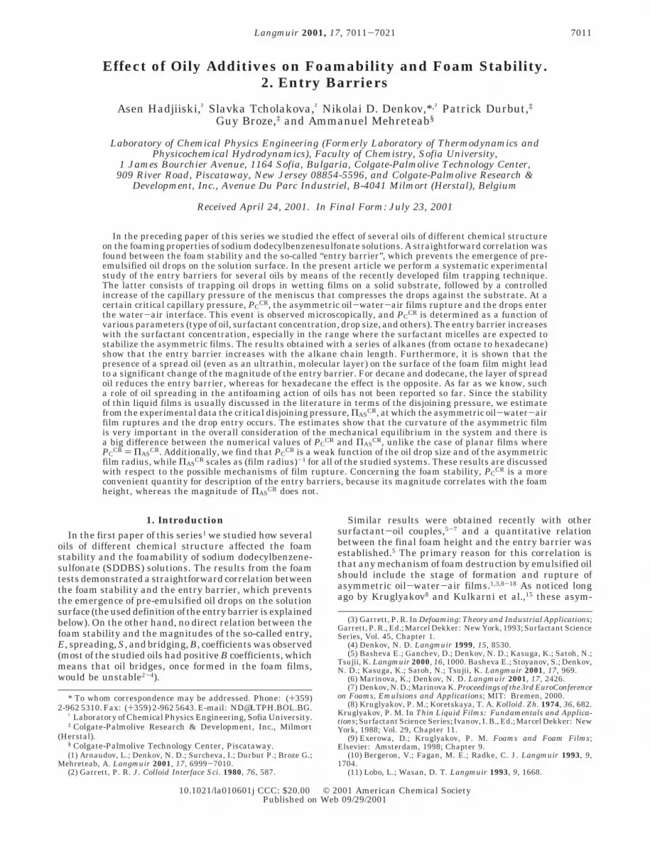
When PA increases, the air-water meniscus in the capillaryis pushed against the glass substrate and a wetting film is formed,which traps some of the oil drops (Figure 1B). These drops remainsandwiched between the air-water meniscus and the glasssubstrate. The capillary pressure of the air-water meniscusaround the trapped drops is PC ) PA - PW, where PW is thepressure in the liquid around the drops, which can be determinedfrom the liquid level in the external part of the vessel (outsidethe capillary). The height of water there is Z + ZC, where Z isthe distance between the flat air-water interface and the lowercapillary end, whereas ZC is the distance between the substrateand the capillary end (Figure 1B). Thus the pressure at the bottomof the liquid is PA
0 + FWg(Z + ZC), where FW is the water massdensity and g is the acceleration of gravity. If one neglects the
small variation of the hydrostatic pressure in the meniscus regioninside the capillary (ZC , Z), one finds the following relationshipbetween the capillary pressure, PC, and the measured pressuredifference, ∆PA
The depth of the liquid, Z, is measured during the submersionof the capillary in the solution (before starting the actualexperiments) by a micrometer translator having an accuracy of(5 µm, which corresponds to precision of (0.05 Pa in thedetermination of the hydrostatic pressure (the last term in eq 3).
Figure 1. Scheme of the experimental setup and the basicprinciple of operation of the film trapping technique (FTT). (A)A vertical capillary, partially immersed in surfactant solutioncontaining oil drops, is held close above the bottom of theexperimental vessel. (B) The air pressure inside the capillary,PA, is increased, and the water-air meniscus in the capillaryis pressed against the glass substrate. Some of the oil dropsremain trapped in the wetting glass-water-air film and arecompressed by the meniscus. At a given critical capillarypressure (see section 2.2 for details) the asymmetric film formedbetween the oil drop and the solution surface ruptures and adrop entry event is observed by an optical microscope. (C)Another modification called “gentle FTT” is used for measuringvery low entry barriers (below 20 Pa); a flat meniscus is formed,which allows the trapping of drops at virtually zero capillarypressure.
Table 1. Model and Main Characteristics of the UsedPressure Sensors
pressuretransducer
modelapressurerange, Pa
statedaccuracy, Pa
statedhysteresis and
repeatability, Pa
PX274-01DI (125 <(1.25 (0.31PX163-005BD5V (1250 <(12.5 (3.1PX142-001D5V 0-6900 <(51.8 (20.7
a Omega Engineering, Inc., Stamford, U.S.A.
PC ) ∆PA - FWgZ (3)
Effect of Oily Additives on Foams Langmuir, Vol. 17, No. 22, 2001 7013
During the experiment, one increases the pressure in thecapillary, PA, by very small increments. After each step of pressureincrease, one waits for liquid drainage from the wetting filmregion and for reaching a mechanical equilibrium. The changesof the meniscus shape around the trapped drops (caused by theliquid drainage) are observed by optical microscope in reflectedmonochromatic light of wavelength λ ) 546 nm; a characteristicinterference pattern is seen, which changes with time if dynamicprocesses occur in the wetting film region. The equatorialdiameter of the trapped drops, 2RE, is measured microscopically(in white transmitted light) with an accuracy of (0.8 µm. A CarlZeiss Jena inverted microscope, equipped with objective LDEpiplan, 20×/0.40, digital CCD camera (Kappa CF 8/1 DX), andVCR (Panasonic NV-HD 680), is used for these observations.
The experiments show that the trapped drops enter (pierce)the surface of the wetting film at a given, critical capillarypressure, PC
CR. The moment of drop entry, which is accompaniedwith a significant local change in the shape of the air-waterinterface, is clearly seen in both reflected and transmitted light.Therefore, the equipment allows one to measure PC
CR as a functionof the solution composition and drop radius. As mentioned above,for brevity we refer to PC
CR as the barrier to drop entry. LargerPC
CR corresponds to higher barriers (more difficult drop entry)and vice versa.
The experimental setup described above allows one to measurethe entry barriers higher than ca. 20 Pa.24 This limit is determinedby the capillary pressure of the meniscus formed in the capillarybefore trapping the drops. Since the liquid wets the inner surfaceof the capillary, a spherical meniscus is formed of capillarypressure PC ≈ 2σAW/RCAP ∼ 20 Pa (σAW ≈ 30 mN/m is the surfacetension of the solution and RCAP ≈ 3 mm is the capillary radius).However, the barriers are sometimes lower and another modi-fication of the method (called gentle FTT,24,25 see Figure 1C) isused in such cases.
The main idea of the gentle FTT is to create a virtually flatair-water interface in the capillary before trapping the drops,so that PC in the beginning of the experiment is almost zero. Forthis purpose, a sapphire disk of special design is attached to thelower end of the capillary. The disk has an opening with awedgelike shape (Figure 1C), which ensures the stable attach-ment of the air-water interface to the sapphire upper edge.Additionally, a substrate with a small stub, cut out onto a glassplate, is used in these experiments. The plate is placed on thevessel’s bottom, so that the stub is projected upward into theopening of the sapphire. One can move precisely the capillary inthe x-y-z directions and to juxtapose the flat fluid interfacewith the glass stub. Thus one can achieve trapping of drops bya flat interface, followed by a gentle increase of PC until PC
CR isreached.
2.2.2. Drop Entry Measurements in the Presence ofSpread Oil Layer. One series of experiments is directed to revealthe effect of the oil layer, spread over the water-air interface,on the height of the drop entry barrier. For this purpose parallelexperiments in the presence and in the absence of spread oil areperformed.
For oils that are not very much soluble in the surfactantsolution, like dodecane and hexadecane, a clean surface (free ofspread oil) is created by pouring the studied emulsions into theexperimental vessel for FTT experiments by the so-called “two-tips procedure” (TTP).18 The latter consists of a gentle injectionof the working emulsion through a narrow orifice (syringe needleor pipet tip)sin this way the oil layer, spread on the surface ofthe “mother” emulsion, is retained and a clean solution surfaceis created. It takes some period of time, which depends verymuch on the used oil and surfactant, before a new portion ofspread oil appears due to coalescence of oil drops with the solutionsurface or to molecular transfer of oil.18 Independent surfacetension measurements reveal that the value ofσAW of the dodecaneand hexadecane emulsions, poured by the TTP, is virtually thesame as that of the pure surfactant solution (without oil) anddecreases very slowly with timesby less than 0.5 mN/m for aperiod of 1 h, which is about the time span of the typical FTTexperiment. In these FTT tests, the number of the drop entryevents observed in a single experiment is restricted to 6, to avoidthe accumulation of detectable layer of spread oil from theentering drops.
The experiments, in which the effect of the spread layer is tobe studied with water-soluble and volatile oils (octane, decane,2BO, IHNP), are difficult and require a more complex procedure.When the oil drops are trapped in an wetting film, whose surfaceis cleaned from oil by the TTP, a significant oil evaporationthrough the asymmetric oil-water-air film occurs (evidencedby the rapid decrease of the drop size), because the air in thecapillary is not saturated with oil vapors. The observed shrinkingof the oil drops is certainly not caused by solubilization in thesurfactant micelles, because the surfactant solutions are pre-equilibrated with oil and because no drop size reduction isobserved before trapping the drops in the wetting film. Since theprocess of oil evaporation is very fast, the trapped oil dropsdisappear (evaporate) before the capillary pressure in the FTTequipment is increased up to the critical values, correspondingto drop entry. Hence it is impossible to measure the entry barrierwith clean solution surface for these oils, because the air phaseshould be almost saturated with oil vapors to reduce the rate ofoil evaporation, which inevitably leads to the formation of a spreadoil layer.27-29 That is why, we employed another procedure tostudy the effect of the spread layer on the entry barrier for thevolatile oils. First, we measure the entry barrier for a solutionsurface saturated with oil, so that no drop evaporation takesplace. In a separate experiment, which starts with saturatedsolution surface, we increase the capillary pressure up to a valuejust below the critical one. Afterward, maintaining the capillarypressure constant, we connect the air in the capillary with amuch bigger volume of air (“buffer” of the same mechanicalpressure), which is free from oil. As a result, the oil vapors diffuseinto the buffer and the air in the capillary becomes undersatu-rated with oil. Thus an evaporation from the spread layer isinduced, which is evidenced by the observed shrinking of the oildrops. In this moment, the capillary pressure is increased further,and a comparison of the entry barrier under these conditions(nonsaturated, evaporating oil layer) with the barrier in thepresence of saturated oil layer becomes possible.
All experiments are carried out at the ambient room tem-perature (T ) 25 ( 2 °C). The experiments with n-C12OH areperformed at 27 °C, to be well above its melting point (24 °C).The water evaporation inside the capillary is avoided, becausethe atmosphere above the wetting film is kept always saturatedwith aqueous vapors.
2.2.3. Surface Tension Measurements. The surface tensionof the surfactant solution is measured by the Wilhelmy platemethod, whereas the surface tension of the oil is measured byDu Nouy ring technique on Kruss K10T digital tensiometer. Theinterfacial tension of the oil-solution interface is measured bythe pendant drop method.
3. Experimental Results and Discussion
3.1. Effect of SDDBS Concentration on the DropEntry Barrier. 3.1.1. Critical Micelle Concentration(cmc) of SDDBS. The surface tension isotherm of theSDDBS in the presence of 12 mM NaCl shows no minimumaround the cmc, which is an indication that the mainsurfactant is not contaminated by surface active impuri-ties. The cmc obtained from the surface tension isotherm,0.25 ( 0.1 mM, is in a reasonable agreement with thevalue 0.15 ( 0.05 mM measured by electrical conductivity(conductivity meter model 30, Denver Instrument Co.,Arvada, CO). In the following discussions we use the meanvalue, cmc ) 0.2 mM.
3.1.2. Dependence of PCCR on the Surfactant
Concentration. This series of experiments is performedwith drops of hexadecane, and the obtained results areshown in Figure 2. The working emulsion is poured in theexperimental vessel by using the TTP to avoid the presence
(27) Aveyard, R.; Cooper, P.; Fletcher, P. D. I. J. Chem. Soc., FaradayTrans. 1990, 86, 3623.
(28) Aveyard, R.; Binks, B. P.; Fletcher, P. D. I.; MacNab, J. R.Langmuir 1995, 11, 2515.
(29) Binks, B. P.; Crichton, D.; Fletcher, P. D. I.; MacNab, J. R.; Li,Z. X.; Thomas, R. K.; Penfold, J. Colloids Surf., A 1999, 146, 299.
7014 Langmuir, Vol. 17, No. 22, 2001 Hadjiiski et al.

of oil on the solution surface. The surfactant concentration,CS, is varied between 0.16 and 12.8 mM (from 0.8 to 64times cmc), while the salt concentration is fixed at 12 mMNaCl. To eliminate a possible effect of the drop size on theentry barrier, the average values obtained with drops ofequatorial diameter, 2RE, confined between 5 and 6 µmare plotted in Figure 2. At least three independentexperimental runs are carried out at a given value of CS,with two to three entry events observed in each run. Thereproducibility of the data is very good, typically (5%.
The results shown in Figure 2 indicate a complexdependence of PC
CR on the surfactant concentration: Atconcentrations below 0.16 mM (0.8 × cmc), the entrybarrier is too low to be measured by the used experimentalprocedure. The main problem is that one observesnumerous lenses of hexadecane covering the solutionsurface even after the TTP is used for loading theexperimental cell - therefore, we could not prepare asolution surface free of oil for the entry experiments. Atthe lowest concentration where measurements are pos-sible, CS ) 0.16 mM (0.8 × cmc), we obtained PC
CR ) 10Pa. In the concentration range between 0.2 and 0.5 mM(1 to 2.5 × cmc), the entry barrier is almost constant,around 30 Pa. At higher concentrations, between 0.5 and9 mM (2.5 to 45 × cmc), the barrier exhibits a slow butsteady increase from ca. 40 to 150 Pa with the surfactantconcentration. A much steeper increase of PC
CR is observedat concentrations above 9 mM (45 × cmc) and the barrieris 400 Pa at CS ) 12.8 mM (64 × cmc).
The observed independence of the entry barrier on thesurfactant concentration around the cmc can be explainedby the facts that the surfactant adsorption layers aresaturated in this concentration range and that there is nosignificant concentration of micelles in the solution.Therefore, all of the important characteristics determiningthe film stability, such as the surfactant adsorption,surface charge density, Debye screening length, Hamakerconstant, etc., are virtually constant.
The observed sharp increase of PCCR at CS > 9 mM is
probably related to the stabilizing effect of the surfactantmicelles trapped in the asymmetric oil-water-airfilm.11,14,30-34 One can estimate that the effective volume
fraction of the SDDBS micelles, Φ, including the contri-bution of the counterion atmosphere, is about 6% at thekink point (9 mM):
FM is the number concentration of micelles, κ-1 ) 2.6 nmis the Debye screening length, and dM is the actualdiameter of the micelles (aggregation number νA ) 50 anddM ) 5 nm were adopted for this estimate). From the valuesof FM and Φ, one can estimate the height of the lastmaximum (corresponding to one layer of micelles trappedin the film) in the oscillatory component of the disjoiningpressure, by using the formulas from ref 30. The estimateshows that this maximum is about 73 Pa, which is not faraway from the measured values of PC
CR ≈ 160 Pa (notethat the electrostatic and van der Waals forces alsocontribute to the height of this maximum in the real film).Therefore, a detectable contribution of micelles in thestability of the films might be expected in this concentra-tion range.
More difficult for explanation is the increase of PCCR in
the intermediate concentration range, between 2.5 and45 × cmc, because the micelles are not expected to playa significant role there. Most probably, the increase ofPC
CR is due to a gradual increase of the density of thesurfactant adsorption layers on the oil-water and air-water interfaces. Indeed, the ionic strength of the ionicsurfactant solutions increases above the cmc, due to thecounterions dissociated from the micelles.30,35 On the otherside, the adsorption layers are denser at higher ionicstrength, because the electrostatic repulsion between theionized surfactant molecules is screened.36 As a result,one may expect that the surfactant adsorption and theentry barrier increase above the cmc for ionic surfactants.
3.2. Drop Entry Barriers for Different Oils. Allexperiments described in sections 3.2 and 3.3 are carriedout with solutions containing 2.6 mM SDDBS (≈13 × cmc)and 12 mM NaCl. The drop entry barriers for a series ofn-alkanes (octane, decane, dodecane, hexadecane), 2BO,IHNP, heptanol, dodecanol, and silicone oil are measured.Drops of diameter between 2 and 12 µm are studied, andno significant dependence of PC
CR on the drop size isobserved. As a typical example, PC
CR for dodecane dropsis plotted in Figure 3 as a function of the equatorial dropdiameter, 2RE. The points present the mean value of PC
CR
for drops of similar size, while the error bars show thestandard deviation. Two curves are shown in Figure 3:The solid squares present the experimental data for 26drops (5.0 ( 2.8 µm mean diameter) in the presence of athin spread layer of oil on the solution surface. The emptysquares present the experimental data for 27 drops (7.6( 2.8 µm mean diameter) in the absence of a spread oilsthe working emulsions are poured by the TTP in theseexperiments. The barrier measured in the experimentswith the spread oil layer is 48 ( 5 Pa, which is two timeslower than the barrier for the surface free of oil (96 ( 5Pa). Such a systematic change of the entry barrier in thepresence of spread oil is detected with other systems aswell and will be discussed in more detail in the nextsubsection. All experiments discussed hereafter in thissection are performed with spread oil layer on the solutionsurface.
(30) Kralchevsky, P. A.; Denkov, N. D. Chem. Phys. Lett. 1995, 240,385.
(31) Nikolov, A. D.; Wasan, D. T.; Kralchevsky, P. A.; Ivanov, I. B.J. Colloid Interface Sci. 1989, 133, 1, 13.
(32) Bergeron, V.; Radke, C. J. Langmuir 1992, 8, 3020.(33) Pollard, M. L.; Radke, C. J. J. Chem. Phys. 1994, 101, 6979.(34) Chu, X. L.; Nikolov, A. D.; Wasan, D. T. Langmuir 1994, 10,
4403.
(35) Richetti, P.; Kekicheff, P. Phys. Rev. Lett. 1992, 68, 1951.(36) Davies, J.; Rideal, E. Interfacial Phenomena; Academic Press:
New York, 1963.
Figure 2. Dependence of the entry barrier, PCCR, on the SDDBS
concentration, CS, for hexadecane drops. All solutions contain12 mM NaCl. The entry barriers are obtained with drops havingapproximately the same equatorial diameter 2RE ) 5.5 ( 0.5µm. The solution surface is free from oil (the two-tips procedureis used to load the experimental cell). The size of the symbolscorresponds to the accuracy of measurement.
Φ ) 43
πRκ3FM (4)
Rκ ) (dM
2+ κ
-1)
Effect of Oily Additives on Foams Langmuir, Vol. 17, No. 22, 2001 7015

The mean values of the drop entry barrier, PCCR,
measured for the different oils are summarized in Table2. The results demonstrate that the entry barrier forn-alkane drops increases with the molecular mass of thealkane: for octane PC
CR ) 30 ( 2 Pa, for decane PCCR )
35 ( 5 Pa, for dodecane PCCR ) 48 ( 5 Pa, and for
hexadecane PCCR ) 400 ( 10 Pa. The latter value is much
higher than the value reported in the previous section,PC
CR ) 80 ( 5 Pa, in the absence of a spread hexadecanelayer (for discussion see section 3.3). Such a significantincrease of the entry barrier with the alkane chain lengthis certainly important for the antifoam action of theseoils, and systematic foam tests are planned soon to checkquantitatively this relation.
The mean entry barrier for IHNP drops (Figure 4) isPC
CR ) 75 ( 7 Pa, obtained as an average from 195 dropsof diameter 6.6 ( 3.2 µm. For 2BO the barrier PC
CR )44 ( 2 Pa (in this case 8 drops of diameter 6.4 ( 3.7 µmare observed). The experiments with drops of n-dodecanolwith saturated surface reveal that the entry barrier israther highsabove 1500 Pa. Similarly, a very high entrybarrier is measured with silicone oil (PC
CR > 3 000 Pa).Note that these values correlate rather well with theresults from the foam stability tests reported in ref 1.
It is worthwhile noting that no detectable drop shrinking(due to oil evaporation across the oil-water-air film) isobserved with IHNP, 2BO, and hexadecane, when thestudied emulsions are poured in the FTT equipmentwithout using the TTP. This means that the surface of thesurfactant solutions has been covered by a thin layer ofoil (in the cases of 2BO and hexadecane, this layer is in
equilibrium with oil lenses), which saturates the atmo-sphere with oil vapors, so that the evaporation from thedrops is suppressed. This observation suggests that,probably, the oil evaporation was not a very importantfactor for the stability of the foams studied in ref 1, becausethe surface of the foaming solutions was always coveredby an oil layer (this is evidenced by the reduced equilibriumand dynamic surface tension of these solutionsssee Table1 and Figure 4 in ref 1). However, we could not rule outthe possibility that the foam destabilization in the presenceof volatile oils, under certain conditions (e.g., when thefoam is generated in open containers), could be affectedby oil evaporation and the ensuing Marangoni effect, orother processes related to the oil volatility and solubilityin the solutions (see also the comments at the end of section4.2 below).
Results with heptanol are not shown in Table 2, becausethe wetting film around the trapped drops ruptures atPC ≈ 60 Pa. This event makes impossible the furtherincrease of the capillary pressure of the meniscus com-pressing the drops; isolated water “islands” are formedaround the heptanol drops, and there is no direct aqueousconnection between these islands and the meniscus formedat the periphery of the wetting film.
The question about the actual reasons for the differententry barriers of the studied oils is very important, butthe information available so far is rather insufficient toanswer it. That is why we restrict our comment only tothe list (probably nonexhaustive) of different factors thatcould affect significantly the entry barriers: (1) the densityand the other properties of the surfactant adsorption layerson the oil-water interface;8 (2) the formation of mixedoil-surfactant and/or of spread oil layers at the water-air interface;27-29 (3) change of the micellar aggregationnumber due to oil solubilization;37 (4) change in themicelle-micelle and micelle-surface interactions in thepresence of solubilized oil.38 All of these factors are ratherspecific for thedifferentoils, and furthersystematic studiesare needed to reveal their importance for the studiedphenomenon.
3.3. Effect of the Spread Oil Layer on the EntryBarrier. As mentioned in section 3.2, the experimentswith dodecane demonstrate a significant effect of thespread oil layer on the entry barrier of the dropssit is twotimes lower in the presence of spread dodecane. A similareffect of the spread oil was measured also for decane; the
(37) Nakagawa, T.; Shinoda, K. In Colloidal Surfactants; Shinoda,K., Nakagawa, T., Tamamushi, B., Isemura, T., Eds.; Academic Press:Orlando, FL, 1963; p 139.
(38) Lobo, L. A.; Nikolov, A. D.; Wasan, D. T. J. Dispersion Sci.Technol. 1989, 10, 143.
Figure 3. Drop entry barrier, PCCR, as a function of equatorial
drop diameter, 2RE, measured for dodecane drops in aqueoussolution of 2.6 mM SDDBS and 12 mM NaCl. The empty squarespresent the data for clean air-water surface (without a spreadoil layer), whereas the solid squares present the data for solutionsurface, which is saturated with oil. The points present themean values and the error bars are the standard deviation fordrops of similar size.
Table 2. Drop Entry Barriers, PCCR, Measured for
Different Oils with Solution Surface Saturated with Oil(the results shown in parentheses correspond to solution
surface free of spread oil)a
oil PCCR, Pa VF/VIN
octane 30 ( 2decane 35 ( 5 (>70)dodecane 48 ( 5 (96 ( 5)hexadecane 400 ( 10 (80 ( 5) 0.942BO 44 ( 2 0.21IHNP 75 ( 7 0.22dodecanol >1500 0.93SO >3000 0.86
a The aqueous solution contains 2.6 mM SDDBS and 12 mMNaCl. The ratio of the final over initial foam volumes, VF/VIN (asmeasured by the Ross-Miles method in ref 1), is also shown forcomparison.
Figure 4. Drop entry barrier, PCCR, as a function of equatorial
drop diameter, 2RE, measured for drops of IHNP (opendiamonds) and 2BO (solid squares) in aqueous solution of 2.6mM SDDBS and 12 mM NaCl.
7016 Langmuir, Vol. 17, No. 22, 2001 Hadjiiski et al.

barrier obtained in the presence of spread layer was35 ( 5 Pa, whereas the capillary pressure can be increasedup to 70 Pa without drop entry to take place for a solutionsurface that is free of oil (the trapped drops evaporatedwithout entry, as explained in section 2.2.2). Thereforethe barrier for decane with a clean surface is at least twotimes higher than the barrier for the surface covered bya spread layer. On the contrary, the formation of a mixedadsorption layer SDDBS-hexadecane led to about a fivetimes higher barrier (section 3.2) as compared to thebarrier measured with solution surface free of hexadecane(section 3.1). Therefore, the presence of oils on the solutionsurface might significantly affect the magnitude of theentry barriers. It is rather possible that the high entrybarrier observed with n-C12OH is similalry due to theformation of a dense mixed adsorption layer on the solutionsurface.39,40
The observed increase of the entry barrier with themolecular mass of the alkanes (from octane to hexadecane)might be also related to the structure of the formed spreador mixed layers on the solution surface. As shown byAveyard, Binks and co-workers,27-29 mixed adsorptionlayers are formed typically by long-chain alkanes (>C11),which do not spread in the form of a multimolecular layeron the surface. On the contrary, the short-chain alkanesoften either form a thin multimolecular layer or spreadas a thick (duplex) film. It is worthwhile noting that theinteraction of an oil drop with a solution surface coveredby a thick oil layer would resemble the interaction of thedrop with its own homophase (i.e., an oil-water-oil filmof emulsion type will be formed), but a systematiccomparison of the stability of the asymmetric oil-water-air and the emulsion oil-water-oil films is still missing.
Let us note at the end of this section that the observedchange of the entry barrier in the presence of spread oilhas an important implication for the antifoaming actionof the oils. However, as discussed in refs 1, 3, 5, 6, 41, andmany others, different factors are often more importantand no straightforward correlation between the spreadingbehavior and the antifoam activity is observed.
4. Dependence of the Critical DisjoiningPressure for Film Rupture on the Film Size
The results presented in Figures 3 and 4 show that thecritical capillary pressure, PC
CR, is a very weak functionof the size of the asymmetrical oil-water-air film.Additional analysis is needed, however, to understandhow the critical disjoining pressure, ΠAS
CR, depends onthe film size. In this section we investigate this dependenceand discuss it from the viewpoint of the mechanism ofrupture of the thin asymmetric films.
4.1. Estimation of the Critical Disjoining Pressurefor Curved Asymmetric Films. 4.1.1. DisjoiningPressure for Spherical Films. The disjoining pressure,ΠAS, accounts for the interactions between the two filmsurfaces (van der Waals, elctrostatic, steric, etc.) and isconventionally defined as the surface force per unit area(a more general and rigorous definition was given throughthe components of the pressure tensor).42,43 Positive
disjoining pressure corresponds to a repulsive surface force(i.e., to film stabilization) and vice versa. In the case ofplanar films, the condition for mechanical equilibriumrequires that the capillary sucking pressure must beexactly counterbalanced by the disjoining pressure.42-45
However, the thin films in our experiments are curvedand the condition for mechanical equilibrium is morecomplex, because it includes the capillary pressure jumpsacross the curved film surfaces. The relevant theoreticalapproach to this configuration was developed by Ivanovand Kralchevsky,24,26,44 who showed that the disjoiningpressure is related to the capillary pressure across thewater-air interface, PC ) PA - PW, by the expression
where PF is the pressure in the asymmetric oil-water-air film and RF is its radius of curvature (Figures 5 and6). The aqueous phase, from which the asymmetric filmis formed, is chosen as a referent phase for the definitionof the disjoining pressure as usual.26,44
For micrometer-sized drops, RF is on the order of thedrop size and 2σAW/RF > 104 Pa. In most of our systemsPC ≈ 102 Pa and can be neglected in eq 5. Thus only theradius of film curvature, RF, would be sufficient to calculateΠAS, because σAW is a known quantity (the slight change
(39) Lu, J. R.; Purcell, I. P.; Lee, E. M.; Simister, E. A.; Thomas, R.K.; Rennie, A. R.; Penfold, J. J. Colloid Interface Sci. 1995, 174, 441.
(40) Angarska, J. K.; Tachev, K. D.; Kralchevsky, P. A.; Mehreteab,A.; Broze G. J. Colloid Interface Sci. 1998, 200, 31.
(41) Garrett, P. R.; Davis, J.; Rendall, H. M. Colloids Surf., A 1994,85, 159.
(42) Derjaguin, B. V. Theory of Stability of Colloids and Thin LiquidFilms; Plenum, Consultants Bureau: New York, 1989.
(43) Ivanov, I. B., Ed. Thin Liquid Films: Fundamentals andApplications; Surfactant Science Series; Marcel Dekker: New York,1988; Vol. 29.
(44) Kralchevsky, P. A. Effect of Film Curvature on the Thermody-namic Properties of Thin Liquid Films. Ph.D. Thesis, Sofia University,Sofia, Bulgaria, 1984 (in Bulgarian).
(45) Ivanov, I. B.; Toshev, B. V. Colloid Polym. Sci. 1975, 253, 558and 593.
Figure 5. Schematic cross section of an oil drop trapped bywater-air meniscus on a solid substrate. The arc AA′ corre-sponds to the asymmetric (pseudoemulsion) oil-water-air film.The line BB′ corresponds to the oil-water-glass film. Thecurves AC and A′C′ represent the air-water interface aroundthe droplet. PC ) (PA - PW) and PC1 ) (POIL - PW) are thecapillary pressures across the water-air and the oil-waterinterfaces, respectively.
Figure 6. Schematic presentation of the forces (disjoiningpressures and transversal line tensions), contributing to thevertically resolved balance of forces acting on the drop surface,eq 14.
ΠAS ) PF - PW ) (PF - PA) + (PA - PW) )2σAW
RF+ PC (5)
Effect of Oily Additives on Foams Langmuir, Vol. 17, No. 22, 2001 7017

of the surface tension of the film due to the surface forcesis neglected in eq 5, because it is a higher order effect).Note, however, that RF depends on the drop deformation,which in turn is determined by the applied capillarypressure, PC. For large drops or bubbles, one can measuredirectly the radius of film curvature, RF, by using themicroscopic method of differential interferometry,46 butthis method cannot be used for small, micrometer sizeddrops. That is why we apply below an indirect method toestimate the magnitude of ΠAS from the accessibleexperimental data and to study how the critical disjoiningpressure for drop entry, ΠAS
CR, depends on the size of theasymmetric film.
4.1.2. Main Assumption. From the experiment weknow the capillary pressure PC, the equatorial drop radiusRE, and the interfacial tensions, σAW and σOW. To makethe problem tractable and to estimate ΠAS, we make theassumption that the contact angles between the films andthe adjacent menisci (see Figure 5) are known and havesome small (fictitious) values: æS, angle of the oil-water-glass film; ψS, angle of the wetting glass-water-air film;R, angle of the curved asymmetric film. Since these anglesare of the type liquid film-meniscus, they are typicallybelow 5°. The numerical calculations revealed that theestimated disjoining pressure, ΠAS, is virtually insensitiveto the chosen values of the contact angles in the range0-5°. Therefore, for clarifying the effect of the film sizeon the value of ΠAS
CR, one may choose any value between0 and 5° for these angles. Once the angles are chosen, onecan calculate ΠAS from the experimental data as explainedbelow. In most computations, we will use for simplicityæS ) ψS ) R ) 0. The influence of this assumption on thecalculated values of ΠAS is checked a posteriori (see below).
4.1.3. Derivation of the Basic Equations. The shapesof the water-air and oil-water interfaces are describedby solutions of the Laplace equation of capillarity, whichcan be presented in the following form for axially sym-metric system:47,48
Here φ is the running slope angle of the interface andPC is the capillary pressure. The index i denotes thefollowing interfaces: i ) 1 for the oil-water interface,PC1 ≡ POIL - PW, σ1 ≡ σOW; i ) 2 for the air-water interface,PC2 ≡ PC )PA - PW, σ2 ≡ σAW.
Let us consider the shape of the drop interface describedby eqs 6 and 7 for i ) 1. The integration of eq 6 from theequatorial radius RE to a given value of the runningcoordinate r leads to
Substituting φ1(RS) ) æS in eq 8, one derives an expressionfor the contact radius, RS, of the drop with the substrate
Similarly, one can express the angle æC, which iscomplementary to the slope angle of the drop generatrixat the contact line of the asymmetric film, φ1(RC)
The angles ψC and θC (Figure 5) can be expressed throughæC in the following way
The last equation is a corollary of the horizontal andvertical balances of the interfacial tensions acting on thecontact line26,49 of the asymmetric film, with neglectedeffect of the line tension50
Here γ is the membrane tension26 of the asymmetric film.From the geometric relation
one obtains the radius of the film curvature,RF. Therefore,if one knows the capillary pressure at the oil-waterinterface, PC1, and the contact radius, RC (which are stillunknown at that stage), the disjoining pressure, ΠAS, canbe calculated by means of eqs 5, 12, and 13.
An equation for calculating RC can be derived from thebalance of the vertically resolved forces acting on thetrapped drop (the horizontal force balance is trivial,because the system is axially symmetric). Since the dropsize is very small, one can neglect the variations of thehydrostatic pressure around the drop surface and assumethat PW is constant. Therefore, PW does not contribute tothe vertical force balance. The drop contacts with thesubstrate through the oil-water-glass film and with theair phase through the asymmetric oil-water-air film (seeFigure 6). The condition for mechanical equilibrium inthese two thin films implies that the respective disjoiningpressures, arising from the interaction between the filmsurfaces, are exerted on the surface of the drop. Therefore,the vertical force balance includes the contributions ofthe disjoining pressures acting in the oil-water-air film,ΠAS, and in the film formed between the drop and thesubstrate, ΠS (multiplied by the respective projected filmareas). Since the aqueous film between the drop and thesubstrate is planar, ΠS must be equal to the capillarypressure PC1.
Along with the contribution of the disjoining pressures,the force balance includes the contributions of the linear
(46) Nikolov, A. D.; Kralchevsky, P. A.; Ivanov, I. B. J. Colloid InterfaceSci. 1986, 112, 122.
(47) Kralchevsky, P. A.; Danov, K. D.; Denkov, N. D. In Handbookof Surface and Colloid Chemistry; Birdi, K. S., Ed.; CRC Press: NewYork, 1997; Chapter 11.
(48) Princen, H. M. In Surface and Colloid Science; Matijevic, E.,Ed.; Wiley-Interscience: New York, 1969; Vol. 2, p 1.
(49) Kralchevsky, P. A.; Danov, K. D.; Ivanov, I. B. In Foams: Theory,Measurements, and Applications; Prud’homme, R. K., Khan, S. A., Eds.;Marcel Dekker: New York, 1995; Chapter 1.
(50) Ivanov, I. B.; Kralchevsky, P. A.; Nikolov, A. D.J. Colloid InterfaceSci. 1986, 112, 97. Ivanov, I. B.; Kralchevsky, P. A.; Dimitrov, A. S.;Nikolov, A. D. Adv. Colloid Interface Sci. 1992, 39, 77.
1r
ddr
(r sin φi) ) 2ki, ki )PCi
2σi(6)
dzdr
) (tan φi ) (sin φi
(1 - sin2φi)
1/2(7)
sin φ1(r) ) 1r[k1(r
2 - RE2) + RE] (8)
RS )sin æS + (sin2 æS - 4k1RE(1 - k1RE))1/2
2k1(9)
k1RE > 1
æC ) π - φ1(RC) ) arcsin[ k1
RC(RC
2 - RE2) +
RE
RC] (10)
ψC ) æC -R (11)
θC ) arctan(σAW sin ψC + σOW sin æC
σAW cos ψC + σOW cos æC) (12)
σAW cos ψC + σOW cos æC ) γ cos θC
σAW sin ψC + σOW sin æC ) γ sin θC
RF ) RC/sin θC (13)
7018 Langmuir, Vol. 17, No. 22, 2001 Hadjiiski et al.

forces acting on the contact lines of the films, due to so-called “transversal line tensions”.26,47 The vertical projec-tion of the force created by the transversal tension at thecontact line of the oil-water-air film is 2πRCτC cos θC,where τC is the corresponding transversal tension
The linear excess force acting on the contact line of thefilm with the glass substrate is 2πRSτS, where τS is
Thus one obtains the following balance of forces acting onthe drop surface
The left-hand side of eq 14 presents the force acting in theregion of the asymmetric oil-water-air film: the firstterm accounts for the disjoining pressure in the film, whilethe second term accounts for the transversal tension actingon the contact line. The right-hand side of eq 14 presentsthe corresponding terms for the film intervening betweenthe drop and the substrate.
Finally, we should define a procedure for determinationof the capillary pressure at the oil-water interface, PC1.The procedure is based on the necessary geometricalcondition for matching the generatrix of the air-watermeniscus with the drop surface and with the substrate atthe specified contact angles, ψC and ψS. The shape of thewater-air meniscus can be obtained by integration of eqs6 an 7 (i ) 2, PC is known from the experiment) withboundary conditions at the contact line of the asymmetricfilm
This meniscus has to intersect the plane of the substrateat the following angle
Explicit expressions for ZC ) z(RC) and ZS ) z(RS) can befound from the solutions of the Laplace equation ofcapillarity (eq 6 and 7) for the drop surface (i ) 1)44,47
where R1, q, and Λ(r) are defined as
F(Λ,q) and E(Λ,q) are elliptic integrals of the first andsecond kind, respectively51
Note that k1 depends on PC1 (eq 6), which allows one touse eqs 15-17 for determination of PC1 (see the followingsubsection).
4.1.4. Numerical Iterative Procedure for Calcula-tion of ΠAS. On the basis of the above analysis, one cancalculate the disjoining pressure of the asymmetric film,ΠAS, by means of an iterative procedure whose blockscheme is shown in Figure 7. One starts with an initialguess for the two independent unknownssthe capillarypressure of the drop, PC1, and the contact radius of theasymmetric film, RC (see Figure 5). From eq 9 onecalculates a value for the contact radius drop substrate,RS. Then, from eqs 10-12 one calculates the angles æC,ψC, and θC and by eqs 13 and 5, the radius of film curvature,RF, and the disjoining pressure, ΠAS, respectively. One
(51) Abramowitz, M.; Stegun, I. A. Handbook of MathematicalFunctions; Applied Mathematics Series; National Bureau of Standards,Washington, 1964; Vol. 55, Chapter 17 (reprinted by Dover Publica-tions: New York, 1968).
τC ) σOW sin(æC - θC)
τS ) σOW sin æS
πRC2ΠAS -2πRCσOW cos θC sin(æC - θC) )
πRS2PC1 - 2πRSσOW sin æS (14)
φ2(r) ) -ψC; r ) RC, z ) ZC (15)
φ2(r) ) -ψS; r ) RS, z ) -ZS (16)
z(r) ) ([(RE - 1k1
)F(Λ,q) - RE E(Λ,q)] (17)
R1 e r e RE, k1RE > 1
R1 ) |1 - k1RE
k1| (18)
q ) (1 -R1
2
RE2)1/2
sinΛ ) q-1(1 - r2
RE2)1/2
Figure 7. A block scheme of the iterative procedure forcalculating the disjoining pressure, ΠAS, of the asymmetricaloil-water-air film (see section 4.1.4).
F(Λ,q) ) ∫0
Λ dê(1 - q2 sin2 ê)1/2
(19)
E(Λ,q) ) ∫0
Λ(1 - q2 sin2 ê)1/2 dê (20)
Effect of Oily Additives on Foams Langmuir, Vol. 17, No. 22, 2001 7019
varies the value of RC (and the corresponding values ofæC, ψC, θC, RF, and ΠAS) until the vertical force balance,eq 14, is satisfied. In another (larger) loop, one varies PC1to satisfy the condition for matching the generatrix of theair-water meniscus at the contact lines with the dropand the substrate given by eqs 15 and 16. The variationof PC1 and RC is performed by the minimization methodof Brent.52 The integration of the Laplace equation for theair-water meniscus, which is necessary for matching theinterfaces, is performed by a fifth order Runge-Kuttamethod with adaptive step size control.52 The procedureis implemented in a computer program written in C++(Borland C++ Builder) with interactive user interfaceunder Windows NT/98. The reliability of the calculationsperformed by this procedure is evidenced by experimentswith larger drops (diameter above 100 µm), where a directoptical measurement of the radii RC, RS, and the contactradius of the air-water meniscus with the substrate ispossible. These experiments reveal a very good agreementbetween the calculated and the measured values of thecontact radii within the framework of experimentalaccuracy.
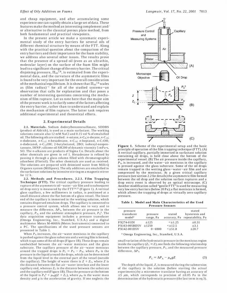
4.2. Numerical Results. In Figure 8, the calculateddependence of ΠAS
CR as a function of the inverse film radiusfor 3.2 mM SDDBS, 12 mM NaCl, and hexadecane drops(clean water-air surface) is shown by a solid line. Thecontact angles are taken as equal to zero, æS ) ψS ) R )0. Since the asymmetric film is curved, there are differentpossible definitions of its size. For this plot we have chosenthe “effective” film radius to be equal to the radius of aplanar film, which has the same area as the realasymmetric film
where AF is the actual area of the asymmetric film. Asseen from Figure 8, ΠAS
CR is a linear function of 1/REFF.It is worth noting that such a linear dependence is obtainedalso if ΠAS
CR is plotted against 1/RC or 1/RF; i.e., this is nota particular property of REFF. The dashed line shows thesame plot but for different contact angles, æS ) R ) 5°.The angle of the wetting glass-water-air film in bothcases is taken as ψS ) 0 because the direct microscopeobservations show that in all experiments this angle is
below 1°. As evidenced from the comparison of the solidand dashed lines in Figure 8, the variation of the contactangles does not affect significantly the magnitude of thecalculated ΠAS
CR or its linear dependence on 1/REFF.The observed dependence ΠAS
CR on REFF is by no meansa trivial fact. The isotherm ΠAS(h) is not expected to dependon either the film size or the film curvature, because thefilm thickness h is much smaller than both REFF and RF.Therefore, if the film rupture were accomplished bysurmounting the maximum in the isotherm ΠAS(h), thenthe rupture event for a given system would be expectedto occur always at ΠAS
CR ) ΠASMAX, independently of the
drop size.One possible explanation of the observed dependence
might be related to the relatively small size of theasymmetric films. As shown previously for micrometer-sized liquid films,53-56 the interaction force and energyacross the film might be comparable in magnitude withthe interaction across the meniscus region surroundingthe film. If such is the case, the film destabilization willdepend on the overall force of interaction between thedrop and the water-air interface, including the meniscusregion; i.e., ΠAS
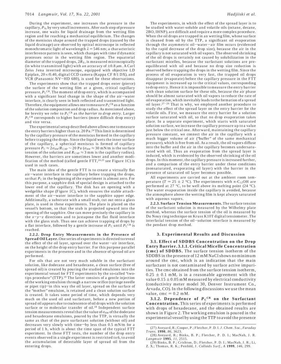
CR should not necessarily coincide withΠMAX and might depend on the film size. Another possibleexplanation of the experimental results is that the filmrupture in our systems occurs by passing below the barrierΠMAX (Figure 9), similar to the results obtained with planarfoam films by Bergeron.22 Such a possibility is offered bydifferent theoretical models of film rupture, in which theformation of unstable spots in large liquid films by variousmechanisms is considered.22,42,57,58 However, all thesemodels are developed for planar films and cannot bedirectly applied without a careful analysis of the role offilm curvature in the film rupture process. For solubleoils (octane, decane, dodecane, 2BO, etc.) it was recentlyshown59 that the asymmetric oil-water-air films can be
(52) Press, W. H.; Teukolsky, S. A.; Vetterling, W. T.; Flannery, B.P. Numerical Recipes in C. The Art of Scientific Computing; 2nd ed.;Cambridge University Press: New York, 1992.
(53) Denkov, N. D.; Petsev, D. N.; Danov, K. D. Phys. Rev. Lett. 1993,71, 3226.
(54) Danov, K. D.; Petsev, D. N.; Denkov, N. D.; Borwankar, R. J.Chem. Phys. 1993, 99, 7179.
(55) Denkov, N. D.; Petsev, D. N.; Danov, K. D. J. Colloid InterfaceSci. 1995, 176, 189.
(56) Petsev, D. N.; Denkov, N. D.; Kralchevsky, P. A. J. ColloidInterface Sci. 1995, 176, 201.
(57) Kaschiev, D.; Exerowa, D. J. Colloid Interface Sci. 1980, 77,501.
(58) Kralchevsky, P. A.; Nikolov, A. D.; Wasan, D. T.; Ivanov, I. B.Langmuir 1990, 6, 1180.
(59) Valkovska, D. S.; Kralchevsky, P. A.; Danov, K. D.; Broze, G.;Mehreteab, A. Langmuir 2000, 16, 8892.
Figure 8. Dependence of the critical disjoining pressure, ΠASCR,
on the inverse radius of the asymmetric film, REFF-1 ) (πAF)-1/2;
AF is the actual area of the asymmetric film (corresponding tothe arc AA′ in Figure 5). The calculations are made for 3.2 mMSDDBS, 12 mM NaCl, and hexadecane drops (clean water-airsurface). The solid line represents the calculations with R )æS ) 0°, whereas the dashed line corresponds to R ) æS ) 5°.The angle of the wetting glass-water-air film in both casesis ψS ) 0 since direct microscope observations show that in allexperiments this angle is virtually zero.
REFF ) (AF/π)1/2 (21)
Figure 9. Schematic presentation of the disjoining pressureisotherm ΠAS(h). Two ways for overcoming the barrier andpossible film rupture are indicated: (1) The film surfaces arecompressed against each other by a capillary pressure thatdrives the system to surmount the barrier ΠMAXsin this casethe critical disjoining pressure ΠAS
CR should be equal to ΠMAXindependently of the drop radius. (2) A local fluctuation in thefilm could lead to the formation of unstable spot that leads toa local film rupture.22,57,58 In this case the film rupture mayoccur at a critical disjoining pressure ΠAS
CR < ΠMAX. Further-more, ΠAS
CR could depend on the film size.22
7020 Langmuir, Vol. 17, No. 22, 2001 Hadjiiski et al.
destabilized by a transfer of oil molecules across the film.Since the conditions in our experiments are not entirelycompatible with some of the assumptions made in therespective theoretical model,59 it is impossible to make adirect comparison of the theoretical predictions with ourexperimental results. Further experimental and theoreti-cal work is intended to reveal the actual mechanism offilm rupture in our systems, to modify some of the existingmodels or to develop a new model of this process, and toexplain the observed dependence ΠAS
CR(REFF).
5. ConclusionsA systematic experimental study of the entry barriers
for several oils of different chemical structure in SDDBSsolutions is performed by means of the film trappingtechnique.First, thecritical capillarypressure,PC
CR,whichleads to rupture of the asymmetric oil-water-air filmand to drop entry at the water-air interface, is measured(for brevity, PC
CR is denoted as “the entry barrier”throughout the paper). Second, the critical disjoiningpressure in the moment of film rupture, ΠAS
CR, is estimatedfrom the experimental data. The obtained results andconclusions can be summarized in the following way:
The entry barrier increases with the surfactant con-centration. Close to the cmc, the increase of the entrybarrier is relatively slow, whereas at about 9 mM (45 ×cmc, effective volume fraction of the micelles ≈6%) theincrease becomes much steeper. The latter observationimplies that the micelles play a significant role in the filmstabilization above a certain threshold surfactant con-centration.
The presence of a spread oil layer on the surface of thesolution was shown to reduce significantly the entrybarrier for decane and dodecane. Remarkably, the pres-ence of hexadecane on the solution surface (which makesa mixed adsorption layer with the SDDBS) leads to a 5-foldincrease of the entry barrier with important consequencesfor the antifoam activity of this oil.1 The explanation ofthis effect is certainly connected to the incorporation ofoil molecules into the surfactant adsorption layer. How-ever, without a more detailed picture of the mechanismsof asymmetric film rupture and drop entry, it is impossibleto specify what are the properties of the mixed adsorptionlayer that play a major role (Gibbs elasticity, surface
charge density, etc.). As far as we know, such a role of oilspreading in the antifoaming action of the oils has notbeen reported so far.
The entry barriers for a series of n-alkanes are measuredin the presence of a spread oil layer. The barriers increasewith the molecular mass of the alkane. Again, additionalstudies are needed to clarify the main factors, which governthis trend.
The calculations show that for micrometer-sized oildrops, like those in the real oil-containing antifoams, thereis a big difference between the numerical values of PC
CR
and ΠASCR (unlike the case of planar films where PC
CR )ΠAS
CR). The reason is that the radius of curvature of theasymmetric oil-water-air film is very small and thecapillary pressure jumps across the film surfaces are verylarge and cannot be neglected. Therefore, one shouldseparately consider the dependence of ΠAS
CR and PCCR on
the size of the asymmetric film.The experiments show that PC
CR is a weak function ofthe oil drop size and of the asymmetric film radius, whileΠAS
CR scales as (film radius)-1 for all of the studied systems.The strong dependence of ΠAS
CR on the film radius showsthat the rupture of the asymmetric film does not occursimply by surmounting the barrier in the ΠAS(h) curve,because the latter is expected to be independent of thefilm radius in the studied size range. Some possibleexplanations of this experimental fact are discussed.
When discussing the foam stability, PCCR is a more
convenient quantity for description of the entry barriers,because its magnitude correlates with the foam height,5,25
whereas the magnitude of ΠASCR does not.
Let us conclude that the film trapping technique is apowerful and versatile tool for quantifying the entrybarriers of oil drops. The obtained new experimentalresults have posed several interesting questions concern-ing the general mechanism of film stability, which call forfurther experimental and theoretical work on this subject.
Acknowledgment. The support of this study byColgate-Palmolive is gratefully acknowledged. The au-thors are indebted to Professor Ivan B. Ivanov, ProfessorP. A. Kralchevsky, and Dr. S. Stoyanov for the helpfuldiscussions.
LA010601J
Effect of Oily Additives on Foams Langmuir, Vol. 17, No. 22, 2001 7021