edcr 52321 draft scope and intent, unit difference and
TRANSCRIPT
Enclosure 2TVA Letter Dated October 29, 2010
Responses to Licensee Open Items to be Resolved for SER Approval
Attachment I
EDCR 52321 Draft Scope And Intent, Unit Difference And Technical Evaluation
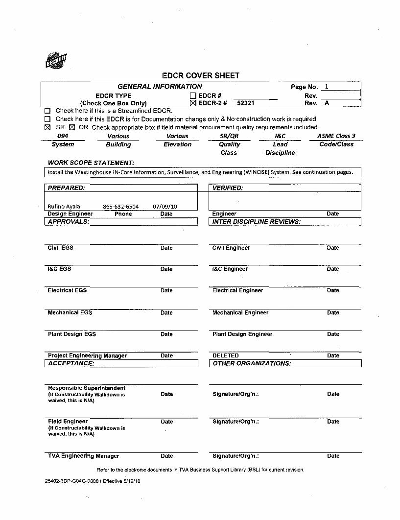
EDCR COVER SHEETGENERAL INFORMATION Page No. 1
EDCR TYPE F-1 EDCR # Rev.(Check One Box Only) Z EDCR-2 # 52321 Rev. A
C] Check here if this is a Streamlined EDCR.C Check here if this EDCR is for Documentation change only & No construction work is required.0 SR 10 QR Check appropriate box if field material procurement quality requirements included.
094 Various Various SR/QR I&C ASME Class 3System Building Elevation Quality Lead Code/Class
Class Discipline
WORK SCOPE STATEMENT:Install the Westinghouse IN-Core Information, Surveillance, and Engineering (WINCISE) System. See continuation pages.
PREPARED: VERIFIED:
Rufino Ayala 865-632-6504 07/09/10Design Engineer Phone DateAPPROVALS:
Civil EGS Date
I&C EGS Date
Electrical EGS Date
Mechanical EGS Date
Plant Design EGS Date
Project Engineering Manager Date
ACCEPTANCE:
Responsible Superintendent(If Constructability Wal kdown is Datewaived, this is N/A)
Field Engineer Date(If Constructability Walkdown iswaived, this is NIA)
TVA Engineering Manager Date
IEngineer DateINTER DISCIPLINE REVIEWS:
Civil Engineer Date
I&C Engineer Date
Electrical Engineer Date
Mechanical Engineer Date
Plant Design Engineer Date
DELETED DateFOTHER ORGANIZATIONS:
SignaturelOrg'n.: Date
SignaturelOrg'n.: Date
Signature/Org'n.: Date
Refer to the electronic documents in TVA Business Support Library (BSL) for current revision.
25402-3DP-GO4G-00081 Effective 5/19/10
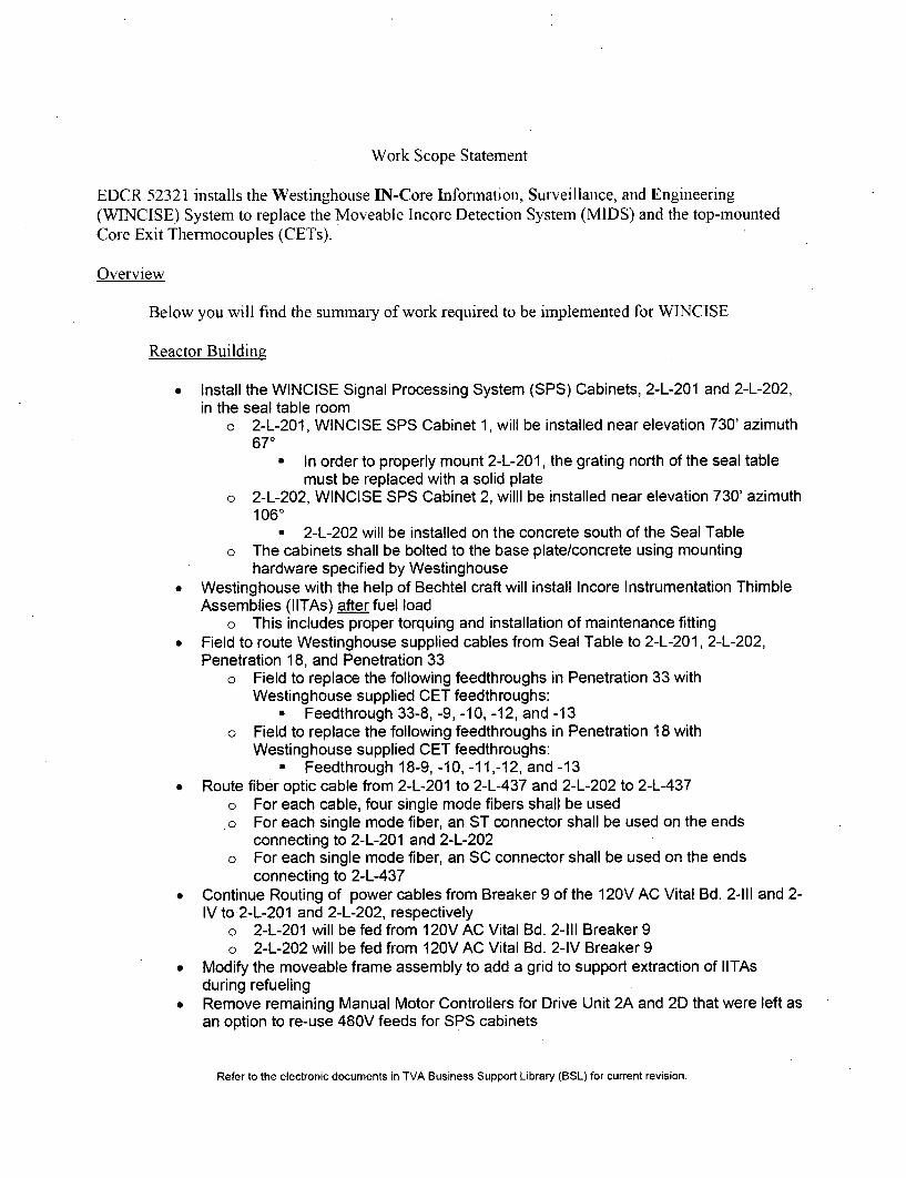
Work Scope Statement
EDCR 52321 installs the Westinghouse IN-Core Information, Surveillance, and Engineering(WINCISE) System to replace the Moveable Incore Detection System (MIDS) and the top-mountedCore Exit Thermocouples (CETs).
Overview
Below you will find the summary of work required to be implemented for WINCISE
Reactor Building
* Install the WINCISE Signal Processing System (SPS) Cabinets, 2-L-201 and 2-L-202,in the seal table room
o 2-L-201, WINCISE SPS Cabinet 1, will be installed near elevation 730' azimuth670
* In order to properly mount 2-L-201, the grating north of the seal tablemust be replaced with a solid plate
o 2-L-202, WINCISE SPS Cabinet 2, willl be installed near elevation 730' azimuth1060
a 2-L-202 will be installed on the concrete south of the Seal Tableo The cabinets shall be bolted to the base plate/concrete using mounting
hardware specified by Westinghouse* Westinghouse with the help of Bechtel craft will install Incore Instrumentation Thimble
Assemblies (IITAs) after fuel loado This includes proper torquing and installation of maintenance fitting
* Field to route Westinghouse supplied cables from Seal Table to 2-L-201, 2-L-202,Penetration 18, and Penetration 33
o Field to replace the following feedthroughs in Penetration 33 withWestinghouse supplied CET feedthroughs:
W Feedthrough 33-8, -9, -10, -12, and -13o Field to replace the following feedthroughs in Penetration 18 with
Westinghouse supplied CET feedthroughs:0 Feedthrough 18-9, -10, -11,-12, and -13
* Route fiber optic cable from 2-L-201 to 2-L-437 and 2-L-202 to 2-L-437o For each cable, four single mode fibers shall be used
.o For each single mode fiber, an ST connector shall be used on the endsconnecting to 2-L-201 and 2-L-202
o For each single mode fiber, an SC connector shall be used on the endsconnecting to 2-L-437
" Continue Routing of power cables from Breaker 9 of the 120V AC Vital Bd. 2-111 and 2-IV to 2-L-201 and 2-L-202, respectively
o 2-L-201 will be fed from 120V AC Vital Bd. 2-111 Breaker 9o 2-L-202 will be fed from 120V AC Vital Bd. 2-IV Breaker 9
* Modify the moveable frame assembly to add a grid to support extraction of IITAsduring refueling
* Remove remaining Manual Motor Controllers for Drive Unit 2A and 2D that were left asan option to re-use 480V feeds for SPS cabinets
Refer to the electronic documents in TVA Business Support Library (BSL) for current revision.
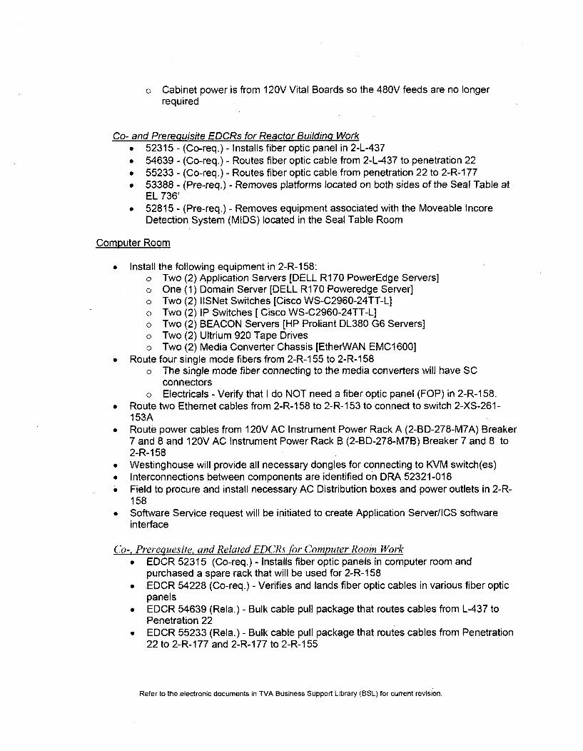
o Cabinet power is from 120V Vital Boards so the 480V feeds are no longerrequired
Co- and Prerequisite EDCRs for Reactor Building Worke 52315 - (Co-req.) - Installs fiber optic panel in 2-L-437* 54639 - (Co-req.) - Routes fiber optic cable from 2-L-437 to penetration 22* 55233 - (Co-req.) - Routes fiber optic cable from penetration 22 to 2-R-177• 53388 - (Pre-req.) - Removes platforms located on both sides of the Seal Table at
EL 736'* 52815 - (Pre-req.) - Removes equipment associated with the Moveable Incore
Detection System (MIDS) located in the Seal Table Room
Computer Room
* Install the following equipment in 2-R-158:o Two (2) Application Servers [DELL R170 PowerEdge Servers]o One (1) Domain Server [DELL R170 Poweredge Server]o Two (2) IISNet Switches [Cisco WS-C2960-24TT-L]o Two (2) IP Switches [ Cisco WS-C2960-24TT-L]o Two (2) BEACON Servers [HP Proliant DL380 G6 Servers]o Two (2) Ultrium 920 Tape Driveso Two (2) Media Converter Chassis [EtherWAN EMC1600]
* Route four single mode fibers from 2-R-155 to 2-R-158o The single mode fiber connecting to the media converters will have SC
connectorso Electricals - Verify that I do NOT need a fiber optic panel (FOP) in 2-R-1 58.
* Route two Ethernet cables from 2-R-158 to 2-R-153 to connect to switch 2-XS-261-153A
* Route power cables from 120V AC Instrument Power Rack A (2-BD-278-M7A) Breaker7 and 8 and 120V AC Instrument Power Rack B (2-BD-278-M7B) Breaker 7 and 8 to2-R-1 58
* Westinghouse will provide all necessary dongles for connecting to KVM switch(es)* Interconnections between components are identified on DRA 52321-018* Field to procure and install necessary AC Distribution boxes and power outlets in 2-R-
158* Software Service request will be initiated to create Application Server/ICS software
interface
('o-, Prerequesite, and Related EDCRs for Computer Room Work* EDCR 52315 (Co-req.) - Installs fiber optic panels in computer room and
purchased a spare rack that will be used for 2-R-158* EDCR 54228 (Co-req.) - Verifies and lands fiber optic cables in various fiber optic
panels" EDCR 54639 (Rela.) - Bulk cable pull package that routes cables from L-437 to
Penetration 22* EDCR 55233 (Rela.) - Bulk cable pull package that routes cables from Penetration
22 to 2-R-177 and 2-R-177 to 2-R-155
Refer to the.electronic documents in TVA Business Support Library (BSL) for current revision.
EDCR UNIT DIFFERENCE FORM
EDCR# 52321 Rev. A Page No.
Operations Difference is identified as follows:The Moveable Incore Detection System (MIDS) and top-mounted CETs are being completelyreplaced with the Westinghouse INCore Instrumentation, Surveillance, and Engineering (WINCISE)System:
" Controls and indication relating to MIDS is no longer required on 2-M-18 and ICS* WINCISE introduces Incore Instrument Thimble Assemblies (IITAs) which create the
following differences:o 58 CETs instead of 65 and CETs located in different core locationso 290 Self Powered Vanadium Detectors (SPD) [5 per IITA] located through the upper,
middle, and lower areas of the core instead of using 6 detectors,•*•;i •o•:iiDetectors do not nee:d to be moved to obtaiin a fluxma
o During certain accident scenarios, it is possible for the CETs to see temperatures upto 20'F different from Unit 1
• In order to process thei microampere analog signals, Signal Processing System (SPS)Cabinets 2-L-201 and 2-L-202 are installed in the Seal Table Room. As a result:
o Each cabinet collects and does Analog-to-Digital conversions for 29 IITAs0•o SPS Cabinets shall operate at temperature up to 1300 F ± 100
" Temperatures above this limit results in power being cutoff to the SPSelectronics
." ' Power is returned to SPS electronics once temperature drops below 11 O0F±100 and breakers are cycled OFF/ON
o Redundant communication paths are provided within each cabinet to ensure that nosingle component failure results in data not being sent to the Application Serverslocated in 2-R-158
o Each cabinet has two single mode fiber outputs with the same cabinet status andneutron flux information corresponding with that cabinet going to 2-R-1 58
* BEACON Power Distribution Monitoring System (PDMS) system no longer interfacesdirectly with the Integrated Computer System (ICS):
o Application Servers, Domain Server, fiber optic converters, and switches provideBEACON with data from both cabinets and other plant data
o Information between BEACON and ICS is transferred by the Application Serverso Redundant communication paths allow for BEACON servers to receive data from
each SPS cabinet regardless of a single failure
Unit 2 TVA Operations Acceptance (Mgr or Designee): Date:
Refer to the electronic documents in TVA Business Support Library (BSL) for current revision.
25402-3DP-GO4G-00081 Effective 5/19/10 Page 1 of 3
Maintenance Difference is identified as follows:The Moveable Incore Detection System (MIDS) and top-mounted CETs are being completelyreplaced with the Westinghouse INCore Instrumentation, Surveillance, and Engineering (WINCISE)System:
" Troubleshooting or maintenance activities for the Incore Instrumentation System will nowonly involve the IITAs, SPS Cabinets and internal electronics, Application Servers, DomainServer, BEACON servers, fiber optic converters, switches and all interconnecting cablesand peripherals
" The outage activities related to the Incore Instrumentation System are different:o CETs cable are no longer connected to the reactor vessel head, thus no CET outage
work in this area is requiredo IITAs are retracted until they are out of the fuel assembly and stored within the
bottom mounted instrument (BMI) thimble guide tubes0 Moveable frame assembly will hold retracted IITAs in place
o Eddy current testing will not be required on IITAs* Westinghouse.calculation notes haVe indicated that a•compa.son .between•. IITA and U• thimbles results in IITAs having a higher, natural frequency and
lower vibration amplitude. Thus the I ITAs are expected to exhibit essentiallyno wear due to vibrations
• Unlike U11 thimbles, a breach of the IITA outer sheath does not result in aloss of the RCS pressure boundary
o "Pinging" of the loose parts mon itori ngr system (LPMS) sensor at the bottom of:thevessel ýmust be done after fuel load and after IITAs are inserted back into the core
* Certain SPS electronics (further details are provided in SPS Cabinet Tech Manual) shall beremoved prior to performance of any integrated leak rate testing
9
Unit 2 TVA Maintenance Acceptance (Mgr or Designee): Date:
Refer to the electronic documents in TVA Business Support Library (BSL) for current revision.
25402-3DP-GO4G-00081 Effective 5/19/10 Page 2 of 3
Design Difference is identified as follows:The Moveable Incore Detection System (MIDS) and top-mounted CETs are being completelyreplaced with the Westinghouse INCore Instrumentation, Surveillance, and Engineering (WINCISE)System:
" Fission chamber detectors, thimbles, 5-path and 10-path rotary devices, drive units, and allassociated controls and indication are replaced by the IITAs
" IITAs each contain five vanadium self-powered detectors (SPD) and one Type-Kthermocouple
o The five detectors are distributed between lower and upper areas of the coreo Due to the new CET location, it is possible for the CETs to measure temperatures up
to 20°F different from Unit 1 under certain accident scenarioso WINCISE does not require input from more than 75%
" For MI cable system from the electrical connector at the end of the IITA to the SPS Cabinetsand Penetration 18 and 33:
o Certain portions of the cable system requires that PAM (CETs) signals be housed in"'the same cable"With neutron flux (non-safety related)
o The two channels/trains of the PAM 1/2 CET cables are bundled at the seal tableand no protection is provided by the rod control mechanisms and rod positionindicator stacks
o Five feedthroughs on Penetration 18 and 33 will be replaced with Westinghousesupplied equipment
This allows for the referencejunction boxes to be removed from containmentand for Type-K thermocouple :splices to be located outside of containment
* SPS cabinets will collect and provide analog-to-digital conversion from neutron flux, signalsprior to sending it along with cabinet status to the Application Servers
o Redundant communication paths are provided within each cabinet to ensure that nosingle component failure results in data not being sent to the Application Serverslocated in 2-R-158
* BEACON receives neitron flux information and additional plant data from the ApplicationServers instead of directly from ICS
o To address cybersecurity, only the Application Servers, via a firewall, communicatewith the ICS. All other data traffic is maintained within the WINCISE network and notseen by any other devices
" Differences identified under Maintenance and Operating Differences also describe furtherdesiqn changes
Unit 2 TVA Engineering Acceptance (Mgr or Designee): Date:
Prepared By: Date:
Streamlined EDCR approved by TVA Oversight
SESG TO ROUTE A COPY OF THIS COMPLETED FORM TO TVA TRAINING MANAGER AND TO UNIT2 LICENSING.
Refer to the electronic documents in TVA Business Support Library (BSL) for current revision.
25402-3DP-GO4G-00081 Effective 5/19/10 Page 3 of 3
Attachment 1Page 1 of 24
Technical Evaluation Considerations of 0-TI-2
This attachment provides topics to be considered when evaluating the technical and safetyaspect of changes being implemented in WBN Unit 0 and/or Unit 1 by the EDCR-2 process;see Reference 5.OA. It is not intended to be an all inclusive list of items to be considered. It isto be used as an aid in determining 'attributes that should be addressed in a technicalevaluation. Information is also provided to aid in determining coordination interfaces. Theseare minimum guidelines which are primarily excerpts from SPP-9.3. It should be recognizedthat many topics and changes involve multiple disciplines and organizations and technicalconsiderations must be coordinated accordingly. All parts of Attachment 1 must be consideredfor applicability for the associated EDCR-2.
Attachment 1Page 2 of 24
Technical Evaluation Considerations of 0-TI-2
GENERAL:
1. Are the nuclear safety functions, protective safety functions, Class IE requirements, orYSeismic Category I or I(L) requirements of a design criteria, system description, FSAR,
Technical Specification (Bases), or Technical Requirements Manual (Bases) affected?
Changes to the safety function, Class IE requirements and Seismic Category ILrequirements of the Incore Instrumentation System will described in the Unit 2System Description. A Unit 2 System Description change package is required tobe completed prior to issuing EDCR 52321.
Additionally, changes to FSAR, TS, TS Bases, TRM, and TRM (Bases), as aresult of this modification, are required to be included as part of the final issuedEDCR
2. Is there an operational/configurationchange? Is a component being addedd to orYES No removedfrom the plant? Is a component being disabled or abandoned in place? Is
YES N. " the normal or accident position'dof a valve changing? Is an electrical isolation devicebeing added or deleted? Is a portion of the systeml being rerouted?
The replacement of the Moveable Incore Detection System (MIDS) and topmounted CETs with WINCISE will results in an operationallconfiguration changeby.
" , Replacing 6 moveable fission chamber detectors and their associateddrive units and controls with 58 fixed Incore Instrument ThimbleAssemblies (IITAs). Each IITA consists of five (5) self-powered vanadiumdetectors (SPDs) and a Type K thermocouple
o The.MIDS controls and status information in 2-M-18 are no longerreq~uired
o Flux mapping can now be done without having to move anydetectors
o The Integrated Computer System (ICS) status points relating toMIDS are no longer required
* Reducing the number of CETs from 65 to 58
* Requiring that IITAs only be retracted out of the fuel assembly instead ofretracting them and placing them in storage within the crane wall asdone for fission chamber detectors
* SPS cabinet status and neutron flux information will be transmitted fromSPS cabinets to the Application Servers where it is collected and sent tothe Best Estimate Analyzer for Core Operation - Nuclear (BEACON)Power Distribution Monitoring System (PDMS) along with additionalIntegrated Computer System (ICS) information.
Attachment 1Page 3 of 24
Technical Evaluation Considerations of 0-TI-2
GENERAL:
2. [continued from previous page]YES NO
The following components are being added by this modification:
0 Two SPS Cabinets
* Swagelok Maintenance Fittings
* 58 Incore Instrument Thimble Assemblies (IITAs)
* MI Cable system from seal table to SPS Cabinets and to Penetration 18and 33
* WINCISE Server Rack 2-R-158 in Computer Room with BEACON,Application Servers, Domain Server, Switches, fiber optic convertersand necessary peripherals
, Necessary fiber cables and connectors from SPS Cabinets to the IPSwitches located in 2-R-1 58-
The following components are being deleted by this modification:
0 Manual Motor Controller for Drive Units;2A and 2D
3. Could the change affect the basic function of a structure, system or component thatperforms or supports the performance of a safetylfunction (deleting or changing logic
YES NO interlocking, additional pumps, etc.)? Is the most limiting operating condition or designcriteria imnposed an the change,;orby the c'hange, evaluated? Include effects by or onSafety Related or Non-Safety Reiated systems in their various possible configurations.Doesithe change meet or exceed design criteria or other SSCs in similar applications?
The CETs continue to have the same function even though they are fewer innumber and located in-different core locations.
Since the MI cable system is shared between the safety related CET and non-safety related neutron flux signals, Class 1 E power source with qualifiedisolation device is being used for the Signal Processing System (SPS) cabinetsto provide adequate protection to CET signals and allows for classification ofSPS cabinets as non-IE
4. Could the change affect environmental conditions such as pressure, temperature,humidity, flooding, corrosiveness, site elevation, nuclear radiation (both rate and total
YES NO integrated dose), and duration of exposure in either harsh or mild areas?
There is a good possibility that the duration and amount of exposure duringoutages related to CET and Incore Instrumentation System activities to be lowerin Unit 2
* No work will be required for CETs at the top of reactor vessel
* Fission chamber detectors will not be required to be extracted from thecore and placed into crane wall storage
Attachment 1Page 4 of 24
Technical Evaluation Considerations of 0-TI-2
GENERAL:
If "YES", the change shall be coordinated with the Lead Electrical/I&C Engineer, and ifapplicable, with ME/NE for potential revisions to the EQ/MEQ Binders.
5. Could the change involve relocating or reorienting a device or system which couldimpact location-specific dose calculation or shielding analyses or place the device or
YES NO system in an area with different environmental conditions?
Portions of the MI cable system for the CETs will be in areas with less severeenvironmental conditions as a result of IITAs providing neutron flux and CETsignals.
If YES, coordinate with ME/NE to revise the affected location specific dose calculation,environmental drawings, and EQ/MEQ documentation.
6. Are Security Systems modified?
YES NO
7. Does Ithe modification add quantities•of chemicals that may have an impact on control
YES NO room habitability?.,
If YES, evaluate impact on control room habitability per NRC Reg. Guide 1.78.
8. Has the component being added or modified been evaluated for proper physicalorientation? Components thatrequire consideration are: capacitors, relays, check
YES NO valves, steam traps, flow andilevel measuring devices, pressure switches, andsolen'oid valves. Other cdmponents may require consideration based on specialapplications, unique pircumstances or vendor/manufacturer's recommendJations.
Equipment being added and requiring considerations is being installed pervendor's recommendation and/or instructions.
9. Based on the following considerations does the change create an operating unitdifference?
YES NO
V , The change being made creates operational differences that wouldY affect actions by the Operations staff.YES NO
Use of the new WINCISE system no longer requires the use of themanual controls or indication on 2-M-18.
If YES, coordinate with Operations to ensure impacts on training areconsidered.
The change being made creates operational differences that wouldaffect the simulator.
YES NOWith the installation of the WINCISE equipment, there is nolonger a need to use the controls and indicators for MIDS locatedon 2-M-18
Attachment 1Page 5 of 24
Technical Evaluation Considerations of 0-TI-2
GENERAL:
If YES, coordinate with Operations to ensure simulator is updated.
, The change being made creates unit differences that are economicallyfeasible and would improve the operation or maintenance of the other
YES NO unit or units.
This change is intended to reduce the operating andmaintenance cost of the Incore Instrumentation System andIncore Thermocouple System by:
* Reducing radiation exposure during outages by nothaving to disconnecting/reconnecting CET cables fromreactor vessel head
* Reducing radiation exposure during outages by nothaving to withdraw fission chamber detectors out of thecore into storage within the crane wall
& Providing flux maps without needing to move thedetectors
0 Reducing risk associated with losing operability of DriveUnits and being unable to access certain thimbles due toexcessive wear
If YES, initiate the appropriate package for Technical ReviewCommittee.. -
r. 10. Have considerations for mounting, connecting, and positioning of componentsNO included an evaluation ofthe required robustness of associated elements? Has the
YES NO evaldation for robustness dnsidered the need for protection from bumping, jarring,vibration, etc?"
Equipment being added and requiring consideration is being installed pervendor's recommendation andlor instructions.
r 11. Is this modification subject to vibration, thermal movement, and/or leaks on tripsensitive equipment? (i.e., replace carbon steel piping with stainless steel piping,
YES NO modify routing such that thermal flexibility is reduced, modify support or supportlocations to resist thermal expansion, process and/or pneumatic leaks.) If yes,develop and incorporate a monitoring plan.
Attachment 1Page 6 of 24
Technical Evaluation Considerations of 0-TI-2
CIVIL
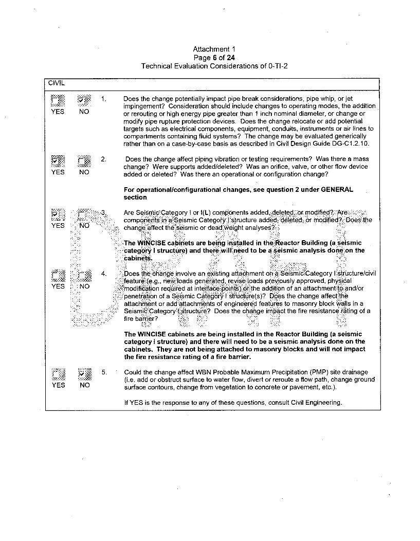
S1. Does the change potentially impact pipe break considerations, pipe whip, or jetimpingement? Consideration should include changes to operating modes, the addition
YES NO or rerouting or high energy pipe greater than 1 inch nominal diameter, or change ormodify pipe rupture protection devices. Does the change relocate or add potentialtargets such as electrical components, equipment, conduits, instruments or air lines tocompartments containing fluid systems? The change may be evaluated genericallyrather than on a case-by-case basis as described in Civil Design Guide DG-C1.2.10.
2. Does the change affect piping vibration or testing requirements? Was there a masschange? Were supports added/deleted? Was an orifice, valve, or other flow device
YES NO added or deleted? Was there an operational or configuration change?
For operationallconfigurational changes, see question 2 under GENERALsection
4 • "" •3. Are Seismic Category I or I(L) components added, deleted, or modified? Arecomponents in a Seismic CategorylI structure add'ed, deleted,.or modified? Does the
YES NO " 0 change affect the seismic or dead .weight analyses?
The WINCISE cabinets are being installed in the Reactor Building (a seismiccategory I structure) and there 4will-need to be a seismic analysis done on thecabinets.
F! 4. Does the change involve an existing attachment on a Seismic:Category I'structure/civil'feature (e.g., new, loads generated, previously approved, physical
YES NO modification required at interface points) or the addition of an attachment to and/orpenetration of a Seismic Category I structure(s)? Does the change affect theattachment or add attachments of engineered features to masonry block walls in a
' Seismic CategoryI•istructure? Does the change im;pact the fire resistance rating of afire barrier?
The WINCISE cabinets are being installed in the Reactor Building (a seismiccategory I structure) and there will need to be a seismic analysis done on thecabinets. They are not being attached to masonry blocks and will not impactthe fire resistance rating of a fire barrier.
p 5. Could the change affect WBN Probable Maximum Precipitation (PMP) site drainage(i.e. add or obstruct surface to water flow, divert or reroute a flow path, change ground
YES NO surface contours, change from vegetation to concrete or pavement, etc.).
If YES is the response to any of these questions, consult Civil Engineering.
Attachment 1Page 7 of 24
Technical Evaluation Considerations of 0-TI-2
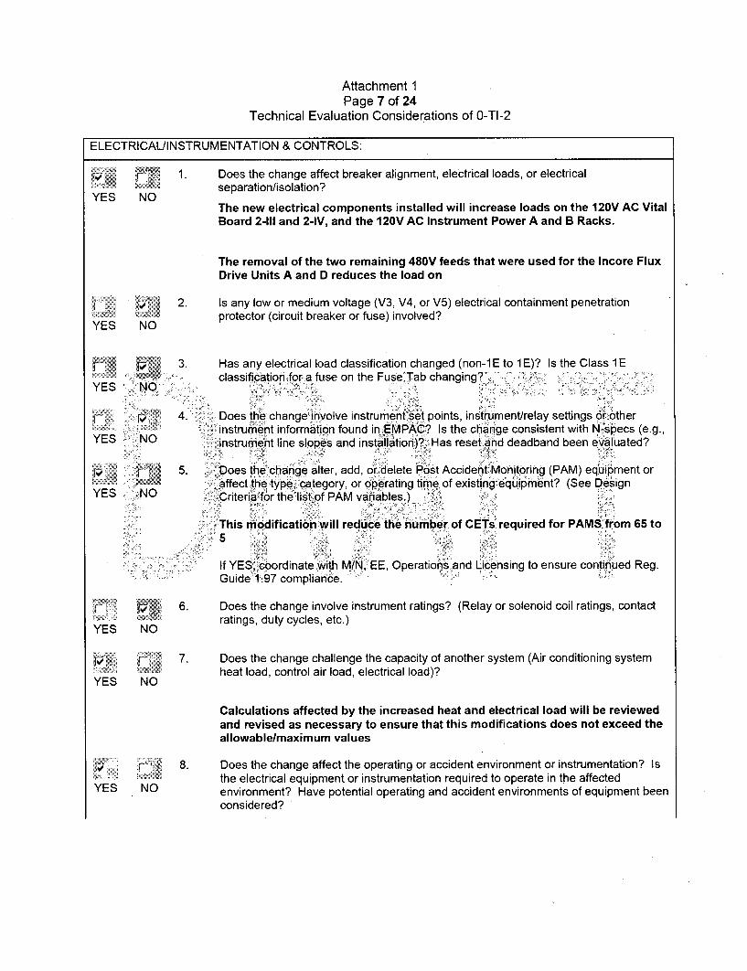
ELECTRICAL/INSTRUMENTATION & CONTROLS:
1. Does the change affect breaker alignment, electrical loads, or electricalYES No 'separation/isolation?YES NO
The new electrical components installed will increase loads on the 120V AC VitalBoard 2-111 and 2-IV, and the 120V AC Instrument Power A and B Racks.
The removal of the two remaining 480V feeds that were used for the Incore FluxDrive Units A and D reduces the load on
- 2. Is any low or medium voltage (V3, V4, or V5) electrical containment penetration
protector (circuit breaker or fuse) involved?YES NO
3. Has any electrical load classification changed (non-lE to 1E)? Is the Class 1Eclassification for a fuse on the Fuse Tab changing? .
YES NO
: : 4. Does the change involve instrument set points, instrument/relay settings or otherinstrument information found in EMPAC? Is the change consistent with N-specs (e.g.,
YES NO instrument line slopes and installation)?' Has reset and deadband been evaluated?
t 5. iDoes the change.alter, add, dr delete Post Accident Monitoring (PAM) equipment oraffect the type, category, or operating time of existing eq.iip ment? (See Design
YES NO Criteria for the list of PAM variables.)
SThis modification will reduce the number of CETs required for PAMS from 65 to5
If YES, coordinate with MIN, EE, Operations and Licensing to ensure continued Reg.Guide 1'97 compliance.
r 6. Does the change involve instrument ratings? (Relay or solenoid coil ratings, contactYES NO• ratings, duty cycles, etc.)YES NO
1/ 7. Does the change challenge the capacity of another system (Air conditioning system
YES No heat load, control air load, electrical load)?
Calculations affected by the increased heat and electrical load will be reviewedand revised as necessary to ensure that this modifications does not exceed theallowablelmaximum values
r 8. Does the change affect the operating or accident environment or instrumentation? IsYthe electrical equipment or instrumentation required to operate in the affectedYES NO environment? Have potential operating and accident environments of equipment been
considered?
Attachment 1Page 8 of 24
Technical Evaluation Considerations of 0-TI-2
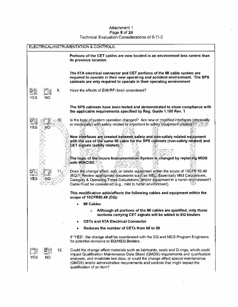
ELECTRICAL/INSTRUMENTATION & CONTROLS:
Portions of the CET cables are now located in an environment less severe thanits previous location.
The IITA electrical connector and CET portions of the MI cable system arerequired to operate in their new operating and accident environment. The SPScabinets are only required to operate in their operating environment
• •ij 9. Have the effects of EMI/RFI been considered?
YES NO
The SPS cabinets have been tested and demonstrated to show compliance withthe applicable requirements specified by Reg. Guide 1.180 Rev. 1
10. Is the logic ofsystem operation changed? Are new or modified interfaces (physicallyYES NOor electrically) with safety related or important to safety ',quiprment created?,
New interfaces are created between safety and non-safety related equipmentwith the use of the same MI cable for the SPS cabinets (non-safety related) andCET signals (safety related)..
The logic of the Incore Instrumentation System is changed by replacing MIDS
,with WINCISE.> add, or t wiin theisope=o
•,11. Does the change affect add, or delete equipment within the scope of 10CFR 50.49YES j (EQ)? Review appropriate documents such as MEL, Essentially Mild Calculations,
YES NO Category & Operating Tirnes Calculations, and/or equipment in a harsh envi~ronment?Cable~must be considered (e.g., mild to harsh environment). --
This modification adds/affects the following cables and equipment within thescope of 10CFR50.49 (EQ):
" MI Cables
o Although all portions of the MI cables are qualified, only thosesections carrying CET signals will be added to EQ binders
" GETs and IITA Electrical Connector
" Reduces the number of CETs from 65 to 58
If "YES", the change shall be coordinated with the EQ and MEQ Program Engineersfor potential revisions to EQ/MEQ Binders.
12. Could the change affect materials such as lubricants, seals and 0-rings, which couldimpact Qualification Maintenance Data Sheet (QMDS) requirements and qualification
YES NO analyses, and invalidate test data, or could the change affect special maintenance(QMDS) and/or administrative requirements and controls that might impact thequalification of an item?
Attachment 1Page 9 of 24
Technical Evaluation Considerations of 0-TI-2
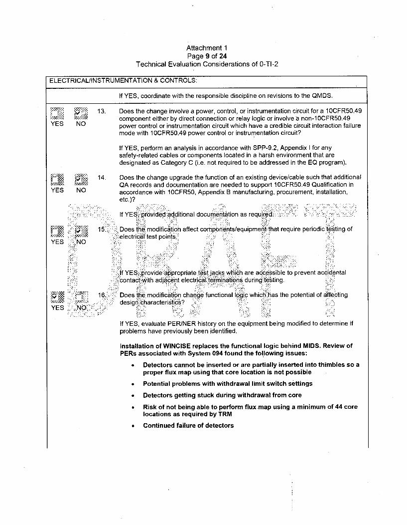
ELECTRICAL/INSTRUMENTATION & CONTROLS:
If YES, coordinate with the responsible discipline on revisions to the QMDS.
13. Does the change involve a power, control, or instrumentation circuit for a 1 0CFR50.49component either by direct connection or relay logic or involve a non-1 OCFR50.49
YES NO power control or instrumentation circuit which have a credible circuit interaction failuremode with 1OCFR50.49 power control or instrumentation circuit?
If YES, perform an analysis in accordance with SPP-9.2, Appendix I for anysafety-related cables or components located in a harsh environment that aredesignated as Category C (i.e. not required to be addressed in the EQ program).
r 14. Does the change upgrade the function of an existing device/cable such that additionalQA records and documentation are needed to support 10CFR50.49 Qualification in
YES NO accordance with 10CFR50, Appendix B manufacturing, procurement, installation,etc.)?
If YE prvided additional cumentation as required.
15. Does the modification affect components/equipment that require periodic tsting of
YES NO .electrical test points.
If YES, provide appropriate test jacks which are accessible to prevent accidentalzontact with adjacent electrical terminations during testing.
16. Does the modification change functional logic which has the potential of affecting
YES NOýdesign haracteristics?
If YES, evaluate PER/NER history on the equipment being modified to determine ifproblems have previously been identified.
Installation of WINCISE replaces the functional logic behind MIDS. Review ofPERs associated with System 094 found the following issues:
• Detectors cannot be inserted or are partially inserted into thimbles so aproper flux map using that core location is not possible
" Potential problems with withdrawal limit switch settings
* Detectors getting stuck during withdrawal from core
• Risk of not being able to perform flux map using a minimum of 44 corelocations as required by TRM
" Continued failure of detectors
Attachment 1Page 10 of 24
Technical Evaluation Considerations of 0-TI-2
ELECTRICAL/INSTRUMENTATION & CONTROLS:
YES NO
YES NO
YES <NO
YES NO
17. Does the modification involve a programmatic or digital logic controller?
If YES, has the addition of uninterruptible power supplies been considered?
The SPS cabinets are fed from the 120V Vital Boards 2-111 and 2-IV which arebattery backed
18. Does the modification involve fault tolerant non-safety-related equipment important tooperation such that the need for redundant power sources should be considered (suchas CERPI control room devices)?
SPS cabinets 2-L-201 and 2-L-202 are fed from 120V AC Vital Board 2-111 (Train A)and 2-IV (Train B), respectively
120V A•G Instrument Power Racks A and B each provide two feeds to theWINCISE Computer Rack 2-R-158 to support redundancy.,.
19. Does the design or modification impact an Integrated Computer System (ICS) datapoint that is also an Emergency Response Data System (ERDS) data point?
If YES, coordination with Site Licensing is required in accordance with 10CFR50Appendix E.
20. Does the design or modification impact off site power capability or ability to meet10CFR50 Appendix A Critenon-17 requirements?
If YES, coordinate with Electrical Lead Engineer.
Attachment 1Page 11 of 24
Technical Evaluation Considerations of 0-TI-2
MECHANICAL:
Ensure EQ requirements addressed for ancillary subcomponents (e.g., Limit Switches on Mechanical, onlyvalves). Coordinate with Electrical EQ Engineer as necessary.
YES NO
1. Does the change affect design conditions or requirements such as process pressure,temperature, chemistry or operating cycles? Is the change affected by operation ofother systems, either Safety Related or Non-Safety Related in any of their variousoperating configurations?
If YES, ensure the evaluation encompasses all aspects of the affected system,including impacts on interfacing systems. Coordinate with MEQ Program Engineer forpotential revisions to affected MEQ documentation.
2. Does the change affect ECCS, decay heat removal systems, or MPC cooling ancillaryequipment? Ensure that any changes are consistent with the safety analyses for theplant including WBN SAR Chapter 15 NPSH minimum flow requirements, dieselloading sequencing, and ultimate heat sink limits.
YE
YES
YES
YES
NO
3. Is the Auxiliary Building Secondary Containment Enclosures (ABSCE) as defined inWBN2-30AB-4001, affected by this change? Does this change modify any cable,
NO... cabie tray, conduit, duct, ppe orinstrument tubing penetrating secondary..?containment? Consult 46W501 drawing series for the locations of the ABSCEBoundary, and discuss proposed chaniges with the NSSS EGS. A justification for the"Yes/No" is required.
SThe routing of power cables from 120V AC Vital Boards and 120V AC InstrumentPower Racks is expected to require breaches into ABSCE boundary andlor theMain Control Room Habitability Zone,
_NO
Does t•e change involve potential heatingiventilation, and air-conditioning (HVAC)system impacts resultingfrom adding heatdloads, altering air flow or ductwork etc.?
The addition of the WINCISE Computer Servers and associated hardware in theComputer Room will cause an impact to the HVAC systems as a result of theadded heat loads.
Does this change make any alterations or configuration changes to Motor OperatedValves (MOVs) or Air Operated Valves (AOVs)? Does this change impact any MOVor AOV Program documents? Impacts that should be considered include changes toinstrumentation or control circuits, power supplies, or change system operating ordesign conditions such as pressure and flow rate.
YES NO
5.
YES NO
6. Does this change involve replacement of a complete valve or valve internals which arelocated in a system that interfaces directly with the Reactor Coolant System (RCS)?Procurement requirements should evaluate valve and valve internals replacementsthat are located in or interfaces with the Reactor Coolant System (RCS) for hard facedcomponents that are non-cobalt bearing. Hard facing alternatives include NOREMNitronic 60 and may include other non-cobalt materials as approved by Engineering.Cobalt bearing hand materials is a concern in fluid systems that contain radioactivematerials.
Attachment 1Page 12 of 24
Technical Evaluation Considerations of 0-TI-2
MECHANICAL:
S7. Does the modification add a new check valve or impact an existing check valve?Ensure the valve is sized properly, proper type for required service, properly oriented,
YES NO located suitable distance from upstream components. that cause turbulent flow.
8. Does the modification add, delete, or reroute components in a mechanical pipingsystem? If Yes, will the added components come in contact with borated water or
YES NO some other harsh environmental area?
The Incore Instrument Thimble Assemblies (IITAs) will be installed in the BottomMounted Instrument (BMI) thimble guide tubes and are in contact with the RCSborated water. Additionally, the IITA connector is located in the seal table whichis a harsh environment.
V, 8a. Does the modification affect the ASME Section III Code (Class 1, 2, and 3) boundary.YES No• If "YES", ensure that the materials and installations meet the applicable ASME Code.
9. Does this modification introduce material into the containment that could b~ecome
YES No dslodged during LOCA or other.events; and contribute to Emergency Core Coolingsystem (ECCS) sump screen or strainer, blockage?' Does this modification affect
. protective coatings inside the containment?
... 10. Does the modification increase the possibility of flooding from a Moderate Energy Line
YES. NO Break?
S: i11. -Does the, modification affect the power uprate?'
YES NO
'12. Are there NUREG-0612 impacts? Does the change, add, delete, or alter a~permanenthandling system? Does the change move a heavy load path over safe shutdown•
YES NO equipment or move safe shutdown equipment into a heavy load path?
13. Does the change affect barriers such as walls, doors, penetrations, relief panels, andducts which could affect HVAC flow paths, fire barriers, or environmental conditions in
YES NO either harsh or mild areas?
If the answer to any of the above questions is "YES", the change shall be coordinatedwith the Mechanical EGS.
It is expected that the routing of new power cables from 120V AC Vital Boardsand 120V AC Instrument Power Racks will require breaches into ABSCEboundaries, fire barriers, and/or Main Control Room Habitability Zone
14. Is a new material being added and does the change affect components susceptible toYES NO Flow Accelerated Corrosion (FAC) or Microbiologically Induced Corrosion (MIC)?YES NO
r 15. Does the modification increase the susceptibility for cavitation?
YES NO
Attachment 1Page 13 of 24
Technical Evaluation Considerations of 0-TI-2
MECHANICAL:
p 16. Could the change affect location or operation of high energy piping systems, locationor operation of radioactive piping systems, operation of environmental control
YES NO systems, or environmental barriers such as walls, doors, relief panels, piping/otherthermal insulation, and ducts which could affect environmental conditions in eitherharsh or mild areas?
If YES, coordinate with ME for potential revision to the environmental drawings/design
criteria and coordinate with EE for potential impact to EQ of equipment.
17. Does the change involve any valve tabulation information?
YES NO
If YES, include the completed MEL Data Entry Sheet in the EDCR-2 Package.
18. Does this change affect the Seismic Category I boundary?~
YES NO
If YES, the applicable Seismic Category I Boundary calculations must be revised.
NOTE Issuing a•!design calculation in accordance with NEDP-2 is the means ofassuring that the applicable Seismic Category IBoundary calculation is
>revised.
. 19. C.Does the modification change ventilation, cooling requirements for electronic
YES NOequipment?
If YES, coordinate with Mechanical Engineering for determination of impact on HVACcoolant.,
F; •. 20. Does the modification involve strainers for a raw water supply?
YES NO
If YES, proper strainer selection should be based on industry guidelines (FluidControls Institute Std 89-1) and specific site criteria. Major consideration should begiven to the following: type of strainer, redundant strainer capability,materials/housing, perforations number and arrangement, mesh size & free area,capacity and pressure loss, fluid type, particle weight & shape, macro fouling andaquatic debris potential, operating parameters, filtration versus separation, blow downline sizing, vendor recommendations, automatic back flushing and the necessity of abypass line.
NOTE: Contact the appropriate program coordinator in the Mechanical Programsgroup (or in Plant Design for MOV questions) if any Engineering DesignProgram(s) are impacted by the proposed modification.
Attachment 1Page 14 of 24
Technical Evaluation Considerations of 0-TI-2
MECHANICAL:
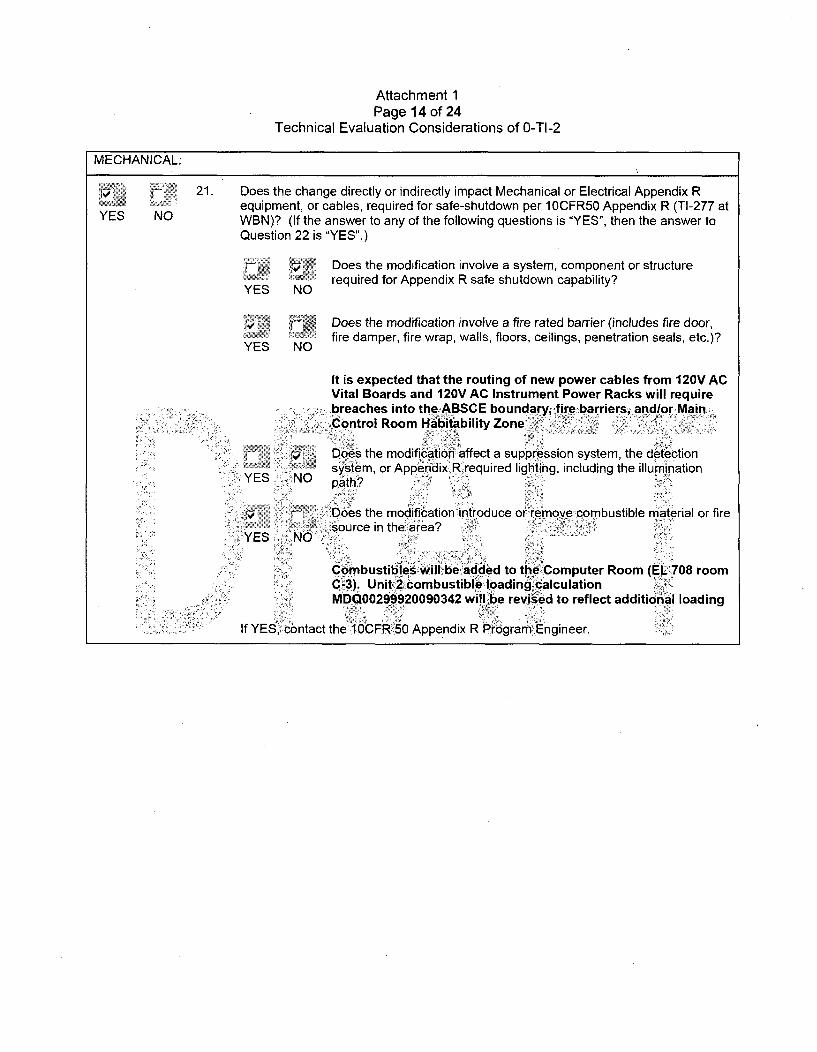
21. Does the change directly or indirectly impact Mechanical or Electrical Appendix Requipment, or cables, required for safe-shutdown per 1OCFR50 Appendix R (TI-277 at
YES NO WBN)? (If the answer to any of the following questions is "YES", then the answer toQuestion 22 is "YES".)
S •Does the modification involve a system, component or structureE N required for Appendix R safe shutdown capability?YES NO
V• - Does the modification involve a fire rated barrier (includes fire door,YES NO, fire damper, fire wrap, walls, floors, ceilings, penetration seals, etc.)?YES NO
It is expected that the routing of new power cables from 120V ACVital Boards and 120V AC Instrument Power Racks will requirebreaches into the ABSCE boundary, fire barriersi and/or MainControl Room Habitability Zone
Does the modification affect a suppression system, the detectionsystem, or Appendix R required lighting, including the illumination
YES <NO path? '
:I Doe6s the modification introduce or remove combustible material or firesource in the area?
YES ~NO
Combustibles will be. added to the :Computer Room (EL 708 roomC-3). Unit 2 combustible loading calculationMDQ00299920090342 will be revised to reflect additional loading
If YES, contact the 10CFR,50 Appendix R Program Engineer.
Attachment 1Page 15 of 24
Technical Evaluation Considerations of 0-TI-2
PERATIONS/HUMAN FACTORS:
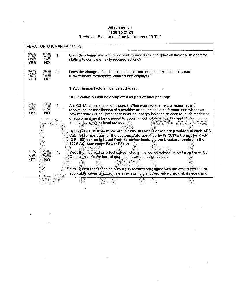
V 1. Does the change involve compensatory measures or require an increase in operator
YES NO staffing to complete newly required actions?
4 2. Does the change affect the main control room or the backup control areas
YES NO (Environment, workspace, controls and displays)?
If YES, human factors must be addressed.
HFE evaluation will be completed as part of final package
ii 3. Are OSHA considerations included? Whenever replacement or major repair,YES NO renovation, or modification of a machine or equipment is performed, and wheneverYES NO new machines or equipment are installed, energy isolating devices for such machines
or equipment: must be designed to~accept a lockout device. ,This applies tomechanical and electrical devices.
Breakers aside from those at the 120V AC Vital Boards are provided in each SPSCabinet for isolation of the system. Additionally, the WINCISE Computer Rack(2-R-1 658) can be isolated from its power feeds viathe breakers located.in the120V AC Instrument Power Racks
v 4. Does the modification affect valves listed in the locked valve checklist maintained byYES .... Operations and the locked position shown on designoutput?
If YES,; ensure that design output (DRAs/drawings) agree with the locked position ofapplicable valves or coordinate a revision to the locked valve checklist, if necessary.
Attachment 1Page 16 of 24
Technical Evaluation Considerations of 0-TI-2
OTHER:
I V
YES NO
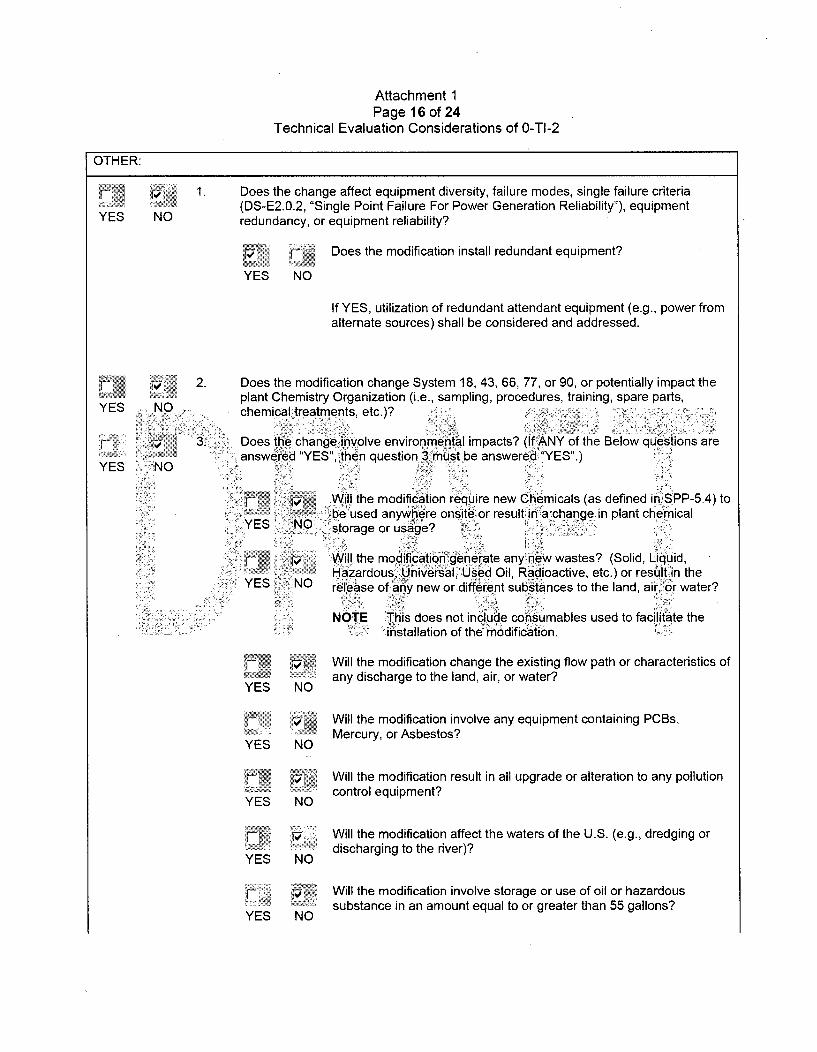
1. Does the change affect equipment diversity, failure modes, single failure criteria(DS-E2.0.2, "Single Point Failure For Power Generation Reliability"), equipmentredundancy, or equipment reliability?
YES NO
Does the modification install redundant equipment?
If YES, utilization of redundant attendant equipment (e.g., power fromalternate sources) shall be considered and addressed.
YES
t4• 2. Does the modification change System 18, 43, 66, 77, or 90, or potentially impact theplant Chemistry Organization (i.e., sampling, procedures, training, spare parts,
NO chemical treatments, etc.)?
YES NO
3. : Does the change involve environmental impacts? (If ANY of the Below questions areanswered "YES", then question 3must be answered "YES".)
if' Will the modification require new Chemicals (as defined in SPP-5.4) to.-. ¾ .~be used anywhere onsite or result in a change in plant chemical
sYES NO storage or usage? j
Will the modification generate any new wastes? (Solid, Liquid,Hazardous, Universal, Used Oi1, Radioactive, etc.) or result in the
YES NO release of any new or-different substances to the land, air, or water?
NOTE This does not include consumables used to facilitate thein~stallation of the modification.
YES
YES
YES
YES
VNO
NO
NO
NO
Will the modification change the existing flow path or characteristics ofany discharge to the land, air, or water?
Will the modification involve any equipment containing PCBs,Mercury, or Asbestos?
Will the modification result in all upgrade or alteration to any pollutioncontrol equipment?
Will the modification affect the waters of the U.S. (e.g., dredging ordischarging to the river)?
Will the modification involve storage or use of oil or hazardoussubstance in an amount equal to or greater than 55 gallons?
YES NO
Attachment 1Page 17 of 24
Technical Evaluation Considerations of 0-TI-2
OTHER:
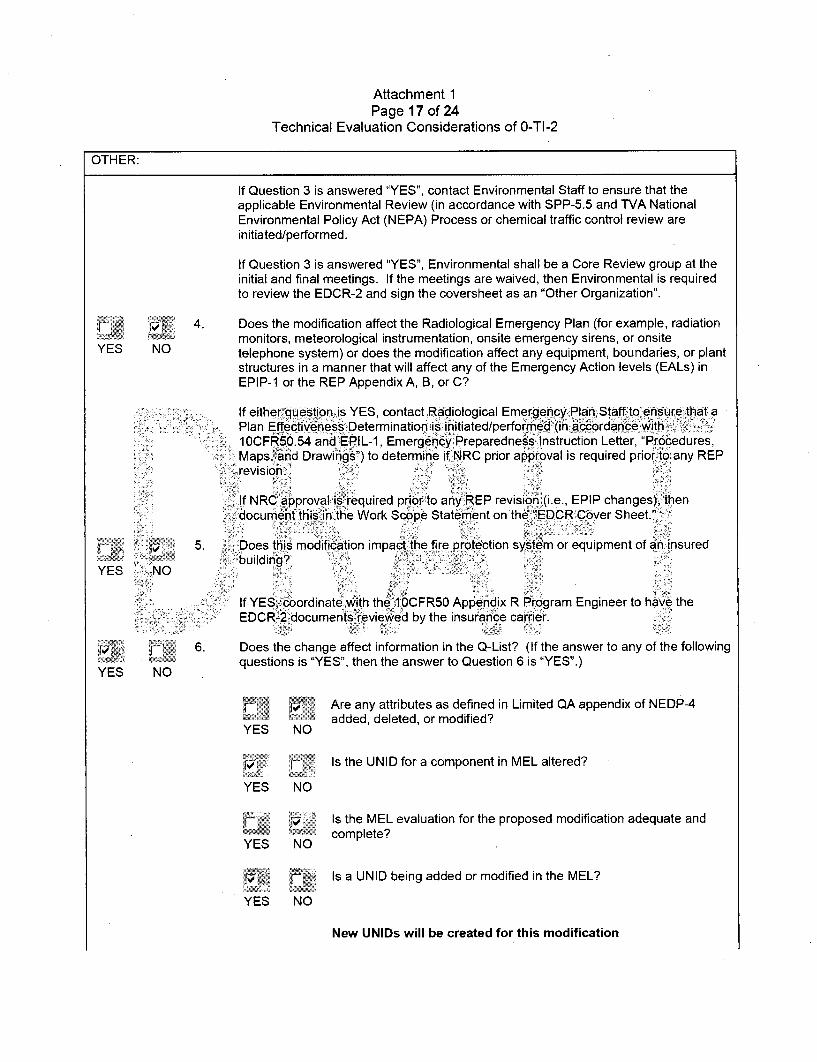
If Question 3 is answered "YES", contact Environmental Staff to ensure that theapplicable Environmental Review (in accordance with SPP-5.5 and TVA NationalEnvironmental Policy Act (NEPA) Process or chemical traffic control review areinitiated/performed.
If Question 3 is answered "YES", Environmental shall be a Core Review group at theinitial and final meetings. If the meetings are waived, then Environmental is requiredto review the EDCR-2 and sign the coversheet as an "Other Organization".
.. 4. Does the modification affect the Radiological Emergency Plan (for example, radiationmonitors, meteorological instrumentation, onsite emergency sirens, or onsite
YES NO telephone system) or does the modification affect any equipment, boundaries, or plantstructures in a manner that will affect any of the Emergency Action levels (EALs) inEPIP-1 or the REP Appendix A, B, or C?
If either question is YES, contact Radiological Emergency Plan Staff to ensure that aPlan EffectivenessiDeterminationis i nitiated/performed (inaccordan~ce w1ith ,10CFR50.54 and EPIL-1, Emergency Preparedness Instruction Letter, "Procedures,Maps, and Drawings") to determine if NRC prior approval is required prior.to any REPrevision.
If NRC approval s required piorto anyREP revision (i.e., EPIP changes), thendocument this •in the Work Scope Statement on the "EDCR Cover Sheet."
fi 5. )•:5. Does this modification impact the fire protection system or equipment of aninsured
YES NO building?,
If YES;, coordinate,,with the 10CFR50 Appendix R Program Engineer to have theEDCR-2 documents reviewed by the insurance carrier.
l 6. Does the change affect information in the Q-List? (If the answer to any of the following
YES NO questions is "YES", then the answer to Question 6 is "YES".)
Are any attributes as defined in Limited QA appendix of NEDP-4YES NO" added, deleted, or modified?YES NO
V.'C 'r.. Is the UNID for a component in MEL altered?
YES NO
/. Is the MEL evaluation for the proposed modification adequate andYS N complete?
Is a UNID being added or modified in the MEL?
YES NO
New UNIDs will be created for this modification
Attachment 1Page 18 of 24
Technical Evaluation Considerations of 0-TI-2
OTHER:
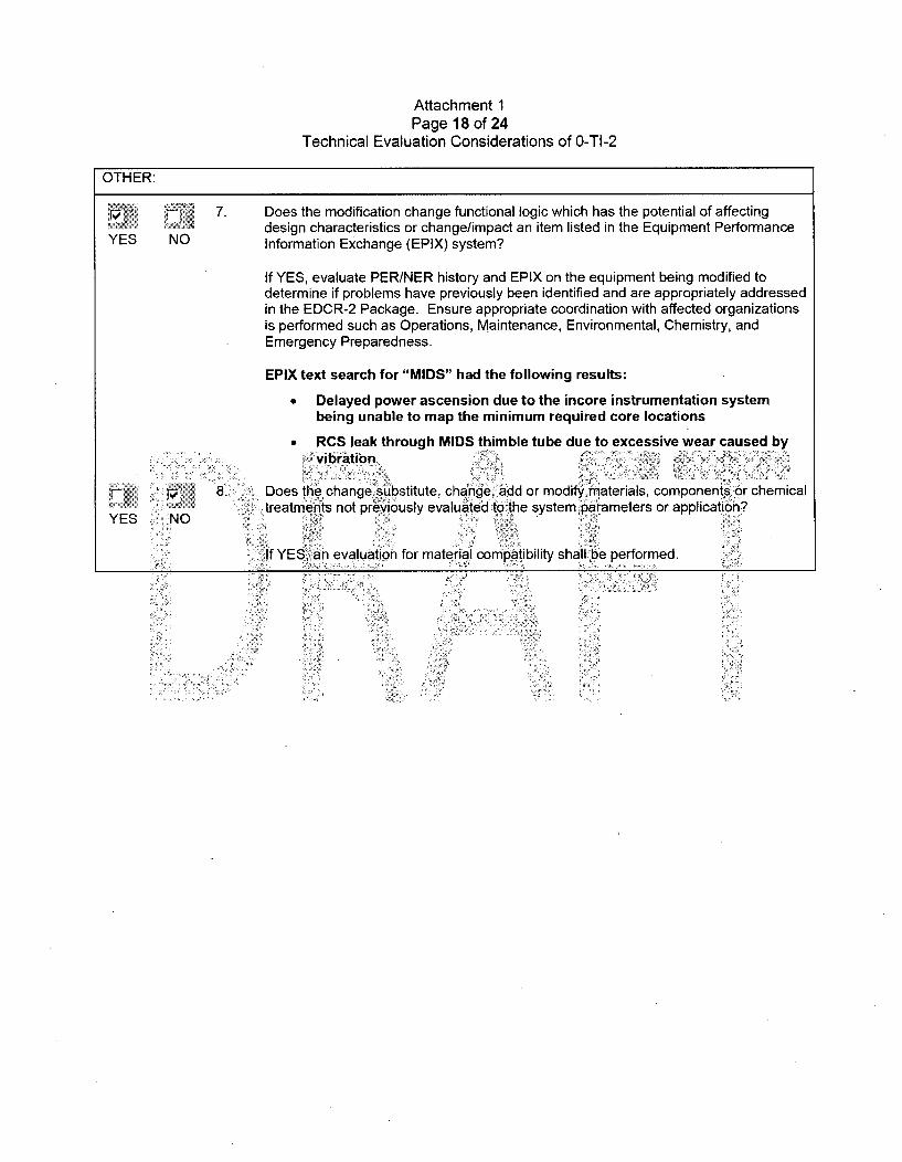
7. Does the modification change functional logic which has the potential of affectingdesign characteristics or change/impact an item listed in the Equipment Performance
YES NO Information Exchange (EPIX) system?
If YES, evaluate PER/NER history and EPIX on the equipment being modified todetermine if problems have previously been identified and are appropriately addressedin the EDCR-2 Package. Ensure appropriate coordination with affected organizationsis performed such as Operations, Maintenance, Environmental, Chemistry, andEmergency Preparedness.
EPIX text search for "MIDS" had the following results:
* Delayed power ascension due to the incore instrumentation systembeing unable to map the minimum required core locations
" RCS leak through MIDS thimble tube due to excessive wear caused bySVibration
8. Does the changesubstitute, change, add or modify materials, components or chemicaltreatments not previously evaluated to the system parameters or application?
YES No
If YES, an evaluation for material compatibility shall be performed.
Attachment 1Page 19 of 24
Technical Evaluation Considerations of 0-TI-2
10CFR50 APPENDIX R AND OTHER FIRE PROTECTION IMPACTS: (Contact the Program Owner)
YES
a.
NO
YES
YES
YES
YES
b.
NO
NO
NO
C.
d.
e.
f.
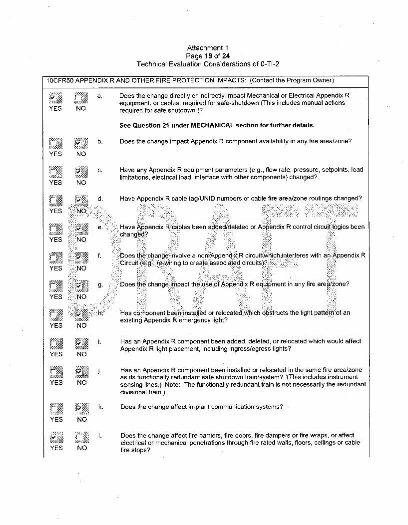
Does the change directly or indirectly impact Mechanical or Electrical Appendix Requipment, or cables, required for safe-shutdown (This includes manual actionsrequired for safe shutdown.)?
See Question 21 under MECHANICAL section for further details.
Does the change impact Appendix R component availability in any fire area/zone?
Have any Appendix R equipment parameters (e.g., flow rate, pressure, setpoints, loadlimitations, electrical load, interface with other components) changed?
Have Appendix R cable tag/UNID numbers or cable fire area/zone routings changed?
Have Appendix R cables been added/deleted or Appendix R control circuit logics beenchanged?
Does the change involve a ngn-Appendix R circuit which interferes with an Appendix RCircuit (e!g., re-iring to create associated circuits)?
YES :NO
YES NO
YES
YES
YES
NO
NO
NO
NO
g. ,Does the change impact the use of Appendix R equipment in any fire area/zone?
h. Has component been installed or relocated which obstructs the light pattern of anexisting Appendix R emergency light?
Has an Appendix R component been added, deleted, or relocated which would affectAppendix R light placement, including ingress/egress lights?
I. Has an Appendix R component been installed or relocated in the same fire area/zoneas its functionally redundant safe shutdown train/system? (This includes instrumentsensing lines.) Note: The functionally redundant train is not necessarily the redundantdivisional train.)
kY
YES NO0
Does the change affect in-plant communication systems?
YES NO
I. Does the change affect fire barriers, fire doors, fire dampers or fire wraps, or affectelectrical or mechanical penetrations through fire rated walls, floors, ceilings or cablefire stops?
Attachment 1Page 20 of 24
Technical Evaluation Considerations of 0-TI-2
10CFR50 APPENDIX R AND OTHER FIRE PROTECTION IMPACTS: (Contact the Program Owner)
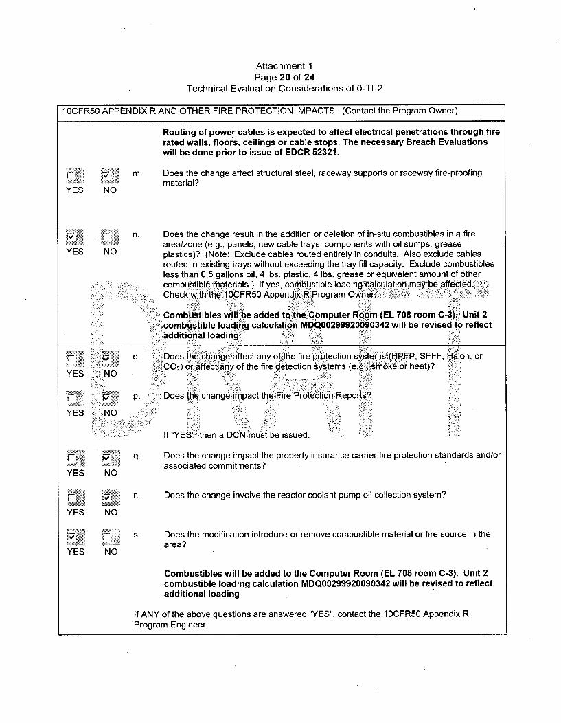
Routing of power cables is expected to affect electrical penetrations through firerated walls, floors, ceilings or cable stops. The necessary Breach Evaluationswill be done prior to issue of EDCR 52321.
m. Does the change affect structural steel, raceway supports or raceway fire-proofingmaterial?
YES NO
n. Does the change result in the addition or deletion of in-situ combustibles in a firearea/zone (e.g., panels, new cable trays, components with oil sumps, grease
YES NO plastics)? (Note: Exclude cables routed entirely in conduits. Also exclude cablesrouted in existing trays without exceeding the tray fill capacity. Exclude combustiblesless than 0.5 gallons oil, 4 lbs. plastic, 4 lbs. grease or equivalent amount of othercombustible materials.) If yes, conibcstible loadingscalculation may b affected.Check with the 10CFR50 Appendix R Program Owner .
Combustibles will be added to the Computer Room (EL 708 room C-3). Unit 2combustible loading calculation MDQ00299920090342 will be revised to reflectadditional loading
o. ~Does the change affect any of the fire protection systems(HFP SFFF, Halon, orYES ...... iC0 2 ) or affect any of the fire detection sy•tems (e.g., smoke or heat)?
pl.i P- Does the change impact the Fire Protection Reports?,
YES NO ~
If "YES"• then a DCN must be issued.
q. Does the change impact the property insurance carrier fire protection standards and/or
associated commitments?YES NO
r. Does the change involve the reactor coolant pump oil collection system?
YES NO
s. Does the modification introduce or remove combustible material or fire source in thearea?
YES NO
Combustibles will be added to the Computer Room (EL 708 room C-3). Unit 2combustible loading calculation MDQ00299920090342 will be revised to reflectadditional loading
If ANY of the above questions are answered "YES", contact the 10CFR50 Appendix R'Program Engineer.
Attachment 1Page 21 of 24
Technical Evaluation Considerations of 0-TI-2
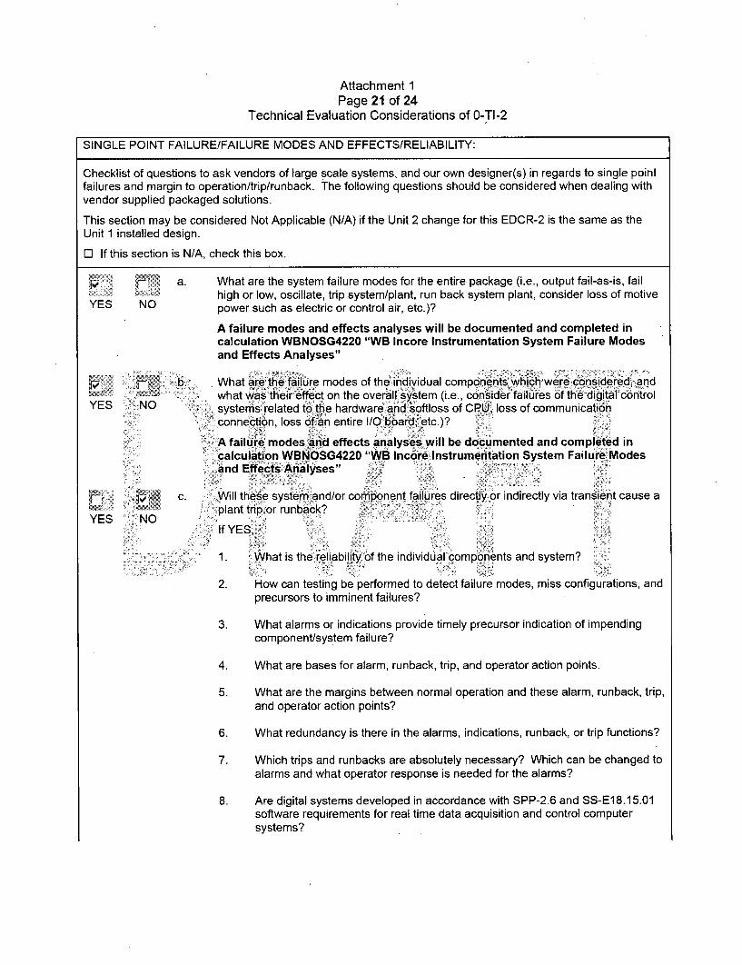
SINGLE POINT FAILURE/FAILURE MODES AND EFFECTS/RELIABILITY:
Checklist of questions to ask vendors of large scale systems, and our own designer(s) in regards to single pointfailures and margin to operation/trip/runback. The following questions should be considered when dealing withvendor supplied packaged solutions.
This section may be considered Not Applicable (N/A) if the Unit 2 change for this EDCR-2 is the same as theUnit 1 installed design.
0 If this section is N/A, check this box.
7ý1 •a. What are the system failure modes for the entire. package (i.e., output fail-as-is, failhigh or low, oscillate, trip system/plant, run back system plant, consider loss of motive
YES NO power such as electric or control air, etc.)?
A failure modes and effects analyses will be documented and completed incalculation WBNOSG4220 "WB Incore Instrumentation System Failure Modesand Effects Analyses"
b. What are the failure modes of the individual components whichwere considered, andwhat was their ffect on the overallI ystem (i.e., consider failures 6fthe digital control
YES NO ,. systems related to the hardware and softloss of CPU, loss of communication. connection, loss of an entire I/O board, etc.)?
A failure modes and effects analyses will be documented and completed incalculation WBNOSG4220 "WB Incore Instrumentation System Failure Modesand Effects Analyses" ,• .
c. .Will these system and/or component failures directly or indirectly via transient cause a.plant trip or runback?
YES ~NoIf YES,
1. What is the reliabilityiof the individual components and system?
2. How can testing be performed to detect failure modes, miss configurations, andprecursors to imminent failures?
3. What alarms or indications provide timely precursor indication of impendingcomponent/system failure?
4. What are bases for alarm, runback, trip, and operator action points.
5. What are the margins between normal operation and these alarm, runback, trip,and operator action points?
6. What redundancy is there in the alarms, indications, runback, or trip functions?
7. Which trips and runbacks are absolutely necessary? Which can be changed toalarms and what operator response is needed for the alarms?
8. Are digital systems developed in accordance with SPP-2.6 and SS-E18.15.01software requirements for real time data acquisition and control computersystems?

Attachment 1Page 22 of 24
Technical Evaluation Considerations of 0-TI-2
SINGLE POINT FAILURE/FAILURE MODES AND EFFECTS/RELIABILITY:
9. Are there any reasons why redundancy was not considered in alarm, trip,runback systems, and can redundancy be added?
Attachment 1Page 23 of 24
Technical Evaluation Considerations of 0-TI-2
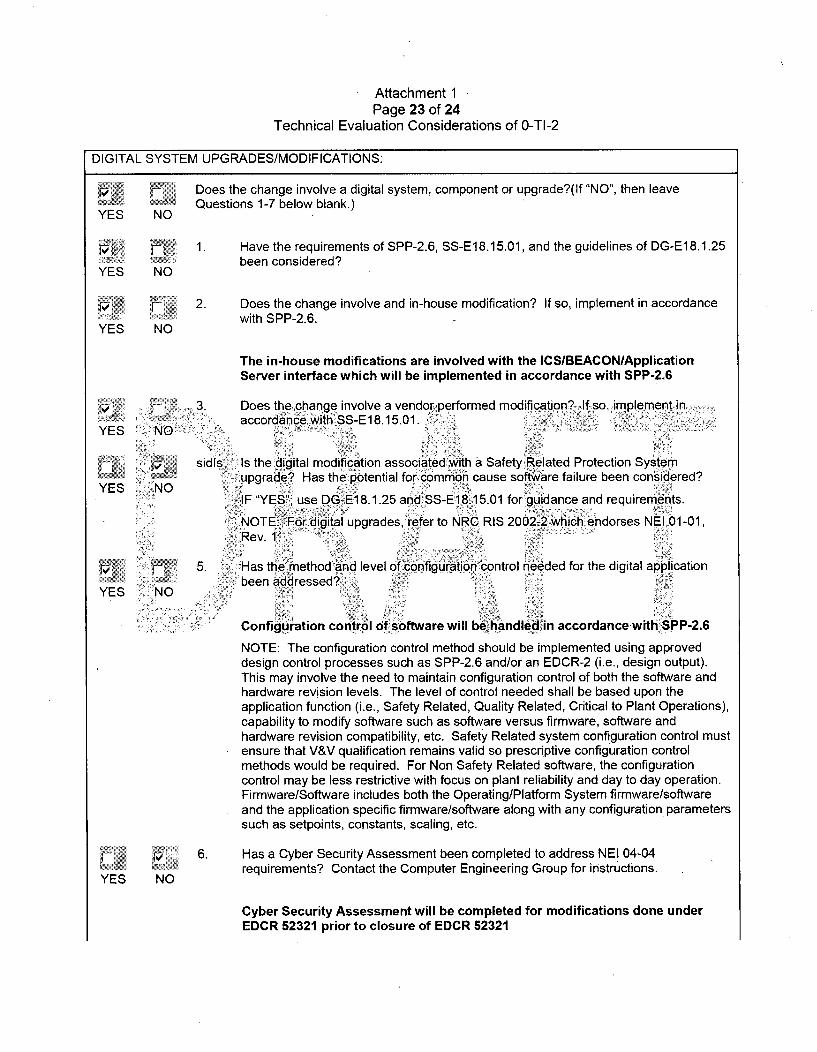
DIGITAL SYSTEM UPGRADES/MODIFICATIONS:
Does the change involve a digital system, component or upgrade?(If "NO", then leaveYE Questions 1-7 below blank.)YES NO
[ " 1. Have the requirements of SPP-2.6, SS-E18.15.01, and the guidelines of DG-E18.1.25been considered?
YES NO
2. Does the change involve and in-house modification? If so, implement in accordancewith SPP-2.6.
YES NO
The in-house modifications are involved with the ICSIBEACON/ApplicationServer interface which will be implemented in accordance with SPP-2.6
3. Does the change involve a vendor performed modification? If so, implement inaccordance with SS-E18.15.01 (
YES NO
sidl•s Is the digital modification associated with a Safety Related Protection Systemupgrade? Has the potential for common cause software failure been considered?
YES NOEIF "YES•;, use DG-E1 8.1.25 and SS-E18.15.01 for guidance and requirements.
NOTE: For digital upgrades, refer to NRC RIS 2002-2 which endorses NEI 01-01,Rev. 1.
5. Has the method and level of configpUation control needed for the digital applicationYES. NO. .been addressed? .
Configuration control of software will be handled in accordance with SPP-2.6
NOTE: The configuration control method should be implemented using approveddesign control processes such as SPP-2.6 and/or an EDCR-2 (i.e., design output).This may involve the need to maintain configuration control of both the software andhardware revision levels. The level of control needed shall be based upon theapplication function (i.e., Safety Related, Quality Related, Critical to Plant Operations),capability to modify software such as software versus firmware, software andhardware revision compatibility, etc. Safety Related system configuration control mustensure that V&V qualification remains valid so prescriptive configuration controlmethods would be required. For Non Safety Related software, the configurationcontrol may be less restrictive with focus on plant reliability and day to day operation.Firmware/Software includes both the Operating/Platform System firmware/softwareand the application specific firmware/software along with any configuration parameterssuch as setpoints, constants, scaling, etc.
6. Has a Cyber Security Assessment been completed to address NEI 04-04
YES NO requirements? Contact the Computer Engineering Group for instructions.
Cyber Security Assessment will be completed for modifications done underEDCR 52321 prior to closure of EDCR 52321

Attachment 1Page 24 of 24
Technical Evaluation Considerations of 0-TI-2
SINGLE POINT FAILUREIFAILURE MODES AND EFFECTS/RELIABILITY:
7. Is there a communication network interfaces such as an ICS interface?
YES NO If "YES", implement design of this interface per the guidelines addressed inDG-E18.1.25.
Enclosure 2TVA Letter Dated October 29, 2010
Responses to Licensee Open Items to be Resolved for SER Approval
Attachment 2
EDCR 52351 Draft Scope And Intent, Unit Difference And Technical Evaluation
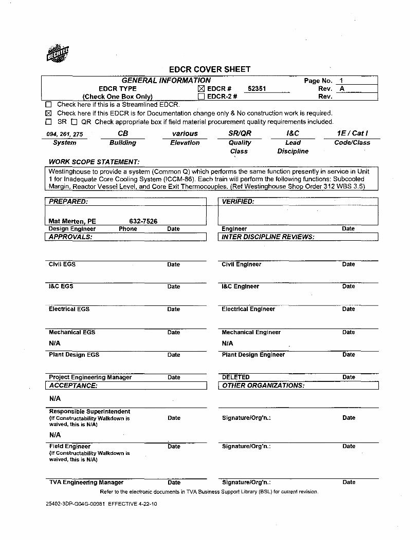
EDCR COVER SHEETGENERAL INFORMATION Page No. 1
EDCR TYPE [ EDCR # 52351 Rev. A(Check One Box Only) Ii EDCR-2 # Rev.
E Check here if this is a Streamlined EDCR.[ Check here if this EDCR is for Documentation change only & No construction work is required.El SR [] QR Check appropriate box if field material procurement quality requirements included.
094, 261, 275 CB various SR/QR I&C 1E / Cat ISystem Building Elevation Quality Lead Code/Class
Class Discipline
WORK SCOPE STATEMENT:Westinghouse to provide a system (Common Q) which performs the same function presently in service in Unit1 for Inadequate Core Cooling System (ICCM-86). Each train will perform the following functions: SubcooledMargin, Reactor Vessel Level, and Core Exit Thermocouples. (Ref Westinghouse Shop Order 312 WBS 3.5)
PREPARED: I-I VERIFIED: IMat Merten, PE 632-7526Design Engineer Phone DateAPPROVALS:
Civil EGS Date
I&C EGS Date
Electrical EGS Date
Mechanical EGS Date
NIA
Plant Design EGS Date
Project Engineering Manager DateACCEPTANCE:
N/A
Responsible Superintendent(If Constructability Walkdown is Datewaived, this is N/A)
NIA
Field Engineer Date(If Constructability Walkdown iswaived, this is N/A)
TVA Engineering Manager Date
Refer to the electronic documents in TVA Busines
25402-3DP-G04G-00081 EFFECTIVE 4-22-10
Engineer DateINTER DISCIPLINE REVIEWS:
Civil Engineer Date
I&C Engineer Date
Electrical Engineer Date
Mechanical Engineer Date
NIA
Plant Design Engineer Date
DELETED Date[OTHER ORGANIZATIONS:
Signature/Org'n.: Date
SignaturelOrg'n.: Date
Signature/Org'n.: Date
ss Support Library (BSL) for current revision.
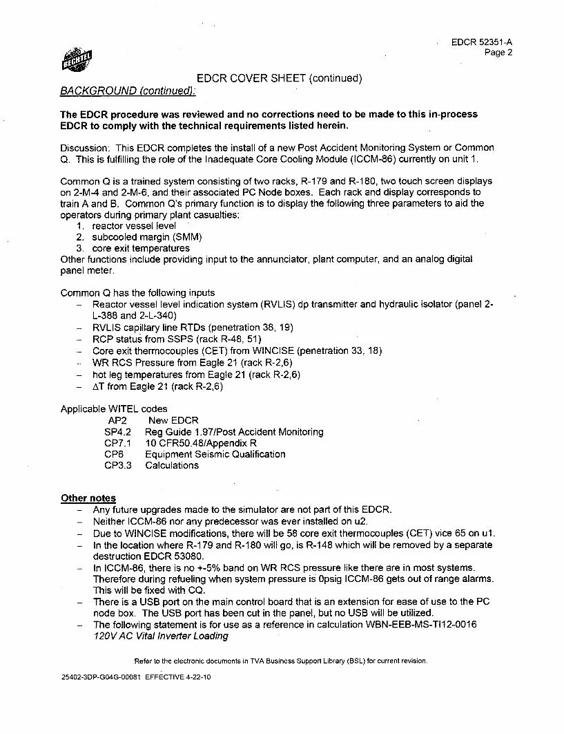
EDCR 52351-APage 2
EDCR COVER SHEET (continued)BACKGROUND (continued):
The EDCR procedure was reviewed and no corrections need to be made to this in-processEDCR to comply with the technical requirements listed herein.
Discussion: This EDCR completes the install of a new Post Accident Monitoring System or CommonQ. This is fulfilling the role of the Inadequate Core Cooling Module (ICCM-86) currently on unit 1.
Common Q is a trained system consisting of two racks, R-179 and R-180, two touch screen displayson 2-M-4 and 2-M-6, and their associated PC Node boxes. Each rack and display corresponds totrain A and B. Common Q's primary function is to display the following three parameters to aid theoperators during primary plant casualties:
1. reactor vessel level2. subcooled margin (SMM)3. core exit temperatures
Other functions include providing input to the annunciator, plant computer, and an analog digitalpanel meter.
Common Q has the following inputs- Reactor vessel level indication system (RVLIS) dp transmitter and hydraulic isolator (panel 2-
L-388 and 2-L-340)- RVLIS capillary line RTDs (penetration 38, 19)- RCP status from SSPS (rack R-48, 51)- Core exit thermocouples (CET) from WINCISE (penetration 33, 18)- WR RCS Pressure from Eagle 21 (rack R-2,6)- hot leg temperatures from Eagle 21 (rack R-2,6)- AT from Eagle 21 (rack R-2,6)
Applicable WITEL codesAP2 New EDCR
SP4.2 Reg Guide 1.97/Post Accident MonitoringCP7.1 10 CFR50.48/Appendix RCP6 Equipment Seismic QualificationCP3.3 Calculations
Other notes- Any future upgrades made to the simulator are not part of this EDCR.- Neither ICCM-86 nor any predecessor was ever installed on u2.- Due to WINCISE modifications, there will be 58 core exit thermocouples (CET) vice 65 on ul.- In the location where R-1 79 and R-1 80 will go, is R-1 48 which will be removed by a separate
destruction EDCR 53080.- In ICCM-86, there is no +-5% band on WR RCS pressure like there are in most systems.
Therefore during refueling when system pressure is 0psig ICCM-86 gets out of range alarms.This will be fixed with CQ.
- There is a USB port on the main control board that is an extension for ease of use to the PCnode box. The USB port has been cut in the panel, but no USB will be utilized.
- The following statement is for use as a reference in calculation WBN-EEB-MS-TI12-0016120V AC Vital Inverter Loading
Refer to the electronic documents in TVA Business Support Library (BSL) for current revision.
25402-3DP-GO4G-00081 EFFECTIVE 4-22-10
EDCR 52351-APage 3
EDCR COVER SHEET (continued)BACKGROUND (continued):
o 2-R-59 and 2-R-60 were part a very preliminary design in which they would receiveand process incore thermocouples. These racks will not be used in unit 2 and anyreference to them can be removed.
AbbreviationsCommon Q Common Qualified platform of componentsOM Operator's Module - located in M-4/6MTP Maintenance test panel - located within the racksFE function enable switchAIR Auxiliary Instrument RoomFE Function Enable (referring to a keyswitch on the OM and MTP)DPM Digital panel meter
Related EDCRs52601 - Reactor vessel level indication (RVLIS), phase 1 (installs tubing, RTDs, and unistrut)55385 - RVLIS phase 2, installs instruments52322 - Integrated computer system (ICS)52319 - Eagle-21 system53080 - removal of rack 2-R-14853301 - external connections for Eagle-21.52987 - hot leg RTDs52328 - SSPS52322 - Foxboro IA (equipment will go into racks occupied by other Foxboro IA equipment)52321 - WINCISE
52718 - cutout work M-452720 - originally M-6 cutout work but was superseded by 5333753337 - cutout M-652361 - labels on M-452363 - labels on M-6
Cabling EDCRs54636, 55233 -Auxiliary building V3 cables - (Sam Lettiere)
* supplying power cables for racks and PC node boxes54637 - Auxiliary room V2 cables, (David Nuchols and Stephen Hopkins), (not fiber cables)
* ABtoCB/ABtoRB• NotCBtoCB
54639, 55231 - reactor building V2 and V3 (Terry Humbert).* RVLIS RTD cabling
54632, 55232 - Control building - John Ostrander" Only within CB to CB* Includes fiber lines
Penetrations and the Auxiliary building secondary containment enclosure (ABSCE) boundary
There are no penetrations in this EDCR due to having no cabling.
Refer to the electronic documents in TVA Business Support Library (BSL) for current revision.
25402-3DP-G04G-00081 EFFECTIVE 4-22-10
EDCR 52351-A
*Page 4
EDCR COVER SHEET (continued)BACKGROUND (continued):
The CET cables outside the reactor building will pick up on the ex-containment side of thepenetrations on a 1 Oft pigtail. It will attach to the "CET Feedthrough Module Assembly" provided byWestinghouse. This will be installed per the WINCISE EDCR. See the WINCISE technicaldescription for more information.
RacksThe racks utilized will be from group G04 .(see section 4.2.1 of System Design Specifications). Theyhave been specified to be painted color 34410 per federal standard 595c (this matches the othercabinets in the AIR. See WBT-D-846 and WBT-D-1 057).
In May 2010 in came to design engineering's attention that the field had installed an approximate 6"column directly in between the proposed locations of the two cabinets in the AIR to support cabletrays. It has been accessed that this column will not cause interference with the cabinets (althoughnot ideal since this space was ear-marked for TVA to store a rack during maintenance).
Weldinq to Aux-lns-RoomThere is a PER that was submitted that the welds on u2 cabinets were not sufficient and need to bere-welded on the outside (the requirements call for welding to the inside of the cabinets on the lip).Therefore the CQ cabinets will need to be welded according to 1044E50-1 and DRA 52351-025.
There are precautions that must be taken when welding in the AIR. See DRA 52351-025 (referenceEDCR 53310 for more information). There is no unique precaution that unit 1 must be shut down.See construction note #1 on DRA 52351-025.
Unit l's ICCM-86 racks are not installed as far down the row as possible (ie rack 1-R-179 is not flushwith the last racks on the other rows). In unit 2, 2-R-179 will be as far down the row as possible tocreate more room.
Interface with Plant ComputerThere is an available feed from the OM for a print page command. This will not be utilized due tointerdivisional communication and cyber security concerns, but will not be disabled. The ability will beleft but under normal operations no printer will be installed. The print buttons on the plasma displaywill be not greyed out. (NOTE - MAY CHANGE - MM 10/19110)
The signal to ICS from the MTP will go to 2-R-023 and 2-R-020. Here it will go through OwlComputing Data Diodes which are installed in Dell R200 servers. The Dell servers were specificallyprocured to except a fiber optic ethernet interface compatible with the network protocol Common Q istransmitting.
Westinghouse provide fiber optic to CAT5 modems that will be utilized downstream of the data diodesprior ICS. These will be by Transition Networks and the model number is J/FE-CF-04. Since theseare not safety related, no other documentation will be sent regarding these modems. These modemswill also be used for the print screen command from the OM. Reference WBT-D-1928 25402-011-G26-03546-001.
Refer to the electronic documents in TVA Business Support Library (BSL) for current revision.
25402-30P-G04G-00081 EFFECTIVE 4-22-10
EDCR 52351-A
*Page 5
EDCR COVER SHEET (continued)BACKGROUND (continued):
Installation of Fiber Optic Cable - includinq safety fiberThe safety function of Common Q PAMS is to display various parameters to the operators via thetouch screen plasma display. Any piece of hardware or cable that plays a role in this must be safetyrelated. Therefore the fiber optic link between the racks and the OM is safety related. Note thefiber optic cable from the MTP going to ICS is not safety related.
At the time of this writing, there is no requirement for safety related fiber optic cable, although IEEEWorking Group P1692 is working on this problem. ISA has committee 67.17, Fiber Optic Cable forNuclear Power Plants & other Nuclear Facilities, but they have not produced a standard.
* Electrical will procure safety fiber (1 E) and complete this installation under the respective bulkcabling package. Connectors will be installed on one end. This will be routed in the samemanner a safety related copper cable is routed. This will be accomplished in the applicablebulk cabling EDCR. This is a much stronger industrial cable compared to more standard fiberoptic cables.
* There will be no patch panel in the rack. The cable is terminating to the AF100 modemswhich are at the bottom of the rack. There is space to wrap and tie down the cable. This willbe adequate for strain relief. This is in compliance with G-38 section 16.4.2.
* There will be no fiber patch panel in the control room. The major purpose of a fiber patchpanel is for strain relief. This can be accomplished via wrapping and tying the cable in thevicinity of the end point. Thus a fiber patch panel is not required.
o The logic to this decision was any fiber patch panel would have to go through seismictesting and since many are plastic it is unsure if it would pass. As long as there isstrain relief, this is technically acceptable.
The fiber link from the MTP to ICS will use the standard project cable of WOF-12. There will be nopatch panel in the rack for the same reason as above, but there will be patch panels at the end pointsin the vicinity of the data diodes.
CablesThere are no cables in this EDCR. What follows is for background information only.
The power cables for rack 148 are present in accordance with the walkthrough for EDCR 53080 2-11and 2-1.
On the main control panel, there is an in-rack temperature indication. This is not a separate cableand will be part of the data sent on the main fiber cable.
The core exit thermocouples (CET) will traverse the penetration with the "CET Feedthrough ModuleAssembly with Integral Electrical Connector". Within the reactor building the cable is provided byWestinghouse and is considered part of the instrument. The cable design and procurement outsidethe reactor building is per the applicable bulk cabling package. This is type K thermocouple cable allthe way to the rack.
Refer to the electronic documents in TVA Business Support Library (BSL) for current revision.
25402-3DP-GO4G-00081 EFFECTIVE 4-22-10
EDCR 52351-APage 6
EDCR COVER SHEET (continued)BACKGROUND (continued):
The thermocouple reference junction, originally located inside containment, will be located inside theCQ cabinets with four RTDs per train. Thus no reference junction cables will be required.Additionally, the CET cable will be thermocouple type K all the way to the cabinets (ICCM-86 has athermocouple to copper transition at containment).
Annunciator InterfaceCommon Q will feed two separate annunciator alarms.Train A is on location 85F - see ARI-81-87 (unit 1 procedure) - 2-XA-55-4B - on M-4Train B is on location 124E - see ARI-124-130 (unit 1 procedure) - 2-XA-55-6C - on M-6The unit 2 ARI procedures will be created by Operations.
This alarm does not alarm on certain plant parameters (such as vessel level being too low), it alarmswhen something goes wrong internally of the Common Q System.
Common Q has five options to choose from (see System Design Specifications table 4.4-6). Thisalarm will utilize the "System trouble alarm" which is the closest in similarity to the ICCM-86 alarm.Reference Software Requirement Specifications table 7.1-2 and WBT-D-0889.
PC Node Box and displayThe display will be mounted via a bolt and nut. Exact specifications have been forwarded to theCRDR group. The OM's node box will be mounted on the floor aft of M-4 and M-6.
There was a previous problem on unit 1 that the software operating system would freeze. Unit 2'sCommon Q and CERPI will be using a new QNX Operating System which does not exhibit the "datafreeze". See WBT-D-0479.
The OM's node box has a port on the back for the Function Enable keyswitch which will not normallybe plugged in. (Westinghouse's vision was this would be mounted on the main control board - thereis no space). Since the FE keyswitch will not be permanently installed, no UNID will be assigned.
Not installing the FE keyswitch will result in the loss of some intended functionality as discussed inWBT-D-1897 (25402-011-G26-GAKS-03394-001). It has been assessed that these functions wouldnot affect normal operations and is acceptable. The lost functions are more for setting up the system
The OM will come with a removable USB floppy drive to load addressable constants on the MTP.Since this floppy drive will not be permanently installed, no UNID will be assigned.
See discussion in Interface with Plant Computer section which discusses the fiber optic to CAT5modem used for the print screen command from the OM.
RVLIS InputsUnit one has six RTDs on one train and 5 on the other train. Common Q will have an allowable ofeight RTDs. Therefore there can be no more than eight vertical sections in the installed RVLISsystem. The RTD location plan corresponds with this.
Refer to the electronic documents in TVA Business Support Library (BSL) for current revision.
25402-3DP-GO4G-00081 EFFECTIVE 4-22-10
EDCR 52351-APage 7
EDCR COVER SHEET (continued)BACKGROUND (continued):
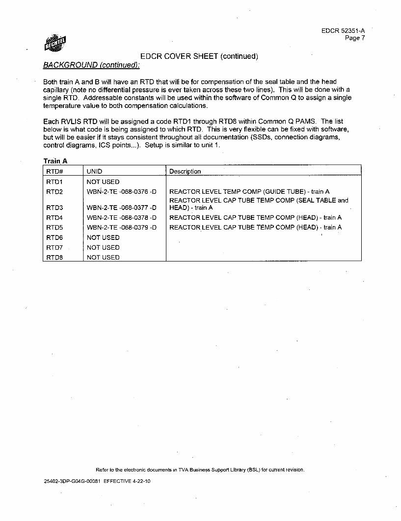
Both train A and B will have an RTD that will be for compensation of the seal table and the headcapillary (note no differential pressure is ever taken across these two lines). This will be done with asingle RTD. Addressable constants will be used within the software of Common Q to assign a singletemperature value to both compensation calculations.
Each RVLIS RTD will be assigned a code RTD1 through RTD8 within Common Q PAMS. The listbelow is what code is being assigned to which RTD. This is very flexible can be fixed with software,but will be easier if it stays consistent throughout all documentation (SSDs, connection diagrams,control diagrams, ICS points...). Setup is similar to unit 1.
Train ARTD# UNID Description
RTD1 NOT USED
RTD2 WBN-2-TE -068-0376 -D REACTOR LEVEL TEMP COMP (GUIDE TUBE) - train AREACTOR LEVEL CAP TUBE TEMP COMP (SEAL TABLE and
RTD3 WBN-2-TE -068-0377 -D HEAD) - train A
RTD4 WBN-2-TE -068-0378 -D REACTOR LEVEL CAP TUBE TEMP COMP (HEAD) - train ARTD5 WBN-2-TE -068-0379 -D REACTOR LEVEL CAP TUBE TEMP COMP (HEAD) - train A
RTD6 NOT USEDRTD7 NOT USED
RTD8 NOT USED
Refer to the electronic documents in TVA Business Support Library (BSL) for current revision.
25402-3DP-G04G-00081 EFFECTIVE 4-22-10
BA CKGROUND (continued):
EDCR 52351-APage 8
EDCR COVER SHEET (continued)
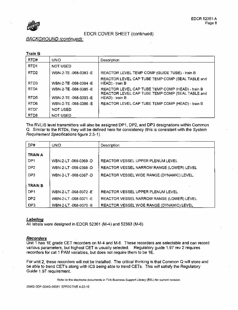
Train B
RTD# UNID Description
RTD1 NOT USED
RTD2 WBN-2-TE -068-0383 -E REACTOR LEVEL TEMP COMP (GUIDE TUBE) - train B
REACTOR LEVEL CAP TUBE TEMP COMP (SEAL TABLE andRTD3 WBN-2-TE -068-0384 -E HEAD) - train BRTD4 WBN-2-TE -068-0385 -E REACTOR LEVEL CAP TUBE TEMP COMP (HEAD) - train B
REACTOR LEVEL CAP TUBE TEMP COMP (SEAL TABLE andRTD5 WBN-2-TE -068-0393 -E HEAD) - train BRTD6 WBN-2-TE -068-0386 -E REACTOR LEVEL CAP TUBE TEMP COMP (HEAD) - train BRTD7 NOT USEDRTD8 NOT USED I
The RVLIS level transmitters will also be assigned DP1, DP2, and DP3 designations within CommonQ. Similar to the RTDs, they will be defined here for consistency (this is consistent with the SystemRequirement Specifications figure 2.5-1).
DP# UNID Description
TRAIN ADP1 WBN-2-LT -068-0369 -D REACTOR VESSEL UPPER PLENUM LEVEL
DP2 WBN-2-LT -068-0368 -D REACTOR VESSEL NARROW RANGE (LOWER) LEVEL
DP3 WBN-2-LT -068-0367 -D REACTOR VESSEL WIDE RANGE (DYNAMIC) LEVEL.
TRAIN B
DP1 WBN-2-LT -068-0372 -E REACTOR VESSEL UPPER PLENUM LEVEL
DP2 WBN-2-LT -068-0371 -E REACTOR VESSEL NARROW RANGE (LOWER) LEVEL
DP3 WBN-2-LT -068-0370 -E REACTOR VESSEL WIDE RANGE (DYNAMIC) LEVEL
LabelingAll labels were designed in EDCR 52361 (M-4) and 52363 (M-6)
RecordersUnit 1 has 1E grade CET recorders on M-4 and M-6. These recorders are selectable and can recordvarious parameters, but highest CET is usually selected. Regulatory guide 1.97 rev 2 requiresrecorders for cat 1 PAM variables, but does not require them to be 1 E.
For unit 2, these recorders will not be installed. The critical thinking is that Common Q will store andbe able to trend CET's along with ICS being able to trend CETs. This will satisfy the RegulatoryGuide 1.97 requirement.
Refer to the electronic documents in TVA Business Support Library (BSL) for current revision.
25402-3DP-GO4G-00081 EFFECTIVE 4-22-10
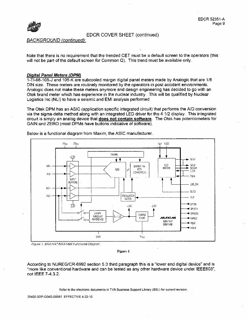
BACKGROUND (continued):
EDCR 52351-APage 9
EDCR COVER SHEET (continued)
Note that there is no requirement that the trended CET must be a default screen to the operators (thiswill not be part of the default screen for Common Q). This trend must be available only.
DiMital Panel Meters (DPM)1-TI-68-105-J and 105-K are subcooled margin digital panel meters made by Analogic that are 1/8DIN size. These meters are routinely monitored by the operators in post accident environments.Analogic does not make these meters anymore and design engineering has decided to go with anOtek brand meter which has experience in the nuclear industry. This will be qualified by NuclearLogistics Inc (NLI) to have a seismic and EMI analysis performed
The Otek DPM has an ASIC (application specific integrated circuit) that performs the A/D conversionvia the sigma-delta method along with an integrated LED driver for the 4 1/2 display. This integratedcircuit is simply an analog device that does not contain software. The Otek has potentiometers forGAIN and ZERO (most DPMs have buttons indicative of software).
Below is a functional diagram from Maxim, the ASIC manufacturer.
L'ED EN
GLED
IDPSUE2
RAiG E
R~qure 1. M4AX1447,A,AXI498 Funcxwnai Diagfým
Figure 1
According to NUREG/CR-6992 section 5.3 third paragraph this is a "lower end digital device" and is"more like conventional hardware and can be tested as any other hardware device under IEEE603",not IEEE 7-4.3.2.
Refer to the electronic documents in TVA Business Support Library (BSL) for current revision.
25402-3DP-GO4G-00081 EFFECTIVE 4-22-10
EDCR 52351-A
*Page 10
EDCR COVER SHEET (continued)BACKGROUND (continued):
In conclusion, due to the simple analog type nature of these DPM, it does not have to go through aV&V or ISGO6.
PERS in Question144982 - Mineral insulated cables for various cables in system 94 were installed in unistrut with nodetailed installation instructions - or it had no supporting design input or output. Thus some of thecables were found to be damaged.
- Applicable DCWB-DC-30-4 - separation of electrical equipment and wiringWB-DC-30-5 - power, control, and signal cables used in CAT I structures
- This is being addressed in the RVLIS EDCR 52601.
145147 - Westinghouse RTD cables were not installed correctly according to the drawings. Forexample the drawings require no more than 24" separation, but this was routinely violated.
- This appears to mostly be a construction issue, but there were not as good document controlas exists currently so it was difficult to identify applicable vendor drawings.
- This is being addressed in the RVLIS EDCR 52601.
143833 - This PER found that the welding was inadequate to drawing 47w605-3 and thus all cabinetsin the aux instrument room will be welded from the outside.
- This EDCR will include welding information. No additional action required
172694 - Modify NCH cards (function generator) within ICCM-86 which will restore the RVLISaccuracy to plus or minus 6 percent. This modification was implemented by Westinghouse FCNWBTM-10717B.This is not applicable to unit 2 because the Common Q hardware is completely different than the unit1 hardware. Additionally, TVA has no requirement in any design basis or licensing document of whatthe RVLIS accuracy must be (although Westinghouse does make claims what its accuracy will be).
233598 - Reconcile the fact the design basis of WBN2 is RG 1.97 rev 2 but common Q PAMS isdesigned to RG 1.97 rev 3 (note at the time of issuing this package, the most up to date RG 1.97 rev4). This analysis was performed and submitted to the NRC. No further action required.
Important TS/DS/ESWB-DC-30-7 - post accident monitoring instrumentationNRC's Technical specifications - section 3.3.3WB-DC-30-20 - attaching cabinetsWB-DC-30-4 - separation
Procurement" The Common Q system was procured via Procurement Request to Westinghouse. At time of
issuance it is at revision 5" Dual diodes from Owl Computing - purchased as NQR" Digital panel meters from Otek - purchased as safety related* Field will procure any fiber optic connectors for the interface with ICS as NQR
Refer to the electronic documents in TVA Business Support Library (BSL) for current revision.
25402-3DP-GO4G-00081 EFFECTIVE 4-22-10
EDCR 52351-APage 11
EDCR COVER SHEET (continued)BA CKGROUND (continued):
0 Field will procure any fiber optic connectors for the interface between the racks and OM assafety related.
Calculations* Electrical calculations - see Electrical and I&C Checklist for details* SSD supporting calculations (various) - open itemed and mentioned in calculation checklist" ICCMCALCNOTE - Inadequate Core Cooling Monitor (ICCM) Calculation Note Supporting
ICCM Setpoint and Scaling Documentso This is the supporting calculation for the SSDs. These are being supplied by
Westinghouse under alternative names.* WBPEVAR8902002 - Determination of Devices Required for Indicating Safety-Related Trends
for WBN PAM. Defines the type of devices to display safety related trends for PAMmonitoring of RG 1.97 compliance.
o RG 1.97 rev 2 requires type A variables be category 1 which means a recorder isneeded but it can be a computer. This is what WBN2 is intending to do with thedisplay.
o This calculation states in unit 1 their display was adequate for trending (even thoughthey had a recorder). This wording is vague enough that it is still applicable to unit 2.
o No action or revision is needed to this calculations" WBNOSG4076 - RG 1.97 variables needing trend recording
o Establishes which of the CAT 1 parameters (which SMM is) must be provided with acontinuously available trend recorder.
o Since WBN2 is claiming the node box as the trend recorder, Common Q PAMS is stillin compliance with the calculation and no revision is required.
• WBPEVAR9202003 - NON CLASS 1E cables required for PAM cat 2 Variableso This determines which non 1 E cables are required for PAM cat 2 variables. This is a
unit 0, 1 calculation.o Out of the three PAM variables relevant to Common Q PAMS, none are listed in
section 7.0 as identified that are not 1E.o Section 7.1.1 discusses all NON-1 E recorders and all applicable variables (#6, 16,22
in WB-DC-30-7) are listed. This means it is acceptable that these variables can berecorded in a non 1E manner. Since Common Q PAMS is claiming the node box as its"qualified recorder", no revision is needed for this calculation.
• WBNEEBIDQ29990901 - Non-Class 1E Cables Required For Post Accident MonitoringCategory 2 Variables
o This calculation contains the "block diagrams" from the respective RG 1.97 variables.However all variables are CAT 1. No revision is needed for this calculation.
* WBPEVAR8809048 - PAM Instrumentation Evaluation and Verification Methodology,Standards and Guidelines
o This is a unit 1 calco The unit 2 calc is WBNEEBIDQ29990903 and is being open iterned - see 01-52351-
17. There is various instrumentation information including applicable UNID - theseneed to be updated for unit 2 UNIDs.
" WBNEEBIDQ299909002 - Instrument Loop Evaluation for Containment Isolation ValvePosition
o RG 1.97 requirements of containment isolation valves
Refer to the electronic documents in TVA Business Support Library (BSL) for current revision.
25402-3DP-GO4G-00081 EFFECTIVE 4-22-10
EDCR 52351-APage 12
EDCR COVER SHEET (continued)BACKGROUND (continued):
o There are no isolation valves in Common Q - this calculation is not applicable." MDQ00299920090342 - WBN2CCP-COMBUSTIBLE LOADING DATA (CLD)
o Must be revised for adding burnable weights to various compartments." EPMMCP071689 - Cooling/Heating Load & Equipment/Component Performance Analysis For
The Control Building Electrical Board Room Areas (el. 692.0 & 708.0)o To be revised with new heat loads going into AIR. This is being open itemed.
• EPMLCP072489 - Cooling And Heating Load Analysis, Main Control Room HVAC* WCGACQ037I - Seismic Qualification of Weld Anchorage of R Panels
o Unsure if revision, is needed.
For the following three see write up in technical evaluation. Since all EQ instruments that feedCommon Q are installed in other EDCRs, no revision to these calculations are needed." WBNOSG4134 - 10CFR50.49 methodology and listing of other calculations* WBNOSG4017 - System 68 category and operating times calculation• WBNOSG4028 - System 94 category and operating times calculation
IMPORTANT DOCUMENTS (U1 AND U2)G-38
2-45W2623 serie45N 1643-1,445N 1644-445N1645-2,1045W1 623-1LSWD-1 0573D20465 SERIE5D92409 series1775E24 series5D92298 series
SSD-2-X-1 00SSD-2-X-1 10SSD-2-T-94-790SSD-2-T-94-800SSD-2-T-94-034SSD-2-T-94-1 01SSD-2-T-94-001SSD-2-T-94-102SSD-2-T-68-105SSD-2-T-68-115SSD-2-L-68-367SSD-2-L-68-368SSD-2-L-68-369SSD-2-L-68-370SSD-2-L-68-371SSD-2-L-68-372
Installation, Modification, and Maintenance of Insulated Cables Rated Up To15,000 VOLTS, see section 16.4.2
es R-179,180 connection diagrams1-M-4 connection diagram1-M-5 connection diagram1-M-6 connection diagram1-R-148 connection diagram (R-148 was removed in unit 1 and unit 2)R-148 walkdown for EDCR 53080
S Westinghouse ICCM-86 external connection diagramsWestinghouse ICCM-86 schematic diagramsWestinghouse ICCM-86 assembly diagramsWestinghouse ICCM-86 block diagrams
ICCM train A RVLIS level monitoring (by W)ICCM train B RVLIS level monitoring (by W)
5 ICCM train A heatup and cooldown rate (by W)5 ICCM train B heatup and cooldown rate (by W)
ICCM train A CET Monitoring (by W)ICCM train A CET Monitoring (by W)ICCM train A CET Monitoring (by W)ICCM train B CET Monitoring (by W)SMM monitoring (by W)SMM monitoring (by W)ICCM Train A RVLIS dynamic head (by W)ICCM Train A RVLIS lower range (by W)ICCM Train A RVLIS upper range (by W)ICCM Train B RVLIS dynamic head (by W)ICCM Train B RVLIS lower range (by W)ICCM Train B RVLIS upper range (by W)
Refer to the electronic documents in TVA Business Support Library (BSL) for current revision.
25402-3DP-GO4G-00081 EFFECTIVE 4-22-10
EDCR 52351-APage 13
EDCR COVER SHEET (continued)BACKGROUND (continued):
ARI-81-87ARI-124-130
annunciator response instruction - unit 1 - train Aannunciator response instruction - unit 1 - train B
Project CorrespondenceThe following is the list of all correspondence between Westinghouse and TVA. Some of these areon the EDCR index because they led a direct role in the design. This list is for information only andwill not be updated.
TO BE ADDED
Refer to the electronic documents in TVA Business Support Library (BSL) for current revision.
25402-3DP-GO4G-00081 EFFECTIVE 4-22-10
EDCR UNIT DIFFERENCE FORM
EDCR# 52351 Rev. A Page No.
The Unit l's ICCM-86 system is an outdated digital system. The CommonQualified Platform of components from Westinghouse is the newer echelon ofdigital I&C hardware that has become the industry standard. TVA made theearly decision to accept the unit differences and utilize the Common Q systemfor Post Accident Monitoring.
Operations Difference is identified as follows:
, The outdated monochrome CRT is being replaced with a touch screen multi-color display.This difference is an improvement in that it is larger and more visible to the operators andtherefore technically acceptable.
" The default screen will be different than unit 1. This difference is what was decided by TVAduring the initial contract generation process. Additionally, the cost of softwaredevelopment to make the new system mirror the unit 1 default screen was prohibitive.
o Unit 1 displays - reference WBN-VTD-W120-3020 figure 5-5" THOT
" CET Highest quadrant average" RCS pressure" CET based subcooled margin" RVLIS level" Logo of pump in dynamic mode and the core in static mode" RCP status" RVLIS mode
o Unit 2 will display - reference WBT-D-1675 (G26-GAKS-02739-001)a The highest CET value in each quadrant0 CET and auctioneered THOT based subcooled margina RVLIS level along with a much improved graphic of the core depicting the
loops.a RCP statusa RVLIS mode0 RCS pressure
* Recorders on the control board are being removed. These recorders are selectable andcan record various parameters, but highest CET is usually selected in unit 1. Regulatoryguide 1.97 rev 2 requires recorders for cat 1 PAM variables, but does not require them to be1E. The PC node box along with ICS is fulfilling the role of a recorder and thus thisdifference is acceptable.
• Push buttons are being removed and superseded with a touch screen display. The samefunctions are being accomplished with the touch screen and thus this difference is
Refer to the electronic documents in TVA Business Support Library (BSL) for current revision.
25402-3DP-GO4G-00081 EFFECTIVE 5/19/10 Page 1 of 6
acceptable.
" Value feeding the ICCM trouble alarm (to be changed to "Common Q Trouble'.") will alarm onmore items than what unit 1 does. However out of the five alarms that Common Q has tosend to the annunciator, this is the closest. This alarm does not alarm on any parametersbeing too high or low, it alarms on various internal problems within the rack. There aredifferences between these two alarm configurations mainly due to the significant differencesin hardware. Overall what CQ is alarming on seems to cover all failures and is deemedacceptable by Bechtel Engineering.
o For the Common Q system trouble see the Soft Req Specifications table 7.1-2. ForICCM-86 reference VTD-W120-3020 section 5.10.8.4.
* There is high temp alarm for within the rack. This is an improvement and is technicallyacceptable.
* Operator will be able to print screen from the Operator's Module - but the printer will notnormally be connected.
" The submargin monitor digital panel meter is an Otek brand vice an the outdated andunavailable Analogic. The LED display will be 0.6" tall vice approximately 0.5" tall.Although this meter is not off-the-shelf safety related, it is going through Nuclear LogisticsIncorporated to get seismically and EMI testing (there is no V&V required - see scopestatement or justification). The same color blue is being procured. Due to the similarity, thisdifference is acceptable.
" It is possible that due to the differences in CET values (estimated at a.20d.difference) theSMM values will be up to 20 latrgerduringnormal operations. Post accident, we are told,,Will come back to normal. MORE ANALYSIS NEEDED.
Unit 2 TVA Operations Acceptance (Mgr or Designee): Date:
Refer to the electronic documents in TVA Business Support Library (BSL) for current revision.
25402-3DP-GO4G-00081 EFFECTIVE 5/19/10 Page 2 of 6
Maintenance Difference is identified as follows:
" There is no separate maintenance test panel box. All similar functions can be accomplishedinternal to the racks.
* Number and location of RVLtS RTDs are different. This is due to the route of the RVLIScapillary being different. This could affect maintenance if an RTD fails.
• See Design Difference section for more background.
" There is a "simulator" hookup location at the bottom of the racks where signals can be inputto replicate various plant conditions. This will be used by maintenance for their testing.
• Westinghouse has designed a special apparatus for use in their FAT that willreplicate various plant configurations. Whether TVA systems engineers build orprocure a device similar to this is at their discretion and is not relevant to this EDCR.
Unit 2 TVA Maintenance Acceptance (Mgr or Designee): Date:
Refer to the electronic documents in TVA Business Support Library (BSL) for current revision.
25402-3DP-GO4G-00081 EFFECTIVE 5/19/10 Page 3 of 6
Design Difference is identified as follows:
" Different number of CETs, 58 in unit 2 and 65 in unit 1. This is based on the differencesdue to WINCISE and is Westinghouse's design responsibility.
" Reference junction for the CETs is accomplished within the rack vice in the reactor building.Therefore cabling for CETs is thermocouple type K all the way to the rack. Since thisaccomplishes the same goal, it is technically acceptable.
" Location and number of the RVLIS RTDs will be different. This is because the Unistrut wasmostly installed in unit 2 and to save cost will be used. This was "field routed" as it was inunit 1 and thus is not exactly the same. For example on the hot legs, due to the horizontalrouting of the capillary, there is no need for an RTD. Design engineering has noted theroute as part of the reactor vessel level indication system EDCR 52601 and has adjustedthe location of all RTDs. This difference is technically acceptable.
" In one location on train A and two locations on train B, a single RTD will be used forcompensation of both the head and seal table capillary lines. This is because these twolines are run together during places where compensation is needed (vertical sections) andno differential pressure is taken across the head and bottom of the core. Common Q issophisticated enough to take one input and use it for two separate compensationcalculations depending on the plant status through the use of addressable constants. Thisdecision was made to save cost and keep the system simpler. Since this setup serves thesame end and Common Q can accommodate - it is technically acceptable.
* THIS ALL MAY C.ANGE.-MM 6115/10 - The digital submargin monitor (SMM) displayedon a digital panel meter will not be selectable (unit 1 can select it with the portablemaintenance test panel). It will display saturation margin based on effective thermocouplevalue TCREP. Additionally, this value is assessed to be a smaller margin than unit 1.
o Unit 1 could base SMM on auctioneered THOT or high quadrant average CET valueby selecting it with the maintenance computer. Unit 2 constantly calculates bothvalues and has the option to send an analog output for either, but they are onseparate terminal blocks. Therefore Common Q has three options (a) select onlyone to display, (b) have two meters each per train, or (c) procure a moresophisticated multiple input meter. Bechtel engineering has chosen the first option
o It is possible that SMM based on TCREP will be different in unit 2 because (1) thecalculation is different (TCREP versus high quadrant average CET) and (2) thedifferences in WINCISE.
o In unit 1, auctioneered THOT is around 2-4°F lower than highest average quadrantvalue. Therefore the saturation margin is lower and hence more conservative for theCET based calculation. This is why unit 1 utilizes this value (reference 1-SSD-T-105/115)
o It is Westinghouse's engineering assessment that due to the flow differences withWINCISE, the CET values will be slightly higher than unit 1. Therefore BechtelEngineering believes that utilizing the CET value for SMM will result in a smallermargin and is therefore the more conservative approach and thus technicallyacceptable..
Refer to the electronic documents in TVA Business Support Library (BSL) for current revision.
25402-3DP-GO4G-00081 EFFECTIVE 5/19/10 Page 4 of 6
o If this assessment turns to be untrue, TVA can easily remedy the situation byswitching the terminals on the cable going to the panel meter within the Common Qracks.
Analog output to SMM will be 4-20 mA vice 0-1OVdc. The scaling is different from -20 to200°F in unit 1 to -200 to +800'F for Common Q. It is possible due to the scale increasingso dramatically there could be some "fluttering" of the values on the display. No action inthis package will be taken to install any damping. If this is a problem, it will be addressed inthe future by TVA. Note that this span is not something easily changeable byWestinghouse and would have cost and schedule impacts if changed. Bechtel Engineeringhas assessed that this change is technically acceptable.
" Various UNID differences due to the hardware differences. Attempts were made to assignUNIDs to individual items that would be replaced if it or a part within it fails. For examplethe termination units are fairly complex internally with multiple relays within it - however itwas assessed that the entire assembly would be replaced if an individual relay failed. Thusa UNID was assigned to each termination unit, and not each of the relays within each unit.
" Link to ICS will have a data diode device to ensure one way TCP/IP network flow. This isfor a dual reason of cyber security compliance (reference regulatory guide 5.71) along withminimal extra assurance that non-safety to safety communications will not be a problem.Since this difference is a significant reason Common Q PAMS will be acceptable from aCyber Security perspective, it is technically acceptable.
* Data link to ICS is similar to, but does not exactly match unit 1. Some calculations are nolonger being performed (for example average thermocouple value per quadrant) and hencecannot be sent. Error codes are no longer being sent. The values no longer beingcalculated are often replaced with other similar values. It is Bechtel Engineering'sassessment that upon review of all the differences they are acceptable.
o For Common Q reference Soft Req Specifications table 7.2-1 and 7.2-2o For unit 1 there is not a consolidated list of data points, but the design engineer
created a list from searching PEDs (there is a list on 47W610-94-1 but does notcontain all unit 1 points).
The cabling connections into Common Q have a different setup in that they will be going todifferent terminal boards. This is causing the connection diagrams 2-45W2623 series to bedifferent, This is Westinghouse's decision and it makes no difference to BechtelEngineering as long as all cables are accounted for. This difference is acceptable.
Safety related fiber optic cable will be used in the link between the racks and the Operator'sModule. (This is not the same as the "data link" to ICS mentioned earlier). Safety relatedfiber optic cable has not been used in TVA to date and - as far as the author knows - hasbeen used in two other U.S. plants to date. There is no specification that has establishedwhat "safety related fiber optic cable" is defined as, although there is an IEEE committeethat is working on this problem from a harsh environment perspective (which this case isnot). The project is in the process of acquiring 1E fiber (some vendor's can provide). Thisdifference is technically acceptable.
Refer to the electronic documents in TVA Business Support Library (BSL) for current revision.
25402-3DP-GO4G-00081 EFFECTIVE 5/19/10 Page 5 of 6
Unit 2 TVA Engineering Acceptance (Mgr or Designee):
Date:Mat Merten, PEPrepared By: Date:
Streamlined EDCR approved by TVA Oversight__
SESG TO ROUTE A COPY OF THIS COMPLETED FORM TO TVA TRAINING MANAGER AND TO UNIT2 LICENSING.
Refer to the electronic documents in TVA Business Support Library (BSL) for current revision.
25402-3DP-GO4G-00081 EFFECTIVE 5/19/10 Page 6 of 6
Attachment 1 EDCR 52351-A
(Page I of 32) Page____
TECHNICAL EVALUATION CONSIDERATIONS OF 0-TI-2
This attachment provides topics to be considered when evaluating the technical andsafety aspect of changes being implemented in WBN Unit 0 and/or Unit 1 by the EDCRprocess; see Reference 5.1. It is not intended to be an all inclusive list of items to beconsidered. It is to be used as an aid in determining attributes that should beaddressed in a technical evaluation. Information is also provided to aid in determiningcoordination interfaces. These are minimum guidelines which are primarily excerptsfrom SPP-9.3. It should be recognized that many topics and changes involve multipledisciplines and organizations and technical considerations must be coordinatedaccordingly. All parts of Attachment 1 must be considered for applicability for theassociated EDCR.
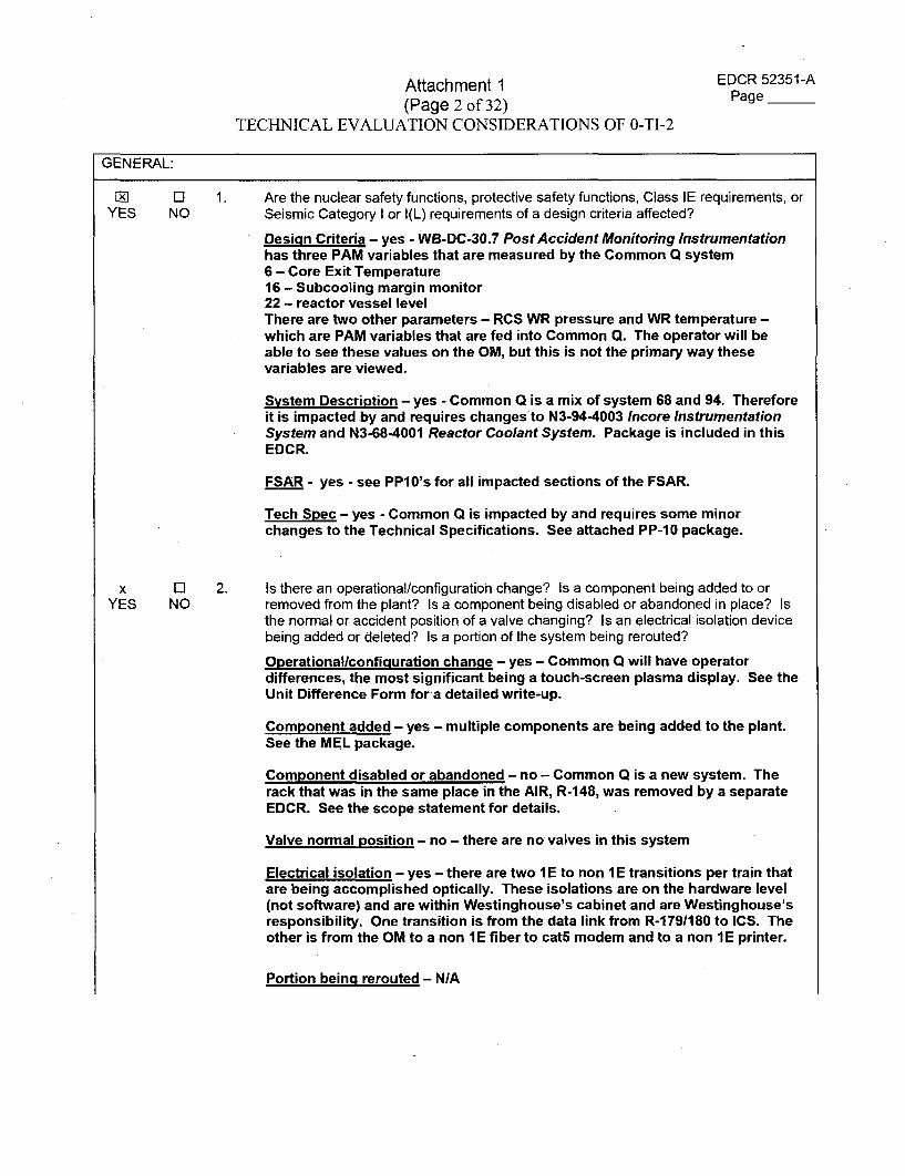
Attachment 1(Page 2 of 32)
TECHNICAL EVALUATION CONSIDERATIONS OF 0-TI-2
EDCR 52351-APage __
GEN ERAL:
FRlYES NO
1. Are the nuclear safety functions, protective safety functions, Class IE requirements, orSeismic Category I or I(L) requirements of a design criteria affected?
Desicin Criteria - yes - WB-DC-30.7 Post Accident Monitoring Instrumentationhas three PAM variables that are measured by the Common Q system6 - Core Exit Temperature16 - Subcooling margin monitor22 - reactor vessel levelThere are two other parameters - RCS WR pressure and WR temperature -which are PAM variables that are fed into Common Q. The operator will beable to see these values on the OM, but this is not the primary way thesevariables are viewed.
System Description - yes - Common Q is a mix of system 68 and 94. Thereforeit is impacted by and requires changesto N3-94-4003 Incore InstrumentationSystem and N3-68-4001 Reactor Coolant System. Package is included in thisEDCR.
FSAR - yes - see PP10's for all impacted sections of the FSAR.
Tech Spec - yes - Common Q is impacted by and requires some minorchanges to the Technical Specifications. See attached PP-10 package.
2. Is there an operational/configuration change? Is a component being added to orremoved from the plant? Is a component being disabled or abandoned in place? Isthe normal or accident position of a valve changing? Is an electrical isolation devicebeing added or deleted? Is a portion of the system being rerouted?
Operationallconfiquration chanue - yes - Common Q will have operatordifferences, the most significant being a touch-screen plasma display. See theUnit Difference Form for a detailed write-up.
Component added - yes - multiple components are being added to the plant.See the MEL package.
Component disabled or abandoned - no - Common Q is a new system. Therack that was in the same place in the AIR, R-148, was removed by a separateEDCR. See the scope statement for details.
Valve normal position - no - there are no valves in this system
Electrical isolation - yes - there are two I E to non 1 E transitions per train thatare being accomplished optically. These isolations are on the hardware level(not software) and are within Westinghouse's cabinet and are Westinghouse'sresponsibility. One transition is from the data link from R-1791180 to ICS. Theother is from the OM to a non 1 E fiber to cat5 modem and to a non 1 E printer.
x ElYES NO
Portion being rerouted - NIA
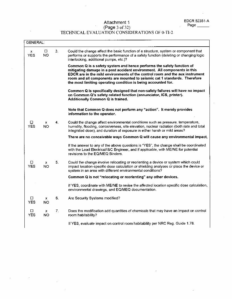
Attachment 1 EDCR 52351-A
(Page 3 of 32) Page
TECHNICAL EVALUATION CONSIDERATIONS OF 0-TI-2
GENERAL:
x El 3. Could the change affect the basic function of a structure, system or component thatYES NO performs or supports the performance of a safety function (deleting or changing logic
interlocking, additional pumps, etc.)?
Common Q is a safety system and hence performs the safety function ofmitigating damage in a post accident environment. All components in thisEDCR are in the mild environments of the control room and the aux instrumentroom and all components are mounted to seismic cat I standards. Thereforethe most limiting operating condition is being accounted for.
Common Q is specifically designed that non-safety failures will have no impacton Common Q's safety related function (annunciator, ICS, printer).Additionally Common Q is trained.
Note that Common Q does not perform any "action". It merely providesinformation to the operator.
El x 4. Could the change affect environmental conditions such as pressure, temperature,YES NO humidity, flooding, corrosiveness, site elevation, nuclear radiation (both rate and total
integrated dose),.and duration of exposure in either harsh or mild areas?
There are no conceivable ways Common Q will cause any environmental impact,
If the answer to any of the above questions is "YES", the change shall be coordinatedwith the Lead Electrical/l&C Engineer, and if applicable, with ME/NE for potentialrevisions to the EQ/MEQ Binders.
El x 5. Could the change involve relocating or reorienting a device or system which couldYES NO impact location-specific dose calculation or shielding analyses or place the device or
system in an area with different environmental conditions?
Common Q is not "relocating or reorienting" any other devices.
If YES, coordinate with ME/NE to revise the affected location specific dose calculation,environmental drawings, and EQ/MEQ documentation.
El x 6. Are Security Systems modified?YES NO
El x 7. Does the modification add quantities of chemicals that may have an impact on controlYES NO room habitability?
If YES, evaluate impact on control room habitability per NRC Reg. Guide 1.78.
Attachment 1(Page 4 of 32)
TECHNICAL EVALUATION CONSIDERATIONS OF 0-TI-2
EDCR 52351-APage __
GENERAL:
x FJYES NO
8. Has the component being added or modified been evaluated for proper physicalorientation? Components that require consideration are: capacitors, relays, checkvalves, steam traps, flow and level measuring devices, pressure switches, andsolenoid valves. Other components may require consideration based on specialapplications, unique circumstances or vendor/manufacturer's recommendations.
All components will be installed according to manufacturers' installationinstructions. The devices that need to be installed are...
* Racks* PC Node Box" Touch screen display" AF100 modems 1 and 2 (each train has two)" Fiber optic to cat5 modem" Printer* OWL data diode• Fiber optic patch panels
Attachment 1(Page 5 of 32)
TECHNICAL EVALUATION CONSIDERATIONS OF 0-TI-2
EDCR 52351-APage ___
GENERAL:
X ElYES NO
9. Based on the following considerations does the change create an operating unitdifference?
x El The change being made creates operational differences that wouldYES NO affect actions by the Operations staff.
There are unit differences, the most significant being the touchscreen display. See the Unit Difference Form for a detailedwrite-up.
This change would affect "actions" because the Common Qpanel is a completely different design and operated differently.Note that efforts were taken to give the display the same "feel"and "look" as the ul ICCM display.
If YES, coordinate with Operations to ensure impacts on training areconsidered.
x El The change being made creates operational differences that wouldYES NO affect the simulator.
The differences that affect the operators would also be applicableto the simulator.
If YES, coordinate with Operations to ensure simulator is updated.
The simulator is a unit I simulator. Any changes being made tounit2 that would affect the simulator will be handled withindependent operator training or another process separate fromthis EDCR.
x El The change being made creates unit differences that are economicallyYES NO feasible and would improve the operation or maintenance of the other
unit or units.
If YES, initiate the appropriate package for Technical ReviewCommittee.
10. Have considerations for mounting, connecting, and positioning of componentsincluded an evaluation of the required robustness of associated elements? Has theevaluation for robustness considered the need for protection from bumping, jarring,vibration, etc."
All components are being installed per the vendor's installation details. Thisanalysis was done by the vendor, not Bechtel Engineering.
Note as of 12/15 - it is unsure the mounting configuration of the PC Node Boxand AF100 modems, specifically can it be mounted sideways for example. Thiswas asked in a formal letter and has not had a response.
El ElYES NO
Attachment 1(Page 6 of 32)
TECHNICAL EVALUATION CONSIDERATIONS OF 0-TI-2
EDCR 52351-APage __
GENERAL:
l D 11. Is this modification subject to vibration, thermalmovement, and/or leaks on tripYES NO sensitive equipment? (i.e., replace carbon steel piping with stainless steel piping,
modify routing such that thermal flexibility is reduced, modify support or supportlocations to resist thermal expansion, process and/or pneumatic leaks.) If yes,develop and incorporate a monitoring plan.
Common Q has no ability to trip the plant.
Attachment 1(Page 7 of 32)
TECHNICAL EVALUATION CONSIDERATIONS OF 0-TI-2
EDCR 52351-APage __
CIVIL
11 x 1. Does the change potentially impact pipe break considerations, pipe whip, or jetYES NO impingement? Consideration should include changes to operating modes, the addition
or rerouting or high energy pipe greater than 1 inch nominal diameter, or change ormodify pipe rupture protection devices. Does the change relocate or add potentialtargets such as electrical components, equipment, conduits, instruments or air lines tocompartments containing fluid systems? The change may be evaluated genericallyrather than on a case-by-case basis as described in Civil Design Guide DG-Cl.2.10:
This EDCR, which contains no cabling, has components in the AIR and controlroom. There is no conceivable way that this would impact pipe breakconsiderations.
x ElYES NO
x ElYES NO
2. Does the change affect piping vibration or testing requirements? Was there a masschange? Were supports added/deleted? Was an orifice, valve, or other flow deviceadded or deleted? Was there an operational or configuration change?
Piping vibration - no
Mass change - yes - multiple components are being added
Supports - no?
Orifice, valve, flow device - no
Operation or configuration change - yes - see unit difference form for detailedwrite-up.
3. Are Seismic Category I or I(L) components added, deleted, or modified? Arecomponents in a Seismic Category I structure added, deleted, or modified? Does thechange affect the seismic or dead weight analyses?
Seismic components - yes there are multiple Seismic Cat I components beingadded.
Seismic structure - I don't know - need to verify ~contro-l building is seism-icstructure
Seismic or dead weigih analysis -I don't, know
4. Does the change involve an existing attachment on a Seismic Category I structure/civilfeature (e.g., new loads generated, revise loads previously approved, physicalmodification requried at interface points) or the addition of an attachment to and/orpenetration of a Seismic Category I structure(s)? Does the change affect theattachment or add attachments of engineered features to masonry block walls in aSeismic Category I structure? Does the change impact the fire resistance rating of afire barrier?
Involve an attachment to Seismic Cat I structure - yes - all components arelocated in the control building which is a CAT I structure
Masonry block walls in" dATlI structure - I dlon;'4t knz`w
Fire barrier - no fire barriers are impacted. All cabling is dealt with in separatebulk cabling EDCRs. See scope statement for explanation
El ElYES NO
Attachment 1(Page 8 of 32)
TECHNICAL EVALUATION CONSIDERATIONS OF 0-TI-2
EDCR 52351-APage
CIVIL
0 x 5. Could the change affect WBN Probable Maximum Precipitation (PMP) site drainageYES NO (i.e. add or obstruct surface to water flow, divert or reroute a flow path, change ground
surface contours, change from vegetation to concrete or pavement, etc.).
If YES is the response to any of these questions, consult Civil Engineering.
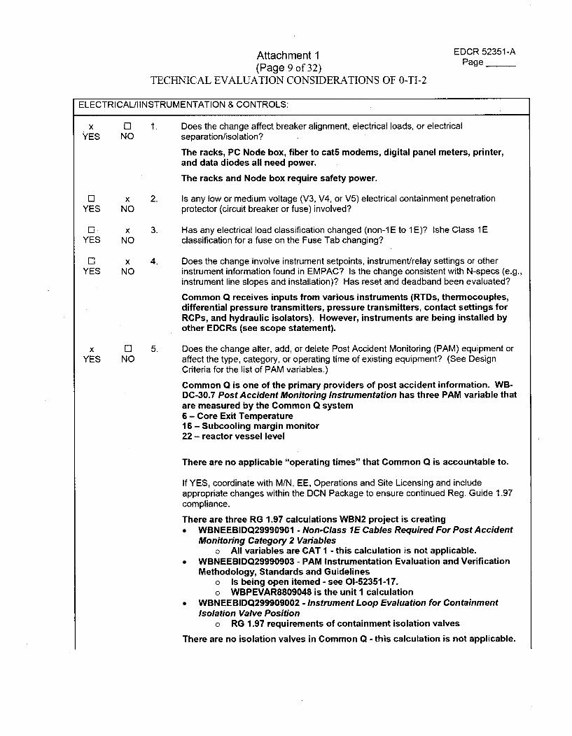
Attachment 1(Page 9 of 32)
TECHNICAL EVALUATION CONSIDERATIONS OF 0-TI-2
EDCR 52351-APage __
[ELECTRICAL/I INSTRUMENTATION & CONTROLS:
x LIYES NO
1. Does the change affect breaker alignment, electrical loads, or electricalseparation/isolation?
The racks, PC Node box, fiber to cat5 modems, digital panel meters, printer,and data diodes all need power.
The racks and Node box require safety power.
LI XYES NO
2. Is any low or medium voltage (V3, V4, or V5) electrical containment penetrationprotector (circuit breaker or fuse) involved?
YEYES
x 3. Has any electrical load classification changed (non-lE to 1E)? Ishe Class 1ENO classification for a fuse on the Fuse Tab changing?
E3 xYES NO
4. Does the change involve instrument setpoints, instrument/relay settings or otherinstrument information found in EMPAC? Is the change consistent with N-specs (e.g.,instrument line slopes and installation)? Has reset and deadband been evaluated?
Common Q receives inputs from various instruments (RTDs, thermocouples,differential pressure transmitters, pressure transmitters, contact settings forRCPs, and hydraulic isolators). However, instruments are being installed byother EDCRs (see scope statement).
x LIYES NO
5. Does the change alter, add, or delete Post Accident Monitoring (PAM) equipment oraffect the type, category, or operating time of existing equipment? (See DesignCriteria for the list of PAM variables.)
Common Q is one of the primary providers of post accident information. WB-DC-30.7 Post Accident Monitoring Instrumentation has three PAM variable thatare measured by the Common Q system6 - Core Exit Temperature16- Subcooling margin monitor22 - reactor vessel level
There are no applicable "operating times" that Common Q is accountable to.
If YES, coordinate with M/N, EE, Operations and Site Licensing and includeappropriate changes within the DCN Package to ensure continued Reg. Guide 1.97compliance.
There are three RG 1.97 calculations WBN2 project is creating" WBNEEBIDQ29990901 - Non-Class 1E Cables Required For Post Accident
Monitoring Category 2 Variableso All variables are CAT 1 - this calculation is not applicable.
* WBNEEBIDQ29990903 - PAM Instrumentation Evaluation and VerificationMethodology, Standards and Guidelines
o Is being open itemed - see 01-52351-17.o WBPEVAR8809048 is the unit 1 calculation
" WBNEEBIDQ299909002 - Instrument Loop Evaluation for ContainmentIsolation Valve Position
o RG 1.97 requirements of containment isolation valves
There are no isolation valves in Common Q - this calculation is not applicable.
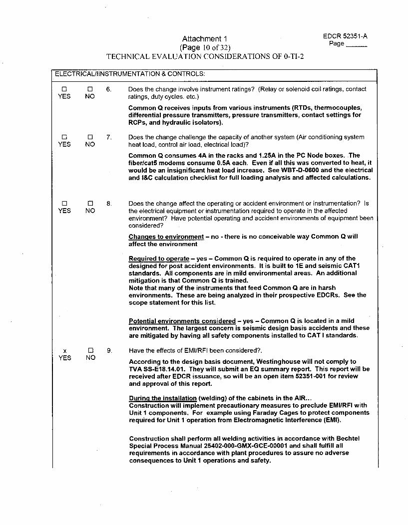
Attachment 1(Page 10 of 32)
TECHNICAL EVALUATION CONSIDERATIONS OF 0-TI-2
EDCR 52351-APage __
ELECTRICALJIINSTRUMENTATION & CONTROLS:
0 0YES NO
6. Does the change involve instrument ratings? (Relay or solenoid coil ratings, contactratings, duty cycles, etc.)
Common Q receives inputs from various instruments (RTDs, thermocouples,differential pressure transmitters, pressure transmitters, contact settings forRCPs, and hydraulic isolators).
0 5YES NO
7. Does the change challenge the capacity of another system (Air conditioning systemheat load, control air load, electrical load)?
Common Q consumes 4A in the racks and 1.25A in the PC Node boxes. ThefiberlcatS modems consume O.5A each. Even if all this was converted to heat, itwould be an insignificant heat load increase. See WBT-D-0600 and the electricaland I&C calculation checklist for full loading analysis and affected calculations.
0 0YES NO
8. Does the change affect the operating or accident environment or instrumentation? Isthe electrical equipment or instrumentation required to operate in the affectedenvironment? Have potential operating and accident environments of equipment beenconsidered?
Changes to environment - no - there is no conceivable way Common Q willaffect the environment
Required to operate - yes - Common Q is required to operate in any of thedesigned for post accident environments. It is built to 1 E and seismic CAT1standards. All components are in mild environmental areas. An additionalmitigation is that Common Q is trained.Note that many of the instruments that feed Common Q are in harshenvironments. These are being analyzed in their prospective EDCRs. See thescope statement for this list.
Potential environments considered - yes - Common Q is located in a mildenvironment. The largest concern is seismic design basis accidents and theseare mitigated by having all safety components installed to CAT I standards.
9. Have the effects of EMI/RFI been considered?.
According to the design basis document, Westinghouse will not comply toTVA SS-E18.14.01. They will submit an EQ summary report. This report will bereceived after EDCR issuance, so will be an open item 52351-001 for reviewand approval of this report.
During the installation (welding) of the cabinets in the AIR...Construction will implement precautionary measures to preclude EMIIRFI withUnit I components. For example using Faraday Cages to protect componentsrequired for Unit I operation from Electromagnetic Interference (EMI).
Construction shall perform all welding activities in accordance with BechtelSpecial Process Manual 25402-000-GMX-GCE-00001 and shall fulfill allrequirements in accordance with plant procedures to assure no adverseconsequences to Unit 1 operations and safety.
x 0YES NO
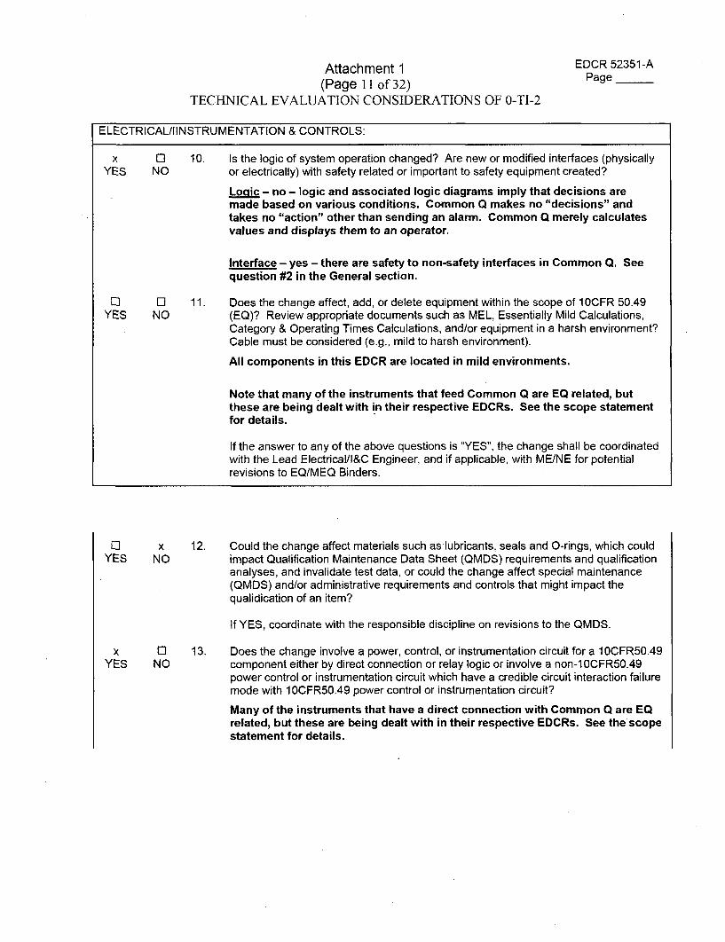
Attachment 1(Page II of 32)
TECHNICAL EVALUATION CONSIDERATIONS OF 0-TI-2
EDCR 52351-APage __
ELECTRICAL/lINSTRUMENTATION & CONTROLS:
x ElYES NO
10. Is the logic of system operation changed? Are new or modified interfaces (physicallyor electrically) with safety related or important to safety equipment created?
Logic - no - logic and associated logic diagrams imply that decisions aremade based on various conditions. Common Q makes no "decisions" andtakes no "action" other than sending an alarm. Common Q merely calculatesvalues and displays them to an operator.
Interface - yes - there are safety to non-safety interfaces in Common Q. Seequestion #2 in the General section.
11. Does the change affect, add, or delete equipment within the scope of 10CFR 50.49(EQ)? Review appropriate documents such as MEL, Essentially Mild Calculations,Category & Operating Times Calculations, and/or equipment in a harsh environment?Cable must be considered (e.g., mild to harsh environment).
El ElYES NO
All components in this EDCR are located in mild environments.
Note that many of the instruments that feed Common Q are EQ related, butthese are being dealt with in their respective EDCRs. See the scope statementfor details.
If the answer to any of the above questions is "YES", the change shall be coordinatedwith the Lead Electrical/l&C Engineer, and if applicable, with ME/NE for potentialrevisions to EQ/MEQ Binders.
ElYES
x 12. Could the change affect materials such as lubricants, seals and O-rings, which couldNO impact Qualification Maintenance Data Sheet (QMDS) requirements and qualification
analyses, and invalidate test data, or could the change affect special maintenance(QMDS) and/or administrative requirements and controls that might impact thequalidication of an item?
x ElYES NO
If YES, coordinate with the responsible discipline on revisions to the QMDS.
13. Does the change involve a power, control, or instrumentation circuit for a 10CFR50.49component either by direct connection or relay logic or involve a non-10CFR50.49power control or instrumentation circuit which have a credible circuit interaction failuremode with 10CFR50.49 power control or instrumentation circuit?
Many of the instruments that have a direct connection with Common Q are EQrelated, but these are being dealt with in their respective EDCRs. See the scopestatement for details.
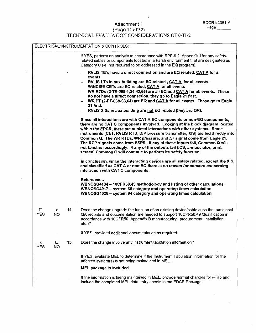
Attachment 1 EDCR 52351-A
(Page 12 of 32) Page __
TECHNICAL EVALUATION CONSIDERATIONS OF 0-TI-2
ELECTRICAL/IINSTRUMENTATION & CONTROLS:
If YES, perform an analysis in accordance with SPP-9.2, Appendix I for any safety-related cables or components located in a harsh environment that are designated asCategory C (ie. not required to be addressed in the EQ program).
- RVLIS TE's have a direct connection and are EQ related, CAT A for allevents
- RVLIS LTs in aux building are EQ related, CAT A for all events- WINCISE CETs are EQ related, CAT A for all events- WR RTDs (2-TE-068-1,24,43,65) are all EQ and CAT A for all events. These
do not have a direct connection, they go to Eagle 21 first.- WR PT (2-PT-068-63,64) are EQ and CAT A for all events. These go to Eagle
21 first.- RVLIS XlSs in aux building are not EQ related (they are QR).
Since all interactions are with CAT A EQ components or non-EQ components,there are no CAT C components involved. Looking at the block diagram locatedwithin the EDCR, there are minimal interactions with other systems. Someinstruments (CET, RVLIS RTD, DIP pressure transmitter, XIS) are fed directly intoCommon Q. The WR RTDs, WR pressure, and AT signal come from Eagle 21.The RCP signals come from SSPS. If any of these inputs fail, Common Q willnot function accordingly. If any of the outputs fail (ICS, annunciator, printscreen) Common Q will continue to perform its safety function.
In conclusion, since the interacting devices are all safety related, except the XIS,and classified as CAT A or non EQ there is no reason for concern concerninginteraction with CAT C components.
Reference...WBNOSG4134 - 10CFR50.49 methodology and listing of other calculationsWBNOSG4017 - system 68 category and operating times calculationWBNOSG4028 - system 94 category and operating times calculation
El x 14. Does the change upgrade the function of an existing device/cable such that additionalYES NO QA records and documentation are needed to support 10CFR50.49 Qualification in
accordance with 10CFR50, Appendix B manufacturing, procurement, installation,etc.)?
If YES, provided additional documentation as required.
x LI 15. Does the change involve any instrument tabulation information?YES NO
If YES, evaluate MEL to determine if the Instrument Tabulation information for theaffected system(s) is not being maintained in MEL.
MEL package is included
If the information is bieng maintained in MEL, provide normal changes for I-Tab andinclude the completed MEL data entry sheets in the EDCR Package.
Attachment 1(Page 13 of 32)
TECHNICAL EVALUATION CONSIDERATIONS OF 0-TI-2
EDCR 52351-APage __
ELECTRICAL/IINSTRUMENTATION & CONTROLS:
NOTE: Since the information on the instrument tabulation drawings is now maintainedin MEL for affected systems the instrument tabulation drawings for these systemshave been superseded and are no longer updated. If the information is not beingmaintained in MEL, continue to process the drawing.
16. Does the modification affect components/equipment that require periodic testing ofelectrical test points.
x [0YES NO
If YES, provide appropriate test jacks which are accessible to prevent accidentalcontact with adjacent electrical terminations during testing.
Common Q is being provided with external simulator that the can be used tosimulate various plant configurations for maintenance and testing purposes.
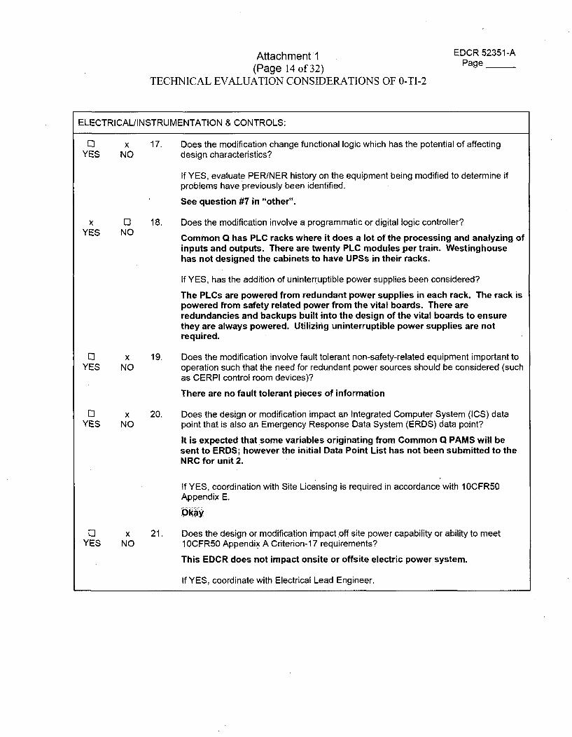
Attachment 1 EDCR 52351-A
(Page 14 of 32) Page__
TECHNICAL EVALUATION CONSIDERATIONS OF 0-TI-2
ELECTRICAL/INSTRUMENTATION & CONTROLS:
11 x 17. Does the modification change functional logic which has the potential of affectingYES NO design characteristics?
If YES, evaluate PER/NER history on the equipment being modified to determine ifproblems have previously been identified.
See question #7 in "other".
x 0I 18. Does the modification involve a programmatic or digital logic controller?
YES NO Common Q has PLC racks where it does a lot of the processing and analyzing of
inputs and outputs. There are twenty PLC modules per train. Westinghousehas not designed the cabinets to have UPSs in their racks.
If YES, has the addition of uninterruptible power supplies been considered?
The PLCs are powered from redundant power supplies in each rack. The rack ispowered from safety related power from the vital boards. There areredundancies and backups built into the design of the vital boards to ensurethey are always powered. Utilizing uninterruptible power supplies are notrequired.
El x 19. Does the modification involve fault tolerant non-safety-related equipment important toYES NO operation such that the need for redundant power sources should be considered (such
as CERPI control room devices)?
There are no fault tolerant pieces of information
LI x 20. Does the design or modification impact an Integrated Computer System (ICS) dataYES NO point that is also an Emergency Response Data System (ERDS) data point?
It is expected that some variables originating from Common Q PAMS will besent to ERDS; however the initial Data Point List has not been submitted to theNRC for unit 2.
If YES, coordination with Site Licensing is required in accordance with 10CFR50Appendix E.
Okay13 x 21. Does the design or modification impact off site power capability or ability to meet
YES NO 1 OCFR50 Appendix A Criterion-1 7 requirements?
This EDCR does not impact onsite or offsite electric power system.
If YES, coordinate with Electrical Lead Engineer.
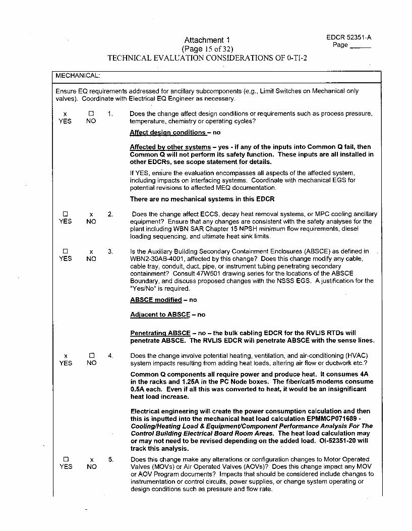
Attachment 1(Page 15 of 32)
TECHNICAL EVALUATION CONSIDERATIONS OF 0-TI-2
EDCR 52351-APage __
MECHANICAL:
Ensure EQ requirements addressed for ancillary subcomponents (e.g., Limit Switches on Mechanical onlyvalves). Coordinate with Electrical EQ Engineer as necessary.
x ElYES NO
1. Does the change affect design conditions or requirements such as process pressure,temperature, chemistry or operating cycles?
Affect design conditions - no
Affected by other systems - yes - if any of the inputs into Common Q fail, thenCommon Q will not perform its safety function. These inputs are all installed inother EDCRs, see scope statement for details.
If YES, ensure the evaluation encompasses all aspects of the affected system,including impacts on interfacing systems. Coordinate with mechanical EGS forpotential revisions to affected MEQ documentation.
There are no mechanical systems in this EDCR
El x 2. Does the change affect ECCS, decay heat removal systems, or MPC cooling ancillaryYES NO equipment? Ensure that any changes are consistent with the safety analyses for the
plant including WBN SAR Chapter 15 NPSH minimum flow requirements, dieselloading sequencing, and ultimate heat sink limits.
El xYES NO
3. Is the Auxiliary Building Secondary Containment Enclosures (ABSCE) as defined inWBN2-30AB-4001, affected by this change? Does this change modify any cable,cable tray, conduit, duct, pipe, or instrument tubing penetrating secondarycontainment? Consult 47W501 drawing series for the locations of the ABSCEBoundary, and discuss proposed changes with the NSSS EGS. A justification for the"Yes/No" is required.
ABSCE modified - no
Adiacent to ABSCE - no
Penetrating ABSCE - no - the bulk cabling EDCR for the RVLIS RTDs willpenetrate ABSCE. The RVLIS EDCR will penetrate ABSCE with the sense lines.
x ElYES NO
4. Does the change involve potential heating, ventilation, and air-conditioning (HVAC)system impacts resulting from adding heat loads, altering air flow or ductwork etc.?
Common Q components all require power and produce heat. It consumes 4Ain the racks and 1.25A in the PC Node boxes. The fiber/cat5 modems consume0.5A each. Even if all this was converted to heat, it would be an insignificantheat load increase.
Electrical engineering will create the power consumption calculation and thenthis is inputted into the mechanical heat load calculation EPMMCP071689 -CoolinglHeating Load & Equipment/Component Performance Analysis For TheControl Building Electrical Board Room Areas. The heat load calculation mayor may not need to be revised depending on the added load. 01-52351-20 willtrack this analysis.
El xYES NO
5. Does this change make any alterations or configuration changes to Motor OperatedValves (MOVs) or Air Operated Valves (AOVs)? Does this change impact any MOVor AOV Program documents? Impacts that should be considered include changes toinstrumentation or control circuits, power supplies, or change system operating ordesign conditions such as pressure and flow rate.
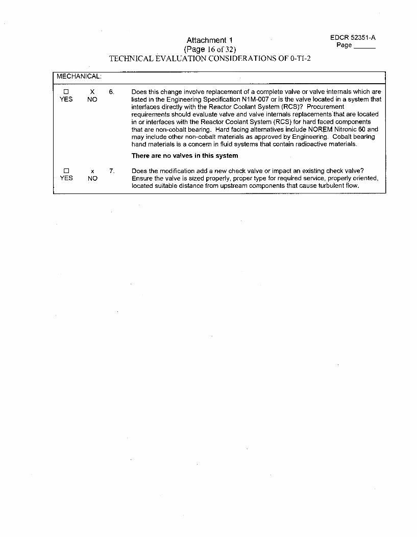
Attachment 1(Page 16 of 32)
TECHNICAL EVALUATION CONSIDERATIONS OF 0-TI-2
EDCR 52351-APage __
MECHANICAL:
El XYES NO
6. Does this change involve replacement of a complete valve or valve internals which arelisted in the Engineering Specification N1M-007 or is the valve located in a system thatinterfaces directly with the Reactor Coolant System (RCS)? Procurementrequirements should evaluate valve and valve internals replacementsthat are locatedin or interfaces with the Reactor Coolant System (RCS) for hard faced componentsthat are non-cobalt bearing. Hard facing alternatives include NOREM Nitronic 60 andmay include other non-cobalt materials as approved by Engineering. Cobalt bearinghand materials is a concern in fluid systems that contain radioactive materials.
There are no valves in this system
El xYES NO
7. Does the modification add a new check valve or impact an existing check valve?Ensure the valve is sized properly, proper type for required service, properly oriented,located suitable distance from upstream components that cause turbulent flow.
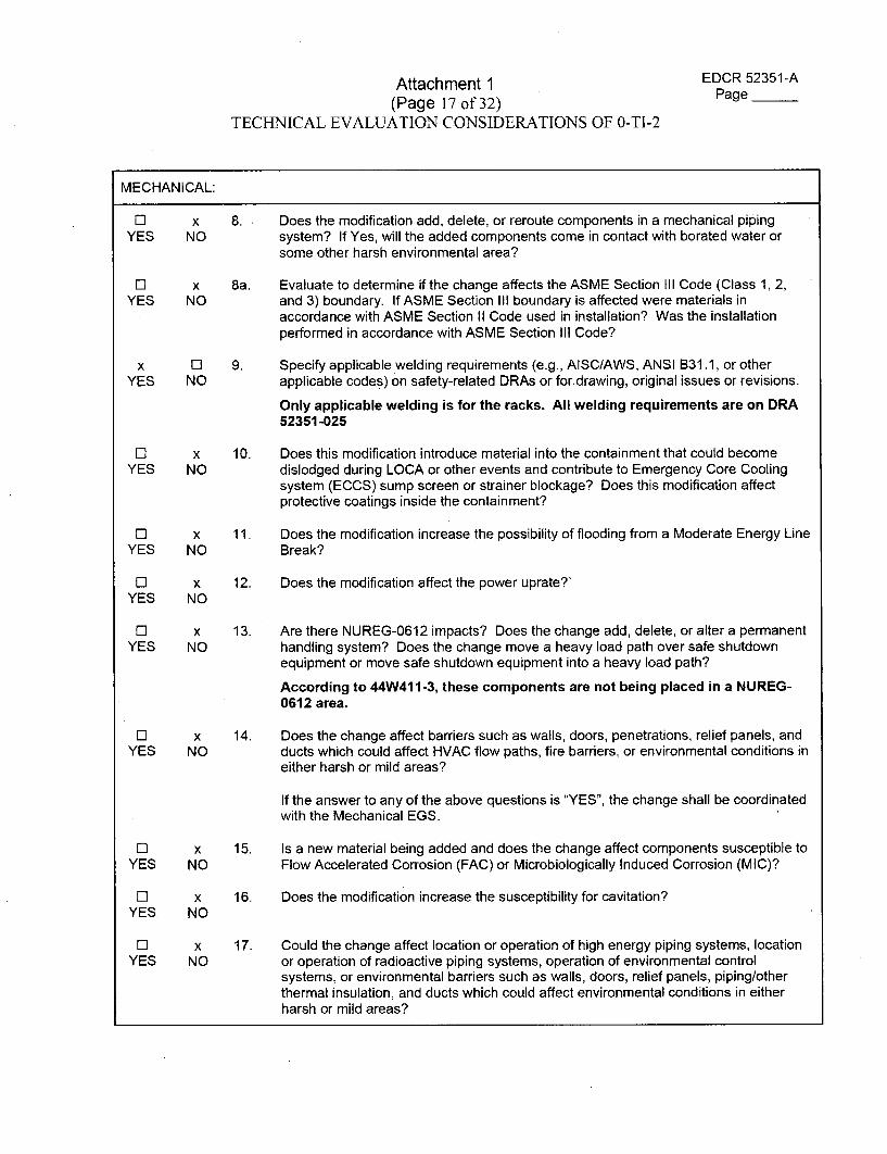
Attachment 1(Page 17 of 32)
TECHNICAL EVALUATION CONSIDERATIONS OF 0-TI-2
EDCR 52351-APage __
MECHANICAL:
ElYES
x 8. Does the modification add, delete, or reroute components in a mechanical pipingNO system? If Yes, will the added components come in contact with borated water or
some other harsh environmental area?
El xYES NO
x ElYES NO
8a. Evaluate to determine if the change affects the ASME Section III Code (Class 1, 2,and 3) boundary. If ASME Section III boundary is affected were materials inaccordance with ASME Section II Code used in installation? Was the installationperformed in accordance with ASME Section III Code?
9. Specify applicable welding requirements (e.g., AISC/AWS, ANSI B31.1, or otherapplicable codes) on safety-related DRAs or for.drawing, original issues or revisions.
Only applicable welding is for the racks. All welding requirements are on DRA52351-025
ElYES
x 10. Does this modification introduce material into the containment that could becomeNO dislodged during LOCA or other events and contribute to Emergency Core Cooling
system (ECCS) sump screen or strainer blockage? Does this modification affectprotective coatings inside the containment?
El x 11. Does the modification increase the possibility of flooding from a Moderate Energy LineYES NO Break?
El xYES NO
12. Does the modification affect the power uprate?"
ElYES
x 13. Are there NUREG-0612 impacts? Does the change add, delete, or alter a permanentNO handling system? Does the change move a heavy load path over safe shutdown
equipment or move safe shutdown equipment into a heavy load path?
According to 44W411-3, these components are not being placed in a NUREG-0612 area.
El x 14. Does the change affect barriers such as walls, doors, penetrations, relief panels, andYES NO ducts which could affect HVAC flow paths, fire barriers, or environmental conditions in
either harsh or mild areas?
If the answer to any of the above questions is "YES", the change shall be coordinatedwith the Mechanical EGS.
El x 15. Is a new material being added and does the change affect components susceptible toYES NO Flow Accelerated Corrosion (FAC) or Microbiologically Induced Corrosion (MIC)?
El xYES, NO
16. Does the modification increase the susceptibility for cavitation?
El x 17. Could the change affect location or operation of high energy piping systems, locationYES NO or operation of radioactive piping systems, operation of environmental control
systems, or environmental barriers such as walls, doors, relief panels, piping/otherthermal insulation, and ducts which could affect environmental conditions in eitherharsh or mild areas?
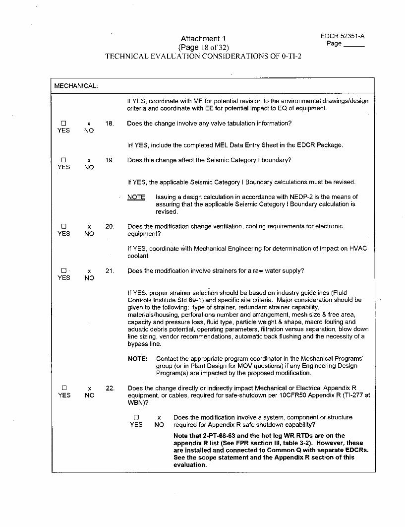
Attachment 1 EDCR 52351-A
(Page 18 of 32) Page __
TECHNICAL EVALUATION CONSIDERATIONS OF 0-TI-2
MECHANICAL:
If YES, coordinate with ME for potential revision to the environmental drawings/designcriteria and coordinate with EE for potential impact to EQ of equipment.
El x 18. Does the change involve any valve tabulation information?YES NO
Irf YES, include the completed MEL Data Entry Sheet in the EDCR Package.
El x 19. Does this change affect the Seismic Category I boundary?YES NO
If YES, the applicable Seismic Category I Boundary calculations must be revised.
NOTE Issuing a design calculation in accordance with NEDP-2 is the means ofassuring that the applicable Seismic Category I Boundary calculation isrevised.
El x 20. Does the modification change ventilation, cooling requirements for electronicYES NO equipment?
If YES, coordinate with Mechanical Engineering for determination of impact on HVACcoolant.
El x 21. Does the modification involve strainers for a raw water supply?YES NO
If YES, proper strainer selection should be based on industry guidelines (FluidControls Institute Std 89-1) and specific site criteria. Major consideration should begiven to the following: type of strainer, redundant strainer capability,materials/housing, perforations number and arrangement, mesh size & free area,capacity and pressure loss, fluid type, particle weight & shape, macro fouling andaduatic debris potential, operating parameters, filtration versus separation, blow downline sizing, vendor recommendations, automatic back flushing and the necessity of abypass line.
NOTE: Contact the appropriate program coordinator in the Mechanical Programsgroup (or in Plant Design for MOV questions) if any Engineering DesignProgram(s) are impacted by the proposed modification.
El x 22. Does the change directly or indirectly impact Mechanical or Electrical Appendix RYES NO equipment, or cables, required for safe-shutdown per 1OCFR50 Appendix R (TI-277 at
WBN)?
El x Does the modification involve a system, component or structureYES NO required for Appendix R safe shutdown capability?
Note that 2-PT-68-63 and the hot leg WR RTDs are on theappendix R list (See FPR section III, table 3-2). However, theseare installed and connected to Common Q with separate EDCRs.See the scope statement and the Appendix R section of thisevaluation.
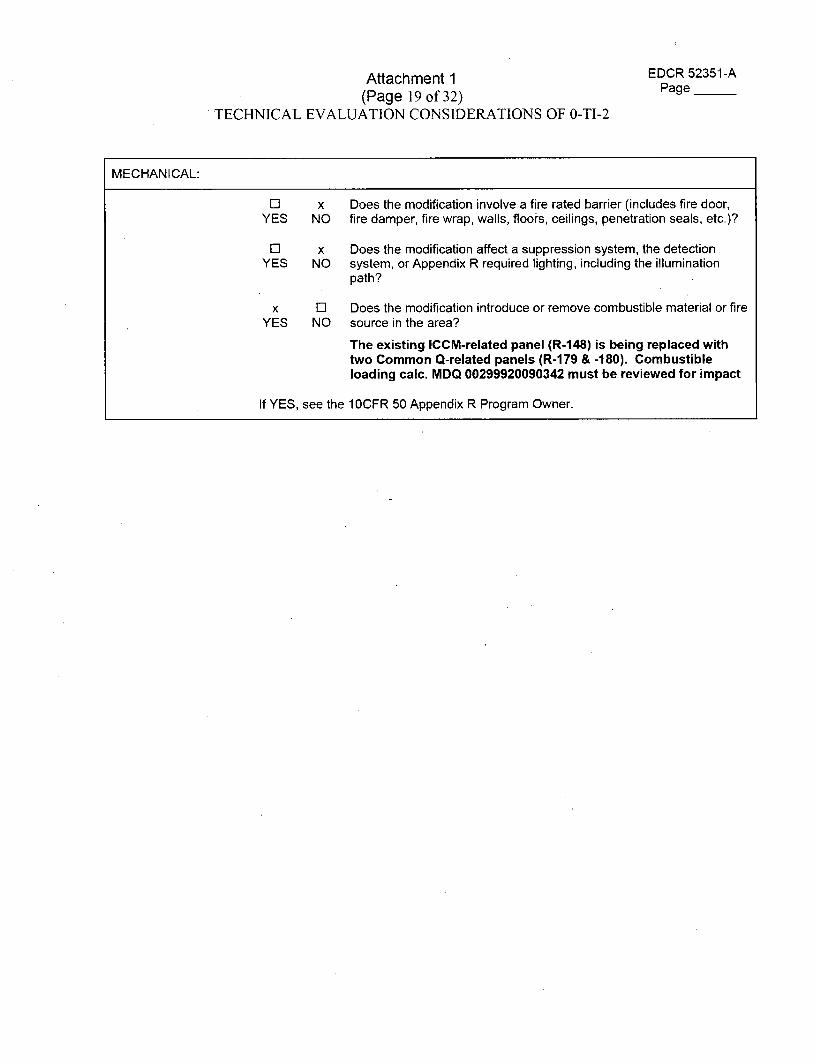
Attachment 1(Page 19 of 32)
TECHNICAL EVALUATION CONSIDERATIONS OF 0-TI-2
EDCR 52351-APage ___
MECHANICAL:
El x Does the modification involve a fire rated barrier (includes fire door,YES NO fire damper, fire wrap, walls, floors, ceilings, penetration seals, etc.)?
ElYES
x Does the modification affect a suppression system, the detectionNO system, or Appendix R required lighting, including the illumination
path?
x El Does the modification introduce or remove combustible material or fireYES NO source in the area?
The existing ICCM-related panel (R-148) is being replaced withtwo Common Q-related panels (R-179 & -180). Combustibleloading calc. MDQ 00299920090342 must be reviewed for impact
If YES, see the 1 OCFR 50 Appendix R Program Owner.
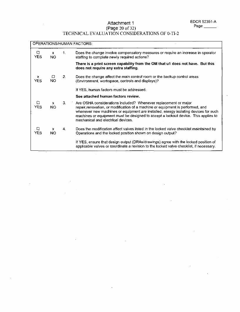
Attachment 1(Page 20 of 32)
TECHNICAL EVALUATION CONSIDERATIONS OF 0-TI-2
EDCR 52351-APage __
OPERATIONS/HUMAN FACTORS:
[] XYES NO
1. Does the change involve compensatory measures or require an increase in operatorstaffing to complete newly required actions?
There is a print screen capability from the OM that ul does not have. But thisdoes not require any extra staffing.
X 0]YES NO
2. Does the change affect the main control room or the backup control areas(Environment, workspace, controls and displays)?
If YES, human factors must be addressed:
See attached human factors review.
11 x 3. Are OSHA considerations included? Whenever replacement or majorYES NO repair, renovation, or modification of a machine or equipment is performed, and
whenever new machines or equipment are installed, energy isolating devices for suchmachines or equipment must be designed to accept a lockout device. This applies tomechanical and electrical devices.
Ci xYES NO
4. Does the modification affect valves listed in the locked valve checklist maintained byOperations and the locked position shown on design output?
If YES, ensure that design output (DRAs/drawings) agree with the locked position ofapplicable valves or coordinate a revision to the locked valve checklist, if necessary.
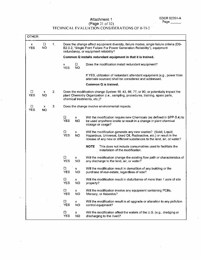
Attachment 1(Page 21 of 32)
TECHNICAL EVALUATION CONSIDERATIONS OF 0-TI-2
EDCR 52351-APage __
OTHER:
x 0iYES NO
1. Does the change affect equipment diversity, failure modes, single failure criteria (DS-E2.0.2, "Single Point Failure For Power Generation Reliability"), equipmentredundancy, or equipment reliability?
Common Q installs redundant equipment in that it is trained.
x LiYES NO
Does the modification install redundant equipment?
El xYES NO
Li xYES NO
2.
3.
If YES, utilization of redundant attendant equipment (e.g., power fromalternate sources) shall be considered and addressed.
Common Q is trained.
Does the modification change System 18, 43, 66, 77, or 90, or potentially impact theplant Chemistry Organization (i.e., sampling, procedures, training, spare parts,chemical treatments, etc.)?
Does the change involve environmental impacts.
Li x Will the modification require new Chemicals (as defined in SPP-5.4) toYES NO be used anywhere onsite or result in a change in plant chemical
storage or usage?
Li x Will the modification generate any new wastes? (Solid, Liquid,YES NO Hazardous, Universal, Used Oil, Radioactive, etc.) or result in the
release of any new or different substances to the land, air, or water?
NOTE This does not include consumables used to facilitate theinstallation of the modification.
0i x Will the modification change the existing flow path or characteristics ofYES NO any discharge to the land, air, or water?
LiYES
x Will the modification result in demolition of any building or theNO purchase of real-estate, regardless of size?
Li x Will the modification result in disturbance of more than 1 acre of siteYES NO property?
LiYES
x Will the modification involve any equipment containing PCBs,NO Mercury, or Asbestos?
Li x Will the modification result in all upgrade or alteration to any pollutionYES NO control equipment?
Li x Will the modification affect the waters of the U.S. (e.g., dredging orYES NO discharging to the river)?
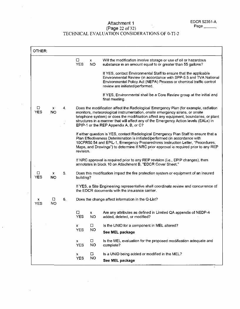
Attachment 1(Page 22 of 32)
TECHNICAL EVALUATION CONSIDERATIONS OF 0-TI-2
EDCR 52351-APage __
OTHER:
El x Will the modification involve storage or use of oil or hazardousYES NO substance in an amount equal to or greater than 55 gallons?
If YES, contact Environmental Staff to ensure that the applicableEnvironmental Review (in accordance with SPP-5.5 and TVA NationalEnvironmental Policy Act (NEPA) Process or chemical traffic controlreview are initiated/performed.
If YES, Environmental shall be a Core Review group at the initial andfinal meeting.
El xYES NO
4. Does the modification affect the Radiological Emergency Plan (for example, radiationmonitors, meteorological instrumentation, onsite emergency sirens, or onsitetelephone system) or does the modification affect any equipment, boundaries, or plantstructures in a manner that will affect any of the Emergency Action levels (EALs) inEPIP-1 or the REP Appendix A, B, or C?
If either question is YES, contact Radiological Emergency Plan Staff to ensure that aPlan Effectiveness Determination is initiated/performed (in accordance with10CFR50.54 and EPIL-1, Emergency Preparedness Instruction Letter, "Procedures,Maps, and Drawings") to determine if NRC prior approval is required prior to any REPrevision.
If NRC approval is required prior to any REP revision (i.e., EPIP changes), thenannotates in block 10 on Attachment B, "EDCR Cover Sheet."
ElYES
xNO
5. Does this modification impact the fire protection system or equipment of an insuredbuilding?
If YES, a Site Engineering representative shall coordinate review and concurrence ofthe EDCR documents with the insurance carrier.
x ElYES NO
6. Does the change affect information in the Q-List?
El x Are any attributes as defined in Limited QA appendix of NEDP-4YES NO added, deleted, or modified?
x ElYES NO
Is the UNID for a component in MEL altered?
See MEL package
x El Is the MEL evaluation for the proposed modification adequate andYES NO complete?
x ElYES NO
Is a UNID being added or modified in the MEL?
See MEL package
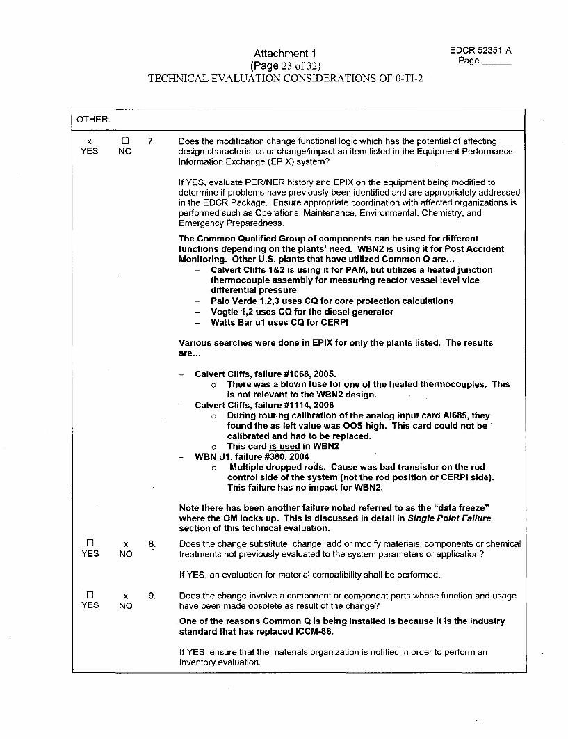
Attachment 1 EDCR 52351-A
(Page 23 of 32) Page__
TECHNICAL EVALUATION CONSIDERATIONS OF 0-TI-2
OTHER:
x 0 7. Does the modification change functional logic which has the potential of affectingYES NO design characteristics or change/impact an item listed in the Equipment Performance
Information Exchange (EPIX) system?
If YES, evaluate PER/NER history and EPIX on the equipment being modified todetermine if problems have previously been identified and are appropriately addressedin the EDCR Package. Ensure appropriate coordination with affected organizations isperformed such as Operations, Maintenance, Environmental, Chemistry, andEmergency Preparedness.
The Common Qualified Group of components can be used for differentfunctions depending on the plants' need. WBN2 is using it for Post AccidentMonitoring. Other U.S. plants that have utilized Common Q are...
- Calvert Cliffs 1&2 is using it for PAM, but utilizes a heated junctionthermocouple assembly for measuring reactor vessel level vicedifferential pressure
- Palo Verde 1,2,3 uses CQ for core protection calculations- Vogtle 1,2 uses CQ for the diesel generator- Watts Bar ul uses CQ for CERPI
Various searches were done in EPIX for only the plants listed. The resultsare...
- Calvert Cliffs, failure #1068, 2005.o There was a blown fuse for one of the heated thermocouples. This
is not relevant to the WBN2 design.- Calvert Cliffs, failure #1114, 2006
o During routing calibration of the analog input card A1685, theyfound the as left value was OOS high. This card could not becalibrated and had to be replaced.
o This card is used in WBN2- WBN U1, failure #380, 2004
o Multiple dropped rods. Cause was bad transistor on the rodcontrol side of the system (not the rod position or CERPI side).This failure has no impact for WBN2.
Note there has been another failure noted referred to as the "data freeze"where the OM locks up. This is discussed in detail in Single Point Failuresection of this technical evaluation.
i x 8. Does the change substitute, change, add or modify materials, components or chemicalYES NO treatments not previously evaluated to the system parameters or application?
If YES, an evaluation for material compatibility shall be performed.
El x 9. Does the change involve a component or component parts whose function and usageYES NO have been made obsolete as result of the change?
One of the reasons Common Q is being installed is because it is the industrystandard that has replaced ICCM-86.
If YES, ensure that the materials organization is notified in order to perform aninventory evaluation.
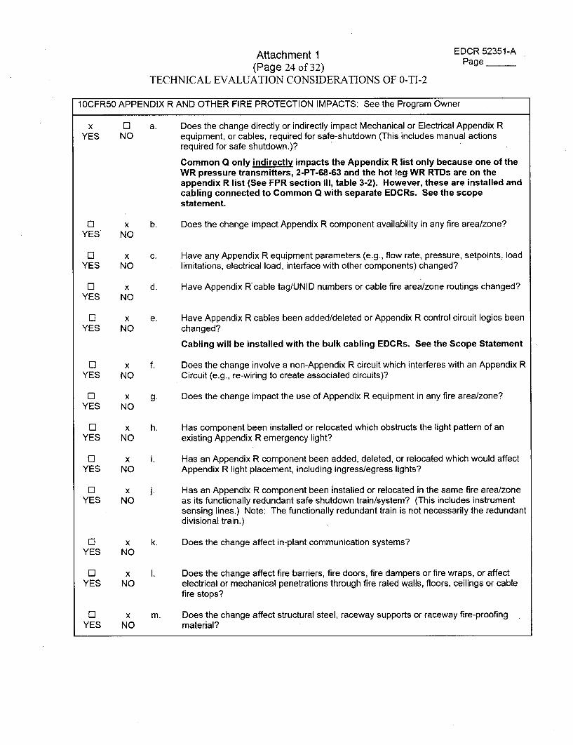
Attachment 1 EDCR 52351-A
(Page 24 of 32) Page
TECHNICAL EVALUATION CONSIDERATIONS OF 0-TI-2
10CFR50 APPENDIX R AND OTHER FIRE PROTECTION IMPACTS: See the Program Owner
x Li a. Does the change directly or indirectly impact Mechanical or Electrical Appendix RYES NO equipment, or cables, required for safe-shutdown (This includes manual actions
required for safe shutdown.)?
Common Q only indirectly impacts the Appendix R list only because one of theWR pressure transmitters, 2-PT-68-63 and the hot leg WR RTDs are on theappendix R list (See FPR section III, table 3-2). However, these are installed andcabling connected to Common Q with separate EDCRs. See the scopestatement.
Li x b. Does the change impact Appendix R component availability in any fire area/zone?YES NO
Li x c. Have any Appendix R equipment parameters (e.g., flow rate, pressure, setpoints, loadYES NO limitations, electrical load, interface with other components) changed?
El x d. Have Appendix Rcable tag/UNID numbers or cable fire area/zone routings changed?YES NO
Li x e. Have Appendix R cables been added/deleted or Appendix R control circuit logics beenYES NO changed?
Cabling will be installed with the bulk cabling EDCRs. See the Scope Statement
Li x f. Does the change involve a non-Appendix R circuit which interferes with an Appendix RYES NO Circuit (e.g., re-wiring to create associated circuits)?
Li x g. Does the change impact the use of Appendix R equipment in any fire area/zone?YES NO
Li x h. Has component been installed or relocated which obstructs the light pattern of anYES NO existing Appendix R emergency light?
EL x i. Has an Appendix R component been added, deleted, or relocated which would affectYES NO Appendix R light placement, including ingress/egress lights?
Li x j. Has an Appendix R component been installed or relocated in the same fire area/zoneYES NO as its functionally redundant safe shutdown train/system? (This includes instrument
sensing lines.) Note: The functionally redundant train is not necessarily the redundantdivisional train.)
Li x k. Does the change affect in-plant communication systems?YES NO
Li x 1. Does the change affect fire barriers, fire doors, fire dampers or fire wraps, or affectYES NO electrical or mechanical penetrations through fire rated walls, floors, ceilings or cable
fire stops?
Li x m. Does the change affect structural steel, raceway supports or raceway fire-proofingYES NO material?
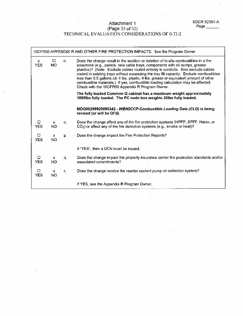
Attachment 1(Page 25 of 32)
TECHNICAL EVALUATION CONSIDERATIONS OF 0-TI-2
EDCR 52351-APage __
1 OCFR50 APPENDIX R AND OTHER FIRE PROTECTION IMPACTS: See the Program Owner
x 51YES NO
n. Does the change result in the accition or deletion of in-situ combustibles in a firearea/zone (e.g., panels, new cable trays, components with oil sumps, greaseplastics)? (Note: Exclude cables routed entirely in conduits. Also exclude cablesrouted in existing trays without exceeding the tray fill capacity. Exclude combustiblesless than 0.5 gallons oil, 4 lbs. plastic, 4 lbs. grease or equivalent amount of othercombustible materials.) If yes, combustible loading calculation may be affected.Check with the 10CFR50 Appendix R Program Owner.
The fully loaded Common Q cabinet has a maximum weight approximately1000lbs fully loaded. The PC node box weights 20lbs fully loaded.
MDQ00299920090342 - WBN2CCP-Combustible Loading Data (CLD) is beingrevised (or will be Ol'd).
0 XYES NO
[] xYES NO
0 xYES NO
0 xYES NO
0.
p.
Does the change affect any of the fire protection systems (HPFP, SFFF, Halon, orCO2) or affect any of the fire detection systems (e.g., smoke or heat)?
Does the change impact the Fire Protection Reports?
If "YES", then a DCN must be issued.
Does the change impact the property insurance carrier fire protection standards and/orassociated commitments?
Does the change involve the reactor coolant pump oil collection system?
q.
r.
If YES, see the Appendix R Program Owner.
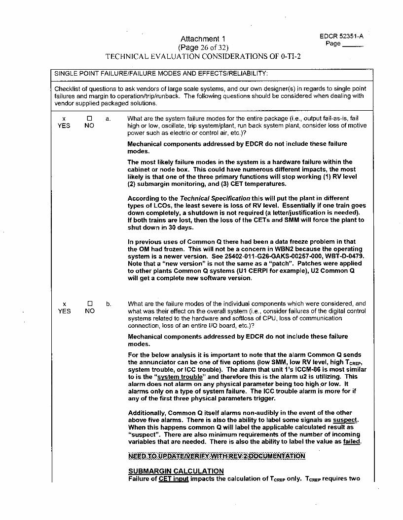
Attachment 1 EDCR 52351-A
(Page 26 of 32) Page __
TECHNICAL EVALUATION CONSIDERATIONS OF 0-TI-2
SINGLE POINT FAILURE/FAILURE MODES AND EFFECTS/RELIABILITY:
Checklist of questions to ask vendors of large scale systems, and our own designer(s) in regards to single pointfailures and margin to operation/trip/runback. The following questions should be considered when dealing withvendor supplied packaged solutions.
x El a. What are the system failure modes for the entire package (i.e., output fail-as-is, failYES NO high or low, oscillate, trip system/plant, run back system plant, consider loss of motive
power such as electric or control air, etc.)?
Mechanical components addressed by EDCR do not include these failure
modes.
The most likely failure modes in the system is a hardware failure within thecabinet or node box. This could have numerous different impacts, the mostlikely is that one of the three primary functions will stop working (1) RV level(2) submargin monitoring, and (3) CET temperatures.
According to the Technical Specification this will put the plant in differenttypes of LCOs, the least severe is loss of RV level. Essentially if one train goesdown completely, a shutdown is not required (a letter/justification is needed).If both trains are lost, then the loss of the CETs and SMM will force the plant toshut down in 30 days.
In previous uses of Common Q there had been a data freeze problem in thatthe OM had frozen. This will not be a concern in WBN2 because the operatingsystem is a newer version. See 25402-011-G26-GAKS-00257-000, WBT-D-0479.Note that a "new version" is not the same as a "patch". Patches were appliedto other plants Common Q systems (U1 CERPI for example), U2 Common Qwill get a complete new software version.
x 0i b. What are the failure modes of the individual components which were considered, andYES NO what was their effect on the overall system (i.e., consider failures of the digital control
systems related to the hardware and softloss of CPU, loss of communicationconnection, loss of an entire I/O board, etc.)?
Mechanical components addressed by EDCR do not include these failuremodes.
For the below analysis it is important to note that the alarm Common Q sendsthe annunciator can be one of five options (low SMM, low RV level, high TCREP,
system trouble, or ICC trouble). The alarm that unit l's ICCM-86 is most similarto is the "system trouble" and therefore this is the alarm u2 is utilizing. Thisalarm does not alarm on any physical parameter being too high or low. Italarms only on a type of system failure. The ICC trouble alarm is more for ifany of the first three physical parameters trigger.
Additionally, Common Q itself alarms non-audibly in the event of the otherabove five alarms. There is also the ability to label some signals as suspect.When this happens common Q will label the applicable calculated result as"suspect". There are also minimum requirements of the number of incomingvariables that are needed. There is also the ability to label the value as failed.
NEED TO UPDATENEIRIFY WITH REV 2. DOCUMENTATION
SUBMARGIN CALCULATIONFailure of CET input impacts the calculation of TCREP only. TCREP requires two
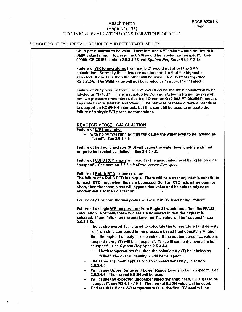
Attachment 1 EDCR 52351-A
(Page 27 of 32) Page
TECHNICAL EVALUATION CONSIDERATIONS OF 0-TI-2
SINGLE POINT FAILURE/FAILURE MODES AND EFFECTS/RELIABILITY:
CETs per quadrant to be valid. Therefore one CET failure would not result inSMM value failing. However the SMM would be labeled as "suspect". See00000-ICE-30156 section 2.5.3.4.26 and System Req Spec R2.5.3.2-12.
Failure of WR temperatures from Eagle 21 would not affect the SMMcalculation. Normally these two are auctioneered in that the highest isselected. If one fails then the other will be used. See System Req SpecR2.5.3.2-6. The SMM value will not be labeled as "suspect" or "failed".
Failure of WR pressure from Eagle 21 would cause the SMM calculation to belabeled as "failed". This is mitigated by Common Q being trained along withthe two pressure transmitters that feed Common Q (2-068-PT-063/064) and areseparate brands (Barton and Weed). The purpose of these different brands isto support an RCSlRHR interlock, but this can still be used to mitigate thefailure of a single WR pressure transmitter.
REACTOR VESSEL CALCUALTIONFailure of DIP transmitter
- with no pumps running this will cause the water level to be labeled as"failed". See 2.5.3.4.6
Failure of hydraulic isolator (XIS) will cause the water level quality with thatrange to be labeled as "failed". See 2.5.3.4.8.
Failure of SSPS RCP status will result is the associated level being labeled as"suspect". See section 2.5.3.4.9 of the System Req Spec.
Failure of RVLIS RTD - open or shortThe failure of a RVLS RTD is unique. There will be a user adjustable substitutefor each RTD input when they are bypassed. So if an RTD fails either open orshort, then the technicians will bypass that value and be able to adjust toanother value at their discretion.
Failure of AT or core thermal power will result in RV level being "failed".
Failure of a single WR temperature from Eagle 21 would not affect the RVLIScalculation. Normally these two are auctioneered in that the highest isselected. If one fails then the auctioneered Thot value will be "suspect" (see2.5.3.4.5).
- The auctioneered Thot is used to calculate the temperature fluid densitypl(T) which is compared to the pressure based fluid density pl(P) andthen the highest density p, is selected. If the auctioneered Thot value issuspect then p1(T) will be "suspect". This will cause the overall p, be"suspect". See System Req Spec 2.5.3.4.3.- If both temperatures fail, then the calculated p1(T) be labeled as
"failed", the overall density p, will be "suspect".- The same argument applies to vapor based density pg. Section
2.5.3.4.4.- Will cause Upper Range and Lower Range Levels to be "suspect". See
2.5.3.4.6. The normal EUDH will be used- Will cause the expected uncompensated dynamic head, EUDH(T) to be
"suspect", see R2.5.3.4.10-4. The normal EUDH value will be used.- End result is if one WR temperature fails, the final RV level will be
Attachment 1 EDCR 52351-A
(Page 28 of 32) Page
TECHNICAL EVALUATION CONSIDERATIONS OF 0-TI-2
SINGLE POINT FAILURE/FAILURE MODES AND EFFECTS/RELIABILITY:''suspect"
WR pressure is used to calculate different aspects is the vessel levelalgorithm.
- pressure based fluid density p1(P). This is compared to p1(T) and thehighest of the densities is utilized. If the pressure signal fails then PI(P)will be labeled "failed", and pi will be "suspect". See section R2.5.3.4.3-3.
- The same argument applies to vapor based density pg in that it will be"suspect". Section 2.5.3.4.4
- Will cause Upper Range and Lower Range Levels to be "suspect". See2.5.3.4.6.
- Will cause expected uncompensated dynamic head, EUDH(P) to be"failed", see R2.5.3.4.10-5. The normal EUDH value will be used.
- End result is if the WR pressure fails, RV level will still be calculatedand be labeled as "failed" with no pumps running and "suspect" withpumps running.
OTHER FAILURESFailure ICS/printerlannunciator - Common 0 is specifically designed so any ofthese external failures will not affect the safety function
Failure of AC160 data link to the OM - there is a heartbeat that the operator cansee along with an alarm.
Failure of PC Node box would result in failure of the entire train. This wouldput the plant in a 30 day LCO until a report is required to the NRC. Long termoperation is acceptable.
Failure of fiber to cat 5 modems will affect the printing capability only. Nosafety related function will be lost.
Failure of AF100 modem will have no effect. There is a redundant data link thateach end has an AF100 modem. If one fails the other link will still function.
Failure of OWL Dual Data Diode will result in the data link ceasing to function.There will be no other impacts.
COMPONENT WITHIN RACKThere are numerous components within the rack that would cause a diversityof failures. It is assessed that these failures will result in either a failure similarto the one mentioned above, or a complete system failure resulting in the lossof a whole train.
El x c. Will these system and/or component failures directly or indirectly via transient cause aYES NO plant trip or runback?
Common Q does not have the ability to affect the plant in any way. It is amonitoring device only.
If YES,
Attachment 1 EDCR 52351-A
(Page 29 of 32) Page
TECHNICAL EVALUATION CONSIDERATIONS OF 0-TI-2
SINGLE POINT FAILURE/FAILURE MODES AND EFFECTS/RELIABILITY:
1. What is the reliability of the individual components and system?
2. How can testing be performed to detect failure modes, miss configurations, andprecursors to imminent failures?
3. What airms or indications provide timely precursor indication of impendingcomponent/system failure?
4. What are bases for alarm, runback, trip, and operator action points.
5. What are the margins between normal operation and these alrm, runback, trip,and opreator action points?
6. What redundancy is there in the alarms, indications, runback, or trip functions?
7. Which trips and runbacks are absolutely necessary? Which can be changed toalarms and what operator response is needed for the alarms?
8. Are digital systems developed in accordance with SPP-2.6 and SS-El 8.15.01software requirements for real time data acquisition and control computersystems?
Attachment 1 EDCR 52351-A
(Page 30 of 32) Page__
TECHNICAL EVALUATION CONSIDERATIONS OF 0-TI-2
SINGLE POINT FAILURE/FAILURE MODES AND EFFECTS/RELIABILITY:
9. Are there any reasons why redundancy was not considered in alarm, trip,runback systems, and can redundancy be added?
DIGITAL SYSTEM UPGRADES/MODIFICATIONS:
If the change involves a digital system, component or upgrade:
Common 0 is a safety related digital computer system. There are numerousregulations involved,
- the primary one being NRC Regulatory Guide 1.152 - Criteria For Use ofComputers in Safety Systems of Nuclear Power Plants
- RG 1.152 endorses IEEE 7-4.3.2 Standard Criteria for Digital Computersin Safety Systems of Nuclear Power Generating Stations, however itdoes not endorse Annexes B through F
- TVA's SPP 2.6 Computer Software Control- TVA's SS-E18.15.01 Software Requirements For Real-Time DataAcquisition And Control Computer Systems which implements SPP 2.6- TVA's DG-E18.1.25 Digital System Development, Procurement, and
Implementation
The contract with Westinghouse states "the Codes, Standards, andlor licensingrequirements and regulations shall be those applicable to the standardWestinghouse product(s) or service(s) andlor product licensing basis for theidentified product(s) or service(s)." This means that Westinghouse was notdesigning to any of the specific TVA requirements mentioned below.
Westinghouse created this software via the Westinghouse Software ProgramManual which was reviewed by the NRC and complies with accepted industrystandards and regulatory guidance. This process guarantees the software wasdeveloped by the applicable life cycle processes.
] ] 1. Implement digital upgrade using SPP-2.6, SS-E18.15.01, and the guidelines of DG-YES NO El 8.1.25.
This was not completed, see section above.
0 0 2. If the change involves a modification of a digital system or component, use SPP-2.6
YES NO for in-house modifications and SS-E18.15.01 for modifications performed by a vendor.
This is not a modification, it is a new system.
Attachment 1(Page 31 of 32)
TECHNICAL EVALUATION CONSIDERATIONS OF 0-TI-2
EDCR 52351-APage __
0i 0iYES NO
El ElYES NO
3. For digital upgrades, refer to NRC RIS 2002-22 (Replaced Generic Letter 95-02)which endorses NEI 01-01, Rev. 1. The potential for common cause software failuremust be considered (normally only required to be analyzed for when associated with aSafety Related Protection System upgrade) in the design phase (See DG-E 18.1.25and SS-E1 8.15.01 for guidance and requirements).
The Common Q system is a high quality, highly dependable digital system andis approved by the NRC in their applicable Safety Evaluation Reports (SER).Automated self testing is provided to monitor system health and alert theoperators of failures. A failure modes and effects analysis has found that nosingle component failure will result in failure of both trains.
A software common mode failure, while not quantifiable, is not expected todecrease the dependability of the new PAM system. NEI-01 -01 states thatsoftware developed with such processes should not result in more than aminimal increase in the likelihood of malfunction. A software common failureshould relate to the same likelihood of a hardware common malfunction.
4. Determine the method and level of configuration control needed for the digitalapplication. The configuration control method should be implemented using approveddesign control processes such as SPP-2.6 and/or SPP-9.3 (i.e., design output). Thismay involve the need to maintain configuration control of both the software andhardware revision levels. The level of control needed shall be based upon theapplication function (i.e., Safety Related, Quality Related, Critical to Plant Operations),capability to modify software such as software versus firmware, software andhardware revision compability, etc. Safety Related system configuration control mustensure that V&V qualification remains valid so prescriptive configuration controlmethods would be required. For Non Safety Related software, the configurationcontrol may be less restrictive with focus on plant reliability and day to day operation.Firmware/Software includes both the Operating/Platform System firmware/softwareand the application specific firmware/software along with any configuration parameterssuch as setpoints, constants, scaling, etc.
SPP-2.6's configuration control section discusses that the"application's source code and/or executables shall be stored in an environmentthat it is protected from inadvertent changes. Cyber security considerationsshould be addressed in the storage environment. Cyber security considerationsmay include protection against source code contamination by malicious codes(viruses, worm Trojans, etc.), protection against code information exploited formalicious intent (i.e., storage area is not connected to a LAN that has internetconnectivity), username and password required to access source code, firewallprotection to prevent unwanted access, and Intrusion Detection to monitoraccess."
TVA will not be given the source code, this is Westinghouse proprietaryinformation. The requirements of having a username and password is met(reference Software Req Spec - R.8.2.1-12). The unwanted access requirementis being met, see the cyber security section.
Attachment 1(Page 32 of 32)
TECHNICAL EVALUATION CONSIDERATIONS OF 0-TI-2
EDCR 52351-APage __
El ElYES NO
5. Perform Cyber Security Assessment to address NEI 04-04 requirements. Contact theComputer Engineering Group for instructions.
Preliminary cyber security assessment completed on February 2 4 th 2010. Actionitems consisted of updating the UNIDs for the data diodes to have system 068on the Common Q side and ICS's 261 on the ICS side.
Note that this assessment was not according to Regulatory Guide 5.71 becausethis has not been updated into NEI 04-04. When this is done, Common Q will get"fast tracked" through this assessment process. End result is the intent of thequestion is that this assessment is not complete.
6. If there is communication network interfaces such as an ICS interface, implementdesign of this interface per the guidelines addressed in DG-E18.1.25.
There is a data link that transmits approximately seventy data points everysecond to ICS. This network interface is TCPIIP, will be done optically, and thesignal will traverse a DualDiode device (cyber security device guaranteeing oneway network flow).
See Software Service Request included in package.
El ElYES NO
Enclosure 2TVA Letter Dated October 29, 2010
Responses to Licensee Open Items to be Resolved for SER Approval
Attachment 3
Draft FSAR Amendment 102 Change Markups
WATTS BAR WBNP-100
and 13869, "Reactor Protection System Diversity in Westinghouse Pressurized WaterReactors," Reference [2] and Reference [6]. Generally, two or more diverse protectionfunctions would automatically terminate an accident before unacceptableconsequences could occur.
For example, there are automatic reactor trips based upon nuclear flux measurements,reactor coolant loop temperature and flow measurements, pressurizer pressure andlevel measurements, reactor coolant pump under frequency and under voltagemeasurements, and steam generator water level measurements, as well as manually,and by initiation of a safety injection signal.
Regarding the engineered safety features actuation system for a loss-of-coolantaccident, a safety injection signal can be obtained manually or by automatic initiationfrom diverse parameter measurements as shown in Table 7.3-1.
7.1.2.1.9 Trip SetpointsInsert new Trip Setpoint Section
The rea•cto protection system trip setpoints have been Selected to ensure that credlam:age and 19o9s6 of integrity of the reactor coolant systemi are prevented dur~inganticipat, operational e. ents. These setpoints were analytically deteFrmined- inaccor9-d-ance With the methodology deScribed in ReferenceS [3] and [5]. Both thenomina (tIp", 6etpoint) and limniting (allewable value) settings have been incorporatedinto the Technical Specifications. Nominal settings are more conservative than thelimtingR setpints. This allows for me6aucrement and •alibration umr-ntainties andinst-rument c-hannel drif which may occur. between periodic tests without eXceeding thelimiting setpoints. Trip setpeint values are monitored by periodic peorfbmancc ofsurveillance test• n, accordance ;ith Technical Spe•ification requirements.The setpoint calculations incl,-de the effects of both measurable and unmeasurable
r.ce-ainties to ensure the associated protective actions are performed beforeanaytical limitS ar e&xceededý lncorpG.rating these uncrtaities provides assurance
that the analytical limitf ill not be exceeded under accident conditions if the AllowableValue is satisfied under normal conditions.
The square root sum of the squares (SRSS) method i..used for combining U..e.;ainyterms to meAe"t the folrlwing three criteria:- random, independent, and approximately
orm.al d1itFribution. The probability that all of the independent processes. wouldsimul4 ..taneously be at their maximum value (i.e., + o ) is very smal. The SRSS methodprovides a means to Gombine individual random unce.ainty terms to establish a netrndor -m unerainty term. All other uncerta inties; that do Aodet n fth he
criteria are arithmetically summ~ed-.
The following sections describe the methodologies used for the calcla,-1tion of RPSGetpoints within the SGope of T-STF= 193 revision 4 as incorporated into the WBN Unit2 Technical Specifications. WBN Unit 2 uses two methodologies in the performance ofcalcul-1ations6 associated with these functions. A m~ajority of the RPS functions which areNSSS su..pply sOPe Wuse the Wetinghouse.. Setpoint Methodo•lgy (Reference 5) Thefunctions in TVA's scope of supply utilize the TVA methodology based on lSA standar67.04 (Reference 3) and defined in "A technical instruction..
INTRODUCTION 7.1-11
WATTS BAR WBNP-100
Safety Limit (SL) A safety limit is Specified to prFotect th integritY Of physiral barriersthat guard against the uncontroed rease of radioactivity. The safety limit f
paramter iS typically providedI in the plant Safeqty analysesq in accnord-ance With 10CE
Analytical Li mit (AL) The analytical limit represents the parameter value at which -aSafety action is assumed to be initiated to ensure that the safety limits are notexceeded during either accidents or anticipated operational occurrenE.No.minal Trip Setpoint (NTSP) The NTSP is t nomina valu, a which thn mi s set when i iS calibrated. Sinermse ins ftrumentS cGant be set to an ewacht Value,einstrumet is- set to the nominal setpoint within an allowed telerance bard defined as
Acceptable As Left (AALT.
AllowayV;;bl Value (AV) The limiting value of the as found trip setting used duringsurvillces testient for the pG4isRn of the channl beinrg tented, beyondcwhich Theoperabilty Of the hanneAl must be evaluated. Th • 4V ensur h rh -sfiricent marginexists to the-AL- to- accounLt foGr unmasuab e u teainties such as rocess-,-, effects toensure that the protective acstion is consideunde RS cendtions befdoei theanalytical limit iG excaeeded.
Acceptable As Found Tolerance (AAF) A tolerance- ban;d On either Side of the WTSPthish Pefines the limits of acceptable iRstrument pe~orMAnc and hich, if exQeedeq
may requ~wir corrective ac;tion. T-he 44F=i based-nmaual nsrmn hne. essGh as drift, expectd dWur-i the survill.nce intervl. The RPS
funcrAtionMs use double sided tolera•nre limit-s fo the ,AAF. ,nstrUMents Whihh exceedte as Found tolerance limits Will b c ted and evaluated in the CorrectiveA4-tctionProgram.
Acceptable As Le#t Tolerance (AML) The condiotion; a transmitter, process rack moduleOr proceFss instrument loop is left inAfter calibration or setpoint verification. The as; lefc-alibraption toler;ance isbsd on the reerne curacy Of thedeiebngclradbut may take calibration hiStoFY into consi deration. The RPS- funcutions use doublesidetolerance limqits for the IV\L. The trip setpoint must be adjusted wiAthin the as left
tlrneprior to retulrning the ch~annel to seRvice.
Qperational Limit (OL) The operational limit is a value which the operating paarameterFis not expected to eXceed duing normal operation. The NTSP is set beyond the OL= sothat Spurious trips of the inisttrumlesnt do1- not ogccur.
7.1..1..1 estanghouse Setpoint Mecthodolg
The; WMN IUnit 2RPS nominal trip setpointg and allowable value I;Are determinegd inaccorFdance With the W~estinghouse setpoint methodology as described in Referenc5. The fallowing Technical Specification functions use the W~estinghouse Getpoint
7.1-12 INTRODUCTION
WBNP-IO00WATTS BAR
WN-0
Reactor Trip FunctionS:
Power Rang"e Neutron Flux - HighPwrRange Neutron" Flux Low
Power Range Neutron Flux High Positive RateýOvertemperaturme AT
Pressurizer Pressure LowpressuriZer Pressure High
° Pressurizer Water Level HighReacGt• CoolaRt Flew Lo.
RCPs Und9FfFGqUecY* SG Water Level Low Low
Vessel•AT Equivalent to Power for SG-Water Level Low-Low
Esetaafety Features; Ac~tuation System Functions:
*w Safety Injectio Containment Pressure HighSafety Injection PressuriZer Pressure LoQw
*Safet" Injection Stoamline Pressure LewContainment Spray Containment Pressure High HighG ontainment Iolaio Phase B ~otimen. Pressure High HighStaln soainCnaimn rsur ihHg
*SteaMline Isolation SteaMline Pressure LoEwSte-amline, Islaio teampline Pressure Negative Rate HighTurbhine Trpip and Fe atrIoainSam eeaorWater Lepvel High High
*Auxiliapy Feedwater Steam Generator Water Level 1LowLo1,Vesse ATr Equvaen toPoer forF Auxiiary Feedwater, QSG Water: LevelI LowA LoGw
Swichve to Containment SUMP on Refueling Water Storage Tanl Level Low*~ ~~4 Swtcovr oContainment SuMp oan CnametSum~p Level High
The as founPd tolerance for GotpOintS using the W~estinghouse S etpqimt methodolog ithe algebraic GUM of the- followingR aua@ uc~ito for the; su1vill0anc
For sensors: drift, measurement and test equipment (M&TE) accur~acy, and calibratioaccuracy.
ForF rack components: drft,. M&TE accurFacy, calibration accuracGy, and, for analogchannels, the bistable setting accuracy.
INTRODUCTION 7.1-13
WATTS BAR WBNP-IO0WATT BARWBNP-100
.Alcce-AtA-;;ble As Loft Tolezr;;nce
The as left calibration toleranc-e is equal to or greater than the refe8rene accuracy otthe deiceiG being czlibr;4ted And may, tAke cAlibra;tion his~torv ;nto osdean
-- j i
7.1.2.1.9.2 TVA Set~oont Methodok)oav
TVA's instrument 69tpoint methodolo~gy is bae@d- On 12SA s-tan;dard 67,94 (RefeFrenc 34and is; inr,-.,porated into- TV!A techiral instruc-tions for performace- Of instrumentuncertainty calculations. The following Technical Specification functions use the TVA
Reactor Trip System Instrumentation Functions:
*SourceFGA Range Neu1tron Flux*intermediate Range Neutron Flux
- Tulbin Trip Low Fluid Oil Pressure
Enginere••d Safety Feature Ac.tua-tion S"ystem Instrumentation Functions:
* Auxiliary Feedwater Loss of OffeAuxiliary Feedwater Trip of al i rn ain Feedwater Pumps
Auxiliary Feedwater Auxiliary Feedwater Pumps Suction Transfer on Low SuctionPressure
Acceptable As Found Tole-ranGe
ThAccrptable As Found tolerance is the SRSS combination of the drift, M&TEaccuracy, calibrFation accUracy,, and other measurable UncertaýntieS as appro~priate(iýe., those present during calibration, SUch as normal radiation effects Or tcMperatureeffects).
Acceptable As Left Tolerance
The Acceptable As Left tolerance is equal to or greater than the reference accuracy Of
the device being calibrated and may take calibration hstory intg cnstidefation.
Allowable Value
The allowance between the AL and the WTSP is to be large enough to contain the toaUncertainty (mneasurable and unmeasurable), duFrng accident or seismic and nrmalq~operation, as determined using theQ SRSS2 method. The alwnebetw'e-en the A an
the ~ 1 -T1P is limte totaprinfte instrumnent hannel being tested for thsurveillnc interva and should acutfo-r- only the measurable Wnce~taintie6.
*-~Pft.-(based on surveillance interval).4 rý Lurir H Rt*- .uriuus +GI ti pguruuri t-44 TPAS I1-zýurT;rI ; IuRiuitju
7.1-14 INTRODUCnON
WATTS BAR WBNP-100
InStrUm~ent uncertainties Qturing nrGmal operation '<hich are measured durig
in the discussiOn Which follOWS, At is ssrd that the Grocess Variable increaSes
would be reversed.
frm the AL. The NTSP could then be calculated by subtracting the normal measurableunceetainties plus , any margin fom the AV. This- caluate d• AV is the bounding
meximm riit AVmax. if m~argin existS betWeen both the NTSP versus the AL. and theNTSP versus the oper-ational limlit, the NTSP could be reduced to a lower limit OL plu4the normnal un~ertainties, and then the AV could be reduced to the new NTSP plus themeasurable uncertainties, This calculated AV is the bounding minimum limit AVmin toprevent spurious initiations, The actual AV can be set within these two iis
7.1.2.2 Independence of Redundant Safety-Related Systems
The safety-related systems in Section 7.1.1.1 are designed to meet the independenceand separation requirements Criterion 22 of the of General Design Criteria (GDC)(Appendix A to 1 OCFR50) and Paragraph 4.6 of IEEE 279-1971. The administrativeresponsibility and control provided during the design and installation is discussed inChapter 17 which addresses the Quality Assurance programs applied byWestinghouse and TVA.
The electrical power supply instrumentation and control conductors for redundantcircuits of a nuclear plant have physical separation including PAM Category 1 andprotection set 1, 11, 111 and IV instrumentation and control. Their cables are run inseparate raceways to preserve divisional integrity and to ensure that no single credibleevent will prevent operation of the associated function due to electrical conductordamage. Detailed information pertaining to electrical cable for safety-related systemsis given in Section 8.3.1.4. Critical circuits and functions include: power, control, andprocess protection channels associated with the operations of the reactor trip systemor engineered safety features actuation system. Failure events are evaluated forcredibility and credible events shall include, but not be limited to, the effects of shortcircuits, pipe rupture, missiles, etc., and are considered in the basic plant design.Control board details are given in Section 7.7.1.10. In the control board, separation ofredundant circuits is maintained as described in Section 7.1.2.2.2.
Instrument sensing lines (including capillary systems) which serve safety-relatedsystems identified in Section 7.1.1.1 are designed to meet the independencerequirements of criterion 22 of the 1971 General Design Criteria and IEEE 279-1971Section 4.6. The requirements consider the following events: (1) normal activities inthe area (e.g., maintenance); (2) high and moderate energy jet streams, missiles, andpipe whip; and (3) possible damage caused by falling loads from the plant liftingsystems (e.g., cranes, monorails). Exceptions to these requirements shall beevaluated for technical adequacy and documented in Design Basis Documents.
INTRODUCnON 7.1-15

7.1.2.1.9 Trip Setpoints
The scope of TSTF-493 includes setpoints within the reactor protection system (RPS)which includes the Reactor Trip System (RTS) and the Engineered Safeguards FeaturesActuation System (ESFAS). The specific setpoints within the scope of TSTF-493 areidentified in Technical Specifications 3.3.1 and 3.3.2. These trip setpoints have beenselected to ensure that core damage and loss of integrity of the reactor coolant systemare prevented during anticipated operational events. These setpoints were analyticallydetermined in accordance with the methodology described in References 3 and 5. TheTVA instrument setpoint methodology is based on ISA standard 67.04 (Reference 3) andis incorporated into TVA technical instructions. The Westinghouse setpoint methodologyis described in Reference 5. Both the nominal (trip setpoint) and limiting (allowablevalue) settings have been incorporated into the Technical Specifications. Nominalsettings are more conservative than the limiting setpoints. This allows for measurementand calibration uncertainties and instrument channel drift which may occur betweenperiodic tests without exceeding the allowable value. Trip setpoint values are monitoredby periodic performance of surveillance tests in accordance with Technical Specificationrequirements.
The setpoint calculations include the effects of both measurable and unmeasurableuncertainties to ensure the associated protective actions are performed before analyticallimits are exceeded. The square root sum of the squares (SRSS) method is used forcombining uncertainty terms to meet the following three criteria: random, independent,and normal distribution. The probability that all of the independent processes wouldsimultaneously be at their maximum value (i.e., + or -) is very small. The SRSS methodprovides a means to combine individual random uncertainty terms to establish a netrandom uncertainty term. All other uncertainties that do not meet any of the three criteriaare arithmetically summed. Single-sided correction factors are not used in setpointcalculations within the scope of TSTF-493.
The following describes the methodology used for the setpoint calculations within thescope of TSTF-493 revision 4 as incorporated into the WBN Unit 2 TechnicalSpecifications.
Safety Limit (SL) - A safety limit is specified to protect the integrity of physical barriersthat guard against the uncontrolled release of radioactivity. The safety limit for aparameter is typically provided in the plant safety analyses in accordance with 10 CFR50.36(c).1 .ii.A.
Analytical Limit (AL) - The analytical limit represents the parameter value at which asafety action is assumed to be initiated to ensure that the safety limits are not exceededduring either accidents or anticipated operational occurrences.
Nominal Trip Setpoint (NTSP) - The NTSP is the nominal value at which the instrumentis set when it is calibrated. Since most instruments cannot be set to an exact value, theinstrument is set to the nominal setpoint within an allowed tolerance band defined asAcceptable As Left (AAL).
Operational Limit (OL) - The operational limit is a value which the operating parameter isnot expected to exceed during normal operation. The NTSP is set beyond the OL so thatspurious trips of the instrument do not occur.
Acceptable As Found Tolerance (AAF) - A tolerance band on either side of the NTSPwhich defines the limits of acceptable instrument performance, beyond which thechannel may be considered degraded and must be evaluated for operability prior toreturning it to service. Channels which 'exceed the AAF will be entered into the
Corrective Action Program for further evaluation and trending. The Acceptable As Foundtolerance is the SRSS combination of drift, maintenance and test equipment (M&TE)accuracy and readability, and calibration/reference accuracy. Other uncertainties maybe included in the AAF if applicable.
Acceptable As Left Tolerance (AAL) - A tolerance band on either side of the NTSP withinwhich an instrument or instrument loop is left after calibration or setpoint verification. TheAcceptable As Left tolerance is equal to or less than the SRSS combination of referenceaccuracy, M&TE accuracy and M&TE readability. Other uncertainties may be included inthe AAL if applicable.
The trip setpoint must be adjusted within the AAL tolerance prior to returning the channelto service.
Allowable Value (AV) - The limiting value of the as-found trip setting used duringsurveillance testing for the portion of the channel being tested, beyond which thechannel is inoperable. The AV ensures that sufficient margin exists to the AL to accountfor unmeasurable uncertainties such as process effects to ensure that the protectiveaction is performed under worst case conditions before the analytical limit is exceededwhen the channel is reset to within the AAL tolerance.
Calculation of the allowable value by the Westinghouse setpoint methodology isdescribed in Reference 5. In the Westinghouse methodology, the AV is limited to racksurveillance testing. Two values are calculated. The first value is the arithmetic sum ofthe measurable rack uncertainties. The second value is based on the total allowancebetween the trip setpoint and the safety analysis limit. This value is the differencebetween the total allowance and those uncertainties which are not present during therack surveillance test. These uncertainties are combined in accordance with Reference5. The AV is the nominal trip setpoint plus or minus, dependent on the trip setpointdirection, the minimum of the two calculated values.
The TVA methodology for the allowable value calculation is described in TVA technicalinstructions based on Reference 3. An upper limit of AV is determined by subtracting theunmeasurable uncertainties from the AL. A lower limit of AV is determined by adding themeasurable uncertainties to the NTSP. The actual AV is set within these limits. Thisapplies to a high setpoint with an upper Analytical Limit; the directions would be reversedfor a low setpoint with a lower AL.
WATTS BAR WBNP-100
FCV 63-1 (8812) FCV 63-67 (8808D) FCV 63-98 (8808B)FCV 63-3 (8813) FCV 63-72 (8811A) FCV 63-118 (8808A)FCV 63-5 (8806) FCV 63-73 (8811 B) FCV 63-156 (8802A)FCV 63-8 (8804A) FCV 63-80 (8808C) FCV 63-157 (8802B)FCV 63-11 (8804B) FCV 63-93 (8809A) FCV 63-172 (8840)FCV 63-22 (8835) FCV 63-94 (8809B) FCV 62-98 (8110)
FCV 62-99 (8111)
Means have been provided to preclude such spurious misalignment. Except for FCV 62-98 and FCV 62-99, the design consists of modified control circuits for these valves toensure that no single failure will be able to energize the opening and/or closing coils forthe valve operator. The design utilizes separate contacts which are wired before andafter each opening and closing coil as required. Figure 7.6-4 illustrates this protectionscheme. In this typical schematic, isolation of the opening and closing coils is providedby contacts R 11-R12, R31-R32, L21-L22, and (L41-L42). Valves FCV 63- 67, FCV 63-72,FCV 63-73, FCV 63-80, FCV 63-98, and FCV 63-118 require this protection schemeonly for the closing coil.
In addition, single failure has been considered on the part of the operator. The designincludes easily accessible, clear protective covers attached to the main control boardpanel over each respective control room switch except for valves FCV 62-98, FCV 62-99 and FCV-63-1. The operator would be required to open this protective cover beforehe operates the control switch.
For FCV 63-1, FCV 63-22, FCV 63-67, FCV 63-80, FCV 63-98, and FCV 63-118operating instructions specify the removal of power during specific modes of Plantoperation. For FCV 62-98 and FCV 62-99, the motive power has been removed.
For FCV 63-8, FCV 63-11 power will be removed and will be administratively controlledjust prior to use of the t#4e-RHR system for plant cooldown (<350 Deg. F) to preventinadvertent valve opening and over pressurization of the SI pump and CCP suctionpiping.
7.6.7 Loose Part Monitoring System (LPMS) System Description
Digital Metl )matMnitoring System (DMIMS-IDX-tM)
General System Description
The metal impact monitoring system, (DMIMS , DxTM)LPMS is designed to detect looseparts in the reactor coolant system. The system consists of sensors, preamplifiers, signalconditioners, signal processors, and a display. It contains 12 active instrument channels,each comprised of a piezoelectric accelerometer (sensor), signal conditioning anddiagnostic equipment. Conformance with Regulatory Guide 1.133, Revision 1 isdiscussed in Table 7.1-1.
7.6-4 ALL OTHER SYSTEMS REQUIRED FOR SAFETY
WBNP-IO00WATTS BAR WNPI0
Two redundant sensors are fastened mechanically to the RCS at each of the following
potential loose parts collection regions:
" Reactor pressure vessel: upper head region
" Reactor pressure vessel: lower head region
" Each steam generator: reactor coolant inlet region
The output signal from each accelerometer is passed through a preamplifier and anamplifier. The amplified signal is processed through a discriminator to eliminate noises andsignals that are not indicative of loose parts. The processed signal is compared to a presetalarm setpoint. Alarm setpoints for each channel are determined through the analysis ofbaseline test data taken with the system prior to plant start-up. During baseline testing, thereactor vessel and steam generator are impacted three feet from each sensor with a force of0.5 ft-lb. Loose parts detection is accomplished at a frequency of 1 kHz to 20 kHz, wherebackground signals from the RCS are acceptable. Spurious alarming from control rodstepping is prevented by a module that detects CRDM motion commands and automaticallyinhibits alarms during control rod stepping.
If measured impact signals exceed the preset alarm level, audible and visible alarms in thecontrol room are activated. Digital signal processors record the times that the first andsubsequent impact signals reach various sensors. This timing information provides a basisfor locating the loose part. The DMhMS DXTM soLPMS has a provision for audio monitoringof any channel. The audio signal can be compared to a previously recorded audio signal, ifdesired.
The online sensitivity of the DMIMS-DXT•IALPMS is such that the system will detect a loosepart that weighs from 0.25 to 30 lb, and impacts with a kinetic energy of 0.5 ft-lb on theinside surface of the RCS pressure boundary within 3 ft of a sensor.
The DMMS [DXTm-LPMS audio and visual alarm capability will remain functional after anOperating Basis Earthquake (OBE). All of the DMIMS DX TM LPMS components are qualifiedfor structural integrity during a Safe Shutdown Earthquake (SSE) and will not mechanicallyimpact any safety-related equipment. In addition, the equipment inside containment isdesigned to remain functional through normal radiation exposures anticipated during a 40-year operating lifetime. Physical separation of the two instrument channels, associated withthe redundant sensors at each reactor coolant system location, exists from each sensor tothe in-containment signal conditioning devices except the upper head channels which shallbe physically separated, starting at the sensor location and extending out to the patch panel.The in:containment signal conditioning devices are accessible during power operation withthe exception of the upper head signal conditioning modules which wi&llbeare mounted injunction boxes on upper head support in reactor cavity. The DMIMS -DX TM LPMScomponents outside containment located in a mild environment. Capabilities exist forsubsequent periodic online channel checks and channel functional tests and for offlinechannel calibrations at refueling outages.
ALL OTHER SYSTEMS REQUIRED FOR SAFETY 7.6-5
WATTS BAR WBNP-1O00
Key Features, Components and Architecture
Key features of system components and architecture are discussed in the followingsections.
Sensors (in containment)
The sensors are piezoelectric accelerometers that convert acceleration to electriccharge. The acoustic waves created by an impacting metallic object can be detected bythe piezoelectric accelerometers. While the excitation of the impact produces a verywideband frequency response, the frequency range of interest for most loose parts is 1kHz to 20 kHz.
Piezoelectric accelerometers are high output impedance devices that convertacceleration to electric charge. The flat frequency response range for theaccelerometers used in DMlMSDXThthe LPMS is from 5-10_ Hz to 10 kHz, and they havea useful frequency upper limit of over 20 kHz. The resonant frequency of theaccelerometers is greater than 30 kHz. The accelerometers are designed to operate athigh temperature (nominally 625°F-) and have high radiation capability.
The piezoelectric elements in the accelerometers are electrically isolated from thecomponent to which they are attached in order to prevent unwanted noise due to groundloops. The accelerometers typically have an integral 4 foot mineral-insulated ("hardline")cable and a large triax connector. This hardline cable is also built to withstand hightemperatures, while the connector allows for interfacing to lower temperature softlinecables.
Softline Cable (in containment)
Because the charge output of an accelerometer is a very low level signal, and normalcables can emit charge upon being vibrated, a special low-noise, radiation-resistantsoftline cable is used between the accelerometer and preamplifier.
Preamplifier (in containment)
The remote preamplifier is mounted in a sealed metal enclosure inside containment. Thecharge signal from the accelerometer is converted to a voltage signal. The preamplifieroperates in a "charge" amplifier mode such that the capacitance of the cable betweenthe high-output-impedance accelerometer and the preamplifier has very little effect onthe signal or its calibration. The charge preamplifier output voltage is then a normal, low-impedance millivolt instrument signal requiring only normal cabling and shieldingconsiderations.
Signal Conditioner
The signal conditioner module provides power to the remote preamplifier, provides finalamplification of the signal to a calibrated full scale range, and provides low:pass andhigh-pass filtering.
7.6-6 ALL OTHER SYSTEMS REQUIRED FOR SAFETY
WATTS BAR WBNP-100
Audio Subsystem
The audio patch panel, audio amplifier, and speakers make up the audio subsystem.Listening by a trained ear can be a very effective tool for evaluation and validation ofsignal characteristics. The system is designed such that any channel may be selected atany time for audio monitoring. The audio subsystem features are only available locally inthe D1.41.42 XTmLPMS cabinet.
Digital Signal Processing (DSP) Processor
In the Digital Signal Processing (DSP) processor, the signals are converted from analogto digital at a high rate, and the impact detection algorithm is applied by a specialmicroprocessor optimized for digital signal processing. The board contains a buffermemory that can store the complete impact signal time history for its monitoredchannels. Upon the detection of an impact, the data are normally transferred to the mainCentral Processing Unit (CPU) process for further evaluation, waveform storage, andalarm generation. However, if for some reason the CPU processor fails, the DSPprocessor has the capability for generating alarms on its own.
Central Processing Unit (CPU) Processor
The CPU processor is a personal computer architecture device. It takes the data fromthe DSP processors, controls the mass storage devices, provides displays of monitoringsystem information, drives the printer, and generates alarms. The CPU uses a PCI busfor high speed communication with the other processor modules and drives the tape anddisk peripherals by means of a parallel Small Computers System Interface (SCSI)interface. Addition of the peripherals provides for mass data storage onto high speeddigital tape and writeable CDs.
Display
The display is a qualified, high-resolution, color panel that is overlaid with a highresolution touch screen surface. The display shows the system and alarm statuses at aglance, presents the waveforms used in impact analysis, and shows the analysisconclusions. By means of the touch screen, which has all of the capabilities of astandard mouse, many system functions can be run without opening the keyboarddrawer. The color display features are only available locally in the DMIMS DX TMLPMScabinet.
Alarm Panel
The alarm panel provides continuous indication of alarm or trouble status, allowing thecolor display to be turned off when not being viewed. The panel contains red LEDs foralarm indication, orange LEDs for trouble indication, yellow LEDs that flash each time animpact event is detected by their respective channels, and green LEDs for indication ofproper DSP operation. The alarm panel features are only available locally in the DM4MS-FDXTI LPMS cabinet.
ALL OTHER SYSTEMS REQUIRED FOR SAFETY 7.6-7
WATTS BAR WBNP-100
Printer
A high-resolution laser printer is provided for printout of system status, waveformgraphs, and other data for the generation of reports. The printer features are onlyavailable locally in the .... D --LPMS cabinet.
The trainigRey- program scope is addressed in Reference [6].
7.6.8 Interlocks for RCS Pressure Control During Low Temperature Operation
The basic function of the RCS overpressure mitigation system during low temperatureoperation is discussed in Section 5.2.2.4. As noted in Section 5.2.2.4, this pressurecontrol system includes manually armed semi-automatic actuation logic for the twoPressurizer Power Operated Relief Valves (PORVs). The function of this actuation logicis to continuously monitor RCS temperature and pressure conditions; the actuation logicis manually unblocked when plant operation is at a temperature below the armingsetpoint. The monitored system temperature signals are processed to generate thereference pressure limit program which is compared to the actual measured systempressure. This comparison will provide an actuation signal to cause the PORV toautomatically open if necessary to prevent pressure conditions from exceeding allowablelimits. See Figure 7.6-5 for the block diagram showing the interlocks for RCS pressurecontrol during low temperature operation.
Two separated, independent sets of controls are provided for the interlocks, with therequired process variables being derived from redundant protection sets as follows:
(1) Protection Set I
(a) Wide Range RCS Temperature (TE-68-1, TE-68-18, TE-68-24, TE-68-41)
(2) Protection Set II
(a) Wide Range RCS System Pressure (PT-68-68).
(b) Wide Range RCS Temperature (TE-68-43, TE-68-60, TE-68-65, TE-68-83)
(3) Protection Set III
(a) Wide Range RCS System Pressure (PT-68-66).
The wide range temperature signals, as inputs to the Protection Sets I and II,continuously monitor RCS temperature conditions. In Protection Set I, the existing RCSwide range temperature channels on RCS loops 1 and 2 provide inputs to the Eagle 21digital process protection system. Eagle 21 provides isolated analog signals to the digitalprocess control system. An auctioneer function selects the lowest temperature signalwhich is then used to calculate an acceptable reference pressure limit (PORV setpoint)considering the plant's allowable pressure and temperature limits. An isolated widerange RCS pressure signal is also provided from Eagle 21
7.6-8 ALL OTHER SYSTEMS REQUIRED FOR SAFETY
WATTS BAR WBNP-100
indicated. The assemblies are always moved in preselected banks and the banks arealways moved in the same preselected sequence.
Each bank of RCCAs is divided into two groups except Shutdown Banks C and D whichhave one group each. The rods comprising a group operate in parallel throughmultiplexing thyristors. The two groups in a bank move sequentially such that the firstgroup is always within one step of the second group in the bank. A definite sequence ofactuation of the stationary gripper, movable gripper, and lift coils of a mechanism isrequired to withdraw or insert the RCCA attached to the mechanism. Since thestationary gripper, movable gripper, and lift coils associated with the RCCAs of a rodgroup are driven in parallel, any single failure which would cause rod withdrawal would
affect just that one group. Mechanical failures are in the direction of insertions, orimmobility.
A dropped RCCA or RCCA bank is detected by:
(1) Sudden drop in the core power level is seen by the nuclear instrumentationsystem;
(2) Asymmetric power distribution as seen on out of core neutron detectors or coreexit thermocouples;
(3) Rod at bottom signal;
(4) Rod deviation alarm (control banks only);
(5) Rod position indication;
(6) Power Distribution Monitoring System.
Misaligned RCCAs are detected by:
(1) Asymmetric power distribution as seen on out of core neutron detectors or coreexit thermocouples;
(2) Rod deviation alarm (control banks only);
(3) Rod position indicators;
(4) Power Distribution Monitoring System.
The resolution of the rod position indicator channel is ± 12 steps÷ 5% of span (± 7T2i+he&). Deviation of any RCCA from its group by twice this distance (100% of span, 1 4.4iRqhes24 steps) will not cause power distributions worse than the design limits. Thedeviation alarm alerts the operator to rod deviation with respect to group demandposition in excess of 404,12 steps.-f-span.- If the rod deviation alarm is not operable, theoperator is required to take action as required by the Technical Specifications.
If one or more rod position indicator channels should be out of service, detailed plantinstructions are followed to assure the alignment of the non-indicated RCCAs. The
15.2-10 CONDITION II - FA UL TS OF MODERATE FREQUENC Y
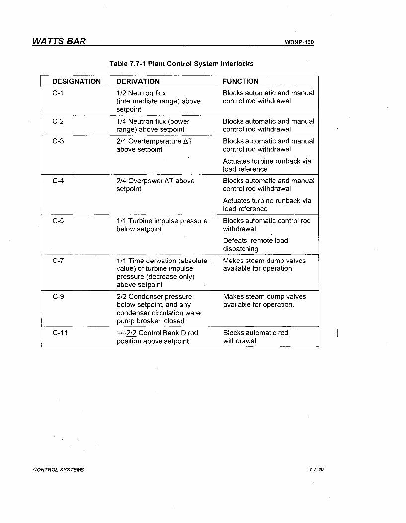
WATTS BAR WBNP-100
Table 7.7-1 Plant Control System Interlocks
DESIGNATION DERIVATION FUNCTION
C-1 1/2 Neutron flux Blocks automatic and manual(intermediate range) above control rod withdrawalsetpoint
C-2 1/4 Neutron flux (power Blocks automatic and manualrange) above setpoint control rod withdrawal
C-3 2/4 Overtemperature AT Blocks automatic and manualabove setpoint control rod withdrawal
Actuates turbine runback viaload reference
C-4 2/4 Overpower AT above Blocks automatic and manualsetpoint control rod withdrawal
Actuates turbine runback viaload reference
C-5 1/1 Turbine impulse pressure Blocks automatic control rodbelow setpoint withdrawal
Defeats remote loaddispatching
C-7 1/1 Time derivation (absolute Makes steam dump valvesvalue) of turbine impulse available for operationpressure (decrease only)above setpoint
C-9 2/2 Condenser pressure Makes steam dump valvesbelow setpoint, and any available for operation.condenser circulation waterpump breaker closed
C-1 1 4-142/2 Control Bank D rod Blocks automatic rodposition above setpoint withdrawal
CONTROL SYSTEMS 7. 7-29
Enclosure 2TVA Letter Dated October 29, 2010
Responses to Licensee Open Items to be Resolved for SER Approval
Attachment 4
EDCR 55385 Draft Scope And Intent, Unit Difference And Technical Evaluation
EDCR COVER SHEET
GENERAL INFORMATION Page No. 1EDCR TYPE [] EDCR # Rev.
(Check One Box Only) []EDCR-2 # 55385 Rev. A
0 Check here if this is a Streamlined EDCR.El Check here if this EDCR is for Documentation change only & No construction work is required.0 SR [L QR Check appropriate box if field material procurement quality requirements included.
068 RB IAUX Various SR I&C ASME class 3System Building Elevation Quality Lead Code/Class
Class Discipline
WORK SCOPE S TA TEMENT:EDCR 55385 is installing the reactor vessel level indicating system (RVLIS) in similar fashion as unit 1. RVLISworks by measuring various differential pressures across the core and sending this information to Common Qfor calculation. There is no cabling in this EDCR.
I
[PREPARED:
Mat Merten 632-7526Design Engineer Phone DateAPPROVALS:
Civil EGS Date
I&C EGS Date
Electrical EGS Date
Mechanical EGS Date
Plant Design EGS Date
Project Engineering Manager Date[ACCEPTANCE:.
Responsible Superintendent Date
Field Engineer Date
TVA Engineering Manager Date
VERIFIED:
Engineer DateINTER DISCIPLINE REVIEWS:
Civil Engineer Date
I&C Engineer Date
Electrical Engineer Date
Mechanical Engineer Date
Plant Design Engineer Date
Project QA Manager DateOTHER ORGANIZATIONS:
Signature/Org'n.: Date
Signature/Org'n.: Date
Signature/Org'n.: Date
Refer to the electronic documents in TVA Business Support Library (BSL) for current revision.
25402-3DP-GO4G-00081-004 Page 1 of 1
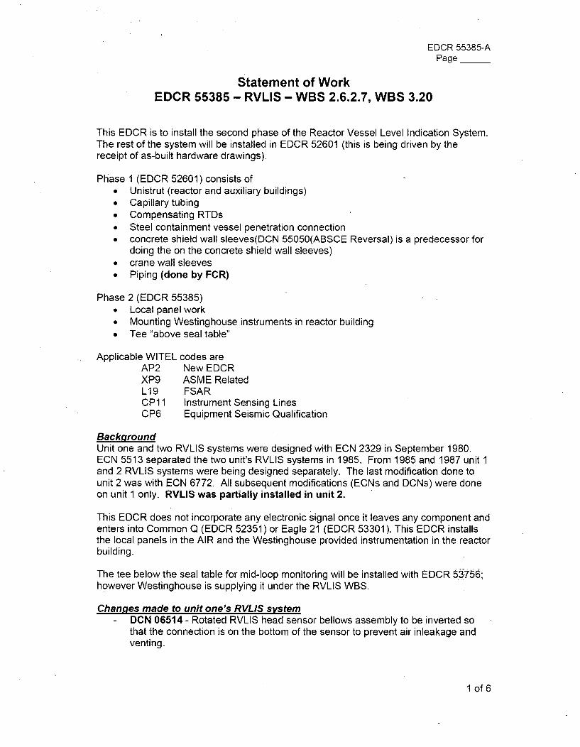
EDCR 55385-APage __
Statement of WorkEDCR 55385 - RVLIS - WBS 2.6.2.7, WBS 3.20
This EDCR is to install the second phase of the Reactor Vessel Level Indication System.The rest of the system will be installed in EDCR 52601 (this is being driven by thereceipt of as-built hardware drawings).
Phase 1 (EDCR 52601) consists of* Unistrut (reactor and auxiliary buildings)" Capillary tubing* Compensating RTDs• Steel containment vessel penetration connection" concrete shield wall sleeves(DCN 55050(ABSCE Reversal) is a predecessor for
doing the on the concrete shield wall sleeves)" crane wall sleeves* Piping (done by FCR)
Phase 2 (EDCR 55385)* Local panel work* Mounting Westinghouse instruments in reactor building" Tee "above seal table"
Applicable WITEL codes areAP2 New EDCRXP9 ASME RelatedL19 FSARCP1 1 Instrument Sensing LinesCP6 Equipment Seismic Qualification
BackgroundUnit one and two RVLIS systems were designed with ECN 2329 in September 1980.ECN 5513 separated the two unit's RVLIS systems in 1985. From 1985 and 1987 unit 1and 2 RVLIS systems were being designed separately. The last modification done tounit 2 was with ECN 6772. All subsequent modifications (ECNs and DCNs) were doneon unit 1 only. RVLIS was partially installed in unit 2.
This EDCR does not incorporate any electronic signal once it leaves any component andenters into Common Q (EDCR 52351) or Eagle 21 (EDCR 53301). This EDCR installsthe local panels in the AIR and the Westinghouse provided instrumentation in the reactorbuilding.
The tee below the seal table for mid-loop monitoring will be installed with EDCR 53756;however Westinghouse is supplying it under the RVLIS WBS.
Chan-ges made to unit one's RVLIS system- DCN 06514 - Rotated RVLIS head sensor bellows assembly to be inverted so
that the connection is on the bottom of the sensor to prevent air inleakage andventing.
1 of 6
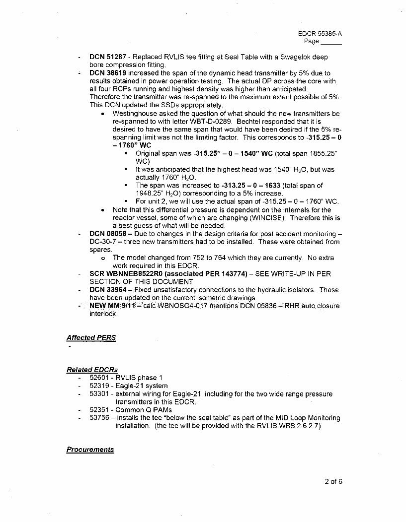
EDCR 55385-APage __
- DCN 51287 - Replaced RVLIS tee fitting at Seal Table with a Swagelok deepbore compression fitting.
- DCN 38619 increased the span of the dynamic head transmitter by 5% due toresults obtained in power operation testing. The actual DP across the core with.all four RCPs running and highest density was higher than anticipated.Therefore the transmitter was re-spanned to the maximum extent possible of 5%.This DCN updated the SSDs appropriately.
" Westinghouse asked the question of what should the new transmitters bere-spanned to with letter WBT-D-0289. Bechtel responded that it isdesired to have the same span that would have been desired if the 5% re-spanning limit was not the limiting factor. This corresponds to -315.25- 0- 1760" WC
" Original span was -315.25" - 0 - 1540" WC (total span 1855.25"WC)
" It was anticipated that the highest head was 1540" H20, but wasactually 1760" H20.
" The span was increased to -313.25 - 0 - 1633 (total span of1948.25" H20) corresponding to a 5% increase.
" For unit 2, we will use the actual span of -315.25 - 0 - 1760" WC.* Note that this differential pressure is dependent on the internals for the
reactor vessel, some of which are changing (WINCISE). Therefore this isa best guess of what will be needed.
- DCN 08058 - Due to changes in the design criteria for post accident monitoring -DC-30-7 - three new transmitters had to be installed. These were obtained fromspares.
o The model changed from 752 to 764 which they are currently. No extrawork required in this EDCR.
- SCR WBNNEB8522RO (associated PER 143774) - SEE WRITE-UP IN PERSECTION OF THIS DOCUMENT
- DCN 33964 - Fixed unsatisfactory connections to the hydraulic isolators. Thesehave been updated on the current isometric drawings.
-NEw MM911 '-l•L-"calc WBNOSG4-017 mentions DCN 05836- RHR auto closureinterlock.
Affected PERS
Related EDCRs- 52601 - RVLIS phase 1- 52319 - Eagle-21 system- 53301 - external wiring for Eagle-21, including for the two wide range pressure
transmitters in this EDCR.- 52351 - Common Q PAMs- 53756 - installs the tee "below the seal table" as part of the MID Loop Monitoring
installation. (the tee will be provided with the RVLIS WBS 2.6.2.7)
Procurements
2 of 6
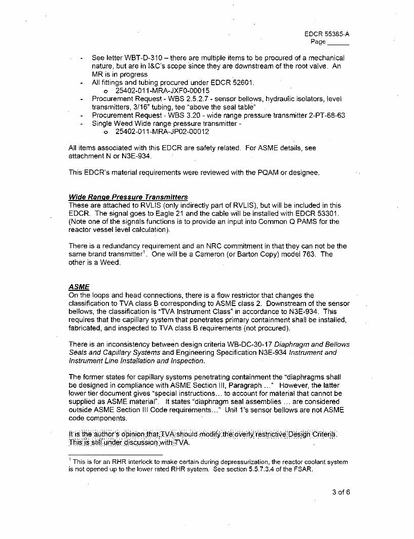
EDCR 55385-APage __
- See letter WBT-D-310 - there are multiple items to be procured of a mechanicalnature, but are in I&C's scope since they are downstream of the root valve. AnMR is in progress
- All fittings and tubing procured under EDCR 52601.o 25402-011-MRA-JXFO-00015
- Procurement Request - WBS 2.5.2.7 - sensor bellows, hydraulic isolators, leveltransmitters, 3/16" tubing, tee "above the seal table"
Procurement Request - WBS 3.20 - wide range pressure transmitter 2-PT-68-63Single Weed Wide range pressure transmitter -
o 25402-011-MRA-JP02-00012
All items associated with this EDCR are safety related. For ASME details, seeattachment N or N3E-934.
This EDCR's material requirements were reviewed with the PQAM or designee.
Wide Rangle Pressure TransmittersThese are attached to RVLIS (only indirectly part of RVLIS), but will be included in thisEDCR. The signal goes to Eagle 21 and the cable will be installed with EDCR 53301.(Note one of the signals functions is to provide an input into Common Q PAMS for thereactor vessel level calculation).
There is a redundancy requirement and an NRC commitment in that they can not be thesame brand transmitter1 . One will be a Cameron (or Barton Copy) model 763. Theother is a Weed.
ASMEOn the loops and head connections, there is a flow restrictor that changes theclassification to TVA class B corresponding to ASME class 2. Downstream of the sensorbellows, the classification is "TVA Instrument Class" in accordance to N3E-934. Thisrequires that the capillary system that penetrates primary containment shall be installed,fabricated, and inspected to TVA class B requirements (not procured).
There is an inconsistency between design criteria WB-DC-30-17 Diaphragm and BellowsSea/s and Capillary Systems and Engineering Specification N3E-934 Instrument andInstrument Line Installation and Inspection.
The former states for capillary systems penetrating containment the "diaphragms shallbe designed in compliance with ASME Section III, Paragraph ... " However, the latterlower tier document gives "special instructions... to account for material that cannot besupplied as ASME material". It states "diaphragm seal assemblies ... are consideredoutside ASME Section III Code requirements..." Unit l's sensor bellows are not ASMEcode components.
It is the author's opinion that TVA should modify the overly,. restrictive Design Criteria.This is still under discussion with TVA.
This is for an RHR interlock to make certain during depressurization, the reactor coolant system
is not opened up to the lower rated RHR system. See section 5.5.7.3.4 of the FSAR.
3 of 6
EDCR 55385-APage __
Ranges of TransmittersUnit l's level transmitters are all 4-2OmA. This will be continued on unit 1.
Mounting of EquipmentThe hydraulic isolators will come with a mount and no special plate needs to beutilized. This mount is mounted to Unistrut. See note 10 on 2-47W600-314.
The sensor bellows will be mounted in accordance three yet to be received drawingssimilar to
* 1552e77 Sensor bellows seal table mounting* 1552e76 Sensor bellows head mounting* 9559d76 Sensor bellows loop mounting
The level transmitters will be mounted with detail F274 on 2-47w600-274
The Weed WR pressure transmitter for train A will be mounted with detail C86 andJ230. NEED TO CONFIRM THIS
The Tobar WR pressure transmitter for train B will be mounted with detail J89 from 2-47w600-89.
The fill and vent assemblies will be mounted with detail J274.
The Magnex instrument valves will be mounted according to detail D314 on the mainRVLIS drawing.
Steel Containment Penetrations and Sleeves throughout Reactor BuildingAll SCV penetrations, Crane Wall sleeves, and concrete shield wall sleeves are installedin EDCR 52601.
Applicable DCIDS/TSIES and Procedures and other requirements- WB-DC-30-16 rev 6 - Instrument Sense Lines - slope and separations. This is
not for closed capillary systems. This DC is mostly applicable to capillarybefore the sensor bellows, however there are a few applicable requirements.
o Minimum separation between trained capillary is 18"o Minimize line length due to increased potential of having sensing line
configurations which can trap gas or air at high points in liquid filled lines.o If it is necessary to route a liquid filled sense line with an upward slope, a
vent valve shall be placed at the high point in the line and have a loopseal at the root.
- WB-DC-30-17 Rev 3 - Diaphragm And Bellows Seals and Capillary Systemso Volumetric displacement of the pressure sensing device shall be less
than full span volumetric displacement of the diaphragm/bellows seal.o Section 3.7.1 states the diaphragms shall be designed in compliance with
ASME section III paragraph NC-3649 -- this seems contradictory to
4 of 6
EDCR 55385-APage __
N3E-934 and the ASME code. See a more detailed comment in theASME section.
o Armored capillary shall be used when available to reduce potential forphysical damage to the capillary tube.
o Minimum bend radius supplied by manufacturer. If no specification isprovided, then assume the minimum bend radius shall be 3 times theoutside diameter of the capillary tubing.
- N3E-934 - Instrument line installation inspection - Engineering Specificationso States that capillary tubing which penetrate primary containment shall be
installed, fabricated, and inspected to TVA class B (ASME class two)requirements.
o See Appendix E for capillary lines exiting containment.- WB-DC-40-36 The Classification of Piping Pumps, Valves, and Vessels- WBNP-DS-1935-2618 - ASME Section III, Nuclear Class 2 Piping System
IMI-122.004 backfilling, venting, flushing and/or draining of instrument sensinglines and instruments
- SI-68-81 - Offline Channel Calibration Of RVLIS Transmitters And RCS WideRange Pressure Transmitters Trains A And B
- MAI-4.4A instrument line installation- TI-208 Design of supports for category I piping and instrument lines- 47W600-0-4 - various mounting and routing requirements
o Has requirement that 3/16" OD or less must be in UNISTRUT - see47a051
- WB-DC-40-34 - Containment Isolation System - Section 7.6.1 states RVLISshould not use any containment isolation valves because it would jeopardize theperformance of the system.
- WB-DC-30-7 - Post Accident Monitoring Instrumentation - establishes thatreactor vessel level is a post accident monitoring needed parameter, see table A-1 variable 22.
- WB-DC-40-31.9 - criteria for design of piping supports and supplemental steel incategory I structures
Planned Open ItemsSee open items list
Note that NUREG section 0612 (see N3E-934 3.7.2.1) interaction area interferenceevaluation will be done separately. Any changes to RVLIS from this would be with theFCN process unless this program comes alive before the final package.
Unit Differences- See Unit Differences Form
Required CalculationsCertification of panels
FSAR ImpactsSee attached PP-10 change packages
5 of 6
EDCR 55385-APage __
Expected DRAs in Final PackaqeI&C* 2-47W600-314* 2-47W610-7* SSD-2-L-68-367* SSD-2-L-68-368* SSD-2-L-68-369* SSD-2-L-68-370* SSD-2-L-68-371* SSD-2-L-68-372Plant Design* 2-47W462-229* 2-47W600-723-1* 2-47W600-723-2* 2-47W600-941* 2-47W600-942* UnknownCivil0 47w331-2Expected MD Drawings* Unknown* Unknown* Unknown* Unknown* 2654C65 (received)* 2656C12 (expected)* 2658C88 (expected)* Unknown* Unknown* 30-9480 (expected)* 1552E77 (expected)* 1552E76 (expected)* 9559D76 (expected)
Main RVLIS drawingControl diagramICCM Train A RVLIS dynamic headICCM Train A RVLIS lower rangeICCM Train A RVLIS upper rangeICCM Train B RVLIS dynamic headICCM Train B RVLIS lower rangeICCM Train B RVLIS upper range
Isometric for head connectionUpper head isometricloop 1 RVLIS isometricseal table isometricloop 3 RVLIS isometricIsometric for Unistrut routing
penetration assembly drawing (maybe no changes)
Sensor bellows physical drawingHydraulic isolators physical drawingLevel transmitters physical drawingWR pressure transmitterswrap around RTDstransmitter access assemblySensor bellows in line teetee above the seal tablecapillary schematicMagnex valves for local panelSensor bellows seal table mountingSensor bellows head mountingSensor bellows loop mounting
6 of 6
EDCR UNIT DIFFERENCE FORM
EDCR# 55385 Rev. A Page No.
Operations Difference is identified as follows:RVLIS is being installed in the same fashion as unit 1 and there should be no operationaldifference. Note that RVLIS signals feed into ICCM-86 for unit land Common Q PAMS (EDCR52351) for unit 2. This is a significant unit difference, but this change does not affect RVLISoperationally.
Unit 2 TVA Operations Acceptance (Mgr or Designee): Date:
Maintenance Difference is identified as follows:The second WR PT in unit 1 is made by Tobar. The Tobar line is now owned by WeedInstruments. The model for unit 1 has been replaced with the model DTN2010. It is similar to unitl's, but there may be maintenance differences. More information will be known once theinstallation manual is received.
In unit 1, the level transmitters, hydraulic isolators, sensor bellows, and the first WR pressuretransmitter were manufactured by ITT Barton. Barton was bought by Cameron who will be makingBarton copies. It is not known for certain whether there will be any maintenance differences untilmore documentation is received from Cameron via Westinghouse.
Unit 2 TVA Maintenance Acceptance (Mgr or Designee): Date:
Refer'to the electronic documents in TVA Business Support Library (BSL) for current revision.
25402-3DP-GO4G-00081 Effective 5/19/10 Page I of 2
Desicn Difference is identified as follows:* The sensor bellows will have UNIDs (the lack of UNIDs for the sensor bellows for unit 1 ads
confusion). The designator will be "SEN" for sensor.
" The procured range of the dynamic range transmitter will match what unit l's transmittershould have been re-spanned to after plant testing. However the 5% span limit wasreached first.
Note that the change in Wincise from the top to the bottom of the core barrel has thepossibility of changing internal differential pressures. The plan is that if there areany changes to internal differential pressure compared to unit 1, they should beminimal and could be changed with the allowable 5% re-span of the transmitterssupplied by Westinghouse.
* Welded fittings will be used for the second Weed pressure transmitter, unlike thecompression fittings on unit 1. This will lower the chance of any leakage which is vital in afilled system.
Unit 2 TVA Engineering Acceptance (Mgr or Designee): Date:
Mat Merten, PE 10/19/10Prepared By: Date:
Streamlined EDCR approved by TVA Oversight
SESG TO ROUTE A COPY OF THIS COMPLETED FORM TO TVA TRAINING MANAGER AND TO UNIT2 LICENSING.
Refer to the electronic documents in TVA Business Support Library (BSL) for current revision.
25402-3DP-GO4G-00081 Effective 5/19/10 Page 2 of 2
EDCR 55385-APage_
EDCR TECHNICAL EVALUATION
TECHNICAL EVALUATION CONSIDERATIONSThis attachment provides topics to be considered when evaluating the technical and safety aspect ofchanges. It is not intended to be an all inclusive list of items to be considered. It is to be used as an aidin determining attributes that should be addressed in a technical evaluation. Information is also providedto aid in determining coordination interfaces. These are minimum guidelines. It should be recognizedthat many topics and changes involve multiple disciplines and organizations and technical considerationsmust be coordinated accordingly. All parts of Attachment I must be considered for applicability for theassociated EDCR.
Attachment I has been formatted to facilitate proposed modifications during the WB2CCP. If theproposed modification potentially impact WBN Unit 1 power generations, operability (as defined by theWBN Unit 1 Technical Specifications), or any licensing basis, then terminate the use of this procedure,and use TVA Procedure Standard Program & Processes SPP-9.3, Plant Modification & EngineeringChange Control. EDCR(s) are permitted to modify selected WBN Unit 0 and/or Unit 1 SSC(s) via WBNprocedure 0-TI-2. (Reference 0-TI-2.)
NOTE: If the change involves an ASME Section III component or boundary that has not been previouslyincluded on the Unit 1 N-5 report, an EDCR is required to meet the ASME Section III requirements. If it isdetermined that the change affects Unit 1/0 and that it cannot be done by an EDCR-2, coordinate withMechanical EGS to determine the process needed to implement the modification.
EDCR Potential Impacts on Unit 0 and/or Unit I Systems, Structures and Components
NOTE: If the answer to the following question is "YES", reference WBN Technical Instruction 0-TI-2,"Criteria for Issuing Engineering Document Construction Releases (EDCR) Potentially Impacting WBNUnit 0 and/or Unit 1 Design" and do not complete this EDCR Technical Evaluation.
D Z 1. Does the EDCR activity involve Unit 2 modifications, changes, repairs, and/orYES NO refurbishments that interface physically with Unit 1 or Unit 0 and/or that affect drawings
under Unit 1 control (CCDs)?
Refer to the electronic documents in TVA Business Support Library (BSL) for current revision.
25402-3DP-GO4G-00081 Effective 5/19/10 Page 1 of 25
EDCR 55385-APage __
EDCR TECHNICAL EVALUATION
INITIAL:Li X
YES NO
D] EYES NO
Is the Auxiliary Building Secondary Containment Enclosure (ABSCE), as defined inWBN2-30AB-4001, affected by this change? Is the work adjacent or in the proximityto an ABSCE component, such that the component's Structural Interface Boundarycould be affected? Does this change modify any cable, cable tray, conduit, duct,pipe, or instrument tubing penetrating secondary containment? Consult 46W501drawing series for the location of the ABSCE boundary, and discuss proposedchanges with the Mechanical EGS. A justification for the "YES/NO" is required.
2. Does the modification have the potential to affect the Structural Interface Boundaryof a Unit 1/Unit 2 Interface Point? A justification for the "YES/NO" is required.
Z F] 3.YES NO
Is a full Technical Evaluation required for the proposed modification?
If "NO," provide a detailed justification explaining why the evaluation is not requiredfor this modification. Things to consider are any Unit Differences, Type ofDifference, whether or not the modification was evaluated by some other means(e.g., Unit 1 DCN), etc. The remainder of Attachment I need not be completed orkept as part of the EDCR, page 1 and 2 must be maintained.
If "YES," then perform and maintain as a part of the EDCR the remainder ofAttachment I, or 0-TI-2 Attachment 1 or 8, as applicable.
Refer to the electronic documents in TVA Business Support Library (BSL) for current revision.
25402-3DP-G04G-00081 Effective 5/19/10 Page 2 of 25
aEDCR 55385-AEDCR TECHNICAL EVALUATION Page
GENERAL:171 0 1. Are the nuclear safety functions, protective safety functions, Class 1 E requirements,
YES NO or Seismic Category I or I(L) requirements of a design criteria, system description,
FSAR, or Tech Spec affected?Design Criteria - no - WB-DC-30.7 Post Accident Monitoring Instrumentationestablishes the applicable PAM variable22 - reactor vessel levelNote WR pressure are PAM variables and are installed in this EDCR
System Description - no - RVLIS is part of system 68 and is impacted by, butrequires no changes to, N3-68-4001 Reactor Coolant System.
FSAR - yes - The overall RVLIS project (both EDCRs 52601 and 55385)requires changes to two different sections of the FSAR. These have to do witha change of a WR PT to a Weed brand. PP-10 change packages will be part ofEDCR 55385.
Tech Spec - no - RVLIS is affected by, but requires no changes to thetechnical specifications.
0 El 2. Is there an operational/configuration change? Is a component being added to or
YES NO removed from the plant? Is a component being disabled or abandoned in place? Is
the normal or accident position of a valve changing? Is an electrical isolation devicebeing added or deleted? Is a portion of the system being rerouted?
Operational change - yes - only in the sense that RVLIS is "read" by theCommon Q system which is changing
Configuration change - no
Component added - yes - multiple components are being added to the plant.See the MEL package.
Component disabled or abandoned - no
Valve normal position - no - no valves
Electrical isolation - no -
Portion being rerouted - yes - the Unistrut is being field routed (EDCR 52601)
0 El 3. Could the change affect the basic function of a structure, system or component thatYES NO performs or supports the performance of a safety function (deleting or changing logic
interlocking, additional pumps, etc.)? Is the most limiting operating condition ordesign criteria imposed on the change or by the change, evaluated? Include effectsby or on Safety Related or Non Safety Related systems in their various possibleconfigurations. Does the change meet or exceed design criteria of other SSCs insimilar applications?
Refer to the electronic documents in TVA Business Support Library (BSL) for current revision.
25402-3DP-GO4G-00081 Effective 5/19/10 Page 3 of 25
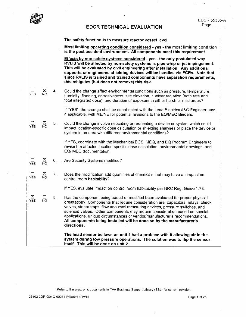
EDCR 55385-A
EDCR TECHNICAL EVALUATION Page
The safety function is to measure reactor vessel level
Most limiting operating condition considered - yes - the most limiting conditionis the post accident environment. All components meet this requirement
Effects by non safety systems considered - yes - the only postulated wayRVLIS will be affected by non-safety systems is pipe whip or jet impingement.This will be evaluated by civil engineering after installation. Any additionalsupports or engineered shielding devices will be handled via FCRs. Note thatsince RVLIS is trained and trained components have separation requirements,this mitigates (but does not remove) this risk.
El 0 4. Could the change affect environmental conditions such as pressure, temperature,YES NO humidity, flooding, corrosiveness, site elevation, nuclear radiation (both rate and
total integrated dose), and duration of exposure in either harsh or mild areas?
If "YES", the change shall be coordinated with the Lead Electrical/l&C Engineer, andif applicable, with ME/NE for potential revisions to the EQ/MEQ Binders.
El ED 5. Could the change involve relocating or reorienting a device or system which couldYES NO impact location-specific dose calculation or shielding analyses or place the device or
system in an area with different environmental conditions?
If YES, coordinate with the Mechanical EGS, MEQ, and EQ Program Engineers torevise the affected location specific dose calculation, environmental drawings, andEQ/ MEQ documentation.
El 12 6. Are Security Systems modified?YES NO
El 0 7. Does the modification add quantities of chemicals that may have an impact onYES NO control room habitability?
If YES, evaluate impact on control room habitability per NRC Reg. Guide 1.78.
0 El 8. Has the component being added or modified been evaluated for proper physicalYES NO orientation? Components that require consideration are: capacitors, relays, check
valves, steam traps, flow and level measuring devices, pressure switches, andsolenoid valves. Other components may require consideration based on specialapplications, unique circumstances or vendor/manufacturer's recommendations.All components being installed will be done so by the manufacturer'sdirections.
The head sensor bellows on unit 1 had a problem with it allowing air in thesystem during low pressure operations. The solution was to flip the sensoritself. This will be done on unit 2.
Refer to the electronic documents in TVA Business Support Library (BSL) for current revision.
25402-3DP-GO4G-00081 Effective 5/19/10 Page 4 of 25
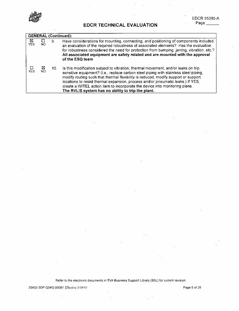
EDCR 55385-APage __EDCR TECHNICAL EVALUATION
GENERAL (Continued):Z El 9. Have considerations for mounting, connecting, and positioning of components included
YES NO an evaluation of the required robustness of associated elements? Has the evaluationfor robustness considered the need for protection from bumping, jarring, vibration, etc.?All associated equipment are safety related and are mounted with the approvalof the ESQ team
l 0] 10. Is this modification subject to vibration, thermal movement, and/or leaks on trip
YES NO sensitive equipment? (i.e., replace carbon steel piping with stainless steel piping,
modify routing such that thermal flexibility is reduced, modify support or supportlocations to resist thermal expansion, process and/or pneumatic leaks.) If YES,create a WITEL action item to incorporate the device into*monitoring plans.The RVLIS system has no ability to trip the plant.
Refer to the electronic documents in TVA Business Support Library (BSL) for current revision.
25402-3DP-GO4G-00081 Effective 5/19/10 Page 5 of 25
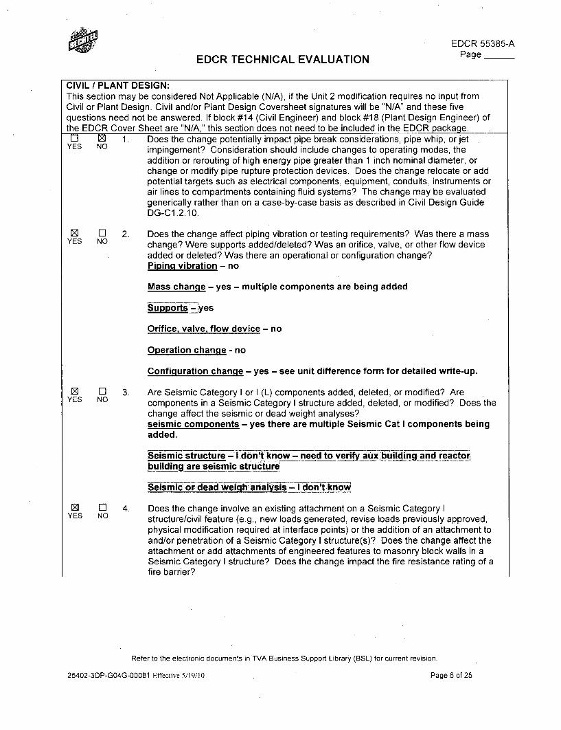
R EDCR 55385-AEDCR TECHNICAL EVALUATION Page
CIVIL / PLANT DESIGN:This section may be considered Not Applicable (N/A), if the Unit 2 modification requires no input fromCivil or Plant Design. Civil and/or Plant Design Coversheet signatures will be "N/A" and these fivequestions need not be answered. If block #14 (Civil Engineer) and block #18 (Plant Design Engineer) ofthe EDCR Cover Sheet are "N/A," this section does not need to be included in the EDCR package.
El M 1. Does the change potentially impact pipe break considerations, pipe whip, or jetYES NO impingement? Consideration should include changes to operating modes, the
addition or rerouting of high energy pipe greater than 1 inch nominal diameter, orchange or modify pipe rupture protection devices. Does the change relocate or addpotential targets such as electrical components, equipment, conduits, instruments orair lines to compartments containing fluid systems? The change may be evaluatedgenerically rather than on a case-by-case basis as described in Civil Design GuideDG-C1.2.10.
0 El 2. Does the change affect piping vibration or testing requirements? Was there a mass
YES NO change? Were supports added/deleted? Was an orifice, valve, or other flow device
added or deleted? Was there an operational or configuration change?Piping vibration - no
Mass change - yes - multiple components are being added
upports _'yes
Orifice, valve, flow device - no
Operation change - no
Configuration change - yes - see unit difference form for detailed write-up.
0 El 3. Are Seismic Category I or I (L) components added, deleted, or modified? AreYES NO components in a Seismic Category I structure added, deleted, or modified? Does'the
change affect the seismic or dead weight analyses?seismic components - yes there are multiple Seismic Cat I components beingadded.
eismic structure i- doWnknow - need to verify aux buiing and reactor
building are seismic strc.tureSeismic or dead wdeih analysis - I don't know
0 El 4. Does the change involve an existing attachment on a Seismic Category IYES NO structure/civil feature (e.g., new loads generated, revise loads previously approved,
physical modification required at interface points) or the addition of an attachment toand/or penetration of a Seismic Category I structure(s)? Does the change affect theattachment or add attachments of engineered features to masonry block walls in aSeismic Category I structure? Does the change impact the fire resistance rating of afire barrier?
Refer to the electronic documents in TVA Business Support Library (BSL) for current revision.
25402-3DP-GO4G-00081 Effective 5/19/10 Page 6 of 25
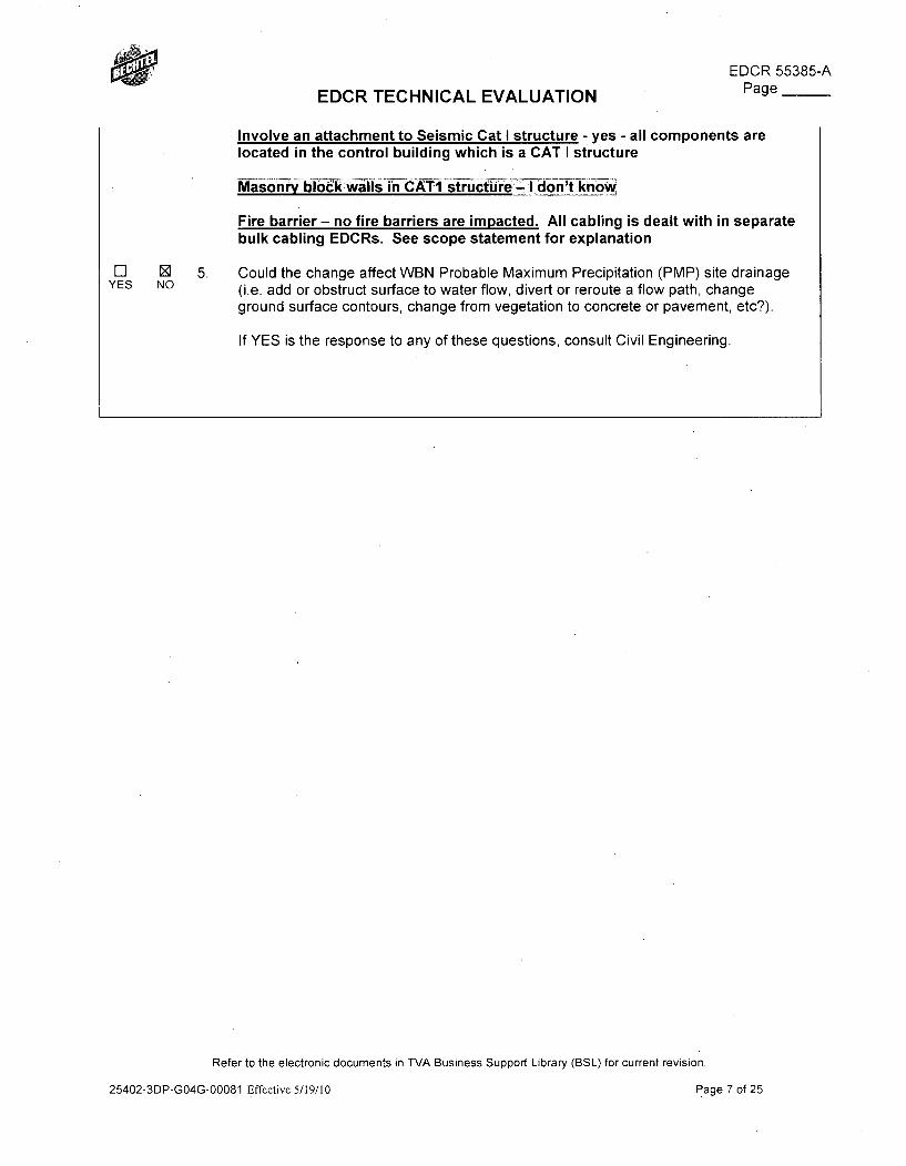
EDCR 55385-A
EDCR TECHNICAL EVALUATION Page
Involve an attachment to Seismic Cat I structure - yes - all components are
located in the control building which is a CAT I structure
Fire barrier - no fire barriers are impacted. All cabling is dealt with in separatebulk cabling EDCRs. See scope statement for explanation
Could the change affect WBN Probable Maximum Precipitation (PMP) site drainage(i.e. add or obstruct surface to water flow, divert or reroute a flow path, changeground surface contours, change from vegetation to concrete or pavement, etc?).
If YES is the response to any of these questions, consult Civil Engineering.
El E 5.YES NO
Refer to the electronic documents in TVA Business Support Library (BSL) for current revision.
25402-3DP-GO4G-00081 Effective 5/19/10 Page 7 of 25
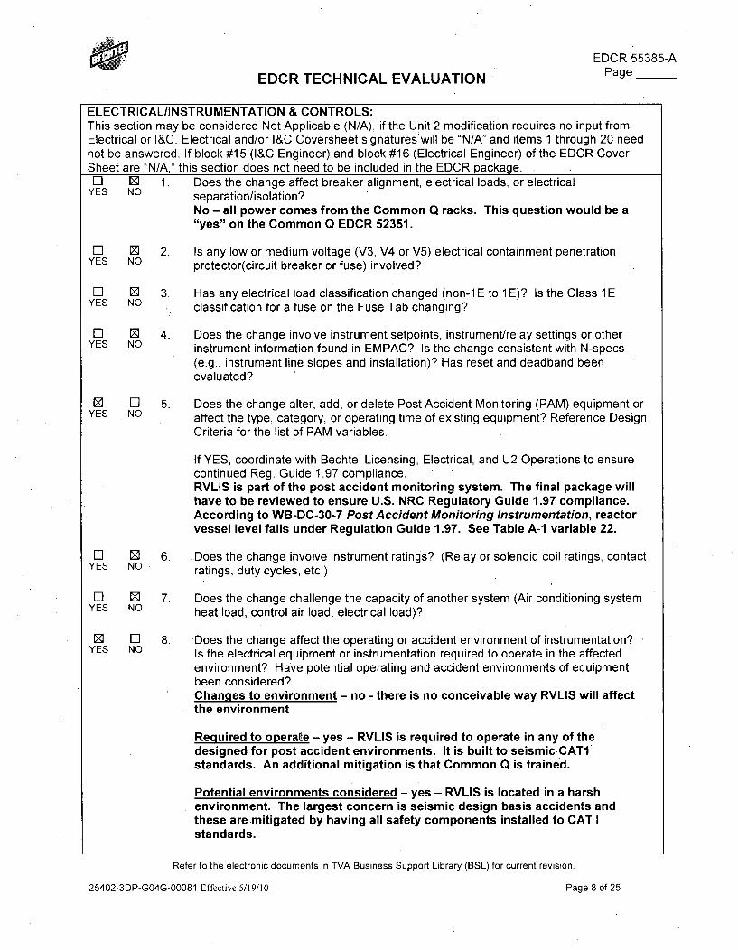
eEDCR 55385-A
EDCR TECHNICAL EVALUATION Page
ELECTRICAL/INSTRUMENTATION & CONTROLS:This section may be considered Not Applicable (N/A), if the Unit 2 modification requires no input fromElectrical or I&C. Electrical and/or I&C Coversheet signatureswill be "N/A" and items 1 through 20 neednot be answered. If block #15 (I&C Engineer) and block #16 (Electrical Engineer) of the EDCR CoverSheet are "N/A," this section does not need to be included in the EDCR package.
El 0 1. Does the change affect breaker alignment, electrical loads, or electricalYES NO separation/isolation?
No - all power comes from the Common Q racks. This question would be a"yes" on the Common Q EDCR 52351.
El 0 2. Is any low or medium voltage (V3, V4 orV5) electrical containment penetrationYES NO protector(circuit breaker or fuse) involved?
El N 3. Has any electrical load classification changed (non-1 E to 1 E)? Is the Class 1 EYES NO I classification for a fuse on the Fuse Tab changing?
El 0D 4. Does the change involve instrument setpoints, instrument/relay settings or other
YES NO instrument information found in EMPAC? Is the change consistent with N-specs
(e.g., instrument line slopes and installation)? Has reset and deadband beenevaluated?
Z El 5. Does the change alter, add, or delete Post Accident Monitoring (PAM) equipment orYES NO affect the type, category, or operating time of existing equipment? Reference Design
Criteria for the list of PAM variables.
If YES, coordinate with Bechtel Licensing, Electrical, and U2 Operations to ensurecontinued Reg. Guide 1.97 compliance.RVLIS is part of the post accident monitoring system. The final package willhave to be reviewed to ensure U.S. NRC Regulatory Guide 1.97 compliance.According to WB-DC-30-7 Post Accident Monitoring Instrumentation, reactorvessel level falls under Regulation Guide 1.97. See Table A-1 variable 22.
El 01 6. Does the change involve instrument ratings? (Relay or solenoid coil ratings, contactYES NO ratings, duty cycles, etc.)
El Z 7. Does the change challenge the capacity of another system (Air conditioning systemYES NO heat load, control air load, electrical load)?
0 El 8. -Does the change affect the operating or accident environment of instrumentation?
YES NO Is the electrical equipment or instrumentation required to operate in the affected
environment? Have potential operating and accident environments of equipmentbeen considered?Changes to environment - no - there is no conceivable way RVLIS will affectthe environment
Required to operate - yes - RVLIS is required to operate in any of thedesigned for post accident environments. It is built to seismic CATIstandards. An additional mitigation is that Common Q is trained.
Potential environments considered - yes - RVLIS is located in a harshenvironment. The largest concern is seismic design basis accidents andthese are mitigated by having all safety components installed to CAT Istandards.
Refer to the electronic documents in TVA Business Support Library (BSL) for current revision.
25402-3DP-GO4G-00081 Effective 5/19/10 Page 8 of 25
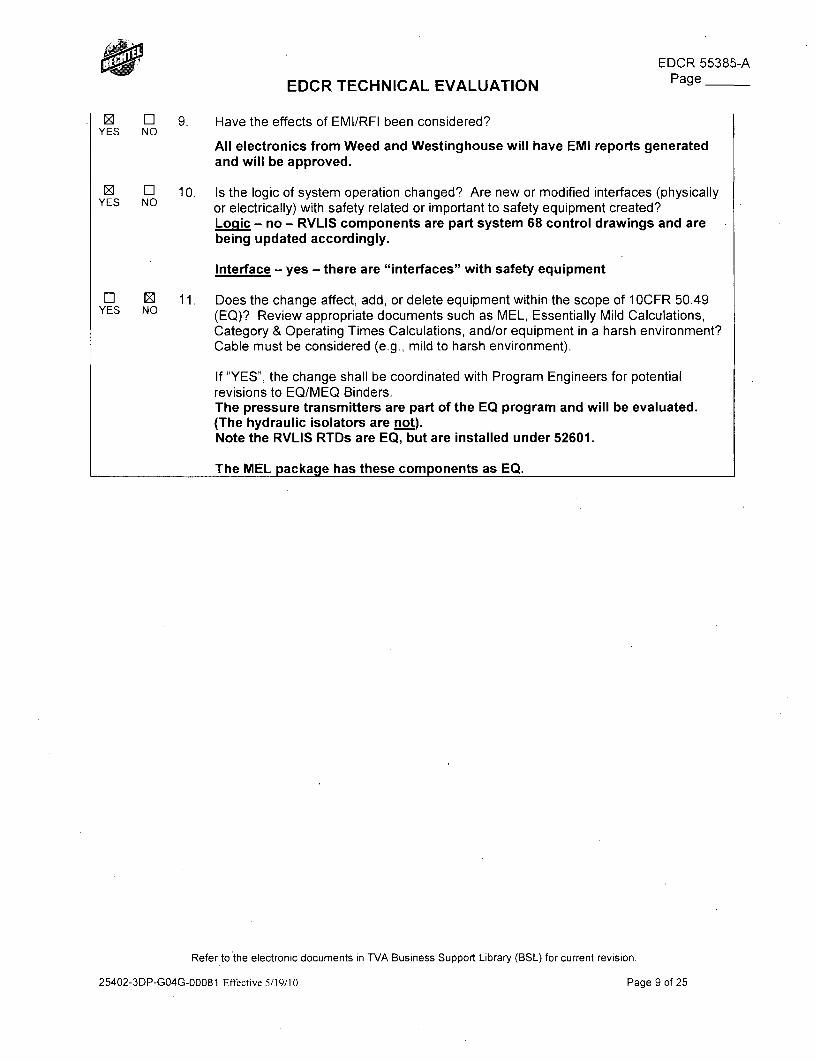
EDCR 55385-APage __EDCR TECHNICAL EVALUATION
0 [EYES NO
9 EJYES NO
El EYES NO
9. Have the effects of EMI/RFI been considered?
All electronics from Weed and Westinghouse will have EMI reports generatedand will be approved.
10. Is the logic of system operation changed? Are new or modified interfaces (physicallyor electrically) with safety related or important to safety equipment created?Loqic - no - RVLIS components are part system 68 control drawings and arebeing updated accordingly.
Interface - yes - there are "interfaces" with safety equipment
11. Does the change affect, add, or delete equipment within the scope of 1 OCFR 50.49(EQ)? Review appropriate documents such as MEL, Essentially Mild Calculations,Category & Operating Times Calculations, and/or equipment in a harsh environment?Cable must be considered (e.g., mild to harsh environment).
If "YES", the change shall be coordinated with Program Engineers for potentialrevisions to EQ/MEQ Binders.The pressure transmitters are part of the EQ program and will be evaluated.(The hydraulic isolators are not).Note the RVLIS RTDs are EQ, but are installed under 52601.
The MEL package has these components as EQ.
Refer to the electronic documents in TVA Business Support Library (BSL) for current revision.
25402-3DP-GO4G-00081 Effective 5/19/10 Page 9 of 25
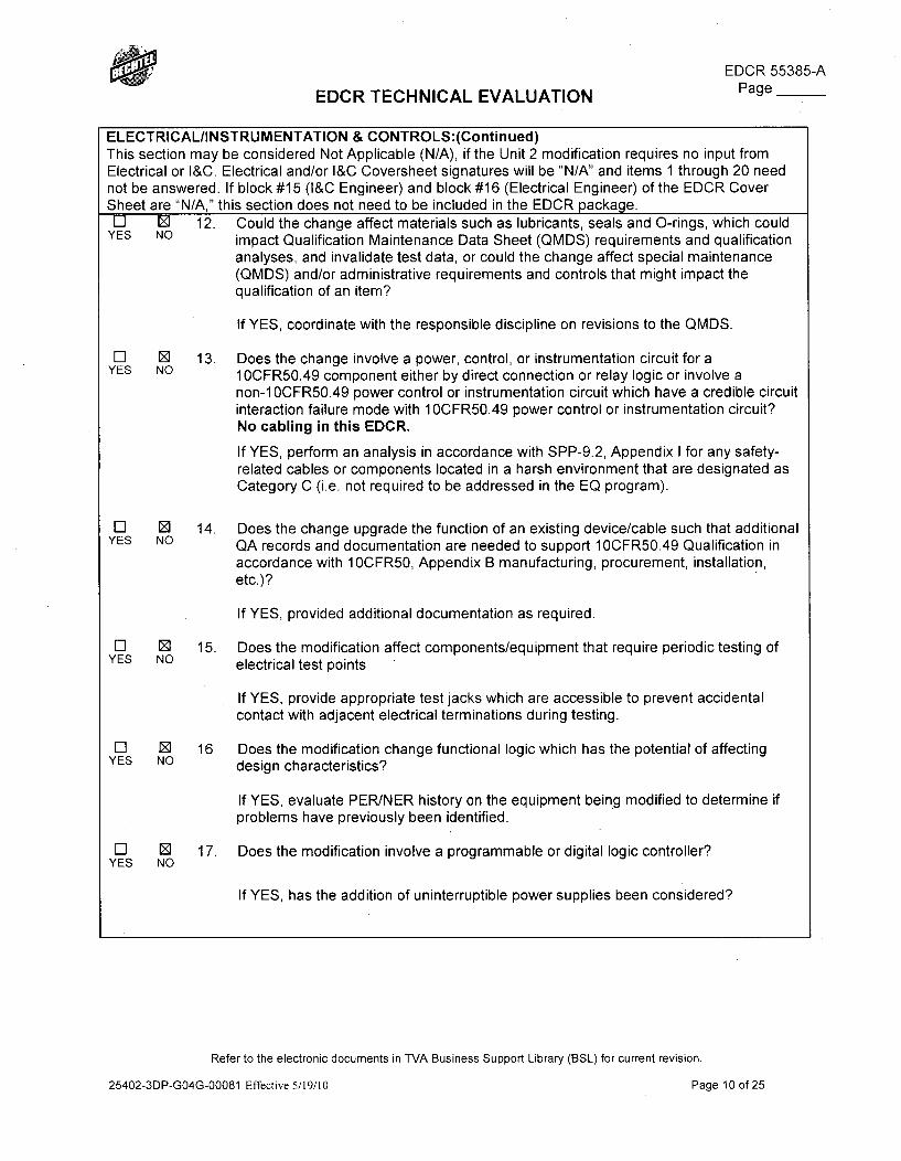
WEDCR 55385-AEDCR TECHNICAL EVALUATION Page
ELECTRICAL/INSTRUMENTATION & CONTROLS:(Continued)This section may be considered Not Applicable (N/A), if the Unit 2 modification requires no input fromElectrical or I&C. Electrical and/or I&C Coversheet signatures will be "N/A" and items 1 through 20 neednot be answered. If block #15 (I&C Engineer) and block #16 (Electrical Engineer) of the EDCR CoverSheet are "N/A," this section does not need to be included in the EDCR package.
El E 12. Could the change affect materials such as lubricants, seals and 0-rings, which couldYES NO impact Qualification Maintenance Data Sheet (QMDS) requirements and qualification
analyses, and invalidate test data, or could the change affect special maintenance(QMDS) and/or administrative requirements and controls that might impact thequalification of an item?
If YES, coordinate with the responsible discipline on revisions to the QMDS.
El 9 13. Does the change involve a power, control, or instrumentation circuit for aYES NO 1OCFR50.49 component either by direct connection or relay logic or involve a
non-1 OCFR50.49 power control or instrumentation circuit which have a credible circuitinteraction failure mode with 1OCFR50.49 power control or instrumentation circuit?No cabling in this EDCR.
If YES, perform an analysis in accordance with SPP-9.2, Appendix I for any safety-related cables or components located in a harsh environment that are designated asCategory C (i.e. not required to be addressed in the EQ program).
El Z 14. Does the change upgrade the function of an existing device/cable such that additional
YES NO QA records and documentation are needed to support 1OCFR50.49 Qualification in
accordance with 1OCFR50, Appendix B manufacturing, procurement, installation,etc.)?
If YES, provided additional documentation as required.
El 0 15. Does the modification affect components/equipment that require periodic testing ofYES NO electrical test points
If YES, provide appropriate test jacks which are accessible to prevent accidentalcontact with adjacent electrical terminations during testing.
El 0 16 Does the modification change functional logic which has the potential of affectingYES NO design characteristics?
If YES, evaluate PER/NER history on the equipment being modified to determine ifproblems have previously been identified.
El 0 17. Does the modification involve a programmable or digital logic controller?YES NO
If YES, has the addition of uninterruptible power supplies been considered?
Refer to the electronic documents in TVA Business Support Library (BSL) for current revision.
25402-3DP-GO4G-00081 Effective 5/19/10 Page 10of 25
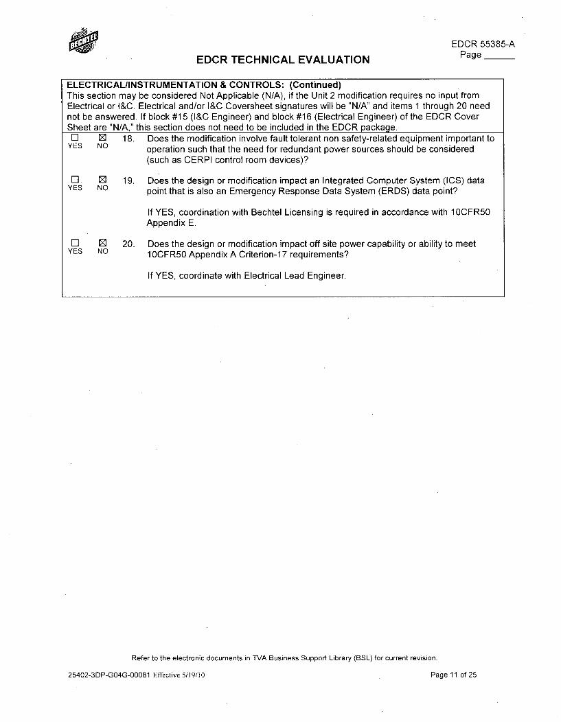
EDCR 55385-APage __EDCR TECHNICAL EVALUATION
ELECTRICAL/INSTRUMENTATION & CONTROLS: (Continued)This section may be considered Not Applicable (N/A), if the Unit 2 modification requires no input fromElectrical or l&C. Electrical and/or I&C Coversheet signatures will be "N/A" and items 1 through 20 neednot be answered. If block #15 (I&C Engineer) and block #16 (Electrical Engineer) of the EDCR CoverSheet are "N/A," this section does not need to be included in the EDCR package.El E 18. Does the modification involve fault tolerant non safety-related equipment important to
YES NO operation such that the need for redundant power sources should be considered(such as CERPI control room devices)?
El [ 19. Does the design or modification impact an Integrated Computer System (ICS) dataYES NO point that is also an Emergency Response Data System (ERDS) data point?
If YES, coordination with Bechtel Licensing is required in accordance with 10CFR50Appendix E.
El E 20. Does the design or modification impact off site power capability or ability to meetYES NO 1 OCFR50 Appendix A Criterion-1 7 requirements?
If YES, coordinate with Electrical Lead Engineer.
Refer to the electronic documents in TVA Business Support Library (BSL) for current revision.
25402-3DP-GO4G-00081 Effective 5/19/10 Page 11 of 25
HEDCR 55385-A
EDCR TECHNICAL EVALUATION Page__
MECHANICAL:This section may be considered Not Applicable (N/A), if the Unit 2 modification requires no input fromMechanical. Mechanical Coversheet signatures will be "N/A" and items 1 through 17 need not beanswered. If block #17 (Mechanical Engineer) of the EDCR Cover Sheet is "N/A," this section does notneed to be included in the EDCR package.
Ensure EQ requirements addressed for ancillary subcomponents (e.g. Limit Switches on Mechanicalonly valves). Coordinate with Electrical EQ Engineer as necessary.
E3 0 1. Does the change affect design conditions or requirements such as processYES NO pressure, temperature, chemistry or operating cycles? Is the change affected by
operation of other systems, either Safety Related or Non Safety Related in any oftheir various operating configurations?Affect design conditions - no
Affected by other systems - no - RVLIS needs no other systems to function tosend its inputs into Common Q PAMS and Eagle 21.
If YES, ensure the evaluation encompasses all aspects of the affected system,including impacts on or by interfacing systems. Coordinate with MEQ ProgramEngineer for potential revisions to affected MEQ documentation.
l [] 2. Does the change affect ECCS, decay heat removal systems, or. MPC cooling
YES NO ancillary equipment? Ensure that any changes are consistent with the safety
analyses for the plant including WBN SAR Chapter 15 NPSH minimum flowrequirements, diesel loading sequencing, and ultimate heat sink limits.
El 0 3. Does the change involve potential heating, ventilation, and air conditioning (HVAC)YES NO system impacts resulting from adding heat loads, altering air flow or ductwork, etc.?
l 0] 4. Does this change make any alterations or configuration changes to Motor OperatedYES NO Valves (MOVs) or Air Operated Valves (AOVs)? Does this change impact any MOV
or AOV Program documents? Impacts that should be considered include changesto instrumentation or control circuits, power supplies, or change system operating ordesign conditions such as pressure and flow rate.
El Z 5. Does this change involve replacement of a complete valve or valve internals whichYES NO are located in a system that interfaces directly with the Reactor Coolant System
(RCS)? Procurement requirements should evaluate valve and valve internalsreplacements that are located in or interfaces with the Reactor Coolant System(RCS) for hard faced components that are non-cobalt bearing. Hard facingalternatives include NOREM, Nitronic 60 and may include other non-cobalt materialsas approved by Engineering. Cobalt bearing hard facing materials is a concern influid systems that contain radioactive materials.
El 0 6. Does the modification add a new check valve or impact an existing check valve?
YES NO Ensure the valve is sized properly, proper type for required service, properly
oriented, located suitable distance from upstream components that cause turbulentflow.
Refer to the electronic documents in TVA Business Support Library (BSL) for current revision.
25402-3DP-GO4G-00081 Effective 5/19/10 Page 12 of 25
EDCR 55385-A
EDCR TECHNICAL EVALUATION Page
MECHANICAL: (Continued)This section may be considered Not Applicable (N/A), if the Unit 2 modification requires no input fromMechanical. Mechanical Coversheet signatures will be "N/A" and items 1 through 17 need not beanswered. If block #17 (Mechanical Engineer) of the EDCR Cover Sheet is "N/A," this section does notneed to be included in the EDCR.package.El M 7. Does the modification add, delete, or reroute components in a mechanical piping
YES NO system? If Yes, will the added components come in contact with borated water orsome other harsh environment area?
] El 8 Does the modification affect ASME Section III Code (Class 1, 2, and/or 3)YES NO boundary?
If "YES," ensure that the materials and installations meet the applicable ASME code.All components in this EDCR are instrument class according to N3E-934.
El E 9. Does this modification introduce material into the containment that could become
YES NO dislodged during LOCA or other events and contribute to Emergency Core Cooling
System (ECCS) sump screen or strainer blockage? Does this modification affectprotective coatings inside the containment?
l [] 10. Does the modification increase the possibility of flooding from a Moderate EnergyYES NO Line Break?
NOTE: Coordinate response with the MELB Program Engineer.
El E 11. Are there NUREG-0612 impacts? Does the change add, delete, or alter a
YES NO permanent handling system? Does the change move a heavy load path over safe
shutdown equipment or move safe shutdown equipment into a heavy load path?This EDCR does not modify any handling system, but the head sensor bellowsare located within a NUREG-0612 interaction area as shown on 44W411 sheet7. However this program has not come to fruition and no analysis can bedone.
El E 12. Does the change affect barriers such as walls, doors, penetrations, relief panels,YES NO and ducts which could affect HVAC flow paths, fire barriers, or environmental
conditions in either harsh or mild areas?
If the answer to any of the above questions is "YES", the change shall becoordinated with the Mechanical EGS.
El E 13. Is a new material being added and does the change affect components susceptibleYES NO to Flow Accelerated Corrosion (FAC) or Microbiologically Induced Corrosion (MIC)?
El 0 14. Does the modification increase the susceptibility for cavitation?YES NO
El ED 15. Could the change affect location or operation of high energy piping systems,
YES NO location or operation of radioactive piping systems, operation of environmental
control systems, or environmental barriers such as walls, doors, relief panels,piping/other thermal insulation, and ducts which could affect environmentalconditions in either harsh or mild areas?
If YES, coordinate with Mechanical EGS for potential revision to the environmentaldrawings/design criteria and coordinate with Electrical EGS for potential impact toEQ of equipment.
Refer to the electronic documents in TVA Business Support Library (BSL) for current revision.
25402-3DP-GO4G-00081 Effective 5/19/10 Page 13 of 25
EDCR 55385-APage __EDCR TECHNICAL EVALUATION
This installs piping that is part of the reactor coolant system which isradioactive. The RCS boundary is the sensor bellows which are located withinthe reactor building.
Refer to the electronic documents in TVA Business Support Library (BSL) for current revision.
25402-3DP-GO4G-00081 Effective 5/19/10 Page 14 of 25
EDCR 55385-APage __EDCR TECHNICAL EVALUATION
MECHANICAL: (Continued)This section may be considered Not Applicable (N/A), if the Unit 2 modification requires no input fromMechanical. Mechanical Coversheet signatures will be "N/A" and items 1 through 17 need not beanswered. If block #17 (Mechanical Engineer) of the EDCR Cover Sheet is "N/A," this section does notneed to be included in the EDCR package.El [] 16. Does the modification change ventilation, cooling requirements for electronic
YES NO equipment?
If YES, coordinate with Mechanical Engineering for determination of impact on HVACcoolant
[ 17. Does the modification involve strainers for a raw water supply?YES NO
If YES, proper strainer selection should be based on industry guidelines (FluidControls Institute Std 89-1) and specific site criteria. Major consideration should begiven to the following; type of strainer, redundant strainer capability,materials/housing, perforations number and arrangement, mesh size & free area,capacity and pressure loss, fluid type, particle weight & shape, macro fouling andaquatic debris potential, operating parameters, filtration versus separation, blow downline sizing, vendor recommendations, automatic back flushing and the necessity of abypass line.
NOTE: Contact the appropriate program coordinator in the Mechanical Programs group (or in PlantDesign for MOV questions), if any Engineering Design Program(s) are impacted by the proposedmodification.
Refer to the electronic documents in TVA Business Support Library (BSL) for current revision.
25402-3DP-GO4G-00081 Effective 5/19/10 Page 15 of 25
EDCR 55385-APage __EDCR TECHNICAL EVALUATION
OPERATIONS/HUMAN FACTORS:El 0 1. Does the change affect the main control room or the backup control areas
YES NO (Environment, workspace, controls and displays)?
If YES, human factors must be addressed.
El E 2. Are OSHA considerations included? Whenever replacement or major repair,
YES NO renovation, or modification of a machine or equipment is performed, and whenever
new machines or equipment are installed, energy isolating devices for suchmachines or equipment must be designed to accept a lockout device. This applies tomechanical and electrical devices.The construction of RVLIS will not require the isolation of any high energysystem. Therefore there would be no applicable OSHA considerations.
Refer to the electronic documents in TVA Business Support Library (BSL) for current revision.
25402-3DP-GO4G-00081 Effective 5/19/10 Page 16 of 25
EDCR 55385-A
EDCR TECHNICAL EVALUATION Page
OTHER:Note: This section is not required for Plant Design EDCRs.Z El 1. Does the change affect equipment diversity, failure modes, single failure criteria
YES NO (DS-E2.0.2, "Single Point Failure For Power Generation Reliability"), equipmentredundancy, or equipment reliability?
0 El Does the modification install redundant equipment?YES NO
If YES, utilization of redundant attendant equipment (e.g., power from alternatesources) shall be considered and addressed.Redundant equipment is being installed in the form of trained components.
E] ED 2. Does the modification change System 18, 43, 77, or 90, or potentially impact theYES NO plant Chemistry Organization (i.e., sampling, procedures, training, spare parts,
chemical treatments, etc.)?
El Z 3. Does the change involve environmental impacts? If ANY of the questions below areYES NO answered "YES," then question #3 must be answered "YES."
El 0 Will the modification require new Chemicals (as defined in SPP-5.4) toYES NO be used anywhere onsite or result in a change in plant chemical storage
or usage?
El Z Will the modification generate any new wastes (Solid, Liquid,YES NO Hazardous, Universal, Used Oil, Radioactive etc.) or result in the
release of any new or different substances to the land, air, or water?
NOTE This does not include consumables used to facilitate theinstallation of the modification.
El 0D Will the modification change the existing flow path or characteristics ofYES NO any discharge to the land, air, or water?
ED Z Will the modification involve any equipment containing PCBs, Mercury,YES NO or Asbestos?
El Z Will the modification involve storage or use of oil or hazardousYES NO substance in an amount equal to or greater than 55 gallons?
If Question #3 is answered "YES," contact Environmental Staff to ensurethat the applicable Environmental Review (in accordance with SPP-5.5and TVA National Environmental Policy Act (NEPA) Process) orchemical traffic control review are initiated/performed.
If Question #3 is answered "YES," Environmental shall be a CoreReview group at the initial and final meeting. If the meetings are waived,then Environmental is required to review the EDCR and sign theCoversheet as an "Other Organization."
Refer to the electronic documents in TVA Business Support Library (BSL) for current revision.
25402-3DP-GO4G-00081 Effective 5/19/10 Page 17 of 25
EDCR 55385-A
EDCR TECHNICAL EVALUATION Page__
OTHER: (continued)Note: This section is not required for Plant Design EDCRs.0 El 4. Does this modification impact the fire protection system or equipment of an insured
YES NO building?See Appendix R sectionIf YES, coordinate with the 1 OCFR50 Appendix R Program Engineer to have theEDCR documents reviewed by the insurance carrier.
El 0 5. Does the modification change functional logic which has the potential of affectingYES NO design characteristics or change/impact an item listed in the Equipment Performance
Information Exchange (EPIX) system?
If YES, evaluate PER/NER history and EPIX on the equipment being modified todetermine if problems have previously been identified and are appropriatelyaddressed in the EDCR Package. Ensure appropriate coordination with affectedorganizations is performed such as Operations, Maintenance, Environmental,Chemistry, and Emergency Preparedness.Various searches were performed on EPIX concerning the current scope ofwork. The following was found
- Wolf Creek - failure #74 - 1998
o One of the RTDs on train A read 40'F different than B train. As aresult train B was declared inoperable.
o There is no maintenance that can effectively and economicallydetect or prevent the onset of failure.
- Oconee Unit 2 - failure #38 - 1997o Failure of RTD caused ICCM Trouble alarm. Replaced RTD
- Calvert cliffs - failure #625o Problem with heated junction TIC RVLIS system - not applicable.
- Wolf Creek - failure #359o One dynamic range transmitter was very different than the other due
to a calibration issue- Oconee Unit 3 - failure #714 - 2005
o Leaking fitting on hydraulic isolator caused entire train to go downo Will be mitigated by using welded fittings when possible
- Vogtle Ul - failure #340 - 2005o Barton level transmitter developed a leak due to "aging". Replaced
with a Rosemount.- Vogtle U2 - failure #341 - 2003
o One train's Barton transmitter started to drift low and would not re-calibrate
o Replaced bad transmitter- Robinson Unit 2 - failure #475 - 2007
o Barton LT drifted out of calibration during a depressurization forrefueling. Replaced transmitter.
- North Anna Ul - failure #2831o Barton LT failed due to the strain gage internal to transmitter.
In conclusion, no action or design change will be taken as a result of theinformation found in EPIX.
Refer to the electronic documents in TVA Business Support Library (BSL) for current revision.
25402-3DP-GO4G-00081 Effective 5/19/10 Page 18 of 25
EDCR 55385-APage __EDCR TECHNICAL EVALUATION
ElYES NO
6. Does the change substitute, change, add or modify materials, components orchemical treatments not previously evaluated to the system parameters orapplication?
Refer to the electronic documents in TVA Business Support Library (BSL) for current revision.
25402-3DP-GO4G-00081 Effective 5/19/10 Page 19 of 25
EDCR 55385-A
EDCR TECHNICAL EVALUATION Page__
IOCFR50 APPENDIX R AND OTHER FIRE PROTECTION IMPACTS: Contact the Program OwnerNote: This section is not required for Plant Design EDCRs.E El a. Does the change directly or indirectly impact Mechanical or Electrical Appendix R
YES NO equipment, or cables, required for safe-shutdown (This includes manual actionsrequired for safe shutdown.)?2-PT-68-63-D is on the safe equipment list. This is a wide range pressuretransmitter.
l [ b. Does the change impact Appendix R component availability in any fire area/zone?YES NO
El 0 c. Have any Appendix R equipment parameters (e.g., flow rate, pressure, setpoints, loadYES NO limitations, electrical load, interface with other components) changed?
E3 Z d. Have Appendix R cable tag/UNID numbers or cable fire area/zone routings changed?YES NO
El Z e. Have Appendix R cables been added/deleted or Appendix R control circuit logics
YES NO been changed?
The cables to be installed to 2-PT-68-63 will be done with EDCR 53301 which isthe wiring EDCR for Eagle-21.
l [] f. Does the change involve a non-Appendix R circuit which interferes with an AppendixYES NO R Circuit (e.g., re-wiring to create associated circuits)?
El 0 g. Does the change impact the use of Appendix R equipment in any fire area/zone?YES NO
El E h. Has component been installed or relocated which obstructs the light pattern of anYES NO existing Appendix R emergency light?
El Z i. Has an Appendix R component been added, deleted or relocated which would affectYES NO Appendix R light placement, including ingress/egress lights?
El 0 j. Has an Appendix R component been installed or relocated in the same fire area/zone
YES NO as its functionally redundant safe shutdown train/system? (This includes instrument
sensing lines.) (Note: The functionally redundant train is not necessarily theredundant divisional train.)
El Z k. Does the change affect in-plant communication systems?YES NO
El Z I. Does the change affect fire barriers, fire doors, fire dampers or fire wraps, or affectYES NO electrical or mechanical penetrations through fire rated walls, floors, ceilings or cable
fire stops?
Refer to the electronic documents in TVA Business Support Library (BSL) for current revision.
25402-3DP-GO4G-00081 Effective 5/19/10 Page 20 of 25
EDCR 55385-A
EDCR TECHNICAL EVALUATION Page__
El [ m. Does the change affect structural steel, raceway supports or raceway fire-proofingYES NO material?
l [] n. Does the change result in the addition or deletion of in-situ combustibles in a fire
YES NO area/zone (e.g., panels, new cable trays, components with oil sumps, grease,
plastics)? (Note: Exclude cables routed entirely in conduits. Also exclude cablesrouted in existing trays without exceeding the tray fill capacity. Exclude combustiblesless than 0.5 gallons oil, 4 lbs plastic, 4 lbs grease or equivalent amount of othercombustible materials.) If yes, combustible loading calculation may be affected.Check with the 1 OCFR50 Appendix R Program Owner.
This EDCR is not adding any combustible components to the reactor building.The sensor bellows are all metal with o-rings. The RTDs have long pig-tails,some 70ft that do have cabling inside, but these are armored so they are treatedlike cabling in conduit. This means that it has no additional impact to thecombustible loading calculations in the reactor building.
In the auxiliary building there would be limited combustible materials within thetransmitters and hydraulic isolators consisting of minimal electricalconnections. This would certainly be less-than 4lbs total and will have noimpact.
The capillary tubing within Unistrut and RTDs routed throughout the plant hasno combustible materials and is installed in 52601.
El ] o. Does the change affect any of the fire protection systems (HPFP, AFFF, Halon, orYES NO CO2) or affect any of the fire detection systems (e.g., smoke or heat)?
El 0 p. Does the change impact the Fire Protection Reports?YES NO
If "YES", then a DCN must be issued.
l [] q. Does the change impact the property insurance carrier fire protection standardsYES NO and/or associated commitments?
El r. Does the change involve the reactor coolant pump oil collection system?YES NO
El 0 s. Does the modification introduce or remove combustible material or fire source in theYES NO area?
If ANY of the above questions are answered "YES," contact the 1 OCFR50 Appendix RProgram Engineer.
Refer to the electronic documents in TVA Business Support Library (BSL) for current revision.
25402-3DP-GO4G-00081 Effective 5/19/10 Page 21 of 25
aEDCR 55385-A
EDCR TECHNICAL EVALUATION Page
SINGLE POINT FAILUREIFAILURE MODES AND EFFECTSIRELIABILITY:Note: This section is not required for Plant Design EDCRs.Checklist of questions to ask vendors of large scale systems, and our own designer(s) in regards to singlepoint failures and margin to operation/trip/runback. The following questions should be considered whendealing with vendor supplied packaged solutions.
This section may be considered Not Applicable (N/A) if the Unit 2 change for the associated EDCR is thesame as the Unit 1 installed design.
If this section is NA, check this box.
Although this EDCR is splitting the RVLIS system,this analysis will cover the system as a whole.
0 El a. What are the system failure modes for the entire package (i.e., output fail-as-is, failYES NO high or low, oscillate, trip system/plant, run back system plant, consider loss of motive
power such as electric or control air, etc.)?
The most likely cause of failure for RVLIS is a leak in one of the fittings on thefilled system side (any amount of leakage will cause failure). This will cause achange in pressure which will cause the hydraulic isolator to "switch" and senda signal to Common Q. A failure indication will appear on the main controlroom display. This will be mitigated by having welded fittings. This failure willlead to a limited condition for operation (LCO) according to the TechnicalSpecification section 3.3.3.
Another cause of failure in the RVLIS system is a leak in the bellows assemblyinternal to the sensor bellows. This will cause no change of pressuredownstream so the hydraulic isolator will not "switch". This will be realized atthe next refueling outage during depressurization when surveillance SI-68-81 isperformed or possibly Auxiliary building radiation surveys since primarycoolant is mixing within the capillary.
Note that it is logically possible that the bellows within the hydraulic isolatorcould seize and not allow any hydraulic coupling to occur - perhaps as a resultof an overpressurization. In this case measuring reactor vessel level would beimpacted since the level transmitter would not see any change in pressure.This is mitigated by having a trained system so the operators would see thedifference between the two trains.
Z El b. What are the failure modes of the individual components, which were considered, andYES NO what was their effect on the overall system (i.e., consider failures of the digital control
systems related to the hardware and software, loss of CPU, loss of communicationconnection, loss of an entire I/O board, etc.)?
Refer to the electronic documents in TVA Business Support Library (BSL) for current revision.
25402-3DP-GO4G-00081 Effective 5/19/10 Page 22 of 25
EDCR 55385-A
EDCR TECHNICAL EVALUATION Page__
Sensor bellows - a breakage of the bellows is the most likely failure. See abovefor explanation.
Hydraulic isolators - if either the switch or internal bellows fails, RVLIS will stillfunction properly since the purpose of the hydraulic isolators is to provide asignal if there is a leak in the filled capillary system.
Level transmitters - the likely failure is that no signal would be sent to CommonQ. Common Q would pick this up and give a system trouble alarm.
The RTD's will fail open or short defaulting to a temperature of 50°F or 450'F.There is no associated alarm with this indication within ICCM-86, but there willbe one within Common Q. Furthermore, the operator will realize this by havinga difference in the two train's vessel levels in which they would troubleshootand quickly find the failed RTD. However it is important to note that this error ishighly dependent upon the height of the vertical run of capillary tubing the RTDis strapped to. In unit 1 there is a method of forcing a failed RTD to read acertain temperature within ICCM-86. Unit 2's Common Q is capable of doing thesame.
In order to account for the failed RTD be either locking in a value or completeremoval, some sort of justification must be done to allow the situation. Thisrequest has been passed to Westinghouse to do in a yet to be determined pieceof documentation.
See RVLIS Instrumentation Manual page 2-12 for further failure analysis.
] El c. Will these system and/or component failures directly or indirectly via transient cause a
YES NO plant trip or runback?
RVLIS is an important system for post accident monitoring, but it has no abilityto trip the plant. It is theoretically possible that RVLIS could rupture upstreamof the sensor bellows, but there is a flow restrictor upstream of the isolationvalve to minimize flow. Thus RVLIS has little ability to impact the plant, andcertainly has no ability to trip the plant.If YES,1 What is the reliability of the individual components and system?
The same components are being used from unit 1. All known PERconditions on unit I are being addressed.
2. How can testing be performed to detect failure modes, miss configurations, andprecursors to imminent failures?
3. What alarms or indications provide timely precursor indication of impendingcomponent/system failure?System trouble alarm on the Common Q display along with theannunciator.
4. What redundancy is there in the alarms, indications, runback, or trip functions?
5. Which trips and runbacks are absolutely necessary? Which can be changed toalarms and what operator response is needed for the alarms?
6. Are digital systems developed in accordance with SPP-2.6 and SS-E18.15.01software requirements for real time data acquisition and control computersystems?RVLIS is trained.
7. Are there any reasons why redundancy was not considered in alarm, trip,runback systems, and can redundancy be added?
Refer to the electronic documents in TVA Business Support Library (BSL) for current revision.
25402-3DP-GO4G-00081 Effective 5/19/10 Page 23 of 25
EDCR 55385-A
EDCR TECHNICAL EVALUATION Page
DIGITAL SYSTEM UPGRADES/MODIFICATIONS:Note: This section is not required for Plant Design EDCRs.Does this change involve a digital system, component, or upgrade?
E] YES E NO If "NO," then leave Questions #1 through 6 below blank.
No digital upgrade is involved. The digital upgrade of Common Q PAMS will be addressed inEDCR 52351.
S 0 1. Have the requirements of SPP-2.6, SS-E1 8.15.01, and the guidelines of DG-E1 8.1.25YES NO been considered?
El El 2. Does the change involve any in-house modification? If so, implement in accordance withYES NO SPP-2.6. Doe the change involve a vendor-performed modification? If so, implement in
accordance with SS-El18.15.01.
l [ 3. Is the digital modification associated with a Safety-Related Protection upgrade? Has theYES NO potential for common cause software failure been considered?
NOTE: For digital upgrades, refer to NRC RIS 2002-2 which endorses NEI 01-01, Rev 1.
4. Has the method and level of configuration control needed for the digital application beenYES NO addressed?
NOTE: The configuration control method should be implemented using approved designcontrol processes such as SPP-2.6 and/or an EDCR (i.e., design output). This mayinvolve the need to maintain configuration control of both the software and hardwarerevision levels. The level of control needed shall be based upon the application function(i.e., Safety Related, Quality Related, Critical to Plant Operations), capability to modifysoftware such as software versus firmware, software and hardware revision compatibility,etc. Safety Related system configuration control must ensure that V&V qualificationremains valid so prescriptive configuration control methods would be required. For NonSafety Related software, the configuration control may be less restrictive with focus onplant reliability and day to day operation. Firmware/Software includes both theOperating/Platform System firmware/software and the application specificfirmware/software along with any configuration parameters such as setpoints, constants,scaling, etc.
Refer to the electronic documents in TVA Business Support Library (BSL) for current revision.
25402-3DP-GO4G-00081 Effective 5/19/10 Page 24 of 25
EDCR 55385-APage __EDCR TECHNICAL EVALUATION
DIGITAL SYSTEM UPGRADES/MODIFICATIONS: (continued)Note: This section is not required for Plant Design EDCRs.Does this change involve a digital system, component, or upgrade?
El YES Z NO If "NO," then leave Questions #1 through 6 below blank.El El 5. Has a Cyber Security Assessment been completed to address NEI 04-04 requirements?
YES NO Contact the Computer Engineering Group for instructions.
El El 6. Is there a communication network interface such as an ICS interface?YES NO
If yes, implement design of this interface per the guidelines addressed in DG-E18.1.25.
Based on the Technical Evaluation Considerations responses listed above, the modifications describedwithin this EDCR are considered safe from a nuclear safety standpoint.
Refer to the electronic documents in TVA Business Support Library (BSL) for current revision.
25402-3DP-GO4G-00081 Effective 5/19/10 Page 25 of 25
Enclosure 2TVA Letter Dated October 29, 2010
Responses to Licensee Open Items to be Resolved for SER Approval
Attachment 5
Draft FSAR Section 7.6.8 COMS Changes
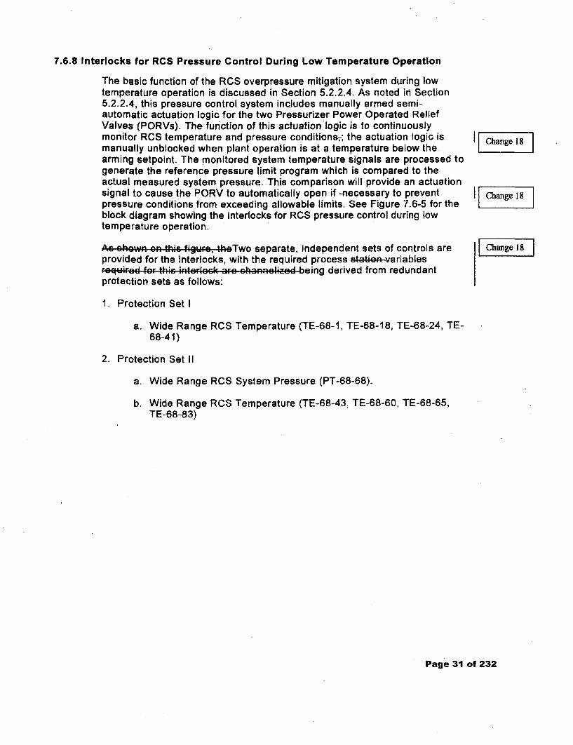
7.6.8 Interlocks for RCS Pressure Control During Low Temperature Operation
The basic function of the RCS overpressure mitigation system during lowtemperature operation is discussed in Section 5.2.2.4. As noted in Section5.2.2.4, this pressure control system includes manually armed semi-automatic actuation logic for the two Pressurizer Power Operated ReliefValves (PORVs). The function of this actuation logic is to continuouslymonitor RCS temperature and pressure conditions;-; the actuation logic ismanually unblocked when plant operation is at a temperature below thearming setpoint. The monitored system temperature signals are processed togenerate the reference pressure limit program which is compared to theactual measured system pressure. This comparison will provide. an actuationsignal to cause the PORV to automatically open if -necessary to preventpressure conditions from exceeding allowable limits. See Figure 7.6-5 for theblock diagram showing the interlocks for RCS pressure control during lowtemperature operation.
As shown Cn thi. figure, thoTwo separate, independent sets of controls areprovided for the interlocks, with the required process statkaA-variables.. quired for- this i•terloc• ah•r c..nnA.kiAd being derived from redundantprotection sets as follows:
1. Protection Set I
a. Wide Range RCS Temperature (TE-68-1, TE-68-18, TE-68-24, TE-68-41)
2. Protection Set II
a. Wide Range RCS System Pressure (PT-68-68).
b. Wide Range RCS Temperature (TE-68-43, TE-68-60, TE-68-65,TE-68-83)
Changel J
[Changel18
Page 31 of 232
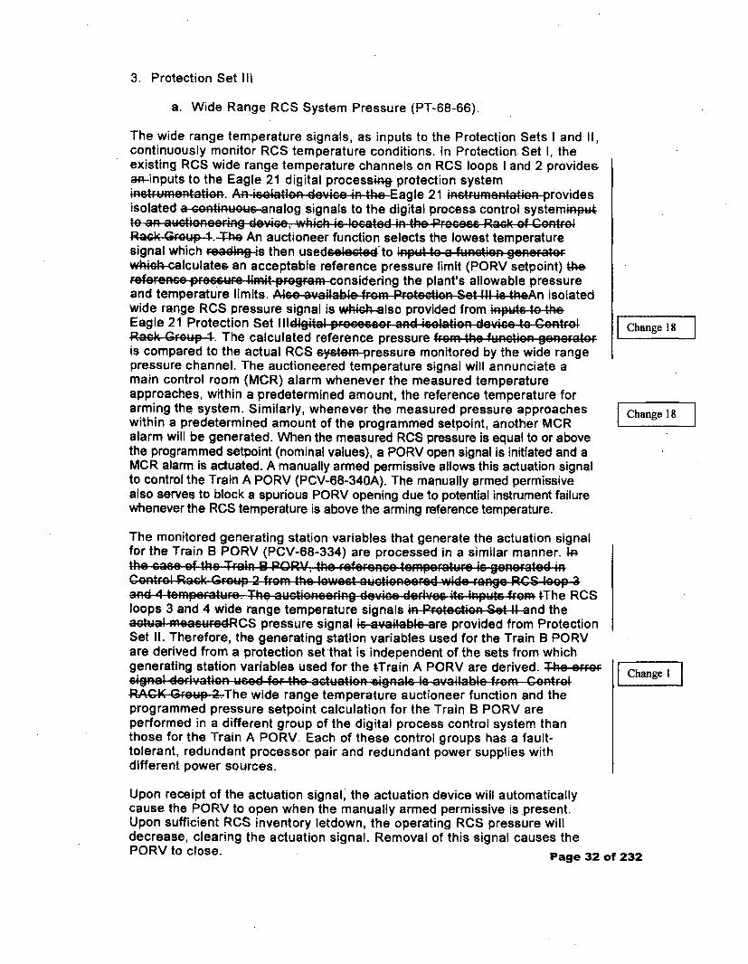
3. Protection Set Ill
a. Wide Range RCS System Pressure (PT-68-66).
The wide range temperature signals, as inputs to the Protection Sets I and II,continuously monitor RCS temperature conditions. In Protection Set I, theexisting RCS wide range temperature channels on RCS loops I and 2 providesa;;-inputs to the Eagle 21 digital process.ig protection systeminetrumentaton. An isolation device in the Eagle 21 instrumentat.on providesisolated a sontinuous-analog signals to the digital process control system*p*to an auctioneer-ng device, which is located in the PrOcacc RGck Of ConrolGRa•k G 4rup.-T-he An auctioneer function selects the lowest temperaturesignal which reading s then used'oleedto input to a fun-tion • gen..t• owh~ik-calculatee an acceptable reference pressure limit (PORV setpoint) therefe.rence pr..UF. limigt progrAm considering the plant's allowable pressureand temperature limits. Also available from Protectlon Set Ill Ic theAn isolatedwide range RCS pressure signal is whiah lso provided from inputs o heEagle 21 Protection Set Illdigital proco....r and i,,latio; dovi,, to ControlRae O•up4. The calculated reference pressure from the fun'ctin gonorateris compared to the actual RCS system-pressure monitored by the wide rangepressure channel. The auctioneered temperature signal will annunciate amain control room (MCR) alarm whenever the measured temperatureapproaches, within a predetermined amount, the reference temperature forarming the system. Similarly, whenever the measured pressure approacheswithin a predetermined amount of the programmed setpoint, another MCRalarm will be generated. When the measured RCS pressure is equal to or abovethe programmed setpoint (nominal values), a PORV open signal is initiated and aMCR alarm is actuated. A manually armed permissive allows this actuation signalto control the Train A PORV (PCV-68-340A). The manually armed permissivealso serves to block a spurious PORV opening due to potential instrument failurewhenever the RCS temperature is above the arming reference temperature.
The monitored generating station variables that generate the actuation signalfor the Train B PORV (PCV-68-334) are processed in a similar manner. 4rýthe caso Of the Train 1B PORV, the re-ference6 temFperature is gener811ated 4inControl Rack Group 2 fromR the lowest auctioneorfed mwide range RCS loop 3and 4 tem•p.ratur.e. The auction. eing device de;iVG"" it. inputs froGm tThe RCSloops 3 and 4 wide range temperature signals in Protectioen Set 1! and theact!al .meacuredRCS pressure signal is.av•ailableare provided from ProtectionSet II. Therefore, the generating station variables used for the Train B PORVare derived from a protection set that is independent of the sets from whichgenerating station variables used for the tTrain A PORV are derived. T1e eFF9Fsignol derivation weod for the actuation -signals is available fromA ControlRAGK. GFe-p-2.The wide range temperature auctioneer function and theprogrammed pressure setpoint calculation for the Train B PORV areperformed in a different group of the digital process control system thanthose for the Train A PORV. Each of these control groups has a fault-tolerant, redundant processor pair and redundant power supplies withdifferent power sources.
Change 187
Change 18
SChange lI
Upon receipt of the actuation signal, the actuation device will automaticallycause the PORV to open when the manually armed permissive is present.Upon sufficient RCS inventory letdown, the operating RCS pressure willdecrease, clearing the actuation signal. Removal of this signal causes thePORV to close. Page 32 of 232
Enclosure 2TVA Letter Dated October 29, 2010
Responses to Licensee Open Items to be Resolved for SER Approval
Attachment 6
TVA Design Criteria Document WB-DC-40-24,Radiation Monitoring (Unit 1/Unit 2), Revision 21, dated June 17, 2009
TITLERADIATION MONITORING -- (UNIT I I
UNIT 2)
WB-DC-40-24Rev. 0021Page 1 of 86
NPG DesignCriteria Document
Quality Related
Effective Date
El Yes 0 No
06-17-2009
Prepared by: J. S. Robertson
Reviewed by: J. F .Lund 06-15-2009
Date
Concurred by: J. F. Lund 06-15-2009
Date
Approved by: D. M. Viscusie 06-15-2009
Project Manager, Design Engineering Date
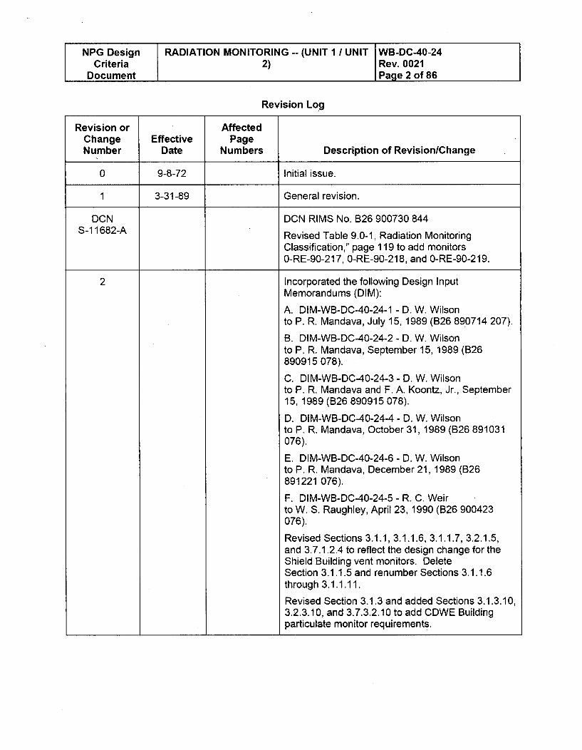
L NPG Design RADIATION MONITORING -- (UNIT 1 / UNIT WB-DC-40-24Criteria 2) Rev. 0021
Document Page 2 of 86
Revision Log
Revision or AffectedChange Effective PageNumber Date Numbers Description of Revision/Change
0 9-8-72 Initial issue.
1 3-31-89 General revision.
DCN DCN RIMS No. B26 900730 844S-1 1682-A Revised Table 9.0-1, Radiation Monitoring
Classification," page 119 to add monitors0-RE-90-217, 0-RE-90-218, and 0-RE-90-219.
2 Incorporated the following Design InputMemorandums (DIM):
A. DIM-WB-DC-40-24-1 - D. W. Wilsonto P. R. Mandava, July 15, 1989 (B26 890714 207).
B. DIM-WB-DC-40-24-2 - D. W. Wilsonto P. R. Mandava, September 15, 1989 (B26890915 078).
C. DIM-WB-DC-40-24-3 - D. W. Wilsonto P. R. Mandava and F. A. Koontz, Jr., September15, 1989 (B26 890915 078).
D. DIM-WB-DC-40-24-4 - D. W. Wilsonto P. R. Mandava, October 31, 1989 (B26 891031076).
E. DIM-WB-DC-40-24-6 - D. W. Wilsonto P. R. Mandava, December 21, 1989 (B26891221 076).
F. DIM-WB-DC-40-24-5 - R. C. Weirto W. S. Raughley, April 23,1990 (B26 900423076).
Revised Sections 3.1.1, 3.1.1.6, 3.1.1.7, 3.2.1.5,and 3.7.1.2.4 to reflect the design change for theShield Building vent monitors. DeleteSection 3.1.1.5 and renumber Sections 3.1.1.6through 3.1.1.11.
Revised Section 3.1.3 and added Sections 3.1.3.10,3.2.3.10, and 3.7.3.2.10 to add CDWE Buildingparticulate monitor requirements.
NPG Design RADIATION MONITORING -- (UNIT 1 / UNIT WB-DC-40-24Criteria 2) Rev. 0021
Document Page 3 of 86
Revision Log
Revision or AffectedChange Effective PageNumber Date Numbers Description of RevisionlChange
2 Revised Section 3.1.6 to add the CDWE Building(cont'd) area monitors and correct the name of
1,2-RE-90-010 from Auxiliary Building access areamonitors to CVCS board area monitors. AddedSections 3.1.6.21, 3.2.6.21, and 3.7.6.2.21 to addrequirements for the CDWE Building area monitors.Revise Section 3.2.5.1 b to correct the safetyfunction from primary to secondary for the wastedisposal system gaseous effluent monitor.
Revised Sections 3.2.6.1 through 3.2.6.14and 3.2.6.17 through 3.2.6.20, 3.7.6.2.1through 3.7.6.2.14 and 3.7.6.2.17through 3.7.6.2.20 to delete the requirements for alocal alert and malfunction alarm for the areamonitors.
Revised Section 7.2 to add approved exceptions.
Added references 8.2.1, 8.4.11, 8.4.12, and 8.6.1through 8.6.33 (requirements calculations).
Revised Tables 9.0-1, 9.0-2, 9.0-3, 9.0-4, and 9.0-5to reflect design changes, CDWE Building monitoradditions, to correct environmental and mechanicaldata, and to incorporate the results of therequirements (range and accuracy calculations.
Revised Sections 3.1.1.11 (now 3.1.1.10), 3.2.1.8,and 3.7.1.2.7 to add the requirements for theportable airborne radioactivity monitors.
Revised Sections 3.1.1.2, 3.1.4.1, 3.1.4.10 (now3.1.4.9), 3.1.6.10, 3.2.1.2, 3.2.1.3, 3.2.1.4, 3.2.1.7,3.2.2.2, 3.2.4.5, 3.2.4.10 (now 3.2.4.9), 3.7.1.2.8,3.7.2.2.3, 3.7.3.1, 3.7.3.2.9, 3.7.4.1, 3.7.5.2.1,3.7.7, 4.1.1.3, 4.1.2.1, and 4.1.3, and deleted 3.9,4.0, 4.1.1.2, 3.7.6.2.20b and relettered paragraphs.
Revised the Table of Contents as necessary.
Made editorial changes for consistency innomenclature and when required for clarity.
This revision incorporated applicablecommitments/requirements per WBEP-DB.02.
Revised Sections 3.1.7.1 and 3.1.7.2 to allow use ofa single monitor if one monitor that satisfies therequired range and accuracy is obtainable.
NPG Design RADIATION MONITORING -- (UNIT 1 / UNIT WB-DC-40-24Criteria 2) Rev. 0021
Document Page 4 of 86
Revision Log
Revision or AffectedChange Effective PageNumber Date Numbers Description of RevisionlChange
2 Make clear requirements that containment lower(cont'd) and upper compartment monitors provide real-time
detection of radioiodine.
Section 3.2.4 - Clarified minimum sample flowrequirements for the off-line liquid monitors.
Clarified requirements for remote indication ofseveral area monitors.
Section 3.7.1.2.2 - Changed sample flow raterequirements for the Service Building vent monitor.
Section 3.12 - Changed a requirement for low pointtaps in sampling systems to a recommendation.
In Sections 3.1.3.2, 3.1.3.7, in subsequent sections,and in the tables, the two area monitors previouslyboth identified as "Waste Packaging Area Monitor"are differentiated by renaming one of them the"Second Waste Packaging Area Monitor."
Section 3.1.7 - The letdown monitor, RE-90-104, isreclassified from an offline liquid monitor to anonline monitor. The changes in the criteria thatresult from this reclassification are made.
Sections 3.2.6.15 and 3.2.6.16 - A requirement toprovide indication of exposure rates measured bythe Reactor Building post-accident monitors in theMCR is added.
Section 3.7.1.2.5 - The requirement to provideoutput from the condenser vacuum pump normalrange monitors to the plant computer data logger isdeleted.
Section 3.9 - The requirement for sample pumps tohave remote on/off controls is deleted.
Section 3.8 - Revised to state thermal overloadbypass of thermal overload protection devices forsafety-related motor-operated valves and torqueswitches is not required.
Clarified Note 1 to Table 9.0-1. Deleted unusednotes in the tables
NPG Design RADIATION MONITORING -- (UNIT 1 / UNIT WB-DC-40-24Criteria 2) Rev. 0021
Document Page 5 of 86
Revision Log
Revision or AffectedChange Effective PageNumber Date Numbers Description of Revision/Change
2 Section 3.7.1.2.4 - Deleted requirement that the(cont'd) SBV Noble gas monitor provide means for local
display of the latest averaged measured data, andmeans for local actuation of the check source forchannels that have check sources.
Deleted requirement that the SBV particulate andiodine monitor include a radiation detector near theparticulate/iodine grab sample filters.
DCN Revise Table of Contents to delete existingM-21861-A Section 3.10.1.1 and re-number Section 3.10.1.2 as
new Section 3.10.1.1.
Delete the automatic control functions of theAuxiliary Building Vent Monitor as specified inSections 3.1.1.1, 3.2.1.1, and 3.7.1.2.1.
Delete existing Section 3.10.1.1 for the AuxiliaryBuilding Vent Monitor automatic control functions.Re-number Section 3.10.1.2 as newSection 3.10.1.1.
Delete Auxiliary Building Ventilation Monitor fromtable 9.0-4.
DCN 06/18/93 RIMS No. T56 930618 881
S-1 7772-A Revise Table of Contents to delete
Sections 3.1.1.10, 3.1.6.13, 3.2.1.8, 3.2.6.13,3.7.1.2.7 and 3.7.6.2.13, 3.10.1 and 3.10.1.1 andrenumber Sections 3.1.6.14 thru 3.1.6.21 as3.1.6.13 thru 3.1.6.20, Section 3.2.1.9 as 3.2.1.8,Sections 3.2.6.14 thru 3.2.6.21 as 3.2.6.13thru 3.7.6.20, Section 3.7.1.2.8 as 3.7.1.2.7, andSections 3.7.6.2.14 thru 3.7.6.2.21 ad 3.7.6.2.13thru 3.7.6.2.20.
Revise Sections 3.1.1, 3.1.1.5, 3.1.1.6, 3.2.1.5, 3.6and 3.7.1.2.4 to address changes related to theShield Building Vent Monitors.
Revise Sections 3.1.1.3, 3.1.1.4, 3.2.1.3, 3.2.1.4,3.7.1.2.3, 3.10.1.1 and Table 9.0-4 to addresschanges to the Containment Lower and UpperCompartment Monitors.
Delete Section 3.1.1.10.
NPG Design RADIATION MONITORING -- (UNIT 1 / UNIT WB-DC-40-24Criteria 2) Rev. 0021
Document Page 6 of 86
Revision Log
Revision or AffectedChange Effective PageNumber Date Numbers Description of Revision/Change
DCN In Section 3.1.6 delete line for Laundry RoomS-1 7772-A Monitor O-RE-90-063.
(cont'd) Delete Section 3.1.6.13 and renumber succeeding
Sections 3.1.6.14 through 3.1.6.21 as 3.1.6.13through 3.1.6.20.
Delete Section 3.2.1.8 and renumber paragraph3.2.1.9 as 3.2.1.8.
Delete Section 3.2.6.13 and renumber succeedingSections 3.2.6.14 through 3.2.6.21 as 3.2.6.13through 3.2.6.20.
Revised Section 3.5 to add pressure andtemperature effects.
Revised Section 3.2.7.1 to revise the SafetyClassification and Safety Function for the MainSteam Line Monitors from primary to secondarysafety function.
Delete Section 3.7.1.2.7 and renumberSection 3.7.1.2.8 as 3.7.1.2.7.
Delete Section 3.7.6.2.13 and renumbersucceeding Sections 3.7.6.2.14 through 3.7.6.2.21as 3.7.6.2.13 through 3.7.6.2.20.
Revise reference list to update and addReferences.
Revised Table 9.0-1 to revise the Electrical SafetyClass, Seismic Category of Detector Assembly, andWB-DC-30-7 Category/Type for 1, 2-RE-90-421thru 1, 2-RE-90-424 to reflect non IE, Seismic I(L)and 2/C, E respectively, to delete 0-RE-90-063, toadd note 39 for 1, 2-RE-90-400 and 402, to deletePortable Monitors 0-RE-90-217, 218, 219 and todelete Monitor 1-RE-90-104.
Revised Table 9.0-2 to revise the source of sampledescription for 1, 2-RE-90-106 and 112, and todelete Portable Monitors 1, 2-RE-90-217, 218and 219.
Revise Table 9.0-3 to delete Laundry RoomMonitor 0-RE-90-063 and Portable Monitors0-RE-90-217, 218, and 219.
NPG Design RADIATION MONITORING -- (UNIT 1 I UNIT WB-DC-40-24Criteria 2) Rev. 0021
Document Page 7 of 86
Revision Log
Revision or AffectedChange Effective PageNumber Date Numbers Description of RevisionlChange
DCN Revised Table 9.0-4 to delete Cnmt Bldg. LowerS-17772-A and Upper Compartment Monitors.
(cont'd) Revised Table 9.0-5 to revise the Primary Safety
Function, and Secondary Safety Function for 1,2-RE-90-421 thru 1, 2-RE-90-424 to reflect No andYes respectively, to delete 0-RE-90-063 and todelete Portable Monitors 0-RE-90-217, 218and 219.
These revisions reflect the changes implementedby DCNs M-09964-A, M-3450-A, M-3451 -A,F-24447-A, M-13516, and M-11823.
Pages Added: Revision Log (2 pages)
Pages Changes: i, ii, iii, iv, vi, 6, 8, 9, 18, 21,22,27-32, 49-54, 56, 57, 61-64, 77-80, 86, 87, 106,108, 109, 111-114, 116,117, 120, 128-130, 132,133, 138-140.
Pages Replaced: None
3 07-30-93 Revision 3 is performed as part of the CorrectiveAction to SCAR WBE890178901SCA, Revision 3.This is a general revision based on a review inaccordance with the guidelines of Appendix B toEAI-3.08 and included comments from SERTProgram, thus revision bars are omitted on editorialcomments.
This revision incorporates EX-WB-DC-40-24-3 andEX-WB-DC-40-24-4 of Revision 2 of this DesignCriteria.
DCN 02/25/94 DCN RIMS NO. T56 940226 909S-29571 -A Revised Section 3.2.4.5 to correct the seismic
category of the detection assembly of monitors 0, 1,2-RE-90-123 from I to I(L).
Revised Pages: va and 41
NPG Design RADIATION MONITORING -- (UNIT 1 / UNIT WB-DC-40-24Criteria 2) Rev. 0021
Document Page 8 of 86
Revision Log
Revision or AffectedChange Effective PageNumber Date Numbers Description of RevisionlChange
DCN 04/14/94 DCN RIMS NO. T56 940415 844S-30248-A Revised to update references to new revision of
10CFR20, correct minor documentationdiscrepancies, provide clarifying statements forfunctional requirements.
Revised Pages: va, 11, 12, 13, 14, 23, 27, 28, 30,31, 41,44, 54, 55, 59,67, 83, 84, 89, 96, 97, 104,105, 106, 107, 108, 109, 111,112, 113, 115, 116,117, 123, 124, 125, 131, 133, 134, and 136
Pages Added: 55a
DCN 05/02/94 DCN RIMS NO. T56 940503 928
S-29903-A Revised to state that SGBD radiation
monitor 1-RE-90-124 is not used for Unit 1operation.
Revised Pages: va, 14, 15, 112, 121, and 133
DCN 06/03/94 DCN RIMS NO. T56 940603 850S-30248-B Revised Table 9.0-1 for clarification of the power
requirements for RE-90-133/134/140/141 and torevise the range of RE-90-002 from MR/hr to R/hr.Revised to add revision bar to table 9.0-3. Changewas performed by DCN S-30248-A which omittedthe revision bar.
Revised Pages: va, 112, and 123
DCN 09/10/94 DCN RIMS NO. T56 940910 810
S-32560-A Revised Section 3.1.4.3, Table 9.0-1, 9.0-3,
and 9.0-4 to indicate the boric acid evaporatorcondensate monitor (1-RE-90-170) is not used forUnit 1 operation.
Revised Section 3.2.7.2.a, 3.2.7.3.a, and 3.2.7.4.ato delete the requirement for visual alarm locally onchannel malfunction.
Revised Section 3.7.1.1 (Page 60) to clarify thatinstruments to measure flow rate and systempressure are required to correct particulate andiodine measurements.
NPG Design RADIATION MONITORING -- (UNIT 1 / UNIT WB-DC-40-24Criteria 2) Rev. 0021
Document Page 9 of 86
Revision Log
Revision or AffectedChange Effective PageNumber Date Numbers Description of Revision/Change
DCN Revised Section 3.7.6.2.21 .c to correct mR/m toS-32560-A mR/Hr.
(cont'd) Revised Section 4.1.1.2 to refer to Reference
8.6.31 for guidance on probe isokinetic design andto delete "Later" for minimum probe nozzlediameter.
Revised References to add Reference 8.6.31.
Revised Table 9.0-5 to indicate monitor,1,2-RE-90-129 has no post accident monitoringfunction and that monitor 1,2-RE-90-421 does notperform a primary safety function.
Pages Revised: 15, 54, 55, 60, 80, 95, 109, 112,121,129,131,133Pages Added: vbTotal Pages: 154 (Including i - xiv, va, vb, 55a,104a)
DCN DCN RIMS Number T56 940926 882
S-31881-A Revised to add Source Notes CATD
2291 1-WBN-01.
Revised Pages vb, xivAdded Pages: 137Deleted Pages: None
DCN 10/07/94 DCN RIMS NO. T56 941008 900
S-32575-A Revised Index, Page xiv, to reflect renumbered
pages.
Revised Section 3.1.4 to add ". to 1-RE-90-170.
Revised Section 3.7.1.2.3 to correct typographicalerror.
Revised Section 3.7.4.1, Paragraph 10, to changereference from Section 3.10.4 to Table 9.0-5.
Revised Section 4.1.1.1.2, Paragraph 6, to delete"Reference Later."
Revised Calculation Section 8.6 to add RIMSnumber for Reference 8.6.13.
ENPG Design RADIATION MONITORING -- (UNIT 1 / UNIT WB-DC-40-24Criteria 2) Rev. 0021Document Page 10 of 86
Revision Log
Revision or AffectedChange Effective PageNumber Date Numbers Description of RevisionlChange
DCN Revised Table 9.0-1 to delete 1E electrical safetyS-32575-A class for 1,2-RE-90-404 and to delete 1 E from Note
(cont'd) 14.
Revised Table 9.0-3, Page 121, to deletetransmission factor and Page 126 to revised Note10 and add Note 10.1.
Consolidated Pages 127 and 128 and renumberedPages 129 through 137 to 129 through 136.
Revised Table 9.0-5, Page 132, to add "*" to1 -RE-90-170.
Pages Added: vcPages Deleted: 137Pages Revised: xiv, 14, 61,69, 94, 108, 111, 115,121,126 through 136Total Pages: 156 (Including cover sheet, i, xiv, va,vb, vc, 55a, 104a)
DCN DCN RIMS NO. T56 950204 831S-34674-A Revised Index, Sections 3.1.4, 3.1.4.8, 3.2.4.8,
3.7.4.2.8, Table 9.0-1, Table 9.0-3, and 9.0-5 todelete plant liquid discharge monitor 0-RE-90-21 1.This monitor is not required since all radioactiveliquid sources making up the plant liquid dischargestream are monitored separately. DCN W-34481-Adeleted the monitor from the drawings.
Pages revised: vc, viii, ix, xi, 14, 17, 42, 43,112,121,132Total Pages: 156 (Including cover sheet i, xiv, va,vb, vc, 55a, 104a)
4. 4/28/95 This is a complete revision of the entire designcriteria. This revision is being performed as part ofthe corrective action to WBPER940423 andWBPER940601. Since this revision constitutes atotal rewrite of the design criteria, revision barshave been omitted.
Total Pages: 73
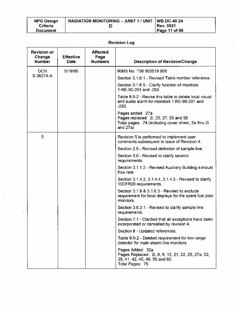
NPG Design RADIATION MONITORING -- (UNIT 1 / UNIT WB-DC-40-24Criteria 2) Rev. 0021
Document Page 11 of 86
Revision Log
Revision or AffectedChange Effective PageNumber Date Numbers Description of Revision/Change
DCN 5/19/95 RIMS No. T56 950519 958S-36274-A Section 3.1.6.1 - Revised Table number reference.
Section 3.1.6.5 - Clarify function of monitors1-RE-90-291 and -293.
Table 9.0-2 - Revise this table to delete local visualand audio alarm for monitors 1-RE-90-291 and-293.
Pages added: 27aPages replaced: 2i, 25, 27, 55 and 56Total pages: 74 (including cover sheet, 2a thru 2iand 27a)
5 Revision 5 is performed to implement user
comments subsequent to issue of Revision 4.
Section 2.0 - Revised definition of sample line.
Section 3.0 - Revised to clarify seismicrequirements.
Section 3.1.1.2 - Revised Auxiliary Building exhaustflow rate.
Section 3.1.4.2, 3.1.4.4, 3.1.4.5 - Revised to clarify10CFR20 requirements.
Section 3.1.6 & 3.1.6.3 - Revised to excluderequirement for local displays for the spent fuel poolmonitors.
Section 3.6.3.1 - Revised to clarify sample line
requirements.
Section 7.1 - Clarified that all exceptions have beenincorporated or cancelled by revision 4.
Section 8 - Updated references.
Table 9.0-2 - Deleted requirement for low rangedetector for main steam line monitors.
Pages Added: 32aPages Replaced: 2i, 8, 9, 13, 21, 22, 25, 27a, 32,35, 41, 42, 45, 46, 56 and 60.Total Pages: 75
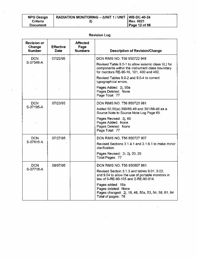
NPG Design RADIATION MONITORING -- (UNIT 1 I UNIT WB-DC-40-24Criteria 2) Rev. 0021
Document Page 12 of 86
Revision Log
Revision or AffectedChange Effective PageNumber Date Numbers Description of RevisionlChange
DCN 07/22/95 DCN RIMS NO. T56 950722 948S-37549-A Revised Table 9.0-1 to allow seismic class I(L) for
components within the instrument class boundaryfor monitors RE-90-16, 101, 400 and 402.
Revised Tables 9.0-2 and 9.0-4 to correcttypographical errors.
Pages Added: 2j, 50aPages Deleted: NonePage Total: 77
DCN 07/23/95 DCN RIMS NO. T56 950723 981
S-37195-A Added 50.55(e) 390/86-49 and 391/86-46 as a
Source Note to Source Note Log Page 65.
Pages Revised: 2j, 65Pages Added: NonePages Deleted: NonePage Total: 77
DCN 07/27/95 DCN RIMS NO. T56 950727 907
S-37610-A Revised Sections 3.1.4.1 and 3.1.6.1 to make minor
clarification.
Pages Revised: 2i, 2j, 20, 25Total Pages: 77
DCN 08/07/95 DCN RIMS NO. T56 950807 861S*-37718-A Revised Section 3.1.3 and tables 9.01, 9.02,
and 9.04 to allow the use of portable monitors inlieu of 0-RE-90-105 and 2-RE-90-014.
Pages added: 18aPages deleted: NonePages changed: 2j, 18, 48, 50a, 53, 54, 58, 61, 64Total of pages: 78
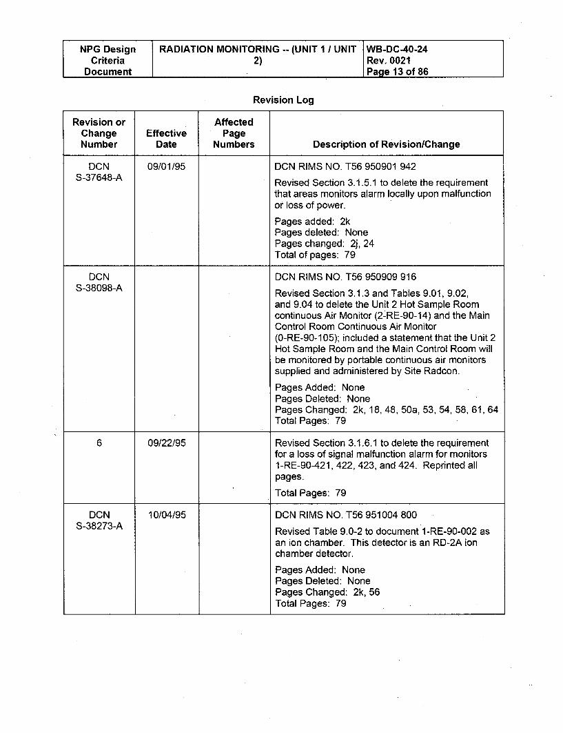
[NPG Design RADIATION MONITORING -- (UNIT 1 / UNIT WB-DC-40-24Criteria 2) Rev. 0021Document Page 13 of 86
Revision Log
Revision or AffectedChange Effective PageNumber Date Numbers Description of Revision/Change
DCN 09/01/95 DCN RIMS NO. T56 950901 942S-37648-A Revised Section 3.1.5.1 to delete the requirement
that areas monitors alarm locally upon malfunctionor loss of power.
Pages added: 2kPages deleted: NonePages changed: 2j, 24Total of pages: 79
DCN DCN RIMS NO. T56 950909 916S-38098-A Revised Section 3.1.3 and Tables 9.01, 9.02,
and 9.04 to delete the Unit 2 Hot Sample Roomcontinuous Air Monitor (2-RE-90-14) and the MainControl Room Continuous Air Monitor(0-RE-90-105); included a statement that the Unit 2Hot Sample Room and the Main Control Room willbe monitored by portable continuous air monitorssupplied and administered by Site Radcon.
Pages Added: NonePages Deleted: NonePages Changed: 2k, 18, 48, 50a, 53, 54, 58, 61, 64Total Pages: 79
6 09/22/95 Revised Section 3.1.6.1 to delete the requirementfor a loss of signal malfunction alarm for monitors1-RE-90-421, 422, 423, and 424. Reprinted allpages.
Total Pages: 79
DCN 10/04/95 DCN RIMS NO. T56 951004 800S-38273-A Revised Table 9.0-2 to document 1-RE-90-002 as
an ion chamber. This detector is an RD-2A ionchamber detector.
Pages Added: NonePages Deleted: NonePages Changed: 2k, 56Total Pages: 79
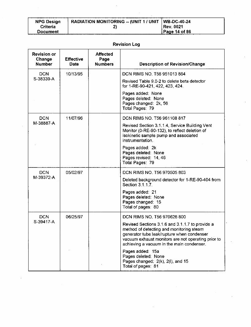
NPG Design RADIATION MONITORING -- (UNIT 1 / UNIT WB-DC-40-24Criteria 2) Rev. 0021
Document Page 14 of 86
Revision Log
Revision or AffectedChange Effective PageNumber Date Numbers Description of RevisionlChange
DCN 10/13/95 DCN RIMS NO. T56 951013 864
S-38339-A Revised Table 9.0-2 to delete beta detector
for 1-RE-90-421, 422,423,424.
Pages added: NonePages deleted: NonePages changed: 2k, 56Total Pages: 79
DCN 11/07/96 DCN RIMS NO. T56 961108 817M-38887-A Revised Section 3.1.1.4, Service Building Vent
Monitor (0-RE-90-132), to reflect deletion ofisokinetic sample pump and associatedinstrumentation.
Pages added: 2kPages deleted: NonePages revised: 14, 46Total Pages: 79
DCN 05/02/97 DCN RIMS NO. T56 970505 803
M-39372-A Deleted background detector for 1-RE-90-404 from
Section 3.1.1.7.
Pages added: 21Pages deleted: NonePages changed: 15Total of pages: 80
DCN 06/25/97 DCN RIMS NO. T56 970626 800S-39417-A Revised Sections 3.1.6 and 3.1.1.7 to provide a
method of detecting and monitoring steamgenerator tube leak/rupture when condenservacuum exhaust monitors are not operating prior toachieving a vacuum in the main condenser.
Pages added: 15aPages deleted: NonePages changed: 2(k), 2(l), and 15Total of pages: 81
NPG Design RADIATION MONITORING -- (UNIT 1 / UNIT WB-DC-40-24Criteria 2) Rev. 0021
Document Page 15 of 86
Revision Log
Revision or AffectedChange Effective PageNumber Date Numbers Description of RevisionlChange
7 2/18/99 DCN M-39854-B (T56 980714 802) revisedTable 9.0-2 to delete listing of Service Building Ventmonitor particulate channel 0-RE-90-132A.
Incorporates DCNs S-38273-A, S-38339-A,M-38887-A, M-39372-A, S-39417-A, andM-39854-B.
Reformatted entire document, which made itnecessary to renumber pages. Changed pagenumbers on the Table of Contents (pages xvthrough xvi).
Pages Revised: AllTotal Pages: 84 (which includes i through xvi andpages 1-68)
8 5/27/99 Incorporates DCNs as follows:DCN M-39911-A (T56 981215 803) replaces theobsolete Unit 1 Westinghouse P2500 Plant ProcessComputer with a new Plant Integrated ComputerSystem. This Plant Computer System provides anoperator friendly, state of the art, real time processcomputer system for the WBN plant operators.After this modification, the new Plant Computer willbe operational and performing all the functions ofthe existing Plant Computer (WB-DC-30-29) andEmergency Response Facilities Data System(ERFDS) (WB-DC-30-8). Therefore, DesignCriteria's WB-DC-30-8 and WB-DC-30-29 havebeen combined into one Design CriteriaWB-DC-30-29 "Plant Integrated Computer System."Design Criteria WB-DC-40-24 has been revised toincorporate this change by removing references tothe Emergency Response Facilities Data System(ERFDS), Technical Support Center (TSC)Computer or P2500 and replacing them with PlantComputer references.
DCN D-50122-A (T56 990218 802) revised normalvent monitor flow in Section 3.1.1.2.
Deleted Coordination Log which is not required perNEDP-10, which required renumbering of pagesi-xv and changed Table of Contents).
Pages Revised: AllTotal Pages: 83 (includes pages i-xv and 1-68)
NPG Design RADIATION MONITORING -- (UNIT 1 / UNIT WB-DC-40-24Criteria 2) Rev. 0021
Document Page 16 of 86
Revision Log
Revision or AffectedChange Effective PageNumber Date Numbers Description of Revision/Change
9 4/10/2000 Incorporates DCN as indicated below:
DCN D-50502-A (T56 000309 801) revisedSection 3.1.4.2 to clarify an additional function forthe radiation monitors and revised calculationreference 8.5.9.
Reformatted and renumbered pages i-xiii,which changed page numbers on the Table ofContents (pages xii-xiii).
Total Pages: 81 (includes pages i-xiii and 1-68)
10 10-23-2000 Screening Review WBPLMN-00-063-0 (T25 000816906) evaluated this revision to Section 3.1.4.1 toinclude a reference for minimum flow requirementsfor 1-RE-90-1 20, -121, 0-RE-90-122, -225.
Added Reference 8.5.33.Revised calculation Reference 8.5.9.
Incorporates DCN D-50483-A (T56 000523801) - Revised Section 3.1.3 and Tables 9.0-1,9.0-2, and 9.0-4 to delete the DecontaminationRoom Continuous Air Monitor (0-RE-90-016),Waste Packaging Room Continuous Air Monitor(0-RE-90-138), Unit 1 Sample Room Continuous AirMonitors (1-RE-90-14), and Reactor Building LowerCompartment Instrument Room Continuous AirMonitor (1-RE-90-062); includes a statement thatthe Waste Packaging Room and Unit 1 SampleRoom will be monitored by portable continuous airmonitors supplied and administered by SiteRADCON.Renumbered pages i-xiv, which changed pagenumbers on the Table of Contents (pages xiii-xiv).
Total Pages: 82 (includes pages i-xiv and 1-68)
NPG Design RADIATION MONITORING -- (UNIT I / UNIT WB-DC-40-24Criteria 2) Rev. 0021
Document Page 17 of 86
Revision Log
Revision or AffectedChange Effective PageNumber Date Numbers Description of RevisionlChange
11 4-16-2001 Incorporates DCN as follows:
DCN D-50482-A (T56 000815 800) deleted areamonitors 1-RE-90-280, 275-278 and 290-293.Deleted iodine channels 0-RE-90-132Cand 1-RE-90-1060. Revised Sections 3.1.1,3.1.1.3, 3.1.1.6, 3.1.5, 3.1.6, 3.1.6.1; deletedSections 3.1.6.5, 3.1.6.6, and 3.1.6.7; revisedSection 3.6.3.4.1; revised Tables 9.0-1, 9.0-2,9.0-3, and 9.0-4.
Section 3.1.1 was revised to delete the normalrange particulate and iodine sampler 1-RE-90-129for consistency with DCN D-50482-A.
Renumbered pages 1-67, which changed pagenumbers on the Table of Contents (pages xiii-xiv).
Total Pages: 81 (includes pages i-xiv and 1-67)
12 3-6-2003 Incorporates EDC as follows:
EDC-51385-A revised Section 3.1.1.6 to add ameans of maintaining the operability of1-RE-90-119 after a turbine trip.
Total Pages: 81 (includes pages i-xiv and 1-67)
NPG Design RADIATION MONITORING -- (UNIT 1 / UNIT WB-DC-40-24Criteria 2) Rev. 0021
Document Page 18 of 86
Revision Log
Revision or AffectedChange Effective PageNumber Date Numbers Description of RevisionlChange
13 5-14-2003 Incorporates EDC as follows:
EDC E-51278-A revised Sections 3.1.1.6and 3.1.1.7 to remove the requirement for aportable monitor to be placed at the CVE exhaustonce each hour if CVE and steam generator blowdown radiation monitors are not in service andcorrected EPIP-16 to EPIP-13. Also revisedSection 3.1.1.6 to state that sampling in accordancewith the ODCM will be used to assess radioactivityin the CVE in the event the CVE is operating andthe CVE normal range monitor is inoperable.
Section 3.1.1.7 was revised to delete therequirement for a portable monitor to be placed atthe CVE exhaust once each hour and use of thesteam generator blowdown monitors to identify andassess a steam generator tube leak when theaccident range monitor is inoperable since thefunction of the accident range monitor is to monitoraccidents and not normal operations. The accidenteffluents are monitored and assessed by the mainsteam monitors and EPIP-13 as stated inSection 3.1.1.7. This EDC partially implements thecorrective action plan of PER 01-17357-000.
Total Pages: 81 (includes pages i-xiv and 1-67)
NPG Design RADIATION MONITORING -- (UNIT 1 1 UNIT WB-DC-40-24Criteria 2) Rev. 0021
Document Page 19 of 86
Revision Log
Revision or AffectedChange Effective PageNumber Date Numbers Description of Revision/Change
14 1-28-2004 Incorporates DCN as follows:
DCN D51229-A - Installs tritium samplers0-SMPL-90-800, 1-SMPL-90-801and 2-SMPL-90-801 in the Auxiliary and ShieldBuildings.
-Section 3.1.1.2 was revised to add a tritiumsampler to monitor the quantity of tritium exiting theAuxiliary Building Stack.
-Section 3.1.1.4 was revised to justify the potentialrelease of tritium in the Service Building isnegligible and therefore no tritium monitoring isrequired.
-Section 3.1.1.5 was revised to add a tritiumsampler to monitor the quantity of tritium exiting theShield Building Stack.
-Section 3.1.1.6 was revised to state WBN willmonitor the condenser vacuum pump exhaust fortritium if tritium bars are present in the reactor core,and a SG tube leak is detected.
-Section 8.6 was added to add Reference 8.6.1 todocument TVA commitment to continuously monitorTritium.
-Revised Table 9.0.1 Radiation MonitoringClassification to add tritium samplers0-SMPL-90-800, 1-SMPL-90-801,and 2-SMPL-90-801.
-Revised Tables 9.0-4 Radiation MonitoringFunctions, and 9.0-2 Radiation MonitoringCharacteristics to add tritium samplers0-SMPL-90-800, 1-SMPL-90-801,and 2-SMPL-90-801.
Renumbered pages i-xv due to adding a page tothe Revision Log, which changed page numbers onpage xiv of the Table of Contents.
Total Pages: 82 (includes pages i-xv and 1-67)
NPG Design RADIATION MONITORING -- (UNIT 1 / UNIT WB-DC-40-24Criteria 2) Rev. 0021
Document Page 20 of 86
Revision Log
Revision or AffectedChange Effective PageNumber Date Numbers Description of Revision/Change
15 5-23-2005 Incorporates DCN as follows:
DCN 51426-A revised Sections 3.1.3, 3.6.3.4.1,3.6.3.5.2, and 8.5.7, Table 9.0-1, Table 9.0-2, andTable 9.0-4 to delete the Spent Fuel Pool AreaContinuous Air Monitor (0-RE-90-012), ShippingBay Area Continuous Air Monitor (0-RE-90-013),Holdup Valve Gallery Area Continuous Air Monitor(0-RE-90-015), and the SI Pump Area ContinuousAir Monitor (0-RE-90-017); and to include astatement that the Spent Fuel Pool Area, ShippingBay Area, Holdup Valve Gallery Area, and SI PumpArea will be monitored by portable continuous airmonitors applied and administered by Site Radcon.
Renumbered pages 1-66, which changed pagenumbers on the Table of Contents (pages xiv-xv).
Total Pages: 81 (includes i-xv and 1-66)
16 05-04-2007 All This design criteria was converted from Word 95 toWord 2003 using Rev. 15.
Section 3.1.6A, 4th paragraph, changed 3.1.6.7(Word 95 format) to 3.1.6D. Sections 3.1.6.5through 3.1.6.7 were deleted by Revision 11.
Section 3.6.3E.1, 3rd paragraph, changed "Section8.6.3.5.3" to "Sections 3.6.3E.3 and 3.6.3E.6.There is not a Section 8.6.3.5.3.
Incorporates DCN 51786 which modified the turbinebuilding sump radiation monitor 0-RE-90-212 toeliminate the sample flow line problem. Section3.1.4F (Section 3.1.4.6 in Word 95 version) wasdeleted and Section 3.1.6E added. Tables 9.0-1,9.0-2, and 9.0-4 were revised to reflect the changeto 0-RE-90-212 from an off-line monitor to an on-line monitor.
NPG Design RADIATION MONITORING -- (UNIT 1 / UNIT WB-DC-40-24Criteria 2) Rev. 0021
Document Page 21 of 86
Revision Log
Revision or AffectedChange Effective PageNumber Date Numbers Description of RevisionlChange
17 03-13-2008 1,21, 38, 48, DCN 52220: Revised Sections 3.1.2, 3.1.6, and79, 80 Table 9.0-3 to reflect the design change to permit
initiation of a CVI from a high radiation signal fromthe spent fuel pool radiation monitors and to permitinitiation of that portion of an ABI signal (normallyinitiated by the spent fuel pool radiation monitors)by a CVI signal during movement of irradiated fuelwhen the Containment is open to the AuxiliaryBuilding. This change will allow operation of thecontainment purge system during movement ofirradiated fuel in the Auxiliary Building with thecontainment open to the Auxiliary Building ABSCEspaces.
18 04-21-2008 1, 21,48, 70 Incorporates DCN 52211-A (PIC 52299-A) asfollows:
Section 3.1.6C - added notation to section toinclude mention of the areas being monitored notpreviously included in the section. Also addedreference to the system description section whichnotes the special ventilation interface requirementsassociated with the Fuel Handling Exhaust (FHE)System during irradiated fuel movement in the FuelTransfer Canal to support the proper operation ofthe radiation monitor function (Ref. 96939).
Section 8.5 - added new reference 8.5.34calculation, WBNTSR-009, which specifies thespecial requirements associated with the FHexhaust ventilation system.
19 08-26-2008 1,21, 24 This revision was issued by WB2CCP to addressthe Radiation Monitoring System applicability toUnit 2 in Section 1.0 of this DCD. An outstandingWITEL Punchlist item applicable to Unit 2 is listedas follows:
-- PL-08-1094, see Section 1.0
New and upgraded radiation monitoring detectorsare being supplied thru WB2CCP purchaserequisitions 25402-011-MRA-HARA-00001 and25402-011 -MRA-HARA-00002.
NPG Design RADIATION MONITORING -- (UNIT 1 / UNIT WB-DC-40-24Criteria 2) Rev. 0021
Document Page 22 of 86
Revision Log
Revision or AffectedChange Effective PageNumber Date Numbers Description of Revision/Change
20 01-21-2009 1,22, 84 Administrative change to add Notes to Table 9.0-4,that were lost during issue of Revision 17.Reference PER 158904
21 06-17-2009 1, 22, 44, 45, Incorporates EDC as follows:
50, 71,72 EDC E-53382: Document the stroke time credited
for closure of valves 0-FCV-77-119, 0-RCV-77-43,0-FCV-14-451. Add associated references inconjunction with change.
Revised Section 3.1.4.C to specify the stroke timefor 0-RCV-77-43.
Revised Section 3.1.4.E to specify the stroke timefor 0-FCV-14-451.
Revised Section 3.1.6.B to specify the stroke timefor 0-FCV-77-119.
Added References 7.5.35 and 7.5.36.
Updated revision level of References 8.5.10, 8.5.17,and 8.5.21.
NPG Design RADIATION MONITORING -- (UNIT 1/ UNIT - WB-DC-40-24Criteria 2) Rev. 0021
Document Page 23 of 86
Table of Contents
1.0 SCOPE .................................................................................................................................... 25
2.0 DEFINITIONS .......................................................................................................................... 25
3.0 DESIGN REQUIREMENTS ................................................................................................ 28
3.1 Functional Requirements ..................................................................................................... 29
3.1.1 Off-Line Particulate, Iodine and Noble Gas Monitors ........................................... 30
3.1.2 Off-Line Gas Monitors .............................................. 37
3.1.3 Continuous Air Monitors (Airborne Particulate Monitors) ....................................... 41
3.1.4 Off-Line Liquid Monitors ....................................................................................... 41
3.1.5 Area Radiation Monitors ....................................................................................... 45
3.1.6 On/In-Line Monitors .............................................................................................. 48
3.2 Design Basis Events ............................................................................................................... 51
3.3 Environmental Requirements ............................................................................................... 51
3.4 External Events ........................................................................................................................ 51
3.4.1 Loss of Off-site Power ......................................................................................... 52
3.4.2 Safe Shutdown Earthquake.................................................................................. 52
3.4.3 W ind and Tornado Loadings ................................................................................ 52
3 .4 .4 F lo o d in g ................................................................................................................... 5 2
3.5 Electrical Requirements ....................................................................................................... 53
3.6 Mechanical Requirements .................................................................................................. 54
3.6.1 General Requirements .......................................................................................... 54
3.6.2 Seismic Qualification of Instrumentation and Electrical Equipment ...................... 55
3.6.3 RMS Sample Line Design Criteria ....................................................................... 55
3.7 Instrumentation Requirements ............................................................................................ 63
3.8 Safety Limits ............................................................................................................................ 63
3.9 Maintenance ............................................................................................................................ 63
4.0 LAYOUT AND ARRANGEM ENT ...................... ................................................................ 64
5.0 TESTS AND INSPECTIONS .............................................................................................. 65
5.1 Vendor Testing ......................................................................................................................... 65
5.2 Site Testing .............................................................................................................................. 65
5.3 Monitor Calibrations (Vendor or Site Testing) ..................................... 65
6.0 QUALITY ASSURANCE ..................................................................................................... 65
NPG Design RADIATION MONITORING -- (UNIT 1 / UNIT WB-DC-40-24Criteria 2) Rev. 0021
Document Page 24 of 86
Table of Contents (continued)
7.0 EXCEPTIO NS .......................................................................................................................... 65
7.1 Approved Exceptions ............................................................................................................... 65
8.0 REFERENCES ........................................................................................................................ 66
8.1 NRC Docum ents ........... ........................................................................................................... 66
8.2 Industry Standards ................................................................................................................... 67
8.3 Design Criteria ......................................................................................................................... 68
8.4 System Descriptions ................................................................................................................ 69
8.5 TVA Calculations ..................................................................................................................... 70
8 .6 O th e r ........................................................................................................................................ 7 2
9.0 TABLES ................................................................................................................................... 73
9.1 Table 9.0-1 - Radiation M onitoring Classification ............................................................... 73
9.2 Table 9.0-2 - Radiation M onitor Characteristics ................................................................... 76
9.3 Table 9.0-3 - Radiation Monitors that Initiate Automatic Control Functions ......................... 82
9.4 Table 9.0-4 - Radiation M onitoring Functions ..................................................................... 84
Source Notes ..................................................................................................... 86
NPG Design RADIATION MONITORING -- (UNIT I / UNIT WB-DC-40-24Criteria 2) Rev. 0021
Document Page 25 of 86
1.0 SCOPE
This document establishes the design requirements of the Radiation Monitoring System(RMS) for the operation of Watts Bar Unit 1 [Source Note 7]. The RMS provides continuousmonitoring of radiation levels, provides the results of the monitoring to the operator and insome instances produces signals to initiate automatic control actions. In addition, the RMSincludes equipment for off-line particulate and iodine sample collection with no real-timedetection. The RMS consists of process, airborne, area, and effluent radioactivity monitors.The outdoor radiological monitoring instrumentation, laboratory radiation measurementequipment, criticality monitoring equipment, and portable survey instrumentation is outsidethe scope of this criteria. If a discrepancy exists between this design criteria and any otherNuclear Engineering (NE) design criteria, the appropriate Engineering Manager should benotified by a memorandum. If a discrepancy exists between this design criteria and anyother document where the other document is not a NE design criteria, this design criteriashall govern.
Radiation monitoring detectors are being upgraded to support the Watts Bar Unit 2Construction Completion (WB2CCP) Project. Supporting vendor and engineeringanalyses shall be completed and incorporated into this design criteria document priorto the Unit 2 Radiation Monitoring System being declared operational. [PL-08-1094]
2.0 DEFINITIONS
Accuracy - The degree of agreement with the true value of the quantity being measured.
Accessible Area - An area which is designed to be entered without special radiologicalcontrols (i.e., is not a high radiation area or airborne radioactivity area), dismantling ofinstalled equipment or the introduction of support equipment such as staging, ladders, etc.
Anticipated Operational Occurrences - Those conditions of normal operation which areexpected to occur one or more times during the life of the nuclear power unit and include butare not limited to the loss of power to all reactor coolant recirculation pumps, a trip of theturbine generator set, isolation of the main condenser and a loss of all off-site power.
Categories 1, 2, and 3 - References to Categories 1, 2, and 3 are as stated in RG 1.97(Reference 8.1.11).
Channel - A channel includes all of the instrumentation necessary to provide the monitoringfunction. A channel includes associated sample lines, skid assemblies, and local readoutand alarm devices. A channel also includes equipment in the control room for recording,readout, and alarm and includes the electrical cable that connects monitor components.
Check Source - A test source supplied as an integral part of the monitor channel for use indetermining if the channel is functional. This may be a radioactive source, or when a checkof the channel exclusive of the detector scintillator is appropriate (i.e., where increasedbackground cannot be tolerated), a pulsed light source or other similar device appropriatefor the type of detector.
Class 1 E - The safety-related classification of the electrical equipment and systems that areessential to emergency reactor shutdown, containment isolation, reactor core cooling andcontainment and reactor heat removal, or otherwise are essential in preventing significantrelease of radioactive material to the environment.
NPG Design RADIATION MONITORING -- (UNIT 1 / UNIT WB-DC-40-24Criteria 2) Rev. 0021
Document Page 26 of 86
2.0 DEFINITIONS (continued)
Grab Sample - A volume removed from a process or effluent for laboratory analysis.
Gross beta or gamma radioactivity - The combined radioactivity from the mix of nuclideswithout distinction as to energy levels of the emissions.
In-Line Monitor - A monitor with no sample line where the detector or the detector well isimmersed in the source fluid to be measured.
Isokinetic - A condition which prevails when the velocity of air entering a sample probe orthe collector when held in the airstream is identical to the velocity of the airstream beingsampled within a specific accuracy.
May - Denotes permission, neither a requirement nor a recommendation.
Minimum Detectable Level - The smallest amount of a quantity, e.g., radioactivity, which canbe consistently detected by an instrument.
Off-line Monitor - A monitor where a representative sample is withdrawn from the sourcefluid stream and conveyed by a sample line to the detector assembly.
On-Line Monitor - A monitor where the detector is adjacent to or near the pipe, tubing, ortank containing the source fluid. Sometimes referred to as "shine" monitor.
Plate Out - A thermal, electrical, chemical, or mechanical action that results in a loss ofsample material by deposition on surfaces between sample intake and sample collector.
Primary Calibration - The determination of the response of a monitor channel when thechannel detector is exposed to radiation from multiple sources of known energies andactivity levels traceable to the National Institute of Standards and Technology (formerlyknown as the National Bureau of Standards) and having the same physical state as themedium to be measured.
Primary Safety Function - The function of a structure, system, or component which mustremain functional to assure: (1) integrity of the reactor coolant pressure boundary, (2)capability to shut down the reactor and maintain it in a safe shutdown condition, or (3)capability to prevent or mitigate the consequences of accidents which could result inpotential off-site exposures comparable to the guideline exposures of 10 CFR Part 100(Reference 8.1.4) and limit radiation exposure in the control room to the requirementsdefined in 10 CFR 50, Appendix A, General Design Criteria 19 (Reference 8.1..1).
Radiation Monitor - A device composed of one or more channels that measures radiation ora device composed of one or more channels that share an off-line sample intake to obtain asample for measurement of its radioactivity.
Radiation Sampler - A radiation monitor which only collects samples for subsequentanalysis.
Real-Time - Refers to measurements that are current and from continuously operatinginstruments that provide detection capability when a sample is presented.
NPG Design RADIATION MONITORING -- (UNIT 1 / UNIT WB-DC-40-24Criteria 2) Rev. 0021
Document Page 27 of 86
2.0 DEFINITIONS (continued)
Response Time - The time interval from the appearance of the input concentrationcorresponding to the high alarm setpoint level at the sample line intake for off-line monitors,or opposite the detector for on-line or in-line monitors, to completion of required controlaction.
Representative Sample - A sample which has a specific activity similar to the entire volumefrom which the sample is drawn.
Safe Shutdown Earthquake (SSE) - That earthquake which produces the maximumvibratory ground motion for which structures, systems, and components important to safetyare designed to remain functional.
Sample Line - A pipe or tube which conveys fluid from and back to a vent, duct, pipe, or anopen area for the purpose of providing a sample for assessment of its radioactivity content.For the purposes of this design criteria, the sample line is defined to include the line throughwhich the sample normally flows from and back to the source fluid or process line, to theinstrument isolation valves (including the valves) or to the manufacturer's instrumentconnections if there are no isolation valves. For liquid monitors the sample line originates atthe monitor side of the root valve if the process line is equal to or less than 36 inches fromthe root valve and at the process tap if the process line is greater than 36 inches from theroot valve. The root valve and 36 inch line segment not defined as a sample line shall meetcode and seismic requirements of the process line. For gas monitors the sample lineoriginates at the probe or the end of the sample line.
Secondary Calibration - The determination of the response of a system with an applicablesource whose effect on the system was established at the time of a primary calibration orwhose effect on the system is otherwise known.
Secondary Safety Function - The function of a structure, system, or component which musteither: (1) retain limited structural integrity because its failure could jeopardize to anunacceptable extent the achievement of a primary safety function or because it forms aninterface between Seismic Category I and Non-seismic Category I plant features, or (2)performs a mechanical motion which is not required in the performance of a primary safetyfunction but whose failure to act could jeopardize to an unacceptable extent theachievement of a primary safety function.
Seismic Category I - Those structures, systems, or components which perform primarysafety functions are designated as Seismic Category I and are designed and constructed soas to assure achievement of their primary safety functions during and after a safe shutdownearthquake (SSE).
NPG Design RADIATION MONITORING -- (UNIT 1 / UNIT WB-DC-40-24Criteria 2) Rev. 0021
Document Page 28 of 86
2.0 DEFINITIONS (continued)
Seismic Category I(L) - Those portions of structures, systems, or components which aredesigned and constructed so as to assure achievement of their pressure boundary and/orlimited structural integrity at all times including a concurrent safe shutdown earthquake(SSE) because their failure could jeopardize to an unacceptable extent the achievement of aprimary safety function or because it forms an interface between Seismic Category I andNon-seismic Category I plant features. This may be accomplished without meeting the fullextent of the design, construction, quality assurance, and other regulatory requirementsnormally specified for Seismic Category I structures, systems, or components wherein aprimary safety function must be assured. These are designated (by TVA) as SeismicCategory I(L) (i.e., limited seismic requirements) and are considered to serve a secondarysafety function.
Shall - Denotes a requirement.
Should - Denotes a recommendation.
Source Fluid - A liquid or gaseous fluid from which a measure of radioactivity is obtained byreal time monitoring or by sampling and analysis. The source fluid may denote a volume,process, effluent, or airborne stream as appropriate.
3.0 DESIGN REQUIREMENTS
The primary function of the RMS is to detect ionizing radiation at selected places or inselected processes and effluents throughout the plant. The RMS may be used inconjunction with analysis of samples collected to determine the quantity of radioactivematerial released to the environment. The RMS shall have, (a) monitors which providereal-time monitoring of selected source fluids and initiate required automatic controlfunctions, (b) monitors which provide real-time monitoring without an automatic controlfunction and (c) monitors which provide for the collection of samples for analysis. The RMSshould also provide, by means of audible and visual alarm devices, warning to the plantoperator of (1) potential malfunction of systems which contain radioactive material, (2)excessive radioactive releases to the environment and/or (3) selected plant areaswhich exceed the radiation zone design limits.
Radiation monitors that perform a function to mitigate the dose consequences off-site or forcontrol room habitability requirements for design basis events as described in WB-DC-40-64(Reference 8.3.17), shall be considered to perform a primary safety function. Radiationdetectors which monitor Category 1 post-accident key variables, as described inWB-DC-30-7 (Reference 8.3.5) shall be considered to perform a primary safety function.
RMS equipment (excluding sample lines) located in Seismic Category I structures that donot perform a primary safety function shall be qualified to Seismic Category I(L) except forthat equipment, in these structures, that is located in areas which are designated as notrequiring seismic qualification. The qualification to Seismic Category I(L) is required toretain pressure boundary and/or limited structural integrity because the equipment's failurecould jeopardize to an unacceptable extent the achievement of a primary safety function orbecause it forms an interface between Seismic Category I and Non-Seismic Category I plantfeatures. Seismic Qualification of sample lines shall be per Section 3.6.3C.
NPG Design RADIATION MONITORING -- (UNIT 1 / UNIT WB-DC-40-24Criteria 2) Rev. 0021
Document Page 29 of 86
3.0 DESIGN REQUIREMENTS (continued)
Purge lines, instrument sensing lines, and instrument air lines connected to sample linesshall have safety class requirements similar to that of the sample lines as described inTable 9.0-1 of this document, or incorporate a class break between the sample and thepurge line, instrument sensing line, or instrument air line. Instrument sensing lines shall bedesigned in accordance with WB-DC-30-16 (Reference 8.3.18). Interfaces with process andeffluent piping and ductwork shall be designed in accordance with WB-DC-40-36 (Reference8.3.10).
This design criteria satisfies the requirements of:
10 CFR 50 Appendix A (Reference 8.1.1)10 CFR 50 Appendix I (Reference 8.1.2)10 CFR 20 Appendix B and Numbered Sections (Reference 8.1.3)10 CFR 100 (Reference 8.1.4)40 CFR 60 Appendix A (Reference 8.1.5)
The requirements of this design criteria meet the intent of the recommendations andguidance provided in the pertinent sections of the following documents:
ANSI N42.18-1974 (Reference 8.2.7)ANSI A59.1 (Reference 8.2. 1)ANSI/ISA-S67.10 (Reference 8.2.4)ANSI N18.2 (Reference 8.2.6)ANSI/ANS-HPSSC-6.8.1-1981
(Reference 8.2.3)ANSI B40.1-1980 (Reference 8.2.2)ANSI N 13.1 (Reference 8.2.5)ANSI N320-1979 (Reference 8.2.8)IEEE 344-1971 (Reference 8.2.10)IEEE 344-1975 (Reference 8.2.11)IEEE 279-1971 (Reference 8.2.9)
NRC NUREG-0133 (Reference 8.1.12)-0737 (Reference 8.1.14)-0800 (Reference 8.1.15)
IE Notice 82-49 (Reference 8.1.16)ISA 57.3 (Reference 8.2.12)
NRC RG 1.21 (Reference 8.1.7)1.97 (Reference 8.1.11)1.53 (Reference 8.1.9)1.76 (Reference 8.1.10)1.45 (Reference 8.1.8)8.8 (Reference 8.1.6)
3.1 Functional Requirements
In the following subsections, the monitors of the RMS are assigned to the following groups:
Off-line Particulate, Iodine, and Noble Gas MonitoringOff-Line Gas MonitorsContinuous Air Monitors (Airborne Particulate Monitoring)Off-Line Liquid MonitorsArea Type MonitorOn/In-Line Monitors
Under the subsection for each of the above groups, general requirements and features areprovided and specific features and functions for each monitor of the group are described.
NPG Design RADIATION MONITORING -- (UNIT 11 UNIT WB-DC-40-24Criteria 2) Rev. 0021
Document Page 30 of 86
3.1.1 Off-Line Particulate, Iodine and Noble Gas Monitors
The design of the following monitors shall include off-line channels to provide continuousreal-time detection of particulate, iodine (except 1-RE-90-106), and noble gas (PIG)radioactivity (including collection of particulate and radiohalogens for on-site analysis):
Auxiliary Building Vent Monitor Q-RE-90-101Containment Lower Compartment Monitor 1-RE-90-106Containment Upper Compartment Monitor 1-RE-90-112
The design of the monitors listed below shall include off-line channels to provide for acombination of real-time detection of noble gas radioactivity and for the collection ofparticulates and iodine without real-time detection:
Service Building Vent Monitor O-RE-90-132 (Iodine channeldeleted)
Shield Building Vent Wide Range Gas Monitor 1,2-RE-90-400Sample Detection Skid
Shield Building Vent Wide Range Gas Monitor 1,2-RE-90-402Sample Conditioning Skid
Condenser Vacuum Pump Exhaust Monitors: 1-RE-90-119Normal Range Noble Gas
Accident (Mid- and High-Range) Noble Gas 1-RE-90-404
A. General Requirements
PIG monitors shallwithdraw, by means of a pump, a representative gaseous samplewith entrained particulates from a source fluid volume. Samples taken from a remotevolume, duct, pipe or stack shall be transported to the detector skid assembly via asample line. For particulate monitoring or collection only, if the source fluid is flowing ina duct, pipe or stack, then measures shall be taken either to ensure the sample istaken under isokinetic conditions, or that the effects of non-isokinetic sampling areanalyzed and properly accounted for. The sample that is provided to the monitorparticulate filter may be a subsample (see Section 3.6.1) of that taken from the processor effluent source fluid. Other gas sample lines do not require isokinetic conditions.
Various flow path arrangements are acceptable. For channels in series, the sampleshould sequentially pass through a particulate filter for particle collection, a charcoaladsorption medium for iodine (a radiohalogen) vapor removal and finally through a gaschamber. Alternatively, a system in which the particulate filter and the gas chamber (inseries) are installed in parallel with the charcoal absorber (radiohalogen) is acceptable.It is also acceptable for gas monitoring and for particulate and radiohalogen (iodine)collection to have a completely separate sample points and flow paths from the samesource fluid. The radiohalogen adsorption medium flow path should be provided withparticulate filtering prior to the sample flow passing through the adsorption medium. Ifthe design includes real-time detection of particulates, a moving filter with eitherautomatic step advance or continuous advance should be provided. Filters forcollection of particulates for subsequent laboratory analysis should use a fixed filterdesign.
NPG Design RADIATION MONITORING -- (UNIT 1 / UNIT WB-DC-40-24Criteria 2) Rev. 0021
Document Page 31 of 86
3.1.1 Off-Line Particulate, Iodine and Noble Gas Monitors (continued)
The channels with real-time monitoring capabilities shall have sufficient range tomeasure the anticipated quantity or concentration of radioactivity in the sampleconsidering the ambient background radiation conditions at the detector's location.The real-time radiation detectors shall be shielded from background radiation to attainthe required minimum detectable activity level during background radiation conditions.It should be assumed that the background radiation level is from a high energy gammaemitting source such as Cobalt 60 or Cesium 137. Where multiple detectors arerequired to cover the anticipated range, the range of the detectors shall overlap.Overlap should be at least one decade. The monitor's minimum detectable activitylevel shall be less than or equal to the lower end of the required radioactivityconcentration range identified in Table 9.0-2.
A normal range monitors' design shall ensure retaining a full-scale reading for aradiation field of up to two decades above the full-scale radiation field.
Those monitors which include real-time detection shall include the appropriate circuitryto produce audible and visible alarms in the control room and at additional locations asprescribed in the individual monitor's description section when the radiation levelexceeds high alarm set points (see Table 9.0-4) or there is a system malfunction (as aminimum, a malfunction alarm condition shall be initiated for loss of detector signal,power or flow). Each type of alarm condition i.e., high radiation or system malfunctionshall be readily identifiable on the appropriate radiation monitor panel.
Channels which include real-time detection shall have devices to display measuredcpm values for each channel in the control room and allow for retrieval of historicaldata. Accomplishing these functions by the use of computer terminals or numericaldisplays common to more than one channel is acceptable as long as the displaycredited with satisfying the required functions meets the same safety classificationrequirements as the channel. Care must be exercised to provide proper isolation oranalysis performed to demonstrate no impact where primary safety relatedcomponents of the loop are interfaced with non-essential components of the loop (seeSection 3.5). Selected monitors shall transmit measured cpm data to the PlantComputer System for display in the Technical Support Center (TSC) in accordancewith Section 2.9 of NUREG-0696 (Reference 8.1.13).
Process monitors which include real-time detection shall have provisions to allow forperiodic on-line testing of the channel's response by actuation of an installed checksource of sufficient intensity to provide an upscale reading of the ratemeter when thedetector is subjected to normally expected background radiation levels. The checksource may be radioactive, a photon source such as an LED, or other similar deviceappropriate for the type of detector. The check source should verify, to the extentpossible, operability of the entire channel from the point that radiation is incident on thedetector to the output device. The check source may be remotely activated from thecontrol room or locally. Radioactive check sources should be shielded from thedetector while in the stored position to preclude misleading radiation contributions whilesample measurements are made.
NPG Design RADIATION MONITORING -- (UNIT 1 / UNIT WB-DC-40-24Criteria 2) Rev. 0021
Document Page 32 of 86
3.1.1 Off-Line Particulate, Iodine and Noble Gas Monitors (continued)
The monitors shall have the capability to either measure or monitor the flow rate of thesample. If necessary to provide more accurate measurements, the sample pressureand/or temperature should also be measured to allow corrections to be made tosample flow rates and noble gas channel cpm or activity measurements. This satisfiesthe recommendations in IE Information Notice 82-49 (Reference 8.1.16).
The monitors' sampling system shall provide means by which grab samples may bewithdrawn for laboratory analysis. Where multiple monitors are used to monitor asingle process or source fluid, grab sample capability is not required on every monitor.The sample line shall include inlet and outlet flow taps from which grab samples maybe taken. The grab sample inlet and outlet flow taps should be isolated from thenormal sampling flow path. The taps should be located to best utilize the componentsof the installed system, e.g., sample pump, flow meter. Where subsampling is utilized,the grab sample may be taken from either the sample extracted from the source fluid orfrom the subsample.
Acceptable methods of detection of particulates, iodines and gases are described inthis paragraph. For the normal range channels, beta radiation detection shall be usedfor gross real-time analysis of the radioactivity in the gas collection chamber. A betaradiation detector should be provided for particulate radioactivity. A gammascintillation detector may be provided for determination of the iodine-1 31 radioactivity,by utilizing both lower and upper energy discriminators for observing the 1-131 energypeak.
For accident conditions, energy compensated GM tubes or Cd-Te detectors may beprovided for mid-range and high-range noble gas detection.
The sampling system shall have provisions for purging the gas sample chamber for thepurposes of determining background count rate without damaging the particulate andiodine collection media (when applicable). Care should be taken in the design topreclude potential damage to sample line instrumentation from the purging operation.
B. Auxiliary Building Vent Monitor (0-RE-90-101)
The Auxiliary Building Vent Monitor is an effluent monitor which shall continuouslymonitor the Auxiliary Building effluent discharge to the environment and performreal-time detection of the noble gas radioactivity as required by 10 CFR 50,Appendix A, GDC 60 and 64 (Reference 8.1.1), 10 CFR 50, Appendix I (Reference8.1.2), and meet the intent of the guidance of RG 1.21 (Reference 8.1.7) and RG 1.97(Reference 8.1.11) [Source Note 8].
The particulate and iodine real-time monitoring shall be used to support therequirements of 10 CFR 20 Section 20.1101 (b) (Reference 8.1.2) and 10 CFR 50Appendix A, GDC 19 (Reference 8.1.1). These channels shall monitor the normalAuxiliary Building Exhaust path and should detect airborne radioactivity fromparticulates and iodine in excess of 10 DAC/hr from any area of the Auxiliary Buildingwhich normally may be occupied by personnel, taking into account dilution in theventilation system (see Reference 8.5.23).
NPG Design RADIATION MONITORING -- (UNIT 1 / UNIT WB-DC-40-24Criteria 2) Rev. 0021
Document Page 33 of 86
3.1.1 Off-Line Particulate, Iodine and Noble Gas Monitors (continued)
The monitor should provide a means for collection of iodines and particulates foron-site analysis.
The monitor shall provide isokinetic sampling of the vent at normal vent flow rates(160,000-229,000 CFM). It shall include sample line flow rate measurements and flowcontrols necessary to allow manual or automatic adjustments to maintain isokineticsampling conditions or an analysis shall be performed to justify flow adjustments arenot necessary to obtain a representative sample.
The measured volumetric flow rate of the source fluid in the Auxiliary Building ventductwork should be provided to the TSC and plant computer data logger. Real timeactivity should be provided to the plant computer data logger.
A tritium sampler shall be installed to assure accurate monitoring of the AuxiliaryBuilding stack. This sampler shall utilize a pump and integrator to ensure accuratedata is utilized to determine the quantity of tritium exiting the Auxiliary Building Stack.This is per TVA commitment in Section 2.11.4 (Gaseous Waste Management SystemsEvaluation) of Reference 8.6.1.
C. Containment Upper (1-RE-90-112 and Lower (1-RE-90-106) Compartment Monitors
These monitors shall detect and measure the airborne radioactivity concentration in theContainment Building upper and lower compartments and perform real-time detectionof the particulate and noble gas radioactivity in compliance with 10 CFR 50Appendix A, GDC 30 and 64 (Reference 8.1.1) These monitors are used to satisfy theguidance in RG 1.45 (Reference 8.1.8). The upper containment monitor 1 -RE-90-112should also perform real-time detection of radioiodine.
The monitors shall have the capability to take a sample from either or both of twoseparate locations in containment in order to provide assistance in locating the generalarea of abnormal leakage.
The upper compartment monitor shall have the backup capability to monitor theradioactivity in the containment lower compartment atmosphere and the lowercompartment monitor shall have the backup capability to monitor the radioactivity in thecontainment upper compartment atmosphere.
The monitors shall be capable of continued operation after loss of off-site power. Thissatisfies the guidance in Section 12.3-12.4 of NUREG-0800 (Reference 8.1.15).
The monitors shall provide for local display of measured noble gas channel cpm valuesand local audible and visible alarms for high radioactivity from the noble gas channelwhich meets the intent of the guidance in Section 2.7 of RG 8.8 (Reference 8.1.6).Local alarms for the Containment Lower and Upper Compartment Monitors should bein proximity to the Containment Lower and Upper Containment access hatch,respectively. This meets the intent of the guidance in Section 2.7 of RG 8.8(Reference 8.1.6).
NPG Design RADIATION MONITORING -- (UNIT 1 / UNIT WB-DC-40-24Criteria 2) Rev. 0021
Document Page 34 of 86
3.1.1 Off-Line Particulate, Iodine and Noble Gas Monitors (continued)
The Containment Upper and Lower Compartment Airborne Monitors do not perform aprimary safety function but do perform a secondary safety function and they shall bequalified to Seismic Category I. The monitors are being maintained as a 1 E, SeismicCategory I component (as noted in the Q-List) in order to meet the guidance in RG1.45 (Reference 8.1.8) which states that the gaseous and particulate radiationmonitoring channels should remain functional for a SSE (See Table 9.0-1). Real-timeactivity levels for particulate, iodine and gas channels should be provided to the PlantComputer System for display in the TSC.
D. Service Building Vent Monitor (0-RE-90-132)
The Service Building Vent Monitor shall continuously monitor the radioactivity releasefrom the Service Building vent and perform real-time detection of noble gasradioactivity as required in 10 CFR 50 Appendix A GDC 64 (Reference 8.1.1), 10 CFR50 Appendix I (Reference 8.1.2), and meet the intent of the guidance in Appendix A ofRG 1.21 (Reference 8.1.7) [Source Note 8].
The monitor shall provide a means for collection of iodines and particulates. Real-timeiodine and particulate channels may be provided, but are not required.
The monitor shall provide sampling of the vent at a sampleflow rate not greater thanthat necessary for isokinetic sampling at the maximum normal vent flow rate. Isokineticsampling over the range of normal flow rates is not required since the Service Buildingvent is not a principle radioactivity discharge path. For non-isokinetic sampling,calculations must be completed (Ref. 8.5.24, 8.5.32) to determine partical losssuch that estimates of effluent release can be made based on particulate samplesobtained.
The measured volumetric flow rate of the source fluid in the Service Building ventductwork should be provided to the plant computer data logger. Real-time gaseousactivity should be provided to the plant computer data logger.
The only credible path for Tritium into the Service Building is through the Chem. Lab(from samples). The potential amount of Tritium release from this source is negligible,therefore Tritium monitoring of the Service Building exhaust vent is not required.
NPG Design RADIATION MONITORING -- (UNIT 1 / UNIT WB-DC-40-24Criteria 2) Rev. 0021
Document Page 35 of 86
3.1.1 Off-Line Particulate, Iodine and Noble Gas Monitors (continued)
E. Shield Building Vent Wide Range Radiation Monitor (1,2-RE-90-400 & -402)
The monitors' Sample Detection Skid shall perform real-time detection of gaseousradioactivity in the Shield Building effluent discharge to the environment during normaloperation and subsequent to a design basis accident. This conforms to therequirements in 10 CFR 50 Appendix A, GDC 64 (Reference 8.1.1) and the guidancein Appendix A of RG 1.21 (Reference 8.1.7) and RG 1.97 (Reference 8.1.11) [SourceNote 8]. If multiple detectors are required to cover the full range, channels whoseranges overlap shall be used. This complies with the requirements of Section II.F.1 ofNUREG-0737 (Reference 8.1.14). The flow paths to the low range radiation detectorsshall be automatically isolated whenever the counting rate exceeds their range. Localaudible and visible alarms for activity levels which exceed the radiation alarm setpointand a local visible alarm for channel malfunction should be provided. The capability forreal-time background radiation measurements for automatic or manual backgroundsubtraction from noble gas channel measurements should be provided.
The monitors' Sample Conditioning Skid shall collect particulates and iodine in theShield Building effluent discharge to the environment during normal operation andsubsequent to a design basis accident. This conforms to the requirements in 10 CFR50, Appendix A, GDC 64 (Reference 8.1.1) and RG 1.97 (Reference 8.1.11). Themonitor sampling system design and location shall allow plant personnel to removesamples, replace sampling media, and transport the sample to the on-site analysisfacility without exceeding the dose of 5 rem whole body or 75 rem to the extremities asdescribed in Section II.F.1 of NUREG-0737 (Reference 8.1.14).
The monitors shall have automatic isokinetic sampling capabilities for Shield Buildingexhaust flows from 7,200 to 14,000 cubic feet per minute (cfm). This meets therequirements of RG 1.97 (Reference 8.1.11). The automatic control requirementsapply from sample intake from the shield building vent to the particulate collector. Theflow elements are Category 2 components located in a harsh environment and shall bequalified in accordance with the requirements of WB-DC-30-7 and WB-DC-40-54(References 8.3.5 and 8.3.9, respectively).
The vent flow rate and noble gas activity level shall be transmitted to the PlantComputer System for display in the TSC.
A tritium sampler shall be installed to assure accurate monitoring of the Shield Buildingstack. This sampler shall utilize a pump and integrator to ensure accurate data isutilized to determine the quantity of tritium exiting the Shield Building Stack. This is perTVA commitment in Section 2.11.4 (Gaseous Waste Management SystemsEvaluation) of Reference 8.6.1.
NPG Design RADIATION MONITORING -- (UNIT I / UNIT WB-DC-40-24Criteria 2) Rev. 0021
Document Page 36 of 86
3.1.1 Off-Line Particulate, Iodine and Noble Gas Monitors (continued)
F. Condenser Vacuum Pump Exhaust Normal Range Noble Gas Monitor (1-RE-90-119)
The Condenser Vacuum Pump Exhaust Normal Range Monitor is an effluent monitorconsisting of a low range noble gas channel which shall continuously (except as notedbelow) make real-time measurements of the condenser vacuum pump exhaustdischarge to the environment during normal operations (except as noted below) asrequired in 10 CFR 50 Appendix A, GDC 64 (Reference 8.1.1), 10 CFR 50 Appendix I(Reference 8.1.2), and meet the intent of the guidance in Appendix A of RG 1.21(Reference 8.1.7) and RG 1.45 (Reference 8.1.8) [Source Note 8]. Subsequent to adesign basis accident, the noble gas monitors shall monitor the low range ofradioactivity in the Condenser Vacuum Pump Exhaust effluent discharge to theenvironment as required in 10 CFR 50 Appendix A, GDC 64 (Reference 8.1.1) andWB-DC-30-7 (Reference 8.3.5). Upon increased noble gas activity, a portable samplercould be put in place to provide means to quantify any particulate or iodine effluent. Ifthere is a steam generator tube rupture, alternate means, such as recent primary andsecondary system lab analysis, can be used to conservatively estimate particulate andiodine releases through the Condenser Vacuum Exhaust.
Prior to achieving a vacuum in the Main Condenser (6.5 inches Hg absolute), the highcondenser vacuum exhaust (CVE) flow drives water into the CVE Radiation Monitors.Since the CVE Radiation Monitors contain components sensitive to water (i.e., carbonpump vanes), the monitors cannot be operated until a vacuum is achieved in thecondenser. As a compensatory measure to identify and assess steam generator.tubeleaks, Steam Generator Blowdown Monitor 1-RE-90-120 or 1-RE-90-121 shall beused. If these monitors indicate a steam generator tube leak, the radioactive effluentthrough the condenser vacuum exhaust shall be assessed under the provisions of theOffsite Dose Calculation Manual (ODCM). In addition, if the normal range CVEradiation monitor is not operable prior to and after a vacuum is established in the maincondenser, the radioactive effluent through the condenser vacuum exhaust shall alsobe assessed under the provisions of the ODCM.
In the unlikely event of a steam generator tube rupture during the time the CVEMonitors are not operating, the tube rupture will be identified by the Main SteamRadiation Monitors 1-RE-90-421, 422, 423 & 424, and radioactive effluents through theCVE shall be determined by sampling per the requirements of EPIP-13. In addition,the steam activity, as determined by the Main Steam Radiation Monitors may be usedin conjunction with the quantity of steam entering the condenser to determine theamount of radioactivity released through the condenser vacuum exhaust.
When the Condenser Vacuum system is still in service after a turbine trip, condenserin-leakage increases, initiating a spurious low flow alarm in the CVE radiation monitor,1-RE-90-119. Manual valves at the radiation monitor can be adjusted to reset the flowswitch and enable the monitor to detect a low flow condition. Upon return to full power,the valves are again adjusted to reset the flow switch for the normal flow condition.
The applicable Operations procedures shall be revised to reflect the above operationalrequirements, which are a result of the corrective actions for PER 01-017357-000.
The measured noble gas activity level shall be transmitted to the Plant ComputerSystem for display in the TSC.
NPG Design RADIATION MONITORING -- (UNIT 1 / UNIT WB-DC-40-24Criteria 2) Rev. 0021
Document Page 37 of 86
3.1.1 Off-Line Particulate, Iodine and Noble Gas Monitors (continued)
G. Condenser Vacuum Pump Exhaust Accident Range Noble Gas Monitor (1 -RE-90-404)
The Condenser Vacuum Pump Exhaust Accident Range Noble Gas Monitor is adual-channel effluent monitor with mid- and high-range radiation detection capabilitywhich shall continuously (except as noted below) make real-time measurements of theactivity of the noble gases in the condenser vacuum pump exhaust subsequent to adesign basis accident. This conforms to the requirements in 10 CFR 50, Appendix A,GDC 64 (Reference 8.1.1) and WB-DC-30-7 (Reference 8.3.5). Since two channelsare required to cover the full range, channels whose ranges overlap shall be used.This complies with the requirements of Section II.F.1 of NUREG-0737 (Reference8.1.14) [Source Note 8]. This monitor is intended to measure radioactivity in thecondenser vacuum pump exhaust effluent after an accident and therefore, has nofunction during normal operation.
Prior to achieving a vacuum in the Main Condenser (6.5 inches Hg absolute), the highcondenser vacuum exhaust (CVE) flow drives water into the CVE Radiation Monitors.Since the CVE Radiation Monitors contain components sensitive to water (i.e., carbonpump vanes), the monitors cannot be operated until a vacuum is achieved in thecondenser.
In the unlikely event of a steam generator tube rupture during the time the CVE Monitoris not operating, the tube rupture will be identified by the Main Steam RadiationMonitors 1-RE-90-421,422,423 & 424, and radioactive effluents through the CVE shallbe determined by sampling per the requirements of EPIP-13. In addition, the steamactivity, as determined by the Main Steam Radiation Monitors may be used inconjunction with the quantity of steam entering the condenser to determine the amountof radioactivity released through the condenser vacuum exhaust.
The applicable Operations procedures shall be revised to reflect the above operationalrequirements, which are a result of the corrective actions for PER 01-017357-000.
The measured noble gas activity level shall be transmitted to the Plant ComputerSystem for display in the TSC.
When TPBARs (Tritium Producing Burnable Absorber Rods) are present in the reactorcore, and a steam generator tube leak is detected, the condensor vacuum pumpexhaust will be monitored for Tritium.
3.1.2 Off-Line Gas Monitors
The design of these monitors shall include an off-line sampling channel to provide real-timedetection of noble gas radioactivity:
Main Control Room Normal Air Intake Monitors O-RE-90-125 & -126Main Control Room Emergency Air Intake Monitors O-RE-90-205 & -206Containment Purge Air Exhaust Monitors 1-RE-90-130.& -131
NPG Design RADIATION MONITORING -- (UNIT 1 / UNIT WB-DC-40-24Criteria 2) Rev. 0021
Document Page 38 of 86
3.1.2 Off-Line Gas Monitors (continued)
A. General Requirements
The gas monitors shall withdraw, by means of a.vacuum pump, a gaseous samplefrom a source fluid volume. Samples taken from a duct, pipe or stack shall betransported to the RMS skid assembly via a sample line.
The channels with real-time monitoring capabilities shall have sufficient range tomeasure the anticipated quantity of radioactivity in the sample considering the ambientbackground radiation conditions at the detector's location. The sensing elements shallbe shielded from background radiation to attain the required minimum detectableactivity level during background radiation conditions. It should be assumed that thebackground radiation level is from a high energy gamma emitting source such asCobalt 60 or Cesium 137. Where multiple detectors are required to cover theanticipated range, the range of the detectors shall overlap. Overlap should be at leastone decade. The monitor's minimum detectable activity level shall be less than orequal to the lower end of the required radioactivity concentration range identified inTable 9.0-2.
The normal range monitors' design shall ensure retaining a full-scale reading for aradiation field of up to two decades above the full-scale radiation field.
Those monitors which include real-time detection shall include the appropriate circuitryto produce audible and visible alarms in the control room and at additional locations asprescribed in the individual monitor's description section when the radiation levelexceeds high alarm set points (see Table 9.0-4) or there is a system malfunction (as aminimum, a malfunction alarm condition shall be initiated for loss of detector signal,power or flow). Each type of alarm conditions i.e., high radiation or system malfunctionshall be readily identifiable on the appropriate radiation monitor panel.
Those monitors which include real-time detection shall have devices to displaymeasured cpm values for each channel in the control room and allow for retrieval ofhistorical data, except for the containment purge air exhaust monitoring channelswhich have local display and no provisions for retrieval of historical data.Accomplishing these functions by the use of computer terminals or numerical displayscommon to more than one channel is acceptable as long as the output device creditedwith satisfying the required functions has the same safety classification as the channel.Care shall be exercised to provide proper isolation or analysis performed todemonstrate no impact where primary safety related components of the loop areinterfaced with non-essential components of the loop (see Section 3.5). Selectedmonitors shall transmit measured cpm data to the Plant Computer System for displayin the Technical Support Center (TSC) in accordance with Section 2.9 of NUREG-0696(Reference 8.1.13).
NPG Design RADIATION MONITORING -- (UNIT I I UNIT WB-DC-40-24Criteria 2) Rev. 0021
Document Page 39 of 86
3.1.2 Off-Line Gas Monitors (continued)
Process monitors shall have provisions to allow for periodic on-line testing of thechannel's response by actuation of an installed check source of sufficient intensity toprovide an upscale reading of the ratemeter when the detector is subjected to normallyexpected background radiation levels. The check source may be radioactive, a photonsource such as an LED, or other similar device appropriate for the type of detector.The check source should verify, to the extent possible, operability of the entire channelfrom the point that radiation is incident on the detector to the output device. The checksource may be remotely activated from the control room or locally. Radioactive checksources should be shielded from the detector while in the stored position to precludemisleading radiation contributions while sample measurements are made. The monitorshould be provided with appropriate circuitry to avoid control actuation during checksource operation.
The monitors shall have the capability to either measure or monitor the flow rate of thesample. If necessary to provide more accurate measurements, the sample pressureand/or temperature should also be measured to allow corrections to be made to thegas channel cpm or activity measurements. This satisfies the recommendations in IEInformation Notice 82-49 (Reference 8.1.16).
The monitors' sampling system shall provide means by which grab samples may bewithdrawn for laboratory analysis. The sample line shall include inlet and outlet flowtaps from which grab samples may be taken. The grab sample inlet and outlet tapsshould be isolated from the normal sampling flow path. The taps should be located tobest utilize the components of the installed system, e.g., sample pump, flow meter.
For normal range channels, beta radiation detection shall be provided for grossreal-time analysis of the radioactivity in the gas collection chamber.
The sampling system shall have provisions for purging the sample chamber for thepurposes of determining background count rate. The design should provide for localactuation of the purge system. The clean air used for purging normal range channelsmay be filtered ambient air.
B. Main Control Room Normal Air Intake Monitors (0-RE-90-125 & -126)
Two redundant, safety-related monitors that perform a primary safety function shall beprovided. Their actions permit occupancy of the Control Room during design basisevents without personnel exceeding the exposure limits described in 10 CFR 50Appendix A, GDC 19 (Reference 8.1.1) and Section ll.B.2 of NUREG 0737 (Reference8.1.14). The monitors shall perform real-time detection of the radioactivity in the inlet,air to meet the intent of the guidance in Section 2.4 of RG 8.8 (Reference 8.1.'6)[Source Note 3].
Upon receipt of a high radiation alarm signal from either of the noble gas monitors, themonitor shall automatically generate a Control Room Isolation Signal which in turn willinterface with the Control Room HVAC and Air Cleanup System to a) reduce the intakeair flow and divert it through HEPA and charcoal filters, b) pressurize the ControlRoom, and c) clean up the air recirculated to the Control Room. The specific controlactions initiated by these monitors are described in system description No.N3-30CB-4002 (Reference 8.4.2).
NPG Design RADIATION MONITORING -- (UNIT 1 / UNIT WB-DC-40-24Criteria 2) Rev. 0021
Document Page 40 of 86
3.1.2 Off-Line Gas Monitors (continued)
The measured noble gas activity level shall be transmitted to the Plant ComputerSystem for display in the TSC.
C. Main Control Room Emergency Air Intake Monitor (0-RE-90-205,-206)
Two redundant, safety-related monitors that perform a primary safety function shall beprovided. The safety function will limit the exposure of personnel in the Control Roomto satisfy the dose limit requirements defined in 10 CFR 50, Appendix A, GDC 19(Reference 8.1.1).
The monitors shall not perform an automatic function. Upon manual actuation by thecontrol room operator, these channels shall continuously monitor the radioactivity in theventilation air flow entering the control room habitability zone through the emergencyair intake [Source Note 3).
Upon a high alarm, the operator may make an appraisal of the existing conditions forpossible manual action to switch control room air intake location. The safetyclassification of the monitor is described in Table 9.0-1.
The measured noble gas activity level shall be transmitted to the Plant Computer
System for display in the TSC.
D. Containment Purge Air Exhaust Monitors (1-RE-90-130 & -131)
These are gaseous effluent monitors which shall continuously monitor the radioactivityin the exhaust air from the containment atmosphere as required in 10 CFR 50,Appendix A, GDC 60 and 64 (Reference 8.1.1) and meet the intent of the guidance inSection C.2 of RG 1.21, (Reference 8.1.7) [Source Note 8]. The monitors shallincorporate provisions to display measured data locally. Two redundant, safety-relatedmonitors that perform primary safety functions shall be provided. The primary safetyfunction is the mitigation of the off-site dose consequences for the small loss of coolantaccident.
A high radiation alarm signal from either noble gas monitor shall automatically generatea Containment Ventilation Isolation Signal which in turn will interface with the ReactorBuilding Ventilation System to isolate the containment purge. During movement ofirradiated fuel inside containment when the containment and/or the annulus is open tothe Auxiliary Building Secondary Containment Enclosure (ABSCE) spaces, the noblegas monitors shall generate that portion of an ABI signal normally initiated by the spentfuel pool accident radiation monitors. This requirement is to ensure radioactivematerial released from a fuel handling accident in containment will be filtered by theAuxiliary Building Gas Treatment System (ABGTS) if such releases migrate into theAuxiliary Building. The specific control actions initiated by either of these monitors aredescribed in system description No.N3-30RB-4002 (Reference 8.4.3). The automaticcontrol function of these monitors' is a primary safety function, since it mitigates thepotential release of radioactive material to the environment following a postulateddesign basis event which satisfies the requirements described in 10 CFR 100(Reference 8.1.4).
The measured noble gas activity level shall be transmitted to the Plant ComputerSystem for display in the TSC.
NPG*Design RADIATION MONITORING -- (UNIT I / UNIT WB-DC-40-24Criteria 2) Rev. 0021
Document Page 41 of 86
3.1.3 Continuous Air Monitors (Airborne Particulate Monitors)
The following continuous air (particulate) monitors shall be provided for plant areas whereairborne particulate radioactivity may potentially exist and where normal occupancy isrequired either on a continuous basis or on an infrequent but routine basis:
* Spent Fuel Pool Monitor* Shipping Bay Monitor* Holdup Valve Gallery Monitor* SI Pump Area Monitor.* Main Control Room Monitor* Waste Packaging Room Monitor* Sample Rooms Monitors
Monitoring of the above listed plant areas are accomplished using portablecontinuous air monitors supplied and administered by Site Radcon. Therequirements of this Design Criteria do not apply to these monitors.
3.1.4 Off-Line Liquid Monitors
The monitors that come under this category are:
Steam Generator Blowdown Liquid Monitor 1-RE-90-120 & -121Waste Disposal System Liquid Monitor 0-RE-90-122
Component Cooling System Monitor 0,1,2-RE-90-123
Condensate Demineralizer Regenerant Waste 0-RE-90-225Discharge Monitor
Essential Raw Cooling Water Effluent Monitors 0-RE-90-134,-140 & -141
These monitors provide real-time monitoring of the gross gamma radioactivity in liquidsamples. Selected off-line liquid monitor channels shall initiate an automatic control functionto terminate releases either to the unrestricted area or to the plant environs as described inthe following subsections.
A. General Requirements
The monitors shall have pumps or the process connection points shall providesufficient differential pressure to ensure that an adequate flow rate from the processstreams can be predictably delivered to the sample chamber.
The monitors shall have detectors with sufficient range to measure the anticipatedquantity of radioactivity in the sample considering the ambient background radiationconditions at the detectors' location. The sensing elements shall be shielded frombackground radiation to attain the required minimum detectable level duringbackground radiation conditions. Where multiple detectors are required to cover theanticipated range, the range of the detectors shall overlap. Overlap should be at leastone decade. The detectors shall be able to detect a minimum activity level equal to orless than the lower end of the radioactivity concentration range identified inTable 9.0-2.
NPG Design RADIATION MONITORING -- (UNIT 1 / UNIT WB-DC-40-24Criteria 2) Rev. 0021
Document Page 42 of 86
3.1.4 Off-Line Liquid Monitors (continued)
The normal range monitors' design shall ensure retaining a full-scale reading for aradiation field of up to two decades above the full-scale radiation field.
The monitor channels which include real-time detection shall include the appropriatecircuitry to produce audible and visible alarms in the control room and at additionallocations as prescribed in the individual monitor's description section when theradiation level measured by a detector exceeds high alarm set points (see Table 9.0-4)or there is a system malfunction (as a minimum, a malfunction alarm condition shall beinitiated for loss of detector signal, power or flow). Each of the alarm conditions, i.e.,high radiation or system malfunction shall be readily identifiable on the appropriateradiation monitor panel. To the extent described in the individual monitor sections, themonitors shall have (1) devices to display measured cpm values for each channel inthe control room or locally and allow for retrieval of historical data and (2) transmitmeasured cpm data to the Plant Computer System for display in the Technical SupportCenter (TSC) in accordance with Section 2.9 of NUREG-0696 (Reference 8.1.13).
Process monitors shall have provisions to allow for periodic on-line testing of thechannel's response by actuation of an installed check source of sufficient intensity toprovide an upscale reading of the ratemeter when the detector is subjected to normallyexpected background radiation levels. The check source may be radioactive, a photonsource such as an LED, or other similar device appropriate for the type of detector.The check source should verify, to the extent possible, operability of the entire channelfrom the point that radiation is incident on the detector to the output device. The checksource may be remotely activated from the control room or locally.
Radioactive check sources should be shielded from the detector while in the storedposition to preclude misleading radiation contributions while sample measurements aremade. The monitor should be provided with appropriate circuitry to avoid controlactuation during check source operation.
The monitors shall have the capability to either measure or monitor the flow rate of thesample and the means to initiate alarms for low flow conditions. Minimum flowrequirements for 1-RE-90-120, -121, 0-RE-90-122, -225 are specified in Reference8.5.33. A low flow alarm in the main control room is not required for monitors onbatch release paths.
The monitors' sampling system shall provide means by which grab samples may bewithdrawn for laboratory analysis. Where multiple monitors are used to monitor aprocess, grab sample capability is not required on every monitor. The sample linesshall include flow taps from which grab samples may be taken and are normallyisolated from the sampling flow path. The flush valves may be used to obtain a grabsample. The taps should be located to best utilize the components of the installedsystem, e.g., sample pump, flow meter.
The sampling system should have provisions to allow flushing of the sample chamberwith clean water or decontamination solution for purposes of background determinationor removal of surface contamination. The design may provide for local or remoteactuation of the purge system. The design should preclude potential damage tosample line instrumentation from the flushing operation.
NPG Design RADIATION MONITORING -- (UNIT 1 / UNIT WB-DC-40-24Criteria 2) Rev. 0021
Document Page 43 of 86
3.1.4 Off-Line Liquid Monitors (continued)
B. Steam Generator Blowdown Liquid Monitor (1-RE-90-120 & -121)
This monitor is a liquid effluent monitor which shall continuously make real-timemeasurements of the gross gamma radioactivity in the blowdown liquid from the steamgenerators to the cooling tower blowdown and shall be capable of detecting theradioactivity resulting from primary to secondary side leakage in compliance with10 CFR 50 Appendix A, GDC 30, 60 and 64, (Reference 8.1.1); 10 CFR 50, Appendix I(Reference 8.1.2), RG 1.21 (Reference 8.1.7) and RG 1.45 (Reference 8.1.8).
During periods when there is no indication of a primary to secondary leak, these liquideffluent monitors have an additional function to isolate the Steam Generator Blowdownwhen activity is > 5 E-7 .Ci/cc (Ref. 8.5.9).
The monitor shall have two channels of detection capability. Each channel shall havethe capability to monitor samples taken either downstream of the steam generatorblowdown heat exchangers or from the discharge line of the steam generatorblowdown flash tank.
Upon receipt of a high radiation alarm signal from either channel (1-RE-90-120or 1-RE-90-121) the monitor shall generate a signal to terminate steam generatorblowdown flow directly to the cooling tower blowdown line and divert the flow throughthe Condensate Demineralizer System [Source Note 2]. The specific control actionsinitiated by this monitor are described in system description No. N3-15-4002(Reference 8.4.4). The automatic control function of this monitor is not a primarysafety function since it is not required for the mitigation of any design basis events.The purpose of the automatic isolation of the effluent release path to the environmentduring normal operations is to prevent radioactivity release in excess of limitsprescribed in Table 2 of 10 CFR 20, Appendix B (Reference 8.1.3) as determined byODCM methodology.
The monitor shall provide measured cpm data and historical data to the main control
room and shall transmit the data to the Plant Computer System for display in the TSC.
C. Waste Disposal System Liquid Monitor (0-RE-90-122)
This monitor is a single channel liquid effluent monitor which shall continuously makereal-time measurements of the gross gamma radioactivity in the liquid waste disposaleffluent discharge to the cooling tower blowdown in compliance with 10 CFR 50Appendix A, GDC 60 and 64 (Reference 8.1.1), 10 CFR 50, Appendix I (Reference8.1.2). This satisfies the guidance of RG 1.21 (Reference 8.1.7). This monitor is on abatch release path.
NPG Design RADIATION MONITORING -- (UNIT 1 I UNIT WB-DC-40-24Criteria 2) Rev. 0021
Document Page 44 of 86
3.1.4 Off-Line Liquid Monitors (continued)
Upon receipt of a high radiation alarm signal or a malfunction alarm signal from themonitor channel, the monitor shall generate a signal to terminate flow to the coolingtower blowdown [Source Note 2]. Valve 0-RCV-77-43 performs the isolation functionand is credited with a 5 second stroke time in the required response time anddemonstrated accuracy calculations (References 8.5.10 and 8.5.35). The specificcontrol actions initiated by the monitor are described in system descriptionNo. N3-77C-4001 (Reference 8.4.5). The automatic control function of this monitor isnot a primary safety function since its action is not required for the mitigation of anydesign basis event. The purpose of the automatic isolation of the effluent release pathto the environment during normal operations is to prevent radioactivity release inexcess of limits prescribed in Table 2 of 10 CFR 20, Appendix B (Reference 8.1.3) asdetermined by ODCM methodology.
The monitor shall provide measured cpm data and historical data to the main controlroom and shall transmit the data to the Plant Computer System for display in the TSC.Additionally, this monitor provides local display and high radiation alarm onpanel 0-L-2.
D. Component Cooling System Monitors (0,1,2-RE-90-123)
These monitors are single channel liquid process monitors which shall continuouslyperform real-time measurements of the gross gamma radioactivity in the ComponentCooling System water. This conforms to the requirements in 10 CFR 50 Appendix A,GDC 30 (Reference 8.1.1) and satisfies the guidance in RG 1.45 (Reference 8.1.8).
Any of the three component cooling system monitors shall generate, upon receipt of ahigh radiation alarm, a signal to isolate the component cooling surge tank vent for bothUnit 1 and Unit 2. The specific control actions initiated by this monitor are described insystem description No. N3-70-4002 (Reference 8.4.6). The automatic control functionof these monitors is not a primary safety function since its action is not required tomitigate any design basis event. These monitors assist other methods of RCSintersystem leak detection recommended by R.G. 1.45 (Reference 8.1.8).
The monitor shall provide measured cpm data and historical data to the main control
room.
E. Condensate Demineralizer Regenerant Waste Discharge Monitor (0-RE-90-225)
This monitor is a single channel liquid effluent monitor which shall continuously performreal-time measurements of the gross gamma radioactivity in the fluids coming fromcondensate demineralizer regeneration process (waste fluid from the NonreclaimableWaste Tank, fluids from the Neutralization Tank and the discharge fluid from the HighCrud Filter) for discharge to the environment via the cooling tower blowdown incompliance with 10 CFR 50, Appendix A, GDC 60 and 64 (Reference 8.1.1), 10 CFR50 Appendix I, (Reference 8.1.2) and meet the intent of the guidance of RG 1.21(Reference 8.1.7).
NPG Design RADIATION MONITORING -- (UNIT 1 / UNIT WB-DC-40-24Criteria 2) Rev. 0021
Document Page 45 of 86
3.1.4 Off-Line Liquid Monitors (continued)
Upon receipt of a high radiation alarm signal, the monitor shall generate a signal toterminate flow to the cooling tower blowdown (Condenser Circulating Water System)and the Turbine Building Sump [Source Note 2]. Valve 0-FCV-14-451 performs theisolation function and is credited with a 5 second stroke time in the required responsetime and demonstrated accuracy calculations (References 8.5.17 and 8.5.35). Thespecific control actions initiated by the monitor are described in system descriptionNo. N3-14-4002 (Reference 8.4.7). The automatic control function of this monitor isnot a primary safety function since its action is not required to mitigate any designbasis event. The purpose of the automatic isolation of the effluent release path to theenvironment during normal operations is to prevent radioactivity release in excess oflimits prescribed in Table 2 of 10 CFR 20, Appendix B (Reference 8.1.3) as determinedby ODCM methodology.
The monitor shall provide measured cpm data and historical data to the main controlroom and shall transmit the data to the Plant Computer System for display in the TSC.
F. DELETED
G. Essential Raw Cooling Water Effluent Monitors (0-RE-90-133,-134, -140 & -141)
The Essential Raw Cooling Water (ERCW) Effluent Monitors shall continuouslyperform real-time measurements of the gross gamma radioactivity in the ERCWdischarge to the cooling tower basins or to the yard holding pond during normaloperations and post-accident as required in 10 CFR 50, Appendix A, GDC 64(Reference 8.1.1) and WB-DC-30-7 (Reference 8.3.5). An ERCW monitor shall beprovided for each ERCW effluent line. Each monitor shall have two channels.
The monitors shall be provided to detect leakage from the containment spray heatexchangers post-accident. In the event of a high radiation signal, the operator mayinitiate isolation of the leaking heat exchanger.
These monitors shall provide measured cpm data and historical data to the maincontrol room and shall transmit the data to the Plant Computer System for display inthe TSC.
The monitors do not perform a primary safety function. These monitors are beingmaintained as 1 E Seismic Category I, safety-related components (as noted in theQ-List) which is acceptable since it exceeds the functional requirements of themonitors. However, the sample pumps included in the monitor assemblies are onlyrequired to meet Seismic I(L) pressure boundary retention requirements (Also seeTable 9.0-1).
3.1.5 Area Radiation Monitors
The following monitors shall continuously monitor ambient radiation levels in the plantbuildings to assure that work areas designed for short-term accessibility or normaloccupancy have exposure rates which do not exceed the prescribed radiation zone limits,and to provide early warning of abnormal process system operations.
NPG Design RADIATION MONITORING -- (UNIT 1 / UNIT WB-DC-40-24Criteria 2) Rev. 0021
Document Page 46 of 86
3.1.5 Area Radiation Monitors (continued)
Spent Fuel Pool Area Monitors
Personnel Lock Monitor
Waste Packaging Area Monitor
Decontamination Room Monitor
Spent Fuel Pool Pumps Area Monitor
Component Cooling Heat Exchanger Area Monitors
Sample Rooms Monitors
Auxiliary Feedwater Pump Area Monitors
Waste Evaporator Condensate Tank Area Monitor
CVCS Board Area Monitors
Containment Spray RHR Pump Area Monitor
RB Upper Compartment Refueling Floor Area Monitor
RB Upper Compartment Area Monitor
RB Lower Compartment Instrument Room Monitor
Main Control Room Monitor
Condensate Demineralizer Area Monitor
Condensate Demineralizer Area Monitor
RB Upper Compartment Post Accident Monitors
RB Lower Compartment Post Accident Monitors
1,2-RE-90-001
1 -RE-90-002
O-RE-90-003
O-RE-90-004
O-RE-90-0051,2-RE-90-006
1,2-RE-90-007
1,2-RE-90-008
O-RE-90-009
1,2-RE-90-01 00-RE-90-011
1 -RE-90-059
1-RE-90-060
1 -RE-90-061
0-RE-90-135
0-RE-90-230
O-RE-90-2311-RE-90-271 & -272
1-RE-90-273 & -274
A. General Requirements
The monitors shall provide real-time measurement of gross gamma ambient radiationexposure rates in plant areas. These instruments shall be installed in locationswhich satisfy the guidelines in RG 8.8 (Reference 8.1.6) andANSI/ANS-HPSSC-6.8.1-1981 (Reference 8.2.3).
The monitors shall have detectors with sufficient range to encompass the minimum andmaximum exposure rate expected during normal and anticipated operationaloccurrences (considering the ambient background radiation conditions at the detectors'location). The monitors should have a minimum of five decades of range as describedin ANSI/ANS-HPSSC-6.8.1-1981 (Reference 8.2.3). Certain locations may require arange in excess of five decades. Where multiple detectors are required to cover theanticipated range, the range of the detectors shall overlap. Overlap should be at leastone decade. Extended ranges are discussed in the individual monitor sections below.
The normal range monitors' design shall ensure retaining a full-scale reading for aradiation field of up to two decades above the full-scale radiation field.
NPG Design RADIATION MONITORING -- (UNIT I / UNIT WB-DC-40-24Criteria 2) Rev. 0021
Document Page 47 of 86
3.1.5 Area Radiation Monitors (continued)
The monitors shall include the appropriate circuitry to produce audible and visiblealarms in the control room when the radiation level measured by a detector exceedshigh alarm set points (see Table 9.0-4) or there is a system malfunction (as aminimum, a malfunction alarm condition shall be initiated for loss of detector signal orpower). High radiation shall be visibly and audibly alarmed at the local station (except0-RE-90-135 and 1-RE-90-271, -272, -273 & -274). Each type of alarm conditions i.e.,high radiation or system malfunction shall be readily identifiable on the appropriateradiation monitor panel.
The monitors shall have devices to display measured exposure rate of mR/hr or R/hr inthe control room and locally (except 0-RE-90-135 and 1-RE-90-271, -272, -273 & -274)and allow for retrieval of historical data.
The monitors shall have provisions to allow for periodic on-line testing of the channel'sresponse by actuation of an installed check source of sufficient intensity to provide anupscale reading of the ratemeter when the detector is subjected to normally expectedbackground radiation levels. The check source may be radioactive, a photon sourcesuch as an LED, or other similar device appropriate for the type of detector. The checksource should verify, to the extent possible, operability of the entire channel from thepoint that radiation is incident on the detector to the output device. The check sourcemay be remotely activated from the control room or locally. Radioactive check sourcesshould be shielded from the detector while in the stored position to preclude misleadingradiation contributions while sample measurements are made.
Only those monitors having specific requirements in addition to the above generalrequirements are discussed in the following subsections.
B. Personnel Lock Monitor (1-RE-90-002)
This monitor shall be located to indirectly measure the airborne radioactivity in theprimary containment under accident conditions. The monitor shall include devices totransmit measured radiation exposure rate data to the Plant Computer System fordisplay in the Technical Support Center. This satisfies the guidance in Section 2.9 ofNUREG-0696 (Reference 8.1.13)
C. Reactor Building Upper Containment & Refueling Floor Area Monitor (1-RE-90-59& -60)
These monitors shall include devices to transmit measured radiation exposure ratedata to the Plant Computer System for display in the Technical Support Center. Thissatisfies the guidance in Section 2.9 of NUREG-0696 (Reference 8.1.13)
D. Reactor Building Upper and Lower Compartment Post-accident Monitors(1-RE-90-271, -272, -273 & -274)
These redundant area type monitors shall be used to measure the radiation fromairborne radioactivity and shall be installed in locations which satisfy the guidelines inRG 1.97 (Reference 8.1.11) and NUREG-0737 (Reference 8.1.14).
NPG Design RADIATION MONITORING -- (UNIT I / UNIT WB-DC-40-24Criteria 2) Rev. 0021
Document Page 48 of 86
3.1.5 Area Radiation Monitors (continued)
These redundant monitors shall continuously monitor the radiation exposure rate in theReactor Building Upper and Lower Compartments during and after an accident. Thisconforms to the requirements in WB-DC-30-7 (Reference 8.3.5) [Source Notes 4, 5 &6]. The measured exposure rates shall be provided in the MCR in accordance with therequirements of reference 8.3.5. Exposure rates shall be transmitted to the PlantComputer System for display in the Technical Support Center. These monitorsperform a primary safety function as described in WB-DC-30-7 (Reference 8.3.5).
3.1.6 Onlln-Line Monitors
The monitors which shall provide continuous surveillance of the radioactive fluid in therespective system flow paths or volumes are:
Waste Disposal System Gas Effluent Monitor 0-RE-90-118
Spent Fuel Pool Accident Monitors 0-RE-90-102 & -103
Main Steam Line Monitors 1-RE-90-421, -422, -423 & -424
Turbine Building Sump Discharge Monitor 0-RE-90-212
These monitors shall be capable of providing continuous detection and measurement of thegross gamma radioactivity in selected process and effluent lines. Only the Waste DisposalSystem Gas Effluent Monitor is an in-line monitor; all the others are on-line monitors.On-line monitors may also be called shine monitors.
A. General Requirements
The monitors shall have detectors with sufficient range to measure the anticipatedquantity of radioactivity in the sample considering the ambient background radiationconditions at the detectors' location. The sensing elements shall be shielded frombackground radiation (unless it is known that the background radiation at the point ofmeasurement is not significant when compared to the process measurement of theunshielded sensing element) to attain the required minimum detectable level duringbackground radiation conditions. Where multiple detectors are required to cover theanticipated range, the range of the detectors shall overlap. Overlap should be at leastone decade. The detectors shall be able to detect a minimum activity level equal to orless than lower end of the radioactivity concentration range identified in Table 9.0-2.The monitor design for a required detection range should take into account thebackground radiation level assuming a high energy gamma emitting source such asCobalt 60 or Cesium 137.
The normal range monitors' design shall ensure retaining a full-scale reading for aradiation field of up to two decades above the full-scale radiation field.
These monitor channels shall include the appropriate circuitry to produce audible andvisible alarm annunciation in the control room and/or locally when the radiation levelmeasured by a detector exceeds high alarm set points (see Table 9.0-2) or there is asystem malfunction (as a minimum, a malfunction alarm condition shall be initiated forloss of detector signal with exception of 1-RE-90-421, 422, 423, 424, or power). Eachtype of alarm conditions i.e., high radiation or system malfunction shall be readilyidentifiable on the appropriate radiation monitor panel.
NPG Design RADIATION MONITORING -- (UNIT 1 / UNIT WB-DC-40-24Criteria 2) Rev. 0021
Document Page 49 of 86
3.1.6 On/In-Line Monitors (continued)
Those monitor channels which include real-time detection, except as noted in thefollowing subsections, shall have devices to display measured activity levels for eachchannel locally (as specified in Sections 3.1.6B through 3.1.6D) and in the control roomand allow for retrieval of historical data. The monitors shall transmit measured cpmdata to the Plant Computer System for display in the Technical Support Center (TSC)in accordance with Section 2.9 of NUREG-0696 (Reference 8.1.13).
The monitors shall have provisions to allow for periodic on-line testing of the channel'sresponse by actuation of an installed check source of sufficient intensity to provide anupscale reading of the ratemeter when the detector is subjected to normally expectedbackground radiation levels. The check source may be radioactive, a photon sourcesuch as an LED, or other similar device appropriate for the type of detector. The checksource should verify, to the extent possible, operability of the entire channel from thepoint that radiation is incident on the detector to the output device. The check sourcemay be remotely activated from the control room or locally. Radioactive check sourcesshould be shielded from the detector while in the stored position to preclude misleadingradiation contributions while sample measurements are made. The monitor should beprovided with appropriate circuitry to avoid control actuation during check sourceoperation.
Shine monitors should incorporate GM detectors or ion chambers for on-line monitoringof radioactive fluids contained in system pipes. For the in-line monitor (O-RE-90-1 18),beta radiation detection shall be provided for gross real-time analysis of theradioactivity in the gas stream.
With the exception of 0-RE-90-102 & -103, none of these monitors perform a primarysafety function.
Some of the monitors perform automatic functions to terminate flow and isolate the flowpath of fluid lines transporting fluid with excessive levels of radioactivity. With theexception of 0-RE-90-102 & -103, there are no automatic control actions that are safetyrelated associated with these monitors. Monitor channels that initiate automatic controlactions are identified in Table 9.0-3.
B. Waste Disposal System Gas Effluent Monitor (0-RE-90-118)
This monitor shall continuously provide real-time measurements of the noble gasradioactivity of the waste gas releases to the environment. This conforms to therequirements of 10 CFR 50, Appendix A, GDCs 60 and 64 (Reference 8.1.1) andsatisfies the guidance in regulatory Guide 1.21 (Reference 8.1.7) [Source Note 8].
The design shall include an in-line, single channel assembly for detection of the grossnoble gas radioactivity within the discharge line. The channel shall have recording,alarm, and display instrumentation in the main control room. Local indication and highradiation alarm shall be provided on panel 0-L-2 and measured cpm data shall betransmitted to the plant computer for display in the TSC.
NPG Design RADIATION MONITORING -- (UNIT 1 / UNIT WB-DC-40-24Criteria 2) Rev. 0021
Document Page 50 of 86
3.1.6 On/In-Line Monitors (continued)
Upon receipt of a high radiation signal or an instrument malfunction signal, this monitorshall initiate the isolation of the gaseous waste disposal system vent to atmosphere viathe Shield Building Vent. Valve 0-FCV-77-119 performs the isolation function and iscredited with a 4.5 second stroke time in the required response time and demonstratedaccuracy calculations (References 8.5.21 and 8.5.36). The specific control actionsinitiated by the monitor are described in the Gaseous Waste Disposal Systemdescription No. N3-77A-4001 (Reference 8.4.8). The automatic control functionperformed by this monitor is not required for the mitigation of any design basis event.The purpose of the automatic isolation of the effluent release path to the environmentduring normal operations is to restrict radioactivity releases and prevent off-siteexposures in excess of the limits prescribed in Section 20.1301 of 10 CFR 20(Reference 8.1.3).
C. Spent Fuel Pool Accident Monitors (0-RE-90-102 & -103)
These redundant monitors shall be installed in proximity to the surface of the water ofthe spent fuel pool and continuously monitor the radiation exposure rate above thespent fuel pool water surface [Source Note 9], fuel transfer canal, and cask loadingarea. Refer to system description no. N3-30AB-4001 (Sections 4.27 and 4.28) forspecial ventilation requirements during movement of irradiated fuel in either the fueltransfer canal or cask loading areas. A high radiation signal from either of the SpentFuel Pool Accident Monitors shall generate a signal to initiate the isolation of theAuxiliary Building normal ventilation system, to start the Auxiliary Building GasTreatment Subsystem as defined in System Description document No. N3-30AB-4001(Reference 8.4.1). Also, during movement of irradiated fuel in the Auxiliary Buildingduring times when the containment and/or the annulus is open to the Auxiliary BuildingSecondary Containment Enclosure (ABSCE) spaces, a high radiation signal from eitherof the Spent Fuel Pool Accident Monitors shall generate a Containment VentilationIsolation (CVI) signal. This requirement is to ensure the ABSCE can be established inthe event of a fuel handling accident in the Auxiliary Building when the containment isopen to the Auxiliary Building ABSCE spaces and the containment purge system isoperating. Local display of activity is not required for these monitors.
These instruments shall transmit measured exposure rate data to the Plant ComputerSystem for display in the TSC. This satisfies the guidance in Section 2.9 ofNUREG-0696 (Reference 8.1.13).
These monitors perform a primary safety function as described in WB-DC-40-64(Reference 8.3.17) and are required to be Seismic Category I and to receive Class 1Epower.
D. Main Steam Line Monitors (1-RE-90-421, -422, -423 & -424)
These monitors shall continuously provide real-time measurement of the gross gammaradioactivity of the steam in the Main Steam Lines. This conforms to the requirementsin 10 CFR 50, Appendix A, GDC 60 and 64 (Reference 8.1.1) and WB-DC-30-7(Reference 8.3.5). Each Main Steam Line shall be provided with a single channel tocover the full range of expected radioactivity unless two channels are required tosatisfy the required range and accuracy.
NPG Design RADIATION MONITORING -- (UNIT I / UNIT WB-DC-40-24Criteria 2) Rev. 0021
Document Page 51 of 86
3.1.6 On/In-Line Monitors (continued)
These monitors shall provide activity level indication, alarm and historical data to themain control room and measured activity level shall be transmitted to the PlantComputer System for display in the TSC.
E. Turbine Building Sump Discharge Monitor (0-RE-90-212)
The Turbine Building Sump Discharge Monitor is a single channel effluent monitorwhich shall continuously perform real-time detection of the radioactivity in the TurbineBuilding sump liquid effluent discharge to the environment as required in 10 CFR 50,Appendix A, GDC 60 and 64 (Reference 8.1.1), 10 CFR 50, Appendix I (Reference8.1.2), and satisfies with the guidance of RG 1.21 (Reference 8.1.7).
This monitor does not perform an automatic function.
The monitor shall provide measured cpm data locally and shall transmit the data to thePlant Computer System for display in the TSC historical data recording.
3.2 Design Basis Events
The Radiation Monitoring System shall include monitors which, on high radiation alarm, shallgenerate signals to actuate responses from safety-related systems as described inSection 3.1 of this document, to mitigate potential radioactivity releases and to reduce thedose to control room operators from postulated- design basis accidents in accordance with10 CFR 50, Appendix A, GDC 19 (Reference 8.1.1).
3.3 Environmental Requirements
The Radiation Monitoring System shall be designed to operate in an environmentassociated with normal conditions, including anticipated operational occurrences.
Design and procurement of radiation monitoring system equipment that perform primarysafety functions shall satisfy the ambient conditions described in WB-DC-40-42 (Reference8.3.8) for the pressure, temperature, and humidity environment. The radiation dose valuesfor normal operating conditions shall be the maximum 40-year integrated dose for therespective location in the plant. Those components located in a harsh environment shall beenvironmentally qualified for the applicable design basis events in accordance withWB-DC-40-54 (Reference 8.3.9) to the environmental conditions of pressure, temperature,humidity, and radiation dose at the specific monitor location. Radiation monitor channelsprovided for RG 1.97 (Reference 8.1.11) post-accident monitoring functions shall bedesigned to meet the requirements of WB-DC-30-7 (Reference 8.3.5).
Non-safety related monitors should be procured to reasonable industry standards. Qualifiedlife determinations are not required. Procurement specifications should include the designenvironmental requirements.
3.4 External Events
Radiation monitor channels that perform a primary safety function as identified inTable 9.0-4 and defined in this document shall be designed to withstand or be protectedfrom the phenomena described in Sections 3.4.1 through 3.4.4 for design basis accidentconditions without loss of capability to perform their design function.
NPG Design RADIATION MONITORING -- (UNIT 1 / UNIT WB-DC-40-24Criteria 2) Rev. 0021
Document Page 52 of 86
3.4.1 Loss of Off-site Power
Radiation monitors which perform a primary safety function shall be designed to remainfunctional following a loss of off-site power, shall be powered from redundant on-siteelectrical power systems in accordance with the criteria of Section 3.5 of this document andshall be automatically loaded onto the standby bus.
3.4.2 Safe Shutdown Earthquake
Radiation monitors which serve a primary safety function shall be qualified to SeismicCategory I requirements. If the primary safety function is attributable only to sample linerequirements, the Seismic I requirement is applicable only to the monitor sample lines up toand including a suitable class break. Radiation Monitors which serve a secondary safetyfunction as defined in this document and described in Table 9.0-1, shall be qualified toSeismic Category I(L) as described in Section 3.0 of this document.
3.4.3 Wind and Tornado Loadings
Radiation monitors which serve either a primary or secondary safety function shall beprotected from the effects of a design basis wind or design basis tornado in accordance withthe requirements of 10 CFR 50 Appendix A, GDC 2, (Reference 8.1.1). This protection maybe afforded by locating components within plant structures designed to withstand designbasis winds, and design basis tornado winds in accordance with WB-DC-30-1 (Reference8.3.15).
3.4.4 Flooding
Components of the Radiation Monitoring System (RMS) necessary for operation in theDesign Basis Flood (DBF) mode shall be installed in accordance with paragraph 4.6.6 ofWB-DC-40-29 (Reference 8.3.16). Components of the RMS necessary for operation duringnon-DBF conditions shall be installed at elevations higher than the relevant internal floodwater level for specific plant areas or be designed to operate submerged.
Monitors that should be operational during design basis flood conditions, with the plant insafe shutdown conditions, are those which provide the Control Room operator informationregarding the ambient in-plant airborne radioactivity and radiation exposure rates in areaswhich are not flooded and may require access, and the Spent Fuel Pool Area AccidentMonitors. Monitors which provide surveillance of airborne radioactivity levels and exposurerate levels in areas which are not flooded and where access may be required are:
Off-Line Particulate Monitors 0-RE-90-012
0-RE-90-105
Area Monitors 1,2-RE-90-001
1 -RE-90-059
0-RE-90-135
NPG Design RADIATION MONITORING -- (UNIT 1 / UNIT WB-DC-40-24Criteria 2) Rev. 0021
Document Page 53 of 86
3.5 Electrical Requirements
All components of Radiation Monitoring System (RMS) requiring electrical power, includingelectric heat tracing, shall be energized from electrical sources which are commensuratewith the component's safety classification and electrical category as described inTable 9.0-1.
Safety and nonsafety-related electrical components of the RMS shall be capable of
performing their design function when supplied with the following power as appropriate:
117 V ac (±10 percent), single phase, 60 ±1 Hz (safety and nonsafety)
Vital (uninterruptable power supply) 120 V ac, (±2 percent), single phase, 60 Hz,+0.6 Hz
480V ac (±10 percent), three phase, 60 +1 Hz (safety and nonsafety)
The components of Radiation Monitoring channels classified as Category 1 variables, asdefined in Regulatory Position 1.3 of NRC RG 1.97 (Reference 8.1.11), as well as thecomponents of Radiation Monitoring channels performing primary safety functions, shall besupplied from Class 1 E electric systems. Redundancy, signal isolation, and control powerfor Radiation Monitoring channels functioning as Category 1 variables shall be designed inaccordance with Section 3.5.1 of WB-DC-30-7 (Reference 8.3.5).
Power systems and associated components for the Class 1 E portion of the RMS shall bedesigned in accordance with WB-DC-30-27 (Reference 8.3.11) and WB-DC-30-28(Reference 8.3.12). Electric equipment, cable, and raceways for the Class 1 E portion of theRMS shall have separation and redundancy in accordance with WB-DC-30-4 (Reference8.3.6).
Electrical requirements for Radiation Monitoring channels classified as Category 2 variables,as defined in Regulatory Position 1.3 of NRC RG 1.97 (Reference 8.1.11), shall be inaccordance with Sections 3.5.2 or 3.5.3 of WB-DC-30-7 (Reference 8.3.5).
Thermal overload bypass protection devices for safety-related motor-operated valves andtorque switches are not required (reference 8.5.8).
Care should be taken in the design of the RMS so that low level signal circuits are notadversely affected by electro-magnetic or radio frequency interference (RFI) noise. Circuitsshould be protected from these interferences by proper attention to equipment design, cableselection, avoidance of multiple grounds (i.e., ground loops) in accordance withSection 2.2.3.3 of WB-DC-30-32 (Reference 8.3.13) and cable routing to provide adequateseparation of detector and signal circuits from power circuits and from circuits subject toinductive switching surges. The selection of cables for equipment interconnection (i.e., ofcoaxial, triaxial, mineral insulated, or shielded construction) should be made to themanufacturer's recommendations. Cable selection shall also be in accordance withWB-DC-30-5 (Reference 8.3.7).
NPG Design RADIATION MONITORING -- (UNIT 1 / UNIT WB-DC-40-24Criteria 2) Rev. 0021
Document Page 54 of 86
3.6 Mechanical Requirements
3.6.1 General Requirements
For monitors which collect or monitor particulates and iodines, the monitor sample flowpaths should either be sized to provide flow rates such that off-line particulate and iodinefilter efficiencies and loading capabilities are not impaired (Reference 8.1.14) or a studyshall be performed to show these effects are negligible (Reference 8.2.5). In cases whererequired response times have been determined, the sampling process shall be designedsuch that required response times for terminating effluent releases can be achieved.
Sample line connections to systems expected to be contaminated in the course of normalplant operation shall be welded, threaded, or flareless as described in this paragraph,which is based on Section 5.6 of ANSI/ISA S67.10 (reference 8.2.4). Welded lines less thanor equal to 1 inch shall be socket welded in accordance with the guidance of Section 5.6.2of ANSI/ISA S67.10 (Reference 8.2.4). Welded lines greater than 1 inch should be buttwelded where socket weld fittings could create radioactive particle (crud) traps. Liquidsample lines of the RMS which transport reactor coolant samples and which are greaterthan 1 inch nominal diameter, shall be butt welded. Flareless fittings may be used in lieu ofwelded fittings in those sample lines fabricated using tubing subject to the followingrestrictions. Flareless fittings shall not be used where sample lines must be protectedagainst inadvertent disassembly. Threaded pipe or tubing fittings should not be used in thenormal sample flow path of those monitors connected to systems expected to becontaminated, or in the inlet flow path of gaseous particulate/non-volatile iodine samplers upto the particulate/iodine collection medium, unless an in-line device is manufactured withthreaded connections. Threaded pipe or tubing fittings may be used as necessary inconjunction with off-line instruments or components supplied with threaded fittings, or inthose monitors connected to systems with a low potential for becoming contaminated.
Components of the sample lines and monitors which are exposed to the sample fluid shallbe designed to the pressure and temperature of the process system at the point the sampleis drawn unless design features are provided to change the sample fluid characteristics, themonitor is isolated during periods of high pressure or temperature in the source fluid, or ananalysis is performed to demonstrate that the sample is within the pressure and temperaturecapability of the monitor when the sample reaches the monitor.
Pumps used for drawing representative air samples from a process duct shall be sized totake into account the pressure drops due to the intake nozzles/manifold and sample lineconfiguration, as well as the required volumetric flow rate. Where the number of intakenozzles and the required nozzle diameter result in a sample flow which exceeds thoseallowable for the particulate and iodine channels, the final sample shall be obtained througha secondary air sampling system which uses the sample line from the process duct as itssource duct. This technique may be referred to as subsampling.
For gas monitoring applications, positive displacement piston type vacuum pumps should beprovided with a bleed line or other design feature to allow the sample pump to operate atdesign flow rate capacity when sample flow rate requirements are less than the pumpdesign capacity. Radiation Monitor skids which incorporate rotary type vacuum pumps shallprovide indication of a degraded flow condition in the Main Control Room to allow the pumpto be turned off prior to experiencing damage. Sample monitors may alarm locally sincethese monitors have no real-time display in the main control room and protable samplingcan be substituted in the event of monitor failure.
NPG Design RADIATION MONITORING -- (UNIT 1 / UNIT WB-DC-40-24Criteria 2) Rev. 0021
Document Page 55 of 86
3.6.2 Seismic Qualification of Instrumentation and Electrical Equipment
For those functional safety related Seismic Category I instrumentation and equipment (asspecified by the Q-list in EMS), the seismic qualification shall be in accordance withWB-DC-40-31.2 and WB-DC-40-31.12 (references 8.3.1 and 8.3.22, respectively).
For those non-safety related Seismic Category I(L) instrumentation and equipment (asspecified by the Q-list in EMS), the seismic qualification shall be in accordance withWB-DC-40-31.13 (reference 8.3.2).
3.6.3 RMS Sample Line Design Criteria
The purpose of this section is to establish the general design criteria for RMS sample linesused with gaseous and liquid off-line monitors listed in Table 9.0-2.
Criteria that apply to both gaseous and liquid sample lines are given in Sections 3.6.3Athrough 3.6.3D. Criteria specific to gaseous or liquid sample lines are given inSections 3.6.3E and 3.6.3F, respectively.
A. General Criteria for Sample Lines
Sample tubing runs should normally be as short as practical with the number of fittingsand direction changes minimized. Sample lines shall be routed to avoid contactinterferences caused by relative motion between the line and adjacent equipment orthe configuration shall be evaluated for acceptability (reference 8.3.21). Sources ofrelative motion that shall be considered are thermal expansion and seismic motion.Sample lines should be routed so as to minimize changes in the sample fluidtemperature. Sample lines should also be routed so as not to interfere with doorways,accessways, stairways, ladders, or equipment which require frequent maintenance.Sample lines should be routed and protected so that physical damage duringconstruction and plant operation is improbable. When required for a specific monitor,sample lines shall be routed and supported to allow sufficient clearance for installationof heat tracing and/or insulation.
Where changes in direction of the inlet tubing run for gaseous monitors with aparticulate collection function are required, large radius bends should be utilized.Sample line bend radii in these cases should be a minimum of 5 times the tube O.D. tominimize line losses and, in general, to be consistent with current practices of thenuclear industry for sample line design for collection of particulates. For cases wherethis bend radius requirement cannot be met, an analysis shall be performed to properlyaccount for adverse effect in obtaining a representative particulate sample. The aboverequirements shall not apply to purge and/or test connections, bypass lines, controlvalve feed back lines, and portions of the sample line downstream of the point atwhich the particulates are collected or filtered. The particle loss calculation ofReference 8.5.24 determines the transmission efficiency for monitors: 0-RE-90-101,-106, & 112 and 1,2-RE-90-402.
NPG Design RADIATION MONITORING -- (UNIT 1 / UNIT WB-DC-40-24Criteria 2) Rev. 0021
Document Page 56 of 86
3.6.3 RMS Sample Line Design Criteria (continued)
Sample line valves should be ball valves, or similar nonrestrictive type, in lines wherethe build up of radioactive contaminants could result when flow path discontinuities arepresent, or in the portion of particulate sample lines prior to the particulate filters.Examples of such lines include the liquid waste disposal and containment atmospheresample lines. Valves should be accessible for maintenance. Restriction orificesshould be avoided. For cases where other types of valves are used in particulatesample lines, an analysis shall be performed to confirm that there is no adverse effecton obtaining a representative particulate sample. Valves in sample lines for particulatemonitors have been evaluated in the particle loss calculation of Reference 8.5.24.
Where root valves are used in addition to isolation valves, the root valves should beinstalled as close as practical to process connections. Where root valves must belocated in an inaccessible area an isolation valve (i.e., a valve in addition to the rootvalve at the sample connection) should be installed at a point where the sample linebecomes accessible.
Off-line liquid sample systems shall have isolation valves in addition to process rootvalves on both the sample intake and sample return tubing to isolate the monitor fromthe process pipe.
B. Line Classification Criteria
The sample line portion of off-line monitors shall be seismically classified inaccordance with Section 3.5 of WB-DC-40-36 (Reference 8.3.10) for those monitorsconnected to piping, or WB-DC-40-36 & -36.1 (References 8.3.10 and 8.3.19,respectively) for those monitors connected to ductwork, and designed in accordancewith that classification subject to the following clarifications. The skid-mounted portionsof the monitor shall be designed to the requirements which satisfy its safety function orto the requirements imposed by virtue of its location in a Seismic Category I buildingarea, which ever is greater.
In-line components of RMS sample lines such as heat exchangers, valves, fittings, orother in-line mechanical components are subject to TVA code class requirements asdescribed in WB-DC-40-36 (Reference 8.3.10) for those monitors connected to piping,or WB-DC-40-36 & -36.1 (References 8.3.10 and 8.3.19, respectively) for thosemonitors connected to ductwork. Other off line mechanical components such aspressure or flow measurement devices are instruments and shall comply withinterfacing requirements described in Section 3.5 of WB-DC-40-36 (Reference 8.3.10).As defined in Section 3.5 of WB-DC-40-36 (Reference 8.3.10), the RMS monitor skidconstitutes an instrument and is subject to the interfacing requirements of that section.
Sample lines connected to ANS Safety Class 2.b ductwork (TVA Class Q or S) shall bedesigned in accordance with the code requirements of TVA Class C piping. Samplelines for the Shield Building Vent monitors shall be designed and installed to therequirements of TVA Class C, Seismic I including the portions located in thenon-Seismic Additional Equipment Building.
Sample lines attached to non-ASME piping shall be designed to TVA Class Grequirements within seismic structures and Class H requirements in non-seismicstructures.
NPG Design RADIATION MONITORING -- (UNIT 1 / UNIT WB-DC-40-24Criteria 2) Rev. 0021
Document Page 57 of 86
3.6.3 RMS Sample Line Design Criteria (continued)
Sample lines for monitors that are required for post-accident monitoring and are notattached to either ASME piping or TVA Class Q or S duct work and that are not locatedin seismically qualified buildings should be designed to the requirements of TVAClass H piping.
Sample lines for the containment airborne radioactivity monitors shall be Class Cexcept that those parts of the sample lines, including the containment isolation valves,which form a part of the primary containment isolation boundary shall be Class B.
Sample lines which may be subjected to severe vibration shall be pre-engineered andanalyzed based on their code classifications. Sample lines that are connected toprocess piping, vessels or line-mounted equipment, which are subject to thermal andseismic movement, shall be routed and analyzed to insure sufficient flexibility betweenthe root valve and the first support of the sample lines. See Section 3.6.3C, SeismicCriteria for Sample Lines, for thermal expansion requirements that apply to Seismic Iand I(L) sample tubing.
Inlet sample lines shall be fabricated of stainless steel tubing or piping. Internalsurfaces of associated in-line components which come in contact with the sample fluidprior to its reaching the detector(s) should also be stainless steel in order to minimizepotential changes to the sample characteristics due to corrosion products. The internalsurfaces of liquid sample heat exchangers may also be of material other than stainlesssteel provided the selection of the materials used considers the corrosion properties ofthe fluid being transported and the material characteristics of interfacing systems and ifthe sample fluid is drawn from a piping system that is not stainless steel such as thesteam generator blowdown liquid monitor. Discharge sample lines and other in-linecomponents downstream of the detector(s) may be fabricated of materials other thanstainless steel provided the selection of the materials used considers the corrosionproperties of the fluid being transported and the material characteristics of interfacingsystems.
Flexible stainless steel metal hose may be used for short distances on filter holders,where the filters must be removed frequently. The hose shall only be used on thedownstream side of the filter holder.
C. Seismic Criteria for Sample Lines
1. Seismic Category I and I(L) Instrumentation Sample Lines
Requirements for the seismic design and analysis of Category I and I(L)instrumentation sample line tubing and tubing supports are given inWB-DC-40-31.7 (Reference 8.3.3) and WB-DC-40-31.9 (Reference 8.3.4).
Sample lines routed across seismic zones shall be analyzed to includeconsideration of the building movement in accordance with WB-DC-40-31.7(Reference 8.3.3).
NPG Design RADIATION MONITORING -- (UNIT 1 / UNIT WB-DC-40-24Criteria 2) Rev. 0021
Document Page 58 of 86
3.6.3 RMS Sample Line Design Criteria (continued)
2. Seismic Category I and I(L) Instrumentation Sample Line Supports
Sample line supports shall meet seismic requirements not less than that requiredof the piping system from which the sample is being drawn until such point thatthe sample line incorporates a class break. Support design shall consider theeffects of seismic events and thermal expansion which the source piping orsample line may be subjected to during normal and accident conditions inaccordance with ISA-S67.10, Section 5.10 (Reference 8.2.4).
Requirements for design of tubing supports can be found in Design CriteriaNo. WB-DC-40-31.9 (Reference 8.3.4).
Sample line support structures such as channels, struts, etc., shall be supportedindependently of equipment supports such as cabinets, racks, stands, brackets,etc., and shall have no direct connection to them or contact with them. Whereindependent support is not possible, equipment qualification approval is required.
D. Heat Tracing Criteria for Sample Lines:
Monitors whose sample lines transport gaseous or liquid samples subject to thephysical changes described below and which do not meet the requirements ofSection 3.6.3E.2 shall be heat traced, chilled, and/or insulated as appropriate toprovide a representative sample at the channel detector..
1. Gaseous Sample Line Heat Tracing or Insulation Requirements (Particulate andNon-particulate)
Sample lines for gaseous fluids that have the potential for condensation duringtransit to the RMS sample skid should be insulated or heat traced to maintain the
.fluid at a temperature which prevents condensation. Minimum slope requirementsmay be used to protect gas (non-particulate) monitors from condensation insample lines. Insulation should be considered for those cases wherecondensation is possible due to short term variations in the surrounding airtemperature. For those cases where it has been determined that insulation alonecannot maintain the fluid temperature above the dew point, heat tracing should beconsidered to maintain the temperature at a level which precludes condensation.The addition of heat tracing shall not produce a sample which exceeds themaximum temperature capability of either the detector or sample collection media.
Evaluation or analysis were performed for the gas and PIG monitors to determinethe potential for condensation. Based on the potential for condensation andsample line routing, monitors 1-RE-90-106, -112, -400 & -402, and condenservacuum exhaust sampling point shall be insulated and heat traced, or shall beanalyzed to show such condensation will have a negligible affect on the properoperation of the monitors (references 8.5.25, 8.5.27 and 8.5.28).Monitor 0-RE-90-1 01 shall be insulated and heat traced on the section of thesample line external to the auxiliary building (reference 8.5.26).
NPG Design RADIATION MONITORING -- (UNIT I / UNIT WB-DC-40-24Criteria 2) Rev. 0021
Document Page 59 of 86
3.6.3 RMS Sample Line Design Criteria (continued)
Portions of gas sample lines which are subject to temperatures which could causefreezing of the sample line shall be insulated. In instances where it has beendetermined that insulation alone cannot prevent freezing or precipitation, heattracing and insulation shall be required.
The decon room monitor, O-RE-90-016, does not require heat trace or insulationsince the same environment exists in the decon room as in the general area onelevation 713'.
2. Liquid Sample Line Heat Tracing or Insulation Requirements
Liquid sample lines which are subject to temperatures which could cause freezingof the sample fluid or precipitation of a solute shall be insulated. In instanceswhere it has been determined that insulation alone cannot prevent freezing orprecipitation, heat tracing and insulation shall be required.
E. Gaseous Sample Line Criteria
This section provides the design criteria for gaseous RMS sample lines which aredivided up into those that sample gas only (non-particulate), those that also include aniodine and particulate collection or monitoring functions (particulate), and those thatsample open areas.
1. General Criteria for Gaseous Sample Lines (Particulate and Non-particulate)
For gaseous monitors that utilize a single sample probe, the sample may be takenfrom either a vertical or horizontal pipe or duct run. Sample probes, when usedwith intake sample lines, shall be installed with nozzle openings facing upstreaminto the direction of flow.
Sample connections on horizontal rectangular ducts should be on the side or onthe top of the duct. Sample connections on horizontal round ducts should belocated above the horizontal midplane of the duct. Sample connections may beon the bottom of horizontal rectangular ducts or below the horizontal midplane ofhorizontal round ducts as long as the probe design internal to the duct does notallow condensate that may form in the duct to enter the sample line. Theserestrictions do not apply to vertical ducts (rectangular or round).
The discharge flow from sample skids should be returned to the duct sufficientlydownstream of the sample withdrawal location to preclude creating disturbancesat the sample withdrawal location (see Sections 3.6.3E.3 and 3.6.3E.6 foradditional criteria).
2. Routing of Gaseous Sample Lines (Particulate and'Non- particulate)
Horizontal runs for monitors with a particulate collection function and laminar flowconditions in the sample lines should be avoided to minimize particulategravitational deposition in accordance with the guidance of ANSI N13.1,Section 4.2.2.1 and B2 (Reference 8.2.5). Per ANSI N13.1, Appendix B, thisrestriction applies to sample lines with laminar flow conditions only (Reference8.2.5).
NPG Design RADIATION MONITORING -- (UNIT 1 / UNIT WB-DC-40-24Criteria 2) Rev. 0021
Document Page 60 of 86
3.6.3 RMS Sample Line Design Criteria (continued)
It is good engineering practice for sample lines, except for short horizontalsections such as those at the sample intake, wall penetrations, and the finalisolation valve at the RMS skid assembly, to have a continuous upward slopefrom the source sample withdrawal point toward the RMS assembly to promotekeeping the line free of liquids due to condensation. Sample lines should have acontinuous slope of one-inch, or more, per foot and shall have a minimumcontinuous slope of 1/4-inch per foot in accordance with the guidance ofSection 5.5 of ANSI/ISA S67.10 (Reference 8.2.4) if condensation is possible inthe sample lines. If condensation is not a design concern or if other measures,such as heat tracing, are employed, then minimum and/or continuous sloperequirements shall not be required. See Section 3.6.3D.1 for monitors which havebeen analyzed for heat tracing and/or insulation requirements.
The sample line requirements of this Section are not required to be met for thesample lines of the Service Building Vent Monitor, 0-RE-90-132 since thetemperature of the air exhausted through the service building vent is nearly thesame temperature as at the monitor's location. This precludes the possibility ofcondensation formation in the sample lines since the temperature of the samplecannot decrease significantly.
3. Non-particulate Sampling
This subsection provides design criteria for sample lines from ducts whenmonitoring of particulates is not required. The criteria are applicable to ducts ofany size in which the sample can be expected to be uniform over the duct crosssection containing the sample withdrawal point (with the exception of the areanear the duct wall). The criteria are based on Sections 3.1.1, 3.1.2, and 3.2 of40 CFR 60 Appendix B, Specification 2 (Reference 8.1.5). The use of fewersample nozzles than are required for particulate sampling in Section 3.6.3E.5 isallowed for non-particulate sampling.
Sample withdrawal points shall be from an area that is well mixed and should belocated at least two diameters or equivalent diameters downstream of flowdisturbances and 1/2 diameter or equivalent diameters upstream of flowdisturbances. For rectangular ducts an equivalent diameter (ED) is determinedfrom the following (Reference 8.1.5):
ED 2 * (HW)
(H + W)
where: H = height of the duct and
W = width of the duct.
Regardless of duct size, a single withdrawal point may be used and shall belocated in the duct outside the stagnant wall film (reference 8.2.4).
NPG Design RADIATION MONITORING -- (UNIT 1 / UNIT WB-DC-40-24Criteria 2) Rev. 0021
Document Page 61 of 86
3.6.3 RMS Sample Line Design Criteria (continued)
4. Particulate Sample Line Sizing
For gaseous monitors which include a particulate collection function and employmore than one sample nozzle, the total cross sectional area of the nozzles shouldbe approximately equal to the cross sectional area of the sample nozzle manifold.The cross sectional area of the connecting tubing should be approximately equalto the cross sectional area of the sample nozzle manifold. For gaseous monitorswhich include a particulate collection function and have one sample intake nozzle,the cross sectional area of the nozzle and the connecting tubing should beapproximately equal.
5. Sample Nozzle Requirements for Particulate Sampling
This subsection provides design criteria in accordance with the guidance of ANSIN13.1, Section A.3.2 (Reference 8.2.5).
For circular ducts the minimum number of sample nozzles shall be as follows:
Duct Diameter in Inches Minimum Number of Nozzles
2-6 1
8-12 2
14-18 3
20-28 4
30-48 5
50 and larger 6
For rectangular ducts the number of sample nozzles shall be as follows:
Duct Area Number of Nozzles
Less than 0.5 sq. ft. 1
1 - 2 sq. ft. 42 - 25 sq. ft. 6-12
> 25 sq. ft. 20
Sample withdrawal points should be selected to obtain a representative sample.In general, withdrawal points should be spaced to obtain samples from the totalduct cross section.
The Decontamination Room Continuous Air Monitor, 0-RE-90-016, samples theair in the Decontamination Room by sample withdrawal from the room's exhaustduct. Withdrawing a sample from the exhaust duct allows the monitor to sampleair more representative of the entire room than possible with the standard singlepoint configuration for continuous air monitors. Since the sample configuration forthe monitor is superior to the standard configuration, the sample connection to theduct is not required to meet the criteria of this Section.
NPG Design RADIATION MONITORING -- (UNIT 1 / UNIT WB-DC-40-24Criteria 2) Rev. 0021
Document Page 62 of 86
3.6.3 RMS Sample Line Design Criteria (continued)
6. Location of Particulate Sample Withdrawal Point in the Duct
Sample withdrawal points should be located at least 5 duct diametersdownstream of flow disturbances such as bends or transitions as described inANSI N13.1 Appendix A, Section A3 (Reference 8.2.5). For rectangular ducts usethe major dimension of the duct as the diameter. For configurations where thisrecommendation is not met, other engineering features, such as flow straightners,additional nozzles, etc., may be used to ensure a representative sample.
7. Particulate Sampling Probe and Probe Manifold Design Requirements
Air sampling for particulate monitoring shall be considered isokinetic when thedifference between the air velocity in the duct and the air velocity entering thesample nozzle is plus or minus 20 percent of the duct velocity (Reference 8.1.14).
Probes for isokinetic sampling may be specified to be designed in accordancewith the guidance of ANSI N13.1 Appendix A Figures A2 or A5 (Reference 8.2.5).The selected location of the sample sites within the duct shall be accessible foreasy removal of the sample probe for cleaning, inspection and replacement asrecommended in ANSI N 13.1, Section A3.4 (Reference 8.2.5).
8. Gaseous Sampling From Open Areas
The sample collection point (inlet nozzle(s), if nozzles are used) should be locatedin an area where the air is well mixed by natural or forced circulation. Isokineticsampling requirements have no meaning and thus are not applicable whensampling from open areas
For single inlet nozzle installations, the sample collection point location may be inproximity to a location, such as an air exhaust outlet, where the airborneradioactivity would be expected to make a rapid appearance albeit diluted.
When it is desirable to have a monitor sample more than one location in an openvolume, multiple sample points may be installed and connected to one monitor.Multiple intake nozzles may provide a capability to determine the relative locationof a system leak from measured radioactivity by manipulation of the sample linevalves, if present. This can be useful in volumes such as containment.
F. Liquid Sample Lines
This section provides the general design criteria for liquid radiation monitoring samplelines.
NPG Design RADIATION MONITORING -- (UNIT 1 / UNIT WB-DC-40-24Criteria 2) Rev. 0021
Document Page 63 of 86
3.6.3 RMS Sample Line Design Criteria (continued)
1. Selection of Liquid Sample Points
Liquid samples should be taken at only one point in the cross section. Samplepoints shall be located where the fluid is well mixed and should be located wherethere is a minimum disturbance of the flow pattern due to fittings and otherphysical characteristics of the piping or in-line components in accordance withRegulatory Guide 1.21, Section C6 (Reference 8.1.7). To meet this requirementthe return point should be a sufficient distance downstream of the intake point tominimize disturbance of the inlet sample.
Liquid sample connections shall not be located on the bottom and should belocated on the side of horizontal pipe runs. Liquid sample connectionswhich must be located on vertical piping runs may be located at any azimuth.Batch release samples shall be well mixed prior to determining its isotopiccontent.
2. Routing of Liquid Sample Lines
Liquid-filled sample lines that connect to normally radioactive process systemsshould not be routed with dead legs or low points that cannot be flushed anddrained.
3.7 Instrumentation Requirements
Sample flow measuring instrumentation should be accurate to within ±10 percent of fullscale between 10% and 100% of scale reading. Current pressure measuringinstrumentation has an accuracy of ±5% which is accounted for in the instrument accuracycalculations.
3.8 Safety Limits
Safety limits or references to documents governing the determination of safety limits formonitor channels which provide an automatic control function are provided in Table 9.0-4.References to documents governing the determination of maximum allowable responsetimes corresponding to these safety limits are shown in Table 9.0-3.
3.9 Maintenance
Off-line gaseous monitoring systems shall have appropriate connections to allow for purgingthe gas sample chamber with clean air as needed to remove loose contamination prior toopening the system for component maintenance or replacement. Liquid monitoringsystems, except those that monitor systems designed to be clean such as the CCW andERCW, shall be provided with taps and sampler isolation to allow the sampler chamber tobe flushed with clean water for removal of loose contamination prior to opening the system.Low point taps should be provided to allow for drainage of the gaseous and liquid samplingsystems.
NPG Design RADIATION MONITORING -- (UNIT 1 / UNIT WB-DC-40-24Criteria 2) Rev. 0021
Document Page 64 of 86
4.0 LAYOUT AND ARRANGEMENT
Radiation monitoring detection systems should be located in areas where the effects ofbackground radiation levels and sources of EMI are minimized. The location of a samplingskid should also take into account the design requirements of the sample line. Monitors thatare located in areas where potentially adverse conditions may exist, e.g., water spray,airborne dust, should include design features such as appropriate NEMA graded enclosuresor spray shields that will adequately protect the sensitive components of the system. Themonitoring system should be readily accessible for purposes of periodic system testing,maintenance, and calibration. Monitor components that require frequent maintenance orcalibration should be located in the lowest practical radiation fields.
Off-line air-sampling systems and in-containment leak detection should include an installedspare pump with appropriate flow control and isolation capabilities to allow for continuedsampling in the event of primary pump failure.
Monitors identified in Table 9.0-1 under WB-DC-30-7 (Reference 8.3.5) as Category 1 shallhave a redundant monitor installed and powered from the opposite train such that thecombination of the two monitors shall be capable of providing the monitoring function in thepresence of any single component failure or design basis event.
The separation requirements of this section are established to meet the intent of the singlefailure criteria of IEEE-279-1971 (Reference 8.2.9). Sample lines for redundant monitorswhich perform a primary safety function as identified in Table 9.0-4 shall be routed withsufficient separation such that no single event can prevent more than one redundantchannel from performing its safety function.
Minimum required separation for sample lines for redundant primary safety function monitorsshall be achieved in as short a distance as possible after their sample intakes. Theminimum required separation between sample lines attached to redundant monitors shall beat least 18 inches in air.
Redundant monitors that perform a primary safety function as identified in Table 9.0-4 andwhose sample lines do not meet the 18 inch minimum separation stated above or whosesample lines are located in a common area subject to possible missiles, jets and pipe-whip,shall have analysis or calculations performed as necessary to document that the existingseparation protects the redundant sample lines from failure due to common cause.
As an alternative a suitable steel or concrete barrier may be used. When a barrier is used, itshall extend at least one inch beyond the line of sight between redundant lines and shall bedesigned and mounted to Seismic Category I requirements.
The sample lines for the containment purge radiation monitors (1-RE-90-130 & -131)originate from the same duct and run approximately 6 inches apart for a distance ofapproximately 6 feet. These lines are inaccessible to personnel and there is no potential forsample line damage due to high or moderate energy line breaks, pipe whip or postulatedmissiles. Therefore, the sample line separation criteria of this section for the area wherethere is less than 18 inches separation between the sample lines of these monitors is notrequired to be met since the sample lines are not threatened by any credible failure thatwould compromise the safety function of these monitors.
NPG Design RADIATION MONITORING -- (UNIT I / UNIT WB-DC-40-24Criteria 2) Rev. 0021
Document Page 65 of 86
5.0 TESTS AND INSPECTIONS
5.1 Vendor Testing
The vendor shall by test or other means as set forth in the procurement specification,comply with the specified functions as described in the procurement specification.
5.2 Site Testing
At completion of installation of each of the monitors, an integrated system test shall then beundertaken to test system functions such as (a) the communication links with the controlroom for operation of the recorder, actuation of the visual and audible alarm(s) annunciators,response of measurements readout and (b) the communications to the Technical SupportCenter. The communication test shall also test the capability of remote operation of thecheck sources, purge valve(s), and filter advance as applicable. Operability tests of thesample pump(s) and flow control valves shall be completed locally for the appropriatemonitors. The monitoring systems interaction with other plant systems shall also bedemonstrated by introduction of input signals at the appropriate locations on RMSequipment to initiate the automatic control functions described in Section 3.1. Wherepractical, interactive systems such as the HVAC duct flow velocity detection system shall betested to observe changes in sample system flow rate resulting from input signals originatingfrom the duct flow velocity detection systems.
5.3 Monitor Calibrations (Vendor or Site Testing)
Primary and secondary calibrations shall be performed for each monitor system. The Upperand Lower Compartment Reactor Building Post-accident Monitors shall be calibrated inaccordance with the requirements of NUREG-0737 (Reference 8.1.14).
6.0 QUALITY ASSURANCE
A description of the Quality Assurance Program for equipment to be seismically orenvironmentally qualified is given in TVA Topical Report TVA-TR75-1A, "Quality AssuranceProgram Description for Design, Construction, and Operation of TVA Nuclear Power Plants."
Components of the radiation monitoring system shall meet the mechanical and electrical QArequirements applicable to the qualification classification and safety function described inTable 9.0-4.
7.0 EXCEPTIONS
Consideration shall be given where exceptions to these criteria are necessary due to, forexample, incompatibility of plant structural configuration and location of radiation monitoringsystems, and it can be shown that the criteria is overly conservative and/or the proposedexception does not jeopardize the safety-related or effective performance of the affectedsystem. Any approved or disapproved request for an exception shall be technicallysupported and adequately documented.
7.1 Approved Exceptions
All exceptions approved prior to Revision 4 are incorporated or canceled by Revision 4.
NPG Design RADIATION MONITORING -- (UNIT 1 / UNIT WB-DC-40-24Criteria 2) Rev. 0021
Document Page 66 of 86
8.0
8.1
REFERENCES
NRC Documents
8.1.1 10 CFR 50 Appendix A, General Design Criteria (GDC) for Nuclear Power Plants:
GDC 2: Design Basis for Protection Against Natural Phenomena
GDC 19: Control Room
GDC 30: Quality of Reactor Coolant Pressure Boundary
GDC 60: Control of Releases of Radioactive Materials to the Environment
GDC 63: Monitoring of Fuel and Waste Storage
GDC 64: Monitoring Radioactivity Releases
8.1.2 10 CFR 50 Appendix I, Numerical Guides for Design Objectives and LimitingConditions for Operation to Meet the Criterion As Low As Practicable forRadioactive Material in Light-Water-Cooled Nuclear Power Reactor Effluents
8.1.3 10CFR 20:
Paragraph 20.1101(b): ALARA
Paragraph 20.1204: Determination of Internal Exposure
Paragraph 20.1301: Dose Limits for Individual Members of the Public
Paragraph 20.1302: Compliance With Dose Limits for Individual Membersof the Public
Paragraph 20.1601, Control of Access to High Radiation Areas
Table 2 of Appendix B to Annual Limits on Intake (ALIs) and derived Air20.1001-20.2401: Concentrations (DACs) of Radionuclides for
Occupational Exposure; Effluent Concentrations;Concentrations for Release to Sewerage
10 CFR 100, Reactor Site Criteria
40 CFR 60:
Method 1 of Appendix A: Sample and Velocity Traverses for Stationary Source
Method 5 of Appendix A: Determination of Particulate Emissions from Stationai
8.1.4
8.1.5
S
ry
Spec. 2 of Appendix B:
Sources
Performance Specification 2 - Specification and TestProcedures for SO2 and NOx Continuous EmissionMonitoring Systems in Stationary Sources
NPG Design RADIATION MONITORING -- (UNIT 1 / UNIT WB-DC-40-24Criteria 2) Rev. 0021
Document Page 67 of 86
8.1 NRC Documents (continued)
8.1.6 NRC Regulatory Guide (RG) 8.8, Second Proposed Revision 4, InformationRelevant to Ensuring That Occupational Radiation Exposures at Nuclear PowerStations Will Be As Low As Is Reasonably Achievable (ALARA)
8.1.7 NRC RG 1.21, Revision 1, Measuring, Evaluating, and Reporting Radioactivity inSolid Wastes and Releases of Radioactive Materials in Liquid and GaseousEffluents from Light Water Reactors. -
8.1.8 NRC RG 1.45, Reactor Coolant Pressure Boundary Leakage Detection Systems
8.1.9 NRC RG 1.53, Application of the Single Failure Criterion to Nuclear PowerGeneration Station Protection Systems
8.1.10 NRC RG 1.76, Design Basis Tornado For Nuclear Power Plants
8.1.11 NRC RG 1.97, Rev. 2, Instrumentation for Light-Water-Cooled Nuclear PowerPlants to Assess Plant and Environs Conditions During and Following an Accident
8.1.12 NRC NUREG 0133, Preparation of Radiological Technical Specification forNuclear Power Plant
8.1.13 NRC NUREG 0696, Functional Criteria For Emergency Response Facilities
8.1.14 NRC NUREG 0737, RO, Clarification of TMI Action Plan Requirements
8.1.15 NRC NUREG-0800, Standard Review Plan
8.1.16 IE Information Notice 82-49, Correction for Sample Conditions For Air and GasMonitoring.
8.2 Industry Standards
8.2.1 ANSI A59.1, Nuclear Safety Related Cooling Water Systems for Nuclear Reactors
8.2.2 ANSI B40.1-1980, Gauges - Pressure Indicating Dial Type Elastic Element
8.2.3 ANSI/ANS-HPSSC-6.8.1-1981, Location and Design Criteria for Area RadiationMonitoring Systems for Light Water Nuclear Plants
8.2.4 ANSI/ISA-S67.10, Sample-Line Piping and Tubing Standard for Use in NuclearPower Plants
8.2.5 ANSI N13.1:
Section 4: Sampling From a Duct or Exhaust Stack
Appendix A: Guides for Sampling from Ducts and Stacks
Appendix B: Particle Deposition in Sample Lines
NPG Design RADIATION MONITORING -- (UNIT 1 I UNIT. WB-DC-40-24Criteria 2) Rev. 0021
Document Page 68 of 86
8.2 Industry Standards (continued)
8.2.6 ANSI N 18.2, Nuclear Safety Criteria for the Design of Stationary PressurizedWater Reactor Plants
8.2.7 ANSI N42.18-1974, American National Standard Specification and Performance ofOn-site Instrumentation for Continuously Monitoring Radioactivity in Effluents
8.2.8 ANSI N320-1979, Performance Specification for Reactor Emergency RadiologicalMonitoring Instrumentation
8.2.9 IEEE 279-1971, Criteria for Protection Systems for Nuclear Power GeneratingStations
8.2.10 IEEE 344-1971, Recommended Practices for Seismic Qualification of Class 1 EEquipment for Nuclear Power Generating Stations
8.2.11 IEEE 344-1975, Recommended Practices for Seismic Qualification of Class 1 EEquipment for Nuclear Power Generating Stations
8.2.12 ISA 57.3, Quality Standard for Instrument Air.
8.3 Design Criteria
8.3.1 TVA WB-DC-40-31.2, Seismic Qualification of Category I Fluid SystemComponents and Electrical or Mechanical Equipment
8.3.2 TVA WB-DC-40-31.13, Seismic Qualification of Category I (L) Fluid SystemComponents and Electrical or Mechanical Equipment
8.3.3 TVA WB-DC-40-31.7, Analysis of Category I and I (L) Piping Systems
8.3.4 TVA WB-DC-40-31.9, Criteria for Design of Piping Supports and SupplementalSteel in Category I Structures
8.3.5 TVA WB-DC-30-7, Post Accident Monitoring Instrumentation
8.3.6 TVA WB-DC-30-4, Separation of Electric Equipment and Wiring
8.3.7 TVA WB-DC-30-5, Power, Control, and Signal Cables for Use in Category IStructures
8.3.8 TVA WB-DC-40-42, Environmental Design - October 28, 1982
8.3.9 TVA WB-DC-40-54, Environmental Qualification to 10 CFR 50.49
8.3.10 TVA WB-DC-40-36, The Classification of Piping, Pumps, Valves, and Vessels
8.3.11 WVA WB-DC-30-27, AC and DC Control Power System
8.3.12 TVA WB-DC-30-28, Low and Medium Voltage Power System
NPG Design RADIATION MONITORING -- (UNIT 1 / UNIT WB-DC-40-24Criteria 2) Rev. 0021
Document Page 69 of 86
8.3 Design Criteria (continued)
8.3.13 WVA WB-DC-30-32, Design Criteria For Grounding
8.3.14 WVA WB-DC-20-21, Miscellaneous Steel Components for Category I Structures
8.3.15 WVA WB-DC-30-1, Concrete Structure - General
8.3.16 TVA WB-DC-40-29, Flood Protection Provisions
8.3.17 TVAWB-DC-40-64, Design Basis Events Design Criteria
8.3.18 TVAWB-DC-30-16, Instrument Sensing Lines - Slope and Separation
8.3.19 TVA WB-DC-40-36.1, The Classification of Heating Ventilating and AirConditioning Systems
8.3.20 TVA WB-DC-20-24, Dynamic Earthquake Analysis of Category I Structures andEarth Embankments
8.3.21 TVA WB-DC-20-32, Integrated Interaction Program Screening and AcceptanceCriteria
8.3.22 TVA WB-DC-40-31.12, Seismic Qualification of Category I and I(L) Valves andOther Inline Fluid System Components
8.4 System Descriptions
8.4.1 N3-30AB-4001, System Description For Auxiliary Building - Heating, Ventilationand Air Conditioning System
8.4.2 N3-30CB-4002, Control Building Heating Ventilating, Air Conditioning and AirCleanup System
8.4.3 N3-30RB-4002, Reactor Building Ventilation System
8.4.4 N3-15-4002 Steam Generator Blowdown System
8.4.5 N3-77C-4001, Liquid Radwaste Processing System
8.4.6 N3-70-4002, Component Cooling
8.4.7 N3-14-4002, Condensate Polishing Demineralizer System
8.4.8 N3-77A-4001, Gaseous Waste Disposal System
8.4.9 N3-65-4001, Emergency Gas Treatment System
NPG Design RADIATION MONITORING -- (UNIT 1 / UNIT WB-DC-40-24Criteria 2) Rev. 0021
Document Page 70 of 86
8.5 TVA Calculations
8.5.1 EPMCC022495, RO (B26 950301343) - Temperatures and Pressures of the FluidsProcessed by the Off Line Detectors of the Radiation Monitoring System
8.5.2 WBNAPS3-048, R9 (B26 950517 341) - RG 1.97 Type E Variables - Range andAccuracy Requirements and demonstrated Range
8.5.3 WBNTSR-062, R2 (B26 930827 401) - Requirements for the Containment Upperand Lower Compartment Radiation Monitors
8.5.4 WBNTSR-037, RO (B18 891227 259) - Service Building Vent Monitor RE-90-132BRequired Range and Accuracy
8.5.5 WBNTSR-028, R1 (B26 950214396) - Main Control Room Normal Air IntakeRadiation Monitors Required Range, Safety Limit, Maximum Allowable ResponseTime and Accuracy
8.5.6 WBNTSR-038, R5 (B26 950303360) - Required Response Time, Range andAccuracy for the Containment Purge Exhaust Monitors
8.5.7 WBNTSR-043, R2 (B26 950302348) - Required Range and Accuracy for theWBNP Airborne Particulate Radiation Monitors (APRM)
8.5.8 WBN-0SG4-095, R11 (B26 950402326) - Selection Criteria for MOVs RequiringThermal Overload Bypass
8.5.9 WBNTSR-024, R4 - Steam Generator Blowdown Monitors - RE-90-120, 121Required Response Time, Range, and Accuracy Calculation
8.5.10 WBNTSR-033, R3 - Waste Disposal System Liquid Effluent Monitor RE-90-122Required Range, Accuracy and Response Time Calculation
8.5.11 WBNTSR-042, RO (B18 900223 253) - Component Cooling SystemMonitor 0,1,2-RE-90-123 Required Range, Accuracy, Safety Limit and ResponseTime Calculation
8.5.12 WBNTSR-020, R2 (B26 950130360) - Safety Limit for Spent Fuel Pool RadiationMonitors
8.5.13 WBNTSR-072, R1 - (B26 950213394) - Refined Requirements for the ERCWDischarge Radiation Monitors
8.5.14 WBNTSR-023, R4 (B26 950216302) - Response Time, Range and Accuracy forthe Spent Fuel Pool Radiation Monitors (TSFPRM)
8.5.15 WBNTSR-027, R1 (B26 930827 402) - Containment High Range RadiationMonitors
8.5.16 WBNTSR-031, R3 (B26 950227326) - Turbine Building Sump MonitorRE-90-22 - Required.Range, Accuracy and the maximum allowable ResponseTime Calculation
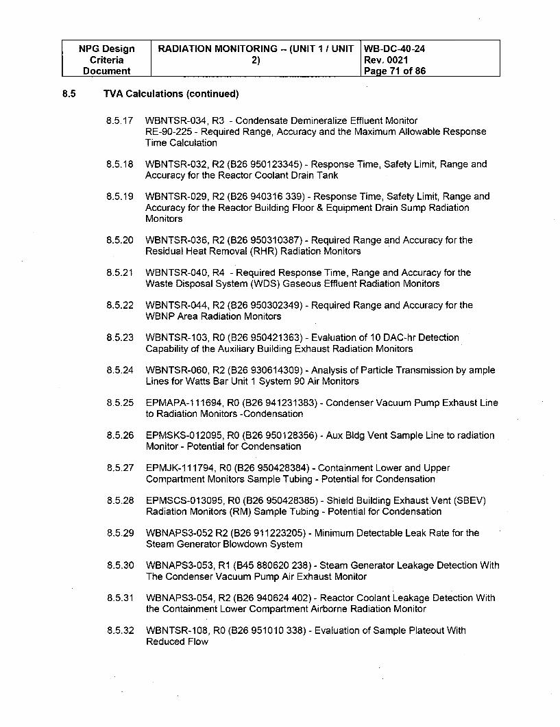
NPG Design RADIATION MONITORING -- (UNIT 1 / UNIT WB-DC-40-24Criteria 2) Rev. 0021
Document Page 71 of 86
8.5 TVA Calculations (continued)
8.5.17 WBNTSR-034, R3 - Condensate Demineralize Effluent MonitorRE-90-225 - Required Range, Accuracy and the Maximum Allowable ResponseTime Calculation
8.5.18 WBNTSR-032, R2 (B26 950123345) - Response Time, Safety Limit, Range andAccuracy for the Reactor Coolant Drain Tank
8.5.19 WBNTSR-029, R2 (B26 940316 339) - Response Time, Safety Limit, Range andAccuracy for the Reactor Building Floor & Equipment Drain Sump RadiationMonitors
8.5.20 WBNTSR-036, R2 (B26 950310387) - Required Range and Accuracy for theResidual Heat Removal (RHR) Radiation Monitors
8.5.21 WBNTSR-040, R4 - Required Response Time, Range and Accuracy for theWaste Disposal System (WDS) Gaseous Effluent Radiation Monitors
8.5.22 WBNTSR-044, R2 (B26 950302349) - Required Range and Accuracy for theWBNP Area Radiation Monitors
8.5.23 WBNTSR-103, RO (B26 950421363) - Evaluation of 10 DAC-hr DetectionCapability of the Auxiliary Building Exhaust Radiation Monitors
8.5.24 WBNTSR-060, R2 (B26 930614309) - Analysis of Particle Transmission by ampleLines for Watts Bar Unit 1 System 90 Air Monitors
8.5.25 EPMAPA-111694, RO (B26 941231383) - Condenser Vacuum Pump Exhaust Lineto Radiation Monitors -Condensation
8.5.26 EPMSKS-012095, RO (B26 950128356) - Aux Bldg Vent Sample Line to radiationMonitor - Potential for Condensation
8.5.27 EPMJK-1 11794, RO (B26 950428384) - Containment Lower and UpperCompartment Monitors Sample Tubing - Potential for Condensation
8.5.28 EPMSCS-01 3095, RO (B26 950428385) - Shield Building Exhaust Vent (SBEV)Radiation Monitors (RM) Sample Tubing - Potential for Condensation
8.5.29 WBNAPS3-052 R2 (826 911223205) - Minimum Detectable Leak Rate for theSteam Generator Blowdown System
8.5.30 WBNAPS3-053, R1 (B45 880620 238) - Steam Generator Leakage Detection WithThe Condenser Vacuum Pump Air Exhaust Monitor
8.5.31 WBNAPS3-054, R2 (B26 940624 402) - Reactor Coolant Leakage Detection Withthe Containment Lower Compartment Airborne Radiation Monitor
8.5.32 WBNTSR-108, RO (826 951010 338) - Evaluation of Sample Plateout WithReduced Flow
NPG Design RADIATION MONITORING -- (UNIT 1 / UNIT WB-DC-40-24Criteria 2) Rev. 0021
Document Page 72 of 86
8.5 TVA Calculations (continued)
8.5.33 WBNTSR-066, R6 - Design Flowrate for the Offline Liquid Radiation Monitors.
8.5.34 WBNTSR-009, R1 1 - Control Room Operator and Offsite Doses From a FuelHandling Accident
8.5.35 Calculation 1 RE90120, R10, "Demonstrated Accuracy Calculation for WBNPLiquid Effluent Compliance Radiation Monitors"
8.5.36 Calculation WBPE0909002007, R7, "Demonstrated Accuracy Calculation forWaste Disposal System Gas Effluent Radiation Monitor"
Other
8.6.1 Technical Specification Change TVA-WBN-TS-00-015, "Revision of BoronConcentration Limits and Reactor Core Limitations for Tritium Production Cores(TPCs)" (T04 010821 812).
8.6
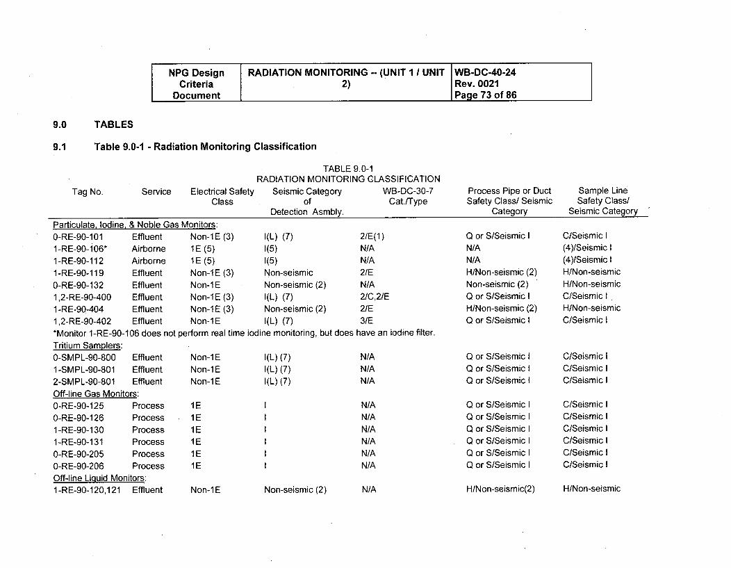
NPG Design RADIATION MONITORING -- (UNIT 1 / UNIT WB-DC-40-24Criteria 2) Rev. 0021
Document Page 73 of 86
9.0 TABLES
9.1 Table 9.0-1 - Radiation Monitoring Classification
Tag No.
TABLE 9.0-1RADIATION MONITORING CLASSIFICATION
Service Electrical Safety Seismic Category WB-DC-30-7Class of Cat./Type
Detection Asmbly.
Process Pipe or DuctSafety Class/ Seismic
Category
Sample LineSafety Class/
Seismic Category
Particulate, Iodine, & Noble Gas Monitors:0-RE-90-101 Effluent Non-lE (3) 1(L) (7) 2/E(l)1-RE-90-i06" Airborne 1E (5) 1(5) N/A1 -RE-90-112 Airborne 1E (5) 1(5) N/A
1-RE-90-119 Effluent Non-1E (3) Non-seismic 2/E
0-RE-90-132 Effluent Non-lE Non-seismic (2) N/A
1,2-RE-90-400 Effluent Non-i E (3) 1(L) (7) 2/C,2/E1 -RE-90-404 Effluent Non-1 E (3) Non-seismic (2) 2/E1,2-RE-90-402 Effluent Non-i E I(L) (7) 3/E*Monitor 1-RE-90-106 does not perform real time iodine monitoring, but does have an iodine filter.Tritium Samplers:0-SMPL-90-800 Effluent Non-1E I(L) (7) N/A1-SMPL-90-801 Effluent Non-lE I(L) (7) N/A2-SMPL-90-801 Effluent Non-1E I(L) (7) N/AOff-line Gas Monitors:O-RE-90-125 Process 1E I N/A
O-RE-90-126 Process 1E I N/A1 -RE-90-130 Process 1 E I N/A1 -RE-90-131 Process 1E I N/A0-RE-90-205 Process 1 E I N/A
O-RE-90-206 Process 1E I N/AOff-line Liquid Monitors:1-RE-90-120,121 Effluent Non-lE Non-seismic (2) N/A
Q or S/Seismic IN/AN/AH/Non-seismic (2)Non-seismic (2)Q or S/Seismic IH/Non-seismic (2)Q or S/Seismic I
Q or S/Seismic IQ or S/Seismic IQ or S/Seismic I
Q or S/Seismic IQ or S/Seismic IQ or S/Seismic IQ or S/Seismic IQ or S/Seismic IQ or S/Seismic I
C/Seismic I(4)/Seismic I(4)/Seismic IH/Non-seismicH/Non-seismicC/Seismic IH/Non-seismicC/Seismic I
C/Seismic IC/Seismic IC/Seismic I
C/Seismic IC/Seismic IC/Seismic IC/Seismic IC/Seismic IC/Seismic I
H/Non-seismic(2) H/Non-seismic
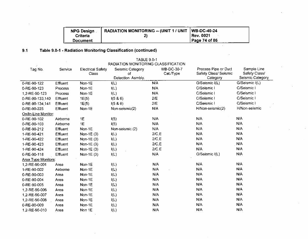
NPG Design RADIATION MONITORING -- (UNIT 1 I UNIT WB-DC-40-24Criteria 2) Rev. 0021
Document Page 74 of 86
9.1 Table 9.0-1 - Radiation Monitoring Classification (continued)
Tag No. Service Electrical SafetyClass
O-RE-90-122 EffluentO-RE-90-123 Process1,2-RE-90-123 Process0-RE-90-133,140 Effluent0-RE-90-134,141 Effluent0-RE-90-225 EffluentOn/In-Line Monitor:0-RE-90-102 Airborne0-RE-90-103 Airborne0-RE-90-212 Effluent1 -RE-90-421 Effluent1 -RE-90-422 Effluent1-RE-90-423 Effluent1 -RE-90-424 Effluent0-RE-90-118 EffluentArea Type Monitors:1,2-RE-90-001 Area1 -RE-90-002 Airborne0-RE-90-003 Area0-RE-90-004 Area0-RE-90-005 Area1,2-RE-90-006 Area1,2-RE-90-007 Area1,2-RE-90-008 AreaO-RE-90-009 Area1,2-RE-90-01 0 Area
Non-lENon-lENon-1E1E(5)1E(5)Non-1E
1E1ENon-1ENon-1 E (3)Non-1 E (3)Non-1 E (3)Non-1E (3)Non-1 E (3)
Non-lENon-lENon-lENon-lENon-iENon-lENon-lENon-lENon-1ENon 1E
TABLE 9.0-1RADIATION MONITORING CLASSIFICATION
Seismic Category WB-DC-30-7of Cat./Type
Detection Asmbly.I(L) N/AI(L) N/AI(L) N/A1(5 & 6) 2/E1(5 & 6) 2/ENon-seismic(2) N/A
1(5)1(5)Non-seismic (2)I(L)I(L)I(L)I(L)I(L)
N/AN/AN/A2/C,E2/C,E2/C,E2/C, EN/A
Process Pipe or DuctSafety Class/ Seismic
CategoryG/Seismic I(L)C/Seismic IC/Seismic IC/Seismic IC/Seismic IH/Non-seismic(2)
N/AN/AN/AN/AN/AN/AN/AG/Seismic I(L)
N/AN/AN/AN/AN/AN/AN/AN/AN/AN/A
Sample LineSafety Class/
Seismic CategoryG/Seismic I(L)C/Seismic IC/Seismic IC/Seismic IC/Seismic IH/Non-seismic
N/AN/AN/AN/AN/AN/AN/AN/A
N/AN/AN/AN/AN/AN/AN/AN/AN/AN/A
I(L)I(L)
I(L)
I(L)
I(L)I(L)I(L)I(L)I(L)I(L)
N/AN/AN/AN/AN/AN/AN/AN/AN/AN/A
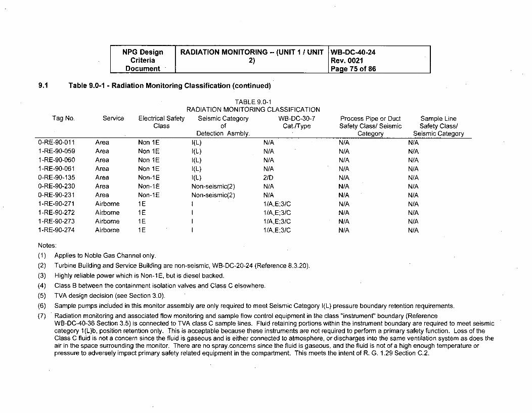
NPG Design RADIATION MONITORING -- (UNIT 1 / UNIT WB-DC-40-24Criteria 2) Rev. 0021
Document Page 75 of 86
9.1 Table 9.0-1 - Radiation Monitoring Classification (continued)
Tag No. Service Electrical SafetyClass
TABLE 9.0-1RADIATION MONITORING CLASSIFICATION
Seismic Category WB-DC-30-7of Cat./Type
Detection Asmbly.
Process Pipe or DuctSafety Class/ Seismic
Category0-RE-90-01 11 -RE-90-0591 -RE-90-0601 -RE-90-0610-RE-90-1350-RE-90-2300-RE-90-2311 -RE-90-2711 -RE-90-2721 -RE-90-2731 -RE-90-274
AreaAreaAreaAreaAreaAreaAreaAirborneAirborneAirborneAirborne
Non 1ENon 1ENon 1ENon 1ENon-1ENon-lENon-iE1E1E1E1E
I(L)1(L)I(L)I(L)I(L)
Non-seismic(2)Non-seismic(2)
N/AN/AN/AN/A2/DN/AN/A1/A,E;3/C1/A,E;3/C1/A,E;3/C1/A, E; 3/C
N/AN/AN/AN/AN/AN/AN/AN/AN/AN/AN/A
Sample LineSafety Class/
Seismic CategoryN/AN/AN/AN/AN/AN/AN/AN/AN/AN/AN/A
Notes:
(1)(2)
Applies to Noble Gas Channel only.
Turbine Building and Service Building are non-seismic, WB-DC-20-24 (Reference 8.3.20).
(3) Highly reliable power which is Non-i E, but is diesel backed.
(4) Class B between the containment isolation valves and Class C elsewhere.
(5) TVA design decision (see Section 3.0).
(6) Sample pumps included in this monitor assembly are only required to meet Seismic Category I(L) pressure boundary retention requirements.
(7) Radiation monitoring and associated flow monitoring and sample flow control equipment in the class "instrument" boundary (ReferenceWB-DC-40-36 Section 3.5) is connected to TVA class C sample lines. Fluid retaining portions within the instrument boundary are required to meet seismiccategory 1 (L)b, position retention only. This is acceptable because these instruments are not required to perform a primary safety function. Loss of theClass C fluid is not a concern since the fluid is gaseous and is either connected to atmosphere, or discharges into the same ventilation system as does theair in the space surrounding the monitor. There are no spray concerns since the fluid is gaseous, and the fluid is not of a high enough temperature orpressure to adversely impact primary safety related equipment in the compartment. This meets the intent of R. G. 1.29 Section C.2.
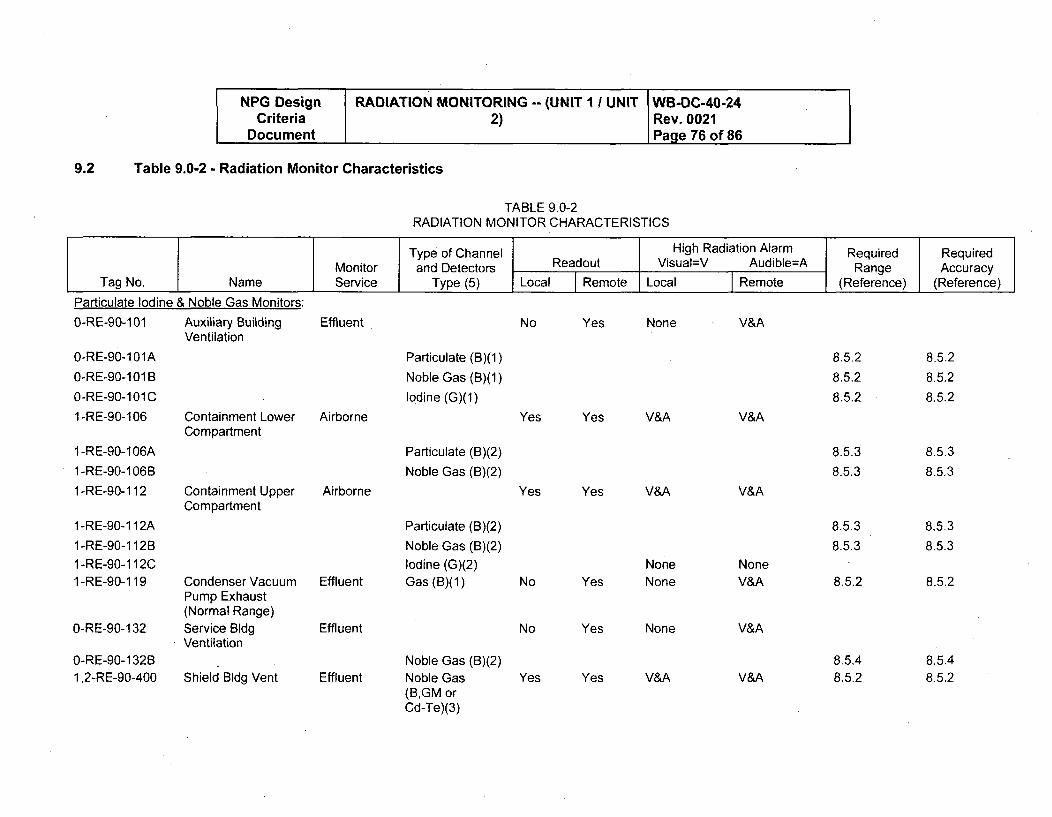
NPG Design RADIATION MONITORING -- (UNIT I I UNIT WB-DC-40-24Criteria 2) Rev. 0021
Document Page 76 of 86
Table 9.0-2 - Radiation Monitor Characteristics
TABLE 9.0-2RADIATION MONITOR CHARACTERISTICS
9.2
Type of Channel High Radiation Alarm Required RequiredMonitor and Detectors Readout Visual=V Audible=A Range Accuracy
Tag No. Name Service Type (5) Local I Remote Local FRemote (Reference) (Reference)
Particulate Iodine
0-RE-90-101
& Noble Gas Monitors:
Auxiliary BuildingVentilation
Effluent No Yes None V&A
0-RE-90-101A
0-RE-90-1 01 B
0-RE-90-1 01 C1 -RE-90-106
1 -RE-90-106A
1 -RE-90-106B
1 -RE-90-112
1 -RE-90-112A
1 -RE-90-112B1 -RE-90-112C1 -RE-90-119
0-RE-90-132
0-RE-90-132B1,2-RE-90-400
Containment LowerCompartment
Containment UpperCompartment
Airborne
Particulate (B)(1)
Noble Gas (B)(1)
Iodine (G)(1)
Particulate (B)(2)
Noble Gas (B)(2)
Particulate (B)(2)
Noble Gas (B)(2)
Iodine (G)(2)Gas (B)(1)
Yes Yes V&A V&A
8.5.2
8.5.2
8.5.2
8.5.3
8.5.3
8.5.3
8.5.3
8.5.2
8.5.2
8.5.2
8.5.2
8.5.3
8.5.3
8.5.3
8.5.3
8.5.2
Airborne Yes Yes V&A V&A
Condenser VacuumPump Exhaust(Normal Range)Service BldgVentilation
Shield Bldg Vent
Effluent
Effluent
Effluent
No Yes
No Yes
NoneNone
None
V&A
NoneV&A
V&A
V&ANoble Gas (B)(2)Noble Gas(B,GM orCd-Te)(3)
8.5.48.5.2
8.5.48.5.2Yes Yes
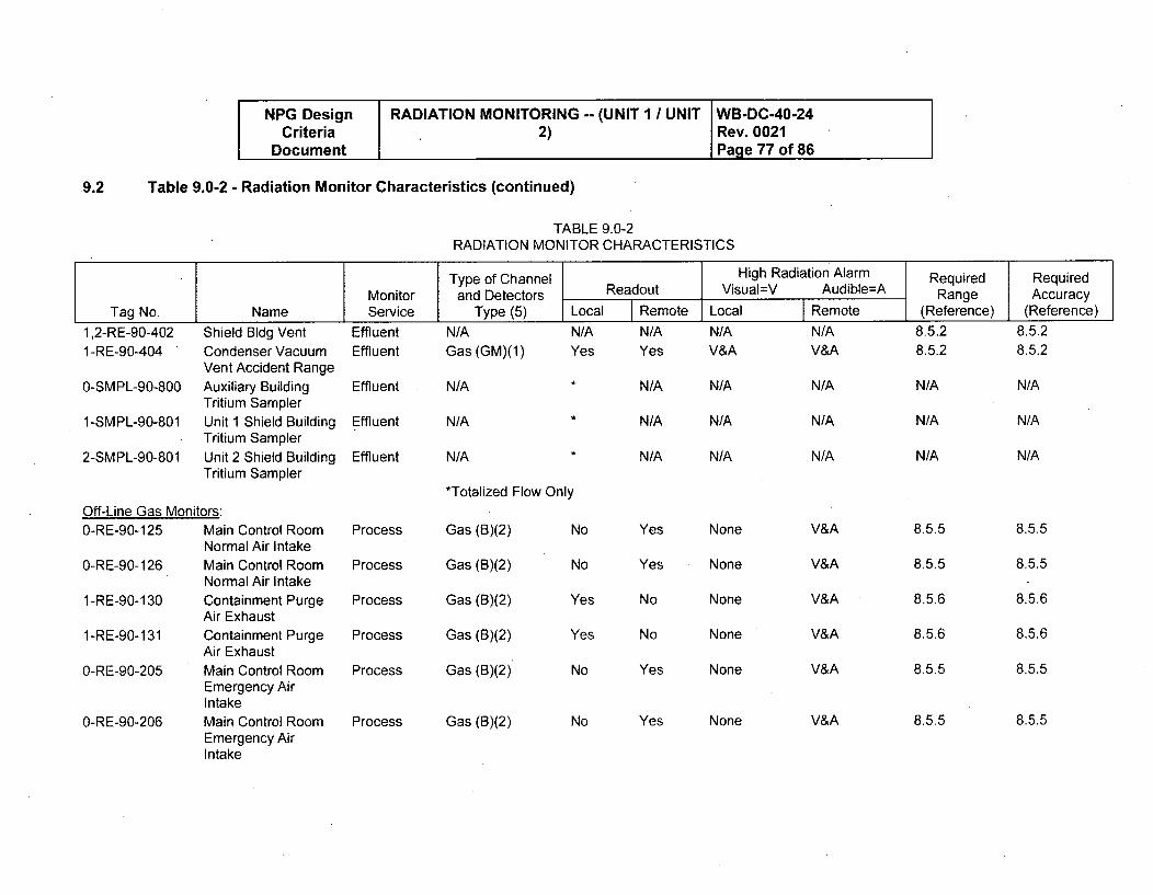
NPG Design RADIATION MONITORINGCriteria 2)
Document
Table 9.0-2 - Radiation Monitor Characteristics (continued)
-- (UNIT I / UNIT WB-DC-40-24Rev. 0021Page 77 of 86
9.2
MonitorTag No.
1,2-RE-90-4021 -RE-90-404
0-SMPL-90-800
1-SMPL-90-801
2-SMPL-90-801
NameShield Bldg VentCondenser VacuumVent Accident RangeAuxiliary BuildingTritium SamplerUnit 1 Shield BuildingTritium SamplerUnit 2 Shield BuildingTritium Sampler
ServiceEffluentEffluent
Effluent
Effluent
Effluent
TABLE 9.0-2RADIATION MONITOR CHARACTERISTICS
Type of Channel RIand Detectors Readout Vis
Type (5) Local Remote Local
N/A N/A N/A N/AGas (GM)(1) Yes Yes V&A
N/A * N/A N/A
N/A * N/A N/A
N/A * N/A N/A
*Totalized Flow Only
Gas (B)(2) No Yes None
Gas (B)(2) No Yes None
Gas (B)(2) Yes No None
Gas (B)(2) Yes No None
Gas (B)(2) No Yes None
-igh Radiation Alarmual=V Audible=A
Remote
N/AV&A
N/A
N/A
N/A
V&A
V&A
V&A
V&A
V&A
V&A
RequiredRange
(Reference)
8.5.28.5.2
N/A
N/A
N/A
RequiredAccuracy
(Reference)8.5.28.5.2
N/A
N/A
N/A
Off-Line Gas Monitors:0-RE-90-125 Main Control Room
Normal Air Intake0-RE-90-126 Main Control Room
Normal Air Intake1-RE-90-130 Containment Purge
Air Exhaust1-RE-90-131 Containment Purge
Air Exhaust0-RE-90-205 Main Control Room
Emergency AirIntake
0-RE-90-206 Main Control RoomEmergency AirIntake
Process
Process
Process
Process
Process
Process
8.5.5
8.5.6
8,5.6
8.5.6
8.5.5
8.5.5
8.5.5
8.5.5
8.5.6
8.5.6
8.5.5
8.5.5NoneGas (B)(2) No Yes
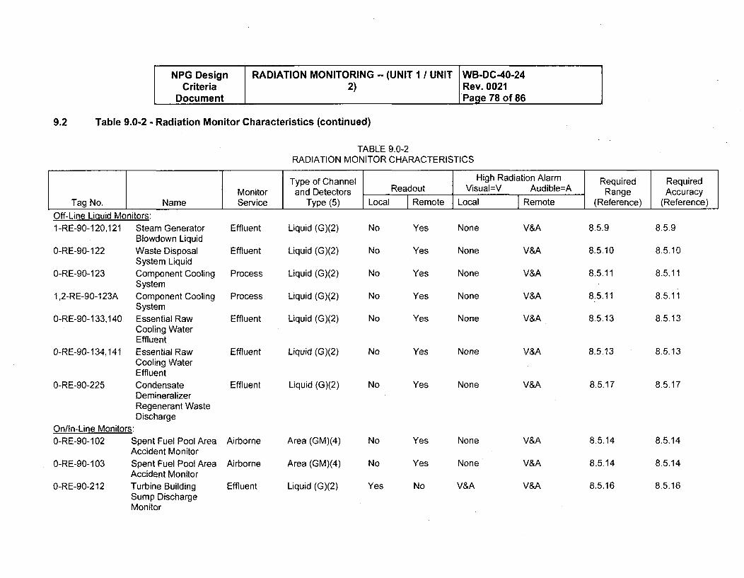
NPG Design RADIATION MONITORING -- (UNIT I / UNIT WB-DC-40-24Criteria 2) Rev. 0021
Document Page 78 of 86
Table 9.0-2 - Radiation Monitor Characteristics (continued)9.2
TABLE 9.0-2RADIATION MONITOR CHARACTERISTICS
Type of Channel High Radiation Alarm Required Required
Monitor and Detectors Readout Visual=V Audible=A Range AccuracyTag No. Name Service Type (5) Local Remote Local Remote (Reference) (Reference)
Off-Line Liquid Monitors:1-RE-90-120,121 Steam Generator
Blowdown LiquidEffluent Liquid (G)(2)
0-RE-90-122 Waste DisposalSystem Liquid
0-RE-90-123 Component CoolingSystem
1,2-RE-90-123A Component CoolingSystem
0-RE-90-133,140 Essential RawCooling WaterEffluent
0-RE-90-134,141 Essential RawCooling WaterEffluent
0-RE-90-225 CondensateDemineralizerRegenerant WasteDischarge
On/In-Line Monitors:0-RE-90-102 Spent Fuel Pool Area
Accident MonitorO-RE-90-103 Spent Fuel Pool Area
Accident Monitor0-RE-90-212 Turbine Building
Sump DischargeMonitor
Effluent
Process
Process
Effluent
Liquid (G)(2)
Liquid (G)(2)
Liquid (G)(2)
Liquid (G)(2)
No
No
No
No
No
Yes
Yes
Yes
Yes
Yes
Effluent Liquid (G)(2)
Effluent Liquid (G)(2)
Airborne Area (GM)(4)
Airborne Area (GM)(4)
Effluent Liquid (G)(2)
No Yes
No Yes
None
None
None
None
None
None
None
None
None
V&A
V&A
V&A
V&A
V&A
V&A
V&A
V&A
V&A
V&A
V&A
8.5.9
8.5.10
8.511
8.5.11
8.5.13
8.5.13
8.5.17
8.5.14
8.5.14
8.5.16
8.5.9
8.5.10
8.5.11
8.5.11
8.5.13
8.5.13
8.5.17
8.5.14
8&5.14
8.5.16
No
No
Yes
Yes
Yes
No
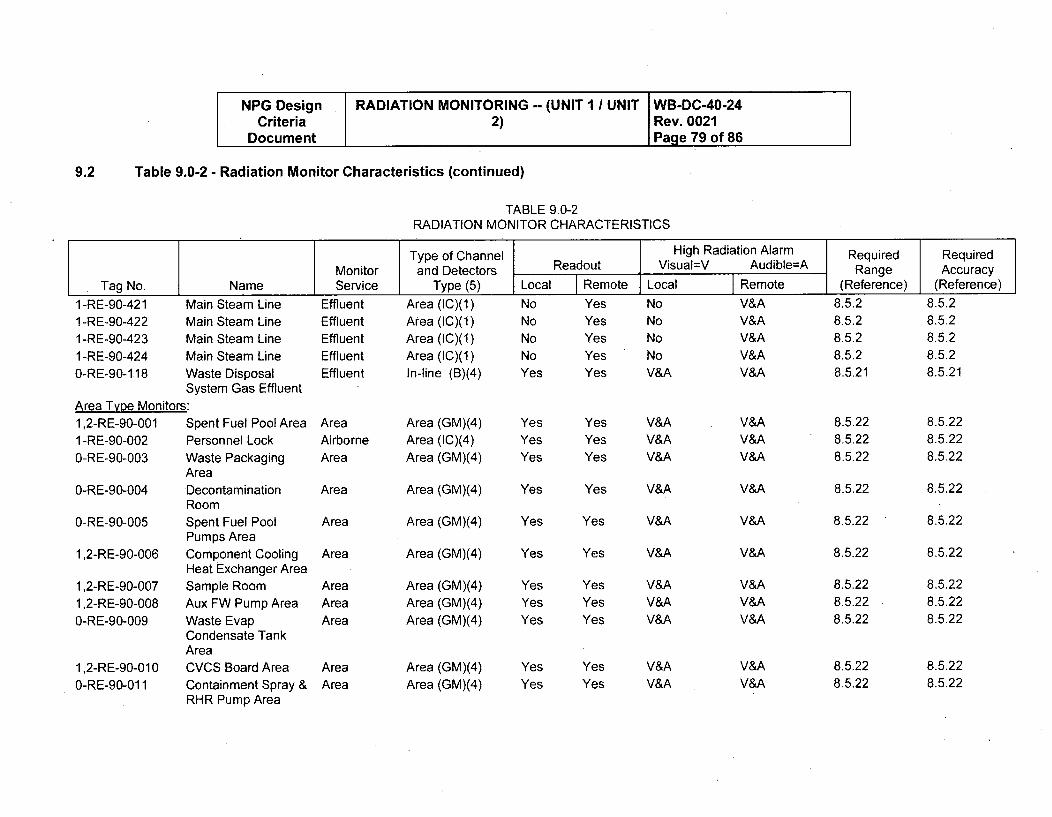
NPG Design RADIATION MONITORING -- (UNIT 1 UNIT WB-DC-40-24Criteria 2) Rev. 0021
Document Page 79 of 86
9.2 Table 9.0-2 - Radiation Monitor Characteristics (continued)
TABLE 9.0-2RADIATION MONITOR CHARACTERISTICS
Type of Channel High Radiation Alarm Required RequiredMonitor and Detectors Readout Visual=V Audible=A Range Accuracy
Tag No. Name Service Type (5) Local Remote Local Remote (Reference) (Reference)
1 -RE-90-4211 -RE-90-4221 -RE-90-4231 -RE-90-4240-RE-90-1,18
Area Tvye Monitors:1,2-RE-90-001 C1 -RE-90-002 F0-RE-90-003 V
0-RE-90-004 EF
0-RE-90-005 CF
1,2-RE-90-006 CI-
1,2-RE-90-0071,2-RE-90-008 A0-RE-90-009 V
CA
1,2-RE-90-01 0 C0-RE-90-011 C
Vlain Steam LineAlain Steam LineVlain Steam LineVlain Steam LineNaste Disposal3ystem Gas Effluent
Spent Fuel Pool Area'ersonnel LockVaste Packaging,rea)econtamination,oom3pent Fuel Pool'umps Areaomponent Cooling
leat Exchanger Areaiample Roomux FW Pump Area
Vaste Evapondensate Tank
krea.VCS Board Areaontainment Spray &
RHR Pump Area
EffluentEffluentEffluentEffluentEffluent
AreaAirborneArea
Area (IC)(1)Area (IC)(1)Area (IC)(1)Area (IC)(1)In-line (B)(4)
NoNoNoNoYes
YesYesYesYesYes
Area
Area
Area
AreaAreaArea
AreaArea
Area (GM)(4)Area (IC)(4)Area (GM)(4)
Area (GM)(4)
Area (GM)(4)
Area (GM)(4)
Area (GM)(4)Area (GM)(4)Area (GM)(4)
Area (GM)(4)Area (GM)(4)
YesYesYes
Yes
Yes
Yes
YesYesYes
YesYes
YesYesYes
Yes
Yes
Yes
YesYesYes
YesYes
NoNoNoNoV&A
V&AV&AV&A
V&A
V&A
V&A
V&AV&AV&A
V&AV&A
V&AV&AV&A
V&A
V&A
V&A
V&AV&AV&A
V&AV&A
8.5.228.5.228.5.22
8.5.22
8.5.22
8.5.22
8.5.228.5.228.5.22
8.5.228.5.22
V&AV&AV&AV&AV&A
8.5.28.5.28.5.28.5.28.5.21
8.5.28.5.28.5.28.5.28.5.21
8.5.228.5.228.5.22
8.5.22
8.5.22
8.5.22
8.5.228.5.228.5.22
8.5.228.5.22
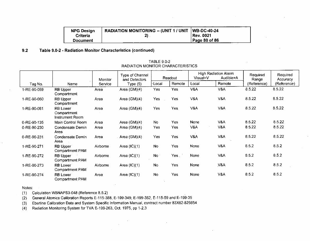
NPG Design RADIATION MONITORING -- (UNIT 1 I UNIT WB-DC-40-24Criteria 2) Rev. 0021
Document Page 80 of 86
Table 9.0-2 - Radiation Monitor Characteristics (continued)
TABLE 9.0-2RADIATION MONITOR CHARACTERISTICS
9.2
Type of Channel High Radiation Alarm• Required RequiredMonitor and Detectors Readout Visual=V Audible=A Range Accuracy
Tag No. Name Service Type (5) Local Remote Local Remote (Reference) (Reference)
1-RE-90-059 RB Upper Area Area (GM)(4) Yes Yes V&A V&A 8.5.22 8.5.22
1 -RE-90-060
1 -RE-90-061
0-RE-90-1 350-RE-90-230
0-RE-90-231
1 -RE-90-271
1 -RE-90-272
1 -RE-90-273
1 -RE-90-274
CompartmentRB UpperCompartmentRB LowerCompartmentInstrument RoomMain Control RoomCondensate DeminAreaCondensate DeminAreaRB UpperCompartment PAMRB UpperCompartment PAMRB LowerCompartment PAMRB LowerCompartment PAM
Area
Area
AreaArea
Area
Area (GM)(4)
Area (GM)(4)
Area (GM)(4)Area (GM)(4)
Area (GM)(4)
Yes
Yes
No
Yes
Yes
Yes
Yes
Yes
Yes
Yes
V&A
V&A
None
V&A
V&A
None
V&A
V&A
V&A
V&A
V&A
V&A
V&A
V&A
V&A
8.5.22
8.5.22
8.5.22
8.5.22
8.5.22
8.5.2
8.5.2
8.5.2
8.5.2
8.5.22
8.5.22
8.5.22
8.5.22
8.5.22
8.5.2
8.5.2
8.5.2
8.5.2
Airborne Area (IC)(1)
Airborne Area (IC)(1)
Airborne Area (IC)(1)
No Yes
No, Yes ' None
No Yes
No Yes
None
NoneArea Area (IC)(1)
Notes:(1) Calculation WBNAPS3-048 (Reference 8.5.2)(2) General Atomics Calibration Reports E-115-388, E-199-349, E-199-352, E-115-59 and E-199-35(3) Eberline Calibration Data and System Specific Information Manual, contract number 83X62-829854(4) Radiation Monitoring System for TVA E-199-263, Oct. 1975, pp 1-2,3
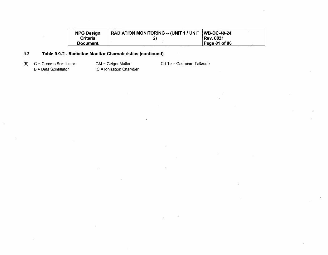
NPG Design RADIATION MONITORINGCriteria 2)
Document
Table 9.0-2 - Radiation Monitor Characteristics (continued)
G = Gamma Scintillator GM = Geiger Muller C(B = Beta Scintillator IC = Ionization Chamber
-- (UNIT, IUNIT WB-DC-40-24Rev. 0021Page 81 of 86
9.2
(5) I-Te = Cadmium Telluride
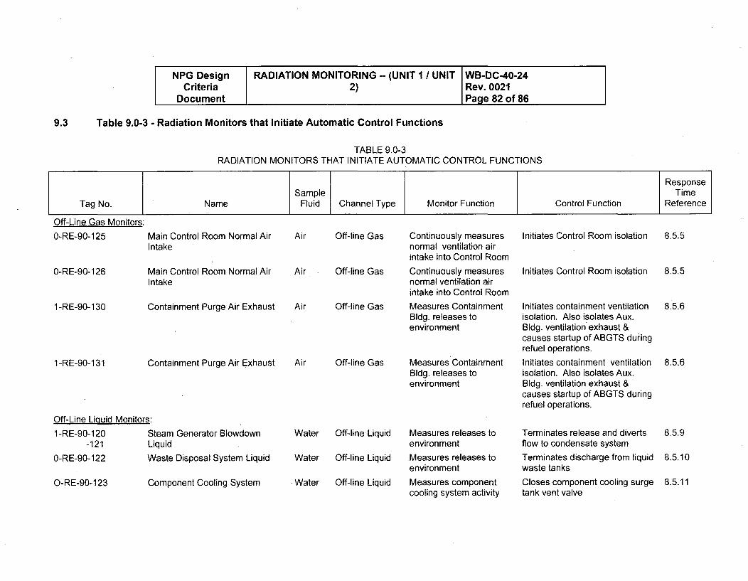
NPG Design RADIATION MONITORING -- (UNIT I / UNIT WB-DC-40-24Criteria 2) Rev. 0021
Document Page 82 of 86
Table 9.0-3 - Radiation Monitors that Initiate Automatic Control Functions
TABLE 9.0-3RADIATION MONITORS THAT INITIATE AUTOMATIC CONTROL FUNCTIONS
9.3
Off-Line Gas Monitors:
0-RE-90-125 Main Control Room Normal Air Air Off-line Gas Continuously measures Initiates Control Room isolation 8.5.5Intake normal ventilation air
intake into Control Room
O-RE-90-126 MIn
1-RE-90-130 C
1-RE-90-131 C
Off-Line Liquid Monitors:
1-RE-90-120 S-121 Li
0-RE-90-122 Vý
O-RE-90-123 C
lain Control Room Normal Airitake
ontainment Purge Air Exhaust
ontainment Purge Air Exhaust
team Generator Blowdownquid
/aste Disposal System Liquid
omponent Cooling System
Air Off-line Gas
Air Off-line Gas
Air Off-line Gas
Water Off-line Liquid
Water Off-line Liquid
Water Off-line Liquid
Continuously measuresnormal ventilation airintake into Control Room
Measures ContainmentBldg. releases toenvironment
Measures ContainmentBldg. releases toenvironment
Measures releases toenvironment
Measures releases toenvironment
Measures componentcooling system activity
Initiates Control Room isolation
Initiates containment ventilationisolation. Also isolates Aux.Bldg. ventilation exhaust &causes startup of ABGTS duringrefuel operations.Initiates containment ventilationisolation. Also isolates Aux.Bldg, ventilation exhaust &causes startup of ABGTS duringrefuel operations.
Terminates release and divertsflow to condensate systemTerminates discharge from liquidwaste tanksCloses component cooling surgetank vent valve
8.5.5
8.5.6
8.5.6
8.5.9
8.5.10
8.5.11
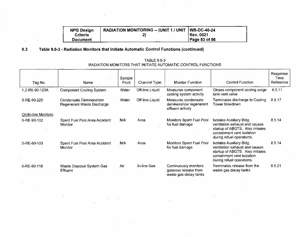
NPG Design RADIATION MONITORING -- (UNIT I / UNIT WB-DC-40-24Criteria 2) Rev. 0021
Document Page 83 of 86
Table 9.0-3 - Radiation Monitors that Initiate Automatic Control Functions (continued)
TABLE 9.0-3RADIATION MONITORS THAT INITIATE AUTOMATIC CONTROL FUNCTIONS
9.3
ResponseSample Time
Tag No. Name Fluid Channel Type, Monitor Function Control Function Reference
1,2-RE-90-123A Component Cooling System Water Off-line Liquid Measures component Closes component cooling surge 8.5.11
0-RE-90-225
On/In-line Monitors:0-RE-90-102
O-RE-90-103
Condensate DemineralizerRegenerant Waste Discharge
Spent Fuel Pool Area AccidentMonitor
Spent Fuel Pool Area AccidentMonitor
Water Off-line Liquid
N/A
N/A
Area
Area
cooling system activity
Measures condensatedemineralizer regeneranteffluent activity
Monitors Spent Fuel Poolfor fuel damage
Monitors Spent Fuel Poolfor fuel damage
tank vent valve
Terminates discharge to CoolingTower blowdown
Isolates Auxiliary Bldg.ventilation exhaust and causesstartup of ABGTS. Also initiatescontainment vent isolationduring refuel operations.
Isolates Auxiliary Bldg.ventilation exhaust and causesstartup of ABGTS. Also initiatescontainment vent isolationduring refuel operations.
Terminates release from thewaste gas decay tanks
8.5.17
8.5.14
8.5.14
O-RE-90-118 Waste Disposal System GasEffluent
Air In-line Gas Continuously monitorsgaseous release fromwaste gas decay tanks
8.5.21
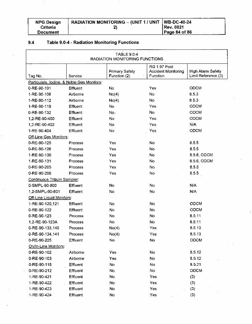
NPG Design RADIATION MONITORING -- (UNIT 1 / UNIT WB-DC-40-24Criteria 2) Rev. 0021
Document Page 84 of 86
9.4 Table 9.0-4 - Radiation Monitoring Functions
TABLE 9.0-4RADIATION MONITORING FUNCTIONS
RG 1.97 PostPrimary Safety Accident Monitoring High Alarm Safety
Tag No. Service Function (2) Function Limit Reference (3)
Particulate, Iodine, & Noble Gas Monitors:
0-RE-90-101 Effluent
1-RE-90-106 Airborne
1-RE-90-112 Airborne
1-RE-90-119 Effluent
0-RE-90-132 Effluent
1,2-RE-90-400 Effluent
1,2-RE-90-402 Effluent
1-RE-90-404 Effluent
Off-Line Gas Monitors:
0-RE-90-125 Process
0-RE-90-126 Process
1 -RE-90-130 Process
1-RE-90-131 Process
O-RE-90-205 Process
0-RE-90-206 Process
Continuous Tritium Sampler:
0-SMPL-90-800 Effluent
1,2-SMPL-90-801 Effluent
Off-Line Liquid Monitors:
1-RE-90-120,121 Effluent
0-RE-90-122 Effluent
0-RE-90-123 Process
1,2-RE-90-123A Process
0-RE-90-133,140 Process
0-RE-90-134,141 Process
0-RE-90-225 Effluent
On/In-Line Monitors:
0-RE-90-102 Airborne
0-RE-90-103 Airborne
0-RE-90-118 Effluent
0-RE-90-212 Effluent
1-RE-90-421 Effluent
1-RE-90-422 Effluent
1-RE-90-423 Effluent
1-RE-90-424 Effluent
No
No(4)
No(4)
No
No,
No
No
No
Yes
Yes
Yes
Yes
Yes
Yes
No
No
No
No
No
No
No(4)
No(4)
No
Yes
No
No
Yes
No
Yes
Yes
Yes
No
No
No
No
No
No
No
No
No
No
No
No
Yes
Yes
No
No
No
No.No
Yes
Yes
Yes
* Yes
ODCM
8.5.3
8.5.3
ODCM
ODCM
ODCM
N/A
ODCM
8.5.5
8.5.5
8.5.6, ODCM
8.5.6, ODCM
8.5.5
8.5.5
N/A
N/A
ODCM
ODCM
8.5.11
8.5.11
8.5.13
8.5.13
ODCM
8.5.12
8.5.12
8.5.21
ODCM
(3)
(3)
(3)
(3)
Yes
Yes
No
No
No
No
No
No
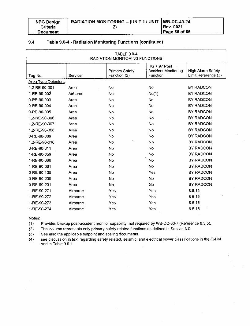
NPG Design RADIATION MONITORING -- (UNIT 1 I UNIT WB-DC-40-24Criteria 2) Rev. 0021
Document Page 85 of 86
9.4 Table 9.0-4 - Radiation Monitoring Functions (continued)
TABLE 9.0-4RADIATION MONITORING FUNCTIONS
RG 1.97 PostPrimary Safety Accident Monitoring High Alarm Safety
Tag No. Service Function (2) Function Limit Reference (3)
Area Type Detectors:
1,2-RE-90-001
1-RE-90-002
0-RE-90-003
0-RE-90-004
0-RE-90-005
1,2-RE-90-006
1,2-RE-90-007
1,2-RE-90-008
O-RE-90-0091,2-RE-90-010
0-RE-90-011
1-RE-90-059
1 -RE-90-060
1 -RE-90-061
0-RE-90-135
O-RE-90-230
O-RE-90-231
1 -RE-90-271
1 -RE-90-272
1 -RE-90-273
I-RE-90-274
Area
Airborne
Area
Area
Area
Area
Area
Area
Area
Area
Area
Area
Area
Area
Area
Area
Area
Airborne
Airborne
Airborne
Airborne
No
No
No
No
No
No
No
No
No
No
No
No
No
No
No
No
No
Yes
Yes
Yes
Yes
No
No(l)
No
No
No
No
No
No
No
No
No
No
No
No
Yes
No
No
Yes
Yes
Yes
Yes
BY RADCON
BY RADCON
BY RADCON
BY RADCON
BY RADCON
BY RADCON
BY RADCON
BY RADCON
BY RADCON
BY RADCON
BY RADCON
BY RADCON
BY RADCON
BY RADCON
BY RADCON
BY RADCON
BY RADCON
8.5.15
8.5.15
8.5.15
8.5.15
Notes:(1) Provides backup post-accident monitor capability, not required by WB-DC-30-7 (Reference 8.3.5).
(2) This column represents only primary safety related functions as defined in Section 3.0.
(3) See also the applicable setpoint and scaling documents.
(4) see discussion in text regarding safety related, seismic, and electrical power classifications in the Q-Listand in Table 9.0-1.
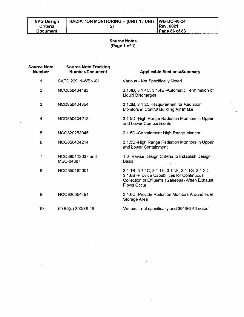
NPG Design RADIATION MONITORING -- (UNIT I / UNIT WB-DC-40-24Criteria 2) Rev. 0021
Document Page 86 of 86
Source Notes(Page 1 of 1)
Source Note Source Note TrackingNumber NumberlDocument
1 CATD 22911-WBN-01
2 NCO850404193
3 NCO850404354
4
5
6
NC0850404213
NC0820253045
NC0850404214
Applicable SectionslSummary
Various - Not Specifically Noted
3.1 44B, 3.1.4C, 3.1.4E -Automatic Termination ofLiquid Discharges
3.1.2B, 3.1.2C -Requirement for RadiationMonitors in Control Building Air Intake
3.1.5D -High Range Radiation Monitors in Upperand Lower Compartments
3.1.5D -Containment High Range Monitor
3.1.5D -High Range Radiation Monitors in Upperand Lower Containment
1.0 -Revise Design Criteria to Establish DesignBasis
3.1.1B, 3.1.1C, 3.1.1E, 3.1.1F, 3.1.1G, 3.1.2D,3.1.6B -Provide Capabilities for ContinuousCollection of Effluents (Gaseous) When ExhaustFlows Occur
3.1.6C -Provide Radiation Monitors Around Fuel
Storage Area
Various - not specifically and 391/86-46 noted
7 NC0890112037 andMSC-04387
8 NC0850192001
9 NC0920054491
10 50.55(e) 390/86-49
Enclosure 2TVA Letter Dated October 29, 2010
Responses to Licensee Open Items to be Resolved for SER Approval
Attachment 7
General Atomics Detector Type Comparison
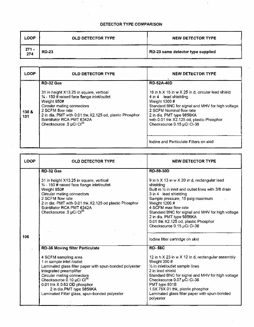
DETECTOR TYPE COMPARISON
LOOP OLD DETECTOR TYPE NEW DETECTOR TYPE
271 RD-23 RD-23 same detector type supplied274
LOOP OLD DETECTOR TYPE NEW DETECTOR TYPE
RD-32 Gas RD-52A-40D
31 in height X13.25 in square, vertical 16 in h X 15 in w X 25 in d, circular lead shield¾ - 150 # raised face flange inlet/outlet 4 in 4 lead shieldingWeight 950# Weight 1300 #Circular mating connectors Standard BNC for signal and MHV for high voltage
130 & 2 SCFM flow rate 2 SCFM Nominal flow rate131 2 in dia. PMT with 0.01 thk X2.125 od, plastic Phosphor 2 in dia. PMT type 9856KA
Scintillator RCA PMT 6342A with 0.01 thk X2.125 od, plastic PhosphorChecksource .5 pCi Cl36 Checksource 0.15 pCi CI-36
Iodine and Particulate Filters on skid
LOOP OLD DETECTOR TYPE NEW DETECTOR TYPE
RD-32 Gas RD-59-30D
31 in'height X13.25 in square, vertical 9 in h X 13 in w X 20 in d, rectangular lead¾ - 150 # raised face flange inlet/outlet shieldingWeight 950# Built in ½ in inlet and outlet lines with 3/8 drainCircular mating connectors 3 in 4 lead shielding2 SCFM flow rate Sample pressure, 15 psig maximum2 in dia. PMT with 0.01 thk X2.125 od plastic Phosphor Weight 1200 #Scintillator RCA PMT 6342A 4 SCFM max flow rateChecksource .5 pCi C136 Standard BNC for signal and MHV for high voltage
2 in dia. PMT type 9856KA0.01 thk X2.125 od, plastic PhosphorChecksource 0.15 pCi CI-36
106 Iodine filter cartridge on skid
RD-36 Moving filter Particulate RD- 56C
4 SCFM sampling area 12 in h X 23 in w X 12 in d, rectangular assembly1 in sample inlet /outlet Weight 350 #Laminated glass filter paper with spun-bonded polyester ½ in inlet/outlet sample linesIntegrated preamplifier 2 in lead shieldCircular mating connectors Standard BNC for signal and MHV for high voltageChecksource 0.10 pCi C136 Checksource 0.07 pCi CI-360.01 thk X 0.63 OD phosphor PMT type .931B
2 in dia.PMT type 9856KA 1.5X.75X.01 thk, plastic phosphorLaminated Filter glass, spun-bonded polyester Laminated glass filter paper with spun-bonded
polyester
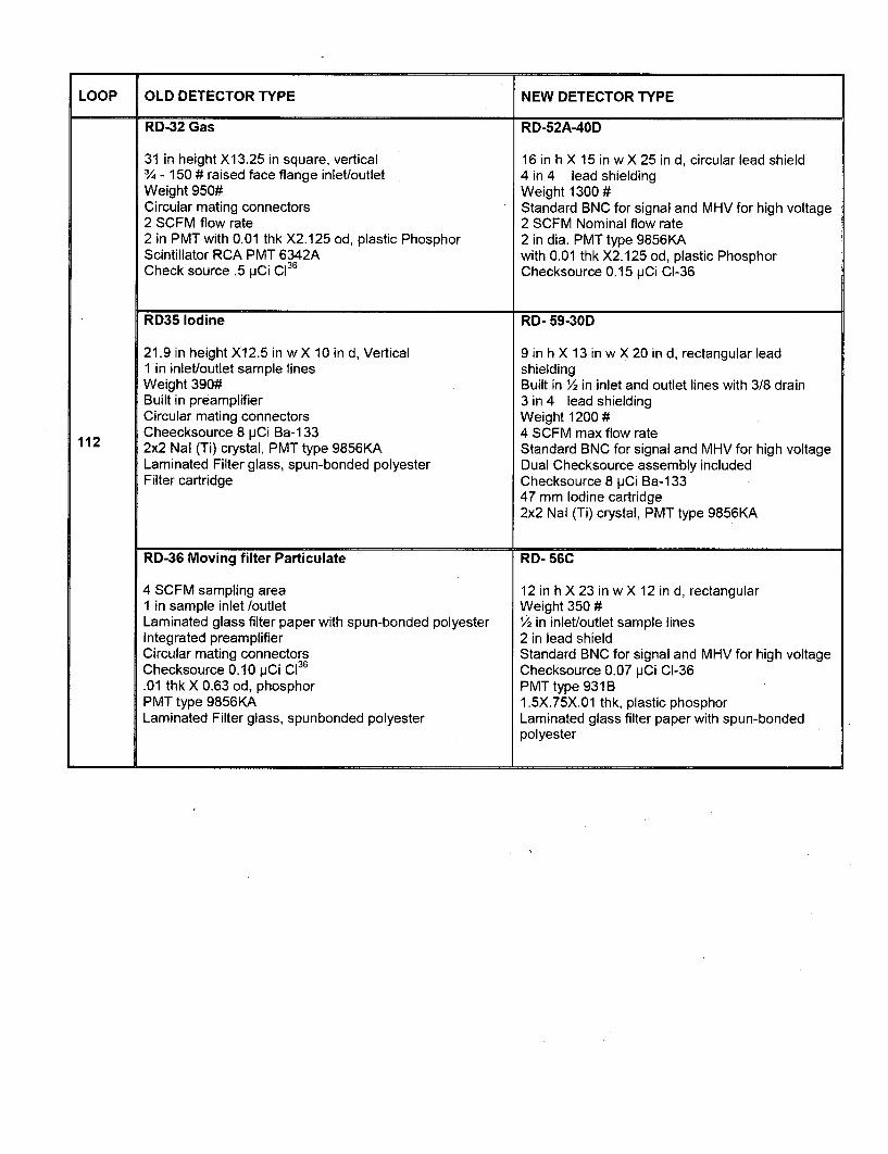
LOOP OLD DETECTOR TYPE NEW DETECTOR TYPE
RD-32 Gas RD-52A-40D
31 in height X1 3.25 in square, vertical3/4 - 150 # raised face flange inlet/outletWeight 950#Circular mating connectors2 SCFM flow rate2 in PMT with 0.01 thk X2.125 od, plastic PhosphorScintillator RCA PMT 6342ACheck source .5 pCi C1
3 6
16 in h X 15 in wX 25 in d, circular lead shield4 in 4 lead shieldingWeight 1300 #Standard BNC for signal and MHV for high voltage2 SCFM Nominal flow rate2 in dia. PMT type 9856KAwith 0.01 thk X2.125 od, plastic PhosphorChecksource 0.15 pCi CI-36
.9.
RD35 Iodine
21.9 in height X12.5 in w X 10 in d, Vertical1 in inlet/outlet sample linesWeight 390#Built in preamplifierCircular mating connectorsCheecksource 8 pCi Ba-1 332x2 Nal (Ti) crystal, PMT type 9856KALaminated Filter glass, spun-bonded polyesterFilter cartridge
RD- 59-30D
9 in h X 13 in w X 20 in d, rectangular leadshieldingBuilt in 2 in inlet and outlet lines with 3/8 drain3 in 4 lead shieldingWeight 1200 #4 SCFM max flow rateStandard BNC for signal and MHV for high voltageDual Checksource assembly includedChecksource 8 pCi Ba-13347 mm Iodine cartridge2x2 Nal (Ti) crystal, PMT type 9856KA
112
RD-36 Moving filter Particulate
4 SCFM sampling area1 in sample inlet /outletLaminated glass filter paper with spun-bonded polyesterIntegrated preamplifierCircular mating connectorsChecksource 0.10 pCi C136
.01 thk X 0.63 od, phosphorPMT type 9856KALaminated Filter glass, spunbonded polyester
RD- 56C
12 in h X 23 in w X 12 in d, rectangularWeight 350 #1/2 in inlet/outlet sample lines2 in lead shieldStandard BNC for signal and MHV for high voltageChecksource 0.07 pCi CI-36PMTtype 931B1.5X.75X.01 thk, plastic phosphorLaminated glass filter paper with spun-bondedpolyester
Enclosure 2TVA Letter Dated October 29, 2010
Responses to Licensee Open Items to be Resolved for SER Approval
Attachment 8
Unit I PAM Variables Changed Under 10 CFR 50.59 Listing And 50.59 Documents.
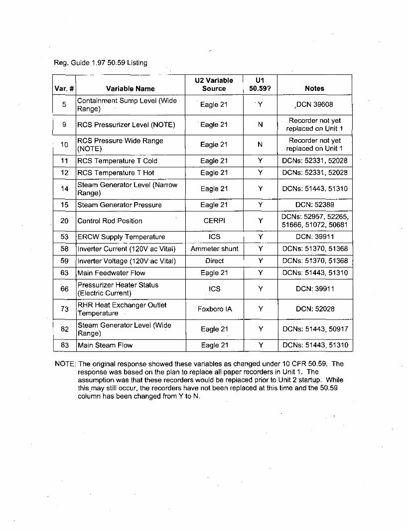
Reg., Guide 1.97 50.59 Listing
U2 Variable UlVar. # Variable Name Source 50.59? Notes
5 Containment Sump Level (Wide Eagle 21 Y ýDCN 39608Range) Eagle21_____DCN39 __
9 Recorder not yet9 RCS Pressurizer Level (NOTE) Eagle 21 N Replaced on Unt
replaced on Unit I10 RCS Pressure Wide Range N Recorder not yet
• (NOTE) Eagle 21 replaced on Unit 1
11 RCS Temperature T Cold Eagle 21 Y DCNs: 52331, 52028
12 RCS Temperature T Hot Eagle 21 Y DCNs: 52331, 52028
14 Steam Generator Level (Narrow Eagle 21 Y DCNs: 51443, 51310Range)
15 Steam Generator Pressure Eagle 21 Y DCN: 52389DCNs: 52957, 52265,
20 Control Rod Position CERPI Y 51666 5107, 5068151666, 51072, 50681
53 ERCW Supply Temperature ICS Y DCN: 39911
58 Inverter Current (1 20V ac Vital) Ammeter shunt Y DCNs: 51370, 51368
59 Inverter Voltage (120V ac Vital) Direct Y DCNs: 51370, 51368
63 Main Feedwater Flow Eagle 21 Y DCNs: 51443, 51310
66 Pressurizer Heater Status ICS Y DCN: 39911(Electric Current)
73 RHR Heat Exchanger Outlet Foxboro IA Y DCN: 52028Temperature
Steam Generator Level (Wide82 Range) Eagle 21 Y DCNs: 51443, 50917
83 Main Steam Flow Eagle 21 Y DCNs: 51443, 51310
NOTE: The original response showed these variables as changed under 10 CFR 50.59. Theresponse was based on the plan to replace all paper recorders in Unit 1. Theassumption was that these recorders would be replaced prior to Unit 2 startup. Whilethis.may still occur, the recorders have not been replaced at this time and the 50.59column has been changed from Y to N.
SAFETY ASSESSMENT NO. WBPLEE-98-010-O PAGE 1 DCN NO. M4968-PAGE /"7
't1~ Pi~,wdSAFETY ASSESSMENTISCREENING REVIEW/SAFETY EVALUATION COVERSHEET
~nI~tu A .,,.'ntlRr.rnntna IMt,~U, AnNi I, ~mf~5v Au umenIIqei~,~lnu RautAwI~urw¶ nunluatlnn i~Salb Assessmen creenin ReviewOnIv Safttv A sessmen cre-Ins Raylaw/Safetv Evaluation -
RIMS Accession No
Safety Assessment/Evaluatlan Revision No. 0If Not Rev, 0, Previous Revision's RIMS No. (if applicable) 1128 980318 80 7Plant W8N Affeoted unIt(s) I
Ac
Design Change[3 Engineering Docun
o Temporary Altaret[i
[3 Special TcstExperi
o Temporary ShicidirO Procedure Change
Oj New Procedure
O Maintenance
Itvlty
enot Change
onment1g Request
DCN No.
Number (Inolud0 Rzvlslan No.)
W-39608-A
EDC No.TACP No.Special Test No.
TSRF No.
Procedure No, and
PCF No. (ir•applcable)
Procedure No.
WRJWO No.
[] Other (Identify)
Comments;Brief DeserlptlonlComments: This DCN replaces the four Containment Sump level transmitters t-LT-63-.80, -181, -182 & -183.. These instruments provide Input to level switches which are the permissive to switch over ftom RWST torecirculation lfrom the sump, These transmitters also input into indicators used for Post Accident Monitoring (PAM)indication. These Instrument loops are required for Tech Spec compliance. The Instrumentation and indication are notdescribed in enough delail In the FSAR to require a text revision, except for PSAR Table 7.5-2, which will be revisedto reflect the new instrument range.
Distribution
cc: RIMSSite I CFR50.59 Program Coordinator • P. A. KOONTZ, EQB.2NPreparer- I-, H. Moseley LP4P-C
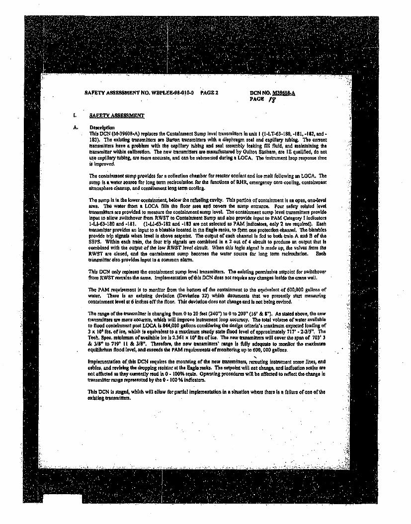
SAFETY ASSESSMENT NO. WBPLEE-98.}I0.0 PAGE 2 DCN NO. M39609.APAGE /,
SAFETY ASSESSMENT
A. DescriptionThis DCN (M-39608-A) replaces the Containment Sump level transmitters In unit I (I-LT-63-1 80, -181, -182, and -183). The existing transmitters are Barton transmitters with a diaphragm seal and capillary tubing. The currenttransmitters have a problem with the capillary tubing and seat assembly leaking fill fluid, and maintaining thetransmitter within calibration. The now transmitters are manufactured by Ouiton Statham, are I E qualified, do notuse capillary tubing, are more accurate, and can be submersed during a LOCA, The Instrument loop response timeis Improved.
The containment sump provides for a collection chamber for reactor coolant and ice melt following an LOCA. Thesutmp is a water source for long term recirculation for the functions of RHIR, emergency core cooling, containmentatmosphere cleanup, and contdinment long term cooling,
The sump Is In the lower containment, below the refueling cavity. This portion of containment Is an open, one-levelarea. ThO water from a LOCA fills, the floor area so€ covers the sump entrance. Four safety related leveltransmitters are provided to measure the containment sump level, The containment sump level transmitters provideInput to allow switchover from RWST to Contalnmant Sump and also provide input to PAM Category I Indicatorsl-LI-63-180 and -ill. (1-LI-63-i82 and -183 are not selected as PAM indicators, only 2 are required). Eachtrannmitter provides an input to a bistable located In the Eagle racks, to form one protection channel, The bistabiesprovide tip signals when level Is above serpoint. The output of each channel Is fed to both train A and B of theSSPS. Within each train, the four trip signals are combined in a 2 out of 4 circuit to produce an output that Iscombined with the output of the low RWST level circuit. When this logic signal is made up, the valves from theRWST are closed, and the containment sump becomes the water source fro long term recirculation. EachtransMitter also provides input to a common alarm.
This DCN only replaces the containment sump level transmitters. The existing permissive setpoint for switchoverfrom RWST remalas the same. Implementation of this DCN does not require any changes Inside the crane wall.
The PAM requirement Is to monitor from the bottom of the containment to the equivalent of 600,000 gallons ofwater. There Is an existing deviation (Deviation 32) which documents that we presently start measuringcontainment level at 6 inches off the floor. This deviation does not change and is not being revised.
The range of the transmitter Is changing from 0 to 20 feet (240") to 0 to 200" (16' & 8"). As stated above, the newtransmitters are More aceurate, which will Improve Instrument loop accuracy. The total volume of water availableto flood containment post LOCA is 844,000 gallons considering the design criterla's maximum expected loading of3 x 106 lbs. of Ice, which Is equivalent to a maximum steady state flood level of epproximately 717' - 2-2/5". TheTech. Spec. minimum of available ice Is 2.361 x 10⁶ lbs of Ice. The new transmitters will cover the span of 703' 3& 3/1" to 719' II & 3/8". Therefore, the now transmitters' range Is fully adequate to monitor the maximumequilibrium flood level, and exceeds the PAM requirements of monitoring up to 600, 000 gallons.
Implementation of.this DCN requires the mounting of the new transmitters, rerouting instrument sense lines, andcables, and revising the dropping resistor at the Eagle racks. The setpolnt will not change, and indication scales arenot affected as they eurrently read in 0 - 100% scale. Operating procedures wilt be affected to reflect the change Intransmitter range represented by the 0 - tO0 % indicators.
This DCN is staged, which will allow forpartial implementation in a situation where there is a failure of one of theexisting transmitters.
SAFETY ASSESSMENT NO. WBPLEE-98-010-0 " PAGE 3 DCN NO. KPAGBif
Implementing the proposed activities may require revision of existing plant procedures, and/or the Issuance of nowplant procedures of the (ollowing types to maintain and operate the equipment during normal plant conditions.
" Maintenance instructions (M1s)• Instrument Maintenance Instructions (IMlis)" Surveillance Instructions (Sis)" SystemOpemtlng Instructions (SOls)" General Operating Instructions (GOs)" Special Maintenance Instructions (SMis)• Periodic Instructions (Pig)* Annunciator Response Instructions (ARIs)9 Fuel Handling Instructions (FIlls)
These procedures shall Integrate the requirements contained within this design change package. Revision to theseprocedures fbr reasons other than implementation of this modification are not within the scope of this SaltyAssessment. Functional Impacts or the revision to these procedures to implement these changes ame not within thescope of this Safety Assessment.. Functional Impacts of any requIred procedure changes must be reviewed by thoseresponsible for the procedure revision per SSP-2.03.
References
I. Watts Bar System Description Manual, N3-74-4001, R4, Residual Heat Removal System2. Watts Bar System Description Manual, N3-63-400f, R5, Safety Injection System3. Watts Bar System Design Criteria, WB-DC-30-7, Post Accident Monitoring System4. Watts Bar System Design Criteria, WB.DC-30-4, Separationflsolation5. UFSAR 7.5 Reactor Trips6. UFSAR Chapter 15 Accident Analysis7. DCN M39608-A8. Gulton-Statham Qualification Test Report: PER 1006, Contract 2230199. Watts Bar SER
• ., r,7
"..a
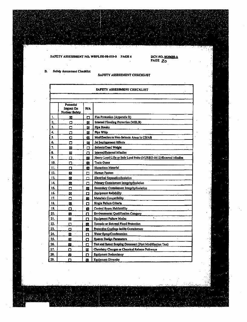
SAFETY ASSESSMENT NO. WBPLEE-93-OIO-0 PAGE 4 DCN NO, M39,g&PAGE 2o
.9 Safety Assessment ChecklistSAFETY ASSESSMENT CHECKLIST
SAFETY ASSESSMENT CHECKLIST
PotentialImpact On N/A
Nuclear Safety_,
. , . [Fire Protection (Appendix R)
2, O ,] Internal Flooding Protection (MELB)
3. (71 R Pipe Breaks
4. 0 I Pipe Whip
5. - *l Modification to Non.Sesmic Areas in CBWAS6. [ Jet Impingement Effects
7. ] , Seismic/Dead Weigh.
8. [] [] intornal/Extemal Missiles9. n 6a Heavy Load Lifts or Safe Load Paths (NUREO-0612)/External Missiles
Lo. ". Toxic Oases
I. 11 Hazardous Material
12. M nl Human Factors
13. go rl Electlrcal Separatlonfisolatloan
4.1 4 . Primary Containment Integrety/lsolation
15. Q , [ Secondary Containment lntegrity/1solation
16. [] Q Equipment Rellability
17. 17 M Materials Compatibility
is. a Sin Is Failure Criteria
19. 0 Control Room Habitability,.
20, t o Environmental Quelfloatlon Category
2t. cm [] Eguipment Failure Modes
22. [ Tornado or EBi., .al Flood Protection
23. I C] Pcotective Coatings Inside Containment
24. -Dl Water Spy/Condensatlon
25. g f"1 System Design Parameters
26. . Test and Retest Seoping Document (Post Modification Test)
27. - • Chemistry Changes or Chemical Release Pathways
26. M ,] I Eipment Redundancy
29. - .3a.. Equipment Diversity
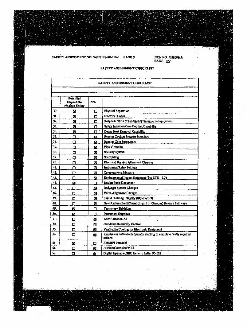
SAFETY ASSESSMENT NO. WBPLEE-98.010o0 PAGE 5 DCN NO. M3960PAGE Z/
SAFETY ASSESSMENT CHECKLIST
SAFETY ASSESSMENT CHECKLIST
PotentialImpact On N/A
Nuclear Safety
30. .... Physical Sepamlion31. []fI Electrical Loads
32. El . Response Time of Emergeny Safeguurds Equipment
33. 0 [3 ' Saf.Vy lnjection/Core Cooling Capability
34. [3 . Decay Heat Removal Capaablity
3S, M] Reactor Coolant Pressure boundary
36. [ Reactor Core Parameters
37. Q [ Pipe Vibration
35. r - [M Security System
39, [ , Scaffolding
40. Q Electrical Breaker Alignment Changes
41. ) N [nstrnent/Raclay Setting .
42. M * Compensatory.Measure
43, ] CM Environmentat Impact Statement (See STD- 13.3)
44. to 0 Desisn Basis Document
45, 0 IM Radwasta System Changcs
46. n* M Valve Alilnent Changes
47. I M Shield Building Integrity (SQN"WBN)
48, -m - Now Radioactive Effluent (Liquid or Gaseous) Release Pathways
49. 1 71 Temporary Shieldin.
50. [] Instrunent Seatolnts
5I. 0 IN ASMB Section Xi
52. 17 M Shutdown Reactivity Control
33. . O Ventilation Cooling for Electronic Equipment54 0 [ Requires an Increase In operator staffing to complete newly required
actions
55 to [ MI/RFI Potential
56 g I ,rosion/Corrooon/MIC57 01 1 Digital Upgrade (NRC Generio Letter 95-02)
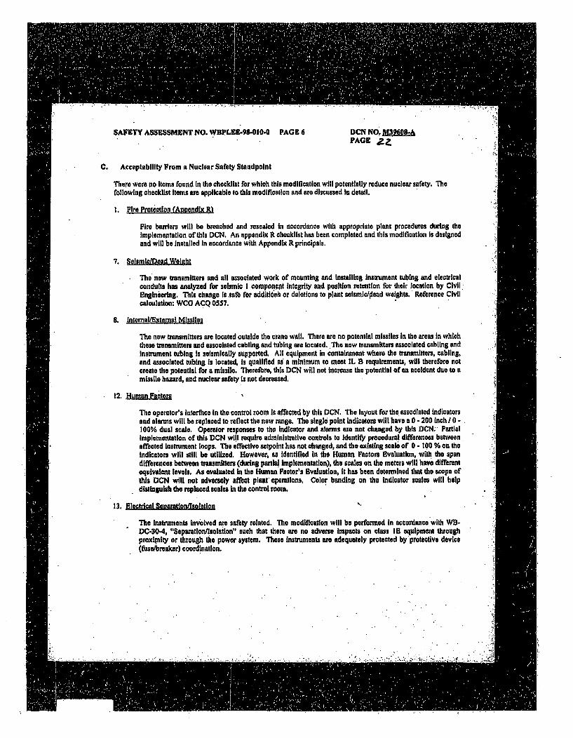
SAFETY ASSESSMENT NO. WBPLEE-98.010-0 PAGE 6 DCN N0Ofllf&PAGE
C. Acceptability From a Nuclear Safety Standpoint
There were no Items found In the checklist for which this modification will potentially reduce nuclear safety. The
following checklist Items are applicable to this modification and are discussed In detail.
I. Fire Protection (Annendix R)
Fire barriers will be breached and resealed in accordance with appropriate plant procedures during theImplementation of this DCN. An appendix R checklist has been completed and this modlfiantion is designedand will be Installed In accordance with Appendix R principals.
7. selslem caead Weight
The new transmitters and all associated work of mounting and Installing Instrument tubing and electricalconduits has analyzed for seismic I component Integrity and position retention for their location by CivilEngineering. This change Is xata for additiont or deletions to plant seismic/ioead weights. Reference Civilcalculation: WCO ACQ 0557.
8. Internal/Exte1ai Misiles
The new transmitters are located outside the crane wall, There are no potential missiles in the areas in whichthese transmitters and associated cabling and tubing are located. The new transmitters associated cabling andInstrument tubing Is seismically supported. All equipment in containment where the transmitters, cabling,and associated tubing Is located, Is qualified as a minimum to meet IL B requirements, will therefore notcreate the potential for a missile. Therefore, this DCN will not Increase the potential of an accident due to amissile hazard, and nuclear safety is not decreased.
12. Human Factors
The operator's interfbce In the control room is affected by this DCN. The layout for the associated Indicatorsand alarms will be replaced to reflect the new range. The single point Indicators wilt have a 0 - 200 Inch/ 0 .100% dual scale. Operator responses to the Indicator and alarms are not changed by this DCN; PartialImplementation of this DCN will require administrative controls to Identif procedural differences between.affected Instrument loops. The effective setpoint has not changed, and the existing scale of 0 - 100 % on theIndicators will still be utilized. However, as Identified In the Human Factors Evaluation, with the spandifferences between transmitters (during partial Implementation), the scales on the meters will have differentequivalent levels. As evaluated in the Human PFator's Evaluation, it has been determined that the scope ofthis DCN1 will not adversely aftbct plant operations. Color banding on the indicator scales will helpdistinguish the replaced scales In the control room.
13. Electrical Senaration/dsolation
The Instruments involved mre safety related. The modification will be performed In accordance with WB-DC-30-4, "Seperation/folation" such that there are no adverse impacts on class IS equipment throughproximity or through the power system. These Instruments are adequately protected by protective device(ftase/breaker) coordination.
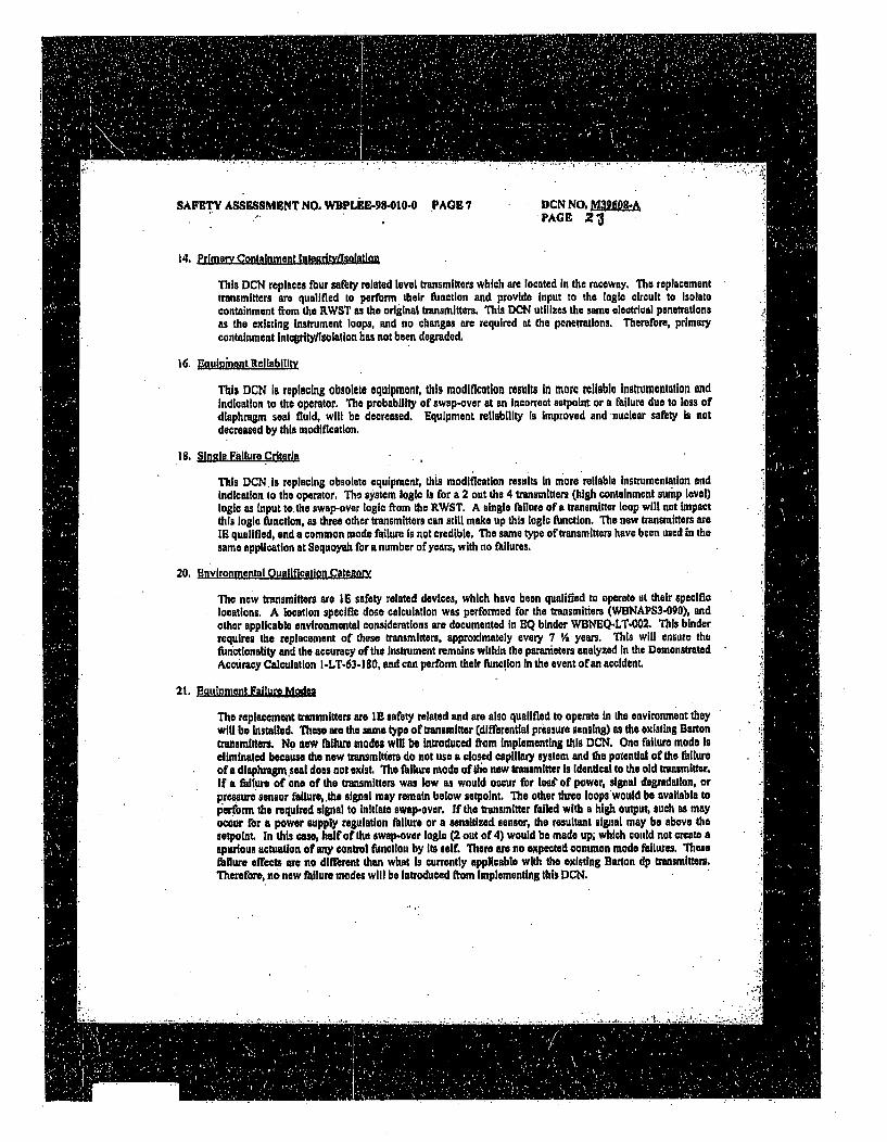
SAFETY ASSESMENT NO. WBPLkE•98-10-0 .PAGE 7 DCN NO. APAGE 23
14. Primary Containment Integrity!Isolation
This DCN replaces fbur safety related level transmitters which are located In the raceway. The replacementtransmitters are qualified to perform their function and provide Input to the logic circuit to Isolatecontainment from the RWST as the original transmitters. This DCN utilizes the same electrical penetrationsas the existing Instrument loops, and no changes are required at the penetrations, Therefbre, primarycontainment integritylisolation has not been degraded,
16. gauioinant Reliability
This DCN is replacing obsolete equipment, this modification results in more reliable Instrumentation andIndication to the operator. The probability of swap.over at an Incorrect setpoint or a failure due to loss ofdiaphragm seal fluid, will be decreased. Equipment reliability is improved and -nuclear safety Is notdecreased by this modification.
18, Sinal. Failure Criteria
This DCN. is replacing obsolete equipment, this modification results In more reliable Instrumentation andIndication to the operator, The system logic is for a 2 out the 4 transmitters (high containment sump level)logic as Input to.the swap-over logic from the RWST. A single failure of a transmitter loop will not impactthis logic function, as three other transmitters can still make up this logic function. The new transmitters arel qualified, and a common mode failure Is not credible, The same type of transmitters have been used in thesame application at Sequoyah for a number of years, with no failures.
20. Environmgental Oualification Catemory
The new transmitters are 16 safety related devices, which have been qualified to operate at their specificlocations. A location specific dose calculation was performed for the transmitters (WBNAPS3-090), andother applicable environmental considerations are documented in EQ binder WBNEQ-LT-002. This bInderrequires the replacement of these transmitters, approximately every 7 Va years. This will ensure thefunctionality and the accuracy of the Instrument remains within the paranieters analyzed In the DemonstratedAccuracy Calculation I-LT-63-180, and can perform their fanction In the event of an accident.
21. Eaugiment Fallure Modes
The replacement transmitters are IB safety related and am also qualified to operate In the environment theywill be Installed. These am the same typo of transmitter (differential pressure sensing) as the existing Bartomtransmitters. No new failure modes will be Introduced from Implementing this DCN. One failure mode Iseliminated because the new transmitters do not use a closed caplilary system and the potential of the failureof a diaphragm.seal does not exist, The failure mode of the now transmitter is Identical to the old transmitter.If a failure of one of the transmitters was low as would occur for los' of power, signal degradation, orpressure sensor failure, the signal may remain below aetpoint. The other three loops would be available topIerform the required signal to Initiate swap-over. If the transmitter failed with a high output, such as mayoccur for a power supply regulation failure or a sensitized sensor, the resultant signal may be above thesetpoint. In this case, half of the swap.over logic (2 out of 4) would be made up; which could not create aspurious actuation of any control function by its self. There are no expected common mode failures. Thesefailure effects are no diffbrent than what is currently applicable with the existing Barton dp transmitters.Theretire, no new failure modes will be Introduced from implementing this DCN.
SAFETY ASSESSMENT NO. WBPLEE-98-0.10-0 PAGES DCN NO.PACE .
24. Water SnmviCondenisatlon
The design has considered the efTects or water spray and condensation on these Instruments, The designIncludes a condensation chamber on the low pressure side of the instrument to collect condensation duringnormal and accident conditions, and ensure accurate operation of the Instrument loops. The high pressureside Is routcd downward through the transmitter and tied directly to the lower sensing point, Anycondensation on the high pressure side would drain through the transmitter and onto the containment floor,Therefore, condensation will not be a problem. For water spray considerations. the sense lines are routedabove the maximum expected flood level in containment, with the vented sense lines pointed doivn to preventsprayed water fromi entering the sense line. This also allows for condensation to drain out of the sense line.
25. ,Ssteni Design Parameters
The basic configuration and requirements for the monitoring Containment Sump level have not changed,Only the.method of monitoring the required parameters is changing and the Instrumentation Is beingupgraded lo be more reliable and useful to the operator. Nuclear Safety is not decreased.
26. Teat and Retest §coolng Dornment (Post Modiqlation Test)
A test coplqg document has been written to require pressure testing of the instrument sense line and for thetubing assembly used as a conduit. The testing is to be performed after implementation, and'is also requiredany time the tubing/conduit assemblies are reworked, This test ensures pressure boundary integrity Ismaintained, in the event of an accident, the low pressure side of the transmitter Is con'ectly referenced toatmosphere,. and the Instrument pigtails will remain dry. Perfbrmance of these tests ensures instrumentaccuracy Is maltained,
28. EouIlment Redundancy
The configuration of equipment redundancy is being maintained for this function, There are four separateInstrument loops, which Independently fUnction to initiate the required 2 out of 4 logic signal for containmentsump level high.
30. Physical Scretion
The Instruments involved are safety related, The modification will be performed such that physicalseparation Is maintained for this type of 15 equipment and associated sense lines and cables.
31. Blaca' Load
The replacement level transmitters are being supplied from the existing power supply for the existing Bartontransmitters, which is from the Eagle 21 system, Though tha trensmittels being replaced with a differentmodel, and the dropping resistor value is also changing, the change Is negligible due to. the total loopresistance Is within the normal load limitation for adequate supply voltage of the Eagle 21 system, and doesnot affect loading.
32. Heanonsa Time of Enermency Safeuards ,ouinment
For the L.O. 1.97 lunction, a response time analysis is nut required since electronic loops respond within afew seconds. The resultant operator recognition and response Is very slow compared to this. For theswapover function, a response time analysis Is not required since these loops only makeup part of the logic,where the containment sump level swapover point Is reached prior to the RWST Low level awapover point.That Is, the minimum RWST Inventory will flood the sump to above the containment sump level transmittersetpoint befiore the RWST Is emptied to the RWST low level transmitter setpoint,
SAFETY ASSESSMENT NO. WBPLEE-98-010-O PAGE 9 DCN NO.PAGE g(
33. Safetv Iniection/Core Cooling Capaclty
This DCN replaces the existing Barton transmitters which utilized a silicon filled diaphragm seal system.The new Instrumentation Is more accurate, and operates at the existing setpolnt which assures adequatereliability for switchover. Implementation orfthis DCN improves the accuracy of the control loop, which inturn ensures sufficlent Inventory Is available In the sump prior to swapover and that acceptable sump level Isdetected, This ensures the capability of the Safety Injection and core cooling to perform their function asdesigned.
34. Decay Heat Removal Canabilitv
This DCN replaces the existing Barton transmitters which utilize a silicon filled diaphragm seal system. Thenew instrumentation Is more accurate, and operates at the existing setpoint which assures adequate reliabilityfor switchover. Implementation of this DCN Improves the accuracy of the control loop, which in turnensures sufficient inventory is available in the sump prior to swapover and that acceptable sump level isdetected. This7nsures the capability of the Decay Heat Removql System to perform its function as designed.
44. Desi•n Basis Document
System Design Criteria, Post Accident Monitoring System, WB-DC-30-7, Is being revised as a part of thisDCN to clarify the description of the existing deviation number 32, which discusses the range of theContainment Sump level transmitters. Deviation 32 documents ;.iiat we presently start measuringcontainment levul at.6 Inches offthe floor. This deviation does not change and is not bolig'revised, No newdeviations are being taken against R.G. 1.97, This change Is to reference the revised upper level being
- monitored,System Description N3-63-4001 is being revised to reflect the change in the % 6of range used for verifyingleak detection in the containment, The value has not changed, only the equivalent percent of range haschanged.A new exception was taken to WB-DC-30.5 to nllow the use of vendor supplied pigtails on the transmittersrather than cables qualified to IEEE 383 for vertical flame test requirements. The vendor pigtails werequalified to a different standard and are qualified for this application.A new exception to WB.DC-30-22 that required flexible conduit to be used in seismic considerations wastaken to allow the use of the seismically qualified tubing used to maintain the cables in a dry watertightconduit considering the effects ofa LOCA.A new exception was also taken against 0-40 for routing the associated cables below the maximum floodlevel, This was acceptable based upon the previous exception which maintains the cables in a dry, watertightenvironmentA now exception to N3B-934 was taken which requires that potentially radioactive processes have theirdrains and high point vents permanently piped to the closed drain system. This application does not utilizedrain lines or high point vents, as It is not a part of a potentially contaminated process system which wouldneed to be controlled and diverted to the Radwaste drain system. Anothair exception to N3E-934 was forslope requirements for liquid filled sense lines or sloping down from the root valve to the Instrument. Thesense line in this applicaon was routed to eliminate the effects of condensate buildup as described above andensure an accurate reference leg to the instrument.
49. Temoor Shieldin
Tempory shielding may be required during Implementation of this DCN. All work requiring shielding willbe controlled based on Rod Con procedures,
SAFETY ASSESSMENT NO. WDPLER-98-030-0 PAGE 10 DCN NO. M3960"PAGE e4
50. Instmment Setogints
Because the transmitters range Is changed, this DCN modifies operator action setpolnts. In ercent of senAused for the SDPS display. The previous value was < so % orspan. The now value is < 83 % ofspan. Thisis not a control seipoint, but isused for operations monitoring of the containment sump level to determine Ifthe water level Is greater than the maximum equilibrium level. If water Is greater than this value, then there Isthe potential for the inventory to be supplemented from a source beyond that analyzed for a LOCA. Theequivalent swapover saetpoint and EOP setpoint values In Inches of water has not been changed by this DCN.Therefore, this DCN does not affect directly or Indhectly the operations at the facility. Westinghousecalculation WCAP 12096 shows the loop accuracy is within the previous calculated loop accuracy, therefore,with the awpovers.tpolnt (in Ina unchanged, the 3Afety margin Is not affected.
5S. G.MYLVI
The new equipment being installed has been documented to meet the requirements of TVA StandardSpeciflation 118.14.01 for on EMI/RFI through FCC testing. Therefore, the potential for spuriousactuation's from these transmitters, or the causing of an actuation of another device because of these new -transmitters Is not likely.
D. SBaely Assessment - Review and ApprovalsPreparer: Ken Moseley Date: ' /.. %
Reviewer.,1 (7l Date:~'3(-Name Silgnatur-e
Other: Date:Reviewers Name/Organization Signature(as appropriate)
• .. - .
SAFETY ASSESSMENT NO. WBPLEE..s-010.O PAGE II DCN NO. P36cA
PAGE 2 7
SCREENING REVIEW
if. SCREENING REVIEW
A. Potential Technical Specification (T/$) Impact
Yes C" No 0 Is a change to the TIS required rotconducting or implementing the channge (designor procedure), test, or experiment?
Justification: The Instrumentation affected by this DCN is Included in the Technical Specifications.The DCN does not effect the existing Instrument setpolnts, decrease margin or modify howtho systom operates, and the Togh Specs ar not affected.
If the ansower Is "Yes", a T/S change Is required prior to Implementation or the activityneeds to be revised or canceled.
B, Is an SE obviously required?
Yes [] No o If yes, provide basis for conclusion and proceed to Part D.
C. Potential Safety Analysis Impact
Yes ' Noo Is this a special test, or experiment not described In the SAR?
Does the proposed activity affect (directly or indirectly) any information presented in the SAR ordeviate from the description given in the SAR?
Yes 0 No 0 By chenging: the system design or functional requirements; the technical contentof text, tables, graphs, or figures? (For radwasta changes see Note In Appendix afor guidance.)
Justification: The text is not affected by this change. Only the equipment with which a functionis accomplished as described in the FSAR is changed. However, FSAR Figure10.2.4 (I-47W610-47-3) will be revised duo to this modification. The FSAR
drawings will be updated in accordance with NADP-7, ".SAR Management".
Does the proposed change Involve new procedures or Instructions or revisions thereof that:
Yes 0 No 0 NA [ Differ with system operation characteristics from that described In theSAR?
Yes fj No [ NA 0 Conflict with or affect a procas or procedure outlined, summarized, ordescribed in the BAR?
Justification: This change does not Involve procedures that affect system operational characteristicsdescribed In the FSAR or impact compliance with the Technical Specification.Maintenance procedures will be revised to address equipment specific changes&Operattonsl procedures will be revised only to reflect the range in which the 0- tO- 00acontrol room meters represent, These procedures are not outlined, summarized ordescribed In the SAL This change does not conflict with or affect any processes orprocedures outlined, summarized, or described In the FSAR
If the questions are answered "No" or "N/A." the activity may be Implemented without fUrtherevaluation. If any question Is answered "Yes," an SE Is required.
SAFETY ASSESSMENT NO. WDPLEE-98.-010 PAG IZ DCK NO. MWOI-PAGE
0. Screening Review - Review and Approvals
Prepucs: Ken Mosoany Date: _.._/,_/___
Reviewer 5A%!21 CvAtCr Date ____
frdame Sinture
Other- Date:Revlewers Nam argmlzeilon Signature(as appropriate)
""-
.... . . . .. : .. ~ ~ ~~.. . . . .. . . . . . ! , ; . , , . ;• .
dH
SAFETY ASSESSMENT NO. WBPLEE.98-0W0-0 PAGE13 DCN NO. M39i0&&PAGE 21
SAFETY EVALUATION
A. Description and Accident Evaluation:
Detailed description of the change, test, or experiment, including the design basis accident, end credible Failuremodes of activity. Summarize why the activity does or does not constitute a USQ.
This DCN (M-39608-A) replaces the Containment Sump level transmitters In unit i. The existing transmittersare Barton transmitters with a diaphragm seal and capilleay tubing. These existing transmitters have a problemwith the capillary tubing leaking flit fluid, and maintaining the transmitter within calibration, The newtransmitters are IE qualified, do not have capillary tubing, aue more accurate, and can be submersed during aLOCA. This change upgrades equipment used to perfbmin a tbrmction. Functional performance of the plant Is notaftected and protective logic Is not affected.
The range of the transmitter is changing Rom 0 to 20 feet (2401") to 0 to 200" (16' & 8") which will improveinstrument loop accuracy. The existing selpoint for switchovor from KWST remains the same. The newtransmitters' range is folly adequate to monitor the maximum equilibrium flood level, which is above the PAMrequirement of 600,000 gallons.
The sump Is In the lower containment, below the ramialing cavity. The sump Is a water source tbr long termrecirculation for the fuinctions of RHR, emergency core cooling, containment atmosphere cleanup, andcontainment long term cooling, The transmitters will be located just outside the sump In the raceway. Thesetiansmitters are associated with the protective features used to detect and mitigate the effects of Condition fit &IV events isoca-ated with a LOCA. Four safety related level transmitters (one per channel) are provided tomeasure the containment sump level. These transmitters provide Input to allow switohover Rom RWST toContainment Sump rechroulation and also provide input to PAM Category I indicators I-LI-63-180 and -181.The tour containment sump level high trip signals are Combined in a 2 out of 4 circuit to produce an output thatIn combined with the output ofithe RWST low level switches. When this logic signal is made up the valves fRomthe RWST are closed, and the containment sump becomes the water source for long term recirgualtlon.
Implementation of this DCN requires the mounting of the new transmitters, rerouting instrument sense lines, andcables, and revising the droppin; resistor at the Eagle racks, The setpolnt will not change, and indication scalesare not affeoted as they currently read in 0 - 100% scale.
This change upgrades existing plant equipment. The failure modes. of the replacement equipment do not differfrom the equipment being replaced, and common mode failure has been deronswted not to be an issue basedon experience with these types of transmitters at Sequoyah. The Installed loops (equipment and cable/conduit)are separated physically and electrically. Proper separationnisolaton of cable routing and equipment Ismaintained by the DCN and appropriate plant Installation procedures. The Independence of safety relatedequipment Is not challenged. Civil calculations have been perforned to verify that, when instled per the DL.N,the equipment will remain able to parfbrm it's function l.owing a seaismic event, The equipment has beentested and the test report reviewed documenting the now tranmiltters aem noi to be susceptible to BMURF'I andwill not cause radiated emissions outside the requirements of DS-111. 14,01 and adversely affiM the operation ofsurrounding equipment. This change will not compromise the ability of plant safety-relited equipment toperform Its Intended rianction. Westinghouse calculatlon WCAP 12096 shows the loop accuracy Is within theprevious calculated loop accuracy, therefore, with the swapover selpolal unchanged, the safety margin Is notaffected,
SAFETY ASSESSMENT NO. W I'LEE-98-0100 fPA•E 14 DCN NO, M326084PAGE 3E
B. Evaluation of Effects
13.1 May the proposed activity increase the probability of an accident previously evaluated In the SAR? Yes0 NonJustification: This DCN affects only monitoring devices used for PAM Cat I and protective f1notions,It does not add or modily any plant systems which hilure can result In an accident. This change does notmodily any Interfaces with plant systems whose failure can result In an accident. This change will notIncrease the likelihood of a design basis accident.
B.2 May the proposed activity Increase the probability of occurrene of a malfunction of equipment Importantto safety previously evaluated In the SAR? Yes (3 No n
Justiflcatton, This change, DCN M-39242-A, replaces existing equipment with more reliableinstrumentation. The Instrumentation and associated cable, conduit and sense lines are qualified andinstalled to operate In their environment. Therefore the probability of an Inadvertent iailure is notincreased. These transmitters provide Input to allow switchover from RWST to Containment Sump andalao provide input to PAM Indicators I-L1-63-180 and -181. Each transmitter provides an input to ablstable located In the Eagle rocks, to brnr one protection channel, The bistables provide trip signals-when level It above setpoint. The output of each channel Is fted to both train A and B of the SSPS,Within each train, the four trip signals are combined in a 2 out of 4 circuit to produce an output that iscombined with the output of the low RWST level circuit. When this logic signal Is made up the valvesRfom the RWST are olosed. where the containment sump Is the water source for long tairt relruattlon,Each transmitter provides MCR Indication and input to a common alarm, Considering the methodotogythe swItchover logic Is made up, the failure of one transmitter will not prevent system swltchover fromRWST to the containment sump from taking place or prevent MCR Indication. This change does notIntroduce any additional equipment failure modes. Therefbre, this change does not increase theprobability of occurrence of a malfunction of equipment Important to safaty previously evaluated In theSAR.
S.3 May the proposod activity Increase the consequences of an accident previously evaluated In the BAR?•;:•. Yes [3 No a]
Justification These transmitters are associated with the protective features used to detect and mitigatethe effects of Condition III & IV events associated with a LOCA. The protective f•nctIonal logicrequirements for these transmitteis has not changed. The new instrumentation Is mor reliable, (nocapillary system) and are more accurate per WCAP 12096. The existing values In the TechnicalSpecifications, setpoints, allowable values, and margin are not changed, The abilty to respond to aLOCA has not changed. There is no adveirse impact on primary and secondary containment integrity,isolation, source torms. filtration of EOTS, ABOTS or CRLEVS. Therefore, this DCN does not change theradlologleal consequences of an accident previously evaluated In the SAR:
B4 May the proposed activity ingrease the consequences ofre malfbnotlon of equipment important to saietypreviously evaluated In the SAR? Yes f] No m.
Justification: This change upgrades existing plant equipment, The failure modes of the replacementequipment do not differ from the equipment being replaced.. Proper sepaationlisolion of cable routingand equipment is maintained by the DCN and appropriate plant Installation procedures. Theindependence of safety related equipment is not challenged, Civil calculations have bean performed toverify that, when Installed per the DCN, the equipment will retai• it's position in a seismic event. Theequipment has been tested and the test report reviewed documenting the new transmitters am not to besusceptible to EMI/RPI and will not cause radiated emissions outside the requirements of DS.BI,.14.01and adversely aff•ct the opertion of sutrounding equipment. This ohange will not compromise the
* ability of plant saiety-related equipment to perfom is Intended function. This change does not Increasethe radiological consequences ofa malfunction ofequipment Important to safety previously evaluated inthe BAR.
SAFETY ASSESSMENT NO. WBPLEE-98410-0 PAGE IS DCN NO. ,PAGE 5,
B5. May the proposed activity create a possibility for an accident of a different type than any evaluatedpreviously In the SAR? Yes [Q No aJustification: There are no functions or controls being added or revised by this change, No Interfacesare changed other than the 4 20 mA output replacing the 10 - 50 mA output of the transmitterrepresenting the transmitter range, Since this interfhce has changed (resistors replaced) and calibrationswill be performed to assure the loop will Ainction per the current design basis, this change does not createa possibility for an accident of a different type.
Bs May the proposed activity create a possibility for a maltunction ofa diffirent type than any evaluatedpreviously intheSAR? Yes(I No*C
Justification: These transmitter& provide Input to allow switchover from RWST to Containment Sumpand also provide input to PAM indicators l.LI-63-180 and .181. Each transmitter provides an Input to abtstable loomed in the Eagle racks, to form one protection channel. The blsteables provide trip signalswhen level Is above sotpolnt, The output of' each channel Is fed to both train A 'ad B of the 8SBS,Within each tran, the four trip signals are combined In a 2 out of 4 circuit to produce an output that is.,
cormbined with the output of the low RWST level clrcult, When this logic signal is made up the valvesfrom the RWST are closed, whaeo the contalnment sump Is the water sourca fbr long term recircualtion.Each transmitter provides MCR indication and input to a common alarm. Considering the methodologythe switchover logic Is made up, the fallwre or oene transmitter will notprevent system switchover fromRWST to the containment sunmp from taking place or prevent MCR Indication. This change does notintroduce any additienal equipment or control foilure modes. Therefore, this change does not create anew malfunction pathway than previously evaluated In the SAR.
8.7 May the proposed activity reduce the margin oftsalsty as defined In the basis for any TechnicalSpecification? Yes E3 No 3
Justitication: This DCN does not modify any system trip setpolnts or indicated ranges , therefore, thisDCN does not affect directly or Indirectly the operations at the facility, Westinghouse calculation WCAP12096 shows the loop accuracy Is within the previous calculated loop accuracy, therefore, with itheswapover setpoint unchanged, the safety margin Is not affected, This change does not reduce any marginofsifety Identified in the basis lbr any Technical Speciflcation.
C. Unreviewed Sarety Question Determination Conclusion
The change, test, or experiment:
Does not involve an unrovlewed safity question. I@
involves an unreviewed safbty question and ."must be revised, canceled, or reviewed by theNRC prior to Implementation.
D. Safety Evaluation - Reviews and Approvals"
Preparer. Ket Monelay Wate% _ /_____Re.vic¥1wer• Dat, - Be: ____.,__1___
Reviewer: 4 C Date:
• (PORC/QR~a
Other.. Date:Reviewer Name liusture(sa appropriate)
a As reqvired by Technical Specitltation,
PIC P-50169-APage 8
T25 990219 97! DCN M-39911-A
Page 84P
SAFETY ASSESSMENTISCREENING REVIEWISAFETY EVALUATION COVERSHEETPage I of 43
I SAFETY ASSESSMENT/SCREENING REVIEWISAFETY EVALUATION COVERSHEET IDocument Number SA-M-39911-A
Screening Review Only 0Safety Assessment/Screening Review El
Rev. 1Safety Assessment/Screening Review/Safety Evaluation [
Procedure Exemption [I
Procedure Change Evaluation Ml
Plant WBN Preparer Stacey L. Parrott
Reviewer Robert P. BalchAffected Unit(s)
Preparing Group
I1
CEE
Activity
C4 Design Change
[] Engineering Document Change
E] Temporary Alteration
E] Special Test/Experiment
E] Temporary Shielding Request
C] Procedure Change
El New Procedure
El Maintenance
El Other (Identify)
Number (Include Revision No.)
DCN No. M-3991 1-A
EDC No.
TACF No.
Special Test No.
TSRF No.
Procedure No. and
PCF No. (if applicable)
Procedure No.
WR/WO No.
Comments:DCN M-39911-A Revision 1 (Tracking Number WBPLEE-98-093-1)
Revision: (Provide a brief summary of the reason for the revision to the SR, SA, or SE)
*SA has been revised to add additional assessment of removing 1-XR-1-5 from panel 1-R-177. The SR and SE have been evaluated by this revision and upon further review it has beenresolved that there was no impact to these documents. In order to verify that there are noimpacts to the SR and SE, these documents have also been raised to revision 1.
Distribution'cc: EDM
Preparer - Return original to originating document
"TVA 40518 [08-19981 Pagel1 of 1 SPP-9.4-1 [11-23-1998]
PIC P-50169-APage 9 •ZT S2-57 q 2-ý4- 2
DCN M-3991 1-APage %,o..
SAFETY ASSESSMENTISCREENING REVIEWISAFETY EVALUATION COVERSHEET
Screening Review Only El Safety Assessment/Screening Review/Safety Evaluation Z
Safety Assessment/Screening Review F1
Plant WBN Preparer J. Mike Casner
Affected Unit(s) 1 Reviewer William G. Sexton
Preparing Group CEE
ElElElElElEl
Activity
Design Change .
Engineering Document Change
Temporary Alteration
Special Test/Experiment
Temporary Shielding Request
Procedure Change
New Procedure
DCN No.EDC No.
TACF No.
Special Test No.
TSRF No.
Procedure No. and
PCF No. (if applicable)
Procedure No.
WRNWO No.
Number (include Revision No.)
M-3991 I-A
El Maintenance
El Other (Identify)
Comments:
DCN M-3991 1-A Revision 0, (Tracking Number WBPLEE-98-093-0)
Revision: (Provide a brief summary of the reason for the revision to the SR, SA, or SE)
Distribution:cc: EDM WBN- ADM 1B
Preparer - Return original to originating document
TVA 40518 E08~1 9981 Page 1 of 1
SPP-9.4-1 [08-14-1998]
"TVA 405`18[08-19981 Page 1 of I SPP-9.4-1 108-14-19981
PIC P-50169-A DCN M-39911 -APage 0 iPage E,-7
SAFETY ASSESSMENT FORM
Page 3 of 43Document No.: DCN M-39911-A Rev.: 001
I. SAFETY ASSESSMENT
A. Description
1. Brief synopsis of the change, special test, experiment or condition including thesystems, structures, and components affected. Include the number of the activityproposed (e.g., ECN/DCN No., procedure No.).
DCN M-3991 1-A, replaces the obsolete Unit I Westinghouse P2500 Plant Process Computer andconsolidates the Emergency Response Facilities Data System (ERFDS) into a new Plant IntegratedComputer System (ICS). The ICS provides an operator friendly, state of the art, real time processcomputer system for the WBN plant operators and Emergency Operation Facility (EOF) personnel.This modification consists of replacing the P2500 processor, data acquisition equipment, andapplicable operator interface devices. Through the use of special adapters, most of the actual fieldterminations will remain unchanged while the scanning and converting electronics will be replaced.All input signal jumpering that resulted in redundant computer points between the P2500 andERFDS multiplexers have been removed. These redundant points are no longer needed since theICS can access all data directly from either the existing P2500 or ERFDS multiplexers.
After this modification; the new ICS computer will be operational and performing all functions ofthe old P2500 computer and most of the functions of the Emergency Response Facilities DataSystem (ERFDS), including SPDS, BISI, BOP, NSSS, Communications Data Links, and RHRMid-Loop Operation Monitoring Functions, All display functions currently associated with theEmergency Response Facilities Data System (ERFDS) computer will be incorporated into the ICS.The ICS will be driving all the current Main Control Room (MCR) and Technical Support Center(TSC) "ERFDS" displays. The "ERFDS" display terminology will no longer exist after thismodification, and all the displays will be "ICS" displays, or in ICS terminology Satellite DisplayStations (SDS). The only functions that will still be performed on the old ERFDS processor areEnvironmental Data Station (MET Tower) functions; limited Eberline radiation monitoringfunctions; Turbine Supervisory functions (Bentley Nevada); and Landis and Gyr interfacefunctions (Switch Gear). These functions are still performed on the old ERFDS processor but areavailable to the ICS for processing via a data link. [Note: These functions are only intended toremain on the old ERFDS processor temporarily. As part of the next phase of the ICS project theabove functions will be transferred entirely to the ICS and the ERFDS processor will be removed.]
This modification will add new data acquisition equipment in Aux. Inst. Ram. panel 1-R-177 toincorporate the functions of the Main Steam RAD Release Rate Computer/Recorder (1-XR-1-5)into the ICS. The Main Steam RAD Release Rate Computer/Recorder (I-XR-1-5) will beremoved.
TVA 40674 lo081 aga1 Page I of i SPP-9.4-3 [08-14-19981
PIC P-50169-A DCN M-39911-APage ii Page 8s
SAFETY ASSESSMENT FORM
Page 4 of 43Document No.: DCN M-39911-A Rev.: 001
So e o thkey points associated with this modification are:
1. Replace the P2500 computer with dual Alpha computers.
2. Replace the P2500 software with SAIC-based software.
3. Replace the P2500 and some limited ERFDS scanning and conversion electronics with fiberoptic data acquisition equipment to be located in the existing [10 cabinets.
4. Delete all redundant input cabling between the P2500 and ERFDS 110 cabinets.
5. Adda data link betweenthe ERFDS and ICS.
6. Add a data link be•ween the ICS and PEDS.
7. The ICS will be powered from the TSC inverter. The new power scheme will be diversified aspossible in order to prevent the failure of one fuse or breaker from disabling the entire ICSsystem.
8. Computer Inverter #1 and it's associated equipment which currently power the P2500computer will be removed.
9. A new IRIG-B Time Synchronizer will be installed in the computer room to provide timesyntchronization between the ICS, RONAN armunciator system, Turbine Supervisory system(Bentley Nevada), and the MCR clock.
10. Add new chassis in Aux. Inst. Rut. panel (1-R-177) for incorporation of the Main Steam RADRelease Rate Computer/Recorder (1-XR- 1-5) into the ICS.
11. New software will be developed and loaded into the ICS to insure that all functions of theMain Steam RAD Release Rate Computer are incorporated into the ICS.
12. Run Fiber Optic cable ([C 1186) from Computer Room to Aux. Instrument Room panel (1-R-177) to support incorporation of the Main Steam RAD Release Rate Computer/Recorder intothe ICS.
13. In the MCR the Graphical User Interface (GUI) will be deleted and replaced with an ICSSDS. The existing communications hubs will be replaced with redundant hubs.
14. Replace P2500 printers in MCR with new laser printers (for logs and alarms).
15. Replace all special function ERFDS workstation (After this modification ICS SDS) keyboardswith new standard computer keyboards in both the MCR and TSC. This change is neededsince the existing keyboards can not be replaced by DCN M-39931-A (MCR and TSC PCreplacement modification). The existing keyboards were specially designed to support theexisting ERFDS software.
TVA 40674 [08-199] Page1I of I SPP-9.4-3 108-14-.998]
PIC P-501 69-APage .ZL.
DCN M-39911-APage B41
SAFETY ASSESSMENT FORM
Page 5 of
43
Rev.: 001
Document No.: DCN M-39911-APage 5 of 43Rev.: 001
16.
17.
Deactivate P2500 point U2035 (CCW Pump Average Overall Efficiency). This point wasevaluated to be no longer needed by WBN personnel.
Add an ICS trouble alarm to the RONAN Annunciator system. This is accomplished bycombining existing Windows 99A ("RCP MOTOR THRUST BEARING TEMP HI"(Computer Point Y9002C)] and 100A ["RCP STATOR TEMP H1 (FROM P-2500)"(Computer Point Y9001C)] on MCR window box 1-XA-55-5B into one window (100A onwindow box 1-XA-55-5B). The new combined window 100A will be re-engraved to read"RCP STATORIMTR THRUST BRG TEMP Hf" and window 99A will be blanked. Thecombining of these computer points on one annunciator window will spare an input cable toRONAN, which will then be used for the new "PLANT COMPUTER TROUBLE"annunciator. This annunciator will be located on window 136F on MCR Window Box 1-XA-55-6D. This new Plant Computer Trouble alarm will annunciate for the following conditions:(1) the primry alpha computer is down and the backup alpha computer is running, (2) theprimary and backup alpha computers are both down, or (3) there is a loss of power to thechassis that contains the new Delay Timer (Watchdog) I/O Card.
18. Resolve PER WBPER980807. The following computer points were identified by operationsas critical computer points that should be included on the RONAN annunciator system. Thesepoints will be added to existing annunciator window 83D ["ROD DEVN & SEQ PWRRANGE TILT COMPUTER ALARM" (Computer Point Y9000C )] on MCR Window Box1-XA-55-4B:
U0270DP1000AP1001AP1002AP1003AU0965U0966U0968U0969
DELTA FLUX ALARM (AXIAL FLUX DIFFERENCE (AFD))CONTAINMENT 1 PRESSURECONTAINMENT 2 PRESSURECONTAINMENT 3 PRESSURECONTAINMENT 4 PRESSURERBF&ED POCKET SMP 15M AVG RORISE, (Calculated Point)RBF&ED POCKET SMW 15M AVG RORISE, (Calculated Point)RBF&ED POCKET SMP 60M AVG RORISE, (Calculated Point)RBF&ED POCKET SMP 60M AVG RORISE, (Calculated Point)
As part of this change annunciator window 83D will be re-engraved to read "PLANTCOMPUTER GENERATED ALARM (SEE ICS)". Since this annunciator modification willresult in numerous computer points activating one annunciator window, a special screen will beadded to the ICS displays especially for the 83D alarm. After this change whenever any ofthese computer points exceed their alarm setpoints, window 83D will annunciate. Operatorsshould then go to an ICS SDS and proceed to the NSSS menu and select the "Annunciator 83DAlarms" screen. This screen will then give operations personnel exact indication of whichcritical alarm brought in the 83D annunciator window. Therefore, decreasing their responsetime to the annunciator.
TVA 406741M8-19Ml Page 1 of I SPPP-9.4-3 [08-14-1998]
PIC P-50169-APage 13
DCN M-39911-APage 9 0
SAFETY ASSESSMENT FORM
Page 6 of 43Rev.: 001Document No.: DCN M-39911-A
Systems Affected:
Main Systems Affected by DCN M-399117-A:
System 261 Plant Process Computer SystemSystem 264 Emergency Response Facilities Data System (ERFDS), formerly the Technical
Support Center ComputerSystem 241 120V AC Computer SystemSystem 239 250V DC Power SystemSystem 290 Control Building Conduit and Cable TraysSystem 001 Main Steam System
Minor Impacts to Systems (Typically documentation and computer point ID changes):
System 002System 003System 005System 006System 024System 027System 030System 031System 032System 035System 043System 046ASystem 046BSystem 047System 054System 055System 056System 062System 063System 065System 067System 068System 070System 072System 074System 077
Condensate SystemMain Feedwater SystemExtraction Steam SystemHeater Drains and Vents SystemRaw Cooling Water SystemCondenser Circulating Water SystemVentilating SystemAir Conditioning (cooling-Heating) SystemControl Air SystemGenerator Cooling SystemSampling and Water Quality SystemMain Feedwater Control SystemAuxiliary Feedwater Control SystemTurbogenerator Control SystemInjection Water SystemAnnunciatorlSequential Events Recording SystemPlant Temperature MonitoringChemical Volume and Control SystemSafety Injection SystemEmergency Gas Treatment SystemEssential Raw Cooling water SystemReactor Coolant SystemComponent Cooling Water SystemContainment Spray SystemResidual Heat Removal SystemWaste Disposal System
TVA 40674 [08-1 9N1 Page 1 of I SPP-9.4-3 [08-14-19981
PIC P-501 69-APage 1L4-
DCN M-39911-APage R I
SAFETY ASSESSMENT FORM
Page 7 of 43Rev.: 001Document No.: DCN M-3991 1-A
System 082System 085System 088System 090System 092System 094System 099
Standby Diesel Generator SystemControl Rod Drive SystemContainment Isolation SystemRadiation Monitoring SystemNeutron Monitoring SystemIncore Flux Detector SystemReactor Protection System
2. References (SARI/Technical Specifications/etc.).
1. Watts Bar Nuclear Plant (WBNP) Updated Final Safety Analysis Report (UFSAR) - Initialissue.
FSAR Sections:2.0 Site Characteristics2.3 Meteorology4.0 Reactor
4.3.2.2.5 Limiting Power Distributions5.0 Reactor Coolant System5.2 Integrity Of Reactor Coolant Pressure Boundary5.6 Instrumentation Application7.0 Instrumentation And Controls7.5.1 Post Accident Monitoring Instrumentation (PAM)
7.5.1.4.3 Design Criteria For Category 1 Variables7.5.1.4.4 Design Criteria For Category 2 Variables7.5.1.4.5 Design Criteria For Category 3 Variables7.5.1.6 Analysis
7.5.2 Emergency Response Facilities Data System (ERFDS)7.5.2.1 Safety Parameter Display System7.5.2.1.2 Design Basis7.5.2.2 Bypassed and Inoperable Status Indication System (BISI)7.5.2.3 Technical Support Center and Nuclear Data Links7.5.2.3.2 Communication Data Links
7.6.2 Residual Heat Removal Isolation Valves7.6.2.1 Description
TVA 40674 [08-199M] Page I of I SPP-9.4-3 (08-14-19981
PIC P-50169-APage 15
DCN M-39911-APage .7,
SAFETY ASSESSMENT FORM
Page 8 of 43Rev.: 001Document No.: DCN M-39911-A
7.7 Control Systems7.7.1.3 Plant Control Signals for Monitoring and Indicating
8.3 Onsite (Standby) Power System
8.3.2.1.2 Non-Safety-Related DC Power Systems
9.4 Air Conditioning, Heating, Cooling, And Ventilation Systems
Chapter 15.0 Accident Analyses
FSAR Tables: TABLE 7.5-1 - Post Accident Monitoring Instrmentation ComponentQualification Matrix
2. Watts Bar Safety Evaluation Report (NUREG-0847) related to the operation of Watts BarNuclear Plant Units I and 2 including supplements 1-20.
3. WBNP Unit 1 Technical Specifications (TS) revised through Amendment 12
4. WBNP Technical Requirements Manual, Revision 9
5. WBNP Technical Bases, Revision 19
6. Design Criteria:WB-DC-30-8WB-DC-30-29WB-DC-00-3WB-DC-30-7WB-DC-30-23WB-DC-40-24WB-DC-30-27WB-DC-40-57
WB-DC-40-31.13
EMERGENCY RESPONSE FACILITIES DATA SYSTEMPLANT INTEGRATED COMPUTER SYSTEMTECHNICAL SUPPORT CENTERPOST ACCIDENT MONITORING INSTRUMENTATIONHUMAN FACTORSRADIATION MONITORINGAC AND DC CONTROL POWER SYSTEMSANTICIPATED TRANSIENTS WITHOUT SCRAM MITIGATIONSYSTEM ACTUATION CIRCUITRY (AMSAC)SEISMIC QUALIFICATION OF CATEGORY I(L) FLUID SYSTEMCOMPONENTS AND ELECTRICAL OR MECHANICALEQUIPMENT.
7. System Descriptions:N3-15-4002 STEAM BLOWDOWN SYSTEMN3-30RB-4002 REACTOR BUILDING VENTILATION SYSTEMN3-41-4002 STEAM GENERATOR WET LAYOUTN3-1-4002 MAIN STEAM SYSTEM
TVA 4W64 [o8-1 oW1 Page I of 1 SPP-9.4-3 [08-14-1998]
PIC P-50169-APage I L.
DCN M-39911-APage 9*b
SAFETY ASSESSMENT FORM
Page 9 of 43Rev.; 001Document No.: DCN M-3991 1-A
N3-85-4003N3-94-4003N3-99-4003N3-72-400 1N3-67-4002N3-68-4001
CONTROL ROD DRIVE SYSTEMINCORE INSTRUMENTATION SYSTEMREACTOR PROTECTION SYSTEMCONTAINMENT HEAT REMOVAL SPRAY SYSTEMESSENTIAL RAW COOLING WATER SYSTEMREACTOR COOLANT SYSTEM
8. Watts Bar Safety Evaluation Report (NUREG-0737), Item U.F.l.l - Revised Response(T04940519905)
9. Root Cause Analysis Report CHPER990021 RO
10. DCN P-50169-A
B. Safety Assessment Checklist (Form SPP-9.4-4) - (required for all changes)
SEE ATTACHED
C. Acceptability from a Nuclear Safety Standpoint
A determination if the proposed activity is acceptable from a nuclear safety perspective.This includes a written justification for the acceptability,
Justification. Checklist Item No. 4 - Control Room Habitability noted as a potential impacton Nuclear Safety.
This modification adds, replaces, and removes electrical equipment located in the MCR. Thisequipment and the replacement equipment will affect the analyzed heat loads for the MCR. All heatloads increases/deletions resulting from new, replaced, or removed equipment have been analyzedand determined to be acceptable per the results of mechanical engineering calculations issued forDCN M-3991 1-A. These heat loads have no adverse impact on the MCR room temperature andhave no adverse affect on the capacity of the MCR HVAC system. Therefore, there is noreduction in nuclear safety.
TVA 40674 [WI-1998) Page I of 1 SPP-9.4-3 [08-14-1998]
PIC P-50169-A DCN M-39911-APage 1'- Page 94
SAFETY ASSESSMENT FORM
Document No.: DCN M-39911-APage 10 of 43Rev.: 001
Justification : Checklist Item No. 6 - Design Basis Document noted as a potential impact onNuclear Safety.
As described in Section A of this Safety Assessment, DCN M-3991 IA replaces the obsolete Unit IWestinghouse P2500 Plant Process Computer and consolidates numerous functions of theEmergency Response Facilities Data System (ERFDS) into a new Plant Integrated ComputerSystem (ICS). As a result of these changes all Design Criteria and System Descriptions werereviewed and revisions to the following prepared:
Design Criteria:WB-DC-30-8WB-DC-30-29WB-DC-00-3WB-DC-30-7WB-DC-30-23WB-DC-40-24WB-DC-30-27WB-DC-40-57
EMERGENCY RESPONSE FACILITIES DATA SYSTEMPLANT INTEGRATED COMPUTER SYSTEMTECHNICAL SUPPORT CENTERPOST ACCIDENT MONITORING INSTRUMENTATIONHUMAN FACTORSRADIATION MONITORINGAC AND DC CONTROL POWER SYSTEMSANTICIPATED TRANSIENTS WITHIOUT SCRAM MITIGATIONSYSTEM ACTUATION CIRCUITRY (AMSAC)
VOIDEDENTIRE REVISIONREVISEDREVISEDREVISEDREVISEDREVISEDREVISED
System Descrptions:N3-15-4002 STEAM BLOWDOWN SYSTEMN3-30RB-4002 REACTOR BUILDING VENTILATION SYSTEMN3-41-4002 STEAM GENERATOR WET LAYOUTN3-1-4002 MAIN STEAM SYSTEMN3-85-4003 CONTROL ROD DRIVE SYSTEMN3-94-4003 INCORE INSTRUMENTATION SYSTEMN3-99-4003 REACTOR PROTECTION SYSTEMN3-724001 CONTAINMENT HEAT REMOVAL SPRAY SYSTEMN3-67-4002 ESSENTIAL RAW COOLING WATER SYSTEMN3-68-4001 REACTOR COOLANT SYSTEM
REVISEDREVISEDREVISEDREVISEDREVISEDREVISEDREVISEDREVISEDREVISEDREVISED
The above Design Criteria and System Descriptions revisions have been evaluated and were foundto be acceptable and accurately document the changes made as a result of DCN M-3991 IA.Therefore, nuclear safety is not reduced.
Justification : Checklist Item No. 7 - Digital Upgrade (NRC Generic Letter 95-02) noted as apotential impact on Nuclear Safety.
NRC Generic Letter 95-02 primarily addresses analog to digital instrumentation and controlsreplacements in safety related systems, and the possibility of common mode software failuresassociated with them.
TVA 40674 (08-19981l Page I of 1 SPP-9.4-3 108-14-1998]
PIC P-50169-A DCN M-39911-APage )a Page_ 9-
SAFETY ASSESSMENT FORM
Page 11 of 43Document No.: DCN M-39911-A Rev.: 001
DCN M-3991 1A replaces the obsolete Unit 1 Westinghouse P2500 Plant Process Computer andconsolidates numerous functions of the Emergency Response Facilities Data System (ERFDS) intoa new Plant Integrated Computer System (ICS). The existing P2500 and ERFDS computers arealready performing both analog to digital and digital to digital conversions. The ICS will performthe same analog to digital and digital to digital conversions with similar failure modes to that of theP2500 and ERFDS computers.. The ICS is not safety related and is properly isolated andseparated from safety related equipment. The ICS is not required to meet the single failurecriterion or be qualified to IEEE criteria for Class 1E equipment. The ICS is not to be used toperform functions essential to the health and safety of the public. Although the ICS indirectlyprovides support to safety related systems by alerting operators that an abnormal condition mayexist, operators cannot procedurally take inappropriate safety related action based solely on ICSinformation. There are other safety grade equipment that is provided for mitigating the events ofdesign basis accidents. Since the ICS is designed to seismic category I(L)B criteria inside seismiccategory I areas, it will not fail during a design basis seismic event in a manner which willadversely affect safety-related structures, systems or components.
After this modification, the new ICS computer will be operational and performing all functions ofthe old P2500 computer and most of the functions of the Emergency Response Facilities DataSystem (ERFDS), including SPDS, BISI, BOP, NSSS, Communications Data Links, and RHRMid-Loop Operation Monitoring Functions. All display functions currently associated with theEmergency Response Facilities Data System (ERFDS) computer will be incorporated into the ICS.The ICS software will be similar to that of the P2500 and ERFDS and will be designed, developed,and tested in accordance with SPP-2.6. The requirements of SPP-2.6 includes formal test cases forICS software as well as informal supplemental testing to further demonstrate software features andchallenge calculation algorithms. Therefore, there is a high degree of confidence that the ICSsoftware and calculations are correct.
Therefore, with respect to Digital Upgrades (NRC Generic Letter 95-02) nuclear safety is notreduced.
Justification : Checklist Item No. 8 - Electrical Breaker Alignment Changes and Item 9 -Electrical Loads noted as a potential impact on Nuclear Safety.
Currently, the P2500 is powered from the Unit 1 Plant Computer Inverter. In a effort to improvethe reliability of power for the ICS, power for the electrical loads associated with the ICS will beprovided by the Unit 1 Technical Support Center (TSC) Inverter (except 1-R-177 ICS loads).This change will allow for the removal of the Plant Computer Inverter. As part of this change anew 120 VAC distribution network was required to be installed in computer room panel 1-R-103for the ICS 110 equipment. The ICS's 1/0 equipment, located in Aux. Instrument Room rackI-R-177 will be powered from the 120VAC Vital Instrument Board I-IV. Electrical engineeringcalculations have been revised to document the acceptability of these load changes and
"TVA 4W674 [08-1 W] Page I of I SPP-9.4-3 108-14-1998]
PIC P-50169-A DCN M-39911-APage I,1 Page - 9
SAFETY ASSESSMENT FORM
Page 12 of 43Document No.: DCN M-3991 1-A Rev.: 001
breaker/fuse coordination for electrical equipment associated with this DCN. Therefore, nuclearsafety is not reduced.
Justification: Checklist Item No. 10 - Electrical Separation/Isolation noted as a potentialimpact on Nuclear Safety.
This modification (DCN M39911 -A) will add/abandon/remove numerous scheduled cablingassociated with the computers. The majority of this cabling is located in the computer room. Thereis however, one major signal cable run, and the rework of one existing power cable associated withthe ICS modification. The new signal cable is a fiber optic cable (ICI 186) which will be run fromthe computer room (panel 1-R-155) to the Aux. Instrument Room (panel 1-R-177). This cable ispart of the incorporation of the Main Steam RAD Release Rate Computer/Recorder (1-XR-1-5)into the ICS. The other significant cable work is to power cable M42. This cable is an existingpower cable which was installed (but not terninated on either end) during a previous modification(M3379 IB) for use during this modification. Cable M42 currently runs from the TSC DistributionPanel #1 (located in the 250V Battery Board Room #1) to under the sub-floor of the Computerroom. During this modification cable M42 will be trminated in the TSC Distribution Panel #1and to the new ICS distribution network located in 1-R-103 (Computer Room). As part of thetermination process cable M42 will be reworked/rerouted as necessary to insure that allseparation/isolation requirements are satisfied.
As stated previously, there are also numerous cable additions, abandonments, and deletionsassociated with this modification. The majority of this cable work will be limited to the computerroom with only limited cable work required in the Aux. Instrument Room, 250V Battery BoardRoom, MCR, and Aux. Building Lighting Board #3. All cable work associated with themodification will be done in accordance with all applicable separation criteria (WB-DC-30-4). Allequipment associated with this modification is non-safety related and is properly isolated andseparated from safety related equipment. None of the safety related isolation devices used betweensafety related systems and the ICS were affected by this modification. Therefore, per the abovediscussion, nuclear safety is not reduced.
Justification : Item No. 11 - EMI/RFI Potential noted as a potential impact on NuclearSafety.
All equipment added as part of this modification has been evaluated for EMI/RFI interference aspart of DCN M-3991 IA. This equipment was determined to be acceptable for use with noreduction in nuclear safety.
TVA 40074 108-19981 Page I of I SPP-9.4-3 [08-14-1998]
PIC P-50169-A DCN M-39911-APage o2 Page Iq
SAFETY ASSESSMENT FORM
Page 13 of 43Document No.: DCN M-39911-A Rev.: 001
Justification : Checklist Item No. 13 - Environmental Qualification Category noted as apotential impact on Nuclear Safety.
Computer equipment changes attributed to this DCN generally reduced the heat loads in theaffected rooms. Existing non-conservative methodologies were found in the heat load calcs andwhen corrected, resulted in the LOCA temperature for the Unit 1 Auxiliary Instrumnent Room,708-C l being higher than the maximum allowed. PER CHPER980147 was initiated to documentthis condition and track corrective actions which are beyond the scope of this design change. Thisroom is a mild environment and therefore no EQ Binders will be affected. There is no reduction tonuclear safety caused by heat load reductions associated with DCN M-3991 1-A.
Justification : Checklist Item No. 14 - Equipment Diversity; Item 16 - Equipment
Redundancy and Item 17 - Equipment Reliability noted as a potential impact on NuclearSafety.
The ICS is non-safety related and is not required to meet the single failure criterion or to bequalified to IEEE criteria for Class 1E equipment. Although the ICS is not required to meet singlefailure criteria, system redundancy has been incorporated into the ICS to enhance reliability. TheICS will have dual Alpha computer processors with one serving as the main and one as the backupprocessor. The ICS will be powered by the TSC Inverter. This Inverter has three sources ofpower including 250V DC Station battery power inverted to 120V AC, for use during a stationblackout. The ICS Power distribution system has also been diversified as much as possible inorder to prevent the failure of one fuse or breaker from disabling the entire ICS system. In theMCR the single communications hub will be replaced with 2 communications hubs. With dualcommunications hubs, 3 MCR ICS satellite display station (SDS) will be connected to one hub and2 to the other hub. With this configuration, in the unlikely event of a communications hub failure,the MCR will still have at least 2 operational ICS SDS and, with only a minor signal cablemodification, all 5 workstations can be driven off a single operating communications hub.
Therefore, per the previous discussion this modification maintains or increases equipmentDiversity, Redundancy, and Reliability with no reduction to nuclear safety.
Justification : Checklist Item 15- Equipment Failure Modes and Item No. 49 - Single FailureCriteria noted as a potential impact on Nuclear Safety
The ICS is non-safety related and it is not required to meet the single failure criterion or to bequalified to IEEE criteria for Class 1E equipment. There are no new single failures or equipmentfailure modes introduced by this modification. This modification actually increases the redundancyand reliability of the computer system thereby reducing the probability of a failure of the ICS.Therefore nuclear safety is not reduced.
TVA 40674 (08-19981 Page i of 1 SPP-9.4-3 08-14-1998]
PIC P-60169-A DCN M-39911-APage zi Page I8 J
SAFETY ASSESSMENT FORM
Page 14 of 43Document No.: DCN M-39911-A Rev.: 001
Justification : Checklist Item No. 19 - Fire Protection (Appendix R) noted as a potentialimpact on Nuclear Safety
This DCN does not change location or function of any Fire Safe Shutdown equipment or cables.The modification does not involve any fire rated compartmentation and does not interfere with anysprinkler heads or emergency lighting unit illumination paths. All affected penetrations associatedwith cable additions/deletions will be restored to tested configuration in accordance with plantprocedures to ensure fire barriers and pressure boundaries are maintained. Breaching permits willbe handled in accordance with site procedures. This modification does affect the combustionloading for the Computer Room, Aux Instrument Room, MCR, and 250V Battery Board Room.Therefore, mechanical engineering calculation WBN-MEB-EPMDOM0 12990 has been revised todocument the acceptability of the combustion loading changes associated with this DCN.
The Fire Protection Report willrequire a minor revision as a result of this modification- Applicablereferences to the P2500 or ERFDS computer systems shall be removed and replaced withappropriate Plant Computer references.
This DCN has no adverse impact on the plant with regards to Appendix R Fire Protection.Therefore, nuclear safety is not reduced.
Justification : Checklist Item No. 22 - Human Factors noted as a potential impact on NuclearSafety
The WBN ICS software is essentially the same as that installed on the SQN Unit 1 and 2 ICS.The basic SAIC Plant Monitoring System (PMS) that is the backbone of the ICS software packageis in service at many other nuclear power plants including Susquehanna, Waterford, Seabrook,Browns Ferry, and Diablo Canyon.
The ICS was subjected to an extensive Human Factors Engineering (HFE) review during itsdesign, development, and testing at SQN. There was extensive SQN Senior Reactor Operator(SRO) involvement in the man-machine interface design including display development.
The new WBN ICS screen displays (including SPDS and BISI) have been enhanced from thosecurrently running on the P2500 and ERFDS. All ICS screen displays will receive an extensiveHuman Factor Engineering (WFE) review. This review will be done by Computer EngineeringService, Inc. (CES), under contract P-95BYE-1 19256-001, Release 1279465. This review willconsist of an initial HFE of the new ICS display screens. Secondly, Operation's personnel will beinterviewed after new the software becomes operational on the WBN simulator. The final FIFEshall then be submitted to TVA for approval. All concerns will be resolved or justified before theW-BN ICS becomes operational. Only ICS computer displays will be evaluated by CES; all otherhardware modifications will be evaluated from a HFE perspective as part of the normal DCNprocess.
TVA 40674 [08-1998] Page I of I SPP-9.4-3 108-14-1998]
PIC P-50169-A DCN M-39911-APage 7z7- Page q9
SAFETY ASSESSMENT FORM
Page 15 of 43Document No.: DCN M-3991 1-A Rev.: 001
This DCN will also replace the Operator's GUI workstation with a new ICS satellite displaystation (SDS). The new ICS SDS will consist of a new central processing unit (CPU), monitor,keyboard, and mouse. All special function ERFDS workstation (after this modification ICS SDS)keyboards will be replaced with new standard computer keyboards in both the MCR and TSC.This change is needed since the existing keyboards could not be replaced by DCN M-3 993 I-A(MCR and TSC PC replacement modification) because the existing keyboards were speciallydesigned to support the existing ERFDS software. The two P2500 line printers (located in thehorseshoe) will be replaced with laser printers. The P2500 line printer at 1-M-24 (in the hallway)is no longer needed and will be removed.
An ICS trouble alarm will be added to the RONAN Annunciator system. This is accomplished bycombining existing Windows 99A ["RCP MOTOR THRUST BEARING TEMP HI" (ComputerPoint Y9002C)] and 1 OOA ["RCP STATOR TEMP HI (FROM P-2500)" (Computer PointY9001C)] on MCR window box I-XA-55-5B into one window (1OOA on window box l-XA-55-5B). The new combined window 100A will be re-engraved to read "RCP STATORIMTRTHRUST BRG TEMP HI" and window 99A will be blanked. The combining of these computerpoints on one annunciator window will spare an input cable to RONAN, which will then be usedfor the new "PLANT COMPUTER TROUBLE" annunciator. This annunciator will be located onwindow 136F on MCR Window Box 1-XA-55-6D. This new Plant Computer Trouble alarm willannunciate for the following conditions: (1) the primary alpha computer is down and the backupalpha computer is running, (2) the primary and backup alpha computers are both down, or (3)there is loss of power to the chassis that contains the new Delay Timer (Watchdog) 1/0 Card.
PER WBPER980807 will also be resolved by this DCN. The following operations identifiedcritical computer points will be added to existing annunciator window 83D ["ROD DEVN & SEQPWR RANGE TILT COMPUTER ALARM" (Computer Point Y9000C )] on MCR Wimdow Box1-XA-55-4B:
U0270D DELTA FLUX ALARM (AXIAL FLUX DIFFERENCE (AFD))P1000A CONTAINMENT I PRESSUREP1001A CONTAINMENT 2 PRESSUREP1002A CONTAINMENT 3 PRESSUREP1003A CONTAINMENT 4 PRESSUREU0965 RBF&ED POCKET SMP 15M AVG RORISE, (Calculated Point)U0966 RBF&ED POCKET SMP 15M AVG RORISE, (Calculated Point)U0968 RBF&ED POCKET SMP 60M AVG RORISE, (Calculated Point)U0969 RBF&ED POCKET SMP 60M AVG RORISE, (Calculated Point)
As part of this change annunciator window 83D will be re-engraved to read "PLANT COMPUTERGENERATED ALARM (SEE ICS)". Since this annunciator modification will add so many newcomputer points to one annunciator window a special screen will be added to the ICS especially for the83D alarm. After this change whenever these computer points exceed their alarm setpoints, window83D will be activated. Operators should then go to an ICS SDS and proceed to the NSSS menu and
'TVA 40674 [08-1998] Page 1 of I SPP-9.4-3 [08-14-t9981
PIC P-50169-A DCN M-39911-A
Page Zs Page i eo
SAFETY ASSESSMENT FORM
Page 16 of 43Document No.: DCN M-3991 1-A Rev.: 001
select the "Annunciator 83D Alarms" screen. This screen will then give operations personnel exactindication of exactly which critical alarm brought in the 83D annunciator window.
MCR operators will receive training on the ICS on the WBN plant specific control room simulatorprior to placing the ICS in service. Therefore, the chances of human error are decreased.
As a result of the removal of Computer Inverter #1 by this modification annunciator window 16E(" PFD INVR/PWR BD 1 OR COMW RIN 1 OR TSC INVR 1 ABNORMAL") on window box1-XA-55-IC will be re-engrave to read" PFD INVR/PWR BD 1 OR TSC UNYR IABNORMAL".
Again, only ICS computer displays will be evaluated by CES. However, a Human FactorsEngineering (HFE) review was completed in accordance with DS-E 18.1.24 for all other changesdiscussed above. This HIFE review found the design acceptable from an HFIE perspective.Therefore, nuclear safety is not reduced.
Justification: Checklist Item No. 23 - Instrument Setpoints noted as a potential impact onNuclear Safety
DCN M-3991 I-A, replaces the obsolete Unit 1 Westinghouse P2500 Plant Process Computer andconsolidates the Emergency Response Facilities Data System (ERFDS) into a new Plant IntegratedComputer System ([CS). As part of this change, electrical engineering calculation WBN-ICS-Generic was prepared and issued to document the inaccuracies of the new ICS. The results of thiscalculation shows that the new ICS is more accurate than the old P25 00 and ERFDS systemsdesign criteria requirements. The ICS is also more accurate than the Design Criteria requirementsthat the analog to digital (A/D) conversion should be calibrated accurate/repeatable to +/- 0.25percent. However, in order to minimize the impact to plant procedures the conservative DesignCriteria accuracies were used- All Nuclear Engineering Setpoint and Scaling Documents(NESSDs) and supporting calculations were reviewed to determine impact. Only a limited numberof NESSDs revisions were required for inaccuracy adjustments. But numerous NESSDs andcalculations were revised to remove P2500 and ERFDS references and to correct computer pointIDs which were changed/removed due to the removal of redundant inputs between the P2500 andERFDS systems. All calculations affected by this DCN have been revised and issued as a part ofthis modification. All NESSDs affected by this DCN have been revised and are included in theDCN package.See Page 100a for additional discussion of Checklist Item No. 23 r
Per the above discussion there are no changes to any alarm or instrument setpoints associated withthis modification. All necessary documentation revisions to NESSDs and supporting calculationshave been performed. Therefore, there is not reduction in nuclear safety.
TVA 40674 S108-1998 Page I of 1 S[PoP-9.4-3 [08-14-1998]
PIC P-50169-A DCN M-39911 -APage 2-11 Page_/ ,
SAFETY ASSESSMENT FORM
Page 17 of 43Document No.: DCN M-39911-A Rev.: 001
B. Safety Assessment Checklist Justifications
23. Instrument Setpoints (Contd)
The removal of the Main Steam Rad Release Rate Recorder (1-XR-1-5) will involve de-termination and removal of cables from terminal points located in R-panel l-R-146. The RateRecorder no longer performs it's originally intended finction of recording steam flow and SGpressure output data from EAGLE 21. Those functions are now performed by other componentsin separate instrument loops. However, since the recorder is wuired in series with the downstreamcomponents, it has served to complete the electrical circuit for the components remaining in theloop. In order to continue to complete the circuit for the remaining components following removalof the recorder, permanent field cables will be installed in panel 1-R-146. The cables will beterminated on the terminal points from winch the field cables for the recorder were removed. Thiswill tie the points back together and complete the circuits.
R1The removal of the recorder, and the subsequent installation of permanent field cables in its placewill not affect the integrity of the remaining components within the affected loops. The ranges,setpoints and allowable values of the remaining loop components will remain unchanged. TheEAGLE 21 analog output boards have an impedance range of 100 to 600 ohms, per the EAGLE21 vendor manual, and the loop impedance will remain within this range after removal of therecorder, and therefore there is no adverse impact on the EAGLE 21 output for these loops.
The remaining loop components downstream of EAGLE 21 (pressure switches, pressureindicators, recorder, and computer log points) do not perform any Safety Related function, nor dothey monitor or mitigate any Design Basis Accident described in the SAR. The contadt side of thepressure switches, for water hammer, have been previously disconmected and no longer performany bistable function. The pressure indicators only provide backup indication for plantparameters already displayed on PAM 1 and PAM 2 MCR indicators, and the PAM indicatorsare not in the same instrument loops, and are thus not affected by this change. The computer logpoints, and the recorder (SG loop 3) are Non-Divisional, non-lE, not Safety-Related and do notperform any Safety-Related function.
TVA 40674 [08-1998] Page 1 of I SPP-9.4-3 [08-14-19981
PIC P-50169-A DCN M-39911-APage 2r Page L61
SAFETY ASSESSMENT FORM
Page 18 of 43Document No.: DCN M-3991 1-A Rev.: 001
Justification: Checklist Item No. 28 - Materials Compatibility noted as a potential impact onNuclear Safety
All new equipment affected by this modification is being installed to support replacement of theP2500 Plant Process Computer. This equipment will operate efficiently with all equipment whichwas previously installed by DCN M-39931-A and all remaining ERFDS computer software. Allnew equipment will also be year 2000 compliant. Therefore, there are no material compatibilityproblems and no reduction in nuclear safety.
Justification : Checklist Item No. 36 - Radioactive Effluent (Liquid or Gaseous) ReleasePathways noted as a potential impact on Nuclear Safety.
This modification will remove Main Steam Rad Release Rate Recorder (1-XR-1-5) from R1R-panel 1-R-177. The recorder is outdated, therefore, this DCN will replace therecorder with an interface monitor which communicates the release rate inputinformation to the new ICS computer. The change does not affect any operational orfunctional features of the noble gas release monitoring through the Steam GeneratorAtmospheric relief valve flow paths. Therefore, there are no potential release pathwaysissues that will decrease nuclear safety.
Justification : Checklist Item No. 39 - Reactor Core Parameters noted as a potential impacton Nuclear Safety.
Reactor core parameters that were previously monitored with the P2500 computer software willnow be monitored by the ICS. P2500, software algorithms including thermal power, axial fluxdifference (AFD), Quadrant Power Tilt Ratio (QPTR), Rod Supervision, heatup/cooldown, andRCS inventory, will be loaded into the ICS. This ICS software will be designed, developed, andtested in accordance with SPP-2.6. Test case results of the calorimetric calculation and the othercalculations identified above from the old P2500 are compared to similar calculations made by theICS as part of the validation testing. The requirements of SPP-2.6 includes formal test cases forICS software as well as informal supplemental testing to further demonstrate software features andchallenge calculation algorithms. Therefore, there is a high degree of confidence that the ICScalculations are correct. Per the above discussion there is no reduction in nuclear safety.
Justification: Checklist Item No. 43 - Scaffolding noted as a potential impact on NuclearSafety
This modification may require the erection of temporary scaffolding. If scaffolding is required itwill be constructed and controlled in accordance with WBN plant procedures. Nuclear safety willnot be decreased by the construction of scaffolding.
TVA 40674 [08-1998] Page1I of I SPP-9.4-3 [08-14-19981
PIC P-50169-A DCN M-39911-APage 2(p Page ioz
SAFETY ASSESSMENT FORM
Page 19 of 43Document No.: DCN M-39911-A Rev.: 001
Justification: Checklist Item No. 46 - Seismic/Dead Weight noted as a potential impact onNuclear Safety:.
This modification will install, replace, and remove equipment located in the Auxiliary ControlBuilding (ACB) in the following locations: Aux. Instumeint Room, 250V Battery Board Roon,MCR, TS C, Computer Room, and the Auxiliary Building (Aux. Building Lighting Board #3).The ACB is a. Category I stnxcture.' Equipment changes as a result of this DCN have beenanalyzed and determined to be acceptable per the results of civil: engineering calculations issued forDCNM-39911-A.
For.cables that require routing or re-routing, the affected raceways have been evaluated inaccordance with WBN EAI 3.15 to confirm the addition of cables will not exceed the maximum fill.weights, affected conduit (new or exLsting) will be field routed in accordance with WBN MAI-3.1.
Therefore, per the above.discussion there is no reduction in nuclear safety.
Justification: Checklist Item No. 48 -.Shutdown Reactivity Control noted as a potentialimpact on Nuclear Safety.
Shutdown reactivity control parameters that are currently monitored by the P2500 computer willnow be monitored by the ICS. P2500 shutdovw reactivity control programs such as for Xenonand Samarium will be loaded on the ICS. Currently on the P2500 the program for Samarium hasbeen deactivated, since Westinghouse does not support the use of Samarium. For possible fuitureuse, the program for Samarium will be loaded in the ICS but will remain deactivated. .Both Xenonand Samarium ICS software will be designed, developed; and tested in accordance.with SPP-2.6.Test case results of the calculations identified above from the old P2500 are compared to similarcalculations made bythe ICS as part of the validation testing. The requirements of SPP-2.6includes formal test cases for ICS software as well as informal supplemental testing to furtherdemonstrate software features and challenge calculation:algorithms. Therefore, there is: a highdegree of confidencethat the ICS calculations concerning shutdown reactivity control are correct.Per the above discussion there is no reduction in nuclear safety:.
TrVA 40674 [08-1 998] Page 1 of I SPP-9.4-3 [08-14-19981

PIC P-50169-APage -zq
DCN M-39911-APage 107..o
SAFETY ASSESSMENT FORM
Document No.: DCN M-3991 1-APage 20 of 43Rev.: 001
Justification Conclusions:
Based upon the previous discussion, this modification is safe from a nuclear safety standpointD. Review and Approvals
Preparer:3M).' Ike- Ca"C-"0Name
Reviewer: )// vi• $~[)AName
Other: ~Ja Fo -AeRewtvn"r Name
Signature
S SignatureY,-4-
"/ -01.rl
Date
Dame
(si appiap~ate)
Othcr Rz-iewers: n4 LNamc
Justification Conclusions:
Based upon the previous discussion, this modification is safe from a nuclear safety standpoint.
D. Review and Approvals
Preparer 5'TScmzi L.--AP Po-rr
Reviewer.
Other:Reviewers(as appropriate)
Other Reviewers:
Name
NamPefALrName
Name
Signature
Sintre
Date
Date
Date
X I
1ýq Signature
Name Sinar1ý
Date
TVA 40674[108-199M1 Page I of 1 SPP-9.4-3 [08-14-1998]
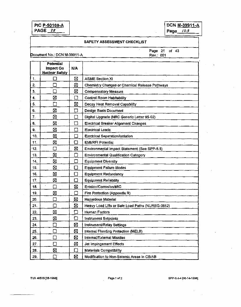
PIC P-50169-APAGE Zif
DCN M-39911-A
Page /03
SAFETY ASSESSMENT CHECKLIST
Page 21 of 43
Document No.: DCN M-3991 1-A Rev.: 001
PotentialImpact On NIA
Nuclear Safety
1. Li [] ASME Section XI
2. Li _ Chemistry Changes or Chemical Release Pathways
3. Ei l Compensatory Measure
4. 0 L1 Control Room Habitability
5. Zi 0 Decay Heat Removal Capability
6. El Design Basis Document
7. 0 Li Digital Upgrade (NRC Generic Letter 95-02)
8. 0 , , i Electrical Breaker Alignment Changes
9. E Li Electrical Loads
10. 0 Li Electrical Separation/Isolation
11. M Li EMI/RFI Potential
'12. Li [K Environmental Impact Statement (See SPP-5.5)
13. 0] EL Environmental Qualification Category
14. 3 Li Equipment Diversity
15. 0 Li Equipment Failure Modes
16. 0 Li Equipment Redundancy
17. E Li Equipment Reliability
18. Li 0 Erosion/Corrosion/MIC
19. 0 L Fire Protection (Appendix R)
20. El ED Hazardous Material
21. Li 0 Heavy Load Lifts or Safe Load Paths (NUREG-0612)
22. 0 Li Human Factors
23. 0 Li Instrument Setpoints
24. C3 0 Instrument/Relay Settings
25. _L 0 Internal Flooding Protection (MELB)
26. Li 0 Internal/External Missiles
27. Li 0 Jet Impingement Effects
28. 0 Li Materials Compatibility
29. i 0 Modification to Non-Seismic Areas in CBIAB
TVA 40516 [06-1998I Page 1 of 2 SPP-9.4-4 108-14-1998]
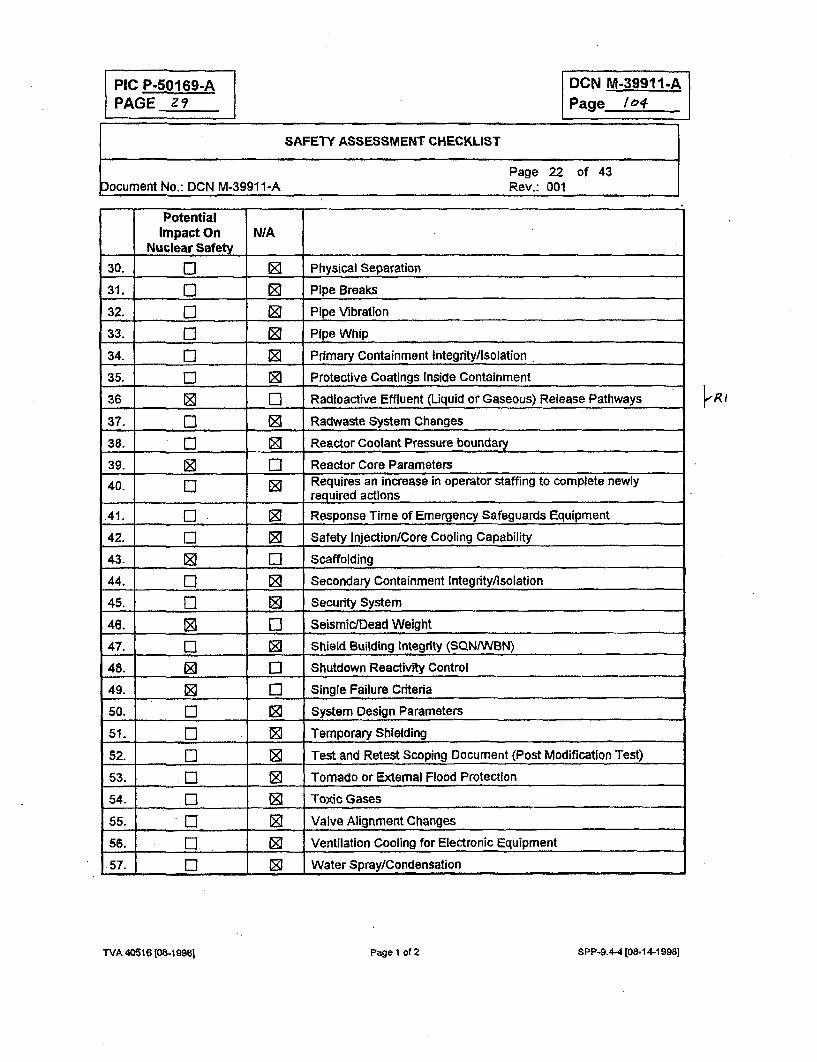
PIC P-50169-APAGE z9
DCN M-39911-APage 104
SAFETY ASSESSMENT CHECKLIST
Page 22 of 43Document No.: DCN M-39911-A Rev.: 001
PotentialImpact On N/A
Nuclear Safety
30. 5 0 Physical Separation
31. 0 0 Pipe Breaks
32. ,l -0 Pipe Vibration
33. El . Pipe Whip
34. El 0 Primary Containment Integrity/isolation
35. El 0 Protective Coatings Inside Containment
36 [] z] Radioactive Effluent (Liquid or Gaseous) Release Pathways
37. 13 . Radwaste System Changes
38. El 0 Reactor Coolant Pressure boundary
39. ____ _ Reactor Core Parameters
40. 0 Requires an increase in operator staffing to complete newly..... required actions
.41. El 0 Response Time of Emergency Safeguards Equipment
42. El 0 Safety Injection/Core Cooling Capability
43. , . . Scaffolding
44. El 0 Secondary Containment Integrity/Isolation
45. 1 , Security System
46. 0 C] Seismic/Dead Weight
47. 5 0 Shield Building Integrity (SQN/VBN)
48. 0 [] Shutdown Reactivity Control
49. El Single Failure Criteria
50. El 0 System Design Parameters
51. [] 0 Temporary Shielding
52. El 0 Test and Retest Scoping Document (Post Modification Test)
53. El 0 Tornado or External Flood Protection
54. El 0 Toxic Gases
55. "l 0 Valve Alignment Changes
56. El 0 Ventilation Cooling for Electronic Equipment
57. El F Water Spray/Condensation
k R1
TrVA 40516 eM [-9961 Page I of 2 WA 4516t06- 991 P~e1 f 2SPP-9.4-4 [O8.1 4-19981
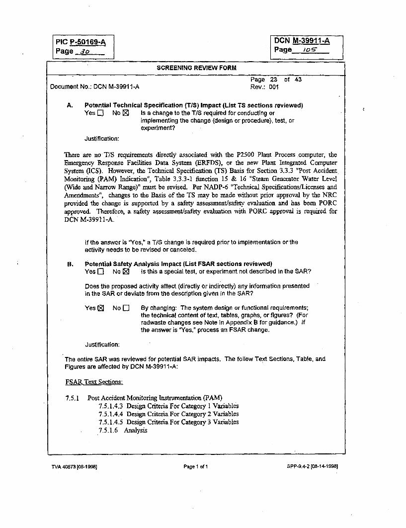
PIC P-50169-A DCN M-39911-APage 3o Page /Os"
SCREENING REVIEW FORM
Page 23 of 43Document No.: DCN M-39911-A Rev.: 001
A. Potential Technical Specification (TIS) Impact (List TS sections reviewed)Yes [] No [ Is a change to the T/S required for conducting or
implementing the change (design or procedure), test, orexperiment?
Justification:
There are no T/S requirements directly associated with the P2500 Plant Process computer, theEmergency Response Facilities Data System (ERFDS), or the new Plant Integrated ComputerSystem (ICS). However, the Technical Specification (TS) Basis for Section 3.3.3 "Post AccidentMonitoring (PAM) Indication", Table 3.3.3-1 finction 15 & 16 "Steam Generator Water Level(Wide and Narrow Range)" must be revised. Per NADP-6 "Technical Specifications/Licenses andAmendments", changes to the Basis of the TS may be made without prior approval by the NRCprovided the change is supported by a safety assessment/safery evaluation and has been PORCapproved. Therefore, a safety assessment/safety evaluation with PORC approval is required forDCN M-39911-A.
If the answer is "Yes," a TI/S change is required prior to implementation or theactivity needs to be revised or canceled.
B. Potential Safety Analysis Impact (List FSAR sections reviewed)Yes El No 0 Is this a special test, or experiment not described in the SAR?
Does the proposed activity affect (directly or indirectly) any information presentedin the SAR or deviate from the description given in the SAR?
Yes (D No E] By changing: The system design or functional requirements;the technical content of text, tables, graphs, or figures? (Forradwaste changes see Note in Appendix B for guidance.) Ifthe answer is 'Yes," process an FSAR change.
Justification:
The entire SAR was reviewed for potential SAR impacts. The follow Text Sections, Table, andFigures are affected by DCN M-39911 -A:
FSAR Text Sections:
7.5.1 Post Accident Monitoring Instrumentation (PAM)7.5.1.4.3 Design Criteria For Category I Variables7.5.1.4.4 Design Criteria For Category 2 Variables7.5.1.4.5 Design Criteria For Category 3 Variables7.5.1.6 Analysis
WA 40573 [08-1 998] Page 1 nfl
5PP-9.4-2 [08-14-1998]
TVA 406n3 [08-1 Ml] Page I of 1 SPP-9.+2 (08-14-1998]
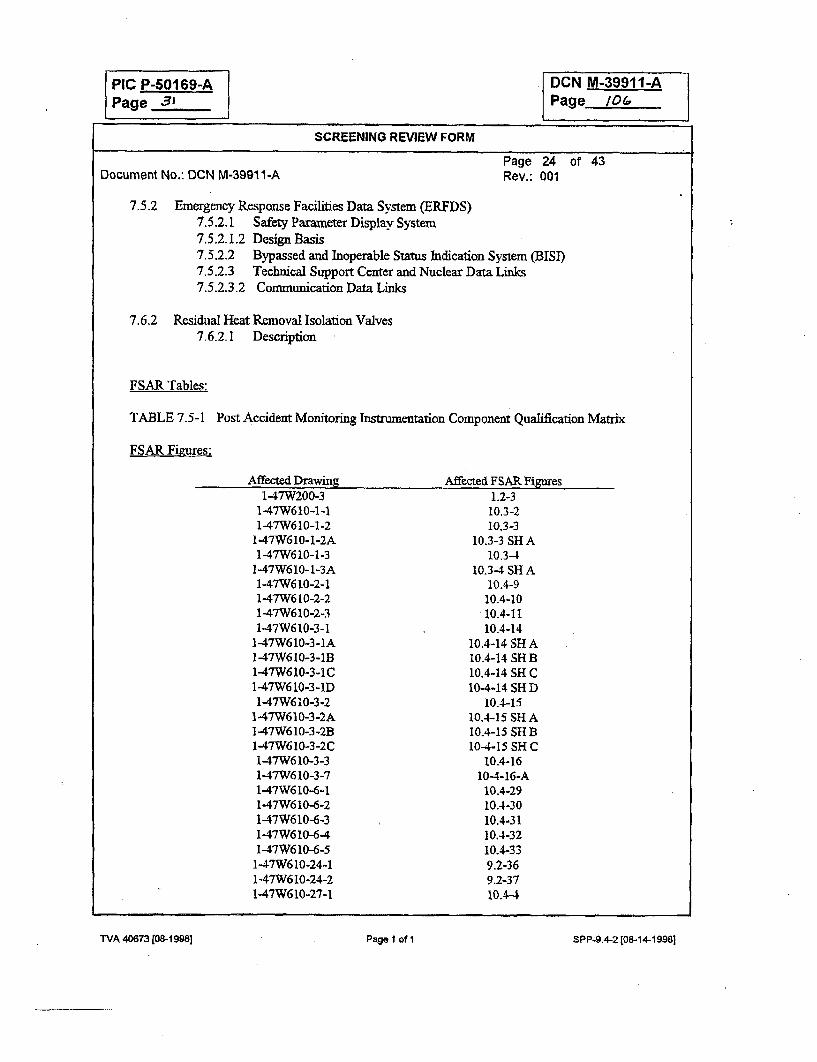
PIC P-R0169-Apage 3'
DCN M-39911-APage /0_
SCREENING REVIEW FORM
Document No.: DCN M-3991 1-APage 24 of 43Rev.: 001
7.5.2 Emergency Response Facilities Data System (ERFDS)7.5.2.1 Safety Parameter Display System7.5.2.1.2 Design Basis7.5.2.2 Bypassed and Inoperable Status Indication System (BISI)7.5.2.3 Technical Support Center and Nuclear Data Links7.5.2.3.2 Communication Data Links
7.6.2 Residual Heat Removal Isolation Valves7.6.2.1 Description
FSAR Tables:
TABLE 7.5-1 Post Accident Monitoring Instrumentation Component Qualification Matrix
FSAR Fibres:
Affected Drawing Affected FSAR Figures1-47W200-3
1-47W610-1-11-47W610-1-2
1-47W610-1-2A1-47W610-1-3
1-47W610-1-3A147W610-2-11-47W610-2-21-47W610-2-31-47W610-3-1
147W610-3-1A1-47W610-3-1B1-47W610-3-IC1-47W610-3-1D1-47W610-3-2
147W610-3-2A1-47W610-3-2B1-47W610-3-2C1-47W610-3-31-47W610-3-71-47W610-6-11-47W6 10-6-21-47W610-6-3147W610-6-41-47W610-6-5
1-47W610-24-11-47W610-24-21-47W610-27-1
1.2-310.3-210.3-3
10.3-3 SH A10.3-4
10.3-4 SH A10.4-910.4-1010.4-1110.4-14
10.4-14 SH A10.4-14 SH B10.4-14 SH C10.4-14 SHD
10.4-1510.4-15 SH A10.4-15 SU-tB
10-4-15 SH C10.4-16
10-4-16-A10.4-2910.4-3010.4-3110.4-3210.4-339.2-369.2-3710.A-4
TVA 40673 [08-I 998] Page 1 of 1
SPP-9.4.2 [08-14-1 998j
TVA 4W673 (08-1998] Page I of I SPP-9.4-2108-14-19981
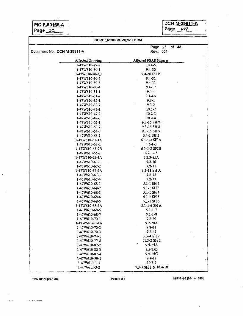
PIC P-50169-APage 3z
DCN M-39911-APage io7
SCREENING REVIEW FORM
Page 25 of 43Rev.: 001Document No.: DCN M-39911-A
Affected Drawine Affected FSAR Figures1-47W61 0-27-21-47W610-30-1
l-47W6 10-30-lB1-4'7W610-30-21-47W610-30-31-47W610-30-4-1-47W610-3 1-11-47W610-3 1-2147W610-32-11-47W610-32-21-47W610-47-11-47W610-47-2147W610-47-31-47W61 0-62-11-47W610-62-21-4'W610-62-3147W610.-63-1
1-47W610-63-IA1-4'7W610-63-2
1-47W6 1O-63-2B1-47W610-65-1
1-47W610-65-IA1-47W610-67-11-47W6710-67-2
1-47W610-67-2A1-47W610-67-31-47W610-67-41-47W610-68-11-47W610-68-21-47W610-68-31-47W610-68-41-47W610-68-5
1-47W610-68-5A1-47W610-6"-1-47W610-68471-47W610-70-1
1-4,7W610-70-IA1-47W610-70-21-47W610-70-3147W610-74-11-47W610-77-51-47W610-82-21-47W610-82-31-47W6 10-8241-47W610-90-11-47W6 11-1-I1 47W61 1-3-2
10.4-59.4-30
9.4-30 SH B9.4-319.4-119.4-179.4-4
9.4-4A9.3-19.3-210.2-210.2-310.2-4
9-3-15 SH 79.3-15 SH 89.3-15 S- 96.3-1 SH 2
6.3-1-2 SH A6.3-1-3
6.3-1-3 SH B6.2.3-15
6.2.3-15A9.2-109.2-11
9.2-11 SH A9.2-129.2-13
5.1-1 SH25.1-1 SH35.1-1 SH 45.1-1 SH 55.1-1 SH 6
5.1-1-6 SH A5.1-1-75.1I-1-s
9.2-209.2-20A9.2-219.2-22
5.5-4 SH 211.3-2 SH 2
9.5-25A9.5-25B9.5-25C9.4-1210.3-5
7.3-3 SH 1 & 10.4-18
WA 40673 [08-1898) Page 1 of 1
SPP-9,4-2 [08-14.19981
TVA 406731[08-19981 Page I of I SPP-9.4-2 (06-14-19981
PACE 3 DCN M-39911-APage /lo
SCREENING REVIEW FORM
Page 26 of 43Rev.: 001Document No.: DCN M-39911-A
Affected Drawing Affected FSAR Figures1-47W610-82-41-47W610-90-11-47W61 1-1-11.-47W611-3-2147W611-3-4
1-4'7W611-63-11-47W611-88-11-47W611-99-11-47W611-99-6
1-45W704-1
9.5-25C9.4.1210.3-5
7.3-3 SH 1 & 10.4-187.3-3 SH 2
7.3-3 SH 3 & 10.3-87.3-3 SH 47.2-1 SH 17.2-1 SH3
8.2-12
Does the proposed change involve new procedures or instructions or revisionsthereof that:
Yes 0 No Z
Yes 0 No 0
NIA ED Differ with system operation characteristics fromthat described in the SAR?
N/A E] Conflict with or affect a process or procedureoutlined, summarized, or described in the SAR?
Justification:
This change does not involve any new procedures, instructions, or revisions that differ withany information presented in the SAR.
If the questions are answered "No" or "N/A," the activity may be implementedwithout a safety evaluation. If any question is answered 'Yes," an SE is required.
Per the above discussion a safety evaluation is required for DCN M-3991 1-A.
C. Review and Approvals
Pr-eparer' .-71 Njz3.Name (. Signature
Reviewers£L2zkOa29 qe
'Data'
OtherRev.iewem(as appropriati
Other Reviewers:
Ja-n. e .5 Al. A'oc'/e-Naae'w~tWradon
ITA L urb~ SgnazreDateName
WA 40673 [08.1 9g~j Page 1 of 1
SPP..9.4-2 (08-14-1998]
TVA 40673 [08-1998) Page 1 of I SPP-9.4-2 (08-14-19981
PIC PR50169-APage 3
DCN M-39911-APage 108._. _
SCREENING REVIEW FORM
Document No.: DCN M-39911-APage 27 of 43Rev.: 001
C. Review and Approvals
Preparer 5TA49y L .- s gdr,- gz, ro 0."Name Signature Date
Reviewer . 86P &xW - A m a -I-,...Name Signature Date
Other: es Al. ~ ~ ~ ~-Reviewers Name/Organizatdon Signature Date(as appropra)te)e~viewers: T, l,., t. E r.4• ./Y4MIf/
OtherName Signaruoý Date
TVA 40673 (08-1998B] Page I of 1 SPP-9.4-2 [08-14-1998]
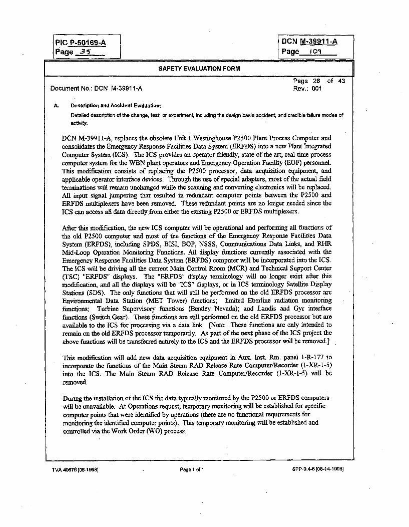
PIC P-50169-A DCN M-39911-APage ,3 per__ Page 109J
SAFETY EVALUATION FORM
Page 28 of 43Document No.: DCN M-39911-A Rev.: 001
A. Description and Accident Evaluation:
Detailed descriptlon of the change, test, or experiment, including the design basis accident, and credible failure modes of
acti .
DCN M-3991 l-A, replaces the obsolete Unit I Westinghouse P2500 Plant Process Computer andconsolidates the Emergency Response Facilities Data System (ERFDS) into a new Plant IntegratedComputer System (ICS). The ICS provides an operator friendly, state of the art, real time processcomputer system for the WBN plant operators and Emergency Operation Facility (EOF) personnel.This modification consists of replacing the P2500 processor, data acquisition equipment, andapplicable operator interface devices. Through the use of special adapters, most of the actual fieldterminations will remain unchanged while the scanning and converting electronics will be replaced.All input signal jumpering that resulted in redundant computer points between the P2500 andERFDS multiplexers have been removed. These redundant points are no longer needed since theICS can access all data directly.from either the existing P25 00 or ERFDS multiplexers.
After this modification, the new ICS computer will be operational and performing all functions ofthe old P2500 computer and most of the functions of the Emergency Response Facilities DataSystem (ERFDS), including SPDS, BISI, BOP, NSSS, Communications Data Links, and RHRMid-Loop Operation Monitoring Functions. All display functions currently associated with theEmergency Response Facilities Data System (ERFDS) computer will be incorporated into the ICS.The ICS will be driving all the current Main Control Room (MCR) and Technical Support Center(TSC) "ERFDS" displays. The "ERFDS" display terminology will no longer exist after thismodification, and all the displays will be "ICS" displays, or in ICS terminology Satellite DisplayStations (SDS). The only functions that will still be performed on the old ERFDS processor areEnvironmental Data Station (MET Tower) functions; limited Eberline radiation monitoringfunctions; Turbine Supervisory functions (Bentley Nevada); and Landis and Gyr interfacefunctions (Switch Gear). These functions are still performed on the old ERFDS processor but areavailable to the ICS for processing via a data link. [Note: These functions are only intended toremain on the old ERFDS processor temporarily. As part of the next phase of the ICS project theabove functions will be transferred entirely to the ICS and the ERFDS processor will be removed.]
This modification will add new data acquisition equipment in Aui. Inst. Rm. panel l-R-177 toincorporate the functions of the Main Steam RAD Release Rate Computer/Recorder (1-XR-1-5)into the ICS. The Main Steam RAD Release Rate Computer/Recorder (1-XR-1-5) will beremoved.
During the installation of the ICS the data typically monitored by the P2500 or ERFDS computerswill be unavailable. At Operations request, temporary monitoring will be established for specificcomputer points that were identified by operations (there are no functional requirements formonitoring the identified computer points). This temporary monitoring will be established andcontrolled via the Work Order (WO) process.
TVA 40676 [08-1IM8 Page I of I SPP-9.4-6108-14-19981
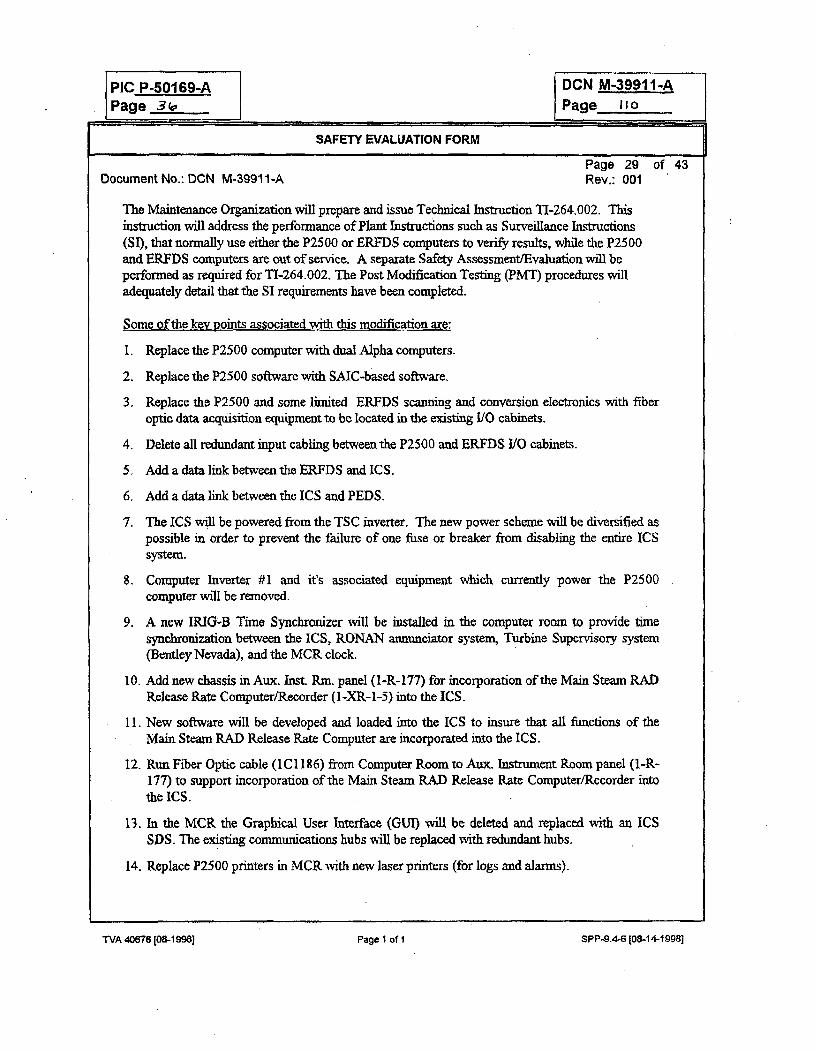
PIC P-50169-A DCN M-39911-APage 3 (a Page Ito.j
SAFETY EVALUATION FORM
Page 29 of 43Document No.: DCN M-39911-A Rev.: 001
The Maintenance Organization will prepare and issue Technical Instruction TI-264.002. Thisinstruction will address the performance of Plant Instructions such as Surveillance Instructions(SI), that normally use either the P2500 or ERFDS computers to verify results, while the P2500and ERFDS computers are out of service. A separate Safety Assessment/Evaluation will beperformed as required for TI-264.002. The Post Modification Testing (PMT) procedures willadequately detail that the SI requirements have been completed.
Some of the key points associated with this modification are:
1. Replace the P2500 computer with dual Alpha computers.
2. Replace the P2500 software with SAIC-based software.
3. Replace the P2500 and some limited ERFDS scanning and conversion electronics with fiberoptic data acquisition equipment to be located in the existing 110 cabinets.
4. Delete all redundant input cabling between the P2500 and ERFDS I/O cabinets.
5. Add a data link between the ERFDS and ICS.
6. Add a data link between the ICS and PEDS.
7. The ICS will be powered from the TSC inverter. The new power scheme will be diversified aspossible in order to prevent the failure of one fuse or breaker from disabling the entire ICSsystem.
8. Computer Inverter #1 and it's associated equipment which currently power the P2500computer will be removed.
9. A new IRIG-B Time Synchronizer will be installed in the computer room to provide timesynchronization between the ICS, RONAN annunciator system, Turbine Supervisory system(Bentley Nevada), and the MCR clock.
10. Add new chassis in Aux. Inst. Rm. panel (1-R-177) for incorporation of the Main Steam RADRelease Rate Computer/Recorder (I-XR-1-5) into the ICS.
11. New software will be developed and loaded into the ICS to insure that all functions of theMain Steam RAD Release Rate Computer are incorporated into the ICS.
12. Run Fiber Optic cable (1C 1186) from Computer Room to Aux. Instrument Room panel (I-R-177) to support incorporation of the Main Steam RAD Release Rate Computer/Recorder intothe ICS.
13. In the MCR the Graphical User Interface (GUI) will be deleted and replaced with an ICSSDS. The existing communications hubs wAill be replaced with redundant hubs.
14. Replace P2500 printers in MCR with new laser printers (for logs and alarms)-
WA 40676 [08-1998) Page 1 of I SPP-9.4-6 [08-141998]
TVA 40676 [os-1 Ml] Page 1 of 1 SPP-9.."4 [0W-14-19981
PIC P-501 69-A DCN M-39911-APage 31 Page Ill
SAFETY EVALUATION FORM
Page 30 of 43Document No.: DCN M-3991 1-A Rev.: 001
15. Replace all special function ERFDS workstation (After this modification ICS SDS) keyboardswith new standard computer keyboards in both the MCR and TSC. This change is neededsince the existing keyboards can not be replaced by DCN M-3993 1-A (MCR and TSC PCreplacement modification). The existing keyboards were specially designed to support theexisting ERFDS software.
16. Deactivate P2500 point U2035 (CCW Pump Average Overall Efficiency). This point wasevaluated to be no longer needed by WBN personnel.
17. Add an ICS trouble alarm to the RONAN Annunciator system. This is accomplished bycombining existing Windows 99A ["RCP MOTOR THRUST BEARING TEMP HI"(Computer Point Y9002C)] and 100A ["RCP STATOR TEMP HI (FROM P-2500)'(Computer Point Y9001C)] on MCR window box 1-XA-55-5B into one window (100A onwindow box 1-XA-55-5B). The new combined window 100A will be re-engraved to read"RCP STATOR/MTR THRUST BRG TEMP HI" and window 99A will be blanked. Thecombining of these computer points on one annunciator window will spare an input cable toRONAN, which will then be used for the new "PLANT COMPUTER TROUBLE"annunciator. This annunciator will be located on window 136F on MCR Window Box 1-XA-55-6D. This new Plant Computer Trouble alarm will annunciate for the following conditions:(1) the primary alpha computer is down and the backup alpha computer is running, (2) theprimary and backup alpha computers are both down, or (3) there is a loss of power to thechassis that contains the new Delay Timer (Watchdog) 1/0 Card.
19. Resolve PER WBPER9%0807. The following computer points were identified by operationsas critical computer points that should be included on the RONAN annunciator system. Thesepoints will be added to existing annunciator window 83D ["ROD DEVN & SEQ PWRRANGE TILT COMPUTER ALARM" (Computer Point Y9000C )] on MCR Window Box1-XA-55-4B:
U0270D DELTA FLUX ALARM (AXIAL FLUX DIFFERENCE (AFD))POO0A- CONTAINMENT 1 PRESSUREP1001A CONTAINMENT 2 PRESSUREP1002A CONTAINMENT 3 PRESSUREP1003A CONTAINMENT 4 PRESSUREU0965 RI3F&ED POCKET SMP 15M AVG RORISE. (Calculated Point)U0966 RBF&ED POCKET SMIP 15M AVG RORISE, (Calculated Point)U0968 RBF&ED POCKET SMP 60M AVG RORISE. (Calculated Point)U0969 RBF&ED POCKET SMP 60M AVG RORISE, (Calculated Point)
As part of this change annunciator window 83D will be re-engraved to read "PLANT COMPUTERGENERATED ALARM (SEE ICS)". Since this annunciator modification will result in numerouscomputer points activating one annunciator window, a special screen wdll be added to the ICSdisplays especially for the 83D alarm. After this change whenever any of these computer pointsexceed their alarm setpoints, window 83D will annunciate. Operators should then go to an ICS SDSand proceed to the NSSS menu and select the "Annunciator 83D Alarms" screen. This screen will
iVA 40678108-19983 Page 1 of 1 SPP-9.4-6 ~O8-14-1998I
"TVA 40676 10&-1998] Page I of I SPP-9.4-6 [08-14-19981
PIC P-50169-A DCN M-39911-A
Page -3oPage I I Z.
SAFETY EVALUATION FORM
Page 31 of 43Document No.; DCN M-3991 1-A Rev.: 001
then give operations personnel exact indication of which critical alarm brought in the 83D
annunciator window. Therefore, decreasing their response time to the annunciator.
SUMMARY OF MODIFICATION WORK BY ROOM
(This is a summara only and is not intended to be a complete listing of all work required for theinstallation of the ICS)
AUX. INSTRUMENT ROOM:
Rack l-R-177 "Main Steam Data Logger Replacement":" Removal of the 1-XR-1-5 recorder." Installation of RTP chassis and fan assembly, lightguide, 1/O cards, terminal strip cable
assemblies, dropping resistors, and plug strip, etc..." Abandon cables as required.
New fiber optic cable (12 pairs) pulled from computer room to 1-R-177. This fiber will be required toconnect the new RTP chassis for the Main Steam Data Logger inputs into the ICS data acquisitionnetwork. It will also connect the existing RTP chassis' for panels 1-R-133, -134, lAI, IBI, andEagle-21 interface into the ICS network during a later phase of this project, not included in DCNM-3991 1A.
250V BATTERY BOARD ROOM #1:
* Demolition of computer inverter # 1 and computer inverter #1 SYNC fused disconnect switch (removeor abandon associated cabling/conduit).
* Demolition of anchors / grout pads, as necessary.
* Removal of unit I cabling from the computer maintenance supply transfer switch. This will require thedeletion of Unit 2 cable M35 in order to allow the removal of computer inverter #1 sync fuseddisconnect switch. This also includes the abandonment of cable M21 which originates from AuxiliaryBuilding Lighting Board 3.
o TSC distribution panel #1: terminate cable No. M42 (previouslýy installed) at breaker 12 and tagappropriately.
6 Nameplate changes to breakers on TSC distribution panel #1.
TVA 40876(08-19981 Page 1 of 1 SPP-9.4-6 [08-14-1998]
TVA 40676 [08-199M] Page 1 of I SPP-9.4-6 [08-14-19981
PIC P-50169-A DCN M-39911-APage 3q Page---
SAFETY EVALUATION FORM
Page 32 of 43Document No.: DCN M-39911-A Rev.: 001
AUX. BUILDING -LIGHTING BOARD 3:
* Determinate & abandon the computer maintenance supply feeder cable M21 and re-tag breaker asspare.
MAIN CONTROL ROOM:
o Replace GUI workstation with new ICS satellite display station (SDS). The new SDS will consist of anew a central processing unit (CPU), monitor, keyboard, and mouse.
" Replace communication hub with redundant stackable hubs.
* Replace P2500 Alarm and Trend line printers in horseshoe and remove the P2500 line printer atI-M-24 in hallway. The 2 new printers will be Laser printers.
" Re-design power for the GUI and printers (the GUI will be replaced with a new SDS). The GUI iscurrently powered from the P2500 computer inverter which will be removed during this modification.The plan is to reutilize the power cable from the P2500 distribution panel and reconnect it to the newpower distribution network located.l-R-103. This new network will be powered from TSCDistribution Panel #1, breaker 12.
" l-M-14: Rework cable IC 1140 under the GUI desk, to accommodate a new 48VDC horn for ICS pointannunciation in the main control room. Abandon/delete cabling/equipment associated with the old24VDC power supply and horn.
* l-M-21: Rework IRIG-B cabling to RONAN annunciator system from the computer room.
" Replace all special function ERFDS workstation (after this modification ICS SDS) keyboards withnew standard computer keyboards. This change is needed since the existing keyboards could not bereplaced during DCN M-3993 1-A (MCR and TSC PC replacement modification) because they werespecially designed to support the existing ERFDS software.
" Rework RONAN annunciator windows 1-XA-55-4B-83D, 1-XA-55-5B-99A, 1-XA-55-5B-100A,1 -XA-55-6D-136F, and I-XA-55-1C-16E.
TECHNICAL SUPPORT CENTER:
* Replace all special function ERFDS workstation (after this modification ICS SDS) keyboards withnew standard computer keyboards. This change is needed since the existing keyboards could not bereplaced during DCN M-3 993 1-A (MCR and TSC, PC replacement modification) because they werespecially designed to support the existing ERFDS software.
TVA 4W76 (08-1 W8a Page I of I SPP-9.4-6 [08-14-1998]
PIC P-50169-APage 4•
DCN M-39911-APage_ If -
SAFETY EVALUATION FORM
Page 33 of 43Document No.: DCN M-3991 1-A Rev.: 001
COMPUTER ROOM: RACK 1-R-103
" Remove and surplus all equipment inside of this cabinet.
* Install new 120VAC distribution network and route cable M42 (currently under the subfloor nearl-R-103) to new distribution network and terminate. Terminate power cabling to cabinets l-R-104, -105, & -106. Re-terminate cable 1C520 from old distribution network to the new network. This cablewill power the new printers and workstation in the main control room (1-M-14).
* Miscellaneous cable deletions and abandonment's.
COMPUTER ROOM: RACK 1-R-104
" ERFDS intertied cable deletions & abandonment's.
" Abandon &/or delete miscellaneous signal cabling.
* Make changes for new power / grounding, install plug molds.
* Remove old Westinghouse 1/0 chassis/cards and related equipment & install new chassis/cards andrelated equipment and terminate fiber optic jumper cabling.
" Internal cable removals.
* Removal of existing AC power cabling (and associated outlets) originating from l-R-103.
* Install new RTD modules on cold junction box # 1 & associated cable terminations on half-shell.
o RTD power supplies will remain.
COMPUTER ROOM- RACK 1-R-105
ERFDS intertied cable deletions & abandonment's.
Abandon &for delete miscellaneous signal cabling.
• Make changes for new power / grounding, install plug molds.
TVA 4W66 [MI- MI8 Page I of I SPP-9.4-6 [08-14-19981
PIP P-50169-A DCN M-39911-APage __ , Page I15
SAFETY EVALUATION FORM
Page 34 of 43Document No.: DCN M-39911-A Rev.: 001
* Remove old Westinghouse I/O chassis/cards and related equipment & install new chassis/cards andrelated equipment and terminate fiber optic jumper cabling.
" Install new delay timer (Watchdog Timer) barrier terminal strip cable assembly and reland cable ontoit. This is for the "Plant Computer Trouble" alarm on RONAN.
" Replace old 48VDC power supply with new ACOPIAN model. Existing P2500 cabling from the old
48VDC power supply to the taper pin busses will be re-used/maintained.
" Internal cable removals.
* Removal of existing AC power cabling (and associated outlets) originating from 1-R-103.
* Rework cable 1CI 140, (located in front-right-bottom of panel), extending to l-R-157 and tenninate onrelay-out barrier terminal strip. This will be utilized for ICS annunciation in the main control room.
* Rework of pulse input, relay output, and analog output cabling; terminate onto new barrier terminalstrip cable assemblies (BTSCA). 48VDC from half-shels 68M & N will be used to supply the sensingand return voltage for the pulse input BTSCAs.
* SSPS demultiplexer equipment will remain including:
1. Demultiplexer
2. U/O cable connector panel
3. 48VDC power supply
4. 15VDC power supply
, 48VDC circuit breaker panels A & B will remain.
B Blower unit in bottom of cabinet will remain.
COMTIUTER ROOM: RACK l-R-106
* Install new RTD modules on cold junction boxes #2 and #3 & associated cable terminations on half-shell.
* ERFDS intertied cable deletions & abandonment's.
o Abandon &/or delete miscellaneous signal cabling-
* Make changes for new power ! grounding, install plug molds.
TVA 4067S [08-1 sea1 Page I of I SPP-9.4-6108-14-19981
PIC P-50169-A DCN M-39911-APage 4z Page 1it,
SAFETY EVALUATION FORM
Page 35 of 43Document No.: DCN M-39911-A Rev.: 001
* Remove old Westinghouse 1/0 chassis/cards and related equipment & install new chassis/cards and
related equipment / terminate fiber optic jumper cabling.
o Internal cable removals.
" Removal of existing AC power cabling (and associated outlets) originating from l-R-103.
* Existing RTP test chassis and associated equipment will remain.
COMPUTER ROOM: RACKS I-R-151, 2-R-152, 1/2-R-153, 1-R-154, -155, -158, -159,1(2)-R-160, l-R-161, -162
* l-R-151: Remove ERFDS computer DEC PDP 11/84 (entire cabinet).
a 1/2-R-153: Remove ERFDS peripheral expansion cabinet (entire cabinet). UNID I-R-153 will bereused as one of the two new ICS cabinets. l-R-151 power feed will also be reused to supply power tothe new 1-R-153. Make fiber, coax, and twisted pair connections as required per new design drawings.Cabinet 2-CMPT-264-R152 will have to be removed as it is physically connected to cabinet 1/2-CMPT-264-R153.
a 1-R-154: Remove ERFDS disk & tape drives (entire cabinet). UNID 1-R-154 will be re-used as oneof the two new ICS cabinets. 1-R-154 power feed will also be reused for supply to one of the two newICS cabinets. Make fiber, coax, and twisted pair connections as required per new design drawings.
a 1-R-155: Terminate fiber optic cable from Auxiliary Instrument Room. Miscellaneous cableabandotuments/deletions. Establish new datalink between ERFDS and the ICS.
1 l-R-158: Remove magnetic tape recorder (entire cabinet). Incorporate Plant Temperature MonitoringSystem (PTMS) interface into the new system (currently tied to the P2500 via modems in rack1-R-158). Need to disconnect the modems and drop back down under the subfloor and extend to thenew panels via a DB-25 to RJ-45 adapter and twisted pair cabling.
o 1-R-159: Remove P2500 printer (entire cabinet).
* 1(2)-R-160: Remove ERFDS line printers (entire device removed).
* 1-R-161: Remove ERFDS operators console and printer. Install 2 new text monitors forprogramming of redundant ICS computers.
a 1-R-162: Remove VAX printer.
iVA 40676 [08-1998] Page 1 of I SPP-9.4-6 [08.14.19981TVA 406761[08-199N] Page 1 of I SPP-9.4-6 [08-14-1998
PIC P-501 69-APage 43
DCN M-39911-APage 1I
SAFETY EVALUATION FORM
Page 36 of 43Document No.: DCN M-39911-A Rev.: 001
COMPUTER ROOM: RACKS 1-R-156 & 1-R-157
" 1-R-156: Installation of 3 new cards: (remote RTP controller, univ. Interface card, & A/D converter)
* l-R-157: Installation of 2 new cards: (univ. Interface card & A/D converter)
= 1-R-156 & -157: Removal of old DEC DYS50 chassis and associated cabling.
" 1-R-156: Removal of universal chassis 41, reinstallation of new extended side universal chassis #1,and termination of fiber optic jumper cabling. One remote RTP controller will be used for bothl-R-156 and -157 instead of one in each cabinet.
* 1-R-157: Terminate cable ICI 140 onto barrier terminal strip cable assembly that already exists in this
cabinet- (1C1140 is being spliced onto and extended from I-R-I05)
* I-R-156 and -157: Cable deletions / abandonment.
COMPUTER ROOM: RACKS 1-R-10O & I-R-102:
I-R-100: Remove P2500 datalink computer/ programmers console and line printer from table.Extend coax cabling (removed from datalink computer) to new cabinet (I-R- 153) for timesynchronization of ICS to the main control room clock, RONAN annunciation system, and the turbinesupervisory system. Install new ICS SDS and printer and associated network cabling.
* l-R-100: Rework 120VAC outlets under l-R-100 subfloor.
* l-R-102: Remove paper tape reader and abandon associated cabling.
COMPUTER ROOM (Miscellaneous):
o Remove computer #1 transfer switch and delete/abandon cabling and conduit.
* Replace floor tiles as necessary.
" Rework power outlets for all new equipment as necessary to accommodate additional plugs andsurge/EMI filters.
WA 40876 [08-1 998] P8ge 1 of 1 SPP-9.4.8 [08-14-1998]
TVA 4W6 [0W1 9Wj] Page I of 1 SPP-9.4-6 [Nk14-1998]
PIC P-50169-A DCN M-39911-APage 46 Page htS
SAFETY EVALUATION FORMPage 37 of 43
Document No.: DCN M-3991 1-A Rev.: 001
Design Basis Accident
Essentially all "at power" design basis accidents are associated with the ICS because accident analysisassumes reactor conditions are within Tech. Spec. conditions. Several of these Tech. Spec. parameters aremonitored with ICS computer software including thermal power, axial flux difference (AFD), QuadrantPower Tilt Ratio (QPTR), Rod Supervision, heatup/cooldown, and RCS inventory. The power rangenuclear instrument gains are adjusted based on calorimetric calculations completed by the ICS. This ICScalorimetric calculation software will be designed, developed, and tested in accordance with SPP-2.6. Testcase results of the calorimetric calculation and the other calculations identified above from the old P2500are compared to similar calculations made by the ICS as part of the validation testing. The requirements ofSPP-2.6 includes formal test cases for ICS software as well as informal supplemental testing to furtherdemonstrate software features and challenge calculation algorithms. Therefore, there is a high degree ofconfidence that the ICS Tech- Spec. compliance calculations are correct.
The ICS is not safety related and is properly isolated and separated from safety related equipment. It isdesigned to seismic category I(L)B criteria inside seismic category I areas. In the event of an accident,MCR, and ERF personnel can use the SPDS and other aspects of the ICS as an aid to restore the plant to asafe condition. However, Operators must be trained to respond to accidents both with and without theSPDS available. The ICS will not be designed to safety system criteria, and it is not used to performfunctions essential to the health and safety of the public. Although the ICS indirectly provides support tosafety related systems by alerting operators that an abnormal condition may exist, operators cannotprocedurally take inappropriate safety related action based solely on ICS information. There are othersafety grade equipment that is provided for mitigating the events of design basis accidents.
Therefore, the new ICS will not adversely impact any previously completed analysis of DBA's. Thereplacement of the P2500 and limited ERFDS equipment with state-of-the-art ICS equipment does notcreate any new accidents of any type that would represent an unreviewed safety question.
Credible Failure Modes
The credible failure modes associated with the existing P2500 computer and ERFDS have not changed as aresult of this modification. The new ICS is susceptible to the same failure modes as the P2500.
1. Total Loss of ICS2. Display of Incorrect Information3. Loss of ICS Satellite Display Stations (SDS)4. Loss of one or more data sources
The ICS is not defined as being safety-related and it is not required to meet the single failure criterion or bequalified to IEEE criteria for Class IE equipment. The ICS is not to be used to perform functions essentialto the health and safety of the public. Although the ICS indirectly provides support to safety relatedsystems by alerting operators that an abnormal condition may exist, operators cannot procedurally take
WA 40676(08-1998] Page 1 of 1 5PP-9.4-6 (08-14-1 9981
TVA 40W76 [0&-19N]o Page I of 1 SPP-9.4-6 [08-14-19981
PIC P.50169-A DCN M-39911-APage 45. Page iiq
SAFETY EVALUATION FORM
Page 38 of 43Document No.: DCN M-3991 1-A Rev.: 001
inappropriate safety related action based solely on ICS information. Since it is designed to seismiccategory I(L)B criteria inside seismic category I areas, it will not fail during a design basis seismic event ina manner which will adversely affect safety-related structures, systems or components. Therefore, thismodification does not create any new credible failure modes of any type that would represent anunreviewed safety question.
B. Evaluation of Effects
B.1 May the proposed activity increase the probability of an accident previously evaluated in the SAR? Yes 0 No 0Justification:
This modification replaces obsolete computer equipment with an operator friendly, state of the art,real time process computer system for the WBN plant operators and Emergency Operation Facility(EOF) personnel.
The ICS is not safety-related and it is not required to meet the single failure criterion or be qualifiedto IEEE criteria for Class 1E equipment. It is properly isolated and separated from safety relatedequipment in accordance with Design Criteria WB-DC-30-4 and is designed to seismic categoryI(L)B criteria inside seismic category I areas per WB-DC-40-31.13. The ICS is not used toperform functions essential to the health and safety of the public. Although the ICS indirectlyprovides support to safety related systems by alerting operators that an abnormal condition mayexist, operators cannot procedurally take inappropriate safety related action based solely on ICSinformation. There are other safety grade equipment that is provided for mitigating the events ofdesign basis accidents.
Several Tech. Spec. parameters are monitored with ICS computer software including thermalpower, axial flux difference (AFD), Quadrant Power Tilt Ratio (QPTR), Rod Supervision,heatup/cooldown, and RCS inventory. The power range nuclear instrument gains are adjustedbased on calorimetric calculations completed by the ICS. This ICS calorimetric calculation softwarewill be designed, developed, and tested in accordance with SPP-2.6. Test case results of thecalorimetric calculation and the other calculations identified above from the old P2500 arecompared to similar calculations made by the ICS as part of the validation testing. Therequirements of SPP-2.6 includes formal test cases for ICS software as well as informalsupplemental testing to further demonstrate software features and challenge calculation algorithms.Therefore, there is a high degree of confidence that the ICS Tech. Spec. compliance calculations arecorrect. The ICS will alert Operations personnel at the same thereshold as the existing P2500 andERFDS computers. Therefore, there is no increase in the probablity of an acident due to plantoperation outside limits as defined in the Techincal Specifications.
The Equipment changes as a result of this DCN have been analyzed and determined to beseismically adequate per the results of civil engineering calculations issued for DCN M-3991 1-A.
Electrical load changes resulting from new and removed equipment has been analyzed anddetermined to be acceptable per the results of electrical engineering calculations issued for DCNM-3991 1-A.
WA 40676 108-I 998J Page 1 of I SPP-9.4-6 !O8-14-19981
TVA 40676 108-1 MI] Page 1 of If SP P-9.4-6 [084 4-19981
PIC P-50169-A DCN M-39911-A
Page 4 Page Iz-0
SAFETY EVALUATION FORM
Page 39 of 43Document No.: DCN M-3991 1-A Rev.: 001
Fire load changes resulting from new and removed equipment has been analyzed and determined tobe acceptable per the results of mechanical engineering calculations issued for DCN M-3 991 1-A.
The WBN ICS software is essentially the same as that installed on the SQN Unit I and 2 ICS. Thebasic SAIC Plant Monitoring System (PMS) that is the backbone of the ICS software package is inservice at many other nuclear power plants including Susquehanna, Waterford, Seabrook, BrownsFerry, and Diablo Canyon.
The ICS was subjected to an extensive Human Factors Engineering (HWE) review during its design,development, and testing at SQN. There was extensive SQN Senior Reactor Operator (SRO)involvement in the man-machine interface including display development. The enhanced WBN ICSdisplays (including SPDS and BISI) will also receive an extensive Human Factor Engineering(lIFE) review. This review will be done by Computer Engineering Service, INC. (CES), undercontract P-95BYE-119256-001, Release 1279465. This review is to be completed and approvedand any problems resolved by TVA before this DCN is installed. Only ICS computer displays willbe evaluated by CES; all other hardware modifications have been evaluated from a IFE perspectiveas part DCN M3991 1-A.
MCR operators will receive training on the ICS on the WBN plant specific control room simulatorprior to placing the ICS in service. Therefore the chances of human error are decreased.
A failure of the ICS could not initiate any event or accident. Computer hardware and softwaredeveloped for the ICS will be designed, developed, and tested in accordance with SPP-2.6. The ICSsystem architecture includes backup processors with automatic fhil over capability, redundant dataacquisition processing equipment, and redundant communication cables to the primary ICSman-machine interface (SDS). These features reduce the risks associated with ICS componentfailures and helps to increases the reliability of the ICS.
The installation of the new Plant Integrated Computer System (ICS) will help to increase the overalleffectiveness of plant personnel by providing them with accurate, reliable and timely informationwhich may be used during abnormal and emergency conditions in determining the safety status ofthe plant and in assessing whether abnormal conditions require corrective action by the operators toavoid a degraded core.
Consequently this modification introduces no increased probability or frequency of an accidentpreviously evaluated in the SAR.
WA 40676108-1998] Page 1 of 1 SPP-9.4-6 (08-14-19981
TVA 40676 I08-1998] Page I of 1 SPPA" (08-14-19981
PIC P-50169-A DCN M-39911-A
Page 4"1 Page IW_
SAFETY EVALUATION FORM
Page 40 of 43Document No.: DCN M-39911-A Rev.: 001
B.2 May the proposed activity increase the probability of occurrence of a malfunction of equipment important to safetypreviously evaluated in the SAR? Yes (] No g
Justification:
As stated above, the ICS is not safety-related and it is not required to meet the single failurecriterion or be qualified to IEEE criteria for Class IE equipment. It is properly isolated andseparated from safety related equipment, and is designed to seismic category I(L)B criteria insideseismic category I areas. All equipment added as part of DCN M-399 11-A has been evaluated forEMI/RFI interference per SS-E18.14.01 and was determined to be adequate for installation andoperation in the plant with installation of power supply filters. The computer software is designed,developed, and tested in accordance with the requirements of SPP-2.6.
Although the ICS indirectly provides support to safety related systems by alerting operators that anabnormal condition may existoperators cannot procedurally take inappropriate safety relatedaction based solely on ICS information. Validated information from other sources will be used priorto taking actions which affect safety. Therefore this modification will not decrease the ability ofsystems important to safety to perform their intended functions. Therefbre, the probability ofoccurrence of a malfunction of equipment important to safety is not increased.
B.3 May the proposed activity increase the consequences of an accident previously evaluated In the SAR?Yes 0 No 0Justification:
As noted above, the ICS is not safety related and will not have detrimental effects on safety relatedequipment. Failure of any ICS equipment will not result in the release of radioactive products.
The.ICS software for performing the process radiation levels and radiation release rate calculationswill be designed, developed, tested, and verified in accordance with the requirements of SPP-2.6.
Therefore, this modification introduces no increased radiological consequences of an accidentpreviously evaluated in the SAR.
8.4 May the proposed activity increase the consequences of a malfunction of equipment important to safety previouslyevaluated in the SAR? Yese No 0Justification:
As noted above, the ICS is properly isolated and separated from safety related equipment, and isdesigned to seismic category I(L)B criteria inside seismic category I areas. Therefore, theradiological consequences of a mafimction of equipment important to safety are not changed.
WA 40676 C08-1 998] Page 1 oft SPP-9.4-8 (08-14-19981
TVA 40676 (08,-1998] Page I of I SPP-9.4-6108-14-19981
PIC P-60169-A DCN M-39911-APage 45 Page 17.,
SAFETY EVALUATION FORM
Page 41 of 43Document No.: DCN M-3991 1-A Rev.: 001
B.5 May the proposed activity create a possibility for an accident of a different type than any evaluated previously in theSAR? Yes 0 No 0Justification:
The credible failure modes of the ICS are: total loss of ICS, incorrect information displayed, loss ofone or more ICS SDS, loss of one or more ICS input data sources. These failure modes are thesame as those associated with the P2500. There are administrative procedures in place whichpermit safe and reliable operation of the plant without the ICS. The ICS monitors input data andflags information which may be incorrect with quality codes. Equipment monitored by the ICSwhich is important to safety have alternate indications in the MCR as necessary for operators todistinguish between a false ICS indication and the actual condition. If a false indication is received,operators can distinguish between false and legitimate conditions using information readily availableto them. As mentioned earlier, the ICS is not to be used to perform functions essential to the healthand safety of the public. Although the ICS indirectly provides support to safety related systems byalerting operators that an abnormal condition may exist, operators cannot procedurally takeinappropriate safety related action based solely on ICS information. Validated information fromother sources will be used prior to taking actions which affect safety.
Therefore this modification will not create a possibility for an accident of a different type that anyevaluated previously in the SAR.
B.6 May the proposed activity create a possibility for a malfunction of a different type than any evaluated previously inthe SAR? Yes 0 No 0Justification:
Based on the credible failure modes discussed in B.5 above, there will be no new malfunctionpathways introduced which have not been previously evaluated in the SAR accident analysis.Therefore there will be no creation of a possibility for a malfunction of a different týpe than anyevaluated previously in the SAR
B.7 May the proposed activity reduce the margin of safety as defined in the basis for any Technical Specification?YesQ] No 0Justification:
DCN M-39911-A will revise Technical Specification Bases Section 3.3.3 "Post AccidentMonitoring (PAM) Indication", Table 3.3.3-1 function 15 & 16 "Steam Generator Water Level(Wide and Narrow Range)". This revision is minor in nature and only removes a reference to theEmergency Response Facility Data System (ERFDS). In this reference a signal was described asinput to both the Plant Computer and the ERFDS. With the new ICS redundant inputs are nolonger required and therefore, this reference was removed from this TS bases. Therefore, there isno reduction in the margin of safety as defined in the Basis for any Tech Specs.
TVA 40676E08-19981 Page 1 of 1 SPP-9.4-6[08-14-1998]
PIC P-50169-A DCN M-39911-APage ..4 .. Page /Z3
SAFETY EVALUATION FORM
Page 42 of 43Document No.: DCN M-3991 1-A Rev.: 001
The ICS has no defined margin of safety as defined in the basis for any technical specification.The secondary heat balance calorimetric is one method which can be used to ensure power iswithin Rated Thermal Power when nuclear instrumentation is indicating 100% power. Thiscalculation will be designed, developed, tested, and verified in accordance with the requirements ofSPP-2.6. It is of comparable accuracy to the existing secondary heat balance calculationsperformed by the P2500 computer. Software for QPTR, AFD, Rod Deviation, and RCS Inventoryis treated in a similar manner. The requirements of SSP-2.6 includes formal test cases for softwareas well as informal supplemental testing to further demonstrate software features and challengecalculation algorithms.
This modification will not degrade the ability of any equipment important to safety to perform itsintended safety function, thereby reducing any margin of safety in the Tech. Specs. Therefore,there is no reduction in the margin of safety as defined in the basis for any technical specification.
C. Unreviewed Safety Question Determination Conclusion
The change, test, or experiment:Does not involve an unreviewed safety question. 0Involves an unreviewed safety question and must be revised, canceled, or reviewed by the NRC prior to implementation. CSummarize why the activity does or does not constitute a USQ.
DCN M-3991 1-A, replaces the obsolete Unit 1 Westinghouse P2500 Plant Process Computer andconsolidates the Emergency Response Facilities Data System (ERFDS) into a new Plant IntegratedComputer System (ICS). The ICS provides an operator friendly, state of the art, real time processcomputer system for the WBN plant operators and Emergency Operation Facility (EOF) personnel-After this modification, the new ICS computer will be operational and performing all functions ofthe old P2500 computer and most of the functions of the Emergency Response Facilities DataSystem (ERFDS), including SPDS, BISI, BOP, NSSS, Communications Data Links, and RIRMid-Loop Operation Monitoring Functions. The ICS is not safety-related and is isolated fromsafety related equipment. It is designed to seismic category I(L)B criteria inside seismic category Iareas. It is not required to meet the single failure criterion or be qualified to IEEE criteria forClass lE equipment. The ICS is not used to perform functions essential to the health and safety ofthe public. Although the ICS indirectly provides support to safety related systems by alertingoperators that an abnormal condition may exist, operators cannot procedurally take inappropriatesafety related action based solely on ICS information. Consequently, this modification introducesno increased probability of an accident or malfunction of equipment important to safety; or create apossibility for an accident or malfunction of a different type than any evaluated previously in theSAR. This modification introduces no increased radiological consequences of an accident ormalfunction of equipment important to safety previously evaluated in the SAPR.
Class B and C software on the ICS will be designed, developed, tested, and verified in accordancewith the requirements of SPP-2.6. Consequently no margin of safety as defined in the Basis forTech Specs is reduced.
TVA 40676 [0M-19N] Page1I of I SPP-9.4-6 108-14-1998]

PAIGPI N O.,- DCN M-39911-APage 1 c
SAFETY EVALUATION FORMI
Page 43 of 43Rev.: 001Document No.: DCN M-3991 1-A
Multiple SAR drawings are modified to show new and revised computer point IDs. Various SARtext sections and tables are modified in a minor fashion to reflect the new ICS arrangement,expanded functions, and communications scheme.
Technical Specification Bases Section 3.3.3 "Post Accident Monitoring (PAM) Indication", Table3.3.3-1 function 15 & 16 "Steam Generator Water Level (Wide and Narrow Range)" must berevised. This revision is minor in nature and only removes a reference to the Emergency ResponseFacility Data System (ERFDS). In this reference a signal was input to both the Plant Computerand the ERFDS. With the nev ICS redundant inputs are no longer required and therefore, thisreference was removed from this TS bases. Therefore, there is no reduction in the margin of safetyas defined in the Basis for any Tech Specs.
Therefore, per the previous discussion DCN M-3991 i-A does not result in an Unreviewed SafetyQuestion.
0. Reviews and Approvals
Preparer~ wT M ke-.\. 9R/.wwe _A 1, 4 .acneI -*, " //~a, i Oat~
I/ I Wq?Reviewer a-QS1
Reviewers j9 Nrni
'As requhWe by Technlc~l Specification
gj-4 P
.h e.//~.- Signature
&ýi-4ý j~/Ye(9e
0. Reviews and Approvals
Preparer. 5rAr •gy L ." RAIt 'r-
Name
Reviewer eog6&r P. R&La 4natur
Z7&ov _22- I(T- F?
Date-Itg •-ge
Reviewer:. ,-. z
AW IR@m Namr
g am#1 terzReviewew Nam(as appropriate)
'As required by Technical Specification
en
I *( . .Date
Date
Signature Date'0e
TVA 40676 ~O8-1 998] Page 1 of I S PP-9.4-6 (08-i 4-1998]
TVA 40676 [081998} Page 1 of 1 SPP-9.4.-6 [08-14-.19g81
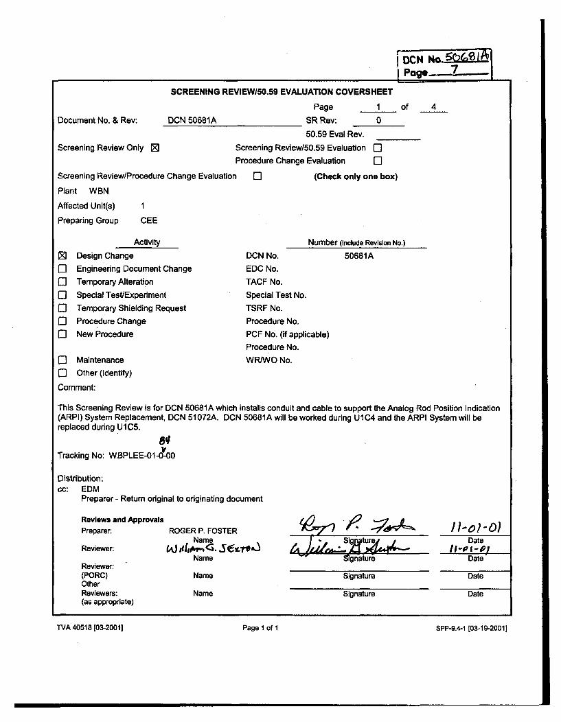
SCREENING REVIEWI50.59 EVALUATION COVERSHEET
Page 1 of 4Document No. & Rev: DCN 50681A SR Rev: 0
50.59 Eval Rev.
Screening Review Only 0 Screening Review/50.59 Evaluation 0"Procedure Change Evaluation El
Screening Review/Procedure Change Evaluation El (Check only one box)
Plant WBN
Affected Unit(s) 1
Preparing Group CEE
Activity
[ Design Change
El Engineering Document Change
C] Temporary AlterationE] Special Test/Experiment
El Temporary Shielding RequestE] Procedure Change
E] New Procedure
0- Maintenance
E- Other (Identify)
Comment:
Number (Include Revision No.)
DCN No.
EDC No.
TACF No.
Special Test No.
TSRF No.
Procedure No.
PCF No. (if applicable)
Procedure No.
WRJWO No.
50681A
This Screening Review is for DCN 50681A which installs conduit and cable to support the Analog Rod Position Indication(ARPI) System Replacement, DCN 51072A. DCN 50681A will be worked during UIC4 and the ARPI System will bereplaced during U 1C5.
Tracking No: WBPLEE-01-0-00
Distribution:cc: EDM
Preparer - Return original to originating document
Reviews and ApprovalsPreparer:
Reviewer:
Reviewer:(PORC)OtherReviewers:(as appropriate)
i6vj ý op'?ROGER P. FOSTERNameNaeJ dIMViName
Name
Name
Signature
Signature
Signature
Date
Date
Date
Date
IVA 40518 [03-20011 Page 1 of 1 SPP-9.4-1 [03-19-2001]
TVA 40518 [03-2001] Page 1 of I SPP-9.4-1 [03-19-20011
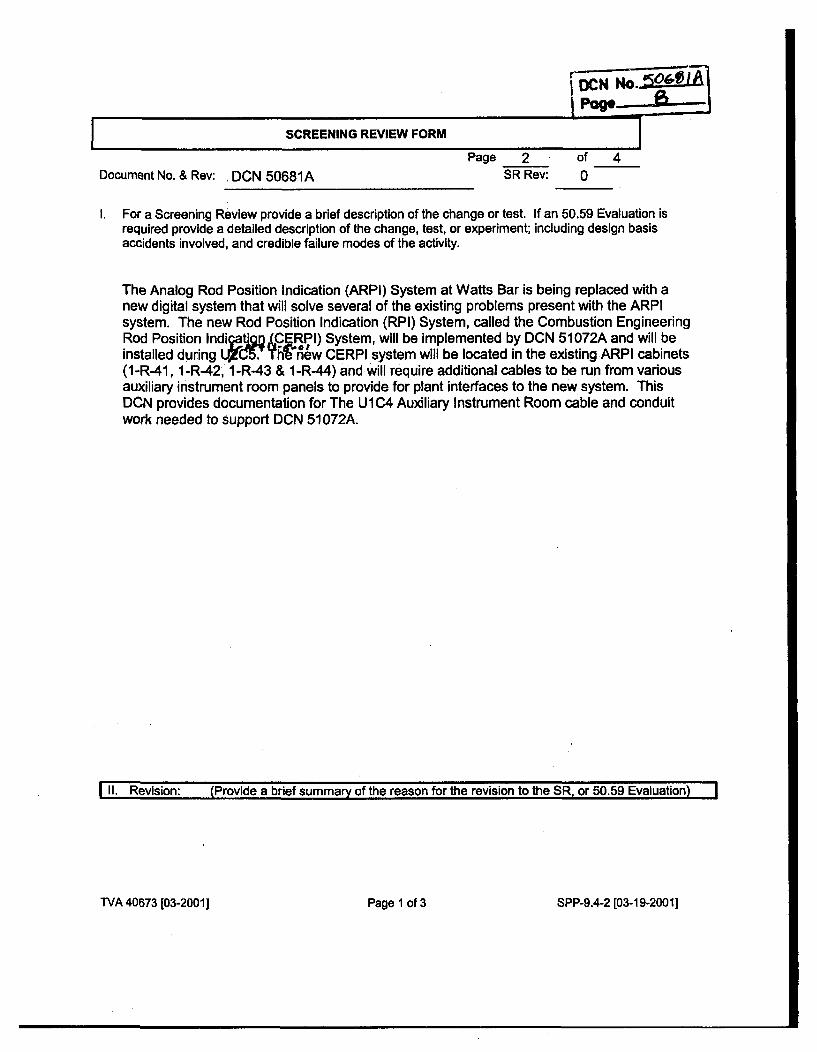
CD)CKN. rl ý1iIPoe-~-f-f-1
I SCREENING REVIEW FORM IPage 2
SR Rev:of 40Document No. & Rev: DCN 50681A
1. For a Screening Review provide a brief description of the change or test. If an 50.59 Evaluation isrequired provide a detailed description of the change, test, or experiment; including design basisaccidents involved, and credible failure modes of the activity.
The Analog Rod Position Indication (ARPI) System at Watts Bar is being replaced with anew digital system that will solve several of the existing problems present with the ARPIsystem. The new Rod Position Indication (RPI) System, called the Combustion EngineeringRod Position IndicatanD .CERPI) System, will be implemented by DCN 51072A and will beinstalled during LrC5. h= new CERPI system will be located in the existing ARPI cabinets(1-R-41, 1-R-42, 1-R-43 & 1-R-44) and will require additional cables to be run from variousauxiliary instrument room panels to provide for plant interfaces to the new system. ThisDCN provides documentation for The U1C4 Auxiliary Instrument Room cable and conduitwork needed to support DCN 51072A.
1II. Revision: (Provide a brief summary of the reason for the revision to the SR, or 50.59 Evaluation)
TVA 40673 [03-20011 Page I of 3 SPP-9.4-2 [03-19-2001]
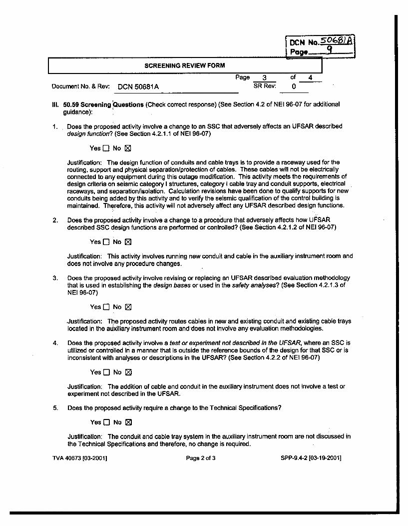
DC N0.0Q1
Page 3 of 4Document No. & Rev: DCN 50681A SR Rev: 0
II1. 50.59 Screening Questions (Check correct response) (See Section 4.2 of NEI 96-07 for additionalguidance):
1. Does the proposed activity involve a change to an SSC that adversely affects an UFSAR describeddesign function? (See Section 4.2.1.1 of NEI 96-07)
Yes [3 No 0D
Justification: The design function of conduits and cable trays is to provide a raceway used for therouting, support and physical separation/protection of cables. These cables will not be electricallyconnected to any equipment during this outage modification. This activity meets the requirements ofdesign criteria on seismic category I structures, category I cable tray and conduit supports, electricalraceways, and separation/isolation. Calculation revisions have been done to qualify supports for newconduits being added by this activity and to verify the seismic qualification of the control building ismaintained. Therefore, this activity will not adversely affect any UFSAR described design functions.
2. Does the proposed activity involve a change to a procedure that adversely affects how UFSARdescribed SSC design functions are performed or controlled? (See Section 4.2.1.2 of NEI 96-07)
Yes El No 0
Justification: This activity involves running new conduit and cable in the auxiliary instrument room anddoes not involve any procedure changes.
3. Does the proposed activity involve revising or replacing an UFSAR described evaluation methodologythat is used in establishing the design bases or used in the safety analyses? (See Section 4.2.1.3 ofNEI 96-07)
Yes El No 0
Justification: The proposed activity routes cables in new and existing conduit and existing cable trayslocated in the auxiliary instrument room and does not involve any evaluation methodologies.
4. Does the proposed activity involve a test or experiment not described in the UFSAR, where an SSC isutilized or controlled in a manner that is outside the reference bounds of the design for that SSC or isinconsistent with analyses or descriptions in the UFSAR? (See Section 4.2.2 of NEI 96-07)
Yes El No 0
Justification: The addition of cable and conduit in the auxiliary instrument does not involve a test orexperiment not described in the UFSAR.
5. Does the proposed activity require a change to the Technical Specifications?
Yes [- No Z
Justification: The conduit and cable tray system in the auxiliary instrument room are not discussed inthe Technical Specifications and therefore, no change is required.
TVA 40673 [03-20011 Page 2 of 3 SPP-9.4-2 [03-19-20011
SDCN NoCF
SCREENING REVIEW FORM I
Page 4SR Rev:
of 40Document No. & Rev: DCN 50681A
IV. If all questions are answered NO, then implement the activity per the applicable plant procedure forthe type of activity without obtaining a License Amendment.If screen question 5 is answered YES, then request and receive a License Amendment prior toimplementation of the activity.If screen question 5 is answered NO and question 1, 2, 3 or 4 is answered YES, then a 50.59Evaluation shall be performed.If only screen question 3 is answered YES, then only question 8 in the 50.59 Evaluation is required tobe answered.If screen question 3 is answered NO, then question 8 in the 50.59 Evaluation may be leftunanswered.
NOTE If an FSAR change is involved process that change per NADP-7, FSAR Management.
All questions, I through 5, were answered NO therefore, no 50.59 Evaluation is required.
V. List the documents (UFSAR, Technical Specifications, and other documents) reviewed where relevantinformation was found, including section numbers:
UFSAR sectionsitables reviewed:3.10.3 Methods of Qualifying TVA-Designed Supports for Electrical Equipment
Instrumentation and Cables8.3.1.4 Independence of Redundant AC Power Systems
Design Criteria reviewed:WB-DC-20-21.1WB-DC-30-22WB-DC-30-4WB.DC-40-31.10
Category I Cable Tray SupportsElectrical RacewaysSeparationllsolationSeismically Qualifying Conduit Supports
TVA 40673 103-2001 ] Page 3 of 3 SPP-9.4-2 [03-19-2001]
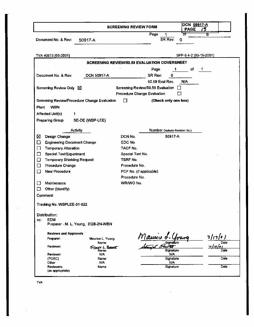
IDCN 50917-ASCREENING REVIEW FORM Pw G 7 II IPAE1 11
Page 1SR Rev:
or0Document No. & Rev: 50917-A
TVA 40673 103-20011 SPP-9.4-2 [03-19-20011
SCREENING REVIEW/50.59 EVALUATION COVERSHEET
Page I of 1
Document No. & Rev: DCN 50917-A
Screening Review Only 0
Screening Review/Procedure Change Evaluation
Plant WBN
Affected Unit(s) 1
Preparing Group SE-DE (WBP-LEE)
SR Rev: 0
50.59 Eval Rev. NIA
Screening Review150.59 Evaluation Dl
Procedure Change Evaluation ElEl (Check only one box)
Number (Include Revision No.)
E]0l1:1El
Activity
Design Change
Engineering Document Change
Temporary AlterationSpecial Test/Experiment
Temporary Shielding Request
Procedure Change
New Procedure
DCN No.EDC No.
TACF No.Special Test No.TSRF No.
Procedure No.
PCF No. (if applicable)Procedure No.
WR/WO No.
50917-A
El MaintenanceEl Other (Identify)
Comment:
Tracking No. WBPLEE-01-022
Distribution:cc: EDM
Preparer - M. L. Young, EQB-2N-WBN
Reviews and Approvals
Preparer
Reviewer:
Reviewer:(PORC)OtherReviewers:(as appropriate)
/flaAAM 4f U4419srMaurice L. YoungName
6jKg L. ?AfrrNameN/A
NameN/A
Name
Signalirei
SignatureN/A
Date"7/I 60 /•
Date
Date
Date
SignatureN/A
Signature
TVA
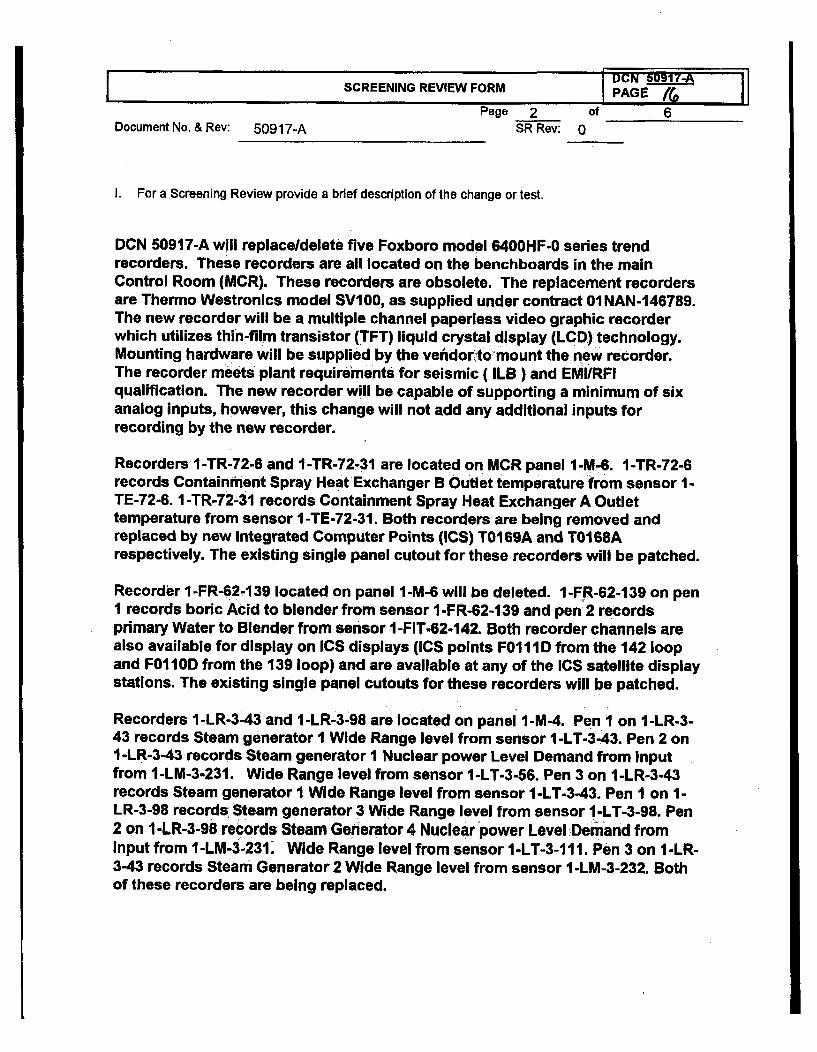
DUN 5I1ISCREENING REVIEW FORM PAGE /& 1
Page 2 of 6Document No. & Rev: 50917-A SR Rev: 0
I. For a Screening Review provide a brief description of the change or test.
DCN 50917-A will replaceldelete five Foxboro model 6400HF-0 series trendrecorders. These recorders are all located on the benchboards in the mainControl Room (MCR). These recorders are obsolete. The replacement recordersare Thermo Westronics model SV100, as supplied under contract 01NAN-146789.The new recorder will be a multiple channel paperless video graphic recorderwhich utilizes thin-film transistor (TFT) liquid crystal display (LCD) technology.Mounting hardware will be supplied by the vendor to mount the new recorder.The recorder meets plant requirements for seismic ( ILB ) and EMI/RFIqualification. The new recorder will be capable of supporting a minimum of sixanalog Inputs, however, this change will not add any additional inputs forrecording by the new recorder.
Recorders I-TR-72-6 and I-TR-72-31 are located on MCR panel 1-M-6. I-TR-72-6records Containment Spray Heat Exchanger B Outlet temperature from sensor 1-TE-72-6. 1-TR-72-31 records Containment Spray Heat Exchanger A Outlettemperature from sensor 1-TE-72-31. Both recorders are being removed andreplaced by new Integrated Computer Points (ICS) T0169A and T0168Arespectively. The existing single panel cutout for these recorders will be patched.
Recorder I-FR-62-139 located on panel 1-M-6 will be deleted. 1-FR-62-139 on penI records boric Acid to blender from sensor I-FR-62-139 and pen 2 recordsprimary Water to Blender from sensor I -FIT-62-142. Both recorder channels arealso available for display on ICS displays (ICS points F0I ID from the 142 loopand F011OD from the 139 loop) and are available at any of the ICS satellite displaystations. The existing single panel cutouts for these recorders will be patched.
Recorders 1-LR-3-43 and 1-LR-3-98 are located on panel 1-M-4. Pen I on I-LR-3-43 records Steam generator I Wide Range level from sensor I -LT-3-43. Pen 2 onI-LR-3-43 records Steam generator I Nuclear power Level Demand from Inputfrom 1-LM-3-231. Wide Range level from sensor 1-LT-3-56. Pen 3 on 1-LR-3-43records Steam generator I Wide Range level from sensor 1-LT-3-43. Pen I on 1-LR-3-98 records, Steam generator 3 Wide Range level from sensor I-LT-3-98. Pen2 on I -LR-3-98 records Steam Generator 4 Nuclear power Level Demand frominput from 1I-LM-3-231. Wide Range level from sensor I-LT-3-111. Pen 3 on I-LR-3-43 records Steam Generator 2 Wide Range level from sensor I -LM-3-232. Bothof these recorders are being replaced.
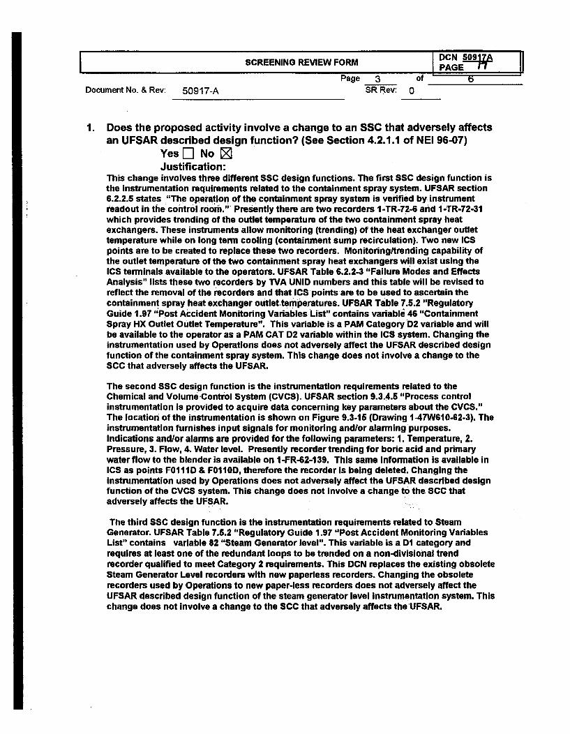
SCREENING REVIEW FORM P DCN 5AF _IPAGE 17 11
Page 3 ofDocument No. & Rev: 50917-A SR Rev: 0
1. Does the proposed activity involve a change to an SSC that adversely affectsan UFSAR described design function? (See Section 4.2.1.1 of NEI 96-07)
Yes [] No M
Justification:This change involves three different SSC design functions. The first SSC design function isthe instrumentation requirements related to the containment spray system. UFSAR section6.2.2.5 states "The operation of the containment spray system is verified by instrumentreadout in the control room." Presently there are two recorders 1-TR-72-6 and 1-TR-72-31which provides trending of the outlet temperature of the two containment spray heatexchangers. These instruments allow monitoring (trending) of the heat exchanger outlettemperature while on long term cooling (containment sump recirculation). Two new ICSpoints are to be created to replace these two recorders. Monitoringltrending capability ofthe outlet temperature of the two containment spray heat exchangers will exist using theICS terminals available to the operators. UFSAR Table 6.2.2-3 "Failure Modes and EffectsAnalysis" lists these two recorders by TVA UNID numbers and this table will be revised toreflect the removal of the recorders and that ICS points are to be used to ascertain thecontainment spray heat exchanger outlet temperatures. UFSAR Table 7.5.2 "RegulatoryGuide 1.97 "Post Accident Monitoring Variables List" contains variable 46 "ContainmentSpray HX Outlet Outlet Temperature". This variable is a PAM Category D2 variable and willbe available to the operator as a PAM CAT D2 variable within the ICS system. Changing theinstrumentation used by Operations does not adversely affect the UFSAR described designfunction of the containment spray system. This change does not involve a change to theSCC that adversely affects the UFSAR.
The second SSC design function is the instrumentation requirements related to theChemical and VolumeControl System (CVCS). UFSAR section 9.3.4.5 "Process controlinstrumentation is provided to acquire data concerning key parameters about the CVCS."The location of the instrumentation is shown on Figure 9.3-15 (Drawing 1-47W610-62-3). Theinstrumentation furnishes input signals for monitoring andlor alarming purposes.Indications andlor alarms are provided for the following parameters: 1. Temperature, 2.Pressure, 3. Flow, 4. Water level. Presently recorder trending for boric acid and primarywater flow to the blender is available on 1-FR-62-139. This same Information is available inICS as points F0111D & F0110D, therefore the recorder is being deleted. Changing theinstrumentation used by Operations does not adversely affect the UFSAR described designfunction of the CVCS system. This change does not involve a change to the 8CC thatadversely affects the UFSAR.
The third SSC design function is the instrumentation requirements related to SteamGenerator. UFSAR Table 7.5.2 "Regulatory Guide 1.97 "Post Accident Monitoring VariablesList" contains variable 82 "Steam Generator level". This variable is a D1 category andrequires at least one of the redundant loops to be trended on a non-divisional trendrecorder qualified to meet Category 2 requirements. This DCN replaces the existing obsoleteSteam Generator Level recorders with new paperless recorders. Changing the obsoleterecorders used by Operations to new paper-less recorders does not adversely affect theUFSAR described design function of the steam generator level instrumentation system. Thischange does not involve a change to the SCC that adversely affects the UFSAR.
I
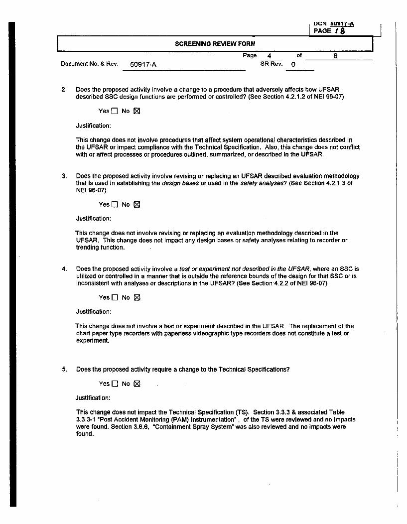
UGN 50917-A
IPAGE I a8
SCREENING REVIEW FORM I
Page 4 of 6Document No. & Rev: 50917-A SR Rev: 0
2. Does the proposed activity involve a change to a procedure that adversely affects how UFSAR
described SSC design functions are performed or controlled? (See Section 4.2.1.2 of NEI 96-07)
Yes Ej No 9
Justification:
This change does not involve procedures that affect system operational characteristics described inthe UFSAR or impact compliance with the Technical Specification. Also, this change does not conflictwith or affect processes or procedures outlined, summarized, or described in the UFSAR.
3. Does the proposed activity involve revising or replacing an UFSAR described evaluation methodologythat Is used In establishing the design bases or used in the safety analyses? (See Section 4.2.1.3 ofNEI 96-07)
Yes [] No [
Justification:
This change does not involve revising or replacing an evaluation methodology described in theUFSAR. This change does not impact any design bases or safety analyses relating to recorder ortrending function.
4. Does the proposed activity involve a test or experiment not described in the UFSAR, where an SSC isutilized or controlled in a manner that is outside the reference bounds of the design for that SSC or isInconsistent with analyses or descriptions in the UFSAR? (See Section 4.2.2 of NEI 96-07)
YesE] No Z
Justification:
This change does not involve a test or experiment described in the UFSAR. The replacement of thechart paper type recorders with paperless videographic type recorders does not constitute a test orexperiment.
5. Does the proposed activity require a change to the Technical Specifications?
Yes El No ER
Justification:
This change does not impact the Technical Specification (TS). Section 3.3.3 & associated Table3.3.3-1 "Post Accident Monitoring (PAM) Instrumentation", of the TS were reviewed and no Impactswere found. Section 3.6.6, "Containment Spray System" was also reviewed and no impacts werefound.
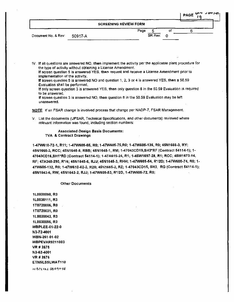
Page 5Document No. & Rev: 50917-A SR Rev: 0
6
IV. If all questions are answered NO, then implement the activity per the applicable plant procedure forthe type of activity without obtaining a License Amendment.If screen question 5 is answered YES, then request and receive a License Amendment prior toimplementation of the activity.If screen question 5 is answered NO and question 1, 2, 3 or 4 is answered YES, then a 50.59Evaluation shall be performed.If only screen question 3 is answered YES, then only question 8 in the 50.59 Evaluation is requiredto be answered.If screen question 3 is answered NO, then question 8 in the 50.59 Evaluation may be leftunanswered.
NOTE If an FSAR change is involved process that change per NADP-7, FSAR Management.
V. List the documents (UFSAR, Technical Specifications, and other documents) reviewed whererelevant information was found, including section numbers:
Associated Design Basis Documents:TVA & Contract Drawings
1-47W610-72-1, R11; 1-47W605-55, RO; 1-47W605-75,RO; 1-47W606-136, RO; 45N1666-3, RY;
45N1665-3, RCC; 45N1645-8, RBB; 45N1645-1, RM; 1-47043CD19,SH3*RF (Contract 54114-1); 1-
47043CD16,SHI*RD (Contract 54114-1); 1-47A615-24, RI; 1-45W1697-28, RI; RCC; 45W1673-14,
RF; 47A348-290, R*14; 45N1645-6, RJJ; 45N1645-3, RHH; 1-47W605-54, R* 1-47W605-74, RO; 1-
47W605-132, R0; 1-47W610-62-3, R20; 45N1665-2, RZ; 1-47043CD15, SH3, RG (Contract 54114-1);
45N1643-6, RW; 45N1643-2, RJJ; 1-47W605-53, R*12D, 1-47W605-72, RO;
Other Documents
1L0030098, R3
1L0030111, R3
1T0720006, R0
1T0720031, RO
1L0030043, R3
1L0030056, R3WBPLEE-01-22-0N3-72-4001WBN-261-01-02WBPEVAR9211003VR # 2678N3-62-4001VR # 2676ETNSLSSLWAT110
'/J FI VA 4 i3B 01 Z)'4
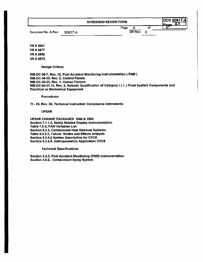
I SCREENING REVIEW FORMI
DCN 50917-A ISoo
of ____jPage 6SR Rev:Document No. & Rev: 50917-A 0
VR # 2681VR # 2677VR # 2682VR # 2672
Design Criteria
WB-DC-30-7, Rev. 12, Post Accident Monitoring Instrumentation ( PAM)WB-DC-30-20, Rev. 2, Control PanelsWB-DC-30-23, Rev. 1, Human FactorsWB-DC-40-31.13, Rev. 4, Seismic Qualification of Category I ( L) Fluid System Components andElectrical or Mechanical Equipment
Procedures
TI - 49, Rev. 26, Technical Instruction Compliance Instruments
UFSAR
UFSAR CHANGE PACKAGES 1680 & 1684Section 7.1.1.2, Safety Related Display InstrumentationTable 7.5-2, PAM Variables ListSection 6.2.2, Containment Heat Removal SystemsTable 6.2.2-3, Failure Modes and Effects AnalysisSection 9.3.4.2 System Description for CVCSSection 9.3.4.5, Instrumentation Application CVCS
Technical Specifications
Section 3.3.3, Post Accident Monitoring (PAM) InstrumentationSection 3.6.6, Containment Spray System
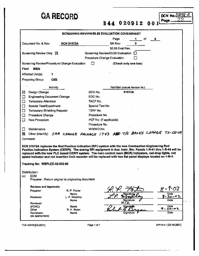
QA RECORD0 0 1 P" 2B44 020912
SCREENING REVIEWI5O.59 EVALUATION COVERSHEET
Document No. & Rev: DCN 51072A
Page 1 of 6
SR Rev: 0
50.59 Eval Rev.
Screening Review Only Z
Screening Review/Procedure Change Evaluatio
Plant WBN
Affected Unit(s) I
Preparing Group CEE
Activity
[ Design Change
C] Engineering Document Change
El Temporary Alteration
El Special Test/Experiment0I Temporary Shielding Request
El Procedure Change
0l New Procedure
Screening Review/50.59 Evaluation E]Procedure Change Evaluation El
n 0l (Check only one box)
Number (Indude Revision No.)
DCN No.
EDC No.
TACF No.
Special Test No.TSRF No.
Procedure No.
PCF No. (if applicable)
Procedure No.
WR/WO No.
51072A
El MaintenanceN Other(ldentify) SP'R C-Hi4&iE MArc*,G 17#/3 A*W "r/, 5As c-i r"6- 7.-02-o?
Comment:
DCN 51072A replaces the Rod Position Indication (RPI) system with the new Combustion Engineering RodPosition Indication System (CERPI). The analog RPI equipment In Aux. Instr. Rm. Panels 1-R-41 thru 1-R-44 will bereplaced with the new PLC based CERPI system. The main control room (MCR) Indicators, rod drop lights, rodspeed indicator and rod insertion limit recorder will be replaced with two flat panel displays located on I -M-4.
Tracking No: WBPLEE-02-052-00
Distribution:cc: EDM
Preparer - Return original to originating document
Reviews and ApprovalsPreparer R. P. Foster
NameReviewer.
Reviewer(PORC)OtherReviewers:(as appropriate)
L. P. WoodleyName
NameR. H. Bryan
Name
.Zloty Si t
S' n ure irl
?-D2Date
Date
DateDate
Signature f
WA 40518 [03-2001] Page 1 of I SPP-9.4-i [03-19-2001]
TVA 40518 [03-2001] Page 1 of 1 SPP-9.4-1 [03-19-20011
SCREENING REVIEW FORM l
Page 2 of 6Document No. & Rev: DCN 51072A SR Rev: 0
1. For a Screening Review provide a brief description of the change or test. If an 50.59 Evaluation isrequired provide a detailed description of the change, test, or experiment; including design basisaccidents involved, and credible failure modes of the activity.
This DCN will replace the Analog Rod Position Indication (RPI) System in Auxiliary InstrumentRoom panels 1 -R-41, -42, -43, & .44. The present RPI system has experienced problems withdetector non-linearity, detector steady-state thermal dependence and electro-magneticcoupling to nearby detectors. Reducing or eliminating these problems will ensure compliancewith the technical specification accuracy requirement across the entire operating range.
All analog signal processing equipment associated with the RPI system in the AuxiliaryInstrument Room racks and Indicators in the Main Control Room (MCR) will be replaced withnew up-to-date equipment from Westinghouse Nuclear Automation (WNA). The NewWestinghouse system is called the Combustion Engineering Rod Position Indication (CERPI)System. The new CERPI system will also replace the Rod Insertion Limit Monitoring (RIL)equipment and the Bank D Withdrawal Limit equipment in 1-R-25. The only control functionperformed by the CERPI system is the blocking of automatic rod movement when the Bank DWithdrawal Limit has been reached. The rod position Indication portion of system 85 is non-safety related.
The existing rod position detectors and associated field cabling will remain Intact. The MCRIndicators, rod bottom lights and rod speed Indicator on 1-M-4 will be replaced with tworedundant LCD flat panel displays. The RPI processing equipment will be upgraded to PLCbased controllers and new detector Interface boards will be installed. The new system willInclude a maintenance terminal In one of the Auxiliary Instrument Room racks for accessingsystem diagnostics, ease of maintenance, and calibration access. The new system will alsoinclude a Rod Drop Test Computer which will capture rod drop times following'a reactor trip inaddition to the periodic rod drop testing required by plant Technical Specifications.
The new CERPI system MCR monitors will display the position of each rod in numeric and/orbar format, rod drop Indication, rod insertion limit monitoring Information, rod movementdemand, rod speed, various rod position alarms and CERPI system trouble alarms. The rodInsertion limit monitoring and bank D withdrawal limit equipment in 1-R-25 will be abandonedIn place and the RIL recorder on I -M-23A will be deleted.
The existing 57 analog Inputs into the Integrated Computer System (ICS) for rod position willbe deleted and a data-link installed to receive data digitally. Inputs from rod control logic rack1-R-25 for rod speed and rod demand signals will be required by the new system. Additionally,reactor trip signals (Train A & B) from 1-R-58 will be required for the CERPI rod drop testcomputer.
TVA 40673 [03-20011 Page 1 of 3 SPP-9.4-2 [03-19-2001]
SCREENING REVIEW FORM
Page 3 of 6Document No. & Rev: DCN 51072A SR Rev: 0
The UFSAR is being revised to remove reference to the individual rod position Indicators, rodbottom bistables and rod bottom lights (Sections 7.7.1, 7.7.2 and 15.2.3). The TechnicalSpecifications (TIS) Bases and UFSAR are both being revised to correct the sections listingthat each bank of rods is divided into two groups (T/S Bases SectionsB3.1.5, B3.1.6, B3.1.7,B3.1.8 and UFSAR Section 15.2.3)., This statement is Incorrect since shutdown banks C and Dhave only one group each while all other banks have two groups each.
1II. Revision: (Provide a brief summary of the reason for the revision to the SR, or 50.59 Evaluation)
TVA 40673 [03-20011 Page I of 3 SPP-9.4-2 [03-19-2001]
SCREENING REVIEW FORM IPage 4 of 6
Document No. & Rev: DCN 51072A SR Rev: 0
III. 50.59 Screening Questions (Check correct response) (See Section 4.2 of NEI 96-07 for additionalguidance):
1. Does the proposed activity involve a change to an SSC that adversely affects an UFSAR described
design function? (See Section 4.2.1.1 of NEI 96-07)
Yes ] No 0
Justification:The design functions of the Rod Position Indication System are to sense the actual position of eachcontrol and shutdown rod and display that information to the operator. This system also suppliessignals used to determine rod deviations. The design function of the Rod Insertion Limit Monitor is toalert the operator when one or more control bank rods approach excessive rod insertion. The newCERPI system will use the same detectors as the old RPI system but it will calculate a more accuraterod position from the detector signal. The calculation of the rod insertion limits by the CERPI systemwill be performed using exact values from the ICS computer instead of using the output of a pulse-to-analog converter. The UFSAR does not describe in detail the method in which these design functionsare to be performed and since the CERPI system methods provide more accurate and reliable results,this modification does not adversely affect the above listed design functions.
2. Does the proposed activity involve a change to a procedure that adversely affects how UFSARdescribed SSC design functions are performed or controlled? (See Section 4.2.1.2 of NEI 96-07)
Yes[] No 0
Justification:The design functions of the Rod Position Indication System and the Rod Insertion Limit Monitor listedabove will be performed by the new CERPI system. Procedures for the RPI system are not specificallydetailed in the UFSAR such that the change to the CERPI system would have an adverse affect. It willactually enhance the RPI system since the CERPI system Is a more accurate and reliable system.Therefore, no procedure changes that could adversely affect how a UFSAR described design functionis performed or controlled will be required by this modification.
3. Does the proposed activity involve revising or replacing an UFSAR described evaluation methodologythat is used in establishing the design bases or used in the safety analyses? (See Section 4.2.1.3 ofNEI 96-07)
Yes [I No 0
Justification:This activity does not revise or replace any evaluation methodology described in the UFSAR.
TVA 40673 [03-20011 Page 2 of 3 SPP-9.4-2 [03-19-2001]
DC eN o. 5J079a
SCREENING REVIEW FORM
Page 5 of 6Document No. & Rev: DCN 51072A SR Rev: 0
4. Does the proposed activity involve a test or experiment not described In the UFSAR, where an SSCis utilized or controlled in a manner that is outside the reference bounds of the design for that SSC oris inconsistent with analyses or descriptions in the UFSAR? (See Section 4.2.2 of NEI 96-07)
Yes 0] No 0o
Justification:This activity does not involve a test or experiment that is not described in the UFSAR.
5. Does the proposed activity require a change to the Technical Specifications?
Yes [-] No 0
Justification:The surveillance requirements listed in the Technical Specifications for the RPI system and RodInsertion Limit Monitor will be maintained by the new CERPI system and do not require any changesto the Technical Specifications.
TVA 40673 [03-2001] Page 2 of 3 SPP-9.4-2 [03-19-20011
I IDCSCREENING REVIEW FORM1
Page 6 of 6Document No. & Rev: DCN 51072A SR Rev: 0
IV. If all questions are answered NO, then implement the activity per the applicable plant procedure forthe type of activity without obtaining a License Amendment.If screen question 5 is answered YES, then request and receive a License Amendment prior toimplementation of the activity.If screen question 5 is answered NO and question 1, 2, 3 or 4 is answered YES, then a 50.59Evaluation shall be performed.If only screen question 3 is answered YES, then only question 8 in the 50.59 Evaluation is required tobe answered.If screen question 3 is answered NO, then question 8 in the 50.59 Evaluation may be leftunanswered.
NOTE If an FSAR change Is involved process that change per NADP-7, FSAR Management.
All questions, I through 5, were answered NO therefore, no 50.59 Evaluation is required.
V. List the documents (UFSAR, Technical Specifications, and other documents) reviewed where relevantinformation was found, including section numbers:
UFSAR sectionsltables reviewed:3.1.2.2 Protection by Multiple Fission Product Barriers3.1.2.3 Protection and Reactivity Control Systems4.2.3 Reactivity.Control System7.7.1.3 Plant Control Signals for Monitoring and Indicating7.7.2 Analysis15.2.3 Rod Cluster Control Assembly Misalignment15.3.1 Single Rod Cluster Control Assembly at Full Power15.3.6.1 Identification of Causes and Accident Description
Tech Spec/Tech Spec Bases sections reviewed:3.1.51B3.1.5 Rod Group Alignment Limits3.1.61B3.1.6 Shutdown Bank Insertion Limits3.1 .7/B3.1.7 Control Bank Insertion Limits3.11.81B3.1.8 Rod Position Indication
Technical Requirements Manual (TRM) I TRM Bases sections reviewed:TR 3.1.7113.1.7 Position Indication'System, Shutdown
System Description reviewed:N3-85-4003 Control Rod Drive System
TVA 40673 [03-2001] Page 3 of 3 SPP-9.4-2 [03-19-2001]
DCN 51310-APAGE 10
SCREENING REVIEWISO.59 EVALUATION COVERSHEET
Document No. & Rev: DCN 51310-APage 1 of
SR Rev: 0
50.59 Eval Rev.
Screening Review/50.59 Evaluation fiProcedure Change Evaluation El
DI (Check only one box)
I
Screening Review Only 0
Screening Review/Procedure Change Evaluation
Plant WBN
Affected Unit(s) 1
Preparing Group Design Engr / I & C
LIElCLIILIIC
Activity
Design ChangeEngineering Document Change
Temporary Alteration
Special Test/Experiment
Temporary Shielding Request
Procedure Change
New Procedure
DCN No.
EDC No.
TACF No.
Special Test No.
TSRF No.
Procedure No.
PCF No. (if applicable)
Procedure No.
WR/WO No.
Number (Include Revision No.)
51310-A
E] MaintenanceEl Other (Identify)Comment:WBPLEE-02-060-0
Distribution:cc: EDM
Preparer - Return original to originating document
Reviews and ApprovalsPreparer:
Reviewer:
Reviewer:(PORC)OtherReviewers:(as appropriate)
C. C. LykeName
5rA1"SV L.?"MASr-NameMAM
Name
NameName
Ce. e.-
SignatureNIA,
Signature
Signature
Date
Date
Date
Date
TVA 40618 [03-20011 Page 1 of 1 SPP-9.4-1 [03-19-20011
TVA 40518 [03-20011 Page I of I SPP-9.4-1 [03-19-20011
DCN 51310-APage
SCREENING REVIEW FORM I
Page 1 of NADocument No. & Rev: DCN 51310-A SR Rev: 0
I. For a Screening Review provide a brief description of the change or test. If an 50.59 Evaluation isrequired providewa detailed description of the change, test, or experiment; Including design basisaccidents involved, and credible failure modes of the activity.
DCN 51310-A will replace four Hagan Controls model Optimac 100 recorders in the Main ControlRoom (MCR) on panel 1-M-4. UNID's for the recorders are 1-FR-003-0035, 1-FR-003-0048, 1-FR-003-0090, and 1-FR-003-0103. These recorders are obsolete.
There is one recorder on panel 1-M-4 for each of the four steam generator loops. Each recorder hasthree inputs to monitor feedwater flow, main steam header flow, and steam generator level for itsassociated steam generator loop.
The replacement recorders are Thermo Westronics model SV1 00, as supplied under contract 01 NAN-146789. The new'recorders will be multiple channel paperless video graphic recorders which utilizethin-film transistor (TFT) liquid crystal display (LCD) technology. The recorders meet plantrequirements for EMI/RFI qualification. The new recorders will be capable of supporting a minimum ofsix analog inputs, however, this change will not add any additional inputs for recording by the newrecorders. The new recorders will be located on the same panels and use the same panel cutoutsand cabling as the existing recorders.
DCN 51310-A will be staged in four stages to correlate with each of the four steam generator loops.Stage 01 is for steam generator loop 1Stage 02 is for steam generator loop 2Stage 03 is for steam generator loop 3Stage 04 is for steam generator loop 4
I II. Revision: (Provide a brief summary of the reason for the revision to the SR. or 50.59 Evaluation) IE
TVA 40673 [03-20011 Page 1 of 3 SPP-9.4-2 [03-19-2001]
D CN 51310-APage 1
SCREENING REVIEW FORMIPage 2 of NA
Document No. & Rev: DCN 51310-A SR Rev: 0
III. 50.59 Screening Questions (Check correct response) (See Section 4.2 of NEI 96-07 for additionalguidance):
1. Does the proposed activity involve a change to an SSC that adversely affects an UFSAR describeddesign function? (See Section 4.2.1.1 of NEI 96-07)
Yes E] No 0
Justification:The design function of the main steam supply system is to conduct steam from the steam generatoroutlets to the high pressure turbine and to the condenser steam dump system. This system alsosupplies steam to the feedwater pump turbines, an auxiliary feedwater pump turbine, moisture-separator reheaters, and the turbine seals.
The design function of the feedwater system is to supply a sufficient quantity of feedwater to thesteam generator secondary side inlet during all normal operating conditions and to guarantee thatfeedwater will not be delivered to the steam generators when feedwater Isolation is required.
The design function of Post Accident Monitoring (PAM) instrumentation Is to monitor plant andenvirons conditions during and following design basis Condition II, Ill, and IV faults.
A recorder to record feedwater flow, main steam header flow, and steam generator level for itsassociated steam generator loop is not required for the main steam supply system and feedwatersystem to perform their design functions. A recorder is required to trend PAM variable steamgenerator level narrow range. Pen 3 on each steam generator loop recorder provides the trendcapability for this variable.
The replacement of these obsolete recorders with current generation video graphic recorders underDCN 51310-A is considered "like for like' replacements so there are no changes in the function ofdevices that are replaced and no changes in the SSC in which they operate.
Therefore, this change does not involve a change to the SSC that adversely affects UFSAR section7.5.1, Post Accident Monitoring Instrumentation ( PAM ), section 10.3, Main Steam Supply System,or section 10.4.7, Condensate and Feedwater Systems.
FCN 51310-APage 11
2. Does the proposed activity involve a change to a procedure that adversely affects how UFSAR
described SSC design functions are performed or controlled? (See Section 4.2.1.2 of NEI 96-07)
Yes [] No [
Justification:
The design function of the main steam supply system is to conduct steam from the steam generatoroutlets to the high pressure turbine and to the condenser steam dump system. This system alsosupplies steam to the feedwater pump turbines, an auxiliary feedwater pump turbine, moisture-separator reheaters, and the turbine seals.
The design function of the feedwater system, Is to supply a sufficient quantity of feedwater to thesteam generator secondary side iniet during all normal operating conditions and to guarantee thatfeedwater will not be delivered to the steam generators when feedwater isolation is required.
The design function of Post Accident Monitoring (PAM) instrumentation is to monitor plant andenvirons conditions during and following design basis Condition II, Ill, and IV faults.
This change does not involve procedures that affect system operational characteristics described inthe UFSAR or Impact compliance with the Technical Specification. Also, this change does not conflictwith or affect processes or procedures outlined, summarized, or described in the UFSAR.
3. Does the proposed activity involve revising or replacing an UFSAR described evaluation methodologythat Is used in establishing the design bases or used in the safety analyses? (See Section 4.2.1.3 ofNEI 96-07)
Yes l No [
Justification:
This change does not involve revising or replacing an evaluation methodology described in theUFSAR. This change does not impact any design bases or safety analyses relating to recorder ortrending function.
4. Does the proposed activity involve a test or experiment not described In the UFSAR, where an SSC isutilized or controlled in a manner that Is outside the reference bounds of the design for that SSC or isinconsistent with analyses or descriptions in the UFSAR? (See Section 4.2.2 of NEI 9W-07)
Yes EJ No Z
Justification:
This change does not involve a test or experiment described in the UFSAR. The replacement of thechart paper type recorders with paperless video graphic type recorders does not constitute a test orexperiment.
DCN 5131-A
5. Does the proposed activity require a change to the Technical Specifications?
Yes E] No 0
Justification:
This change does not Impact the Technical Specification (TS). Section 3.3.3, Post AccidentMonitoring ( PAM ) Instrumentation, section 3.7.1, Main Steam Safety Valves, section 3.7.2, MainSteam Isolation Valves, and section 3.7.3, Main Feedwater Isolation Valves and Main FeedwaterRegulation Valves and Associated Bypass Valves, of the TS were reviewed and no Impacts werefound.
TVA 40673 [03-20011 Page 2 of 3 SPP-9.4-2 [03-19-20011
DCN 51310-A IPage 15
SCREENING REVIEW FORM
Page ofDocument No. & Rev: DCN 51310-A SR Rev: 0
IV. If all questions are answered NO, then Implement the activity per the applicable plant procedure forthe type of activity without obtaining a License Amendment.If screen question 5 is answered YES, then request and receive a License Amendment prior toimplementation of the activity,.If screen question 5 is answered NO and question 1, 2, 3 or 4 Is answered YES, then a 50.59Evaluation shall be performed.If only screen question 3 is answered YES, then only question 8 In the 50.59 Evaluation is requiredto be answered.If screen question 3 is answered NO, then question 8 In the 50.59 Evaluation may be leftunanswered.
NOTE If an FSAR change is involved process that change per NADP-7, FSAR Management.
V. List the documents (UFSAR, Technical Specifications, and other documents) reviewed whererelevant Information was found, Including section numbers:
UFSAR Sections5.5.5 Steam Generators7.5.1 Post Accident Monitoring Instrumentation ( PAM)10.3 Main Steam Supply System10.4.7 Condensate and Feedwater Systems15.2.8 Loss of Normal Feedwater15.2.10 Excessive Heat Removal Due to Feedwater System Malfunctions15.2.13 Accidental Depressurization of the Main Steam System
Technical Specifications Sections3.3.3 Post Accident Monitoring ( PAM ) Instrumentation3.7.1 Main Steam Safety Valves3.7.2 Main Steam Isolation Valves3.7.3 Main Feedwater Isolation Valves and Main Feedwater Regulation Valves and Associated Bypass
Valves
TVA Drawings1-47W610-3-1B, Rev. 6 1-47W610-3-ID, Rev. 51-47W610-3-2A, Rev. 16 1-47W610-3-2C, Rev. 51-47W610-3-1, Rev. 26 1-47W610-3-1A, Rev. 61-47W610-1-1, Rev. 261-47W611-3-2, Rev. 191-47W605-53, Rev. 2 1-47W605-72, Rev. 11-47W605-117, Rev. 1 1-47W605-118, Rev. 21-47A605-194, Rev. */445N706-4, Rev. 1845N1643-1, Rev. JJ 45N1643-2, Rev. LL45N1643-6, Rev, Y 45N1643-8, Rev. T45N1665-2, Rev. AA
Contract 5411401 Drawina1-47043CD15 SHT 1, Rev. F
8C 1310-APage 16
System DescriptionN3-3A-4002, Rev. 8, "Main Feedwater, Feedwater Control and Injection Water"N3-1-4002, Rev. 9, "Main Steam System"
Desion CriteriaWB-DC-30-7, Rev. 15, "Post Accident Monitoring Instrumentation"
TVA 40673 [03-20011 Page 3 of 3 SPP-9.4-2 [03-19-20011
DCN 51368-APAGE I
SCREENING REVIEWI50.59 EVALUATION COVERSHEET
Page 1 of 5
Document No. & Rev: DCN 51368-A SR Rev: 0
50.59 Eval Rev.
Screening Review Only [ Screening Review/50.59 Evaluation ElProcedure Change Evaluation 1]
Screening Review/Procedure Change Evaluation 1] (Check only one box)
Plant WBN
Affected Unit(s) 1,2
Preparing Group Corporate Electrical Enginnering
Activity Number (Include Revision No.)
0 Design Change DCN No. 51368-A[ r Engineering Document Change EDC No.0I Temporary Alteration TACF No.
LI Special Test/Experiment Special Test No.LI Temporary Shielding Request TSRF No.EL Procedure Change Procedure No.0I New Procedure PCF No. (if applicable)
Procedure No.
El Maintenance WR/WO No.I Other (Identify) Technical Specification License Amendment Request WBN-TS-03-09
SAR Change Package # 1764
Comment WBPLEE-03-011-00This screening review is for DCN 51388-A which abandons the Unit 2 Vital Invrters In place. The Unit I and Unit 2 120VAC Vital Instrument Power Boards will be connected together on a per channel basis to allow the operation of oneInverter per channel. This change will facilitate the future replacement of the 120V AC Vital Inverters.
Distribution:cc: EDM
Preparer - Return original to originating document
Reviews and ApprovalsPreparar SHERMANDA SHELTON
ROGER P. FOSTER__Name Date
Reviewer: '@6tu eD
(PORC) Name Signature DateOtherReviewers: Name Signature Date(as appropriate)
WA 40518 (03.20011 Page 1 of I SPP-9.4-1 (03-19-2001]TVA 40518 [03-20011 Page I of' I SPP-9.4-1 (03-19-20011
DCN 511318-A6PAGE (
SCREENING REVIEW FORM IPage 2 of 5
Document No. & Rev: DCN 51368-A SR Rev: 0
I. For a Screening Review provide a brief description of the change or test. If an 50.59 Evaluation isrequired provide a detailed description of the change, test, or experiment; including design basisaccidents involved, and credible failure modes of the activity.
DCN 51368-A will facilitate the future replacement of the 120V AC Vital Inverters by making the followingchanges. Each channel of the Unit 2 120V AC Vital Instrument Power Boards will be disconnected fromits Unit 2 Vital Inverter and connected to the corresponding channel of the Unit 1 120 V AC Vital Inverter.The Unit 1 and Unit 2 Vital Instrument Power Boards on each channel will then be fed from only the Unit 1Vital Inverters. The Unit 2 Vital Inverter will be abandoned in place until it is replaced at a future time.This DCN also installs four (one per channel) 480V AC Vital Disconnect Panels that will allow the Unit 1120V AC Vital Inverters and the 125V DC Vital Chargers to be Individually isolated from the 480V AC VitalTransfer Bus. These new disconnect panels will be field located on the wall adjacent to the 480V AC VitalTransfer Switches on EL 772.0. The Unit 2 120V AC Vital Instrument Power Boards are lightly loaded(3 KVA or less) and will not tax the ability of the Unit I Vital Inverter to perform its intended safetyfunction. The load limit for each Unit 1 Vital Instrument Power Board has been reduced to 17 KVA or lesswhich ensures the maximum load on the Unit 1 Inverter will never exceed its rated value of 20 KVA.
This DCN will require a change to FSAR Sections 1.2.2, 8.1, 8.3, and various FSAR figures depicting theOnsite Power System (SAR Change Request 1764). These changes are required to accurately describeand show the new configuration which utilizes the four Unit I Vital Inverters and abandons the Unit 2 VitalInverters. A Tech Spec change and a Tech Spec Bases change will also be required for thismodification. A License Amendment Request (WBN-TS-03-09) to change the Tech Specs and TechSpec Bases has been prepared to update LCO 3.8.7 and Tech Spec Bases Sections 3.8.7 and 3.8.8. TheLicense Amendment will be received prior to implementation of this modification.
II. Revision: (Provide a brief summary of the reason for the revision to the SR, or 50.59 Evaluation)
TVA 40673 [03-20011 SPP-9.4-2 [03-19-2001]
DCN 61368-A
SCREENING REVIEW FORM 1Page 3 of 6
Document No. & Rev: DCN 61368-A SR Rev: 0
III. 50.69 Screening Questions (Check correct response) (See Section 4.2 of NEI 96-07 for additionalguidance):,
1. Does the proposed activity involve a change to an SSC that adversely affects an UFSAR describeddesign function? (See Section 4.2.1.1 of NEI 96-07)
Yes El No 0
Justification:
The design function of the 120-Vac vital power system Is to supply a continuous reliable source ofClass 1E, regulated, single phase, 120-Vac power for the operation of reactor protectioninstrumentation and control systems; engineered safety features Instrumentation and control'systems:and other safety-related components and systems.
The addition of the 480V AC Vital Disconnect Panel allows for isolation of the Unit 1 Inverter and VitalBattery Charger; This does not change the design function because the panels will be feeding thesame power to the same loads. The Disconnect Panel switches provide no automatic functions andmust be disconnected manually. Control of these switches will be administratively controlled throughprocedures and any loss of power to battery charger will be indicated by an alarm In the control room.The disconnection of the Unit 2 Inverters and the connection of the Unit 1 and Unit2 Vital InstrumentPower Boards together do not alter the design function of theSSC. Presently, the Unit I Inverterprovides normal power to the Unit I Instrument Power Board and the Unit 2 Inverter provides normalpower to the Unit 2 Instrument Power Board. If the Unit 1 Inverter lost power, the Unit 1 and Unit 2 VitalInstrument Power Boards could be switched to the alternate supply from the Instrument PowerDistulbution Panel. The Unit 2 board Is lightly loaded and the loads can be supplied by the Unit 1Inverter which will still maintain adequate margin. Under the modifications outlined in this DCN, foreach channel both the Unit I and Unit 2 Instrument Power Boards will be powered by the UnitInverter. The design function Is notadversely affected because with the two boards tied together, theUnit I Inverter Is the normal power supply and the Instrument Power Distribution Panel is the alternatepower supply.
2. Does the proposed activity involve a change to a procedure that adversely affects how UFSARdescribed SSC desIgn functions are performed or controlled? (See Section 4.2.112 of NEI 96-07)
Yes 0 No 0
Justification:
The design function of the 120-Vac vital power system Is to supply a continuous reliable source of ClassI E, regulated, single phase, 120-Vac power for the operation of essential systems. This modificationwill require revisions to annunciator response and operating procedures due to the deletion of the Unit 2Inverter, changes to the Unit 2 Instrument Power Board and the addition of the new disconnect panel.These procedure changes will not adversely affect how the 120-Vac vital power system design functionswill be performed or controlled.
TVA 40673 [03-2001] SPP-9.4-2 [03-19-2001]
DCN 51368-AflPAGE •-
SCREENING REVIEW FORMPage 4 of 5
Document No. & Rev: DCN 51368-A SR Rev: 0
III. 80.59 Screening Questions (Check correct response) (See Section 4.2 of NEI 96-07 for additionalguidance):
3. Does the proposed activity involve revising or replacing an UFSAR described evaluation methodologythat is used in establishing the design bases or used in the safety analyses? (See Section 4.2.1.3 of NEI96-07)
Yes[] No 0
Justification:
This modification changes the vital AC Inverter connection arrangement. The design function of the vitalAC inverters is to provide 120-Vac electrical power to I E equipment and this has not been changed.There are no changes associated with this modification that require UFSAR described evaluationmethodology to be revised or replaced.
4. Does the proposed activity involve a test or experiment not described In the UFSAR, where an SSC isutilized or controlled in a manner that is outside the reference bounds of the design for that SSC or isinconsistent with analyses or descriptions in the UFSAR? (See Section 4.2.2 of NEI 96-07)
Yes E] No 0
Justification:
There are no tests or experiments that are involved with this modification not addressed in the UFSAR.The design function for the 120-Vac vital power system is not being altered, nor is it being operatedoutside of the bounds presented in the UFSAR.
5. Does the proposed activity require a change to the Technical Specifications?
Yes 1@ No I]
Justification:
In accordance with the 50.90 process, a Technical Specification License Amendment Request (WBN-TS-03-09) has been prepared and the License Amendment will be received prior to implementing thismodification.
TVA 40673 (03-2001] SPP-9.4-2 [0349-20013
DCN 51-368APAGE I'S_
SCREENING REVIEW FORM
Page 5 of 5Document No. & Rev: DCN 51368-A SR Rev: 0
IV. If all questions are answered NO, then implement the activity per the applicable plant procedure forthe type of activity without obtaining a License Amendment.If screen question 5 is answered YES, then request and receive a License Amendment prior toimplementation of the activity.If screen question 5 is answered NO and question 1, 2, 3 or 4 is answered YES, then a 50,59Evaluation shall be performed.If only screen question 3 is answered YES, then only question 8 in the 50.59 Evaluation Is required tobe answered.If screen question 3 is answered NO, then question 8 In the 50.59 Evaluation may be leftunanswered.
NOTE If an FSAR change is involved process that change per NADP-7, FSAR Management.
V. List the documents (UFSAR, Technical Specifications, and other documents) reviewed where relevantinformation was found, Including section numbers:
SAR Sections Reviewed (Amendment 3):1.2.2 Facility Description3.1.2 WBNP Conformance with GDCs8.1 Introduction8.3 Onsite (Standby) Power System
Technical Specifications Sections Reviewed (Amendment 43):3.8 Electrical Power Systems
Technical Specifications Bases Sections Reviewed (Revision 55):B 3.6 Containment SystemsB 3.7 Plant SystemsB 3.8 Electrical Power Systems
Design Criteria Reviewed:WB-DC-30-27 R24 AC and DC Control Power Systems
TVA 40673 103-20011 SPP-9.4-2 [03-19-2001]
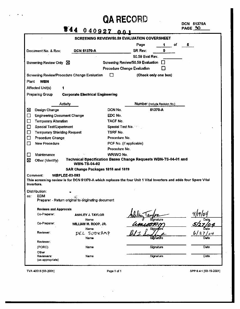
. I
QA RECORD1'44 040927 nnf
DCN 51370APAGE -W
SCREENING REVIEWlS0.59 EVALUATION COVERSHEET
Page 1 of 5
Document No. & Rev: DCN 51370-A SR Rev: 0
50.59 Eval Rev.
Screening Review Only 0 Screening Review/50.59 Evaluation ElProcedure Change Evaluation El
Screening Review/Procedure Change Evaluation El (Check only one box)
Plant WBN
Affected Unit(s) 1
Preparing Group Corporate Electrical Engineering
Activity Number (Include Revision No.)
Design Change DCN No. 51370-A
El Engineering Document Change EDC No.
El Temporary Alteration TACF No.
El Special Test/Experiment Special Test No.
El Temporary Shielding Request TSRF No.
o Procedure Change Procedure No.
El New Procedure PCF No. (if applicable)
Procedure No.
El Maintenance WRNVO No.
0 Other (Identify) Technical -Spectifcation Bases Change Requests WBN-TS-04-01 andWBN-TS-04-02
SAR Change Packages 1818 and 1819
Comment: WBPLEE-03-093This screening review is for DCN 51370-A which replaces the four Unit 1 Vital Inverters and adds four Spare VitalInverters.
Distribution:cc: EDM
Preparer - Return original to originating document
Reviews and Approvals
Co-Preparer:
Co-Preparer.
Reviewer:
Reviewer:
(PORC)
OtherReviewers:(as appropriate)
ASHLEY J. TAYLORName
WILLIAM M. ROOP, JR.Name
PCL sovieAm?Name
U Tgnatre Date
xIz71o %Date
Date
Date
SIignture
Name
Name
Signature
Signature
WA 40518(03-2001 Page 1 of 1 SPP-9.4-1 [03-19-2001]
"rVA 40518 [03-2001 ] Page I of 1 SPP-9.4-1 103-19-2001 ]
DCN 51370-APAGE '51
SCREENING REVIEW FORM
Page 2 of 5
Document No. & Rev: DCN 51370-A SR Rev: 0
I. For a Screening Review provide a brief description of the change or test. If an 50.59 Evaluation isrequired provide a detailed description of the change, test, or experiment; Including design basisaccidents involved, and credible failure modes of the activity.
DCN 51370A is the last phase of the Vital Inverter Replacement plan. The existing disconnected Unit 2Inverters will be replaced with uninterruptible power supply (UPS) systems which each include aregulated rectifier, auctioneering diodes, an inverter, and a regulated transformer bypass source. Astatic switch will automatically transfer the load from the inverter output to the regulated transformerbypass supply. This is alarmed in the Main Control Room. A manual bypass switch will allow manualtransfer to the regulated transformer bypass source for maintenance or until a Spare Inverter may bealigned. These UPS systems will become the new Unit 1 Inverters. The existing Unit I Inverters will bereplaced by new Inverters that will become Spare Inverters. They will each include a regulated rectifier,auctioneering diodes, and an inverter and will not have a regulated transformer bypass source, staticswitch, or manual bypass switch. These can be aligned manually and will be the new 1E alternatesource for the 120V AC Vital Instrument Power Boards. Since the Spare Inverters will be qualified
- uninterruptible power systems, they will meet the Technical Specifications requirements for an operableinverter on a channel when energized, aligned, and the surveillance requirement completed. The SpareInverters will be shared between units on each channel if Unit 2 is completed.
The Unit 1 and Unit 2 120V AC Vital Instrument Power Boards will continue to be fed from their normalpower supply, the Unit 1 Inverter on each channel. This eliminates the necessity of operating all eightinverters for operation of a single reactor unit. Existing cable and conduit will be used with splices asnecessary. New cable will be installed between the Vital Disconnect Panels and the new Unit 1 VitalInverter bypass transformer inputs to power the transformer. New cable will also be installed betweenthe new Unit I Inverters and the new Spare Inverters to provide a synchronization signal and paralleledannunciation.
This DCN will be implemented over the span of time prior to and during two outages. The first fourstages, for channels 1, 11, III, and IV respectively, include the changes made before and during the firstoutage period. This will indude physically removing the existing Unit 2 Inverters and replacing them withthe new Unit I Inverters with the regulated transformer bypass supply as well as electricallydisconnecting the existing old Unit I Inverters. The existing old Unit 1 Inverters may be physicallyremoved at this time. The last four stages, one each for channels I, II, 1II, and IV, correspond to thesecond outage period. If not already completed, this will include physically removing the old Unit 1Inverters. Then, in their place, the new Spare Inverters will be installed and will reflect the final proposedconfiguration.
Each outage period will require an FSAR and Technical Specification Bases change so the plant is not inan unapproved interim configuration. Each outage period will require a change to FSAR Section 8.3 andvarious FSAR figures depicting the Onsite Power System (SAR Change Requests 1818 and 1819).These changes are required to accurately describe and show the appropriate new configuration. TwoTechnical Specification Bases changes will also be required for this modification. Tech Spec BasesChange Requests (WBN-TS-04-01 and WBN-TS-04-02) to change the Tech Spec Bases have beenprepared to update Bases Sections 3.8.7, 3.8.8, and 3.8.9. FSAR Change Request 1818 and Tech SpecBases Change Requests WBN-TS-04-01 are tied to DCN stages 1 through 4. FSAR Change Request1819 and Tech Spec Bases Change Requests WBN-TS-04-02 are tied to DCN stages 5 through 8.
I1. Revision: (Provide a brief summary of the reason for the revision to the SR, or 50.59 Evaluation)Revision 0 - Initial Issue
TVA 40673 [03-2001] SPP-9.4-2 [03-19-2001]
DCN 51370-APAGE- Z.
SCREENING REVIEW FORM,
Page 3 of 5Document No. & Rev: DCN 51370-A SR Rev: 0
Ill. 50.59 Screening Questions (Check correct response) (See Section 4.2 of NEI 96-07 for additionalguidance):
1. Does the proposed activity involve a change to an SSC that adversely affects an UFSAR describeddesign function? (See Section 4.2.1.1 of NEI 96-07)
Yes El No ER
Justification:
The design function of the 120V AC Vital Power System is to supply a continuous reliable source of Class 1 E,regulated, single phase, 120V AC power for the operation of reactor protection instrumentation and controlsystems; engineered safety features instrumentation and control systems; and other safety-relatedcomponents and systems..
The function of the Inverters willnot change. They will continue to provide power to instrumentation thatsupports the Identification and mitigation of accidents as well as critical system control functions during normalplant operation. Replacing the existing Unit 1 Vital Inverters with new UPS systems including regulatedtransformers and static and manual transfer switches will enhance equipment reliability. The addition of aregulated transformer bypass source and the automatic static switch provides additional capability to supplyreliable power during maintenance and inverter failure to the Vital Instrument Power Boards and minimize thepotential for a unit trip. The ability to use qualified installed Spare Vital Inverters will allow better opportunitiesto properly maintain the Inverters and minimize the potential to require unit shutdown for an Inverter problem.This modification will meet or exceed the specifications and capabilities of the old system.
2. Does the proposed activity involve a change to a procedure that adversely affects how UFSARdescribed SSC design functions are performed or controlled? (See Section 4.2.1.2 of NEI 96-07)
Yes El No 0
Justification:
The design function of the 120V AC Vital Power System is to supply a continuous reliable source of Class 1 E,regulated, single phase, 120V AC power for the operation of essential systems. The annunciation signals fromthe Unit 1 Vital Inverters will now include a signal on automatic transfer of the static switch but otherwise willremain unchanged even though the physical location of the Unit 1 Vital Inverters will change. With theimplementation of this DCN, each Spare Vital Inverter's annunciation signals will be sent to the correspondingUnit 1 Inverter and then to Panel 1-M-21 in the Main Control Room, paralleled along with the annunciation forthe Unit I Vital Inverters. The newSpare Vital Inverters will become the alternate source for the 120V ACVital Instrument Power Boards and will be a qualified 1E uninterruptible power supply (UPS)., One of thealarm inputs for the Power Board undervoltage or breaker trip displays in window box 1-XA-55-1 C is thetransfer to the alternate source, presentfy a non safety related source. This alarm input will be removed sincethe alternate source is a qualified UPS and the alarm is no longer required. These changes do not after anymeans of performing or controlling the system design function arid do not create or modify any Operatoractions. This modification will not adversely affect how the 120V AC Vital Power System design functions willbe performed or controlled as described in the UFSAR.
This design change may require revisions to various plant procedures to reflect changes to plant hardware anddesign output documentation. Updating procedures to ensure they are consistent with this design change iswithin the scope of the analysis and will not adversely impact any SAR design functions.
TVA 40673 [03-2001 ] SPP-9.4-2 [03-19-20011
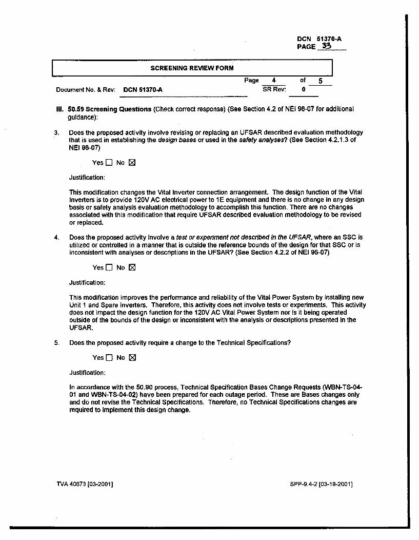
DCN 51370-APAGE 3-S
SCREENING REVIEW FORM IPage 4 of 5
Document No. & Rev: DCN 51370-A SR Rev: 0
II1. 60.59 Screening Questions (Check correct response) (See Section 4.2 of NEI 96-07 for additionalguidance):
3. Does the proposed activity involve revising or replacing an UFSAR described evaluation methodologythat is used in establishing the design bases or used in the safety analyses? (See Section 4.2.1.3 ofNEI 96-07)
Yes [] No [
Justification:
This modification changes the Vital Inverter connection arrangement. The design function of the VitalInverters is to provide 120V AC electrical power to 1 E equipment and there is no change in any designbasis or safety analysis evaluation methodology to accomplish this function. There are no changesassociated with this modification that require UFSAR described evaluation methodology to be revisedor replaced.
4. Does the proposed activity Involve a test or experiment not described in the UFSAR, where an SSC isutilized or controlled in a manner that is outside the reference bounds of the design for that SSC or isinconsistent with analyses or descriptions in the UFSAR? (See Section 4.2.2 of NEI 96-07)
Yes [] No [
Justification:
This modification improves the performance and reliability of the Vital Power System by installing newUnit 1 and Spare Inverters. Therefore, this activity does not involve tests or experiments. This activitydoes not impact the design function for the 120V AC Vital Power System nor is it being operatedoutside of the bounds of the design or inconsistent with the analysis or descriptions presented in theUFSAR.
5. Does the proposed activity require a change to the Technical Specifications?
Yes [] No [
Justification:
In accordance with the 50.90 process, Technical Specification Bases Change Requests (WBN-TS-04-01 and WBN-TS-04-02) have been prepared for each outage period. These are Bases changes onlyand do not revise the Technical Specifications. Therefore, no Technical Specifications changes arerequired to implement this design change.
TVA 40673 (03-2001 ] SPP-9.4-2 [03-19-2001]
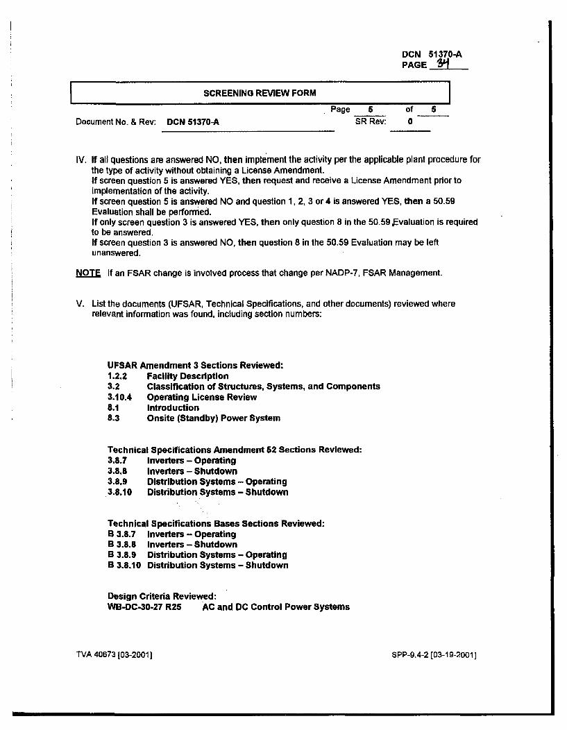
DCN 51370-APAGE S4
SCREENING REVIEW FORM
Page 5 of 5Document No. & Rev: DCN 51370-A SR Rev: 0
IV. If all questions are answered NO, then implement the activity per the applicable plant procedure forthe type of activity without obtaining a License Amendment.If screen question 5 is answered YES, then request and receive a License Amendment prior toimplementation of the activity.If screen question 5 is answered NO and question 1, 2, 3 or 4 is answered YES, then a 50.59Evaluation shall be performed.If only screen question 3 is answered YES, then only question 8 in the 50.59 Evaluation is requiredto be answered.If screen question 3 is answered NO, then question 8 in the 50.59 Evaluation may be leftunanswered.
NOTE If an FSAR change is involved process that change per NADP-7, FSAR Management.
V. List the documents (UFSAR, Technical Specifications, and other documents) reviewed whererelevant information was found, Including section numbers:
UPSAR Amendment 3 Sections Reviewed:1.2.2 Facility Description3.2 Classification of Structures, Systems, and Components3.10.4 Operating License Review8.1 Introduction8.3 Onsite (Standby) Power System
Technical Specifications Amendment 62 Sections Reviewed:3.8.7 Inverters - Operating3.8.8 Inverters - Shutdown3.8.9 Distribution Systems - Operating3.8.10 Distribution Systems - Shutdown
Technical Specifications Bases Sections Reviewed:B 3.8.7 Inverters - OperatingB 3.8.8 Inverters - ShutdownB 3.8.9 Distribution Systems - OperatingB 3.8.10 Distribution Systems - Shutdown
Design Criteria Reviewed:WB-DC-30-27 R25 AC and DC Control Power Systems
TVA 40673 103-20011 SPP-9.4-2 [03-19-2001]
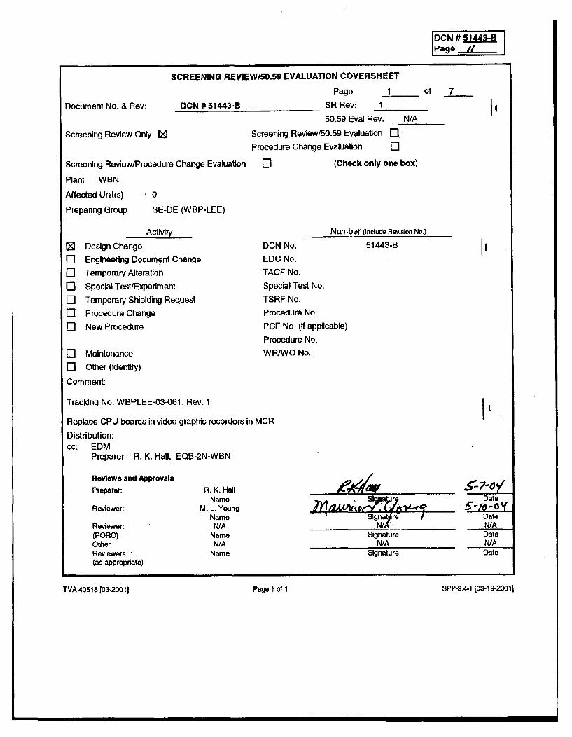
[CN 5143-
Document No. & Rev:
Screening Review Only 0
SCREENING REVIEWI50.59 EVALUATION COVERSHEET
Page 1 of
DCN # 51443-B SR Rev: 150.59 Eval Rev. N/A
Screening Review/50.59 Evaluation r'
Procedure Change Evaluation I]re Change Evaluation Q] (Check only one box)
II
7
Screening Review/Procedur
Plant WBN
Affected Unit(s) 0
Preparing Group SE-DE (WBP-LEE)
0ElEl01
Activity
Design Change
Engineering Document Change
Temporary Alteration
Special Test/Experiment
Temporary Shielding Request
Procedure Change
New Procedure
DCN No.
EDC No.
TACF No.
Special Test No.
TSRF No.
Procedure No.
PCF No. (id applicable)
Procedure No.
WR/WO No.
51443-B
Number (Include Revision No.)
II
El Maintenance
El Other (Identify)
Comment:
Tracking No. WBPLEE-03-061, Rev. 1
Replace CPU boards in video graphic recorders in MCR
Distribution:cc: EDM
Preparer - R. K. Hall, EQB-2N-WBN
I'
Reviews and Approvals
Preparer:
Reviewer:
Reviewer:(PORC)OtherReviewers:(as appropriate)
R. K, HallName
M. L. YoungNameN/A
NameN/A
Name
-'1 JSlgnaterrlA
SignatureN/A
Signature
Datey
DateN/ADate
W/ADate
TVA 40518 [03-2001] Page 1 011
SPP-9.4-1 [03-19-20011
TVA 40518 [03-2o01 ] Page I of 1 SPP-9.4-1 [03-19-20011
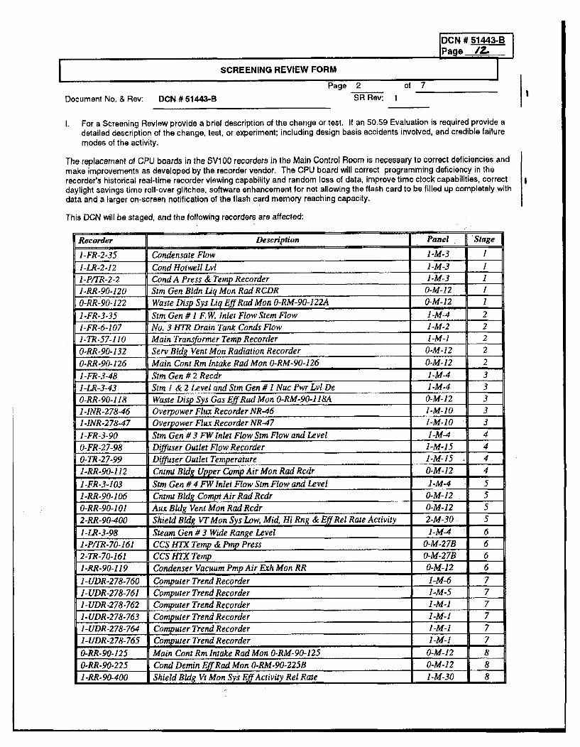
Page 2
Document No. & Rev: DCN # 51443-8 SR Rev: 1
1. For a Screening Review provide a brief description of the change or test. It an 50.59 Evaluation is required provide adetailed description of the change, test, or experiment; including design basis accidents involved, and credible failuremodes of the activity.
The replacement of CPU boards in the SV1 00 recorders in the Main Control Room is necessary to correct deficiencies andmake improvements as developed by the recorder vendor. The CPU board will correct programming deficiency in therecorder's historical real-time recorder viewing capability and random loss of data, improve time clock capabilities, correctdaylight savings time roll-over glitches, software enhancement for not allowing the flash card to be filled up completely withdata and a larger on-screen notification of the flash card memory reaching capacity.
This DCN will be staged, and the following recorders are affected:
Recorder Description Panel Stage
1-FR-2-35 Condensate Flow 1-M-3 I
I-LR-2-12 Cond Hotwell Lvl I-M-3 I
1-P/TR-2-2 Cond A Press & Temp Recorder 1-M-3 1
1-RR-90-120 Sim Gen Bldn Lig Mon Rad RCDR O-M-12 I
O-RR-90-122 Waste Disp Sys Lig Eff Rad Mon O-RM-90-122A 0-M-12 I
1-FR-3-35 Sim Gen # 1 F. W. Inlet Flow Stem Flow 1-M-4 2
1-FR-6-107 No. 3 HTR Drain Tank Conds Flow I-M-2 2
1-TR-57-110 Main Transformer Temp Recorder I-M-l 2
0-RR-90-132 Serv Bldg Vent Mon Radiation Recorder 0-M-12 2
0-RR-90-126 Main Cons Rm Intake Rad Mon 0-RM-90-126 0-M-12 2
1-FR-3-48 Stm Gen # 2 Recdr I-M-4 3
1-LR-3-43 Stm 1 & 2 Level and Stm Gen #1 Nuc Pwr Lvt De I-M-4 3
O-RR-90-118 Waste Disp Sys Gas Eff Rad Mon O-RM-90-118'A O-M- 12 3
1-INR-278-46 Overpower Flux Recorder NR-46 1-M-10 3
1-INR-278-47 Overpower Flux Recorder NR-47 1-M-10 31-FR-3-90 Stm Gen # 3 FW Inlet Flow Stm Flow and Level 1-M-4 4
0-FR-27-98 Diffuser Outlet Flow Recorder 1-M-15 4
0-TR-27-99 Diffuser Outlet Temperature 1-M-15 4
I-RR-90-112 Cntmi Bldg Upper Comp Air Mon Rad Rcdr 0-M-12 4
i-FR-3-103 Stm Gen # 4 FW Inlet Flow Stm Flow and Level 1-M-4 5
1-RR-90-106 Cnrmt Bdlg Compt Air Rad Rcdr 0-M-12 5
0-RR-90-101 Aux Bldg Vent Mon Rad Rcdr 0-M-12 52-RR-90-400 Shield Bldg VT Mon Sys Low, Mid, Hi Rng & Eff Rel Rate Activity 2-M-30 5
1-LR-3-98 Steam Gen # 3 Wide Range Level 1-M-4 6
1-P/IR-70-161 CCS HTX Temp & Pmp Press O-M-27B 6
2-TR-70-161 CCS H7X Temp 0-M-27B 6
1-RR-90-119 Condenser Vacuum Pmp Air Exh Mon RR 0-M-12 6
1-UDR-278-760 Computer Trend Recorder I-M-6 7
1-UDR-278-761 Computer Trend Recorder 1-M-5 7
I-UDR-278-762 Computer Trend Recorder 1-M-1 7
1-UDR-278-763 Computer Trend Recorder 1-M-1 7
I-UDR-278-764 Computer Trend Recorder 1-M-1 7
1-UDR-278-765 Computer Trend Recorder 1-M-1 7
0-RR-90-125 Main Cont Rm Intake Rad Mon 0-RM-90-125 0-M-12 8
0-RR-90-225 Cond Demin Eff Rad Mon O-RM-90-225B 0-M-12 8
l-RR-90-400 Shield Bldg Vt Mon Sy's Eff Activity Rel Rate 1-M-30 8
I
DCN # 51443-B
Page I
SCREENING REVIEW FORM IPage 3 of 7
Document No. & Rev: DCN # 51443-B SR Rev: 1
WBN PER # 03-003315-000 was written as a result of the firmware deficiencies, and this design changeimplements the corrective actions associated with correcting the problems with the radiation recorders.WBN PER # 03-011999-000 was written to identify the random data loss that was being experienced bysome recorders due to a thread synchronization problem in the firmware. This initialization issue wasidentified by the recorder vendor and has been fixed by the new CPU board. WBN PER # 03-004850-000 I'was written to document the poor time clock accuracy associated with the recorders.
System Design and Functions
This change addresses various systems in the plant, but does not change any operational or functionalrequirements of those systems. The recorders are used for indication and trending purposes in the MainControl Room and are not required for safe shutdown of the plant. The recorders are Quality - Related,and seismic 1L(B). This change meets the design basis requirements as stated by the Design Criteria (DC)and system descriptions for the various systems affected by this change.
Justification for this chanceThe current firmware configuration does not support all of the required functions applicable to therecorders, specifically when used to view logarithmic historical trends. The firmware does store and recordlive information properly, it does not allow one to view the historical trend on the recorder screen. The newCPU board will improve the clock accuracy, correct daylight savings time roll-over deficiencies, randomdata loss due to a thread synchronization error in the firmware, and prevent the flash cards from being filled100% with data from their respective recorder and includes a larger on-screen notification that the flashmedia has reached the preset fill level.
This DCN is being revised to change out the CPU boards in the SV1O0 recorders instead of replacing firmware. The CPUboard replacement has a much more 'solid' software package. It will correct programming deficiency in the recordershistorical real-time recorder viewing capability and random loss of data, solve the clock accuracy, solve the daylightsaving time problem, and the media alert window problem. Also, the new CPU board will eliminate the need to send theEPOM's from the existing recorders back to the vendor to be reconfigured.
Ili. Revision: (Provide a brief summary of the reason for the revision to the SR, or 50.59 EvaluationTVA 40673 [03-20011 Page 1 of 3 SPP-9.4-2 [03-19-20011
DCN # 51443-BPage 7
SCREENING REVIEW FORM
Page 4 of 7Document No. & Rev: DCN #51443-B SR Rev: 1
III. 50.59 Screening Questions (Check correct response) (See Section 4.2 of NEI 96-07 for additionalguidance):
1. Does the proposed activity involve a change to an SSC that adversely affects an UFSAR describeddesign function? (See Section 4.2.1.1 of NEI 96-07)
Yes E- No 0
Justification:The design function of the recorders is to provide indication and trending capability inthe Main Control Room of parameters required by procedure, regulation or Important toOperations. The replacement of the recorder CPU boards does not change the designfunction of the recorders, nor does It affect any system design function. This change does notadversely affect any SSC design function described in the UFSAR. All referenced UFSARsections discuss the design and operational requirements of each system or component anddoes not discuss the firmware of the recorders to any level of detail. Therefore, this changedoes not revise or contradict with functional and safety requirements specified in theUFSAR.
2. Does the proposed activity involve a change to a procedure that adversely affects how UFSARdescribed SSC design functions are performed or controlled? (See Section 4.2.1.2 of NEI 96-07)
Yes 17 No 0
Justification:The design function of the recorders is to provide indication and trending capability in theMain Control Room of parameters required by procedure, regulation or important toOperations. This change does not involve procedures that affect system operationalcharacteristics described in the UFSAR or impact compliance with the TechnicalSpecification. Also, this change does not conflict with or affect processes or proceduresoutlined, summarized, or described in the UFSAR.
3. Does the proposed activity involve revising or replacing an UFSAR described evaluation methodologythat is used in establishing the design bases or used in the safety analyses? (See Section 4.2.1.3 ofNEI 96-07)
Yes El No 0R
Justification:This change will replace CPU boards firmware in paperless recorders in the Main Control Room inorder to correct deficiencies identified in Problem Evaluation Reports. This change does not revise orreplace an evaluation methodology that is described in the UFSAR. This change meets the designbasis requirements of the various systems the change is applicable too. This change does not impactany design bases or safety analyses relating to recorder or trending function.
TVA 40673 [03-20011 Page 2 of 3 SPP-9.4-2 [03-19-20011
DN# 1443-B--
SCREENING REVIEW FORM
Page 5 of 7Document No. & Rev: DCN # 51443-B SR Rev: 1
4. Does the proposed activity involve a test or experiment not described in the UFSAR, where an SSC isutilized or controlled In a manner that is outside the reference bounds of the design for that SSC or isinconsistent with analyses or descriptions in the UFSAR? (See Section 4.2.2 of NEI 96-07)
Yes[] No 10
Justification:This change does not involve a test or experiment described in the UFSAR. This DCNwill replace the recorder CPU boards with an upgraded version from the recordermanufacturer. There are no tests or experiments associated with this activity.
5. Does the proposed activity require a change to the Technical Specifications?
YesE] No Z
Justification:This change does not Impact the Technical Specifications. The recorders are used fortrending and historical purposes only and do not affect the design function or operationof the various systems. This change does not require a change to the TechnicalSpecifications and does not change the safety functions associated with those systemsand components associated with the Technical Specifications. Section 3.3,Instrumentation, Section 3.6.6, Containment Spray, Section 3.7, Plant Systems, Section3.8, Electrical Power System, Section 5.7.2.3, Offsite Dose Calculation Manual, andSection 5.11, High Radiation of the TS were reviewed and no impacts were found.
I
TVA 40673 [03-20011 Page 2 of 3 SPP-9.4-2 [03-19-2001]
DCN # 51 443-Bpage
SCREENING REVIEW FORMPage 6 of 7
Document No. & Rev: DCN # 51443-B SR Rev: 1
IV. If all questions are answered NO, then implement the activity per the applicable plant procedure forthe type of activity without obtaining a License Amendment.If screen question 5 is answered YES, then request and receive a License Amendment prior toimplementation of the activity.If screen question 5 Is answered NO and question 1, 2, 3 or 4 is answered YES, then a 50.59Evaluation shall be performed.If only screen question 3 is answered YES, then only question 8 in the 50.59 Evaluation is requiredto be answered.If screen question 3 is answered NO, then question 8 in the 50.59 Evaluation may be leftunanswered.
NOTE If an FSAR change is involved process that change per NADP-7, FSAR Management.
V. List the documents (UFSAR, Technical Specifications, and other documents) reviewed whererelevant information was found, including section numbers:
1. UFSAR SectionsSection 1.2.2.8, "Cooling Water"Section 4.4.5.3, "Instrumentation to Limit Maximum Power Output"Section 5.2.7.4.4, "Main Steam Line Isolation System"Section 5.5.5, "Steam Generators"Section 9.2.2, "Component Cooling System"Section 7, "Instrumentation and Controls"Section 10.4.5, "Condenser Circulating Water System"Section 10.4.7, "Condensate and Feedwater Systems"Section 10.4,8, "Steam Generator Blowdown System"Section 11.2, "Liquid Waste Systems"Section 11.2.3.2, "Spent Resin Instrument Design"Section 11.3.8, "Release Points"Section 11.4, "Process and Effluent Radiological Monitoring and Sampling System"Section 12.3.4, "Area Radiation and Airborne Radioactivity Monitoring Instrumentation"Section 12,3.4.2.2, "Airborne Monitoring Channels"Section 13.6,3, "Event Records"Table 7.5-1, "Post Accident Monitoring Instrumentation Component Qualification Matrix'Table 11.4-2, "Process and Effluent Radiation Monitors Gaseous Media"Table 11.4-3, "Locations for Gaseous Process and Effluent Radiation Monitor Indicators, Recorders, andAnnunciators"
2. Technical SpecificationsSection 3.3, InstrumentationSection 3.6.6, Containment Spray SystemSection 3.7, Plant SystemsSection 3.8, Electrical Power SystemSection 5.7.2.3, Offsite Dose Calculation Manual (ODCM)Section 5.11, High Radiation
3. Deslqn CriteriaWB-DC-30-7, Rev. 16, "Post Accident Monitoring System (PAM)"WB-DC-30-20, Rev. 2, "Control Panels"WB-DC-30-23, Rev. 1, "Human Factors"WB-DC-30-27, Rev. 25 "AC and DC Control Power Systems"
TVA 40673 [03-20011 Page 3 of 3 SPP-9.4-2 (03-19-2001]
DCN 5143-B
SCREENING REVIEW FORM
Page 7 of 7
Document No. & Rev: DCN # 51443-B SR Rev: 1
3. Desln CriteriaWB-DC-30-29, Rev. 5, "Plant Computer"WB-DC-40-24, Rev.13, "Radiation Monitoring"WB-DC-40-31.13, Rev. 4, "Seismic Qualification of Category I(L) Fluid System Components andElectrical or Mechanical Equipment"WB-DC-40-58, Rev 3A, "Auxiliary Control System"
4. TVA Drawinas Contract # 1467891-47W610-90 series 1-45W706-sedes DM1001651-47W610-92 series 1-47W610-3-sedes1-47W610-2-sedes 1-47W610-6-sedes1-47W610-72-series 1-47W610-27-sedes1-47W605-seres 45N1645-series45N 1641- series 45N1651 -series45N 1635- series 45N1653-serles
5. Vendor Manuals
WBN-VM-W130-3005, 'Thermo Westronics SV100 Smartview Video graphic Recorders"
6. Technical Requirements Manual
7. Safety Evaluation Report (including all supplements)
8. Master Equipment List (MEL)
9. ContractWatts Bar TVA Contract # 146789 I
10. ProceduresTI-49, Rev. 29, Technical Instruction Compliance Instruments
11. Design Changes50369-B 50915-A50916-A 50917-A50933-A 50936-A51097-A 51310-A51443-B
12. WBN PERs03-003315-00003-011999-00003-004850-000
TVA 40673 [03-20011 Page 3 of 3 SPP-9.4-2 [03-19-2001]
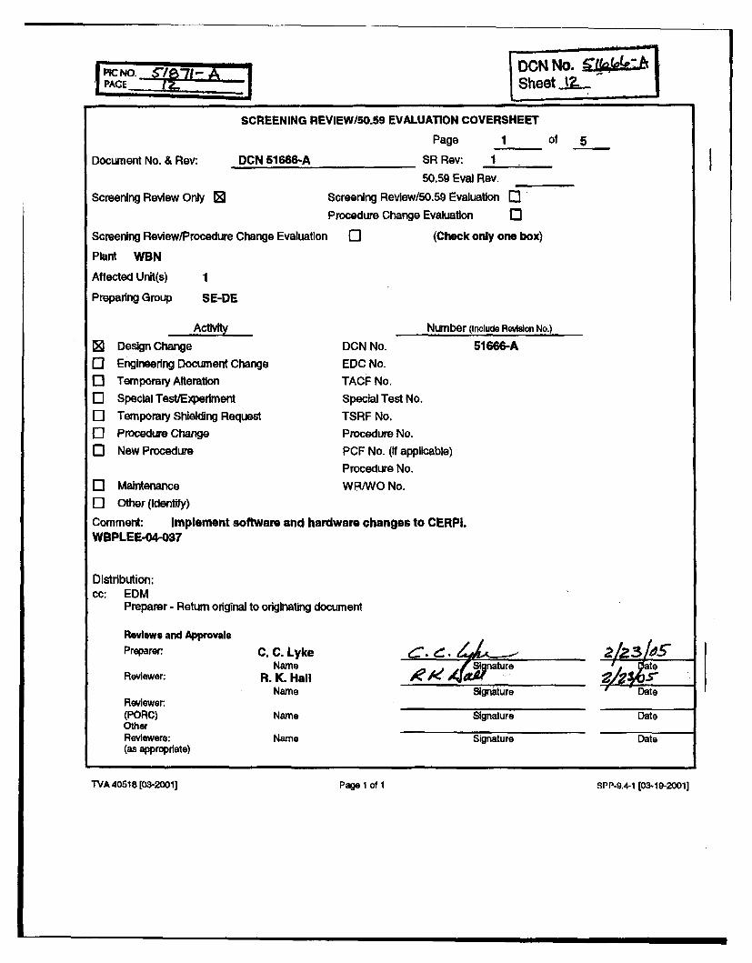
V4 O.Q 71 - DION NO. LLakSheet J .-
Document No. & Rev:
Screening Review Only [
Screening Review/Procedun
SCREENING REVIEW/50.59 EVALUATION COVERSHEET
Page 1 of
DCN 51666-A SR Rev: 1
50.59 Eval Rev.
Screening Review/50.59 Evaluation 0Procedure Change Evalualon 0
e Change Evaluation 0 (Check only one box)
5
I
Plant WVBN
Affected Unit(s)
Preparing Group SE-DE
0]0][][]0]0]
Design Change
Engineering Document Change
Temporary Alteration
Special Test/Experiment
Temporary Shielding Request
Procedure Change
New Procedure
DCN No.
EDC No.
TACF No.
Special Test No.
TSRF No.Procedure No.
PCF No. (If applicable)
Procedure No.
Number (Include Revision No.)
51666-A
0 Maintenance WR/WO No.
[I] Other (Identify)
Comment: Implement software and hardware changes to CERPI.
WBPLEE-04-037
Distribution:cc: EDM
Preparer - Return original to originating document
Reviews and ApprovalsPreparer
Reviewer:
Reviewer:(PORC)OtherReviewers:(as appropriate)
C. C. LykeName
R. K. HallName
• n ature
Signature
Signature
Signature
Date
Date
Date
Name
Name
TVA 40618 [08-2001] Page 1 of 1
SPP.9.4-1 (03.19-20011
TVA 40618 [03-2001] Pago 1 of I SPP-9.4-1 [03-1-19-20011
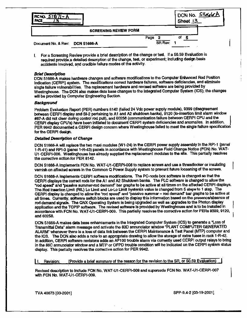
MPC NO. 1621A 0GW No. ______e
______ I R Sheet
SCREENING REVIEW FORM2 of 5
Document No. & Rev: DCN 51666-A SR Rev: 1 oI
I. For a Screening Review provide a brief description of the change or test. If a 50.59 Evaluation is
required provide'a detailed description of the change, test, or experiment; Including design basisaccidents Involved, and credible failure modes of the activity.
Brief DescriptionDCN 51666-A makes hardware changes and software modifications to the Computer Enhanced Rod Positionindication (CERPI) system. The modifications correct hardware failures, software deficiencies, and eliminatesingle failure vuinerabilities. The replacement hardware and revised software are being provided byWestinghouse. The DCN also makes data base changes to the Integrated Computer System (ICS); the changeswill be provided by Computer Engineering Section.
Background
Problem Evaluation Report (PER) numbers 8142 (failed 24 Vdc power supply module), 9399 (disagreementbetween CERPI display and SI-2 pertaining to Al and A2 shutdown banks), 9120 (lo-insertion limit alarm window#87-A did not clear during control rod pull), and 60258 (communication failure between CERPI CPU and theCERPI display CPU's) have been Initiated to document CERPI system deficiencies and anomalies. In addition,PER 9942 documented a CERPI design concern where Westinghouse failed to meet the single failure specificationfor the CERPI design.
Detailed Description of Change
DCN 51666-A will replace the two maxi modules (Wi-24) in the CERPI power supply assembly In the RPI-1 (panel1-R-41) and RPI-3 (panel 1-R-43) panels In accordance with Westinghouse Field Change Notice (FCN) No. WAT-Ul -CERPI-006. Westinghouse has already supplied the replacement modules to the site. This partially resolvesthe corrective action for PER 8142.
DCN 51666-A implements FCN No. WAT-Ul -CERPI-008 to replace screws and use a threadlocker or insulating
varnish on affected screws in the Common Q Power Supply system to prevent future loosening of the screws.
DCN 51666-A implements CERPI software modifications. The PC-node box software is changed so that theCERPI displays the correct rods for the Al and A2 Shutdown banks. The PLC software is changed to allow the"rod speed' and "passive summer-rod demand' bar graphs to be active at all times on the affected CERPI displays.The Rod Insertion Limit (RIL) Lo Limit and Lo-Lo Umit hystersis value Is changed from 5 steps to 1 step. TheCERPI display is changed to allow the "rod speed" and "passive summer - rod demand" bar graphs to be active atall times. Currently, software switch blocks are used to display this information based on the presence/absence ofrod demand signals. The QNX Operating System is being upgraded as well as upgrades to the Photon displayapplication and the TCPIP software. The revised software is provided by Westinghouse and Is to be Installed inaccordance with FCN No. WAT-Ul-CERPI-009. This partially resolves the corrective action for PERs 9399, 9120,and 60258.
DCN 51666-A makes data base enhancements in the Integrated Computer System (ICS) to generate a "Loss ofTransmittal Data" alarm message and activate the 83D annunciator window "PLANT COMPUTER GENERATEDALARM" whenever there is a loss of data link between the CERPI Maintenance & Test Panel (MTP) computer andthe ICS. The DCN also adds a note to an appropriate drawing to allow the storage of extra fuses in rack 1-R-42.In addition, CERPI software revisions adds an AF1 00 trouble alarm via currently used CERPI output relays to bringin the 86C annunciator window and a MTP or OFPD trouble condition will be indicated on the CERPI system statusdisplay. This partially resolves the corrective action for PER 9942.
1I. Revision: (Provide a brief summary of the reason for the revision to the SR, or 50.59 Evaluation)-"
Revised description to Include FCN No. WAT-UI-CERPI-008 and supersede FCN No. WAT-U1-CERPI-007with FCN No. WAT-U1-CERPI-009.
TVA 40673 (03-20011 SPP-9.4-2 [03-19-2001]
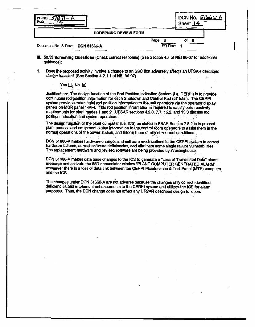
PICNO. i,3"-|':1 A - '" DON No. ,/ePvPAGE 1!.... Sheet__ -
SCREENING REVIEW FORM
...... Pag/e 3 Of 5 I
Document No. & Rev: DCN 51666-A SR Rev: 1I
Ill. 50.59 Screening Questions (Check correct response) (See Section 4.2 of NEI 96-07 for additional
guidance):
1 Does the proposed activity Involve a change to an SSC that adversely affects an UFSAR described
design function? (See Section 4.2.1.1 of NEI 96-07)
Yesr[I No [
Justification: The design function of the Rod Position Indication System (i.e. CERPI) is to providecontinuous rod position information for each Shutdown ard Control Rod (57 total). The CERPIsystem provides meaningful rod position information to the unit operators via the operator displaypanels on MCR panel 1 -M-4. This rod position information is required to satisfy core reactivityrequirements for plant modes 1 and 2. UFSAR sections 4.2.3, 7.7,15.2, and 15.3 discuss rodposition Indication and system operation.
The design function of the plant computer (i.e. ICS) as stated in FSAR Section 7.5.2 is to presentplant process and equipment status Information to the control room operators to assist them in thenormal operations of the power station, and inform them of any off-normal conditions.
DON 51666-A makes hardware changes and software modifications to the CERPI system to correcthardware failures, correct: software deficiencies, and eliminate some single failure vulnerabllities.The replacement hardware and revised software are being provided by Westinghouse.
DCN 51666-A makes data base changes to the ICS to generate a uLoss of Transmittal Data" alarmmessage and activate the 83D annunciator window "PLANT COMPUTER GENERATED ALARM"whenever there is a loss of data link between the CERPI Maintenance & Test Panel (MTP) computer
and the ICS.
The changes under DON 51 666-A are not adverse because the changes only correct identifieddeficiencies and implement enhancements to the CERPI system and utilizes the ICS for alarmpurposes. Thus, the DCN change does not affect any UFSAR described design function.
oDCN NO. 5Lf 7AE PSheet 1I
.. Page'5TSW1iI2. Does the proposed activity involve a change to a procedure that adversely affects how UFSAR
described SSC design functions are performed or controlled? (See Section 4.2.1.2 of NEI 96-07)
Yes [I No 0
Justification: The design function of the Rod Position Indication System (i.e. CERPI) is to providecontinuous rod position information for each Shutdown and Control Rod (57 total). The CERPIsystem provides meaningful rod position information to the unit operators via the operator display.panels on MCR panel 1 -M-4. This rod position information Is required to satisfy core reactivityrequirements for plant modes 1 and 2. UFSAR sections 4.2.3, 7.7, 15.2, and 15.3 discuss rod positionIndication and system operation.
The design function of the plant computer (i.e. ICS) as stated in FSAR Section 7.5.2 is to presentplant process and equipment status information to the control room operators to assist them in thenormal operations of the power station, and inform them of any off-normal conditions.
DCN 51666-A makes hardware changes and software modifications to the CERPI system to correcthardware failures, correct software deficiencies, and eliminate some single failure vulnerabilities.DCN 51666-A also makes data base changes to the ICS to generate an alarm message.
The modification under DCN 51666-A will result a procedure change (i.e. ARI-81-87). This procedurechange will identify the inputs to the annunciator window 83D. This procedure change does notadversely affect how an UFSAR described SSC design function Is performed or controlled.
3. Does the proposed activity involve revising or replacing an UFSAR described evaluation methodologythat is used In establishing the design bases or used in the safety analyses? (See Section 4.2.1.3 ofNEI 96-07)
Yesr7 No J@
Justification: There is no UFSAR described evaluation methodology associated with the hardwarereplacement and software changes to be Implemented under DCN 51666-A. Furthermore, theproposed DCN change does not revise any evaluation methodology associated with the Rod PositionIndication System (CERPI) or plant computer (ICS).
4. Does the proposed activity Involve a test or experiment not described in the UFSAR, where an SSC Isutilized or controlled in a manner that is outside the reference bounds of the design for that SSC or isinconsistent with analyses or descriptions in the UFSAR? (See Section 4.2.2 of NEI 96-07)
Yes[ No 0
Justification: The proposed change under DCN 51666-A does not involve a test or experiment eitherdescribed or not described in the UFSAR.
5. Does the proposed activity require a change to the Technical Specifications?
YesL7 No 0Justification: The proposed DCN modification does not affect or contradict with requirements andstatements In Tech Spec/Tech Spec Bases section 3.1.7/B3.1.7, Control Bank Insertion Limits;section 3.11.8/B3.1.8, Rod Position Indication; or Technical Requirements Manual (TRM)/TRM Basessection TR 3.1.7/B3.1.7, Position Indication System, Shutdown. Therefore, the proposed activity willnot require a change to the Technical Specifications.
TVA 40673 [03-2001] SPP-9.4-2 [03-19-2001]
mple nai o t heet~~SCREENING REVIEW FR
Page 5 of 5Document No. & Rev: DCN 51066-A SR Rev: 1
IV. It all questions are answered NO, then Implement the activity per the applicable plant procedure forthe type of activity without obtaining a License Amendment.If screen question 5 Is answered YES, then request and receive a License Amendment prior toimplementation of the activity.If screen question 5 is answered NO and question 1, 2, 3 or 4 is answered YES, then a 50.59Evaluation shall be performed.If only screen question 3 is answered YES, then only question 8 In the 50.59 Evaluation is requiredto be answered.If screen question 3 Is answered NO. then question 8 in the 50.59 Evaluation may be leftunanswered.
NOTE If an FSAR change is involved process that change per NADP-7, FSAR Management.
V. List the documents (UFSAR, Technical Specifications, and other documents) reviewed whererelevant information was found, Including section numbers:
UFSAR section 4.2.3, Reactivity Control System
UFSAR section 7.5.2, Plant Computer
UFSAR section 7.7, Control Systems
UFSAR section 15.2, Condition II - Faults of Moderate Frequency
UFSAR section 15.3, Condition III - Infrequent Faults
Tech Spec/Tech Spec Bases section 3.1.7/B3.1.7, Control Bank Insertion Limits
Tech Spec/Tech Spec Bases section 3.1.8/B3.1.8, Rod Position Indication
Technical Requirements Manual (TRM)/TRM Bases section TR 3.1.7/B3.1.7, PositionIndication System, Shutdown
System Description for Control Rod Drive System, N3-85-4003, Rev. 9Design Criteria WB-DC-30-29, Rev. 5, Plant Computer
DCN 51072-A
Contract 2695 Drawinas
2E10005-1, Rev. 5
2E10005-8, -12, Rev. 4
D00000435081-1, Rev. 2
2E10010-1, Rev. 0
TVA drawing 1-47A618-261-1, Rev. 7
TVA 40673 [03-20011 SPP-9.4-2 [03-19-2001]
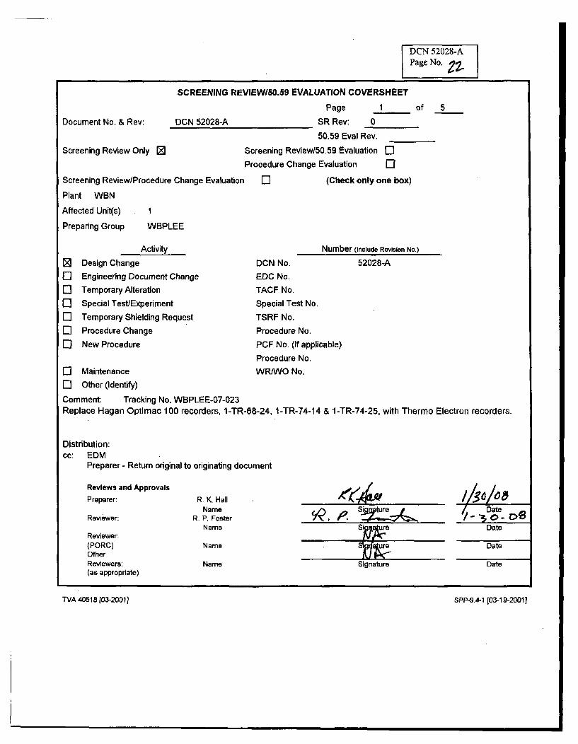
DCN 52028-A
Page No. 97-
SCREENING REVIEWI5O.59 EVALUATION COVERSHEET
Document No. & Rev: DCN 52028-A
Screening Review Only M
Screening Review/Procedure Change Evaluation
Plant WBN
Affected Unit(s) 1
Preparing Group WBPLEE
Page 1 of 5
SR Rev: 0
50.59 Eval Rev.
Screening Review/50.59 Evaluation [
Procedure Change Evaluation ElE] (Check only one box)
Number (Include Revision No.)
El01
Activity
Design Change
Engineering Document Change
Temporary Alteration
Special Test/Experiment
Temporary Shielding Request
Procedure Change
New Procedure
DCN No.
EDC No.
TACF No.
Special Test No.
TSRF No.
Procedure No.
PCF No. (if applicable)
Procedure No.
52028-A
El Maintenance WR/WO No.El Other (Identify)
Comment: Tracking No. WBPLEE-07-023Replace Hagan Optimac 100 recorders, 1-TR-68-24, 1-TR-74-14 & 1-TR-74-25, with Thermo Electron recorders.
Distribution:cc: EDM
Preparer - Return original to originating document
Reviews and Approvals
Preparer:
Reviewer:
Reviewer:(PORC)OtherReviewers:(as appropriate)
A4'4wR. K. HallName
R. P. FosterName
Sintr I~//S/O 8
Date
Date
Name
Name
Date
Signature Date
TX/A 40515 [03-2031] SPP-9.4-1 (03-19-2001]
TVA 405181[03-2001] SPP-9.4-1 [03-19-20011
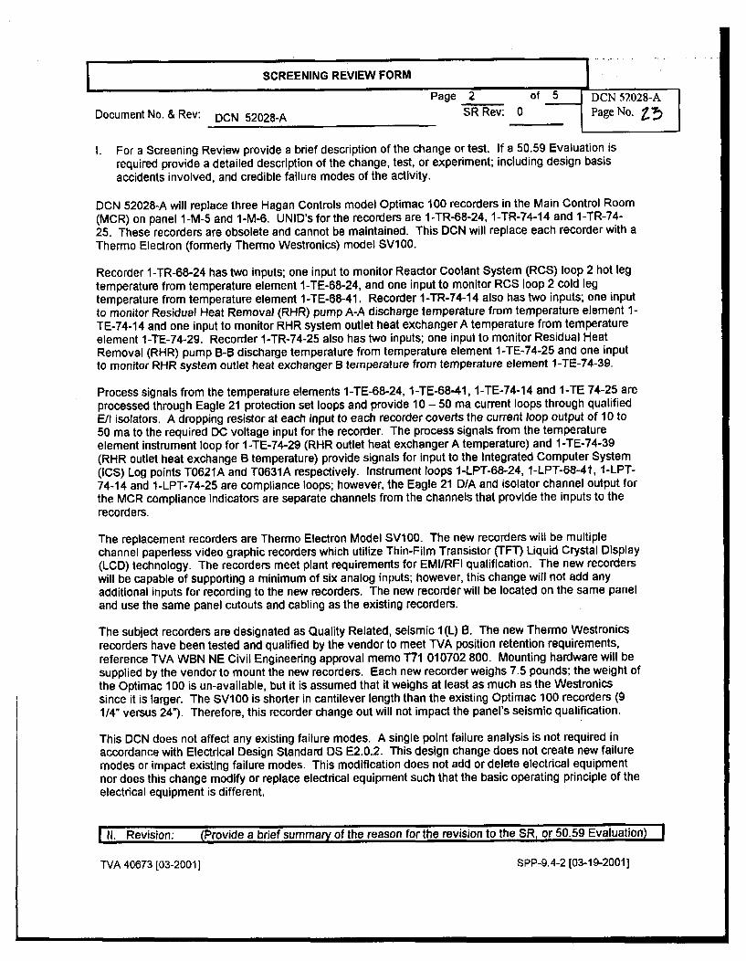
SCREENING REVIEW FORM
Page 2 of 5 DCN 52028-A
Document No. & Rev: DCN 52028-A SR Rev: 0 Page No. Z!)
I. For a Screening Review provide a brief description of the change or test. If a 50.59 Evaluation Isrequired provide a detailed description of the change, test, or experiment; including design basisaccidents involved, and credible failure modes of the activity.
DCN 52028-A will replace three Hagan Controls model Optimac 100 recorders in the Main Control Room(MCR) on panel 1-M-5 and 1-M-6. UNID's for the recorders are 1-TR-68-24, 1-TR-74-14 and 1-TR-74-25. These recorders are obsolete and cannot be maintained. This DCN will replace each recorder with aThermo Electron (formerly Thermo Westronics) model SV100.
Recorder 1-TR-68-24 has two inputs; one input to monitor Reactor Coolant System (RCS) loop 2 hot legtemperature from temperature element 1-TE-68-24, and one input to monitor RCS loop 2 cold legtemperature from temperature element 1-TE-68-41. Recorder 1-TR-74-14 also has two inputs; one inputto monitor Residual Heat Removal (RHR) pump A-A discharge temperature from temperature element 1-TE-74-14 and one input to monitor RHR system outlet heat exchanger A temperature from temperatureelement 1-TE-74-29. Recorder 1-TR-74-25 also has two inputs; one input to monitor Residual HeatRemoval (RHR) pump B-B discharge temperature from temperature element 1-TE-74-25 and one inputto monitor RHR system outlet heat exchanger B temperature from temperature element 1-TE-74-39.
Process signals from the temperature elements 1-TE-68-24, 1-TE-68-41, 1-TE-74-14 and 1-TE 74-25 areprocessed through Eagle 21 protection set loops and provide 10 - 50 ma current loops through qualifiedE/I isolators. A dropping resistor at each input to each recorder coverts the current loop output of 10 to50 ma to the required DC voltage input for the recorder. The process signals from the temperatureelement instrument loop for 1-TE-74-29 (RHR outlet heat exchanger A temperature) and 1-TE-74-39(RHR outlet heat exchange B temperature) provide signals for input to the Integrated Computer System(ICS) Log points T0621A and T0631A respectively. Instrument loops 1-LPT-68-24, 1-LPT-68-41, 1-LPT-74-14 and 1-LPT-74-25 are compliance loops; however, the Eagle 21 D/A and isolator channel output forthe MCR compliance Indicators are separate channels from the channels that provide the inputs to therecorders.
The replacement recorders are Thermo Electron Model SV100. The new recorders will be multiplechannel paperless video graphic recorders which utilize Thin-Film Transistor (TFT) Liquid Crystal Display(LCD) technology. The recorders meet plant requirements for EMI/RFI qualification. The new recorderswill be capable of supporting a minimum of six analog inputs; however, this change will not add anyadditional inputs for recording to the new recorders. The new recorder will be located on the same paneland use the same panel cutouts and cabling as the existing recorders.
The subject recorders are designated as Quality Related, seismic I(L) B. The new Thermo Westronicsrecorders have been tested and qualified by the vendor to meet TVA position retention requirements,reference TVA WBN NE Civil Engineering approval memo T71 010702 800. Mounting hardware will besupplied by the vendor to mount the new recorders. Each new recorder weighs 7.5 pounds; the weight ofthe Optimac 100 is un-available, but it is assumed that it weighs at least as much as the Westronicssince it is larger. The SV100 is shorter in cantilever length than the existing Optimac 100 recorders (9114" versus 24"). Therefore, this recorder change out will not impact the panel's seismic qualification.
This DCN does not affect any existing failure modes. A single point failure analysis is not required inaccordance with Electrical Design Standard DS E2.0,2. This design change does not create new failuremodes or impact existing failure modes. This modification does not add or delete electrical equipmentnor does this change modify or replace electrical equipment such that the basic operating principle of theelectrical equipment is different,
111. Revision: (Provide a brief summary of the reason for the revision to the SR, or 50.59 Evaluation)
TVA 40673 [03-2001] SPP-9.4-2 [03-19-2001]
SCREENING REVIEW FORM j DCN 52028-A
Page 3 of 5 Page No.
Document No. & Rev: DCN 52028-A SR Rev: 0
III. 50.59 Screening Questions (Check correct response) (See Section 4.2 of NEI 96-07 for additionalguidance):
1 Does the proposed activity involve a change to an SSC that adversely affects an UFSAR describeddesign function? (See Section 4.2.1.1 of NEI 96-07)
Yes [L No MJustification:The design function of recorder 1-TR-68-24 is to provide information for use by the operator to controlcoolant temperature during startup and shutdown. More specifically, RCS cold leg and hot legtemperature indication is used for maintaining an adequate reactor heat sink, maintaining the properrelationship between RCS pressure and temperature, verifying vessel Nil-Ductility Temperature (NDT)criteria, establishing correct conditions for RHRs operations, ensuring proper cool down rate,determining whether SI should be terminated or reinstated and determining core DuctilityTemperature (DT) during natural circulation. The recorders are the trending recorder for PostAccident Monitoring (PAM) category 2 variable RCS hot/cold leg temperature.
The design function of recorders 1-TR-74-14 and 1-TR-74-25 is to provide Information for use by theoperator for the RHR pump discharge during the recirculation mode and RHR Heat exchangersoutlet temperature. The recorders are the trending recorder for PAM category 2 variable RHR pumpA-A and B-B discharge temperature.
The RCS is discussed in UFSAR section 5.0, PAM instrumentation is discussed in UFSAR Section7.5.1, the Residual Heat Removal System is discussed in UFSAR section 5.5.7.
The change under DCN 52028-A is not adverse because the replacement of two obsolete recorderswith current generation video graphic recorders is considered "like for like" replacements; there is nochange in the function of the devices that are replaced and no change in the SSC in which thedevices operate. Thus, the DCN change does not affect any UFSAR described design function.
2. Does the proposed activity involve a change to a procedure that adversely affects an UFSARdescribed SSC design functions are performed or controlled? (See Section 4.2.1.2 of NEI 96-07)
Yes L] No MJustification:
The design function of recorder 1-TR-68-24 is to provide information for use by the operator to controlcoolant temperature during startup and shutdown. More specifically, RCS cold leg and hot legtemperature indication is used for maintaining an adequate reactor heat sink, maintaining the properrelationship between RCS pressure and temperature, verifying vessel NDT criteria, establishingcorrect conditions for RHRs operations, ensuring proper cooldown rate, determining whether SIshould be terminated or reinstated and determining core DT during natural circulation. The recorderis the trending recorder for PAM category 2 variable RCS hot/cold leg temperature.
The design function of recorders 1-TR-74-14 and 1-TR-74-25 is to provide information for use by theoperator for the RHR pump discharge during the recirculation mode and RHR Heat exchangersoutlet temperature. The recorders are the trending recorder for PAM category 2 variable RHR pumpA-A and B-B discharge temperature,
The RCS is discussed in UFSAR section 5.0, PAM instrumentation is discussed in UFSAR Section7.5.1, the Residual Heat Removal System is discussed in UFSAR section 5.5.7.
The change under DCN 52028-A does not involve procedures that affect system operationalcharacteristics described in the UFSAR or Impact compliance with the Technical Specification. Alsothis change does not conflict with or affect processes or procedures outlined, summarized, ordescribed in the UFSAR.
SCREENING REVIEW FORM DCN 52028-A
Page 4 of 5 Page No.0
Document No. & DCN 52028-A SR Rev: 0Rev:
3 Does the proposed activity involve revising or replacing an UFSAR described evaluation methodologythat is used in establishing the design bases or used in the safety analyses? (See Section 4.2.1.3 ofNEI 96-07)
Yes [I No 0
Justification: There is no UFSAR described evaluation methodology associated with the hardwarereplacement to be implemented under DCN 52028-A.
4 Does the proposed activity involve a test or experiment not described In the UFSAR, where an SSC isutilized or controlled in a manner that is outside the reference bounds of the design for that SSC or isinconsistent with analyses or descriptions in the UFSAR? (See Section 4.2.2 of NEI 96-07)
Yes El No Z
Justification: The proposed change under DCN 52028-A does not involve a test or experiment eitherdescribed or not described in the UFSAR.
5 Does the proposed activity require a change to the Technical Specifications?
Yes E] No 0
Justification: The proposed DCN modification does not affect or contradict any requirements orstatements in Tech Spec section 3.3.3 Post Accident Monitoring (PAM) instrumentation, section 3.2Reactor Coolant System (RCS), or section B 3.9.5 RHR & Coolant Circulation. Therefore, theproposed activity will not require a change to the Technical Specifications.
TVA 40673 [03-2001 ] SPP-9.4-2 [03-19-2001]
I DCN 52028-ASCREENING REVIEW FORM PPage No.
Page 5 of 5
Document No. & Rev: DCN 52028-A SR Rev: 0
IV. If all questions are answered NO, then implement the activity per the applicable plant procedure forthe type of activity without obtaining a License Amendment.If screen question 5 is answered YES, then request and receive a License Amendment prior toimplementation of the activity.If screen question 5 is answered NO and question 1, 2, 3 or 4 is answered YES, then a 50.59Evaluation shall be performed.If only screen question 3 is answered YES, then only question 8 in the 50.59 Evaluation is requiredto be answered.If screen question 3 is answered NO, then question 8 in the 50.59 Evaluation may be leftunanswered.
NOTE If an FSAR change is involved process that change per NADP-7, FSAR Management.
V. List the documents (UFSAR, Technical Specifications, and other documents) reviewed whererelevant information was found, including section numbers:
System DescriptionsN3-68-4001 R25, Reactor Coolant SystemN3-74-4001, R12, System Description for Residual Heat Removal System
Design CriteriaWB-DC-30-7, Post Accident Monitoring
UFSAR Sections5.5.7 - RHR System5.0 - RCS System7.5.1 - PAM Instrumentation
Technical Svecification Sections3.2 - RCS3.3.3 - PAMB 3.9.5 - RHR
TVA 40673 [03-20011 SPP-9.4-2 [03-19-2001]
F26i622 A
SCREENING REVIEWi50.59 EVALUATION COVERSHEET
Page 1 of
Document No. & Rev: DCN 52265-A SR Rev: 0
50.59 Eval Rev.
Screening Review Only [ Screening Review/50.59 Evaluation ElProcedure Change Evaluation El
Screening Review/Procedure Change Evaluation El (Check only one box)
Plant WBN
Affected Unit(s) 1
Preparing Group SE-DE
5
ElElEl1ElEl
Activity
Design ChangeEngineering Document Change
Temporary Alteration
Special Test/Experiment
Temporary Shielding Request
Procedure ChangeNew Procedure
DCN No.
EDC No.
TACF No.
Special Test No.TSRF No.
Procedure No.
PCF No..(if applicable)
Procedure No.
Number (Include Revision No.)
52265-A
El Maintenance WR/WO No.El Other (Identify)
Comment: TRACKING NO. WBPLEE-07-035-0
This Screening Review is for DCN 52265-A which revises the values for the rod bank overlapswitches and the rod insertion limit alarms.
Distribution:cc: EDM
Preparer - Return original to originating document
Reviews and ApprovalsPreparer:
Reviewer:
Reviewer:(PORC)OtherReviewers:(as appropriate)
c7e,R P. FOSTERName
R. K. HALLName
Name
Name
Sig~ature
Sign re
Signature
23 23- C
Date
pate
Date
II458[0-01 Pae1IfI P-.41 I0-9-01
TVA 40518 103-2001] Page I of I SPP-9.4-1 [03-19-20011
DCN 52266-APage -00
SCREENING REVIEW FORM IPage 2 of 5
Document No. & Rev: DCN 52265-A SR Rev: 0
I. For a Screening Review provide a brief description of the change or test. If an 50.59 Evaluation isrequired provide a detailed description of the change, test, or experiment; including design basisaccidents involved, and credible failure modes of the activity.
DCN 52265-A revises the rod bank overlap switch settings in panel 1-PNL-85-L122 and revisesthe Rod Insertion Limit (RIL) alarm calculation constants in the Computer Enhanced RodPosition Indication (CERPI) System to improve reactivity management and to account forchanges in the Core Operating Limits Report (COLR). When the CERPI system was installed itwas programmed with the RIL constant values based on the current COLR. These values maychange based on core design. The CERPI RIL alarm calculation constants are stored on thesystem Programmable Logic Controllers (PLC)s and can be changed through the CERPIMaintenance Test Panel (MTP). The basis for this change is the Westinghouse Cycle 9 ReloadSafety Evaluation (RSE) and COLR.
The overlapping of the control banks is required to keep the incremental changes in reactivityrelatively constant while the control banks are being moved. Shutdown bank overlap operationis not required. Control bank overlap is controlled by six thumbwheel switches (sl thru s6) incontrol rod drive panel 1-L-122. These switches control the rod bank withdrawal overlap valueswhich determine when control bank movement starts and stops. The rod control startupsequence is listed below showing the function of each switch. The sequence is reversed forcontrol bank insertion.
SwitchControl Bank A starts moving out
S1 - Control Bank B starts moving outS2 - Control Bank A stops movingS3 - Control Bank C starts moving outS4 - Control Bank B stops movingS5 - Control Bank D starts moving outS6 - Control Bank C stops moving
Control Bank D continues moving as required for control
Presently the control banks (except for bank A) start moving out when the previous bank is at128 steps but this modification changes that value to 116 steps. The system description for thecontrol rod drive system is being revised due to this modification.
1II. Revision: 0 (Provide a brief summary of the reason for the revision to the SR, or 50.59 Evaluation!
Initial Issue
TVA 40673 [03-20011 Page 1 of 3 SPP-9.4-2 [03-19-20011
DCN 52265-APage 2. 1
SCREENING REVIEW FORMPage 3 of 5
Document No. & Rev: DCN 52265-A SR Rev: 0
II1. 50.59 Screening Questions (Check correct response) (See Section 4.2 of NEI 96-07 for additionalguidance):
I Does the proposed activity involve a change to an SSC that adversely affects an UFSAR describeddesign function? (See Section 4.2.1.1 of NEI 96-07)
Yes El No 0
Justification: The design function of the CERPI Rod Insertion Limit Monitor is to ensure sufficient corereactivity shutdown margin. While at power, the Rod Insertion Limits also bound 1) worth inserted dueto an ejected rod and 2) power distribution. The CERPI Rod Insertion Limit Monitor compares theCOLR Control Bank insertion limits to the actual Control Bank positions and provides an alarm if theactual bank positions approach their COLR limits. The design function of the bank overlap unit is toautomatically select the proper Control Bank for movement and to overlap the Control Banks beingmoved according to a preset pattern which is defined in the COLR. Control Bank overlap Is required tokeep the incremental changes in reactivity relatively constant while the Control Banks are beingmoved. The changes being made by this DCN are due to the Westinghouse Watts Bar Unit I Cycle 9revision of the COLR. The Cycle 9 COLR has been prepared and evaluated using the NRC-approvedmethods identified In Technical Specification Section 5.9.5. Per the Westinghouse RSE, the fuel, corecomponents, and core will continue to operate within their respective design criteria, safety analysislimits, and the Technical Specification requirements. Therefore, the design functions of the fuel, corecomponents, and core are not being adversely affected by the Cycle 9 core design and COLR.Therefore, this activity (based on the new COLR values) does not adversely affect any UFSARdescribed design functions.
2. Does the proposed activity involve a change to a procedure that adversely affects how UFSAR
described SSC design functions are performed or controlled? (See Section 4.2.1.2 of NEI 96-07)
Yes [I] No 0
Justification: The design function of the CERPI Rod Insertion Limit Monitor is to ensure sufficient corereactivity shutdown margin. While at power, the Rod Insertion Limits also bound 1) worth inserted dueto an ejected rod and 2) power distribution. The CERPI Rod Insertion Limit Monitor compares theCOLR Control Bank insertion limits to the actual Control Bank positions and provides an alarm if theactual bank positions approach their COLR limits. The design function of the bank overlap unit is toautomatically select the proper Control Bank for movement and to overlap the Control Banks beingmoved according to a preset pattern which is defined in the COLR. Control Bank overlap is required tokeep the incremental changes in reactivity relatively constant while the Control Banks are being moved.The changes being made to the CERPI Rod Insertion Limits and Control Bank overlap values due tothe changes in the COLR may require changes to surveillance or operating limits contained in plantprocedures. Updating these procedures for each operating cycle is expected and they will receive theirown 50.59 reviews based on the Westinghouse RSE. This activity does not require any additionalprocedure changes that will affect how design functions are performed or controlled.
TVA 40673 [03-2001] Page 2 of 3 SPP-9.4-2 [03-19-2001 ]
5DCN 2265-APage A2
SCREENING REVIEW FORMPage 4 of 5
Document No. & Rev: DCN 52265-A SR Rev: 0
III. 50.59 Screening Questions (Check correct response) (See Section 4.2 of NEI 96-07 for additionalguidance):
3. Does the proposed activity involve revising or replacing an UFSAR described evaluation methodologythat is used in establishing the design bases or used in the safety analyses? (See Section 4.2.1.3 ofNEI 96-07)
Yes EJ No [0'
Justification: Per the Westinghouse RSE, there were no changes made to the methods that were usedin the analyses and evaluations for the cycle 9 limits in the COLR (rod insertion limits and bank overlapvalues).
4, Does the proposed activity involve a test or experiment not described in the UFSAR, where an SSC isutilized or controlled in a manner that is outside the reference bounds of the design for that SSC or isinconsistent with analyses or descriptions in the UFSAR? (See Section 4.2.2 of NEI 96-07)
Yes C No Z
Justification: The changes being made to the COLR for cycle 9 (rod insertion limits and control bankoverlap changes) are permanent changes to the plant required to allow cycle 9 to operate at ratedpower for the entire cycle. These changes are not part of a test or experiment.
5. Does the proposed activity require a change to the Technical Specifications?
Yes C No 0
Justification: The COLR is being revised to implement the limits required for operation of Cycle 9. Asdocumented in the Westinghouse RSE, the cycle 9 limits in the COLR were calculated using NRC-approved methodology as required and identified by Technical Specification 5.9.5, Core OperatingLimits Report (0OLR), The Technical Specifications'(TS) have been reviewed and no additionalchanges to the TS are required as a result of this activity.
TVA 40673 [03-20011 Page 2 of 3 SPP-9.4-2 [03-19-2001]
DCN 52265-APage 23
SCREENING REVIEW FORM
Page 5 of 5
Document No. & Rev: DCN 52265-A SR Rev: 0
IV. If all questions are answered NO, then implement the activity per the applicable plant procedure forthe type of activity without obtaining a License Amendment.If screen question 5 is answered YES, then request and receive a License Amendment prior toimplementation of the activity.If screen question 5 is answered NO and question 1, 2, 3 or 4 is answered YES, then a 50.59Evaluation shall be performed.If only screen question 3 is answered YES, then only question 8 in the 50.59 Evaluation is required tobe answered.If screen question 3 is answered NO, then question 8 in the 50.59 Evaluation may be leftunanswered.
NOTE If an FSAR change is involved process that change per NADP-7, FSAR Management.
V. List the documents (UFSAR, Technical Specifications, and other documents) reviewed where relevantinformation was found, including section numbers:
UFSAR Sections3.1.2.3 Protection and Reactivity Control Systems4.2.3 Reactivity Control System4.3 Nuclear Design7.7 Control Systems15.2 Condition II - Faults of Moderate Frequency15.3.6 Single Rod Cluster Control Assembly Withdrawal at Full Power15.4.6 Rupture of a Control Rod Drive Mechanism Housing (Rod Cluster Control Assembly
Ejection)
TS Sections
3.1.51B3.1.5 Rod Group Alignment Limits3.1.71B3.1.7 Control Bank Insertion Limits5.9.5 Core Operating Limits Report (COLR)
System DescriptionsN3-85-4003, R9
Vendor Manual DocumentsVM-W120-3015VD-W120-3015
Westlnahouse DocumentsWatts Bar Nuclear Plant Unit I Cycle 9 Reload Safety Evaluation (RSE)Core Operating Limits Report (COLR) for Watts Bar Unit I Cycle 9
TVA 40673 [03-20011 Page 3 of 3 SPP-9.4-2 [03-19-2001]
DCN 52331-APage 12
SCREENING REVIEW/50.59 EVALUATION COVERSHEET
Page 1 ofDocument No. & Rev: DCN 52331-A SR Rev: 0
50.59 Eval Rev.
Screening Review Only 0 Screening Review/50.59 Evaluation DlProcedure Change Evaluation El
Screening Review/Procedure Change Evaluation El (Check only one box)
Plant WBN
Affected Unit(s) 1
5
Preparing Group SE-DE
Activity
0 Design Change
El Engineering Document Change
El Temporary Alteration.El Special Test/Experiment
El Temporary Shielding Request
El Procedure Change
El New Procedure
_], MaintenanceEl Other (Identify)
Comment: Tracking No. WBPLEE-09-007
Number (Include Revision No.)
DCN No.
EDC No.
TACF No.
Special Test No.
TSRF No.
Procedure No.
PCF No. (if applicable)
Procedure No.
WRMWO No.
52331-A
Replace obsolete Hagan Optimac 100 recorders on 1-M-5 (1-TR-68-1, 1-TR-68-43 & 1-TR-68-65) with ThermoWestronlcs recorders.
Distribution:cc: EDM
Preparer - Return original to originating document
Reviews and ApprovalsPreparer
Reviewer:
Reviewer:(PORC)OtherReviewers:(as appropriate)
Roger P. FosterName
Jojeý, ,./344b6"7Name
Name
Name
Signature
Signature
Date
Date
Date
Date
TVA 40518 (03-2001] Page 1 of 1 SPP-9.4-1 (03-19-2001]
-rVA 40518 [03-2001]j Page 1 of 1 SPP-9.4-1 [03-19-2001]
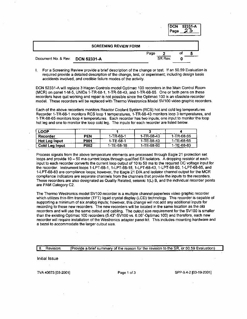
DCN 52331-APage 2o
SCREENING REVIEW FORM
Page 2 of 5Document No. & Rev: DCN 52331-A SR Rev: 0
I. For a Screening Review provide a brief description of the change or test. If an 50.59 Evaluation isrequired provide a detailed description of the change, test, or experiment; including design basisaccidents involved, and credible failure modes of the activity.
DCN 52331-A will replace 3 Hagan Controls model Optimac 100 recorders in the Main Control Room(MCR) on panel 1-M-5, UNIDs 1-TR-68-1, 1-TR-68-43, and 1-TR-68-65. One or both pens on theserecorders have quit working and repair is not possible since the Optimac 100 is an obsolete recordermodel. These recorders will be replaced with Thermo Westronics Model SV100 video graphic recorders.
Each of the above recorders monitors Reactor Coolant System (RCS) hot and cold leg temperatures.Recorder 1-TR-68-1 monitors RCS loop 1 temperatures, 1-TR-68-43 monitors loop 3 temperatures, and1-TR-68-65 monitors loop 4 temperatures. Each recorder has two inputs; one input to monitor the loophot leg and one to monitor the loop cold leg. The inputs for each recorder are listed below.
LOOP 1 3 4Recorder PEN 1-TR-68-1 1-TR-68-43 1-TR-68-65Hot Leg Input Pool 1-TE-68-1 1-TE-68-43 1-TE-68-65Cold Leg Input P002 1-TE-68-18 1-TE-68-60 1-TE-68-83
Process signals from the above temperature elements are processed through Eagle 21 protection setloops and provide 10 - 50 ma current loops through qualified E/I isolators. A dropping resistor at eachinput to each recorder converts the current loop output of 10 to 50 ma to the required DC voltage input forthe recorder. Instrument loops 1 -LPT-68-1, 1 -LPT-68-1 8, 1 -LPT-68-43, 1 -LPT-68-60, 1 -LPT-68-65, and1-LPT-68-83 are compliance loops; however, the Eagle 21 D/A and isolator channel output for the MCRcompliance indicators are separate channels from the channels that provide the inputs to the recorders.These recorders are also designated as Quality Related, seismic 1(L) B, and the individual recorder pointsare PAM Category C2.
The Thermo Westronics model SV100 recorder is a multiple channel, paperless video graphic recorderwhich utilizes thin-film transistor (TFT) liquid crystal display (LCD) technology. This recorder is capable ofsupporting a minimum of six analog inputs; however, this change will not add any additional inputs forrecording to these new recorders. The new recorders will be located in the same location as the oldrecorders and will use the same cutout and cabling. The cutout size requirement for the SV100 is smallerthan the existing Optimac 100 recorders (5.43"-SV100 vs. 6.06"-Optimac 100) and therefore, each newrecorder will require installation of the Westronics adapter panel kit. This includes mounting hardware anda bezel to accommodate the larger cutout size.
II. Revision: (Provide a brief summary of the reason for the revision to the SR, or 50.59 Evaluation)
Initial Issue
TVA 40673 [03-20011 Page 1 of 3 SPP-9.4-2 [03-19-2001]

DCN # 52331-APage 24
THIS PAGE INTENTIONALLY LEFT BLANK
DCN 52331-APage 25
SCREENING REVIEW FORM I
Page 3 of 5Document No. & Rev: DCN 52331-A SR Rev: 0
III. 50.59 Screening Questions (Check correct response) (See Section 4.2 of NEI 96-07 for additionalguidance):
1. Does the proposed activity involve a change to an SSC that adversely affects an UFSAR described
design function? (See Section 4.2.1.1 of NEI 96-07)
Yesi[] No [
Justification:The design function of recorders 1-TR-68-1, 1-TR-68-43, and 1-TR-68-1 is to provide information foruse by the operator to control coolant temperature during startup and shutdown. More specifically,RCS cold leg and hot leg temperature indication is used for maintaining an adequate reactor heat sink,maintaining the proper relationship between RCS pressure and temperature, verifying vessel Nil-Ductility Temperature (NDT) criteria, establishing correct conditions for RHR operations, ensuringproper cool down rate, determining whether SI should be terminated or reinstated and determiningcore Ductility Temperature (DT) during natural circulation. The recorders are also the trendingrecorders for Post Accident Monitoring (PAM) category 2 variable RCS hot/cold leg temperature.
The RCS is discussed in UFSAR section 5.0 and PAM instrumentation is discussed in UFSAR Section7.5.1.
The change under DCN 52331-A is not adverse because the replacement of three obsolete recorderswith current generation video graphic recorders is considered "like for like" replacements; there is nochange in the function of the devices that are replaced and no change in the SSC in which the devicesoperate. Thus, the DCN change does not affect any UFSAR described design function.
2. Does the proposed activity involve a change to a procedure that adversely affects how UFSARdescribed SSC design functions are performed or controlled? (See Section 4.2.1.2 of NEI 96-07)
Yes [I No [
Justification:The design function of recorders 1-TR-68-1, 1-TR-68-43, and 1-TR-68-1 is to provide information foruse by the operator to control coolant temperature during startup and shutdown. More specifically,RCS cold leg and hot leg temperature indication is used for maintaining an adequate reactor heat sink,maintaining the proper relationship between RCS pressure and temperature, verifying vessel Nil-Ductility Temperature (NDT) criteria, establishing correct conditions for RHR operations, ensuringproper cool down rate, determining whether SI should be terminated or reinstated and determining coreDuctility Temperature (DT) during natural circulation. The recorders are also the trending recorders forPost Accident Monitoring (PAM) category 2 variable RCS hot/cold leg temperature.
The change under DCN 52331-A does not involve procedures that affect system operationalcharacteristics described in the UFSAR or impact compliance with the Technical Specification. Alsothis change does not conflict with or affect processes or procedures outlined, summarized, ordescribed in the UFSAR.
TVA 40673 [03-200 11 Page 2 of 3 SPP-9.4-2 [03-19-2001]
DCN 52331-APage
SCREENING REVIEW FORM
Page 4 of -5Document No. & Rev: DCN 52331-A SR Rev: 0
II1. 50.59 Screening Questions (Check correct response) (See Section 4.2 of NEI 96-07 for additionalguidance):
3. Does the proposed activity involve revising or replacing an UFSAR described evaluation methodologythat is used in establishing the design bases or used in the safety analyses? (See Section 4.2.1.3 ofNEI 96-07)
Yes [] No 29
Justification:There is no UFSAR described evaluation methodology associated with the hardware replacement to beimplemented under DCN 52331-A.
4. Does the, proposed activity involve a test or experiment not described in the UFSAR, where an SSC isutilized or controlled in a manner that is outside the reference bounds of the design for that SSC or isinconsistent with analyses or descriptions in the UFSAR? (See Section 4.2.2 of NEI 96-07)
Yes[] No [
Justification:The proposed change under DCN 52331-A does not involve a test or experiment either described ornot described in the UFSAR.
5. Does the proposed activity require a change to the Technical Specifications?
Yes E] No H
Justification:The proposed DCN modification does not affect or contradict any requirements or statements in TechSpec section 3.3.3, Post Accident Monitoring (PAM) instrumentation, or section 3.2, Reactor CoolantSystem (RCS). Other sections of the Tech Specs were reviewed and found not to be affected by thischange. Therefore, the proposed activity will not require a change to the Technical Specifications.
TVA 40673 [03-20011 Page 2 of 3 SPP-9.4-2 [03-19-2001]
DCN 52331-APage =7
SCREENING REVIEW FORM
Page 5 of 5Document No. & Rev: DCN 52331-A SR Rev: 0
IV. If all questions are answered NO, then implement the activity per the applicable plant procedure forthe type of activity without obtaining a License Amendment.If screen question 5 is answered YES, then request and receive a License Amendment prior toimplementation of the activity.If screen question 5 is answered NO and question 1, 2, 3 or 4 is answered YES, then a 50.59Evaluation shall be performed.If only screen question 3 is answered YES, then only question 8'in the 50.59 Evaluation is required tobe answered.If screen question 3 is answered NO, then question 8 in the 50.59 Evaluation may be leftunanswered.
NOTE If an FSAR change is involved process that change per NADP-7, FSAR Management.
V. List the documents (UFSAR, Technical Specifications, and other documents) reviewed where relevantinformation was found, including section numbers:
System DescriptionN3-68-4001 R26, Reactor Coolant System
Design CriteriaWB-DC-30-7 R2, Post Accident Monitoring
UFSAR Sections5.0 - RCS System7.5.1 - PAM Instrumentation
Technical Specification Sections3.2 - RCS3.3.3 - PAM
IVA 40673 [03-20011 Page 3 of 3 SPP-9.4-2 [03-19-20011
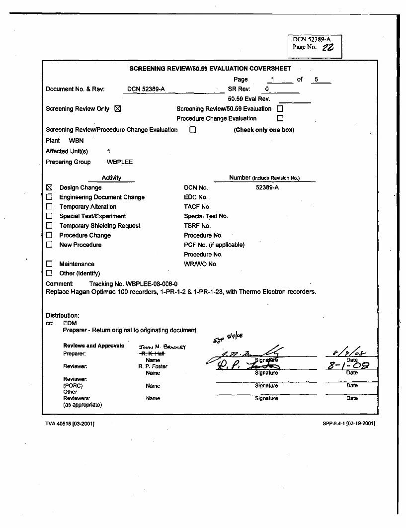
DCN 52389-APage No.
SCREENING REVIEWiS0.59 EVALUATION COVERSHEET
Page 1 of 5Document No. & Rev: DCN 52389-A SR Rev: 0
50.59 Eval Rev.
Screening Review Only 0 Screening Review150.59 Evaluation ElProcedure Change Evaluation El
Screening Review/Procedure Change Evaluation El (Check only one box)
Plant WBN
Affected Unit(s) I
Preparing Group WBPLEE
E]
0
ElElElElElEl
Activity
Design Change
Engineering Document Change
Temporary Alteration
Special Test/Experment
Temporary Shielding Request
Procedure Change
New Procedure
DCN No.
EDC No.
TACF No.
Special Test No.
TSRF No.
Procedure No.
PCF No. (if applicable)
Procedure No.
Number (Include Revision No.)
52389-A
El' Maintenance WRIWO No.El Other (Identify)Comment: Tracking No. WBPLEE-08-006-0Replace Hagan Optimac 100 recorders, 1-PR-1-2 & 1-PR-1-23, with Thermo Electron recorders.
Distribution:cc: EDM
Preparer - Return original to originating document
Qr4146cReviews and ApprovalsPreparer.
Reviewer:
Reviewer.(PORC)OtherReviewers:(as appropriate)
NameR. P. Foster
NameDateDate
Date
Date
Name
Name
Signature
Signature
TVA 40518 103-2001] SPP-9.4-1 103-19-2001]
TVA 40518103-20011 SPP-9.4-1103-19-20011
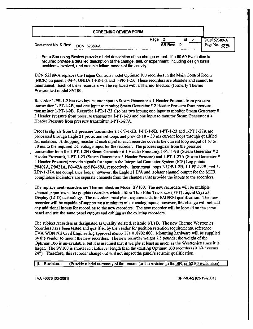
SCREENING REVIEW FORM
Document No. & Rev: DCN 52389-A SR Rev: 0
I. For a Screening Review provide a brief description of the change or test. If a 50.59 Evaluation isrequired provide a detailed description of the change, test, or experiment; including design basisaccidents involved, and credible failure modes of the activity.
DCN 52389-A replaces the Hagan Controls model Optimac 100 recorders in the Main Control Room(MCR) on panel 1-M4, UNIDs 1-PR-1 -2 and 1-PR- 1-23. These recorders are obsolete and cannot bemaintained. Each of these recorders will be replaced with a Thermo Electron (formerly ThermoWestronics) model SVI100.
Recorder 1-PR-1 -2 has two inputs; one input to Steam Generator # I Header Pressure from pressuretransmitter 1-PT-1-2B, and one input to monitor Steam Generator # 2 Header Pressure from pressuretransmitter 1-PT-l-9B. Recorder 1-PR-1-23 also has two inputs; one input to monitor Steam Generator #3 Header Pressure from pressure transmitter I-PT-1-23 and one input to monitor Steam Generator # 4Header Pressure from pressure transmitter 1-PT-1-27A.
Process signals from the pressure transmitter's 1-PT-1-2B, 1-PT-1-9B, 1-PT-1-23 and 1-PT 1-27A areprocessed through Eagle 21 protection set loops and provide 10 - 50 ma current loops through qualifiedE/I isolators. A dropping resistor at each input to each recorder coverts the currentrloop output of 10 to50 ma to the required DC voltage input for the recorder. The process signals from the pressuretransmitter loop for 1-PT-1 -2B (Steam Generator # 1 Header Pressure), 1-PT- 1-9B (Steam Generator # 2Header Pressure), 1-PT- 1-23 (Steam Generator # 3 Header Pressure) and 1-PT-1-27A (Steam Generator #4 Header Pressure) provide signals for input to the Integrated Computer System (ICS) Log pointsP0401A, P0421A, P0442A and P0460A, respectively. Instrument loops I-LPP-1-2B, 1-LPP-1-9B, and 1-LPP-1 -27A are compliance loops; however, the Eagle 21 D/A and isolator channel output for the MCRcompliance indicators are separate channels from the channels that provide the inputs to the recorders.
The replacement recorders are Thermo Electron Model SV100. The new recorders will be multiplechannel paperless video graphic recorders which utilize Thin-Film Transistor (TFT) Liquid CrystalDisplay (LCD) technology. The recorders meet plant requirements for EMI/RFI qualification. The newrecorder will be capable of supporting a minimum of six analog inputs; however, this change will not addany additional inputs for recording to the new recorders. The new recorder will be located on the samepanel and use the same panel cutouts and cabling as the existing recorders.
The subject recorders as designated as Quality Related, seismic I(L) B. The new Thermo Westronicsrecorders have been tested and qualified by the vendor for position retention requirements, referenceTVA WBN NE Civil Engineering approval memo T71 010702 800. Mounting hardware will be suppliedby the vendor to mount the new recorders. The new recorder weight 7.5 pounds; the weight of theOptimac 100 is un-available, but it is assumed that it weighs at least as much as the Westronics since it islarger. The SV100 is shorter in cantilever length than the existing Optimac 100 recorders (9 1/4" versus24"). Therefore, this recorder change out will not impact the panel's seismic qualification.
1II. Revision: (Provide a brief summary of the reason for the revision to the SR, or 50.59 Evaluation)
TVA 40673 [03-20011 SPP-9.4-2 [03-19-2001]
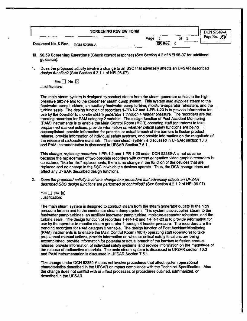
SCREENING REVIEW FORM DCN 52389-A
Page 3 of 5 Page No.
Document No. & Rev: DCN 52389-A SR Rev: 0
II1. 50.59 Screening Questions (Check correct response) (See Section 4.2 of NEI 96-07 for additionalguidance):
1. Does the proposed activity involve a change to an SSC that adversely affects an UFSAR describeddesign function? (See Section 4.2.1.1 of NEI 96-07)
Yes F1 No 0Justification:
The main steam system is designed to conduct steam from the steam generator outlets to the highpressure turbine and to the condenser steam dump system. This system also supplies steam to thefeedwater pump turbines, an auxiliary feedwater pump turbine, moisture-separator reheaters, and theturbine seals. The design function of recorders I-PR-1-2 and 1-PR-1-23 is to provide information foruse by the operator to monitor steam generator I through 4 header pressure. The recorders are thetrending recorders for PAM category 2 variable. The design function of Post Accident Monitoring(PAM) instruments is to enable the Main Control Room (MCR) operating staff (operators) to takepreplanned manual actions, provide information on whether critical safety functions are beingaccomplished, provide information for potential or actual breach of the barriers to fission productrelease, provide information of individual safety systems, and provide information on the magnitude ofthe release of radioactive materials. The main steam system is discussed in UFSAR section 10.3and PAM instrumentation is discussed in UFSAR Section 7.5.1.
This change, replacing recorders 1-PR-1-2 and 1-PR-1-23 under DCN 52389-A is not adversebecause the replacement of two obsolete recorders with current generation video graphic recorders isconsidered "like for like" replacements; there is no change in the function of the devices that arereplaced and no change in the SSC in which the devices operate. Thus, the DCN change does notaffect any UFSAR described design functions.
2. Does the proposed activity involve a change to a procedure that adversely affects an UFSARdescribed SSC design functions are performed or controlled? (See Section 4.2.1.2 of NEI 96-07)
Yes 5] No 09Justification:
The main steam system is designed to conduct steam from the steam generator outlets to the highpressure turbine and to the condenser steam dump system. This system also supplies steam to thefeedwater pump turbines, an auxiliary feedwater pump turbine, moisture-separator reheaters, and theturbine seals. The design function of recorders 1-PR-1-2 and 1-PR-1-23 is to provide information foruse by the operator to monitor steam generator 1 through 4 header pressure. The recorders are thetrending recorders for PAM category 2 variable. The design function of Post Accident Monitoring(PAM) instruments is to enable the Main Control Room (MCR) operating staff (operators) to takepreplanned manual actions, provide information on whether critical safety functions are beingaccomplished, provide information for potential or actual breach of the barriers to fission productrelease, provide information of individual safety systems, and provide information on the magnitude ofthe release of radioactive materials. The main steam system is discussed in UFSAR section 10.3and PAM instrumentation is discussed in UFSAR Section 7.5.1.
The change under DCN 52389-A does not involve procedures that affect system operationalcharacteristics described in the UFSAR or impact compliance with the Technical Specification. Alsothe change does not conflict with or affect processes or procedures outlined, summarized, ordescribed in the UFSAR.
Document No. &Rev:
3 Does the proposed activity involve revising or replacing an UFSAR described evaluation methodologythat is used in establishing the design bases or used in the safety analyses? (See Section 4.2.1.3 ofNEI 96-07)
YesE[] No 0
Justification: There is no UFSAR described evaluation methodologies associated with the hardwarereplacement to be implemented under DCN 52389-A.
4 Does the proposed activity involve a test or experiment not described in the UFSAR, where an SSC isutilized or controlled in a manner that is outside the reference bounds of the design for that SSC or isinconsistent with analyses or descriptions in the UFSAR? (See Section 4.2.2 of NEI 96-07)
Yes E] No 0
Justification: The proposed change under DCN 52389-A does not involve a test or experiment eitherdescribed or not described in the UFSAR.
5 Does the proposed activity require a change to the Technical Specifications?
Yes El No 0
Justification: The proposed DCN modification does not affect or contradict with requirements andstatements in Tech Spec section 3.3.3 Post Accident Monitoring (PAM) instrumentation and section 3.7Plant Systems. Therefore, the proposed activity will not require a change to the TechnicalSpecifications.
TVA 40673 [03-20011 SPP-9.4-2 [03-19-2001]
DCN 52389-ASCREENING REVIEW FORM Page No.
Page 5 of5
Document No. & Rev: DCN 52389-A SR Rev: 0
IV. If all questions are answered NO, then implement the activity per the applicable plant procedure forthe type of activity without obtaining a License Amendment.If screen question 5 is answered YES, then request and receive a License Amendment prior toimplementation of the activity.If screen question 5 is answered NO-and question 1, 2, 3 or 4 is answered YES, then a 50.59Evaluation shall be performed.If only screen question 3 is answered YES, then only question 8 in the 50.59 Evaluation is required tobe answered.If screen question 3 is answered NO, then question 8 in the 50.59 Evaluation may be leftunanswered.
NOTE If an FSAR change is involved process that change per NADP-7, FSAR Management.
V. List the documents (UFSAR, Technical Specifications, and other documents) reviewed where relevantinformation was found, including section numbers:
System DescriptionsN3-1-4002 Rev. 14- Main Steam System
Desiqn CriteriaWB-DC-30-7 Rev. 21 - Post Accident Monitoring Instrumentation
UFSAR Sections7.5.1 - PAM Instrumentation10.3 - Main Steam
Technical Specification Sections3.3.3 - PAMB-3.2 - Plant Systems
TVA 40673 [03-20011 SPP-9.4-2 [03-19-2001]
I"MN-:S4ZAC- -7 ý0.6, ý ý
f~t~- L~*' ~ I L/
SCREENING REVIEW/50.59 EVALUATION COVERSHEET
Page 1 of 8
Docuuumentro. & Rev: UCN 52957A SR Rev: 1
50.59 Eval Rev.
Screening Review Only [ Screening Review/50.59 Evaluation ElProcedure Change Evaluation I]
Screening Review/Procedure Change Evaluation El (Check only one box)
Plant WBN
Affected Unit(s) 1
Preparing Group SE-EE
I ;
Activity
ED Design Change
C3 Engineering Document ChangeEl Temporary Alteration
El Special Test/Experiment
El Temporary Shielding Request
E3 Procedure Change
El New Procedure
El Maintenance
[E Other (Identify)
Comment:WBLEE-09-1 0
Number (include Revision No.)
DCN No.
EDC No.
TACF No.
Special Test No.
TSRF No.
Procedure No.
PCF No. (if applicable)
Procedure No.
WR/WO No.
52957A
Distribution:cc: EDM
Preparer - Return originalto originating document
Reviews and Approvals Onu;l L Pede A-
Preparer:
Reviewer:
Reviewer:(PORC)OtherReviewers:(as appropriate)
Samuel J. TyusName
Tyson D. WashburnName
Name
Name
Date
Date
Date
SignatureN/A
SignatureN/A
Signature
TVA 40518 [03-2001] SPP-9.4-l
[03-19-2001]
T-VA 40518 [03 -200 1 ] SPP-9.4-1 [03-19-2001]
ALy Q62LJ_50.59 EVALUATION FORM-
Page 2 of 8Document No. & Rev: DCN 52957 A 50.59 Eval Rev:
I.For a Screening Review provide a brief description of the change or test. If a 50.59 Evaluation is requiredprovide a detailed description of the change, test, or experiment; including design basis accidents involved,and credible failure modes of the activity.
The operability, including position indication, of the shutdown and control rods is an initialassumption In all safety analyses that assume rod insertion upon reactor trip. Rod PositionIndication (RPI) is required to assess operability and misalignment (Technical Specification BasesSection B 3.1.8). PER 147132 documents a condition where all three forms of RPI, indication on l-M-4, Maintenance Test Panel (MTP) in the Auxiliary Instrument Room (AIR) and the IntegratedComputer System (ICS), was lost due to a communications path failure while the alternate path wasout of service for testing. A simultaneous failure of all Indications of the Rod Position IndicationSystem (RPIS) places the plant in LCO 3.0.3. CERPI components do not perform a primary safetyfunction defined in N3-85-4003 Section 2.1.1; it does support Instrumentation and ControlRequirements In Section N3-85-4003 2.2.8 and In TS LCO 3.1.8. The simultaneous failure of bothCERPI channels A and B would prevent the compliance with the actions in LCO 3.1.8 which wouldrequire entry Into LCO 3.0.3.
The RPIS provides continuous rod position information for each Shutdown and Control Rod. Thissystem provides rod position information independent of the Rod Control System. The equipmentassociated with rod position monitoring does not perform a safety-related function and Is onlyrequired to be qualified to Seismic Category I(L), position retention only, In accordance with WB-DC-40-31.13. (System Description N3-85-4003)
The System Description Is changed as Indicated in this package. No changes to the FSAR orTechnical Specifications are required by this DCN.
DCN 52957 performs modifications to the RPIS to make the system more reliable. The modificationis accomplished by adding components to the existing system that will provide physicalindependence leading to two redundant communication paths between each PLC, in the AIR, andthe flat panel displays on Panel 1-M-4 In the Main Control Room (MCR). The Westinghouse portionof the system is known as the Computer Enhanced-Rod Position Indication System (CERPI). Thethree terms, RPIS, CERPI, and ARPI, are used interchangeably and will be treated as such in thisdocument.
The new system will have redundant Independent communication paths for each PLC between theAIR and MCR; Li and L2 for each PLC. This configuration allows complete failure in one PLCcommunication path while continuing to provide RPi in the MCR (1-M-4), AIR (MTP), and ICS.
An additional power cable will be added from 1-M-7, 120V Instrument Power A Rack, to a newredundant power strip in the AIR CERPI panels to provide a secondary power source. This willprovide two independent power sources, one for each PLC and MTP, in order to provide a separatecommunications path to each flat panel display in the MCR. The existing power strip Is suppliedfrom 1-M-7, 120V Instrument Power B Rack. Instrument Power A Rack is the alternate source for BRack via a transfer switch. This minimizes the Impact to the system since the alternate path alreadywas considered for the entire load; the existing load is split between the sources and additionalredundant components added in the CERPI panels. In addition, the existing spare breaker in 1-M-7(A & B) are replaced with new like for like breakers for the CERPI panel feeds.
Redundancy is also added to further enhance CERPI reliability with regards to connection to thePlant Computer System (ICS). The existing ICS connection to CERPI AIR Panel 1-R-41 Is via Panel 1-R-174 in the AIR. Due to the addition of the new redundant equipment in the CERPI AIR Panels, aredundant ICS connection Is added. This requires a new fiber optic cable to be pulled. Due to thelocation of the CERPI panels In relation to the ICS main connection in the Computer Room and thefact that the new fiber optic cables are hybrid cables with 12 multimode and 6 single mode fibers, it
TVA 40676 [03-2001] SPP-9.4-6 [03-19-20011
rIc No. 54246
50.59 EVALUATION FORM -
Page 3 of 8Document No. & Rev: DCN 52957 A 50.59 Eval Rev:
Is more efficient to pull a new fiber directly to the ICS panels, 1-R-153 & 1-R-154, in the ComputerRoom. The existing fiber cable, 1C1170, between 1-R-41 and 1-R-174 Is left In place for futureconnection to ICS. To support new Cyber Security requirements new Ethernet switches, Firewalls,and line sensing equipment are added to Panels 1-R-153 & 1-R-154. Existing connections to ICSfrom 1-R-174 and CERPI are routed to these new switches which are connected to the DataAcquisition Network via new fire walls, one layer below ICS to provide improved security.
This modification will require changes to annunciator panel 1-XA-55-4A & 4B; windows 64F (C-lIBank D Auto Withdrawal Blocked), 86C (RPI Trouble), 87A (Rod Insertion Limit LO), 87B (RodInsertion Limit LO LO), and 87D (Rods At Bottom) are engraved for re-flash. These alarm changesmeet the requirement of DS-E18.1.24, section 3.7. ARI-64-70 & ARI-81-87 requires revision to reflectthe re-flash function.
UFSAR Described System Functions
RPIS, ICS (Plant Computer), and Annunciation7.7.1.3.2 Main Control Room Rod Position IndicationTwo separate systems are used to indicate rod position information in the main control room.One system measures the actual drive rod position as part of the Rod Position Indicator System(RPIS). The second system counts and displays the pulses for rod movement generated in thelogic cabinet.
1. Rod Position Indication SystemThe position of each rod (57) [Shutdown and Control banks] is displayed on main control room(MCR) displays. These RPIS receives analog signals from sensors mounted on the rod drivemechanism, calculates rod position from these signals, and displays this information on the MCRdisplays. The scale is in units of steps and covers the entire range of travel. Additionally, a rodbottom indicator light for each rod (57) is shown on the MCR displays to indicate a rod is near thefully inserted position.
2. Rod Position Step CounterThe position demand signal for each rod group (14) is displayed on a 3-digit, add-subtract stepcounter. The input signal is supplied from the logic cabinet circuitry. The demand position and rodposition indication systems are separate systems; the rod position indication system is described indetail in References [3] and [17].
Unit Operation with an Inoperable RPIS IndicatorThe malfunction of an indicator in the RPIS is addressed by controls established in the technicalspecifications. The controls include requirements to use the moveable incore detectors to verify theposition of the affected rod whenever an indicator is inoperable. This action may be periodicallyrepeated for the duration of the period the indicator is inoperable. A second action is available inthe technical specifications to address the malfunction of an indicator for an extended period oftime (referred to as the extended action in this discussion). The options provided by the extendedaction allows for continued operation in a situation where the component causing the indicator tobe inoperable is inaccessible due to operating conditions (adverse radiological or temperature
TVA 40676 [03-2001] SPP-9.4-6 [03-19-20011]
L41 ~Dclv 5T27s7 PA41;.j-1/
I 50.59 EVALUATION FORM -
Page 4 of 8Document No. & Rev: DCN 52957 A 50.59 Eval Rev:
environment). In this situation, repair of the indicator cannot occur until the unit is in an operatingmode that allows access to the failed components.
The primary purpose for this option is to prevent unnecessary wear on the incore detectors due torepeated use over an extended period. During the use of the extended action signal cables areconnected to the CRDM circuitry test points on a temporary basis to monitor the operation andtiming of the lift coil and the stationary gripper coil and to provide instrumentation for themonitoring of the position of the affected rod in the MCR. As indicated previously, the initialposition of the affected rod (control or shutdown) is verified by use of the incore detectors. Oncethe position is known and the monitoring circuits required for use of the extended action are inplace, the position of the rod is programmed into the plant computer. The program displays theposition of the rod on the plant computer or on a recorder located in the MCR.
Once the extended action is implemented, the parameters of the rod control system must bemonitored until the failed indicator is repaired. The monitoring function is assisted by a series ofalarms controlled by the plant computer that address unintended movement of the rod. Alarms areinitiated if the affected rod steps in a direction other than what was demanded, if the affected rodstepped with no demand and if the monitoring circuitry fails. Receipt of any alarm requires theverification of the position of the rod by use of the incore detectors. The technical specificationsthat govern the use of the extended action contains the following provisions to ensure thetemporary circuit is functioning properly and the position of the affected rod is periodicallyverified:
1. Verification of the position of the rod every 31 days using the incore movable detectors.2. Verification of the position of the rod with the inoperable analogy rod position indication(ARPI) by use of the moveable incore detectors, whenever the rod is moved greater than 12 stepsin one direction.
During the period the extended ,action is implemented, actions required by the technicalspecifications that address rod group alignment limits, heat flux hot channel factor and nuclearenthalpy rise hot channel factor may serve to verify the correct operation of the temporary circuit.Provisions are also provided in the technical specifications that address operation of the unit underthe extended action when reactor thermal power (RTP) is less than or equal to 50%RTP and the unit is to be returned for full power operation. Implementation of the extended actionand the installation of the temporary circuit include a review of the modification for impact onplant procedures and training. This ensures that changes are initiated for key issues like themonitoring requirements in the MCR, and operator training on the temporary equipment.
7.7.1.3.5 Rods At BottomA "Rods At Bottom" annunciation is actuated in the main control room when any of the shutdownand control bank rods are near the fully inserted position. The RPIS monitors the analog signalfrom the rod position detectors and actuates this alarm when the rods are positioned below thesetpoint. (The RPIS blocks this alarm signal for control banks B, C, and D). '
TVA 40676 [03-2001] SPP-9.4-6 [03-19-2001 ]
5.9EVALUATION FORM - -
Page 5 of 8Document No. & Rev: DCN 52957 A 50.59 Eval Rev:
7.7.2.2 Response Considerations of ReactivityThe control rod drive system is designed to minimize the effects of a single electrical ormechanical failure in the rod control system that could cause the accidental withdrawal of a singlerod cluster control assembly from the partially inserted bank at full power operation. The operatorcould deliberately withdraw a single rod cluster control assembly in the control bank; this featureis necessary in order to retrieve a rod, should one be accidentally dropped. In the extremelyunlikely event of simultaneous electrical failures which could result in single rod cluster controlassembly withdrawal, rod deviation would be displayed on the plant annunciator, and the rodposition displays would indicate the relative positions of the rods in the bank.
The rod position indication system provides direct visual displays of each control rod assemblyposition. The plant computer alarms for deviation of rods from their banks. In addition, the RPISprovides a rod insertion limit monitor which provides an alarm to warn the operator of an approachto an abnormal condition due to dilution. The low-low insertion limit alarm alerts the operator tofollow immediate boration procedures. The facility reactivity control systems are such thatacceptable fuel damage limits will not be exceeded even in the event of a single malfunction ofeither system.
15.3.6.1 Identification of Causes and Accident DescriptionThe current WBN design basis for the single rod cluster control assembly (RCCA) withdrawal atfull power event assumes no single electrical or mechanical failure in the rod control system couldcause the accidental withdrawal of a single RCCA from the inserted bank at full power operation.The operator could deliberately withdraw a single RCCA in the control bank since this feature isnecessary in order to retrieve an assembly should one be accidentally dropped. In the ,extremelyunlikely event of simultaneous electrical failures which could result in single RCCA withdrawal,rod deviation and rod control urgent failure would both be displayed on the plant annunciator, andthe rod position indicators would indicate the relative positions in the assemblies in the bank. Theurgent failure alarm also inhibits automatic rod withdrawal. Withdrawal of a single RCCA byoperator action would result in activation of the same alarm and the same visual indications.
Other sections of the SAR address RPIS (see reference section) but the above reflects the major
description of RPIS and the remaining sections only restate what is described here
|11. Revision: (Provide a brief summary of the reason for the revision to the SR, or 50.59 Evaluation)
Revision 0: Initial IssueRevision 1: Incorporation of PIC 54248
TVA 40676 [03-2001] SPP-9.4-6 [03-19-20011
:074& -ý-.i7T7 Pht,.,,550-69 EVALUATION FORM -
Page 6 of 8Document No. & Rev: DCN 52957 A 50.59 Eval Rev:
III. 50.59 Screening Questions (Check correct response) (See Section 4.2 of NEI 96-07 for additionalguidance):
1. Does the proposed activity involve a change to an SSC that adversely affects an UFSAR describeddesign function? (See Section 4.2.1.1 of NEI 96-07)
Yes El No 0
Justification:The design function of the RPIS is to receive signals from sensors mounted on the rod drivemechanism, calculates rod position from these signals, and displays this information on theMCR displays. This DCN does not change the original design function of the RPIS system. DCN52957 performs modifications to the RPISI CERPI to make the system more reliable. Themodification is accomplished by adding components to the existing system that will providephysical independence leading to two redundant communication paths between each PLC andflat panel display; In addition ICS communication path redundancy is added between the AIRCERPI Node Boxes and the Computer Room ICS connections. (The terms, RPIS, CERPI andARPI, are used interchangeably.)
With the existing configuration, PLC A and B provide Inputs to both MCR monitors. Eachmonitor can display data from both PLC A and B. With the new configuration implemented bythis DCN, monitor A can only display data from PLC A and monitor B can only display datafrom PLC B. While this improves system reliability by removing a single failure point that couldin-op the data to both MCR displays, the MCR displays are no longer able to display data fromeither PLC. If a PLC fails operators will no longer be able to use both displays to see the datafrom the remaining PLC. This is acceptable because the remaining operable PLCIMCR monitorpair can display all rod positions.
Firewalls are installed so that a network failure (data storm) in the other CERPI channel or theplant computer system (ICS) will not adversely impact both the A and B CERPI channels. ACyber Security Assessment was performed by TVA Corporate. Based on this assessment anew Cyber Security Intrusion Detection computer is added to this equipment to insurecompliance with the Cyber Security requirement of SS E18.15.01.
The CERPI software code has had a long successful operating history on various plants. Thechanges to the CERPI software will have Verification and Validation testing performedincluding factory acceptance testing (FAT) and post modification testing (PMT). This minimizesthe potential for software failures including common mode failures. Note that this is not aprotection system or an Injection system so the requirement in BTP-19 that a common modesoftware failure must be assumed is not applicable.
Site Evaluations for Electrical, Civil, and Mechanical, including calculations as referenced,prove no adverse impact to the site electrical system, structures, or fire protection due to themodifications by DCN 52957.
Equipment that is replaced I added by Westinghouse Is considered like for like or identical tothat previously evaluated and installed for EMIIRFI considerations. The new power supplies,which are more efficient, are FCC Class A compliant and therefore approved by TVA forEMI/RFI considerations in accordance with SPP-4.1 and TVA Corporate Engineering. Operatinghistory at WBN with existing CERPI equipment shows no EMIIRFI related Issues.
Therefore the UFSAR described functions are not adversely affected.
TVA 40676 [03-20011 SPP-9.4-6 [03-19-2001]
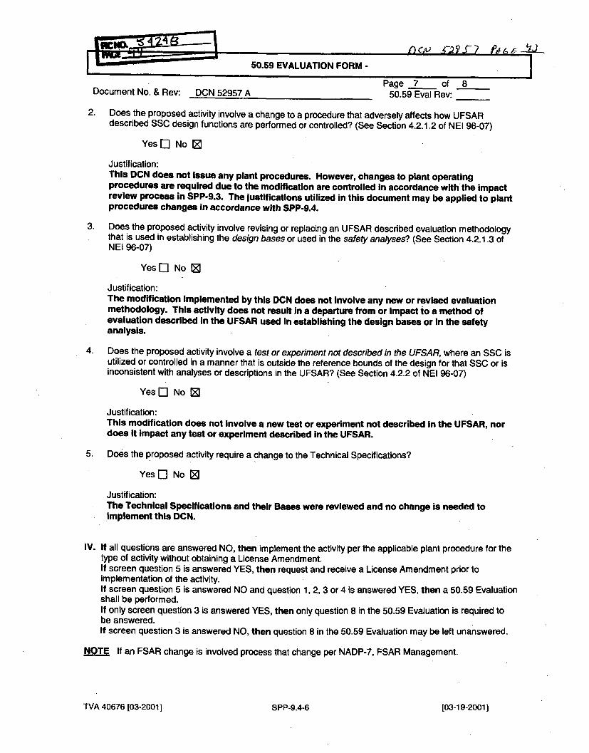
~~~~~50.59 EVALUATION FORM - J =•L-.-
Page 7 of 8Document No. & Rev: DCN 52957 A 50.59 Eval Rev:
2. Does the proposed activity involve a change to a procedure that adversely affects how UFSARdescribed SSC design functions are performed or controlled? (See Section 4.2.1.2 of NEI 96-07)
Yes [3 No 0
Justification:This DCN does not Issue any plant procedures. However, changes to plant operatingprocedures are required due to the modification are controlled in accordance with the impactreview process in SPP-9.3. The justifications utilized in this document may be applied to plantprocedures changes in accordance with SPP-9.4.
3. Does the proposed activity involve revising or replacing an UFSAR described evaluation methodologythat is used in establishing the design bases or used in the safety analyses? (See Section 4.2.1.3 ofNEI 96-07)
Yes El No 0
Justification:The modification Implemented by this DCN does not Involve any new or revised evaluationmethodology. This activity does not result In a departure from or Impact to a method ofevaluation described in the UFSAR used In establishing the design bases or In the safetyanalysis.
4. Does the proposed activity involve a test or experiment not described in the UFSAR, where an SSC isutilized or controlled in a manner that is outside the reference bounds of the design for that SSC or isinconsistent with analyses or descriptions in the UFSAR? (See Section 4.2.2 of NEI 96-07)
Yes E] No 0@
Justification:This modification does not involve a new test or experiment not described in the UFSAR, nordoes it Impact any test or experiment described in the UFSAR.
5. Does the proposed activity require a change to the Technical Specifications?
Yes El No 0]
Justification:The Technical Specifications and their Bases were reviewed and no change is needed toImplement this DCN.
IV. If all questions are answered NO, then implement the activity per the applicable plant procedure for thetype of activity without obtaining a License Amendment.If screen question 5 is answered YES, then request and receive a License Amendment prior toimplementation of the activity.If screen question 5 is answered NO and question 1, 2, 3 or 4 is answered YES, then a 50.59 Evaluationshall be performed.If only screen question 3 is answered YES, then only question 8 in the 50.59 Evaluation is required tobe answered.If screen question 3 is answered NO, then question 8 in the 50.59 Evaluation may be left unanswered.
NOTE If an FSAR change is involved process that change per NADP-7, FSAR Management.
TVA 40676 [03-2001] SPP-9.4-6 [03-19-20011
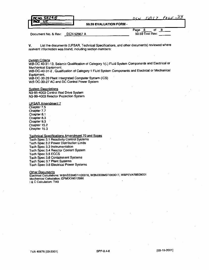
- L~)PAGE. id5--I 1flcNO.~4Z~e 1 50.59 EVALUATION FORM - b -t7
Page 8 of 8Document No. & Rev: DCN 52957 A 50.59 Eval Rev:
V. List the documents (UFSAR, Technical Specifications, and other documents) reviewed whererelevant information was found, including section numbers:
Design CriteriaWI3-DC 40-31-13, Seismic Qualification of Category 1(L) Fluid System Components and Electrical orMechanical Equipment.WB-DC-40-31-2 , Qualification of Category 1 Fluid System Components and Electrical or MechanicalEquipment.WB-DC-30-29 Plant Intergrated Computer System (ICS)WB-DC-30-27 AC and DC Control Power System
Sy-stem DescriptionsN3-85-4003 Control Rod Drive SystemN3-99-4003 Reactor Protection System
UFSAR Amendment 7Chapter 7.5Chapter 7.7Chapter 8.1Chapter 8.3Chapter 9.3Chapter 15.2Chapter 15.3
Technical Specifications Amendment 70 and BasesTech Spec 3.1 Reactivity Control SystemsTech Spec 3.2 Power Distribution LimitsTech Spec 3.3 InstrumentationTech Spec 3.4 Reactor Coolant SystemTech Spec 3.5 ECCSTech Spec 3.6 Containment SystemsTech Spec 3.7 Plant SystemsTech Spec 3.8 Electrical ,Power Systems
Other DocumentsElectrical. Calculations: WBNEEBMSTI120016, W BNEEBMSTI060017, WBPEVAR9509001Mechanical Calculation: EPMDOM012990I & C Calculation: T149
TVA 40676 [03-2001] SPP-9.4-6 [03-19-2001]
Enclosure 2TVA Letter Dated October 29, 2010
Responses, to Licensee Open Items to be Resolved for SER Approval
Attachment 9
Cross Reference Between The Unit 2 and Unit I PAMS Variable SourcesFor Unique WBN Unit 2 Variables Within The Scope Of The Foxboro Spec 200, Common
Q PAMS And Foxboro I/A changes.
Q'
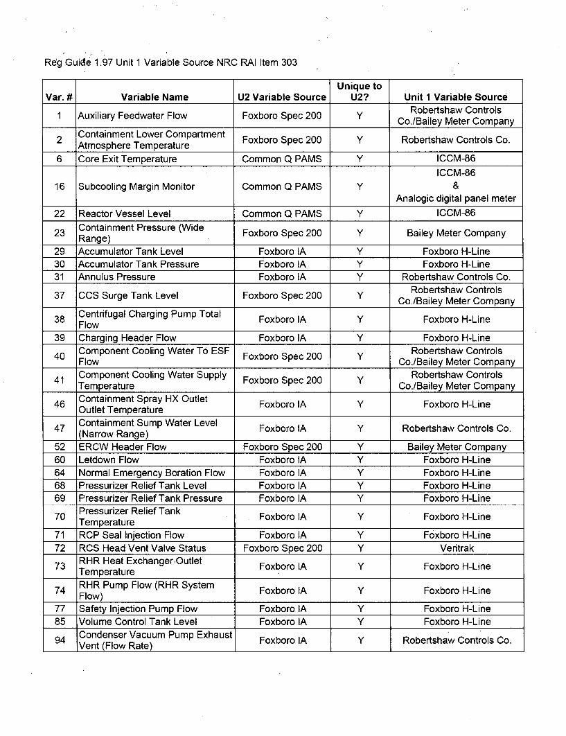
Reg Guide 1.97 Unit 1 Variable Source NRC RAI Item 303
Unique toVar. # Variable Name U2 Variable Source U2? Unit 1 Variable Source
Robertshaw Controls1 Auxiliary Feedwater Flow Foxboro Spec 200 Y CoBeyter Company
Co./Bailey Meter CompanyContainment Lower Compartment
2 Atment Loweratme Foxboro Spec 200 Y Robertshaw Controls Co.____Atmosphere Temperature__________________
6 Core Exit Temperature Common Q PAMS Y ICCM-86
ICCM-8616 Subcooling Margin Monitor Common Q PAMS Y &
Analogic digital panel meter
22 Reactor Vessel Level Common Q PAMS Y ICCM-86
23 Containment Pressure (Wide Foxboro Spec 200 Y Bailey Meter CompanyRange) _________ _____ _ _ _ _ _ _ _ _ _ _ _ _
29 Accumulator Tank Level Foxboro IA Y Foxboro H-Line30 Accumulator Tank Pressure Foxboro IA Y Foxboro H-Line31 Annulus Pressure Foxboro IA Y Robertshaw Controls Co.
Robertshaw Controls37 CCS Surge Tank Level Foxboro Spec 200 Y CoBeyter Company
Co./Bailey Meter Company
38 Centrifugal Charging Pump Total Foxboro IA Y Foxboro H-LineFlow39 Charging Header Flow Foxboro IA Y Foxboro H-Line
Component Cooling Water To ESF Foxboro Spec 200 Y Robertshaw Controls40 Flow Co./Bailey Meter Company
Component Cooling Water Supply Robertshaw Controls41 Temperature Foxboro Spec 200 Co./Bailey Meter Company
46 Containment Spray HX Outlet Foxboro IA Y Foxboro H-LineOutlet Temperature
47 Containment Sump Water Level Foxboro IA Y Robertshaw Controls Co.(Narrow Range)
52 ERCW Header Flow Foxboro Spec 200 Y Bailey Meter Company60 Letdown Flow Foxboro IA Y Foxboro H-Line64 Normal Emergency Boration Flow Foxboro IA Y Foxboro H-Line68 Pressurizer Relief Tank Level Foxboro IA Y Foxboro H-Line69 Pressurizer Relief Tank Pressure Foxboro IA Y Foxboro H-Line70 Pressurizer Relief Tank Foxboro IA Y Foxboro H-Line
Temperature71 RCP Seal Injection Flow Foxboro IA Y Foxboro H-Line72 RCS Head Vent Valve Status Foxboro Spec 200 Y Veritrak73 RHR Heat Exchanger, Outlet Foxboro IA Y Foxboro H-Line
Temperature74 RHR Pump Flow (RHR System Foxboro IA Y Foxboro H-Line
Flow)77 Safety Injection Pump Flow Foxboro IA Y Foxboro H-Line85 Volume Control Tank Level Foxboro IA Y Foxboro H-Line94 Condenser Vacuum Pump Exhaust Foxboro IA Y Robertshaw Controls Co.
Vent (Flow Rate)
Enclosure 2TVA Letter Dated October 29, 2010
Responses to Licensee Open Items to be Resolved for SER Approval
Attachment 10
TVA Design Criteria Document WB-DC-40-57,Watts Bar Nuclear Plant Unit 1/Unit 2,
"Anticipated Transients Without Scram Mitigation SystemActuation Circuitry (AMSAC)," Revision 4, dated August 11, 2008
and WITEL Open Items Report
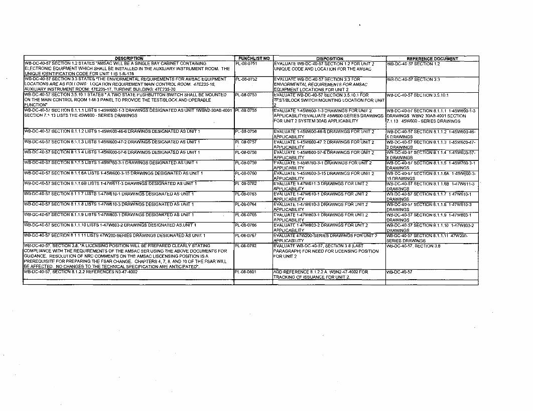
DESCRIPTION . PUNCHLIST NO DISPOSITION REFERENCE DOCUMENTWB-DC-40-57 SECTION 1.2 STATES "AMSAC WILL BE A SINGLE BAY CABINET CONTAINING PL-08-0751 EVALUATE WB-DC-40-57 SECTION 1.2 FOR UNIT 2 WB-DC-40-57 SECTION 1.2ELECTRONIC EQUIPMENT WHICH SHALL BE INSTALLED IN THE AUXILIARY INSTRUMENT ROOM. THE UNIQUE CODE AND LOCATION FOR THE AMSACUNIQUE IDENTIFICATION CODE FOR UNIT I IS 1-R-178.WB-DC-40-57 SECTION 3.3 STATES -THE ENVIORMENTAL REQUIREMENTS FOR AMSAC EQUIPMENT PL-08-0752 EVALUATE WB-DC-40-57 SECTION 3.3 FOR WB-DC-40-57 SECTION 3.3LOCATIONS ARE AS FOLLOWS: LOCATION REQUIREMENT MAIN CONTROL ROOM: 47E235-16, ENVIORMENTAL REQUIREMENTS FOR AMSACAUXILIARY INSTRUMENT ROOM: 47E235-17, TURBINE BUILDING: 47E235-20 EQUIPMENT LOCATIONS FOR UNIT 2
WB-DC-40-57 SECTION 3.5.10.1 STATES "A TWO STATE PUSHBUTTON SWITCH SHALL BE MOUNTED PL-08-0753 EVALUATE WB-DC-40-57 SECTION 3.5.10.1 FOR WB-DC-40-57 SECTION 3.5.10.1ON THE MAIN CONTROL ROOM 1-M-3 PANEL TO PROVIDE THE TEST/BLOCK AND OPERABLE TEST/BLOCK SWITCH MOUNTING LOCATION FOR UNITFUNCTION" 2WB-DC-40-57 SECTION 8.1.1.1 LISTS 1-45W600-1-3 DRAWINGS DESIGNATED AS UNIT 1WBN2-30AB-4001 PL-08-0755 EVALUATE 1-45W600-1-3 DRAWINGS FOR UNIT 2 WB-DC-40-57 SECTION 8.1.1.1 1-5W600-1-3
SECTION 7.1.13 LISTS THE 45W600 - SERIES DRAWINGS APPLICABILITYEVALUATE 45W600-SERIES DRAWINGS DRAWINGS WBN2-30AB-4001 SECTIONFOR UNIT 2 SYSTEM 30AB APPLICABILITY 7.1.13 45W600 - SERIES DRAWINGS
WB-DC-40-57 SECTION 8.1.1.2 LISTS 1-45W600-46-6 DRAWINGS DESIGNATED AS UNIT 1 PL-08-0756 EVALUATE 1-45W600-46-6 DRAWINGS FOR UNIT 2 WB-DC-40-57 SECTION 8.1.1.2 1-45W600-46-APPLICABILITY 6 DRAWINGS
WB-DC-40-57 SECTION 8.1.1.3 LISTS 1-45W600-47-2 DRAWINGS DESIGNATED AS UNIT 1 PL-08-0757 EVALUATE 1-45W600-47-2 DRAWINGS FOR UNIT 2 WB-DC-40-57 SECTION 8.1.1.3 1-45W600-47-APPLICABILITY 2 DRAWINGS
WB-DC-40-57 SECTION 8.1.1.4 LISTS 1-45W600-57-8 DRAWINGS DESIGNATED AS UNIT 1 PL-08-0758 EVALUATE 1-45W600-57-8 DRAWINGS FOR UNIT 2 WB-DC-40-57 SECTION 8.1.1.4 1-45W600-57-APPLICABILITY 8 DRAWINGS
WB-DC-40-57 SECTION 8.1.1.5 LISTS 1-45W760-3-1 DRAWINGS DESIGNATED AS UNIT 1 PL-08-0759 EVALUATE 145W760-3-1 DRAWINGS FOR UNIT 2 WB-DC-40-57 SECTION 8.1.1.5 1-45W760-3-1APPLICABILITY DRAWINGS
WB-DC-40-57 SECTION 8.1.1.6A LISTS 1-45W600-3-15 DRAWINGS DESIGNATED AS UNIT 1 PL-08-0760 EVALUATE 1-45W600-3-15 DRAWINGS FOR UNIT 2 WB-DC-40-57 SECTION 8.1.1.1A 1-45W600-3-_ APPLICABILITY 15 DRAWINGS
WB-DCA40-57 SECTION 8.1.1.6B LISTS 1-47W611-3 DRAWINGS DESIGNATED AS UNIT 1 PL-08-0762 EVALUATE 1-47W611-3 DRAWINGS FOR UNIT 2 WB-DC-40-57 SECTION 8.1.1.6B 1-4TW611-3APPLICABILITY DRAWINGS
WB-DC-40-57 SECTION 8.1.1.7 LISTS 1-47W610-1 DRAWINGS DESIGNATED AS UNIT 1 PL-08-0763 EVALUATE 1-47W610-1 DRAWINGS FOR UNIT 2 WB-DC-40-57 SECTION 8.1.1.7 1-47W610-1APPLICABILITY DRAWINGS
WB-DC-40-57 SECTION 8.1.1.8 LISTS 1-47W610-3 DRAWINGS DESIGNATED AS UNIT 1 PL-08-0764 EVALUATE 1-47W610-3 DRAWINGS FOR UNIT 2 WB-DC-40-57 SECTION 8.1.1.8 1-47W610-3APPLICABILITY DRAWINGS
WB-DC-40-57 SECTION 8.1.1.9 LISTS 1-47W803-1 DRAWINGS DESIGNATED AS UNIT 1 PL-08-0765 EVALUATE 1-47W803-1 DRAWINGS FOR UNIT 2 WB-DC-40-57 SECTION 8.1.1.9 1-47W803-1APPLICABILITY DRAWINGS
WB-DC-40-57 SECTION 8.1.1.10 LISTS 1-47W803-2 DRAWINGS DESIGNATED AS-UNIT 1 PL-08-0766 EVALUATE 1-47W803-2 DRAWINGS FOR UNIT 2 WB-DC-40-57 SECTION 8.1.1.10 1-47W803-2APPLICABILITY DRAWINGS
WB-DC-40-57 SECTION 8.1.1.11 LISTS 47W200-SERIES DRAWINGS DESIGNATED AS UNIT 1 PL-08-0767 EVALUATE 47W200-SERIES DRAWINGS FOR UNIT 2 WB-DC-40-57 SECTION 8.1.1.11 47W200-APPLICABILITY SERIES DRAWINGS
WB-DC-40-57, SECTION 3.8. "A LICENSING POSITION WILL BE PREPARED CLEARLY STATING PL-08-0792 EVALUATE WB-DC-40-57, SECTION 3.8 (LAST WB-DC-40-57. SECTION 3.8
COMPLIANCE WITH THE REQUIREMENTS OF THE AMSAC SER USING THE ABOVE DOCUMENTS FOR PARAGRAPH) FOR NEED FOR LICENSING POSITIONGUIDANCE. RESOLUTION OF NRC COMMENTS ON THE AMSAC LISCENSING POSITION IS A FOR UNIT 2PREREQUISITE FOR PREPARING THE FSAR CHANGE. CHAPTERS 4,7, 8, AND 10 OF THE FSAR WILLBE AFFECTED. NO CHANGES TO THE TECHNICAL SPECIFICATION ARE ANTICIPATED".
WB-DC-40-57, SECTION 8.1.2.2 REFERENCES N3-47-4002 PL-08-0801 ADD REFERENCE 8.1.2.2.A WBN2-47-4002 FOR WB-DC-40-57I TRACKING OF ISSUANCE FOR UNIT 2.
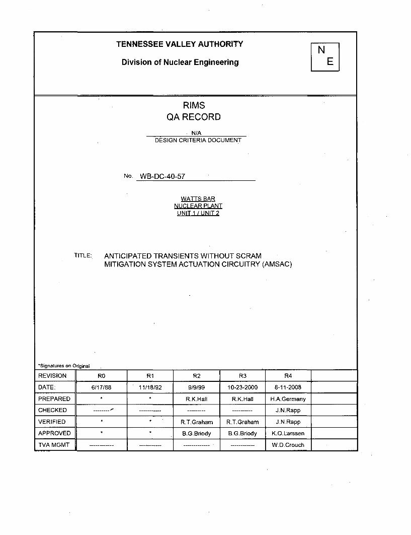
TENNESSEE VALLEY AUTHORITY
Division of Nuclear Engineering
RIMSQA RECORD
N/ADESIGN CRITERIA DOCUMENT
No. WB-DC-40-57
WATTS BARNUCLEAR PLANTUNIT 1 / UNIT 2
TITLE: ANTICIPATED TRANSIENTS WITHOUT SCRAMMITIGATION SYSTEM ACTUATION CIRCUITRY (AMSAC)
*Signatures on Original
REVISION RO R1 R2 R3 R4
DATE: 6/17/88 11/18/92 9/9/99 10-23-2000 8-11-2008
PREPARED * R.K.Hall R.K.Hall H.A.Germany
CHECKED -------- - J.N.Rapp
VERIFIED * * R.T.Graham R.T.Graham J.N.Rapp
APPROVED * * B.G.Briody B.G.Briody K.O.Larssen
TVA MGMT W.D.Crouch
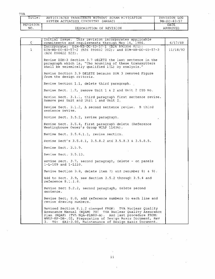
TVATitle: ANTICIPATED TRANSIENTS WITHOUT SCRAM MITIGATION REVISION LOG
SYSTEM ACTUATION CIRCUITRY (ANSAC) WB-DC-40-57REVISION I DATE
NO. DESCRIPTION OF REVISION APPROVED
Initial issue. This revision incorporates applicable0 commitments and requirements through May 16, 1986. 6/17/88
Incorporate: DIM-WB-DC-40-57-1 (B26 890306 021):DIM-WB-DC-40-57-2 (B26 890602 302); and DIM-WB-DC-40-57-3 11/18/92(B26 890622 523).
Revise DIM-3 Section 3.7 DELETE the last sentence in theparagraph which is, "The mounting of these transmittersshall be seismically qualified 1(L) by analysis."
Revise Section 3.9 DELETE because DIM 3 removed Figurefrom the design criteria.
Revise Section 1.1, delete third paragraph.
Revise Sect. 1.2, remove Unit 1 & 2 and Unit 2 CID No.
Revise Sect. 3.1.1, third paragraph first sentence revise.Remove per Unit and Unit 1 and Unit 2.
Revise Sect. 3.1.2, A second sentence revise. B thirdsentence revise.
Revise Sect. 3.5.2, revise paragraph.
Revise Sect. 3.5.4, first paragraph delete (ReferenceWestinghouse Owner's Group WCAP 11436).
Revise Sect. 3.5.6.1.1, revise section.
Revise Sect's 3.5.8.1, 3.5.8.2 and 3.5.8.3 & 3.5.8.5.
Revise Sect. 3.5.9.
Revise Sect. 3.5.13.
Revise Sect. 3.7, second paragraph, delete - on panels1-L-109 and 1-L110.
Revise Section 3.8, delete item 7) and renumber 8) & 9).
Add to Sect. 3.9, see Section 3.5.2 through 3.5.4 andreference 8.1.1.6.
Revise Sect 5.2.2, second paragraph, delete secondsentence.
Revise Sect. 8.0, add reference numbers to each line andrevise drawing numbers.
Revised Section 8.1.2 changed FROM: TVA Nuclear QualityAssurance Manual (NQAM) TO: TVA Nuclear Quality AssurancePlan (NQAP) (TVA-NQA-PLN89-A). And last procedure FROM:WBEP-EP-DB-.02, Preparation of Design Basis Document, Rev3. TO: EAI-3.08, Maintenance of Design Basis Document.
ii
TVATitle: ANTICIPATED TRANSIENTS WITHOUT SCRAM MITIGATION REVISION LOG
SYSTEM ACTUATION CIRCUITRY (AMSAC) WB-DC-40-57REVISION I DATE
NO. DESCRIPTION OF REVISION APPROVED
Justification:1
(Con't) The justification for this revision of the designcriteria is to incorporate the outstanding DIM's 1, 2,and 3 and to remove the requirement to seismicallyqualify transmitters located in the Turbine Buildingwhich is a non seismic building and to correct the TVAdocumentation callouts for the NQAP and EAI-3.08.
DCN DCN RIMS NO. T56 930525 900M-21462-A 5/24/93
Revised Sections 3.5.4, 3.5.8.3 and 3.5.9 to reflect newAMSAC actuation set point (12% of narrow range levelspan. Also deleted references to 80% power level.Removed "Inhibit" from Section 3.5.9.
Justification:
New Westinghouse evaluation WCAP-12096 requires that RPSSG level setpoint be changed to 17%. WCAP-10858 requiresthat AMSAC be set at 5% below RPS SG level. Also, thisactuation level is constant for turbine power level above40% thru 100%. Therefore, references to 80% aresuperfluous.
Pages affected: iia, 9, 11, 12
DCN DCN RIMS NO. T56 940902 807S-32449-A 9/2/94
Revise accuracy requirements of Paragraph 3.5.4.1 toreflect the requirements of WCAP 12096, Rev. 6,WCAP-10858P-A, Rev. 1, and calculation WBPEVAR9301002,Rev. 0.
Pages Affected: iia, 9
* DCN M-39911-A (T56 981215 803): Modification M-39911-Areplaces the obsolete Unit 1 Westinghouse P2500 Plant 9/9/99Process Computer with a new Plant Integrated ComputerSystem. This Plant Computer System provides anoperator friendly, state of the art, real time processcomputer system for the WBN plant operators. Afterthis modification, the new Plant Computer will beoperational and performing all the functions of theexisting Plant Computer (WB-DC-30-29) and EmergencyResponse Facilities Data System (ERFDS) (WB-DC-30-8).Therefore, Design Criteria's WB-DC-30-8 and WB-DC-30-29 have been combined into one Design Criteria WB-DC-30-29, "Plant Integrated Computer System." DesignCriteria WB-DC-40-57 has been revised to incorporatethis change by removing references to the EmergencyResponse Facilities Data System (ERFDS) and replacingthem with Plant Computer references.
& Incorporates DCNs M-21462-A, S-32449-A, and M-39911-A.0 Deleted Coordination Log, which is not required per
NEDP-10.0 Renumbered entire document, which changed page numbers
on the Table of Contents (pages iv-v).
Pages Revised: AllTotal Pages: 26 (includes pages i-vi and 1-20)
iii
TVATitle: ANTICIPATED TRANSIENTS WITHOUT SCRAM MITIGATION REVISION LOG
SYSTEM ACTUATION CIRCUITRY (AMSAC) WB-DC-40-57REVISION DATE
NO. DESCRIPTION OF REVISION APPROVED
Incorporates DCN as follows:3 DCN D-50475-A (T56 000217 802) replaces the PLC based 10-23-2000
AMSAC System with relay logic circuitry. This revisionto the design criteria reflects the requirements forthe new instrumentation. Revisions to Table ofContents, Abbreviations and Acronyms, Sections 1.2,
3.1.1, 3.2, 3.5.1, 3.5.2, 3.5.4, 3.5.7, 3.5.8, 3.5.9,3.5.10, 3.5.12, 3.10, 5.1, 5.2, 5.3, 6.1, and 8.1.
* Administrative change to correct Reference 8.1.1.6 (twoReference 8.1.1.6 existed with the addition by DCN D-50475-A) . Reference 8.1.1.6a is added by DCN D-50475-A, and Reference 8.1.1.6b is the reference added byRevision 1. Revisions to 3.9 and 8.1.
* Renumbered entire document, which changed page numberson the Table of Contents (page v-vi).
Total Pages: 25 (includes pages i-vii and 1-18)This DCD has been reviewed and determined to be fully
4 applicable to both Unit 1 and Unit 2. 8-11-2008
Outstanding WITEL punchlist items are listed below:
* PL-08-0751, see Section 1.2* PL-08-0752, see Section 3.3
" PL-08-0753, see Section 3.5.10.1* PL-08-0792, see Section 3.8* PL-08-0755, see Section 8.1.1.1* PL-08-0756, see Section 8.1.1.2* PL-08-0757, see Section 8.1.1.3* PL-08-0758, see Section 8.1.1.4* PL-08-0759, see Section 8.1.1.5" PL-08-0760, see Section 8.1.1.6a* PL-08-0762, see Section 3.9 and 8.1.1.6b* PL-08-0763, see Section 8.1.1.7" PL-08-0764, see Section 8.1.1.8" PL-08-0765, see Section 8.1.1.9* PL-08-0766, see Section 8.1.1.10" PL-08-0767, see Section 8.1.1.11" PL-08-0801, see Section 8.1.2.2a
Editorial change to 8.1.2.1, 8.1.2.2, add 8.1.2.1a and8.1.2.2a.
Pages Revised: Coversheet, iv, 1, 6, 10, 13, 16Total Pages: 25 (includes pages i-vii and 1-18)
iv
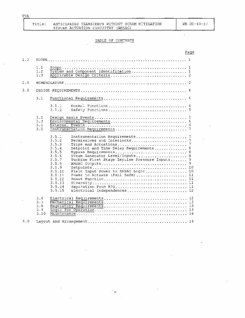
TVA
Title: ANTICIPATED TRANSIENTS WITHOUT SCRAM MITIGATION WB-DC-40-57SYSTEM ACTUATION CIRCUITRY (AMSAC)
TABLE OF CONTENTS
Page
1 .0 SCOPE . ............................................................ 1
1.1 Scope ........................... ........................... 11.2 System and Component Identification ........................ 11.3 Applicable Design Criteria ................................. 2
2.0 NOMENCLATURE . ..................................... .................
3.0 DESIGN REQUIREMENTS .............................................. 4
3.1 Functional Requirements..................................... 4
3.1.1 Normal Functions .................................. 43.1.2 Safety Functions .... .............................. 5
3.2 Design Basis Events ........................................ 53.3 Environmental Requirements ................................. 63.4 External Events ............................................ 63.5 Instrumentation Requirements ............................... 7
3.5.1 Instrumentation Requirements ...................... 73.5.2 Permissives and Interlocks ........................ 73.5.3 Trips and Actuations .............................. 73.5.4 Setpoint and Time Delay Requirements ............... 83.5.5 Bypass Requirements ............................... 83.5.6 Steam Generator Level/Inputs ...................... 83.5.7 Turbine First Stage Impulse Pressure Inputs ....... 93.5.8 AMSAC Outputs ..................................... 93.5.9 Setpoints ......................................... 103.5.10 Plant Input Power to AMSAC Logic .................... 103.5.11 Power to Actuate (Fail Safe) ....................... 113.5.12 Reset Function .................................... 113.5.13 Diversity ......................................... 113.5.14 Separation From RPS ............................... 113.5.15 Electrical Independences ................ ............. 12
3.6 Electrical Requirements .................................... 123.7 Mechanical Requirements .................................... 133.8 Regulatory Requirements .................................... 133.9 Logic for Operation ........................................ 133.10 Maintenance .. .............................................. 14
4.0 Layout and Arrangement ............................................ 14
v
TVA
Title: ANTICIPATED TRANSIENTS WITHOUT SCRAM MITIGATION WB-DC-40-57SYSTEM ACTUATION CIRCUITRY (AMSAC)
TABLE OF CONTENTS
Page
5.0 Test and Inspection Component Test Function Mechanization ........ 14
5.1 On-Line Testing ............................................ 145.2 System and Factory Acceptance Test Requirements ............. 155.3 System Testing ............................................. 15
6.0 Quality Assurance ................................................ 15
7.0 Exceptions . ....................................................... 16
8.0 References ....................................................... 16
8.1 Design Input ............................................... 168.2 Background ................................................. 178.3 Design Criteria ............................................ 18
vi
TVA
Title: ANTICIPATED TRANSIENTS WITHOUT SCRAM MITIGATION WB-DC-40-57SYSTEM ACTUATION CIRCUITRY (AMSAC)
ABBREVIATIONS AND ACRONYMS
AFW
AMSAC
AMSAC SER
ASME
ATWS
CFR
CRT
DNE
EMI
FSAR
FW
GL
LOL/ATWS
LONF/ATWS
MCR
NRC
NSSS
PAM
PSIG
PWRs
QA
RCS
RG
RPS
Auxiliary Feedwater
ATWS Mitigation System Actuation Circuitry
Safety Evaluation of Topical Report (WCAP-10858) "AMSAC GenericDesign Package," dated July 7, 1986
American Society of Mechanical Engineers
Anticipated Transients Without Scram
Code of Federal Regulations
Cathode Ray Tube
Division of Nuclear Engineering
Electro-Magnetic Interference
Final Safety Analysis Report
Feedwater
Generic Letter
Loss of Load accompanied by an ATWS event
Loss of Normal Feedwater accompanied by an ATWS event
Main Control Room
Nuclear Regulatory Commission
Nuclear Steam Supply System
Post Accident Monitoring
Pounds per Square Inch Gauge
Pressurized Water Reactors
Quality Assurance
Reactor Coolant System
Regulatory Guide
Reactor Protection System
vii
TVA
Title: ANTICIPATED TRANSIENTS WITHOUT SCRAM MITIGATION WB-DC-40-57SYSTEM ACTUATION CIRCUITRY (ANSAC)
1.0 SCOPE
1.1 Scope
This document defines the functional and design requirements of theAnticipated Transient Without SCRAM (ATWS) Mitigating SystemActuating Circuitry (AMSAC) of the Watts Bar Nuclear Plant.
An ATWS event is a postulated severe accident sequence which isinitiated by an anticipated operational occurrence as defined inAppendix A of 10CFRSO followed by the failure of the reactor tripportion of the reactor protection system to shut down or scram thereactor. The NRC on June 26, 1984, issued the ATWS Final Rule asI0CFR50.62 (Reference 8.1.3.1). The ATWS Final Rule required of allWestinghouse pressurized water reactors to install equipment that isdiverse from sensor output to final actuation device to automaticallyinitiate auxiliary feedwater flow and turbine trip under conditionsindicative of an ATWS. This equipment (AMSAC) must be reliable andindependent from the existing reactor trip system. An ATWS eventwill be detected by AMSAC whenever three out of the. four steamgenerators have low-low level and the turbine is at or above 40percent load. Consequently, the applicable plant features are:Feedwater System, Auxiliary Feedwater System, Process Instrumentationand Turbogenerator Control System. The Auxiliary Instrument Room andthe Main Control Room will be affected by hardware additions and/ormodifications.
Conceptual documents that establish the design features are:
o IOCFR50.62 ....................... ATWS Final Rule
o Generic Letter 85-06 ........... Quality Assurance Guidance for
ATWS Equipment that is notSafety Related
o Letter to S. A. White, TVA ..... ATWS - Watts Bar Nuclear Plant
from T. J. Kenyon, NRC AMSAC Safety Evaluationdated November 7, 1986
No input document exceptions have been identified.
1.2 System and Component Identification
AMSAC will be a single bay cabinet containing electronic equipmentwhich shall be installed in the auxiliary instrument room. The uniqueidentification code for Unit 1 is 1-R-178. [PL-08-0751]
AMSAC will contain non-safety related equipment. All input signalsto AMSAC are non-safety-related. AMSAC timing, coincidence logic,and outputs are non-safety related. The safety-related outputs tothe auxiliary feedwater system are provided by interposing safetygrade relays outside the AMSAC cabinet.
AMSAC will interface with the following pieces of equipment: ProcessInstrumentation steam generator blowdown valves, steam generatorsampling valves, motor driven auxiliary feedwater pumps, turbinedriven auxiliary feedwater pump, annunciator system, status lights,turbine trip circuits, and the 120V a-c distribution system.
1
TVA
Title: ANTICIPATED TRANSIENTS WITHOUT SCRAM MITIGATION WB-DC-40-57SYSTEM ACTUATION CIRCUITRY (AMSAC)
Following is a list of the applicable System Description:
Number TitleN3-3B-4002 Auxiliary FeedwaterN3-47-4002 Turbogenerator Control and
Protection
1.3 Applicable Design Criteria
The following is a list of applicable Design Criteria:
Number Title
WB-DC-30-4 Separation of Electrical Equipmentand wiring
WB-DC-30-5 Power, Control, and Signal Cablesfor Use in Category I Structures
WB-DC-30-29 Plant Integrated Computer System(ICS)
The AMSAC System shall be designed in accordance with the designclassifications as defined in WB-DC-40-64, "Design Basis Events DesignCriteria."
2.0 NOMENCLATURE
2.1 ATWS - Anticipated Transient Without Scram - a postulated severeaccident sequence which is initiated by an anticipated operationaloccurrence as defined in Appendix A of 10CFR50 followed by thefailure of the reactor protection system as specified in GeneralDesign Criteria 20 of 10CFR50 Appendix A.
2.2 AMSAC - ATWS Mitigating System Actuating Circuitry - Equipment whichis to function to mitigate the consequences of an ATWS event.
2.3 Class 1E - The safety classification of the electric equipment andsystems that are essential to emergency reactor shutdown,containment isolation, reactor core cooling and containment andreactor heat removal, or are otherwise essential in preventing asignificant release of radioactive material to the environment.
2.4 Design Basis Events - lOCFR50.49 defines design basis events as"conditions of normal operation, including anticipated operationaloccurance for which the plant must be designed to ensure (i) theintegrity of the reactor coolant pressure boundary, (ii) thecapability to shut down the reactor and maintain it in a safeshutdown condition, and (iii) the capability to prevent or mitigatethe consequence of accidents that could result in potential off-siteexposures comparable to the 10 CFR Part 100 guidelines.
2.5 Independence - The state in which there is no mechanism by which anysingle design basis event, such as a flood, can cause redundantequipment to be inoperable.
2.6 Isolation Device - A device in a circuit which prevents malfunctionsin one section of a circuit from causing unacceptable influences inother sections of the circuit or in other circuits.
2
TVA
Title: ANTICIPATED TRANSIENTS WITHOUT SCRAM MITIGATION WB-DC-40-57SYSTEM ACTUATION CIRCUITRY (AMSAC)
2.7 Redundant Equipment or System - Equipment or system that duplicatesthe essential function of another piece of equipment or system to theextent that either may perform the required function regardless ofthe state of operation or failure of the other.
2.8 Safety-Related - Those structures, systems, and components which areimportant to safety because they perform either a primary or asecondary safety function.
(A) Primary Safety Function - That function of a structure, system,or component which is necessary to assure: (1) integrity of thereactor coolant pressure boundary, (2) capability to shut downthe reactor and maintain it in a safe shutdown condition, or (3)capability to prevent or mitigate the consequences of accidentswhich could result in potential offsite exposure to a significantfraction of the guideline exposures of 10CFR100 (reference8.2.3). Also included are supporting and auxiliary systems whichmust function to provide such assurance.
(B) Secondary Safety Function - That function of a portion of astructure, system, or component which must either: (1) retainlimited structural integrity because its failure could jeopardizeto an unacceptable extent the achievement of a primary safetyfunction or because it forms an interface between SeismicCategory I and non-Seismic Category I plant features or (2)perform a mechanical motion which is not required in theperformance of a primary safety function but whose failure to actor unwanted action could jeopardize to an unacceptable extent theachievement of a primary safety function.
2.9 Seismic Category I - Those structures, systems, or components whichperform primary safety functions. They are designed and constructedto assure achievement of their primary safety functions at all timesincluding a concurrent Safe Shutdown Earthquake (SSE).
2.10 Seismic Category I(L) - Those portions of structures, systems, orcomponents which perform secondary safety functions to the extentthat only limited structural integrity is required. They aredesignated as Seismic Category I(L) (i.e., limited seismicrequirements) and are designed and constructed to assure achievementof their limited structural integrity at all times including aconcurrent SSE. The limited structural integrity requirementsassociated with these plant features are either retention (remain inplace) or pressure boundary retention. This may be accomplishedwithout meeting the full extent of the design, construction, QA, andother regulatory requirements normally specified for Seismic CategoryI structures, systems, or components wherein a primary safetyfunction must be assured. The requirements and provisions should bedetermined on a case-by-case basis with regard for credible failuremodes and circumstances and for the extent of jeopardy to theachievement of primary safety functions.
3
TVA
Title: ANTICIPATED TRANSIENTS WITHOUT SCRAM MITIGATION WB-DC-40-57SYSTEM ACTUATION CIRCUITRY (AMSAC)
3.0 DESIGN REQUIREMENTS
3.1 Functional Requirements
3.1.1 Normal Functions
Section I0CFR50.62 of the Code of Federal Regulations,"Requirements for Reduction of Risk from AnticipatedTransients Without Scram (ATWS) Events for Light-Water CooledNuclear Power Plants" (ATWS Final Rule) requires equipmentfrom sensor output to final actuation device that is diversefrom the reactor trip system to automatically initiate theauxiliary feedwater system and initiate a turbine trip underconditions indicative of an ATWS.
Since an ATWS type event results in a reactor coolant systempressure increase, it is essential to maintain a heat sinkthrough control of steam generator level and to providesufficient pressurizer relief capacity. Westinghouse PWRs arethe least sensitive of light water reactors to ATWS becauselarge relief capacity is an integral part of its design.Reduction of reactor coolant pressure is essential to allowthe high pressure safety injection 'system to add borated waterto bring the reactor into a shutdown condition. Failure toreduce reactor coolant system pressure could result in anunacceptable loss of coolant resulting in uncovering the coreand challenging fuel integrity with the possibility ofexceeding the release requirements of 10CFRI00. The auxiliaryfeedwater system, through the steam generators, will be usedto remove reactor heat and hence reactor coolant systempressure. High pressure safety injection will be used forboration to achieve a controlled shutdown.
To meet the ATWS Final Rule, Watts Bar will add equipment thatis diverse from the existing reactor trip system. Thisadditional equipment will consist of a free standing panelwhich will be installed in the Auxiliary Instrument Room ofthe Control Building. This modification will be diverse fromsensor output to the final actuation device, and automaticallyinitiates auxiliary feedwater and trips the main turbine underconditions indicative of an ATWS. An ATWS event will bedetected by this equipment when low-low level in three out ofthe four steam generators are coincident with the turbine ator above 40 percent load.
If an ATWS event occurs below 40 percent turbine load,operator action is required to trip the main turbine andinitiate auxiliary feedwater flow to control the reactorcoolant system (RCS) pressure transient and remove reactorheat.
4
TVA
Title: ANTICIPATED TRANSIENTS WITHOUT SCRAM MITIGATION WB-DC-40-57SYSTEM ACTUATION CIRCUITRY (AMSAC)
3.1.2 Safety Functions
A. Primary Safety Function
AMSAC has no primary safety function. The AMSAC cabinetwill be seismically qualified 1(L). Class 1E interposingrelays will be provided outside the AMSAC cabinet forinterface to the auxiliary feedwater system.
B. Secondary Safety Function
AMSAC performs secondary safety functions. The primarypurpose of AMSAC is to reduce the probability ofunacceptable consequences following an ATWS event. Thiswill be accomplished by requiring diversity to theexisting RPS. AMSAC shall be of sufficient quality andreliability so that it can perform its intended functionwithout contributing to transients which may challengesafety systems. Implementation of AMSAC shall not degradethe existing RPS.
ATWS events are a concern because of the potential to overj, pressurize the RCS with resulting core damage and a
release of radioactivity to the environment.
3.2 Design Basis Events
For the definition of an ATWS Event, Reference WB-DC-40-64 "DesignBasis Events Design Criteria".
The most severe ATWS scenarios have been determined to be those inwhich there is a complete loss of normal feedwater (Reference8.1.4.1, WCAP-10858) . The design basis events for the AMSAC are Lossof Normal Feedwater/ATWS (LONF/ATWS) and the Loss of Load/ATWS(LOL/ATWS). The scenarios of those two events are described below.
Loss of Normal Feedwater/ATWS (LONF/ATWS)
A complete loss of normal feedwater occurs as a result of amalfunction in the feedwater/condensate system or its control systemfrom such causes as the simultaneous trip of all condensate pumps,the simultaneous trip of all main feedwater pumps or the simultaneousclosure of all main feedwater control, pump discharge or blockvalves. Because if a postulated common mode failure in the RPS, thereactor is incapable of being automatically tripped when any ofseveral plant process variables have reached their reactor tripsetpoints.
Loss of Load/ATWS Transient (LOL/ATWS)
The most severe plant conditions that could result from a loss ofload occur following a turbine trip from full power when the turbinetrip is caused by a loss of main condenser vacuum. Because-of acommon mode failure in the protection system, the reactor isincapable of being automatically tripped as a result of the turbinetrip or as the result of any several other reactor trip signals thatoccur later in time when several plant process variables reach theirreactor trip setpoints.
5
TVA
Title: ANTICIPATED TRANSIENTS WITHOUT SCRAM MITIGATION WB-DC-40-57SYSTEM ACTUATION CIRCUITRY (AMSAC)
Upon loss of the main condenser vacuum, the main feedwater turbine-driven pumps, which do not exhaust into the main condenser, are alsotripped, thereby cutting off feedwater flow to the steam generators.Since there is a complete loss of normal feedwater during both ofthese transients (LONF/ATWS and LOL/ATWS), both transients assumedauxiliary feedwater (AFW) flow is started 60 seconds after theinitiating event for long term reactor protection. Also the CompleteLoss of Normal Feedwater transient assumed a turbine trip 30 secondsafter the initiating event to maintain short term RCS pressures below3200 psig. (The NRC has defined unacceptable pressure as exceedingASME Service Level C pressure, or 3200 psig, in the preamble to theATWS Final Rule, I0CFR50.62). Normally these features would beactuated by the Reactor Protection System (RPS).
The principle safety concern from these two transients is thepotential for high pressure within the RCS. If a common mode failurein the RPS incapacitates AFW flow initiation and/or turbine trip inaddition to prohibiting a scram, then an alternate method ofproviding AFW flow and a turbine trip is required to maintain the RCSpressure below 3200 psig. The ATWS Final Rule which was approved bythe Commissioners on June 26, 1984, requires that Westinghousedesigned plants install ATWS Mitigating System Actuation Circuitry(AMSAC) to automatically initiate a turbine trip and actuate AFW flowindependent of the RPS (from the sensor output). These twofunctions, turbine trip and AFW flow actuation, are provided viaAMSAC.
3.3 Environmental Requirements
Non-safety related AMSAC system equipment qualification shall beconsistent with the non-safety-related equipment qualificationlicensing basis for the Watts Bar Nuclear Plant during normaloperation and anticipated operational occurrences only. Accidentenvironment qualification is not required for non-safety relatedequipment.
The environmental requirements for AMSAC equipment locations are asfollows:
Location RequirementMain Control Room 47E235-16Auxiliary Instrument Room 47E235-17Turbine Building 47E235-20
[PL-08-0752]
3.4 External Events
AMSAC is not required for safe shutdown of the plant during externaldesign basis events such as tornados, floods, rain, andtransportation accidents.
6
TVA
Title: ANTICIPATED TRANSIENTS WITHOUT SCRAM MITIGATION WB-DC-40-57SYSTEM ACTUATION CIRCUITRY (AMSAC)
3.5 Instrumentation Requirements
3.5.1 Instrumentation Requirements
Equipment diversity to the extent reasonable and practicableto minimize the potential for common cause failures isrequired from the sensor output to, but not including, thefinal actuation device. The sensors need not be of a diversedesign or manufacture. Existing protection system instrumentsensing lines, sensors, and sensor power supplies may be used.Sensor and instrument sensing lines will be selected such thatadverse interactions with existing control system are avoided.
1) Steam generator I narrow range level2) Steam generator 2 narrow range level3) Steam generator 3 narrow range level4) Steam generator 4 narrow range level5) Turbine impulse chamber pressure6) Redundant turbine impulse chamber pressure
A failure tolerant relay logic based system shall comparethese inputs with their setpoints and provide the logic andtiming function to produce the required AMSAC output signals.
Output signals shall be provided for alarms and annunciatorswhen the ANSAC has been actuated or is removed from service.AMSAC shall provide at least the following outputs to thePlant Computer: (1) AMSAC Tripped; (2) AMSAC Armed.
3.5.2 Permissives and Interlocks
AMSAC shall be designed to be automatically blocked at powerlevels below 40% as indicated by main turbine first stagepressure. A permissive signal shall be provided to arm theAMSAC system if two out of two turbine impulse chamberpressure setpoints are actuated which indicates that the plantis at or above 40% power. The removal of the permissive shallbe delayed so that the AMSAC will stay armed and be capable ofperforming its function for 360 seconds (60-600 secondsadjustable) after turbine trip or power reduction below 40%power (Reference Westinghouse Owner's Group, WCAP-10858P-A,Rev. 1).
3.5.3 Trip and Actuations
A main turbine trip and startup of all AFW pumps shall occurupon generation of an AMSAC signal. The AMSAC signal shall begenerated by low-low water level signals in the steamgenerators. The AMSAC coincidence logic will be 3 out of 4(3/4) low-low level signals with one channel per steamgenerator and the main turbine at or above 40% load. Only oneof the three narrow range level channels per steam generatorshall be used for input to AMSAC coincidence logic.
7
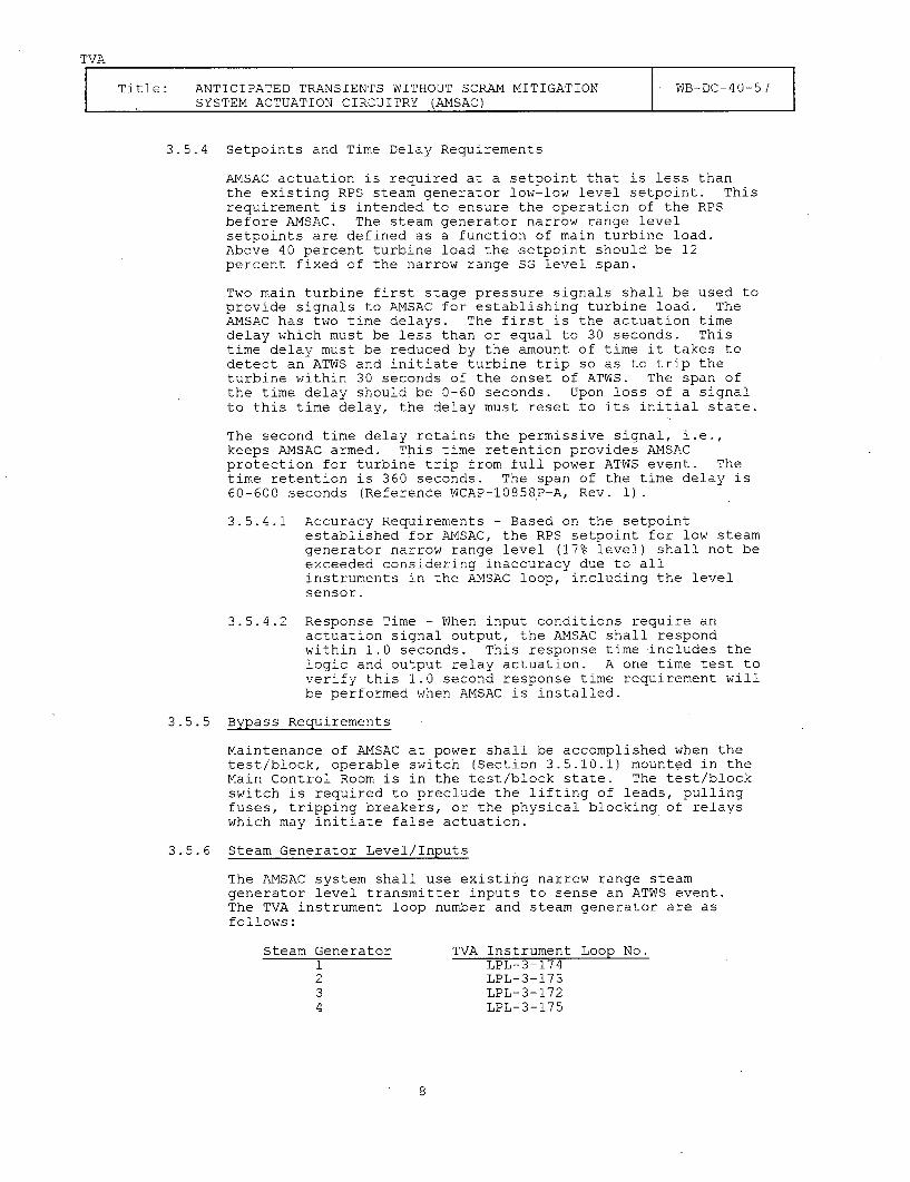
TVA
Title: ANTICIPATED TRANSIENTS WITHOUT SCRAM MITIGATION WB-DC-40-57SYSTEM ACTUATION CIRCUITRY (AMSAC)
3.5.4 Setpoints and Time Delay Requirements
AMSAC actuation is required at a setpoint that is less thanthe existing RPS steam generator low-low level setpoint. Thisrequirement is intended to ensure the operation of the RPSbefore AMSAC. The steam generator narrow range levelsetpoints are defined as a function of main turbine load.Above 40 percent turbine load the setpoint should be 12percent fixed of the narrow range SG level span.
Two main turbine first stage pressure signals shall be used toprovide signals to AMSAC for establishing turbine load. TheAMSAC has two time delays. The first is the actuation timedelay which must be less than or equal to 30 seconds. Thistime delay must be reduced by the amount of time it takes todetect an ATWS and initiate turbine trip so as to trip theturbine within 30 seconds of the onset of ATWS. The span ofthe time delay should be 0-60 seconds. Upon loss of a signalto this time delay, the delay must reset to its initial state.
The second time delay retains the permissive signal, i.e.,keeps AMSAC armed. This time retention provides AMSACprotection for turbine trip from full power ATWS event. Thetime retention is 360 seconds. The span of the time delay is60-600 seconds (Reference WCAP-10858P-A, Rev. 1).
3.5.4.1 Accuracy Requirements - Based on the setpointestablished for AMSAC, the RPS setpoint for low steamgenerator narrow range level (17% level) shall not beexceeded considering inaccuracy due to allinstruments in the AMSAC loop, including the levelsensor.
3.5.4.2 Response Time - When input conditions require anactuation signal output, the AMSAC shall respondwithin 1.0 seconds. This response time includes thelogic and output relay actuation. A one time test toverify this 1.0 second response time requirement willbe performed when AMSAC is installed.
3.5.5 Bypass Requirements
Maintenance of AMSAC at power shall be accomplished when thetest/block, operable switch (Section 3.5.10.1) mounted in theMain Control Room is in the test/block state. The test/blockswitch is required to preclude the lifting of leads, pullingfuses, tripping breakers, or the physical blocking of relayswhich may initiate false actuation.
3.5.6 Steam Generator Level/Inputs
The AMSAC system shall use existing narrow range steamgenerator level transmitter inputs to sense an ATWS event.The TVA instrument loop number and steam generator are asfollows:
Steam Generator TVA Instrument Loop No.1 LPL-3-1742 LPL-3-1733 LPL-3-1724 LPL-3-175
8
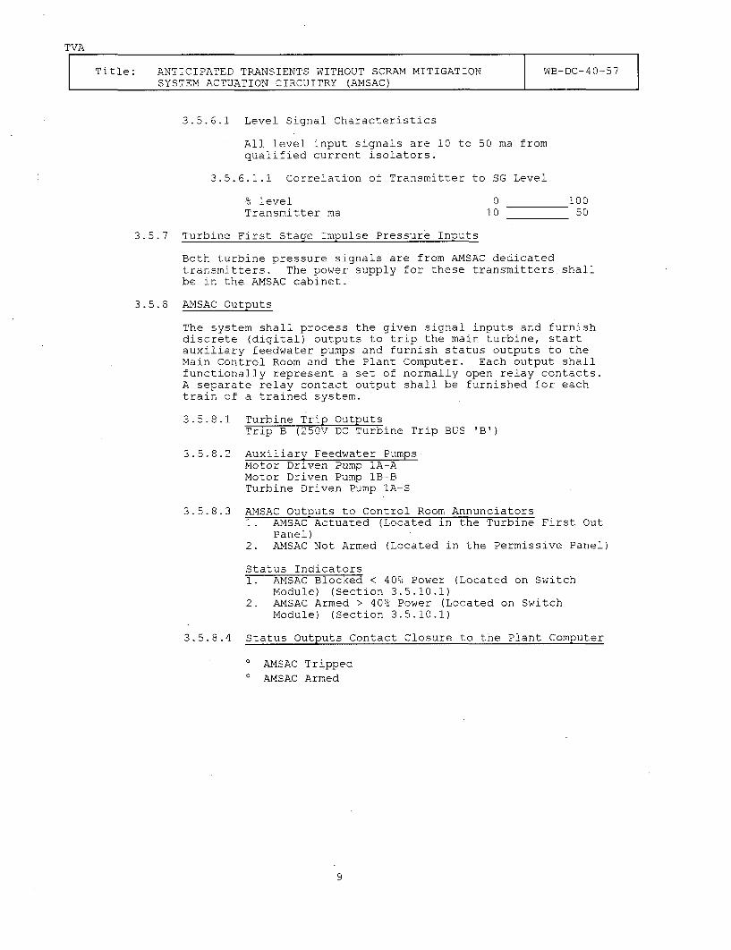
TVA
Title: ANTICIPATED TRANSIENTS WITHOUT SCRAM MITIGATION WB-DC-40-57SYSTEM ACTUATION CIRCUITRY (AMSAC)
3.5.6.1 Level Signal Characteristics
All level input signals are 10 to 50 ma fromqualified current isolators.
3.5.6.1.1 Correlation of Transmitter to SG Level
% level 0 100Transmitter ma 10 50
3.5.7 Turbine First Stage Impulse Pressure Inputs
Both turbine pressure signals are from AMSAC dedicatedtransmitters. The power supply for these transmitters shallbe in the AMSAC cabinet.
3.5.8 AMSAC Outputs
The system shall process the given signal inputs and furnishdiscrete (digital) outputs to trip the main turbine, startauxiliary feedwater pumps and furnish status outputs to theMain Control Room and the Plant Computer. Each output shallfunctionally represent a set of normally open relay contacts.A separate relay contact output shall be furnished for eachtrain of a trained system.
3.5.8.1 Turbine Trip OutputsTrip B (250V DC Turbine Trip BUS 'B')
3.5.8.2 Auxiliary Feedwater PumpsMotor Driven Pump IA-AMotor Driven Pump lB-BTurbine Driven Pump lA-S
3.5.8.3 AMSAC Outputs to Control Room Annunciators1. AMSAC Actuated (Located in the Turbine First Out
Panel)2. AMSAC Not Armed (Located in the Permissive Panel)
Status Indicators1. AMSAC Blocked < 40% Power (Located on Switch
Module) (Section 3.5.10.1)2. AMSAC Armed > 40% Power (Located on Switch
Module) (Section 3.5.10.1)
3.5.8.4 Status Outputs Contact Closure to the Plant Computer
o AMSAC Tripped0 AMSAC Armed
9
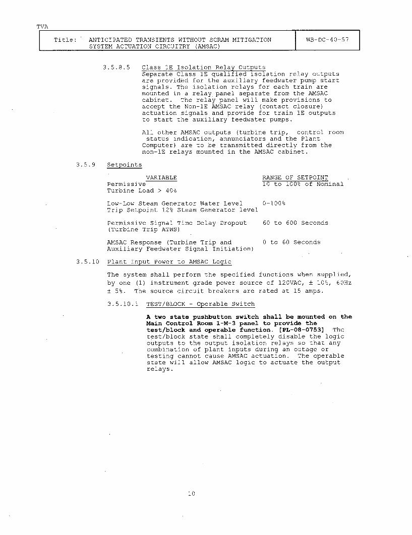
TVA
Title: ANTICIPATED TRANSIENTS WITHOUT SCRAM MITIGATION WB-DC-40-57SYSTEM ACTUATION CIRCUITRY (AMSAC)
3.5.8.5 Class 1E Isolation Relay OutputsSeparate Class 1E qualified isolation relay outputsare provided for the auxiliary feedwater pump startsignals. The isolation relays for each train aremounted in a relay panel separate from the AMSACcabinet. The relay panel will make provisions toaccept the Non-iE AMSAC relay (contact closure)actuation signals and provide for train 1E outputsto start the auxiliary feedwater pumps.
All other AMSAC outputs (turbine trip, control roomstatus indication, annunciators and the Plant
Computer) are to be transmitted directly from thenon-lE relays mounted in the AMSAC cabinet.
3.5.9 Setpoints
VARIABLE RANGE OF SETPOINTPermissive 10 to 100% of NominalTurbine Load > 40%
Low-Low Steam Generator Water Level 0-100%Trip Setpoint 12% Steam Generator level
Permissive Signal Time Delay Dropout 60 to 600 Seconds(Turbine Trip ATWS)
AMSAC Response (Turbine Trip and 0 to 60 SecondsAuxiliary Feedwater Signal Initiation)
3.5.10 Plant Input Power to AMSAC Logic
The system shall perform the specified functions when supplied,by one (1) instrument grade power source of 120VAC, ± 10%, 60Hz± 5%. The source circuit breakers are rated at 15 amps.
3.5.10.1 TEST/BLOCK - Operable Switch
A two state pushbutton switch shall be mounted on theMain Control Room 1-M-3 panel to provide thetest/block and operable function. [PL-08-0753] Thetest/block state shall completely disable the logicoutputs to the output isolation relays so that anycombination of plant inputs during an outage ortesting cannot cause AMSAC actuation. The operablestate will allow AMSAC logic to actuate the outputrelays.
10
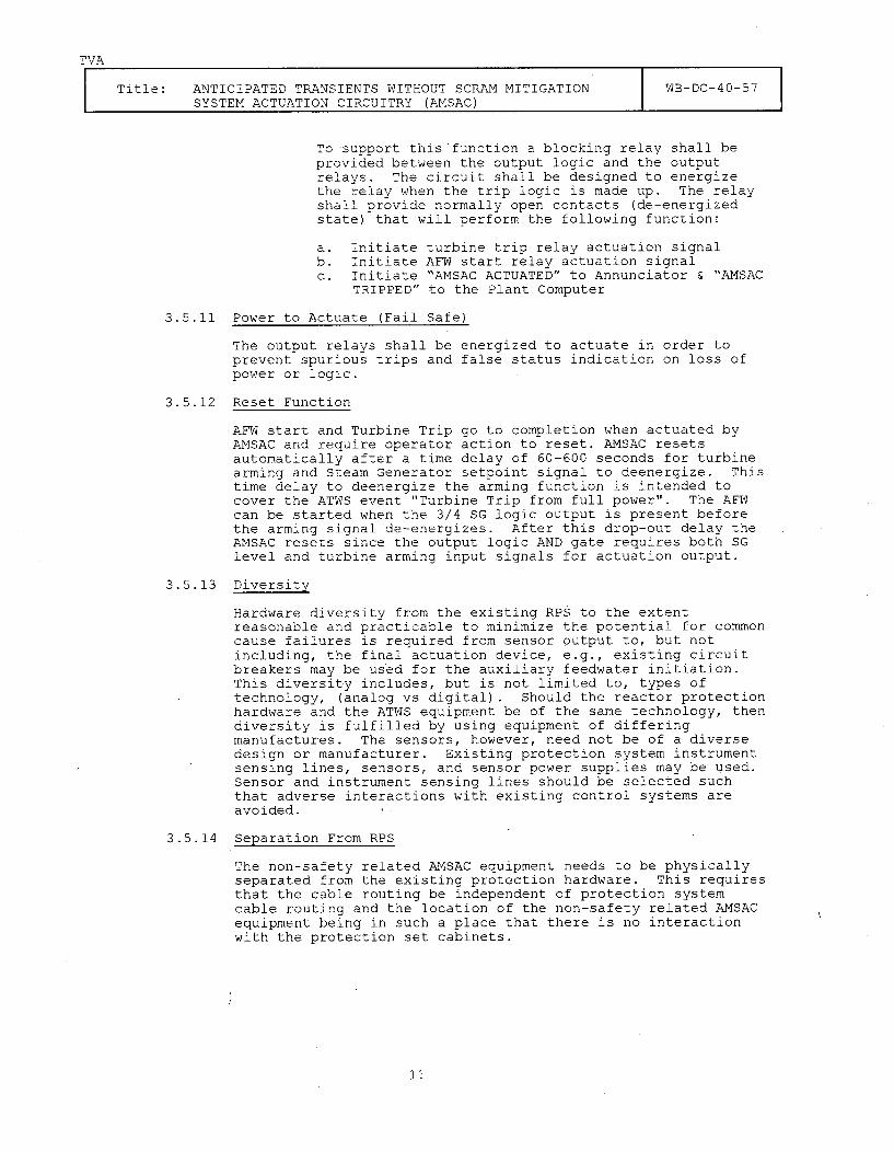
TVA
Title: ANTICIPATED TRANSIENTS WITHOUT SCRAM MITIGATION iWB-DC-40-57SYSTEM ACTUATION CIRCUITRY (AMSAC) I
To support this'function a blocking relay shall beprovided between the output logic and the outputrelays. The circuit shall be designed to energizethe relay when the trip logic is made up. The relayshall provide normally open contacts (de-energizedstate) that will perform the following function:
a. Initiate turbine trip relay actuation signalb. Initiate AFW start relay actuation signalc. Initiate "AMSAC ACTUATED" to Annunciator & "AMSAC
TRIPPED" to the Plant Computer
3.5.11 Power to Actuate (Fail Safe)
The output relays shall be energized to actuate in order toprevent spurious trips and false status indication on loss ofpower or logic.
3.5.12 Reset Function
AFW start and Turbine Trip go to completion when actuated byAMSAC and require operator action to reset. AMSAC resetsautomatically after a time delay of 60-600 seconds for turbinearming and Steam Generator setpoint signal to deenergize. Thistime delay to deenergize the arming function is intended tocover the ATWS event "Turbine Trip from full power". The AFWcan be started when the 3/4 SG logic output is present beforethe arming signal de-energizes. After this drop-out delay theAMSAC resets since the output logic AND gate requires both SGlevel and turbine arming input signals for actuation output.
3.5.13 Diversity
Hardware diversity from the existing RPS to the extentreasonable and practicable to minimize the potential for commoncause failures is required from sensor output to, but notincluding, the final actuation device, e.g., existing circuitbreakers may be used for the auxiliary feedwater initiation.This diversity includes, but is not limited to, types oftechnology, (analog vs digital). Should the reactor protectionhardware and the ATWS equipment be of the same technology, thendiversity is fulfilled by using equipment of differingmanufactures. The sensors, however, need not be of a diversedesign or manufacturer. Existing protection system instrumentsensing lines, sensors, and sensor power supplies may be used.Sensor and instrument sensing lines should be selected suchthat adverse interactions with existing control systems areavoided.
3.5.14 Separation From RPS
The non-safety related AMSAC equipment needs to be physicallyseparated from the existing protection hardware. This requiresthat the cable routing be independent of protection systemcable routing and the location of the non-safety related AMSACequipment being in such a place that there is no interactionwith the protection set cabinets.
11
TVA
Title: ANTICIPATED TRANSIENTS WITHOUT SCRAM MITIGATION WB-DC-40-57SYSTEM ACTUATION CIRCUITRY (AMSAC)
3.5.15 Electrical Independence
Electrical Independence is required at the safety-relatedsensor output and at the input to the safety-related finalactuation device at which point AMSAC input and output signalsshall be isolated from the RPS, AFW system, and other safety-related systems with diverse isolation devices. The NRC,through the AMSAC SER, has established the followingrequirements for AMSAC input and output isolation devices.
A. For the type of device used to accomplish electricalisolation, describe the specific testing performed todemonstrate that the device is acceptable for its ownapplication(s). This description should include elementarydiagrams when necessary to indicate the test configurationand how the maximum credible faults were applied to thedevices.
B. Data to verify that the maximum credible faults appliedduring the test were the maximum voltage/current to whichthe device could be exposed, and define how the maximumvoltage/current was determined.
C. Data to verify that the maximum credible fault was appliedto the output of the device in the transverse mode (betweensignal and return) and other faults were considered (i.e.,open and short circuits).
D. Define the pass/fail acceptance criteria for each type ofdevice.
E. Provide the commitment that the isolation devices complywith the environmental qualifications (l0CFR50.49) and withthe seismic qualifications which are the basis for the plantlicensing.
F. Provide a description of the measures taken to protect thesafety systems from electrical interference (i.e.,Electrostatic Coupling, EMI, Common Mode and Crosstalk) thatmay be generated by the ATWS circuits.
G. Provide information to verify that the Class 1E isolator ispowered from a Class 1E source.
3.6 Electrical Requirements
Power Supply - The AMSAC logic power supply must be a battery backedinstrument grade supply independent of RPS supplies and capable ofperforming its function with loss of off-site power.
The power supply for the redundant dedicated turbine pressuretransmitters is located in the AMSAC cabinet and receives power fromthis source. The steam generator level transmitters receive theirpower from Class 1E power supplies in the Auxiliary Feedwater System.
Appendix R to 10CFR50 will be affected due to cable additions in theMain Control Room, Auxiliary Instrument Room, Turbine Building andControl Building. The impact will be the increase in combustiblesresulting from the cable jacket on the added cables.
12
TVA
Title: ANTICIPATED TRANSIENTS WITHOUT SCRAM MITIGATION WB-DC-40-57SYSTEM ACTUATION CIRCUITRY (AMSAC)
3.7 Mechanical Requirements
Seismic Qualification - AMSAC logic cabinet is non-safety related butsupported to Seismic Category I(L) so that it does not become a hazardto safety-related equipment in the Auxiliary Instrument Room. Theseismic I(L) qualification may be performed by analysis.The AMSAC dedicated pressure transmitters are located in the turbine
building.
3.8 Regulatory Requirements
The design, installation, and operation of AMSAC shall comply with thefollowing regulations and standards:
1) I0CFR50.62, "Requirements for Reduction of Risk from ATWS Eventsfor Light Water Cooled Nuclear Power Plants."
2) Generic Letter 85-06, "Quality Assurance Requirements for ATWSEquipment that is not Safety-Related".
3) Letter to S. A. White, TVA, from T. J. Kenyon, NRC, datedNovember 7, 1986, Subject - ATWS Watts Bar Nuclear Plant, Unit 1 &2, AMSAC Safety Evaluation.
4) Regulatory Guide 1.29, Seismic Design Classification.
5) Appendix R to 10CFR50, Fire Protection Program for Nuclear PowerFacilities operating prior to January 1, 1979. (For consequenceof additional combustibles in affected fire zones, i.e., cableinsulation only.)
6) WOG letter to the NRC, OG-87-I0, dated February 26, 1987,providing the basis for the C-20 permissive.
7) Topical Report, WCAP-10858P-A, AMSAC Generic Design Package, by M.R. Adler, dated October 1986.
8) Topical Report, WCAP-10858P-A Rev. 1, AMSAC Generic DesignPackage, by M. R. Adler, dated July 1987.
A licensing position will be prepared clearly stating compliance withthe requirements of the AMSAC SER using the above documents forguidance. Resolution of NRC comments on the AMSAC licensing positionis a prerequisite for preparing the FSAR change. Chapters 4, 7, 8 and10 of the FSAR will be affected. No changes to the TechnicalSpecification are anticipated. [PL-08-0792]
3.9 Logic for Operation
See Section 3.5.2 through 3.5.4 and reference 8.1.1.6b. [PL-08-0762]
13
TVA
Title: ANTICIPATED TRANSIENTS WITHOUT SCRAM MITIGATION WB-DC-40-57SYSTEM ACTUATION CIRCUITRY (ANSAC)
3.10 Maintenance
AMSAC equipment shall be designed and constructed for ease ofmaintenance. The equipment shall be designed such that the removal ofany piece of equipment or lifting of any wire which is associated witha finite number of signals or signal loops does not affect any loopsor signals other than the associated ones and does not disable therest of the system. Normal or scheduled maintenance shall not berequired in an interval less than 24 months.
4.0 LAYOUT AND ARRANGEMENT
AMSAC will be installed in the Auxiliary Instrument Room, EL 708.0', of theControl Building. AMSAC will interface with the following equipment withinthe Control Building:
0 Process Instrumentation System
o Turbine Generator Electro-Hydraulic Controller
o Main Control Board/Annunciator
5.0 TEST AND INSPECTION COMPONENT TEST FUNCTION MECHANIZATION
5.1 On-Line Test
An AMSAC control panel shall provide local operations and functionalstatus indication. Hand-switches HS-3-172E, -173E, -174E and -175Eare being installed which trip the AMSAC logic function for eachsteam generator low-low level switch. These hand-switches arelocated in the AMSAC panel, and will allow testing of system logic ormaintenance activities to be performed for that level loop. Trippinga level switch with the hand-switch will makeup the associated relayin the three out of four logic.
5.1.1 On-Line Test/Manual
On-line manual testing capability shall be incorporated in theAMSAC system. The Control Room TEST/BLOCK - Operable switchin the TEST/BLOCK state shall prevent inadvertent actuation byinhibiting the output relays.
Relay actuation shall be fully checked during plant shutdown.When a process setpoint has been reached the associatedbistable alarm unit has a indicating light which illuminates.
5.1.2 System Calibration and Accuracy
The system shall be designed to be maintainable and hold itsaccuracy in the time interval between calibrations. Allcomponents that require calibration shall specify therequirements and calibration interval. System calibrationswhich require the system to be out of service shall not bemore frequent than once every 24 months.
14
TVA
Title: ANTICIPATED TRANSIENTS WITHOUT SCRAM MITIGATION WB-DC-40-57SYSTEM ACTUATION CIRCUITRY (AMSAC)
5.2 System and Factory Acceptance Test Requirements
5.2.1 Electromagnetic Interference (EMI) Test
EMI tests are required in accordance with TVA E18.14.01 forthe components procured and installed which perform the AMSAClogic functions. However, the contractor may substitute hisstandard EMI test in place of test requried by TVA E18.14.01.If this option is exercised, the contractor shall submit hisEMI test parameters, procedures and pass/fail criteria to TVAfor evaluation with his technical proposal.
5.3 System Testing
AMSAC system testing, i.e., the generation of turbine trip andauxiliary feedwater initiation, shall be performed in modes 5, 6 andno mode (core off loaded) only. It is imperative that theTurbogenerator Controls for the turbine generator be configured toreceive a turbine trip signal and the auxiliary feedwater pumps arealigned so that they can receive a start signal. AMSAC systemtesting requires mandatory coordination to prevent personnel injuryor equipment damage.
6.0 QUALITY ASSURANCE
The Watts Bar Nuclear Plant (WBN) will comply with the Quality Assuranceguidance for ATWS equipment that is not safety-related as set forth in thegeneric letter 85-06.
6.1 Watts Bar shall consider the following to be within the scope of thatQuality Assurance Guidance:
a. The AMSAC cabinet and hardware, including all internalinstrumentation, internal power conditioners, internal wiring,relays, input/output modules and other miscellaneous parts withinthe AMSAC cabinet.
b. The main control room switch and status light module, allinternal wiring and main control panel wiring associated with thetest/block operable switch module.
c. The dedicated pressure transmitters and associated tubing.
d. The associated power cables and signal cables, including theirconduit systems and their terminations.
6.2 Existing non safety-related interface points, power supplies,annunciators, and other equipment not included in the Appendix Bquality assurance program will not be included in the scope of theAMSAC quality assurance guidance.
The non safety-related level indicator loops associated with theauxiliary feedwater level control system where the AMSAC steam generatorlevel signals are acquired are not included in the scope of Appendix Bor the Quality Assurance Guidance in Generic Letter 85-06. After initialinstallation of the AMSAC system any additional modifications to thisportion of the level indicator loops shall be done according to theguidance as set forth in the Generic Letter 85-06.
15
TVA
Title: ANTICIPATED TRANSIENTS WITHOUT SCRAM MITIGATION WB-DC-40-57SYSTEM ACTUATION CIRCUITRY (AMSAC)
The isolated AMSAC signals to start the auxiliary feedwater pumpswill be divisional Class 1E outputs conforming to the QA requirementsof 10 CFR 50 Appendix B.
7.0 EXCEPTIONS
None.
8.0 REFERENCES
8.1 Design Input
8.1.1 TVA Drawings
Schematic Diagrams
8.1.1.18.1.1.28.1.1.38.1.1.4
1-45W600-1-31-45W600-46-61-45W600-47-21-45W600-57-8
Main Steam System [PL-08-0755]Feedwater Pump and Turbines [PL-08-0756]Turbo-Generator Auxiliaries [PL-08-0757]Separation and Miscellaneous AuxiliaryRelays [PL-08-07581Motor Driven Auxiliary Feedwater Pumps IA-A and IB-B [PL-08-0759]Aux Feedwater System [PL-08-0760]
8.1.1.5 1-45W760-3-1
8.1.1.6a 1-45W600-3-15
Electrical Logic Diagrams
8.1.1.6b 1-47W611-3 [PL-08-0762]
Electrical Control Diagrams
8.1.1.7 1-47W610-18.1.1.8 1-47W610-3
Main Steam System [PL-08-0763]Main and Auxiliary Feedwater [PL-08-0764]
Flow Diagrams
8.1.1.9 1-47W803-18.1.1.10 1-47W803-2
Feedwater [PL-08-0765]Auxiliary Feedwater [PL-08-0766]
Arrangement Drawing
8.1.1.11 47W200-Series Equipment Auxiliary Building and TurbineBuilding [PL-08-0767]
8.1.2 TVA Documents
System Descriptions
8.1.2.18.1.2.1.a8.1.2.28.1.2.2.a
N3-3B-4002WBN2-3B-4002N3-47-4002WBN2-47-4002[PL-08-0801]
Auxiliary Feedwater (Unit 1)Auxiliary Feedwater (Unit 2)Turbo Generator Control and ProtectionTurbo Generator Control and Protection
(Unit 1)(Unit 2)
Design Criteria
8.1.2.3 WB-DC-30-48.1.2.4 WB-DC-30-5
8.1.2.5 WB-DC-30-29WB-DC-40-64
Separation of Electrical Equipment and WiringPower, Control, and Signal Cables for Use inCategory I StructuresPlant Integrated Computer System (ICS)Design Basis Events Design Criteria
16
TVA
Title: ANTICIPATED TRANSIENTS WITHOUT SCRAM MITIGATION WB-DC-40-57SYSTEM ACTUATION CIRCUITRY (AMSAC)
8.1.2.6 Final Safety Analysis Report
8.1.2.7 Watts Bar Nuclear Plant Final Safety Analysis Report
Quality Assurance
8.1.2.8 TVA Nuclear Quality Assurance Plan (NQAP) (TVA-NQA-PLN89-A-R2)
8.1.2.9 Limited Quality Assurance Program Requirements, GenericProcedure, No. Part I, Section 1.3
8.1.2.10 Watts Bar Engineering project Manual, Project Procedure EAI-3.08, Maintenance of Design Basis Document.
8.1.3 NRC Documents
8.1.3.1 10 CFR 50.62 ATWS Final Rule8.1.3.2 10 CFR 50 Appendix A General Design Criteria for Nuclear Power
Plants8.1.3.3 10 CFR 50 Appendix B Quality Assurance Criteria for Nuclear
Power Plants and Fuel Reprocessing Plants8.1.3.4 10 CFR 50 Appendix R Fire Protection Program8.1.3.5 Generic Letter 85-06 "Quality Assurance requirements for ATWS
Equipment That is Not Safety-related"8.1.3.6 Regulatory Guide 1.75, "Physical Independence of Electrical
Systems." Revision 2, (September 1978)
8.1.3.7 Regulatory Guide 1.38 "Quality Assurance Requirements forPackaging, Shipping, Receiving, Storage and Handling of Itemsfor Water-Cooled Nuclear Power Plants." Revision 2 (May 1977)
8.1.3.8 Letter to S. A. White from T. J. Kenyon datedNovember 7, 1986, Subject - ATWS Watts Bar Nuclear Plant Units1 and 2
8.1.4 Westinghouse Documents
8.1.4.1 Topical Report, WCAP-10858, "AMSAC Generic Design Package,"dated June 1985
8.1.4.2 Topical Report WCAP-10858P-A, "AMSAC Generic DesignPackage," dated October 1986
8.1.4.3 Topical Report WCAP-10858P-A, Rev. 1, "AMSAC GenericPackage," dated July 1987
8.1.5 WOG Documents
8.1.5.1 Letter to the NRC, OG-87-10, dated February 26, 1987,providing the basis for the C-20 permissive.
8.2 Background
8.2.1 TVA Documents
8.2.1.1 Memorandum from G. Toto to H. B. Bounds, datedDecember 12, 1986, Subject - AMSAC
17
TVA
Title: ANTICIPATED TRANSIENTS WITHOUT SCRAM MITIGATION WB-DC-40-57SYSTEM ACTUATION CIRCUITRY (AMSAC)
8.2.1.2 QIR from M. C. Brickey to P. D. Metcalf, dated May 7, 1987,Subject - AMSAC
8.2.1.3- Scope of Work Document No. WBNDCR607, not dated, Subject -
AMSAC
8.2.1.4 E18.01 Electromagnetic Interference (EMI) Testing Requiredfor Electronic Devices (Standard Specifications)
8.2.2 Westinghouse Documents
8.2.2.1 NS-TMA-2182, "Anticipated Transients Without SCRAM forWestinghouse Plants," dated December 1979
8.2.3 NRC Documents
8.2.3.1 10 CFR 100 - Reactor Site Criteria, Section 11,Determination of Exclusion Area, Low Population Zone, andPopulation Center Distance.
8.3 Design Criteria
8.3.1 Institute of Electrical and Electronic Engineers (IEEE)
8.3.1.1 IEEE-Standard 279-1971 "Criteria for Protection Systems forNuclear Power Generating Stations (ANSI-N42.7-1972)
8.3.1.2 IEEE-Standard 323-1974 "Standard for Qualifying Class 1EEquipment for Nuclear Power Generating Stations"
8-3.1.3 IEEE-Standard 344-1975 "Standard for Seismic Qualificationof Class 1E Equipment for Nuclear Power Generating Stations"
18