ean-gpio and i2c | sightline applications
TRANSCRIPT

© SightLine Applications, Inc.
EAN-GPIO and I2C 2022-8-03
Exports: Export Summary Sheet
EULA: End User License Agreement
Web: sightlineapplications.com
Sales: [email protected]
Support: [email protected]
Phone: +1 (541) 716-5137
1 Overview............................................................. 1
1.1 Additional Support Documentation ................... 1
1.2 SightLine Software Requirements ...................... 1
1.3 Third Party Software ........................................... 1
2 GPIO Framework ................................................ 1
3 VIOSEL - Powering the 1500-OEM IO ................. 2
4 SLA-1500-AB Board Setup .................................. 3
5 GPIO Circuit and Requirements .......................... 3
5.1 GPIO Level Translators and Output Impedance . 3
5.1.1 1500-OEM ........................................................... 3
5.1.2 3000-OEM and 4000-OEM ................................. 4
5.2 GPIO Input - 3000-OEM / 4000-OEM ................. 4
5.3 GPIO Output - 3000-OEM / 4000-OEM .............. 4
6 Testing GPIO ....................................................... 5
6.1 Configure GPIO for Output ................................. 5
6.2 Configure GPIO for Input .................................... 5
7 Configuring GPIO Pins from Panel Plus ............... 5
8 GPIO Example Application .................................. 5
8.1 SLAGPIO\gpioMain2017 ..................................... 6
8.2 GPIO Linux Application ....................................... 6
9 Linux Hardware Configuration ........................... 7
10 Configuring I2C .................................................... 7
10.1 I2C Linux Commands ........................................... 8
10.2 Changing I2C Clock Speed - 4000-OEM / 4000-MIPI-IN .................................. 9
10.3 Changing the 4000-OEM I2C Bus Speed ............. 9
10.3.1 Testing the Current Bus Speed ......................... 10
10.3.2 I2C 1 MHz Incompatibility ................................. 11
10.4 3000-OEM I2C Connectors ................................ 11
10.5 I2C Target Addressing ....................................... 11
10.6 Example Linux Code ......................................... 12
11 Questions and Additional Support ................... 13
CAUTION: Alerts to a potential hazard that may result in personal injury, or an unsafe practice that causes damage to the equipment if not avoided.
IMPORTANT: Identifies crucial information that is important to setup and configuration procedures.
Used to emphasize points or reminds the user of something. Supplementary information that aids in the use or understanding of the equipment or subject that is not critical to system use.

EAN-GPIO-and-I2C
© SightLine Applications, Inc. 1
1 Overview
This document covers how to configure GPIO lines to work with a custom ARM application that triggers the SightLine OEM to take a snapshot, or to be able to start a video recording using a button. It also covers how to send commands through the video processing boards for communicating with I2C devices. The ability to perform I2C read and write commands is done through the SLAI2CCommand
(0x94).
1.1 Additional Support Documentation
Additional Engineering Application Notes (EANs) can be found on the Documentation page of the SightLine Applications website.
The Panel Plus User Guide provides a complete overview of settings and dialog windows located in the Help menu of the Panel Plus application.
The Interface Command and Control (IDD) describes the native communications protocol used by the SightLine Applications product line. The IDD is also available as a PDF download on the Documentation page under Software Support Documentation.
1.2 SightLine Software Requirements
IMPORTANT: The Panel Plus software version should match the firmware version running on the board.
1.3 Third Party Software
Tera Term (or PuTTY): SightLine recommends Tera Term for troubleshooting, debugging, and issuing commands on SightLine hardware.
2 GPIO Framework
GPIO General Purpose Input/Output lines.
OEM Main processing boards that have an ARM processor for supporting customer developed applications.
VideoTrack1500
VT3000_Release
VT4000_Release
The SightLine primary application that runs on the ARM that manages command and
control, acquisition, and video processing functionality.
SightLine Command and Control Primary API for communicating with the OEM either through a serial port or
Ethernet.
SLA-1500-AB A bench-top interface board for working with the 1500-OEM that exposes the GPIO
through headers pins.
3000-IO Main adapter board for working with the 3000-OEM board serial and Ethernet.

EAN-GPIO-and-I2C
© SightLine Applications, Inc. 2
GPIO Framework notes:
See the ICD-1500 Adapter Boards and ICD-3000-4000 Adapter Boards for serial port and GPIO pin number references.
The GPIO pins are available on the J4 (50 pin) connector on the 1500-OEM. This connector is also used to attach to a variety of digital camera input boards (Tau, Sony, Hitachi). If an external camera interface board is attached, not all the GPIO pins may be available. See ICD-1500-Adapter Boards for additional information.
The example in Figure 1 refers to connector J10 on the SLA-1500-AB board. This is functionally equivalent to the J4 connector of the 1500-OEM.
The GPIO pins are available on the J2, J3, and J4 connectors on the 3000-OEM.
3 VIOSEL - Powering the 1500-OEM IO
The voltage level on all GPIO pins is set using VIOSEL. A voltage of 3.3V must be supplied to J10:46 (VIOSEL) to enable the GPIO. All GPIO output levels will follow VIOSEL. This must match the voltage output level (CMOS) of camera digital data, which is typically 3.3V.
3.3V and ground can be supplied from an external source or use the 3.3V power and GND available through the following points on the SLA-1500-AB board:
• J9 Pin 10 (3.3V) and J9 Pin 12 (GND) [REV A and above]
• The test points labeled 3.3V and GND [Rev D].
Table 1: 1500-OEM IO Power and Ground
J10 Pin # Signal Name Values Purpose
46 VIOSEL 1.8V, 2.5V, 3.3V Sets voltage level for some GPIO
18 TAUDET GND, NC, 1.8V Enables or disables some GPIO
5 GND Ground
17 GND Ground
27 GND Ground
37 GND Ground
41 GND Ground
45 GND Ground
47 GND Ground
49 GND Ground

EAN-GPIO-and-I2C
© SightLine Applications, Inc. 3
4 SLA-1500-AB Board Setup
Figure 1: SLA-1500-AB (Rev J) + 1500-OEM (Rev E) GPIO Setup
5 GPIO Circuit and Requirements
See the ICD-1500 Adapter Boards and ICD-3000-4000 Adapter Boards for serial port and GPIO pin number references.
5.1 GPIO Level Translators and Output Impedance
5.1.1 1500-OEM
GPIO signal levels are voltage translated to match VIOSEL. To allow GPIOs to be used as both inputs and outputs bi-directional voltage translators are used. SightLine hardware currently uses Texas Instruments TXB0104 voltage translators with automatic direction sensing.
Texas Instruments provides a comprehensive guide to working with the TXB output.
The TXB chip has an output impedance of 4K ohm. This chip is intended to have a very weak output drive (~2ma), with the intention that an external device with a stronger drive can overcome this weak drive and reverse the direction of the translator. This allows GPIOs to work as inputs and outputs without separate I/O direction select lines.
External hardware attached to this output must have an input impedance of 50K ohm or higher. This is due to the weak drive and resultant bidirectional nature. Input capacitance of external hardware must be less than 70 pF. The capacitance requirement can mean short wire lengths. Issues have been reported using scope probes in 1X mode vs 10X mode (10X has higher impedance than 1X).
Network Switch or PC Direct SLA-PWR-B05V Serial 0
Ethernet Port
GPIO172 to 175 VIOSEL Jumper
GPIO145 and
GPIO144 Test Points

EAN-GPIO-and-I2C
© SightLine Applications, Inc. 4
For external circuitry that has low input impedance a MOSFET should be part of the design. This provides high input impedance to the TXB and proper drive levels for external circuitry.
Chose a MOSFET that meets the voltage and current needs of the external circuitry with a Vgs(th) max that is less than the VIOSEL voltage (typically VIOSEL= 3.3V). Vgs(th) is the voltage that the MOSFET will start to turn on. Choose a Vgs (th) less than 3.3V, e.g., 2V.
The max and min specs show variances among individual devices. In this case choosing the max value is the best option.
5.1.2 3000-OEM and 4000-OEM
GPIOs on the 4000-OEM are at 3.3V TTL levels. Each GPIO can be configured as an input or output. As outputs, each GPIO can source or sink 10mA of current. An open drain GPIO is provided on J25 pin 8 of the 4000-OEM. This open-drain FET can sink 500mA max with a max Vds of 20V. GPIOs exposed on camera input adapter boards may have additional circuitry restricting their use.
GPIOs on the 3000-OEM are always exposed through camera input adapter boards, see the ICD-3000-4000-Adapter Boards for additional GPIO information.
5.2 GPIO Input - 3000-OEM / 4000-OEM
Button closure
Requires an external pullup resistor
VCC = VIOSEL (or 3.3V for GPIO178)
R1 ~= 1 K ohm
Figure 2: Push Button GPIO
5.3 GPIO Output - 3000-OEM / 4000-OEM
Drives LED
Requires an external circuit
VCC = VIOSEL (or 3.3V for GPIO178)
R1 ~= 500 ohm (depends on LED)
Figure 3: GPIO Drives LED

EAN-GPIO-and-I2C
© SightLine Applications, Inc. 5
6 Testing GPIO
GPIO can be exercised from the Linux command line. This is useful when testing the GPIO circuit.
6.1 Configure GPIO for Output
echo 175 > /sys/class/gpio/export
cat /sys/class/gpio/gpio175/direction
echo out >
/sys/class/gpio/gpio175/direction
echo “0” >
/sys/class/gpio/gpio175/active_low
echo “0” > /sys/class/gpio/gpio175/value
echo “1” > /sys/class/gpio/gpio175/value
6.2 Configure GPIO for Input
echo 175 > /sys/class/gpio/export
cat /sys/class/gpio/gpio175/direction
echo “in” >
/sys/class/gpio/gpio175/direction
echo “0” >
/sys/class/gpio/gpio175/active_low
echo “both” >
/sys/class/gpio/gpio175/edge
for (( ; ; ))
do
cat /sys/class/gpio/gpio175/value
done
7 Configuring GPIO Pins from Panel Plus
Panel Plus includes a widget that can be used to view current GPIO settings and change GPIO pin direction. If applicable it can also output value.
To use this feature the GPIO_UI.lua script must be on the board and loaded. Running the Lua script automatically exports the GPIO pins of the connected board as shown in the Testing GPIO section. To remove this, comment out the call to gpioInit in the SLLoad function.
For more details on this feature see the Panel Plus User guide.
8 GPIO Example Application
An example Linux application is available as part of the ARM Processor Code Examples.

EAN-GPIO-and-I2C
© SightLine Applications, Inc. 6
8.1 SLAGPIO\gpioMain2017
A Visual Studio 2017 project which generates a PC console application (gpioMain.exe) that does the following:
• Communicates with SightLine hardware using the SightLine Command and Control protocol over Ethernet.
• Reads and reports current microSD card video record status.
• Toggles video recording on/off with the F1 function key.
• Intended as an uncomplicated way of understanding and debugging the SightLine Command and Control and connections to SightLine hardware. Uses the same main code/threads/objects as all the Linux example applications.
• Application requires changing the IP address #define IPADDR_VIDEOTRACK 192.168.1.107 to match the IP address of the SightLine hardware. This can be determined by connecting Panel Plus to the SightLine hardware and then reading the IP address from the lower left corner of the application.
8.2 GPIO Linux Application
Code Composer Studio from Texas Instruments is used to compile applications for deployment on SightLine OEM hardware. For installation and compiling information see the EAN-ARM Application Development document.
For versions of the example code prior to version 3.5.x software, GPIO requires Ubuntu Linux-image UbuntuSLA_2_21.7z or higher. For software versions 3.5.x and above, GPIO requires the HyperV disk image R_Drive_Copy.vhdx.
The 1500-OEM requires installation of VideoTrack1500 application 2.21 and above. The 3000-OEM requires the VT3000_Release application 2.22 and above.
The Code Composer is common with the PC application, except for the implementation of the GPIOCtrl class, which uses Linux GPIO pins as opposed to the F1 key.
The application uses the following GPIO pins by default:
1500-OEM
• GPIO178 (input) - video record toggle.
• GPIO174 (input) - Initiate a single JPEG snapshot. Snapshot settings must be setup and persisted using the Panel Plus application.
• GPIO175 (output) - Display video record status on an LED.
3000-OEM
• GPIO16 (input) - video record toggle.
• GPIO22 (input) - Initiate a single JPEG snapshot. Snapshot settings must be setup and persisted using the Panel Plus application.
• GPIO24 (output) - Display record status on an LED.

EAN-GPIO-and-I2C
© SightLine Applications, Inc. 7
9 Linux Hardware Configuration
Once the GPIO Linux application has been customized, it must be setup to run in parallel with the VideoTrackxxx application on the SightLine hardware. This requires modifying the /etc/rc.d/rc.local file on the 1500-OEM or similar scripts on the other OEM platforms.
Section of code that needs modified: Modify code to:
if [ -f slStabTrackOMAP.out ]; then
#./VideoTrack1500 -S0 0 -Q -CAPTURE
sony_720p &
#sleep 10
#./SLAGimbal &
./VideoTrack1500 -Q &
if [ -f slStabTrackOMAP.out ];
then
./VideoTrack1500 -Q &
sleep 20
./SLAGPIO1500 &
The -Q option runs VideoTrack1500 in quiet mode. The sleep command is to let the command and control processing begin.
A similar change should be made to the /home/root/sla3000_init.sh file on the 3000-OEM.
10 Configuring I2C
This section describes how to login into SightLine hardware using Tera Term and read/write data to support I2C devices using Linux commands. It also provides simple example C code that reads/writes I2C data.
For testing and system configuration, read and write commands I2C commands can be performed through the SLA Command Protocol (SLA I2C Command, release 2.24). Details on command structure and examples of I2C read/write operations are included in the IDD.
Login:
1. Open the Tera Term application.
2. From the main menu go to File » New Connection.
3. Enter the IP address of the OEM board and click OK.

EAN-GPIO-and-I2C
© SightLine Applications, Inc. 8
4. Enter the Username (root) and password (root), and then click OK. If prompted to key cache, click Yes (or OK).
For the 4000-OEM, username, and password (passphrase) are slroot.
5. At the command prompt, use the following commands when working with the I2C bus:
• i2cdetect - Lists devices on the bus
• i2cget - Read registers from the I2C device
• i2cset - Write registers on the I2C device
10.1 I2C Linux Commands
Listing I2C buses:
Listing I2C devices on the bus:
Reading values:
Writing values:

EAN-GPIO-and-I2C
© SightLine Applications, Inc. 9
10.2 Changing I2C Clock Speed - 4000-OEM / 4000-MIPI-IN
The I2C clock speeds on both the 4000-OEM and 4000-MIPI-IN can be increased from the default 400kHz to 1MHz using the SetSystemValue (0x92) command and dialog in Panel Plus.
1. Connect to 4000-OEM within Panel Plus.
2. From the Panel Plus main menu » Configure » System Value.
3. Select I2C_CONF from the System Value
4. Check the Persist checkbox so changes are persisted through parameter saves and subsequent restarts.
5. Enter System Values:
a. 0x300 in the field for Value0 if setting I2C -1 on 4000-OEM.
b. 0x3000000 in the field for Value0 if setting I2C -3 on 4000-MIPI-IN.
c. 0x3000300 in the field for Value0 if setting both I2C -1 and I2C -3 at the same time.
6. Click Send.
7. Main menu » Parameters » Save to Board. Main menu » Reset » Board.
8. After the system reboots reconnect to the board.
9. Verify the system value change took effect:
a. Use Tera Term to establish an SSH session to the target hardware.
b. Send command for I2C-1 and verify output.
c. Send command for I2C-3 and verify output.
Table 2: Clock Frequency Output
Hex Decimal Frequency
0x00061a80 400,000 Hz 400 kHz
0x00f4240 1,000,000 Hz 1 MHz
10.3 Changing the 4000-OEM I2C Bus Speed
To support 921K baud rate on serial the bus speed must be changed from the default 400 kHz to 1 MHz. This can be done through the System Value dialog window in Panel Plus.
Some SightLine camera adapter boards are incompatible with I2C 1 MHz. See the I2C 1 MHz Incompatibility section for more information.

EAN-GPIO-and-I2C
© SightLine Applications, Inc. 10
1. From the main menu in Panel Plus got to Configure » System Value. This opens the System Value dialog (Figure 4).
2. Select I2C_CONF in the System Value drop-down menu.
3. Check Persist.
4. Enter 0x3000300 (For serial ports 0 - 3 use 0x300 for I2C-1. For serial ports 4 - 7 use 0x3000000 for I2C-3.)
The two values can be ORed together to change both.
5. Click Send.
6. Main menu » Parameters » Save to Board.
Figure 4: Changing the 4000-OEM I2C Bus Speed
7. To go back to 400 kHz:
a. Clear the system value.
b. Uncheck persist.
c. Main menu » Parameters » Save to Board.
10.3.1 Testing the Current Bus Speed
Use Tera Term to establish an SSH session to the target hardware. Type:
xxd /proc/device-tree/soc/i2c\@075b6000/clock-frequency
This will return the bus speed for i2c-1 hex. For I2C-3 use address 075ba000.
• F4240 = 1 M
• 61A80 = 400K
• 186A0 = 100K
EAN-GPIO-and-I2C
© SightLine Applications, Inc. 11
10.3.2 I2C 1 MHz Incompatibility
IMPORTANT: Since I2C bus is shared by peripherals on the 4000-OEM, setting I2C to 1 MHz can cause system instability issues and possible crashes. The following SightLine camera I/F boards are known to be incompatible with 1 MHz clock:
• 3000-HDSDI (REVC and REVC1 or older)
• 3000-HDMI
• 3000-AB
• 3000-FPC (with Airborne Innovations camera)
The first 3 I/F boards are checked by software and will not switch to 1 MHz. The others cannot be checked by software.
10.4 3000-OEM I2C Connectors
Table 3: 3000-OEM I2C Connectors
Connector Common Name I2C Bus Bus Speed
J2 Vout I2C-1 400 kHz
J3 Vin0 (Camera 0) I2C-1 400 kHz
J4 Vin1 (Camera 2) I2C-4 400 kHz
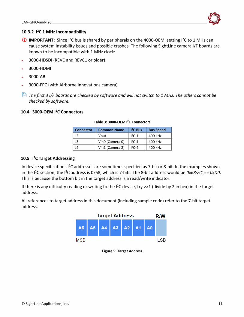
10.5 I2C Target Addressing
In device specifications I2C addresses are sometimes specified as 7-bit or 8-bit. In the examples shown in the I2C section, the I2C address is 0x68, which is 7-bits. The 8-bit address would be 0x68<<1 == 0xD0. This is because the bottom bit in the target address is a read/write indicator.
If there is any difficulty reading or writing to the I2C device, try >>1 (divide by 2 in hex) in the target address.
All references to target address in this document (including sample code) refer to the 7-bit target address.
Figure 5: Target Address

EAN-GPIO-and-I2C
© SightLine Applications, Inc. 12
✓ Verify the I2C device is powered up.
✓ Check that the SDA and SCL are connected correctly between the SightLine hardware and the target device.
✓ Check the bus speed of the target device. 3000-OEM I2C bus runs at 400 kHz.
✓ SightLine hardware I2C bus runs at 3.3V levels.
✓ There are multiple I2C buses exposed by the SightLine Hardware. Verify the I2C device is connected to the correct bus.
10.6 Example Linux Code
This section illustrates a simple example of using a Linux driver to read and write bytes from an I2C device.
Example of calling the code:
u8 buf[2] = {0x28, 0x04}; int ret = SLI2cSet(buf, 2, 2, 0x5D); //
returns -1 on failure, 0 on success
Example code:
#include <fcntl.h>
#include <unistd.h>
#include <sys/ioctl.h>
#include <stdio.h>
#include <linux/i2c-dev.h>
#include <linux/i2c.h>
int I2cGet(unsigned char *buf, long
nbytes, unsigned char bus, unsigned char
addr)
{
char fname[20];
sprintf(fname, "/dev/i2c-%d", bus);
int file;
if((file = open(fname, O_RDWR)) < 0) {
printf("failed to open %s\n", fname);
return -1 ;
}
if(ioctl(file, I2C_TARGET, addr) < 0) {
printf("Failed to access device
0x%x\n", addr);
close(file);
return -1 ;
}

EAN-GPIO-and-I2C
© SightLine Applications, Inc. 13
if(read(file, buf, nbytes) != nbytes) {
printf("Failed to read from %s
(%d)\n", fname, bus);
close(file);
return -1;
}
close(file);
return 0;
}
int I2cSet(unsigned char *buf, long
nbytes, unsigned char bus, unsigned char
addr)
{
char fname[20];
sprintf(fname, "/dev/i2c-%d", bus);
int file;
if((file = open(fname, O_RDWR)) < 0) {
printf("failed to open %s\n", fname);
return -1;
}
if(ioctl(file, I2C_TARGET_FORCE, addr) <
0) {
printf("Failed to access device
0x%x\n", addr);
close(file);
return -1;
}
if(write(file, buf, nbytes) != nbytes) {
printf("Failed to write to %s (%d)\n",
fname, bus);
close(file);
return -1;
}
close(file);
return 0;
}
11 Questions and Additional Support
Questions and additional support, please contact SightLine Support. Additional support documentation and Engineering Application Notes (EANs) can be found on the Documentation page of the SightLine Applications website.