dynamics of the arch-type reconfigurable machine tool
TRANSCRIPT
This article was originally published in a journal published byElsevier, and the attached copy is provided by Elsevier for the
author’s benefit and for the benefit of the author’s institution, fornon-commercial research and educational use including without
limitation use in instruction at your institution, sending it to specificcolleagues that you know, and providing a copy to your institution’s
administrator.
All other uses, reproduction and distribution, including withoutlimitation commercial reprints, selling or licensing copies or access,
or posting on open internet sites, your personal or institution’swebsite or repository, are prohibited. For exceptions, permission
may be sought for such use through Elsevier’s permissions site at:
http://www.elsevier.com/locate/permissionusematerial
Autho
r's
pers
onal
co
py
International Journal of Machine Tools & Manufacture 47 (2007) 326–334
Dynamics of the arch-type reconfigurable machine tool
Jaspreet Dhupia�, Bartosz Powalka, Reuven Katz, A. Galip Ulsoy
NSF Engineering Research Center for Reconfigurable Manufacturing Systems, University of Michigan, 2250 GGBL, 2350 Hayward Street,
Ann Arbor, MI 48109-2125, USA
Received 14 July 2005; received in revised form 20 March 2006; accepted 23 March 2006
Available online 22 May 2006
Abstract
Reconfigurable manufacturing systems (RMS) address challenges in modern manufacturing systems arising from product variety and
from rapid changes in product demand. This paper considers an arch-type reconfigurable machine tool (RMT) that has been built to
demonstrate the basic concepts of RMT design. The arch-type RMT was designed to achieve customized flexibility and includes a passive
degree-of-freedom, which allows it to be reconfigured to machine a family of parts. The kinematic and dynamic capabilities of the
machine are presented, including the experimental frequency response functions (FRFs) and computed stability lobes of the machine in
different configurations. A comparison of FRFs and stability lobes of the arch-type RMT reveals almost similar dynamic characteristics
at different reconfiguration positions. These similar characteristics arise because the dominant mode where chatter occurs is due to the
spindle–tool–tool holder assembly. Consequently, to ensure consistent dynamic behavior regardless of reconfiguration, a desirable
dynamic design feature for RMTs is that the machine’s structural frequencies are less dominant than the structural frequencies of the
spindle, tool and tool holder.
r 2006 Elsevier Ltd. All rights reserved.
Keywords: Dynamics; Stability lobes; Customization; Reconfiguration
1. Introduction
Traditional manufacturing systems can be classified as:(a) dedicated manufacturing systems (DMS)—designed toproduce a specific part or (b) flexible manufacturingsystems (FMS)—designed to accommodate a large varietyof parts even though parts are not specified at the designstage. While DMS is economical when the output volumesare high for a manufactured product over a long period oftime, FMS is more suited if the production volume is lowand a large variety of parts are produced. Changingproduct demands in current markets makes DMS lessdesirable, but FMS lacks the efficiency and robustness ofDMS, making it uneconomical for many productionsituations.
Reconfigurable manufacturing systems (RMSs), whichaim to achieve ‘exactly the capacity and functionality
needed, exactly when needed,’ have garnered considerableattention in recent years [1–5]. Research has been done on
design and operation of RMSs; lead-time; and ramp-uptime reduction and open architecture controllers at variousresearch centers in US, Europe and Japan [6–12]. Industryis also beginning to adopt and implement various aspectsof RMS [13,14]. Indeed, it is becoming clear thatreconfiguration will be an important aspect of many futuremanufacturing systems. Key characteristics of an RMSinclude: (1) modularity, (2) integrability, (3) convertibility,(4) customization, (5) scalability, and (6) diagnosibility.The more of these characteristics a manufacturing systempossesses, the more reconfigurable it becomes.An important issue is the appropriate ‘granularity’ of the
modules in an RMS. For many manufacturing systems thebasic module for reconfiguration will be a 3-axis CNCmachine tool—a commodity product whose cost hassignificantly fallen in recent years, while accuracy andreliability have improved. However, in research one mustconsider a variety of alternatives. Consequently, this paperwill discuss the concept of a reconfigurable machine tool(RMT), which brings the ‘granularity’ of reconfigurationdown from the machine level to the component level.Reconfiguration at the component level, as in RMTs, raises
ARTICLE IN PRESS
www.elsevier.com/locate/ijmactool
0890-6955/$ - see front matter r 2006 Elsevier Ltd. All rights reserved.
doi:10.1016/j.ijmachtools.2006.03.017
�Corresponding author. Tel.: +1734 276 8010; fax: +1 734 615 0312.
E-mail address: [email protected] (J. Dhupia).
Autho
r's
pers
onal
co
py
several difficult research issues such as costs, joints,accuracy and dynamic structural response. Nevertheless,the concept of an RMT brings many of the potentialadvantages of an RMS to the component level. Thus, it isuseful to conduct research on RMTs, to assess weathersome of the basic research challenges can be addressed, andif attractive application niches for RMTs can be developed.Consequently, our research group has designed and builtseveral RMTs, including a table-top Cartesian 3-axisRMT, a reconfigurable inspection machine, and an arch-type RMT [3,15–20].
The purpose of this paper is to describe the so-calledarch-type RMT, first demonstrated at the 2002 Interna-tional Manufacturing Technology Show in Chicago, and toprovide a brief description of the design concept, the designand construction, and dynamic characteristics of themachine. This paper describes the frequency responsefunctions (FRFs) and experimentally verified analyticalstability lobes for the machine at different reconfigurationpositions. Cutting model estimation has also been carriedout to evaluate the stability lobes of the machine. Contraryto predictions during the design stage of arch-type RMT[15,18], the dynamic performance of the machine does notvary significantly with reconfiguration position. The reasonfor this is discussed in the paper.
2. Background and methodology
2.1. Arch-type RMT: design and construction
The characteristics of customized flexibility on which thearch-type RMT design is based, makes the designprocedure more involved than the design of a dedicatedmachine tool or a flexible CNC machine tool [17,20]. Thefunctional design of the arch-type RMT is focused on thefinish milling of cylinder head inclined surfaces. Thetooling tolerances and process parameters were the samefor all inclined surfaces. However, the surfaces to be milled
are at different angles with respect to the horizontal: 301(for V6 cylinder heads) and 451 (for V8 cylinder heads). Adedicated machine tool solution would need a customizedstation for each member of the part family. If a commercialCNC machine solution is sought, one would have tochoose from available 5-axis CNC machines with ortho-gonal kinematics. In the arch-type RMT an alternativereconfigurable solution is presented where the machine iscapable of 3-axis kinematics with one passive degree-of-freedom available for reconfiguration.A detailed evaluation of various possible conceptual
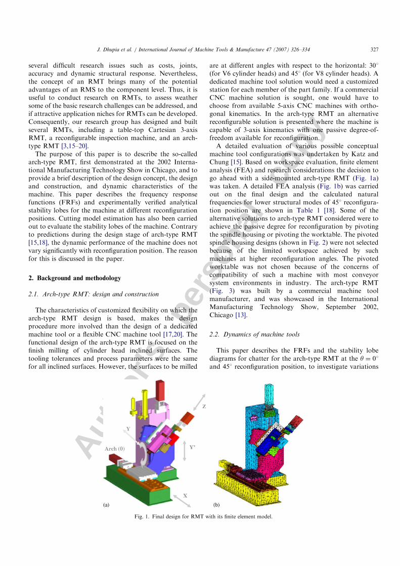
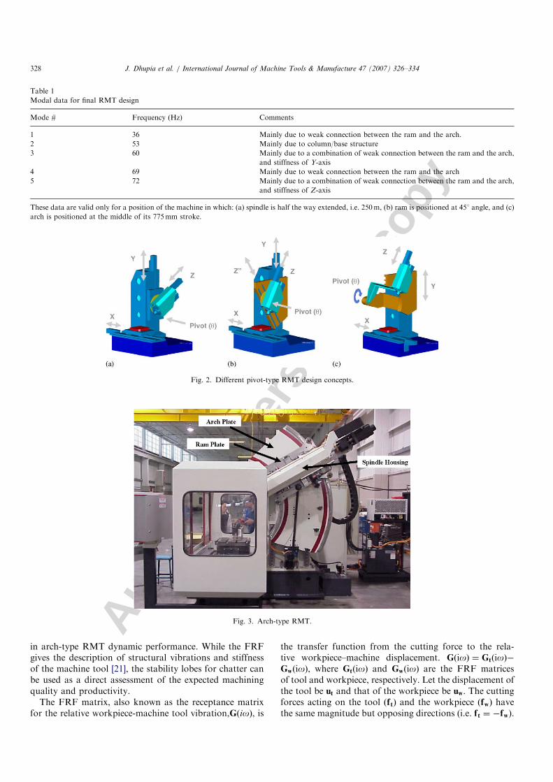
machine tool configurations was undertaken by Katz andChung [15]. Based on workspace evaluation, finite elementanalysis (FEA) and research considerations the decision togo ahead with a side-mounted arch-type RMT (Fig. 1a)was taken. A detailed FEA analysis (Fig. 1b) was carriedout on the final design and the calculated naturalfrequencies for lower structural modes of 451 reconfigura-tion position are shown in Table 1 [18]. Some of thealternative solutions to arch-type RMT considered were toachieve the passive degree for reconfiguration by pivotingthe spindle housing or pivoting the worktable. The pivotedspindle housing designs (shown in Fig. 2) were not selectedbecause of the limited workspace achieved by suchmachines at higher reconfiguration angles. The pivotedworktable was not chosen because of the concerns ofcompatibility of such a machine with most conveyorsystem environments in industry. The arch-type RMT(Fig. 3) was built by a commercial machine toolmanufacturer, and was showcased in the InternationalManufacturing Technology Show, September 2002,Chicago [13].
2.2. Dynamics of machine tools
This paper describes the FRFs and the stability lobediagrams for chatter for the arch-type RMT at the y ¼ 01and 451 reconfiguration position, to investigate variations
ARTICLE IN PRESS
Fig. 1. Final design for RMT with its finite element model.
J. Dhupia et al. / International Journal of Machine Tools & Manufacture 47 (2007) 326–334 327
Autho
r's
pers
onal
co
py
in arch-type RMT dynamic performance. While the FRFgives the description of structural vibrations and stiffnessof the machine tool [21], the stability lobes for chatter canbe used as a direct assessment of the expected machiningquality and productivity.
The FRF matrix, also known as the receptance matrixfor the relative workpiece-machine tool vibration,GðioÞ, is
the transfer function from the cutting force to the rela-tive workpiece–machine displacement. GðioÞ ¼ GtðioÞ�GwðioÞ, where GtðioÞ and GwðioÞ are the FRF matricesof tool and workpiece, respectively. Let the displacement ofthe tool be ut and that of the workpiece be uw. The cuttingforces acting on the tool ðftÞ and the workpiece ðfwÞ havethe same magnitude but opposing directions (i.e. ft ¼ �fw).
ARTICLE IN PRESS
Table 1
Modal data for final RMT design
Mode # Frequency (Hz) Comments
1 36 Mainly due to weak connection between the ram and the arch.
2 53 Mainly due to column/base structure
3 60 Mainly due to a combination of weak connection between the ram and the arch,
and stiffness of Y-axis
4 69 Mainly due to weak connection between the ram and the arch
5 72 Mainly due to a combination of weak connection between the ram and the arch,
and stiffness of Z-axis
These data are valid only for a position of the machine in which: (a) spindle is half the way extended, i.e. 250m, (b) ram is positioned at 451 angle, and (c)
arch is positioned at the middle of its 775mm stroke.
Fig. 2. Different pivot-type RMT design concepts.
Fig. 3. Arch-type RMT.
J. Dhupia et al. / International Journal of Machine Tools & Manufacture 47 (2007) 326–334328
Autho
r's
pers
onal
co
py
In this paper the workpiece is assumed rigid, and theassumption was verified by measuring the FRF of theworkpiece and measuring the vibrations displacement ofthe workpiece during the cutting experiments. Thus, therelationship between the cutting force and vibrations at thetool tip become:
GðioÞ ftðioÞ ¼ utðioÞ. (1)
In general, GðioÞ would be a 3� 3 matrix, as displace-ments and the force vector are defined in the three-dimensional Cartesian system. However in the millingprocess, the axial direction (Z) is typically much stiffer thanthe feed force direction (X) and the cross feed forcedirection (Y) (see Fig. 1). Therefore
GðioÞ ¼GXX ðioÞ GXY ðioÞ
GYX ðioÞ GYY ðioÞ
" #. (2)
Here, GXX and GYY are FRFs that were experimentallydetermined by an impact hammer test. The off-diagonalcross coupling terms GXY, GYX in Eq. (2) are relativelysmall and are neglected.
The vibrations of the machine affect the quality ofmachining due to chatter (i.e., regenerative self excitedvibrations). Chatter occurs due to the interaction of theworkpiece and tool, which leads to vibrations near one ofthe structural modes. At some combinations of spindlespeed and depth of cut, the cutting forces can becomeunstable and cause chatter. The analytical chatter predic-tion model presented by Altintas and Budak [22,23] givesthe characteristic equation of the milling process andequates it to zero to find the stability limit. Thecharacteristic equation for finding the stability limit for
this system is
det I�1
2K tc apð1� e�ioc T ÞA0GðiocÞ
� �¼ 0, (3)
where ap is the nominal depth of cut, Ktc is the tangentialcutting coefficient, oc is the chatter frequency, T is thetooth passage period and A0 is the immersion dependentmatrix which is a function of the cutting coefficients.The cutting experiments were done for estimating the
cutting coefficients and to verify the analytical stabilitylobes by verifying the regions of stability and instability.The cutting coefficients are constant for a given toolinsert–workpiece combination and not affected by thechange in machine structure. The axial cutting coefficientsare not necessary for finding the stability lobes because thestructure has been assumed rigid along the axial direction.Feed and cross-feed forces were measured while cutting infull immersion with two inserts only. The mechanisticcutting force model [22] for the milling cutting process isdescribed as
FX ¼ �K tc ap f t sin f sin f� K te ap sin f
� K rc ap f t sin f cos f� K re ap cos f,
FY ¼ K tc ap f t sin f cos fþ K te ap cos f
� K rc ap f t sin f sin f� K re ap cos f. ð4Þ
Knowing FX, FY for different values of instantaneouscutter angular locations f, the cutting coefficients Ktc, Kte,Krc and Kre can be estimated using the least-squaresapproach. The forces FX and FY are the components of ft inEq. (1), i.e., ft ¼ ½FX ;FY �
T. The constants Ktc and Krc arisedue to the shearing action in the tangential and radialdirections respectively. Kte and Kre are the corresponding
ARTICLE IN PRESS
10.15 10.2 10.25 10.3 10.35 10.4 10.45-500
0
500
1000
1500Cross-feed direction
Time, t [sec]
10.15 10.2 10.25 10.3 10.35 10.4 10.45
Time, t [sec]
Cut
ting
For
ce, F
Y [N
]
-1500
-1000
-500
0
500Feed direction
Cut
ting
For
ce, F
X [N
]
ExperimentalEstimated
ExperimentalEstimated
(a)
(b)
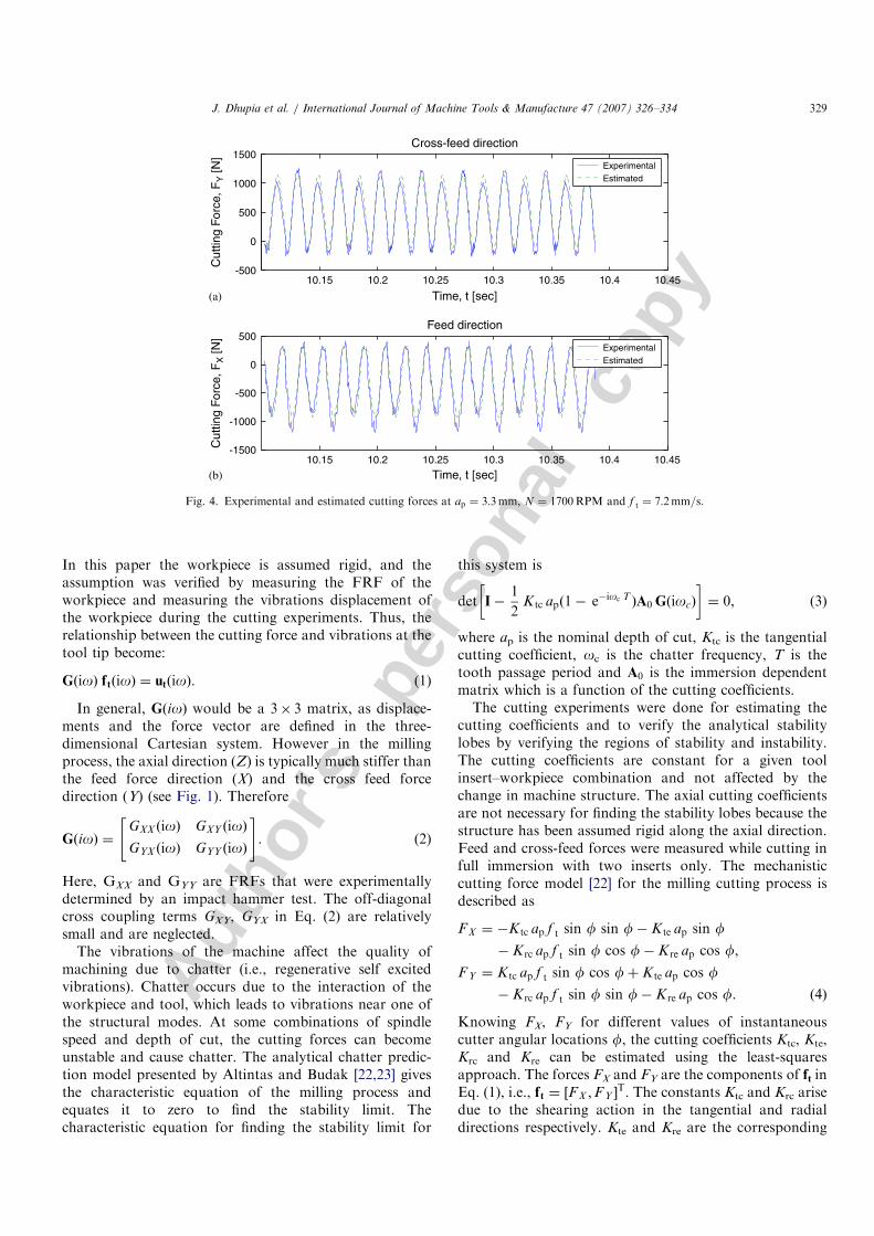
Fig. 4. Experimental and estimated cutting forces at ap ¼ 3:3mm, N ¼ 1700RPM and f t ¼ 7:2mm=s.
J. Dhupia et al. / International Journal of Machine Tools & Manufacture 47 (2007) 326–334 329
Autho
r's
pers
onal
co
py
edge constants, and ft represents the feed per tooth.While the tangential cutting coefficient, Ktc, appearsdirectly in Eq. (3), the matrix A0 is dependent on Krc.The edge constants are needed for the cutting coefficientestimation.
All the cutting experiments were carried out using aValenite V490 square shoulder end mill with rectangularinserts (outer diameter: 50.8mm, insert width: 15.875mm)and AISI 1018 steel. While two inserts were used forcutting model estimation, stability lobe diagram andchatter estimation was carried out for four inserts. Sincethe goal of the paper is to provide a comparison betweenthe different reconfiguration positions of the arch-typeRMT, the tool and the workpiece were kept the same indifferent reconfiguration positions.
3. Results and discussion
3.1. Cutting model
Fig. 4 shows the results for force measurements whilecutting AISI 1018 steel at depth of cut, ap ¼ 3:3mm,spindle speed, N ¼ 1700RPM and feed per tooth,f t ¼ 0:127mm=tooth. The cutting coefficients determinedby the least-squares method, using the force signal after theinitial transients due to the tool entering the workpiecedecayed were
K tc ¼ 2309:94N=mm2; K rc ¼ 1337:79N=mm2,
K te ¼ 24:79N=mm; K re ¼ 17:69N=mm:
The correlation factors for the estimated and experimentaldata have large values of 0.98 for feed (X) direction and0.96 for cross feed (Y) direction, indicating a good fit.
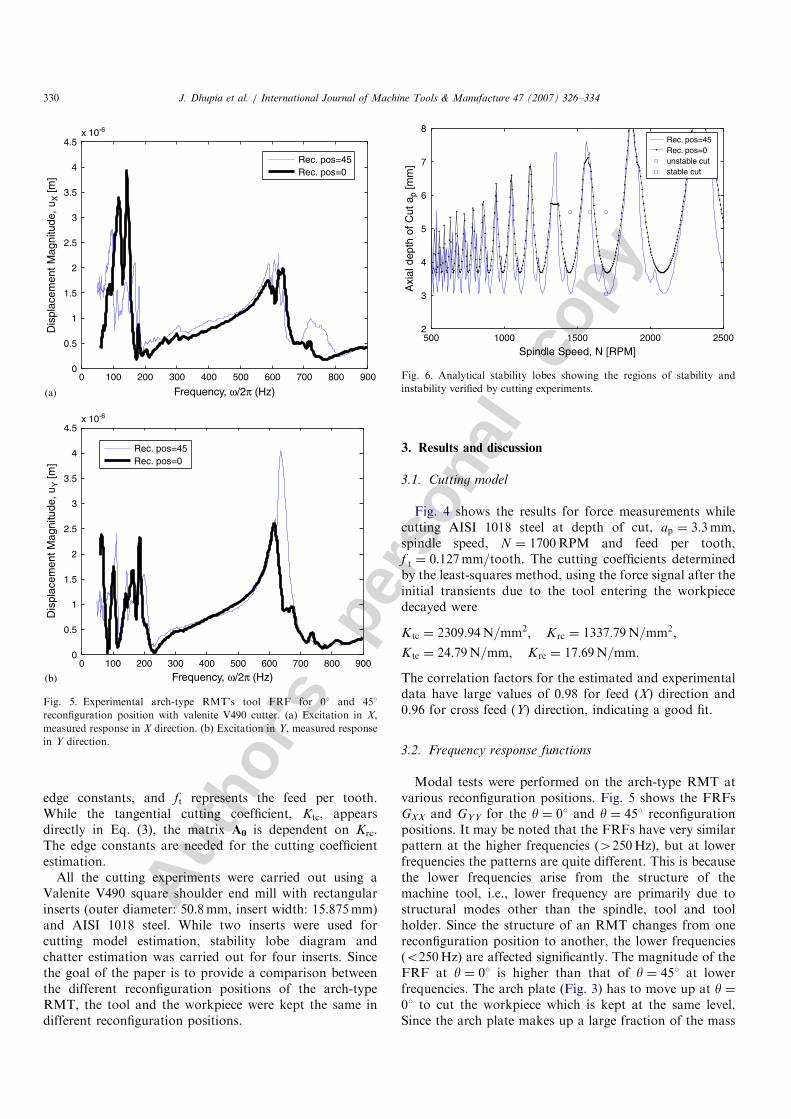
3.2. Frequency response functions
Modal tests were performed on the arch-type RMT atvarious reconfiguration positions. Fig. 5 shows the FRFsGXX and GYY for the y ¼ 01 and y ¼ 451 reconfigurationpositions. It may be noted that the FRFs have very similarpattern at the higher frequencies (4250Hz), but at lowerfrequencies the patterns are quite different. This is becausethe lower frequencies arise from the structure of themachine tool, i.e., lower frequency are primarily due tostructural modes other than the spindle, tool and toolholder. Since the structure of an RMT changes from onereconfiguration position to another, the lower frequencies(o250Hz) are affected significantly. The magnitude of theFRF at y ¼ 01 is higher than that of y ¼ 451 at lowerfrequencies. The arch plate (Fig. 3) has to move up at y ¼01 to cut the workpiece which is kept at the same level.Since the arch plate makes up a large fraction of the mass
ARTICLE IN PRESS
0 100 200 300 400 500 600 700 800 900
Rec. pos=45Rec. pos=0
0 100 200 300 400 500 600 700 800 9000
0.5
1
1.5
2
2.5
3
3.5
4
4.5x 10⁻⁶
Frequency, ω/2π (Hz)
Frequency, ω/2π (Hz)
Dis
plac
emen
t M
agni
tude
, u X
[m]
0
0.5
1
1.5
2
2.5
3
3.5
4
4.5x 10⁻⁶
Dis
plac
emen
t Mag
nitu
de, u
Y [m
]
Rec. pos=45Rec. pos=0
(a)
(b)
Fig. 5. Experimental arch-type RMT’s tool FRF for 01 and 451
reconfiguration position with valenite V490 cutter. (a) Excitation in X,
measured response in X direction. (b) Excitation in Y, measured response
in Y direction.
500 1000 1500 2000 25002
3
4
5
6
7
8
Spindle Speed, N [RPM]
Axi
al d
epth
of
Cut
ap
[mm
]
Rec. pos=45Rec. pos=0unstable cutstable cut
Fig. 6. Analytical stability lobes showing the regions of stability and
instability verified by cutting experiments.
J. Dhupia et al. / International Journal of Machine Tools & Manufacture 47 (2007) 326–334330
Autho
r's
pers
onal
co
py
of the machine, the displacement of the arch on themachine has the most significant effect on the FRF of themachine structure. The higher the arch plate moves, lessstiff the structure becomes. Thus, in this case, theconfiguration at y ¼ 01is less stiff at lower frequenciesmodes, than the configuration at y ¼ 451 since the archplate is located higher for y ¼ 01. A large hammer(bandwidth 0–600Hz) was used to study the lowerfrequencies range of the structural FRF of the machine.The lowest dominant natural frequency of the machinefound was around 60Hz.
3.3. Stability lobes
The analytical stability lobes generated for y ¼ 01 and451 are shown in Fig. 6. Various cutting experiments weredone to verify the regions of stability and instability basedon these lobes. These points are marked on the stabilitylobe diagram and validate the stability lobe prediction. Thecutting experiments results for y ¼ 01 and 451 were similarat various cutting conditions. The analytical stability lobesindicate that the chatter occurs for the y ¼ 451 configura-tion at a smaller depth of cut compared to that for the
ARTICLE IN PRESS
8.2 8.25 8.3 8.35 8.4 8.45 8.5 8.55-2000
-1500
-1000
-500
0
500
Time, t [sec]
8.2 8.25 8.3 8.35 8.4 8.45 8.5 8.55Time, t [sec]
Cut
ting
For
ce, F
X [N
]
-2000
-1500
-1000
-500
0
500
Cut
ting
For
ce, F
X [N
]
Feed Force in time domain
ap=5.5mm, N=1585RPM, R.P.=0°, no chatter
ap=5.5mm, N=1700RPM, R.P.=0°, no chatter
ap=5.5mm, N=1700RPM, R.P.=0°, no chatter
ap=5.5mm, N=1585RPM, R.P.=0°, no chatter
0 500 1000 1500 2000 25000
5
10
15x 104 FFT plot of feed direction forces
Frequency, ω/2π [Hz]
Frequency, ω/2π [Hz]
Mag
., |F
X(iω
)| [N
]M
ag.,
|FX(iω
)| [N
]
0 500 1000 1500 2000 25000
1
2
3x 10⁶
(a)
(b)
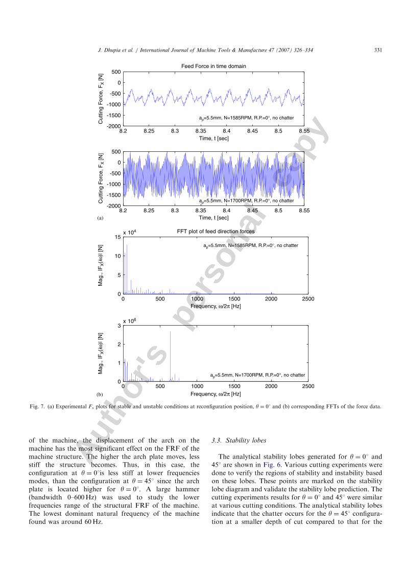
Fig. 7. (a) Experimental Fx plots for stable and unstable conditions at reconfiguration position, y ¼ 01 and (b) corresponding FFTs of the force data.
J. Dhupia et al. / International Journal of Machine Tools & Manufacture 47 (2007) 326–334 331
Autho
r's
pers
onal
co
py
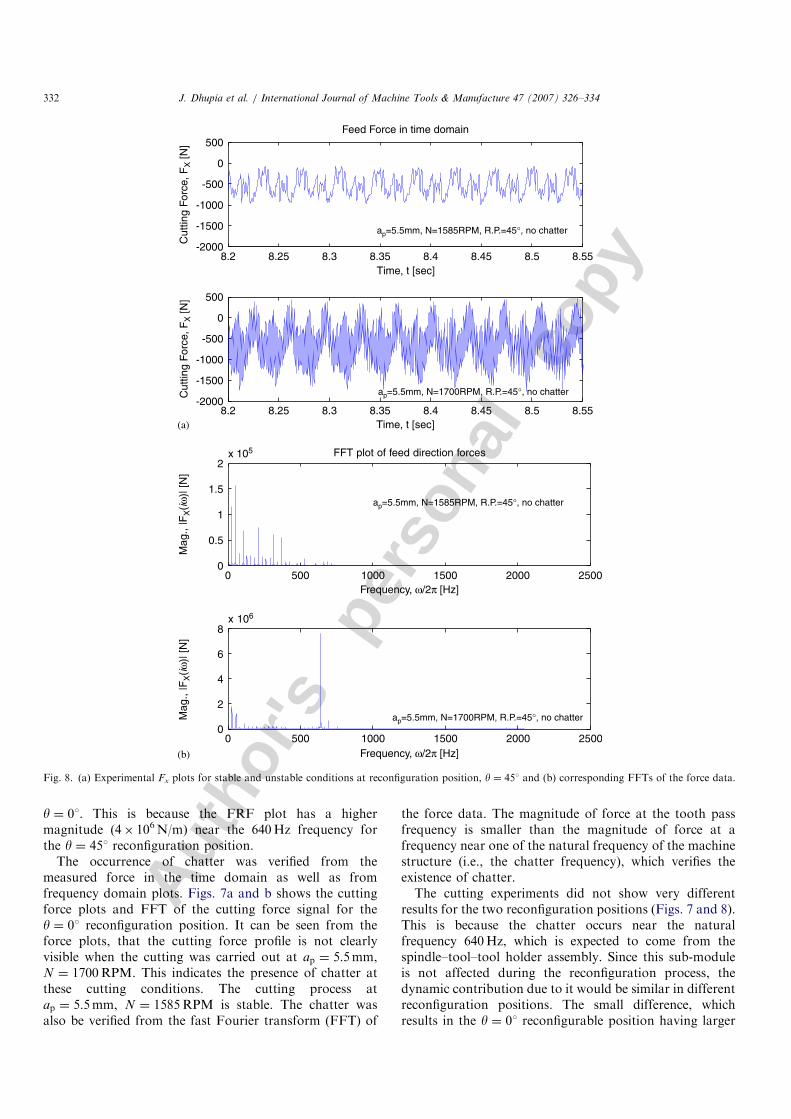
y ¼ 01. This is because the FRF plot has a highermagnitude (4� 106N/m) near the 640Hz frequency forthe y ¼ 451 reconfiguration position.
The occurrence of chatter was verified from themeasured force in the time domain as well as fromfrequency domain plots. Figs. 7a and b shows the cuttingforce plots and FFT of the cutting force signal for they ¼ 01 reconfiguration position. It can be seen from theforce plots, that the cutting force profile is not clearlyvisible when the cutting was carried out at ap ¼ 5:5mm,N ¼ 1700RPM. This indicates the presence of chatter atthese cutting conditions. The cutting process atap ¼ 5:5mm, N ¼ 1585RPM is stable. The chatter wasalso be verified from the fast Fourier transform (FFT) of
the force data. The magnitude of force at the tooth passfrequency is smaller than the magnitude of force at afrequency near one of the natural frequency of the machinestructure (i.e., the chatter frequency), which verifies theexistence of chatter.The cutting experiments did not show very different
results for the two reconfiguration positions (Figs. 7 and 8).This is because the chatter occurs near the naturalfrequency 640Hz, which is expected to come from thespindle–tool–tool holder assembly. Since this sub-moduleis not affected during the reconfiguration process, thedynamic contribution due to it would be similar in differentreconfiguration positions. The small difference, whichresults in the y ¼ 01 reconfigurable position having larger
ARTICLE IN PRESS
8.2 8.25 8.3 8.35 8.4 8.45 8.5 8.55-2000
-1500
-1000
-500
0
500
Time, t [sec]
8.2 8.25 8.3 8.35 8.4 8.45 8.5 8.55Time, t [sec]
Cut
ting
For
ce, F
X [N
]
-2000
-1500
-1000
-500
0
500
Cut
ting
For
ce, F
X [N
]
Feed Force in time domain
ap=5.5mm, N=1585RPM, R.P.=45°, no chatter
ap=5.5mm, N=1700RPM, R.P.=45°, no chatter
ap=5.5mm, N=1700RPM, R.P.=45°, no chatter
ap=5.5mm, N=1585RPM, R.P.=45°, no chatter
0 500 1000 1500 2000 25000
1
0.5
1.5
2x 10⁵ FFT plot of feed direction forces
Frequency, ω/2π [Hz]
Frequency, ω/2π [Hz]
Mag
., |F
X(iω
)| [N
]M
ag.,
|FX(iω
)| [N
]
0 500 1000 1500 2000 25000
4
2
6
8x 10⁶
(a)
(b)
Fig. 8. (a) Experimental Fx plots for stable and unstable conditions at reconfiguration position, y ¼ 451 and (b) corresponding FFTs of the force data.
J. Dhupia et al. / International Journal of Machine Tools & Manufacture 47 (2007) 326–334332
Autho
r's
pers
onal
co
py
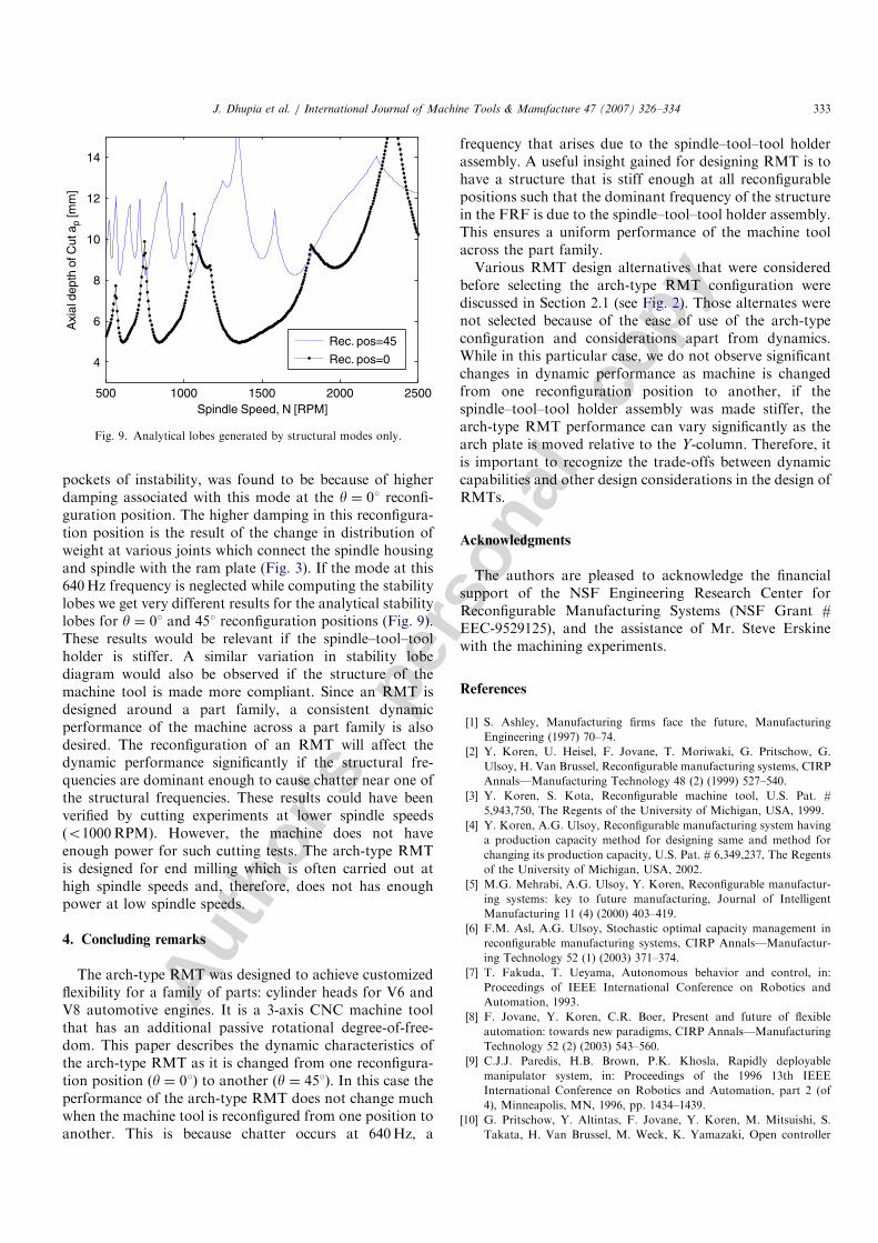
pockets of instability, was found to be because of higherdamping associated with this mode at the y ¼ 01 reconfi-guration position. The higher damping in this reconfigura-tion position is the result of the change in distribution ofweight at various joints which connect the spindle housingand spindle with the ram plate (Fig. 3). If the mode at this640Hz frequency is neglected while computing the stabilitylobes we get very different results for the analytical stabilitylobes for y ¼ 01 and 451 reconfiguration positions (Fig. 9).These results would be relevant if the spindle–tool–toolholder is stiffer. A similar variation in stability lobediagram would also be observed if the structure of themachine tool is made more compliant. Since an RMT isdesigned around a part family, a consistent dynamicperformance of the machine across a part family is alsodesired. The reconfiguration of an RMT will affect thedynamic performance significantly if the structural fre-quencies are dominant enough to cause chatter near one ofthe structural frequencies. These results could have beenverified by cutting experiments at lower spindle speeds(o1000RPM). However, the machine does not haveenough power for such cutting tests. The arch-type RMTis designed for end milling which is often carried out athigh spindle speeds and, therefore, does not has enoughpower at low spindle speeds.
4. Concluding remarks
The arch-type RMT was designed to achieve customizedflexibility for a family of parts: cylinder heads for V6 andV8 automotive engines. It is a 3-axis CNC machine toolthat has an additional passive rotational degree-of-free-dom. This paper describes the dynamic characteristics ofthe arch-type RMT as it is changed from one reconfigura-tion position (y ¼ 01) to another (y ¼ 451). In this case theperformance of the arch-type RMT does not change muchwhen the machine tool is reconfigured from one position toanother. This is because chatter occurs at 640Hz, a
frequency that arises due to the spindle–tool–tool holderassembly. A useful insight gained for designing RMT is tohave a structure that is stiff enough at all reconfigurablepositions such that the dominant frequency of the structurein the FRF is due to the spindle–tool–tool holder assembly.This ensures a uniform performance of the machine toolacross the part family.Various RMT design alternatives that were considered
before selecting the arch-type RMT configuration werediscussed in Section 2.1 (see Fig. 2). Those alternates werenot selected because of the ease of use of the arch-typeconfiguration and considerations apart from dynamics.While in this particular case, we do not observe significantchanges in dynamic performance as machine is changedfrom one reconfiguration position to another, if thespindle–tool–tool holder assembly was made stiffer, thearch-type RMT performance can vary significantly as thearch plate is moved relative to the Y-column. Therefore, itis important to recognize the trade-offs between dynamiccapabilities and other design considerations in the design ofRMTs.
Acknowledgments
The authors are pleased to acknowledge the financialsupport of the NSF Engineering Research Center forReconfigurable Manufacturing Systems (NSF Grant #EEC-9529125), and the assistance of Mr. Steve Erskinewith the machining experiments.
References
[1] S. Ashley, Manufacturing firms face the future, Manufacturing
Engineering (1997) 70–74.
[2] Y. Koren, U. Heisel, F. Jovane, T. Moriwaki, G. Pritschow, G.
Ulsoy, H. Van Brussel, Reconfigurable manufacturing systems, CIRP
Annals—Manufacturing Technology 48 (2) (1999) 527–540.
[3] Y. Koren, S. Kota, Reconfigurable machine tool, U.S. Pat. #
5,943,750, The Regents of the University of Michigan, USA, 1999.
[4] Y. Koren, A.G. Ulsoy, Reconfigurable manufacturing system having
a production capacity method for designing same and method for
changing its production capacity, U.S. Pat. # 6,349,237, The Regents
of the University of Michigan, USA, 2002.
[5] M.G. Mehrabi, A.G. Ulsoy, Y. Koren, Reconfigurable manufactur-
ing systems: key to future manufacturing, Journal of Intelligent
Manufacturing 11 (4) (2000) 403–419.
[6] F.M. Asl, A.G. Ulsoy, Stochastic optimal capacity management in
reconfigurable manufacturing systems, CIRP Annals—Manufactur-
ing Technology 52 (1) (2003) 371–374.
[7] T. Fakuda, T. Ueyama, Autonomous behavior and control, in:
Proceedings of IEEE International Conference on Robotics and
Automation, 1993.
[8] F. Jovane, Y. Koren, C.R. Boer, Present and future of flexible
automation: towards new paradigms, CIRP Annals—Manufacturing
Technology 52 (2) (2003) 543–560.
[9] C.J.J. Paredis, H.B. Brown, P.K. Khosla, Rapidly deployable
manipulator system, in: Proceedings of the 1996 13th IEEE
International Conference on Robotics and Automation, part 2 (of
4), Minneapolis, MN, 1996, pp. 1434–1439.
[10] G. Pritschow, Y. Altintas, F. Jovane, Y. Koren, M. Mitsuishi, S.
Takata, H. Van Brussel, M. Weck, K. Yamazaki, Open controller
ARTICLE IN PRESS
500 1000 1500 2000 2500
4
6
8
10
12
14
Spindle Speed, N [RPM]
Axi
al d
epth
of C
ut a
p [m
m]
Rec. pos=45
Rec. pos=0
Fig. 9. Analytical lobes generated by structural modes only.
J. Dhupia et al. / International Journal of Machine Tools & Manufacture 47 (2007) 326–334 333
Autho
r's
pers
onal
co
py
architecture—past, present and future, CIRP Annals—Manufactur-
ing Technology 50 (2) (2001) 463–470.
[11] A.S. Yigit, A.G. Ulsoy, Dynamic stiffness evaluation for reconfigur-
able machine tools including weakly non-linear joint characteristics,
Proceedings of the Institution of Mechanical Engineers, Part B:
Journal of Engineering Manufacture 216 (1) (2002) 87–101.
[12] A.S. Yigit, A.G. Ulsoy, A. Allahverdi, Optimizing modular product
design for reconfigurable manufacturing, Journal of Intelligent
Manufacturing 13 (4) (2002) 309–316.
[13] Anonymous, An easier way to machine? Manufacturing Engineering
129 (Sept 2002) 39.
[14] J. DeGaspari, All in the family, Mechanical Engineering 124 (2002)
56–58.
[15] R. Katz, H. Chung, Design of an experimental reconfigurable
machine tool, Japan–USA Symposium on Flexible Automation,
Ann Arbor, MI, 2000.
[16] R. Katz, Y.-M. Moon, Virtual arch type reconfigurable machine tool
design: principles and methodology, ERC RMS, The University of
Michigan, Ann Arbor, 2000, p. 34.
[17] R.G. Landers, B.-K. Min, Y. Koren, Reconfigurable machine tools,
CIRP Annals—Manufacturing Technology 50 (1) (2001) 269–274.
[18] J. Manjunathaiah, A. Saeedy, Design and engineering of the
reconfigurable machine tool, Final Report, Lamb Technicon, Lx-
0445, 1999.
[19] Y.-M. Moon, Reconfigurable machine tool design: theory and
application, Mechanical Engineering, University of Michigan, Ann
Arbor, 2000, p. 166.
[20] Z.J. Pasek, S. Badrawy, Z. Li, K.-G. Ahn, Challenges and
opportunities in the design of reconfigurable machine tools,
Japan–USA Symposium on Flexible Automation, Hiroshima, Japan,
2002.
[21] D.J. Ewins, Modal testing: theory and practice, Letchworth,
New York, Research Studies Press, Hertfordshire, England, 1984.
[22] Y. Altintas, Manufacturing automation: metal cutting mechanics,
machine tool vibrations, and CNC design, Cambridge University
Press, Cambridge, 2000.
[23] E. Budak, Y. Altintas, Analytical prediction of chatter stability in
milling—part I: general formulation, part II: application of the
general formulation to common milling systems, Proceedings of the
1995 ASME International Mechanical Engineering Congress and
Exposition, part 1 (of 2), 12–17 November 1995, San Francisco, CA,
USA, 1995, pp. 545–565.
ARTICLE IN PRESSJ. Dhupia et al. / International Journal of Machine Tools & Manufacture 47 (2007) 326–334334