dynamical behaviour of cmi based statcom
TRANSCRIPT

Journal of Futuristic Sciences and Applications
Vol. 4(2), Jul-Dec 2021, pp. 47-54
doi: 10.51976/jfsa.422107
www.gla.ac.in/journals/jfsa
© 2021 JFSA, GLA University
Dynamical Behaviour of CMI based STATCOM
Abhay Agrawal* and Sanjay Soni**
ABSTRACT
Cascade multilevel inverters (CMI) are superior to other multilevel inverter configurations in
STATCOM applications owing to their distinguishing features, such as structural flexibility and
control design feasibility in the service of lower device losses and high value of AC output voltage
waveform quality. Voltage output stabilization and power factor correction at the point of common
connection are two challenging difficulties that might lead to the system’s dominance. In this
work, the overall control architecture for the system is presented, provides information on how the
9-level CMI may be utilised as STATCOM to carry out dc link voltage balancing and reactive
power compensation. The superiority of the system under varying loads and fault circumstances
has been confirmed by computer modelling.
Keywords: Point of Common Coupling (PCC); Cascade Multilevel Inverter (CMI); Line Ground (LG)
Fault.
1.0 Introduction
Continuous and accurate power management, such as voltage level regulation, power flow in
overhead transmission management, and system stability improvement [1] are all made possible by
converter-based FACTS controllers. By transferring power exchanged in a reactive manner between
STATCOM and the grid, this FACTS device greatly improves voltage control and transient stability
[2]. Since it requires fewer parts and is more efficient overall, the CMI converter is often used as a
STATCOM [3, 4]. Other multilevel topologies, such as the diode clamped and flying capacitor, are
also in use. Maximizing the figure of levels in the output voltage waveform is made feasible by the
increased switching repetition with trade off flexibility between voltage regulation, switching losses,
and harmonic performance. In comparison to other multilevel inverter topologies, reduced switching
device losses, reduced component requirements, and simplified control are all advantages of cascade
multilevel inverters. To prevent potential imbalance on the DC side of a number of H bridges, active
power balancing is used to compensate for the power losses of each H bridge individually [5]. The
grid voltage is used as a standard against which the reactive power is measured in order to
compensate for it. Differences between dc-link voltages and the reference voltage are used to
determine the amount of active power that must be supplied to the STATCOM.
____________________
*Corresponding author; Associate Professor, Department of Mechanical Engineering, Rewa Engineering
College, Rewa, India (E-mail: [email protected])
**Associate Professor, Department of Industrial Production, JEC Jabalpur, RGPV Bhopal, Madhya Pradesh,
India (E-mail: [email protected])

48 Journal of Futuristic Sciences and Applications, Volume 4, Issue 2, Jul-Dec 2021
Doi: 10.51976/jfsa.422107
By balancing measurements of dc link voltage and monitoring reactive power as needed, a
well-designed controller and a carefully chosen modulation method may significantly boost a
system’s dynamic performance. STATCOM system setup based on three-phase cascade multi-level
inverters is shown in Figure 1.
Figure 1: CMI based STATCOM Layout
Cell 2
Cell 3
Th
e B P
hase C
luster
Th
e C P
hase C
luster
N
Th
e A P
hase C
luster
La Lb
LoadN
Generator
i
i3
i1i2
Lc
Cell 4
RaRb Rc
S1 S3
S4 S2
2.0 DC Voltage Balancing
When a cascade multilevel inverter (CMI) is used in a STATCOM application, the system’s
practicality and modularity are both improved by the use of a separate dc capacitor; nevertheless, the
dc voltage often becomes unbalanced as a result of the CMI’s internal losses. Poor waveform quality,
unequal voltage pressure throughout switching devices, and overvoltage at any one connection are all
conditions that may be avoided with proper dc voltage balancing. To offset the power losses caused
by CMI’s internal components, a phase shift between the converter’s output voltage and the network
voltage may be used to accomplish dc voltage balancing. In order to accomplish dc voltage balancing,
it is necessary to STATCOM’s active power input to each H bridge may be changed. [6]. As
illustrated in Figure 2, a DC voltage phenomenon in a system is created by measuring and calculating
DC voltage of each individual H bridge with a reference dc potential and then sending the resulting
error signal via a PI controller. As illustrated in Figure 2, the average of each cluster’s DC voltage
(i.e. V (dca), V (dcb), and V dcc) is made to track the average of all clusters’ voltages ( Vdc).
3.0 CMI based Statcom Mathematical Modelling and Control
3.1 Mathematical modelling
In this model, a CMI-based STATCOM is represented by a voltage source converter that is
reactively connected to the transmission or distribution network. In Figure 3, Vs represents the

Dynamical Behaviour of CMI based STATCOM 49 voltage of the power system, Vc represents the voltage of the STATCOM, represents the current
drawn by the STATCOM, and R and L represent the total resistance and inductance between the
source and the STATCOM, respectively. As a result of the disparity between the network voltage and
the STATCOM voltage, the STATCOM is able to generate its own current by adjusting the coupling
parameters in the following ways:
(1).....
V
Vcb
Vca
V
Vsb
Vsa
Ic
Ib
Ia
R
Ic
Ib
Ia
dt
dL
ccsc Where Vsa, Vsb and Vsc represents the three phase source voltages and denotes the three phase
STATCOM voltages.
Type of ahead-or-behind current transmitting from STATCOM to the network or network to
STATCOM is determined by the voltage magnitudes between STATCOM and network, which are as
follows:
Figure 2: A Technique for Balancing DC Voltage
KpCB
KiCB ʃ
PI
PI
Vdca
Vdcb
Vdcc
Vdc
-
-
-
+
+
+
++
PCBa
PCBc
PCBb
Figure 3: Linear Representation of a CMI-based STATCOM System
C
Ls PCC
Power System
Vs
Vpcc
Ic
Cascade
multilevel
inerter
Rs
Vc
Lc
Inductive Load
Capacitive Load
Non linear load
If Vc > Vs, then the STATCOM will be the source of the leading reactive current in the
power grid. When Vc < Vs, a lagged reactive current flow from the power grid to the STATCOM.
50 Journal of Futuristic Sciences and Applications, Volume 4, Issue 2, Jul-Dec 2021
Doi: 10.51976/jfsa.422107
Reactive power and active power exchange between STATCOM and network may be
controlled and understood in terms of a mathematical model using equations (2-8) where the three-
phase quantity is transformed into a synchronous dq reference frame using a matrix called [T].
(2)....cosθsinθ
sinθcosθT
(3)....VTV
VV c,VsT
V
VVs c
cq
cd
sq
sd
(4)....IcTIcq
IcdIc
(5)....VV
VVRwL
dt
dL
cqsq
cdsd
I
I
I
I
I
I
cq
cd
cd
cq
cq
cd
(6).....0
Vs
V
VVs
sq
sd
(7).....Vspc I cd
(8).....Vsqc I cq
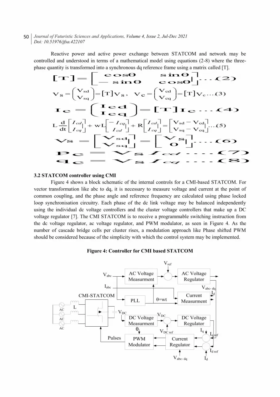
3.2 STATCOM controller using CMI
Figure 4 shows a block schematic of the internal controls for a CMI-based STATCOM. For
vector transformation like abc to dq, it is necessary to measure voltage and current at the point of
common coupling, and the phase angle and reference frequency are calculated using phase locked
loop synchronisation circuitry. Each phase of the dc link voltage may be balanced independently
using the individual dc voltage controllers and the cluster voltage controllers that make up a DC
voltage regulator [7]. The CMI STATCOM is to receive a programmable switching instruction from
the dc voltage regulator, ac voltage regulator, and PWM modulator, as seen in Figure 4. As the
number of cascade bridge cells per cluster rises, a modulation approach like Phase shifted PWM
should be considered because of the simplicity with which the control system may be implemented.
Figure 4: Controller for CMI based STATCOM
AC
AC
AC
AC Voltage
Measurment
PWM
Modulator
DC Voltage
Regulator
DC Voltage
Measurment
Current
MeasurmentPLL
Current
Regulator
AC Voltage
Regulator
CMI-STATCOM
L
θ=wt
Vabc
Iabc
Vref
VDC VDC
VDC ref
Vabc- dq
Vabc- dq Id
Id
Id ref
Iq ref
Iq θ
Pulses

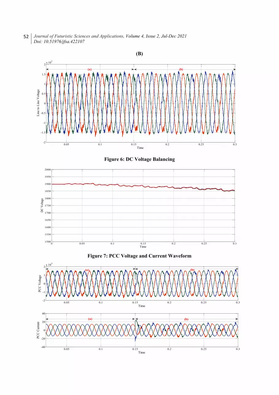
Dynamical Behaviour of CMI based STATCOM 51 4.0 Simulation Result
The simulation results demonstrate the system’s superiority by revealing its clearly defined
dynamic performance, such as meeting Demand for reactive power from the load side, while
maintaining a constant dc link voltage throughout the inductive/capacitive operation. The
mathematical description of STATCOM is used to compile Table I, which lists the simulation
parameters. The waveforms of the three-phase STATCOM output voltage are shown in Figure 5 (A)
in standby mode, (B) in inductive mode (0.02 to 0.15 sec), and (C) in capacitive mode (0.15 to 0.3
sec). Four capacitors are employed in a single phase CMI – STATCOM, and their dc voltage balance
is shown in Figure 6.
There is a 0.15-second transition time between the inductive mode (a) and the capacitive
mode (b), as shown in Figure 7.
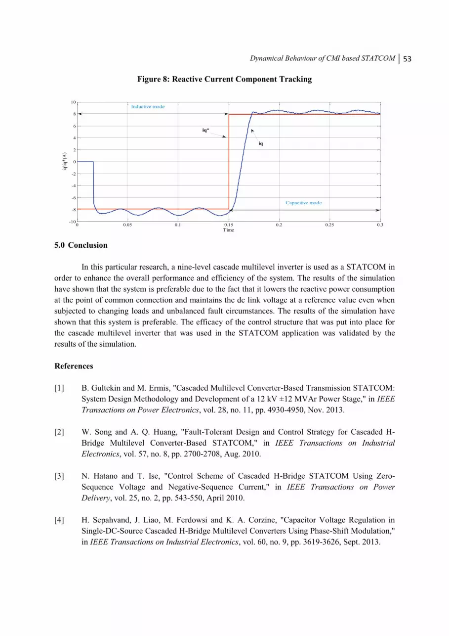
During the switch from inductive to capacitive mode, Figure 8 demonstrates the dynamic
performance of CMI-based STATCOM by displaying the tracking between the reactive current
reference (Iq*) and the reactive current (Iq) given by STATCOM.
Table 1: Simulation Parameters
Rated Power 130 Kvar
Rated Voltage 11 kv
Number of Cells/Phase 4
DC Capacitor 5.66 mF
DC Voltage 1995 Vdc
Output waveform Frequency 50 Hz
Reactive Current (Iq*)
9 Amp
Figure 5 STATCOM output waveform of the voltage in (A) the standby mode and (B) the
inductive mode (a)/capacitive mode (b)
(A)
0 0.01 0.02 0.03 0.04 0.05 0.06 0.07 0.08 0.09 0.1-2
-1.5
-1
-0.5
0
0.5
1
1.5
2x 10
4
Time
Lin
e to
Lin
e V
olt
age
52 Journal of Futuristic Sciences and Applications, Volume 4, Issue 2, Jul-Dec 2021
Doi: 10.51976/jfsa.422107
(B)
Figure 6: DC Voltage Balancing
Figure 7: PCC Voltage and Current Waveform
0.05 0.1 0.15 0.2 0.25 0.3-2
-1.5
-1
-0.5
0
0.5
1
1.5
2x 10
4
Time
Lin
e to
Lin
e V
olt
age
(a) (b)
0 0.05 0.1 0.15 0.2 0.25 0.31500
1550
1600
1650
1700
1750
1800
1850
1900
1950
2000
Time
DC
Vo
ltag
e
0.05 0.1 0.15 0.2 0.25 0.3-2
-1
0
1
2x 10
4
Time
PC
C V
olt
age
0.05 0.1 0.15 0.2 0.25 0.3-40
-20
0
20
40
Time
PC
C C
urr
ent
(a)
(a)
(b)
(b)
Dynamical Behaviour of CMI based STATCOM 53
Figure 8: Reactive Current Component Tracking
5.0 Conclusion
In this particular research, a nine-level cascade multilevel inverter is used as a STATCOM in
order to enhance the overall performance and efficiency of the system. The results of the simulation
have shown that the system is preferable due to the fact that it lowers the reactive power consumption
at the point of common connection and maintains the dc link voltage at a reference value even when
subjected to changing loads and unbalanced fault circumstances. The results of the simulation have
shown that this system is preferable. The efficacy of the control structure that was put into place for
the cascade multilevel inverter that was used in the STATCOM application was validated by the
results of the simulation.
References
[1] B. Gultekin and M. Ermis, "Cascaded Multilevel Converter-Based Transmission STATCOM:
System Design Methodology and Development of a 12 kV ±12 MVAr Power Stage," in IEEE
Transactions on Power Electronics, vol. 28, no. 11, pp. 4930-4950, Nov. 2013.
[2] W. Song and A. Q. Huang, "Fault-Tolerant Design and Control Strategy for Cascaded H-
Bridge Multilevel Converter-Based STATCOM," in IEEE Transactions on Industrial
Electronics, vol. 57, no. 8, pp. 2700-2708, Aug. 2010.
[3] N. Hatano and T. Ise, "Control Scheme of Cascaded H-Bridge STATCOM Using Zero-
Sequence Voltage and Negative-Sequence Current," in IEEE Transactions on Power
Delivery, vol. 25, no. 2, pp. 543-550, April 2010.
[4] H. Sepahvand, J. Liao, M. Ferdowsi and K. A. Corzine, "Capacitor Voltage Regulation in
Single-DC-Source Cascaded H-Bridge Multilevel Converters Using Phase-Shift Modulation,"
in IEEE Transactions on Industrial Electronics, vol. 60, no. 9, pp. 3619-3626, Sept. 2013.
0 0.05 0.1 0.15 0.2 0.25 0.3-10
-8
-6
-4
-2
0
2
4
6
8
10
Time
iq\i
q*
(A)
Inductive mode
Capacitive mode
iq*
iq
54 Journal of Futuristic Sciences and Applications, Volume 4, Issue 2, Jul-Dec 2021
Doi: 10.51976/jfsa.422107
[5] J. I. Y. Ota, Y. Shibano, N. Niimura and H. Akagi, "A Phase-Shifted-PWM D-STATCOM
Using a Modular Multilevel Cascade Converter (SSBC)—Part I: Modeling, Analysis, and
Design of Current Control," in IEEE Transactions on Industry Applications, vol. 51, no. 1,
pp. 279-288, Jan.-Feb. 2015.
[6] Y. Li and B. Wu, "A Novel DC Voltage Detection Technique in the CHB Inverter-Based
STATCOM," in IEEE Transactions on Power Delivery, vol. 23, no. 3, pp. 1613-1619, July
2008.
[7] C. t. Lee et al., "Average Power Balancing Control of a STATCOM Based on the Cascaded
H-Bridge PWM Converter With Star Configuration," in IEEE Transactions on Industry
Applications, vol. 50, no. 6, pp. 3893-3901, Nov.-Dec. 2014.