dynamic fuzzy logic elevator group control system for energy optimization
TRANSCRIPT
1
DYNAMIC FUZZY LOGIC ELEVATOR GROUP CONTROL SYSTEM FOR
ENERGY OPTIMIZATION*
J. Fernández, P. Cortés, J. Muñuzuri, J. Guadix
University of Seville
The abstract should summarize the context, content and conclusions of the paper in less than 200
words. It should not contain any references or displayed equations. Typeset the abstract in 8 pt
Times Roman with line spacing of 10 pt, making an indentation of 0.25 inches on the left and right
margins. Typeset similarly for keywords below.
Keywords: Keyword1; keyword2; keywords3.
1. Introduction
An Elevator group control system (EGCS) [1] manages multiple elevators in a building in
order to efficiently transport passengers. Performance of EGCS is measured through
different criteria parameters like average waiting time, percentage of waits longer than 60
seconds and power consumption.
Usually, an EGCS assumes the following statements during its performance: (1) each
landing call is answered by only one elevator, (2) maximum number of passengers being
transported in the cabin is bound by its capacity, (3) elevators can stop at a floor only if
there is a landing call or a car call on that floor, (4) car calls are sequentially served in
accordance with the elevator trip direction, (5) an elevator carrying passengers cannot
change its trip direction. Therefore, most common controllers designed to manage groups
of about two or three elevators in not very high buildings implement dispatch rules based
on an IF-ELSE logical command set. In this sense, the computer-aided design suite Lift
Simulation and Design (LSD), implemented at the elevator systems: the algorithm named
THV collects most of the above mentioned common rules in duplex or triplex systems
and assigns the landing call to the nearest elevator in the correct trip direction. Other
modern examples of different rules of logic have been proposed in [2] or [3] where a
general set of rules is defined and particular norms prevail over them for specific
moments.
However a snapshot elevator dispatching problem has been shown to be NP-Hard. In
fact, in a building with n number of elevators where k floors need elevators, the number
of solutions to be considered is nk. Therefore, the complexity of the problem becomes
huge in modern skyscrapers and other high-rise buildings in general. In this sense, once a
certain grade of optimization is reached, it is impossible to satisfy all criteria at the same
* For the title, try not to use more than three lines. Typeset the title in 10 pt Times Roman, bold and uppercase.
2
time. The EGCS is, therefore, designed to satisfy each one to a certain level depending on
the tenant’s preferences. However, each criteria optimization is also limited not only to
inverse correlations of other criteria but also to physical constraints regarding the effects
and elements inherent to the system such as acceleration/deceleration [4] or doors [5].
2. Elevator group control system literature review
An EGCS mainly consists of hall call buttons situated on every floor, car call buttons
inside each cabin and a group controller. In normal systems there is a considerable
amount of uncertainty, as usually neither the quantity of passengers behind a landing call
nor the exact destination until they press the car button inside the cabin is known [6].
Apart from complexity and data shortage, the system also has to deal with possible future
calls. As a result partial mathematical approaches are very complicated ([7], [8] and [9]).
Therefore, modern heuristics usually has to be employed in order to solve the problem
(sometimes helped by technological measures [10] that contribute to reduce uncertainty):
Algorithms based on Prioritized A* Search (pruning a solution tree) [11] have shown
certain accurate performance. Usually, artificial intelligence like genetic algorithms [12],
[13], [14], [15] and [16], immune algorithms [17] or particle swarm [18] show acceptable
results, but the time employed in obtaining a solution or convergence problems do not
make them efficient enough solutions. Other techniques like neural networks [19] need
too much training time to work properly, are sometimes difficult to implement and do not
show desirable results at all when adapting to fast unforeseen variations. Methodologies
like ant colony optimization (ACO) show fast convergence but are tedious to implement
and they are usually integrated with other methodologies in an attempt to merge
advantages: in [20] they combined neural network and fuzzy logic (Fuzzy Neural
Network) with Ant Colony Optimization and in [21], they joined the principles of genetic
algorithm and neural network in a Genetic Network Programming with ACO transition
considerations, but their respective deficiencies are not overcome at all by this
combination. The more complex design became a serious obstacle for the actual
implementation of the system. On the other hand, fuzzy reasoning logic has been
designed to represent very complex models difficult to depict ([22], [23], and [24]) and
combines both fast performance and cheap implementation. The fuzzy EGCS depicted in
[25] constitutes a typical example, where, as is usual, the fuzzy design does not benefit
from complete dynamic dispatching.
All these artificial techniques bring about problems concerning the tuning of the
parameters. Usually the parameters are just specially optimized for each concrete design.
However, on some occasions the designs are developed in a self-tuning way like [26] or
in [27] where a way to integrate both advantages of the most widely employed techniques
(“the nearest car algorithm” and “the earliest car algorithm”) is offered, and takes into
account different factors such as velocity profiles, number of stops and time to arrival.
This, therefore, accurately estimates the most suitable car to reduce overall waiting time.
Another vertical transport research line is aimed at providing reliable simulation
software for the design problem [28].

3
Currently, with the rise in importance of sustainable development, the problem of
energy consumption is becoming one of the most important features in technology. The
total percentage of electricity wasted by the group of elevators in a building goes from
2% to 8% [29]. However, although the total amount of power is considerable, it is not an
issue which has often been researched. Apart from some early studies, few serious
proposals have been developed: [25] proposes a fuzzy model but the energy performance
is not based on actual resistors capable of recuperating part of the energy employed, [30]
designs a combination that integrated a bi-objective genetic algorithm and the control of
its performance due to a PI controller, but the design has to know information about its
possible performance in advance (expected waiting time).
In this paper, a novel fuzzy logic elevator group control system that minimizes power
consumption is proposed and, as far as the authors are aware, it constitutes the first
complete dynamic fuzzy logic elevator group control system. The following Section II
describes consumption in an elevator hoisting system and details some energy aspects.
Section III describes the global idea of the dynamic algorithm that allocates landing calls
minimizing the energy employed, while in Section IV the assignment criteria is clearly
stated and extensively described. The fuzzy procedures are well detailed in the following
Section V and some aspects concerning the dispatch problem are described in Section VI.
Section VII proposes a practical methodology developed to integrate the energy
algorithm with a time optimizer algorithm. Finally, Section VIII presents the simulation
results and in Section IX the main conclusions are highlighted.
3. Energy consumption in an elevator hoisting system
Nowadays with the fall into disuse of the hydraulic elevator, all the modern elevator
systems placed in buildings can be represented as a counterweight plus cabin and ropes
system. From this situation a mathematical model with its implications can be inferred.
3.1. Mathematical energy model consumption for an elevator hoisting system
Normally, the design is made to be in equilibrium every time the deck load is equal to
half of the maximum load allowed, as shown in fig. 1: When a cabin moves towards a
height h2 from a height h1, its potential energy changes, and as a result so does the whole
potential energy of the system:
∆E = mg (h2-h1)= mg∆h (3.1)
Where m represents the static balance of the system and the mass of ropes could be
disregarded in relation to those others elements:
m = mDeck + mLoad - mCounterweight=mLoad - (½)mMaximum Load (3.2)

4
Fig 1. Balanced elevator system.
From the previous descriptions it can be concluded that elevator systems do not use
energy during every movement. In fact, when an elevator moves downwards with less
load than half the maximum allowed or upwards with more load than half the maximum
allowed, the hoisting system wastes energy. But vice versa, every time the deck moves
downwards with more load than half the maximum allowed or upwards with less load
than half the maximum allowed, the hoisting system gains energy.
Current brakes use resistors that can recuperate the energy gained, however due to
reasons of mechanical friction not all the energy can be restored. In this scenario, energy
system consumption depends strongly on efficient dispatching.
3.2. Deductions from the energy model consumption for an elevator hoisting
system
From the previously explained model, the following deductions can be obtained
concerning certain energy aspects:
3.2.1. Avoiding unnecessary stops
When dispatching for average waiting time optimization, it is typical to sometimes
employ a policy to avoid unnecessary stops, such as in the cases when it could be
predicted that there is no space available for all the passengers making the landing call so
another stop will have to be made in the future to collect the passengers left. The elevator
would thus make two stops in the end instead of just one making the overall performance
worse, especially during highest traffic demands. However, strictly from a purely energy
point of view, two stops instead of one could be profitable. It just depends on the
snapshot situation.
mDeck+(½) mMaximum Load+ (½)mRope
mCounterweigh+ (½)mRope
50%
5
3.2.2. Sectoring techniques
Also when dispatching to optimize time, it is common in periods such as interfloor traffic
to distribute the elevators among some defined zones of the building made up of
consecutive floors. The aim here is to minimize the space a cabin has to move to respond
to a landing call and therefore reducing waiting time.
On the other hand, when dispatching to optimize energy, such a division has no sense
at all because it could limit the amount of energy that can be recuperated, as the longer
the distance to the landing call when the elevator is generating power the better it is for
energy efficiency.
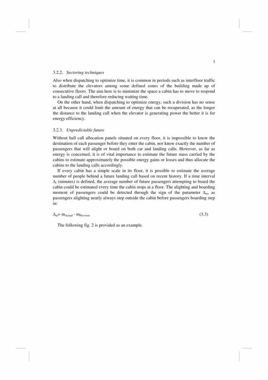
3.2.3. Unpredictable future
Without hall call allocation panels situated on every floor, it is impossible to know the
destination of each passenger before they enter the cabin, nor know exactly the number of
passengers that will alight or board on both car and landing calls. However, as far as
energy is concerned, it is of vital importance to estimate the future mass carried by the
cabins to estimate approximately the possible energy gains or losses and thus allocate the
cabins to the landing calls accordingly.
If every cabin has a simple scale in its floor, it is possible to estimate the average
number of people behind a future landing call based on recent history. If a time interval
∆t (minutes) is defined, the average number of future passengers attempting to board the
cabin could be estimated every time the cabin stops at a floor. The alighting and boarding
moment of passengers could be detected through the sign of the parameter ∆m, as
passengers alighting nearly always step outside the cabin before passengers boarding step
in:
∆m= mActual - mPrevious (3.3)
The following fig. 2 is provided as an example.
6
∆m < 0 � Passengers alighting
∆m > 0 � Passengers boarding
Fig 2. Estimation of the number of passenger boarding.
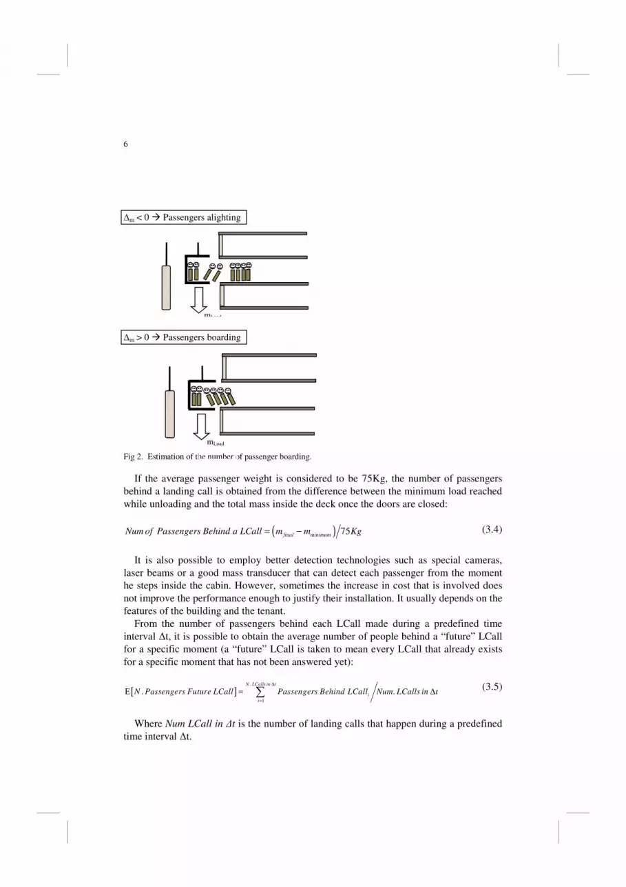
If the average passenger weight is considered to be 75Kg, the number of passengers
behind a landing call is obtained from the difference between the minimum load reached
while unloading and the total mass inside the deck once the doors are closed:
( ) 75final minimumNum of Passengers Behind a LCall m m Kg = − (3.4)
It is also possible to employ better detection technologies such as special cameras,
laser beams or a good mass transducer that can detect each passenger from the moment
he steps inside the cabin. However, sometimes the increase in cost that is involved does
not improve the performance enough to justify their installation. It usually depends on the
features of the building and the tenant.
From the number of passengers behind each LCall made during a predefined time
interval ∆t, it is possible to obtain the average number of people behind a “future” LCall
for a specific moment (a “future” LCall is taken to mean every LCall that already exists
for a specific moment that has not been answered yet):
[ ].
1
. .N LCalls in t
i
i
N Passengers Future LCall Passengers Behind LCall Num LCalls in t ∆
=
Ε = ∆∑ (3.5)
Where Num LCall in ∆t is the number of landing calls that happen during a predefined
time interval ∆t.
mLoad
mLoad

7
5
2
3
4
1
Moreover, it is also possible to estimate the average number of people carried in the
cabin during consecutive trips answering the number of car calls produced, landing calls
assigned and the total weight inside the cabin. The predicted number of passengers
alighting for a specific deck could be easily obtained every time:
[ ] 75 .LoadNumof Passengers Alighting M Kg Num Car CallsΕ = ⋅ (3.6)
The following fig. 3 is provided as an example:
Ascending Landing Call Car Call
Descending Landing Call
Fig 3. Estimation of number of passenger alighting.
The elevator is moving upwards and is assigned to the two ascending landing calls and
must answer the two car calls. If we take the estimated number of people behind a
landing call to be four for the calculation detailed above, the estimated number of
passengers alighting on every car call would therefore be:
[ ] ( )4 75 75 2 2Num of Passengers Alighting x kg kg Car CallsΕ = =� (3.7)
Therefore, the estimated number of passenger in the cabin throughout the trips for this
specific snapshot problem is calculated as follows:
• Trip 1 (from floor 1 to 2): 4 passenger already aboard.
• Trip 2 (from floor 2 to 4): 4 passenger already aboard + 4 passengers estimated
boarding – 2 passengers estimated alighting = 6 passengers on board.
• Trip 3 (from floor 4 to 5): 6 passenger already aboard – 2 passengers estimated
alighting = 4 passengers on board.
• Trip 4 (from floor 5 on): 4 passenger already aboard + 4 passengers estimated
boarding = 8 passengers on board.
mLoad

8
Uppeak
Morning
Interfloor
Lunch (in)
Lunch (out)
Afternoon
Interfloor
Down Peak
Up Traffic
Down Traffic 20
15
10
5
0
0
10
5
15
POP
Time
Every time a new landing call appears or the elevator stops again at a new floor, each
calculation is redone. Employing these techniques, the EGCS is able to estimate the total
amount of passengers throughout the trip and the consequent energy implications.
3.2.4. Energy Considerations about traffic pattern
Classical theory [6] describes four traffic patterns for a typical day in a workers’ building
according to whether the main flow is significantly ascending, significantly descending,
both or none of them.
As mentioned in the introduction, some intelligent dispatchers make their decisions
based on different criteria: average passenger waiting time and the most advanced,
energy or percentage of long waits.
Destination or starting floor are usually known in downpeak or uppeak periods
respectively, and this also occurs in the lunchpeak period, (which constitutes a mixture of
both) reducing the dispatching options. Besides, there is a considerable amount of
passengers in these periods so waiting time is critical. As a consequence, it is usually
during the interfloor pattern when dispatching options are higher and traffic lighter (so
the waiting time problem does not have the same importance as in other periods), when
the EGCS is able to dispatch landing calls taking the energy problem into account more
than other factors.
Fig 4. Traffics patterns occurring through the day in a typical workers’ building.
3.2.5. Adjoining landing calls
Proximity between landing calls should be a decisive factor to take into account when
dispatching. Adjacent landing calls must be assigned to the same or different cabins
according to the energy state of the elevator. For example, a cabin that is moving
downwards with a total load inferior to half the maximum load allowed should answer a
number of landing calls in a row to increment its inside weight to reduce energy wastage
or even to start generating energy as it is shown in Fig. 5:

9
Fig. 5. Trivial Example: An Elevator should answer the most number of adjoining calls as possible.
On the other hand, for example, cabins moving upwards with a total load inferior to
half the maximum load, should answer the least number of landing calls possible as every
passenger will reduce the gain in energy as it is shown in Fig. 6.
Real situations involve artificial intelligence methodologies to deduce an optimal
dispatching solution.
3.2.6. Promote loading passengers depending on cabin direction
As an alternative to the adjoining landing calls consideration, EGCS could prompt or not
loading passengers into the same cabin for the same reason as stated previously.
However, in an attempt to not make this multi-criteria design redundant, promoting
loading passengers was not considered in favour of answering adjoining landing calls, as
the latter makes a simple complete dynamical dispatching in a fuzzy logic system
possible.
4. Dynamical dispatching feature of the fuzzy logic egcs proposed
The algorithm is based on the statement that dynamic dispatching produces better results
than a static one. So every time the system detects a change (cabin load or a new landing
call appears), the whole set of landing calls are re-allocated. This allows the system to
optimize the assignations. However, common fuzzy logic methods are not able to process
the information in a parallel form or to calculate solutions in the way other methodologies
do, such as genetic or tabu algorithms. Therefore, it is necessary to establish an optimal
sequential order to evaluate the landing calls properly according to certain criteria. Few
fuzzy logic elevator group controllers have been proposed [14] in the past years, but the
following Fuzzy Logic Elevator Group Control System constitutes the first one which is
completely based on dynamic dispatching. This has never been seen in the elevator
industry before.

10
Fig. 6. Trivial Example: Elevators should answer the least number of adjoining calls.
5. Principles of the fuzzy logic algorithm for energy optimization
The fuzzy logic-based algorithm for energy consumption optimization proposed here can
be characterized by the flow-chart diagram shown in fig. 7. It works as follows: in a
facility with n number of elevators and p number of active landing calls, the algorithm
evaluates nxp fuzzy procedures, each one representing the possibility for a cabin i to
respond to a landing call j. In view of the above, landing calls are allocated in an
optimized order to the best desired elevator among all the possibilities according to the
final estimated figure SE[i][j] obtained for each i-j pair.
This final figure SE[i][j] is evaluated in agreement with a set of weights [v1, v2, v3] and
three fuzzy-inferred evaluation criteria defined for each i-j pair: possible absolute energy
(EABS[i][j]), possible relative energy (EREL[i][j]) and possible adjacent energy
(EADJ[i][j]):
[ ][ ] [ ][ ] [ ][ ] [ ][ ]E ABS REL ADJS i j E i j E i j E i j= + + (5.1)
Each of the different evaluations contributes to examine a partial and non-related
aspect of the energy problem.
At the beginning there are no landing calls assigned to any cabin at all as allocation is
dynamic, so all parameter values are zero. The whole set of nxp procedures that represent
the fitness of each i-j dispatch option has to be calculated only once in its entirety (for the
first I-J assignment). The following times, only the related figures that have changed as a
consequence of the previous I-J assignment need to be recalculated to reflect the new
state (cabin I assigned to LCall J). There is no need to recalculate the rest of the figures as
their values have not changed since the first calculation (this feature gives the controller a
very fast performance). The only parameters that need to be updated are:

11
• The values of EABS[i][j] for the specific wining cabin i and the whole set of active
landing calls.
• The values of all EREL[i][j] figures for all the i cabins and the p active landing
calls.
• The values of EADJ[i][j] for the cabin i and the entire set of landing calls j.
6. Dispatch option evaluation
The three assignment criteria shown in the flow-chart diagram in fig. 7 in the previous
Section III constitute the main body of the dispatch option evaluation concerning saving
power. Their calculation for each dispatch option i-j lets us obtain the final energy fitness
figure SE[i][j] for each i-j pair and therefore, to establish an optimal sequential order for
assigning the set of active landing calls as well as the optimal cabin for each one of the
landing calls.
All three criteria represent fuzzy inference processes that are calculated according to
some input parameters. In this section each set of inputs is listed and a theoretical
definition is also given for each criterion (the next section is fully-detailed with
descriptions about the fuzzy procedures). The aim is to put forward and justify the nature
of the energy evaluation developed.
6.1. Absolute energy evaluation
The absolute energy evaluation (EABS[i][j]) estimates the total amount of power wasted
by cabin i if it attended landing call j. The definition of the absolute energy evaluation
depends on:
• The possible flight made by the cabin.
• The unbalanced weight compared to the equilibrium balanced state.
• The current direction of the cabin (which at the same time depends on the car calls
and landing calls already assigned to the cabin).
Absolute evaluation acts as a measurement of the objective energy employed in the
action without considering the snapshot problem conditions.
6.2. Adjacent energy evaluation
The adjacent energy evaluation (EADJ[i][j]) estimates if a landing call j should be
allocated to a cabin i according to the landing calls already assigned to cabin i. The
definition of the adjacent energy evaluation depends on:
• The proximity of the landing call j considered with the nearest landing call already
assigned to cabin i.
• The unbalanced weight with respect to the equilibrium balanced state.
• The current direction of the cabin (which at the same time depends on the car calls
and landing calls already assigned to the cabin).
Adjacent estimation contributes to whether a group of nearby landing calls should be
assigned to the same cabin with regards to saving energy as described in the previous

12
section 2.2. This evaluation combined with the relative evaluation acts as a measurement
of the overall snapshot problem situation.
6.3. Relative energy evaluation
Relative energy evaluation (EREL[i][j]) makes a quality comparison between the total
amount of power wasted by the cabin i if it answered the landing call j (EABS[i][j]) and
the energy wasted by the rest of n-1 deck possibilities for answering the specific landing
call j. The definition of the relative energy evaluation depends on:
• ∆E[i][j]: It measures in number of average deviations the difference between the
absolute energy of the i-j pair decision and the average of the whole set of n elevator
possibilities to answer the specific landing call j:
[ ][ ] [ ][ ] [ ]ABS ABS ABSE i j E i j E j S∆ = − (6.1)
Where:
[ ] [ ][ ]1
n
ABS ABS
k
E j E k j n=
=∑ (6.2)
[ ] [ ][ ] [ ]( )22
1
n
ABS ABS
k
S j E k j E j n=
= −∑ (6.3)
S[j] is the average deviation and EABS[j] the average energy consumption for all
possible assignations for a fixed landing call j.
• The quality of the best alternative to cabin i to answer the specific landing call j
(Q[i][j]):
[ ][ ] [ ][ ] [ ][ ] [ ][ ]ABS ABS ABSQ i j E i j E l j E k j′ ′′= − (6.4)
Where E´ABS[l][j] is the best alternative to EABS[i][j] for a fixed landing call j and
E´´
ABS[k][j] the best options among all the possibilities (including EABS[i][j]) for a specific
landing call j.
Relative evaluation acts as a measurement of the environmental situation. This lets the
dispatcher set out decisions on the suitability of n possibilities for answering a specific
landing call j and by extension, lets the dispatcher set out decisions on the quality of the
nxp possibilities in general.
In fact, relative evaluation affects the order in which landing calls are answered. The
∆E[i][j] measurement can detect whether an option is profitable enough in the sense that
it exceeds the average cabin marks or not. And jointly with Q[i][j], the dispatcher can
find out if the i option constitutes a critical dispatching decision for the specific landing
call j. This allows the dispatcher to resolve difficult situations satisfactorily, for example:
when there is no optimal cabin to assign to a landing call j, in the sense that all choices
would waste a considerable amount of power but one cabin would employ less significant
energy than the others (or even produce a gain in energy). Therefore, this critical cabin
option could be assigned to the landing call j before being allocated to another landing
call which does not have this vital cabin choice and which would also make the cabin not
ready to answer landing call j.

13
Fig 7. Flow-chart showing main steps for a complete dispatch of a set of p active landing calls in a building.
In Fig. 8, elevator 3 and 1 are especially well situated to answer the ascending landing
call at floor 6. Elevator number 3 is located at the same distance as elevator number 1 but
Possible Flight
Unbalance
Current Direction
∆E[n][p]
Quality of Alternative
Unbalance
Current Direction
Proximity
Fuzzy procedure Input parameter
Non-Fuzzy procedure Logic Sequence
Procdure with mechanical implications
Absolute Energy
Evaluation of the i-j
pair (EABS[i][j])
Final Energy
Evaluation of the i-j
par (SE[i][j])
Relative Energy
Evaluation of the i-j
pair (EREL[i][j])
Adjacent Energy
Evaluation of the i-j
pair (EADJ[i][j])
Changed
detected
End
While?
i=1 and j=1
While i ≤n and j≤p
While i≤n and j≤p
i=1 and j=1 Any
LCall
remain
unassi
gned?
i++; j++;
End
While? i++; j++;
Best i-j Par Election:
I-J
Cabin I
assigned to
LCall J
END

14
moving upwards partially loaded (still carrying less load than half the maximum allowed
so acting as a generator) to floor 5. While elevator number 1 is empty so it would,
therefore, produce a slightly higher amount of power in the case of responding to the
landing call at floor 6. However, there is no critical difference in magnitude of the energy
recovered. However among all the elevators, elevator number 1 is by far the best option
to respond to the landing call located at floor number 2 because while wasting some
energy doing it, it is located only one floor above it while the others are further (elevator
number 3 has to arrive to floor 5 first before it could answer it due to direction
constrictions).
Without ∆E[i][j] and the quality of the best alternative criteria (Q[i][j]), elevator 1 could
be assigned firstly to the landing call at floor 6 because it produces a slight gain
compared to elevator 3 (and elevator 1 also wastes energy answering floor 2 and
therefore it is behind it in the serving order) so there would not be any optimal cabin to
answer floor 2 in the sense that all would use a considerable amount of power (elevator 1
would be higher than floor number 6 and elevators 3 and 4 would be at floor 5 before
they could attend it). However, ∆E[i][j] and Q[i][j] criteria allow the dispatcher to detect
such a situation as it considers cabin 1 option for attending landing call at floor number 2
as a vital one and is, therefore, given preference in the allocation order. With preference
in the serving order, the landing call at floor 2 would firstly be assigned to elevator
number 1 and, after estimating the number of passenger that would board the cabin based
on recent history, the landing call at floor 5 would be assigned to elevator number 1 or 3
depending on the gain in energy.
In the same way, through ∆E[i][j] and Q[i][j], some other complicated situations
could also be detected and, therefore, solved correctly: for example, when there are not
one but two (or more) critical decisions, in the sense that their marks for answering a
specific landing call j strongly exceed the others, assigning the first one to another
landing call j does not involve losing the energy bonus opportunity since the other cabin
with a similar mark remains unassigned. However, once the latter cabin is the only one
that remains as a crucial choice, it cannot be assigned to another landing call if that
makes it impossible for it to respond to landing call j.
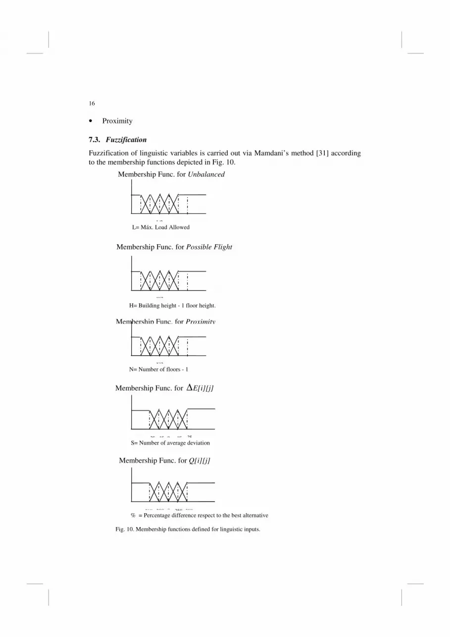
Fig. 9 shows an example similar to the previous one. In this case, the three cabins 1, 3
and 4 are well situated to answer the landing call at floor 6 with similar energy results.
Cabins 1 and 4 are also well-placed to answer the landing call at floor 2. They both
constitute critical decisions if standing alone but Q[i][j] criteria let the dispatcher detect
the situation. It is therefore possible to allocate one of the two cabins to floor 6 while the
other remains as a critical decision (in case there are more landing calls).
In short, relative criteria evaluation allows the dispatcher to detect the situations when
an optimal decision for attending a specific landing call j does not produce the best
overall performance.
NOTE: In the above examples the decisions about criticality of every option seem to
appear as an abrupt dichotomy, but this has been done for reasons of simplicity and
comprehensibility, while in the real model the criticality of a decision is defined
implicitly along a continuous range through ∆E[i][j] and the Q[i][j] criteria as detailed
before.
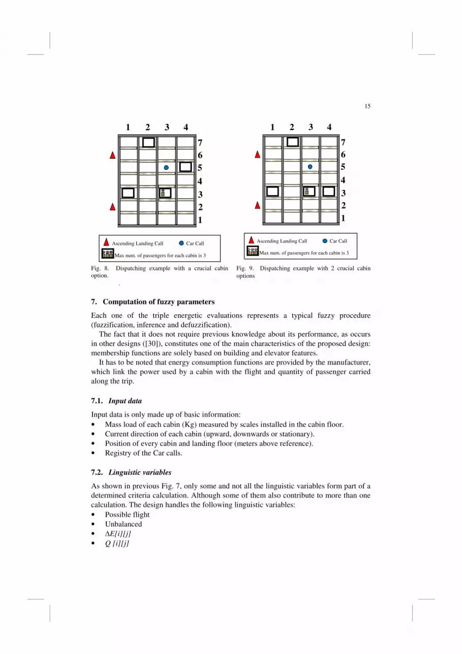
15
Fig. 8. Dispatching example with a crucial cabin
option.
Fig. 9. Dispatching example with 2 crucial cabin
options .
7. Computation of fuzzy parameters
Each one of the triple energetic evaluations represents a typical fuzzy procedure
(fuzzification, inference and defuzzification).
The fact that it does not require previous knowledge about its performance, as occurs
in other designs ([30]), constitutes one of the main characteristics of the proposed design:
membership functions are solely based on building and elevator features.
It has to be noted that energy consumption functions are provided by the manufacturer,
which link the power used by a cabin with the flight and quantity of passenger carried
along the trip.
7.1. Input data
Input data is only made up of basic information:
• Mass load of each cabin (Kg) measured by scales installed in the cabin floor.
• Current direction of each cabin (upward, downwards or stationary).
• Position of every cabin and landing floor (meters above reference).
• Registry of the Car calls.
7.2. Linguistic variables
As shown in previous Fig. 7, only some and not all the linguistic variables form part of a
determined criteria calculation. Although some of them also contribute to more than one
calculation. The design handles the following linguistic variables:
• Possible flight
• Unbalanced
• ∆E[i][j]
• Q [i][j]
1
2
3
4
5
6
7
1 2 3 4
Ascending Landing Call Car Call
Max num. of passengers for each cabin is 3
1
2
3
4
5
6
7
1 2 3 4
Ascending Landing Call Car Call
Max num. of passengers for each cabin is 3
16
• Proximity
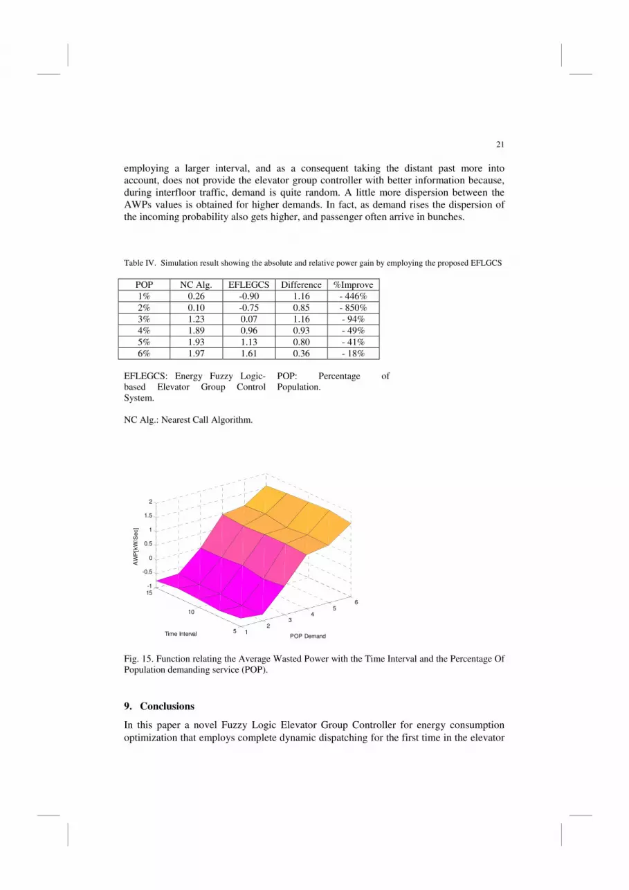
7.3. Fuzzification
Fuzzification of linguistic variables is carried out via Mamdani’s method [31] according
to the membership functions depicted in Fig. 10.
L= Máx. Load Allowed
H= Building height - 1 floor height.
N= Number of floors - 1
Membership Func. for ∆E[i][j]
S= Number of average deviation
Membership Func. for Q[i][j]
% = Percentage difference respect to the best alternative
Fig. 10. Membership functions defined for linguistic inputs.
N/2 N
2S 1S 0 -1S -2S
25% 0 -25% -50% 50%
Membership Func. for Proximity
H/2 H
L/2 L
Membership Func. for Possible Flight
Membership Func. for Unbalanced

17
7.4. Fuzzy inference
Each energy evaluation is worked out from fuzzy variables according to a set of logical
rules. As an example, Table I shows logical rules representing the deduction on the
quality of absolute energy for a specific i-j pair (EABS[i][j]).
Table I. Logic Rules for absolute energy criteria.
PFVS PFS PFA PFL PFVL
UE
R1
↑G B↓
R6
↑G B↓
R11
↑VG VB↓
R16
↑VG VB↓
R21
↑VG VB↓
UNE
R2
↑A A↓
R7
↑G B↓
R12
↑G B↓
R17
↑VG VB↓
R22
↑VG VB↓
UEQ
R3
↑G G↓
R8
↑G G↓
R13
↑A A↓
R18
↑A A↓
R23
↑B B↓
UNF
R4
↑A A↓
R9
↑B G↓
R14
↑B G↓
R19
↑VB
VG↓
R24
↑VB
VG↓
UF
R5
↑B G↓
R10
↑B G↓
R15
↑VB
VG↓
R20
↑VB
VG↓
R25
↑VB VG↓
PF: Possible Flight
U: Unbalanced
VG: Very Good
G: Good
A: Average
B: Bad
VB: Very Bad
VL: Very Large
L: Large
A: Average
S: Short
VS: Very Short
E: Empty
NE: Near Empty
EQ: Equilibrium
NF: Near Full
F: Full
7.5. Defuzzification
The defuzzification is carried out through a typical center of gravity method to obtain a
unique decision value between zero and one.
8. Experimental results
Elevator systems are designed mainly according to classical theory [6] in the sense that a
system that can handle the logistic transport during uppeak is also able to transport
passengers efficiently during the rest of the periods. Above all, this gives a large extra
handling capacity during interfloor interval, as shown in the previous section, which
allows the dispatcher to focus exclusively on the problem of energy. In this aspect, the
fuzzy based elevator group control design is able to dispatch the landing calls efficiently.
The most common dispatch algorithm actually implemented by most companies is the
“nearest call algorithm” (which is self-descriptive: it dispatches the landing call to the
nearest elevator following the collective principle) because of its reliability and short
processing time. In this sense, it has been proposed as a benchmark for testing the
proposed algorithm.

18
Simulation has been carried out through ELEVATE software. The example building
has 19 floors and has been designed to accomplish the vertical transport requirement ([6])
so it possesses 7 elevators for a total population of 1520 workers equally distributed
throughout the facility. Therefore, while different demands for interfloor traffic occurred
(Percentage Of Population requiring service, POP), the following average results were
obtained (Fig. from 12 to 15 and Table IV).
Fig. 12 represents the Average Wasted Power (AWP) per second depending on
passenger demand (Percentage Of Population, POP) for both dispatch algorithms so that
the total amount of energy saved by the proposed dispatch method can be observed. Fig.
13 complements Fig. 12 and relates the Average Wasted Power (AWP) per trip made by
an elevator and the Percentage Of Population demanding service (POP). Although the
total number of trips made by the elevators in a time interval depends on the dispatch
algorithm, in practice this number is very similar. Therefore, the consumption per trip can
be compared to give a very approximate idea of the total amount of energy wasted or
gained by each algorithm.
Nearest Call Algorithm
Fuzzy Logic Energy Controller Proposed
Fig. 11. Function relating the Average Wasted Power (AWP) per second and the Percentage Of
Population demanding service (POP).
By looking at the energy saving for each trip and that the total amount of trips
performed by each elevator every five minutes goes from approximately 30 to 120 during
interfloor (depending on demand), a specific idea on the vast amount of energy that can
be saved without deteriorating time service can be calculated.
The results summarized in Table IV are conclusive: for low demand, the total amount
of energy wasted in the movement of the elevator can be extensively decreased and even
1 1.5 2 2.5 3 3.5 4 4.5 5 5.5 6 -1
-0.5
0
0.5
1
1.5
2
POP
AWP

19
produce a gain in energy for the system with a slight disadvantage to Average Waiting
Time (AWT) and practically keeping the Average Transit Time (ATT) constant.
As traffic demand rises so do the marginal costs, reducing the advantages of
decreasing average time in favour of energy consumption. When the demand is
considerably high, around 6% POP, (interfloor traffic rarely exceeds the 4% POP level),
the disadvantages of increasing waiting time surpass the advantages of reducing
consumption, producing waiting times that become unacceptable and involving an energy
gain which is not worthwhile enough.
Nearest Call Alg. Fuzzy logic Energy Cont.
Proposed
Fig. 12. Function relating the Average Wasted Power (AWP) per trip and the Percentage Of
Population demanding service (POP).
1 2 3 4 5 6-10
-8
-6
-4
-2
0
2
4
6
8
POP Demand
AW
P [
Kw
/Trip]

20
Fig. 13. Function relating the Average Waiting Time (AWT) and the Percentage Of Population
demanding service (POP).
Nearest Call Algorithm
Fuzzy Logic Energy Controller Proposed
Fig. 14. Function relating the Average Transit Time (ATT) and the Percentage Of Population
demanding service (POP).
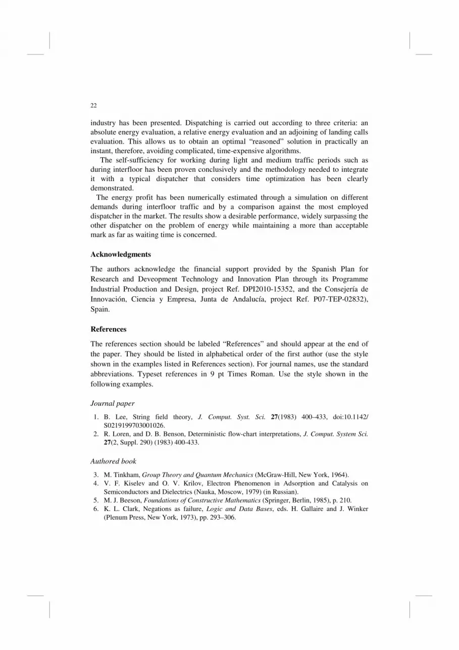
Fig. 16 points out the variation in the energy consumption depending on the size of the
time interval (∆t). It can be seen that different time intervals (from time intervals long
enough to consider a significant number of LCalls) produce only slightly different AWPs.
This is probably due, apart from the random nature of the simulations, to the fact that
Nearest Call Algorithm
Fuzzy Logic Energy Controller Proposed
1 1.5 2 2.5 3 3.5 4 4.5 5 5.5 60
5
10
15
20
25
30
35
40
45
POP Demand
AWT [Sec]
1 1.5 2 2.5 3 3.5 4 4.5 5 5.5 60
5
10
15
20
25
30
35
40
45
POP Demand
ATT
21
employing a larger interval, and as a consequent taking the distant past more into
account, does not provide the elevator group controller with better information because,
during interfloor traffic, demand is quite random. A little more dispersion between the
AWPs values is obtained for higher demands. In fact, as demand rises the dispersion of
the incoming probability also gets higher, and passenger often arrive in bunches.
Table IV. Simulation result showing the absolute and relative power gain by employing the proposed EFLGCS
POP NC Alg. EFLEGCS Difference %Improve
1% 0.26 -0.90 1.16 - 446%
2% 0.10 -0.75 0.85 - 850%
3% 1.23 0.07 1.16 - 94%
4% 1.89 0.96 0.93 - 49%
5% 1.93 1.13 0.80 - 41%
6% 1.97 1.61 0.36 - 18%
EFLEGCS: Energy Fuzzy Logic-
based Elevator Group Control
System.
NC Alg.: Nearest Call Algorithm.
POP: Percentage of
Population.
Fig. 15. Function relating the Average Wasted Power with the Time Interval and the Percentage Of
Population demanding service (POP).
9. Conclusions
In this paper a novel Fuzzy Logic Elevator Group Controller for energy consumption
optimization that employs complete dynamic dispatching for the first time in the elevator
12
34
56
5
10
15-1
-0.5
0
0.5
1
1.5
2
POP DemandTime Interval
AW
P[k
W/S
ec]
22
industry has been presented. Dispatching is carried out according to three criteria: an
absolute energy evaluation, a relative energy evaluation and an adjoining of landing calls
evaluation. This allows us to obtain an optimal “reasoned” solution in practically an
instant, therefore, avoiding complicated, time-expensive algorithms.
The self-sufficiency for working during light and medium traffic periods such as
during interfloor has been proven conclusively and the methodology needed to integrate
it with a typical dispatcher that considers time optimization has been clearly
demonstrated.
The energy profit has been numerically estimated through a simulation on different
demands during interfloor traffic and by a comparison against the most employed
dispatcher in the market. The results show a desirable performance, widely surpassing the
other dispatcher on the problem of energy while maintaining a more than acceptable
mark as far as waiting time is concerned.
Acknowledgments
The authors acknowledge the financial support provided by the Spanish Plan for
Research and Deveopment Technology and Innovation Plan through its Programme
Industrial Production and Design, project Ref. DPI2010-15352, and the Consejería de
Innovación, Ciencia y Empresa, Junta de Andalucía, project Ref. P07-TEP-02832),
Spain.
References
The references section should be labeled “References” and should appear at the end of
the paper. They should be listed in alphabetical order of the first author (use the style
shown in the examples listed in References section). For journal names, use the standard
abbreviations. Typeset references in 9 pt Times Roman. Use the style shown in the
following examples.
Journal paper
1. B. Lee, String field theory, J. Comput. Syst. Sci. 27(1983) 400–433, doi:10.1142/
S0219199703001026.
2. R. Loren, and D. B. Benson, Deterministic flow-chart interpretations, J. Comput. System Sci.
27(2, Suppl. 290) (1983) 400-433.
Authored book
3. M. Tinkham, Group Theory and Quantum Mechanics (McGraw-Hill, New York, 1964).
4. V. F. Kiselev and O. V. Krilov, Electron Phenomenon in Adsorption and Catalysis on
Semiconductors and Dielectrics (Nauka, Moscow, 1979) (in Russian).
5. M. J. Beeson, Foundations of Constructive Mathematics (Springer, Berlin, 1985), p. 210.
6. K. L. Clark, Negations as failure, Logic and Data Bases, eds. H. Gallaire and J. Winker
(Plenum Press, New York, 1973), pp. 293–306.
23
Edited book
7. T. Tel, Experimental Study and Characterization of Chaos, ed. Hao Bailin (World Scientific,
Singapore, 1990), p. 149.
8. J. K. Srivastava, S. C. Bhargava, P. K. Iyengar and B. V. Thosar, Advances in Mössbauer
Spectroscopy: Applications to Physics, Chemistry and Biology, eds. B. V. Thosar, P. K.
Iyengar, J. K. Srivastava and S. C. Bhargava (Elsevier, Amsterdam, 1983), pp. 39–89.
Proceedings
9. A. N. Kolmogorov, Théorie générale des sytémes dynamiques et mécanique classique, Proc.
Int. Congr. Mathematicians, Vol. I, Amsterdam, 1954 (North-Holland, Amsterdam, 1957), pp.
315–333.
Electronic Resource
10. J. J. Dubray, Standards for a service oriented architecture (2003), http://www.ebxml
forum.org/articles/ebFor_20031109.html.
11. D. H. Akehurst, Transformations based on relations (2004), http://heim.ifi.uio.no/~janoa
/wmdd2004/papers/akehurst.pdf.
References
1. B. Lee, String field theory, J. Comput. Syst. Sci. 27(1983) 400–433, doi:10.1142/
S0219199703001026.
2. R. Loren, and D. B. Benson, Deterministic flow-chart interpretations, J. Comput. System Sci.
27(2, Suppl. 290) (1983) 400–433.
3. M. Tinkham, Group Theory and Quantum Mechanics (McGraw-Hill, New York, 1964).
4. V. F. Kiselev and O. V. Krilov, Electron Phenomenon in Adsorption and Catalysis on
Semiconductors and Dielectrics (Nauka, Moscow, 1979) (in Russian).
5. M. J. Beeson, Foundations of Constructive Mathematics (Springer, Berlin, 1985), p. 210.
6. K. L. Clark, Negations as failure, Logic and Data Bases, eds. H. Gallaire and J. Winker
(Plenum Press, New York, 1973), pp. 293–306.
7. T. Tel, Experimental Study and Characterization of Chaos, ed. Hao Bailin (World Scientific,
Singapore, 1990), p. 149.
8. J. K. Srivastava, S. C. Bhargava, P. K. Iyengar and B. V. Thosar, Advances in Mössbauer
Spectroscopy: Applications to Physics, Chemistry and Biology, eds. B. V. Thosar, P. K.
Iyengar, J. K. Srivastava and S. C. Bhargava (Elsevier, Amsterdam, 1983), pp. 39–89.
9. A. N. Kolmogorov, Théorie générale des sytémes dynamiques et mécanique classique, Proc.
Int. Congr. Mathematicians, Vol. I, Amsterdam, 1954 (North-Holland, Amsterdam, 1957), pp.
315–333.
10. J. J. Dubray, Standards for a service oriented architecture (2003), http://www.ebxml
forum.org/articles/ebFor_20031109.html.
11. D. H. Akehurst, Transformations based on relations (2004), http://heim.ifi.uio.no/~janoa
/wmdd2004/papers/akehurst.pdf.
Nuestras referencias para incluir (ojo! Van sin corchetes):
[1] P. B. Luh, B. Xiong and S. C. Chang. Group elevator scheduling with advance information for
normal and emergency modes. IEEE Trans. Autom. Apr. 2008; Sci. Eng, vol. 5, no. 2: 245–258.

24
[2] Derek N. Dyck and Pêter E. Caines. The Logical Control of an Elevator. IEEE Transactions on
Automatic Control, March, 1995; Vol. 40, No. 3.
[3] Michael A. Covington. Logical Control of an Elevator with Deafisible Logic. IEEE
Transactions On Automatic Control, July, 2000; Vol. 45, No. 7.
[4] M. Schlemmer and S. K. Agrawal. A Computational Approach for Time-Optimal Planning of
High-Rise. IEEE Transactions On Control Systems Technology, January, 2002; Vol. 10, No. 1,
105.
[5] Jin Sun, Qian-Chuan Zhao, and Peter B. Luh. Optimization of Group Elevator Scheduling With
Advance Information. IEEE Transactions on Automation Science and Engineering, April, 2010;
Vol. 7, No. 2.
[6] Barney G. Elevator Traffic Handbook. Spon Press; 2004.
[7] David L. Pepyne and Christos G. Cassandras. Design and Implementation of an Adaptive
Dispatching Controller for Elevator Systems During Uppeak Traffic. IEEE Transactions on Control
Systems Technology, September, 1998; Vol. 6, No. 5: 635.
[8] Yutae Lee, Tai Suk Kim, Ho-Shin Cho, Dan Keun Sung and Bong Dae Choi. Performance
analysis of an elevator system during up-peak. Mathematical and Computer Modelling 2009; 49:
423_431.
[9] Lutfi Al-Sharif. The effect of multiple entrances on the elevator round trip time under up-peak
traffic. Mathematical and Computer Modelling August 2010; Volume 52, Issues 3-4: 545-555.
[10] J. H. Kim and B. R. Moon. Adaptive elevator group control with cameras. IEEE Trans. Ind.
Electron. Apr. 2001; vol. 48, no. 2: 377–382.
[11] Muna Hamdia, D.J. Mulvaneyb. Prioritised A* search in real-time elevator dispatching.
Control Engineering Practice, February 2007; Volume 15, Issue 2: 219-230
[12] P. Cortés, J. Larraneta and L. Onieva. Genetic algorithms for controllers in elevator groups:
Analysis and simulation during lunchpeak. Applied Soft Computing 2004; Vol. 4, Issue 2: 159-174.
[13] J. Sorsa, M-L. Siikonen, H. Ehtamo. Optimal control of double-deck elevator group using
genetic algorithm. International Transactions in Operational Research 2003; Vol. 10:103-114.
[14] B. Bolat. P. Cortés, Ersun Yalcin and Mustafa Alisverisci. Optimal car dispatching for elevator
groups using genetic algorithms. International Journal of Intelligent Automation and Soft
Computing 2010; Vol. 16 No. 1: 89-99.
[15] K. Hirasawa, T. Eguchi, J. Zhou, L. Yu, J. Hu and S. Markon. A double-deck elevator group
supervisory control system using genetic network programming. IEEE Trans. Syst., Man, Cybern.
C, Appl. Rev., July 2008; Vol. 38, no. 4: 535–550.
[16] P. Cortés, J. Larrañeta and L. Onieva. A genetic algorithm for controlling elevator group
systems. Artificial Neural Nets Problem Solving Methods 2003, Pt Ii Vol. 2687: 313-320.
[17] Z. Li, Z. Mao and J. Wu. Research on dynamic zoning of elevator traffic based on artificial
immune algorithm. In Proc. 8th Conf. Contr., Autom., Robot., Vis., 2004: 2170–2175.
[18] Z. Li, Y. Zhang and H. Tan. Particle swarm optimization for dynamic sectoring control during
peak traffic pattern. In Book Series of Communications in Computer and Information 2, D. S.
Huang, L. Heutte and M. Loog, Eds., Berlin, Germany: Springer Berlin Heidelberg, 2007: 650–
659.
[19] C. E. Imrak and G. C. Barney. Application of neural networks on traffic control. In Proc.
ELEVCON, 1998: 140–148.
[20] Jianchang Liu, Yiyang Liu. Ant Colony Algorithm and Fuzzy Neural Networkbased Intelligent
Dispatching Algorithm of An Elevator Group Control System, IEEE International Conference on
Control and Automation FrB3-2, Guangzhou, China, 2007.
[21] Lu Yu, Jin Zhou, Shingo Mabu, Kotaro Hirasawa, Jinglu Hu, Sandor Markon, Elevator Group
Control System using Genetic Network Programming with ACO Considering Transitions, SICE
Annual Conference, Kagawa University, Japan, 2007.
[22] Christos Anagnostopoulos, and Stathes Hadjiefthymiades, Enhancing Situation-Aware
Systems through Imprecise Reasoning, IEEE Transactions on Mobile Computing October, 2008;
Vol. 7, No 10.

25
[23] Xi-Zhao Wan, and Chun-Ru Dong. Improving Generalization of Fuzzy IF–THEN Rules by
Maximizing Fuzzy Entropy. IEEE Transactions on Fuzzy Systems, June 2009; Vol. 17, No. 3.
[24] Xinyu Du, Hao Ying and Feng Lin. Theory of Extended Fuzzy Discrete-Event Systems for
Handling Ranges of Knowledge Uncertainties and Subjectivity. IEEE Transactions on Fuzzy
Systems, April 2009; Vol. 17, No. 2.
[25] C. B. Kim, K. A. Seong, H. L. Kwang, and J. O. Kim. Design and implementation of a fuzzy
elevator group control system. IEEE Trans. Syst., Man, Cybern. A, Syst., Humans, May 1998; vol.
28, no. 3: 277–287.
[26] R. K. Mudi and N. R. Pal. A robust self-tuning scheme for PI- and PDtype fuzzy controllers.
IEEE Trans. Fuzzy Syst., Feb 1999; vol. 7, no. 1: 2–16.
[27] J. Jamaludin, N. A. Rahim and W. P. Hew. Development of a self-tuning fuzzy logic controller
for intelligent control of elevator systems. Engineering Applications of Artificial
Intelligence, December 2009; Volume 22, Issue 8: 1167-1178
[28] P.Cortés, J. Muñuzuri and L. Onieva. Design and Analysis of a Tool for Planning and
Simulating Dynamic Vertical Transport. Simulation: Transactions of the society for Modeling and
Simulation International, 2006; Vol. 82, No. 4, 255-274.
[29] The chartered Institution of Building Services Engineers. CIBSE Guide D: Transportation
systems in buildings. 2005.
[30] Tapio Tyni and Jari Ylinen. Evolutionary bi-objective optimisation in the elevador car routing
problem. European Journal Of Operational Research, 2006; 169: 960-977.
[31] E. H. Mamdani. Application of fuzzy algorithms for control of simple dynamic plant. In IEEE
Proc. Control Science, 1974; vol. 121, no. 12: 1285–1588.
[32] Ronald R. Yager. 57 Norms Induced from OWA Operators. IEEE Transactions on Fuzzy
Systems, February 2010; Vol. 18, No. 1.