duct design
TRANSCRIPT
COMMERCIAL DISTRIBUTION
SYSTEMS
Duct Design Level1: Fundamentals
I I \\ ,II \ \1
Technical . Development Prograrh ..
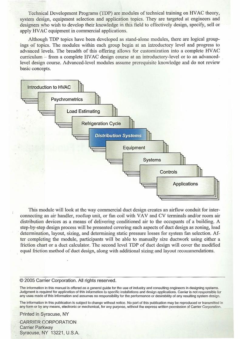
Technical Development Programs (TDP) are modules of technical training on HV AC theory, system design, equipment selection and application topics. They are targeted at engineers and designers who wish to dev~lop their knowledge in this field to effectively design, specify, sell or apply HV AC equipment in commercial applications.
Although TDP topics have been developed as stand-alone modules, there are logical groupings ·of topics. The modules within each group begin at an introductory level and progress to advanced levels. The breadth of this offering allows for customization into a complete HV AC curriculum - from a complete HVAC design course at an introductory-level or to an advancedlevel design course. Advanced-level modules assume prerequisite knowledge and do not review basic concepts.
Psychrometries
Equipment
Systems
Controls
Applications
This module will look at the way commercial duct design creates an airflow conduit for interconnecting an air handler, rooftop unit, or fan coil with VA V and CV terminals and/or room air distribution devices as a means of delivering conditioned air to the occupants of a building. A step-by-step design process will be presented covering such aspects of duct design as zoning, load
· determination, layout, sizing, and determining static pressure losses for system fan selection. After completing the module, participants will be able to manually size ductwork using either a friction chart or a duct calculator. The second level TDP of duct design will cover the modified equal friction method of duct design, along with additional sizing and layout recorrunendations.
© 2005 Carrier Corporation. All rights reserved.
The information in this manual is offered as a general guide for the use of industry and consulting engineers in designing systems. Judgment is required for application of this information to specific installations and design applications. Carrier is not responsible for any uses made of this information and assumes no responsibility for the performance or desirability of any resulting system design.
The information in this publication is subject to change without notice. No part of this publication may be reproduced or transmitted in any form or by any means, electronic or mechanical, for any purpose, without the express written permission of Carrier Corporation.
PrinteEI in Syracuse, NY
CARRIER CORPORATION Carrier Parkway Syracuse, NY 13221 , U.S.A.
Table of Contents
Introduction ............................................................. ......................................................................... 1 Duct Design Ctiteria ...................................................................................... .................................. 1
Space Availability ........................................................................................................................ 2 Duct Terms .............................................................................................................................. 2
Installation Cost .......... ................................................................................................................. 3 Air Friction Loss .......................................................................................................................... 3 Noise Level ......................... .......................................................................................... ............... 4 Heat Transfer and Leakage .............................................................. ...... ...................................... 4 Codes and Standards .................................................................................................................... 5
Theory and Fundamentals .......... ...................................................................................................... 5 Law of Conservation of Energy- Bernoulli's Law ........................................... .......................... 5 Friction Loss in Ducts .................................................................................................................. 8
Recommended Duct Velocities for Ductwork and HV AC Components ................................. 8 Effects of Shape ....................................................................................................................... 9 Surface Roughness of Ducts .................................................................................................. 1 0 Recommended Friction Rates-/ ........................................................................................... 10
Fitting Dynamic Losses ............................................................................................................. 11 Equivalent Length Method .................................................................................................... 11 Use of Fitting Loss Coefficients ............................................................................................ 12 System Effect ......................................................................................................................... 12
Duct Sizing Methods .................. .............. ................................................................................ . 13 Equal Friction ........................................................................................................................ 13 Modified Equal Friction ......................................................................................................... 13 Static Regain .......................................................................................................................... 13 Other Methods ...................................... ............................................................ ... ..... ............. 14
Duct Design Process Steps ............................................................................................................. 15 Design Step 1: Determine Number of Zones ............................................................................ 15 Design Step 2: Perform Cooling and Heating Load Estimates ................................................. 15 Design Step 3: Determine Space, Zone and Block Airflows .................................................... 16 Design Step 4: Select Duct Material, Shape and Insulation ............. ............ ............................. 16
System Classification ............................................................................................................. 16 'What Can Be a Duct and 'What is it Made of? ....................................................................... 17 How are Ducts put Together, Sealed and Insulated? ............................................................. 18
Design Step 5: Lay Out Ductwork from AHU to Air Distribution Devices .............................. 19 Fit Trunk Duct to Building ........... ............. ............................................................................ 20 Create a System Sizing Schematic .............. ........................................................................... 21
Design Step 6: Summarize Duct cfm and Label Duct Schematic ............................................. 21 Use a Duct Sizing Worksheet ................................................................................................ 22
Design Step 7: Size Ductwork from Fan, Out to Extremities ................................................... 22 Duct Sizing Using the Friction Chart .......... ........................................................................... 23 Example 1 -Using the Duct Friction Chart ........................................................................... 24 Circular Equivalent Diameters of Rectangular Ducts ............................................................ 25 Example 2 - Converting From Round to Equivalent Rectangular Ducts .............................. 25 Duct Sizing Using Duct Calculators ....................... ............................................................... 26 Changing One Dimension at a Time ...................................................................................... 30 Extended Plenum ................................................................................................................... 30 Return and Supply Air Plenums .............................................................................. .............. 31
Design Step 8: Calculate Air System Pressure Losses ............................................................. 31 Design Step 9: Select Fan and Adjust System Airflows ........................................................... 32
Sun1mary .................................................................................. · ...................................................... 32 Example 3 -Equal Friction Sizing Example Using the Duct Friction Table ............................ 33 Work Session 1 - Fundamentals ................................................................................................ 3 7 Work Session 2- Duct Sizing ................................................................................................... 39
Appendix and Supplemental Material.. .......................................................................................... 42 Chart 1 -Friction Loss Chart for Round Duct.. ......................................................................... 43 Table 1 - Circular Equivalent Diameter*, Equivalent Area of Rectangular Ducts for Equal Friction ....................................................................................................................................... 44 Table 2 - Recommended Maximum Duct Velocities for Low Velocity Systems (fpm) .......... .47 Table 3- Velocity Pressures ...................................................................................................... 47 Table 4 - Duct Material Roughness Multipliers ........................................................................ 48 Table 5 - Friction of Rectangular Duct System Elements ......................................................... 49 Table 6 - Friction of Round Elbows .......................................................................................... 51 Table 7 - Friction of Rectangular Elbows ................................................................................. 52 Table 8 - Flat Oval Equivalent Duct Sizes ................................................................................ 54 Symbols for HVAC Systems ..................................................................................................... 55 Duct Sizing Worksheet .............................................................................................................. 56 Glossary ..................................................................................................................................... 57 References .................................................................................................................................. 59 Work Session 1 - Answers ........................................................................................................ 61 Work Session 2 - Answers ........................................................................................................ 62
DUCT DESIGN, LEVEL 1: FUNDAMENTALS --------------------------------------- -
Introduction
This Technical Development Program (TDP) covers the fundamental principles of duct system design for commercial building applications. The most popular duct sizing method - equal friction - is covered in detail. Modified equal friction , incorporating many of the benefits of static regain, is presented in the related TDP-505, Duct Design, Level 2. Although many other duct sizing methods exist (e.g. velocity reduction, T -method, extended plenum, constant velocity, static regain), none are widely used by designers and are beyond the scope of this training module. The reader should refer to other publications for information on these sizing methods.
It is recognized that the use of manual duct calculators is normal, and that computer-aided duct design is becoming more popular; however, it is important to learn the manual friction chart method of duct sizing that is the foundation of these other methods. This will provide the knowledge necessary to recognize possible design errors and understand the effects of various design decisions. Once properly covered, use of Carrier's Duct Calculator for equal friction sizing will be presented.
Proper duct design requires performing load estimates to determine the zone and space cfm that the duct system will distribute. Once the cfm has been determined, the duct system components can be laid out. This includes locating the supply and return diffusers and registers to provide adequate air distribution to the spaces. Load estimating and room air distribution principles are covered in detail in other related TDPs.
This TDP will cover each duct design step in sufficient detail to permit the participant to lay out and size ductwork into a coordinated system that is energy efficient and cost effective to fabricate, install and commission. The Level 2 Duct Design TDP will present many areas of design enhancement, such as SMACNA Duct Construction Standards, duct design code requirements, fitting selection using loss coefficients, avoiding acoustic issues, unique VA V system duct features, and using life cycle cost analysis as a design criteria.
Level 1 Duct Design develops various aspects of sizing in detail because an oversized duct system will be difficult to balance and will increase the installed cost of the system. An undersized duct system will create higher than necessa1y air pressure drops, generate noise, and will not deliver the required airflow quantities.
Work sessions are included as part of this program to assist the participant in evaluating his or her understanding of these fundamental principles and sizing parameters.
Duct Design Criteria
Several factors must be considered when designing a duct system. Generally, in order of importance, they are as follows:
•
•
•
•
Space availability
Installation cost
Air friction loss
Noise level
• Duct heat transfer and airflow leakage
• Codes and standards requirements
48) --------------------------- Turn to the ExpertS: Distribution Systems
1
_I?UCT DESIGN, LEVEL 1: FUNDAME~TAL§_ __
Space Availability
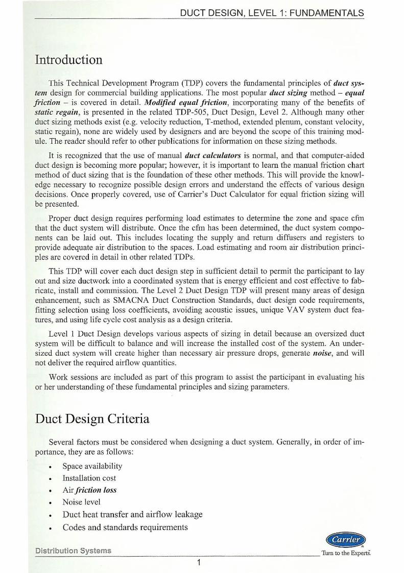
The sizing criteria will often be defined by the space available to run the ductwork (Figure 1). Ceiling plenums, duct chases, and obstructions such as walls and beams often dictate that a certain size duct be used, regardless of whether or not it is the best size from a first cost or air friction loss perspective. There are most likely other building system components competing for the available space. Coordination is required to avoid sprinkler piping, power and communication conduit, light fixtures, and audio speakers. Header ducts and runouts are easier to locate, especially out in the perimeter areas of the floor. Larger trunk and branch ducts require greater coordination with equally large piping and conduit service utilities that tend to get located in the core areas of the building.
Duct Terms
(o '
'1r ® - 1
(!) Boot Diffuser I Takeoff Duct I itr Lay in_/ ~Speaker I Conduit ~ T-bar ® Header Duct ~
Ceiling @) Sprinkler I Piping @ Ughts I Conduit
Figure 1
Fitting In the Ductwork
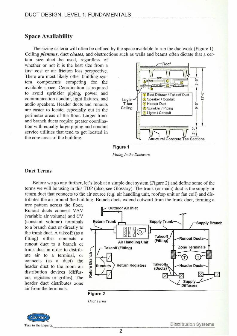
Before we go any fmiher, let's look at a simple duct system (Figure 2) and define some of the terms we will be using in this TDP (also, see Glossary). The trunk (or main) duct is the supply or return duct that connects to the air source (e.g. air handling unit, rooftop unit or fan coil) and distributes the air around the building. Branch ducts extend outward from the trunk duct, forming a tree pattern across the floor. Runout ducts connect VA V (variable air volume) and CV (constant volume) terminals to a branch duct or directly to the trunk duct. A takeoff (as a fitting) either connects a runout duct to a branch or trunk duct in order to distribute air to a terminal, or connects (as a duct) the header duct to the room air distribution devices ( diffusers, registers or grilles). The header duct distributes zone air from the terminals.
<CIJ8t> Turn to the Experts._
Air Handling Unit
-g { Takeoff (Fitting)
c: ~ Ill
Figure 2
Duct Terms
j-Return Registers
2
~ Supply~ Diffusers
Distribution Systems
DUCT DESIGN, LEVEL 1: FUNDAMENTALS --------------------------- -
Installation Cost
First cost is often quite important. First cost is not only impacted by the size of ducts and types of materials used to construct the ductwork, but also by the number and complexity of the duct fittings, and the height/ complexity of the site conditions impacting duct installation labor.
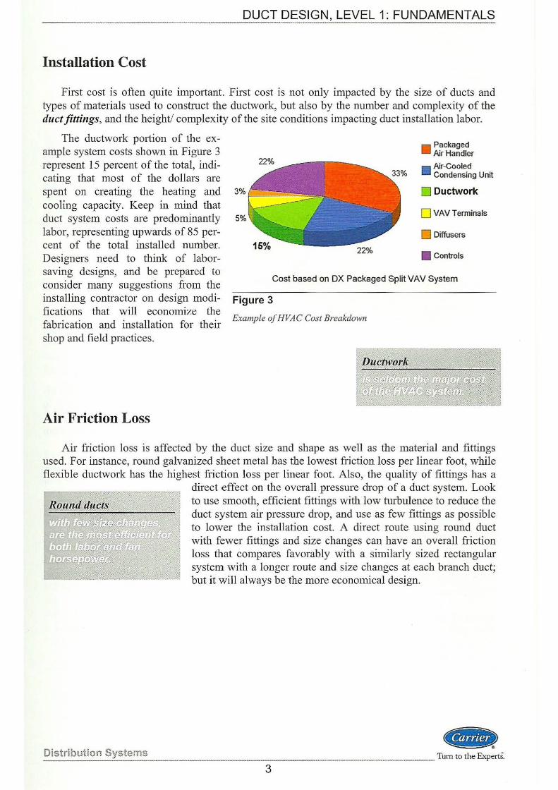
The ductwork portion of the ex-ample system costs shown in Figure 3 represent 15 percent of the total, indicating that most of the dollars are spent on creating the heating and 3% !-'-- - --=
cooling capacity. Keep in mind that duct system costs are predominantly 5%
labor, representing upwards of 85 per-
Packaged Air Handler
• Air-Cooled Condensing Unit
D Ductwork
0 VAV Terminals
0 Diffusers
• Controls cent of the total installed number. Designers need to think of laborsaving designs, and be prepared to consider many suggestions from the installing contractor on design modifications that will economize the fabrication and installation for their shop and field practices.
Cost based on DX Packaged Split VAV System
Figure 3
Example of HVAC Cost Breakdown
Air Friction Loss
Air friction loss is affected by the duct size and shape as well as the material and fittings used. For instance, round galvanized sheet metal has the lowest friction loss per linear foot, while flexible ductwork has the highest friction loss per linear foot. Also, the quality of fittings has a
direct effect on the overall pressure drop of a duct system. Look to use smooth, efficient fittings with low turbulence to reduce the duct system air pressure drop, and use as few fittings as possible to lower the installation cost. A direct route using round duct with fewer fittings and size changes can have an overall friction loss that compares favorably with a similarly sized rectangular system with a longer route and size changes at each branch duct; but it will always be the more economical design.
~ Distribution Systems Turn to the ExpertS. --------------------------------------... -------·-----------..
3
Noise Level
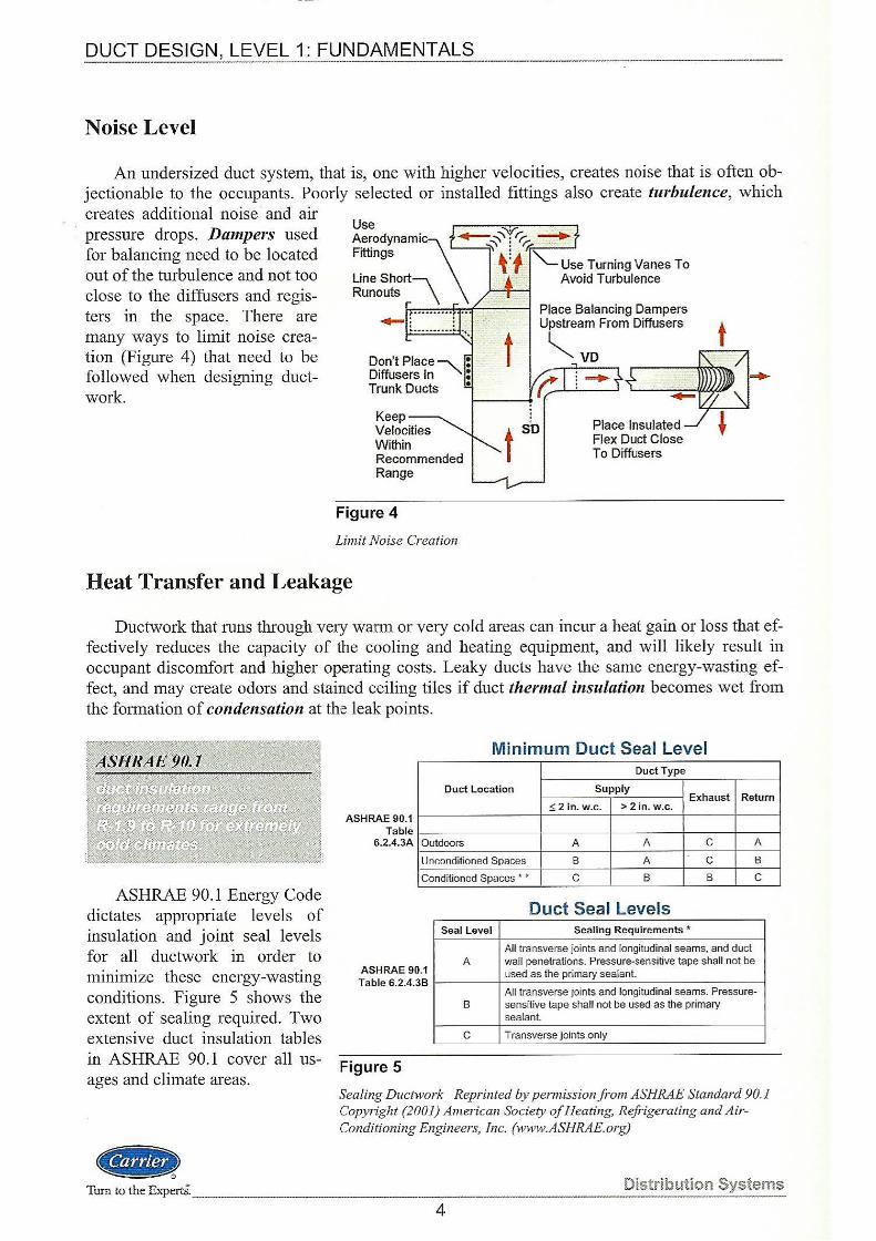
An undersized duct system, that is, one with higher velocities, creates noise that is often objectionable to the occupants. Poorly selected or installed fittings also create turbulence, which creates additional noise and air pressure drops. Dampers used for balancing need to be located out of the turbulence and not too close to the diffusers and registers in the space. There are many ways to limit noise creation (Figure 4) that need to be followed when designing ductwork.
Keep Velocities Within Recommended Range
Figure 4
Limit Noise Creation
Place Insulated Flex Duct Close To Diffusers
Heat Transfer and Leakage
Ductwork that runs through ve1y warm or very cold areas can incur a heat gain or loss that effectively reduces the capacity of the cooling and heating equipment, and will likely result in occupant discomfort and higher operating costs. Leaky ducts have the same energy-wasting effect, and may create odors and stained ceiling tiles if duct thermal insulation becomes wet from the formation of condensation at the leak points.
ASHRAE 90.1 Energy Code dictates appropriate levels of insulation and joint seal levels for all ductwork in order to minimize these energy-wasting conditions. Figure 5 shows the extent of sealing required. Two extensive duct insulation tables in ASHRAE 90.1 cover all usages and climate areas.
( .. Turn to the ExpertS.
ASHRAE 90.1 Table
6.2.4.3A
Minimum Duct Seal Level Duct Type
Duct Location Supply Exhaust Return
;!;2 in. w.c. > 2 in. w.c.
Outdoors A A c A
lJ nr.onclilioned Spaces B A c B
Conditioned Spaces • • c B B c
Duct Seal Levels Seal Level Sealing Requirements •
All transverse joints and longitudinal seams, and duct A
ASHRAE 90.1 Table 6.2.4.38
wall penetrations. Pressure-sensitive tape shall not be used as the primary sealant.
All transverse joints and longitudinal seams. Pressure-B sensitive tape shall not be used as the primary
sealant.
c Transverse joints only
Figure 5
Sealing Ductwork Reprinted by permission from ASHRAE Standard 90.1 Copyright (2001) American Society of Heating, Refrigerating and AirConditioning Engineers, Inc. (www.ASHRAE.org)
Distribution Systems
4
DUCT DESIGN, LEVEL 1: FUNDAMENTALS ·------
Codes and Standards
HV AC duct systems are addressed in a number of building construction codes. Now that the International Codes Council's family of publications is being adopted across the United States, it is safe to say that familiarity with the International Building Code, International Mechanical
Code, and International Energy Conservation Code will capture most of the code-related requirements for duct systems. Always check with your specific project code requirements for additional design related issues.
Theory and Fundamentals
Now that we have spent time going over duct design criteria, and before we spend time discussing a number of practical duct design issues, we need to cover a few basics of airflow fluid dynamics, present a couple airflow formulas, and talk about the relationship between static, velocity, and total pressures. When completed, we will cover some fundamentals on duct friction, fitting losses and duct sizing methods before moving on to the duct design process steps.
Law of Conservation of Energy- Bernoulli's Law
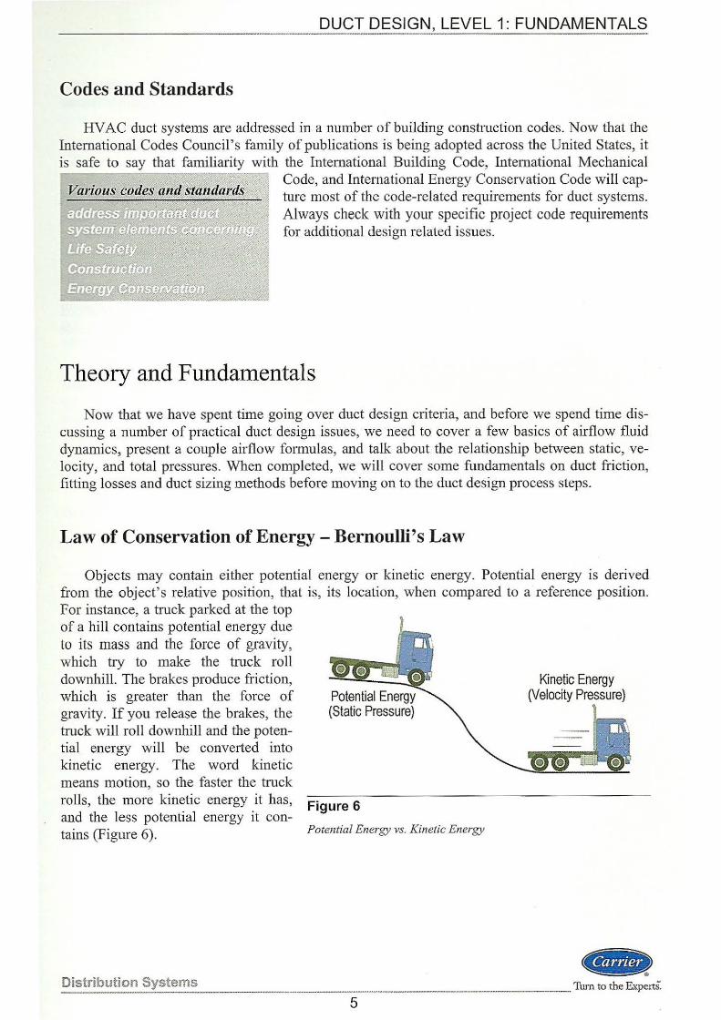
Objects may contain either potential energy or kinetic energy. Potential energy is derived from the object's relative position, that is, its location, when compared to a reference position. For instance, a truck parked at the top of a hill contains potential energy due to its mass and the force of gravity, which try to make the truck roll downhill. The brakes produce friction, which is greater than the force of gravity. If you release the brakes, the truck will roll downhill and the potential energy will be converted into kinetic energy. The word kinetic means motion, so the faster the truck rolls, the more kinetic energy it has, Figure 6 and the less potential energy it con-tains (Figure 6). Potential Energy vs. Kinetic Energy
Distribution Systems
5
Kinetic Energy (Velocity Pressure)
GR ------·Turn to the ExpertS:
DUCT DESIGN, LEVEL 1: FUNDAMENTALS ------------ - - --- - - ----
A typical fan wheel, driven by an electric motor, creates pressure and flow because the rotating blades on the impeller impart kinetic energy to the air by increasing its velocity. The air leaving the fan contains air pressure (energy) in two different fonns:
Static pressure ( P8 )
Velocity pressure ( Pv )
As the high-velocity air exits the fan, the total pressure consists mostly of velocity pressure. This velocity pressure begins to convert into static pressure in the first few feet of supply air duct. Both velocity pressure and static pressure exist throughout the entire air system. Whenever the duct changes cross-sectional flow area, there is a conversion of velocity pressure into static pressure.
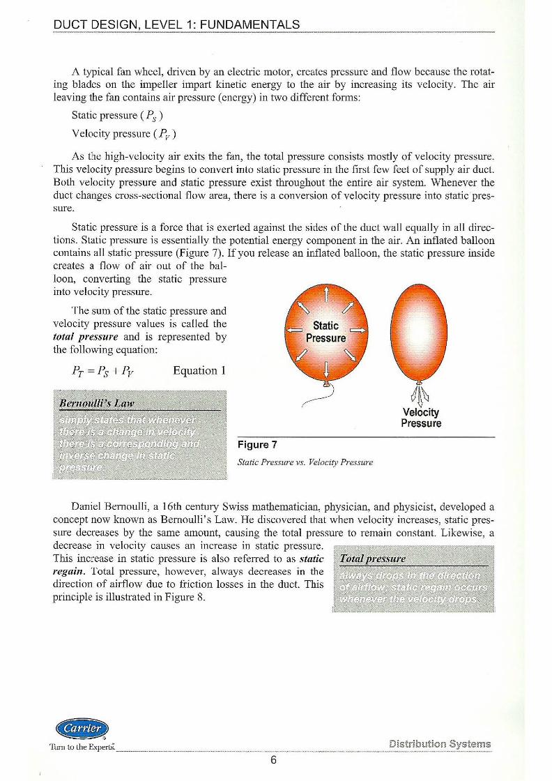
Static pressure is a force that is exerted against the sides of the duct wall equally in all directions. Static pressure is essentially the potential energy component in the air. An inflated balloon contains all static pressure (Figure 7). If you release an inflated balloon, the static pressure inside creates a flow of air out of the bal-loon, converting the static pressure into velocity pressure.
The sum of the static pressure and velocity pressure values is called the total pressure and is represented by the following equation:
Equation 1
Figure 7
Static Pressure vs. Velocity Pressure
J~\ Velocity Pressure
Daniel Bernoulli, a 16th century Swiss mathematician, physician, and physicist, developed a concept now known as Bernoulli's Law. He discovered that when velocity increases, static pressure decreases by the same amount, causing the total pressure to remain constant. Likewise, a decrease in velocity causes an increase in static pressure. This increase in static pressure is also referred to as static regain. Total pressure, however, always decreases in the direction of airflow due to friction losses in the duct. This principle is illustrated in Figure 8.
411Jt> Tl.u·n to the Experts. Distribution Systems _______________________ . ______ ..., _____ .., ______________ _
6
DUCT DESIGN, LEVEL 1: FUNDAMENTALS ----.. --------~- ---- --- - - --- ---
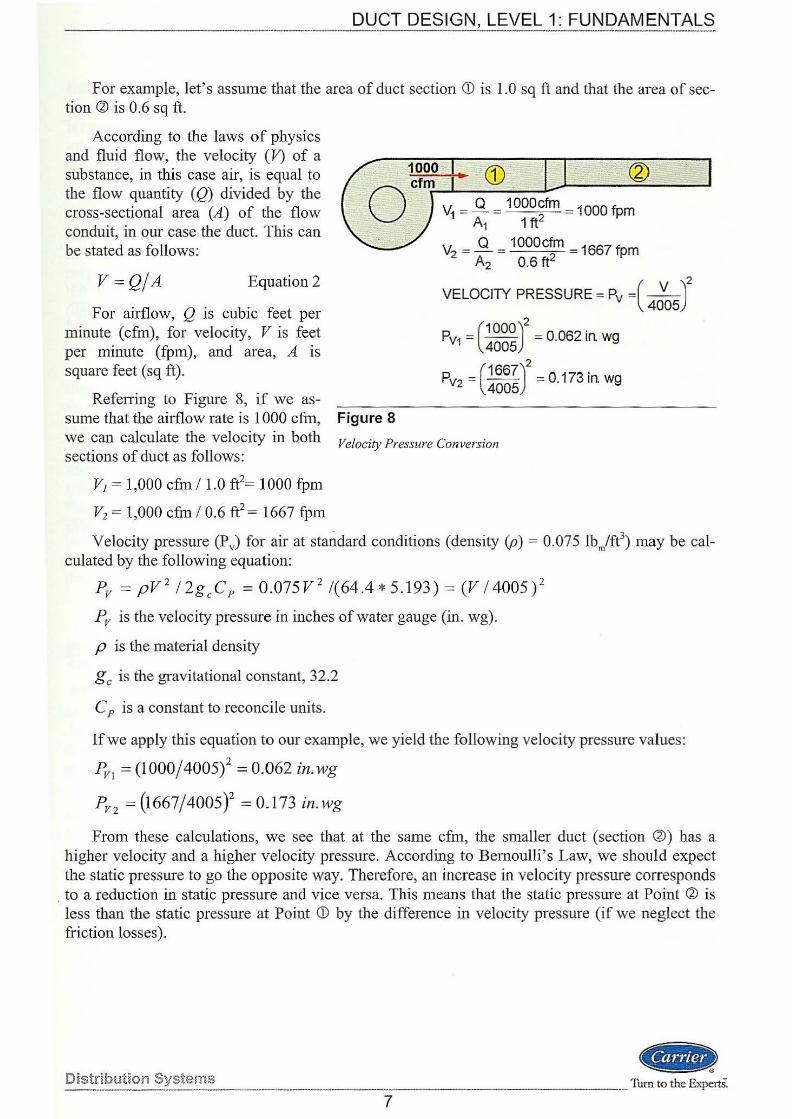
For example, let's assume that the area of duct section <D is 1.0 sq ft and that the area of section !1l is 0.6 sq ft.
According to the laws of physics and fluid flow, the velocity (V) of a substance, in this case air, is equal to the flow quantity (Q) divided by the cross-sectional area (A) of the flow conduit, in our case the duct. This can be stated as follows:
V = Qj A Equation2
For airflow, Q is cubic feet per minute (cfm), for velocity, V is feet per minute (fpm), and area, A is square feet (sq ft).
Referring to Figure 8, if we assume that the airflow rate is 1 000 cfm, we can calculate the velocity in both sections of duct as follows:
V1 = 1,000 cfm /1.0 fi= 1000 fpm
V2 = 1,000 cfm / 0.6 fi = 1667 fpm
Figure 8
Velocity Pressure Conversion
Velocity pressure (PJ for air at standard conditions (density (p) = 0.075 lbm/ft3) may be cal
culated by the following equation:
Pv = pV 2 / 2gcCP = 0.075V 2 /(64.4*5.193) = (V / 4005) 2
Pv is the velocity pressure in inches of water gauge (in. wg).
p is the material density
gc is the gravitational constant, 32.2
C P is a constant to reconcile units.
If we apply this equation to our example, we yield the following velocity pressure values:
Pvt = (1000/ 4005)2 = 0.062 in.wg
PV2 = (1667/ 4005Y = 0_173 in. wg
From these calculations, we see that at the same cfm, the smaller duct (section @) has a higher velocity and a higher velocity pressure. According to Bernoulli's Law, we should expect the static pressure to go the opposite way. Thereforej an increase in velocity pressure corresponds
. to a reduction in static pressure and vice versa. This means that the static pressure at Point !1l is less than the static pressure at Point <D by the difference in velocity pressure (if we neglect the friction losses).
Distribution Systerns ~
------------ _____ Tum to the ExpertS:
7
DUCT DESIGN, LEVEL 1: FUNDAMENTALS
This principle is also analogous to water flowing through a water hose connected to a pressure nozzle. As the water flows through the hose and passes through the nozzle, the velocity is increased because the flow area has been greatly reduced at the nozzle. Even though it seems as if the water pressure has increased at the outlet of the nozzle, this actually represents only an increase of velocity. The actual static pressure of the water has decreased and the nozzle has converted all of the available static pressure of the water into velocity pressure.
Friction Loss in Ducts
When air· flows through a duct, it encounters many obstacles along the way, such as elbows, transitions, and fittings. In addition, the surfaces of the duct walls are not completely smooth, creating friction as the air flows through the duct. Overall, duct friction loss is affected by these and many other factors, including:
• Air velocity
• Duct size and shape
• Duct material roughness factor
• Duct length
Changing any one of these variables will affect the friction loss. All of these factors contribute to what is commonly referred to as the friction loss. Other synonymous terms are often used when referring to friction loss in air systems such as "air pressure drop," or "static pressure loss." In most cases, these terms are measured in inches of water gauge (in. wg) per 100 feet equivalent length (EL). Equivalent length is covered in detail later under fitting losses.
Recommended Duct Velocities for Ductwork and HV AC Components
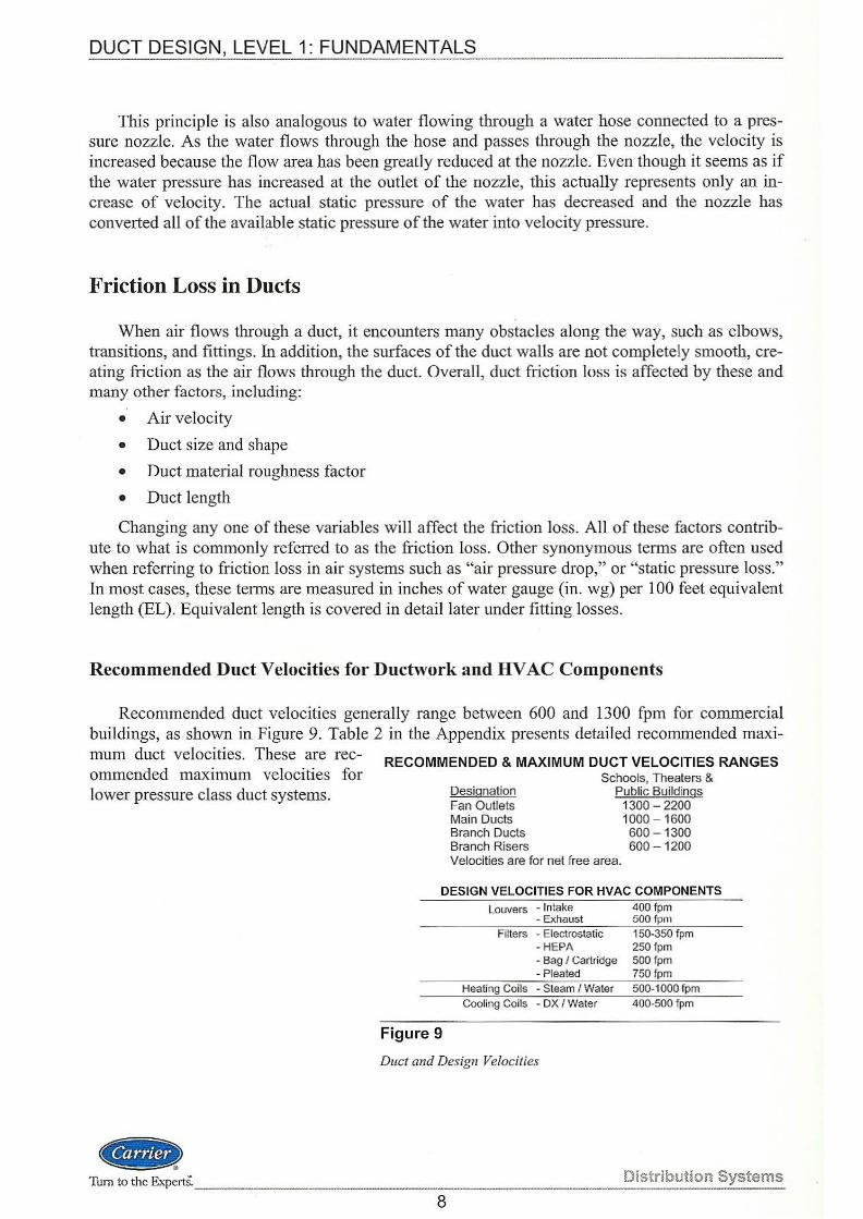
Recommended duct velocities generally range between 600 and 1300 fpm for commercial buildings, as shown in Figure 9. Table 2 in the Appendix presents detailed recommended maximum duct velocities. These are recommended maximum velocities for lower pressure class duct systems.
RECOMMENDED & MAXIMUM DUCT VELOCITIES RANGES Schools, Theaters &
Designation Public Buildings Fan Outlets 1300 - 2200 Main Ducts 1000 - 1600 Branch Ducts 600 - 1300 Branch Risers 600 - 1200 Velocities are for net free area.
DESIGN VELOCITIES FOR HVAC COMPONENTS
Figure 9
Louvers - Intake - Exhaust
Filters - Electrostatic -HEPA - Bag I Cartridge -Pleated
Heating Coils - Steam I Water Cooling Coils - OX I Water
Duct and Design Velocities
400 fpm 500 fpm 150-350 fpm 250fpm 500 fpm 750 fpm 500-1000 fpm 400-500 fpm
«<8> Turn to the Experts. ____ ---------------.-------------·-------D_i_s_tri_kn~tion Systems
8
DUCT DESIGN, LEVEL 1: FUNDAMENTALS
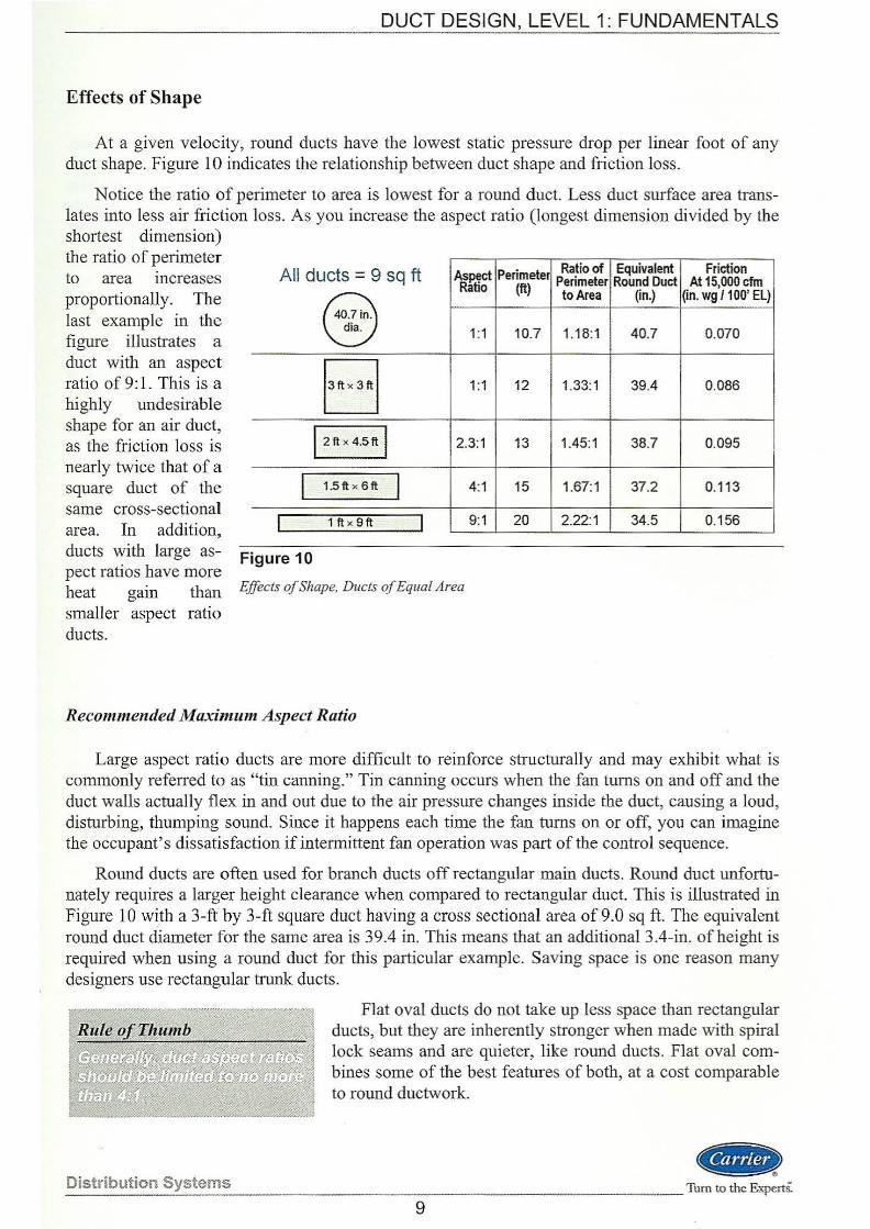
Effects of Shape
At a given velocity, round ducts have the lowest static pressure drop per linear foot of any duct shape. Figure 10 indicates the relationship between duct shape and friction loss.
Notice the ratio of perimeter to area is lowest for a round duct. Less duct smface area translates into less air friction loss. As you increase the aspect ratio (longest dimension divided by the shortest dimension) the ratio of perimeter to area increases proportionally. The last example in the figme illustrates a duct with an aspect ratio of 9: L This is a highly undesirable shape for an air duct, as the friction loss is nearly twice that of a square duct of the same cross-sectional area. In addition, ducts with large aspect ratios have more heat gam than smaller aspect ratio ducts.
All ducts = 9 sq ft Aspect Ratio
@ 1:1 .
13ftdftl 1:1
1 2 ft X 4.5 ft I 2.3:1
I 1.5ft X 6ft I 4:1
I 1ft x 9ft I 9:1
Figure 10
Effects of Shape, Ducts of Equal Area
Perimeter Ratio of Equivalent Friction (ft) Perimeter Round Duct At 15,000 cfm
to Area (in.) Qn. wg /1 00' EL)
10.7 1.18:1 40.7 0.070
12 1.33:1 39.4 0.086
13 1.45:1 38.7 0.095
15 1.67:1 37.2 0.113
20 2.22:1 34.5 0.156
Recommended Maximum Aspect Ratio
Large aspect ratio ducts are more difficult to reinforce structurally and may exhibit what is commonly referred to as "tin canning." Tin canning occurs when the fan turns on and off and the duct walls actually flex in and out due to the air pressme changes inside the duct, causing a loud, disturbing, thun1ping sound. Since it happens each time the fan turns on or off, you can imagine the occupant's dissatisfaction if intermittent fan operation was part of the control sequence.
Round ducts are often used for branch ducts off rectangular main ducts. Round duct unfortunately requires a larger height clearance when compared to rectangular duct. This is illustrated in Figure 10 with a 3-ft by 3-ft square duct having a cross sectional area of9.0 sq ft. The equivalent round duct diameter for the same area is 39.4 in. This means that an additional3.4-in. of height is required when using a round duct for this particular example. Saving space is one reason many designers use rectangular trunk ducts.
Distribution Systems
Flat oval ducts do not take up less space than rectangular ducts, but they are inherently stronger when made with spiral lock seams and are quieter, like round ducts. Flat oval combines some of the best features of both, at a cost comparable to round ductwork.
.. ) _______ __ Tum to the ExpertS:
9
DUCT DESIGN, LEVEL 1: FUNDAMENTALS -------------------------
Surface Roughness of Ducts
Duct material roughness (~::) refers to the inside surface of the duct; the rougher the surface, the higher the friction loss. Most duct sizing tables use the roughness factor for smooth, galvanized sheet metal as the reference value (£ = 0.0003 ft). This value of£ is based on bare sheet metal with joints every 4-ft. For other duct construction materials such as duct board, flexible duct, or duct liner, a multiplier of the measured duct length is used to correct for the higher roughness values. Duct material roughness multipliers are included as Table 4 in the Appendix.
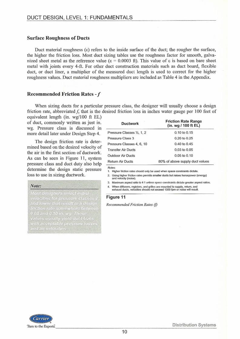
Recommended Friction Rates -f
When sizing ducts for a particular pressure class, the designer will usually choose a design friction rate, abbreviated f, that is the desired friction loss in inches water gauge per 1 00 feet of equivalent length (in. wg/100 ft EL) of duct, commonly written as just in. wg. Pressure class is discussed in more detail later under Design Step 4.
The design friction rate is determined based on the desired velocity of the air in the first section of ductwork. As can be seen in Figure 11, system pressure class and duct duty also help dete1mine the design static pressure loss to use in sizing ductwork.
.. Turn to the ExpertS._
Ductwork
Pressure Classes %, 1, 2
Pressure Class 3
Pressure Classes 4, 6, 10
Transfer Air Ducts
Outdoor Air Ducts
Return Air Ducts
Notes:
Friction Rate Range (in. wg / 100 ft EL)
0.10to0.15
0.20 to 0.25
0.40 to 0.45
0.03 to 0.05
0.05 to 0.10
80% of above supply duct values
1. Higher friction rates should only be used when space constraints dictate.
2. Using higher friction rates permits smaller ducts but raises horsepower (energy) and velocity {noise).
3. Maximum aspect ratio is 4:1 unless space constraints dictate greater aspect ratios.
4. When diffusers, registers, and grilles are mounted to supply, return, and exhaust ducts, velocities should not exceed 1500 fpm or noise will result.
Figure 11
Recommended Friction Rates (f)
Distribution Systems ---·
10
DUCT DESIGN, LEVEL 1: FUNDAMENTALS
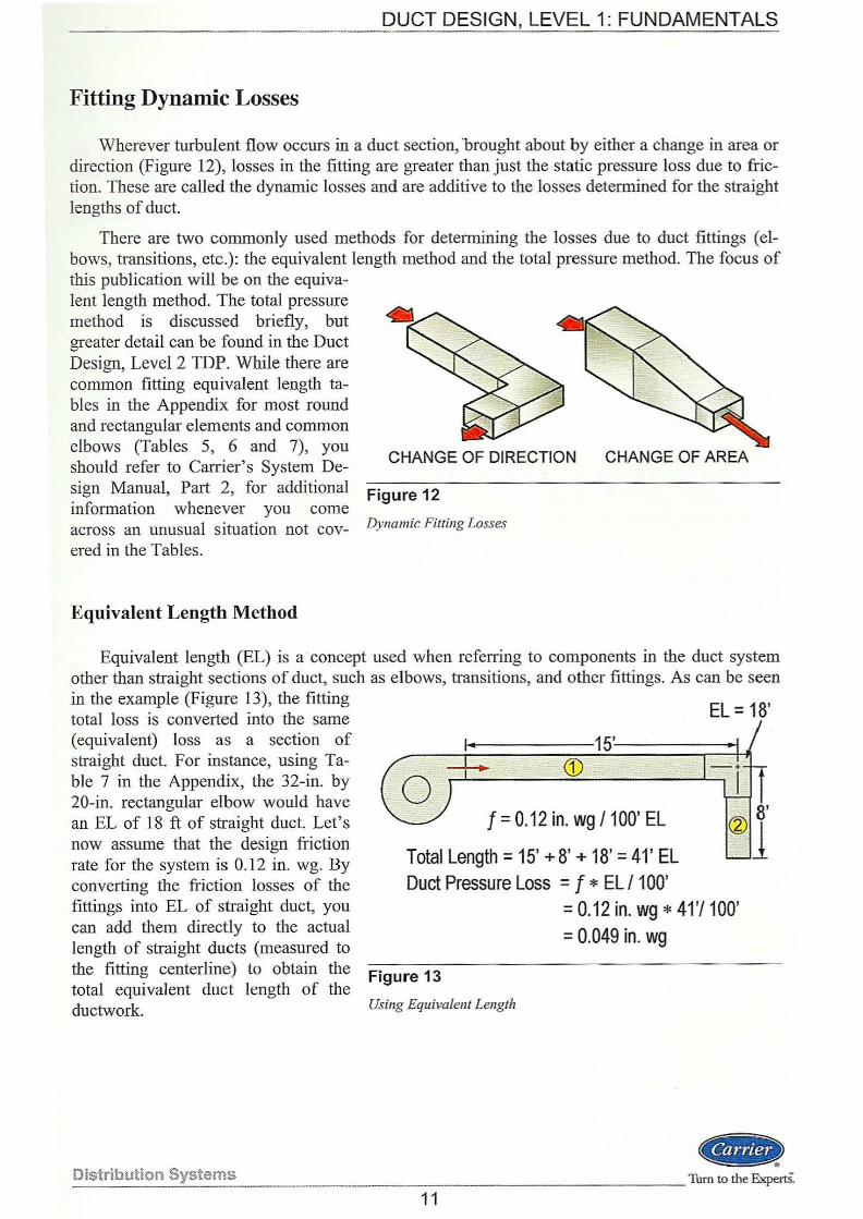
Fitting Dynamic Losses
Wherever turbulent flow occurs in a duct section, 'brought about by either a change in area or direction (Figure 12), losses in the fitting are greater than just the static pressure loss due to friction. These are called the dynamic losses and are additive to the losses determined for the straight lengths of duct.
There are two commonly used methods for determining the losses due to duct fittings ( elbows, transitions, etc.): the equivalent length method and the total pressure method. The focus of this publication will be on the equiva-lent length method. The total pressure method is discussed briefly, but greater detail can be found in the Duct Design, Level 2 TDP. ·while there are common fitting equivalent length tables in the Appendix for most round and rectangular elements and common elbows (Tables 5, 6 and 7), you should refer to Carrier's System De
CHANGE OF DIRECTION CHANGE OF AREA
sign Manual, Part 2, for additional Figure 12 information whenever you come across an unusual situation not cov- Dynamic Fitting Losses
ered in the Tables.
Equivalent Length Method
Equivalent length (EL) is a · concept used when referring to components in the duct system other than straight sections of duct, such as elbows, transitions, and other fittings. As can be seen in the example (Figure 13), the fitting total loss is converted into the same (equivalent) loss as a section of straight duct. For instance, using Table 7 in the Appendix, the 32-in. by 20-in. rectangular elbow would have an EL of 18 ft of straight duct. Let's now assume that the design friction rate for the system is 0.12 in. wg. By converting the friction losses of the fittings into EL of straight duct, you can add them directly to the actual length of straight ducts (measured to
f = 0.12 in. wg I 100' EL
Total Length= 15' + 8' + 18' = 41' EL Duct Pressure Loss = f *ELI 100'
EL = 18'
= 0.12 in. wg * 41 'I 1 00' = 0.049 in. wg
the fitting centerline) to obtain the Figure 13 total equivalent duct length of the ductwork. Using Equivalent Length
Distribution Systeros ..
·- --- ------- - - -Tum to the ExpertS: 11
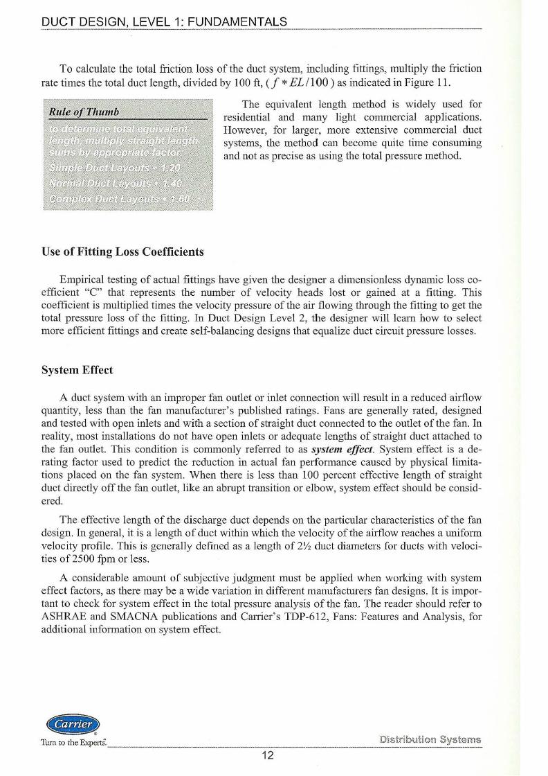
To calculate the total friction loss of the duct system, including fittings, multiply the friction rate times the total duct length, divided by 100ft,(/* EL/100) as indicated in Figure 11.
Use of Fitting Loss Coefficients
The equivalent length method is widely used for residential and many light commercial applications. However, for larger, more extensive commercial duct systems, the method can become quite time consuming and not as precise as using the total pressure method.
Empirical testing of actual fittings have given the designer a dimensionless dynamic loss coefficient "C" that represents the number of velocity heads lost or gained at a fitting. This coefficient is multiplied times the velocity pressure of the air flowing through the fitting to get the total pressure loss of the fitting. In Duct Design Level 2, the designer will learn how to select more efficient fittings and create self-balancing designs that equalize duct circuit pressure losses.
System Effect
A duct system with an improper fan outlet or inlet connection will result in a reduced airflow quantity, less than the fan manufacturer's published ratings. Fans are generally rated, designed and tested with open inlets and with a section of straight duct connected to the outlet of the fan. In reality, most installations do not have open inlets or adequate lengths of straight duct attached to the fan outlet. This condition is commonly referred to as system effect. System effect is a derating factor used to predict the reduction in actual fan perfotmance caused by physical limitations placed on the fan system. When there is less than 100 percent effective length of straight duct directly off the fan outlet, like an abrupt transition or elbow, system effect should be considered.
The effective length of the discharge duct depends on the particular characteristics of the fan design. In general, it is a length of duct within which the velocity of the airflow reaches a uniform velocity profile. This is generally defined as a length of 2Yz duct diameters for ducts with velocities of 2500 fpm or less.
A considerable amount of subjective judgment must be applied when working with system effect factors, as there may be a wide variation in different manufacturers fan designs. It is important to check for system effect in the total pressure analysis of the fan. The reader should refer to ASHRAE and SMACNA publications and Carrier's TDP-612, Fans: Features and Analysis, for additional information on system effect.
@it> Turn to the Experts·. Distributkm Systems
---~-------------~--.. --.. ----·--------..__ .... ___ ._....._ ...... ----·-----------.. ·----12
DUCT DESIGN, LEVEL 1: FUNDAMENTALS --------------------------------
Duct Sizing Methods
The most common methods of sizing duct sections after the fan outlet in use today are:
• Equal friction
• Modified equal friction
• Static regain
Equal Friction
With the equal friction method, as the name implies, ducts are sized for an equal (constant) friction loss per unit length. In its purest form, this uniform friction loss per linear foot of duct is held constant for the entire duct system. The equal friction method is the most widely used method for sizing lower pressure systems. This method automatically reduces the velocity of the air in the direction of flow. Therefore some "regain" of static pressure is created; however it occurs in unknown amounts and is not usually accounted for.
Once initial sizes are calculated, the total pressure of all sections should be calculated and noted. Sections should then be resized to equalize the pressure at all junctions. This is demonstrated later in the example problem.
The equal friction method is generally used when sizing supply and return systems in CV (Constant Volume), and exhaust systems.
The primary disadvantages of the equal friction method are:
• There is difficulty in balancing branch flow rates, even with balancing dampers.
• It cannot ensure a uniform, constant inlet pressure to variable air volume devices and terminals.
Modified Equal Friction
To overcome these disadvantages, modifications to the equal friction procedure have been made that take advantage of the static regain effect. This sizing method is sometimes referred to as the modified equal friction design procedure. This procedure is used whenever the duct system is non-symmetrical or for systems with both long and short duct runs. By downsizing the shorter duct runs with lower friction loss there is less of a requirement to "choke" the airflow by the use of balancing dampers; results in smaller ducts, which saves money. The modified equal friction design procedure is descrihed in detail in the Duct Design, Level 2 TDP.
Static Regain
The static regain method of duct sizing is a more complex and detailed method and may be used to size supply duct systems of any pressure/velocity class. The advantages of lower fan brake horsepower (bhp) and self-balancing sizing to the VA V terminals often outweigh the extra work involved in performing the calculations. In this method, the velocities are systematically reduced, resulting in a conversion of the velocity pressure into static pressure, which overcomes a portion of the air friction loss in the next downstream section of duct.
Distribution Systems _ .. ..,...._ ... .__ .. _~------------·-.......
4ilt.> --------------- -----Turn to the ExpertS.
13

DUC_T DESIGN, LEVEL 1: FU.N __ DA_ M_E_N_TA_ LS _____________ _
This phenomenon is not totally efficient, however. A regain efficiency of 75 percent is assumed for most average duct systems. This method is also advantageous because it creates a selfbalancing system, in that all gains and losses are proportional to the velocities. This makes it especially useful for higher-velocity systems, where the turbulence and noise generated by air balancing dampers prohibits their use.
The main disadvantage of the static regain method is the larger duct sizes that result. This translates into higher first cost; however, the reduced static pressure on the fan often results in a lower fan operating cost over the life of the system.
Static regain manual sizing of ducts is not covered in the TOP series. It can be effectively applied using computer duct design software and should be studied using the program instructional manual.
Other Methods
While other duct sizing methods exist, such as the T -method, velocity reduction, total pressure, and constant velocity methods, they are not widely used and are not included in this text.
Work Session 1 Fundamentals
This is a good time to complete Work Session 1 and test your knowledge of the fundamentals, including design criteria and theory.
<f1iiJr Turn to the Expe1ts. _____________ _ Distribution Systems
·---14
DUCT DESIGN, LEVEL 1: FUNDAMENTALS
Duct Design Process Steps
Duct design should be thought of as a simple straightforward process that occurs over many segments of HV AC system design. The duct design steps should be performed in the order shown, though much iteration may be required for some of the steps before the HV AC system is fmally designed. There is a separate duct system for each independent air handling system (air source) within the building.
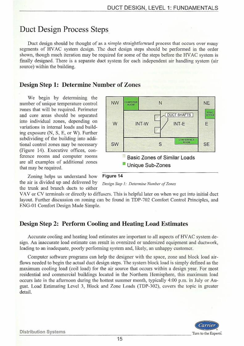
Design Step 1: Determine Number of Zones
We begin by determining the number of unique temperature control zones that will be required. Perimeter and core areas should be separated into individual zones, depending on variations in internal loads and building exposure (N, S, E, or W). Further subdividing of the building into additional control zones may be necessary (Figure 14). Executive offices, conference rooms and computer rooms are all examples of additional zones that may be required.
NW
• W
SW
INT-VV~
Basic Zones of Similar Loads 11 Unique Sub-Zones
Zoning helps us understand how Figure 14 the air is divided up and delivered by Design Step I: Determine Number of Zones the trunk and branch ducts to either
NE
VA V or CV terminals or directly to diffusers. This is helpful later on when we get into initial duct layout. Further discussion on zoning can be found in TDP-702 Comfort Control Principles, and ENG-0 1 Comfort Design Made Simple.
Design Step 2: Perform Cooling and Heating Load Estimates
Accurate cooling and heating load estimates are important to all aspects of HV AC system design. An inaccurate load estimate can result in oversized or undersized equipment and ductwork, leading to an inadequate, poorly performing system and, likely, an unhappy customer.
Computer software programs can help the designer with the space, zone and block load airflows needed to begin the actual duct design steps. The system block load is simply defined as the maximum cooling load (coil load) for the air source that occurs within a design year. For most residential and commercial buildings located in the N orthem Hemisphere, this maximum load occurs late in the afternoon during the hottest summer month, typically 4:00 p.m. in July or August. Load Estimating Level 3, Block and Zone Loads (TDP-302), covers the topic in greater detail.
Distribution Systems ..
_ _ ___ Turn to the Experts.
15
Design Step 3: Determine Space, Zone and Block Airflows
The results of a load estimate calculation include the airflow quantities required for conditioning each of the spaces and zones, and for sizing the main coils and system fan. The room-byroom airflow quantities are used to size the supply diffusers and return grilles, as well as the takeoffs and header ducts that serve them. If duct design was begun with assumptions for supply airflow .M or cfrnlsq ft, these values will need to be verified after final load estimates are completed. If the airflows change there is a very real chance that the ducts will need resizing.
The sum of the zone airflow quantities is the total amount of air the fan must deliver, also referred to as the total supply air quantity. This value, obtained from the maximum block load, is also used to size the first section of supply duct off the fan. The sum of these airflow quantities is used to calculate the branch duct sizes and the trunk ducts that serve them.
Load estimating and room air distribution principles are covered in greater detail in other TDP publications. The scope of this program will be limited to the task of duct sizing.
Design Step 4: Select Duct Material, Shape and Insulation
After calculating the cooling and heating loads, the designer decides which materials and shape of duct to use, and how to insulate it to control energy loss/gain and limit noise levels. But even before beginning these first duct design steps, a quick word on the new classifications for duct systems now that low pressure and high pressure, or low velocity and high velocity classifications are no longer used.
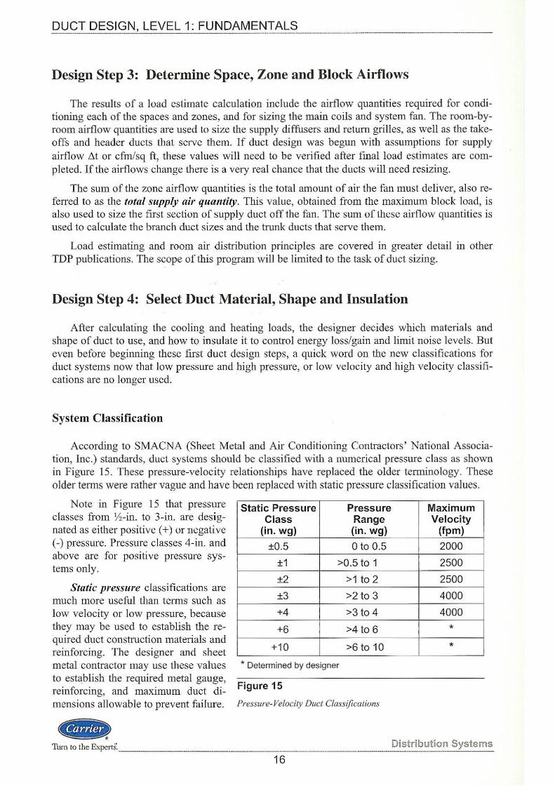
System Classification
According to SMACNA (Sheet Metal and Air Conditioning Contractors' National Association, Inc.) standards, duct systems should be classified with a numerical pressure class as shown in Figure 15. These pressure-velocity relationships have replaced the older terminology. These older terms were rather vague and have been replaced with static pressure classification values.
Note in Figure 15 that pressure classes from V2-in. to 3-in. are designated as either positive(+) or negative (-) pressure. Pressure classes 4-in. and above are for positive pressure systems only.
Static pressure classifications are much more useful than terms such as low velocity or low pressure, because they may be used to establish the required duct construction materials and reinforcing. The designer and sheet metal contractor may use these values to est~blish the required metal gauge, reinforcing, and maximum duct dimensions allowable to prevent failure.
<a-
Static Pressure Pressure Class Range
(in. wg) (in. wg)
±0.5 0 to 0.5
±1 >0.5 to 1
±2 >1 to 2
±3 >2 to 3 +4 >3 to 4
+6 >4 to 6
+10 >6 to 10
* Determined by designer
Figure 15
Pressure-Velocity Duct Classifications
1hrn to the Experts. _ ________________ _____________ _
16
Maximum Velocity
(fpm)
2000
2500
2500
4000
4000
*
*
Distribution Systems
DUCT DESIGN, LEVEL 1: FUNDAMENTALS -------- --- --·----- ---·-
Therefore, if someone refers to a SMACNA Pressure Class 4 system, according to the chart, the pressure is greater than 3.0-in. wg and up to 4.0-in. wg, with a maximum velocity of 4000 feet per minute (fpm).
While we are discussing pressure-velocity classifications, it is a SMACNA-recommended practice to note the duct drawings with the design static pressure classes. This can be seen in the Symbols List in the Appendix in the first few symbols on the left-hand side of the List. If this is done, the installing contractor now knows how to construct the duct, along with the size, whether it is lined or not, and in which direction the air flows.
W hat Can Be a Duct and What is it Made of?
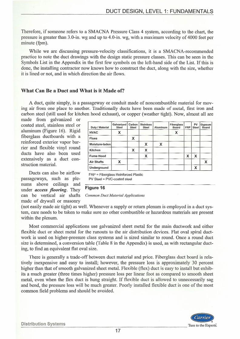
A duct, quite simply, is a passageway or conduit made of noncombustible material for moving air from one place to another. Traditionally ducts have been made of melal, first iron and carbon steel (still used for kitchen hood exhaust), or copper (weather tight). Now, almost all are made from galvanized or coated steel, stainless steel or aluminum (Figure 16). Rigid fiberglass ductboards with a reinforced exterior vapor barrier and flexible vinyl round ducts have also been used extensively as a duct construction material.
Galvanized Carbon Stainless Duty I Material Steel Steel Steel
HVAC X
Flues X Moisture-laden X
Kitchen X X
Fume Hood X
Air Shafts X
Underground
FRP = Fiberglass Reinforced Plastic PV Steel = PVC-coated steel
Ducts can also be airflow passageways, such as plenums above ceilings and under access flooring. They Figure 16 can be vertical air shafts Common Duct Material Applications
made of drywall or masonry
Fiberglass PV Gypsum Aluminum Board FRP Steel Board
X
X
X X
X
X
(not easily made air tight) as well. Whenever a supply or return plenum is employed in a duct system, care needs to be taken to make sure no other combustible or hazardous materials are present within the plenum.
Most commercial applications use galvanized sheet metal for the main ductwork and either flexible duct or sheet metal for the runouts to the air distribution devices. Flat oval spiral ductwork is used on higher-pressure class systems and is sized similar to round. Once a round duct size is determined, a conversion table (Table 8 in the Appendix) is used, as with rectangular ducting, to find an equivalent flat oval size.
There is generally a trade-off between duct material and price. Fiberglass duct board is relatively inexpensive and easy to install; however, the pressure loss is approximately 30 percent higher than that of smooth galvanized sheet metal. Flexible (flex) duct is easy to install but exhibits a much greater (three times higher) pressure loss per linear foot as compared to smooth sheet metal, even when the flex duct is hung straight. If flexible duct is allowed to unnecessarily sag and bend, the pressure loss will be much greater. Poorly installed flexible duct is one of the most common field problems and should be avoided.
Distribution Systems ---
(@It> --------------··-- ---------------Tum to the R"<pertS:
17
QQgl_p~S IGN , LEVEL 1: FUNDAMENT}\~_? ___ _
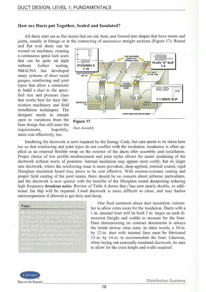
How are Ducts put Together, Sealed and Insulated?
All ducts start out as flat sheets that are cut, bent, and formed into shapes that have seams and joints, usually at fittings or at the connecting of successive straight sections (Figure 17). Round and flat oval ducts can be wound on machines, creating a continuous spiral lock seam that can be quite air tight without further sealing. SMACNA has developed many systems of sheet metal gauges, reinforcing and joint types that allow a contractor to build a duct to the specified size and pressure class that works best for their fabrication machinery and field installation techniques. The designer needs to remain open to variations from the base design that still meet the requirements, hopefully, more cost effectively, too.
Figure 17
Duct Assembly
I~ I
OPEN HEM FOR DRIVE SEAM__)
Insulating the ductwork is now required by the Energy Code, but care needs to be taken here too so that reinforcing and joint types do not conflict with the insulation. Insulation is often applied as an extemal flexible wrap on the exterior of the ducts after assembly and installation. Proper choice of low profile reinforcement and joint styles allows for easier insulating of the ductwork without worry of puncture. Internal insulation may appear more costly, but on larger size ductwork, where the reinforcing issue is more prevalent, shop-applied, internal coated, rigid fiberglass insulation board may prove to be cost effective. With erosion-resistant coating and proper field coating of the joint seams, there should be no concern about airbome particulates, and the ductwork is now quieter with the benefits of the fiberglass sound dampening reducing high frequency breakout noise. Review of Table 4 shows thatfhas now nearly double, so additional fan bhp will be required. Lined ductwork is more difficult to clean, and may harbor microorganisms if allowed to get dirty and damp.
CUL4if Turn to the ExpertS. _______ _
One final comment about duct insulation: remember to allow extra room for the insulation. Ducts with a 1 in. intemal liner will be built 2 in. larger on each dimension (height and width) to account for the liner. Duct dimensioning on contract documents is always the inside airway clear sizes. In other words, a 10-in. by 12-in. duct with intemal liner must be fabricated 12-in. by 14-in. to accommodate the liner. Likewise, when laying out externally-insulated ductwork, be sure to allow for the extra height and width required.
Distribution Systems
18
DUCT DESIGN, LEVEL 1: FUNDAMENTALS
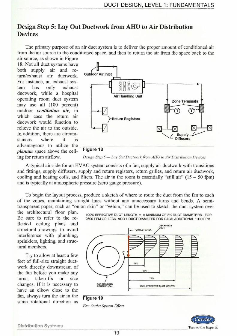
Design Step 5: Lay Out Ductwork from AHU to Air Distribution Devices
The primary purpose of an air duct system is to deliver the proper amount of conditioned air from the air source to the conditioned space, and then to return the air from the space back to the air source, as shown in Figure 18. Not all duct systems have both supply arr and return/exhaust a1r ductwork. For instance, an exhaust system has only exhaust ductwork, while a hospital operating room duct system may use all (1 00 percent) outdoor ventilation air, in which case the return air ductwork would function to relieve the air to the outside. In addition, there are circumstances where it is
Air Handling Unit
)-Return Registers
~Supply~ Diffusers
advantageous to utilize the . -. - ----- ----------- ------plenum space above the ceil- F•gure 18 ing for return airflow. Design Step 5-Lay Out Ductwork from AHU to Air Distribution Devices
A typical air-side for an HV AC system consists of a fan, supply air ductwork with transitions and fittings, supply diffusers, supply and return registers, return grilles, and return air ductwork, cooling and heating coils, and filters. The air in the room is essentially "still air" (15 - 50 fpm) and is typically at atmospheric pressure (zero gauge pressure).
To begin the layout process, produce a sketch of where to route the duct from the fan to each of the zones, maintaining straight lines without any unnecessary turns and bends. A semitransparent paper, such as "onion skin" or "velum," can be used to sketch the duct system over the architectural floor plan. Be sure to refer to the reflected ceiling plans and stmctural drawings to avoid interference with plumbing, sprinklers, lighting, and stmctural members.
Try to allow at least a few feet of full-size straight ductwork directly dmvnstream of the fan before you make any turns, take-offs or size changes. If it is necessary to have an elbow close to the fan, always turn the air in the same rotational direction as
Distribution Systems
100% EFFECTIVE DUCT LENGTH ;;o A MINIMUM OF 2% DUCT DIAMETERS. FOR 2500 FPM OR LESS. ADD 1 DUCT DIAMETER FOR EACH ADDITIONAL 1000 FPM.
I FAN HOUSING CENTRIFUGAL
Figure 19
Fan Outlet System Effect
19
75"/o
DISCHARGE DUCT
100"/o EFFECTIVE DUCT LENGTH
<Ci!a __ Tum to the ExpertS.
DUCT DESIGN, LEVEL 1: FUNDAMENTALS
the fan wheel. The air in the duct is very turhulent coming off the fan discharge. The air needs a few feet of straight duct to establish a uniform velocity profile so that all of the energy from the fan can be converted into pressure. Any energy not converted into pressure becomes turbulence and vibration, which will likely lead to a noisy system.
Wherever possible, ducts should not be located in extreme temperature areas such as hot attics to minimize heat gain and loss. If you must route duct through extreme temperature environments, be sure to use adequate insulation to minimize thermal losses.
Do not forget the return air duct system design. They are sized the same ways as the supply ducts, though usually at a slightly lower friction rate. Some buildings use a ceiling plenum return for the return air; so, a fully ducted return air system may not be required.
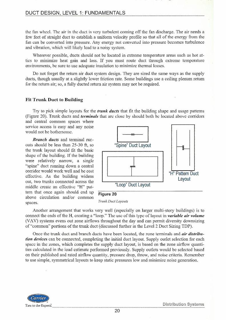
Fit Trunk Duct to Building
Try to pick simple layouts for the trunk ducts that fit the building shape and usage patterns (Figure 20). Trunk ducts and terminals that are close by should both be located above corridors and central common spaces where service access is easy and any noise would not be bothersome.
Branch ducts and terminal runouts should be less than 25-30 ft, so the trunk layout should fit the basic shape of the building. If the building were relatively narrow, a single "spine" duct running down a central corridor would work well and be cost effective. As the building widens out, two trunks connected across the middle create an effective "H" pattern that once again should end up above circulation and/or common spaces.
EJ "Spine" Duct Layout
"Loop" Duct Layout
Figure 20
Trunk Duct Layouts
"H" Pattern Duct Layout
Another arrangement that works very well (especially on larger multi-story buildings) is to connect the ends of the H, creating a "loop." The use of this type of layout in variable air volume (VA V) systems evens out zone airflows throughout the day and can permit diversity downsizing of "common" portions of the trunk duct (discussed further in the Level 2 Duct Sizing TDP).
Once the trunk duct and branch ducts have been located, the zone terminals and air distribution devices can be connected, completing the initial duct layout. Supply outlet selection for each space in the zones, which completes the supply duct layout, is based on the zone airflow quantities calculated in the load estimate performed previously. Supply outlets would be selected based on their published and rated airflow quantity, pressure drop, throw, and noise criteria. Remember to use simple, symmetrical layouts to keep static pressures low and minimize noise generation.
CilD!> Turn to the ExpertS.---· Distribution Systems
---------------------------------20
-----------------------------------··--· DUfT DE§J_Q_~_!__~EVEL 1: F~NDAMENTALS
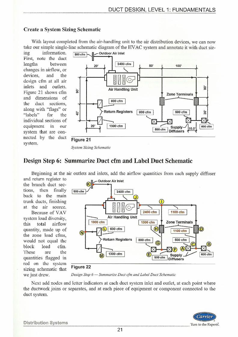
Create a System Sizing Schematic
vVith layout completed from the air-handling unit to the air distribution devices, we can now take our simple single-line schematic diagram of the HV AC system and annotate it with duct siz-ing information. Outdoor Air Inlet
50'
First, note the duct lengths between changes in airflow, or devices, and the design cfm at all air inlets and outlets. Figure 21 shows cfm and dimensions of the duct sections, along with "flags" or "labels" for the individual sections of equipment in our system that are connected by the duct
0 Air Handling Unit en
system. Figure 21
System Sizing Schematic
I 800 cfm I '--
l 100'
1
Design Step 6: Summarize Duct cfm and Label Duct Schematic
Beginning at the air outlets and inlets, add the airflow quantities from each supply diffuser and return register to outdoor Air Inlet
the branch duct sections, then finally back to the main trunk ducts, finishing at the a1r source.
Because of VA V system load diversity, this total airflow quantity, made up of the zone load cfms, would not equal the block load cfin. These are the quantities flagged in red on the system sizing schematic that we just drew.
)-Return Registers
Figure 22
Design Step 6- Summarize Duct cfm and Label Duct Schematic
Next add nodes and letter indicators at each duct system inlet and outlet, at each point where the ductwork joins or separates, and at each piece of equipment or component connected to the duct system.
4§D.) Distribution Systems Turn to the Exp;rts. ---...-.----·-------------~---------------------------------------------------
21
DUCT DESIGN, LEVEL 1: FUNDAMENTALS
Use a Duct Sizing Worksheet
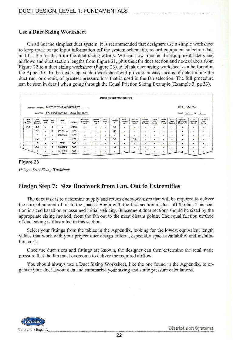
On all but the simplest duct system, it is recommended that designers use a simple worksheet to keep track of the input information off the system schematic, record equipment selection data and list the results from the duct sizing efforts. We can now transfer the equipment labels and airflows and duct section lengths from Figure 21, plus the cfm duct section and nodes/labels from Figure 22 to a duct sizing worksheet (Figure 23). A blank duct sizing worksheet can be found in the Appendix. In the next step, such a worksheet will provide an easy means of determining the duct run, or circuit, of greatest pressure loss that is used in the fan selection. The full procedure can be seen in detail when going through the Equal Friction Sizing Example (Example 3, pg 33).
PROJECT NAME: DUCT SIZING WORKSHEET
SYSTEJ.i: EXAMPLE SUPPLY· LONGEST RUN
Figure 23
Using a Duct Sizing Worksheet
Ve!Oelty~
Aoumldut ' {fpm)
DUCT SIZING WORKSHEET
Y•locity FiUint PNIStllll V1111J• ., .
50
190
30
10
MtNtbl Co-rrKUon
F11C'!o r
3.2
Frio:J:io.n L~tfPOt 1~'d11CI
Ftktlotl l<r\OW'rl l.<IU La&t
(11\. Wg} II:I.WG}
...... Do«
Sittiin,)
DATE: 10/ 1/04
PAGE: _! _· OF 1
E~~ .. llv11lent Aecl.;llng~r
SIJ:II j'WXH)
X
X
X
X
X
X
To~l CUI'M.Ibtiv& h• m LOtt Lou
iiii.WQ) llt!.wg)
Design Step 7: Size Ductwork from Fan, Out to Extremities
The next task is to detetmine supply and return ductwork sizes that will be required to deliver the correct amount of air to the spaces. Begin with the first section of duct off the fan. This section is sized based on an assumed initial velocity. Subsequent duct sections should be sized by the appropriate sizing method, from the fan out to the most distant points. The equal friction method of duct sizing is illustrated in this section.
Select your fittings from the tables in the Appendix, looking for the lowest equivalent length values that work with your project duct design criteria, especially space availability and installation cost.
Once the duct sizes and fittings are known, the designer can then determine the total static pressure that the fan must overcome to deliver the required airflow.
You should always use a Duct Sizing Worksheet, like the one found in the Appendix, to organize your duct layout data and summarize your sizing and static pressure calculations.
<GID.) Tum to the Experts ... Distribution Systems
22
DUCT DESIGN, LEVEL 1: FUNDAMENTALS
Duct Sizing Using the Friction Chart
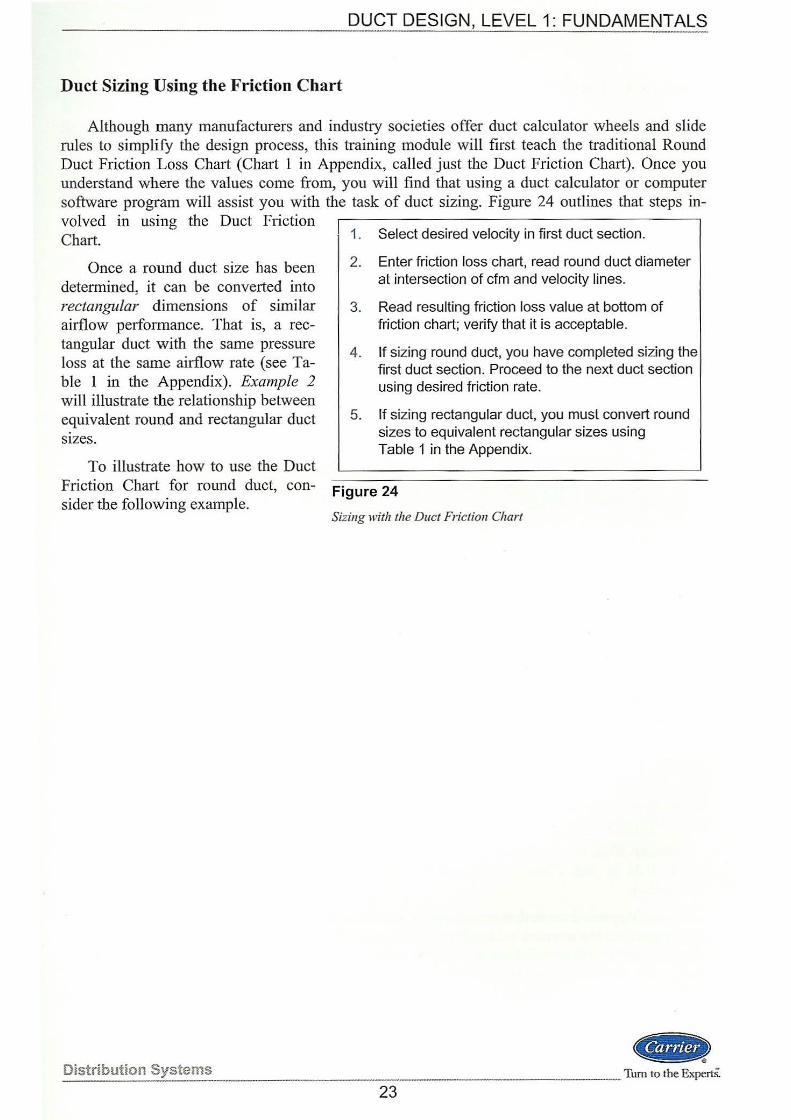
Although many manufacturers and industry societies offer duct calculator wheels and slide rules to simplify the design process, this training module will first teach the traditional Round Duct Friction Loss Chart (Chart 1 in Appendix, called just the Duct Friction Chart). Once you understand where the values come from, you will find that using a duct calculator or computer software program will assist you with the task of duct sizing. Figure 24 outlines that steps involved in using the Duct Friction Chart.
Once a round duct size has been determined; it can be converted into rectangular dimensions of similar airflow performance. That is, a rectangular duct with the same pressure loss at the same airflow rate (see Table 1 in the Appendix). Example 2 will illustrate the relationship between equivalent round and rectangular duct SIZeS.
To illustrate how to use the Duct Friction Chart for round duct, consider the following example.
Distribution Systems
1. Select desired velocity in first duct section.
2. Enter friction loss chart, read round duct diameter at intersection of cfm and velocity lines.
3. Read resulting friction loss value at bottom of friction chart; verify that it is acceptable.
4. If sizing round duct, you have completed sizing the first duct section. Proceed to the next duct section using desired friction rate.
5. If sizing rectangular duct, you must convert round sizes to equivalent rectangular sizes using Table 1 in the Appendix.
Figure 24
Sizing with the Duct Friction Chart
(«<.> _Turn to the Experts.
23
Example 1 - Using the Duct Friction Chart
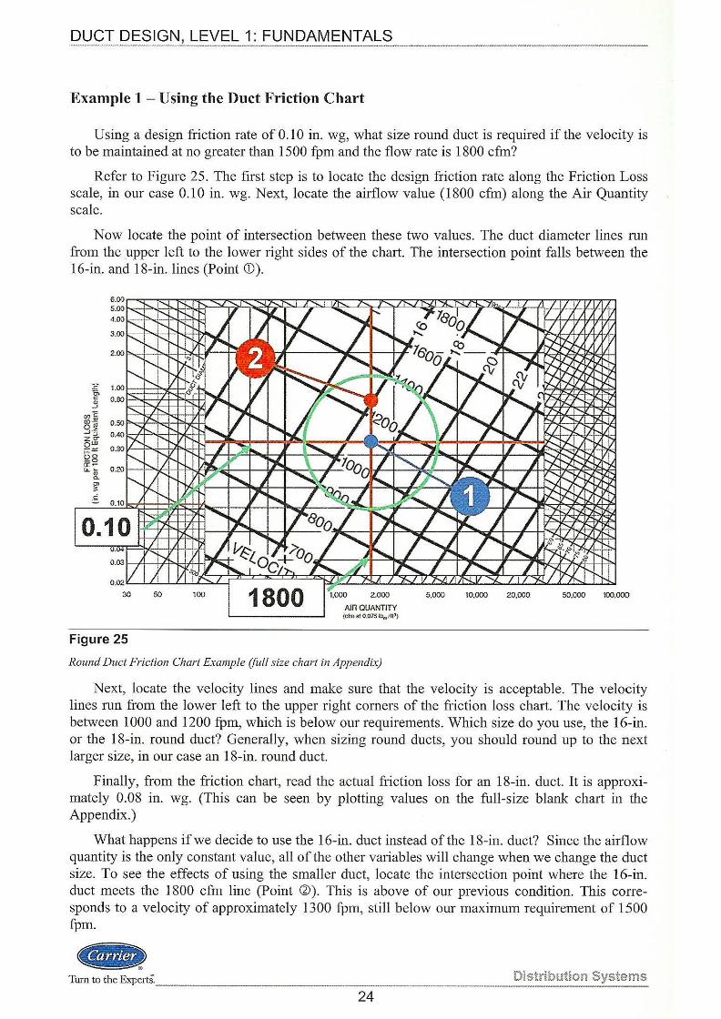
Using a design friction rate of 0.10 in. wg, what size round duct is required if the velocity is to be maintained at no greater than 1500 fpm and the flow rate is 1800 cfin?
Refer to Figure 25. The first step is to locate the design friction rate along the Friction Loss scale, in our case 0.10 in. wg. Next, locate the airflow value (1800 cfm) along the Air Quantity scale.
Now locate the point of intersection between these two values. The duct diameter lines run from the upper left to the lower right sides of the chart. The intersection point falls between the 16-in. and 18-in. lines (Point <D).
Figure 25
AlA QUANTITY {crm at o.0751br;~!ltl)
Round Duct Friction Chart Example (full size chart in Appendix}
Next, locate the velocity lines and make sure that the velocity is acceptable. The velocity lines run from the lower left to the upper right comers of the friction loss chart. The velocity is between 1000 and 1200 fpm, which is below our requirements. Which size do you use, the 16-in. or the 18-in. round duct? Generally, when sizing round ducts, you should round up to the next larger size, in our case an 18-in. round duct.
Finally, from the friction chart, read the actual friction loss for an 18-in. duct. It is approximately 0.08 in. wg. (This can be seen by plotting values on the full-size blank chart in the Appendix.)
What happens ifwe decide to use the 16-in. duct instead of the 18-in. duct? Since the airflow quantity is the only constant value, all of the other variables will change when we change the duct size. To see the effects of using the smaller duct, locate the intersection point where the 16-in. duct meets the 1800 cfm line (Point ~). This is above of our previous condition. This corresponds to a velocity of approximately 1300 fpm, still below our maximum requirement of 1500 fpm.
(«il\\D! Turn to the ExpertS.-- · Distribution Systems
24
DUCT DESIGN, LEVEL 1: FUNDAMENTALS
However, our friction rate has increased to 0.14 in. wg. As a designer you will have to decide if this higher friction rate is acceptable. For short duct lengths it is probably not a significant factor. When designing duct systems, however, it is best to stay as close as possible to the initial design friction rate, in our case 0.10 in. wg (Figure 11 recommendation).
Circular Equivalent Diameters of Rectangular Ducts
Duct sizing is generally done first as round ducts, then when required they are converted to rectangular sizes of equivalent friction rate. You cannot simply calculate the area of the circle (round duct), and then use a rectangular duct with the same cross-sectional area. Doing so would create a duct with a higher pressure drop than the round duct of the same area. This goes back to the ratio of perimeter to area shown in Figure 10. The velocity in a rectangular duct with equivalent friction rate will be less than the velocity in the round duct. This is necessary so that the pressure losses for the two ducts are equal.
To accomplish this conversion from round duct to an equivalent rectangular duct, refer to Table 1 in the Appendix.
Example 2 - Converting From Round to Equivalent Rectangular Ducts
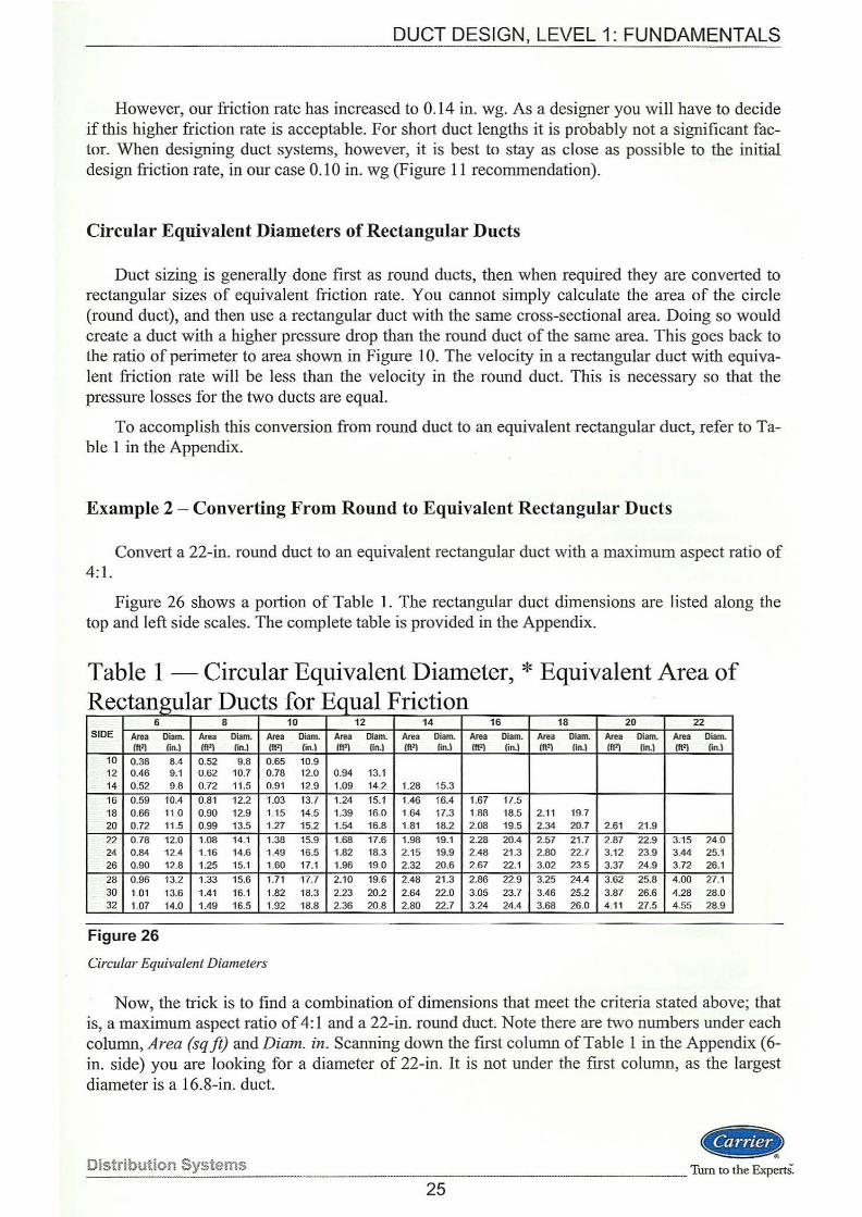
Convert a 22-in. round duct to an equivalent rectangular duct with a maximum aspect ratio of 4:1.
Figure 26 shows a portion of Table 1. The rectangular duct dimensions are listed along the top and left side scales. The complete table is provided in the Appendix.
Table 1-Circular Equivalent Diameter,* Equivalent Area of R t 1 D t £ E IF. f ec angu ar uc s or ~qua nc lOll
6 8 10 12 14 16 18 20 22 SIDE Area Diam. Area Diam. Area Diam. Area Diam. Area Diam. Area Diam. Area Diam. Area Diam. Area Diam.
(ft2) fin.) (f\2) lin.) (ft2l fin.) fft' l (in.) (ft2) fin.) fft2) fin.) (ft2) (in.l (ft2) lin. I (ft2l fin.) 10 0.38 8.4 0 .52 9.8 0.65 10.9 12 0.46 9.1 0.62 10.7 0.78 12.0 0.94 13.1 14 0.52 9.8 0.72 11.5 0.91 12.9 1.09 14.2 1.28 15.3
16 0.59 10.4 0.81 12.2 1.03 13.7 1.24 15.1 1.46 16.4 1.67 17.5 18 0.66 11.0 0.90 12.9 1.15 14.5 1.39 16.0 1.64 17.3 1.88 18.5 2 .11 19.7 20 0.72 11.5 0.99 13.5 1.27 15.2 1.54 16.8 1.81 18.2 2.08 19.5 2.34 20.7 2.61 21.9 22 0.78 12.0 1.08 14.1 1.38 15.9 1.68 17.6 1.98 19.1 2.28 20.4 2 .57 21.7 2 .87 22.9 3.15 24.0 24 0.84 12.4 1.16 14.6 1.49 16.5 1.82 18.3 2 .15 19.9 2.48 21.3 2.80 22.7 3.12 23.9 3.44 25.1 26 0.90 12.8 1.25 15.1 1.60 17.1 1.96 19.0 2.32 20.6 2.67 22.1 3.02 23.5 3.37 24.9 3.72 26.1
28 0.96 13.2 1.33 15.6 1.71 17.7 2.10 19.6 2.48 21 .3 2.86 22.9 3.25 24.4 3.62 25.8 4.00 27.1 30 1.01 13.6 1.41 16.1 1.82 18.3 2.23 20.2 2.64 22.0 3.05 23.7 3.46 25.2 3.87 26.6 4.28 28.0 32 1.07 14.0 1.49 16.5 1.92 18.8 2.36 20.8 2.80 22.7 3.24 24.4 3.68 26.0 4.11 27.5 4.55 28.9
Figure 26
Circular Equivalent Diameters
Now, the trick is to find a combination of dimensions that meet the criteria stated above; that is, a maximum aspect ratio of 4:1 and a 22-in. round duct. Note there are two numbers under each column, Area (sq ft) and Diam. in. Scanning down the first column of Table 1 in the Appendix (6-in. side) you are looking for a diameter of 22-in. It is not under the first column, as the largest diameter is a 16.8-in. duct.
Distribution Systems ________________________________ .._ ____ _ cCR> _ _____ Turn to the ExpertS:
25
DUCT DESIGN, LEVEL 1: FUNDAMENTALS
Now look under the 8-in. column. There is a 22-in. diameter duct listed for the 64-in. side duct. However, the 8: 1 aspect ratio (64 x 8) violates the 4:1 aspect ratio limit.
Continue over to the 10-in. column. Read down till you see the 21.9-in. diameter. This equates to a 46-in. duct, which makes our aspect ratio 4.6:1 , still too large.
Read over to the 12-in. column, then read down to the 21.9-in. diameter corresponding to a 36-in. duct. That works, as the aspect ratio is 3:1 (36 x 12).
There are other combinations of values that also work, such as: 30 x 14, 26 x 16, 24 x 18, and 20 x 20.
Designers generally attempt to use the larger dimension for the width and the smaller dimension for the height. This is due to the fact that available space to run duct above most ceilings is usually in short supply. Also, try to maintain one of the duct dimensions (either height or width) whenever possible when transitioning from one duct size to the next. This saves money during fabrication by simplifying the transition.
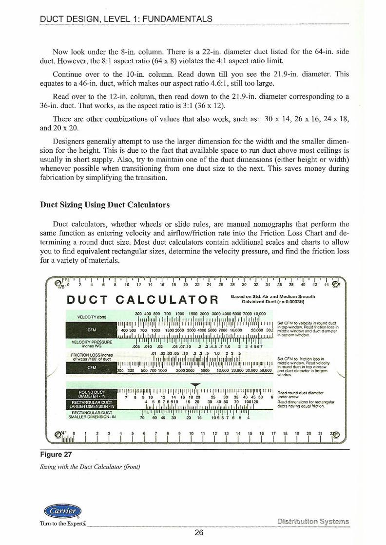
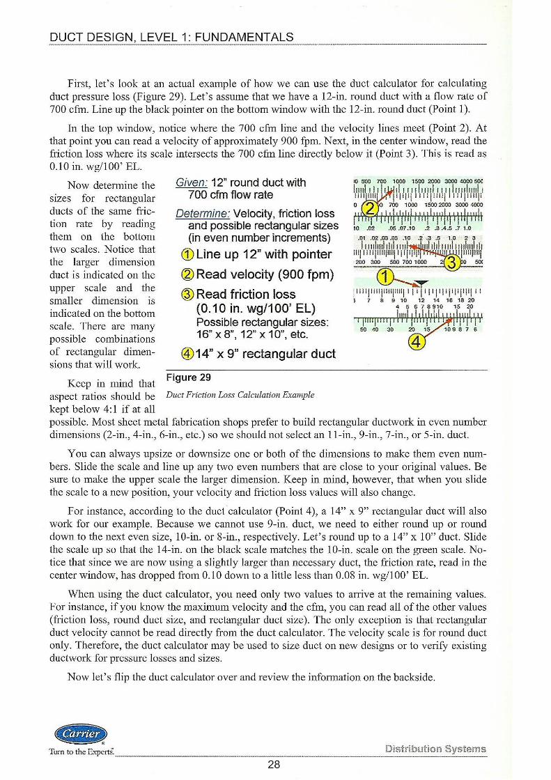
Duct Sizing Using Duct Calculators
Duct calculators, whether wheels or slide rules, are manual nomographs that perform the same function as entering velocity and airflow/friction rate into the Friction Loss Chart and determining a round duct size. Most duct calculators contain additional scales and charts to allow you to find equivalent rectangular sizes, detennine the velocity pressure, and find the friction loss for a variety of materials.
DUCT CALCULATOR e ... sed un Std. Air and M<XIium Smooth Galvlnlzcd Duct (.: = 0.000311)
VELOCITY (fpm)
CFM
VElOCITY PRESSU~E incr.es WG
FRIC'TlON LOSS inches of w:~tcr /1 oo· ol duct
ROU:IIOOUCT OIAME1'Efl • IN
RECTANGULAR DUCT LARGER OtMENSION ·IN
RECTA.'lGULAR OUCT SMALLER OtMENSION· IN
.005 .010 .02 .05 .07 .10 .2 .3 .4.5 .7 1.0 2 3 4 567
.01 .02 .03 .OS .10 .2 .3 .5 1.0 2 3 5
. . . ''"I'll I~ 111'' 111111111111'\ '1'' '"1'1"1'11111' Ill lllllllilllllij l!ljlllll I IIIII "I"' l il l jllll ll llllillj l llljll!ljlll:l' ll 300 500 700 1000 2000 3000 5000 10.000 20.000 :!0.000 50.000
T lllllll llllll ljlllll ll l l llll'!ll'l'l' lll lllllllll[llllll ll! jllllllllllilll !
7 6 9 10 12 14 IG 18 20 25 30 35 40 45 50 6
Ser CFM ~o tncl}C;~ 10'!,~ an mi<!<l!<.> w<>Cow. Rc~d 'ICioci:y in rot,;nd d~.o"C~ in top wlndcw ana duct d•ametor in 0o1:om \'.indow.
Read round duct di~rnc:cr uMer .o.uow.
4 5 6 7 8910 15 20 30 40 50 70 100120 Re;.~d domonsien.s I :it ru<:W>Gular
---'rltli"rl'rl+!'!Wf+'r'r.J.r'+-\-Wol'++r'+i-'ll-'r'r'!'ffi'ffl+'n'IWr.u--- ducts h 3't •ng ()Q·.I.ll !riction.
70 50 40 30 20 15 10 9 8 7 6 5 4
2 3 4 5 6 8 9 10 11 12 16 17 18 19 20 21
Figure 27
Sizing with the Duct Calculator (front)
.. ) Tum to the Expert:S: ______________________ ~-------~~!ributi~~ Systems
26
DUCT DESIGN, LEVEL 1: FUNDAMENTALS
Carrier offers the handy pocket-sized duct calculator (Figure 27), with Instructional Manual, that does all the tasks mentioned above. A short discussion on the use of the duct calculator follows. Once you have mastered the Duct Ftiction Chart, rework some of the earlier examples and Example 3 after the Summary to see how a duct calculator can be used for sizing.
The duct calculator allows you to quickly and easily determine duct sizes for round and rectangular duct systems. It works for a variety of duct construction materials and unique inside surface roughness factors (£). All of the information contained in the round duct friction chart, as well as the conversion chart for converting round to rectangular ducts, has been incorporated into this slide chart. Values indicated on the front are based on standard air (70° F, 29.92 in. Hg) and medium-smooth galvanized sheet metal duct with a specified roughness factor £ = 0.0003 ft.
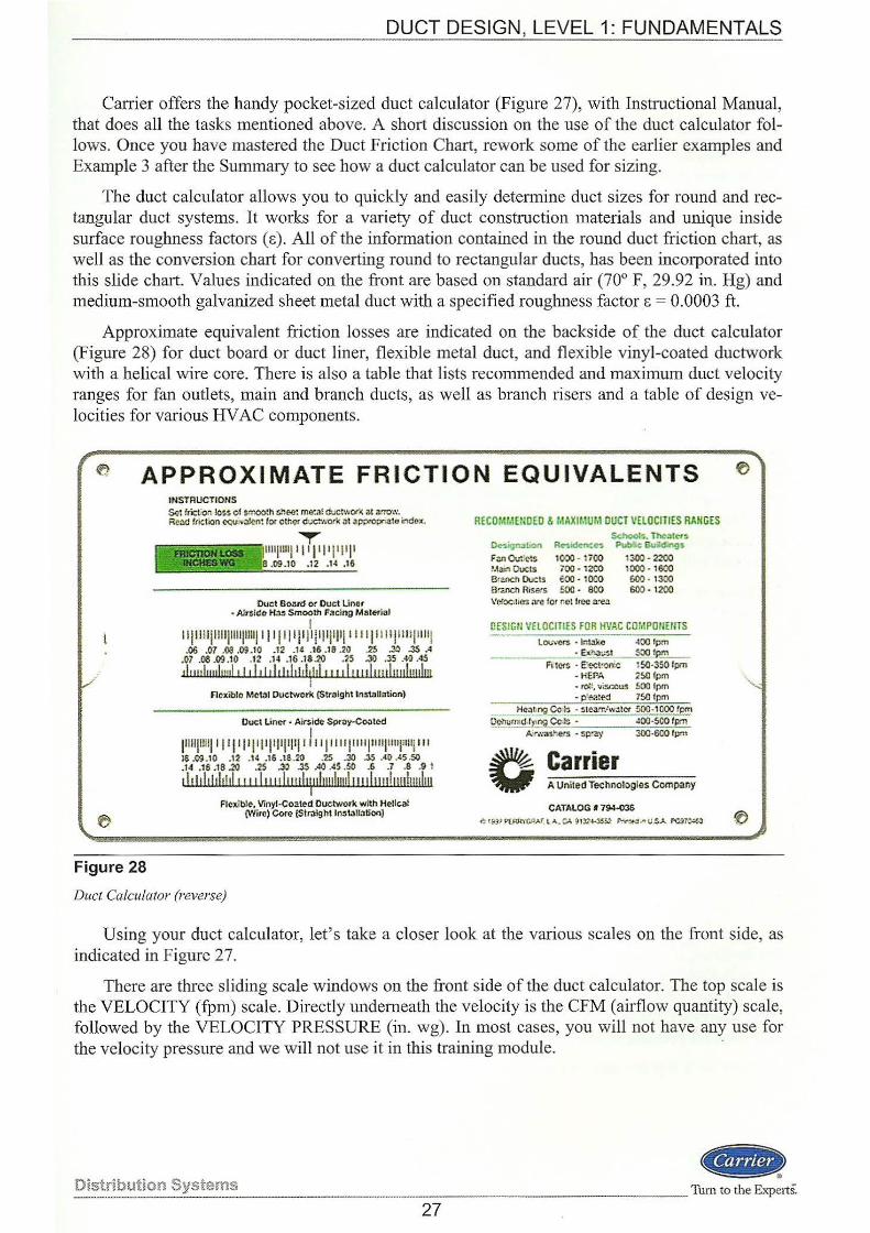
Approximate equivalent friction losses are indicated on the backside of. the duct calculator (Figure 28) for duct board or duct liner, flexible metal duct, and flexible vinyl-coated ductwork with a helical wire core. There is also a table that lists recommended and maximum duct velocity ranges for fan outlets, main and branch ducts, as well as branch risers and a table of design velocities for various HV AC components.
~ APPROXIMATE FRICTION EQUIVALENTS
Figure 28
INSTRUCTIONS Set ftictio.~ less of $rt".OOlh shee: me:..,l ductw()(~ at arrcm. Re:W ftiction c<;uN:llen! for other duaworlc Jl ap;J<Opr>ato i.1d~x.
lllljllllji7Tj': Ii i' jl I' 8 .09 .10 .12 .1( .16
'Duel Board or Ouet Linor • Alrtlde> li;lll Smooth Facing Maletial
I 1 ljiiii!IIIIJ1111p111jll l p II jl ]I Pl'i'l'l''ll II lll jl!lljllll! .06 .07 ,OS .09.10 .12 .14 .Hi .18 .70 .25 .30 .35 .4
.07 .08 .09.10 .12 .14 .16 .18.20 .25 .30 .35 .40 .45
th mlrwht•'l ' ltltltl r ltlt!ti ,J,!,,,,It rl 1 luulunl11ulm i
Flexible MciJI Duetwork (Straight lnstaUation}
Ouct Liner • Airl>id~ SP<liY·~ted
I l'llljlllljllljl III'PI'III'I'I''' IIIIIIjlllljlllljUittillljlll 1$.09.10 .1Z .14 .16.18.20 .~ .:!0 .l5 .40.45.50 .14 .16 .18 .20 .2s .30 .3S AO .45 .so .6 .7 .a .9 1
d tit ltl!ltttlt 11tl11 p l11 Hltluluuluuh 11 tluuluuluuhu Flexible. VInyl-coated Ouctwork,with Helical
(Wiro) Coro {Sir.llght ln~l.tlllatfOn}
Duel Calculator (reverse)
RECOM!.!HIOED & MAXIMUM DUCT VELOCITIES RAiiG£S ~.TIIe:ltt-r~
~i<Jn.lt.on R~ock.-.c~ P\ob!ic Builditlgs
Filll Ov::ets 1000 • 17()Q 1300 • 2200 Mll>'l Oucts 700 • 12CO 1000- 1600 Branch DuelS 600 • 1000 600 • 1300 BrEIICh Risers 500 • 800 600 • 1200 \'er.:tc1Hes are for net tree a:ea
OfSIGU VHOCITIES FOR HVAC CO!•IPOPIEtiTS Loo.Ne<s - lrrtal<e -100 lpm
• ~:Gt _5001~ F• te<~ • E'ectrornc 150-350 fpm
- HEPA 2!10 fpm • tol!. ~isc<:~ SOO fpm - p:t>3itd 750 tpm
··- ~· Heal•"'d ~~::; - ste;l!r/w~l« 500-1000 tpm !_)cnumtd,ty.ng Cc~ - 400·500 fpm
k•,,;as'tets - sp.•ay 300-600 lprn
c ~u~.~~!!~.,_~ComOO'Y CATALOG • 79-!~30
¢tit~'~GJlAI't"'.C).~J~I-~SJ- ~to...,U.SA rG)~
Using your duct calculator, let's take a closer look at the various scales on the front side, as indicated in Figure 27.
There are three sliding scale windows on the front side of the duct calculator. The top scale is the VELOCITY (fpm) scale. Directly underneath the velocity is the CFM (airflow quantity) scale, followed by the VELOCITY PRESSURE (in. wg). In most cases, you will not have any use for the velocity pressure and we will not use it in this training module. ·
Distribution Systems ~
·-------------·----·Turn to the Experts.
27
DUCT DESIGN, LEVEL 1: FUNDAMENT~_!::S -------------·--··-·-------------------
First, let's look at an actual example of how we can use the duct calculator for calculating duct pressure loss (Figure 29). Let's assume that we have a 12-in. round duct with a flow rate of 700 cfm. Line up the black pointer on the bottom window with the 12-in. round duct (Point 1).
In the top window, notice where the 700 cfm line and the velocity lines meet (Point 2). At that point you can read a velocity of approximately 900 fpm. Next, in the center window, read the friction loss where its scale intersects the 700 cfm line directly below it (Point 3). This is read as 0.10 in. wg/100' EL.
Now determine the sizes for rectangular ducts of the same friction rate by reading them on the bottom two scales. Notice that the larger dimension duct is indicated on the upper scale and the smaller dimension is indicated on the bottom scale. There are many possible combinations of rectangular dimensions that will work.
Keep in mind that
Given: 12" round duct with 700 cfm flow rate
Determine: Velocity, friction loss and possible rectangular sizes (in even number increments)
CD Line up 12" with pointer
~Read velocity (900 fpm)
®Read friction loss (0.10 in. wg/100' EL) Possible rectangular sizes: 16" x 8", 12" x 10", etc.
@14" x 9" rectangular duct
Figure 29
aspect ratios should be Duct Friction Loss Calculation Example
kept below 4:1 if at all
10 .02 .05 .07 .10 .2 .3 .4.5 .7 1.0
possible. Most sheet metal fabrication shops prefer to build rectangular ductwork in even number dimensions (2-in., 4-in., 6-in., etc.) so we should not select an 11-in., 9-in., 7-in., or 5-in. duct.
You can always upsize or downsize one or both of the dimensions to make them even numbers. Slide the scale and line up any two even numbers that are close to your original values. Be sure to make the upper scale the larger dimension. Keep in mind, however, that when you slide the scale to a new position, your velocity and friction loss values will also change.
For instance, according to the duct calculator (Point 4), a 14" x 9" rectangular duct v;rill also work for our example. Because we cannot use 9-in. duct, we need to either round up or round down to the next even size, 10-in. or 8-in., respectively. Let's round up to a 14" x 10" duct. Slide the scale up so that the 14-in. on the black scale matches the 10-in. scale on the green scale. Notice that since we are now using a slightly larger than necessary duct, the friction rate, read in the center window, has dropped from 0.10 down to a little less than 0.08 in. vvg/100' EL.
When using the duct calculator, you need only two values to arrive at the remaining values. For instance, if you know the maximum velocity and the cfm, you can read all of the other values (friction loss, round duct size, and rectangular duct size). The only exception is that rectangular duct velocity carmot be read directly from the duct calculator. The velocity scale is for round duct only. Therefore, the duct calculator may be used to size duct on new designs or to verify existing ductwork for pressure losses and sizes.
Now let's flip the duct calculator over and review the information on the backside.
81!> Turn to the Expe1tS: .. Distribution Systems
28
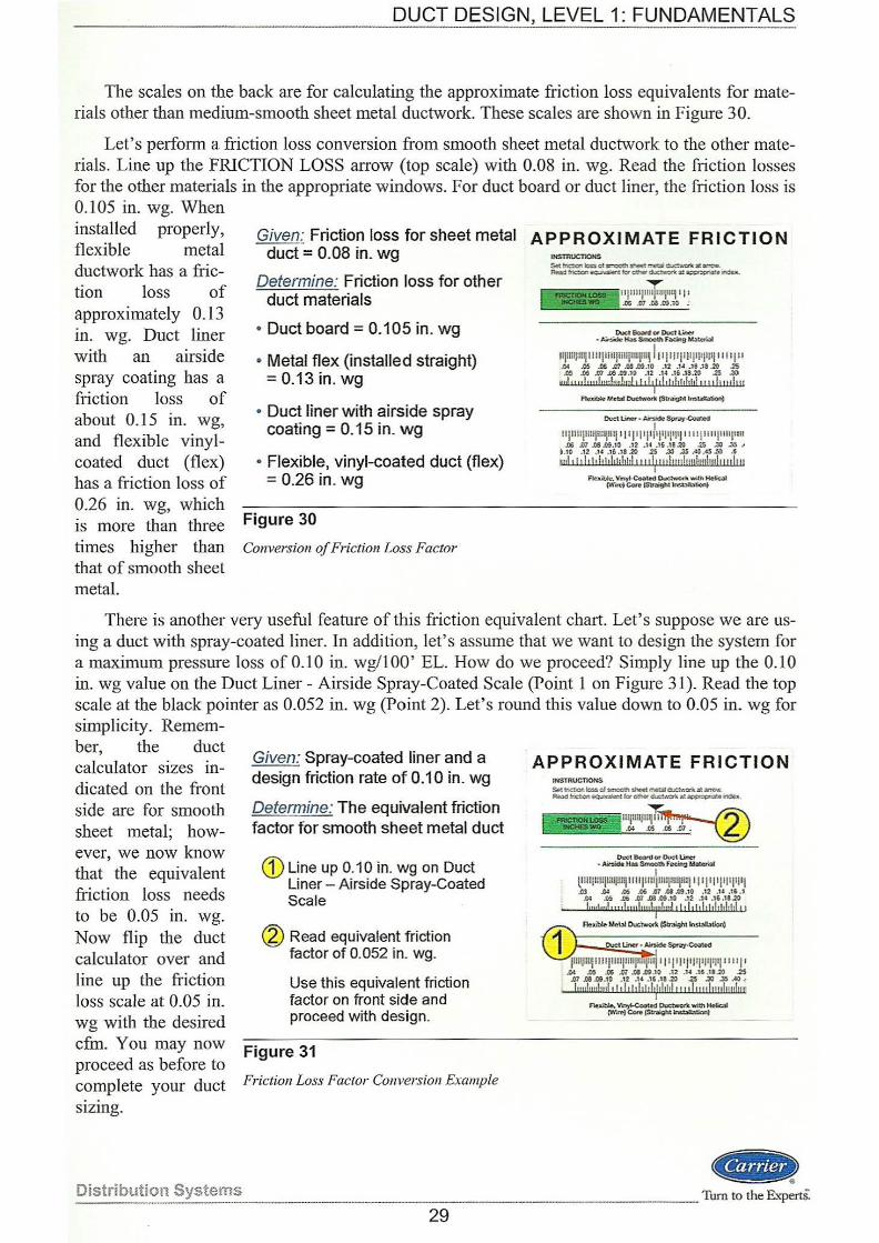
DUCT DESIGN, LEVEL 1: FUNDAMENTALS ·----·
The scales on the back are for calculating the approximate friction loss equivalents for materials other than medium-smooth sheet metal ductwork. These scales are shown in Figure 30.
Let's perform a friction loss conversion from smooth sheet metal ductwork to the other materials. Line up the FRICTION LOSS arrow (top scale) with 0.08 in. wg. Read the friction losses for the other materials in the appropriate windows. For duct board or duct liner, the friction loss is 0.105 in. wg. When installed properly, flexible metal ductwork has a friction loss of approximately 0.13 in. wg. Duct liner with an airside spray coating has a friction loss of about 0.15 in. wg, and flexible vinylcoated duct (flex) has a friction loss of 0.26 in. wg, which is more than three
Given: Friction loss for sheet metal APPROXIMATE FRICTION duct= 0.08 in. wg INSTRUC'IlOHS
Determine: Friction loss for other duct materials
• Duct board= 0.105 in. wg
• Metal flex (installed straight) = 0.13 in. wg
• Duct liner with airside spray coating= 0.15 in. wg
• Flexible, vinyl-coated duct (flex) = 0.26 in. wg
Figure 30
times higher than Conversion of Friction Loss Factor
that of smooth sheet metal.
Dul;t 6oant 01 Duc1l.ine-r - Air$idlr: Ha$ Strooth Facing llota:.trial
IIIIIIIJtllll lllljlliljillljlllljiU· ' fl jllljlllllllJIJij i i i iJ II .o; .os .M .Jf1 .oa .cs.1o .12 .1.t .1s .1a .20 .2S .OS .00 lP .00 .o9 .10 .12 .14 .16 .18-20 .2S ..30
twl tt,!l!,fuuf,w!rmlt! tfthl tl!ltltf!ltl r! t ! hudeu I
f1uibk!. J'J~tal Ductwork (Str.Jight tnstaR;ation)
~ Vanyt..Coateod CJruc;twont w;lh H8<:.1l
(W" .. )ecn.- ·--
There is another very useful feature of this friction equivalent chart. Let's suppose we are using a duct with spray-coated liner. In addition, let's assume that we want to design the system for a maximum pressure loss of 0.10 in. wg/100' EL. How do we proceed? Simply line up the 0.10 in. wg value on the Duct Liner - Airside Spray-Coated Scale (Point 1 on Figure 31 ). Read the top scale at the black pointer as 0.052 in. wg (Point 2). Let's round this value down to 0.05 in. wg for simplicity. Remem-
Given: Spray-coated liner and a design friction rate of 0.10 in. wg
Determine: The equivalent friction factor for smooth sheet metal duct
G) Line up 0.1 0 in. wg on Duct Liner- Airside Spray-Coated Scale
~ Read equivalent friction factor of 0.052 in. wg.
Use this equivalent friction factor on front side and proceed with design.
Figure 31
ber, the duct calculator sizes indicated on the front side are for smooth sheet metal; however, we now know that the equivalent friction loss needs to be 0.05 in. wg. Now flip the duct calculator over and line up the friction loss scale at 0.05 in. wg with the desired cfrn. You may now proceed as before to complete your duct Friction Loss Factor Conversion Example
sizing.
Distribution Systems ·--------- --
29
APPROXIMATE FRICTION INSTRUCTIONS s.~ tnC'..ottk:r!.s cl ~!h sheet mt::al c-.:ct.-.7k ~~ F.t.l.d tnalon~!:C,o:htt<JUC!\~ a:~e~
Duct Bo:ltd or Duct Linef - Ar...ide Has Smooth f~ M:d~
I llllllllli!IHIJlll!jllll jllllllllljtul]llli! ' I ' I'I'JII'I'I'I .Cl ..04 .OS .o6 61 .GS.O':UO .12 .U .15 . 1
.0.: .05 .t<Ei .07 .()3.(!9.10 .12 .14 .16.18.20 luul,m!., ,,!,u,f,ml'j',f,ml t lt lt l!lt!Jithltl!l r t
FJ.>ible Metal Due~ (Sirnight lns!Ob"""l
jiiiiJlUijlllllllllllllljllljll IJI fl Jljll'l'l'l'l'l lll I I ' ..o.t .os ..o6 .m ..ce. m .10 .12 .n .16 .11 .20 .25
.01 .oa .auo .12 .1• .16 .1! .20 .25 .3l .35 ~ ~
lunluulnnl tltithhit l•hlthl tt• tluu!uuhmlnn I
.-...-.~~ ..... -CWft! Ca<e (Stoaght......,tionl
... Tum to the Experts.
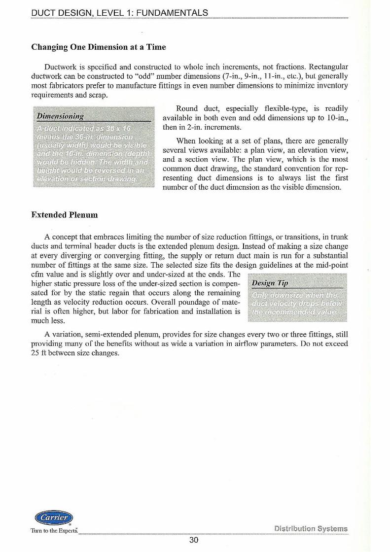
DUCT DESIGN, LEVEL 1: FUNDAMENTALS
Changing One Dimension at a Time
Ductwork is specified and constructed to whole inch increments, not fractions. Rectangular ductwork can be constructed to "odd" number dimensions (7-in., 9-in., 11-in., etc.), but generally most fabricators prefer to manufacture fittings in even number dimensions to minimize inventory requirements and scrap.
Extended Plenum
Round duct, especially flexible-type, is readily available in both even and odd dimensions up to 1 0-in., then in 2-in. increments.
When looking at a set of plans, there are generally several views available: a plan view, an elevation view, and a section view. The plan view, which is the most common duct drawing, the standard convention for representing duct dimensions is to always list the first number of the duct dimension as the visible dimension.
A concept that embraces limiting the number of size reduction fittings, or transitions, in trunk ducts and terminal header ducts is the extended plenum design. Instead of making a size change at every diverging or converging fitting, the supply or return duct main is run for a substantial number of fittings at the same size. The selected size fits the design guidelines at the mid-point cfm value and is slightly over and under-sized at the ends. The higher static pressure loss of the under-sized section is compensated for by the static regain that occurs along the remaining length as velocity reduction occurs. Overall poundage of material is often higher, but labor for fabrication and installation is much less.
A variation, semi-extended plenum, provides for size changes every two or three fittings, still providing many of the benefits without as wide a variation in airflow parameters. Do not exceed 25 ft between size changes .
.. Turn to the ExpertS. Distribution Systems
30
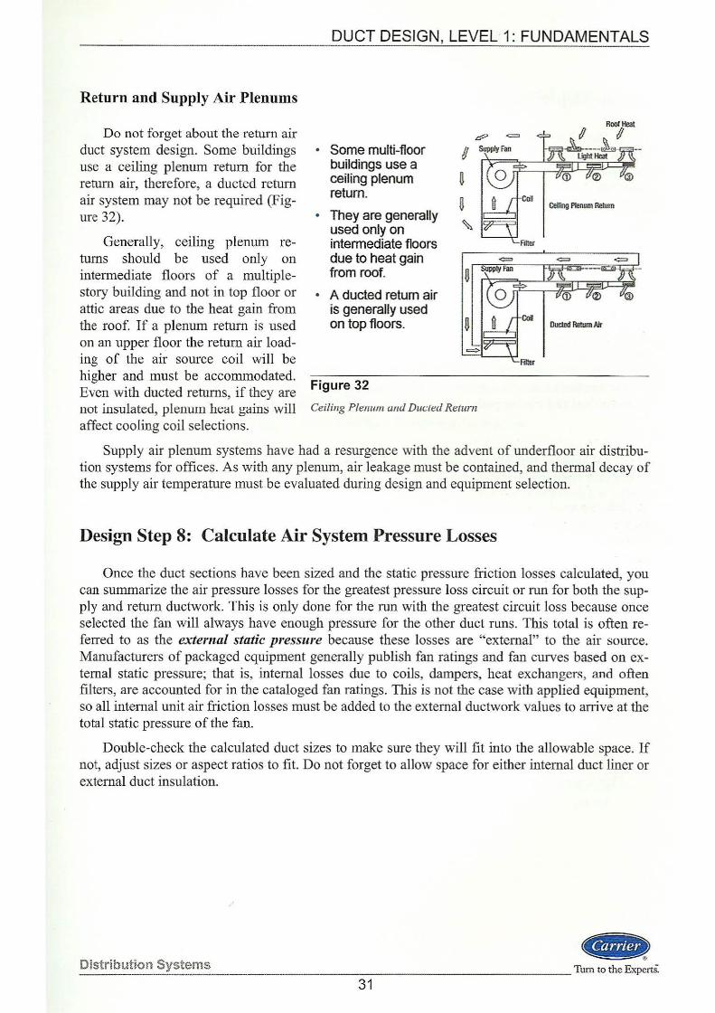
Return and Supply Air Plenums
Do not forget about the return air duct system design. Some buildings use a ceiling plenum return for the return air, therefore, a ducted return air system may not be required (Figure 32).
Generally, ceiling plenum returns should be used only on intermediate floors of a multiplestory building and not in top floor or attic areas due to the heat gain from the roof. If a plenum return is used on an upper floor the return air loading of the air source coil will be higher and must be accommodated. Even with ducted returns, if they are not insulated, plenum heat gains will affect cooling coil selections.
DUCT DESIGN, LEVEL 1: FUNDAMENTALS
• Some multi-floor buildings use a ceiling plenum return.
• They are generally used only on intermediate floors due to heat gain from roof.
• A ducted return air is generally used on top floors.
Figure 32
Ceiling P lenum ami Due.: ted Return
Ceiling Plenum Return
Supply air plenum systems have had a resurgence with the advent of underfloor air distribution systems for offices. As with any plenum, air leakage must be contained, and thermal decay of the supply air temperature must be evaluated during design and equipment selection.
Design Step 8: Calculate Air System Pressure Losses
Once the duct sections have been sized and the static pressure friction losses calculated, you can summarize the air pressure losses for the greatest pressure loss circuit or run for both the supply and return ductwork. This is only done for the run with the greatest circuit loss because once selected the fan will always have enough pressure for the other duct runs. This total is often referred to as the external static pressure because these losses are "external" to the air source. Manufacturers of packaged equipment generally publish fan ratings and fan curves based on external static pressure; that is, internal losses due to coils, dampers, heat exchangers, and often filters, are accounted for in the cataloged fan ratings. This is not the case with applied equipment, so all internal unit air friction losses must be added to the external ductwork values to arrive at the total static pressure of the fan.
Double-check the calculated duct sizes to make sure they will fit into the allowable space. If not, adjust sizes or aspect ratios to fit. Do not forget to a11ow space for either internal duct liner or external duct insulation.
Distribution Systems ~)
-----------------Tum to the ExpertS. 31
DUCT DESIGN, LEVEL 1: FUNDAMENTALS
Design Step 9: Select Fan and Adjust System Airflows
In Step 8 we summarized the static pressure losses for the duct system. To this amount we add any unaccounted pressure losses due to filters, dampers and any other components in the duct system and equipment to arrive at a value referred to as the total static pressure. This total amount is the static pressure that the fan must overcome to deliver the required amount of air. This total amount is also used to select the required fan motor size.
While it is more correct to select the fan using the total pressure difference between the inlet of the fan and the outlet (referred to as the fan total pressure), in HV AC systems, fans are commonly selected by using the difference between the fan inlet and fan outlet static pressures, not subtracting the velocity pressure of the inlet (often too small to matter).
Once the fan is selected and installed, an air balance usually done by the testing and balancing contractor as part of commissioning the system. This involves measuring the fan speed (rpm) and total static pressure drop across the fan, as well as measuring and summarizing the airflows at all of the diffusers. These measured values are then compared against the required values from the cooling and heating load estimate. Balancing dampers are adjusted to attempt to deliver the correct amount of air to each zone. Often the actual airflow being delivered is less than or greater than required and the fan pulley (sheave) may require adjustment or resizing.
Summary
Like so much of HV AC system design, creating cost effective duct designs is as much an art as it is a science. Bemoulli's Law explains the relationship between velocity and static pressures, a very important concept to understand when sizing ducts, especially when static regain is desired.
Selecting fittings and thinking about the effects of turbulence in the ducts is critical to keep the fmal designs quiet, self-balanced and at a low system static pressure loss.
Manual duct sizing and selection of fittings using charts and tables present the designer with the optimum situation for reinforcing duct design principals and gaining experience in balancing the many design criteria that often create conflicting requirements. Once learned through this manual chart method, use of a duct calculator or design software can be properly applied to speed up the process and facilitate using the static regain effect to improve system performance.
Work Session 2 - Duct Sizing
This is a good time to complete Work Session 2 and test your knowledge on duct sizing.
--Turn to the Experts. -------------------Distribution Systems
-------32
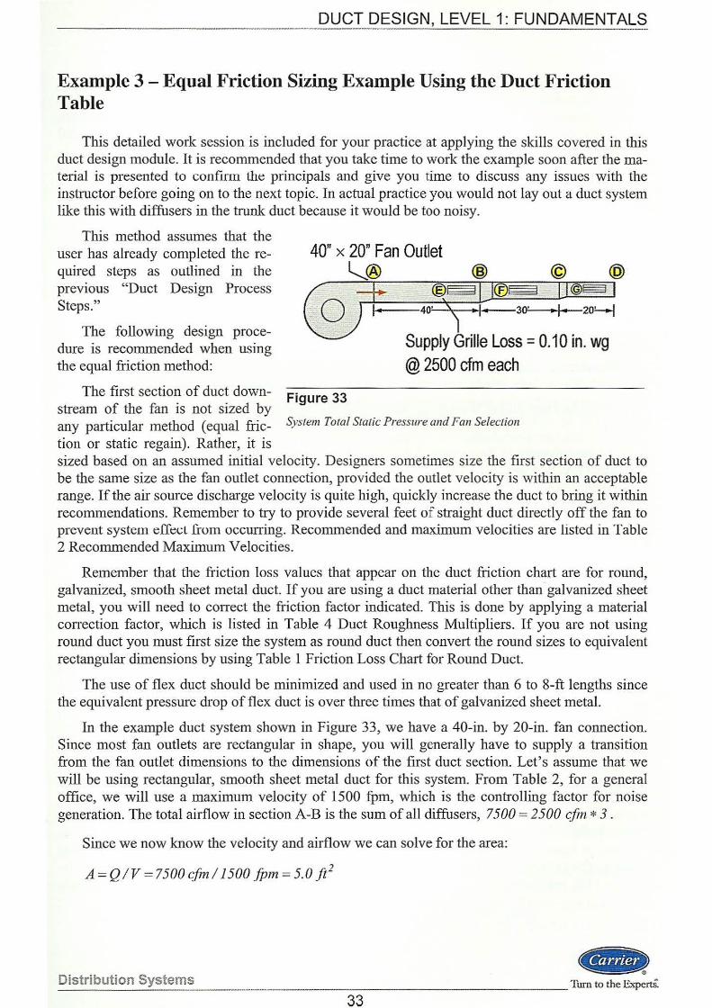
DUCT DESIGN, LEVEL 1: FUNDAMENTALS - -·- -- ----·---
Example 3 - Equal Friction Sizing Example Using the Duct Friction Table
This detailed work session is included for your practice at applying the skills covered in this duct design module. It is recommended that you take time to work the example soon after the material is presented to confirm lh~ principals and give you time to discuss any issues with the instructor before going on to the next topic. In actual practice you would not lay out a duct system like this with diffusers in the trunk duct because it would be too noisy.
This method assumes that the user has already completed the required steps as outlined in the previous "Duct Design Process Steps."
The following design procedure is recommended when using the equal friction method:
The first section of duct down- Figure 33
Supply Grille Loss= 0.10 in. wg @ 2500 cfm each
stream of the fan is not sized by any particular method (equal fric- System Total Static Pressure and Fan Selection
tion or static regain). Rather, it is sized based on an assumed initial velocity. Designers sometimes size the first section of duct to be the same size as the fan outlet connection, provided the outlet velocity is within an acceptable range. If the air source discharge velocity is quite high, quickly increase the duct to bring it within recommendations. Remember to try to provide several feet of straight duct directly off the fan to prevent system eff~<.:L from occuning. Recommended and maximum velocities are listed in Table 2 Recommended Maximum Velocities.
Remember that the fi"iction loss values that appear on the duct friction chart are for round, galvanized, smooth sheet metal duct. If you are using a duct material other than galvanized sheet metal, you will need to correct the friction factor indicated. This is done by applying a material conection factor, which is listed in Table 4 Duct Roughness Multipliers. If you are not using round duct you must first size the system as round duct then convert the round sizes to equivalent rectangular dimensions by using Table 1 Friction Loss Chart for Round Duct.
The use of flex duct should be minimized and used in no greater than 6 to 8-ft lengths since the equivalent pressure drop of flex duct is over three times that of galvanized sheet metal.
In the example duct system shown in Figure 33, we have a 40-in. by 20-in. fan connection. Since most fan outlets are rectangular in shape, you will generally have to supply a transition from the fan outlet dimensions to the dimensions of the first duct section. Let's assume that we will be using rectangular, smooth sheet metal duct for this system. From Table 2, for a general office, we will use a maximum velocity of 1500 fpm, which is the controlling factor for noise generation. The total airflow in section A-B is the sum of all diffusers, 7500 = 2500 cfin * 3.
Since we now know the velocity and airflow we can solve for the area:
A= Q IV = 7500 cfm/1500 fPm = 5.0 ji2
... _D_is_t_ri_b_u_ti_o_n_S....:y:...s_t_e_m_s _ _ ____ _ _ _ _ __________ ___ Tum to the Experti
33
DUCT DESIGN, LEVEL 1: FUNDAMENTALS -------------~------------------
Now enter Table 1 (Circular Equivalent Diameter) and locate a combination of duct dimensions with an area equal to or greater than 5.0 sq ft. From Table 1 we find that there are many possible combinations of duct dimensions with an area of 5.0 sq ft. Since the fan outlet is 40 x 20, let's check the velocity using the same size duct as the fan outlet. From Table 1 for a 40 x 20 duct, the equivalent area is 5.07 sq ft, which is adequate. Therefore, a transition from the fan to duct section is not required and there is no fan outlet gain or loss to consider. In Table 1, under each column of duct dimensions, there is a value labeled "Diam, in." This is the diameter for a round duct with an equivalent friction loss. For a 40" x 20" rectangular duct, the round equivalent is 30.5 in.
Next, on the Duct Friction Chart, locate the 7500 cfm line on the vertical axis. Follow this line to the right until it intersects with the 30.5 in. round duct line. Now read vertically to determine the friction loss value, in our case 0.085 in. wg/1 00 ft EL. This means that for a flow rate of 7500 cfm, for a 30.5 in. round duct, the friction loss for a 100 ft length section will be 0.085 in. wg. But section A-B is only 40ft long, the cmTesponding friction loss will therefore be:
L1P8 = 0.085 * (40/100) = 0.034 in. wg
This corresponds to a velocity of approximately 1500 fpm, which may be read from the friction chart. We will use this friction rate (f= 0.085 in. wg) to size the remaining duct sections.
Using the Duct Sizing Worksheet included in the Appendix, enter the information we lmow thus far.
The next element in the system is outlet E in section A-B with an airflow rate of 2500 cfm. The outlet loss is given as 0.10 in. wg. You should consult actual diffuser, grille and register catalogs when designing duct systems to determine the appropriate friction losses. Add this !mown loss value to the worksheet. Consider the duct length from the fan to outlet E, section A-E, to be the same 40ft we just used for section A-B.
Next we come to duct run B-:C. Since the airflow quantity is reduced significantly (7500- 2500 = 5000 cfm) we need to transition to a smaller duct. To determine the required rectangular dimensions of section B-C we must first find the required round size then convert it to a rectangular equivalent. Refer to the Friction Loss Chart and use an equal friction rate of 0.085 in. wg. Determine the intersection of the airflow quantity (5000 cfm) with the friction rate. The intersection point falls very close to the 26 in. diameter line. Now refer to Table 1 and locate a combination of rectangular dimensions that are close to a 26 in. diameter. There are several possibilities. As mentioned previously, it is generally a good idea to try to maintain at least one of the dimensions when transitioning duct sizes. This makes the fitting less difficult to fabricate and saves money too. Let's maintain a constant duct height of 20 in. and vary the duct width. From Table 1 we will select a 28" x 20" size for section B-C. This size is equivalent to a 25.7 in. round duct with a velocity of approximately 1400 fpm and a friction rate of 0.095 in. wg. Here the duct section is only 30 ft long, so the static pressure loss will be less. Compute the value and enter it into the Worksheet.
Continuing, we can now calculate the friction loss due to the transition that starts section B-C. Refer to Table 5 (Friction of Rectangular Duct System Elements), specifically the contraction fitting, using a 30° angle for least amount of static pressure loss. According to the table notes, the Ps loss is equal to the change in velocity pressure (downstream- upstream) times the fitting value n. The velocity pressures can be looked up on the Friction Loss Chart or from Table 3. Using n = 1.02, and finding Pv1 = 0.062 (remember, the upstream 30.5-in. duct only has 5000 cfm in it too) and Pv2 = 0.122, the Table 5 formula would give a fitting loss of:
M s = 1.02*(0.122-0.062)=0.061 in.wg
--Turn to the Experts. ----------···---------~----------------------------~.!._~tr!~~tio~~_Ystems 34
DUCT DESIGN, LEVEL 1: FUNDAMENTALS ------
Since there is static regain from the decrease in velocity due to the outlet, use a value less than calculated, say 50 percent in this case (loss becomes 0.031). In the Duct Design, Level 2 TDP you will see that empirically derived fitting loss coefficients will give more reliable data in many cases.
For all practical purposes, this is an insignificant amount. You should note that the total pressure loss due to a fitting is highly influenced by the velocity. Had the velocity in the previous example been say twice as high, the pressure loss would have increased by a factor of four times due to the "squared" relationship between pressure and velocity. Add these values to the worksheet.
The last element in duct run B-C is outlet F, with a flow rate of 2500 cfm. Again, this loss is given as 0.10 in. wg. Add this value into the Worksheet.
The final duct run is C-D. Similar to the previous section, we have another transition since the airflow is reduced to 2500 cfm. We will maintain our previous duct height of 2011 and locate the width required. As before, we must determine the required round duct size and then convert it to an equivalent rectangular size. From the Friction Loss Chart find the round duct size corresponding to the friction rate of 0.09 in. wg. A 20-in. round duct meets our requirements for section C-D. Next, in Table 1 locate a round duct with a 20-in. diameter that corresponds to a duct height of 20 in. A 20 in. by 16 in. duct has an equivalent diameter of 19.5-in., a round duct velocity of 1200 :fj:>m, and a corresponding friction rate of 0.10 in. wg. Here too the duct length has shortened to 20 ft, so losses will reduce as well. Complete the calculations and add these values to the worksheet, remembering that again we have an outlet G.
Now we need to calculate the loss due to the transition at the start of section C-D. This transition is the same type as the one before. Since we now know the sizes of both sections, we can once again determine the velocity pressures and plug them into the table formula, again using the loss reduction adjustment of 50 percent to account for static regain.
iJP8 =1.02*(0.096 - 0.032)*50%= 0.033 in.wg
We are now ready to calculate the static pressure friction loss of each duct run. From the Duct Sizing Worksheet (Figure 34) we see that the cumulative static pressure loss for duct run A-E is 0.134 in. wg, for duct run A-Fit is 0. 194 in. wg, and the longest duct run A-G it has increased to 0.247 in. wg. Since our system was simple, the Worksheet was tabulated fully for each of the three duct runs. Alternatively, only the individual duct sections and outlets could have been entered. Then, the potential highest pressure loss runs would need to be checked, which in our case was easily the longest run. On large systems this is somewhat of a tedious task, making experience a good teacher for searching out and checking only those runs that exhibit the potential for large pressure drop. If you choose to use a duct design software program to size the ductwork, the highest pressure drop run will be a program output after the sizing is done.
Comparing the friction losses of the three runs, or circuits, they are within 0.12 in. wg of each other. Therefore, air balancing will be easy to accomplish by the use of diffuser opposed blade control dampers.
In this example there is no return ductwork, so the fan can be selected at 0.25 in. wg total static pressure, verifying that the fan was rated with no inlet ductwork.
Remember to allow room for either internal duct lining or external duct wrap (insulation) when designing duct systems.
This completes our calculations for the equal friction method sizing example.
--Distribu!~n ~~:~~-TI_s ______________________________ ~----------------Tum to the ExpertS.
35
!I ~ 6 !'It
w 0)1
0 u;· .....
lg .. t--
10. t;::, loo '< Cll ..,,. Ct)
3 t/)
0 , ;:: 10' () .... c ~ ""' t--t' (1) ::::· Oq w
~
~
* <-l ;::-~ ~ ... ~ >:l .g ~ ~
PROJ!:CT NAME: EQUAL FRICTION EXAMPLE
SYSTEM: SUPPLY
Due: I Due: I llnlno tnsul. OII>Ot VolociiY In Run S<l<:tlon Round ~uet
From,To (oionllnl) (ln.) {ln.) It om 1\Jillow (l~n~
A-E A-B - I - 7500 1500
E - - OUTLET 2500 -
A-F A·B - I - 7500 1500
B-C - I - 5000 1400 ------1--
~ ~ B - 1 TRANS 5000 00
F - - OUTLET 2500 -
A-G A-B - 1 . 7500 1500
B-C - I - 5000 1400
B - l TRANS ~~ 0 ~(" 1400
C-D - .I - 2500 1200
c - 1 TRANS ~ 00 ~ 00
G - - OUTLET 2500 -
--~-· - '
NOTES: All dltct sizes lndiC~hld MO Inside clear dlmonstons •
Velocity Proasuro
Pv
0.140
-
0.014
0.122
~ 0.12?.
-
0.140
0.122
~~ .122
0.096
~ 0.096
-
DUCT SIZING WORKSHEET
Fitting Lonoth(ftl EquiV, ~\ltorlol
Vatuo Lonoth(fll Corroctlon n l El FUchn
- 40 - .
- - - .
- 40 - . . 30 - -
1.02 - - -- - - -
- 40 - -- 30 - -
1.02 .. - -- 20 - -
1.02 - - -- - - -
DATE: 10/1/04
PAGE: OF
Frlc:llon Frlc:tlon Known Round Equlv•lont Tot.> I cu,..l<ltlvO LOIIII IP<lf Loa~> lOlSS 0\lr:t Roet.>noutor ttotn lo$ll lOlSS IOQ'dU<:I (111, WII) (ln.wg) SllO(IU.) Stlo(WxH} (ln.wu) (iii.WQ)
0.085 0.034 - 30.5 40 X 20 0.034 0.034
- . 0.10 - . 0.10 0.134
0.085 0.034 - 30.5 40 X 20 0.034 0.034
0.095 0.029 25.7 28 X 20 0.029 0.063
- 0.061 -50% - ~~ 28 X 2( 0.031 0.094
- - 0.10 - - 0.10 0.194 --
0.085 0.034 - 30.5 40 X 20 0.034 0.034
0.095 0.029 25.7 28 X 20 0.029 0.063
- 0.061 -50'/~ - 4::.~ 28 x ?.C 0.031 0.094 -
0.10 0.02 - 20.7 16 X 20 0.02 0.114
- 0.065 -50% - 2~ !6 X 2( 0.033 0.147
- .. 0.10 - - 0.10 0.247
---
LARGESTSTATICPRESSUREL.OSS(In.wg) I 0.247 I FOR RUN " A- G
0 c 0 ~
0 m (/')
G') z r m < m r .....l..
11 c z 0 )> s: m z ~ r (/')
DUqT DESIGN, ~EVEL 1: FUNDAMENTALS
Work Session 1 - Fundamentals
1. Define the following terms:
Total Pressure:
Velocity Pressure:
Static Pressure:
2. Which of the following affects duct friction loss? (Choose all that apply): ----- ------------a.) duct size d.) air velocity b.) duct length e.) duct constmction material c.) thickness of duct wrap f.) fitting type
3. True or False? A fan begins to convert static pressure into velocity pressure in the first few feet of supply duct. ______________ _
4. A bowling ball sitting still at the top of a hill contains what type of energy?
If this same ball is rolling downhill it contains mostly what type of energy?
5. Define Bernoulli's Law in simple terms:
6. Given: An airflow of2250 cfm through a round duct and a square duct with the same crosssectional area, 1.5 sq ft.
Calculate: The velocity of the air flowing through each duct. ______ ______ _
7. Which shape duct (round or square) has the highest pressure loss per unit length? _ ____ _
Why?
8. Given: Refer to the ducts in Question 7 above, with a cross-sectional area of 1.5 sq ft.
Calculate: The maximum allowable airflow through the duct if the maximum velocity of the air in the duct is 1,000 feet per minute. ·
Distribution Systems ·----------------·--..
_ Turn to the Experts.
37
DUCT DESIGN, LEVEL 1: FUNDAMENTALS
9. Increasing the aspect ratio of a duct causes which of the following to occur? (Choose all that apply):
a.) the ratio of perimeter to area increases b.) the weight of the duct increases c.) the duct heat gain increases
d.) the duct cross-sectional area increases e.) the fabrication cost is increased f.) the friction loss increases
10. Given a design friction rate of0.08 in. wg/100 ft EL for a smooth sheet metal supply duct, what is the equivalent friction rate for flexible, vinyl-coated ductwork with helical wire core?
11. The phenomenon of system effect is caused by which of the following conditions?
(Choose all that apply):
a.) an undersized duct system b.) an oversized fan c.) an elbow located directly at the fan outlet
<lf1R!»
d.) turning vanes in an elbow_ e.) a very short supply duct f.) a very long supply duct
Tum to the Experts. _ ___ _ ___ _____ ____ _ Distribution Systems
38
____ D~_CT QESIGN, LEVEL 1: FUNDAMENTALS
Work Session 2 - Duct Sizing
1. The is the total amount of air that the fan ------------------------------------must deliver.
2. Define the term block load cfm
3. True or False? Flex duct should be used as much as possible because it is easier and less expensive to install. ------------------
Explain your answer ---------------------------------------------------
4. List the advantages and disadvantages of using lined ductwork:
5. Why should you provide several feet of straight duct immediately after the fan? ____ _ _
6. True or False? It is a good design practice to downsize trunk duct sections after each branch take-off to save money. ____ _
VVhy? ___________ _ _________ _______ __ __
Distribution Syste':ly __________________________________ _ 48->
-------· Turn to the ExpertS:
39
Describe the recommended procedure for sizing the first section of duct downstream of the fan.
True or False? Ceiling plenums should be used for return air on all floors of a building when-ever possible. ___ _ _
Why?
Choose the correct answer. The sum of all pressure losses external to the HV AC unit is referred to as the: - ---- -----
a.) duct friction loss b.) total friction loss c.) external static pressure
d.) velocity pressure e.) total static pressure f.) total fitting loss
Which of the following best describes a duct system with an operating static pressure of 3.25 in. wg?
a.) high velocity b.) SMACNA Pressure Class 3 c.) high pressure
d.) low velocity e.) SMACNA Pressure Class 4
Choose the correct answer. The sum of all pressure losses from the duct system plus any internal unit losses such as coils, filters, etc. is referred to as the:
a.) duct friction loss b.) total friction loss c.) external static pressure
d.) velocity pressure e.) total static pressure f.) total fitting loss
True or False? The equal friction method of duct design means that all duct sections have an equal friction loss. ______ _ _
True or False? The equal friction method should not be used to design return air duct systems.
GD.> .1m to the ExpertS. -------------·---·---·--------·
Distribution Systems
40
DUCT DESIGN, LEVEL 1: FUNDAMENTALS
14. Which of the following are advantages of the equal friction method as compared to the static regain method? (Choose all that apply):
a.) duct system is self-balancing b.) lower friction loss c.) easier to design
d.) results in smaller ducts e.) reduced fan energy requirements f.) reduced installation costs
15. What are the advantages of the modified equal friction method of duct design? _ ____ _
16. List the advantages and disadvantages of the static regain method of duct design:
17. Describe the phenomenon of static regain in ducts:
Distribution Systems ----·
Ga ------·------------------ ---Tum to the ExpertS.
41
_QU_CI_ __ Q§_S~G~, LEVEL 1: FUNDAMENT ~J:.S __________________________ _
Appendix and Supplemental Material
The tables and supplemental material presented in the back of the module are presented both for teaching the duct design principles covered in this module and for the designer's continued use afterwards. Further information on duct design is available in many of the references. Please continue your growth in duct design and enjoy the lmowledge and experience you gain in successfully applying this aspect ofHV AC system design.
Chart 1 - Friction Loss Chart for Round Duct
Table 1 - Circular Equivalent Diameter, Equivalent Area, and Duct Class of Rectangular Ducts for Equal Friction
Table 2 - Recommended Maximum Duct Velocities for Low Velocity Systems (fpm)
Table 3 -Velocity Pressures
Table 4- Duct Roughness Multipliers
Table 5- Friction of Rectangular Duct System Elements (from SDM-2, Table 10)
Table 6- Friction-of Round Elbows (from SDM-2, Table 11)
Table 7- Friction of Rectangular Elbows (from SDM-2, Tabl3 12)
Table 8 -Flat Oval Equivalent Duct Sizes
Symbols for HV AC Systems (from SMACNA)
Duct Sizing Worksheet
Glossary
References
Work Session 1 Answers
Work Session 2 Answers
.. ) Distribution Systems Turn to the Experts. ------------------·------------------------------
42
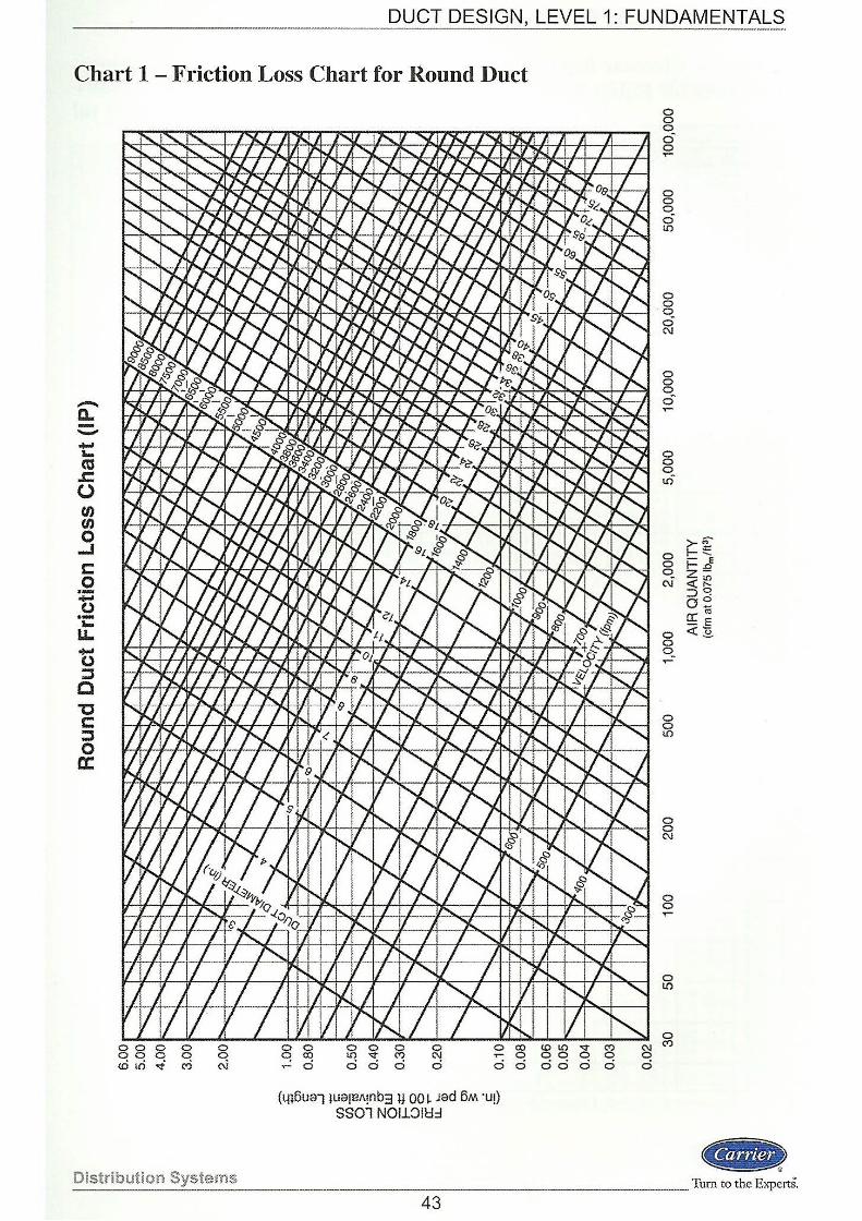
DUCT DESIGN, LEVEL 1: FUNDAMENTALS - ----------- ---------·---·--··
Chart 1 - Friction Loss Chart for Round Duct
.-. 0.. --.... """ cu .c 0 t/) t/) 0 ...J c 0 ·-... 0 ·-""' LL. ..... (.) j
c "0 c: j 0 a:
0 0 0 0 0 00 0 0 0 <Ci tri .t «> C\i
0 0 0 0 0 0 0 C! co l!) "<t (") (\J .,..... 0 0 0 0 0 a
(t.n6ual }U91BA!nb3 u 00~ Jed 6M ·u!) SSOl NOLL~IU::I
co 0 a
(!)1.() 00
'<t 0
C') 0
(\J 0
ao 0 a a
0 0 0 c5 0 ...-
0 0 0 0 1.()
0 0 0 c5 N
0 0 0 0-
0 0 o_ 1.()
0 0 q N
0 0 0 .....
0 0 1.()
0 0 C\l
0 0 ..-
0 1.()
0 ('t)
>-€ r-:::: - E rD z-<(:!? ::::>~ 0~ crcu - E <(:§_
... Distribution Systems --------------------Turn to the ExpertS.
43
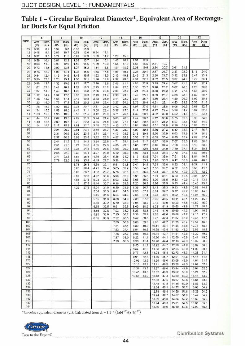
DUCT DESIGN, LEVEL 1: FUNDAMENTALS ----------------------------
Table 1 - Circular Equivalent Diameter*, Equivalent Area of Rectangular Ducts for Equal Friction
6 8 10 12 14 16 18 20 22 SIDE Area Diam. Area Diam. Area Diam. Area Dlam. Area Diam. Area Diam. Area Diam. Area Diam. Area Diam.
(It') (in.) (It') . (ln.) (It') (in.) (It') (ln.) (It') (in.) (It') (in.) (ft' ) (in.) (ft') (in.) (ft') (in.) 10 0.38 8.4 0.52 9.8 0.65 10.9 12 0.46 9 .1 0.62 10.7 0.78 12.0 0.94 13.1 14 0.52 9.8 0.72 11.5 0.91 12.9 1.09 14.2 1.28 15.3
16 0.59 10.4 0.81 12.2 1.03 13.7 1.24 15.1 1.46 16.4 1.67 17.5 18 0.66 11.0 0.90 12.9 1.15 14.5 1.39 16.0 1.64 17.3 1.88 18.5 2.11 19.7 20 0.72 11.5 0.99 13.5 1.27 15.2 1.54 16.8 1.81 18.2 2.08 19.5 2.34 20.7 2.61 21 .9
22 0.78 12.0 1.08 14.1 1.38 15.9 1.68 17.6 1.98 19.1 2.28 20.4 2.57 21.7 2.87 22.9 3.15 24.0 24 0.84 12.4 1.16 14.6 1.49 16.5 1.82 18.3 2.15 19.9 2.48 21.3 2.80 22.7 3.12 23.9 3.44 25.1 26 0.90 12.8 1.25 15.1 1.60 17.1 1.96 19.0 2.32 20.6 2.67 22.1 3.02 23.5 3.37 24.9 3.72 26.1
28 0.96 13.2 1.33 15.6 1.71 17.7 2.10 19.6 2.48 21.3 2.86 22.9 3.25 24.4 3.62 25.8 4.00 27.1 30 1.01 13.6 1.41 16.1 1.82 18.3 2.23 20.2 2.64 22.0 3.05 23.7 3.46 25.2 3.87 26.6 4.28 28.0 32 1.07 14.0 1.49 16.5 1.92 18.8 2 .36 20.8 2.80 22.7 3.24 24.4 3.68 26.0 4.11 27.5 4.55 28.9 34 1.12 14.4 1.57 17.0 2.03 19.3 2.49 21.4 2.96 23.3 3.42 25.1 3.89 26.7 436 28.3 4.82 29.7 36 1.18 14.7 1.65 17.4 2.13 19.8 2 .62 21.9 3.11 23.9 3.61 25.7 4.10 27.4 4.59 29.0 5.09 30.5 38 1.23 15.0 1.73 17.8 2.23 20.2 2.75 22.4 3.27 24.5 3.79 26.4 4.31 28.1 4 .83 29.8 5.35 31.3 40 1.28 15.3 1.80 18.2 2.33 20.7 2.87 22.9 3.42 25.0 3.97 27.0 4.51 28.8 5.06 30.5 5.61 32.1 42 1.34 15.6 1.88 18.5 2.43 21.1 3.00 23.4 3.57 25.6 4.14 27.6 4.72 29.4 5.29 31.2 5.87 32.8 44 1.39 15.9 1.95 18.9 2.53 21 .5 3.12 23.9 3.71 26.1 4.32 28.1 4 .92 30.0 5.52 31.8 6.13 33.5
46. 1.44 16.2 202 19.3 2.62 21.9 3.24 24 .4 3.86 26.6 4.49 28.7 5.12 30.6 5.75 32.5 6.38 34.2 48 1.49 16.5 2.09 19.6 2.72 22.3 3.36 24.8 4.01 27.1 4.66 29.2 5.31 31.2 5.97 33.1 6.63 34.9 50 1.54 16.8 2.17 19.9 2.81 22.7 3.48 25.2 4.15 27.6 4.83 29.8 5.51 31.8 6.20 33.7 6.88 35.5
52 2.24 20.2 2.91 23.1 3.59 25.7 4 .29 28.0 4.99 30.3 5.70 32.3 6.42 34.3 7.13 36.2 54 2.31 20.6 3.00 23.5 3.71 26.1 4.43 28.5 5.16 30.8 5.90 32.9 6.63 34.9 7 .37 36.8 56 2.37 20.9 3.09 23.8 3.82 26.5 4.57 28.9 5.33 31.2 6.09 33.4 6 .85 35.4 7 .62 37.4 58 2.44 21.2 3.18 24.2 3.94 26.9 4 .71 29.4 5.49 31.7 6.27 33.9 7.07 36.0 7.86 38.0 60 2.51 21.5 3.27 24.5 4.05 27.3 4.85 29.8 5.65 32.2 6.46 34.4 7.28 36.5 8.10 38.5 62 2.58 21 .7 3.36 24.8 4.16 27.6 4.98 30.2 5.81 32.6 6.65 34.9 7.49 37.1 8.34 39.1 64 2.65 22.0 3.45 25.1 4.27 28.0 5 .12 30.6 5.97 33.1 6.83 35.4 7.70 37.6 8 .57 39.6 66 2.71 22.3 3.54 25.5 4.39 28.4 5 .25 31 .0 6.13 33.5 7.01 35.9 7.91 38.1 8.81 40.2 68 2.78 22.6 3.62 25.8 4.49 28.7 5.38 31.4 6.28 33.9 7.20 36.3 8.12 38.6 9.04 40.7
70 3.71 26.1 4.60 29.1 5.51 31.8 6.44 34.4 7.38 36.8 8.32 39.1 9.27 41.2 72 3.80 26.4 4.71 29.4 5.65 32.2 6.59 34.8 7.56 37.2 8.52 39.5 9.50 41.7 74 3.88 26.7 4.82 29.7 5.78 32.5 6.75 35.2 7.73 37.7 8.73 40.0 9.73 42.2
76 3.97 27.0 4.92 30.0 5.90 32.9 6.90 35.6 7.91 38.1 8.93 40.5 9.96 42.7 78 4.05 27.3 5.03 30.4 6.03 33.3 7.05 36.0 8.09 38.5 9.13 40.9 10.18 43.2 80 4.13 27.5 5.14 30.7 6.16 33.6 7.20 36.3 8.26 38.9 9.33 41.4 10.40 43.7
82 4.22 27.8 5.24 31 .0 6.29 33.9 7.35 36.7 8.43 39.3 9.53 41.8 10.63 44.1 84 5.34 31 .3 6.41 34.3 7.50 37.1 8.61 39.7 9.72 42.2 10.85 44.6 86 5.45 31.6 6.54 34.6 7.65 37.4 8.78 40.1 9.92 42.6 11.07 45.0
88 5.55 31.9 6.66 34.9 7.80 37.8 8.95 40.5 10.11 43.1 11.29 45.5 90 5.65 32.2 6.79 35.3 7.94 38.2 9.12 40.9 10.30 43.5 11 .50 45.9 92 5.75 32.5 6.91 35.6 8.09 38.5 9.28 41.3 10.50 43.9 11 .72 46.4 94 5.85 32.8 7.03 35.9 8.23 38.8 9 .45 41.6 10.69 44.3 11.94 46.8 96 5.95 33.0 7.15 36.2 8.38 39.2 9.62 42.0 10.88 44.7 12.15 47.2 98 6.05 33.3 7.27 36.5 8.52 39.5 9.78 42.4 11.07 45.0 12.36 47.6
100 7.39 36.8 8.66 39.8 9.95 42.7 11.25 45.4 12.57 48.0 102 7.51 37.1 8.80 40.2 10.11 43.1 11.44 45.8 12.78 48.4
·104 7.63 37.4 8 .94 40.5 10.28 43.4 11.63 46.2 12.99 48.8 106 7.75 37.7 9.08 40.8 10.44 43.7 11.81 46.5 13.20 49.2 108 7.87 38.0 9.22 41.1 10.60 44.1 12.00 46.9 13.41 49.6 110 7.99 38.3 9.36 41.4 10.76 44.4 12 .18 47.3 13.62 50.0 11 2 9.50 41 .7 10.92 44.7 12.36 47.6 13.82 50.3 114 9.64 42.0 11.08 45.1 12.55 48.0 14.03 50.7 116 9.77 42.3 11.24 45.4 12.73 48.3 14.23 51 .1 118 9.91 42.6 11.40 45.7 12.91 48.6 14.44 51.4 120 10.05 42.9 11 .55 46.0 13.09 49.0 14.64 51 .8 122 10.18 43.2 11 .71 46.3 13.26 49.3 14.84 52.2 124 10.32 43.5 11.87 46.6 13.44 49.6 15.04 52.5 126 10.45 43.8 12.02 46.9 13.62 50.0 15.24 52.9 128 10.58 44.0 12.18 47.3 13.80 50.3 15.44 53.2 130 12.33 47.5 13.97 50.6 15.64 53.5 132 12.48 47.8 14.15 50.9 15.83 53.9 134 12.64 48.1 14.32 51.2 16.03 54.2 136 12.79 48.4 14.50 51.6 16.23 54.5 138 12.94 48.7 14.67 51 .9 16.42 54.9 140 13.09 49.0 14.84 52.2 16.62 55.2 142 13.24 49.3 15.01 52.5 16.81 55.5 144 13.39 49.6 15 19 52.8 17.00 55.8
*Circular equivalent diameter (d.). Calculated from de= 1.3 * ((ab) 625/(a+b)'15)
.. Turn to the Experts. __ Distribution Systems
----44
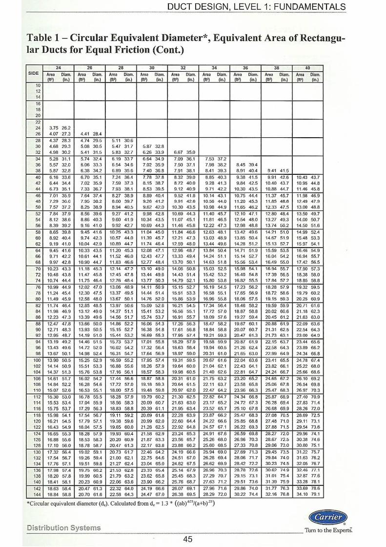
DUCT DESIGN, LEVEL 1: FUNDAMENTALS --------------------------------------------
Table 1 - Circular Equivalent Diameter*, Equivalent Area of Rectangular Ducts for Equal Friction (Cont.)
24 26 28 30 32 34 36 38 40 SIDE Area Diam. Area Diam. Area Diam. Area Diam. Area Diam. Area Diam. Area Diam. Area Diam. Area Diam.
(ft2) (in.) (ft2) (in.) (ft2) (in.) (ft2) (in.) (ft2) (in.) (ft2) (in.) (ft2) (in.) (ft') (in.) (ft2) (in.) 10 12 14
16 18 20
22 24 3.75 26.2 26 4.07 27.3 4.41 28.4 28 4.37 28.3 4 .74 29.5 5.11 30.6 30 4.68 29.3 5.08 30.5 5.47 31 .7 5.87 32.8 32 4.98 30.2 5.41 31.5 5.83 32.7 6.26 33.9 6.67 35.0
34 5.28 31.1 5.74 32.4 6.19 33.7 6.64 34.9 7.09 36.1 7.53 37.2 36 5.57 32.0 6.06 33.3 6.54 34.6 7.02 35.9 7.50 37.1 7.98 38.2 8.45 39.4 38 5.87 32.8 6.38 34.2 6.89 35.6 7.40 36.8 7.91 38.1 8.41 39.3 8.91 40.4 9.41 41.5
40 6.16 33.6 6.70 35.1 7.24 36.4 7.78 37.8 8.32 39.0 8.85 40.3 9.38 41.5 9.91 42.6 10.43 43.7 42 6.44 34.4 7.02 35.9 7.59 37.3 8.15 38.7 8.72 40.0 9.28 41.3 9.84 42.5 10.40 43.7 10.95 44.8 44 6.73 35.1 7.33 36.7 7.93 38.1 8.53 39.5 9.12 40.9 9.71 42.2 10.30 43.5 10.88 44.7 11.46 45.8
46 7.01 35.9 7.64 37.4 8.27 38.9 8.89 40.4 9.52 41.8 10.14 43.1 10.75 44.4 11.37 45.7 11 .98 46.9 40 7.29 30.0 7.9!i 30.2 8.00 39.7 9.26 41.2 9.91 42.6 10.56 44.0 11.20 45.3 11.85 46.6 12.49 47.9 50 7.57 37.2 8.25 38.9 8.94 40.5 9.62 42.0 10.30 43.5 10.98 44.9 11.65 46.2 12.33 47.5 13.00 48.8
52 7.84 37.9 8.56 39.6 9.27 41.2 9.98 42.8 10.69 44.3 11.40 45.7 12.10 47.1 12.80 48.4 13.50 49.7 54 8.12 38.6 8.86 40.3 9.60 41.9 10.34 43.5 11.07 45.1 11 .81 46.5 12.54 48.0 13.27 49.3 14.00 50.7 56 8.39 39.2 9.16 41.0 9.92 42.7 10.69 44.3 11.46 45.8 12.22 47.3 12.98 48.8 13.74 50.2 14.50 51.6
58 8.65 39.8 9.45 41 .6 10.25 43.3 11.04 45.0 11.84 46.6 12.63 48.1 13.42 49.6 14.21 51.0 14.99 52.4 60 8.92 40.4 9.74 42.3 10.57 44.0 11.39 45.7 12.21 47.3 13.03 48.9 13.85 50.4 14.67 51.9 15.48 53.3 62 9.19 41.0 10.04 42.9 10.89 44.7 11.74 46.4 12.59 48.0 13.44 49.6 14.28 51.2 15.13 52.7 15.97 54.1 64 9.45 41.6 10.33 43.5 11.20 45.3 12.08 47.1 12.96 48.7 13.84 50.4 14.71 51.9 15.59 53.5 16.46 54.9 66 9.71 42.2 10.61 44.1 11 .52 46.0 12.43 47.7 13.33 49.4 14.24 51.1 15.14 52.7 16.04 54.2 16.94 55.7 68 9 .97 42.8 10.90 44.7 11.83 46.6 12.77 48.4 13.70 50.1 14.63 51 .8 15.56 53.4 16.49 55.0 17.42 56.5
70 10.23 43.3 11.18 45.3 12.14 47.2 13.10 49.0 14.06 50.8 15.03 52.5 15.98 54.1 16.94 55.7 17.90 57.3 72 10.48 43.8 11.47 45.8 12.45 47.8 13.44 49.6 14.43 51.4 15.42 53.2 16.40 54.8 17.39 56.5 18.38 58.0 74 10.74 44.4 11.75 46.4 12.76 48.4 13.77 50.3 14.79 52.1 15.80 53.8 16.82 55.5 17.84 57.2 18.85 58.8
76 10.99 44.9 12.02 47.0 13.06 48.9 14.11 50.9 15.15 52.7 16.19 54.5 17.23 56.2 18.28 57.9 19.32 59.5 78 11.24 45.4 12.30 47.5 13.37 49.5 14.44 51.4 15.51 53.3 16.58 55.1 17.65 56.9 18.72 58.6 19.79 60.2 80 11.49 45.9 12.58 48.0 13.67 50.1 14.76 52.0 15.86 53.9 16.96 55.8 18.06 57.5 19.15 59.3 20.25 60.9
82 11.74 46.4 12.85 48.5 13.97 50.6 15.09 52.6 16.21 54.5 17.34 56.4 18.46 58.2 19.59 59.9 20.71 61.6 84 11 .98 46.9 13.12 49.0 14:27 51.1 15.41 53.2 16.56 55.1 17.72 57.0 18.87 58.8 20.02 60.6 21.18 62.3 86 12.23 47.3 13.39 49.6 14.56 51.7 15.74 53.7 16.91 55.7 18.09 57.6 19.27 59.4 20.45 61.2 21.63 63.0
88 12.47 47.8 13.66 50.0 14.86 52.2 16.06 54.3 17.26 56.3 18.47 58.2 19.67 60.1 20.88 61.9 22.09 63.6 90 12.71 48.3 13.93 50.5 15.15 52.7 16.38 54.8 17.61 56.8 18.84 58.8 20.07 60.7 21.31 62.5 22.54 64.3 92 12.95 48.7 14.19 51.0 15.44 53.2 16.69 55.3 17.95 51.4 19.21 59.3 20.47 61.3 21.73 63.1 23.00 64.0 94 13.19 49.2 14.46 51.5 15.73 53.7 17.01 55.8 18.29 57.9 19.58 59.9 20.87 61.9 22.15 63.7 23.44 65.6 96 13.43 49.6 14.72 52.0 16.02 54.2 17.32 56.4 18.63 58.4 19.94 60.5 21.26 62.4 22.58 64.3 23.89 66.2 98 13.67 50.1 14.98 52.4 16.31 54.7 17.64 56.9 18.97 59.0 20.31 61.0 21.65 63.0 22.99 64.9 24.34 66.8
100 13.90 50.5 15.25 52.9 16.59 55.2 17.95 57.4 19.31 59.5 20.67 61.6 22.04 63.6 23.41 65.5 24.78 67.4 102 14.14 50.9 15.51 53.3 16.88 55.6 18.26 57.9 19.64 60.0 21.04 62.1 22.43 64.1 23.82 66.1 25.22 68.0 104 14.37 51.3 15.76 53.8 17.16 56.1 18.57 58.3 19.98 60.5 21.40 62.6 22.81 64.7 24.24 66.7 25.66 68.6
106 14.61 51.7 16.02 54.2 17.44 56.6 18.87 58.8 20.31 61 .0 21.75 63.2 23.20 65.2 24.65 67.2 26.10 69.2 108 14.84 52.2 16.28 54.6 17.72 57.0 19.18 59.3 20.64 61.5 22.11 63.7 23.58 65.8 25.06 67.8 26.54 69.8 110 15.07 52.6 16.53 55.1 18.00 57.5 19.48 59.8 20.97 62.0 22.47 64.2 23.96 66.3 25.47 68.3 26.97 70.3 112 15.30 53.0 16.78 55.5 18.28 57.9 19.79 60.2 21.30 62.5 22.82 64.7 24.34 66.8 25.87 68.9 27.40 70.9 114 15.53 53.4 17.04 55.9 18.56 58.3 20.09 60.7 21.63 63.0 23.17 65.2 24.72 67.3 26.28 69.4 27.83 71.4 116 15.75 53.7 17.29 56.3 18.83 58.8 20.39 61.1 21.95 63.4 23.52 65.7 25.10 67.8 26.68 69.9 28.26 72.0 118 15.98 54.1 17.54 56.7 19.11 59.2 20.69 61.6 22.28 63.9 23.87 66.2 25.47 68.3 27.08 70.5 28.69 72.5 120 16.21 54 .5 17.79 57.1 19.38 59.6 20.99 62.0 22.60 64.4 24.22 66.6 25.85 68.8 27.48 71.0 29.11 73.1 122 16.43 54.9 18.04 57.5 19.65 60.0 21.28 62.5 22.92 64.8 24.57 67.1 26.22 69.3 27.88 71.5 29.54 73.6
124 16.65 55.3 18.28 57.9 19.93 60.4 21.58 62.9 23.24 65.3 24.91 67.6 26.59 69.8 28.27 72.0 29.96 74.1 126 16.88 55.6 18.53 58.3 20.20 60.9 21.87 63.3 23.56 65.7 25.26 68.0 26.96 70.3 28.67 72.5 30.38 74.6 128 17.10 56.0 18.78 58.7 20.47 61.3 22.17 63.8 23.88 66.2 25.60 68.5 27.33 70.8 29.06 73.0 30.80 75.1
130 17.32 56.4 19.02 59.1 20.73 61.7 22.46 64.2 24.19 66.6 25.94 69.0 27.69 71.3 29.45 73.5 31.22 75.7 132 17.54 56.7 19.26 59.4 21.00 62.1 22.75 64.6 24.51 67.0 26.28 69.4 28.06 71.7 29.84 74.0 31.63 76.2 134 17.76 57.1 19.51 59.8 21.27 62.4 23.04 65.0 24.82 67.5 26.62 69.9 28.42 72.2 30.23 74.5 32.05 76.7
136 17.98 57.4 19.75 60.2 21.53 62.8 23.33 65.4 25.14 67.9 26.96 70.3 28.78 72.6 30.62 74.9 32.46 77.1 138 18.20 57.8 19.99 60.5 21.79 63.2 23.62 65.8 25.45 68.3 27.29 70.7 29.15 73.1 31.01 75.4 32.87 77.6 140 18.41 58.1 20.23 60.9 22.06 63.6 23.90 66.2 25.76 68.7 27.63 71.2 29.51 73.6 31.39 75.9 33.28 78.1
142 18.63 58.4 20.47 61.3 22.32 64.0 24.19 66.6 26.07 69.1 27.96 71.6 29.86 74.0 31.77 76.3 33.69 78.6 144 18.84 58.8 20.70 61.6 22.58 64.3 24.47 67.0 26.38 69.5 28.29 72.0 30.22 74.4 32.16 76.8 34.10 79.1
*Circular equivalent diameter (de). Calculated from de= 1.3 * ((ab)'625/(a+b)'25)
Distribution Systems ..
____________ Turn to the Experts~
45
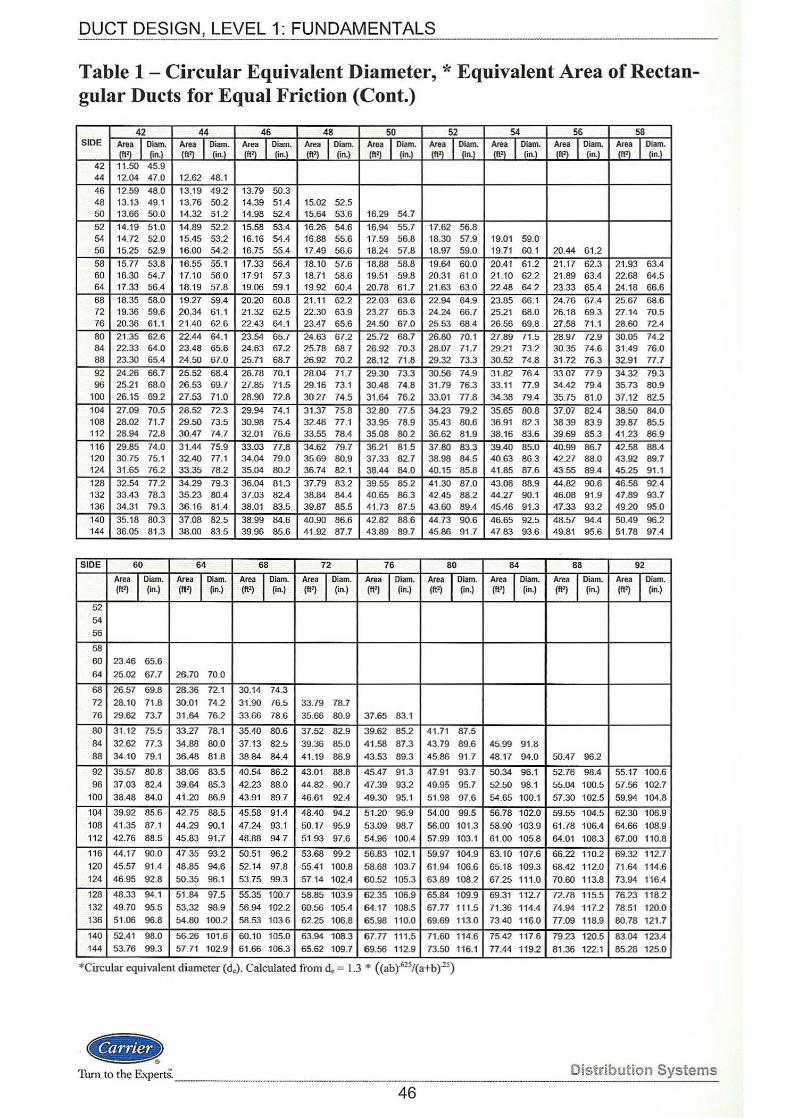
DUCT DESIGN, LEVEL 1: FUNDAMENTALS ------
Table 1 - Circular Equivalent Diameter,* Equivalent Area of Rectangular Ducts for Equal Friction (Cont.)
42 44 46 48 50 52 54 56 58 SIDE Area I Diam. Area I Diam. Area I Diam. Area I Diarn. Area I Diam. Area I Diam. Area I Diam. Area I Diam. Area I Diam.
(ft'l (in.) (It') (in.) (It') (in.) (It') (in.) (It') (in.) (It') On.) (ft'l On.l (It') (in.) (It') fon.) 42 11.50 45.9 44 12.04 47.0 12.62 48.1
46 12.59 48.0 13.19 49.2 13.79 50.3 48 13.13 49.1 13.76 50.2 14.39 51.4 15.02 52.5 50 13.66 50.0 14.32 51.2 14.98 52.4 15.64 53.6 16.29 54.7 52 14.19 51.0 14 .89 52.2 15.58 53.4 16.26 54.6 16.94 55.7 17.62 56.8 54 14.72 52.0 15.45 53.2 16.16 54.4 16.88 55.6 17.59 56.8 18.30 57.9 19.01 59.0 56 15.25 52.9 16.00 54.2 16.75 55.4 17.49 56.6 18.24 57.8 18.97 59.0 19.71 60 1 20.44 61.2 58 15.77 53.8 16.55 55.1 17.33 56.4 18.10 57.6 18.88 58.8 19.64 60.0 20.41 61.2 21.17 62.3 21.93 63.4 60 16.30 54.7 17.10 56.0 17.91 57.3 18.71 58.6 19.51 59.8 20.31 61.0 21.10 62.2 21.89 63.4 22.68 64.5 64 17.33 56.4 18.19 57.8 19.06 59.1 19.92 60.4 20.78 61.7 21.63 63.0 22.48 64.2 23.33 65.4 24.18 66.6 68 18.35 58.0 19.27 59.4 20.20 60.8 21.11 62.2 22.03 63.6 22.94 64.9 23.85 66.1 24.76 67.4 25.67 68.6 72 19.36 59.6 20.34 61.1 21.32 62.5 22.30 63.9 23.27 65.3 24.24 66.7 25.21 68.0 26.18 69.3 27.14 70.5 76 20.36 61.1 2 1.40 62.6 22.43 64.1 23.47 65.6 24.50 67.0 25.53 68.4 26.56 69.8 27.58 71.1 28.60 72.4 80 21.35 62.6 22.44 64.1 23.54 65.7 24.63 67.2 25.72 68.7 26.80 70.1 27.89 71.5 28.97 72.9 30.05 74.2 84 22.33 64.0 23.48 65.6 24.63 67.2 25.78 68.7 26.92 70.3 28.07 71.7 29.21 73.2 30.35 74.6 31.49 76.0 88 23.30 65.4 24.50 67.0 25.71 68.7 26.92 70.2 28.12 71.8 29.32 73.3 30.52 74.8 31.72 76.3 32.91 77.7 92 24.26 66.7 25.52 68.4 26.78 70.1 28.04 71.7 29.30 73.3 30.56 74.9 31.82 76.4 33.07 77.9 34.32 79.3 96 25.21 68.0 26.53 69.7 27.85 71.5 29.16 73.1 30.48 74.8 31.79 76.3 33.11 77.9 34.42 79.4 35.73 80.9
100 26.15 69.2 27.53 71.0 28.90 72.8 30.27 74.5 31.64 76.2 33.01 77.8 34.38 79.4 35.75 81.0 37.12 82.5 104 27.09 70.5 28.52 72.3 29.94 74.1 31.37 75.8 32.80 77.5 34.23 79.2 35.65 80.8 37.07 82.4 38.50 84.0 108 28.02 71.7 29.50 73.5 30.98 75.4 32.46 77.1 33.95 78.9 35.43 80.6 36.91 82.3 38.39 83.9 39.87 85.5 112 28.94 72.8 30.47 74.7 32.01 76.6 33.55 78.4 35.08 80.2 36.62 81.9 38.16 83.6 39.69 85.3 41.23 86.9 116 29.85 74.0 31.44 75.9 33.03 77.8 34.62 79.7 36.21 81 .5 37.80 83.3 39.40 85.0 40.99 86.7 42.58 88.4 120 30.75 75.1 32.40 77.1 34.04 79.0 35.69 80.9 37.33 82.7 38.98 84.5 40.63 86.3 42.27 88.0 43.92 89.7 124 31.65 76.2 33.35 78.2 35.04 80.2 36.74 82.1 38.44 84.0 40.15 85.8 41.85 87.6 43.55 89.4 45.25 91 .1 128 32.54 77.2 34.29 79.3 36.04 81.3 37.79 83.2 39.55 85.2 41.30 87.0 43.06 88.9 44.82 90.6 46.58 92.4 132 33.43 78.3 35.23 80.4 37.03 82.4 38.84 84.4 40.65 86.3 42.45 88.2 44.27 90.1 46.08 91.9 47.89 93.7 136 34.31 79.3 36.16 81.4 38.01 83.5 39.87 85.5 41 .73 87.5 43.60 89.4 45.46 91.3 47.33 93.2 49.20 95.0 140 35.18 80.3 37.08 82.5 38.99 84.6 40.90 86.6 42.82 88.6 44.73 90.6 46.65 92.5 48.57 94.4 50.49 96.2 144 36.05 81.3 38.00 83.5 39.96 85.6 41.92 87.7 43.89 89.7 45.86 91.7 47.83 93.6 49.81 95.6 51.78 97.4
SIDE 60 64 68 72 76 80 84 88 92
Area I Diam. (ft' ) (in.)
Area I Diam. (112) (in.)
Area I Diam. (ft') (in.)
Area I Diam. (ft2) (in.)
Area I Diam. (It') (in.)
Area I Diam. (ft'l (in.)
Area I Diam. (112) (in.)
Area I Diam. (It') (in.)
Area I Diam. (112) (in.)
52 54 56
58 60 23.46 65.6
64 25.02 67.7 26.70 70.0
68 26.57 69.8 28.36 72.1 30.14 74.3 72 28.10 71.8 30.01 74.2 31.90 76.5 33.79 78.7 76 29.62 73.7 31.64 76.2 33.66 78.6 35.66 80.9 37.65 83.1
80 31.12 75.5 33.27 78.1 35.40 80.6 37.52 82.9 39.62 85.2 41 .71 87.5 84 32.62 77.3 34.88 80.0 37.13 82.5 39.36 85.0 41.58 87.3 43.79 89.6 45.99 91.8 88 34.10 79.1 36.48 81.8 38.84 84.4 41.19 86.9 43.53 89.3 45.86 91 .7 48.17 94.0 50.47 96.2
92 35.57 80.8 38.06 83.5 40.54 86.2 43.01 88.8 45.47 91.3 47.91 93.7 50.34 96.1 52.76 98.4 55.17 100.6 96 37.03 82.4 39.64 85.3 42.23 88.0 44.82 90.7 47.39 93.2 49.95 95.7 52.50 98.1 55.04 100.5 57.56 102.7
100 38.48 84.0 41.20 86.9 43.91 89.7 46.61 92.4 49.30 95.1 51 .98 97.6 54.65 100.1 57.30 102.5 59.94 104.8
104 39.92 85.6 42.75 88.5 45.58 91.4 48.40 94.2 5 1.20 96.9 54.00 99.5 56.78 102.0 59.55 104.5 62.30 106.9 108 41.35 87.1 44.29 90.1 47.24 93.1 50.17 95.9 53.09 98.7 56.00 101.3 58.90 103.9 61.78 106.4 64.66 108.9 11 2 42.76 88.5 45.83 91.7 48.88 94.7 51.93 97.6 54.96 100.4 57.99 103.1 61.00 105.8 64.01 108.3 67.00 110.8
116 44.17 90.0 47.35 93.2 50.51 96.2 53.68 99.2 56.83 102.1 59.97 104.9 63.10 107.6 66.22 110.2 69.32 112.7 120 45.57 91 .4 48.85 94.6 52.14 97.8 55.41 100.8 58.68 103.7 61 .94 106.6 65.18 109.3 68.42 112.0 71.64 114.6 124 46.95 92.8 50.35 96.1 53.75 99.3 57.14 102.4 60.52 105.3 63.89 108.2 67.25 111 .0 70.60 113.8 73.94 116.4
128 48.33 94.1 51.84 97.5 55.35 100.7 58.85 103.9 62.35 106.9 65.84 109.9 69.31 112.7 72.78 115.5 76.23 118.2 132 49.70 95.5 53.32 98.9 56.94 102.2 60.56 105.4 64.17 108.5 67.77 11 1.5 71.36 114.4 74.94 117.2 78.51 120.0 136 51.06 96.8 54.80 100.2 58.53 103.6 62.25 106.8 65.98 110.0 69.69 113.0 73.40 116.0 77.09 118.9 80.78 121.7
140 52.41 98.0 56.26 101.6 60.10 105.0 63.94 108.3 67.77 111.5 71.60 114.6 75.42 117.6 79.23 120.5 83.04 123.4 144 53.76 99.3 57.71 102.9 61.66 106.3 65.62 109.7 69.56 112.9 73.50 116.1 77.44 119.2 81.36 122.1 85.28 125.0
*Circular equivalent diameter (d0 ) . Calculated from d.,= 1.3 * ((ab)'625/(a+b)'25)
. (~ Turn to the ExpertS. _____ _ ---------·-------------------
Distribution Systems
46
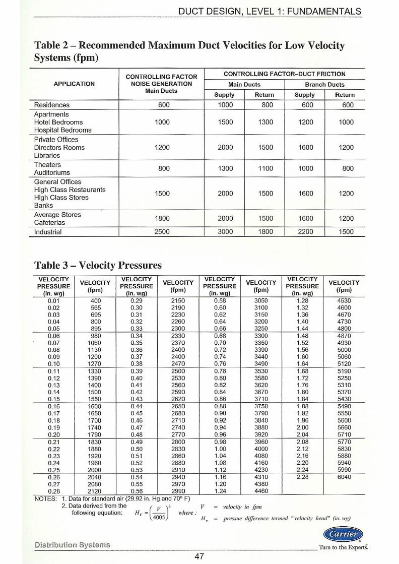
DUCT DESIGN, LEVEL 1: FUNDAMENTALS -------------------------------------
Table 2 - Recommended Maximum Duct Velocities for Low Velocity Systems (fpm)
CONTROLLING FACTOR CONTROLLING FACTOR-DUCT FRICTION
APPLICATION NOISE GENERATION Main Ducts Branch Ducts Main Ducts
Supply Return Supply Return
Residences 600 1000 800 600 600 Apartments Hotel Bedrooms 1000 1500 1300 1200 1000 Hospital Bedrooms
Private Offices Directors Rooms 1200 2000 1500 1600 1200 Libraries
Theaters 800 1300 1100 1000 800 Auditoriums
General Offices High Class Restaurants 1500 2000 1500 1600 1200 High Class Stores Banks Average Stores 1800 2000 1500 1600 1200 Cafeterias Industrial 2500 I 3000 1800 2200 1500
Table 3 - Velocity Pressures VELOCITY
VELOCITY VELOCITY
VELOCITY VELOCITY VELOCITY VELOCITY
VELOCITY PRESSURE PRESSURE PRESSURE PRESSURE
(in. wg) (fpm) (in. wg) (fpm)
(in. wgl (tpm)
(in. wg) (fpm)
0.01 400 0.29 2150 0.58 3050 1.28 4530 0.02 565 0.30 2190 0.60 3100 1.32 4600 0.03 695 0.31 2230 0.62 3150 1.36 4670 0.04 800 0.32 2260 0.64 3200 1.40 4730 0.05 895 0.33 2300 0.66 3250 1.44 4800 0.06 980 0.34 2330 0.68 3300 1.48 4870 0.07 1060 0.35 2370 0.70 3350 1.52 4930 0.08 1130 0.36 2400 0.72 3390 1.56 5000 0.09 1200 0.37 2400 0.74 3440 1.60 5060 0.10 1270 0.38 2470 0.76 3490 1.64 5120 0.11 1330 0.39 2500 0.78 3530 1.68 5190 0.12 1390 0.40 2530 0.80 3580 1.72 5250 0.13 1400 0.41 2560 0.82 3620 1.76 5310 0.14 1500 0.42 2590 0.84 3670 1.80 5370 0.15 1550 0.43 2620 0.86 3710 1.84 5430 0.16 1600 0.44 2650 0.88 3750 1.88 5490 0.17 1650 0.45 2680 0.90 3790 1.92 5550 0.18 1700 0.46 2710 0.92 3840 1.96 5600 0.19 1740 0.47 2740 0.94 3880 2.00 5660 0.20 1790 0.48 2770 0.96 3920 2.04 5710 0.21 1830 0.49 2800 0.98 3960 2.08 5770 0.22 1880 0.50 2830 1.00 4000 2.12 5830 0.23 1920 0.51 2860 1.04 4080 2.16 5880 0.24 1960 0.52 2880 1.08 4160 2.20 5940 0.25 2000 0.53 2910 1.12 4230 2.24 5990 0.26 2040 0.54 2940 1.16 4310 2.28 6040 0.27 2080 0.55 2970 1.20 4380 0.28 2120 0.56 2990 1.24 4460
NOTES: 1. Data for standard a1r (29.92 m. Hg and 70° F) 2. Data derived from the ( v )2 v
following equation: Hr = 4005
where: H ,.
velocity in fpm
pressue difference tenned " velocity head" (in. wg)
Distribution Systems
(--) --------------------Turn to the ExpertS:
47
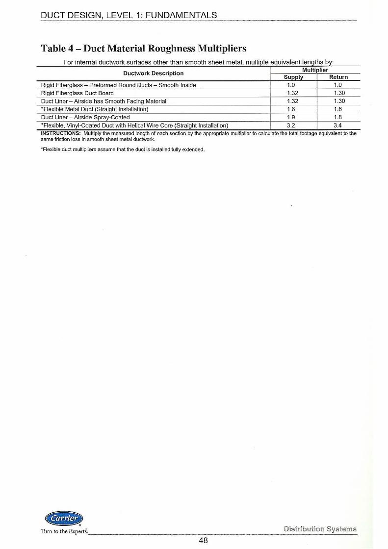
DUCT DESIGN, LEVEL 1: FUNDAMENTAL_§__ ______________________ _
Table 4 - Duct Material Roughness Multipliers F . t or merna l d t k rf th th ucwor su aces o er th h t I an smoo s ee me a , mu If I 1p e eqwva en t I th b eng1 s )y:
Ductwork Description Multiplier Supply Return
Rigid Fiberglass - Preformed Round Ducts - Smooth Inside 1.0 1.0 Rigid Fiberglass Duct Board 1.32 1.30 Duct Liner - Airside has Smooth Facing Material 1.32 1.30
*Flexible Metal Duct (Straight Installation) 1.6 1.6 Duct Liner- Airside Spray-Coated 1.9 1.8 *Flexible, Vinyl-Coated Duct with Helical Wire Core (Straight Installation) 3.2 3.4
. . INSTRUCTIONS: Multiply the measured length of each sect1on by the appropnate multiplier to calculate the total footage equivalent to the same friction loss in smooth sheet metal ductwork.
*Flexible duct multipliers assume that the duct is installed fully extended.
«8> Turn to the ExpertS. ________ . Distribution Systems
48
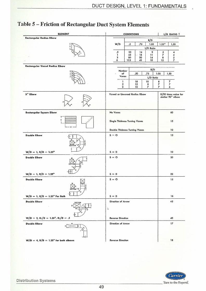
DUCT DESIGN, LEVEL 1: FUNDAMENTALS .. ~ ......... _._~~-----------------.. ---~------
Table 5 - Friction of Rectangular Duct System Elements
ELEMENT
Rectangular Radius Elbow
Rectangular Vaned Radius Elbow
X0 Elbow
Redangular Squore Elbow
Double Elbow
W/D = 1, R/D = 1.25*
Double Elbow
W/D = l, R/0 = 1.25*
Double Elbow
W/D = 1, R/D = 1.25* For Bo;.th
Double Elbow
T D
-t_~ol w ~
[Sjo · s SECTION ,? T
~0 SECTION
,?
J.: s T
w ~ cgjo ~~ SECTiO.~ ~ '---r
+ 11
w 1> ·.p /1 <'
W/D = 2, R!/D = 1.25*, R2/ D = .S
D~·SECTIOO
Double Elbow .,w il:· .
/o
' I . . ~ W/D = 4, R/D = 1.25* for both elbows
CONDITIONS I L/ D RATIO t
R/D
W/D .5 .7S 1.00 1.2S* I.SO l/D Ratio
.s 33 u 9 5 4 I 45 18 11 7 4 3
I 80 30 14 8 5
6 t25 40 18 12 7
Number
I R/D
of .so i .75 I 1.00 I l.SO Vanes
I l/0 Ratio
1 18
I 10
I 8
I 7
2 12 8 7 7 3 I 10 7 7 6
Vaned or Vnvaned Radius Elbow X/90 times value for similar 90" elbow
No Vanes 60
Single Thickness Turning Vanes IS
Double Thickness Turning Vanes to
s = 0 15
s = 0 to
S=O 20
s = 0 22
s = 0 15
s = 0 16
Direction of Arrow
Reverse Direction 40
Direction of Arrow 17
Rev•me Direction 18
(«BBIt> _D_i_s_tr_i_b_u_t_io __ n_S~y_s_te __ rn_s ________________________________________________________ TurntotheExpert&
49
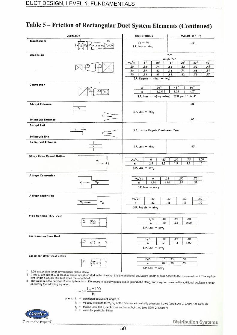
DUCT DESIGN, LEVEL 1: FUNDAMENTA~S ___________ _
Table 5- Friction of Rectangular Duct System Elements (Continued)
CLEM ENT CONDITIONS VALUE OF nt
Transformer ~--.- 2o V2 = V1 .15
2a ~~t±3~~ S.P. loss = nhvl
Expansion un"
Angle "a"
cg]]~=ncg] v2/v1 so 10° 15° 20° 30° 40°
.20 .83 .71. .68 .62 .52 .45
.40 .89 .83 .78 .74 .68 .M
.60 .93 .87 .84 .82 .79 .77
S.P. Regain = n(hvl - hv2l
Contraction
[6]1If[2J a I 30° I 45 °
I 60 °
n l.02tt 1.04 1.07
S.P. l oss = n(hv, -hv,) TtSiope I " in 4"
Abru pt Entrance I .35
- v ,
I --- S.P. loss = nhv1 v,-
Bellmouth Entrance --- .03
Abr upt Ex it J v , - --- S.P. Loss or Regain Considered Zero
I v, -Bellmouth Exit ----Rc- Entl'a nt Entrance I
VI I
S.P. loss = nhv1 .as
Sh<1rp Edge Roun d Orifice u I I AI A,/Ao I 0 I .25 I .50 .75 1.00
- A2 n 2.5 2.3 1.9 1.1 0
0 S.P. l oss = nhv2
Abrupt CCintr Ciclion
I v,;v, I
0
I .25 I .50
I 75
v,~ v2 n 1,31. . 1.21. .96 .52
I S.P. l oss = nhv2
Abrupt Ex p<1nsi on
I I I V2/V1 _I
.20
I .40 .60 .80
V) - - v 2 n .32 .48 .48 .32
L S.P. Regain = nhv1
Pipe Running Thru Duct
I t E/0 I .10
I .25 .50
f ~ ~ n .20 .55 2.00
S.P. Loss = nhv1
Bar Runni ng Thru Duel
I I } E/D I .10 .25 • .50
f' t .i. .7 1.4 4.00 E fil n
! S.P. l oss = nhv1
Egsement Over Obstruction
.10 I I t E/D I .25 .50 -P tm>t n .07 .23 .90
S.P. Loss = nhv1 . 1.25 rs standard for an unvaned full radiUS elbow.
t Land Dare in faet D is the duct dimension illustrated in the drawing. L is the additional equivalent length of duct added to the measured duct. The equivalent length L eqJals Din feet times the ratio listed.
+ The value n is the number of velocity heads or differences in velocity heads lost or gained at a fitting, and may be converted to additional equivalent length of duct by the following equalion:
Gil!> Turn to the ExpertS._
L = n * hv * 100 hf
where: L = additional equivalent length, ft
h. ~ velocity pressure forV1, V2 or tihe difference in velocity pressure, in. wg (see SDM-2, Chart 7 or Table 8)
h1 friction loss/100ft, duct cross section at h.. in. wg (see SDM-2, Chart 7) n = value for particular fitting
Distribution Systems
50
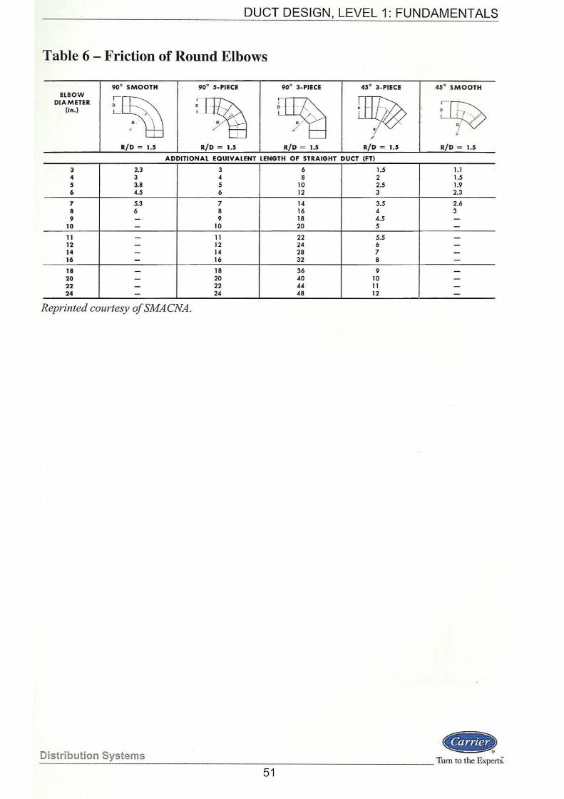
DYCT DESIGN, LEVEL 1: FUNDAMENTALS
Table 6 - Friction of Round Elbows
90° SMOOTH 90° 5-PIECE 90° 3-PIECE 45° 3-PIECE 45° SMOOTH ELBOW
[~ ~~ ~ ~ DIAMETER
c~ (in.) L . .;
f
R/D = 1.5 R/ D = 1.5 R/ D = 1.5 R/D = 1.5 R/ D = 1.5
ADDITIONAL EQUIVALENT LENGTH OF STRAIGHT DUCT (FT)
3 2.3 3 6 1.5 1.1 4 3 4 8 2 1.5 5 3.8 5 10 2.5 1.9 6 4.5 6 12 3 2.3
7 5.3 7 14 3.5 2.6 8 6 8 16 4 3 9 - · 9 18 4.5 -
10 - 10 20 s -11 - 11 22 5.5 -12 - 12 24 6 -14 - 14 28 7 -16 16 32 8 -18 - 18 36 9 -20 - 20 40 10 -22 - 22 44 11 -24 24 48 12 -
Reprinted courtesy ofSMACNA.
_D_i_s_tr_ib __ u_ti_o_n __ S~y_s_te __ rn_s ____________________________________________________ Tum roilieExpertS.
51
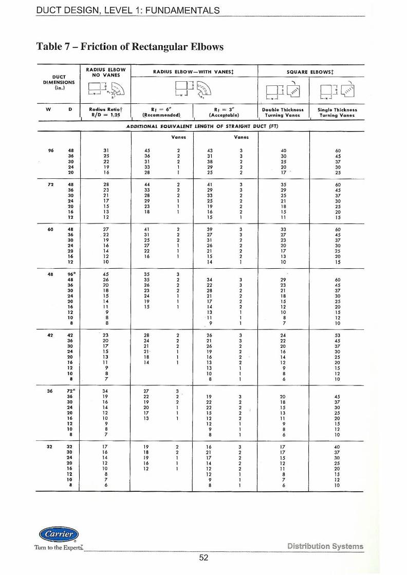
DUCT DESIGN, LEVEL 1: FUNDAMENTALS
Table 7 - Friction of Rectangular Elbows
RADI US ELBOW RADIUS ELBOW-WITH VANESt SQUARE ELBOWSt DUCT NO VANES
DIMENSIONS 06 ~ D J §hl ""\ ' (in.) -' ' RJCZJ D J l{j L w...l "• L. J ,,
R .. w L . J
w D Ra dius Ratiot Rt = 6" l Rt = 3" Double Thickness Single Thickness R/D = 1 .2~ (!tecommended) (Accel!table) Turning Vanes Turning Vanes
.ADDJJJON.Al EOUJV.ALENJ lENGTH OF STRAIGHT DUCT {FT)
Vanes Vanes
96 48 31 45 2 43 3 40 60 36 25 36 2 31 3 30 45 30 22 31 2 38 2 25 37 24 19 33 1 29 2 20 30 20 16 28 1 25 2 17 25
72 48 28 44 2 41 3 35 60 36 23 33 2 29 3 29 45 30 21 28 2 33 2 25 37 24 17 29 1 25 2 21 30 20 15 23 1 19 2 18 25 16 13 18 1 16 2 15 20 12 12 15 1 11 15
60 48 27 41 2 39 3 33 60 36 22 31 2 27 3 27 45 30 19 25 2 31 2 23 37 24 16 27 1 26 2 20 30 20 J.4 22 1 21 2 17 25 16 12 16 I 15 2 13 20 12 10 14 I 10 15
48 96* 45 35 3 48 26 35 2 34 3 29 60 36 20 26 2 22 3 23 45 30 18 23 2 28 2 21 37 24 15 24 1 21 2 18 30 20 14 19 I 17 2 15 25 16 11 15 I 14 2 12 20 12 9 13 1 10 15 10 8 · 11 I 8 12 8 8 9 1 7 10
42 42 23 28 2 26 3 24 53 36 20 24 2 21 3 22 45 30 17 21 2 26 2 20 37 24 15 21· I 19 2 16 30 20 13 18 1 16 2 14 25 16 11 14 1 13 2 12 20 12 9 13 I 9 15 10 8 10 1 8 12
8 7 8 I 6 10
36 72* 34 27 3 36 19 22 2 19 3 20 45 30 16 19 2 22 2 18 37 24 14 20 1 22 2 : 15 30 20 12 17 1 15 2 13 25 16 10 13 1 12 2 11 20 12 9 12 1 9 15 10 8 9 1 8 12
8 7 8 1 6 10
32 32 17 19 2 16 3 17 40 30 16 18 2 21 2 17 37 24 14 19 1 17 2 15 30 20 12 16 1 14 2 12 25 16 10 12 1 12 2 11 20 12 8 12 1 8 IS 10 7 9 1 7 12
I 6 8 1 6 10
.. Tum to the ExpertS: -------·--· ·---
Distribution Systems
52
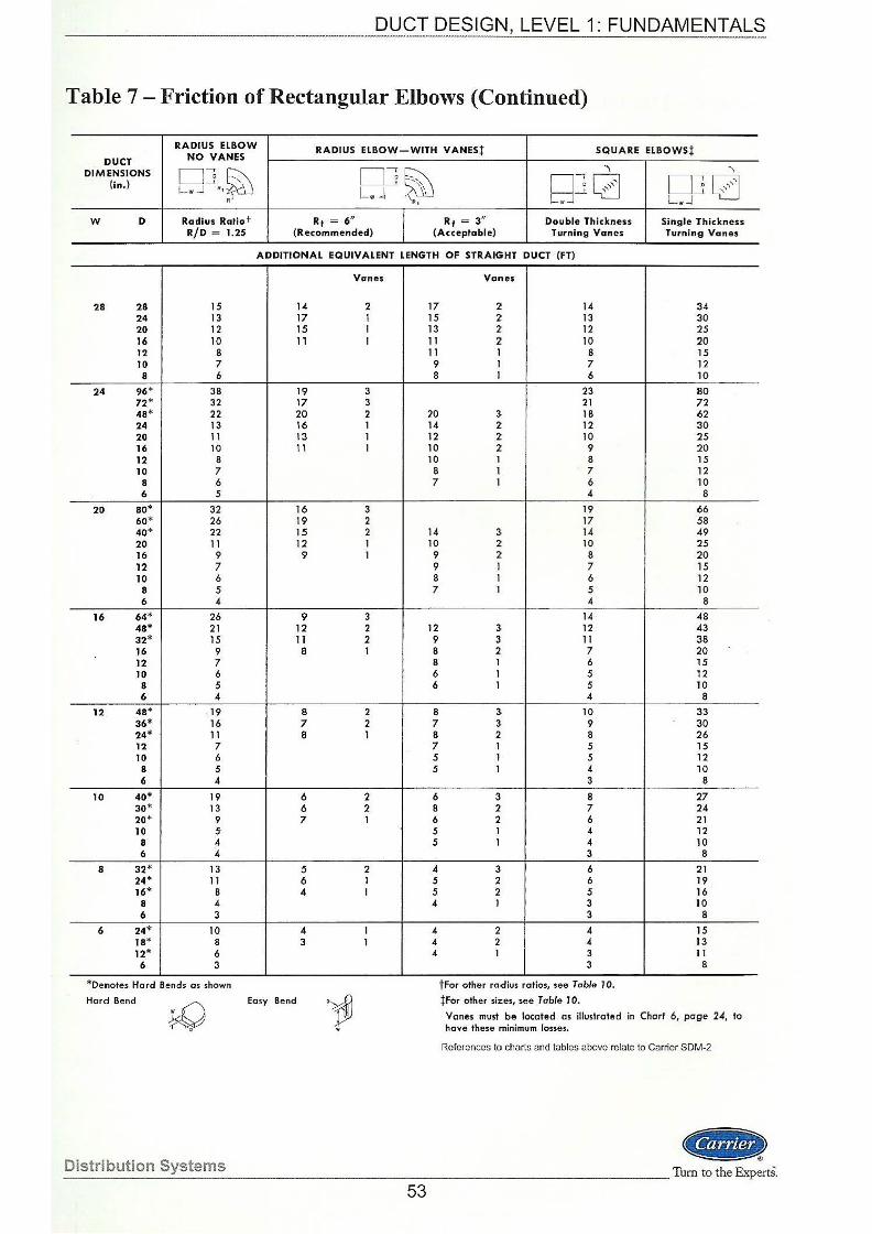
--------· __ _____ .__Q!}CT DESIGN, LEVEL 1: FUNDAMENTALS
Table 7- Friction of Rectangular Elbows (Continued)
RADIUS ELBOW RADIUS ELBOW-WITH VANES! SQUARE ELBOWSt DUCT NO VANES
DIMENSIONS DJ~ DJ§hl ""\ \
(in.) o~CZJ DJ[{j L w J "• Lw J '' _l_ ,,
RJ .. LwJ L w-J
w D Radius Ratiot Rt = 6" I Rt = 3" Double Thickness Single Thickness R/D = 1.25 (Recommended) (Acceptable) Turning Vanes Turning Vanes
ADDITIONAL EQUIVALENT LENGTH OF STRAIGHT DUCT (FT)
Vanes Vones
28 28 15 14 2 17 2 14 34 24 13 17 1 15 2 13 30 20 12 15 1 13 2 12 25 16 10 1, 1 11 2 10 20 12 8 11 1 8 15 10 7 9 1 7 12 8 6 8 1 6 10
24 96* 38 19 3 23 80 72* 32 17 3 21 72 48* 22 20 2 20 3 18 62 24 13 16 1 14 2 12 30 20 11 13 1 12 2 10 25 16 10 11 1 10 2 9 20 12 8 10 1 8 15 10 7 8 1 7 12
8 6 7 1 6 10 6 5 4 8
20 80* 32 16 3 19 66 60* 26 19 2 17 58 40* 22 15 2 14 3 14 49 20 11 12 1 10 2 10 25 16 9 9 1 9 2 8 20 12 7 9 1 7 15 10 6 8 1 6 12
8 5 7 1 5 10 6 4 4 8
16 64* 26 9 3 14 48 48* 21 12 2 12 3 12 43 32* 15 11 2 9 3 11 38 16 9 8 1 8 2 7 20 12 7 8 1 6 15 10 6 6 1 5 12
8 5 6 1 5 TO 6 4 4 8
12 48* . 19 8 2 8 J. 10 33 36* 16 7 2 7 3 9 30 24* 11 8 1 8 2 8 26 12 7 7 1 5 15 10 6 5 1 5 12
8 5 5 1 4 10 6 4 3 8
10 40* 19 6 2 6 3 8 27 30* 13 6 2 8 2 7 24 20* 9 7 1 6 2 6 21 10 5 5 1 4 12
8 4 5 1 4 10 6 4 3 8
8 32* 13 5 2 4 3 6 21 24* 11 6 1 5 2 6 19 16* 8 4 I 5 2 5 16
8 4 4 1 3 10 6 3 3 8
6 24* 10 4 I 4 2 4 15 TB* 8 3 1 4 2 4 13 12* 6 4 1 3 11
6 3 3 8
*Denotes Hard Bends as shown tFor other radius ratios, see Table 10.
! For other sizes, see Table T 0. Hard Be nd Easy Bend
Yanes must be located os illustrated in Chart 6, page 24, to have these minimum rosses.
References to charts and tables above relate to Carrier SDM-2
4D _D_i_s_tr_i_b_u_t_io_n_ S_:y:_s_t_e_m_ s __________________________ Turn to the Experts.
53
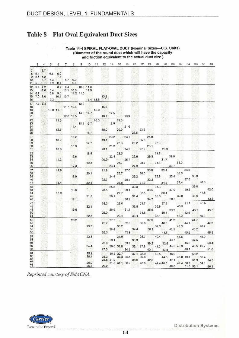
DUCT DESIGN, LEVEL 1: FUNDAMENTALS --------------------------------------
Table 8 - Flat Oval Equivalent Duct Sizes
Table 14-4 SPIRAL FLAT-OVAL DUCT (Nominal Sizes-U.S. Units) (Diameter of the round duct which will have the capacity
and friction equivalent to the actual duct size.)
3 4 5 6 7 8 9 10 11 12 14 16 18 20 22 24 26 28 30 32 34 36 38 40 .~·"···
'7 "'5.7 '' 8 5.1 ' 6.6 6.9 9 5.6 :6.2 . 7.7
1o c6.7. : 7.3 : 8.7 9.0 11 6.0 'f>: 7.9 8.4 9.8
12 6.4 ' 7.2 8.9 9.4 10.8 11.0 13 7.6 8.4 10.1 10.6 11.9 14 6.7 8.8 9.6 11.2 11 .5 15 7.0 8.0 10.1 10.7 13.8 16 9.3 13.4 13.6
17 7.3 il~4 12.9 18 11.7 12.4 15.3 19 10.0 11.0 15.0 . ' 20 14.0 14.7 17.5 21 12.6 13.5 16.7 19.9
22 11 ~8 . _, 16.3 19.5 23 15.1 15.7 : 18.9 24 14.4 21 .6 25 12.5 18.0 20.9 23.9 26 16.7 23.6
27 15.2 20.2 : 23.1 25.9 28 13.2 19.1 25.6 29 17.7 22.3 25.2 27.9 30 15.9 21.3 28.1 31 13.8 20.1 24.5 27.2 29.9
32 18.5 23.5 29.7 33 16.6 22.4 26.6 29.3 32.0 34 14.3 . 20.9 25.7 31) 35. 19.3 24.7 . 28.7 31.3 34.0 36 17.3 23.4 27.9 33.7
37 14.9 21 .9 27.0 30.8 33.4 36.0 38. 20.1 25.7 30.0 35.8 39 17.9 24.4 29.2 32.8 35.4 38.0 40 22,7 28.1 32.2" 37.8 41 15.4 20.8 26.8 31 .3 34.9 37.4 40.0
42. 25.3 30.3 34.3 ' 39.8 43 18.6 23.5 29.1 33.5 37.0 39.5 42.0 44 15.9 27.7 32.5 36.4 41 .8 45 21.5 26.1 31.4 35.6 39.0 41 .5 46 19.1 30.2 34.7 38.5 43.8
47 24.3 28.6 33.7 37.8 41 .1 43.5 Ml 22.1 32:s 36.9 40.5 49 19.6 26.9 31.1 35.9 39.9 43.1 45.6 50 25.0 34.8 39.1 42.6 51 22.8 29.4 33.4 . 38.1 . 42.0 45.2
52 20.2 27.7 37.0 41 .2 44.7 53 . 25.7 32.0 35.8 40.3 44.1 47.2 54 23.3 30.2 39.3 43.3 46.7 55 . 28.4 34.4 38.1 42.5 46.2 56 26.3 32.9 41.5 . 45.5 48.8 57 23.8 31.0 36.7 40.4 44.6 48.2 58 29.1 35.3 43.7 47.6 59 26.9 33.7 39.2 42.6 46.8 50.4 60 24.4 29.6 31./:l. '36.1 37.8 41 .3 44.5 45.9 48.5 49.7 62 27.5 34.5 40.1 43.5 48.1 51.8 64 25.1 30.5 32.7 37.1 38.9 42.5 46.0 50.2 66 25.4 28.3 33.3 35.4 39.6 44.8 48.0 49.7 52.4 68 28.6 31.2 38.0 42.0 47.1 51.9 54.5 70 26.0 31.5 34.1_ 36.2 40.6 44.4 46.0 49.4 50.9 54.1 12 26.3 29.2 48.6 51.6 53.1 56.2
Reprinted courtesy ofSMACNA .
.. Turn to the Experts.-· Distribution Systems
54
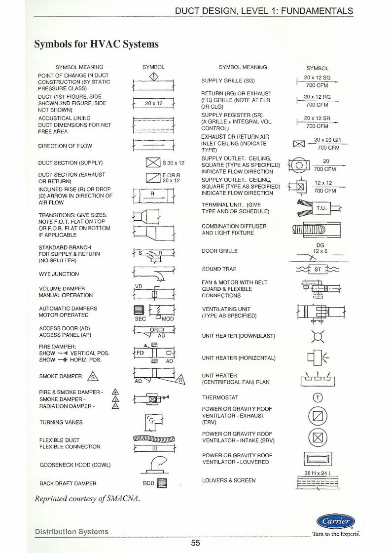
_ DUCT DESIGN, LEVEL 1: FUNDAMENTALS
Symbols for HV AC Systems
SYMBOL MEANING
POINT OF CHANGE IN DUCT CONSTRUCTION (BY STATIC PRESSURE CLASS)
DUCT (1 ST FIGURE, SIDE SHOWN 2ND FIGURE, SIDE NOT SHOWN)
ACOUSTICAL LINING DUCT DIMENSIONS FOR NET FREE AREA
DIRECTION OF FLOW
DUCT SECTION (SUPPLY)
DUCT SECTION (EXHAUST OR RETURN)
INCLINED RISE (R) OR DROP (D) ARROW IN DIRECTION OF AIR FLOW
TRANSITIONS: GIVE SIZES. NOTE F.O. T. FLAT ON TOP OR F.O.B. FLAT ON BOTTOM IF APPLICABLE
STANDARD BRANCH FOR SUPPLY & RETURN (NO SPLITTER)
WYE JUNCTION
VOLUME DAMPER MANUAL O PERATION
AUTOMATIC DAMPERS MOTOR OPERATED
ACCESS DOOR (AD) ACCESS PANEL (AP)
FIRE DAMPER: SHOW ---4 VERTICAL POS. SHOW --+ HORIZ. POS.
SMOKE DAMPER &. FIRE & SMOKE DAMPER- &, SMOKE DAMPER - & RADIATION DAMPER - &_
TURNING VANES
FLEXIBLE DUCT FLEXIBLE CONNECTION
GOOSENECK HOOD (COWL)
BACK DRAFT DAMPER
SYMBOL
+ <J>
+ 20 X 12 }
t-=--=--4 + + ~ S30x 12
t::7l EOA A lL:_j 20 X 12
t l R l}
ab fs~ }
f ~ VD £ + JR } ~n--1 SEC~ f ORD f
"""J AD
A.Uiil
fFD Jl o} U:iJ AD
tD"""'I~ ~
51 ~ f Il l + g BOD~
Reprinted courtesy of SMA CNA.
Distribution Systems
SYMBOL MEANING
SUPPLY GRILLE (SG)
RETURN (RG) OR EXHAUST (EG) GRILLE (NOTE AT FLR ORCLG}
SUPPLY REGISTER (SA) (A GRILLE + INTEGRAL VOL. CONTROL)
EXHAUST OR RETURN AIR INLET CEILING (INDICATE TYPE)
SUPPLY OUTLET. CEILING, SQUARE (TYPE AS SPECIFIED) INDICATE FLOW DIRECTION
SUPPLY OUTLET. CEILING SQUARE (TYPE AS SPECIFiED) INDICATE FLOW DIRECTION
TERMINAL UNIT. (GIVE TYPE AND OR SCHEDULE)
COMBINATION DIFFUSER AND LIGHT FIXTURE
DOOR GRILLE
SOUND TRAP
FAN & MOTOR WITH BELT GUARD & FLEXIBLE CONNECTIONS
VENTILATING UNIT (TYPE AS SPECIFIED)
UNIT HEATER (DOWNBLAST)
UNIT HEATER (HORIZONTAL)
UNIT HEATER (CENTRIFUGAL FAN) PLAN
THERMOSTAT
POWER OA GRAVITY ROOF VENTILATOR - EXHAUST (ERV)
POWER OR GRAVITY ROOF VENTI LA TOR - INTAKE (SRV)
POWER OR GRAVITY ROOF VENTILATOR- LOUVERED
LOUVERS & SCREEN
SYMBOL
20 X 12 SG
700 CFM
20 X 12 RG
?OOCFM
20 X 12 SR
700CFM
20 X 20 GR
700 CFM
~ 20
~ 70DCFM
~ 12xl2
~ ?OOCFM
~ Ql!l! 111 11m» 1
DG 12 X 6
----r...
T-=+ fill;, f
M c[]<
,~ 6 ~ ,
(i)
@) @)
I" 111 36 H x 24 L
§=--;---3 '
(&it) ::-:::--------------Turn to the ExpertS.
55

01 (j)
il ~.
l I
I 10
(E' ..... :!. 0" c:: :::!: 0 :l (JJ '< (/1 ..... <D 3 (/1
PROJECT NAME:
Duet Run
From-To
SYSTEM:
Duet Section
(element)
Lining (in.)
lnsul. (ln.)
Othor Item Airflow
Velocity In Round duct
(fpm)
!-----+--·----·-+- I-- -·--.. --f.-··---+
!.-..... .. ..
NOTES: All duct sizes indicated are Inside clear dimensions.
Velocity Pressure
Pv
DUCT SIZING WORKSHEET
Fitting Value
n
Length (ft) L
Equiv. Length (It)
EL
Material Corr<>etlon
Fnctor
Friction Loss fper 100' duct
Friction Loss
(in. wg)
Known Loss
(ln. wg)
Round Duct
Slzo(in.)
DATE:
PAGE: OF
Rectangular Item Loss Cumulative
Loss (ln.wg)
·-l- ··--····----
Equivalent 1 Total
~ (W X·~-· ..... ~:~:.:!.~ .j
X
X
X
X
X
X
X
X
X
--I- -- ·----X
X
X
X
-· -j-.......... j .. --- -1 X
X
X ,_, • .! .. , ___ _,_ ___ _,__
LARGEST STATIC PRESSURE LOSS (in. wg) C ............ ] FOR RUN=
0 c () -; 0 m (j)
G) z r m < m r -lo.
II c z 0 )> :5: m z ~ r (j)
DUCT DESIGN, LEVEL 1: FUNDAMENTALS ---------------------------------
Glossary
access floor
air distribution device
air handling unit ( AHU) I air handler
branch duct
breakout noise
chase
condensation
damper
duct
duct calculator
duct circuit
duct fitting
duct sizing
duct system
ductwork
equal friction duct sizing
external static pressure
fan
fan static pressure
Distribution Systems
a system of floor panels and supports that create a service utility plenum above the structural slab; allows using underfloor air distribution (UFAD) opening through which air discharges from (outlet) or enters into (inlet) a duct; may be a grille, register, diffuser, or geometric shape, like a slot. equipment, usually connected to duct\vork, to move and condition air; contains components such as fans, cooling coils, heating coils, filters and dampers to control return, outdoor and exhaust air
a duct section of the same size or smaller, connected to a hunk duct; serves one or more zones.
transmission or radiation of noise from some part of a duct system to an occupied space in the building.
vertical passage within a building for enclosing ducts, pipes or w1res. the process by which a vapor is changed into a liquid of the same temperature by removing heat from the vapor.
a device used to regulate the flow of air.
a conduit section used to move air, i.e. supply to the conditioned space, or return or exhaust from the space
slide rule or wheel used to manually size ducts and fittings based on parameters such as friction loss, velocity, static regain, and fitting coefficients. path from a fan to an outlet or inlet; duct systems normally have many circuits which need to be balanced to a similar static pressure.
connector creating a change of direction and/or cross-sectional area within the ductwork.
calculation of dimensions of ducts and fittings for a given duct system. interconnected sections of ductwork used to convey air or other gases from one location to another; may include fans, coils, terminals, and air distribution devices. series of interconnected ducts and fittings
method for calculating the size of ducts so that the frictional resistance per unit length is constant.
total static pressure difference of the duct system as measured between the equipment air outlet and inlet connections; see static pressure. a component that provides the energy to move air, typically through a duct system difference between fan total pressure and fan discharge velocity pressure.
--- ·---·--- -------------------- Turn to the ExpertS.
57
DUCT DESIGN, LEVEL 1: FUNDAMENTALS ·----------- - -- - -----------------------------
[1-iction loss
header duct
main duct I trunk duct
pressure loss created as a result of friction between a flowing fluid and its contact surface. an extended plenum off a terminal unit discharge that distributes the zone air to the air distribution devices.
the supply or return duct connected to the air source; distributes or collects air from building spaces.
modified equal friction duct method in which ducts sized by the equal friction method are resized sizing to increase or decrease the static pressure loss of a duct circuit to
improve self-balancing characteristic of the duct system.
noise
plenum
runout duct
static pressure
static regain duct sizing
system effects
takeoff
terminal unit
thermal insulation
total pressure
total supply air quantity
trunk duct I main duct
turbulence (eddy flow)
variable air volume (VA Ji)
velocity pressure
ventilation air
• , .. )
a sound, especially one that is loud, harsh or confused or undesired.
enclosed space within a building where air flows, similar to ductwork. Also used to enclose mechanical and electrical services. a connector duct between a terminal unit and a branch or trunk duct.
the potential energy component of air flowing in ductwork, represented by the Ideal Gas Law equation, PV=nRT, where the fan filling (static) pressure at the supply duct inlet is above atmospheric pressure due to the ductwork (V term in equation) outlet and friction losses. method for calculating the size of ducts so that the regain in static pressure due to decreased velocity between two points totally or partially compensates for the frictional resistance between the points.
inlet and outlet duct conditions at the fan that affect its performance and related testing, adjusting, and balancing work.
as a duct, connects the header duct to the air distribution devices; as a fitting, connects a runout duct to a branch or trunk duct.
component located in or near the zone that controls the supply airflow and/or temperature to the zone spaces; may have a fan, heating coil, and/or cooling coil. material or assembly of materials used to provide resistance to heat flow. the sum of the static pressure and velocity pressure.
the sum of the zone airflow quantities; determined from the maximum block load. the supply or return duct connected to the air source; distributes or collects air from building spaces.
fluid flow in which the velocity varies in magnitude and direction in an irregular mam1er throughout the mass.
systems where the supply airflow to the space is varied to maintain the temperature set point; the supply air temperature is usually constant. This is contrasted with a constant volume (CV) system. the kinetic energy component of air flowing in ductwork; represented by the equation Pv = (v/4005)2
.
planned outdoor airflow that is provided to a space to replace oxygen and dilute odors and contaminants .
Turn to the ExpertS._______ _____________________________ _ Distribution Systems 58
DUCT DESIGN, LEVEL 1: FUNDAMENTALS -------------------------
References
Carrier Corp.
System Design Manual - Air Distribution, SDM-2, Cat. No. 510-308.
Duct Design, Level 2: Modified Equal Friction, TDP-505: (IN DEVELOPMENT) Presentation Cat. No. 797-046 Book Cat. No. 796-046
Variable Air Volume and Constant Volume Terminals, TDP-506: Presentation Cat. No. 797-047 Book Cat. No. 796-047
Room Air Distribution, TDP-507 (IN DEVELOPMENT) Presentation Cat. No. 797-048 Book Cat. No. 796-048
SMACNA Technical Manuals and Standards
HV AC Systems- Duct Design, 3rd Ed., 1990.
Duct System Calculator, 1988.
HV AC Duct Construction Standards-Metal & Flexible, 2od Ed., 199 5. ·
Duct System Design
ASHRAE Handbook- Fundamentals (Duct Design)
ASHRAE/IES Standard 90.1-Energy Efficient Design ofNew Buildings (except Low Rise Residential Buildings).
Flexible Duct
UL Standard 181, for Factory-Made Duct Materials and Air Duct Connectors.
NFP A Standard 90A- Installation of Air Conditioning and Ventilating Systems.
Duct Liner
NFP A Standard 90A- Installation of Air Conditioning and Ventilating Systems .
.. Distribution Systems _________ _ ___ Thm to the ExpertS:
59
DUCT DESIGN, LEVEL 1: FUNDAMENTALS
Work Session 1 - Answers
1. Total Pressure: The sum of velocity pressure and static pressure.
Velocity Pressure: The force exerted in the duct system due to the relative speed of the air.
Static Pressure: The force exerted in all directions when air pressure is either elevated above or lowered below the atmospheric pressure.
2. a.), b.), d.), e.), f.)
3. False- The fan converts velocity pressure into static pressure in the first few feet of duct.
4. Potential energy
Kinetic energy
5. Whenever there is a change in velocity there is a corresponding and inverse change in static pressure.
6. From Equation 2: V = Q I A; V = 2,250 I 1.5 sq ft = 1,500 fpm [same fo:r both round and square].
7. Square- Square duct has a higher perimeter to area ratio.
8. Solve Equation 2 for flow rate Q; Q = V * A; Q = 1,000 fpm * 1.5 sq ft = 1,500 cfm.
9. a.), b.), c.), e.), f.)
10. From Table 4 in the Appendix: Read multiplier of3.2; f= 0.08 * 3.2 = 0.26 in. wg
11. c.), e.)
See Page 36 for Work Session 1 Equal Friction Duct Sizing Worksheet example .
Distribution Systems ..
. _ ___ ___ _ _ ________ Turn to the ExpertS.
61
DUCT DESIGN, LEVEL 1: FUNDAMENTALS -----·--------·--------
Work Session 2 -Answers
1. total supply air quantity
2. The air source cfin that meets the maximum simultaneous cooling load for the zones. This is often less than the sum of the largest zone cfms because they usually do not occur at the same time or day of the year.
3. False- Flex duct has over three times the friction loss rate of smooth sheet metal and should be used in 8 ft or less lengths to minimize total friction loss.
4. Advantages: quieter (attenuates fan noise), eliminates need for external duct insulation;
Disadvantages: increases duct friction loss, difficult to clean, may harbor microorganisms if allowed to get dirty and damp.
5. The air is very turbulent right off the fan and needs time to establish a uniform velocity profile. When fittings, transitions, etc. are located too close to the fan outlet it creates an additional friction loss value known as system effect.
6. False- Transition fittings cost more to fabricate and install than straight duct sections. You should attempt, whenever possible, to maintain at least one of the duct dimensions when transitioning from one duct size to another and should only downsize when the velocity drops below the recommended value.
7. The first duct section is sized based on an assumed velocity. Table 2 in the Appendix lists recommended design velocity values.
8. False - Retum air plenums should not be used on top floors adjacent to roofs due to the heat gain from the roof being entrained in the return air. Also, under certain conditions the temperature of the structural beams or other materials located in the plenum may be colder than the dew point of the retum air. Under these conditions condensation will form on these surfaces causing stained ceiling tiles and possibly wet surfaces that can harbor growth of microorganisms.
9. c.)
10. e.)
11. e.)
12. False - It means that all duct sections are sized using an equal friction rate. Variations in section friction losses are balanced by downsizing the shorter mns or by installing balancing dampers.
13. False- The equal friction rate is generally the preferred method for sizing retum duct systems.
14. c.), d.), f.)
15. By downsizing the shorter duct runs with lower friction loss there is less of a requirement to "choke" the airflow by the use of balancing dampers; results in smaller ducts, which saves money.
16. Advantages: lower system pressure drop, creates a self-balancing duct system, lower fan operating cost Disadvantages: larger duct sizes, more expensive to install, more difficult to design.
17. The duct velocities are systematically reduced as you proceed down the duct system from the fan, resulting in a conversion of the velocity pressure into static pressure. This increased static pressure overcomes a portion of the air friction loss in the next downstream duct section .
.. ) Tum to the Expe1tS: ------·----------- Distribution Systems
62
Prerequisites:
An understanding of air conditioning equipment and systems along with the airflows required to satisfy the heating and/or cooling loads. This knowledge can be gained from: TDP-1 03, ABCs of Comfort; TDP-301, Load Estimating, Level 1: Fundamentals; and TDP-302, Load Estimating, Level 2: Block and Zone Loads.
Learning Objectives:
After completing this module, participants will be able to:
• Describe fundamental theory and principles of airflow through duct systems.
• Apply a step-by-step process and evaluation criteria to duct design.
• Calculate air velocity and pressure loss in round and rectangular ducts and fittings.
• Diagram the ductwork layout for the actual building design and notate it with airflows, dimensions, and devices affecting sizing selections.
• Size supply and return air duct systems manually, with either a friction chart or duct cakulator, using the equal friction method.
• Estimate the approximate total duct system static pressure losses in order to size the system fan. ·
' • Integrate code and standard requirements for energy conservation into the design process.
Supplemental Material:
Form No.
T200-11
Instructor Information:
Cat. No.
794-036
Title
Duct Calculator
/
Each TOP topic is supported with a number of different items to meet the specific needs of the user. Instructor materials consist of a CD-ROM disk that includes a PowerPoinf"' presentation with convenient links to all required support materials required for the topic. This always includes: slides, presenter notes, text file including work sessions and work session solutions, quiz and quiz answers. Depending upon the topiC, the instructor -€ D may also include sqund;- video, spreadsheets, forms, or other material required to present a complete class. Self-study or student material consists of a text including work session~ and work session answers, aRd may also include forms, worksheets, calculators, etc.