downsizing semi-submersible rig by using an electric bop
TRANSCRIPT
NTN
UN
orw
egia
n U
nive
rsity
of S
cien
ce a
nd T
echn
olog
yFa
culty
of E
ngin
eerin
gD
epar
tmen
t of G
eosc
ienc
e an
d Pe
trol
eum
Mehm
an Ahmadli
Dow
nsizing semi-subm
ersible rig by using an electric BOP and riserless drilling system
Mehman Ahmadli
Downsizing semi-submersible rig byusing an electric BOP and riserlessdrilling system
Master’s thesis in Petroleum EngineeringSupervisor: prof. Behzad ElahifarCo-supervisor: prof. Sigbjørn Sangesland
June 2021
Mas
ter’s
thes
is

Mehman Ahmadli
Downsizing semi-submersible rig byusing an electric BOP and riserlessdrilling system
Master’s thesis in Petroleum EngineeringSupervisor: prof. Behzad ElahifarCo-supervisor: prof. Sigbjørn SangeslandJune 2021
Norwegian University of Science and TechnologyFaculty of EngineeringDepartment of Geoscience and Petroleum

TPG 4920 Petroleum Engineering – Master’s Thesis Mehman Ahmadli
1
PREFACE
This Master Thesis report is written for the course of “TPG 4920” as the last part of the two-
years international master’s degree programme in Petroleum Engineering at the Department
of Geoscience and Petroleum at the Norwegian University of Science and Technology, NTNU
during spring semester of 2021.
“The stone age ended, not because we ran out of stones” was the phrase that came to my
mind when I first started to work on this project. This is because this report has brought
innovative ideas and products together, at the end to offer a new drilling system that will
support continuity of the safe and clean petroleum extraction in future by being a product of
the new drilling era. Having a specialization in Drilling Engineering and working against the
traditional way of drilling process are the main motivation for me during this semester.
Without any doubt, the motivation alone cannot do much work unless there are strong
supports from my supervisor – prof. Behzad Elahifar who guided me during the whole project
and shared his valuable ideas that mirrored on the report, my co-supervisor – prof. Sigbjørn
Sangesland whose reflections and critical questions gave directions to the report, my co-
supervisor in petroleum industry – Farid Huseynov, drilling engineer at BP, who guided me
during “Maersk Explorer” rig data processing. I would also like to express my sincere gratitude
to Electrical Subsea & Drilling (ESD), especially John Dale, to Noble Drilling, especially Robert
van Kuilenburg, to Gradient Drilling Solutions, especially Børre Fossli for their valuable inputs.
Full Name: Mehman Ahmadli
Date / Place: 17th June 2021 / Trondheim, NORWAY
Signature:
TPG 4920 Petroleum Engineering – Master’s Thesis Mehman Ahmadli
2
SUMMARY
In comparison with the other sectors, the petroleum industry is more resistive to significant
changes, and to adapt new technologies. The oil- and gas companies prefer to stay with the
traditional and well proven methods. However, it is also true that the individual challenges
are bringing new methods and techniques to the petroleum industry (e.g., advances in
directional- and horizontal drilling on the Troll field, Norway). Now, it is again a time for the
drilling industry to open a new page. Future global demand will be provided from ultra-deep-
water reservoirs. Conventional drilling operation using standard systems and equipment will
be a challenge due to increasing size & weight of the BOP and marine drilling riser system, and
thus the requirement for large and costly drilling vessel.
To overcome the above-mentioned challenges and to downsize the semi-submersible rig, this
master’s thesis report deals with a new system for drilling, which will be referred as a Riserless
Drilling (RD) system. In the design of the RD system, all hydraulic system of the BOP, marine
riser and their associated rig equipment are eliminated. Instead, electric control system and
actuators have been integrated, which offers efficiency, durability, reliability, follow-up inputs,
continuous monitoring, maintenance input, speed-torque control, autonomous control by
CPU unit, and most importantly cost-saving solution. Heavy and large marine riser is replaced
by mud return line which is lighter and smaller in diameter. Just a BOP update offers 140 mT
weight reduction and 1051 ft2 rig space saving, while by counting the elimination of the marine
riser, this figure is multiplied to 3600 ft2 saving in the rig area.
Apart from the CAPEX reduction in the new RD system, OPEX is also decreased due to shorter
rig time and less down time (NPT). The report compares a typical BOP maintenance operation
in the CRD and new RD system, and concludes that the latter one offers 2,550,000 USD cost
reduction in just one operation. Considering the significant advantages that the new RD
system offers, we can witness major changes in future drilling operation. However, the
concept requires significant development including subsea boosting system and a safe well
control solution, etc.
TPG 4920 Petroleum Engineering – Master’s Thesis Mehman Ahmadli
3
SAMMENDRAG
Sammenlignet med andre sektorer er petroleumsindustrien mer konservativ for å gjøre
betydelige endringer, og for å tilpasse ny teknologi. Olje- og gasselskapene foretrekker å holde
seg til de tradisjonelle og velprøvde metodene. Imidlertid er det også riktig at de enkelte
utfordringene bringer nye metoder og teknikker til petroleumsindustrien (f.eks. fremskritt
innen retnings- og horisontal boring på Troll-feltet, Norge). Nå er det igjen tid for borebransjen
å åpne en ny side. Fremtidig global etterspørsel vil komme fra fra ultra-dypt vann.
Konvensjonell boreoperasjon ved bruk av standard systemer og utstyr vil være en utfordring
på grunn av økende størrelse og vekt på BOP og marint borestigerør, og dermed tilhørende
stort og kostbart boreskip.
For å overvinne de ovennevnte utfordringene og redusere størrelse og vekt på borefartøyet,
er det i denne masteroppgaven fokusert et nytt system for boring, og vil bli referert til som
Riserless Drilling (RD) system. I utformingen av RD-systemet er alt hydraulisk system i BOP,
marine stigerør og tilhørende riggutstyr eliminert. I stedet er det elektriske styresystemet og
aktuatorene integrert, noe som gir bedre effektivitet, holdbarhet, pålitelighet, oppfølging,
kontinuerlig overvåking, vedlikeholdsinngang, hastighet og momentkontroll, autonom
kontroll med CPU-enhet og viktigst av alt, en kostnadsbesparende løsning. Det store 21
tommers marine stigerøret erstattes av slamreturlinje som er lettere og mindre i diameter.
Bare en BOP-oppdatering muliggjør 140 mT vektreduksjon og 1051 ft2 plassbesparelse
fartøyet, mens ved å eliminere det marine store stigerøret, blir besparelse i riggområdet ca.
3600 ft2.
Bortsett fra CAPEX-reduksjonen i det nye RD-systemet, reduseres også OPEX på grunn av
kortere riggtid og mindre nedetid (NPT). Rapporten sammenligner en typisk BOP-
vedlikeholdsoperasjon i CRD og det nye RD-systemet, og konkluderer med at sistnevnte
muliggjør 2,550,000 USD kostnadsreduksjon for bare en operasjon. Med tanke på de
betydelige fordelene som det nye RD-systemet gir, kan vi være vitne til store endringer i
fremtidig boreoperasjon. Imidlertid krever konseptet betydelig utvikling, inkludert subsea
pumpe system og en sikker løsning for brønnkontroll, etc.
TPG 4920 Petroleum Engineering – Master’s Thesis Mehman Ahmadli
4
PREFACE ..................................................................................................................................... 1
SUMMARY................................................................................................................................... 2
SAMMENDRAG ............................................................................................................................ 3
i. List of Figures .............................................................................................................. 6
ii. List of Tables ........................................................................................................... 8
i. List of Equations .......................................................................................................... 8
ii. Nomenclatures ......................................................................................................... 9
I. INTRODUCTION ................................................................................................................. 11
A. BACKGROUND............................................................................................................ 11
B. OBJECTIVES ............................................................................................................... 12
C. LIMITATION ............................................................................................................... 13
D. STRUCTURE OF THE REPORT ..................................................................................... 13
II. CONVENTIONAL RISER DRILLING SYSTEM .................................................................. 14
A. ELECTRO – HYDRAULIC BOP CONTROL SYSTEM .................................................... 14
1. BASIC DESIGN ........................................................................................................ 15
2. CONTROL SYSTEM ................................................................................................. 18
3. ACTUATORS ........................................................................................................... 19
4. HYDRAULIC POWER UNIT ..................................................................................... 21
5. CASE STUDY .......................................................................................................... 23
B. MARINE RISER SYSTEM ............................................................................................ 26
1. BASIC DESIGN ........................................................................................................ 27
III. UNCONVENTIONAL RISER DRILLING SYSTEMS ........................................................... 31
A. MANAGED PRESSURE DRILLING (MPD) .................................................................. 31
B. CONTROLLED MUD LEVEL (CML) ........................................................................... 34
C. DUAL GRADIENT DRILLING (DGD) ......................................................................... 36
IV. ELECTRIC BOP CONTROL SYSTEM .............................................................................. 37
A. EBOP SYSTEM – «NOBLE DRILLING» ....................................................................... 37
1. BASIC DESIGN & ACTUATORS ............................................................................... 37
2. CONTROL & POWER SYSTEM ................................................................................. 40
B. ALL-ELECTRIC BOP CONTROL SYSTEM – “ELECTRICAL SUBSEA & DRILLING” ... 42
TPG 4920 Petroleum Engineering – Master’s Thesis Mehman Ahmadli
5
1. BASIC DESIGN & ACTUATORS .............................................................................. 42
2. CONTROL & POWER SYSTEM ................................................................................ 49
C. COMPARISON OF ELECTRIC BOP CONTROL SYSTEMS ............................................. 51
V. COMPARISON OF ALL-ELECTRIC VS. ELECTRO-HYDRAULIC BOPS ................................. 52
A. CHALLENGES ............................................................................................................. 53
1. ULTRA-DEEP-WATER DEPTH DRILLING, WEIGHT & SIZE CHALLENGES ................ 53
2. BOP EQUIPMENT RUNNING & RETRIEVING. .......................................................... 54
B. ACTUATORS ............................................................................................................... 55
C. POWER SYSTEMS ........................................................................................................ 56
D. DURABILITY .............................................................................................................. 57
E. FOOTPRINTS ............................................................................................................... 58
F. EXPENDITURES .......................................................................................................... 61
VI. RISERLESS DRILLING SYSTEM ...................................................................................... 63
A. RISERLESS MUD RECOVERY, RMR® SYSTEM – “ENHANCED DRILLING” ............. 63
1. BASIC DESIGN ........................................................................................................ 64
B. SUBSEA RCD SYSTEM – «ELECTRICAL SUBSEA & DRILLING AS” ......................... 67
1. BASIC DESIGN ........................................................................................................ 68
C. NEW RISERLESS DRILLING (RD) SYSTEM ................................................................ 70
1. BASIC DESIGN ........................................................................................................ 71
2. FOOTPRINT ............................................................................................................. 75
3. CHOKE & KILL LINES ............................................................................................ 77
4. WELL CONTROL ..................................................................................................... 81
VII. DISCUSSION ............................................................................................................... 85
VIII. CONCLUSION & FUTURE WORK ................................................................................ 90
IX. REFERENCES .................................................................................................................. 91
X. APPENDIX ......................................................................................................................... 95
A. “MAERSK EXPLORER” RIG........................................................................................ 95
B. COST COMPARISON OF OWDS VS. CONVENTIONAL DRILLING SYSTEM ................. 99
C. COST OF FUEL AND CONSUMPTION ........................................................................ 100
TPG 4920 Petroleum Engineering – Master’s Thesis Mehman Ahmadli
6
i. List of Figures
Figure 1: Subsea BOP Configuration......................................................................................... 15
Figure 2: Schemes of Annular BOP ........................................................................................... 16
Figure 3: Schematic View of Ram BOP Preventers Shear Ram on top; Pipe Ram on bottom .. 17
Figure 4: Hydraulic BOP Operating Sequence – Close Function ............................................... 18
Figure 5: Main Elements of Annular Preventer ........................................................................ 19
Figure 6: Annular Preventer in "Closed Position" ..................................................................... 20
Figure 7: Annular Preventer in "Open Position" ....................................................................... 20
Figure 8: Ram Preventer in "Closed Position" .......................................................................... 21
Figure 9: Ram Preventer in "Open Position" ............................................................................ 21
Figure 10: BOP Control Unit ..................................................................................................... 22
Figure 11: Schematic View of the BOP used by "Maersk Explorer" rig ...... Error! Bookmark not
defined.
Figure 12: BOP Stack in Maersk Explorer ................................................................................. 25
Figure 13: 15-gallon hydraulic bottles ..................................................................................... 26
Figure 14: External Line Orientation......................................................................................... 27
Figure 15: Tool Locked and Unlocked ...................................................................................... 28
Figure 16: Test Running Tool .................................................................................................... 28
Figure 17: Spider - front view ................................................................................................... 28
Figure 18: Gimbal - top view .................................................................................................... 29
Figure 19: Telescopic Joint ....................................................................................................... 29
Figure 20: Tension Ring (ID: 48 in.) .......................................................................................... 30
Figure 21: Hydraulic Control Panel and 4-Way Valve .............................................................. 30
Figure 22: Pressure Profiles ...................................................................................................... 32
Figure 23: MPD Integrated Riser Joint (IRJ) .............................................................................. 33
Figure 24: Marine Riser modified for CML system ................................................................... 34
Figure 25: BHP in Conventional Drilling System ....................................................................... 35
Figure 26: BHP concept in CML System .................................................................................... 35
Figure 27: Dual-gradient drilling riser and equipment configuration ..................................... 36
Figure 28: eBOP™ prototype demonstrated in Texas, 2017 ..................................................... 37
Figure 29: eBOP™ Actuator Concept Model ............................................................................ 38
Figure 30: Assembled Roller Screw Drive ................................................................................. 38
TPG 4920 Petroleum Engineering – Master’s Thesis Mehman Ahmadli
7
Figure 31: Booster Pressure System ......................................................................................... 39
Figure 32: Subsea Electrical BOP System Concept ................................................................... 41
Figure 33: eBOP Shear Chart ................................................................................................... 42
Figure 34: System Architecture for the Electric BOP concept ................................................... 43
Figure 35: Ring Piston Actuator ................................................................................................ 44
Figure 36: Ring Piston Actuator Concept for Connectors ......................................................... 44
Figure 37: General View of the Electro-mechanic Ram Actuator ............................................ 45
Figure 38: Inner View of the Electro-mechanic Ram Actuator ................................................. 46
Figure 39: Ring Motor of the Electro-mechanic Ram Actuator ............................................... 46
Figure 40: Internal Planetary Gear of the Electro-mechanic Ram Actuator ............................ 47
Figure 41: Transfer of the Torque from the Gear to the Drive Shaft ....................................... 47
Figure 42: Electro-mechanic Ram Actuator in the Closing Operation ..................................... 48
Figure 43: (a) Double Acting (b) Spring Return Valve Actuators ............................................ 48
Figure 44: Comparison of BOP Stacks - Hydraulic (left) and All-electric (right) Control Syste . 54
Figure 45: Eliminated Parts of the BOP .................................................................................... 58
Figure 46: HPU & other Hydraulic Equipment (left) MUX Reels (right) .................................... 59
Figure 47: BOP Hydraulic System related Rig Parts ................................................................. 60
Figure 48: Basic Design of RMR system .................................................................................... 64
Figure 49: Suction Module of the RMR system ........................................................................ 65
Figure 50: Subsea Pump Module (SPM) ................................................................................... 65
Figure 51: RCD System ............................................................................................................. 69
Figure 52: RCD Housing integration to BOP ............................................................................. 70
Figure 53: Cutaway View of the CRP ........................................................................................ 73
Figure 54: Process Unit (PU) (left); Control Unit (CU) (right).................................................... 74
Figure 55: Schematic View of the Return Line)......................................................................... 74
Figure 56: Basic Schematic Design of the Drillstring valve ....................................................... 75
Figure 57: (a) Direct Riser Tensioners (b) Riser String Storage Room ...................................... 76
Figure 58: Riser string storage space in (a) Lower Deck (b) Main Deck (c) Upper Deck / (d)
Riser Tensioner Dual Unit ......................................................................................................... 77
Figure 59: Illustration of Conventional Riser Drilling ................................................................ 77
Figure 60: Configuration I of RD system ................................................................................... 78
Figure 61: Configuration II of RD System.................................................................................. 80
TPG 4920 Petroleum Engineering – Master’s Thesis Mehman Ahmadli
8
Figure 62: Equal Mud Density illustration in CRD and RD systems .......................................... 82
Figure 63: U-tube representation during (a) Normal Drilling Operation (b) Gas Influx ........... 83
Figure 64: (a) Circulation rate at subsea and surface (b) SPP and pump inlet pressure .......... 84
Figure 65: Schematic View of Lower Deck ................................................................................ 97
Figure 66: Schematic View of Main Deck ................................................................................. 98
Figure 67: Schematic View of Upper Deck ................................................................................ 98
Figure 68: Expenditures during 1,000 ft. drilling with Conventional Drilling System ............... 99
Figure 69: Expenditures during 1,000 ft. drilling with OWDS .................................................. 99
ii. List of Tables
Table 1: All-electric BOP Actuators ........................................................................................ 43
Table 2: Patent Details of the All-electric Actuators ............................................................... 49
Table 3: Comparison of two electric BOP control system ....................................................... 52
Table 4: Comparison of BOP running & retrieving duration ................................................. 55
Table 5: Estimated BOP Weight Loss after switching to electric BOP ................................... 58
Table 6: Estimated Rig Weight Loss after switching to electric BOP ..................................... 59
Table 7: Estimated Rig Space Savings after switching to electric BOP. ................................. 60
Table 8: Hydraulic BOP Reliability Analysis........................................................................... 62
Table 9: Typical spend time in case of hydraulic BOP failure. .............................................. 62
Table 10: Estimated Rig Space Savings after eliminating marine riser. ................................. 76
iii. List of Equations
Equation 1: Boyles's Law ......................................................................................................... 39
Equation 2: BHP Calculation in the RD system ....................................................................... 81
Equation 3: Equal Mud Density calculation for the new RD system ....................................... 81
TPG 4920 Petroleum Engineering – Master’s Thesis Mehman Ahmadli
9
iv. Nomenclatures
A – Amper
AID – Annular Isolation Device
API – American Petroleum Institute
BHP – Bottom-hole Pressure
BOP – Blowout Preventer
BP – British Petroleum
BSEE – Bureau of Safety and Environmental Enforcement
BSR - Blind Shear Ram
BTR – Below Tension Ring
CAPEX – Capital Expenditures
CBHP – Constant Bottom-hole Pressure
CC – Control Container
CML – Controlled Mud Level
CPU - Central Processing Unit
CRD – Conventional Riser Drilling
CRP – Central Reciprocating Pump
CU – Control Unit
DAT – Direct Acting Tensioners
DC – Direct Current
DGD – Dual Gradient Drilling
ECD – Equivalent Circulating Density
EHBS - Emergency Hydraulic Backup System
EMD – Equal Mud Density
ESD – Electrical, Subsea & Drilling
FG – Fracture Gradient
FIT – Formation Integrity Test
HMI – Human-Machine Interface
HPHT – High Pressure High Temperature
TPG 4920 Petroleum Engineering – Master’s Thesis Mehman Ahmadli
10
HPU – Hydraulic Power Unit
ID – Inner Diameter
IRJ – Integrated Riser Joint
kV – kilo Volt
kW – kilo Watt
LMRP – Lower Marine Riser Package
LOT – Leak-off Test
MPD – Managed Pressure Drilling
MRL – Mud Return Line
MUX - Multiplex system
MW – Mud Weight
NORSOK - Norsk Sokkels Konkurranseposisjon
NPT – Non-productive rig Time
OPEX – Operational Expenditures
OTC – Office Tool Container
OWDS – Open Water Drilling System
PPFG – Pore Pressure Fracture Gradient
PU – Process Unit
QRS – Quick Release System
RCD – Rotating Control Device
RD – Riserless Drilling
RMR – Riserless Mud Recovery
ROV – Remotely Operated Vehicle
SMO – Suction Module
SPM – Subsea Pump Module
SPP – Standpipe Pressure
SSR - Super Shear Ram
TD – Total Depth
UPR - Upper Pipe Ram
UW – Umbilical & Umbilical Winch
VFD – Variable Frequency Drive
WOW – Wait on Weather
TPG 4920 Petroleum Engineering – Master’s Thesis Mehman Ahmadli
11
I. INTRODUCTION
A. BACKGROUND
Published energy outlook reports by international energy companies has predicted that the
global oil demand will range between 50 and 110 mbd in 2050 depending on the world energy
transition scenarios. Today’s existing oil assets will not be able to supply before mentioned
amounts of demand in the future, which suggests that oil exploration process will continue. A
similar analogy is also valid for global gas production, thereby gas exploration process.
Therefore, in future drilling operations will continue in deep-water and ultra-deep-water
locations, which seems quite challenging with today’s drilling technology and practice. The
challenges mainly include the significant costs (CAPEX & OPEX) associated with the process,
and stricter ecological regulations.
The main cost contributor during ultra-deep-water drilling process is the rental fee of the
higher generation semi-submersible rigs, e.g., for the sixth-generation drilling rig, daily rate is
equal to approximately 300,000 USD. The need for the higher generation drilling rig arises as
the lower generation rigs cannot provide required rig space, high-capacity equipment and
cannot handle the loads that will be experienced during ultra-deep-water drilling.
Another point is the increasing time spending for drilling operation as the rig is moved to
deeper locations. The reason is because running & retrieving drill string, casings, BOP, and
other tools requires more time. Adding the fact that hydraulic system of the BOP and subsea
valves is willing to leak or fail more often than it is in shallower water locations, the
expenditures will be multiplied due to increasing non-productive rig time (NPT). Additionally,
it should be noted that to drill deep-water wells is also consuming more time due to the
pressure imbalance while drilling conventional. The narrower drilling window as water depth
increases leads to shorter drilling lengths for each well section, hence requiring more casing
strings to be set. This takes time and always working within the narrow margins against PPFG
creates more NPT.
TPG 4920 Petroleum Engineering – Master’s Thesis Mehman Ahmadli
12
All in all, to be able to drill in ultra-deep sea water locations, the size and capacity of rig & rig
equipment, marine riser, subsea equipment are to be increased, which increases the capital
& operational expenditures and associated problems proportionally. Therefore, in the market
there is a strong need for a new, safe, reliable, durable, and most importantly cheaper
solution.
B. OBJECTIVES
As it is clear from the name, an ultimate goal for the master’s thesis project is downsizing a
semi-submersible rig. However, a reader can feel the way that the discussions are mainly
around the deep-water drilling. The reason for focusing mainly on the ultra-deep-water
drilling, is because there the challenges and issues of the larger drilling rigs, equipment is more
significant and noticeable which can attract the companies easily. In case of the successful
implementation of the suggested riserless drilling concept in deep sea water locations, shallow
water drilling can follow up later, after which a new page in drilling operations will be opened.
Regarding the other objectives, they are listed below:
• Literature review of current electro-hydraulic BOP control system, its basic design,
hydraulic parts, and power unit.
• Going through the design of marine riser system and its functionalities.
• Literature review of the unconventional riser drilling system and detecting concepts
that will be used in the new RD system.
• Literature review of different electric BOP control systems, designs, power unit, that
are available on the market.
• Comparison of the electric vs electric and electric vs electro-hydraulic BOP control
systems in the manner of the challenges, reliability, footprints, expenditures.
• Literature review of the riserless drilling system and detecting concepts that will be
used in the new RD system.
• Analyzing new suggested RD system, its basic design, choke & kill line configurations,
and most importantly its well control procedures.

TPG 4920 Petroleum Engineering – Master’s Thesis Mehman Ahmadli
13
C. LIMITATION
“Electric BOP” and “Riserless Drilling” systems. Regarding each term there have been
publications dating back to early 20th century, however surprisingly it is very rare to see an
extensive paper that suggests using drilling all the well sections with an electric BOP in the
absence of marine riser.
Addition to the challenge of less publications related to the topic, another obstacle is the fact
that all-electric BOP has never been implemented by any drilling company, in other words we
do not have real data about all-electric BOP rather relied on the theoretical & simulation data.
Regarding hydraulic BOP and rig data, inputs are provided by “BP Azerbaijan” and “Maersk”
companies, regarding the electric BOP control system Electrical Subsea & Drilling company has
provided the related data. It is also important to mention that author’s previous works have
been used partly in this report.
D. STRUCTURE OF THE REPORT
The report is structured in a way that through the report the reader is informed about the
conventional drilling system, its components including electro-hydraulic BOP control system,
basic design, and after that is introduced about the unconventional riser drilling system and
its parts. Related case studies and current products on the market are also covered there. The
report then follows the various electric BOP control systems, their design basis, working
principle, and power unit, after which the comparison takes place between two different
electric BOP control systems and between electro-hydraulic and all-electric BOP control
system in the manner of the challenges, actuator concept, power system, durability, footprint
and most importantly expenditures. Under VI section, which is about riserless drilling system,
the products of different companies that will be integrated into the new RD system, are
covered in detail. As a last part in this section, the new RD system is described, its design basis,
configurations and well control concept are analysed. Finally, the Discussion and Conclusion
part discuss the whole project extensively, and gives recommendations for future work,
respectively.
TPG 4920 Petroleum Engineering – Master’s Thesis Mehman Ahmadli
14
II. CONVENTIONAL RISER DRILLING SYSTEM
A. ELECTRO – HYDRAULIC BOP CONTROL SYSTEM
During normal drilling process the well is kept stable by means of hydrostatic head of drilling
fluid within the wellbore, which is called primary well control. Primary well control is simply
based on the bottom hole pressure created by drilling fluid, that is higher than formation pore
pressure, less than formation fracture pressure. However, in case of loss of primary well
control which can be caused by many factors, the balance between the wellbore pressure and
formation pressure is shifted and this leads to the occurrence of the well kick. Depending on
the formation fluid type there are three types of the well influx among which gas influx is
considered as the worst-case scenario.
When the influx happens, the well is closed immediately to prevent further influx by sealing
the pressure inside the wellbore. For that the well barrier elements that exposed to the high
pressure must be capable of handling such pressures. BOP is a top barrier element and closing
the well, indeed, means closing the BOP valves. This is called secondary well control, that rely
on the design pressures of the valves and other barrier elements.
Therefore, a BOP is an important part of the well control process, and there are a lot of
requirements for the design of the BOP system, which makes is quite complex system.
Nowadays, most of the BOP system in the world are controlled electro-hydraulically from the
surface land or rig. In the following headings, electro-hydraulically controlled subsea BOP
system will be studied, and then the technical data of the BOP used in the Caspian Sea region
will be given as a case study and further comparison with the different systems.

TPG 4920 Petroleum Engineering – Master’s Thesis Mehman Ahmadli
15
1. BASIC DESIGN
Basically, the whole BOP equipment can be
considered as a stack of various BOP valves as
represented in Basic Design The configuration,
number, capacity, and other technical
parameters of the valve types used in the stack
vary a lot depending on the location, water
depth, fluid type and so on. The one that we are
going through is the subsea BOP system, which
has differences from the one used on land. The
differences mainly include the parts needed for
subsea BOP system to build communication
with the surface rig (Umbilical system, hydraulic lines, and connectors), to control the BOP
from the surface and automatically in case of emergency (Control pods, remote actuation
system, hydraulic accumulators), to overcome the underwater load and flows (riser joint,
support frame).
Lower Marine Riser Package (LMRP) is the upper section of the BOP system that connects the
riser system to the BOP stack. The LMRP is designed to overcome the horizontal movements
of the riser due to harsh weather condition, in worst case scenario to release itself from the
BOP stack to ensure the well safety. Additionally, two independent control pods are placed on
the LMRP, which includes all the primary system controls for lower BOP and the LMRP itself.
The following elements basically form the LMRP:
• Riser adapter is a top element of the BOP which connects the riser string to the LMRP.
It also includes choke, kill, conduit and booster lines.
• Flex Joint allows movement of the riser around the BOP stack with minimum bending
moment. Typically, up to 10 degrees angle of deflection from the BOP vertical axis can
be compensated (Bai & Bai, 2005).
Figure 1: Subsea BOP Configuration
TPG 4920 Petroleum Engineering – Master’s Thesis Mehman Ahmadli
16
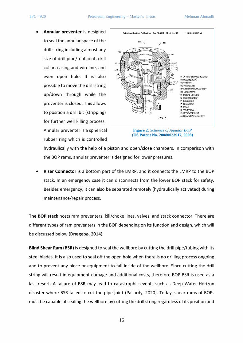
• Annular preventer is designed
to seal the annular space of the
drill string including almost any
size of drill pipe/tool joint, drill
collar, casing and wireline, and
even open hole. It is also
possible to move the drill string
up/down through while the
preventer is closed. This allows
to position a drill bit (stripping)
for further well killing process.
Annular preventer is a spherical
rubber ring which is controlled
hydraulically with the help of a piston and open/close chambers. In comparison with
the BOP rams, annular preventer is designed for lower pressures.
• Riser Connector is a bottom part of the LMRP, and it connects the LMRP to the BOP
stack. In an emergency case it can disconnects from the lower BOP stack for safety.
Besides emergency, it can also be separated remotely (hydraulically activated) during
maintenance/repair process.
The BOP stack hosts ram preventers, kill/choke lines, valves, and stack connector. There are
different types of ram preventers in the BOP depending on its function and design, which will
be discussed below (Drægebø, 2014).
Blind Shear Ram (BSR) is designed to seal the wellbore by cutting the drill pipe/tubing with its
steel blades. It is also used to seal off the open hole when there is no drilling process ongoing
and to prevent any piece or equipment to fall inside of the wellbore. Since cutting the drill
string will result in equipment damage and additional costs, therefore BOP BSR is used as a
last resort. A failure of BSR may lead to catastrophic events such as Deep-Water Horizon
disaster where BSR failed to cut the pipe joint (Pallardy, 2020). Today, shear rams of BOPs
must be capable of sealing the wellbore by cutting the drill string regardless of its position and
Figure 2: Schemes of Annular BOP
(US Patent No. 20080023917, 2008)
TPG 4920 Petroleum Engineering – Master’s Thesis Mehman Ahmadli
17
the BOP must be tested on the basis of 21 days interval (American Petroleum Institute (API),
2018).
Super (Casing) Shear Ram (SSR) is placed below the BSR and it is used to seal the wellbore in
the presence of heavy drill string and casings. Therefore, the SSR has a higher pressure
capacity in comrarison to the BSR.
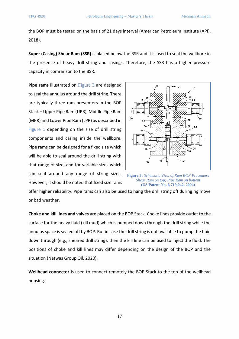
Pipe rams illustrated on Figure 3 are designed
to seal the annulus around the drill string. There
are typically three ram preventers in the BOP
Stack – Upper Pipe Ram (UPR), Middle Pipe Ram
(MPR) and Lower Pipe Ram (LPR) as described in
Figure 1 depending on the size of drill string
components and casing inside the wellbore.
Pipe rams can be designed for a fixed size which
will be able to seal around the drill string with
that range of size, and for variable sizes which
can seal around any range of string sizes.
However, it should be noted that fixed size rams
offer higher reliability. Pipe rams can also be used to hang the drill string off during rig move
or bad weather.
Choke and kill lines and valves are placed on the BOP Stack. Choke lines provide outlet to the
surface for the heavy fluid (kill mud) which is pumped down through the drill string while the
annulus space is sealed off by BOP. But in case the drill string is not available to pump the fluid
down through (e.g., sheared drill string), then the kill line can be used to inject the fluid. The
positions of choke and kill lines may differ depending on the design of the BOP and the
situation (Netwas Group Oil, 2020).
Wellhead connector is used to connect remotely the BOP Stack to the top of the wellhead
housing.
Figure 3: Schematic View of Ram BOP Preventers
Shear Ram on top; Pipe Ram on bottom
(US Patent No. 6,719,042, 2004)
TPG 4920 Petroleum Engineering – Master’s Thesis Mehman Ahmadli
18
2. CONTROL SYSTEM
The BOP valves can be controlled by hydraulically and electro-hydraulically from the surface.
The main advantage of electro-hydraulic control system is its less response time in comparison
to the hydraulic one while drilling a deep-water well. Electro-hydraulic control system is called
Multiplex system (MUX) and is used on the well deeper than 1500 meters. (McCrae, 2003).
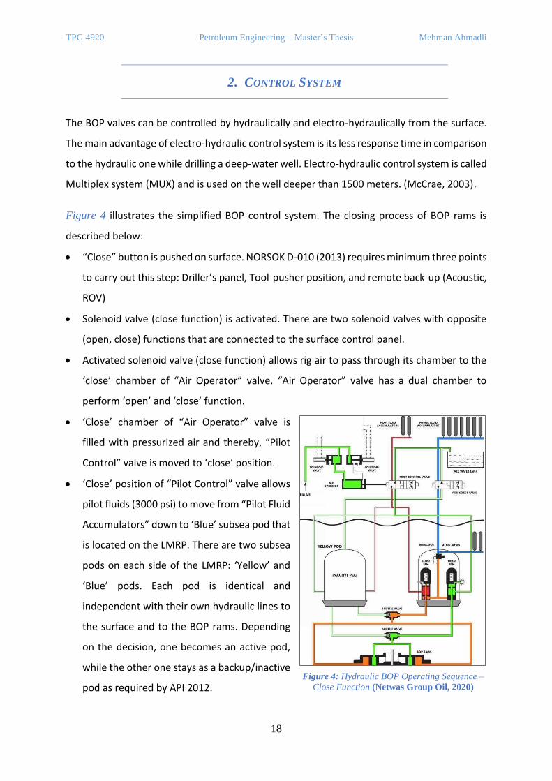
Figure 4 illustrates the simplified BOP control system. The closing process of BOP rams is
described below:
• “Close” button is pushed on surface. NORSOK D-010 (2013) requires minimum three points
to carry out this step: Driller’s panel, Tool-pusher position, and remote back-up (Acoustic,
ROV)
• Solenoid valve (close function) is activated. There are two solenoid valves with opposite
(open, close) functions that are connected to the surface control panel.
• Activated solenoid valve (close function) allows rig air to pass through its chamber to the
‘close’ chamber of “Air Operator” valve. “Air Operator” valve has a dual chamber to
perform ‘open’ and ‘close’ function.
• ‘Close’ chamber of “Air Operator” valve is
filled with pressurized air and thereby, “Pilot
Control” valve is moved to ‘close’ position.
• ‘Close’ position of “Pilot Control” valve allows
pilot fluids (3000 psi) to move from “Pilot Fluid
Accumulators” down to ‘Blue’ subsea pod that
is located on the LMRP. There are two subsea
pods on each side of the LMRP: ‘Yellow’ and
‘Blue’ pods. Each pod is identical and
independent with their own hydraulic lines to
the surface and to the BOP rams. Depending
on the decision, one becomes an active pod,
while the other one stays as a backup/inactive
pod as required by API 2012. Figure 4: Hydraulic BOP Operating Sequence –
Close Function (Netwas Group Oil, 2020)
TPG 4920 Petroleum Engineering – Master’s Thesis Mehman Ahmadli
19
• In that case, ‘Blue’ pod is an active pod. Inside it there are two SPM valves with ‘Close’ and
‘Open’ functions. The spindle inside the “Close SPM” valve is lifted due to pressure and
thereby, the vent is blocked. After which, power fluid from the surface and subsea fluid
accumulators can move through the valve to “Shuttle” valve (‘Close’ function). The BOP
has two “Shuttle” valves with ‘Open’ and ‘Close’ tasks, and each is connected to ‘Open’
and ‘Close’ chambers of BOP rams, respectively.
• Through the “Close Shuttle” valve power fluid is filled into ‘Close’ chamber of BOP ram
and thereby, BOP rams are closed.
The hydraulic fluid used to control the BOP is made environmentally friendly since there is no
return line, and the fluid is released to out (sea water) to release the pressure of power line.
While drilling an ultra-deep offshore well, the BOP will experience very high pressure due to
hydraulic head of the riser, and if we also add the number of connectors through the lines
these factors will decrease the reliability of the hydraulic BOP.
3. ACTUATORS
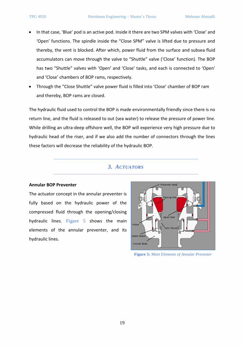
Annular BOP Preventer
The actuator concept in the annular preventer is
fully based on the hydraulic power of the
compressed fluid through the opening/closing
hydraulic lines. Figure 5 shows the main
elements of the annular preventer, and its
hydraulic lines.
Figure 5: Main Elements of Annular Preventer
TPG 4920 Petroleum Engineering – Master’s Thesis Mehman Ahmadli
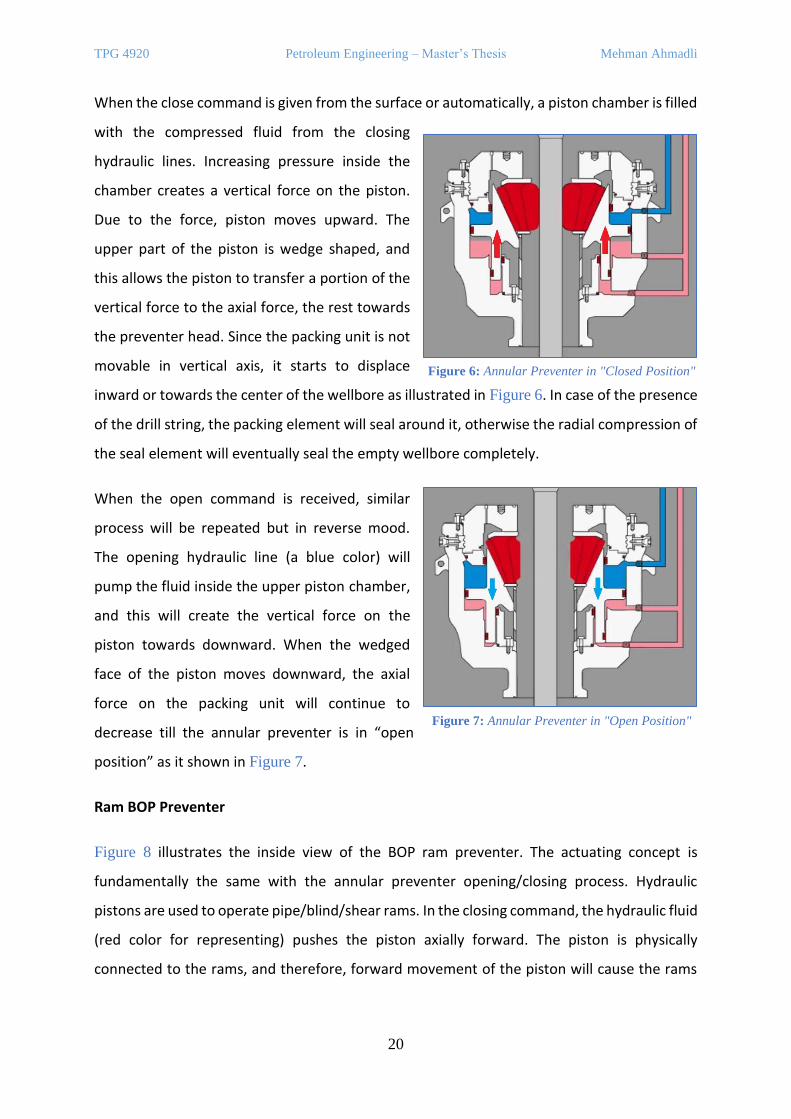
20
When the close command is given from the surface or automatically, a piston chamber is filled
with the compressed fluid from the closing
hydraulic lines. Increasing pressure inside the
chamber creates a vertical force on the piston.
Due to the force, piston moves upward. The
upper part of the piston is wedge shaped, and
this allows the piston to transfer a portion of the
vertical force to the axial force, the rest towards
the preventer head. Since the packing unit is not
movable in vertical axis, it starts to displace
inward or towards the center of the wellbore as illustrated in Figure 6. In case of the presence
of the drill string, the packing element will seal around it, otherwise the radial compression of
the seal element will eventually seal the empty wellbore completely.
When the open command is received, similar
process will be repeated but in reverse mood.
The opening hydraulic line (a blue color) will
pump the fluid inside the upper piston chamber,
and this will create the vertical force on the
piston towards downward. When the wedged
face of the piston moves downward, the axial
force on the packing unit will continue to
decrease till the annular preventer is in “open
position” as it shown in Figure 7.
Ram BOP Preventer
Figure 8 illustrates the inside view of the BOP ram preventer. The actuating concept is
fundamentally the same with the annular preventer opening/closing process. Hydraulic
pistons are used to operate pipe/blind/shear rams. In the closing command, the hydraulic fluid
(red color for representing) pushes the piston axially forward. The piston is physically
connected to the rams, and therefore, forward movement of the piston will cause the rams
Figure 6: Annular Preventer in "Closed Position"
Figure 7: Annular Preventer in "Open Position"
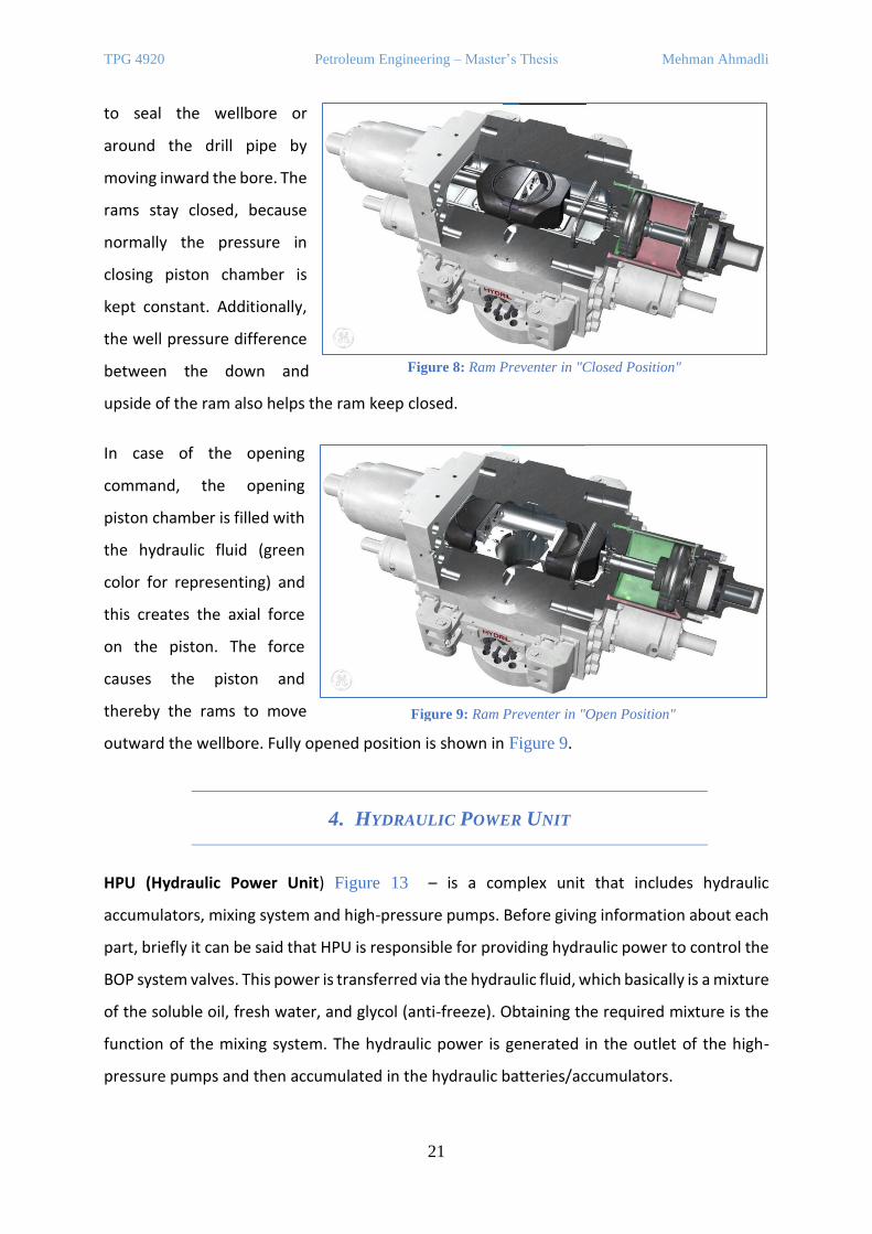
TPG 4920 Petroleum Engineering – Master’s Thesis Mehman Ahmadli
21
to seal the wellbore or
around the drill pipe by
moving inward the bore. The
rams stay closed, because
normally the pressure in
closing piston chamber is
kept constant. Additionally,
the well pressure difference
between the down and
upside of the ram also helps the ram keep closed.
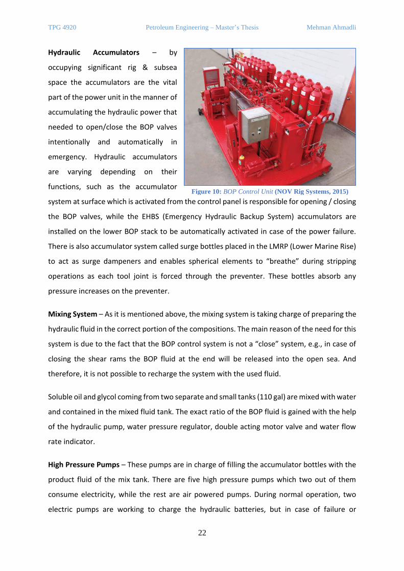
In case of the opening
command, the opening
piston chamber is filled with
the hydraulic fluid (green
color for representing) and
this creates the axial force
on the piston. The force
causes the piston and
thereby the rams to move
outward the wellbore. Fully opened position is shown in Figure 9.
4. HYDRAULIC POWER UNIT
HPU (Hydraulic Power Unit) Figure 13 – is a complex unit that includes hydraulic
accumulators, mixing system and high-pressure pumps. Before giving information about each
part, briefly it can be said that HPU is responsible for providing hydraulic power to control the
BOP system valves. This power is transferred via the hydraulic fluid, which basically is a mixture
of the soluble oil, fresh water, and glycol (anti-freeze). Obtaining the required mixture is the
function of the mixing system. The hydraulic power is generated in the outlet of the high-
pressure pumps and then accumulated in the hydraulic batteries/accumulators.
Figure 8: Ram Preventer in "Closed Position"
Figure 9: Ram Preventer in "Open Position"
TPG 4920 Petroleum Engineering – Master’s Thesis Mehman Ahmadli
22
Hydraulic Accumulators – by
occupying significant rig & subsea
space the accumulators are the vital
part of the power unit in the manner of
accumulating the hydraulic power that
needed to open/close the BOP valves
intentionally and automatically in
emergency. Hydraulic accumulators
are varying depending on their
functions, such as the accumulator
system at surface which is activated from the control panel is responsible for opening / closing
the BOP valves, while the EHBS (Emergency Hydraulic Backup System) accumulators are
installed on the lower BOP stack to be automatically activated in case of the power failure.
There is also accumulator system called surge bottles placed in the LMRP (Lower Marine Rise)
to act as surge dampeners and enables spherical elements to “breathe” during stripping
operations as each tool joint is forced through the preventer. These bottles absorb any
pressure increases on the preventer.
Mixing System – As it is mentioned above, the mixing system is taking charge of preparing the
hydraulic fluid in the correct portion of the compositions. The main reason of the need for this
system is due to the fact that the BOP control system is not a “close” system, e.g., in case of
closing the shear rams the BOP fluid at the end will be released into the open sea. And
therefore, it is not possible to recharge the system with the used fluid.
Soluble oil and glycol coming from two separate and small tanks (110 gal) are mixed with water
and contained in the mixed fluid tank. The exact ratio of the BOP fluid is gained with the help
of the hydraulic pump, water pressure regulator, double acting motor valve and water flow
rate indicator.
High Pressure Pumps – These pumps are in charge of filling the accumulator bottles with the
product fluid of the mix tank. There are five high pressure pumps which two out of them
consume electricity, while the rest are air powered pumps. During normal operation, two
electric pumps are working to charge the hydraulic batteries, but in case of failure or
Figure 10: BOP Control Unit (NOV Rig Systems, 2015)

TPG 4920 Petroleum Engineering – Master’s Thesis Mehman Ahmadli
23
emergency, air powered pumps also start to act. Since the pump system is a vital element of
the control system, the place where the pumps stand is chosen in a way that in case of the
fire, explosion etc., they can be still safe. Addition to that the motor of the pump is explosion-
proof.
As a design 15 minutes is the time requirement for the pumps to charge the batteries from
their minimum to maximum. The pumps are automatically controlled, so for the batteries
filled with the 3000-psi fluid in case of pressure drop to 2700 psi the electric pumps will start
to charge and will be switched off reaching 3000 psi if that pressure is pre-set. However, if the
pressure drop is not gradual, then air powered pumps will also assist. Oppositely, if the pumps
do not switch off in the pre-set pressure, then the relief valve is activated after a pre-set
pressure difference and the fluid is pumped to the mix tank again.
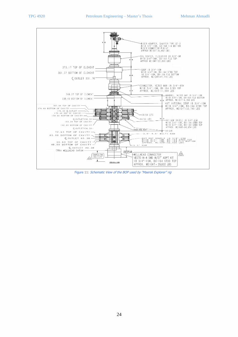
5. CASE STUDY
Figure 11 shows the schematics of the hydraulic BOP stack used in drilling and other well
operations by Maersk Explorer offshore rig in the Caspian Sea. Maersk Explorer rig was built
in Baku, Azerbaijan in 2003 and since then has been rented by BP company to conduct mainly
drilling operations in the region. Giving general information about the selected BOP, the
design pressure of the BOP is rated to 15,000 psi, which is common for the region considering
HPHT reservoirs are not usual. The length of the BOP is equal to 50 feet approximately in total
with the estimated weight of 700 klbs. The BOP stack includes one annular type of preventer,
and five rams. The annular preventer is the first one to be closed in case of well control
situation. The operating pressure of the annular preventer is rated to 1,500 psi, but to allow
stripping of the drill string lower pressure is applied. Upper triple BOP consists of three rams
including two shear rams and one pipe ram. Upper shear ram is casing shear ram, and the
below one is blind shear ram. Both are designed for 15,000 psi. Casing shear ram is operating
in 3,000 psi. The pipe ram in upper triple BOP is called upper pipe ram, while the two pipe
rams in Lower double BOP are called middle and lower pipe rams, respectively. Lower pipe
rams are fixed size 5 ½ inch, but upper and middle pipe rams size variable from 3 ½ inch to 5
½ inch. They are designed to close the open hole and to seal around the pipe in case of well
control.
TPG 4920 Petroleum Engineering – Master’s Thesis Mehman Ahmadli
24
Figure 11: Schematic View of the BOP used by "Maersk Explorer" rig
TPG 4920 Petroleum Engineering – Master’s Thesis Mehman Ahmadli
25
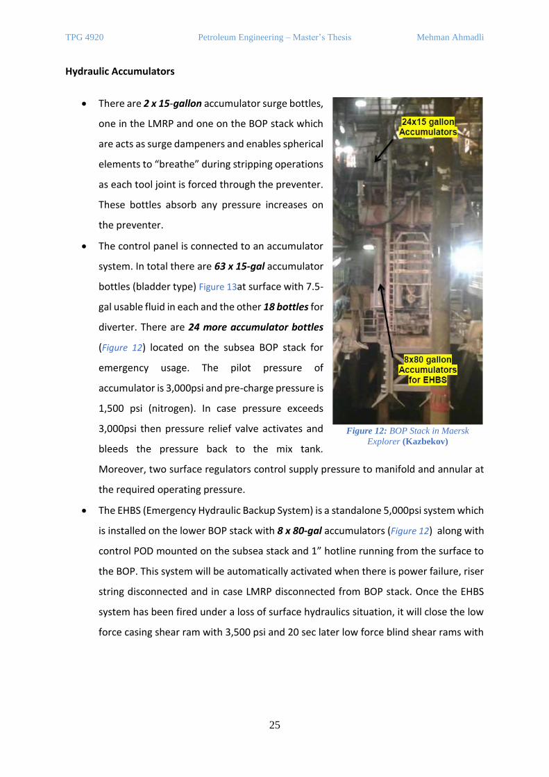
Hydraulic Accumulators
• There are 2 x 15-gallon accumulator surge bottles,
one in the LMRP and one on the BOP stack which
are acts as surge dampeners and enables spherical
elements to “breathe” during stripping operations
as each tool joint is forced through the preventer.
These bottles absorb any pressure increases on
the preventer.
• The control panel is connected to an accumulator
system. In total there are 63 x 15-gal accumulator
bottles (bladder type) Figure 13at surface with 7.5-
gal usable fluid in each and the other 18 bottles for
diverter. There are 24 more accumulator bottles
(Figure 12) located on the subsea BOP stack for
emergency usage. The pilot pressure of
accumulator is 3,000psi and pre-charge pressure is
1,500 psi (nitrogen). In case pressure exceeds
3,000psi then pressure relief valve activates and
bleeds the pressure back to the mix tank.
Moreover, two surface regulators control supply pressure to manifold and annular at
the required operating pressure.
• The EHBS (Emergency Hydraulic Backup System) is a standalone 5,000psi system which
is installed on the lower BOP stack with 8 x 80-gal accumulators (Figure 12) along with
control POD mounted on the subsea stack and 1” hotline running from the surface to
the BOP. This system will be automatically activated when there is power failure, riser
string disconnected and in case LMRP disconnected from BOP stack. Once the EHBS
system has been fired under a loss of surface hydraulics situation, it will close the low
force casing shear ram with 3,500 psi and 20 sec later low force blind shear rams with
Figure 12: BOP Stack in Maersk
Explorer (Kazbekov)
TPG 4920 Petroleum Engineering – Master’s Thesis Mehman Ahmadli
26
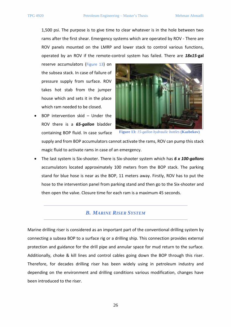
1,500 psi. The purpose is to give time to clear whatever is in the hole between two
rams after the first shear. Emergency systems which are operated by ROV - There are
ROV panels mounted on the LMRP and lower stack to control various functions,
operated by an ROV if the remote-control system has failed. There are 18x15-gal
reserve accumulators (Figure 13) on
the subsea stack. In case of failure of
pressure supply from surface. ROV
takes hot stab from the jumper
house which and sets it in the place
which ram needed to be closed.
• BOP intervention skid – Under the
ROV there is a 65-gallon bladder
containing BOP fluid. In case surface
supply and from BOP accumulators cannot activate the rams, ROV can pump this stack
magic fluid to activate rams in case of an emergency.
• The last system is Six-shooter. There is Six-shooter system which has 6 x 100-gallons
accumulators located approximately 100 meters from the BOP stack. The parking
stand for blue hose is near as the BOP, 11 meters away. Firstly, ROV has to put the
hose to the intervention panel from parking stand and then go to the Six-shooter and
then open the valve. Closure time for each ram is a maximum 45 seconds.
B. MARINE RISER SYSTEM
Marine drilling riser is considered as an important part of the conventional drilling system by
connecting a subsea BOP to a surface rig or a drilling ship. This connection provides external
protection and guidance for the drill pipe and annular space for mud return to the surface.
Additionally, choke & kill lines and control cables going down the BOP through this riser.
Therefore, for decades drilling riser has been widely using in petroleum industry and
depending on the environment and drilling conditions various modification, changes have
been introduced to the riser.
Figure 13: 15-gallon hydraulic bottles (Kazbekov)
TPG 4920 Petroleum Engineering – Master’s Thesis Mehman Ahmadli
27
1. BASIC DESIGN
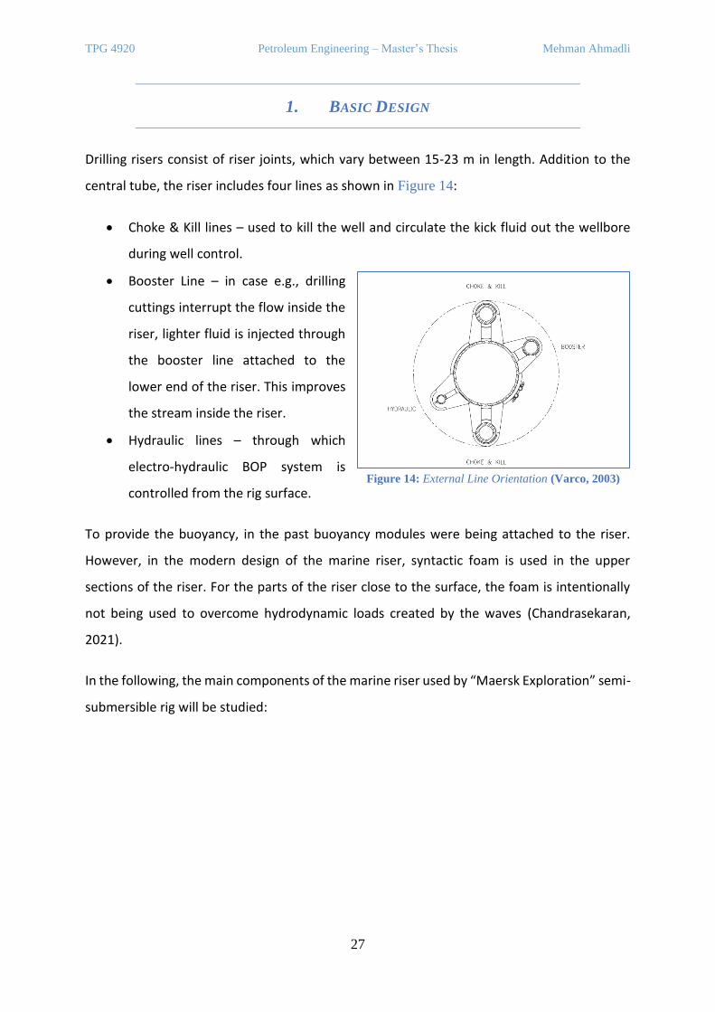
Drilling risers consist of riser joints, which vary between 15-23 m in length. Addition to the
central tube, the riser includes four lines as shown in Figure 14:
• Choke & Kill lines – used to kill the well and circulate the kick fluid out the wellbore
during well control.
• Booster Line – in case e.g., drilling
cuttings interrupt the flow inside the
riser, lighter fluid is injected through
the booster line attached to the
lower end of the riser. This improves
the stream inside the riser.
• Hydraulic lines – through which
electro-hydraulic BOP system is
controlled from the rig surface.
To provide the buoyancy, in the past buoyancy modules were being attached to the riser.
However, in the modern design of the marine riser, syntactic foam is used in the upper
sections of the riser. For the parts of the riser close to the surface, the foam is intentionally
not being used to overcome hydrodynamic loads created by the waves (Chandrasekaran,
2021).
In the following, the main components of the marine riser used by “Maersk Exploration” semi-
submersible rig will be studied:
Figure 14: External Line Orientation (Varco, 2003)
TPG 4920 Petroleum Engineering – Master’s Thesis Mehman Ahmadli
28
Hydraulic Handling Tool
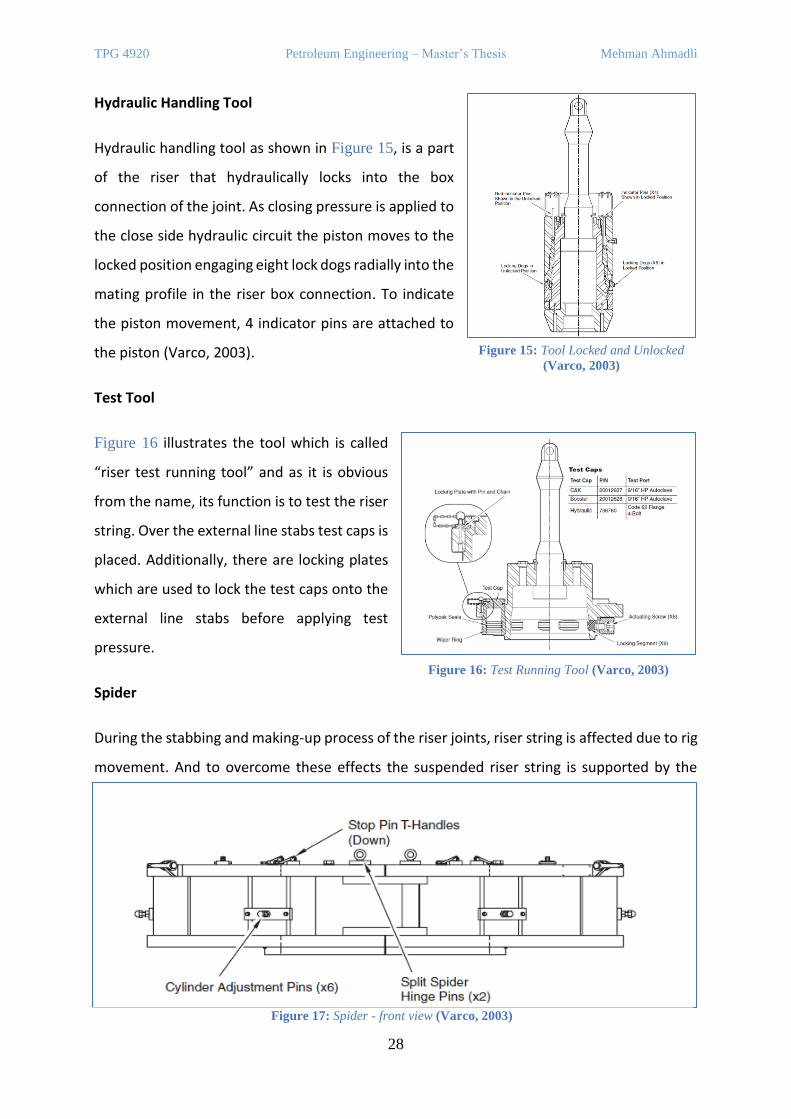
Hydraulic handling tool as shown in Figure 15, is a part
of the riser that hydraulically locks into the box
connection of the joint. As closing pressure is applied to
the close side hydraulic circuit the piston moves to the
locked position engaging eight lock dogs radially into the
mating profile in the riser box connection. To indicate
the piston movement, 4 indicator pins are attached to
the piston (Varco, 2003).
Test Tool
Figure 16 illustrates the tool which is called
“riser test running tool” and as it is obvious
from the name, its function is to test the riser
string. Over the external line stabs test caps is
placed. Additionally, there are locking plates
which are used to lock the test caps onto the
external line stabs before applying test
pressure.
Spider
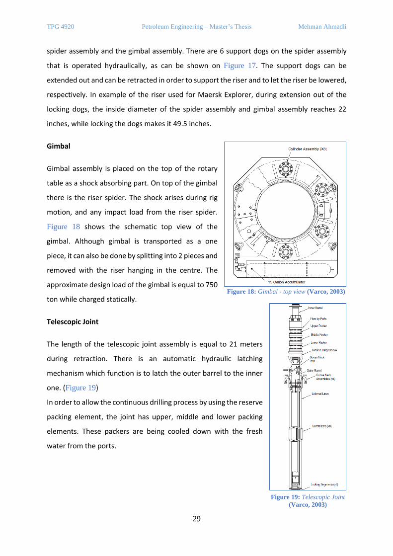
During the stabbing and making-up process of the riser joints, riser string is affected due to rig
movement. And to overcome these effects the suspended riser string is supported by the
Figure 15: Tool Locked and Unlocked
(Varco, 2003)
Figure 16: Test Running Tool (Varco, 2003)
Figure 17: Spider - front view (Varco, 2003)
TPG 4920 Petroleum Engineering – Master’s Thesis Mehman Ahmadli
29
spider assembly and the gimbal assembly. There are 6 support dogs on the spider assembly
that is operated hydraulically, as can be shown on Figure 17. The support dogs can be
extended out and can be retracted in order to support the riser and to let the riser be lowered,
respectively. In example of the riser used for Maersk Explorer, during extension out of the
locking dogs, the inside diameter of the spider assembly and gimbal assembly reaches 22
inches, while locking the dogs makes it 49.5 inches.
Gimbal
Gimbal assembly is placed on the top of the rotary
table as a shock absorbing part. On top of the gimbal
there is the riser spider. The shock arises during rig
motion, and any impact load from the riser spider.
Figure 18 shows the schematic top view of the
gimbal. Although gimbal is transported as a one
piece, it can also be done by splitting into 2 pieces and
removed with the riser hanging in the centre. The
approximate design load of the gimbal is equal to 750
ton while charged statically.
Telescopic Joint
The length of the telescopic joint assembly is equal to 21 meters
during retraction. There is an automatic hydraulic latching
mechanism which function is to latch the outer barrel to the inner
one. (Figure 19)
In order to allow the continuous drilling process by using the reserve
packing element, the joint has upper, middle and lower packing
elements. These packers are being cooled down with the fresh
water from the ports.
Figure 18: Gimbal - top view (Varco, 2003)
Figure 19: Telescopic Joint
(Varco, 2003)
TPG 4920 Petroleum Engineering – Master’s Thesis Mehman Ahmadli
30
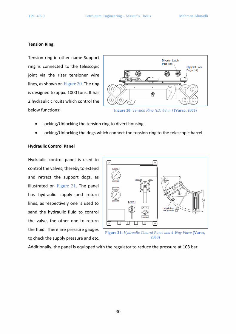
Tension Ring
Tension ring in other name Support
ring is connected to the telescopic
joint via the riser tensioner wire
lines, as shown on Figure 20. The ring
is designed to appx. 1000 tons. It has
2 hydraulic circuits which control the
below functions:
• Locking/Unlocking the tension ring to divert housing.
• Locking/Unlocking the dogs which connect the tension ring to the telescopic barrel.
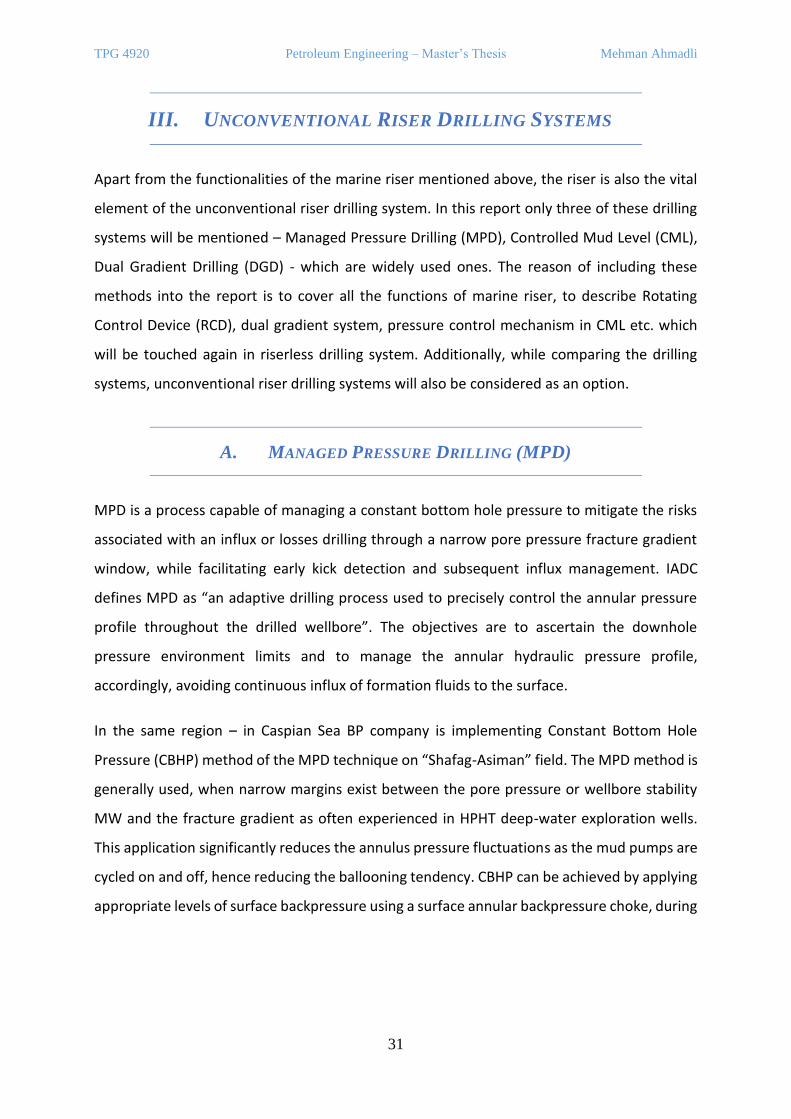
Hydraulic Control Panel
Hydraulic control panel is used to
control the valves, thereby to extend
and retract the support dogs, as
illustrated on Figure 21. The panel
has hydraulic supply and return
lines, as respectively one is used to
send the hydraulic fluid to control
the valve, the other one to return
the fluid. There are pressure gauges
to check the supply pressure and etc.
Additionally, the panel is equipped with the regulator to reduce the pressure at 103 bar.
Figure 20: Tension Ring (ID: 48 in.) (Varco, 2003)
Figure 21: Hydraulic Control Panel and 4-Way Valve (Varco,
2003)
TPG 4920 Petroleum Engineering – Master’s Thesis Mehman Ahmadli
31
III. UNCONVENTIONAL RISER DRILLING SYSTEMS
Apart from the functionalities of the marine riser mentioned above, the riser is also the vital
element of the unconventional riser drilling system. In this report only three of these drilling
systems will be mentioned – Managed Pressure Drilling (MPD), Controlled Mud Level (CML),
Dual Gradient Drilling (DGD) - which are widely used ones. The reason of including these
methods into the report is to cover all the functions of marine riser, to describe Rotating
Control Device (RCD), dual gradient system, pressure control mechanism in CML etc. which
will be touched again in riserless drilling system. Additionally, while comparing the drilling
systems, unconventional riser drilling systems will also be considered as an option.
A. MANAGED PRESSURE DRILLING (MPD)
MPD is a process capable of managing a constant bottom hole pressure to mitigate the risks
associated with an influx or losses drilling through a narrow pore pressure fracture gradient
window, while facilitating early kick detection and subsequent influx management. IADC
defines MPD as “an adaptive drilling process used to precisely control the annular pressure
profile throughout the drilled wellbore”. The objectives are to ascertain the downhole
pressure environment limits and to manage the annular hydraulic pressure profile,
accordingly, avoiding continuous influx of formation fluids to the surface.
In the same region – in Caspian Sea BP company is implementing Constant Bottom Hole
Pressure (CBHP) method of the MPD technique on “Shafag-Asiman” field. The MPD method is
generally used, when narrow margins exist between the pore pressure or wellbore stability
MW and the fracture gradient as often experienced in HPHT deep-water exploration wells.
This application significantly reduces the annulus pressure fluctuations as the mud pumps are
cycled on and off, hence reducing the ballooning tendency. CBHP can be achieved by applying
appropriate levels of surface backpressure using a surface annular backpressure choke, during
TPG 4920 Petroleum Engineering – Master’s Thesis Mehman Ahmadli
32
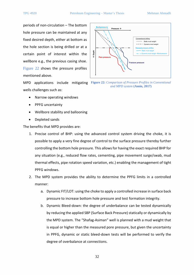
periods of non-circulation – The bottom
hole pressure can be maintained at any
fixed desired depth, either at bottom as
the hole section is being drilled or at a
certain point of interest within the
wellbore e.g., the previous casing shoe.
Figure 22 shows the pressure profiles
mentioned above.
MPD applications include mitigating
wells challenges such as:
• Narrow operating windows
• PPFG uncertainty
• Wellbore stability and ballooning
• Depleted sands
The benefits that MPD provides are:
1. Precise control of BHP: using the advanced control system driving the choke, it is
possible to apply a very fine degree of control to the surface pressure thereby further
controlling the bottom hole pressure. This allows for having the exact required BHP for
any situation (e.g., reduced flow rates, cementing, pipe movement surge/swab, mud
thermal effects, pipe rotation speed variation, etc.) enabling the management of tight
PPFG windows.
2. The MPD system provides the ability to determine the PPFG limits in a controlled
manner:
a. Dynamic FIT/LOT: using the choke to apply a controlled increase in surface back
pressure to increase bottom hole pressure and test formation integrity.
b. Dynamic Bleed-down: the degree of underbalance can be tested dynamically
by reducing the applied SBP (Surface Back Pressure) statically or dynamically by
the MPD system. The “Shafag-Asiman” well is planned with a mud weight that
is equal or higher than the measured pore pressure, but given the uncertainty
in PPFG, dynamic or static bleed-down tests will be performed to verify the
degree of overbalance at connections.
Figure 22: Comparison of Pressure Profiles in Conventional
and MPD system (Amin, 2017)
TPG 4920 Petroleum Engineering – Master’s Thesis Mehman Ahmadli
33
c. Simulate MW increase. ECD increase can be applied by MPD chokes to ensure
Fracture Gradient (FG) is not exceeded prior to any actual MW increases. This
will help to minimize the risk of lost circulation and ballooning issues before
weighting up the system.
3. Rapid Response to downhole conditions: The ability to response rapidly to changes in
the operating window (PP, FG, WBS), by changing the EMW and remaining within the
boundaries. For example, incremental reduction of SBP allows to rapidly respond to a
loss situation before the losses worsen. When compared to losses incurred due to
physical MW increase, mitigations/reversal measures in this case are often too late.
4. Ability to Navigate a tight PPFG window: In tight PPFG and low kick tolerance situation,
losses can progress into well control incidents and increase the risk of underground
crossflow. The ability to navigate the tight PPFG window without inducing losses, and
at the same time minimizing the volume of possible influxes, reduces the overall well
control risk from escalating.
5. Any ballooning tendencies will be minimized or prevented by trapping or continuously
applying annular back pressure equal to, or near the drilling ECD.
6. Reducing WBS risk due to proximity to shale pore pressure and downhole pressure
cycling. During conventional drilling operations, the wellbore sees dynamic pressure
during circulating and static downhole pressures during connections. In deeper hole
sections this range can be multiple points of SG, as such can result in formation related
instability when overbalance MW conditions are minimal due to tight drilling windows.
Holding back pressure during connections close to downhole circulating densities can
help reduce this pressure cycling induced formation fatigue.
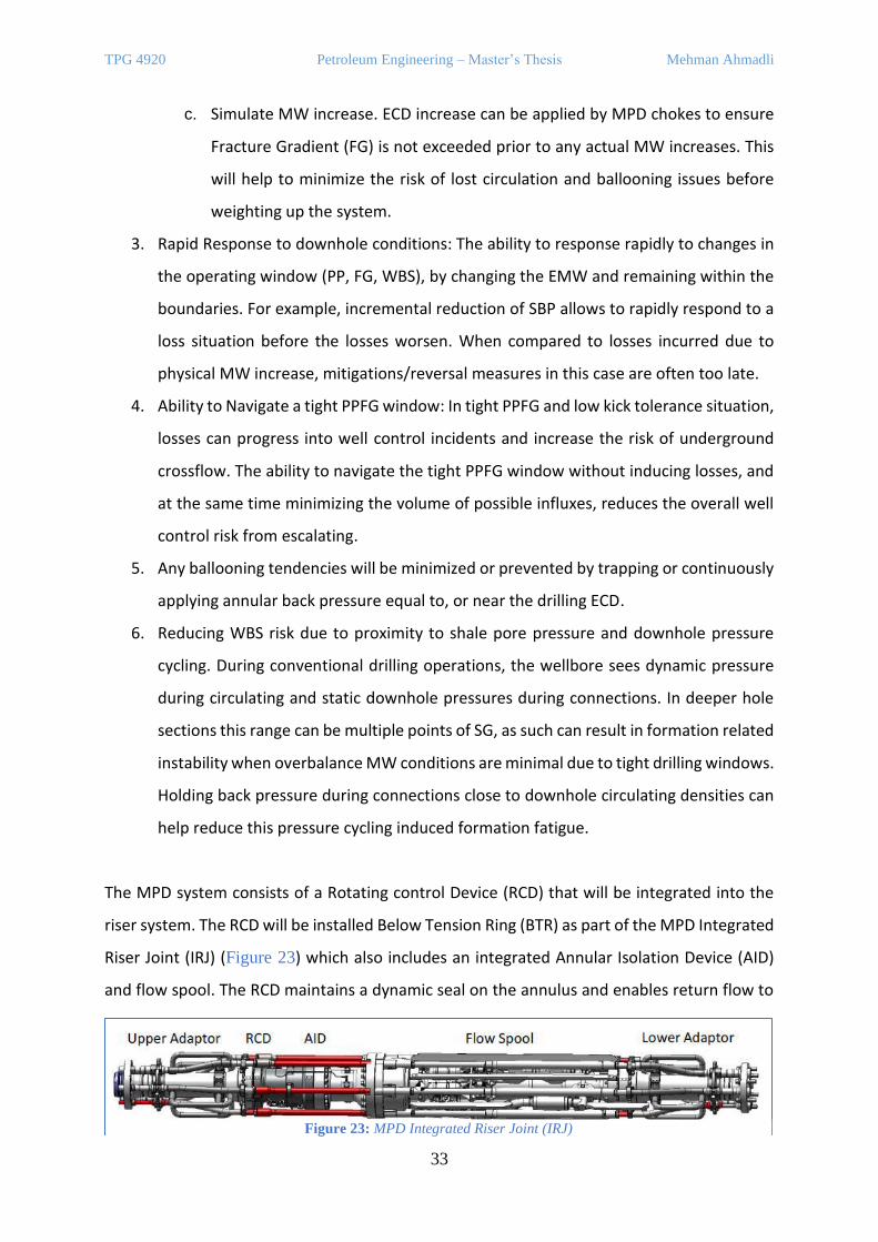
The MPD system consists of a Rotating control Device (RCD) that will be integrated into the
riser system. The RCD will be installed Below Tension Ring (BTR) as part of the MPD Integrated
Riser Joint (IRJ) (Figure 23) which also includes an integrated Annular Isolation Device (AID)
and flow spool. The RCD maintains a dynamic seal on the annulus and enables return flow to
Figure 23: MPD Integrated Riser Joint (IRJ)
TPG 4920 Petroleum Engineering – Master’s Thesis Mehman Ahmadli
34
be diverted to the Weatherford dedicated choke manifold where return flow and pressure
can be accurately controlled and measured. The return flow from the MPD system will be
routed to the rig circulation system so rig pumps, shakers, MGS and trip tank can also be used
during MPD operations.
During normal drilling operations with the mud pumps on, the MPD choke(s) and possibly the
bypass line will be open to minimize any additional surface pressures that would increase
downhole ECD. During connections or any low flowrate events, surface back pressure (SBP)
equal to or near the drilling ECD, can be trapped or dynamically applied to maintain CBHP. In
general, the bottom hole pressure is controlled using an auto choke on surface such that it is
above the pore pressure and below the fracture gradient lines. Sometimes, the drilling can be
continued with a lighter MW and additional surface back pressure applied to maintain BHP
dynamically and statically above a targeted BHP.
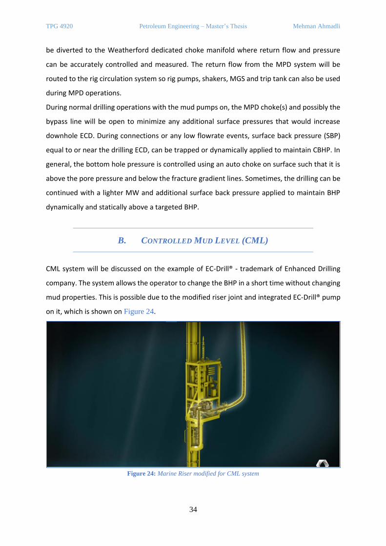
B. CONTROLLED MUD LEVEL (CML)
CML system will be discussed on the example of EC-Drill® - trademark of Enhanced Drilling
company. The system allows the operator to change the BHP in a short time without changing
mud properties. This is possible due to the modified riser joint and integrated EC-Drill® pump
on it, which is shown on Figure 24.
Figure 24: Marine Riser modified for CML system
TPG 4920 Petroleum Engineering – Master’s Thesis Mehman Ahmadli
35
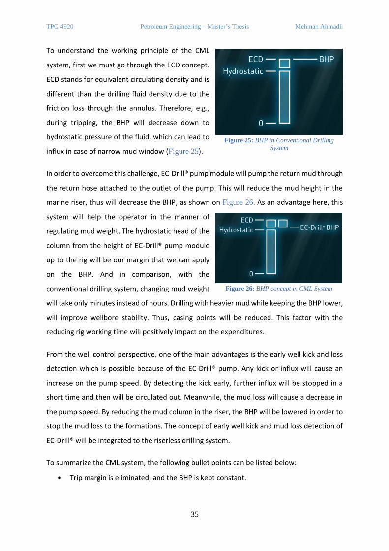
To understand the working principle of the CML
system, first we must go through the ECD concept.
ECD stands for equivalent circulating density and is
different than the drilling fluid density due to the
friction loss through the annulus. Therefore, e.g.,
during tripping, the BHP will decrease down to
hydrostatic pressure of the fluid, which can lead to
influx in case of narrow mud window (Figure 25).
In order to overcome this challenge, EC-Drill® pump module will pump the return mud through
the return hose attached to the outlet of the pump. This will reduce the mud height in the
marine riser, thus will decrease the BHP, as shown on Figure 26. As an advantage here, this
system will help the operator in the manner of
regulating mud weight. The hydrostatic head of the
column from the height of EC-Drill® pump module
up to the rig will be our margin that we can apply
on the BHP. And in comparison, with the
conventional drilling system, changing mud weight
will take only minutes instead of hours. Drilling with heavier mud while keeping the BHP lower,
will improve wellbore stability. Thus, casing points will be reduced. This factor with the
reducing rig working time will positively impact on the expenditures.
From the well control perspective, one of the main advantages is the early well kick and loss
detection which is possible because of the EC-Drill® pump. Any kick or influx will cause an
increase on the pump speed. By detecting the kick early, further influx will be stopped in a
short time and then will be circulated out. Meanwhile, the mud loss will cause a decrease in
the pump speed. By reducing the mud column in the riser, the BHP will be lowered in order to
stop the mud loss to the formations. The concept of early well kick and mud loss detection of
EC-Drill® will be integrated to the riserless drilling system.
To summarize the CML system, the following bullet points can be listed below:
• Trip margin is eliminated, and the BHP is kept constant.
Figure 25: BHP in Conventional Drilling
System
Figure 26: BHP concept in CML System
TPG 4920 Petroleum Engineering – Master’s Thesis Mehman Ahmadli
36
• Since the ECD effects is reduced, the reservoirs with narrow mud window can be drilled
safely.
• Maintaining the BHP stable will allow to drill HPHT wells.
• Easy switch to the conventional drilling system.
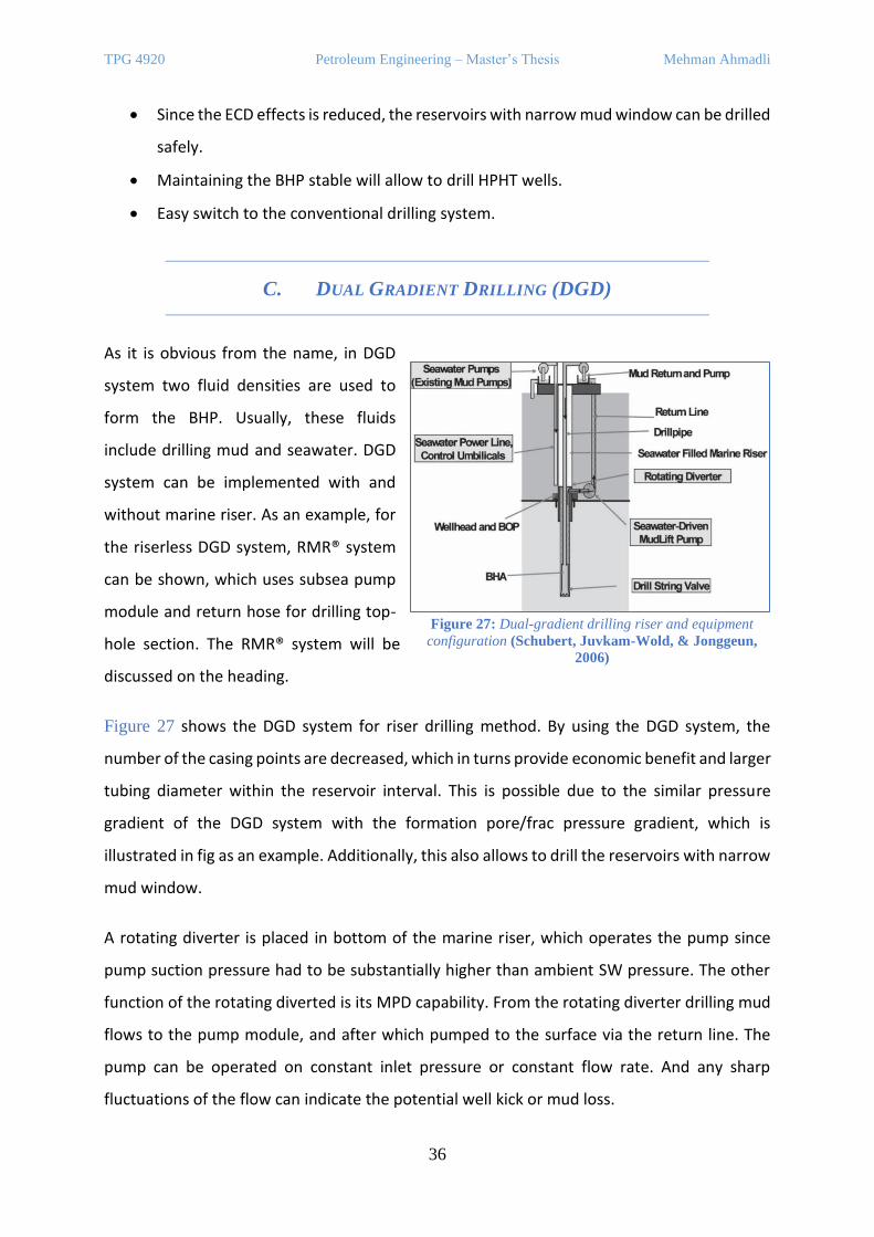
C. DUAL GRADIENT DRILLING (DGD)
As it is obvious from the name, in DGD
system two fluid densities are used to
form the BHP. Usually, these fluids
include drilling mud and seawater. DGD
system can be implemented with and
without marine riser. As an example, for
the riserless DGD system, RMR® system
can be shown, which uses subsea pump
module and return hose for drilling top-
hole section. The RMR® system will be
discussed on the heading.
Figure 27 shows the DGD system for riser drilling method. By using the DGD system, the
number of the casing points are decreased, which in turns provide economic benefit and larger
tubing diameter within the reservoir interval. This is possible due to the similar pressure
gradient of the DGD system with the formation pore/frac pressure gradient, which is
illustrated in fig as an example. Additionally, this also allows to drill the reservoirs with narrow
mud window.
A rotating diverter is placed in bottom of the marine riser, which operates the pump since
pump suction pressure had to be substantially higher than ambient SW pressure. The other
function of the rotating diverted is its MPD capability. From the rotating diverter drilling mud
flows to the pump module, and after which pumped to the surface via the return line. The
pump can be operated on constant inlet pressure or constant flow rate. And any sharp
fluctuations of the flow can indicate the potential well kick or mud loss.
Figure 27: Dual-gradient drilling riser and equipment
configuration (Schubert, Juvkam-Wold, & Jonggeun,
2006)

TPG 4920 Petroleum Engineering – Master’s Thesis Mehman Ahmadli
37
In DGD system the concept of dual fluid density, return line, and well kick/mud loss will be
used the proposed riserless drilling concept.
IV. ELECTRIC BOP CONTROL SYSTEM
A. EBOP SYSTEM – «NOBLE DRILLING»
eBOP™ is a trademark of Noble Drilling
Services Inc. and was introduced in a
detailed way by Robert van Kuilenburg
and Jie Li on their paper (Kuilenburg, Li, &
Noble Drilling, 2018). Figure 28 shows the
prototype of the eBOP™ system. Starting
in 2003 the project could not be
developed due to the low capabilities of
then battery technology. However, in
2014 the situation was much better which led to the introduction of the 1st and 2nd
prototypes in 2015 and 2016, respectively. Both prototypes were tested for their designed
pressure which was 500,000 lbf for the 1st prototype, 2 million lbf for the 2nd one. The tests
were completed successfully.
1. BASIC DESIGN & ACTUATORS
The eBOP™ concept is based on the idea of decreasing complexity in well control system, as
interpreted by Kuilenburg as “anything that is not there cannot fail”. The prototype was built
on the body of 18 ¾” 10K type U BOP. 75 kW off-the-shelf industrial type electric motor was
selected since it is easy to get in the industry. By this way time and cost was saved. For the
serial production, however, subsea type of electric motors will be integrated, and this will
allow the electric BOP to function in deeper water depth. Currently, without any modification
the limit is 12,000ft.
Figure 28: eBOP™ prototype demonstrated in Texas,
2017
TPG 4920 Petroleum Engineering – Master’s Thesis Mehman Ahmadli
38
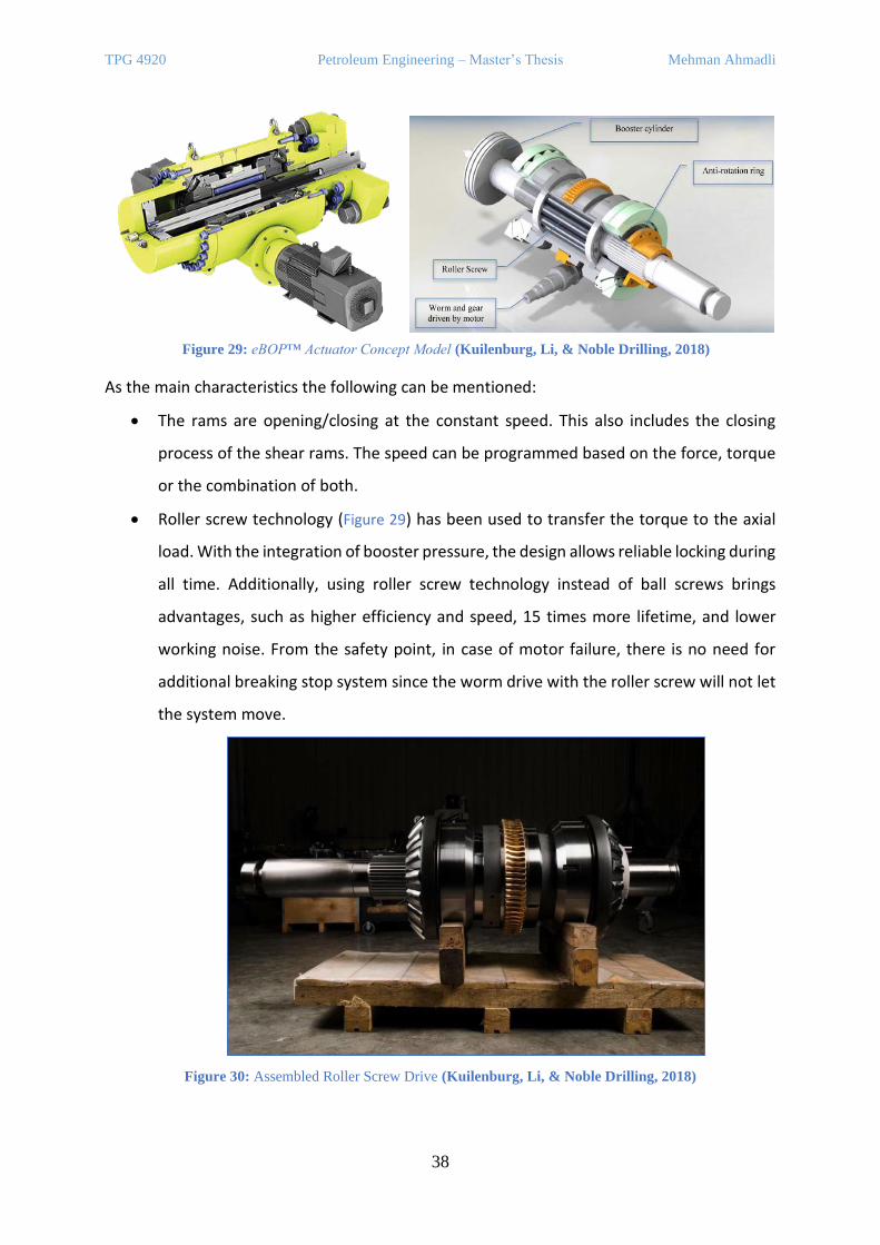
As the main characteristics the following can be mentioned:
• The rams are opening/closing at the constant speed. This also includes the closing
process of the shear rams. The speed can be programmed based on the force, torque
or the combination of both.
• Roller screw technology (Figure 29) has been used to transfer the torque to the axial
load. With the integration of booster pressure, the design allows reliable locking during
all time. Additionally, using roller screw technology instead of ball screws brings
advantages, such as higher efficiency and speed, 15 times more lifetime, and lower
working noise. From the safety point, in case of motor failure, there is no need for
additional breaking stop system since the worm drive with the roller screw will not let
the system move.
Figure 30: Assembled Roller Screw Drive (Kuilenburg, Li, & Noble Drilling, 2018)
Figure 29: eBOP™ Actuator Concept Model (Kuilenburg, Li, & Noble Drilling, 2018)
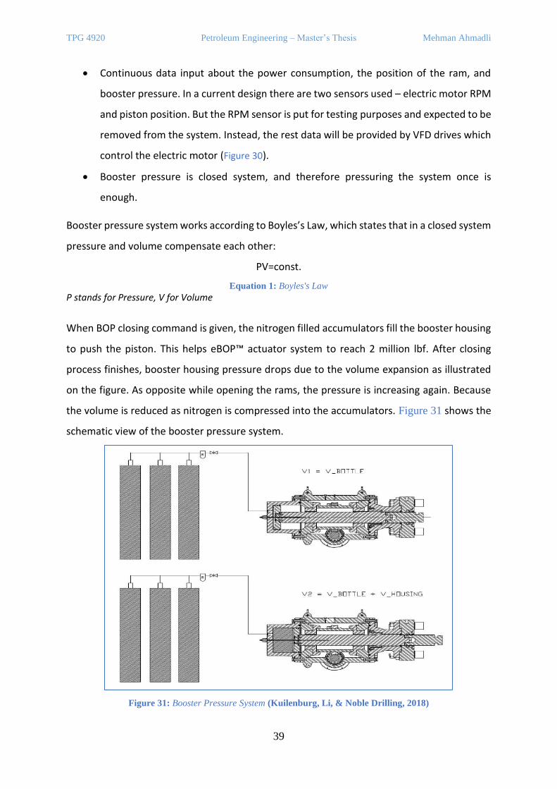
TPG 4920 Petroleum Engineering – Master’s Thesis Mehman Ahmadli
39
• Continuous data input about the power consumption, the position of the ram, and
booster pressure. In a current design there are two sensors used – electric motor RPM
and piston position. But the RPM sensor is put for testing purposes and expected to be
removed from the system. Instead, the rest data will be provided by VFD drives which
control the electric motor (Figure 30).
• Booster pressure is closed system, and therefore pressuring the system once is
enough.
Booster pressure system works according to Boyles’s Law, which states that in a closed system
pressure and volume compensate each other:
PV=const.
Equation 1: Boyles's Law
P stands for Pressure, V for Volume
When BOP closing command is given, the nitrogen filled accumulators fill the booster housing
to push the piston. This helps eBOP™ actuator system to reach 2 million lbf. After closing
process finishes, booster housing pressure drops due to the volume expansion as illustrated
on the figure. As opposite while opening the rams, the pressure is increasing again. Because
the volume is reduced as nitrogen is compressed into the accumulators. Figure 31 shows the
schematic view of the booster pressure system.
Figure 31: Booster Pressure System (Kuilenburg, Li, & Noble Drilling, 2018)
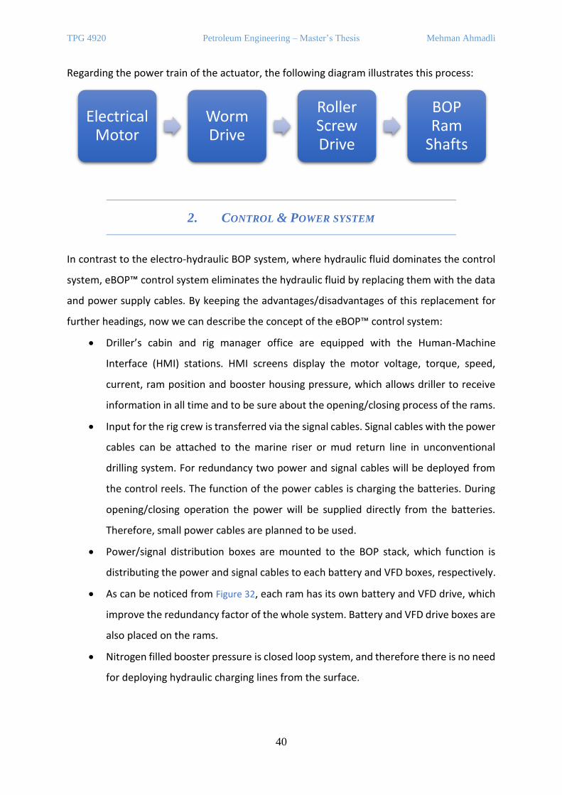
TPG 4920 Petroleum Engineering – Master’s Thesis Mehman Ahmadli
40
Regarding the power train of the actuator, the following diagram illustrates this process:
2. CONTROL & POWER SYSTEM
In contrast to the electro-hydraulic BOP system, where hydraulic fluid dominates the control
system, eBOP™ control system eliminates the hydraulic fluid by replacing them with the data
and power supply cables. By keeping the advantages/disadvantages of this replacement for
further headings, now we can describe the concept of the eBOP™ control system:
• Driller’s cabin and rig manager office are equipped with the Human-Machine
Interface (HMI) stations. HMI screens display the motor voltage, torque, speed,
current, ram position and booster housing pressure, which allows driller to receive
information in all time and to be sure about the opening/closing process of the rams.
• Input for the rig crew is transferred via the signal cables. Signal cables with the power
cables can be attached to the marine riser or mud return line in unconventional
drilling system. For redundancy two power and signal cables will be deployed from
the control reels. The function of the power cables is charging the batteries. During
opening/closing operation the power will be supplied directly from the batteries.
Therefore, small power cables are planned to be used.
• Power/signal distribution boxes are mounted to the BOP stack, which function is
distributing the power and signal cables to each battery and VFD boxes, respectively.
• As can be noticed from Figure 32, each ram has its own battery and VFD drive, which
improve the redundancy factor of the whole system. Battery and VFD drive boxes are
also placed on the rams.
• Nitrogen filled booster pressure is closed loop system, and therefore there is no need
for deploying hydraulic charging lines from the surface.
Electrical Motor
Worm Drive
Roller Screw Drive
BOP Ram
Shafts

TPG 4920 Petroleum Engineering – Master’s Thesis Mehman Ahmadli
41
Closing sequence: (Shear test performance of eBOP – carried out in 2017 on 6 5/8” 40 ppf S-
135 drill pipe)
• From the HMI screen a close command is entered.
• Via the signal cable the command is sent to the power/signal distribution box.
• VFD drives increase the rotational speed up to 1,800 RPM within seven seconds.
• Within 21.7 seconds actual shearing begins and at 27.5 seconds the pipe was sheared.
• The pressure inside the booster housing is reduced from 3,200 psi down to 2,400 psi.
• Total closing time is counted as total 30 seconds, which is within the requirement
period by API STD53.
• During closing process, only 18% of the available motor torque was used while
ramped up to 38%.
Figure 32: Subsea Electrical BOP System Concept (Kuilenburg, Li, & Noble Drilling,
2018)

TPG 4920 Petroleum Engineering – Master’s Thesis Mehman Ahmadli
42
B. ALL-ELECTRIC BOP CONTROL SYSTEM – “ELECTRICAL
SUBSEA & DRILLING AS”
1. BASIC DESIGN & ACTUATORS
The electric BOP control system that will be analysed under this heading is developed by the
“Electrical, Subsea & Drilling” (ESD) company. Figure 34 represents the architecture of all-
electric BOP system, where one can easily notice that the general designs are similar in both
BOP types.
Figure 33: eBOP Shear Chart (Kuilenburg, Li, & Noble Drilling, 2018)

TPG 4920 Petroleum Engineering – Master’s Thesis Mehman Ahmadli
43
Figure 34: System Architecture for the Electric BOP concept (Dale, Rød, & Howes, 2017)
The main difference between them is the actuators. The electric BOP includes different
electro-mechanical actuators, and they are listed on Table 1:
ACTUATOR TYPE USED FOR
RING PISTON ACTUATORS Connectors, Annular Preventers
RAM ACTUATORS Shear Rams including Blind Shear Ram (BSR)
VALVE ACTUATORS Choke & Kill and other hydraulic lines
Table 1: All-electric BOP Actuators
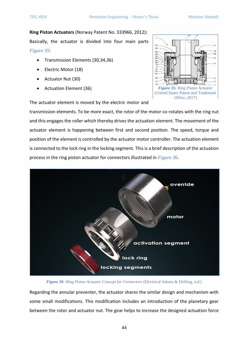
TPG 4920 Petroleum Engineering – Master’s Thesis Mehman Ahmadli
44
Ring Piston Actuators (Norway Patent No. 333966, 2012):
Basically, the actuator is divided into four main parts
Figure 35:
• Transmission Elements (30,34,36)
• Electric Motor (18)
• Actuator Nut (30)
• Actuation Element (36)
The actuator element is moved by the electric motor and
transmission elements. To be more exact, the rotor of the motor co-rotates with the ring nut
and this engages the roller which thereby drives the actuation element. The movement of the
actuator element is happening between first and second position. The speed, torque and
position of the element is controlled by the actuator motor controller. The actuation element
is connected to the lock ring in the locking segment. This is a brief description of the actuation
process in the ring piston actuator for connectors illustrated in Figure 36.
Figure 36: Ring Piston Actuator Concept for Connectors (Electrical Subsea & Drilling, n.d.)
Regarding the annular preventer, the actuator shares the similar design and mechanism with
some small modifications. This modification includes an introduction of the planetary gear
between the rotor and actuator nut. The gear helps to increase the designed actuation force
Figure 35: Ring Piston Actuator
(United States Patent and Trademark
Office, 2017)
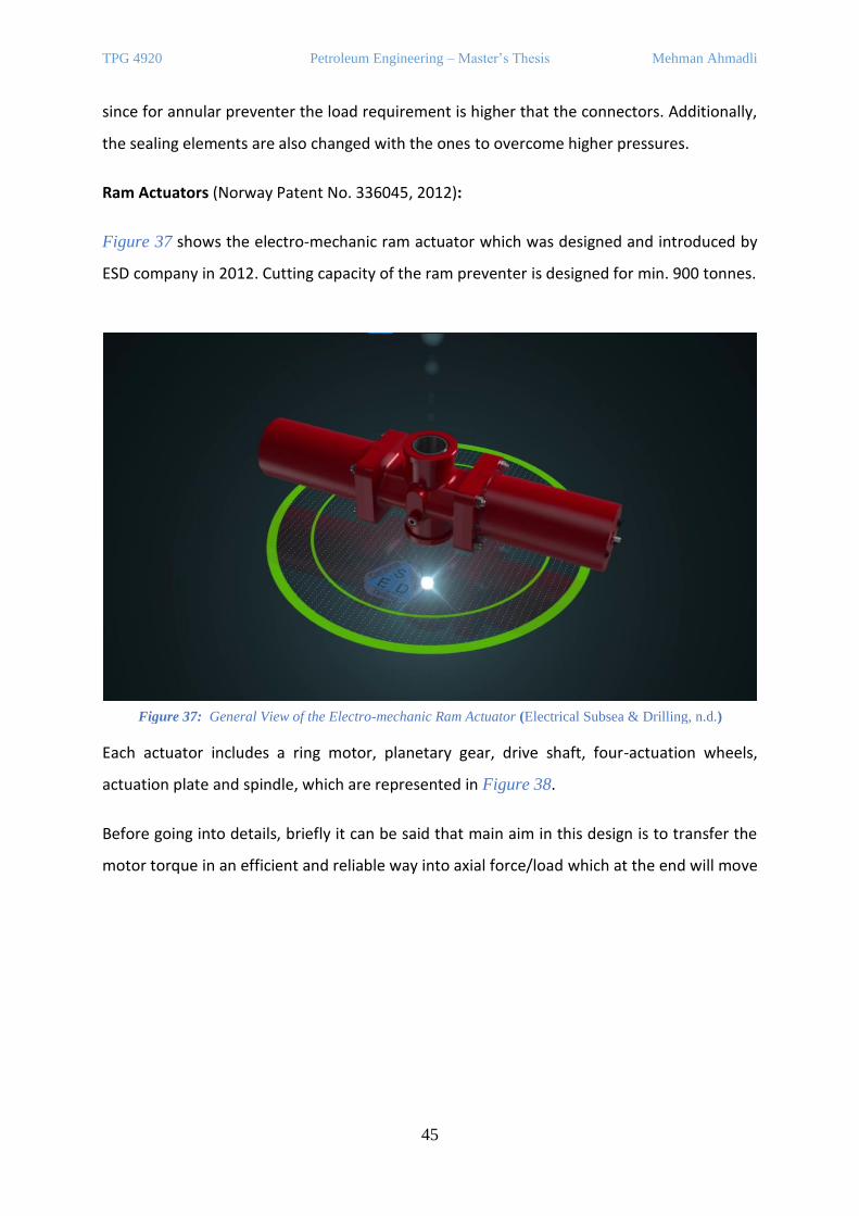
TPG 4920 Petroleum Engineering – Master’s Thesis Mehman Ahmadli
45
since for annular preventer the load requirement is higher that the connectors. Additionally,
the sealing elements are also changed with the ones to overcome higher pressures.
Ram Actuators (Norway Patent No. 336045, 2012):
Figure 37 shows the electro-mechanic ram actuator which was designed and introduced by
ESD company in 2012. Cutting capacity of the ram preventer is designed for min. 900 tonnes.
Each actuator includes a ring motor, planetary gear, drive shaft, four-actuation wheels,
actuation plate and spindle, which are represented in Figure 38.
Before going into details, briefly it can be said that main aim in this design is to transfer the
motor torque in an efficient and reliable way into axial force/load which at the end will move
Figure 37: General View of the Electro-mechanic Ram Actuator (Electrical Subsea & Drilling, n.d.)
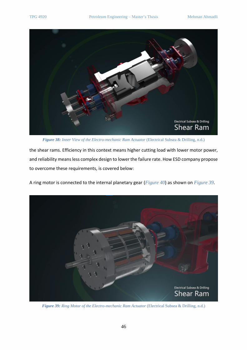
TPG 4920 Petroleum Engineering – Master’s Thesis Mehman Ahmadli
46
the shear rams. Efficiency in this context means higher cutting load with lower motor power,
and reliability means less complex design to lower the failure rate. How ESD company propose
to overcome these requirements, is covered below:
A ring motor is connected to the internal planetary gear (Figure 40) as shown on Figure 39.
Figure 38: Inner View of the Electro-mechanic Ram Actuator (Electrical Subsea & Drilling, n.d.)
Figure 39: Ring Motor of the Electro-mechanic Ram Actuator (Electrical Subsea & Drilling, n.d.)
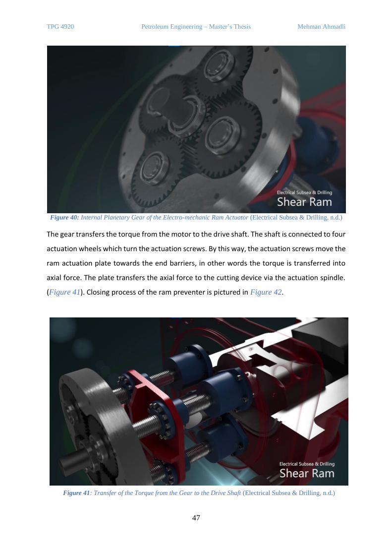
TPG 4920 Petroleum Engineering – Master’s Thesis Mehman Ahmadli
47
The gear transfers the torque from the motor to the drive shaft. The shaft is connected to four
actuation wheels which turn the actuation screws. By this way, the actuation screws move the
ram actuation plate towards the end barriers, in other words the torque is transferred into
axial force. The plate transfers the axial force to the cutting device via the actuation spindle.
(Figure 41). Closing process of the ram preventer is pictured in Figure 42.
Figure 40: Internal Planetary Gear of the Electro-mechanic Ram Actuator (Electrical Subsea & Drilling, n.d.)
Figure 41: Transfer of the Torque from the Gear to the Drive Shaft (Electrical Subsea & Drilling, n.d.)
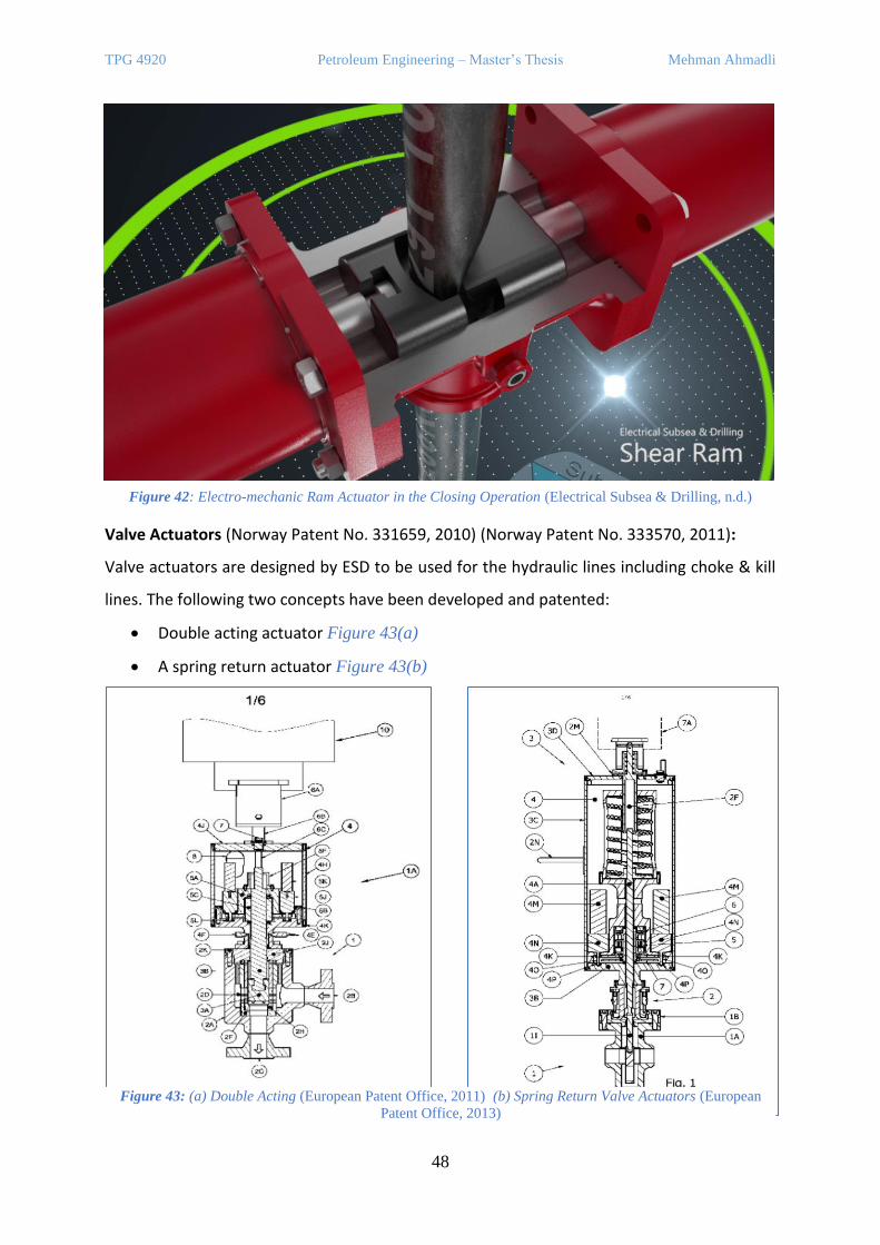
TPG 4920 Petroleum Engineering – Master’s Thesis Mehman Ahmadli
48
Valve Actuators (Norway Patent No. 331659, 2010) (Norway Patent No. 333570, 2011):
Valve actuators are designed by ESD to be used for the hydraulic lines including choke & kill
lines. The following two concepts have been developed and patented:
• Double acting actuator Figure 43(a)
• A spring return actuator Figure 43(b)
Figure 42: Electro-mechanic Ram Actuator in the Closing Operation (Electrical Subsea & Drilling, n.d.)
Figure 43: (a) Double Acting (European Patent Office, 2011) (b) Spring Return Valve Actuators (European
Patent Office, 2013)
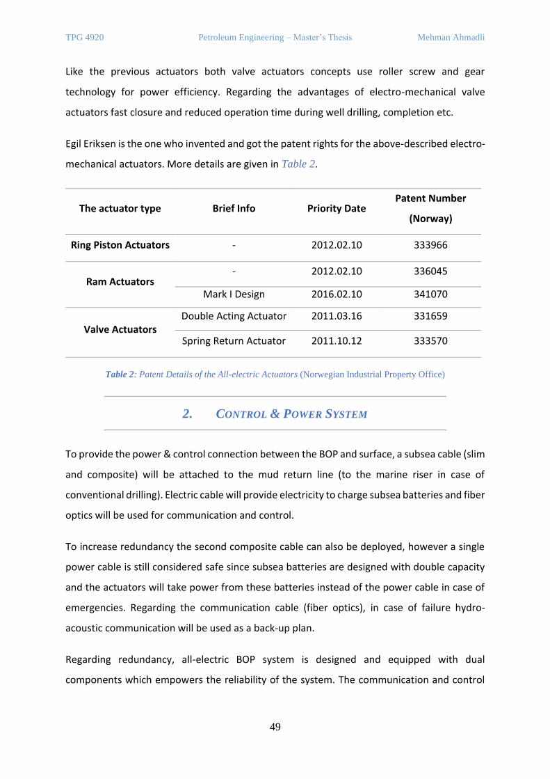
TPG 4920 Petroleum Engineering – Master’s Thesis Mehman Ahmadli
49
Like the previous actuators both valve actuators concepts use roller screw and gear
technology for power efficiency. Regarding the advantages of electro-mechanical valve
actuators fast closure and reduced operation time during well drilling, completion etc.
Egil Eriksen is the one who invented and got the patent rights for the above-described electro-
mechanical actuators. More details are given in Table 2.
The actuator type Brief Info Priority Date Patent Number
(Norway)
Ring Piston Actuators - 2012.02.10 333966
Ram Actuators - 2012.02.10 336045
Mark I Design 2016.02.10 341070
Valve Actuators Double Acting Actuator 2011.03.16 331659
Spring Return Actuator 2011.10.12 333570
Table 2: Patent Details of the All-electric Actuators (Norwegian Industrial Property Office)
2. CONTROL & POWER SYSTEM
To provide the power & control connection between the BOP and surface, a subsea cable (slim
and composite) will be attached to the mud return line (to the marine riser in case of
conventional drilling). Electric cable will provide electricity to charge subsea batteries and fiber
optics will be used for communication and control.
To increase redundancy the second composite cable can also be deployed, however a single
power cable is still considered safe since subsea batteries are designed with double capacity
and the actuators will take power from these batteries instead of the power cable in case of
emergencies. Regarding the communication cable (fiber optics), in case of failure hydro-
acoustic communication will be used as a back-up plan.
Regarding redundancy, all-electric BOP system is designed and equipped with dual
components which empowers the reliability of the system. The communication and control
TPG 4920 Petroleum Engineering – Master’s Thesis Mehman Ahmadli
50
cables will be well insulated from the outside. The control unit, power systems, controllers,
batteries will be kept in the nitrogen filled canisters at atmospheric pressure.
Starting with the power system, subsea batteries are a key part of the system since actuators
will only take the power from them. Lithium-ion batteries will be used due to its higher energy
density, longer working life, easy rechargeable capacity etc. The batteries will be placed on
the LMRP and lower BOP as several packages. Splitting into packages will increase redundancy
of the system. Another subsea challenge here for the batteries is the high external pressure
due to the hydraulic head of sea water. To avoid this pressure, the batteries will be put inside
the canisters that are filled with nitrogen and have atmospheric pressure condition. The
design of the canisters will be practical to be replaced easily by ROV.
Energy supply from the surface varies due to re-charging time requirements. The variation is
within the interval of 2-3 kV and 175-205 kW on the voltage and power scales, respectively.
The reason for the high voltage is due to the resistivity loss through the cables, however, to
charge the batteries it is lowered down to 1 kV DC (typical max. current ~60A) by transformer.
Regarding the monitoring systems, the BOP system is equipped with various sensors and the
input data from the sensors will be collected and processed by the Central Processing Unit
(CPU). As a benefit, daily routines on the BOP will be done automatically by CPU, which
includes condition monitoring, function tests, annular stripping operations, and battery health
checking. Addition to that, automation system will check the control & power lines, electric
cables, quality of the input data. Alarm system will be available in case of corrupted data input.
The CPU will be able to control the speed, torque, axial force, and stroke of the electric motors
via motor controllers. To monitor gears, bearings, and motors, accelerometers will be placed
inside the actuators. Additional subsea sensors will be provided to measure motor
temperature, to monitor water ingress in the actuators and battery canisters and to check the
force applied on the BOP stack by the marine riser in case of conventional drilling.
In emergency cases the response can be initiated manually from the surface or automatically
by CPU system. In case of disconnection or other events, automatic sequences will be
performed based on “cause & effect” scheme. Additionally, as it is mentioned earlier hydro-
acoustic control from the surface will also be available to respond any emergency events.
TPG 4920 Petroleum Engineering – Master’s Thesis Mehman Ahmadli
51
C. COMPARISON OF ELECTRIC BOP CONTROL SYSTEMS
Starting with the basic design, both systems aim to change the conventional actuator concept
into the simpler, more reliable, redundant, and safer design. It should be noted that eBOP™
system offer the change of the ram preventer instead of whole BOP equipment as All-electric
BOP system. Therefore, Noble Drilling is also offering to replace some of the ram preventers
with the electric ones while keeping the rest as hydraulic. This gives eBOP™ system an
advantage of easier integration to the industry, where most of companies do not want to be
the first one to go with all-electric system. On the contrary, All-electric BOP system is designed
to replace the whole BOP equipment and therefore its integration into the industry is more
challenging. However, from the perspective of taking full benefit of electric system, All-electric
BOP system takes the credits.
BOP control concept in each design is sharing similarities by both offering data inputs after
the command about the position, speed, torque of the rams, battery info, power consumption
etc. This is the advantage of electric motorized actuator which both systems take benefit.
Regarding the redundancy of the electric motor, eBOP™ uses four electric motors, two on
each side, and in case of failure of one motor, the other one is designed to be able to take all
the loads. In all-electric BOP there are 2 electric motors, one on each side, and each motor has
at least two independent sets of coils. And in case of failure of one side motor, the preventer
will be closed by one motor. This is also valid for eBOP™ system. Additionally, the motors are
different on both designs. As it is mentioned above, eBOP™ system focused on the easy
integration into the industry, they implement one of the widely available electric motor in
market - 75 kW off-the-shelf industrial type electric motor is used. For all-electric BOP system,
ring electric motor is chosen and designed specifically for the electric BOP system. Regarding
the maximum water depth to operate, eBOP™ has the 12,000 ft water depth limit, and all-
electric BOP system has 13,000 ft depth limit. Both systems aim to increase these limits.
Duration of closing shear rams for eBOP™ prototype is recorded as 30 seconds. This is also the
time duration ESD company put as maximum closing time in their design, however, has not
tested yet. All-electric system is using speed variation concept in shear ram, such as until
touching the drill string, ram speed will be high (torque is low)., which will save some valuable
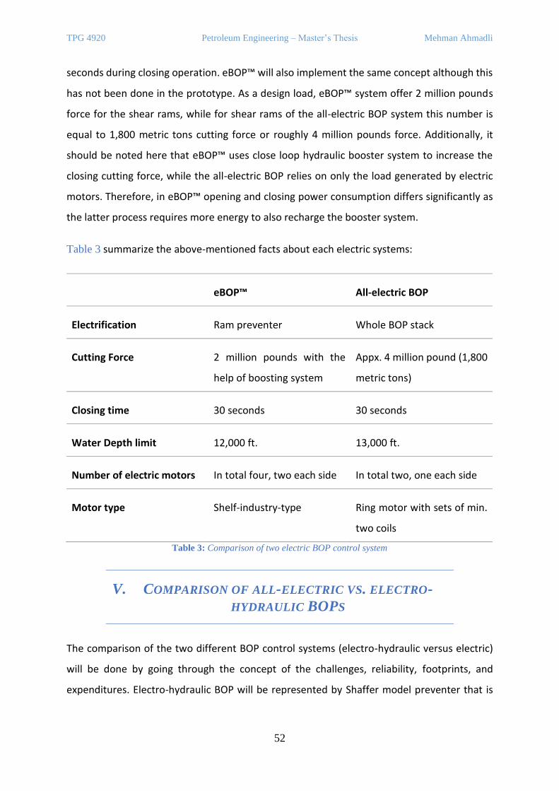
TPG 4920 Petroleum Engineering – Master’s Thesis Mehman Ahmadli
52
seconds during closing operation. eBOP™ will also implement the same concept although this
has not been done in the prototype. As a design load, eBOP™ system offer 2 million pounds
force for the shear rams, while for shear rams of the all-electric BOP system this number is
equal to 1,800 metric tons cutting force or roughly 4 million pounds force. Additionally, it
should be noted here that eBOP™ uses close loop hydraulic booster system to increase the
closing cutting force, while the all-electric BOP relies on only the load generated by electric
motors. Therefore, in eBOP™ opening and closing power consumption differs significantly as
the latter process requires more energy to also recharge the booster system.
Table 3 summarize the above-mentioned facts about each electric systems:
eBOP™ All-electric BOP
Electrification Ram preventer Whole BOP stack
Cutting Force 2 million pounds with the
help of boosting system
Appx. 4 million pound (1,800
metric tons)
Closing time 30 seconds 30 seconds
Water Depth limit 12,000 ft. 13,000 ft.
Number of electric motors In total four, two each side In total two, one each side
Motor type Shelf-industry-type Ring motor with sets of min.
two coils
Table 3: Comparison of two electric BOP control system
V. COMPARISON OF ALL-ELECTRIC VS. ELECTRO-
HYDRAULIC BOPS
The comparison of the two different BOP control systems (electro-hydraulic versus electric)
will be done by going through the concept of the challenges, reliability, footprints, and
expenditures. Electro-hydraulic BOP will be represented by Shaffer model preventer that is
TPG 4920 Petroleum Engineering – Master’s Thesis Mehman Ahmadli
53
used in “Maersk Explorer” rig. All-electric BOP stack will represent electric BOP since it is whole
BOP system rather than ram preventer as in eBOP™ system.
A. CHALLENGES
1. ULTRA-DEEP-WATER DEPTH DRILLING, WEIGHT & SIZE
CHALLENGES
The challenges in both systems vary from each other. Starting with the conventional BOP
system, the first things come to one’s mind are its complexity, weight, size, and dimension. As
the exploration operations are moving towards ultra-deep-water locations, the operator
companies will need heavier, bigger, and more advanced equipment. This sentence has been
already mentioned many times in different forms in the report, but now let us consider why
the companies need to increase the properties of the BOP as going to deeper water depth.
Deeper water depth means higher hydrostatic head of water, for which the parts of the BOP
is to be adapted by increasing wall thickness, strengthening seals. Additionally, the capacity of
the hydraulic accumulators is also needed to be increased to overcome the hydrostatic
pressure of water head. As a result, the number of the accumulators, their wall thickness is
increasing, and the BOP support frame are designed to carry the increasing weight, and
overall, the size and weight are going up. Just to note here, this increasing weight of the BOP
causes well fatigue issues on the wellhead.
The above-mentioned challenge is the main driving force for the electric BOP control system.
Because the elimination of the hydraulic system results in 154 metric tons weight reduction,
including the shrinkage of the BOP stack dimensions. On the contrary to the hydraulic
accumulators, electric accumulators do not need to be increased in capacity as going deeper
water depth locations. Adding to that the fact that the volume and weight of the electric
accumulators are much smaller than the hydraulic ones, is also important. This difference is
visualized in Figure 44 by showing the space gained due to using the electric system.

TPG 4920 Petroleum Engineering – Master’s Thesis Mehman Ahmadli
54
2. BOP EQUIPMENT RUNNING & RETRIEVING.
Another challenge will be the time spent on running BOP/marine riser or retrieving them back.
Traditionally, the BOP stack is lowered via the drilling riser and therefore, running BOP/marine
riser joint by joint and retrieving them consume duration of weeks. And in case of its failure
during pressure test after placement can increase NPT significantly. In comparison, all-electric
BOP can be lowered with the help of a rig crane due to its much lower weight, and the whole
process will take just some days. Just to compare, Table 4 shows the running duration of the
electro-hydraulic BOP/marine riser and all-electric BOP without marine riser in the depth of
1,000 ft:
Figure 44: Comparison of BOP Stacks - Hydraulic (left) and All-electric (right)
Control Systems (Dale, Rød, & Howes, 2017)
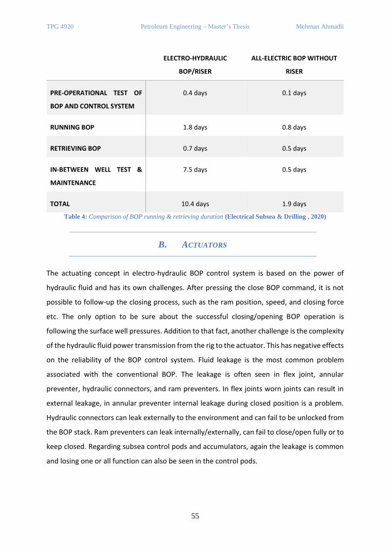
TPG 4920 Petroleum Engineering – Master’s Thesis Mehman Ahmadli
55
ELECTRO-HYDRAULIC
BOP/RISER
ALL-ELECTRIC BOP WITHOUT
RISER
PRE-OPERATIONAL TEST OF
BOP AND CONTROL SYSTEM
0.4 days 0.1 days
RUNNING BOP 1.8 days 0.8 days
RETRIEVING BOP 0.7 days 0.5 days
IN-BETWEEN WELL TEST &
MAINTENANCE
7.5 days 0.5 days
TOTAL 10.4 days 1.9 days
Table 4: Comparison of BOP running & retrieving duration (Electrical Subsea & Drilling , 2020)
B. ACTUATORS
The actuating concept in electro-hydraulic BOP control system is based on the power of
hydraulic fluid and has its own challenges. After pressing the close BOP command, it is not
possible to follow-up the closing process, such as the ram position, speed, and closing force
etc. The only option to be sure about the successful closing/opening BOP operation is
following the surface well pressures. Addition to that fact, another challenge is the complexity
of the hydraulic fluid power transmission from the rig to the actuator. This has negative effects
on the reliability of the BOP control system. Fluid leakage is the most common problem
associated with the conventional BOP. The leakage is often seen in flex joint, annular
preventer, hydraulic connectors, and ram preventers. In flex joints worn joints can result in
external leakage, in annular preventer internal leakage during closed position is a problem.
Hydraulic connectors can leak externally to the environment and can fail to be unlocked from
the BOP stack. Ram preventers can leak internally/externally, can fail to close/open fully or to
keep closed. Regarding subsea control pods and accumulators, again the leakage is common
and losing one or all function can also be seen in the control pods.
TPG 4920 Petroleum Engineering – Master’s Thesis Mehman Ahmadli
56
Earlier we mentioned three electro-mechanical actuators in all-electric BOP control system,
ring piston, ram, valve actuators. Starting with the ring piston actuators, the main challenge
for it is improved sealing systems. Since annular preventers are frequently used preventer
type and they allow vertical movements of the drilling string in closed position, the sealing
efficiency can be degraded after a while. In fact, all-electric BOP system offers longer period
of usage of the seals than the hydraulic one. It is because the CPU can adjust the speed and
force of the preventer in the electric BOP in such a way to minimize wearing. Additionally, the
automation system also reduces the time of the closing operation. For example, the CPU will
increase the speed of the shear rams until touching the drill sting and then will decrease to
obtain higher cutting load. Higher cutting capacity is the main challenge for the ram
preventers. Regarding valve actuators, it is aimed to reduce the design variations and to create
a typical one which can be used for different purposes (choke, kill etc.)
C. POWER SYSTEMS
In electro-hydraulic BOP system, the power system includes compressed hydraulic fluid
bottles. Main challenges with the hydraulic bottles are external hydraulic leakage and its
increasing size & weight. The leakage is caused mainly in the hydraulic joints due to poor
sealing or late maintenance. Going deeper locations, the capacity of the hydraulic
accumulators will be increased and again preventing leakage will get more difficult, which in
turn will increase NPT and the cost. Additionally, increasing capacity and going deeper will
require thicker wall thickness for the bottles which again will negative impact on the cost and
weight & size.
In all-electric BOP system, the batteries are charged from the surface via the power cables.
Since it is planning to be used in deep-water locations, the length of power cables will reach
approximately 10,000 ft. and this can lead to the presence of Ferranti effect. Ferranti effect is
the situation when the receiving end of the cable has higher voltage than the sending end.
Being experienced in long and high voltage cables, this effect is caused due to capacitance and
inductance of the cable. By two ways this challenge can be solved; using special cables to
reduce Ferranti effect; or using power cables only to charge the batteries rather to power the
actuators as well. The second option is more practical and cost-efficient.
TPG 4920 Petroleum Engineering – Master’s Thesis Mehman Ahmadli
57
Regarding the battery system, main challenges are achieving longer life, explosion proof and
less weight and size for batteries. Achieving longer battery life is a common challenge for
worldwide industry. Currently Lithium-ion batteries are the one widely used but there is
ongoing research to replace it with better alternatives. Less weight and dimensions can be
achieved with elimination of the nitrogen filled canisters in which the batteries are placed.
However, in this case the batteries will expose to harsh subsea environments, and it needs to
be developed.
D. DURABILITY
Regardless of the problems experienced in the hydraulic BOP system such as internal/external
leaking, failing to open/close, control loss, in general hydraulic BOP system is accepted as a
durable system in the industry. Therefore, it has been long time that the companies especially
the service companies are reluctant to the significant changes within the BOP system with the
fear of well control problems. However, the industry requirements are changing, and drilling
locations are switching towards ultra-deep-water zones, where using hydraulic BOP stacks is
getting difficult due to the challenges mentioned above. In the background of this situation,
different electric BOP system designs have been introduced, which eliminates the hydraulic
lines, actuators, accumulators, and associated parts in the system and replace them with the
electric alternatives. However, due to the lack of industrial usage of the electric BOP there is
no extensive industrial study about its durability. It can be expected that with the electric BOP
the reliability factor will be improved. The reliability is connected to the durability. Issues
associated with the hydraulic leakage will not be a concern anymore due to the elimination of
the hydraulic system. Possibility of controlling the speed and axial force of the rams will allow
the blades to stop softly just before touching each other and this will improve the lifetime of
the seals and the reliability in general terms. Additionally, the CPU will collect data from the
sensors regularly and will monitor the status of the BOP equipment. This will allow the
engineers to be aware of the developing or potential failures on time.
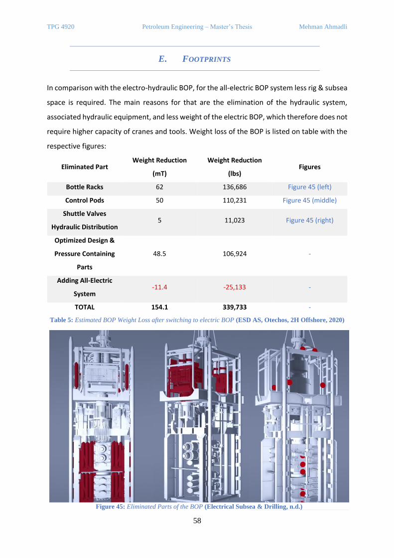
TPG 4920 Petroleum Engineering – Master’s Thesis Mehman Ahmadli
58
E. FOOTPRINTS
In comparison with the electro-hydraulic BOP, for the all-electric BOP system less rig & subsea
space is required. The main reasons for that are the elimination of the hydraulic system,
associated hydraulic equipment, and less weight of the electric BOP, which therefore does not
require higher capacity of cranes and tools. Weight loss of the BOP is listed on table with the
respective figures:
Eliminated Part Weight Reduction
(mT)
Weight Reduction
(lbs) Figures
Bottle Racks 62 136,686 Figure 45 (left)
Control Pods 50 110,231 Figure 45 (middle)
Shuttle Valves
Hydraulic Distribution 5 11,023 Figure 45 (right)
Optimized Design &
Pressure Containing
Parts
48.5 106,924 -
Adding All-Electric
System -11.4 -25,133 -
TOTAL 154.1 339,733 -
Table 5: Estimated BOP Weight Loss after switching to electric BOP (ESD AS, Otechos, 2H Offshore, 2020)
Figure 45: Eliminated Parts of the BOP (Electrical Subsea & Drilling, n.d.)
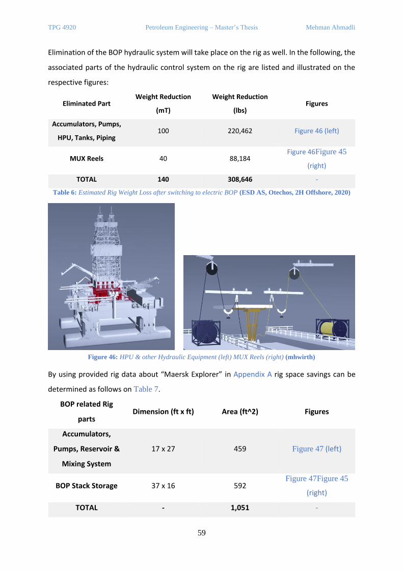
TPG 4920 Petroleum Engineering – Master’s Thesis Mehman Ahmadli
59
Elimination of the BOP hydraulic system will take place on the rig as well. In the following, the
associated parts of the hydraulic control system on the rig are listed and illustrated on the
respective figures:
Eliminated Part Weight Reduction
(mT)
Weight Reduction
(lbs) Figures
Accumulators, Pumps,
HPU, Tanks, Piping 100 220,462 Figure 46 (left)
MUX Reels 40 88,184 Figure 46Figure 45
(right)
TOTAL 140 308,646 -
Table 6: Estimated Rig Weight Loss after switching to electric BOP (ESD AS, Otechos, 2H Offshore, 2020)
By using provided rig data about “Maersk Explorer” in Appendix A rig space savings can be
determined as follows on Table 7.
BOP related Rig
parts Dimension (ft x ft) Area (ft^2) Figures
Accumulators,
Pumps, Reservoir &
Mixing System
17 x 27 459 Figure 47 (left)
BOP Stack Storage 37 x 16 592 Figure 47Figure 45
(right)
TOTAL - 1,051 -
Figure 46: HPU & other Hydraulic Equipment (left) MUX Reels (right) (mhwirth)
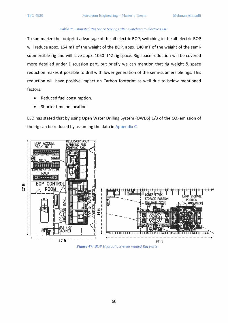
TPG 4920 Petroleum Engineering – Master’s Thesis Mehman Ahmadli
60
Table 7: Estimated Rig Space Savings after switching to electric BOP.
To summarize the footprint advantage of the all-electric BOP, switching to the all-electric BOP
will reduce appx. 154 mT of the weight of the BOP, appx. 140 mT of the weight of the semi-
submersible rig and will save appx. 1050 ft^2 rig space. Rig space reduction will be covered
more detailed under Discussion part, but briefly we can mention that rig weight & space
reduction makes it possible to drill with lower generation of the semi-submersible rigs. This
reduction will have positive impact on Carbon footprint as well due to below mentioned
factors:
• Reduced fuel consumption.
• Shorter time on location
ESD has stated that by using Open Water Drilling System (OWDS) 1/3 of the CO2 emission of
the rig can be reduced by assuming the data in Appendix C.
Figure 47: BOP Hydraulic System related Rig Parts
TPG 4920 Petroleum Engineering – Master’s Thesis Mehman Ahmadli
61
F. EXPENDITURES
Expenditures of both BOP control system cannot be compared by just looking their market
price, indeed all BOP related operations including BOP running & retrieving, maintenance,
failure, etc. are to be considered. Therefore, the comparison is carried out through the
following parts:
• Market price of the BOP equipment.
• Down-time analysis & BOP related operations.
Market Price
Starting with the electro-hydrautic BOP control system, its cost is usually included in the
package offered by a drilling rig owner. For example, Shaffer 18 ¾” 15k type of subsea BOP
which is owned by Maersk and rented by BP Azerbaijan in Caspian Sea region, will cost
approximately 20 million USD in case BP company decides to buy it. To compete in the market,
all-electric BOP is also offered for the similar price. The problem with getting an exact price, is
related to the fact that the BOP prices are always being negotiating between parties and
therefore, it varies from case to case.
Down-time analysis & BOP related operations
Down-time analysis includes the non-productive time (NPT) of the drilling rig due to BOP
failures. Since electro-hydrautic BOP has much more practical usage than the electric one,
there are quite a lot of reliability analysis reports for traditional BOP equipment. As an
example, the result of the SINTEF Phase II DW and BSEE ABS reliability analysis reports are
given on Table 8.
From Table 8, it can be concluded that hydraulic control system is that most problematic part
of the BOP system. Although there is not a reliability report for the all-electric BOP control
system since it has not been implemented yet, it can be roughly assumed that in the electric
BOP system the failure rate is going to decrease since all the hydraulic system is eliminated.
Of course, this is just a thought rather than statistical conclusion but having less components,
becoming less complex in design enables the possibility of this assumption.
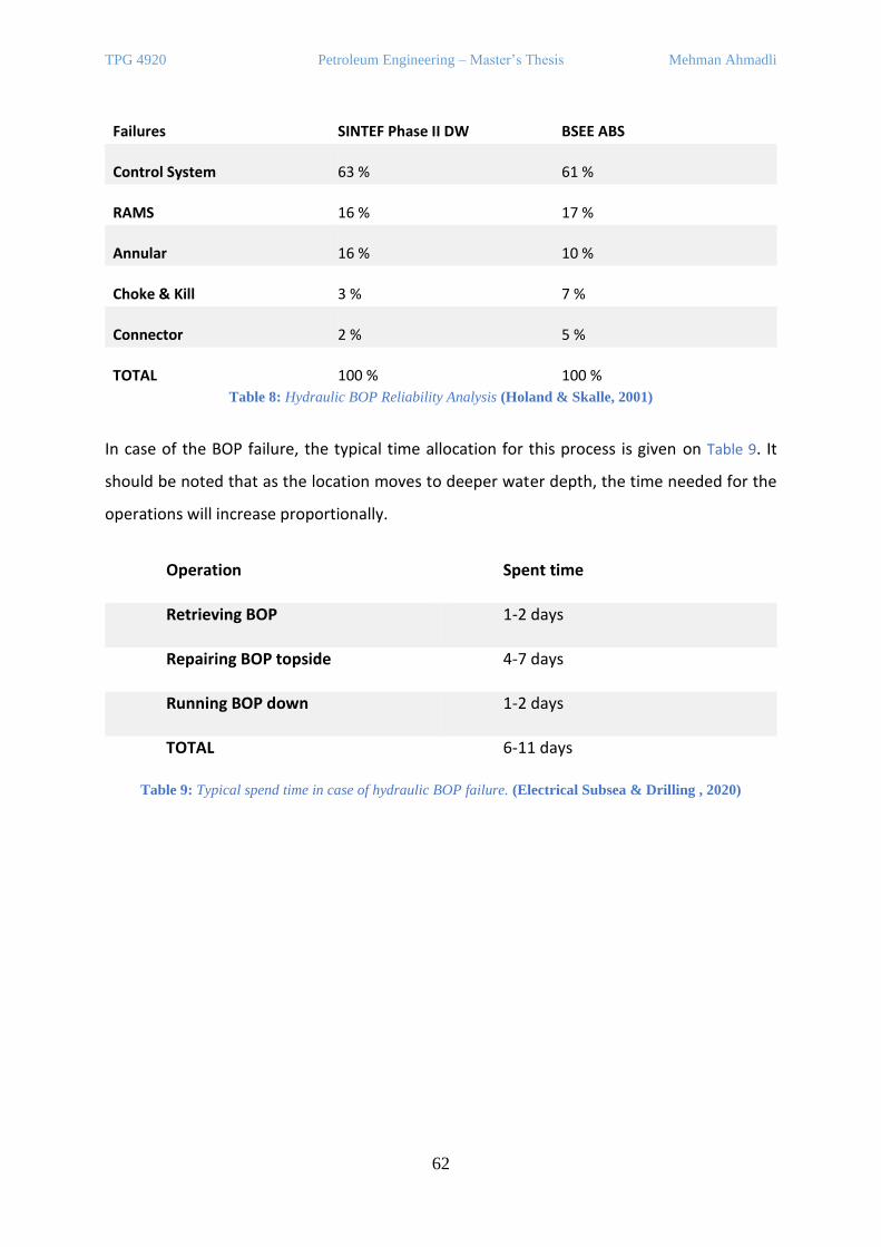
TPG 4920 Petroleum Engineering – Master’s Thesis Mehman Ahmadli
62
Failures SINTEF Phase II DW BSEE ABS
Control System 63 % 61 %
RAMS 16 % 17 %
Annular 16 % 10 %
Choke & Kill 3 % 7 %
Connector 2 % 5 %
TOTAL 100 % 100 %
Table 8: Hydraulic BOP Reliability Analysis (Holand & Skalle, 2001)
In case of the BOP failure, the typical time allocation for this process is given on Table 9. It
should be noted that as the location moves to deeper water depth, the time needed for the
operations will increase proportionally.
Operation Spent time
Retrieving BOP 1-2 days
Repairing BOP topside 4-7 days
Running BOP down 1-2 days
TOTAL 6-11 days
Table 9: Typical spend time in case of hydraulic BOP failure. (Electrical Subsea & Drilling , 2020)

TPG 4920 Petroleum Engineering – Master’s Thesis Mehman Ahmadli
63
VI. RISERLESS DRILLING SYSTEM
RD is not a new term for the industry, the concept was mentioned and described for the first
time by Watkins in 1969. This unconventional drilling system is based on the elimination of
the marine riser. At that time, the motivation to use this system was reducing wear problems
of BOPs and balancing pressures inside and outside of the well to make tripping process easier.
However, the RD did not find commercial success since drilling process was usually carried out
in the shallow water depths and the companies were satisfied by modifying riser and BOP
equipment. However, today’s realities are different than the past, and the RD system is again
an interesting topic to be considered. In the following different products and components of
the riserless drilling system are covered, and their integration into the new RD system is
described.
A. RISERLESS MUD RECOVERY, RMR® SYSTEM – “ENHANCED
DRILLING”
RMR® system is developed by AGR Subsea AS or with today’s name - Enhanced Drilling and as
stated by company, RMR® system has contributed to the changes in drilling industry
preferences. It is developed to drill top-hole sections safely, efficiently, quicker and with less
environmental impact. Traditionally, top-hole sections are drilled with seawater and the
cuttings are not returned to the rig, instead, deployed on the seafloor. Seawater as drilling
fluid may not be enough to overcome the challenges raised during top-hole drilling, such as
wellbore stability, water formation flow, shallow gases, and even cause problems such as clay
swelling. Due to the mentioned factors, conductor casing shoes are usually designed for not
deeper depths, which otherwise could save significant amount of money by reducing casing
points and allowing larger diameter of production casing/tubing.
Another challenge for top-hole drilling is the environmental factor. Drilling with seawater and
extracting the cuttings into open sea does not create an environment friendly outlook, and in
some areas the environmental regulations are stricter (Sakhalin Island, Russia), (Thorogood,
Rolland, Brown, & Urvant, 2007) or have endangered animal species (cold water corals, North
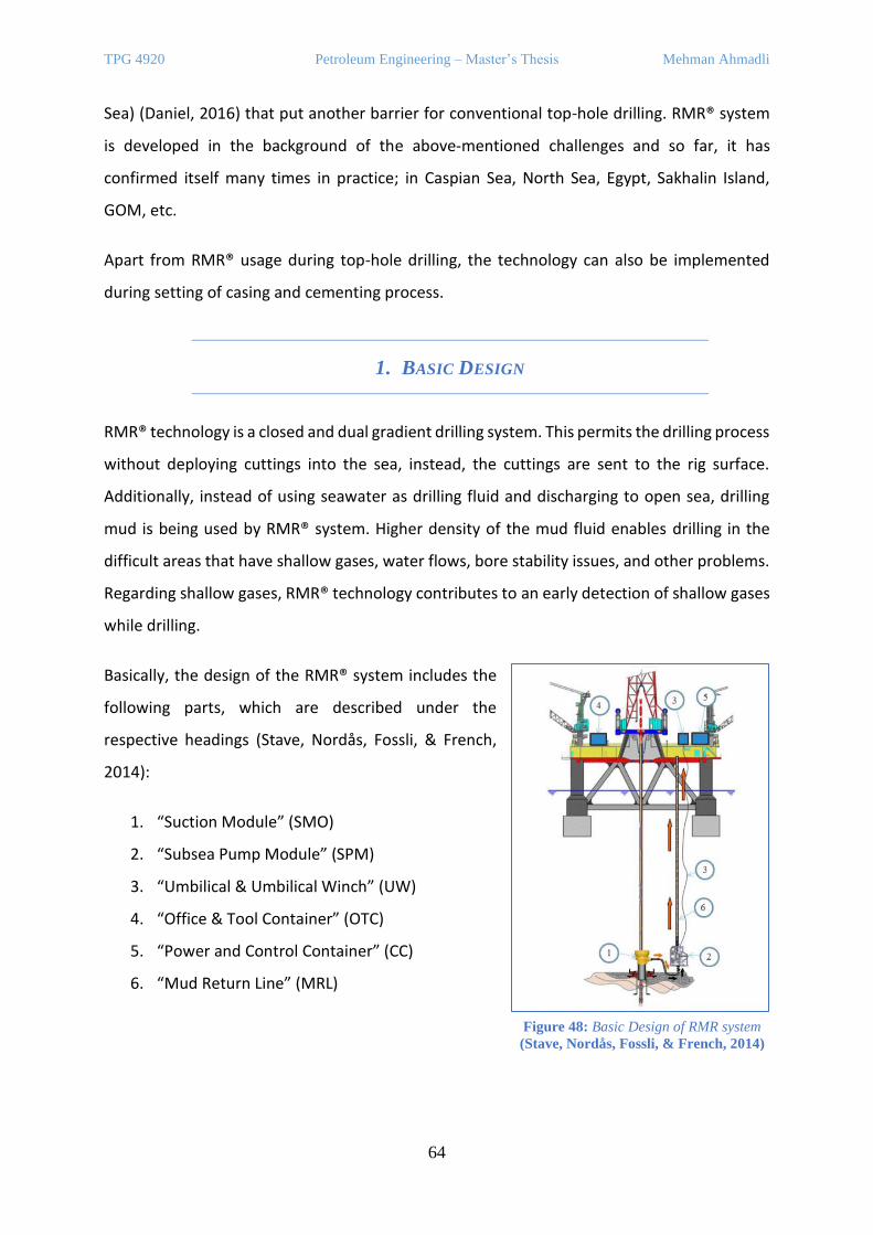
TPG 4920 Petroleum Engineering – Master’s Thesis Mehman Ahmadli
64
Sea) (Daniel, 2016) that put another barrier for conventional top-hole drilling. RMR® system
is developed in the background of the above-mentioned challenges and so far, it has
confirmed itself many times in practice; in Caspian Sea, North Sea, Egypt, Sakhalin Island,
GOM, etc.
Apart from RMR® usage during top-hole drilling, the technology can also be implemented
during setting of casing and cementing process.
1. BASIC DESIGN
RMR® technology is a closed and dual gradient drilling system. This permits the drilling process
without deploying cuttings into the sea, instead, the cuttings are sent to the rig surface.
Additionally, instead of using seawater as drilling fluid and discharging to open sea, drilling
mud is being used by RMR® system. Higher density of the mud fluid enables drilling in the
difficult areas that have shallow gases, water flows, bore stability issues, and other problems.
Regarding shallow gases, RMR® technology contributes to an early detection of shallow gases
while drilling.
Basically, the design of the RMR® system includes the
following parts, which are described under the
respective headings (Stave, Nordås, Fossli, & French,
2014):
1. “Suction Module” (SMO)
2. “Subsea Pump Module” (SPM)
3. “Umbilical & Umbilical Winch” (UW)
4. “Office & Tool Container” (OTC)
5. “Power and Control Container” (CC)
6. “Mud Return Line” (MRL)
Figure 48: Basic Design of RMR system
(Stave, Nordås, Fossli, & French, 2014)
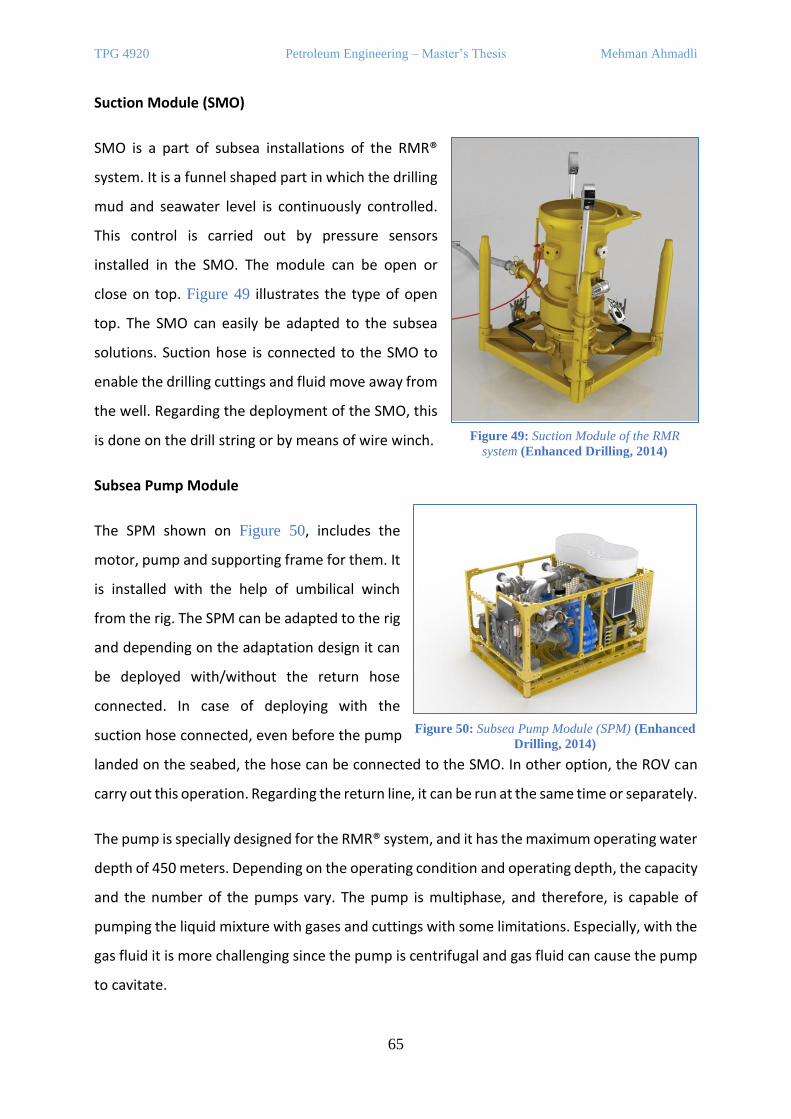
TPG 4920 Petroleum Engineering – Master’s Thesis Mehman Ahmadli
65
Suction Module (SMO)
SMO is a part of subsea installations of the RMR®
system. It is a funnel shaped part in which the drilling
mud and seawater level is continuously controlled.
This control is carried out by pressure sensors
installed in the SMO. The module can be open or
close on top. Figure 49 illustrates the type of open
top. The SMO can easily be adapted to the subsea
solutions. Suction hose is connected to the SMO to
enable the drilling cuttings and fluid move away from
the well. Regarding the deployment of the SMO, this
is done on the drill string or by means of wire winch.
Subsea Pump Module
The SPM shown on Figure 50, includes the
motor, pump and supporting frame for them. It
is installed with the help of umbilical winch
from the rig. The SPM can be adapted to the rig
and depending on the adaptation design it can
be deployed with/without the return hose
connected. In case of deploying with the
suction hose connected, even before the pump
landed on the seabed, the hose can be connected to the SMO. In other option, the ROV can
carry out this operation. Regarding the return line, it can be run at the same time or separately.
The pump is specially designed for the RMR® system, and it has the maximum operating water
depth of 450 meters. Depending on the operating condition and operating depth, the capacity
and the number of the pumps vary. The pump is multiphase, and therefore, is capable of
pumping the liquid mixture with gases and cuttings with some limitations. Especially, with the
gas fluid it is more challenging since the pump is centrifugal and gas fluid can cause the pump
to cavitate.
Figure 49: Suction Module of the RMR
system (Enhanced Drilling, 2014)
Figure 50: Subsea Pump Module (SPM) (Enhanced
Drilling, 2014)
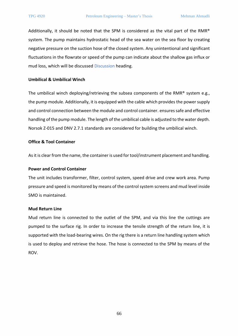
TPG 4920 Petroleum Engineering – Master’s Thesis Mehman Ahmadli
66
Additionally, it should be noted that the SPM is considered as the vital part of the RMR®
system. The pump maintains hydrostatic head of the sea water on the sea floor by creating
negative pressure on the suction hose of the closed system. Any unintentional and significant
fluctuations in the flowrate or speed of the pump can indicate about the shallow gas influx or
mud loss, which will be discussed Discussion heading.
Umbilical & Umbilical Winch
The umbilical winch deploying/retrieving the subsea components of the RMR® system e.g.,
the pump module. Additionally, it is equipped with the cable which provides the power supply
and control connection between the module and control container. ensures safe and effective
handling of the pump module. The length of the umbilical cable is adjusted to the water depth.
Norsok Z-015 and DNV 2.7.1 standards are considered for building the umbilical winch.
Office & Tool Container
As it is clear from the name, the container is used for tool/instrument placement and handling.
Power and Control Container
The unit includes transformer, filter, control system, speed drive and crew work area. Pump
pressure and speed is monitored by means of the control system screens and mud level inside
SMO is maintained.
Mud Return Line
Mud return line is connected to the outlet of the SPM, and via this line the cuttings are
pumped to the surface rig. In order to increase the tensile strength of the return line, it is
supported with the load-bearing wires. On the rig there is a return line handling system which
is used to deploy and retrieve the hose. The hose is connected to the SPM by means of the
ROV.
TPG 4920 Petroleum Engineering – Master’s Thesis Mehman Ahmadli
67
Well Control
No, it is not like this today. The RMR will be able to detect increase in flow since it will try to
maintain a constant level in the SMO and therefore need to speed up if there is more flow
coming from the well. However, whether this is gas or water flow will not be detected before
it is seen on cameras or other detection methods on seabed. In case of the blurry vision on
the sea floor, the fluctuations in the SPM parameters should be considered sufficient.
Additionally, there was a concept of Quick Release System (QRS) which has not been
developed fully yet. The system objectives are listed below:
• Disconnecting RMR® system from the well.
• Preventing gas influx to reach to the rig via the return line.
• Preventing RMR® equipment from any damage in case of emergency rig abandonment.
The power for the QRS is supplied from other source in order to create a fail-safe system. The
QRS will also be activated in case of power supply cut. Manually activation of the QRS is also
possible.
B. SUBSEA RCD SYSTEM – «ELECTRICAL SUBSEA & DRILLING AS”
RCD has already been mentioned under the heading of MPD system, where the device is used
to isolate the upper annulus of the riser from the below part. The RCD has been integrated
into MPD system, and there are integration concepts to ECD-C riser drilling, DGD system, and
Open Water Drilling System (OWDS). The OWDS is a riserless drilling concept that has been
developed by Electrical Subsea & Drilling AS (ESD) company. Rather than focusing on the
OWDS concept which will be touched under the following headings, now we will go through
the RCD equipment which is one of the specially designed equipment for the OWDS.
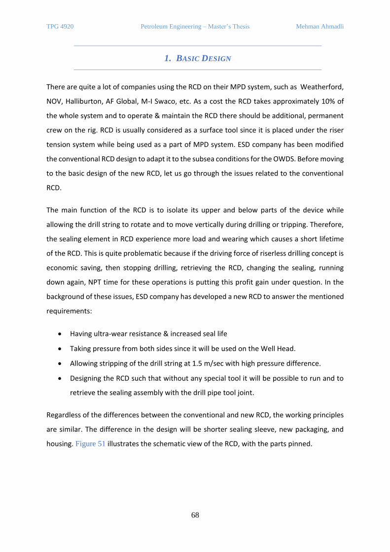
TPG 4920 Petroleum Engineering – Master’s Thesis Mehman Ahmadli
68
1. BASIC DESIGN
There are quite a lot of companies using the RCD on their MPD system, such as Weatherford,
NOV, Halliburton, AF Global, M-I Swaco, etc. As a cost the RCD takes approximately 10% of
the whole system and to operate & maintain the RCD there should be additional, permanent
crew on the rig. RCD is usually considered as a surface tool since it is placed under the riser
tension system while being used as a part of MPD system. ESD company has been modified
the conventional RCD design to adapt it to the subsea conditions for the OWDS. Before moving
to the basic design of the new RCD, let us go through the issues related to the conventional
RCD.
The main function of the RCD is to isolate its upper and below parts of the device while
allowing the drill string to rotate and to move vertically during drilling or tripping. Therefore,
the sealing element in RCD experience more load and wearing which causes a short lifetime
of the RCD. This is quite problematic because if the driving force of riserless drilling concept is
economic saving, then stopping drilling, retrieving the RCD, changing the sealing, running
down again, NPT time for these operations is putting this profit gain under question. In the
background of these issues, ESD company has developed a new RCD to answer the mentioned
requirements:
• Having ultra-wear resistance & increased seal life
• Taking pressure from both sides since it will be used on the Well Head.
• Allowing stripping of the drill string at 1.5 m/sec with high pressure difference.
• Designing the RCD such that without any special tool it will be possible to run and to
retrieve the sealing assembly with the drill pipe tool joint.
Regardless of the differences between the conventional and new RCD, the working principles
are similar. The difference in the design will be shorter sealing sleeve, new packaging, and
housing. Figure 51 illustrates the schematic view of the RCD, with the parts pinned.

TPG 4920 Petroleum Engineering – Master’s Thesis Mehman Ahmadli
69
In the concept of the OWDS, the RCD will be integrated to the all-electric BOP system which
is also developed by ESD company. Figure 52 shows the RCD housing integration with the BOP.
Figure 51: RCD System (ESD AS, Otechos, 2H Offshore, 2020)
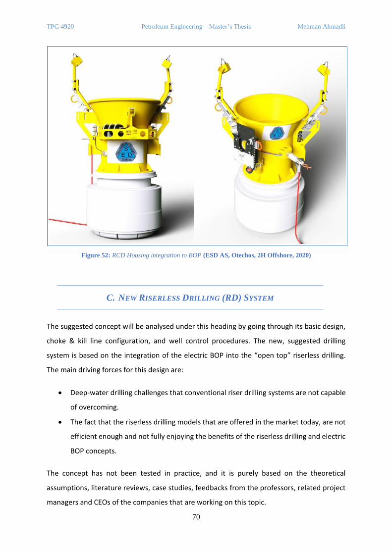
TPG 4920 Petroleum Engineering – Master’s Thesis Mehman Ahmadli
70
Figure 52: RCD Housing integration to BOP (ESD AS, Otechos, 2H Offshore, 2020)
C. NEW RISERLESS DRILLING (RD) SYSTEM
The suggested concept will be analysed under this heading by going through its basic design,
choke & kill line configuration, and well control procedures. The new, suggested drilling
system is based on the integration of the electric BOP into the “open top” riserless drilling.
The main driving forces for this design are:
• Deep-water drilling challenges that conventional riser drilling systems are not capable
of overcoming.
• The fact that the riserless drilling models that are offered in the market today, are not
efficient enough and not fully enjoying the benefits of the riserless drilling and electric
BOP concepts.
The concept has not been tested in practice, and it is purely based on the theoretical
assumptions, literature reviews, case studies, feedbacks from the professors, related project
managers and CEOs of the companies that are working on this topic.
TPG 4920 Petroleum Engineering – Master’s Thesis Mehman Ahmadli
71
For the new concept, various products of the companies are implemented, which have been
described extensively in the previous headings, such as “All-electric BOP”, “RMR” system, well
control procedures in unconventional drilling system, etc. Additionally, the integration of the
other related products is evaluated and discussed under Basic Design heading.
1. BASIC DESIGN
As it is mentioned in the previous heading, in the suggested concept, a marine riser, elector-
hydraulic BOP, its associated hydraulic and rig equipment – all are eliminated. Basically, the
new riserless drilling system is consist of the following parts:
• All-electric subsea BOP
The product of the ESD company – All-electric BOP is used. The design pressure can vary
depending on the working condition and depth. The variation is also valid for the ram
preventer configuration, its number and operating power. As a default, 15,000 psi all-electric
BOP system is selected, which is typical for deep-water drilling operations. On top of the BOP
stack, there is a BOP joint which connects the BOP stack to the SMO unit.
• Suction Module
SMO is the integrated part from the RMR® system, which is placed on the BOP joint. By being
open top, it is the upper part of the subsea well system. Therefore, to control the mud level
inside the SMO, it is equipped with the cameras, sensors, lightings, and mud level indicators.
Another factors considered on the design of the SMO, are the drill string re-entry, tripping up
& down operations. As is can be seen from Figure 52, the upper part of the SMO is designed
in such a way that:
1. Locating the drill-string into the SMO must be easy regardless of the underwater
flows.
2. Drill-string entry into the well must be a smooth process.
3. The cleaning elements inside the SMO must assure on the cleanliness of the drill pipes
to prevent any drilling mud release into the sea especially while tripping up to the rig.
TPG 4920 Petroleum Engineering – Master’s Thesis Mehman Ahmadli
72
• Suction Hose (Lower Umbilical) & Upper Umbilical
Suction hose is an elastic hose connecting the SMO to the inlet of the pump module – SPM.
Its function is to transport the returning fluid from the well up to the mud process plant on
the rig. In comparison with the suction hose of the RMR® system, on this design suction hose
is strengthened internally and externally. The need for that is coming from the fact that the
riserless drilling system will be used to drill to TD, instead of just top-hole section, and this will
expose the hose to denser cuttings, heavier mud fluid, and more variation of chemical
compounds. Except during ultra-deep-water drilling where the hydrostatic head is much
greater than on the typical water depths, suction hose is expected to be exposed similar
pressure as in the RMR® drilling. Because, in both designs, the SPM will maintain the
hydrostatic head of the seawater on the well-head.
Regarding upper umbilical, it is also an elastic hose connecting the surface rig to the mud
return line.
• Subsea Pump Module (SPM)
SPM is a backbone of the riserless drilling (RD) system due to controlling mud level,
maintaining sea floor gradient in the return line on sea floor, detecting a kick, keeping
flowrate/suction pressure constant (depending on the RD program) and being able to operate
with two-phase fluid. Since, the SPM is such an essential part, on the sea floor minimum two
backup subsea pumps are placed.
As similar as in the RMR® system, the main components of the SPM are the electric motor,
pump, and outer frame. The SPM is equipped with the sensors and a motor driver. The sensors
will provide input about the inside & outside pressures of the SPM to verify sealing of the
frame, inlet & outlet pressures for continuous drilling, well control or other purposes that will
be extensively covered under the Well control headings. Additionally, inside & outside
temperatures will be measured for early detection of the motor problems. Flowmeter will
measure the flowrate of the return fluid. This measurement is especially important due to the
fact that significant fluctuation in the flowrate of the returning fluid may indicate an influx into
the wellbore or mud loss into the formation. A motor driver is responsible to adjust the electric
motor speed thereby the pump flowrate. For example, if “constant flowrate” is selected as a
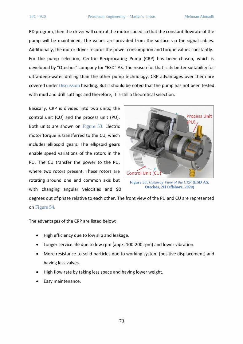
TPG 4920 Petroleum Engineering – Master’s Thesis Mehman Ahmadli
73
RD program, then the driver will control the motor speed so that the constant flowrate of the
pump will be maintained. The values are provided from the surface via the signal cables.
Additionally, the motor driver records the power consumption and torque values constantly.
For the pump selection, Centric Reciprocating Pump (CRP) has been chosen, which is
developed by “Otechos” company for “ESD” AS. The reason for that is its better suitability for
ultra-deep-water drilling than the other pump technology. CRP advantages over them are
covered under Discussion heading. But it should be noted that the pump has not been tested
with mud and drill cuttings and therefore, It is still a theoretical selection.
Basically, CRP is divided into two units; the
control unit (CU) and the process unit (PU).
Both units are shown on Figure 53. Electric
motor torque is transferred to the CU, which
includes ellipsoid gears. The ellipsoid gears
enable speed variations of the rotors in the
PU. The CU transfer the power to the PU,
where two rotors present. These rotors are
rotating around one and common axis but
with changing angular velocities and 90
degrees out of phase relative to each other. The front view of the PU and CU are represented
on Figure 54.
The advantages of the CRP are listed below:
• High efficiency due to low slip and leakage.
• Longer service life due to low rpm (appx. 100-200 rpm) and lower vibration.
• More resistance to solid particles due to working system (positive displacement) and
having less valves.
• High flow rate by taking less space and having lower weight.
• Easy maintenance.
Figure 53: Cutaway View of the CRP (ESD AS,
Otechos, 2H Offshore, 2020)
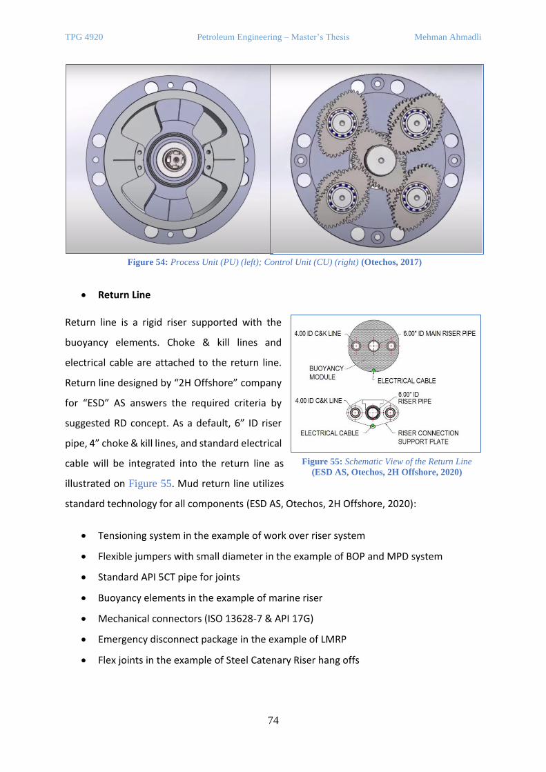
TPG 4920 Petroleum Engineering – Master’s Thesis Mehman Ahmadli
74
• Return Line
Return line is a rigid riser supported with the
buoyancy elements. Choke & kill lines and
electrical cable are attached to the return line.
Return line designed by “2H Offshore” company
for “ESD” AS answers the required criteria by
suggested RD concept. As a default, 6” ID riser
pipe, 4” choke & kill lines, and standard electrical
cable will be integrated into the return line as
illustrated on Figure 55. Mud return line utilizes
standard technology for all components (ESD AS, Otechos, 2H Offshore, 2020):
• Tensioning system in the example of work over riser system
• Flexible jumpers with small diameter in the example of BOP and MPD system
• Standard API 5CT pipe for joints
• Buoyancy elements in the example of marine riser
• Mechanical connectors (ISO 13628-7 & API 17G)
• Emergency disconnect package in the example of LMRP
• Flex joints in the example of Steel Catenary Riser hang offs
Figure 54: Process Unit (PU) (left); Control Unit (CU) (right) (Otechos, 2017)
Figure 55: Schematic View of the Return Line
(ESD AS, Otechos, 2H Offshore, 2020)
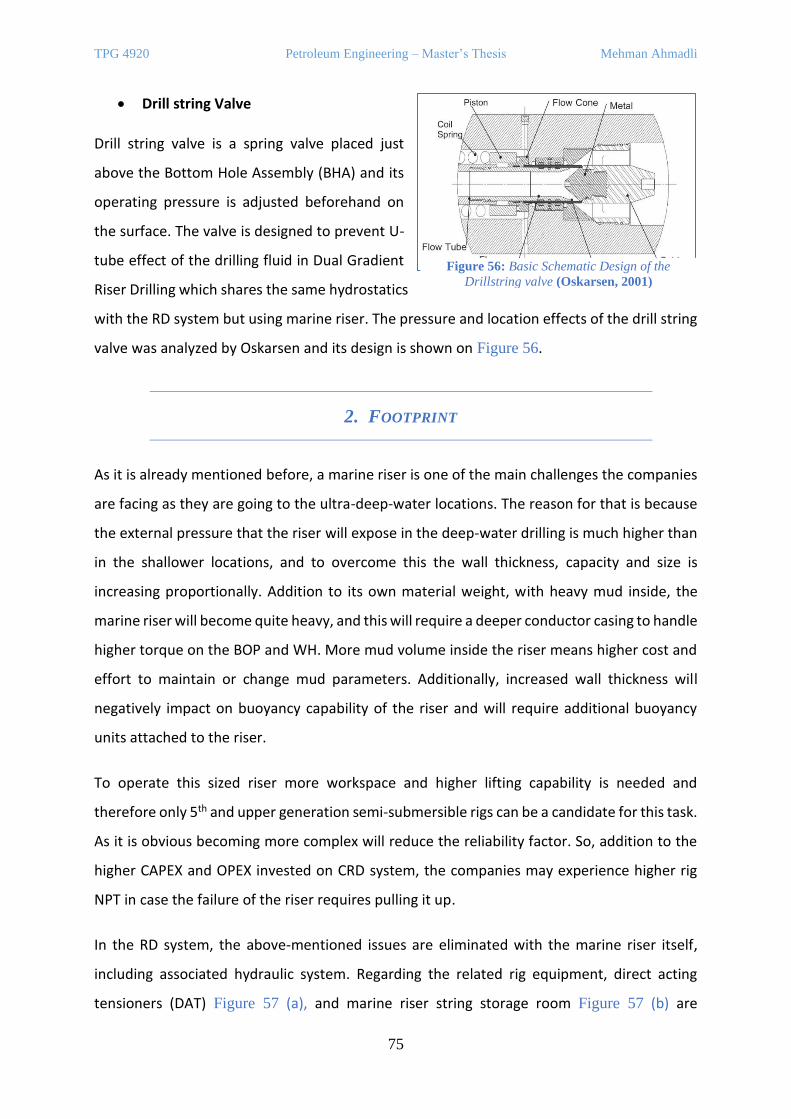
TPG 4920 Petroleum Engineering – Master’s Thesis Mehman Ahmadli
75
• Drill string Valve
Drill string valve is a spring valve placed just
above the Bottom Hole Assembly (BHA) and its
operating pressure is adjusted beforehand on
the surface. The valve is designed to prevent U-
tube effect of the drilling fluid in Dual Gradient
Riser Drilling which shares the same hydrostatics
with the RD system but using marine riser. The pressure and location effects of the drill string
valve was analyzed by Oskarsen and its design is shown on Figure 56.
2. FOOTPRINT
As it is already mentioned before, a marine riser is one of the main challenges the companies
are facing as they are going to the ultra-deep-water locations. The reason for that is because
the external pressure that the riser will expose in the deep-water drilling is much higher than
in the shallower locations, and to overcome this the wall thickness, capacity and size is
increasing proportionally. Addition to its own material weight, with heavy mud inside, the
marine riser will become quite heavy, and this will require a deeper conductor casing to handle
higher torque on the BOP and WH. More mud volume inside the riser means higher cost and
effort to maintain or change mud parameters. Additionally, increased wall thickness will
negatively impact on buoyancy capability of the riser and will require additional buoyancy
units attached to the riser.
To operate this sized riser more workspace and higher lifting capability is needed and
therefore only 5th and upper generation semi-submersible rigs can be a candidate for this task.
As it is obvious becoming more complex will reduce the reliability factor. So, addition to the
higher CAPEX and OPEX invested on CRD system, the companies may experience higher rig
NPT in case the failure of the riser requires pulling it up.
In the RD system, the above-mentioned issues are eliminated with the marine riser itself,
including associated hydraulic system. Regarding the related rig equipment, direct acting
tensioners (DAT) Figure 57 (a), and marine riser string storage room Figure 57 (b) are
Figure 56: Basic Schematic Design of the
Drillstring valve (Oskarsen, 2001)
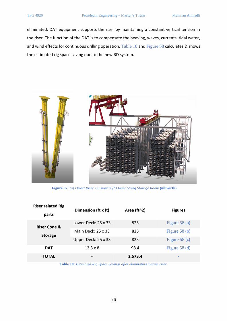
TPG 4920 Petroleum Engineering – Master’s Thesis Mehman Ahmadli
76
eliminated. DAT equipment supports the riser by maintaining a constant vertical tension in
the riser. The function of the DAT is to compensate the heaving, waves, currents, tidal water,
and wind effects for continuous drilling operation. Table 10 and Figure 58 calculates & shows
the estimated rig space saving due to the new RD system.
Riser related Rig
parts Dimension (ft x ft) Area (ft^2) Figures
Riser Cone &
Storage
Lower Deck: 25 x 33 825 Figure 58 (a)
Main Deck: 25 x 33 825 Figure 58 (b)
Upper Deck: 25 x 33 825 Figure 58 (c)
DAT 12.3 x 8 98.4 Figure 58 (d)
TOTAL - 2,573.4 -
Table 10: Estimated Rig Space Savings after eliminating marine riser.
Figure 57: (a) Direct Riser Tensioners (b) Riser String Storage Room (mhwirth)

TPG 4920 Petroleum Engineering – Master’s Thesis Mehman Ahmadli
77
3. CHOKE & KILL LINES
Choke and Kill lines are important part of the well
control process. In conventional drilling, in case of
the well kick situation, the BOP valves are shut,
and the only contact with the wellbore stayed on
are these lines and drill string if it is in the
wellbore. To return the BHP back to the mud
window, drilling fluid with new properties is
injected into the wellbore via the drill string, and
thereby the kick fluid is circulated out of the well
via the choke line. Measured pressure values in
the choke line are equally important in the
manner of calculating kill mud properties. This is
the main function of these lines, however
depending on the situation they can also be used for other purposes, e.g., chemical injection.
In conventional riser drilling, choke & kill lines are attached to the marine riser as illustrated
on Figure 59, as yellow & green colours, respectively.
In the riserless drilling concept, choke & kill lines are attached to the mud return line, after
which to the upper umbilical. However, from the subsea BOP to the mud return line there can
Figure 59: Illustration of Conventional Riser
Drilling
Figure 58: Riser string storage space in (a) Lower Deck (b) Main Deck (c) Upper Deck / (d) Riser Tensioner Dual Unit
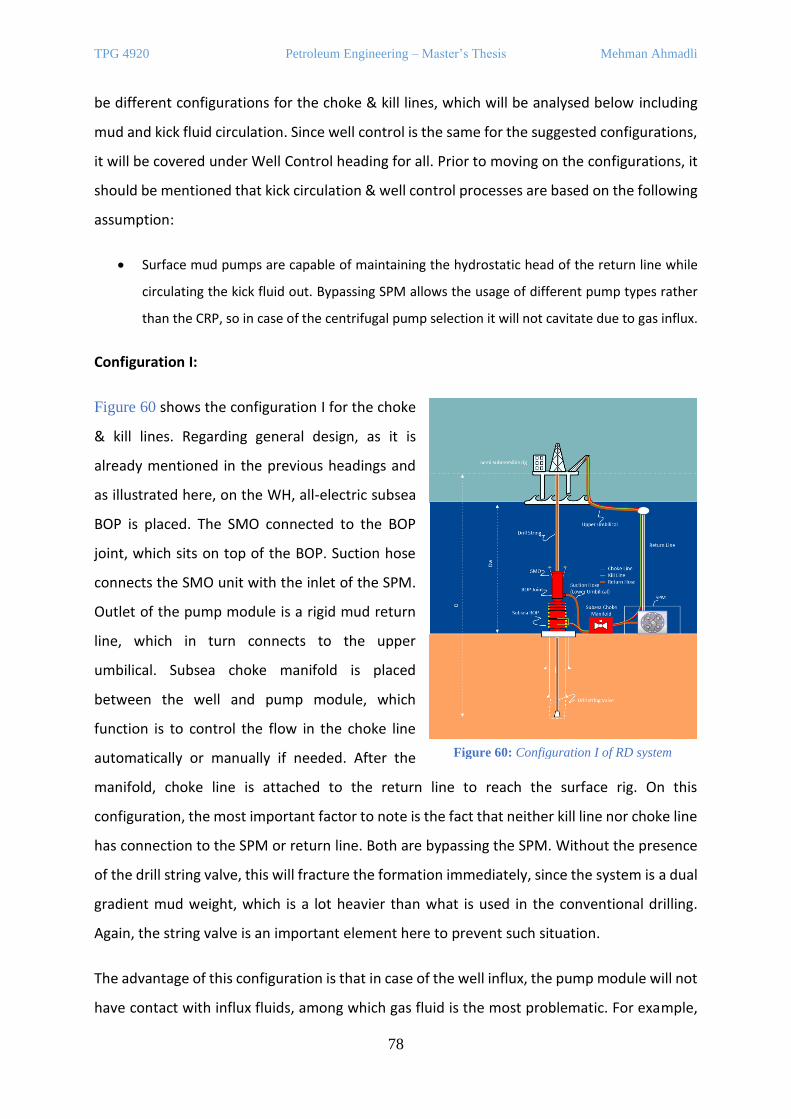
TPG 4920 Petroleum Engineering – Master’s Thesis Mehman Ahmadli
78
be different configurations for the choke & kill lines, which will be analysed below including
mud and kick fluid circulation. Since well control is the same for the suggested configurations,
it will be covered under Well Control heading for all. Prior to moving on the configurations, it
should be mentioned that kick circulation & well control processes are based on the following
assumption:
• Surface mud pumps are capable of maintaining the hydrostatic head of the return line while
circulating the kick fluid out. Bypassing SPM allows the usage of different pump types rather
than the CRP, so in case of the centrifugal pump selection it will not cavitate due to gas influx.
Configuration I:
Figure 60 shows the configuration I for the choke
& kill lines. Regarding general design, as it is
already mentioned in the previous headings and
as illustrated here, on the WH, all-electric subsea
BOP is placed. The SMO connected to the BOP
joint, which sits on top of the BOP. Suction hose
connects the SMO unit with the inlet of the SPM.
Outlet of the pump module is a rigid mud return
line, which in turn connects to the upper
umbilical. Subsea choke manifold is placed
between the well and pump module, which
function is to control the flow in the choke line
automatically or manually if needed. After the
manifold, choke line is attached to the return line to reach the surface rig. On this
configuration, the most important factor to note is the fact that neither kill line nor choke line
has connection to the SPM or return line. Both are bypassing the SPM. Without the presence
of the drill string valve, this will fracture the formation immediately, since the system is a dual
gradient mud weight, which is a lot heavier than what is used in the conventional drilling.
Again, the string valve is an important element here to prevent such situation.
The advantage of this configuration is that in case of the well influx, the pump module will not
have contact with influx fluids, among which gas fluid is the most problematic. For example,
Figure 60: Configuration I of RD system
TPG 4920 Petroleum Engineering – Master’s Thesis Mehman Ahmadli
79
in case of the centrifugal pump integration into this design, the gas can lead to pump
cavitation, while in PD pumps this will decrease the performance of the pump system.
Regarding the disadvantage, the material cost of these lines and the running & maintaining
expenditures can be considered.
Mud Circulation:
1. Drilling mud is pumped from semi-submersible rig or drilling ship down through drill
string.
2. Then through the annulus up to the BOP the mud flows as similar as CRD.
3. Passing through the subsea BOP the mud enters the SMO and there is diverted to
Subsea Pump Module (SPM) through suction hose (Lower umbilical).
4. Mud is pumped up to sea level through Mud Return Line which is a rigid line floating
parallel to the drill string.
5. The connection from return line to the floating vessel (rig or ship) is provided via upper
umbilical (elastic hose). And after that one circulation of the drilling mud is completed.
Kick Fluid Circulation
In case of the confirming well influx, as conventionally surface mud pumps will be shut off, the
SPM will be turned off, and the BOP valves will be closed. Drill string valve will prevent
happening of U-tube effect.
1. Kill mud is pumped from semi-submersible rig or drilling ship down through kill line.
2. Subsea choke manifold adjusts the choke valve automatically to assure maintenance
of the constant BHP.
3. Kick fluid pass through the manifold and reach up to the rig via the choke line attached
to the return line.
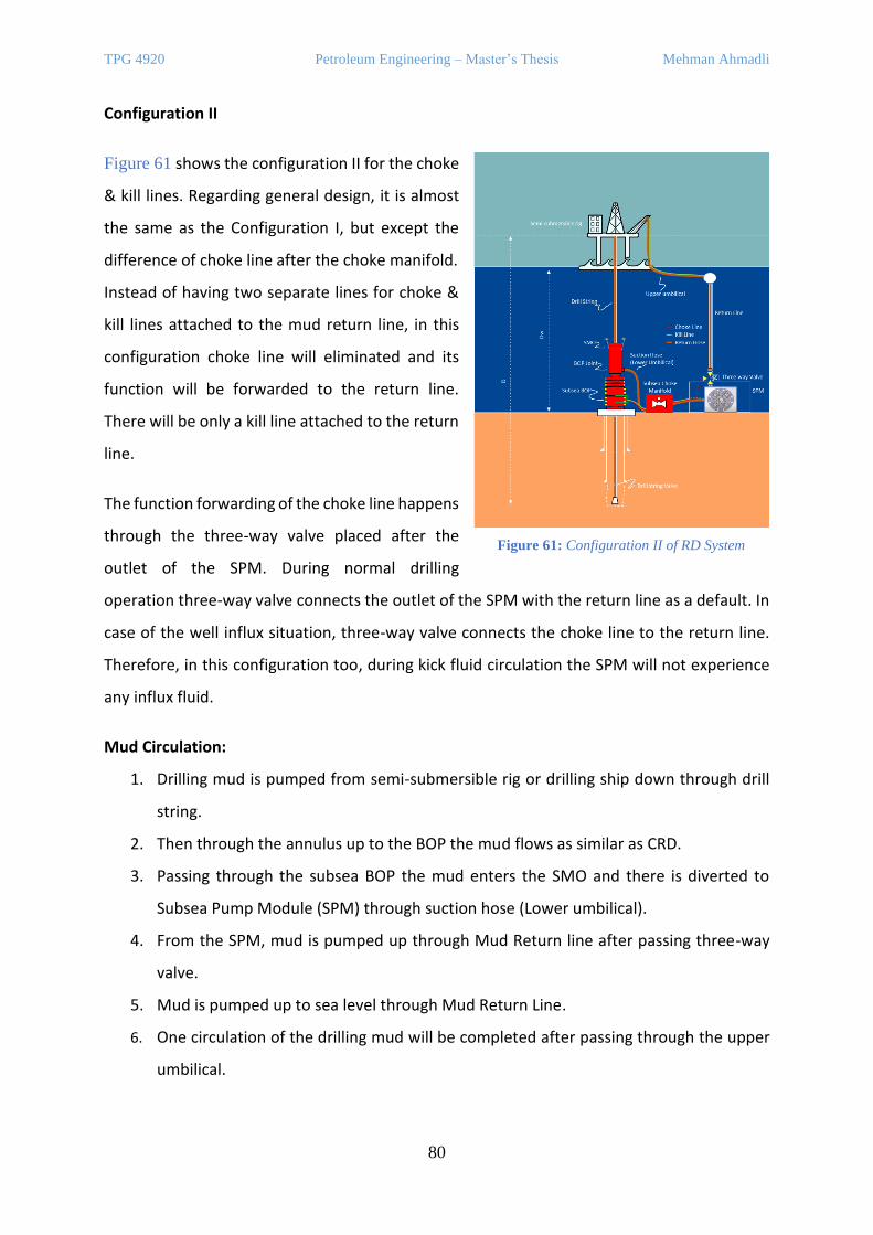
TPG 4920 Petroleum Engineering – Master’s Thesis Mehman Ahmadli
80
Configuration II
Figure 61 shows the configuration II for the choke
& kill lines. Regarding general design, it is almost
the same as the Configuration I, but except the
difference of choke line after the choke manifold.
Instead of having two separate lines for choke &
kill lines attached to the mud return line, in this
configuration choke line will eliminated and its
function will be forwarded to the return line.
There will be only a kill line attached to the return
line.
The function forwarding of the choke line happens
through the three-way valve placed after the
outlet of the SPM. During normal drilling
operation three-way valve connects the outlet of the SPM with the return line as a default. In
case of the well influx situation, three-way valve connects the choke line to the return line.
Therefore, in this configuration too, during kick fluid circulation the SPM will not experience
any influx fluid.
Mud Circulation:
1. Drilling mud is pumped from semi-submersible rig or drilling ship down through drill
string.
2. Then through the annulus up to the BOP the mud flows as similar as CRD.
3. Passing through the subsea BOP the mud enters the SMO and there is diverted to
Subsea Pump Module (SPM) through suction hose (Lower umbilical).
4. From the SPM, mud is pumped up through Mud Return line after passing three-way
valve.
5. Mud is pumped up to sea level through Mud Return Line.
6. One circulation of the drilling mud will be completed after passing through the upper
umbilical.
Figure 61: Configuration II of RD System
TPG 4920 Petroleum Engineering – Master’s Thesis Mehman Ahmadli
81
Kick Fluid Circulation
In case of the confirming well influx, as conventionally surface mud pumps will be shut off, the
SPM will be turned off, and the BOP valves will be closed. Drill string valve will prevent
happening of U-tube effect. Three-way valve connection is switched automatically between
the choke line and the return line.
1. Kill mud is pumped from semi-submersible rig or drilling ship down through the kill
line.
2. Subsea choke manifold adjusts the choke valve automatically to assure maintenance
of the constant BHP.
3. Kick fluid pass through the manifold, enters the return line via the three-way valve and
reaches up to the rig via the return line.
4. WELL CONTROL
The system is based on the “Dual Gradient Riserless Drilling” system. As it is mentioned the
SPM will be responsible to keep sea floor gradient in the return line. As a result of this balance,
the formations will see the Bottom Hole Pressure (BHP) composed of hydraulic heads of two
fluids – drilling mud and sea water and can be calculated via Equation 2 as follows:
𝐵𝐻𝑃 = 0.098𝜌𝑠𝑤𝐷𝑤 + 0.098𝜌𝑚(𝐷 − 𝐷𝑤)
Equation 2: BHP Calculation in the RD system
where 𝐷 stands for total depth, 𝐷𝑤 for sea water level.
Unsimilar to the CRD system where equal mud density (𝜌𝑒𝑚) is stable, in the RD system 𝜌𝑒𝑚
is dependent on the depth and calculated via Equation 3 as below:
𝜌𝑒𝑚 =𝐵𝐻𝑃
𝐷= 0.098 [𝜌𝑚 −
𝐷𝑤𝐷(𝜌𝑚 − 𝜌𝑠𝑤)]
Equation 3: Equal Mud Density calculation for the new RD system
The difference between conventional riser drilling (CRD) and riserless drilling (RD) system was
well illustrated on Figure 62 which compares the equal mud densities (EMD) of two systems
changes depending on the total depth. As can be seen from the figure, down to the sea floor,
3,000 meters, the EMD in the RD system is equal to the density of sea water, after which starts
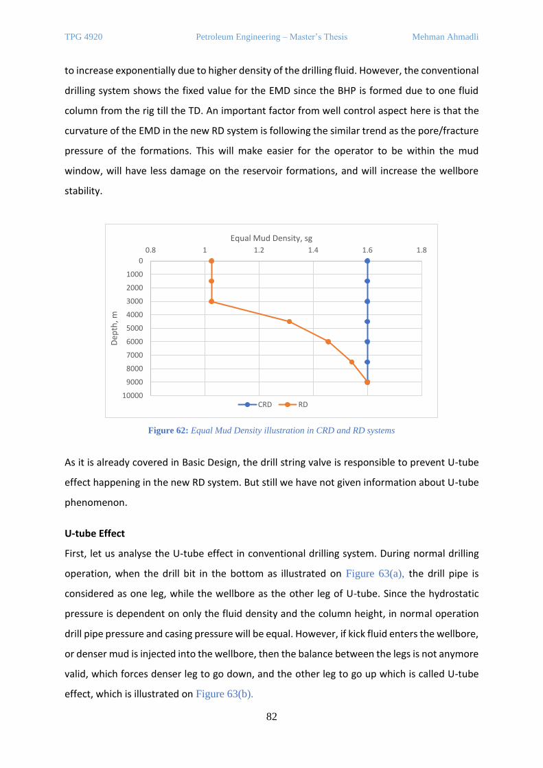
TPG 4920 Petroleum Engineering – Master’s Thesis Mehman Ahmadli
82
to increase exponentially due to higher density of the drilling fluid. However, the conventional
drilling system shows the fixed value for the EMD since the BHP is formed due to one fluid
column from the rig till the TD. An important factor from well control aspect here is that the
curvature of the EMD in the new RD system is following the similar trend as the pore/fracture
pressure of the formations. This will make easier for the operator to be within the mud
window, will have less damage on the reservoir formations, and will increase the wellbore
stability.
Figure 62: Equal Mud Density illustration in CRD and RD systems
As it is already covered in Basic Design, the drill string valve is responsible to prevent U-tube
effect happening in the new RD system. But still we have not given information about U-tube
phenomenon.
U-tube Effect
First, let us analyse the U-tube effect in conventional drilling system. During normal drilling
operation, when the drill bit in the bottom as illustrated on Figure 63(a), the drill pipe is
considered as one leg, while the wellbore as the other leg of U-tube. Since the hydrostatic
pressure is dependent on only the fluid density and the column height, in normal operation
drill pipe pressure and casing pressure will be equal. However, if kick fluid enters the wellbore,
or denser mud is injected into the wellbore, then the balance between the legs is not anymore
valid, which forces denser leg to go down, and the other leg to go up which is called U-tube
effect, which is illustrated on Figure 63(b).
0
1000
2000
3000
4000
5000
6000
7000
8000
9000
10000
0.8 1 1.2 1.4 1.6 1.8
Dep
th, m
Equal Mud Density, sg
CRD RD
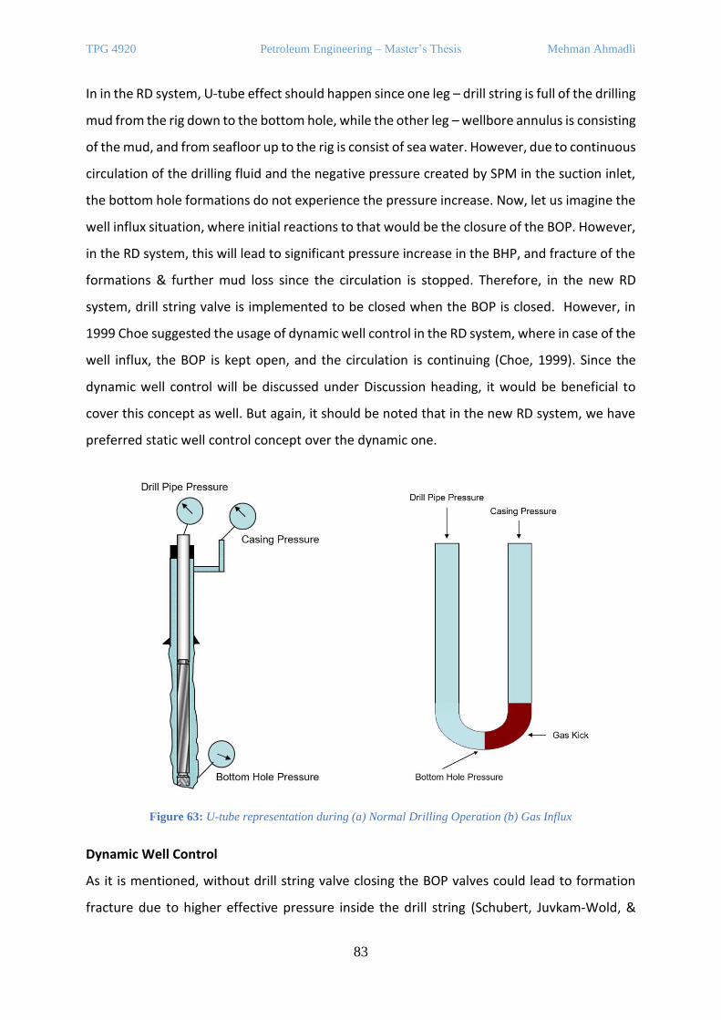
TPG 4920 Petroleum Engineering – Master’s Thesis Mehman Ahmadli
83
In in the RD system, U-tube effect should happen since one leg – drill string is full of the drilling
mud from the rig down to the bottom hole, while the other leg – wellbore annulus is consisting
of the mud, and from seafloor up to the rig is consist of sea water. However, due to continuous
circulation of the drilling fluid and the negative pressure created by SPM in the suction inlet,
the bottom hole formations do not experience the pressure increase. Now, let us imagine the
well influx situation, where initial reactions to that would be the closure of the BOP. However,
in the RD system, this will lead to significant pressure increase in the BHP, and fracture of the
formations & further mud loss since the circulation is stopped. Therefore, in the new RD
system, drill string valve is implemented to be closed when the BOP is closed. However, in
1999 Choe suggested the usage of dynamic well control in the RD system, where in case of the
well influx, the BOP is kept open, and the circulation is continuing (Choe, 1999). Since the
dynamic well control will be discussed under Discussion heading, it would be beneficial to
cover this concept as well. But again, it should be noted that in the new RD system, we have
preferred static well control concept over the dynamic one.
Dynamic Well Control
As it is mentioned, without drill string valve closing the BOP valves could lead to formation
fracture due to higher effective pressure inside the drill string (Schubert, Juvkam-Wold, &
Figure 63: U-tube representation during (a) Normal Drilling Operation (b) Gas Influx
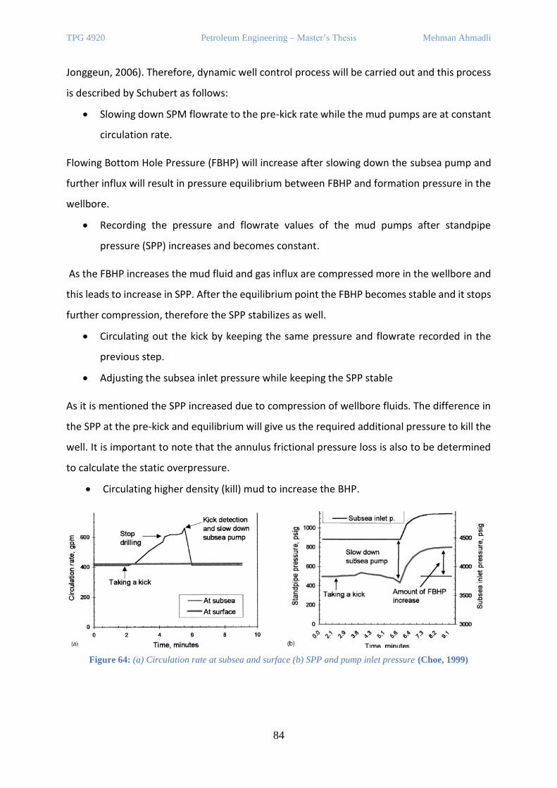
TPG 4920 Petroleum Engineering – Master’s Thesis Mehman Ahmadli
84
Jonggeun, 2006). Therefore, dynamic well control process will be carried out and this process
is described by Schubert as follows:
• Slowing down SPM flowrate to the pre-kick rate while the mud pumps are at constant
circulation rate.
Flowing Bottom Hole Pressure (FBHP) will increase after slowing down the subsea pump and
further influx will result in pressure equilibrium between FBHP and formation pressure in the
wellbore.
• Recording the pressure and flowrate values of the mud pumps after standpipe
pressure (SPP) increases and becomes constant.
As the FBHP increases the mud fluid and gas influx are compressed more in the wellbore and
this leads to increase in SPP. After the equilibrium point the FBHP becomes stable and it stops
further compression, therefore the SPP stabilizes as well.
• Circulating out the kick by keeping the same pressure and flowrate recorded in the
previous step.
• Adjusting the subsea inlet pressure while keeping the SPP stable
As it is mentioned the SPP increased due to compression of wellbore fluids. The difference in
the SPP at the pre-kick and equilibrium will give us the required additional pressure to kill the
well. It is important to note that the annulus frictional pressure loss is also to be determined
to calculate the static overpressure.
• Circulating higher density (kill) mud to increase the BHP.
Figure 64: (a) Circulation rate at subsea and surface (b) SPP and pump inlet pressure (Choe, 1999)
TPG 4920 Petroleum Engineering – Master’s Thesis Mehman Ahmadli
85
VII. DISCUSSION
Petroleum industry is usually considered as conservative industry due to its perseverance with
the traditional techniques. The changes in the industry are usually happened after the
situations where the known techniques are not able to overcome a challenge, or the current
system is not reliable and causes incidents such as the Macondo tragedy. Today, a similar
analogy can be done to highlight the issues that conventional drilling techniques are having in
ultra-deep-water locations.
Even though “ultra-deep-water drilling” word sounds as an exotic term, it is a reality of the
future drilling. While paging through the energy outlook reports published by major
international petroleum or energy companies, all of them predict that in 2050 even in the
most optimist and greenest scenario, hydrocarbon will be one of the main energy sources for
the world. From here, it can be concluded that the drilling operations will still be intact, but
where? Since shallow and deep-water reservoirs are being extracted today, ultra-deep-water
locations will be the next place to be drilled. Here, the main question arises – “Is it durable to
implement today’s conventional drilling system on ultra-deep-water reservoirs?”. Durability
in this concept also includes the economic preferences.
For the reader, the following sentence has already become a cliché, but should be mentioned
again. The BOP is an essential part of the conventional drilling system, it allows us to drill safely
and seals the inside of the wellbore from the outside. Although the BOP equipment basically
has not changed much since its first introduction by James Abercrombie and Harry Cameron,
till today plenty of reservoirs have been drilled and extracted thanks to our hundreds of metric
tonnes weighted equipment. This weight is continuously increasing as going deeper locations
(appx. 400-500 mT), plus governments accepting stricter environmental policies. In this report
well fatigues are not covered, but it is only mentioned as a result of the increasing BOP weight.
Apart from well fatigue issue, there are other difficulties such as transporting, running down
& up, handling. Indeed, Table 4 indicates that typical BOP issue causes 10.4 NPT days, while
for the electric BOP this number equal only to 1.9 days. Assuming 300,000 USD daily rate for
the 6th generation of semi-sub rig, we should consider 2,550,000 USD difference between two
systems. Therefore, the BOP must be lighter, but how?
TPG 4920 Petroleum Engineering – Master’s Thesis Mehman Ahmadli
86
One of the options for that, is replacing BOP material with lighter material, on which there are
ongoing research by different companies and scientists, but this is not covered in this report.
The option that the report covered is eliminating the hydraulic system, equipment and
pressure containing frames Figure 44. Hydraulic control system in a far distance is not really
a good solution. The reason for saying that so easily is because of the rig NPT reports and
electro-hydraulic BOP reliability reports, which state that rig down-time is mostly caused by
BOP control issues. The problem is simple – hydraulic system is willing to leak. To prevent this
problem, it should be checked, tested, and maintained regularly. The test can be carried out
once in two weeks, a month interval depending on the regulation of the host country and
company. Another discomfort of the hydraulic system is that when an operator presses the
red BOP closing button on the drilling panel, the light came up to indicate the closing process
is on the way. However, in reality, it indicates that the solenoid valve (on the rig) is activated,
and pressure from surface was released. But what about any input from the ram activation,
position, etc.? Well, for this information the operator must rely on the standpipe and surface
casing pressures.
Hydraulic vs. Electric power unit. For sure the winner is the electric one, and indeed this
advantage is in the center of the advertisement of the products by “Electrical Subsea &
Drilling” and “Noble Drilling”. Hydraulic power system uses the hydraulic bottles on subsea
and on the rig. Apart from the leaking and sealing issues with them, these bottles take a
massive area with its heavy weight. In case of going ultra-deep-water drilling with
conventional drilling system, hydraulic bottles are going to be the first issue. The bottle walls
are to be thickened; the capacity is to be increased to overcome increasing sea water
hydrostatic pressure. This adjustment is also valid for associated hoses. To supply the bottles
on the rig there are compressors with back-ups. The mixture unit produces control fluid on
the rig since hydraulic control system is an open system, which releases the fluid into the sea.
Even not going deeper about how this fluid release into the sea seems from the environmental
aspects, although the fluid is designed to be maximum biodegradable. While going through
the electric control system, we can see that these issues are eliminated, the system is simple,
and more reliable. No fluid release into the sea. Hoses are replaced with the electric cables,
that are more reliable and cheaper. Electric control system offers a full control to the operator
by continuously sending information about the ram position, speed, torque etc. The control

TPG 4920 Petroleum Engineering – Master’s Thesis Mehman Ahmadli
87
in electric actuators is so precise that with eBOP™ preventer 4mm distance can be kept
intentionally, which makes Robert van Kuilenburg to think about eliminating choke line and
just using an electric BOP instead.
The effect of the replacing hydraulic BOP control system with the electric one on the semi-
submersible rig is quite significant. This replacement eliminates the BOP related rig equipment
& tools, as indicated on Table 6 this reduces in total of 140 mT of the rig weight, while Table
7 determines in total of 1,051 ft2 rig space saving. This will lead to a reduction in capital
investment and operating expenditures of the rig due to reduced fuel consumption and
shorter time on location. Adding the advantages of the less carbon footprint for the electric
BOP, the questions arise – “Why the companies still use the electro-hydraulic BOP and why
the electric BOP is not commercially successful yet?”. John Dale’s approach on this question
is that none of the companies wants to be the first one on using the electric BOP. Adding the
fact that usually BOP equipment is provided by rig owner or service company, the operator
company does not involve on this too much. And the service companies are reluctant to the
equipment changes since the cost is paid by operator company.
Summarizing the BOP concept, we can now discuss another major part of the conventional
drilling system, which is a marine riser. The marine riser is simply a tube between the wellhead
and surface rig, thus drilling in ultra-deep-sea water will require a longer riser. Additionally,
due to increasing hydrostatic pressure of the sea water, the wall thickness, size, and
volumetric capacity of the riser will be designed thicker, bigger, and higher. These mentioned
factors, of course, will increase the capital investment of the riser, and will make the riser
running process costly and more time-consuming. Bigger marine riser requires higher capacity
of cranes, trolleys, storage area, and in general higher generation of the rig. Regarding the
operating difficulties, larger mud volumes inside the riser will require more time to change the
mud density, will decrease the reaction time for the rig crew to adjust the BHP. Weight of the
riser will increase significantly, the load on the BOP stack proportionally. The rig will be more
dependent on the weather, which will increase WoW time. Without any doubt, these
mentioned factors will have negative impacts on the CAPEX & OPEX in ultra-deep sea water
locations.
TPG 4920 Petroleum Engineering – Master’s Thesis Mehman Ahmadli
88
The new RD system eliminates the marine riser, and thereby its related issues. Table 10
indicates that this elimination saves approximately 2,600 ft2 rig space. This is possible due to
excluding the riser tensioners and riser string storage area. In the concept of the
unconventional riser drilling system, RMR® and RCD systems are covered. Each system has
useful components which can be used in the RD system.
In RMR® system, drilling process is carried out with open top SMO system. However, the Open
Water Drilling System (OWDS) developed by Electrical Subsea & Drilling implements RCD
system which is top close. The advantage of the RCD system is that it enables using the same
well control method for the RD system. However, RCD equipment is a problematic equipment,
and its sealing elements need checking & maintaining in shorter intervals. In case of ultra-
deep-water RCD equipment can increase rig NPT due to more time spending on retrieving and
running the equipment again. Therefore, in the new RD system, the SMO open top concept is
implemented. In order to keep the advantage of using conventional well control techniques,
drill string valve is added to the design.
Regarding the pump selection for the SPM, mainly two options were on the table: centrifugal
pump and positive displacement pump. The main issue with the centrifugal pump is its cavity
problem in presence of gas fluid. Another issue is lower pumping power in comparison to the
PD pumps. Being heavy and taking larger space are the main disadvantages for the PD pump.
Additionally, for the centrifugal pump working on the closed suction inlet does not create a
problem, while for the PD pump that would create problems on the inlet section. However,
by considering the expected gas fluid and solid within the mud and higher capacity of the
power, it was decided to go on with the PD pump, more exactly Centric Reciprocating Pump
(CRP) type. More detailed comparison of CRP pump with the other types is given below:
• Piston Cylinder
Comparing to the piston cylinder, CRP is working more balanced. Relative to its size & weight,
the CRP is capable of pumping higher flowrate. Having less valve makes CRP more resistive to
solid particles than the piston cylinder.
• Lobe
Comparing to the lobe pump, CRP can provide higher pressure with longer service life.
TPG 4920 Petroleum Engineering – Master’s Thesis Mehman Ahmadli
89
• Centrifugal
As it is already stated, CRP is more resistive to solid particles and can offer higher efficiency
for two-phase flows (liquid and gas). Additionally, for the same flow rate CRP counts lower
RPM which makes it more durable.
• Progressive Cavity
Comparing to the progressive cavity, CRP is more resistive to the solid particles, offers higher
flow rate and pressure relative to its size & weight.
• Rotary Vane
Comparing to the rotary vane pump, CRP is more efficient due to lower internal friction, thus
has longer service life.
• Diaphragm Pump
Although diaphragm pump is simpler in design than the CRP, it becomes more complex due
to its auxiliary system and components. The one especially designed for the subsea and
offshore drilling is Hydril pump developed for Chevron, however the OTECHOS CRP is more
robust and compact, due to flexible composite/rubber element that can be worn and teared.
Regarding the suggested configurations, it is highly likely that Configuration I will be
highlighted more since Configuration II suggests the elimination of the choke line and instead
usage of the mud return line for the same function. Elimination of the choke line might be
seen as a bold move by companies, and this might decrease its commercial success. Other
than that, from technical point, adding three-way valve increases the component number, and
decreases the system reliability. The typical issues, testing, maintenance, and service for the
valve are included. From these perspectives, the new RD system implements the
Configuration I concept.
Regarding well control process, due to integration of the drill string valve, the process is similar
with the conventional system. Static well control is used, so in case of the well influx situation
the BOP is shut off. There is no change about the well barrier coverage. However, it should be
noted that the drill string valve is not the best solution. It increases the friction rate inside the
drill string, requires pre-set pressure on the rig and regular checking & maintenance. In case
of eliminating the drill-string valve and choosing dynamic well control method, then we must

TPG 4920 Petroleum Engineering – Master’s Thesis Mehman Ahmadli
90
consider the following facts. Although theoretically the method is possible, practically there
are some unanswered questions that need to be developed, such as the size of influx can be
taken, how much reliable the flow in - & flow out – measurements, who is in main control,
driller or pump operator, gas influx cavity, etc.
As a final note, it should be stated that implementing the new RD system over the
conventional riser drilling system will save roughly 3600 ft2 rig space. By this way, the new rigs
can be downsized till the optimal size and the rest area can be used for other purposes, e.g.,
extra mud sacks. The width of the semi-sub rig will be decreased while keeping the area same,
and this will lower the gravity point of the rig, thereby weather & waves tolerance of the rig
will be improved. The modifications can be made on the existing rigs, and this can make
possible to drill in ultra-deep-water locations with 4th or lower generation of the semi-
submersible rigs.
VIII. CONCLUSION & FUTURE WORK
This report suggests the use of the new RD system which includes the integration of all-electric
BOP control system and RMR® technology. Comparison of the new system with the
conventional system is carried out by considering the related challenges, rig operations,
actuating concepts, power systems, durability, footprints, and expenditures. The new RD
system in these perspectives got much more advantageous position in front of the
conventional drilling system, which results in downsizing the semi-submersible rig
significantly.
Regarding the future work, to make the design simpler, the drill string valve should be
removed. But for that well control procedures need to be analysed, and in case of selecting
static well control method, then new ways must be found to prevent U-tube effect happening.
RCD system might be an option for that in case longer sealing & maintenance lifetime is
reached for the RCD equipment. Therefore, investigations on this direction could benefit the
RD system. Further studies should be carried out on the extension of the well barrier till the
subsea choke manifold via the suction hose. In case of having the same design pressure with
the BOP, e.g., 15k psi, dynamic well control method might be implemented. This would result

TPG 4920 Petroleum Engineering – Master’s Thesis Mehman Ahmadli
91
in keeping BOP valves open while circulating the kick fluid out of the well. Although the last
sentence sounds quite scary for the energy companies, somehow in future the whole concept
or parts of the RD system will be implemented and a new era for the petroleum industry will
start.
IX. REFERENCES
American Petroleum Institute (API). (2018). Blowout Preventer Systems and Well Control Revisions 1014-AA39. Retrieved from http://dev2.iadc.org/wp-content/uploads/2018/08/20180806-Joint-Trades-ltr-to-BSE-on-BOP-Well-Control-rulemaking.pdf
Amin, A. (2017). Design, Development and Control of a Managed. Newfoundland: Memorial University of Newfoundland.
API - American Petroleum Institute. (2017). API SPEC 16A, Specification for Drill-through Equipment (4th ed.).
Bai, Y., & Bai, Q. (2005). Subsea Pipelines and Risers. Elsevier Science Ltd. doi:10.1016/B978-008044566-3.50032-4
Beal, V., Claro, R., Araújo, M., Colombo, D., & Souza, S. (2019, October 28). Challenges for the Development of New Bop Generation. Offshore Technology Conference. doi:10.4043/29680-MS
Chandrasekaran, S. (2021). Chapter 1 - Marine risers: introduction, Design of Marine Risers with Functionally Graded Materials. doi:10.1016/B978-0-12-823537-9.00006-2
Choe, J. (1999). Analysis of Riserless Drilling and Well-Control Hydraulics. Society of Petroleum Engineers (SPE). doi:10.2118/55056-PA
Clark, M. (2009, January 1). Minimizing Environmental Footprint by Utilizing Prevention Technology. Society of Petroleum Engineers. doi:10.2118/124235-MS
Dale, J., Rød, M., & Howes, T. (2017, October 24). An All-Electric BOP Control System: A Game-Changing Technology. Offshore Technology Conference. doi:10.4043/28029-MS
Daniel, M. (2016). Use of Riserless Mud Recovery for Protection of Cold Water Corals While. Society of Petroleum Engineers (SPE). doi:https://doi.org/10.2118/179283-MS
Drægebø, E. (2014). Reliability Analysis of Blowout Preventer. Trondheim: NTNU.
Electrical Subsea & Drilling . (2020). Business Case Review: Open Water drilling w/Electrical BOP & RCD vs. Conventional Drilling w/Hydraulic BOP.
TPG 4920 Petroleum Engineering – Master’s Thesis Mehman Ahmadli
92
Electrical Subsea & Drilling. (n.d.). Products. Retrieved from https://esdrilling.no/products
Enhanced Drilling. (2014). Brochure: Riserless Mud Recovery system.
Eriksen, E. (2010). Norway Patent No. 331659. Retrieved from https://search.patentstyret.no/Patent/20110403/331659
Eriksen, E. (2011). Norway Patent No. 333570. Retrieved from https://search.patentstyret.no/Patent/20111384/333570
Eriksen, E. (2012, February 10). Norway Patent No. 333966. Retrieved from https://search.patentstyret.no/Patent/20130129/333966
Eriksen, E. (2012, February 10). Norway Patent No. 336045. Retrieved from https://search.patentstyret.no/Patent/20130157/336045
ESD AS, Otechos, 2H Offshore. (2020). Riserless Drilling - Joint Industry Partnering (JIP).
European Patent Office. (2011, October 10). Espacenet Patent Search. Mosaics: DEVICE FOR ELECTROMECHANICAL ACTUATOR. Retrieved from https://worldwide.espacenet.com/publicationDetails/mosaics?CC=NO&NR=20110403A1&KC=A1&FT=D&ND=3&date=20111010&DB=EPODOC&locale=
European Patent Office. (2013, April 15). Espacenet Patent Search. Mosaics: DEVICE FOR A SPRING RETURN VALVE ACTUATOR AND METHOD OF OPERATING A VALVE . Retrieved from https://worldwide.espacenet.com/publicationDetails/mosaics?CC=NO&NR=20111384A1&KC=A1&FT=D&ND=3&date=20130415&DB=EPODOC&locale=
Gaines, L., & Dunn, J. (2014). Lithium-Ion Battery Environmental Impacts. ELSEVIER. doi:https://doi.org/10.1016/B978-0-444-59513-3.00021-2
Heriot-Watt University. (2017). Drilling Engineering, Institute of Petroleum Engineering. Edinburgh.
Holand, P., & Skalle, P. (2001). Deepwater Kicks and BOP Performance, Unrestricted version. Trondheim: SINTEF Industrial Management.
Holme, L. P. (2016, October 14). Change in drilling strategy brings string of efficiency milestones to Troll. Retrieved from Offshore: https://www.offshore-mag.com/drilling-completion/article/16754830/change-in-drilling-strategy-brings-string-of-efficiency-milestones-to-troll
Houghton Plc. (n.d.). Retrieved from http://www.oilfieldwiki.com/wiki/Houghton_Offshore
Johnson, C., Le, T., Tisdale, G., & Palomo, J. (2004). US Patent No. 6,719,042.
Kazbekov, B. (n.d.). Logbook 3: BOP control system. BP Azerbaijan AGT Region.
Khandoker, S. (2008). US Patentnr. 20080023917.
TPG 4920 Petroleum Engineering – Master’s Thesis Mehman Ahmadli
93
Kindle, J. (1981, January 1). Hydraulic Fluids For BOP Control Systems. Offshore Technology Conference. doi:10.4043/4004-MS
Kuilenburg, R., Li, J., & Noble Drilling. (2018). 2 Million Pounds Force Electrical Ram BOP. Offshore Technology Conference (OTC). doi:10.4043/28964-MS
MacDermid Offshore Solutions. (n.d.). Retrieved from http://www.oilfieldwiki.com/wiki/MacDermid_Offshore_Solutions
mhwirth. (n.d.). Video material: Change to eBOP and RCD.
Netwas Group Oil. (2020, December 18). Choke Kill Valves. Retrieved from https://www.netwasgroup.us/offshore/chokekill-valves.html#:~:text=Two%20valves%20are%20used%20for,two%20lower%20sets%20of%20rams.
Netwas Group Oil. (2020, December 24). Subsea Bop Control Systems. Retrieved from https://www.netwasgroup.us/well-control/subsea-bop-control-systems.html
Niche Products. (n.d.). Retrieved from http://www.oilfieldwiki.com/wiki/Niche_Products_Ltd
Norwegian Industrial Property Office. (n.d.). Retrieved from https://search.patentstyret.no/advanced/#/
NOV Rig Systems. (2015). BOP Control Unit. Hentet fra https://www.nov.com/-/media/nov/files/products/rig/rig-equipment/pressure-control-systems/bop-control-unit-flyer.pdf
Oskarsen, R. T. (2001). Toolkit and Drill string Valve for Subsea Mudlift Drilling. Texas: Texas A&M U.
Otechos. (2017). CR-Technology Animation. Retrieved from Youtube: https://youtu.be/leO2hY0_4k0
Pallardy, R. (2020, November 02). Deepwater Horizon oil spill. Retrieved from https://www.britannica.com/event/Deepwater-Horizon-oil-spill
Peters, J., Baumann, M., Zimmermann, B., Braun , J., & Weil, M. (2017, January). The environmental impact of Li-Ion batteries and the role of key parameters – A review. ELSEVIER. doi:https://doi.org/10.1016/j.rser.2016.08.039
Schlumberger. (n.d.). Oilfield Glossary.
Schubert, J., Juvkam-Wold, H., & Jonggeun, C. (2006). Well Control Procedures for Dual Gradient Drilling as Compared to Conventional Riser Drilling. Society of Petroleum Engineers.
Stave, R., Nordås, P., Fossli, B., & French, C. (2014). Safe and Efficient Tophole Drilling using Riserless Mud Recovery and Managed Pressure Cementing. Offshore Technology Conference.

TPG 4920 Petroleum Engineering – Master’s Thesis Mehman Ahmadli
94
Subsea Control Fluids. (n.d.). Retrieved from http://www.oilfieldwiki.com/wiki/Subsea_control_fluids
The American Society of Mechanical Engineers. (n.d.). Retrieved from https://www.asme.org/about-asme/engineering-history/landmarks/227-first-ram-type-blowout-preventer#:~:text=Cameron%20(1872%2D1928)%20developed,pressure%20during%20drilling%20and%20production.
Thorogood, J. L., Rolland, L. N., Brown, J. D., & Urvant, V. V. (2007). Deployment of a Riserless Mud-Recovery System Offshore Sakhalin Island. Society of Petroleum Engineers (SPE). doi:https://doi.org/10.2118/105212-MS
United States Patent and Trademark Office. (2017, April 18). Electromechanical Actuator Device and Method of Actuating A Ring Piston. Retrieved from https://patentimages.storage.googleapis.com/7d/cc/bd/02b8ae844943ee/US9627940.pdf
United States Patent and Trademark Office. (u.d.). Electromechanical Actuator Device and Method of Actuating A Ring Piston. Hentet fra https://patentimages.storage.googleapis.com/7d/cc/bd/02b8ae844943ee/US9627940.pdf
Varco. (2003). Marine Riser System User's Manual. Maersk, Caspian Sea.
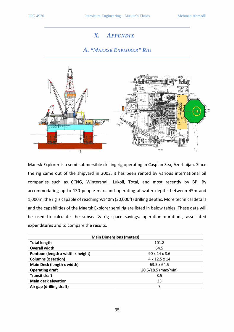
TPG 4920 Petroleum Engineering – Master’s Thesis Mehman Ahmadli
95
X. APPENDIX
A. “MAERSK EXPLORER” RIG
Maersk Explorer is a semi-submersible drilling rig operating in Caspian Sea, Azerbaijan. Since
the rig came out of the shipyard in 2003, it has been rented by various international oil
companies such as CCNG, Wintershall, Lukoil, Total, and most recently by BP. By
accommodating up to 130 people max. and operating at water depths between 45m and
1,000m, the rig is capable of reaching 9,140m (30,000ft) drilling depths. More technical details
and the capabilities of the Maersk Explorer semi rig are listed in below tables. These data will
be used to calculate the subsea & rig space savings, operation durations, associated
expenditures and to compare the results.
Main Dimensions (meters)
Total length 101.8
Overall width 64.5
Pontoon (length x width x height) 90 x 14 x 8.6
Columns (x section) 4 x 12.5 x 14
Main Deck (length x width) 63.5 x 64.5
Operating draft 20.5/18.5 (max/min)
Transit draft 8.5
Main deck elevation 35
Air gap (drilling draft) 7

TPG 4920 Petroleum Engineering – Master’s Thesis Mehman Ahmadli
96
Design Limits
Water depth 1,000m
Wind speed 29m/sec
Wave height 17.2m
Wave period 9.9 sec
Drilling depth 9,140m
Riser tensioner load 910MT
Addition to the design limits stated above, it can be mentioned that 1.52m is the maximum
heave allowed to do operations - running/retrieving riser/BOP, landing BOP on wellhead,
running casing, logging and cementing. In case of 3.05m heave, LMRP or BOP disconnects from
the rig.
Storage Capabilities
Drill water 1,212m3
Potable water 584m3
Fuel oil 870m3
Brine 349m3
Base oil 349m3
Liquid mud 625m3
Reserve mud 354m3
Bulk mud 460m3
Bulk cement 460m3
Sack material 110m3
Slurrification tank 300m3
Accommodation 130people
The rig is powered by four Wärtsilä 16V 200 engines that provides 2,680kW, 600 volts, 60 Hz
power output. Each engine drives one ABB AMG 710 S6 diesel generator. Top drive system
includes National Oilwell PS-2 with pipe handler and block retract system powered by two GE-
752 DC motors with 1,000MT capacity, and four the same type of motors power drawworks
system. Pipe racking system is vertical and can hold 360 stands of drill pipe or collar. Maersk
Explorer is equipped with nine cranes for handling tubulars, BOP, Xmas tree etc. and for
supporting subsea completion, as listed below:
Deck Cranes
Kenz DHC 40 diesel-hydraulic crane 43m boom, 40 MT to boat, 40MT deck to deck
Kenz DHC 60 diesel-hydraulic crane 51m boom, 50MT to boat, 66MT deck to deck
Knuckle boom electric-hydraulic crane 25m boom, 12MT deck to catwalk
Riser gantry crane 30MT capacity
Hydralift BOP carrier 350MT
Hydralift BOP gantry crane 2 x 100MT rated lifting blocks
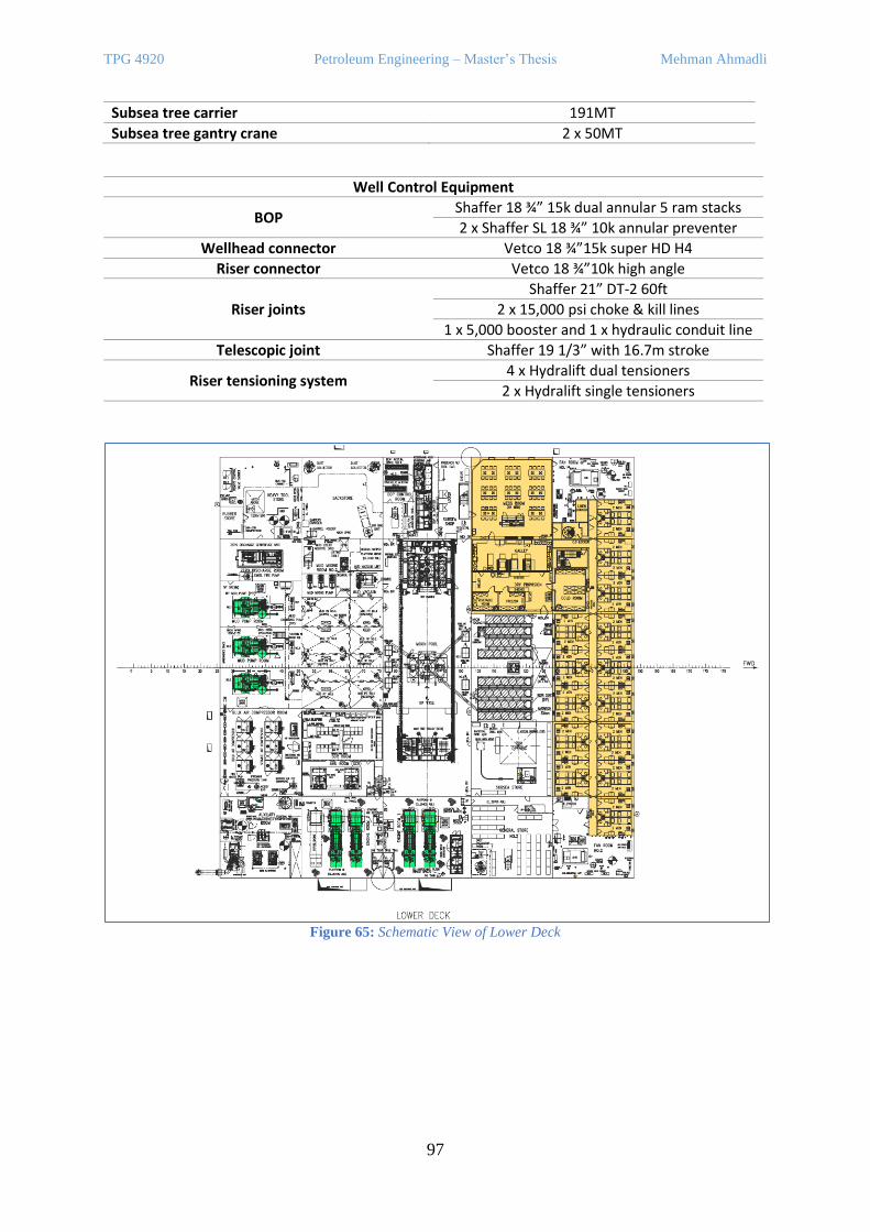
TPG 4920 Petroleum Engineering – Master’s Thesis Mehman Ahmadli
97
Subsea tree carrier 191MT
Subsea tree gantry crane 2 x 50MT
Well Control Equipment
BOP Shaffer 18 ¾” 15k dual annular 5 ram stacks
2 x Shaffer SL 18 ¾” 10k annular preventer
Wellhead connector Vetco 18 ¾”15k super HD H4
Riser connector Vetco 18 ¾”10k high angle
Riser joints
Shaffer 21” DT-2 60ft
2 x 15,000 psi choke & kill lines
1 x 5,000 booster and 1 x hydraulic conduit line
Telescopic joint Shaffer 19 1/3” with 16.7m stroke
Riser tensioning system 4 x Hydralift dual tensioners
2 x Hydralift single tensioners
Figure 65: Schematic View of Lower Deck
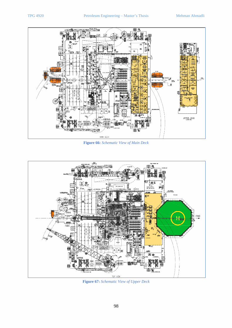
TPG 4920 Petroleum Engineering – Master’s Thesis Mehman Ahmadli
98
Figure 66: Schematic View of Main Deck
Figure 67: Schematic View of Upper Deck
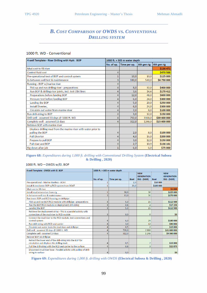
TPG 4920 Petroleum Engineering – Master’s Thesis Mehman Ahmadli
99
B. COST COMPARISON OF OWDS VS. CONVENTIONAL
DRILLING SYSTEM
Figure 68: Expenditures during 1,000 ft. drilling with Conventional Drilling System (Electrical Subsea
& Drilling , 2020)
Figure 69: Expenditures during 1,000 ft. drilling with OWDS (Electrical Subsea & Drilling , 2020)
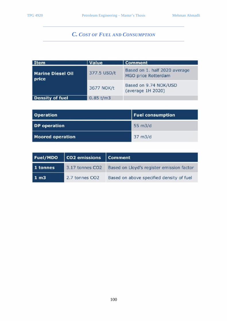
TPG 4920 Petroleum Engineering – Master’s Thesis Mehman Ahmadli
100
C. COST OF FUEL AND CONSUMPTION

NTN
UN
orw
egia
n U
nive
rsity
of S
cien
ce a
nd T
echn
olog
yFa
culty
of E
ngin
eerin
gD
epar
tmen
t of G
eosc
ienc
e an
d Pe
trol
eum
Mehm
an Ahmadli
Dow
nsizing semi-subm
ersible rig by using an electric BOP and riserless drilling system
Mehman Ahmadli
Downsizing semi-submersible rig byusing an electric BOP and riserlessdrilling system
Master’s thesis in Petroleum EngineeringSupervisor: prof. Behzad ElahifarCo-supervisor: prof. Sigbjørn Sangesland
June 2021
Mas
ter’s
thes
is