document uncontrolled when printed pipeline welding procedure specification
TRANSCRIPT

Document Uncontrolled When Printed
Page 1 of 4
PIPELINE WELDING PROCEDURE SPECIFICATION
WPS NUMBER: ENB-MA-WPS-5 REV.0 AUGUST 11, 2014
REVISION LOG
REV. NO. 0:
SCOPE
This welding procedure specification details the procedure to be followed for SMAW / Mechanized FCAW Up, section & tie-in field butt welding of pipe as required by CSA Standard Z662, Oil and Gas Pipeline Systems. This procedure uses CRC Evans Welding Equipment and includes a provision for Mechanized Gas Shielded FCAW Up for fill and cap passes.
Normative References: This welding procedure specification was prepared in accordance to CSA Z662-11 and incorporates by undated references, provisions from other publications. Revision to this specification is not required unless subsequent referenced code and or specification additions include changes to essential welding variables.
Service Restrictions: Sweet
Temperature Restrictions: Notch Toughness Tested to -5°C (23°F)
1. WELDING PROCESS & METHOD
1.1. Shielded Metal Arc Welding (SMAW) manual method- Root, Hotpass & Bohler Fox BVD First Fill.
1.2. Flux Core Arc Welding (FCAW) Remaining Fill(s) & Cap- mechanized method.
2. BASE MATERIAL
2.1. Composition: This specification applies to pipe and/or component material manufactured in accordance with, or listed as "Acceptable Alternative Materials" in any of the following standards:
CSA Z662, Oil and Gas Pipeline Systems CAN/CSA-Z245.1, Steel Line Pipe CAN/CSA-Z245.11, Steel Fittings CAN/CSA-Z245.12, Steel Flanges CAN/CSA-Z245.15, Steel Valves
2.2. Pipe Grades: 483 MPa (SMYS) or less 2.3. Wall Thickness Qualified: 4.0 to 14.25 mm (0.157 to 0.561 in.) inclusive. 2.4. Pipe Diameters Qualified: 457 mm (18 in.) O.D. minimum 2.5. Carbon Equivalent: 0.33% maximum
3. FILLER METAL CLASSIFICATION & SIZE
3.1. Root Pass: E6010; 3.2 to 4.8 mm (1/8 to 3/16 in.) 3.2. Hot Pass: E8010-P1; 4.0 to 6.4 mm (5/32 to 1/4 in.) 3.3. Fill Pass 1: E8045-P2 (Bohler Fox BVD 85) 3.2 to 4.8mm (1/8 to 3/16 in.) 3.4. Remaining Fill Pass(s): E81T1-GM (Lincoln Pipeliner 81M) 1.2mm (0.047in.) 3.5. Cap pass: E81T1-GM (Lincoln Pipeliner 81M) 1.2mm (0.047in.)

Document Uncontrolled When Printed
Page 2 of 4
ENB-MA-WPS-5
4. JOINT GEOMETRY
4.1. Joint Type: Groove - Single Vee Butt 4.2. Bevel Angle: 30°, +6° / -1.5° 4.3. Root Face: 1.6mm (0.063 in. ), +/- 0.8mm (0.031 in.) 4.4. Root Gap: 3.2mm (0.125 in. ), +/- 1.6mm (0.063 in.)
4.5. The surfaces to be welded shall be smooth, uniform, free of fins, laminations, tears, scale, slag, grease, paint or other foreign matter, which may adversely affect the welding.
5. POSITION & DIRECTION OF WELDING
5.1. Position: Pipe horizontal, fixed position (5G) 5.2. Direction of Welding: Root, Hotpass & First Fill Pass: Vertical Down
Remaining Fill(s) and Cap Passes: Vertical Up
6. PREHEATING, INTERPASS TEMPERATURE & CONTROLLED COOLING
6.1. Butt Welds: A minimum preheat temperature of 120°C (250°F) shall be applied to an area at least 51 mm (2.0 in.) on each side of the weld joint for its entire circumference prior to welding.
6.2. During root and second pass welding, under no circumstances shall the minimum temperature fall below the minimum interpass temperature from the start of the root pass until after the completion of the second pass. Reheating is permitted before the start of the fill/cap passes.
6.3. If the interpass temperature falls below the minimum preheat temperature after completion of the second pass, the entire weld joint shall be heated to the minimum preheat temperature prior to starting the next weld pass.
6.4. The maximum interpass temperature shall not exceed 204°C (400°F). 6.5. Preheating may be applied by oxy-fuel torch, propane torch, electrical induction coils or any
other method approved by the owner. 6.6. Temperature of the joint shall be verified using temperature indicating crayons, thermocouples,
pyrometers or other suitable method. 6.7. Where applicable, precautions shall be taken through the use of insulating covers or other
means to control the cooling rate of the weld after any pass.
7. POSTWELD HEAT TREATMENT
Welds prepared in accordance with this specification shall not be subjected to post weld heat treatment.
8. SHIELDING GAS
8.1. Root, Hotpass & Fill 1: N/A 8.2. Remaining Fill(s) & Cap Pass(es): 75/25 Argon/CO2 @ 23.6 to 28.3 LPM (50 to 60 CFH)
9. ELECTRICAL CHARACTERISTICS
9.1. Current Type: Direct current, reverse polarity (DCRP) 9.2. Voltage, amperage & travel speed: See Table #1 9.3. Heat Input: See Table #1

Document Uncontrolled When Printed
Page 3 of 4
ENB-MA-WPS-5
10. TECHNIQUE
10.1. Minimum number of welders: Two for all passes. 10.2. String or Weave: Bead Root, Hotpass & Fill 1-String
Fill & Cap-Weave
10.3. Number of Weld Layers: Five layers minimum. 10.4. Type of line-up clamp & removal: Internal line-up clamps shall be used wherever practicable
and shall not be removed until the root bead is completed. 10.5. Movement shall be minimized until the required hot pass on the bottom has been completed
as per table below.
Pipe Outside Diameter (OD) Minimum Length of Second Pass
610 mm and Greater 250 mm
Less than 610 mm to 323.9 mm inclusive
150mm
Less than 323.9 mm Not Required
10.6. When external line-up clamps are used, the root bead shall be uniformly spaced around the
circumference of the joint and, where practicable, shall have a cumulative length of at least
50% of the circumference prior to removal. 10.7. Cleaning methods: Hand or power tools may be used. Each pass shall be thoroughly cleaned
and free of slag and scale prior to depositing the next weld layer. The completed weld shall be brushed and free of spatter.
10.8. Finish Profile: The completed weld shall have a substantially uniform cross-section for its entire circumference. The crown of the weld shall not be below the surface of the adjacent base metal.
10.9. The time and interval requirements for each welding pass is as follows:
11. REMOVAL AND REPAIR OF DEFECTS
11.1. Repairable areas are restricted to the weld cap and shall be removed by grinding. Welding of such repairable areas shall be performed following the details outlined in this specification.
11.2. Subsurface weld repairs shall be made in accordance with WPS# EPI-11-WP9 Rev.1.
Interval Time
Root pass to hot pass 10 minutes maximum
Hot pass to fill 1 60 minutes maximum
Fill 1 to completion 24 Hours maximum (Unless otherwise Authorized by
Enbridge Assigned Designate)

Document Uncontrolled When Printed
Page 4 of 4
ENB-MA-WPS-5
12. ATTACHMENTS
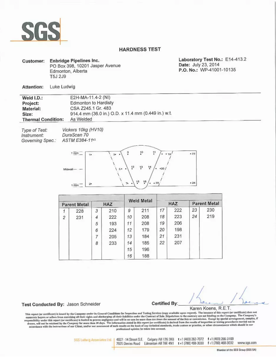
12.1. Procedure Qualification Test Records: E2H-MA-11.4-2 12.2. Laboratory Test Reports: E14-413.2 12.3. Radiographic, Automated Ultrasonic & MPI Examination Results:
CRC Evans RT Report: 1071V (E2H-MA-11.4-2) Applus RTD AUT Report: E2H-MA-11.4/15.9-WPQ
12.4. Material Test Reports: Evraz Heat No.514112
TABLE #1 WELDING PARAMETERS
Pass Process
Electrode
Wire Speed mm/min (in/min)
Amperage Range
Amperes
Voltage Range volts
Travel Speed mm/min (in./min)
OSC/BPM
Heat Input kJ/mm (J/in.)
Size mm (in.)
AWS Class
Root SMAW 4.0mm (5/32)
E6010 NA 94-160 19-34.8 206-361
(8.1-14.2) NA
0.47-1.01 (11938-25654)
Hot Pass
SMAW 4.8mm (3/16)
E8010-P1 NA 142-230 21.2-38.8 254-395
(9.6-15.6) NA
0.69-1.40 (17526-35560)
Fill-1 SMAW 4.0mm (5/32)
*E8045-P2 H4R NA 166-272 14.9-30.4 209-324
(8.2-12.8) NA
0.73-1.50 (18542-38100)
Fill(s) Mech.
Mech.-FCAW
1.2mm (0.047)
**E81T1-GM 5029-7620 (198-300)
141-260 18.1-28.5 122-299
(4.8-11.8) As
Req. 0.87-2.21
(22098-56134)
Cap(s) Mech.
Mech.-FCAW
1.2mm (0.047)
**E81T1-GM 4597-7010 (181-276)
130-238 18.2-28.5 104-250 (4.1-9.8)
As Req.
0.98-2.45 (24892-62230)
* - Bohler Fox BVD 85 **- Lincoln Pipeliner 81M
Note #1 - The use of stripper passes is optional, however welding parameters must remain within the parameters of the above table. Note#2 - Maximum cap height above adjacent parent material: 2.5mm for W.T.≤ 10.0mm. 3.5mm for W.T. >10.0 mm. (+1mm permitted in localized areas).
13. JOINT GEOMETRY
Root (SMAW)
Hotpass
(SMAW)
Fill1 (SMAW)
Fill(S)
(Mechanized
FCAW)
Cap (S)
(Mechanized
FCAW)
1.6mm±08mm
3.2mm ± 1.6mm
+6/ -1.5
Schematic of Joint Design
Pass Sequence
% C
CE
Pcm
Units
(mm)
(LPM) 23.6 28.3 23.6 28.3
(%)
(mm) 9.5 19.0 9.5 19.0
(BPM)
(mm)
(sec)
Units Root Hot Fill 1 Fill 2 Cap
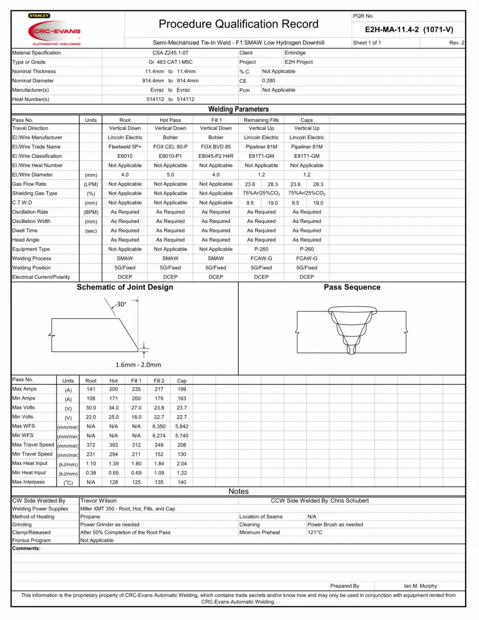
(A) 141 200 235 217 199
(A) 108 171 200 176 163
(V) 30.0 34.0 27.0 23.8 23.7
(V) 22.0 25.0 18.0 22.7 22.7
(mm/min) N/A N/A N/A 6,350 5,842
(mm/min) N/A N/A N/A 6,274 5,740
(mm/min) 372 393 312 249 208
(mm/min) 231 294 211 152 130
(kJ/mm) 1.10 1.39 1.80 1.84 2.04
(kJ/mm) 0.38 0.65 0.69 1.09 1.22
(oC) N/A 128 125 135 140
CW Side Welded ByWelding Power Supplies
Client Enbridge
Type or Grade Gr. 483 CAT I M5C Project E2H Project
Procedure Qualification RecordPQR No.
E2H-MA-11.4-2 (1071-V)Semi-Mechanized Tie-In Weld - F1 SMAW Low Hydrogen Downhill Sheet 1 of 1 Rev. 2
Manufacturer(s) Evraz to Evraz
Heat Number(s) 514112 to 514112
Nominal Thickness 11.4mm to 11.4mm
Nominal Diameter 914.4mm to 914.4mm
Material Specification CSA Z245.1-07
Welding ParametersPass No. Root Hot Pass Fill 1 Remaining Fills Caps
El./Wire Manufacturer Lincoln Electric Bohler Bohler Lincoln Electric Lincoln Electric
Travel Direction Vertical Down Vertical Down Vertical Down Vertical Up Vertical Up
El./Wire Trade Name Fleetweld 5P+ FOX CEL 80-P FOX BVD 85 Pipeliner 81M Pipeliner 81M
El./Wire Classification E6010 E8010-P1 E8045-P2 H4R E81T1-GM E81T1-GM
Gas Flow Rate Not Applicable Not Applicable Not Applicable
El./Wire Diameter 4.0 5.0 4.0 1.2 1.2
El./Wire Heat Number Not Applicable Not Applicable Not Applicable Not Applicable Not Applicable
Shielding Gas Type Not Applicable Not Applicable Not Applicable 75%Ar/25%CO2 75%Ar/25%CO2
Oscillation Rate As Required As Required As Required As Required As Required
C.T.W.D Not Applicable Not Applicable Not Applicable
Oscillation Width As Required As Required As Required As Required As Required
Dwell Time As Required As Required As Required As Required As Required
Equipment Type Not Applicable Not Applicable Not Applicable P-260 P-260
Head Angle As Required As Required As Required As Required As Required
Welding Process SMAW SMAW SMAW FCAW-G FCAW-G
Welding Position 5G/Fixed 5G/Fixed 5G/Fixed 5G/Fixed 5G/Fixed
Pass No.
Max Amps
Min Amps
Max Volts
Min Volts
Max WFS
Schematic of Joint Design Pass SequenceElectrical Current/Polarity DCEP DCEP DCEP DCEP DCEP
Power Brush as needed
NotesTrevor Wilson CCW Side Welded By Chris Schubert
Min WFS
Max Travel Speed
Min Travel Speed
Max Heat Input
Min Heat Input
Max Interpass
Not Applicable
0.280
Not Applicable
This information is the proprietary property of CRC-Evans Automatic Welding, which contains trade secrets and/or know how and may only be used in conjunction with equipment rented from CRC-Evans Automatic Welding.
Comments:
Prepared By Ian M. Murphy
Clamp/Released After 50% Completion of the Root Pass Minimum Preheat 121°CFronius Program Not Applicable
Miller XMT 350 - Root, Hot, Fills, and CapMethod of Heating Propane Location of Seams N/AGrinding Power Grinder as needed Cleaning
30°
1.6mm - 2.0mm


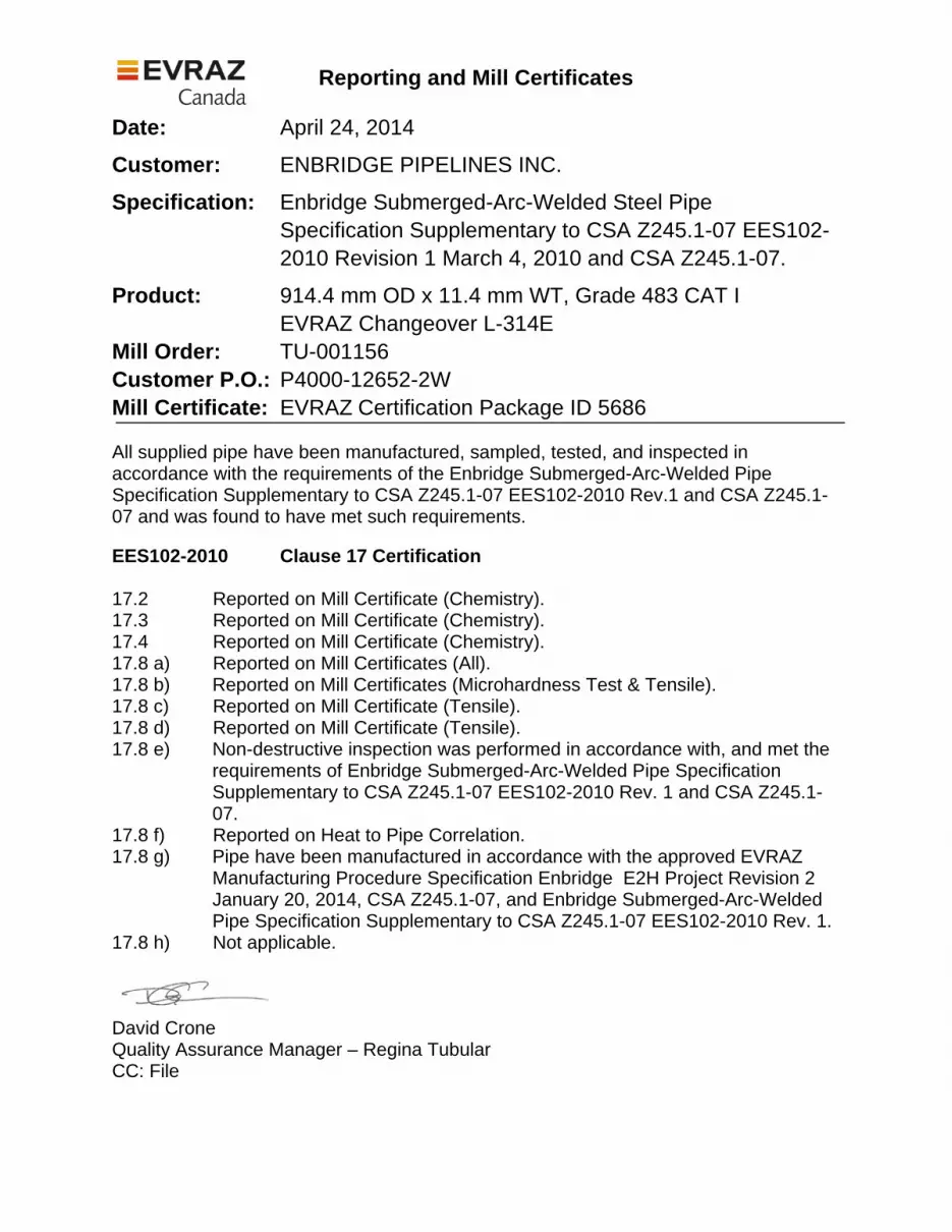
Reporting and Mill Certificates
Date: April 24, 2014
Customer: ENBRIDGE PIPELINES INC.
Specification: Enbridge Submerged-Arc-Welded Steel Pipe Specification Supplementary to CSA Z245.1-07 EES102-2010 Revision 1 March 4, 2010 and CSA Z245.1-07.
Product: 914.4 mm OD x 11.4 mm WT, Grade 483 CAT I EVRAZ Changeover L-314E
Mill Order: TU-001156 Customer P.O.: P4000-12652-2W Mill Certificate: EVRAZ Certification Package ID 5686 All supplied pipe have been manufactured, sampled, tested, and inspected in accordance with the requirements of the Enbridge Submerged-Arc-Welded Pipe Specification Supplementary to CSA Z245.1-07 EES102-2010 Rev.1 and CSA Z245.1-07 and was found to have met such requirements. EES102-2010 Clause 17 Certification 17.2 Reported on Mill Certificate (Chemistry). 17.3 Reported on Mill Certificate (Chemistry). 17.4 Reported on Mill Certificate (Chemistry). 17.8 a) Reported on Mill Certificates (All). 17.8 b) Reported on Mill Certificates (Microhardness Test & Tensile). 17.8 c) Reported on Mill Certificate (Tensile). 17.8 d) Reported on Mill Certificate (Tensile). 17.8 e) Non-destructive inspection was performed in accordance with, and met the
requirements of Enbridge Submerged-Arc-Welded Pipe Specification Supplementary to CSA Z245.1-07 EES102-2010 Rev. 1 and CSA Z245.1-07.
17.8 f) Reported on Heat to Pipe Correlation. 17.8 g) Pipe have been manufactured in accordance with the approved EVRAZ
Manufacturing Procedure Specification Enbridge E2H Project Revision 2 January 20, 2014, CSA Z245.1-07, and Enbridge Submerged-Arc-Welded Pipe Specification Supplementary to CSA Z245.1-07 EES102-2010 Rev. 1.
17.8 h) Not applicable.
David Crone Quality Assurance Manager – Regina Tubular CC: File

Pipe Test TypeCoil PM PM HAZ HAZ WMZ WMZ HAZ HAZ PMPMScale
Microhardness Test Heat Qualifiers
MS HAZ WMZ HAZPM PMHeatChangeover
CERTIFICATE OF TESTINGSpiral Mill
EVRAZ Regina
Customer:
Specification:
ENBRIDGE PIPELINES INC.CSA Z245.1-07 / ENBRIDGE SPECIFICATION EES102-2010 REV 1
04/24/2014 13:28:17
Diameter: 914.400 Wall Thickness: 11.400mm mmMill Order No:
P4000126522WCustomer PO:
TU001156
Form No: L 4443Certificate ID: 5686
Grade: 483 CAT I
Page 1
Supplier: EVRAZ REGINA
10114 QUAL INITIALA0175 237 224 247 229 212ODVickers OK495826L-314E245 227 237 218 229MID241 245 205 222 231ID
40063 QUAL INITIALA0073 208 227 249 243 210ODVickers OK514112L-314E229 213 239 213 224MID224 222 226 202 239ID
form cipr8773
Measurement Taken In HV500
MS = Micro Structure
Quality Assurance
We certify that the product described above has been manufactured, sampled,inspected, and tested in accordance to the referenced specification.The product has been found to be in compliance with all requirements.
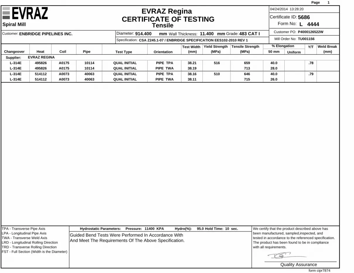
Tensile
PipeCoil OrientationY/T
(mm) (MPa)% Elongation
(MPa) UniformTest Type 50 mm (mm)HeatTest Width Tensile Strength Weld BreakYield Strength
Changeover
CERTIFICATE OF TESTINGSpiral Mill
EVRAZ Regina
Customer:
Specification:
ENBRIDGE PIPELINES INC.CSA Z245.1-07 / ENBRIDGE SPECIFICATION EES102-2010 REV 1
04/24/2014 13:28:20
Diameter: 914.400 Wall Thickness: 11.400mm mmMill Order No:
P4000126522WCustomer PO:
TU001156
Form No: L 4444Certificate ID: 5686
Grade: 483 CAT I
Page 1
Supplier: EVRAZ REGINA10114A0175 PIPE TPA 38.21 659516 40.0 .78QUAL INITIAL495826L-314E10114A0175 PIPE TWA 38.19 713 28.0QUAL INITIAL495826L-314E40063A0073 PIPE TPA 38.16 646510 40.0 .79QUAL INITIAL514112L-314E40063A0073 PIPE TWA 38.11 715 26.0QUAL INITIAL514112L-314E
form cipr7874
TPA - Transverse Pipe AxisLPA - Longitudinal Pipe AxisTWA - Transverse Weld AxisLRD - Longitudinal Rolling DirectionTRD - Transverse Rolling DirectionFST - Full Section (Width is the Diameter)
Guided Bend Tests Were Performed In Accordance WithAnd Meet The Requirements Of The Above Specification.
Hydro(%): 95.0Hydrostatic Parameters: Pressure: 11400 KPA Hold Time: 10 sec.
Quality Assurance
We certify that the product described above has been manufactured, sampled,inspected, and tested in accordance to the referenced specification.The product has been found to be in compliance with all requirements.

PipeCoil CType Mn S P Si Cu Ni Cr V Cb Mo Al Ca B Ti N Ce SoAlceqSn CE
Chemistry
Heat Changeover
CERTIFICATE OF TESTINGSpiral Mill
EVRAZ Regina
Customer:
Specification:
ENBRIDGE PIPELINES INC.CSA Z245.1-07 / ENBRIDGE SPECIFICATION EES102-2010 REV 1
04/24/2014 13:28:15
Diameter: 914.400 Wall Thickness: 11.400mm mmMill Order No:
P4000126522WCustomer PO:
TU001156
Form No: L 4442Certificate ID: 5686
Grade: 483 CAT I
Page 1
Supplier: EVRAZ REGINA0.035HEAT 0.0000.0070.0170.00010.00250.0410.1160.0790.05 1.72 0.002 0.009 0.0010.220.070.210.27 0.008 0.264958260.03510114 PRODUCTA0175 0.0000.0070.0170.00010.00220.0400.1180.0780.05 1.72 0.001 0.009 0.0010.230.060.200.28 0.008 0.26495826 L-314E0.034HEAT 0.0000.0090.0150.00020.00310.0400.1160.0790.06 1.74 0.002 0.009 0.0010.220.090.260.24 0.009 0.285141120.03440063 PRODUCTA0073 0.0000.0090.0150.00010.00260.0400.1170.0770.06 1.78 0.002 0.009 0.0010.230.090.260.24 0.009 0.28514112 L-314E
form cipr787F
Deoxidization Practice: Aluminum Fully KilledFurnace: ELECTRIC ARC Casting: CONTINUOUS SLAB Rolling Mill: STECKEL
Quality Assurance
We certify that the product described above has been manufactured, sampled,inspected, and tested in accordance to the referenced specification.The product has been found to be in compliance with all requirements.