dnv-cg-0051 non-destructive testing
TRANSCRIPT

CLASS GUIDELINE
DNV-CG-0051 Edition January 2022
Non-destructive testing
The content of this service document is the subject of intellectual property rights reserved by DNV AS (“DNV”). The useraccepts that it is prohibited by anyone else but DNV and/or its licensees to offer and/or perform classification, certificationand/or verification services, including the issuance of certificates and/or declarations of conformity, wholly or partly, on thebasis of and/or pursuant to this document whether free of charge or chargeable, without DNV’s prior written consent. DNVis not responsible for the consequences arising from any use of this document by others.
The PDF electronic version of this document available at the DNV website dnv.com is the official version. If thereare any inconsistencies between the PDF version and any other available version, the PDF version shall prevail.
DNV AS

FOREWORD
DNV class guidelines contain methods, technical requirements, principles and acceptance criteriarelated to classed objects as referred to from the rules.
© DNV AS January 2022
Any comments may be sent by e-mail to [email protected]
This service document has been prepared based on available knowledge, technology and/or information at the time of issuance of thisdocument. The use of this document by other parties than DNV is at the user's sole risk. Unless otherwise stated in an applicable contract,or following from mandatory law, the liability of DNV AS, its parent companies and subsidiaries as well as their officers, directors andemployees (“DNV”) for proved loss or damage arising from or in connection with any act or omission of DNV, whether in contract or in tort(including negligence), shall be limited to direct losses and under any circumstance be limited to 300,000 USD.

CHANGES – CURRENT
This document supersedes the December 2015 edition of DNVGL-CG-0051.The numbering and/or title of items containing changes is highlighted in red.
Changes January 2022
Topic Reference Description
Sec.1 to Sec.8 The document is updated and aligned with applicable rules,standards and general practice, including but not limited toalignment with IACS UR W33 Non-destructive testing of shiphull steel welds - Rev.1 Corr1 Aug 2021 and IACS UR W34Advanced non-destructive testing of materials and welds - NewDec 2019.
Major update
Sec.7 and App.A The former guideline for NDT of TMCP materials and root areaof single side welds have been included as requirements inSec.7. The new appendix gives a guideline for qualification ofPAUT and TOFD procedures.
Rebranding to DNV All This document has been revised due to the rebranding of DNVGL to DNV. The following have been updated: the companyname, material and certificate designations, and references toother documents in the DNV portfolio. Some of the documentsreferred to may not yet have been rebranded. If so, please seethe relevant DNV GL document.
Editorial correctionsIn addition to the above stated changes, editorial corrections may have been made.
Changes - current
Class guideline — DNV-CG-0051. Edition January 2022 Page 3Non-destructive testing
DNV AS

CONTENTS
Changes – current.................................................................................................. 3
Section 1 General....................................................................................................71 General................................................................................................ 72 References........................................................................................... 83 Definitions and abbreviations............................................................ 11
Section 2 Personnel qualifications, methods selection, procedures and reports....141 Personnel certification and qualification............................................142 Selection of testing method...............................................................153 Extent of testing................................................................................154 Information required prior to testing................................................ 165 Time of testing.................................................................................. 166 Requirements to NDT procedures...................................................... 167 Final report........................................................................................17
Section 3 Eddy current testing..............................................................................191 Scope................................................................................................. 192 Definitions..........................................................................................193 Personnel qualifications.....................................................................194 Information required (prior to testing)............................................. 195 Surface conditions............................................................................. 206 Equipment..........................................................................................207 Testing...............................................................................................218 Acceptance criteria............................................................................ 249 Evaluation of indications................................................................... 2410 Reporting......................................................................................... 24
Section 4 Magnetic particle testing.......................................................................291 Magnetic particle testing of welds.....................................................292 Magnetic particle testing of components........................................... 38
Section 5 Penetrant testing.................................................................................. 461 Scope................................................................................................. 462 Personnel qualifications.....................................................................463 Equipment/testing material...............................................................464 Compatibility of testing materials with the parts to be tested............475 Preparation, pre-cleaning and testing............................................... 48
Contents
Class guideline — DNV-CG-0051. Edition January 2022 Page 4Non-destructive testing
DNV AS

6 Inspection..........................................................................................517 Acceptance criteria............................................................................ 528 Post cleaning and protection............................................................. 539 Retesting............................................................................................5310 Reporting......................................................................................... 53
Section 6 Radiographic testing............................................................................. 561 Scope................................................................................................. 562 Personnel qualifications.....................................................................573 General.............................................................................................. 574 Techniques for making radiographs...................................................625 Acceptance criteria............................................................................ 756 Reporting........................................................................................... 75
Section 7 Ultrasonic testing.................................................................................. 761 Scope................................................................................................. 762 Definitions and symbols.................................................................... 763 Personnel qualifications.....................................................................774 Requirements for equipment............................................................. 775 Testing volume.................................................................................. 806 Preparation of scanning surfaces...................................................... 817 Parent material testing......................................................................828 Range and sensitivity setting............................................................ 829 Testing techniques - weld connections..............................................8710 Welds in austenitic stainless and duplex (ferritic-austenitic)stainless steel.....................................................................................10711 Acceptance criteria, weld connections........................................... 11112 Reporting, weld connections..........................................................11213 Ultrasonic testing of rolled steel plates......................................... 11314 Ultrasonic testing of castings........................................................ 11515 Ultrasonic testing of forgings........................................................ 11816 PAUT - automated phased array for testing of welds....................12217 TOFD of welds............................................................................... 131
Section 8 Visual testing...................................................................................... 1471 Scope............................................................................................... 1472 Information required prior to testing.............................................. 1473 Requirements for personnel and equipment.................................... 1474 Testing conditions............................................................................1475 Testing volume................................................................................ 148
Contents
Class guideline — DNV-CG-0051. Edition January 2022 Page 5Non-destructive testing
DNV AS

6 Preparation of surfaces................................................................... 1487 Evaluation of indications..................................................................1488 Visual testing of repaired welds...................................................... 1499 Acceptance criteria.......................................................................... 14910 Reporting....................................................................................... 149
Appendix A Guidelines for qualification of PAUT and TOFD procedures...............1501 Guideline for qualification of PAUT procedure................................. 1502 Guideline for qualification of TOFD procedure................................. 154
Changes – historic.............................................................................................. 159
Contents
Class guideline — DNV-CG-0051. Edition January 2022 Page 6Non-destructive testing
DNV AS

SECTION 1 GENERAL
1 General
1.1 IntroductionThis document is developed in order to represent the Society's general requirements, recommendationsand best practices for non-destructive testing (NDT) of metallic materials. This document is referred to in anumber of DNV rules and standards, and has been adopted and used extensively throughout the years. It isdeveloped and maintained by DNV. In addition to several updates related to the standard NDT methods, thislatest revision has included further details related to new and more advanced NDT methods.
1.2 ObjectiveThe objective of this document is to facilitate that NDT is carried out in a uniform and consistent way.
1.3 ScopeThis class guideline applies to non-destructive testing using the following methods:
— eddy current testing— magnetic particle testing— penetrant testing— radiographic testing, including digital and computed radiography— ultrasonic testing, including phased array and time-of-flight diffraction— visual testing.
The requirements for methods, equipment, procedures, reporting, and the qualification and certification ofpersonnel for visual examination and non-destructive testing of castings, forgings, rolled materials and fusionwelds are specified.Acceptance criteria are specified and may be applied where the referring rules or standard do not givedetailed acceptance criteria.
1.4 ApplicationIn general, this class guideline shall be adhered to whenever specified in the applicable Society's rules andstandards, and may be used for guidance whenever non-destructive testing is otherwise required by theSociety. The use of other standards or specifications may, however, be granted if an equivalent or strictertesting procedure is applied.The requirements are applicable for testing of C-Mn steels, low alloy steels, duplex steels and other stainlesssteels as specified. Requirements for NDT and visual examination of other materials shall be evaluated oncase by case basis.The specified acceptance criteria apply where the referring rules or standard do not give detailed acceptancecriteria.
Guidance note:The standard may be referred and used e.g. by regulatory bodies, purchasers and builders without involvement of DNV, i.e. whereDNV's certification, verification or classification is not required. For such cases, and where the class programme is indicating thatsomething shall be agreed with, submitted to, approved, etc. by the Society (DNV), it shall then be agreed, submitted, approvedetc. by a verifier mandated by the referrer to verify compliance.
---e-n-d---o-f---g-u-i-d-a-n-c-e---n-o-t-e---
Section 1
Class guideline — DNV-CG-0051. Edition January 2022 Page 7Non-destructive testing
DNV AS

1.5 SafetyInternational, national and local safety and environmental protection regulation shall always be observed.
2 References
2.1 GeneralThis class guideline incorporates references to other publications. The relevant references are citedat the appropriate places in the text and constitute provisions of this class guideline. Latest edition ofthe publications shall be used unless otherwise specified or agreed with the Society. Other recognisedpublications may be used provided it can be shown that they meet or exceed the requirements for thepublications referenced below.
2.2 DNV referencesTable 1 lists DNV references used in this document.
Table 1 DNV references
Document code Title
DNV-RU-SHIP Pt.2Ch.4 Sec.7
Non destructive testing of welds
DNV-OS-C401 Fabrication and testing of offshore structures
DNV-OS-D101 Marine and machinery systems and equipment
DNV-CG-0550 Maritime services – terms and systematics
2.3 Other referencesTable 2 lists other references used in this document.
Table 2 Other references
Document code Title
ASTM A388 Standard Practice for Ultrasonic Examination of Steel Forgings
ASTM A609 Standard Practice for Castings, Carbon, Low-Alloy, and Martensitic Stainless Steel, UltrasonicExamination Thereof
ASTM E747 Standard Practice for Design, Manufacture and Material Grouping Classification of Wire ImageQuality Indicators (IQI) Used for Radiology
ASTM E2491 Standard Guide for Evaluating Performance Characteristics of Phased-Array Ultrasonic TestingInstruments and Systems
ASTM E2597 Standard Practice for Manufacturing Characterization of Digital Detector Arrays
EN 1330-1 Non-destructive testing – Terminology - Part 1: List of general terms
EN 1330-2 Non-destructive testing – Terminology - Part 2: Terms common to the non-destructive testingmethods
Section 1
Class guideline — DNV-CG-0051. Edition January 2022 Page 8Non-destructive testing
DNV AS

Document code Title
EN 1330-3 Non-destructive testing – Terminology - Part 3: Terms used in industrial radiographic testing
EN 1330-10 Non-destructive testing – Terminology - Part 10: Terms used in visual testing
EN 10160 Ultrasonic testing of steel and flat product of thickness equal or greater than 6 mm (reflectionmethod)
EN 10228 Non-destructive testing of steel forgings – Part 1: Magnetic particle inspection; - Part 2: Penetranttesting; - Part 3: Ultrasonic testing of ferritic or martensitic steel forgings; - Part 4: Ultrasonictesting of austenitic and austenitic-ferritic stainless steel forgings
EN 12543 Non-destructive testing. Characteristics of focal spots in industrial X-ray systems for use in non-destructive testing. Pinhole camera radiographic method
EN 12679 Non-destructive testing. Radiographic testing. Determination of the size of industrial radiographicgamma sources
IACS Rec.68 Guidelines for non-destructive examination of hull and machinery steel forgings
IACS Rec.69 Guidelines for non-destructive examination of marine steel castings
ISO 2400 Non-destructive testing - Ultrasonic testing - Specification for calibration block No. 1
ISO 3059 Non-destructive testing – Penetrant testing and magnetic particle testing – Viewing conditions
ISO 3452 Non-destructive testing - Penetrant testing – Part 1: General principles; – Part 2: Testing ofpenetrant materials; – Part 3: Reference test blocks; – Part 4: Equipment
ISO 4986 Steel and iron castings - Magnetic particle testing
ISO 4987 Steel and iron castings - Liquid penetrant testing
ISO 4993 Steel castings; Radiographic inspection
ISO 5576 Non-destructive testing - Industrial X-ray and gamma-ray radiology - Vocabulary
ISO 5577 Non-destructive testing - Ultrasonic testing - Vocabulary
ISO 5579 Non-destructive testing - Radiographic testing of metallic materials using film and X- or gamma rays- Basic rules
ISO 5580 Non-destructive testing; Industrial radiographic illuminators; Minimum requirements
ISO 5817 Arc-welded joints in steels – Guidance on quality levels for imperfections. Welding – Fusion-welded joints in steel, nickel, titanium and their alloys (beam welding excluded) – Quality levels forimperfections
ISO 6520-1 Welding and allied processes – Classification of geometric imperfections in metallic materials – Part1: Fusion welding
ISO 7963 Non-destructive testing - Ultrasonic testing - Specification for calibration block No. 2
ISO 9712 Non-destructive testing – Qualification and certification of NDT personnel
ISO 9934 Non-destructive testing – Magnetic particle testing
ISO 10042 Welding – Arc-welded joints in aluminium and its alloys – Quality levels for imperfections
ISO 10675 Non-destructive testing of welds - Acceptance levels for radiographic testing
ISO 10863 Non-destructive testing of welds - Ultrasonic testing - Use of time-of-flight diffraction technique(TOFD)
Section 1
Class guideline — DNV-CG-0051. Edition January 2022 Page 9Non-destructive testing
DNV AS

Document code Title
ISO 11666 Non-destructive testing of welds – Ultrasonic testing – Acceptance levels
ISO 11699 Non-destructive testing – Industrial radiographic film
ISO 12706 Non-destructive testing – Penetrant Testing – Vocabulary
ISO 12707 Non-destructive testing - Magnetic particle testing - Vocabulary
ISO 12718 Non-destructive testing - Eddy current testing - Vocabulary
ISO 13588 Non-destructive testing of welds - Ultrasonic testing - Use of automated phased array technology
ISO 14096-1 Non-destructive testing - Qualification of radiographic film digitalisation systems - Part 1:Definitions, quantitative measurements of image quality parameters, standard reference film andqualitative control
ISO 15548 Non-destructive testing – Equipment for eddy current examination.
ISO 15549 Non-destructive testing – Eddy Current Testing – General Principles
ISO 15626 Non-destructive testing of welds - Time- of-flight diffraction technique (TOFD) - Acceptance levels
ISO 16811 Non-destructive testing - Ultrasonic testing - Sensitivity and range setting
ISO 16828 Non-destructive testing. Ultrasonic testing. Time-of-flight diffraction technique as a method fordetection and sizing of discontinuities
ISO/TS 16829 Non-destructive testing - Automated ultrasonic testing - Selection and application of systems
ISO 17635 Non-destructive examination of welds – General rules for metallic materials
ISO 17636-1 Non-destructive examination of weldsRadiographic testing – Part 1: X- and gamma-ray techniques with film
ISO 17636-2 Non-destructive testing of weldsRadiographic testing - Part 2: X- and gamma-ray techniques with digital detectors
ISO 17637 Non-destructive examination of fusion welds – Visual examination
ISO 17638 Non-destructive testing of welds – Magnetic particle testing
ISO 17640 Non-destructive examination of welds – Ultrasonic testing – Techniques, testing levels, andassessment
ISO 17643 Non-destructive examination of welds – Eddy Current Examination of welds by complex planeanalysis.
ISO 18563 Non-destructive testing - Characterization and verification of ultrasonic phased array equipment
ISO 19232 Non-destructive testing – Image quality of radiographs
ISO 19285 Non-destructive testing of welds - Phased array ultrasonic testing (PAUT) - Acceptance levels
ISO 19675 Non-destructive testing - Ultrasonic testing - Specification for a calibration block for phased arraytesting (PAUT)
ISO 22232 Non-destructive testing - Characterization and verification of ultrasonic test equipment
ISO 22825 Non-destructive testing of welds - Ultrasonic testing - Testing of welds in austenitic steels andnickel-based alloys
ISO 23243 Non-destructive testing - Ultrasonic testing with arrays - Vocabulary
Section 1
Class guideline — DNV-CG-0051. Edition January 2022 Page 10Non-destructive testing
DNV AS

Document code Title
ISO 23277 Non-destructive examination of welds – Penetrant testing– Acceptance levels.
ISO 23278 Non-destructive examination of welds – Magnetic particle testing - Acceptance levels
ISO 23279 Non-destructive testing of welds – Ultrasonic testing – Characterization of indications in welds
SNT-TC-1A Personnel Qualification and Certification in Nondestructive Testing
3 Definitions and abbreviations
3.1 Definitions of verbal forms and termsThe general verbal forms defined in Table 3 are used in this document. The general terms defined in Table 4are used, and the specific terms relevant for magnetic particle testing (MT) and penetrant testing (PT) aregiven in Table 5.
Table 3 Definition of verbal forms
Term Definition
shall verbal form used to indicate requirements strictly to be followed in order to conform to the document
should verbal form used to indicate that among several possibilities one is recommended as particularlysuitable, without mentioning or excluding others
may verbal form used to indicate a course of action permissible within the limits of the document
Table 4 Definition of terms
Term Definition
acceptance level prescribed limits below which a component is accepted
defect one or more flaws whose aggregate size, shape, orientation, location or properties do not meetspecified requirements and is therefore rejectable
discontinuity lack of continuity or cohesion, an intentional or unintentional interruption in the physical structure orconfiguration of a material or component
externaldiscontinuity
surface discontinuity
false indication test indication that could be interpreted as originating from a discontinuity but which actuallyoriginates where no discontinuity exists
flaw in NDT, a synonym for a discontinuity
imperfections any deviation from the ideal weld, i.e. discontinuity in the weld or a deviation from the intendedgeometry
indication representation of a discontinuity that requires interpretation to determine its significance
non-planardiscontinuity
discontinuity having three measurable dimensions, e.g. slag, porosity
non relevantindication
indications from something on the test piece which is expected, i.e. internal splines, drilled holes,weld geometries
Section 1
Class guideline — DNV-CG-0051. Edition January 2022 Page 11Non-destructive testing
DNV AS

Term Definition
planardiscontinuity
discontinuity having two measurable dimensions, e.g. crack, lack of fusion
quality level description of the quality of a weld on the basis of type, size and amount of selected imperfections
shallowdiscontinuity
discontinuity open to the surface of a solid object which possesses little depth in proportion to thewidth of this opening
subsurfaceimperfection
imperfection that is not open to a surface or not directly accessible
testing testing or examination of a material or component in accordance with this class guideline, or astandard, or a specification or a procedure in order to detect, locate, measure and evaluate flaws
Table 5 Definition of terms relevant to MT or PT indications
Term Definition
aligned indication three or more indications in a line, separated by 2 mm or less edge-to-edge
leakage field the magnetic field formed outside of a magnet when there is a crack in the magnet
linear indication indication in which the length is at least three times the width
non-linear indication indication of circular or elliptical shape with a length less than three times the width
non-open indication indication that is not visually detectable after removal of the magnetic particles or thatcannot be detected by the use of dye penetrant testing
open indication indication visible after removal of the magnetic particles or that can be detected by the useof penetrant testing
relevant indication indication that is caused by a condition or type of discontinuity that requires evaluationOnly indications which have any dimension greater than 1.5 mm shall be consideredrelevant.
3.2 AbbreviationsThe abbreviation described in Table 6 are used in this document.
Table 6 Abbreviations
Abbreviation Definition
ACFM alternating current field measurement
AUT automated ultrasonic testing
CR computed radiography
DR digital radiography
ET eddy current testing
HAZ heat affected zone
IACS international assosiacion of class societies
MT magnetic particle testing
Section 1
Class guideline — DNV-CG-0051. Edition January 2022 Page 12Non-destructive testing
DNV AS

Abbreviation Definition
NDT non-destructive testing
PAUT phased-array ultrasonic testing
PT penetrant testing
RT radiographic testing
TMCP thermo mechanically controlled processed
TOFD time-of-flight diffraction
UT ultrasonic testing
VT visual testing
WPS welding procedure specification
Section 1
Class guideline — DNV-CG-0051. Edition January 2022 Page 13Non-destructive testing
DNV AS

SECTION 2 PERSONNEL QUALIFICATIONS, METHODS SELECTION,PROCEDURES AND REPORTS
1 Personnel certification and qualification
1.1 GeneralAll testing shall be carried out by qualified and where required, certified personnel. The NDT operators andthe supervisors shall be certified according to a third party certification scheme based on ISO 9712 or ASNTCentral Certification Program (ACCP). SNT-TC-1A may be accepted if the NDT company's written practiceis reviewed and accepted by the Society. The supplier's written practice shall as a minimum, except forthe impartiality requirements of a certification body and/or authorised body, comply with ISO 9712. Thecertificate shall clearly state the qualifications as to which testing method, level and within which industrialsector the operator is certified.
1.2 NDT operators1.2.1 GeneralNDT operators performing testing shall, unless otherwise specified by the referring rule or standard, becertified at minimum Level 2 in the testing method and industrial sector concerned.Operators performing testing and visual examination shall have passed a visual acuity test such as requiredby ISO 9712 or a Jaeger J-w test. The documented test of visual acuity shall be carried out at least oncewithin 12 months.
1.2.2 Testing of duplex, stainless and nickel alloy steel weldsOperators performing testing of welds with duplex, stainless and nickel alloy steel welds shall havedocumented experience or dedicated training for this type of ultrasonic testing.For special methods such as TOFD, DR, CR, PAUT, AUT, UT of austenitic stainless steel/duplex/nickel alloymaterials mock-up test under DNV supervision may be required.
Guidance note:Mock-up tests is intended both for qualification of the procedure and verification of the operator's ability to detect and dispositionrelevant indications.
---e-n-d---o-f---g-u-i-d-a-n-c-e---n-o-t-e---
1.2.3 Ultrasonic testing of tubular node weldsPersonnel performing ultrasonic testing of tubular node welds (i.e. tubular TKY connections) shall undergo apractical test in the typical connections to be tested. The practical test shall have a scope as described in ISO9712 for industrial sector, welds (w). See also Sec.7 [3].
1.3 NDT supervisorSupervisors shall, unless otherwise agreed with the Society, be certified level 3 in the testing methodand industrial sector concerned, and should have sufficient practical background in applicable materials,fabrication, and fabrication technology. Company appointed level 3 not holding the required competence isnot accepted.The supervisor shall be available for scheduling and monitoring of the performed NDT. The supervisor isalso responsible for development, verification and approval of the NDT procedures in compliance with theapplicable rules.
Section 2
Class guideline — DNV-CG-0051. Edition January 2022 Page 14Non-destructive testing
DNV AS

2 Selection of testing methodMethod of NDT shall be chosen based on ability to detect relevant discontinuities and shall be consideredfor the material, joint geometry and welding process used. Combination of two or more methods shouldalways be considered to ensure higher probability of detection. Typical NDT-methods applicable for differentmaterials and joints are shown in Table 1.
Table 1 Selection of testing method
Clad WeldNDT
method Materialsweld plate
Plate T-joint,Partial T-joint Butt Fillet
Castings Forgings
VT All X X X X X X X X X
MTFerromagnetic Cand C-Mn/ Alloy/Duplex 1)
- - X X X X X X X
PT
Non-ferromagnetic,Aluminium/ Cu-Alloys/SS/ Duplex
X - X X X X X X X
UT 4)
Aluminium/C and C-Mn/
Alloy/
SS/Duplex
X X X - X X - X X
RT 3)
Aluminium/C and C-Mn/
Alloy/
SS/Duplex
- - - - - X - 2) 2)
ET 2) All X - X X X X X 2) 2)
1) Method is applicable with limitations for Duplex, shall be approved case-by-case by the Society.2) May be used subject to case-by-case approval by the Society.3) Recommended for t ≤ 40 mm.4) Only applicable for welds with t ≥ 10 mm, unless otherwise qualified.
3 Extent of testingThe extent of testing shall comply with the requirements given in the relevant parts of the rules, standards orspecifications.If a non-conforming discontinuity is detected, the scope of testing shall be extended as required by applicablerules or standard. Corrective actions shall be taken to ensure that all similar defects will be detected.The Society reserves the right to alter the test positions and/or to extend the scope of NDT against the NDTPlan in case of doubts about proper workmanship.Prior to NDT all welds shall be 100% visually inspected by qualified personnel. The qualifications shall bedocumented by the builder/manufacturer.
Section 2
Class guideline — DNV-CG-0051. Edition January 2022 Page 15Non-destructive testing
DNV AS

4 Information required prior to testingPrior to testing, the following information shall be known to the operator:
— manufacturing method (weld, casting, forging, rolled product, etc.)— heat treatment— grade of parent material— welding parameters and conditions used to make the weld— location and extent of welds to be tested— weld surface— geometry— coating type and thickness— casting details— forging details— rolling directions.
Operators may ask for further information that will be helpful in determining the nature of discontinuities.
5 Time of testingIf not otherwise specified in the applicable rules, the following applies:
— When heat treatment is performed, the final NDT shall be carried out when all heat treatments have beencompleted and material has cooled to ambient temperature.
— For steel grades with minimum yield strength in the range 420 N/mm2 to 690 N/mm2 (e.g. NV 420 to NV690 grades), final inspection and NDT shall not be carried out before 48 hours after completion, exceptwhere PWHT is required. At the discretion of the Society, a longer interval and/or additional randominspection at a later period may be required, for example in case of high thickness welds.
— For hull structural welds on steel with specified minimum yield greater than 690 MPa, NDT shall not becarried out before 72 hours after completion of welding. At the discretion of the Society, the 72 hoursinterval may be reduced to 48 hours for radiographic testing (RT) or ultrasonic testing (UT) inspection,provided there is no indication of delayed cracking, and a complete visual and random magnetic particle(MT) or penetrant testing (PT) inspection to the satisfaction of the Society is conducted 72 hours afterwelds have been completed and cooled to ambient temperature.
When heat treatment is performed, the final NDT shall be carried out when all heat treatments have beencompleted. The requirement for the delay period may be relaxed after PWHT (at temperature ≥ 550°C),subject to agreement with the Society.
6 Requirements to NDT procedures
6.1 GeneralWhere specified in the applicable rules and standards, written NDT procedures shall be prepared andagreed or approved by the Society, and where required, the procedures shall be qualified by testing anddemonstration. NDT procedures may use this class guideline as a reference document without repeatingthe text herein, as relevant. The relevant content given in this class guideline indicates the expectations tothe content of an NDT procedure. Where the techniques described in this class guideline are not applicable,detailed written procedures shall be prepared and accepted by the Society before the testing is carried out.Non-destructive testing shall be performed in accordance with written and where required, approvedprocedures that, as a minimum, contain following information:
— reference to applicable rules and standards— material grades
Section 2
Class guideline — DNV-CG-0051. Edition January 2022 Page 16Non-destructive testing
DNV AS

— thickness range— methods and specific testing techniques— extent of testing— details on testing equipment— details for equipment calibration— consumables (including brand name)— details on reference block— sensitivity settings— testing parameters and variables— acceptance level and criteria— assessment of discontinuities— reporting and documentation— reporting forms— extensions requirements.
All non-destructive testing procedures shall be approved and signed by the responsible level 3 supervisor.Note:Procedures and techniques may be established by other competent personnel, e.g. level 2, but shall be verified and approved bypersonnel certified to level 3 in the applicable NDT method.
---e-n-d---o-f---n-o-t-e---
6.2 Procedure qualificationNDT procedure qualification is required for advanced NDT methods, UT of duplex and other stainless-steelgrades and for UT of thicknesses below 10 mm.Qualification shall demonstrate that applied procedure achieves 100% coverage of tested volume andis adequate in reliability, repeatability and accuracy for detection and sizing of relevant indications. Thequalification of the procedure is normally project specific and shall only be valid when all essential testingvariables remain nominally the same as covered by the documented qualification.Qualification shall be performed by means of practical demonstration on project specific validation blocks.Unless otherwise agreed with the Society, validation blocks shall be of representative geometry, material/properties and contain agreed natural and/or artificial discontinuities with size and types that are typicalfor the manufacturing process. Number, size, and location of discontinuities should be adequate to ensurereliability of testing.CR and DR procedures shall be qualified by making radiographic exposures of a welded joint or base materialwith the same or typical configuration and dimensions, and of material equivalent to that which shall beused in production radiography. Requirements for process technique in Sec.6 shall be met, and detection andcharacterization of all relevant indications shall be achieved.
7 Final reportAll NDT shall be properly documented in such a way that the performed testing can be easily retraced at alater stage. The reports shall identify the unacceptable defects present in the tested area, and a conclusivestatement as to whether the weld satisfies the acceptance criteria or not.When defects shall be reported, the defect information shall include defect type, size, lateral, and longitudinalposition (as applicable for the test method) in relation to datums.The report shall include a reference to the applicable standard, NDT procedure, and acceptance criteria. Inaddition, as a minimum, the following information shall be given:
— object and drawing references— place and date of examination— material type and dimensions
Section 2
Class guideline — DNV-CG-0051. Edition January 2022 Page 17Non-destructive testing
DNV AS

— post weld heat treatment, if required— location of examined areas, type of joint— welding process used— name of the company and operator carrying out the testing including certification level of the operator— surface conditions— temperature of the object, if relevant— number of repairs if specific area repaired twice or more— contract requirements e.g. order no., specifications, special agreements etc.— sketch, photograph, photocopy, video, written description showing location and information regardingdetected defects
— extent of testing— test equipment used— description of the parameters used for each method— description and location of all recordable indications— examination results with reference to acceptance level— signatures (ordinary signatures or electronic signatures) of personnel responsible for the testing.
Other information related to the specific method may be listed under each method.
Section 2
Class guideline — DNV-CG-0051. Edition January 2022 Page 18Non-destructive testing
DNV AS

SECTION 3 EDDY CURRENT TESTING
1 ScopeThis section defines eddy current testing techniques (ET) for detection of surface breaking and near surfaceplanar defects in:
— welds— heat affected zone— parent material.
ET may be applied on coated and uncoated objects and the testing may be carried out on all accessiblesurfaces on welds of almost any configuration.For other applications than weld testing, it is recommended that eddy current testing is done according toISO 15549.Usually, it may be applied in the as-welded condition. However, a very rough surface may prevent an efficienttesting.The electromagnetic testing method includes the techniques eddy current testing and alternating current fieldmeasurement (ACFM). If ACFM is applied, written procedures shall be established according to recognisedstandards and are subjected for approval by the Society before the testing starts.
2 DefinitionsIn addition to definitions given in Sec.1 [3] and ISO 12718 the following applies:
Table 1 Definition of terms relevant to ET
Term Definition
balance compensation of the signal, corresponding to the operating point, to achieve apredetermined value, for example zero point
impedance plane diagram graphical representation of the focus points, indicating the variation in the impedance of atest coil as a function of the test parameters
noise any unwanted signal which could corrupt the measurement
phase reference direction in the complex plane display chosen as the origin for the phase measurement
probe eddy current transducerPhysical device containing excitation elements and receiving elements.
lift off indication visible after removal of the magnetic particles or that can be detected by the useof contrast dye penetrant
3 Personnel qualificationsSee Sec.2 [1].
4 Information required (prior to testing)See general information in Sec.2 [4].
Section 3
Class guideline — DNV-CG-0051. Edition January 2022 Page 19Non-destructive testing
DNV AS

5 Surface conditionsDepending on the sensitivity requirements, the eddy current method is able to detect surface cracks throughnon-metallic coating up to 2 mm thickness. Coating thickness in excess may be considered if the relevantsensitivity is maintained.Excessive weld spatters, scale, rust and damaged paint may influence sensitivity by separating the probe (liftoff) from the test object and shall be removed before the inspection.It shall also be noted some types of coating, such as zinc primers, could seriously influence the results asthey could deposit electrical conductive metallic material in all cracks open to the surface.Normally, zinc rich shop primer used for corrosion protection (typical thickness max. 30 µm) will not influencethe testing.
6 Equipment
6.1 Instrument6.1.1 GeneralThe instrument used for the testing described in this class guideline shall at least have the features describedin [6.1.2] to [6.1.6].
6.1.2 FrequencyThe instrument shall be able to operate at the frequency range from 1 kHz to 1 MHz.
6.1.3 Gain/noiseAfter compensation (lift off), a 1 mm deep artificial defect shall be indicated as a full screen deflectionthrough a coating thickness corresponding to the maximum expected on the object to be tested.Further, a 0.5 mm deep artificial defect shall be indicated through the same coating thickness by a minimumnoise/signal ratio of 1 to 3.Both requirements shall apply to the chosen probe and shall be verified on a relevant calibration block.
6.1.4 Evaluation modeThe evaluation mode uses both phase analysis and amplitude analysis of vector traced to the complex planedisplay. Evaluation may be by comparison of this display with reference data previously stored.
6.1.5 Signal displayAs a minimum, the signal display shall be a complex plane display with the facility to freeze data on thescreen until reset by the operator. The trace shall be clearly visible under all lighting conditions during thetesting.
6.1.6 Phase controlThe phase control shall be able to give complete rotation in steps of no more than 10° each.
6.2 Probes6.2.1 Probes for measuring thickness of coatingThe probe shall be capable of providing a full screen deflection lift-off signal on the instrument when movedfrom an uncoated spot on a calibration block to a spot covered with the maximum coating thickness expectedon the object to be tested. The probe shall operate in the frequency range from 1 kHz to 1 MHz. The probesshall be clearly marked with their operating frequency range.
Section 3
Class guideline — DNV-CG-0051. Edition January 2022 Page 20Non-destructive testing
DNV AS

6.2.2 Probes for weld testingFor testing of welds, probes specially designed for this purpose shall be used. The probe assembly shall bedifferential, orthogonal, tangential or equivalent which is characterised by having a minimal dependency onvariations in conductivity, permeability and lift off in welded and heat-affected zones.The diameter of the probe shall be selected relative to the geometry of the component under test. Suchprobes shall be able to operate when covered by a thin layer on non-metallic wear-resistant material over theactive face. If the probe is used with a cover, then the cover shall always be in place during the calibration.The probe shall operate at a selected frequency in the range from 100 kHz to 1 MHz. Probes to be used inspecially difficult accessible areas along and in welds are typical an absolute, shielded pencil probe operatingat 200 kHz or 500 kHz.
6.3 Accessories6.3.1 Calibration blockA calibration block, of the same type of the material as the component to be tested shall be used. It shallhave EDM (electric discharge machined) notches of 0.5, 1.0 and 2.0 mm depth, unless otherwise agreed withthe Society. Tolerance of notch depth shall be ± 0.1 mm. Recommended width of notch shall be ≤ 0.2 mm.
6.3.2 Non-metallic sheetsNon-metallic flexible strips of a known thickness to simulate the coating or actual coatings on the calibrationblock shall be used.It is recommended that non-metallic flexible strips be multiples of 0.5 mm thickness.
6.3.3 Probe extension cablesExtension cables may only be used between the probe and the instrument if the function, sensitivity and theresolution of the whole system can be maintained.
6.4 Systematic equipment maintenanceThe equipment shall be checked and adjusted on a periodic basis for correct functioning in accordance withstandard ISO 15548 - all parts. This shall only include such measurements or adjustments, which can bemade from the outside of the equipment. Electronic adjustments shall be carried out in case of device faultsor partial deterioration or as a minimum on an annual basis. It shall follow a written procedure. The results ofmaintenance checks shall be recorded. Records shall be filed by owner.
7 Testing
7.1 General information for coating thickness7.1.1 GeneralThe coating thickness on the un-machined surface is never constant. However, it will influence the sensitivityof crack detection. The lift off signal obtain from the object to be tested shall be similar to the signal obtainfrom the calibration block, i.e. it shall be within 5° either side of the reference signal. In the event thatthe signal is out of this range, a calibration block more representative of the material to be tested shall beproduced/ manufactured.
7.1.2 Calibration
— Select frequency to desired value between 1 kHz and 1 MHz, depending on probe design, for instance abroad band pencil probe set at 100 kHz.
— Place the probe in air and balance the equipment.
Section 3
Class guideline — DNV-CG-0051. Edition January 2022 Page 21Non-destructive testing
DNV AS

— Use the X- and Y-controls to adjust the position of the spot until it is on the right hand side of the screen.Move the probe on and off the calibration block. Adjust the phase angle control until the movement of thespot is horizontal.
— Place the probe on the uncovered calibration block ensuring it is not close to any of the notches. Repeatthis on the same spot of the block now covered with 0.5, 1.0 and 1.5 mm non-metallic sheets.
— Note the different signal amplitudes, see Figure 8.
7.1.3 Measuring of coating thickness
— Balance the equipment with the probe in air.— Place the probe on selected spots adjacent to the weld or area to be tested. Note the signal amplitudes.— The thickness of the coating may be estimated by interpolation between the signal amplitudes from theknown thicknesses, see Figure 9.
— The estimated coating thickness shall be recorded.
7.2 Testing of welds in ferritic materials7.2.1 FrequencyThe frequency shall be chosen according to the material (conductivity, permeability), the defect (type,location, size) and the probe design. It is suggested to use a frequency around 100 kHz.
7.2.2 CalibrationCalibration is performed by passing the probe over the notches in the calibration block, see Figure 7. Thenotched surface shall first be covered by non-metallic flexible strips having a thickness equal to or greaterthan the measured coating thickness.The equipment sensitivity is adjusted to give increasing signals from increasing notch depths. The 1 mmdeep notch shall give signal amplitude of approximately 80% of full screen height. The sensitivity levels shallthen be adjusted to compensate for object geometry.Calibration check shall be performed periodically and at least at the beginning and the end of the shift andafter every change in working conditions.When the calibration is complete it is recommended the balance is adjusted to the centre of the display.Calibration procedure:
— select frequency to 100 kHz— use the X- and Y- controls to adjust the spot position to the centre of the screen (X-axis) and minimumone and a half screen divisions above the bottom line (Y-axis), ensuring that no noise signal is fullydisplayed on the screen
— place the probe on the uncovered calibration block ensuring it is not close to any of the notches. Balancethe equipment
— to obtain a correct defect display, run the probe over the representative notch. Care should be taken thatthe longitudinal axis of the probe is kept parallel to the notches and the scanning direction is at rightangles to the notch. Indications from the notch will appear on the screen. The phase angle control is inthe vertical upwards direction
— the sensitivity level shall be adjusted to compensate for the coating thickness measured under [7.1.3]using the following procedure:
— place the non-metallic sheets of the actual thickness corresponding to the measured coating thicknesson the calibration block, or the nearest higher thickness of the non-metallic sheets
— place the probe on the covered calibration block, ensuring it is not close to any of the notches andbalance the equipment
— run the probe over the 1.0 mm deep notch. Adjust the gain (dB) control until the signal amplitude fromthe notch is in 80% of full screen height.
Section 3
Class guideline — DNV-CG-0051. Edition January 2022 Page 22Non-destructive testing
DNV AS

7.2.3 ScanningThe weld surface and 25 mm of each side of the weld (including the heat-affected zones) shall be scannedwith the chosen probe(s). As far as the geometry of the test objects permits, the probe shall be moved indirections perpendicular to the main direction of the expected indications. If this is unknown, or if indicationsin different directions are expected, at least two probe runs shall be carried out, one perpendicular to theother.The testing may be split into two parts: the heat affected zones (25 mm each side of the weld), see Figure 1,Figure 2, Figure 3 and the weld surface, see Figure 4.It shall be noted that the reliability of the testing is highly dependent on the probe relative to the surface(weld) under test. Care shall also be taken to ensure that the probe is at the optimum angle to meet thevarying surface conditions in the heat affected zone.For probes of differential coil type, the sensitivity is affected by the orientation of the imperfection relative tothe coil. Therefore, care shall be taken that this also is controlled during the testing.
Guidance note:Especially defects with an orientation of 45° to the main direction of the probe movement could be difficult to detect.
---e-n-d---o-f---g-u-i-d-a-n-c-e---n-o-t-e---
7.2.4 Detectability of imperfectionsThe ability to detect imperfections depends on many factors.Some recommendations are made below to take account of the limiting factors which affect indicationsdetectability.
— Material of calibration block:Testing of metalized welds/components require equivalent calibration blocks and established calibrationprocedures.
— Conductive coatings:Conductive coatings reduce the sensitivity of the test. The maximum coating thickness shall also bereduced and depending on the conductivity.
— Non-conductive coatings:Non-conductive coatings reduce the sensitivity of the test depending on the distance between the probeand the test object.
— Geometry of the object:The shape of the object and the access of the probe to the area under test reduce the sensitivity of thetest. Complex weld geometries such as cruciform and gusset plates shall be tested relative to the complexgeometry and possible orientation of the indications.
— Orientation of coils to the indication:Directional induced current; the induced current is directional, therefore care shall be taken to ensure thatthe orientation of current is perpendicular and/or parallel to the expected indication position.
— Inclination:Care shall be taken to ensure the optimum angle of the coils relative to the area under test is maintained.
7.3 Procedure for examination of welds in other materialsAs previous stated, the eddy current method is also applicable to welds in other materials such as aluminium,duplex, stainless steels and titanium.The procedure for testing of such welds shall generally include the same items as in [7.2] but the choice offrequency, probes, calibration and scanning patterns shall be optimised to the actual materials, and maydeviate considerably from what is recommended for ferritic materials.Therefore, the testing shall be based on practical experience with suitable equipment and probes, and shallbe shown in a specific procedure.
Section 3
Class guideline — DNV-CG-0051. Edition January 2022 Page 23Non-destructive testing
DNV AS

8 Acceptance criteriaWhenever acceptance criteria are defined in the rules, approved drawings, IACS recommendations or otheragreed product standards, these criteria are mandatory.If acceptance criteria are not defined, evaluation criteria in [9] should be used. This is provided a sensitivityadjustment for welds in ferritic steel of 80% of FSH from the 1.0 mm deep notch in the reference block.
9 Evaluation of indicationsAn indication is defined as an area displaying an abnormal signal compared to that expected from that areaof the object under test.In the event of a non-acceptable indication being noted, see Figure 5, a further investigation of the area isrequested, e.g. by using magnetic particle testing.A longitudinal scan shall be performed and the length of the indication noted.Where possible a single pass scan along the length of the indication shall be performed to obtain the signalamplitude. The maximum amplitude shall be noted, see Figure 6. This is provided a sensitivity adjustment forwelds in ferritic steel of 80% of FSH from the 1.0 mm deep notch in the reference block.If there is a need for further clarification or when the removal of an indication shall be verified, it is requestedthat the testing is supplemented with other non-destructive testing methods like magnetic particle testing(MT) or penetrant testing (PT).Where a non-acceptable indication is noted, but no depth information is possible alternative NDT methodsuch as ultrasonic and/or Alternating Current Potential Drop techniques shall be used to determine the depthand orientation of the indication.
10 ReportingIn addition to the items listed under Sec.2 [7] the following shall be included in the eddy current report:
— probes, type and frequency— phase, e.g. 180° and/or 360°— identification of reference blocks used— calibration report— reporting level, if different from acceptance level.
Figure 1 First scan of heat affected zones - Probe movement almost perpendicular to weld axis
Section 3
Class guideline — DNV-CG-0051. Edition January 2022 Page 24Non-destructive testing
DNV AS

Figure 2 Probe angle (at scans shown in Figure 1 shall be adjusted to meet varying surfaceconditions)
Figure 3 Recommended additional scans of heat affected zones - Probe movement parallel to theweld axis
Guidance note:Both scanning patterns in Figure 1 and Figure 3 are mainly for longitudinal defects. Therefore, the probe orientation shall alwaysbe in position giving maximum sensitivity for the defect direction.
---e-n-d---o-f---g-u-i-d-a-n-c-e---n-o-t-e---
Section 3
Class guideline — DNV-CG-0051. Edition January 2022 Page 25Non-destructive testing
DNV AS

Figure 4 Scan of weld surface - Transverse/longitudinal scanning technique to be used relative toweld surface condition
Figure 5 Defect evaluation using transversal scanning techniques
Section 3
Class guideline — DNV-CG-0051. Edition January 2022 Page 26Non-destructive testing
DNV AS

Figure 6 Defect evaluation using single pass longitudinal technique in heat affected zones
Figure 7 Calibration on notches
Section 3
Class guideline — DNV-CG-0051. Edition January 2022 Page 27Non-destructive testing
DNV AS

Figure 8 Coating thickness measurement (Calibration procedure. Vertical shift adjustmentbetween readings)
Figure 9 Coating Thickness Measurement. (Vertical shift adjustment between readings)Section 3
Class guideline — DNV-CG-0051. Edition January 2022 Page 28Non-destructive testing
DNV AS

SECTION 4 MAGNETIC PARTICLE TESTING
1 Magnetic particle testing of welds
1.1 ScopeThis part of the class guideline specifies magnetic particle testing techniques for the detection of surfaceimperfections in ferromagnetic welds including the heat affecting zones using the continuous wet or drymethod. It can also detect imperfections just below the surface, but its sensitivity reduced rapidly with depth.If such imperfections shall be detected with high reliability, additional inspection methods shall be used.Techniques recommended are suitable for most welding processes and joint configurations.
1.2 Definitions and symbolsSee Sec.1 [3].
1.3 Information required (prior to testing)See Sec.2 [4].
1.4 Personnel qualificationsSee Sec.2 [1].
1.5 Magnetizing1.5.1 EquipmentUnless otherwise agreed with the Society the following types of alternate current-magnetising equipmentshall be used:
— AC electromagnetic yoke— current flow equipment with prods— adjacent or threading conductors or coil techniques.
The magnetising equipment used shall comply with the requirements of ISO 9934-3 or equivalent standards.Where prods are used, precautions shall be taken to minimise overheating, burning or arcing at the contacttips. Removal of arc burns shall be carried out where necessary. The affected area shall be tested by asuitable method to ensure the integrity of the surface. The prod tips should be steel or aluminium to avoidcopper deposit on the part being tested.
a) Use of alternating current magnetizationThe use of alternating current gives the best sensitivity for detecting surface imperfections. Preferably,alternating current, AC electromagnetic yoke shall be used. Each AC electromagnetic yoke shall havea lifting force of at least 44 N lifting a weight of 4.5 kg (10 lb.) at the maximum pole space that will beused.The pole of the magnet shall have close contact with the component.
b) Use of direct current magnetizationUnless otherwise agreed with the Society, use of DC magnets shall be avoided, due to limitationof the different equipment and the difficulty to obtain sufficient magnetic field/strength for severalconfigurations for surface imperfections.If accepted used, each DC electromagnetic yoke shall have a lifting force of at least 175 N, i.e. lifting aweight of 18 kg (40 lb.) at the maximum pole space that will be used.
Section 4
Class guideline — DNV-CG-0051. Edition January 2022 Page 29Non-destructive testing
DNV AS

c) Use of permanent magnetsUse of permanent magnets are not allowed at all, due to limitation of the different equipment and thedifficulty to obtain sufficient magnetic field/strength for several configurations for surface imperfections.
1.5.2 Verification of magnetizationThe adequacy of the surface flux density shall be established by one or more of the following methods:
— by using a component containing fine natural or artificial discontinuities in the least favourable locations— by measuring the tangential field strength as close as possible to the surface using a Hall effect probe theappropriate tangential field strength can be difficult to measure close to abrupt changes in the shape ofa component, or where flux leaves the surface of a component, relevant for other techniques than yoketechnique
— by calculation of the approximate tangential field strength. The basis for the calculations are the electricalcurrent values specified in Table 1, Table 2 and Table 3
— by verification of lifting force on material similar to test object— other methods based on established principles.
Guidance note:Flux indicators, placed in contact with the surfaces under examination, can provide a guide to magnitude and direction of thetangential field, but should be used with care to verify that the field strength is acceptable.
---e-n-d---o-f---g-u-i-d-a-n-c-e---n-o-t-e---
1.6 Overall performance testBefore testing begins, a test to check the overall performance of the testing shall be done. The test shall bedesigned to ensure a proper functioning of the entire chain of parameters including equipment, the magneticfield strength and direction, surface characteristics, detecting media and illumination.The most reliable test shall use representative test pieces containing real imperfections of known type,location, size and size-distribution i.e. 'Castrol' strips type II. Where these are not available, fabricated testpieces with artificial imperfections, of flux shunting indicators of the cross or shim type may be used. The testpieces shall be demagnetized and free from indications resulting from previous tests.
1.7 Surface condition and preparationSatisfactory results are usually obtained when the surfaces are in the as-welded condition. However, surfacepreparation by grinding or machining may be necessary where surface irregularities could mask indications.Prior to testing the surface shall be free from scale, oil, grease, weld spatter, machining marks, dirt, heavyand loose paint and any other foreign matter that may affect the sensitivity. It may be necessary to improvethe surface condition e.g. by abrasive paper or local grinding to permit accurate interpretation of indications.When testing of welds is required, the surface and all adjacent areas within 25 mm shall be prepared asdescribed above.There shall be a good visual contrast between the indications and the surface under test. For non-fluorescenttechnique, it may be necessary to apply a uniform thin, adherent layer of contrast paint. The total thicknessof any paint layers shall normally not exceed 50 µm.
1.8 Application techniques1.8.1 Field directions and examination areaThe detectability of an imperfection depends on the angle of its major axis with respect to the direction to themagnetic field.To ensure detection of imperfections in all orientations, the welds shall be magnetized in two directionsapproximately perpendicular to each other with a maximum deviation of 30°. This may be achieved usingone or more magnetization methods.
Section 4
Class guideline — DNV-CG-0051. Edition January 2022 Page 30Non-destructive testing
DNV AS

When testing incorporates the use of yokes or prods, there will be an area of the component, in the area ofeach pole piece or tip that will be impossible to test due to excessive magnetic field strength, usually shownby furring of particles, see Figure 1. Adequate overlap of the tested areas shall be ensured.
Figure 1 Sketches indicating the non-tested area close to the pole pieces
1.8.2 Typical magnetic particle testing techniquesApplication of magnetic particle testing techniques to common weld joint configurations is shown in Table1, Table 2, and Table 3. Values are given for guidance purposes only. Where possible the same directions ofmagnetization and field overlaps should be used for other weld geometry’s to be tested. The dimension a, theflux current path in the material, shall be greater or equal to the width of the weld and the heat affected zone+50 mm and in all cases the weld and the heat affected zone shall be included in the effective area.
Section 4
Class guideline — DNV-CG-0051. Edition January 2022 Page 31Non-destructive testing
DNV AS

Table 1 Typical magnetizing techniques for yokes
Material type:Ferromagnetic material
Dimensions in mm
1
75 ≤ d ≤ 250b ≤ 0.5d
β ≈ 90°
2
d1 ≥ 75b1 ≤ 0.5d1
b2 ≤ d2 – 50 (minimum overlap 50)
d2 ≥ 75
3
d1 ≥ 75d2 ≥ 75
b1 ≤ 0.5 d1b2 ≤ d2 – 50 (minimum overlap 50)
Section 4
Class guideline — DNV-CG-0051. Edition January 2022 Page 32Non-destructive testing
DNV AS

Material type:Ferromagnetic material
Dimensions in mm
4
d1 ≥ 75d2 ≥ 75
b2 ≤ d2 – 50 (minimum overlap 50)
b1 ≤ 0.5 d1
Table 2 Typical magnetizing techniques for prods, using a magnetization current 5 A/mm (r.m.s.)prod spacing
Material type:Ferromagnetic material
Dimensions in mm
1
a ≥ 75b1 ≤ a - 50 (minimum overlap 50)
b2 ≤ 0.8 a
b3 ≤ 0.5 a
β ≈ 90°
2
a ≥ 75b1 ≤ 0.8 a
b2 ≤ a – 50 (minimum overlap 50)
b3 ≤ 0.5 a
Section 4
Class guideline — DNV-CG-0051. Edition January 2022 Page 33Non-destructive testing
DNV AS

Material type:Ferromagnetic material
Dimensions in mm
3
a ≥ 75b1 ≤ 0.8 a
b2 ≤ a – 50 (minimum overlap 50)
b3 ≤ 0.5 a
4
a ≥ 75b1 ≤ a – 50 (minimum overlap 50)
b2 ≤ 0.8 a
b3 ≤ 0.5 a
Table 3 Typical magnetizing techniques for flexible cables or coils
Material type:Ferromagnetic material
Dimensions in mm
1
20 ≤ a ≤ 50N × I ≥ 8 D
Section 4
Class guideline — DNV-CG-0051. Edition January 2022 Page 34Non-destructive testing
DNV AS

Material type:Ferromagnetic material
Dimensions in mm
2
20 ≤ a ≤ 50N × I ≥ 8 D
3
20 ≤ a ≤ 50N × I ≥ 8 D
Legend: N = number of turns; I = current (r.m.s.); a = distance between weld and coil or cable.
1.9 Detecting media1.9.1 GeneralDetecting media may be either in dry powder or liquid form and the magnetic particles shall be eitherfluorescent or non-fluorescent. The detecting media shall be traceable to a batch certificate or data sheetdocumenting compliance with ISO 9934-2 or equivalent.
1.9.2 Dry particlesThe colour of the dry particles (dry powder) shall provide adequate contrast with the surface being examinedand they may be of fluorescent or non-fluorescent type. Dry particles shall only be used if the surfacetemperature of the test object is in the range 57°C to 300 °C.
Section 4
Class guideline — DNV-CG-0051. Edition January 2022 Page 35Non-destructive testing
DNV AS

1.9.3 Wet particlesThe colour of the wet particles shall provide adequate contrast with the surface being examined and theyare available in both fluorescent and non-fluorescent concentrates. The particles are suspended in a suitableliquid medium such as water or petroleum distillates. When using wet particles, the temperature range of thewet particle suspension and the surface of the test object should be within 0°C ≤ T ≤ 57°C.
1.9.4 Verification of detection media performanceChecking of wet particles concentration shall be carried out as per ISO 9934-2. Concentration between 0.1%and 0.4% is considered acceptable for fluorescent wet particles. Concentration between 1.0% and 2.5% isconsidered acceptable for colour contrast wet particles.Verification of the detection media shall be carried out periodically to confirm continuing satisfactoryperformance. The verification shall be carried out on components having known or artificial surfaceimperfections, or on premagnetized reference pieces, preferably either Castrol strips type II or MTU block.
1.10 Viewing conditions1.10.1 GeneralThe viewing conditions shall be in accordance with ISO 3059.
1.10.2 Fluorescent techniqueWith fluorescent particles the testing is performed using an ultraviolet light, called black light. The testingshall be performed as follows:
— the testing shall be performed in darkened area where the visible light is limited to a maximum of 20 lx— photo chromatic spectacles shall not be used— sufficient time shall be allowed for the operator's eyes to become dark adapted in the inspection booth,usually at least 1 min
— UV radiation shall not be directed in the operator’s eyes. All surfaces which can be viewed by theoperators shall not fluoresce
— the test surface shall be viewed under a UV-A radiation source. The UV-A irradiance at the surfaceinspected shall not be less than 10 W/m2 (1000 µW/cm2).
1.10.3 Colour contrast techniqueThe test surface for colour contrast method shall be inspected under daylight or under artificial whiteluminance of not less than 500 lx on the surface of the tested object. The viewing conditions shall be suchthat glare and reflections are avoided.
1.11 Application of detecting mediaAfter the object has been prepared for testing, magnetic particle detecting medium shall be applied byspraying, flooding or dusting immediately prior to and during the magnetization. Following this, time shall beallowed for indications to form before removal of the magnetic field.When magnetic suspension is used, the magnetic field shall be maintained within the object until the majorityof the suspension carrier liquid has drained away from the testing surface. This will prevent any indicationsbeing washed away.Dependent on the material being tested, its surface condition and magnetic permeability, indications willnormally remain on the surface even after removal of the magnetic field, due to residual magnetism withinthe part. However, the presence of residual magnetism shall not be presumed, post evaluation techniquesafter removal of the prime magnetic source may be permitted only when a component has been proven byan overall performance test to retain magnetic indications.
Section 4
Class guideline — DNV-CG-0051. Edition January 2022 Page 36Non-destructive testing
DNV AS

1.12 False indicationsCertain indications may arise not from imperfections, but from spurious effects, such as scratches, changeof section, the boundary between regions of different magnetic properties, weld toes or magnetic writing.These are defined as false indications. The operator shall carry out any necessary testing and observationsto identify and if possible, eliminate such false indications. Light surface dressing may be of value wherepermitted.
1.13 Acceptance criteriaWhenever acceptance criteria are defined in the rules, approved drawings, IACS recommendations or otheragreed product standards, these criteria are mandatory.If no acceptance criteria are defined, acceptance criteria as specified below may be applied.The quality for welds shall normally comply with ISO 5817 quality level C, Intermediate. For highly stressedareas more stringent requirements, such as quality level B, may be applied, see Table 4.
Table 4 Quality levels and acceptance levels for magnetic particle testing (MT)
Quality levels inaccordance with ISO 5817
Testing techniques andlevels in accordance with
ISO 17638 or DNV-CG-0051
Acceptance levels inaccordance with ISO 23278
B 2 ×
C 2 ×
D
Level not specified
3 ×
Acceptance level 1)Type of indication
1 2 3
Linear indicationℓ = length of indication [mm]
ℓ ≤ 1.5 ℓ ≤ 3 ℓ ≤ 6
Non-linear indicationd = major axis dimension [mm]
d ≤ 2 d ≤ 3 d ≤ 4
1) Acceptance level 2 and 3 may be specified with a suffix '×' which denotes that all linear indications shallbe assessed to level 1. However the probability of detection of indications smaller than those denoted bythe original acceptance level can be low.
1.14 DemagnetizationAfter testing with alternating current, residual magnetization will normally be low for low carbon steels, andthere will generally be no need for demagnetization of the object.If required, the demagnetization shall be carried out within a method and to a level agreed with the Society.The demagnetization shall be described in the procedure for magnetic particle testing.
1.15 ReportingIn addition to the items listed in Sec.2 [7] the following shall be included in the magnetic particle testingreport:
Section 4
Class guideline — DNV-CG-0051. Edition January 2022 Page 37Non-destructive testing
DNV AS

— type of magnetization equipment— testing technique— type of current— detection media— viewing conditions— demagnetization, if required— lifting force— other means of magnetic field strength verification.
2 Magnetic particle testing of components
2.1 ScopeThis part of the class guideline specifies magnetic particle testing techniques for the detection of surfaceimperfections in ferromagnetic castings and forgings using the continuous wet or dry method. It mayalso detect imperfections just below the surface, but its sensitivity reduced rapidly with depth. If suchimperfections shall be detected with high reliability, additional inspection methods shall be used.
2.2 Definitions and symbolsSee Sec.1 [3].
2.3 Information required (prior to testing)See Sec.2 [4].
2.4 Personnel qualificationsSee Sec.2 [1].
2.5 MagnetizingThe minimum magnetic flux density (B) regarded as adequate for testing is 1 T. The applied magnetic field(H) required to achieve this in low alloy and low carbon steels is determined by the relative permeability ofthe material. This varies according to the material, the temperatures and also with the applied magnetic fieldand for these reasons it is not possible to provide a definitive requirement for the applied magnetic field.However typically a tangential field of approximately 2 kA/m will be required.It shall be magnetized with an AC current enabling true r.m.s. measurements of the current value.For steels, with low relative permeability, higher tangential field strength may be necessary. Typically, atangential field of approximately 4 kA/m to 8 kA/m will be required. If magnetization is too high, spuriousbackground indications may appear, which could mask relevant indications.If cracks or other linear discontinuities are likely to be aligned in a particular direction, the magnetic flux shallbe aligned perpendicular to this direction where possible.The flux may be regarded as effective in detecting discontinuities aligned up to 60° from the optimumdirection. Full coverage may then be achieved by magnetizing the surface in two perpendicular directions.Magnetic particle testing should be regarded as a surface NDT method, however discontinuities close tothe surface may also be detected. For time varying waveforms the depth of magnetisation (skin depth) willdepend on the frequency of the current waveform. Magnetic leakage fields produced by imperfections belowthe surface will fall rapidly with distance. Therefore magnetic particle testing is not recommended for thedetection of imperfections other than on the surface it may be noted that the use of smooth DC or rectifiedwaveforms may improve detection of imperfections just below the surface.
Section 4
Class guideline — DNV-CG-0051. Edition January 2022 Page 38Non-destructive testing
DNV AS
2.6 Verification of magnetizationThe adequacy of the surface flux density shall be established by one or more of the following methods:
— by testing a representative component containing fine natural or artificial discontinuities in the leastfavourable locations, i.e. a 'Castrol strip' type II or type A
— by measuring the tangential field strength as close as possible to the surface Information on this is givenin ISO 9934-3
— by calculating the tangential field strength for current flow methods. Simple calculations are possible inmany cases, and they form the basis for current values specified in ISO 9934-1
— by the use of other methods based on established principles.
2.7 Preparation of surfacesAreas to be tested shall be free from dirt, scale, loose rust, weld spatter, grease, oil and any other foreignmatter that may affect the test sensitivity.The surface quality requirements are dependent upon the size and orientation of the discontinuity to bedetected. The surface shall be prepared so that relevant indications can be clearly distinguished from falseindications.Non-ferromagnetic coatings up to approximately 50 μm thick, such as unbroken adherent paint layers, donot normally impair detection sensitivity. Thicker coatings reduce sensitivity. Under these conditions, thesensitivity shall be verified.There shall be a sufficient visual contrast between the indications and the test surface. For the non-fluorescent technique, it may be necessary to apply a uniform, thin, temporarily adherent layer of approvedcontrast aid paint.The component needs to be thoroughly demagnetised prior to MT – testing to avoid false indications areproduced.The roughness of the machined test areas shall not exceed an average roughness of Ra = 12.5 µm for pre-machined surface, and Ra = 6.3 µm for final machined surface.
2.8 Magnetizing techniques2.8.1 GeneralThis section describes a range of magnetization techniques. Multi-directional magnetization may be used tofind discontinuities in any direction. In the case of simple-shaped objects, formulae are given in ISO 9934-1for achieving approximate tangential field strengths. Magnetizing equipment shall meet the requirements ofand be used in accordance with ISO 9934-3.It is not allowed to employ prods on final machined surfaces.Contact points visible on the surface shall be ground and to be retested by yoke magnetization if they will notbe removed by the following machining.Where magnetisation is achieved in partial areas, AC magnetisation shall normally be used. The DCmagnetisation method shall only be used upon special agreement with the Society and in cases whereindications on opposite surfaces or below the surface are sought.It shall be ensured that in the contact areas overheating of the material to be examined is avoided. In thecase of AC magnetisation the tangential field strength on the surface shall be at least 4 kA/m and shall notexceed 8 kA/m. It shall be checked by measurements that these values are adhered to or test conditionsshall be determined under which these values may be obtained.Where the probable nature and orientation of flaws in a forging may be forecast with confidence as, forexample, in certain long forged parts, and where specified in the enquiry or order, magnetization may beperformed in a single direction.
Section 4
Class guideline — DNV-CG-0051. Edition January 2022 Page 39Non-destructive testing
DNV AS

Unless residual magnetization techniques are used, the detecting medium shall be applied immediately priorto and during magnetization. The application shall cease before magnetization is terminated. Sufficient timeshall be allowed for the indications to build up before moving or examining the component or structure undertest.The following guide values apply with respect to the application of the magnetic particles and magnetisation:
a) magnetisation and application: at least 3 secondsb) subsequent magnetisation: at least 5 seconds.
2.8.2 Current flow techniques
2.8.2.1 Axial current flowCurrent flow offers high sensitivity for detection of discontinuities parallel to the direction of the current.Current passes through the component, which shall be in good electrical contact with the pads. A typicalarrangement is shown in Figure 2. The current is assumed to be distributed evenly over the surface and shallbe derived from the peripheral dimensions. An example of approximate formula for the current required toachieve a specified tangential field strength is given in ISO 9934-1. Care shall be taken to avoid damageto the component at the point of electrical contacts. Possible hazards include excessive heat, burning andarcing.
Legend:1 Specimen2 Flaw3 Flux4 Current5 Contact pad6 Contact head
Figure 2 Axial current flow
2.8.2.2 Prods, current flowCurrent is passed between hand-held or clamped contact prods as shown in Figure 3, providing an inspectionof a small area of a larger surface. The prods are then moved in a prescribed pattern to cover the requiredtotal area. Examples of testing patterns are shown in [1.8.1] and Table 5. Approximate formulae for thecurrent required to achieve a specified tangential field strength are given in ISO 9934-1.This technique offers the highest sensitivity for discontinuities elongated parallel to the direction of thecurrent. Particular care shall be taken to avoid surface damage due to burning or contamination of thecomponent by the prods. Arcing or excessive heating shall be regarded as a defect requiring a verdict onacceptability. If further testing is required on such affected areas, it shall be carried out using a differenttechnique.
Section 4
Class guideline — DNV-CG-0051. Edition January 2022 Page 40Non-destructive testing
DNV AS

2.8.2.3 Induced current flowCurrent is induced in a ring shaped component by making it, in effect, the secondary of a transformer, asshown in Figure 3. An example of an approximate formula for the induced current required to achieve aspecified tangential field strength is given in ISO 9934-1.
Key:1 = flux2 = specimen3 = current4 = flaw5 = transformer primary coil.
Figure 3 Induced current flow
2.8.3 Magnetic flow techniques
2.8.3.1 Threading conductor (central conductor)Current is passed through an insulated bar or flexible cable, placed within the bore of a component orthrough an aperture, as shown in Figure 4.This method offers the highest sensitivity for discontinuities parallel to the direction of current flow. Theexample of approximate formula given in ISO 9934-1 for a central conductor is also applicable in this case.For a non-central conductor, the tangential field strength shall be verified by measurement.
Section 4
Class guideline — DNV-CG-0051. Edition January 2022 Page 41Non-destructive testing
DNV AS

Key:1 = insulated threading bar2 = flaw3 = flux4 = current5 = sSpecimen.
Figure 4 Threading conductor
2.8.3.2 Portable YokeThe poles of an AC electromagnet (yoke) are placed in contact with the component surface as shown in[1.8.1] and Table 1. The testing area shall not be greater than that defined by a circle inscribed between thepole pieces and shall exclude the zone immediately adjacent to the poles. An example of a suitable testingarea is shown in [1.8.1].
Guidance note:The magnetization requirements defined in this section of the class guideline is only achievable by the use of AC.
---e-n-d---o-f---g-u-i-d-a-n-c-e---n-o-t-e---
2.8.3.3 Rigid coilThe component is placed within a current-carrying coil so that it is magnetized in the direction parallelto the axis of the coil, as shown in Figure 5. Highest sensitivity is achieved for discontinuities elongatedperpendicular to the coil axis.When using rigid coils of a helical form, the pitch of the helix shall be less than 25% of the coil diameter.For short components, where the length to diameter ratio is less than 5, it is recommended to use magneticextenders. The current required to achieve the necessary magnetization is thus reduced.An example of an approximate formula is given in ISO 9934-1 for the current required to achieve a specifiedtangential field strength.
Section 4
Class guideline — DNV-CG-0051. Edition January 2022 Page 42Non-destructive testing
DNV AS

Key:1 = current2 = specimen3 = flux4 = flaws.
Figure 5 Rigid coil
2.8.3.4 Flexible coilA coil is formed by winding a current-carrying cable tightly around the component. The area to be testedshall lie between the turns of the coil, as shown in Table 3 in [1.8.2].ISO 9934-1 and Table 3 in [1.8.2] give approximate formulae for the current required to achieve a specifiedtangential field strength.
2.9 Detecting mediaSee [1.9].
2.10 Viewing conditionsSee also [1.10].Where viewing is obstructed, the component or equipment shall be moved to permit adequate viewing of allareas. Care shall be taken to ensure that indications are not disturbed after magnetization has stopped andbefore the component has been inspected and indications recorded.
2.11 Acceptance criteriaWhenever acceptance criteria are defined in the rules, approved drawings, IACS recommendations or otheragreed product standards, these criteria are mandatory.If no acceptance criteria are defined, acceptance criteria as specified in Table 5 may be applied.
Section 4
Class guideline — DNV-CG-0051. Edition January 2022 Page 43Non-destructive testing
DNV AS

Table 5 Acceptance criteria for magnetic particle testing of forgings according to EN 10228-1
Quality class acc. to EN 10228-1Parameter for evaluation
1 2 3 1) 4 2) , 3)
6.3 µm < Ra < 12.5 µm × ×
Ra ≤ 6.3 µm × × × 2) × 3)
Recording level: length of indications [mm] ≥ 5 ≥ 2 ≥ 2 ≥ 1
max. allowed length Lg of aligned or isolated indications Ln [mm] 20 8 4 2
max. allowed cumulative length of indications Lk [mm] 75 36 24 5
max. allowed number of indications on the reference area 15 10 7 5
1) Class of quality not applicable for testing of surfaces with machining allowance exceeding 3 mm.2) Class of quality not applicable for testing of surfaces with machining allowance exceeding 1 mm.3) Class of quality not applicable for surfaces of fillets and oil hole bores of crankshafts.Ra= arithmetical mean deviation of the profile
Four quality classes shall be applied to a forging or to parts of a forging. Quality class 4 is the most stringent,determining the smallest recording level and the smallest acceptance standard. For forgings for generalapplication supplied in the as-forged surface condition only, quality classes 1 and 2 are applicable. For closeddie forgings, quality class 3 shall be the minimum requirement.The applicable quality class(es) shall be agreed between the purchaser and supplier prior to the inspection.Table 5 details recording levels and acceptance criteria that shall be applied for four quality classes.NOTE: Where agreed with the Society, recording levels and acceptance criteria different from those detailedin Table 5 may be used.For hull and machinery steel forgings, IACS Rec. No. 68 is regarded as an example of an acceptable standardfor acceptance criteria.For marine steel castings IACS Rec. No. 69 is regarded as an example of an acceptable standard foracceptance criteria. For other castings, ISO 4986 is an example of a typical acceptable standard foracceptance criteria.
2.12 DemagnetizationWhen required at the time of enquiry and order, post-test demagnetization shall be carried out by anappropriate technique, in order to achieve the minimum residual field strength value. If viewing forindications is carried out after demagnetization, indications shall be preserved by a suitable method.The residual magnetic field strength shall not exceed 400 A/m unless a lower value is required. Where thespecified value is exceeded, the part shall be demagnetised and the value of the residual magnetic fieldstrength be recorded.There are occasional circumstances when demagnetization is necessary before testing is carried out. This iswhen the initial level of residual magnetism is such that adherent swarf, opposing fluxor spurious indicationscould limit the effectiveness of the test.Magnetic field remaining after magnetization may be determined by detecting the residual field strengthusing a residual field meter, a Hall effect instrument or by an agreed physical method (e.g. compass test orpaper clip test). Generally this will require moving the sensitive element all over the part and observing themaximum level. Care shall be taken when using Hall effect instruments because these usually are designedto measure tangential field strength.Demagnetization can be achieved by using an alternating field (i.e. AC) with an initial field strength equal to,or greater than, that used for magnetization and then gradually lower the field towards zero.
Section 4
Class guideline — DNV-CG-0051. Edition January 2022 Page 44Non-destructive testing
DNV AS

2.13 ReportingSee [1.15].
Section 4
Class guideline — DNV-CG-0051. Edition January 2022 Page 45Non-destructive testing
DNV AS
SECTION 5 PENETRANT TESTING
1 ScopeThis section describes penetrant testing used to detect imperfections which are open to the surface ofthe tested material. It is mainly applied to metallic materials, but may also be performed on non-metallicmaterials, e.g. non-porous surfaces like ceramics or plastics.
2 Personnel qualificationsSee Sec.2 [1].
3 Equipment/testing materialUV-A lamps shall be checked at least once a month.The equipment for carrying out penetrant testing depends on the number, size and shape of the part to betested. A product family is understood as a combination of the penetrant testing products/materials.Cleaner, penetrant, excess penetrant remover and developer shall be from one manufacturer and shall becompatible with each other as a complete brand system.Colour contrast product family, penetrant products certified to sensitivity level 2 in accordance with ISO3452-2 are accepted. Penetrant products certified and qualified to other standards may be considered foracceptance subject to special evaluation by the Society. Sensitivity level 2 for colour contrast product familyshall be defined using type 1 reference block (ref. ISO 3452-3). The type 1 reference block consists of a setof four nickel-chrome plated panels with 10 μm, 20 μm, 30 μm and 50 μm thickness of plating, respectively.The sensitivity of colour contrast penetrant systems is determined using the 30 μm and 50 μm panels. Thetype 1 panels are rectangular in shape with typical dimensions of 35 mm × 100 mm × 2 mm, see Figure1. Each panel consists of a uniform layer of nickel-chromium plated on to a brass base, the thickness ofnickel-chromium being 10 μm, 20 μm, 30 μm and 50 μm respectively. Transverse cracks are made in eachpanel by stretching the panels in the longitudinal direction. The width to depth ratio of each crack should beapproximately 1:20.
Section 5
Class guideline — DNV-CG-0051. Edition January 2022 Page 46Non-destructive testing
DNV AS

Dimensions in mm.Key:
1) Transverse cracks.2) Nickel chromium plating thickness 10 μm, 20 μm, 30 μm and 50 μm respectively.
Figure 1 Type 1 references block
4 Compatibility of testing materials with the parts to be testedThe penetrant testing products shall be compatible with the material to be tested, the use for which the partis designed and compliant with ISO 3452-2.When examining nickel base alloys, all penetrant materials shall be analysed individually for sulphur content,unless it can be documented that the sulphur content is not exceeding 200 ppm by mass.When examining austenitic or duplex stainless steel and titanium, all penetrant materials shall be analysedindividually for halogens content, unless it can be documented that the total halogens content is notexceeding 200 ppm by mass. These impurities may cause embrittlement or corrosion, particularly at elevatedtemperatures.The penetrant products (penetrant, remover and developer) shall be traceable to a batch certificate or datasheet documenting compliance with one or more of the following combinations from ISO 3452-1.
Section 5
Class guideline — DNV-CG-0051. Edition January 2022 Page 47Non-destructive testing
DNV AS

Table 1 Testing products
Penetrant Excess penetrant remover Developer
Type Denomination Method Denomination Form Denomination
A Water a Dry
B Lipophilic emulsifier b Water soluble
CSolventClass 2: Non-halogenated
c Water suspendable
D Hydrophilic emulsifier dSolvent based(non-aqueous for Type I)
III
Fluorescent penetrantColour contrast penetrant
E 1) Water and solvent removable eSolvent based(non-aqueous for Type II)
1) Method E relates to application. Penetrant material qualified for method A are also considered qualified for method E.
Under no circumstances is a fluorescent liquid penetrant examination to follow a colour contrast dyeexamination on the same component.
5 Preparation, pre-cleaning and testing
5.1 GeneralThe penetrant process shall be as stated below and as illustrated in Figure 2.
5.2 Preparation and pre-cleaning of the surface5.2.1 GeneralContaminants, e.g. scale, rust, oil, grease or paint shall be removed, if necessary using mechanical orchemical methods or a combination of these methods. Pre-cleaning shall ensure that the test surface is freefrom residues and that it allows the penetrant to enter any defects/discontinuities. The cleaned area shall belarge enough to prevent interference from areas adjacent to the actual test surface.Scale, slag, rust, etc., shall be removed using suitable methods such as brushing, rubbing, abrasion, blasting,high pressure water blasting, etc. These methods remove contaminants from the surface and generally areincapable of removing contaminants from within surface discontinuities. In all cases and in particular inthe case of shot blasting, care shall be taken to ensure that the discontinuities are not masked by plasticdeformation or clogging from abrasive materials. If it is necessary, to ensure that discontinuities are open tothe surface, subsequent etching treatment shall be carried out, followed by adequate rinsing and drying.
5.2.2 DryingAs the final stage of pre-cleaning, the object to be tested shall be thoroughly dried, so that neither wateror solvent remains in the defects/discontinuities. Where wire brushing or grinding is applied to removeimperfections that would interfere with the examination, the material thickness shall not be reduced belowthe minimum thickness permitted by the design specification and the dressed areas shall be faired with thesurrounding surface.After surface preparation and cleaning has been performed, a visual examination of the surface is usuallyundertaken.
Section 5
Class guideline — DNV-CG-0051. Edition January 2022 Page 48Non-destructive testing
DNV AS
5.3 Application of penetrant5.3.1 Methods of applicationThe penetrant may be applied to the object to be tested by spraying, brushing, flooding or immersion.Care shall be taken to ensure that the test surface remains completely wetted throughout the entirepenetration time.
5.3.2 TemperatureIn order to minimize moisture entering defects/discontinuities, the temperature of the test surface shallgenerally be within the range from 10°C to 50°C. In special cases temperatures as low as 5°C may beaccepted, provided the penetrant system is qualified for this temperature using a comparison block.For temperatures below 10°C or above 50°C only penetrant product families and procedures approved inaccordance with recognised standard for this purpose shall be used.
5.3.3 Penetration timeThe appropriate penetration time depends on the properties of the penetrant, the application temperature,the material of the object to be tested and the defects/discontinuities to be detected. The penetrationtime shall be in accordance with the time used by the manufacturer when certifying the product family inaccordance with ISO 3452-2 for sensitivity level 2 and at least 15 minutes.
5.4 Excess penetrant removal5.4.1 GeneralThe application of the remover medium shall be done such that no penetrant is removed from the defects/discontinuities. It is not allowed to spray the cleaner directly upon the surface to be tested.
5.4.2 WaterThe excess penetrant shall be removed using a suitable rinsing technique. Examples: spray rinsing or wipingwith a damp cloth. Care shall be taken to minimize any detrimental effect caused by the rinsing method andto avoid excessive washing. The temperature of the water shall not exceed 45°C. The water pressure shallnot exceed 50 psi (3.4 bar).
5.4.3 SolventGenerally, the excess penetrant shall be removed first by using a clean lint-free cloth. Subsequent cleaningwith a clean lint-free cloth lightly moistened with solvent shall then be carried out. Any other removaltechnique shall be approved by the Society. Care shall be taken to minimize any detrimental effect caused bythe rinsing method.
5.4.4 EmulsifierHydrophilic (water-dilutable):To allow the post-emulsifiable penetrant to be removed from the test surface, it shall be made waterwashable by application of an emulsifier. Before the application of the emulsifier, a water wash should beperformed in order to remove the bulk of the excess penetrant from the test surface and to facilitate auniform action of the hydrophilic emulsifier which be applied subsequently.The emulsifier shall be applied by immersion or by foam equipment. The concentration and the contact timeof the emulsifier shall be evaluated by the user through pre-test according to the manufacturers’ instruction.The predetermined emulsifier contact time shall not be exceeded and the contact time shall be stated inthe procedure. After emulsification, a final wash shall be carried out. Care shall be taken to minimize anydetrimental effect caused by the rinsing method and to avoid excessive washing.Lipophilic (oil-based):To allow the post emulsifiable penetrant to be removed from test surface, it shall be rendered water-washable by application of an emulsifier. This shall only be done by immersion. The emulsifier contact time
Section 5
Class guideline — DNV-CG-0051. Edition January 2022 Page 49Non-destructive testing
DNV AS

shall be evaluated by the user through pre-test according to the manufacturers’ instruction and the contacttime shall be stated in the procedure.This time shall be sufficient to allow only the excess penetrant to be removed from the test surface duringthe subsequent water wash. The emulsifying time shall not be exceeded. Immediately after emulsification, awater wash shall be carried out. Care shall be taken to minimize any detrimental effect caused by the rinsingmethod and to avoid excessive washing.
5.4.5 Water and solventFirst the excess water washable penetrant shall be removed with water. Subsequent cleaning with a cleanlint-free cloth, lightly moistened, with solvent shall be then carried out. Care shall be taken to minimize anydetrimental effect caused by the rinsing method and to avoid excessive washing.
5.4.6 Excess penetrant removal checkDuring excess penetrant removal the test surface shall be visually checked for penetrant residues. Forfluorescent penetrants, this shall be carried out under a UV-A source.
5.5 DryingIn order to facilitate rapid drying of excess water, any droplets and puddles of water shall be removed fromthe object.Except when using water-based developer the test surface shall be dried as quickly as possible after excesspenetrant removal, using one of the following methods:
— wiping with clean, dry, lint-free cloth— forced air circulation— evaporation at elevated temperature.
If compressed air is used, particular care shall be taken to ensure that it is water and oil-free and appliedpressure on surface of the object is kept as low as possible.The method of drying the object to be tested shall be carried out in a way ensuring that the penetrantentrapped in the defects/discontinuities does not dry.The surface temperature shall not exceed 45°C during drying unless otherwise approved by the Society.
Section 5
Class guideline — DNV-CG-0051. Edition January 2022 Page 50Non-destructive testing
DNV AS

5.6 Application of developerThe developer shall be maintained in a uniform condition during use and shall be evenly applied to the testsurface. The application of the developer shall be carried out as soon as possible after the removal of excesspenetrant.
Table 2 Overview of developers
Type of Developer Description
Dry powder May only be used with fluorescent penetrants.Shall be uniformly applied to the test surface.
Techniques for application: dust storm, electrostatic spraying, flock gun, fluidized bed or stormcabinet.
The test surface shall be thinly covered; local agglomerations are not permitted.
Water-suspendableand
Water soluble
A thin uniform application shall be carried out.Techniques for application: by immersion in agitated suspension or by spraying with suitableequipment in accordance with the approved procedure.
Immersion time and temperature of the developer shall be evaluated by the user through pre-testaccording to the manufacturers’ instruction.
The immersion time shall be as short as possible to ensure optimum results.
The object shall de dried by evaporation and/or by the use of a forced air circulation oven.
Solvent-based The developer shall be applied by spraying uniformly.Techniques for application: the spray shall be such that the developer arrives slightly wet on thesurface, giving a thin, uniform layer. The thickness of the developer layer shall be so thin that onevaguely will see the surface through.
Usually this requires a spraying distance of minimum 300 mm.
5.6.1 Developing timeThe developing time shall as a minimum be the same as the penetration time, however, longer times may beagreed with the Society. The developing time shall be stated in the test procedure to ensure repeatable testresults with respect to defect sizing. The development time begins:
— immediately after application when dry developer is applied— immediately after drying when wet developer is applied.
To verify the penetrant procedure, it is recommended to use a reference object with known defects suchas test panel type 2 described in ISO 3452-3 or equivalent. The test panel type 2 and penetrant productsshall before testing achieve the same temperature as relevant for the actual testing to be performed. Theminimum defect size to be detected shall respond to the maximum acceptable defect size.
6 Inspection
6.1 GeneralGenerally, it is advisable to carry out the first examination just after the application of the developer or soonas the developer is dry. This facilitates a better interpretation of indications.The final inspection shall be carried out when the development time has elapsed.Equipment for visual examination, such as magnification instruments or contrast spectacles, may be used.
Section 5
Class guideline — DNV-CG-0051. Edition January 2022 Page 51Non-destructive testing
DNV AS

6.2 Viewing conditions and inspection parameters6.2.1 Fluorescent techniqueViewing technique and inspection parameters for fluorescent technique are given in Table 3.
Table 3 Viewing technique and inspection parameters for fluorescent technique
Inspection-parameter Control device Limits/Values
UV-A radiation UV A – intensity testing device 400 mm distance between test object and UV lamp.UV intensity ≥ 10 W/m²
Ambient light Lux meter Max. 20 lux
Test medium Reference Block Type 1 (ISO 3452-3)Reference Block Type 2 (ISO 3452-3)
Control of inspection material
Photo chromatic spectacles shall not be used.Sufficient time shall be allowed for the operators eyes to become dark-adapted in the inspection area, atleast 1 min.UV radiation shall not be directed in the operator’s eyes.
6.2.2 Colour contrast techniqueViewing technique and inspection parameters for colour contrast technique are given in Table 4.
Table 4 Viewing technique and inspection parameters for colour contrast technique
Inspection-parameter Control device Limits/Values
Ambient light Lux meter Min. 500 lux
Test medium Reference block type 1 (ISO 3452-3)Reference block type 2 (ISO 3452-3)
Control of inspection material
The viewing conditions shall be such that glare and reflections are avoided.
7 Acceptance criteria
7.1 GeneralWhenever acceptance criteria are defined in the rules, approved drawings, IACS recommendations or otheragreed product standards, these criteria are mandatory. If no acceptance criteria are defined, acceptancecriteria as specified below may be applied.The indication produced by penetrant testing do not usually display the same size and shape characteristicsas the imperfections causing that indication, it is the size of the indication, (bleed out) which shall beassessed against the values referred to or given below.
7.2 WeldsSee also [7.1].The quality shall normally comply with Level 2X. For highly stressed areas more stringent requirements, suchas level 1, may be applied, see Table 5.
Section 5
Class guideline — DNV-CG-0051. Edition January 2022 Page 52Non-destructive testing
DNV AS

Table 5 Acceptance levels for indications
Acceptance level a)Type of indication
1 2 3
Linear indicationℓ = length of indication
ℓ ≤ 2 mm ℓ ≤ 4 mm ℓ ≤ 8 mm
Non-linear indicationd = major axis dimension
d ≤ 4 mm d ≤ 6 mm d ≤ 8 mm
a) Acceptance levels 2 and 3 may be specified with suffix 'x' which denotes that alllinear indications detected shall be evaluated to level 1.
However, the probability of detection of indications smaller than those denoted bythe original acceptance level could be low. Linear defect such like crack, lack offusion and lack of penetration is NOT acceptable regardless of length.
7.3 ForgingsFor hull and machinery forgings, IACS Rec. No.68 is regarded as an example of an acceptable standard. Forother forgings, EN 10228-2 is regarded as an example of an acceptable standard.
7.4 CastingsFor marine steel castings IACS Rec. No. 69 is regarded as an example of an acceptable standard. For othercastings, ISO 4987 is regarded as an example of an acceptable standard.
8 Post cleaning and protection
8.1 Post cleaningAfter final inspection, post cleaning of the object is necessary only in those cases where the penetrant testingproducts could interfere with subsequent processing or service requirements.
8.2 ProtectionIf required a suitable corrosion protection shall be applied.
9 RetestingIf retesting is necessary, e.g. because no unambiguous evaluation of indication is possible, the entire testprocedure, starting with the pre cleaning, shall be repeated.The use of a different type of penetrant or a penetrant of the same type from a different supplier is notallowed unless a thorough cleaning has been carried out to remove penetrant residues remaining in thedefects/discontinuities.
10 ReportingIn addition to the items listed under Sec.2 [7] the following shall be included in the penetrant testing report:
— penetrant system used, e.g. coloured or fluorescent— penetrant product
Section 5
Class guideline — DNV-CG-0051. Edition January 2022 Page 53Non-destructive testing
DNV AS

— application methods— penetration and development time— viewing conditions— test temperature.
Section 5
Class guideline — DNV-CG-0051. Edition January 2022 Page 54Non-destructive testing
DNV AS

Figure 2 Main stages of penetrant testing, sequence of operations
Section 5
Class guideline — DNV-CG-0051. Edition January 2022 Page 55Non-destructive testing
DNV AS

SECTION 6 RADIOGRAPHIC TESTING
1 Scope
1.1 GeneralThis section describes fundamental techniques for radiography with the objective of enabling satisfactory andrepeatable results. The techniques are based on generally recognized practice and fundamental theory ofthe subject. This section of the class guideline applies to the radiographic testing of fusion welded joints inmetallic materials and radiographic flaw detection of non-welded metallic materials.
1.2 Definitions and symbolsIn addition to that given in Sec.1 [3], the symbols defined in Table 1 apply.
Table 1 Definition of symbols
Term and symbol Definition Unit
diameter, De the nominal external diameter of a pipe/tube mm
effective film length,EFL
the area of the film that shall be interpreted mm
IQI image quality indicator -
minimum source–to–object distance, fmin
the minimum allowable distance between the focal spot and the source side ofthe object
mm
nominal thickness, t the nominal thickness of the parent material only. Manufacturing tolerancesshall not be taken into account
object–to–filmdistance, b
the distance between the radiation side of the test object and the film surfacemeasured along the central axis of the radiation beam
mm
penetrated thickness,w
the thickness of the material in the direction of the radiation beam calculatedon the basis of the nominal thickness
mm
source size, d the size of the radiation source
Guidance note:Source size is according to EN 12679 for gamma ray sources or EN 12543 for X-ray tubes.
---e-n-d---o-f---g-u-i-d-a-n-c-e---n-o-t-e---
mm
source–to–objectdistance, f
the distance between the source of the radiation and the source side of the testobject measured along the central axis of the radiation beam
mm
source–to–filmdistance, SFD
the distance between the source of radiation and the film measured in thedirection of the beam
mm
Ug geometrical unsharpness mm
In addition, relevant definitions for digital radiography given in ISO 17636-2 also apply.
Section 6
Class guideline — DNV-CG-0051. Edition January 2022 Page 56Non-destructive testing
DNV AS

2 Personnel qualificationsSee Sec.2 [1].In addition, requirements for radiation protection qualification should be in accordance with nationallegislation or international standards.However, operators only producing radiographs and not performing film interpretation may be qualified andcertified in RT at level 1 in accordance with an accredited 3rd party certification scheme based on ISO 9712.
3 General
3.1 Protection against ionizing radiationWhen using ionizing radiation, local, national or international safety precautions and legislation shall bestrictly applied.
3.2 Surface preparationThe inside and outside surfaces (e.g. cap and root of welds) to be tested by x-ray/gamma-ray shall besufficiently free from irregularities that may mask or interfere with the interpretation.Where surface imperfections or coatings cause difficulty in detecting defects, the surface shall be groundsmooth or the coatings shall be removed. Otherwise, surface preparation is not necessary. Unless otherwisespecified, radiography shall be carried out after the final stage of manufacture, e.g. after grinding or heattreatment.
3.3 Identification of radiographsEach radiograph shall be properly marked to clearly indicate the hull number or other equivalent traceableidentification and to identify the exact location of the area of interest. The images of these symbols shallappear in the radiograph outside the region of interest where possible and shall ensure unambiguousidentification of the section. Permanent markings shall be made on the object to be tested, in order toaccurately locate the position of each radiograph. Where the nature of the material and/or service conditionsdo not permit permanent marking, the location may be recorded by means of accurate sketches.If the weld does not clearly appear on the radiograph, markers, usually in the form of lead arrows or othersymbols, shall be placed on each side of the weld.The images of these letters should appear in the radiograph to ensure unequivocal identification of thesection.
3.4 Overlap of radiographsWhen exposing radiographs of an area with two or more separate films/detectors, they shall show overlapsufficiently to ensure that the complete region of interest is radiographed. This shall be verified by highdensity marker placed on the surface of the object which will appear on each film/digital image.
3.5 Types and position of Image quality indicator (IQI)3.5.1 GeneralThe quality of the image shall be verified by use of IQIs in accordance with ISO 19232-1 and (for digitalimages) ISO 19232-5. ASTM E747 IQIs may be used if the material group of this standard fits better to thetesting task. Tables for the conversion of wire numbers from the standards ASTM E747 and ISO 19232-1 aregiven in both standards. By agreement between contracting parties and with the Society, other image quality
Section 6
Class guideline — DNV-CG-0051. Edition January 2022 Page 57Non-destructive testing
DNV AS

indicators with the same radiographic attenuation as the test object and same dimensions as defined in ISO19232-1 may be used.IQI shall be selected from either the same alloy material group or grade or from an alloy material group withless radiation absorption than the material being tested.
3.5.2 Single wire IQIThe IQI used shall be placed on the source side of the test object, at the centre of the area of interest, alongthe centre beam, w, and in close contact with the surface of the object. The IQI shall be located in a sectionof a uniform thickness characterized by a uniform optical density on the film. If not otherwise approved bythe Society, wire penetrameter should be used.The wires shall be perpendicular to the weld and its location shall ensure that at least 10 mm of the wirelength shows in a section of uniform optical density, which is normally in the parent metal adjacent to theweld. For exposures in accordance with Figure 5 and Figure 6, the IQI may be placed with the wires acrossthe pipe axis and they should not be projected into the image of the weld. The visible wire length may beshorter than 10 mm for De < 50 mm. The visible wire length shall be ≥ 20% of De.For exposures in accordance with Figure 5 and Figure 6, the IQI type used may be placed either on thesource side or on the film side. If an IQI cannot be physically placed on the side of the weld facing the sourceof radiation, the IQI may be placed in contact with the back surface of the weld. This shall be indicated bythe placement of a lead letter 'F' near the IQI and this shall be recorded in the test report.For pipe diameter, De ≥ 200 mm and with the source centrally located, at least three IQIs should be placedequally spaced at the circumference. The film(s) showing IQI image(s) are then considered representative ofthe whole circumference.
3.5.3 Duplex wire IQIFollowing the procedure outlined in Annex C of ISO 17636-2, a reference image is required for theverification of the basic spatial resolution of the digital detector system ( SRb
detector). In this case, the duplexwire IQI (ISO 19232-5) shall be positioned directly on the digital detector. The basic spatial resolution orduplex wire value shall be determined to verify that the system hardware meets the requirements specifiedas a function of the penetrated material thickness in Table 5. For double wall double image inspection, theSRb
detector shall correspond to the values of Table 5 chosen on the basis of twice the nominal single wallthickness as the penetrated material thickness.When used on production radiographs, the duplex wire IQI shall be placed on the source side of the object,and positioned as described for single wire IQIs.For calculation of SNRN from measured SNR the value SRb
detector shall be used if the magnification ≤ 1.2.If the basic spatial resolution is measured in the digital image ( SRb
image), it shall not exceed the maximumvalues specified as a function of the penetrated material thickness in Table 5.For double wall double image technique (Figure 5 or Figure 6), with the duplex wire IQI on the source side ofthe pipe, the pipe diameter, De is taken as the value b for determination of fmin and for determination of therequired basic spatial resolution ( SRb
image) from Table 5.The duplex wire IQI shall be positioned tilted by a few degrees (2° to 5°) to the digital rows or columns ofthe digital image.
3.6 Evaluation of image quality3.6.1 Film qualityExposed films shall be viewed in accordance with ISO 5580.The image of the IQI on the radiograph shall be tested and the number of the smallest wire which can bediscerned shall be determined. The image of the wire is acceptable if a continuous length of at least 10 mm isclearly visible in a section of uniform optical density.The image quality obtained shall be recorded on the radiographic testing report. The type of IQI used shallalso be clearly stated.
Section 6
Class guideline — DNV-CG-0051. Edition January 2022 Page 58Non-destructive testing
DNV AS

3.6.2 Digital image qualityThe digital images shall be evaluated on a monitor. The monitor and the viewing conditions shall fulfill therequirements of [4.14].From the examination of the radiographic image of the wire IQI, the number of the smallest wire which canbe discerned shall be determined. The image of a wire is accepted if a continuous length of at least 10 mmis clearly visible in a section of uniform characterized by a uniform grey value (mean) in the digital image ,typically in the HAZ near the weld. See also [3.5.2], for the exception of DWDI evaluation of small pipes.The duplex wire IQI shall be evaluated with the profile function of the image processing system in the linearor linearized GV image as stated in ISO 19232-5.The image quality shall be determined in the unprocessed (raw) image, the wire IQI shall be evaluatedand the achieved values shall fulfil the requirements of Table 2, Table 3 or Table 4. Where the images areevaluated after application of digital processing e.g. using filters, the image quality shall additionally bedetermined and satisfy the given requirements in the final processed condition.
3.7 Minimum image quality valuesTable 2, Table 3 and Table 4 show the minimum quality values for ferrous materials. They may be applied fornonferrous materials unless otherwise agreed with the Society.
Table 2 Single-wall technique, wire IQI on source side 1)
Nominal thickness, t [mm] Nominal wire diameter [mm] IQI value
t ≤ 1.5 0.050 W19
1.5 < t ≤ 2.5 0.063 W18
2.5 < t ≤ 4 0.080 W17
4 < t ≤ 6 0.100 W16
6 < t ≤ 8 0.125 W15
8 < t ≤ 12 0.16 W14
12 < t ≤ 20 0.20 W13
20 < t ≤ 30 0.25 W12
30 < t ≤ 35 0.32 W11
35 < t ≤ 45 0.40 W10
45 < t ≤ 65 0.50 W9
65 < t ≤ 120 0.63 W8
120 < t ≤ 200 0.80 W7
200 < t ≤ 350 1.0 W6
t > 350 1.25 W5
1) If it is not possible to place the IQI on the source side, the IQI shall be placed on the film side andthe image quality determined from comparison exposure with one IQI placed on the source sideand one on the film side under the same conditions.
Section 6
Class guideline — DNV-CG-0051. Edition January 2022 Page 59Non-destructive testing
DNV AS

Table 3 Double-wall technique, double image, IQI on source side
Penetrated thickness, w [mm] Nominal wire diameter [mm] IQI value
w ≤ 1.5 0.050 W19
1.5 < w ≤ 2.5 0.063 W18
2.5 < w ≤ 4 0.080 W17
4 < w ≤ 6 0.100 W16
6 < w ≤ 8 0.125 W15
8 < w ≤ 15 0.16 W14
15 < w ≤ 25 0.20 W13
25 < w ≤ 38 0.25 W12
38 < w ≤ 45 0.32 W11
45 < w ≤ 55 0.40 W10
55 < w ≤ 70 0.50 W9
70 < w ≤ 100 0.63 W8
100 < w ≤ 170 0.80 W7
170 < w ≤ 250 1.0 W6
w > 250 1.25 W5
Table 4 Double-wall technique, single or double image, IQI on film side
Penetrated thickness, w [mm] Nominal wire diameter [mm] IQI value
w ≤ 1.5 0.050 W19
1.5 < w ≤ 2.5 0.063 W18
2.5 < w ≤ 4 0.080 W17
4 < w ≤ 6 0.100 W16
6 < w ≤ 12 0.125 W15
12 < w ≤ 18 0.16 W14
18 < w ≤ 30 0.20 W13
30 < w ≤ 45 0.25 W12
45 < w ≤ 55 0.32 W11
55 < w ≤ 70 0.40 W10
70 < w ≤ 100 0.50 W9
100 < w ≤ 180 0.63 W8
180 < w ≤ 300 0.80 W7
w > 300 1.0 W6
Section 6
Class guideline — DNV-CG-0051. Edition January 2022 Page 60Non-destructive testing
DNV AS

3.8 Maximum unsharpness and basic spatial resolutionTable 5 Maximum unsharpness for all techniques
Penetrated thickness, w [mm] 1)Minimum IQI value andmaximum unsharpness[mm] (per ISO 19232-5)
Maximum basic spatial resolutionSRb
image [mm]
w ≤ 1.5D 13+0.08
0.04
1.5 < w ≤ 4D 130.063
0.05
4 < w ≤ 8D120.080
0.063
8 < w ≤ 12D 110.125
0.08
12 < w ≤ 40D 100.16
0.10
40 < w ≤ 120D 90.20
0.13
120 < w ≤ 200D 80.25
0.16
w > 200D 70.32
0.20
1) For double wall technique, single image, the nominal thickness t shall be used instead of thepenetrated thickness w.
Both the inherent unsharpness (ui = 2SRbdetector) of a digital detector system and the geometric unsharpness
(ug) contribute to the total unsharpness (uT) in the image if not corrected by means of geometricmagnification:
(1)
Therefore, it is important that the distance fmin shall be increased to compensate for any additionalunsharpness of the detector system.
Section 6
Class guideline — DNV-CG-0051. Edition January 2022 Page 61Non-destructive testing
DNV AS

4 Techniques for making radiographs
4.1 Test arrangementsThe radiographic techniques in accordance with Figure 1 through Figure 9 are recommended.The elliptical technique in accordance with Figure 5 should not be used for external diameters De > 100 mm,wall thickness t > 8 mm and weld widths > De /4. Two 90° displaced images are sufficient if t/ De <0.12. Thedistance between the two weld images shall be about one weld width.When it is difficult to carry out an elliptic test at De ≤ 100 mm, the perpendicular technique in accordancewith Figure 6 should be used. In this case three exposures 120° or 60° apart are required.For test arrangements in accordance with Figure 7 and Figure 8, the inclination of the beam shall be kept assmall as possible and be such as to prevent superimposition of the two images.Other radiographic techniques may be used, when the geometry of the piece or differences in materialthickness do not permit use of one of the techniques listed in Figure 1 to Figure 9. Radiographic techniquesfor castings, applicable test arrangements and requirements shown in ISO 4993, Annex A, shall be used.Multi-film techniques shall not be used to reduce exposure times on uniform sections. The use of multi-filmtechniques shall be pre-qualified.
Guidance note:The minimum number of radiographs necessary to obtain an acceptable radiographic coverage of the total circumference of a buttweld in pipe shall be in accordance with ISO 17636-1 or 2, Figure A.1 and Figure A.2.
---e-n-d---o-f---g-u-i-d-a-n-c-e---n-o-t-e---
Legend:
S = radiation sourceF = film/detectorb = the distance between the radiation side of the test object and the film surface measured along the
central axis of the radiation beamf = the distance between the source of the radiation and the source side of the test object measured along
the central axis of the radiation beamt = the nominal thickness of the parent material.
Figure 1 Test arrangement - for plane walls and single-walls penetration
Section 6
Class guideline — DNV-CG-0051. Edition January 2022 Page 62Non-destructive testing
DNV AS

The ratio of the penetrated thickness at the outer edge of an evaluated area of uniform thickness to that atthe beam centre shall not be more than 1.1.
a) with film or curved detectors b) with planar detectors
Legend:
1/S = radiation source2/D = film or detectorb = the distance between the radiation side of the test object and the film surface measured along the
central axis of the radiation beamf = the distance between the source of the radiation and the source side of the test object measured
along the central axis of the radiation beamt = the nominal thickness of the parent material.
Figure 2 Test arrangement for single wall penetration of curved objects
Figure 3 Test arrangement for single wall penetration of curved objects
Section 6
Class guideline — DNV-CG-0051. Edition January 2022 Page 63Non-destructive testing
DNV AS

a) with film or curved detectors b) with planar detectors
Figure 4 Test arrangement for single wall penetration of curved objects. Radiation source locatedoff-centre inside the object and film outside
Figure 5 Test arrangement for elliptical technique of curved objects for evaluation of both walls(source and film outside the test object)
This technique may be used for pipe diameter ≤ 100 mm, wall thickness ≤ 8 mm and weld width less thanDe/4. It is sufficient with two 90° displaced images if t/D < 0.12. The distance between the two weld imagesshall be about one weld width.
Section 6
Class guideline — DNV-CG-0051. Edition January 2022 Page 64Non-destructive testing
DNV AS

Figure 6 Test arrangement for double-wall/double image technique of curved objects forevaluation of both walls (source and film outside the test object)
When it is difficult to carry out an elliptical examination at De ≤ 100 mm, this perpendicular technique maybe used, see Figure 5. In this case, three exposures 120° or 60° apart are required.
a) with film or curved detectors b) with planar detectors
Figure 7 Test arrangement for double-wall technique single image of curved objects forevaluation of the wall next to the film with the IQI placed close to the film
Section 6
Class guideline — DNV-CG-0051. Edition January 2022 Page 65Non-destructive testing
DNV AS

a) with film or curved detectors b) with planar detectors
Figure 8 Test arrangement for double-wall technique single image (contact) technique for pipediameter > 100 mm
1 = copper/nickel and alloys2 = steel3 = titanium and alloys4 = aluminium and alloys.
Figure 9 Multi-film technique for different material thicknesses
Section 6
Class guideline — DNV-CG-0051. Edition January 2022 Page 66Non-destructive testing
DNV AS

4.2 Choice of tube voltage and radiation source4.2.1 X-ray devices up to 1000 kVTo maintain good flaw sensitivity, the X-ray tube voltage should be as low as possible. The maximum valuesof tube voltage versus thickness are given in Figure 10.For some applications where there is a thickness change across the area of object being tested, a modifiedtechnique with a slightly higher voltage may be used, but it should be noted that an excessively high tubevoltage will lead to a loss of detection sensitivity. For copper and nickel and its alloys, the increment shallnot be more than 60 kV. For steel the increment shall not be more than 50 kV, for titanium and its alloys, notmore than 40 kV and for aluminium and its alloys, not more than 30 kV.
Figure 10 Maximum X-ray voltage for X-ray devices up to 1000 kV as a function of penetratedthickness and material
Section 6
Class guideline — DNV-CG-0051. Edition January 2022 Page 67Non-destructive testing
DNV AS

4.2.2 Other radiation sourcesThe permitted penetrated thickness ranges for gamma ray sources are given in Table 6.On thin steel specimens, gamma rays from Se 75, Ir 192 and Co 60 will not produce radiographs having asgood defect detection sensitivity as X-rays used with appropriate techniques and parameters.For certain applications wider wall thickness range may be permitted, if sufficient image quality is achieved.X-ray equipment with energy 1 MeV and above may be used if special approved by the Society.In cases where radiographs are produced using gamma rays, the travel time to position the source shall notexceed 10% of the total exposure time.
Table 6 Penetrated thickness range for gamma ray sources for steel, copper and nickel base alloy.
Radiation source Penetrated thickness, w [mm]
Se75 14 ≤ w ≤ 40
Ir 192 20 ≤ w ≤ 90
Co 601) 60 ≤ w ≤ 150
1) Co 60 shall not be used for radiographic testing of welds.
Section 6
Class guideline — DNV-CG-0051. Edition January 2022 Page 68Non-destructive testing
DNV AS

4.3 Film systems and screensFilm system classes and metal screens for radiographic testing of steels, aluminium, copper and nickel-basedalloys shall be in accordance with ISO 17636-1 and ISO 11699-1.When using metal screens, good contact between film and screens is required.The requirements for film system classes and metal screens for steels, copper and nickel-based alloys arespecified in Table 7.
Table 7 Film system classes and metal screens for steels, copper and nickel-based alloys
Radiation source Penetratedthickness, w [mm]
Film systemclass 1) Type and thickness of metal screens
X-ray ≤ 100 kV - C3 None or up to 0.03 mm front and backscreens of lead.
100 kV < X-ray ≤ 150 kV - C3 Up to 0.15 mm front and back screens oflead.
150 kV < X-ray ≤ 250 kV - C4 0.02 mm to 0.15 mm front and backscreens of lead.
≤ 50 C4 0.02 mm to 0.2 mm front and backscreens of lead.
250 kV < X-ray ≤ 500 kV
> 50 C5 0.1 mm to 0.2 mm front and back screensof lead 2).
≤ 75 C4500 kV < X-ray ≤ 1000 kV
> 75 C5
0.25 mm to 0.7 mm front and backscreens of steel or copper.
≤ 100 C31 MeV < X-ray ≤ 4 MeV
> 100 C5
0.25 mm to 0.7 mm front and backscreens of steel or copper.
Se75 ≥ 14 C4 0.02 mm to 0.2 mm front and backscreens of lead.
Ir192 ≥ 20 C4 0.1 mm to 0.2 mm front and back screensof lead 2).
≤ 100 C4Co60
> 100 C5
0.25 mm to 0.7 mm front and backscreens of steel or copper.
1) Better film system classes may also be used, see ISO 11699-1.2) Ready packed films with a front screen up to 0.03 mm may be used if an additional lead screen of 0.1 mm is placed
between the object and the film.
Table 8 Film system classes and metal screens for aluminium and titanium alloys
Radiation source Film systemclass 1) Type and thickness of metal screens
X-ray ≤ 150 kV C3 None or up to 0.03 mm front and 0.15 mm back screens of lead.
150 kV < X-ray ≤ 250 kV C3 0.02 mm to 0.15 mm front and back screens of lead.
Section 6
Class guideline — DNV-CG-0051. Edition January 2022 Page 69Non-destructive testing
DNV AS

Radiation source Film systemclass 1) Type and thickness of metal screens
250 kV < X-ray ≤ 500 kV C3 0.1 mm to 0.2 mm front and back screens of lead.
1) Better film system classes may also be used, see ISO 11699-1.
4.4 Alignment of beamThe radiation beam shall be directed to the centre of the area being tested and should be perpendicular tothe object surface at that point, except when it is demonstrated that certain imperfections are best revealedby a different alignment of the beam. In this case, an appropriate alignment of the beam may be permitted.
4.5 Digital detector systems and metal screens4.5.1 Minimum normalized signal-to-noise ratioFor digital radiographic examination, minimum SNRN values as given in Table 9 and Table 10 or minimumgrey values (CR only) shall be achieved.The SNRN value shall be measured beside the weld near the wire or step hole IQIs in the thicker part of theparent material in a zone of homogeneous wall thickness and grey values. The grey values in CR (only) shallbe measured in the region of interest in the weldment near the wire or step hole IQI. The roughness of thematerial influences image noise and SNRN, hence the minimum SNRN values shall be increased by a factor of1,4 in comparison to Table 9 and Table 10 if the SNRN measurement is performed adjacent to the weld in theheat-affected zone, except if the weld cap and root are flush with the parent material.The minimum SNRN values are given in Table 9 and Table 10 for different radiation sources and materialthicknesses.
4.5.2 Metal screens for IPs and shieldingWhen using metal front screens, good contact between the sensitive detector layer and screens is required.This may be achieved either by using vacuum-packed IPs or by applying pressure.Table 9 and Table 10 show the necessary screen materials and thicknesses for different radiation sources.Other screen thicknesses may be also be used in agreement with the Society, provided the required imagequality is achieved. The usage of metal screens is applicable in front of IPs, and they may also reduce theinfluence of scattered radiation when used with DDAs.
Table 9 Minimum SNRN values (CR and DDA) and metal front screens (for CR only) for digitalradiography of steels, copper and nickel-based alloys
Radiation source Penetratedthickness, w [mm]
MinimumSNRN
1)Type and thickness [mm]of metal front screens
X-ray ≤ 50 kV - 150 none
50 kV < X-ray ≤ 150 kV - 120 0 to 0.1 (Pb) 2)
150 kV < X-ray ≤ 250 kV - 100 0 to 0.1 (Pb) 2)
≤ 50 100 0 to 0.3 (Pb) 2)250 kV < X-ray ≤ 350 kV
> 50 70 0 to 0.3 (Pb) 2)
≤ 50 100350 kV < X-ray ≤ 1000 kV
> 50 700 to 0.3 (Pb) 2)
1 MeV < X-ray ≤ 5 MeV 3, 4) ≤ 100 100 0.3 to 0.8 (Fe or Cu) + 0.6 to 2 (Pb)
Section 6
Class guideline — DNV-CG-0051. Edition January 2022 Page 70Non-destructive testing
DNV AS

Radiation source Penetratedthickness, w [mm]
MinimumSNRN
1)Type and thickness [mm]of metal front screens
> 100 70
≤ 50 100 0 to 0.3 (Pb) 2)Se75 and Ir192
> 50 70 0 to 0.4 (Pb) 2)
≤ 100 100Co60 3, 4)
> 100 700.3 to 0.8 (Fe or Cu) + 0.6 to 2 (Pb)
1) If the SNR N is measured in the HAZ/parent material these values shall be multiplied by 1.4, except if the weld capand root are flush with the parent material.
2) Pb screens may be replaced completely or partially by Fe or Cu screens. The equivalent thickness for Fe or Cu isthree times the Pb thickness.
3) In the case of multiple screens (Fe+Pb), the steel screen shall be located between the IP and the lead screen.4) Instead of Fe or Fe+Pb also copper, tantalum or tungsten screens may be used if the required image quality is
proven.
Table 10 Minimum SNRN values (CR and DDA) and metal front screens (for CR only) for digitalradiography of aluminium and titanium alloys
Radiation source Minimum SNRN 1) Type and thickness [mm] of metal front screens
X-ray ≤ 150 kV 120 ≤ 0.03 (Pb)
150 kV < X-ray ≤ 250 kV 100 ≤ 0.2 (Pb)
250 kV < X-ray ≤ 500 kV 100 ≤ 0.2 (Pb)
1) If the SNR N is measured in the HAZ/parent material these values shall be multiplied by 1.4, except if the weld capand root are flush with the parent material.
4.6 Reduction of scattered radiation4.6.1 Filters and collimatorsIn order to reduce the effect of back-scattered radiation, direct radiation shall be collimated as much aspossible to the section being tested.With Ir 192 and Co 60 radiation sources or in the case of edge scatter, a sheet of lead may be used as a lowenergy scattered radiation filter between the object and the cassette. The thickness of this sheet shall bebetween 0.5 mm and 2 mm in accordance with the penetrated thickness.
4.6.2 Interception of back-scattered radiationIf necessary, the film shall be shielded from back-scattered radiation by an adequate thickness of lead, or oftin, placed behind the film-screen combination.The presence of back-scattered radiation shall be checked for each new test arrangement by a lead letter'B' (with a minimum height of 10 mm and a minimum thickness of 1.5 mm) placed immediately behind eachcassette/film. This shall be outside the image of the weld and HAZ in the area of interest (AoI). If the imageof this symbol records as a lighter image on the radiograph, it shall be rejected. If the symbol is darker orinvisible, the radiograph is acceptable and demonstrates good protection against scattered radiation.
Section 6
Class guideline — DNV-CG-0051. Edition January 2022 Page 71Non-destructive testing
DNV AS

4.7 Geometrical unsharpness and source to object distance for filmradiographyThe minimum source to object distance fmin depends on the source size of focal spot size d, on the film toobject distance, b and the maximum allowable geometrical unsharpness. The source size value d, used incalculations, shall conform to EN 12543 or EN 12679.The maximum geometrical unsharpness (Ug) is: 0.2 mm.The minimum source to object distance is calculated from the equation below:
(2)
If the distance b < 1.2 t, the dimension b in the equation above shall be replaced by the nominal thickness,t.For critical technical applications in crack-sensitive materials, more sensitive radiographic techniques thandescribed in this section shall be considered.When using the elliptical technique described in Figure 5 or the perpendicular technique described in Figure6, b shall be replaced by the external diameter, De, of the pipe in above equation.When it is possible to place the radiation source inside the object to be radiographed (techniques shown inFigure 2) to achieve a more suitable direction of testing, so that a double wall technique (see Figure 7 toFigure 8) is avoided, the method indicated in Figure 2 should be preferred.The reduction in minimum source to object distance should not be greater than 20%. When the source islocated centrally inside the object and the film (see Figure 2) and provided that the IQI requirements aremet, this percentage may be increased. However, the reduction in minimum source to object distance shallbe no greater than 50%.
4.8 Unsharpness and source to object distance for digital radiographyBoth the inherent unsharpness (ui = 2SRb
detector) of a digital detector system and the geometric unsharpness(ug) contribute to the total unsharpness (uT) in the image if not corrected by means of geometricmagnification:
(3)
Therefore, it is important that the distance fmin shall be increased to compensate for any additionalunsharpness of the detector system.For exposure arrangements set on the basis of Figure 2 b), Figure 4 b), Figure 7 b), and Figure 8 b), thedistance f shall, where practicable, be chosen so that the minimum is not below that given by formulaebelow:
(4)
If digital detectors are used, which have a greater inherent unsharpness than X-ray film, conditions a) andb) are recommended, if similar low total image unsharpness values, as resulted in film radiography, shall beachieved.
a) Provided the object is in contact with the detector (this is not valid for any geometric magnificationtechnique), then select digital detectors so that the detector basic spatial resolution (SR b ) is less thanthe values given by formulae (5) depending on the object to detector distance b:
(5)
Section 6
Class guideline — DNV-CG-0051. Edition January 2022 Page 72Non-destructive testing
DNV AS

b) Where an unsharpness comparable to that obtained with film radiography (ISO 17636-1) shall beachieved, then f min should be increased compared with the values given by formulae (2) or (4), usingthe following formulae (6) provided formulae for SRb (5) is fulfilled):
(6)
4.9 Maximum area for a single exposureThe number of radiographs for complete testing of flat welds and of curved welds with the radiation sourcearranged off-centre should be specified.The ratio of the penetrated thickness at the outer edge of an evaluated area of uniform thickness to that atthe beam centre shall not be more than 1.1.The densities for film radiography, resulting from any variation of penetrated thickness should not be lowerthan those indicated in [4.10] and not higher than those allowed by the available illuminator, providedsuitable masking is possible. The SNRN values resulting from any variation of penetrated thickness should notbe lower than those indicated in Table 9 or Table 10.The size of the area to be tested includes the welds and the heat affected zones. In general, about 10 mm ofparent metal should also be tested on each side of the weld.
4.10 Density of film radiographsExposure conditions should be such that the minimum optical density of the radiograph in the area ofinterest, see Figure 11, is minimum 2.3 and not more than 4.0.The density shall be verified by measuring using an annually calibrated densitometer or by checking thedensitometer using a calibrated film strip as reference. A measuring tolerance of ±0.1 is permitted.Higher optical densities than given above, may be used where the viewing light is sufficiently bright and inaccordance with ISO 5580. This shall be documented by the manufacturer of the viewing equipment. Fordensities above 2.5, the minimum luminance through film shall be 10 cd/m2.In order to avoid unduly high fog densities arising from film ageing, development or temperature, the fogdensity shall be checked periodically on a non-exposed sample taken from the films being used, handled andprocessed under the same conditions as the actual exposed radiograph. The fog density shall not exceed 0.3.Fog density is defined as the total density (emulsion and base) of a processed, unexposed film.When using a multi-film technique with interpretation of single films, the optical density of each film shall bein accordance with density limitations stated above.If double film viewing is required, the optical density of one single film shall not be lower than 1.3.
Section 6
Class guideline — DNV-CG-0051. Edition January 2022 Page 73Non-destructive testing
DNV AS

Figure 11 Area of interest (numbers in [mm])
4.11 ProcessingFilms should be processed in accordance with the conditions recommended by the film and chemicalmanufacturer to obtain the selected film system class per ISO 11699-1. Particular attention shall be paidto the temperature, developing time and washing time. The film processing shall be controlled regularly inaccordance with ISO 11699-2.Processing of digital radiographs shall be in accordance with ISO 17636-2, section 7.9.
4.12 Film viewing conditionsThe radiographs shall be examined in a darkened area using viewing screens with adjustable luminance inaccordance with ISO 5580. The viewing screens should be masked to the area of interest.
4.13 Quality of radiographsAll radiographs shall be free from mechanical, chemical, or other blemishes to the extent that they do notmask the image of any discontinuity in the area of interest of the object being tested.
4.14 Monitor viewing conditions and storage of digital radiographsThe digital radiographs shall be examined in a darkened room. The monitor setup shall be verified with asuitable test image.The display for image evaluation shall fulfil minimum requirements a) to d):
a) minimal brightness of 250 cd/m2
b) display of at least 256 shades of greyc) minimum displayable light intensity ratio of 1:250d) display of at least 1 mill. pixels of a pixel size < 0.3 mm.
The original images shall be stored at the full resolution as delivered by the detector system. Only imageprocessing connected with the detector calibration (see ASTM E2597 for more details) to provide artefact-freedetector images shall be applied before storage of these raw data.
Section 6
Class guideline — DNV-CG-0051. Edition January 2022 Page 74Non-destructive testing
DNV AS

The data storage shall be redundant and supported by suitable back-up strategies to ensure long-timestorage using lossless data compression only.
5 Acceptance criteriaWhenever acceptance criteria are defined in the rules, approved drawings, IACS recommendations or otheragreed product standards, the criteria given therein are mandatory.
If no acceptance criteria are defined, acceptance criteria for welds as specified below may be applied. Thestandard ISO 17636 below, comprises both part 1 and part 2 of the standard. Referenced ISO 17636, Class Bbelow is considered to be equivalent to this section of the class guideline.The quality of welds shall comply with ISO 5817 quality level C. For highly stressed areas more stringentrequirements, such as quality level B, may be applied.
Table 11 Radiographic testing using films and digital detectors
Quality levels in accordance withISO 5817 or ISO 10042
Testing techniques and levelsin accordance with ISO 17636
or this class guideline1)Acceptance levels in accordance with
ISO 10675-1 or ISO 10675-2
B B 1
C B 2) 2
D At least A 3
1) Stated testing techniques and levels refers to ISO 17636. The corresponding testing techniques in this class guidelineare compliant with Class B in ISO 17636
2) The minimum number of exposures for circumferential weld testing may correspond to the requirements given in ISO17636, class A.
For hull and machinery forgings and castings acceptance criteria shall be agreed with the Society.
6 ReportingIn addition to the items listed under Sec.2 [7] the following shall be included in the radiographic testingreport:
— test arrangement— type and position of image quality indicator(s)— source to film distance and exposure value— geometric unsharpness— required IQI sensitivity— achieved IQI sensitivity— required and achieved density— film type and class used, screens (material type and thickness) and filter (material type and thickness)— source type and activity if gamma ray used— focus/source dimension, source activity— used tube voltage and filament current; if X-ray— system of marking used— film position plan— film processing: manual or automatic, and development conditions.
Section 6
Class guideline — DNV-CG-0051. Edition January 2022 Page 75Non-destructive testing
DNV AS

SECTION 7 ULTRASONIC TESTING
1 ScopeThis section specifies techniques for ultrasonic testing (UT) of fusion welded joints in metallic materials equalto and above 10 mm thickness. It is primarily intended for use on full penetrations welds in C, C-Mn steels,alloy steels and aluminium.However, techniques for ultrasonic testing of welds in austenitic stainless steel and ferritic-austenitic (duplex)steels are also described.In addition, methods for manual ultrasonic testing of rolled steel plates, castings and forgings are covered.The definitions, techniques and requirements specified in this class guideline will always satisfy the need fora written procedure. Where techniques described in this class guideline are not applicable to the weld jointor material to be examined, additional written procedures shall be used. The procedures shall be establishedaccording to recognised standards and are subjected for approval by the Society.Typical applications which require specific procedures, procedure qualifications and accompanyingrequirements are:
— ultrasonic testing of welds in austenitic stainless steel— ultrasonic testing of welds in ferritic-austenitic (duplex) stainless steels— detection of corrosion and/or thickness measurement— estimation of defect size (height) using conventional beam spread diagram (20 dB-drop) or Time-of-Flight-Diffraction (TOFD) technique. TOFD shall be done according to ISO 10863 (or ISO 16828) forthicknesses above 10 mm and limitations in coverage for surface and back wall shall be taken intoconsideration and compensated for. Acceptance levels 1 or 2 according to ISO 15626 shall be used
— Phased Array Ultrasonic Testing, PAUT. PAUT shall be done according to ISO 13588. In addition therequirements for testing volume coverage outlined in this class guideline shall be fulfilled (i.e. there shallbe a normal incidence for the sound to the fusion face in the welds)
— Automatic Ultrasonic Testing, AUT— for special application during in-service inspection— testing of objects with temperature outside the range 0°C to 40°C.
2 Definitions and symbolsFor the purpose of this section, and in addition to Sec.1 [3], the terms and definitions given in ISO 5577 andISO 17635 apply. Additionally, see Table 1.
Table 1 Definition of terms
Term Definition
6 dB-drop technique method for defect size assessment, where the probe is moved from a position showingmaximum reflection amplitude until the echo has decreased to its half-value (by 6dB)
amplitude maximum value of the motion or pressure of a sound wave (echo-height)
back wall echo pulse reflected from a boundary surface which is perpendicular to the sound beam axis
corrected primary gain primary gain plus transfer correction
dead zone zone adjacent to the scanning surface within which reflectors of interest are not revealed
DGS-diagram series of curves which shows relationship between distance along a beam and gain in dBfor an infinity reflector and different sizes of disc shaped reflectors
manual scanning manual displacement of the probe on the scanning surface
Section 7
Class guideline — DNV-CG-0051. Edition January 2022 Page 76Non-destructive testing
DNV AS

Term Definition
primary gain the gain noted when constructing the DAC using the reference block
probe index intersection point of the sound beam axis with the probe surface
The abbreviations described in Table 2 are used in this document.
Table 2 Abbreviations
Abbreviation Description
DAC distance amplitude curve
dB decibel
FBH flat bottom hole
FSH full screen height
S skip distance
SDH side drilled hole
3 Personnel qualificationsIn addition to Sec.2 [1] the following applies:Personnel performing ultrasonic testing of welds in austenitic and duplex stainless steel material shall bespecially trained and qualified for the purpose according to an ISO 9712 based scheme.All certificates shall state qualifications as to which application/joint-configuration the operator is qualifiedand certified.Personnel performing ultrasonic testing of tubular node welds (i.e. tubular TKY connections), shall undergo apractical test in the typical connections to be tested. The practical test shall have a scope as described in ISO9712 for industrial sector, welds (w).
4 Requirements for equipment
4.1 Test equipment4.1.1 Test equipment requirementsAny equipment used for testing in conjunction with this document shall comply with the requirements of ISO22232 (all parts).In addition, if not already covered by standard above, the ultrasonic instrument shall:
— be applicable for the pulse-echo technique and for the double-probe technique— cover at least a frequency range from 1 MHz to 6 MHz— if used for testing of material thickness between 8 mm and 10 mm, cover frequency ranges up to 12 MHz— have a calibrated gain regulator with minimum 2 dB per step over a range of minimum 60 dB— be equipped with digital DAC- display presentation— be able to clearly distinguish echoes with amplitudes at 5% of full screen height.
Each ultrasonic instrument shall have a calibration certificate with reference to its serial number. Thiscalibration of the instrument shall be performed by a company approved by the manufacturer of the
Section 7
Class guideline — DNV-CG-0051. Edition January 2022 Page 77Non-destructive testing
DNV AS

instrument. The calibration is valid for maximum one year. The instrument serial number shall be included inthe calibration report.
4.1.2 Periodic check and calibration of equipmentCalibration, verification and periodic check of all ultrasonic equipment shall be undertaken as per ISO 22232(all parts). Records shall be filed by the owner of the equipment.
4.2 Probe parameters4.2.1 Test frequencyThe frequency shall be within the range 2 MHz to 5 MHz and shall be selected to consider the properties ofthe test object and to comply with acceptance levels specified in the applicable rules. For material thicknessbetween 8 mm and 10 mm, the frequency shall be within the range 4 MHz to 10 MHz.Higher frequencies may be used to improve range resolution if this is necessary when using standards foracceptance levels based on characterization of discontinuities.Lower frequencies should be used for testing at long sound paths and/or when the material shows highattenuation.
4.2.2 Angles of incidenceProbes used for testing of welds in C, C-Mn steels and alloy steels shall be straight beam transducersand angle shear-wave transducers of 35° to 70°. When testing is carried out with transverse waves andtechniques that require the ultrasonic beam to be reflected from an opposite surface, care shall be takento ensure that the incident angle of the beam, with the opposite reflecting surface, is not less than 35° andpreferably not greater than 70°. Where more than one probe angle is used, at least one of the angle probesused shall conform to this requirement. One of the probe angles used shall ensure that the weld fusion facesare tested at, or as near as possible to, normal incidence. When the use of two or more probe angles isspecified, the difference between the nominal beam angles shall be 10° or greater.A favourable probe angle when the weld connections are being tested for lack of fusion in the transitionbetween weld and parent material is the angle which gives incident sound perpendicular to the weld bevel.The optimal angle for a V-groove is given by the groove geometry and is calculated as shown in Figure 1. Ifthe calculated angle does not comply with any standard probe angle, the nearest larger probe angle shouldbe selected, provided there are not other reasons for choosing the smaller probe angle. When use of two ormore angle probes is specified, the difference between the nominal beam angles shall be 10° or greater.
Figure 1 Selection of probe angle for detection of side wall fusion, α = 90° - β, where α is probeangle and β is weld bevel angle
4.2.3 Element sizeThe element size of the probe shall be chosen according to the ultrasonic path to be used and the frequency.The smaller the element, the smaller the length and width of the near field and larger the beam spread in thefar field at a given frequency.
Section 7
Class guideline — DNV-CG-0051. Edition January 2022 Page 78Non-destructive testing
DNV AS

Small probes having 6 mm to 12 mm diameter elements are best suited for short beam path ranges. Forbeam path ranges > 100 mm (for single crystal normal beam probes), an element size of 12 mm to 24 mmis preferred. For rectangular elements the element sizes described in Table 3 related to material thicknessshall be chosen.
Table 3 Material thickness and related element size
Material thickness t [mm] Element size [mm]
10 to 30 8 × 9
25 to 80 14 × 14
t > 50 20 × 22
4.2.4 Adaption of probes to curved scanning surfacesThe gap between the test surface and the bottom of the probe shoe shall not be greater than 0.5 mm.
For flat probes on cylindrical or spherical surfaces, compliance this requirement may be checked with thefollowing equation:
(1)
where:
a = dimension of the probe in the direction of the curvature [mm]D = diameter of the curvature [mm]g = calculated gap.
If the calculated value for g is larger than 0.5 mm based on above equation, the probe shoe shall be adaptedto the surface and the sensitivity and time base shall be set accordingly.
For spherical or complex shaped surfaces, the equation above shall be applied in both length and widthdirection of the probe (possible differences in curvature and/or probe dimensions).
4.2.5 Coupling mediaDifferent coupling media may be used, but their type shall be compatible with the materials to be examined.Examples are: contact paste, oil, glycerin, grease. Any couplant causing corrosion on material surface is notallowed.The characteristics of the coupling medium shall remain constant throughout the verification, calibrationoperations, and the examination. It shall be suitable for the temperature range in which it will be used. Ifthe constancy of the characteristics cannot be guaranteed between calibration and examination, a transfercorrection may be applied.After the examination is completed, the coupling medium shall be removed if its presence is liable to hindersubsequent operations, inspection or use of the object.The coupling medium used for range and sensitivity setting and for the test shall be the same.
4.3 Calibration blocksThe calibration blocks to be used for time base calibration and for angle determination are defined in ISO2400 and ISO 7963. These calibration blocks shall preferably have the same acoustic properties as thematerial to be tested.
Section 7
Class guideline — DNV-CG-0051. Edition January 2022 Page 79Non-destructive testing
DNV AS

4.4 Reference blocks for testing of weldsReference blocks shall be made with thickness and side-drilled holes, as described in ISO 16811 Annex B.The reference block shall normally be manufactured from the actual material tested and at least haveacoustic properties which are within a specified range with respect to the material to be tested and shallhave a surface condition comparable to that of the object to be examined. If these characteristics are not thesame, a transfer correction shall be applied.When ultrasonic testing shall be performed on steel produced by controlled rolling or thermo mechanicaltreatment (TMCP steel), reference blocks shall be both produced perpendicular to, and parallel to, thedirection of rolling. The rolling direction shall clearly be identified on the reference block.The position and number of reflectors should relate to the scanning of the entire examination zone and shallcover this zone and at least 1.5 × skip distance.The consequences of temperature differences between examination object, probes, and reference blocks,shall be considered and compared to the requirements for the accuracy of the examination. If necessary thereference blocks shall be maintained within the specified temperature range during the examination.
5 Testing volumeThe testing volume is defined as the zone which includes weld and parent material for at least 10 mm oneach side of the weld, or the width of the heat affected zone (HAZ), whichever is greater.In all cases, scanning shall cover the whole testing volume, see e.g. Figure 2. If individual sections of thisvolume cannot be covered in at least one scanning direction, or if the angles of incidence with the oppositesurface do not meet the requirements set out in [4.2.2], alternative or supplementary ultrasonic techniquesor other non-destructive techniques shall be done. This may, require removal of the weld reinforcement. Useof multiple angle probes scanning in addition to normal probe scanning is required.The welds shall whenever feasible be tested from both sides on the same surface and include scanning forboth transverse and longitudinal indications. For T-joints and plate thickness above 40 mm, scanning fromboth surfaces and all accessible sides shall be performed.Where configuration or adjacent parts of the object are such that scanning from both sides is not possiblethis fact shall be included in the report.
Section 7
Class guideline — DNV-CG-0051. Edition January 2022 Page 80Non-destructive testing
DNV AS

Legend:1 = probe approaching full scanning length2 = probe approaching full skip3 = probe as close to weld reinforcement as possible4 = defined test volume of parent materiala = width of testing volumeb = scanning zone width, excluding width of weld due to presence of weld cap (at least 1.5 × full skip
distance).
Figure 2 Illustration of testing volume to be covered when scanning for longitudinaldiscontinuities
6 Preparation of scanning surfacesScanning surfaces shall be wide enough to permit the testing volume to be fully covered (i.e. width shall be1.5 × full skip distance). Alternatively, scanning from both the upper and the lower surface of the joint shallbe done.All scanning surfaces shall be free from dirt, loose scale, weld spatter, residues of previous couplant etc. andshall be of sufficiently uniform contour and smoothness that satisfactory acoustic coupling is maintained.Waviness of the test surface shall not result in a gap between the probe and test surfaces greater than 0.5mm. In addition, such features of the surface of the object that may give rise to errors of interpretation shallbe removed prior to testing.Scanning surfaces and surfaces from which the sound beam is reflected shall allow undisturbed coupling andreflection.
Section 7
Class guideline — DNV-CG-0051. Edition January 2022 Page 81Non-destructive testing
DNV AS

7 Parent material testingThe parent metal, in the scanning zone area, shall be tested with straight beam (normal) probes prior to orafter welding. The scanning zone is at least 1.5 × full skip distance (S).Scanning of parent material is performed in order to reveal laminations, imperfections, large variations inattenuation or thickness variation, which might influence the angle beam testing.Where imperfections are found, their influence on the upcoming angle-beam testing shall be assessed and,if necessary, the techniques adjusted correspondingly. When satisfactory coverage by ultrasonic testing isseriously affected, other test methods or techniques shall be considered.The gain setting shall be calibrated on a defect free place on the parent material. The second back wall echoshall be set to 75% of FSH Imperfections with a cross section larger than the sound beam (loss of back wallecho) shall be reported. The extent of the imperfections is measured with the aid of the 6 dB-drop methodwhen complete loss of back wall echo occurs.See also [13] for Ultrasonic testing of rolled steel plates.
8 Range and sensitivity setting
8.1 GeneralSetting of range and sensitivity shall be carried out prior to each testing in accordance with this section andISO 16811, taking the influence of temperature into account. The temperature difference during range andsensitivity setting and during the test shall be within ±15°C.Checks to confirm settings above, shall be performed at least every 4 hours and upon completion of thetesting. Checks shall also be carried out whenever a system parameter is changed or changes in theequivalent settings are suspected.If deviations greater than 2 dB in sensitivity, respectively 1% of range, are found during these checks, thecorrections given in Table 4 shall be carried out.
Table 4 Sensitivity and range corrections
No. Sensitivity Correction
1 Deviations ≤ 2 dB No correction required
2 2 dB < deviation ≤ 4 dB Setting shall be corrected before the testing is continued
3 Reduction in sensitivity > 4 dB Setting shall be corrected, and all testing carried out with theequipment since last check of setting shall be repeated
4 Increase in sensitivity > 4 dB Setting shall be corrected, and all recorded indications shall be re-examined
No. Range Correction
1 Deviations < 1% range No correction required
2 1% range < deviation ≤2% range Setting shall be corrected before the testing is continued
3 Deviations > 2% range Setting shall be corrected, and all testing carried out with theequipment since last check of setting shall be repeated
Section 7
Class guideline — DNV-CG-0051. Edition January 2022 Page 82Non-destructive testing
DNV AS

8.2 Reference for sensitivity settingOne of the following techniques for setting the reference shall be used.
— Technique 1: the reference is a distance-amplitude curve (DAC) for side-drilled holes diameter (DSDH)given in Table 5. The length of the side-drilled holes and notches shall be greater than the width of thesound beam at −20 dB amplitude.
Table 5 Diameter, side drilled hole (DSDH) for reference block
Thickness of parent material [mm] DSDH [mm]
8 ≤ t < 10 Ø 1.5 ± 0.2
10 ≤ t ≤ 100 Ø 3 ± 0.2
t > 100 Ø 6 ± 0.2
— Technique 4: for the tandem technique, the reference is a disk-shaped reflector (flat-bottom hole) of 6mm diameter (for all thicknesses), perpendicular to the scanning surface. This technique is best suited forbeam angle 45° and thickness t ≥ 40 mm.
8.3 Evaluation and recording levelsThe evaluation and recording levels are defined in relevant standards, referenced in the rules. If these levelsare not defined, the values applied during the examination shall be included in the examination report.All indications equal to or exceeding the evaluation levels shall be evaluated. All indications equal to orexceeding the recording levels shall be recorded and reported.
8.4 Transfer correctionAny possible difference in attenuation and surface character between the reference block and the object to betested shall be checked in the following way: for angle probes, two of the same type as those to be utilizedduring the testing shall be used. The probes are placed on the object to be tested as shown in Figure 3. Oneof the probes works as transmitter probe, whilst the other acts as receiver. The first echo is maximised andwith the aid of the gain control it is adjusted to reach DAC. The gain setting is noted. Without altering thisgain setting the probes are moved to the reference block. The echo is adjusted to reach DAC and the gainsetting is noted.Any difference in echo amplitude between the two materials can now be determined with the aid of the gaincontrol.If the differences are less than 2 dB, correction is not required.If the differences are greater than 2 dB but smaller than 12 dB, they shall be compensated for.If transfer losses exceed 12 dB, the reason shall be considered and further preparation of the scanningsurfaces shall be carried out, if applicable.When there are no apparent reasons for high correction values, the attenuation, at various locations on thetest object shall be measured. Where it is found to vary significantly, corrective actions shall be considered.
Section 7
Class guideline — DNV-CG-0051. Edition January 2022 Page 83Non-destructive testing
DNV AS

Figure 3 Attenuation and transfer correction
8.5 Corrections for testing of TMCP materials8.5.1 IntroductionIn ultrasonic angle beam examination, no variation arises in refraction angle or echo height with thepropagation direction (longitudinal- or transverse to rolling direction) for isotropic steels, but the influence
Section 7
Class guideline — DNV-CG-0051. Edition January 2022 Page 84Non-destructive testing
DNV AS

of the propagation direction of ultrasonic waves may be significant for anisotropic steels such as TM/TMCPmaterials.The actual refraction angle varies with the propagation direction; the actual refraction angle can be largerthan the nominal angle in the rolling direction (longitudinal L-direction), while it can be smaller in thetransverse direction (T-direction). The echo height obtained using nominal 45° probe is normally nearly equalin the L-direction and in the T-direction, where the echo height with the nominal 60° and 70° probe may bemuch lower in the L-direction, and the position of its maximum amplitude is unclear.Transmitted pulse amplitude and actual refraction angle of various types of anisotropic steels may bedetermined by the V-path method, shown in Figure 4.
8.5.2 Measurement of difference in angle of refraction and echo height/amplitudeThe measurement of the difference in angle of refraction shall be carried out as follows:Use the same type of probe as shall be used for the flaw examination (60° and 70°) and oppose theseto each other in the direction of L (main rolling direction) or T (perpendicular to the rolling direction) asshown in Figure 4. Adjust the position of probe so that maximum transmission pulse strength (echo height)is obtained by the arrangement of V scanning/path. The actual probe angle refraction αL or αT may becalculated using the formula for skip-distance S between the points of incidence at the position where thelargest transmission pulse strength has been obtained:
(2)
(3)
(4)
The difference between the measured/calculated values of αL and αT shall be considered and compared tothe nominal probe angle.
Figure 4 Through Transmission Technique
Also the echo height (amplitude) obtained when the probes are positioned respectively in the rolling directionand perpendicular to the rolling direction shall be considered.
8.5.3 Verification and adjustment (TM/TMCP)The acoustic anisotropy shall be measured in accordance with [8.5.2]. If the result of the measurementconfirms that the material is anisotropic the following shall be carried out: when the measured anglerefraction deviates more than ± 2°, compared to the nominal probe angle, or the echo height varies morethan ± 2dB the result of this measurement for both angle deviation and the attenuation/damping of the echoamplitude shall be adjusted and recorded before testing.
Section 7
Class guideline — DNV-CG-0051. Edition January 2022 Page 85Non-destructive testing
DNV AS

8.5.4 Reference block for TM/TMCP materialsWhen ultrasonic testing is performed on such materials, reference blocks shall be made from the samematerial grades (and traceable to heat no.) used in the production. The reference block shall have adimension of min. 2 × full skip for 70º angle probe in both longitudinal rolling direction and perpendicular tothe rolling direction, see Figure 5 and Figure 6. A side drilled hole (SDH) of diameter 3.0 mm shall be madein a depth of ½ or ¾ of the thickness of the block in both directions. Due to deviation in attenuation andrefraction angle for these materials, the result of this measurement shall be adjusted before examination.
Figure 5 Cross section of reference block for TM/TMCP materials
Figure 6 Top view of reference block for TM/TMCP materials
8.5.5 Conclusion for field verificationWhen ultrasonic testing is performed on TM/TMCP material without having reference block of the actualmaterial, angle deviation and material attenuation shall be adjusted before start of testing. A materialreference block shall be made for projects that uses large amounts of such material.
Section 7
Class guideline — DNV-CG-0051. Edition January 2022 Page 86Non-destructive testing
DNV AS

8.6 Signal-to-noise ratioDuring testing of the weld, the noise level, excluding spurious surface indications, shall remain at least 12 dBbelow the evaluation level. This requirement may be relaxed but shall be specified prior to testing.
9 Testing techniques - weld connections
9.1 GeneralTesting of weld connections shall be undertaken for the purpose of revealing possible:
— imperfections in the parent metal (see [7]) and in the transition between weld and parent metal— imperfections in the weld metal and HAZ.
Applicable testing techniques giving sufficient probability of detection is shown in [9] and [10].The joint types shown in the following are ideal examples only. Where actual weld conditions or accessibilitydo not conform exactly to those shown, the testing technique shall be modified to satisfy the generalrequirements of this document and the specific testing level required. For these cases, a written testprocedure shall be prepared.
9.2 Scanning and overlap9.2.1 OverlapFor a 100% examination, the interval between two successive scan lines should not be greater than the -6 dBbeam width at any depth within the examination volume.For practical purposes, each pass of the search unit shall overlap a minimum of 10% of the active transducer(piezoelectric element).
9.2.2 Scanning speedThe choice of scanning speed shall take into consideration the pulse repetition frequency and the abilityof the operator to recognize or of the instrument to record signals. The scanning speed shall under nocircumstances exceed 100 mm/s.
9.2.3 Manual scan pathDuring angle-beam scanning (as illustrated in Figure 7), a slight swiveling movement with an angle of about5° and up to an angle of approximately 10° on either side of the nominal beam direction shall be applied tothe probe.
Section 7
Class guideline — DNV-CG-0051. Edition January 2022 Page 87Non-destructive testing
DNV AS
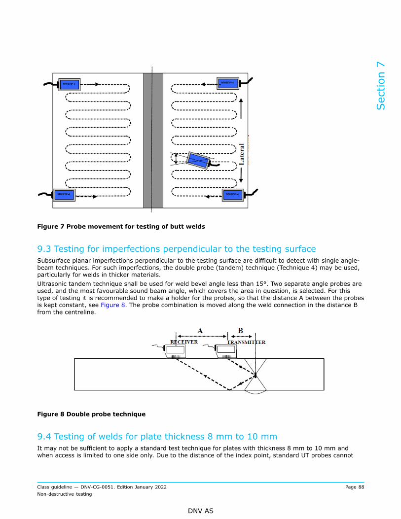
Figure 7 Probe movement for testing of butt welds
9.3 Testing for imperfections perpendicular to the testing surfaceSubsurface planar imperfections perpendicular to the testing surface are difficult to detect with single angle-beam techniques. For such imperfections, the double probe (tandem) technique (Technique 4) may be used,particularly for welds in thicker materials.Ultrasonic tandem technique shall be used for weld bevel angle less than 15°. Two separate angle probes areused, and the most favourable sound beam angle, which covers the area in question, is selected. For thistype of testing it is recommended to make a holder for the probes, so that the distance A between the probesis kept constant, see Figure 8. The probe combination is moved along the weld connection in the distance Bfrom the centreline.
Figure 8 Double probe technique
9.4 Testing of welds for plate thickness 8 mm to 10 mmIt may not be sufficient to apply a standard test technique for plates with thickness 8 mm to 10 mm andwhen access is limited to one side only. Due to the distance of the index point, standard UT probes cannot
Section 7
Class guideline — DNV-CG-0051. Edition January 2022 Page 88Non-destructive testing
DNV AS

approach the weld close enough, resulting in reduced coverage. Another challenge is the evaluation ofroot indications, i.e. differentiation of the signals from defect and from the geometry of the root. Henceit is required that a special scanning technique is developed and described for thicknesses below 10 mm.Qualification on project-specific validation blocks shall be performed to ensure that the applied techniquemeets detectability, coverage, and evaluation requirements.Another challenge is the evaluation of root indications, i.e. differentiation of the signals from defect and fromthe geometry of the root. Hence it is required that a special scanning technique is developed and describedfor thicknesses below 10 mm. Qualification on project-specific validation blocks shall be performed to ensurethat the applied technique meets detectability, coverage, and evaluation requirements.It is recommended to use high frequencies probes, 4 MHz-5 MHz, 6 mm to 12 mm diameter elements(commonly 8 mm x 9 mm) designed to have an exit point (index point) as close as possible to the probefront. This allows to address the root in half skip and increase the resolution power with higher frequency. Itis generally recommended to perform the scanning on full and 1.5 skips (it is also often necessary to scanon 2×skip or as much as 3×skip). The probe angle should be in the range of 60° to 70° (70° for the root).Smooth grinding of the external cap may be required. Scanning the cap with a twin crystal straight beamprobe may required where the weld geometry allows it, which consequently requires the that weld cap isground flush.The personnel responsible for performing an ultrasonic examination of welds in thin plates shall be familiarwith the limitations of the test method and be specifically trained in the practical testing of welds in theactual thickness range. Qualification tests may be requested to prove the mentioned personnel's proficiency.
A = plate thickness t; 8 mm (for qualification down to 8 mm)B = distance from root side to side-drilled hole; ¼ t (SDH =1.5 mm diameter, min. 20 mm depth)C = distance from cap side to side drilled hole; ¼ t (SDH = 1.5 mm diameter, min. 20 mm depth)D = center thickness side drilled hole; ½ t (SDH = 1.5 mm diameter, min. 20 mm depth)E = EDM notch at cap side weld toe, depth 1 mm, width max. 0.2 mm, length 20 mmF = EDM notch at root side weld toe, depth 1 mm, width max. 0.2 mm, length 20 mm
Figure 9 Example of typical validation block for plate thickness 8 mm to 10 mm
Section 7
Class guideline — DNV-CG-0051. Edition January 2022 Page 89Non-destructive testing
DNV AS

9.5 Location of discontinuitiesThe location of discontinuities shall be defined by reference to a coordinate or reference system, e.g. asshown in Figure 10. A point on the testing surface shall be selected as the origin for these measurements.Where testing is carried out from more than one surface, reference points shall be established on eachsurface. In this case, care shall be taken to establish a positional relationship between all reference pointsused, so that the absolute location of all discontinuities can be established from any nominated referencepoint.In the case of circumferential welds, this may require the establishment of the inner and outer referencepoints prior to assembly for welding.
Figure 10 Coordinate/reference system for defining the location of discontinuities
9.6 Evaluation of indications9.6.1 GeneralAll relevant indications above the evaluation level shall be assessed as indicated in the following.
9.6.2 Maximum echo amplitudeThe echo amplitude shall be maximized by probe movement and recorded in relation to the reference level.
9.6.3 Discontinuity lengthThe length of a discontinuity, in either the longitudinal or transverse direction shall, where possible, bedetermined using the technique specified in the acceptance levels standard, unless otherwise agreed with theSociety.
Section 7
Class guideline — DNV-CG-0051. Edition January 2022 Page 90Non-destructive testing
DNV AS

The length of the imperfections shall be evaluated by maximising the echo amplitude in the middle of thedefect. Subsequently, the probe is traversed towards the edge of the imperfection until the echo amplitudehas dropped to the required evaluation level. The centre of the probe is then marked off as the edge of theimperfection.
Figure 11 Evaluation of length of the defect
9.6.4 Discontinuity heightThe height of a discontinuity shall only be determined if required by acceptance criteria in the rules or byspecification.
9.6.5 Characterization of discontinuitiesThe gain which shall be used in the evaluation of the imperfection is the primary gain.When scanning, the gain shall be the corrected primary gain plus 6 dB in order to increase the sensitivity todefects with a difficult orientation. The gain shall then be reduced to the corrected primary dB level whendefect evaluation is carried out. The evaluation level stated in the acceptance criteria shall be used.Discontinuities shall be characterized in accordance with excerpt from ISO 23279 as shown in Figure 12.
Section 7
Class guideline — DNV-CG-0051. Edition January 2022 Page 91Non-destructive testing
DNV AS

Figure 12 Characterization of discontinuitiesaccording to ISO 23279
Where:Hd = indication echo aplitudeHd,max= maximum echo amplitudeHd,min= minimum echo amplitudeL = lengthLspec = specified lengthT1 = evaluation levelT2 = reference level +6 dBT3 = reference level -6 dBT4 = 9 dB shear wave or 15 dB difference
between reflection obtained with a shearand longitudinal wave respectively.
Stage 1 (T1, i.e. evaluation level): all indications≤ T1 are not classified.
Stage 2 (T2, i.e. reference level + 6 dB): anindication being at least twice as reflective as thereference is classified as planar.
Stage 3 (T3, i.e. reference level - 6 dB): if theindication echo amplitude is at least half of thereference echo and, if the imbalance in reflectivityis greater than or equal to T4, the indication isclassified as planar:
— with T4 = 9 dB for shear waves— with T4 = 15 dB between reflections obtainedwith shear waves and longitudinal waves.
The angles at which the ultrasonic beamis incident upon the indication shall have adifference of at least 10°. The comparison shall bemade upon the same area of the indication.
Stages 4 and 5: these criteria shall be fulfilled forat least two directions of examination.
Stage 5: if the echodynamic pattern does notmatch pattern 3, the indication is classified asnon-planar.
The echo patterns are defined in ISO 23279,Annex C.
Section 7
Class guideline — DNV-CG-0051. Edition January 2022 Page 92Non-destructive testing
DNV AS

Discontinuities in the root area of single sided welds shall be distinguished by measuring the horizontaldistances (a) as shown in Figure 13 to Figure 16.
Figure 13 Weld misalignment
Figure 14 Excessive root penetration
Figure 15 Lack of root penetration
Section 7
Class guideline — DNV-CG-0051. Edition January 2022 Page 93Non-destructive testing
DNV AS

Figure 16 Root defect
9.7 Requirements for testing9.7.1 Probe angleFor testing with several angle probes, the probe angles described in Table 6 are optimal for testing, related tothe thickness.
Table 6 Parent material thickness and related probe angle
Parent material thickness, t [mm] Probe angle [°]
10 ≤ t < 15 60 and 70
15 < t ≤ 40 45, 60 and 70
t > 4045, 60 and 70(70 when ½ V or K groove)
9.7.2 Probe positions
9.7.2.1 GeneralProbe positions for testing of butt welds are illustrated in Figure 17 to Figure 23 followed by correspondingtables, Table 7 to Table 13, related to material thickness, test positions, and number of scans.
Section 7
Class guideline — DNV-CG-0051. Edition January 2022 Page 94Non-destructive testing
DNV AS

9.7.2.2 Probe positions and testing of butt welds
where:
1 side 1, related to weld
2 top view
3 side 2 related to weld
4 side view
A, B, C, D, E, F, G, H,W, X, Y, Z
probe positions (shown on one side only, but shall also be mirrored about the weldcentre line)
b scanning zone width (SZW) related to skip distance, p, to cover the testing volume
p full-skip distance.
Figure 17 Probe positions and testing of butt welds
Table 7 Probe positions, beam angles and number of scans for butt welds
Longitudinal discontinuities Transverse discontinuities
L-scans N-scans T-scansThicknessof parentmaterial[mm]
Beamangles(min.
number)
Probepositions SZW
probepositionsSZW (min.number)
Total scans(min.
number)
Beamangles(min.
number)
Probepositions
Total scans(min.
number)
8 ≤ t < 10 2 A or B 1.5p G (or H)2 5 1 (2)(C andD) or (Eand F)1
2 (4)
Section 7
Class guideline — DNV-CG-0051. Edition January 2022 Page 95Non-destructive testing
DNV AS

Longitudinal discontinuities Transverse discontinuities
L-scans N-scans T-scansThicknessof parentmaterial[mm]
Beamangles(min.
number)
Probepositions SZW
probepositionsSZW (min.number)
Total scans(min.
number)
Beamangles(min.
number)
Probepositions
Total scans(min.
number)
10 ≤ t < 15 2 A or B 1.5p G (or H)2 5 1 (2)(C andD) or (Eand F)1
2 (4)
15 ≤ t < 40 2 A or B 1.5p G (or H)2 5 1 (2)(C andD) or (Eand F)1
2 (4)
t ≥ 40 2 A and B 1.5p G (or H)2 7 2(C andD) or (Eand F)1
4
1) One angle and two scans if surface is as per [6]. It shall be substituted by scanning from X&Y or W&Z if surfacemakes it impossible to perform.
2) Only to be done if access. Eventually surface preparation as outlined in [6] shall be done.
Section 7
Class guideline — DNV-CG-0051. Edition January 2022 Page 96Non-destructive testing
DNV AS

9.7.2.3 Probe positions and testing of full penetration structural T-joint welds
legend:
1 component 1
2 component 2
A, B, C, D, E, F, G, H, W, X, Y, Z probe positions
a, b, c, d, e, f, g scanning zone width (SZW) indicators
t thickness
p full-skip distance.
Figure 18 Probe positions and testing of full penetration structural T-joint welds
Table 8 Probe positions, beam angles and number of scans for full penetration structural T-jointwelds
Longitudinal discontinuities Transverse discontinuities
L-scans N-scans T-scansThicknessof parentmaterial[mm]
Beamangles(min.
number)
Probepositions SZW probe
positions SZW
Totalscans(min.
number)
Beamangles(min.
number)
Probepositions SZW
Totalscans(min.
number)
8 ≤ t < 10 2 A or B 1,5p C c 4 2(F and G) &(X and Y) or
(W and Z)
cf+g
8
10 ≤ t < 15 2 A or B 1.5p C c 7 2(F and G) &(X and Y) or
(W and Z)
cf+g
8
Section 7
Class guideline — DNV-CG-0051. Edition January 2022 Page 97Non-destructive testing
DNV AS

Longitudinal discontinuities Transverse discontinuities
L-scans N-scans T-scansThicknessof parentmaterial[mm]
Beamangles(min.
number)
Probepositions SZW probe
positions SZW
Totalscans(min.
number)
Beamangles(min.
number)
Probepositions SZW
Totalscans(min.
number)
15 ≤ t < 40 2 A or B 1.5p C1) c 7 2(F and G) &(X and Y) or
(W and Z)
cf+g
8
40 ≤ t < 100 2 A and B 1.5p C1) c 7 2(F and G) &(X and Y) or
(W and Z)
cf+g
8
t ≥ 100 3 A and B 1.5p C1) c 8 2(F and G) &(X and Y) or
(W and Z)
cf+g
8
1) To be substituted by tandem technique from A or B if C is not possible.
Section 7
Class guideline — DNV-CG-0051. Edition January 2022 Page 98Non-destructive testing
DNV AS

9.7.2.4 Probe positions and testing of set-through nozzle joint
where:
1 component 1, cylindrical shell/flat plate
2 component 2, nozzle
3 straight-beam probe
A, B, C, W, X, Y, Z probe positions
a, b, c scanning zone width (SZW) indicators
t thickness
p full-skip distance.
Figure 19 Probe positions and testing of set-through nozzle joint
Table 9 Probe positions, beam angles and number of scans for set-through nozzle joint
Longitudinal discontinuities Transverse discontinuities
L-scans N-scans T-scansThicknessof parentmaterial[mm]
Beamangles(min.
number)
Probepositions SZW probe
positions SZW
Totalscans(min.
number)
Beamangles(min.
number)
Probe positions
Totalscans(min.
number)
8 ≤ t < 10 2 A or B 1.5p C c 5 2(X and Y) and
(W and Z)2 or 4
10 ≤ t < 15 2 A or B 1.5p C c 5 2(X and Y) and
(W and Z)2 or 4
Section 7
Class guideline — DNV-CG-0051. Edition January 2022 Page 99Non-destructive testing
DNV AS

Longitudinal discontinuities Transverse discontinuities
L-scans N-scans T-scansThicknessof parentmaterial[mm]
Beamangles(min.
number)
Probepositions SZW probe
positions SZW
Totalscans(min.
number)
Beamangles(min.
number)
Probe positions
Totalscans(min.
number)
15 ≤ t < 40 2 A or B 1.5p C c 5 2(X and Y) and(W and Z)
8
t ≥ 40 2 A or B 1.5p C c 9 2(X and Y) and(W and Z)
8
Section 7
Class guideline — DNV-CG-0051. Edition January 2022 Page 100Non-destructive testing
DNV AS

9.7.2.5 Probe positions and testing of set-on nozzle joint
where:
1 component 1, nozzle
2 component 2, shell
3 straight-beam probe
A, B, C, X, Y probe positions
a, b, c, x scanning zone width (SZW) indicators
t thickness
p full-skip distance.
Figure 20 Probe positions and testing of set-on nozzle joint
Table 10 Probe positions, beam angles and number of scans for set-on nozzle joint
Longitudinal discontinuities Transverse discontinuities
L-scans N-scans T-scansThicknessof parentmaterial[mm]
Beamangles(min.
number)
Probepositions SZW probe
positions SZW
Totalscans(min.number)
Beamangles(min.
number)
Probe positions
Totalscans(min.
number)
8 ≤ t < 10 3 A or B 1.5p C c 4 2 X and Y 4
10 ≤ t < 15 3 A or B 1.5p C c 4 2 X and Y 4
Section 7
Class guideline — DNV-CG-0051. Edition January 2022 Page 101Non-destructive testing
DNV AS

Longitudinal discontinuities Transverse discontinuities
L-scans N-scans T-scansThicknessof parentmaterial[mm]
Beamangles(min.
number)
Probepositions SZW probe
positions SZW
Totalscans(min.number)
Beamangles(min.
number)
Probe positions
Totalscans(min.
number)
15 ≤ t < 40 3 A or B 1.5p C c 4 2 X andY 4
40 ≤ t < 60 3 A and B 1.5p C c 7 2 X and Y 4
60 ≤ t < 100 3 A and B 1.5p C c 7 2 X and Y 4
Section 7
Class guideline — DNV-CG-0051. Edition January 2022 Page 102Non-destructive testing
DNV AS

9.7.2.6 Probe positions and testing of structural L-joint
where:
1 component 1
2 component 2
A, B, C, D, E, F, G, H, I, X, Y probe positions
a, b, c scanning zone width (SZW) indicators
t thickness
p full-skip distance.
Figure 21 Probe positions and testing of structural L-joint
Table 11 Probe positions, beam angles and number of scans for structural L-joint
Longitudinal discontinuities Transverse discontinuities
L-scans N-scans T-scansThicknessof parentmaterial[mm]
Beamangles(min.
number)
Probepositions SZW probe
positions SZW
Totalscans(min.
number)
Beamangles(min.
number)
Probe positions
Totalscans(min.
number)
8 ≤ t < 10 2(H or A)and B
1.5p C c 5 2 D and E 4
10 ≤ t < 15 2(H or A)and B
1.5p C c 5 2 D and E 4
15 ≤ t < 40 2(H or A)and B
1.5p C c 5 2 D and E 4
Section 7
Class guideline — DNV-CG-0051. Edition January 2022 Page 103Non-destructive testing
DNV AS

Longitudinal discontinuities Transverse discontinuities
L-scans N-scans T-scansThicknessof parentmaterial[mm]
Beamangles(min.
number)
Probepositions SZW probe
positions SZW
Totalscans(min.
number)
Beamangles(min.
number)
Probe positions
Totalscans(min.
number)
40 ≤ t < 100 3(H or A)and B
1.5p C c 7 2 D and E 4
t ≥ 100 3(H or A)and B
1.5p C c 7 2 D and E 4
9.7.2.7 Probe positions and testing of a cruciform joint
where:
1 component 1
2 component 2
3 component 3
A, B, C, D, W, W1, W2, X, X1, X2, Y, Y1, Y2, Z, Z1, Z2, probe positions
a, b, c, d scanning zone width (SZW) indicators
t thickness
p full-skip distance.
Figure 22 Probe positions and testing of cruciform joint
Section 7
Class guideline — DNV-CG-0051. Edition January 2022 Page 104Non-destructive testing
DNV AS

Table 12 Probe positions, beam angles and number of scans for cruciform joint
Longitudinal discontinuities Transverse discontinuities
L-scans T-scansThicknessof parentmaterial[mm]
Beamangles(min.
number)
Probe positions SZW
Total scans(min.
number)
Beamangles(min.
number)
Probe positions
Total scans(min.
number)
8 ≤ t < 10 2(A or B)and
(C or D)
and tandem(A or B) and
(C or D)1)1.5p ≥ 6 2
(X1&Y1 &W1&Z1)and
(X2&Y2 &W2&Z2)
16
10 ≤ t < 15 2(A or B)and
(C or D)
and tandem(A or B) and
(C or D)1)1.5p ≥ 6 2
(X1&Y1 &W1&Z1)and
(X2&Y2 &W2&Z2)
16
15 ≤ t < 40 2(A or B)and
(C or D)
and tandem(A or B) and
(C or D)1)1.5p ≥ 6 2
(X1&Y1 &W1&Z1)and
(X2&Y2 &W2&Z2)
16
40 ≤ t < 100 2(A or B)and
(C or D)
and tandem(A or B) and
(C or D)1)1.5p ≥ 6 2
(X1&Y1 &W1&Z1)and
(X2&Y2 &W2&Z2)
16
1) Tandem technique from A or B and C or D only if possible.
Section 7
Class guideline — DNV-CG-0051. Edition January 2022 Page 105Non-destructive testing
DNV AS

9.7.2.8 Probe positions and testing of node joint in tubular structure
where:
1 component 1, main pipe
2 component 2, branch pipe
A, B, C, D, F, G, H, X, Y probe positions
d, f, g, h scanning zone width (SZW) indicators
t thickness
p full-skip distance.
Figure 23 Probe positions and testing of node joint in tubular structure
Section 7
Class guideline — DNV-CG-0051. Edition January 2022 Page 106Non-destructive testing
DNV AS

Table 13 Probe positions, beam angles and number of scans for node joint in tubular structure
Longitudinal discontinuities Transverse discontinuities
L-scans N-scans T-scansThicknessof parentmaterial[mm]
Beamangles(min.
number)
Probepositions SZW Probe
positions SZW
Totalscans(min.
number)
Beamangles(min.
number)
Probe positions
Totalscans(min.
number)
8 ≤ t < 10 2 F,G and H 1.5p D d 7 2 X and Y 4
10 ≤ t < 15 2 F,G and H 1.5p D d 7 2 X and Y 4
15 ≤ t < 40 3 F,G and H 1.5p D d 10 2 X and Y 4
40 ≤ t < 100 3 F,G,H and E 1.5p D d 11 2 X and Y 4
10 Welds in austenitic stainless and duplex (ferritic-austenitic)stainless steel
10.1 GeneralUltrasonic testing of welds in austenitic stainless steel and duplex (ferritic-austenitic) stainless steel requiresspecial equipment especially in the area of reference blocks and probes to be used.Due to the coarse grain structure of the material and the weld metal in particular a probe which generatescompression waves at angles, shall be used in addition to straight beam - and angle shear wave probes.Physical properties of stainless steels results in a variation of grain size and structure which entails variationin attenuation and imperfection detectability.The testing shall be carried out in accordance with specific developed written UT- procedures for the item inquestion or procedure qualification if found necessary and shall be approved by the Society.Scan plans shall be provided to the procedures, showing probe placement, movement, and testing coverage.The scan plans shall also include the beam angles used, beam directions with respect to weld centreline, thefocusing used, and weld volume tested.The testing of welds shall be as set out in [3] to [9] and as given in ISO 22825. Exceptions and additions aregiven in subsections [10.2] to [10.7].
10.2 ProbesThe equipment used for testing shall fulfil the requirements of ISO 22232-1 and ISO 22232-2. Theverification of the combined equipment shall be done in accordance with ISO 22232-3, except for dual-element compression wave angle-beam probes, which may be verified on appropriate reference blocks otherthan the blocks mentioned in ISO 22232-3.Focal curves shall be available for the dual-element probes to be used, determined on a materialrepresentative of the material to be tested.It shall be verified using reference blocks with actual weld connections, see [10.4] whether angle shear waveprobes are suitable.In general, a combination using both shear and compression wave angle probes is recommended in additionto straight beam (normal (0°)) and creep wave probes.The detectability of 'open to surface' imperfections like incomplete penetration and lack of fusion mayincrease using shear wave probes. Sub surface defects closed to the scanning surface shall be detected byuse of creep wave probes.
Section 7
Class guideline — DNV-CG-0051. Edition January 2022 Page 107Non-destructive testing
DNV AS

10.3 Coupling mediumIn addition to already stated requirements for coupling media, for austenitic and duplex stainless steel,impurities such as sulphur, halogens and alkali metals in the couplant shall be restricted.
10.4 Calibration blocks for calibration of amplificationRange setting shall be carried out on appropriate calibration blocks, which are designed to be similar indimension to Block No. 2 in accordance with ISO 7963. The dimension of at least one of the radii of the blockused shall be close to the focal distance of the probes, e.g. for calibration of time base for duplex K2 block,see Figure 24.
Figure 24 Calibration of time base for duplex K2 block
Guidance note:Angle compression wave probes should only be used for ½ skip (S) scanning.
---e-n-d---o-f---g-u-i-d-a-n-c-e---n-o-t-e---
10.5 Reference blockReference blocks for sensitivity setting should contain a weld and be representative in terms of wallthickness, material, welding procedure, weld shape and structure, and surface condition. It should be notedthat parameters such as heat input, deposition rate, and the number of weld runs have a great impact on theultrasonic properties of welds.Reference reflectors may be side-drilled holes or flat-bottomed holes, dependent on application. Surfacenotches to represent surface discontinuities are used at the scanning and opposite surface. These may berectangular notches or notches with their reflection side in the local plane of the weld bevel, with a length ofat least 25 mm.
Section 7
Class guideline — DNV-CG-0051. Edition January 2022 Page 108Non-destructive testing
DNV AS

These reference blocks shall have drilled holes (Ø 3 mm or Ø 6 mm depending on thickness) positioned indepths of 1/4 T, 1/2 T and 3/4 T. The drilled holes (reflectors) shall be located as shown in Figure 25. Thethickness of the reference block shall be sufficient in order to encompass a DAC curve covering the wholethickness to be tested.For calibration of amplifier and sensitivity setting on the reference block, see Figure 25.
Figure 25 Reference block for ultrasonic testing of welds in austenitic and austenitic-ferritic steel
Calibration of amplification
Figure 26 Sensitivity setting on reference block
Note:Reflector holes shall be drilled in both fusion lines whenever two dissimilar materials are welded to each other.
---e-n-d---o-f---n-o-t-e---
Section 7
Class guideline — DNV-CG-0051. Edition January 2022 Page 109Non-destructive testing
DNV AS

Reference blocks for creep wave probes shall contain 0.5 mm, 1.0 mm and 2.0 mm EDM (electric dischargemachining) notches at the scanning surfaces, see Figure 27.The surface condition of the reference blocks shall be similar to the condition of the parent material to betested.
Figure 27 Reference block for creep wave probe
10.6 Range settingsThe index point of each probe shall be marked on the probe’s side, after having optimized the echo amplitudeon the radius closest to its focal distance. Since echo optimization can be difficult for high-angle probes andcreeping wave probes, the shear wave component may be used for optimization instead. In that case, thecalibration methodology shall be included in the test procedure.Optimization of the echoes shall be done on the two radii separately, and by iteration until the signals fromthe smaller and the larger radius are on their correct positions.Alternatively, the time base may be set with the aid of a single-element straight-beam probe on the widthof the calibration block, and subsequent zero-point adjustment with the angle-beam probe placed on thecalibration block, on the radius which is closest to the probe’s focal distance.For correct geometrical positioning of indications, the influence of different sound velocities between basematerial and weld material may be considered, using the reflectors as used in Figure 25. Range setting shallbe carried out prior to each testing. Checks to confirm these settings shall be performed at least every 4 hand on completion of testing.Checks shall also be carried out whenever a system parameter is changed or whenever changes in theequivalent settings are suspected.
10.7 Sensitivity setting and construction of DACSensitivity shall be set as indicated in ISO 22825, [8.1], [8.2] (and [8.4]).DAC curves shall be constructed from the drilled holes in the parent material of the reference blocks, seeFigure 26.A maximum response shall then be obtained from the holes in the weld fusion zone and if necessary the gainsetting shall be adjusted such that this response reach DAC, see Figure 26. This shall be the primary gain
Section 7
Class guideline — DNV-CG-0051. Edition January 2022 Page 110Non-destructive testing
DNV AS

to be used when locating indications on the fusion boundary in those cases where the ultrasonic beam ispassing through the parent metal only.Another set of DAC curves shall be constructed, as shown in Figure 26, in order to establish sensitivity levelsfor instance where the ultrasound is traversing the weld material, when scanning the fusion face.These sensitivity levels shall be verified against the holes drilled in the base material. Any variations shallbe noted so that echoes reflected from indications within the weld zone may be evaluated for amplituderesponse.It shall be verified on reference blocks with welds produced in accordance with the actual WPS if an 1.5 × S(full skip scanning) is possible to obtain using shear wave angle probes. Note that angle compression waveprobes should only be used at ½ S scanning.The EDM notches on the surface of the reference block, see Figure 27, for creep wave probes shall be usedfor sensitivity setting. It is recommended to adjust the echo response from the 1.0 mm notch to 75% of FSH.
11 Acceptance criteria, weld connectionsWhenever acceptance criteria are defined in the rules, approved drawings, IACS recommendations or otheragreed product standards, these criteria are mandatory.Unless otherwise agreed with the Society, all indications in the test volume (defined in [5]) shall follow theacceptance criteria for the weld connection.
Guidance note:Indications found in the parent metal and heat affected zone (as included in the test volume defined in [5]), and judged 'beyondreasonable doubt' to be laminar imperfections originating from the plate rolling process, may typically follow the acceptancecriteria for the plate, see [13.9].
---e-n-d---o-f---g-u-i-d-a-n-c-e---n-o-t-e---
If no acceptance criteria are defined, acceptance criteria for welds as specified below may be applied.The quality of welds shall comply with ISO 5817 Quality Level C. For highly stressed areas more stringentrequirements, such as Quality Level B, may be applied. See further details inTable 14.
Table 14 Ultrasonic testing using pulse-echo technique
Quality levels inaccordance with ISO 5817
Testing techniques andlevels in accordance with ISO17640 1) or DNV CG 0051 2)
Acceptance levels inaccordance with ISO 11666
B at least B 2
C at least A 3
D not defined not required 3)
1) When characterization of indications is required, ISO 23279 shall apply2) Stated testing techniques and levels refers to ISO 17640. All testing techniques in DNV-CG-0051 are compliant with
Testing Level A, B and C ISO 176403) UT is not recommended but can be defined in a specification (with the same requirements as quality level C).
Sensitivity level is based on a SDH as defined in this class guideline.In addition, the following applies: All indications from which the reflected echo amplitude exceeds theevaluation levelshall be characterized and all indications characterized as planar (i.e. cracks, lack of fusionand incomplete penetration) shall be rejected.
Section 7
Class guideline — DNV-CG-0051. Edition January 2022 Page 111Non-destructive testing
DNV AS

12 Reporting, weld connectionsIn addition to the items listed under item Sec.2 [7], the following shall be included in the ultrasonic testingreport:The test report shall include, as a minimum, the following information:
— identification of the test object— the material type, grade and product form— the dimensions of the test object— the location or identification of the weld tested— a sketch showing the geometrical configuration (if necessary)— a reference to the welding procedure and stage of heat treatment (if any)— the state of manufacture— the surface conditions— the temperature of the object, if outside the range 0°C to 40°C— contract requirements, e.g. specifications, guidelines, special agreements— the place and date of testing— identification of testing organizations and identification, certification, and signature of the operator.
The test report shall include the following information related to equipment:
— the manufacturer and type of the ultrasonic instrument, with identification number— the manufacturer, type, nominal frequency, beam angle and focal distance of probes used withidentification number
— the identification of reference blocks used with a sketch— the couplant medium.
The test report shall include the following information related to testing technique:
— reference to the written test procedure— the extent of testing, including any restrictions— the location of the scanning areas— the reference points and details of the coordinate system— identification of probe positions— the time base range— the method and values used for sensitivity setting— the reference levels— the result of the parent material testing— the standard for acceptance and/or recording levels— the deviations from this document or from contract requirements— any factors which have prevented the testing from being carried out as intended.
The test report shall include a tabular summary (or sketches) providing the following information for recordedindications:
— the coordinates of the indication with details of associated probes and corresponding probe positions— the maximum echo amplitude and information, if required, on the type and height of indication— the lengths of indications— the results of the evaluation in accordance with specified acceptance and/or recording levels.
Section 7
Class guideline — DNV-CG-0051. Edition January 2022 Page 112Non-destructive testing
DNV AS
13 Ultrasonic testing of rolled steel plates
13.1 GeneralThis subsection covers manual testing of rolled plates in carbon and alloy steel with thickness ≥ 6.0 mm forthe detection of imperfections which are oriented parallel with the rolled surface.The intention of the ultrasonic testing shall ensure that the steel plates are free of gross discontinuities suchas planar inclusions or laminations.
13.2 Personnel qualificationsFor systems for personnel qualifications see Sec.2 [1] and [3]. However, if the testing is restricted only tothickness properties of rolled steel plates, level 1 certification in UT is sufficient.
13.3 Ultrasonic instrumentThe instrument shall:
— be applicable for the pulse-echo technique and for the double-probe technique— cover a minimum frequency range from 1 to 12 MHz— have a calibrated gain regulator with minimum 2 dB pr. step over a range of minimum 60 dB— be equipped with automatic DAC- display presentation— have the opportunity for mounting distance gain size (DGS) -scales on the screen— be able to clearly distinguish echoes with amplitudes of 5% of full screen height.
13.4 ProbesThe probes shall be straight beam transducers single- or twin crystal.Twin crystal probes shall be used when examination is performed on steel plates with nominal thickness lessthan 60 mm.Single or twin crystal probes may be used when testing is performed on steel plates with nominal thickness T≥ 60 mm.The single crystal probes shall have a dead zone as small as possible, 15% of the plate thickness or 15 mmwhichever is the smaller. The focusing zone of the twin crystal probes shall be adapted to the thickness of theplate to be examined.Selected probes shall have a nominal frequency in the range of 2 MHz to 5 MHz and dimensions Ø 10 mm toØ 25 mm.
13.5 Coupling medium and surface conditionsThe coupling medium shall ensure an adequate contact between the probe and the surface of the steel plateto be tested. Water is normally used but other coupling media, e.g. oil or paste, may be used.The surface condition shall permit at least two successive back-wall echoes to be distinguished when theprobe is placed on any area free from internal imperfections.
13.6 Range and sensitivity setting13.6.1 Range settingThe calibration of time base shall be carried out using an IIW calibration block, a K2 calibration block or on adefect free area of the material to be examined.
Section 7
Class guideline — DNV-CG-0051. Edition January 2022 Page 113Non-destructive testing
DNV AS

The time base shall be selected such that there are always at least 2 back-wall echoes (reflections) on thescreen.
13.6.2 Sensitivity settingThe calibration of sensitivity is based on echoes reflected from flat bottom holes in reference blocks of carbonsteel. Characteristics curves corresponding to flat bottom holes with various diameters may be suppliedby the manufacturer of the probes. The curves are either presented on a DGS diagram or on DGS - scales'attachment scales' to be mounted on the screen of the ultrasonic apparatus.The DGS - scales, which are most commonly used, are developed from the DGS diagrams. Differently sizedreflectors (flat bottom holes 'FBH') may be correlated to the evaluating curves. The FBH reflectors are usedas reference sizes for evaluating echo amplitudes.By using a DGS - scale it is possible to evaluate echo amplitudes reflected from imperfections quickly anddirectly. The evaluation is done by measuring the dB distance from an evaluation curve.
13.7 Evaluation of imperfectionsOnly imperfections from which the reflected echo amplitude is greater than that of the characteristic curve ofan Ø11 mm FBH shall be considered.The area of the imperfections shall be determined using the 6 dB-drop technique whenever complete loss ofback wall echo is obtained, see Figure 28.
Figure 28 Half value method
Section 7
Class guideline — DNV-CG-0051. Edition January 2022 Page 114Non-destructive testing
DNV AS

Using single crystal probes the imperfections giving echoes above the characteristic curve for the Ø11 mmFBH shall be counted and evaluated against the acceptance criteria.Two nearby imperfections shall be considered as one, the area being equal to the sum of the two, if thedistance between them is less than or equal to the length of the smaller of the two.
13.8 ScanningScanning comprises in general continuous examination along the lines of a grid made of a 200 mm squareparallel to the edges of the plate, or along parallel or oscillating lines distributed uniformly over the surface,giving the same degree of control.Scanning of plate edges comprises a full examination of zone in accordance with Table 15 over the four edgesof the plate.
Table 15 Zone width for steel plate edges
Thickness of plate, T, [mm] Zone width [mm]
10 ≤ T < 50 50
50 ≤ T < 100 75
100 ≤ T 100
13.9 Acceptance criteriaWhenever acceptance criteria are defined in the rules, approved drawings, IACS recommendations or otheragreed product standards, these criteria are mandatory.If no acceptance criteria are specified, the quality class S1 – E2 of EN 10160 may be applied.
13.10 Reporting, rolled steel platesIn addition to the items listed under Sec.2 [7], the following shall be included in the ultrasonic testing report:
— probes, type and frequency— identification of reference blocks used— couplant medium— reporting level, if different from acceptance level.
14 Ultrasonic testing of castings
14.1 GeneralThis subsection covers manual testing of castings, carbon, low-alloy and martensitic stainless steel using theflat bottom hole calibration technique.The intention of the testing shall reveal unacceptable internal imperfections.Testing shall be carried out after final heat treatment when the casting surface has been brought to acondition suitable for UT.As an alternative to the flat bottom hole calibration technique the DGS technique may, upon agreement withthe Society, be accepted. The DGS technique is described in [15].The back wall echo obtained on parallel sections should be used to monitor variations in probe coupling andmaterial attenuation. Any reduction in the amplitude of the back wall echo without evidence of intervening
Section 7
Class guideline — DNV-CG-0051. Edition January 2022 Page 115Non-destructive testing
DNV AS

defects should be corrected. Attenuation in excess of 30 dB/m could be indicative of an unsatisfactoryannealing heat treatment.
14.2 Personnel qualifications and requirements for equipment14.2.1 GeneralSee Sec.2 [1] and [3] In addition, the personnel shall be familiar and trained with use of flat bottom holecalibration technique.
14.2.2 Ultrasonic instrumentThe apparatus shall:
— be applicable for the pulse-echo technique and for the double-probe technique— cover a minimum frequency range from 1 to 6 MHz— have a calibrated gain regulator with minimum 2 dB pr. step over a range of minimum 60 dB— be equipped with automatic DAC- display presentation— be able to clearly distinguish echoes with amplitudes of 5% of full screen height.
14.2.3 ProbesThe probes shall be straight beam transducers (normal probes) single- or twin crystal.Twin crystal probes shall be used when testing is performed on castings with nominal thickness T ≤ 25 mm.Selected probes shall have dimensions Ø 10 mm to Ø 30 mm. The background noise shall not exceed 25% ofthe reference curve.Supplementary:Angle beam probes shall be used only when agreed upon between the contracting parties or required by theSociety. Typical applications are castings that cannot be effectively tested using a straight beam probe as aresult of casting design or possible discontinuity orientation.It is recommended to use probes producing angle beam in steel in the range 35° to 75° inclusive, measuredto the perpendicular of the entire surface of the casting being tested.As a minimum a 45° probe shall be used.
14.3 Surface preparation and coupling mediumAll surfaces to be examined shall be free of any substance which may impede the free movement of theprobe or hinder the transmission of ultrasound to the material. Machined surfaces should be preferred for thefinal examination.As coupling medium oil, grease or cellulose gum may be used. The coupling medium used for range andsensitivity setting shall also be used for testing.
14.4 Range settingThe same equipment shall be used during range setting and testing, i.e. instrument, probes, cables, andcoupling medium.The temperature of the test object and the calibration-/reference blocks shall be within ±14°C.Range setting with normal probes shall be performed using K1/K2 calibration blocks or the reference blockfor sensitivity setting.The range for normal probes shall be selected in order to always be at least 2 back-wall echoes (reflections)on the screen.The range for the angle probe shall cover minimum a full skip distance if scanning is accessible only from onesurface. If scanning is possible from two surfaces (inside and outside) 0.5 × S is sufficient.
Section 7
Class guideline — DNV-CG-0051. Edition January 2022 Page 116Non-destructive testing
DNV AS

14.5 Reference blocks14.5.1 GeneralBasis for the sensitivity setting is a set of test blocks containing flat bottoms holes. The reference blocks shallhave the same acoustic properties or material grade as the material to be examined.In addiction, the blocks shall be stamped with the reference charge/heat number for traceability to the actualmaterial certificate, and also be given the same heat treatment as the test object.The blocks defined in [14.5.2] to [14.5.4] shall be used.
14.5.2 Block no 1Ultrasonic standard reference blocks as specified in ASTM A609 4.3.3, Figure 1 and Table 1.The blocks are used for sensitivity setting when using straight beam probes. The dimension of the blocks isdepending of the thickness of the test object. The basic set shall consist of those blocks listed in ASTM A609Table 1. When section thicknesses over 380 mm shall be tested, an additional block of the maximum testthickness shall be made to supplement the basic set. The reference reflector shall be a flat bottom hole (FBH)with diameter 6.4 mm.
14.5.3 Block no. 2Ultrasonic standard reference block for sensitivity setting when using twin crystal (transmitter/receiver T/R)probes shall be machined and contain 2.4 mm drilled holes in various depths as shown in ASTM A609 4.3.4,Figure 2. The block shall be used for sensitivity setting of objects with thickness ≤ 25 mm.
14.5.4 Block no 3Reference block for angle beam testing is shown in ASTM A609 Figure S1.1. The dimensions of the referenceblock shall be according to ASTM A609, Table S1.1.
14.6 Sensitivity setting14.6.1 Straight beam probesSensitivity setting shall include whole of the ultrasonic system, this includes the ultrasonic instrument,probes, cables and coupling medium.The blocks that encompass the metal thickness to be inspected shall be used for calibration.The range of the screen should be selected to be twice the thickness of the object. Establish the DAC usingthe set of reference blocks spanning the thickness containing the applicable flat bottom holes.The casting testing surface will normally be rougher than that of the test blocks, consequently, employ atransfer mechanism to provide approximate compensation. In order to accomplish this, first select a regionof the casting that has parallel walls and a surface condition representative of the rest of the casting as atransfer point. Next select the test block whose thickness most closely matches the thickness of the testobject.Place the search unit on the casting at the transfer point and adjust the instrument gain until the back-reflection amplitude through the casting matches that through the test block.Using this transfer technique the variation in attenuation/surface condition between the reference block andtest object may be found and taken into consideration.Do not change those instrument controls and the test frequency set during calibration, except the attenuator,or calibrated gain control, during acceptance examination of a given thickness of the casting. Make a periodiccalibration during the inspection by checking the amplitude of response from the 6.4 mm (2.4 mm for twincrystal probes) diameter flat-bottom hole in the test block utilized for the transfer.The attenuator or calibrated gain control may be used to change the signal amplitude during examinationto permit small amplitude signals to be more readily detected. Signal evaluation is made by returning theattenuator or calibrated gain control to its original setting.
Section 7
Class guideline — DNV-CG-0051. Edition January 2022 Page 117Non-destructive testing
DNV AS

During examination of areas of casting having parallel walls recheck areas showing 75% or greater loss ofback reflection to determine whether loss of back reflection is due to poor contact, insufficient couplant,misoriented discontinuity, etc. If the reason for loss of back reflection is not evident, consider the areaquestionable and investigate further.
14.6.2 Angle ProbesThe angle probe shall be calibrated using a set of calibration blocks with side-drilled holes at 1/4 t, 1/2 t and3/4 t (where t = thickness of the block).The hole diameter is depending on the thickness of the casting being tested.Use the reflection (amplitude) from the side drilled holes to establish the applicable DAC as describedpreviously in this section.
14.7 ScanningAll surfaces specified for ultrasonic testing shall be completely inspected from both sides, whenever bothsides are accessible. Where scanning is restricted to one side only scanning shall be performed using a twincrystal probe for the near surface scans (25 mm below surface) and a single probe for the remaining volume.When practical radial and axial scanning shall be performed.The operators shall ensure complete coverage of all areas specified for testing by carrying out systematicallyoverlapping of scans. Minimum scanning speed shall not exceed 100 mm/s and each pass of the search unitshall overlap a minimum of 10% of the active transducer (piezoelectric element).
14.8 Reporting, castingIn addition to the items listed under Sec.2 [7], the following shall be included in the ultrasonic testing report:All indications from which the reflected echo response is greater than 100% of DAC shall be reported.Areas showing 75% or greater loss of back reflection shall be reported if, upon further investigation, thereduction of reflection is evaluated to be caused by discontinuities.
14.9 Acceptance criteriaWhenever acceptance criteria are defined in the rules, approved drawings, IACS recommendations or otheragreed product standards, these criteria are mandatory.
15 Ultrasonic testing of forgings
15.1 GeneralThis subsection covers manual testing of forgings of carbon or low-alloy steel using the straight- and anglebeam technique. The straight beam technique utilised is the DGS (Distance Gain Size) method.The intention of the testing shall reveal unacceptable internal discontinuities.Final testing shall be carried out after heat treatment when the forging surface has been brought to acondition suitable for UT.
15.2 Personnel qualificationsIn addition to Sec.2 [1] and [3] the personnel shall be familiar and trained for use of the DGS method.
15.3 Ultrasonic instrumentThe instrument shall:
Section 7
Class guideline — DNV-CG-0051. Edition January 2022 Page 118Non-destructive testing
DNV AS
— be applicable for the pulse-echo technique and for the double-probe technique— cover a minimum frequency range from 1 to 6 MHz— have a calibrated gain regulator with minimum 2 dB pr. step over a range of minimum 60 dB— be equipped with automatic DAC- display presentation— have the possibility for automatic DGS-scales on the screen— be able to clearly distinguish echoes with amplitudes of 5% of full screen height.
15.4 ProbesStraight beam (normal) probes with frequency 2 MHz - 4 MHz and dimension Ø 10 mm - 30 mm shall beused. Angle beam probe shall be used as supplementary testing on rings, hollow and cylindrical sections.It is recommended to use probes producing angle beam in steel in the range 35° to 75° inclusive, measuredto the perpendicular of the entire surface of the forging being tested. As a minimum a 45° probe shall beused.
15.5 Surface preparation and coupling mediumAll surfaces to be tested shall be free of any substance which may impede the free movement of the probeor hinder the transmission of ultrasound to the material. Machined surfaces should be preferred for the finalexamination.Unless otherwise specified the forgings shall be machined to provide cylindrical surfaces for radial testingin the cases of round forgings; the ends of the forgings shall be machined perpendicular to the axis of theforging for the axial testing. Faces of disk and rectangular forgings shall be machined flat and parallel to oneanother.As coupling medium oil, grease or cellulose gum may be used. The coupling medium used for range andsensitivity setting shall also be used for testing.
15.6 Range settingThe same equipment shall be used duringrange setting and testing, i.e. instrument, probes, cables andcoupling medium.The range for normal probes shall be selected such that there always are at least 2 back-wall echoes(reflections) on the screen.The time base for the angle probe shall cover minimum a full skip distance if scanning is accessible only fromone surface. If scanning is possible from two surfaces (inside and outside 0.5 × S is sufficient.
15.7 Sensitivity setting15.7.1 Probes
15.7.1.1 Normal probesDGS scales, matched to the ultrasonic instrument and probes, shall be used for straight-beam testing. TheDGS scale range shall be selected to include the full thickness cross-section of the forging to be tested.Insert the DGS scale on the ultrasonic instrument screen ensuring the DGS scale baseline coincides with thesweep line of the instrument's screen. Place the probe on the forging and adjust the first backwall echo toappear clearly on the CRT screen at the value corresponding to the thickness of the forging.Adjust the gain until forging back wall echo matches the height of the DGS reference slope within ± 1 dB.Once adjusted, increase the gain by the dB value shown on the DGS scale for the reference slope.The instrument is now calibrated and may be used for all solid-cylinder forgings (non-drilled) and planebackwall forgings. If the ultrasonic instrument is equipment with digital DGS Calibration Interface Program,this programmay be used.
Section 7
Class guideline — DNV-CG-0051. Edition January 2022 Page 119Non-destructive testing
DNV AS

When testing cylindrical hollow forgings the hole of the specimens will cause sound scatter. In these cases acorrection depending of the specimen thickness and the hole diameter is required.Determine the correction value in dB from the Nomogram shown in ASTM A388, Figure X4.1.Proceed as described above. Using the gain 'Gain-dB' control reduce the flaw detector by the correction valuedetermined using the Nomogram.The apparatus is then calibrated for testing cylindrical bored or hollow forgings.
15.7.1.2 Angle probeRings and hollow sections with an outside to inside diameter (OD/ID) less than 2.0 to 1.0 should be testedusing angle probes, at least 45° probe as a supplement to the normal probe. Forgings which cannot be testedaxially using normal probes, are also to be tested with the use of angle probes, min. 45° probe.Set the sensitivity at the instrument for the angle beam testing to obtain an indication amplitude ofapproximately 75% of FSH from a rectangular or 60° V-notch on inside diameter in the axial direction andparallel to the axis of the forgings to be tested.A separate standard reference block may be used. However, it shall have the same configuration, nominalcomposition, heat treatment and thickness as the forgings it represents.Where a group of identical forgings is made, one of the forgings may be used as the separate sensitivitysetting standard.Cut the ID depth notch to 3% maximum of the thickness or 6 mm, whichever is smaller, and its length toapproximately 25 mm. At the same instrument setting, obtain a reflection from a similar OD notch. Draw aline through the peaks of the first reflections obtained from the ID and OD notches. This shall be the distanceamplitude curve (DAC).When practical utilise the ID notch when scanning from the OD surface and the OD notch when scanningfrom the ID surface. Curve wedges or probe-shoes may be used when necessary for a proper contactbetween probe and testing surface.
15.8 Scanning15.8.1 Straight beam probesAll surfaces specified for ultrasonic testing shall be completely inspected from both sides, whenever bothsides are accessible. Where access is restricted to one side only scanning shall be performed using a twincrystal probe for the near surface scans (25 mm below surface) plus a single probe for the remaining volume.When practical both radial and axial scanning shall be performed.On larger diameter rudder stocks and especially axial scanning, the pulse repetition frequency (PRF) shall belimited to max. 150 Hz to avoid false signals due to interference on larger dimensions.The scanning rate shall not exceed 100 mm/s.The operators shall ensure complete coverage of all areas specified for testing by carrying out systematicallyoverlapping of scans. In general the testing shall be carried out prior to drilling holes, tapers, grooves, ormachining sections to contour.
15.8.2 Angle probesRings and hollow sections as specified in item [15.7.1.2] shall be tested using angle probe. The testing shallbe performed by scanning over the entire surface area circumferentially in both the clockwise and counterclockwise direction from the OD surface.Forgings which cannot be tested axially by normal probes shall be tested in both axial directions with anangle beam probe. For axial scanning the notches as specified in item [15.7.1.2] shall be used for calibration.These notches, placed on the ID and OD surface, shall be perpendicular to the axis of the forging and havethe same dimensions as the axial notch.
Section 7
Class guideline — DNV-CG-0051. Edition January 2022 Page 120Non-destructive testing
DNV AS

15.9 Sizing of imperfectionsIn general, the area containing imperfections, shall be sized (area and length) using the 6 dB drop technique.The area refers to the surface area on the forgings over which a continuous indication exceeds theacceptance criteria. This area will be approximately equal to the area of the real defect provided the defectsize is larger than the 6 dB beam profile of the probe.However, if the real imperfection size is smaller than the 6 dB beam profile, the 6 dB drop technique isnot suited for sizing. The area measured on the surface will, in such cases, be measured too large and notrepresent the real indication size.A guide to classify if the revealed indications are greater or smaller than the 6 dB drop profile is given in EN10228-3, para. 13.If the size of the indication is evaluated to be smaller than the 6 dB drop profile at the depth of discontinuitya graphic plot, that incorporates a consideration of beam spread, should be used for realistic size estimation.In certain forgings, because of very long metal path distances or curvature of the scanning surfaces, thesurface area over which a given discontinuity is detected may be considerably larger or smaller than theactual size of the discontinuity; in such cases criteria that incorporate a consideration of beam angles orbeam spread shall be used for realistic size evaluation.This may include reference blocks identical with the forgings to be tested. In cases of dispute flat bottomholes or notches, drilled or machined in the reference blocks, may act as reflectors to verify the correctdefect size.
15.10 Reporting, forgingsIn addition to the items listed under Sec.2 [7] the following shall be included in the ultrasonic testing report:When using normal probes:
— All indication from which the reflected echo response exceeds the specified DGS acceptance criteria shallbe reported.
— An indication that is continuous on the same plane and found over an area larger than twice the probediameter shall be reported regardless of echo amplitude.
— Areas showing 20% or greater loss of back reflection shall be reported if, upon further investigation, thereduction of reflection is evaluated to be caused by discontinuities.
When using angle probes:
— Record discontinuities indications equal to or exceeding 50% of the indication from the reference line.
The above reportable indications do not themselves mean that an item will be rejected, unless specified inthe acceptance criteria.
15.11 Acceptance criteria15.11.1 GeneralWhenever acceptance criteria are defined in the rules, approved drawings, IACS recommendations or otheragreed product standards, these criteria are mandatory.
15.11.2 Alternative acceptance criteria where these are not given by the referring standardAny reflections caused by discontinuities, exceeding 20% of full screen height (FSH) shall be evaluated andshall comply with the acceptance criteria for the length as specified by IACS Rec.68.When 6 dB drop cannot be used for sizing of point-like indications which are smaller than 6 dB beam profilethe probe beam spread to be considered to ensure indication is less than allowable length as specified inIACS Rec.68.
Section 7
Class guideline — DNV-CG-0051. Edition January 2022 Page 121Non-destructive testing
DNV AS

16 PAUT - automated phased array for testing of welds
16.1 ScopeThis subsection specifies the application of phased array for semi- or fully automated ultrasonic testing offusion-welded joints in metallic materials of minimum thickness 6 mm (PAUT). It applies to full penetrationwelded joints of simple geometry in plates, pipes, and vessels, where both the weld and the parent materialare low-alloy and/or fine grained steel.For the testing of welds in other steel materials this subsection may give guidance. For coarse-grained oraustenitic steels, previous parts of this section and ISO 22825 apply in addition to this subsection.This subsection provides guidance on the specific capabilities and limitations of phased array for thedetection, location, sizing and characterization of discontinuities in fusion-welded joints. Phased array may beused as a stand-alone technique or in combination with other NDT methods or techniques, for manufacturinginspection, pre-service and for in-service inspection.In the following it is specified a testing level comprising all quality levels for welds.
16.2 Terms and definitionsFor the purposes of this document, the terms and definitions given in ISO 5577 and ISO 23243 and definedin Table 16 apply.
Table 16 Definition of terms
Term Definition
phased array image one- or two-dimensional display, constructed from the collected information of phasedarray operation
indication, phased arrayindication
pattern or disturbance in the phased array image which may need further evaluation
phased array setup probe arrangement defined by probe characteristics (e.g. frequency, probe elementsize, beam angle, wave mode), probe position, and the number of probes
probe position, PP distance between the front of the wedge and the weld centre line
scan increment distance between successive data collection points in the direction of scanning(mechanically or electronically)
skewed scan scan performed with a skewed angle (The skewed angle can be achieved electronicallyor by means of probe orientation)
mode, phased array mode combination of ultrasonic beams created by phased array, e.g. fixed angle, E-scan, S-scan
16.3 Testing levelQuality requirements for welded joints are mainly associated with the material, welding process and serviceconditions. To comply with all of these requirements, this section specifies only one testing level comprisingall coverage of welds.PAUT of welds shall include a linear scan of the fusion face, together with other scans as defined in thespecific test technique.If the evaluation of the indications is based on amplitude only, it is a requirement that an ‘E’ scan (or linearscan) shall be utilized to scan the fusion faces of welds, so that the sound beam is perpendicular to the fusion
Section 7
Class guideline — DNV-CG-0051. Edition January 2022 Page 122Non-destructive testing
DNV AS

face ± 6° maximum, recommended ± 2°. This requirement may be omitted if an ‘S’ (or sectorial) scan canbe demonstrated to verify that discontinuities at the fusion face can be detected and sized, using the statedprocedure (note, this demonstration shall utilize reference blocks containing suitable reflectors in location offusion zone).Indications detected when applying testing procedure shall be evaluated either by length and height or bylength and maximum amplitude. Indication assessment shall be in accordance with ISO 19285:2017 orrecognized standards and the specific requirements of the classification society. The sizing techniques includereference levels, time corrected gain (TCG), distance gain size (DGS) and 6 dB drop. 6 dB drop method shallonly be used for measuring the indications larger than the beam width.
16.4 Information required prior to testing16.4.1 GeneralThe purpose of the testing shall be defined by the testing procedure. Based on this, the volume to beinspected shall be determined.A scan plan shall be provided. The scan plan shall show the beam coverage, the weld thickness and the weldgeometry.The procedure shall include a documented testing strategy or scan plan showing probe placement, probemovement, and component coverage that provides a standardized and repeatable methodology for weldtesting. The scan plan shall also include ultrasonic beam angles used, beam directions with respect to theweld centre line, the focusing used, and the volume to be tested for each weld.
16.4.2 Items to be defined prior to procedure developmentInformation on the following items is required:
a) purpose and extent of testingb) testing levelsc) acceptance criteriad) specification of reference blockse) manufacturing or operation stage at which the testing shall be carried outf) weld details and information on the size of the heat-affected zoneg) requirements for access and surface conditions and temperatureh) personnel qualificationsi) reporting requirements.
16.4.3 Specific information required by the operator before testingBefore any testing of a welded joint can begin, the operator shall have access to all the information asspecified in [16.4.2] together with the following additional information:
a) written test procedureb) type(s) of parent material and product form (i.e. cast, forged, rolled)c) joint preparation and dimensionsd) welding instruction or relevant information on the welding process.
16.5 Requirements for personnel and test equipment16.5.1 Personnel qualificationsSee Sec.2 [1]. The Shipbuilder, manufacturer or its subcontractors is responsible for the qualification andpreferably third party certification of its supervisors and operators to a recognised certification scheme basedon ISO 9712:2012.The operator carrying out the NDT and interpreting indications, shall as a minimum, be qualified and certifiedto level 2 in the NDT method concerned. However, operators only undertaking the gathering of data using
Section 7
Class guideline — DNV-CG-0051. Edition January 2022 Page 123Non-destructive testing
DNV AS

any NDT method and not performing data interpretation or data analysis may be qualified and certified asappropriate, at level 1.In addition to general knowledge of ultrasonic weld testing, the operators shall be familiar with, and havepractical experience in, the use of ultrasonic phased arrays. Specific training and examination of personnelshall be performed on representative pieces. These training and examination results shall be documented. Ifthis is not the case, specific training and examination shall be performed with the finalized ultrasonic testingprocedures and selected ultrasonic test equipment on representative samples containing natural or artificialreflectors similar to those expected. These training and examination results shall be documented.
16.5.2 Test equipment
16.5.2.1 GeneralIn selecting the system components (hardware and software), ISO/TS 16829 gives useful information.Ultrasonic equipment used for phased array testing shall be in accordance with the requirements of ISO18563-1, ISO 18563-2, and ISO 18563-3 when applicable.
16.5.2.2 Ultrasonic instrumentThe instrument shall be able to select an appropriate portion of the time base within which A-scans aredigitized.It is recommended that a sampling rate of the A-scan be used of at least six times the nominal probefrequency. If smaller sampling frequencies are used, the signal quality shall be demonstrated.
16.5.2.3 Ultrasonic probesBoth longitudinal and shear waves may be used.Adaptation of probes to curved scanning surfaces shall comply with MUT part of Sec.7. When adapted probesare used, the influence on the sound beam shall be taken into account.The number of dead elements on the each active aperture shall be a maximum of 1 out of 16 and deadelements are not allowed to be adjacent. For active apertures using less than 16 elements, no dead elementis allowed, unless adequate performance is demonstrated.
16.5.2.4 Scanning mechanismsTo achieve consistency of the images (collected data), guiding mechanisms and scan encoder(s) shall beused.
16.6 Preparation for testing16.6.1 Volume to be testedThe purpose of the testing shall be defined by the rules. Based on this, the volume to be tested shall bedetermined.For tests at the manufacturing stage, the testing volume shall include the weld and the parent material for atleast 10 mm on each side of the weld, or the width of the heat-affected zone, whichever is greater.A scan plan shall be provided. The scan plan should show the beam coverage, the weld thickness and theweld geometry.It shall be ensured that the sound beam(s) cover(s) the volume to be tested.
16.6.2 Verification of the test setupThe capability of the test setup shall be verified by the use of adequate reference blocks.
16.6.3 Scan increment settingThe scan increment setting along the weld is dependent upon the wall thickness to be tested. For thicknessesup to 10 mm, the scan increment shall be no more than 1 mm. For thicknesses between 10 mm and 150mm, the scan increment shall be no more than 2 mm. Above 150 mm, a scan increment of no more than 3mm is recommended.
Section 7
Class guideline — DNV-CG-0051. Edition January 2022 Page 124Non-destructive testing
DNV AS

The scan increment setting perpendicular to the weld when applicable shall be chosen in order to ensure thecoverage of the test volume.When TOFD is used, the scan increment shall be in accordance with [17].
16.6.4 Geometry considerationsCare should be taken when testing welds of complex geometry, e.g. welds joining materials of unequalthickness, materials that are joined at an angle or nozzles. These tests should be planned carefully andrequire in-depth knowledge of sound propagation. These tests shall always be carried out after a specificprocedure qualification.For tests of complex geometry, scan plan(s), representative reference block(s), and a performancedemonstration are mandatory.
Note:In some cases, the number of reference blocks may be reduced by the use of simulation programmes.
---e-n-d---o-f---n-o-t-e---
16.6.5 Preparation of scanning surfacesScanning surfaces shall be clean in an area wide enough to permit the test volume to be fully covered.Scanning surfaces shall be even and free from foreign matter likely to interfere with probe coupling (e.g.rust, loose scale, weld spatter, notches, grooves). Waviness of the test surface shall not result in a gapbetween a probe and the test surface greater than 0.5 mm. These requirements shall be ensured by dressingthe scanning surface, if necessary.Scanning surfaces may be assumed to be satisfactory if the surface roughness, Ra, is not greater than 6.3μm for machined surfaces, or not greater than 12.5 μm for shot-blasted surfaces.When a layer of different material, e.g. coating, paint, cladding, is present on the scanning surface and is notto be removed, testing after specific procedure qualification is applicable.
16.6.6 TemperatureWhen not using special high-temperature phased array probes and couplants, the surface temperature of theobject to be tested shall be in the range 0°C to 50°C.For temperatures outside this range, the suitability of the test equipment shall be verified.
16.6.7 CouplantIn order to generate proper images, a couplant shall be used which provides a constant transmission ofultrasound between the probes and the test object. The couplant used for the calibration shall be the same asthat used in subsequent testing and post-calibrations.
16.7 Testing of base materialWhen the test is performed according to this class guideline, a test for the detection of laminations shall beperformed. This may be carried out as part of the test or independently of it.
16.8 Range and sensitivity settings16.8.1 Settings
16.8.1.1 GeneralSetting of range and sensitivity shall be carried out prior to each test in accordance with this document. Anychange of the phased array setup, e.g. probe position (PP) and steering parameters, requires a new setting.Signal-to-noise ratio should be optimized with a minimum of 12 dB for the reference signals, when using A-scans, or with a minimum of 6 dB when using phased-array images.
Section 7
Class guideline — DNV-CG-0051. Edition January 2022 Page 125Non-destructive testing
DNV AS

16.8.1.2 Pulse-echo time windowIf applicable, the time window used for pulse-echo signals shall include the volume of interest and bedescribed in the written test procedure.Ensure that the combination of beams covers the area of interest.
16.8.1.3 Pulse-echo sensitivity settings
1) General:After selection of the mode (fixed angle, E-scan, S-scan) the following shall be carried out:
a) the test sensitivity shall be set for each beam generated (e.g. beam angle, focal point) by thephased array probe
b) when a probe with wedge is used, the sensitivity shall be set with the wedge in place.
2) Focusing:Different modes of focusing may be applied with phased array probes, e.g. static and dynamic depthfocusing (DDF).When focusing is used, the sensitivity shall be set for each focused beam.
3) Gain corrections:The use of angle-corrected gain (ACG) and time-corrected gain (TCG) enables the display of signals forall beam angles and all distances with the same amplitude.
4) Sensitivity settings for different modes of phased array testing:For weld testing, different modes may be applied, e.g. fixed angles, E-scans, S-scans. After the previoussteps, the reference sensitivity for each beam generated shall be set as for manual UT in this classguideline, including transfer correction if applicable.
5) TOFD settings:If TOFD testing is performed, all settings shall comply with the requirements specified in [17].
Section 7
Class guideline — DNV-CG-0051. Edition January 2022 Page 126Non-destructive testing
DNV AS

16.8.2 Checking of the settingsSettings shall be checked at least every 4 h and after completion of the testing. If the single test takes morethan 4 h, the settings shall be checked after completion of the test.If a reference block was used for initial setting, the same reference block shall be used for checking.Alternatively, a smaller block with known transfer properties may be used.If deviations from the initial settings are found during these checks, corrections given in Table 17 shall becarried out.
Table 17 Sensitivity and range corrections
Sensitivity Action
Deviation ≤ 4 dB No action required, data may be corrected by software.
Deviation > 4 dB The complete chain of measurements shall be checked. Ifno defective components are identified, settings shall becorrected and all tests carried out since the last valid checkshall be repeated.
The required signal-to-noise ratio shall be achieved.The deviation 4 dB applies for pulse-echo testing. For TOFD, testing a 6 dB deviation is allowed.
Range Action
Deviation ≤ 0.5 mm or 2% of depth-range, whichever isgreater
No action required.
Deviation > 0.5 mm or 2% of depth-range, whichever isgreater
Settings shall be corrected and all tests carried out sincethe last valid check shall be repeated.
16.8.3 Calibration block, reference block and validation blockAs defined by ISO 19675, the standard calibration block should be used for velocity, wedge delay, and ACGcalibration.As defined by ISO 13588, reference block can be used for the sensitivity setting and to determine the generaladequacy of the testing. Please note that, unless otherwise agreed with the Society, DNV does not acceptreference blocks for procedure qualification.Validation blocks shall be used for qualification purposes as described in App.A.
16.8.4 Reference blocks
16.8.4.1 GeneralRepresentative reference blocks shall be used to determine the adequacy of the testing (i.e. coverage,sensitivity setting). Recommendations and requirements for reference blocks relevant for different materialsare given in this section.
16.8.4.2 MaterialThe reference block shall be made of similar material to the test object (i.e. with regard to sound velocity,grain structure, and surface condition).
16.8.4.3 Dimensions and shapeThe thickness of the reference blocks is recommended to be between 0.8 times and 1.5 times the thicknessof the test object, with a maximum difference in thickness of 20 mm compared to the test object. The lengthand width of the reference block should be chosen such that all the artificial discontinuities can be properlyscanned. For testing of longitudinal welds in cylindrical test objects, curved reference blocks shall be usedhaving diameters from 0.9 times to 1.5 times the test object diameter. For test objects having a diametergreater than or equal to 300 mm, a flat reference block may be used.
Section 7
Class guideline — DNV-CG-0051. Edition January 2022 Page 127Non-destructive testing
DNV AS
In all cases, with regard to the diameter or curvature, the requirements mentioned in this section aremandatory. The maximum allowed gap between probe shoe and reference block is 0.5 mm.
16.8.4.4 Reference reflectorsFor a thickness, t, between 6 mm and 25 mm, at least three reflectors are required. For a thickness t > 25mm, at least five reflectors are required. Reference reflectors are side-drilled holes.
16.9 Equipment checksIt shall be checked that all relevant channels, probes, and cables of the ultrasonic phased array systemare functional. This check shall be performed daily before and after testing. If any item of the system fails,corrective action shall be taken and the system shall be retested.
16.10 Procedure qualificationA procedure qualification is required for all testing as per this class guideline. The test procedure shall havebeen demonstrated to perform acceptably on representative specimens. A satisfactory procedure qualificationshall take place prior to the first testing.A satisfactory procedure qualification includes:
a) detection of all required reflectorsb) capability of measuring size, position and depth as required by specificationc) proof of coverage in depth and width.
16.11 Weld testing and scan planBefore initial testing, the coverage shall be verified with the scan plan and demonstrated on a suitablereference block.Acceptable deviations of the probe position relative to the weld centre line shall be documented in the testprocedure, and shall be covered in the scan plan and shown on a reference block.Some discontinuities detected during the initial scanning can require additional evaluation, e.g. offset-scans,scans perpendicular to the discontinuity, complementary phased array-setups.The scanning speed shall be chosen such that satisfactory images are generated. The scanning speed shallbe selected dependent on factors such as number of delay laws, scan resolution, signal averaging, pulse-repetition frequency, data acquisition frequency, and volume to be tested. Missing scan lines indicate that thescanning speed used was too high. A maximum of 5 % of the total number of lines collected in one singlescan may be missed but no adjacent lines shall be missed.If the length of a weld is scanned in more than one section, an overlap of at least 20 mm between theadjacent scans is required. When scanning circumferential welds, the same overlap is required for the endof the last scan with the start of the first scan. If applicable, a control function for the coupling efficiency isrecommended.
16.12 Data storageThe ultrasonic testing (PAUT) shall be performed using a device employing computer-based data acquisition.All A-scan data covering the test area shall be stored and all data sets with setup parameters shall beincluded in the data record. All data shall be stored for a period as agreed with the contracting parties.
16.13 Interpretation and analysis of phased array data16.13.1 GeneralInterpretation and analysis of phased array data are typically performed as follows:
Section 7
Class guideline — DNV-CG-0051. Edition January 2022 Page 128Non-destructive testing
DNV AS

a) assess the quality of the phased array datab) identify relevant indicationsc) classify relevant discontinuities as specifiedd) determine location and size of the discontinuities as specifiede) evaluate the data against acceptance criteria.
16.13.2 Assessing the quality of the phased array dataA phased array (PAUT) test shall be carried out such that satisfactory images are generated which can beevaluated with confidence. Satisfactory images are defined by appropriate:
a) couplingb) time-base settingc) sensitivity settingd) signal-to-noise ratioe) indication of saturationf) data acquisition.
Assessing the quality of phased array images requires skilled and experienced personnel. The personnelassessing the quality of PAUT images shall decide whether non-satisfactory images require new dataacquisition (re-scanning).
16.13.3 Identification of relevant indicationsThe phased array technique images both discontinuities in the weld and geometric features of the test object.In order to distinguish between indications and geometric features, detailed knowledge of the test object isnecessary.To decide whether an indication is relevant (caused by a discontinuity), patterns or disturbances in thephased array image shall be evaluated considering shape and signal amplitude relative to general noise level.
16.13.4 Classification of relevant indicationsAmplitude, location, and pattern of relevant indications can contain information on the type of thediscontinuity.Relevant indications shall be classified as specified.
16.13.5 Determination of locationThe location of a discontinuity parallel to the weld axis, perpendicular to the weld axis and in the through-wall direction shall be determined from the related indication.
16.13.6 Determination of length and heightThe length and height of a discontinuity are determined by the length and height of its indication.
1) Determination of length:The length is defined by the difference of the x-coordinates of the indication. The length of an indicationshall be measured as described in ISO 11666.Alternative techniques for measuring indication length may be used when specified.
Section 7
Class guideline — DNV-CG-0051. Edition January 2022 Page 129Non-destructive testing
DNV AS

2) Determination of height:The height is defined as the maximum difference of the z-coordinates. For indications displaying varyingheight along their length, the height shall be determined at the scan position of maximum extent.
a) Diffracted signals:If diffracted signals are identified they shall be used to determine height. The height is determinedusing:
— 2 diffracted signals identified from the same discontinuity (upper and lower tip)— 1 diffracted signal and a surface signal identified from the same discontinuity— 1 diffracted signal and the known wall thickness for root connected indications, or— 1 diffracted signal in relation to the surface for surface breaking discontinuity.
b) Amplitude-based and other signals:The determination can be based on:
— amplitudes using the reference levels as described in ISO 11666. Other sizing techniques may beused (TCG, DGS, 6 dB drop)
— the time of flight of reflections (e.g. hollow root, mismatch)— time of flight of mode converted signals.
16.14 Evaluation against acceptance criteriaAfter classification of all relevant indications, determination of their location and length, and afterassessment, the discontinuities shall be evaluated against the acceptance criteria of ISO 19285, AL2, if notspecified differently by the relevant part of the rules. For critical welds ISO 19285 AL1 may be used.
16.15 Test reportIn addition to relvent parts of [12], the test report shall include at least the following information:
a) information relating to the object under test:
1) identification of the test object2) dimensions including wall thickness3) material type and product form4) geometrical configuration5) location of the tested welded joint(s)6) reference to welding process and heat treatment7) surface condition and temperature of the test object8) stage of manufacture of the test object
b) information relating to the test equipment:
1) manufacturer and type of the phased array instrument including scanning mechanisms withidentification numbers if required
2) manufacturer, type, frequency of the phased array probes including number and size of elements,material and angle(s) of wedges with identification numbers if required
3) details of the reference block(s) with identification numbers if required4) type of couplant used
Section 7
Class guideline — DNV-CG-0051. Edition January 2022 Page 130Non-destructive testing
DNV AS

c) information relating to the test technology:
1) testing level and reference to a written test procedure2) purpose and extent of test3) details of datum and coordinate systems4) method and values used for range and sensitivity settings5) details of signal processing and scan increment setting6) scan plan7) access limitations and deviations from this document, if any
d) information relating to the phased array setting:
1) increment (E-scans) or angular increment (S-scans)2) element pitch and gap dimensions3) focus (calibration should be the same as for scanning)4) virtual aperture size, i.e. number of elements and element width5) element numbers used for focal laws6) maximum deviation of the beam direction from the normal to the weld bevel7) documentation on permitted wedge angular range, specified by the manufacturer8) documented calibration, time-corrected gain (TCG) and angle-corrected gain (ACG)
e) information relating to the test results:
1) reference to the phased array raw data file(s)2) phased array images of at least those locations where relevant discontinuities have been detected on
hard copy, all images or data available in soft format3) acceptance criteria applied4) tabulated data recording the classification, location and size of relevant discontinuities and the
results of evaluation5) reference points and details of the coordinate system6) date of test7) names, signatures and qualification of the test personnel.
17 TOFD of welds
17.1 ScopeThis part of the class guideline specifies the application of the time-of-flight diffraction (TOFD) technique tothe semi- or fully automated ultrasonic testing of fusion-welded joints in low-alloyed carbon steel of minimumthickness 10 mm.TOFD shall be carried out according to procedure based on ISO 10863 and ISO 15626 with additionalclarifications in this section.It applies to full penetration welded joints of simple geometry in plates, pipes, and vessels, where both theweld and the parent material are low-alloyed carbon steel. Where specified and appropriate, TOFD mayalso be used on other types of materials that exhibit low ultrasonic attenuation. Where material-dependentultrasonic parameters are specified in this section, they are based on low-alloyed carbon steels havinga sound velocity of 5920 (± 50) m/s for longitudinal waves and 3255 (± 30) m/s for shear waves. It isnecessary to take this fact into account when testing materials with a different velocity.In this guideline TOFD shall not be used as a stand-alone technique. TOFD shall be used in combinationwith other non-destructive testing (NDT) methods or techniques. This is due to the fact that there is areduced capability for the detection of discontinuities close to or connected with the scanning surfaceand with the opposite surface. In most cases, full coverage of these mentioned zones is required. Thenadditional measures shall be taken, i.e. TOFD shall be accompanied by other NDT methods or other ultrasonictechniques.
Section 7
Class guideline — DNV-CG-0051. Edition January 2022 Page 131Non-destructive testing
DNV AS

Four testing levels are specified in ISO 10863, each corresponding to a different probability of detection ofimperfections. Due requirement of a written procedure for all TOFD testing as per this guideline, at leasttesting level C shall always be used.The purpose of the testing shall be defined by the testing procedure. Based on this, the volume to beinspected shall be determined.A scan plan shall be provided. The scan plan shall show the locations of the probes, beam coverage, the weldthickness, and the weld geometry.
17.2 Terms and definitionsFor the purposes of this document, the terms and definitions given in ISO 5577 and ISO 23243 and theterms in Table 18 apply.
Table 18 Definition of terms
Term Definition
time-of-flight diffraction image(TOFD image)
two-dimensional image, constructed by collecting adjacent A-scans while moving thetime-of-flight diffraction setup
time-of-flight diffractionindication (TOFD indication)
pattern or disturbance in the time-of-flight diffraction image which can need furtherevaluation
time-of-flight diffraction setup(TOFD setup)
probe arrangement defined by probe characteristics (e.g. frequency, probe elementsize, beam angle, wave mode) and probe centre separation
beam intersection point point of intersection of the two main beam axes
lateral wave longitudinal wave travelling the shortest path from transmitter probe to receiver probe
probe centre separation (PCS) distance between the index points of the two probes
offset scan scan parallel to the weld axis, where the beam intersection point is not on thecenterline of the weld
17.3 Testing levelFour testing levels are specified in ISO 10863, each corresponding to a different probability of detection ofimperfections. Due requirement of a written procedure for all TOFD testing as per this guideline, at leasttesting level C shall always be used. See further specific requirements to the testing levels C and D in Table19.
Table 19 TOFD testing levels
Testing level TOFD setupReference block forsetup verification(see [8.2])
Reference block forsensitivity settings(see [10.1.4])
Offset scan
C As in Table 2 Yes Yes a
D As defined byspecification Yes Yes a
a) The necessity, number and position of offset scans shall be determined.
Section 7
Class guideline — DNV-CG-0051. Edition January 2022 Page 132Non-destructive testing
DNV AS

17.4 Information required prior to testing17.4.1 Items to be defined by specificationInformation on the following items is required:
a) purpose and extent of TOFD testingb) testing levels (C or D)c) specification of reference blocks, if requiredd) manufacturing or operation stage at which the testing shall be carried oute) requirements for: temperature, access and surface conditionsf) reporting requirementsg) acceptance criteriah) personnel qualifications.
17.4.2 Specific information required by the operator before testingBefore any testing of a welded joint can begin, the operator shall have access to all the information asspecified above, together with the following additional information:
a) written test instruction or procedureb) type(s) of parent material and product form (i.e. cast, forged, rolled)c) joint preparation and dimensionsd) welding procedure or relevant information on the welding processe) time of testing relative to any post-weld heat treatmentf) result of any parent metal testing carried out prior to and/or after weldingg) discontinuity type and morphology to be detected.
17.4.3 Written test instruction or procedureA procedure shall be written and include the following information as shown in Table 20. When an essentialvariable in table below is to change from the specified value, or range of values, the written procedureshall require requalification. When a non-essential variable is to change from the specified value, or rangeof values, requalification of the written procedure is not required. All changes of essential or nonessentialvariables from the value, or range of values, specified by the written procedure shall require revision of, or anaddendum to, the written procedure.
Table 20 Requirements to a TOFD procedure
Requirement Essential variable Non-essential variable
Weld configurations to be examined, including thicknessdimensions and material product form (castings, forgings, pipe,plate, etc.)
X
The surfaces from which the examination shall be performed X
Angle(s) of wave propagation in the material X
Search unit type(s), frequency(ies), and element size(s)/shape(s) X
Special search units, wedges, shoes, or saddles, when used X
Ultrasonic instrument(s) and software(s) X
Calibration [calibration block(s) and technique(s)] X
Directions and extent of scanning X
Scanning (manual vs. automatic) X
Section 7
Class guideline — DNV-CG-0051. Edition January 2022 Page 133Non-destructive testing
DNV AS

Requirement Essential variable Non-essential variable
Data sampling spacing (increase only) X
Method for sizing indications and discriminating geometric fromflaw indications X
Computer enhanced data acquisition, when used X
Scan overlap (decrease only) X
Personnel performance requirements, when required X
Testing levels, acceptance levels and/or recording levels X
Personnel qualification requirements X
Surface condition (examination surface, calibration block) X
Couplant (brand name or type) X
Post-examination cleaning technique X
Automatic alarm and/or recording equipment, when applicable X
Records, including minimum calibration data to be recorded (e.g.,instrument settings) X
Environmental and safety issues X
17.5 Requirements for personnel and test equipment17.5.1 Personnel qualificationsSee Sec.2 [1]. In addition to a qualification by certification to at least level 2 of ultrasonic weld testing, allpersonnel shall be competent in the TOFD technique. Documented evidence of their competence is required.Testing, aquisition of data, final off-line analysis of data, and acceptance of the report shall be performed bypersonnel qualified as a minimum to level 2 in accordance with ISO 9712 or equivalent in ultrasonic testing inthe relevant industrial sector.In cases where the above minimum qualifications are not considered adequate, job-specific training shall becarried out.
17.5.2 Test equipment
17.5.2.1 Ultrasonic equipmentThe ultrasonic instrument used for the TOFD technique shall comply with the requirements of ISO 22232-1,where applicable.The TOFD software shall not mask any problems such as loss of coupling, missing scan lines, synchronizationerrors or electronic noise.In addition, the requirements of ISO 16828 shall apply, taking into account the following:
a) the instrument shall be able to select an appropriate portion of the time base within which A-scans aredigitized
b) it is recommended that a sampling rate of the A-scan of at least 6 times the nominal probe frequency beused.
17.5.2.2 Ultrasonic probesProbes used for the TOFD technique on welds shall comply with ISO 22232-2 and ISO 16828.Adaptation of probes to curved scanning surfaces shall comply with ISO 17640.
Section 7
Class guideline — DNV-CG-0051. Edition January 2022 Page 134Non-destructive testing
DNV AS

A recommendation for the selection of probes is given in Table 21.
17.5.2.3 Scanning mechanismsThe requirements of ISO 16828 shall apply. To achieve consistency of the images (collected data), guidingmechanisms should be used.
17.6 Preparation for testing17.6.1 Volume to be testedTesting shall be performed in accordance with ISO 16828. The purpose of the testing shall be defined byspecification. Based on this, the volume to be tested shall be determined.The volume to be tested is located between the probes. The probes shall be placed symmetrically about theweld centreline and additional offset scans may be required.For manufacturing inspection, the examination volume is defined as the zone which includes weld and parentmaterial for at least 10 mm on each side. In all cases, the whole examination volume shall be covered.For in-service inspections, the examination volume may be targeted to specific areas of interest, e.g. theinner third of the weld body.
17.6.2 Setup of probesThe probes shall be set up to ensure adequate coverage and optimum conditions for the initiation anddetection of diffracted signals in the area of interest. For butt welds of simple geometry and with narrowweld crowns at the opposite surface, the testing shall be performed in one or more setups (scans) dependenton the wall thickness, see Table 21. For other configurations, e.g. X-shaped welds, different base metalthickness at either side of the weld, or tapering, Table 21 may be used as guidance. In this case, theeffectiveness and coverage of the setup shall be verified by using reference blocks. Selection of probesfor full coverage of the complete weld thickness should follow Table 21. Care should be taken to chooseappropriate combinations of parameters.All the setups chosen for the test object shall be verified by use of reference blocks.If setup parameters are not in accordance with Table 21, the capability shall be verified by using referenceblocks.For in-service inspection the intersection point of the beam centrelines should be optimized for the specifiedexamination volume.
Table 21 Recommended TOFD setups for simple butt welds dependent on wall thickness
Thicknesst [mm]
Number ofTOFD setups
Depth range∆t [mm]
Centrefrequencyf [MHz]
Beam angle(longitudinalwaves) α
Elementsize [mm]
Beamintersection
t ≤ 10 1 0 to t 15 70° 2 to 3 2/3 of t
10 < t ≤ 15 1 0 to t 15 to 10 70° 2 to 3 2/3 of t
15 < t ≤ 35 1 0 to t 10 to 5 70° to 60° 2 to 6 2/3 of t
35 < t ≤ 50 1 0 to t 5 to 3 70° to 60° 3 to 6 2/3 of t
0 to t/2 5 to 3 70° to 60° 3 to 6 2/6 of t50 < t ≤ 100 2
t/2 to t 5 to 3 60° to 45° 6 to 12 5/6 of t
0 to t/3 5 to 3 70° to 60° 3 to 6 2/9 of t
t/3 to 2t/3 5 to 3 60° to 45° 6 to 12 5/9 of t100 < t ≤ 200 3
2t/3 to t 5 to 2 60° to 45° 6 to 20 8/9 of t
Section 7
Class guideline — DNV-CG-0051. Edition January 2022 Page 135Non-destructive testing
DNV AS

Thicknesst [mm]
Number ofTOFD setups
Depth range∆t [mm]
Centrefrequencyf [MHz]
Beam angle(longitudinalwaves) α
Elementsize [mm]
Beamintersection
0 to t/4 5 to 3 70° to 60° 3 to 6 2/12 of t
t/4 to t/2 5 to 3 60° to 45° 6 to 12 5/12 of t
t/2 to 3t/4 5 to 2 60° to 45° 6 to 20 8/12 of t200 < t ≤ 300 4
3t/4 to t 3 to 1 50° to 40° 10 to 20 11/12 of t or tfor α ≤ 45°
17.6.3 Scan increment settingThe scan increment setting shall be dependent on the wall thickness to be tested. For thicknesses up to 10mm, the scan increment shall be no more than 0.5 mm. For thicknesses between 10 mm and 150 mm, thescan increment shall be no more than 1 mm. Above 150 mm, the scan increment shall be no more than 2mm.
17.6.4 Preparation of scanning surfacesScanning surfaces shall be wide enough to permit the examination volume to be fully covered.Scanning surfaces shall be even and free from foreign matter likely to interfere with probe coupling (i.a. rust,loose scale, weld spatter, notches, grooves). Waviness of the test surface shall not result in a gap betweenone of the probes and test surface greater than 0.5 mm. These requirements shall be ensured by dressing, ifnecessary.Scanning surfaces may be assumed to be satisfactory if the surface roughness, Ra, is not greater than 6.3μm for machined surfaces, or not greater than 12.5 μm for shot blasted surfaces.
17.6.5 TemperatureWhen not using special high-temperature phased array probes and couplants, the surface temperature of theobject to be tested shall be in the range 0°C to 50°C.For temperatures outside this range, the suitability of the test equipment shall be verified.
17.6.6 CouplantIn order to generate proper images, a couplant shall be used which provides a constant transmission ofultrasound between the probes and the test object. The couplant used for the calibration shall be the same asthat used in subsequent testing and post-calibrations.
17.6.7 Provision of datum pointsIn order to ensure repeatability of the testing, a permanent reference system shall be applied.
17.7 Testing of base materialThe base material does not generally require prior testing for laminations (typically by using straight-beamprobes), as they are detected during the TOFD weld testing. Nevertheless, the presence of discontinuities inthe base material adjacent to the weld can lead to obscured areas or to difficulties in interpretation of thedata.
Section 7
Class guideline — DNV-CG-0051. Edition January 2022 Page 136Non-destructive testing
DNV AS

17.8 Range and sensitivity settings17.8.1 Settings
17.8.1.1 GeneralSetting of range and sensitivity in accordance with this guide line and ISO 16828 shall be carried out priorto each testing. Any change of the TOFD setup, requires a new setting. Noise should be minimized, e.g. bysignal averaging.
17.8.1.2 Time windowThe time window shall at least cover the depth range as shown in Table 21:
a) for full-thickness testing using only one setup, the time window recorded should start at least 1 μs priorto the time of arrival of the lateral wave, and should extend beyond the first mode-converted back-wallsignal, where possible
b) if more than one setup is used, the time windows shall overlap by at least 10 % of the depth range.
The start and extent of the time windows shall be verified on the test object.
17.8.1.3 Time-to-depth conversionFor a given PCS, setting of time-to-depth conversion is best carried out using the lateral wave signal and theback-wall signal with a known material velocity.This setting shall be verified by a suitable block of known thickness (accuracy 0.05 mm). At least one depthmeasurement shall be performed in the depth range of interest, typically by recording a minimum of 20 A-scans.The measured thickness or depth shall be within 0.2 mm of the actual or known thickness or depth. Forcurved components geometrical corrections can be necessary.
17.8.2 Checking of the settingsChecks to confirm the range and sensitivity settings shall be performed at least every 4 hour and oncompletion of the testing. Checks shall also be carried out whenever a system parameter is changed orchanges in the equivalent settings are suspected. If a reference block was used for the initial setup, the samereference block should be used for subsequent checks. Alternatively, a smaller block with known transferproperties may be used, provided that this is cross-referenced to the initial reference block.Where a reference block was not used, but instead the test object was used for checking, then subsequentchecks shall be carried out at the same location as the initial check.If deviations from the initial settings are found during these checks, corrections given in Table 22 shall becarried out.
Table 22 Sensitivity and range corrections
Sensitivity Action
Deviation ≤ 6 dB No action required, data may be corrected by software.
Deviation > 6 dB Settings shall be corrected and all tests carried out sincethe last valid check shall be repeated.
Range
Deviation ≤ 0.5 mm or 2% of depth-range, whichever isgreater
No action required.
Deviation > 0.5 mm or 2% of depth-range, whichever isgreater
Settings shall be corrected and all tests carried out sincethe last valid check shall be repeated.
Section 7
Class guideline — DNV-CG-0051. Edition January 2022 Page 137Non-destructive testing
DNV AS

17.8.3 Reference blocks
17.8.3.1 GeneralDepending on the testing level, a reference block shall be used to determine the adequacy of the testing(e.g. coverage, sensitivity setting). Recommendations for reference blocks are given in ISO 10863.
17.8.3.2 MaterialThe reference block should be made of similar material to the test object (e.g. with regard to sound velocity,grain structure, and surface condition).
17.8.3.3 Dimensions and shapeThe thickness of the reference block should be representative of the thickness of the test object. Therefore,the thickness should be limited to a minimum and a maximum value related to the thickness of the testobject.Thickness of reference blocks is recommended to be between 0.8 times and 1.5 times the thickness of thetest object with a maximum difference in thickness of 20 mm compared to the test object. Care shouldbe taken that on the centreline between the probes there is no angle smaller than 40° at the bottom ofthe reference block. The minimum thickness of the reference block should be chosen such that the beamintersection point of the chosen setup is always within the reference block.The length and width of the reference block should be chosen so that all the artificial discontinuities withinthe area of interest can be captured within the appropriate scan range.For testing of longitudinal welds in cylindrical test objects, curved reference blocks shall be used havingdiameters from 0.9 times to 1.5 times the diameter of the test object. For objects having a diameter ≥ 300mm, a flat reference block may be used.
17.8.3.4 Reference reflectorsFor thicknesses between 6 mm and 25 mm, at least three reflectors are required. For thicknesses > 25 mm,at least five reflectors are required. Typical reference reflectors used are side-drilled holes and notches.Different shapes of notches may be used provided they generate diffracted signals.
17.9 Weld testingThe two probes are scanned parallel to the weld at a fixed distance and orientation in relation to the weldcentreline.Data collected during a scan can be used for detection and sizing purposes. Further evaluation of TOFDindications as detected during the initial scanning may require additional scans such as offset scans, scansperpendicular to the discontinuity or complementary TOFD setups.Scanning speed shall be chosen such that satisfactory images are generated and with minimum data loss.The scanning speed is dependent on scan increment, signal averaging, pulse repetition frequency, dataacquisition frequency, and the volume to be tested. Missing scan lines can indicate that too high a scanningspeed has been used. A maximum of 5% of the total number of lines collected in one single scan may bemissed, but no adjacent lines shall be missed.If a weld is scanned in more than one part, an overlap of at least 20 mm between the adjacent scans isrequired. When scanning circumferential welds, the same overlap is required for the end of the last scan withthe start of the first scan.Reduction of signal amplitude of lateral wave, back-wall signal, grain noise, or mode-converted signals duringa scan by more than 12 dB can indicate loss of coupling. If coupling loss is suspected, the area shall be re-scanned. If the results are still not satisfactory, appropriate action shall be taken.Saturation of the lateral wave or excessive grain noise (> 20% of FSH) during scanning requires correctiveaction and re-scanning.
Section 7
Class guideline — DNV-CG-0051. Edition January 2022 Page 138Non-destructive testing
DNV AS

17.10 Interpretation and analysis of TOFD images17.10.1 GeneralInterpretation and analysis of TOFD images are generally performed by:
a) assessing the quality of the TOFD imageb) identification of relevant TOFD indications and discrimination of non-relevant TOFD indicationsc) classification of relevant TOFD indications in terms of
1) embedded (linear, point-like)2) surface breaking
d) determination of location (typically position in x-direction and z-direction) and size (length and through-wall extent)
e) evaluate the data against acceptance criteria.
17.10.2 Assessing the quality of the TOFD imageA TOFD test shall be carried out such that satisfactory images are generated which can be evaluated withconfidence. Satisfactory images are defined by appropriate:
a) couplingb) data acquisitionc) sensitivity settingd) time-base setting.
The operator shall decide whether non-satisfactory images require new data acquisition (re-scanning).
17.10.3 Identification of relevant TOFD indicationsSatisfactory TOFD images shall be assessed for the presence of TOFD indications. TOFD indications areidentified by patterns or disturbances within the image.TOFD is able to image discontinuities in the weld as well as geometric features of the test object. In orderto identify TOFD indications of geometric features, detailed knowledge of the test object is necessary. ThoseTOFD indications arising from the intended or actual shape of the test object are considered as non-relevant.To decide whether a TOFD indication is relevant (caused by a discontinuity), patterns or disturbances shallbe evaluated considering shape and signal amplitude relative to general noise level. Grey level values orpatterns of neighbouring sections can may be required to be taken into account to determine the extent of aTOFD indication.
17.10.4 Classification of relevant TOFD indications
17.10.4.1 GeneralAmplitude, phase, location, and pattern of relevant TOFD indications can contain information on the type of adiscontinuity.Relevant TOFD indications are classified as indications from either surface-breaking or embeddeddiscontinuities by analysing the following features:
a) disturbance of the lateral waveb) disturbance of the back-wall reflectionc) TOFD indications between lateral wave and back-wall reflectiond) phase of TOFD indications between lateral wave and back-wall reflectione) mode-converted signals after the first back-wall reflection.
17.10.4.2 TOFD indications from surface-breaking discontinuitiesSurface-breaking discontinuities can be classified into three categories.
Section 7
Class guideline — DNV-CG-0051. Edition January 2022 Page 139Non-destructive testing
DNV AS

1) Scanning surface discontinuity: this type shows up as an elongated pattern generated by the signalemitted from the lower edge of the discontinuity and a weakening or loss of the lateral wave (not alwaysobserved). The TOFD indication from the lower edge can be hidden by the lateral wave, but generally apattern can be observed in the mode-converted part of the image. For small discontinuities, only a smalldelay of the lateral wave can be observed.
2) Opposite surface discontinuity: this type shows up as an elongated pattern generated by the signalemitted from the upper edge of the discontinuity and a weakening, loss, or delay of the back-wallreflection (not always observed).
3) Through-wall discontinuity: this type shows up as a loss or weakening of both the lateral wave and theback-wall reflection accompanied by diffracted signals from both ends of the discontinuity.
17.10.4.3 TOFD indications from embedded discontinuitiesTOFD indications of embedded discontinuities usually do not disturb the lateral wave or the back-wallreflection. Embedded discontinuities can be classified into three categories.
1) Point-like discontinuity:this type shows up as a single hyperbola-shaped curve which can lie at any depth.
2) Elongated discontinuity with no measurable height:this type appears as an elongated pattern corresponding to an apparent upper edge signal.
3) Elongated discontinuity with a measurable height:this type appears as two elongated patterns located at different positions in depth, corresponding to thelower and upper edges of the discontinuity. The TOFD indication of the lower edge is usually in phasewith the lateral wave. The TOFD indication of the upper edge is usually in phase with the back-wallreflection.
17.10.4.4 Unclassified TOFD indicationsTOFD indications that cannot be classified in accordance with [17.10.4.2] and [17.10.4.3] may requirefurther testing and analysis.
17.10.5 Determination of locationThe location of a discontinuity in the x-direction and z-direction as defined in ISO 16828 is determined fromthe data collected in accordance with [17.9]. The location of a point-like discontinuity is sufficiently describedby its x-coordinates and z-coordinates. The location of elongated discontinuities shall be described by the x-coordinates and z-coordinates of their extremities. If the location in the y-direction as defined in ISO 16828is required, additional scans are necessary. If a more accurate determination of the location is required,reconstruction algorithms, may be used.
17.10.6 Definition and determination of length and height
17.10.6.1 GeneralThe size of a discontinuity is described by the length and height of its indication.Length is defined by the difference of the x coordinates of the indication.The height is defined as the maximum difference of the z coordinates at any given x position.The length and height measurements are illustrated in Figure 29 to Figure 31.
Section 7
Class guideline — DNV-CG-0051. Edition January 2022 Page 140Non-destructive testing
DNV AS

Key:1 = scanning surface2 = opposite surfacex1 = start position of discontinuityx2 = end position of discontinuityz1 = start depth of discontinuityz2 = end depth of discontinuityh = z2 - z1 = heightl = x2 - x1 = length.
Figure 29 Length and height definition of a scanning surface-breaking discontinuity
Section 7
Class guideline — DNV-CG-0051. Edition January 2022 Page 141Non-destructive testing
DNV AS

Key:1 = scanning surface2 = opposite surfacex1 = start position of discontinuityx2 = end position of discontinuityz1 = start depth of discontinuityz2 = end depth of discontinuityh = height (not necessarily z2 - z1)l = x2 - x1 = length.
Figure 30 Length and height definition of an opposite surface-breaking discontinuity
Section 7
Class guideline — DNV-CG-0051. Edition January 2022 Page 142Non-destructive testing
DNV AS

Key:1 = scanning surface2 = opposite surfacex1 = start position of discontinuityx2 = end position of discontinuityz1 = start depth of discontinuityz2 = end depth of discontinuityh = height (not necessarily z2 - z1)l = x2 - x1 = length.
Figure 31 Length and height definition of an embedded discontinuity
17.10.6.2 Determination of lengthDepending on the type of indication, one of the techniques for length sizing according to 1) or 2) shall beapplied:
1) Length sizing of embedded indications:a hyperbolic cursor is fitted to the indication. Assuming the discontinuity is elongated and has a finitelength, this is only possible at each end. The distance moved between acceptable fits at each end of theindication is taken to represent the length of the discontinuity.
2) Length sizing of elongated curved surface-breaking indications:this type of indication does change significantly in the through wall direction.A hyperbolic cursor is positioned at either end of the indication at a time delay of one third of theindication penetration. The distance moved between the cursor positions at each end of the indication istaken to represent the length of the discontinuity.
17.10.6.3 Determination of heightThe height measurement shall be done from the A scan and by choosing a consistent position on the signals,if applicable, taking phase reversal into account. It is recommended to use one of the following methods:
Section 7
Class guideline — DNV-CG-0051. Edition January 2022 Page 143Non-destructive testing
DNV AS

a) General:
1) method 1:by measuring the transit time between the leading edges of the signals
2) method 2:by measuring the transit time between the first peaks
3) method 3:by measuring the transit time between the maximum amplitudes
4) method 4:by measuring the transit time between the first zero crossings of the signals.
b) Surface breaking discontinuities:the height of an indication of a surface breaking discontinuity at the scanning surface is determined bythe maximum difference between the lateral wave and the lower tip diffraction signal.For a surface breaking discontinuity at the opposite surface, the height is determined by the maximumdifference between the upper tip diffraction signal and the back-wall reflection.
c) Embedded discontinuities:the height of an indication of an embedded discontinuity is determined by the maximum differencebetween the upper tip diffraction signal and the lower tip diffraction signal at the same x position.
17.11 Acceptance criteria17.11.1 Acceptance criteria given in the referring rulesAfter classification of all relevant TOFD indications and after determination of their location and size, theyshall be evaluated against acceptance criteria specified in the rules. If no acceptance criteria in the rules aregiven, the acceptance criteria in [17.11.2] shall be used. Based on the evaluation against the acceptancecriteria, the TOFD indications shall be categorized as 'acceptable' or 'not acceptable'.
17.11.2 No acceptance criteria given by the referring rules
17.11.2.1 GeneralWhere no acceptance criteria are specified in the referring rules, or agreed, the acceptance criteria defined in[17.11.2.3] to [17.11.2.5] apply.
17.11.2.2 Indications from single discontinuities
Table 23 Indications from single discontinuities
Maximum acceptable height if: l ≤ lmaxThickness range [mm] Maximum acceptable
length if h < h2 or h3 Surface breakingindication 1), h3 [mm]
Embeddedindication, h2 [mm]
Maximum acceptableheight 2) if: l > lmax
6 < t ≤ 15 0.75 t 1.5 2 1
15 < t ≤ 50 0.75 t 2 3 1
50 < t ≤ 100 40 mm 2.5 4 2
t > 100 50 mm 3 5 2
1) When indications from surface breaking discontinuities are detected, and the resolution is not sufficient to resolvethe depth, different techniques or methods shall be applied to determine the acceptability. If it is not possibleto apply other techniques or methods all indications from surface breaking discontinuities shall be consideredunacceptable.
2) Indications with height less than h1 shall not be considered.
Section 7
Class guideline — DNV-CG-0051. Edition January 2022 Page 144Non-destructive testing
DNV AS

17.11.2.3 Total length of indicationsThe sum of the lengths of the individual indications larger than h1 measured along the weld over a length of12 t shall be less than or equal to 3.5 t with a maximum of 150 mm.
17.11.2.4 Grouping of indicationsPoint like indications and indications with height smaller than h1 are not considered for grouping.Grouping of indications is based on the size and the separation of individual indications. The length and thesize of a group shall not be used for further grouping.For evaluation, a group of indications shall be considered as a single one if:
— the distance between two individual indications along the weld is less than the length of the longerindication, and
— the distance between two individual indications in the thickness direction of the weld is less than theheight of the higher indication.
In case of an indication with varying height, the maximum local height h as shown in Figure 32 shall be used.hg for a grouped indication is defined as the sum of the heights of the individual indications plus the distancebetween them (see Figure 32).lg for a grouped indication is defined as the sum of the lengths of the individual indications plus the distancebetween them (see Figure 32).
Key:1, 2, 3 = simple representation of three indicationsh = maximum height of indications 1, 2, 3l = maximum length of indications 1, 2, 3hg = total height of grouped indicationslg = total length of grouped indicationst = thickness.
Figure 32 Dimensions of grouped indications
17.11.2.5 Point like indicationsThe maximum acceptable number, N, of single diffraction signals in any 150 mm of weld length may becalculated with formula below:
(5)
where:
Section 7
Class guideline — DNV-CG-0051. Edition January 2022 Page 145Non-destructive testing
DNV AS

N = number of indications as specified above, rounded to the higher integert = thickness, [mm].
17.12 Test reportIn addition to relevant parts of [12], the test report shall include at least the following information:
a) information relating to the object under test:
1) identification of the test object2) dimensions including wall thickness3) material type and product form4) geometrical configuration5) location of the tested welded joint(s)6) reference to welding process and heat treatment7) surface condition, and temperature if outside the range 0°C to 50°C8) stage of manufacture
b) information relating to the test equipment:
1) manufacturer and type of the TOFD equipment scanning mechanisms with identification numbers ifrequired
2) manufacturer, type, frequency, transducer size, and beam angle(s) of the probes with identificationnumbers if required
3) details of the reference block(s) with identification numbers if required4) type of couplant used
c) information relating to the test technique:
1) testing level and reference to a written test procedure, if required2) purpose and extent of test3) details of datum and coordinate systems4) method and values used for range and sensitivity settings5) details of signal averaging and scan increment setting6) details of offset scans, if required7) access limitations and deviations from this document, if any
d) information relating to the test results:
1) TOFD images of at least those locations where relevant not-acceptable TOFD indications have beendetected
2) acceptance criteria applied3) tabulated data recording the classification, location and size of relevant TOFD indications and the
results of the evaluation4) date of test5) names, signatures and qualification of the test personnel.
Section 7
Class guideline — DNV-CG-0051. Edition January 2022 Page 146Non-destructive testing
DNV AS

SECTION 8 VISUAL TESTING
1 ScopeThis section specifies visual testing of fusion welds in metallic materials and applies unless specifiedotherwise in the referring rules or standard. It may also be applied to visual testing of joints prior to welding.
2 Information required prior to testingSee general information under Sec.2 [4].
3 Requirements for personnel and equipment
3.1 Personnel qualificationsSee Sec.2 [1].Alternatively personnel performing visual examination and visual testing of welds may instead havedocumented training and qualifications according to NS 477, minimum CSWIP3.1 (level 2), AWS' minimumCWI or minimum IWI-S or equivalent certification scheme.
3.2 EquipmentThe following equipment may be needed:
— for visual testing of welds with limited accessibility: mirrors, endoscopes, boroscopes, fibre optics or TVcameras
— magnifying lens— radius gauge— various set of weld gauges for measuring fillet welds, reinforcement, undercuts, misalignment etc.— light source— lux meter.
For all equipment it shall demonstrated sufficient functionality. This means calibration of lux meters at regularintervals, resolution test for endoscopes, boroscopes, fibre optics or TV cameras, verification of zero mark/zero readings for all gauges etc. For examples of measuring equipment, see ISO 17637 Annex A.
4 Testing conditionsThe luminance at the surface shall be minimum 500 lx.If required to obtain a good contrast and relief effect between imperfections and background, an additionallight source should be used. All techniques and options that will be able to enhance the detectability ofdefects are allowed as far as the surface will not be damaged and/or the product functionality will not beinfluenced.For performance of direct inspection, the access shall be sufficient to place the eye within 600 mm of thesurface to be inspected and at an angle not less than approximately 30°.
Section 8
Class guideline — DNV-CG-0051. Edition January 2022 Page 147Non-destructive testing
DNV AS

Figure 1 Access for testing
5 Testing volumeIf not otherwise agreed all weld connections in question should be 100 % visually inspected.The testing volume shall as a minimum cover the zone which includes welds and parent metal for at least 20mm on each side of the weld.In case of doubt, visual testing should be supplemented by other non-destructive testing methods for surfaceinspections.
6 Preparation of surfacesThe weld surface shall be free of weld spatter, slag, scale, oil, grease, heavy and loose paint or other surfaceirregularities which might avoid imperfections from being obscured.It may be necessary to improve the surface conditions e.g. by abrasive paper or local grinding to permitaccurate interpretation of indications.
7 Evaluation of indicationsThe weld shall be visually tested to check that the following meets the requirements for the agreedacceptance criteria:
— the profile of the weld face and the height of any excess weld metal— the surface of the weld is regular and present an even and satisfactory visual appearance— the distance between the last layer and the parent metal or the position of runs has been carried out asrequired as described by the WPS
— the weld merge smoothly into the parent metal.— the fillet welds have correct throat thickness and geometry— undercuts, porosity or other surface imperfections to be within the maximum limit— in case of butt welds it shall be checked that the weld preparation has been completely filled— in case of single sided butt welds, the penetration, root concavity and any burn-through or shrinkagegrooves are within the specified limits.
Weld zones in stainless steels, nickel and titanium alloys shall be visually inspected and fulfil the criteria foroxidation levels (annealing colours, corrosion, scratches).In addition:
— any attachments temporarily welded to the object shall be removed. The area where the attachment wasfixed shall be checked to ensure freedom of unacceptable imperfections
Section 8
Class guideline — DNV-CG-0051. Edition January 2022 Page 148Non-destructive testing
DNV AS

— all sharp corners adjacent to the weld shall be rounded. Preparation of edges/structural shapes to beprepared to an acceptable surface finish.
8 Visual testing of repaired weldsWhen welds fail to comply wholly or in part with the acceptance criteria and repair is necessary, the followingactions shall be taken:
— if removal of metal exceeds 7% of the wall thickness or 3 mm, whichever is less, repair welding isrequired according to an approved procedure
— if the weld is partly removed it shall be checked that the excavation is sufficiently deep and long toremove all imperfections. It shall also be ensured that there is a gradual taper from the base of the cutto the surface of the weld metal at the ends and sides of the cut. The width and profile of the cut shall beprepared such that there is adequate access for re-welding
— it shall be checked that, when a cut has been made through a faulty weld and there has been no seriousloss of material, or when a section of materials containing a faulty weld has been removed and a newsection shall be inserted, the shape and dimensions of the weld preparation meet the requirements
— in case where part of a weld is gouged out the excavated area shall be ground and either magneticparticle testing or penetrant testing should be carried out prior to re-welding in order to ensure that theimperfection is removed.
9 Acceptance criteriaWhenever acceptance criteria are defined in the rules, approved drawings, IACS recommendations or otheragreed product standards, these criteria are mandatory. If no acceptance criteria are specified quality class C– Intermediate of ISO 5817 applies. For highly stressed areas more stringent requirements, such as qualitylevel B of ISO 5817 may be applied.
10 ReportingWhen test reports are required, at least the following information in addition to the items listed under Sec.2[7] shall be included in the report:
— viewing conditions— imperfections exceeding the acceptance criteria and their location— the extent of testing with reference to drawings as appropriate— test devices used— result of testing with reference to acceptance criteria.
If a permanent visual record of an examined weld is required, photographs or accurate sketches or bothshould be made with any imperfections clearly indicated. In case of photo documentation a ruler shall be partof the picture to serve for size comparison purposes.
Section 8
Class guideline — DNV-CG-0051. Edition January 2022 Page 149Non-destructive testing
DNV AS

APPENDIX A GUIDELINES FOR QUALIFICATION OF PAUT AND TOFDPROCEDURES
1 Guideline for qualification of PAUT procedure
1.1 ObjectiveThe objective of this appendix is to provide a systemic approach for the general development andqualification of the procedure for the use of phased array ultrasonic testing (PAUT) on DNV projects. Mainlyreference standards is this document and ISO 13588.
1.2 GeneralThe general requirements are specified in Sec.7 [16].As part of the approval of a procedure it shall be carried out a practical demonstration to the Society onproject specific validation blocks, showing that the procedure is adequate in reliability, repeatability andaccuracy for detection and sizing of relevant indications, see further details in Sec.7 [16].The approval of the procedure is normally project specific and shall only be valid when all essential variablesremain nominally the same as covered by the documented qualification.
Guidance note:Following parameters are considered essential for the validity of the procedure (see full details in Sec.7 [16]):
— probes: number of elements, pitch, size of elements
— focal range, focal law design
— virtual aperture size
— wedge characteristics
— scanning plans/techniques
— weld geometries, root and cap set up
— thickness ranges, pipe diameters
— software.
---e-n-d---o-f---g-u-i-d-a-n-c-e---n-o-t-e---
1.3 Procedure qualificationThe extent of the qualification will normally be established for each project and will reflect the range forwhich procedure is intended to be used.Unless otherwise agreed with the Society, qualification of the procedure shall be performed on validationblocks with artificial reflectors required for checking sensitivity detectability, coverage, sizing and evaluation.Validation blocks shall contain:
— representative thickness range to the inspected product— representative acoustic properties— representative production welds, including welding methods, weld bevel geometry, dimensions andtolerances
— representative and agreed natural and/or artificial reflectors with size range of types that are typical forthe manufacturing process
— identification, and defect map with all reflectors, their actual number, type, dimensions and relativelocation in the validation block.
Validation blocks shall be traceable to the manufactured material.
Appendix A
Class guideline — DNV-CG-0051. Edition January 2022 Page 150Non-destructive testing
DNV AS

Number and location of reflectors should be sufficient to ensure reliability of testing. Reflectors shall vary inlength, height and location. Too close spacing and stacking of the imperfections shall be avoided.Qualification shall demonstrate theoretically and practically that 100% coverage of the weld and heat affectzone (HAZ) is obtained, with adequate beam coverage overlap and signal amplitude for relevant imperfectionsizes.All relevant reflectors shall be adequately detected, located and sized.The following will be analysed as part of qualification:
— detectability— accuracy in height sizing (random and systematic deviation)— accuracy in length sizing— accuracy in imperfection depth estimate— characterisation abilities.
All scans shall be given a unique number and the documentation of the test scans shall include hard copy andelectronic output of all raw scans data.DNV may request additional supporting documents to verify adequacy of the procedure.Upon successful completion of the qualification scope it is assumed that procedure will remain qualifiedwithin the range of qualification for the project if procedure remains unchanged, i.e. with no changes that arejudged to have an impact on the performance parameters.The qualification may be validated for application on other projects, if the parameters range of thequalification are regarded relevant.
1.4 PAUT procedure checklistContent Requirement
1.0 Title page — title— document no.— author and approver— revision and revision status.
2.0 Scope — scope and purpose of inspection— applied method and techniques— material grades and delivery condition, component/weld geometry, thickness
range, joints configuration— test limitations.
3.0 Reference standards — reference to applicable rules, standards and codes.
4.0 Terminology and abbreviations — main terms and abbreviations used in procedure.
5.0 Safety — company safety practice— local regulations— hazard and risks etc.
6.0 Personnel qualification — training and certification requirements.
7.0 Information prior inspection — coverage, scanning distance, distance allowable for scanning— testing volume and weld geometry— time of testing, minimum 24 hours or 48 hours after welding— extent of testing— limitations.
Appendix A
Class guideline — DNV-CG-0051. Edition January 2022 Page 151Non-destructive testing
DNV AS

Content Requirement
8.0 Equipment requirement — details on PAUT instrument as ref. in ISO 18563-1, -2, -3, ASTM E2491— probes and cables: list of probes used, frequency, number of element, pitch,
element size etc.— wedges: list of wedges, diameter, wedge angle— calibration blocks— reference blocks for sensitivity calibration— validation blocks used for procedure qualification with described reflectors size,
depth, material grade and delivery condition— scanner and encoder: type of scanner and encoder used in procedure— software name and version.
9.0 Couplant — Type— Temperature range— Same couplant shall be used for calibration and testing
10.0 Equipment functioncalibration
— dead element check— velocity calibration— wedge delay calibration— sensitivity (ACG) calibration— TCG set-up— encoder calibration.
11.0 Equipment system checkingand periodical checking
System checking (every monthly):
— screen high linearity— amplitude control linearity— time-based linearity.
Periodical checking:
— every 4hrs checking sensitivity and range deviation.
12.0 Surface compensation,lamination, transverse scanning
— transfer correction measurement— lamination and transverse scanning.
13.0 Inspection process — scanning sequence— parameters selection.
14.0 Data validation and storage — scanning speed— no more than 5% of the total scan area, or adjacent two data missing— poor couplant— scanning resolution/increment— overlap— data storage, naming system and backup.
15.0 Data assessment andevaluation
— evaluation levels— determination of indication length, size, depth, maximum amplitude— characterized of indications.
16.0 Recording — recording levels.
17.0 Acceptance criteria — acceptance criteria in accordance with applicable rule or code requirements.
18.0 Report — report template as per ISO 13588 or sample PAUT report below.
Appendix A
Class guideline — DNV-CG-0051. Edition January 2022 Page 152Non-destructive testing
DNV AS

Content Requirement
19.0 Non-compliances — any non-compliances to the procedure shall be reported to PAUT supervisor andagreed with the Society.
Appendix A scanning plan — scanning plan shall cover all joints configurations and thickness range— scanning plan shall include extent of coverage and demonstrate that complete
volume of the weld and HAZ (10mm from each side) is covered with sectoralscanning or linear scanning, number of groups
— joints configuration details such as welding bevel, root, weld cap, bevel angle— focus law— probe details such as frequency, element number, element size, pitch, gaps, fire
number of elements, angle range, angle incremental change, focal range, startand end element number for each group
— wedge angle, serial no. curvature and shape— offset values.
Appendix B — system calibration tables. Ref. to item 11.0.
Appendix C — sketches of calibration, reference blocks.
Appendix D — sketches of validation blocks.— validation blocks PAUT test results, including detailed defect location maps.
1.5 Report format examplePAUT TESTING REPORT (Phased array ultrasonic testing)
Order No. Customer Report No.
Drwg. No Rev No. SubjectPage___of___Date:
Manufacture/site Detail Sign/ Name
Reference to Material Extent of testing Heat treatment
Code reference: Joint Type Structure category
Yes
No
TMCP plate
Procedure no.: Material/Thickness Piping class:
Acceptance criteria/level: Weld groove/weld caps Welding process:Surface condition &Temperature:
PAUT Parameters and Instrument setup
Instrument type & Serial no. Calibration blocks/thickness/ reflectors
Reference blocks/ thickness/reflectors
Encode no.
Testing level:Scanning method: S-scan (sectoral scan)
E-scan (Linear scan)Wedge type/serial no. Scanner no.
Probe type/Serial no. Element number/ pitch Frequency [Mhz] Welder no.
Appendix A
Class guideline — DNV-CG-0051. Edition January 2022 Page 153Non-destructive testing
DNV AS

GroupNo.
Activeelements
First/lastelement
Anglerange
Scanningincrement
Focusdepth
Offset[mm]
TCG sensitivitygain [dB]
Transfer correction[dB]
S-scanGroup1
E-scanGroup1
E-scanGroup2
Weld No/position Testinglength
DefectNo.
DefectPos.[mm]
Defectlength[mm]
Defectdepth[mm]
Defecthight[mm]
Defecttype 1)
Con-clusionAcc/Rej
Remarks:
1) S = surface breaking, E = embedded
Approved by: Verified by: Operators Name/Certificate No:
2 Guideline for qualification of TOFD procedure
2.1 ObjectiveThe objective of this section is to define a systematic approach for the development and qualification of theprocedure for the use of time of flight diffraction testing (TOFD) on DNV projects. Main reference standardsare this document and ISO 10863.The guideline can be utilised for all materials however care shall be taken for application with anisotropicmaterials.
2.2 GeneralThe general requirements are specified in Sec.7 [17].As part of approval it shall be demonstrated that applied procedure is adequate in reliability, repeatability andaccuracy for detection and sizing of relevant indications.As part of the approval of a procedure it shall be carried out a practical demonstration to the Society onproject specific validation blocks, showing that the procedure is adequate in reliability, repeatability andaccuracy for detection and sizing of relevant indications, see further details in Sec.7 [17].The approval of the procedure is normally project specific and shall only be valid when all essential variablesremain nominally the same as covered by the documented qualification.
Appendix A
Class guideline — DNV-CG-0051. Edition January 2022 Page 154Non-destructive testing
DNV AS

Guidance note:Following parameters are considered essential for the validity of the procedure (see full details in Sec.7 [17]):
— number of probes: frequency, size of elements, wedge angle
— PCS setting, beam coverage, beam intersection
— scanning mechanisms
— weld geometries, root and cap set up
— thickness ranges, pipe diameters
— averaging, sampling rate
— reference blocks with artificial reflectors
— dead zone.
---e-n-d---o-f---g-u-i-d-a-n-c-e---n-o-t-e---
2.3 Procedure qualificationThe extent of the qualification will normally be established for each project and will reflect the range forwhich procedure is intended to be used.Unless otherwise agreed with the Society, qualification of the procedure shall be performed on validationblocks with artificial reflectors required for checking sensitivity detectability, coverage, sizing and evaluation.Validation blocks shall contain:
— representative thickness range to the inspected product— representative acoustic properties— representative production welds, including welding methods, weld bevel geometry, dimensions andtolerances
— representative and agreed natural and/or artificial reflectors with size range of types that are typical forthe manufacturing process
— identification, and defect map with all reflectors, their actual number, type, dimensions and relativelocation in the validation block.
Validation blocks shall be traceable to the manufactured material.Number and location of reflectors should be sufficient to ensure reliability of testing. Reflectors shall vary inlength, height and location. Too close spacing and stacking of the imperfections shall be avoided.Qualification shall demonstrate 100% coverage of the weld and heat affect zone (HAZ) with adequate beamcoverage. If ESBEAM tool or Setupbuilder software used for scanning plan, number of validation blocks canbe reduced by agreement with the Society.All relevant reflectors shall be adequately detected, located and sized.Reflectors shall be positioned correctly with respect to the weld centerline. Cross sectional plotting of flawindications on the indication data sheets may be required in order to determine the location of the reflector.For detection of reflectors in dead/lind zone, procedure shall define alternative methods or techniques oftesting.The following will be analysed as part of qualification:
— detectability— accuracy in height sizing (random and systematic deviation)— accuracy in length sizing— accuracy in imperfection depth estimate— characterisation abilities.
All scans shall be given a unique number and the documentation of the test scans shall include hard copy andelectronic output of all raw scans data.DNV may request additional supporting documents to verify adequacy of the procedure.
Appendix A
Class guideline — DNV-CG-0051. Edition January 2022 Page 155Non-destructive testing
DNV AS

Upon successful completion of the qualification scope it is assumed that procedure will remain qualifiedwithin the range of qualification for the project if procedure remains unchanged, i.e. with no changes that arejudged to have an impact on the performance parameters.The qualification can be validated for application on other projects, if the parameters range of thequalification are regarded relevant.
2.4 TOFD procedure checklistContent Requirement
1.0 Title page — title— document no.— author and approver— revision and revision status.
2.0 Scope — scope and purpose of inspection— applied method and techniques— material grades and delivery condition, component/weld geometry, thickness
range, joints configuration— test limitations.
3.0 Reference standards — reference to applicable rules, standards and codes.
4.0 Terminology and abbreviations — main terms and abbreviations used in procedure.
5.0 Safety — company safety practice— local regulations— hazard and risks etc.
6.0 Personnel qualification — training and certification requirements.
7.0 Information prior inspection — testing levels— volume to be inspected, extend of testing— scanning increment setting— time of testing, minimum 24 hours or 48 hours after welding— surface preparation— temperature range.
8.0 Equipment requirement — details on TOFD instrument as specified in Sec.7 [17.5.2]— computer display and software name revision— recommend probes, frequency, element size, number of setting ups, depth
range, beam intersection etc.— wedges angle 70, 60, 45; gaps between test surface less than 0.5 mm— reference blocks for sensitivity calibration— qualification with described reflectors size, depth, material grade and delivery
condition— scanning mechanisms type and serial no.— encoder: type, encoder calibration.
9.0 Couplant — type— same couplant shall be used for calibration and testing.
Appendix A
Class guideline — DNV-CG-0051. Edition January 2022 Page 156Non-destructive testing
DNV AS

Content Requirement
10.0 Range and sensitivity setting — PCS set-up— time window— time to depth conversion— sensitivity setting.
11.0 Equipment system checkingand periodical checking
System checking (every monthly):
— screen high linearity— amplitude control linearity— time-based linearity.
Periodical checking:
— every 4hrs checking sensitivity and range correction.
12.0 Reference blocks — whether reference blocks need, recommended to be between 0,8 and 1,5 timesthe thickness of the test object with a maximum difference in thickness of 20mm compared to the test object
— validation blocks used for procedure.
13.0 Dead zone limitations,lamination transverse scanning
— dead zone: supplement with other NDT methods— limitations, lamination and transverse scanning.
14.0 Data validation and storage — scanning speed— no more than 5% of the total scan area, or adjacent two data missing— amplitude of lateral wave being between 40 to 80% FSH— adequate couplant— scanning resolution/increment— adequate overlap— data storage, naming system and backup.
15.0 Interpretation and analysis ofdata
— characterized of indications: surface breaking defects, embedded defects, pointlike or planar like
— flaw length: depth and height.
16.0 Recording — recording levels.
17.0 Acceptance criteria — acceptance criteria in accordance with applicable rule or code requirements.
18.0 Report — report template as per ISO 10863 or sample TOFD report below.
19.0 Non-compliances — any non-compliances to the procedure shall be reported to TOFD supervisor andagreed with the Society.
Appendix A scanning plan — scanning plan shall cover all joints configurations and thickness range, such aswelding bevel, root, weld cap, bevel angle
— number of probes, frequency, element size— PCS setting, beam intersection— wedge angle, serial no. curvature and shape— scanning plan shall include extent of beam coverage and demonstrate that
complete volume of the weld and HAZ (10 mm from each side)— near surface dead zone and far surface dead zone— averaging etc.
Appendix B — system calibration tables. Ref. to Item 11.0
Appendix A
Class guideline — DNV-CG-0051. Edition January 2022 Page 157Non-destructive testing
DNV AS

Content Requirement
Appendix C — sketches of reference blocks
Appendix D — sketches of validation blocks— validation blocks TOFD test results, including detailed defect location maps.
2.5 Report format exampleTOFD TESTING REPORT (Time of flight diffraction)
Order No. Customer Report No.
Drwg. No Rev No. SubjectPage___of___Date:
Manufacture/site Detail Sign/ Name
Reference to Material Extent of testing Heat treatment
Code reference: Joint Type Structure category
Procedure no.: Material/Thickness Piping class:
Yes
No
TMCP plate
Acceptance criteria/level: Weld groove/weld caps Welding process:Surface condition &Temperature:
TOFD Parameters and Instrument setup
Instrument type & Serial no. Reference blocks/ thickness Scanner no. Encode no.
Testing level: Scanning method: Scanning increment Couplant
Scanning plan: Software rev. no. Limitation of access: Welder no.
GroupNo. Probe type/No Angle
Frequency[MHz]
Crystalsize[mm]
PCS[mm]
Sensitivity gain[dB]
Time window[μS]
Weld No/position Testinglength
DefectNo.
DefectPos.[mm]
Defectlength[mm]
Defectdepth[mm]
Defecthight[mm]
Defecttype 1)
Con-clusionAcc/Rej
Remarks:
1) S = surface breaking, E = embedded
Approved by: Verified by: Operators Name/Certificate No:
Appendix A
Class guideline — DNV-CG-0051. Edition January 2022 Page 158Non-destructive testing
DNV AS
CHANGES – HISTORIC
December 2015 editionThis is a new document.
Changes – historic
Class guideline — DNV-CG-0051. Edition January 2022 Page 159Non-destructive testing
DNV AS

About DNVDNV is the independent expert in risk management and assurance, operating in more than 100countries. Through its broad experience and deep expertise DNV advances safety and sustainableperformance, sets industry benchmarks, and inspires and invents solutions.
Whether assessing a new ship design, optimizing the performance of a wind farm, analyzing sensordata from a gas pipeline or certifying a food company’s supply chain, DNV enables its customers andtheir stakeholders to make critical decisions with confidence.
Driven by its purpose, to safeguard life, property, and the environment, DNV helps tackle thechallenges and global transformations facing its customers and the world today and is a trustedvoice for many of the world’s most successful and forward-thinking companies.
WHEN TRUST MATTERS