distribution: product selection charts
TRANSCRIPT

Distribution: Product Selection Charts
1
Page
Distribution: Product Selection Charts
Table of Contents
ACSR Conductors
Tie Products .................................................................................DSC-2
Dead-ends and other Products ..................................................DSC-4
All Aluminum (AAC) Conductors
Tie Products .................................................................................DSC-6
Dead-ends and other Products ..................................................DSC-9
Aluminum Alloy Conductors
Tie Products ...............................................................................DSC-11
Dead-ends and other Products ................................................DSC-12
PREVIOUS SEARCH NEXT

Distribution: Product Selection Charts
DSC-2
Distribution Line Tie Products for Popular ACSR Conductors
(see Catalog Pages for Conductors Not Listed)
kcmil #6 6/1 #4 6/1 #4 7/1 #2 6/1 #2 7/1 #1 6/1 1/0 6/1 2/0 6/1
Code Word Turkey Swan Swanate Sparrow Sparate Robin Raven Quail
diameter (in.) 0.198 0.250 0.257 0.316 0.325 0.355 0.398 0.447
PRODUCT
WRAPLOCK Tie, C-Neck N/A WTC-0100 WTC-0100 WTC-0106 WTC-0106 WTC-0109 WTC-0112 WTC-0114WRAPLOCK Tie, F-Neck N/A WTF-0200 WTF-0200 WTF-0206 WTF-0206 WTF-0209 WTF-0212 WTF-0214WRAPLOCK Tie, J-Neck N/A WTJ-0400 WTJ-0400 WTJ-0406 WTJ-0406 WTJ-0409 WTJ-0412 WTJ-0414Distribution Tie, C-Neck UTC-1100 UTC-1102 UTC-1102 UTC-1104 UTC-1104 UTC-1104 UTC-1105 UTC-1106Distribution Tie, F-Neck UTF-1200 UTF-1202 UTF-1202 UTF-1204 UTF-1204 UTF-1204 UTF-1205 UTF-1206Distribution Tie, J-Neck UTJ-1300 UTJ-1302 UTJ-1302 UTJ-1304 UTJ-1304 UTJ-1304 UTJ-1305 UTJ-1306Distribution Tie, K-Neck UTK-1600 UTK-1602 UTK-1602 UTK-1604 UTK-1604 UTK-1604 UTK-1605 UTK-1606EZ-Wrap Twin Tie, C & F TTCF-100 TTCF-102 TTCF-102 TTCF-104 TTCF-104 TTCF-104 TTCF-105 TTCF-106EZ-Wrap Twin Tie, F & J TTFJ-100 TTFJ-202 TTFJ-202 TTFJ-204 TTFJ-204 TTFJ-204 TTFJ-205 TTFJ-206Double Support Tie, C & F N/A DST-0150 DST-0150 DST-0152 DST-0152 DST-0152 DST-0153 DST-0154Double Support Tie, J-Neck N/A DST-0350 DST-0350 DST-0352 DST-0352 DST-0352 DST-0353 DST-0354Side Tie, C-Neck STC-1250-P STC-1251-P STC-1252-P STC-1254-P STC-1254-P STC-1254-P STC-1255-P STC-1256-PSide Tie, F-Neck STF-1150-P STF-1151-P STF-1151-P STF-1154-P STF-1154-P STF-1154-P STF-1155-P STF-1156-PSide Tie, J-Neck STJ-1500-P STJ-1501-P STJ-1501-P STJ-1504-P STJ-1504-P STJ-1504-P STJ-1505-P STJ-1506-PEZ-Wrap Side Tie, C-Neck EZSTC-270 EZSTC-271 EZSTC-271 EZSTC-274 EZSTC-274 EZSTC-274 EZSTC-275 EZSTC-276EZ-Wrap Side Tie, F-Neck EZSTF-170 EZSTF-171 EZSTF-171 EZSTF-174 EZSTF-174 EZSTF-174 EZSTF-175 EZSTF-176EZ-Wrap Side Tie, J-Neck EZSTJ-570 EZSTJ-571 EZSTJ-571 EZSTJ-574 EZSTJ-574 EZSTJ-574 EZSTJ-575 EZSTJ-576Double Side Tie, C & F N/A DBST-1100 DBST-1100 DBST-1102 DBST-1102 DBST-1102 DBST-1103 DBST-1104Double Side Tie, J-Neck N/A DBST-1300 DBST-1300 DBST-1302 DBST-1302 DBST-1302 DBST-1303 DBST-1304Spool Tie SPL-1350 SPL-1352-P SPL-1352-P SPL-1354-P SPL-1354-P SPL-1354-P SPL-1355-P SPL-1356-PEZ-Wrap Spool Tie EZSP-4370 EZSP-4372 EZSP-4372 EZSP-4374 EZSP-4374 EZSP-4374 EZSP-4375 EZSP-4376Line Guard, Single MG-0123 MG-0127 MG-0127 MG-0131 MG-0131 MG-0133 MG-0135 MG-0137Line Guard, Double MG-0306 MG-0310 MG-0310 MG-0314 MG-0314 MG-0316 MG-0318 MG-0320
Distribution Line Tie Products for Popular ACSR Conductors
(see Catalog Pages for Conductors Not Listed)
kcmil 3/0 6/1 4/0 6/1 266.8 18/1 266.8 26/7 336.4 18/1 336.4 26/7 397.5 18/1 397.5 26/7
Code Word Pigeon Penguin Waxwing Partridge Merlin Linnet Chickadee Ibis
diameter (in.) 0.502 0.563 0.609 0.642 0.684 0.720 0.743 0.783
PRODUCT
WRAPLOCK Tie, C-Neck WTC-0116 WTC-0118 WTC-0119 WTC-0120 WTC-0121 WTC-0122 WTC-0122 WTC-0123WRAPLOCK Tie, F-Neck WTF-0216 WTF-0218 WTF-0219 WTF-0220 WTF-0221 WTF-0222 WTF-0222 WTF-0223WRAPLOCK Tie, J-Neck WTJ-0416 WTJ-0418 WTJ-0419 WTJ-0420 WTJ-0421 WTJ-0422 WTJ-0422 WTJ-0423Distribution Tie, C-Neck UTC-1107 UTC-1108 UTC-1109 UTC-1109 UTC-1110 UTC-1110 UTC-1110 UTC-1111Distribution Tie, F-Neck UTF-1207 UTF-1208 UTF-1209 UTF-1209 UTF-1210 UTF-1210 UTF-1210 UTF-1211Distribution Tie, J-Neck UTJ-1307 UTJ-1308 UTJ-1309 UTJ-1309 UTJ-1310 UTJ-1310 UTJ-1310 UTJ-1311Distribution Tie, K-Neck UTK-1607 UTK-1608 UTK-1609 UTK-1609 UTK-1610 UTK-1610 UTK-1610 UTK-1611EZ-Wrap Twin Tie, C & F TTCF-107 TTCF-108 TTCF-109 TTCF-109 TTCF-110 TTCF-110 TTCF-110 TTCF-111EZ-Wrap Twin Tie, F & J TTFJ-207 TTFJ-208 TTFJ-209 TTFJ-209 TTFJ-210 TTFJ-210 TTFJ-210 TTFJ-211Double Support Tie, C & F DST-0155 DST-0156 DST-0157 DST-0157 DST-0158 DST-0158 DST-0158 DST-0159Double Support Tie, J-Neck DST-0355 DST-0356 DST-0357 DST-0357 DST-0358 DST-0358 DST-0358 DST-0359Side Tie, C-Neck STC-1257-P STC-1258-P STC-1259-P STC-1259-P STC-1260-P STC-1260-P STC-1260-P STC-1261-PSide Tie, F-Neck STF-1157-P STF-1158-P STF-1159-P STF-1159-P STF-1160-P STF-1160-P STF-1160-P STF-1161-PSide Tie, J-Neck STJ-1507-P STJ-1508-P STJ-1509-P STJ-1509-P STJ-1510-P STJ-1510-P STJ-1510-P STJ-1511-PEZ-Wrap Side Tie, C-Neck EZSTC-277 EZSTC-278 EZSTC-279 EZSTC-279 EZSTC-280 EZSTC-280 EZSTC-280 EZSTC-281EZ-Wrap Side Tie, F-Neck EZSTF-177 EZSTF-178 EZSTF-179 EZSTF-179 EZSTF-180 EZSTF-180 EZSTF-180 EZSTF-181EZ-Wrap Side Tie, J-Neck EZSTJ-577 EZSTJ-578 EZSTJ-579 EZSTJ-579 EZSTJ-580 EZSTJ-580 EZSTJ-580 EZSTJ-581Double Side Tie, C & F DBST-1105 DBST-1106 DBST-1107 DBST-1107 DBST-1108 DBST-1108 DBST-1108 DBST-1109Double Side Tie, J-Neck DBST-1305 DBST-1306 DBST-1307 DBST-1307 DBST-1308 DBST-1308 DBST-1308 DBST-1309Spool Tie SPL-1357-P SPL-1358-P SPL-1359-P SPL-1359-P SPL-1360-P SPL-1360-P SPL-I360-P SPL-1361-PEZ-Wrap Spool Tie EZSP-4377 EZSP-4378 EZSP-4379 EZSP-4379 EZSP-4380 EZSP-4380 EZSP-4380 EZSP-4381Line Guard, Single MG-0139 MG-0141 MG-0143 MG-0144 MG-0146 MG-0147 MG-0148 MG-0148Line Guard, Double MG-0322 MG-0324 MG-0326 MG-0327 MG-0329 MG-0330 MG-0331 MG-0331
PREVIOUS SECTION CONTENTS SEARCH NEXT

Distribution: Product Selection Charts
1
Dis
tribu
tion
: P
rod
uct S
ele
ctio
n C
harts
Distribution: Product Selection Charts
DSC-3
Distribution Line Tie Products for Popular ACSR Conductors
(see Catalog Pages for Conductors Not Listed)
kcmil 477 18/1 477 26/7 556.5 18/1 556.5 26/7 605 26/7 636 18/1 636 26/7 666.6 26/7
Code Word Pelican Hawk Osprey Dove Squab Kingbird Grosbeak Gannet
diameter (in.) 0.814 0.858 0.879 0.927 0.966 0.940 0.990 1.014
PRODUCT
WRAPLOCK Tie, C-Neck WTC-0124 WTC-0125 WTC-0125 WTC-0126 WTC-0127 WTC-0126 WTC-0127 WTC-0127WRAPLOCK Tie, F-Neck WTF-0224 WTF-0225 WTF-0225 WTF-0226 WTF-0227 WTF-0226 WTF-0227 WTF-0227WRAPLOCK Tie, J-Neck WTJ-0424 WTJ-0425 WTJ-0425 WTJ-0426 WTJ-0427 WTJ-0426 WTJ-0427 WTJ-0427Distribution Tie, C-Neck UTC-1111 UTC-1111 UTC-1112 UTC-1112 UTC-1112 UTC-1112 UTC-1113 UTC-1113Distribution Tie, F-Neck UTF-1211 UTF-1211 UTF-1212 UTF-1212 UTF-1212 UTF-1212 UTF-1213 UTF-1213Distribution Tie, J-Neck UTJ-1311 UTJ-1311 UTJ-1312 UTJ-1312 UTJ-1312 UTJ-1312 UTJ-1313 UTJ-1313Distribution Tie, K-Neck UTK-1611 UTK-1611 UTK-1612 UTK-1612 UTK-1612 UTK-1612 UTK-1613 UTK-1613EZ-Wrap Twin Tie, C & F TTCF-111 TTCF-111 TTF-112 TTF-112 TTF-112 TTF-112 TTF-113 TTF-113EZ-Wrap Twin Tie, F & J TTFJ-211 TTFJ-211 TTJ-212 TTJ-212 TTJ-212 TTJ-212 TTJ-213 TTJ-213Double Support Tie, C & F DST-0159 DST-0159 DST-0160 DST-0160 DST-0160 DST-0160 DST-0161 DST-0161Double Support Tie, J-Neck DST-0359 DST-0359 DST-0360 DST-0360 DST-0360 DST-0360 DST-0361 DST-0361Side Tie, C-Neck STC-1261-P STC-1261-P STC-1262-P STC-1262-P STC-1262-P STC-1262-P STC-1263-P STC-1263-PSide Tie, F-Neck STF-1161-P STF-1161-P STF-1162-P STF-1162-P STF-1162-P STF-1162-P STF-1163-P STF-1163-PSide Tie, J-Neck STJ-1511-P STJ-1511-P STJ-1512-P STJ-1512-P STJ-1512-P STJ-1512-P STJ-1513-P STJ-1513-PEZ-Wrap Side Tie, C-Neck EZSTC-281 EZSTC-281 EZSTC-282 EZSTC-282 EZSTC-282 EZSTC-282 EZSTC-283 EZSTC-283EZ-Wrap Side Tie, F-Neck EZSTF-181 EZSTF-181 EZSTF-182 EZSTF-182 EZSTF-182 EZSTF-182 EZSTF-183 EZSTF-183EZ-Wrap Side Tie, J-Neck EZSTJ-581 EZSTJ-581 EZSTJ-582 EZSTJ-582 EZSTJ-582 EZSTJ-582 EZSTJ-583 EZSTJ-583Double Side Tie, C & F DBST-1109 DBST-1109 DBST-1110 DBST-1110 DBST-1110 DBST-1110 DBST-1111 DBST-1111Double Side Tie, J-Neck DBST-1309 DBST-1309 DBST-1310 DBST-1310 DBST-1310 DBST-1310 DBST-1311 DBST-1311Spool Tie SPL-1361-P SPL-1361-P SPL-1362-P SPL-1362-P SPL-1362-P SPL-1362-P N/A N/AEZ-Wrap Spool Tie EZSP-4381 EZSP-4381 EZSP-4382 EZSP-4382 EZSP-4382 EZSP-4382 N/A N/ALine Guard, Single MG-0149 MG-0150 MG-0150 MG-0151 MG-0152 MG-0151 MG-0153 MG-0153Line Guard, Double MG-0332 MG-0333 MG-0333 MG-0334 MG-0335 MG-0334 MG-0336 MG-0336
Distribution Line Tie Products for Popular ACSR Conductors
(see Catalog Pages for Conductors Not Listed)
kcmil 715.5 26/7 795 36/1 795 45/7 795 26/7 954 45/7 954 54/7 1033.5 45/7
Code Word Starling Coot Tern Drake Rail Cardinal Ortolan
diameter (in.) 1.051 1.040 1.063 1.108 1.165 1.196 1.212
PRODUCT
WRAPLOCK Tie, C-Neck WTC-0128 WTC-0128 WTC-0128 WTC-0129 WTC-0130 WTC-0130 WTC-0130WRAPLOCK Tie, F-Neck WTF-0228 WTF-0228 WTF-0228 WTF-0229 WTF-0230 WTF-0230 WTF-0230WRAPLOCK Tie, J-Neck WTJ-0428 WTJ-0428 WTJ-0428 WTJ-0429 WTJ-0430 WTJ-0430 WTJ-0430Distribution Tie, C-Neck UTC-1113 UTC-1113 UTC-1113 UTC-1114 UTC-1114 UTC-1114 UTC-1114Distribution Tie, F-Neck UTF-1213 UTF-1213 UTF-1213 UTF-1214 UTF-1214 UTF-1214 UTF-1214Distribution Tie, J-Neck UTJ-1313 UTJ-1313 UTJ-1313 UTJ-1314 UTJ-1314 UTJ-1314 UTJ-1314Distribution Tie, K-Neck UTK-1613 UTK-1613 UTK-1613 UTK-1614 UTK-1614 UTK-1614 UTK-1614EZ-Wrap Twin Tie TTF-113 TTF-113 TTF-113 TTF-114 TTF-114 TTF-114 TTF-114EZ-Wrap Twin Tie TTJ-213 TTJ-213 TTJ-213 TTJ-214 TTJ-214 TTJ-214 TTJ-214Double Support Tie, C & F DST-0161 DST-0161 DST-0161 DST-0162 DST-0162 DST-0162 DST-0162Double Support Tie, J-Neck DST-0361 DST-0361 DST-0361 DST-0362 DST-0362 DST-0362 DST-0362Side Tie, C-Neck STC-1263-P STC-1263-P STC-1263-P STC-1264-P STC-1264-P STC-1264-P STC-1264-PSide Tie, F-Neck STF-1163-P STF-1163-P STF-1163-P STF-1164-P STF-1164-P STF-1164-P STF-1164-PSide Tie, J-Neck STJ-1513-P STJ-1513-P STJ-1513-P STJ-1514-P STJ-1514-P STJ-1514-P STJ-1514-PEZ-Wrap Side Tie, C-Neck EZSTC-283 EZSTC-283 EZSTC-283 EZSTC-284 EZSTC-284 EZSTC-284 EZSTC-284EZ-Wrap Side Tie, F-Neck EZSTF-183 EZSTF-183 EZSTF-183 EZSTF-184 EZSTF-184 EZSTF-184 EZSTF-184EZ-Wrap Side Tie, J-Neck EZSTJ-583 EZSTJ-583 EZSTJ-583 EZSTJ-584 EZSTJ-584 EZSTJ-584 EZSTJ-584Double Side Tie, C & F DST-1111 DST-1111 DST-1111 DST-1112 DST-1112 DST-1112 DST-1112Double Side Tie, J-Neck DST-1311 DST-1311 DST-1311 DST-1312 DST-1312 DST-1312 DST-1312Spool Tie N/A N/A N/A N/A N/A N/A N/AEZ-Wrap Spool Tie N/A N/A N/A N/A N/A N/A N/ALine Guard, Single MG-0154 MG-0154 MG-0154 MG-0156 MG-0157 MG-0157 MG-0158Line Guard, Double MG-0337 MG-0337 MG-0337 MG-0339 MG-0340 MG-0340 MG-0341
PREVIOUS SECTION CONTENTS SEARCH NEXT

Distribution: Product Selection Charts
DSC-4
Other Distribution Line Products for Popular ACSR Conductors
(see Catalog Pages for Conductors Not Listed)
kcmil #6 6/1 #4 6/1 #4 7/1 #2 6/1 #2 7/1 #1 6/1 1/0 6/1 2/0 6/1
Code Word Turkey Swan Swanate Sparrow Sparate Robin Raven Quail
diameter (in.) 0.198 0.250 0.257 0.316 0.325 0.355 0.398 0.447
DEAD-END PRODUCTS
Distribution-Grip Dead-End DG-4554 DG-4541 DG-4541 DG-4542 DG-4542 DG-4543 DG-4544 DG-4545Slack Span Dead-End, C & F SJDE-9120 SSDE-9122 SSDE-9122 SSDE-9124 SSDE-9124 SSDE-9125 SSDE-9126 SSDE-9127Slack Span Dead-End, J-Neck N/A SSDE-9142 SSDE-9142 SSDE-9144 SSDE-9144 SSDE-9145 SSDE-9146 SSDE-9147Service-Grip Dead-End SG-4500 SG-4502 SG-4502 SG-4504 SG-4504 SG-4505 SG-4506 SG-4507
SPLICE PRODUCTS
Conductor Splice LS-0108 LS-0114 LS-0114 LS-0120 LS-0120 LS-0123 LS-0125 LS-0129Full Tension Splice N/A FTS-5100 FTS-5101 FTS-5102 FTS-5103 N/A FTS-5104 FTS-5105
MOTION CONTROL PRODUCTS
Spiral Vibration Damper 5050102 5050103 5050103 5050103 5050103 5050104 5050104 5050104VORTX Conductor damper N/A N/A N/A N/A N/A N/A VSD-1012 VSD-1012Air Flow Spoiler N/A 5058100 5058100 5058100 5058100 5058101 5058101 5058101
Other Distribution Line Products for Popular ACSR Conductors
(see Catalog Pages for Conductors Not Listed)kcmil 3/0 6/1 4/0 6/1 266.8 18/1 266.8 26/7 336.4 18/1 336.4 26/7 397.5 18/1 397.5 26/7
Code Word Pigeon Penguin Waxwing Partridge Merlin Linnet Chickadee Ibis
diameter (in.) 0.502 0.563 0.609 0.642 0.684 0.720 0.743 0.783
DEAD-END PRODUCTS
Distribution-Grip Dead-End DG-4546 DG-4547 DG-4548 DG-4548 DG-4549 DG-4549 DG-4550 DG-4550Overhead Dead-End OHDE-9540 OHDE-4577 N/A N/A N/A N/A N/A N/ASlack Span Dead-End, C & F SSDE-9128 SSDE-9129 SSDE-9130 SSDE-9130 SSDE-9131 SSDE-9131 SSDE-9131 SSDE-9131Slack Span Dead-End, J-Neck SSDE-9148 SSDE-9149 SSDE-9150 SSDE-9150 SSDE-9151 SSDE-9151 SSDE-9151 SSDE-9151Service-Grip Dead-End SG-4508 SG-4509 N/A N/A N/A N/A N/A N/A
SPLICE PRODUCTS
Conductor Splice LS-0131 LS-0134 LS-0136 LS-0137 LS-0139 LS-0140 LS-0141 LS-0142Full Tension Splice FTS-5108 FTS-5110 FTSMS4290 FTS-5111 FTS-5112 FTS-5113 N/A FTS-5115
MOTION CONTROL PRODUCTS
Spiral Vibration Damper 5050105 5050105 5050106 5050106 5050106 5050106 5050106 N/AVORTX Conductor Damper VSD-2016 VSD-2016 VSD-2016 VSD-2020 VSD-2020 VSD-2020 VSD-2520 VSD-2520Air Flow Spoiler 5058102 5058102 5058103 5058103 5058103 5058103 5058103 5058104
PREVIOUS SECTION CONTENTS SEARCH NEXT

Distribution: Product Selection Charts
1
Dis
tribu
tion
: P
rod
uct S
ele
ctio
n C
harts
Distribution: Product Selection Charts
DSC-5
Other Distribution Line Products for Popular ACSR Conductors
(see Catalog Pages for Conductors Not Listed)
kcmil 477 18/1 477 26/7 556.5 18/1 556.5 26/7 605 26/7 636 18/1 636 26/7 666.6 26/7
Code Word Pelican Hawk Osprey Dove Squab Kingbird Grosbeak Gannet
diameter (in.) 0.814 0.858 0.879 0.927 0.966 0.940 0.990 1.014
DEAD-END PRODUCTS
Distribution-Grip Dead-End DG-4550 DG-4551 DG-4551 DG-4551 DG-4552 DG-4552 DG-4552 DG-4552Slack Span Dead-End, C & F SSDE-9132 SSDE-9132 SSDE-9132 SSDE-9133 SSDE-9133 SSDE-9133 SSDE-9133 SSDE-9133Slack Span Dead-End, J-Neck SSDE-9152 SSDE-9152 SSDE-9152 SSDE-9153 SSDE-9153 SSDE-9153 SSDE-9153 SSDE-9153
SPLICE PRODUCTS
Conductor Splice LS-0143 LS-0145 LS-0145 LS-0146 LS-0147 LS-0147 LS-0148 LS-0149Full Tension Splice FTMS6056 FTS-5117 FTSMS6515 FTS-5118 N/A FTSMS4264 FTS-5120 FTSMS6627
MOTION CONTROL PRODUCTS
VORTX Conductor Damper VSD-2525 VSD-3525 VSD-3525 VSD-3525 VSD-3525 VSD-3525 VSD-4032 VSD-4032Air Flow Spoiler 5058104 5058104 5058104 5058105 5058105 5058105 5058105 5058105
Other Distribution Line Products for Popular ACSR Conductors
(see Catalog Pages for Conductors Not Listed)kcmil 715.5 26/7 795 36/1 795 45/7 795 26/7 954 45/7 954 54/7 1033.5 45/7
Code Word Starling Coot Tern Drake Rail Cardinal Ortolan
diameter (in.) 1.051 1.040 1.063 1.108 1.165 1.196 1.212
DEAD-END PRODUCTS
Distribution-Grip Dead-End DG-4552 DG-4552 DG-4552 DG-4553 DG-4553 DG-4553 DG-4553Slack Span Dead-End, C & F SSDE-9134 SSDE-9134 SSDE-9134 SSDE-9134 SSDE-9134 SSDE-9134 SSDE-9134Slack Span Dead-End, J-Neck SSDE-9154 SSDE-9154 SSDE-9154 SSDE-9154 SSDE-9154 SSDE-9154 SSDE-9154
SPLICE PRODUCTS
Conductor Splice LS-0150 LS-0149 LS-0150 LS-0151 LS-0152 LS-0153 LS-0153Full Tension Splice FTSMS2901 N/A N/A FTS-5122 FTSMS4739 FTSMS4743 N/A
MOTION CONTROL PRODUCTS
VORTX Conductor Damper VSD-4032 VSD-4032 VSD-4032 VSD-4032 VSD-4032 VSD-4032 VSD-4032Air Flow Spoiler 5058106 5058106 5058106 5058106 5058106 5058107 5058107
PREVIOUS SECTION CONTENTS SEARCH NEXT
Distribution: Product Selection Charts
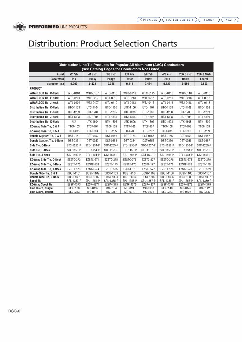
DSC-6
Distribution Line Tie Products for Popular All Aluminum (AAC) Conductors
(see Catalog Pages for Conductors Not Listed)
kcmil #2 7str #1 7str 1/0 7str 2/0 7str 3/0 7str 4/0 7str 266.8 7str 266.8 16str
Code Word Iris Pansy Poppy Aster Phlox Oxlip Daisy Laurel
diameter (in.) 0.292 0.328 0.368 0.414 0.464 0.522 0.586 0.593
PRODUCT
WRAPLOCK Tie, C-Neck WTC-0104 WTC-0107 WTC-0110 WTC-0113 WTC-0115 WTC-0116 WTC-0118 WTC-0118
WRAPLOCK Tie, F-Neck WTF-0204 WTF-0207 WTF-0210 WTF-0213 WTF-0215 WTF-0216 WTF-0218 WTF-0218
WRAPLOCK Tie, J-Neck WTJ-0404 WTJ-0407 WTJ-0410 WTJ-0413 WTJ-0415 WTJ-0416 WTJ-0418 WTJ-0418
Distribution Tie, C-Neck UTC-1103 UTC-1104 UTC-1105 UTC-1106 UTC-1107 UTC-1108 UTC-1108 UTC-1109
Distribution Tie, F-Neck UTF-1203 UTF-1204 UTF-1205 UTF-1206 UTF-1207 UTF-1208 UTF-1208 UTF-1209
Distribution Tie, J-Neck UTJ-1303 UTJ-1304 UTJ-1305 UTJ-1306 UTJ-1307 UTJ-1308 UTJ-1308 UTJ-1309
Distribution Tie, K-Neck N/A UTK-1604 UTK-1605 UTK-1606 UTK-1607 UTK-1608 UTK-1608 UTK-1609
EZ-Wrap Twin Tie, C & F TTCF-103 TTCF-104 TTCF-105 TTCF-106 TTCF-107 TTCF-108 TTCF-108 TTCF-109
EZ-Wrap Twin Tie, F & J TTFJ-203 TTFJ-204 TTFJ-205 TTFJ-206 TTFJ-207 TTFJ-208 TTFJ-208 TTFJ-209
Double Support Tie, C & F DST-0151 DST-0152 DST-0153 DST-0154 DST-0155 DST-0156 DST-0156 DST-0157
Double Support Tie, J-Neck DST-0351 DST-0352 DST-0353 DST-0354 DST-0355 DST-0356 DST-0356 DST-0357
Side Tie, C-Neck STC-1253-P STC-1254-P STC-1255-P STC-1256-P STC-1257-P STC-1258-P STC-1258-P STC-1259-P
Side Tie, F-Neck STF-1153-P STF-1154-P STF-1155-P STF-1156-P STF-1157-P STF-1158-P STF-1158-P STF-1159-P
Side Tie, J-Neck STJ-1503-P STJ-1504-P STJ-1505-P STJ-1506-P STJ-1507-P STJ-1508-P STJ-1508-P STJ-1509-P
EZ-Wrap Side Tie, C-Neck EZSTC-273 EZSTC-274 EZSTC-275 EZSTC-276 EZSTC-277 EZSTC-278 EZSTC-278 EZSTC-279
EZ-Wrap Side Tie, F-Neck EZSTF-173 EZSTF-174 EZSTF-175 EZSTF-176 EZSTF-177 EZSTF-178 EZSTF-178 EZSTF-179
EZ-Wrap Side Tie, J-Neck EZSTJ-573 EZSTJ-574 EZSTJ-575 EZSTJ-576 EZSTJ-577 EZSTJ-578 EZSTJ-578 EZSTJ-579Double Side Tie, C & F DBST-1101 DBST-1102 DBST-1103 DBST-1104 DBST-1105 DBST-1106 DBST-1106 DBST-1107Double Side Tie, J-Neck DBST-1301 DBST-1302 DBST-1303 DBST-1304 DBST-1305 DBST-1306 DBST-1306 DBST-1307Spool Tie SPL-1353-P SPL-1354-P SPL-1355-P SPL-1356-P SPL-1357-P SPL-1358-P SPL-1358-P SPL-1359-PEZ-Wrap Spool Tie EZSP-4373 EZSP-4374 EZSP-4375 EZSP-4376 EZSP-4377 EZSP-4378 EZSP-4378 EZSP-4379Line Guard, Single MG-0130 MG-0132 MG-0134 MG-0136 MG-0138 MG-0140 MG-0142 MG-0142Line Guard, Double MG-0313 MG-0315 MG-0317 MG-0319 MG-0321 MG-0323 MG-0325 MG-0325
PREVIOUS SECTION CONTENTS SEARCH NEXT

Distribution: Product Selection Charts
1
Dis
tribu
tion
: P
rod
uct S
ele
ctio
n C
harts
Distribution: Product Selection Charts
DSC-7
Distribution Line Tie Products for Popular All Aluminum (AAC) Conductors
(see Catalog Pages for Conductors Not Listed)
kcmil 336.4 19str 350 19str 397.5 19str 450 19str 477 19str 477 37str 556.5 19str 556.5 37str
Code Word Tulip Daffodil Canna Goldentuft Cosmos Syringa Dahlia Mistletoe
diameter (in.) 0.666 0.679 0.724 0.770 0.793 0.795 0.856 0.858
PRODUCT
WRAPLOCK Tie, C-Neck WTC-0121 WTC-0121 WTC-0122 WTC-0123 WTC-0123 WTC-0123 WTC-0125 WTC-0125
WRAPLOCK Tie, F-Neck WTF-0221 WTF-0221 WTF-0222 WTF-0223 WTF-0223 WTF-0223 WTF-0225 WTF-0225
WRAPLOCK Tie, J-Neck WTJ-0421 WTJ-0421 WTJ-0422 WTJ-0423 WTJ-0423 WTJ-0423 WTJ-0425 WTJ-0425
Distribution Tie, C-Neck UTC-1110 UTC-1110 UTC-1110 UTC-1111 UTC-1111 UTC-1111 UTC-1111 UTC-1111
Distribution Tie, F-Neck UTF-1210 UTF-1210 UTF-1210 UTF-1211 UTF-1211 UTF-1211 UTF-1211 UTF-1211
Distribution Tie, J-Neck UTJ-1310 UTJ-1310 UTJ-1310 UTJ-1311 UTJ-1311 UTJ-1311 UTJ-1311 UTJ-1311
Distribution Tie, K-Neck UTK-1610 UTK-1610 UTK-1610 UTK-1611 UTK-1611 UTK-1611 UTK-1611 UTK-1611
EZ-Wrap Twin Tie, C & F TTCF-110 TTCF-110 TTCF-110 TTCF-111 TTCF-111 TTCF-111 TTCF-111 TTCF-111
EZ-Wrap Twin Tie, F & J TTFJ-210 TTFJ-210 TTFJ-210 TTFJ-211 TTFJ-211 TTFJ-211 TTFJ-211 TTFJ-211
Double Support Tie, C & F DST-0158 DST-0158 DST-0158 DST-0159 DST-0159 DST-0159 DST-0159 DST-0159
Double Support Tie, J-Neck DST-0358 DST-0358 DST-0358 DST-0359 DST-0359 DST-0359 DST-0359 DST-0359
Side Tie, C-Neck STC-1260-P STC-1260-P STC-1260-P STC-1261-P STC-1261-P STC-1261-P STC-1261-P STC-1261-P
Side Tie, F-Neck STF-1160-P STF-1160-P STF-1160-P STF-1161-P STF-1161-P STF-1161-P STF-1161-P STF-1161-P
Side Tie, J-Neck STJ-1510-P STJ-1510-P STJ-1510-P STJ-1511-P STJ-1511-P STJ-1511-P STJ-1511-P STJ-1511-P
EZ-Wrap Side Tie, C-Neck EZSTC-280 EZSTC-280 EZSTC-280 EZSTC-281 EZSTC-281 EZSTC-281 EZSTC-281 EZSTC-281
EZ-Wrap Side Tie, F-Neck EZSTF-180 EZSTF-180 EZSTF-180 EZSTF-181 EZSTF-181 EZSTF-181 EZSTF-181 EZSTF-181
EZ-Wrap Side Tie, J-Neck EZSTJ-580 EZSTJ-580 EZSTJ-580 EZSTJ-581 EZSTJ-581 EZSTJ-581 EZSTJ-581 EZSTJ-581
Double Side Tie, C & F DBST-1108 DBST-1108 DBST-1108 DBST-1109 DBST-1109 DBST-1109 DBST-1109 DBST-1109
Double Side Tie, J-Neck DBST-1308 DBST-1308 DBST-1308 DBST-1309 DBST-1309 DBST-1309 DBST-1309 DBST-1309
Spool Tie SPL-1360-P SPL-1360-P SPL-1360-P SPL-1361-P SPL-1361-P SPL-1361-P SPL-I361-P SPL-1361-P
EZ-Wrap Spool Tie EZSP-4380 EZSP-4380 EZSP-4380 EZSP-4381 EZSP-4381 EZSP-4381 EZSP-4381 EZSP-4381
Line Guard, Single MG-0145 MG-0145 MG-0147 MG-0148 MG-0149 MG-0149 MG-0150 MG-0150
Line Guard, Double MG-0328 MG-0328 MG-0330 MG-0331 MG-0332 MG-0332 MG-0333 MG-0333
PREVIOUS SECTION CONTENTS SEARCH NEXT

Distribution: Product Selection Charts
DSC-8
Distribution Line Tie Products for Popular All Aluminum (AAC) Conductors
(see Catalog Pages for Conductors Not Listed)
kcmil 600 37str 636 37str 650 37str 700 37str 715.5 37str 750 37str 750 61str 795 37str
Code Word Meadowsweet Orchid Heuchera Verbena Violet Petunia Cattail Arbutus
diameter (in.) 0.891 0.918 0.928 0.963 0.974 0.997 0.998 1.026
PRODUCT
WRAPLOCK Tie, C-Neck WTC-0125 WTC-0126 WTC-0126 WTC-0127 WTC-0127 WTC-0127 WTC-0127 WTC-0128WRAPLOCK Tie, F-Neck WTF-0225 WTF-0226 WTF-0226 WTF-0227 WTF-0227 WTF-0227 WTF-0227 WTF-0228WRAPLOCK Tie, J-Neck WTJ-0425 WTJ-0426 WTJ-0426 WTJ-0427 WTJ-0427 WTJ-0427 WTJ-0427 WTJ-0428Distribution Tie, C-Neck UTC-1112 UTC-1112 UTC-1112 UTC-1112 UTC-1113 UTC-1113 UTC-1113 UTC-1113Distribution Tie, F-Neck UTF-1212 UTF-1212 UTF-1212 UTF-1212 UTF-1213 UTF-1213 UTF-1213 UTF-1213Distribution Tie, J-Neck UTJ-1312 UTJ-1312 UTJ-1312 UTJ-1312 UTJ-1313 UTJ-1313 UTJ-1313 UTJ-1313Distribution Tie, K-Neck UTK-1612 UTK-1612 UTK-1612 UTK-1612 UTK-1613 UTK-1613 UTK-1613 UTK-1613EZ-Wrap Twin Tie TTF-112 TTF-112 TTF-112 TTF-112 TTF-113 TTF-113 TTF-113 TTF-113EZ-Wrap Twin Tie TTJ-212 TTJ-212 TTJ-212 TTJ-212 TTJ-213 TTJ-213 TTJ-213 TTJ-213Double Support Tie, C & F DST-0160 DST-0160 DST-0160 DST-0160 DST-0161 DST-0161 DST-0161 DST-0161Double Support Tie, J-Neck DST-0360 DST-0360 DST-0360 DST-0360 DST-0361 DST-0361 DST-0361 DST-0361Side Tie, C-Neck STC-1262-P STC-1262-P STC-1262-P STC-1262-P STC-1263-P STC-1263-P STC-1263-P STC-1263-PSide Tie, F-Neck STF-1162-P STF-1162-P STF-1162-P STF-1162-P STF-1163-P STF-1163-P STF-1163-P STF-1163-PSide Tie, J-Neck STJ-1512-P STJ-1512-P STJ-1512-P STJ-1512-P STJ-1513-P STJ-1513-P STJ-1513-P STJ-1513-PEZ-Wrap Side Tie, C-Neck EZSTC-282 EZSTC-282 EZSTC-282 EZSTC-282 EZSTC-283 EZSTC-283 EZSTC-283 EZSTC-283EZ-Wrap Side Tie, F-Neck EZSTF-182 EZSTF-182 EZSTF-182 EZSTF-182 EZSTF-183 EZSTF-183 EZSTF-183 EZSTF-183EZ-Wrap Side Tie, J-Neck EZSTJ-582 EZSTJ-582 EZSTJ-582 EZSTJ-582 EZSTJ-583 EZSTJ-583 EZSTJ-583 EZSTJ-583Double Side Tie, C & F DBST-1110 DBST-1110 DBST-1110 DBST-1110 DBST-1111 DBST-1111 DBST-1111 DBST-1111Double Side Tie, J-Neck DBST-1310 DBST-1310 DBST-1310 DBST-1310 DBST-1311 DBST-1311 DBST-1311 DBST-1311Spool Tie SPL-1362-P SPL-1362-P SPL-1362-P SPL-1362-P N/A N/A N/A N/AEZ-Wrap Spool Tie EZSP-4382 EZSP-4382 EZSP-4382 EZSP-4382 N/A N/A N/A N/ALine Guard, Single MG-0150 MG-0151 MG-0151 MG-0152 MG-0152 MG-0153 MG-0153 MG-0154Line Guard, Double MG-0333 MG-0334 MG-0334 MG-0335 MG-0335 MG-0336 MG-0336 MG-0337
Distribution Line Tie Products for Popular All Aluminum (AAC) Conductors
(see Catalog Pages for Conductors Not Listed)
kcmil 795 61str 954 37str 954 61str 1033.5 37str 1033.5 61str 1113 61str
Code Word Lilac Magnolia Goldenrod Bluebell Larkspur Marigold
diameter (in.) 1.028 1.124 1.126 1.170 1.172 1.216
PRODUCT
WRAPLOCK Tie, C-Neck WTC-0128 WTC-0129 WTC-0129 WTC-0129 WTC-0130 WTC-0130WRAPLOCK Tie, F-Neck WTF-0228 WTF-0229 WTF-0229 WTF-0229 WTF-0230 WTF-0230WRAPLOCK Tie, J-Neck WTJ-0428 WTJ-0429 WTJ-0429 WTJ-0429 WTJ-0430 WTJ-0430Distribution Tie, C-Neck UTC-1113 UTC-1114 UTC-1114 UTC-1114 UTC-1114 UTC-1114Distribution Tie, F-Neck UTF-1213 UTF-1214 UTF-1214 UTF-1214 UTF-1214 UTF-1214Distribution Tie, J-Neck UTJ-1313 UTJ-1314 UTJ-1314 UTJ-1314 UTJ-1314 UTJ-1314Distribution Tie, K-Neck UTK-1613 UTK-1614 UTK-1614 UTK-1614 UTK-1614 UTK-1614EZ-Wrap Twin Tie TTF-113 TTF-114 TTF-114 TTF-114 TTF-114 TTF-114EZ-Wrap Twin Tie TTJ-213 TTJ-214 TTJ-214 TTJ-214 TTJ-214 TTJ-214Double Support Tie, C & F DST-0161 DST-0162 DST-0162 DST-0162 DST-0162 DST-0162Double Support Tie, J-Neck DST-0361 DST-0362 DST-0362 DST-0362 DST-0362 DST-0362Side Tie, C-Neck STC-1263-P STC-1264-P STC-1264-P STC-1264-P STC-1264-P STC-1264-PSide Tie, F-Neck STF-1163-P STF-1164-P STF-1164-P STF-1164-P STF-1164-P STF-1164-PSide Tie, J-Neck STJ-1513-P STJ-1514-P STJ-1514-P STJ-1514-P STJ-1514-P STJ-1514-PEZ-Wrap Side Tie, C-Neck EZSTC-283 EZSTC-284 EZSTC-284 EZSTC-284 EZSTC-284 EZSTC-284EZ-Wrap Side Tie, F-Neck EZSTF-183 EZSTF-184 EZSTF-184 EZSTF-184 EZSTF-184 EZSTF-184EZ-Wrap Side Tie, J-Neck EZSTJ-583 EZSTJ-584 EZSTJ-584 EZSTJ-584 EZSTJ-584 EZSTJ-584Double Side Tie, C & F DST-1111 DST-1112 DST-1112 DST-1112 DST-1112 DST-1112Double Side Tie, J-Neck DST-1311 DST-1312 DST-1312 DST-1312 DST-1312 DST-1312Spool Tie N/A N/A N/A N/A N/A N/AEZ-Wrap Spool Tie N/A N/A N/A N/A N/A N/ALine Guard, Single MG-0154 MG-0156 MG-0156 MG-0156 MG-0157 MG-0158Line Guard, Double MG-0337 MG-0339 MG-0339 MG-0339 MG-0340 MG-0341
PREVIOUS SECTION CONTENTS SEARCH NEXT

Distribution: Product Selection Charts
1
Dis
tribu
tion
: P
rod
uct S
ele
ctio
n C
harts
Distribution: Product Selection Charts
DSC-9
Other Distribution Line Products for Popular All Aluminum (AAC) Conductors
(see Catalog Pages for Conductors Not Listed)
kcmil #2 7str #1 7str 1/0 7str 2/0 7str 3/0 7str 4/0 7str 266.8 7str 266.8 16str
Code Word Iris Pansy Poppy Aster Phlox Oxlip Daisy Laurel
diameter (in.) 0.292 0.328 0.368 0.414 0.464 0.522 0.586 0.593
DEAD-END PRODUCTS
Distribution-Grip Dead-End DG-4542 DG-4543 DG-4544 DG-4545 DG-4546 DG-4547 DG-4548 DG-4548Overhead Dead-End OHDE-9536 OHDE-9537 OHDE-9538 OHDE-9539 OHDE-9540 OHDE-4577 N/A N/AO-Grip Dead-End OG-9361 N/A N/A N/A N/A N/A N/A N/ASlack Span Dead-End, C & F SSDE-9124 SSDE-9125 SSDE-9126 SSDE-9127 SSDE-9128 SSDE-9129 SSDE-9130 SSDE-9130Slack Span Dead-End, J-Neck SSDE-9144 SSDE-9145 SSDE-9146 SSDE-9147 SSDE-9148 SSDE-9149 SSDE-9150 SSDE-9150Service-Grip Dead-End SG-4504 SG-4505 SG-4506 SG-4507 SG-4508 SG-4509 N/A N/A
SPLICE PRODUCTS
Conductor Splice LS-0118 LS-0121 LS-0124 LS-0127 LS-0130 LS-0133 LS-0135 LS-0135
MOTION CONTROL PRODUCTS
Spiral Vibration Damper 5050103 5050104 5050104 5050104 5050105 5050105 5050106 5050106VORTX Conductor damper N/A N/A N/A VSD-1012 VSD-1012 VSD-2016 VSD-2016 VSD-2016Air Flow Spoiler 5058100 5058101 5058101 5058101 5058102 5058102 5058103 5058103
Other Distribution Line Products for Popular All Aluminum (AAC) Conductors
(see Catalog Pages for Conductors Not Listed)
kcmil 336.4 19str 350 19str 397.5 19str 450 19str 477 19str 477 37str 556.5 19str 556.5 37str
Code Word Tulip Daffodil Canna Goldentuft Cosmos Syringa Dahlia Mistletoe
diameter (in.) 0.666 0.679 0.724 0.770 0.793 0.795 0.856 0.858
DEAD-END PRODUCTS
Distribution-Grip Dead-End DG-4549 DG-4549 DG-4549 DG-4550 DG-4550 DG-4550 DG-4551 DG-4551Slack Span Dead-End, C & F SSDE-9131 SSDE-9131 SSDE-9131 SSDE-9131 SSDE-9132 SSDE-9132 SSDE-9132 SSDE-9132Slack Span Dead-End, J-Neck SSDE9151 SSDE9151 SSDE9151 SSDE9151 SSDE-9152 SSDE-9152 SSDE-9152 SSDE-9152
SPLICE PRODUCTS
Conductor Splice LS-0138 LS-0139 LS-0140 LS-0142 LS-0143 LS-0143 LS-0145 LS-0145
MOTION CONTROL PRODUCTS
Spiral Vibration Damper 5050106 5050106 5050106 N/A N/A N/A N/A N/AVORTX Conductor damper VSD-2020 VSD-2020 VSD-2520 VSD-2520 VSD-2525 VSD-2525 VSD-2525 VSD-3525Air Flow Spoiler 5058103 5058103 5058103 5058104 5058104 5058104 5058104 5058104
PREVIOUS SECTION CONTENTS SEARCH NEXT

Distribution: Product Selection Charts
DSC-10
Other Distribution Line Products for Popular All Aluminum (AAC) Conductors
(see Catalog Pages for Conductors Not Listed)
kcmil 600 37str 636 37str 650 37str 700 37str 715.5 37str 750 37str 750 61str 795 37str
Code Word Meadowsweet Orchid Heuchera Verbena Violet Petunia Cattail Arbutus
diameter (in.) 0.891 0.918 0.928 0.963 0.974 0.997 0.998 1.026
DEAD-END PRODUCTS
Distribution-Grip Dead-End DG-4551 DG-4551 DG-4551 DG-4552 DG-4552 DG-4552 DG-4552 DG-4552Slack Span Dead-End, C & F SSDE-9133 SSDE-9133 SSDE-9133 SSDE-9133 SSDE-9133 SSDE-9133 SSDE-9133 SSDE-9134Slack Span Dead-End, J-Neck SSDE-9153 SSDE-9153 SSDE-9153 SSDE-9153 SSDE-9153 SSDE-9153 SSDE-9153 SSDE-9154
SPLICE PRODUCTS
Conductor Splice LS-0146 LS-0146 LS-0146 LS-0147 LS-0148 LS-0148 LS-0148 LS-0149
MOTION CONTROL PRODUCTS
VORTX Conductor damper VSD-3525 VSD-3525 VSD-3525 VSD-3525 VSD-3525 VSD-4032 VSD-4032 VSD-4032Air Flow Spoiler 5058104 5058104 5058105 5058105 5058105 5058105 5058105 5058106
Other Distribution Line Products for Popular All Aluminum (AAC) Conductors
(see Catalog Pages for Conductors Not Listed)
kcmil 795 61str 954 37str 954 61str 1033.5 37str 1033.5 61str 1113 61str
Code Word Lilac Magnolia Goldenrod Bluebell Larkspur Marigold
diameter (in.) 1.028 1.124 1.126 1.170 1.172 1.216
DEAD-END PRODUCTS
Distribution-Grip Dead-End DG-4552 DG-4553 DG-4553 DG-4553 DG-4553 N/ASlack Span Dead-End, C & F SSDE-9134 SSDE-9134 SSDE-9134 SSDE-9134 SSDE-9134 SSDE-9134Slack Span Dead-End, J-Neck SSDE-9154 SSDE-9154 SSDE-9154 SSDE-9154 SSDE-9154 SSDE-9154
SPLICE PRODUCTS
Conductor Splice LS-0149 LS-0151 LS-0151 LS-0152 LS-0152 LS-0153
MOTION CONTROL PRODUCTS
VORTX Conductor damper VSD-4032 VSD-4032 VSD-4032 VSD-4032 VSD-4032 VSD-4032Air Flow Spoiler 5058106 5058106 5058106 5058107 5085107 5058107
PREVIOUS SECTION CONTENTS SEARCH NEXT

Distribution: Product Selection Charts
1
Dis
tribu
tion
: P
rod
uct S
ele
ctio
n C
harts
Distribution: Product Selection Charts
DSC-11
Distribution Line Tie Products for Popular Aluminum Alloy Conductors
(see Catalog Pages for Conductors Not Listed)
kcmil #6 7str #4 7str #2 7str 1/0 7str 2/0 7str 3/0 7str 4/0 7str 266.8 19str
Code Word Akron Alton Ames Azusa Anaheim Amherst Alliance Butte
diameter (in.) 0.198 0.250 0.316 0.398 0.447 0.502 0.563 0.642
PRODUCT
WRAPLOCK Tie, C-Neck N/A WTC-0100 WTC-0106 WTC-0112 WTC-0114 WTC-0116 WTC-0118 WTC-0120WRAPLOCK Tie, F-Neck N/A WTF-0200 WTF-0206 WTC-0212 WTC-0214 WTF-0216 WTF-0218 WTF-0220WRAPLOCK Tie, J-Neck N/A WTJ-0400 WTJ-0406 WTJ-0412 WTJ-0414 WTJ-0416 WTJ-0418 WTJ-0420Distribution Tie, C-Neck UTC-1100 UTC-1102 UTC-1104 UTC-1105 UTC-1106 UTC-1107 UTC-1108 UTC-1109Distribution Tie, F-Neck UTF-1200 UTF-1202 UTF-1204 UTF-1205 UTF-1206 UTF-1207 UTF-1208 UTF-1209Distribution Tie, J-Neck UTJ-1300 UTJ-1302 UTJ-1304 UTJ-1305 UTJ-1306 UTJ-1307 UTJ-1308 UTJ-1309Distribution Tie, K-Neck UTK-1600 UTK-1602 UTK-1604 UTK-1605 UTK-1606 UTK-1607 UTK-1608 UTK-1609EZ-Wrap Twin Tie, C & F TTCF-0100 TTCF-102 TTCF-104 TTCF-105 TTCF-106 TTCF-107 TTCF-108 TTCF-109EZ-Wrap Twin Tie, F & J N/A TTFJ-202 TTFJ-204 TTFJ-205 TTFJ-206 TTFJ-207 TTFJ-208 TTFJ-209Double Support Tie, C & F N/A DST-0150 DST-0152 DST-0153 DST-0154 DST-0155 DST-0156 DST-0157Double Support Tie, J-Neck N/A DST-0350 DST-0352 DST-0353 DST-0354 DST-0355 DST-0356 DST-0357Side Tie, C-Neck STC-1250-P STC-1252-P STC-1254-P STC-1255-P STC-1256-P STC-1257-P STC-1258-P STC-1259-PSide Tie, F-Neck STF-1150-P STF-1152-P STF-1154-P STF-1155-P STF-1156-P STF-1157-P STF-1158-P STF-1159-PSide Tie, J-Neck STJ-1500-P STJ-1502-P STJ-1504-P STJ-1505-P STJ-1506-P STJ-1507-P STJ-1508-P STJ-1509-PEZ-Wrap Side Tie, C-Neck EZSTC-270 EZSTC-272 EZSTC-274 EZSTC-275 EZSTC-276 EZSTC-277 EZSTC-278 EZSTC-279EZ-Wrap Side Tie, F-Neck EZSTF-170 EZSTF-172 EZSTF-174 EZSTF-175 EZSTF-176 EZSTF-177 EZSTF-178 EZSTF-179EZ-Wrap Side Tie, J-Neck EZSTJ-570 EZSTJ-572 EZSTJ-574 EZSTJ-575 EZSTJ-576 EZSTJ-577 EZSTJ-578 EZSTJ-579Double Side Tie, C & F N/A DBST-1100 DBST-1102 DBST-1103 DBST-1104 DBST-1105 DBST-1106 DBST-1107Double Side Tie, J-Neck N/A DBST-1300 DBST-1302 DBST-1303 DBST-1304 DBST-1305 DBST-1306 DBST-1307Spool Tie SPL-1350-P SPL-1352-P SPL-1354-P SPL-1355-P SPL-1356-P SPL-1357-P SPL-1358-P SPL-1359-PEZ-Wrap Spool Tie EZSP-4370 EZSP-4372 EZSP-4374 EZSP-4375 EZSP-4376 EZSP-4377 EZSP-4378 EZSP-4379Line Guard, Single MG-0123 MG-0127 MG-0131 MG-0135 MG-0137 MG-0139 MG-0141 MG-0144Line Guard, Double MG-0306 MG-0310 MG-0314 MG-0318 MG-0320 MG-0322 MG-0324 MG-0327
Distribution Line Tie Products for Popular Aluminum Alloy Conductors
(see Catalog Pages for Conductors Not Listed)
kcmil 336.4 19str 397.5 19str 477 19str 556.5 19str 636 37str 795 37str
Code Word Canton Cairo Darien Elgin Flint Greeley
diameter (in.) 0.721 0.783 0.858 0.927 0.991 1.108
PRODUCT
WRAPLOCK Tie, C-Neck WTC-0122 WTC-0123 WTC-0125 WTC-0126 WTC-0127 WTC-0129WRAPLOCK Tie, F-Neck WTF-0222 WTF-0223 WTF-0225 WTF-0226 WTF-0227 WTF-0229WRAPLOCK Tie, J-Neck WTJ-0422 WTJ-0423 WTJ-0425 WTJ-0426 WTJ-0427 WTJ-0429Distribution Tie, C-Neck UTC-1110 UTC-1111 UTC-1111 UTC-1112 UTC-1113 UTC-1114Distribution Tie, F-Neck UTF-1210 UTF-1211 UTF-1211 UTF-1212 UTF-1213 UTF-1214Distribution Tie, J-Neck UTJ-1310 UTJ-1311 UTJ-1311 UTJ-1312 UTJ-1313 UTJ-1314Distribution Tie, K-Neck UTK-1610 UTK-1611 UTK-1611 UTK-1612 UTK-1613 UTK-1614EZ-Wrap Twin Tie, C & F TTCF-110 TTCF-111 TTCF-111 TTF-112 TTF-113 TTF-114EZ-Wrap Twin Tie, F & J TTFJ-210 TTFJ-211 TTFJ-211 TTJ-212 TTJ-213 TTJ-214Double Support Tie, C & F DST-0158 DST-0159 DST-0159 DST-0160 DST-0161 DST-0162Double Support Tie, J-Neck DST-0358 DST-0359 DST-0359 DST-0360 DST-0361 DST-0362Side Tie, C-Neck STC-1260-P STC-1261-P STC-1261-P STC-1262-P STC-1263-P STC-1264-PSide Tie, F-Neck STF-1160-P STF-1161-P STF-1161-P STF-1162-P STF-1163-P STF-1164-PSide Tie, J-Neck STJ-1510-P STJ-1511-P STJ-1511-P STJ-1512-P STJ-1513-P STJ-1514-PEZ-Wrap Side Tie, C-Neck EZSTC-280 EZSTC-281 EZSTC-281 EZSTC-282 EZSTC-283 EZSTC-284EZ-Wrap Side Tie, F-Neck EZSTF-180 EZSTF-181 EZSTF-181 EZSTF-182 EZSTF-183 EZSTF-184EZ-Wrap Side Tie, J-Neck EZSTJ-580 EZSTJ-581 EZSTJ-581 EZSTJ-582 EZSTJ-583 EZSTJ-584Double Side Tie, C & F DBST-1108 DBST-1109 DBST-1109 DBST-1110 DBST-1111 DBST-1112Double Side Tie, J-Neck DBST-1308 DBST-1309 DBST-1309 DBST-1310 DBST-1311 DBST-1312Spool Tie SPL-1360-P SPL-1361-P SPL-1361-P SPL-1362-P N/A N/AEZ-Wrap Spool Tie EZSP-4380 EZSP-4381 EZSP-4381 EZSP-4382 N/A N/ALine Guard, Single MG-0147 MG-0148 MG-0150 MG-0151 MG-0153 MG-0156Line Guard, Double MG-0330 MG-0331 MG-0333 MG-0334 MG-0336 MG-0339
PREVIOUS SECTION CONTENTS SEARCH NEXT
Distribution: Product Selection Charts
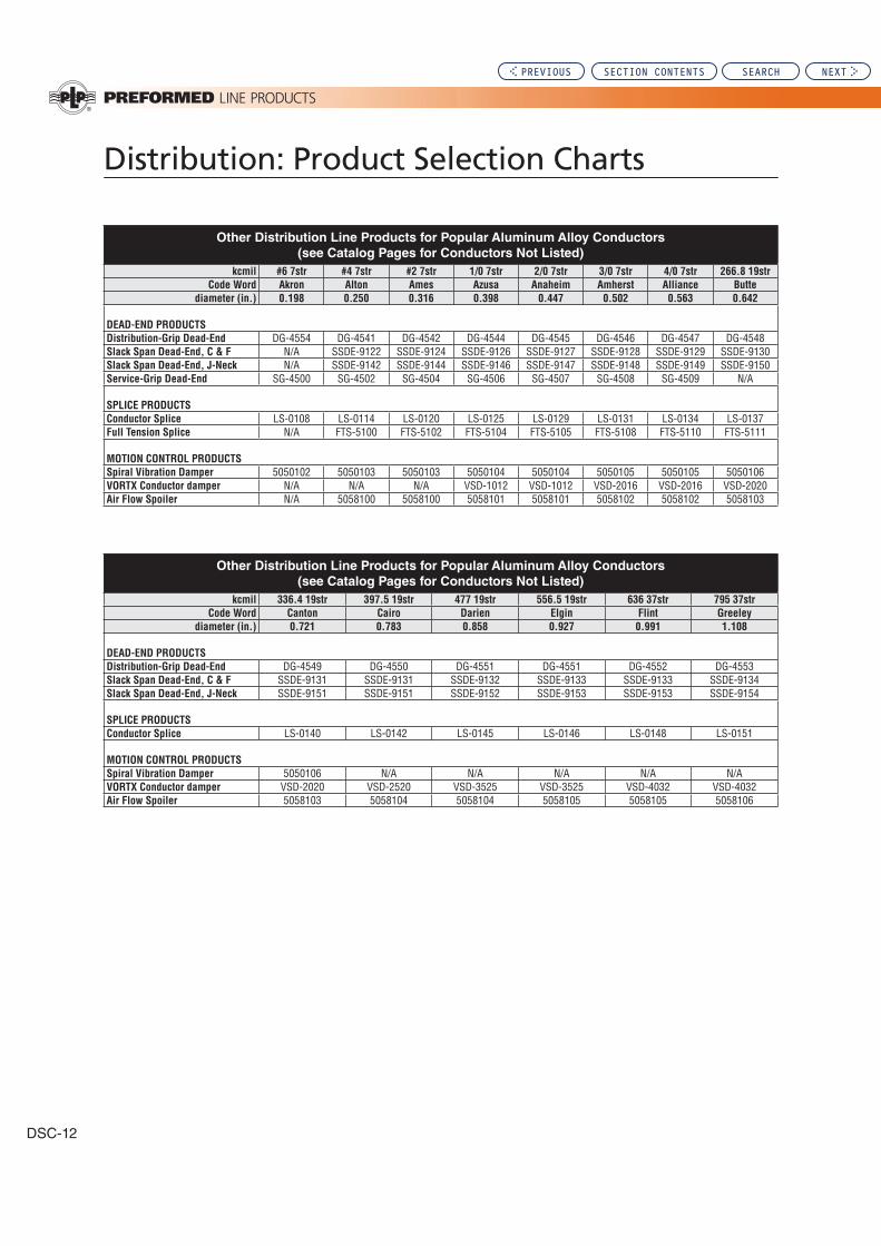
DSC-12
Other Distribution Line Products for Popular Aluminum Alloy Conductors
(see Catalog Pages for Conductors Not Listed)
kcmil #6 7str #4 7str #2 7str 1/0 7str 2/0 7str 3/0 7str 4/0 7str 266.8 19str
Code Word Akron Alton Ames Azusa Anaheim Amherst Alliance Butte
diameter (in.) 0.198 0.250 0.316 0.398 0.447 0.502 0.563 0.642
DEAD-END PRODUCTS
Distribution-Grip Dead-End DG-4554 DG-4541 DG-4542 DG-4544 DG-4545 DG-4546 DG-4547 DG-4548Slack Span Dead-End, C & F N/A SSDE-9122 SSDE-9124 SSDE-9126 SSDE-9127 SSDE-9128 SSDE-9129 SSDE-9130Slack Span Dead-End, J-Neck N/A SSDE-9142 SSDE-9144 SSDE-9146 SSDE-9147 SSDE-9148 SSDE-9149 SSDE-9150Service-Grip Dead-End SG-4500 SG-4502 SG-4504 SG-4506 SG-4507 SG-4508 SG-4509 N/A
SPLICE PRODUCTS
Conductor Splice LS-0108 LS-0114 LS-0120 LS-0125 LS-0129 LS-0131 LS-0134 LS-0137Full Tension Splice N/A FTS-5100 FTS-5102 FTS-5104 FTS-5105 FTS-5108 FTS-5110 FTS-5111
MOTION CONTROL PRODUCTS
Spiral Vibration Damper 5050102 5050103 5050103 5050104 5050104 5050105 5050105 5050106VORTX Conductor damper N/A N/A N/A VSD-1012 VSD-1012 VSD-2016 VSD-2016 VSD-2020Air Flow Spoiler N/A 5058100 5058100 5058101 5058101 5058102 5058102 5058103
Other Distribution Line Products for Popular Aluminum Alloy Conductors
(see Catalog Pages for Conductors Not Listed)
kcmil 336.4 19str 397.5 19str 477 19str 556.5 19str 636 37str 795 37str
Code Word Canton Cairo Darien Elgin Flint Greeley
diameter (in.) 0.721 0.783 0.858 0.927 0.991 1.108
DEAD-END PRODUCTS
Distribution-Grip Dead-End DG-4549 DG-4550 DG-4551 DG-4551 DG-4552 DG-4553Slack Span Dead-End, C & F SSDE-9131 SSDE-9131 SSDE-9132 SSDE-9133 SSDE-9133 SSDE-9134Slack Span Dead-End, J-Neck SSDE-9151 SSDE-9151 SSDE-9152 SSDE-9153 SSDE-9153 SSDE-9154
SPLICE PRODUCTS
Conductor Splice LS-0140 LS-0142 LS-0145 LS-0146 LS-0148 LS-0151
MOTION CONTROL PRODUCTS
Spiral Vibration Damper 5050106 N/A N/A N/A N/A N/AVORTX Conductor damper VSD-2020 VSD-2520 VSD-3525 VSD-3525 VSD-4032 VSD-4032Air Flow Spoiler 5058103 5058104 5058104 5058105 5058105 5058106
PREVIOUS SECTION CONTENTS SEARCH NEXT

Distribution (Overhead): Section
9
Section 9 – Distribution (Overhead): Ties
Table of Contents
Insulator Fit ............................................................................................................9-2
WRAPLOCK® Tie ...................................................................................................9-4
Distribution Tie ....................................................................................................9-11
EZ-WRAP® Twin Tie ............................................................................................9-17
Double Support Tie .............................................................................................9-21
Side Tie.................................................................................................................9-25
EZ-WRAP® Side Tie .............................................................................................9-31
Double Side Tie ...................................................................................................9-36
Spool Tie ..............................................................................................................9-40
EZ-WRAP® Spool Tie ..........................................................................................9-45
Coated Form Wire Tie .........................................................................................9-48 Coated Top Tie .............................................................................................9-48 Coated Side Tie ............................................................................................9-50
Plastic Ties – General Info. ................................................................................9-52 Plastic Line Ties ...........................................................................................9-54
Angle Side Tie: Plastic ................................................................................9-56
Tangent Side Tie: Plastic ............................................................................9-58
Line Guards .........................................................................................................9-60
Helical Ties for T2 Conductors .................................................. 9-64 through 9-67 WRAPLOCK® Tie for T2 Distribution Tie for T2 EZ-Wrap® Spool Tie for T2 Spool Tie for T2 Double Support Tie for T2 Side Tie for T2 Double Side Tie for T2
Products for Oval Conductor ............................................................................9-68
Applicator Ring ...................................................................................................9-69
Page
PREVIOUS SEARCH NEXT

9-2
Insulator Fit
ANSI C29 Insulator Specifications and their Affects on PLP TiesANSI C29 specifies and defines dimensions for insulator heads that are crucial to the proper application and lifetime performance of PLP factory formed ties. These dimensions include:
Insulator characteristics that are not part of the ANSI C29 Specifications
the application and performance of PLP Ties are not included in the ANSI specification. These characteristics include:1. The transition contour of the top groove
into side groove
2. Length of the saddle or top groove
3. Extension of shoulders past the edge of
the top groove.
4. Depth of the top groove
Interchangeable Insulators for use with PLP® Ties Dimensional Factors that affect Tie Application and Performance
Each of these items has different results on a factory formed ties
-
for both the insulator and tie.
C-neck Insulator F-neck Insulator
Shoulder Dia.
Top Groove to Side Groove
Distance
Neck Diameter
Side GrooveRadius
Top Groove Radius
Saddle Length Groove Depth2.
3. 1.4.
®
PREVIOUS SECTION CONTENTS SEARCH NEXT

Distribution (Overhead): Section
9
Insu
lato
r Fit
Insulator Fit
-
contact point and results in an abnormal tie application.
point contact at the insulator tie interface.
of top ties. As the tie is rotated the added protrusions from
difficulties of top ties when its diameter is at the mini-
®
conductor.
®
and the inner surface of the insulator. This increases the installation difficulty of the tie.
soft hand tie wire as well as a factory formed tie.
Insulator Review and Trial Applications
fits with the ties, prior to full scale field installations. Con-sult PLP for assistance, especially if there are any doubts
Non-ANSI C29 InsulatorsSome insulators that do not technically meet all the ANSI
-
specified in that standard.
PREVIOUS SECTION CONTENTS SEARCH NEXT

WRAPLOCK® Tie
WRAPLOCK Tie Tube: Component is detached and placed
Molded Center Section:
Insulator Identification Mark: Identifies the correct insula-
INTENDED USE:
conductor compared to clamp-top insulators or hand ties
WRAPLOCK TIE TUBE: -rior abrasion protection for the conductor under all types
The elastomer components are recommended because they surround the bare conductor with a resilient cushion where the conductor would come into contact with the insulator
VIBRATION DAMPERS:
-ment with dampers.
“Excessive”
rod diameter has been abraded.
“Severe” -
“Moderate”
“severe” or “moderate” “excessive”
INTERCHANGEABLE HEAD-STYLE INSULATOR:
GENERAL RECOMMENDATIONS
NOMENCLATURE
Color Code: Assists in identification of conductor di-
Applied Length: Assists in identification of conductor
Identification Tape:
Cabled Section
RUS Accepted
PREVIOUS SECTION CONTENTS SEARCH NEXT
Distribution (Overhead): Section
9
WR
AP
LO
CK
® Tie
WRAPLOCK® Tie
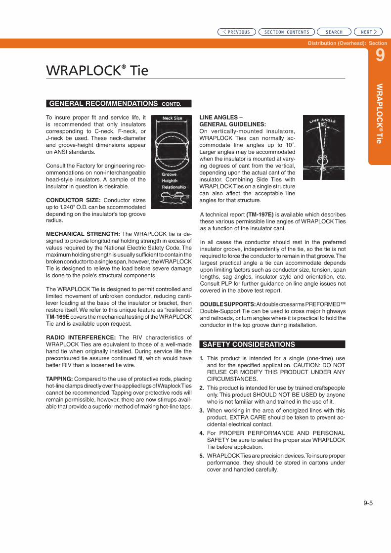
LINE ANGLES –
GENERAL GUIDELINES:
-
-
can also affect the acceptable line
A technical report (TM-197E)
as a function of the insulator cant.
In all cases the conductor should rest in the preferred
DOUBLE SUPPORTS:
radius.
MECHANICAL STRENGTH: -
-
TM-169E
RADIO INTERFERENCE:
TAPPING:
-
1.
2. This product is intended for use by trained craftspeople
who is not familiar with and trained in the use of it.
3.
-cidental electrical contact.
4.
Tie before application.
5.
performance, they should be stored in cartons under
GENERAL RECOMMENDATIONS CONTD.
SAFETY CONSIDERATIONS
is recommended that only insulators
on ANSI standards.
-ommendations
head-style insulators. A sample of the
CONDUCTOR SIZE:
PREVIOUS SECTION CONTENTS SEARCH NEXT

9-6
WRAPLOCK® Tie
For use on:
ACSR, Compacted ACSR,
Aluminum Alloy
All-Aluminum, AWAC®
Compacted All-Aluminum
C-Neck Interchangeable
Headstyle Insulators
ANSI 55-2 Pin
ANSI 55-3 Pin 2-1/4" Neck Diameter
EXPLANATORY NOTES:
Catalog
Number
Diameter Range
(inches) Nominal
Conductor Size
Units Wt./Lbs.Applied
Length
(inches)
Insulator
Identification
Mark
Color
CodeMin. Max. Per Carton
9/16" R Groove (See Note 2)
.269
.292
Purple
Brown
Blue
26
26
22 Brown
Blue
Purple
(Continued on next page)
PREVIOUS SECTION CONTENTS SEARCH NEXT

Distribution (Overhead): Section
9
WR
AP
LO
CK
® Tie
WRAPLOCK® Tie
EXPLANATORY NOTES:
For use on:
ACSR, Compacted ACSR,
Aluminum Alloy
All-Aluminum, AWAC®
Compacted All-Aluminum
C-Neck Interchangeable
Headstyle Insulators
ANSI 55-2 Pin
ANSI 55-3 Pin 2-1/4" Neck Diameter
Catalog
Number
Diameter Range
(Inches) Nominal
Conductor Size
Units Wt./Lbs.Applied
Length
(Inches)
Insulator
Identification
Mark Color CodeMin. Max. Per Carton
5/8", R. Groove (See Note 2)
Brown
22
3/4" R. Groove (See Note 2)
Purple
Blue
22
13/16" R. Groove (See Note 2)
Brown
7/8" or 1" R. Groove (See Note 2)
Purple
29
PREVIOUS SECTION CONTENTS SEARCH NEXT

WRAPLOCK® Tie
EXPLANATORY NOTES:
For use on:
ACSR, Compacted ACSR, Aluminum Alloy
All-Aluminum, AWAC® Compacted All-Aluminum
F-Neck Interchangeable Headstyle Insulators
ANSI 55-4 Pin
ANSI 55-5 Pin 2-7/8"
ANSI 57-1 Post Neck Diameter
ANSI 57-2 Post
ANSI 57-3 Post
Catalog
Number
Diameter Range
(inches)Nominal
Conductor Size
Units Wt./Lbs. Applied
Length
(inches)
Insulator
Identification
Mark
Color
CodeMin. Max. Per Carton
9/16" R Groove (See Note 2)
.269
26
.292 26 Purple
Brown
Blue
29
29
29
Brown
Blue
22 Purple
5/8", R. Groove (See Note 2)
22 29
22 29 Brown
3/4" R. Groove (See Note 2)
(Continued on next page)
PREVIOUS SECTION CONTENTS SEARCH NEXT

Distribution (Overhead): Section
9
9-9
WR
AP
LO
CK
® Tie
WRAPLOCK® Tie
Catalog
Number
Diameter Range
(Inches)
Nominal Conductor Size
Units Wt./Lbs.Applied
Length
(Inches)
Insulator
Identification
Mark
Color
CodeMin. Max. Per Carton
All-Alum. Purple
Blue
22
22
13/16" R. Groove (See Note 2)
All-Alum. Brown
7/8" R. or 1" R. Groove (See Note 2)
Purple
29
EXPLANATORY NOTES:
For use on:
ACSR, Compacted ACSR,
Aluminum Alloy
All-Aluminum, AWAC®
Compacted All-Aluminum
F-Neck Interchangeable
Headstyle Insulators
ANSI 55-4 Pin
ANSI 55-5 Pin 2-7/8"
ANSI 57-1 Post Neck Diameter
ANSI 57-2 Post
ANSI 57-3 Post
PREVIOUS SECTION CONTENTS SEARCH NEXT

WRAPLOCK® Tie
For use on:ACSR, Compacted ACSR, Aluminum Alloy All-Aluminum, AWAC® Compacted All-AluminumJ-Neck Interchangeable Headstyle Insulators
ANSI 55-6 Single Skirt Pin ANSI 55-7 Single Skirt Pin
3-1/2" Neck Diameter
ANSI 56-1 Double Skirt Pin
EXPLANATORY NOTES:
Catalog
Number
Diameter Range
(Inches)
Nominal Conductor Size
Units Wt./Lbs.Applied
Length
(Inches)
Insulator
Identification
Mark
Color
CodeMin. Max. Per Carton
9/16" R Groove (See Note 2)
29.269 29
29
.292 22 Purple22 Brown
Blue
Brown26 Blue
22 29Purple
5/8" R Groove (See Note 2)
Brown
3/4" R Groove (See Note 2)
All-Alum. 26
PurpleBlue
13/16" R Groove (See Note 2)
Brown7/8" or 1" Groove (See Note 2)
Purple
PREVIOUS SECTION CONTENTS SEARCH NEXT

Distribution (Overhead): Section
9
Dis
tribu
tion
Tie
Distribution Tie
INTENDED USE: -
conductor compared to clamp-top insulators or hand ties -
sion protection for the conductor under all types of motion,
-rounds the bare conductor with a resilient cushion where the conductor would come into contact with the insulator and
be disposed of because contact with the bare conductor is
Plastic Line Ties are also offered as an al-
INTERCHANGEABLE HEADSTYLE INSULATOR: To
appear on ANSI standards.
Tie Tube: Each tie is furnished with Tie Tube Component. The
Identification Tape:
Color Code:
Insulator Identification Mark: Identifies the correct insula-
-
headstyle insulators. A sample of the
CONDUCTOR SIZE:can accommodate conductor diameters
-tors
. Consult the tables in
RADIO INTERFERENCE:
tie wire.
DOUBLE SUPPORTS:
GENERAL RECOMMENDATIONS
NOMENCLATURE
Applied Length:
PREVIOUS SECTION CONTENTS SEARCH NEXT

Distribution Tie
LINE ANGLES -
GENERAL GUIDELINES:
to 10° -dated when the insulator is mounted at
-
that structure.
“Severe”
is necessary.
“Moderate”
-
TAPPING:
-
APPLICATION-INSPECTION:
be installed parallel to the pole when pole or conductor
A technical report (TM-197E)
as a function of the insulator cant.
In all cases the conductor should rest in the preferred
MECHANICAL STRENGTH: -
conductor and other structure components.
TM-166E
VIBRATION DAMPERS:
recommended.
-
“Excessive”
rod diameter has been abraded.
1.
-STANCES.
2. This product is intended for use by trained craftspeople
who is not familiar with and trained in the use of it.
3.
-cidental electrical contact.
4.
5.
To insure proper performance, they should be stored in
GENERAL RECOMMENDATIONS CONTD.
SAFETY CONSIDERATIONS
PREVIOUS SECTION CONTENTS SEARCH NEXT

Distribution (Overhead): Section
9
Dis
tribu
tion
Tie
Distribution Tie
For use on:
ACSR, Compacted ACSR,
Aluminum Alloy,
All-Aluminum, AWAC®
Compacted All-Aluminum
C-Neck Interchangeable
Headstyle Insulators
ANSI 55-2 Pin 2-1/4" Neck Diameter
ANSI 55-3 Pin
EXPLANATORY NOTES:
Catalog
Number
Diameter
Range (Inches)
Nominal Conductor Size
Units Wt./Lbs.Applied
Length
(Inches)
Insulator
Identification
Mark
Color
CodeMin. Max. Per Carton
9/16" R. GROOVE (See Note 2)
Blue
Brown
26
26 Purple
Blue
Purple
9/16" R. GROOVE (See Note 2)
.666 Brown
5/8" R. GROOVE (See Note 2)
Alum. Blue
3/4" R. GROOVE (See Note 2)
.969
22
(Continued on next page)
PREVIOUS SECTION CONTENTS SEARCH NEXT

Distribution Tie
EXPLANATORY NOTES:
For use on:
ACSR, Compacted ACSR,
Aluminum Alloy,
All-Aluminum, AWAC®
Compacted All-Aluminum
F-Neck Interchangeable
Headstyle Insulators
ANSI 55-4 Pin
ANSI 55-5 Pin
ANSI 57-1 Pin 2-7/8" Neck Diameter
ANSI 57-2 Pin
ANSI 57-3 Pin
Catalog
Number
Diameter Range
(Inches)
Nominal Conductor Size
Units Wt./Lbs.Applied
Length
(Inches)
Insulator
Identification
Mark
Color
CodeMin. Max. Per Carton
9/16" R. GROOVE (See Note 2)
Blue
26 Brown
29 Purple
26 Blue
29
Purple
9/16" R. GROOVE (See Note 2)
.666 All Alum. Brown
5/8" R. GROOVE (See Note 2)
Blue
3/4" R. GROOVE (See Note 2)
.969 22
1" R. GROOVE (See Note 2)
26
PREVIOUS SECTION CONTENTS SEARCH NEXT

Distribution (Overhead): Section
9
Dis
tribu
tion
Tie
Distribution Tie
EXPLANATORY NOTES:
For use on:
ACSR, Compacted ACSR,
Aluminum Alloy,
All-Aluminum, AWAC®
Compacted All-Aluminum
J-Neck Interchangeable
Headstyle Insulators
ANSI 55-6 Pin
ANSI 55-7 Pin 3-1/2" Neck Diameter
ANSI 56-1 Pin
Catalog
Number
Diameter Range
(Inches)
Nominal Conductor Size
Units Wt./Lbs.Applied
Length
(Inches)
Insulator
Identification
Mark
Color
CodeMin. Max. Per Carton
9/16" R. GROOVE (See Note 2)
26 BlueBrown
Purple
29
Alum. Alloy
Alum. Alloy Blue
Alum. Alloy
Alum. Alloy 22
22 Purple
9/16" R. GROOVE (See Note 2)
.666 Brown
5/8" R. GROOVE (See Note 2)
Blue
3/4" R. GROOVE (See Note 2)
.969
PREVIOUS SECTION CONTENTS SEARCH NEXT

Distribution Tie
EXPLANATORY NOTES:
For use on:
ACSR, Compacted ACSR,
Aluminum Alloy,
All-Aluminum, AWAC®
Compacted All-Aluminum
K-Neck Interchangeable
Headstyle Insulators
ANSI 56-2 Pin
ANSI 56-3 Pin 4" Neck Diameter
Catalog
Number
Diameter Range
(Inches)
Nominal Conductor Size
Units Wt./Lbs.Applied
Length
(Inches)
Insulator
Identification
Mark
Color
CodeMin. Max. Per Carton
9/16" R. GROOVE (See Note 2)
Blue
Blue
Blue
Blue Blue
22 Blue
Blue
Blue Purple
.666 Blue Brown
Blue
5/8", R. GROOVE (See Note 2)
Blue Blue
3/4", R. GROOVE (See Note 2)
.969 29 Blue
Blue
PREVIOUS SECTION CONTENTS SEARCH NEXT

Distribution (Overhead): Section
9
EZ
-WR
AP
® Tw
in T
ie
EZ-WRAP® Twin Tie
Tie Tube: Each tie is furnished with Tie Tube Component. The
Insulator Identification Mark:
Color Code and Application Helix: Assists in identification of
Identification Tape:
INTENDED USE: -
-
-
with a resilient cushion where the conductor would come into contact with the insulator.
LOOP DESIGN:
consistent with ANSI C29 Insulator Standards can be -
most insulators while another will accommo-
date insulators. See note below for
Note:
Twin Ties for conductors only
In addition, it is recommended that only
Consult PLP for recommendations when the application
APPLICATION HELIX: Each metal component of the EZ-Application Helix formed on one
Applica-
tion Helix
INTERCHANGEABLE HEADSTYLE INSULATOR: To
only insulators with dimensions consistent with ANSI C29
for non-
CONDUCTOR SIZE:
TIE TUBE
NOMENCLATURE
GENERAL RECOMMENDATIONS
PREVIOUS SECTION CONTENTS SEARCH NEXT

EZ-WRAP® Twin Tie
In order for the tie to fit properly there must
minimum
and conductor diameter is shown
-sulator manufacturer or PLP when in doubt about proper insulator top
VIBRATION DAMPERS:
aeolian vibration,
such as Spiral Vibration Dampers
-
In addition, conductor galloping
as the Air Flow Spoiler
-
RADIO INTERFERENCE:
a loosened tie wire.
TAPPING:
Twin Tie is not recommended.
DOUBLE SUPPORTS: -
APPLICATION-INSPECTION:
non-rotational and can be installed when pole or conductor
1.
2. This product is intended for use by trained craftspeople
who is not familiar with and trained in the use of it.
3.
accidental electrical contact.
LINE ANGLES–GENERAL q
GUIDELINES: -
can normally accommodate line 10°
may be accommodated when the
structure can also affect the accept-
In all cases the conductor should
-
MECHANICAL STRENGTH:
TR-729E
-
GENERAL RECOMMENDATIONS CONTD.
SAFETY CONSIDERATIONS
4.
Twin Tie before application.
5.
proper performance, they should be stored in cartons
PREVIOUS SECTION CONTENTS SEARCH NEXT

Distribution (Overhead): Section
9
EZ
-WR
AP
® Tw
in T
ie
EZ-WRAP® Twin Tie
For use on:
ACSR, Compacted ACSR,
Aluminum Alloy,
All-Aluminum, AWAC®
Compacted All-Aluminum
C-Neck & F-Neck Interchangeable
Headstyle Insulators
ANSI 55-2 Pin
ANSI 55-3 Pin
ANSI 55-4 Pin 2-1/4" & 2-7/8"
ANSI 55-5 Pin Neck Diameter
ANSI 57-1 Post
ANSI 57-2 Post
ANSI 57-3 Post
EXPLANATORY NOTES:
Catalog
Number
Diameter Range
(Inches)
Nominal Conductor Size
Units Wt./Lbs.Applied
Length
(Inches)
Insulator
Identification
Mark
Color
CodeMin. Max. Per Carton
9/16" R. GROOVE (See Note 2)
22 Purple
26 Blue
29 Purple
9/16" R. GROOVE (See Note 2)
.666 Brown
26
5/8" R. GROOVE (See Note 2)
Blue
3/4" R. GROOVE (See Note 2)
.969
* These sizes are recommended for use with F-neck insulators only due to C-neck insulator top groove space limitations.
PREVIOUS SECTION CONTENTS SEARCH NEXT

EZ-WRAP® Twin Tie
For use on:
ACSR, Compacted ACSR,
Aluminum Alloy,
All-Aluminum, AWAC®
Compacted All-Aluminum
F-Neck & J-Neck Interchangeable
Headstyle Insulators
ANSI 55-4 Pin
ANSI 55-5 Pin 2-7/8" & 3-1/2"
ANSI 57-1 Pin Neck Diameter
ANSI 57-2 Pin
ANSI 57-3 Pin
ANSI 55-6 Single Skirt Pin
ANSI 55-7 Single Skirt Pin
ANSI 56-1 Double Skirt Pin
EXPLANATORY NOTES:
Catalog
Number
Diameter Range
(Inches)
Nominal Conductor Size
Units Wt./Lbs.Applied
Length
(Inches)
Insulator
Identification
Mark
Color
CodeMin. Max. Per Carton
9/16" R. GROOVE (See Note 2)
Purple
Blue29
Purple
9/16" R. GROOVE (See Note 2)
.666 Brown
5/8" R. GROOVE (See Note 2)
Blue
3/4" R. GROOVE (See Note 2)
.969
* These sizes are recommended for use with J-neck insulators only. For F-neck insulator applications use F-neck catalog numbers on page 9-19.
PREVIOUS SECTION CONTENTS SEARCH NEXT

Distribution (Overhead): Section
9
Do
ub
le S
up
po
rt Tie
Double Support Tie
INTENDED USE:
use on aluminum based conductors with diameters from
this section.
INTERCHANGEABLE Headstyle INSULATORS:
insulators with uniform dimensions as described by the ANSI insulator standards be used. Consult PLP for application on nonstandard insulators.
TIE DESIGN:
conductors, the tube may be discarded.
MECHANICAL STRENGTH:
-
TM-171E -
RADIO INTERFERENCE:
loosened hand-tie wire.
VIBRATION DAMPERS: -
-
Consult PLP®
Tie Assembly
two metal tie components plus two tie tubes.
Tie Tube:
Color Code: -
TIE TUBE TIE TUBE
GENERAL RECOMMENDATIONS
NOMENCLATURE
Insulator Identification Mark: Identifies the correct insula-
Identification Tape:
Applied Length:
after installation, plus assists in product identification.
RUS Accepted
PREVIOUS SECTION CONTENTS SEARCH NEXT
9-22
Double Support Tie
INSULATOR MOUNTING: -
LINE ANGLES - GENERAL GUIDELINES:
up to a total of 20°, with no more than a 10˚
A technical report (TM-197E)
In all cases, the conductor should rest in the preferred
Consult PLP®
TAPPING:
CONDUCTOR COMPATIBILITY:
-
Tie or conductor.
additional installation information.
1.
2. This product is intended for use by trained craftspeople
who is not familiar with and trained in the use of it.
3.
-cidental electrical contact.
4.
-port Tie before application.
5.
proper performance, they should be stored in cartons
GENERAL RECOMMENDATIONS CONTD. SAFETY CONSIDERATIONS
PREVIOUS SECTION CONTENTS SEARCH NEXT

Distribution (Overhead): Section
9
Do
ub
le S
up
po
rt Tie
Double Support Tie
EXPLANATORY NOTES:
For use on:
ACSR, All-Aluminum, AWAC®, Aluminum
Alloy, Compacted All-Aluminum
Compacted ACSR
C-Neck & F-Neck Interchangeable
Headstyle Insulators
ANSI 55-2 Pin
ANSI 55-3 Pin
ANSI 55-4 Pin 2-1/4" & 2-7/8"
ANSI 55-5 Pin Neck Diameters
ANSI 57-1 Post
ANSI 57-2 Post
ANSI 57-3 Post
Catalog
Number
C & F Neck
Diameter Range
(Inches)
Nominal Conductor Size
Units Wt./Lbs.
Approx.
Applied
Length-
Each Tie
(Inches)
Insulator
Identification
Mark
Color
CodeMin. Max. Per Carton
9/16" R. GROOVE (See Note 4)
Purple
Blue
26 Purple
9/16" R. GROOVE (See Note 4)
.666 Brown
5/8" R. GROOVE (See Note 4)
Blue
3/4" R. GROOVE (See Note 4)
.969 22
PREVIOUS SECTION CONTENTS SEARCH NEXT

Double Support Tie
For use on:
ACSR, All-Aluminum, AWAC®, Aluminum
Alloy, Compacted All-Aluminum
Compacted ACSR
J-Neck Interchangeable
Headstyle Insulators
ANSI 55-6
Single Skirt Pin
ANSI 55-7 3-1/2"
Single Skirt Pin Neck Diameters
ANSI 56-1
Double Skirt Pin
EXPLANATORY NOTES:
Catalog
Number
J Neck
Diameter Range
(Inches)
Nominal Conductor Size
Units Wt./Lbs.
Approx.
Applied
Length-
Each Tie
(Inches)
Insulator
Identification
Mark
Color
CodeMin. Max. Per Carton
9/16" R. GROOVE (See Note 4)
Purple
Blue
Purple
9/16" R. GROOVE (See Note 4)
.666 Brown
5/8" R. GROOVE (See Note 4)
22 Blue
3/4" R. GROOVE (See Note 4)
.969
PREVIOUS SECTION CONTENTS SEARCH NEXT

Distribution (Overhead): Section
9
Sid
e T
ie
Gro
ove F
orm
ed
Side Tie – Groove Formed
Tie Tube: For bare conductor, each tie is furnished with a Tie Tube Component. The Tie Tube is detached and
Identification Tape:
Insulator Identification Mark: Identifies the correct insula-
Color Code and Applied Length: Assists in identification
INTENDED USE: Side Ties manufactured of aluminum
-
GROOVE-FORMED: -
SIDE TIE WITH TUBE: -sion protection for the conductor under all types of motion,
The tube component is recom-mended because it surrounds the bare conductor with a resilient cushion where the conductor would come into contact with the insulator and with the center section of the tie.
-
Plastic Side Ties are also offered as an
Side Ties used without tubes can replace hand tie wire in
VIBRATION DAMPERS:
-
GENERAL RECOMMENDATIONS
NOMENCLATURE
TIE TUBE
RUS Accepted
PREVIOUS SECTION CONTENTS SEARCH NEXT

9-26
Side Tie – Groove Formed
“Excessive”
rod diameter has been abraded.
“Severe”
is necessary.
“Moderate”
"moderate"
MECHANICAL STRENGTH:
-
structural components. TM-167E
INTERCHANGEABLE HEAD-
STYLE INSULATOR: To insure
recommended only insulators
dimensions appear on ANSI standards.
CONDUCTOR SIZE: The
-cal color codes on armless construction. Conductor
be accommodated depend-
-
RADIO INTERFERENCE:
TAPPING:
-
LINE ANGLES GENERAL GUIDELINES:
mounted insulators, Side Ties can normally accommodate 10°
40° -
cant of the insulator.
A technical report (TM-197E)
for Side Ties as a function of
In all cases, the conductor should rest in the preferred
Consult PLP®
GENERAL RECOMMENDATIONS CONTD.
PREVIOUS SECTION CONTENTS SEARCH NEXT

Distribution (Overhead): Section
9
Sid
e T
ie
Gro
ove F
orm
ed
Side Tie – Groove Formed
1.
2. This product is intended for use by trained craftspeople
who is not familiar with and trained in the use of it.
3.
-cidental electrical contact.
4. -
5.
proper performance, they should be stored in cartons
APPLICATION-INSPECTION:
under the corner of the tube as shown.
Because the clearance for applica-tion is the same whether or not the
the Tube.
SAFETY CONSIDERATIONS
PREVIOUS SECTION CONTENTS SEARCH NEXT
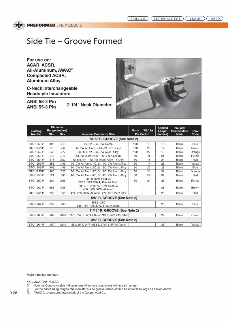
Side Tie – Groove Formed
EXPLANATORY NOTES:
For use on:
ACAR, ACSR,
All-Aluminum, AWAC®
Compacted ACSR,
Aluminum Alloy
C-Neck Interchangeable
Headstyle Insulators
ANSI 55-2 Pin
ANSI 55-3 Pin 2-1/4" Neck Diameter
Catalog
Number
Diameter
Range (Inches)
Nominal Conductor Size
Units Wt./Lbs.Applied
Length
(Inches)
Insulator
Identification
Mark
Color
CodeMin. Max. Per Carton
9/16" R. GROOVE (See Note 2)
Blue
Brown22
Purple
26Blue
22 Purple
.666 Brown
26
5/8" R. GROOVE (See Note 2)
Blue
11/16" R. GROOVE (See Note 2)
.969 29
3/4" R. GROOVE (See Note 2)
PREVIOUS SECTION CONTENTS SEARCH NEXT

Distribution (Overhead): Section
9
9-29
Sid
e T
ie
Gro
ove F
orm
ed
Side Tie – Groove Formed
EXPLANATORY NOTES:
For use on:
ACAR, ACSR,
All-Aluminum, AWAC®
Compacted ASCR,
Aluminum Alloy
F-Neck Interchangeable
Headstyle Insulators
ANSI 53-4 Spool
ANSI 53-5 Spool
ANSI 55-4 Pin 2-7/8"
ANSI 55-5 Pin Neck Diameter
ANSI 57-1 Post
ANSI 57-2 Post
ANSI 57-3 Post
Catalog
Number
Diameter Range
(Inches)
Nominal Conductor Size
Units Wt./Lbs.Applied
Length
(Inches)
Insulator
Identification
Mark
Color
CodeMin. Max. Per Carton
9/16" R. GROOVE (See Note 2)
Blue
Brown
Purple
26
Blue
22
Purple
.666 Brown
26
5/8" R. GROOVE (See Note 2)
Blue
11/16" R. GROOVE (See Note 2)
.969 29
3/4" R. GROOVE (See Note 2)
PREVIOUS SECTION CONTENTS SEARCH NEXT
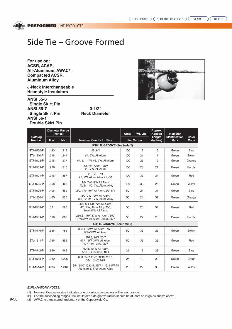
Side Tie – Groove Formed
For use on:
ACSR, ACAR,
All-Aluminum, AWAC®,
Compacted ACSR,
Aluminum Alloy
J-Neck Interchangeable
Headstyle Insulators
ANSI 55-6
Single Skirt Pin
ANSI 55-7 3-1/2"
Single Skirt Pin Neck Diameter
ANSI 56-1
Double Skirt Pin
EXPLANATORY NOTES:
Catalog
Number
Diameter Range
(Inches)
Nominal Conductor Size
Units Wt./Lbs.
Approx.
Applied
Length
(Inches)
Insulator
Identification
Mark
Color
CodeMin. Max. Per Carton
9/16" R. GROOVE (See Note 2)
Blue
Brown
Purple
26
Blue
Purple
5/8" R. GROOVE (See Note 2)
.666 Brown
26
Blue
.969 29
22
PREVIOUS SECTION CONTENTS SEARCH NEXT

Distribution (Overhead): Section
9
EZ
-WR
AP
® Sid
e T
ie
EZ-WRAP® Side Tie
Tie Tube: For bare conductor, each tie is furnished with a Tie Tube Component. The Tie Tube is detached and
Identification Tape:
INTENDED USE:
-
EZ-WRAP SIDE TIE:
The tube component surrounds the bare conductor with a resilient cush-ion where the conductor would come into contact with the insulator. In the
the tube can be discarded because contact with the bare conductor is
VIBRATION DAMPERS:
superior to hand tie wire, there may be conditions where -
mental dampers.
aeolian vibration
-
upon a number of factors.
TIE TUBE
Color Code Conductor
For conductor galloping, the Air Flow Spoiler is recom-
MECHANICAL STRENGTH:
TM-200E
INTERCHANGEABLE
HEADSTYLE INSULATOR:
is recommended that only insulators
-
appear on ANSI standards.
GENERAL RECOMMENDATIONS
NOMENCLATURE
Insulator Identification Mark: Identifies the correct insula-
Color Code: -
PREVIOUS SECTION CONTENTS SEARCH NEXT

EZ-WRAP® Side Tie
CONDUCTOR SIZE:
identical color codes on armless construction. Conductor
radius.
-
RADIO INTERFERENCE:
loosened tie wire.
TAPPING:
rods will remain permissible, -
hot-line taps.
LINE ANGLES GENERAL
GUIDELINES: -tally-mounted insulators, EZ-
to 10°
40°
actual cant of the insulator.
In all cases, the conductor should rest in the preferred insula-
-
PLP®
1.
2. This product is intended for use by trained craftspeople
who is not familiar with and trained in the use of it.
3.
-cidental electrical contact.
GENERAL RECOMMENDATIONS CONTD.
SAFETY CONSIDERATIONS
4.
Side Tie before application.
5.
proper performance, they should be stored in cartons
PREVIOUS SECTION CONTENTS SEARCH NEXT

Distribution (Overhead): Section
9
EZ
-WR
AP
® Sid
e T
ie
EZ-WRAP® Side Tie
For use on:
ACAR, ACSR,
All-Aluminum, AWAC®
Compacted ACSR,
Aluminum Alloy
C-Neck Interchangeable
Headstyle Insulators
ANSI 55-2 PIN 2-1/4" Neck Diameter
ANSI 55-3 PIN
EXPLANATORY NOTES:
Catalog
Number
Diameter Range
(Inches)
Nominal Conductor Size
Units Wt./Lbs.
Approx.
Applied
Length
(Inches)
Insulator
Identification
Mark
Color
CodeMin. Max. Per Carton
9/16" R. GROOVE (See Note 2)
Blue
22 Brown
Purple
All Alum. Alum. Alloy 22 Blue
Purple
.666
Brown
29
5/8" R. GROOVE (See Note 2)
Blue
11/16" R. GROOVE (See Note 2)
.969
3/4" R. GROOVE (See Note 2)
PREVIOUS SECTION CONTENTS SEARCH NEXT

EZ-WRAP® Side Tie
For use on:
ACAR, ACSR,
All-Aluminum, AWAC®
Compacted ASCR,
Aluminum Alloy
F-Neck Interchangeable
Headstyle Insulators
ANSI 53-4 Spool
ANSI 53-5 SpoolANSI 55-4 Pin
ANSI 55-5 Pin 2-7/8"
ANSI 57-1 Post Neck Diameter
ANSI 57-2 Post
ANSI 57-3 Post
Catalog
Number
Diameter Range
(Inches)
Nominal Conductor Size
Units Wt./Lbs.Applied
Length
(Inches)
Insulator
Identification
Mark
Color
CodeMin. Max. Per Carton
9/16" R. GROOVE (See Note 2)
Blue
22 Brown
Purple
22 Blue
Purple
.666
Brown
5/8" R. GROOVE (See Note 2)
Blue
11/16" R. GROOVE (See Note 2)
.969
3/4" R. GROOVE (See Note 2)
EXPLANATORY NOTES:
PREVIOUS SECTION CONTENTS SEARCH NEXT

Distribution (Overhead): Section
9
EZ
-WR
AP
® Sid
e T
ie
EZ-WRAP® Side Tie
For use on:
ACSR, ACAR, All-Aluminum, AWAC®,
Compacted ACSR, Aluminum Alloy
J-Neck Interchangeable
Headstyle Insulators
ANSI 55-6
Single Skirt Pin 3-1/2"
ANSI 55-7 Neck Diameter
Single Skirt Pin
ANSI 56-1
Double Skirt Pin
Catalog
Number
Diameter Range
(Inches)
Nominal Conductor Size
Units Wt./Lbs.Applied
Length
(Inches)
Insulator
Identification
Mark
Color
CodeMin. Max. Per Carton
9/16" R. GROOVE (See Note 2)
Blue
Brown
26
Purple
26
Blue
26
Purple
5/8" R. GROOVE (See Note 2)
.666 Brown
Blue
.969
EXPLANATORY NOTES:
PREVIOUS SECTION CONTENTS SEARCH NEXT

Double Side Tie
Tie Assemblymetal tie components plus two tie tubes.
Tie Tube
Cross-Over Marks
Insulator Identification Mark: Identifies the correct insula-
-
LINE ANGLES – GENERAL GUIDELINES
between 0 80 40
-
A technical report (TM-197E)
In all cases, the conductor should rest in the preferred
Consult PLP®
INTERCHANGEABLE Headstyle INSULATORS:
insulators with uniform dimensions as described by the ANSI insulator standards be used. Consult PLP for application on nonstandard insulators.DOUBLE SIDE TIE:
tube which surrounds the bare conductor with a resilient
TIE TUBE TIE TUBE
TIE TUBE
TIE TUBE
GENERAL RECOMMENDATIONS
NOMENCLATURE
Color Code and Applied Length: Assist in identification
Identification Tape:
INTENDED USE:
RUS Accepted
PREVIOUS SECTION CONTENTS SEARCH NEXT
Distribution (Overhead): Section
9
Do
ub
le S
ide T
ie
Double Side Tie
SAFETY CONSIDERATIONS
1.
2. This product is intended for use by trained craftspeople
who is not familiar with and trained in the use of it.
3.
-cidental electrical contact.
4.
5.
To insure proper performance, they should be stored in
GENERAL RECOMMENDATIONS CONTD.
-
tube may be discarded.
MECHANICAL STRENGTH: -
-TM-170E
RADIO INTERFERENCE:
loosened hand-tie wire.
VIBRATION DAMPERS:
® -
TAPPING:
CONDUCTOR COMPATIBILITY:
Tie or conductor.
additional installation information.
Line Products.
PREVIOUS SECTION CONTENTS SEARCH NEXT

Double Side Tie
EXPLANATORY NOTES:
For use on:
ACSR, All-Aluminum,
AWAC®, Aluminum Alloy
Compacted ACSR, ACAR
C-Neck & F-Neck Interchangeable
Headstyle Insulators
ANSI 55-2 PIN
ANSI 55-3 PIN
ANSI 55-4 PIN 2-1/4" & 2-7/8"
ANSI 55-5 PIN Neck Diameters
ANSI 57-1 POST
ANSI 57-2 POST
ANSI 57-3 POST
Catalog
Number
Diameter
Range (Inches)
Nominal Conductor Size
Units Wt./Lbs.Applied
Length
(Inches)
Insulator
Identification
Mark
Color
CodeMin. Max. Per Carton
9/16" R. GROOVE (See Note 2)
Purple
Blue
Purple
.666 Brown
5/8" R. GROOVE (See Note 2)
22 Blue
11/16" R. GROOVE (See Note 2)
.969
3/4" R. GROOVE (See Note 2)
PREVIOUS SECTION CONTENTS SEARCH NEXT

Distribution (Overhead): Section
9
Do
ub
le S
ide T
ie
Double Side Tie
For use on:
ACSR, All-Aluminum,
AWAC®, Aluminum Alloy
Compacted ASCR, ACAR
J-Neck Interchangeable
Headstyle Insulators
ANSI 55-6
Single Skirt Pin
ANSI 55-7 3-1/2"
Single Skirt Pin Neck Diameter
ANSI 56-1
Double Skirt Pin
EXPLANATORY NOTES:
Catalog
Number
Diameter
Range (Inches)
Nominal Conductor Size
Units Wt./Lbs.Applied
Length
(Inches)
Insulator
Identification
Mark
Color
CodeMin. Max. Per Carton
9/16" R. GROOVE (See Note 2)
Purple
22
26
Blue
Purple
.666 Brown
5/8" R. GROOVE (See Note 2)
Blue
11/16" R. GROOVE (See Note 2)
.969
PREVIOUS SECTION CONTENTS SEARCH NEXT

Spool Tie
The Spool Tie is intended for use on aluminum based
Interchangeable Neck-Style Insulators: Spool Ties listed
diameters. Consult PLP for specifics.
recommended only spool insulators with uniform dimen-sions,
on non-listed or non-standard insulators.
Each Spool Tie is supplied with an elastomeric tie tube
tube may be discarded. Spool Ties can also be applied to
Mechanical Strength:
-tional Electric Safety Code. TM-168E -
than a loosened tie wire.
Vibration Dampers: The -
®
Tie Assembly: A Spool Tie Assembly consists of one metal tie component plus tie tube.
Tie Tube: Each Spool Tie is supplied with an elastomeric tie
Color Code
Identification Tape
Applied Length
plus assists in product identification.
TIE TUBE
TIE TUBE
GENERAL RECOMMENDATIONS
NOMENCLATURE RUS Accepted
PREVIOUS SECTION CONTENTS SEARCH NEXT

Distribution (Overhead): Section
9
Sp
oo
l Tie
Spool Tie
1. Insulator Mounting --
sulator may be mounted either -
conductor should be positioned so it will bear, as much as pos-
conductor may be positioned
into the pole, the conductor should be placed on the outside of the insulator so the conductor bears
2. Line Angles - General Guide-
lines:
10°
40° can
In all cases the conductor should rest in the preferred
-
and orientation, etc. Consult PLP®
3. Tapping:
or loop of the Spool Tie.
4. Conductor Compatibility: Spool Ties should be used
5.
the Spool Tie or the conductor.
6.
7. Consult the Spool Tie Application Procedure for additional installation information.
8.
1.
-STANCES.
2. This product is intended for use by trained craftspeople
who is not familiar with and trained in the use of it.
3.
-cidental electrical contact.
4.
Spool Tie before application.
5.
proper performance, they should be stored in cartons
INSTALLATION GUIDELINES SAFETY CONSIDERATIONS
PREVIOUS SECTION CONTENTS SEARCH NEXT

Spool Tie
EXPLANATORY NOTES:
For use on:
ACAR, All-Aluminum
ACSR, Aluminum Alloy
AWAC, Compacted ACSR
Spool Insulator
ANSI 53-1
ANSI 53-2 1-3/4" Neck Diam.
ANSI 53-3
Catalog
Number
Diameter
Range (Inches) Nominal Conductor Size Units Wt./Lbs.Applied
Length
(Inches)
Color
CodeMin. Max.
Bare
Conductor
Plastic Jacketed
Conductor Per Carton
Purple
26
PREVIOUS SECTION CONTENTS SEARCH NEXT

Distribution (Overhead): Section
9
Sp
oo
l Tie
Spool Tie
EXPLANATORY NOTES:
For use on:
ACSR, Compacted ACSR,
Aluminum Alloy , ACAR
All-Aluminum, AWAC®
Compacted All-Aluminum
Spool Insulator
ANSI 53-1
ANSI 53-2 1-3/4" Diameter
ANSI 53-3
Catalog
Number
Diameter Range
(Inches) Nominal Conductor Size Units
Wt./
Lbs.Applied
Length
(Inches)
Color
CodeMin. Max.
Bare
Conductor
Plastic Jacketed
Conductor Per Carton
Blue
Purple
.666
All Alum.
Brown
26
26 Blue
PREVIOUS SECTION CONTENTS SEARCH NEXT

Spool Tie
Spool Tie -Spool Ties, are part of the ANSI
INSULATOR MANUFACTURER LIST:
ANSI 53-1
ANSI 53-2
ANSI 53-3
1-3/4" Neck Diameter
Chance Joslyn L.M.
Locke
(G.E.) Knox Ohio Brass Oliver
Utilities
Serv. ITE-Victor
Note: ANSI 53-1 and 53-3 spool insulators with 1-3/4" neck diameter will accept only a maximum conductor of .563" with a Spool Tie.
PREVIOUS SECTION CONTENTS SEARCH NEXT

Distribution (Overhead): Section
9
EZ
-WR
AP
® Sp
oo
l Tie
EZ-WRAP® Spool Tie
Tie Assembly
of one metal tie component plus tie tube.
Tie Tube
bare conductors.
Color Code
Identification Tape
Interchangeable Neck-Style Insulators:
Tie, it is recommended only spool insulators with uniform -
dards, be used.
applied to bare conductor without the tube where desired,
Mechanical Strength:
-TR-695E
Vibration Dampers: The
® -
TIE TUBECONDUCTOR COLOR CODE
TIE LOOP
IDENTIFICATION TAG
GENERAL RECOMMENDATIONS
NOMENCLATURE
TIE TUBE
RUS Accepted
Applied Length
plus assists in product identification.
PREVIOUS SECTION CONTENTS SEARCH NEXT
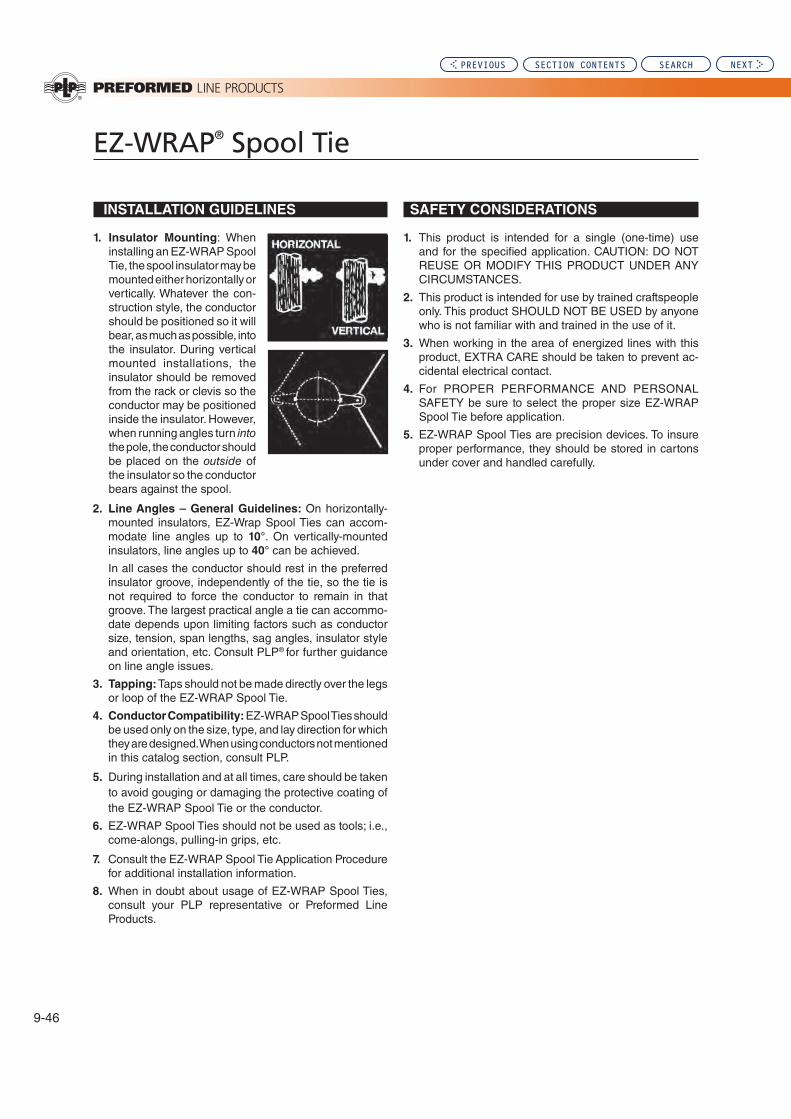
EZ-WRAP® Spool Tie
1. Insulator Mounting
Tie, the spool insulator may be
-struction style, the conductor should be positioned so it will bear, as much as possible, into
mounted installations, the
conductor may be positioned
into the pole, the conductor should be placed on the outside of the insulator so the conductor
2. Line Angles – General Guidelines:
-10°
40°
In all cases the conductor should rest in the preferred
-
and orientation, etc. Consult PLP®
3. Tapping:
4. Conductor Compatibility:
5.
the
6.
7. Consult the for additional installation information.
8.
Products.
1.
2. This product is intended for use by trained craftspeople
who is not familiar with and trained in the use of it.
3.
-cidental electrical contact.
4.
Spool Tie before application.
5.
proper performance, they should be stored in cartons
INSTALLATION GUIDELINES SAFETY CONSIDERATIONS
PREVIOUS SECTION CONTENTS SEARCH NEXT

Distribution (Overhead): Section
9
EZ
-WR
AP
® Sp
oo
l Tie
EZ-WRAP® Spool Tie
For use on:
ACAR, All-Aluminum
ACSR, Aluminum Alloy
AWAC, Compacted ACSR
Spool Insulator
ANSI 53-1 1-3/4"
ANSI 53-2 Neck Diam.
ANSI 53-3
EXPLANATORY NOTES:
Catalog
Number
Diameter Range
(Inches) Nominal Conductor Size Units Wt./Lbs. Applied
Length
(Inches)
Color
CodeMin. Max.
Bare
Conductor
Plastic Jacketed
Conductor Per Carton
26
Blue
Purple
.666
Brown
26
Blue
.969
66
PREVIOUS SECTION CONTENTS SEARCH NEXT

Coated Top Tie
NOMENCLATURE
Applied Length: Assists in identification of conductor
Relieved Ends:
Insulator Identification Mark: Identifies the correct
Intended Use:
insulators only. They are suitable for use with any plastic
Material:
Mechanical:
Line Angles:
10°.
In all cases the conductor should rest in the preferred insula-
Insulators: To ensure proper fit and performance, it is
GENERAL RECOMMENDATIONS
1.
2. This product is intended for use by trained craftspeople
who is not familiar with and trained in the use of it.
3.
accidental electrical contact.
4.
5.
insure proper performance, they should be stored in
SAFETY CONSIDERATIONS
Insulator Identification Mark* “C” Neck – Black
“F” Neck – Yellow
Conductor Color Code*
(Identifies Conductor Size Range)
Color Code:
*
Relieved Ends
PREVIOUS SECTION CONTENTS SEARCH NEXT
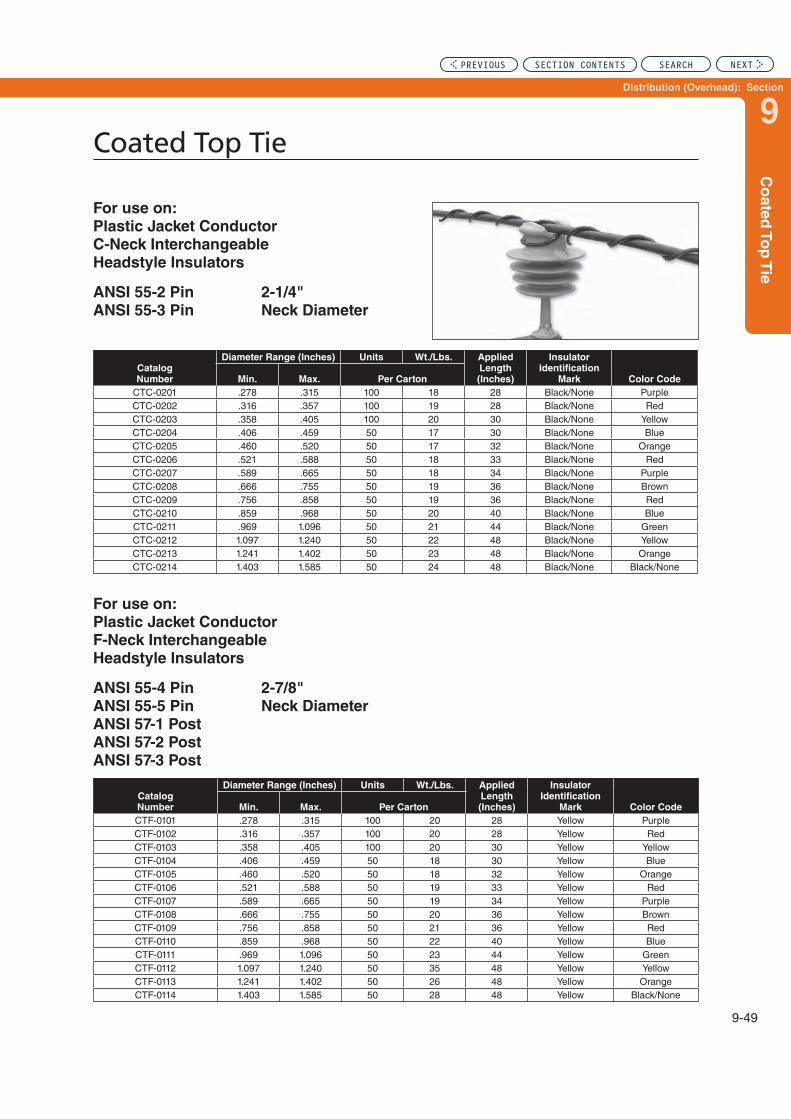
Distribution (Overhead): Section
9
Co
ate
d T
op
Tie
Coated Top Tie
For use on:
Plastic Jacket Conductor
C-Neck Interchangeable
Headstyle Insulators
ANSI 55-2 Pin 2-1/4"
ANSI 55-3 Pin Neck Diameter
For use on:
Plastic Jacket Conductor
F-Neck Interchangeable
Headstyle Insulators
ANSI 55-4 Pin 2-7/8"
ANSI 55-5 Pin Neck Diameter
ANSI 57-1 Post
ANSI 57-2 Post
ANSI 57-3 Post
Catalog
Number
Diameter Range (Inches) Units Wt./Lbs. Applied
Length
(Inches)
Insulator
Identification
Mark Color CodeMin. Max. Per Carton
Purple
Blue
Purple.666 Brown
Blue.969
22
Catalog
Number
Diameter Range (Inches) Units Wt./Lbs. Applied
Length
(Inches)
Insulator
Identification
Mark Color CodeMin. Max. Per Carton
Purple
Blue
Purple.666 Brown
22 Blue.969
26
PREVIOUS SECTION CONTENTS SEARCH NEXT

Coated Side Tie
NOMENCLATURE
Applied Length: Assists in identification of conductor
Relieved Ends:
Insulator Identification Mark: Identifies the correct insu-
Intended Use:
insulators only. They are suitable for use with any plastic
Material:
Mechanical:
LINE ANGLES GENERAL GUIDELINES:
10°
40°
the actual cant of the insulator. Consult PLP® for further
In all cases the conductor should rest in the preferred insula-
GENERAL RECOMMENDATIONS
1.
2. This product is intended for use by trained craftspeople
who is not familiar with and trained in the use of it.
3.
accidental electrical contact.
4.
before application.
5. performance, they should be stored in cartons under
SAFETY CONSIDERATIONS
CONDUCTOR COLOR CODE*
(Identifies conductor size range)
Insulator Identification Mark* “C” Neck – Black
“F” Neck – Yellow
Relieved Ends
Color Code:
*
Insulators: To ensure proper fit and performance, it is
compliant polymer or porcelain insulators.
PREVIOUS SECTION CONTENTS SEARCH NEXT

Distribution (Overhead): Section
9
Co
ate
d S
ide T
ie
Coated Side Tie
For use on:
Plastic Jacket Conductor
C-Neck Interchangeable
Headstyle Insulators
ANSI 55-2 Pin 2-1/4"
ANSI 55-3 Pin Neck Diameter
For use on:
Plastic Jacket Conductor
F-Neck Interchangeable
Headstyle Insulators
ANSI 55-4 Pin 2-7/8"
ANSI 55-5 Pin Neck Diameter
ANSI 57-1 Post
ANSI 57-2 Post
ANSI 57-3 Post
Catalog
Number
Diameter Range (Inches) Units Wt./Lbs. Applied
Length
(Inches)
Insulator
Identification
Mark Color CodeMin. Max. Per Carton
Purple
22 Blue
Purple.666 Brown
Blue.969
Catalog
Number
Diameter Range (Inches) Units Wt./Lbs. Applied
Length
(Inches)
Insulator
Identification
Mark Color CodeMin. Max. Per Carton
Purple
22 Blue
Purple.666 Brown
Blue.969
PREVIOUS SECTION CONTENTS SEARCH NEXT

Plastic Ties; PVC and Semi-Con
mounted tie top insulators on cross-arms, pole-top mounted insulators, or
Plastic Line Ties are intended
on cross-arms, pole-top mount-ed insulators, or Spacer Cable
are recommended.
-ductors and side mounted tie top insulators on armless construc-
Insulator Identification Mark: Identifies the correct insu--
Identification Printing (where applicable):
to identification tape on PUC ties.
Relieved Ends
Color Code (where applicaple) and Applied Length:
-
-
NOMENCLATURE
PREVIOUS SECTION CONTENTS SEARCH NEXT

Distribution (Overhead): Section
9
Pla
stic
Tie
s
Plastic Ties; PVC and Semi-Con
GENERAL RECOMMENDATIONS
INTENDED USE: Plastic Line Ties and Plastic Side Ties
top ANSI C29 compliant insulators only. They are suitable
MATERIAL:
properties.
VOLTAGE APPLICATIONS: Electrical performance of any
-
porcelain insulators, and the similar dielectric characteristics
-
Caution:
is suitable for use in a particular installation.
MECHANICAL:
conductor.
INSULATORS: To insure proper fit and performance, it is
Plastic Ties are suitable for use with either ANSI Compliant Polymer or porcelain insulators.
COLD WEATHER INSTALLATION/REMOVAL: Caution
laboratory installation tests indicate they may remain supple
SAFETY CONSIDERATIONS
1.
2. This product is intended for use by trained craftspeople
who is not familiar with and trained in the use of it.
3.
-
materials, Plastic Ties should not be considered as
4.
before application.
5. -
and handled carefully.
PREVIOUS SECTION CONTENTS SEARCH NEXT

Plastic Line Tie
EXPLANATORY NOTES:
For use on:
Plastic Jacketed Conductor
C-Neck Interchangeable
Headstyle Insulators
ANSI 55-2 Pin 2-1/4"
ANSI 55-3 Pin Neck Diameter
PVC
Plastic
Ties
Catalog #
Semi-Con
Plastic
Ties
Catalog #
OD Range (in.) Nominal
Conductor
Size
Units
per
carton
Approx.
Wt./Lbs.
Approx.
Applied
Length
(in.)
Insulator
Color ID
Mark
(PVC/SC)
Conductor
Color Code
(PVC/SC)Min. Max.
Blue
22
PREVIOUS SECTION CONTENTS SEARCH NEXT

Distribution (Overhead): Section
9
Pla
stic
Lin
e T
ies
Plastic Line Tie
For use on:
Plastic Jacketed Conductor
F-Neck Interchangeable
Headstyle Insulators
ANSI 55-4 Pin
ANSI 55-5 Pin 2-7/8"
ANSI 57-1 Post Neck Diameter
ANSI 57-2 Post
ANSI 57-3 Post
EXPLANATORY NOTES:
PVC
Plastic
Ties
Catalog #
Semi-Con
Plastic
Ties
Catalog #
OD Range (in.) Nominal
Conductor
Size
Units
per
carton
Approx.
Wt./Lbs.
Approx.
Applied
Length
(in.)
Insulator
Color ID
Mark
(PVC/SC)
Conductor
Color Code
(PVC/SC)Min. Max.
Blue
22
PREVIOUS SECTION CONTENTS SEARCH NEXT

Angle Side Tie: Plastic
For use on:
Plastic Jacketed Conductor
C-Neck Interchangeable
Headstyle Insulators
ANSI 55-2 Pin 2-1/4"
ANSI 55-3 Pin Neck Diameter
EXPLANATORY NOTES:
PVC
Plastic
Ties
Catalog #
Semi-Con
Plastic
Ties
Catalog #
OD Range (in.) Nominal
Conductor
Size
Units
per
carton
Approx.
Wt./Lbs.
Approx.
Applied
Length
(in.)
Insulator
Color ID
Mark
(PVC/SC)
Conductor
Color Code
(PVC/SC)Min. Max.
Blue
22
PREVIOUS SECTION CONTENTS SEARCH NEXT

Distribution (Overhead): Section
9
An
gle
Sid
e T
ie: P
lastic
Angle Side Tie: Plastic
For use on:
Plastic Jacketed Conductor
F-Neck Interchangeable
Headstyle Insulators
ANSI 55-4 Pin
ANSI 55-5 Pin 2-7/8"
ANSI 57-1 Post Neck Diameter
ANSI 57-2 Post
ANSI 57-3 Post
EXPLANATORY NOTES:
PVC
Plastic
Ties
Catalog #
Semi-Con
Plastic
Ties
Catalog #
OD Range (in.) Nominal
Conductor
Size
Units
per
carton
Approx.
Wt./Lbs.
Approx.
Applied
Length
(in.)
Insulator
Color ID
Mark
(PVC/SC)
Conductor
Color Code
(PVC/SC)Min. Max.
Blue
22
PREVIOUS SECTION CONTENTS SEARCH NEXT

Tangent Side Tie: Plastic
For use on:
Plastic Jacketed Conductor
C-Neck Interchangeable
Headstyle Insulators
ANSI 55-2 Pin 2-1/4"
ANSI 55-3 Pin Neck Diameter
EXPLANATORY NOTES:
PVC
Plastic
Ties
Catalog #
Semi-Con
Plastic
Ties
Catalog #
OD Range (in.) Nominal
Conductor
Size
Units
per
carton
Approx.
Wt./Lbs.
Approx.
Applied
Length
(in.)
Insulator
Color ID
Mark
(PVC/SC)
Conductor
Color Code
(PVC/SC)Min. Max.
22 None
22 None
None Blue
None
None
None None
PREVIOUS SECTION CONTENTS SEARCH NEXT

Distribution (Overhead): Section
9
Tan
gen
t Sid
e T
ie: P
lastic
Tangent Side Tie: Plastic
For use on:
Plastic Jacketed Conductor
F-Neck Interchangeable
Headstyle Insulators
ANSI 55-4 Pin
ANSI 55-5 Pin 2-7/8"
ANSI 57-1 Post Neck Diameter
ANSI 57-2 Post
ANSI 57-3 Post
EXPLANATORY NOTES:
PVC
Plastic
Ties
Catalog #
Semi-Con
Plastic
Ties
Catalog #
OD Range (in.) Nominal
Conductor
Size
Units
per
carton
Approx.
Wt./Lbs.
Approx.
Applied
Length
(in.)
Insulator
Color ID
Mark
(PVC/SC)
Conductor
Color Code
(PVC/SC)Min. Max.
Blue
22 None
PREVIOUS SECTION CONTENTS SEARCH NEXT

Line Guards
Single Support and Double Support Length: Identified
Rod Diameter:
Rods Per Set: Indicates the proper number of rods for each application.
Center Mark:
LINE GUARDS RESTORATIVE-REPAIR. Line Guards may
-
NOTE:
will produce optimum electrical repair: Step 1:
Step 2:
TAPPING. Line Guards may be used as tap armor to protect
Line Guards, it is recommended that the conductor be
APPLICATION-INSPECTION. After application of the
Apply no more than one-half the number of rods per set at a
PROTECTION. Line Guards are intended
-cific line depends upon a number of factors such as line
be adopted to the specific conditions.
Line Guards are recommended as minimum protection for hand-tied spans.
PLP® Factory Formed Ties are recommended as improve-
ments over Line Guards secured with hand tie wire. They
protect against chafing or wear caused by wind sway or
unbalanced loading. PLP Ties also provide a stronger
material and greater uniformity than hand tie wire.
Armor Rods are recommended as minimum protection for clamp-type supports or suspensions. The use of supple-
GENERAL RECOMMENDATIONS
NOMENCLATURE
Color Code and Length: Assists in identification of
-
Identification Tape: Shows
PREVIOUS SECTION CONTENTS SEARCH NEXT

Distribution (Overhead): Section
9
Lin
e G
uard
s
Line Guards
tables.
1.
2. This product is intended for use by trained craftspeople
who is not familiar with and trained in the use of it.
3.
-cidental electrical contact.
4. -
5.
insure proper performance, they should be stored in
O.D. CALCULATIONS
SAFETY CONSIDERATIONSGENERAL RECOMMENDATIONS CONTD.
the ends of the rods should be maintained within 2 inches.
-
Parrot-Bill®
PREVIOUS SECTION CONTENTS SEARCH NEXT

9-62
For use on:
ACSR, Compacted ACSR,
Aluminum Alloy
All-Aluminum, AWAC®
Compacted All-Aluminum, ACAR
EXPLANATORY NOTES:
Catalog
Number
Diameter Range
(Inches)
Nominal Conductor Size
Units Wt./Lbs. Length
(Inches)
Rod
Diameter
(Inches)
Rods Per
Set
Color
CodeMin. Max. Per Carton
Purple
Blue
.229 Brown
9
9 Purple
9
Blue
Brown
Blue
Line Guards: Aluminum
(Continued on next page)
PREVIOUS SECTION CONTENTS SEARCH NEXT

Distribution (Overhead): Section
9
Lin
e G
uard
s
Line Guards: Aluminum
EXPLANATORY NOTES:
Catalog
Number
Diameter Range
(Inches)
Nominal Conductor Size
Units Wt/LbsLength
(Inches)
Rod
Diameter
(Inches)
Rods
Per Set
Color
CodeMin. Max. Per Carton
Brown
Blue
Purple
Blue
Brown
Purple
Brown
Blue
PREVIOUS SECTION CONTENTS SEARCH NEXT

Helical Ties for T2 Conductor
disrupts the forces created by the steady crosswinds that can cause cable motion. The forces are disrupted by the
-
THEORY
CONSTRUCTION
T2 conductor consists of two identical conductors twisted
APPLICATION
-
installed within accepted tension limits.
PREVIOUS SECTION CONTENTS SEARCH NEXT

Distribution (Overhead): Section
9
Helic
al T
ies
for T
2 C
on
du
cto
r
Helical Ties for T2 Conductor
GENERAL RECOMMENDATIONS
-
listed in the product table in this section, contact Preformed
In many cases, Preformed Line Products can recommend products for a particular installation.
INTENDED USE.
insulators.
-
DEAD-ENDING. T2 conductor can be terminated in the
on separate hardware on the structure.
CONDUCTOR REPAIR.
repaired separately. To accomplish this, it is important to
repair components can be chosen.
ARMOR RODS/ARMOR-GRIP® SUSPENSION/SUPPORT.
Supports, the introduction of a third piece of conductor is
of the conductor elements of the T2 conductor. The addi-tional piece of conductor is placed in the interstices of the two conductor elements of the T2 conductor assembly in order to create an assembly that is closer to the shape of
should be held in place by a few pieces of tape prior to the
Preformed Line Products.
INTERCHANGEABLE HEADSTYLE INSULATOR. To
Consult Preformed Line Products
insulators. A sample of the insulator
1.
2. This product is intended for use by trained craftspeople
who is not familiar with and trained in the use of it.
3.
-cidental electrical contact.
SAFETY CONSIDERATIONS
4.
products before application.
5.
proper performance, they should be stored in cartons
PREVIOUS SECTION CONTENTS SEARCH NEXT

9-66
Helical Ties for T2 Conductor
PREFORMED™ TIES FOR T2 CONDUCTOR
BENEFITS:
WRAPLOCK® Tie Distribution Tie
EZ-WRAP® Spool Tie Spool Tie
Double Support Tie Side Tie Double Side Tie
PREVIOUS SECTION CONTENTS SEARCH NEXT

Distribution (Overhead): Section
9
Helic
al T
ies
for T
2 C
on
du
cto
r
Helical Ties for T2 Conductor
EXPLANATORY NOTES:
® Suspensions or Supports, or T2 conductor not shown.
For use on:
ACSR, Compacted ACSR,
Aluminum Alloy,
All-Aluminum, AWAC®,
Compacted All-Aluminum
T2 Conductors Distribution Tie Wraplock Tie Spool Tie
Ez Wrap Spool
Tie
Double
Support Tie
Double Side
Tie Side Tie
PREVIOUS SECTION CONTENTS SEARCH NEXT

Oval Conductor Products
Courtesy of Southwire Company
the forces created by steady cross winds which cause cable -
THEORY
CONSTRUCTION
APPLICATION
-tion protection when installed within accepted tension limits.
GENERAL RECOMMENDATIONS
Always contact PLP to obtain a complete list of recommended
INTENDED USE.
loads on the cable.
SUB TRANSMISSION/TRANSMISSION.
-
It is important to follow all recommendations for the specific -
PRODUCT LIST.
® Suspension family of products
- Conductor Splices - Full-Tension Splices
® Tie
Twin Tie - Side Tie
Side Tie
- Spool Tie Spool Tie
This is not a complete list of products offered by Preformed
for your application.
PREVIOUS SECTION CONTENTS SEARCH NEXT

Distribution (Overhead): Section
9
and removal of the product. The angle-curved neck of the Applicator Ring allows the tool to be safely and easily maneuvered around conductors.
The Applicator Ring is available with a threaded base, or with a universal base, to secure it to either style of hot stick.
The PREFORMED™ Applicator Ring is a PLP®-designed tool which aids the lineman in making safe, fast, distortion-free applications of helically-formed products on energized conductors. The specially-beveled ring permits easy encirclement of the helical leg, and facilitates positioning
A A
1.50" DIA
SECTION A-A
ARMOR RODS
WRAPLOCK® TIE DISTRIBUTION–GRIP DEAD-END
SIDE TIE
Catalog Number Description
SH-0001 Applicator Ring – Universal Base
9-69
Ap
plic
ato
r Rin
g
Applicator Ring
PREVIOUS SECTION CONTENTS SEARCH NEXT

Distribution (Overhead): Section
10
Section 10 – Distribution (Overhead): Polymer Insulators
Table of Contents
Polymer Insulators ................................................................................10-2
Polymer Insulator Accessories and Tools ..........................................10-5
Polymer Insulator Dimensions and Data .............................................10-6
Page
SEARCHPREVIOUS NEXT

10-2
Polymer Insulators
GENERAL RECOMMENDATIONS
NOMENCLATURE
The PLP Polymer Insulators are for use in overhead dis-tribution lines using bare or covered conductors. They are particularly suited for use with Spacer Cable and Tree wire as a better electrical alternative, to porcelain insulators.
The insulators are made from a proprietary, high-density polyethylene-based compound with a dielectric constant compatible with polyethylene covered conductors.
They are designed to meet most of the dimensional, elec-trical, and mechanical requirements of the ANSI C29.5 insulator standards, even though this standard applies only to Wet-Process Porcelain Insulators. These insulators can be used in any application that calls for porcelain insu-lators requiring adherence to this ANSI standard.
Two basic designs are offered: Tie Top and Vise Top Insulators, both available for application on 1" or 1-3/8" pins depending upon the specific ANSI class or voltage application.
The Tie Top Insulators are designed to meet most ANSI C29.5 insulator head dimensional standards for appropri-ate insulator classes with “C” or “F” necks. Therefore they are compatible with all PLP Formed Wire and Plastic Ties, and covered or bare tie wire.
The Vise Top Insulators employ a unique clamp style head. While they are also designed to meet certain ANSI standards, the clamp head design is not applicable to ANSI tie top insulator head dimensional standards.
Benefits:
• The polymer insulators match the dielectric properties of the covered conductor jacket.
• The polyethylene surface coupled with the multiple skirt design with descending skirt diameters and long leakage distances provides superior moisture and con-tamination shedding properties.
• UV Stabilized for long-term service.
• High impact resistance – designed to reduce breakage and vandal/gun shot damage, particularly at cold temperatures.
• The light weight design reduces shipping costs and lineman handling requirements.
• ANSI compliant tie top head design facilitates the use of factory-formed ties for exceptional fit and performance.
• Polyethylene material eliminates abrasion at the insulator/conductor interface.
• Polymer Insulators can be used with jacketed jumper wires, eliminating skinning, and providing additional wildlife protection at equipment locations.
• Vise Top Polymer Insulator designs provide a unique clamping mechanism for quick installation.
• The same clamp and head design is used for all Vise Top Polymer Insulators. The skirt design varies by voltage application.
• A Vise Top Stringing Tool is offered to aid jacketed conductor installation.
PREVIOUS SECTION CONTENTS SEARCH NEXT

Distribution (Overhead): Section
10
10-3
Po
lym
er In
su
lato
rs
Polymer Insulators
Tie Top Polymer Insulators:
The PLP Tie Top Polymer Insulators are designed to match most Head and Neck dimensional standards for ANSI C29.5, class 55-3, 55-4, 55-5 or 55-6, 55-7, 56-1 pin type insulators. “C” ( 2 -1/4" nominal) and “F” ( 2-7/8" nominal) Neck sizes are available.
Certain ANSI C29.5 25 & 35 kV insulator classes specify “J” neck dimensions (nominal 3.5" diameter) while the PLP polymer insulators for those classes utilize the more common “F” neck design.
By using ANSI head and neck dimensional standards, PLP metal or plastic factory formed ties will install easily and provide superior holding and electrical performance on PLP Tie Top Polymer Insulators. Consult PLP for suitability of other formed tie brands with these insulators.
Covered or bare hand tie wire is also sutable for use with PLP Tie Top Polymer Insulators depending upon condutor type.
Vise Top Polymer Insulators:
The PLP Vise Top Polymer Insulator utilizes a unique plas-tic clamp mechanism and black nylon torque bolts to se-cure the conductor. Nylon Torque bolts with break away heads are designed to provide a method to insure that proper torque is applied to the mechanism for fast and proper conductor clamping force.
Conductor Inserts:
Compatible conductor inserts for either jacketed or bare conductors are available. Nylon inserts are offered for use with jacketed or bare copper conductors. Aluminum inserts are offered for bare aluminum conductors, although it is recommended that the utility determine the suitability of PLP Vise Top Polymer Insulators on bare conductors before installation.
Torque Bolts:
Two Torque Bolts are supplied with each vise top insulator. The breakaway torque ring is designed to insure the proper torque and subsequent holding force to the conductor will be applied during initial installation. All Vise Top Insulators use the same Torque Bolt.
New Torque Bolts should be used whenever conductors are removed from the Vise Top Insulator or any time the bolts are unscrewed and initial torque is lost. Individual Torque Bolts are available for replacement as needed.
Torque Bolt Hook Tool:
An aluminum hook tool accessory is offered for use with hydraulic or power wrenches for easy installation of Torque Bolts. However the tool should be operated at low speeds.
PREVIOUS SECTION CONTENTS SEARCH NEXT

10-4
Polymer Insulators
PLP Polymer Insulator Ordering Guide
Application
Catalog
Number
PLP Part
Number
Approx. Unit
Weight lbs
Carton
Quantity
Pallet
Quantity
General
Appearance
15kV
15kV C Neck Tie Top: ANSI Class 55-3*; 1" Pin**
IP-15-C 600064950701 1.2 18 594
15kV F Neck Tie Top: ANSI Class 55-4*; 1" Pin**
IP-15-F 600064987701 1.3 18 594
15kV Vise Top: Nylon Inserts for Jacketed & Copper Conductors; ANSI Class 55-3/4; 1" Pin
IP-15-VTN 600064987801 2.0 18 216
15kV Vise Top: Metal Inserts for Bare Aluminum Conductors; ANSI Class 55-3/4; 1" Pin
IP-15-VTM 600064951001 2.0 18 216
25kV
25kV F Neck Tie Top: ANSI Class 55-5/ 56-1*; 1" Pin
IP-25-F1 600064977101 1.9 13 195
25kV F Neck Tie Top: ANSI Class 55+5/ 56-1*; 1-3/8" Pin
IP-25-F2 600064977301 1.8 13 195
25kV Vise Top: Nylon Inserts for Jacketed & Copper Conductors; ANSI Class 55-5/ 56-1*; 1" Pin
IP-25-VTN1 600064977401 2.3 13 117
25kV Vise Top: Nylon Inserts for Jacketed & Copper Conductors; ANSI Class 55-5/ 56-1*; 1-3/8" Pin
IP-25-VTN2 600064977501 2.2 13 117
25kV Vise Top: Metal Inserts for Bare Aluminum Conductors; ANSI Class 55-5/ 56-1*; 1" Pin
IP-25-VTM1 600064977601 2.3 13 117
25kV Vise Top: Metal Inserts for Bare Aluminum Conductors; ANSI Class 55-5/ 56-1*; 1-3/8" Pin
IP-25-VTM2 600064977701 2.2 13 117
35kV
35kV F Neck Tie Top: ANSI Class 55-6*; 1" Pin
IP-35-F1 600064946301 2.8 12 216
35kV F Neck Tie Top: ANSI Class 55-7*; 1-3/8" Pin
IP-35-F2 600064946401 2.8 13 195
35kV Vise Top: Nylon Inserts for Jacketed & Copper Conductors; ANSI Class 55-6*; 1" Pin
IP-35-VTN1 600064988301 3.2 13 117
35kV Vise Top: Nylon Inserts for Jacketed & Copper Conductors;ANSI Class 55-7*; 1-3/8" Pin
IP-35-VTN2 600064988401 3.2 13 117
35kV Vise Top: Metal Inserts for Bare Aluminum Conductors; ANSI Class 55-6*; 1" Pin
IP-35-VTM1 600064951201 3.2 13 117
35kV Vise Top: Metal Inserts for Bare Aluminum Conductors; ANSI Class 55-7*; 1-3/8" Pin
IP-35-VTM2 600064951401 3.2 13 117
*Nominal ANSI Classes**RUS Technically Accepted
Ordering Guide
PREVIOUS SECTION CONTENTS SEARCH NEXT

Distribution (Overhead): Section
10
10-5
Po
lym
er In
su
lato
rs
Polymer Insulators
Vise Top Stringing Tool:The polyurethane Vise Top String Tool (VTST) is offered to aid jacketed conductor installation. The VTST temporarily installs in the Vise Top clamp, by hand or with Hot Sticks, and is designed to permit short span, low tension jacketed conductor stringing without the need for stringing wheels.
The tool is not recommended for use with bare cables, long spans, or line or sag angles over approximately 10˚. A proper size stringing block should be used at the 1st and last pole, at large line or sag angles, or long spans throughout the pull, rather then the tool.
It is recommended harsh material pulling ropes, such as nylon, be avoided to minimize excessive wear to the inner bore surface of the tool. It is also suggested low pulling speeds be used when pulling rope or cable through the tool to avoid excessive wear.
The tool can be reused, however it is recommended the tool be inspected after each pull to insure it is suitable for further use. Areas of wear on the tool from previous pulls can be rotated away from where the rope and conduc-tors will rest in the bore during subsequent pulls. However do not reuse the tool if there has been excessive wear throughout all areas of the inner bore.
Consult PLP for additional recommendations.
Vise Top Polymer Insulator Accessories and Tools
Optional Accessories
ProductCatalog Number
PLP Part Number
Approx.
Unit
Weight Lbs
Carton
Quantity
Pallet
Quantity
General
Appearance
Vise Top Torque BoltMaterial: Black UV Resistant NylonLength: 6/5"Approximate Weight: .1lbs
PT-01 600064986501 0.1As
OrderedAs
Ordered
Vise Top Hook ToolMaterial: Aluminum AlloySize: 7/16" HexLength: 6.375"Approximate Weight: .13 lbs
VTHT-01 600064988501 1.13As
OrderedAs
Ordered
Vise Top Stringing ToolMaterial: Polyurethane BodiesSteel Hot Stick RingLength: 5"Conductor Opening Diameter: 1.75"Approximate Weight: .54 lbs
IP-VLST-01 600064991601 0.54As
OrderedAs
Ordered
PREVIOUS SECTION CONTENTS SEARCH NEXT

10-6
Polymer Insulators
Nominal Dimensions & PLP Formed Tie Applications
Nominal Insulator Dimensions
Insulator Type
Catalog Number
Tie Top
IP-15-C
Tie Top
IP-15-F
Vise Top
IP-15-VT
(all)
Tie Top
IP-25-F1/2
Vise Top
IP-25-VT
(all)
Tie Top
IP-35-F1/2
Vise Top
IP-35-VT
(all)
Dimensions (in)
A 4.9 5.1 8.5 6.0 8.4 7.3 10.0
B 5.5 5.5 5.5 7.5 7.5 7.6 7.6
C 3.75 3.81 3.75 4.6 4.6 4.625 5.0
D 2.25 2.875 2.56 2.875 2.56 2.875 2.56
E 0.67 1 NA 1.0 NA 1.0 NA
F 0.625 0.625 0.5 .75 .5 0.75 0.5
Number of Skirts 4 4 4 3 3 4 4
Maximum Conductor OD, Top Groove
1.3 1.875 1.875 1.75 1.875 1.75 1.875
Maximum Conductor OD, Side Groove
1.375 1.375 1.0 1.625 1.0 1.625 1.0
Maximum Conductor Outer Diameter (in) with PLP Factory Formed Ties*
PLP Tie
Distribution Tie 1.05 1.75 NA 1.75 NA 1.75 NA
WRAPLOCK® Tie 0.75 1.15 NA 1.15 NA 1.15 NA
EZ-WRAP® Twin Tie 1.05 1.75 NA 1.75 NA 1.75 NA
Double Support Tie 1.05 1.75 NA 1.75 NA 1.75 NA
Side Tie 0.87 1.6 NA 1.6 NA 1.6 NA
EZ-WRAP® Side Tie 1.05 1.75 NA 1.75 NA 1.75 NA
Double Side Tie 1 1 NA 1.25 NA 1.25 NA
Plastic Top Tie; Jacketed Cond.
1.3 1.875 NA 1.875 NA 1.875 NA
Plastic Side Tie; Jacketed Cond.
0.8 0.8 NA 1.06 NA 1.06 NA
Plastic Angle Side Tie; Jacketed Cond.
0.8 0.8 NA 1.06 NA 1.06 NA
*For some Formed Ties it is necessary to reduce Max Conductor OD that can fit into the insulator groove because allowance needs to be made for tie tube thickness &/or wires of the tie may take up space in the groove.
PREVIOUS SECTION CONTENTS SEARCH NEXT

Distribution (Overhead): Section
10
10-7
Po
lym
er In
su
lato
rs
Polymer Insulators
15, 25 & 35kV Polymer Insulator Data Table
Insulator Data
15kV Applications 25 kV Applications 35 kV Applications
PLP PI
ANSI
C29 55-3
Standards PLP PI
ANSI
C29 55-4
Standards PLP Polymer Insulator
ANSI
C29 55-5
Standards PLP PI
ANSI
C29 55-6
Standards PLP PI
ANSI
C29 55-7
Standards
Catalog Number
& Application
IP-15-C Tie Top
IP-15-VTN/M*
Vise Top
NA IP-15-F Tie Top
NA IP-25-F1 Tie Top
IP-25-VTN/M*1 Vise Top
IP-25-F2 Tie Top
IP-25-VTN/M*2 Vise Top
NA IP-35-F1 Tie Top
IP-35-VTN/M*1 Vise Top
NA IP-35-F2 Tie Top
IP-35-VTN/M*2 Vise Top
NA
“Nominal”
ANSI Class
55-3 55-3 55-3 55-4 55-4 55-5 55-5 55-5 55-5 55-5 55-6 (w F neck)
55-6 55-6 55-7 (w F neck)
55-7 55-7
Neck Size/Style C NA C F F F NA F NA F F NA J F NA J
Typical Operating
Voltage Application,
kV (L-L)
15 15 15 15 15 25 25 25 25 25 35 35 35 35 35 35
Leakage
Distance (in)
14.5 16.1 7 14.5 9 15.3 18 15.3 18 12 20.9 21 15 20.9 21 15
Dry Arcing
Distance (in)
6.3 7 4.5 6.3 5 7.2 8 7.2 8 6.25 9.5 9.8 8 9.5 9.8 8
Pin Hole
Diameter (in)
1 1 1 1 1 1 1 1.375 1.375 1 1 1 1 1.375 1.375 1.375
Suggested Minimum
Pin Length (in)
6 6 5 6 5 7.5 7.5 7.5 7.5 6 7.5 7.5 7.5 7.5 7.5 7.5
60Hz Dry
Flashover (kV)
92 101 (N) 97 (M)
55 93 65 87(1) 88 (Ny) 94 (Met)
(1)
87 88 (Ny) 94 (Met)
85 126 (1) 128 (Ny) 115 (Met)
(1)
100 126 128 (Ny) 115 (Met)
100
60Hz Wet
Flashover (kV)
53 50(N) 65(M)
30 50 35 50(1) 55 (Ny) 55 (Met)
(1)
50 55 (Ny) 55 (Met)
45 82 (1) 72 (Ny) 80 (Met)
(1)
50 82 72 (Ny) 80 (Met)
50
Positive Impulse
Flashover (kV)
127 114(N) 154(M)
90 147 105 141(1) 150 (Ny) 152
(Met) (1)
141 150 (Ny) 152
(Met) (1)
140 175 (1) 188 (Ny) 196 (Met)
(1)
150 175 188 (Ny) 196 (Met)
150
Negative Impulse
Flashover (kV)
-134 -144(N) -200(M)
-110 -201 -130 -235(1) -219(Ny) -216 (Met) (1)
-235 -219(Ny) -216 (Met)
-170 -238 (1) -272 (Ny) -261
(Met) (1)
-170 -238 -272 (Ny) -261 (Met)
-170
Low Frequency
Puncture (kV)
176 174(N) 163(M)
90 160 95 197 228 (Ny) 218 (Met) (1)
201 191 (Ny) 184
(Met) (1)
115 223 219(Ny) (1)
209 (Met) (1)
135 235 219 (Ny) 209 (Met)
135
RIV @ 1MHz
10kV to grd, μV <5 <5 <50μV @10kV
<5 <50μV @10kV
NA NA NA NA NA NA NA NA NA NA NA
15kV to grd, μV NA NA NA NA NA <5 <5 <5 <5 <100μV @15kV
NA NA NA NA NA NA
22kV to grd, μV NA NA NA NA NA NA NA NA NA NA <5(1) <6(1) <100μV @22kV
<5 <6 <100μV @22kV
Cantilever
Strength (lbs)
3000 3000 2500 3000 3000 3000 3000 3000 3000 3000 3000 3000 3000 3000 3000 3000
Aproximate
Weight (lbs)
1.2 2 NA 1.3 NA 1.9 2.3 1.8 2.3 NA 2.8 3 NA 2.8 3.2 NA
Maximum Operating
Temperature
(Degree C)
120 120 NA 120 NA 120 120 120 120 NA 120 120 NA 120 120 NA
Notes:*Vise Top Insert Catalog #’s: Use Suffix “N” for Nylon Inserts for Jacketed & Bare Copper ConductorsUse Suffix “M” for Metal Inserts for Bare Aluminum Conductors(1) Electrical test data extrapolated from simiar design PI’s with 1 3/8” pin
PREVIOUS SECTION CONTENTS SEARCH NEXT

Distribution (Overhead): Section
11
Section 11 – Distribution (Overhead): Conductor Dead-ends
Table of Contents
Thimble Clevis for Conductor Dead-end .............................................11-2
Distribution-Grip Dead-end ..................................................................11-4
Overhead Dead-end .............................................................................11-13
Coated Dead-end .................................................................................11-17
Slack Span Dead-end ..........................................................................11-23
Service-Grip Dead-end ........................................................................11-28
Page
PREVIOUS SEARCH NEXT

11-2
Thimble Clevis for Conductor Dead-ends
Catalog Number Wt. Per Unit
Units Per Carton RHS Material
TC-5A 0.75 lb 25 12,000 Aluminum
ATC-20M 1.8 lb 25 20,000 Aluminum
TC-5F 1.6 lb 25 26,900 Iron
TC-17 1 lb 25 15,000 Iron
TC-6F 2.4 lb 25 42,400 Iron
Thimble Clevises are used in conjunction with PREFORMED Dead-ends on suspension-type or Dead-end insulators. The thimble is intended to pro-vide a smooth internal contour to prevent stress concentration within the loop of a PREFORMED Dead-end. The Clevis includes a steel pin which links it through the eye of an insulator and secures it with a humpbacked cotter key.
If removal or replacement of an insulator, or similar maintenance, is required, only the cotter key and steel pin need to be removed to release the clevis.
The TC-17 Thimble Clevis can be used with all but the largest Distribution Grips, all Overhead Dead-ends and Coated Dead-ends for conductors up to 0.783". The balance of the Dead-ends and Dead-ends for optical cable can be covered by the other listed Thimble Clevises. Refer to the tables entitled “Recommended Fitting” in the individual Dead-end sect ions for the appropr iate appl icat ion recommendations.
GENERAL RECOMMENDATIONS
PREVIOUS SECTION CONTENTS SEARCH NEXT

Distribution (Overhead): Section
11
11-3
Th
imb
le C
levis
for
Co
nd
ucto
r Dead
-en
ds
Thimble Clevis for Conductor Dead-ends
A
B
C
E
F
G
H
I
J
K
HUMP BACK COTTERFOR PIN
D
Catalog Number
Dimensions (Inches)
A BC
Dia D E F G H I J K
TC-5A 1-1/8 1-1/4 11/16 3 1-3/4 15/16 1-13/32 1/2 2-3/16 2-15/16 5/8
ATC-20M 1-1/2 1 11/16 4-11/32 2-13/16 1-1/2 2-3/32 3/4 3-3/8 3-1/16 5/8
TC-5F 1-1/8 1-1/4 11/16 3 1-5/8 15/16 1-13/32 1/2 2-3/16 2-15/16 5/8
TC-17 13/16 3/4 11/16 2-5/16 1-3/8 3/4 1-1/8 3/8 1-7/8 1-5/8 5/8
TC-6F 1-1/4 1-1/2 13/16 3-1/2 2-1/16 1-1/16 1-23/32 17/32 2-3/4 2-7/16 3/4
Thimble Clevis
PREVIOUS SECTION CONTENTS SEARCH NEXT

11-4
Distribution-Grip Dead-end
Crossover Marks: Indicate starting point for application.
Color Code and Length: Assist in identification of conduc-tor size, corresponding to tabular information appearing on catalog pages.
Identification Tape: Shows catalog number, nominal sizes.
Distribution-Grip Dead-end, manufactured of aluminum-covered steel, is designed for single-pole distribution con-struction. Mechanical strength meets the requirements of primaries, secondaries, and substation feeders.
Distribution-Grip Dead-end is recommended for direct application over plastic jacketed (not fabric covered) conduc-tor. Coated Dead-ends are also recommended for jacketed conductor.
The Distribution-Grip Dead-end is designed to grip the conductor uniformly to prevent distortion of the conductor. It also offers a unique design that eliminates bolts, nuts, washers and other component parts that may become lost or damaged during installation or in service.
During installation, and at all times, care should be taken to avoid gouging or damaging the coating of the Distribution-Grip Dead-end or the conductor itself.
Distribution-Grip Dead-ends should not be used as
tools; i.e., come-alongs, pulling-in grips, etc.
Tools are not required nor recommended to install Distribution-Grip Dead-ends, except for hot stick applications.
Service-Grip Dead-ends are recommended for service drops.
RURAL UTILITIES SERVICE: The Distribution Grip Dead-end is listed for use on RUS accepted conductors used by RUS fund borrowers. The Distribution Grip Dead-end is listed on page BY-1 of the RUS accepted list of material.
RATED HOLDING STRENGTH. In arriving at “Rated Holding Strengths,” actual results of tests on unweathered conductor are studied, and consideration is given to dimensional toler-ances for the sizes encompassed. These minimum values
are conservative when compared to “typical” values, or, actual tests on conductor which has been in service.
TAPPING. Tapping over the applied legs of Distribution-Grip Dead-end is not recommended. Taps can be made on the conductor, ahead of the Dead-end, or, the conductor can continue through the crossover point of the grip with con-nectors applied to the continued tail.
VIBRATION DAMPERS. The use of Spiral Vibration Damp-ers, in Motion control section, should be considered for areas experiencing a history of vibration.
APPLICATION-INSPECTION. Dead-ends should not be re-used after original installation.
Lay direction of both the Dead-end and the conductor should be the same. Most conductor is right-hand lay.
Not recommended for use on overhead shield wires. Distribu-tion Grip (Slack Span/Overhead) Dead Ends are not recom-mended for use with high temperature/low sag conductors such as ACSS, ACSS/AW, ACSS/TW, ACCR or other types of conductors with loose, and/or annealed outer layer strands. Typically THERMOLINE Dead Ends are suggested for these applications. Consult PLP for further information.
Distribution Grip (Slack Span/Overhead) Dead Ends are
not recommended for use with high temperature/low sag
conductors such as ACSS, ACSS/AW, ACSS/TW, ACCR or
other types of conductors with loose, and/or annealed
outer layer strands. Typically THERMOLIGN® Dead Ends
are suggested for these applications; consult PLP for
further information.
GENERAL RECOMMENDATIONS
NOMENCLATURE RUS Accepted
PREVIOUS SECTION CONTENTS SEARCH NEXT

Distribution (Overhead): Section
11
11-5
Dis
tribu
tion
-Grip
D
ead
-en
d
Distribution-Grip Dead-end
GENERAL RECOMMENDATIONS CONTD.
SAFETY CONSIDERATIONS
1. This product is intended for a single (one-time) use and for the specified application, although it may be reapplied twice for retensioning within 90 days of initial installation. CAU-TION: DO NOT MODIFY OR REUSE THIS PRODUCT AFTER 90 DAYS UNDER ANY CIRCUMSTANCES.
2. This product is intended for use by trained craftspeople only. This product SHOULD NOT BE USED by anyone who is not familiar with and trained in the use of it.
Loops of the Distribution-Grip Dead-end are designed for smoothly contoured fittings which have inside groove widths and diameters corresponding to the dimensions appearing in this table.
3. When working in the area of energized lines with this product, EXTRA CARE should be taken to prevent ac-cidental electrical contact.
4. For PROPER PERFORMANCE AND PERSONAL SAFETY be sure to select the proper size Distribution-Grip Dead-end before application.
5. Distribution-Grip Dead-ends are precision devices. To insure proper performance, they should be stored in cartons under cover and handled carefully.
Catalog
Number ACSR Size
DG-4554 #6
DG-4541 #4
DG-4542 #2
DG-4543 #1
DG-4544 1/0
DG-4545 2/0
DG-4546 3/0
DG-4547 4/0
DG-4548 266.8
DG-4549 336.4
DG-4550397.5, 19W 477, 19W 500, 37W
DG-4551556.5, 36/1 636, 37W 650, 61W
DG-4552666, 36/1
715.5, 36/1 795, 61W
DG-4553874.5, 36/1 954, 61W
1033.5, 61W
PREVIOUS SECTION CONTENTS SEARCH NEXT

11-6
Distribution-Grip Dead-end
Right-hand lay standard
EXPLANATORY NOTES:
(1) Nominal conductor size indicates a few of the various conductors within each range. Consult PLP for sizes or strandings not shown.
(2) AWAC is a registered trademark of the Copperweld Co.
For use on:
ACSR, All-Aluminum
Aluminum Alloy, AWAC®
Compacted ACSR
Catalog
Number
Diameter Range
(Inches)
ACSR
Nominal Conductor Sizes
AWAC
6/1
Units Wt./Lbs.
Length
(Inches)
Color
CodeMin. Max.
All-
Alum.
Alum.
Alloy
Comp.
ACSR Per Carton
DG-4554 .182 .203 #6, 6/1 #6, 7W #6, 7W #6, 6/1 100 14 16 Blue
DG-4541 .229 .257 #4, 6/1 #4, 7/1 #4, 7W #4, 7W #4, 6/1 #4 100 20 17 Orange
DG-4542 .290 .325 #2, 6/1 #2, 7/1 #2, 7W #2, 7W #2, 6/1 #2 100 33 24 Red
DG-4543 .326 .364 #1, 6/1 #1, 7W #1, 7W #1, 6/1 #1 100 44 26 Green
DG-4544 .365 .409 1/0, 6/1 1/0, 7W 1/0, 7W 1/0, 6/1 1/0 50 31 26 Yellow
DG-4545 .410 .460 2/0, 6/1 2/0, 7W 2/0, 7W 2/0, 6/1 2/0 50 31 28 Blue
DG-4546 .461 .516 3/0, 6/1 3/0, 7W 3/0, 7W 3/0, 6/1 3/0 25 22 32 Orange
DG-4547 .517 .577 4/0, 6/1 4/0, 7W 4/0, 7W 4/0, 6/1 4/0 25 60 34 Red
DG-4548 .578 .653 266.8, 18/1
266.8, 19W
266.8, 19W
336.4, 18/1 – 25 39 35 Black
DG-4549 .654 .739 336.4, 18/1
336.4, 19W
336.4, 19W
397.5, 18/1 – 25 53 39 Green
PREVIOUS SECTION CONTENTS SEARCH NEXT

Distribution (Overhead): Section
11
11-7
Dis
tribu
tion
-Grip
D
ead
-en
d
Distribution-Grip Dead-end
Right-hand lay standard
EXPLANATORY NOTES:(1) Refer to General Recommendations for explanation of “Rated Holding Strength.”(2) Consult PLP for sizes or strandings not shown.(3) AWAC is a registered trademarks of the Copperweld Co.
RATED HOLDING STRENGTHS
Holding strengths of the applied Dead-ends are shown in pounds. Percentage of conductor RBS shown in parentheses.
Catalog
Number Size ACSR All-alum. Alum. Alloy Compacted AWAC®
DG-4554 #6 #6, 6/1 971 lbs. (83%)
#6, 7W 555 lbs. (100%)
#6, 7W 1,050 lbs. (100%)
#6, 6/1 1,112 lbs. (95%)
DG-4541 #4 #4, 6/1 1,710 lbs. (92%) #4, 7/1 1,899
#4, 7W 875 lbs. (100%)
#4, 7W 1,670 lbs. (100%)
#4, 6/1 1,739 lbs. (95%)
#4, 6/1 1,480 lbs. (83%)
DG-4542#2 #2, 6/1 2,576 lbs. (90%)
#2, 7/1 2,926 lbs. (83%)#2, 7W
1,335 lbs. (100%)#2, 7W
2,655 lbs. (100%)#2, 6/1
2,651 lbs. (95%)#2, 6/1
2,291 lbs. (83%)
#3 #3, 5/2 3,196 lbs. (90%)
DG-4543#1 #1, 6/1 3,207 lbs. (90%) #1, 7W
1,625 lbs. (100%)#1, 7W
3,420 lbs. (100%)#1, 6/1
3,306 lbs. (95%)#1, 6/1
2,864 lbs. (83%)
#2 #2, 5/2 3,992 lbs. (90%)
DG-45441/0 1/0, 6/1 3,974 lbs. (90%) 1/0, 7W
1,970 lbs. (100%)1/0, 7W
4,230 lbs. (100%)1/0, 6/1
3,852 lbs. (90%)1/0, 6/1
3,524 lbs. (83%)
#1 #1, 5/2 4,708 lbs. (85%)
DG-45452/0 2/0, 6/1 4,781 lbs. (90%) 2/0, 7W
2,480 lbs. (100%)2/0, 7W
5,055 lbs. (100%)2/0, 6/1
4,009 lbs. (75%)2/0, 6/1
3,903 lbs. (76%)
1/0 1/0, 5/2 5,706 lbs. (85%)
DG-45463/0 3/0, 6/1 5,963 lbs. (90%) 3/0, 7W
3,005 lbs. (100%)3/0, 7W
6,365 lbs. (100%)3/0, 6/1
5,006 lbs. (75%)3/0, 6/1
4,540 lbs. (72%)
2/0 2/0, 5/2 6,834 lbs. (85%)
DG-45474/0 4/0, 6/1 7,520 lbs. (90%) 4/0, 7W
3,790 lbs. (100%)4/0, 7W
8,025 lbs. (100%)4/0, 6/1
6,315 lbs. (75%)4/0, 6/1
5,072 lbs. (66%)
3/0 3/0, 5/2 8,249 lbs. (85%)
DG-4548
266.8 mcm266.8 mcm. 18/1 6,206 lbs. (90%) 266.8 mcm. 26/7 7,313 lbs. (65%)
266.8 mcm. 19W 4,800 lbs. (100%) 266.8 mcm. 37W 5,185 lbs. (100%)
266.8 mcm. 19W 9,549 lbs. (90%)
266.8 mcm. 18/1 5,534 lbs. (80%)
300 mcm 300 mcm. 18/1 6,152 lbs. (80%)
300 mcm. 19W 5,300 lbs. (100%) 300 mcm. 37W
5,831 lbs. (100%)
300mcm. 18/1 6,392 lbs. (80%)
336.4 mcm 336.4 mcm. 18/1 6,900 lbs. (80%)
DG-4549
300 mcm
300 mcm. 26/7 8,223 lbs. (65%) 300 mcm. 30/7
10,030 lbs. (65%)
336.4 mcm
336.4 mcm. 18/1 7,821 lbs. (90%) 336.4 mcm. 36/1 6,104 lbs. (80%) 336.4 mcm. 26/7 9,133 lbs. (65%)
336.4 mcm. 19W 5,940 lbs. (100%) 336.4 mcm. 37W 6,420 lbs. (100%)
336.4 mcm. 19W 11,547 lbs. (90%)
336.4 mcm. 18/1 6,920 lbs. (80%)
350 mcm
350 mcm. 19W 6,180 lbs. (100%) 350 mcm. 37W
6,680 lbs. (100%)
397.5 mcm 397.5 mcm. 36/1 6,992 lbs. (80%)
397.5 mcm. 19W 6,880 lbs. (100%) 397.5 mcm. 37W 7,305 lbs. (100%)
397.5 mcm. 18/1 8,032 lbs. (80%)
400 mcm
400 mcm. 19W 6,925 lbs. (100%) 400 mcm. 37W
7,350 lbs. (100%)
PREVIOUS SECTION CONTENTS SEARCH NEXT

11-8
Distribution-Grip Dead-end
LARGE SIZES for use on:
ACSR, All-Aluminum
Aluminum Alloy, Compacted ACSR
Compacted All-Aluminum
Right-hand lay standard
EXPLANATORY NOTES:
(1) Distribution-Grip Dead-ends, manufactured of aluminum covered steel, are designed to meet the requirements of primaries and sub-station feeders.
(2) Nominal conductor size indicates a few of the various conductors within each range. Consult PLP for sizes or strandings not shown.
(3) For quantities less than 25 pieces, consult PLP.
Catalog
Number
Diameter
Range (Inches) Nominal Sizes Units
Wt./
Lbs.
Length
(Inches)
Color
CodeMin. Max. ACSR All-Aluminum
Aluminum
Alloy Compacted Per Carton
DG-4550 .740 .837397.5, 18/1 477, 36/1 477, 18/1
450, 19W 477, 19W 500, 37W
397.5, 19W 477, 18/1 556, 19W 10 43 50 Orange
DG-4551 .838 .947556.5, 36/1 605, 36/1 636, 18/1
556.5, 37W 636, 37W 650, 61W
477, 19W 556.5, 19W
636, 18/1 795, 19W 10 50 55 Blue
DG-4552 .948 1.071666.6, 36/1 715.5, 36/1 795, 36/1
715.5, 37W 750, 61W 795, 61W
636, 37W 874.5, 37W 954, 37W 10 67 62 Brown
DG-4553 1.072 1.212874.5, 36/1 954, 36/1
1033.5, 36/1
874.5, 61W 954, 61W
1033.5, 61W 795, 37W — 5 48 70 Orange
PREVIOUS SECTION CONTENTS SEARCH NEXT

Distribution (Overhead): Section
11
11-9
Dis
tribu
tion
-Grip
D
ead
-en
d
Distribution-Grip Dead-end
Right-hand lay standard
EXPLANATORY NOTES:
(1) Consult PLP before using Distribution-Grip Dead-ends on conductor sizes and strandings not shown.
RATED HOLDING STRENGTHS
Holding strengths of the applied Dead-ends are shown in pounds.
Percentage of conductor RBS shown in parentheses.
Catalog Number Size ACSR All-Aluminum Aluminum Alloy Compacted
DG-4550
336.4 30/7 11,076 lbs. (65%)
397.5
18/1 8,024 lbs. (80%) 26/7 10,524 lbs. (65%) 30/7
12,987 lbs. (65%)
19W 13,617 lbs. (90%)
45019W
7,630 lbs. (100%) 37W 8,110 lbs. (100%)
477
36/1 8,256 lbs. (80%)
18/1 10,638 lbs. (90%)
19W 8,090 lbs. (100%)
37W 8,600 lbs. (100%)
18/1 9,496 lbs. (80%)
500
19W 8,480 lbs. (100%)
37W 9,010 lbs. (100%)
556.5
18/1 11,080 lbs. (80%)
19W 9,440 lbs. (100%)
636 19W 10,790 lbs. (100%)
DG-4551
477
26/7 12,630 lbs. (65%)
30/7 15,145 lbs. (65%)
19W 16,371 lbs. (90%)
500 30/7 15,893 lbs. (65%)
550
37W 9,270 lbs. (100%)
61W 9,450 lbs. (90%)
556.5
36/1 9,440 lbs. (80%)
18/1 11,080 lbs. (80%)
26/7 14,560 lbs. (65%)
19W 9,440 lbs. (100%)
37W 9,830 lbs. (100%)
61W 9,558 lbs. (90%)
19W 19,080 lbs. (90%)
600
37W 10,600 lbs. (100%)
61W 10,305 lbs. (90%)
605 36/1 10,240 lbs. (80%)
636
36/1 12,112 lbs. (80%)
18/1 12,672 lbs. (80%)
37W 11,240 lbs. (100%)
61W 10,521 lbs. (90%)
18/1 12,664 lbs. (80%)
650
37W 11,480 lbs. (100%)
61W 10,755 lbs. (90%)
795
36/1 13,232 lbs. (80%)
19W 13,200 lbs. (100%)
(Continued on next page)
PREVIOUS SECTION CONTENTS SEARCH NEXT

11-10
Distribution-Grip Dead-end
Right-hand lay standard EXPLANATORY NOTES:(1) Consult PLP before using Distribution-Grip Dead-ends on conductor sizes and strandings not shown.
RATED HOLDING STRENGTHSHolding strengths of the applied Dead-ends are shown in pounds.
Percentage of conductor RBS shown in parentheses.
Catalog Number Size ACSR All-Aluminum Aluminum Alloy Compacted
DG-4552
556.5 30/7 17,680 lbs. (65%)
605
54/7 13,500 lbs. (60%)
26/7 15,665 lbs. (60%)
636
54/7 14,160 lbs. (60%)
26/7 16,250 lbs. (65%)
37W 21,690 lbs. (90%)
666.6
36/1 11,280 lbs. (80%)
54/7 14,700 lbs. (60%)
700
37W 12,370 lbs. (100%)
61W 11,574 lbs. (90%)
715.5
36/1 11,920 lbs. (80%)
26/7 18,265 lbs. (65%)
37W 12,640 lbs. (100%)
61W 11,835 lbs. (90%)
750
37W 12,990 lbs. (100%)
61W 12,168 lbs. (90%)
795
36/1 13,232 lbs. (80%)
45/7 13,740 lbs. (60%)
37W 13,770 lbs. (100%)
61W 12,897 lbs. (90%)
800
37W 13,850 lbs. (100%)
61W 12,978 lbs. (90%)
874.5
36/1 14,320 lbs. (80%)
37W 14,830 lbs. (100%)
954
36/1 15,616 lbs. (80%)
37W 16,180 lbs. (100%)
DG-4553
795
54/7 17,100 lbs. (60%)
26/7 20,280 lbs. (65%)
37W 27,135 lbs. (90%)
874.5
36/1 14,320 lbs. (80%)
54/7 18,840 lbs. (60%)
37W 14,830 lbs. (100%)
61W 14,184 lbs. (90%)
900
45/7 15,240 lbs. (80%)
54/7 19,380 lbs. (60%)
37W 15,260 lbs. (100%)
61W 14,310 lbs. (90%)
954
36/1 15,608 lbs. (80%)
45/7 16,140 lbs. (60%)
54/7 20,520 lbs. (60%)
37W 16,180 lbs. (100%)
61W 15,174 lbs. (90%)
37W 32,778 lbs. (90%)
1000
37W 16,960 lbs. (100%)
61W 15,903 lbs. (90%)
1033.5 36/1 16,904 lbs. (80%)
37W 17,530 lbs. (100%)
61W 16,434 lbs. (90%)
PREVIOUS SECTION CONTENTS SEARCH NEXT

Distribution (Overhead): Section
11
11-11
Dis
tribu
tion
-Grip
D
ead
-en
d
Distribution-Grip Dead-end
For use on:
AWAC®, Aluminum/Aluminum-Clad Steel
Catalog
Number
Conductor Size Units Wt./Lbs. Length
(Inches) Color CodeAWAC Outside Diam. (Inches) Per Carton
DG-4560 #4 AWAC 5/2 #4 AWAC 4/3 .261 .281 100 44 25 Green
DG-4561#3 AWAC 5/2 #4 AWAC 3/4 #3 AWAC 4/3
.293 .307 .316 100 46 26 Brown
DG-4562
#2 AWAC 5/2 #4 AWAC 2/5 #3 AWAC 3/4 #2 AWAC 4/3
.330 .340 .344 .355 50 33 29 Orange
DG-4563#1 AWAC 5/2 #3 AWAC 2/5 #2 AWAC 3/4
.370 .382 .386 50 44 31 Green
DG-4564 #1 AWAC 4/3 1/0 AWAC 5/2 .398 .416 50 45 32 Brown
DG-4565#2 AWAC 2/5 #1 AWAC 3/4 1/0 AWAC 4/3
.429 .434 .447 50 58 33 Green
DG-45662/0 AWAC 5/2 #1 AWAC 2/5 1/0 AWAC 3/4
.467 .482 .487 50 60 35 Blue
DG-4567 2/0 AWAC 4/3 3/0 AWAC 5/2 .502 .524 50 62 36 Green
DG-45681/0 AWAC 2/5 2/0 AWAC 3/4 3/0 AWAC 4/3
.541 .547 .564 25 42 37 Purple
DG-4100 4/0 AWAC 15/4 .575 25 42 38 Orange
Right-hand lay standard EXPLANATORY NOTES:(1) AWAC is a registered trademark of the Copperweld Co.
Rated Holding Strengths
Catalog
Number
AWAC Sizes
#4 #3 #2 #1 1/0 2/0 3/0 4/0
DG-4560
#4, 5/2 2,790 lbs. (100%)
#4, 4/3 4,190 lbs. (100%)
DG-4561
#4, 3/4 6,130 lbs. (100%)
#3, 5/2 3,500 lbs. (100%)
#3, 4/3 5,260 lbs. (100%)
DG-4562
#4, 2/5 8,960 lbs. (100%)
#3, 3/4 7,700 lbs. (100%)
#2, 5/2 4,370 lbs. (100%)
#2, 4/3 6,600 lbs. (100%)
DG-4563 #3, 2/5 11,300 lbs. (100%)
#2, 3/4 9,690 lbs. (100%)
#1, 5/2 5,450 lbs. (100%)
DG-4564 #1, 4/3 8,100 lbs. (100%)
1/0, 5/2 6,580 lbs. (100%)
DG-4565 #2, 2/5 13,500 lbs. (100%)
#1, 3/4 11,200 lbs. (100%)
1/0, 4/3 9,680 lbs. (100%)
DG-4566 #1, 2/5 16,500 lbs. (100%)
1/0, 4/3 13,800 lbs. (100%)
2/0, 5/2 8,030 lbs. (100%)
DG-4567 2/0, 4/3 11,900 lbs. (100%)
3/0, 5/2 9,660 lbs. (100%)
DG-4568 1/0, 2/5 19,500 lbs. (100%)
2/0, 3/4 16,400 lbs. (100%)
3/0, 4/3 14,200 lbs. (100%)
DG-4100 4/0, 15/4 7,560 lbs. (70%)
Right-hand lay standard EXPLANATORY NOTES:(1) Refer to General Recommendations for explanation of “Rated Holding Strength.”(2) Consult PLP for sizes or strandings not shown.(3) AWAC and Copperweld are registered trademarks of the Copperweld Co.
PREVIOUS SECTION CONTENTS SEARCH NEXT

11-12
Conductor may be right-hand lay or left-hand lay. EXPLANATORY NOTES:
(1) Nominal conductor size indicates one of various combinations of conductor sizes and jacket thickness within each range.(2) Rated holding strengths for all sizes are not practical to publish, due to the multiple combinations of conductor, jacket thickness and type. As a general guide, Distribution Grip Dead-ends are expected to approximate the typical test results for coated Dead-ends.
For use on:
Plastic Jacketed Conductors,
Polyethylene, Neoprene,
Vinyl, Rubber
Distribution-Grip Dead-end (GALVANIZED STEEL)
Catalog
Number
Diameter Range
(Inches)
Nominal Conductor Size
Units Wt./Lbs.Length
(Inches) Color CodeMin. Max. Per Carton
DG-2510 .229 .257 #6, 7W, 2/64s #6, Solid, 3/64s 100 20 18 Orange
DG-2511 .258 .289 #4, Solid, 2/64s #6, 7W, 3/64s 100 35 21 Yellow
DG-2512 .290 .325 #6, 7W, 4/64s #4, 7W, 2/64s 100 40 26 Red
DG-2513 .326 .364 #4, 7W, 3/64s #4, 7W, 4/64s 100 60 27 Green
DG-2514 .365 .409 #2, 7W, 3/64s #4, 7W, 5/64s 100 60 27 Yellow
DG-2515 .410 .460 #2, 7W, 5/64s #2, 7W, 4/64s 50 45 29 Blue
DG-2516 .461 .516 #1, 19W, 5/64s 1/0, 7W, 4/64s 50 45 31 Orange
DG-2517 .517 .577 1/0, 19W, 5/64s 1/0, 19W, 6/64s 50 65 34 Purple
DG-2100 .578 .653 3/0, 7W, 4/64s 4/0, 7W, 4/64s 25 45 35 Blue
DG-2101 .654 .739 250, 19W, 4/64s 266.8, 19W, 4/64s 25 60 38 Red
DG-2102 .740 .837 300, 19W, 5/64s 336.4, 19W, 8/64s 10 40 40 Brown
DG-2103 .838 .947 336.4, 19W, 8/64s 397.5, 19W, 6/64s 10 45 40 Green
DG-2104 .948 1.071 477, 37W, 5/64s 500, 37W, 8/64s 10 50 40 Black
DG-2105 1.072 1.212 350, 19W, 12/64s 500, 37W, 12/64s 10 70 40 Purple
PREVIOUS SECTION CONTENTS SEARCH NEXT

Distribution (Overhead): Section
11
11-13
Overh
ead
D
ead
-en
d
Overhead Dead-end
Overhead Dead-end Material: Aluminum covered steel.
Crossover Marks: Indicate starting point for application on conductor.
Color Code and Length: Assist in identification of conductor diameter range.
Identification Tape: Identifies catalog number, conductor type, and diameter range.
The Overhead Dead-end, intended for use on aluminum-based conductor, with a diameter range of .229" to .577", is designed to terminate primary, secondary and neutral wire conductors.
The Overhead Dead-end is designed to grip the conductor uniformly to prevent distortion of the conductor. It also offers a unique design that eliminates bolts, nuts, washers and other component parts that may become lost or damaged during installation or in service.
During installation, and at all times, care should be taken to avoid gouging or damaging the aluminum coating of the Overhead Dead-end or the conductor itself.
Overhead Dead-ends should not be used as tools; i.e.,
come-alongs, pulling-in grips, etc.
Tools are not required nor recommended to install Overhead Dead-ends, except for hot stick applications.
Overhead Dead-ends should be installed on smoothly contoured fittings that have acceptable groove dimensions and diameters to minimize abrasion and fatigue of the loop area. Refer to Tables 1 and 2 in this section, for acceptable dimensions and examples of acceptable fittings. Fittings other than those shown may be used if they have accept-able dimensions.
Overhead Dead-ends should not be used on overhead
shield wires.
RATED HOLDING STRENGTH. Each of the Overhead Dead-ends will hold 90% of the appropriate ACSR 6/1 conductor's Rated Breaking Strength listed within each conductor diameter range.
When used on aluminum based conductors other than ACSR 6/1, they will develop in excess of 90% of the conductors' Rated Breaking Strength. Holding strengths ratings were established in conjunction with RUS testing requirements for ACSR 6/1 conductor.
When requirements call for Dead-ending conductors larger than .577", holding strengths less than 90% of ACSR (6/1) conductors, use the Distribution Grip Dead-end listed in the previous section. Also refer to the Dead-end: Coated for applications on jacketed conductors.
When requirements call for Dead-ending conductors as-sociated with bare neutral messengers of self-supported cable used in making service drops, use the Service-Grip Dead-end.
MATERIAL SELECTION. The Overhead Dead-end is made from aluminum covered steel wire for compatibility with aluminum based conductors. They also have the same right hand lay direction as most conductors.
VIBRATION DAMPERS. On some lines, excessive vibration may require the use of vibration dampers. Utilities that have experienced vibration, or expect to, should consider add-ing dampers. Consult Preformed Line Products for general guidelines and advice concerning vibration and dampers. Also consult the Motion Control Section.
GENERAL RECOMMENDATIONS
NOMENCLATURE
(Continued)
PREVIOUS SECTION CONTENTS SEARCH NEXT

11-14
Overhead Dead-end
GENERAL RECOMMENDATIONS CONTD.
CONDUCTOR COMPATIBILITY. Overhead Dead-ends should be used only on the size and type of conductor for which they are designed. They must have the same lay as the conductor to which they are being applied. When ordering Overhead Dead-ends, make sure to specify the conductor size and type they are to be used on. When using types and/or sizes of conductors not mentioned in these catalog pages, consult Preformed Line Products Company.
TAPPING. Tapping over the legs of the Overhead Dead-end is not recommended. Taps can be made beyond the Dead-end on the conductor or on the tail of the conductor that extends through the Dead-end.
When in doubt about dimensions, fittings, installations, or unusual applications, consult your PREFORMED™ sales representative or Preformed Line Products Co.
SAFETY CONSIDERATIONS
1. This product is intended for a single (one-time) use and for the specified application, although it may be reapplied twice for retensioning within 90 days of initial installation. CAU-TION: DO NOT MODIFY OR REUSE THIS PRODUCT AFTER 90 DAYS UNDER ANY CIRCUMSTANCES.
2. This product is intended for use by trained craftspeople only. This product SHOULD NOT BE USED by anyone who is not familiar with and trained in the use of it.
3. When working in the area of energized lines with this product, EXTRA CARE should be taken to prevent ac-cidental electrical contact.
4. For PROPER PERFORMANCE AND PERSONAL SAFETY be sure to select the proper size PREFORMED™ product before application.
5. PREFORMED™ products are precision devices. To insure proper performance, they should be stored in cartons under cover and handled carefully.
ACCEPTABLE FITTINGS
The Overhead Dead-end is designed to be installed on smoothly contoured fittings. Minimum groove widths, mini-mum and maximum seat diameters for each size are listed in Table 1.
PREFORMED™ Thimble Clevis (TC-17) is suggested for use with all sizes of the Overhead Dead-end. The dimensions of the TC-17 are consistent with the minimum groove widths and seat diameters acceptable for use with the Overhead Dead-end.
A working load of 8500 lbs. has been established for rig-ging purposes.
PREFORMED™ Aluminum Thimble Clevis. The ATC 20M, listed in this section, is suggested for use with the Overhead Dead-end sizes from .326" to .577". The dimensions of the ATC 20M are consistent with the minimum groove widths and seat dimensions acceptable for use with those sizes of the Overhead Dead-end.
A working load of 3500 lbs. has been established for rig-ging purposes.
PREVIOUS SECTION CONTENTS SEARCH NEXT

Distribution (Overhead): Section
11
11-15
Overh
ead
D
ead
-en
d
Overhead Dead-end
Table 2. Examples of Acceptable Fittings
1. Cast Iron Thimble Clevis TC-17 For all sizes listed
2. Cast Aluminum ATC-20M For sizes .326" to .577"
Table 1. Acceptable Fitting DimensionsFigure 1. Groove Width
Figure 2. Seat Diameter
3. Spool Insulators ANSI 53-1 53-2 53-3 53-4 53-4
NOTE: Fittings other than those shown may be used provided they have dimensions shown on Table 1.
}
} For all sizes
For sizes.326"-.577"
Catalog
Number
Conductor
Range
(Inches)
Acceptable Fitting
Dimensions (Inches)
Groove
Width Seat Diameter
Minimum Min. Max.
OHDE-9534 .229-.257 1/4 1-1/4 2-3/8
OHDE-9536 .290-.325 3/8 1-1/4 2-3/8
OHDE-9537 .326-.364 3/8 1-1/2 3
OHDE-9538 .365-.409 7/16 1-1/2 3
OHDE-9539 .410-.460 7/16 1-1/2 3
OHDE-9540 .461-.516 1/2 1-1/2 3
OHDE-4577 .517-.577 5/8 1-1/2 3
NOTE: The Overhead Dead-end is designed to be installed on smoothly contoured fittings. Minimum groove widths and minimum and maximum seat diameters are shown above.
PREVIOUS SECTION CONTENTS SEARCH NEXT

11-16
Overhead Dead-end
For use on:
ACSR, Aluminum Alloy
All Aluminum, AWAC (6/1)
Compacted ACSR
Right-hand lay standard
EXPLANATORY NOTES:
(1) Nominal conductor size indicates one of various combinations of conductor sizes and jacket thickness within each range.(2) When in doubt about dimensions, fittings, installations, or unusual applications, consult your PREFORMED™ sales
representative or Preformed Line Products Co.
Catalog Number
Conductor (Inches) Units Wt./Lbs.Length (Inches) Color CodeRange Nominal Size Per Carton
OHDE-9534 .229-.257 #4 100 31 24 Orange
OHDE-9536 .290-.325 #2 100 59 30 Red
OHDE-9537 .326-.364 #1 75 60 34 Green
OHDE-9538 .365-.409 1/0 50 47 38 Yellow
OHDE-9539 .410-.460 2/0 50 60 38 Blue
OHDE-9540 .461-.516 3/0 50 71 45 Orange
OHDE-4577 .517-.577 4/0 25 57 52 Red
PREVIOUS SECTION CONTENTS SEARCH NEXT

Distribution (Overhead): Section
11
11-17
Co
ate
d D
ead
-en
d
Coated Dead-end
Crossover Marks: Indicate starting point for application.
Gritted and Neoprene Dipped Legs: Grit is permanently embedded in a coating of neoprene.
Dead-end: Coated, manufactured of aluminum alloy wire, is designed for direct application over conductors jacketed with neoprene, polyethylene, vinyl, or rubber. The sub-setted rods in each leg, bonded together with neoprene, exert a low radial pressure without damaging the jacket. Becasue it is not necessary to skin the plastic covering, the same Dead-end can be used for either aluminum-base or copper-base conductors.
Coated Dead-ends should not be used over fabric braided conductor. In this case, the fabric should be skinned and a Distribution-Grip Dead-end applied.
RATED HOLDING STRENGTH. Holding values of coated Dead-ends are dependent on a combination of several factors:
• Conductor size, type, stranding• Thickness of jacket• Type of jacket• Specific density of various polyethylenes
The multiplicity of combinations makes it impractical to publish a table of “Rated Holding Strengths.” As a general guide, the following considerations may be adapted for a certain conductor and construction practice.
When tested under static tension (ram speed of two inches per minute), Coated Dead-ends will hold the full rated breaking strength of all-aluminum and copper conductors, jacketed with neoprene or medium density polyethylene. Static tension results on ACSR approximates the full strength of the aluminum strands plus 10% of the steel core strength.
When Coated Dead-ends are tested under sustained (24 hours) loading, generally lower holding strengths are re-corded. This is attributed to the cold-flow characteristics and frictional coefficient of various plastics. The tables appearing on the back of each catalog page are based on long-term sustained load tests and may be considered representative of the cables described.
This data indicates that the highest percentage of rated breaking strength (RBS) is held on medium density poly-ethylene and vinyl. High density (linear) polyethylene has the lowest percent of RBS.
In addition to the specific densities, the data indicates the percent of RBS will also be reduced by increased jacket thickness.
The test results, expressed in actual pounds of sustained load capacity, make it apparent that values between 500 and 1,000 lbs. should be sufficient to meet field requirements on industrial or commercial service drops and messengered aerial spacer cables. Values exceeding 1,000 lbs. are suf-ficient for primaries and secondaries in urban distribution.
TAPPING. Coated Dead-ends allow the plastic jacket to remain intact and the conductor continues through the cross-over point of the grip. Connectors are applied to the continued tail, with minimum stripping and exposure to corrosion.
RADIO INTERFERENCE. R.I.V. readings and flashover tests indicate Coated Dead-ends, applied over plastic jacketed conductors, have the same satisfactory electrical performance as Dead-ends applied over bare conductors. This statement does not apply to fabric covered conductor. Distribution Grip (Slack Span/Overhead) Dead Ends are not recommended for use with high temperature/low sag conduc-tors such as ACSS, ACSS/AW, ACSS/TW, ACCR or other types of conductors with loose, and/or annealed outer layer strands. Typically THERMOLIGN® Dead-ends are suggested for these applications. Consult PLP for further information.
Distribution Grip (Slack Span/Overhead) Dead Ends are
not recommended for use with high temperature/low sag
conductors such as ACSS, ACSS/AW, ACSS/TW, ACCR or
other types of conductors with loose, and/or annealed
outer layer strands. Typically THERMOLIGN® Dead Ends
are suggested for these applications; consult PLP for
further information.
GENERAL RECOMMENDATIONS
NOMENCLATURE
Color Code and Length: Assist in identification of conduc-tor size, corresponding to tabular information appearing on catalog pages.
Identification Tape: Shows catalog number and range of outside diameters.
PREVIOUS SECTION CONTENTS SEARCH NEXT

11-18
Coated Dead-end
Loops are designed for use with a variety of thimble-clevises, insulators, and thimbles. The fittings appearing in this table have smoothly contoured diameters and adequate groove widths. See page 10-1 for a list of available Thimble Clevises.
(1) Consult Factory for spool insulators ANSI Class 53-4 and 53-5.
1. This product is intended for a single (one-time) use and for the specified application, although it may be reapplied twice for re-tensioning within 90 days of initial installation. CAUTION: DO NOT MODIFY OR REUSE THIS PRODUCT AFTER 90 DAYS UNDER ANY CIRCUMSTANCES.
2. This product is intended for use by trained craftspeople only. This product SHOULD NOT BE USED by anyone who is not familiar with and trained in the use of it.
3. When working in the area of energized lines with this product, EXTRA CARE should be taken to prevent ac-cidental electrical contact.
4. For PROPER PERFORMANCE AND PERSONAL SAFETY be sure to select the proper size PLP® product before application.
5. PLP® Products are precision devices. To insure proper performance, they should be stored in cartons under cover and handled carefully.
GENERAL RECOMMENDATIONS CONTD.
SAFETY CONSIDERATIONS
PREVIOUS SECTION CONTENTS SEARCH NEXT
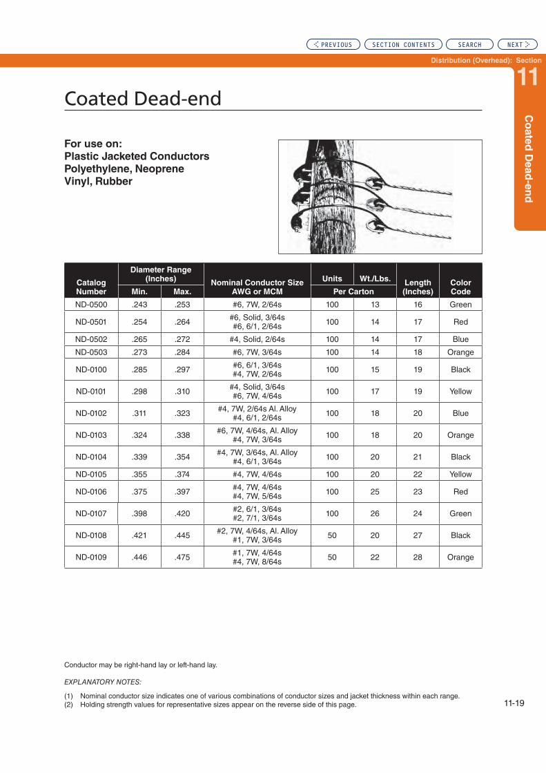
Distribution (Overhead): Section
11
11-19
Co
ate
d D
ead
-en
d
Coated Dead-end
For use on:
Plastic Jacketed Conductors
Polyethylene, Neoprene
Vinyl, Rubber
Conductor may be right-hand lay or left-hand lay.
EXPLANATORY NOTES:
(1) Nominal conductor size indicates one of various combinations of conductor sizes and jacket thickness within each range.(2) Holding strength values for representative sizes appear on the reverse side of this page.
Catalog Number
Diameter Range (Inches)
Nominal Conductor SizeAWG or MCM
Units Wt./Lbs.Length (Inches)
Color CodeMin. Max. Per Carton
ND-0500 .243 .253 #6, 7W, 2/64s 100 13 16 Green
ND-0501 .254 .264 #6, Solid, 3/64s #6, 6/1, 2/64s 100 14 17 Red
ND-0502 .265 .272 #4, Solid, 2/64s 100 14 17 Blue
ND-0503 .273 .284 #6, 7W, 3/64s 100 14 18 Orange
ND-0100 .285 .297 #6, 6/1, 3/64s #4, 7W, 2/64s 100 15 19 Black
ND-0101 .298 .310 #4, Solid, 3/64s #6, 7W, 4/64s 100 17 19 Yellow
ND-0102 .311 .323 #4, 7W, 2/64s Al. Alloy #4, 6/1, 2/64s 100 18 20 Blue
ND-0103 .324 .338 #6, 7W, 4/64s, Al. Alloy #4, 7W, 3/64s 100 18 20 Orange
ND-0104 .339 .354 #4, 7W, 3/64s, Al. Alloy #4, 6/1, 3/64s 100 20 21 Black
ND-0105 .355 .374 #4, 7W, 4/64s 100 20 22 Yellow
ND-0106 .375 .397 #4, 7W, 4/64s #4, 7W, 5/64s 100 25 23 Red
ND-0107 .398 .420 #2, 6/1, 3/64s #2, 7/1, 3/64s 100 26 24 Green
ND-0108 .421 .445 #2, 7W, 4/64s, Al. Alloy #1, 7W, 3/64s 50 20 27 Black
ND-0109 .446 .475 #1, 7W, 4/64s #4, 7W, 8/64s 50 22 28 Orange
PREVIOUS SECTION CONTENTS SEARCH NEXT

11-20
Coated Dead-end
For use on:
Plastic Jacketed Conductors
Polyethylene, Neoprene
Vinyl, Rubber
Catalog Number Size Jacketing
Outside Diameter (Inches)
Sustained Load Test Results
(Lbs.)
Percent of Breaking Strength
ND-0500 #6, 7W, 2/64s Poly* .246 450 89%
ND-0100 #4, 7W, 2/64s Poly* .294 750 95%
ND-0102#4, 6/1, 2/64s Poly* .313 800 46%
#4, 7/1, 2/64s Poly (.929) .320 850 39%
ND-0103 #4, 7W, 3/64s Neoprene .326 800 108%
ND-0104 #4, 6/1, 3/64s Neoprene .344 750 43%
ND-0106#2, 7W, 3/64s Neoprene .386 600 52%
#2, 6/1, 3/64s Poly* .386 750 62%
ND-0107
#2, 6/1, 3/64s Poly* .410 900 34%
#2, 6/1, 3/64s Neoprene .410 900 34%
#2, 7/1, 3/64s Poly* .419 1,200 35%
#2, 7/1, 3/64s Neoprene .419 1,000 30%
*Low density or medium density polyethylene per ASTM D-1243-58T.
This table is based on actual results of long term sustained load tests and may be considered representative of the cables described. Refer earlier in this section for an explanation of the multiple factors affecting holding strength of Dead-ends Coated.
PREVIOUS SECTION CONTENTS SEARCH NEXT

Distribution (Overhead): Section
11
11-21
Co
ate
d D
ead
-en
d
Coated Dead-end
For use on:
Plastic Jacketed Conductors
Polyethylene, Neoprene
Vinyl, Rubber
Right-hand or left-hand lay standard
EXPLANATORY NOTES:
(1) Nominal conductor size indicates one of various combinations of conductor sizes and jacket thickness within each range.(2) Cabled loop design furnished for all sizes on this page. See reference chart in this section for acceptable fittings.(3) Holding strength values for representative sizes appear on the reverse side of this page.
Catalog
Number
Diameter Range
(Inches) Nominal Conductor Size Units Wt./Lbs.Length
(Inches)
Color
CodeMin. Max. AWG or MCM Per Carton
ND-0110 .476 .507 #1, 19W, 5/64s 1/0, 7W, 4/64s 50 30 30 Blue
ND-0111 .508 .536 1/0, 19W, 6/64s /0, 19W, 5/64s 50 29 30 Red
ND-0112 .537 .571 2/0, 7W, 4/64s 2/0, 19W, 6/64s, Comp. 50 34 31 Black
ND-0113 .572 .608 3/0, 19W, 4/64s 2/0, 19W, 5/64s 50 36 33 Yellow
ND-0114 .609 .648 1/0, 7W, 8/64s 4/0, 7W, 4/64s 25 24 33 Red
ND-0115 .649 .690 1/0, 7W, 10/64s 4/0, 19W, 4/64s 25 26 34 Green
ND-0116 .691 .735 250, 19W, 4/64s 266.8, 18/1, 4/64s 25 30 35 Black
ND-0117 .736 .783 3/0, 7W, 10/64s 25 32 36 Orange
ND-0118 .784 .834 300, 19W, 5/64s 336.4, 19W, 5/64s 25 34 38 Blue
ND-0119 .835 .888 350, 19W, 5/64s 300, 19W, 10/64s Comp. 25 40 40 Black
ND-0120 .889 .945 250, 19W, 10/64s 300, 19W, 10/64s 25 44 42 Yellow
ND-0121 .946 1.005 450, 37W, 6/64s 500, 37W, 6/64s 25 52 44 Green
ND-0122 1.006 1.070 450, 37W, 8/64s 336.4, 19W, 12/64s 10 24 45 Red
ND-0123 1.071 1.138 350, 19W, 12/64s 500, 37W, 10/64s 10 24 47 Blue
ND-0124 1.139 1.212 636, 37W, 10/64s Comp. 500, 37W, 12/64s 10 30 48 Orange
ND-0125 1.213 1.288 795, 61W, 6/64s 795, 37W, 10/64s Comp. 10 30 49 Black
ND-0126 1.289 1.372 1033.5, 61W, 6/64s 10 32 51 Yellow
ND-0127 1.373 1.458 715, 37W, 14/64s 10 38 53 Green
ND-0128 1.459 1.550 795, 37W, 14/64s 10 40 56 Red
PREVIOUS SECTION CONTENTS SEARCH NEXT

11-22
Coated Dead-end
For use on:
Plastic Jacketed Conductors
Polyethylene, Neoprene
Vinyl, Rubber
This table is based on actual results of long term sustained load tests and may be considered representative of the cables described.
Refer to reference charts in this section for additional information on Holding Strengths.
Specific gravity of various polyethylenes:
ASTM Designation D-1248-58T
Low Density (g/cu. cm.) ....................... 0.910-0.925 Medium Density (g/cu. cm.) .................... 0.926-0.940 High Density (g/cu. cm.) ....................... 0.941-0.965
SizeJacketing
(Specific Gravity)Outside Diameter
(Inches)Sustained Load
Test Results (Lbs.)Percent of Breaking
Strength
2/0, 7W, 4/64s Poly. (.928) .539 1,800 104%
1/0, 7W, 4/64s Poly. (.931) .493 2,200 101%
1/0, 7W, 4/64s Neoprene .493 1,650 98%
2/0, 7W, 4/64s Neoprene .539 2,100 99%
366.4, 19W, 4/64s Poly. (.933) .791 4,500 79%
400, 19W, 6/64s Neoprene .913 5,000 80%
250, 19W, 5/64s Neoprene .732 3,200 79%
397.5, 19W, 6/64s Poly. (.928) .912 4,700 72%
3/0, 7W, 8/64s Poly. (.927) .706 1,900 70%
336.4, 19W, 5/64s Neoprene .824 3,600 67%
500, 37W, 6/64s Poly. (.926) 1.001 5,600 65%
336.4, 19W, 4/64s Poly. (.920) .791 3,600 63%
1/0, 7W, 4/64s Poly. (.918) .493 1,100 62%
#4, 6/1, 8/64s Poly. (.929) .502 950 54%
4/0, 7W, 10/64s Poly. (.920) .830 3,000 49%
4/0, 7W, .078 Vinyl .695 1,600 47%
336.4, 19W, .150" Compacted Poly. (.943) .910 2,600 46%
266.8, 19W, 10/64s Poly. (.966) .885 1,800 40%
4/0, 6/1, 4/64s Neoprene .688 2,900 36%
1/0, 7W, 10/64s Poly. (.982) .678 600 33%
1/0, 7W, 10/64s Poly. (.949) .692 500 28%
PREVIOUS SECTION CONTENTS SEARCH NEXT

Distribution (Overhead): Section
11
11-23
Sla
ck S
pan
D
ead
-en
d
Slack Span Dead-end
Dead-end Material Helical Leg Section: Aluminum covered steel. An aluminum alloy version is available for corrosive environment. Contact PLP.
Crossover Marks: Indicates starting point for application on conductor.
Color Code & Length: Assists in identification of conductor diameter range, corresponding to tabular information listed on catalog pages.
GENERAL RECOMMENDATIONS
Slack Span Dead-end is intended for use on aluminum based conductors with diameter ranges from .229" to 1.216". It is specifically designed to terminate primary, secondary and neutral conductors.
Each Slack Span Dead-end covers a range of conductor di-ameters as outlined on catalog pages.
Conductor Tension Limitations: The Slack Span Dead-end is specifically designed for LIMITED TENSION APPLICATIONS. IT SHOULD NOT BE USED AS A FULL TENSION DEAD-END.
The Slack Span Dead-end is intended for use where guying (or other) restrictions prevent full tension spans. While individual utility construction and safety practices should dictate actual installations, each Slack Span Dead-end has a warning label attached suggesting a maximum allowable loaded tension of 1000 lbs. This value does not indicate a holding strength rating for Slack Span Dead-ends; rather, it suggests a practical limit for tensions in this type of construction.
The Slack Span Dead-end replaces conventional Dead-ending equipment used in slack span construction.
Dead-end insulators, clamps, and associated hardware when used in this way normally do not offer tight, solid electrical connections between each other. This “looseness” can allow intermittent contact and ultimately produce troublesome RFI (RIV) and TVI. Construction practices utilizing the Slack Span Dead-end can minimize this problem.
The Slack Span Dead-end is specifically designed to be in-stalled on pin, line post or spool insulators when used in limited tension construction. Refer to Figure 1 for a typical installation. Refer to Illustrations 1 and 2 and Acceptable Fitting Section for acceptable types and sizes of insulators and fittings.
Covered Loop Section: The loop of the Dead-end is covered with an elastomer to provide protection against abrasion and damage to the glaze of the insulator. It also helps minimize RFI, TVI, etc.
The Slack Span Dead-end is designed to grip the conductor uniformly to prevent distortion. It also offers a unique design that eliminates bolts, nuts, washers and other component parts that may become lost or damaged during installation or in service.
Where requirements call for increased tension applications, use either the Distribution Grip Dead-end or the Overhead Dead-end. On jacketed conductors, use either coated Dead-ends or Distribution Grip Dead-ends.
Where requirements call for Dead-ending conductors associ-ated with bare neutral messengers or self-supporting cable used in making service drops, use Service Grip Dead-ends. Distribution Grip (Slack Span/Overhead) Dead Ends are not recommended for use with high temperature/low sag conduc-tors such as ACSS, ACSS/AW, ACSS/TW, ACCR or other types of conductors with loose, and/or annealed outer layer strands. Typically THERMOLINE Dead Ends are suggested for these applications. Consult PLP for further information.
Distribution Grip (Slack Span/Overhead) Dead Ends are
not recommended for use with high temperature/low sag
conductors such as ACSS, ACSS/AW, ACSS/TW, ACCR
or other types of conductors with loose, and/or annealed
outer layer strands. Typically THERMOLIGN® Dead Ends
are suggested for these applications; consult PLP for
further information.
GENERAL RECOMMENDATIONS
NOMENCLATURE
Covered Loop Section: Elastomeric compound specifi-cally formulated for resistance to ozone attack, weathering and abrasion.
Product Identification Tag/Warning Label: Identifies catalog number, appropriate conductor types and sizes and product usage limitations.
PREVIOUS SECTION CONTENTS SEARCH NEXT

11-24
Slack Span Dead-end
Conductor Compatibility: Slack Span Dead-ends should be used only on the size and type of conductor for which they are designed. They must have the same lay as the conductor to which they are being applied. When ordering Slack Span Dead-ends, make sure to specify the conductor size and type they are to be used on. When using types and/or sizes of conductors not mentioned in these catalog pages, consult Preformed Line Products Company.
During installation, and at all times, care should be taken to avoid gouging or damaging the protective coating of the Slack Span Dead-end or the conductor itself.
Slack Span Dead-ends should not be used as tools;
i.e., come-alongs, pulling-in grips, etc.
Tools are not required to install Slack Span Dead-ends, except for hot stick applications.
Tapping: Tapping over the legs of the Slack Span Dead-end is NOT recommended. Taps can be made beyond the ends of the Dead-end on the conductor or on the conductor tail that extends through the loop.
Slack Span Dead-ends should not be used on overhead shield wires.
FOR ADDITIONAL INFORMATION REGARDING INSTAL-LATION, REFER TO THE Slack Span Dead-end APPLICA-TION PROCEDURE.
When in doubt about dimensions, fittings, installations, or unusual applications, consult your PREFORMED™ Sales Representative or Preformed Line Products Company.
Slack Span Dead-ends are specifically designed to be applied around the necks of certain pin, line post and spool insulators.
Slack Span Dead-ends can be applied to either:a. ANSI “C” and “F” neck insulators and ANSI class 53-1
to 53-5 spool insulators, orb. ANSI “J” neck insulators.
Refer to Illustration 1. for nominal insulator neck sizes and appropriate size Slack Span Dead-end.
Application of Slack Span Dead-ends to non-insulator fittings is acceptable as long as the fitting:a. has smoothly contoured dimensions,b. has a seat diameter (Illustration 2, Figure 1)
consistent with the insulator neck diameters shown in Illustration 1.,
c. has a minimum groove width (Illustration 2, Figure 2) of 9/16".
1. This product is intended for a single (one-time) use and for the specified application, although it may be reapplied twice for retensioning within 90 days of initial installation. CAU-TION: DO NOT MODIFY OR REUSE THIS PRODUCT AFTER 90 DAYS UNDER ANY CIRCUMSTANCES.
2. This product is intended for use by trained craftspeople only. This product SHOULD NOT BE USED by anyone who is not familiar with and trained in the use of it.
3. When working in the area of energized lines with this product, EXTRA CARE should be taken to prevent ac-cidental electrical contact.
4. For PROPER PERFORMANCE AND PERSONAL SAFETY be sure to select the proper size PREFORMED™ product before application.
5. PREFORMED™ products are precision devices. To insure proper performance, they should be stored in cartons under cover and handled carefully.
SAFETY CONSIDERATIONS
INSTALLATION GUIDELINES ACCEPTABLE FITTINGS
PREVIOUS SECTION CONTENTS SEARCH NEXT

Distribution (Overhead): Section
11
11-25
Sla
ck S
pan
D
ead
-en
d
Slack Span Dead-end
Illustration 1. Applicable Pin, Line post and Spool Insulators
Illustration 2. Acceptable Dimensions for Non-Insulator Fittings
PREVIOUS SECTION CONTENTS SEARCH NEXT

11-26
Slack Span Dead-end
Right-hand lay standard
EXPLANATORY NOTES:
(1) AWAC is a registered trademark of the Copperweld Co.(2) Where Dead-ending requirements call for other than limited tension requirements, refer to Distribution-Grip Dead-ends,
Dead-end-Coated, or Overhead Dead-end.(3) Where Dead-ending requirements call for Service Grip Dead-ends, refer to that section.(4) Insulators with C and F neck dimensions can be identified by consulting the manufacturer.(5) “Conductor Range” indicates the range of conductors that utilize the same Dead-end. (6) Refer to Illustrations 1 and 2 and Acceptable fittings portion of this section for dimensions of appropriate insulators and fittings.(7) When in doubt about dimensions, insulators, fittings, installations, or unusual applications, consult your PREFORMED™ sales
representative or Preformed Line Products Co.
For use on:
ACAR, All-Aluminum
ACSR, Aluminum Alloy
AWAC®, Compacted ACSR
C-Neck and F-Neck Interchangeable
Headstyle Insulators:
2-1/4" Neck Diameter
2-7/8" Neck Diameter
ANSI Class Spool Insulators:
ANSI 53-1, 53-2, 53-3
1-3/4" Neck Diameter
ANSI 53-4, 53-5
2-7/8" Neck Diameter
Catalog Number
ConductorPer Carton
Units Length (Inches) Color Code Range (Inches) Nominal Size
SSDE-9122 .229-.257 #4 AWG 25 16 Orange
SSDE-9124 .290-.325 #2 AWG 25 18 Red
SSDE-9125 .326-.364 #1 AWG 25 19 Green
SSDE-9126 .365-.409 1/0 AWG 25 20 Yellow
SSDE-9127 .410-.460 2/0 AWG 25 18 Blue
SSDE-9128 .461-.516 3/0 AWG 25 18 Orange
SSDE-9129 .517-.577 4/0 AWG 25 19 Red
SSDE-9130 .578-.665 266.8 kcmil 25 21 Black
SSDE-9131 .666-.783 336.4 kcmil 25 21 Green
SSDE-9132 .784-.883 477 kcmil 25 22 Orange
SSDE-9133 .884-1.025 636 kcmil 25 25 Brown
SSDE-9134 1.026-1.216 795 kcmil 25 26 Orange
PREVIOUS SECTION CONTENTS SEARCH NEXT

Distribution (Overhead): Section
11
11-27
Sla
ck S
pan
D
ead
-en
d
Slack Span Dead-end
For use on:
ACAR, All-Aluminum
ACSR, Aluminum Alloy
AWAC®, Compacted ACSR
J-Neck Interchangeable
Headstyle Insulators:
3-1/2" Neck Diameter
ANSI 55-6 Single Skirt Pin
ANSI 55-7 Single Skirt Pin
ANSI 55-8 Double Skirt Pin
Right-hand lay standard
EXPLANATORY NOTES:
(1) AWAC is a registered trademark of the Copperweld Co.(2) Where Dead-ending requirements call for other than limited tension requirements, refer to Distribution Grip Dead-ends, Dead-
end-Coated, or Overhead Dead-end.(3) Where Dead-ending requirements call for Service Grip Dead-ends, refer to that section.(4) Insulators with C and F neck dimensions can be identified by consulting the manufacturer.(5) “Conductor Range” indicates the range of conductors that utilize the same Dead-end.(6) Refer to Illustrations 1 and 2 and Acceptable fittings portion of this section for dimensions of appropriate insulators and fittings.(7) When in doubt about dimensions, insulators, fittings, installations, or unusual applications, consult your PREFORMED™ sales
representative or Preformed Line Products Co.
Catalog Number
ConductorPer Carton
Units Length (Inches) Color Code Range (Inches) Nominal Size
SSDE-9142 .229-.357 #4 AWG 25 18 Orange
SSDE-9144 .290-.325 #2 AWG 25 19 Red
SSDE-9145 .326-.364 #1 AWG 25 20 Green
SSDE-9146 .365-.409 1/0 AWG 25 21 Yellow
SSDE-9147 .410-.460 2/0 AWG 25 19 Blue
SSDE-9148 .461-.516 3/0 AWG 25 20 Orange
SSDE-9149 .517-.577 4/0 AWG 25 21 Red
SSDE-9150 .578-.665 266.8 kcmil 25 22 Black
SSDE-9151 .666-.783 336.4 kcmil 25 23 Green
SSDE-9152 .784-.883 477 kcmil 25 24 Orange
SSDE-9153 .884-1.025 636 kcmil 25 27 Brown
SSDE-9154 1.026-1.216 795 kcmil 25 28 Orange
PREVIOUS SECTION CONTENTS SEARCH NEXT

11-28
Service-Grip Dead-end
Crossover Marks: Indicate starting point for application.
Color Code and Length: Assist in identification of conduc-tor size, corresponding to tabular information appearing on catalog pages.
Identification Tape: Shows catalog number, nominal sizes.
Service-Grip Dead-end, manufactured of aluminum-covered steel, is designed for bare neutral messengers of self-sup-porting cable used in making service drops. The Dead-end is recommended for service drops by reason of minimum length, economy, and neatness of appearance. Mechanical strength meets the requirements for NESC Grade “N”, Rule 263-E, Supply Services, Spans not exceeding 150 feet.
For service drops exceeding 150 feet, Grade “C” Construc-tion, the Distribution Grip Dead-end is recommended.
Dead-end: Coated is recommended for direct application over plastic jacketed open-wire service drops.
RATED HOLDING STRENGTH. Published for individual sizes on the page following the initial specification page. In arriving at “Rated Holding Strengths”, actual results of tests on unweathered conductor are studied, and consideration is given to dimensional tolerances for the sizes encompassed. These minimum values are conservative when compared to “typical” values, or, actual tests on conductor which has been in service.
TAPPING. Tapping over the applied legs of Service-Grip Dead-end is not recommended. Taps can be made on the conductor, ahead of the Dead-end, or, the conductor can continue through the crossover point of the grip with con-nectors applied to the continued tail.
VIBRATION DAMPERS. No consideration of dampen-ing devices with Service-Grip Dead-ends is made since Distribution-Grip Dead-ends are recommended when vibration is suspected.
APPLICATION-INSPECTION. Dead-ends should not be re-used after original installation.
Lay direction of both the Dead-end and the conductor should be the same. Lay direction of most neutral-messengers is right hand lay.
The loops of Service-Grip Dead-ends should not be criss-crossed, when two or more are applied to the same spool.
1. This product is intended for a single (one-time) use and for the specified application, although it may be reapplied twice for retensioning within 90 days of initial installation. CAU-TION: DO NOT MODIFY OR REUSE THIS PRODUCT AFTER 90 DAYS UNDER ANY CIRCUMSTANCES.
2. This product is intended for use by trained craftspeople only. This product SHOULD NOT BE USED by anyone who is not familiar with and trained in the use of it.
3. When working in the area of energized lines with this product, EXTRA CARE should be taken to prevent ac-cidental electrical contact.
4. For PROPER PERFORMANCE AND PERSONAL SAFETY be sure to select the proper size Service-Grip Dead-end before application.
5. Service-Grip Dead-ends are precision devices. To insure proper performance, they should be stored in cartons under cover and handled carefully.
GENERAL RECOMMENDATIONS
NOMENCLATURE
SAFETY CONSIDERATIONS
(Continued on next page)
PREVIOUS SECTION CONTENTS SEARCH NEXT

Distribution (Overhead): Section
11
11-29
Serv
ice-G
rip
Dead
-en
d
Service-Grip Dead-end
Loops of the Service-Grip Dead-end are designed for use with a variety of porcelain fittings. These fittings are recommended because they have smoothly contoured diameters between 1-1/8" minimum and 3" maximum. Refer to catalog pages for maximum neck diameters for specific Service-Grip Dead-ends.
Consult PLP for fittings not appearing in this table.
GENERAL RECOMMENDATIONS CONTD.
PREVIOUS SECTION CONTENTS SEARCH NEXT

11-30
Service-Grip Dead-end
Right-hand lay standard
EXPLANATORY NOTES:
(1) Nominal conductor size indicates a few of the various conductors within each range. Refer to the following page for additional conductor sizes interchangeable with the same Dead-end. Consult PLP for sizes or strandings not shown.
(2) Refer earlier in this section for acceptable fittings.(3) Rated Holding Strengths are listed on the following page.
For use on:
ACSR, All-Aluminum
Aluminum Alloy, Compacted ACSR
Compacted All-Aluminum
Catalog
Number
Diameter Range
(In.) Nominal Conductor Sizes Units Wt./Lbs.
Length
(In.)
Color
Code
Max.
Neck
Dia. (In.) Min. Max. ACSR
All-
Alum.
Alum.
Alloy Comp. Per Carton
SG-4500 .169 .198 #6, 6/1 #6, 7W #6, 7W #6, 6/1 #6, 7W 300 24 11 Blue 2-3/8
SG-4501 .199 .224 #5, 6/1 #4, Solid #5, 7W #4, 7W 300 27 12 White 2-3/8
SG-4502 .225 .257 #4, 6/1 #4, 7/1 #4, 7W #4, 7W #4, 6/1
#4, 7/1 300 29 13 Orange 2-3/8
SG-4503 .258 .289 #3, 6/1 #3, 7W #2, Solid #3, 7W #3, 6/1
#2, 7W 200 27 14 Black 2-5/8
SG-4504 .290 .325 #2, 6/1 #2, 7/1 #2, 7W #2, 7W #2, 6/1
#1, 7W 200 28 15 Red 2-5/8
SG-4505 .326 .360 #1, 6/1 #1, 7W #1, 7W #1, 6/1 1/0, 7W 200 31 17 Green 2-5/8
SG-4506 .361 .400 1/0, 6/1 1/0, 7W 1/0, 7W 1/0, 6/1 2/0, 7W 100 28 19 Yellow 2-7/8
SG-4507 .401 .450 2/0, 6/1 2/0, 7W 2/0, 7W 2/0, 6/1 3/0, 7W 100 31 21 Blue 2-7/8
SG-4508 .451 .510 3/0, 6/1 3/0, 7W 3/0, 7W 4/0, 7W 100 33 23 Orange 2-7/8
SG-4509 .511 .580 4/0, 6/1 4/0, 18/1 4/0, 7W 4/0, 7W 4/0, 6/1 100 37 26 Red 3
PREVIOUS SECTION CONTENTS SEARCH NEXT
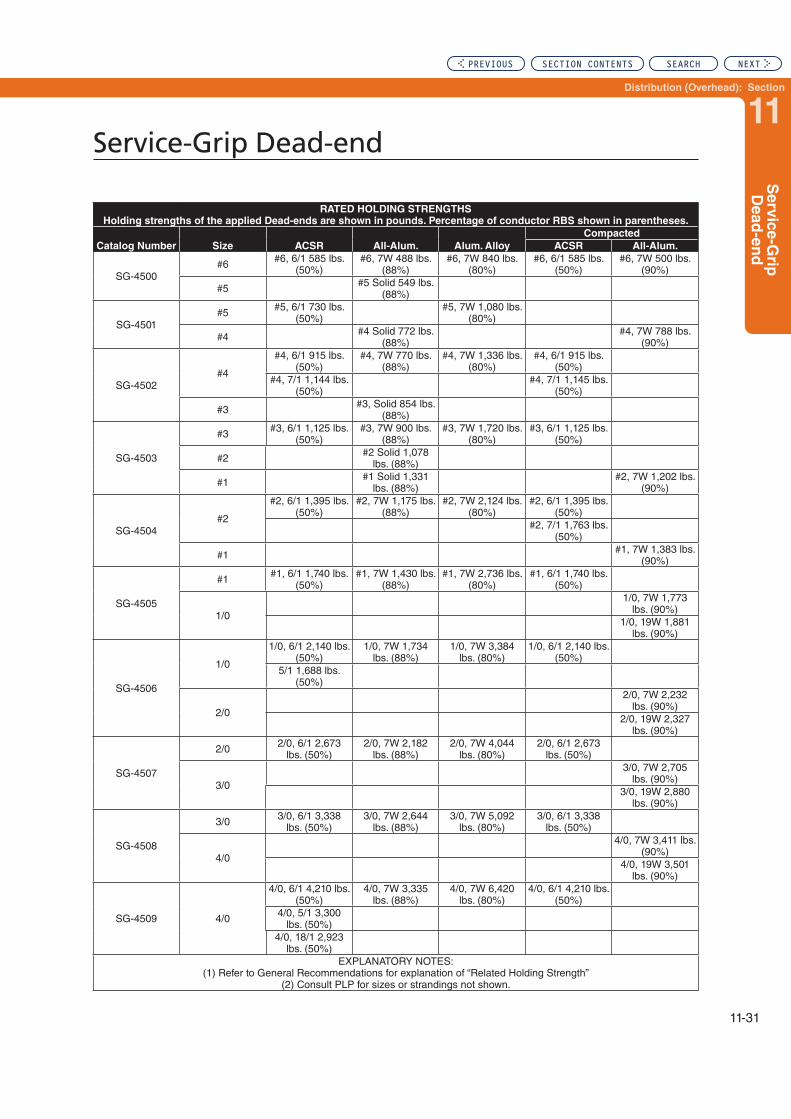
Distribution (Overhead): Section
11
11-31
Serv
ice-G
rip
Dead
-en
d
Service-Grip Dead-end
RATED HOLDING STRENGTHS
Holding strengths of the applied Dead-ends are shown in pounds. Percentage of conductor RBS shown in parentheses.
Catalog Number Size ACSR All-Alum. Alum. Alloy
Compacted
ACSR All-Alum.
SG-4500#6 #6, 6/1 585 lbs.
(50%)#6, 7W 488 lbs.
(88%)#6, 7W 840 lbs.
(80%)#6, 6/1 585 lbs.
(50%)#6, 7W 500 lbs.
(90%)
#5 #5 Solid 549 lbs. (88%)
SG-4501#5 #5, 6/1 730 lbs.
(50%)#5, 7W 1,080 lbs.
(80%)
#4 #4 Solid 772 lbs. (88%)
#4, 7W 788 lbs. (90%)
SG-4502#4
#4, 6/1 915 lbs. (50%)
#4, 7W 770 lbs. (88%)
#4, 7W 1,336 lbs. (80%)
#4, 6/1 915 lbs. (50%)
#4, 7/1 1,144 lbs. (50%)
#4, 7/1 1,145 lbs. (50%)
#3 #3, Solid 854 lbs. (88%)
SG-4503
#3 #3, 6/1 1,125 lbs. (50%)
#3, 7W 900 lbs. (88%)
#3, 7W 1,720 lbs. (80%)
#3, 6/1 1,125 lbs. (50%)
#2 #2 Solid 1,078 lbs. (88%)
#1 #1 Solid 1,331 lbs. (88%)
#2, 7W 1,202 lbs. (90%)
SG-4504#2
#2, 6/1 1,395 lbs. (50%)
#2, 7W 1,175 lbs. (88%)
#2, 7W 2,124 lbs. (80%)
#2, 6/1 1,395 lbs. (50%)
#2, 7/1 1,763 lbs. (50%)
#1 #1, 7W 1,383 lbs. (90%)
SG-4505
#1 #1, 6/1 1,740 lbs. (50%)
#1, 7W 1,430 lbs. (88%)
#1, 7W 2,736 lbs. (80%)
#1, 6/1 1,740 lbs. (50%)
1/0
1/0, 7W 1,773 lbs. (90%)
1/0, 19W 1,881 lbs. (90%)
SG-4506
1/0
1/0, 6/1 2,140 lbs. (50%)
1/0, 7W 1,734 lbs. (88%)
1/0, 7W 3,384 lbs. (80%)
1/0, 6/1 2,140 lbs. (50%)
5/1 1,688 lbs. (50%)
2/0
2/0, 7W 2,232 lbs. (90%)
2/0, 19W 2,327 lbs. (90%)
SG-4507
2/0 2/0, 6/1 2,673 lbs. (50%)
2/0, 7W 2,182 lbs. (88%)
2/0, 7W 4,044 lbs. (80%)
2/0, 6/1 2,673 lbs. (50%)
3/0
3/0, 7W 2,705 lbs. (90%)
3/0, 19W 2,880 lbs. (90%)
SG-4508
3/0 3/0, 6/1 3,338 lbs. (50%)
3/0, 7W 2,644 lbs. (88%)
3/0, 7W 5,092 lbs. (80%)
3/0, 6/1 3,338 lbs. (50%)
4/0
4/0, 7W 3,411 lbs. (90%)
4/0, 19W 3,501 lbs. (90%)
SG-4509 4/0
4/0, 6/1 4,210 lbs. (50%)
4/0, 7W 3,335 lbs. (88%)
4/0, 7W 6,420 lbs. (80%)
4/0, 6/1 4,210 lbs. (50%)
4/0, 5/1 3,300 lbs. (50%)
4/0, 18/1 2,923 lbs. (50%)
EXPLANATORY NOTES:(1) Refer to General Recommendations for explanation of “Related Holding Strength”
(2) Consult PLP for sizes or strandings not shown.
PREVIOUS SECTION CONTENTS SEARCH NEXT

Distribution (Overhead): Section
12
Section 12 – Distribution (Overhead): Splices
Table of Contents
Conductor Splice ...................................................................................12-2
ACSR Full Tension Splice ...................................................................12-16
Page
PREVIOUS SEARCH NEXT

Conductor Splice
12-2
Conductor Splices are designed as a single-component outer-layer assembly generally for Sub-EHV applications.
Conductor splices are available for EHV applications. Consult PLP for details.
JOINING: On all-aluminum, aluminum alloy, and copper conductors of homogenous stranding, the Conductor Splice will hold a minimum of 90% of the rated breaking strength of, and provide better conductance than, an equal length of unspliced conductor.
On ACSR conductor, the Conductor Splice will hold a minimum tension amounting to the full strength of the aluminum strands plus 10% of the steel core strength. Conductance will be better than in an equivalent length of unspliced conductor.
RESTORATIVE-REPAIR: Conductor Splices will restore original conductivity to all-aluminum, aluminum alloy, cop-per, and ACSR type conductors.
Full-rated breaking strength will be restored to homogeneous stranded conductors. On ACSR, strength will be restored to all of the aluminum strands, but not to the core. When core damage on ACSR is suspected, consult the following catalog section for Splice: ACSR F.T.
Other PREFORMED™ products with restorative-repair ca-pabilities are Armor Rods, Line Guards, Splice Shunt, and ARMOR-GRIP® Suspension: for Line Repair.
RATED HOLDING STRENGTH: Published for individual sizes on the page following the specification page. In arriving at “Rated Hold Strength,” actual results of tests on unweath-ered conductor are studied, and consideration is given to dimensional tolerances for the sizes encompassed.
APPLICATION-INSPECTION: All conductors, new or weath-ered, must be thoroughly scratch brushed until bright and clean. Immediately thereafter, an industry accepted inhibitor (compatible with the conductor) should be applied before installing the product.
TAPPING: Tapping over a conductor splice is permissible. Whenever a tapping clamp will be installed over a splice, it is imperative that the conductor be scratch brushed and an inhibitor be used. The outer surface of the splice should be thoroughly scratch brushed to remove any oxides and glue which may be present. Inhibitor should then be applied to the area beneath the tap itself.
NOMENCLATURE
Sub-Sets: Individual rods assembled and gritted into groups (subsets), corresponding to tabular information appearing on catalog page.
Center Mark: Establishes recommended alignment of rods during application.
Color Code and Length: Assist in identification of conduc-tor size, corresponding to tabular information appearing on catalog page.
Identification Tape: Shows catalog number, nominal sizes.
GENERAL RECOMMENDATIONS
Thermal Rating (Continuous)125°C
PREVIOUS SECTION CONTENTS SEARCH NEXT
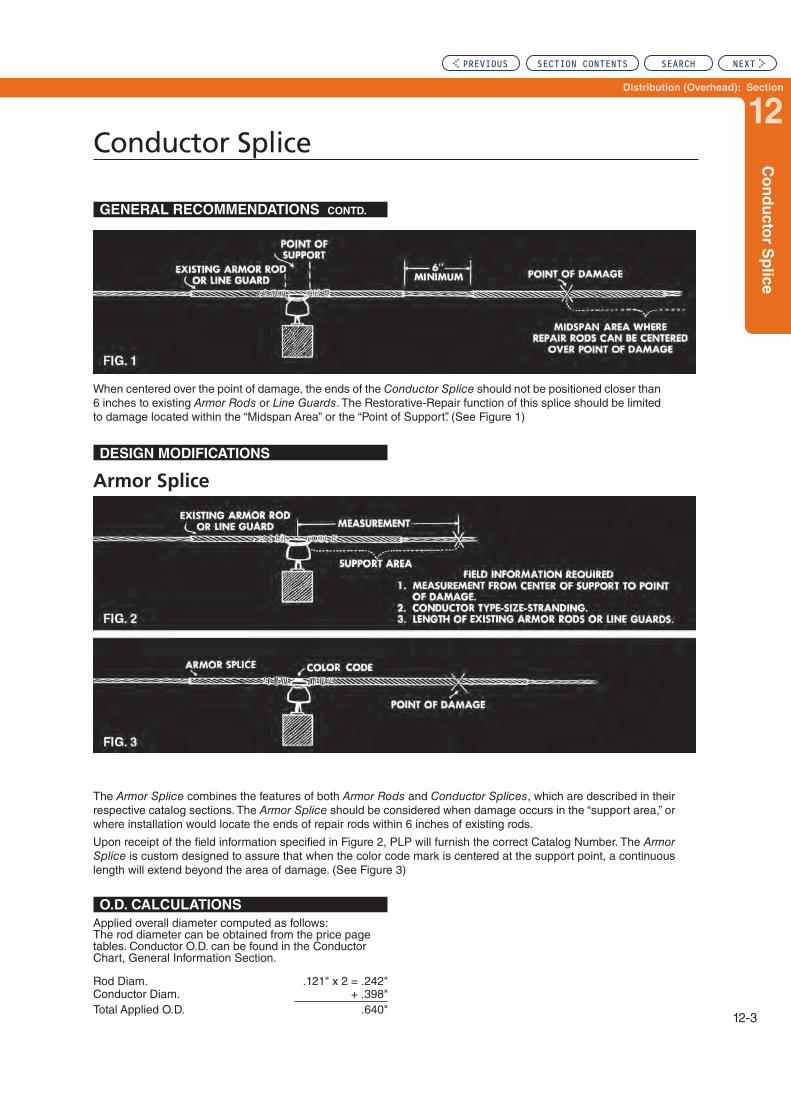
Distribution (Overhead): Section
12
Co
nd
ucto
r Sp
lice
Conductor Splice
12-3
When centered over the point of damage, the ends of the Conductor Splice should not be positioned closer than 6 inches to existing Armor Rods or Line Guards. The Restorative-Repair function of this splice should be limited to damage located within the “Midspan Area” or the “Point of Support”. (See Figure 1)
GENERAL RECOMMENDATIONS CONTD.
DESIGN MODIFICATIONS
Armor Splice
The Armor Splice combines the features of both Armor Rods and Conductor Splices, which are described in their respective catalog sections. The Armor Splice should be considered when damage occurs in the “support area,” or where installation would locate the ends of repair rods within 6 inches of existing rods.
Upon receipt of the field information specified in Figure 2, PLP will furnish the correct Catalog Number. The Armor Splice is custom designed to assure that when the color code mark is centered at the support point, a continuous length will extend beyond the area of damage. (See Figure 3)
O.D. CALCULATIONS
Applied overall diameter computed as follows:The rod diameter can be obtained from the price page tables. Conductor O.D. can be found in the Conductor Chart, General Information Section.
Rod Diam. .121" x 2 = .242"Conductor Diam. + .398"Total Applied O.D. .640"
PREVIOUS SECTION CONTENTS SEARCH NEXT

Conductor Splice – Aluminum
12-4
Right-hand lay standard
EXPLANATORY NOTES:
(1) Rated Holding Strengths are listed on the next page.
(2) Nominal Conductor size indicates one of various conductors within each range. Refer to the next page for additional conductor sizes interchangeable with the same conductor splice. Consult PLP for sizes not shown.
(3) AWAC and Copperweld are registered trademarks of the Copperweld Co.
For use on:
ACSR, All-Aluminum
Aluminum Alloy
AWAC® Conductor
Catalog
Number
Diameter Range
(Inches) Nominal Conductor
Size
Units Wt./Lbs. Length
(Inches)
Rod
Diameter
(Inches)
No. of
Subsets
Color
CodeMin.. Max. Per Carton
LS-0106 .177 .184 #6, 7W All-Alum. 50 6 21 .086 2 Purple
LS-0108 .194 .202 #6, 6/1 #6, 7W Alum. Alloy 50 6 22 .086 2 Blue
LS-0112 .229 .239 #4, 7W All-Alum. 50 9 24 .086 2 Brown
LS-0114 .247 .257 #4, 6/1 - 7/1 #4, 7W Alum. Alloy 50 10 26 .094 3 Orange
LS-0115 .258 .270 #3, 7W All-Alum. 50 11 26 .094 3 GreenLS-0116 .271 .280 #3, 7W Alum. Alloy 50 12 27 .094 3 YellowLS-0118 .290 .298 #2, 7W All-Alum. 50 13 28 .094 3 Purple
LS-0119 .299 .310 #2, AWAC 6/1 #3, AWAC 5/2 50 15 30 .102 3 Brown
LS-0120 .311 .325 #2, 6/1 - 7/1 #2, 7W Alum. Alloy 50 16 31 .102 3 Red
LS-0121 .326 .340 #1, 7W All-Alum. 50 16 31 .102 3 BlueLS-0122 .341 .351 #1, AWAC 6/1 50 17 33 .102 3 Orange
LS-0123 .352 .367 #1, 6/1 #1, 7W Alum. Alloy 50 19 34 .102 3 Green
LS-0124 .368 .380 #1, AWAC 5/2 1/0, 7W All-Alum. 50 27 38 .121 3 Black
LS-0125 .381 .398 1/0, AWAC 6/1 1/0, 6/1 1/0, 7W Alum. Alloy 50 27 38 .121 3 Yellow
LS-0127 .414 .425 2/0, 7W All-Alum. 50 27 40 .121 3 Brown
LS-0129 .444 .462 2/0, 6/1 2/0, 7W Alum. Alloy 50 37 42 .136 3 Blue
LS-0130 .463 .481 3/0, 7W All-Alum. 50 43 46 .136 3 Green
LS-0131 .482 .503 3/0, 7W, Alum. Alloy 3/0, AWAC 6/1 3/0, 6/1 50 46 46 .146 3 Orange
PREVIOUS SECTION CONTENTS SEARCH NEXT

Distribution (Overhead): Section
12
Co
nd
ucto
r Sp
lice –
A
lum
inu
m
Conductor Splice – Aluminum
12-5
Right-hand lay standard
EXPLANATORY NOTES:
(1) Refer to General Recommendations at the beginning of this section for explanation of “Rated Holding Strength”.
(2) For sizes or strandings not shown, consult PLP.
(3) Refer to the Splice: ACSR F. T. section for an alternate product with higher Rated Holding Strength on ACSR type conductors.
(4) AWAC and Copperweld are registered trademarks of the Copperweld Co.
RATED HOLDING STRENGTHS
Holding strengths of the applied splices are shown in pounds. Percentage of conductor RBS shown in parentheses.
Catalog Number Size ACSR All-Aluminum Aluminum Alloy AWAC®
LS-0106 #6 #6, 7W 555 lbs. (100%)
LS-0108 #6 #6, 6/1 702 lbs. (60%)
#6, 7W 1,050 lbs. (100%)
LS-0112 #4 #4, 7W 875 lbs. (100%)
LS-0114 #4
#4, 6/1 1,098 lbs. (60%)
#4, 7/1 1,374 lbs. (60%)
#4, 7W 1,670 lbs. (100%)
LS-0115
#3 #3, 7W 1,023 lbs. (100%)
#4 #4, 5/2 2,790 lbs. (100%)
LS-0116 #3 #3, 7W 2,150 lbs. (100%)
LS-0118 #2 #2, 7W 1,335 lbs. (100%)
LS-0119#3 #3, 5/2
3,500 lbs. 100%)
#2 #2, 6/1 1,590 lbs. (60%)
LS-0120 #2
#2, 6/1 1,674 lbs. (60%)
#2, 7/1 2,115 lbs. (60%)
#2, 7W 2,655 lbs. (100%)
LS-0121 #1 #1, 7W 1,625 lbs. (100%)
LS-0122 #1 #1, 6/1 1,986 lbs. (60%)
LS-0123 #1 #1, 6/1 2,088 lbs. (60%)
#1, 7W 3,420 lbs. (100%)
LS-0124#1 #1, 5/2
5,450 lbs. (100%)
1/0 1/0, 7W 1,970 lbs. (100%)
LS-0125 1/0 1/0, 6/1 2,568 lbs. (60%)
1/0, 7W 4,230 lbs. (100%)
1/0, 6/1 2,448 lbs. (100%)
LS-0127 2/0 2/0, 7W 2,480 lbs. (100%)
LS-0129 2/0 2/0, 6/1 2,940 lbs. (55%)
2/0, 7W 5,055 lbs. (100%)
LS-0130 3/0 3/0, 7W 3,005 lbs. (100%)
LS-0131 3/0 3/0, 6/1 3,671 lbs. (55%)
3/0, 7W 6,365 lbs. (100%)
3/0, 6/1 3,333 lbs. (55%)
PREVIOUS SECTION CONTENTS SEARCH NEXT

Conductor Splice – Aluminum
12-6
Right-hand lay standard
EXPLANATORY NOTES:
(1) Rated Holding Strengths are listed on the next page.
(2) Nominal Conductor size indicates one of various conductors within each range. Refer to the next page for additional conductor sizes interchangeable with the same conductor splice. Consult PLP for sizes not shown.
(3) For an example of applied overall diameter see “O.D. CALCULATIONS” at the beginning of this section.
For use on:
ACSR, All-Aluminum
Aluminum Alloy
AWAC® Conductor
Catalog Number
Diameter Range
(Inches)Nominal Conductor
Size
UnitsWt./Lbs.
Length (Inches)
Rod Diameter (Inches)
No. of Subsets
Color CodeMin. Max. Per Carton
LS-0133 .522 .544 3/0, AWAC 5/2 4/0, 7W All-Alum. 50 66 51 .167 3 Black
LS-0134 .545 .567 4/0, 7W Alum. Alloy 4/0, 6/1 25 33 52 .167 3 Red
LS-0135 .568 .594
250, 19W-37W All-Alum. 4/0, AWAC 15/4
266.8, 7W-19W-37W All-Alum.
25 48 61 .182 3 Blue
LS-0136 .595 .618 266.8, 18/1 25 50 63 .182 3 Purple
LS-0137 .619 .644 266.8, 26/7 300, 19W-37W All-Alum. 25 58 67 .182 3 Yellow
LS-0138 .645 .671300, 18/1
336.4, 19W-37W All Alum.
25 66 69 .204 3 Brown
LS-0139 .672 .700300, 26/7 - 30/7
336.4, 18/1 - 36/1 350, 19W-37W All-Alum.
25 68 70 .204 3 Orange
PREVIOUS SECTION CONTENTS SEARCH NEXT
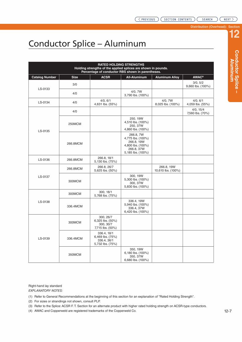
Distribution (Overhead): Section
12
Co
nd
ucto
r Sp
lice –
A
lum
inu
m
Conductor Splice – Aluminum
12-7
Right-hand lay standard
EXPLANATORY NOTES:
(1) Refer to General Recommendations at the beginning of this section for an explanation of "Rated Holding Strength".
(2) For sizes or strandings not shown, consult PLP.
(3) Refer to the Splice: ACSR F. T. Section for an alternate product with higher rated holding strength on ACSR-type conductors.
(4) AWAC and Copperweld are registered trademarks of the Copperweld Co.
RATED HOLDING STRENGTHS
Holding strengths of the applied splices are shown in pounds.
Percentage of conductor RBS shown in parentheses.
Catalog Number Size ACSR All-Aluminum Aluminum Alloy AWAC®
LS-01333/0 3/0, 5/2
9,660 lbs. (100%)
4/0 4/0, 7W 3,790 lbs. (100%)
LS-0134 4/0 4/0, 6/1 4,631 lbs. (55%)
4/0, 7W 8,025 lbs. (100%)
4/0, 6/1 4,059 lbs. (55%)
LS-0135
4/0 4/0, 15/4 7,560 lbs. (70%)
250MCM
250, 19W 4,510 lbs. (100%)
250, 37W 4,860 lbs. (100%)
266.8MCM
266.8, 7W 4,775 lbs. (100%)
266.8, 19W 4,800 lbs. (100%)
266.8, 37W 5,185 lbs. (100%)
LS-0136 266.8MCM 266.8, 18/1 5,130 lbs. (75%)
LS-0137
266.8MCM 266.8, 26/7 5,625 lbs. (50%)
266.8, 19W 10,610 lbs. (100%)
300MCM
300, 19W 5,300 lbs. (100%)
300, 37W 5,830 lbs. (100%)
LS-0138
300MCM 300, 18/1 5,768 lbs. (75%)
336.4MCM
336.4, 19W 5,940 lbs. (100%)
336.4, 37W 6,420 lbs. (100%)
LS-0139
300MCM
300, 26/7 6,325 lbs. (50%)
300, 30/7 7,715 lbs. (50%)
336.4MCM
336.4, 18/1 6,469 lbs. (75%)
336.4, 36/1 5,732 lbs. (75%)
350MCM
350, 19W 6,180 lbs. (100%)
350, 37W 6,680 lbs. (100%)
PREVIOUS SECTION CONTENTS SEARCH NEXT

Conductor Splice – Aluminum
12-8
Right-hand lay standard
EXPLANATORY NOTES:
(1) Rated Holding Strengths are listed on the next page.
(2) Nominal Conductor size indicates one of various conductors within each range. Refer to the next page for additional conductor sizes interchangeable with the same conductor splice. Consult PLP for sizes not shown.
(3) For an example of applied overall diameter see “O.D. CALCULATIONS” at the beginning of this section.
For use on:
ACSR, All-Aluminum
Aluminum Alloy
Catalog
Number
Diameter
Range (Inches)
Nominal Conductor Size
Units
Wt./
Lbs.Length
(Inches)
Rod
Diameter
(Inches)
No. Of
Subsets
Color
CodeMin. Max. Per Carton
LS-0140 .701 .729
336.4, 26/7 336.4, 19W Alum. Alloy
397.5, 19W-37W All-Alum. 400, 19W-37W All-Alum.
15 62 77 .250 3 Green
LS-0141 .730 .760 336.4, 30/7 397.5, 18/1 15 64 79 .250 3 Black
LS-0142 .761 .792397.5, 26/7
397.5, 19W Alum. Alloy 450, 19W-37W All-Alum.
15 74 83 .250 3 Purple
LS-0143 .793 .825477, 18/1 - 36/1
477, 19W-37W All-Alum. 500, 19W-37W All-Alum.
3 18 84 .250 3 Red
LS-0145 .851 .886477, 26/7
556.5, 18/1 - 36/1 556.5, 19W-37W All-Alum.
3 23 99 .250 4 Orange
PREVIOUS SECTION CONTENTS SEARCH NEXT

Distribution (Overhead): Section
12
Co
nd
ucto
r Sp
lice –
A
lum
inu
m
Conductor Splice – Aluminum
12-9
Right-hand lay standard
EXPLANATORY NOTES:
(1) Refer to General Recommendations at the beginning of this section for explanation of “Rated Holding Strength”.
(2) For sizes or strandings not shown, consult PLP.
(3) Refer to the Splice: ACSR F. T. Section for an alternate product with higher rated holding strength on ACSR-type conductors.
(4) AWAC and Copperweld are registered trademarks of the Copperweld Co.
RATED HOLDING STRENGTHSHolding strengths of the applied splices are shown in pounds.
Percentage of conductor RBS shown in parentheses.
Catalog Number
Nominal Conductor Size ACSR All-Aluminum Aluminum Alloy
LS-0140
363.4 336.4, 26/7 7,025 lbs. (50%)
336.4, 19W 12,830 lbs. (100%)
397.5
397.5, 19W 6,880 lbs. (100%)
397.5, 37W 7,305 lbs. (100%)
400
400, 19W 6,928 lbs. (100%)
400, 37W 7,350 lbs. (100%)
LS-0141
336.4 336.4, 30/7 8,520 lbs. (50%)
397.5
397.5, 18/1 7,530 lbs. (75%)
397.5, 36/1 6,555 lbs. (75%)
LS-0142
397.5 397.5, 26/7 8,095 lbs. (50%)
397.5, 19W 13,617 lbs. (90%)
450
450, 19W 7,630 lbs. (100%)
450, 37W 8,110 lbs. (100%)
LS-0143
477
477, 18/1 8,903 lbs. (75%)
477, 36/1 7,740 lbs. (75%)
477, 19W 8,090 lbs. (100%)
477, 37W 8,600 lbs. (100%)
500500, 19W 8,480 lbs. (100%) 500, 37W 9,100 lbs. (100%)
477 477, 19W 6,371 lbs. (90%)
LS-0145
477 477, 26/7 9,715 lbs. (50%)
550
550, 37W 9,720 lbs. (100%)
550, 61W 9,440 lbs. (90%)
556.5
556.5, 18/1 10,388 lbs. (75%)
556.5, 36/1 8,850 lbs. (75%)
556.5, 19W 9,440 lbs. (100%)
556.5, 37W 9,830 lbs. (100%)
PREVIOUS SECTION CONTENTS SEARCH NEXT

Conductor Splice – Aluminum
12-10
Right-hand lay standard
EXPLANATORY NOTES:
(1) Rated Holding Strengths are listed on the next page.
(2) Nominal Conductor size indicates one of various conductors within each range. Refer to the next page for additional conductor sizes interchangeable with the same conductor splice. Consult PLP for sizes not shown.
(3) For an example of applied overall diameter see “O.D. CALCULATIONS” at the beginning of this section.
For use on:
ACSR, All-Aluminum
Aluminum Alloy
Catalog
Number
Diameter
Range (Inches)
Nominal Conductor Size
Units
Wt./
Lbs.Length
(Inches)
Rod
Diameter
(Inches)
No. Of
Subsets
Color
CodeMin. Max. Per Carton
LS-0146 .887 .929 605, 36/1 636, 37W-61W All-Alum. 3 31 105 .310 3 Orange
LS-0147 .930 .968 636, 18/1 - 36/1 666.6 - 36/1 3 36 108 .310 4 Brown
LS-0148 .969 1.008 636, 54/7 - 26/7 666.6, 54/7 715.5, 36/1 3 37 111 .310 4 Yellow
LS-0149 1.009 1.050 795, 36/1 795, 37W-61W All-Alum. 3 39 121 .310 4 Green
PREVIOUS SECTION CONTENTS SEARCH NEXT

Distribution (Overhead): Section
12
Co
nd
ucto
r Sp
lice –
A
lum
inu
m
Conductor Splice – Aluminum
12-11
Right-hand lay standard
EXPLANATORY NOTES:
(1) Refer to General Recommendations at the beginning of this section for explanation of “Rated Holding Strength”.
(2) For sizes or strandings not shown, consult PLP.
RATED HOLDING STRENGTHS
Holding strengths of the applied splices are shown in pounds.
Percentage of conductor RBS shown in parentheses.
Catalog Number
Nominal Conductor
Size ACSR All-Aluminum Aluminum Alloy
LS-0146
500 500, 30/7 12,225 lbs. (50%)
556.5 556.5, 26/7 11,200 lbs. (50%)
556.5, 19W 19,080 lbs. (90%)
605 605, 36/1 9,600 lbs. (75%)
636
636, 37W 11,240 lbs. (100%)
636, 61W 10,520 lbs. (100%)
LS-0147
605
605, 30/7 12,050 lbs. (50%)
605, 54/7 11,250 lbs. (50%)
556.5 556.5, 30/7 13,600 lbs. (50%)
636
636, 18/1 11,873 lbs. (75%)
636, 36/1 10,088 lbs. (75%)
666 666.6, 36/1 10,575 lbs. (75%)
700
700, 37W 12,370 lbs. (100%)
700, 61W 11,570 lbs. (100%)
LS-0148
636 636, 26/7 12,500 lbs. (50%)
636 636, 54/7 11,180 lbs. (50%)
636, 37W 21,690 lbs. (90%)
715 715.5, 36/1 11,175 lbs. (75%)
715.5, 37W 12,640 lbs. (100%)
715.5, 61W 11,835 lbs. (100%)
750
750, 37W 2,990 lbs. (100%)
750, 61W 12,160 lbs. (100%)
LS-0149
795 795, 36/1 12,405 lbs. (75%)
795, 37W 13,770 lbs. (100%)
795, 61W 12,900 lbs. (100%)
800
800, 37W 13,850 lbs. (100%)
800, 61W 12,970 lbs. (100%)
PREVIOUS SECTION CONTENTS SEARCH NEXT

Conductor Splice – Aluminum
12-12
Right-hand lay standard
EXPLANATORY NOTES:
(1) Rated Holding Strengths are listed on the next page.
(2) Nominal Conductor size indicates one of various conductors within each range. Refer to the next page for additional conductor sizes interchangeable with the same conductor splice. Consult PLP for sizes not shown.
(3) For an example of applied overall diameter, see “O.D. CALCULATIONS” at the beginning of this section.
For use on:
ACSR, All-Aluminum
Aluminum Alloy
Catalog
Number
Diameter
Range (Inches)
Nominal Conductor Size
Units
Wt./
Lbs.Length
(Inches)
Rod
Diameter
(Inches)
No. of
Subsets
Color
CodeMin. Max. Per Carton
LS-0150 1.051 1.091 874.5, 36/1 874.5, 37W-61W All-Alum. 3 45 127 .310 4 Black
LS-0151 1.092 1.136 795, 54/7 954, 37W–61W All-Alum. 3 59 137 .365 4 Purple
LS-0152 1.137 1.183 954, 36/1–45/7 1,033.5, 37W–61W All-Alum. 3 62 141 .365 4 Red
LS-0153 1.184 1.232 1,033.5, 36/1–45/7 1,113, 61W All-Alum. 3 63 143 .365 4 Blue
LS-0155 1.300 1.353 1,272, 45/7 1,272, 61W All-Alum. 3 101 165 .436 4 Yellow
PREVIOUS SECTION CONTENTS SEARCH NEXT

Distribution (Overhead): Section
12
Co
nd
ucto
r Sp
lice
Conductor Splice
12-13
Right-hand lay standard
EXPLANATORY NOTES:
(1) Refer to General Recommendations at the beginning of this section for explanation of “Rated Holding Strength”.
(2) For sizes or strandings not shown, consult PLP.
RATED HOLDING STRENGTHS
Holding strengths of the applied splices are shown in pounds.
Percentage of conductor RBS shown in parentheses.
Catalog Number
Nominal Conductor
Size ACSR All-Aluminum Aluminum Alloy
LS-0150
715.5 715.5, 26/7 14,050 lbs. (50%)
795 795, 45/7 11,450 lbs. (50%)
874.5 874.5, 36/1 13,425 lbs. (75%)
874.5, 37W 14,830 lbs. (100%)
874.5, 61W 14,200 lbs. (90%)
LS-0151
795
795, 54/7 14,250 lbs. (50%)
795, 26/7 15,600 lbs. (50%)
795, 37W 27,135 lbs. (90%)
900 900, 45/7 12,700 lbs. (50%)
900, 37W 15,270 lbs. (100%)
900, 61W 14,310 lbs. (90%)
954
954, 37W 16,180 lbs. (100%)
954, 61W 15,175 lbs. (90%)
LS-0152
874.5 874.5, 54/7 15,700 lbs. (50%)
900 900, 54/7 16,5150 lbs. (50%)
954
954, 36/1 14,640 lbs. (75%)
954, 45/7 13,450 lbs. (50%)
1,000
1,000, 37W 16,960 lbs. (100%)
1,000, 61W 15,900 lbs. (90%)
1,033.5
1,033.5, 37W 17,530 lbs. (100%)
1,033.5, 61W 16,430 lbs. (90%)
LS-0153
954 954, 54/7 17,100 lbs. (50%)
954, 37W 32,780 lbs. (90%)
1,033.5
1,033.5, 36/1 15,825 lbs. (75%)
1,033.5, 45/7 14,450 lbs. (50%)
1,113 1,113, 61W 17,690 lbs. (90%)
LS-0155 1,272 1,272, 45/7 17,700 lbs. (50%)
1,272, 61W 19,800 lbs. (90%)
PREVIOUS SECTION CONTENTS SEARCH NEXT

Conductor Splice
12-14
Right-hand lay standard
EXPLANATORY NOTES:
(1) Conductor Splices for AWAC stranded 6/1, selected sizes stranded 5/2 and 5/4, not appearing above, can be found earlier in this section.
(2) Rated Holding Strengths are listed on the next page.
(3) Consult PLP for sizes, strandings, or lay direction not shown.
(4) For an example of applied overall diameter see O.D. CALCULATIONS at the beginning of this section.
(5) AWAC and Copperweld are registered trademarks of the Copperweld Co.
For use on:
AWAC® Conductor
Aluminum
Catalog
Number
Conductor Size Units Wt./Lbs.
Length
(Inches)
Rod
Diameter
(Inches)
No. of
Subsets
Color
CodeAWAC
Outside
Diameter
(Inches) Per Carton
LS-0185 #4 AWAC 4/3 .281 50 21 33 .121 3 Green
LS-0186 #3 AWAC 4/3 .316 50 27 36 .136 3 Purple
LS-0187 #2 AWAC 5/2 .330 50 24 36 .121 3 Green
LS-0188 #2 AWAC 4/3 .355 50 35 40 .146 3 Purple
LS-0189 #1 AWAC 4/3 .398 50 50 45 .167 3 Red
LS-0190 1/0 AWAC 5/2 .416 50 40 44 .136 3 Orange
LS-0191 1/0 AWAC 4/3 .447 50 61 50 .167 3 Brown
LS-0192 2/0 AWAC 5/2 .467 50 49 47 .146 3 Orange
LS-0193 2/0 AWAC 4/3 .502 50 41 55 .182 3 Black
LS-0194 3/0 AWAC 4/3 .564 50 55 59 .204 3 Yellow
Aluminum-Clad Steel
Catalog
Number
Conductor Size Units Wt./Lbs.
Length
(Inches)
Rod
Diameter
(Inches)
No. of
Subsets
Color
CodeAWAC
Outside
Diameter
(Inches) Per Carton
LS-5112 #4 AWAC 3/4 .307 50 34 30 .102 3 Purple
LS-5113 #4 AWAC 2/5 #3 AWAC 3/4 .340 .344 50 46 33 .114 3 Blue
LS-5114 #3 AWAC 2/5 #2 AWAC 3/4 .382 .386 50 67 38 .128 3 Brown
LS-5115 #2 AWAC 2/5 #1 AWAC 3/4 .429 .434 25 55 50 .144 3 Green
LS-5116 #1 AWAC 2/5 1/0 AWAC 3/4 .482 .487 25 75 55 .162 3 Red
LS-5117 1/0 AWAC 2/5 2/0 AWAC 3/4 .541 .547 10 48 67 .183 3 Green
PREVIOUS SECTION CONTENTS SEARCH NEXT

Distribution (Overhead): Section
12
Co
nd
ucto
r Sp
lice
Conductor Splice
12-15
Right-hand lay standard
EXPLANATORY NOTES:
(1) Conductor Splices for AWAC stranded 6/1 or selected sizes stranded 5/2, not appearing above, can be found earlier in this section.
(2) Refer to General Recommendations at the beginning of this section for explanation of “Rated Holding Strength”.
(3) Consult PLP for sizes, stranding or lay direction not shown.
(4) AWAC is a registered trademark of the Copperweld Co.
RATED HOLDING STRENGTHS
Holding strengths of the applied splices are shown in pounds. Percentage of conductor RBS shown in parentheses.
Catalog
Number
AWAC® SIZES
#4 #3 #2 #1 1/0 2/0 3/0 4/0
LS-0185#4, 4/3
4,190 lbs. (100%)
LS-5112#4, 3/4
6,130 lbs. (100%)
LS-5113#4, 2/5
8,960 lbs. (100%)
LS-0186#3, 4/3
5,260 lbs. (100%)
LS-5113#3, 3/4
7,700 lbs. (100%)
LS-5114#3, 2/5
11,300 lbs. (100%)
LS-0119#2, 6/1
1,590 lbs. (100%)
LS-0187#2, 5/2
4,370 lbs. (100%)
LS-0188#2, 4/3
6,600 lbs. (100%)
LS-5114#2, 3/4
9,690 lbs. (100%)
LS-5115#2, 2/5
13,500 lbs. (100%)
LS-0189#1, 4/3
8,100 lbs. (100%)
LS-5115#1, 3/4
11,200 lbs. (100%)
LS-5116#1, 2/5
16,500 lbs. (100%)
LS-01901/0, 5/2
6,580 lbs. (100%)
LS-01911/0, 4/3
9,680 lbs. (100%)
LS-51161/0, 3/4
13,800 lbs. (100%)
LS-51171/0, 2/5
19,500 lbs. (100%)
LS-01922/0, 5/2
8,030 lbs. (100%)
LS-01932/0, 4/3
11,900 lbs. (100%)
LS-51172/0, 3/4
16,400 lbs. (100%)
LS-01943/0, 4/3
14,200 lbs. (100%)
PREVIOUS SECTION CONTENTS SEARCH NEXT
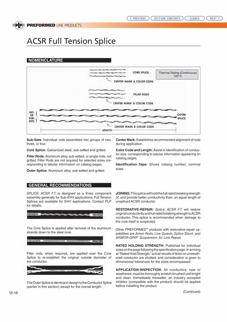
ACSR Full Tension Splice
12-16
SPLICE: ACSR F.T. is designed as a three component assembly generally for Sub-EHV applications. Full Tension Splices are available for EHV applications. Contact PLP for details.
The Core Splice is applied after removal of the aluminum strands down to the steel core.
Sub-Sets: Individual rods assembled into groups of two, three, or four.
Core Splice: Galvanized steel, sub-setted and gritted.
Filler Rods: Aluminum alloy, sub-setted, or single rods, not gritted. Filler Rods are not required for selected sizes cor-responding to tabular information on catalog pages.
Outer Splice: Aluminum alloy, sub-setted and gritted.
NOMENCLATURE
GENERAL RECOMMENDATIONS
Filler rods, when required, are applied over the Core Splice to re-establish the original outside diameter of the conductor.
JOINING: This splice will hold the full rated breaking strength of, and provide better conductivity than, an equal length of unspliced ACSR conductor.
RESTORATIVE-REPAIR: Splice: ACSR F.T. will restore original conductivity and full rated breaking strength to ACSR conductor. This splice is recommended when damage to the core itself is suspected.
Other PREFORMED™ products with restorative-repair ca-pabilities are Armor Rods, Line Guards, Splice Shunt, and ARMOR-GRIP® Suspension: for Line Repair.
RATED HOLDING STRENGTH: Published for individual sizes on the page following the specification page. In arriving at “Rated Hold Strength,” actual results of tests on unweath-ered conductor are studied, and consideration is given to dimensional tolerances for the sizes encompassed.
APPLICATION-INSPECTION: All conductors, new or weathered, must be thoroughly scratch-brushed until bright and clean. Immediately thereafter, an industry accepted inhibitor (compatible with the product) should be applied before installing the product.
The Outer Splice is identical in design to the Conductor Splice (earlier in this section) except for the overall length.
Center Mark: Establishes recommended alignment of rods during application.
Color Code and Length: Assist in identification of conduc-tor size, corresponding to tabular information appearing on catalog pages.
Identification Tape: Shows catalog number, nominal sizes.
(Continued)
Thermal Rating (Continuous)125°C
PREVIOUS SECTION CONTENTS SEARCH NEXT
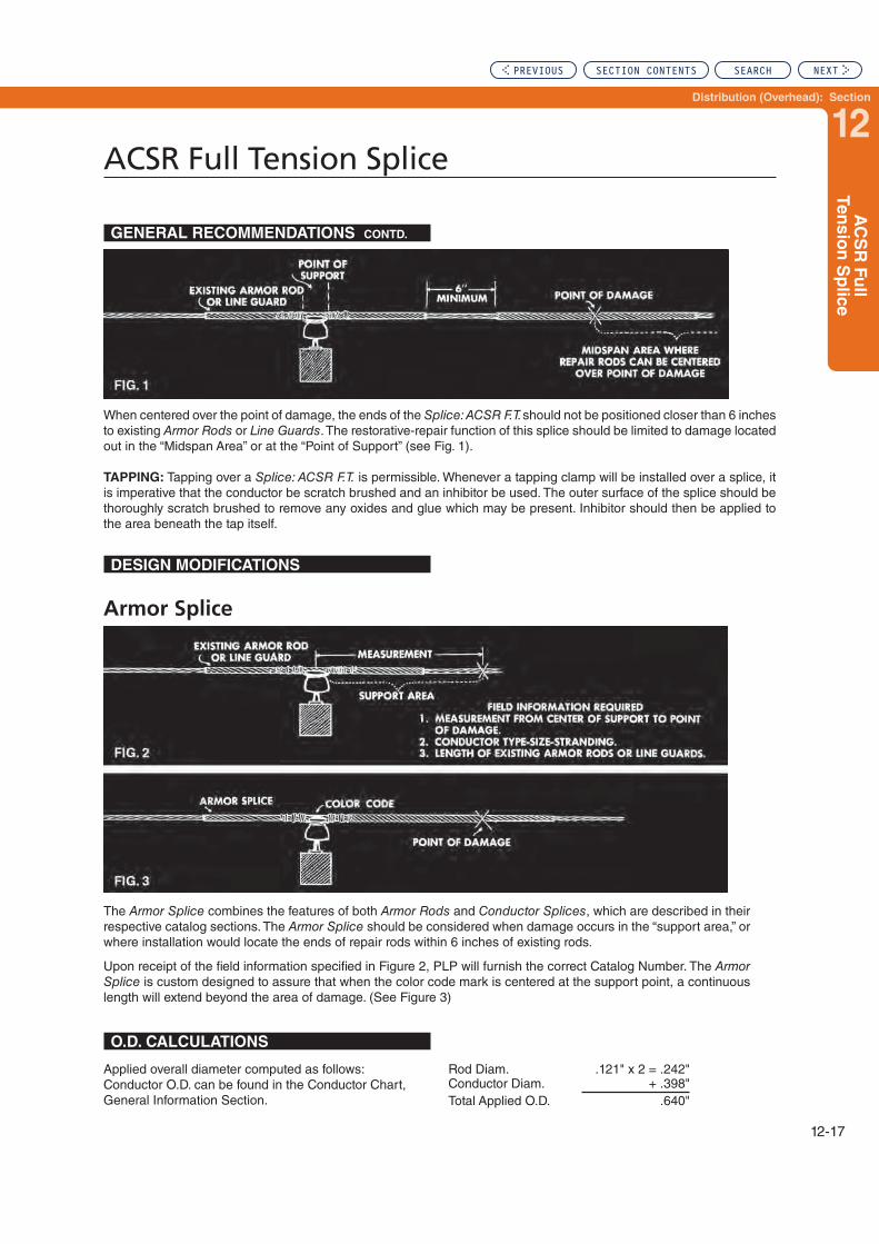
Distribution (Overhead): Section
12
AC
SR
Fu
ll Ten
sio
n S
plic
e
ACSR Full Tension Splice
12-17
When centered over the point of damage, the ends of the Splice: ACSR F.T. should not be positioned closer than 6 inches to existing Armor Rods or Line Guards. The restorative-repair function of this splice should be limited to damage located out in the “Midspan Area” or at the “Point of Support” (see Fig. 1).
TAPPING: Tapping over a Splice: ACSR F.T. is permissible. Whenever a tapping clamp will be installed over a splice, it is imperative that the conductor be scratch brushed and an inhibitor be used. The outer surface of the splice should be thoroughly scratch brushed to remove any oxides and glue which may be present. Inhibitor should then be applied to the area beneath the tap itself.
GENERAL RECOMMENDATIONS CONTD.
DESIGN MODIFICATIONS
Armor Splice
The Armor Splice combines the features of both Armor Rods and Conductor Splices, which are described in their respective catalog sections. The Armor Splice should be considered when damage occurs in the “support area,” or where installation would locate the ends of repair rods within 6 inches of existing rods.
Upon receipt of the field information specified in Figure 2, PLP will furnish the correct Catalog Number. The Armor Splice is custom designed to assure that when the color code mark is centered at the support point, a continuous length will extend beyond the area of damage. (See Figure 3)
O.D. CALCULATIONS
Applied overall diameter computed as follows:Conductor O.D. can be found in the Conductor Chart, General Information Section.
Rod Diam. .121" x 2 = .242"Conductor Diam. + .398"Total Applied O.D. .640"
PREVIOUS SECTION CONTENTS SEARCH NEXT

ACSR Full Tension Splice
12-18
For use on: ACSR
Right-hand lay standard
EXPLANATORY NOTES:
(1) ACSR Conductor Sizes should be used only with Catalog Numbers shown.
(2) Rated Holding Strengths are 100% of the conductor rated breaking strength (RBS).
(3) Conduit PLP for sizes or strandings not shown.
Catalog
Number
ACSR
Conductor
Size
Units Wt./Lbs. Outer SpliceRod
Diameter
(Inches)
Color Codes
Per Carton
Length
(Inches)
No. of
Subsets Core Filler Outer
FTS-5100 #4, 6/1 100 34 35 3 .094 Black None Orange
FTS-5101 #4, 7/1 100 34 35 3 .094 Black None Orange
FTS-5102 #2, 6/1 100 58 44 3 .102 Black None Red
FTS-5103 #2, 7/1 100 66 45 3 .102 Black None Red
FTS-5104 1/0, 6/1 50 80 52 3 .121 Black Black Yellow
FTS-5105 2/0, 6/1 50 65 55 3 .136 Black Black Blue
FTS-5108 3/0, 6/1 25 38 59 3 .146 Black Black Orange
FTS-5110 4/0, 6/1 25 56 67 3 .167 Black Black Red
FTS-5106 101.8, 12/7 25 40 65 3 .136 Black None Blue
FTS-5107 110.8, 12/7 25 50 69 3 .136 Black None Green
FTS-5109 134.6, 12/7 10 68 75 3 .167 Black None Purple
FTS-5111 266.8, 26/7 10 40 91 3 .182 Black None Yellow
FTS-5112 336.4, 18/1 10 40 87 3 .204 Black Black Blue
FTS-5113 336.4, 26/7 10 65 103 3 .250 Black Black Green
FTS-5114 336.4, 30/7 10 70 108 3 .250 Black Black Orange
FTS-5115 397.5, 26/7 5 40 110 3 .250 Black Black Purple
FTS-5116 477, 24/7 5 40 113 3 .250 Black Black Blue
FTS-5117 477, 26/7 5 48 120 4 .250 Black Black Blue
FTS-5118 556.5, 26/7 3 44 129 3 .310 Black Black Green
FTS-5119 636, 24/7 3 48 132 4 .310 Black Black Yellow
FTS-5120 636, 26/7 3 50 134 4 .310 Black Black Yellow
FTS-5121 795, 45/7 3 52 153 4 .310 Black Black Blue
FTS-5122 795, 26/7 3 78 158 4 .365 Black Black Orange
FTS-5123 1,272, 45/7 3 133 203 4 .463 Black Black Yellow
PREVIOUS SECTION CONTENTS SEARCH NEXT

Distribution (Overhead): Section
13
Section 13 – Distribution (Overhead): T-Connectors
Table of Contents
T-Connector ...........................................................................................13-2
T-Connector – Reducing .......................................................................13-4
Page
PREVIOUS SEARCH NEXT

13-2
T-Connector
NOMENCLATURE
T-Connectors as received
in the field
T-Connector
For conductors of equal size
Line Angles
Refer to paragraph belowT-Connector: Reducing
For diameter ratios up to three to one
Intended Use: T-Connectors mechanically join slack span laterals (TAP) to verticaly spaced primaries (RUN) which can be reached by bucket truck. Extra poles can be eliminated while permitting equal spans for street lighting.
A pair of T-Connectors installed back-to-back provide a mid-span junction for vertically spaced primaries. Poles can be set back from intersections and buck-arms eliminated.
T-Connectors are available for conductors of equal and unequal diameters (REDUCING TYPE).
Holding Strength: T-Connectors are conservatively rated at 25% of the RBS (rated breaking strength) of the small-est conductor. Because of their intended use on slack span laterals or junctions of continuous conductors, mechanical requirements are not expected to approach 25% RBS.
Line Angles: Slack span laterals (TAP) should not exceed the line angle shown in the illustration, to insure ease of application and to avoid over stressing the T-Connector.
Conductivity: T-Connectors, both regular and reducing types, are designed to a minimum conductivity of 100% of the smallest conductor.
T-Connectors are primarily mechanical holding devices. To insure proper long term electrical current transfer, it is sug-gested that a jumper or shunt be connected directly between the run and tap conductors so that the T-Connector alone is not required to transfer the current.
APPLICATION-INSPECTION: All conductors, new or weath-ered, must be thoroughly scratch-brushed until bright and clean. Immediately thereafter, an industry accepted inhibitor (compatible with the conductor) should be applied before installing the product.
GENERAL RECOMMENDATIONS
PREVIOUS SECTION CONTENTS SEARCH NEXT

Distribution (Overhead): Section
13
13-3
T-C
on
necto
r
T-Connector
For Conductors of Equal Size
For use on:
ACSR, Aluminum Alloy
All-Aluminum
Right-hand lay standard
EXPLANATORY NOTES:
(1) Nominal Conductor Size indicates one of various conductors within each range.(2) General Recommendations for T-Connectors are referenced earlier in this section.
Catalog
Number Conductor Size Run and Tap Min.
Diameter Range (Inches) Color Codes
Min. Max. Run Tap
TC-0112 #4, 7W, All Alum. .229 .239 Brown BrownTC-0113 .240 .246 Red RedTC-0114 #4, 6/1, 7/1 .247 .257 Orange OrangeTC- 0115 #3, 7W, All Alum. .258 .270 Green GreenTC-0116 .271 .280 Yellow YellowTC-0117 .281 .289 White WhiteTC-0118 #2, 7W, All Alum. .290 .298 Purple PurpleTC-0119 .299 .310 Brown BrownTC-0120 #2, 6/1, 7/1 #2, 7W, All Alum. .311 .325 Red RedTC-0121 #1, 7W, All Alum. .326 .340 Blue BlueTC-0122 #1, 5/1 .341 .351 Orange OrangeTC-0123 #1, 6/1 .352 .367 Green GreenTC-0124 .368 .380 Black BlackTC-0125 1/0, 6/1 1/0, 7W, Alum. Alloy .381 .398 Yellow YellowTC-0126 .399 .413 Purple PurpleTC-0127 2/0, 7W, All Alum. .414 .425 Brown BrownTC-0128 2/0, 18/1 .426 .443 Red RedTC-0129 2/0, 7W, Alum. Alloy .444 .462 Blue BlueTC-0130 3/0, 7W, All Alum. .463 .481 Green GreenTC-0131 3/0, 6/1 3/0, 7W, Alum. Alloy .482 .503 Orange OrangeTC-0132 .504 .521 Black BlackTC-0133 4/0, 7W, All Alum. .522 .544 Yellow YellowTC-0134 4/0, 6/1 4/0, 7W, Alum. Alloy .545 .567 Red Red
TC-0135 250, 19W, All Alum. 266.8, 7W-19W, All Alum. 159, 12/7 .568 .594 Blue Blue
TC-0136 266.8, 18/1 266.8, Alum. Alloy .595 .618 Purple PurpleTC-0137 266.8, 26/7 300, 19W-37W, All Alum. .619 .644 Yellow YellowTC-0138 300, 18/1 336.4, 19W-37W, All Alum. .645 .671 Brown BrownTC-0139 300, 26/7, 30/7 336.4, 18/1, 36/1 .672 .700 Orange OrangeTC-0140 336.4, 26/7 397.5, 19W-37W, All Alum. .701 .729 Green GreenTC-0141 336.4, 30/7 397.5, 18/1 .730 .760 BlackTC-0142 397.5, 26/7 297.5, 19W-37W, Alum. Alloy .761 .792 PurpleTC-0143 477, 18/1, 36/1 477, 19W-37W, All Alum. .793 .825 RedTC-0144 477, 24/7 .826 .850 Blue BlueTC-0145 477, 26/7 556.5, 19W-37W, All Alum. .851 .886 Orange OrangeTC-0146 605, 36/1 636, 37W-61W, All Alum. .887 .929 Black BlackTC-0147 636, 18/1, 36/1 605, 37W, Alum. Alloy .930 .968 Brown BrownTC-0148 666.6, 24/7 636, 37W, All Alum. .969 1.008 Yellow YellowTC-0149 795, 36/1 795, 37W-61W, All Alum. 1.009 1.050 Green GreenTC-0150 795, 45/7 715.5, 37W, Alum. Alloy 1.051 1.091 Black BlackTC-0151 795, 26/7 795, 37W, Alum. Alloy 1.092 1.136 Purple Purple
PREVIOUS SECTION CONTENTS SEARCH NEXT

13-4
T-Connector – Reducing
Catalog Number
Conductor Length of Leg (In.) Color
Codes
Run Tap
Size Min. (In.) Max. (In.) Size Min. (In.) Max. (In.) Run Tap
TCR-MS-6038 #2, 6/1, 7/1 .311 .325 #4, 6/1, 7/1 .247 .257 11 11 OrangeTCR-MS-5972 1/0, 7W, All Alum. .368 .380 #4, 6/1, 7/1 .247 .257 12 12 BlackTCR-MS-2701 1/0, 6/1 .381 .398 #4, 6/1, 7/1 .247 .257 12 12 BlackTCR-MS-5362 1/0, 6/1 .381 .398 #2, 6/1 .311 .325 14 14 YellowTCR-MS-5258 2/0, 7W, All Alum. .414 .425 #4, 6/1, 7/1 .247 .257 12 12 BlackTCR-MS-5818 2/0, 6/1 .444 .462 #4, 6/1, 7/1 .247 .257 13 13 BlueTCR-MS-5249 2/0, 4/3 .444 .462 #2, 7W, All Alum. .290 .298 14 14 PurpleTCR-MS-5273 2/0, 6/1 .444 .462 #2, 6/1, 7/1 .311 .325 14 14 RedTCR-MS-4407 3/0, 7W, All Alum. .463 .481 #2, 7W, All Alum. .290 .298 14 14 PurpleTCR-MS-4761 3/0, 7W, Alum. Alloy .482 .503 #4, 7W, All Alum. .229 .239 13 13 OrangeTCR-MS-9984 2/0 AWAC 4/3, 3/0, 6/1 .482 .503 #2, 7W, All Alum. .290 .298 14 14 OrangeTCR-MS-6151 3/0, 7W, Alum. Alloy .482 .503 #2, 7W,Alum. Alloy .311 .325 15 15 RedTCR-MS-5476 3/0, 7W, Alum. Alloy .482 .503 1/0, 7W, All Alum. .368 .380 17 17 OrangeTCR-MS-6058 3/0, 6/1 .482 .503 1/0, 6/1 .381 .398 18 18 GreenTCR-MS-5973 4/0, 7W, All Alum. .522 .544 #4, 6/1, 7/1 .247 .257 14 14 BlackTCR-MS-6127 4/0, 6/1 .545 .567 #4, 6/1, 7/1 .247 .257 15 15 RedTCR-MS-5363 4/0, 6/1 .545 .567 #2, 6/1, 7/1 .311 .325 16 16 RedTCR-MS-5317 4/0, 6/1 .545 .567 1/0, 5/1 .381 .398 17 17 RedTCR-MS-4413 266.8, 7W-19W, All Alum. .568 .594 #2, 7W, All Alum. .290 .298 16 16 PurpleTCR-MS-6173 266.8, 7W-19W, All Alum. .568 .594 1/0, 6/1 .381 .398 18 18 YellowTCR-MS-5255 336.4,19W-37W, All Alum. .645 .671 #4, 6/1, 7/1 .247 .257 15 15TCR-MS-6311 336.4,19W-37W, All Alum. .645 .671 #2, 6/1, 7/1 .311 .325 16 16TCR-MS-5475 336.4,19W-37W, All Alum. .645 .671 1/0, 7W, All Alum. .368 .380 19 19TCR-MS-5483 336.4,19W-37W, All Alum. .645 .671 1/0, 6/1 .381 .398 19 19TCR-MS-6174 336.4,19W-37W, All Alum. .645 .671 2/0, 7W, All Alum. .414 .425 24 24TCR-MS-5817 336.4,19W-37W, All Alum. .645 .671 2/0, 6/1 .444 .462 20 20TCR-MS-5433 336.4, 18/1 .672 .700 #4, 6/1, 7/1 .247 .257 15 15TCR-MS-2700 336.4, 18/1 .672 .700 1/0, 6/1 .381 .398 19 19TCR-MS-6126 336.4, 18/1 .672 .700 #2, 6/1, 7/1 .311 .325 18 18TCR-MS-5261 336.4, 18/1 .672 .700 2/0, 6/1 .444 .462 20 20TCR-MS-5945 336.4, 26/7 .701 .729 #2, 7W, Alum. Alloy .311 .325 19 19TCR-MS-6303 336.4, 26/7 .701 .729 2/0, 6/1 .444 .462 25 25TCR-MS-6025 336.4, 26/7 .701 .729 4/0, 6/1 .545 .567 24 24TCR-MS-5672 397.5, 18/1 .730 .760 2/0, 6/1 .444 .462 21 21TCR-MS-4426 477, 19W-37W, All Alum. .793 .825 #4, 7W, All Alum. .229 .239 20 20TCR-MS-4402 477, 19W-37W, All Alum. .793 .825 #2, 7W, All Alum. .290 .298 19 19TCR-MS-5904 477, 19W-37W, All Alum. .793 .825 #2, 6/1, 7/1 .311 .325 18 18TCR-MS-5771 477, 18/1 .793 .825 1/0, 6/1 .381 .398 22 22TCR-MS-5253 477, 19W-37W, All Alum. .793 .825 2/0, 7W, All Alum. .414 .425 21 21TCR-MS-4405 477, 19W-37W, All Alum. .793 .825 3/0, 7W-19W, All Alum. .463 .481 23 23TCR-MS-5772 477, 18/1 .793 .825 4/0, 6/1 .545 .567 29 29TCR-MS-5977 500,19W-37W, All Alum. .793 .825 250, 19W-37W, All Alum. .568 .594 29 29TCR-MS-5254 477,19W, All Alum. .793 .825 336.4, 19W, All Alum. .645 .671 35 35TCR-MS-6312 556.5,19W-37W, All Alum. .851 .886 #2, 6/1, 7/1 .311 .325 20 20TCR-MS-6079 477, 26/7 .851 .886 1/0, 6/1 .381 .398 23 23TCR-MS-6080 477, 26/7 .851 .886 3/0, 6/1 .482 .503 24 24TCR-MS-5912 556.5,19W-37W, All Alum. .851 .886 4/0, 7W, All Alum. .522 .544 25 25TCR-MS-5986 477, 19W, Alum. Alloy .851 .886 4/0, 6/1 .545 .567 27 27TCR-MS-5081 636, 37W, All Alum. .887 .929 2/0, 7W, All Alum. .414 .425 23 23TCR-MS-5816 636, 37W, All Alum. .887 .929 2/0, 6/1 .444 .462 23 23TCR-MS-1810 556.5, 26/7 .887 .929 4/0, 6/1 .545 .567 32 32TCR-MS-5158 636, 37W, All Alum. .887 .929 336.4, 19W-37W, All Alum. .645 .671 40 40TCR-MS-5426 556.5, 24/7 .887 .929 336.4, 26/7 .701 .729 40 40TCR-MS-5974 636, 18/1 .930 .968 1/0, 6/1 .381 .398 22 22TCR-MS-5905 795, 37W, All Alum. 1.009 1.050 3/0, 6/1 .482 .503 26 26TCR-MS-6164 795, 37W, All Alum. 1.009 1.050 4/0, 6/1 .545 .567 27 27TCR-MS-5260 795, 37W, All Alum. 1.009 1.050 336.4, 18/1 .672 .700 42 42TCR-MS-5190 795, 37W, All Alum. 1.009 1.050 336.4, 19W-37W, All Alum. .793 .825 44 44TCR-MS-5425 795, 45/7 1.051 1.091 336.4, 26/7 .701 .729 43 43TCR-MS-6055 795, 26/7 1.092 1.136 336.4, 18/1 .672 .700 42 42TCR-MS-5844 795, 26/7 1.092 1.136 336.4, 26/7 .701 .729 43 43
Right-hand lay standardEXPLANATORY NOTES:(1) Nominal Conductor Size indicates one of various conductors within each range.(2) For combinations of conductors outside of the ranges listed, consult PLP for an engineering specification.
PREVIOUS SECTION CONTENTS SEARCH NEXT
Distribution (Overhead): Section
14
Section 14 – Distribution (Overhead): Motion Control Products
Table of Contents
VORTX™ Vibration Damper....................................................................14-2
Spiral Vibration Damper (Standard & Hi Mass) ..................................14-7
Air Flow Spoiler .....................................................................................14-9
Page
PREVIOUS SEARCH NEXT

14-2
VORTX® Vibration Damper
1
2
3 5 4
Product Identification
NOMENCLATURE
1. Clamp & Keeper: The Clamp has an extruded hook shaped profile to hang onto the cable or conductor while tightening the keeper. Together, the aluminum keeper and clamp capture the conductor to hold the damper assembly firmly onto the conductor or cable. Product identification, installation torque, and lot number are permanently etched on the clamp.
2. Bolt, Washer, and Lock Washer: The bolt, washer, and lock washer are used to fasten the keeper to the clamp and secure the entire damper assembly to the cable or conductor. The materials used are galvanized steel. An optional break-away bolt version is available.
3. Large Damper Weight: The VORTX damper design shown above has two weight sizes – this provides up to 4 resonant response frequencies (two for the large weight and two for the small weight) for more effective protection. The weight is a galvanized ductile iron casting.
4. Small Damper Weight: The small weight provides damp-ing at higher frequencies. The weight is a galvanized ductile iron casting.
5. Messenger: The messenger is made of formed hard steel wires that are galvanized for corrosion resistance.
INTENDED USE: VORTX Dampers respond to wind induced line vibration that is characterized by high frequency, low amplitude motion a.k.a. aeolian vibration. The VORTX damper with Large and Small weights can achieve greater power dissipation and frequency response performance than “symmetrical weight” Stockbridge damper designs. Wider frequency coverage translates into better protection as energy is more effectively dissipated over the entire range of conductor/cable frequencies.
APPLICATION: VORTX Dampers can be clamped directly onto most aluminum based conductors including ACSR, AAC, AAAC and ACAR. PLP® Protector Rods should be considered for applications on aluminum conductors with relatively soft outer aluminum strand construction such as ACSS. Protector rods are designed to reduce direct clamping stress on cable vulnerable to surface or core damage – this includes fiber optic cable designs such as ADSS and OPGW.
GENERAL RECOMMENDATIONS
CONDUCTOR/CABLE SIZE: Generally as conductors and cables increase in size they tend to vibrate at lower frequencies. The VORTX Damper is more effective for larger size conductors while the Spiral Vibration Dampers (SVD) are generally more effective for the smaller diameter cables that can vibrate at much higher frequencies. The following table provides a general recommendation for VORTX dampers and Spirial Vibration Damper’s based on conductor or cable size (see table on next page):
Thermal Rating (Continuous)125°C
250°C when applied over Protector Rods
PREVIOUS SECTION CONTENTS SEARCH NEXT

Distribution (Overhead): Section
14
14-3
VO
RT
X®
Vib
ratio
n D
am
per
VORTX® Vibration Damper
ApplicationOuter
Diameter
Recommended Damper Product
Conductor OHSW and
OPGW
up to 0.75" (19 mm) SVD
over 0.75" (19 mm) VORTX
ADSS
up to 1.25" (32 mm) SVD
over 1.25" (32 mm) VORTX
The degree of protection required on a specific line depends upon a number of factors such as line design, local climate, tension, exposure to wind flow, and line vibration history in the area. With assistance from your local PLP Sales Representative, the necessary information can be assembled for review and followed up with detailed PLP recommendations for your system.
DAMPERS PER SPAN: The recommended number of dampers per span depends on the amount of wind energy exposure and the conductor/cable characteristics. Self-Damping is a conductor or cable characteristic attributed to component material and construction – for example the individual metal strands that make up a conductor can move relative to one-another and dissipate energy (much the same way as the messenger does in the damper). Increasing line tension however, will decrease self-dampening as the individual strands begin to lock together.
Single Dampers are capable of a predetermined amount of energy dissipation that can protect spans approximately 300 meters (1000 feet) long or more considering self damp-ening. Longer spans may require more than one damper.
DAMPER PLACEMENT: VORTX dampers have specific performance characteristics that require strategic placement on the line to counter potential damage to the line system. Placement information shall be provided to assure that the damper will bring effective protection.
Placement information refers to locations A, B, C, and D for the first four dampers as measured from the respec-tive hardware – See the sketch below. Longer spans that require additional protection may require dampers placed midspan. In many cases extremely long spans extend over rivers, and require additional protection due to high laminar wind speeds.
The general placement sequence is typical for spans with tangent hardware at both ends. Unlike tangent hardware, Dead-ends are not symmetric about the point of attachment to the structure – thus it is difficult to determine the most effective placement location for single dampers. If damp-ers must be placed at Dead-end hardware, the sequence requires dampers at A and C (or B and D) i.e. two dampers for single damper placement as shown below:
Compression Dead-end Damper Placement
FIBERLIGN® Dead-end Damper Placement
PERFORMANCE QUALIFICATION: VORTX Dampers meet the requirements of International Standard IEC 61897. This standard includes levels of acceptable performance for Forced Response, Fatigue, Weight Pull-off, Messenger Pull-out, Damper Efficiency, Corrosion Resistance, Bolt Torque, Clamp Slip, and Corona. Response curves and test reports can be provided upon request.
A C
A C
GENERAL RECOMMENDATIONS cont.
General Placement Sequence, Dampers A, B, C, and D
placed 1st, 2nd, 3rd, and 4th respectively.
PREVIOUS SECTION CONTENTS SEARCH NEXT

14-4
VORTX® Vibration Damper
VORTX DAMPER Catalog Number code:
VSD- 40 32 B“VSD” – VORTX (Stockbridge) Damper
Weight Combination (10, 20, 25, 35, 40, 50) Weight selection is based on appropriate impedance for respective conductor or cable.
Clamp Code (10, 12, 16, 20, 25, 32, 40, 50, 61) The clamp code represents the top end of the clamp range or maximum accepted cable diameter in millimeters.
Include only for optional design with break-away bolt.
VORTX Damper Details for Conductor and Shield Wire Applications
Catalog
Number
Clamp
Range
Inches
Clamp
Range mm
Overall
Length
Reference
Length Long Clamp Width Bolt Size
Install
Torque
Assembled
Weight
Min Max Min Max Inches mm Inches mm Inches mm mm Ft-lb N-m lb kg
VSD-1010 0.300 0.381 7.6 9.7 11.0 278 5.0 128 1.250 31.8 M10 x 50 30 41 2.3 1.0
VSD-1012 0.381 0.483 9.7 12.3 11.3 288 5.0 128 1.630 41.4 M10 x 50 30 41 2.4 1.1
VSD-1016 0.483 0.612 12.3 15.5 11.3 288 5.0 128 1.630 41.4 M10 x 50 30 41 2.4 1.1
VSD-1020 0.612 0.786 15.5 20.0 11.7 297 5.0 128 2.000 50.8 M10 x 50 30 41 2.7 1.2
VSD-1025 0.786 0.983 20.0 25.0 11.7 297 5.0 128 2.000 50.8 M10 x 50 30 41 2.8 1.3
VSD-1032 0.983 1.261 25.0 32.0 11.9 302 5.0 128 2.200 55.9 M12 x 70 40 54 3.2 1.4
VSD-2016 0.483 0.612 12.3 15.5 14.6 370 6.9 175 1.630 41.4 M10 x 50 30 41 3.6 1.6
VSD-2020 0.612 0.786 15.5 20.0 14.9 379 6.9 175 2.000 50.8 M10 x 50 30 41 3.9 1.8
VSD-2025 0.786 0.983 20.0 25.0 14.9 379 6.9 175 2.000 50.8 M10 x 50 30 41 4.0 1.8
VSD-2032 0.983 1.261 25.0 32.0 15.1 384 6.9 175 2.200 55.9 M12 x 70 40 54 4.4 2.0
VSD-2040 1.261 1.579 32.0 40.1 15.3 389 6.9 175 2.380 60.5 M12 x 70 40 54 4.6 2.1
VSD-2050 1.579 1.970 40.1 50.0 15.4 392 6.9 175 2.500 63.5 M12 x 70 40 54 4.9 2.2
VSD-2520 0.612 0.786 15.5 20.0 12.7 322 6.4 161 2.000 50.8 M10 x 50 30 41 4.9 2.2
VSD-2525 0.786 0.983 20.0 25.0 12.7 322 6.4 161 2.000 50.8 M10 x 50 30 41 5.0 2.3
VSD-2532 0.983 1.261 25.0 32.0 12.9 327 6.4 161 2.200 55.9 M12 x 70 40 54 5.4 2.5
VSD-2540 1.261 1.579 32.0 40.1 13.1 332 6.4 161 2.380 60.5 M12 x 70 40 54 5.7 2.6
VSD-3525 0.786 0.983 20.0 25.0 14.7 374 7.0 179 2.000 50.8 M10 x 50 30 41 7.3 3.3
VSD-3532 0.983 1.261 25.0 32.0 14.9 379 7.0 179 2.200 55.9 M12 x 70 40 54 7.7 3.5
VSD-3540 1.261 1.579 32.0 40.1 15.1 384 7.0 179 2.380 60.5 M12 x 70 40 54 7.9 3.6
VSD-3550 1.579 1.970 40.1 50.0 15.2 387 7.0 179 2.500 63.5 M12 x 70 40 54 8.2 3.7
VSD-4032 0.983 1.261 25.0 32.0 20.3 515 10.5 267 2.200 55.9 M12 x 70 40 54 10.8 4.9
VSD-4040 1.261 1.579 32.0 40.1 20.4 519 10.5 267 2.380 60.5 M12 x 70 40 54 11.1 5.0
VSD-4050 1.579 1.970 40.1 50.0 20.6 523 10.5 267 2.500 63.5 M12 x 70 40 54 11.4 5.2
VSD-4061 1.970 2.403 50.0 61.0 21.1 535 10.5 267 3.000 76.2 M12 x 75 40 54 12.1 5.5
VSD-5040 1.261 1.579 32.0 40.1 23.9 606 12.1 307 2.380 60.5 M12 x 75 40 54 11.5 5.2
VSD-5050 1.579 1.970 40.1 50.0 24.0 609 12.1 307 2.500 63.5 M12 x 75 40 54 11.8 5.3
VSD-5061 1.970 2.403 50.0 61.0 24.5 622 12.1 307 3.000 76.2 M12 x 75 40 54 12.5 5.7Shaded rows represent dampers that in most cases are directly applied to ACSR, ACAR, ACCR, and AAAC conductors without armor or other protective rods. *Verify the appropriate weight code for the specific conductor in the catalog table entitled “Weight Conbination for Conductor and Shield Wire Sizes” or otherwise contact PLP technical support.
PREVIOUS SECTION CONTENTS SEARCH NEXT

Distribution (Overhead): Section
14
14-5
VO
RT
X®
Vib
ratio
n D
am
per
VORTX® Vibration Damper
Weight Combination for Conductor and Shield Wire Sizes
Weight
Combination
Code
Number*
ACSR, AAC, AAAC and ACAR Range Galvanized Steel and Alumoweld Range
Inches mm Inches mm
Min. Max. Min. Max. Min. Max. Min. Max.
10 0.381 0.472 9.7 11.9 .275 .400 7.0 10.1
20 0.473 0.721 12.0 18.2 .401 .486 10.2 12.3
25 0.723 0.858 18.3 21.7 .487 .650 12.4 16.5
35 0.859 0.983 21.8 24.9
40 0.984 1.335 25.0 33.9
50 1.261 1.762 32.1 44.7
*Final selection for weight combination at merging ranges are determined from conductor type and tension. Contact PLP Technical Support for final recommendation.
Weight Combination for OPGW
Weight Combination
Code Number*
Inches mm
Min. Max. Min. Max.
10 0.300 0.381 7.6 12.4
20 0.375 0.720 9.5 18.2
25 0.612 1.260 15.5 32.0
35 0.721 1.260 18.3 32.0
*Final selection for weight combination at merging ranges are determined from conductor type and tension. Contact PLP Technical Support for final recommendation.
Bolt Size and Torque Information
Clamp
Code
Clamp Range
Bolt
Thread
Size
Wrench Size TorqueMillimeters Inches
Min. Max. Min. Max. mm in N-m Ft-Lb
10 7.6 9.7 .300 .381 M10 17 11/16 41 30
12 9.7 12.3 .381 .483 M10 17 11/16 41 30
16 12.3 15.5 .483 .612 M10 17 11/16 41 30
20 15.5 20.0 .612 .786 M10 17 11/16 41 30
25 20.0 25.0 .786 .983 M10 17 11/16 41 30
32 25.0 32.0 .983 1.261 M12 19 3/4 54 40
40 32.0 40.1 1.261 1.579 M12 19 3/4 54 40
50 40.1 50.0 1.579 1.970 M12 19 3/4 54 40
61 50.0 61.0 1.970 2.403 M12 19 3/4 54 40
PREVIOUS SECTION CONTENTS SEARCH NEXT

14-6
VORTX® Vibration Damper
PLP Protector Rods
Catalog
Number*
Cable Diameter Range
Rod Length Wire Size
Inches
(mm)
Color
Code
Units
Per
Carton
Weight/
Carton
Pounds
(Kg)
Inches mm
Min. Max. Min. Max. Inches mm
PR-0135 0.378 0.423 9.6 10.7 12 304 0.121 (3.1) Yellow 50 10 (4.5)
PR-0137 0.424 0.475 10.8 12.1 12 304 0.121 (3.1) Brown 50 10 (4.5)
PR-0139 0.476 0.533 12.1 13.5 16 406 0.121 (3.1) Blue 50 14 (6.4)
PR-0141 0.534 0.585 13.6 14.8 16 406 0.121 (3.1) Green 50 14 (6.4)
PR-0142 0.586 0.618 14.9 15.6 16 406 0.146 (3.7) Orange 50 21 (9.5)
PR-0144 0.619 0.667 15.7 16.9 16 508 0.146 (3.7) Purple 50 21 (9.5)
PR-0146 0.668 0.722 17.0 18.3 20 508 0.146 (3.7) Red 50 29 (13.1)
PR-0148 0.723 0.816 18.4 20.3 20 508 0.146 (3.7) Black 50 29 (13.1)
PR-0150 0.817 0.898 20.8 22.7 20 508 0.146 (3.7) White 50 31 (14.1)
PR-0151 0.899 0.954 22.8 24.2 24 610 0.167 (4.2) Yellow 50 47 (21.3)
PR-0152 0.955 1.019 24.3 25.8 24 610 0.182 (4.6) Brown 25 29 (13.1)
PR-0154 1.020 1.064 25.9 27.0 24 610 0.182 (4.6) Blue 25 29 (16.1)
PR-0155 1.065 1.098 27.1 27.8 26 660 0.204 (5.2) Green 25 36 (16.3)
PR-0156 1.099 1.181 27.9 29.9 26 660 0.250 (6.4) Orange 25 48 (21.7)
PR-0158 1.182 1.298 30.0 32.9 26 660 0.250 (6.4) Purple 25 51 (23.1)
PR-0160 1.299 1.415 33.0 35.9 26 660 0.250 (6.4) Blue 20 44 (19.9)
PR-0162 1.416 1.543 36.0 39.2 26 660 0.250 (6.4) Yellow 20 48 (21.7)
PR-0163 1.544 1.685 39.2 42.8 26 660 0.250 (6.4) Brown 15 40 (18.1)
PR-0164 1.686 1.840 42.8 46.7 26 660 0.250 (6.4) Blue 15 42 (19.0)
Protector Rods for VORTX Damper on OPGW or Special Conductors:
Protector Rods provide a layer of mechanical protection and reinforcement for accessory items such as VORTX Dampers that clamp onto a cable. This product is not designed for protection at clamp type supports or suspensions. Protector Rods are not to be used as a repair product as they are not
Protector Rods
Thermal Rating (Continuous)
250°C
designed to restore conductance or tensile strength to a cable or conductor. Standard Protector Rods are designed for line voltages of 230 kV and lower. For higher voltage applications, Parrot Bill rod end treatment can be provided – contact PLP for details.
PREVIOUS SECTION CONTENTS SEARCH NEXT

Distribution (Overhead): Section
14
1. This product may be reused if in good condition.
2. This product is intended for use by trained craftspeople only. This product SHOULD NOT BE USED by anyone who is not familiar with and trained in the use of it.
3. When working in the area of energized lines with this product, EXTRA CARE should be taken to prevent ac-cidental electrical contact.
Damping devices are designed for the single purpose of reducing vibration. This single function is entirely different from that of protecting against (1) stress concentrations, (2) fretting or abrasion, and (3) arc-over burning. Because of this, damping devices should be considered only as supplemental to WRAPLOCK® Tie, Armor Rod, Side Tie, Spool Tie, or other hardware at tangent supports. Dampers are also used as supplemental protection at Dead-ends.
The degree of protection needed on a specific line depends upon a number of factors such as line design, temperature, tension, exposure to wind flow, and vibration history on similar construction in the same area.
Spiral Vibration Dampers are also effective on certain size overhead shield wires and OPGW. Consult PLP® for specifics.
For damper applications on ADSS cable, refer to the FIBER-LIGN® Fiber Optic Products section under motion control.
Consult your PLP Sales Representative for placement and installation guidelines.
MATERIAL. The solid polyvinyl chloride helical rod material is noncorrosive and has a surface hardness which does not abrade the conductor.
GENERAL RECOMMENDATIONS
SAFETY CONSIDERATIONS
Length: Assists in identifying conductor size, correspond-ing to tabular information appearing on following page.
Damping Section: Helically scaled for interplay of damper and conductor, to provide the action/reaction motion that opposes the natural vibration wave.
Note: Water/Canyon Crossings - due to the increased potential of laminar wind flow, an additional 50% more dampers per span should be added to the standard recommendations above for adequate protection.
In areas that are prone to high levels of vibration or conductor ten-sion is in excess of 18% RBS, consult Preformed Line Products for specific recommendations.
NOMENCLATURE
4. For PROPER PERFORMANCE AND PERSONAL SAFETY be sure to select the proper size PLP Spiral Vibration Damper before application.
5. PLP Spiral Vibration Dampers are precision devices. To insure proper performance, they should be stored in cartons under cover and handled carefully.
APPLICATION-INSPECTION. The Gripping Section should be installed approximately one hand’s width from the ends of Armor Rod or other hardware. It is not necessary to make engineering calculations as to placement.
Usage Recommendations for Spiral Vibration Dampers
on Bare Conductor, Shield Wire and OPGW.
Gripping Section: Has a smaller helix designed to the grip conductor.
Thermal Rating (Continuous)
125°C
Span
Length 0'-800' 801'-1600' 1601'-2400'
Standard 2 4 6
Hi Mass 1 2 3
Number of SVDs Per Span
14-7
Sp
iral V
ibra
tion
Da
mp
er
Spiral Vibration Damper
PREVIOUS SECTION CONTENTS SEARCH NEXT
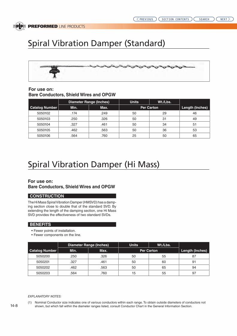
Spiral Vibration Damper (Standard)
EXPLANATORY NOTES:
(1) Nominal Conductor size indicates one of various conductors within each range. To obtain outside diameters of conductors not shown, but which fall within the diameter ranges listed, consult Conductor Chart in the General Information Section.
For use on:
Bare Conductors, Shield Wires and OPGW
Catalog Number
Diameter Range (Inches) Units Wt./Lbs.
Length (Inches)Min. Max. Per Carton
5050102 .174 .249 50 29 46
5050103 .250 .326 50 31 49
5050104 .327 .461 50 34 51
5050105 .462 .563 50 36 53
5050106 .564 .760 25 50 65
Spiral Vibration Damper (Hi Mass)
For use on:
Bare Conductors, Shield Wires and OPGW
CONSTRUCTION
The Hi Mass Spiral Vibration Damper (HMSVD) has a damp-ing section close to double that of the standard SVD. By extending the length of the damping section, one Hi Mass SVD provides the effectiveness of two standard SVDs.
BENEFITS
• Fewer points of installation.• Fewer components on the line.
Catalog Number
Diameter Range (Inches) Units Wt./Lbs.
Length (Inches)Min. Max. Per Carton
5050200 .250 .326 50 55 87
5050201 .327 .461 50 60 91
5050202 .462 .563 50 65 94
5050203 .564 .760 15 55 97
14-8
PREVIOUS SECTION CONTENTS SEARCH NEXT

Distribution (Overhead): Section
14
NOMENCLATURE
Gripping Section: Grips cable. Consists of several pitches (360° wraps around the cable) and holds the Air Flow Spoiler firmly in position.
Spoiling Section: Disrupts aerodynamic lift. The spoiling section is wrapped around the cable in a manner which presents a constantly changing profile to wind flow and cancels lift forces which cause galloping. The spoiling section is wrapped around the cable either two or three times, depending on cable diameter.
Application Support Helix: Supports Spoiler. Air Flow Spoilers range in length from 14 to 16 feet. The Application Support Helix on one end keeps the Air Flow Spoiler from hanging down, while the gripping section on the opposite end is applied.
Air Flow Spoilers for EHV applications have a co-extended semi-conductive outer layer of material which resists the surface effects of high electrical gradients and minimizes the possible generation of radio interference (RI).
Thermal Rating (Continuous) 125°C
GENERAL RECOMMENDATIONS
Several Air Flow Spoilers are required in each span to offset the aerodynamic lift forces which cause galloping. Each cable, conductor or phase, and neutral need to be treated in each span.
The number and placement of Air Flow Spoilers in each span can be determined by using the General Placement guidelines that follow or by submitting the Air Flow Spoiler Placement Request form. The information submitted on this form is input into a computer program for the determination of the exact placement of the Air Flow Spoilers in each span. The program also supplies the increased wind loading on each span as a percentage increase.
When using the Air Flow Spoiler Placement Request form, the information should be completed and returned to PLP® prior to installation of Air Flow Spoilers. The placement scheme will be returned giving the placement of Air Flow Spoilers in each span.
Please advise whether the cables contain optical fibers or if the Air Flow Spoilers are to be installed on Figure 8/Lashed Messenger cables. This may influence the Air Flow Spoiler selection and/or quantity.
GENERAL PLACEMENT GUIDELINES
Extensive laboratory and field research has shown that Air Flow Spoilers are most effective when they are placed on 25% of the span length (based on the 12' spoiling section). For example, a 600' span would require 13 Air Flow Spoilers ((.25x600)/12). The Air Flow Spoilers are grouped in the middle 50% of the span by leaving a blank space equal to an Air Flow Spoiler lemgth between adjacent units.
14-9
Air F
low
Sp
oile
r
Air Flow Spoiler
PREVIOUS SECTION CONTENTS SEARCH NEXT

For use on all standard conductors.
EXPLANATORY NOTES:
(1) For installation on Figure 8 and Lashed Messenger cables, consult PLP.(2) Obtain the Air Flow Spoiler Placement Request form from your local PLP representative or directly from PLP.
Catalog Number
Diameter Range (Inches)
Length (Feet) Wt./Unit Lbs. Color CodeMin. Max.
5058100 0.250 0.326 13-1/2 1.00 Red
5058101 0.327 0.461 13-1/2 1.00 White
5058102 0.462 0.563 14 2.25 Orange
5058103 0.564 0.76 14-1/2 2.40 Yellow
5058104 0.761 0.926 15 4.25 Blue
5058105 0.927 1.019 15-1/4 4.50 Black
5058106 1.020 1.165 15-3/4 5.50 Purple
5058107 1.166 1.469 16 5.75 Brown
5058108 1.470 1.602 17 9.50 Green
5058109 1.603 1.762 17-1/2 9.75 Pink
14-10
Air Flow Spoiler
PREVIOUS SECTION CONTENTS SEARCH NEXT

Distribution (Overhead): Section
15
Section 15 – Distribution (Overhead): Repair Products
Table of Contents
General Information ..............................................................................15-2
Distribution Conductor Repair .............................................................15-3
Splice Shunt ...........................................................................................15-4
Page
SEARCH NEXTPREVIOUS

15-2
Repair Products
GENERAL INFORMATION
Repair of damaged distribution line phase and neutral conductors
Damage to distribution line phase and neutral conductor can occur in service for a number of reasons, including:
• Aeolian vibration and galloping• Loose hand ties• Lightning strikes• Contact from trees or other objects• Firearms
PLP offers a number of solutions for repairing dam-aged or broken conductors so that re-conductoring is not required. In most cases the repair solution will depend on the extent of the damage. Therefore, the first step in any repair is an accurate assessment of the level of damage.
Generally an accurate assessment of the number of damaged or broken strands can be made by a close visual inspection, with the tension relieved in the damaged area. Since damage can be hidden under ties or support hardware it is usually necessary to carefully remove this hardware to completely assess the amount of damage.
If the total extent of the damage can not be accu-rately determined, then the repair solution should be based on the worst possible condition.
At support locations once the conductor has been repaired, a factory formed tie such as the WRAPLOCK™ Tie or Distribution Tie should be used to minimize the possibility of future damage to the repaired conductor.
PREVIOUS SECTION CONTENTS SEARCH NEXT

Distribution (Overhead): Section
15
15-3
Dis
tribu
tion
C
on
du
cto
r Rep
air
Distribution Conductor Repair
ARMOR RODS & LINE GUARD
Armor Rods or Line Guard can be used to restore the me-chanical strength and electrical conductivity for a limited number of broken aluminum strands only in all types of aluminum-based conductors shown in table below.
See Armor Rod (1-40) and Line Guard (9-56) catalog pages for the catalog numbers of a specific conductor size.
Total Repairable Number of Broken or Damaged Aluminum Strands
Conductor
Type ACSR AAC AAAC
Stranding 5/1 6/1 7/1 8/1 18/1 12/7 24/7 26/7 30/7 45/7 54/7 7w 19w 37w 61w 7w 19w
Armor Rods
2 3 3 4 6 6 7 8 9 10 12 2 5 9 12 2 6
Line Guard
1 1 1 1 4 3 3 4 5 5 6 1 3 4 6 1 2
CONDUCTOR SPLICE
A Conductor Splice can be used for conductors which have more aluminum strands broken or damaged that can be repaired with Armor Rod or Line Guard.
A Conductor Splice will restore the mechanical strength and electrical conductivity for up to all the aluminum strands on ACSR Conductors.
The steel core must be intact, otherwise the mechanical
restoration of the complete conductor will be limited
(as low as 50%).
A Conductor Splice will restore from 90% to 100% of the mechanical strength and 100% of the electrical conductivity for all the strands broken or damaged on all-alluminum or aluminum alloy conductors.
See conductor splice catalog pages (12-2) for catalog numbers of specific conductor sizes.
ACSR FULL TENSION SPLICE
For ACSR conductors when the damage includes strands of the steel core the ASCR full tension splice will restore 100% of both the mechanical strength and electrical conductivity of the complete conductor. See catalog pages (12-16) for ACSR full tension splice for specific conductor size.
PREVIOUS SECTION CONTENTS SEARCH NEXT

GENERAL RECOMMENDATIONS
The Splice Shunt is designed to restore complete electrical conductivity and a portion of the mechanical strength to compression splices that are found to be excessively hot during thermal line inspections.
Mechanically, the splice shunt is designed to restore 100% of the strength of the aluminum strands of ACSR and about 10% of the strength of the steel core. 100% of the mechanical strength is restored for AAC and AAAC conductors.
The Splice Shunt is applied directly over the compres-sion splice and over the conductor for some distance on either side of the splice.
To order Splice Shunts please provide PLP with the following information:
• Conductor Size (Kcmil, standing, diameter)
• Length of Compression Splice
• Diameter of Compression Splice (measured in the center, non-compressed area)
15-4
Splice Shunt
PREVIOUS SECTION CONTENTS SEARCH NEXT

Distribution (Overhead): Section
16
Section 16 – Distribution (Overhead): Multiplexed Cable Hardware
Table of Contents
Cable Separator .....................................................................................16-2
Cable Separator Tie ...............................................................................16-4
Lashing Rods .........................................................................................16-6
Galvanized Steel ..............................................................................16-8
Aluminum-clad Steel .......................................................................16-9
Copperweld ....................................................................................16-10
Stainless Steel, Type 302 ..............................................................16-11
Stainless Steel, Type 316 ..............................................................16-12
Page
PREVIOUS SEARCH NEXT

16-2
Cable Separator: For use with Triplex or Quadraplex Cable
Typical Installation -
POLE-MOUNT Cable Separator
(NOTE: product is available in black only)
Features:
Typical Installation -
Cable Separator
(NOTE: product is available in black only)
Features:
Catalog No. Description Wt. Per Unit (oz.)Units Per
Carton
Dimensions (continued next page)
PREVIOUS SECTION CONTENTS SEARCH NEXT

Distribution (Overhead): Section
16
Cab
le S
ep
ara
tor
Cable Separator: For use with Triplex or Quadraplex Cable
1.
2.
3.
SAFETY CONSIDERATIONS
5060100 – Front View
™
5. ™
Dimensions
1"Dia.
5/8" Dia. (3 Holes)
1" Dia. Typical
(4 places)
11/16"Dia.
Through Hole
Note: Cable Separators are available in black only
1" Dia.
Typical
(4 places)
5060100 – Side View
5060150B – (1-1/4" width) 5060160
PREVIOUS SECTION CONTENTS SEARCH NEXT
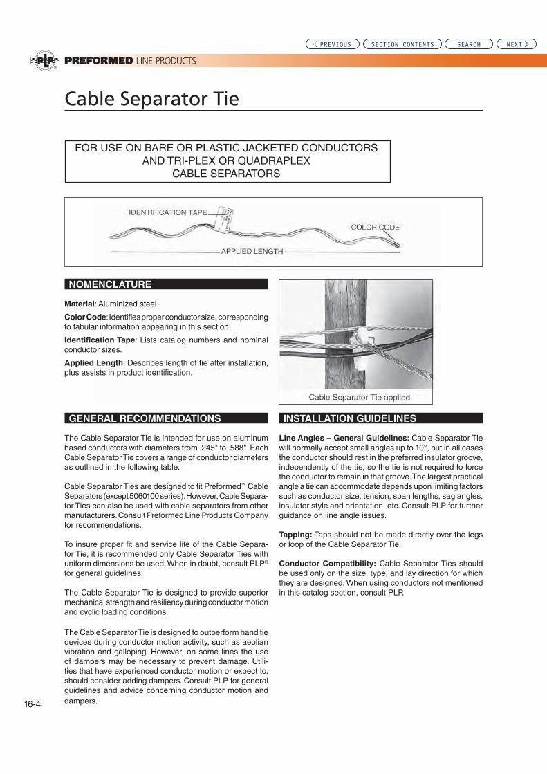
16-4
Cable Separator Tie
FOR USE ON BARE OR PLASTIC JACKETED CONDUCTORS AND TRI-PLEX OR QUADRAPLEX
CABLE SEPARATORS
GENERAL RECOMMENDATIONS INSTALLATION GUIDELINES
The Cable Separator Tie is intended for use on aluminum based conductors with diameters from .245" to .588". Each Cable Separator Tie covers a range of conductor diameters as outlined in the following table.
Cable Separator Ties are designed to fit Preformed™ Cable Separators (except 5060100 series). However, Cable Separa-tor Ties can also be used with cable separators from other manufacturers. Consult Preformed Line Products Company for recommendations.
To insure proper fit and service life of the Cable Separa-tor Tie, it is recommended only Cable Separator Ties with uniform dimensions be used. When in doubt, consult PLP® for general guidelines.
The Cable Separator Tie is designed to provide superior mechanical strength and resiliency during conductor motion and cyclic loading conditions.
The Cable Separator Tie is designed to outperform hand tie devices during conductor motion activity, such as aeolian vibration and galloping. However, on some lines the use of dampers may be necessary to prevent damage. Utili-ties that have experienced conductor motion or expect to, should consider adding dampers. Consult PLP for general guidelines and advice concerning conductor motion and dampers.
Line Angles – General Guidelines: Cable Separator Tie will normally accept small angles up to 10°, but in all cases the conductor should rest in the preferred insulator groove, independently of the tie, so the tie is not required to force the conductor to remain in that groove. The largest practical angle a tie can accommodate depends upon limiting factors such as conductor size, tension, span lengths, sag angles, insulator style and orientation, etc. Consult PLP for further guidance on line angle issues.
Tapping: Taps should not be made directly over the legs or loop of the Cable Separator Tie.
Conductor Compatibility: Cable Separator Ties should be used only on the size, type, and lay direction for which they are designed. When using conductors not mentioned in this catalog section, consult PLP.
Material: Aluminized steel.
Color Code: Identifies proper conductor size, corresponding to tabular information appearing in this section.
Identification Tape: Lists catalog numbers and nominal conductor sizes.
Applied Length: Describes length of tie after installation, plus assists in product identification.
NOMENCLATURE
PREVIOUS SECTION CONTENTS SEARCH NEXT

Distribution (Overhead): Section
16
16-5
Cab
le S
ep
ara
tor T
ie
Cable Separator Tie
For use on:
ACAR, All-Aluminum
ACSR, Aluminum Alloy
AWAC®, Compacted ACSR
Plastic Jacketed Conductor
EXPLANATORY NOTES:
(1.) “Diameter Range” indicates the size of conductors that utilize the same tie. To obtain outside diameters of many conductors falling within the diameter range listed, consult the conductor charts in the General Information Section.
(2.) “Nominal Conductor Size” indicates only a few conductors, that have outside diameters within the ranges listed. Consult the General Information Section for those not shown.
(3.) AWAC is a registered trademark of the Copperweld Co.
Catalog
Number
Diameter Range
(Inches) Nominal Conductor Size Units
Wt./
Lbs.Applied
Length
(Inches)
Color
CodeMin. Max. Bare Conductor
Plastic Jacket
Conductor Per Carton
CST-4102 .245 .277 #4 (6/1, 7/1) #4 (7W Alum. Alloy)
#6 (7W, 2/64s) #6 (solid 3/64s) #6 (6/1, 2/64s)
100 9 12 Orange
CST-4104 .316 .357#2 (6/1, 7/1)
#2 (7W Alum. Alloy) #1 (6/1)
#4 (7W, 3/64s) #4 (6/1, 7/1, 3/64s) 100 10 14 Red
CST-4105 .358 .4051/0 (7W All Alum.)
1/0 (6/1) 1/0 (7W Alum Alloy)
#3 (7W, 4/64s) #2 (7W, 3/64s) #4 (7W, 5/64s)
100 12 15 Yellow
CST-4106 .406 .4592/0 (7W All Alum.)
2/0 (6/1) 2/0 (7W Alum. Alloy)
#2 (6/1, 3/64s) #2 (7W, 4/64s) #1 (7W, 4/64s)
100 14 17 Blue
CST-4107 .460 .5203/0 (7W All Alum.)
3/0 (6/1) 3/0 (7W Alum. Alloy)
#4 (7W, 8/64s) #1 (6/1, 4/64s)
#1 (7W-19W, 5/64s) 1/0 (7W, 4/64s)
100 14 18 Orange
CST-4108 .521 .5884/0 (7W All Alum.)
4/0 (6/1) 4/0 (7W Alum. Alloy)
1/0 (6/1, 4/64s) 1/0 (7W, 5/64s) 2/0 (7W, 64s)
1/0 (6/1, 5/64s)
100 18 19 Red
PREVIOUS SECTION CONTENTS SEARCH NEXT

16-6
Lashing Rods
NOMENCLATURE
GENERAL RECOMMENDATIONS
C = (D + m) x .850
C = D x 2.00
C = D x 2.414
m = D x .483C = D x 2.155
m = D x .414
m = D x .666INTENDED USE: PREFORMED Lashing Rodscan be used on all types of messegered by overhead cables. They are particularly adaptable to spans ob-structed by trees, short spans over traffic intersections and support of power cable into and out of substa-tions.
MATERIAL SELECTION: Lashing Rods are made of the same basic material as the messenger to which they are applied. This pertains to Galvanized, Copperweld, Aluminum-clad Steel, Stainless Type 302, and Stainless Type 316. Any of these materials can be selected from the catalog page tables. The recommended types of strand are also indicated.
SIZE SELECTION: In selecting the proper size Lash-ing Rod it is necessary to determine the smallest circum-scribing circle that will enclose the messengers and the cables.
For grouping only one cable with a messenger, add the diameters and multiply by a factor of .850.
Color Code and Length: Assist in identification of size, corresponding to tabular information appearing on price pages.
For grouping two equal diameter cables, multiply the di-ameter of one cable times 2.00. Then to find the diameter of the maximum messenger that will fit in the interstices of the cables, multiply the diameter of one cable times .666.
For grouping three equal diameter cables, multiply the di-ameter of one cable times 2.155. Then to find the diameter of the maximum messenger that will fit in the interstices of the cables, multiply the diameter of one cable times .483.
For grouping four equal diameter cables, multiply the di-ameter of one cable times 2.414. Then to find the diameter of the maximum messenger that will fit in the interstices of the cables, multiply the diameter of one cable times .414.
For grouping unequal diameter cables, or messengers too large to fit into the interstices above, the minimum diameter grouping can best be determined by a graphic layout to scale.
Length
Rod DiameterColor CodeDeburred
Rod diameter: Identifies size of metal wire, correspond-ing to tabular information appearing on price pages. For covered rod, approximate thickness of plastic is indicated in addition to rod diameters.
PREVIOUS SECTION CONTENTS SEARCH NEXT

Distribution (Overhead): Section
16
16-7
Lash
ing
Ro
ds
Lashing Rods
DESIGN MODIFICATIONS
Application – Inspection
The smaller inside diameter of the proper size Lashing Rod should exert a low radial pressure on the cables and messenger.
For most installations one Lashing Rod should be applied, overlapping one pitch length with each successive rod.
GENERAL RECOMMENDATIONS (continued)
Two Lashing Rods, applied 180o apart, are recom-mended when the cable-messenger assembly weighs more than 8 pounds per foot, or at installations where the angle of sag exceeds 20o from the horizontal.
Lashing Rod: Neoprene Covered
For use in highly corrosive environment, or on extra heavy cables, a neoprene coating can be applied to the Galvanized, Copperweld®, Aluminum-clad Steel or Stain-less Steel Lashing Rods appearing on the price pages.
However, for normal outdoor power installations, the un-coated Lashing Rods are satisfactory.
In calculating circumscribing diameters for size selection, the thickness of the neoprene coating can be neglected.
Consult PLP for neoprene covered Lashing Rod. Include the minimum circumscribing diameter and the type of messenger material.
Copperweld and Aluminum-clad Steel are registered trade-marks of the Copperweld Co.
PREVIOUS SECTION CONTENTS SEARCH NEXT
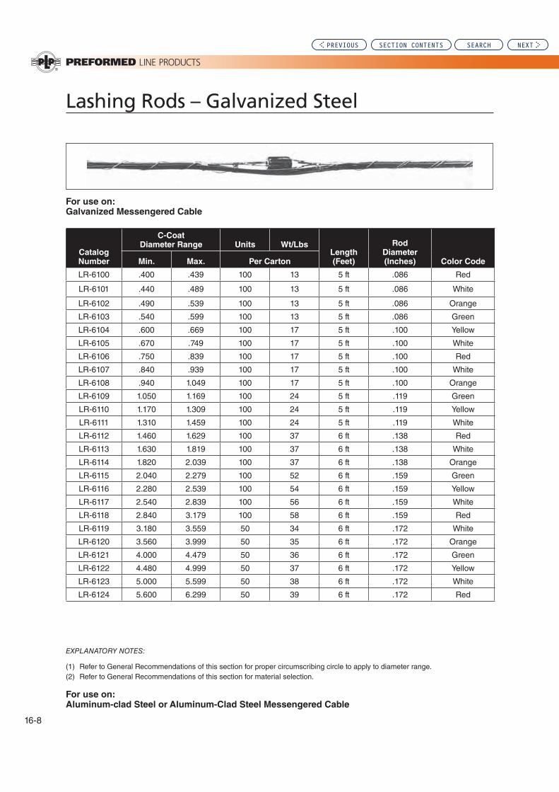
16-8
Lashing Rods – Galvanized Steel
For use on:Galvanized Messengered Cable
Catalog Number
C-CoatDiameter Range Units Wt/Lbs
Length (Feet)
Rod Diameter (Inches) Color CodeMin. Max. Per Carton
LR-6100 .400 .439 100 13 5 ft .086 Red
LR-6101 .440 .489 100 13 5 ft .086 White
LR-6102 .490 .539 100 13 5 ft .086 Orange
LR-6103 .540 .599 100 13 5 ft .086 Green
LR-6104 .600 .669 100 17 5 ft .100 Yellow
LR-6105 .670 .749 100 17 5 ft .100 White
LR-6106 .750 .839 100 17 5 ft .100 Red
LR-6107 .840 .939 100 17 5 ft .100 White
LR-6108 .940 1.049 100 17 5 ft .100 Orange
LR-6109 1.050 1.169 100 24 5 ft .119 Green
LR-6110 1.170 1.309 100 24 5 ft .119 Yellow
LR-6111 1.310 1.459 100 24 5 ft .119 White
LR-6112 1.460 1.629 100 37 6 ft .138 Red
LR-6113 1.630 1.819 100 37 6 ft .138 White
LR-6114 1.820 2.039 100 37 6 ft .138 Orange
LR-6115 2.040 2.279 100 52 6 ft .159 Green
LR-6116 2.280 2.539 100 54 6 ft .159 Yellow
LR-6117 2.540 2.839 100 56 6 ft .159 White
LR-6118 2.840 3.179 100 58 6 ft .159 Red
LR-6119 3.180 3.559 50 34 6 ft .172 White
LR-6120 3.560 3.999 50 35 6 ft .172 Orange
LR-6121 4.000 4.479 50 36 6 ft .172 Green
LR-6122 4.480 4.999 50 37 6 ft .172 Yellow
LR-6123 5.000 5.599 50 38 6 ft .172 White
LR-6124 5.600 6.299 50 39 6 ft .172 Red
EXPLANATORY NOTES:
(1) Refer to General Recommendations of this section for proper circumscribing circle to apply to diameter range.(2) Refer to General Recommendations of this section for material selection.
For use on:Aluminum-clad Steel or Aluminum-Clad Steel Messengered Cable
PREVIOUS SECTION CONTENTS SEARCH NEXT

Distribution (Overhead): Section
16
16-9
Lash
ing
Ro
ds
Lashing Rods – Aluminum-Clad Steel
Catalog Number
Diameter Range Units Wt/LbsLength (Feet)
Rod Diameter (Inches) Color CodeMin. Max. Per Carton
LR-2100 .400 .439 100 14 5 ft .102 Red
LR-2101 .440 .489 100 14 5 ft .102 White
LR-2102 .490 .539 100 14 5 ft .102 Orange
LR-2103 .540 .599 100 14 5 ft .102 Green
LR-2104 .600 .669 100 18 5 ft .114 Yellow
LR-2105 .670 .749 100 18 5 ft .114 White
LR-2106 .750 .839 100 18 5 ft .114 Red
LR-2107 .840 .939 100 18 5 ft .114 White
LR-2108 .940 1.049 100 18 5 ft .114 Orange
LR-2109 1.050 1.169 100 24 5 ft .128 Green
LR-2110 1.170 1.309 100 24 5 ft .128 Yellow
LR-2111 1.310 1.459 100 24 5 ft .128 White
LR-2112 1.460 1.629 100 36 6 ft .144 Red
LR-2113 1.630 1.819 100 36 6 ft .144 White
LR-2114 1.820 2.039 100 36 6 ft .144 Orange
LR-2115 2.040 2.279 100 46 6 ft .162 Green
LR-2116 2.280 2.539 100 47 6 ft .162 Yellow
LR-2117 2.540 2.839 100 48 6 ft .162 White
LR-2118 2.840 3.179 100 49 6 ft .162 Red
LR-2119 3.180 3.559 50 32 6 ft .182 White
LR-2120 3.560 3.999 50 33 6 ft .182 Orange
LR-2121 4.000 4.479 50 34 6 ft .182 Green
LR-2122 4.480 4.999 50 35 6 ft .182 Yellow
LR-2123 5.000 5.599 50 36 6 ft. .182 White
LR-2124 5.600 6.299 50 37 6 ft .182 Red
EXPLANATORY NOTES:
(1) Refer to General Recommendations of this section for proper circumscribing circle to apply to diameter range.(2) Refer to General Recommendations of this section for material selection.
For use on:Copperweld Messengered Cable
PREVIOUS SECTION CONTENTS SEARCH NEXT

16-10
Lashing Rods – Copperweld
Catalog Number
Diameter Range Units Wt/LbsLength (Feet)
Rod Diameter (Inches) Color CodeMin. Max. Per Carton
LR-3100 .400 .439 100 18 5 ft .102 Red
LR-3101 .440 .489 100 18 5 ft .102 White
LR-3102 .490 .539 100 18 5 ft .102 Orange
LR-3103 .540 .599 100 18 5 ft .102 Green
LR-3104 .600 .669 100 23 5 ft .114 Yellow
LR-3105 .670 .749 100 23 5 ft .114 White
LR-3106 .750 .839 100 23 5 ft .114 Red
LR-3107 .840 .939 100 23 5 ft .114 White
LR-3108 .940 1.049 100 23 5 ft .114 Orange
LR-3109 1.050 1.169 100 29 5 ft .128 Green
LR-3110 1.170 1.309 100 29 5 ft .128 Yellow
LR-3111 1.310 1.459 100 29 5 ft .128 White
LR-3112 1.460 1.629 100 45 6 ft .144 Red
LR-3113 1.630 1.819 100 45 6 ft .144 White
LR-3114 1.820 2.039 100 45 6 ft .144 Orange
LR-3115 2.040 2.279 100 56 6 ft .162 Green
LR-3116 2.280 2.539 100 58 6 ft .162 Yellow
LR-3117 2.540 2.839 100 58 6 ft .162 White
LR-3118 2.840 3.179 100 60 6 ft .162 Red
LR-3119 3.180 3.559 50 40 6 ft .182 White
LR-3120 3.560 3.999 50 41 6 ft .182 Orange
LR-3121 4.000 4.479 50 42 6 ft .182 Green
LR-3122 4.480 4.999 50 43 6 ft .182 Yellow
LR-3123 5.000 5.599 50 44 6 ft .182 White
LR-3124 5.600 6.299 50 45 6 ft .182 Red
EXPLANATORY NOTES:
(1) Refer to General Recommendations of this section for proper circumscribing circle to apply to diameter range.(2) Refer to General Recommendations of this section for material selection.(3) Copperweld is a registered trademark of the Copperweld Co.
For use on:Type 302 Stainless Steel Messengered Cable
PREVIOUS SECTION CONTENTS SEARCH NEXT

Distribution (Overhead): Section
16
16-11
Lash
ing
Ro
ds
Lashing Rods – Stainless Steel, Type 302
Catalog Number
Diameter Range Units Wt/LbsLength (Feet)
Rod Diameter (Inches) Color CodeMin. Max. Per Carton
LR-4100 .400 .439 100 13 5 ft .085 Red
LR-4101 .440 .489 100 13 5 ft .085 White
LR-4102 .490 .539 100 13 5 ft .085 Orange
LR-4103 .540 .599 100 13 5 ft .085 Green
LR-4104 .600 .669 100 18 5 ft .101 Yellow
LR-4105 .670 .749 100 18 5 ft .101 White
LR-4106 .750 .839 100 18 5 ft .101 Red
LR-4107 .840 .939 100 18 5 ft .101 White
LR-4108 .940 1.049 100 18 5 ft .101 Orange
LR-4109 1.050 1.169 100 25 5 ft .120 Green
LR-4110 1.170 1.309 100 25 5 ft .120 Yellow
LR-4111 1.310 1.459 100 25 5 ft .120 White
LR-4112 1.460 1.629 100 40 6 ft .139 Red
LR-4113 1.630 1.819 100 40 6 ft .139 White
LR-4114 1.820 2.039 100 40 6 ft .139 Orange
LR-4115 2.040 2.279 100 54 6 ft .161 Green
LR-4116 2.280 2.539 100 56 6 ft .161 Yellow
LR-4117 2.540 2.839 100 56 6 ft .161 White
LR-4118 2.840 3.179 100 58 6 ft .161 Red
LR-4119 3.180 3.559 50 36 6 ft .175 White
LR-4120 3.560 3.999 50 37 6 ft .175 Orange
LR-4121 4.000 4.479 50 38 6 ft .175 Green
LR-4122 4.480 4.999 50 39 6 ft .175 Yellow
LR-4123 5.000 5.599 50 40 6 ft .175 White
LR-4124 5.600 6.299 50 41 6 ft .175 Red
EXPLANATORY NOTES:
(1) Refer to General Recommendations of this section for proper circumscribing circle to apply to diameter range.(2) Refer to General Recommendations of this section for material selection.
For use on:Type 316 Stainless Steel Messengered Cable
PREVIOUS SECTION CONTENTS SEARCH NEXT

16-12
Lashing Rods – Stainless Steel, Type 316
Catalog Number
Diameter Range Units Wt/LbsLength (Feet)
Rod Diameter (Inches) Color CodeMin. Max. Per Carton
LR-5100 .400 .439 100 13 5 ft .085 Red
LR-5101 .440 .489 100 13 5 ft .085 White
LR-5102 .490 .539 100 13 5 ft .085 Orange
LR-5103 .540 .599 100 13 5 ft .085 Green
LR-5104 .600 .669 100 18 5 ft .101 Yellow
LR-5105 .670 .749 100 18 5 ft .101 White
LR-5106 .750 .839 100 18 5 ft .101 Red
LR-5107 .840 .939 100 18 5 ft .101 White
LR-5108 .940 1.049 100 18 5 ft .101 Orange
LR-5109 1.050 1.169 100 25 5 ft .120 Green
LR-5110 1.170 1.309 100 25 5 ft .120 Yellow
LR-5111 1.310 1.459 100 25 5 ft .120 White
LR-5112 1.460 1.629 100 40 6 ft .139 Red
LR-5113 1.630 1.819 100 40 6 ft .139 White
LR-5114 1.820 2.039 100 40 6 ft .139 Orange
LR-5115 2.040 2.279 100 54 6 ft .161 Green
LR-5116 2.280 2.539 100 56 6 ft .161 Yellow
LR-5117 2.540 2.839 100 56 6 ft .161 White
LR-5118 2.840 3.179 100 58 6 ft .161 Red
LR-5119 3.180 3.559 50 36 6 ft .175 White
LR-5120 3.560 3.999 50 37 6 ft .175 Orange
LR-5121 4.000 4.479 50 38 6 ft .175 Green
LR-5122 4.480 4.999 50 39 6 ft .175 Yellow
LR-5123 5.000 5.599 50 40 6 ft .175 White
LR-5124 5.600 6.299 50 41 6 ft .175 Red
EXPLANATORY NOTES:
(1) Refer to General Recommendations of this section for proper circumscribing circle to apply to diameter range.(2) Refer to General Recommendations of this section for material selection.
PREVIOUS SECTION CONTENTS SEARCH NEXT

Distribution (Overhead): Section
17
Section 17 – Distribution (Overhead): Guying Products
Table of Contents
GUY-GRIP® Dead-end ............................................................................17-2
GUY-LOCK ...........................................................................................17-10
Wrap Guy Link .....................................................................................17-11
Big-Grip Dead-end ...............................................................................17-13
Strand Splice ........................................................................................17-17
Safety Guy Wire Dispenser .................................................................17-23
Pulling Eye ...........................................................................................17-24
Page
PREVIOUS SEARCH NEXT

17-2
GUY-GRIP® Dead-end
Cross-over Marks*:
(A) – Indicate starting point for application on smaller diameter fittings described on the reverse side of this page.
(B) – Indicates alternate starting point for application on larger diameter fittings described on the reverse side of this page.
Cabled Loop: Furnished as standard, all sizes.
GENERAL INFORMATION
GUY-GRIP Dead-ends are intended for use on single wood poles associated with distribution construction.
GUY-GRIP Dead-ends were not designed or tested for use on overhead shield wires and not intended for that application.
Refer to Big-Grip Dead-end, an alternate product recom-mended for guying transmission construction, or tower and antenna applications.
Refer to the Installation Tools section for the PLP® Pulling Eye, designed to assist application at the anchor.
RATED HOLDING STRENGTH: GUY-GRIP Dead-ends are rated at 100% of the strand’s published rated breaking strength.
MATERIAL SELECTION: GUY-GRIP Dead-ends are made of the same basic material as the strand to which they are applied. This pertains to galvanized, *Bezinal®, **Cop-perweld®, Aluminum clad steel, stainless Type 302, and stainless Type 316. Any of these materials can be selected from the catalog tables. The recommended types of strand are also indicated.
NOMENCLATURE
TAPPING: GUY-GRIP Dead-ends are mechanical devices not designed as current transfer connectors. Consequently, tapping is not recommended over or through the GUY-GRIP Dead-end.
APPLICATION-INSPECTION: Within the first 3 months after initial application, GUY-GRIP Dead-ends may be removed and reapplied two times after initial application for the purpose of retensioning the guy. After 3 months a new Dead-end should be used any time removal is required.
GUY-GRIP Dead-ends should be used on hardware that is held in a fixed position; the fitting should not be allowed to rotate or spin about the axis of the strand. They should not be
used as tools; that is, come-alongs, pulling-in grips, etc.
Lay direction of both the GUY-GRIP Dead-ends and the strand should be the same. Most strand is left-hand lay.
STRAND TAIL: For appearance and safety the strand tail should be cut as close as convenient to the crossover mark and buried inside the crossover mark if possible. If desired, the strand tail can, instead, extend through the loop for grounding purposes. Any tail over 2" or 3" should be restrained and not permitted to rotate during loading of the guy.
SAFETY CONSIDERATIONS
1. This product is intended for a single (one-time, perma-nent) use and for the specified application, although it may be reapplied twice for retensioning within 90 days of initial installation. CAUTION: DO NOT MODIFY OR REUSE THIS PRODUCT AFTER 90 DAYS UNDER ANY CIRCUMSTANCES.
2. This product SHOULD NOT be used as a tool; that is a come-along, pulling in grips, temporairy bracing, etc.
3. This product is intended for use by trained crafts people only. This product SHOULD NOT BE USED by anyone who is not familiar with and trained in the use of it.
Pitch Length: One complete wrap.
Color Code and Length: Assist in identification of strand size, corresponding to tabular information appearing on catalog pages.
Identification Tape: Shows catalog number, nominal sizes.
Short Leg-Long Leg: Identifies rods belonging to each leg, after application. During application, the short leg should be applied first.
4. When working in the area of energized lines with this product, EXTRA CARE should be taken to prevent accidental electrical contact.
5. For PROPER PERFORMANCE AND PERSONAL SAFETY be sure to select the proper size GUY-GRIP Dead-end before application.
6. GUY-GRIP Dead-ends are precision devices. To insure proper performance, they should be stored in cartons under cover and handled carefully.
*Bezinal is a registered trademark of the Bekaert Corporation. **Copperweld® is a registered trademark of the Copperweld Co.
PREVIOUS SECTION CONTENTS SEARCH NEXT

Distribution (Overhead): Section
17
17-3
GU
Y-G
RIP
® Dead
-en
d
GUY-GRIP® Dead-end
HARDWARE CONSIDERATIONS
CABLED LOOP: Anchor eyes and other fittings need groove diameters only slightly larger than the strand because the diameter of the cabled rods of GUY-GRIP Dead-ends approximates strand diameter. Cabled loops are designed for a variety of fittings with dimensions shown in the table below.
CAUTION: Hardware of this type is not normally acceptable because fatigue life of GUY-GRIP Dead-ends could be substantially reduced.
Heavy-Duty-Type Cable Thimbles, if used, can collapse when guy tensions are high. If thimbles are used in the loop of the GUY-GRIP Dead-end, a large pin is recom-mended to fill the loop of the thimble to prevent distortion. The collapsing strength of the thimble and the proper pin size should be obtained from the thimble manufacturer.
Suggested hardware dimensions for cabled-loop GUY-GRIP Dead-ends
Dead-end
Diameter
Range
(Inches) Nominal Strand Sizes Seat Dimensions (Figures 1 & 2) (Inches)
Minimum
Groove
Diameter (in.)
(fig. 2)
Minimum
Hole
Diameter* (in.)
(fig. 3)Min. Max.
Galvanized
Steel
Aluminum-
clad Steel
Min. seat diameter with
Dead-end at first
cross-over mark.
Max. seat diameter
with Dead-end at first
cross over mark.
Max. seat diameter
with Dead-end at
second cross-over
mark.
.123 .143 1/8 – 3/4 1-3/4 – 3/16 1/4
.144 .173 5/32 – 3/4 1-3/4 2-1/2 1/4 5/16
.174 .203 3/16 – 1-0 1-3/4 2-1/2 1/4 3/8
.204 .230 7/32 3 #10, 4M3 1-1/8 1-3/4 2-1/2 5/16 3/8
.231 .259 1/4 7 #12, 6M 1-1/8 1-3/4 2-1/2 5/16 7/16
.260 .291 9/32 7 #11, 8M 1-1/8 1-3/4 2-1/2 3/8 1/2
.292 .336 5/16 7 #10, 10M 1-1/4 1-3/4 2-1/2 3/8 9/16
.337 .394 3/8 7 #8, 14M, 16M 1-3/8 1-3/4 2-1/2 7/16 5/8
.395 .474 7/16 7 #7, 18M, 20M 1-3/8 2-3/8 – 1/2 11/16
.475 .515 ** 7 #6 1-3/8 2-3/8 – 9/16 3/4
.516 .570 ** 7 #5, 25M 1-1/2 2-5/8 – 5/8 15/16
* Depending on geometric shape of the hole, a hole diameter less than specified may be acceptable.
** Use Big-Grip Dead-ends.† Guying of transmission structures and metal towers require Big-Grip
Dead-ends, VARI-GRIP™ Dead-ends.
Acceptable Fittings
Anchor RodsThimble Eye-Bolts, -Eyenuts & Eyes Pole Fittings Guy-Strain Insulators
ANSI54-1 54-2 54-3 54-4
PREVIOUS SECTION CONTENTS SEARCH NEXT

17-4
GUY-GRIP® Dead-end
For use on:
Extra High Strength, High Strength,
Siemens Martin, Utilities Grade3
Left-hand lay standard
EXPLANATORY NOTES:
(1) Big-Grip Dead-end is recommended as an alternative product for guying multiple pole structures or metal towers associated with transmission construction.(2) Refer to Hardware Considerations for acceptable fittings. Cabled Loop design furnished as standard, all sizes.(3) Rated holding strength is 100% of published rating for all grades of galvanized strand.(4) Consult PLP for sizes and stranding not shown.
GUY-GRIP® Dead-end: Galvanized Steel
B-Coat
Catalog Number
Strand
Units per carton
Wt./Lbs. per carton
Length (Inches)
Color Code
Size(Inches) Construction
Mean Diameter (Inches)
GDE-1102 3/16 7W 7W
.186
.195 100 30 20 Red
GDE-1103 7/32 7W .216 50 19 24 Green
GDE-1104 1/4 3W 7W
.259
.240 50 24 25 Yellow
GDE-1105 9/32 7W .279 50 26 28 Blue
GDE-1106 5/163W 7W 7W
.312
.312
.32750 39 31 Black
GDE-1107 3/8 3W 7W
.356
.360 50 51 35 Orange
GDE-1108 7/16 7W .435 25 40 38 Green
C-coat
Catalog Number
Strand
Units per carton
Wt./Lbs. per carton
Length (Inches)
Color Code
Size (Inches) Construction
Mean Diameter (Inches)
GDE-2102 3/16 7W 7W
.186
.195 100 30 20 Red
GDE-2103 7/32 7W .216 50 19 24 Green
GDE-2104 1/4 3W 7W
.259
.240 50 24 25 Yellow
GDE-2105 9/32 7W .279 50 26 28 Blue
GDE-2106 5/163W 7W 7W
.312
.312
.32750 39 31 Black
GDE-2107 3/8 3W 7W
.356
.360 50 51 35 Orange
GDE-2108 7/16 7W .435 25 40 38 Green
PREVIOUS SECTION CONTENTS SEARCH NEXT

Distribution (Overhead): Section
17
17-5
GU
Y-G
RIP
® Dead
-en
d
GUY-GRIP® Dead-end
For use on:
Bezinal Strand2
Left-hand lay standard
EXPLANATORY NOTES:
(1) Big-Grip Dead-end is recommended as an alternative product for guying multiple pole structures or metal towers associated with transmission construction.(2) Rating holding strength is 100% of the published rating for the strand.(3) Bezinal is a registered trademark of the Bekaert Company.
Catalog Number
Strand
Units per carton
Weight (Lbs)
per cartonLength (Inches) Color Code
Size (Inches) Construction
Mean Diameter (Inches)
BDE-9102 3/16 7W7W
.186
.195 100 30 20 Red
BDE-9104 1/4 3W7W
.259
.240 50 24 25 Yellow
BDE-9106 5/163W7W7W
.312
.312
.32750 39 31 Black
BDE-9107 3/8 3W7W
.356
.360 50 51 35 Orange
BDE-9108 7/16 7W .435 25 41 38 Green
GUY-GRIP® Dead-end: Bezinal®
PREVIOUS SECTION CONTENTS SEARCH NEXT

17-6
GUY-GRIP® Dead-end
Left-Hand Lay standard
EXPLANATORY NOTES:
(1) Big-Grip Dead-end is recommended as an alternative product for guying multiple pole structures or metal towers associated with transmission construction.(2) Refer to Hardware Considerations for acceptable fittings. Cabled Loop design furnished as standard, all sizes.(3) Rated holding strength is 100% of all grades of aluminum clad steel strand.(4) Rated holding stength is 100% of the published rating for the strand.(5) Consult PLP for sizes and stranding not shown.
For use on:
Aluminum Clad Steel Strand3
Catalog Number
Mean Diameter (Inches)
Nominal Strand Size
Units per carton
Wt./lbs. per carton
Length (Inches) Color Code
AWDE-4102 .174 3 # 12 100 21 18 Orange
AWDE-4108 .220 .220
4M 3 # 10 50 20 21 Green
AWDE-4110 .247 .242
3 # 9 6M 50 20 24 Yellow
AWDE-4113 .277 .272
3 # 8 8M 50 22 24 Blue
AWDE-4116.311 .306 .306
3 # 7 10M
5/16" - 7 # 1050 29 26 Black
AWDE-4118 .330 11.5M 50 30 26 Green
AWDE-4119.349 .343 .343
3 # 6 12.5M
11/32" - 7 # 950 41 29 Yellow
AWDE-4120 .363 14M 50 53 31 Blue
AWDE-4122.392.385 .386
3 # 5 3/8" - 7 # 8
16M50 55 32 Orange
AWDE-4124 .417 18M 25 37 34 Black
AWDE-4125 .433 7/16" - 7 # 7 25 40 36 Green
AWDE-4126 .444 20M 10 22 37 Yellow
AWDE-4128 .486 1/2" - 7 # 6 10 23 39 Blue
AWDE-4130 .519 25M 10 31 43 Red
AWDE-4131 .546 7 # 5 10 32 44 Yellow
PREVIOUS SECTION CONTENTS SEARCH NEXT

Distribution (Overhead): Section
17
17-7
GU
Y-G
RIP
® Dead
-en
d
GUY-GRIP® Dead-end
For use on:
Aluminized Strand4
Left-Hand Lay standard
EXPLANATORY NOTES:
(1) Big-Grip Dead-end is recommended as an alternative product for guying multiple pole structures or metal towers associated with transmission construction.(2) Refer to Hardware Considerations for acceptable fittings. Cabled Loop design furnished as standard, all sizes.(3) Refer to General Information for material selection.(4) Rated holding strength is 100% of all grades of aluminized strand.(5) Consult PLP for sizes and stranding not shown.
GUY-GRIP® Dead-end: Aluminized
Catalog Number
Strand
Units per carton
Wt./lbs. per carton
Length (Inches)
Color Code
Size (Inches) Construction
Mean Diameter (Inches)
AZDE-7100 3/16 7W 7W
.186
.195 100 25 18 Red
AZDE-7102 1/4 3W 7W
.259
.240 50 22 23 Yellow
AZDE-7103 9/32 7W .279 50 27 24 Blue
AZDE-7104 5/163W 7W 7W
.312
.312
.32750 37 27 Black
AZDE-7106 3/8 3W 7W
.356 .360 50 63 32 Orange
AZDE-7107 7/16 7W .435 25 45 34 Green
PREVIOUS SECTION CONTENTS SEARCH NEXT

17-8
GUY-GRIP® Dead-end
Left-Hand Lay standard
EXPLANATORY NOTES:
(1) Big-Grip Dead-end is recommended as an alternative product for guying multiple pole structures or metal towers associated with transmission construction.(2) Refer to Hardware Considerations for acceptable fittings. Cabled Loop design furnished as standard, all sizes.(3) Refer to General Information for material selection.(4) Rated holding strength is 100% of the published rating of the strand.(5) Consult PLP for sizes and stranding not shown.(6) Copperweld is a registered trademark of the Copperweld Co.
For use on:
Copperweld Strand4
GUY-GRIP® Dead-end: Copperweld®
Catalog Number
Mean Diameter (Inches)
Nominal Strand Size Units Wt./lbs
Length (Inches) Color Code
CDE-8100 .164 2.2M 100 19 17 Orange
CDE-8102 .174 3 # 12 100 24 17 Red
CDE-8106 .209 4M 100 32 18 White
CDE-3101 .220 3 # 10 100 44 20 Green
CDE-3103 .247 .237 3 # 9 6M 50 24 21 Yellow
CDE-3104 .258 6M3 50 25 22 White
CDE-3106 .276 .277 8M 3 # 8 50 26 23 Blue
CDE-3109.303 .306 .311
10M 7 # 10 - 5/16"
3 # 750 34 25 Red
CDE-3112.343 .345 .349
7 # 9 - 11/32" 12.5M 3 # 6
50 46 27 Green
CDE-3113 .360 14M 50 64 30 Blue
CDE-3115.385 .386 .392
7 # 8 - 3/8" 16M 3 # 5
50 65 31 White
CDE-3117 .414 18M 25 46 34 Orange
CDE-3118 .438 .433
20M 7 # 7 - 7/16" 25 47 35 Yellow
CDE-3121 .486 7 # 6 - 1/2" 25 65 39 Blue
CDE-3123 .525 25M 10 37 43 Green
CDE-3124 .546 7 # 5 - 9/16" 10 38 44 Yellow
PREVIOUS SECTION CONTENTS SEARCH NEXT

Distribution (Overhead): Section
17
17-9
GU
Y-G
RIP
® Dead
-en
d
GUY-GRIP® Dead-end
For use on:
Type 316 Strand
For use on:
Type 302 and Type 430 Strand
*These Dead-ends utilize the open helix design.
Left-Hand Lay standard
EXPLANATORY NOTES:
(1) Big-Grip Dead-end is recommended as an alternative product for guying multiple pole structures or metal towers associated with transmission construction.(2) Refer to Hardware Considerations for acceptable fittings. Cabled Loop design furnished as standard, all sizes.(3) Refer to General Information for material selection.(4) Consult PLP for sizes and stranding not shown.
GUY-GRIP® Dead-end: Stainless Steel
Type 302
Catalog Number
Strand UnitsWt./Lbs.
Length (Inches)
Color Code
Percent of Strands Rated
BreakingStrength
Size (Inches) Construction
Mean Diameter (Inches) Per Carton
SDE-5101 7/32 3W 7W
.224
.216 100 30 22 Blue 100%
SDE-5102 1/4 3W 7W
.259
.249 50 25 26 Yellow 100%
SDE-5103 9/32 7W .279 50 26 27 Black 90%
SDE-5104 5/16 3W 7W
.312
.312 50 41 31 Orange 93%
SDE-5105 3/8 3W 7W
.356
.360 50 66 37 Green 83%
Type 316
Catalog Number
Strand UnitsWt./Lbs.
Length (Inches)
Color Code
Percent of Strands Rated
BreakingStrength
Size (Inches) Construction
Mean Diameter (Inches) Per Carton
SDE-6101 7/32 3W 7W
.224
.216 100 30 22 Blue 100%
SDE-6102 1/4 3W 7W
.259
.249 50 25 26 Yellow 100%
SDE-6103 9/32 7W .279 50 26 27 Black 90%
SDE-6504* 5/16 3W 7W
.312
.312 50 41 31 Orange 93%
SDE-6105 3/8 3W 7W
.356
.360 50 66 37 Green 87%
SDE-6107 1/2 7W .500 10 52 53 Blue 85%
PREVIOUS SECTION CONTENTS SEARCH NEXT

17-10
GUY-LOCK
GENERAL RECOMMENDATIONS
The GUY-LOCK is intended for use on single wood poles associated with distribution constructions.
The GUY-LOCK is designed to perform the same function as GUY-GRIP® dead-ends, but are for those who prefer a “wrap around” guy at the pole. The GUY-LOCK is recom-mended for any size pole and neatly secures the tail of the guy strand to the load portion of the down guy. The GUY-LOCK can also be used to secure the down guy at the anchor location.
NOMENCLATURE
RATED HOLDING STRENGTH: The GUY-LOCK is rated at 100% of the strands published rated breaking strength.
This product is intended for a single (one-time) use and for the specified application although it may be reapplied twice for retensioning within 90 days of initial installation. CAUTION: DO NOT MODIFY OR REUSE THIS PRODUCT AFTER 90 DAYS UNDER ANY CIRCUMSTANCES.
Catalog Number Size (Inches) Construction
Mean Diameter (Inches)
Length (Inches) Color Code
Rated Holding Strength
(Lbs.)
GL-1104* 1/4 7W 3W .259 .240 33 Yellow 6,650
GL-1106* 5/16 7W 3W .312 .327 35 Black 11,200
GL-1107* 3/8 7W 3W .356 .360 42 Orange 15,400
GL-1108 7/16 7W .435 44 Green 20,800
GL-1109 1/2 7W 19W .495 .500 46 Blue 26,900
Length: Indicates length of GUY-LOCK before installation.
Subset: GUY-LOCK consists of sub-sets of helically formed galvanized steel wires, bonded together and coated internally with an abrasive material.
Color Code: Provides strand size identification and indicates cross-over point for starting application.
Color Code
Subsets
*Denotes a single subset design
Length
PREVIOUS SECTION CONTENTS SEARCH NEXT

Distribution (Overhead): Section
17
17-11
Wra
p G
uy L
ink
Wrap Guy Link
GENERAL RECOMMENDATIONS
As a general guide, the following recommendations can be adapted to the specific conditions.
This product is intended for a single (one-time) use and for the specified application although it may be reapplied twice for retensioning within 90 days of initial installation. CAUTION: DO NOT MODIFY OR REUSE THIS PRODUCT AFTER 90 DAYS UNDER ANY CIRCUMSTANCES.
INTENDED USE
Wrap Guy Links are designed as an alternate for GUY-GRIP® Dead-ends, for use at the pole only, when the guy strand is wrapped around the pole. Recommended for any size pole, single or double wrapped, the Wrap Guy Link neatly secures the tail of the guy strand to the load portion of the down guy.
APPLICATION-INSPECTION
Either of the gritted leg sections can be applied to the tail-end of the strand. The end of the strand should coincide with the crossover mark on the gritted leg. The Circle Clamp, a component part of each Wrap Guy Link, is then crimped one inch above the
NOMENCLATURE
crossover mark. The strand, with one of the gritted legs applied, is now ready to be wrapped around the pole. The purposes of the circle clamp is to assure that the gritted legs remain applied when single or double turns are wrapped around the pole.
After wrapping the strand around the pole, the remaining gritted leg is applied to the continued strand, or load por-tion of the down guy. The completed application should be inspected for two conditions:
1. The Wrap Guy Link itself, should be free of the pole. Only the wrapped portion of the strand should make contact with the pole.
2. The distance between the pole and the crossover mark on the continued strand should approximate 1-1/2 pole diameters.
The purpose of these two contions is to assure that the angle formed by the loop will not exceed 30°.
ACCEPTABLE FITTINGS
Contrary to recommendations for GUY-GRIP® Dead-ends, Guy Hooks are acceptable for use with Wrap Guy Links.
Strand -Single
orDouble
Wrapped
Maintain endfree of pole
Circle ClampCrossover MarkEnd of Strand
Min. 11⁄2 xPole Diameter
CrossoverMark
PREVIOUS SECTION CONTENTS SEARCH NEXT
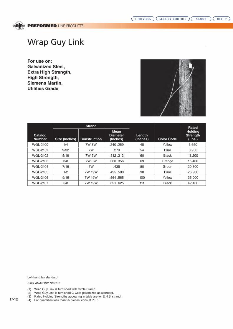
17-12
Wrap Guy Link
For use on:
Galvanized Steel,
Extra High Strength,
High Strength,
Siemens Martin,
Utilities Grade
Left-hand lay standard
EXPLANATORY NOTES:
(1) Wrap Guy Link is furnished with Circle Clamp.(2) Wrap Guy Link is furnished C-Coat galvanized as standard.(3) Rated Holding Strengths appearing in table are for E.H.S. strand.(4) For quantities less than 25 pieces, consult PLP.
Catalog Number
Strand
Length (Inches) Color Code
Rated Holding Strength
(Lbs.)Size (Inches) Construction
Mean Diameter (Inches)
WGL-2100 1/4 7W 3W .240 .259 48 Yellow 6,650
WGL-2101 9/32 7W .279 54 Blue 8,950
WGL-2102 5/16 7W 3W .312 .312 60 Black 11,200
WGL-2103 3/8 7W 3W .360 .356 69 Orange 15,400
WGL-2104 7/16 7W .435 80 Green 20,800
WGL-2105 1/2 7W 19W .495 .500 90 Blue 26,900
WGL-2106 9/16 7W 19W .564 .565 100 Yellow 35,000
WGL-2107 5/8 7W 19W .621 .625 111 Black 42,400
PREVIOUS SECTION CONTENTS SEARCH NEXT

Distribution (Overhead): Section
17
17-13
Big
-Grip
Dead
-en
d
Big-Grip Dead-end
Cross-over Marks: Indicate starting point for application.
Color Code and Length: Assist in identification of strand size, corresponding to tabular information appearing on catalog pages.
GENERAL INFORMATION
Big-Grip Dead-ends are designed for use on Transmis-sion, Antenna, Communications, and other types of guyed structures that require use of large guy strand.
Rated Holding Strength (RHS): Big-Grip Dead-ends are designed to develop the maximum loads published on the catalog pages only for those specific strands listed.
INSTALLATION GUIDELINES
Strand Compatibility: Big-Grip Dead-ends should be used only on the size and strand for which they are designed. They must have the same lay as the strand to which they are applied.
When ordering Big-Grip Dead-ends, make sure to specify the strand on which it is to be used and the strand lay.
When using types of strand and/or sizes of strand not men-tioned in these catalog pages, consult PLP for compatible Big-Grip Dead-end designs.
During installation and at all times, care should be taken to avoid gouging or damaging the corrosion preventive material of either the Big-Grip Dead-end or the strand.
Big-Grip Dead-ends must not be used as tools, that is,
come-alongs, pulling-in grips, etc.
Normally tools are not required to install Big-Grip Dead-ends, however a screwdriver may be used to split the legs into subsets. When splitting the legs, do not make more than two subsets per leg.
For hardware and hardware dimensions to be used in conjunction with Big-Grip Dead-ends refer to Table 1, on the next page.
Big-Grip Dead-ends should not be used on hardware which allows the strand to rotate or spin about its axis uncontrolled. Adjustable hardware, such as a turnbuckle, may be used as long as rotational movement of the strand is restricted. Consult PLP for additional information concerning adjust-able hardware that can be used with Big-Grip Dead-ends.
Hardware used in conjunction with Big-Grip Dead-ends should have smooth contours, ample groove clearances, acceptable diameters and sufficient strength to minimize abrasion and fatigue of the loop area.
Hardware: Table 1, Figures 1-6 illustrate some of the pos-sible hardware and their dimensions that may be used with Big-Grip Dead-ends:
(A) Figure 1 illustrates minimum and maximum accept-able seat diameters to which the Big-Grip Dead-end can be applied.
(B) Figure 2 illustrates seat diameters and minimum groove diameters.
(C) Figure 3 illustrates minimum hardware hole diameters.
NOMENCLATURE
Identification Tape: Shows catalog number, nominal sizes.
Short Leg-Long Leg: Identifies rods belonging to each leg, after application. During application, the short leg should be applied first.
Material Selection: Big-Grip Dead-ends are made from material which is compatible with the strand they are designed to be used with except where noted otherwise.
This product is intended for a single (one-time) use and for the specified application although it may be reapplied twice for retensioning within 90 days of initial installation. CAUTION: DO NOT MODIFY OR REUSE THIS PRODUCT AFTER 90 DAYS UNDER ANY CIRCUMSTANCES.
PREVIOUS SECTION CONTENTS SEARCH NEXT

17-14
Big-Grip Dead-end
(C) In order to prevent collapse of the thimble, either a solid Hawser type thimble (Figure 4), or a large pin inside the thimble (Figure 5), or a smaller pin (such as a shackle pin) plus double extra strong weight pipe or equivalent (Figure 6) is necessary. Double extra strong weight pipe, which has increased wall thickness and strength over schedule 160 pipe, does not have a schedule number but information can be obtained from a pipe supplier. Thimble strengths and dimensions can be obtained from a thimble supplier.
PLP suggests guy tensions be maintained at a minimum of approximately 10% of the Strand’s Rated Breaking Strength (RBS).
When in doubt about installations, hardware, or applications, contact your PLP representative.
Thimble Recommendations
(A) Only heavy-duty type wire rope thimbles or solid Hawser type thimbles are recommended for use with Big-Grip Dead-ends. (Refer to Figures 4,5, and 6.)
(B) Heavy-duty type wire rope thimbles can collapse when guy tensions are high. In order to support and protect the loop area of the Big-Grip Dead-end special precau- tions are necessary.
Table 1 - Big-Grip Dead-end Hardware Accessories Dimensions (All Dimensions In Inches)
Dead-end
Diameter
Range
Nominal
Strand
Sizes
Fig. 1 & 2 Seat
Dimensions Fig. 2
Minimum
Groove
Diameter
Fig. 3
Minimum
Hardware
Hole
Diameter*
Heavy
Duty
Thimble
Size
Fig. 4 & 5
Pin Diameters
Double Extra Strong
Weight Pipe Fig. 6
Min. Max. Min. Max.
Nominal
Size O.D. I.D.
.475-.515 1/2 1-3/8 2-3/8 9/16 3/4 5/8 1 1-5/8 1-1/4 1.66 .896
.516-.570 9/16 1-1/2 2-5/8 5/8 15/16 5/8 1-1/8 1-5/8 1-1/4 1.66 .896
.571-.635 5/8 2 2-5/8 3/4 1 3/4 1-1/2 1-7/8 1-1/4 1.66 .896
.636-.772 3/4 2-1/2 3-1/8 7/8 1-3/16 7/8 1-7/8 2-1/8 1-1/2 1.9 1.1
.773-.868 2-1/2 3-5/8 1 1-3/8 1 2 2-3/8 2 2.375 1.503
.869-1.024 7/8 1 3 4-1/8 1 1-3/8 1-1/8 - 1-1/4 2-3/8 2-3/4 2 2.375 1.503
1.025-1.27 3-1/2 5-1/8 1-3/8 1-3/4 1-1/4 - 1-3/8 2-3/4 3-1/4 2-1/2 2.875 1.7711.30 4 5-1/8 1-3/8 1-15/16 1-3/8 - 1-1/2 2-7/8 3-3/8 2-1/2 2.875 1.771
Figure 1 Figure 2 Figure 3 Figure 4 Figure 5 Figure 6
*Depending on geometric shape of the hole, the legs of Big-Grip Dead-ends may insert into hole diameter less than specified.
PREVIOUS SECTION CONTENTS SEARCH NEXT

Distribution (Overhead): Section
17
17-15
Big
-Grip
Dead
-en
d
For use on:
Extra High Strength
Siemens Martin
High Strength
Utilities Grade
Left-hand lay standard + Down-Rated for 37 stranding (1994)
EXPLANATORY NOTES:
(1) For strand sizes smaller than 1/2", refer to the GUY-GRIP® Dead-end.(2) Reference table earlier in this section for acceptable fitting dimensions.(3) Cabled loop design is furnished as standard for all sizes.(4) Rated Holding Strengths (RHS) of the Big-Grip Dead-ends are listed for each strand and are expressed as a percent of the
strand's Rated Breaking Strength (RBS).(5) C-Coat galvanized steel is standard for the Big-Grip Dead-ends used on 1/2", 9/16", and 5/8" strand.(6) B-Coat galvanized steel is used for the Big-Grip Dead-ends used on 3/4" strand. However, use of this material is subject to
availability and other materials such as aluminum-covered steel may be substituted. Before ordering, consult Preformed™ as to material availability.
(7) Big-Grip Dead-ends for 7/8" and 1" strand are made from aluminum-covered steel material. Galvanized steel material is not available. Before using, check to make sure that atmospheric conditions in the area they are to be used will not create a problem caused by two dissimilar metals.
(8) Consult PLP for sizes and stranding not shown.
Big-Grip Dead-end: Galvanized Strand
Catalog
Number
Strand BG Per Carton
Approx.
Length
(In.)
Color
Code
Rated
Holding
Strength
(Lbs.)
Percent of
Strand’s
Rated
Breaking
Strength
Size
(In.) Construction
Actual
Diameter
(In.) Units Wt./Lbs.
BG-2115 1/2 7W or 19W .495 or .500 20 63 49 Blue 26,900 (100%)
BG-2116 9/16 7W or 19W .564 or .565 10 48 55 Yellow 35,000 (100%)
BG-2111 5/8 7W or 19W .621 or .625 10 65 64 Black 7W 42,400
19W 40,200(100%) (100%)
BG-2112 3/4 19W .750 5 54 76 Orange 58,300 (100%)
BG-MS-7023 7/8 19W .885 5 76 90 Green 79,700 (100%)
BG-MS-7047 1 19W or 37W 1.000 or 1.001 3 76 125 Blue
19W 104,500
37W 92,430
(100%) (90%) +
PREVIOUS SECTION CONTENTS SEARCH NEXT

17-16
Big-Grip Dead-end
Left-hand lay standard + Down-Rated for 37 stranding (1994)
EXPLANATORY NOTES:
(1) For strand sizes smaller than 7#6, refer to the GUY-GRIP® Dead-end.(2) “Nominal Strand Size” indicates the strand which fits within the “Strand Diameter Range”. (3) Reference table earlier in this section for acceptable fitting dimensions.(4) Cabled loop design is furnished as standard for all sizes.(5) Rated Holding Strengths (RHS) of the Big-Grip Dead-ends are listed for each strand and are expressed as a percent of the
strand’s Rated Breaking Strength (RBS).(6) Consult PLP for sizes and stranding not shown.
For use on:
Aluminum Clad Steel Strand
Catalog
Number
Strand Diameter Range
(In.)
Nominal
Strand
Size
BG Per Carton
Approx.
Length
(In.)
Color
Code
Rated
Holding
Strength
(Lbs.)
Percent of
Strand’s
Rated
Breaking
StrengthMin. Max. Units Wt./Lbs.
BG-4168 .475 .494 7 # 6 25 60 42 Blue 22,730 (100%)
BG-4169 .495 .515 19 # 10 25 62 44 Green 27,190 (100%)
BG-4170 .516 .536 25M 20 66 47 Red 25,000 (100%)
BG-4171 .537 .555 7 # 5 20 67 48 Yellow 27,030 (100%)
BG-4172 .556 .570 - 15 68 49 Blue 33,330
BG-4173 .571 .591 19 # 9 20 68 50 Orange 34,290 (100%)
BG-4174 .592 .612 - 15 50 50 Green 34,450
BG-4175 .613 .635 - 10 49 54 Yellow 45,000
BG-4176 .636 .661 19 # 8 10 50 56 Black 43,240 (100%)
BG-4177 .662 .686 19 x .1363" 10 66 59 Blue 47,400 (100%)
BG-4178 .687 .712 - 10 68 61 Red 54,200
BG-4179 .713 .741 19 # 7 37 # 10 10 70 63 Black 51,730
50,300 (100%) (95%)+
BG-4180 .742 .772 19 x .1499" 5 41 71 Yellow 54,300 (100%)
The following products are for the specific cables listed.
Actual Diameters
BG-4181 .792 19 x .1584 5 50 80 Blue 59,000
BG-4183 .801, .810, .82737 # 9 19 # 6
19 x .1660"5 69 84 Green
63,430 61,700 63,000
(95%)+ (100%) (100%)
BG-4185 .849, .850, .866
37 x .121" 19 x .170" 19 x .173" 37 x. 123"
5 68 87 Black
71,250 66,000 68,500 74,100
(95%)+ (100%) (100%) (95%)+
BG-4186 .899 37 # 8 5 76 91 Yellow 80,000 (95%)+
BG-4187 .910, .934 19 # 5 19 x .1868" 5 78 93 Blue 73,350
75,000(100%) (100%)
BG-4188 .981 37 x .1404" 4 52 95 Red 90,250 (95%)+
BG-4189 1.01 37 # 7 4 85 108 Green 90,600 (90%)+
BG-4190 1.10 37 x .1571" 6 84 117 Black 101,700 (90%)+
BG-4191 1.134 37 # 6 3 86 120 Yellow 108,200 (90%)+
BG-4192 1.27 37 # 5 2 82 151 Red 127,000 (89%)
PREVIOUS SECTION CONTENTS SEARCH NEXT

Distribution (Overhead): Section
17
17-17
Stra
nd
Sp
lice
Strand Splice
NOMENCLATURE
GENERAL RECOMMENDATIONS
Strand Splices are intended for use on guys or messengers.
Strand splices were not designed nor tested for use on overhead shield wires and are not intended for that application.
JOINING: These splices have a rated holding strength which is equivalent to the rated breaking strength of the strand.
RESTORATIVE-REPAIR: When the Strand Splice is centered over the point of damage, the full rated breaking strength of the strand will be restored.
Consult the Factory when the damage is located beyond the center of the immediate support area.
RATED HOLDING STRENGTH: Strand splices are rated for 100% of the strands published rated breaking strength unless otherwise noted. In arriving at “Rated Hold Strength,” actual results of tests on unweathered strand are studied,
SAFETY CONSIDERATIONS
1. This product is intended for a single (one-time) use and for the specified application. CAUTION: DO NOT REUSE OR MODIFY THIS PRODUCT UNDER ANY CIRCUM-STANCES.
2. This product is intended for use by trained craftspeople only. This product SHOULD NOT BE USED by anyone who is not familiar with and trained in the use of it.
3. When working in the area of energized lines with this product, EXTRA CARE should be taken to prevent ac-cidental electrical contact.
and consideration is given to dimensional tolerances for the sizes encompassed.
APPLICATION-INSPECTION: Strand Splices should not be reused after original application. Lay direction of both the splice and the strand should be the same. Most strand is left-hand lay.
On lashed messenger, Strand Splices permit the spinner to travel over the splice without the need of lifting or adjust-ing the gates.
Alignment of the ends of the rods should be maintained within 1/2 pitch length.
MATERIAL SELECTION: Strand Splices are made of the same basic material as the strand to which they are applied. This pertains to galvanized, Copperweld, Aluminum-clad, stainless Type 302, and stainless Type 316. Any of these materials can be selected from the catalog tables. The recommended types of strand are also indicated.
Sub-Sets: Individual rods assembled and gritted into groups. The number of sub-sets per splice corresponds to the tabular information appearing on the catalog pages.
Center Mark: Establishes recommended alignment of strand size, corresponding to tabular information appearing on catalog page.
Identification Tape: Shows catalog number, nominal sizes.
4. For PROPER PERFORMANCE AND PERSONAL SAFETY be sure to select the proper size PREFORMED™ Strand Splices before application.
5. PREFORMED Strand Splices are precision devices. To insure proper performance, they should be stored in cartons under cover and handled carefully.
PREVIOUS SECTION CONTENTS SEARCH NEXT

17-18
For use on:
Extra High Strength, High Strength,
Siemens Martin, Utilities Grade2
Left-hand lay standard
EXPLANATORY NOTES:
(1) Refer to General Recommendations for explanation of “Rated Holding Strength.”(2) Rated Holding Strengths are 100% of the published ratingss for the strand.(3) Consult PLP for availability and sizes not shown.
Strand Splice: Galvanized Steel
Catalog
Number
Strand Units Wt./Lbs.
Length
(In.)
No. of
Subsets
Rod
Diameter
(In.)
Color
Code
Size
(In.) Construction
Actual
Diameter
(In.) Per Carton
GLS-2102 3/16 7W 7W .195 .186 100 30 27 2 .070 Red
GLS-2103 7/32 7W .216 100 36 29 2 .070 Green
GLS-2104 1/4 3W 7W .259 .240 50 34 35 2 .086 Yellow
GLS-2105 9/32 7W .279 50 36 38 2 .086 Blue
GLS-2106 5/16 3W 7W .312 .327 50 46 42 3 .086 Black
GLS-2107 3/8 3W 7W .356 .360 25 38 50 3 .100 Orange
GLS-2108 7/16 7W .435 25 58 56 3 .119 Green
GLS-2109 1/2 7W 19W .495 .500 10 36 63 3 .138 Blue
GLS-2110 9/16 7W 19W .564 .565 10 52 70 4 .159 Yellow
PREVIOUS SECTION CONTENTS SEARCH NEXT

Distribution (Overhead): Section
17
17-19
Stra
nd
Sp
lice
For use on:
Bezinal Strand2
Catalog
Number
Strand
Per
Carton
Length
(Inches)
Number of
Subsets
Rod
Diameter
(Inches)
Color
Code
Size
(Inches) Construction
Mean
Diameter
(Inches) Units
Weight
(Lbs)
BLS-9102 3/16 7W .186 100 30 27 2 .070 Red
BLS-9104 1/4 3W7W .240 50 34 35 2 .086 Yellow
BLS-9106 5/16 3W7W .312 50 46 42 3 .086 Black
BLS-9107 3/8 3W7W .360 25 38 50 3 .100 Orange
BLS-9108 7/16 7W .435 25 57 56 3 .119 Green
BLS-9109 1/2 7W19W
.495 10 34 63 3 .138 Blue
Left-hand lay standard
EXPLANATORY NOTES:
(1) Refer to General Recommendations for explanation of “Rated Holding Strength”.(2) Rating holding strength is 100% of the published rating for the strand.(3) Consult PLP for sizes and stranding not shown.(4) Bezinal is a registered trademark of the Bekaert Corporation.
Strand Splice: Bezinal®
PREVIOUS SECTION CONTENTS SEARCH NEXT

17-20
Strand Splice
For use on:
Aluminum Clad Steel2
Left-hand lay standard
EXPLANATORY NOTES:
(1) Refer to General Recommendations for material selection.(2) Rated holding strengths are 100% of the published rating of the strand.(3) Consult PLP for availability and sizes not shown.
Catalog
Number
Strand Units Wt./Lbs.
Length
(Inches)
No. of
Subsets
Rod
Diameter
(Inches) Color CodeConstruction
Mean
Diameter
(Inches) Per Carton
AWLS-4102 3#12 .174 50 12 19 2 .081 Orange
AWLS-4108 4M 3#10
.220
.220 50 22 24 2 .102 Green
AWLS-41103#9 6M 1/4"
.247
.242
.242 50 24 25 2 .102 Yellow
AWLS-41133#8
9/32" 8M
.277
.272
.272 50 30 28 3 .102 Blue
AWLS-41163#7 10M
5/16"-7#10
.311
.306
.306 50 34 30 3 .102 Black
AWLS-41193#6
12.5M 11/32"-7#9
.349
.343
.343 50 46 33 3 .114 Yellow
AWLS-4120 14M .363 25 32 36 3 .128 Blue
AWLS-4122 3#5 3/8"-7#8 16M
.392
.385
.386 25 34 38 3 .128 Orange
AWLS-4124 18M .417 25 45 41 3 .144 Black
AWLS-4125 7/16"-7#7 .433 25 55 50 3 .144 Green
AWLS-4126 20M .444 10 30 53 3 .162 Yellow
PREVIOUS SECTION CONTENTS SEARCH NEXT

Distribution (Overhead): Section
17
17-21
Stra
nd
Sp
lice
For use on:
Copperweld Strand2
Left-hand lay standard
EXPLANATORY NOTES:
(1) Refer to General Recommendations for material selection.(2) Rated holding strengths are 100% of the published rating of the strand.(3) Consult PLP for availability and sizes not shown.
Strand Splice: Copperweld
Catalog
Number
Strand Units Wt./Lbs.
Length
(Inches)
No. of
Subsets
Rod
Diameter
(Inches) Color CodeSize
Mean
Diameter
(Inches) Per Carton
CLS-8100 2.2M .164 50 12 18 2 .081 Orange
CLS-8102 3#12 .174 50 14 19 2 .081 Red
CLS-8106 4M .209 50 20 22 2 .091 White
CLS-3101 3#10 .220 50 28 24 2 .102 Green
CLS-3103 3#9 6M .247 .237 50 28 25 2 .102 Yellow
CLS-3104 6M3 .258 50 32 26 3 .102 White
CLS-3106 8M 3#8 .276 .277 50 36 28 3 .102 Blue
CLS-310910M
7#10, 5/16" 3#7
.303
.306
.31150 40 30 3 .102 Red
CLS-31127#9, 11/32"
12.5M 3#6
.343
.345
.34950 58 33 3 .114 Green
CLS-3113 14M .360 25 38 36 3 .128 Blue
CLS-31157#8, 3/8"
16M 3#5
.385
.386
.39225 40 38 3 .128 White
CLS-3117 18M .414 25 56 41 3 .144 Orange
CLS-3118 20M 7#7, 7/16"
.438
.433 10 28 50 3 .144 Yellow
CLS-3121 7#6, 1/2" .486 10 38 55 3 .162 Blue
CLS-3123 25M .525 10 52 61 3 .182 Green
CLS-3124 7#5, 9/16" .546 10 54 63 3 .182 Yellow
PREVIOUS SECTION CONTENTS SEARCH NEXT

17-22
For use on:
Type 302, 430 or 316 Stainless Steel Strand.
Left-hand lay standard
EXPLANATORY NOTES:
(1) Refer to General Recommendations for material selection.(2) Rated holding strengths are 100% of the published rating of the strand.(3) Consult PLP® for availability and sizes not shown.
Strand Splice: Stainless Steel
Catalog Number
Strand Units Wt./Lbs.
Rod Diameter (Inches) Color CodeSize (Inches)
Mean Diameter (Inches) Per Carton
For Use On: Type 302 and 430 Strand
SLS-5101 7/32,-3W -7W
.224
.216 50 24 .071 Blue
SLS-5102 1/4,-3W -7W
.259
.249 50 36 .085 Yellow
SLS-5103 9/32,-7W .279 50 40 .085 Black
SLS-5104 5/16,-7W .312 50 34 .101 Orange
SLS-5105 3/8,-3W 7W
.356
.360 25 50 .120 Green
For Use On: Type 430 Strand
SLS-5106 7/16,-7W .435 10 38 .139 Red
SLS-5107 1/2,-7W .495 10 58 .161 Blue
For Use: Type 316 Strand
SLS-6101 7/32,-3W 7W
.224
.216 50 24 .071 Blue
SLS-6102 1/4,-3W -7W
.259
.249 50 36 .085 Yellow
SLS-6103 9/32,-7W .279 50 40 .085 Black
SLS-6104 5/16,7W .312 50 64 .101 Orange
SLS-6105 3/8,-3W -7W .356 .360 25 50 .120 Green
PREVIOUS SECTION CONTENTS SEARCH NEXT

Distribution (Overhead): Section
17
17-23
Safe
ty G
uy
Wire
Dis
pen
ser
Safety Guy Wire Dispenser
EXPLANATORY NOTES:
(1) Accommodates any size coil, provided about two inches of the end of each leg can be twisted.(2) The size coil each unit can encompass depends upon the coil’s girth, which is the combined diameter and width x 2. The Standard Unit will accommodate a girth up to 63". The Jumbo Unit will accommodate a girth up to 75".(3) The Standard Unit is designed to withstand 15 ft. free-fall impact of a 200 lb. coil; the Jumbo Unit will withstand a free-fall impact of a 300 lb. coil.
1. Fold out the legs. 2. Bend the legs over the coil. 3. Twist at least two inches of the legs together until the wire cage is tight.
4. Turn the wire cage over and pay-out from the open side. Tuck the end back into the cage.
Catalog NumberStandard Carton
QuantityTypical Size Coils Accommodated Leg Length (mm) Wire Size
SGD-0700 (Standard Size) 50
500' 7/16" 250' 1/2" Strand
23" by 9" Triplex Coils24" (610) 14 gauge
SGD-0701 (Jumbo Size) 25 500' 1/2" Strand 30" (762) 12 guage
Safety Guy Wire DispenserNO MORE RUNAWAYS. PREFORMED™ Safety Guy Wire Dispenser is designed to provide safe, easy, completely controlled handling and paying-out of strand coils up to 500 ft. in length, including EHS strand. It also can be used with wire, wire rope, cable, conductor, etc. Eliminate weight lifting, handling struggle, and the hazards of “runaway” coil ends. Small and light in weight (a carton of 50 weighs only 22 pounds), the Safety Guy Wire Dispenser occupies
minimal truck space. No banding or taping of coils is necessary. Saves personnel cost (only one person to pay out a loaded coil) and reduces inventory (just one universal size).
PREFORMED Safety Guy Wire Dispenser accommodates any size coil, provided at least two inches of the end of each leg can be twisted. Designed to withstand the free-fall impact of a 200 pound coil from 15 ft.
PREVIOUS SECTION CONTENTS SEARCH NEXT

17-24
Pulling Eye
The PREFORMED™ Pulling Eye is designed to facilitate safe, fast installation of GUY-GRIP® Dead-ends at the anchor rod. Constructed of corrosion-resistant nodular iron, this reusable tool has a large eye which is offset to position the hook of the chain hoist safely to one side, and
permit easy, uncrowded application of the Dead-end. The PREFORMED Pulling Eye is adjustable for rod size, and is engineered to withstand a 3,000 lb. working load. An orange vinyl coating provides weather and handling protection and ready identification.
SAFETY CONSIDERATIONS
1. This product is intended for a specified application. CAUTION: DO NOT USE THIS PRODUCT BEYOND ITS WORKING LOAD LIMITS. DO NOT MODIFY THIS PRODUCT IN ANY WAY OTHER THAN SHOWN.
2. This product is intended for use by trained craftspeople only. This product SHOULD NOT BE USED by anyone who is not familiar with and trained in the use of it.
3. When working in the area of energized lines with this product, EXTRA CARE should be taken to prevent ac-cidental electrical contact.
4. For PROPER PERFORMANCE AND PERSONAL SAFETY be sure to select the proper size PREFORMED Pulling Eye before application.
5. PREFORMED Pulling Eyes are precision devices. To in-sure proper performance, they should be stored in cartons under cover and handled carefully.
1. Component Parts: The keeper is to be used with 1/2", 5/8", and 3/4" anchor rods (see arrows). For 1" and 1-1/4" anchor rods, the PREFORMED Pulling Eye is used without the keeper.
CAUTION: The Pulling Eye must be secured with the nut and bolt on every installation.
(Note: The bolt is made of specially heat-treated extra-high-strength steel, and is identified by the industry mark on its head. Any replacement should be of the same quality.)
2. PREFORMED Pulling Eye is position on 3/4" an-chor rod. Note that the keep-er (see arrow) is used.
3. PREFORMED Pulling Eye in position on 1-1/4" anchor rod. Note that the keeper is not used.
Catalog Number Description Std. Ctn.
PE-0300 Pulling Eye 4 Units
Replacement Parts
Catalog Number Description Std. Ctn.
PE-A-0002 Pulling Eye: Keeper As Required
PE-B-2019 Pulling Eye: Bolt As Required
PE-C-0607 Pulling Eye: Nut As Required
Note: 3,000 lb. working load is based on a 5 to 1 safety factor.
PREVIOUS SECTION CONTENTS SEARCH NEXT

Distribution (Overhead): Section
18
Section 18 – Distribution (Overhead): Protective Guards & Markers
Table of Contents
Guy Markers ...........................................................................................18-2
Tree Guard ..............................................................................................18-5
Ground Wire Molding .......................................................................... 18-10
Page
SEARCHPREVIOUS NEXT

Guy Markers
18-2
Integral Pigtail: Attached to the inside of the marker tube and wraps on to secure it to the strand. Generally fits a strand range of 3/16" – 1/2" diameters and provides a unique one-way slip down motion for ease of installation. The installed pigtail resists upward movement. The pigtail is made from specially formulated plastic designed to provide high strength, tear resistance, and no corrosion.
Lock Strap and Cable Tie:The short lock strap is primarily used with the pigtail device and helps deter vandalism. The cable tie is used on Dead-end devices that restrict the use of the LOOP-LOCK® Pin.
Attachment DevicesPREFORMED™ Guy Markers utilize five basic attachment devices. These are:
Cable Tie
LOOP-LOCK® Pin
Integral Helical Pigtail (used in conjuction with Short Lock Strap)
Mounted Cable Tie
Plastic Clamp (see next page)
CableTie: Supplied as an alternate to the LOOP-LOCK Pin.Helps deter vandalism.
LOOP-LOCK® Pin: A unique, one-way method that applies through the marker’s tube and loop of a GUY-GRIP® Dead-end. Once a p p l i e d , t h e t u b e i s “ l o c k e d ” o n t o the Dead-end and cannot be removed easily by vandals. Removal and reinstallation of the marker by authorized personnel is possible with a new pin, which can be supplied separately.
PREFORMED™ Guy Markers are used for identifying Down Guys or other wire and cable installations where anchoring devices are exposed to pedestrian and/or vehicular traffic.
Cable Tie Attachment
LOOP LOCK® Pin
Pig Tail
Short Lock Strap
Profile OptionsPREFORMED™ Guy Markers are available in three basic profiles:
Full Round – 1-1/2" and 1-1/4" OD (Outer Diameter) “B” Profile “heart shape” – 1-1/2" effective OD Two Piece Spiral Round – 1-1/2" OD, helically slit to create two halves
Material
Guy Markers are available in PVC and Polyethylene materi-als as shown in tables. All materials employ UV inhibitors to enhance life span performance.
Color
Guy Markers are available in yellow, gray, and orange. For other available colors and combinations of colors consult PLP for availability.
Reflective tape is available as an option. If desired configuration is not shown in catalog tables. Contact PLP for availability.
PREVIOUS SECTION CONTENTS SEARCH NEXT

Distribution (Overhead): Section
18
Gu
y M
ark
ers
Guy Markers
18-3
Catalog Number
Length
Color Material
Tube ODAttachment
Type
Carton Information
Feet Meters Inches (mm) Units Wt./Lbs.
PG-5750 8 2.4 Orange/Yellow Poly 1-1/4 32 2-CT 25 30
PG-5752 8 2.4 Orange Poly 1-1/4 32 2-CT 25 30
Two Piece Spiral Round Markers:Designed to provide increased visibility for many guying or cable applications. Can provide coverage from the ground line, around fittings and above normal reach depending upon installation.
The addition of a third Helical section can provide up to 360° coverage for diameters over 1". This method may require special application techniques as outlined in the application procedure.
Limited coverage is possible for diameters over 1-5/8" or over large, non-circular fittings. Consult the application procedure for special techniques.
Attachment Devices ContinuedPlastic Clamp:An addition to PLP’s traditional attachment devices the in-novative plastic clamp is completely internal to the marker tube. The clamp is held in place and tightened by the same bolt which is roughly 32" from the top of the Guy Marker. The Clamp provides a positive locking attachment to the strand, without strand damage making it difficult for vandals to remove.
Currently supplied on the PG-5800 and PG-5810.
For alternate attachment devices on any profile,
availability of different tube sizes, or tube lengths
other than eight (8) feet, contact Preformed Line
Products.
Note: Photo shows marker cut away to show clamp
PREVIOUS SECTION CONTENTS SEARCH NEXT
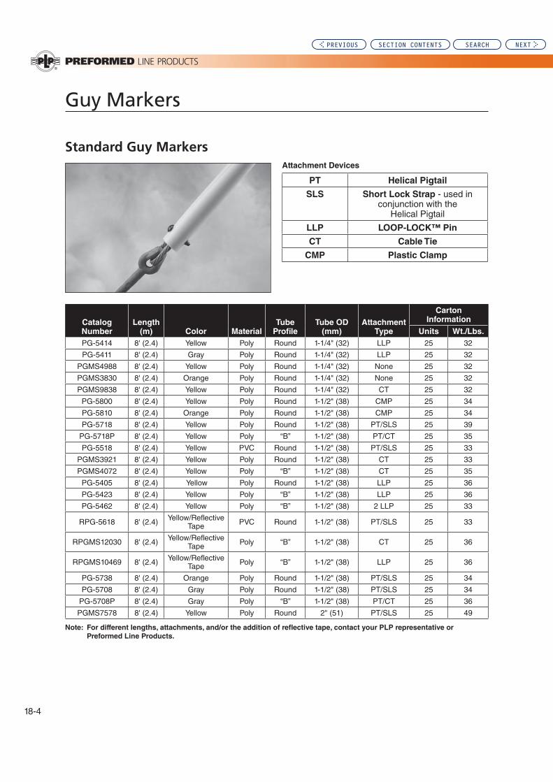
Guy Markers
18-4
Standard Guy MarkersAttachment Devices
PT Helical Pigtail
SLS Short Lock Strap - used in conjunction with the
Helical Pigtail
LLP LOOP-LOCK™ Pin
CT Cable Tie
CMP Plastic Clamp
Catalog Number
Length(m) Color Material
Tube Profile
Tube OD(mm)
Attachment Type
Carton Information
Units Wt./Lbs.
PG-5414 8' (2.4) Yellow Poly Round 1-1/4" (32) LLP 25 32
PG-5411 8' (2.4) Gray Poly Round 1-1/4" (32) LLP 25 32
PGMS4988 8' (2.4) Yellow Poly Round 1-1/4" (32) None 25 32
PGMS3830 8' (2.4) Orange Poly Round 1-1/4" (32) None 25 32
PGMS9838 8' (2.4) Yellow Poly Round 1-1/4" (32) CT 25 32
PG-5800 8' (2.4) Yellow Poly Round 1-1/2" (38) CMP 25 34
PG-5810 8' (2.4) Orange Poly Round 1-1/2" (38) CMP 25 34
PG-5718 8' (2.4) Yellow Poly Round 1-1/2" (38) PT/SLS 25 39
PG-5718P 8' (2.4) Yellow Poly “B” 1-1/2" (38) PT/CT 25 35
PG-5518 8' (2.4) Yellow PVC Round 1-1/2" (38) PT/SLS 25 33
PGMS3921 8' (2.4) Yellow Poly Round 1-1/2" (38) CT 25 33
PGMS4072 8' (2.4) Yellow Poly “B” 1-1/2" (38) CT 25 35
PG-5405 8' (2.4) Yellow Poly Round 1-1/2" (38) LLP 25 36
PG-5423 8' (2.4) Yellow Poly “B” 1-1/2" (38) LLP 25 36
PG-5462 8' (2.4) Yellow Poly “B” 1-1/2" (38) 2 LLP 25 33
RPG-5618 8' (2.4) Yellow/Reflective Tape PVC Round 1-1/2" (38) PT/SLS 25 33
RPGMS12030 8' (2.4) Yellow/Reflective Tape Poly “B” 1-1/2" (38) CT 25 36
RPGMS10469 8' (2.4) Yellow/Reflective Tape Poly “B” 1-1/2" (38) LLP 25 36
PG-5738 8' (2.4) Orange Poly Round 1-1/2" (38) PT/SLS 25 34
PG-5708 8' (2.4) Gray Poly Round 1-1/2" (38) PT/SLS 25 34
PG-5708P 8' (2.4) Gray Poly “B” 1-1/2" (38) PT/CT 25 36
PGMS7578 8' (2.4) Yellow Poly Round 2" (51) PT/SLS 25 49
Note: For different lengths, attachments, and/or the addition of reflective tape, contact your PLP representative or
Preformed Line Products.
PREVIOUS SECTION CONTENTS SEARCH NEXT
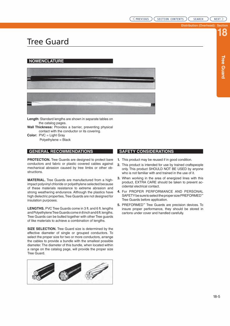
Distribution (Overhead): Section
18
Tre
e G
uard
Tree Guard
18-5
Length: Standard lengths are shown in separate tables on the catalog pages.
Wall Thickness: Provides a barrier, preventing physical contact with the conductor or its covering.
Color: PVC = Light Gray Polyethylene = Black
PROTECTION. Tree Guards are designed to protect bare conductors and fabric or plastic covered cables against mechanical abrasion caused by tree limbs or other ob-structions.
MATERIAL. Tree Guards are manufactured from a high-impact polyvinyl chloride or polyethylene selected because of these materials resistance to extreme abrasion and strong weathering endurance. Although the plastics have high dielectric properties, Tree Guards are not designed for insulation purposes.
LENGTHS. PVC Tree Guards come in 3 ft. and 6 ft. lengths and Polyethylene Tree Guards come in 8 inch and 6 ft. lengths. Tree Guards can be butted together with other Tree guards of like materials to achieve a combination of lengths.
SIZE SELECTION. Tree Guard size is determined by the effective diameter of single or grouped conductors. To select the proper size for two or more conductors, arrange the cables to provide a bundle with the smallest possible diameter. The diameter of this bundle, when located within a range on the catalog page, will provide the proper size Tree Guard.
SAFETY CONSIDERATIONS
1. This product may be reused if in good condition.
2. This product is intended for use by trained craftspeople only. This product SHOULD NOT BE USED by anyone who is not familiar with and trained in the use of it.
3. When working in the area of energized lines with this product, EXTRA CARE should be taken to prevent ac-cidental electrical contact.
4. For PROPER PERFORMANCE AND PERSONAL SAFETY be sure to select the proper size PREFORMED™ Tree Guards before application.
5. PREFORMED™ Tree Guards are precision devices. To insure proper performance, they should be stored in cartons under cover and handled carefully.
GENERAL RECOMMENDATIONS
NOMENCLATURE
PREVIOUS SECTION CONTENTS SEARCH NEXT

Tree Guard
18-6
Size Selection: In selecting the proper size PVC Tree Guard it is necessary to determine the smallest circumscribing circle that will enclose the messenger and cables.
For grouping only one cable with messenger, add the diameters and multiply by a factor of .850.
C = (D + m) x .850
C = D x 2.00 C = D x 2.414
m = D x .483C = D x 2.155
m = D x .414
For grouping two equal diameter cables, multiply the diameter of one cable times 2.00. Then find the diameter of the maximum messenger that will fit in the interstices of the cables, multiply the diameter of one cable times .666.
For grouping three equal diameter cables, multiply the diameter of one cable times 2.155. Then to find the diameter of the maximum messenger that will fit in the interstices of the cables multiply the diameter of one cable times .483.
For grouping four equal diameter cables; multiply the diameter of one cable times 2.414. Then to find the diameter of the maximum messenger that will fit in the interstices of the cables multiply the diameter of one cable times .414.
For grouping unequal diameter cables or messengers too large to fit into the interstices above, the minimum diameter grouping can best be determined by a graphic layout scale.
m = D x .666
Cm
D D
D
C
m
D D
C
m
D
C
m
D D
D D
GENERAL RECOMMENDATIONS
PREVIOUS SECTION CONTENTS SEARCH NEXT

Distribution (Overhead): Section
18
Tre
e G
uard
Tree Guard
18-7
6 Ft. Length – PVC
EXPLANATORY NOTES:
(1) Nominal Size indicates one of various single or grouped conductors within each range. To select the proper size for two or more conductors not shown, refer to “General Recommendations”, first page in this section.
For use on:
All Cables and Conductors
Catalog Number
Diameter Range (Inches) Units Weight (Lbs.)
Length (Feet)
Wall Thickness (Inches)Min. Max. Per Carton
PTG-0101 PTG-0104 PTG-0107 PTG-0110
.238
.267
.297
.329
.266
.296
.328
.358
100 100 100 100
24 26 28 30
6 6 6 6
1/16 1/16 1/16 1/16
PTG-0113 PTG-0116 PTG-0119 PTG-0122
.359
.390
.422
.454
.389
.421
.453
.478
100 100 100 75
32 34 36 30
6 6 6 6
1/16 1/16 1/16 1/16
PTG-0125 PTG-0128 PTG-0131 PTG-0134
.479
.512
.543
.569
.511
.542
.568
.598
75 75 75 75
32 32 44 46
6 6 6 6
1/16 1/16 5/64 5/64
PTG-0137 PTG-0140 PTG-0143 PTG-0146
.599
.642
.707
.763
.641
.706
.762
.820
75 75 50 50
48 52 46 48
6 6 6 6
5/64 5/64 3/32 3/32
PTG-0149 PTG-0152 PTG-0155 PTG-0158
.821
.883
.948 1.011
.882
.947 1.010 1.074
50 50 50 50
52 56 58 62
6 6 6 6
3/32 3/32 3/32 3/32
PTG-0161 PTG-0164 PTG-0167 PTG-0170
1.075 1.132 1.195 1.256
1.131 1.194 1.255 1.328
25 25 25 25
66 36 36 38
6 6 6 6
3/32 3/32 3/32 3/32
PTG-0173 PTG-0176 PTG-0179 PTG-0182
1.329 1.451 1.579 1.706
1.450 1.578 1.705 1.832
25 25 10 10
42 46 48 50
6 6 6 6
3/32 3/32 3/32 3/32
PREVIOUS SECTION CONTENTS SEARCH NEXT

Tree Guard
18-8
EXPLANATORY NOTES:
(1) Nominal Size indicates one of various single or grouped conductors within each range. To select the proper size for two or more conductors not shown, refer to “General Recommendations”, first page in this section.
For use on:
All Cables and Conductors
3 Ft. Length – PVC
Catalog Number
Diameter Range (Inches) Units Weight (Lbs.)Length (Feet)
Wall Thickness (Inches)Min. Max. Per Carton
PTG-0100 PTG-0103 PTG-0106 PTG-0109
.238
.267
.297
.329
.266
.296
.328
.358
100 100 100 100
12 14 15 16
3 3 3 3
1/16 1/16 1/16 1/16
PTG-0112 PTG-0115 PTG-0118 PTG-0121
.359
.390
.422
.454
.389
.421
.453
.478
100 100 100 100
18 18 20 20
3 3 3 3
1/16 1/16 1/16 1/16
PTG-0124 PTG-0127 PTG-0130 PTG-0133
.479
.512
.543
.569
.511
.542
.568
.598
100 100 100 100
22 24 30 30
3 3 3 3
1/16 1/16 5/64 5/64
PTG-0136 PTG-0139 PTG-0142 PTG-0145
.599
.642
.707
.763
.641
.706
.762
.820
100 100 100 100
32 34 46 50
3 3 3 3
5/64 5/64 3/32 3/32
PTG-0148 PTG-0151 PTG-0154
.821
.883
.948
.882
.947 1.010
100 100 100
52 56 58
3 3 3
3/32 3/32 3/32
PREVIOUS SECTION CONTENTS SEARCH NEXT

Distribution (Overhead): Section
18
Tre
e G
uard
Tree Guard – Polyethylene
18-9
For use on:
All Cables and Conductors
Catalog Number
Inside Diameter (Inches)
Diameter Range (Inches)
Length
Units Wt./Lbs.
Min. Max. Per Carton
PTG-0200.5
.238 .500 8 in. 1,000 35
PTG-0201 .238 .500 6 ft. 150 46
PTG-02021
.501 1.00 8 in. 500 34
PTG-0203 .501 1.00 6 ft. 60 39
PTG-02041.5
1.01 1.50 8 in. 250 30
PTG-0205 1.01 1.50 6 ft. 25 25
PTG-02062
1.51 2.00 8 in. 175 25
PTG-0207 1.51 2.00 6 ft. 20 26
PTG-0208 3 2.01 3.00 6 ft. 12 25
PREVIOUS SECTION CONTENTS SEARCH NEXT

Ground Wire Molding
NOMENCLATURE
GENERAL INFORMATION
Intended Use: PREFORMED LINE PRODUCTS Ground Wire Molding protects and covers surface-mounted cable, wire, or conductor.
Color: Soft gray coloring provides a natural blend for in-dustrial and urban situations.
Material: Corrosion resistant, lightweight polyethylene provides retention of good physical characteristics over temperature ranges and exposure to ultraviolet radiation. It will provide many years of protection and is easily handled and stored.
INSTALLATION GUIDELINES
Standard lineman’s tools (hammer & staples) are all that is required for quick and easy application. When installing the staple, drive the staple in until it
comes in contact with the exterior of the Ground Wire
Molding. If the staple is driven in too far, the Ground
Wire Molding will be deformed and can pull away from
the pole.
When in doubt about particular application, consult your PREFORMED™ Sales Representative or Preformed Line Products.
SAFETY CONSIDERATIONS
1. This product may be reused, if in good condition.
2. This product is intended for use by trained craftspeople only. This product SHOULD NOT BE USED by anyone who is not familiar with and trained in the use of it.
3. When working in the area of energized lines with this product, EXTRA CARE should be taken to prevent ac-cidental electrical contact.
4. For PROPER PERFORMANCE AND PERSONAL SAFETY be sure to select the proper size PREFORMED Ground Wire Molding before application.
5. PREFORMED Ground Wire Moldings are precision devices. To insure proper performance, they should be stored in cartons under cover and handled carefully.
Available in three nominal widths: 1/2", 3/4" & 1"
Catalog
Number
Length
In Feet
Units
Carton Color
Dimensions
A&B (In.)
GWM-7100 8 125 Gray - Poly 1/2
GWM-7101 8 100 Gray - Poly 3/4
GWM-7102 8 50 Gray - Poly 1
GWM-7200 8 125 Black - Poly 1/2
GWM-7201 8 100 Black - Poly 3/4
GWM-7202 8 50 Black - Poly 1
18-10
PREVIOUS SECTION CONTENTS SEARCH NEXT

Distribution (Overhead): Section
19
Section 19 – Distribution (Overhead): Wildlife Protection
Table of Contents
RAPTOR PROTECTOR™ .....................................................................19-2
BIRD-FLIGHT™ Diverters .....................................................................19-3
SWAN-FLIGHT™ Diverters ...................................................................19-5
Wildlife Protectors .................................................................................19-6
Protector Tubing ....................................................................................19-7
POLE PLUG ............................................................................................19-8
Page
PREVIOUS SEARCH NEXT

19-2
RAPTOR PROTECTOR™
GENERAL RECOMMENDATIONS
The RAPTOR PROTECTOR is designed to provide protection from incidental avian contact with overhead distribution lines. It provides an economical means of reducing bird fatalities and line outages while being easily installed over single or double pin/or post tie top C, F, J and K neck insulators. For double pin insulators the RAPTOR PROTECTOR can accommodate 6.5" – 22" center to center distances.
The RAPTOR PROTECTOR is lightweight, offers little wind resistance and is easily and quickly installed by hand or by hot stick. The RAPTOR PROTECTOR will remain in its applied location and will not move along the conductor under Aeolian vibration or other conditions. This product comes with four Round Eye Lock Pins that are easily installed by hand or using a hot stick.
Materials: The RAPTOR PROTECTOR is manufactured from low density polyethylene (LLDPE) possessing excellent environmental stress crack resistance and is fully UV stabilized.
Catalog Number Description Overall Length Color
RPC-0800 Raptor Cover-Up (4 pins included) 80" Black
RPC-0801 Raptor Cover-Up (4 pins included) 80" Gray
RPP-0840 Round Eye Lock Pins (4) N/A Black
The RPP-0840 Round Eye Lock Pins are included with each RAPTOR PROTECTOR.
PREVIOUS SECTION CONTENTS SEARCH NEXT

Distribution (Overhead): Section
19
19-3
BIR
D-F
LIG
HT
™ D
iverte
rs
BIRD-FLIGHT™ Diverter
NOMENCLATURE
GENERAL RECOMMENDATIONS
The BIRD-FLIGHT Diverter is designed to make overhead lines and guyed structures visible to birds and provides an economical means of reducing the hazard to both lines and birds. For low and medium voltage construction, the BIRD-FLIGHT Diverter is applied to the phase conductors (bare or jacketed). For high voltages, it is used on the shield wire.
The BIRD-FLIGHT Diverter is lightweight, offers little wind resistance and is easily and quickly applied by hand or by hot stick. The positive grip on the conductor ensures that the Bird-Flight Diverter remains in the applied position and cannot move along the span under aeolian vibration or other conditions.
Visibility: The diverter section increases the visible profile of the cable or conductor to a degree necessary to ensure safety, but avoids an undesirably bulky outline.
Materials: The plastic BFD is manufactured from rigid .375" and .500" high impact polyvinyl chloride (PVC) pos-sessing excellent chemical resistance and tensile strength properties. The BIRD-FLIGHT Diverter will retain good physical characteristics within a range of extreme temperatures. Aging tests confirm the material does not deteriorate in function or appearance from the effects of severe weather conditions. Industrial fumes and salt water cannot seriously degrade the properties of rigid PVC.
The Aluminum BFD is manufactured from a high strength, corrosive resistant aluminum alloy material. It is ideal for use on conductors operated at elevated temperatures.
Length: Distance product covers the conductor.
Color Code: Identifies conductor range, corresponding to tabular information on the following page.
Color: Yellow, Gray or Black
Material: Outdoor grade PVC
Coil Diameter: Internal diameter of diverter coil
Thermal Rating: 125°C Continuous
Application Voltage: Gray and Yellow – 230kV and below Semi-Conductive Black – 345kV
Length: Distance product covers the conductor.
Color Code: Identifies conductor range, corresponding to tabular information on the following page.
Color: Silver
Material: Aluminum Alloy
Coil Diameter: Approximately 4"
Thermal Rating: 250°C Continuous
Application Voltage: 230kV and below
APPLICATIONS
Ensure the correct size BIRD-FLIGHT Diverter is used. For a detailed installation description, refer to the application instructions. Hot stick application is fast and simple with standard equipment.
Spacing: For optimum results, spacing distances are gen-erally recommended at 15' intervals depending upon local conditions. Since wind resistance is very limited, sufficient BIRD-FLIGHT Diverters can be used to ensure adequate visibility without creating stresses on the line. When marking adjacent spans, overall visibility is improved by staggering the application.
Voltage: For applications on the phase conductors, any of the BIRD-FLIGHT Diverters (BFD) can be used at 3 phase voltages of 230kV and below. For applications of the BFD at 345kV, the black BFD which utilizes a semi-conductive polymer layer, can be used. The aluminum BFD should not be used above 230 kV due to the issues of RIV.
Temperature: The Plastic BIRD-FLIGHT Diverter can be used on conductors operating at 125°C or below. For operational temperatures above 125°C, the Aluminum BIRD-FLIGHT Diverter should be used if the voltage level is appropriate.
COIL DIA.
COIL DIA.
OVERALL LENGTHCOLOR CODE
COLOR CODE
PLASTIC BIRD-FLIGHT DIVERTER ALUMINUM BIRD-FLIGHT DIVERTER
OVERALL LENGTH
PREVIOUS SECTION CONTENTS SEARCH NEXT

19-4
BIRD-FLIGHT™ Diverters
For use on:Bare and Jacketed Conductors & Strand
Explanatory Notes:For field study results, consult Preformed Line Products.
Catalog
Number
Material
Color
Conductor
Range (Inches) Overall
Length
(Inches)
Diameter
of Diverter
Coil (Inches)
Diameter
of PVC Rod
(Inches)
Approximate
Weight (Lbs)
Color
CodeMin Max
BFD-MS-3331 Yellow0.175 0.249 7.00 2.25 0.375 0.090 Black
BFD-MS-3346 Gray
BFD-MS-3155 Yellow0.250 0.349 8.50 2.50 0.375 0.100 Blue
BFD-MS-2921 Gray
BFD-MS-3164 Yellow
0.350 0.449
9.50 2.75 0.375 0.110
Brown
BFD-MS-3355 Gray
BFD-MS-10022 Black
BFD-MS-11135 Yellow
12.375 4.50 0.500 0.240BFD-MS-11060 Gray
BFD-MS-11134 Black
BFD-MS-3341 Yellow
0.450 0.599 11.00 3.00 0.375 0.140 GreenBFD-MS-3366 Gray
BFD-MS-10023 Black
BFD-MS-3344 Yellow0.600 0.770 13.00 3.75 0.500 0.300 Purple
BFD-MS-3371 Gray
BFD-MS-3345 Yellow0.771 0.858 15.00 4.25 0.500 0.330 Red
BFD-MS-3376 Gray
BFD-MS-3405 Yellow0.859 0.942 16.50 4.75 0.500 0.360 Orange
BFD-MS-11699 Gray
BFD-MS-11111 Yellow
0.971 1.121 15.50 4.25 0.438 0.420 PinkBFD-MS-12290 Gray
BFD-MS-10277 Black
BFD-MS-11430 Yellow 1.122 1.306 16.25 4.38 0.438 0.450 Gray
BFD-MS-11110 Yellow 1.307 1.530 17.00 4.70 0.438 0.450 Black
BFD-MS-12351 Yellow 1.531 1.786 20.00 4.88 0.438 0.520 White
BFD-MS-11566 Yellow 1.787 2.100 23.00 5.25 0.438 0.600 Purple
BFD-MS-12603 Yellow 2.101 2.500 26.00 5.25 0.438 0.650 Orange
BFD-MS-11543 Aluminum 0.800 0.850 26.00 4.00 0.250 0.200 Pink
BFD-MS-12679 Aluminum 1.100 1.150 37.00 4.00 0.250 0.200 Purple
BFD-MS-12645 Aluminum 1.300 1.350 43.00 4.00 0.250 2.200 Red
BFD-MS-12687 Aluminum 1.565 1.635 54.00 4.00 0.250 2.500 Black
PREVIOUS SECTION CONTENTS SEARCH NEXT

Distribution (Overhead): Section
19
19-5
SW
AN
-FL
IGH
T™
Div
erte
rs
SWAN-FLIGHT™ Diverters
NOMENCLATURE
GENERAL RECOMMENDATIONS
The Preformed Line Products SWAN-FLIGHT Diverter is designed for use on conductor/strand to create greater visibility for avian flight paths on overhead lines and tower down guys. Offering little wind resistance, it reduces hazards to both lines and birds. For construction up to 230kV, the SWAN-FLIGHT Diverter can be applied to phase conductors (bare or jacketed). For EHV voltages, it is typically installed on the shield wire.
The SWAN-FLIGHT Diverter is lightweight, offers little wind resistance and is easily and quickly applied by hand or hot stick. The positive grip on the conductor ensures that the SWAN-FLIGHT Diverter remains in the applied location and cannot move along the span under Aeolian vibration or other conditions.
Visibility:
The diverter section increases the visible profile of the cable or conductor to a degree necessary to ensure safety, but avoids an undesirably bulky outline.
Materials:
The SWAN-FLIGHT Diverter (SFD) is manufactured from rigid .375" and .500" high impact polyvinyl chloride (PVC) possessing excellent chemical resistance and tensile strength properties. The SFD will retain good physical characteristics within a range of extreme temperatures. Aging tests confirm the material does not deteriorate in function or appearance from the effects of severe weather conditions. Industrial fumes and salt water cannot seriously degrade the properties of rigid PVC.
Length: Distance product covers the conductor.
Color Code: Identifies conductor range, corresponding to tabular information on the following page.
Color: Yellow, Gray or Black (semi-conductive)
Material: Outdoor grade High Impact PVC
Coil Diameter: Outside diameter of diverter coil
Thermal Rating (Continuous): 125°C
Application Voltage: Gray and Yellow – below 230kV Semi-Conductive Black – 230kV
For application on phase conductors at 230kV, the SFD utilizes a semi-conductive polymer layer to reduce the pos-sibility of electrical noise, corona and electirical tracking. The SWAN-FLIGHT Diverter should not be applied on phase conductors energized at voltages of 345kV and above.
APPLICATIONS
Ensure the correct size SWAN-FLIGHT Diverter is used. For detailed installation description, refer to the application procedure. Hot stick application is fast and simple with standard equipment.
Spacing:
For optimal results, spacing distances are generally recommended at 15' intervals depending upon local conditions. Since wind resistance is very limited, a sufficient quality of SWAN-FLIGHT Diverters can be used to ensure adequate visibility without creating stresses on the line. When marking adjacent spans, overall visibility is improved by the staggering application.
COIL DIA.
COLOR CODE
Catalog
Number
Conductor Range (Inches) Overall
Length
(Inches)
Diameter of
Diverter Coil
(Inches)
Diameter
of PVC Rod
(Inches)
Approximate
Weight/Unit
(Lbs)
Color
Code
Units
per
CartonMin Max
SFD-0445 0.175 0.249 20 7.0 0.375 0.40 Black 35
SFD-0635 0.250 0.349 23 7.0 0.375 0.46 Blue 35
SFD-0890 0.350 0.449 25 7.5 0.375 0.50 Brown 35
SFD-1140 0.450 0.599 35 8.0 0.375 0.70 Green 15
SFD-1520 0.600 0.770 38 8.0 0.500 1.40 Purple 15
SFD-1960 0.771 0.858 38 8.0 0.500 1.40 Red 15
SFD-2220 0.859 0.942 40 8.0 0.500 1.50 Orange 10
SFD-2460 0.943 1.121 40 8.0 0.500 1.50 Pink 10
SFD-2700 1.122 1.306 40 8.0 0.500 2.00 Gray 10
SFD-3035 1.307 1.530 46 8.0 0.500 2.00 Black 10
NOTE: Add suffix –Y to the catalog number for yellow color (i.e.: SFD-1140-Y). Add suffix –B to the catalog number for black semi-conductive layer for applications @ 230kV (i.e.: SFD-2460-B).
PLASTIC SWAN-FLIGHT DIVERTER
15 Feet
OVERALL LENGTH
PREVIOUS SECTION CONTENTS SEARCH NEXT

19-6
Wildlife Protectors
WP-CSP
WP-10T WP-11SWP-2.25F
WP-17T
CONSTRUCTION
All of the wildlife protectors are made from a light gray, high voltage, plastisol compound that is a minimum of 100 mils thick. This material contains ultraviolet stabilizers and fungicides and has a dielectric strength of 240 V/mil.
NOMENCLATURE
GENERAL RECOMMENDATIONS
These devices are designed to reduce the number of outages experienced on the utility’s distribution system by insulating transformer bushings, lighting arrestors, capacitors and switching equipment from incidental contact by animals. This is achieved by covering energized components suf-ficiently so that an animal can not contact the component and ground potential simultaneously.
INTENDED USE: Plastisol guards are to be secured to the bushings of transformers or similar equipment such that the energized components are covered for a reasonable distance or an insulating medium separates energized components from grounded components in areas open to animal contact.
EXPLANATORY NOTES:1. Designed for use with current limiting fuse.
Catalog
Number
Carton
Quantity
Height
(Inches)
Width
(Inches)
Length
(Inches)
Tap Wire
Opening
(Inches) Description
WP-10T 25 11.75 3.75 3.75 up to 0.75
Single bushing transformer and capacitor. Will cover a maximum of 7.5" of tap wire. Locating tabs hold the guard on the first skirt of the insulator.
WP-17T 25 17.00 3.75 3.75 up to 0.75
Single bushing transformer and capacitor. Will cover a maximum of 12.5" of tap wire. Locking tabs hold the guard on the first skirt of the insulator.
WP-11S 25 11.00 3.50 3.50 0.40 Existing tap retrofit. Apply through slit edge and hold guard in place with the fasteners provided.
WP-CSP 25 8.75 3.50 12.25 0.40Completely Self-Protected (CSP) transformers. Designed as retrofit. Designed to protect both primary bushing and lighting arrestor.
WP-2.25F(2) 25 12.75 3.75 3.75 cut as needed
Single bushing transformer. Covers 2.25" OD current limiting fuse bolted to bushing. Bottom of the double dipped tip indicates point of install for fuse. Locking tabs hold guard on first skirt of the insulator.
PREVIOUS SECTION CONTENTS SEARCH NEXT
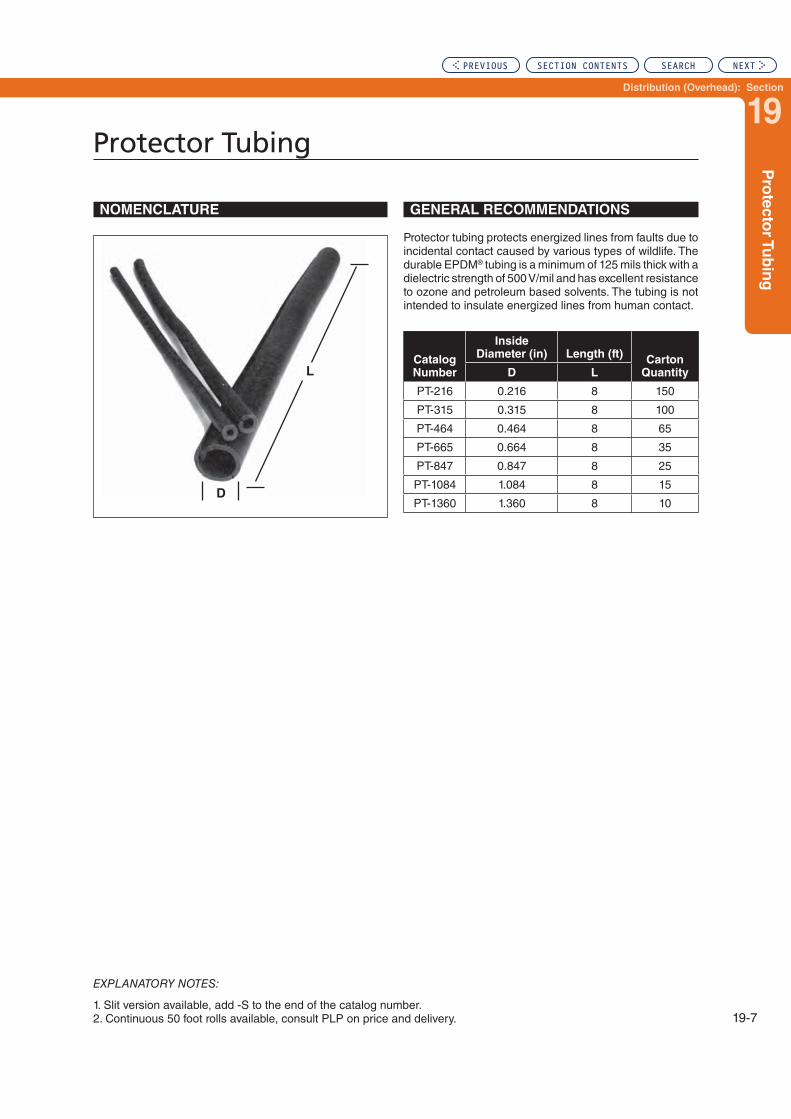
Distribution (Overhead): Section
19
19-7
Pro
tecto
r Tu
bin
g
Protector Tubing
EXPLANATORY NOTES:
1. Slit version available, add -S to the end of the catalog number.2. Continuous 50 foot rolls available, consult PLP on price and delivery.
NOMENCLATURE GENERAL RECOMMENDATIONS
Protector tubing protects energized lines from faults due to incidental contact caused by various types of wildlife. The durable EPDM® tubing is a minimum of 125 mils thick with a dielectric strength of 500 V/mil and has excellent resistance to ozone and petroleum based solvents. The tubing is not intended to insulate energized lines from human contact.
L
D
Catalog Number
Inside Diameter (in) Length (ft)
Carton QuantityD L
PT-216 0.216 8 150
PT-315 0.315 8 100
PT-464 0.464 8 65
PT-665 0.664 8 35
PT-847 0.847 8 25
PT-1084 1.084 8 15
PT-1360 1.360 8 10
PREVIOUS SECTION CONTENTS SEARCH NEXT

The POLE PLUG is designed to close existing holes in steel and composite utility poles or other equipment in order to reduce or eliminate whistling due to the wind and insect intrusion. The plug provides an economical means of reducing the incidents of insect infestations. This reduces possible injury to lineman and loss of productivity.
Application:
Features:
Catalog Number Hole Size Color
POLE PLUG
PREVIOUS SECTION CONTENTS SEARCH NEXT