display driver family combines convenience of use with
TRANSCRIPT
1
AN054
1-888-INTERSIL or 321-724-7143 | Copyright © Intersil Corporation 1999
Display Driver Family Combines Convenience ofUse with Microprocessor Interfaceability
IntroductionFor some time now Intersil has manufactured a line ofdisplay drivers oriented toward convenience of interface tothe displays themselves and to the microprocessor bus orother digital system from which the displayed data comes.These devices have been mainly intended for numeric data(including hexadecimal and similar codes), and have beendesigned to drive Liquid Crystal (LCD), Light Emitting (LED)and Vacuum Fluorescent (VF) displays. Most have offeredfull-time drive, limiting the total number of segments thatcould be driven by each device to 28. The recent growth inpopularity of alphanumeric displays, fueled by intelligenttypewriters, language translators, Point of Sale Equipment,intelligent test equipment, and so on, has led to thedevelopment of a series of alphanumeric display drivers forLCDs and LEDs. The large number of segments involvedmeans that any useful multi-character driver must use amultiplexing scheme, and fortunately LCD technology hasreached a point where suitable multiplexable fluids are nowbecoming widely available. As for LEDs, the circuit andlayout technology to handle the higher currents involved in asuitable LSI process has also been developed at the righttime. A brief glance at the earlier products will lead us to acloser look at these new display drivers.
Advantages of IC DriversDecoding and driving circuits for various types of numericand alphanumeric displays have been greatly simplified bylarge scale integration. These new display driversdramatically exhibit the following benefits and advantagesover discrete designs:
• more circuit functions in less space
• simpler design effort for the user
• more flexible operation
• reduced circuit expense
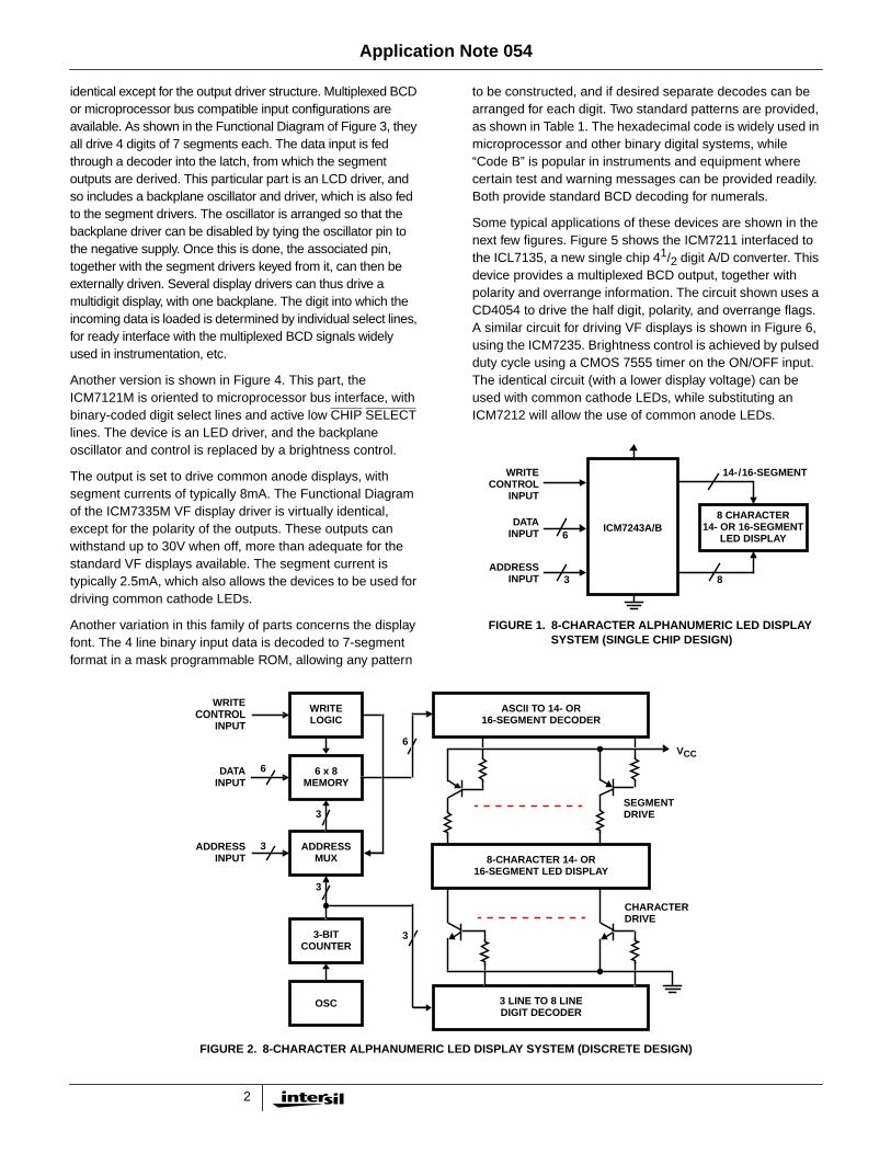
Consider, for example, the design of an ASCII 8-characteralphanumeric multiplexed LED display system. The blockdiagram for such a system constructed with discrete andMSI components is shown in Figure 2. Included as one ofthe blocks is an 8 word by 6-bit memory which stores the 6-bit ASCII word for each of the characters to be displayed.The addresses for the memory are selected either from theinput circuitry, when writing to the display, or from the 3-bitcounter, which generates the addresses for the 3 line to 8line decoder. The NPN transistors drive the commoncathode display for each character. The data from thememory is sent to a decoder which determines the correctsegments to be turned on and must be a speciallyprogrammed ROM or PLA with an output for each of the 14-or 16-character segments. The PNP transistors serve as
individual segment drivers, and the resistors in each of theircollectors serve to set the current for that segment.
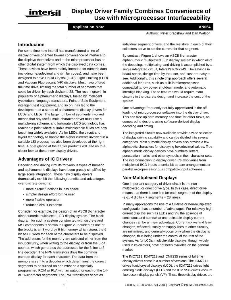
By contrast, Figure 1 shows an ASCII 8-characteralphanumeric multiplexed LED display system in which all ofthe decoding, multiplexing, and driving is accomplished by asingle integrated circuit, Intersil’s ICM7243. The savings inboard space, design time by the user, and cost are easy tosee. Additionally, this single chip approach offers severaladditional features, such as built-in microprocessorcompatibility, low power shutdown mode, and automaticinterdigit blanking. These features would require extracircuitry in the discrete design and increase the cost of thesystem.
One advantage frequently not fully appreciated is the off-loading of microprocessor software into the display driver.This can free up both memory and time for other tasks, ascompared to designs using software-derived displaydecoding and timing.
The integrated circuits now available provide a wide selectionof display driving capability and can be divided into severalcategories. Most numeric display drivers also provide a fewalphabetic characters for displaying hexadecimal values. Truealphanumeric display devices have numbers, letters,punctuation marks, and other symbols in their character sets.The interconnection to display driver ICs also varies frommultiplexed BCD inputs to serial bit-stream arrangements orparallel microprocessor bus compatible input schemes.
Non-Multiplexed DisplaysOne important category of driver circuit is the non-multiplexed, or direct drive type. In this case, direct drivemeans that there is one line for each segment of the display(e.g., 4 digits x 7 segments = 28 lines).
In many applications the use of a full-time or non-multiplexedconfiguration has a number of advantages. For relatively highcurrent displays such as LEDs and VF, the absence ofcontinuous and somewhat unpredictable display currentchanges can be a major advantage. Current spikes and levelchanges, reflected usually on supply lines to other circuitry,are minimized, and generally occur only when the display ischanged, thus being under the control of the rest of thesystem. As for LCDs, multiplexable displays, though widelyused in calculators, have not been available on the generalmarket.
The IMC7211, ICM7212 and ICM7235 series of full timedisplay drivers come in a number of versions. The ICM7211drives liquid crystal displays (LCD), the ICM7212 drives lightemitting diode displays (LED) and the ICM7235 drives vacuumfluorescent display panels (VF). These three display drivers are
Application Note
Authors: Peter Bradshaw and Dan Watson
2
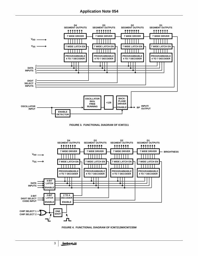
identical except for the output driver structure. Multiplexed BCDor microprocessor bus compatible input configurations areavailable. As shown in the Functional Diagram of Figure 3, theyall drive 4 digits of 7 segments each. The data input is fedthrough a decoder into the latch, from which the segmentoutputs are derived. This particular part is an LCD driver, andso includes a backplane oscillator and driver, which is also fedto the segment drivers. The oscillator is arranged so that thebackplane driver can be disabled by tying the oscillator pin tothe negative supply. Once this is done, the associated pin,together with the segment drivers keyed from it, can then beexternally driven. Several display drivers can thus drive amultidigit display, with one backplane. The digit into which theincoming data is loaded is determined by individual select lines,for ready interface with the multiplexed BCD signals widelyused in instrumentation, etc.
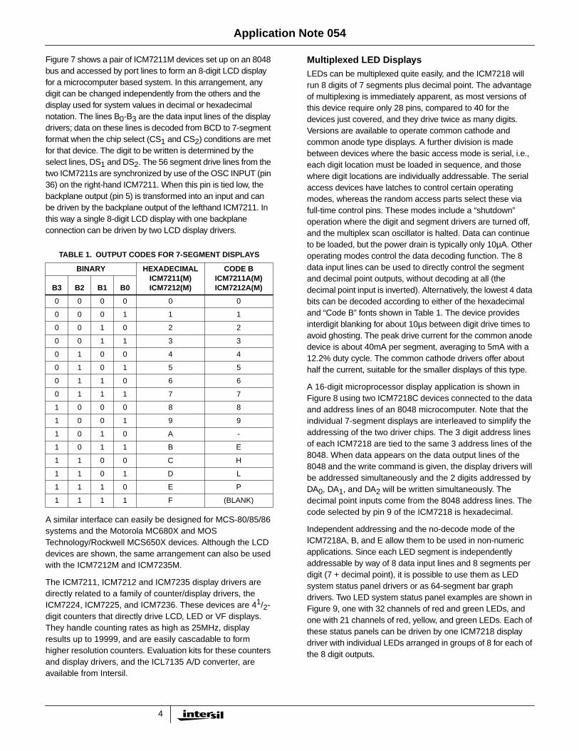
Another version is shown in Figure 4. This part, theICM7121M is oriented to microprocessor bus interface, withbinary-coded digit select lines and active low CHIP SELECTlines. The device is an LED driver, and the backplaneoscillator and control is replaced by a brightness control.
The output is set to drive common anode displays, withsegment currents of typically 8mA. The Functional Diagramof the ICM7335M VF display driver is virtually identical,except for the polarity of the outputs. These outputs canwithstand up to 30V when off, more than adequate for thestandard VF displays available. The segment current istypically 2.5mA, which also allows the devices to be used fordriving common cathode LEDs.
Another variation in this family of parts concerns the displayfont. The 4 line binary input data is decoded to 7-segmentformat in a mask programmable ROM, allowing any pattern
to be constructed, and if desired separate decodes can bearranged for each digit. Two standard patterns are provided,as shown in Table 1. The hexadecimal code is widely used inmicroprocessor and other binary digital systems, while“Code B” is popular in instruments and equipment wherecertain test and warning messages can be provided readily.Both provide standard BCD decoding for numerals.
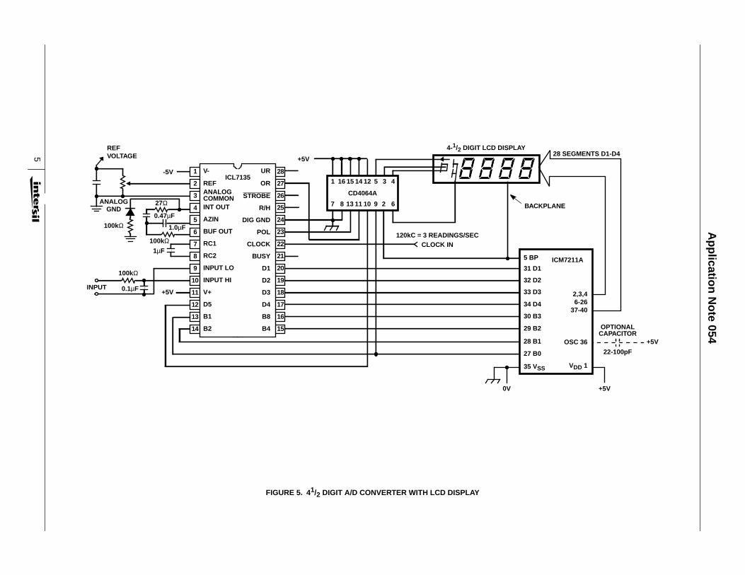
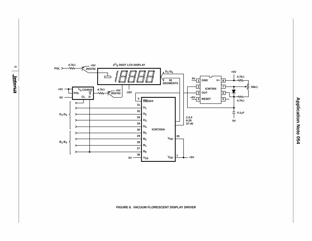
Some typical applications of these devices are shown in thenext few figures. Figure 5 shows the ICM7211 interfaced tothe ICL7135, a new single chip 41/2 digit A/D converter. Thisdevice provides a multiplexed BCD output, together withpolarity and overrange information. The circuit shown uses aCD4054 to drive the half digit, polarity, and overrange flags.A similar circuit for driving VF displays is shown in Figure 6,using the ICM7235. Brightness control is achieved by pulsedduty cycle using a CMOS 7555 timer on the ON/OFF input.The identical circuit (with a lower display voltage) can beused with common cathode LEDs, while substituting anICM7212 will allow the use of common anode LEDs.
WRITECONTROL
INPUT
DATAINPUT
ADDRESSINPUT
6
3
14-/16-SEGMENT
8 CHARACTER14- OR 16-SEGMENT
LED DISPLAY
8
FIGURE 1. 8-CHARACTER ALPHANUMERIC LED DISPLAYSYSTEM (SINGLE CHIP DESIGN)
ICM7243A/B
WRITECONTROL
INPUT
DATAINPUT
ADDRESSINPUT
6 x 8MEMORY
ADDRESSMUX
3-BITCOUNTER
OSC
VCC
SEGMENTDRIVE
CHARACTERDRIVE
3 LINE TO 8 LINEDIGIT DECODER
WRITELOGIC
6
3
3
6
3
3
8-CHARACTER 14- OR16-SEGMENT LED DISPLAY
ASCII TO 14- OR16-SEGMENT DECODER
FIGURE 2. 8-CHARACTER ALPHANUMERIC LED DISPLAY SYSTEM (DISCRETE DESIGN)
Application Note 054
3
D4SEGMENT OUTPUTS
D3SEGMENT OUTPUTS
D2SEGMENT OUTPUTS
D1SEGMENT OUTPUTS
BPINPUT/OUTPUT
VDD
VSS
DATAINPUTS
DIGITSELECTINPUTS
OSCILLATORINPUT
7 WIDE DRIVER 7 WIDE DRIVER 7 WIDE DRIVER
7 WIDE LATCH EN
PROGRAMMABLE4 TO 7 DECODER
7 WIDE LATCH EN
PROGRAMMABLE4 TO 7 DECODER
7 WIDE LATCH EN
PROGRAMMABLE4 TO 7 DECODER
7 WIDE DRIVER
7 WIDE LATCH EN
PROGRAMMABLE4 TO 7 DECODER
ENABLEDETECTOR
OSCILLATOR6kHzFREE
RUNNING
+128
BACK-PLANEDRIVER
ENABLE
FIGURE 3. FUNCTIONAL DIAGRAM OF ICM7211
D4SEGMENT OUTPUTS
D3SEGMENT OUTPUTS
D2SEGMENT OUTPUTS
D1SEGMENT OUTPUTS
VDD
VSS
DATAINPUTS
2-BITDIGIT SELECT
CODE INPUT
7 WIDE DRIVER 7 WIDE DRIVER 7 WIDE DRIVER
7 WIDE LATCH EN
PROGRAMMABLE4 TO 7 DECODER
7 WIDE LATCH EN
PROGRAMMABLE4 TO 7 DECODER
7 WIDE LATCH EN
PROGRAMMABLE4 TO 7 DECODER
7 WIDE DRIVER
7 WIDE LATCH EN
PROGRAMMABLE4 TO 7 DECODER
4-BITLATCH
ENABLE
2 TO 4DECODER
ENABLE
2-BITLATCH
ENABLE
ONESHOT
CHIP SELECT 1CHIP SELECT 2
BRIGHTNESS
FIGURE 4. FUNCTIONAL DIAGRAM OF ICM7212M/ICM7235M
Application Note 054
4
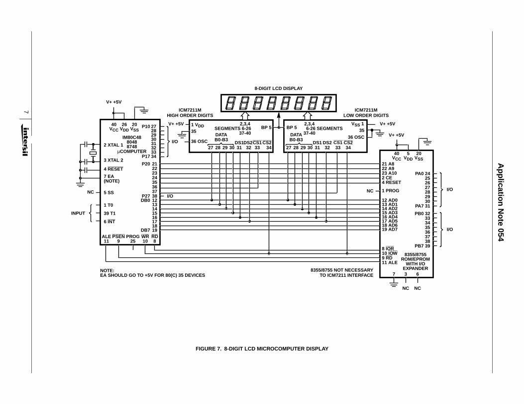
Figure 7 shows a pair of ICM7211M devices set up on an 8048bus and accessed by port lines to form an 8-digit LCD displayfor a microcomputer based system. In this arrangement, anydigit can be changed independently from the others and thedisplay used for system values in decimal or hexadecimalnotation. The lines B0-B3 are the data input lines of the displaydrivers; data on these lines is decoded from BCD to 7-segmentformat when the chip select (CS1 and CS2) conditions are metfor that device. The digit to be written is determined by theselect lines, DS1 and DS2. The 56 segment drive lines from thetwo ICM7211s are synchronized by use of the OSC INPUT (pin36) on the right-hand ICM7211. When this pin is tied low, thebackplane output (pin 5) is transformed into an input and canbe driven by the backplane output of the lefthand ICM7211. Inthis way a single 8-digit LCD display with one backplaneconnection can be driven by two LCD display drivers.
A similar interface can easily be designed for MCS-80/85/86systems and the Motorola MC680X and MOSTechnology/Rockwell MCS650X devices. Although the LCDdevices are shown, the same arrangement can also be usedwith the ICM7212M and ICM7235M.
The ICM7211, ICM7212 and ICM7235 display drivers aredirectly related to a family of counter/display drivers, theICM7224, ICM7225, and ICM7236. These devices are 41/2-digit counters that directly drive LCD, LED or VF displays.They handle counting rates as high as 25MHz, displayresults up to 19999, and are easily cascadable to formhigher resolution counters. Evaluation kits for these countersand display drivers, and the ICL7135 A/D converter, areavailable from Intersil.
Multiplexed LED DisplaysLEDs can be multiplexed quite easily, and the ICM7218 willrun 8 digits of 7 segments plus decimal point. The advantageof multiplexing is immediately apparent, as most versions ofthis device require only 28 pins, compared to 40 for thedevices just covered, and they drive twice as many digits.Versions are available to operate common cathode andcommon anode type displays. A further division is madebetween devices where the basic access mode is serial, i.e.,each digit location must be loaded in sequence, and thosewhere digit locations are individually addressable. The serialaccess devices have latches to control certain operatingmodes, whereas the random access parts select these viafull-time control pins. These modes include a “shutdown”operation where the digit and segment drivers are turned off,and the multiplex scan oscillator is halted. Data can continueto be loaded, but the power drain is typically only 10µA. Otheroperating modes control the data decoding function. The 8data input lines can be used to directly control the segmentand decimal point outputs, without decoding at all (thedecimal point input is inverted). Alternatively, the lowest 4 databits can be decoded according to either of the hexadecimaland “Code B” fonts shown in Table 1. The device providesinterdigit blanking for about 10µs between digit drive times toavoid ghosting. The peak drive current for the common anodedevice is about 40mA per segment, averaging to 5mA with a12.2% duty cycle. The common cathode drivers offer abouthalf the current, suitable for the smaller displays of this type.
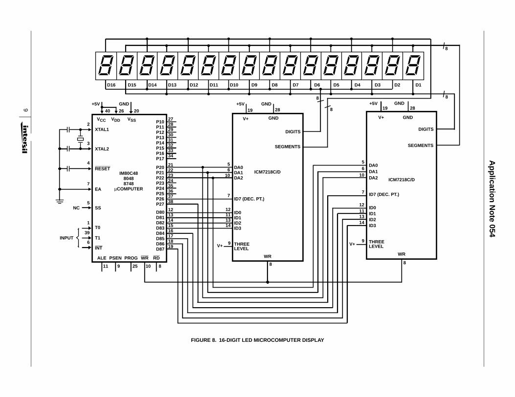
A 16-digit microprocessor display application is shown inFigure 8 using two ICM7218C devices connected to the dataand address lines of an 8048 microcomputer. Note that theindividual 7-segment displays are interleaved to simplify theaddressing of the two driver chips. The 3 digit address linesof each ICM7218 are tied to the same 3 address lines of the8048. When data appears on the data output lines of the8048 and the write command is given, the display drivers willbe addressed simultaneously and the 2 digits addressed byDA0, DA1, and DA2 will be written simultaneously. Thedecimal point inputs come from the 8048 address lines. Thecode selected by pin 9 of the ICM7218 is hexadecimal.
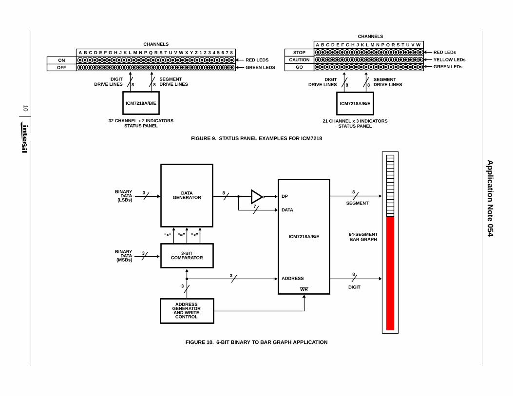
Independent addressing and the no-decode mode of theICM7218A, B, and E allow them to be used in non-numericapplications. Since each LED segment is independentlyaddressable by way of 8 data input lines and 8 segments perdigit (7 + decimal point), it is possible to use them as LEDsystem status panel drivers or as 64-segment bar graphdrivers. Two LED system status panel examples are shown inFigure 9, one with 32 channels of red and green LEDs, andone with 21 channels of red, yellow, and green LEDs. Each ofthese status panels can be driven by one ICM7218 displaydriver with individual LEDs arranged in groups of 8 for each ofthe 8 digit outputs.
TABLE 1. OUTPUT CODES FOR 7-SEGMENT DISPLAYS
BINARY HEXADECIMALICM7211(M)ICM7212(M)
CODE BICM7211A(M)ICM7212A(M)B3 B2 B1 B0
0 0 0 0 0 0
0 0 0 1 1 1
0 0 1 0 2 2
0 0 1 1 3 3
0 1 0 0 4 4
0 1 0 1 5 5
0 1 1 0 6 6
0 1 1 1 7 7
1 0 0 0 8 8
1 0 0 1 9 9
1 0 1 0 A -
1 0 1 1 B E
1 1 0 0 C H
1 1 0 1 D L
1 1 1 0 E P
1 1 1 1 F (BLANK)
Application Note 054
5
FIGURE 5. 41/2 DIGIT A/D CONVERTER WITH LCD DISPLAY
28
27
26
25
24
23
22
21
20
19
18
17
16
15
1
2
3
4
5
6
7
8
9
10
11
12
13
14
REFVOLTAGE
ANALOGGND
100kΩ
-5V
+5V
27Ω
0.47µF
1.0µF
100kΩ1µF
+5V0.1µF
100kΩ
INPUT
V-
REFANALOGCOMMONINT OUT
AZIN
BUF OUT
RC1
RC2
INPUT LO
INPUT HI
V+
D5
B1
B2
UR
OR
STROBE
R/H
DIG GND
POL
CLOCK
BUSY
D1
D2
D3
D4
B8
B4
1 16 15 14 12 5 3 4
CD4064A
7 8 13 11 10 9 2 6
120kC = 3 READINGS/SECCLOCK IN
4-1/2 DIGIT LCD DISPLAY28 SEGMENTS D1-D4
BACKPLANE
5 BP
31 D1
32 D2
33 D3
34 D4
30 B3
29 B2
28 B1
27 B0
35 VSS
ICM7211A
2,3,46-26
37-40
OSC 36
VDD 1
OPTIONALCAPACITOR
22-100pF
+5V
0V +5V
ICL7135
Ap
plicatio
n N
ote 054
6
FIGURE 6. VACUUM FLORESCENT DISPLAY DRIVER
POL
+5V
1
2
3
4
8
7
6
5
4.7kΩ +5V
+5V
+5V
+5V0V
0V
4.7kΩ
50kΩ
2,3,46-2637-40
4.7kΩ
0.1µF
GND V+
ICM7555OUT
RESET
0V
+5V
35
1
VDD
VDD
28SEGMENTS
D1-D4
41/2 DIGIT LCD DISPLAY
-15V2N37024.7kΩ
2N3702
1/4 CD4042POL
CL DQ
0V
D1-D5
B1-B4
5
31
32
33
34
30
29
28
27
36
ON/OFF
D1
D2
D3
D4
B3
B2
B1
B0
VSS
ICM7235A
Ap
plicatio
n N
ote 054
7
FIGURE 7. 8-DIGIT LCD MICROCOMPUTER DISPLAY
V+ +5V
40VCC
26VDD
20VSS
P10 2728293031323334P17
P20 2122232435363738P27 I/O
DB0 12131415161718
RD8
19WR10
PROG25
PSEN9
ALE11
2 XTAL 1
3 XTAL 2
4 RESET
7 EA
5 SS
NOTE:
1 T0
39 T1
6 INT
(NOTE)
EA SHOULD GO TO +5V FOR 80(C) 35 DEVICES
NC
INPUT
8-DIGIT LCD DISPLAY
ICM7211MHIGH ORDER DIGITS
I/O
V+ +5V 1 VDD35
36 OSC
2,3,4SEGMENTS 6-26
37-40
DB7
DATAB0-B3
27 28 29 30 31 32 33 34DS1DS2CS1 CS2
BP 5
DATAB0-B3
27 28 29 30 31 32 33 34DS1 DS2 CS1 CS2
BP 52,3,46-26 SEGMENTS
37-40
VSS 135
36 OSC
V+ +5V
V+ +5V
40VCC
5VDD
20VSS
21 A822 A923 A102 CE4 RESET
1 PROG
12 AD013 AD114 AD215 AD316 AD417 AD518 AD619 AD7
8 IOR10 IOW9 RD11 ALE
7 3 6
PA0 24252627282930
PA7 31
PB0 32333435363738
PB7 39
8355/8755ROM/EPROM
WITH I/OEXPANDER
I/O
I/O
NC NC
8355/8755 NOT NECESSARYTO ICM7211 INTERFACE
ICM7211MLOW ORDER DIGITS
NC
IM80C4880488748
µCOMPUTER
Ap
plicatio
n N
ote 054
8
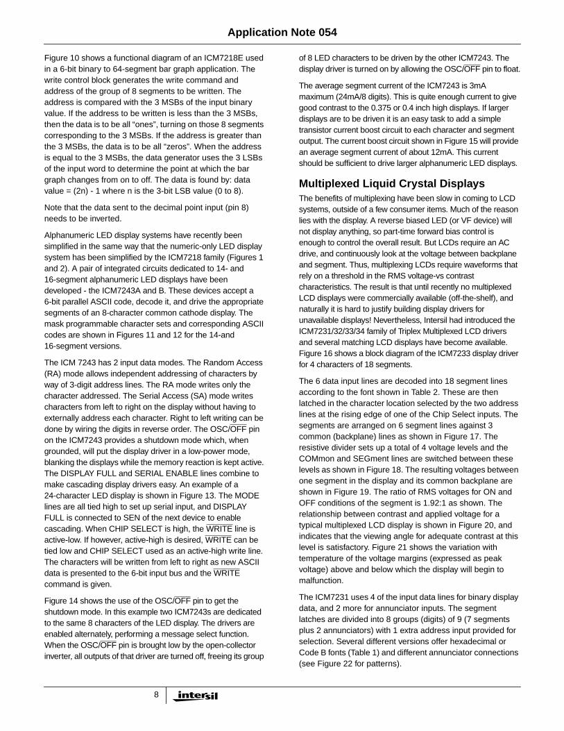
Figure 10 shows a functional diagram of an ICM7218E usedin a 6-bit binary to 64-segment bar graph application. Thewrite control block generates the write command andaddress of the group of 8 segments to be written. Theaddress is compared with the 3 MSBs of the input binaryvalue. If the address to be written is less than the 3 MSBs,then the data is to be all “ones”, turning on those 8 segmentscorresponding to the 3 MSBs. If the address is greater thanthe 3 MSBs, the data is to be all “zeros”. When the addressis equal to the 3 MSBs, the data generator uses the 3 LSBsof the input word to determine the point at which the bargraph changes from on to off. The data is found by: datavalue = (2n) - 1 where n is the 3-bit LSB value (0 to 8).
Note that the data sent to the decimal point input (pin 8)needs to be inverted.
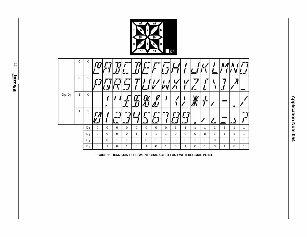
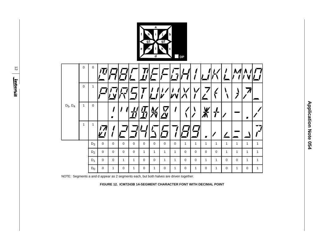
Alphanumeric LED display systems have recently beensimplified in the same way that the numeric-only LED displaysystem has been simplified by the ICM7218 family (Figures 1and 2). A pair of integrated circuits dedicated to 14- and16-segment alphanumeric LED displays have beendeveloped - the ICM7243A and B. These devices accept a6-bit parallel ASCII code, decode it, and drive the appropriatesegments of an 8-character common cathode display. Themask programmable character sets and corresponding ASCIIcodes are shown in Figures 11 and 12 for the 14-and16-segment versions.
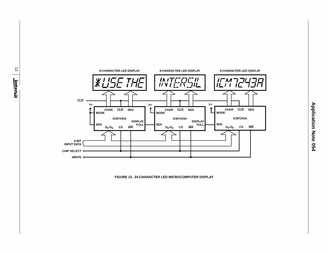
The ICM 7243 has 2 input data modes. The Random Access(RA) mode allows independent addressing of characters byway of 3-digit address lines. The RA mode writes only thecharacter addressed. The Serial Access (SA) mode writescharacters from left to right on the display without having toexternally address each character. Right to left writing can bedone by wiring the digits in reverse order. The OSC/OFF pinon the ICM7243 provides a shutdown mode which, whengrounded, will put the display driver in a low-power mode,blanking the displays while the memory reaction is kept active.The DISPLAY FULL and SERIAL ENABLE lines combine tomake cascading display drivers easy. An example of a24-character LED display is shown in Figure 13. The MODElines are all tied high to set up serial input, and DISPLAYFULL is connected to SEN of the next device to enablecascading. When CHIP SELECT is high, the WRITE line isactive-low. If however, active-high is desired, WRITE can betied low and CHIP SELECT used as an active-high write line.The characters will be written from left to right as new ASCIIdata is presented to the 6-bit input bus and the WRITEcommand is given.
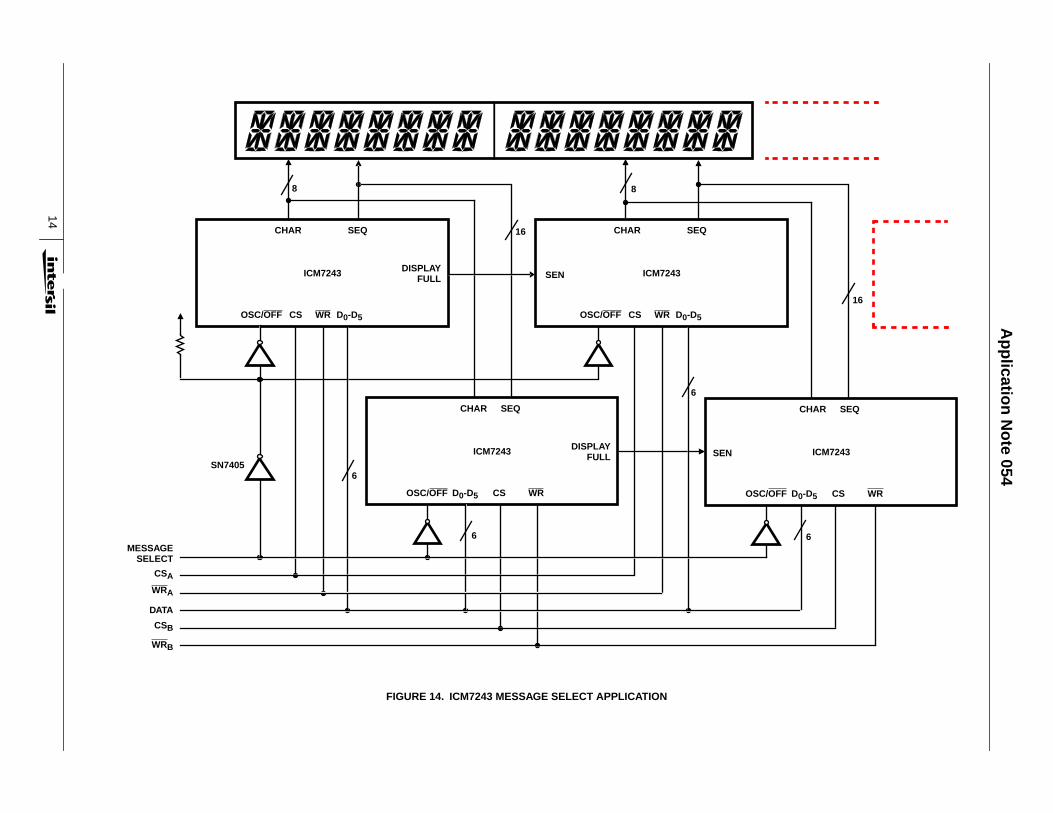
Figure 14 shows the use of the OSC/OFF pin to get theshutdown mode. In this example two ICM7243s are dedicatedto the same 8 characters of the LED display. The drivers areenabled alternately, performing a message select function.When the OSC/OFF pin is brought low by the open-collectorinverter, all outputs of that driver are turned off, freeing its group
of 8 LED characters to be driven by the other ICM7243. Thedisplay driver is turned on by allowing the OSC/OFF pin to float.
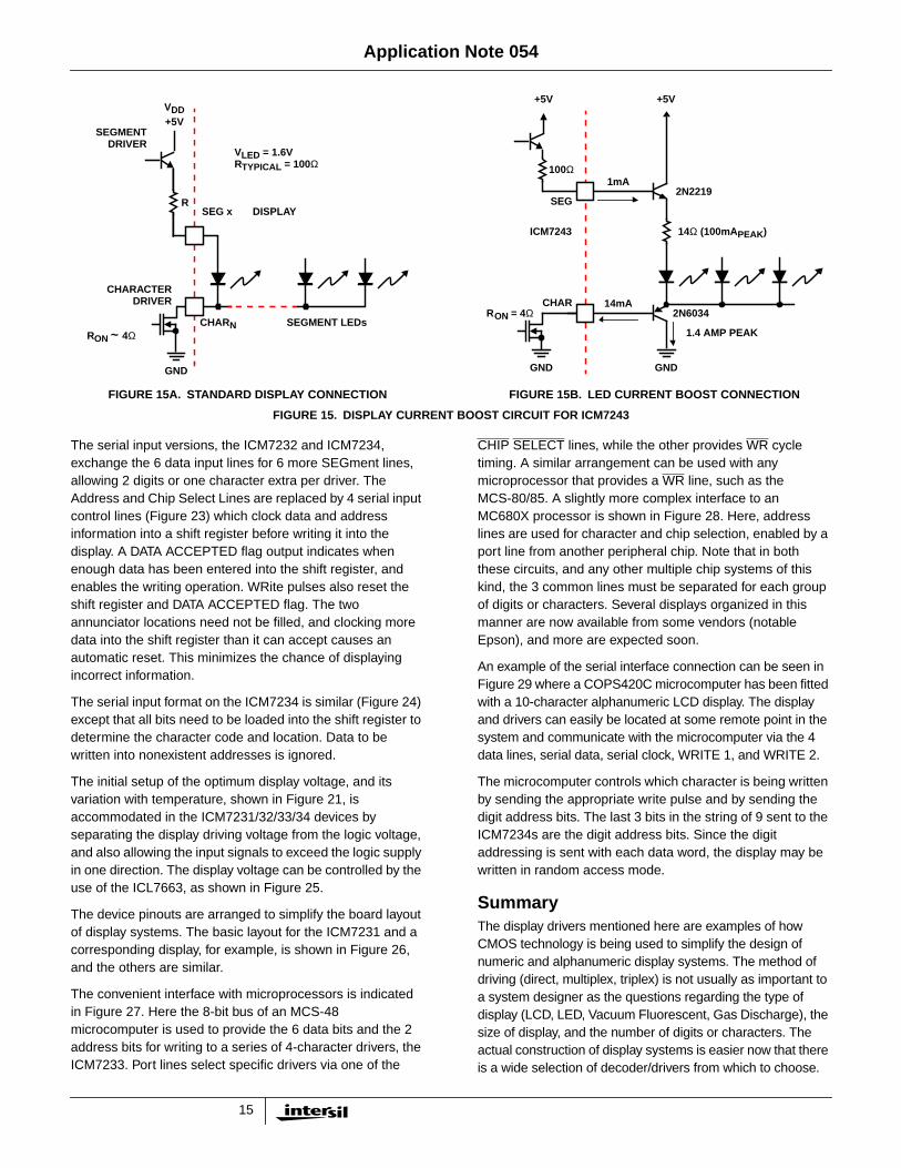
The average segment current of the ICM7243 is 3mAmaximum (24mA/8 digits). This is quite enough current to givegood contrast to the 0.375 or 0.4 inch high displays. If largerdisplays are to be driven it is an easy task to add a simpletransistor current boost circuit to each character and segmentoutput. The current boost circuit shown in Figure 15 will providean average segment current of about 12mA. This currentshould be sufficient to drive larger alphanumeric LED displays.
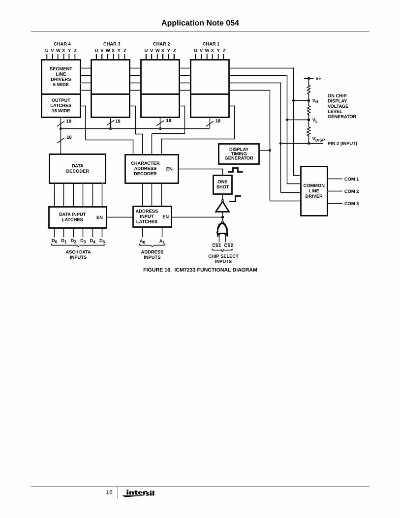
Multiplexed Liquid Crystal DisplaysThe benefits of multiplexing have been slow in coming to LCDsystems, outside of a few consumer items. Much of the reasonlies with the display. A reverse biased LED (or VF device) willnot display anything, so part-time forward bias control isenough to control the overall result. But LCDs require an ACdrive, and continuously look at the voltage between backplaneand segment. Thus, multiplexing LCDs require waveforms thatrely on a threshold in the RMS voltage-vs contrastcharacteristics. The result is that until recently no multiplexedLCD displays were commercially available (off-the-shelf), andnaturally it is hard to justify building display drivers forunavailable displays! Nevertheless, Intersil had introduced theICM7231/32/33/34 family of Triplex Multiplexed LCD driversand several matching LCD displays have become available.Figure 16 shows a block diagram of the ICM7233 display driverfor 4 characters of 18 segments.
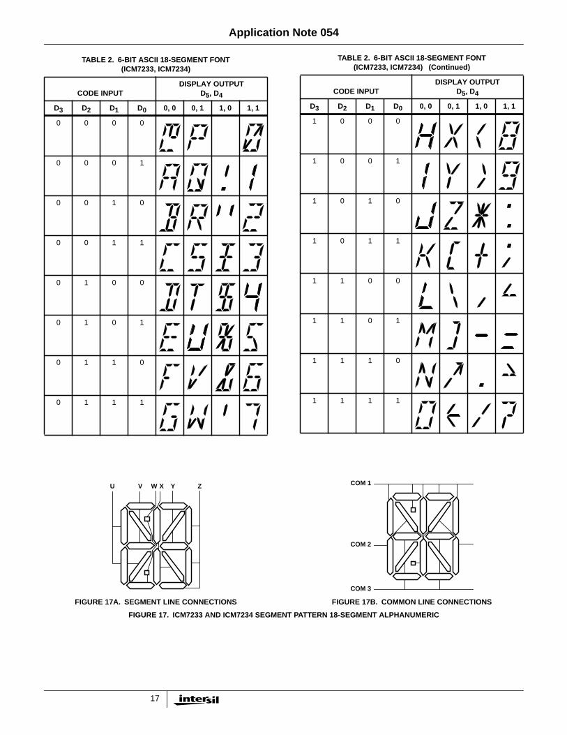
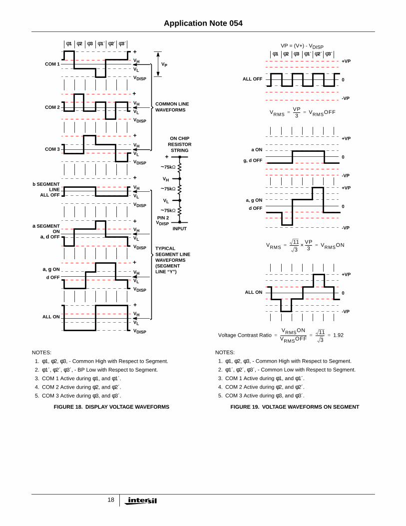
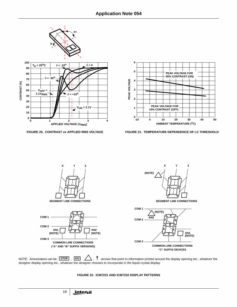
The 6 data input lines are decoded into 18 segment linesaccording to the font shown in Table 2. These are thenlatched in the character location selected by the two addresslines at the rising edge of one of the Chip Select inputs. Thesegments are arranged on 6 segment lines against 3common (backplane) lines as shown in Figure 17. Theresistive divider sets up a total of 4 voltage levels and theCOMmon and SEGment lines are switched between theselevels as shown in Figure 18. The resulting voltages betweenone segment in the display and its common backplane areshown in Figure 19. The ratio of RMS voltages for ON andOFF conditions of the segment is 1.92:1 as shown. Therelationship between contrast and applied voltage for atypical multiplexed LCD display is shown in Figure 20, andindicates that the viewing angle for adequate contrast at thislevel is satisfactory. Figure 21 shows the variation withtemperature of the voltage margins (expressed as peakvoltage) above and below which the display will begin tomalfunction.
The ICM7231 uses 4 of the input data lines for binary displaydata, and 2 more for annunciator inputs. The segmentlatches are divided into 8 groups (digits) of 9 (7 segmentsplus 2 annunciators) with 1 extra address input provided forselection. Several different versions offer hexadecimal orCode B fonts (Table 1) and different annunciator connections(see Figure 22 for patterns).
Application Note 054
9
FIGURE 8. 16-DIGIT LED MICROCOMPUTER DISPLAY
VCC VDD VSS
XTAL1
XTAL2
RESET
EA
SS
T0
T1
INT
ALE PSEN PROG WR RD
P10P11P12P13P14P15P16P17
P20P21P22P23P24P25P26P27
D80D81D82D83D84D85D86D87
IM80C4880488748
µCOMPUTER
2
3
4
7
5NC
1
39
6INPUT
GND+5V
40 26 20
D16 D15 D14 D13 D12 D11 D10 D9 D8 D7 D6 D5 D4 D3 D2 D1
2728293031323334
2122232435363738
1213141516171819
81025911
56
10
DA0DA1DA2
ID7 (DEC. PT.)
ID0ID1ID2ID3
THREELEVEL
WR
V+ 9
14
ICM7218C/D
7
121113
8
SEGMENTS
DIGITS
GNDV+
19 28+5V GND
8
8
SEGMENTS
DIGITS
GNDV+
19 28+5V GND
8
8
56
10
DA0DA1DA2
ID7 (DEC. PT.)
ID0ID1ID2ID3
THREELEVEL
WR
V+9
14
ICM7218C/D
7
121113
8
Ap
plicatio
n N
ote 054
10
FIGURE 9. STATUS PANEL EXAMPLES FOR ICM7218
FIGURE 10. 6-BIT BINARY TO BAR GRAPH APPLICATION
CHANNELS
A B C D E F G H J K L M N P Q R S T U V W X Y Z 1 2 3 4 5 6 7 8
ON
OFF
DIGITDRIVE LINES
SEGMENTDRIVE LINES
ICM7218A/B/E
32 CHANNEL x 2 INDICATORSSTATUS PANEL
8 8
RED LEDS
GREEN LEDS
CHANNELS
A B C D E F G H J K L M N P Q R S T U V W
STOP
CAUTION
DIGITDRIVE LINES
SEGMENTDRIVE LINES
ICM7218A/B/E
21 CHANNEL x 3 INDICATORSSTATUS PANEL
8 8
RED LEDs
YELLOW LEDs
GO GREEN LEDs
DATAGENERATOR
3-BITCOMPARATOR
64-SEGMENTBAR GRAPH
SEGMENT
DIGIT
DP
DATA
ICM7218A/B/E
ADDRESS
WR
3
ADDRESSGENERATORAND WRITECONTROL
88
7
3
BINARYDATA
(LSBs)
BINARYDATA
(MSBs)
3
3
“<“ “=” “>”
8
Ap
plicatio
n N
ote 054
11
FIGURE 11. ICM7243A 16-SEGMENT CHARACTER FONT WITH DECIMAL POINT
0 0
0 1
D5, D4 1 0
1 1
D3 0 0 0 0 0 0 0 0 1 1 1 1 1 1 1 1
D2 0 0 0 0 1 1 1 1 0 0 0 0 1 1 1 1
D1 0 0 1 1 0 0 1 1 0 0 1 1 0 0 1 1
D0 0 1 0 1 0 1 0 1 0 1 0 1 0 1 0 1
g1 g2
km l
f
e
b
c
a1
h ji
a2
d2 d1 DP
Ap
plicatio
n N
ote 054
12
FIGURE 12. ICM7243B 14-SEGMENT CHARACTER FONT WITH DECIMAL POINT
0 0
0 1
D5, D4 1 0
1 1
D3 0 0 0 0 0 0 0 0 1 1 1 1 1 1 1 1
D2 0 0 0 0 1 1 1 1 0 0 0 0 1 1 1 1
D1 0 0 1 1 0 0 1 1 0 0 1 1 0 0 1 1
D0 0 1 0 1 0 1 0 1 0 1 0 1 0 1 0 1
NOTE: Segments a and d appear as 2 segments each, but both halves are driven together.
g1 g2
km l
f
e
b
c
a1
h ji
a2
d2 d1
g1 g2
km
f
e
b
c
h ji
a
d1 DP
l
d
Ap
plicatio
n N
ote 054
13
FIGURE 13. 24-CHARACTER LED MICROCOMPUTER DISPLAY
8-CHARACTER LED DISPLAY 8-CHARACTER LED DISPLAY 8-CHARACTER LED DISPLAY
V+
6-BITINPUT DATA
CHIP SELECT
WRITE
CLR
V+ V+
CHAR CLR SEGMODE
SEND0-D5 CS WR
DISPLAYFULL
ICM7243A
CHAR CLR SEGMODE
SEND0-D5 CS WR
DISPLAYFULL
ICM7243A
CHAR CLR SEGMODE
SEND0-D5 CS WR
ICM7243A
Ap
plicatio
n N
ote 054
14
FIGURE 14. ICM7243 MESSAGE SELECT APPLICATION
SN7405
CHAR SEQ
DISPLAYFULL
ICM7243
OSC/OFF CS WR D0-D5
CHAR SEQ
ICM7243
OSC/OFF CS WR D0-D5
CHAR SEQ
DISPLAYFULL
ICM7243
OSC/OFF CS WRD0-D5
CHAR SEQ
ICM7243
OSC/OFF CS WRD0-D5
SEN
MESSAGESELECT
CSA
WRA
DATA
CSB
WRB
8
6
6 6
6
16
8
16
SEN
Ap
plicatio
n N
ote 054
15
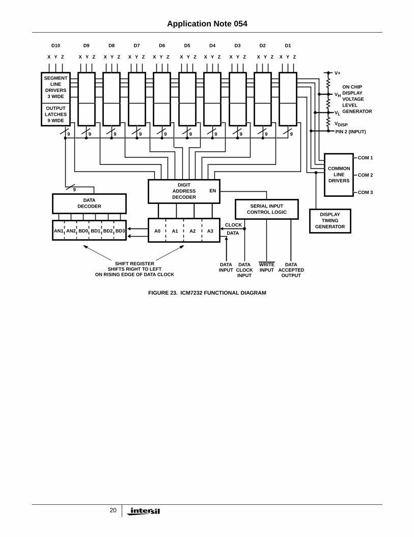
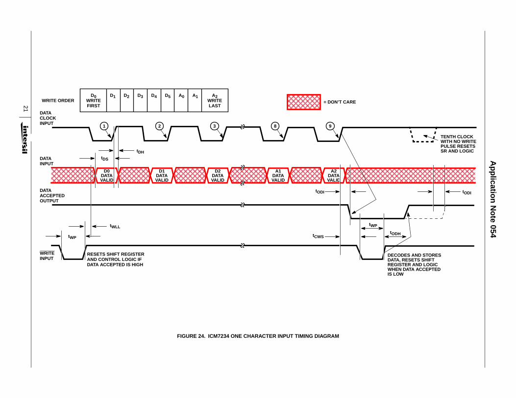
The serial input versions, the ICM7232 and ICM7234,exchange the 6 data input lines for 6 more SEGment lines,allowing 2 digits or one character extra per driver. TheAddress and Chip Select Lines are replaced by 4 serial inputcontrol lines (Figure 23) which clock data and addressinformation into a shift register before writing it into thedisplay. A DATA ACCEPTED flag output indicates whenenough data has been entered into the shift register, andenables the writing operation. WRite pulses also reset theshift register and DATA ACCEPTED flag. The twoannunciator locations need not be filled, and clocking moredata into the shift register than it can accept causes anautomatic reset. This minimizes the chance of displayingincorrect information.
The serial input format on the ICM7234 is similar (Figure 24)except that all bits need to be loaded into the shift register todetermine the character code and location. Data to bewritten into nonexistent addresses is ignored.
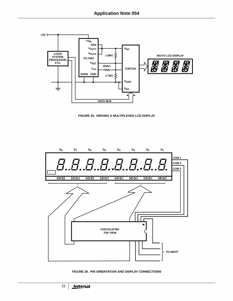
The initial setup of the optimum display voltage, and itsvariation with temperature, shown in Figure 21, isaccommodated in the ICM7231/32/33/34 devices byseparating the display driving voltage from the logic voltage,and also allowing the input signals to exceed the logic supplyin one direction. The display voltage can be controlled by theuse of the ICL7663, as shown in Figure 25.
The device pinouts are arranged to simplify the board layoutof display systems. The basic layout for the ICM7231 and acorresponding display, for example, is shown in Figure 26,and the others are similar.
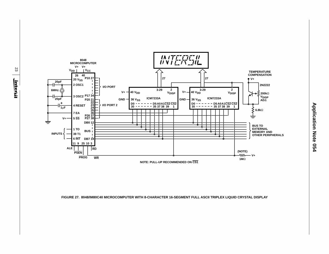
The convenient interface with microprocessors is indicatedin Figure 27. Here the 8-bit bus of an MCS-48microcomputer is used to provide the 6 data bits and the 2address bits for writing to a series of 4-character drivers, theICM7233. Port lines select specific drivers via one of the
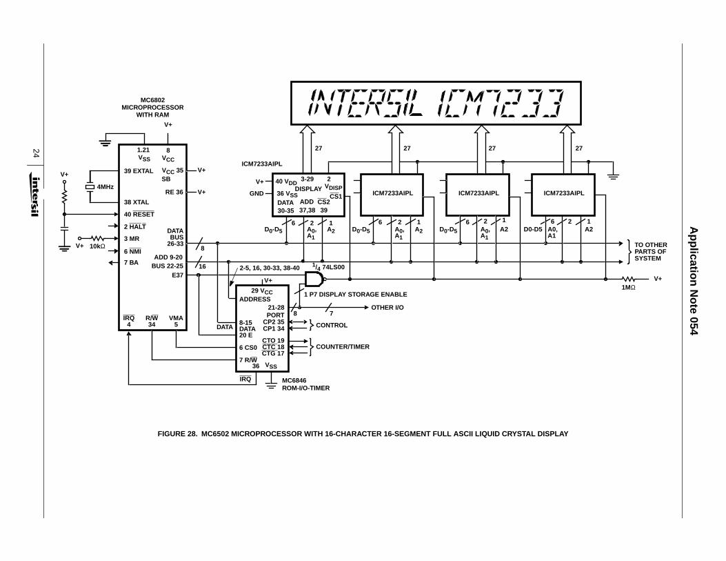
CHIP SELECT lines, while the other provides WR cycletiming. A similar arrangement can be used with anymicroprocessor that provides a WR line, such as theMCS-80/85. A slightly more complex interface to anMC680X processor is shown in Figure 28. Here, addresslines are used for character and chip selection, enabled by aport line from another peripheral chip. Note that in boththese circuits, and any other multiple chip systems of thiskind, the 3 common lines must be separated for each groupof digits or characters. Several displays organized in thismanner are now available from some vendors (notableEpson), and more are expected soon.
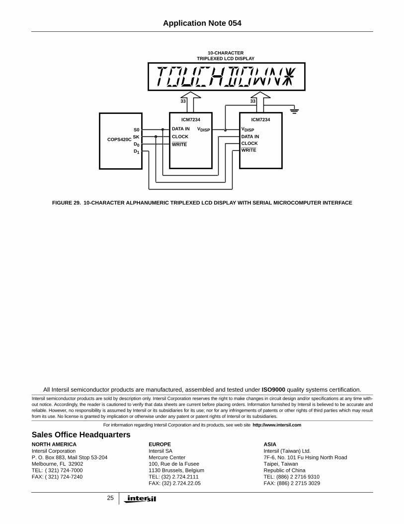
An example of the serial interface connection can be seen inFigure 29 where a COPS420C microcomputer has been fittedwith a 10-character alphanumeric LCD display. The displayand drivers can easily be located at some remote point in thesystem and communicate with the microcomputer via the 4data lines, serial data, serial clock, WRITE 1, and WRITE 2.
The microcomputer controls which character is being writtenby sending the appropriate write pulse and by sending thedigit address bits. The last 3 bits in the string of 9 sent to theICM7234s are the digit address bits. Since the digitaddressing is sent with each data word, the display may bewritten in random access mode.
SummaryThe display drivers mentioned here are examples of howCMOS technology is being used to simplify the design ofnumeric and alphanumeric display systems. The method ofdriving (direct, multiplex, triplex) is not usually as important toa system designer as the questions regarding the type ofdisplay (LCD, LED, Vacuum Fluorescent, Gas Discharge), thesize of display, and the number of digits or characters. Theactual construction of display systems is easier now that thereis a wide selection of decoder/drivers from which to choose.
FIGURE 15A. STANDARD DISPLAY CONNECTION FIGURE 15B. LED CURRENT BOOST CONNECTION
FIGURE 15. DISPLAY CURRENT BOOST CIRCUIT FOR ICM7243
VDD
SEGMENTDRIVER
R
CHARACTERDRIVER
RON ~ 4ΩCHARN SEGMENT LEDs
SEG x DISPLAY
VLED = 1.6VRTYPICAL = 100Ω
+5V
GND
+5V
100Ω1mA
2N2219
14Ω (100mAPEAK)
CHAR 14mA2N6034
1.4 AMP PEAK
GND
RON = 4Ω
ICM7243
+5V
GND
SEG
Application Note 054
16
FIGURE 16. ICM7233 FUNCTIONAL DIAGRAM
ON CHIPDISPLAYVOLTAGELEVELGENERATOR
PIN 2 (INPUT)
COM 1
COM 2
COM 3
DISPLAYTIMING
GENERATOR
A0 A1
ADDRESSINPUTS
18 18
CS1 CS2
CHIP SELECTINPUTS
VDISP
VL
VH
V+
1818
18
D0
CHAR 4U V W X Y Z
D1 D2 D3 D4 D5
ASCII DATAINPUTS
CHAR 3U V W X Y Z
CHAR 2U V W X Y Z
CHAR 1U V W X Y Z
SEGMENTLINE
DRIVERS6 WIDE
OUTPUTLATCHES16 WIDE
DATADECODER
CHARACTERADDRESSDECODER
EN
ONESHOT COMMON
LINEDRIVER
DATA INPUTLATCHES EN
ADDRESSINPUT
LATCHESEN
Application Note 054
17
TABLE 2. 6-BIT ASCII 18-SEGMENT FONT(ICM7233, ICM7234)
CODE INPUTDISPLAY OUTPUT
D5, D4
D3 D2 D1 D0 0, 0 0, 1 1, 0 1, 1
0 0 0 0
0 0 0 1
0 0 1 0
0 0 1 1
0 1 0 0
0 1 0 1
0 1 1 0
0 1 1 1
1 0 0 0
1 0 0 1
1 0 1 0
1 0 1 1
1 1 0 0
1 1 0 1
1 1 1 0
1 1 1 1
TABLE 2. 6-BIT ASCII 18-SEGMENT FONT(ICM7233, ICM7234) (Continued)
CODE INPUTDISPLAY OUTPUT
D5, D4
D3 D2 D1 D0 0, 0 0, 1 1, 0 1, 1
FIGURE 17A. SEGMENT LINE CONNECTIONS FIGURE 17B. COMMON LINE CONNECTIONS
FIGURE 17. ICM7233 AND ICM7234 SEGMENT PATTERN 18-SEGMENT ALPHANUMERIC
U V W X Y Z COM 1
COM 2
COM 3
Application Note 054
18
FIGURE 18. DISPLAY VOLTAGE WAVEFORMS FIGURE 19. VOLTAGE WAVEFORMS ON SEGMENT
VH
VL
VDISP
VH
VL
VDISP
VH
VL
VDISP
VH
VL
VDISP
VH
VL
VDISP
VH
VL
VDISP
VH
VL
VDISP
COM 1
COM 2
COM 3
ALL ON
a, g ON
d OFF
a SEGMENTON
a, d OFF
b SEGMENTLINE
ALL OFF
φ1 φ2 φ3 φ1´ φ2´ φ3´
VP
VH
VL
VDISP
ON CHIPRESISTOR
STRING
~75kΩ
~75kΩ
~75kΩ
INPUT
COMMON LINEWAVEFORMS
TYPICALSEGMENT LINEWAVEFORMS
PIN 2
NOTES:
1. φ1, φ2, φ3, - Common High with Respect to Segment.
2. φ1´, φ2´, φ3´, - BP Low with Respect to Segment.
3. COM 1 Active during φ1, and φ1´.
4. COM 2 Active during φ2, and φ2´.
5. COM 3 Active during φ3, and φ3´.
+
+
+
+
+
+(SEGMENTLINE “Y”)
+
+
φ1 φ2 φ3 φ1´ φ2´ φ3´
ALL ON
a, g ON
d OFF
a ON
g, d OFF
ALL OFF
+VP
0
-VP
+VP
0
-VP
+VP
0
-VP
+VP
0
-VP
VP = (V+) - VDISP
VRMSVP3
-------- VRMSOFF= =
VRMS11
3---------- VP
3--------× VRMSON= =
NOTES:
1. φ1, φ2, φ3, - Common High with Respect to Segment.
2. φ1´, φ2´, φ3´, - Common Low with Respect to Segment.
3. COM 1 Active during φ1, and φ1´.
4. COM 2 Active during φ2, and φ2´.
5. COM 3 Active during φ3, and φ3´.
Voltage Contrast RatioVRMSON
VRMSOFF------------------------------ 11
3---------- 1.92= = =
Application Note 054
19
FIGURE 20. CONTRAST vs APPLIED RMS VOLTAGE FIGURE 21. TEMPERATURE DEPENDENCE OF LC THRESHOLD
FIGURE 22. ICM7231 AND ICM7232 DISPLAY PATTERNS
APPLIED VOLTAGE (VRMS)
CO
NTR
AS
T (%
)
100
90
80
70
60
50
40
30
20
10
0
TA = 25oC θ = -10o
θ = -30o
θ = 0
VON = 2.1V
0 1 2 3 4
θ = +10oVOFF =
1.1VRMS
0-
0+
AMBIENT TEMPERATURE (oC)
6
5
4
3
2
1
0-10 0 10 20 30 40 50
PEAK VOLTAGE FOR90% CONTRAST (ON)
PEAK VOLTAGE FOR10% CONTRAST (OFF)
PE
AK
VO
LTA
GE
a
b
cd
fg
e
COM 1
COM 2
COM 3
AN2
AN1
(NOTE)
COMMON LINE CONNECTIONS
Y
(NOTE)
SEGMENT LINE CONNECTIONS
NOTE: Annunciators can be: , , , -arrows that point to information printed around the display opening etc., whatever thedesigner display opening etc., whatever the designer chooses to incorporate in the liquid crystal display.
STOP GO
a
b
cd
fg
e
COM 1
COM 2
COM 3
AN1 AN2
COMMON LINE CONNECTIONS
SEGMENT LINE CONNECTIONS
X Y Z
(NOTE) (NOTE)
(“A” AND “B” SUFFIX VERSIONS)
X Z
(NOTE)
“C” SUFFIX DEVICES
Application Note 054
20
FIGURE 23. ICM7232 FUNCTIONAL DIAGRAM
SEGMENTLINE
DRIVERS3 WIDE
OUTPUTLATCHES
9 WIDE
DATADECODER
EN
D10 D7 D6 D5 D4 D3 D2 D1
COM 1
COM 2
COM 3
V+
VH
VL
VDISP
ON CHIPDISPLAYVOLTAGELEVELGENERATOR
PIN 2 (INPUT)
SHIFT REGISTER DATA
COMMONLINE
DRIVERSDIGIT
ADDRESSDECODER
AN1 BD0 BD2AN2 BD1 BD3
DISPLAYTIMING
GENERATOR
9
9
D9 D8
9 9 9 9 9 9 9 9 9
INPUTDATA
CLOCKWRITEINPUT
DATAACCEPTED
INPUT OUTPUTSHIFTS RIGHT TO LEFT
ON RISING EDGE OF DATA CLOCK
CLOCK
DATAA2A1A0 A3
X Y Z X Y Z X Y Z X Y Z X Y Z X Y Z X Y Z X Y Z X Y Z X Y Z
SERIAL INPUTCONTROL LOGIC
Application Note 054
21
FIGURE 24. ICM7234 ONE CHARACTER INPUT TIMING DIAGRAM
D0DATAVALID
D1DATAVALID
D2DATAVALID
A1DATAVALID
A2DATAVALID
D0WRITEFIRST
A2WRITELAST
WRITE ORDERD1 D2 D3 D4 D5 A0 A1
RESETS SHIFT REGISTERAND CONTROL LOGIC IFDATA ACCEPTED IS HIGH
DATACLOCKINPUT
DATAINPUT
DATAACCEPTEDOUTPUT
WRITEINPUT
tWP
tWLL
tDS
tDH
1 2 3 8 9
TENTH CLOCKWITH NO WRITEPULSE RESETSSR AND LOGIC
DECODES AND STORESDATA, RESETS SHIFTREGISTER AND LOGICWHEN DATA ACCEPTEDIS LOW
tODH
tODI
tCWS
tWP
tODI
= DON’T CARE
Ap
plicatio
n N
ote 054
22
FIGURE 25. DRIVING A MULTIPLEXED LCD DISPLAY
FIGURE 26. PIN ORIENTATION AND DISPLAY CONNECTIONS
VDD
ICM7233
VDISP
VSS
MUX’D LCD DISPLAY
2.7MΩ
1.8MΩLOGICSYSTEM,
PROCESSOR,ETC.
300kΩ
DATA BUS
+VINSEN
VOUT1
VOUT2
ICL7663
VSET
VTC
SHDN GND
+5V
X Y Z X Y Z X Y Z X Y Z X Y Z X Y Z X Y Z X Y Z
D8 D7 D6 D5 D4 D3 D2 D1
COM 1
COM 2
COM 3
TO INPUT
ICM7231AF/BFTOP VIEW
Application Note 054
23
FIGURE 27. 8048/IM80C40 MICROCOMPUTER WITH 8-CHARACTER 16-SEGMENT FULL ASCII TRIPLEX LIQUID CRYSTAL DISPLAY
ALE
PSEN
PROG
RD
WR
INPUTS
1µF
20pF
6MHz
20pF
V+ V+VDD VCC
I/O PORT
I/O PORT 2
V+
GND
11 9 25 10 3
2620 VSS
40
2 OSC1
3 OSC2
4 RESET
7 EA
1 TO
39 T1
6 INT
P10 27
P17 34P20 21
2223243536
P26 37P27 38DB0 12
BUS
DB7 19
27 27
V+
GND
TEMPERATURECOMPENSATION
V+
2N2222
200kΩVDISPADJ.
6.8kΩ
BUS TOEXTERNALMEMORY ANDOTHER PERIPHERALS
1MΩV+
(NOTE)
NOTE: PULL-UP RECOMMENDED ON CS1
8048MICROCOMPUTER
V+ 5 SS
40 VDD
36 VSSICM7233A
3-29 2VDISP
D030
D535
A037
A138
CS2 CS239 1
40 VDD
36 VSSICM7233A
3-29 2VDISP
D030
D535
A037
A138
CS2 CS239 1
+ Ap
plicatio
n N
ote 054
24
FIGURE 28. MC6502 MICROPROCESSOR WITH 16-CHARACTER 16-SEGMENT FULL ASCII LIQUID CRYSTAL DISPLAY
8
16
V+
V+4MHz
V+
V+
V+
MC6802MICROPROCESSOR
WITH RAM
ICM7233AIPL
1.21VSS
8VCC
39 EXTAL
38 XTAL
40 RESET
2 HALT
3 MR
6 NMI
7 BA
IRQ4
R/W34
VMA5
VCC 35SB
RE 36
DATABUS
26-33
ADD 9-20BUS 22-25
E37
V+
GND
D0-D56 2 1
A0,A1
A2 D0-D5
ICM7233AIPL ICM7233AIPL
DATA
IRQ MC6846ROM-I/O-TIMER
CONTROL
COUNTER/TIMER
2-5, 16, 30-33, 38-40
V+
29 VCCADDRESS
21-28PORT
CP2 35CP1 34
CTO 19CTC 18CTG 17
36 VSS7 R/W
6 CS0
20 EDATA8-15
6 2 1A0,A1
A2 D0-D5
6 2 1A0,A1
A2
8 7
1 P7 DISPLAY STORAGE ENABLE
OTHER I/O
1/4 74LS00
D0-D56 2 1
A0,A1
A2
27 27 27
TO OTHERPARTS OFSYSTEM
1MΩV+
27
40 VDD
36 VSS
3-29 2
DISPLAY VDISP
DATA30-35 37,38 39
ADD CS2CS1
10kΩ
ICM7233AIPL
Ap
plicatio
n N
ote 054
25
All Intersil semiconductor products are manufactured, assembled and tested under ISO9000 quality systems certification.Intersil semiconductor products are sold by description only. Intersil Corporation reserves the right to make changes in circuit design and/or specifications at any time with-out notice. Accordingly, the reader is cautioned to verify that data sheets are current before placing orders. Information furnished by Intersil is believed to be accurate andreliable. However, no responsibility is assumed by Intersil or its subsidiaries for its use; nor for any infringements of patents or other rights of third parties which may resultfrom its use. No license is granted by implication or otherwise under any patent or patent rights of Intersil or its subsidiaries.
For information regarding Intersil Corporation and its products, see web site http://www.intersil.com
Sales Office HeadquartersNORTH AMERICAIntersil CorporationP. O. Box 883, Mail Stop 53-204Melbourne, FL 32902TEL: ( 321) 724-7000FAX: ( 321) 724-7240
EUROPEIntersil SAMercure Center100, Rue de la Fusee1130 Brussels, BelgiumTEL: (32) 2.724.2111FAX: (32) 2.724.22.05
ASIAIntersil (Taiwan) Ltd.7F-6, No. 101 Fu Hsing North RoadTaipei, TaiwanRepublic of ChinaTEL: (886) 2 2716 9310FAX: (886) 2 2715 3029
FIGURE 29. 10-CHARACTER ALPHANUMERIC TRIPLEXED LCD DISPLAY WITH SERIAL MICROCOMPUTER INTERFACE
10-CHARACTERTRIPLEXED LCD DISPLAY
3333
S0
SK
D0D1
COPS420C
ICM7234
DATA INCLOCKWRITE
VDISP
ICM7234
VDISPDATA IN
CLOCK
WRITE
Application Note 054