discovery series ii 04my owner's handbook - nas - pdf4pro
TRANSCRIPT
DISCOVERYOWNER’S HANDBOOK
LRL0650 NDOH04MY 30/6/03 9:32 am Page 4
As part of Land Rover environmental policy, this publication is printed on paper made from chlorine free pulp.
Owner's Handbook
Publication Part No. LRL0650NAS
© Land Rover 2003All rights reserved. No part of this publication may be reproduced, stored in a retrieval system or transmitted in any form, electronic, mechanical,
recording or other means without prior written permission from Land Rover.
2
IntroductionCongratulations on acquiring your new Land Rover Discovery. Please take the time to become acquainted with your vehicle by reading this handbook, which, together with the other books in your literature pack, provides information you will need to derive maximum pleasure from owning and driving your new vehicle.
For your convenience, the handbook is divided into sections, each dealing with a particular aspect of driving or caring for the vehicle. These are listed on the contents page and you will find it worthwhile to take a little time to read each one, and get to know your Discovery as soon as you possibly can. The more you understand before you drive, the greater the satisfaction once you are seated behind the steering wheel.
*An asterisk appearing within the text, identifies features or items of equipment that are either optional, or are only fitted to some vehicles in the model range.
IMPORTANT
The specification of each vehicle will vary according to territorial requirements and also from model to model within the vehicle range. Some of the information published in this handbook, therefore, may not apply to your particular vehicle.
Land Rover operates a policy of constant product improvement and therefore reserves the right to change specifications without notice at any time. Whilst every effort is made to ensure complete accuracy of the information in this handbook, no liabilities for inaccuracies or the consequences thereof can be accepted by the manufacturer or the retailer, except in respect of personal injury caused by the negligence of the manufacturer or the retailer.
Contents
Facia Controls . . . . . . . . . . . . . . . . . . . . . . . 5Information System . . . . . . . . . . . . . . . . . . 6Lights & Indicators . . . . . . . . . . . . . . . . . . . 7Wipers & Washers . . . . . . . . . . . . . . . . . . . 8Binnacle Switches . . . . . . . . . . . . . . . . . . . . 9Facia Switches . . . . . . . . . . . . . . . . . . . . . . 10Air Conditioning Controls . . . . . . . . . . . . . 11Audio System Controls . . . . . . . . . . . . . . . 12Navigation System Controls . . . . . . . . . . . 13
Fuel Filler . . . . . . . . . . . . . . . . . . . . . . . . . 14Opening The Hood. . . . . . . . . . . . . . . . . . . 14Tire Pressures . . . . . . . . . . . . . . . . . . . . . 15
Before You DriveReporting Safety Defects . . . . . . . . . . . . . .19Auto Safety Hotline . . . . . . . . . . . . . . . . . .19California Proposition 65 Warning . . . . . . .19Before You Drive . . . . . . . . . . . . . . . . . . . .20
Controls & InstrumentsKeys & Handsets . . . . . . . . . . . . . . . . . . .29Facia Controls . . . . . . . . . . . . . . . . . . . . . .30Locks & Alarms . . . . . . . . . . . . . . . . . . . .32Seats . . . . . . . . . . . . . . . . . . . . . . . . . . . . .39Seat Belts . . . . . . . . . . . . . . . . . . . . . . . . .47Child Restraints . . . . . . . . . . . . . . . . . . . .52Airbag SRS . . . . . . . . . . . . . . . . . . . . . . . .57Steering Column . . . . . . . . . . . . . . . . . . . .63Door Mirrors . . . . . . . . . . . . . . . . . . . . . . .64Instruments . . . . . . . . . . . . . . . . . . . . . . .65Warning Lights . . . . . . . . . . . . . . . . . . . . .67Audible Warnings . . . . . . . . . . . . . . . . . . .72Lights & Indicators . . . . . . . . . . . . . . . . . .73Wipers & Washers . . . . . . . . . . . . . . . . . .76Horn . . . . . . . . . . . . . . . . . . . . . . . . . . . . .79Electric Windows . . . . . . . . . . . . . . . . . . .80Sunroof . . . . . . . . . . . . . . . . . . . . . . . . . . .82Air Conditioning . . . . . . . . . . . . . . . . . . . .84Heated Screens . . . . . . . . . . . . . . . . . . . . .89Interior Equipment . . . . . . . . . . . . . . . . . .90Interior Mirror & Compass . . . . . . . . . . . .97Rear Door & Step . . . . . . . . . . . . . . . . . .101Loadspace Cover . . . . . . . . . . . . . . . . . .102In-Car Telephones . . . . . . . . . . . . . . . . . .103Audio System . . . . . . . . . . . . . . . . . . . . .104Land Rover HomeLink® . . . . . . . . . . . . .106
Driving & OperatingStarting & Driving . . . . . . . . . . . . . . . . . .111Catalytic Converter . . . . . . . . . . . . . . . . . 116Fuel Filling . . . . . . . . . . . . . . . . . . . . . . . .118Automatic Transmission . . . . . . . . . . . . .122Transfer Gearbox . . . . . . . . . . . . . . . . . .125Cruise Control . . . . . . . . . . . . . . . . . . . . .129Brakes . . . . . . . . . . . . . . . . . . . . . . . . . . .131Traction Control . . . . . . . . . . . . . . . . . . . 135
Quick Overview
Gas Station Information
Contents
Hill Descent Control . . . . . . . . . . . . . . . .136Active Cornering Enhancement . . . . . . . .138Self-levelling Suspension . . . . . . . . . . . .140Park Distance Control . . . . . . . . . . . . . . .143Towing . . . . . . . . . . . . . . . . . . . . . . . . . .144Load Carrying . . . . . . . . . . . . . . . . . . . . .150
Off-Road DrivingOff-Road Driving . . . . . . . . . . . . . . . . . . .155Driving Techniques . . . . . . . . . . . . . . . . .159
On-Road DrivingOn-Road Driving . . . . . . . . . . . . . . . . . . .167
Owner MaintenanceMaintenance . . . . . . . . . . . . . . . . . . . . . .173Hood Opening . . . . . . . . . . . . . . . . . . . . .177Engine Compartment . . . . . . . . . . . . . . .178Engine Oil . . . . . . . . . . . . . . . . . . . . . . . .179Air Cleaner . . . . . . . . . . . . . . . . . . . . . . .182Spark Plugs . . . . . . . . . . . . . . . . . . . . . . .183Cooling System . . . . . . . . . . . . . . . . . . . .184Brakes . . . . . . . . . . . . . . . . . . . . . . . . . . .186Power Steering . . . . . . . . . . . . . . . . . . . .187Active Cornering Enhancement . . . . . . . .188Washers . . . . . . . . . . . . . . . . . . . . . . . . .189Wiper Blades . . . . . . . . . . . . . . . . . . . . . .190Battery . . . . . . . . . . . . . . . . . . . . . . . . . . .191Tires . . . . . . . . . . . . . . . . . . . . . . . . . . . .194Cleaning & Vehicle Care . . . . . . . . . . . . .198Identification Numbers . . . . . . . . . . . . . .201Parts & Accessories . . . . . . . . . . . . . . . .203
Emergency InformationWheel Changing . . . . . . . . . . . . . . . . . . .207Emergency Starting . . . . . . . . . . . . . . . . .212Towing the Vehicle . . . . . . . . . . . . . . . . .214Fuses . . . . . . . . . . . . . . . . . . . . . . . . . . . .216Bulb Replacement . . . . . . . . . . . . . . . . . .223
Technical DataLubricants & Fluids . . . . . . . . . . . . . . . . 237Capacities . . . . . . . . . . . . . . . . . . . . . . . 238Engines . . . . . . . . . . . . . . . . . . . . . . . . . 239Electrical System . . . . . . . . . . . . . . . . . . 240Steering . . . . . . . . . . . . . . . . . . . . . . . . . 241Dimensions . . . . . . . . . . . . . . . . . . . . . . 242Vehicle Weights . . . . . . . . . . . . . . . . . . . 243Towing Weights . . . . . . . . . . . . . . . . . . 244Wheels & Tires . . . . . . . . . . . . . . . . . . . 245
Quick Overview
5
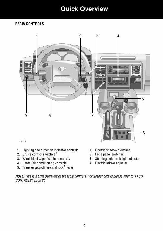
Quick OverviewQuick OverviewFACIA CONTROLS
1. Lighting and direction indicator controls2. Cruise control switches*3. Windshield wiper/washer controls4. Heater/air conditioning controls5. Transfer gear/differential lock* lever
6. Electric window switches7. Facia panel switches8. Steering column height adjuster9. Electric mirror adjuster
NOTE: This is a brief overview of the facia controls. For further details please refer to ‘FACIA CONTROLS’, page 30
H5174
5
6
789
2 3 41
Quick Overview
6
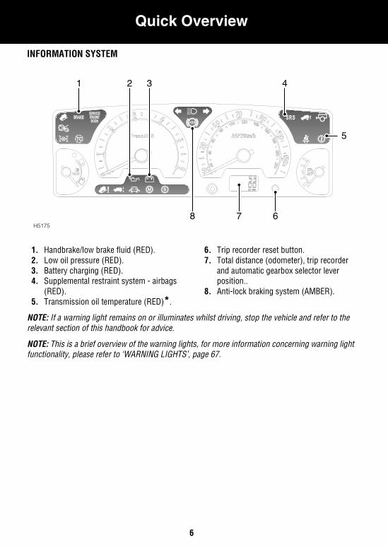
INFORMATION SYSTEM
1. Handbrake/low brake fluid (RED).2. Low oil pressure (RED).3. Battery charging (RED).4. Supplemental restraint system - airbags
(RED).5. Transmission oil temperature (RED)*.
6. Trip recorder reset button.7. Total distance (odometer), trip recorder
and automatic gearbox selector lever position..
8. Anti-lock braking system (AMBER).
NOTE: If a warning light remains on or illuminates whilst driving, stop the vehicle and refer to the relevant section of this handbook for advice.
NOTE: This is a brief overview of the warning lights, for more information concerning warning light functionality, please refer to ‘WARNING LIGHTS’, page 67.
H5175
321 4
5
8 7 6
Quick Overview
7
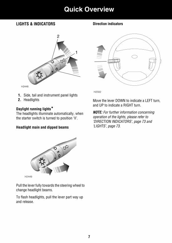
LIGHTS & INDICATORS
1. Side, tail and instrument panel lights2. Headlights
Daylight running lights*The headlights illuminate automatically, when the starter switch is turned to position ‘II’.
Headlight main and dipped beams
Pull the lever fully towards the steering wheel to change headlight beams.
To flash headlights, pull the lever part way up and release.
Direction indicators
Move the lever DOWN to indicate a LEFT turn, and UP to indicate a RIGHT turn.
NOTE: For further information concerning operation of the lights, please refer to ‘DIRECTION INDICATORS’, page 73 and ‘LIGHTS’, page 73.
H2448
2
1
H2449
H2582
Quick Overview
8
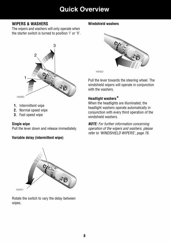
WIPERS & WASHERSThe wipers and washers will only operate when the starter switch is turned to position ‘I’ or ‘II’.
1. Intermittent wipe2. Normal speed wipe3. Fast speed wipe
Single wipePull the lever down and release immediately.
Variable delay (intermittent wipe)
Rotate the switch to vary the delay between wipes.
Windshield washers
Pull the lever towards the steering wheel. The windshield wipers will operate in conjunction with the washers.
Headlight washers*When the headlights are illuminated, the headlight washers operate automatically in conjunction with every third operation of the windshield washers.
NOTE: For further information concerning operation of the wipers and washers, please refer to ‘WINDSHIELD WIPERS’, page 76.
H2450
1
2
3
H2451
H2452
Quick Overview
9
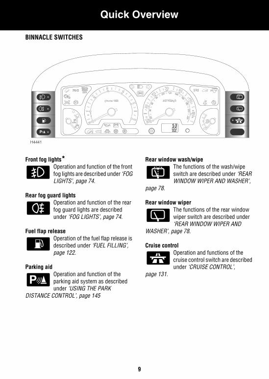
BINNACLE SWITCHES
Front fog lights*Operation and function of the front fog lights are described under ‘FOG LIGHTS’, page 74.
Rear fog guard lightsOperation and function of the rear fog guard lights are described under ‘FOG LIGHTS’, page 74.
Fuel flap releaseOperation of the fuel flap release is described under ‘FUEL FILLING’, page 122.
Parking aidOperation and function of the parking aid system as described under ‘USING THE PARK
DISTANCE CONTROL’, page 145
Rear window wash/wipeThe functions of the wash/wipe switch are described under ‘REAR WINDOW WIPER AND WASHER’,
page 78.
Rear window wiper The functions of the rear window wiper switch are described under ‘REAR WINDOW WIPER AND
WASHER’, page 78.
Cruise controlOperation and functions of the cruise control switch are described under ‘CRUISE CONTROL’,
page 131.
P
H4441
Quick Overview
10
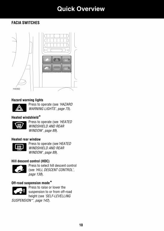
FACIA SWITCHES
Hazard warning lights Press to operate (see ‘HAZARD WARNING LIGHTS’, page 75).
Heated windshield*Press to operate (see ‘HEATED WINDSHIELD AND REAR WINDOW’, page 89).
Heated rear window Press to operate (see‘HEATED WINDSHIELD AND REAR WINDOW’, page 89).
Hill descent control (HDC)Press to select hill descent control (see ‘HILL DESCENT CONTROL’, page 138).
Off-road suspension mode*Press to raise or lower the suspension to or from off-road height (see ‘SELF-LEVELLING
SUSPENSION*’, page 142).
H4392
Quick Overview
11
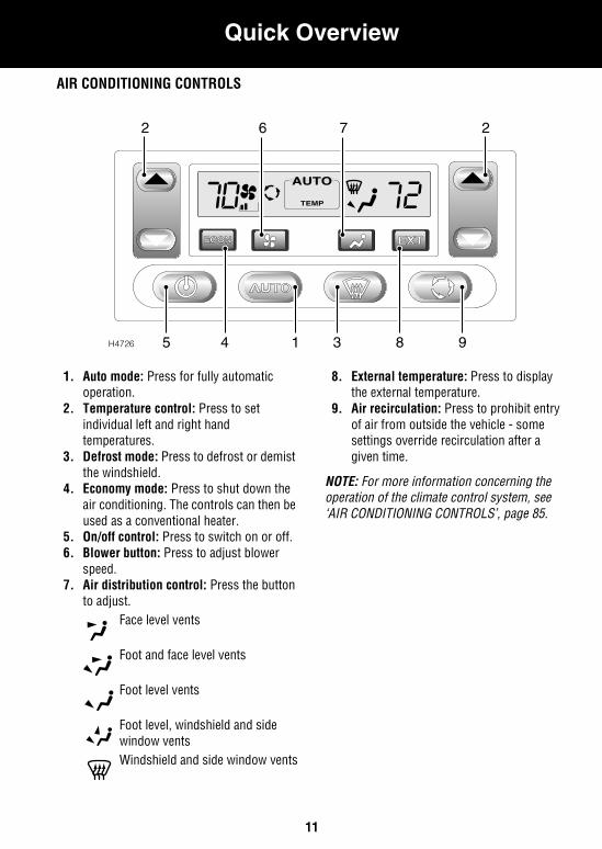
AIR CONDITIONING CONTROLS
1. Auto mode: Press for fully automatic operation.
2. Temperature control: Press to set individual left and right hand temperatures.
3. Defrost mode: Press to defrost or demist the windshield.
4. Economy mode: Press to shut down the air conditioning. The controls can then be used as a conventional heater.
5. On/off control: Press to switch on or off.6. Blower button: Press to adjust blower
speed.7. Air distribution control: Press the button
to adjust.Face level vents
Foot and face level vents
Foot level vents
Foot level, windshield and side window ventsWindshield and side window vents
8. External temperature: Press to display the external temperature.
9. Air recirculation: Press to prohibit entry of air from outside the vehicle - some settings override recirculation after a given time.
NOTE: For more information concerning the operation of the climate control system, see ‘AIR CONDITIONING CONTROLS’, page 85.
H4726
TEMP
2762
983145
Quick Overview
12
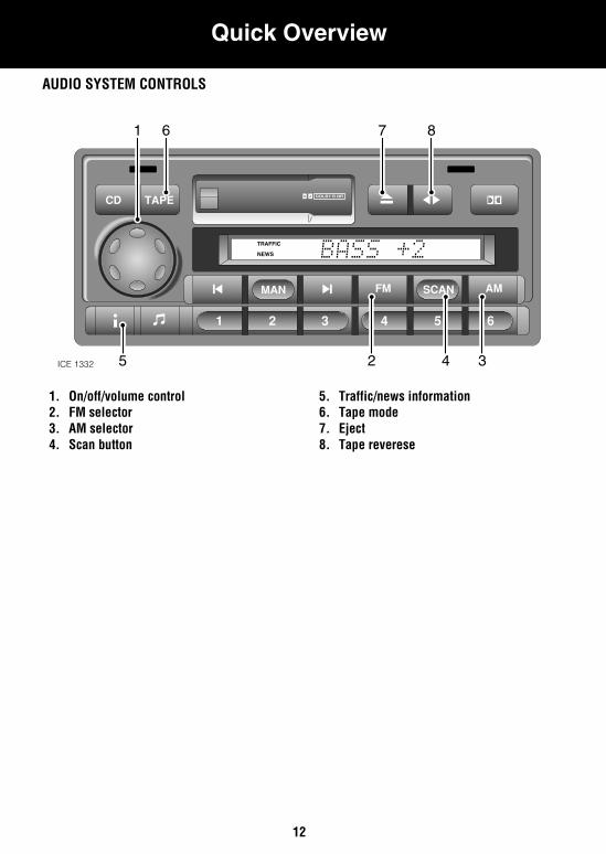
AUDIO SYSTEM CONTROLS
1. On/off/volume control2. FM selector3. AM selector4. Scan button
5. Traffic/news information6. Tape mode7. Eject8. Tape reverese
TRAFFIC
NEWS
ICE 1332 5 4 32
1 6 7 8
Quick Overview
13
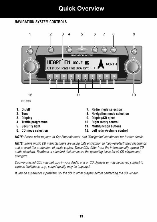
NAVIGATION SYSTEM CONTROLS
1. On/off 2. Tone3. Display4. Traffic programme 5. Security light6. CD mode selection
7. Radio mode selection 8. Navigation mode selection9. Display/CD eject
10. Right rotary control11. Multifunction buttons12. Left rotary/volume control
NOTE: Please refer to your ‘In-Car Entertainment’ and ‘Navigation’ handbooks for further details.
NOTE: Some music CD manufacturers are using data encryption to 'copy-protect' their recordings and prevent the production of pirate copies. These CDs differ from the internationally agreed CD audio standard, RedBook, a standard that serves as the operating basis for all CD players and changers.
Copy-protected CDs may not play in your Audio unit or CD changer or may be played subject to various limitations, e.g., sound quality may be impaired.
If you do experience a problem, try the CD in other players before contacting the CD vendor.
NAVIGATION SYSTEM
NAVISYS
TPTP CDCD RadRad NavNav
Info OK
ON
ICE 0223
1 2 4 5 6 7 8 9
1112 10
3
Gas Station Information
14
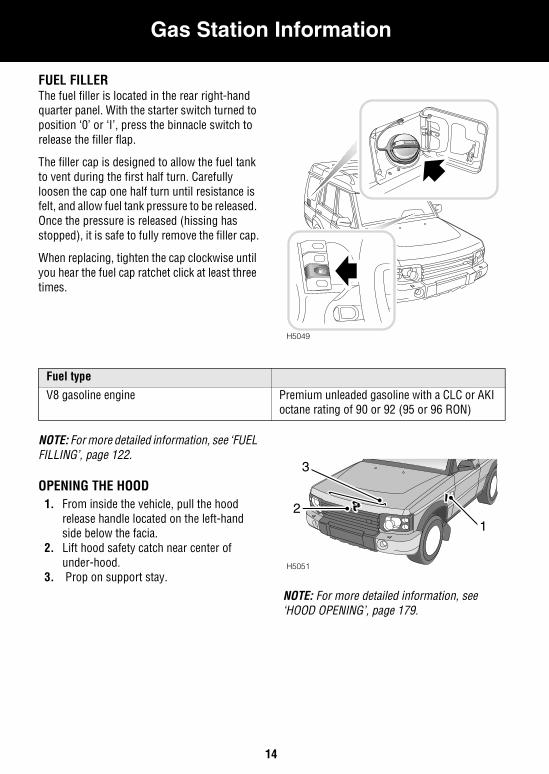
Gas Station InformationGas Station InformationFUEL FILLERThe fuel filler is located in the rear right-hand quarter panel. With the starter switch turned to position ‘0’ or ‘I’, press the binnacle switch to release the filler flap.
The filler cap is designed to allow the fuel tank to vent during the first half turn. Carefully loosen the cap one half turn until resistance is felt, and allow fuel tank pressure to be released. Once the pressure is released (hissing has stopped), it is safe to fully remove the filler cap.
When replacing, tighten the cap clockwise until you hear the fuel cap ratchet click at least three times.
NOTE: For more detailed information, see ‘FUEL FILLING’, page 122.
OPENING THE HOOD1. From inside the vehicle, pull the hood
release handle located on the left-hand side below the facia.
2. Lift hood safety catch near center of under-hood.
3. Prop on support stay.
NOTE: For more detailed information, see ‘HOOD OPENING’, page 179.
H5049
Fuel type
V8 gasoline engine Premium unleaded gasoline with a CLC or AKI octane rating of 90 or 92 (95 or 96 RON)
H5051
12
3
Gas Station Information
15
NOTE: For more detailed information, see ‘LUBRICANTS AND FLUIDS’, page 231.
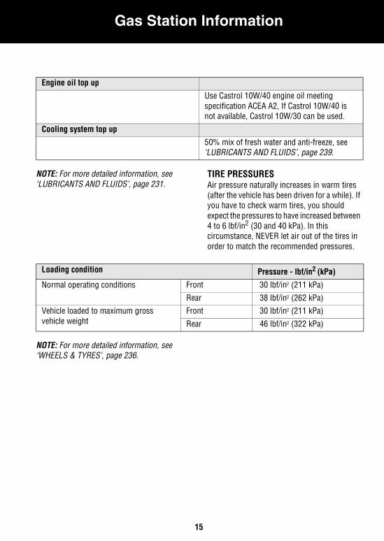
TIRE PRESSURESAir pressure naturally increases in warm tires (after the vehicle has been driven for a while). If you have to check warm tires, you should expect the pressures to have increased between 4 to 6 lbf/in2 (30 and 40 kPa). In this circumstance, NEVER let air out of the tires in order to match the recommended pressures.
NOTE: For more detailed information, see ‘WHEELS & TYRES’, page 236.
Engine oil top up
Use Castrol 10W/40 engine oil meeting specification ACEA A2, If Castrol 10W/40 is not available, Castrol 10W/30 can be used.
Cooling system top up
50% mix of fresh water and anti-freeze, see ‘LUBRICANTS AND FLUIDS’, page 239.
Loading condition Pressure - lbf/in2 (kPa)
Normal operating conditions Front 30 lbf/in2 (211 kPa)
Rear 38 lbf/in2 (262 kPa)Vehicle loaded to maximum gross vehicle weight
Front 30 lbf/in2 (211 kPa)
Rear 46 lbf/in2 (322 kPa)

16
17
Before You Drive
REPORTING SAFETY DEFECTS . . . . . . . . . . . . . . 19CALIFORNIA PROPOSITION 65 WARNING . . . . . 19BEFORE YOU DRIVE . . . . . . . . . . . . . . . . . . . . . . 20WARNINGS IN THIS HANDBOOK. . . . . . . . . . . . . 20SYMBOLS USED . . . . . . . . . . . . . . . . . . . . . . . . . 20PASSPORT TO SERVICE . . . . . . . . . . . . . . . . . . . 21WARNING LABELS ATTACHED TO THE VEHICLE 21GEARBOX SELECTOR LEVER LABELS. . . . . . . . . 21SUN VISOR LABELS . . . . . . . . . . . . . . . . . . . . . . 22PASSENGER AIRBAG LABEL . . . . . . . . . . . . . . . . 23ENGINE COMPARTMENT LABELS . . . . . . . . . . . . 24ANTI-THEFT PRECAUTIONS . . . . . . . . . . . . . . . . 25IN AN EMERGENCY . . . . . . . . . . . . . . . . . . . . . . . 25BREAKING-IN . . . . . . . . . . . . . . . . . . . . . . . . . . . 26

18
Before You Drive
19
Before You DriveREPORTING SAFETY DEFECTSIf you believe that your vehicle has a defect which could cause a crash, or could cause injury or death, you should immediately inform the National Highway Traffic Safety Administration (NHTSA) in addition to notifying Land Rover North America Inc.
If NHTSA receives similar complaints, it may open an investigation and if it finds that a safety defect exists in a group of vehicles, it may order a recall and remedy campaign.
However, NHTSA cannot become involved in individual problems between you, your retailer or Land Rover North America.
Auto safety hotlineTo contact NHTSA, you may either call the Auto Safety HOTLINE toll free at 1-800-424-9393 (or 202-366-0123 in the Washington, D.C. area) or write to: NHTSA, U.S. Department of Transportation, Washington, DC 20590. You can also obtain other information about motor vehicle safety from the HOTLINE.
CALIFORNIA PROPOSITION 65 WARNING
WARNINGEngine exhaust, some of its constituents and certain vehicle components contain or emit chemicals known to the State of California to cause cancer and birth defects or other reproductive harm. In addition, certain fluids contained in vehicles and certain products of component wear contain or emit chemicals known to the State of California to cause cancer, and birth defects or other reproductive harm.
WARNINGBattery posts, terminals and related accessories contain lead and lead compounds. Wash hands after handling.
Before You Drive
20
BEFORE YOU DRIVE WARNINGS IN THIS HANDBOOK
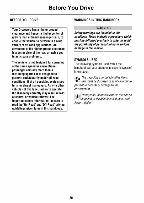
WARNINGSafety warnings are included in this handbook. These indicate a procedure which must be followed precisely in order to avoid the possibility of personal injury or serious damage to the vehicle.
SYMBOLS USEDThe following symbols used within the handbook call your attention to specific types of information.
This recycling symbol identifies items that must be disposed of safely in order to
prevent unnecessary damage to the environment.
This symbol identifies features that can be adjusted or disabled/enabled by a Land
Rover retailer
Your Discovery has a higher ground clearance and hence, a higher center of gravity than ordinary passenger cars, to enable the vehicle to perform in a wide variety of off-road applications. An advantage of the higher ground clearance is a better view of the road allowing you to anticipate problems.
The vehicle is not designed for cornering at the same speed as conventional passenger cars any more than a low-slung sports car is designed to perform satisfactorily under off-road conditions. If at all possible, avoid sharp turns or abrupt maneuvers. As with other vehicles of this type, failure to operate the Discovery correctly may result in loss of control or vehicle rollover. For important safety information, be sure to read the ‘On-Road’ and ‘Off-Road’ driving guidelines given later in this handbook.
Before You Drive
21
PASSPORT TO SERVICEThe Passport to Service book included in your literature pack contains important vehicle identification information, details of your entitlement under the terms of the Land Rover warranty, as well as useful consumer advice.
Most important of all, however, is the section on maintenance. This outlines the servicing requirements for your vehicle and also includes the service record slips, which the retailer should sign and stamp to certify the routine services have been carried out.
WARNING LABELS ATTACHED TO THE VEHICLE
Warning labels attached to your vehicle bearing this symbol mean: DO NOT touch or adjust components until you have read the relevant instructions in the handbook.
Warning labels showing this symbol indicate that the ignition system utilizes very high voltages. DO NOT touch any ignition components while the starter switch is turned on!
NOTE: Always read warning information labels.
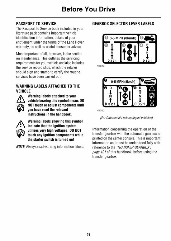
GEARBOX SELECTOR LEVER LABELS
(For Differential Lock equipped vehicles).
Information concerning the operation of the transfer gearbox with the automatic gearbox is printed on the center console. This is important information and must be understood fully with reference to the ‘TRANSFER GEARBOX’, page 121 of this handbook, before using the transfer gearbox.
H4693
H4760
Before You Drive
22
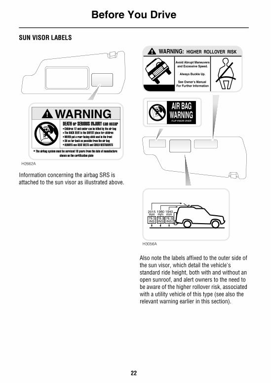
SUN VISOR LABELS
Information concerning the airbag SRS is attached to the sun visor as illustrated above.
Also note the labels affixed to the outer side of the sun visor, which detail the vehicle's standard ride height, both with and without an open sunroof, and alert owners to the need to be aware of the higher rollover risk, associated with a utility vehicle of this type (see also the relevant warning earlier in this section).
H2662A
! WARNINGDEATH or SERIOUS INJURY can occur
Children 12 and under can be killed by the air bagThe BACK SEAT is the SAFEST place for childrenNEVER put a rear-facing child seat in the frontSit as far back as possible from the air bagALWAYS use SEAT BELTS and CHILD RESTRAINTS
The airbag system must be serviced 10 years from the date of manufactureshown on the certification plate
! WARNING: HIGHER ROLLOVER RISK
Avoid Abrupt Maneuversand Excessive Speed.
Always Buckle Up.
See Owner's Manual For Further Information
78.0INS
2015mm79.5INS
1980mm
1940mm
H3056A
76.5INS
AIR BAGWARNING
FLIP VISOR OVER
Before You Drive
23
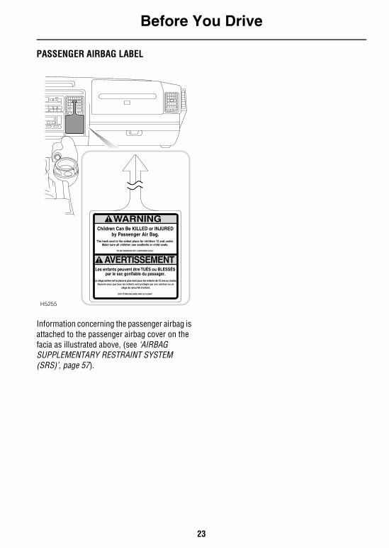
PASSENGER AIRBAG LABEL
Information concerning the passenger airbag is attached to the passenger airbag cover on the facia as illustrated above, (see ‘AIRBAG SUPPLEMENTARY RESTRAINT SYSTEM (SRS)’, page 57).
H5255
Before You Drive
24
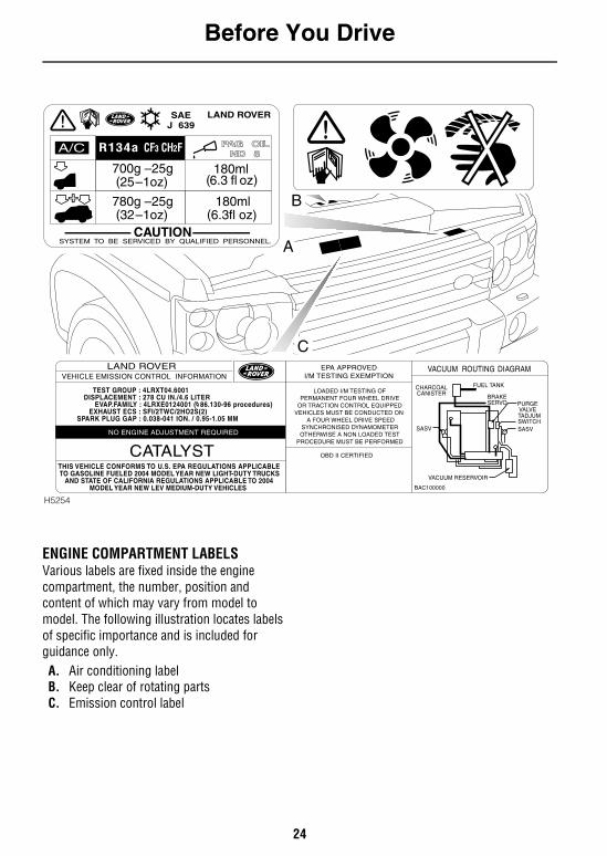
ENGINE COMPARTMENT LABELSVarious labels are fixed inside the engine compartment, the number, position and content of which may vary from model to model. The following illustration locates labels of specific importance and is included for guidance only.A. Air conditioning labelB. Keep clear of rotating partsC. Emission control label
J
180ml700g –25g6.3 fl oz( (25 –1oz)(
780g –25g32 –1oz)(
180ml 6.3fl oz)(
CAUTIONSYSTEM TO BE SERVICED BY QUALIFIED PERSONNEL.
PAG OILND 8
SAE639
A/C CF3 CH2F
LAND ROVER
+
R134a
VACUUM ROUTING DIAGRAMEPA APPROVEDI/M TESTING EXEMPTION
OBD II CERTIFIED
LOADED I/M TESTING OFPERMANENT FOUR WHEEL DRIVE
OR TRACTION CONTROL EQUIPPEDVEHICLES MUST BE CONDUCTED ON
A FOUR WHEEL DRIVE SPEEDSYNCHRONISED DYNAMOMETEROTHERWISE A NON LOADED TEST
PROCEDURE MUST BE PERFORMED
BAC100000
LAND ROVER
CATALYST
VEHICLE EMISSION CONTROL INFORMATION
THIS VEHICLE CONFORMS TO U.S. EPA REGULATIONS APPLICABLE TO GASOLINE FUELED 2004 MODEL YEAR NEW LIGHT-DUTY TRUCKS
AND STATE OF CALIFORNIA REGULATIONS APPLICABLE TO 2004MODEL YEAR NEW LEV MEDIUM-DUTY VEHICLES
NO ENGINE ADJUSTMENT REQUIRED
TEST GROUP : 4LRXT04.6001DISPLACEMENT : 278 CU IN./4.6 LITER
EVAP.FAMILY : 4LRXE0124001 ( 86.130-96 procedures)EXHAUST ECS : SFI/2TWC/2HO2S(2)
SPARK PLUG GAP : 0.038-041 ION. / 0.95-1.05 MM
CHARCOALCANISTER
PURGEVALVE
BRAKESERVO
FUEL TANK
TADJUMSWITCHSASVSASV
VACUUM RESERVOIR
H5254
A
B
C
Before You Drive
25
ANTI-THEFT PRECAUTIONSWhile it may be difficult to deter the ‘professional’ car thief, the majority of thefts are carried out by unskilled opportunists. Therefore, take vehicle security very seriously and ALWAYS adopt this simple ‘four point’ drill whenever you leave your vehicle - even for just a few minutes:
1. Fully close all the windows (and the sunroof).
2. Remove your valuable belongings (or hide them out of sight).
3. Remove the starter key.4. Superlock the vehicle using the remote
handset.
Thieves are attracted by ‘vulnerable’ vehicles. Even if you have followed the ‘four point’ drill, there is still much you can do to make your vehicle a less inviting target.
BE SAFE - NOT SORRY!• Park where your vehicle can be easily seen
by householders and passers-by.
• At night, park in well lit areas and avoid deserted or dimly-lit side streets.
• NEVER leave the keys in the vehicle.
• Do not keep important documents (or spare keys) in the vehicle - these are a real bonus for the thief.
IN AN EMERGENCY
IMPORTANT INFORMATION
Remember the breakdown safety code
If a breakdown occurs while travelling:• Wherever possible, consistent with
road safety and traffic conditions, the vehicle should be moved off the main thoroughfare, preferably onto the shoulder as far as possible. If a breakdown occurs on a motorway, pull well over to the inside of the hard shoulder.
• Switch on hazard lights.
• If possible, position a warning triangle or a flashing amber light at an appropriate distance from the vehicle to warn other traffic of the breakdown, (note the legal requirements of some areas).
• Consider evacuating passengers through the doors facing away from traffic, to a safe area away from the vehicle as a precaution in case your Discovery is accidentally struck by another vehicle.
Before You Drive
26
BREAKING-INProper breaking-in will have a direct bearing on the reliability and smooth running of your vehicle throughout its life.
In particular, the engine, gearbox, brakes and tires need time to ‘bed-in’ and adjust to the demands of everyday motoring. During the first 500 miles (800 km), it is essential to drive with consideration for the running-in process and heed the following advice:• LIMIT maximum road speed to 70 mph (110
km/h) or 3,000 rev/min. Initially, drive the vehicle on a light throttle and only increase engine speeds gradually once the breaking-in distance has been completed.
• DO NOT operate at full throttle or allow the engine to labor in any gear.
• AVOID fast acceleration and heavy braking except in emergencies.
27
Controls & Instruments
Keys & HandsetsKEYS AND HANDSETS. . . . . . . . . . . . . . . . . . . . . 29
Facia ControlsFACIA CONTROLS . . . . . . . . . . . . . . . . . . . . . . . . 30
Locks & AlarmsALARM SYSTEM . . . . . . . . . . . . . . . . . . . . . . . . . 32REMOTE HANDSET BATTERY . . . . . . . . . . . . . . . 36CHILD-PROOF LOCKS . . . . . . . . . . . . . . . . . . . . . 37DOOR LOCKING CUT-OFF SWITCH . . . . . . . . . . . 37ALARM OR HANDSET DIFFICULTIES. . . . . . . . . . 38
SeatsSITTING CORRECTLY . . . . . . . . . . . . . . . . . . . . . 39POWER OPERATED FRONT SEATS . . . . . . . . . . . 39HEAD RESTRAINTS . . . . . . . . . . . . . . . . . . . . . . . 41FOLDING ARMRESTS . . . . . . . . . . . . . . . . . . . . . 42HEATED FRONT SEATS . . . . . . . . . . . . . . . . . . . . 42FOLDING THE REAR SEATS. . . . . . . . . . . . . . . . . 43OCCASIONAL REAR SEATS . . . . . . . . . . . . . . . . . 44
Seat BeltsSEAT BELT SAFETY . . . . . . . . . . . . . . . . . . . . . . . 47WEARING SEAT BELTS CORRECTLY. . . . . . . . . . 48PREGNANT WOMEN . . . . . . . . . . . . . . . . . . . . . . 49FRONT SEAT BELT PRE-TENSIONERS . . . . . . . . 50SERVICE INFORMATION . . . . . . . . . . . . . . . . . . . 51CARING FOR SEAT BELTS . . . . . . . . . . . . . . . . . . 51
Child RestraintsCHILD RESTRAINTS FOR SMALL CHILDREN AND BABIES . . . . . . . . . . . . . . . . . . . . . . . . . . . . . . . . 52CHILD RESTRAINTS FOR LARGER CHILDREN . . 52‘LATCH’ TYPE CHILD RESTRAINTS. . . . . . . . . . . 54TETHER STRAP ANCHORAGES . . . . . . . . . . . . . . 55
Airbag SRSAIRBAG SUPPLEMENTARY RESTRAINT SYSTEM (SRS). . . . . . . . . . . . . . . . . . . . . . . . . . . . . . . . . . 57HOW THE AIRBAG SRS WORKS . . . . . . . . . . . . . 59CHILD SEATS. . . . . . . . . . . . . . . . . . . . . . . . . . . . 61SERVICE INFORMATION . . . . . . . . . . . . . . . . . . . 61
28
Steering ColumnSTEERING COLUMN ADJUSTMENT . . . . . . . . . . 63
Door MirrorsEXTERIOR MIRRORS . . . . . . . . . . . . . . . . . . . . . 64
InstrumentsINSTRUMENT PANEL . . . . . . . . . . . . . . . . . . . . . 65PANEL ILLUMINATION . . . . . . . . . . . . . . . . . . . . 66
Warning LightsWARNING LIGHTS . . . . . . . . . . . . . . . . . . . . . . . 67
Audible WarningsAUDIBLE WARNINGS . . . . . . . . . . . . . . . . . . . . . 72
Lights & IndicatorsDIRECTION INDICATORS . . . . . . . . . . . . . . . . . . 73LIGHTS . . . . . . . . . . . . . . . . . . . . . . . . . . . . . . . . 73FOG LIGHTS . . . . . . . . . . . . . . . . . . . . . . . . . . . . 74HAZARD WARNING LIGHTS . . . . . . . . . . . . . . . . 75
Wipers & WashersOPERATING . . . . . . . . . . . . . . . . . . . . . . . . . . . . 76WINDSHIELD WIPERS . . . . . . . . . . . . . . . . . . . . 76WINDSHIELD WASHER . . . . . . . . . . . . . . . . . . . 77HEADLIGHT WASHERS . . . . . . . . . . . . . . . . . . . 78REAR WINDOW WIPER AND WASHER . . . . . . . 78
HornHORN . . . . . . . . . . . . . . . . . . . . . . . . . . . . . . . . . 79
Electric WindowsELECTRIC WINDOW CONTROLS . . . . . . . . . . . . 80
SunroofELECTRIC SUNROOF . . . . . . . . . . . . . . . . . . . . . 82
Air ConditioningVENTILATION . . . . . . . . . . . . . . . . . . . . . . . . . . . 84AIR CONDITIONING CONTROLS. . . . . . . . . . . . . 85GENERAL NOTES . . . . . . . . . . . . . . . . . . . . . . . . 88
Heated ScreensHEATED WINDSHIELD AND REAR WINDOW . . . 89
Interior EquipmentFRONT INTERIOR & LOADSPACE LIGHTS . . . . . 90REAR INTERIOR LIGHTS . . . . . . . . . . . . . . . . . . 90GLOVEBOX LIGHT . . . . . . . . . . . . . . . . . . . . . . . 90
CLOCK . . . . . . . . . . . . . . . . . . . . . . . . . . . . . . . . 91COIN TRAY . . . . . . . . . . . . . . . . . . . . . . . . . . . . . 91CIGAR LIGHTER . . . . . . . . . . . . . . . . . . . . . . . . . 92ASHTRAYS . . . . . . . . . . . . . . . . . . . . . . . . . . . . . 92CD AUTOCHANGER* . . . . . . . . . . . . . . . . . . . . . 93AUXILIARY POWER SOCKET . . . . . . . . . . . . . . . 94CUP HOLDERS . . . . . . . . . . . . . . . . . . . . . . . . . . 94CUBBY BOX . . . . . . . . . . . . . . . . . . . . . . . . . . . . 96SUN VISOR VANITY MIRROR ILLUMINATION . . 96
Interior Mirror & CompassINTERIOR REAR-VIEW MIRROR . . . . . . . . . . . . 97COMPASS FUNCTION. . . . . . . . . . . . . . . . . . . . . 97COMPASS ZONES. . . . . . . . . . . . . . . . . . . . . . . . 99
Rear Door & StepREAR DOOR . . . . . . . . . . . . . . . . . . . . . . . . . . . 101REAR STEP. . . . . . . . . . . . . . . . . . . . . . . . . . . . 101
Loadspace CoverLOADSPACE COVER . . . . . . . . . . . . . . . . . . . . . 102
In-Car TelephonesIN-CAR TELEPHONES. . . . . . . . . . . . . . . . . . . . 103
Audio SystemRADIO AERIAL . . . . . . . . . . . . . . . . . . . . . . . . . 104AUDIO SYSTEM . . . . . . . . . . . . . . . . . . . . . . . . 104HEADPHONE CONTROLS . . . . . . . . . . . . . . . . . 105RADIO REMOTE CONTROLS. . . . . . . . . . . . . . . 105
Land Rover HomeLink®HOMELINK® TRANSMITTER . . . . . . . . . . . . . . 107
Keys & Handsets
29
Controls & Instruments
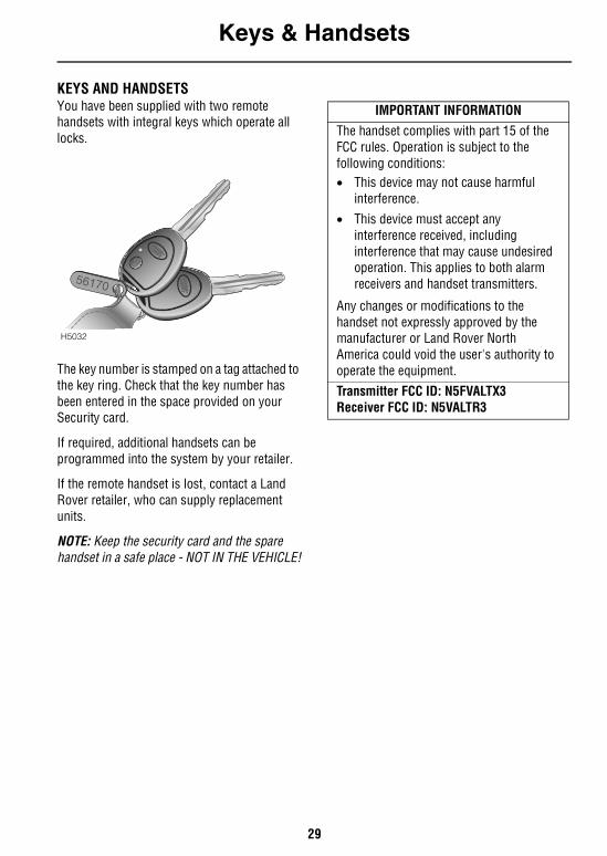
Keys & HandsetsKEYS AND HANDSETS You have been supplied with two remote handsets with integral keys which operate all locks.
The key number is stamped on a tag attached to the key ring. Check that the key number has been entered in the space provided on your Security card.
If required, additional handsets can be programmed into the system by your retailer.
If the remote handset is lost, contact a Land Rover retailer, who can supply replacement units.
NOTE: Keep the security card and the spare handset in a safe place - NOT IN THE VEHICLE!
H5032
IMPORTANT INFORMATIONThe handset complies with part 15 of the FCC rules. Operation is subject to the following conditions:• This device may not cause harmful
interference.• This device must accept any
interference received, including interference that may cause undesired operation. This applies to both alarm receivers and handset transmitters.
Any changes or modifications to the handset not expressly approved by the manufacturer or Land Rover North America could void the user's authority to operate the equipment.Transmitter FCC ID: N5FVALTX3Receiver FCC ID: N5VALTR3
Facia Controls
30
Facia ControlsFACIA CONTROLS
P
TRA
FFIC
NE
WS
P
H50
11
19
98
76
52
43
101
1815
1716
11 12
14
13
Facia Controls
31
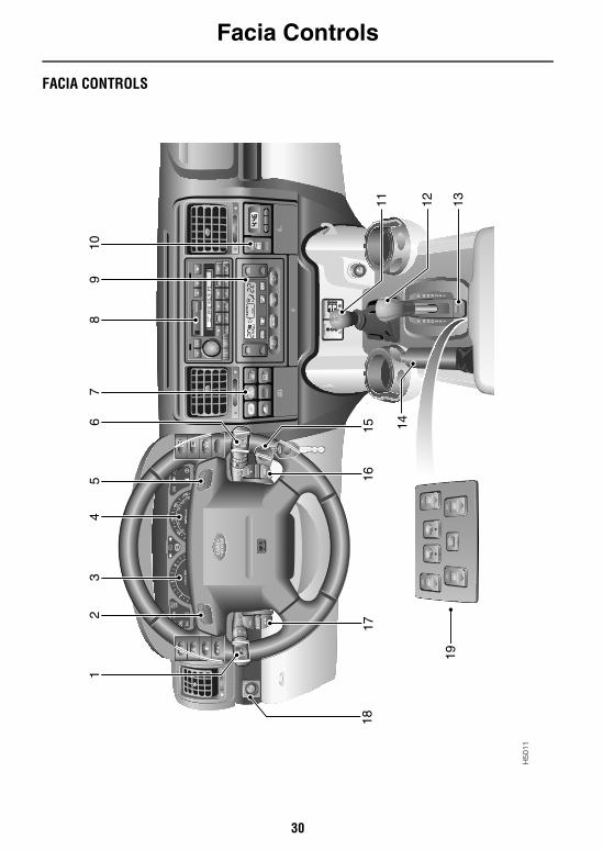
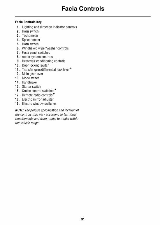
Facia Controls Key1. Lighting and direction indicator controls2. Horn switch3. Tachometer4. Speedometer5. Horn switch6. Windhsield wiper/washer controls7. Facia panel switches8. Audio system controls9. Heater/air conditioning controls
10. Door locking switch11. Transfer gear/differential lock lever*12. Main gear lever13. Mode switch14. Handbrake15. Starter switch16. Cruise control switches*17. Remote radio controls*18. Electric mirror adjuster19. Electric window switches
NOTE: The precise specification and location of the controls may vary according to territorial requirements and from model to model within the vehicle range.
Locks & Alarms
32
Locks & AlarmsALARM SYSTEM
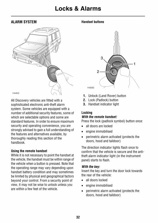
All Discovery vehicles are fitted with a sophisticated electronic anti-theft alarm system. Some vehicles are equipped with a number of additional security features, some of which are selectable options and some are standard features. In order to ensure maximum security and operating convenience, you are strongly advised to gain a full understanding of the features and alternatives available, by thoroughly reading this section of the handbook.
Using the remote handsetWhile it is not necessary to point the handset at the vehicle, the handset must be within range of the vehicle when a button is pressed. Note that the operating range may vary depending upon handset battery condition and may sometimes be limited by physical and geographical factors beyond your control. From a security point of view, it may not be wise to unlock unless you are within a few feet of the vehicle.
Handset buttons
1. Unlock (Land Rover) button2. Lock (Padlock) button3. Handset indicator light
LockingWith the remote handset: Press the lock (padlock symbol) button once:• all doors are locked
• engine immobilised
• perimetric alarm activated (protects the doors, hood and taildoor)
The direction indicator lights flash once to confirm that the vehicle is secure and the anti-theft alarm indicator light (in the instrument panel) starts to flash.
With the key: Insert the key and turn the door lock towards the rear of the vehicle: • all doors locked
• engine immobilised
• perimetric alarm activated (protects the doors, hood and taildoor)
H4402
H4690
2
3
1
Locks & Alarms
33
The direction indicator lights flash once to confirm that the vehicle is secure and the anti-theft alarm indicator light (in the instrument panel) starts to flash.
UnlockingWith the remote handset:Press the unlock (Land Rover) button once to disarm the alarm and unlock the all the doors or, if single point entry is enabled, the driver's door only (also see ‘Single point entry (if enabled)’, page 35).
In either case, the direction indicator lights flash once and the interior lights illuminate.
With the key: In addition to remote handset operation, the door can be unlocked and the alarm disarmed manually using the key.
Superlocking (if enabled)Superlocking provides greater security by immobilising the interior door handles, thereby preventing an intruder from gaining entry by smashing a window and reaching inside the vehicle to operate the door handles.
Provided all the doors are fully closed; Superlocking is activated by pressing the handset lock button twice within one second or turning the door lock to the lock position with the key twice within one second.
The direction indicator lights will flash three times after superlocking has been activated and once after superlocking has been de-activated.
WARNINGFor safety, NEVER use Superlocking if passengers are to remain inside the vehicle - in an emergency they would not be able to escape. Also, any movement from within the vehicle would activate the alarm, if interior space protection has been activated.
Locks & Alarms
34
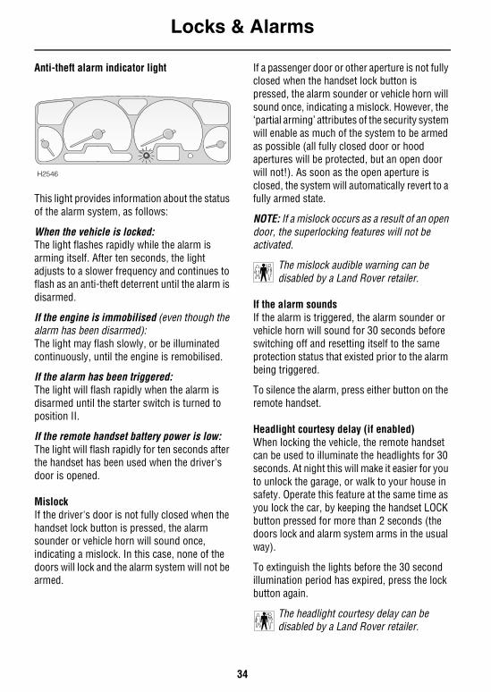
Anti-theft alarm indicator light
This light provides information about the status of the alarm system, as follows:
When the vehicle is locked: The light flashes rapidly while the alarm is arming itself. After ten seconds, the light adjusts to a slower frequency and continues to flash as an anti-theft deterrent until the alarm is disarmed.
If the engine is immobilised (even though the alarm has been disarmed): The light may flash slowly, or be illuminated continuously, until the engine is remobilised.
If the alarm has been triggered: The light will flash rapidly when the alarm is disarmed until the starter switch is turned to position II.
If the remote handset battery power is low: The light will flash rapidly for ten seconds after the handset has been used when the driver's door is opened.
MislockIf the driver's door is not fully closed when the handset lock button is pressed, the alarm sounder or vehicle horn will sound once, indicating a mislock. In this case, none of the doors will lock and the alarm system will not be armed.
If a passenger door or other aperture is not fully closed when the handset lock button is pressed, the alarm sounder or vehicle horn will sound once, indicating a mislock. However, the ‘partial arming’ attributes of the security system will enable as much of the system to be armed as possible (all fully closed door or hood apertures will be protected, but an open door will not!). As soon as the open aperture is closed, the system will automatically revert to a fully armed state.
NOTE: If a mislock occurs as a result of an open door, the superlocking features will not be activated.
The mislock audible warning can be disabled by a Land Rover retailer.
If the alarm soundsIf the alarm is triggered, the alarm sounder or vehicle horn will sound for 30 seconds before switching off and resetting itself to the same protection status that existed prior to the alarm being triggered.
To silence the alarm, press either button on the remote handset.
Headlight courtesy delay (if enabled)When locking the vehicle, the remote handset can be used to illuminate the headlights for 30 seconds. At night this will make it easier for you to unlock the garage, or walk to your house in safety. Operate this feature at the same time as you lock the car, by keeping the handset LOCK button pressed for more than 2 seconds (the doors lock and alarm system arms in the usual way).
To extinguish the lights before the 30 second illumination period has expired, press the lock button again.
The headlight courtesy delay can be disabled by a Land Rover retailer.
H2546
Locks & Alarms
35
Single point entry (if enabled)This is a personal security feature, which enables the driver's door only to be unlocked, leaving the other doors in a locked state. It can be operated by the remote handset as follows:• press the unlock button once to unlock the
driver's door.
• press a second time (within one minute) to unlock the remaining doors.
Single point entry can be disabled by a Land Rover retailer.
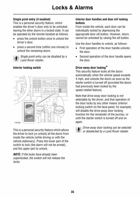
Interior locking switch
This is a personal security feature which allows the driver to lock (or unlock) all the doors from inside the vehicle (while driving or with the vehicle stationary). Press the lower part of the switch to lock (the alarm will not be armed), and the upper part to unlock.
NOTE: If the locks have already been superlocked, the switch will not release the locks.
Interior door handles and door sill locking buttonsFrom inside the vehicle, each door can be individually locked by depressing the appropriate door sill button. However, doors cannot be unlocked by raising the sill button.
Use the door handles to unlock, as follows:• First operation of the door handle unlocks
the door.• Second operation of the door handle opens
the door.
Drive-away door locking*This security feature locks all the doors automatically when the vehicle speed exceeds 4 mph, and unlocks the doors as soon as the starter switch is turned off (provided the doors had previously been locked by the speed related feature).
Note that drive-away door locking is not selectable by the driver, and that operation of the door locks by any other means (interior locking switch on the facia panel, for example) will disable the drive-away door locking function for the remainder of the journey, or until the starter switch is turned off and on again.
Drive-away door locking can be selected or deselected by a Land Rover retailer.
H4538
Locks & Alarms
36
REMOTE HANDSET BATTERYThe battery should last for approximately three years dependent upon use. When the battery needs to be replaced will be apparent from the following symptoms:• A gradual deterioration in range and
performance.• The alarm indicator light in the instrument
panel will flash rapidly for 10 seconds after the driver's door is opened.
Always fit a Land Rover YWX10003L or a Panasonic CR2032 replacement battery (available from a Land Rover retailer).
CAUTION: The handset contains delicate electronic circuits and must be protected from impact and water damage, high temperatures and humidity, direct sunlight and the effects of solvents, waxes and abrasive cleaners.
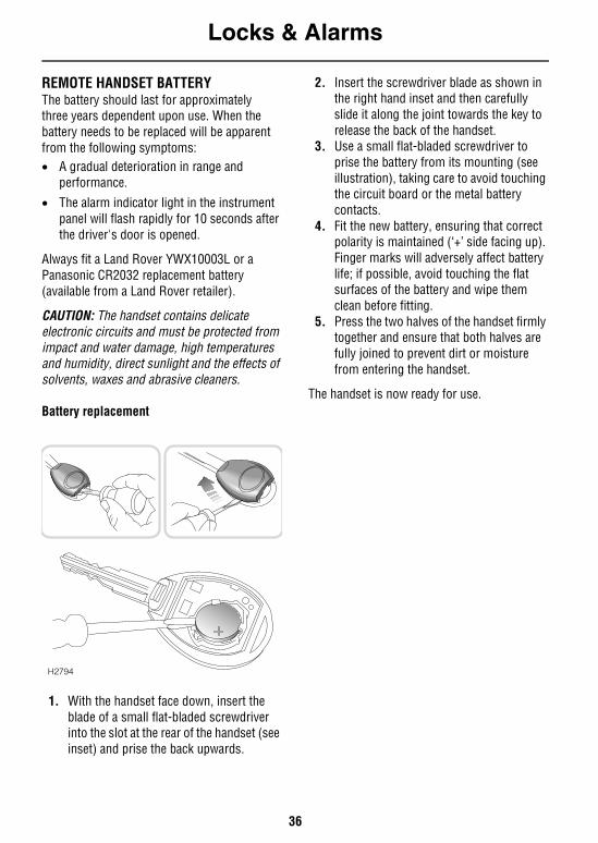
Battery replacement
1. With the handset face down, insert the blade of a small flat-bladed screwdriver into the slot at the rear of the handset (see inset) and prise the back upwards.
2. Insert the screwdriver blade as shown in the right hand inset and then carefully slide it along the joint towards the key to release the back of the handset.
3. Use a small flat-bladed screwdriver to prise the battery from its mounting (see illustration), taking care to avoid touching the circuit board or the metal battery contacts.
4. Fit the new battery, ensuring that correct polarity is maintained (‘+’ side facing up). Finger marks will adversely affect battery life; if possible, avoid touching the flat surfaces of the battery and wipe them clean before fitting.
5. Press the two halves of the handset firmly together and ensure that both halves are fully joined to prevent dirt or moisture from entering the handset.
The handset is now ready for use.
H2794
Locks & Alarms
37
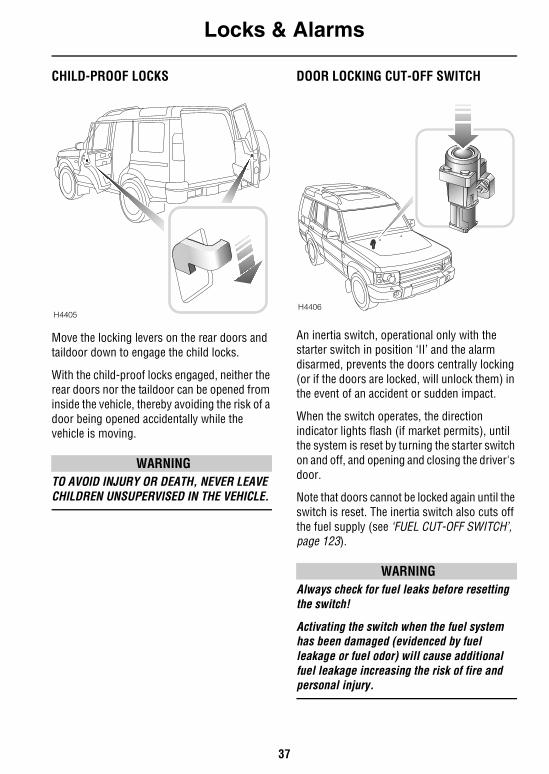
CHILD-PROOF LOCKS
Move the locking levers on the rear doors and taildoor down to engage the child locks.
With the child-proof locks engaged, neither the rear doors nor the taildoor can be opened from inside the vehicle, thereby avoiding the risk of a door being opened accidentally while the vehicle is moving.
WARNINGTO AVOID INJURY OR DEATH, NEVER LEAVE CHILDREN UNSUPERVISED IN THE VEHICLE.
DOOR LOCKING CUT-OFF SWITCH
An inertia switch, operational only with the starter switch in position ‘II’ and the alarm disarmed, prevents the doors centrally locking (or if the doors are locked, will unlock them) in the event of an accident or sudden impact.
When the switch operates, the direction indicator lights flash (if market permits), until the system is reset by turning the starter switch on and off, and opening and closing the driver's door.
Note that doors cannot be locked again until the switch is reset. The inertia switch also cuts off the fuel supply (see ‘FUEL CUT-OFF SWITCH’, page 123).
WARNINGAlways check for fuel leaks before resetting the switch!
Activating the switch when the fuel system has been damaged (evidenced by fuel leakage or fuel odor) will cause additional fuel leakage increasing the risk of fire and personal injury.
H4405H4406
Locks & Alarms
38
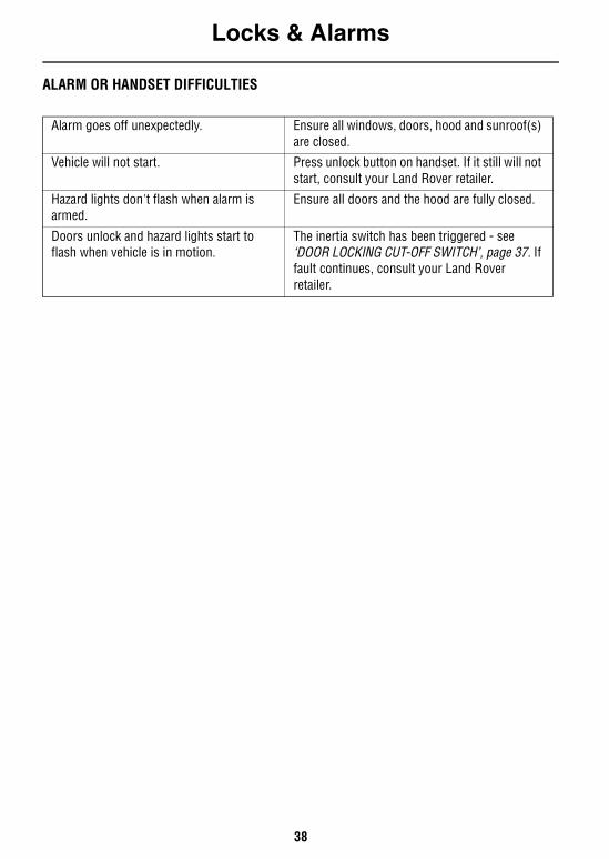
ALARM OR HANDSET DIFFICULTIES
Alarm goes off unexpectedly. Ensure all windows, doors, hood and sunroof(s) are closed.
Vehicle will not start. Press unlock button on handset. If it still will not start, consult your Land Rover retailer.
Hazard lights don't flash when alarm is armed.
Ensure all doors and the hood are fully closed.
Doors unlock and hazard lights start to flash when vehicle is in motion.
The inertia switch has been triggered - see ‘DOOR LOCKING CUT-OFF SWITCH’, page 37. If fault continues, consult your Land Rover retailer.
Seats
39
SeatsSITTING CORRECTLY
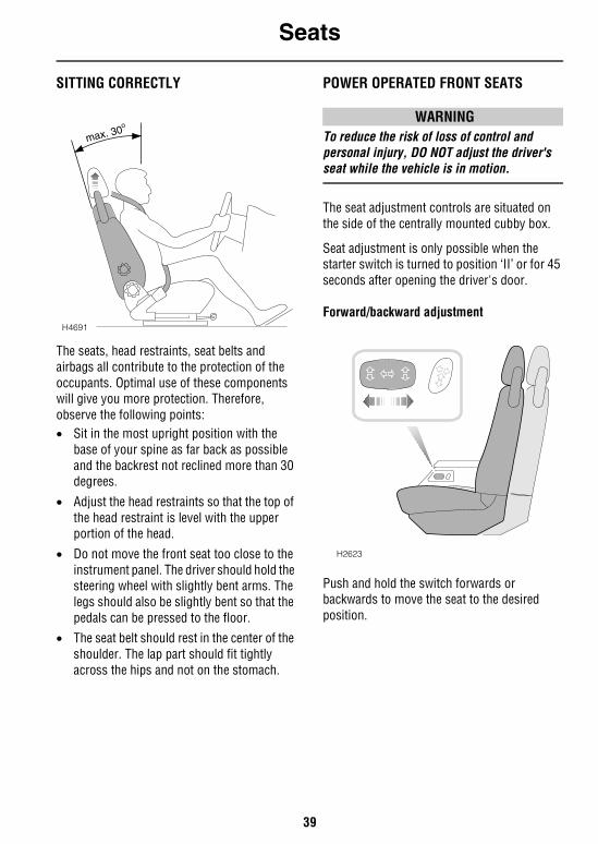
The seats, head restraints, seat belts and airbags all contribute to the protection of the occupants. Optimal use of these components will give you more protection. Therefore, observe the following points:• Sit in the most upright position with the
base of your spine as far back as possible and the backrest not reclined more than 30 degrees.
• Adjust the head restraints so that the top of the head restraint is level with the upper portion of the head.
• Do not move the front seat too close to the instrument panel. The driver should hold the steering wheel with slightly bent arms. The legs should also be slightly bent so that the pedals can be pressed to the floor.
• The seat belt should rest in the center of the shoulder. The lap part should fit tightly across the hips and not on the stomach.
POWER OPERATED FRONT SEATS
WARNINGTo reduce the risk of loss of control and personal injury, DO NOT adjust the driver's seat while the vehicle is in motion.
The seat adjustment controls are situated on the side of the centrally mounted cubby box.
Seat adjustment is only possible when the starter switch is turned to position ‘II’ or for 45 seconds after opening the driver's door.
Forward/backward adjustment
Push and hold the switch forwards or backwards to move the seat to the desired position.
H4691
max. 30o
H2623
Seats
40
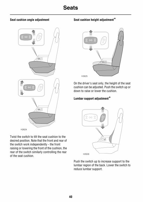
Seat cushion angle adjustment
Twist the switch to tilt the seat cushion to the desired position. Note that the front and rear of the switch work independently - the front raising or lowering the front of the cushion, the rear of the switch similarly controlling the rear of the seat cushion.
Seat cushion height adjustment*
On the driver's seat only, the height of the seat cushion can be adjusted. Push the switch up or down to raise or lower the cushion.
Lumbar support adjustment*
Push the switch up to increase support to the lumbar region of the back. Lower the switch to reduce lumbar support.
H2624
H2625
H2626
Seats
41
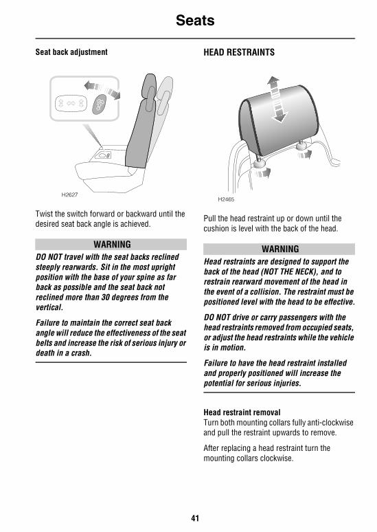
Seat back adjustment
Twist the switch forward or backward until the desired seat back angle is achieved.
WARNINGDO NOT travel with the seat backs reclined steeply rearwards. Sit in the most upright position with the base of your spine as far back as possible and the seat back not reclined more than 30 degrees from the vertical.
Failure to maintain the correct seat back angle will reduce the effectiveness of the seat belts and increase the risk of serious injury or death in a crash.
HEAD RESTRAINTS
Pull the head restraint up or down until the cushion is level with the back of the head.
WARNINGHead restraints are designed to support the back of the head (NOT THE NECK), and to restrain rearward movement of the head in the event of a collision. The restraint must be positioned level with the head to be effective.
DO NOT drive or carry passengers with the head restraints removed from occupied seats, or adjust the head restraints while the vehicle is in motion.
Failure to have the head restraint installed and properly positioned will increase the potential for serious injuries.
Head restraint removalTurn both mounting collars fully anti-clockwise and pull the restraint upwards to remove.
After replacing a head restraint turn the mounting collars clockwise.
H2627H2465
Seats
42
FOLDING ARMRESTS*
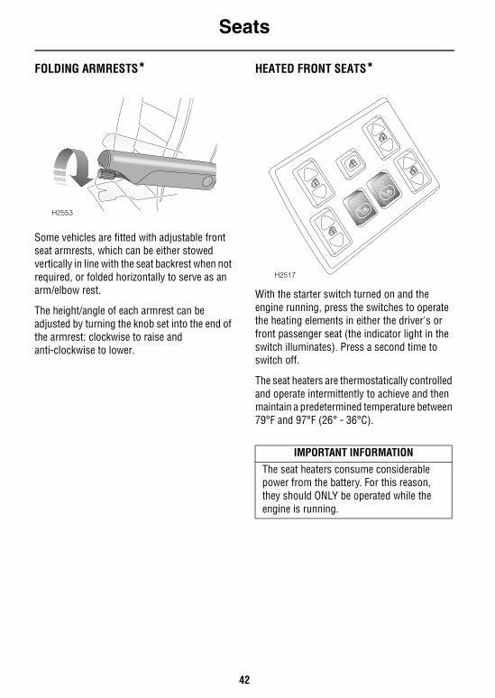
Some vehicles are fitted with adjustable front seat armrests, which can be either stowed vertically in line with the seat backrest when not required, or folded horizontally to serve as an arm/elbow rest.
The height/angle of each armrest can be adjusted by turning the knob set into the end of the armrest: clockwise to raise and anti-clockwise to lower.
HEATED FRONT SEATS*
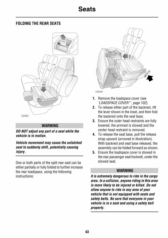
With the starter switch turned on and the engine running, press the switches to operate the heating elements in either the driver's or front passenger seat (the indicator light in the switch illuminates). Press a second time to switch off.
The seat heaters are thermostatically controlled and operate intermittently to achieve and then maintain a predetermined temperature between 79°F and 97°F (26° - 36°C).
H2553
IMPORTANT INFORMATION
The seat heaters consume considerablepower from the battery. For this reason, they should ONLY be operated while the engine is running.
H2517
Seats
43
FOLDING THE REAR SEATS
WARNINGDO NOT adjust any part of a seat while the vehicle is in motion.
Vehicle movement may cause the unlatched seat to suddenly shift, potentially causing injury.
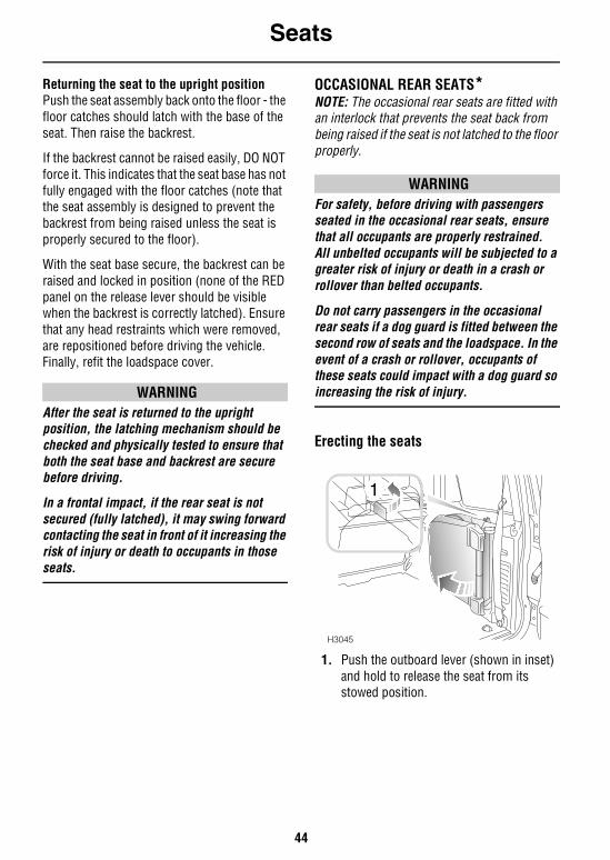
One or both parts of the split rear seat can be either partially or fully folded to further increase the rear loadspace, using the following instructions:
1. Remove the loadspace cover (see ‘LOADSPACE COVER*’, page 102).
2. To release either part of the backrest, lift the lever shown in the inset, and then fold the backrest onto the seat base.
3. Ensure the outer head restraints are fully lowered, the armrest is stowed and the center head restraint is removed.
4. To release the seat base, pull the release strap upward (arrowed in illustration). With backrest and seat base released, the assembly can be folded forward as shown.
5. Ensure the loadspace cover is stowed in the rear passenger seat footwell, under the stowed seat.
WARNINGIt is extremely dangerous to ride in the cargo area. In a collision, anyone riding in this area is more likely to be injured or killed. Do not allow anyone to ride in any area of your vehicle that is not equipped with seats and safety belts. Be sure that everyone in your vehicle is in a seat and using a safety belt properly.
H2493
H2549
Seats
44
Returning the seat to the upright positionPush the seat assembly back onto the floor - the floor catches should latch with the base of the seat. Then raise the backrest.
If the backrest cannot be raised easily, DO NOT force it. This indicates that the seat base has not fully engaged with the floor catches (note that the seat assembly is designed to prevent the backrest from being raised unless the seat is properly secured to the floor).
With the seat base secure, the backrest can be raised and locked in position (none of the RED panel on the release lever should be visible when the backrest is correctly latched). Ensure that any head restraints which were removed, are repositioned before driving the vehicle. Finally, refit the loadspace cover.
WARNINGAfter the seat is returned to the upright position, the latching mechanism should be checked and physically tested to ensure that both the seat base and backrest are secure before driving.
In a frontal impact, if the rear seat is not secured (fully latched), it may swing forward contacting the seat in front of it increasing the risk of injury or death to occupants in those seats.
OCCASIONAL REAR SEATS*NOTE: The occasional rear seats are fitted with an interlock that prevents the seat back from being raised if the seat is not latched to the floor properly.
WARNINGFor safety, before driving with passengers seated in the occasional rear seats, ensure that all occupants are properly restrained.All unbelted occupants will be subjected to a greater risk of injury or death in a crash or rollover than belted occupants.
Do not carry passengers in the occasional rear seats if a dog guard is fitted between the second row of seats and the loadspace. In the event of a crash or rollover, occupants of these seats could impact with a dog guard so increasing the risk of injury.
Erecting the seats
1. Push the outboard lever (shown in inset) and hold to release the seat from its stowed position.
H3045
1
Seats
45
2. Swing the seat away from the vehicle side, at the same time lifting and turning it towards the horizontal.
3. Lower the seat to the loadspace floor, PUSHING DOWN FIRMLY to ensure that the floor latch has fully engaged.
4. Pull the backrest into the upright position.
NOTE: The backrest cannot be raised unless the seat is securely latched to the floor.
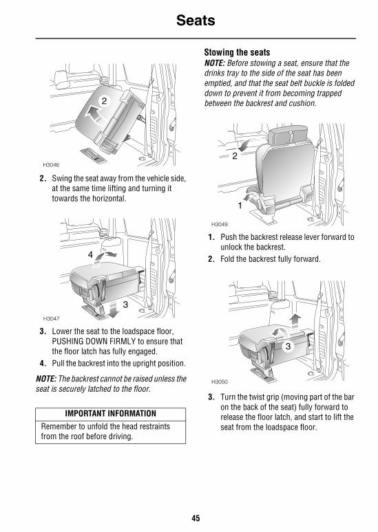
Stowing the seatsNOTE: Before stowing a seat, ensure that the drinks tray to the side of the seat has been emptied, and that the seat belt buckle is folded down to prevent it from becoming trapped between the backrest and cushion.
1. Push the backrest release lever forward to unlock the backrest.
2. Fold the backrest fully forward.
3. Turn the twist grip (moving part of the bar on the back of the seat) fully forward to release the floor latch, and start to lift the seat from the loadspace floor.
IMPORTANT INFORMATION
Remember to unfold the head restraints from the roof before driving.
H3046
2
H3047
3
4
H3049
1
2
H3050
3
Seats
46
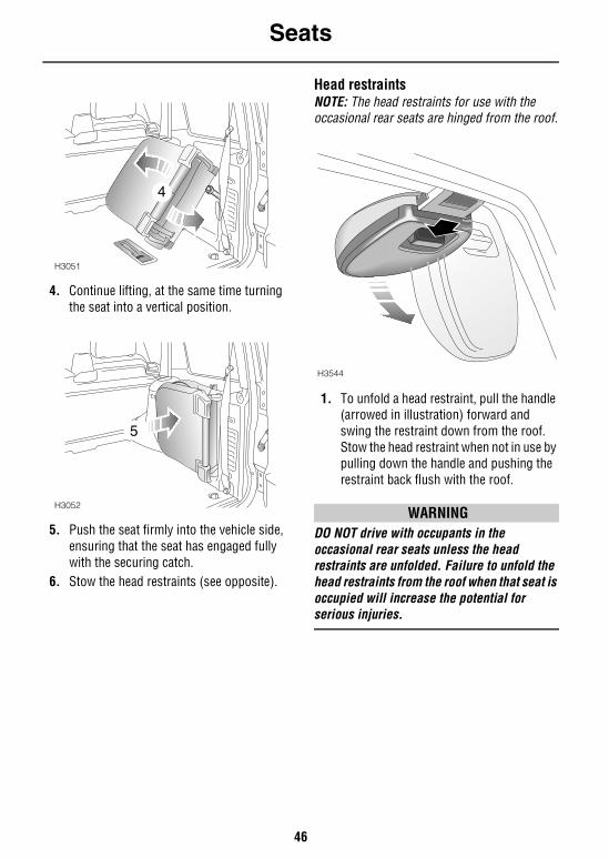
4. Continue lifting, at the same time turning the seat into a vertical position.
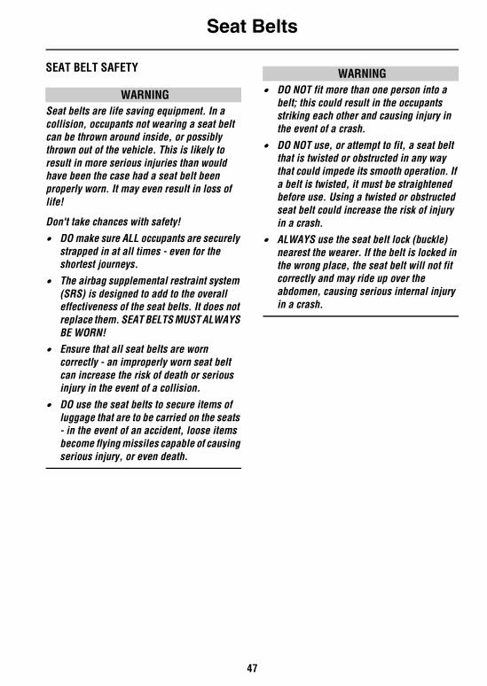
5. Push the seat firmly into the vehicle side, ensuring that the seat has engaged fully with the securing catch.
6. Stow the head restraints (see opposite).
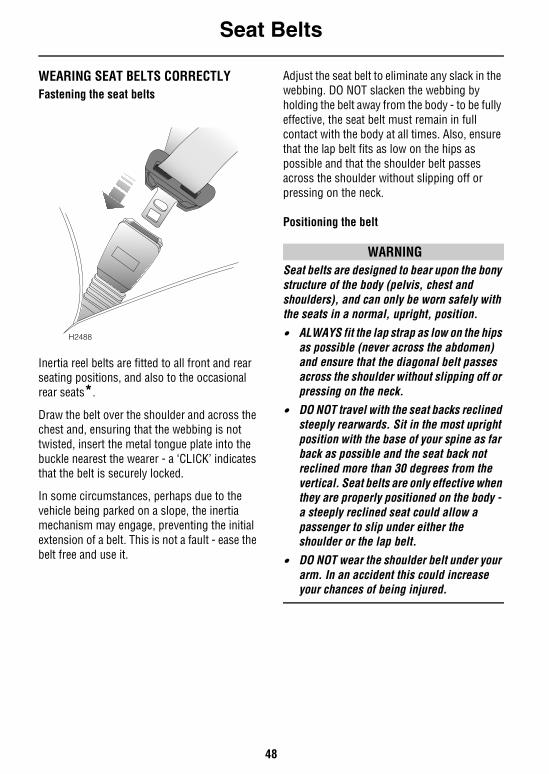
Head restraintsNOTE: The head restraints for use with the occasional rear seats are hinged from the roof.
1. To unfold a head restraint, pull the handle (arrowed in illustration) forward and swing the restraint down from the roof. Stow the head restraint when not in use by pulling down the handle and pushing the restraint back flush with the roof.
WARNINGDO NOT drive with occupants in the occasional rear seats unless the head restraints are unfolded. Failure to unfold the head restraints from the roof when that seat is occupied will increase the potential for serious injuries.
H3051
4
H3052
5
H3544
Seat Belts
47
Seat BeltsSEAT BELT SAFETY
WARNINGSeat belts are life saving equipment. In a collision, occupants not wearing a seat belt can be thrown around inside, or possibly thrown out of the vehicle. This is likely to result in more serious injuries than would have been the case had a seat belt been properly worn. It may even result in loss of life!
Don't take chances with safety!
• DO make sure ALL occupants are securely strapped in at all times - even for the shortest journeys.
• The airbag supplemental restraint system (SRS) is designed to add to the overall effectiveness of the seat belts. It does not replace them. SEAT BELTS MUST ALWAYS BE WORN!
• Ensure that all seat belts are worn correctly - an improperly worn seat belt can increase the risk of death or serious injury in the event of a collision.
• DO use the seat belts to secure items of luggage that are to be carried on the seats - in the event of an accident, loose items become flying missiles capable of causing serious injury, or even death.
WARNING• DO NOT fit more than one person into a
belt; this could result in the occupants striking each other and causing injury in the event of a crash.
• DO NOT use, or attempt to fit, a seat belt that is twisted or obstructed in any way that could impede its smooth operation. If a belt is twisted, it must be straightened before use. Using a twisted or obstructed seat belt could increase the risk of injury in a crash.
• ALWAYS use the seat belt lock (buckle) nearest the wearer. If the belt is locked in the wrong place, the seat belt will not fit correctly and may ride up over the abdomen, causing serious internal injury in a crash.
Seat Belts
48
WEARING SEAT BELTS CORRECTLYFastening the seat belts
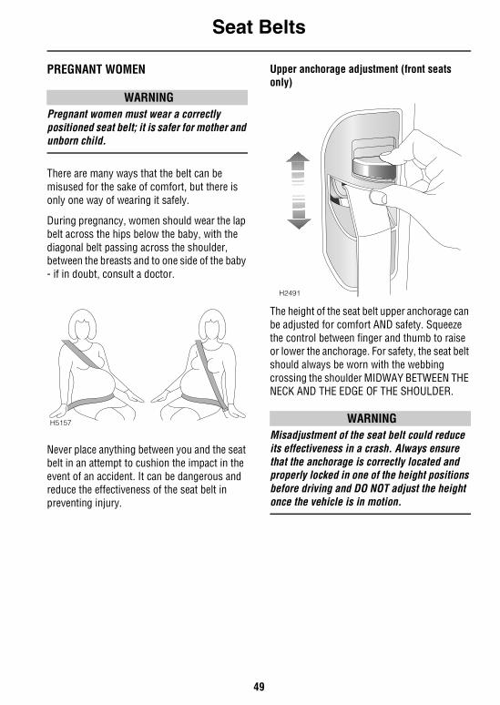
Inertia reel belts are fitted to all front and rear seating positions, and also to the occasional rear seats*.
Draw the belt over the shoulder and across the chest and, ensuring that the webbing is not twisted, insert the metal tongue plate into the buckle nearest the wearer - a ‘CLICK’ indicates that the belt is securely locked.
In some circumstances, perhaps due to the vehicle being parked on a slope, the inertia mechanism may engage, preventing the initial extension of a belt. This is not a fault - ease the belt free and use it.
Adjust the seat belt to eliminate any slack in the webbing. DO NOT slacken the webbing by holding the belt away from the body - to be fully effective, the seat belt must remain in full contact with the body at all times. Also, ensure that the lap belt fits as low on the hips as possible and that the shoulder belt passes across the shoulder without slipping off or pressing on the neck.
Positioning the belt
WARNINGSeat belts are designed to bear upon the bony structure of the body (pelvis, chest and shoulders), and can only be worn safely with the seats in a normal, upright, position.
• ALWAYS fit the lap strap as low on the hips as possible (never across the abdomen) and ensure that the diagonal belt passes across the shoulder without slipping off or pressing on the neck.
• DO NOT travel with the seat backs reclined steeply rearwards. Sit in the most upright position with the base of your spine as far back as possible and the seat back not reclined more than 30 degrees from the vertical. Seat belts are only effective when they are properly positioned on the body - a steeply reclined seat could allow a passenger to slip under either the shoulder or the lap belt.
• DO NOT wear the shoulder belt under your arm. In an accident this could increase your chances of being injured.
H2488
Seat Belts
49
PREGNANT WOMEN
WARNINGPregnant women must wear a correctly positioned seat belt; it is safer for mother and unborn child.
There are many ways that the belt can be misused for the sake of comfort, but there is only one way of wearing it safely.
During pregnancy, women should wear the lap belt across the hips below the baby, with the diagonal belt passing across the shoulder, between the breasts and to one side of the baby - if in doubt, consult a doctor.
Never place anything between you and the seat belt in an attempt to cushion the impact in the event of an accident. It can be dangerous and reduce the effectiveness of the seat belt in preventing injury.
Upper anchorage adjustment (front seats only)
The height of the seat belt upper anchorage can be adjusted for comfort AND safety. Squeeze the control between finger and thumb to raise or lower the anchorage. For safety, the seat belt should always be worn with the webbing crossing the shoulder MIDWAY BETWEEN THE NECK AND THE EDGE OF THE SHOULDER.
WARNINGMisadjustment of the seat belt could reduce its effectiveness in a crash. Always ensure that the anchorage is correctly located and properly locked in one of the height positions before driving and DO NOT adjust the height once the vehicle is in motion.
H5157
H2491
Seat Belts
50
Where possible, rear seat passengers should adjust their position on the seat to enable the seat belt webbing to cross the shoulder without pressing on the neck.
WARNINGAlways transport children 12 years and under in the second row seats and always properly use appropriate child restraints.
For children that are too small to fit the 3-point seat belt properly, the use of appropriate child safety seats or belt-positioning booster seats is recommended.
NOTE: For additional information, (see ‘CHILD RESTRAINTS FOR SMALL CHILDREN AND BABIES’, page 52).
Releasing the beltPress the RED button on the seat belt buckle.
FRONT SEAT BELT PRE-TENSIONERSThe seat belt pre-tensioners activate in conjunction with the airbag SRS and provide additional protection in the event of a severe frontal impact on the vehicle (see ‘HOW THE AIRBAG SRS WORKS’, page 59). The pre-tensioners reduce any slack in both the lap and diagonal portions of the belts, thereby reducing forward movement of the belt wearer in the event of a severe frontal collision.
The airbag SRS warning light on the instrument panel will alert you to any malfunction of the seat belt pre-tensioners (see ‘WARNING LIGHTS’, page 67).
If the pre-tensioners have been activated, the seat belts will still function as restraints, and must be worn in the event that the vehicle remains in a driveable condition, however, for the pre-tensioner to work properly again, it must be replaced.
NOTE: The seat belt pre-tensioners will NOT be activated by rear, side or minor frontal impacts.
WARNINGThe seat belt pre-tensioners will only be activated once and then MUST BE REPLACED by a Land Rover retailer. Failure to replace the pre-tensioners will reduce the efficiency of the vehicle's front restraint systems.
After any frontal impact, always have the seat belts and pre-tensioners checked and, if necessary, replaced by a Land Rover retailer.
In the interests of safety, it is recommended that removal or replacement of the front seats and seat belts, with the use of factory-specified parts, should ONLY be carried out by a Land Rover retailer.
Seat Belts
51
SERVICE INFORMATION
WARNINGDO NOT attempt to service, repair, replace, modify or tamper with any part of the pre-tensioner and airbag SRS, or wiring in the vicinity of a pre-tensioner or airbag SRS component; this could cause the system to activate, resulting in personal injury.
After 15 years from the original date of registration (or the installation date of replacement pre-tensioners) some seat belt pre-tensioner components must be replaced by a Land Rover retailer. See ‘Seat belt pre-tensioner replacement date’ shown in your Passport to Service.
In addition, ALWAYS contact your retailer if: • an airbag inflates.
• a pre-tensioner activates.
• the front or side of the vehicle is damaged, even if the pre-tensioner has not activated.
CARING FOR SEAT BELTS
WARNING• DO NOT allow foreign matter (particularly
sugary food and drink particles) to enter the seat belt locks - such substances can render the locks inoperative.
• Regularly inspect the belt webbing for signs of fraying, cuts and wear, and also pay particular attention to the condition of the fixing points and adjusters.
• DO NOT bleach or dye the webbing. Clean the webbing using warm water and non-detergent soap only - allow to dry naturally and DO NOT retract or use the belts until they are completely dry.
• Always replace a seat belt that shows signs of webbing wear or has withstood the strain of a severe vehicle impact.
Testing inertia reel belts • With the seat belt fastened, give the
webbing near the buckle a quick upward pull. The buckle must remain securely locked.
• With the seat belt unfastened, unreel the webbing to the limit of its travel. Check that unreeling is free from snatches and snags and then allow the belt to FULLY retract.
• Partially unreel the webbing, then hold the tongue plate and give it a quick forward pull. The mechanism must lock automatically and prevent any further unreeling.
If a seat belt should fail any of these tests, contact your retailer immediately.
Child Restraints
52
Child RestraintsCHILD RESTRAINTS FOR SMALL CHILDREN AND BABIESInfants and children too small for adult seat belts should be restrained in a child safety seat or restraint system appropriate to their age and/or size.
Child seats and restraint systems designed for your vehicle will be one of two types:• Those secured in vehicle seats by the seat
belts
• ‘LATCH’ type child restraints employing anchor bars built into the rear seat frame.
All new and most older type child restraint systems incorporate a tether strap which can be attached to an anchorage point on the vehicle. Information about tether strap attachment points and the seat belt locking mechanism, which is used to restrain child seats and restraints, is shown later in this section.
CAUTION: When fitting child seats and restraint systems, always ensure that the manufacturer's fitting instructions are followed exactly. Note that crash statistics show that children are safer when properly restrained in the rear (2nd row) seating positions than in the front.
CHILD RESTRAINTS FOR LARGER CHILDRENIn a situation where a child is too large to fit into a child safety seat, but is still too small to safely fit the 3 point seat belt properly, a booster seat is recommended for maximum safety. Follow the manufacturer’s fitting instructions exactly, then adjust the seat belt to suit.
WARNING• DO NOT allow a baby or infant to be carried
on the lap. The force of a crash can increase effective body weight by as much as 30 times, making it impossible to hold on to the child.
• Children typically require the use of a booster seat appropriate to their age and size, thereby enabling the seat belts to be properly fitted, reducing the risk of injury in a crash.
• Children could be endangered in a crash if their child restraints are not properly secured in the vehicle.
• DO NOT use a child seat that hooks over the seat back. This type of seat cannot be satisfactorily secured, and is unlikely to be safe for your child.
• Never leave a child unattended in your vehicle.
Child Restraints
53
Vehicles fitted with a passenger airbagChildren under 12 years should travel in the rear of the vehicle at all times. Crash statistics show that children are safer when properly restrained in the rear (2nd row) seating positions than in the front.
However, if it is essential that a child travel in the front, set the seat fully rearward and seat the child in a FORWARD FACING child seat.
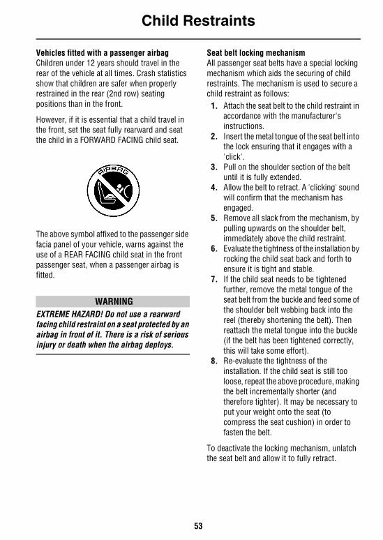
The above symbol affixed to the passenger side facia panel of your vehicle, warns against the use of a REAR FACING child seat in the front passenger seat, when a passenger airbag is fitted.
WARNINGEXTREME HAZARD! Do not use a rearward facing child restraint on a seat protected by an airbag in front of it. There is a risk of serious injury or death when the airbag deploys.
Seat belt locking mechanismAll passenger seat belts have a special locking mechanism which aids the securing of child restraints. The mechanism is used to secure a child restraint as follows:1. Attach the seat belt to the child restraint in
accordance with the manufacturer's instructions.
2. Insert the metal tongue of the seat belt into the lock ensuring that it engages with a 'click'.
3. Pull on the shoulder section of the belt until it is fully extended.
4. Allow the belt to retract. A 'clicking' sound will confirm that the mechanism has engaged.
5. Remove all slack from the mechanism, by pulling upwards on the shoulder belt, immediately above the child restraint.
6. Evaluate the tightness of the installation by rocking the child seat back and forth to ensure it is tight and stable.
7. If the child seat needs to be tightened further, remove the metal tongue of the seat belt from the buckle and feed some of the shoulder belt webbing back into the reel (thereby shortening the belt). Then reattach the metal tongue into the buckle (if the belt has been tightened correctly, this will take some effort).
8. Re-evaluate the tightness of the installation. If the child seat is still too loose, repeat the above procedure, making the belt incrementally shorter (and therefore tighter). It may be necessary to put your weight onto the seat (to compress the seat cushion) in order to fasten the belt.
To deactivate the locking mechanism, unlatch the seat belt and allow it to fully retract.
Child Restraints
54
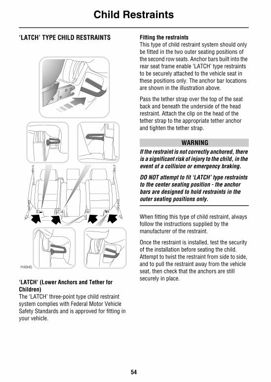
‘LATCH’ TYPE CHILD RESTRAINTS
‘LATCH’ (Lower Anchors and Tether for Children)The ‘LATCH’ three-point type child restraint system complies with Federal Motor Vehicle Safety Standards and is approved for fitting in your vehicle.
Fitting the restraintsThis type of child restraint system should only be fitted in the two outer seating positions of the second row seats. Anchor bars built into the rear seat frame enable ‘LATCH’ type restraints to be securely attached to the vehicle seat in these positions only. The anchor bar locations are shown in the illustration above.
Pass the tether strap over the top of the seat back and beneath the underside of the head restraint. Attach the clip on the head of the tether strap to the appropriate tether anchor and tighten the tether strap.
WARNINGIf the restraint is not correctly anchored, there is a significant risk of injury to the child, in the event of a collision or emergency braking.
DO NOT attempt to fit ‘LATCH’ type restraints to the center seating position - the anchor bars are designed to hold restraints in the outer seating positions only.
When fitting this type of child restraint, always follow the instructions supplied by the manufacturer of the restraint.
Once the restraint is installed, test the security of the installation before seating the child. Attempt to twist the restraint from side to side, and to pull the restraint away from the vehicle seat, then check that the anchors are still securely in place.
H4945
Child Restraints
55
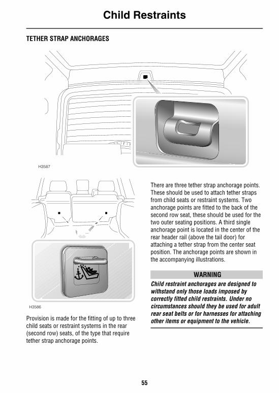
TETHER STRAP ANCHORAGES
Provision is made for the fitting of up to three child seats or restraint systems in the rear (second row) seats, of the type that require tether strap anchorage points.
There are three tether strap anchorage points. These should be used to attach tether straps from child seats or restraint systems. Two anchorage points are fitted to the back of the second row seat, these should be used for the two outer seating positions. A third single anchorage point is located in the center of the rear header rail (above the tail door) for attaching a tether strap from the center seat position. The anchorage points are shown in the accompanying illustrations.
WARNINGChild restraint anchorages are designed to withstand only those loads imposed by correctly fitted child restraints. Under no circumstances should they be used for adult rear seat belts or for harnesses for attaching other items or equipment to the vehicle.
H3587
H3586
Child Restraints
56
Attaching tether straps1. Install the child restraint securely in one of
the second row seating positions.2. Pass the tether strap over the back of the
vehicle seat and beneath the underside of the head restraint.
3. Attach the clip on the head of the tether strap to the tether anchor on the back of the vehicle seat (or, for the center seating position, on the header rail above the taildoor).
4. Tighten the tether strap according to the manufacturer’s instructions to remove any slack in the webbing.
WARNING• Always follow the child seat or restraint
system manufacturer’s instructions when fitting tether straps.
• When fitting a child seat or restraint system, always pass the tether strap over the top of the seat back and beneath the underside of the head restraint.
• If a child seat or restraint system is to be fitted to the center seating position, the center armrest must be in the stowed position (folded into the seat).
Airbag SRS
57
Airbag SRS
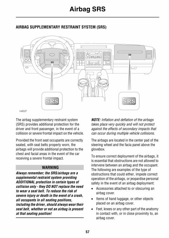
AIRBAG SUPPLEMENTARY RESTRAINT SYSTEM (SRS)
The airbag supplementary restraint system (SRS) provides additional protection for the driver and front passenger, in the event of a collision or severe frontal impact on the vehicle.
Provided the front seat occupants are correctly seated, with seat belts properly worn, the airbags will provide additional protection to the chest and facial areas in the event of the car receiving a severe frontal impact.
WARNINGAlways remember; the SRS/airbags are a supplemental restraint system providing ADDITIONAL protection in certain types of collision only - they DO NOT replace the need to wear a seat belt. To reduce the risk of severe injury or death in the event of a crash, all occupants in all seating positions, including the driver, should always wear their seat belt, whether or not an airbag is present at that seating position!
NOTE: Inflation and deflation of the airbags takes place very quickly and will not protect against the effects of secondary impacts that can occur during multiple vehicle collisions.
The airbags are located in the center pad of the steering wheel and the facia panel above the glovebox.
To ensure correct deployment of the airbags, it is essential that obstructions are not allowed to intervene between an airbag and the occupant. The following are examples of the type of obstructions that could either, impede correct operation of the airbags, or jeopardise personal safety in the event of an airbag deployment:• Accessories attached to or obscuring an
airbag cover.
• Items of hand luggage, or other objects placed on an airbag cover.
• Feet, knees or any other part of the anatomy in contact with, or in close proximity to, an airbag cover.
H4537
Airbag SRS
58
WARNINGFollowing inflation, some SRS/airbag components are hot - DO NOT touch until they have cooled.
Even with SRS/airbag equipment fitted, seat belts must ALWAYS be worn because:• An airbag will only provide additional
protection in certain types of frontal collisions. NO protection is afforded against the effects of side or rear impacts, roll over accidents, or minor frontal impacts.
• Inflation and deflation take place instantaneously and will not provide protection against the effects of secondary impacts that can occur during multiple vehicle collisions.
WARNINGThe airbag module inflates with considerable speed and force. For your safety:
An inflating airbag can cause facial abrasions and other injuries. The injurious effects of airbag inflation can be reduced, by ensuring driver and passenger are seated correctly, with the seat moved back as far as is practical, and the seat belts worn correctly.
National Highway Traffic Safety Administration (NHTSA) recommends a minimum distance of 10 inches (25 cm) between an occupant’s chest and the driver’s air bag module.
NEVER attach accessory items to an airbag module cover, or place items of hand luggage or any objects on the top of a module cover; these could interfere with the inflation of the airbag, or if the airbag inflates, be propelled inside the vehicle causing injury or death to the occupants.
DO NOT allow occupants to obstruct the operation of the airbag modules by placing their feet, knees or any part of their person in contact with, or close to, an airbag module whilst the vehicle is moving.
When an airbag inflates, a fine powder is released. This is not an indication of a malfunction. However, the powder may cause irritation to the skin and should be thoroughly flushed from the eyes and any cuts or abrasions of the skin.
Both front seating positions are equipped with knee bolsters to provide knee protection in the event of an impact. DO NOT modify the bolsters, or mount after market equipment on or behind them.
Airbag SRS
59
Seating positionsIn order to provide optimum protection in the event of a severe frontal impact, it is necessary for the airbags to deploy with considerable speed.
An inflating airbag can cause facial abrasions and other injuries if the occupant is too close to the airbag at the time of its deployment.
WARNING• To reduce the risk of accidental injury from
inflating airbags, seat belts should be correctly worn at all times. In addition, both driver and front seat passenger should adjust their seat to provide the maximum practical distance from the airbags.
• Occupants not seated correctly in allocated seats are subject to serious injury or death upon airbag deployment.
• Never place your arm over an airbag module as a deploying air bag can result in serious arm fractures or other injuries.
HOW THE AIRBAG SRS WORKSIn the event of a severe frontal impact, the airbag control unit monitors the rate of deceleration or acceleration induced by the collision, to determine whether the airbags should be deployed.
Operation of the airbag SRS is dependent entirely on the rate at which the vehicle's passenger compartment changes speed as a result of a collision. The circumstances affecting different collisions (vehicle speed, angle of impact, type and size of object hit, for example), vary considerably and will affect the rate of acceleration or deceleration accordingly.
NOTE: The SRS/airbag is not designed to activate in all frontal impacts; most minor frontal impacts, heavy braking and driving over pot holes will not result in sufficient deceleration to cause the airbags to inflate. This does not indicate that there is a fault with the system. However, if as a result of an impact, you believe the airbags should have deployed and they failed to do so, please call 1(800)637-6837 for advice, or to arrange for a Land Rover representative to inspect the vehicle to determine whether the system operated correctly.
It follows, therefore, that significant superficial damage can occur without the airbags deploying or, conversely, that a relatively small amount of structural damage may cause the airbags to be deployed.
Airbags will only deploy when they are required to supplement the restraining force of the seat belts.
In the case of a severe frontal collision, both front airbags and seat belt pre-tensioners will be deployed.
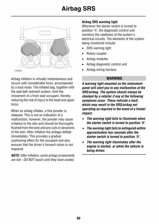
Airbag SRS
60
Airbag inflation is virtually instantaneous and occurs with considerable force, accompanied by a loud noise. The inflated bag, together with the seat belt restraint system, limit the movement of a front seat occupant, thereby reducing the risk of injury to the head and upper torso.
When an airbag inflates, a fine powder is released. This is not an indication of a malfunction, however, the powder may cause irritation to the skin and should be thoroughly flushed from the eyes and any cuts or abrasions of the skin. After inflation the airbags deflate immediately. This provides a gradual cushioning effect for the occupant and also ensures that the driver's forward vision is not impaired.
NOTE: After inflation, some airbag components are hot - DO NOT touch until they have cooled.
Airbag SRS warning lightWhenever the starter switch is turned to position ‘II’, the diagnostic control unit monitors the readiness of the system's electrical circuits. The elements of the system being monitored include:• SRS warning light
• Rotary coupler
• Airbag modules• Airbag diagnostic control unit
• Airbag wiring harness
WARNINGA warning light mounted on the instrument panel will alert you to any malfunction of the SRS/airbag. The system should always be checked by a retailer if any of the following symptoms occur. These indicate a fault, which may result in the SRS/airbag not operating as required in the event of a frontal impact.• The warning light fails to illuminate when
the starter switch is turned to position ‘II’.
• The warning light fails to extinguish within approximately four seconds after the starter switch is turned to position ‘II’.
• The warning light illuminates after the engine is started, or while the vehicle is being driven.
H4939
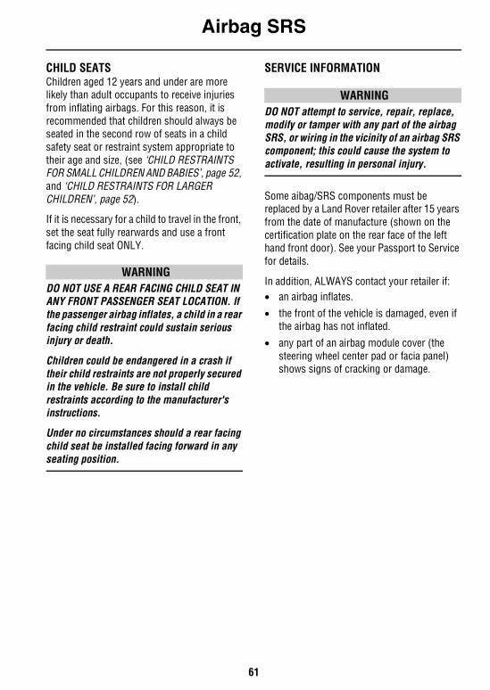
Airbag SRS
61
CHILD SEATSChildren aged 12 years and under are more likely than adult occupants to receive injuries from inflating airbags. For this reason, it is recommended that children should always be seated in the second row of seats in a child safety seat or restraint system appropriate to their age and size, (see ‘CHILD RESTRAINTS FOR SMALL CHILDREN AND BABIES’, page 52, and ‘CHILD RESTRAINTS FOR LARGER CHILDREN’, page 52).
If it is necessary for a child to travel in the front, set the seat fully rearwards and use a front facing child seat ONLY.
WARNINGDO NOT USE A REAR FACING CHILD SEAT IN ANY FRONT PASSENGER SEAT LOCATION. If the passenger airbag inflates, a child in a rear facing child restraint could sustain serious injury or death.
Children could be endangered in a crash if their child restraints are not properly secured in the vehicle. Be sure to install child restraints according to the manufacturer's instructions.
Under no circumstances should a rear facing child seat be installed facing forward in any seating position.
SERVICE INFORMATION
WARNINGDO NOT attempt to service, repair, replace, modify or tamper with any part of the airbag SRS, or wiring in the vicinity of an airbag SRS component; this could cause the system to activate, resulting in personal injury.
Some aibag/SRS components must be replaced by a Land Rover retailer after 15 years from the date of manufacture (shown on the certification plate on the rear face of the left hand front door). See your Passport to Service for details.
In addition, ALWAYS contact your retailer if: • an airbag inflates.
• the front of the vehicle is damaged, even if the airbag has not inflated.
• any part of an airbag module cover (the steering wheel center pad or facia panel) shows signs of cracking or damage.
Airbag SRS
62
Disposing of vehiclesIf you sell your vehicle, be sure to inform the new owner that the vehicle has an SRS/airbag system, and make the new owner aware of the airbag module replacement date shown in the Passport to Service.
If the vehicle is to be scrapped; uninflated airbags are potentially very dangerous and must be safely deployed in a controlled environment before a vehicle is scrapped.
See your Land Rover retailer for advice on safe deployment of SRS/airbags.
IMPORTANT INFORMATION
The components that make up the airbag SRS are sensitive to electrical or physical interference, either of which could easily damage the system and cause inadvertent operation or a malfunction of the airbag.
For your safety it is recommended that you seek the assistance of a Land Rover retailer to carry out any of the following:• Removal or repair of any wiring or
component in the vicinity of any of the SRS components (yellow wiring harness), including the steering wheel, steering column, instrument and facia panels.
• Installation of electronic equipment such as a mobile phone, two-way radio or in-car entertainment system.
• Modification to the front of the vehicle, including the bumper and chassis.
• Attachment of accessories to the front of the vehicle such as a winch or brushbar.
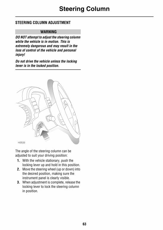
Steering Column
63
Steering ColumnSTEERING COLUMN ADJUSTMENT
WARNINGDO NOT attempt to adjust the steering column while the vehicle is in motion. This is extremely dangerous and may result in the loss of control of the vehicle and personal injury!
Do not drive the vehicle unless the locking lever is in the locked position.
The angle of the steering column can be adjusted to suit your driving position:
1. With the vehicle stationary, push the locking lever up and hold in this position.
2. Move the steering wheel (up or down) into the desired position, making sure the instrument panel is clearly visible.
3. When adjustment is complete, release the locking lever to lock the steering column in position.
H2533
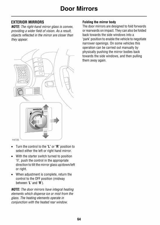
Door Mirrors
64
Door MirrorsEXTERIOR MIRRORSNOTE: The right-hand mirror glass is convex, providing a wider field of vision. As a result, objects reflected in the mirror are closer than they appear.
• Turn the control to the ‘L’ or ‘R’ position to select either the left or right hand mirror.
• With the starter switch turned to position ‘II’, push the control in the appropriate direction to tilt the mirror glass up/down/left or right.
• When adjustment is complete, return the control to the OFF position (midway between ‘L’ and ‘R’).
NOTE: The door mirrors have integral heating elements which disperse ice or mist from the glass. The heating elements operate in conjunction with the heated rear window.
Folding the mirror bodyThe door mirrors are designed to fold forwards or rearwards on impact. They can also be folded back towards the side windows into a‘park’ position to enable the vehicle to negotiate narrower openings. On some vehicles this operation can be carried out manually by physically pushing the mirror bodies back towards the side windows, and then pulling them away again.
H4725
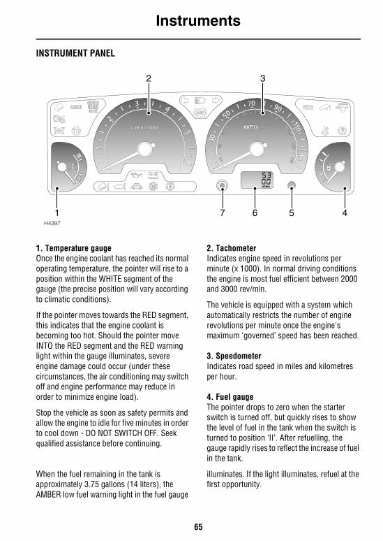
Instruments
65
InstrumentsINSTRUMENT PANEL
1. Temperature gaugeOnce the engine coolant has reached its normal operating temperature, the pointer will rise to a position within the WHITE segment of the gauge (the precise position will vary according to climatic conditions).
If the pointer moves towards the RED segment, this indicates that the engine coolant is becoming too hot. Should the pointer move INTO the RED segment and the RED warning light within the gauge illuminates, severe engine damage could occur (under these circumstances, the air conditioning may switch off and engine performance may reduce in order to minimize engine load).
Stop the vehicle as soon as safety permits and allow the engine to idle for five minutes in order to cool down - DO NOT SWITCH OFF. Seek qualified assistance before continuing.
2. TachometerIndicates engine speed in revolutions per minute (x 1000). In normal driving conditions the engine is most fuel efficient between 2000 and 3000 rev/min.
The vehicle is equipped with a system which automatically restricts the number of engine revolutions per minute once the engine's maximum ‘governed’ speed has been reached.
3. SpeedometerIndicates road speed in miles and kilometres per hour.
4. Fuel gaugeThe pointer drops to zero when the starter switch is turned off, but quickly rises to show the level of fuel in the tank when the switch is turned to position ‘II’. After refuelling, the gauge rapidly rises to reflect the increase of fuel in the tank.
When the fuel remaining in the tank is approximately 3.75 gallons (14 liters), the AMBER low fuel warning light in the fuel gauge
illuminates. If the light illuminates, refuel at the first opportunity.
H4397
2 3
1 6 5 47
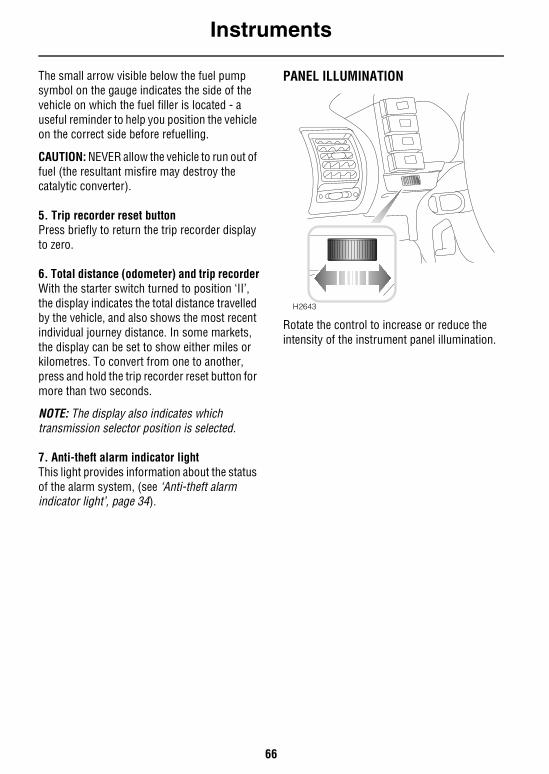
Instruments
66
The small arrow visible below the fuel pump symbol on the gauge indicates the side of the vehicle on which the fuel filler is located - a useful reminder to help you position the vehicle on the correct side before refuelling.
CAUTION: NEVER allow the vehicle to run out of fuel (the resultant misfire may destroy the catalytic converter).
5. Trip recorder reset buttonPress briefly to return the trip recorder display to zero.
6. Total distance (odometer) and trip recorderWith the starter switch turned to position ‘II’, the display indicates the total distance travelled by the vehicle, and also shows the most recent individual journey distance. In some markets, the display can be set to show either miles or kilometres. To convert from one to another, press and hold the trip recorder reset button for more than two seconds.
NOTE: The display also indicates which transmission selector position is selected.
7. Anti-theft alarm indicator lightThis light provides information about the status of the alarm system, (see ‘Anti-theft alarm indicator light’, page 34).
PANEL ILLUMINATION
Rotate the control to increase or reduce the intensity of the instrument panel illumination.
H2643
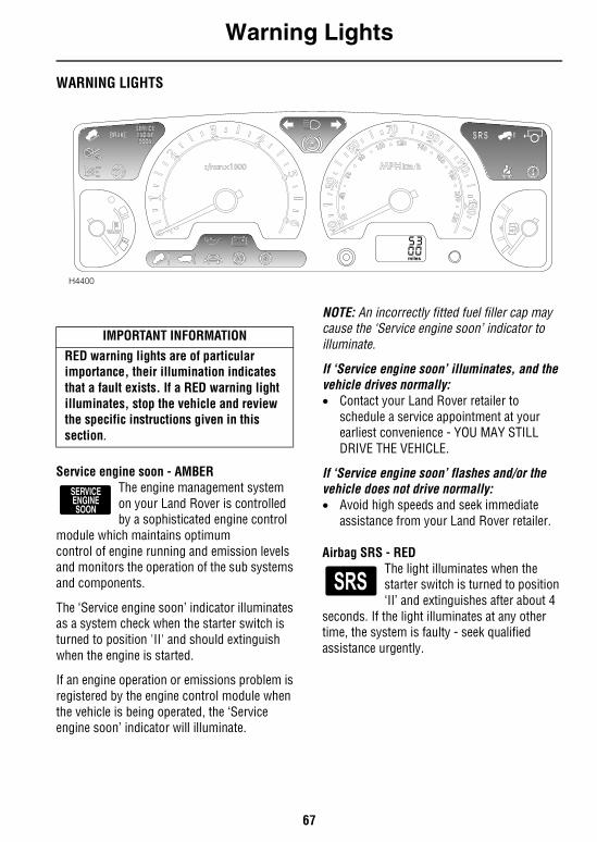
Warning Lights
67
Warning LightsWARNING LIGHTS
Service engine soon - AMBERThe engine management system on your Land Rover is controlled by a sophisticated engine control
module which maintains optimum control of engine running and emission levels and monitors the operation of the sub systems and components.
The ‘Service engine soon’ indicator illuminates as a system check when the starter switch is turned to position 'II' and should extinguish when the engine is started.
If an engine operation or emissions problem is registered by the engine control module when the vehicle is being operated, the ‘Service engine soon’ indicator will illuminate.
NOTE: An incorrectly fitted fuel filler cap may cause the ‘Service engine soon’ indicator to illuminate.
If ‘Service engine soon’ illuminates, and the vehicle drives normally:• Contact your Land Rover retailer to
schedule a service appointment at your earliest convenience - YOU MAY STILL DRIVE THE VEHICLE.
If ‘Service engine soon’ flashes and/or the vehicle does not drive normally:• Avoid high speeds and seek immediate
assistance from your Land Rover retailer.
Airbag SRS - RED The light illuminates when the starter switch is turned to position ‘II’ and extinguishes after about 4
seconds. If the light illuminates at any other time, the system is faulty - seek qualified assistance urgently.
H4400
IMPORTANT INFORMATION
RED warning lights are of particular importance, their illumination indicates that a fault exists. If a RED warning light illuminates, stop the vehicle and review the specific instructions given in this section.
Warning Lights
68
Parking brake, brake fluid - REDThe light illuminates for about 3 seconds as a bulb check when the starter switch is turned on. It also
illuminates when the parking brake is applied with the starter switch in position ‘II’.
The light should extinguish when the parking brake is fully released or shortly after the electrical circuits are switched on. If the light illuminates whilst driving, a fault with the braking system is indicated. Stop the vehicle as soon as safety permits and seek qualified assistance before continuing.
WARNINGDo not drive the vehicle while the brake warning light is illuminated.
Low oil pressure - RED The light illuminates as a bulb check when the starter switch isturned to position ‘II’ and
extinguishes when the engine is started. If the light remains on, flashes on and off, or illuminates whilst driving, stop the vehicle as soon as safety permits and SWITCH OFFTHE ENGINE IMMEDIATELY. Seek qualified assistance before driving. Always check the oil level when this light illuminates.
CAUTION: Do not drive the vehicle while the low oil pressure light is illuminated.
Transmission oil temperature - RED*Illuminates as a bulb check when the starter switch is turned to position ‘II’ and extinguishes after
3 seconds approx. If the light illuminates while driving, the gearbox oil temperature is too high (most likely to occur in very hot weather during continuous high speed driving, or whilst towing heavy loads on steep inclines or if the parking brake has been applied while driving).
If the light illuminates, reduce speed. If the light remains on, stop the vehicle and allow the gearbox to cool. Do not drive until the light has extinguished. (Depending on the ambient temperature and the carrying loads imposed on the vehicle, it may take several minutes before the light extinguishes and it is safe to drive).
Anti-lock braking system - AMBERThe light illuminates as a bulb and system check when the starter switch is turned to position ‘II’. If
the light illuminates whilst driving or remains illuminated after the starter switch is turned on, a fault has occurred. This means that full ABS control may not be available and you should seek qualified assistance urgently.
NOTE: Faults which cause the ABS light to illuminate after the initial system checks, or whilst driving, will be accompanied by a warning chime sounding 3 times.
Three warning chimes may also be heard during engine start-up as part of the ABS system self-checks. This is normal unless the ABS warning light stays illuminated after the engine is running.
WARNINGDrive with extreme caution if the warning light is illuminated - ABS may not be working!
BRAKE
Warning Lights
69
Headlight high beam - BLUEIlluminates when the headlights are switched to main beam.
Direction indicators - GREEN The left or right warning light flashes in time with the corresponding left or right
direction indicator lights whenever they are operated. If the warning light fails to flash, or flashes very rapidly, this may indicate a bulb failure in one of the direction indicator lights.
If the hazard switch is pressed, both warning lights will flash in conjunction with the direction indicator lights.
Trailer direction indicators - GREENThe light illuminates briefly as a bulb check when the starter switch is turned to position ‘II’. If a trailer
is attached, the light illuminates in conjunction with the vehicle direction indicator lights to show that all trailer indicator lights are functioning correctly. In the event of a bulb failure on the trailer, the warning light remains off.
Seat belt - REDThe light illuminates when the starter switch is turned to position ‘II’ and extinguishes after
approximately 6 seconds, even if the driver's seat belt remains unfastened. Always fasten your seat belt before driving.
Battery charging - REDThe light illuminates as a bulb check when the starter switchis turned to position ‘II’ and
extinguishes once the engine is running. If it remains on, or illuminates whilst driving, a fault is indicated. Seek qualified assistance urgently.
Off Road - AMBER*Illuminates briefly as a bulb and system check when the starterswitch is turned to position ‘II’ and
then extinguishes.
If the off-road switch is pressed: The light flashes continually while the rear of the vehicle is either; rising to off-road height, or returning to standard ride height. The light illuminates constantly while the suspension remains at off-road height.
In addition, the light will flash if extended mode is induced.
Hill descent control (HDC) ‘information’ - GREEN
Illuminates briefly as a bulb and system check when the starter switch is turned to position 'II' and
also when HDC is selected.
If HDC is selected when Low Range gears are engaged the light will illuminate continuously indicating that HDC is active.
When HDC is selected and non-operating gears are engaged (i.e. High range), the light will flash to inform the driver that HDC is selected, but will not operate.
If the light starts to flash while HDC is active, normal functionality may cease and HDC ‘fade out’ may be induced (see ‘HILL DESCENT CONTROL’, page 138).
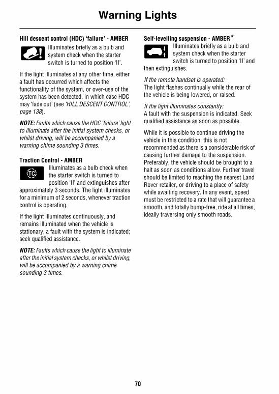
Warning Lights
70
Hill descent control (HDC) ‘failure’ - AMBERIlluminates briefly as a bulb and system check when the starter switch is turned to position ‘II’.
If the light illuminates at any other time, either a fault has occurred which affects the functionality of the system, or over-use of the system has been detected, in which case HDC may ‘fade out’ (see ‘HILL DESCENT CONTROL’, page 138).
NOTE: Faults which cause the HDC ‘failure’ light to illuminate after the initial system checks, or whilst driving, will be accompanied by a warning chime sounding 3 times.
Traction Control - AMBERIlluminates as a bulb check when the starter switch is turned to position ‘II’ and extinguishes after
approximately 3 seconds. The light illuminates for a minimum of 2 seconds, whenever traction control is operating.
If the light illuminates continuously, and remains illuminated when the vehicle is stationary, a fault with the system is indicated; seek qualified assistance.
NOTE: Faults which cause the light to illuminate after the initial system checks, or whilst driving, will be accompanied by a warning chime sounding 3 times.
Self-levelling suspension - AMBER*Illuminates briefly as a bulb and system check when the starterswitch is turned to position ‘II’ and
then extinguishes.
If the remote handset is operated: The light flashes continually while the rear of the vehicle is being lowered, or raised.
If the light illuminates constantly: A fault with the suspension is indicated. Seek qualified assistance as soon as possible.
While it is possible to continue driving the vehicle in this condition, this is not recommended as there is a considerable risk of causing further damage to the suspension. Preferably, the vehicle should be brought to a halt as soon as conditions allow. Further travel should be limited to reaching the nearest Land Rover retailer, or driving to a place of safety while awaiting recovery. In any event, speed must be restricted to a rate that will guarantee a smooth, and totally bump-free, ride at all times, ideally traversing only smooth roads.
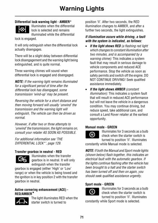
Warning Lights
71
Differential lock warning light - AMBER*Illuminates when the differential lock is selected and remains illuminated while the differential
lock is engaged.
It will only extinguish when the differential lock actually disengages.
There will be a slight delay between differential lock disengagement and the warning light being extinguished, and is quite normal.
Three warning chimes will sound when differential lock is engaged and disengaged.
NOTE: If the warning light remains illuminated for a significant period of time after the differential lock has disengaged, some transmission ‘wind-up’ may be present.
Reversing the vehicle for a short distance and then moving forward will usually ‘unwind’ the transmission and the warning light will extinguish, The vehicle can then be driven as normal.
However, if after two or three attempts to ‘unwind’ the transmission, the light remains on, consult your retailer AS SOON AS POSSIBLE.
For additional information see ‘THE DIFFERENTIAL LOCK*’, page 129.
Transfer gearbox in neutral - REDIlluminates when the transfer gearbox is in neutral. It will only extinguish when the transfer
gearbox is engaged (either ‘High’ or ‘Low’ range) or when the vehicle is being towed and the ignition is in key position 2 with the transfer gearbox in neutral.
Active cornering enhancement (ACE) - RED/AMBER*
The light illuminates RED when the starter switch is turned to
position ‘II’. After two seconds, the RED illumination changes to AMBER, and after a further two seconds, the light extinguishes.
If illumination occurs while driving, a fault with the system is indicated, as follows:• If the light shows RED (a flashing red light
which changes to constant illumination after two minutes, and is accompanied by a warning chime): This indicates a system fault that may result in serious damage to vehicle components and reduced ACE performance. Stop the vehicle as soon as safety permits and switch off the engine. DO NOT CONTINUE DRIVING! Seek qualified assistance immediately.
• If the light shows AMBER (constant illumination): This indicates a system fault that will result in reduced ACE performance but will not leave the vehicle in a dangerous condition. You may continue driving, but reduce speed, take additional care, and consult a Land Rover retailer at the earliest opportunity.
Manual mode - GREENIlluminates for 3 seconds as a bulb check when the starter switch is turned to position ‘II’. Illuminates
constantly while Manual mode is selected.
NOTE: If both the Manual and Sport mode lights (shown below) flash together, this indicates an electrical fault with the automatic gearbox. If the lights continue flashing after the vehicle has been brought to a halt and the starter switch has been turned off and then on again, you should seek qualified assistance urgently.
Sport mode - GREENIlluminates for 3 seconds as a bulb check when the starter switch is turned to position ‘II’. Illuminates
constantly while Sport mode is selected.
Audible Warnings
72
Audible WarningsAUDIBLE WARNINGSLights on reminderIf the lights are left on after the starter switch is turned off, a warning chime will sound when the driver's door is opened. The chime will cease as soon as the lights are switched off or when the driver's door is closed.
Transfer gearbox in neutral reminderA warning will chime continuously while the transfer gearbox is in neutral.
Self-levelling suspension warning• A single warning will chime whenever the
off-road switch is operated to raise the vehicle to off-road height, or to return it to standard ride height.
• A warning will chime continuously while the remote handset is used to lower the vehicle from standard ride height, and also while returning the vehicle to standard ride height.
• A warning chime will sound 3 times if changes to or from off-road height are requested but not permitted.
ABS warningIf a fault with the anti-lock braking system is detected, a warning will chime three times and the warning light will be illuminated. You may continue driving, but should understand that full ABS control may not be available. Consult your retailerretailer at the earliest opportunity.
Three warnings may also be heard during engine start-up as part of the ABS system self-checks. This is normal unless the ABS warning light stays illuminated after the engine is running.
ACE warningA single warning will chime if a fault with the active cornering enhancement system is detected. The chime will coincide with the ACE warning light flashing RED.
HDC warnings• A warning will chime continuously in
conjunction with the HDC warning light flashing green, whenever HDC has been selected but the system's operating criteria have not been met.
• A warning will chime continuously and the HDC failure warning light will illuminate (amber), whenever a fault is detected with the HDC system.
• A single warning will chime when HDC is deselected.
Starter key reminder If the key is left in the starter switch while the driver's door is open, a warning will chime continuously. The chime stops as soon as the door is closed or the key is removed from the starter switch.
Seat belt reminderIf the driver's seat belt has not been fastened when the starter switch is turned on, a warning chime will sound (one second frequency). The chime operates in conjunction with the seat belt warning light and sounds for 6 seconds, or until the seat belt is fastened (whichever occurs first).
Differential lockThree warning chimes will be heard when differential lock is engaged or disengaged.
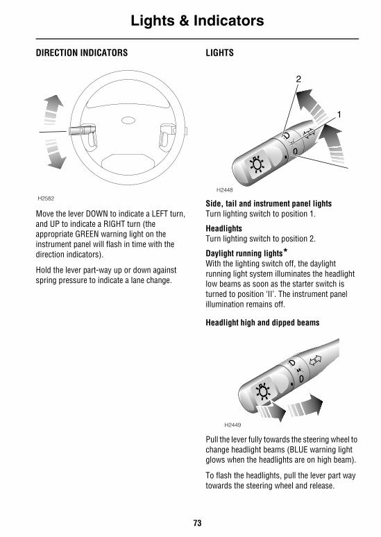
Lights & Indicators
73
Lights & IndicatorsDIRECTION INDICATORS
Move the lever DOWN to indicate a LEFT turn, and UP to indicate a RIGHT turn (the appropriate GREEN warning light on the instrument panel will flash in time with the direction indicators).
Hold the lever part-way up or down against spring pressure to indicate a lane change.
LIGHTS
Side, tail and instrument panel lightsTurn lighting switch to position 1.
HeadlightsTurn lighting switch to position 2.
Daylight running lights*With the lighting switch off, the daylight running light system illuminates the headlight low beams as soon as the starter switch is turned to position ‘II’. The instrument panel illumination remains off.
Headlight high and dipped beams
Pull the lever fully towards the steering wheel to change headlight beams (BLUE warning light glows when the headlights are on high beam).
To flash the headlights, pull the lever part way towards the steering wheel and release.
H2582
H2448
2
1
H2449
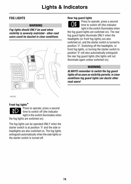
Lights & Indicators
74
FOG LIGHTS
WARNINGFog lights should ONLY be used when visibility is severely restricted - other road users could be dazzled in clear conditions.
Front fog lights*Press to operate, press a second time to switch off (the indicator light in the switch illuminates when
the fog lights are switched on).
The fog lights can be operated ONLY when the starter switch is at position ‘II’ and the side or headlights are also switched on. The fog lights extinguish automatically when the side lights or the starter switch is turned off.
Rear fog guard lightsPress to operate, press a second time to switch off (the indicator light in the switch illuminates when
the fog guard lights are switched on). The rear fog guard lights illuminate ONLY when the headlights (or front fog lights) are also switched on, and the starter switch is turned to position ‘II’. Switching off the headlights, or front fog lights, or turning the starter switch to position ‘0’ will also automatically extinguish the rear fog guard lights (the lights will not illuminate again unless switched on).
WARNINGALWAYS remember to switch the fog guard lights off as soon as visibility permits; in clear conditions fog guard lights can dazzle other road users!
H4732
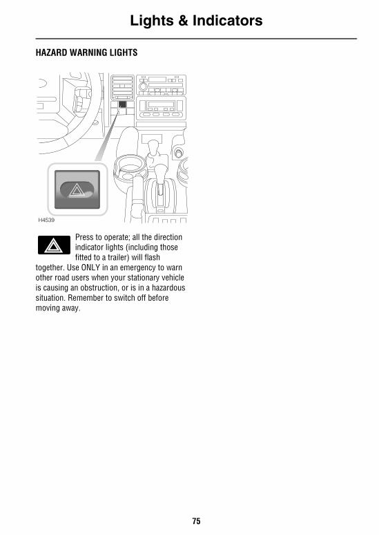
Lights & Indicators
75
HAZARD WARNING LIGHTS
Press to operate; all the direction indicator lights (including those fitted to a trailer) will flash
together. Use ONLY in an emergency to warn other road users when your stationary vehicle is causing an obstruction, or is in a hazardous situation. Remember to switch off before moving away.
H4539
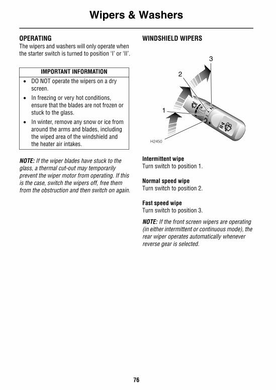
Wipers & Washers
76
Wipers & WashersOPERATINGThe wipers and washers will only operate when the starter switch is turned to position ‘I’ or ‘II’.
NOTE: If the wiper blades have stuck to the glass, a thermal cut-out may temporarily prevent the wiper motor from operating. If this is the case, switch the wipers off, free them from the obstruction and then switch on again.
WINDSHIELD WIPERS
Intermittent wipeTurn switch to position 1.
Normal speed wipeTurn switch to position 2.
Fast speed wipeTurn switch to position 3.
NOTE: If the front screen wipers are operating (in either intermittent or continuous mode), the rear wiper operates automatically whenever reverse gear is selected.
IMPORTANT INFORMATION
• DO NOT operate the wipers on a dry screen.
• In freezing or very hot conditions, ensure that the blades are not frozen or stuck to the glass.
• In winter, remove any snow or ice from around the arms and blades, including the wiped area of the windshield and the heater air intakes. H2450
1
2
3

Wipers & Washers
77
Single wipe
Pull the lever down and release immediately.
NOTE: With the lever held down, the wipers will operate at fast speed until the lever is released.
Variable delay (intermittent wipe)
Rotate the switch to vary the delay between wipes.
WINDSHIELD WASHER
Pull the lever towards the steering wheel. The windshield wipers will operate in conjunction with the washers for as long as the lever is held in this position, the wipers continuing for a further 4 seconds after the lever is released.
WARNINGIf you operate your vehicle in temperatures below 40 degrees F, use washer fluid with anti-freeze protection. In cold weather, failure to use washer fluid with anti-freeze protection could result in impaired windshield vision and increase the risk of a vehicle crash.
NOTE: State or local regulations may restrict the use of volatile organic compounds (VOC’s), which are commonly used as anti-freeze agents in washer fluid. A washer fluid with limited VOC content should be used only if it provides adequate freeze resistance for all regions and climates in which the vehicle will be operated.
For more information on Wipers and Washers, see ‘WINDSHIELD WASHER TOP-UP’, page 191 & ‘HEADLIGHT WASHERS’, page 191
H2583
H2451
H2452
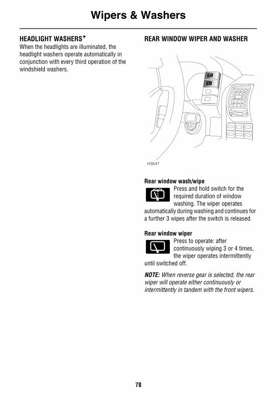
Wipers & Washers
78
HEADLIGHT WASHERS*When the headlights are illuminated, the headlight washers operate automatically in conjunction with every third operation of the windshield washers.
REAR WINDOW WIPER AND WASHER
Rear window wash/wipePress and hold switch for the required duration of window washing. The wiper operates
automatically during washing and continues for a further 3 wipes after the switch is released.
Rear window wiperPress to operate: after continuously wiping 3 or 4 times, the wiper operates intermittently
until switched off.
NOTE: When reverse gear is selected, the rear wiper will operate either continuously or intermittently in tandem with the front wipers.
H3547
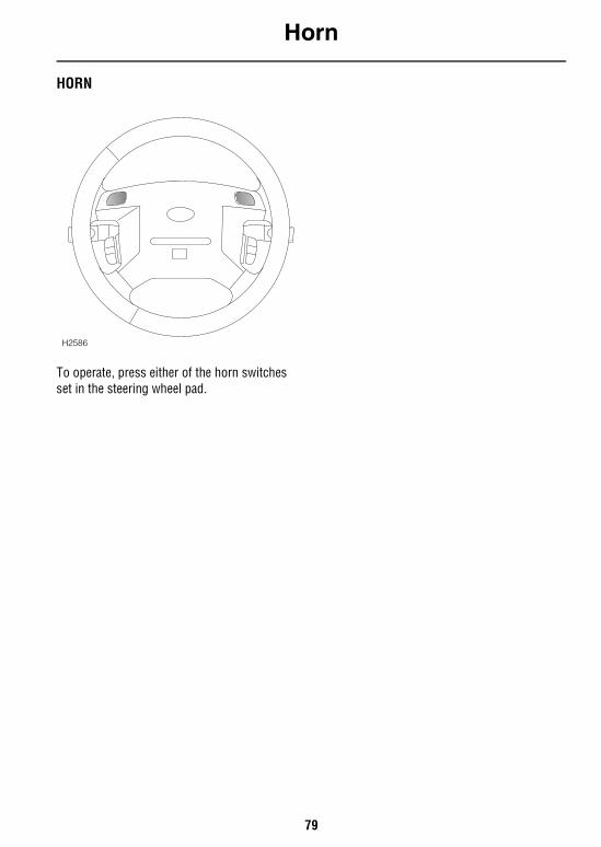
Horn
79
HornHORN
To operate, press either of the horn switches set in the steering wheel pad.
H2586
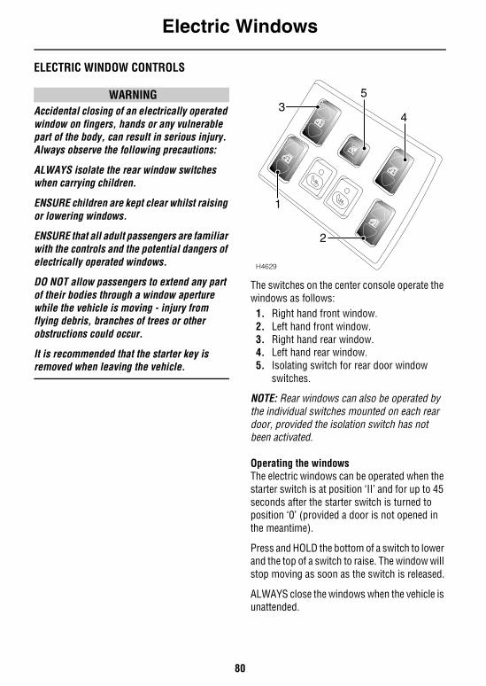
Electric Windows
80
Electric WindowsELECTRIC WINDOW CONTROLS
WARNINGAccidental closing of an electrically operated window on fingers, hands or any vulnerable part of the body, can result in serious injury. Always observe the following precautions:
ALWAYS isolate the rear window switches when carrying children.
ENSURE children are kept clear whilst raising or lowering windows.
ENSURE that all adult passengers are familiar with the controls and the potential dangers of electrically operated windows.
DO NOT allow passengers to extend any part of their bodies through a window aperture while the vehicle is moving - injury from flying debris, branches of trees or other obstructions could occur.
It is recommended that the starter key is removed when leaving the vehicle.
The switches on the center console operate the windows as follows:
1. Right hand front window.2. Left hand front window.3. Right hand rear window.4. Left hand rear window.5. Isolating switch for rear door window
switches.
NOTE: Rear windows can also be operated by the individual switches mounted on each rear door, provided the isolation switch has not been activated.
Operating the windowsThe electric windows can be operated when the starter switch is at position ‘II’ and for up to 45 seconds after the starter switch is turned to position ‘0’ (provided a door is not opened in the meantime).
Press and HOLD the bottom of a switch to lower and the top of a switch to raise. The window will stop moving as soon as the switch is released.
ALWAYS close the windows when the vehicle is unattended.
H4629
5
4
2
1
3
Electric Windows
81
NOTE: ENSURE that all adult passengers are familiar with the controls and the potential dangers of electrically operated windows.
‘One touch’ down (Front windows only) By briefly pressing (and then releasing) thebottom of a switch, a front window will open fully at a single touch. Window movement can be stopped at any time by BRIEFLY pressing the top of the switch.
Rear window isolation switchPress once to isolate the window switches in the rear door; press a second time to restore independent control.
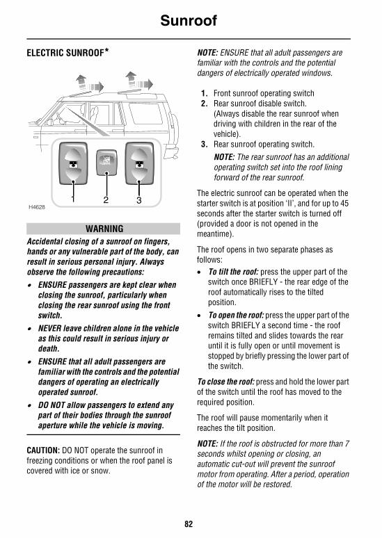
Sunroof
82
SunroofELECTRIC SUNROOF*
WARNINGAccidental closing of a sunroof on fingers, hands or any vulnerable part of the body, can result in serious personal injury. Always observe the following precautions:• ENSURE passengers are kept clear when
closing the sunroof, particularly when closing the rear sunroof using the front switch.
• NEVER leave children alone in the vehicle as this could result in serious injury or death.
• ENSURE that all adult passengers are familiar with the controls and the potential dangers of operating an electrically operated sunroof.
• DO NOT allow passengers to extend any part of their bodies through the sunroof aperture while the vehicle is moving.
CAUTION: DO NOT operate the sunroof in freezing conditions or when the roof panel is covered with ice or snow.
NOTE: ENSURE that all adult passengers are familiar with the controls and the potential dangers of electrically operated windows.
1. Front sunroof operating switch2. Rear sunroof disable switch.
(Always disable the rear sunroof when driving with children in the rear of the vehicle).
3. Rear sunroof operating switch.NOTE: The rear sunroof has an additional operating switch set into the roof lining forward of the rear sunroof.
The electric sunroof can be operated when the starter switch is at position ‘II’, and for up to 45 seconds after the starter switch is turned off (provided a door is not opened in the meantime).
The roof opens in two separate phases as follows:• To tilt the roof: press the upper part of the
switch once BRIEFLY - the rear edge of the roof automatically rises to the tilted position.
• To open the roof: press the upper part of the switch BRIEFLY a second time - the roof remains tilted and slides towards the rear until it is fully open or until movement is stopped by briefly pressing the lower part of the switch.
To close the roof: press and hold the lower part of the switch until the roof has moved to the required position.
The roof will pause momentarily when it reaches the tilt position.
NOTE: If the roof is obstructed for more than 7 seconds whilst opening or closing, an automatic cut-out will prevent the sunroof motor from operating. After a period, operation of the motor will be restored.
H46281 2 3
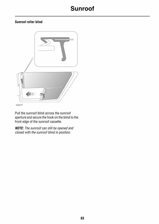
Sunroof
83
Sunroof roller blind
Pull the sunroof blind across the sunroof aperture and secure the hook on the blind to the front edge of the sunroof cassette.
NOTE: The sunroof can still be opened and closed with the sunroof blind in position.
H2477
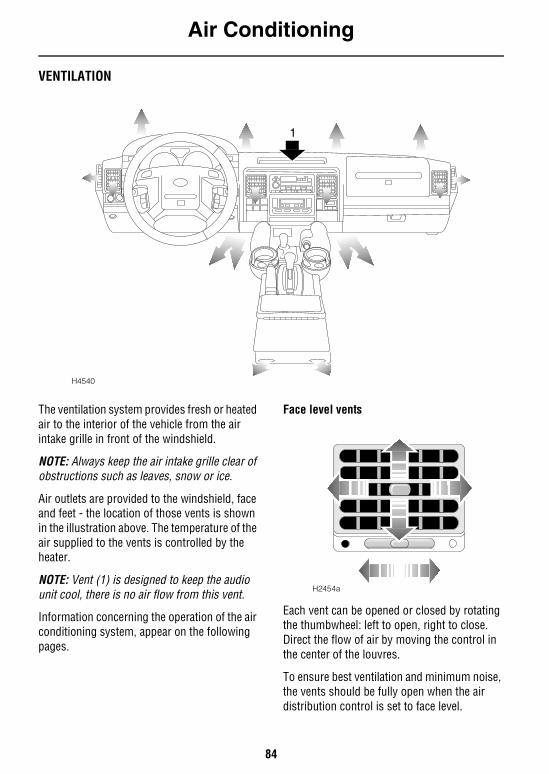
Air Conditioning
84
Air ConditioningVENTILATION
The ventilation system provides fresh or heated air to the interior of the vehicle from the air intake grille in front of the windshield.
NOTE: Always keep the air intake grille clear of obstructions such as leaves, snow or ice.
Air outlets are provided to the windshield, face and feet - the location of those vents is shown in the illustration above. The temperature of the air supplied to the vents is controlled by the heater.
NOTE: Vent (1) is designed to keep the audio unit cool, there is no air flow from this vent.
Information concerning the operation of the air conditioning system, appear on the following pages.
Face level vents
Each vent can be opened or closed by rotating the thumbwheel: left to open, right to close. Direct the flow of air by moving the control in the center of the louvres.
To ensure best ventilation and minimum noise, the vents should be fully open when the air distribution control is set to face level.
H4540
1
H2454a
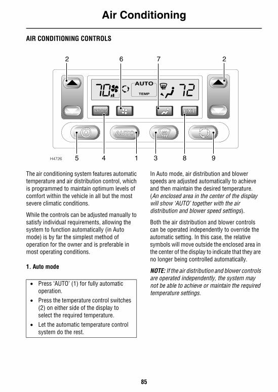
Air Conditioning
85
AIR CONDITIONING CONTROLS
The air conditioning system features automatic temperature and air distribution control, which is programmed to maintain optimum levels of comfort within the vehicle in all but the most severe climatic conditions.
While the controls can be adjusted manually to satisfy individual requirements, allowing the system to function automatically (in Auto mode) is by far the simplest method of operation for the owner and is preferable in most operating conditions.
1. Auto mode
In Auto mode, air distribution and blower speeds are adjusted automatically to achieve and then maintain the desired temperature. (An enclosed area in the center of the display will show ‘AUTO’ together with the air distribution and blower speed settings).
Both the air distribution and blower controls can be operated independently to override the automatic setting. In this case, the relative symbols will move outside the enclosed area in the center of the display to indicate that they are no longer being controlled automatically.
NOTE: If the air distribution and blower controls are operated independently, the system may not be able to achieve or maintain the required temperature settings.
H4726
TEMP
2762
983145
• Press ‘AUTO’ (1) for fully automatic operation.
• Press the temperature control switches (2) on either side of the display to select the required temperature.
• Let the automatic temperature control system do the rest.
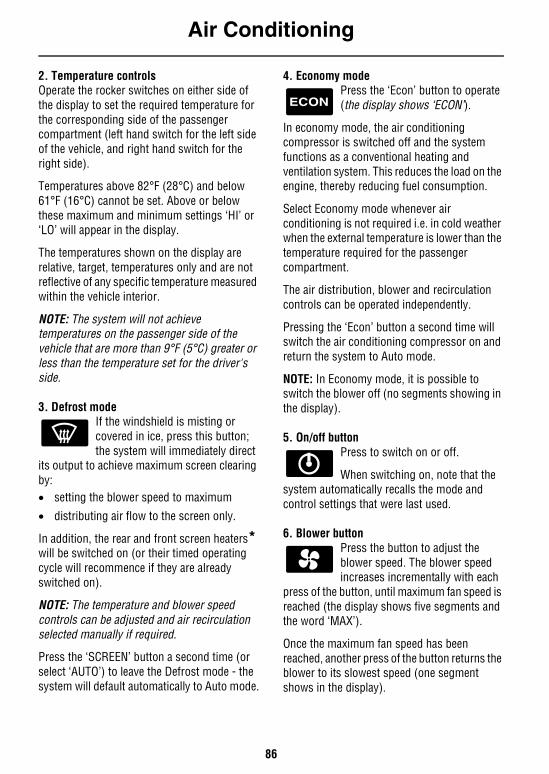
Air Conditioning
86
2. Temperature controls Operate the rocker switches on either side of the display to set the required temperature for the corresponding side of the passenger compartment (left hand switch for the left side of the vehicle, and right hand switch for the right side).
Temperatures above 82°F (28°C) and below 61°F (16°C) cannot be set. Above or below these maximum and minimum settings ‘HI’ or ‘LO’ will appear in the display.
The temperatures shown on the display are relative, target, temperatures only and are not reflective of any specific temperature measured within the vehicle interior.
NOTE: The system will not achieve temperatures on the passenger side of the vehicle that are more than 9°F (5°C) greater or less than the temperature set for the driver's side.
3. Defrost modeIf the windshield is misting or covered in ice, press this button; the system will immediately direct
its output to achieve maximum screen clearing by:• setting the blower speed to maximum
• distributing air flow to the screen only.
In addition, the rear and front screen heaters* will be switched on (or their timed operating cycle will recommence if they are already switched on).
NOTE: The temperature and blower speed controls can be adjusted and air recirculation selected manually if required.
Press the ‘SCREEN’ button a second time (or select ‘AUTO’) to leave the Defrost mode - the system will default automatically to Auto mode.
4. Economy modePress the ‘Econ’ button to operate (the display shows ‘ECON’).
In economy mode, the air conditioning compressor is switched off and the system functions as a conventional heating and ventilation system. This reduces the load on the engine, thereby reducing fuel consumption.
Select Economy mode whenever air conditioning is not required i.e. in cold weather when the external temperature is lower than the temperature required for the passenger compartment.
The air distribution, blower and recirculation controls can be operated independently.
Pressing the ‘Econ’ button a second time will switch the air conditioning compressor on and return the system to Auto mode.
NOTE: In Economy mode, it is possible to switch the blower off (no segments showing in the display).
5. On/off button Press to switch on or off.
When switching on, note that the system automatically recalls the mode and control settings that were last used.
6. Blower buttonPress the button to adjust the blower speed. The blower speed increases incrementally with each
press of the button, until maximum fan speed is reached (the display shows five segments and the word ‘MAX’).
Once the maximum fan speed has been reached, another press of the button returns the blower to its slowest speed (one segment shows in the display).
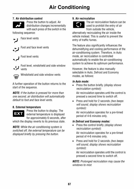
Air Conditioning
87
7. Air distribution controlPress the button to adjust. Air distribution changes incrementally with each press of the switch in the
following sequence:
Face level vents
Foot and face level vents
Foot level vents
Foot level, windshield and side window vents
Windshield and side window vents
A further operation of the button returns to the start of the sequence.
NOTE: If the button is pressed for more than one second, air distribution will automatically default to foot and face level vents.
8. External temperaturePress the button to display. The external temperature is displayed for approximately 6 seconds, after
which the display reverts to its previous state.
NOTE: While the air conditioning system is switched off, the external temperature can be displayed briefly by pressing the button.
9. Air recirculationThe air recirculation feature can be used to prohibit the entry of air from outside the vehicle,
alternatively recirculating the air inside the vehicle instead. This is useful to prevent the entry of traffic fumes.
The feature also significantly influences the dehumidifying and cooling performance of the air-conditioning system. Therefore, in Auto mode, air recirculation is controlled automatically to enable the air-conditioning system to achieve its optimum performance.
However, the feature is also manually selectable in Auto, Defrost and Economy modes, as follows:
In Auto mode:• Press the button briefly (display shows
recirculation symbol):Air recirculation operates until the control is pressed a second time to switch off.
• Press and hold for 2 seconds (two beeps will sound, display shows recirculation symbol):Air recirculation operates for a pre-timed period of 4-6 minutes only.
In Defrost and Economy modes: • Press the control briefly (display shows
recirculation symbol): Air recirculation operates for a pre-timed period of 4-6 minutes only.
• Press and hold for 2 seconds (two beeps will sound, display shows recirculation symbol):Air recirculation operates until the control is pressed a second time to switch off.
NOTE: Prolonged recirculation may cause the windows to mist.
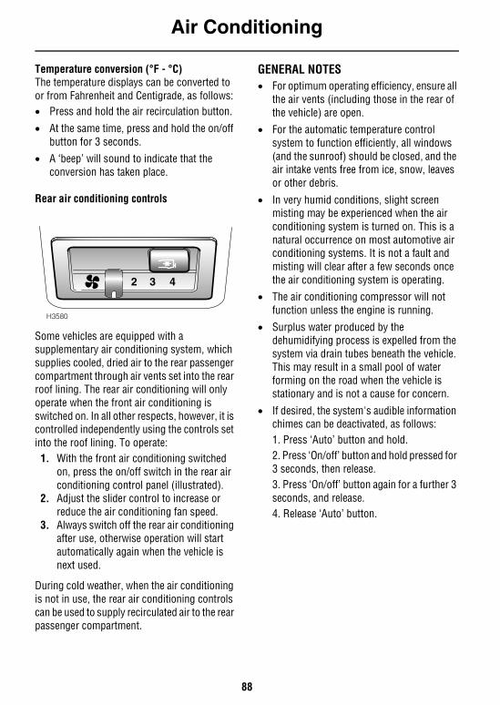
Air Conditioning
88
Temperature conversion (°F - °C)The temperature displays can be converted to or from Fahrenheit and Centigrade, as follows:• Press and hold the air recirculation button.
• At the same time, press and hold the on/off button for 3 seconds.
• A ‘beep’ will sound to indicate that the conversion has taken place.
Rear air conditioning controls
Some vehicles are equipped with a supplementary air conditioning system, which supplies cooled, dried air to the rear passenger compartment through air vents set into the rear roof lining. The rear air conditioning will only operate when the front air conditioning is switched on. In all other respects, however, it is controlled independently using the controls set into the roof lining. To operate:
1. With the front air conditioning switched on, press the on/off switch in the rear air conditioning control panel (illustrated).
2. Adjust the slider control to increase or reduce the air conditioning fan speed.
3. Always switch off the rear air conditioning after use, otherwise operation will start automatically again when the vehicle is next used.
During cold weather, when the air conditioning is not in use, the rear air conditioning controls can be used to supply recirculated air to the rear passenger compartment.
GENERAL NOTES• For optimum operating efficiency, ensure all
the air vents (including those in the rear of the vehicle) are open.
• For the automatic temperature control system to function efficiently, all windows (and the sunroof) should be closed, and the air intake vents free from ice, snow, leaves or other debris.
• In very humid conditions, slight screen misting may be experienced when the air conditioning system is turned on. This is a natural occurrence on most automotive air conditioning systems. It is not a fault and misting will clear after a few seconds once the air conditioning system is operating.
• The air conditioning compressor will not function unless the engine is running.
• Surplus water produced by the dehumidifying process is expelled from the system via drain tubes beneath the vehicle. This may result in a small pool of water forming on the road when the vehicle is stationary and is not a cause for concern.
• If desired, the system's audible information chimes can be deactivated, as follows:1. Press ‘Auto’ button and hold.2. Press ‘On/off’ button and hold pressed for 3 seconds, then release.3. Press ‘On/off’ button again for a further 3 seconds, and release.4. Release ‘Auto’ button.
2 43
H3580
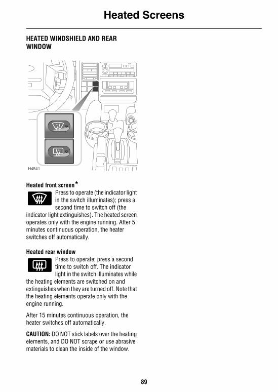
Heated Screens
89
Heated ScreensHEATED WINDSHIELD AND REAR WINDOW
Heated front screen*Press to operate (the indicator light in the switch illuminates); press a second time to switch off (the
indicator light extinguishes). The heated screen operates only with the engine running. After 5 minutes continuous operation, the heater switches off automatically.
Heated rear window Press to operate; press a second time to switch off. The indicator light in the switch illuminates while
the heating elements are switched on and extinguishes when they are turned off. Note that the heating elements operate only with the engine running.
After 15 minutes continuous operation, the heater switches off automatically.
CAUTION: DO NOT stick labels over the heating elements, and DO NOT scrape or use abrasive materials to clean the inside of the window.
H4541
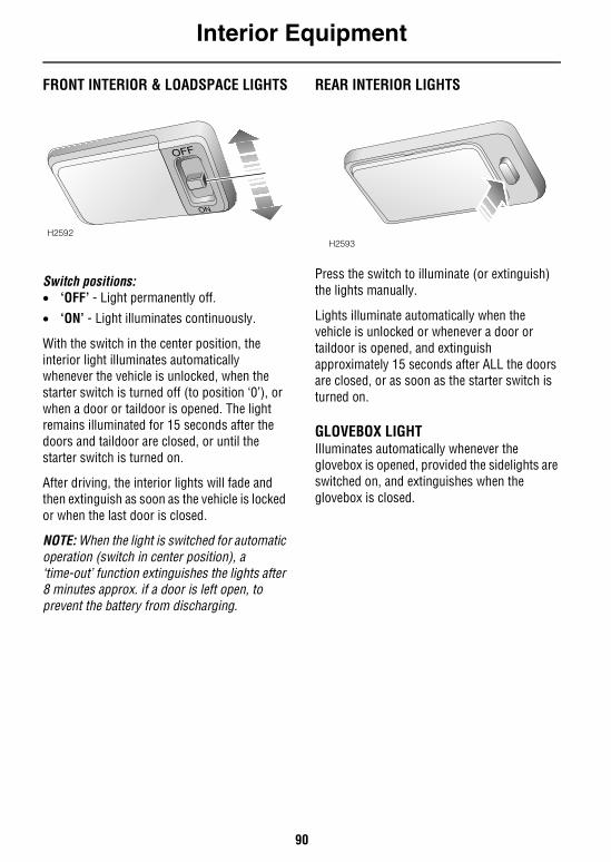
Interior Equipment
90
Interior EquipmentFRONT INTERIOR & LOADSPACE LIGHTS
Switch positions:• ‘OFF’ - Light permanently off.• ‘ON’ - Light illuminates continuously.
With the switch in the center position, the interior light illuminates automatically whenever the vehicle is unlocked, when the starter switch is turned off (to position ‘0’), or when a door or taildoor is opened. The light remains illuminated for 15 seconds after the doors and taildoor are closed, or until the starter switch is turned on.
After driving, the interior lights will fade and then extinguish as soon as the vehicle is locked or when the last door is closed.
NOTE: When the light is switched for automatic operation (switch in center position), a ‘time-out’ function extinguishes the lights after 8 minutes approx. if a door is left open, to prevent the battery from discharging.
REAR INTERIOR LIGHTS
Press the switch to illuminate (or extinguish) the lights manually.
Lights illuminate automatically when the vehicle is unlocked or whenever a door or taildoor is opened, and extinguish approximately 15 seconds after ALL the doors are closed, or as soon as the starter switch is turned on.
GLOVEBOX LIGHTIlluminates automatically whenever the glovebox is opened, provided the sidelights are switched on, and extinguishes when the glovebox is closed.
H2592
OFF
ON
H2593
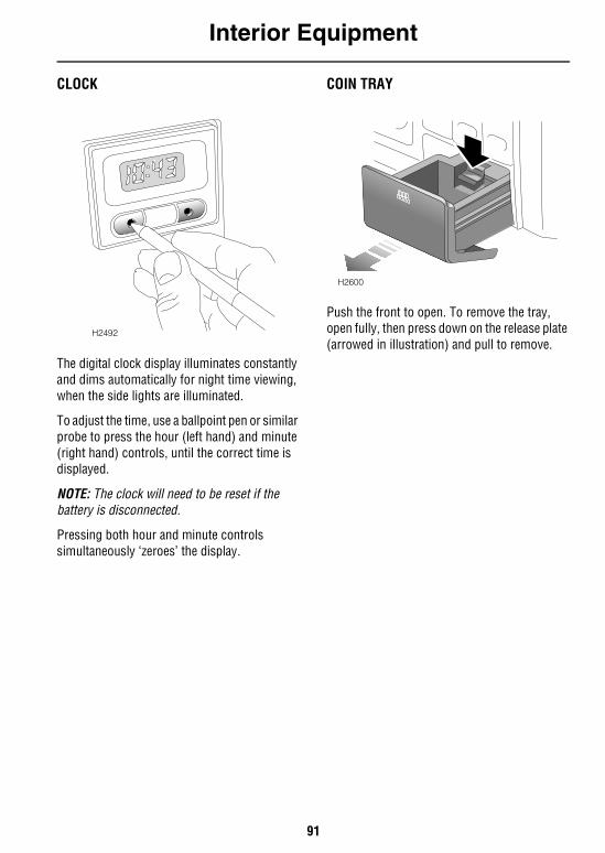
Interior Equipment
91
CLOCK
The digital clock display illuminates constantly and dims automatically for night time viewing, when the side lights are illuminated.
To adjust the time, use a ballpoint pen or similar probe to press the hour (left hand) and minute (right hand) controls, until the correct time is displayed.
NOTE: The clock will need to be reset if the battery is disconnected.
Pressing both hour and minute controls simultaneously ‘zeroes’ the display.
COIN TRAY
Push the front to open. To remove the tray, open fully, then press down on the release plate (arrowed in illustration) and pull to remove.
H2492
H2600
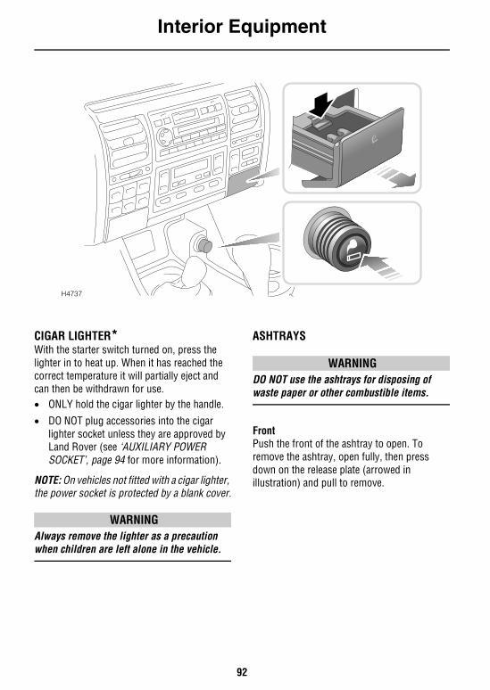
Interior Equipment
92
CIGAR LIGHTER*With the starter switch turned on, press the lighter in to heat up. When it has reached the correct temperature it will partially eject and can then be withdrawn for use.• ONLY hold the cigar lighter by the handle.
• DO NOT plug accessories into the cigar lighter socket unless they are approved by Land Rover (see ‘AUXILIARY POWER SOCKET’, page 94 for more information).
NOTE: On vehicles not fitted with a cigar lighter, the power socket is protected by a blank cover.
WARNINGAlways remove the lighter as a precaution when children are left alone in the vehicle.
ASHTRAYS
WARNINGDO NOT use the ashtrays for disposing of waste paper or other combustible items.
FrontPush the front of the ashtray to open. To remove the ashtray, open fully, then press down on the release plate (arrowed in illustration) and pull to remove.
H4737
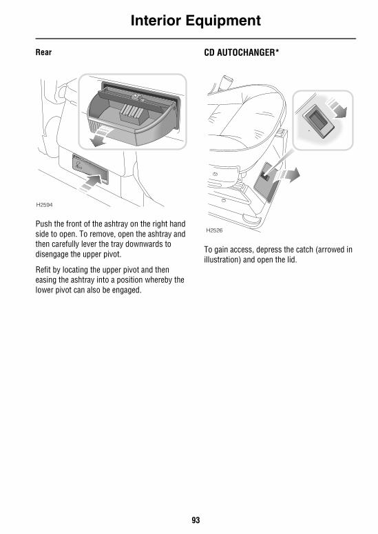
Interior Equipment
93
Rear
Push the front of the ashtray on the right hand side to open. To remove, open the ashtray and then carefully lever the tray downwards to disengage the upper pivot.
Refit by locating the upper pivot and then easing the ashtray into a position whereby the lower pivot can also be engaged.
CD AUTOCHANGER*
To gain access, depress the catch (arrowed in illustration) and open the lid.
H2594
H2526
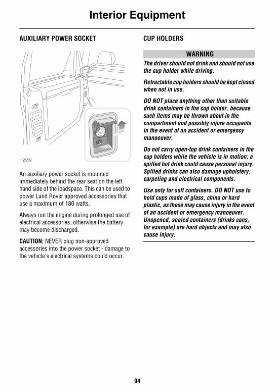
Interior Equipment
94
AUXILIARY POWER SOCKET
An auxiliary power socket is mounted immediately behind the rear seat on the left hand side of the loadspace. This can be used to power Land Rover approved accessories that use a maximum of 180 watts.
Always run the engine during prolonged use of electrical accessories, otherwise the battery may become discharged.
CAUTION: NEVER plug non-approved accessories into the power socket - damage to the vehicle's electrical systems could occur.
CUP HOLDERS
WARNINGThe driver should not drink and should not use the cup holder while driving.
Retractable cup holders should be kept closed when not in use.
DO NOT place anything other than suitable drink containers in the cup holder, because such items may be thrown about in the compartment and possibly injure occupants in the event of an accident or emergency manoeuver.
Do not carry open-top drink containers in the cup holders while the vehicle is in motion; a spilled hot drink could cause personal injury. Spilled drinks can also damage upholstery, carpeting and electrical components.
Use only for soft containers. DO NOT use to hold cups made of glass, china or hard plastic, as these may cause injury in the event of an accident or emergency manoeuver. Unopened, sealed containers (drinks cans, for example) are hard objects and may also cause injury.
H2559
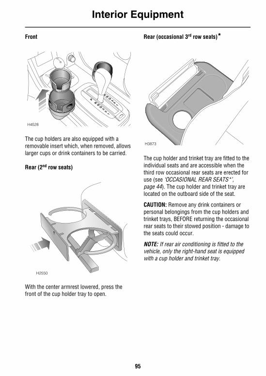
Interior Equipment
95
Front
The cup holders are also equipped with a removable insert which, when removed, allows larger cups or drink containers to be carried.
Rear (2nd row seats)
With the center armrest lowered, press the front of the cup holder tray to open.
Rear (occasional 3rd row seats)*
The cup holder and trinket tray are fitted to the individual seats and are accessible when the third row occasional rear seats are erected for use (see ‘OCCASIONAL REAR SEATS*’, page 44). The cup holder and trinket tray are located on the outboard side of the seat.
CAUTION: Remove any drink containers or personal belongings from the cup holders and trinket trays, BEFORE returning the occasional rear seats to their stowed position - damage to the seats could occur.
NOTE: If rear air conditioning is fitted to the vehicle, only the right-hand seat is equipped with a cup holder and trinket tray.
H4528
H2550
H3873
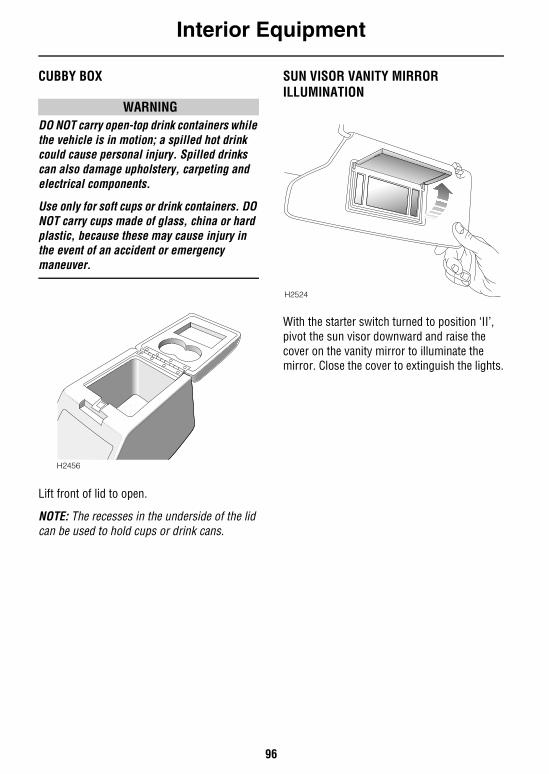
Interior Equipment
96
CUBBY BOX
WARNINGDO NOT carry open-top drink containers while the vehicle is in motion; a spilled hot drink could cause personal injury. Spilled drinks can also damage upholstery, carpeting and electrical components.
Use only for soft cups or drink containers. DO NOT carry cups made of glass, china or hard plastic, because these may cause injury in the event of an accident or emergency maneuver.
Lift front of lid to open.
NOTE: The recesses in the underside of the lid can be used to hold cups or drink cans.
SUN VISOR VANITY MIRROR ILLUMINATION
With the starter switch turned to position ‘II’, pivot the sun visor downward and raise the cover on the vanity mirror to illuminate the mirror. Close the cover to extinguish the lights.
H2456
H2524
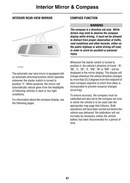
Interior Mirror & Compass
97
Interior Mirror & CompassINTERIOR REAR-VIEW MIRROR
The automatic rear view mirror is equipped with an automatic dimming function which operates whenever the starter switch is turned to position ‘II’. When powered, the mirror will automatically reduce glare from the headlights of following vehicles in dark or low light conditions.
For information about the compass display, see the following pages.
COMPASS FUNCTION
WARNINGThe compass is a direction aid only. While drivers may wish to observe the compass display while driving, it must not be allowed to distract from proper observation of traffic, road conditions and other hazards, either on the public highway or while driving off-road, in order to avoid an accident or personal injury.
Whenever the starter switch is turned to position II, the vehicle's direction of travel - ‘N’, ‘NE’, ‘E’, ‘SE’, ‘S’, ‘SW’, ‘W’ or ‘NW’ - will be displayed in the mirror display. The display will change whenever the vehicle direction changes by more than 22.5 degrees from the midpoint of each compass segment (a short time delay is incorporated to prevent nuisance changes occurring).
To ensure accuracy, the compass must be calibrated and also set to the compass set zone in which the vehicle is to be used (see the appropriate map page that follows). Both operations will have been carried out before the vehicle was delivered. Re-calibration will not normally be necessary unless the vehicle battery has been disconnected for a period of time.
H4104
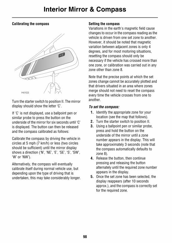
Interior Mirror & Compass
98
Calibrating the compass
Turn the starter switch to position II. The mirror display should show the letter ‘C’.
If 'C' is not displayed, use a ballpoint pen or similar probe to press the button on the underside of the mirror for six seconds until ‘C’ is displayed. The button can then be released and the compass calibrated as follows:
Calibrate the compass by driving the vehicle in circles at 5 mph (7 km/h) or less (two circles should be sufficient) until the mirror display shows a direction (‘N’, ‘NE’, ‘E’, ‘SE’, ‘S’, ‘SW’, ‘W’ or ‘NW’).
Alternatively, the compass will eventually calibrate itself during normal vehicle use, but depending upon the type of driving that is undertaken, this may take considerably longer.
Setting the compassVariations in the earth's magnetic field cause changes to occur in the compass reading as the vehicle is driven from one set zone to another. However, it should be noted that magnetic variation between adjacent zones is only 4 degrees, and for most motoring situations, resetting the compass should only be necessary if the vehicle has crossed more than one zone, or calibration was carried out in any zone other than zone 8.
Note that the precise points at which the set zones change cannot be accurately plotted and that drivers situated in an area where zones merge should not need to reset the compass every time the vehicle crosses from one to another.
To set the compass:1. Identify the appropriate zone for your
location (see the map that follows). 2. Turn the starter switch to position II.3. Using a ballpoint pen or similar probe,
press and hold the button on the underside of the mirror until a zone number appears in the display. This will take approximately 3 seconds (note that the compass automatically defaults to zone 8).
4. Release the button, then continue pressing and releasing the button alternately until the required zone number appears in the display.
5. Once the set zone has been selected, the display reappears (after 10 seconds approx.), and the compass is correctly set for the required zone.
H4103
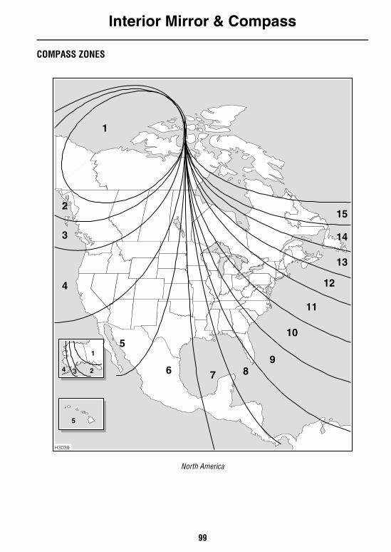
Interior Mirror & Compass
99
COMPASS ZONES
North America
H3039
1
2
4
51
234
5
6 7 89
10
11
12
13
14
15
3
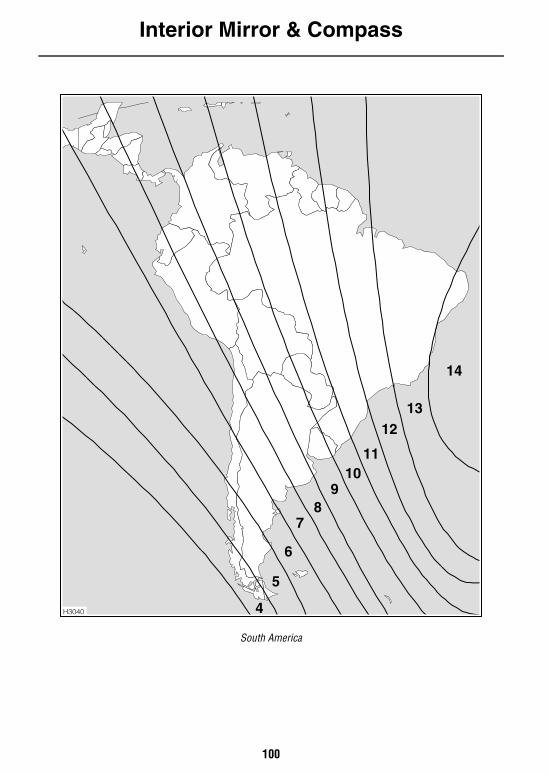
Interior Mirror & Compass
100
South America
H3040
14
1312
1110
98
7
6
5
4
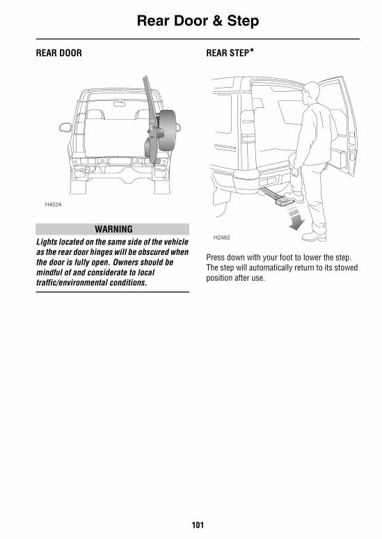
Rear Door & Step
101
Rear Door & StepREAR DOOR
WARNINGLights located on the same side of the vehicle as the rear door hinges will be obscured when the door is fully open. Owners should be mindful of and considerate to local traffic/environmental conditions.
REAR STEP*
Press down with your foot to lower the step. The step will automatically return to its stowed position after use.
H4524
H2482
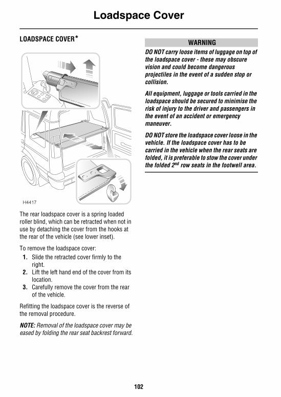
Loadspace Cover
102
Loadspace CoverLOADSPACE COVER*
The rear loadspace cover is a spring loaded roller blind, which can be retracted when not in use by detaching the cover from the hooks at the rear of the vehicle (see lower inset).
To remove the loadspace cover:1. Slide the retracted cover firmly to the
right.2. Lift the left hand end of the cover from its
location.3. Carefully remove the cover from the rear
of the vehicle.
Refitting the loadspace cover is the reverse of the removal procedure.
NOTE: Removal of the loadspace cover may be eased by folding the rear seat backrest forward.
WARNINGDO NOT carry loose items of luggage on top of the loadspace cover - these may obscure vision and could become dangerous projectiles in the event of a sudden stop or collision.
All equipment, luggage or tools carried in the loadspace should be secured to minimise the risk of injury to the driver and passengers in the event of an accident or emergency maneuver.
DO NOT store the loadspace cover loose in the vehicle. If the loadspace cover has to be carried in the vehicle when the rear seats are folded, it is preferable to stow the cover under the folded 2nd row seats in the footwell area.
H4417
In-Car Telephones
103
In-Car TelephonesIN-CAR TELEPHONESFor your safety, always note the following precautions before fitting an in-car telephone, or any mobile communication equipment.• Only use an installation kit incorporating an
aerial external to the vehicle.
• Ensure that the installation is carried out by a competent installer.
WARNING For your safety and that of others, using any hand-held appliance while driving can be dangerous. Always stop the vehicle before making a call and ensure the telephone is switched off while you are driving.
Audio System
104
Audio SystemRADIO AERIALThe radio aerial is etched onto the surface of the glass of one or both rear side windows.
No maintenance is possible, however it is important to ensure that the interior surface of the glass is protected from possible damage caused by contact with hard objects or from the injurious effects of abrasive cleaners.
AUDIO SYSTEMRadio cassette playerFull operating instructions for any audio equipment fitted as standard to your vehicle, are contained in the ‘In-Car Entertainment’ book in the vehicle literature pack.
CD autochanger*The CD autochanger is located under the right hand front seat. Full operating instructions are contained in the ‘In-Car Entertainment’ book.
WARNINGDO NOT insert or eject the magazine while driving - this action could result in the driver losing control of the vehicle.
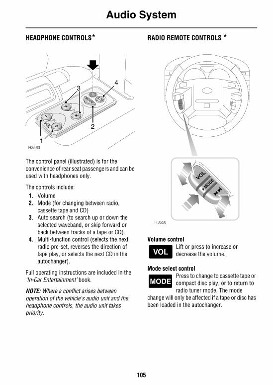
Audio System
105
HEADPHONE CONTROLS*
The control panel (illustrated) is for the convenience of rear seat passengers and can be used with headphones only.
The controls include:1. Volume2. Mode (for changing between radio,
cassette tape and CD)3. Auto search (to search up or down the
selected waveband, or skip forward or back between tracks of a tape or CD).
4. Multi-function control (selects the next radio pre-set, reverses the direction of tape play, or selects the next CD in the autochanger).
Full operating instructions are included in the ‘In-Car Entertainment’ book.
NOTE: Where a conflict arises between operation of the vehicle's audio unit and the headphone controls, the audio unit takes priority.
RADIO REMOTE CONTROLS *
Volume controlLift or press to increase or decrease the volume.
Mode select controlPress to change to cassette tape or compact disc play, or to return to radio tuner mode. The mode
change will only be affected if a tape or disc has been loaded in the autochanger.
H2563
MODE
1
3
2
4
H3550
VOL
MODE
VOL
MODE

Audio System
106
Search controlLift or press to change to the next or previous radio station on the selected waveband.
During tape (or CD) play, lift the control to move forward to the next track on the tape (or disc), or press to return to the start of the current track. Operate the control repeatedly to move forward or backward through several tracks at a time.
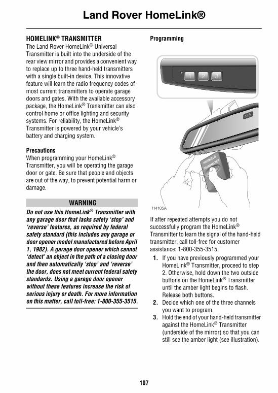
Land Rover HomeLink®
107
Land Rover HomeLink
®HOMELINK® TRANSMITTERThe Land Rover HomeLink® Universal Transmitter is built into the underside of the rear view mirror and provides a convenient way to replace up to three hand-held transmitters with a single built-in device. This innovative feature will learn the radio frequency codes of most current transmitters to operate garage doors and gates. With the available accessory package, the HomeLink® Transmitter can also control home or office lighting and security systems. For reliability, the HomeLink® Transmitter is powered by your vehicle’s battery and charging system.
PrecautionsWhen programming your HomeLink® Transmitter, you will be operating the garage door or gate. Be sure that people and objects are out of the way, to prevent potential harm or damage.
WARNINGDo not use this HomeLink® Transmitter with any garage door that lacks safety ‘stop’ and ‘reverse’ features, as required by federal safety standard (this includes any garage or door opener model manufactured before April 1, 1982). A garage door opener which cannot ‘detect’ an object in the path of a closing door and then automatically ‘stop’ and ‘reverse’ the door, does not meet current federal safety standards. Using a garage door opener without these features increase the risk of serious injury or death. For more information on this matter, call toll-free: 1-800-355-3515.
Programming
If after repeated attempts you do not successfully program the HomeLink® Transmitter to learn the signal of the hand-held transmitter, call toll-free for customer assistance: 1-800-355-3515.1. If you have previously programmed your
HomeLink® Transmitter, proceed to step 2. Otherwise, hold down the two outside buttons on the HomeLink® Transmitter until the amber light begins to flash. Release both buttons.
2. Decide which one of the three channels you want to program.
3. Hold the end of your hand-held transmitter against the HomeLink® Transmitter (underside of the mirror) so that you can still see the amber light (see illustration).
HANDHELD
TRANSMITTER
1 2 3
H4105A
Land Rover HomeLink®
108
4. Using both hands, push the hand-held transmitter button and the desired button on the HomeLink® Transmitter. Continue to press both buttons through step 5.
5. Hold down both buttons until you see the amber light on the Land Rover HomeLink® Transmitter flash, first slowly and then rapidly. It indicates that you have successfully programmed the HomeLink® Transmitter to learn the new frequency signal. Release both buttons once the rapid flashing begins.
Operating the Land Rover HomeLink® TransmitterOnce it is programmed, the HomeLink® Transmitter can be used in place of your hand-held transmitter(s). To operate, simply press the appropriate button on the HomeLink® Transmitter. The amber light comes on while the signal is being transmitted.
NOTE: If your hand-held transmitter appears to program the HomeLink® Transmitter, but does not open your garage door and, if your garage door was manufactured after 1995, your garage door opener may have a ‘code protected’ or ‘rolling code’ feature.
A ‘rolling code’ type of system will change the ‘code’ of your garage door opener every time you open or close your garage door.
To determine if you have one of these systems, depress the button on your HomeLink® Transmitter that you programmed. If the amber light on the HomeLink® Transmitter flashes rapidly for 1-2 seconds, then turns solid, your garage door opener has a rolling code system.
Training a garage door opener equipped with ‘rolling codes’To train your ’rolling code’ garage door opener to operate from your HomeLink® Transmitter, follow these steps:
1. Program your hand-held transmitter to the HomeLink® Transmitter by following the procedures outlined in ‘Programming’, page 107 (if you already completed this programming, proceed to the next instruction).
2. Train your garage door opener receiver to recognize your HomeLink® Transmitter: (your garage door opener receiver will learn to recognize the HomeLink® Transmitter by following the same process used to train the hand-held transmitter)a) Remove the cover panel from your garage door opener receiver (the receiver should be located by the garage door motor).b) Locate the training button on the garage door opener receiver. The exact location and color of the button may vary by garage door opener brand. If you have difficulty locating the training button, reference your garage door opener manual, or call 1-800-355-3515.c) Press the training button on the garage door opener receiver for 1-2 seconds.d) Return to the HomeLink® Transmitter in the vehicle and depress the programmed HomeLink® Transmitter button for the duration of the rapid flash of the HomeLink®’ amber light, (1-2 seconds). Release the button and depress the button to confirm that the HomeLink® Transmitter has been trained to the receiver.
Land Rover HomeLink®
109
e) Your garage door opener should now recognize your HomeLink® Transmitter. You may use either your HomeLink® Transmitter or your original hand-held transmitter to open your garage door.
If after following these suggestions you still have difficulties programming your HomeLink® Transmitter, call toll-free for customer assistance: 1-800-355-3515.
Erasing channelsTo erase all three programmed channels, hold down the two outside buttons until the amber light begins to flash, then release both buttons. Individual channels cannot be erased, but can be reprogrammed using the procedures for programming the HomeLink® Transmitter (steps 2 through 5).
NOTE: Be sure to retain your original transmitter for future programming procedures (i.e. new vehicle purchase).
When selling your vehicle, be sure to erase all channels on the HomeLink® Transmitter that you programmed.
AccessoriesAccessories for your HomeLink® Transmitter are available from the manufacturer of the device. If you would like additional information or would like to purchase other accessories such as home lighting or security products that can be operated by the HomeLink® Transmitter, please call the toll-free: 1-800-355-3515.
The transmitter has been tested and complies with FCC rules part 15 and DOC/MDC rules. Changes or modifications not expressly approved by the party responsible for compliance could void the user’s authority to operate the device.
Operation is subject to the following two conditions:1. This device may not cause harmful
interference: and2. this device must accept any interference
that may be received, including interference that may cause undesired operation.
DOC: ISTC 1763K1313
Prince MODEL/FCC ID: C82 V67690
HomeLink® is a registered trademark owned by the Prince Corporation, Holland. Michigan.

110
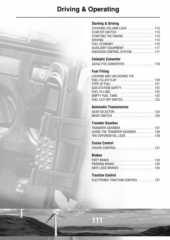
111
Driving & Operating
Starting & DrivingSTEERING COLUMN LOCK . . . . . . . . . . . . . . . . 113STARTER SWITCH. . . . . . . . . . . . . . . . . . . . . . . 113STARTING THE ENGINE. . . . . . . . . . . . . . . . . . . 114DRIVING . . . . . . . . . . . . . . . . . . . . . . . . . . . . . . 115FUEL ECONOMY . . . . . . . . . . . . . . . . . . . . . . . . 116AUXILIARY EQUIPMENT . . . . . . . . . . . . . . . . . . 117EMISSION CONTROL SYSTEM . . . . . . . . . . . . . 117
Catalytic ConverterCATALYTIC CONVERTER . . . . . . . . . . . . . . . . . . 118
Fuel FillingLOCKING AND UNLOCKING THE FUEL FILLER FLAP. . . . . . . . . . . . . . . . . . . . . . . 120TYPE OF FUEL . . . . . . . . . . . . . . . . . . . . . . . . . . 121GAS STATION SAFETY. . . . . . . . . . . . . . . . . . . . 122FUEL FILLING . . . . . . . . . . . . . . . . . . . . . . . . . . 122EMPTY FUEL TANK . . . . . . . . . . . . . . . . . . . . . . 122FUEL CUT-OFF SWITCH. . . . . . . . . . . . . . . . . . . 123
Automatic TransmissionGEAR SELECTOR . . . . . . . . . . . . . . . . . . . . . . . . 124MODE SWITCH . . . . . . . . . . . . . . . . . . . . . . . . . 126
Transfer GearboxTRANSFER GEARBOX . . . . . . . . . . . . . . . . . . . . 127USING THE TRANSFER GEARBOX. . . . . . . . . . . 128THE DIFFERENTIAL LOCK . . . . . . . . . . . . . . . . . 129
Cruise ControlCRUISE CONTROL . . . . . . . . . . . . . . . . . . . . . . . 131
BrakesFOOT BRAKE . . . . . . . . . . . . . . . . . . . . . . . . . . . 133PARKING BRAKE . . . . . . . . . . . . . . . . . . . . . . . . 134ANTI-LOCK BRAKES . . . . . . . . . . . . . . . . . . . . . 134
Traction ControlELECTRONIC TRACTION CONTROL. . . . . . . . . . 137
112
Hill Descent ControlHILL DESCENT CONTROL. . . . . . . . . . . . . . . . . 138
Active Cornering EnhancementACTIVE CORNERING ENHANCEMENT . . . . . . . 140
Self-levelling SuspensionSELF-LEVELLING SUSPENSION . . . . . . . . . . . . 142AUTOMATIC OPERATION . . . . . . . . . . . . . . . . . 142MANUAL OPERATION. . . . . . . . . . . . . . . . . . . . 142WARNING LIGHTS . . . . . . . . . . . . . . . . . . . . . . 144
Park Distance ControlUSING THE PARK DISTANCE CONTROL. . . . . . 145
TowingTOWING . . . . . . . . . . . . . . . . . . . . . . . . . . . . . . 146TOWING WEIGHTS . . . . . . . . . . . . . . . . . . . . . . 151
Load CarryingLUGGAGE ANCHOR POINTS. . . . . . . . . . . . . . . 152STORAGE BINS. . . . . . . . . . . . . . . . . . . . . . . . . 152ROOF RACKS . . . . . . . . . . . . . . . . . . . . . . . . . . 153
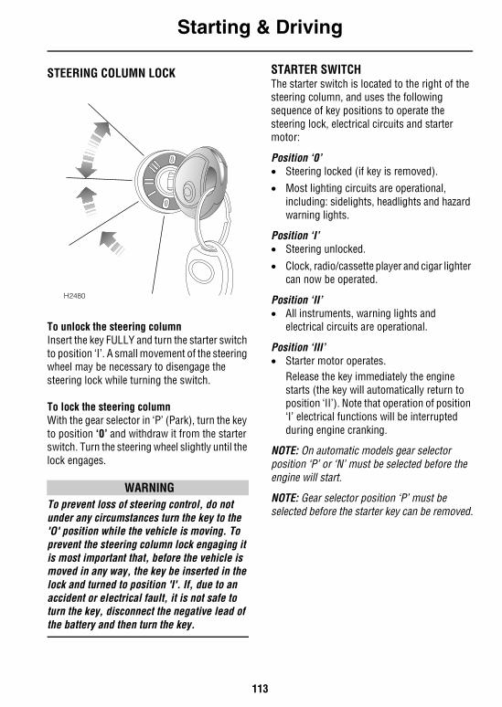
Starting & Driving
113
Driving & Operating
Starting & DrivingSTEERING COLUMN LOCK
To unlock the steering columnInsert the key FULLY and turn the starter switch to position ‘I’. A small movement of the steering wheel may be necessary to disengage the steering lock while turning the switch.
To lock the steering columnWith the gear selector in ‘P’ (Park), turn the key to position ‘0’ and withdraw it from the starter switch. Turn the steering wheel slightly until the lock engages.
WARNINGTo prevent loss of steering control, do not under any circumstances turn the key to the 'O' position while the vehicle is moving. To prevent the steering column lock engaging it is most important that, before the vehicle is moved in any way, the key be inserted in the lock and turned to position 'I'. If, due to an accident or electrical fault, it is not safe to turn the key, disconnect the negative lead of the battery and then turn the key.
STARTER SWITCHThe starter switch is located to the right of the steering column, and uses the following sequence of key positions to operate the steering lock, electrical circuits and starter motor:
Position ‘0’• Steering locked (if key is removed).• Most lighting circuits are operational,
including: sidelights, headlights and hazard warning lights.
Position ‘I’• Steering unlocked.
• Clock, radio/cassette player and cigar lighter can now be operated.
Position ‘II’• All instruments, warning lights and
electrical circuits are operational.
Position ‘III’• Starter motor operates.
Release the key immediately the engine starts (the key will automatically return to position ‘II’). Note that operation of position ‘I’ electrical functions will be interrupted during engine cranking.
NOTE: On automatic models gear selector position ‘P’ or ‘N’ must be selected before the engine will start.
NOTE: Gear selector position ‘P’ must be selected before the starter key can be removed.
H2480
Starting & Driving
114
STARTING THE ENGINE
WARNINGNever start or leave the engine running in an unventilated building - exhaust gases are poisonous and contain carbon monoxide, which can cause unconsciousness and may even be fatal.
Before starting the engine and driving, ensure you are familiar with the precautions shown under ‘CATALYTIC CONVERTER’, page 118.
In particular, you should be aware that if the engine fails to start, continued use of the starter may result in unburnt fuel damaging the catalytic converter.
1. Check that the parking brake is applied and the gear lever is in ‘P’ or ‘N’.
2. Switch off all unnecessary electrical equipment.
3. Turn the starter switch to position ‘II’ and then on to position ‘III’ to operate the starter motor. DO NOT press the accelerator pedal while starting, and RELEASE THE KEY as soon as the engine is running.
In temperate climates DO NOT operate the starter for longer than 10 seconds. If the engine fails to start, switch off and wait 10 seconds before re-using the starter. Please note that continued use of the starter will discharge the battery and may cause the starter motor to overheat.
NOTE: The battery charging and oil pressure warning lights should extinguish as soon as the engine is running.
After starting, ensure that the parking brake and foot brake are firmly applied and the accelerator pedal is not depressed while moving the gear selector lever from ‘N’ or ‘P’, otherwise, the vehicle may move immediately if the selector lever is moved to one of the drive positions (1,2,3,D or R). This is particularly important when the engine is cold, because the engine will be idling at a faster speed than normal. Use the foot brake to control the vehicle until the engine is warm and running at normal speed.
NOTE: The foot brake MUST be applied before the selector can be moved from ‘P’.
Cold climatesIn very cold climates, if the engine fails to start after three attempts, fully depress the accelerator and operate the starter continually for up to 30 seconds, or until the engine runs.
In addition, the oil pressure warning light may take several seconds to extinguish and engine cranking times will also increase; at -13°F (-25°C), the starter motor may need to be operated continuously for as long as 30 seconds before the engine will start. For this reason, ensure that all non-essential electrical equipment is switched off.
Block heatersAdditionally, in very cold temperatures, use of a 110 V AC block heater will improve the engine's starting characteristics. In order to ensure correct performance, only Land Rover approved engine block heaters should be used. In any event, block heaters restricted to a maximum of 400 W should be used. Block heaters that exceed this output may damage the emission control components.
Starting & Driving
115
DRIVING
WARNINGVehicle stabilityYour vehicle has a higher ground clearance and, hence, a higher center of gravity than ordinary passenger cars to enable the vehicle to perform in a wide variety of different off-road applications. An advantage of the higher ground clearance is a better view of the road, allowing the driver to more easily anticipate problems. Inexperienced drivers should take additional care, remembering that the Discovery is not designed for cornering at the same speeds as conventional passenger cars, any more than a low slung sports car is designed to perform satisfactorily in off-road conditions. As with other vehicles of this type, failure to operate the Discovery correctly may result in loss of control or even vehicle rollover.
Vehicle heightThe overall height of your vehicle exceeds that of ordinary passenger cars (for convenience the height is shown on the underside of the sun visor). Always be aware of the height of your vehicle and check the available headroom before driving through low entrances. This is particularly important if the vehicle is fitted with a roof rack or if a sunroof is open.
Before drivingLearn the layout and function of all the instruments, warning lights and controls.
Adjust the seat to a comfortable driving position from which you can ensure full control of the vehicle.
Always start the vehicle and operate the controls from the driving position.
Instruments and warning lightsBefore driving, it is important to fully understand the function of the instruments and warning lights (see ‘WARNING LIGHTS’, page 67).
NOTE: Red warning lights are of particular importance, illumination indicating that a fault exists. If a red light illuminates, always stop the vehicle and seek qualified assistance before continuing.
Warming-up In the interests of fuel economy, it is advisable to drive the vehicle straight away, remembering that harsh acceleration or laboring the engine before the normal operating temperature has been reached can damage the engine.
When the engine is cold, engine idle speeds will be faster than normal. Under these circumstances, use the foot brake to control the vehicle until the engine is warm and running at normal speed, and be aware of the need to take additional care when manoeuvring the vehicle.
Starting & Driving
116
Breaking-in Proper breaking-in will have a direct bearing on the reliability and smooth running of your vehicle throughout its life.
In particular, the engine, gearbox, brakes and tires need time to ‘bed-in’ and adjust to the demands of everyday motoring. During the first 500 miles (800 km), it is essential to drive with consideration for the running-in process and heed the following advice:• LIMIT maximum road speed to 70 mph (110
km/h) or 3,000 rev/min. Initially, drive the vehicle on a light throttle and only increase engine speeds gradually once the breaking-in distance has been completed.
• DO NOT operate at full throttle or allow the engine to labor in any gear.
• AVOID fast acceleration and heavy braking except in emergencies.
Power assisted steeringThe hydraulic power-assisted is progressively geared; when steering straight ahead gearing is relatively low, but becomes progressively higher as the steering wheel is turned.
NOTE: Power assistance is dependent on the engine running. If the engine is not running, greater effort will be required to steer the vehicle.
FUEL ECONOMYFuel consumption is influenced by two major factors: • How your vehicle is maintained.• How you drive your vehicle.
To obtain optimum fuel economy, it is essential that your vehicle is maintained in accordance with the manufacturer's service schedule.
Items such as the condition of the air cleaner element, tire pressures and wheel alignment will have a significant effect on fuel consumption. But, above all, the way in which you drive is most important. The following hints may help you to obtain better value from your motoring: • Avoid unnecessary, short, start-stop
journeys.
• Avoid fast starts by accelerating gently and smoothly from rest.
• Do not drive in the lower gears for longer than necessary.
• Decelerate gently and avoid sudden and heavy braking.
• Anticipate obstructions and adjust your speed accordingly well in advance.
• When stationary in traffic, select neutral to improve fuel economy and air conditioning performance.
Starting & Driving
117
AUXILIARY EQUIPMENTCAUTION: DO NOT use auxiliary equipment, such as roller generators that are driven by one wheel of the vehicle, as they could cause failure of the gearbox differential. The vehicle will also drive itself forward through ETC action.
Some local jurisdictions require emission testing using a two wheel roller dynamometer. Your vehicle is equipped with permanent 4-wheel drive and cannot be safely operated on these machines. For more information regarding safe emission testing of your vehicle consult your local Land Rover retailer.
EMISSION CONTROL SYSTEM
WARNINGExhaust fumes contain poisonous substances which can cause unconsciousness and may even be fatal.
• DO NOT inhale exhaust gases.
• DO NOT start or leave the engine running in an enclosed unventilated area, or drive with the taildoor open.
• DO NOT modify the exhaust system from the original design.
• ALWAYS repair exhaust system leaks immediately.
• If you think exhaust fumes are entering the vehicle, have the cause determined and corrected immediately.
Land Rover vehicles are fitted with emission and evaporative control equipment necessary to meet a number of territorial requirements.
In some juridictions, it is against the law for vehicle owners to modify or tamper with emission control equipment, or to sanction the unauthorised replacement or modification of this equipment. In such cases, the vehicle owner and the repairer may both be liable for legal penalties.
It is important to remember that all Land Rover retailers are properly equipped to perform repairs and to maintain the emission control system on your Discovery.
Catalytic Converter
118
Catalytic ConverterCATALYTIC CONVERTERThe exhaust system incorporates a catalytic converter, which converts poisonous exhaust emissions from the engine into environmentally less harmful gases.
CAUTION: Catalytic converters can be easily damaged through improper use, particularly if the wrong fuel is used, or if an engine misfire occurs. For this reason it is VERY IMPORTANT that you heed the precautions which follow.
FuelONLY use fuel recommended for your vehicle,see ‘ENGINES’, page 241.
MisfireA misfire can cause an engine to run rough or skip for more than just a few seconds. If a misfire is suspected, there is a risk of catalyst damage; consult a Land Rover retailer for assistance.
Starting the engine• DO NOT continue to operate the starter after
a few failed attempts (unburnt fuel may be drawn into the exhaust system, thereby poisoning the catalyst) - seek qualified assistance.
• Do not attempt to push or tow-start the vehicle.
Driving• If a misfire is suspected, the ‘SERVICE
ENGINE SOON’ warning light is flashing, or the vehicle lacks power while driving, avoid high speeds and seek immediate assistance from your Land Rover retailer.
• NEVER allow the vehicle to run out of fuel (the resultant misfire could damage the catalyst).
• Engines burning excessive oil (e.g. 1 quart every 750 miles) will progressively reduce catalyst efficiency. In extreme cases, blue smoke may be emitted from the exhaust.
• On rough terrain, do not allow the underside of the vehicle to be subjected to heavy impacts which could damage the catalytic converter.
• DO NOT overload or excessively ‘rev’ the engine.
• DO NOT switch off the engine when the vehicle is in motion with a drive gear selected.
WARNINGExhaust system temperatures can be extremely high - DO NOT park on ground where combustible materials such as dry grass or leaves could come into contact with the exhaust system - in dry weather a fire could result.
Catalytic Converter
119
Vehicle maintenance• Any engine misfire which causes the
‘Service engine soon’ warning light to flash (see ‘WARNING LIGHTS’, page 67), loss of engine performance or engine run-on, could seriously damage the catalytic converter. For this reason, it is vital that unqualified persons do not tamper with the engine, and that regular systematic maintenance is carried out by a Land Rover retailer.
• DO NOT run the engine with a spark plug or HT lead removed, or use any device that requires an insert into a spark plug.
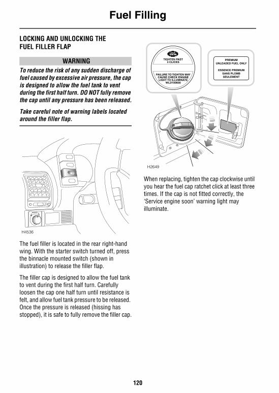
Fuel Filling
120
Fuel FillingLOCKING AND UNLOCKING THE FUEL FILLER FLAP
WARNINGTo reduce the risk of any sudden discharge of fuel caused by excessive air pressure, the cap is designed to allow the fuel tank to vent during the first half turn. DO NOT fully remove the cap until any pressure has been released.
Take careful note of warning labels located around the filler flap.
The fuel filler is located in the rear right-hand wing. With the starter switch turned off, press the binnacle mounted switch (shown in illustration) to release the filler flap.
The filler cap is designed to allow the fuel tank to vent during the first half turn. Carefully loosen the cap one half turn until resistance is felt, and allow fuel tank pressure to be released. Once the pressure is released (hissing has stopped), it is safe to fully remove the filler cap.
When replacing, tighten the cap clockwise until you hear the fuel cap ratchet click at least three times. If the cap is not fitted correctly, the ‘Service engine soon’ warning light may illuminate.
H4536
H2649
TIGHTEN PAST3 CLICKS
PREMIUMUNLEADED FUEL ONLY
ESSENCE PREMIUMSANS PLOMBSEULEMENT
FAILURE TO TIGHTEN MAYCAUSE CHECK ENGINELIGHT TO ILLUMINATE
WLD100600
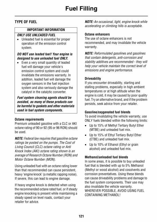
Fuel Filling
121
TYPE OF FUEL
Octane requirementsPremium unleaded gasoline with a CLC or AKIoctane rating of 90 or 92 (95 or 96 RON) should be used.
NOTE: Federal law requires that gasoline octane ratings be posted on the pumps. The Cost of Living Council (CLC) octane rating or Anti Knock Index (AKI) octane rating shown is an average of Research Octane Number (RON) and Motor Octane Number (MON).
Using unleaded fuel with an octane rating lower than that recommended can cause persistent, heavy ‘engine knock’ (a metallic rapping noise). If severe, this can lead to engine damage.
If heavy engine knock is detected when using the recommended octane rated fuel, or if steady engine knocking is present while maintaining a steady speed on level roads, contact your retailer for advice.
NOTE: An occasional, light, engine knock while accelerating or climbing hills is acceptable.
Octane enhancersThe use of octane enhancers is not recommended, and may invalidate the vehicle warranty.
NOTE: Reformulated gasolines and gasolines that contain detergents, anti-corrosion and stability additives are recommended - they will help your vehicle maintain the correct level of emissions and engine performance.
DriveabilityIf you encounter driveability, starting and stalling problems, especially in high ambient temperatures or at high altitude when the engine is cold, it may be caused by poor quality fuel. Try an alternative brand, and if the problem persists, seek advice from your retailer.
Gasoline/oxygenated fuel blendsTo avoid invalidating the vehicle warranty, use ONLY fuels blended within the following limits:• Up to 15% of Methyl Tertiary Butyl Ether
(MTBE) and unleaded fuel mix.
• Up to 15% of Ethyl Tertiary Butyl Ether (ETBE) and unleaded fuel mix.
• Up to 10% of Ethanol (Ethyl or grain alcohol) and unleaded fuel mix.
Methanol/unleaded fuel blendsIn some areas, it is possible to buy unleaded fuel that is blended with up to 5% Methanol (Methyl or wood alcohol) and cosolvents and corrosion preventatives. Using these blends can cause driveability problems and damage to the fuel system components. Their use may also invalidate the vehicle warranty. WHEREVER POSSIBLE, AVOID USING FUEL CONTAINING METHANOL!
IMPORTANT INFORMATIONONLY USE UNLEADED FUEL• Unleaded fuel is essential for proper
operation of the emission control system.
DO NOT use leaded fuel! Your engine is designed to use unleaded fuel ONLY.• Even a very small quantity of leaded
fuel will damage your vehicle's emission control system and could invalidate the emissions warranty. In addition, leaded fuel will damage the oxygen sensors in the fuel injection system and also seriously damage the catalyst in the catalytic converter.
Fuel system cleaning agents should be avoided, as many of these products can be harmful to gaskets and other materials used in fuel system components.
Fuel Filling
122
WARNINGAutomotive fuels can cause serious injury, and even death if misused.
Methanol/unleaded fuel blends, even in small amounts, can cause blindness and possible death if swallowed. Additionally, take precautions to prevent methanol from coming into contact with the skin.
GAS STATION SAFETY
WARNINGPetroleum gases are highly inflammable and, in confined spaces, are also extremely explosive.
Always place portable gasoline containers on the ground while filling. A fire may result if gasoline is pumped into a container that is inside a vehicle or on a truck bed. You could be burned!
Always take sensible precautions when refuelling: • Switch off the engine.• Do not smoke or introduce other ignition
sources.
• Switch off mobile phones.• Take care not to spill fuel.
• Do not overfill the tank.
• Do not fill gas cans in the vehicle.
• Do not get back into your vehicle during refuelling.
• Use only the hold-open latch provided on the gasoline pump. Never jam the latch open with some other object.
FUEL FILLINGGas station pumps are equipped with automatic cut-off sensing to avoid fuel spillage. Fill the tank SLOWLY until the filler nozzle automatically cuts-off the supply.
DO NOT attempt to fill the tank beyond this point or spillage could result due to expansion of the fuel.
The reduced diameter filler neck, accepts ONLY a narrow filler nozzle of the type found on pumps that supply UNLEADED fuel.
NOTE: Ensure the filler cap is fitted correctly after refuelling, otherwise the ‘Service engine soon’ warning light may illuminate.
EMPTY FUEL TANK
IMPORTANT INFORMATION
DO NOT run the fuel tank dry!• Running the fuel tank dry could create
an engine misfire capable of damaging the catalytic converter. It will also cause the ‘Service engine soon’ warning light to illuminate.
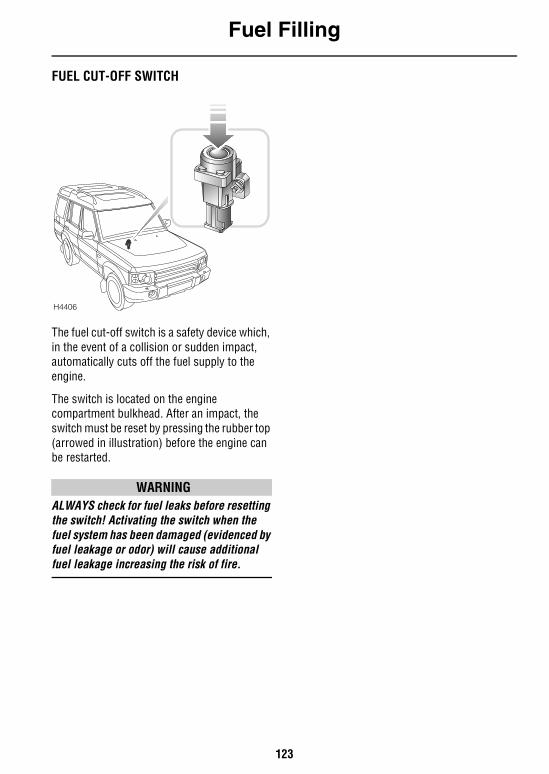
Fuel Filling
123
FUEL CUT-OFF SWITCH
The fuel cut-off switch is a safety device which, in the event of a collision or sudden impact, automatically cuts off the fuel supply to the engine.
The switch is located on the engine compartment bulkhead. After an impact, the switch must be reset by pressing the rubber top (arrowed in illustration) before the engine can be restarted.
WARNINGALWAYS check for fuel leaks before resetting the switch! Activating the switch when the fuel system has been damaged (evidenced by fuel leakage or odor) will cause additional fuel leakage increasing the risk of fire.
H4406
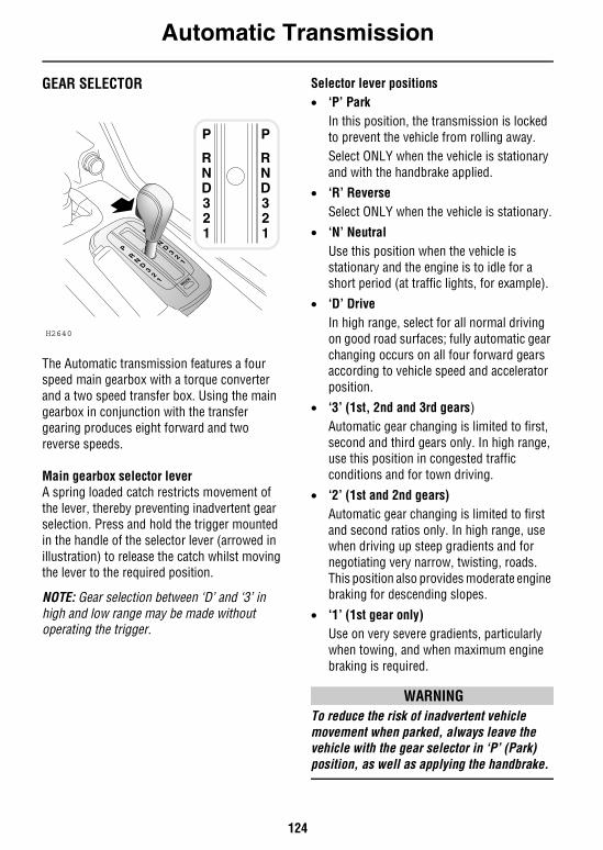
Automatic Transmission
124
Automatic TransmissionGEAR SELECTOR
The Automatic transmission features a four speed main gearbox with a torque converter and a two speed transfer box. Using the main gearbox in conjunction with the transfer gearing produces eight forward and two reverse speeds.
Main gearbox selector leverA spring loaded catch restricts movement of the lever, thereby preventing inadvertent gear selection. Press and hold the trigger mounted in the handle of the selector lever (arrowed in illustration) to release the catch whilst moving the lever to the required position.
NOTE: Gear selection between ‘D’ and ‘3’ in high and low range may be made without operating the trigger.
Selector lever positions• ‘P’ Park
In this position, the transmission is locked to prevent the vehicle from rolling away.Select ONLY when the vehicle is stationary and with the handbrake applied.
• ‘R’ ReverseSelect ONLY when the vehicle is stationary.
• ‘N’ Neutral Use this position when the vehicle is stationary and the engine is to idle for a short period (at traffic lights, for example).
• ‘D’ Drive In high range, select for all normal driving on good road surfaces; fully automatic gear changing occurs on all four forward gears according to vehicle speed and accelerator position.
• ‘3’ (1st, 2nd and 3rd gears)Automatic gear changing is limited to first, second and third gears only. In high range, use this position in congested traffic conditions and for town driving.
• ‘2’ (1st and 2nd gears)Automatic gear changing is limited to first and second ratios only. In high range, use when driving up steep gradients and for negotiating very narrow, twisting, roads. This position also provides moderate engine braking for descending slopes.
• ‘1’ (1st gear only)Use on very severe gradients, particularly when towing, and when maximum engine braking is required.
WARNINGTo reduce the risk of inadvertent vehicle movement when parked, always leave the vehicle with the gear selector in ‘P’ (Park) position, as well as applying the handbrake.
H2640
MODE
Automatic Transmission
125
Starting and drivingDrivers unfamiliar with the performance characteristics of an automatic gearbox should thoroughly familiarize themselves with the following instructions before driving.• Before starting the engine, ensure that both
foot and parking brakes are applied.
• After starting the engine, KEEP BOTH BRAKES APPLIED before and whilst moving the selector lever to the required drive position.
• Keep the brakes applied until you are ready to move - remember, once a drive position is selected, an ‘automatic’ will tend to creep forward (or backward) without throttle application, as soon as the brakes are released.
• Never ‘rev’ the engine while selecting a forward or reverse drive gear, or while the vehicle is stationary with a drive gear selected - remember, an ‘automatic’ will move immediately once the accelerator pedal is pressed.
NOTE: The starter key cannot be removed unless the gear selector is in ‘P’ (Park), and it is impossible to move the selector lever from ‘P’ (Park) unless the foot brake is pressed.
Gear change speedsWith ‘D’ selected, the road speeds at which gear changes take place will vary according to the position of the accelerator: minimum acceleration will result in gear changes at low road speed, while larger throttle openings will cause the gearbox to delay gear changes until faster road speeds have been reached (thereby increasing acceleration).
With practice, gear changes can be made to occur at a wide range of road speeds depending on accelerator pedal pressure.
On long inclines the gearbox will sometimes change back and forth between gears. This occurs because the transmission does not include a ratio that is precisely right for the particular incline and vehicle loading circumstances. However, excessive gear changing results in a loss of momentum and is wasteful of fuel. It can be prevented by selecting the ‘3’ or ‘2’ positions which limit the gearbox to lower ratios.
‘Kick-down’To provide rapid acceleration for overtaking, push the accelerator pedal to the full extent of its travel in a single quick movement (this is known as ‘kick-down’). Up to a certain speed, this will cause an immediate downshift into the lowest appropriate gear, followed by rapid acceleration. Once the pedal is relaxed, normal gear change speeds will resume (dependent upon road speed and accelerator pedal position).
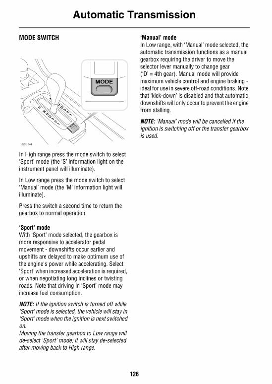
Automatic Transmission
126
MODE SWITCH
In High range press the mode switch to select ‘Sport’ mode (the ‘S’ information light on the instrument panel will illuminate).
In Low range press the mode switch to select ‘Manual’ mode (the ‘M’ information light will illuminate).
Press the switch a second time to return the gearbox to normal operation.
‘Sport’ modeWith ‘Sport’ mode selected, the gearbox is more responsive to accelerator pedal movement - downshifts occur earlier and upshifts are delayed to make optimum use of the engine's power while accelerating. Select ‘Sport’ when increased acceleration is required, or when negotiating long inclines or twisting roads. Note that driving in ‘Sport’ mode may increase fuel consumption.
NOTE: If the ignition switch is turned off while ‘Sport’ mode is selected, the vehicle will stay in ‘Sport’ mode when the ignition is next switched on.Moving the transfer gearbox to Low range will de-select ‘Sport’ mode; it will stay de-selected after moving back to High range.
‘Manual’ modeIn Low range, with ‘Manual’ mode selected, the automatic transmission functions as a manual gearbox requiring the driver to move the selector lever manually to change gear (‘D’ = 4th gear). Manual mode will provide maximum vehicle control and engine braking - ideal for use in severe off-road conditions. Note that ‘kick-down’ is disabled and that automatic downshifts will only occur to prevent the engine from stalling.
NOTE: ‘Manual’ mode will be cancelled if the ignition is switching off or the transfer gearbox is used.
H2664
MODE
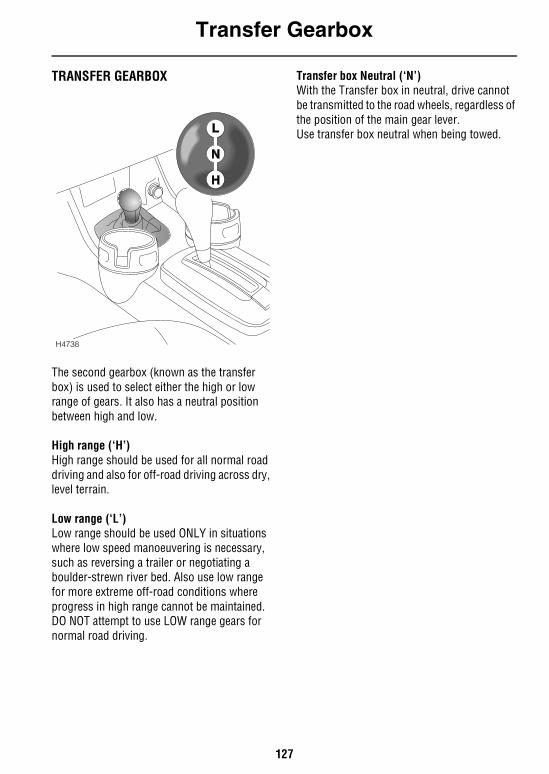
Transfer Gearbox
127
Transfer GearboxTRANSFER GEARBOX
The second gearbox (known as the transfer box) is used to select either the high or low range of gears. It also has a neutral position between high and low.
High range (‘H’)High range should be used for all normal road driving and also for off-road driving across dry, level terrain.
Low range (‘L’)Low range should be used ONLY in situations where low speed manoeuvering is necessary, such as reversing a trailer or negotiating a boulder-strewn river bed. Also use low range for more extreme off-road conditions where progress in high range cannot be maintained. DO NOT attempt to use LOW range gears for normal road driving.
Transfer box Neutral (‘N’)With the Transfer box in neutral, drive cannot be transmitted to the road wheels, regardless of the position of the main gear lever.Use transfer box neutral when being towed.
H4738
Transfer Gearbox
128
USING THE TRANSFER GEARBOXThere are two ways of operating the transfer gearbox lever:
1. ‘Statically’, i.e shifting whilst the vehicle is stationary.
2. ‘Shift on the move’, this is the recommended method, which after a little practice, can be carried out smoothly and quickly.
‘Static’ methodWith the vehicle stationary and the engine running, apply the foot brake and then move the automatic gearbox selector to the ‘N’ (neutral) position.Then move the transfer lever fully forward or backwards to the required position. If there is a resistance to the gear disengaging, do not force the lever. Instead, move the automatic gearbox selector to the ‘R’ (reverse) position for 2 seconds and then return to the ‘N’ (neutral) position and then try range change again.If there is resistance to the gear engaging, (from the neutral position to the either high or low), do not force the lever. Instead:
1. Apply handbrake.2. With the automatic gearbox still in ‘N’
(neutral), momentarily rev the engine whilst applying pressure to the transfer box lever to engage gear.
3. Select appropriate main gearbox gear to pull away.
‘Shift on the move’ method With the vehicle driving forwards, reduce (or increase) the speed of the vehicle to 5 mph (8 km/h), then:
1. Release the accelerator and select auto gearbox ‘N’.
2. As the vehicle reaches walking pace, move the transfer lever to the required ‘H’ or ‘L’ position. (Use positive and confident moves, but do not rush the gear change).
3. Finally, reselect appropriate gear with the main gear selector and continue driving as normal.
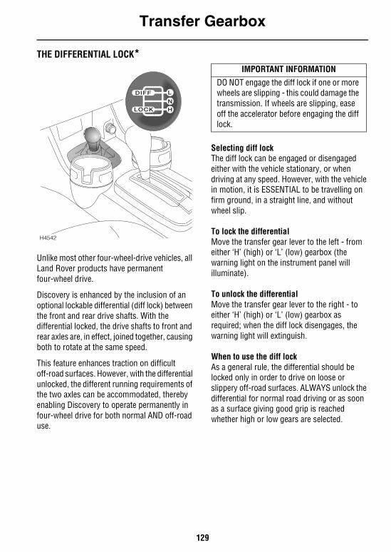
Transfer Gearbox
129
THE DIFFERENTIAL LOCK*
Unlike most other four-wheel-drive vehicles, all Land Rover products have permanent four-wheel drive.
Discovery is enhanced by the inclusion of an optional lockable differential (diff lock) between the front and rear drive shafts. With the differential locked, the drive shafts to front and rear axles are, in effect, joined together, causing both to rotate at the same speed.
This feature enhances traction on difficult off-road surfaces. However, with the differential unlocked, the different running requirements of the two axles can be accommodated, thereby enabling Discovery to operate permanently in four-wheel drive for both normal AND off-road use.
Selecting diff lockThe diff lock can be engaged or disengaged either with the vehicle stationary, or when driving at any speed. However, with the vehicle in motion, it is ESSENTIAL to be travelling on firm ground, in a straight line, and without wheel slip.
To lock the differentialMove the transfer gear lever to the left - from either ‘H’ (high) or ‘L’ (low) gearbox (the warning light on the instrument panel will illuminate).
To unlock the differentialMove the transfer gear lever to the right - to either ‘H’ (high) or ‘L’ (low) gearbox as required; when the diff lock disengages, the warning light will extinguish.
When to use the diff lockAs a general rule, the differential should be locked only in order to drive on loose or slippery off-road surfaces. ALWAYS unlock the differential for normal road driving or as soon as a surface giving good grip is reached whether high or low gears are selected.
DIFF
LOCK
L
N
H
H4542
IMPORTANT INFORMATION
DO NOT engage the diff lock if one or more wheels are slipping - this could damage the transmission. If wheels are slipping, ease off the accelerator before engaging the diff lock.
Transfer Gearbox
130
WARNINGDO NOT drive the vehicle at speeds in excess of 40 mph (60 km/h) with the differential locked.Driving with the differential locked at speeds above 40 mph (60 km/h) may, under certain situations affect the brake performance under ABS conditions.
NOTE: For a valuable introduction to off-road driving, which includes many useful references to the transfer gearbox and diff lock , see ‘BASIC OFF-ROAD TECHNIQUES’, page 158.
IMPORTANT INFORMATION
If the vehicle is driven on normal road surfaces with the differential locked, the steering will feel stiff, excessive tire wear will occur and the transmission will be ‘wound up’ putting excessive strain on the transmission.
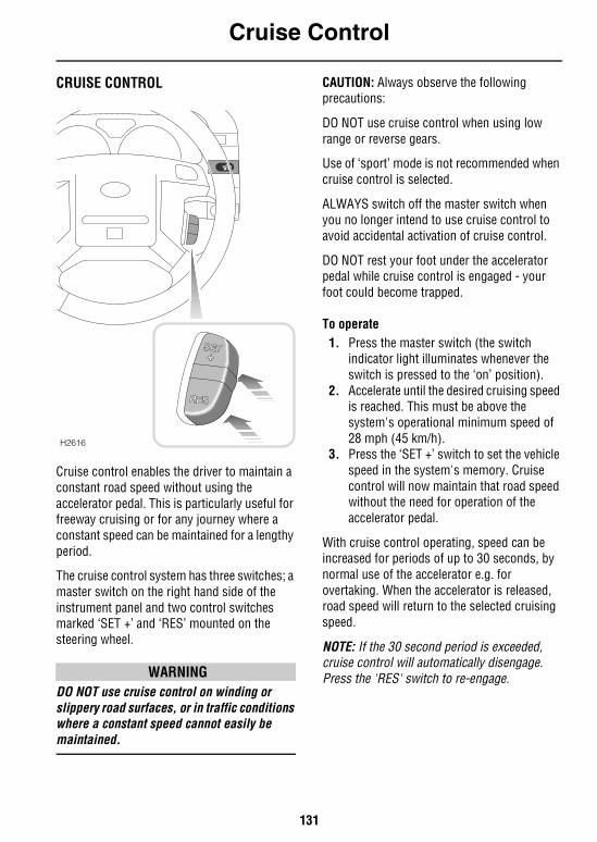
Cruise Control
131
Cruise ControlCRUISE CONTROL
Cruise control enables the driver to maintain a constant road speed without using the accelerator pedal. This is particularly useful for freeway cruising or for any journey where a constant speed can be maintained for a lengthy period.
The cruise control system has three switches; a master switch on the right hand side of the instrument panel and two control switches marked ‘SET +’ and ‘RES’ mounted on the steering wheel.
WARNINGDO NOT use cruise control on winding or slippery road surfaces, or in traffic conditions where a constant speed cannot easily be maintained.
CAUTION: Always observe the following precautions:
DO NOT use cruise control when using low range or reverse gears.
Use of ‘sport’ mode is not recommended when cruise control is selected.
ALWAYS switch off the master switch when you no longer intend to use cruise control to avoid accidental activation of cruise control.
DO NOT rest your foot under the accelerator pedal while cruise control is engaged - your foot could become trapped.
To operate1. Press the master switch (the switch
indicator light illuminates whenever the switch is pressed to the ‘on’ position).
2. Accelerate until the desired cruising speed is reached. This must be above the system's operational minimum speed of 28 mph (45 km/h).
3. Press the ‘SET +’ switch to set the vehicle speed in the system's memory. Cruise control will now maintain that road speed without the need for operation of the accelerator pedal.
With cruise control operating, speed can be increased for periods of up to 30 seconds, by normal use of the accelerator e.g. for overtaking. When the accelerator is released, road speed will return to the selected cruising speed.
NOTE: If the 30 second period is exceeded, cruise control will automatically disengage. Press the 'RES' switch to re-engage.
H2616
Cruise Control
132
To reduce the cruising speed: Press the ‘RES’ switch to slow the vehicle, until the required speed has been reached. Then press the ‘SET +’ switch to establish the new cruising speed (remember that cruise control will not operate at speeds below 28 mph (45 km/h).
To increase the set cruising speed:Press and hold the ‘SET +’ switch - the vehicle will accelerate automatically. Release the switch as soon as the desired speed has been reached.
Alternatively, the set speed can be increased incrementally by ‘tapping’ the ‘SET +’ switch. Each press of the switch will increase the speed by 1 mph (1.5 km/h approx).
Disengaging cruise controlCruise control will disengage when the gear selector is moved into neutral, or when the brake pedal is pressed. Cruise control can also be disengaged by pressing the ‘RES’ switch.
To re-engage cruise control at the previously set speed, press the ‘RES’ switch.
NOTE: The speed held in the cruise control memory will be cancelled when either the cruise control master switch or the starter switch is turned off.
Brakes
133
BrakesFOOT BRAKEFor your safety, the hydraulic braking system operates through dual circuits. If one circuit should fail, the other will continue to function. However, in the event of brake failure where only one circuit is operational, the vehicle should only be driven at slow speed to the nearest qualified retailer. In these circumstances, exercise extreme caution and be aware that increased brake pedal travel, greater pedal pressure, and longer stopping distances will be experienced.
Power assistanceThe braking system is power assisted, but ONLY when the engine is running. Without this assistance greater braking effort is necessary to safely control the vehicle, resulting in longer stopping distances. Always observe the following precautions:• NEVER allow the vehicle to coast with the
engine turned off.• ALWAYS take particular care when being
towed with the engine turned off (see ‘FOUR-WHEEL TOWING’, page 216).
• If the engine should stop for any reason while the vehicle is in motion, bring the vehicle to a halt as quickly as traffic conditions safely allow, and DO NOT pump the brake pedal as the braking system may lose any remaining assistance available.
Electronic brake force distributionIn addition, your vehicle is equipped with Electronic Brake Force Distribution (EBD), which balances the distribution of braking forces between front and rear axles, in order to maintain maximum braking efficiency under all load conditions. For example; under light loads EBD applies less effort to the rear brakes to maintain vehicle stability, conversely reducing front braking effort when the vehicle is towing or is heavily laden.
Driving in wet conditionsDriving through water or even very heavy rain may adversely affect braking efficiency. Always dry the braking surfaces by intermittent light application of the brakes, first ensuring that you are at a safe distance from other road users.
Brake padsBrake pads require a period of bedding in. For the first 500 miles (800 km), you should avoid situations where heavy braking is required.
Remember! Regular servicing is vital to ensure that the brake pads are examined for wear and changed periodically to ensure long term safety and optimum performance.
If the brake warning light comes on when driving, and the parking brake is fully released, a fault with the braking system is indicated. Be prepared for increased brake pedal travel and then stop the vehicle as quickly as traffic conditions and safety permit and seek qualified assistance before continuing. DO NOT pump the brake pedal - the braking system may lose any remaining power assistance available.
CAUTION: DO NOT rest your foot on the brake pedal while travelling, as this may overheat the brakes, reduce their efficiency and cause excessive wear.
WARNING• NEVER place non-approved floor matting
or any other obstructions under the brake pedal. This restricts pedal travel and braking efficiency.
• NEVER move a vehicle without the engine running because braking assistance will not be available. The pedal brakes will still function, but more pressure will be required to operate them.
Brakes
134
WARNINGIf the brake warning light should illuminate while the vehicle is in motion, bring the vehicle to a halt as quickly as traffic conditions and safety permit and seek qualified assistance before continuing. DO NOT pump the brake pedal - the braking system may lose any remaining power assistance available.
PARKING BRAKE Unlike most other vehicles, the handbrake operates on the rear propeller shaft, and NOT on the road wheels. This may result in slight movement of the vehicle after the parking brake is applied.
To engage the parking brake, depress the button and pull the lever up fully.
To release, pull the lever up slightly, depress the button and lower the lever.
When parking on a slope, do not rely on the parking brake alone to hold the vehicle.
Always ensure the parking pawl of the gearbox has fully engaged by carefully releasing the foot brake and allowing the vehicle to ‘rock’ into ‘P’ (park).
CAUTION: DO NOT apply the parking brake whilst the vehicle is in motion (except in an emergency) as this could result in loss of vehicle control and damage to the transmission.
WARNINGALWAYS use wheel chocks when jacking the vehicle. Even with the parking brake applied, vehicle movement is likely due to tolerances in the transmission.
ANTI-LOCK BRAKESCAUTION: ABS cannot overcome the physical limitations of stopping the vehicle in too short a distance, cornering at too high a speed, or the danger of aquaplaning, i.e. where a layer of water prevents adequate contact between the tires and the road surface.
The fact that a vehicle is fitted with ABS must never tempt the driver into taking risks that could affect his/her safety or that of other road users. In all cases, it remains the driver's responsibility to drive within normal safety margins, having due consideration for prevailing weather and traffic conditions.
The ABS is designed to operate only with the tires specified in ‘Technical data’ (see ‘WHEELS & TIRES’, page 247) and genuine Land Rover parts. The manufacturers cannot accept any responsibility for inefficient operation of the system caused by modifications to the vehicle, or the fitting of non-approved components. Always consult your Land Rover retailer for advice.
The driver should always take account of the surface to be travelled over and the fact that brake pedal reactions will be different to those experienced on a non-ABS vehicle.
NOTE: On each initial start up a faint whirring sound can be heard, this is part of the brake system self check and is not a cause for concern.
IMPORTANT INFORMATION
Always apply the parking brake fully whenever you park.
DO NOT rely on the parking brake to operate effectively if the vehicle has been subjected to immersion in mud and water (see ‘Off-Road Driving’ section).
Brakes
135
The purpose of the anti-lock braking system (ABS) is to allow efficient braking without wheel locking - thereby allowing the driver to retain steering control of the vehicle whilst braking.
Under normal braking conditions, (where sufficient road surface friction exists to reliably bring the vehicle to a halt without the wheels locking), ABS will not be activated. However, should the braking force exceed the available adhesion between the tires and the road surface, then ABS will automatically come into operation. This will be recognisable by a rapid pulsation felt through the brake pedal.
In an on-road emergency situation full braking effort should always be applied even when the road surface is slippery. The anti-lock braking system constantly monitors the speed of each wheel and varies braking pressure to each, according to the amount of traction available, thereby ensuring that the wheels do not lock.
WARNINGDO NOT pump the brake pedal at any time; this will interrupt operation of the system and may increase braking distance.
DO NOT place non-approved floor mats or any other obstruction under the brake pedal. This restricts pedal travel and therefore impairs braking efficiency.
Warning lightThe anti-lock braking system incorporates a monitoring system, which checks that all the electrical
components are in working order, as soon as the starter switch is turned on and also continuously during your journey.
The warning light on the instrument panel is an important part of this system. The light should illuminate for approximately 3 seconds when the starter switch is turned to position ‘II’ and then extinguish.
If the light illuminates while driving, or remains illuminated for more than 3 seconds after the starter switch is turned on, a fault has been detected by the self monitoring system and full ABS control may not be available - consult your retailer at the earliest opportunity.
The normal braking system remains fully operational and is not affected by partial or full loss of the ABS. However, braking distances may increase.
Brakes
136
Additional operating informationWhile anti-lock braking is designed to operate equally effectively in ‘off-road’ driving conditions, on certain surfaces total reliance on the system may be unwise - remember, in normal circumstances, anti-lock braking operates only AFTER one or more roadwheels has reached the limit of its grip. It cannot reliably compensate for driver error or inexperience on difficult off-road surfaces.
Note the following:• Under ABS control, heavy braking on a dry
road may produce tire noise and slight marking of the road surface. Neither need cause concern.
• On soft or deep surfaces such as powdery snow, sand or gravel, and on extremely rough ground, the braking distance required by the anti-lock braking system may be greater than those achievable with a non-ABS system, even though improved steering would be experienced. This is because the natural action of locked wheels on soft surfaces is to build up a wedge of surface material in front of the wheels, which assists in stopping.
• The driver should always take account of the surface to be travelled over and the fact that brake pedal reactions will be different from those experienced on a non-ABS vehicle.
• When maximum braking is required on loose or bumpy surfaces, full braking effort should be applied.
• If the vehicle is stopped on a very steep slope where little traction is available, it may slide with the wheels locked because there is no wheel rotation to signal movement to the ABS. To counteract this, briefly release the brakes to permit some wheel movement, then re-apply the brakes to allow the system to gain control at a suitable speed.
• Before driving off-road read and thoroughly understand ‘BASIC OFF-ROAD TECHNIQUES’, page 158.
Traction Control
137
Traction ControlELECTRONIC TRACTION CONTROLThe purpose of electronic traction control is to maintain forward or rearward momentum of the vehicle when one or more wheels are spinning while others have good grip, e.g. if one wheel is on ice and others are on tarmac. The system works by applying the brake to a spinning wheel in order to transfer torque to the remaining wheels.
NOTE: Traction control can operate up to speeds of 62 mph (100 km/h).
Warning lightThe instrument panel has a traction control warning (TC) which illuminates for a minimum of 2
seconds whenever the system is active and also illuminates as a bulb check (for approximately 3 seconds) when the starter switch is turned to position ‘II’.
If there is a fault with the system, the warning light will illuminate continuously and remain illuminated when the vehicle is stopped, in which case you should contact your retailer at the earliest opportunity.
NOTE: Faults with the ETC system will invariably cause the Hill Descent Control warning light to illuminate too. In most cases the ABS and brake system lights will also illuminate.
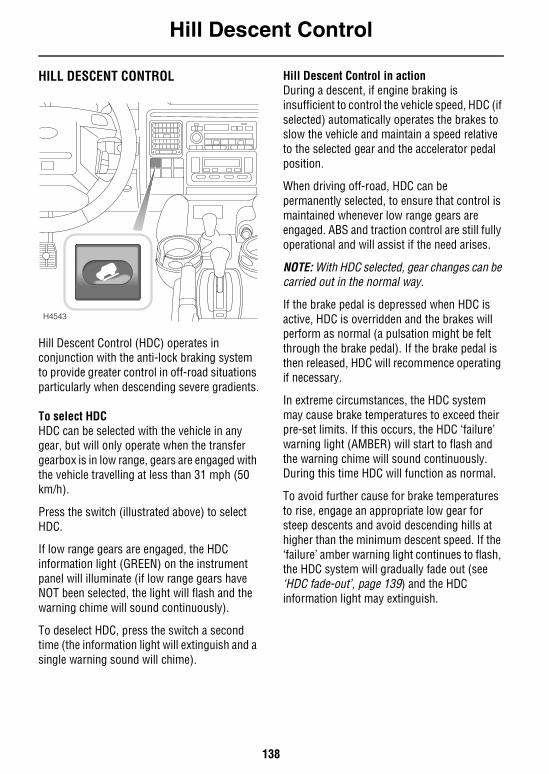
Hill Descent Control
138
Hill Descent ControlHILL DESCENT CONTROL
Hill Descent Control (HDC) operates in conjunction with the anti-lock braking system to provide greater control in off-road situations particularly when descending severe gradients.
To select HDCHDC can be selected with the vehicle in any gear, but will only operate when the transfer gearbox is in low range, gears are engaged with the vehicle travelling at less than 31 mph (50 km/h).
Press the switch (illustrated above) to select HDC.
If low range gears are engaged, the HDC information light (GREEN) on the instrument panel will illuminate (if low range gears have NOT been selected, the light will flash and the warning chime will sound continuously).
To deselect HDC, press the switch a second time (the information light will extinguish and a single warning sound will chime).
Hill Descent Control in actionDuring a descent, if engine braking is insufficient to control the vehicle speed, HDC (if selected) automatically operates the brakes to slow the vehicle and maintain a speed relative to the selected gear and the accelerator pedal position.
When driving off-road, HDC can be permanently selected, to ensure that control is maintained whenever low range gears are engaged. ABS and traction control are still fully operational and will assist if the need arises.
NOTE: With HDC selected, gear changes can be carried out in the normal way.
If the brake pedal is depressed when HDC is active, HDC is overridden and the brakes will perform as normal (a pulsation might be felt through the brake pedal). If the brake pedal is then released, HDC will recommence operating if necessary.
In extreme circumstances, the HDC system may cause brake temperatures to exceed their pre-set limits. If this occurs, the HDC ‘failure’ warning light (AMBER) will start to flash and the warning chime will sound continuously. During this time HDC will function as normal.
To avoid further cause for brake temperatures to rise, engage an appropriate low gear for steep descents and avoid descending hills at higher than the minimum descent speed. If the ‘failure’ amber warning light continues to flash, the HDC system will gradually fade out (see ‘HDC fade-out’, page 139) and the HDC information light may extinguish.
H4543
Hill Descent Control
139
HDC fade-outHDC fade-out gradually decreases the HDC brake intervention with the effect that the rate of hill descent will increase. If this occurs the HDC information light will flash and the warning chime will sound for the period that HDC takes to fade. HDC will be disabled completely once the descent is complete.
If required (e.g. the angle of the descent levels out significantly), fade-out may be achieved deliberately by deselecting HDC while the system is operating.
If a fault with the HDC system is detected, or if the braking system reaches a pre-set temperature due to extreme conditions, HDC will automatically fade out.
Warning lightsHDC information light - GREENThe light illuminates briefly as a bulb and system check when the
starter switch is turned to position ‘II’ and also when HDC is selected.
If HDC is selected when the operating gears (LOW range) are engaged, the light will illuminate continuously.
If HDC has been selected but the system's operating criteria are not met (i.e. gearbox still in high range or vehicle speed too high), the information light will flash and the warning chime will sound continuously.
If the light flashes while HDC is active, normal functionality may cease and HDC ‘fade out’ may be induced.
HDC ‘failure’ light - AMBERThe light illuminates briefly as a bulb and system check when the
starter switch is turned to position ‘II’.
If the light illuminates at any other time, either a fault has occurred which affects the functionality of the system, or over-use of the system has been detected, in which case HDC may ‘fade out’.
NOTE: System faults which cause the ‘failure’ light to illuminate after the initial system checks, or whilst driving, will be accompanied by the warning chime sounding 3 times.
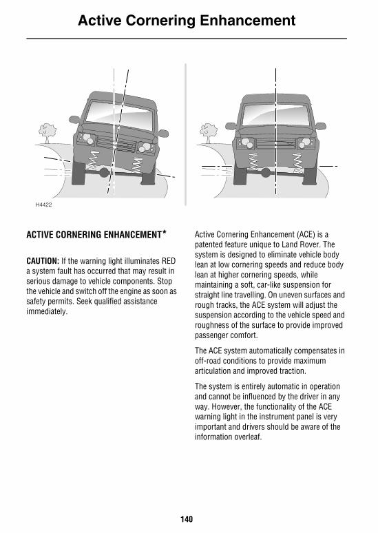
Active Cornering Enhancement
140
Active Cornering Enhancement
ACTIVE CORNERING ENHANCEMENT*
CAUTION: If the warning light illuminates RED a system fault has occurred that may result in serious damage to vehicle components. Stop the vehicle and switch off the engine as soon as safety permits. Seek qualified assistance immediately.
Active Cornering Enhancement (ACE) is a patented feature unique to Land Rover. The system is designed to eliminate vehicle body lean at low cornering speeds and reduce body lean at higher cornering speeds, while maintaining a soft, car-like suspension for straight line travelling. On uneven surfaces and rough tracks, the ACE system will adjust the suspension according to the vehicle speed and roughness of the surface to provide improved passenger comfort.
The ACE system automatically compensates in off-road conditions to provide maximum articulation and improved traction.
The system is entirely automatic in operation and cannot be influenced by the driver in any way. However, the functionality of the ACE warning light in the instrument panel is very important and drivers should be aware of the information overleaf.
H4422
Active Cornering Enhancement
141
Warning light The warning light illuminates RED when the starter switch is turned on (to position 'II'). After two
seconds, the RED illumination changes to AMBER and, after a further two seconds, the light extinguishes. This process is a system check that takes place every time the vehicle is used. Provided the ACE system is operating correctly, illumination will not occur at any other time.
If illumination occurs while driving, a fault with the system is indicated, as follows:• If the light shows RED (a flashing red light,
which changes to constant illumination after two minutes, and is accompanied by a warning chime): This indicates a system fault that may result in serious damage to vehicle components and reduced ACE performance. You must stop the vehicle as soon as safety permits and switch off the engine. DO NOT CONTINUE DRIVING! Seek qualified assistance immediately.
• If the light shows AMBER (constant illumination): This indicates a system fault that will result in reduced ACE performance, but will not leave the vehicle in a dangerous condition. You may continue driving, but reduce speed, take additional care, and consult a Land Rover retailer at the earliest opportunity.
Self-levelling Suspension
142
Self-levelling SuspensionSELF-LEVELLING SUSPENSION*When the engine is running, the self-levelling suspension system (SLS) operates automatically on the rear of the vehicle to maintain a level or efficient vehicle height regardless of vehicle load.
AUTOMATIC OPERATIONIf the height of the vehicle is reduced by additional loading (passengers occupying the occasional rear seats or the attachment of a trailer, for example), the SLS system automatically increases air pressure to the springs to compensate for the additional weight or changed attitude of the vehicle. Similarly, if loads are removed and the vehicle height increases in consequence, the system will reduce air pressure to bring the vehicle back to a level attitude.
Extended modeOff-road, if the vehicle becomes grounded and traction control is induced, the SLS system automatically pumps more air to the rear springs to raise the body clear of the obstruction, thereby enabling the vehicle to be freed. This is known as 'Extended mode' and will cause the off-road warning light to flash. Once forward motion is regained, the suspension height will automatically return to its previous setting and the warning light will extinguish.
MANUAL OPERATIONThe SLS system can also be manually controlled to either:• Raise the rear of the vehicle by 40 mm
(approx.) to increase ground clearance and improve the departure angle for off-road driving. Note that this function operates ONLY below a speed of 18 mph (30 km/h) - above this speed, the vehicle will automatically return to its standard ride height.
• Lower the vehicle in order to ease loading, or to enable various heights of trailer hitch to be connected more easily.
The SLS system will assume automatic control - adjusting the height of the vehicle 10 seconds after a road speed of 3 mph (5 km/h) is reached, or immediately once a road speed of 7 mph (12 km/h) has been achieved. This feature can only be used in conjunction with the remote suspension control handset. Consult your Land Rover retailer for further information.
WARNINGDO NOT operate the SLS while driving on the road, or when the suspension has been manually lowered below standard ride height - any sudden or unexpected change to the vehicle's height or attitude could cause an inexperienced driver to lose control, or disturb the load/weight distribution within the vehicle.
DO NOT select off-road height while towing.
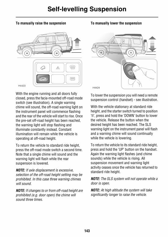
Self-levelling Suspension
143
To manually raise the suspension
With the engine running and all doors fully closed, press the facia-mounted off-road mode switch (see illustration). A single warning chime will sound, the off-road warning light on the instrument panel will commence flashing and the rear of the vehicle will start to rise. Once the pre-set off-road height has been reached, the warning light will stop flashing and illuminate constantly instead. Constant illumination will remain while the vehicle is operating at off-road height.
To return the vehicle to standard ride height, press the off-road mode switch a second time. Note that a single chime will sound and the warning light will flash while the rear suspension is lowered.
NOTE: If axle displacement is excessive, selection of the off-road height setting may be prohibited. In this case three warning chimes will sound.
NOTE: If changes to or from off-road height are prohibited (e.g. door open) the chime will sound three times.
To manually lower the suspension
To lower the suspension you will need a remote suspension control (handset) - see illustration.
With the vehicle stationary at standard ride height, and the starter switch turned to position ‘II’, press and hold the ‘DOWN’ button to lower the vehicle. Release the button when the desired height has been reached. The SLS warning light on the instrument panel will flash and a warning chime will sound continually while the vehicle is lowering.
To return the vehicle to its standard ride height, press and hold the ‘UP’ button on the handset. Again the warning light flashes (and chime sounds) while the vehicle is rising. All suspension movement and warning light activity ceases once the vehicle has returned to standard ride height.
NOTE: The SLS system will not operate while a door is open.
NOTE: At high altitude the system will take significantly longer to raise the vehicle.
H4423H4424
Self-levelling Suspension
144
NOTE: If this feature is subjected to excessive use, the system will automatically disable to prevent components from overheating. The system has a cumulative total of three minutes operation at any one time. If this is exceeded the system will close down (partial operation will return after a few minutes).
Remote SLS handsetIf your vehicle is equipped with SLS, the remote SLS handset is available as an accessory from a Land Rover retailer.
Battery replacement is similar to the equivalent process for the handset key (see ‘REMOTE HANDSET BATTERY’, page 36). Battery specification is identical.
WARNING LIGHTSOff-road - AMBER
Illuminates briefly as a bulb and system check when the starter switch is turned to position ‘II’ and
then extinguishes.
If the off-road switch is pressed: The light flashes while the rear of the vehicle is either; rising to off-road height, or returning to standard ride height. The light then illuminates constantly while the suspension remains at off-road height.
In addition, the light will flash while Extended mode is induced.
Sell-levelling suspension - AMBERIlluminates briefly as a bulb and system check when the starter switch is turned to position ‘II’ and
then extinguishes.
If the remote handset is operated: The light flashes continually while the rear of the vehicle is being lowered, or raised.
If the light illuminates constantly: A fault with the suspension is indicated. Seek qualified assistance as soon as possible.
While it is possible to continue driving the vehicle in this condition, this is not recommended as there is a considerable risk of causing further damage to the suspension. Preferably, the vehicle should be brought to a halt as soon as conditions allow. Further travel should be limited to reaching the nearest Land Rover retailer, or driving to a place of safety while awaiting recovery. In any event, speed must be restricted to a rate that will guarantee a smooth, and totally bump-free, ride at all times, ideally traversing only smooth, roads.
IMPORTANT INFORMATIONNote that the handset will operate effectively from inside the vehicle. It is therefore important to keep it out of reach of children at all times, and especially while towing. When operating the handset from inside the passenger compartment for the purpose of lowering the vehicle to attach a trailer, ensure that the underside of the vehicle has been checked for obstructions before lowering, and that a responsible adult has been posted outside the vehicle to supervise the lowering process.
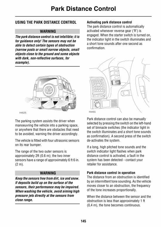
Park Distance Control
145
Park Distance ControlUSING THE PARK DISTANCE CONTROL
WARNINGThe park distance control is not infallible; it is for guidance only! The sensors may not be able to detect certain types of obstruction (narrow posts or small narrow objects, small objects close to the ground and some objects with dark, non-reflective surfaces, for example).
The parking system assists the driver when manoeuvring the vehicle into a parking space, or anywhere that there are obstacles that need to be avoided, warning the driver accordingly.
The vehicle is fitted with four ultrasonic sensors on its rear bumper.
The range of the two outer sensors is approximately 2ft (0.6 m); the two inner sensors have a range of approximately 6 ft 6 in. (2 m).
WARNINGKeep the sensors free from dirt, ice and snow. If deposits build up on the surface of the sensors, their performance may be impaired. When washing the vehicle, avoid aiming high pressure jets directly at the sensors from close range.
Activating park distance controlThe park distance control is automatically activated whenever reverse gear (‘R’) is engaged. When the starter switch is turned on, the indicator light in the switch illuminates and a short tone sounds after one second as confirmation.
Park distance control can also be manually selected by pressing the switch on the left-hand set of binnacle switches (the indicator light in the switch illuminates and a short tone sounds as confirmation). A second press of the switch de-activates the system.
If a long, high pitched tone sounds and the switch indicator light flashes when park distance control is activated, a fault in the system has been detected - contact your retailer for assistance.
Park distance control in operationThe distance from an obstruction is identified by an intermittent tone sounding. As the vehicle moves closer to an obstruction, the frequency of the tone increases proportionally.
When the distance between the sensor and the obstruction is less than approximately 1 ft (0,4 m), the tone becomes continuous.
H4525 H4455
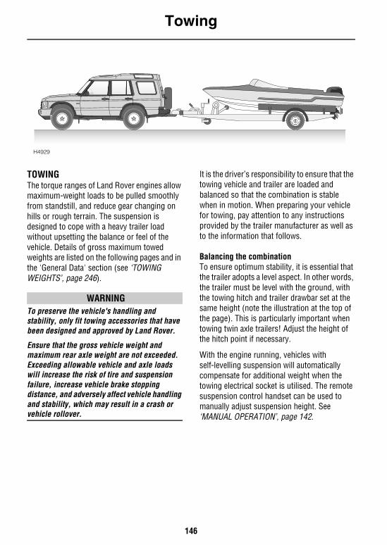
Towing
146
Towing
TOWINGThe torque ranges of Land Rover engines allow maximum-weight loads to be pulled smoothly from standstill, and reduce gear changing on hills or rough terrain. The suspension is designed to cope with a heavy trailer load without upsetting the balance or feel of the vehicle. Details of gross maximum towed weights are listed on the following pages and in the 'General Data' section (see ‘TOWING WEIGHTS’, page 246).
WARNINGTo preserve the vehicle's handling and stability, only fit towing accessories that have been designed and approved by Land Rover.
Ensure that the gross vehicle weight and maximum rear axle weight are not exceeded. Exceeding allowable vehicle and axle loads will increase the risk of tire and suspension failure, increase vehicle brake stopping distance, and adversely affect vehicle handling and stability, which may result in a crash or vehicle rollover.
It is the driver’s responsibility to ensure that the towing vehicle and trailer are loaded and balanced so that the combination is stable when in motion. When preparing your vehicle for towing, pay attention to any instructions provided by the trailer manufacturer as well as to the information that follows.
Balancing the combinationTo ensure optimum stability, it is essential that the trailer adopts a level aspect. In other words, the trailer must be level with the ground, with the towing hitch and trailer drawbar set at the same height (note the illustration at the top of the page). This is particularly important when towing twin axle trailers! Adjust the height of the hitch point if necessary.
With the engine running, vehicles with self-levelling suspension will automatically compensate for additional weight when the towing electrical socket is utilised. The remote suspension control handset can be used to manually adjust suspension height. See ‘MANUAL OPERATION’, page 142.
H4929
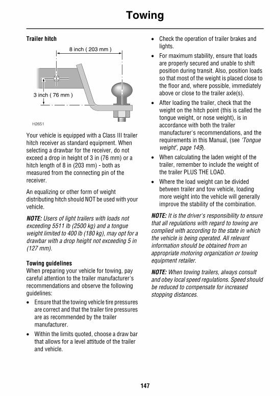
Towing
147
Trailer hitch
Your vehicle is equipped with a Class III trailer hitch receiver as standard equipment. When selecting a drawbar for the receiver, do not exceed a drop in height of 3 in (76 mm) or a hitch length of 8 in (203 mm) - both as measured from the connecting pin of the receiver.
An equalizing or other form of weight distributing hitch should NOT be used with your vehicle.
NOTE: Users of light trailers with loads not exceeding 5511 lb (2500 kg) and a tongue weight limited to 400 lb (180 kg), may opt for a drawbar with a drop height not exceeding 5 in (127 mm).
Towing guidelinesWhen preparing your vehicle for towing, pay careful attention to the trailer manufacturer's recommendations and observe the following guidelines:• Ensure that the towing vehicle tire pressures
are correct and that the trailer tire pressures are as recommended by the trailer manufacturer.
• Within the limits quoted, choose a draw bar that allows for a level attitude of the trailer and vehicle.
• Check the operation of trailer brakes and lights.
• For maximum stability, ensure that loads are properly secured and unable to shift position during transit. Also, position loads so that most of the weight is placed close to the floor and, where possible, immediately above or close to the trailer axle(s).
• After loading the trailer, check that the weight on the hitch point (this is called the tongue weight, or nose weight), is in accordance with both the trailer manufacturer's recommendations, and the requirements in this Manual, (see ‘Tongue weight’, page 149).
• When calculating the laden weight of the trailer, remember to include the weight of the trailer PLUS THE LOAD.
• Where the load weight can be divided between trailer and tow vehicle, loading more weight into the vehicle will generally improve the stability of the combination.
NOTE: It is the driver's responsibility to ensure that all regulations with regard to towing are complied with according to the state in which the vehicle is being operated. All relevant information should be obtained from an appropriate motoring organization or towing equipment retailer.
NOTE: When towing trailers, always consult and obey local speed regulations. Speed should be reduced to compensate for increased stopping distances.
H2651
8 inch ( 203 mm )
3 inch ( 76 mm )
Towing
148
Vehicle weightsWhen loading a vehicle to its maximum (GVW), take account of the load distribution to ensure that axle loads do not exceed the permitted maximum values. It is your responsibility to limit the vehicle load in such a way that neither the maximum axle loads nor the GVW are exceeded. The most accurate method of determining load distribution is by using a public weighbridge.
Tongue weight should be approximately 7% of the actual trailer laden weight to maintain optimum stability. Tongue weight can be measured using a proprietary brand of tongue weight indicator.
Automatic gearboxTo avoid overheating the gearbox, it is not advisable to tow heavy trailer loads at speeds of less than 20 mph (32 km/h) using the main gearbox in high range. Use the transfer gearbox to select low range instead.
Towing on severe inclines If a journey includes severe inclines and the Gross Train Weight (the maximum permissible weight of vehicle, plus trailer, see ‘TOWING WEIGHT’, page 221) is towed, ensure that the grille and radiator are free from obstruction and that only high quality fuel is used. This enables the engine and the cooling system to operate more efficiently.
NOTE: Above 1,000 ft (300 metres) the effects of altitude can adversely affect engine performance and also cause overheating.
Correct gear selection will improve vehicle performance: On vehicles with manual transmission, select the highest practical gear that can be maintained without causing the engine to labour. On vehicles fitted with automatic transmission, select ‘D’ (Drive) and, where possible, maintain a speed that minimises automatic gear changes.
If severe inclines are encountered when towing at high altitude and in a high ambient temperature 86°F (30°C) or greater), the effective Gross Train Weight will be reduced by up to 882 lb (400 kg). Therefore, it may be necessary to reduce the vehicle and/or trailer weight to help counter the reduced engine performance caused by the thinner atmosphere experienced at high altitudes.
ESSENTIAL TOWING CHECKSTire pressures: Increase rear pressures of towing vehicle by at least 3 lbf/in2 (0.2 bar) up to
maximum of 46 lbf/in2 (3.2 bar). Ensure that trailer tires are at recommended pressures.
Loading: Keep trailer loads securely anchored, evenly distributed and as low as possible with heavy loads over the axle. Towing vehicle maximum axle weights and gross vehicle weight must not be exceeded.
Tongue weight: Must be minimum of 7% of gross trailer weight up to maximum of 550 lb (250 kg) - see vehicle/trailer/tow hitch chart in ‘Technical Data’.
Hitch height: Must be set so that caravan/trailer is level when connected to the tow vehicle with engine running.
Towing
149
Tongue weightThe following operating instructions should be read in conjunction with the towing chart given later in this section.
WARNINGDO NOT exceed the gross weight or axle loads stated on the certification label attached to the vehicle. Exceeding allowable vehicle and axle loads will increase the risk of tire or suspension failure, increase vehicle brake stopping distance, and adversely affect vehicle handling and stability which may result in a crash or rollover.
WARNINGThe tongue weight plus the combined weight of the vehicle's load carrying area and rear seat passengers must never exceed the specified maximum rear axle load (see ‘TOWING WEIGHTS’, page 246).
IMPORTANT INFORMATIONFor all of the towing conditions described, it is important that the following points are observed:• All loads in the vehicle should be
distributed as far forward as possible.• The maximum Gross Vehicle Weight
must not be exceeded, see ‘TOWING WEIGHTS’, page 246.
• The maximum individual axle weights must not be exceeded, see ‘TOWING WEIGHTS’, page 246.
• Changes between high and low range should not be made while the vehicle is on the move.
• Total trailer weight and tongue load can be measured with platform scales found at highway weighing stations, building supply companies, etc.
• The loading capacities and conditions for coil sprung and self levelled vehicles are different. Read the following section on permitted loading conditions for full details.
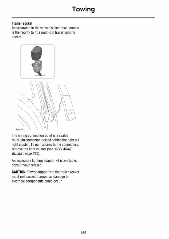
Towing
150
Trailer socketIncorporated in the vehicle's electrical harness is the facility to fit a multi-pin trailer lighting socket.
The wiring connection point is a sealed multi-pin connector located behind the right tail light cluster. To gain access to the connectors, remove the light cluster (see ‘REPLACING BULBS’, page 225).
An accessory lighting adaptor kit is available, consult your retailer.
CAUTION: Power output from the trailer socket must not exceed 5 amps, as damage to electrical components could occur.
H2652
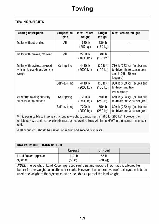
Towing
151
TOWING WEIGHTS
Loading description Suspension Type
Max. Trailer Weight
Tongue Weight
Max. Vehicle Weight
Trailer without brakes All 1650 lb(750 kg)
330 lb(150 kg)
-
Trailer with brakes, off-road All 2200 lb(1000 kg)
330 lb(150 kg)
-
Trailer with brakes, on-road with vehicle at Gross Vehicle Weight
Coil spring 4410 lb(2000 kg)
330 lb (1)
(150 kg)710 lb (322 kg) (equivalent to driver, three passengers and 110 lb (50 kg) luggage)
Self-levelling 4410 lb(2000 kg)
330 lb (1)
(150 kg)900 lb (409 kg) (equivalent to driver and five passengers)
Maximum towing capacity on-road in low range (2)
Coil spring 7700 lb(3500 kg)
550 lb(250 kg)
450 lb (204 kg) (equivalent to driver and 2 passengers)
Self-levelling 7700 lb(3500 kg)
550 lb(250 kg)
600 lb (272 kg) (equivalent to driver and 3 passengers)
(1) It is permissible to increase the tongue weight to a maximum of 550 lb (250 kg), however the vehicle payload and rear axle loads must be reduced to keep within the GVW and maximum rear axle load.(2) All occupants should be seated in the first and second row seats.
MAXIMUM ROOF RACK WEIGHT
On-road Off-road
Land Rover approved system
110 lb(50 kg)
66 lb(30 kg)
NOTE: The weight of Land Rover approved roof bars and cross rail roof rack is allowed for before further weight calculations are made. However, if an alternative roof rack system is to be used, the weight of the system must be included as part of the load weight.
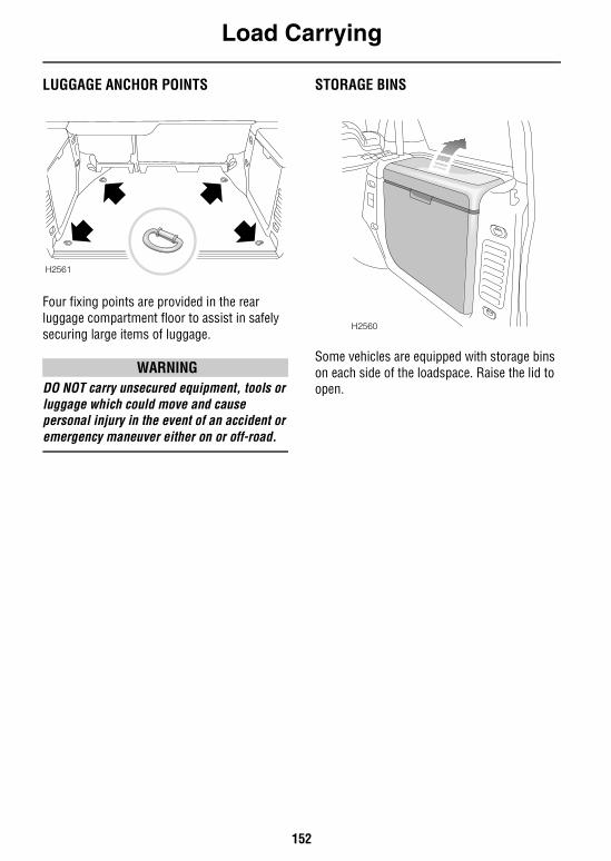
Load Carrying
152
Load CarryingLUGGAGE ANCHOR POINTS
Four fixing points are provided in the rear luggage compartment floor to assist in safely securing large items of luggage.
WARNINGDO NOT carry unsecured equipment, tools or luggage which could move and cause personal injury in the event of an accident or emergency maneuver either on or off-road.
STORAGE BINS
Some vehicles are equipped with storage bins on each side of the loadspace. Raise the lid to open.
H2561
H2560
Load Carrying
153
ROOF RACKS A range of roof rack systems is available as Land Rover approved accessories. For further information about roof rack systems approved for use with your vehicle, and advice as to which system would suit your requirements best, please consult your Land Rover retailer.
The maximum roof rack load must NEVER exceed that given in ‘VEHICLE WEIGHTS’, page 245.
WARNING
• It is recommended that Land Rover approved load-carrying accessories are used wherever possible.
• Only carry loads on cross-rails - do not attach loads directly to the roof bars.
• Use webbing straps (preferably with a ratchet clamp) to secure loads to cross-rails - do not use elastic or ‘bungee’ straps.
• All loads should be evenly distributed and secured within the periphery of the rack.
• Position the roof rack and load so that it does not impede the opening of a sunroof.
• Any roof load will reduce the stability of the vehicle, particularly when cornering and encountering crosswinds.
• Driving off-road with a loaded roof rack is not recommended. If it is necessary to stow luggage on a roof rack while driving off-road, all loads MUST be removed before traversing side slopes
• Check to ensure that the roof rack and load are secure after 30 miles (50 km) of any journey.
WARNINGTo avoid the risk of personal injury or death, DO NOT permit children or any other person to travel on the roof rack (or any access ladder) whilst the vehicle is in motion.

154
155
Off-Road Driving
Off-Road DrivingBEFORE YOU DRIVE . . . . . . . . . . . . . . . . . . . . . 157BASIC OFF-ROAD TECHNIQUES . . . . . . . . . . . . 158AFTER DRIVING OFF-ROAD. . . . . . . . . . . . . . . . 160SERVICING REQUIREMENTS. . . . . . . . . . . . . . . 160
Driving TechniquesDRIVING ON SOFT SURFACES & DRY SAND . . 161STOPPING THE VEHICLE ON SOFTGROUND, IN SAND OR ONAN INCLINE . . . . . . . . . . . . . . . . . . . . . . . . . . . . 161DRIVING ON SLIPPERY SURFACES(ice, snow, mud, wet grass). . . . . . . . . . . . . . . . 161DRIVING ON ROUGH TRACKS. . . . . . . . . . . . . . 161CLIMBING STEEP SLOPES . . . . . . . . . . . . . . . . 162DESCENDING STEEP SLOPES . . . . . . . . . . . . . . 163TRAVERSING A SLOPE . . . . . . . . . . . . . . . . . . . 163NEGOTIATING A ‘V’ SHAPED GULLY. . . . . . . . . 164DRIVING IN EXISTING WHEEL TRACKS . . . . . . 164CROSSING A RIDGE . . . . . . . . . . . . . . . . . . . . . 164CROSSING A DITCH . . . . . . . . . . . . . . . . . . . . . 165WADING . . . . . . . . . . . . . . . . . . . . . . . . . . . . . . 166

156
Off-Road Driving
157
Off-Road Driving
Off-Road DrivingBEFORE YOU DRIVEBefore venturing off-road, it is absolutely essential that inexperienced drivers become fully familiar with the vehicle's controls, in particular the transfer gearbox, and also study the off-road driving techniques described on this and the following pages.
WARNINGOff-road driving can be hazardous!
• DO NOT take unnecessary risks and be prepared for emergencies at all times.
• Your Discovery has a higher ground clearance and hence a higher center of gravity than an ordinary passenger car. An abrupt maneuver at an inappropriate speed or on an unstable surface could cause the vehicle to go out of control or rollover.
• Familiarize yourself with the recommended driving techniques in order to reduce risks to yourself, your vehicle AND your passengers.
• Always ensure that seat belts are worn for personal protection while driving on-road or off-road.
• DO NOT drive off-road alone or without letting someone know where you are going and when you plan to return.
IMPORTANT INFORMATION
• DO NOT drive if the fuel level is low - undulating ground and steep inclines could cause fuel starvation to the engine and consequent damage to the catalytic converter.
• As a precaution against accidental loss, remove the towing eye cover from the front spoiler before driving off-road (see ‘TOWING EYES’, page 216).
• DO NOT stop the engine while driving through water (wading) - water ingress to the exhaust tailpipe could result in severe damage to the catalytic converter.
Off-Road Driving
158
BASIC OFF-ROAD TECHNIQUESThese basic driving techniques are an introduction to the art of off-road driving and do not necessarily provide the information needed to successfully cope with every single off-road situation.
We strongly recommend that owners who intend to drive off-road frequently, should seek as much additional information and practical experience as possible.
Before driving off-road it is important that you check the condition of the wheels and tires and that the tire pressures are correct. Worn or incorrectly inflated tires will adversely affect the performance, stability and safety of the vehicle.
Gear selectionOn automatic models, with the main selector lever set at ‘D’, the gearbox automatically provides the correct gear for the appropriate gear range selected (HIGH or LOW). Remember that position ‘1’ will hold the gearbox in first gear to give maximum engine braking when required.
HIGH range gears should be used whenever possible - only change to LOW range when ground conditions become very difficult or gradients are steep.
‘Manual’ modePress the mode switch whilst the automatic gearbox is in Low range to select ‘Manual’ mode; this enables the transmission to function as a manual gearbox locking the gearbox into whichever gear position has been selected (‘D’ = 4th gear), providing maximum vehicle control and engine braking - ideal for use in severe off-road conditions.
NOTE: Changing from Low to High range will automatically cancel ‘Manual’ mode.
BrakingAs far as possible, vehicle speed should be controlled through correct gear selection and the use of Hill Descent Control (HDC). Application of the brake pedal should be kept to a minimum. In fact, if the correct gear and HDC have been selected, braking will be largely unnecessary.
If the brake pedal is depressed when HDC is active, HDC is overridden and the brakes will perform as normal. If the brake pedal is then released, HDC will recommence operating, if necessary.
Use of engine for brakingBefore descending steep slopes, stop the vehicle at least its length before the descent, engage the parking brake, then engage LOW range and then select first or second gear (‘1’ or ‘2’ for automatic transmission) depending on the severity of the incline.
While descending the slope, it should be remembered that the engine will provide sufficient braking effort to control the rate of descent, and that the brakes should not be applied.
AcceleratingUse the accelerator with care - any sudden surge of power may induce wheel spin and, therefore, invoke unnecessary operation of traction control, or in extreme conditions could lead to loss of control of the vehicle.
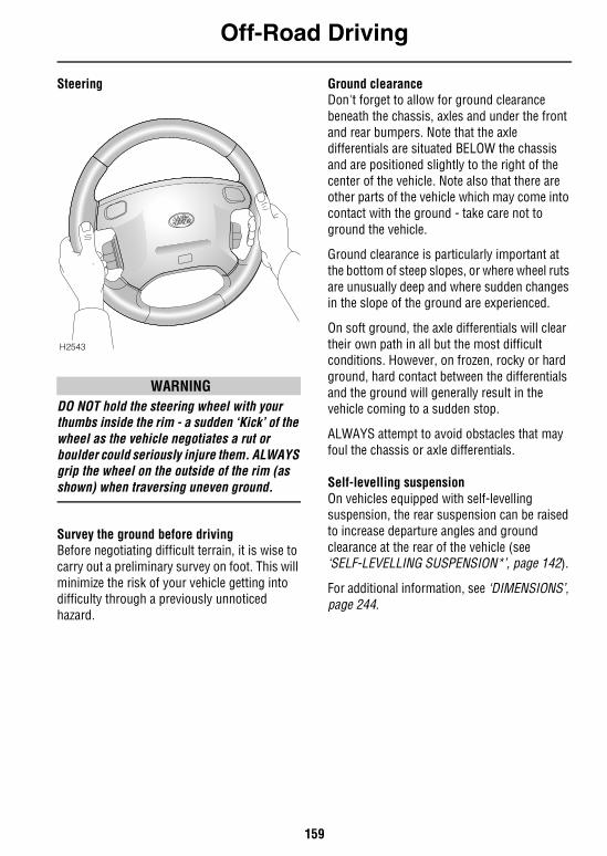
Off-Road Driving
159
Steering
WARNINGDO NOT hold the steering wheel with your thumbs inside the rim - a sudden ‘Kick’ of the wheel as the vehicle negotiates a rut or boulder could seriously injure them. ALWAYS grip the wheel on the outside of the rim (as shown) when traversing uneven ground.
Survey the ground before drivingBefore negotiating difficult terrain, it is wise to carry out a preliminary survey on foot. This will minimize the risk of your vehicle getting into difficulty through a previously unnoticed hazard.
Ground clearanceDon't forget to allow for ground clearance beneath the chassis, axles and under the front and rear bumpers. Note that the axle differentials are situated BELOW the chassis and are positioned slightly to the right of the center of the vehicle. Note also that there are other parts of the vehicle which may come into contact with the ground - take care not to ground the vehicle.
Ground clearance is particularly important at the bottom of steep slopes, or where wheel ruts are unusually deep and where sudden changes in the slope of the ground are experienced.
On soft ground, the axle differentials will clear their own path in all but the most difficult conditions. However, on frozen, rocky or hard ground, hard contact between the differentials and the ground will generally result in the vehicle coming to a sudden stop.
ALWAYS attempt to avoid obstacles that may foul the chassis or axle differentials.
Self-levelling suspensionOn vehicles equipped with self-levelling suspension, the rear suspension can be raised to increase departure angles and ground clearance at the rear of the vehicle (see ‘SELF-LEVELLING SUSPENSION*’, page 142).
For additional information, see ‘DIMENSIONS’, page 244.
H2543
Off-Road Driving
160
Loss of tractionIf the vehicle is immobilised due to loss of tire grip, the following hints could be of value:• Avoid prolonged wheel spin; this will only
make matters worse.
• Remove obstacles rather than forcing the vehicle to cross them.
• Clear clogged tire treads.
• Reverse as far as possible, then attempt an increased speed approach - additional momentum may overcome the obstacle.
• Brushwood, sacking or any similar material placed in front of the tires may improve tire grip.
CD AutochangerPlaying CDs while negotiating arduous off-road terrain is not recommended. Severe jolting of the vehicle may disturb the operation of the autochanger, causing the disc to ‘jump’ or ‘skip’.
AFTER DRIVING OFF-ROAD
WARNINGBefore rejoining the public highway, or driving at speeds above 25 mph (40 km/h), consideration should be given to the following:
• Wheels and tires must be cleaned of mud and inspected for damage - ensure that there are no lumps or bulges in the tires or exposure of the ply or cord structure.
• If wheels and tires are not cleaned properly, damage to the wheels, tires, braking system and suspension components could occur.
• Brake discs and callipers should be examined and any stones or grit that may affect braking efficiency removed.
• The underside of the vehicle should be checked for damage, especially the suspension air springs and dampers.
• Any damage to paint or protective coatings, should be rectified by a Land Rover retailer as soon as possible.
If you have any doubt whether the vehicle has been damaged, have the vehicle inspected by a Land Rover retailer.
SERVICING REQUIREMENTSVehicles operated in arduous conditions, particularly on dusty, muddy or wet terrain, and vehicles undergoing frequent or deep wading conditions will require more frequent servicing. See ‘OWNER MAINTENANCE’, page 176 and contact a Land Rover retailer for advice.
After wading in salt water or driving on sandy beaches, use a hose to wash the underbody components and any exposed body panels with fresh water. This will help to protect the vehicle's cosmetic appearance and help prevent corrosion.
Driving Techniques
161
Driving TechniquesDRIVING ON SOFT SURFACES & DRY SANDThe ideal technique for driving on soft surfaces (dry sand for example) requires the vehicle to be kept moving at all times - soft sand causes excessive drag on the wheels resulting in a rapid loss of motion once driving momentum is lost. For this reason, gear changing should be avoided.• Engage the diff lock*.
• Select the highest suitable gear and REMAIN in that gear until a firm surface is reached. It is generally advisable to use LOW range gears, as they will enable you to accelerate through worsening conditions without the risk of being unable to restart.
• Disengage the diff lock*.
STOPPING THE VEHICLE ON SOFTGROUND, IN SAND OR ONAN INCLINEIf you do stop the vehicle, remember:
Starting on an incline or in soft ground or sand may be difficult. Always park on a firm level area, or with the vehicle facing downhill.
To avoid wheel spin, select ‘D’ and use the MINIMUM throttle necessary to get the vehicle moving.
If forward motion is lost, avoid excessive use of the throttle - this will cause wheel spin and tend to dig the vehicle into the sand. Clear sand from around the tires and ensure that the chassis and axles are not bearing on the sand before again attempting to move.
If the wheels have sunk, use an air bag lifting device or high lift jack to raise the vehicle, and then build up sand under the wheels so that the vehicle is again on level ground. If a restart is still not possible, place ladders or other load spreading aids beneath the wheels.
DRIVING ON SLIPPERY SURFACES(ice, snow, mud, wet grass) • Engage the diff lock*.
• Select the highest gear possible.
• Drive away using the MINIMUM throttle possible.
• Drive slowly at all times, keeping braking to a minimum and avoiding violent movements of the steering wheel.
• Disengage the diff lock* as soon as firm ground is reached.
DRIVING ON ROUGH TRACKSAlthough rough tracks can sometimes be negotiated in normal drive, it is advisable to engage diff lock* if excessive suspension movement is likely to induce wheel spin. On very rough tracks, engage LOW range to enable a steady, low speed to be maintained without constant use of the brake pedal.
WARNINGDO NOT drive the vehicle at speeds in excess of 40 mph (60 km/h) with the differential locked.Driving with the differential locked at speeds above 40 mph (60 km/h) may, under certain situations affect the brake performance under ABS conditions.
Driving Techniques
162
CLIMBING STEEP SLOPESEngage the diff lock* and ALWAYS follow the fall line of the slope - travelling diagonally could cause the vehicle to slide broadside down the slope.
Steep climbs will usually require the LOW gear range. If the surface is loose or slippery, use sufficient speed in the highest practical gear to take advantage of your vehicle's momentum. However, too high a speed over a bumpy surface may result in a wheel lifting, causing the vehicle to lose traction. In this case, try a slower approach. Traction can also be improved by easing off the accelerator just before loss of forward motion.
If the vehicle is unable to complete a climb, do not attempt to turn it around while on the slope. Instead, adopt the following procedure to reverse downhill to the foot of the slope.
1. Hold the vehicle stationary using both the foot and parking brakes.
2. Restart the engine if necessary.3. Engage reverse (‘R’) and LOW range.4. Select hill descent control (HDC). 5. Release the parking brake. Then release
the foot brake and allow the vehicle to reverse down the slope using engine braking and HDC to control the rate of descent.
6. Unless it is necessary to stop the vehicle to negotiate obstructions, DO NOT apply the brake pedal during the descent - even a light application may cause the front wheels to lock, rendering the steering ineffective.
7. If the vehicle begins to slide, accelerate slightly to allow the tires to regain grip.
When the vehicle is back on level ground or where traction can be regained, a faster approach will probably enable the hill to be climbed. However, DO NOT take unnecessary risks, if the hill is too difficult to climb, find an alternative route.
WARNINGDO NOT attempt to reverse down a slope without the engine running and ensure that ‘R’ (reverse) is selected. Otherwise, HDC and the braking effect of the gearbox will be lost.
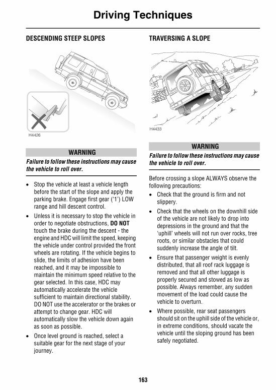
Driving Techniques
163
DESCENDING STEEP SLOPES
WARNINGFailure to follow these instructions may cause the vehicle to roll over.
• Stop the vehicle at least a vehicle length before the start of the slope and apply the parking brake. Engage first gear (‘1’) LOW range and hill descent control.
• Unless it is necessary to stop the vehicle in order to negotiate obstructions, DO NOT touch the brake during the descent - the engine and HDC will limit the speed, keeping the vehicle under control provided the front wheels are rotating. If the vehicle begins to slide, the limits of adhesion have been reached, and it may be impossible to maintain the minimum speed relative to the gear selected. In this case, HDC may automatically accelerate the vehicle sufficient to maintain directional stability. DO NOT use the accelerator or the brakes or attempt to change gear. HDC will automatically slow the vehicle down again as soon as possible.
• Once level ground is reached, select a suitable gear for the next stage of your journey.
TRAVERSING A SLOPE
WARNINGFailure to follow these instructions may cause the vehicle to roll over.
Before crossing a slope ALWAYS observe the following precautions:• Check that the ground is firm and not
slippery.
• Check that the wheels on the downhill side of the vehicle are not likely to drop into depressions in the ground and that the ‘uphill’ wheels will not run over rocks, tree roots, or similar obstacles that could suddenly increase the angle of tilt.
• Ensure that passenger weight is evenly distributed, that all roof rack luggage is removed and that all other luggage is properly secured and stowed as low as possible. Always remember, any sudden movement of the load could cause the vehicle to overturn.
• Where possible, rear seat passengers should sit on the uphill side of the vehicle or, in extreme conditions, should vacate the vehicle until the sloping ground has been safely negotiated.
H4426
H4433
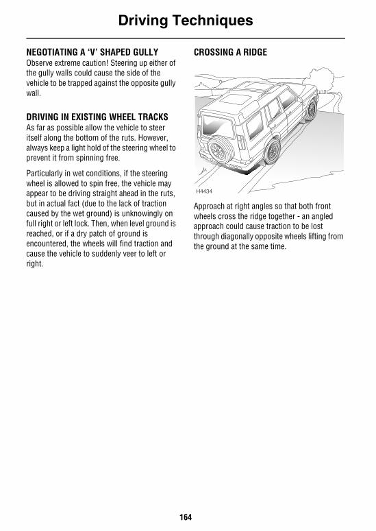
Driving Techniques
164
NEGOTIATING A ‘V’ SHAPED GULLYObserve extreme caution! Steering up either of the gully walls could cause the side of the vehicle to be trapped against the opposite gully wall.
DRIVING IN EXISTING WHEEL TRACKSAs far as possible allow the vehicle to steer itself along the bottom of the ruts. However, always keep a light hold of the steering wheel to prevent it from spinning free.
Particularly in wet conditions, if the steering wheel is allowed to spin free, the vehicle may appear to be driving straight ahead in the ruts, but in actual fact (due to the lack of traction caused by the wet ground) is unknowingly on full right or left lock. Then, when level ground is reached, or if a dry patch of ground is encountered, the wheels will find traction and cause the vehicle to suddenly veer to left or right.
CROSSING A RIDGE
Approach at right angles so that both front wheels cross the ridge together - an angled approach could cause traction to be lost through diagonally opposite wheels lifting from the ground at the same time.
H4434
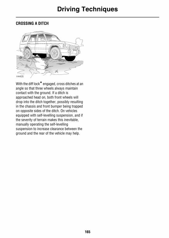
Driving Techniques
165
CROSSING A DITCH
With the diff lock* engaged, cross ditches at an angle so that three wheels always maintain contact with the ground. If a ditch is approached head on, both front wheels will drop into the ditch together, possibly resulting in the chassis and front bumper being trapped on opposite sides of the ditch. On vehicles equipped with self-levelling suspension, and if the severity of terrain makes this inevitable, manually operating the self-levelling suspension to increase clearance between the ground and the rear of the vehicle may help.
H4435
Driving Techniques
166
WADING
WARNINGThe maximum advisable wading depth is 20 inches (0.5 m).
Severe electrical damage may occur if the vehicle remains stationary for any length of time when the water level is above the door sills.
Severe damage to the catalytic converter could occur if the engine is stopped for any length of time when the water level is above the exhaust tail pipe.
If the depth of water is likely to exceed 20 inches (0.5 m), the following precautions should be observed:• Fix a plastic sheet in front of the radiator
grille to prevent water from soaking the engine and mud from blocking the radiator.
• Remove the CD autochanger*.• Ensure that the silt bed beneath the water is
free of obstacles and firm enough to support the vehicle's weight and provide sufficient traction.
• Ensure that the engine air intake is clear of the water level.
• Engage the diff lock*.
• Select a low gear and maintain sufficient throttle to prevent the engine from stalling. This is particularly important if the exhaust pipe is under water.
• Drive slowly into the water and accelerate to a speed which causes a bow wave to form; then maintain that speed.
At all times, keep all the doors fully closed.
NOTE: If deep wading is to be carried out regularly, contact your Land Rover retailer for advice.
After wading• Disengage the diff lock*as soon as firm
ground is reached.• Immediately after wading, remove any
protective covering from in front of the radiator grille.
• Drive the vehicle a short distance and apply the foot brake to check that the brakes are fully effective.
• DO NOT rely on the parking brake to hold the vehicle stationary until the transmission has thoroughly dried out; in the meantime, leave the vehicle with the gearbox selector moved to park (‘P’).
• If the water was particularly muddy, remove any blockages (mud and leaves) from the radiator to reduce the risk of overheating.
• If deep water is regularly negotiated, check all oils for signs of water contamination - contaminated oil can be identified through its ‘milky’ appearance. In addition, check the air filter element for water ingress and replace if wet - consult a Land Rover retailer if necessary.
• If salt water is frequently negotiated, thoroughly wash the underbody components and exposed body panels with fresh water.
NOTE: Vehicles required to undergo frequent or deep wading conditions will require more frequent servicing. Contact a Land Rover retailer for advice.
167
On-Road Driving
On-Road DrivingINSTRUMENTS AND WARNING LIGHTS . . . . . . 169POWER ASSISTED STEERING. . . . . . . . . . . . . . 169WARMING UP . . . . . . . . . . . . . . . . . . . . . . . . . . 169VEHICLE HEIGHT . . . . . . . . . . . . . . . . . . . . . . . . 169DRIVING PRECAUTIONS . . . . . . . . . . . . . . . . . . 170FUEL ECONOMY . . . . . . . . . . . . . . . . . . . . . . . . 171BREAKDOWN SAFETY . . . . . . . . . . . . . . . . . . . . 171

168
On-Road Driving
169
On-Road Driving
On-Road DrivingINSTRUMENTS AND WARNING LIGHTSBefore driving it is important to fully understand the function of the instruments and warning lights (see ‘INSTRUMENT PANEL’, page 65).
NOTE: Red warning lights are of particular importance, illumination indicating that a fault exists. If a red light illuminates, always stop the vehicle and seek qualified assistance before continuing.
POWER ASSISTED STEERINGThe hydraulic power-assisted steering is progressively geared; when steering straight ahead gearing is relatively low, but becomes progressively higher as the steering wheel is turned.
NOTE: Power assistance is dependent on the engine running. If the engine is not running, a much greater effort will be required to steer the vehicle.
WARMING UPIn the interests of fuel economy, it is advisable to drive the vehicle straight away, remembering that harsh acceleration or laboring the engine before the normal operating temperature has been reached can damage the engine.
When the engine is cold, engine idle speeds will be faster than normal. Under these circumstances, use the foot brake to control the vehicle until the engine is warm and running at normal speed, and be aware of the need to take additional care when manoeuvring the vehicle.
VEHICLE HEIGHTCAUTION: The overall height of your vehicle exceeds that of ordinary passenger cars (for convenience the height is shown on the underside of the sun visor). Always be aware of the height of your vehicle and check the available headroom before driving through low entrances. This is particularly important if the vehicle is fitted with a roof rack or if a sunroof is open.
On-Road Driving
170
DRIVING PRECAUTIONS
WARNINGUtility vehicles have a significantly higher roll-over rate than other types of vehicles. Since these vehicles are designed to be operated both on and off-road, these vehicles have a higher ground clearance and hence a higher center of gravity. Such a feature has been associated with an increased risk of vehicle roll-over. An advantage associated with higher ground clearance vehicles is a better view of the road, allowing the driver to anticipate problems. Another factor shown to significantly increase roll-over risk is unauthorized vehicle modifications such as fitting incorrect specification tires (see ‘WHEELS & TIRES’, page 247), oversize tires, body lifting, incorrect springs/dampers, incorrect vehicle loading/trailer towing.
However, on-road crash data also indicates that driver behaviour is a greater factor than a high center of gravity in determining a vehicle's overall roll-over rate. The single most effective driver behaviour that can reduce the risk of injury or death in all crashes including roll-over, is to ALWAYS WEAR YOUR SEAT BELT and to properly restrain all child passengers on the second row seats in appropriate child safety seats. In a roll-over crash, an unbelted person is significantly more likely to die than a person wearing a seat belt.
Other measures that can reduce the risk of injury and death from vehicle crashes and roll-over are:• Limit speed. Posted speed limits should
never be exceeded, and you should always adjust your speed as traffic, weather, road or other conditions dictate. Always use your common sense and good judgement.
• Take curves at reasonable speeds, avoiding unnecessary braking and steering.
• Drive defensively. Be aware of traffic, road and weather conditions. Avoid risk taking behaviour such as following too close, rapid lane changing or abrupt maneuvers.
• Assume that pedestrians or other drivers are going to make mistakes. Anticipate what they might do. Be ready for their mistakes.
• Avoid distractions such as cellular phone calling, reading, eating, drinking or reaching for items on the floor.
• Before changing lanes, check your mirrors and flash your turn signal lights.
• Always leave room for unexpected events such as sudden braking.
• Never operate your vehicle when you have consumed alcohol, are sleepy or fatigued or have taken any medications that affect judgement, reflexes or alertness.
• Many vehicle rollovers occur when a driver attempts to bring a vehicle back onto the road after some or all of the wheels drift onto the shoulder of the road, especially when the shoulder is unpaved. If you find yourself in such a situation, do not initiate any sharp or abrupt steering and/or braking maneuvers to re-enter the roadway. Instead, let the vehicle slow down as much as safely possible before attempting to re-enter the roadway and keep your wheels as straight as possible while re-entering the roadway.
On-Road Driving
171
FUEL ECONOMYFuel consumption is influenced by two major factors: • How your vehicle is maintained.• How you drive your vehicle.
To obtain optimum fuel economy, it is essential that your vehicle is maintained in accordance with the manufacturer's service schedule.
Items such as the condition of the air cleaner element, tire pressures and wheel alignment will have a significant effect on fuel consumption. But, above all, the way in which you drive is most important. The following hints may help you to obtain better value from your motoring: • Avoid unnecessary, short, start-stop
journeys.
• Avoid fast starts by accelerating gently and smoothly from rest.
• Do not drive in the lower gears for longer than necessary.
• Decelerate gently and avoid sudden and heavy braking.
• Anticipate obstructions and adjust your speed accordingly well in advance.
• When stationary in traffic, select neutral to improve fuel economy and air conditioning performance.
BREAKDOWN SAFETY
IMPORTANT INFORMATION
Remember the breakdown safety code
If a breakdown occurs while travelling:• Wherever possible, consistent with
road safety and traffic conditions, the vehicle should be moved off the main thoroughfare, preferably onto the shoulder as far as possible. If a breakdown occurs on a motorway, pull well over to the inside of the hard shoulder.
• Switch on hazard lights.
• If possible, position a warning triangle or a flashing amber light at an appropriate distance from the vehicle to warn other traffic of the breakdown, (note the legal requirements of some countries).
• Consider evacuating passengers through the doors facing away from traffic, to a safe area away from the vehicle, as a precaution in case your Discovery is accidentally struck by another vehicle.

172
173
Owner Maintenance
MaintenanceROUTINE MAINTENANCE . . . . . . . . . . . . . . . . . 175OWNER MAINTENANCE. . . . . . . . . . . . . . . . . . . 176SAFETY IN THE GARAGE . . . . . . . . . . . . . . . . . . 177EMISSION CONTROL. . . . . . . . . . . . . . . . . . . . . 178ROAD TESTING ON DYNAMOMETERS (‘rolling roads’) . . . . . . . . . . . . . . . . . . . . . . . . . . . . . . . . 178
Hood OpeningHOOD OPENING. . . . . . . . . . . . . . . . . . . . . . . . . 179
Engine CompartmentENGINE . . . . . . . . . . . . . . . . . . . . . . . . . . . . . . . 180
Engine OilCHECK & TOP-UP . . . . . . . . . . . . . . . . . . . . . . . 181DRAIN & REFILL . . . . . . . . . . . . . . . . . . . . . . . . 182
Air CleanerELEMENT RENEWAL . . . . . . . . . . . . . . . . . . . . . 184
Spark PlugsSPARK PLUG REMOVE & REFIT . . . . . . . . . . . . 185
Cooling SystemCOOLANT CHECK AND TOP-UP. . . . . . . . . . . . . 186ANTI-FREEZE . . . . . . . . . . . . . . . . . . . . . . . . . . . 187
BrakesBRAKE FLUID. . . . . . . . . . . . . . . . . . . . . . . . . . . 188
Power SteeringPOWER STEERING FLUID . . . . . . . . . . . . . . . . . 189
Active Cornering EnhancementACTIVE CORNERING ENHANCEMENT . . . . . . . . 190
WashersWINDSHIELD WASHER TOP-UP . . . . . . . . . . . . 191WASHER JETS. . . . . . . . . . . . . . . . . . . . . . . . . . 191HEADLIGHT WASHERS . . . . . . . . . . . . . . . . . . . 191
Wiper BladesWIPER BLADE REPLACEMENT . . . . . . . . . . . . . 192
174
BatteryBATTERY SAFETY. . . . . . . . . . . . . . . . . . . . . . . 193BATTERY MAINTENANCE . . . . . . . . . . . . . . . . . 193
TiresCARING FOR YOUR TIRES . . . . . . . . . . . . . . . . 196UNIFORM TIRE QUALITY GRADING . . . . . . . . . 198SNOW CHAINS . . . . . . . . . . . . . . . . . . . . . . . . . 199
Cleaning & Vehicle CareWASHING YOUR VEHICLE . . . . . . . . . . . . . . . . 200CLEANING THE INTERIOR . . . . . . . . . . . . . . . . 202
Identification NumbersVEHICLE IDENTIFICATION NUMBER (VIN). . . . 203
Parts & AccessoriesPARTS AND ACCESSORIES . . . . . . . . . . . . . . . 205
Maintenance
175
Owner Maintenance
MaintenanceROUTINE MAINTENANCERegular systematic maintenance is the key to ensuring the continued reliability and efficiency of your vehicle.
Maintenance is the owner's responsibility and you must ensure that owner maintenance operations, oil services, inspections and brake fluid and coolant changes are carried out when required and according to the manufacturer's recommendations.
The routine maintenance requirements for your vehicle are shown in the Passport to Service book. Most of this necessary workshop maintenance requires specialised knowledge and equipment, and should preferably be entrusted to a Land Rover retailer.
Passport to Service bookThe Passport to Service book includes a Service Record section, which enables a record to be kept of all the oil services and inspections that are carried out on the vehicle. This section of the book also provides a facility for the retailer to record brake fluid and ancillary drive belt changes, as well as the fitting of replacement airbag modules.
Ensure your retailer signs and stamps the book after each oil service and inspection.
Brake fluid/component replacementBrake fluid must be completely renewed every 30,000 miles (48,000 km) or 24 months, whichever is the sooner.
In addition, it is recommended that at 90,000 mile (144,000 km) intervals or every 6 years, whichever is the sooner, all hydraulic brake fluid seals and flexible hoses are renewed. All working surfaces of the caliper cylinders are examined and the components renewed where necessary. Under arduous operating conditions, these intervals may need to be reduced. Please consult your Land Rover retailer.
Coolant replacementThe engine coolant (anti-freeze and water solution) needs to be replaced every 30,000 miles (48,000 km) or 24 months, whichever is the sooner.
Maintenance
176
OWNER MAINTENANCEIn addition to the routine services and inspections referred to previously, a number of simple checks must be carried out more frequently. You can carry out these checks yourself and advice is given on the pages that follow.
Any significant or sudden drop in fluid levels, or uneven tire wear, should be reported to a retailer without delay.
Daily checks• Operation of lights, horn, direction
indicators, wipers, washers and warning lights.
• Operation of seat belts and brakes.
• Look for fluid deposits underneath the vehicle that might indicate a leak (condensation drips from the air conditioning are normal).
Weekly checks• Engine oil level.
NOTE: The engine oil level should be checked more frequently if the vehicle is driven for prolonged periods at high speeds.
• Coolant level.
• Brake fluid level.• Power steering fluid level.
• Screen washer fluid level.
• Active cornering enhancement fluid level• Tire pressures and condition.
• Operate air conditioning.
All fluid specifications and capacities are shown in ‘LUBRICANTS AND FLUIDS’, page 239.
WARNINGIf brake pedal travel is unusually long or if there is any significant loss of brake fluid, contact your retailer immediately. Driving under such conditions could result in extended stopping distances or complete brake failure.
Driving in arduous conditions
IMPORTANT INFORMATIONSpecial operation conditionsWhen a vehicle is operated in extremely arduous conditions, more frequent attention must be paid to servicing requirements.
For example: if your vehicle experiences deep wading conditions, even DAILY servicing could be necessary to ensure the continued safe and reliable operation of the vehicle.
Arduous driving conditions include:• Repeated short distance driving (e.g.
up to 6 miles (10 km), stop-start driving or idling for long periods.
• Driving in dusty and/or sandy conditions.
• Driving on rough and/or muddy roads and/or wading.
• Driving in extremely hot conditions.
• Towing a trailer or driving in mountainous conditions.
Contact a Land Rover retailer for advice.

Maintenance
177
SAFETY IN THE GARAGE
WARNINGCooling fans may continue to operate after the engine is switched off. When the engine is hot, the cooling fans may also COMMENCE operating after the engine is switched off and continue operating for up to 10 minutes. To avoid injury, keep clear of all fans and remove any loose clothing while working in the engine compartment.
Whenever you need to carry out maintenance on your vehicle, observe the following safety precautions at all times:• Keep your hands, hair, tools and clothing
away from drive belts and pulleys.
• If the vehicle has been driven recently, DO NOT TOUCH exhaust and cooling system components until the engine has cooled.
• DO NOT TOUCH electrical leads or components while the engine is running, or with the starter switch turned on.
• NEVER leave the engine running in an unventilated area - exhaust gases are poisonous and extremely dangerous.
• DO NOT work beneath the vehicle with the wheel changing jack as the only means of support.
• Ensure sparks and naked lights are kept away from the engine compartment.
• Wear protective clothing, including, where practicable, gloves made from an impervious material.
• Remove metal wrist bands and jewellery before working in the engine compartment.
• DO NOT allow tools or metal parts of the vehicle to make contact with the battery leads or terminals.
WARNINGUnder no circumstances should any part of the fuel system be dismantled or replaced by anyone other than a suitably qualified motor vehicle technician. Failure to comply with this instruction may result in fuel spillage with a consequent serious risk of fire.
Poisonous fluidsFluids used in motor vehicles are poisonous and should not be consumed or brought into contact with open wounds. These include battery acid, anti-freeze, brake and power steering fluid, petrol, engine oil and windshield washer additives.
For your own safety, ALWAYS read and obey all instructions printed on labels and containers.
Used engine oilProlonged contact with engine oil may cause serious skin disorders, including dermatitis and cancer of the skin. ALWAYS wash thoroughly after contact.
It is illegal to pollute drains, water courses or soil with toxic chemicals such as used
engine oil. Use authorised waste disposal sites to dispose of used oil and toxic chemicals.
Maintenance
178
EMISSION CONTROLYour vehicle is fitted with various items of emission and evaporative control equipment designed to meet specific territorial requirements. You should be aware that unauthorised replacement, modification or tampering with this equipment by an owner or repair shop may be unlawful and subject to legal penalties.
In addition, engine settings must not be tampered with. These have been established to ensure that your vehicle complies with stringent exhaust emission regulations. Incorrect engine settings may adversely affect exhaust emissions, engine performance and fuel consumption, as well as causing high temperatures, which will result in damage to the catalytic converter and the vehicle.
NOTE: While Land Rover North America Inc. maintains that an authorised Land Rover retailer is best equipped to carry out repairs and maintenance on the emission control system, such work may be carried out by any competent automotive repair shop or individual using certified parts.
ROAD TESTING ON DYNAMOMETERS (‘rolling roads’)Because your vehicle is equipped with anti-lock brakes and permanent four-wheel drive, it is essential that any dynamometer testing is carried out ONLY by a qualified person familiar with appropriate testing and safety procedures and ONLY on a four-wheel drive dynamometer.
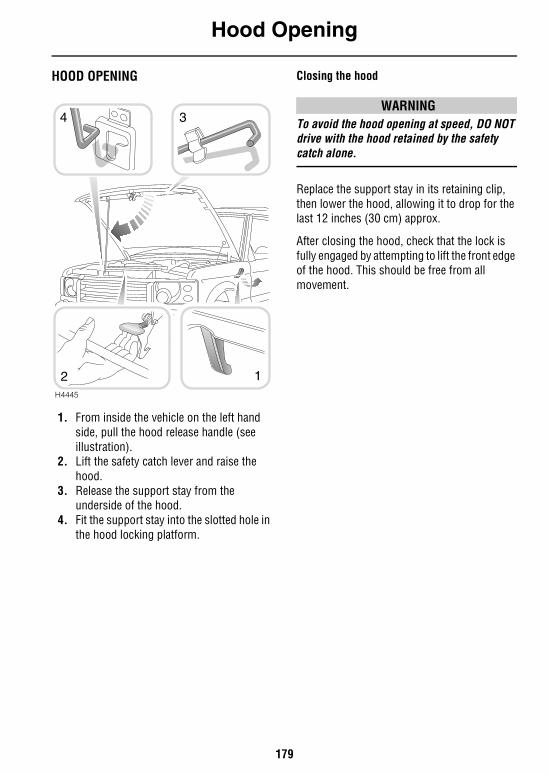
Hood Opening
179
Hood OpeningHOOD OPENING
1. From inside the vehicle on the left hand side, pull the hood release handle (see illustration).
2. Lift the safety catch lever and raise the hood.
3. Release the support stay from the underside of the hood.
4. Fit the support stay into the slotted hole in the hood locking platform.
Closing the hood
WARNINGTo avoid the hood opening at speed, DO NOT drive with the hood retained by the safety catch alone.
Replace the support stay in its retaining clip, then lower the hood, allowing it to drop for the last 12 inches (30 cm) approx.
After closing the hood, check that the lock is fully engaged by attempting to lift the front edge of the hood. This should be free from all movement.
H4445
12
34
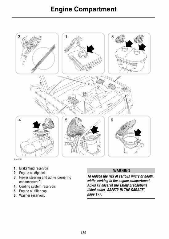
Engine Compartment
180
Engine Compartment
1. Brake fluid reservoir.2. Engine oil dipstick.3. Power steering and active cornering
enhancement*. 4. Cooling system reservoir.5. Engine oil filler cap.6. Washer reservoir.
WARNINGTo reduce the risk of serious injury or death, while working in the engine compartment, ALWAYS observe the safety precautions listed under ‘SAFETY IN THE GARAGE’, page 177.
2 1
654
3
MAXMIN
PAS
ACE
MAXMIN
H4448
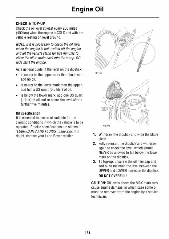
Engine Oil
181
Engine OilCHECK & TOP-UPCheck the oil level at least every 250 miles (400 km) when the engine is COLD and with the vehicle resting on level ground.
NOTE: If it is necessary to check the oil level when the engine is hot, switch off the engine and let the vehicle stand for five minutes to allow the oil to drain back into the sump. DO NOT start the engine.
As a general guide, if the level on the dipstick:• is nearer to the upper mark than the lower,
add no oil.
• is nearer to the lower mark than the upper, add half a US quart (0.5 liter) of oil.
• is below the lower mark, add one US quart (1 liter) of oil and re-check the level after a further five minutes.
Oil specificationIt is essential to use an oil suitable for the climatic conditions in which the vehicle is to be operated. Precise specifications are shown in ‘LUBRICANTS AND FLUIDS’, page 239. If in doubt, contact your Land Rover retailer. 1. Withdraw the dipstick and wipe the blade
clean.2. Fully re-insert the dipstick and withdraw
again to check the level, which should NEVER be allowed to fall below the lower mark on the dipstick.
3. To top-up, unscrew the oil filler cap and add oil to maintain the level between the UPPER and LOWER marks on the dipstick.DO NOT OVERFILL!
CAUTION: Oil levels above the MAX mark may cause engine damage, in which case some oil must be removed from the engine by a service technician.
H3152
H3105
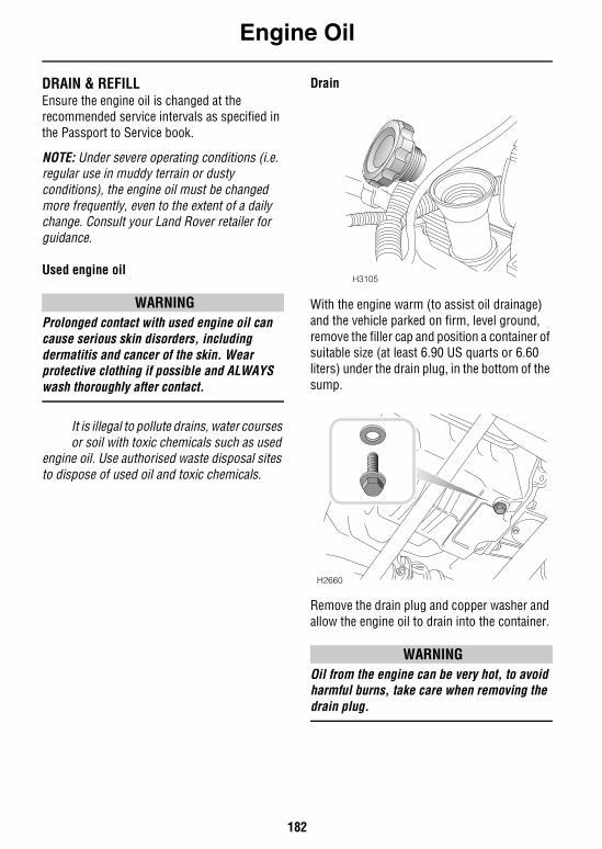
Engine Oil
182
DRAIN & REFILLEnsure the engine oil is changed at the recommended service intervals as specified in the Passport to Service book.
NOTE: Under severe operating conditions (i.e. regular use in muddy terrain or dusty conditions), the engine oil must be changed more frequently, even to the extent of a daily change. Consult your Land Rover retailer for guidance.
Used engine oil
WARNINGProlonged contact with used engine oil can cause serious skin disorders, including dermatitis and cancer of the skin. Wear protective clothing if possible and ALWAYS wash thoroughly after contact.
It is illegal to pollute drains, water courses or soil with toxic chemicals such as used
engine oil. Use authorised waste disposal sites to dispose of used oil and toxic chemicals.
Drain
With the engine warm (to assist oil drainage) and the vehicle parked on firm, level ground, remove the filler cap and position a container of suitable size (at least 6.90 US quarts or 6.60 liters) under the drain plug, in the bottom of the sump.
Remove the drain plug and copper washer and allow the engine oil to drain into the container.
WARNINGOil from the engine can be very hot, to avoid harmful burns, take care when removing the drain plug.
H3105
H2660
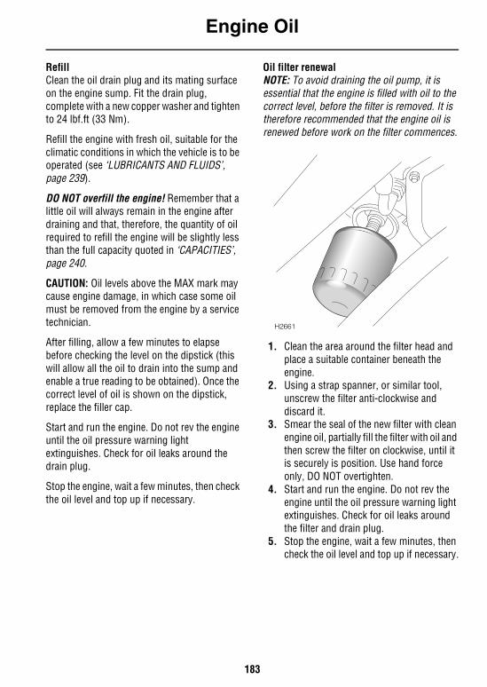
Engine Oil
183
RefillClean the oil drain plug and its mating surface on the engine sump. Fit the drain plug, complete with a new copper washer and tighten to 24 lbf.ft (33 Nm).
Refill the engine with fresh oil, suitable for the climatic conditions in which the vehicle is to be operated (see ‘LUBRICANTS AND FLUIDS’, page 239).
DO NOT overfill the engine! Remember that a little oil will always remain in the engine after draining and that, therefore, the quantity of oil required to refill the engine will be slightly less than the full capacity quoted in ‘CAPACITIES’, page 240.
CAUTION: Oil levels above the MAX mark may cause engine damage, in which case some oil must be removed from the engine by a service technician.
After filling, allow a few minutes to elapse before checking the level on the dipstick (this will allow all the oil to drain into the sump and enable a true reading to be obtained). Once the correct level of oil is shown on the dipstick, replace the filler cap.
Start and run the engine. Do not rev the engine until the oil pressure warning light extinguishes. Check for oil leaks around the drain plug.
Stop the engine, wait a few minutes, then check the oil level and top up if necessary.
Oil filter renewalNOTE: To avoid draining the oil pump, it is essential that the engine is filled with oil to the correct level, before the filter is removed. It is therefore recommended that the engine oil is renewed before work on the filter commences.
1. Clean the area around the filter head and place a suitable container beneath the engine.
2. Using a strap spanner, or similar tool, unscrew the filter anti-clockwise and discard it.
3. Smear the seal of the new filter with clean engine oil, partially fill the filter with oil and then screw the filter on clockwise, until it is securely is position. Use hand force only, DO NOT overtighten.
4. Start and run the engine. Do not rev the engine until the oil pressure warning light extinguishes. Check for oil leaks around the filter and drain plug.
5. Stop the engine, wait a few minutes, then check the oil level and top up if necessary.
H2661
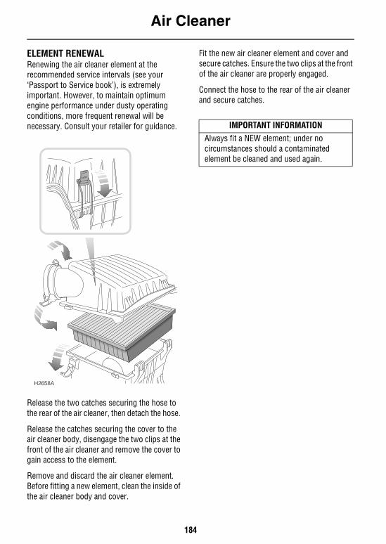
Air Cleaner
184
Air CleanerELEMENT RENEWALRenewing the air cleaner element at the recommended service intervals (see your ‘Passport to Service book’), is extremely important. However, to maintain optimum engine performance under dusty operating conditions, more frequent renewal will be necessary. Consult your retailer for guidance.
Release the two catches securing the hose to the rear of the air cleaner, then detach the hose.
Release the catches securing the cover to the air cleaner body, disengage the two clips at the front of the air cleaner and remove the cover to gain access to the element.
Remove and discard the air cleaner element. Before fitting a new element, clean the inside of the air cleaner body and cover.
Fit the new air cleaner element and cover and secure catches. Ensure the two clips at the front of the air cleaner are properly engaged.
Connect the hose to the rear of the air cleaner and secure catches.
H2658A
IMPORTANT INFORMATION
Always fit a NEW element; under no circumstances should a contaminated element be cleaned and used again.
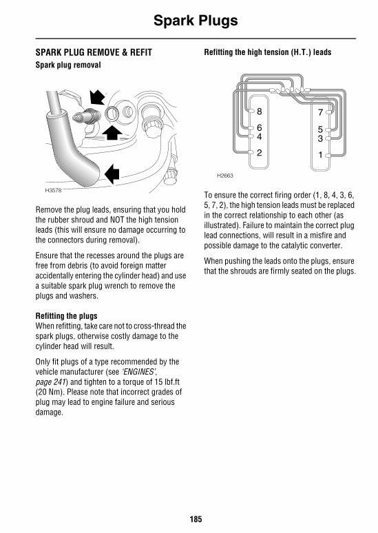
Spark Plugs
185
Spark PlugsSPARK PLUG REMOVE & REFITSpark plug removal
Remove the plug leads, ensuring that you hold the rubber shroud and NOT the high tension leads (this will ensure no damage occurring to the connectors during removal).
Ensure that the recesses around the plugs are free from debris (to avoid foreign matter accidentally entering the cylinder head) and use a suitable spark plug wrench to remove the plugs and washers.
Refitting the plugsWhen refitting, take care not to cross-thread the spark plugs, otherwise costly damage to the cylinder head will result.
Only fit plugs of a type recommended by the vehicle manufacturer (see ‘ENGINES’, page 241) and tighten to a torque of 15 lbf.ft (20 Nm). Please note that incorrect grades of plug may lead to engine failure and serious damage.
Refitting the high tension (H.T.) leads
To ensure the correct firing order (1, 8, 4, 3, 6, 5, 7, 2), the high tension leads must be replaced in the correct relationship to each other (as illustrated). Failure to maintain the correct plug lead connections, will result in a misfire and possible damage to the catalytic converter.
When pushing the leads onto the plugs, ensure that the shrouds are firmly seated on the plugs.
H3578
8
64
2 1
35
7
H2663
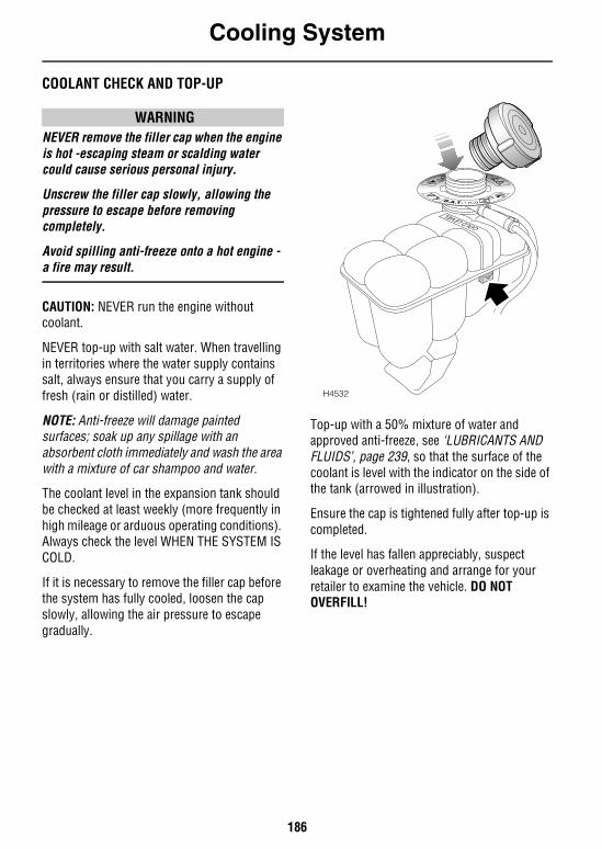
Cooling System
186
Cooling SystemCOOLANT CHECK AND TOP-UP
WARNINGNEVER remove the filler cap when the engine is hot -escaping steam or scalding water could cause serious personal injury.
Unscrew the filler cap slowly, allowing the pressure to escape before removing completely.
Avoid spilling anti-freeze onto a hot engine - a fire may result.
CAUTION: NEVER run the engine without coolant.
NEVER top-up with salt water. When travelling in territories where the water supply contains salt, always ensure that you carry a supply of fresh (rain or distilled) water.
NOTE: Anti-freeze will damage painted surfaces; soak up any spillage with an absorbent cloth immediately and wash the area with a mixture of car shampoo and water.
The coolant level in the expansion tank should be checked at least weekly (more frequently in high mileage or arduous operating conditions). Always check the level WHEN THE SYSTEM IS COLD.
If it is necessary to remove the filler cap before the system has fully cooled, loosen the cap slowly, allowing the air pressure to escape gradually.
Top-up with a 50% mixture of water and approved anti-freeze, see ‘LUBRICANTS AND FLUIDS’, page 239, so that the surface of the coolant is level with the indicator on the side of the tank (arrowed in illustration).
Ensure the cap is tightened fully after top-up is completed.
If the level has fallen appreciably, suspect leakage or overheating and arrange for your retailer to examine the vehicle. DO NOT OVERFILL!
H4532
Cooling System
187
ANTI-FREEZE
WARNINGAnti-freeze is poisonous and can be fatal if swallowed - keep containers sealed and out of the reach of children. If accidental consumption is suspected, seek medical attention immediately.
Prevent anti-freeze coming in contact with the skin or eyes. If this occurs, rinse immediately with plenty of water.
Anti-freeze contains important corrosion inhibitors. The anti-freeze content of the coolant must be maintained at 50% ± 5% all year round (not just in cold conditions). To ensure that the anti-corrosion properties of the coolant are retained, the anti-freeze content should be checked once a year and completely renewed every 30,000 miles (48,000 km) or 24 months, whichever is the sooner. Failure to do so may cause corrosion of the radiator and engine components.
The specific gravity of a 50% anti-freeze solution at 68°F (20°C) is 1.075 and protects against frost down to -33°F (-36°C).
Coolant specificationUse ONLY a 50% mix of water and and an approved anti-freeze, see ‘LUBRICANTS AND FLUIDS’, page 239.
In an emergency - and only if no approved anti-freeze is available - top-up the cooling system with clean water, but be aware of the resultant reduction in frost protection. DO NOT top-up or refill with conventional anti-freeze formulations. If in doubt consult a Land Rover retailer.
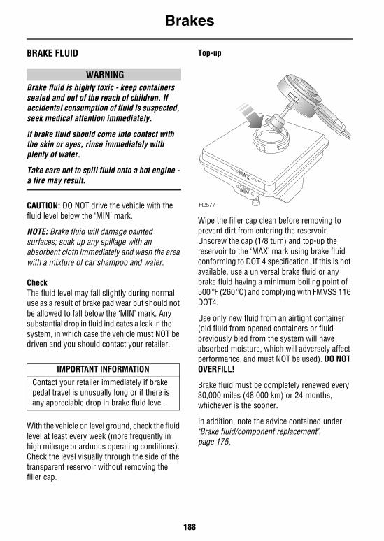
Brakes
188
BrakesBRAKE FLUID
WARNINGBrake fluid is highly toxic - keep containers sealed and out of the reach of children. If accidental consumption of fluid is suspected, seek medical attention immediately.
If brake fluid should come into contact with the skin or eyes, rinse immediately with plenty of water.
Take care not to spill fluid onto a hot engine - a fire may result.
CAUTION: DO NOT drive the vehicle with the fluid level below the ‘MIN’ mark.
NOTE: Brake fluid will damage painted surfaces; soak up any spillage with an absorbent cloth immediately and wash the area with a mixture of car shampoo and water.
CheckThe fluid level may fall slightly during normal use as a result of brake pad wear but should not be allowed to fall below the ‘MIN’ mark. Any substantial drop in fluid indicates a leak in the system, in which case the vehicle must NOT be driven and you should contact your retailer.
With the vehicle on level ground, check the fluid level at least every week (more frequently in high mileage or arduous operating conditions). Check the level visually through the side of the transparent reservoir without removing the filler cap.
Top-up
Wipe the filler cap clean before removing to prevent dirt from entering the reservoir. Unscrew the cap (1/8 turn) and top-up the reservoir to the ‘MAX’ mark using brake fluid conforming to DOT 4 specification. If this is not available, use a universal brake fluid or any brake fluid having a minimum boiling point of 500 ºF (260 ºC) and complying with FMVSS 116 DOT4.
Use only new fluid from an airtight container (old fluid from opened containers or fluid previously bled from the system will have absorbed moisture, which will adversely affect performance, and must NOT be used). DO NOT OVERFILL!
Brake fluid must be completely renewed every 30,000 miles (48,000 km) or 24 months, whichever is the sooner.
In addition, note the advice contained under ‘Brake fluid/component replacement’, page 175.
IMPORTANT INFORMATION
Contact your retailer immediately if brake pedal travel is unusually long or if there is any appreciable drop in brake fluid level.
H2577
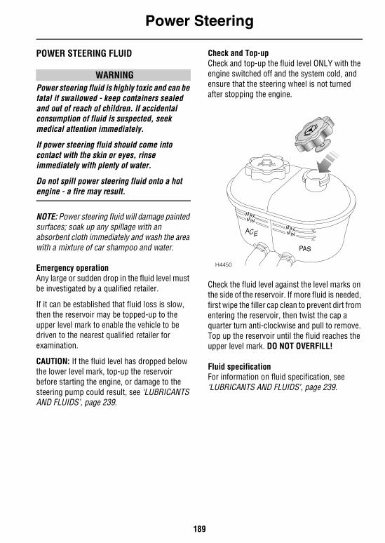
Power Steering
189
Power SteeringPOWER STEERING FLUID
WARNINGPower steering fluid is highly toxic and can be fatal if swallowed - keep containers sealed and out of reach of children. If accidental consumption of fluid is suspected, seek medical attention immediately.
If power steering fluid should come into contact with the skin or eyes, rinse immediately with plenty of water.
Do not spill power steering fluid onto a hot engine - a fire may result.
NOTE: Power steering fluid will damage painted surfaces; soak up any spillage with an absorbent cloth immediately and wash the area with a mixture of car shampoo and water.
Emergency operationAny large or sudden drop in the fluid level must be investigated by a qualified retailer.
If it can be established that fluid loss is slow, then the reservoir may be topped-up to the upper level mark to enable the vehicle to be driven to the nearest qualified retailer for examination.
CAUTION: If the fluid level has dropped below the lower level mark, top-up the reservoir before starting the engine, or damage to the steering pump could result, see ‘LUBRICANTS AND FLUIDS’, page 239.
Check and Top-upCheck and top-up the fluid level ONLY with the engine switched off and the system cold, and ensure that the steering wheel is not turned after stopping the engine.
Check the fluid level against the level marks on the side of the reservoir. If more fluid is needed, first wipe the filler cap clean to prevent dirt from entering the reservoir, then twist the cap a quarter turn anti-clockwise and pull to remove. Top up the reservoir until the fluid reaches the upper level mark. DO NOT OVERFILL!
Fluid specificationFor information on fluid specification, see ‘LUBRICANTS AND FLUIDS’, page 239.
H4450
MAXMIN
PAS
ACE
MAXMIN
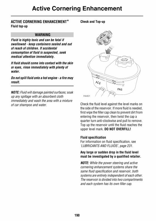
Active Cornering Enhancement
190
Active Cornering EnhancementACTIVE CORNERING ENHANCEMENT*Fluid top-up
WARNINGFluid is highly toxic and can be fatal if swallowed - keep containers sealed and out of reach of children. If accidental consumption of fluid is suspected, seek medical attention immediately.
If fluid should come into contact with the skin or eyes, rinse immediately with plenty of water.
Do not spill fluid onto a hot engine - a fire may result.
NOTE: Fluid will damage painted surfaces; soak up any spillage with an absorbent cloth immediately and wash the area with a mixture of car shampoo and water.
Check and Top-up
Check the fluid level against the level marks on the side of the reservoir. If more fluid is needed, first wipe the filler cap clean to prevent dirt from entering the reservoir, then twist the cap a quarter turn anti-clockwise and pull to remove. Top up the reservoir until the fluid reaches the upper level mark. DO NOT OVERFILL!
Fluid specificationFor information on fluid specification, see ‘LUBRICANTS AND FLUIDS’, page 231.
Any large or sudden drop in the fluid level must be investigated by a qualified retailer.
NOTE: While the power steering and active cornering enhancement systems share the same fluid specification and reservoir, both systems are entirely independent of each other. The reservoir is divided into two compartments and each system has its own filler cap.
H4451
MAXMIN
PAS
ACE
MAXMIN
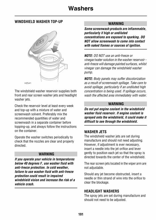
Washers
191
WashersWINDSHIELD WASHER TOP-UP
The windshield washer reservoir supplies both front and rear screen washer jets and headlight washer jets.
Check the reservoir level at least every week and top-up with a mixture of water and screenwash solvent. Preferably mix the recommended quantities of water and screenwash in a separate container before topping-up, and always follow the instructions on the container.
Operate the washer switches periodically to check that the nozzles are clear and properly directed.
WARNINGIf you operate your vehicle in temperatures below 40 degrees F, use washer fluid with anti-freeze protection. In cold weather, failure to use washer fluid with anti-freeze protection could result in impaired windshield vision and increase the risk of a vehicle crash.
WARNINGSome screenwash products are inflammable, particularly if high or undiluted concentrations are exposed to sparking. DO NOT allow screenwash to come into contact with naked flames or sources of ignition.
NOTE: DO NOT use an anti-freeze or vinegar/water solution in the washer reservoir - anti-freeze will damage painted surfaces, whilst vinegar can damage the windshield washer pump.
NOTE: Body panels may suffer discolorization as a result of screenwash spillage. Take care to avoid spillage, particularly if an undiluted high concentration is being used. If spillage occurs, wash the affected area immediately with water.
WARNINGDo not put engine coolant in the windshield washer fluid reservoir. If engine coolant is sprayed onto the windshield, it could make it difficult to see through the windshield.
WASHER JETSThe windshield washer jets are set during manufacture and should not need adjusting. However, if adjustment is ever necessary, insert a needle into the jet orifice and lever gently to position each jet so that the spray is directed towards the center of the windshield.
The rear screen jets located in the wiper arm are not adjustable.
Should any jet become obstructed, insert a needle or thin strand of wire into the orifice to clear the blockage.
HEADLIGHT WASHERSThe spray jets are set during manufacture and should not need to be adjusted.
H2541
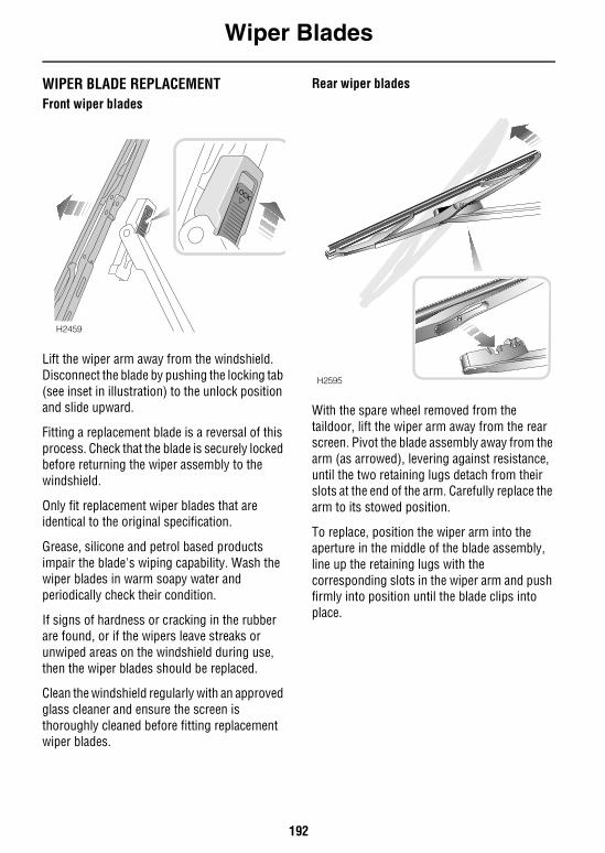
Wiper Blades
192
Wiper BladesWIPER BLADE REPLACEMENTFront wiper blades
Lift the wiper arm away from the windshield. Disconnect the blade by pushing the locking tab (see inset in illustration) to the unlock position and slide upward.
Fitting a replacement blade is a reversal of this process. Check that the blade is securely locked before returning the wiper assembly to the windshield.
Only fit replacement wiper blades that are identical to the original specification.
Grease, silicone and petrol based products impair the blade's wiping capability. Wash the wiper blades in warm soapy water and periodically check their condition.
If signs of hardness or cracking in the rubber are found, or if the wipers leave streaks or unwiped areas on the windshield during use, then the wiper blades should be replaced.
Clean the windshield regularly with an approved glass cleaner and ensure the screen is thoroughly cleaned before fitting replacement wiper blades.
Rear wiper blades
With the spare wheel removed from the taildoor, lift the wiper arm away from the rear screen. Pivot the blade assembly away from the arm (as arrowed), levering against resistance, until the two retaining lugs detach from their slots at the end of the arm. Carefully replace the arm to its stowed position.
To replace, position the wiper arm into the aperture in the middle of the blade assembly, line up the retaining lugs with the corresponding slots in the wiper arm and push firmly into position until the blade clips into place.
LOCK
LOCK
H2459
H2595
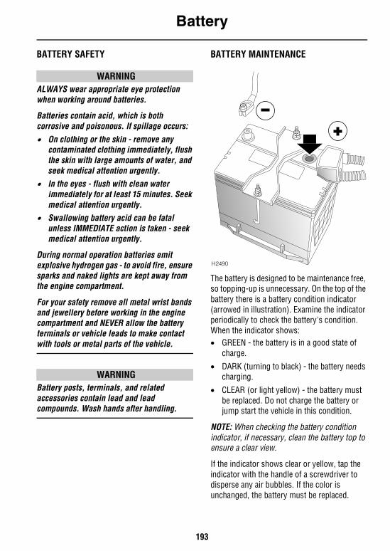
Battery
193
BatteryBATTERY SAFETY
WARNINGALWAYS wear appropriate eye protection when working around batteries.
Batteries contain acid, which is both corrosive and poisonous. If spillage occurs:
• On clothing or the skin - remove any contaminated clothing immediately, flush the skin with large amounts of water, and seek medical attention urgently.
• In the eyes - flush with clean water immediately for at least 15 minutes. Seek medical attention urgently.
• Swallowing battery acid can be fatal unless IMMEDIATE action is taken - seek medical attention urgently.
During normal operation batteries emit explosive hydrogen gas - to avoid fire, ensure sparks and naked lights are kept away from the engine compartment.
For your safety remove all metal wrist bands and jewellery before working in the engine compartment and NEVER allow the battery terminals or vehicle leads to make contact with tools or metal parts of the vehicle.
WARNINGBattery posts, terminals, and related accessories contain lead and lead compounds. Wash hands after handling.
BATTERY MAINTENANCE
The battery is designed to be maintenance free, so topping-up is unnecessary. On the top of the battery there is a battery condition indicator (arrowed in illustration). Examine the indicator periodically to check the battery's condition. When the indicator shows:• GREEN - the battery is in a good state of
charge.
• DARK (turning to black) - the battery needs charging.
• CLEAR (or light yellow) - the battery must be replaced. Do not charge the battery or jump start the vehicle in this condition.
NOTE: When checking the battery condition indicator, if necessary, clean the battery top to ensure a clear view.
If the indicator shows clear or yellow, tap the indicator with the handle of a screwdriver to disperse any air bubbles. If the color is unchanged, the battery must be replaced.
H2490
Battery
194
Battery removal and replacement
WARNINGALWAYS remove the starter key before disconnecting the battery. Failure to do this could cause a failure of the airbag SRS.
To prevent a short circuit, ALWAYS disconnect the negative (‘-’) cable first and NEVER allow the battery terminals or vehicle leads to make contact with tools or metal parts of the vehicle.
Before disconnecting the battery, disarm the alarm, and ensure that the starter switch and all electrical equipment is turned off.
To remove: disconnect the negative (‘-’) cable first and then the positive (‘+’) cable. When reconnecting, connect the positive cable first and then the negative cable.
To release the battery from the vehicle, undo the nuts securing the battery clamping plate and remove the clamping plate.
When replacing, ensure the battery is fitted the right way round (terminal posts towards the rear of the vehicle) and that the clamping plate is secure. Tighten the clamping plate nuts until the clamping plate is free from movement, but do not over tighten.
Replacement batteries
Only fit a replacement battery of the same type and specification as the original - other batteries may vary in size or have different terminal positions which could cause a fire hazard when connected to the vehicle's electrical system.
CAUTION: DO NOT reverse the polarity of the battery - the electrical system may be damaged if the battery leads are connected to the wrong terminals.
CAUTION: Keep the battery upright at all times - damage will be caused if the battery is tilted more than 45 degrees.
CAUTION: DO NOT run the engine with the battery disconnected, or disconnect the battery whilst the engine is running.
Battery disposal
Used batteries should be recycled. However, batteries are hazardous - you
should seek advice about disposal from a Land Rover retailer or your local authority.
WARNINGBattery posts, terminals and related accessories contain lead and lead compounds. Wash hands after handling.
Battery
195
Battery charging
WARNINGBatteries generate explosive gases, contain corrosive acid and produce levels of electric current sufficient to cause serious injury. While charging always heed the following precautions:
• Before charging, disconnect and remove the battery from the vehicle - charging the battery with the cables connected may damage the vehicle's electrical system.
• Make sure the battery charger leads are securely clamped to the battery terminals BEFORE switching on the battery charger. Do not move the leads once the charger is switched on.
• While charging, shield your eyes or avoid leaning over the battery and keep the area around the top of the battery well ventilated.
• Do not allow open flame and/or incandescent lamps near the battery (batteries generate inflammable hydrogen during and after charging).
• If the battery is fitted with a condition indicator, the indicator shows GREEN when the battery is charged sufficiently. When charging is finished, switch off the battery charger BEFORE disconnecting the leads from the battery terminals.
After charging, leave the battery for an hour BEFORE reconnection to the vehicle - this will allow time for explosive gases to disperse, thereby minimising the risk of fire or explosion.
NOTE: Be aware that a battery will take longer to charge in a cold environment.
CAUTION: DO NOT charge the battery if it is connected to the vehicle - this may seriously damage the electrical system.
IMPORTANT INFORMATION
DO NOT attempt to charge the battery if the battery condition indicator is clear or light yellow.
DO NOT charge the battery if it is suspected of being frozen.
Tires
196
TiresCARING FOR YOUR TIRES
WARNINGDEFECTIVE TIRES ARE DANGEROUS! Do not drive if any tire is damaged, is excessively worn, or is inflated to an incorrect pressure.
ALWAYS replace worn or defective tires with the factory recommended specification (see ‘WHEELS & TIRES’, page 247). Failure to do so may affect the safe handling of the vehicle.
Always drive with consideration for the condition of the tires, and regularly inspect the tread and side walls for any sign of distortion (bulges), cuts or wear.
The most common causes of tire failure are:• Bumping against curbs
• Driving over deep potholes in the road• Driving with under or over-inflated tires
NOTE: If possible, protect tires from contamination by oil, grease, fuel and other automotive fluids.
Tire pressuresCorrectly inflated tires will ensure that you enjoy the best combination of tire life, ride comfort, fuel economy and road handling.
Under-inflated tires wear more rapidly, can seriously affect the vehicle's road handling characteristics and fuel consumption, as well as increasing the risk of tire failure. Over-inflated tires give a harsher ride, wear unevenly and are more prone to damage.
Tire pressures should be checked at least once a week with normal road use, but should be checked DAILY if the vehicle is used off-road.
Check the pressures (including the spare wheel) when the tires are cold - be aware that it only takes a mile (1.6 km) of driving to warm up the tires sufficiently to affect the tire pressures.
Air pressure naturally increases in warm tires; if it is necessary to check the tires when they are warm (after the vehicle has been driven for a while), you should expect the pressures to have increased between 4 and 6 lbf/in2
(0.3 to 0.4 kgf/cm2). In this circumstance, NEVER let air out of the tires in order to match the recommended pressures.
NOTE: If the vehicle has been parked in strong sunlight or used in high ambient temperatures, DO NOT reduce tire pressures; instead, move the vehicle into the shade and allow the tires to cool before checking.
The recommended pressures for cold tires are shown in ‘WHEELS & TIRES’, page 247.
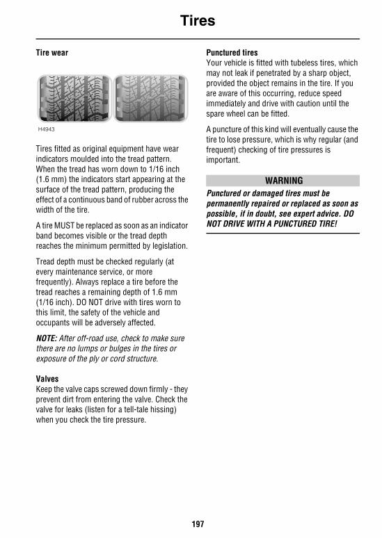
Tires
197
Tire wear
Tires fitted as original equipment have wear indicators moulded into the tread pattern. When the tread has worn down to 1/16 inch (1.6 mm) the indicators start appearing at the surface of the tread pattern, producing the effect of a continuous band of rubber across the width of the tire.
A tire MUST be replaced as soon as an indicator band becomes visible or the tread depth reaches the minimum permitted by legislation.
Tread depth must be checked regularly (at every maintenance service, or more frequently). Always replace a tire before the tread reaches a remaining depth of 1.6 mm (1/16 inch). DO NOT drive with tires worn to this limit, the safety of the vehicle and occupants will be adversely affected.
NOTE: After off-road use, check to make sure there are no lumps or bulges in the tires or exposure of the ply or cord structure.
ValvesKeep the valve caps screwed down firmly - they prevent dirt from entering the valve. Check the valve for leaks (listen for a tell-tale hissing) when you check the tire pressure.
Punctured tiresYour vehicle is fitted with tubeless tires, which may not leak if penetrated by a sharp object, provided the object remains in the tire. If you are aware of this occurring, reduce speed immediately and drive with caution until the spare wheel can be fitted.
A puncture of this kind will eventually cause the tire to lose pressure, which is why regular (and frequent) checking of tire pressures is important.
WARNINGPunctured or damaged tires must be permanently repaired or replaced as soon as possible, if in doubt, see expert advice. DO NOT DRIVE WITH A PUNCTURED TIRE!
H4943
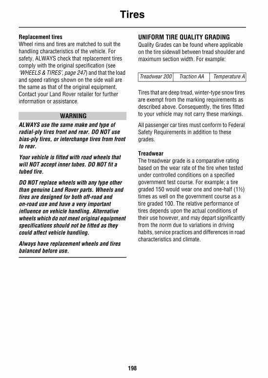
Tires
198
Replacement tiresWheel rims and tires are matched to suit the handling characteristics of the vehicle. For safety, ALWAYS check that replacement tires comply with the original specification (see ‘WHEELS & TIRES’, page 247) and that the load and speed ratings shown on the side wall are the same as that of the original equipment. Contact your Land Rover retailer for further information or assistance.
WARNINGALWAYS use the same make and type of radial-ply tires front and rear. DO NOT use bias-ply tires, or interchange tires from front to rear.
Your vehicle is fitted with road wheels that will NOT accept inner tubes. DO NOT fit a tubed tire.
DO NOT replace wheels with any type other than genuine Land Rover parts. Wheels and tires are designed for both off-road and on-road use and have a very important influence on vehicle handling. Alternative wheels which do not meet original equipment specifications should not be fitted as they could affect vehicle handling.
Always have replacement wheels and tires balanced before use.
UNIFORM TIRE QUALITY GRADINGQuality Grades can be found where applicable on the tire sidewall between tread shoulder and maximum section width. For example:
Tires that are deep tread, winter-type snow tires are exempt from the marking requirements as described above. Consequently, the tires fitted to your vehicle may not carry these markings.
All passenger car tires must conform to Federal Safety Requirements in addition to these grades.
TreadwearThe treadwear grade is a comparative rating based on the wear rate of the tire when tested under controlled conditions on a specified government test course. For example; a tire graded 150 would wear one and one-half (1½)times as well on the government course as a tire graded 100. The relative performance of tires depends upon the actual conditions of their use however, and may depart significantly from the norm due to variations in driving habits, service practices and differences in road characteristics and climate.
Treadwear 200 Traction AA Temperature A
Tires
199
TractionThe traction grades, from highest to lowest, are AA, A, B and C. The grades represent a tire's ability to stop on wet pavement as measured under controlled conditions on specified government test surfaces of asphalt and concrete. A tire marked 'C' may have poor traction performance.
WARNINGThe traction grade assigned to this tire is based on straight-ahead braking traction tests, and does not include acceleration, cornering, hydroplaning, or peak traction characteristics.
TemperatureThe temperature grades A (the highest), B, and C, represent a tire's resistance to the generation of heat and its ability to dissipate heat when tested under controlled conditions on a specified indoor laboratory test wheel. Sustained high temperatures can cause the material of a tire to degenerate and reduce tire life, and excessive temperature can lead to sudden tire failure.
The grade 'C' corresponds to a level of performance which all passenger car tires must meet under the Federal Motor Safety Standard No 109.
Grades 'B' and 'A' represent higher levels of performance on the laboratory test wheel than the minimum required by law.
WARNINGThe temperature grade for this tire is established for a tire that is properly inflated and not overloaded. Excessive speed, underinflation, or excessive loading, either separately or in combination can cause heat buildup and possible tire failure.
SNOW CHAINSSnow chains are designed for use on roads in extreme conditions only, and are not recommended for off-road use. If it is necessary to fit snow chains to your vehicle, ALWAYS observe the following:• Snow chains must ONLY be fitted to the rear
wheels of the vehicle, provided the wheels and tires conform to one of the original equipment specifications listed in the handbook (see ‘WHEELS & TIRES’, page 247).
• ONLY Land Rover approved chains should be used - these are designed for your vehicle and will eliminate any risk of damage to the vehicle.
• Always adhere to the snow chain fitting and retensioning instructions and the speed limitations recommended for varying road conditions. NEVER exceed 30 mph (50 km/h).
• Avoid tire damage by removing the chains a soon as the road is free from snow.
For further information about approved snow chains, consult your Land Rover retailer.
WARNINGDO NOT fit unapproved snow chains to the rear wheels - this could damage brake components, and seriously affect the vehicle's ability to stop, potentially resulting in occupant or third party injury.
DO NOT fit snow chains to the front wheels; this could damage brake components.
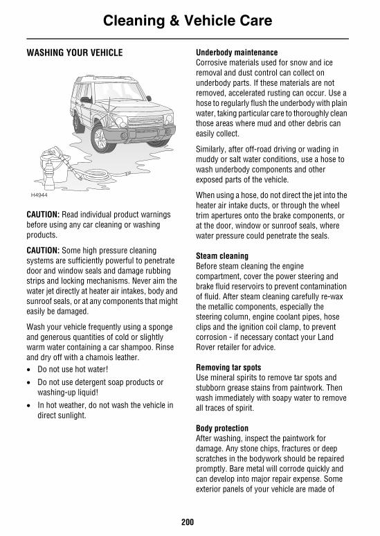
Cleaning & Vehicle Care
200
Cleaning & Vehicle CareWASHING YOUR VEHICLE
CAUTION: Read individual product warnings before using any car cleaning or washing products.
CAUTION: Some high pressure cleaning systems are sufficiently powerful to penetrate door and window seals and damage rubbing strips and locking mechanisms. Never aim the water jet directly at heater air intakes, body and sunroof seals, or at any components that might easily be damaged.
Wash your vehicle frequently using a sponge and generous quantities of cold or slightly warm water containing a car shampoo. Rinse and dry off with a chamois leather.• Do not use hot water!
• Do not use detergent soap products or washing-up liquid!
• In hot weather, do not wash the vehicle in direct sunlight.
Underbody maintenanceCorrosive materials used for snow and ice removal and dust control can collect on underbody parts. If these materials are not removed, accelerated rusting can occur. Use a hose to regularly flush the underbody with plain water, taking particular care to thoroughly clean those areas where mud and other debris can easily collect.
Similarly, after off-road driving or wading in muddy or salt water conditions, use a hose to wash underbody components and other exposed parts of the vehicle.
When using a hose, do not direct the jet into the heater air intake ducts, or through the wheel trim apertures onto the brake components, or at the door, window or sunroof seals, where water pressure could penetrate the seals.
Steam cleaningBefore steam cleaning the engine compartment, cover the power steering and brake fluid reservoirs to prevent contamination of fluid. After steam cleaning carefully re-wax the metallic components, especially the steering column, engine coolant pipes, hose clips and the ignition coil clamp, to prevent corrosion - if necessary contact your Land Rover retailer for advice.
Removing tar spotsUse mineral spirits to remove tar spots and stubborn grease stains from paintwork. Then wash immediately with soapy water to remove all traces of spirit.
Body protectionAfter washing, inspect the paintwork for damage. Any stone chips, fractures or deep scratches in the bodywork should be repaired promptly. Bare metal will corrode quickly and can develop into major repair expense. Some exterior panels of your vehicle are made of
H4944

Cleaning & Vehicle Care
201
aluminium which will not corrode in the same manner as steel. However, any damage should still receive prompt attention. Minor chips and scratches can be repaired with touch-up materials available from your retailer. Larger areas of damage need to be corrected to professional standards immediately.
Cast alloy road wheelsThe cast alloy road wheels are covered with a protective coating. To prevent corrosion it is essential that this coating is not damaged. To clean the wheels use a warm soapy liquid, stubborn stains can be removed using a soft brush.
PolishingOccasionally treat the paint surface with an approved polish containing the following properties:• Very mild abrasives to remove surface
contamination without removing or damaging the paint.
• Filling compounds that will fill scratches and reduce their visibility.
• Wax to provide a protective coating between the paint and the elements.
NOTE: DO NOT apply car polish to the bumper mouldings - polish will become ingrained in the textured finished.
SunroofIt is essential that the sunroof aperture surround, channels, drain tubes and slides (accessible with the panel fully open), are kept clear, clean and lubricated for efficient operation. This requirement is particularly important in dusty environments.
If necessary contact your Land Rover retailer for advice.
Glass and mirrorsClean the rear window with a soft cloth to avoid damaging the heating elements. DO NOT scrape the glass or use an abrasive cleaning fluid.
Mirror glass is particularly susceptible to damage. Wash with soapy water. DO NOT use abrasive cleaning compounds or metal scrapers to remove ice.
Cleaning & Vehicle Care
202
CLEANING THE INTERIOR
WARNINGRead individual product warnings before using any car cleaning or washing products.
Plastic materialsClean plastic-faced or cloth covered surfaces with diluted upholstery cleaner and wipe with a clean cloth.
NOTE: DO NOT polish facia components - for safety, these should remain non-reflective.
LeatherLeather seats, steering wheel and trim features should be cleaned with a damp cloth moistened with undiluted upholstery cleaner. Leave for five minutes, and then repeat the operation using a clean cloth and water - but avoid flooding the area! Dry and polish the leather with a dry, lint-free cloth.
DO NOT use petrol, detergents, furniture creams or polishes!
Carpet and fabricsClean with diluted nylon upholstery cleaner - test on a concealed area first.
Instrument pack, clock and radioClean with a dry cloth only! DO NOT use cleaning fluids or sprays.
Seat beltsExtend the belts, then use warm water and a non-detergent soap to clean. Allow the belts to dry naturally, and do not retract them or use the vehicle until they are completely dry.
Airbag module covers
WARNINGTo prevent airbag SRS damage, the steering wheel center pad and area of the facia panel containing the passenger airbag should ONLY be cleaned sparingly with a damp cloth and upholstery cleaner.
DO NOT allow these areas to be flooded with liquid, and DO NOT use petrol, detergent, furniture cream or polishes.
Heated rear screenThe following precautions must be taken, to avoid irreparable damage being caused to the printed circuit which is ‘baked’ on to theinterior of the screen.• Do not remove labels or stickers from the
screen, with the aid of sharp instruments or similar equipment likely to scratch the glass.
• Care should be taken to avoid inadvertently scratching the glass with a ringed finger etc, when cleaning or wiping the screen.
• Do not clean the screen with harsh abrasives.
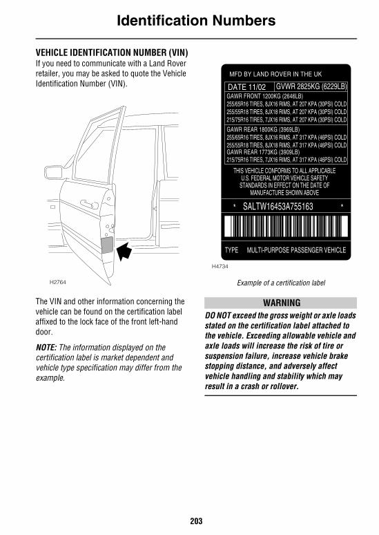
Identification Numbers
203
Identification NumbersVEHICLE IDENTIFICATION NUMBER (VIN)If you need to communicate with a Land Rover retailer, you may be asked to quote the Vehicle Identification Number (VIN).
The VIN and other information concerning the vehicle can be found on the certification label affixed to the lock face of the front left-hand door.
NOTE: The information displayed on the certification label is market dependent and vehicle type specification may differ from the example.
Example of a certification label
WARNINGDO NOT exceed the gross weight or axle loads stated on the certification label attached to the vehicle. Exceeding allowable vehicle and axle loads will increase the risk of tire or suspension failure, increase vehicle brake stopping distance, and adversely affect vehicle handling and stability which may result in a crash or rollover.
H2764
H4734
MFD BY LAND ROVER IN THE UK
GAWR FRONT 1200KG (2646LB)DATE 11/02 GVWR 2825KG (6229LB)
255/65R16 TIRES, 8JX16 RIMS, AT 207 KPA (30PSI) COLD255/55R18 TIRES, 8JX18 RIMS, AT 207 KPA (30PSI) COLD215/75R16 TIRES, 7JX16 RIMS, AT 207 KPA (30PSI) COLD
GAWR REAR 1800KG (3969LB)255/65R16 TIRES, 8JX16 RIMS, AT 317 KPA (46PSI) COLD255/55R18 TIRES, 8JX18 RIMS, AT 317 KPA (46PSI) COLD
215/75R16 TIRES, 7JX16 RIMS, AT 317 KPA (46PSI) COLD
THIS VEHICLE CONFORMS TO ALL APPLICABLEU.S. FEDERAL MOTOR VEHICLE SAFETY
STANDARDS IN EFFECT ON THE DATE OFMANUFACTURE SHOWN ABOVE
SALTW16453A755163* *
TYPE MULTI-PURPOSE PASSENGER VEHICLE
GAWR REAR 1773KG (3909LB)
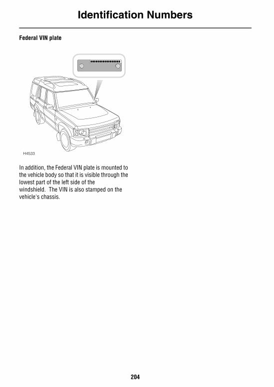
Identification Numbers
204
Federal VIN plate
In addition, the Federal VIN plate is mounted to the vehicle body so that it is visible through the lowest part of the left side of the windshield. The VIN is also stamped on the vehicle's chassis.
H4533
Parts & Accessories
205
Parts & AccessoriesPARTS AND ACCESSORIESYour vehicle has been designed, built and tested to cope with a variety of off-road driving conditions, some of which can place the severest possible demands on control systems and components. As such, fitting replacement parts and accessories that have been developed and tested to the same stringent standards as the original components will safeguard the continued reliability, safety and performance of your vehicle.
To augment the vehicle's already impressive performance, a comprehensive range of Land Rover-approved replacement parts and accessories is available, enabling the vehicle to fulfil a wide variety of roles, and enhancing and protecting the vehicle in the many tasks to which it can be applied.
Land Rover parts are the only parts built to original equipment specifications AND approved by Land Rover designers; this means that every single part and accessory has been rigorously tested by the same engineering team that designed and built the vehicle and, with the exception of maintenance items that are designed to be replaced sooner, is warranted as provided in the Passport to Service.
A full list and description of all accessories is available from your Land Rover retailer.
WARNINGDO NOT fit unapproved accessories or conversions, as they could affect the safety of the vehicle.
Land Rover will not accept any liability for death, personal injury or damage to property which may occur as a direct result of fitment of non-approved accessories or the carrying out of non-approved conversions to Land Rover vehicles.
Land Rover North America Inc. strongly advises against making any modifications to the suspension or steering system. This could seriously affect the handling and stability of the vehicle leading to loss of control or rollover.
Parts & Accessories
206
Electrical equipment
WARNINGIt is extremely hazardous to fit or replace parts or accessories whose installation requires the dismantling of or addition to either the electrical, fuel or SRS airbag systems as damage to the proper operation of these systems could result.
ALWAYS consult a Land Rover retailer before fitting any electrical accessory.
Fitting inferior quality parts or accessories may be dangerous and could invalidate the vehicle warranty.
It is recommended that you always consult a Land Rover retailer for advice regarding the approval, suitability, installation and use of any parts or accessories before fitting.
Travelling abroadIn certain countries, it is illegal to fit parts which have not been made to the vehicle manufacturers' specification.
Owners should ensure that any parts or accessories fitted to the vehicle while travelling abroad will also conform to the legal requirements of their own country when they return home.
SRS/Airbag
WARNINGThe components that make up the SRS/airbag are sensitive to electrical or physical interference, either of which could easily damage the system and cause inadvertent operation or a malfunction of the airbag module.
To prevent any SRS/airbag malfunction, ALWAYS consult a Land Rover retailer before fitting any of the following:
• Electronic equipment such as a mobile phone, two-way radio or in-car entertainment system.
• Accessories attached to the front of the vehicle.
• Any modification to the front of the vehicle.
• Any modification involving the removal or repair of any wiring or component in the vicinity of any of the SRS components (yellow wiring harness), including: the steering wheel, steering column, instrument and facia panels.
• Any modification to the facia panels or steering wheel.
207
Emergency InformationWheel ChangingTOOL KIT . . . . . . . . . . . . . . . . . . . . . . . . . . . . . . 209SPARE WHEEL. . . . . . . . . . . . . . . . . . . . . . . . . . 210CHANGING THE WHEEL . . . . . . . . . . . . . . . . . . 210
Emergency StartingSTARTING AN ENGINE WITH A DISCHARGED BATTERY . . . . . . . . . . . . . . . . . . . . . . . . . . . . . . 214USING BOOSTER CABLES . . . . . . . . . . . . . . . . . 214CONNECTING THE BOOSTER CABLES. . . . . . . . 215
Towing the VehicleTOWING EYES . . . . . . . . . . . . . . . . . . . . . . . . . . 216RECREATIONAL/MOTORHOME TOWING. . . . . . 216FOUR-WHEEL TOWING . . . . . . . . . . . . . . . . . . . 216TRANSPORTER OR TRAILER LASHING. . . . . . . 217
FusesFUSES . . . . . . . . . . . . . . . . . . . . . . . . . . . . . . . . 218MAIN FUSE BOX . . . . . . . . . . . . . . . . . . . . . . . . 218ENGINE COMPARTMENT FUSE BOX . . . . . . . . . 222UNDERSEAT FUSES. . . . . . . . . . . . . . . . . . . . . . 224
Bulb ReplacementREPLACING BULBS . . . . . . . . . . . . . . . . . . . . . . 225FRONT LIGHT UNIT . . . . . . . . . . . . . . . . . . . . . . 226SIDE REPEATER LIGHT . . . . . . . . . . . . . . . . . . . 231REAR LIGHT CLUSTER (Tail/Stop, marker & direction indicator lights) . 232BUMPER MOUNTED LIGHTS(Fog guard & reverse lights) . . . . . . . . . . . . . . . 233NUMBER PLATE LIGHTS . . . . . . . . . . . . . . . . . . 233FRONT FOG LIGHTS . . . . . . . . . . . . . . . . . . . . . 234HIGH MOUNTED STOP LIGHT . . . . . . . . . . . . . . 234GLOVEBOX LIGHT . . . . . . . . . . . . . . . . . . . . . . . 235INTERIOR LIGHT . . . . . . . . . . . . . . . . . . . . . . . . 235INTERIOR COURTESY LIGHTS . . . . . . . . . . . . . 235

208
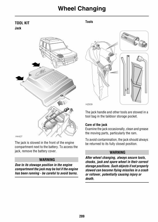
Wheel Changing
209
Emergency Information
Wheel ChangingTOOL KITJack
The jack is stowed in the front of the engine compartment next to the battery. To access the jack, remove the battery cover.
WARNINGDue to its stowage position in the engine compartment the jack may be hot if the engine has been running - be careful to avoid burns.
Tools
The jack handle and other tools are stowed in a tool bag in the taildoor storage pocket.
Care of the jackExamine the jack occasionally, clean and grease the moving parts, particularly the ram.
To avoid contamination, the jack should always be returned to its fully closed position.
WARNINGAfter wheel changing, always secure tools, chocks, jack and spare wheel in their correct storage positions. Such objects if not properly stowed can become flying missiles in a crash or rollover, potentially causing injury or death.
H4427
H2509
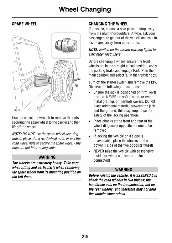
Wheel Changing
210
SPARE WHEEL
Use the wheel nut wrench to remove the nuts securing the spare wheel to the carrier and then lift off the wheel.
NOTE: DO NOT use the spare wheel securing nuts in place of the road wheel nuts, or use the road wheel nuts to secure the spare wheel - the nuts are not inter-changeable.
WARNINGThe wheels are extremely heavy. Take care when lifting and particularly when removing the spare wheel from its mounting position on the tail door.
CHANGING THE WHEELIf possible, choose a safe place to stop away from the main thoroughfare. Always ask your passengers to get out of the vehicle and wait in a safe area away from other traffic.
NOTE: Switch on the hazard warning lights to alert other road users.
Before changing a wheel, ensure the front wheels are in the straight ahead position, apply the parking brake and engage Park ‘P’ in the main gearbox and select ‘L’ in the transfer box.
Turn off the starter switch and remove the key. Observe the following precautions: • Ensure the jack is positioned on firm, level
ground; NEVER on soft ground, or over metal gratings or manhole covers. DO NOT place additional material between the jack and the ground, this may jeopardise the safety of the jacking operation.
• Place chocks at the front and rear of the wheel diagonally opposite the one to be removed.
• If jacking the vehicle on a slope is unavoidable, place the chocks on the downhill side of the two opposite wheels.
• NEVER raise the vehicle with passengers inside, or with a caravan or trailer connected!
WARNINGBefore raising the vehicle, it is ESSENTIAL to chock the road wheels in two places; the handbrake acts on the transmission, not on the rear wheels, and therefore may not hold the vehicle when raised.
H4428
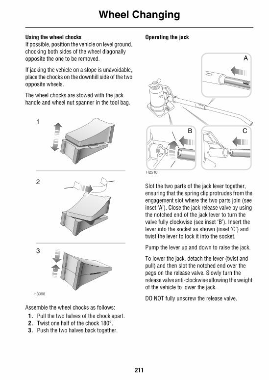
Wheel Changing
211
Using the wheel chocksIf possible, position the vehicle on level ground, chocking both sides of the wheel diagonally opposite the one to be removed.
If jacking the vehicle on a slope is unavoidable, place the chocks on the downhill side of the two opposite wheels.
The wheel chocks are stowed with the jack handle and wheel nut spanner in the tool bag.
Assemble the wheel chocks as follows:1. Pull the two halves of the chock apart.2. Twist one half of the chock 180°.3. Push the two halves back together.
Operating the jack
Slot the two parts of the jack lever together, ensuring that the spring clip protrudes from the engagement slot where the two parts join (see inset ‘A’). Close the jack release valve by using the notched end of the jack lever to turn the valve fully clockwise (see inset ‘B’). Insert the lever into the socket as shown (inset ‘C’) and twist the lever to lock it into the socket.
Pump the lever up and down to raise the jack.
To lower the jack, detach the lever (twist and pull) and then slot the notched end over the pegs on the release valve. Slowly turn the release valve anti-clockwise allowing the weight of the vehicle to lower the jack.
DO NOT fully unscrew the release valve.H3098
2
1
3
H2510
A
B C
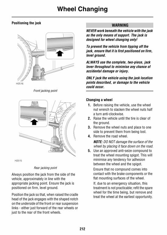
Wheel Changing
212
Positioning the jack
Front jacking point
Rear jacking point
Always position the jack from the side of the vehicle, approximately in line with the appropriate jacking point. Ensure the jack is positioned on firm, level ground.
Position the jack so that, when raised the cradle head of the jack engages with the shaped notch on the underside of the front or rear suspension links - either just forward of the rear wheels or just to the rear of the front wheels.
WARNINGNEVER work beneath the vehicle with the jack as the only means of support. The jack is designed for wheel changing only!
To prevent the vehicle from tipping off the jack, ensure that it is first positioned on firm, level ground.
ALWAYS use the complete, two-piece, jack lever throughout to minimise any chance of accidental damage or injury.
ONLY jack the vehicle using the jack location points described, or damage to the vehicle could occur.
Changing a wheel1. Before raising the vehicle, use the wheel
nut wrench to slacken the wheel nuts half a turn anti-clockwise.
2. Raise the vehicle until the tire is clear of the ground.
3. Remove the wheel nuts and place to one side to prevent them from being lost.
4. Remove the road wheel.
NOTE: DO NOT damage the surface of the wheel by placing it face down on the road.
5. Use an approved anti-seize compound to treat the wheel mounting spigot. This will minimise any tendency for adhesion between the wheel and the spigot. Ensure that no compound comes into contact with the brake components or the flat mounting surfaces of the wheel.If, due to an emergency situation, this treatment is not practicable; refit the spare wheel for the time being, but remove and treat the wheel at the earliest opportunity.
H2516
H2515
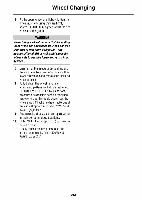
Wheel Changing
213
6. Fit the spare wheel and lightly tighten the wheel nuts, ensuring they are firmly seated. DO NOT fully tighten whilst the tire is clear of the ground.
WARNINGWhen fitting a wheel, ensure that the mating faces of the hub and wheel are clean and free from rust or anti-seize compound - any accumulation of dirt or rust could cause the wheel nuts to become loose and result in an accident.
7. Ensure that the space under and around the vehicle is free from obstructions then lower the vehicle and remove the jack and wheel chocks.
8. Fully tighten the wheel nuts in an alternating pattern until all are tightened. DO NOT OVERTIGHTEN by using foot pressure or extension bars on the wheel nut wrench, as this could overstress the wheel studs. Check the wheel nut torque at the earliest opportunity (see ‘WHEELS & TIRES’, page 247).
9. Return tools, chocks, jack and spare wheel in their correct storage positions.
10. REMEMBER to change to ‘H’ (high range) before driving.
11. Finally, check the tire pressure at the earliest opportunity (see ‘WHEELS & TIRES’, page 247).
Emergency Starting
214
Emergency StartingSTARTING AN ENGINE WITH A DISCHARGED BATTERYUsing booster cables (jump leads) from a donor battery, or a battery fitted to a donor vehicle, is the only approved method of starting a Discovery with a discharged battery.
Vehicles with automatic transmission cannot be restarted by push or towing.
WARNINGAlways wear appropriate eye protection when working with batteries.
During normal use, batteries emit explosive hydrogen gas sufficient to cause severe explosions capable of causing serious injury - keep sparks and naked lights away from the engine compartment.
DO NOT attempt to start the vehicle if the electrolyte in the battery is suspected of being frozen.
Make sure BOTH batteries are of the same voltage (12 volts), and that the booster cables have insulated clamps and are approved for use with 12 volt batteries.
DO NOT disconnect the discharged battery.
DO NOT connect positive (+) terminals to negative (-) terminals, and ensure booster cables are kept away from any moving parts in the engine compartment.
Take care when working near rotating parts of the engine.
USING BOOSTER CABLESIf a donor vehicle is to be used, both vehicles should be parked with their battery locations adjacent to each other. Ensure that the two vehicles do not touch.
Apply the handbrakes and ensure that the transmission of both vehicles is set in neutral (‘P’ or Park for vehicles with automatic transmission).
Turn off the starter switch and ALL electrical equipment of BOTH vehicles, then follow the connection instructions on the following page.
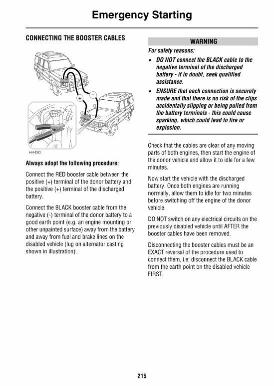
Emergency Starting
215
CONNECTING THE BOOSTER CABLES
Always adopt the following procedure:
Connect the RED booster cable between the positive (+) terminal of the donor battery and the positive (+) terminal of the discharged battery.
Connect the BLACK booster cable from the negative (-) terminal of the donor battery to a good earth point (e.g. an engine mounting or other unpainted surface) away from the battery and away from fuel and brake lines on the disabled vehicle (lug on alternator casting shown in illustration).
WARNINGFor safety reasons:
• DO NOT connect the BLACK cable to the negative terminal of the discharged battery - if in doubt, seek qualified assistance.
• ENSURE that each connection is securely made and that there is no risk of the clips accidentally slipping or being pulled from the battery terminals - this could cause sparking, which could lead to fire or explosion.
Check that the cables are clear of any moving parts of both engines, then start the engine of the donor vehicle and allow it to idle for a few minutes.
Now start the vehicle with the discharged battery. Once both engines are running normally, allow them to idle for two minutes before switching off the engine of the donor vehicle.
DO NOT switch on any electrical circuits on the previously disabled vehicle until AFTER the booster cables have been removed.
Disconnecting the booster cables must be an EXACT reversal of the procedure used to connect them, i.e: disconnect the BLACK cable from the earth point on the disabled vehicle FIRST.
H4430
+
+
+
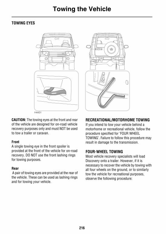
Towing the Vehicle
216
Towing the VehicleTOWING EYES
CAUTION: The towing eyes at the front and rear of the vehicle are designed for on-road vehicle recovery purposes only and must NOT be used to tow a trailer or caravan.
FrontA single towing eye in the front spoiler is provided at the front of the vehicle for on-road recovery. DO NOT use the front lashing rings for towing purposes.
Rear A pair of towing eyes are provided at the rear of the vehicle. These can be used as lashing rings and for towing your vehicle.
RECREATIONAL/MOTORHOME TOWINGIf you intend to tow your vehicle behind a motorhome or recreational vehicle, follow the procedure specified for ‘FOUR WHEEL TOWING’. Failure to follow this procedure may result in damage to the transmission.
FOUR-WHEEL TOWINGMost vehicle recovery specialists will load Discovery onto a trailer. However, if it is necessary to recover the vehicle by towing with all four wheels on the ground, or to similarly tow the vehicle for recreational purposes, observe the following procedure:
H4431
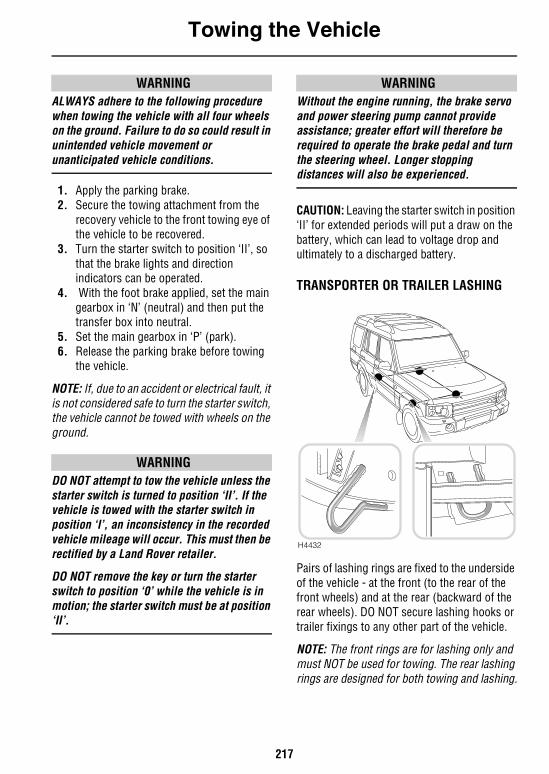
Towing the Vehicle
217
WARNINGALWAYS adhere to the following procedure when towing the vehicle with all four wheels on the ground. Failure to do so could result in unintended vehicle movement or unanticipated vehicle conditions.
1. Apply the parking brake.2. Secure the towing attachment from the
recovery vehicle to the front towing eye of the vehicle to be recovered.
3. Turn the starter switch to position ‘II’, so that the brake lights and direction indicators can be operated.
4. With the foot brake applied, set the main gearbox in ‘N’ (neutral) and then put the transfer box into neutral.
5. Set the main gearbox in ‘P’ (park).6. Release the parking brake before towing
the vehicle.
NOTE: If, due to an accident or electrical fault, it is not considered safe to turn the starter switch, the vehicle cannot be towed with wheels on the ground.
WARNINGDO NOT attempt to tow the vehicle unless the starter switch is turned to position ‘II’. If the vehicle is towed with the starter switch in position ‘I’, an inconsistency in the recorded vehicle mileage will occur. This must then be rectified by a Land Rover retailer.
DO NOT remove the key or turn the starter switch to position ‘0’ while the vehicle is in motion; the starter switch must be at position ‘II’.
WARNINGWithout the engine running, the brake servo and power steering pump cannot provide assistance; greater effort will therefore be required to operate the brake pedal and turn the steering wheel. Longer stopping distances will also be experienced.
CAUTION: Leaving the starter switch in position ‘II’ for extended periods will put a draw on the battery, which can lead to voltage drop and ultimately to a discharged battery.
TRANSPORTER OR TRAILER LASHING
Pairs of lashing rings are fixed to the underside of the vehicle - at the front (to the rear of the front wheels) and at the rear (backward of the rear wheels). DO NOT secure lashing hooks or trailer fixings to any other part of the vehicle.
NOTE: The front rings are for lashing only and must NOT be used for towing. The rear lashing rings are designed for both towing and lashing.
H4432
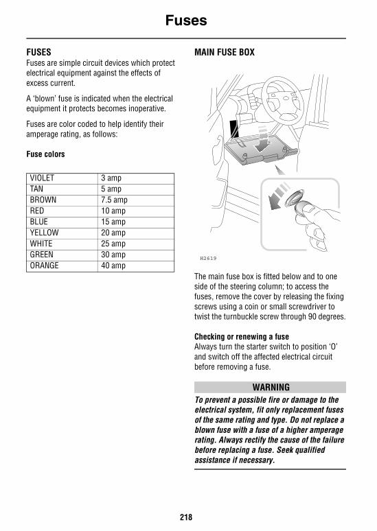
Fuses
218
FusesFUSESFuses are simple circuit devices which protect electrical equipment against the effects of excess current.
A ‘blown’ fuse is indicated when the electrical equipment it protects becomes inoperative.
Fuses are color coded to help identify their amperage rating, as follows:
Fuse colors
MAIN FUSE BOX
The main fuse box is fitted below and to one side of the steering column; to access the fuses, remove the cover by releasing the fixing screws using a coin or small screwdriver to twist the turnbuckle screw through 90 degrees.
Checking or renewing a fuseAlways turn the starter switch to position ‘O’ and switch off the affected electrical circuit before removing a fuse.
WARNINGTo prevent a possible fire or damage to the electrical system, fit only replacement fuses of the same rating and type. Do not replace a blown fuse with a fuse of a higher amperage rating. Always rectify the cause of the failure before replacing a fuse. Seek qualified assistance if necessary.
VIOLET 3 ampTAN 5 ampBROWN 7.5 ampRED 10 ampBLUE 15 ampYELLOW 20 ampWHITE 25 ampGREEN 30 ampORANGE 40 amp
H2619
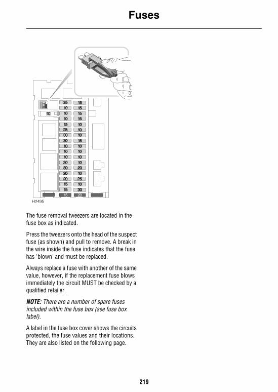
Fuses
219
The fuse removal tweezers are located in the fuse box as indicated.
Press the tweezers onto the head of the suspect fuse (as shown) and pull to remove. A break in the wire inside the fuse indicates that the fuse has 'blown' and must be replaced.
Always replace a fuse with another of the same value, however, if the replacement fuse blows immediately the circuit MUST be checked by a qualified retailer.
NOTE: There are a number of spare fuses included within the fuse box (see fuse box label).
A label in the fuse box cover shows the circuits protected, the fuse values and their locations. They are also listed on the following page.
H2495
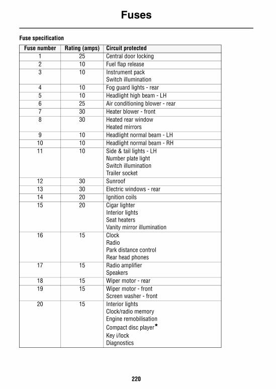
Fuses
220
Fuse specification
Fuse number Rating (amps) Circuit protected1 25 Central door locking2 10 Fuel flap release3 10 Instrument pack
Switch illumination4 10 Fog guard lights - rear5 10 Headlight high beam - LH6 25 Air conditioning blower - rear7 30 Heater blower - front8 30 Heated rear window
Heated mirrors9 10 Headlight normal beam - LH
10 10 Headlight normal beam - RH11 10 Side & tail lights - LH
Number plate light Switch illuminationTrailer socket
12 30 Sunroof13 30 Electric windows - rear14 20 Ignition coils15 20 Cigar lighter
Interior lightsSeat heatersVanity mirror illumination
16 15 ClockRadioPark distance controlRear head phones
17 15 Radio amplifierSpeakers
18 15 Wiper motor - rear19 15 Wiper motor - front
Screen washer - front20 15 Interior lights
Clock/radio memoryEngine remobilisationCompact disc player*Key i/lockDiagnostics
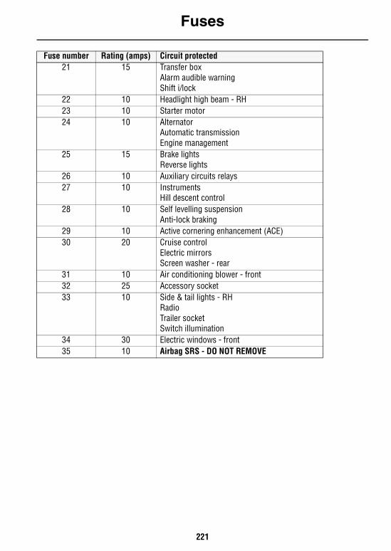
Fuses
221
21 15 Transfer boxAlarm audible warningShift i/lock
22 10 Headlight high beam - RH23 10 Starter motor24 10 Alternator
Automatic transmissionEngine management
25 15 Brake lightsReverse lights
26 10 Auxiliary circuits relays27 10 Instruments
Hill descent control28 10 Self levelling suspension
Anti-lock braking29 10 Active cornering enhancement (ACE)30 20 Cruise control
Electric mirrorsScreen washer - rear
31 10 Air conditioning blower - front32 25 Accessory socket33 10 Side & tail lights - RH
RadioTrailer socketSwitch illumination
34 30 Electric windows - front35 10 Airbag SRS - DO NOT REMOVE
Fuse number Rating (amps) Circuit protected
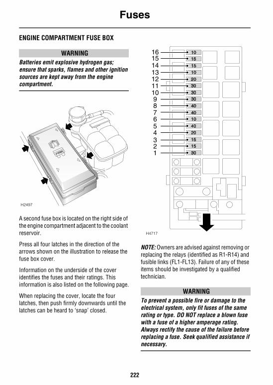
Fuses
222
ENGINE COMPARTMENT FUSE BOX
WARNINGBatteries emit explosive hydrogen gas; ensure that sparks, flames and other ignition sources are kept away from the engine compartment.
A second fuse box is located on the right side of the engine compartment adjacent to the coolant reservoir.
Press all four latches in the direction of the arrows shown on the illustration to release the fuse box cover.
Information on the underside of the cover identifies the fuses and their ratings. This information is also listed on the following page.
When replacing the cover, locate the four latches, then push firmly downwards until the latches can be heard to ‘snap’ closed.
NOTE: Owners are advised against removing or replacing the relays (identified as R1-R14) and fusible links (FL1-FL13). Failure of any of these items should be investigated by a qualified technician.
WARNINGTo prevent a possible fire or damage to the electrical system, only fit fuses of the same rating or type. DO NOT replace a blown fuse with a fuse of a higher amperage rating. Always rectify the cause of the failure before replacing a fuse. Seek qualified assistance if necessary.
H2497
H4717
7654321
89
10111213141516
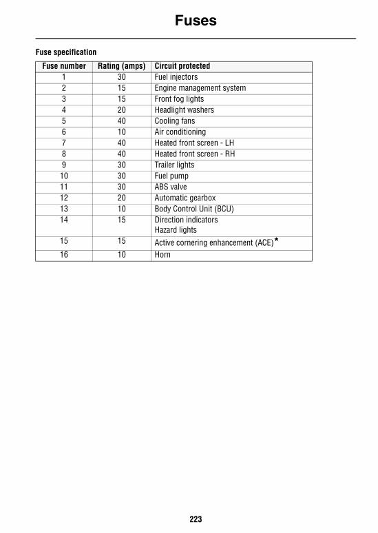
Fuses
223
Fuse specification
Fuse number Rating (amps) Circuit protected1 30 Fuel injectors 2 15 Engine management system3 15 Front fog lights4 20 Headlight washers5 40 Cooling fans6 10 Air conditioning7 40 Heated front screen - LH8 40 Heated front screen - RH9 30 Trailer lights
10 30 Fuel pump11 30 ABS valve12 20 Automatic gearbox13 10 Body Control Unit (BCU)14 15 Direction indicators
Hazard lights15 15 Active cornering enhancement (ACE)*16 10 Horn
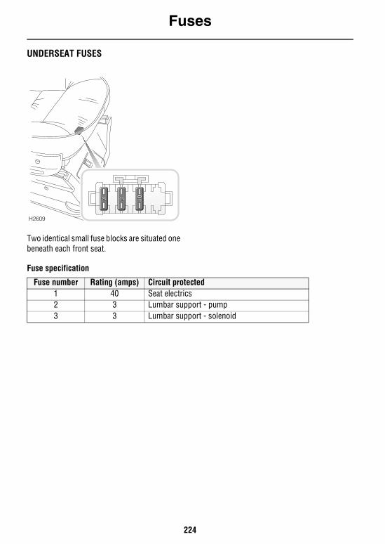
Fuses
224
UNDERSEAT FUSES
Two identical small fuse blocks are situated one beneath each front seat.
Fuse specification
H2609
Fuse number Rating (amps) Circuit protected1 40 Seat electrics2 3 Lumbar support - pump3 3 Lumbar support - solenoid

Bulb Replacement
225
Bulb ReplacementREPLACING BULBSCheck the operation of all exterior lights before you drive the vehicle.
Replacement bulbsNOTE: All bulbs must be rated at 12 volts
NOTE: In certain territories it is a legal requirement to carry spare bulbs, in case of bulb failure. A replacement bulb kit is available as an approved accessory from your Land Rover retailer.
Halogen bulbsHalogen bulbs are used for main beam, dipped beam and front fog lights. Take care NOT to touch this type of bulb with your fingers; always use a cloth to handle them. If necessary, clean the bulb with isopropyl rubbing alcohol to remove fingerprints.
IMPORTANT INFORMATION
Before replacing a bulb, always switch off the starter switch and appropriate lighting switch to prevent any possibility of a short circuit. Only replace bulbs with the same type and specification.
Bulb WattsHeadlights normal beam H7 55Headlights high beam H7 55Front side lights 3 Front side marker lights 3 Rear side marker lights 3 Direction indicators 21 Front fog lights H11 55Side repeater lights 5 Reverse lights 21Rear fog guard lights 21 Stop/Tail lights 21/5High mounted stop light 21Number plate lights 5Interior light 5Interior courtesy lights 10Glovebox light 5Vanity mirror light 1.2
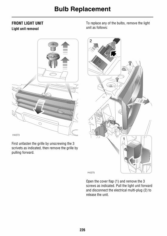
Bulb Replacement
226
FRONT LIGHT UNITLight unit removal
First unfasten the grille by unscrewing the 3 scrivets as indicated, then remove the grille by pulling forward.
To replace any of the bulbs, remove the light unit as follows:
Open the cover flap (1) and remove the 3 screws as indicated. Pull the light unit forward and disconnect the electrical multi-plug (2) to release the unit.
H4373
1
H4375
2
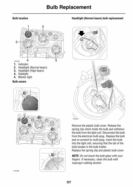
Bulb Replacement
227
Bulb location
1. Indicator2. Headlight (Normal beam)3. Headlight (High beam)4. Sidelight5. Marker light
Bulb covers
Headlight (Normal beam) bulb replacement
Remove the plastic bulb cover. Release the spring clip which holds the bulb and withdraw the bulb from the light unit. Disconnect the bulb from the electrical multi-plug . Replace the bulb and re-connect to multi-plug. Insert the bulb into the light unit, ensuring that the tab of the bulb locates in the bulb holder.Replace the spring clip and plastic bulb cover.
NOTE: Do not touch the bulb glass with your fingers. If necessary, clean the bulb with isopropyl rubbing alcohol.
H4379
1 2
34
5
H4380
H4381
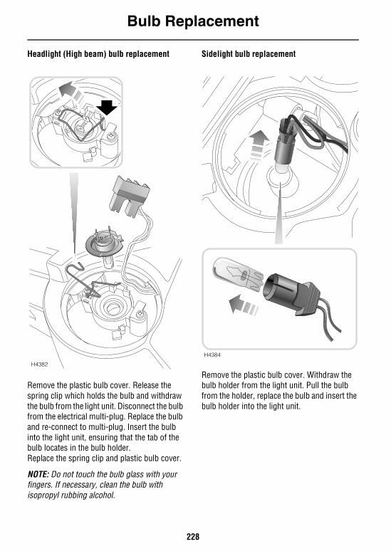
Bulb Replacement
228
Headlight (High beam) bulb replacement
Remove the plastic bulb cover. Release the spring clip which holds the bulb and withdraw the bulb from the light unit. Disconnect the bulb from the electrical multi-plug. Replace the bulb and re-connect to multi-plug. Insert the bulb into the light unit, ensuring that the tab of the bulb locates in the bulb holder.Replace the spring clip and plastic bulb cover.
NOTE: Do not touch the bulb glass with your fingers. If necessary, clean the bulb with isopropyl rubbing alcohol.
Sidelight bulb replacement
Remove the plastic bulb cover. Withdraw the bulb holder from the light unit. Pull the bulb from the holder, replace the bulb and insert the bulb holder into the light unit.
H4382
H4384
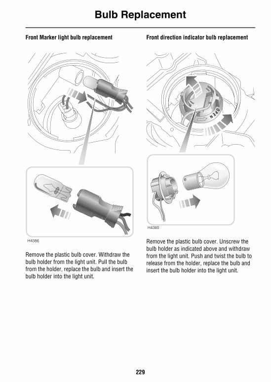
Bulb Replacement
229
Front Marker light bulb replacement
Remove the plastic bulb cover. Withdraw the bulb holder from the light unit. Pull the bulb from the holder, replace the bulb and insert the bulb holder into the light unit.
Front direction indicator bulb replacement
Remove the plastic bulb cover. Unscrew the bulb holder as indicated above and withdraw from the light unit. Push and twist the bulb to release from the holder, replace the bulb and insert the bulb holder into the light unit.
H4386
H4385
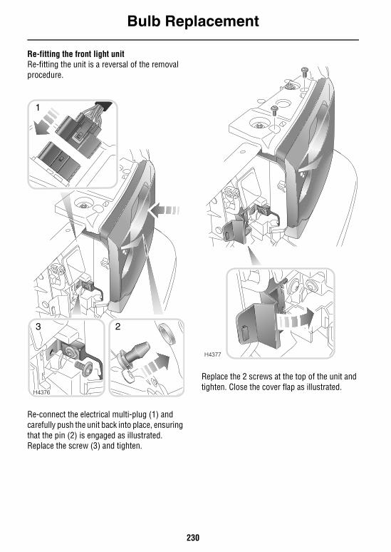
Bulb Replacement
230
Re-fitting the front light unitRe-fitting the unit is a reversal of the removal procedure.
Re-connect the electrical multi-plug (1) and carefully push the unit back into place, ensuring that the pin (2) is engaged as illustrated.Replace the screw (3) and tighten.
Replace the 2 screws at the top of the unit and tighten. Close the cover flap as illustrated.
H4376
1
23
H4377
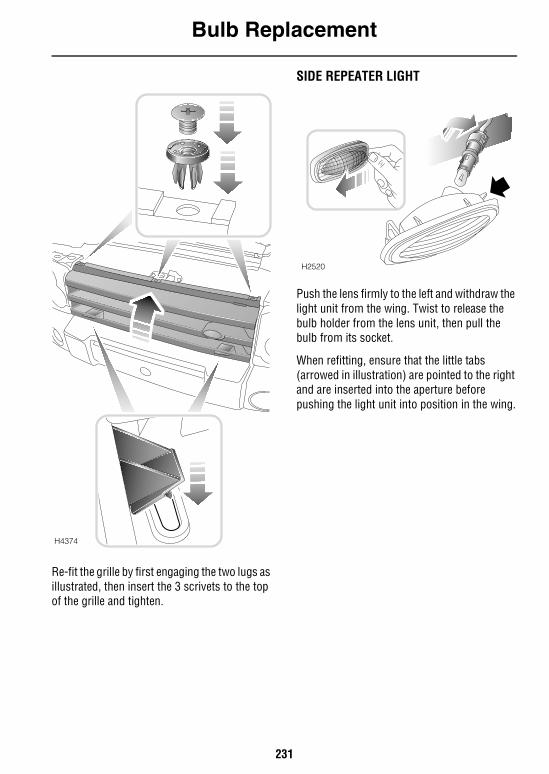
Bulb Replacement
231
Re-fit the grille by first engaging the two lugs as illustrated, then insert the 3 scrivets to the top of the grille and tighten.
SIDE REPEATER LIGHT
Push the lens firmly to the left and withdraw the light unit from the wing. Twist to release the bulb holder from the lens unit, then pull the bulb from its socket.
When refitting, ensure that the little tabs (arrowed in illustration) are pointed to the right and are inserted into the aperture before pushing the light unit into position in the wing.
H4374
H2520
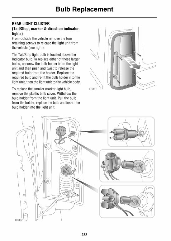
Bulb Replacement
232
REAR LIGHT CLUSTER (Tail/Stop, marker & direction indicator lights) From outside the vehicle remove the four retaining screws to release the light unit from the vehicle (see right).
The Tail/Stop light bulb is located above the Indicator bulb.To replace either of these larger bulbs, unscrew the bulb holder from the light unit and then push and twist to release the required bulb from the holder. Replace the required bulb and re-fit the bulb holder into the light unit, then the light unit to the vehicle body.
To replace the smaller marker light bulb, remove the plastic bulb cover. Withdraw the bulb holder from the light unit. Pull the bulb from the holder, replace the bulb and insert the bulb holder into the light unit.
H4391
H4387
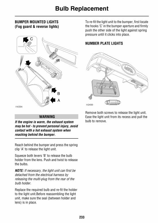
Bulb Replacement
233
BUMPER MOUNTED LIGHTS(Fog guard & reverse lights)
WARNINGIf the engine is warm, the exhaust system may be hot - to prevent personal injury, avoid contact with a hot exhaust system when reaching behind the bumper.
Reach behind the bumper and press the spring clip ‘A’ to release the light unit.
Squeeze both levers ‘B’ to release the bulb holder from the lens. Push and twist to release the bulbs.
NOTE: If necessary, the light unit can first be detached from the electrical harness by releasing the multi-plug from the rear of the bulb holder.
Replace the required bulb and re-fit the holder to the light unit.Before reassembling the light unit, make sure the seal (between holder and lens) is in place.
To re-fit the light unit to the bumper, first locate the hooks ‘C’ in the bumper aperture and firmly push the other side of the light against spring pressure until it clicks into place.
NUMBER PLATE LIGHTS
Remove both screws to release the light unit. Ease the light unit from its recess and pull the bulb to remove.
H4394
C
B
AH2499
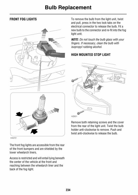
Bulb Replacement
234
FRONT FOG LIGHTS
The front fog lights are accessible from the rear of the front bumpers and are shielded by the lower wheelarch liners.
Access is restricted and will entail lying beneath the center of the vehicle at the front and reaching between the wheelarch liner and the back of the fog light.
To remove the bulb from the light unit, twist and pull, press in the two lock tabs on the electrical connector to release the bulb. Fit a new bulb to the connector and re-fit into the fog light unit.
NOTE: Do not touch the bulb glass with your fingers. If necessary, clean the bulb with isopropyl rubbing alcohol.
HIGH MOUNTED STOP LIGHT
Remove both retaining screws and the cover from the rear of the light unit. Twist the bulb holder anti-clockwise to remove. Push and twist anti-clockwise to release the bulb.
H4372
H2501
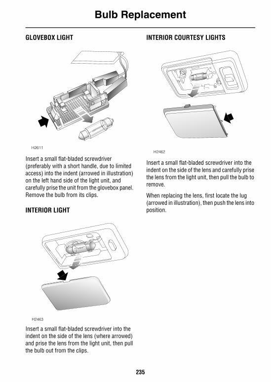
Bulb Replacement
235
GLOVEBOX LIGHT
Insert a small flat-bladed screwdriver (preferably with a short handle, due to limited access) into the indent (arrowed in illustration) on the left hand side of the light unit, and carefully prise the unit from the glovebox panel. Remove the bulb from its clips.
INTERIOR LIGHT
Insert a small flat-bladed screwdriver into the indent on the side of the lens (where arrowed) and prise the lens from the light unit, then pull the bulb out from the clips.
INTERIOR COURTESY LIGHTS
Insert a small flat-bladed screwdriver into the indent on the side of the lens and carefully prise the lens from the light unit, then pull the bulb to remove.
When replacing the lens, first locate the lug (arrowed in illustration), then push the lens into position.
H2611
H2463
H2462

236
237
Technical Data
Lubricants & FluidsLUBRICANTS AND FLUIDS . . . . . . . . . . . . . . . . 239
CapacitiesCAPACITIES. . . . . . . . . . . . . . . . . . . . . . . . . . . . 240
EnginesENGINES . . . . . . . . . . . . . . . . . . . . . . . . . . . . . . 241
Electrical SystemELECTRICAL SYSTEM . . . . . . . . . . . . . . . . . . . . 242
SteeringSTEERING . . . . . . . . . . . . . . . . . . . . . . . . . . . . . 243
DimensionsDIMENSIONS. . . . . . . . . . . . . . . . . . . . . . . . . . . 244
Vehicle WeightsVEHICLE WEIGHTS . . . . . . . . . . . . . . . . . . . . . . 245
Towing WeightsTOWING WEIGHTS . . . . . . . . . . . . . . . . . . . . . . 246
Wheels & TiresWHEELS & TIRES . . . . . . . . . . . . . . . . . . . . . . . 247

238
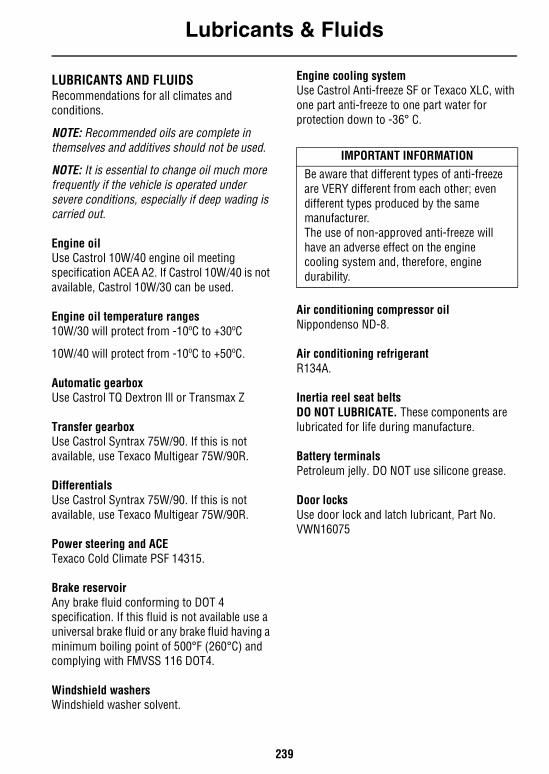
Lubricants & Fluids
239
Technical Data
Lubricants & FluidsLUBRICANTS AND FLUIDSRecommendations for all climates and conditions.
NOTE: Recommended oils are complete in themselves and additives should not be used.
NOTE: It is essential to change oil much more frequently if the vehicle is operated under severe conditions, especially if deep wading is carried out.
Engine oilUse Castrol 10W/40 engine oil meeting specification ACEA A2. If Castrol 10W/40 is not available, Castrol 10W/30 can be used.
Engine oil temperature ranges10W/30 will protect from -10ºC to +30ºC
10W/40 will protect from -10ºC to +50ºC.
Automatic gearboxUse Castrol TQ Dextron lll or Transmax Z
Transfer gearboxUse Castrol Syntrax 75W/90. If this is not available, use Texaco Multigear 75W/90R.
Differentials Use Castrol Syntrax 75W/90. If this is not available, use Texaco Multigear 75W/90R.
Power steering and ACETexaco Cold Climate PSF 14315.
Brake reservoirAny brake fluid conforming to DOT 4 specification. If this fluid is not available use a universal brake fluid or any brake fluid having a minimum boiling point of 500°F (260°C) and complying with FMVSS 116 DOT4.
Windshield washersWindshield washer solvent.
Engine cooling systemUse Castrol Anti-freeze SF or Texaco XLC, with one part anti-freeze to one part water for protection down to -36° C.
Air conditioning compressor oilNippondenso ND-8.
Air conditioning refrigerantR134A.
Inertia reel seat beltsDO NOT LUBRICATE. These components are lubricated for life during manufacture.
Battery terminalsPetroleum jelly. DO NOT use silicone grease.
Door locksUse door lock and latch lubricant, Part No. VWN16075
IMPORTANT INFORMATIONBe aware that different types of anti-freeze are VERY different from each other; even different types produced by the same manufacturer.The use of non-approved anti-freeze will have an adverse effect on the engine cooling system and, therefore, engine durability.
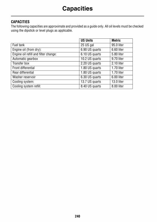
Capacities
240
CapacitiesCAPACITIESThe following capacities are approximate and provided as a guide only. All oil levels must be checked using the dipstick or level plugs as applicable.
US Units MetricFuel tank 25 US gal 95.0 literEngine oil (from dry): 6.90 US quarts 6.60 literEngine oil refill and filter change: 6.10 US quarts 5.80 literAutomatic gearbox 10.2 US quarts 9.70 literTransfer box 2.20 US quarts 2.10 literFront differential 1.80 US quarts 1.70 literRear differential 1.80 US quarts 1.70 literWasher reservoir 6.30 US quarts 6.00 literCooling system: 13.7 US quarts 13.0 literCooling system refill: 8.40 US quarts 8.00 liter
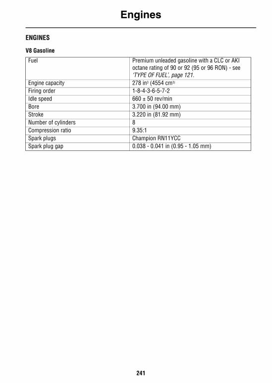
Engines
241
EnginesENGINES
V8 Gasoline
Fuel Premium unleaded gasoline with a CLC or AKI octane rating of 90 or 92 (95 or 96 RON) - see ‘TYPE OF FUEL’, page 121.
Engine capacity 278 in3 (4554 cm3)
Firing order 1-8-4-3-6-5-7-2Idle speed 660 ± 50 rev/minBore 3.700 in (94.00 mm)Stroke 3.220 in (81.92 mm)Number of cylinders 8Compression ratio 9.35:1Spark plugs Champion RN11YCCSpark plug gap 0.038 - 0.041 in (0.95 - 1.05 mm)

Electrical System
242
Electrical SystemELECTRICAL SYSTEM
Battery type: Group 24, sealed for lifeBattery rating: 130 amp/hrVoltage and polarity 12 V, negative (-) earthCharging circuit Alternator
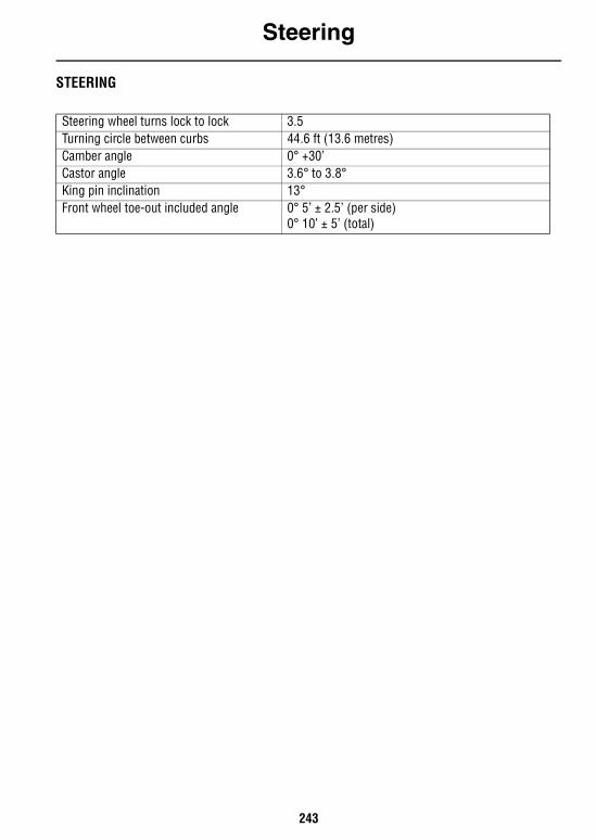
Steering
243
SteeringSTEERING
Steering wheel turns lock to lock 3.5Turning circle between curbs 44.6 ft (13.6 metres)Camber angle 0° +30’Castor angle 3.6° to 3.8°King pin inclination 13°Front wheel toe-out included angle 0° 5’ ± 2.5’ (per side)
0° 10’ ± 5’ (total)
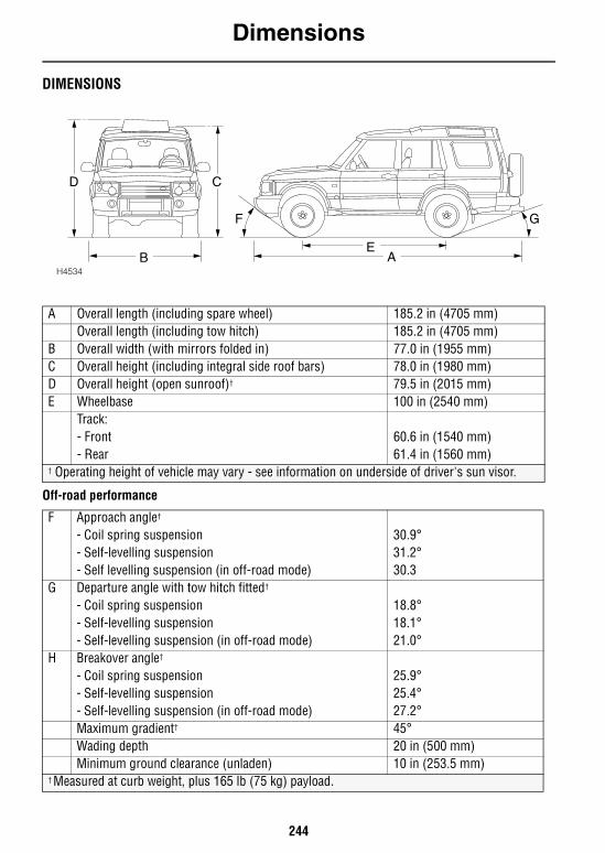
Dimensions
244
DimensionsDIMENSIONS
Off-road performance
H4534AB
CD
E
F G
A Overall length (including spare wheel) 185.2 in (4705 mm)Overall length (including tow hitch) 185.2 in (4705 mm)
B Overall width (with mirrors folded in) 77.0 in (1955 mm)C Overall height (including integral side roof bars) 78.0 in (1980 mm)D Overall height (open sunroof)† 79.5 in (2015 mm)E Wheelbase 100 in (2540 mm)
Track:- Front 60.6 in (1540 mm)- Rear 61.4 in (1560 mm)
† Operating height of vehicle may vary - see information on underside of driver's sun visor.
F Approach angle†
- Coil spring suspension 30.9°- Self-levelling suspension 31.2°- Self levelling suspension (in off-road mode) 30.3
G Departure angle with tow hitch fitted†
- Coil spring suspension 18.8°- Self-levelling suspension 18.1°- Self-levelling suspension (in off-road mode) 21.0°
H Breakover angle†
- Coil spring suspension 25.9°- Self-levelling suspension 25.4°- Self-levelling suspension (in off-road mode) 27.2°Maximum gradient† 45°Wading depth 20 in (500 mm)Minimum ground clearance (unladen) 10 in (253.5 mm)
† Measured at curb weight, plus 165 lb (75 kg) payload.
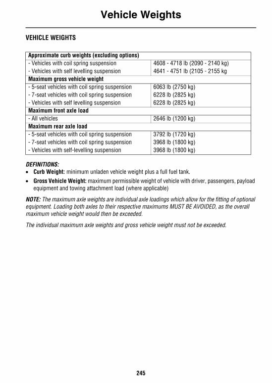
Vehicle Weights
245
Vehicle WeightsVEHICLE WEIGHTS
DEFINITIONS:• Curb Weight: minimum unladen vehicle weight plus a full fuel tank.• Gross Vehicle Weight: maximum permissible weight of vehicle with driver, passengers, payload
equipment and towing attachment load (where applicable)
NOTE: The maximum axle weights are individual axle loadings which allow for the fitting of optional equipment. Loading both axles to their respective maximums MUST BE AVOIDED, as the overall maximum vehicle weight would then be exceeded.
The individual maximum axle weights and gross vehicle weight must not be exceeded.
Approximate curb weights (excluding options)- Vehicles with coil spring suspension 4608 - 4718 lb (2090 - 2140 kg)- Vehicles with self levelling suspension 4641 - 4751 lb (2105 - 2155 kgMaximum gross vehicle weight- 5-seat vehicles with coil spring suspension 6063 lb (2750 kg)- 7-seat vehicles with coil spring suspension 6228 lb (2825 kg)- Vehicles with self levelling suspension 6228 lb (2825 kg)Maximum front axle load- All vehicles 2646 lb (1200 kg)Maximum rear axle load- 5-seat vehicles with coil spring suspension 3792 lb (1720 kg)- 7-seat vehicles with coil spring suspension 3968 lb (1800 kg)- Vehicles with self-levelling suspension 3968 lb (1800 kg)
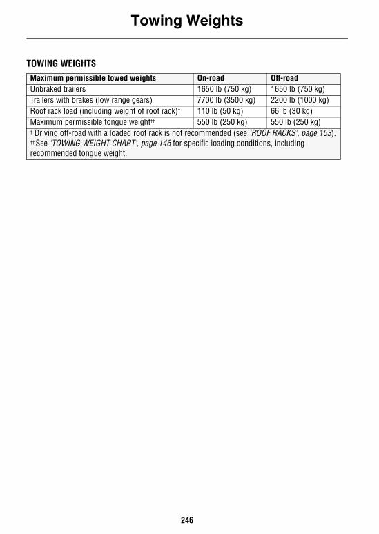
Towing Weights
246
Towing Weights
TOWING WEIGHTSMaximum permissible towed weights On-road Off-roadUnbraked trailers 1650 lb (750 kg) 1650 lb (750 kg)Trailers with brakes (low range gears) 7700 lb (3500 kg) 2200 lb (1000 kg)Roof rack load (including weight of roof rack)† 110 lb (50 kg) 66 lb (30 kg)Maximum permissible tongue weight†† 550 lb (250 kg) 550 lb (250 kg)† Driving off-road with a loaded roof rack is not recommended (see ‘ROOF RACKS’, page 153).†† See ‘TOWING WEIGHT CHART’, page 146 for specific loading conditions, including recommended tongue weight.
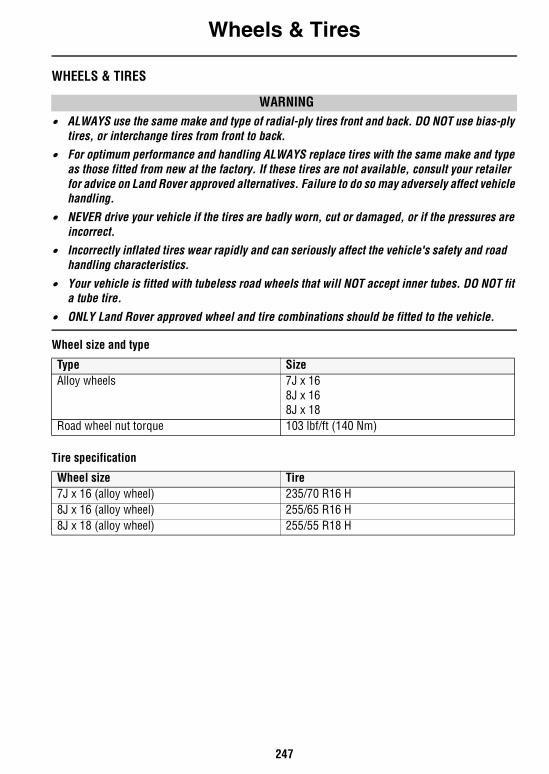
Wheels & Tires
247
Wheels & TiresWHEELS & TIRES
WARNING• ALWAYS use the same make and type of radial-ply tires front and back. DO NOT use bias-ply
tires, or interchange tires from front to back.• For optimum performance and handling ALWAYS replace tires with the same make and type
as those fitted from new at the factory. If these tires are not available, consult your retailer for advice on Land Rover approved alternatives. Failure to do so may adversely affect vehicle handling.
• NEVER drive your vehicle if the tires are badly worn, cut or damaged, or if the pressures are incorrect.
• Incorrectly inflated tires wear rapidly and can seriously affect the vehicle's safety and road handling characteristics.
• Your vehicle is fitted with tubeless road wheels that will NOT accept inner tubes. DO NOT fit a tube tire.
• ONLY Land Rover approved wheel and tire combinations should be fitted to the vehicle.
Wheel size and type
Tire specification
Type SizeAlloy wheels 7J x 16
8J x 168J x 18
Road wheel nut torque 103 lbf/ft (140 Nm)
Wheel size Tire7J x 16 (alloy wheel) 235/70 R16 H8J x 16 (alloy wheel) 255/65 R16 H8J x 18 (alloy wheel) 255/55 R18 H
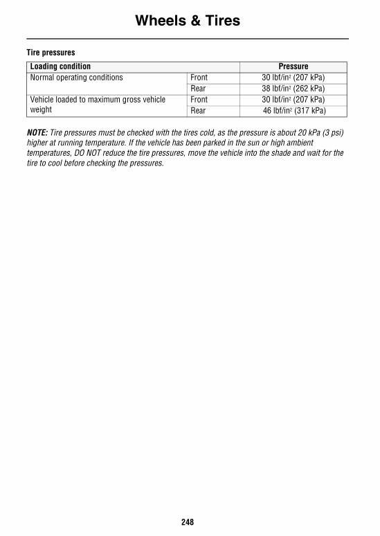
Wheels & Tires
248
Tire pressures
NOTE: Tire pressures must be checked with the tires cold, as the pressure is about 20 kPa (3 psi) higher at running temperature. If the vehicle has been parked in the sun or high ambient temperatures, DO NOT reduce the tire pressures, move the vehicle into the shade and wait for the tire to cool before checking the pressures.
Loading condition PressureNormal operating conditions Front 30 lbf/in2 (207 kPa)
Rear 38 lbf/in2 (262 kPa)Vehicle loaded to maximum gross vehicle weight
Front 30 lbf/in2 (207 kPa)Rear 46 lbf/in2 (317 kPa)
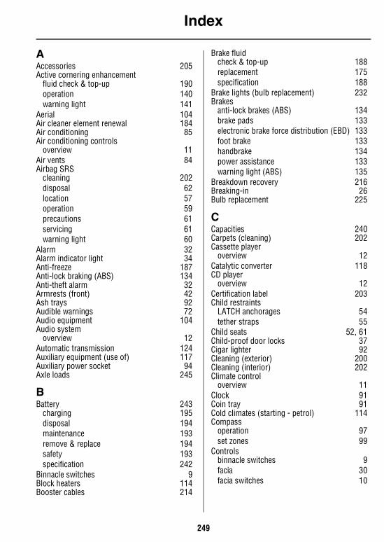
Index
249
AAccessories 205Active cornering enhancement
fluid check & top-up 190operation 140warning light 141
Aerial 104Air cleaner element renewal 184Air conditioning 85Air conditioning controls
overview 11Air vents 84Airbag SRS
cleaning 202disposal 62location 57operation 59precautions 61servicing 61warning light 60
Alarm 32Alarm indicator light 34Anti-freeze 187Anti-lock braking (ABS) 134Anti-theft alarm 32Armrests (front) 42Ash trays 92Audible warnings 72Audio equipment 104Audio system
overview 12Automatic transmission 124Auxiliary equipment (use of) 117Auxiliary power socket 94Axle loads 245
BBattery 243
charging 195disposal 194maintenance 193remove & replace 194safety 193specification 242
Binnacle switches 9Block heaters 114Booster cables 214
Brake fluidcheck & top-up 188replacement 175specification 188
Brake lights (bulb replacement) 232Brakes
anti-lock brakes (ABS) 134brake pads 133electronic brake force distribution (EBD) 133foot brake 133handbrake 134power assistance 133warning light (ABS) 135
Breakdown recovery 216Breaking-in 26Bulb replacement 225
CCapacities 240Carpets (cleaning) 202Cassette player
overview 12Catalytic converter 118CD player
overview 12Certification label 203Child restraints
LATCH anchorages 54tether straps 55
Child seats 52, 61Child-proof door locks 37Cigar lighter 92Cleaning (exterior) 200Cleaning (interior) 202Climate control
overview 11Clock 91Coin tray 91Cold climates (starting - petrol) 114Compass
operation 97set zones 99
Controlsbinnacle switches 9facia 30facia switches 10
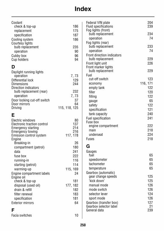
Index
250
Coolantcheck & top-up 186replacement 175specification 187
Cooling system 186Courtesy lights
bulb replacement 235operation 90
Cubby box 96Cup holders 94
DDaylight running lights
operation 7, 73Differential lock 129Dimensions 244Direction indicators
bulb replacement (rear) 232operation 7, 73
Door locking cut-off switch 37Door mirrors 64Driving 115, 118, 125
EElectric windows 80Electronic traction control 137Emergency starting 214Emergency towing 216Emission control system 117, 178Engine
Breaking-in 26compartment (petrol) 180data 241fuse box 222running-in 116starting (petrol) 114warming-up 115, 169
Engine compartment labels 24Engine oil
check & top-up 181disposal (used oil) 177, 182drain & refill 182filter renewal 183specification 181
Exterior mirrors 64
FFacia switches 10
Federal VIN plate 204Fluid specifications 239Fog lights (front)
bulb replacement 234operation 74
Fog lights (rear)bulb replacement 233operation 74
Front direction indicatorsbulb replacement 229
Front light unit 226Front marker lights
bulb replacement 229Fuel
cut-off switch 123economy 116, 171empty tank 122filler 120filling 122gauge 65safety 122specification 121tank capacity 240
Fuel specification 241Fuse box
engine compartment 222main 218underseat 224
Fuses 218
GGauges
fuel 65speedometer 65tachometer 65temperature 65
Gearbox (automatic)gear change speeds 125’kick down’ 125manual mode 126mode switch 126selector lever 124sport mode 126
Gearbox (transfer box) 127Gearbox selector label 21General data 239
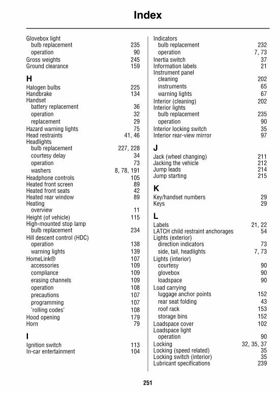
Index
251
Glovebox lightbulb replacement 235operation 90
Gross weights 245Ground clearance 159
HHalogen bulbs 225Handbrake 134Handset
battery replacement 36operation 32replacement 29
Hazard warning lights 75Head restraints 41, 46Headlights
bulb replacement 227, 228courtesy delay 34operation 73washers 8, 78, 191
Headphone controls 105Heated front screen 89Heated front seats 42Heated rear window 89Heating
overview 11Height (of vehicle) 115High-mounted stop lamp
bulb replacement 234Hill descent control (HDC)
operation 138warning lights 139
HomeLink® 107accessories 109compliance 109erasing channels 109operation 108precautions 107programming 107’rolling codes’ 108
Hood opening 179Horn 79
IIgnition switch 113In-car entertainment 104
Indicatorsbulb replacement 232operation 7, 73
Inertia switch 37Information labels 21Instrument panel
cleaning 202instruments 65warning lights 67
Interior (cleaning) 202Interior lights
bulb replacement 235operation 90
Interior locking switch 35Interior rear-view mirror 97
JJack (wheel changing) 211Jacking the vehicle 212Jump leads 214Jump starting 215
KKey/handset numbers 29Keys 29
LLabels 21, 22LATCH child restraint anchorages 54Lights (exterior)
direction indicators 73side, tail, headlights 7, 73
Lights (interior)courtesy 90glovebox 90loadspace 90
Load carryingluggage anchor points 152rear seat folding 43roof rack 153storage bins 152
Loadspace cover 102Loadspace light
operation 90Locking 32, 35, 37Locking (speed related) 35Locking switch (interior) 35Lubricant specifications 239
Index
252
Luggage anchor points 152Lumbar support adjustment 40
MMaintenance 20, 175, 176Mirror (interior) 97Mirrors (exterior)
adjustment 64cleaning 201folding 64
Mislock 34Mobile phones 103Mode switch (automatic transmission) 126Motorhome towing 216
NNumber plate lights
bulb replacement 233
OOccasional rear seats 44Odometer (distance recorder) 66Off-road driving 136, 157Off-road suspension control 142Oil (engine)
check & top-up 181disposal 177, 182drain & refill 182filter renewal 183specification 181
Owner maintenance 176
PPark distance control 145Parts & accessories 205Passenger airbag label 23Poisonous fluids 177Polishing (the bodywork) 201Power assistance (brakes) 133Power socket 94Power steering
check & top-up 189emergency operation 189
Pre-tensioners 50Pre-tensionsers
servicing 51Punctured tires 197
RRadio 104
overview 12remote controls 105
Radio aerial 104Radio/cassette player
aerial 104CD autochanger 104headphone controls 105
Rear door 101Rear lights
bulb replacement 232Rear marker lights
bulb replacement 232Rear seats 43Rear step 101Rear window demister 89Rear window wash/wipe 78Rear-view mirror 97Recovery (of vehicle) 216Recreational towing 216Remote controls (radio) 105Remote handset battery 36Reverse lights (bulb replacement) 233Road testing on dynamometers 178Roof rack 153Running-in 116
SSafety in the garage 177Safety on the forecourt 122Seat belt
adjustment 49care 51child seat locking mechanism 53cleaning 202operation 48pre-tensioners 50safety 47testing 51
Seat belt pretensionsersservicing 51
Seat heaters 42
Index
253
Seatschild seats 52, 61front (power operated) 39heated 42rear 43rear (occasional) 44
Self-levelling suspensionoperation 142warning lights 144
Service portfolio book 20, 175Side repeater light
bulb replacement 231Sidelights
bulb replacement 228operation 73
Single point entry 35Snow chains 199Spare wheel (removing) 210Speed related locking 35Speedometer 65Starter switch 113Starting
automatic models 125catalyst (precautions) 118emergency 214petrol models 114warming-up the engine 115, 169
Steam cleaning (engine) 200Steering column
adjustment 63lock 113
Steering data 243Stop lights
bulb replacement 232Storage bins 152Stowage (under-seat) 93Sun visor 96Sun visor labels 22Sunroof
electric operation 82roller blind 83
Superlocking 33Switches 9
TTachometer 65
Tail lightsbulb replacement 232operation 73
Technical data 239Telephones 103Temperature gauge 65Tether straps 55Tire
pressures 196, 247punctures 197replacement 198specifications 247wear indicators 197
Tongue weight 149Tool kit 209Towing 146
vehicle weights 148Towing eyes 216Towing for recovery 216Towing on severe inclines 148Towing the vehicle 216Towing weights 151, 246Traction control 137Trailer hitch 147Transfer gearbox 127Transmission
automatic 124Transmitter - HomeLink® 107Transporter or trailer lashing 217Trip recorder 66Trip recorder reset button 66
UUnder seat stowage box 93Underbody maintenance 200Underseat fuses 224
VVanity mirror (illumination) 96Vehicle certification label 203Vehicle height 115Vehicle identification number 203Vehicle weights 245Ventilation 84
WWading 166Warming-up (the engine) 115, 169Warning labels 21
Index
254
Warning lightsactive cornering enhancement 71airbag SRS 67anti-lock braking (ABS) 68battery charging 69differential lock 71direction indicators 69headlight main beam 69hill descent control ’failure’ 70hill descent control ’information’ 69low oil pressure 68manual mode (automatic) 71off-road 69overview 6parking brake, brake fluid 68seat belt 69self-levelling suspension 70service engine soon 67sport mode (automatic) 71traction control 70trailer direction indictators 69transmission oil temperature 68
Warnings (in handbook) 20Warranty information 20Washers (windscreen)
jets 191Washers (windshield)
fluid top-up 191operation 8, 77
Washing (the bodywork) 200Weights (vehicle) 245Wheel
size & type 247spare (removal) 210
Wheel changingchanging the wheel 210jacking the vehicle 212spare wheel 210tool kit 209wheel chocks 211
Windows 80Windshield washers
fluid top-up 191operation 8, 77
Windshield wipersoperation 8, 76variable delay 8, 77wiper blade replacement 192