directional control valves cetop3 group english var july 2018.cdr
TRANSCRIPT
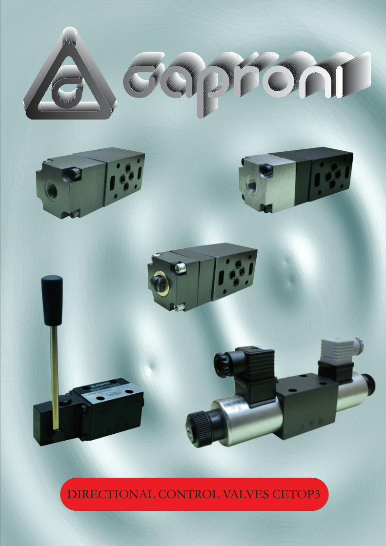
DIRECTIONAL CONTROL VALVES CETOP3
CONTENTS:
RH06...1 - electrical control ......................................
RH06...2 - hydraulic control ..................................... RH06...4 - mechanical control ..............................
RH06...6 - pneumatic control ................................. RH06...7 - manual control ..................................... DVAS06-20 - automatic switch ..............................
Page
1/17...7/17
8/17...9/17
10/17...11/17
12/17...13/17
14/17...15/17
16/17...17/17
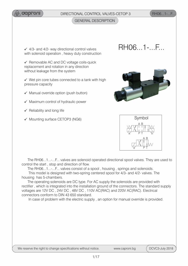
GENERAL DESCRIPTION
RH06...1-...F...
4/3- and 4/2- way directional control valveswith solenoid operation , heavy duty construction
Removable AC and DC voltage coils-quickreplacement and rotation in any directionwithout leakage from the system
Wet pin core tubes connected to a tank with highpressure capacity
Manual override option (push button)
Maximum control of hydraulic power
Reliability and long life
Mounting surface CETOP3 (NG6)
The RH06...1...-...F... valves are solenoid operated directional spool valves. They are used to control the start , stop and direction of flow. The RH06...1...-...F... valves consist of a spool , housing , springs and solenoids. This model is designed with two-spring centered spool for 4/3- and 4/2- valves. The housing has 5-chambers. The operating solenoids are DC type. For AC supply the solenoids are provided withrectifier , which is integrated into the installation ground of the connectors. The standard supplyvoltages are 12V DC , 24V DC , 48V DC , 110V AC(RAC) and 220V AC(RAC). Electrical connectors conform to DIN 43 650 standard. In case of problem with the electric supply , an option for manual override is provided.
DIRECTIONAL CONTROL VALVES-CETOP 3
RH06...1-...F...
Symbol
1/17
We reserve the right to change specifications without notice. www.caproni.bg DCVC3-July 2018
“a”
“a”
“b”
A
A
B
B
P
P
T
T
GENERAL DESCRIPTION
RH06...1-...F...
RH 06 ... 1 - .../... F ... ... ... ... ...
Directional controlvalve
Nominal size
Functional symbol
Type of control: -electrical Supply voltage/current frequency
Modification
Connector
- normal
OmitS
OmitM
Omit K1 K2K3K4K5
NT
C1C2C3C4C5
012/00024/00048/00110/50220/50see page 7/17
see page 7/17
see page 3/17
- tropical
see page 5/17
see page 5/17
see page 5/17
Spacers
Screw cap
- without orifice - orifice Ї0,8mm.
- orifice Ї1mm. - orifice Ї1,2mm. - orifice Ї1,5mm.
- orifice Ї2mm.
Orifice in P line
-without spacers
-with plastic cap
-With spacers
-with metal cap
ORDERING CODE
DIRECTIONAL CONTROL VALVES-CETOP 3
Spool
“a” “b”
P
T
A B
Housing
SolenoidConnector Spring
2/17
We reserve the right to change specifications without notice. www.caproni.bg DCVC3-July 2018
1 7
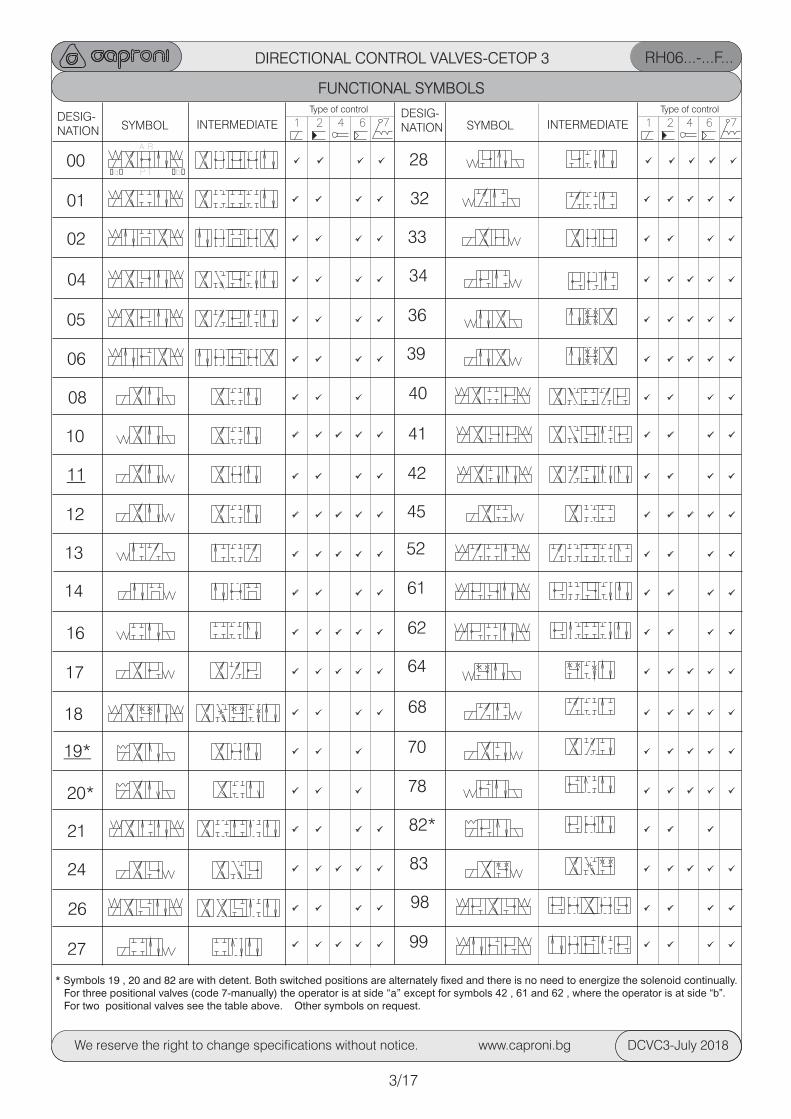
DIRECTIONAL CONTROL VALVES-CETOP 3
FUNCTIONAL SYMBOLS
SYMBOL INTERMEDIATEDESIG-NATION SYMBOL
00
01
02
04
05
06
08
10
11
12
13
16
17
Type of control
2 6 4
14
18
19*
20*
21
24
26
27
1 7INTERMEDIATEDESIG-NATION
Type of control
2 6 4
28
32
33
34
36
39
40
41
42
45
52
61
62
64
68
70
78
82*
83
98
99
RH06...-...F...
�a� �b�
A B
P T
* Symbols 19 , 20 and 82 are with detent. Both switched positions are alternately fixed and there is no need to energize the solenoid continually. For three positional valves (code 7-manually) the operator is at side “a” except for symbols 42 , 61 and 62 , where the operator is at side “b”. For two positional valves see the table above. Other symbols on request.
3/17
We reserve the right to change specifications without notice. www.caproni.bg DCVC3-July 2018
RH06...1-...F...
TECHNICAL DATA
GENERAL
VALUE/RANGEDATA
Cyclic duration % 100
Waterproof IP65
Heat insulation H
Type of voltage DC AC
Available voltage /frequency 12/00 110/50(60) V/Hz 24/00 220/50(60) 48/00
Voltage tolerance % 10±
Current consumption 12VDC 2,4 24VDC 1,3 48VDC A 0,58 110V RAC 0,5 220V RAC 0, 25
cycle/h 15000Max. switching frequencies
Switching time at p=17,5MPa , on ms 50Q=40l/min (measured for off ms 25control valve symbol “01”)
HYDRAULIC
Installation position optional except symb.”08”,”19”, ”20”and”82”-horizontal
oMax. ambient temperature C -20...+50
Weight single solenoid valve kg 1,600 double solenoid valve kg 2,200
Max. pressure port P , A & B MPa 32 port T MPa 21
Rated flow (at Dp 0,1MPa.) l/min 11...20
Max. flow (depend on symbol-see page 6/17) l/min 80
Hydraulic fluid-mineral oil: 2 -viscosity mm /s 10...800
-filtration degree mm 0.025o -temperature C -20...80
ELECTRICAL
DIRECTIONAL CONTROL VALVES-CETOP 3
UNIT
4/17
We reserve the right to change specifications without notice. www.caproni.bg DCVC3-July 2018
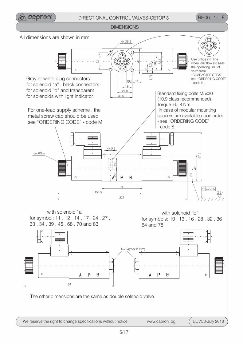
DIMENSIONS
DIRECTIONAL CONTROL VALVES-CETOP 3 RH06...1-...F...
5/17
We reserve the right to change specifications without notice. www.caproni.bg DCVC3-July 2018
2,5
0.01/100
The other dimensions are the same as double solenoid valve.
All dimensions are shown in mm.
Use orifice in P line when inlet flow exceeds the operating limit of valve from “CHARACTERISTICS”see “ORDERING CODE”- code K...
with solenoid “a”for symbol: 11 , 12 , 14 , 17 , 24 , 27 , 33 , 34 , 39 , 45 , 68 , 70 and 83
Gray or white plug connectorsfor solenoid “a” , black connectorsfor solenoid “b” and transparentfor solenoids with light indicator.
For one-lead supply scheme , themetal screw cap should be usedsee “ORDERING CODE” - code M
with solenoid “b”for symbols: 10 , 13 , 16 , 28 , 32 , 36 , 64 and 78
a b
164
S=24(max 20Nm)
max 6Nm
a b
6
6,7
516,3 2
6,6
32,5
46
4x Ї5,5
40,5
27,8
19
10,3 18
a b
155.5
237
74
22 24
48
87,5
20
4x Ї 9
Standard fixing bolts M5x30 (10,9 class recommended).Torque 6...8 Nm. In case of modular mountingspacers are available upon order- see “ORDERING CODE” - code S.
31
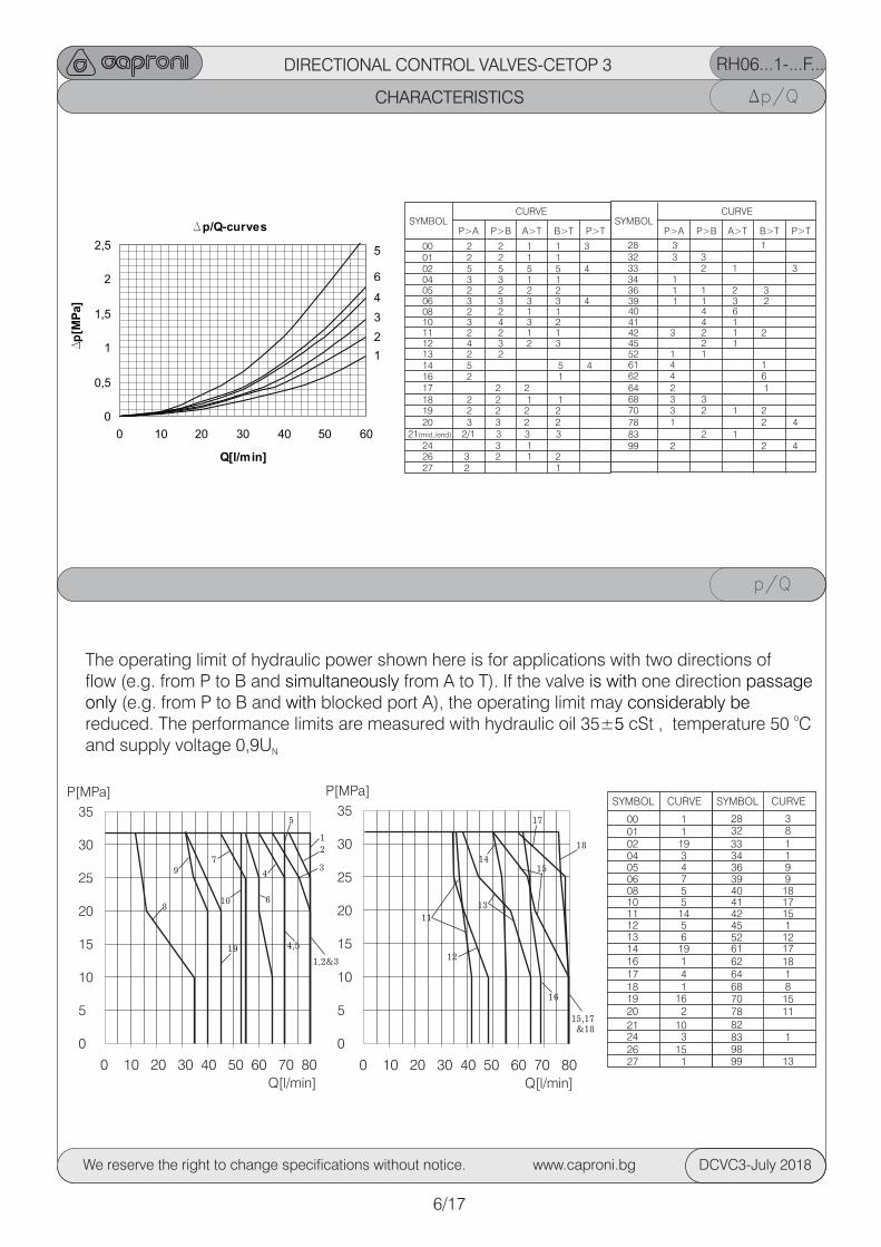
CHARACTERISTICS
CURVESYMBOL
00 101 102 1904 305 406 708 510 511 14
13 6
18 119 1620 2
21 10
26 1527 1
Dp/Q
p/Q
DIRECTIONAL CONTROL VALVES-CETOP 3
CURVESYMBOL
P>A P>B A>T B>T P>T
00 2 2 1 1 301 2 2 1 1 02 5 5 5 5 404 3 3 1 1 05 2 2 2 2 06 3 3 3 3 408 2 2 1 1 10 3 4 3 211 2 2 1 1
13 2 2
18 2 2 1 119 2 2 2 220 3 3 2 2
21(mid./end) 2/1 3 3 3
26 3 2 1 227 2 1
32 3 3
34 1
39 1 1 3 240 4 641 4 1
52 1 1
78 1 2 4
99 2 2 4
CURVESYMBOL
P>A P>B A>T B>T P>T
12 4 3 2 3
14 5 5 4
17 2 216 2 1
24 3 1
28 3 1
33 2 1 3
36 1 1 2 3
42 3 2 1 2 45 2 1
61 4 162 4 6 64 2 1 68 3 370 3 2 1 2
83 2 1
CURVESYMBOL
28 332 833 134 136 939 940 1841 1742 15
52 12
68 870 1578 1182
9899 13
12 5
14 1916 117 4
24 3
45 1
61 1762 1864 1
83 1
The operating limit of hydraulic power shown here is for applications with two directions of flow (e.g. from P to B and from A to T). If the valve one direction simultaneously is with passage only with considerably be (e.g. from P to B and blocked port A), the operating limit may
±5oreduced. The performance limits are measured with hydraulic oil 35 cSt , temperature 50 C
and supply voltage 0,9UN
35
30
25
20
15
10
5
0
0 10 20 30 40 50 60 70 80
P[MPa]
Q[l/min]
2
34
5
4,5
16
1,2&3
15,17 &18
1
6
7
108
19
9
11
12
13
14
17
18
15
RH06...1-...F...
35
30
25
20
15
10
5
0
0 10 20 30 40 50 60 70 80
P[MPa]
Q[l/min]
Dp/Q-curves
0
0,5
1
1,5
2
2,5
0 10 20 30 40 50 60
Q[l/min]
Dp
[MP
a]
1
2
3
4
5
6
6/17
We reserve the right to change specifications without notice. www.caproni.bg DCVC3-July 2018
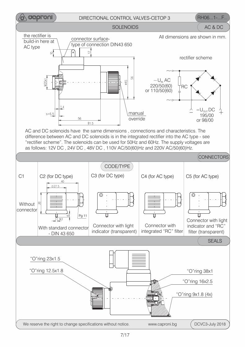
SOLENOIDS AC & DC
AC and DC solenoids have the same dimensions , connections and characteristics. The difference between AC and DC solenoids is in the integrated rectifier into the AC type - see “rectifier scheme”. The solenoids can be used for 50Hz and 60Hz. The supply voltages are as follows: 12V DC , 24V DC , 48V DC , 110V AC/50(60)Hz and 220V AC/50(60)Hz.
RH06...1-...F...DIRECTIONAL CONTROL VALVES-CETOP 3
All dimensions are shown in mm.
rectifier scheme
manualoverride
connector surface-type of connection DIN43 650
the rectifier isbuild-in here atAC type
CONNECTORS
CODE/TYPE
C1 C2 (for DC type)
Pg 11
C3 (for DC type)
Without connector
With standard connector - DIN 43 650
Connector with integrated “RC” filter
Connector with light indicator (transparent)
~
~
U ACIN
RC
U DCOUT
220/50(60)or 110/50(60)
195/00or 98/00
~
= +_
C4 (for AC type) C5 (for AC type)
Connector with light indicator and “RC”filter (transparent)
7/17
SEALS
“O”ring 23x1.5
“O”ring 12.5x1.8
“O”ring 16x2.5
“O”ring 38x1
“O”ring 9x1.8 (4x)
We reserve the right to change specifications without notice. www.caproni.bg DCVC3-July 2018
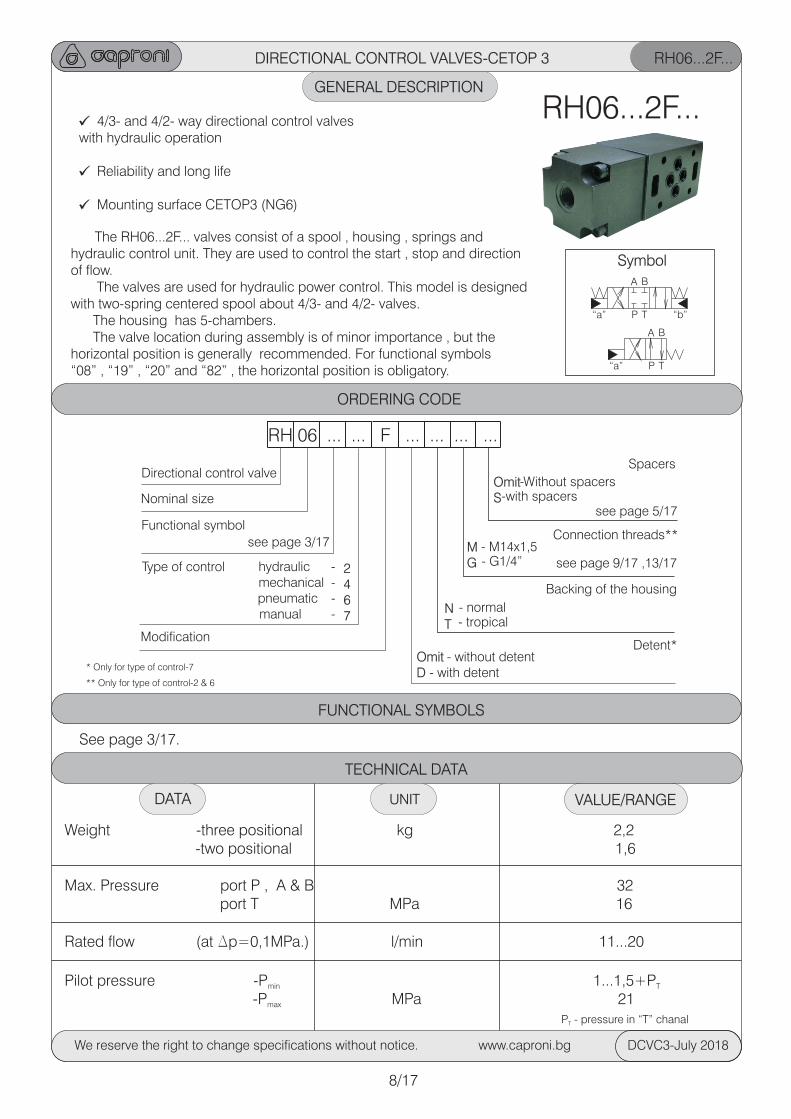
GENERAL DESCRIPTION
RH06...2F...
4/3- and 4/2- way directional control valveswith hydraulic operation
Reliability and long life
Mounting surface CETOP3 (NG6)
The RH06...2F... valves consist of a spool , housing , springs and hydraulic control unit. They are used to control the start , stop and direction of flow. The valves are used for hydraulic power control. This model is designed with two-spring centered spool about 4/3- and 4/2- valves. The housing has 5-chambers. The valve location during assembly is of minor importance , but the horizontal position is generally recommended. For functional symbols “08” , “19” , “20” and “82” , the horizontal position is obligatory.
DIRECTIONAL CONTROL VALVES-CETOP 3
RH06...2F...
ORDERING CODE
RH 06 ... ... F ... ... ... ...
Directional control valve
Nominal size
Functional symbol
Type of control
Modification
- normal
Spacers
Connection threads**
Backing of the housing
Detent*
-Without spacers
- M14x1,5
- without detent
-with spacers
- G1/4”
- with detent
OmitS
MG
OmitD
NT
2467
see page 3/17
- tropical
see page 5/17
see page 9/17 ,13/17 hydraulic - mechanical - pneumatic - manual -
* Only for type of control-7
** Only for type of control-2 & 6
8/17
Symbol
“a”
“a”
“b”
A
A
B
B
P
P
T
T
TECHNICAL DATA
Weight -three positional kg 2,2 -two positional 1,6
Max. Pressure port P , A & B 32 port T MPa 16
Rated flow (at Dp=0,1MPa.) l/min 11...20
Pilot pressure -P 1...1,5+Pmin T
-P MPa 21max
P - pressure in “T” chanalT
VALUE/RANGEDATA UNIT
See page 3/17.
FUNCTIONAL SYMBOLS
We reserve the right to change specifications without notice. www.caproni.bg DCVC3-July 2018
DIRECTIONAL CONTROL VALVES-CETOP 3
DIMENSIONS
All dimensions are shown in mm.
See page 6/18
RH06...2F...
9/17
SEALS
“O”ring 26.5x2.65 “O”ring 16x2.5“O”ring 9x1.8 (4x)
CHARACTERISTICS
We reserve the right to change specifications without notice. www.caproni.bg DCVC3-July 2018
Symbols 00 , 01 , 02 , 04 , 05 , 06 , 08 , 18 , 19 , 20 , 21 , 26 , 40 , 41 , 42 , 52 , 61 , 62 , 82 , 98 , 99
Symbols 11 , 12 , 14 , 17 , 24 , 27 , 33 , 34 , 39 , 45 , 68 , 70 , 83
Pilot
Pilot
Symbols 10 , 13 , 16 , 28 , 32 , 36 , 64 , 78
166
128,5S=24
M1
4x1
,5 o
r G
1/4
”
M1
4x1
,5 o
r G
1/4
”
Pilot
Pilot
6
6,7
516,3 2
6,6
32,5
464x Ї5,5
40,5
27,8
19
10,3 18
74
0,7
5
31
Standard fixing bolts M5x30 (10,9 class recommended). Torque-6...8 Nm. In case of modular mountingspacers are available upon order- see “ORDERING CODE” - code S.
22
20
4x Ї 9
2,5
0.01/100
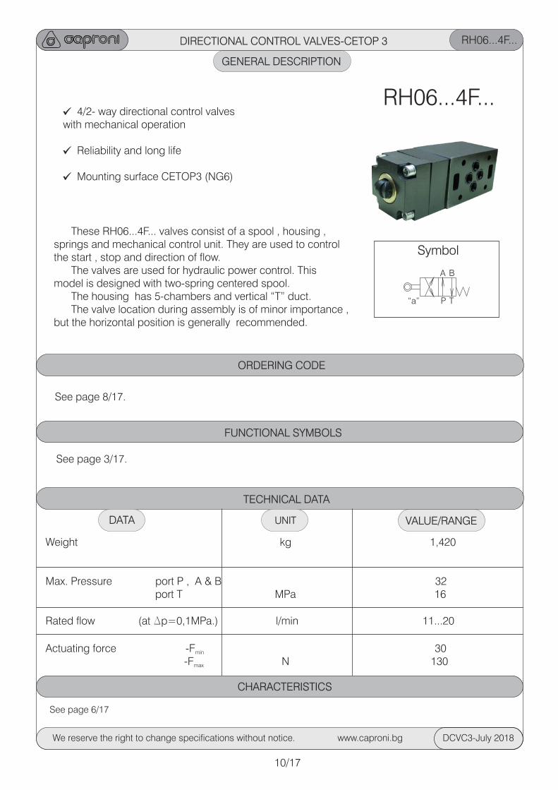
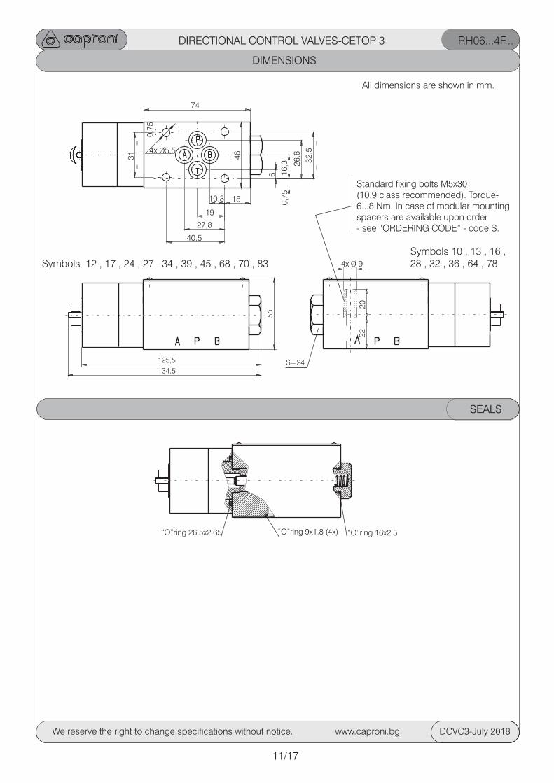
DIRECTIONAL CONTROL VALVES-CETOP 3 RH06...4F...
GENERAL DESCRIPTION
4/2- way directional control valveswith mechanical operation
Reliability and long life
Mounting surface CETOP3 (NG6)
These RH06...4F... valves consist of a spool , housing , springs and mechanical control unit. They are used to control the start , stop and direction of flow. The valves are used for hydraulic power control. This model is designed with two-spring centered spool. The housing has 5-chambers and vertical “T” duct. The valve location during assembly is of minor importance , but the horizontal position is generally recommended.
RH06...4F...
ORDERING CODE
See page 8/17.
10/17
TECHNICAL DATA
Weight kg 1,420
Max. Pressure port P , A & B 32 port T MPa 16
Rated flow (at Dp=0,1MPa.) l/min 11...20
Actuating force -F 30min
-F N 130max
VALUE/RANGEDATA UNIT
Symbol
“a”
A B
P T
See page 3/17.
FUNCTIONAL SYMBOLS
See page 6/17
CHARACTERISTICS
We reserve the right to change specifications without notice. www.caproni.bg DCVC3-July 2018
RH06...4F...DIRECTIONAL CONTROL VALVES-CETOP 3
All dimensions are shown in mm.
11/17
DIMENSIONS
“O”ring 26.5x2.65 “O”ring 16x2.5“O”ring 9x1.8 (4x)
SEALS
We reserve the right to change specifications without notice. www.caproni.bg DCVC3-July 2018
Symbols 12 , 17 , 24 , 27 , 34 , 39 , 45 , 68 , 70 , 83Symbols 10 , 13 , 16 , 28 , 32 , 36 , 64 , 78
S=24134,5
125,5
6
6,7
516,3 2
6,6
32,5
464x Ї5,5
40,5
27,8
19
10,3 18
74
0,7
5
31
Standard fixing bolts M5x30 (10,9 class recommended). Torque-6...8 Nm. In case of modular mountingspacers are available upon order- see “ORDERING CODE” - code S.
22
20
4x Ї 9
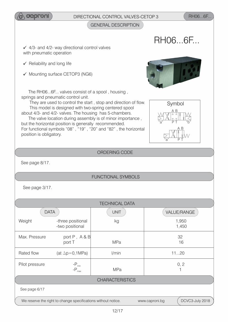
DIRECTIONAL CONTROL VALVES-CETOP 3 RH06...6F...
GENERAL DESCRIPTION
4/3- and 4/2- way directional control valveswith pneumatic operation
Reliability and long life
Mounting surface CETOP3 (NG6)
The RH06...6F... valves consist of a spool , housing , springs and pneumatic control unit. They are used to control the start , stop and direction of flow. This model is designed with two-spring centered spool about 4/3- and 4/2- valves. The housing has 5-chambers. The valve location during assembly is of minor importance , but the horizontal position is generally recommended. For functional symbols “08” , “19” , “20” and “82” , the horizontal position is obligatory.
RH06...6F...
ORDERING CODE
See page 8/17.
See page 3/17.
FUNCTIONAL SYMBOLS
12/17
Symbol
“a”
“a”
“b”
A
A
B
B
P
P
T
T
TECHNICAL DATA
Weight -three positional kg 1,950 -two positional 1,450
Max. Pressure port P , A & B 32 port T MPa 16
Rated flow (at Dp=0,1MPa) l/min 11...20
Pilot pressure -P 0, 2min
-P MPa 1max
VALUE/RANGEDATA UNIT
See page 6/17
CHARACTERISTICS
We reserve the right to change specifications without notice. www.caproni.bg DCVC3-July 2018
DIRECTIONAL CONTROL VALVES-CETOP 3 RH06...6F...
DIMENSIONS
All dimensions are shown in mm.
13/17
We reserve the right to change specifications without notice. www.caproni.bg DCVC3-July 2018
Symbols 00 , 01 , 02 , 04 , 05 , 06 , 08 , 18 , 19 , 20 , 21 , 26 , 40 , 41 , 42 , 52 , 61 , 62 , 82 , 98 , 99
Symbols 11 , 12 , 14 , 17 , 24 , 27 , 33 , 34 , 39 , 45 , 68 , 70 , 83
Symbols 10 , 13 , 16 , 28 , 32 , 36 , 64 , 78
179
135S=24
M1
4x1
,5 o
r G
1/4
”
M1
4x1
,5 o
r G
1/4
”
SEALS
“O”ring 26.5x2.65 “O”ring 16x2.5“O”ring 9x1.8 (4x)
Pilot
Pilot
Pilot
Pilot
6
6,7
516,3 2
6,6
32,5
464x Ї5,5
40,5
27,8
19
10,3 18
74
0,7
5
31
Standard fixing bolts M5x30 (10,9 class recommended). Torque-6...8 Nm. In case of modular mountingspacers are available upon order- see “ORDERING CODE” - code S.
22
20
4x Ї 9
2,5
0.01/100
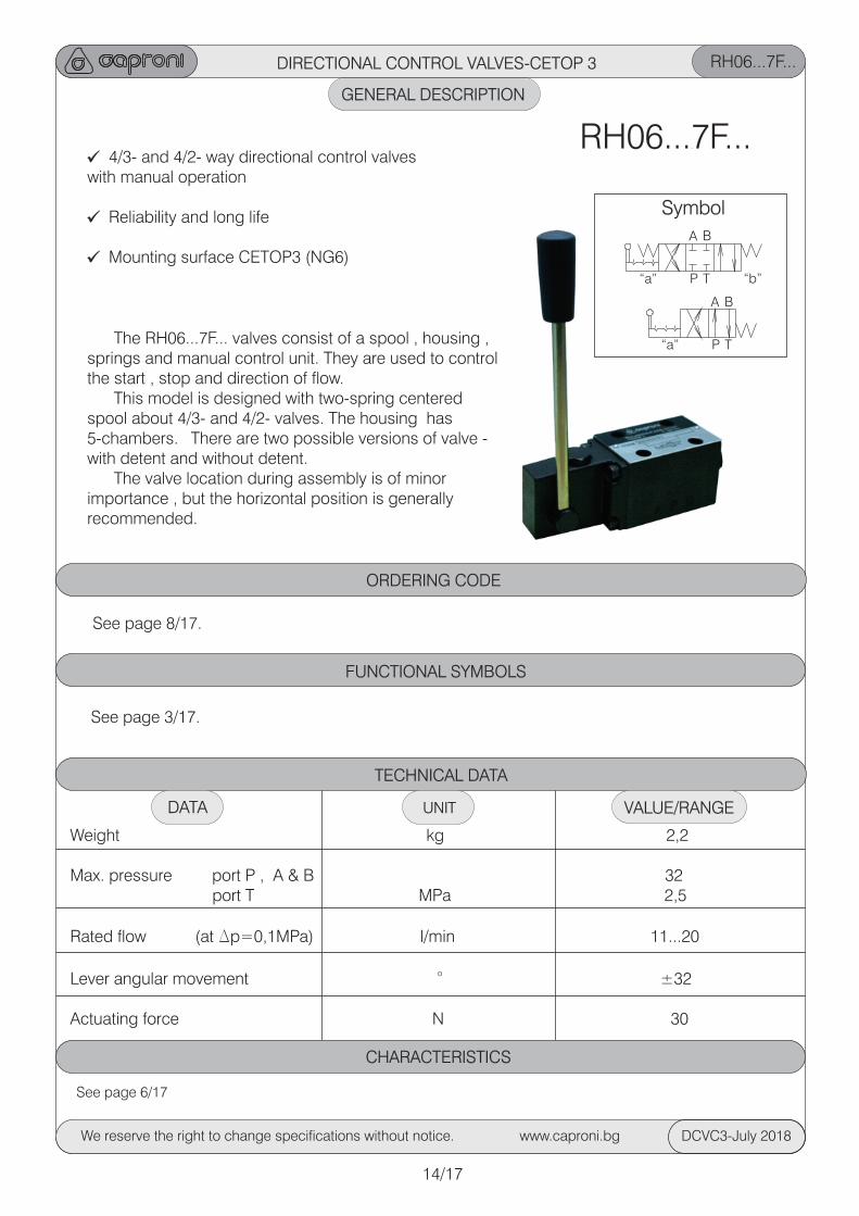
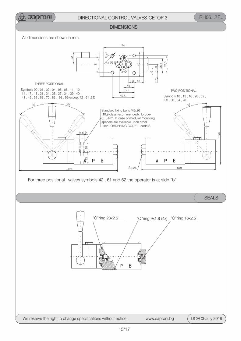
DIRECTIONAL CONTROL VALVES-CETOP 3 RH06...7F...
GENERAL DESCRIPTION
4/3- and 4/2- way directional control valveswith manual operation
Reliability and long life
Mounting surface CETOP3 (NG6)
The RH06...7F... valves consist of a spool , housing , springs and manual control unit. They are used to control the start , stop and direction of flow. This model is designed with two-spring centered spool about 4/3- and 4/2- valves. The housing has 5-chambers. There are two possible versions of valve - with detent and without detent. The valve location during assembly is of minor importance , but the horizontal position is generally recommended.
RH06...7F...
ORDERING CODE
See page 8/17.
TECHNICAL DATA
Weight kg 2,2
Max. pressure port P , A & B 32 port T MPa 2,5
Rated flow (at Dp=0,1MPa) l/min 11...20
oLever angular movement ±32
Actuating force N 30
VALUE/RANGEDATA UNIT
See page 3/17.
FUNCTIONAL SYMBOLS
14/17
Symbol
“a”
“a”
“b”
A
A
B
B
P
P
T
T
See page 6/17
CHARACTERISTICS
We reserve the right to change specifications without notice. www.caproni.bg DCVC3-July 2018
DIRECTIONAL CONTROL VALVES-CETOP 3
DIMENSIONS
All dimensions are shown in mm.
RH06...7F...
15/17
We reserve the right to change specifications without notice. www.caproni.bg DCVC3-July 2018
31
22
6
6,7
51
6,3 2
6,6
32
,5
464x Ї5,5
40,5
27,8
19
10,3 18
74
0,7
5
Symbols 00 , 01 , 02 , 04 , 05 , 06 , 11 , 12 , 14 , 17 , 18 , 21 , 24 , 26 , 27 , 34 , 39 , 40 , 41 , 45 , 52 , 68 , 70 , 83 , 98 , 99(except 42 , 61 ,62)
S=24
Symbols 10 , 13 , 16 , 28 , 32 , 33 , 36 , 64 , 78
TWO POSITIONAL
THREE POSITIONAL
SEALS
“O”ring 23x2.5 “O”ring 16x2.5“O”ring 9x1.8 (4x)
~223
3232 32
For three positional valves symbols 42 , 61 and 62 the operator is at side “b”.
Standard fixing bolts M5x30 (10,9 class recommended). Torque-6...8 Nm. In case of modular mountingspacers are available upon order- see “ORDERING CODE” - code S.
22
20
4x Ї 9
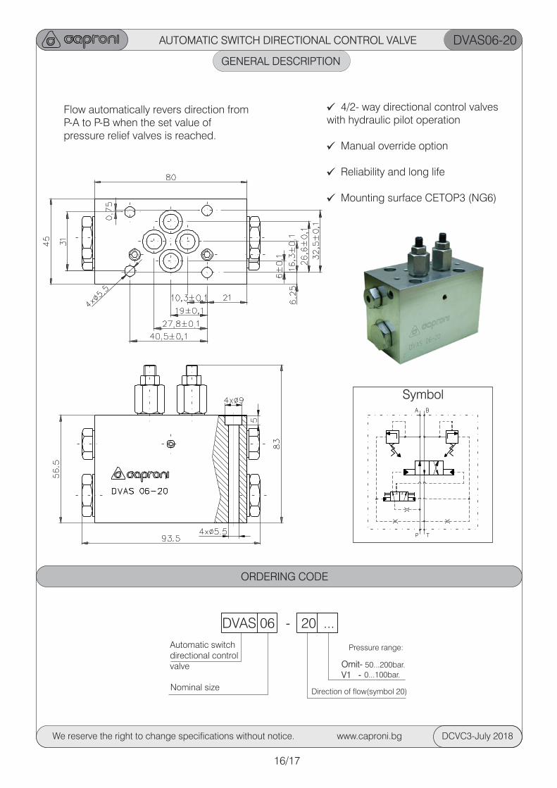
AUTOMATIC SWITCH DIRECTIONAL CONTROL VALVE DVAS06-20
GENERAL DESCRIPTION
16/17
We reserve the right to change specifications without notice. www.caproni.bg DCVC3-July 2018
DVAS 06 - 20 ...
Automatic switch directional control valve
Nominal size
Omit-V1 -
Direction of flow(symbol 20)
Pressure range:
50...200bar.
0...100bar.
4/2- way directional control valveswith hydraulic pilot operation
Manual override option
Reliability and long life
Mounting surface CETOP3 (NG6)
Flow automatically revers direction from P-A to P-B when the set value of pressure relief valves is reached.
ORDERING CODE
Symbol
TECHNICAL DATA
GENERAL
VALUE/RANGEDATA
HYDRAULIC
Installation position preferably horizontal
oMax. ambient temperature C -20...+50
Weight kg 1,400
Max. pressure MPa 21 Maximum flow l/min 30
Minimum flow l/min 4
Hydraulic fluid - mineral oil: 2 -viscosity mm /s 10...800
-filtration degree mm 0.025o -temperature C -20...80
UNIT
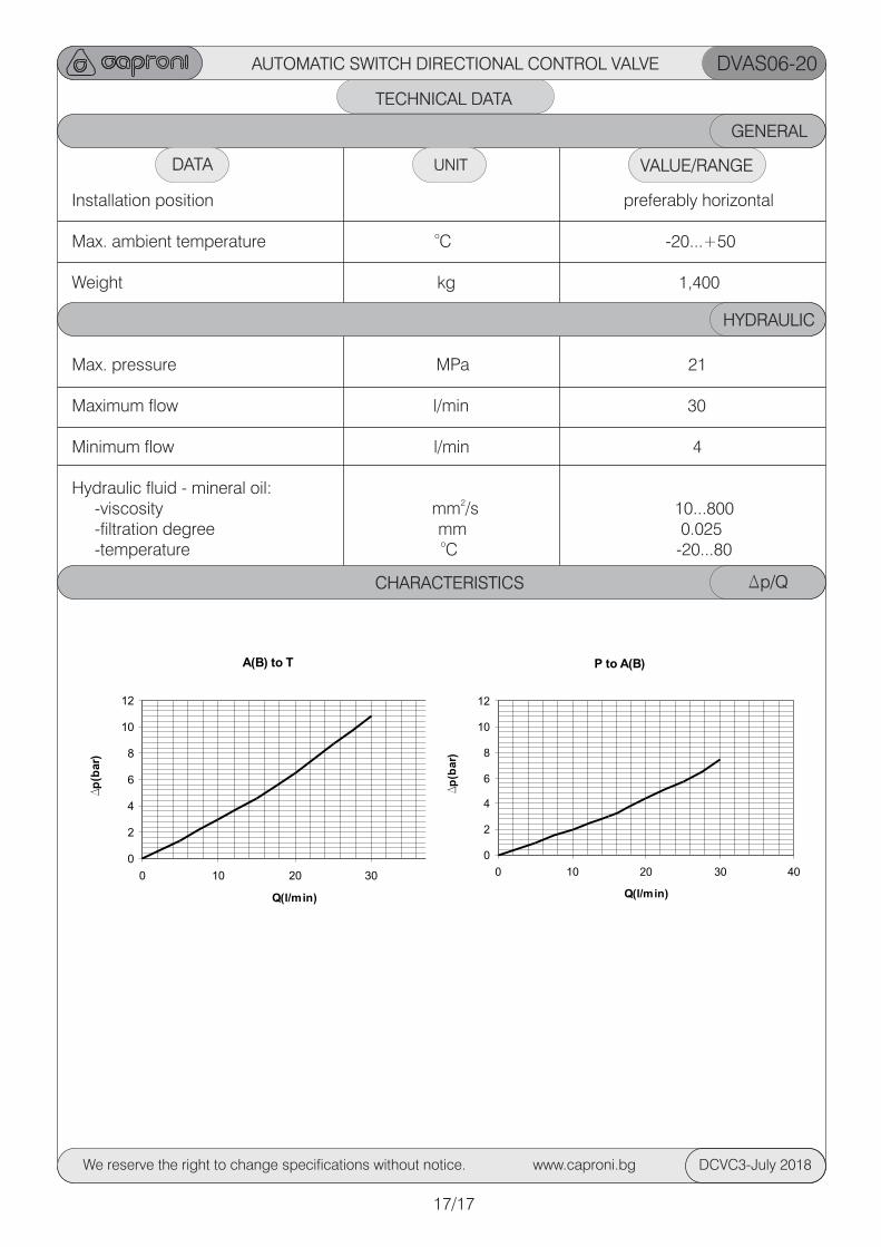
CHARACTERISTICS Dp/Q
A(B) to T
0
2
4
6
8
10
12
0 10 20 30 40
Q(l/min)
Dp
(bar)
P to A(B)
0
2
4
6
8
10
12
0 10 20 30 40
Q(l/min)
Dp
(bar)
AUTOMATIC SWITCH DIRECTIONAL CONTROL VALVE DVAS06-20
17/17
We reserve the right to change specifications without notice. www.caproni.bg DCVC3-July 2018
NOTESDIRECTIONAL CONTROL VALVES-CETOP 3
We reserve the right to change specifications without notice. www.caproni.bg DCVC3-July 2018

NOTESDIRECTIONAL CONTROL VALVES-CETOP 3
We reserve the right to change specifications without notice. www.caproni.bg DCVC3-July 2018

NOTESDIRECTIONAL CONTROL VALVES-CETOP 3
We reserve the right to change specifications without notice. www.caproni.bg DCVC3-July 2018

NOTESDIRECTIONAL CONTROL VALVES-CETOP 3
We reserve the right to change specifications without notice. www.caproni.bg DCVC3-July 2018
BULGARIA JOINT-STOCK COMPANY
BULGARIA , 6100 KAZANLAK , 45 STOLETOV Str. Tel.:+359/431/62 229 , +359/431/6132 , Fax:+359/431/62 230 , +359/431/63 134 E-mail:[email protected] , WEB:http://www.caproni.bg