4/3, 4/2 and 3/2 directional valves with adjustable switching time
TRANSCRIPT
1/12
Informationen zu lieferbaren Ersatzteilen: www.boschrexroth.com/spc
4/3, 4/2 and 3/2 directional valves with adjustable switching time
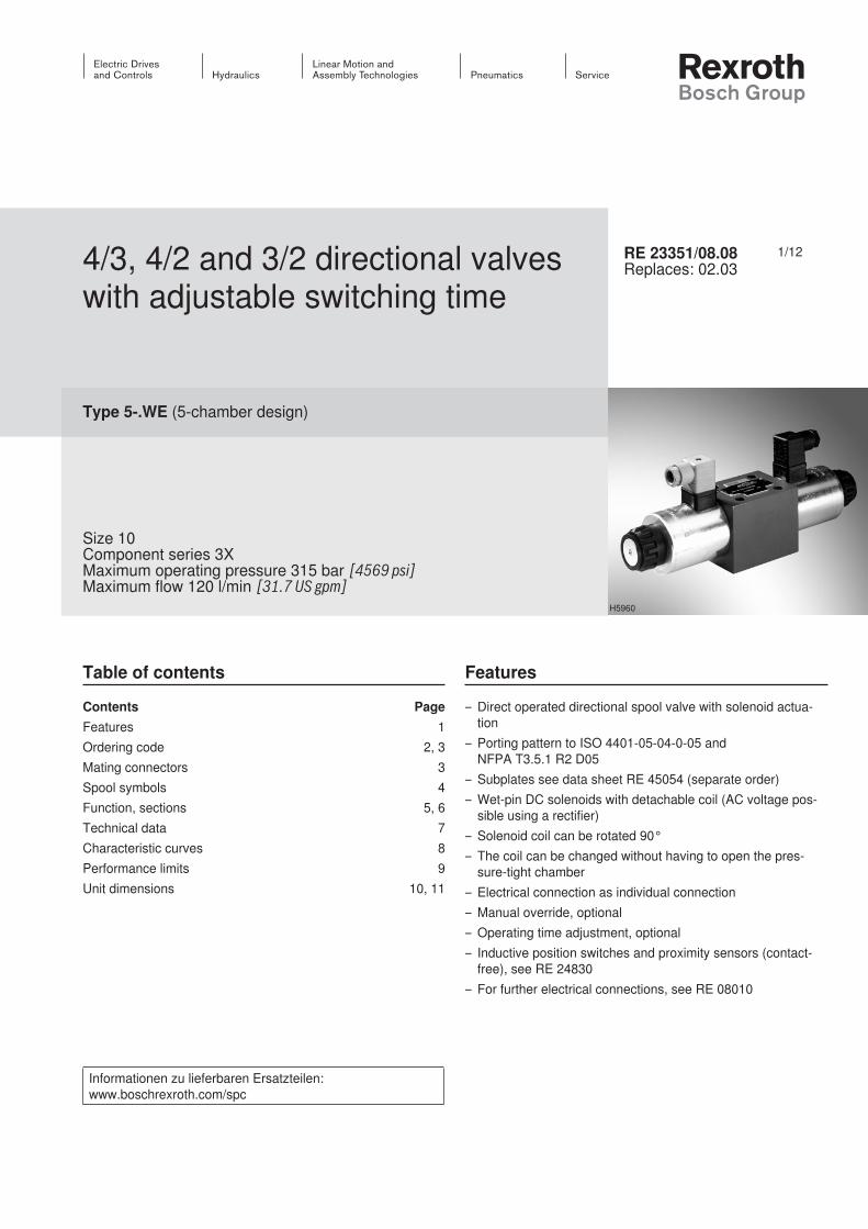
Type 5-.WE (5-chamber design)
Size 10Component series 3XMaximum operating pressure 315 bar [4569 psi]Maximum flow 120 l/min [31.7 US gpm]
RE 23351/08.08Replaces: 02.03
Table of contents Features
– Direct operated directional spool valve with solenoid actua-tion
– Porting pattern to ISO 4401-05-04-0-05 and NFPA T3.5.1 R2 D05
– Subplates see data sheet RE 45054 (separate order)– Wet-pin DC solenoids with detachable coil (AC voltage pos-
sible using a rectifier)– Solenoid coil can be rotated 90°– The coil can be changed without having to open the pres-
sure-tight chamber – Electrical connection as individual connection – Manual override, optional– Operating time adjustment, optional– Inductive position switches and proximity sensors (contact-
free), see RE 24830– For further electrical connections, see RE 08010
Contents PageFeatures 1Ordering code 2, 3Mating connectors 3Spool symbols 4Function, sections 5, 6Technical data 7Characteristic curves 8Performance limits 9Unit dimensions 10, 11
H5960
InhaltTable of contents 1Features 1Ordering code 2 3Mating connectors to DIN EN 175301-803 3Spool symbols 4Function, section 5Function, section 6Technical data (for applications outside these parameters, please consult us!) 7Characteristic curves (measured with HLP46, ϑoil = 40 °C ±5 °C [104 °F ±9 °F]) 8
Performance limits (measured with HLP46, Öl = 40 °C ±5 °C [104 °F ±9 °F]) 9Unit dimensions (dimensions in mm [inch]) 10Unit dimensions 11Notes 12
Standard types and components can be found in the EPS (standard price list).
2/12 Bosch Rexroth AG Hydraulics 5-.WE RE 23351/08.08
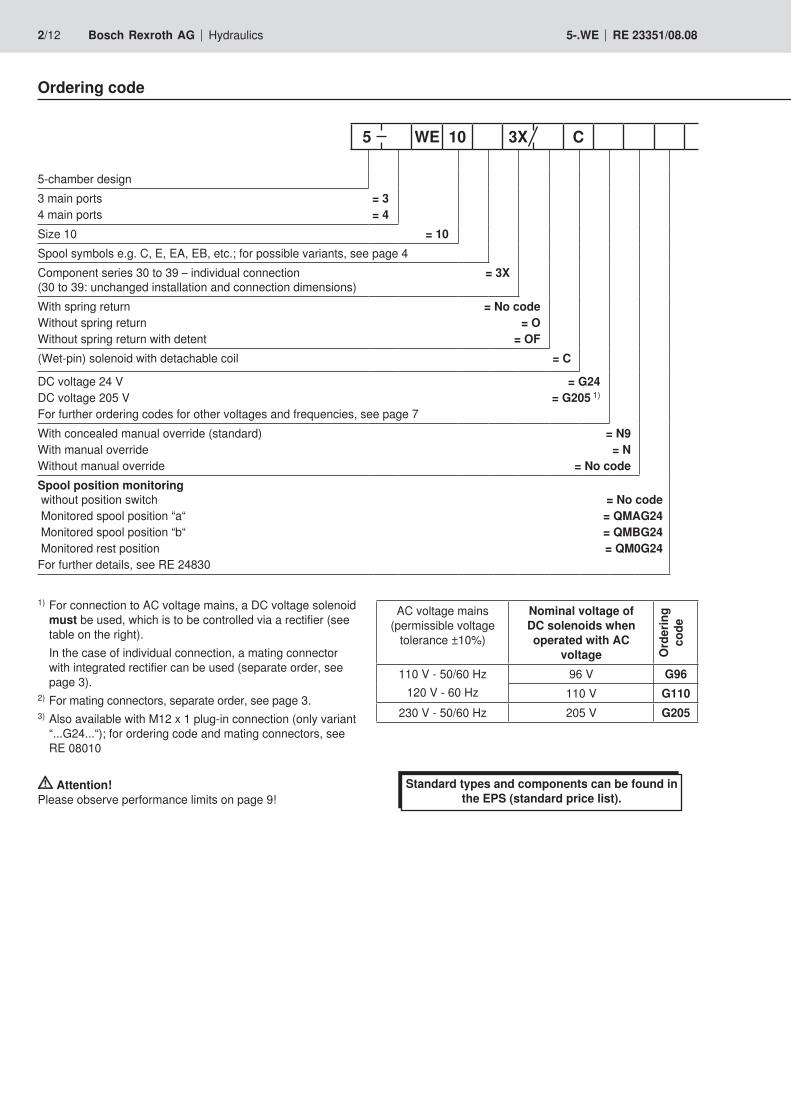
Ordering code
5-chamber design 3 main ports = 34 main ports = 4Size 10 = 10Spool symbols e.g. C, E, EA, EB, etc.; for possible variants, see page 4Component series 30 to 39 – individual connection = 3X (30 to 39: unchanged installation and connection dimensions)With spring return = No codeWithout spring return = OWithout spring return with detent = OF(Wet-pin) solenoid with detachable coil = C
DC voltage 24 V = G24DC voltage 205 V = G205 1)
For further ordering codes for other voltages and frequencies, see page 7With concealed manual override (standard) = N9With manual override = NWithout manual override = No codeSpool position monitoring without position switch = No code Monitored spool position “a“ = QMAG24 Monitored spool position “b“ = QMBG24 Monitored rest position = QM0G24For further details, see RE 24830
AC voltage mains (permissible voltage
tolerance ±10%)
Nominal voltage of DC solenoids when operated with AC
voltage Ord
erin
g co
de110 V - 50/60 Hz
120 V - 60 Hz96 V G96
110 V G110230 V - 50/60 Hz 205 V G205
5 WE 10 3X C
1) For connection to AC voltage mains, a DC voltage solenoid must be used, which is to be controlled via a rectifier (see table on the right).
In the case of individual connection, a mating connector with integrated rectifier can be used (separate order, see page 3).
2) For mating connectors, separate order, see page 3.3) Also available with M12 x 1 plug-in connection (only variant
“...G24...“); for ordering code and mating connectors, see RE 08010
Attention! Please observe performance limits on page 9!

Hydraulics Bosch Rexroth AGRE 23351/08.08 5-.WE 3/12
Further details in clear textSeal material
No code = NBR seals V = FKM seals
(Other seals on request) Attention!
Observe compatibility of seals with hydraulic fluid used!No code = Without throttle insertB08 = Throttle Ø 0.8 mm [0.031 inch] B10 = Throttle Ø 1.0 mm [0.039 inch] B12 = Throttle Ø 1.2 mm [0.047 inch]B15 = Throttle Ø 1.5 mm [0.059 inch] B30 = Throttle Ø 3.0 mm [0.118 inch] To be used in the case of flows that exceed the performance limit of the valve, effective in channel P (see page 6).
No code = Without operating time adjustmentC = With throttling screwA06 = Orifice Ø 0.6 mm [0.024 inch]A07 = Orifice Ø 0.7 mm [0.028 inch]A08 = Orifice Ø 0.8 mm [0.031 inch]
Electrical connection 2)
Individual connection K4 3) = Without mating connector, with component plug DIN EN 175301-803
K4 *
Mating connectors to DIN EN 175301-803
For details and further
mating connectors, see RE 08006
Connec-tion Va
lve
side
Color
Material number
Without circuitry
With indicator lamp 12 … 240 V
With indicator lamp and rectifier
12 … 240 VWith rectifier 12 … 240 V
With indicator lamp and Zener-diode suppres-
sor circuit 24 V
M16 x 1,5a Gray R901017010 – – – –b Black R901017011 – – – –
a/b Black – R901017022 R901017029 R901017025 R901017026
1/2“ NPT (Pg 16)
a Red/brown R900004823 – – – –b Black R900011039 – – – –
a/b Black – R900057453 R900057455 R900842566 –
A B
P T
a b
A B
P T
a b
A B
P T
a b
a b
A B
P T
= …/O..a b
A B
P T
= …/OF..a b
A B
P T
a b
a b
a b
= A
= C
= D
a b
A B
P T
a b
A B
P Ta b
= B
= Y
= L
= M
= E 1)
= F
= G
= H
= J
A B
P T
a 0 a 0
A B
P T
b ba b
A B
P T
a 0 a 0
A B
P Ta
A B
P T
0 0
A B
P T
b b b
= .A 1)
= .B
= R
= T
= U
= V
= W
= P
= Q
4/12 Bosch Rexroth AG Hydraulics 5-.WE RE 23351/08.08
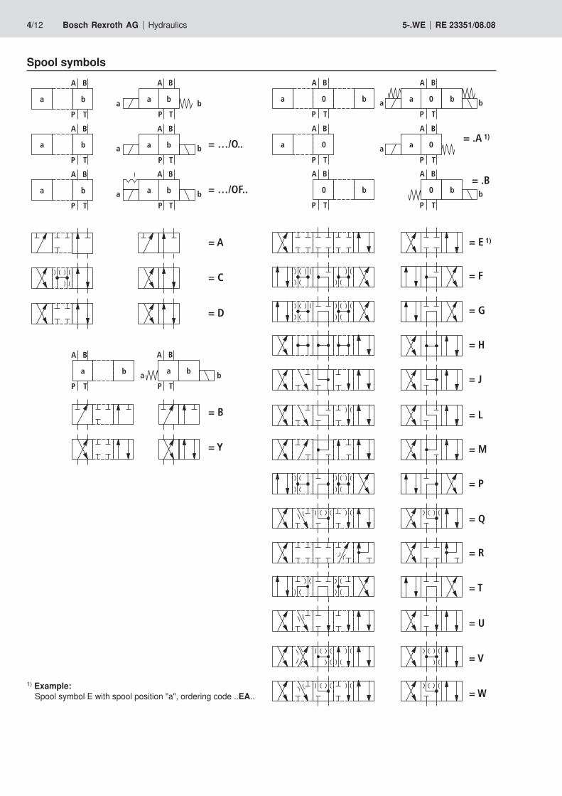
Spool symbols
1) Example: Spool symbol E with spool position "a", ordering code ..EA..
A
TA TBBPA
"a" "b"
52
4
1 3
4
27
6
B
6
5 58
Hydraulics Bosch Rexroth AGRE 23351/08.08 5-.WE 5/12
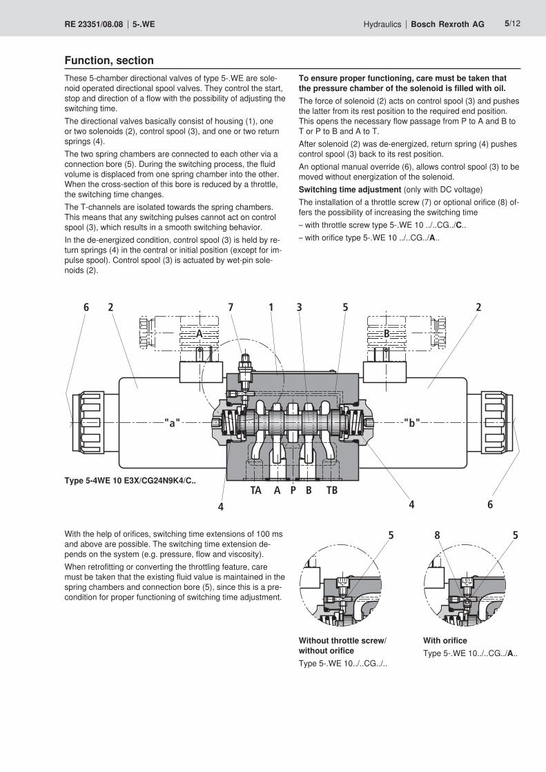
To ensure proper functioning, care must be taken that the pressure chamber of the solenoid is filled with oil.The force of solenoid (2) acts on control spool (3) and pushes the latter from its rest position to the required end position. This opens the necessary flow passage from P to A and B to T or P to B and A to T.After solenoid (2) was de-energized, return spring (4) pushes control spool (3) back to its rest position.An optional manual override (6), allows control spool (3) to be moved without energization of the solenoid.Switching time adjustment (only with DC voltage)The installation of a throttle screw (7) or optional orifice (8) of-fers the possibility of increasing the switching time – with throttle screw type 5-.WE 10 ../..CG../C..– with orifice type 5-.WE 10 ../..CG../A..
These 5-chamber directional valves of type 5-.WE are sole-noid operated directional spool valves. They control the start, stop and direction of a flow with the possibility of adjusting the switching time.The directional valves basically consist of housing (1), one or two solenoids (2), control spool (3), and one or two return springs (4).The two spring chambers are connected to each other via a connection bore (5). During the switching process, the fluid volume is displaced from one spring chamber into the other. When the cross-section of this bore is reduced by a throttle, the switching time changes.The T-channels are isolated towards the spring chambers. This means that any switching pulses cannot act on control spool (3), which results in a smooth switching behavior.In the de-energized condition, control spool (3) is held by re-turn springs (4) in the central or initial position (except for im-pulse spool). Control spool (3) is actuated by wet-pin sole-noids (2).
Type 5-4WE 10 E3X/CG24N9K4/C..
Function, section
Without throttle screw/ without orificeType 5-.WE 10../..CG../..
With the help of orifices, switching time extensions of 100 ms and above are possible. The switching time extension de-pends on the system (e.g. pressure, flow and viscosity).When retrofitting or converting the throttling feature, care must be taken that the existing fluid value is maintained in the spring chambers and connection bore (5), since this is a pre-condition for proper functioning of switching time adjustment.
With orificeType 5-.WE 10../..CG../A..
TA
A
"a"
P
9
6/12 Bosch Rexroth AG Hydraulics 5-.WE RE 23351/08.08
Detent
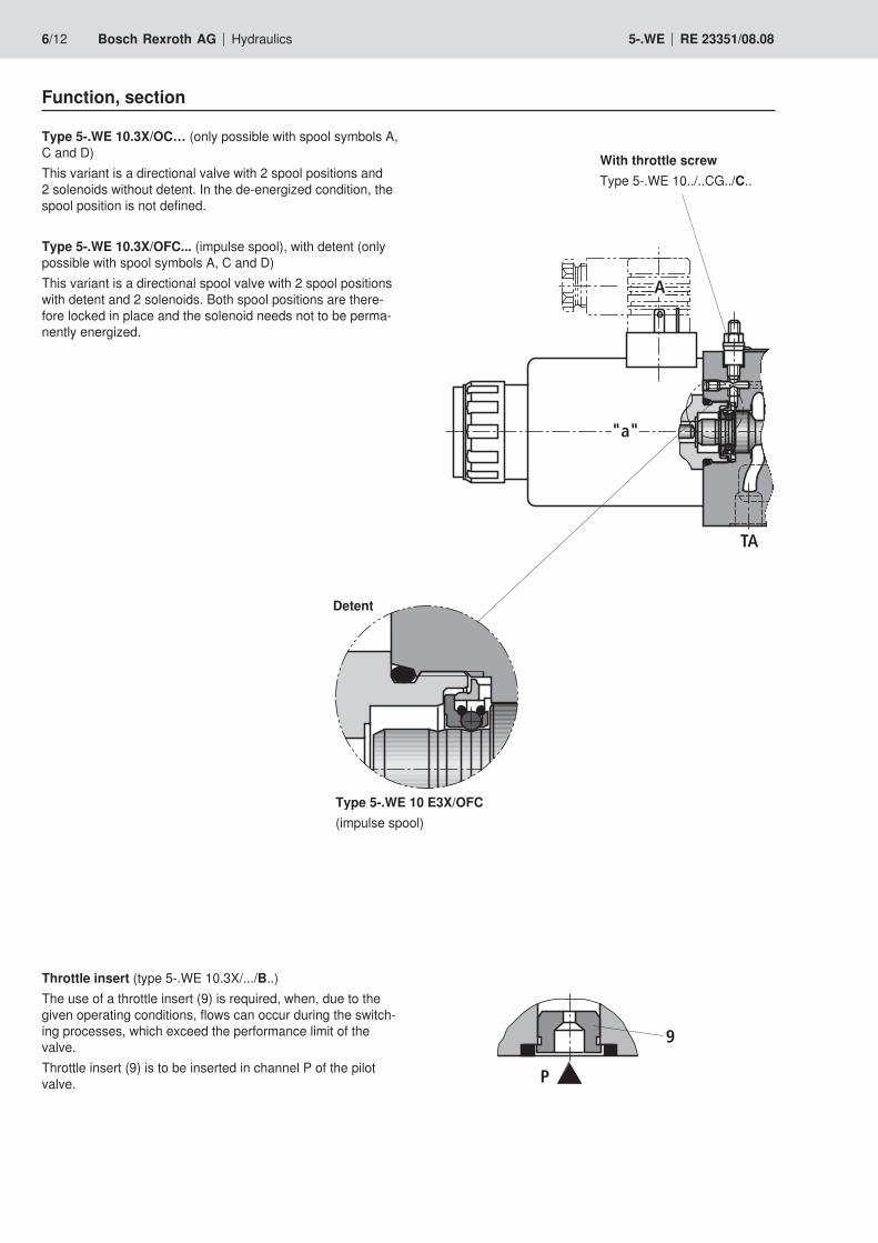
With throttle screwType 5-.WE 10../..CG../C..
Function, section
Type 5-.WE 10.3X/OC… (only possible with spool symbols A, C and D)This variant is a directional valve with 2 spool positions and 2 solenoids without detent. In the de-energized condition, the spool position is not defined.
Type 5-.WE 10.3X/OFC... (impulse spool), with detent (only possible with spool symbols A, C and D)This variant is a directional spool valve with 2 spool positions with detent and 2 solenoids. Both spool positions are there-fore locked in place and the solenoid needs not to be perma-nently energized.
Throttle insert (type 5-.WE 10.3X/.../B..)The use of a throttle insert (9) is required, when, due to the given operating conditions, flows can occur during the switch-ing processes, which exceed the performance limit of the valve.Throttle insert (9) is to be inserted in channel P of the pilot valve.
Type 5-.WE 10 E3X/OFC(impulse spool)
Hydraulics Bosch Rexroth AGRE 23351/08.08 5-.WE 7/12
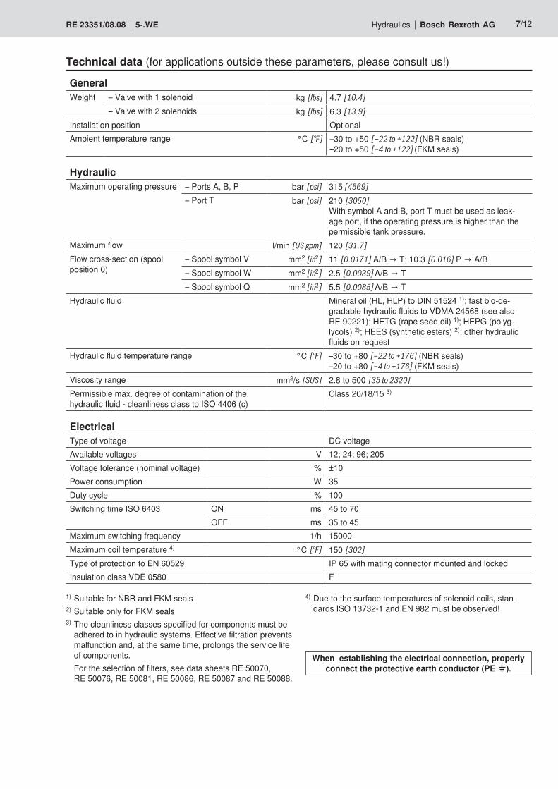
Technical data (for applications outside these parameters, please consult us!)
GeneralWeight – Valve with 1 solenoid kg [lbs] 4.7 [10.4]
– Valve with 2 solenoids kg [lbs] 6.3 [13.9]
Installation position OptionalAmbient temperature range °C [°F] –30 to +50 [–22 to +122] (NBR seals)
–20 to +50 [–4 to +122] (FKM seals)
HydraulicMaximum operating pressure – Ports A, B, P bar [psi] 315 [4569]
– Port T bar [psi] 210 [3050] With symbol A and B, port T must be used as leak-age port, if the operating pressure is higher than the permissible tank pressure.
Maximum flow l/min [US gpm] 120 [31.7]
Flow cross-section (spool position 0)
– Spool symbol V mm2 [in2] 11 [0.0171] A/B → T; 10.3 [0.016] P → A/B– Spool symbol W mm2 [in2] 2.5 [0.0039] A/B → T– Spool symbol Q mm2 [in2] 5.5 [0.0085] A/B → T
Hydraulic fluid Mineral oil (HL, HLP) to DIN 51524 1); fast bio-de-gradable hydraulic fluids to VDMA 24568 (see also RE 90221); HETG (rape seed oil) 1); HEPG (polyg-lycols) 2); HEES (synthetic esters) 2); other hydraulic fluids on request
Hydraulic fluid temperature range °C [°F] –30 to +80 [–22 to +176] (NBR seals)–20 to +80 [–4 to +176] (FKM seals)
Viscosity range mm2/s [SUS] 2.8 to 500 [35 to 2320]
Permissible max. degree of contamination of the hydraulic fluid - cleanliness class to ISO 4406 (c)
Class 20/18/15 3)
ElectricalType of voltage DC voltage Available voltages V 12; 24; 96; 205Voltage tolerance (nominal voltage) % ±10Power consumption W 35Duty cycle % 100Switching time ISO 6403 ON ms 45 to 70
OFF ms 35 to 45Maximum switching frequency 1/h 15000Maximum coil temperature 4) °C [°F] 150 [302]
Type of protection to EN 60529 IP 65 with mating connector mounted and lockedInsulation class VDE 0580 F
1) Suitable for NBR and FKM seals2) Suitable only for FKM seals 3) The cleanliness classes specified for components must be
adhered to in hydraulic systems. Effective filtration prevents malfunction and, at the same time, prolongs the service life of components.
For the selection of filters, see data sheets RE 50070, RE 50076, RE 50081, RE 50086, RE 50087 and RE 50088.
When establishing the electrical connection, properly connect the protective earth conductor (PE ).
4) Due to the surface temperatures of solenoid coils, stan-dards ISO 13732-1 and EN 982 must be observed!
16151413121110987654321
10 20 30 40 50 60 70 80 90 100 110 120
2134
5
6
7
8
9
0
[2][0] [4] [6]
0[0]
[20]
[100]
[200]
[31.7][26] [30][8] [10] [12] [14] [16] [18] [20] [22] [24] [28]
[232]
[40]
[60]
[80]
[120]
[140]
[160]
[180]
[220]
8/12 Bosch Rexroth AG Hydraulics 5-.WE RE 23351/08.08
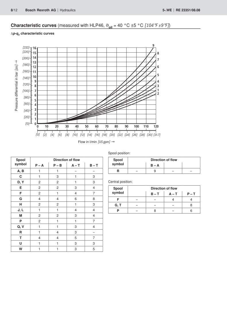
Characteristic curves (measured with HLP46, ϑoil = 40 °C ±5 °C [104 °F ±9 °F])∆p-qV characteristic curves
Pres
sure
diff
eren
tial in
bar
[psi
] →
Flow in l/min [US gpm] →
Spool symbol
Direction of flowP – A P – B A – T B – T
A, B 1 1 – –C 1 3 1 3
D, Y 2 2 1 3E 2 2 3 4F 2 1 4 7G 4 4 6 8H 2 2 1 3
J, L 1 1 4 4M 2 2 3 4P 2 1 1 7
Q, V 1 1 3 4R 1 4 3 –T 4 4 5 7U 1 1 3 3W 1 1 3 5
Spool position:
Spool symbol
Direction of flowB – A
R – 9 – –
Central position:
Spool symbol
Direction of flowB – T A – T P – T
F – – 4 4G, T – – – 8
P – 8 – 6
200
300
100
50
0 10 20 30 40 50 60
[0] [4] [8] [12]
[0]
[1000]
[2000]
[3000]
[4000]
[31.7]
150
250
315[4569]
70 80 90 100 110 120
[16] [20] [24] [28]
5
4
12
10
2
12 1
3
200
300
100
50
0 10 20 30 40 50 60
[0] [4] [8] [12]
[0]
[1000]
[2000]
[3000]
[4000]
[31.7]
150
250
315[4569]
70 80 90 100 110 120
[16] [20] [24] [28]
111
89
9
7
6
Hydraulics Bosch Rexroth AGRE 23351/08.08 5-.WE 9/12
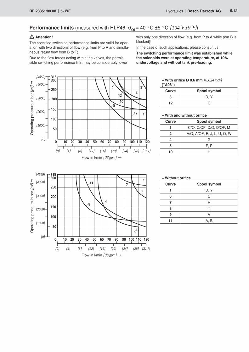
Performance limits (measured with HLP46, Öl = 40 °C ±5 °C [104 °F ±9 °F])O
pera
ting
pres
sure
in b
ar [p
si] →
Flow in l/min [US gpm] →
with only one direction of flow (e.g. from P to A while port B is blocked)!In the case of such applications, please consult us!The switching performance limit was established while the solenoids were at operating temperature, at 10% undervoltage and without tank pre-loading.
Attention!The specified switching performance limits are valid for oper-ation with two directions of flow (e.g. from P to A and simulta-neous return flow from B to T).Due to the flow forces acting within the valves, the permis-sible switching performance limit may be considerably lower
Ope
ratin
g pr
essu
re in
bar
[psi
] →
Flow in l/min [US gpm] →
– With orifice Ø 0.6 mm [0.024 inch] (“A06“)
Curve Spool symbol3 D, Y
12 C
– With and without orificeCurve Spool symbol
1 C/O, C/OF, D/O, D/OF, M2 A/O, A/OF, E, J, L, U, Q, W4 G5 F, P
10 H
– Without orificeCurve Spool symbol
1 D, Y6 C7 R8 T9 V
11 A, B
92
1512
3
18,992,2
12
8026
180,3126,3 5,35,3
(206,3)75
(206,3) 75
(306,6)
30
6,6
11
6
1511
7
A B
40
TA TB
P
A B
12 13
3
10 11 2 10
9
7
1.2
9 1.1 4 8 6 8 5
[0.5
9][4
.61]
[3.6
2]
[1.5
7]
[Ø0.43]
[0.2
4]
[1.18
]
[4.8
4][0
.59]
[Ø0.26][1.02] [3.15]
[4.97][0.21] [0.21]
[8.12]
[8.12]
[2.95]
[12.07]
[2.95]
3
[3.63]
[0.74]
[0.4
7]
70[2
.76]
F1 F2
F3F4
4
11
0,01/100[0.0004/4.0]
Rzmax 4
10/12 Bosch Rexroth AG Hydraulics 5-.WE RE 23351/08.08
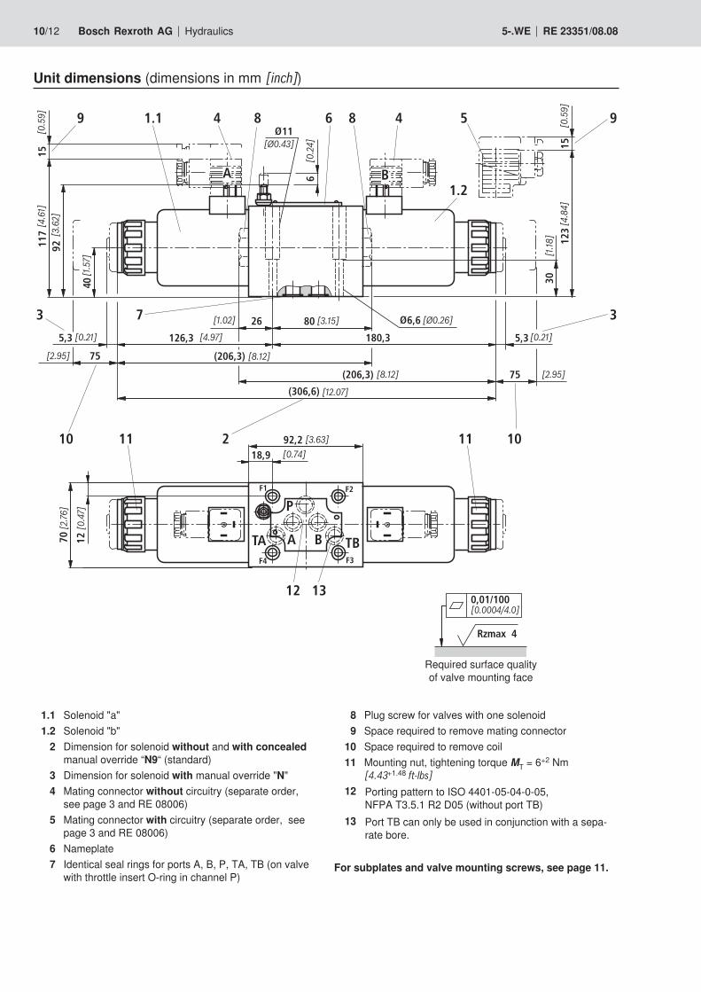
Unit dimensions (dimensions in mm [inch])
Required surface quality of valve mounting face
1.1 Solenoid "a"1.2 Solenoid "b"
2 Dimension for solenoid without and with concealed manual override “N9“ (standard)
3 Dimension for solenoid with manual override "N"4 Mating connector without circuitry (separate order,
see page 3 and RE 08006)5 Mating connector with circuitry (separate order, see
page 3 and RE 08006)6 Nameplate7 Identical seal rings for ports A, B, P, TA, TB (on valve
with throttle insert O-ring in channel P)
8 Plug screw for valves with one solenoid9 Space required to remove mating connector
10 Space required to remove coil11 Mounting nut, tightening torque MT = 6+2 Nm
[4.43+1.48 ft-lbs]12 Porting pattern to ISO 4401-05-04-0-05,
NFPA T3.5.1 R2 D05 (without port TB)13 Port TB can only be used in conjunction with a sepa-
rate bore.
For subplates and valve mounting screws, see page 11.
Hydraulics Bosch Rexroth AGRE 23351/08.08 5-.WE 11/12
Unit dimensions
Subplates to data sheet RE 45054 (separate order) G 66/01 (G3/8) G 67/01 (G1/2) G 534/01 (G3/4)G 66/12 (SAE-6; 9/16-18) 1) G 67/12 (SAE-8; 3/4-16) 1) G 534/12 (SAE-12; 1-1/16-12) 1)
1) on request
Valve mounting screws (separate order)4 hexagon socket head cap screws metric ISO 4762 - M6 x 40 - 10.9-flZn-240h-L (Friction coefficient µtotal = 0.09 to 0.14); tightening torque MT = 12.5 Nm [9.2 ft-lbs] ±10%, Material no. R913000058 or 4 hexagon socket head cap screws ISO 4762 - M6 x 40 - 10.9 (own procurement) (Friction coefficient µtotal = 0.12 to 0.17); tightening torque MT = 15.5 Nm [11.4 ft-lbs] ±10%
4 hexagon socket head cap screws UNC 1/4-20 UNC x 1-1/2” ASTM-A574 (Friction coefficient µtotal = 0.19 to 0.24); tightening torque MT = 20 Nm [14.7 ft-lbs] ±15%, (Friction coefficient µtotal = 0.12 to 0.17); tightening torque MT = 14 Nm [10.3 ft-lbs] ±10%, Material no. R978800710

Bosch Rexroth AG HydraulicsZum Eisengießer 197816 Lohr am Main, Germany Phone +49 (0) 93 52 / 18-0 Fax +49 (0) 93 52 / 18-23 [email protected] www.boschrexroth.de
© This document, as well as the data, specifications and other informa-tion set forth in it, are the exclusive property of Bosch Rexroth AG. It may not be reproduced or given to third parties without its consent.The data specified above only serve to describe the product. No state-ments concerning a certain condition or suitability for a certain applica-tion can be derived from our information. The information given does not release the user from the obligation of own judgment and verifica-tion. It must be remembered that our products are subject to a natural process of wear and aging.
12/12 Bosch Rexroth AG Hydraulics 5-.WE RE 23351/08.08
Notes