digital timer implementation using 7-segment displays
TRANSCRIPT
Digital Timer Implementation using 7-Segment Displays
DLD
EEE241
5/15/14
Digital Timer Implementation using 7-Segment Displays
1
Group Members:
SOHIAB TALLAT CIIT/SP13-BCE-040/ISB
FATIMA FARID CIIT/SP13-BCE-015/ISB
FARHAN SHAHID CIIT/SP13-BCE-013/ISB
Subject: EE241-Digital Logic Design.
Theory Instructor: Dr. Riaz Hussain.
Lab Instructor: Ma’am Wajiha Shariq.
Due Date: 16th May 2014.
TABLE OF CONTENTS
1.0 ABSTRACT- - - - - - - - - - - - - - - - - - - - - - - - - - - - - - - - - - - - - - - - - - - - - - - - - - - - - - - -02
2.0 BACKGROUND- - - - - - - - - - - - - - - - - - - - - - - - - - - - - - - - - - - - - - - - - - - - - - - - - - - - -02
3.0 THEORY- - - - - - - - - - - - - - - - - -- - - - - - - - - - - - - - - - - - - - - - - - - - - - - - - - - - - - - - -02
3.1 555 TIMER- - - - - - - - - - - - - - - - - - - - - - - - - - - - - - - - - - - - - - - - - - - - - - - - - - -02
3.2 4026 UP/DOWN COUNTERS AND DECODERS - - - - - - - - - - - - - - - - - - - - - - - - -03
3.3 4081 AND GATES- - - - - - - - - - - - - - - - - - - - - - - - - - - - - - - - - - - - - - - - - - - - - - 04
3.4 SEVEN SEGMENT DISPLAYS- - - - - - - - - - - - - - - - - - - - - - - - - - - - - - - - - - - - - - -05
4.0 DESIGN- - - - - - - - - - - - - - - - - - - - - - - - - - - - - - - - - - - - - - - - - - - - - - - - - - - - - - - - - - -06
4.1 TOP LEVEL DESIGN- - - - - - - - - - - - - - - - - - - - - - - - - - - - - - - - - - - - - - - - - - - - 06
4.2 LOWER LEVEL DESIGN- - - - - - - - - - - - - - - - - - - - - - - - - - - - - - - - - - - - - - - - - 07
4.3 SIMULATION- - - - - - - - - - - - - - - - - - - - - - - - - - - - - - - - - - - - - - - - - - - - - - - -08
5.0 CONCLUSION- - - - - -- - - - - -- - - - - -- - - - - -- - - - - -- - - - - -- - - - - -- - - - - -- - - - - -- - - - 08
6.0 BIBILOGRAPHY- - - - - - - - - - - - - - - - - - - - - - - - - - - - - - - - - - - - - - - - - - - - - - - - - - - - -08
APPENDEX AT THE END CONTAINING CIRCUIT DESIGN SCHEMATIC AND SIMULATION (09-13)
Digital Timer Implementation using 7-Segment Displays
2
1.0 ABSTRACT:
In this report, design and implementation process of the digital timer circuit based on the 555 timer have been documented. The initial design criteria of this project were to:
1. To have a three digit output using the 7-Segment Displays. 2. To have the circuit count from 0:00 to 9:59 and reset itself after that. 3. To generate a CLOCK using either 555 timer or an op-amp.
Research was conducted in to similar digital electronic circuits and an Electronic dice was selected as the starting point for this circuit. Using this starting point a ten timer was designed using NE555N timers, BCD 4026 UP/DOWN COUNTERS and 7-SEGMENT DISPLAY outputs. The proposed circuit was first simulated on PROTEUS before implementing it on the BREADBOARD. 2.0 BACKGROUND: Timers were originally designed to fulfil a need in industry for a means of keeping time on certain devices. Originally, these timers were mechanical devices and used clockwork mechanisms as a means of keeping a regular time (Timer, 2006). The invention of two electromechanical timer designs allowed for more precise time measurement. The first uses the principle of heat expansion to increase the temperature of a metal finger made of two different metals with differing rates of thermal expansion (Timer, 2006). As electric current flows through the metal, it begins to heat and one side expands more quickly than the other which, in turn, moves the electrical contact away from an electrical switch contact. The second uses a small AC motor which turns at a predetermined rate due to the application of an alternating current (Timer, 2006). Finally, digital timers were invented. Digital logic circuits are now so cheap that it has become a better investment to buy a digital timer than a mechanical or electromechanical timer. Individual timers are implemented with single chip circuits, similar to a watch (Timer, 2006). The 555 timer used in this project is a combination of a digital logic circuit and analogue components. 3.0 THEORY: Electronics designers use 555 timers in timing circuits and the binary counter decimal (BCD) integrated counting circuits in order to implement a timer. Though programmable micro-controllers are more commonly used, a simpler solution for three or more digit timers. BCDs are also valid in this application.
3.1 555 TIMERS:
555 timers are integrated timing circuits which are used commonly as a source of clock pulses to drive subsequent timer circuits. They are analogue devices which can produce an oscillating and digital output. The IC can be configured to give an astable, period output or a monostable, single triggered output.
Digital Timer Implementation using 7-Segment Displays
3
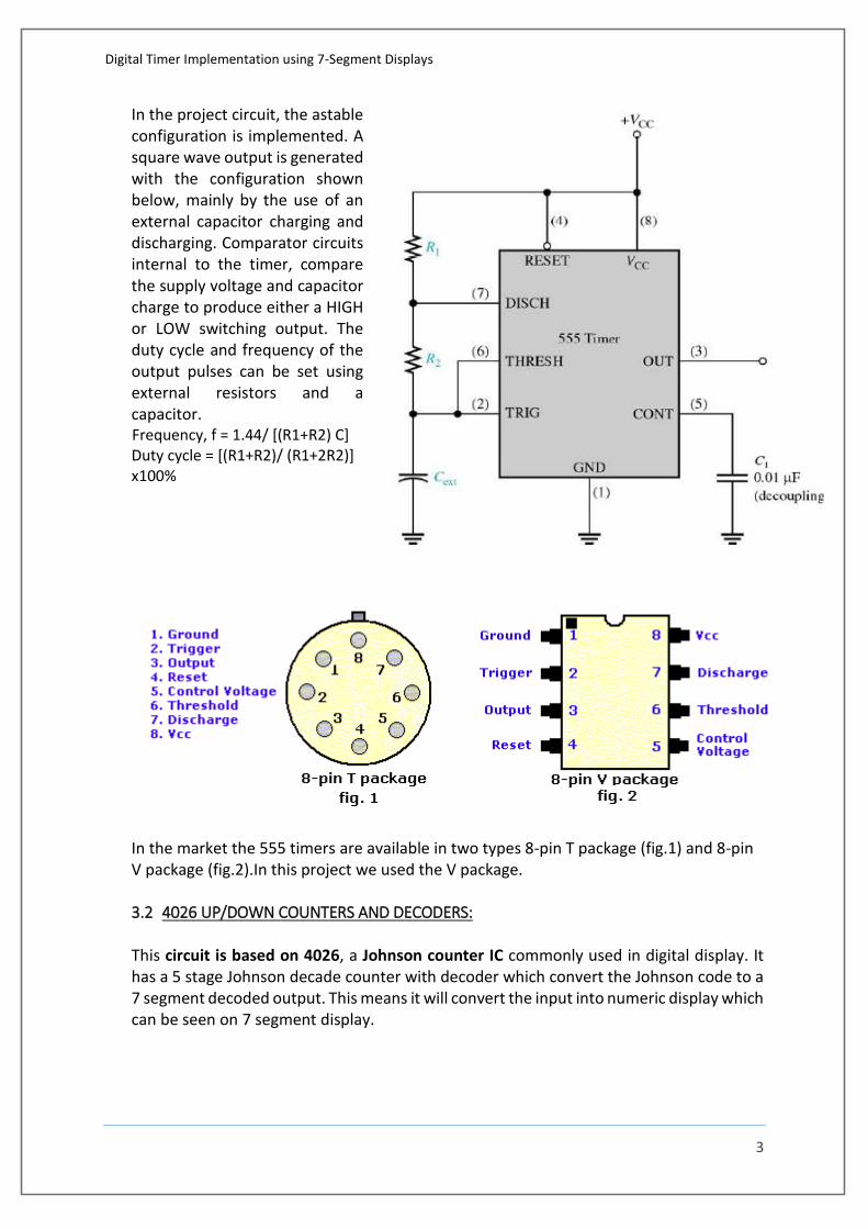
In the project circuit, the astable configuration is implemented. A square wave output is generated with the configuration shown below, mainly by the use of an external capacitor charging and discharging. Comparator circuits internal to the timer, compare the supply voltage and capacitor charge to produce either a HIGH or LOW switching output. The duty cycle and frequency of the output pulses can be set using external resistors and a capacitor.
Frequency, f = 1.44/ [(R1+R2) C] Duty cycle = [(R1+R2)/ (R1+2R2)] x100%
In the market the 555 timers are available in two types 8-pin T package (fig.1) and 8-pin V package (fig.2).In this project we used the V package. 3.2 4026 UP/DOWN COUNTERS AND DECODERS:
This circuit is based on 4026, a Johnson counter IC commonly used in digital display. It has a 5 stage Johnson decade counter with decoder which convert the Johnson code to a 7 segment decoded output. This means it will convert the input into numeric display which can be seen on 7 segment display.
Digital Timer Implementation using 7-Segment Displays
4
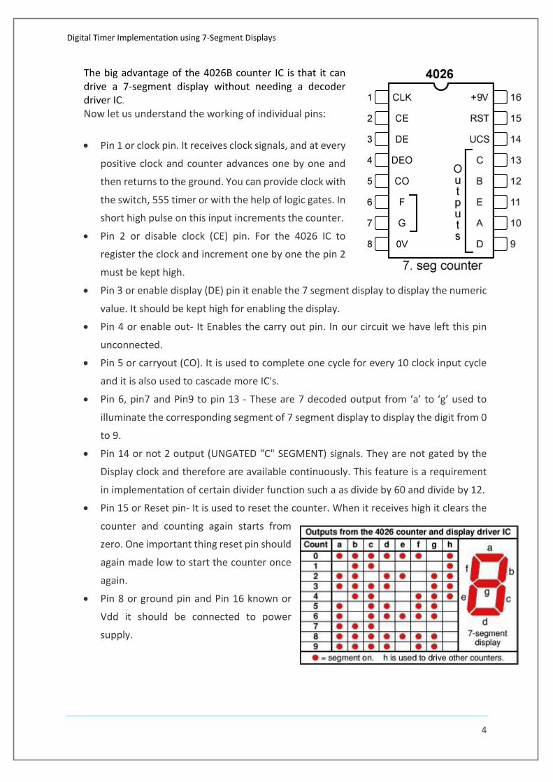
The big advantage of the 4026B counter IC is that it can drive a 7-segment display without needing a decoder driver IC.
Now let us understand the working of individual pins:
Pin 1 or clock pin. It receives clock signals, and at every
positive clock and counter advances one by one and
then returns to the ground. You can provide clock with
the switch, 555 timer or with the help of logic gates. In
short high pulse on this input increments the counter.
Pin 2 or disable clock (CE) pin. For the 4026 IC to
register the clock and increment one by one the pin 2
must be kept high.
Pin 3 or enable display (DE) pin it enable the 7 segment display to display the numeric
value. It should be kept high for enabling the display.
Pin 4 or enable out- It Enables the carry out pin. In our circuit we have left this pin
unconnected.
Pin 5 or carryout (CO). It is used to complete one cycle for every 10 clock input cycle
and it is also used to cascade more IC's.
Pin 6, pin7 and Pin9 to pin 13 - These are 7 decoded output from ‘a’ to ‘g’ used to
illuminate the corresponding segment of 7 segment display to display the digit from 0
to 9.
Pin 14 or not 2 output (UNGATED "C" SEGMENT) signals. They are not gated by the
Display clock and therefore are available continuously. This feature is a requirement
in implementation of certain divider function such a as divide by 60 and divide by 12.
Pin 15 or Reset pin- It is used to reset the counter. When it receives high it clears the
counter and counting again starts from
zero. One important thing reset pin should
again made low to start the counter once
again.
Pin 8 or ground pin and Pin 16 known or
Vdd it should be connected to power
supply.
Digital Timer Implementation using 7-Segment Displays
5
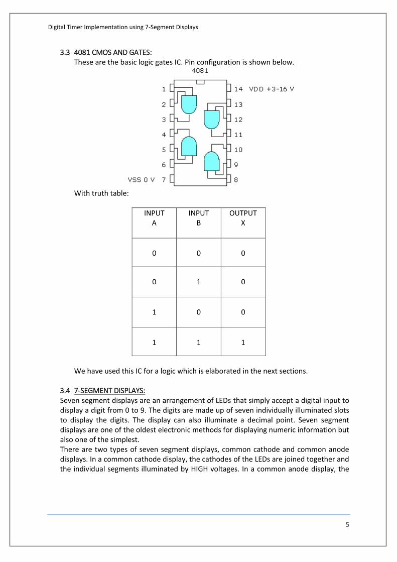
3.3 4081 CMOS AND GATES: These are the basic logic gates IC. Pin configuration is shown below.
With truth table:
INPUT A
INPUT B
OUTPUT X
0
0
0
0
1
0
1
0
0
1
1
1
We have used this IC for a logic which is elaborated in the next sections.
3.4 7-SEGMENT DISPLAYS: Seven segment displays are an arrangement of LEDs that simply accept a digital input to display a digit from 0 to 9. The digits are made up of seven individually illuminated slots to display the digits. The display can also illuminate a decimal point. Seven segment displays are one of the oldest electronic methods for displaying numeric information but also one of the simplest. There are two types of seven segment displays, common cathode and common anode displays. In a common cathode display, the cathodes of the LEDs are joined together and the individual segments illuminated by HIGH voltages. In a common anode display, the
Digital Timer Implementation using 7-Segment Displays
6
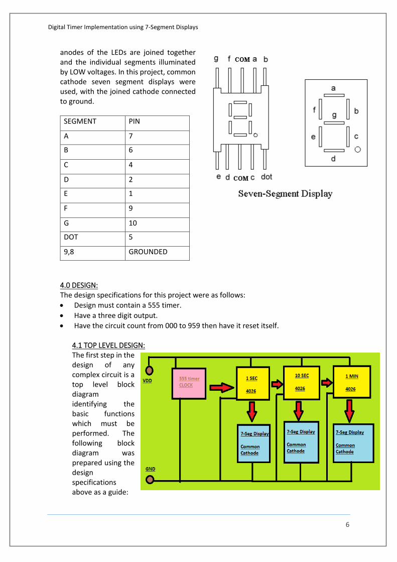
anodes of the LEDs are joined together and the individual segments illuminated by LOW voltages. In this project, common cathode seven segment displays were used, with the joined cathode connected to ground.
SEGMENT PIN
A 7
B 6
C 4
D 2
E 1
F 9
G 10
DOT 5
9,8 GROUNDED
4.0 DESIGN: The design specifications for this project were as follows:
Design must contain a 555 timer.
Have a three digit output.
Have the circuit count from 000 to 959 then have it reset itself.
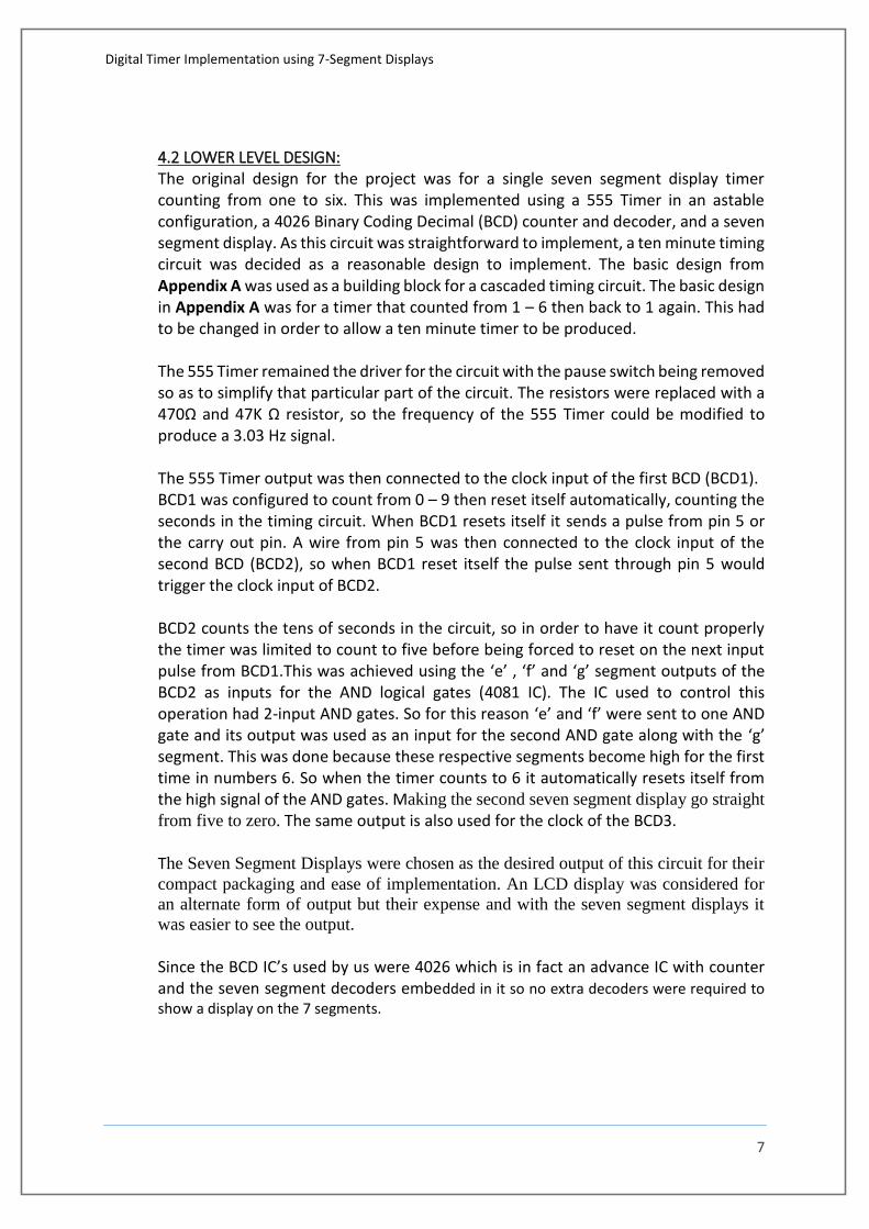
4.1 TOP LEVEL DESIGN: The first step in the design of any complex circuit is a top level block diagram identifying the basic functions which must be performed. The following block diagram was prepared using the design specifications above as a guide:
Digital Timer Implementation using 7-Segment Displays
7
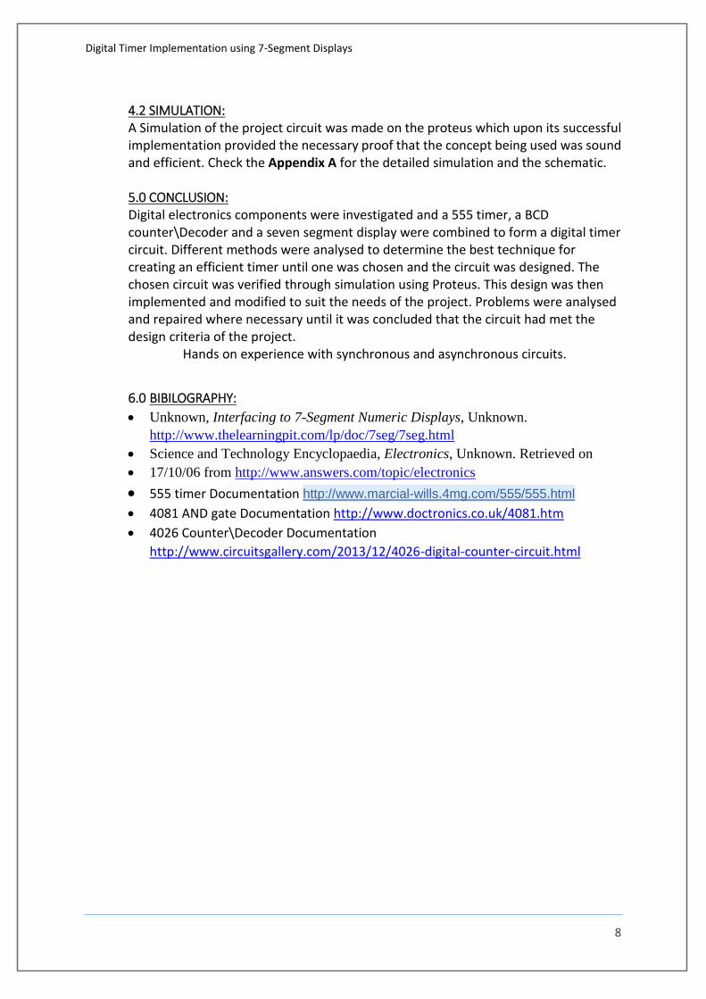
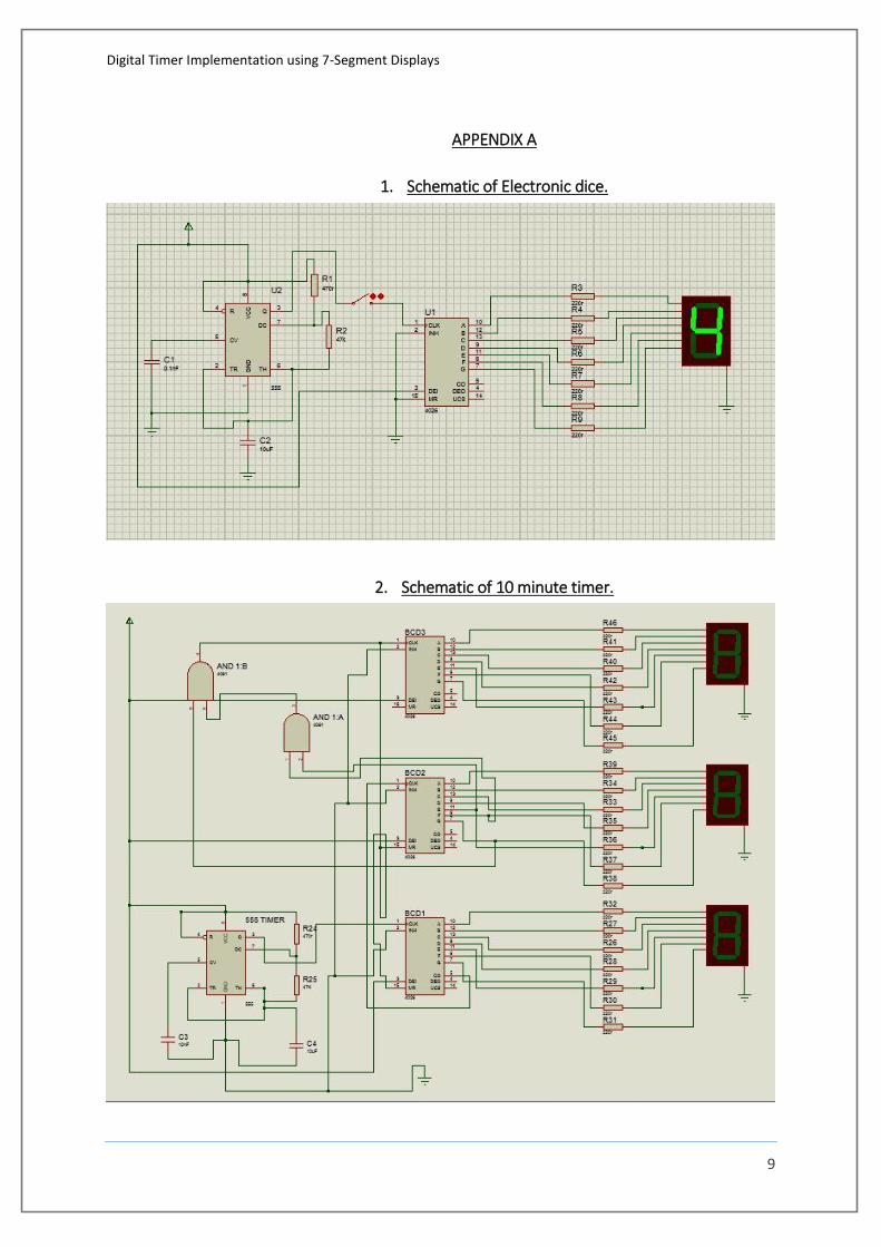
4.2 LOWER LEVEL DESIGN: The original design for the project was for a single seven segment display timer counting from one to six. This was implemented using a 555 Timer in an astable configuration, a 4026 Binary Coding Decimal (BCD) counter and decoder, and a seven segment display. As this circuit was straightforward to implement, a ten minute timing circuit was decided as a reasonable design to implement. The basic design from Appendix A was used as a building block for a cascaded timing circuit. The basic design in Appendix A was for a timer that counted from 1 – 6 then back to 1 again. This had to be changed in order to allow a ten minute timer to be produced. The 555 Timer remained the driver for the circuit with the pause switch being removed so as to simplify that particular part of the circuit. The resistors were replaced with a 470Ω and 47K Ω resistor, so the frequency of the 555 Timer could be modified to produce a 3.03 Hz signal. The 555 Timer output was then connected to the clock input of the first BCD (BCD1). BCD1 was configured to count from 0 – 9 then reset itself automatically, counting the seconds in the timing circuit. When BCD1 resets itself it sends a pulse from pin 5 or the carry out pin. A wire from pin 5 was then connected to the clock input of the second BCD (BCD2), so when BCD1 reset itself the pulse sent through pin 5 would trigger the clock input of BCD2. BCD2 counts the tens of seconds in the circuit, so in order to have it count properly the timer was limited to count to five before being forced to reset on the next input pulse from BCD1.This was achieved using the ‘e’ , ‘f’ and ‘g’ segment outputs of the BCD2 as inputs for the AND logical gates (4081 IC). The IC used to control this operation had 2-input AND gates. So for this reason ‘e’ and ‘f’ were sent to one AND gate and its output was used as an input for the second AND gate along with the ‘g’ segment. This was done because these respective segments become high for the first time in numbers 6. So when the timer counts to 6 it automatically resets itself from the high signal of the AND gates. Making the second seven segment display go straight
from five to zero. The same output is also used for the clock of the BCD3. The Seven Segment Displays were chosen as the desired output of this circuit for their
compact packaging and ease of implementation. An LCD display was considered for
an alternate form of output but their expense and with the seven segment displays it
was easier to see the output.
Since the BCD IC’s used by us were 4026 which is in fact an advance IC with counter and the seven segment decoders embedded in it so no extra decoders were required to show a display on the 7 segments.
Digital Timer Implementation using 7-Segment Displays
8
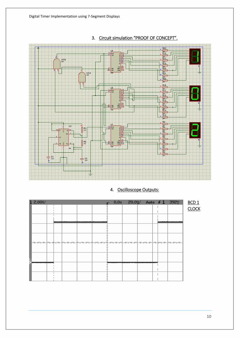
4.2 SIMULATION: A Simulation of the project circuit was made on the proteus which upon its successful implementation provided the necessary proof that the concept being used was sound and efficient. Check the Appendix A for the detailed simulation and the schematic. 5.0 CONCLUSION: Digital electronics components were investigated and a 555 timer, a BCD counter\Decoder and a seven segment display were combined to form a digital timer circuit. Different methods were analysed to determine the best technique for creating an efficient timer until one was chosen and the circuit was designed. The chosen circuit was verified through simulation using Proteus. This design was then implemented and modified to suit the needs of the project. Problems were analysed and repaired where necessary until it was concluded that the circuit had met the design criteria of the project.
Hands on experience with synchronous and asynchronous circuits.
6.0 BIBILOGRAPHY:
Unknown, Interfacing to 7-Segment Numeric Displays, Unknown.
http://www.thelearningpit.com/lp/doc/7seg/7seg.html
Science and Technology Encyclopaedia, Electronics, Unknown. Retrieved on
17/10/06 from http://www.answers.com/topic/electronics
555 timer Documentation http://www.marcial-wills.4mg.com/555/555.html 4081 AND gate Documentation http://www.doctronics.co.uk/4081.htm
4026 Counter\Decoder Documentation
http://www.circuitsgallery.com/2013/12/4026-digital-counter-circuit.html
Digital Timer Implementation using 7-Segment Displays
9
APPENDIX A
1. Schematic of Electronic dice.
2. Schematic of 10 minute timer.
Digital Timer Implementation using 7-Segment Displays
10
3. Circuit simulation “PROOF OF CONCEPT”.
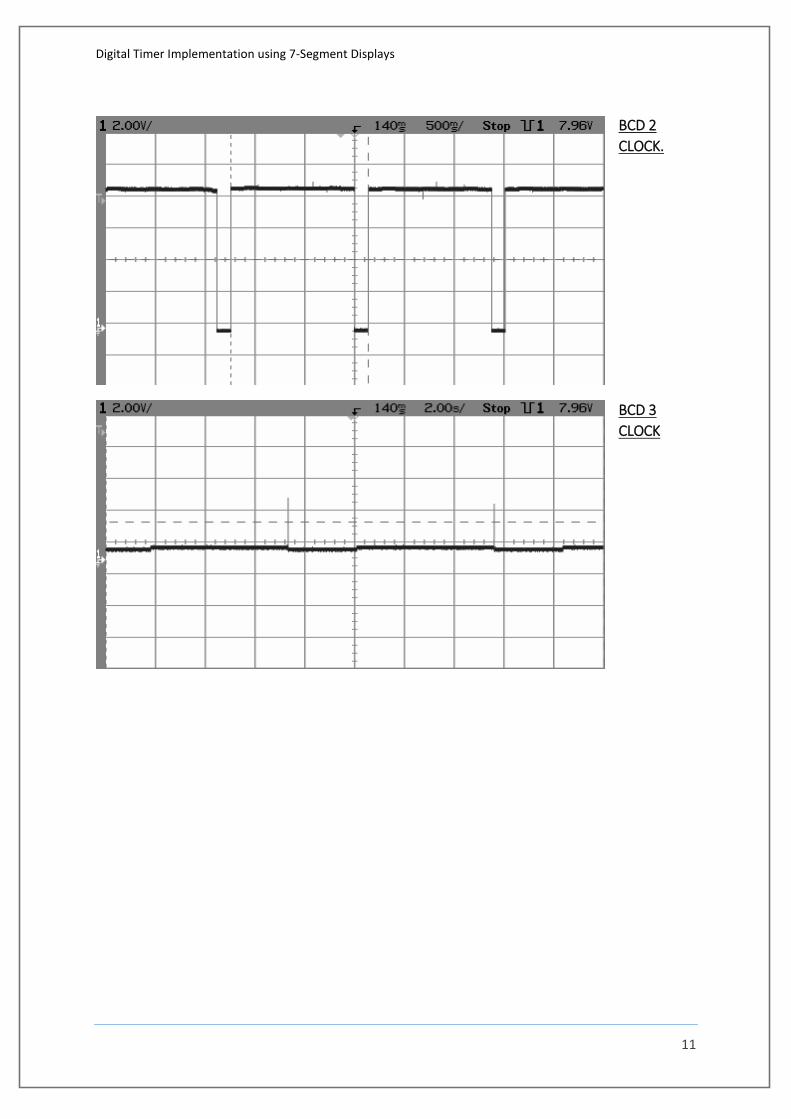
4. Oscilloscope Outputs:
BCD 1
CLOCK
Digital Timer Implementation using 7-Segment Displays
11
BCD 2
CLOCK.
BCD 3
CLOCK
Digital Timer Implementation using 7-Segment Displays
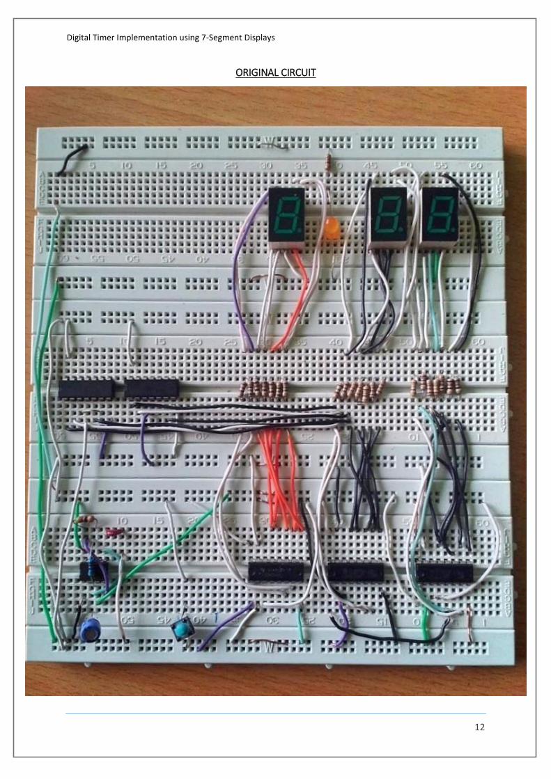
12
ORIGINAL CIRCUIT