dhariwal woollen textile mills
TRANSCRIPT
Dhariwal Woollen Textile Mills
Company Profile
Dhariwal Woollen Textile Mills was incorporated inthe year 1998 in Amritsar (Punjab). The company issmoothly running under the supervision of Mrs.Anita Uppal, the experienced MD of the enterprise.The company has so far become a prominentManufacturer, Exporter, and Supplier of WoolenShawl and Designer Lohi, in India.
Infrastructure
Supported by a high-tech manufacturing unit, wehave set a benchmark for ourselves in the industry.The unit is well equipped with the advanced tools,equipment, and machinery, ensuring flawless WoolenProducts for the global clients.
Team
We are backed by amazingly skilled artisans, who endeavor to bring out vividness in Woolen Products they design. Furthermore, all the team members follow the approach of transparent and ethical business practices, to achieve optimum customer satisfaction.
Strengths
Below mentioned are amongst our major strengths that have gained us an edge over the competitors:
Matchless Woolen Products Competent team Competitive prices Achievement of 100% customer satisfaction Widespread network
Moreover, timely delivery services also contributeto these factors.
Name of ManagingDirector : Mrs . Anita Uppal
Year of Establishment : 1998
Nature of Business : Manufacturer, Exporter & SupplierMarket Covered : Worldwide
Dhariwal Woollen Textile Mills has carved a niche
for itself in the Textile Industry. Located in
Amritsar (Punjab), the company is known as a
dynamic Woolen Products Manufacturer, Exporter, and
Supplier in India. Our collection of Woolen
Products encompasses Woolen Shawl and Designer
Lohi. The Woolen Products, that we offer, are
especially made from the finest woolen fabrics and
pashmina that provide maximum warmth to the body
during winters. Moreover, we also manufacture high
qualuity Tweed, Shawls, Stoles, Lohis, Blankets,
Cashmilon Checks Shirting.
Appreciated amidst the global clients, our Woolen
Products are majorly demanded for their exquisite
designs and superb quality. Furthermore, these
Woolen Products have garnered us a huge clientele
from all across the world in a period of 14 years.
A special emphasis is laid upon delivering the
Woolen Products within the stipulated time frame,
to achieve 100% customer satisfaction.
Threading (manufacturing)
Threading is the process of creating a screw
thread. More screw threads are produced each year
than any other machine element.[1] There are many
methods of generating threads, including
subtractive methods (many kinds of thread cutting
and grinding, as detailed below); deformative or
transformative methods (rolling and forming;
molding and casting); additive methods (such as 3D
printing); or combinations thereof.
Overview of methods (comparison, selection, etc.)There are various methods for generating screw threads. The method chosen for any one application is chosen based on constraints—time, money, degree of precision needed (or not needed), what equipment is already available, what equipment purchases could be justified based on resulting unit price of the threaded part (which depends on how many parts are planned), etc.In general, certain thread-generating processes tend to fall along certain portionsof the spectrum from toolroom-made parts to mass-produced parts, although there can be considerable overlap. For example, thread lapping following thread grinding would fall only on the extreme toolroom end of the spectrum, while thread rolling is a large anddiverse area of practice that is used for everything from microlathe leadscrews (somewhat pricey and very precise) to the
cheapest deck screws (very affordable and with precision to spare).Threads of metal fasteners are usually created on a thread rolling machine. They mayalso be cut with a lathe, tap or die. Rolled threads are stronger than cut threads, with increases of 10% to 20% in tensile strength and possibly more in fatigue resistance and wear resistance.
Subtractive methodsThread cutting
Thread cutting, as compared to thread formingand rolling, is used when full thread depth is required, when the quantity is small, whenthe blank is not very accurate, when threading up to a shoulder is required, when threading a tapered thread, or when the material is brittle.
Taps and diesMain articles: Tap and die and Die head
A common method of threading is cutting with taps
and dies. Unlike drill bits, hand taps do not
automatically remove the chips they create. A hand
tap cannot cut its threads in a single rotation
because it creates long chips which quickly jam the
tap (an effect known as "crowding", possibly
breaking it. Therefore, in manual thread cutting,
normal wrench usage is to cut the threads 1/2 to
2/3 of a turn (180 to 240 degree rotation), then
reverse the tap for about 1/6 of a turn (60
degrees) until the chips are broken by the back
edges of the cutters. It may be necessary to
periodically remove the tap from the hole to clear
the chips, especially when a blind hole is
threaded.
For continuous tapping operations (i.e., power
tapping) specialized spiral point or "gun" taps are
used to eject the chips and prevent crowding.
Single-point threading
Single-point threading, also colloquially
called single-pointing (or just thread cutting when
the context is implicit), is an operation that uses
a single-point tool to produce a thread form on a
cylinder or cone. The tool moves linearly while the
precise rotation of the workpiece determines
the lead of the thread. The process can be done to
create external or internal threads (male or
female). In external thread cutting, the piece can
either be held in a chuck or mounted between
two centers. With internal thread cutting, the
piece is held in a chuck. The tool moves across the
piece linearly, taking chips off the workpiece with
each pass. Usually 5 to 7 light cuts create the
correct depth of the thread.[5]
The coordination of various machine elements
including leadscrew, slide rest, and change gears
was the technological advance that allowed the
invention of the screw-cutting lathe, which was the
origin of single-point threading as we know it
today.
Today engine lathes and CNC lathes are the commonly
used machines for single-point threading. On CNC
machines, the process is quick and easy (relative
to manual control) due to the machine's ability to
constantly track the relationship of the tool
position and spindle position (called "spindle
synchronization"). CNC software includes "canned
cycles", that is, preprogrammed subroutines, that
obviate the manual programming of a single-point
threading cycle. Parameters are entered (e.g.,
thread size, tool offset, length of thread), and
the machine does the rest.
All threading could feasibly be done using a
single-point tool, but because of the high speed
and thus low unit cost of other methods (e.g.,
tapping, die threading, and thread rolling and
forming), single-point threading is usually only
used when other factors of the manufacturing
process happen to favor it (e.g., if only a few
threads need to be made,[6] if an unusual or unique
thread is required,[6] or if there is a need for
very high concentricity with other part features
machined during the same setup.
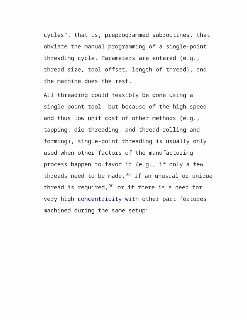
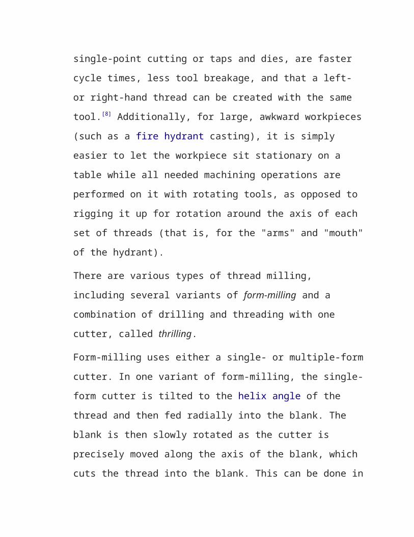
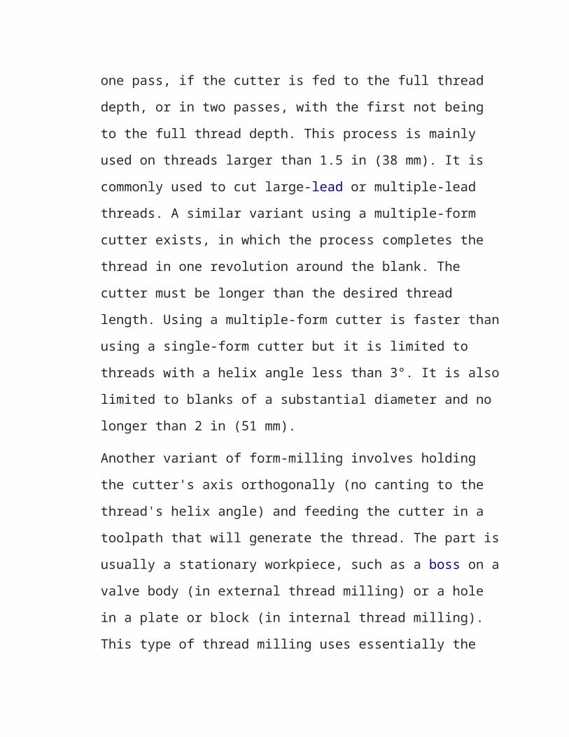
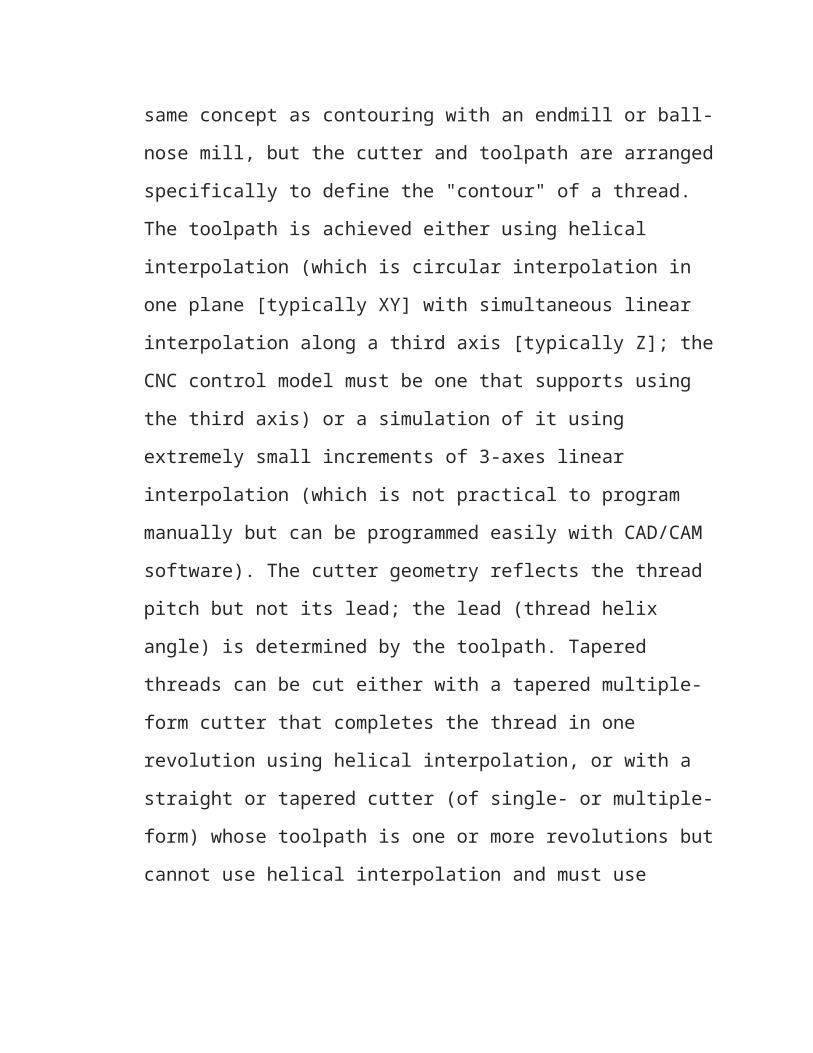
Thread milling
A diagram of a solid single-form thread cutting tool
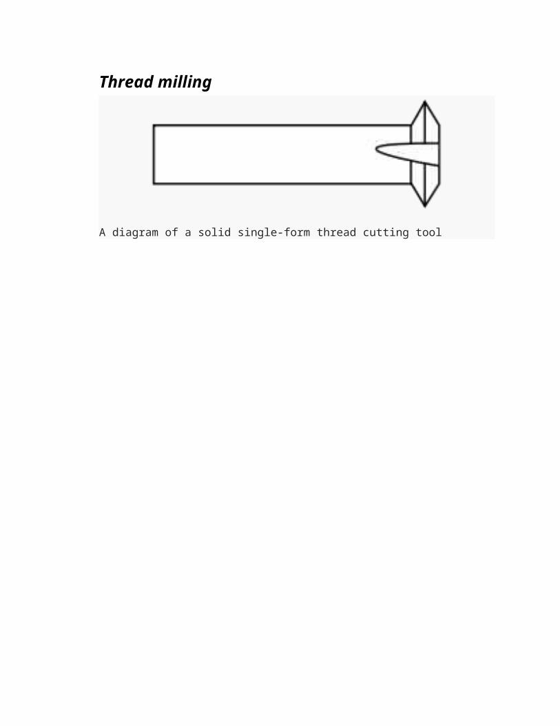
A solid multiple-form thread milling cutter.
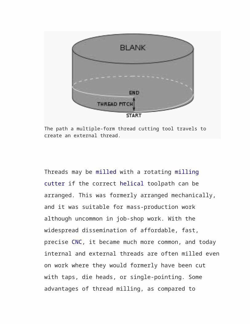
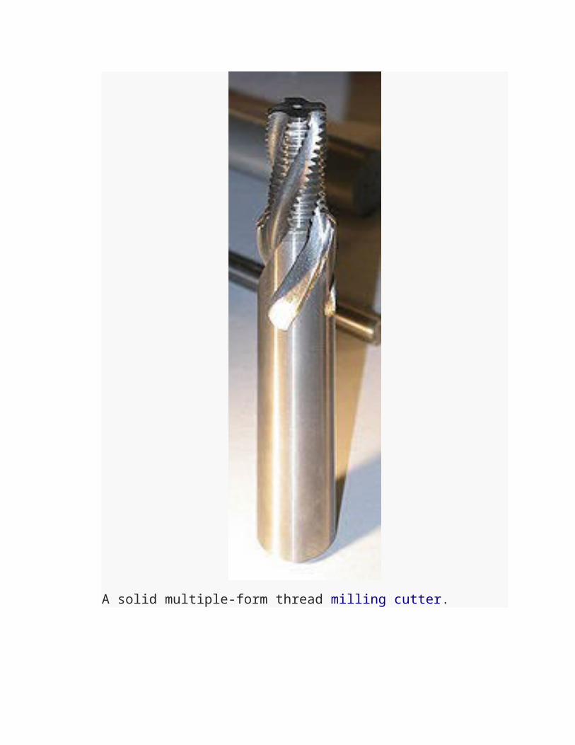
The path a multiple-form thread cutting tool travels to create an external thread.
Threads may be milled with a rotating milling
cutter if the correct helical toolpath can be
arranged. This was formerly arranged mechanically,
and it was suitable for mass-production work
although uncommon in job-shop work. With the
widespread dissemination of affordable, fast,
precise CNC, it became much more common, and today
internal and external threads are often milled even
on work where they would formerly have been cut
with taps, die heads, or single-pointing. Some
advantages of thread milling, as compared to
single-point cutting or taps and dies, are faster
cycle times, less tool breakage, and that a left-
or right-hand thread can be created with the same
tool.[8] Additionally, for large, awkward workpieces
(such as a fire hydrant casting), it is simply
easier to let the workpiece sit stationary on a
table while all needed machining operations are
performed on it with rotating tools, as opposed to
rigging it up for rotation around the axis of each
set of threads (that is, for the "arms" and "mouth"
of the hydrant).
There are various types of thread milling,
including several variants of form-milling and a
combination of drilling and threading with one
cutter, called thrilling.
Form-milling uses either a single- or multiple-form
cutter. In one variant of form-milling, the single-
form cutter is tilted to the helix angle of the
thread and then fed radially into the blank. The
blank is then slowly rotated as the cutter is
precisely moved along the axis of the blank, which
cuts the thread into the blank. This can be done in
one pass, if the cutter is fed to the full thread
depth, or in two passes, with the first not being
to the full thread depth. This process is mainly
used on threads larger than 1.5 in (38 mm). It is
commonly used to cut large-lead or multiple-lead
threads. A similar variant using a multiple-form
cutter exists, in which the process completes the
thread in one revolution around the blank. The
cutter must be longer than the desired thread
length. Using a multiple-form cutter is faster than
using a single-form cutter but it is limited to
threads with a helix angle less than 3°. It is also
limited to blanks of a substantial diameter and no
longer than 2 in (51 mm).
Another variant of form-milling involves holding
the cutter's axis orthogonally (no canting to the
thread's helix angle) and feeding the cutter in a
toolpath that will generate the thread. The part is
usually a stationary workpiece, such as a boss on a
valve body (in external thread milling) or a hole
in a plate or block (in internal thread milling).
This type of thread milling uses essentially the
same concept as contouring with an endmill or ball-
nose mill, but the cutter and toolpath are arranged
specifically to define the "contour" of a thread.
The toolpath is achieved either using helical
interpolation (which is circular interpolation in
one plane [typically XY] with simultaneous linear
interpolation along a third axis [typically Z]; the
CNC control model must be one that supports using
the third axis) or a simulation of it using
extremely small increments of 3-axes linear
interpolation (which is not practical to program
manually but can be programmed easily with CAD/CAM
software). The cutter geometry reflects the thread
pitch but not its lead; the lead (thread helix
angle) is determined by the toolpath. Tapered
threads can be cut either with a tapered multiple-
form cutter that completes the thread in one
revolution using helical interpolation, or with a
straight or tapered cutter (of single- or multiple-
form) whose toolpath is one or more revolutions but
cannot use helical interpolation and must use
CAD/CAM software to generate a contour-like
simulation of helical interpolation.[13]
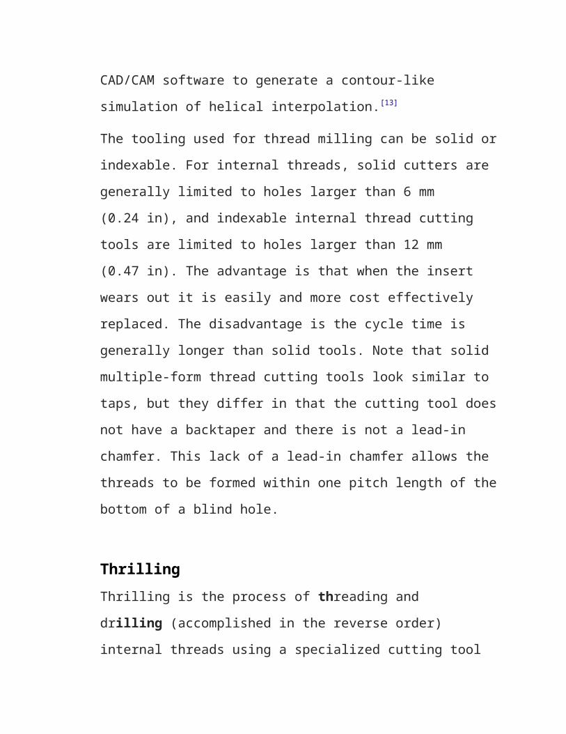
The tooling used for thread milling can be solid or
indexable. For internal threads, solid cutters are
generally limited to holes larger than 6 mm
(0.24 in), and indexable internal thread cutting
tools are limited to holes larger than 12 mm
(0.47 in). The advantage is that when the insert
wears out it is easily and more cost effectively
replaced. The disadvantage is the cycle time is
generally longer than solid tools. Note that solid
multiple-form thread cutting tools look similar to
taps, but they differ in that the cutting tool does
not have a backtaper and there is not a lead-in
chamfer. This lack of a lead-in chamfer allows the
threads to be formed within one pitch length of the
bottom of a blind hole.
ThrillingThrilling is the process of threading and
drilling (accomplished in the reverse order)
internal threads using a specialized cutting tool
on a CNC mill. The cutting tool tip is shaped like
a drill or center-cutting endmill, while the body
has a thread-shaped form with a countersink
cutter form near the shank. The cutter first
plunges to drill the hole. Then the thread is
circularly interpolated just like the multiple-form
cutter described above. This tool drills, chamfers,
and threads a hole all in one compact cycle. The
advantage is this process eliminates a tool, tool-
holder, and tool change. The disadvantage is that
the process is limited to hole depth no greater
than three times the diameter of the tool.
Thread grindingThread grinding is done on a grinding machine using
specially dressed grinding wheels matching the
shape of the threads. The process is usually used
to produce accurate threads or threads in hard
materials; a common application is ball screw
mechanisms. There are three types: center-type grinding
with axial feed, center-type infeed thread grinding and centerless
thread grinding. Center-type grinding with an axial
feed is the most common of the three. It is similar
to cutting a thread on a lathe with a single-point
cutting tool, except the cutting tool is replaced
with a grinding wheel. Usually a single ribbed
wheel is used, although multiple ribbed wheels are
also available. To complete the thread multiple
passes are commonly required. Center-type infeed
thread grinding use a grinding wheel with multiple
ribs that is longer than the length of the desired
thread. First, the grinding wheel is fed into the
blank to the full thread depth. Then the blank is
slowly rotated through approximately 1.5 turns
while axially advancing through one pitch per
revolution. Finally, the centerless thread grinding
process is used to make head-less set screws in a
similar method as centerless grinding. The blanks
are hopper-fed to the grinding wheels, where the
thread is fully formed. Common centerless thread
grinding production rates are 60 to 70 pieces per
minute for a 0.5 in (13 mm) long set screw.[16]
Thread lapping
Rarely, thread cutting or grinding (usually the latter) will be followed by thread lapping in order to achieve the highest precision and surface finish achievable. This is a toolroompractice when the highest precision is required, rarely employed except for the leadscrews or ballscrews of high-end machine tools.
Threading with EDMInternal threads can be electrical discharge machined (EDM) into hard materials using a sinker style machine.
Deformative or transformative methods
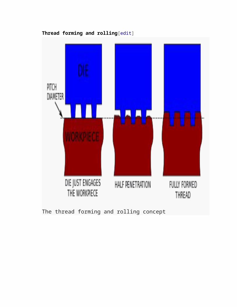
Thread forming and rolling[edit]
The thread forming and rolling concept
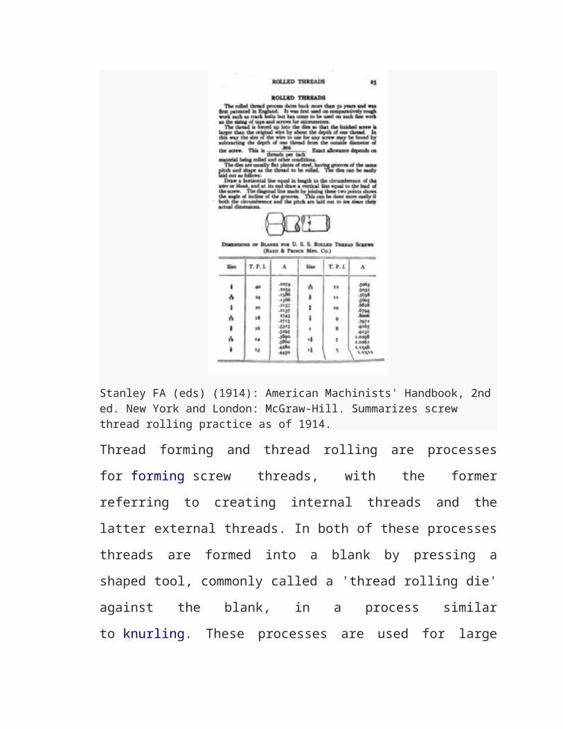
Stanley FA (eds) (1914): American Machinists' Handbook, 2nd ed. New York and London: McGraw-Hill. Summarizes screw thread rolling practice as of 1914.
Thread forming and thread rolling are processes
for forming screw threads, with the former
referring to creating internal threads and the
latter external threads. In both of these processes
threads are formed into a blank by pressing a
shaped tool, commonly called a 'thread rolling die'
against the blank, in a process similar
to knurling. These processes are used for large
production runs because typical production rates
are around one piece per second. Forming and
rolling produce no swarf and less material is
required because the blank size starts smaller than
a blank required for cutting threads; there is
typically a 15 to 20% material savings in the
blank, by weight.[16] A rolled thread can often be
easily recognized because the thread has a larger
diameter than the blank rod from which it has been
made; however, necks and undercuts can be cut or
rolled onto blanks with threads that are not
rolled. Also, the end of the screw usually looks a
bit different from the end of a cut-thread screw.[3]
Materials are limited to ductile materials because
the threads are cold formed. However, this
increases the thread's yield strength, surface
finish, hardness, and wear resistance.[16] Also,
materials with good deformation characteristics are
necessary for rolling; these materials include
softer (more ductile) metals and
exclude brittle materials, such as cast iron.
Tolerances are typically ±0.001 in. (±0.025 mm),
but tolerances as tight as ±0.0006 in (±0.015 mm)
are achievable. Surface finishes range from 6 to 32
micro-inches.[17]
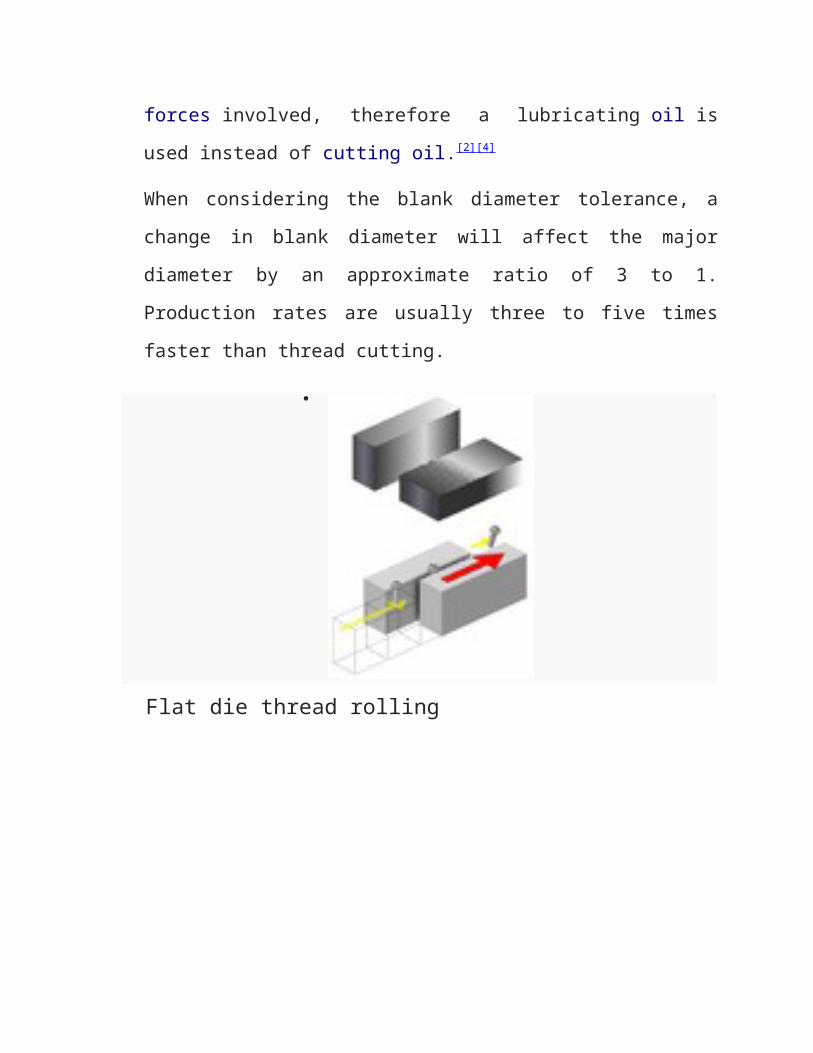
There are four main types of thread rolling, named
after the configuration of the dies: flat dies, two-die
cylindrical, three-die cylindrical, andplanetary dies. The flat
die system has two flat dies, the bottom one is
held stationary and the other slides. The blank is
placed on one end of the stationary die and then
the moving die slides over the blank, which causes
the blank to roll between the two dies forming the
threads. Before the moving die reaches the end of
its stroke the blank rolls off the stationary die
in a finished form. The two-die cylindrical process
is used to produce threads up to 6 in (150 mm) in
diameter and 20 in (510 mm) in length. There are
two types of three-die processes; the first has the
three dies move radially out from the center to let
the blank enter the dies and then closes and
rotates to roll the threads. This type of process
is commonly employed on turret lathes and screw
machines. The second type takes the form of a self-
opening die head. This type is more common than the
former, but is limited by not being able form the
last 1.5 to 2 threads against shoulders. Planetary
dies are used to mass-produce threads up to 1 in
(25 mm) in diameter.[4][16]
Thread forming is performed using a fluteless tap,
or roll tap,[18] which closely resembles a cutting tap
without the flutes. There are lobes periodically
spaced around the tap that actually do the thread
forming as the tap is advanced into a properly
sized hole. Since the tap does not produce chips,
there is no need to periodically back out the tap
to clear away chips, which, in a cutting tap, can
jam and break the tap. Thus thread forming is
particularly suited to tapping blind holes, which
are tougher to tap with a cutting tap due to the
chip build-up in the hole. Note that the tap drill
size differs from that used for a cutting tap and
that an accurate hole size is required because a
slightly undersized hole can break the tap. Proper
lubrication is essential because of the frictional
forces involved, therefore a lubricating oil is
used instead of cutting oil.[2][4]
When considering the blank diameter tolerance, a
change in blank diameter will affect the major
diameter by an approximate ratio of 3 to 1.
Production rates are usually three to five times
faster than thread cutting.
Flat die thread rolling
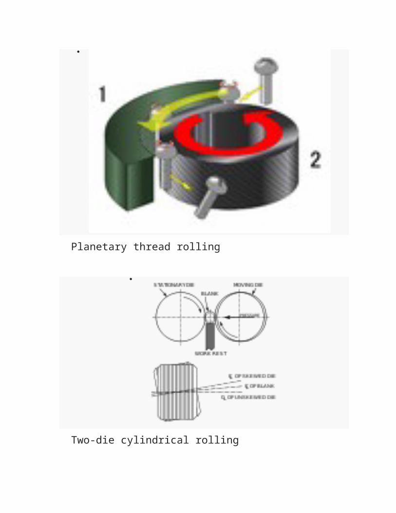
Planetary thread rolling
Two-die cylindrical rolling
Threadcasting and moldingIn casting and molding the threads are directlyformed by the geometry of the mold cavity inthe mold or die. When the material freezes in themold, it retains the shape after the mold isremoved. The material is heated to a liquid, ormixed with a liquid that will either dry or cure(such as plaster or cement). Alternately, thematerial may be forced into a mold as a powder andcompressed into a solid, as with graphite.Although the first thoughts that come to mind formost machinists regarding threading are ofthread cutting processes (such as tapping, single-pointing, or helical milling), Smid points outthat, when plastic bottles for food, beverages,personal care products, and other consumer products
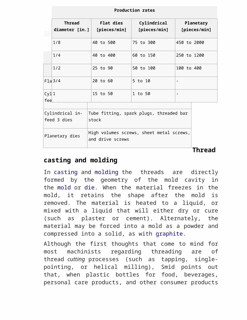
Tool styles
Description Application
Flat dies Machine, tapping and wood screws
Cylindrical in-feed 2 dies
Large or balanced screws, threaded bar stock
Cylindrical in-feed 3 dies
Tube fitting, spark plugs, threaded bar stock
Planetary dies High volumes screws, sheet metal screws,and drive screws
Production rates
Threaddiameter [in.]
Flat dies[pieces/min]
Cylindrical[pieces/min]
Planetary[pieces/min]
1/8 40 to 500 75 to 300 450 to 2000
1/4 40 to 400 60 to 150 250 to 1200
1/2 25 to 90 50 to 100 100 to 400
3/4 20 to 60 5 to 10 -
1 15 to 50 1 to 50 -
are considered, it is actually plastic molding thatis the principal method (by sheer volume) of threadgeneration in manufacturing today.[19] Of course,this fact highlights the importance ofthe moldmakers getting the mold just right (inpreparation for millions of cycles, usually at highspeed).Cast threads in metal parts may be finished bymachining, or may be left in the as-cast state.(The same can be said of cast gear teeth.) Whetheror not to bother with the additional expense of amachining operation depends on the application. Forparts where the extra precision and surface finishis not strictly necessary, the machining is forgonein order to achieve a lower cost. With sandcasting parts this means a rather rough finish; butwith molded plastic or die-cast metal, the threadscan be very nice indeed straight from the mold ordie. A common example of molded plastic threads ison soda (pop) bottles. A common example of die-castthreads is on cable glands (connectors/fittings).
Additive methodsMany, perhaps most, threaded parts have potential to be generated via additive manufacturing (3D printing), of which there are many variants, including fused deposition modeling, selective laser sintering, direct metal laser sintering, selective laser melting, electron beam melting, layered object manufacturing, and stereolithography. For most additive
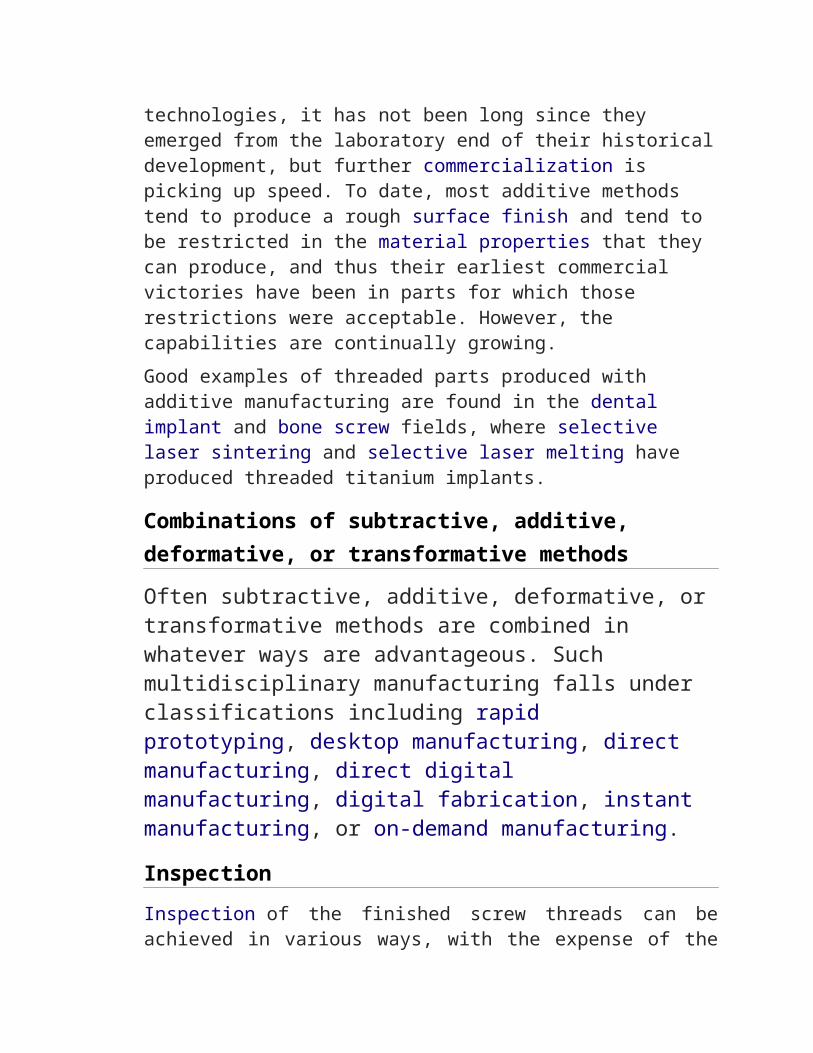
technologies, it has not been long since they emerged from the laboratory end of their historicaldevelopment, but further commercialization is picking up speed. To date, most additive methods tend to produce a rough surface finish and tend to be restricted in the material properties that they can produce, and thus their earliest commercial victories have been in parts for which those restrictions were acceptable. However, the capabilities are continually growing.Good examples of threaded parts produced with additive manufacturing are found in the dental implant and bone screw fields, where selective laser sintering and selective laser melting have produced threaded titanium implants.
Combinations of subtractive, additive, deformative, or transformative methodsOften subtractive, additive, deformative, or transformative methods are combined in whatever ways are advantageous. Such multidisciplinary manufacturing falls under classifications including rapid prototyping, desktop manufacturing, direct manufacturing, direct digital manufacturing, digital fabrication, instant manufacturing, or on-demand manufacturing.
InspectionInspection of the finished screw threads can beachieved in various ways, with the expense of the
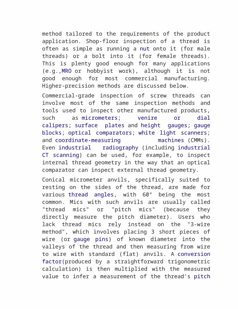
method tailored to the requirements of the productapplication. Shop-floor inspection of a thread isoften as simple as running a nut onto it (for malethreads) or a bolt into it (for female threads).This is plenty good enough for many applications(e.g.,MRO or hobbyist work), although it is notgood enough for most commercial manufacturing.Higher-precision methods are discussed below.Commercial-grade inspection of screw threads caninvolve most of the same inspection methods andtools used to inspect other manufactured products,such as micrometers; venire or dialcalipers; surface plates and height gauges; gaugeblocks; optical comparators; white light scanners;and coordinate-measuring machines (CMMs).Even industrial radiography (including industrialCT scanning) can be used, for example, to inspectinternal thread geometry in the way that an opticalcomparator can inspect external thread geometry.Conical micrometer anvils, specifically suited toresting on the sides of the thread, are made forvarious thread angles, with 60° being the mostcommon. Mics with such anvils are usually called"thread mics" or "pitch mics" (because theydirectly measure the pitch diameter). Users wholack thread mics rely instead on the "3-wiremethod", which involves placing 3 short pieces ofwire (or gauge pins) of known diameter into thevalleys of the thread and then measuring from wireto wire with standard (flat) anvils. A conversionfactor(produced by a straightforward trigonometriccalculation) is then multiplied with the measuredvalue to infer a measurement of the thread's pitch
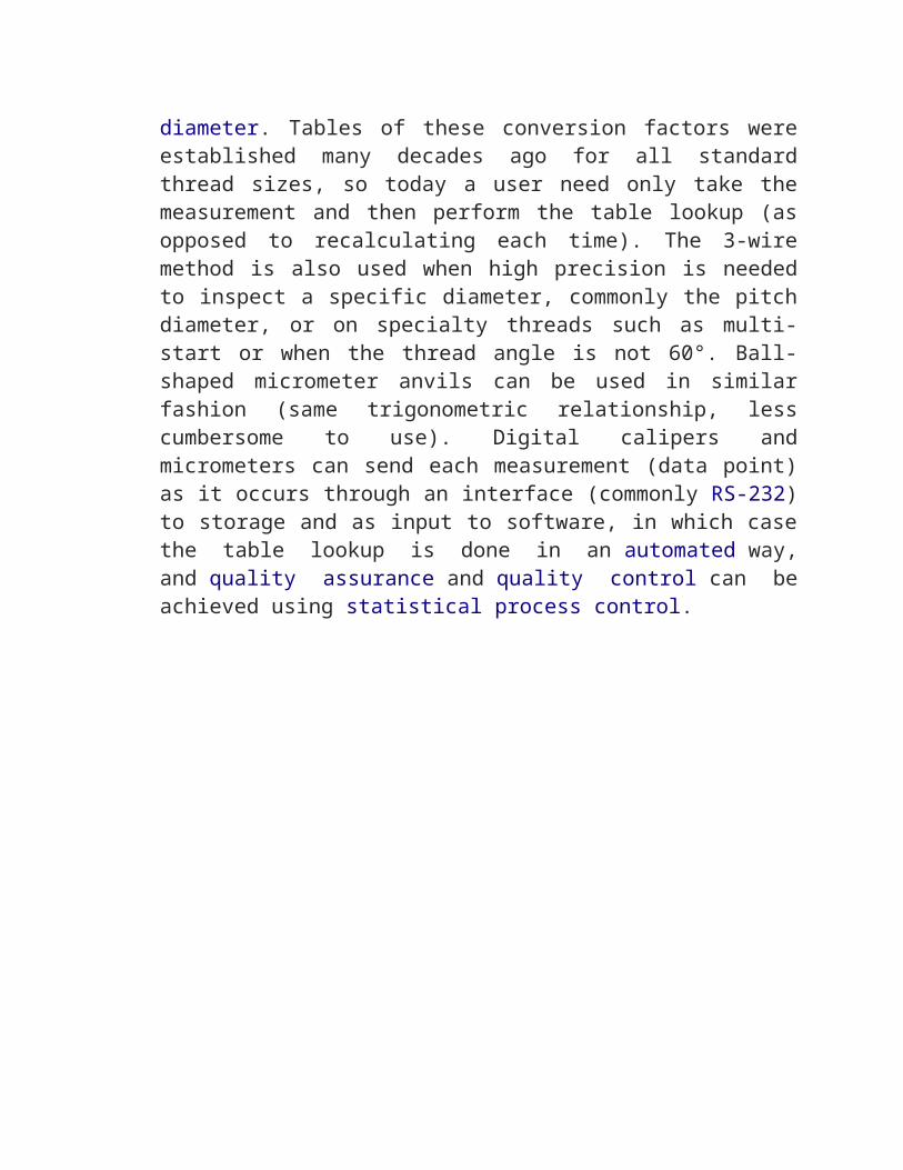
diameter. Tables of these conversion factors wereestablished many decades ago for all standardthread sizes, so today a user need only take themeasurement and then perform the table lookup (asopposed to recalculating each time). The 3-wiremethod is also used when high precision is neededto inspect a specific diameter, commonly the pitchdiameter, or on specialty threads such as multi-start or when the thread angle is not 60°. Ball-shaped micrometer anvils can be used in similarfashion (same trigonometric relationship, lesscumbersome to use). Digital calipers andmicrometers can send each measurement (data point)as it occurs through an interface (commonly RS-232)to storage and as input to software, in which casethe table lookup is done in an automated way,and quality assurance and quality control can beachieved using statistical process control.
