dhaka power distribution company limited (dpdc)
TRANSCRIPT
DHAKA POWER DISTRIBUTION COMPANY LIMITED (DPDC)
TENDER DOCUMENT
FOR
PACKAGE-01: DESIGN, SUPPLY, CONSTRUCTION,
TESTING & COMMISSIONING OF 11 KV NEW
DISTRIBUTION LINE INCLUDING UNDERGROUND
DISTRIBUTION SYSTEM & RENOVATION OF EXISTING 11
KV DISTRIBUTION LINE ON TURNKEY BASIS.
International Competitive Tender
(Single Stage – Two Envelope)
Invitation for Tender No. : 87.117.428.00.00.00.2018.11
Issued on : 02/04/2019
Tender Package No. : 01

Tender Document for Construction of Distribution Network On Turnkey Basis
i
Table of Contents
Section 1.Instructions to Tenderers...................................................................1
A. General ......................................................................................................... 1 1. Scope of Tender .............................................................................................................. 1 2. Interpretation ................................................................................................................... 1 3. Source of Funds .............................................................................................................. 1 4. Corrupt, Fraudulent, Collusive, Coercive (or Obstructive in case of Development
Partner) Practices ............................................................................................................. 2 5. Eligible Tenderers ............................................................................................................ 4 6. Eligible Plant and Services .............................................................................................. 6 7. Site Visit ........................................................................................................................... 7
B. Tender Document ........................................................................................ 7
8. Tender Document: General ............................................................................................. 7 9. Clarification of Tender Document .................................................................................... 8 10. Pre-TenderMeeting ........................................................................................................ 8 11. Addendum to Tender Document ................................................................................... 8
C. Qualification Criteria .................................................................................... 9
12. General Criteria ............................................................................................................. 9 13. LitigationHistory ........................................................................................................... 10 14. Experience Criteria ...................................................................................................... 10 15. Financial Criteria .......................................................................................................... 10 16. Personnel Capacity ..................................................................................................... 10 17. Equipment Capacity .................................................................................................... 10 18. Joint Venture, Consortium or Association ................................................................... 10 19. Subcontractor(s) .......................................................................................................... 11
D. Tender Preparation .................................................................................... 12
20. Only one Tender .......................................................................................................... 12 21. Cost of Tendering ........................................................................................................ 12 22. Issuance and Sale of Tender Document ..................................................................... 12 23. Language of Tender .................................................................................................... 12 24. Contents of Tender(Document establishing the tender‟s qualification) ....................... 13 25. Alternatives .................................................................................................................. 15 26. Tender Prices, Discounts& Price adjustment .............................................................. 15 27.Tender Currency ........................................................................................................... 18 28. Documents Establishing the Conformity of Plant, and Services ................................. 18 29. Documents Establishing Eligibility of the Tenderer ..................................................... 19 30. Validity Period of Tender ............................................................................................. 19 31. Extension of Tender Validity and Tender Security ...................................................... 20 32. Tender Security ........................................................................................................... 20 33.Form of Tender security ............................................................................................... 20 34. Authenticity of Tender Security ................................................................................... 21 35. Return of Tender Security ........................................................................................... 21 36. Forfeiture of Tender Security. ...................................................................................... 22 37. Format and Signing of Tender ..................................................................................... 22

Tender Document for Construction of Distribution Network On Turnkey Basis
ii
E. Tender Submission .................................................................................... 23 38. Sealing, Marking and Submission of Tender............................................................... 23
39. Deadline for Submission of tenders ............................................................................ 24
40. Late tender .................................................................................................................. 24
41. Modification, Substitution or Withdrawal of Tenders ................................................... 24
42. Tender Modification ..................................................................................................... 25
43. Tender Substitution ..................................................................................................... 25
44. Withdrawal of Tender .................................................................................................. 25
F. Tender Opening and Evaluation ............................................................... 25
45. Tender Opening ........................................................................................................... 25
46. Evaluation of Tenders .................................................................................................. 27
47. Evaluation Process ...................................................................................................... 28
48. Preliminary Examination .............................................................................................. 28
49. Technical Evaluation and Responsiveness ................................................................. 29
50. Clarification on Technical Offer ................................................................................... 30
51.Restrictions on Disclosure of Information ..................................................................... 30
52. Approval of Technical Offer ......................................................................................... 31
53. Financial Offer Opening .............................................................................................. 31
54. Clarification on Financial Offer .................................................................................... 32
55. Correction of Arithmetical Errors ................................................................................. 32
56. Conversion to Single Currency .................................................................................... 33
57. Financial Evaluation .................................................................................................... 33
58. Price Comparison ........................................................................................................ 34
59. Post-qualification ......................................................................................................... 35
60. Negotiation .................................................................................................................. 35
61. Rejection of All Tenders .............................................................................................. 36
62. Informing Reasons for Rejection ................................................................................. 36
G. Contract Award .......................................................................................... 37
63. Award Criteria .............................................................................................................. 37
64. Notification of Award .................................................................................................... 37
65. Performance Security .................................................................................................. 37
66. Form and Time Limit for furnishing of Performance security ...................................... 38
67. Validity of Performance Security ................................................................................. 38
68. Authenticity of performance Security ........................................................................... 38
69. Contract Signing ....................................................................................................... 39
70. Publication of Notification of Award of Contract .......................................................... 39
71. Debriefing of Tenderers ............................................................................................... 39
72. Right to Complains ...................................................................................................... 39
Tender Document for Construction of Distribution Network On Turnkey Basis
iii
Section 2. Tender Data Sheet .........................................................................41
A. General ........................................................................................................ 41
B. Tender Document ........................................................................................ 42
C. Qualification Criteria ..................................................................................... 42
D. Tender Preparation ...................................................................................... 46
E. Submission of Tender ................................................................................. 48
F. Opening and Evaluation of Tenders ............................................................. 49
G. Award of Contract ........................................................................................ 50
Section 3. General Conditions of Contract ...................................................51
A. General ....................................................................................................... 51
1. Definitions ...................................................................................................................... 51 2. Interpretation ................................................................................................................. 55 3. Communications & Notices ........................................................................................... 56 4. Governing Law .............................................................................................................. 56 5. Governing Language ..................................................................................................... 56 6. Documents Forming the Contract and Priority of Documents ....................................... 57 7. Contract Agreement ...................................................................................................... 57 8. Assignment .................................................................................................................... 57 9. Eligibility ......................................................................................................................... 57 10. Gratuities / Agency fees .............................................................................................. 57 11. Confidential Details ...................................................................................................... 57 12. Joint Venture (JV) ........................................................................................................ 58 13. Possession of the Site ................................................................................................. 59 14. Access to the Site ........................................................................................................ 59 15. Safety, Security and Protection of the Environment .................................................... 59 16. Working Hours ............................................................................................................ 59 17. Welfare of Laborers ..................................................................................................... 59 18. Child Labor .................................................................................................................. 60 19. Fossils& antiquities ...................................................................................................... 60 20. Corrupt, Fraudulent, Collusive or Coercive Practices ................................................. 60 21. License/ Use of Technical Information ........................................................................ 62
B. Subject Matter of Contract ............................................................................... 62
22. Scope of Facilities ....................................................................................................... 62 23. Time for Commencement ............................................................................................ 63 24. Time for Completion .................................................................................................... 63 25. Employer‟s Responsibilities ......................................................................................... 63 26. Contractor‟s Responsibilities ....................................................................................... 64 27. Employer‟s and Contractor‟s Risks ............................................................................. 65 28. Employer‟s Risks ......................................................................................................... 65 29. Contractor‟s Risks ....................................................................................................... 65

Tender Document for Construction of Distribution Network On Turnkey Basis
iv
C. Execution of the Facilities ................................................................................ 66
30. Representatives ........................................................................................................... 66 31. Work Program ............................................................................................................. 67 32. Subcontractor .............................................................................................................. 69 33. Nominated Subcontractor ............................................................................................ 69 34. Other Contractors ........................................................................................................ 69 35. Design and Engineering .............................................................................................. 70 36. Procurement ................................................................................................................ 71 37. Installation.................................................................................................................... 73 38. Test & Inspection ......................................................................................................... 76 39. Completion of the Facilities ......................................................................................... 78 40. Commissioning and Operational Acceptance ............................................................. 80
D. Guarantees and Liabilities ........................................................................ 83
41. Completion Time Guarantee ....................................................................................... 83 42. Defect Liability ............................................................................................................. 83 43. Functional Guarantees ................................................................................................ 86 44. Patent Indemnity .......................................................................................................... 87 45. Limitation of Liability .................................................................................................... 88
E. Risk Distribution ........................................................................................ 88
46. Transfer of Ownership ................................................................................................. 88 47. Care of Facilities .......................................................................................................... 89 48. Loss of or Damage to Property; Accident or Injury to Workers; Indemnification......... 90 49. Insurance ..................................................................................................................... 91 50. Unforeseen Conditions ................................................................................................ 93 51. Change in Laws and Regulation ................................................................................. 94 52. Force Majeure ............................................................................................................. 94 53. Notice of Force Majeure .............................................................................................. 95 54. Duty to Minimize Delay ................................................................................................ 95 55. Consequences of Force Majeure ................................................................................ 95
F. Payment ............................................................................................................. 96
56. Contract Price .............................................................................................................. 96 57. Terms of Payment ....................................................................................................... 97 58. Advance Payment Security ......................................................................................... 97 59. Performance Security .................................................................................................. 97 60. Taxes and Duties ......................................................................................................... 98 61. Payments to Nominated Subcontractor(s) .................................................................. 99 62. Price Adjustment ........................................................................................................ 99 63. Liquidated Damages .................................................................................................... 99
G. Change in Contract Elements ........................................................................ 100 64. Change in the Facilities ............................................................................................. 100 65. Extension of Time for Completion ............................................................................. 102 66. Suspension ................................................................................................................ 103

Tender Document for Construction of Distribution Network On Turnkey Basis
v
H. Termination and Settlement of Disputes ................................................ 105
67. Termination ................................................................................................................ 105 68. Payment upon Termination ....................................................................................... 107 69. Property ..................................................................................................................... 107 70. Frustration.................................................................................................................. 107
I. Claims, Disputes and Arbitration .................................................................... 108
71. Contractor‟s Claims ................................................................................................... 108 72. Settlement of Disputes .............................................................................................. 108
Section4. Particular Conditions of Contract ..............................................109
Appendix 1. Terms and Procedures of Payment ................................................... 118
Appendix 2. Price Adjustment : Not applicable for this tender ............................... 122
Appendix 3. Insurance Requirements ................................................................... 123
Appendix 4. Time Schedule .................................................................................. 127
Appendix 5. List of Major Items of Plant and Services and List of Approved
Subcontractors ........................................................................................... 128
Appendix 6. Scope of Works and Supply by the Employer ................................... 129
Appendix 7. List of Documents for Approval or Review ........................................ 130
Appendix 8. Functional Guarantees ..................................................................... 131
Section 5. Tender and Contract Forms .......................................................134 Tender Submission Letter for Technical offer ................................................................... 135 (Form PG5A-1a) ............................................................................................................... 135 Tender Submission Letter for Financial offer .................................................................... 137 (Form PG5A-1b) ............................................................................................................... 137 Tenderer Information (Form PG5A-2a) ............................................................................. 140 JVCA Partner Information (Form PG5A-2b) ...................................................................... 143 Subcontractor Information (Form PG5A-2c) ..................................................................... 146 Price Schedule for Plant and Service (Form PG5A-3) ...................................................... 148 Technical Proposal (Form PG5A-4) ............................................................................... 182
Specifications Submission and Compliance Sheet (Form PG5A-4a) .............. 190 Manufacturer‟s Authorisation Letter (Form PG5A - 5) ....................................................... 191 Bank Guarantee for Tender Security (Form PG5A– 6) ..................................................... 192 Letter of Commitment for Bank‟s undertaking for Line of Credit (Form PG5A-6a) ............ 193 Notification of Award (Form PG5A - 7).............................................................................. 194 Contract Agreement (Form PG5A - 8) .............................................................................. 195 Bank Guarantee for Performance Security (Form PG5A – 9) ........................................... 197 Bank Guarantee for Advance Payment (Form PG5A – 10) .............................................. 198 Bank Guarantee for Retention Money Security(Form PG5A-11) ...................................... 199

Tender Document for Construction of Distribution Network On Turnkey Basis
vi
Section 6. Employer‟s Requirements ............................................................200
A. Supply of Materials ............................................................................................ 200
B. Scope of Works for Construction and Expansion of Distribution Network .......... 206
2 TECHNICAL SPECIFICATIONS....................................................................226
Schedule- B: Drawings and Documents to be submitted with Tender .................... 436
Inspection and Testing .......................................................................................446
DRAWINGS .......................................................................................................450
CIVIL WORK PROVISION .................................................................................504
6.3 Form of Completion Certificate ................................................................... 522
6.4 Form of Operational Acceptance Certificate ............................................... 523
6.5 Form of Change Order Procedure and Forms ............................................ 524 Annex 1. Request for Change Proposal ......................................................................... 526 Annex 2. Estimate for Change Proposal ........................................................................ 527 Annex 3. Acceptance of Estimate .................................................................................. 528 Annex 4. Change Proposal ............................................................................................. 529 Annex 5. Change Order .................................................................................................. 531 Annex 6. Pending Agreement Change Order ................................................................. 532
Section 7. Drawings .........................................................................................535

Section-01: Instruction to Tenderers
Tender Document for Construction of Distribution Network On Turnkey Basis
Page 1 of 535
Section 1.Instructions to Tenderers
A. General 1. Scope of Tender 1.1 The Purchaser named in the Tender Data Sheet (TDS)
(hereinafter referred to as the “Purchaser”) wishes to issue these
Tender Documents for the supply and installation of plant &
equipment incidental thereto, as specified in the TDS and as
detailed in Section 6: Employer‟s Requirements.
1.2 The name of the Tender and the number and identification of its
constituent lot(s) are stated in the TDS.
1.3 Unless otherwise stated, throughout this Tender Document
definitions and interpretations shall be as prescribed in the
Section 3: General Conditions of Contract.
2. Interpretation 2.1 Throughout this Tender Document
(a) the term “in writing” means communication written by hand
or machine duly signed and includes properly
authenticated messages by facsimile or electronic mail;
(b) if the context so requires, singular means plural and vice
versa; and
(c) “day” means calendar days unless otherwise specified as
working days;
(d) "Tender Document ", means the Document provided by a
Purchaser to a Tenderer as a basis for preparation of its
Tender;
(e) "Tender ", depending on the context, means a Tender
submitted by a Tenderer for delivery of Goods and Related
Services to a Purchaser in response to an Invitation for
Tender ;
3. Source of Funds 3.1 The Purchaserhas been allocated public funds from the source
as indicated in the TDS and intends to apply a portion of the
funds to eligible payments under the contract for which this
Tender Document is issued.
3.2 For the purpose of this provision, “public funds” means any
funds allocated to a Purchaser under Government budget, or
loan, grants and credits placed at the disposal of a Purchaser
through the Government by the development partners or
foreign states or organizations.

Section-01: Instruction to Tenderers
Tender Document for Construction of Distribution Network On Turnkey Basis
Page 2 of 535
3.3 Payments by the development partner, if so indicated in the
TDS, will be made only at the request of the Government and
upon approval by the development partner in accordance with
the applicable Loan/Credit/Grant Agreement, and will be
subject in all respects to the terms and conditions of that
Agreement.
4. Corrupt, Fraudulent, Collusive, Coercive (or Obstructive in case of Development Partner) Practices
4.1 The Government and the Development Partner, if applicablerequires that the Procuring Entity as well as the Tenderers and Contracts (including , sub-contractors, agents, personnel, consultants, and service providers)shall observe the highest standard of ethics during implementation of procurement proceedings and the execution of Contracts under public funds.
4.2 For the purposes of ITT Sub Clause 4.3, the terms set forth below as follows:
(a) “corrupt practice” means offering, giving or promising to give, receiving, or soliciting either directly or indirectly, to any officer or employee of the Procuring Entity or other public or private authority or individual, a gratuity in any form; employment or any other thing or service of value as an inducement with respect to an act or decision or method followed by the Procuring Entity in connection with a Procurement proceeding or Contract execution;
(b) “fraudulent practice” means the misrepresentation or omission of facts in order to influence a decision to be taken in a Procurement proceeding or Contract execution;
(c) “collusive practice” means a scheme or arrangement between two (2) or more Persons, with or without the knowledge of the Procuring Entity, that is designed to arbitrarily reduce the number of Tenders submitted or fix Tender prices at artificial, non-competitive levels, thereby denying the Procuring Entity the benefits of competitive price arising from genuine and open competition;
(d) “coercive practice” means harming or threatening to harm, directly or indirectly, Persons or their property to influence a decision to be taken in the Procurement proceeding or the execution of a Contract, and this will include creating obstructions in the normal submission process used for Tenders.

Section-01: Instruction to Tenderers
Tender Document for Construction of Distribution Network On Turnkey Basis
Page 3 of 535
(e) “Obstructive practice” (applicable in case of Development Partner) means deliberately destroying, falsifying, altering or concealing of evidence material to the investigation or making false statements to investigators in order to materially impede an investigation into allegations of a corrupt, fraudulent, coercive or collusive practice; and /or threatening, harassing or intimidating any party to prevent it from disclosing its knowledge of matters relevant to the investigation or from pursuing the investigation.
4.3 Should any corrupt, fraudulent, collusive, coercive (or obstructive in case of Development Partner) practice of any kind is determined by the Procuring Entity or the Development Partner, if applicable, this will be dealt in accordance with the provisions of the Public Procurement Act and Rules and Guidelines of the Development
Partners as stated in the ITT sub-clause 3.3. In case of obstructive practice, this will be dealt in accordance with Development Partners Guidelines.
4.4 If corrupt, fraudulent, collusive, coercive (or obstructive in case of Development Partner) practices of any kind is determined by the Procuring Entity against any Tenderer or Contracts (including sub-contractors, agents, personnel, consultants, and service providers) in competing for, or in executing, a contract under public fund:
(a) Procuring Entity and/or the Development Partner shall exclude the concerned Tenderer from further participation in the concerned procurement proceedings;
(b) Procuring Entity and/or the Development Partner shall reject any recommendation for award that had been proposed for that concerned Tenderer;
(c) Procuring Entity and/or the Development Partner shall declare, at its discretion, the concerned Tenderer to be ineligible to participate in further Procurement proceedings, either indefinitely or for a specific period of time;
(d) Development Partner shall sanction the concerned Tenderer or individual, at any time, in accordance with prevailing Development Partner‟ sanctions procedures, including by publicly declaring such Tenderer or individual ineligible, either indefinitely or for a stated period of time: (i) to be awarded a Development Partner-financed contract; and (ii) to be a nominated sub-contractor, consultant, manufacturer or Contractor, or service provider of an otherwise eligible firm being awarded a Development Partner-financed contract; and

Section-01: Instruction to Tenderers
Tender Document for Construction of Distribution Network On Turnkey Basis
Page 4 of 535
(e) Development Partner shall cancel the portion of the
loan allocated to a contract if it determines at any
time that representatives of the Procuring Entity or of
a beneficiary of the loan engaged in corrupt,
fraudulent, collusive, coercive or obstructive
practices during the procurement or the execution of
that Development Partner financed contract, without
the Procuring Entity having taken timely and
appropriate action satisfactory to the Development
Partner to remedy the situation.
Tenderer shall be aware of the provisions on corruption,
fraudulence, collusion,coercion (and obstruction, in case of
Development Partner) of the Public Procurement Act,
2006, the Public Procurement Rules, 2008 and others as
stated in GCC Clause 38.
4.5 In further pursuance of this policy, Tenderers, Contractors
and theirsub-contractors, agents, personnel, consultants,
service providers shall permit the Government and the
Development Partner to inspect any accounts and records
and other documents relating to the Tender submission and
contract performance, and to have them audited by auditors
appointed by the Government and/or the Development
Partner during the procurement or the execution of that
Development Partner financed contract.
5. Eligible Tenderers 5.1 This Invitation for Tenders is open to all potential
Tenderers from all countries, except for any specified in
the TDS.
5.2 Tenderers shall have the legal capacity to enter into the
Contract under the Applicable law.
5.3 Tenderers shall be enrolled in the relevant professional or
trade organisations registered in Bangladesh.
5.4 Tenderers may be a physical or juridical individual or
body of individuals, or company, association or any
combination of them in the form of a Joint Venture(JV)
invited to take part in public procurement or seeking to be
so invited or submitting a Tender in response to an
Invitation for Tenders.
5.5 Tenderers shall have fulfilled its obligations to pay taxes
and social security contributions under the provisions of
laws and regulations of the country of its origin.
Section-01: Instruction to Tenderers
Tender Document for Construction of Distribution Network On Turnkey Basis
Page 5 of 535
5.6 Tenderers should not be associated, or have been
associated in the past, directly or indirectly, with a
consultant or any of its affiliates which have been
engaged by the Procuring Entity to provide consulting
services for the preparation of the design, specifications,
and other documents to be used for the procurement of
the works to be performed under this Invitation for
Tenders.
5.7 Tenderers in its own name or its other names or also in
the case of its Persons in different names shall not be
under a declaration of ineligibility for corrupt, fraudulent,
collusive or coercive practices as stated under ITT Sub
Clause 4.4 (or obstructive practice, in case of
Development Partner) in relation to the Development
Partner‟s Guidelines in projects financed by Development
Partner.
5.8 Tenderers are not restrained or barred from participating
in Public Procurement on grounds of poor performance in
the past under any Contract.
5.9 Tenderers shall not be insolvent, be in receivership, be
bankrupt, be in the process of bankruptcy, be not
temporarily barred from undertaking business and it shall
not be the subject of legal proceedings for any of the
foregoing.
5.10 Government-owned enterprise in Bangladesh may also participate in the Tender if it is legally and financially autonomous, it operates under commercial law, and it is not a dependent agency of the Procuring Entity.
5.11 Tenderers shall provide such evidence of their continued eligibility satisfactory to the Procuring Entity, as the Procuring Entity will reasonably request.
5.12 These above requirements for eligibility will extend, as applicable, to each JV partner and Subcontractor proposed by the Tenderers.
5.13 Tenderers shall have the up-to-date valid license(s),
issued by the corresponding competent authority, as
specified in the TDS.
Section-01: Instruction to Tenderers
Tender Document for Construction of Distribution Network On Turnkey Basis
Page 6 of 535
6. Eligible Plant and Services
6.1 The plant and services to be supplied under the contract are
eligible, unless their origin is from a country specified in the
TDS and all expenditures under the contract will be limited to
such plant, and services.
6.2 For purposes of this Clause, the term “plant” means
permanent plant, equipment, machinery, apparatus, articles
and things of all kinds to be provided in the facilities; and
“installation services” means all those services ancillary to
the supply of the Plant for the Facilities, such as
transportation and provision of marine or other similar
insurance, inspection, expediting, site preparation,
installation, testing, pre-commissioning, commissioning,
operations, maintenance, the provision of operations and
maintenance manuals, training etc
6.3 For purposes of this clause, “origin” means the place where
the plant, or component parts thereof are mined, grown,
produced or manufactured, and from which the services are
provided. Plant components are produced when, through
manufacturing, processing, or substantial or major
assembling of components, a commercially recognized
product results that is substantially different in its basic
characteristics or in purpose or utility from its components
orcountry where the goods have been mined, grown,
cultivated, produced, manufactured or processed; or through
manufacture, processing, or assembly, another commercially
recognized article results that differs substantially in its basic
characteristics from its components.
6.4 The origin of plant & equipment is distinct from the nationality
of the Tenderer. The nationality of the firm that produces,
assembles, distributes, or sells the goods shall not determine
their origin.

Section-01: Instruction to Tenderers
Tender Document for Construction of Distribution Network On Turnkey Basis
Page 7 of 535
7. Site Visit 7.1 The Tenderer is advised to visit and examine the site
where the plant is to be installed and its surroundings and obtain for itself on its own responsibility all information that may be necessary for preparing the tender and entering into a contract for the provision of Plant and Installation Services.
7.2 The Tenderer and any of its personnel or agents will be granted permission by the Employer to enter upon its premises and lands for the purpose of such visit, but only upon the express condition that the Tenderer, its personnel, and agents will release and indemnify the Employer and its personnel and agents from and against all liability in respect thereof, and will be responsible for death or personal injury, loss of or damage to property, and any other loss, damage, costs, and expenses incurred as a result of the inspection.
7.3 The Tenderer should ensure that the Purchaser is informed of the visit in adequate time to allow it to make appropriate arrangements.
7.4 The costs of visiting the Site shall be at the Tenderer‟s own expense.
B. Tender Document 8. Tender Document:
General 8.1 The Sections comprising the Tender Document are listed
below, and should be read in conjunction with any Addendum issued under ITT Clause 11.
Section 1 Instructions to Tenderers (ITT)
Section 2 Tender Data Sheet (TDS)
Section 3 General Conditions of Contract (GCC)
Section 4 Particular Conditions of Contract (PCC)
Section 5 Tender and Contract Forms
Section 6 Employer‟s Requirements
Section 7 Drawings
8.2 The Purchaser shall reject any Tender if the Tender Document was not purchased directly from the Purchaser, or through its agent as stated in the TDS.
8.3 The Tenderer is expected to examine all instructions, forms, terms, and specifications in the Tender Document as well as addendum to Tender Documents.

Section-01: Instruction to Tenderers
Tender Document for Construction of Distribution Network On Turnkey Basis
Page 8 of 535
9. Clarification of Tender Document
9.1 A prospective Tenderer requiring any clarification of the Tender Document shall contact the Purchaser in writing at the Purchasers address indicated in the TDS before two-third of time allowed for preparation and submission of Tender elapses.
9.2 The Procuring Entity is not obliged to answer any clarification request received after that date as stated under ITT Sub Clause 9.1.
9.3 The Procuring Entity shall respond in writing within five (5) working days of receipt of any such request for clarification received under ITT Sub Clause 9.1.
9.4 The Procuring Entity shall forward copies of its response to all those who have purchased the Tender Document, including a description of the enquiry but without identifying its source.
9.5 Should the Procuring Entity deem it necessary to revise the Tender Document as a result of a clarification, it will do so following the procedure under ITT Clause 11.
10. Pre-TenderMeeting 10.1 To clarify issues and to answer questions on any matter arising in the Tender Document, the Purchaser may, if stated in the TDS, hold a Pre-Tender Meeting at the place, date and time as specified in the TDS. All Potential Tenderers are encouraged to attend the meeting, if it is held.
10.2 Minutes of the pre-Tender meeting, including the text of the questions raised and the responses given, together with any responses prepared after the meeting, will be transmitted within one week (7 days) after holding the meeting to all those who purchased the Tender Document and even those who did not attend the meeting.
10.3 Any amendment to the Tender Documents listed in ITT Sub-Clause 8.1 that may become necessary as a result of the pre-Tender meeting shall be made by the Purchaser exclusively through the issue of an Addendum as stated under ITT Sub-Clause 11 and not through the minutes of the pre-Tender meeting.
10.4 Non-attendance at the Pre-Tender meeting will not be a cause for disqualification of a Tenderer.
11. Addendum to Tender Document
11.1 At any time prior to the deadline for submission of Tenders, the Purchaser on its own initiative or in response to a clarification request in writing from a Tenderer, having purchased the Tender Document or as a result of a Pre-Tender meeting, may revise the Tender Document by issuing an addendum pursuant to Rule 95 of the Public Procurement Rules, 2008.
Section-01: Instruction to Tenderers
Tender Document for Construction of Distribution Network On Turnkey Basis
Page 9 of 535
11.2 The addendum issued under ITT Sub-Clause 11.1 shall become an integral part of the Tender Document and shall have a date and an issue number and shall be circulated by fax, mail or e-mail, to Tenderers who have purchased the Tender Documents within five (5) working days of issuance of such addendum, to enable Tenderers to take appropriate action.
11.3 The Tenderer shall acknowledge receipt of an addendum.
11.4 Tenderers who have purchased the Tender Documents but have not received any addendum issued under ITT Sub-clause 11.1 shall inform the Purchaser of the fact by fax, mail or e-mail before two-third of the time allowed for the submission of Tenders has elapsed.
11.5 Procuring Entities shall also ensure posting of relevant addenda with the reference number and date on their website.
11.6 To give a prospective Tenderer reasonable time in which to take an amendment into account in preparing its Tender, the Purchaser may, at its discretion, extend the deadline for the submission of Tenders, pursuant to Rule 95(6) of the Public Procurement Rule, 2008 and under ITT Clause 36.
11.7 If an addendum is issued when time remaining is less than one-third of the time allowed for the preparation of Tenders, a Purchaser shall extend the deadline by an appropriate number of days for the submission of Tenders, depending upon the nature of the Procurement requirement and the addendum. The minimum time for such extension shall not be less than seven (7) days.
C. Qualification Criteria
12. General Criteria 12.1 The Tenderer shall possess the necessary professional and technical qualifications and competence, financial resources, equipment and other physical facilities, managerial capability, specific experience, reputation, and the personnel, to perform the contract.
12.2 In addition to meeting the eligibility criteria, as stated in ITT Clause 5, the Tenderer must satisfy the other criteria stated in ITT Clauses 13 to 15 inclusive.
12.3 To qualify for multiple number of contracts/lots in a package made up of this and other individual contracts/lots for which tenders are invited in the Invitation for Tenders, the Tenderer shall demonstrate having resources and experience sufficient to meet the aggregate of the qualifying criteria for the individual contracts.
Section-01: Instruction to Tenderers
Tender Document for Construction of Distribution Network On Turnkey Basis
Page 10 of 535
13. Litigation History 13.1 The maximum number of arbitration awards against the Tenderer over a period shall be as specified in the TDS.
14. Experience Criteria
14.1 Tenderers shall have the following minimum level of supply
experience to qualify for supplying the Plant and Services under the contract:
(a) a minimum number of years of general experience in the role of Contractor or Subcontractor or Management Contractor as specified in the TDS; and
(b) Specific experience as a Contractor or Subcontractor or Management Contractor that are similar to the proposed plant and services in at least a number of contract(s) and of a minimum value over the period, as specified in the TDS.
15. Financial Criteria 15.1 Tenderers shall have the following minimum level of financial capacity of qualify for the supply, execution and performance of plant and services under the contract.
(a) the average annual turnover as specified in the TDS calculated as total certified payments received for contracts in progress or completed, during the period specified in the TDS;
(b) availability of minimum liquid assets or working capital or credit facilities, as specified in the TDS; and;
(c) satisfactory resolution of all claims, arbitrations or other litigation cases and shall not have serious negative impact on the financial capacity of the Tenderer.
16. Personnel Capacity 16.1 The Tenderer shall have the following minimum level of
personnel capacity to qualify for the performance of the plant and services under the Contract.
A Project Manager, Engineers, and other key staff with qualifications and experience as specified in the TDS;
17. Equipment Capacity 17.1 The Tenderer shall own suitable equipment and other physical facilities or have proven access through contractual arrangement to hire or lease such equipment or facilities for the desired period, where necessary or have assured access through lease, hire, or other such method, of the essential equipment, in full working order, as specified in the TDS.
18. Joint Venture, Consortium or Association
18.1 The Tenderer may participate in the procurement proceedings forming a Joint Venture, Consortium or Associations (JVCA) by an agreement,executed case by case on a non judicial stamp of value as stated in TDS or alternately with the intent to enter into such an agreement supported by a Letter of Intent along with the proposed agreement duly signed by all partners of the intended JVCA and authenticated by a Notary Public.
Section-01: Instruction to Tenderers
Tender Document for Construction of Distribution Network On Turnkey Basis
Page 11 of 535
18.2 The figures for each of the partners of a JVCA shall be added together to determine the Tenderer‟s compliance with the minimum qualifying criteria; however, for a JVCA to qualify, lead partner and its other partners must meet the criteria stated in the TDS. Failure to comply with these requirements will result in rejection of the JVCA Tender. Subcontractors‟ experience and resources will not be taken into account in determining the Tenderer‟s compliance with the qualifying criteria.
18.3 Each partner of the JVCA shall be jointly and severally liable for the execution of the Contract, all liabilities and ethical and legal obligations in accordance with the Contract terms.
18.4 The JVCA shall nominate a Representative (partner-in-charge/Lead Firm) who shall have the authority to conduct all business for and on behalf of any and all the partners of the JVCA during the tendering process and, in the event the JVCA is awarded the Contract, during contract execution including the receipt of payments for and on behalf of the JVCA.
18.5 Each partner of the JVCA shall complete the JVCA Partner Information (Form PG5A-2b)for submission with the Tender
19. Subcontractor(s) 19.1 Tenderer, pursuant to Rule 53 of the PPR2008, is allowed to sub-contract a portion of the Supply.
19.2 The Tenderer shall specify in its Tender all portion of the Plant and Services that will be subcontracted, if any, including the entity(ies) to whom each portion will be subcontracted to, subject to the maximum allowable limit for subcontracting of Plant and Services specified in the TDS.
19.3 The Purchaser may require Tenderers to provide more information about their subcontracting arrangements. If any Subcontractor is found ineligible or unsuitable to carry out the subcontracted tasks, the Procuring Entity may request the Tenderer to propose an acceptable substitute.
19.4 The Purchaser may also select nominated Subcontractor(s) to execute certain specific components of the Works and if so, those will be specified in the TDS.
19.5 The successful Tenderer shall under no circumstances assign the goods/works/services or any part of it to a Subcontractor
19.6 Subcontractors must comply with the provision of ITT Clause 5. For this purpose contractor shall complete the Subcontractor‟s information in Form PG5A-2c for submission with tender
19.7 If the Purchaser determines that a subcontractor is ineligible, the subcontracting of such portion of the Plants and Services assigned to the ineligible subcontractor shall be disallowed
Section-01: Instruction to Tenderers
Tender Document for Construction of Distribution Network On Turnkey Basis
Page 12 of 535
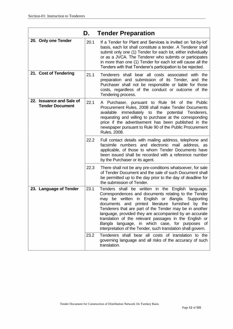
D. Tender Preparation 20. Only one Tender 20.1 If a Tender for Plant and Services is invited on „lot-by-lot‟
basis, each lot shall constitute a tender. A Tenderer shall submit only one (1) Tender for each lot, either individually or as a JVCA. The Tenderer who submits or participates in more than one (1) Tender for each lot will cause all the Tenders with that Tenderer‟s participation to be rejected.
21. Cost of Tendering 21.1 Tenderers shall bear all costs associated with the preparation and submission of its Tender, and the Purchaser shall not be responsible or liable for those costs, regardless of the conduct or outcome of the Tendering process.
22. Issuance and Sale of Tender Document
22.1 A Purchaser, pursuant to Rule 94 of the Public Procurement Rules, 2008 shall make Tender Documents available immediately to the potential Tenderers, requesting and willing to purchase at the corresponding price if the advertisement has been published in the newspaper pursuant to Rule 90 of the Public Procurement Rules, 2008.
22.2 Full contact details with mailing address, telephone and facsimile numbers and electronic mail address, as applicable, of those to whom Tender Documents have been issued shall be recorded with a reference number by the Purchaser or its agent.
22.3 There shall not be any pre-conditions whatsoever, for sale of Tender Document and the sale of such Document shall be permitted up to the day prior to the day of deadline for the submission of Tender.
23. Language of Tender 23.1 Tenders shall be written in the English language. Correspondences and documents relating to the Tender may be written in English or Bangla. Supporting documents and printed literature furnished by the Tenderers that are part of the Tender may be in another language, provided they are accompanied by an accurate translation of the relevant passages in the English or Bangla language, in which case, for purposes of interpretation of the Tender, such translation shall govern.
23.2 Tenderers shall bear all costs of translation to the governing language and all risks of the accuracy of such translation.
Section-01: Instruction to Tenderers
Tender Document for Construction of Distribution Network On Turnkey Basis
Page 13 of 535
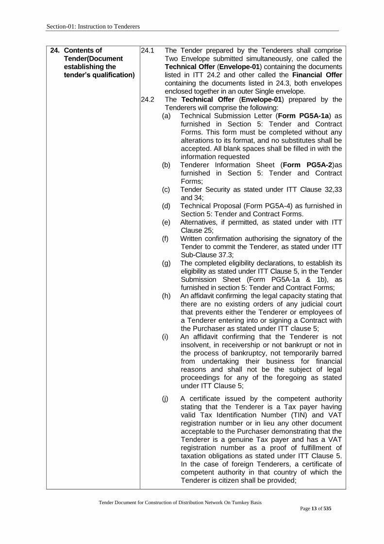
24. Contents of Tender(Document establishing the tender‟s qualification)
24.1 The Tender prepared by the Tenderers shall comprise Two Envelope submitted simultaneously, one called the Technical Offer (Envelope-01) containing the documents listed in ITT 24.2 and other called the Financial Offer containing the documents listed in 24.3, both envelopes enclosed together in an outer Single envelope.
24.2 The Technical Offer (Envelope-01) prepared by the Tenderers will comprise the following:
(a) Technical Submission Letter (Form PG5A-1a) as furnished in Section 5: Tender and Contract Forms. This form must be completed without any alterations to its format, and no substitutes shall be accepted. All blank spaces shall be filled in with the information requested
(b) Tenderer Information Sheet (Form PG5A-2)as furnished in Section 5: Tender and Contract Forms;
(c) Tender Security as stated under ITT Clause 32,33 and 34;
(d) Technical Proposal (Form PG5A-4) as furnished in Section 5: Tender and Contract Forms.
(e) Alternatives, if permitted, as stated under with ITT Clause 25;
(f) Written confirmation authorising the signatory of the Tender to commit the Tenderer, as stated under ITT Sub-Clause 37.3;
(g) The completed eligibility declarations, to establish its eligibility as stated under ITT Clause 5, in the Tender Submission Sheet (Form PG5A-1a & 1b), as furnished in section 5: Tender and Contract Forms;
(h) An affidavit confirming the legal capacity stating that there are no existing orders of any judicial court that prevents either the Tenderer or employees of a Tenderer entering into or signing a Contract with the Purchaser as stated under ITT clause 5;
(i) An affidavit confirming that the Tenderer is not insolvent, in receivership or not bankrupt or not in the process of bankruptcy, not temporarily barred from undertaking their business for financial reasons and shall not be the subject of legal proceedings for any of the foregoing as stated under ITT Clause 5;
(j) A certificate issued by the competent authority stating that the Tenderer is a Tax payer having valid Tax Identification Number (TIN) and VAT registration number or in lieu any other document acceptable to the Purchaser demonstrating that the Tenderer is a genuine Tax payer and has a VAT registration number as a proof of fulfillment of taxation obligations as stated under ITT Clause 5. In the case of foreign Tenderers, a certificate of competent authority in that country of which the Tenderer is citizen shall be provided;

Section-01: Instruction to Tenderers
Tender Document for Construction of Distribution Network On Turnkey Basis
Page 14 of 535
(k) Documentary evidence demonstrating that they are enrolled in the relevant professional or trade organizations registered in Bangladesh or in case of foreign tenderer in their country of origin or a certificate concerning their competency issued by a professional institution in accordance with the law of the country of their origin, as stated under ITT Clause 5;
(l) The country of origin declarations, to establish the eligibility of the Plant and Services as stated under ITT Clause 6, in the Price Schedule for Plant and Services (Form PG5A-3) as, applicable, furnished in Section 5: Tender and Contract Forms;
(m) Documentary evidence as stated under ITT Clauses 28, that the Goods and Related Services conform to the Tender Documents;
(n) Documentary evidence as stated under ITT Clause 29 that the Tenderer‟s qualifications conform to the Tender Documents;
(o) Documents establishing legal and financial autonomy and compliance with commercial law, as stated under ITT Sub-clause 5.3 in case of government owned entity; and
(p) In addition to the requirements stated under ITT Sub Clause 18.1, Tenders submitted by a JVCA or proposing a Subcontractor shall include.
i. a Joint Venture Agreement entered into by all partners, executed on a non-judicial stamp of value or equivalent as stated under ITT Sub Clause 18.1; or
ii. a Letter of Intent along with the proposed agreement duly signed by all partners of the intended JVCA with the declaration that it will execute the Joint Venture agreement in the event the Tenderer is successful;
iii. the JVCA Partner Information (Form PG5A-2b);
iv. the Subcontractor Information (Form PG5A-2c).
(q) the completed Specifications Submission and Compliance Sheet (Form PG5A-4a)as stated under ITT clause 28.1;
(r) Any other document as specified in the TDS.

Section-01: Instruction to Tenderers
Tender Document for Construction of Distribution Network On Turnkey Basis
Page 15 of 535
24.3 The Financial Offer (Financial Envelope -02) prepared by
the Tenderers shall comprise the following:
(a) The Financial offer Submission Letter (Form PG5A-1b) as furnished in Section 5:
(b) The Tenderer shall submit the completed Price Schedule for Plant and Services (Form PG5A-3), according to their origin as appropriate as furnished in section 5: Tender and Contract Forms.
(c) the written confirmation authorizing the signatory of the Tender to commit the Tenderer, as stated under ITT Sub Clause 37.3;
(d) any other document as specified in the TDS.
25. Alternatives 25.1 Unless otherwise stated in the TDS, alternatives shall not be considered.
26. Tender Prices, Discounts& Price adjustment
26.1 Unless otherwise specified in the TDS, tenderers shall quote for the entire Plant and Installation Services on a “single responsibility” basis such that the total tenderprice covers all the Contractor‟s obligations mentioned in or to be reasonably inferred from the tender document in respect of the design, manufacture, including procurement and subcontracting (if any), delivery, construction, installation and completion of the plant. This includes all requirements under the Contractor‟s responsibilities for testing, pre-commissioning and commissioning of the plant and, where so required by the tender document, the acquisition of all permits, approvals and licenses, etc.; the operation, maintenance and training services and such other items and services as may be specified in the Tender Document, all in accordance with the requirements of the General Conditions of Contract. Items against which no price is entered by the Tenderer will not be paid for by the Purchaser when executed and shall be deemed to be covered by the prices for other items.
26.2 Tenderers are required to quote the price for the commercial, contractual and technical obligations outlined in the tender document
26.3 Tenderers shall give a breakdown of the prices in the manner and detail called for in the Price Schedules included in Section 5, Tender and Contract Forms.
Section-01: Instruction to Tenderers
Tender Document for Construction of Distribution Network On Turnkey Basis
Page 16 of 535
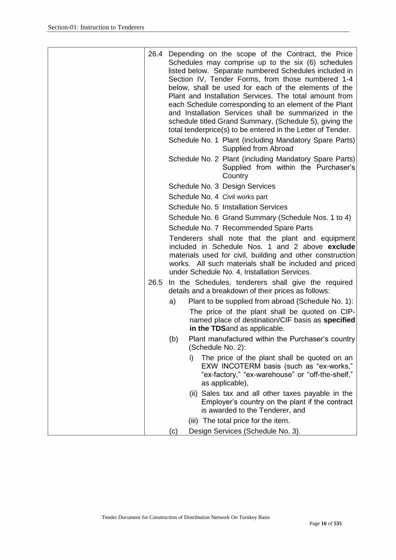
26.4 Depending on the scope of the Contract, the Price Schedules may comprise up to the six (6) schedules listed below. Separate numbered Schedules included in Section IV, Tender Forms, from those numbered 1-4 below, shall be used for each of the elements of the Plant and Installation Services. The total amount from each Schedule corresponding to an element of the Plant and Installation Services shall be summarized in the schedule titled Grand Summary, (Schedule 5), giving the total tenderprice(s) to be entered in the Letter of Tender.
Schedule No. 1 Plant (including Mandatory Spare Parts) Supplied from Abroad
Schedule No. 2 Plant (including Mandatory Spare Parts) Supplied from within the Purchaser‟s Country
Schedule No. 3 Design Services
Schedule No. 4 Civil works part
Schedule No. 5 Installation Services
Schedule No. 6 Grand Summary (Schedule Nos. 1 to 4)
Schedule No. 7 Recommended Spare Parts
Tenderers shall note that the plant and equipment included in Schedule Nos. 1 and 2 above exclude materials used for civil, building and other construction works. All such materials shall be included and priced under Schedule No. 4, Installation Services.
26.5 In the Schedules, tenderers shall give the required details and a breakdown of their prices as follows:
a) Plant to be supplied from abroad (Schedule No. 1):
The price of the plant shall be quoted on CIP-named place of destination/CIF basis as specified in the TDSand as applicable.
(b) Plant manufactured within the Purchaser‟s country (Schedule No. 2):
i) The price of the plant shall be quoted on an EXW INCOTERM basis (such as “ex-works,” “ex-factory,” “ex-warehouse” or “off-the-shelf,” as applicable),
(ii) Sales tax and all other taxes payable in the Employer‟s country on the plant if the contract is awarded to the Tenderer, and
(iii) The total price for the item.
(c) Design Services (Schedule No. 3).
Section-01: Instruction to Tenderers
Tender Document for Construction of Distribution Network On Turnkey Basis
Page 17 of 535
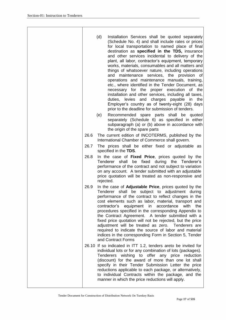
(d) Installation Services shall be quoted separately (Schedule No. 4) and shall include rates or prices for local transportation to named place of final destination as specified in the TDS, insurance and other services incidental to delivery of the plant, all labor, contractor‟s equipment, temporary works, materials, consumables and all matters and things of whatsoever nature, including operations and maintenance services, the provision of operations and maintenance manuals, training, etc., where identified in the Tender Document, as necessary for the proper execution of the installation and other services, including all taxes, duties, levies and charges payable in the Employer‟s country as of twenty-eight (28) days prior to the deadline for submission of tenders.
(e) Recommended spare parts shall be quoted separately (Schedule 6) as specified in either subparagraph (a) or (b) above in accordance with the origin of the spare parts
26.6 The current edition of INCOTERMS, published by the International Chamber of Commerce shall govern.
26.7 The prices shall be either fixed or adjustable as specified in the TDS.
26.8 In the case of Fixed Price, prices quoted by the Tenderer shall be fixed during the Tenderer‟s performance of the contract and not subject to variation on any account. A tender submitted with an adjustable price quotation will be treated as non-responsive and rejected.
26.9 In the case of Adjustable Price, prices quoted by the Tenderer shall be subject to adjustment during performance of the contract to reflect changes in the cost elements such as labor, material, transport and contractor‟s equipment in accordance with the procedures specified in the corresponding Appendix to the Contract Agreement. A tender submitted with a fixed price quotation will not be rejected, but the price adjustment will be treated as zero. Tenderers are required to indicate the source of labor and material indices in the corresponding Form in Section 5, Tender and Contract Forms
26.10 If so indicated in ITT 1.2, tenders areto be invited for individual lots or for any combination of lots (packages). Tenderers wishing to offer any price reduction (discount) for the award of more than one lot shall specify in their Tender Submission Letter the price reductions applicable to each package, or alternatively, to individual Contracts within the package, and the manner in which the price reductions will apply.
Section-01: Instruction to Tenderers
Tender Document for Construction of Distribution Network On Turnkey Basis
Page 18 of 535
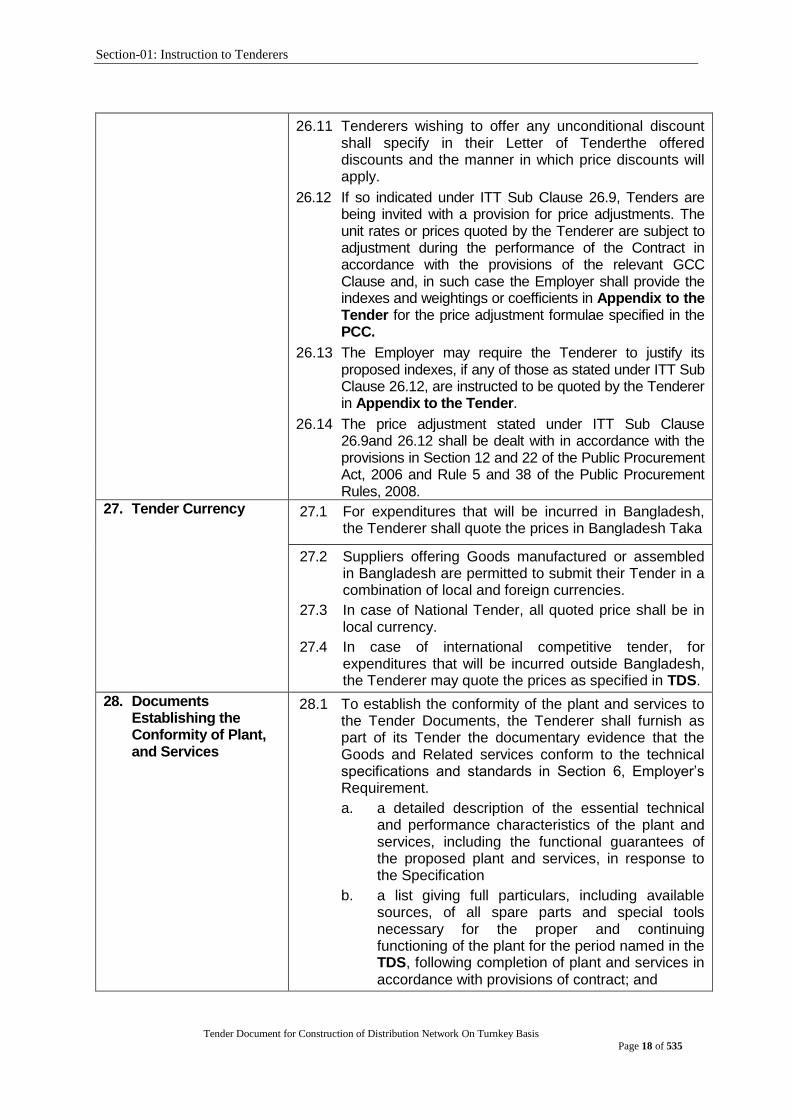
26.11 Tenderers wishing to offer any unconditional discount
shall specify in their Letter of Tenderthe offered discounts and the manner in which price discounts will apply.
26.12 If so indicated under ITT Sub Clause 26.9, Tenders are being invited with a provision for price adjustments. The unit rates or prices quoted by the Tenderer are subject to adjustment during the performance of the Contract in accordance with the provisions of the relevant GCC Clause and, in such case the Employer shall provide the indexes and weightings or coefficients in Appendix to the Tender for the price adjustment formulae specified in the PCC.
26.13 The Employer may require the Tenderer to justify its proposed indexes, if any of those as stated under ITT Sub Clause 26.12, are instructed to be quoted by the Tenderer in Appendix to the Tender.
26.14 The price adjustment stated under ITT Sub Clause 26.9and 26.12 shall be dealt with in accordance with the provisions in Section 12 and 22 of the Public Procurement Act, 2006 and Rule 5 and 38 of the Public Procurement Rules, 2008.
27. Tender Currency 27.1 For expenditures that will be incurred in Bangladesh, the Tenderer shall quote the prices in Bangladesh Taka
27.2 Suppliers offering Goods manufactured or assembled in Bangladesh are permitted to submit their Tender in a combination of local and foreign currencies.
27.3 In case of National Tender, all quoted price shall be in local currency.
27.4 In case of international competitive tender, for expenditures that will be incurred outside Bangladesh, the Tenderer may quote the prices as specified in TDS.
28. Documents Establishing the Conformity of Plant, and Services
28.1 To establish the conformity of the plant and services to the Tender Documents, the Tenderer shall furnish as part of its Tender the documentary evidence that the Goods and Related services conform to the technical specifications and standards in Section 6, Employer‟s Requirement.
a. a detailed description of the essential technical and performance characteristics of the plant and services, including the functional guarantees of the proposed plant and services, in response to the Specification
b. a list giving full particulars, including available sources, of all spare parts and special tools necessary for the proper and continuing functioning of the plant for the period named in the TDS, following completion of plant and services in accordance with provisions of contract; and
Section-01: Instruction to Tenderers
Tender Document for Construction of Distribution Network On Turnkey Basis
Page 19 of 535
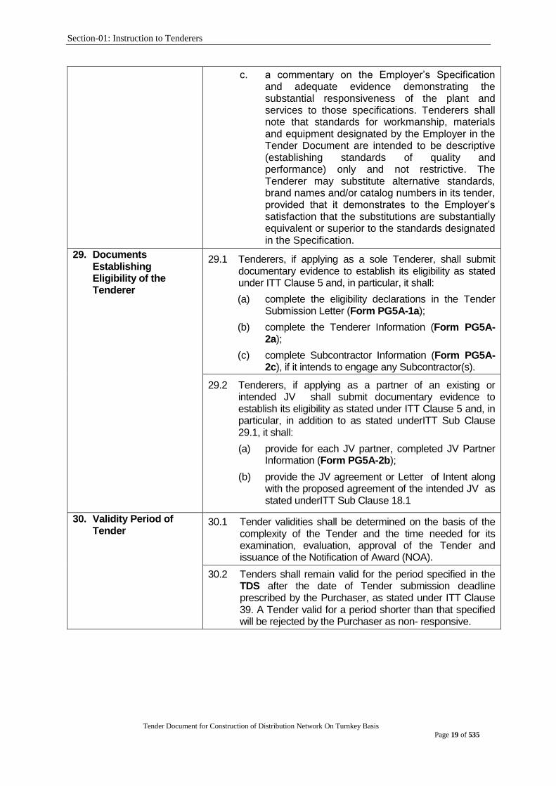
c. a commentary on the Employer‟s Specification and adequate evidence demonstrating the substantial responsiveness of the plant and services to those specifications. Tenderers shall note that standards for workmanship, materials and equipment designated by the Employer in the Tender Document are intended to be descriptive (establishing standards of quality and performance) only and not restrictive. The Tenderer may substitute alternative standards, brand names and/or catalog numbers in its tender, provided that it demonstrates to the Employer‟s satisfaction that the substitutions are substantially equivalent or superior to the standards designated in the Specification.
29. Documents Establishing Eligibility of the Tenderer
29.1 Tenderers, if applying as a sole Tenderer, shall submit documentary evidence to establish its eligibility as stated under ITT Clause 5 and, in particular, it shall:
(a) complete the eligibility declarations in the Tender Submission Letter (Form PG5A-1a);
(b) complete the Tenderer Information (Form PG5A-2a);
(c) complete Subcontractor Information (Form PG5A-2c), if it intends to engage any Subcontractor(s).
29.2 Tenderers, if applying as a partner of an existing or intended JV shall submit documentary evidence to establish its eligibility as stated under ITT Clause 5 and, in particular, in addition to as stated underITT Sub Clause 29.1, it shall:
(a) provide for each JV partner, completed JV Partner Information (Form PG5A-2b);
(b) provide the JV agreement or Letter of Intent along with the proposed agreement of the intended JV as stated underITT Sub Clause 18.1
30. Validity Period of Tender
30.1 Tender validities shall be determined on the basis of the complexity of the Tender and the time needed for its examination, evaluation, approval of the Tender and issuance of the Notification of Award (NOA).
30.2 Tenders shall remain valid for the period specified in the TDS after the date of Tender submission deadline prescribed by the Purchaser, as stated under ITT Clause 39. A Tender valid for a period shorter than that specified will be rejected by the Purchaser as non- responsive.
Section-01: Instruction to Tenderers
Tender Document for Construction of Distribution Network On Turnkey Basis
Page 20 of 535
31. Extension of Tender Validity and Tender Security
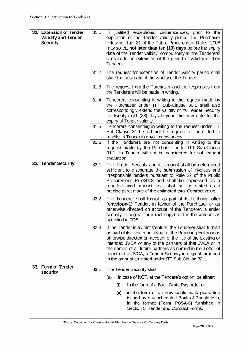
31.1 In justified exceptional circumstances, prior to the expiration of the Tender validity period, the Purchaser following Rule 21 of the Public Procurement Rules, 2008 may solicit, not later than ten (10) days before the expiry date of the Tender validity, compulsorily all the Tenderers‟ consent to an extension of the period of validity of their Tenders.
31.2 The request for extension of Tender validity period shall state the new date of the validity of the Tender.
31.3 The request from the Purchaser and the responses from the Tenderers will be made in writing.
31.4 Tenderers consenting in writing to the request made by the Purchaser under ITT Sub-Clause 30.1 shall also correspondingly extend the validity of its Tender Security for twenty-eight (28) days beyond the new date for the expiry of Tender validity.
31.5 Tenderers consenting in writing to the request under ITT Sub-Clause 31.1 shall not be required or permitted to modify its Tender in any circumstances.
31.6 If the Tenderers are not consenting in writing to the request made by the Purchaser under ITT Sub-Clause 31.1, its Tender will not be considered for subsequent evaluation.
32. Tender Security 32.1 The Tender Security and its amount shall be determined sufficient to discourage the submission of frivolous and irresponsible tenders pursuant to Rule 22 of the Public Procurement Rule2008 and shall be expressed as a rounded fixed amount and, shall not be stated as a precise percentage of the estimated total Contract value.
32.2 The Tenderer shall furnish as part of its Technical offer (envelope-1) Tender, in favour of the Purchaser or as otherwise directed on account of the Tenderer, a ender security in original form (not copy) and in the amount as specified in TDS.
32.3 If the Tender is a Joint Venture, the Tenderer shall furnish as part of its Tender, in favour of the Procuring Entity or as otherwise directed on account of the title of the existing or intended JVCA or any of the partners of that JVCA or in the names of all future partners as named in the Letter of Intent of the JVCA, a Tender Security in original form and in the amount as stated under ITT Sub Clause 32.1.
33. Form of Tender security
33.1 The Tender Security shall:
(a) In case of NCT, at the Tendere‟s option, be either;
(i) In the form of a Bank Draft, Pay order or
(ii) in the form of an irrevocable bank guarantee issued by any scheduled Bank of Bangladesh, in the format (Form PG5A-6) furnished in Section 5: Tender and Contract Forms.
Section-01: Instruction to Tenderers
Tender Document for Construction of Distribution Network On Turnkey Basis
Page 21 of 535
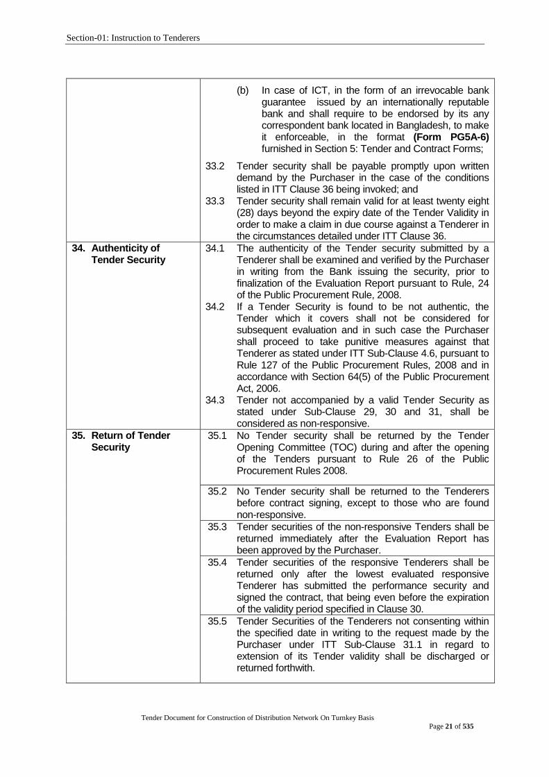
(b) In case of ICT, in the form of an irrevocable bank guarantee issued by an internationally reputable bank and shall require to be endorsed by its any correspondent bank located in Bangladesh, to make it enforceable, in the format (Form PG5A-6) furnished in Section 5: Tender and Contract Forms;
33.2 Tender security shall be payable promptly upon written demand by the Purchaser in the case of the conditions listed in ITT Clause 36 being invoked; and
33.3 Tender security shall remain valid for at least twenty eight (28) days beyond the expiry date of the Tender Validity in order to make a claim in due course against a Tenderer in the circumstances detailed under ITT Clause 36.
34. Authenticity of Tender Security
34.1 The authenticity of the Tender security submitted by a Tenderer shall be examined and verified by the Purchaser in writing from the Bank issuing the security, prior to finalization of the Evaluation Report pursuant to Rule, 24 of the Public Procurement Rule, 2008.
34.2 If a Tender Security is found to be not authentic, the Tender which it covers shall not be considered for subsequent evaluation and in such case the Purchaser shall proceed to take punitive measures against that Tenderer as stated under ITT Sub-Clause 4.6, pursuant to Rule 127 of the Public Procurement Rules, 2008 and in accordance with Section 64(5) of the Public Procurement Act, 2006.
34.3 Tender not accompanied by a valid Tender Security as stated under Sub-Clause 29, 30 and 31, shall be considered as non-responsive.
35. Return of Tender Security
35.1 No Tender security shall be returned by the Tender Opening Committee (TOC) during and after the opening of the Tenders pursuant to Rule 26 of the Public Procurement Rules 2008.
35.2 No Tender security shall be returned to the Tenderers before contract signing, except to those who are found non-responsive.
35.3 Tender securities of the non-responsive Tenders shall be returned immediately after the Evaluation Report has been approved by the Purchaser.
35.4 Tender securities of the responsive Tenderers shall be returned only after the lowest evaluated responsive Tenderer has submitted the performance security and signed the contract, that being even before the expiration of the validity period specified in Clause 30.
35.5 Tender Securities of the Tenderers not consenting within the specified date in writing to the request made by the Purchaser under ITT Sub-Clause 31.1 in regard to extension of its Tender validity shall be discharged or returned forthwith.
Section-01: Instruction to Tenderers
Tender Document for Construction of Distribution Network On Turnkey Basis
Page 22 of 535
36. Forfeiture of Tender Security.
36.1 The Tender security pursuant to Rule 25 of the Public Procurement Rules,2008 may be forfeited if a Tenderer:
(a) withdraws its Tender after opening of Tenders but within the validity of the Tender as stated under ITT Clauses 30,and 31, pursuant to Rule 19 of the Public Procurement Rules 2008; or
(b) refuses to accept a Notification of Award as stated under ITT Sub-Clause 65.3, pursuant to Rule 102 of the Public Procurement Rules 2008; or
(c) fails to furnish performance security as stated under ITT Sub-Clause 66.2, pursuant to Rule 102 of the Public Procurement Rules 2008; or
(d) refuses to sign the Contract as stated under ITT Sub-Clause 70.2 pursuant to Rule 102 of the Public Procurement Rules 2008; or
(e) does not accept the correction of the Tender price following the correction of arithmetic errors as stated under ITT Clause 55, pursuant to Rule 98(11) of the Public Procurement Rules 2008.
37. Format and Signing of Tender
37.1 Tenderers shall prepare one (1) original of the documents comprising the Technical Offer as described in ITT Clause 24.2 and clearly mark it “ORIGINAL OF TECHNICAL OFFER” In addition, the Tenderers shall prepare the number of copies of the Technical Offer, as specified in the TDS and clearly mark each of them “COPY OF THE TECHNICAL OFFER.” In the event of any discrepancy between the original and the copies, the ORIGINAL shall prevail.
37.2 Tenderers shall prepare one (1) original of the documents comprising the Financial Offer as described in ITT Clause 24.3 and clearly mark it “ORIGINAL OF FINANCIAL OFFER” In addition, the Tenderers shall prepare the number of copies of the Financial Offer, as specified in the TDS and clearly mark each of them “COPY OF THE FINANCIAL OFFER” In the event of any discrepancy between the original and the copies, the ORIGINAL shall prevail.
37.3 Alternatives, if permitted under ITT Clause 25, shall be clearly marked “Alternative”.
37.4 The original and each copy of the Offer shall be typed or written in indelible ink and shall be signed by the Person duly authorized to sign on behalf of the Tenderer. This Tender specific authorization shall be attached to the Technical Offer Submission Letter (Form PW5A-1a) and Financial Offer Submission Letter (Form PW5A-1b). The name and position held by each Person(s) signing the authorization must be typed or printed below the signature. All pages of the original and of each copy of the Tender, except for un-amended printed literature, shall be numbered sequentially and signed by the person signing the Tender.

Section-01: Instruction to Tenderers
Tender Document for Construction of Distribution Network On Turnkey Basis
Page 23 of 535
37.5 Any interlineations, erasures, or overwriting will be valid
only if they are signed or initialled by the Person (s) signing the Tender.
E. Tender Submission
38. Sealing, Marking and Submission of Tender
38.1 Tenderers shall enclose the original of Technical Offer in one (1) envelope and all the copies of the Technical Offer, including the alternatives, if permitted under ITT Clause 25, in another envelope, duly marking the envelopes as “ORIGINAL OF TECHNICAL OFFER” “ALTERNATIVES” (if permitted), “COPY OF TECHNICAL OFFER”,”ALTERNATIVES” (if permitted) These sealed envelopes for the original and copies of the technical Tender shall then be enclosed and sealed in one single envelope and clearly mark it “Envelope-01: TECHNICAL OFFER”.
38.2 The inner and outer envelopes of Technical Offer shall:
(a) be addressed to the Procuring Entity at the address
as stated underITT Sub Clause 39.1;
(b) bear the name of the Tender and the Tender Number
as stated under ITT Sub Clause 1.1;
(c) bear the name and address of the Tenderer;
(d) bear a statement “DO NOT OPEN BEFORE -----------
-----------” the time and date for Tender opening as
stated under ITT Sub Clause 45.2
(e) bear any additional identification marks as specified
in the TDS.
38.3 Tenderers shall enclose the original of Financial Offer in one (1) envelope and all the copies of the Financial Offer in another envelope, duly marking the envelopes as “ORIGINAL OF FINANCIAL OFFER” & “COPY OF FINANCIAL OFFER”. These sealed envelopes for the original and copies of the Financial Tender shall then be enclosed and sealed in one single envelope and clearly mark it “ENVELOPE-02: FINANCIAL OFFER.
38.4 The inner and outer envelopes of Financial Offer shall:
(a) be addressed to the Procuring Entity at the address
as stated underITT Sub Clause 39.1;
(b) bear the name of the Tender and the Tender Number
as stated under ITT Sub Clause 1.1;
(c) bear the name and address of the Tenderer;
(d) bear a statement “DO NOT OPEN BEFORE THE
TECHNICAL OFFER EVALUATION AND
APPROVAL”.
(e) bear any additional identification marks as specified
in the TDS.
Section-01: Instruction to Tenderers
Tender Document for Construction of Distribution Network On Turnkey Basis
Page 24 of 535
38.5 The Envelope-01 as stated in ITT Clause 38.1 and Envelope-02 as in ITT Clause 38.3 shall then be enclosed and sealed in one single outer envelope which shall contain the information as stated under ITT Clause 38.2 (a) to (e) & ITT Clause 38.4 (a) to (e)
38.6 Tenderers are solely and entirely responsible for pre-disclosure of Tender information if the envelope(s) are not properly sealed and marked.
38.7 Tenders shall be delivered by hand or by mail, including courier services at the address(s) as stated under ITT Sub Clause 39.1.
38.8 The Procuring Entity will, on request, provide the Tenderer with acknowledgement of receipt showing the date and time when it‟s Tender was received.
39. Deadline for Submission of tenders
39.1 Tenders shall be delivered to the Purchaser at the address specified in the TDS and no later than the date and time specified in the TDS.
39.2 The Purchaser may, at its discretion on justifiably acceptable grounds duly recorded, extend the deadline for submission of Tender as stated under ITT Sub Clause 39.1, in which case all rights and obligations of the Purchaser and Tenderers previously subject to the deadline will thereafter be subject to the new deadline as extended.
39.3 If submission of Tendersis allowed in more than one location, the date and time, for submission of Tenders for both the primary and the secondary place(s), shall be the “same and not different” as specified in the TDS.
39.4 The Procuring Entity shall ensure that the Tenders received at the secondary place(s) are hand-delivered at the primary place as stated under ITT Sub Clause 39.1, within THREE (3) HOURS after the deadline for submission of Tenders at the secondary place (s), in case of MULTIPLE DROPPING as stated under ITT Sub Clause 39.3, as specified in the TDS.
40. Late tender 37.6 Any Tender received by the Purchaser after the deadline for submission of Tenders as stated under ITT Clause 39, shall be declared LATE, rejected, returned unopened to the Tenderer.
41. Modification, Substitution or Withdrawal of Tenders
41.1 Tenderers may modify, substitute or withdraw its Tender after it has been submitted by sending a written notice duly signed by the authorized signatory and properly sealed, and shall include a copy of the authorization; provided that such written notice including the affidavit is received by the Procuring Entity prior to the deadline for submission of Tenders as stated under ITT Clause 39
Section-01: Instruction to Tenderers
Tender Document for Construction of Distribution Network On Turnkey Basis
Page 25 of 535
42. Tender Modification 42.1 Tenderers shall not be allowed to retrieve its original Tender, but shall be allowed to submit corresponding modification either to its original Technical Offer or Financial Offer or both, marked as “MODIFICATION FOR TECHNICAL OFFER(MTO)” or “MODIFICATION FOR FINANCIAL OFFER (MFO)”with two separate envelopes. The envelope/envelopes marked as MTO and/or MFO then be enclosed and sealed in one single outer envelope with a written notice duly as stated under ITT Sub Clause 41.1. The outer envelope shall contain the information as stated under ITT Sub Clause 38.2(a) to (d) and clearly marked as “MODIFICATION (M)”.
43. Tender Substitution 43.1 Tenderers shall not be allowed to retrieve its original Tender, but shall be allowed to submit another Technical Offer or Financial Offer or both, marked as “SUBSTITUTION FOR TECHNICAL OFFER (STO)” or “SUBSTITUTION FOR FINANCIAL OFFER (SFO)”with two separate envelopes. The envelope/envelopes marked as STO and/or SFO then be enclosed and sealed in one single outer envelope with a written notice duly as stated under ITT Sub Clause 41.1. The outer envelope shall contain the information as stated under ITT Sub Clause 38.2(a) to (d) and clearly marked as “SUBSTITUTION (S)”.
44. Withdrawal of Tender 44.1 The Tenderer shall be allowed to withdraw its Tender by a Letter of Withdrawal marked as “WITHDRAWAL” prior to the deadline for submission of Tenders as stated under ITT Clause 39.
F. Tender Opening and Evaluation
45. Tender Opening 45.1 Only the Technical Offer(Envelope-01) shall be opened immediately after the deadline for submission of Tenders at the primary place as specified in the TDS but not later than ONE HOUR, after expiry of the submission deadline at the same primary place unless otherwise stated under ITT Sub Clause 39.2. But with inTHREE HOURS after the dateline of submission of tender at primary place in case of multiple dropping. Tender opening shall not be delayed on the plea of absences of Tenderers or his or her representatives. Financial offer (Envelope-02) shall not open with Technical offer (Envelope-01) and shall be kept unopened at the Custody of the Head of the Procuring Entity or his Authorised Officer (AO).
45.2 Persons not associated with the Tender may not be allowed to attend the public opening of Technical Offers.
45.3 Tenderers‟ representatives shall be duly authorised by the Tenderer. Tenderers or their authorised representatives will be allowed to attend and witness the opening of Technical Offers, and will sign a register evidencing their attendance. Technical Offers Opening shall not be delayed on the plea of absence of Tenderers or his or her representatives.

Section-01: Instruction to Tenderers
Tender Document for Construction of Distribution Network On Turnkey Basis
Page 26 of 535
45.4 The authenticity of withdrawal or substitution of, or modifications to original Tender, if any made by a Tenderer in specified manner, shall be examined and verified by the Tender Opening Committee (TOC) based on documents submitted as stated under ITT Sub Clause 41.1. Any envelope related to financial modification, substitute shall be recorded but not open with technical offer.
45.5 Verify (M), (S), (W), (A), (O) by following step by steps
(a) Step 1: envelopes marked “Withdrawal (W)” shall be opened and “Withdrawal” notice read aloud & recorded in the opening sheet. After verify the withdrawal letter is genuine, corresponding tender shall not be opened, but returned unopened to the Tenderer by Procuring Entity (PE) at a late time. No Tender withdrawal shall be permitted unless the corresponding withdrawal notice shall be as stated in 41.1& 44.1 and in such case the Tender shall be opened and recorded.
(b) Step 2: the remaining Tenders will be sorted out and those marked “SUBSTITUTION (S)” or “MODIFICATION (M)” of Tender will be linked with their corresponding Original Tender.
(c) Step 3: outer envelopes marked “SUBSTITUTION (S)” shall be opened. The inner envelopes containing the “Substitution of Technical Offer (STO)” and/or “Substitution of Financial Offer (SFO)” shall be exchanged for the corresponding envelopes being substituted, which are to be returned to the Tenderer unopened by the Procuring Entity at a later time immediately after opening of Technical Offers. Only the Substitution of Technical Offer, if any, shall be opened, read out, and recorded. Substitution of Financial Offer will remain unopened in accordance with ITT Sub Clause45.1. No envelope shall be substituted unless the corresponding substitution notice contains a valid authorization to request the substitution and is read out and recorded at Technical Offer opening.
(d) Step 4: outer envelopes marked “MODIFICATION (M)” shall be opened. No Technical Offer and/or Financial Offer shall be modified unless the corresponding modification notice contains a valid authorization to request the modification and is read out and recorded at the opening of Technical Offers. Only the Technical Offers, both Original as well as Modification, are to be opened, read out, and recorded at the opening. Financial Offers, both Original as well as Modification, will remain unopened in accordance with ITT Sub Clause 45.1
Section-01: Instruction to Tenderers
Tender Document for Construction of Distribution Network On Turnkey Basis
Page 27 of 535
(e) Step5: if so specified in this Tender Document, the envelopes marked “Alternative of Technical Offer (ATO)” shall be opened and read aloud with the corresponding Technical Offer and recorded.
45.6 Ensuring that only the correct (MTO), (STO), (ATO), (OTO) envelopes are opened, details of each Technical Offer will be dealt with as follows:
(a) the Chairperson of the TOC will read aloud each
Technical Offer and record in the Technical Offer
Opening Sheet (TOOS):
(i) the name and address of the Tenderer;
(ii) state if it is a withdrawn, modified, substituted
or original Technical Offer;
(iii) any alternatives;
(iv) record the rejection of the Tender which
submitted Technical Offer and Financial Offer
together in one envelope.
(v) the presence or absence of any requisite
Tender Security; and
(vi) such other details as the Procuring Entity, at
its discretion, may consider appropriate.
(b) Only Technical Offer and alternatives read aloud at
the Technical Offer Opening will be considered in
evaluation.
(c) all pages of the original version of the Technical
Offer, except for un-amended printed literature, will
be initialled by members of the TOC. Remember, No
financial Offer shall be open with Technical Offer
45.7 Upon completion of Technical Offer opening, all members of the TOC and the Tenderers or Tenderer‟s duly authorised representatives attending the Technical Offer opening shall sign by name, address, designation, the TOS, copies of which shall be issued to the Head of the Procuring Entity or an officer authorised by him or her and also to the members of the TOC and any authorised Consultants and, to the Tenderers immediately.
45.8 The omission of a Tenderer‟s signature on the record shall not invalidate the contents and effect of the record under ITT Sub Clause 45.7
45.9 No Tender i.e., Technical or Financial Offer shall be rejected at the Tender opening stage except the LATE Tenders as stated in the ITT Clause 40.
46. Evaluation of Tenders 46.1 Technical Offers shall be examined and evaluated only on the basis of the criteria specified in the Tender Document.
46.2 Tender Evaluation Committee (TEC) shall examine, evaluate and compare Tenders that are responsive to the requirements of Tender Documents in order to identify the successful Tenderer.
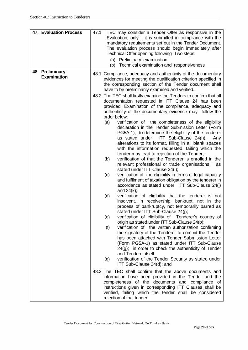
Section-01: Instruction to Tenderers
Tender Document for Construction of Distribution Network On Turnkey Basis
Page 28 of 535
47. Evaluation Process 47.1 TEC may consider a Tender Offer as responsive in the Evaluation, only if it is submitted in compliance with the mandatory requirements set out in the Tender Document. The evaluation process should begin immediately after Technical Offer opening following Two steps:
(a) Preliminary examination (b) Technical examination and responsiveness
48. Preliminary Examination
48.1 Compliance, adequacy and authenticity of the documentary evidences for meeting the qualification criterion specified in the corresponding section of the Tender document shall have to be preliminarily examined and verified.
48.2 The TEC shall firstly examine the Tenders to confirm that all documentation requested in ITT Clause 24 has been provided. Examination of the compliance, adequacy and authenticity of the documentary evidence may follow the order below: (a) verification of the completeness of the eligibility
declaration in the Tender Submission Letter (Form PG5A-1), to determine the eligibility of the tenderer as stated under ITT Sub-Clause 24(h). Any alterations to its format, filling in all blank spaces with the information requested, failing which the tender may lead to rejection of the Tender;
(b) verification of that the Tenderer is enrolled in the relevant professional or trade organisations as stated under ITT Clause 24(l);
(c) verification of the eligibility in terms of legal capacity and fulfilment of taxation obligation by the tenderer in accordance as stated under ITT Sub-Clause 24(i) and 24(k);
(d) verification of eligibility that the tenderer is not insolvent, in receivership, bankrupt, not in the process of bankruptcy, not temporarily barred as stated under ITT Sub-Clause 24(j);
(e) verification of eligibility of Tenderer‟s country of origin as stated under ITT Sub-Clause 24(b);
(f) verification of the written authorization confirming the signatory of the Tenderer to commit the Tender has been attached with Tender Submission Letter (Form PG5A-1) as stated under ITT Sub-Clause 24(g); in order to check the authenticity of Tender and Tenderer itself ;
(g) verification of the Tender Security as stated under ITT Sub-Clause 24(d); and
48.3 The TEC shall confirm that the above documents and information have been provided in the Tender and the completeness of the documents and compliance of instructions given in corresponding ITT Clauses shall be verified, failing which the tender shall be considered rejection of that tender.
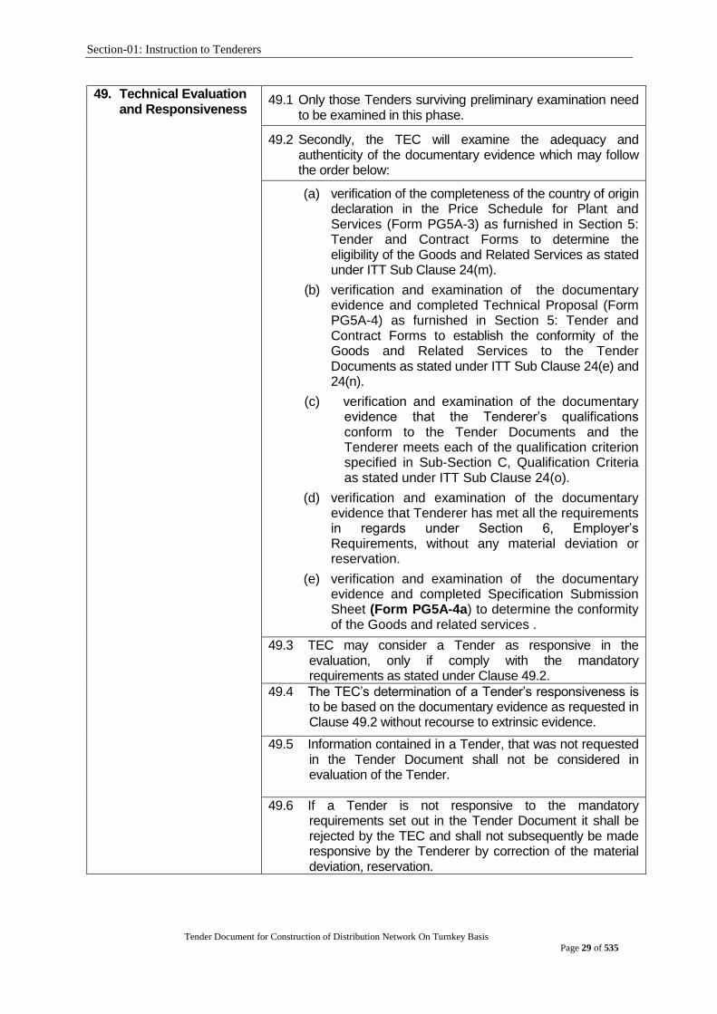
Section-01: Instruction to Tenderers
Tender Document for Construction of Distribution Network On Turnkey Basis
Page 29 of 535
49. Technical Evaluation and Responsiveness
49.1 Only those Tenders surviving preliminary examination need to be examined in this phase.
49.2 Secondly, the TEC will examine the adequacy and authenticity of the documentary evidence which may follow the order below:
(a) verification of the completeness of the country of origin declaration in the Price Schedule for Plant and Services (Form PG5A-3) as furnished in Section 5: Tender and Contract Forms to determine the eligibility of the Goods and Related Services as stated under ITT Sub Clause 24(m).
(b) verification and examination of the documentary evidence and completed Technical Proposal (Form PG5A-4) as furnished in Section 5: Tender and Contract Forms to establish the conformity of the Goods and Related Services to the Tender Documents as stated under ITT Sub Clause 24(e) and 24(n).
(c) verification and examination of the documentary evidence that the Tenderer‟s qualifications conform to the Tender Documents and the Tenderer meets each of the qualification criterion specified in Sub-Section C, Qualification Criteria as stated under ITT Sub Clause 24(o).
(d) verification and examination of the documentary evidence that Tenderer has met all the requirements in regards under Section 6, Employer‟s Requirements, without any material deviation or reservation.
(e) verification and examination of the documentary evidence and completed Specification Submission Sheet (Form PG5A-4a) to determine the conformity of the Goods and related services .
49.3 TEC may consider a Tender as responsive in the evaluation, only if comply with the mandatory requirements as stated under Clause 49.2.
49.4 The TEC‟s determination of a Tender‟s responsiveness is to be based on the documentary evidence as requested in Clause 49.2 without recourse to extrinsic evidence.
49.5 Information contained in a Tender, that was not requested in the Tender Document shall not be considered in evaluation of the Tender.
49.6 If a Tender is not responsive to the mandatory requirements set out in the Tender Document it shall be rejected by the TEC and shall not subsequently be made responsive by the Tenderer by correction of the material deviation, reservation.

Section-01: Instruction to Tenderers
Tender Document for Construction of Distribution Network On Turnkey Basis
Page 30 of 535
49.7 A material deviation or reservation is one- (a) which affects in any substantial way the scope,
quality, or performance of the Goods and Related Services and Tenderer‟s qualifications mentioned in the Tender Document
(b) which limits in any substantial way, inconsistent with the Tender Documents, the Purchaser‟s rights or the Tenderer‟s obligations under the Contract; or
(c) whose rectification would anyway affect unfairly the competitive position of other Tenderers presenting responsive Tenders.
49.8 During the evaluation of Tender, the following definitions apply:
(a) Deviation” is a departure from the requirements specified in the Tender Document;
(d) “Reservation” is the setting of limiting conditions or withholding from complete acceptance of the requirements specified in the Tender Document;
49.9 A TEC may regard a Tender as responsive, even if it contains-minor or insignificant deviations, which do not meaningfully alter or depart from the technical specifications, characteristics and commercial terms and conditions or other requirements set out in the Tender Document; errors or oversights, which if corrected, would not alter the key aspects of the Tender.
50. Clarification on Technical Offer
50.1 TEC may ask Tenderers for clarification of their Technical Offers in order to facilitate the examination and evaluation of Technical Offers. The request for clarification by the TEC and the response from the Tenderer shall be in writing, and Technical Offers clarifications which may lead to a change in the substance of the Technical Offers or in any of the key elements of the Technical Offers as stated under ITT Sub Clause 49.2, will neither be sought nor be permitted.
50.2 Any request for clarifications by the TEC shall not be directed towards making an apparently non-responsive Tender responsive and reciprocally the response from the concerned Tenderer shall not be articulated towards any addition, alteration or modification to its Technical Offer.
50.3 If a Tenderer does not provide clarifications of its Technical Offer by the date and time, its Tender shall not be considered in the evaluation
51. Restrictions on Disclosure of Information
51.1 Following the opening of Technical Offers until issuance of Notification of Award no Tenderer shall, unless requested to provide clarification to its Tender or unless necessary for submission of a complaint, communicate with the concerned Procuring Entity

Section-01: Instruction to Tenderers
Tender Document for Construction of Distribution Network On Turnkey Basis
Page 31 of 535
51.2 Tenderers shall not seek to influence in anyway, the examination and evaluation of the Tenders
51.3 Any effort by a Tenderer to influence the Procuring Entity in its decision concerning the evaluation of Tenders, Contract awards may result in the non-responsiveness of its Tender as well as further action in accordance with Section 64 (5) of the Public Procurement Act, 2006.
51.4 All clarification requests shall remind Tenderers of the need for confidentiality and that any breach of confidentiality on the part of the Tenderer may result in their Tender being non-responsive.
52. Approval of Technical Offer
52.1 TEC shall prepare the Technical Offer Evaluation Report and shall directly submit the Evaluation Report to the Head of the Procuring Entity (HOPE) or Authorized Officer for approval.
53. Financial Offer Opening
53.1 After receiving approval of the Technical Offer Evaluation Report, Financial Offer (Envelope-2) of only the Responsive Tenderers who have been determined as qualified to the requirements of the Technical Offer, shall be opened publicly, The Date, time and place of Financial Offer Opening shall be communicated to the Responsive Tenderers in writing by issuing a Financial Offer Opening notice not less than SEVEN DAYS before the opening.
53.2 Ensuring that only the correct MFO, SFO, OFO envelopes of the Responsive Tenderers shall be opened, in the presence of the Responsive Tenderer‟s representatives who choose to attend, on the date, time and at the place as notified by the Procuring Entity in accordance with ITT Clause 53.1. Details of each Financial Offer will be dealt with as follows:
(a) the Chairperson of the Tender Evaluation Committee
will read aloud each Financial Offer and record in the
Financial Offer Opening Sheet (FOOS):
(i) the name and address of the Tenderer;
(ii) state if it is a modified, substituted or original
Financial Offer;
(iii) the Tender Price;
(iv) the number of initialled corrections;
(v) any discounts; and
(vi) any other details as the Procuring Entity, at its
discretion, may consider appropriate

Section-01: Instruction to Tenderers
Tender Document for Construction of Distribution Network On Turnkey Basis
Page 32 of 535
(b) only the discounts and alternatives read aloud and
recorded at the Financial Offer Opening will be
considered in Financial Offer Evaluation. No Tenders
shall be rejected at the opening of the Financial Offer.
(c) all pages of the original version of the Financial Offer,
except for un-amended printed literature, will be
initialled by members of the Tender Evaluation
Committee.
(d) The Procuring Entity shall, in writing, notify the Non-
responsive Tenderers who have not been
determined as qualified to the requirements of the
Technical Offer and shall return their Financial Offers
(Envelope-02) unopened after signing of the contract.
54. Clarification on Financial Offer
54.1 TEC may ask Tenderers for clarification of their Financial Offers, about the breakdowns of unit rates, in order to facilitate the examination and evaluation of Financial Offers. The request for clarification by the TEC and the response from the Tenderer shall be in writing.
54.2 Changes in the Tender price shall not be sought or permitted, except to confirm the correction of arithmetical errors discovered by the TEC in the evaluation of the Tenders, as stated under ITT Sub Clause 55.1.
54.3 If a Tenderer does not provide clarifications of its Financial Offer by the date and time, its Tender shall not be considered in the evaluation.
54.4 Requests for clarifications on Financial Offers shall be duly signed only by the TEC Chairperson.
55. Correction of Arithmetical Errors
55.1 The TEC shall correct any arithmetic errors that are discovered during the examination of Tenders, and shall promptly notify the concerned Tenderer(s) of any such correction(s) pursuant to Rule 98(11) of the Public Procurement Rule, 2008.
55.2 Provided that the Tender is responsive, TEC shall correct arithmetical errors on the following basis: (a) If there is a discrepancy between the unit price and
the line item total that is obtained by multiplying the unit price by the quantity, the unit price shall prevail and the line item total shall be corrected, unless in the opinion of the TEC there is an obvious misplacement of the decimal point in the unit price, in which case the total price as quoted willgovern and the unit price will be corrected;
(b) If there is an error in a total corresponding to the addition or subtraction of subtotals, the sub-totals shall prevail and the total shall be corrected.
55.3 Any Tenderer that does not accept the correction of the Tender amount following correction of arithmetic errors as determined by the application of ITT Sub-Clause 55.2 shall be considered as non-responsive.
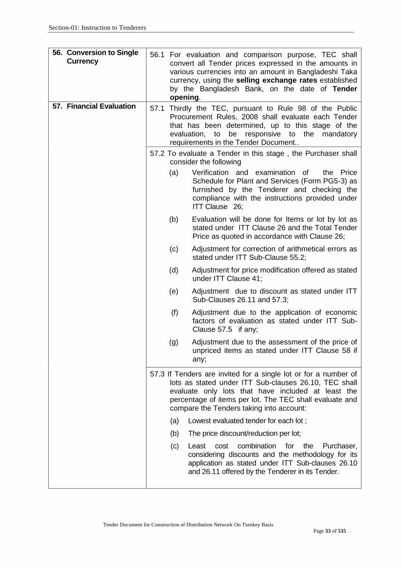
Section-01: Instruction to Tenderers
Tender Document for Construction of Distribution Network On Turnkey Basis
Page 33 of 535
56. Conversion to Single Currency
56.1 For evaluation and comparison purpose, TEC shall convert all Tender prices expressed in the amounts in various currencies into an amount in Bangladeshi Taka currency, using the selling exchange rates established by the Bangladesh Bank, on the date of Tender opening.
57. Financial Evaluation 57.1 Thirdly the TEC, pursuant to Rule 98 of the Public Procurement Rules, 2008 shall evaluate each Tender that has been determined, up to this stage of the evaluation, to be responsive to the mandatory requirements in the Tender Document..
57.2 To evaluate a Tender in this stage , the Purchaser shall consider the following
(a) Verification and examination of the Price Schedule for Plant and Services (Form PG5-3) as furnished by the Tenderer and checking the compliance with the instructions provided under ITT Clause 26;
(b) Evaluation will be done for Items or lot by lot as stated under ITT Clause 26 and the Total Tender Price as quoted in accordance with Clause 26;
(c) Adjustment for correction of arithmetical errors as stated under ITT Sub-Clause 55.2;
(d) Adjustment for price modification offered as stated under ITT Clause 41;
(e) Adjustment due to discount as stated under ITT Sub-Clauses 26.11 and 57.3;
(f) Adjustment due to the application of economic factors of evaluation as stated under ITT Sub-Clause 57.5 if any;
(g) Adjustment due to the assessment of the price of unpriced items as stated under ITT Clause 58 if any;
57.3 If Tenders are invited for a single lot or for a number of lots as stated under ITT Sub-clauses 26.10, TEC shall evaluate only lots that have included at least the percentage of items per lot. The TEC shall evaluate and compare the Tenders taking into account:
(a) Lowest evaluated tender for each lot ;
(b) The price discount/reduction per lot;
(c) Least cost combination for the Purchaser, considering discounts and the methodology for its application as stated under ITT Sub-clauses 26.10 and 26.11 offered by the Tenderer in its Tender.

Section-01: Instruction to Tenderers
Tender Document for Construction of Distribution Network On Turnkey Basis
Page 34 of 535
57.4 Only those spare parts and tools which are specified as a item in the List of Goods and Related Services in Section 6, Employer‟s Requirement or adjustment as stated under ITT Sub-clause 54.5, shall be taken into account in the Tender evaluation. Supplier-recommended spare parts for a specified operating requirement as stated under ITT Sub-clause 28.2(b) shall not be considered in Tender evaluation.
57.5 The Purchaser‟s evaluation of a tender may require the consideration of other factors, in addition to the Tender Price quoted as stated under ITT Clause 26. The effect of the factors selected, if any, shall be expressed in monetary terms to facilitate comparison of tenders. The factors, methodologies and criteria to be used shall be as specified in TDS. The applicable economic factors, for the purposes of evaluation of Tenders shall be:
(a) Adjustment for Deviations in the Delivery and Completion Schedule.
(b) Cost of major replacement components, mandatory spare parts, and service.
57.6 Variations, deviations, and alternatives and other factors which are in excess of the requirements of the Tender Document or otherwise result in unsolicited benefits for the Purchaser will not be taken into account in Tender evaluation.
58. Price Comparison 58.1 The TEC shall compare all responsive Tenders to
determine the lowest-evaluated Tender, as stated in ITT 57.2.
58.2 In the extremely unlikely event that there is a tie for the lowest evaluated price, the Tenderer with the superior past performance with the Purchaser shall be selected, whereby factors such as delivery period, quality of Goods delivered, complaints history and performance indicators could be taken into consideration.
58.3 In the event that there is a tie for the lowest price and none of the Tenderers has the record of past performance with the Purchaser, then the Tenderer shall be selected, subject to firm confirmation through the Post-qualification process described in ITT Clause 61, after consideration as to whether the quality of Goods that is considered more advantageous by the end-users.
58.4 The successful Tenderer as stated under ITT Sub Clauses
58.1, 60.2 and 60.3 shall not be selected through lottery
under any circumstances.

Section-01: Instruction to Tenderers
Tender Document for Construction of Distribution Network On Turnkey Basis
Page 35 of 535
59. Post-qualification 59.1 After determining the lowest-evaluated responsive tender as sated under ITT Sub-Clause 58.1, the Purchaser‟s TEC pursuant to Rule 100 of the Public Procurement Rules, 2008, shall carry out the Post-Qualification of the Tenderer, using only the requirements specified in Sub-Section C, Qualification Criteria.
59.2 The TEC shall contact the references given by Tenderers about their previous Supply experiences to verify, if necessary, statements made by them in their Tender and to obtain the most up-to-date information concerning the Tenderers.
59.3 The TEC may visit the premises of the Tenderer as a part of the post-qualification process, if practical and appropriate, to verify information contained in its Tender.
59.4 The TEC shall determine to its satisfaction whether the Tenderer that is selected as having submitted the lowest evaluated responsive Tender is qualified to perform the Contract satisfactorily.
59.5 The objective of any visit under ITT Sub-Clause 59.3 shall be limited to a general and visual inspection of the Tenderer‟s facilities and its plant and equipment, and there shall be no discussion concerning the Tender or its evaluation with the Tenderer during such visit(s).
59.6 In the event that the Tenderer with lowest evaluated cost fails the post-qualification, the TEC shall make a similar determination for the Tenderer offering the next lowest evaluated cost and so on from the remaining responsive Tenders, provided that,
(a) such action shall only be taken if the evaluated costs of the Tenders under consideration are acceptable to the Purchaser;
(b) when the point is reached whereby the evaluated costs of the remaining responsive Tenders are significantly higher than that of the official estimate, or the market price, the Purchaser may take action pursuant to Rule 33 of the PPR 2008 and may proceed for re-Tendering, using a revised Tender Document designed to achieve a more successful result.
60. Negotiation 60.1 No negotiations shall be held during the financial offer evaluation or award, with the lowest or any other Tenderer.
60.2 The Procuring Entity through the TEC may, however, negotiate with the lowest evaluated Tenderer with the objective to reduce the Contract Price by reducing the scope of works or a reallocation of risks and responsibilities, only when it is found that the lowest evaluated Tender is significantly higher than the official estimated cost; the reasons for such higher price being duly investigated.

Section-01: Instruction to Tenderers
Tender Document for Construction of Distribution Network On Turnkey Basis
Page 36 of 535
60.3 If the Procuring Entity decides to negotiate for reducing the scope of the requirements under ITT Sub Clause 60.2, it will be required to guarantee that the lowest Tenderer remains the lowest Tenderer even after the scope of work has been revised and shall further be ensured that the objective of the Procurement will not be seriously affected through this reduction.
60.4 In the event that the Procuring Entity decides because of a high Tender priceto reduce the scope of the requirements to meet the available budget, the Tenderer is not obliged to accept the award and shall not be penalised in any way for un-accepting the proposed award.
61. Rejection of All Tenders
61.1 The Purchaser may, in the circumstances as stated under ITT Sub-Clause 61.2 and pursuant to Rule 33 of the Public Procurement Rules 2008, reject all Tenders following recommendations from the Tender Evaluation Committee only after the approval of such recommendations by the Head of the Purchaser.rejected, if –
61.2 All Tenders can be rejected, if - (a) the price of the lowest evaluated Tender exceeds
the official estimate, provided the estimate is realistic; or
(b) there is evidence of lack of effective competition; such as non-participation by a number of potential Tenderers; or
(c) the Tenderers are unable to propose completion of the delivery within the stipulated time in its offer, though the stipulated time is reasonable and realistic; or
(d) all Tenders are non-responsive; or (e) evidence of professional misconduct, affecting
seriously the Procurement process, is established pursuant to Rule 127 of the Public Procurement Rules, 2008.
61.3 Notwithstanding anything contained in ITT Sub-Clause 61.2 Tenders may not be rejected if the lowest evaluated price is in conformity with the market price.
61.4 A Purchaser may pursuant to Rule 35 of the Public Procurement Rules, 2008, on justifiable grounds, annul the Procurement proceedings prior to the deadline for the submission of Tenders.
61.5 All Tenders received by the Purchaser shall be returned unopened to the Tenderers in the event Procurement proceedings are annulled under ITT Sub-Clause 61.4.
62. Informing Reasons for Rejection
62.1 Notice of the rejection, pursuant to Rule 35 of the Public Procurement Rules, 2008, will be given promptly within seven (7) days of decision taken by the Purchaser to all Tenderers and, the Purchaser will, upon receipt of a written request, communicate to any Tenderer the reason(s) for its rejection but is not required to justify those reason(s).

Section-01: Instruction to Tenderers
Tender Document for Construction of Distribution Network On Turnkey Basis
Page 37 of 535
G. Contract Award
63. Award Criteria 63.1 The Purchaser shall award the Contract to the Tenderer whose offer is responsive to the Tender Document and that has been determined to be the lowest evaluated Tender, provided further that the Tenderer is determined to be Post-Qualified as stated under ITT Clause 59.
63.2 A Tenderer shall not be required, as a condition for award of contract, to undertake obligations not stipulated in the Tender Document, to change its price, or otherwise to modify its Tender.
64. Notification of Award 64.1 Prior to the expiry of the Tender validity period and within seven (7) working days of receipt of the approval of the award by the Approving Authority, the Purchaser pursuant to Rule 102 of the Public procurement Rules, 2008, shall issue the Notification of Award (NOA) to the successful Tenderer.
64.2 The Notification of Award, attaching the contract as per the sample (Form PG5A-7) to be signed, shall state:
(a) the acceptance of the Tender by the Purchaser;
(b) the price at which the contract is awarded;
(c) the amount of the Performance Security and its format;
(d) the date and time within which the Performance Security shall be submitted; and
(e) the date and time within which the contract shall be signed.
64.3 The Notification of Award shall be accepted in writing by the successful Tenderer within seven (7) working days from the date of issuance of NOA.
64.4 Until a formal contract is signed, the Notification of Award shall constitute a Contract, which shall become binding upon the furnishing of a Performance Security and the signing of the Contract by both parties.
64.5 The Notification of Award establishes a Contract between the Purchaser and the successful Tenderer and the existence of a Contract is confirmed through the signature of the Contract Document that includes all agreements between the Purchaser and the successful Tenderer.
65. Performance Security 65.1 The Performance Security shall be determined sufficient to protect the performance of the Contract pursuant to Rule 27 of the Public Procurement Rules, 2008.
65.2 Performance Security shall be furnished by the successful Tenderer in the amount specified in the TDSanddenominated in the currencies in which the Contract Price is payable pursuant to Rule 102 (8) of the Public Procurement Rules, 2008.

Section-01: Instruction to Tenderers
Tender Document for Construction of Distribution Network On Turnkey Basis
Page 38 of 535
65.3 The proceeds of the Performance Security shall be
payable to the Purchaser unconditionally upon first written demand as compensation for any loss resulting from the Supplier‟s failure to complete its obligations under the Contract.
66. Form and Time Limit for furnishing of Performance security
66.1 The Performance Security shall be in the form of irrevocable Bank Guarantee in the format (Form PG5A-9) as stated under ITT Clause 65, shall be issued by an internationally reputable bank and it shall have correspondent bank located in Bangladesh, to make it enforceable pursuant to Rule 27(4) of the Public Procurement Rules, 2008..
66.2 Within twenty-eight (28) days from issue of the Notification of Award, the successful Tenderer shall furnish the Performance Security for the due performance of the Contract in the amount specified under ITT Sub Clause 65.2.
67. Validity of Performance Security
67.1 The Performance Security shall be required to be valid until a date twenty-eight (28) days beyond the date of completion of the Supplier‟s performance obligations under the Contract, including any warranty obligations.
67.2 If under any circumstances date of completion of the Supplier‟s performance obligations under the Contract, including any warranty obligations is to be extended, the Performance Security shall correspondingly be extended for the extended period.
68. Authenticity of performance Security
69.1 The Purchaser shall verify the authenticity of the Performance Security submitted by the successful Tenderer by sending a written request to the branch of the bank issuing irrevocable Bank Guarantee in specified format.
69.2 If the Performance Security submitted under ITT Sub Clause 65.2 is not found to be authentic, the Purchaser shall proceed to take measures against the Tenderer in accordance with Section 64 of the Act and pursuant to Rule 127 of the Public Procurement Rules, 2008.

Section-01: Instruction to Tenderers
Tender Document for Construction of Distribution Network On Turnkey Basis
Page 39 of 535
69. Contract Signing 69.1 At the same time as the Purchaser issues the Notification of Award, the Purchaser shall send the draft Contract Agreement and all documents forming the Contract pursuant to Rule 102 of the Public Procurement Rule, 2008, to the successful Tenderer.
69.2 Within twenty-eight (28) days of the issuance of Notification of Award, the successful Tenderer and the Purchaser shall sign the contract provided that the Performance Security submitted by the Tenderer is found to be genuine.
69.3 If the successful Tenderer fails to provide the required Performance Security, as stated under ITT Clause 65 or to sign the Contract , as stated under ITT Sub-Clause 69.2, Purchaser shall proceed to award the Contract to the next lowest evaluated Tenderer, and so on, by order of ranking pursuant to Rule 102 of the Public Procurement Rules,2008.
70. Publication of Notification of Award of Contract
70.1 Notification of Awards for Contracts of Taka 10 (ten) million and above shall be notified by the Purchaser to the Central Procurement Technical Unit within 7(seven) days of issuance of the NOA for publication in their website, and that notice shall be kept posted for not less than a month pursuant to Rule 37 of the Public Procurement Rules, 2008.
70.2 Notification of Award for Contracts below Taka 10(ten) million, shall be published by the Purchaser on its Notice Board and where applicable on the website of the Purchaser and that notice shall be kept posted for not less than a month pursuant to Rule 37 of the Public Procurement Rules, 2008..
71. Debriefing of Tenderers
72.1 Debriefing of Tenderers by Purchaser shall outline the relative status and weakness only of his or her Tender requesting to be informed of the grounds for not accepting the Tender submitted by him or her pursuant to Rule 37 of the Public Procurement Rule, 2008, without disclosing information about any other Tenderer.
72.2 In the case of debriefing confidentiality of the evaluation process shall be maintained.
72. Right to Complains 72.1 Any Tenderer has the right to complain if it has suffered or
likely to suffer loss or damage due to a failure of a duty imposed on the Purchaser to fulfil its obligations in accordance with Section 29 of the Public Procurement Act 2006 and pursuant to Part 12 of Chapter Three of the Public Procurement Rules, 2008.
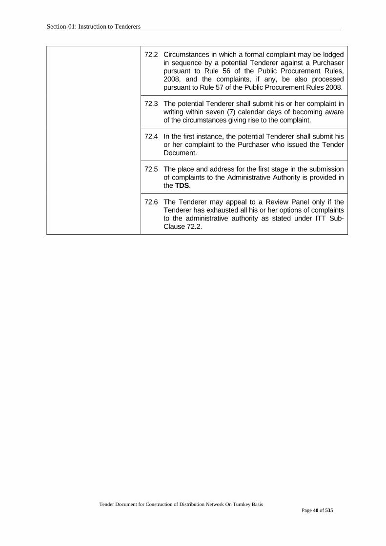
Section-01: Instruction to Tenderers
Tender Document for Construction of Distribution Network On Turnkey Basis
Page 40 of 535
72.2 Circumstances in which a formal complaint may be lodged
in sequence by a potential Tenderer against a Purchaser pursuant to Rule 56 of the Public Procurement Rules, 2008, and the complaints, if any, be also processed pursuant to Rule 57 of the Public Procurement Rules 2008.
72.3 The potential Tenderer shall submit his or her complaint in writing within seven (7) calendar days of becoming aware of the circumstances giving rise to the complaint.
72.4 In the first instance, the potential Tenderer shall submit his or her complaint to the Purchaser who issued the Tender Document.
72.5 The place and address for the first stage in the submission of complaints to the Administrative Authority is provided in the TDS.
72.6 The Tenderer may appeal to a Review Panel only if the Tenderer has exhausted all his or her options of complaints to the administrative authority as stated under ITT Sub-Clause 72.2.
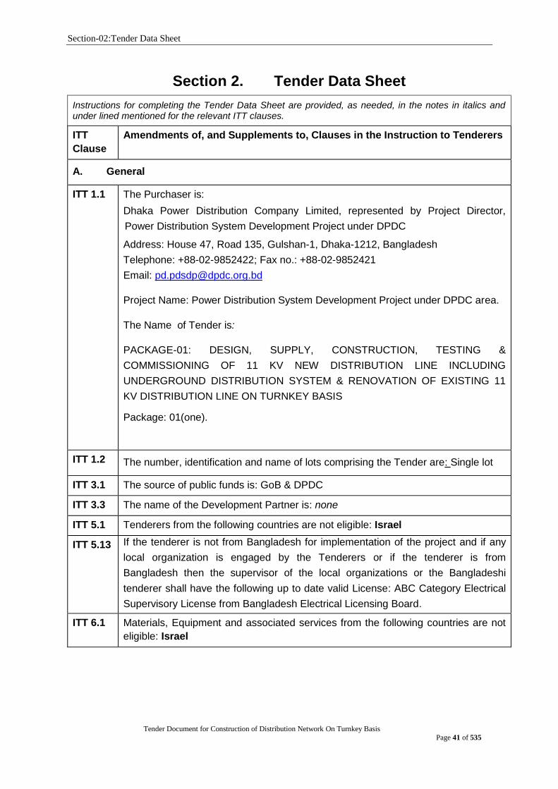
Section-02:Tender Data Sheet
Tender Document for Construction of Distribution Network On Turnkey Basis
Page 41 of 535
Section 2. Tender Data Sheet
Instructions for completing the Tender Data Sheet are provided, as needed, in the notes in italics and under lined mentioned for the relevant ITT clauses.
ITT
Clause
Amendments of, and Supplements to, Clauses in the Instruction to Tenderers
A. General
ITT 1.1
The Purchaser is:
Dhaka Power Distribution Company Limited, represented by Project Director,
Power Distribution System Development Project under DPDC
Address: House 47, Road 135, Gulshan-1, Dhaka-1212, Bangladesh
Telephone: +88-02-9852422; Fax no.: +88-02-9852421
Email: [email protected]
Project Name: Power Distribution System Development Project under DPDC area.
The Name of Tender is:
PACKAGE-01: DESIGN, SUPPLY, CONSTRUCTION, TESTING &
COMMISSIONING OF 11 KV NEW DISTRIBUTION LINE INCLUDING
UNDERGROUND DISTRIBUTION SYSTEM & RENOVATION OF EXISTING 11
KV DISTRIBUTION LINE ON TURNKEY BASIS
Package: 01(one).
ITT 1.2 The number, identification and name of lots comprising the Tender are: Single lot
ITT 3.1 The source of public funds is: GoB & DPDC
ITT 3.3 The name of the Development Partner is: none
ITT 5.1 Tenderers from the following countries are not eligible: Israel
ITT 5.13 If the tenderer is not from Bangladesh for implementation of the project and if any
local organization is engaged by the Tenderers or if the tenderer is from
Bangladesh then the supervisor of the local organizations or the Bangladeshi
tenderer shall have the following up to date valid License: ABC Category Electrical
Supervisory License from Bangladesh Electrical Licensing Board.
ITT 6.1 Materials, Equipment and associated services from the following countries are not
eligible: Israel

Section-02:Tender Data Sheet
Tender Document for Construction of Distribution Network On Turnkey Basis
Page 42 of 535
B. Tender Document
ITT 8.2 The following is the office of the Purchaser for the purpose of providing the Tender
Document:
Office of the Project Director, Power Distribution System Development Project,
DPDC
Address: Level-2, House 47, Road 135, Gulshan-1, Dhaka-1212, Bangladesh
Telephone: +88-02-9852422; Fax no.: +88-02-9852421
ITT9.1 For clarification of Tender Document purposes only, the Procuring Entity‟s
address is:
Attention: Project Director, Power Distribution System Development Project under
DPDC
Address: House 47, Road 135, Gulshan-1, Dhaka-1212, Bangladesh,
Telephone: +88-02-9852422; Fax no.: +88-02-9852421
Email: [email protected] and contact the Procuring Entity within 21 days from
date of publication of tender notice
ITT10.1 A Pre- Tender meeting shall be held at
Address: Conference room of DPDC, Level-3, 1 Abdul Gani Road, Bidyut Bhaban,
Dhaka-1000
Time & Date: 10 am BST on 28/04/2019
C. Qualification Criteria
ITT 13.1 The maximum [3] number of arbitration against the Tenderer over a period of last [5
years
ITT
14.1 (a)
The tenderer or in case of JVCA, any partner must have overall 7 years of
experience or more in the role of contractor and shall have successfully completed
at least 2(two) projects (contract amount should not be less than minimum US$ 20
million or equivalent per contract) within the last 10 (ten) years. For JVCA, other
partner/each of other partners shall have experience of completing at least one
contract amounting to minimum US$ 10 million or equivalent within the last 10 (ten)
years. The experiences are to be counted from the date of tender publication.
Such evidence shall be in end user‟s respective letterhead stationary indicating
address, telephone, email address and fax numbers of the user(s) and shall include
name of the project, name of the employers, description of the work, commissioning
date and contract amount. Certificates must be in English.
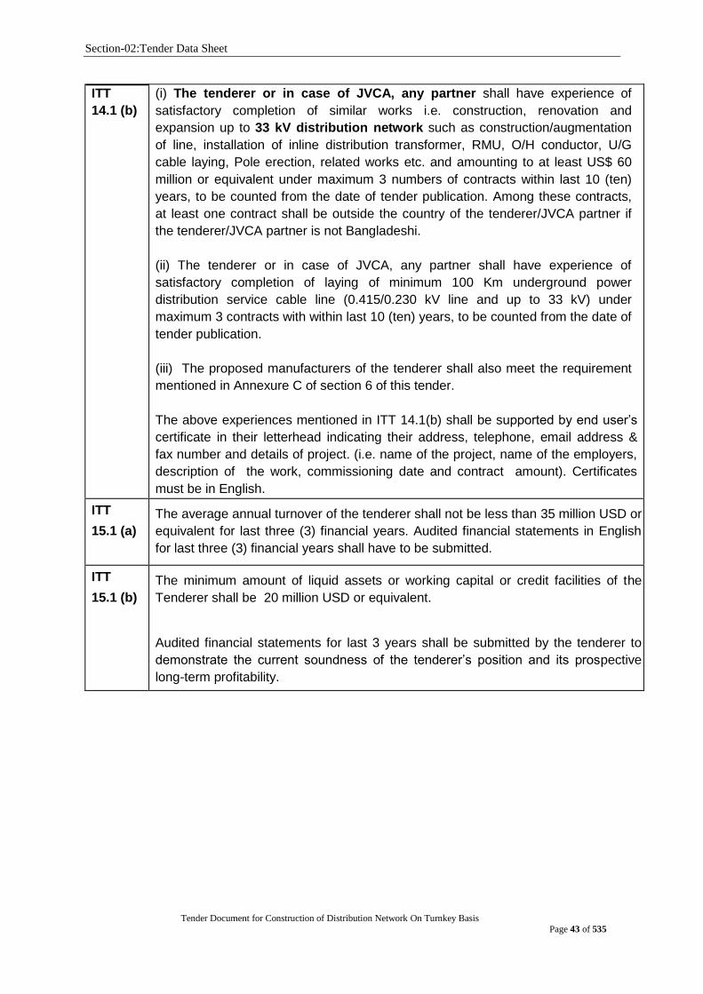
Section-02:Tender Data Sheet
Tender Document for Construction of Distribution Network On Turnkey Basis
Page 43 of 535
ITT
14.1 (b)
(i) The tenderer or in case of JVCA, any partner shall have experience of
satisfactory completion of similar works i.e. construction, renovation and
expansion up to 33 kV distribution network such as construction/augmentation
of line, installation of inline distribution transformer, RMU, O/H conductor, U/G
cable laying, Pole erection, related works etc. and amounting to at least US$ 60
million or equivalent under maximum 3 numbers of contracts within last 10 (ten)
years, to be counted from the date of tender publication. Among these contracts,
at least one contract shall be outside the country of the tenderer/JVCA partner if
the tenderer/JVCA partner is not Bangladeshi.
(ii) The tenderer or in case of JVCA, any partner shall have experience of
satisfactory completion of laying of minimum 100 Km underground power
distribution service cable line (0.415/0.230 kV line and up to 33 kV) under
maximum 3 contracts with within last 10 (ten) years, to be counted from the date of
tender publication.
(iii) The proposed manufacturers of the tenderer shall also meet the requirement
mentioned in Annexure C of section 6 of this tender.
The above experiences mentioned in ITT 14.1(b) shall be supported by end user‟s
certificate in their letterhead indicating their address, telephone, email address &
fax number and details of project. (i.e. name of the project, name of the employers,
description of the work, commissioning date and contract amount). Certificates
must be in English.
ITT
15.1 (a)
The average annual turnover of the tenderer shall not be less than 35 million USD or
equivalent for last three (3) financial years. Audited financial statements in English
for last three (3) financial years shall have to be submitted.
ITT
15.1 (b)
The minimum amount of liquid assets or working capital or credit facilities of the
Tenderer shall be 20 million USD or equivalent.
Audited financial statements for last 3 years shall be submitted by the tenderer to
demonstrate the current soundness of the tenderer‟s position and its prospective
long-term profitability.
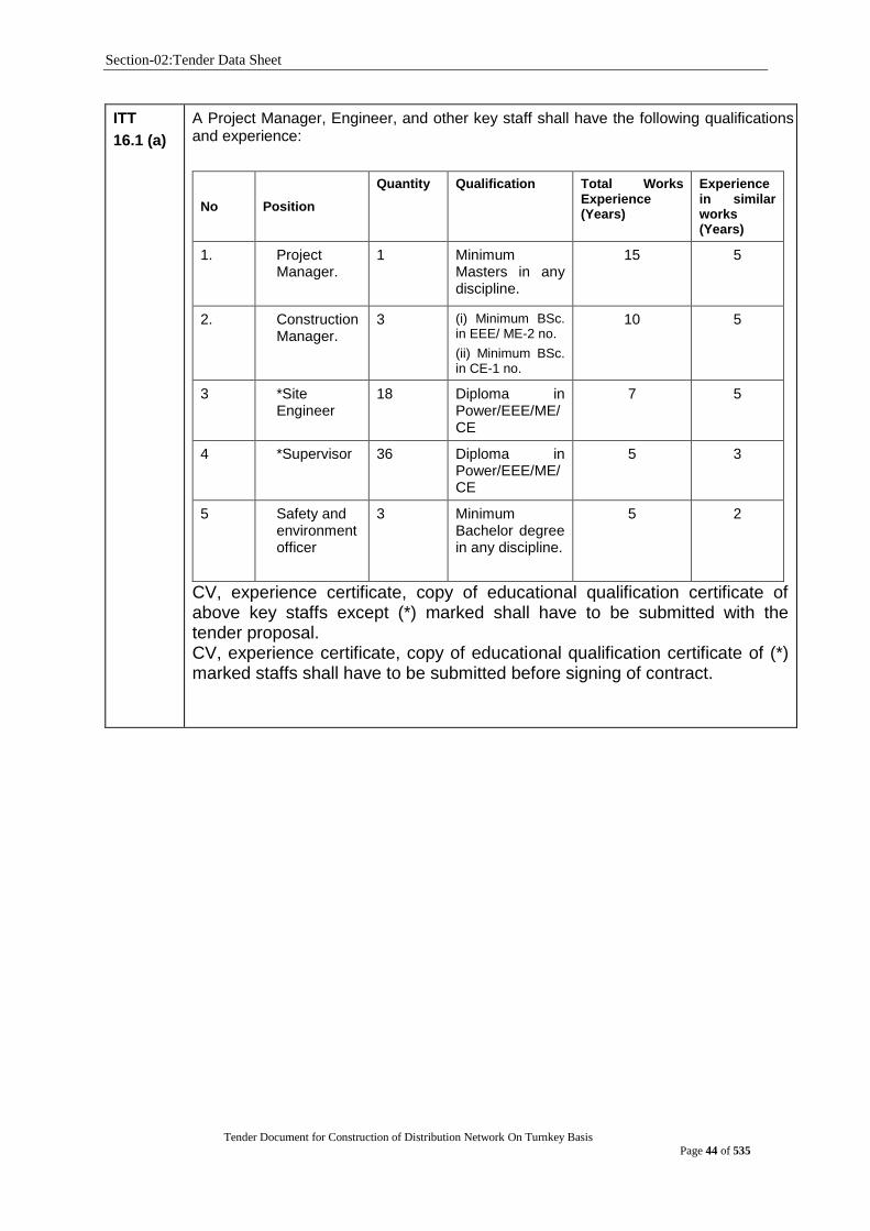
Section-02:Tender Data Sheet
Tender Document for Construction of Distribution Network On Turnkey Basis
Page 44 of 535
ITT
16.1 (a)
A Project Manager, Engineer, and other key staff shall have the following qualifications and experience:
No Position
Quantity Qualification Total Works Experience (Years)
Experience in similar works (Years)
1. Project Manager.
1 Minimum Masters in any discipline.
15 5
2. Construction Manager.
3 (i) Minimum BSc. in EEE/ ME-2 no.
(ii) Minimum BSc. in CE-1 no.
10 5
3 *Site Engineer
18 Diploma in Power/EEE/ME/CE
7 5
4 *Supervisor 36 Diploma in Power/EEE/ME/CE
5 3
5 Safety and environmentofficer
3 Minimum Bachelor degree in any discipline.
5 2
CV, experience certificate, copy of educational qualification certificate of above key staffs except (*) marked shall have to be submitted with the tender proposal. CV, experience certificate, copy of educational qualification certificate of (*) marked staffs shall have to be submitted before signing of contract.
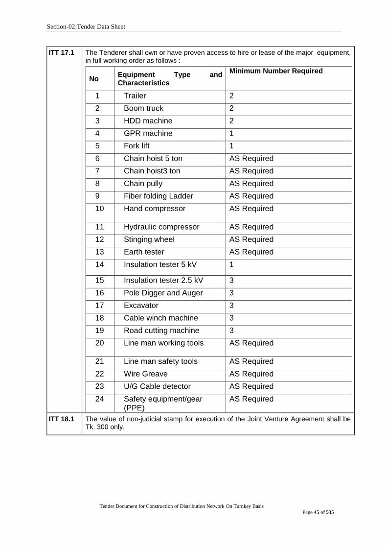
Section-02:Tender Data Sheet
Tender Document for Construction of Distribution Network On Turnkey Basis
Page 45 of 535
ITT 17.1 The Tenderer shall own or have proven access to hire or lease of the major equipment, in full working order as follows :
No Equipment Type and Characteristics
Minimum Number Required
1 Trailer 2
2 Boom truck 2
3 HDD machine 2
4 GPR machine 1
5 Fork lift 1
6 Chain hoist 5 ton AS Required
7 Chain hoist3 ton AS Required
8 Chain pully AS Required
9 Fiber folding Ladder AS Required
10 Hand compressor
AS Required
11 Hydraulic compressor AS Required
12 Stinging wheel AS Required
13 Earth tester AS Required
14 Insulation tester 5 kV 1
15 Insulation tester 2.5 kV 3
16 Pole Digger and Auger 3
17 Excavator 3
18 Cable winch machine 3
19 Road cutting machine 3
20 Line man working tools
AS Required
21 Line man safety tools AS Required
22 Wire Greave AS Required
23 U/G Cable detector AS Required
24 Safety equipment/gear (PPE)
AS Required
ITT 18.1
The value of non-judicial stamp for execution of the Joint Venture Agreement shall be Tk. 300 only.
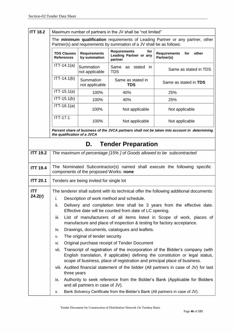
Section-02:Tender Data Sheet
Tender Document for Construction of Distribution Network On Turnkey Basis
Page 46 of 535
ITT 18.2
Maximum number of partners in the JV shall be “not limited”
The minimum qualification requirements of Leading Partner or any partner, other Partner(s) and requirements by summation of a JV shall be as follows:
TDS Clauses References
Requirements by summation
Requirements for Leading Partner or any partner
Requirements for other Partner(s)
ITT-14.1(a) Summation not applicable
Same as stated in TDS
Same as stated in TDS
ITT-14.1(b) Summation not applicable
Same as stated in TDS
Same as stated in TDS
ITT-15.1(a) 100% 40% 25%
ITT-15.1(b) 100% 40% 25%
ITT-16.1(a) 100% Not applicable Not applicable
ITT-17.1 100% Not applicable Not applicable
Percent share of business of the JVCA partners shall not be taken into account in determining the qualification of a JVCA
D. Tender Preparation
ITT 19.2 The maximum of percentage [15% ] of Goods allowed to be subcontracted
ITT 19.4 The Nominated Subcontractor(s) named shall execute the following specific components of the proposed Works: none
ITT 20.1 Tenders are being invited for single lot
ITT 24.2(r)
The tenderer shall submit with its technical offer the following additional documents:
i. Description of work method and schedule.
ii. Delivery and completion time shall be 3 years from the effective date.
Effective date will be counted from date of LC opening.
iii. List of manufacturers of all items listed in Scope of work, places of
manufacture and place of inspection & testing for factory acceptance.
iv. Drawings, documents, catalogues and leaflets.
v. The original of tender security
vi. Original purchase receipt of Tender Document
vii. Transcript of registration of the incorporation of the Bidder‟s company (with
English translation, if applicable) defining the constitution or legal status,
scope of business, place of registration and principal place of business.
viii. Audited financial statement of the bidder (All partners in case of JV) for last
three years
ix. Authority to seek reference from the Bidder‟s Bank (Applicable for Bidders
and all partners in case of JV).
x. Bank Solvency Certificate from the Bidder‟s Bank (All partners in case of JV).
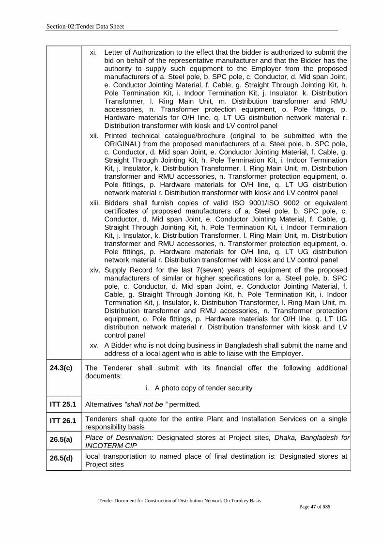
Section-02:Tender Data Sheet
Tender Document for Construction of Distribution Network On Turnkey Basis
Page 47 of 535
xi. Letter of Authorization to the effect that the bidder is authorized to submit the bid on behalf of the representative manufacturer and that the Bidder has the authority to supply such equipment to the Employer from the proposed manufacturers of a. Steel pole, b. SPC pole, c. Conductor, d. Mid span Joint, e. Conductor Jointing Material, f. Cable, g. Straight Through Jointing Kit, h. Pole Termination Kit, i. Indoor Termination Kit, j. Insulator, k. Distribution Transformer, l. Ring Main Unit, m. Distribution transformer and RMU accessories, n. Transformer protection equipment, o. Pole fittings, p. Hardware materials for O/H line, q. LT UG distribution network material r. Distribution transformer with kiosk and LV control panel
xii. Printed technical catalogue/brochure (original to be submitted with the ORIGINAL) from the proposed manufacturers of a. Steel pole, b. SPC pole, c. Conductor, d. Mid span Joint, e. Conductor Jointing Material, f. Cable, g. Straight Through Jointing Kit, h. Pole Termination Kit, i. Indoor Termination Kit, j. Insulator, k. Distribution Transformer, l. Ring Main Unit, m. Distribution transformer and RMU accessories, n. Transformer protection equipment, o. Pole fittings, p. Hardware materials for O/H line, q. LT UG distribution network material r. Distribution transformer with kiosk and LV control panel
xiii. Bidders shall furnish copies of valid ISO 9001/ISO 9002 or equivalent certificates of proposed manufacturers of a. Steel pole, b. SPC pole, c. Conductor, d. Mid span Joint, e. Conductor Jointing Material, f. Cable, g. Straight Through Jointing Kit, h. Pole Termination Kit, i. Indoor Termination Kit, j. Insulator, k. Distribution Transformer, l. Ring Main Unit, m. Distribution transformer and RMU accessories, n. Transformer protection equipment, o. Pole fittings, p. Hardware materials for O/H line, q. LT UG distribution network material r. Distribution transformer with kiosk and LV control panel
xiv. Supply Record for the last 7(seven) years of equipment of the proposed manufacturers of similar or higher specifications for a. Steel pole, b. SPC pole, c. Conductor, d. Mid span Joint, e. Conductor Jointing Material, f. Cable, g. Straight Through Jointing Kit, h. Pole Termination Kit, i. Indoor Termination Kit, j. Insulator, k. Distribution Transformer, l. Ring Main Unit, m. Distribution transformer and RMU accessories, n. Transformer protection equipment, o. Pole fittings, p. Hardware materials for O/H line, q. LT UG distribution network material r. Distribution transformer with kiosk and LV control panel
xv. A Bidder who is not doing business in Bangladesh shall submit the name and address of a local agent who is able to liaise with the Employer.
24.3(c) The Tenderer shall submit with its financial offer the following additional documents:
i. A photo copy of tender security
ITT 25.1 Alternatives “shall not be “ permitted.
ITT 26.1 Tenderers shall quote for the entire Plant and Installation Services on a single responsibility basis
26.5(a) Place of Destination: Designated stores at Project sites, Dhaka, Bangladesh for INCOTERM CIP
26.5(d) local transportation to named place of final destination is: Designated stores at Project sites

Section-02:Tender Data Sheet
Tender Document for Construction of Distribution Network On Turnkey Basis
Page 48 of 535
ITT 26.7 The prices quoted by the Tenderer shall be fixed for the duration of the Contract.
ITT 27.4 Name of the foreign currency: US Dollar (USD). The currency that shall be used for bid evaluation and comparison purposes to convert all bid prices expressed in various currencies into a single currency is: Bangladesh Taka. The source of selling exchange rate shall be: The selling rate of Sonali Bank Limited in Bangladesh. The date for the selling exchange rate shall be: the date of opening of the Technical Proposals.
ITT
28.1 (b)
Spare parts are: “not required”
ITT 28.1(b)
Manufacturer‟s authorization is: “required”
The tenderer shall furnish manufacturer‟s authorization letter for a. Steel pole, b. SPC pole, c. Conductor, d. Mid span Joint, e. Conductor Jointing Material, f. Cable, g. Straight Through Jointing Kit, h. Pole Termination Kit, i. Indoor Termination Kit, j. Insulator, k. Distribution Transformer, l. Ring Main Unit, m. Distribution transformer and RMU accessories, n. Transformer protection equipment, o. Pole fittings, p. Hardware materials for O/H line, q. LT UG distribution network material r. Distribution transformer with kiosk and LV control panel
ITT 30.2 The Tender validity period shall be 180 days.
ITT 32.2
The amount of the Tender Security shall be USD 2.5 million or BDT 210 million in favour of Dhaka Power Distribution Company Limited
ITT 37.1 In addition to the original of the Tender, [2] copies shall be submitted.
E. Submission of Tender
ITT 38.2(e)&38.4(e)
The Tender shall be single stage two envelope. Technical and financial proposal shall be submitted in two separate envelopes duly sealed and signed, which shall be in a single envelope duly addressed to the employer. The Technical envelope will be opened first. The original „Technical Offer‟ and the envelope containing all copies and original of „Financial Offer‟ will be kept in safe custody of „Office of the Company Secretary, DPDC‟.Financial Proposal of only technically responsive bids will be opened at date and time to be notified later to the respective bidder. The Financial Proposal of the technically non-responsive bidder will be returned unopened to the respective bidder.
The tenderer shall enclose the original Technical Proposal and Financial Proposal in different envelope. The envelopes will be marked as Technical Proposal Original and Financial Proposal Original. Similarly copies of technical and financial proposal will be enclosed in two different envelopes and the envelope will be marked 'Copy Technical Proposal' and 'Copy Financial Proposal'. Then original Technical Proposal envelope and copy of the technical proposals will be put into another envelope and the envelope will be marked as technical proposal. Similarly Original of the Financial Proposal and Copy of the Financial Proposal will put into another envelope will be marked as Financial Proposal. These two envelopes of Technical Proposal and Financial proposal shall then be enclosed one single outer envelope. All the envelops should be duly sealed and signed by the bidder.
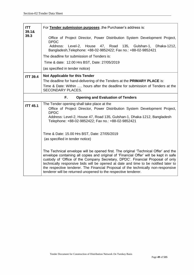
Section-02:Tender Data Sheet
Tender Document for Construction of Distribution Network On Turnkey Basis
Page 49 of 535
ITT 39.1& 39.3
For Tender submission purposes ,the Purchaser‟s address is:
Office of Project Director, Power Distribution System Development Project, DPDC Address: Level-2, House 47, Road 135, Gulshan-1, Dhaka-1212, Bangladesh,Telephone: +88-02-9852422; Fax no.: +88-02-9852421
The deadline for submission of Tenders is:
Time & date: 12.00 Hrs BST, Date: 27/05/2019
(as specified in tender notice)
ITT 39.4 Not Applicable for this Tender
The deadline for hand-delivering of the Tenders at the PRIMARY PLACE is:
Time & Date: Within ..... hours after the deadline for submission of Tenders at the SECONDARY PLACES.
F. Opening and Evaluation of Tenders
ITT 45.1 The Tender opening shall take place at the
Office of Project Director, Power Distribution System Development Project, DPDC Address: Level-2, House 47, Road 135, Gulshan-1, Dhaka-1212, Bangladesh Telephone: +88-02-9852422; Fax no.: +88-02-9852421
Time & Date: 15.00 Hrs BST, Date: 27/05/2019
(as specified in tender notice)
The Technical envelope will be opened first. The original „Technical Offer‟ and the envelope containing all copies and original of „Financial Offer‟ will be kept in safe custody of „Office of the Company Secretary, DPDC‟. Financial Proposal of only technically responsive bids will be opened at date and time to be notified later to the respective tenderer. The Financial Proposal of the technically non-responsive tenderer will be returned unopened to the respective tenderer.

Section-02:Tender Data Sheet
Tender Document for Construction of Distribution Network On Turnkey Basis
Page 50 of 535
ITT 57.5 The applicable economic factors, for the purposes of evaluation of Tenders shall be:Not applicable
(a) Adjustment for Deviations in the Delivery and Completion Schedule
“The Plant and Service covered by this Tendering process are required to be delivered in accordance with, and completed within, the Delivery and Completion Schedule specified in Section 6, Employer’s Requirements. No credit will be given for earlier completion. Tender offering late contract performance schedules within acceptable period will be accepted but the tenders shall be Adjusted in the evaluation by adding to the Tender Price at the rate of [specify percentage] ofthe Tender Price for each day ofdelay. Tender offering delivery schedules beyond [specify time Limit] of the date specified in Section 6, Employer’s Requirement, shall be rejected.”
(b) Cost of major replacement components, mandatory spare parts, and service
The Procuring Entity will draw up a list of high-usage and high-value items of components and spare parts [specify (spare parts, tools, major assemblies, estimated quantities]of usage in the initial period [specify period] of operation. The total cost of these items and quantities will be computed from spare parts unit prices submitted by the Tenderer and added to the tender price, for evaluation purposes only.
(c) Other factors affecting the true economic value
The Procuring Entity will draw up other factors affecting the true economic value of the Tender price may be life span costs, such as cost of fuel, performance or productivity of the equipment, etc.The total cost of these items and quantities will be computed from submitted Tender and added to the tender price, for evaluation purposes only.
G. Award of Contract
ITT 65.2 The amount of Performance Security shall be 10 percent of the Contract Price. However, if the offered price of the tender is deemed to be front loaded by the evaluation committee, Performance Security may be increased up to 25 percent of the Contract.
ITT 72.5 The name and address of the office where complaints to the Purchaser are to be submitted is:
Project Director, Power Distribution System Development Project
Address: House 47, Road 135, Gulshan-1, Dhaka-1212, Bangladesh Telephone: +88-02-9852422; Fax no.: +88-02-9852421
Email: [email protected]
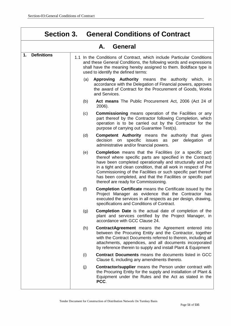
Section-03:General Conditions of Contract
Tender Document for Construction of Distribution Network On Turnkey Basis
Page 51 of 535
Section 3. General Conditions of Contract
A. General
1. Definitions 1.1 In the Conditions of Contract, which include Particular Conditions
and these General Conditions, the following words and expressions shall have the meaning hereby assigned to them. Boldface type is used to identify the defined terms:
(a) Approving Authority means the authority which, in accordance with the Delegation of Financial powers, approves the award of Contract for the Procurement of Goods, Works and Services.
(b) Act means The Public Procurement Act, 2006 (Act 24 of 2006).
(c) Commissioning means operation of the Facilities or any part thereof by the Contractor following Completion, which operation is to be carried out by the Contractor for the purpose of carrying out Guarantee Test(s).
(d) Competent Authority means the authority that gives decision on specific issues as per delegation of administrative and/or financial powers.
(e) Completion means that the Facilities (or a specific part thereof where specific parts are specified in the Contract) have been completed operationally and structurally and put in a tight and clean condition, that all work in respect of Pre Commissioning of the Facilities or such specific part thereof has been completed, and that the Facilities or specific part thereof are ready for Commissioning.
(f) Completion Certificate means the Certificate issued by the Project Manager as evidence that the Contractor has executed the services in all respects as per design, drawing, specifications and Conditions of Contract.
(g) Completion Date is the actual date of completion of the plant and services certified by the Project Manager, in accordance with GCC Clause 24.
(h) ContractAgreement means the Agreement entered into between the Procuring Entity and the Contractor, together with the Contract Documents referred to therein, including all attachments, appendices, and all documents incorporated by reference therein to supply and install Plant & Equipment
(i) Contract Documents means the documents listed in GCC Clause 6, including any amendments thereto.
(j) Contractor/supplier means the Person under contract with the Procuring Entity for the supply and installation of Plant & Equipment under the Rules and the Act as stated in the PCC.
Section-03:General Conditions of Contract
Tender Document for Construction of Distribution Network On Turnkey Basis
Page 52 of 535
(k) Contractor‟s Representative means any person nominated by the Contractor and approved by the Employer to perform the duties delegated by the Contractor.
(l) Contract Price means the price payable to the Contractor as specified in the Contract Agreement, subject to such additions and adjustments thereto or deductions therefrom, for the supply and installation of plant & equipment in accordance with the provisions of the Contract, subject to such additions and adjustments thereto or deductions therefrom, as may be made pursuant to the Contract.
(m) Cost means all expenditures reasonably incurred or to be incurred by the Contractor, whether on or off the Site, including overhead ,profit, taxes, duties, fees, and such other similar levies
(n) Day means calendar day unless otherwise specified as working days.
(o) Dayworks means work carried out following the instructions of the Procuring Entity or the authorised Project Manager and is paid for on the basis of time spent by the Contractor‟s workers and equipment at the rates specified in the Schedules, in addition to payments for associated Materials and Plant.
(p) Defect is any part of the Works not completed in accordance with the Contract.
(q) Defect Liability Period means the period of validity of the warranties given by the Contractor commencing at Completion of the Facilities or a part thereof, during which the Contractor is responsible for defects with respect to the Facilities (or the relevant part thereof) as provided in contract document.
(r) Defects Correction Certificate is the certificate issued by the Project Manager upon correction of defects by the Contractor.
(s) Drawings include calculations and other information provided in Section 7 or as approved by the Project Manager for the execution and completion of the Contract.
(t) Effective Date means the date of fulfillment of all conditions of the Contract Agreement, from which the Time for Completion shall be counted.
(u) Equipmentmeans all facilities, equipment, machinery, tools, apparatus, appliances or things of every kind required in or for installation, completion and maintenance of Facilities that are to be provided by the Contractor, but does not include Plant, or other things intended to form or forming part of the Facilities.
(v) Facilities means the Plant to be supplied and installed, as well as all the Installation Services to be carried out by the Contractor under the Contract. It also includes any ancillary building or infra structure that needs to be constructed/built/erected to support the plant.
Section-03:General Conditions of Contract
Tender Document for Construction of Distribution Network On Turnkey Basis
Page 53 of 535
(w) Force Majeure means an event or situation beyond the control of the Contractor that is not foreseeable, is unavoidable, and its origins not due to negligence or lack of care on the part of the Contractor; such events may include, but not be limited to, acts of the Government in its sovereign capacity, wars or revolutions, fires, floods, epidemics, quarantine restrictions, and freight embargoes or more as included in GCC Clause 52.
(x) Goods mean the Contractor‟s Plant, Equipment, Materials or any of them as appropriate.
(y) GCC means the General Conditions of Contract.
(z) Government means the Government of the People‟s Republic of Bangladesh.
(aa) Guarantee Test(s)means the test(s) specified in the Employer‟s Requirements to be carried out to ascertain whether the Facilities or a specified part thereof is able to attain the Functional Guarantees specified in the Appendix to the Contract Agreement titled Functional Guarantees, in accordance with the provisions of GCC Sub-Clause 25.2 (Guarantee Test) hereof.
(bb) Head of the Procuring Entity means the Secretary of a Ministry or a Division, the Head of a Government Department or Directorate; or the Chief Executive, by whatever designation called, of a local Government agency, an autonomous or semi-autonomous body or a corporation, or a corporate body established under the Companies Act;
(cc) Installation Services means all those services ancillary to the supply of the Plant for the Facilities, to be provided by the Contractor under the Contract, such as transportation and provision of marine or other similar insurance, inspection, expediting, site preparation works (including the provision and use of Contractor‟s Equipment and the supply of all construction materials required), installation, testing, pre-commissioning, commissioning, operations, maintenance, the provision of operations and maintenance manuals, training, etc. as the case may require.
(dd) Intended Completion Date is the date calculated from the Commencement Date as specified in the PCC, on which it is intended that the Contractor shall complete the Works and Physical services as specified in the Contract and may be revised only by the Project Manager by issuing an extension of time or an acceleration order.
(ee) Materials means things of all kinds other than Plant intended to form or forming part of the Permanent Works, including the supply-only materials, if any, to be supplied by the Contractor under the Contract.
(ff) Month means calendar month.
Section-03:General Conditions of Contract
Tender Document for Construction of Distribution Network On Turnkey Basis
Page 54 of 535
(gg) Original Contract Price is the Contract Price stated in the Procuring Entity‟s Notification of Award (Form PG5A-7) and further clearly determined in the PCC.
(hh) Operational Acceptance means the acceptance by the Employer of the Facilities (or any part of the Facilities where the Contract provides for acceptance of the Facilities in parts), which certifies the Contractor‟s fulfillment of the Contract in respect of Functional Guarantees of the Facilities (or the relevant part thereof) in accordance with the provisions of contract
(ii) PCC means the Particular Conditions of Contract. (jj) Plant means permanent plant, equipment, machinery,
apparatus, materials, articles, ancillary buildings/structure and things of all kinds to be provided and incorporated in the Facilities by the Contractor under the Contract (including the spare parts to be supplied by the Contractor), but does not include Contractor‟s Equipment.
(kk) Pre Commissioning means the testing, checking and other requirements specified in the Employer‟s Requirements that are to be carried out by the Contractor in preparation for Commissioning.
(ll) Procuring Entity/Employer/Purchaser means, as the context so applies, an Entity having administrative and financial powers to undertake procurement of Plant and Physical services using public funds and is as named in the PCC who employs the Contractor to carry out the contractual obligations.
(mm) Project Manager is the person named in the PCC or any other competent person appointed by the Procuring Entity and notified to the Contractor who is responsible for supervising the execution and completion of the plant and services and administering the Contract.
(nn) Schedules means the document(s) entitled schedules, completed by the Contractor and submitted with the Tender Submission Letter, as included in the Contract. Such document may include the data, lists and schedules of rates and/or prices.
(oo) Site means the land and other places upon which the Facilities are to be installed, and such other land or places as may be specified in the PCC as forming part of the Site
(pp) Site Investigation Reports are those that were included in the Tender Document and are factual and interpretative reports about the surface and subsurface conditions at the Site.
(qq) Specification means the Specification of the goods/works/related services included in the Contract and any modifications or additions to the specifications made or approved by the Project Manager in accordance with the Contract.
Section-03:General Conditions of Contract
Tender Document for Construction of Distribution Network On Turnkey Basis
Page 55 of 535
(rr) Start Date is the date defined in the PCC and it is the last
date when the Contractor shall commence execution of the goods/works/services under the Contract.
(ss) Subcontractor means a person or corporate body, who has a contract with the Contractor to carry out a part of the work in the Contract, which includes work on the Site.
(tt) Time for Completion means the time within which Completion of the Facilities as a whole (or of a part of the Facilities where a separate Time for Completion of such part has been prescribed) is to be attained, in accordance with the relevant provisions of the Contract.
(uu) Variation means any change to the plant and services directly procured from the original Contractor to cover increases or decreases in quantities, including the introduction of new work items that are either due to change of plans, design or alignment to suit actual field conditions, within the general scope and physical boundaries of the contract.
(vv) Works means all works associated with the construction, reconstruction, site preparation, demolition, repair, maintenance or renovation of railways, roads, highways, or a building, an infrastructure or structure or an installation or any construction work relating to excavation, installation of equipment and materials, decoration, as well as physical services ancillary to works as detailed in the PCC, if the value of those services does not exceed that of the Works themselves.
(ww) Writing means communication written by hand or machine duly signed and includes properly authenticated messages by facsimile or electronic mail.
2. Interpretation 2.1 In interpreting the GCC, singular also means plural, male also
means female or neuter, and the other way around. Headings in the GCC shall not be deemed part thereof or be taken into consideration in the interpretation or construance of the Contract. Words have their normal meaning under the language of the Contract unless specifically defined.
2.2 Entire Agreement.
The Contract constitutes the entire agreement between the Employer and the Contractor and supersedes all communications, negotiations and agreements (whether written or verbal) of parties with respect thereto made prior to the date of Contract Agreement; except those stated under GCC Sub Clause 6.1(j).

Section-03:General Conditions of Contract
Tender Document for Construction of Distribution Network On Turnkey Basis
Page 56 of 535
2.3 Non waiver.
(a) Subject to GCC Sub Clause 2.3(b), no relaxation, forbearance, delay, or indulgence by either party in enforcing any of the terms and conditions of the Contract or the granting of time by either party to the other shall prejudice, affect, or restrict the rights of that party under the Contract, neither shall any waiver by either party of any breach of Contract operate as waiver of any subsequent or continuing breach of Contract.
(b) Any waiver of a party‟s rights, powers, or remedies under the Contract must be in writing, dated, and signed by an authorized representative of the party granting such waiver, and must specify the right and the extent to which it is being waived.
2.4. Severability
If any provision or condition of the Contract is prohibited or rendered invalid or unenforceable, such prohibition, invalidity or unenforceability shall not affect the validity or enforceability of any other provisions and conditions of the Contract.
2.5. Sectional completion
If sectional completion is specified in the PCC, references in the GCC to the Works, the Completion Date, and the Intended Completion Date apply to any section of the Works (other than references to the Completion Date and Intended Completion Date for the whole of the Works).
3. Communications & Notices
3.1 Communications between Parties such as notice, request or consent required or permitted to be given or made by one party to the other pursuant to the Contract shall be in writing to the addresses specified in the PCC.
3.2 A notice shall be effective when delivered or on the notice‟s effective date, whichever is later.
3.3 A Party may change its address for notice hereunder by giving the other Party notice of such change to the address.
4. Governing Law 4.1 The Contract shall be governed by and interpreted in accordance with the laws of the People‟s Republic of Bangladesh.
5. Governing Language
5.1 The Contract shall be written in English. All correspondences and documents relating to the Contract may be written in English. Supporting documents and printed literature that are part of the Contract may be in another language, provided they are accompanied by an accurate translation of the relevant passages in English, in which case, for purposes of interpretation of the Contract, such translation shall govern.
5.2 The Contractor shall bear all costs of translation to the governing language and all risks of the accuracy of such translation.
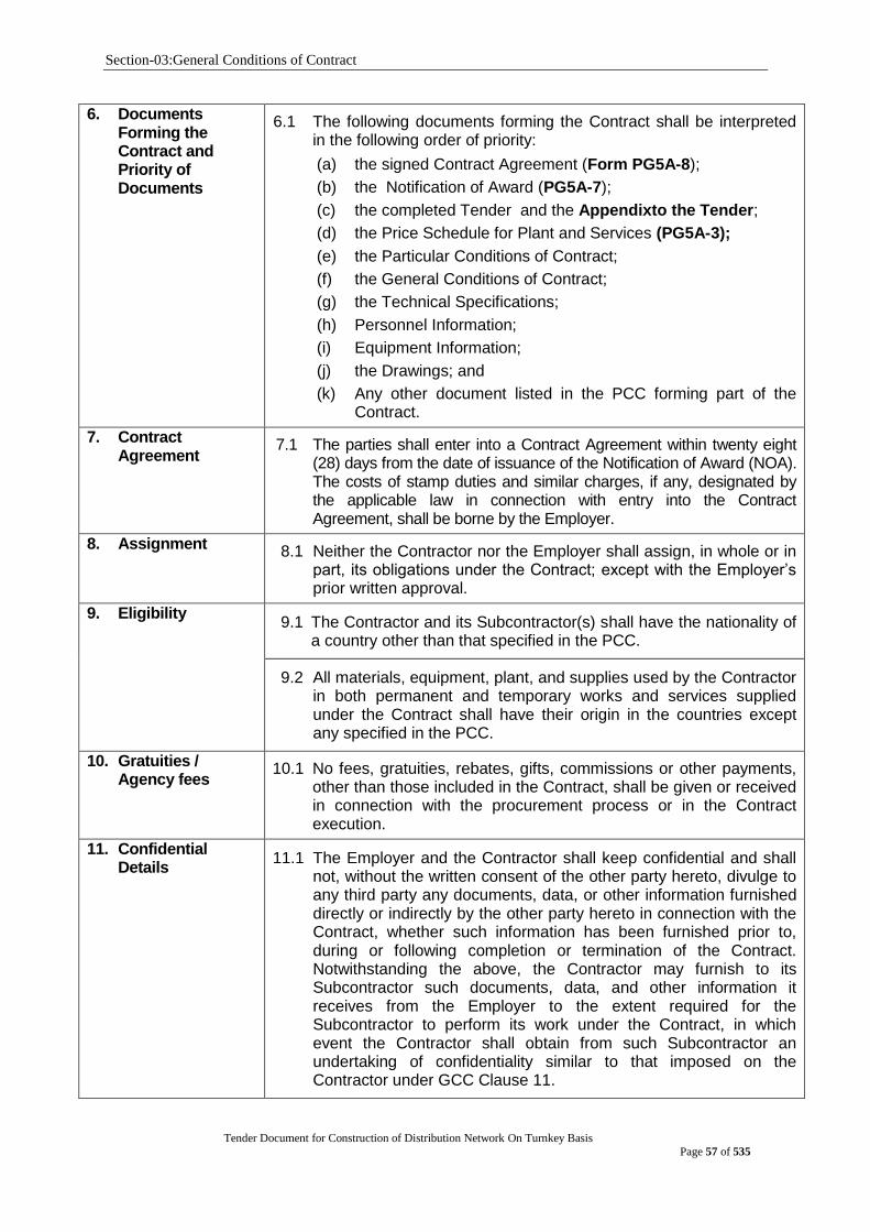
Section-03:General Conditions of Contract
Tender Document for Construction of Distribution Network On Turnkey Basis
Page 57 of 535
6. Documents Forming the Contract and Priority of Documents
6.1 The following documents forming the Contract shall be interpreted in the following order of priority:
(a) the signed Contract Agreement (Form PG5A-8);
(b) the Notification of Award (PG5A-7);
(c) the completed Tender and the Appendixto the Tender;
(d) the Price Schedule for Plant and Services (PG5A-3);
(e) the Particular Conditions of Contract;
(f) the General Conditions of Contract;
(g) the Technical Specifications;
(h) Personnel Information;
(i) Equipment Information;
(j) the Drawings; and
(k) Any other document listed in the PCC forming part of the Contract.
7. Contract Agreement
7.1 The parties shall enter into a Contract Agreement within twenty eight (28) days from the date of issuance of the Notification of Award (NOA). The costs of stamp duties and similar charges, if any, designated by the applicable law in connection with entry into the Contract Agreement, shall be borne by the Employer.
8. Assignment 8.1 Neither the Contractor nor the Employer shall assign, in whole or in part, its obligations under the Contract; except with the Employer‟s prior written approval.
9. Eligibility 9.1 The Contractor and its Subcontractor(s) shall have the nationality of
a country other than that specified in the PCC.
9.2 All materials, equipment, plant, and supplies used by the Contractor in both permanent and temporary works and services supplied under the Contract shall have their origin in the countries except any specified in the PCC.
10. Gratuities / Agency fees
10.1 No fees, gratuities, rebates, gifts, commissions or other payments, other than those included in the Contract, shall be given or received in connection with the procurement process or in the Contract execution.
11. Confidential Details
11.1 The Employer and the Contractor shall keep confidential and shall not, without the written consent of the other party hereto, divulge to any third party any documents, data, or other information furnished directly or indirectly by the other party hereto in connection with the Contract, whether such information has been furnished prior to, during or following completion or termination of the Contract. Notwithstanding the above, the Contractor may furnish to its Subcontractor such documents, data, and other information it receives from the Employer to the extent required for the Subcontractor to perform its work under the Contract, in which event the Contractor shall obtain from such Subcontractor an undertaking of confidentiality similar to that imposed on the Contractor under GCC Clause 11.
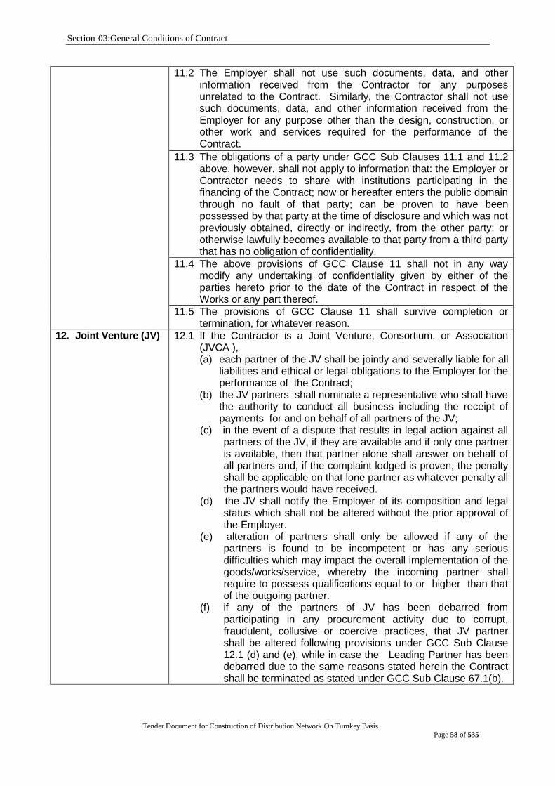
Section-03:General Conditions of Contract
Tender Document for Construction of Distribution Network On Turnkey Basis
Page 58 of 535
11.2 The Employer shall not use such documents, data, and other information received from the Contractor for any purposes unrelated to the Contract. Similarly, the Contractor shall not use such documents, data, and other information received from the Employer for any purpose other than the design, construction, or other work and services required for the performance of the Contract.
11.3 The obligations of a party under GCC Sub Clauses 11.1 and 11.2 above, however, shall not apply to information that: the Employer or Contractor needs to share with institutions participating in the financing of the Contract; now or hereafter enters the public domain through no fault of that party; can be proven to have been possessed by that party at the time of disclosure and which was not previously obtained, directly or indirectly, from the other party; or otherwise lawfully becomes available to that party from a third party that has no obligation of confidentiality.
11.4 The above provisions of GCC Clause 11 shall not in any way modify any undertaking of confidentiality given by either of the parties hereto prior to the date of the Contract in respect of the Works or any part thereof.
11.5 The provisions of GCC Clause 11 shall survive completion or termination, for whatever reason.
12. Joint Venture (JV) 12.1 If the Contractor is a Joint Venture, Consortium, or Association (JVCA ), (a) each partner of the JV shall be jointly and severally liable for all
liabilities and ethical or legal obligations to the Employer for the performance of the Contract;
(b) the JV partners shall nominate a representative who shall have the authority to conduct all business including the receipt of payments for and on behalf of all partners of the JV;
(c) in the event of a dispute that results in legal action against all partners of the JV, if they are available and if only one partner is available, then that partner alone shall answer on behalf of all partners and, if the complaint lodged is proven, the penalty shall be applicable on that lone partner as whatever penalty all the partners would have received.
(d) the JV shall notify the Employer of its composition and legal status which shall not be altered without the prior approval of the Employer.
(e) alteration of partners shall only be allowed if any of the partners is found to be incompetent or has any serious difficulties which may impact the overall implementation of the goods/works/service, whereby the incoming partner shall require to possess qualifications equal to or higher than that of the outgoing partner.
(f) if any of the partners of JV has been debarred from participating in any procurement activity due to corrupt, fraudulent, collusive or coercive practices, that JV partner shall be altered following provisions under GCC Sub Clause 12.1 (d) and (e), while in case the Leading Partner has been debarred due to the same reasons stated herein the Contract shall be terminated as stated under GCC Sub Clause 67.1(b).
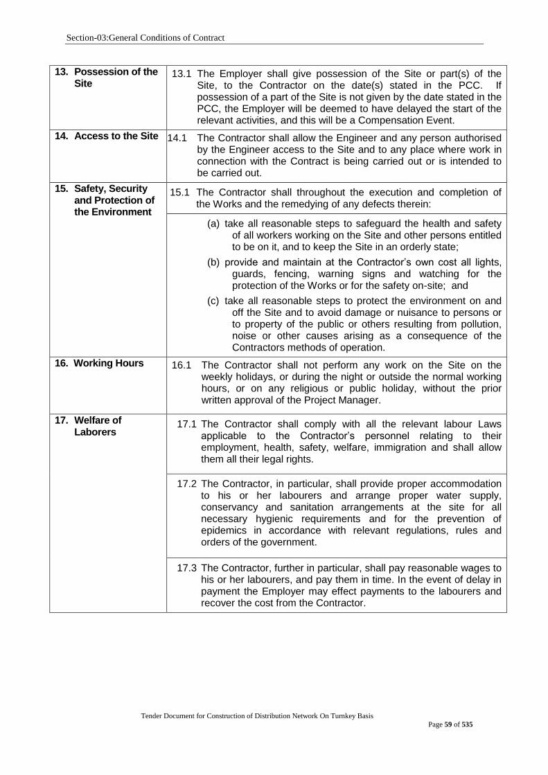
Section-03:General Conditions of Contract
Tender Document for Construction of Distribution Network On Turnkey Basis
Page 59 of 535
13. Possession of the Site
13.1 The Employer shall give possession of the Site or part(s) of the Site, to the Contractor on the date(s) stated in the PCC. If possession of a part of the Site is not given by the date stated in the PCC, the Employer will be deemed to have delayed the start of the relevant activities, and this will be a Compensation Event.
14. Access to the Site 14.1 The Contractor shall allow the Engineer and any person authorised by the Engineer access to the Site and to any place where work in connection with the Contract is being carried out or is intended to be carried out.
15. Safety, Security and Protection of the Environment
15.1 The Contractor shall throughout the execution and completion of the Works and the remedying of any defects therein:
(a) take all reasonable steps to safeguard the health and safety of all workers working on the Site and other persons entitled to be on it, and to keep the Site in an orderly state;
(b) provide and maintain at the Contractor‟s own cost all lights, guards, fencing, warning signs and watching for the protection of the Works or for the safety on-site; and
(c) take all reasonable steps to protect the environment on and off the Site and to avoid damage or nuisance to persons or to property of the public or others resulting from pollution, noise or other causes arising as a consequence of the Contractors methods of operation.
16. Working Hours
16.1 The Contractor shall not perform any work on the Site on the weekly holidays, or during the night or outside the normal working hours, or on any religious or public holiday, without the prior written approval of the Project Manager.
17. Welfare of Laborers
17.1 The Contractor shall comply with all the relevant labour Laws applicable to the Contractor‟s personnel relating to their employment, health, safety, welfare, immigration and shall allow them all their legal rights.
17.2 The Contractor, in particular, shall provide proper accommodation to his or her labourers and arrange proper water supply, conservancy and sanitation arrangements at the site for all necessary hygienic requirements and for the prevention of epidemics in accordance with relevant regulations, rules and orders of the government.
17.3 The Contractor, further in particular, shall pay reasonable wages to his or her labourers, and pay them in time. In the event of delay in payment the Employer may effect payments to the labourers and recover the cost from the Contractor.
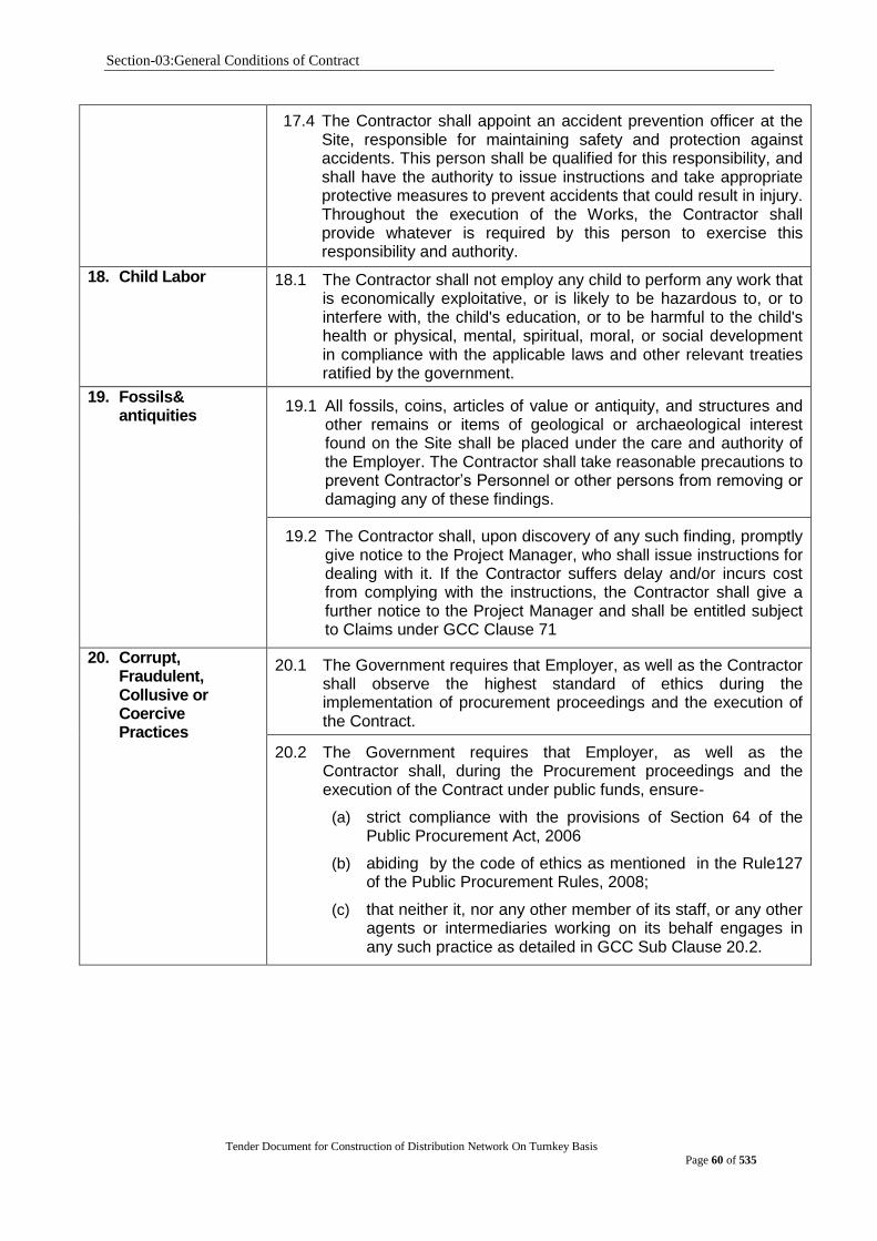
Section-03:General Conditions of Contract
Tender Document for Construction of Distribution Network On Turnkey Basis
Page 60 of 535
17.4 The Contractor shall appoint an accident prevention officer at the Site, responsible for maintaining safety and protection against accidents. This person shall be qualified for this responsibility, and shall have the authority to issue instructions and take appropriate protective measures to prevent accidents that could result in injury. Throughout the execution of the Works, the Contractor shall provide whatever is required by this person to exercise this responsibility and authority.
18. Child Labor 18.1 The Contractor shall not employ any child to perform any work that is economically exploitative, or is likely to be hazardous to, or to interfere with, the child's education, or to be harmful to the child's health or physical, mental, spiritual, moral, or social development in compliance with the applicable laws and other relevant treaties ratified by the government.
19. Fossils& antiquities
19.1 All fossils, coins, articles of value or antiquity, and structures and other remains or items of geological or archaeological interest found on the Site shall be placed under the care and authority of the Employer. The Contractor shall take reasonable precautions to prevent Contractor‟s Personnel or other persons from removing or damaging any of these findings.
19.2 The Contractor shall, upon discovery of any such finding, promptly give notice to the Project Manager, who shall issue instructions for dealing with it. If the Contractor suffers delay and/or incurs cost from complying with the instructions, the Contractor shall give a further notice to the Project Manager and shall be entitled subject to Claims under GCC Clause 71
20. Corrupt, Fraudulent, Collusive or Coercive Practices
20.1 The Government requires that Employer, as well as the Contractor shall observe the highest standard of ethics during the implementation of procurement proceedings and the execution of the Contract.
20.2 The Government requires that Employer, as well as the Contractor shall, during the Procurement proceedings and the execution of the Contract under public funds, ensure-
(a) strict compliance with the provisions of Section 64 of the Public Procurement Act, 2006
(b) abiding by the code of ethics as mentioned in the Rule127 of the Public Procurement Rules, 2008;
(c) that neither it, nor any other member of its staff, or any other agents or intermediaries working on its behalf engages in any such practice as detailed in GCC Sub Clause 20.2.
Section-03:General Conditions of Contract
Tender Document for Construction of Distribution Network On Turnkey Basis
Page 61 of 535
20.3 For the purposes of GCC Sub Clause 20.2, the terms set forth below as follows
(a) “corrupt practice” means offering, giving or promising to give, receiving, or soliciting either directly or indirectly, to any officer or employee of a Employer or other public or private authority or individual, a gratuity in any form; employment or any other thing or service of value as an inducement with respect to an act or decision or method followed by a Employer in connection with a Procurement proceeding or Contract execution;
(b) “fraudulent practice” means the misrepresentation or omission of facts in order to influence a decision to be taken in a Procurement proceeding or Contract execution;
(c) collusive practice” means a scheme or arrangement between two (2) or more Persons, with or without the knowledge of the Employer, that is designed to arbitrarily reduce the number of Tenders submitted or fix Tender prices at artificial, non-competitive levels, thereby denying a Employer the benefits of competitive price arising from genuine and open competition; or
(d) “Coercive practice” means harming or threatening to harm, directly or indirectly, Persons or their property to influence a decision to be taken in the Procurement proceeding or the execution of the Contract, and this will include creating obstructions in the normal submission process used for Tenders.
20.4 Should any corrupt, fraudulent, collusive or coercive practice of any kind come to the knowledge of the Employer, it will, in the first place, allow the Contractor to provide an explanation and shall, take actions only when a satisfactory explanation is not received. Such decision and the reasons thereof, shall be recorded in the record of the procurement proceedings and promptly communicated to the Contractor. Any communications between the Contractor and the Employer related to matters of alleged fraud or corruption shall be in writing.
20.5 If corrupt, fraudulent, collusive or coercive practices of any kind determined by the Employer against the Contractor alleged to have carried out such practices, the Employer will :
(a) exclude the Contractor from further participation in the particular Procurement proceeding; or
(b) declare, at its discretion, the Contractor to be ineligible to participate in further Procurement proceedings, either indefinitely or for a specific period of time.
20.6 The Contractor shall be aware of the provisions on corruption, fraudulence, collusion and coercion in Section 64 of the Public Procurement Act, 2006 and Rule 127 of the Public Procurement Rules, 2008.
Section-03:General Conditions of Contract
Tender Document for Construction of Distribution Network On Turnkey Basis
Page 62 of 535
21. License/ Use of Technical Information
21.1 For the operation and maintenance of the Plant, the Contractor hereby grants a non-exclusive and non-transferable license (without the right to sub-license) to the Employer under the patents, utility models or other industrial property rights owned by the Contractor or by a third Party from whom the Contractor has received the right to grant licenses thereunder, and shall also grant to the Employer a non-exclusive and non-transferable right (without the right to sub-license) to use the know-how and other technical information disclosed to the Employer under the Contract. Nothing contained herein shall be construed as transferring ownership of any patent, utility model, trademark, design, copyright, know-how or other intellectual property right from the Contractor or any third Party to the Employer.
21.2 The copyright in all drawings, documents and other materials containing data and information furnished to the Employer by the Contractor herein shall remain vested in the Contractor or, if they are furnished to the Employer directly or through the Contractor by any third Party, including suppliers of materials, the copyright in such materials shall remain vested in such third Party.
B. Subject Matter of Contract
22. Scope of Facilities 22.1 Unless otherwise expressly limited in the Employer‟s
Requirements, the Contractor‟s obligations cover the provision of all Plant and the performance of all Installation Services required for the design, and the manufacture (including procurement, quality assurance, construction, installation, associated civil works, Pre Commissioning and delivery) of the Plant, and the installation, completion and commissioning of the Facilities in accordance with the plans, procedures, specifications, drawings, codes and any other documents as specified in the Section, Employer‟s Requirements. Such specifications include, but are not limited to, the provision of supervision and engineering services; the supply of labor, materials, equipment, spare parts and accessories; Contractor‟s Equipment; construction utilities and supplies; temporary materials, structures and facilities; transportation (including, without limitation, unloading and hauling to, from and at the Site); and storage, except for those supplies, works and services that will be provided or performed by the Employer, as set forth in the Appendix to the Contract Agreement titled Scope of Works and Supply by the Employer.
22.2 The Contractor shall, unless specifically excluded in the Contract, perform all such work and/or supply all such items and materials not specifically mentioned in the Contract but that can be reasonably inferred from the Contract as being required for attaining Completion of the Facilities as if such work and/or items and materials were expressly mentioned in the Contract.
Section-03:General Conditions of Contract
Tender Document for Construction of Distribution Network On Turnkey Basis
Page 63 of 535
22.3 In addition to the supply of Mandatory Spare Parts included in the
Contract, the Contractor agrees to supply spare parts required for the operation and maintenance of the Facilities for the period specified in the PCC and the provisions, if any, specified in the PCC. However, the identity, specifications and quantities of such spare parts and the terms and conditions relating to the supply thereof are to be agreed between the Employer and the Contractor, and the price of such spare parts shall be that given in Price Schedule No.1 &2 under form PG5A-3, which shall be added to the Contract Price. The price of such spare parts shall include the purchase price therefor and other costs and expenses (including the Contractor‟s fees) relating to the supply of spare parts.
23. Time for Commencement
23.1 The Contractor shall attain Completion of the Facilities or of a part where a separate time for Completion of such part is specified in the Contract, within the time stated in the PCC or within such extended time to which the Contractor shall be entitled under GCC Clause 65.1 hereof.
24. Time for Completion
24.1 The Contractor shall attain Completion of the Facilities or of a part where a separate time for Completion of such part is specified in the Contract, within the time stated in the PCCor within such extended time to which the Contractor shall be entitled under GCC Clause 65.1 hereof.
25. Employer‟s Responsibilities
25.1 All information and/or data to be supplied by the Employer as described in the Appendix to the Contract Agreement titled Scope of Works and Supply by the Employer, shall be deemed to be accurate, except when the Employer expressly states otherwise
25.2 The Employer shall be responsible for acquiring and providing legal and physical possession of the Site and access thereto, and for providing possession of and access to all other areas reasonably required for the proper execution of the Contract, including all requisite rights of way, as specified in the Appendix to the Contract Agreement titled Scope of Works and Supply by the Employer. The Employer shall give full possession of and accord all rights of access thereto on or before the date(s) specified in that Appendix.
25.3 The Employer shall acquire and pay for all permits, approvals and/or licenses from all local, state or national government authorities or public service undertakings in the country where the Site is located which (a) such authorities or undertakings require the Employer to obtain in the Employer‟s name, (b) are necessary for the execution of the Contract, including those required for the performance by both the Contractor and the Employer of their respective obligations under the Contract, and (c) are specified in the Appendix (Scope of Works and Supply by the Employer).
25.4 If requested by the Contractor, the Employer shall use its best endeavors to assist the Contractor in obtaining in a timely and expeditious manner all permits, approvals and/or licenses necessary for the execution of the Contract from all local, state or national government authorities or public service undertakings that such authorities or undertakings require the Contractor or Subcontractors or the personnel of the Contractor or Subcontractors, as the case may be, to obtain

Section-03:General Conditions of Contract
Tender Document for Construction of Distribution Network On Turnkey Basis
Page 64 of 535
25.5 Unless otherwise specified in the Contract or agreed upon by the
Employer and the Contractor, the Employer shall provide
sufficient, properly qualified operating and maintenance personnel;
shall supply and make available all raw materials, utilities,
lubricants, chemicals, catalysts, other materials and facilities; and
shall perform all work and services of whatsoever nature, including
those required by the Contractor to properly carry out Pre
Commissioning, Commissioning and Guarantee Tests, all in
accordance with the provisions of the Appendix to the Contract
Agreement titled Scope of Works and Supply by the Employer, at
or before the time specified in the program furnished by the
Contractor under the provisions of contract specified or as
otherwise agreed upon by the Employer and the Contractor.
25.6 The Employer shall be responsible for the continued operation of
the Facilities after Completion, in accordance with GCC Sub-
Clause 39.8, and shall be responsible for facilitating the Guarantee
Test(s) for the Facilities, in accordance with GCC Sub-Clause
40.2.
25.7 All costs and expenses involved in the performance of the
obligations under this GCC Clause 25 shall be the responsibility of
the Employer, save those to be incurred by the Contractor with
respect to the performance of Guarantee Tests, in accordance with
GCC Sub-Clause 40.2.
In the event that the Employer shall be in breach of any of his obligations
under this Clause, the additional cost incurred by the Contractor in
consequence thereof shall be determined by the Project Manager
and added to the Contract Price
26. Contractor‟s Responsibilities
26.1 The Contractor shall design, manufacture including associated
purchases and/or subcontracting, install and complete the Facilities
in accordance with the Contract. When completed, the Facilities
should be fit for the purposes for which they are intended as defined
in the Contract.
26.2 The Contractor confirms that it has entered into this Contract on the
basis of a proper examination of the data relating to the Facilities
including any data as to boring tests provided by the Employer, and
on the basis of information that the Contractor could have obtained
from a visual inspection of the Site if access thereto was available
and of other data readily available to it relating to the Facilities as of
the date twenty-eight (28) days prior to tender submission. The
Contractor acknowledges that any failure to acquaint itself with all
such data and information shall not relieve its responsibility for
properly estimating the difficulty or cost of successfully performing
the Facilities.
Section-03:General Conditions of Contract
Tender Document for Construction of Distribution Network On Turnkey Basis
Page 65 of 535
26.3 The Contractor shall acquire and pay for all permits, approvals and/or licenses from all local, state or national government authorities or public service undertakings in the country where the Site is located which such authorities or undertakings require the Contractor to obtain in its name and which are necessary for the performance of the Contract, including, without limitation, visas for the Contractor‟s and Subcontractor‟s personnel and entry permits for all imported Contractor‟s Equipment. The Contractor shall acquire all other permits, approvals and/or licenses that are not the responsibility of the Employer under GCC Sub-Clause 25.3 hereof and that are necessary for the performance of the Contract.
27. Employer‟s and Contractor‟s Risks
27.1 The Employer carries the risks that the Contract states are Employer‟s risks and the Contractor carries the risks that the Contract states are Contractor‟s risks.
28. Employer‟s Risks 28.1 From the Start Date until the Defects Correction Certificate has been issued, the following are Employer‟s risks: (a) the risk of personal injury, death, or loss of or damage to
property (excluding the Works, Plant, Materials, and Equipment), which are due to
i. use or occupation of the Site by the Works or for the purpose of the Works, which is the unavoidable result of the Works or
ii. negligence, breach of statutory duty, or interference with any legal right by the Employer or by any person employed by or Contracted to him except the Contractor.
iii. the risk of damage to the Works, Plant, Materials, and Equipment to the extent that it is due to a fault of the Employer or in the Employer‟s design, or due to war or radioactive contamination directly affecting the country where the Works are to be executed.
28.2 From the Completion Date until the Defects Correction Certificate has been issued, the risk of loss of or damage to the Works, Plant, and Materials is Employer‟s risk, except loss or damage due to:
(a) a Defect which existed on the Completion Date;
(b) an event occurring before the Completion Date, which was not itself Employer‟s risk; or
(c) the activities of the Contractor on the Site after the Completion Date.
29. Contractor‟s Risks 29.1 From the Start Date until the Defects Correction Certificate has been issued the risks of personal injury, death, and loss of or damage to property including without limitation, the Works, Plant, Materials, and Equipment, which are not Employer‟s risks are Contractor‟s risks.
Section-03:General Conditions of Contract
Tender Document for Construction of Distribution Network On Turnkey Basis
Page 66 of 535
C. Execution of the Facilities
30. Representatives 31.1 Project Manager If the Project Manager is not named in the Contract, then within fourteen (14) days of the Effective Date, the Employer shall appoint and notify the Contractor in writing of the name of the Project Manager. The Employer may from time to time appoint some other person as the Project Manager in place of the person previously so appointed, and shall give a notice of the name of such other person to the Contractor without delay. No such appointment shall be made at such a time or in such a manner as to impede the progress of work on the Facilities. Such appointment shall only take effect upon receipt of such notice by the Contractor. The Project Manager shall represent and act for the Employer at all times during the performance of the Contract. All notices, instructions, orders, certificates, approvals and all other communications under the Contract shall be given by the Project Manager, except as herein otherwise provided.
All notices, instructions, information and other communications given by the Contractor to the Employer under the Contract shall be given to the Project Manager, except as herein otherwise provided.
30.2 Contractor‟s Representative & Construction Manager
30.2.1 If the Contractor‟s Representative is not named in the Contract, then within fourteen (14) days of the Effective Date, the Contractor shall appoint the Contractor‟s Representative and shall request the Employer in writing to approve the person so appointed. If the Employer makes no objection to the appointment within fourteen (14) days, the Contractor‟s Representative shall be deemed to have been approved. If the Employer objects to the appointment within fourteen (14) days giving the reason therefor, then the Contractor shall appoint a replacement within fourteen (14) days of such objection, and the foregoing provisions of this GCC Sub-Clause 30.2.1 shall apply thereto.
30.2.2 The Contractor‟s Representative shall represent and act for the Contractor at all times during the performance of the Contract and shall give to the Project Manager all the Contractor‟s notices, instructions, information and all other communications under the Contract.
The Contractor shall not revoke the appointment of the Contractor‟s Representative without the Employer‟s prior written consent, which shall not be unreasonably withheld. If the Employer consents thereto, the Contractor shall appoint some other person as the Contractor‟s Representative, pursuant to the procedure set out in GCC Sub-Clause 30.2.1.
Section-03:General Conditions of Contract
Tender Document for Construction of Distribution Network On Turnkey Basis
Page 67 of 535
30.2.3 . The Contractor‟s Representative may, subject to the approval of the Employer which shall not be unreasonably withheld, at any time delegate to any person any of the powers, functions and authorities vested in him or her. Any such delegation may be revoked at any time. Any such delegation or revocation shall be subject to a prior notice signed by the Contractor‟s Representative, and shall specify the powers, functions and authorities thereby delegated or revoked. No such delegation or revocation shall take effect unless and until a copy thereof has been delivered to the Employer and the Project Manager.
Any act or exercise by any person of powers, functions and authorities so delegated to him or her in accordance with this GCC Sub-Clause 30.2.3 shall be deemed to be an act or exercise by the Contractor‟s Representative.
30.2.4 From the commencement of installation of the Facilities at the Site until Completion, the Contractor‟s Representative shall appoint a suitable person as the Construction Manager. The Construction Manager shall supervise all work done at the Site by the Contractor and shall be present at the Site throughout normal working hours except when on leave, sick or absent for reasons connected with the proper performance of the Contract. Whenever the Construction Manager is absent from the Site, a suitable person shall be appointed to act as the Construction Manager‟s deputy.
30.2.5 The Employer may by notice to the Contractor object to any representative or person employed by the Contractor in the execution of the Contract who, in the reasonable opinion of the Employer, may behave inappropriately, may be incompetent or negligent, or may commit a serious breach of the Site regulations provided under GCC Sub-Clause 37.4. The Employer shall provide evidence of the same, whereupon the Contractor shall remove such person from the Facilities.
30.2.6 If any representative or person employed by the Contractor is removed in accordance with GCC Sub-Clause 30.2.5, the Contractor shall, where required, promptly appoint a replacement.
31. Work Program 31.1 Contractor‟s Organization
The Contractor shall supply to the Employer and the Project Manager a chart showing the proposed organization to be established by the Contractor for carrying out work on the Facilities within twenty-one (21) days of the Effective Date. The chart shall include the identities of the key personnel and the curricula vitae of such key personnel to be employed shall be supplied together with the chart. The Contractor shall promptly inform the Employer and the Project Manager in writing of any revision or alteration of such an organization chart.
Section-03:General Conditions of Contract
Tender Document for Construction of Distribution Network On Turnkey Basis
Page 68 of 535
31.2 Program of Performance
Within twenty-eight (28) days after the Effective Date, the Contractor shall submit to the Project Manager a detailed program of performance of the Contract, made in a form acceptable to the Project Manager and showing the sequence in which it proposes to design, manufacture, transport, assemble, install and Pre Commission the Facilities, as well as the date by which the Contractor reasonably requires that the Employer shall have fulfilled its obligations under the Contract so as to enable the Contractor to execute the Contract in accordance with the program and to achieve Completion, Commissioning and Acceptance of the Facilities in accordance with the Contract. The program so submitted by the Contractor shall accord with the Time Schedule included in the Appendix to the Contract Agreement titled Time Schedule, and any other dates and periods specified in the Contract. The Contractor shall update and revise the program as and when appropriate or when required by the Project Manager, but without modification in the Times for Completion specified in the PCC pursuant to Sub-Clause 24.1 and any extension granted in accordance with GCC Clause 65.1, and shall submit all such revisions to the Project Manager.
31.3 Progress Report The Contractor shall monitor progress of all the activities specified in the program referred to in GCC Sub-Clause 31.2 above, and supply a progress report to the Project Manager every month.
The progress report shall be in a form acceptable to the Project Manager and shall indicate: (a) percentage completion achieved compared with the planned percentage completion for each activity; and (b) where any activity is behind the program, giving comments and likely consequences and stating the corrective action being taken.
31.4 Progress of Performance
If at any time the Contractor‟s actual progress falls behind the program referred to in GCC Sub-Clause 31.2, or it becomes apparent that it will so fall behind, the Contractor shall, at the request of the Employer or the Project Manager, prepare and submit to the Project Manager a revised program, taking into account the prevailing circumstances, and shall notify the Project Manager of the steps being taken to expedite progress so as to attain Completion of the Facilities within the Time for Completion under GCC Sub-Clause 24.1, any extension thereof entitled under GCC Sub-Clause 65.1, or any extended period as may otherwise be agreed upon between the Employer and the Contractor.

Section-03:General Conditions of Contract
Tender Document for Construction of Distribution Network On Turnkey Basis
Page 69 of 535
31.5 Procedures The Contract shall be executed in accordance with the Contract
Documents including the procedures given in the Forms and Procedures of the Employer‟s Requirements. The Contractor may execute the Contract in accordance with its own standard project execution plans and procedures to the extent that they do not conflict with the provisions contained in the Contract.
32. Subcontractor 32.1 Subcontracting the whole of the Plant and Service by the Contractor shall not be permissible. The Contractor shall be responsible for the acts or defaults of any Subcontractor, his or her agents or employees, as if they were the acts or defaults of the Contractor.
32.2 The Contractor shall not be required to obtain consent from the Project Manager or his representative, for suppliers solely of Materials or to a subcontract for which the Specialist Subcontractor(s) is already named in the Contract.
32.3 The prior consent, in writing, of the Engineer shall however be obtained for other proposed Subcontractor(s).
33. Nominated Subcontractor
33.1 Nominated Subcontractor named in the Contract shall be entitled to execute the specific components of the Works stated in the PCC.
33.2 The Contractor shall not be under obligations to employ a Nominated Subcontractor against whom the Contractor raises reasonable objection by notice to the Engineer as soon as practicable, with supporting particulars while there are reasons to believe that the Subcontractor does not have sufficient competence, resources or financial strength, or does not accept to indemnify the Contractor against and from any negligence or misuse of Goods by the nominated Subcontractor, or does not accept to enter into a subcontract which specifies that, for the subcontracted work including design, if any, the Nominated Subcontractor shall undertake to the Contractor such obligations and liabilities as will enable the contractor to discharge his or her liabilities under the Contract.
34. Other Contractors 34.1 The Contractor shall cooperate and share the Site with other Contractors, public authorities, utilities, the Engineer and the Employer between the dates given in the Schedule of other Contractors. The Contractor shall also provide facilities and services for them as described in the Schedule. The Employer may modify the Schedule of other Contractors, and shall notify the Contractor of any such modification.
Section-03:General Conditions of Contract
Tender Document for Construction of Distribution Network On Turnkey Basis
Page 70 of 535
35. Design and Engineering
35.1 Specifications and Drawings
35.1.1 The Contractor shall execute the basic and detailed design and the engineering work in compliance with the provisions of the Contract, or where not so specified, in accordance with good engineering practice. The Contractor shall be responsible for any discrepancies, errors or omissions in the specifications, drawings and other technical documents that it has prepared, whether such specifications, drawings and other documents have been approved by the Project Manager or not, provided that such discrepancies, errors or omissions are not because of inaccurate information furnished in writing to the Contractor by or on behalf of the Employer.
35.1.2 The Contractor shall be entitled to disclaim responsibility for any design, data, drawing, specification or other document, or any modification thereof provided or designated by or on behalf of the Employer, by giving a notice of such disclaimer to the Project Manager.
35.2 Codes and Standards
Wherever references are made in the Contract to codes and standards in accordance with which the Contract shall be executed, the edition or the revised version of such codes and standards current at the date twenty-eight (28) days prior to date of tender submission shall apply unless otherwise specified. During Contract execution, any changes in such codes and standards shall be applied subject to approval by the Employer and shall be treated in accordance with GCC Clause 64.
35.3. Approval/Review of Technical Documents by Project Manager
35.3.1 The Contractor shall prepare or cause its Subcontractors to prepare, and furnish to the Project Manager the documents listed in the Appendix to the Contract Agreement titled List of Documents for Approval or Review, for its approval or review as specified and in accordance with the requirements of GCC Sub-Clause 31.2 (Program of Performance).
Any part of the Facilities covered by or related to the documents to be approved by the Project Manager shall be executed only after the Project Manager‟s approval thereof.
GCC Sub-Clauses 35.3.2 through 35.3.6 shall apply to those documents requiring the Project Manager‟s approval, but not to those furnished to the Project Manager for its review only
Section-03:General Conditions of Contract
Tender Document for Construction of Distribution Network On Turnkey Basis
Page 71 of 535
35.3.2 Within fourteen (14) days after receipt by the Project Manager of any document requiring the Project Manager‟s approval in accordance with GCC Sub-Clause 35.3.1, the Project Manager shall either return one copy thereof to the Contractor with its approval endorsed thereon or shall notify the Contractor in writing of its disapproval thereof and the reasons therefor and the modifications that the Project Manager proposes. If the Project Manager fails to take such action within the said fourteen (14) days, then the said document shall be deemed to have been approved by the Project Manager.
35.3.3. The Project Manager shall not disapprove any document, except on the grounds that the document does not comply with the Contract or that it is contrary to good engineering practice.
35.3.4 If the Project Manager disapproves the document, the Contractor shall modify the document and resubmit it for the Project Manager‟s approval in accordance with GCC Sub-Clause 35.3.2. If the Project Manager approves the document subject to modification(s), the Contractor shall make the required modification(s), whereupon the document shall be deemed to have been approved.
35.3.5 The Project Manager‟s approval, with or without modification of the document furnished by the Contractor, shall not relieve the Contractor of any responsibility or liability imposed upon it by any provisions of the Contract except to the extent that any subsequent failure results from modifications required by the Project Manager.
35.3.6 The Contractor shall not depart from any approved document unless the Contractor has first submitted to the Project Manager an amended document and obtained the Project Manager‟s approval thereof, pursuant to the provisions of this GCC Sub-Clause 35.3. If the Project Manager requests any change in any already approved document and/or in any document based thereon, the provisions of GCC Clause 64 shall apply to such request.
36. Procurement 36.1 Plant
Subject to GCC Sub-Clause 60.2, the Contractor shall procure and transport all Plant in an expeditious and orderly manner to the Site.
Section-03:General Conditions of Contract
Tender Document for Construction of Distribution Network On Turnkey Basis
Page 72 of 535
36.2 Employer-Supplied Plant If the Appendix to the Contract Agreement titled Scope of Works and Supply by the Employer, provides that the Employer shall furnish any specific items to the Contractor, the following provisions shall apply: 36.2.1 The Employer shall, at its own risk and expense, transport each item to the place on or near the Site as agreed upon by the Parties and make such item available to the Contractor at the time specified in the program furnished by the Contractor, pursuant to GCC Sub-Clause 31.2, unless otherwise mutually agreed. 36.2.2 Upon receipt of such item, the Contractor shall inspect the same visually and notify the Project Manager of any detected shortage, defect or default. The Employer shall immediately remedy any shortage, defect or default, or the Contractor shall, if practicable and possible, at the request of the Employer, remedy such shortage, defect or default at the Employer‟s cost and expense. After inspection, such item shall fall under the care, custody and control of the Contractor. The provision of this GCC Sub-Clause 36.2.2 shall apply to any item supplied to remedy any such shortage or default or to substitute for any defective item, or shall apply to defective items that have been repaired. 36.2.3 The foregoing responsibilities of the Contractor and its obligations of care, custody and control shall not relieve the Employer of liability for any undetected shortage, defect or default, nor place the Contractor under any liability for any such shortage, defect or default whether under GCC Clause 42 or under any other provision of Contract.
36.3 Transportation 36.3.1 The Contractor shall at its own risk and expense transport all the materials and the Contractor‟s Equipment to the Site by the mode of transport that the Contractor judges most suitable under all the circumstances. 36.3.2 Unless otherwise provided in the Contract, the Contractor shall be entitled to select any safe mode of transport operated by any person to carry the materials and the Contractor‟s Equipment. 36.3.3 Upon dispatch of each shipment of materials and the Contractor‟s Equipment, the Contractor shall notify the Employer by telex, cable, facsimile or electronic means, of the description of the materials and of the Contractor‟s Equipment, the point and means of dispatch, and the estimated time and point of arrival in the country where the Site is located, if applicable, and at the Site. The Contractor shall furnish the Employer with relevant shipping documents to be agreed upon between the Parties. 36.3.4 The Contractor shall be responsible for obtaining, if necessary, approvals from the authorities for transportation of the materials and the Contractor‟s Equipment to the Site. The Employer shall use its best endeavors in a timely and expeditious manner to assist the Contractor in obtaining such approvals, if requested by the Contractor. The Contractor shall indemnify and hold harmless the Employer from and against any claim for damage to roads, bridges or any other traffic facilities that may be caused by the transport of the materials and the Contractor‟s Equipment to the Site.

Section-03:General Conditions of Contract
Tender Document for Construction of Distribution Network On Turnkey Basis
Page 73 of 535
36.4 Customs Clearance
The Contractor shall, at its own expense, handle all imported materials and Contractor‟s Equipment at the point(s) of import and shall handle any formalities for customs clearance, subject to the Employer‟s obligations under GCC Sub-Clause 60.2, provided that if applicable laws or regulations require any application or act to be made by or in the name of the Employer, the Employer shall take all necessary steps to comply with such laws or regulations. In the event of delays in customs clearance that are not the fault of the Contractor, the Contractor shall be entitled to an extension in the Time for Completion, pursuant to GCC Clause 65.
37. Installation 37.1 Setting Out/Supervision
37.1.1 Bench Mark: The Contractor shall be responsible for the true and proper setting-out of the Facilities in relation to bench marks, reference marks and lines provided to it in writing by or on behalf of the Employer.
If, at any time during the progress of installation of the Facilities, any error shall appear in the position, level or alignment of the Facilities, the Contractor shall forthwith notify the Project Manager of such error and, at its own expense, immediately rectify such error to the reasonable satisfaction of the Project Manager. If such error is based on incorrect data provided in writing by or on behalf of the Employer, the expense of rectifying the same shall be borne by the Employer.
37.1.2 Contractor‟s Supervision: The Contractor shall give or provide all necessary superintendence during the installation of the Facilities, and the Construction Manager or its deputy shall be constantly on the Site to provide full-time superintendence of the installation. The Contractor shall provide and employ only technical personnel who are skilled and experienced in their respective callings and supervisory staff who are competent to adequately supervise the work at hand.
37.2 Labor:
37.2.1 Engagement of Staff and Labor
(a) Except as otherwise stated in the Specification, the Contractor shall make arrangements for the engagement of all staff and labor, local or otherwise, and for their payment, housing, feeding and transport.
(b) The Contractor shall provide and employ on the Site in the installation of the Facilities such skilled, semi-skilled and unskilled labor as is necessary for the proper and timely execution of the Contract. The Contractor is encouraged to use local labor that has the necessary skills.

Section-03:General Conditions of Contract
Tender Document for Construction of Distribution Network On Turnkey Basis
Page 74 of 535
(c) The Contractor shall be responsible for obtaining all necessary
permit(s) and/or visa(s) from the appropriate authorities for the entry of all labor and personnel to be employed on the Site into the country where the Site is located. The Employer will, if requested by the Contractor, use his best endeavors in a timely and expeditious manner to assist the Contractor in obtaining any local, state, national or government permission required for bringing in the Contractor‟s personnel.
(d) The Contractor shall at its own expense provide the means of repatriation to all of its and its Subcontractor‟s personnel employed on the Contract at the Site to the place where they were recruited or to their domicile. It shall also provide suitable temporary maintenance of all such persons from the cessation of their employment on the Contract to the date programmed for their departure. In the event that the Contractor defaults in providing such means of transportation and temporary maintenance, the Employer may provide the same to such personnel and recover the cost of doing so from the Contractor.
37.2.2 Persons in the Service of Employer
The Contractor shall not recruit, or attempt to recruit, staff and labor from amongst the Employer‟s Personnel.
37.2.3 Facilities for Staff and Labor
Except as otherwise stated in the Specification, the Contractor shall provide and maintain all necessary accommodation and welfare facilities for the Contractor‟s Personnel. The Contractor shall also provide facilities for the Employer‟s Personnel as stated in the Specification.
The Contractor shall not permit any of the Contractor‟s Personnel to maintain any temporary or permanent living quarters within the structures forming part of the Permanent Works
37.3 Contractor‟s Equipment
37.3.1 All Contractor‟s Equipment brought by the Contractor onto the Site shall be deemed to be intended to be used exclusively for the execution of the Contract. The Contractor shall not remove the same from the Site without the Project Manager‟s consent that such Contractor‟s Equipment is no longer required for the execution of the Contract.
37.3.2 Unless otherwise specified in the Contract, upon completion of the Facilities, the Contractor shall remove from the Site all Equipment brought by the Contractor onto the Site and any surplus materials remaining thereon.
Section-03:General Conditions of Contract
Tender Document for Construction of Distribution Network On Turnkey Basis
Page 75 of 535
37.3.3 The Employer will, if requested, use its best endeavors to
assist the Contractor in obtaining any local, state or national government permission required by the Contractor for the export of the Contractor‟s Equipment imported by the Contractor for use in the execution of the Contract that is no longer required for the execution of the Contract.
37.4 Site Regulations and Safety
The Employer and the Contractor shall establish Site regulations setting out the rules to be observed in the execution of the Contract at the Site and shall comply therewith. The Contractor shall prepare and submit to the Employer, with a copy to the Project Manager, proposed Site regulations for the Employer‟s approval, which approval shall not be unreasonably withheld.
Such Site regulations shall include, but shall not be limited to, rules in respect of security, safety of the Facilities, gate control, sanitation, medical care, and fire prevention. reasonable costs incurred by the Employer in connection therewith shall be paid by the Contractor to the Employer. Otherwise, the cost of such remedial work shall be borne by the Employer.
37.5 Site Clearance
37.5.1 Site Clearance in Course of Performance: In the course of carrying out the Contract, the Contractor shallkeeptheSite reasonably free from all unnecessary obstruction, store or remove any surplus materials, clear away any wreckage, rubbish or temporary works from the Site, and remove any Contractor‟s Equipment no longer required for execution of the Contract
37.6 Opportunities for Other Contractors
37.6.1 The Contractor shall, upon written request from the Employer or the Project Manager, give all reasonable opportunities for carrying out the work to any other contractors employed by the Employer on or near the Site.
37.6.2 If the Contractor, upon written request from the Employer or the Project Manager, makes available to other contractors any roads or ways the maintenance for which the Contractor is responsible, permits the use by such other contractors of the Contractor‟s Equipment, or provides any other service of whatsoever nature for such other contractors, the Employer shall fully compensate the Contractor for any loss or damage caused or occasioned by such other contractors in respect of any such use or service, and shall pay to the Contractor reasonable remuneration for the use of such equipment or the provision of such services.
Section-03:General Conditions of Contract
Tender Document for Construction of Distribution Network On Turnkey Basis
Page 76 of 535
37.7 Emergency Work
37.7.1 If, by reason of an emergency arising in connection with and during the execution of the Contract, any protective or remedial work is necessary as a matter of urgency to prevent damage to the Facilities, the Contractor shall immediately carry out such work.
If the Contractor is unable or unwilling to do such work immediately, the Employer may do or cause such work to be done as the Employer may determine is necessary in order to prevent damage to the Facilities. In such event the Employer shall, as soon as practicable after the occurrence of any such emergency, notify the Contractor in writing of such emergency, the work done and the reasons therefor. If the work done or caused to be done by the Employer is work that the Contractor was liable to do at its own expense under the Contract.
37.7.2 Clearance of Site after Completion: After Completion of all parts of the Facilities, the Contractor shall clear away and remove all wreckage, rubbish and debris of any kind from the Site, and shall leave the Site and Facilities in a clean and safe condition.
37.8 Watching and Lighting
The Contractor shall provide and maintain at its own expense alllighting, fencing, and watching when and where necessary for the proper execution and the protection of the Facilities, or for the safety of the owners and occupiers of adjacent property and for the safety of the public.
38. Test & Inspection 38.1 The Contractor shall at its own expense carry out at the place of manufacture and/or on the Site all such tests and/or inspections of the Plant and any part of the Facilities as are specified in the Contract.
38.2 The Employer and the Project Manager or their designated representatives shall be entitled to attend the aforesaid test and/or inspection, provided that the Employer shall bear all costs and expenses incurred in connection with such attendance including, but not limited to, all traveling and board and lodging expenses.
38.3 Whenever the Contractor is ready to carry out any such test and/or inspection, the Contractor shall give a reasonable advance notice of such test and/or inspection and of the place and time thereof to the Project Manager. The Contractor shall obtain from any relevant third Party or manufacturer any necessary permission or consent to enable the Employer and the Project Manager or their designated representatives to attend the test and/or inspection.
Section-03:General Conditions of Contract
Tender Document for Construction of Distribution Network On Turnkey Basis
Page 77 of 535
38.4 The Contractor shall provide the Project Manager with a certified
report of the results of any such test and/or inspection. If the Employer or Project Manager or their designated representatives fails to attend the test and/or inspection, or if it is agreed between the Parties that such persons shall not do so, then the Contractor may proceed with the test and/or inspection in the absence of such persons, and may provide the Project Manager with a certified report of the results thereof.
38.5 38.5 The Project Manager may require the Contractor to carry out any test and/or inspection not required by the Contract, provided that the Contractor‟s reasonable costs and expenses incurred in the carrying out of such test and/or inspection shall be added to the Contract Price. Further, if such test and/or inspection impede the progress of work on the Facilities and/or the Contractor‟s performance of its other obligations under the Contract, due allowance will be made in respect of the Time for Completion and the other obligations so affected.
38.6 If any Plant or any part of the Facilities fails to pass any test and/or inspection, the Contractor shall either rectify or replace such Plant or part of the Facilities and shall repeat the test and/or inspection upon giving a notice under GCC Sub-Clause 38.3.
38.7 If any dispute or difference of opinion shall arise between the Parties in connection with or arising out of the test and/or inspection of the Plant or part of the Facilities that cannot be settled between the Parties within a reasonable period of time, it may be referred to an 72.2.
38.8 The Contractor shall afford the Employer and the Project Manager, at the Employer‟s expense, access at any reasonable time to any place where the Plant are being manufactured or the Facilities are being installed, in order to inspect the progress and the manner of manufacture or installation, provided that the Project Manager shall give the Contractor a reasonable prior notice.
38.9 The Contractor agrees that neither the execution of a test and/or inspection of Plant or any part of the Facilities, nor the attendance by the Employer or the Project Manager, nor the issue of any test certificate pursuant to GCC Sub-Clause 38.4, shall release the Contractor from any other responsibilities under the Contract.
38.10 No part of the Facilities or foundations shall be covered up on the Site without the Contractor carrying out any test and/or inspection required under the Contract. The Contractor shall give a reasonable notice to the Project Manager whenever any such parts of the Facilities or foundations are ready or about to be ready for test and/or inspection; such test and/or inspection and notice thereof shall be subject to the requirements of the Contract.
Section-03:General Conditions of Contract
Tender Document for Construction of Distribution Network On Turnkey Basis
Page 78 of 535
38.11 The Contractor shall uncover any part of the Facilities or
foundations, or shall make openings in or through the same as the Project Manager may from time to time require at the Site, and shall reinstate and make good such part or parts.
38.12 If any parts of the Facilities or foundations have been covered up at the Site after compliance with the requirement of GCC Sub-Clause 38.10 and are found to be executed in accordance with the Contract, the expenses of uncovering, making openings in or through, reinstating, and making good the same shall be borne by the Employer, and the Time for Completion shall be reasonably adjusted to the extent that the Contractor has thereby been delayed or impeded in the performance of any of its obligations under the Contract.
39. Completion of the Facilities
39.1 As soon as the Facilities or any part thereof has, in the opinion of the Contractor, been completed operationally and structurally and put in a tight and clean condition as specified in the Employer‟s Requirements, excluding minor items not materially affecting the operation or safety of the Facilities, the Contractor shall so notify the Employer in writing.
39.2 Within seven (7) days after receipt of the notice from the Contractor under GCC Sub-Clause 39.1, the Employer shall supply the operating and maintenance personnel specified in the Appendix to the Contract Agreement titled Scope of Works and Supply by the Employer for Pre Commissioning of the Facilities or any part thereof.
Pursuant to the Appendix to the Contract Agreement titled Scope of Works and Supply by the Employer, the Employer shall also provide, within the said seven (7) day period, the raw materials, utilities, lubricants, chemicals, catalysts, facilities, services and other matters required for Pre Commissioning of the Facilities or any part thereof.
39.3 As soon as reasonably practicable after the operating and maintenance personnel have been supplied by the Employer and the raw materials, utilities, lubricants, chemicals, catalysts, facilities, services and other matters have been provided by the Employer in accordance with GCC Sub-Clause 39.2, the Contractor shall commence Pre-commissioning of the Facilities or the relevant part thereof in preparation for Commissioning, subject to GCC Sub-Clause 40.5.
39.4 As soon as all works in respect of Pre-commissioning are completed and, in the opinion of the Contractor, the Facilities or
Section-03:General Conditions of Contract
Tender Document for Construction of Distribution Network On Turnkey Basis
Page 79 of 535
39.5 The Project Manager shall, within fourteen (14) days after receipt of the Contractor‟s notice under GCC Sub-Clause 39.4, either issue a Completion Certificate in the form specified in the Employer‟s Requirements (Forms and Procedures), stating that the Facilities or that part thereof have reached Completion as of the date of the Contractor‟s notice under GCC Sub-Clause 39.4, or notify the Contractor in writing of any defects and/or deficiencies.
If the Project Manager notifies the Contractor of any defects and/or deficiencies, the Contractor shall then correct such defects and/or deficiencies, and shall repeat the procedure described in GCC Sub-Clause 39.4.
39.6 If the Project Manager is satisfied that the Facilities or that part thereof have reached Completion, the Project Manager shall, within seven (7) days after receipt of the Contractor‟s repeated notice, issue a Completion Certificate stating that the Facilities or that part thereof have reached Completion as of the date of the Contractor‟s repeated notice.
39.7 If the Project Manager is not so satisfied, then it shall notify the Contractor in writing of any defects and/or deficiencies within seven (7) days after receipt of the Contractor‟s repeated notice, and the above procedure shall be repeated.
39.8 If the Project Manager fails to issue the Completion Certificate and fails to inform the Contractor of any defects and/or deficiencies within fourteen (14) days after receipt of the Contractor‟s notice under GCC Sub-Clause 39.4 or within seven (7) days after receipt of the Contractor‟s repeated notice under GCC Sub-Clause 39.5, or if the Employer makes use of the Facilities or part thereof, then the Facilities or that part thereof shall be deemed to have reached Completion as of the date of the Contractor‟s notice or repeated notice, or as of the Employer‟s use of the Facilities, as the case may be.
39.9 As soon as possible after Completion, the Contractor shall complete all outstanding minor items so that the Facilities are fully in accordance with the requirements of the Contract, failing which the Employer will undertake such completion and deduct the costs thereof from any monies owing to the Contractor.
39.10 Upon Completion, the Employer shall be responsible for the care and custody of the Facilities or the relevant part thereof, together with the risk of loss or damage thereto, and shall thereafter take over the Facilities or the relevant part thereof.

Section-03:General Conditions of Contract
Tender Document for Construction of Distribution Network On Turnkey Basis
Page 80 of 535
40. Commissioning and Operational Acceptance
40.1 Commissioning
40.1.1 Commissioning of the Facilities or any part thereof shall be commenced by the Contractor immediately after issue of the Completion Certificate by the Project Manager, pursuant to GCC Sub-Clause 39.5, or immediately after the date of the deemed Completion, under GCC Sub-Clause 39.6.
40.1.2 The Employer shall supply the operating and maintenance personnel and all raw materials, utilities, lubricants, chemicals, catalysts, facilities, services and other matters required for Commissioning.
40.1.3 In accordance with the requirements of the Contract, the Contractor‟s and Project Manager‟s advisory personnel shall attend the Commissioning, including the Guarantee Test, and shall advise and assist the Employer.
40.2 Guarantee Test
40.2.1 Subject to GCC Sub-Clause 40.5, the Guarantee Test and repeats thereof shall be conducted by the Contractor during Commissioning of the Facilities or the relevant part thereof to ascertain whether the Facilities or the relevant part can attain the Functional Guarantees specified in the Appendix to the Contract Agreement titled Functional Guarantees. The Employer shall promptly provide the Contractor with such information as the Contractor may reasonably require in relation to the conduct and results of the Guarantee Test and any repeats thereof.
40.2.2 If for reasons not attributable to the Contractor, the Guarantee Test of the Facilities or the relevant part thereof cannot be successfully completed within the period from the date of Completion specified in the PCC or any other period agreed upon by the Employer and the Contractor, the Contractor shall be deemed to have fulfilled its obligations with respect to the Functional Guarantees, and GCC Sub-Clauses 43.2 and 43.3 shall not apply.
40.3 Operational Acceptance
40.3.2 At any time after any of the events set out in GCC Sub-Clause 40.3.1 have occurred, the Contractor may give a notice to the Project Manager requesting the issue of an Operational Acceptance Certificate in the form provided in the Employer‟s Requirements (Forms and Procedures)in respect of the Facilities or the part thereof specified in such notice as of the date of such notice.
40.3.3 The Project Manager shall, after consultation with the Employer, and within seven (7) days after receipt of the Contractor‟s notice, issue an Operational Acceptance Certificate.
Section-03:General Conditions of Contract
Tender Document for Construction of Distribution Network On Turnkey Basis
Page 81 of 535
40.3.4 If within seven (7) days after receipt of the Contractor‟s
notice, the Project Manager fails to issue the Operational
Acceptance Certificate or fails to inform the Contractor in
writing of the justifiable reasons why the Project Manager
has not issued the Operational Acceptance Certificate,
the Facilities or the relevant part thereof shall be deemed
to have been accepted as of the date of the Contractor‟s
said notice.
40.4 Partial Acceptance
40.4.1 If the Contract specifies that Completion and
Commissioning shall be carried out in respect of parts of
the Facilities, the provisions relating to Completion and
Commissioning including the Guarantee Test shall apply
to each such part of the Facilities individually, and the
Operational Acceptance Certificate shall be issued
accordingly for each such part of the Facilities.
40.4.2 If a part of the Facilities comprises facilities such as
buildings, for which no Commissioning or Guarantee Test
is required, then the Project Manager shall issue the
Operational Acceptance Certificate for such facility when
it attains Completion, provided that the Contractor shall
thereafter complete any outstanding minor items that are
listed in the Operational Acceptance Certificate
40.5 Delayed Pre-commissioning and/or Guarantee Test
40.5.1 In the event that the Contractor is unable to proceed with
the Pre-commissioning of the Facilities pursuant to Sub-
Clause 39.3, or with the Guarantee Test pursuant to Sub-
Clause 40.2, for reasons attributable to the Employer
either on account of non-availability of other facilities
under the responsibilities of other contractor(s), or for
reasons beyond the Contractor‟s control, the provisions
leading to “deemed” completion of activities such as
Completion, pursuant to GCC Sub-Clause 39.6, and
Operational Acceptance, pursuant to GCC Sub-Clause
40.3.4, and Contractor‟s obligations regarding Defect
Liability Period, pursuant to GCC Sub-Clause 42.2,
Functional Guarantee, pursuant to GCC Clause 43, and
Care of Facilities, pursuant to GCC Clause 48, and GCC
Clause 66.1, Suspension, shall not apply. In this case,
the following provisions shall apply.
40.5.2 When the Contractor is notified by the Project Manager
that he will be unable to proceed with the activities and
obligations pursuant to clauses 58 & 59, the Contractor
shall be entitled to the following:
Section-03:General Conditions of Contract
Tender Document for Construction of Distribution Network On Turnkey Basis
Page 82 of 535
(a) the Time of Completion shall be extended for the period of
suspension without imposition of liquidated damages
pursuant to GCC Sub-Clause 41.2;
(b) payments due to the Contractor in accordance with the
provision specified in the Appendix to the Contract
Agreement titled Terms and Procedures of Payment, which
would not have been payable in normal circumstances due
to non-completion of the subject activities, shall be released
to the Contractor against submission of a security in the form
of a bank guarantee of equivalent amount acceptable to the
Employer, and which shall become null and void when the
Contractor will have complied with its obligations regarding
those payments, subject to the provision of Sub-Clause
40.5.3 below;
(c) the expenses towards the above security and extension of
other securities under the contract, of which validity needs to
be extended, shall be reimbursed to the Contractor by the
Employer;
(d) the additional charges towards the care of the Facilities
pursuant to GCC Sub-Clause 48.1 shall be reimbursed to
the Contractor by the Employer for the period between the
notification mentioned above and the notification mentioned
in Sub-Clause 40.5.4 below. The provision of GCC Sub-
Clause 49.2 shall apply to the Facilities during the same
period.
40.5.3 In the event that the period of suspension under above
Sub-Clause 40.5.1 actually exceeds one hundred eighty
(180) days, the Employer and Contractor shall mutually
agree to any additional compensation payable to the
Contractor.
40.5.4 When the Contractor is notified by the Project Manager that
the plant is ready for Pre-commissioning, the Contractor
shall proceed without delay in performing Pre-
commissioning, in accordance with Clause 39.

Section-03:General Conditions of Contract
Tender Document for Construction of Distribution Network On Turnkey Basis
Page 83 of 535
D. Guarantees and Liabilities 41. Completion Time
Guarantee 41.1 The Contractor guarantees that it shall attain Completion of the
Facilities (or a part for which a separate time for completion is specified) within the Time for Completion specified in the PCC pursuant to GCC Sub-Clause 24.1, or within such extended time to which the Contractor shall be entitled under GCC Clause 65 hereof
41.2 If the Contractor fails to attain Completion of the Facilities or any part thereof within the Time for Completion or any extension thereof under GCC Clause 65, the Contractor shall pay to the Employer liquidated damages in the amount specified in the PCC as a percentage rate of the Contract Price or the relevant part thereof. The aggregate amount of such liquidated damages shall in no event exceed the amount specified as “Maximum” in the PCC as a percentage rate of the Contract Price. Once the “Maximum” is reached, the Employer may consider termination of the Contract, pursuant to GCC Sub-Clause 67.2.2.
Such payment shall completely satisfy the Contractor‟s obligation to attain Completion of the Facilities or the relevant part thereof within the Time for Completion or any extension thereof under GCC Clause 65. The Contractor shall have no further liability whatsoever to the Employer in respect thereof.
However, the payment of liquidated damages shall not in any way relieve the Contractor from any of its obligations to complete the Facilities or from any other obligations and liabilities of the Contractor under the Contract.
Save for liquidated damages payable under this GCC Sub-Clause 41.2, the failure by the Contractor to attain any milestone or other act, matter or thing by any date specified in the Appendix to the Contract Agreement titled Time Schedule, and/or other program of work prepared pursuant to GCC Sub-Clause 31.2 shall not render the Contractor liable for any loss or damage thereby suffered by the Employer..
41.3 If the Contractor attains Completion of the Facilities or any part thereof before the Time for Completion or any extension thereof under GCC Clause 65, the Employer shall pay to the Contractor a bonus in the amount specified in the PCC. The aggregate amount of such bonus shall in no event exceed the amount specified as “Maximum” in the PCC.
42. Defect Liability 42.1 TheContractor warrants that the Facilities or any part thereof shall be free from defects in the design, engineering, materials and workmanship of the Plant supplied and of the work executed.

Section-03:General Conditions of Contract
Tender Document for Construction of Distribution Network On Turnkey Basis
Page 84 of 535
42.2 The Defect Liability Period shall be five hundred and forty (540) days from the date of Completion of the Facilities (or any part thereof) or one year from the date of Operational Acceptance of the Facilities (or any part thereof), whichever first occurs, unless specified otherwise in the PCC pursuant to GCC Sub-Clause 42.10.
If during the Defect Liability Period any defect should be found in the design, engineering, materials and workmanship of the Plant supplied or of the work executed by the Contractor, the Contractor shall promptly, in consultation and agreement with the Employer regarding appropriate remedying of the defects, and at its cost, repair, replace or otherwise make good as the Contractor shall determine at its discretion, such defect as well as any damage to the Facilities caused by such defect. The Contractor shall not be responsible for the repair, replacement or making good of any defect or of any damage to the Facilities arising out of or resulting from any of the following causes:
(a) improper operation or maintenance of the Facilities by the Employer;
(b) operation of the Facilities outside specifications provided in the Contract; or
(c) Normal wear and tear.
42.3 The Contractor‟s obligations under this GCC Clause 42 shall not apply to:
(a) any materials that are supplied by the Employer under GCC Sub-Clause 36.2, are normally consumed in operation, or have a normal life shorter than the Defect Liability Period stated herein;
(b) any designs, specifications or other data designed, supplied or specified by or on behalf of the Employer or any matters for which the Contractor has disclaimed responsibility herein; or
(c) Any other materials supplied or any other work executed by or on behalf of the Employer, except for the work executed by the Employer under GCC Sub-Clause 42.7.
42.4 The Employer shall give the Contractor a notice stating the nature of any such defect together with all available evidence thereof, promptly following the discovery thereof. The Employer shall afford all reasonable opportunity for the Contractor to inspect any such defect.
Section-03:General Conditions of Contract
Tender Document for Construction of Distribution Network On Turnkey Basis
Page 85 of 535
42.5 The Employer shall afford the Contractor all necessary access to the Facilities and the Site to enable the Contractor to perform its obligations under this GCC Clause 42.
The Contractor may, with the consent of the Employer, remove from the Site any Plant or any part of the Facilities that are defective if the nature of the defect, and/or any damage to the Facilities caused by the defect, is such that repairs cannot be expeditiously carried out at the Site.
42.6 If the repair, replacement or making good is of such a character that it may affect the efficiency of the Facilities or any part thereof, the Employer may give to the Contractor a notice requiring that tests of the defective part of the Facilities shall be made by the Contractor immediately upon completion of such remedial work, whereupon the Contractor shall carry out such tests.
If such part fails the tests, the Contractor shall carry out further repair, replacement or making good, as the case may be, until that part of the Facilities passes such tests. The tests shall be agreed upon by the Employer and the Contractor.
42.7 If the Contractor fails to commence the work necessary to remedy such defect or any damage to the Facilities caused by such defect within a reasonable time (which shall in no event be considered to be less than fifteen (15) days), the Employer may, following notice to the Contractor, proceed to do such work, and the reasonable costs incurred by the Employer in connection therewith shall be paid to the Employer by the Contractor or may be deducted by the Employer from any monies due the Contractor or claimed under the Performance Security.
42.8 If the Facilities or any part thereof cannot be used by reason of such defect and/or making good of such defect, the Defect Liability Period of the Facilities or such part, as the case may be, shall be extended by a period equal to the period during which the Facilities or such part cannot be used by the Employer because of any of the aforesaid reasons.
42.9 Except as provided in GCC Clauses 42 and 49, the Contractor shall be under no liability whatsoever and howsoever arising, and whether under the Contract or at law, in respect of defects in the Facilities or any part thereof, the Plant, design or engineering or work executed that appear after Completion of the Facilities or any part thereof, except where such defects are the result of the gross negligence, fraud, or criminal or willful action of the Contractor.
42.10 In addition, any such component of the Facilities, and during the period of time as may be specified in the PCC, shall be subject to an extended defect liability period. Such obligation of the Contractor shall be in addition to the defect liability period specified under GCC Sub-Clause 42.2.
Section-03:General Conditions of Contract
Tender Document for Construction of Distribution Network On Turnkey Basis
Page 86 of 535
43. Functional Guarantees
43.1 The Contractor guarantees that during the Guarantee Test, the
Facilities and all parts thereof shall attain the Functional Guarantees
specified in the Appendix to the Contract Agreement titled
Functional Guarantees, subject to and upon the conditions therein
specified.
43.2 If, for reasons attributable to the Contractor, the minimum level of
the Functional Guarantees specified in the Appendix to the Contract
Agreement titled Functional Guarantees, are not met either in whole
or in part, the Contractor shall at its cost and expense make such
changes, modifications and/or additions to the Plant or any part
thereof as may be necessary to meet at least the minimum level of
such Guarantees. The Contractor shall notify the Employer upon
completion of the necessary changes, modifications and/or
additions, and shall request the Employer to repeat the Guarantee
Test until the minimum level of the Guarantees has been met. If the
Contractor eventually fails to meet the minimum level of Functional
Guarantees, the Employer may consider termination of the Contract,
pursuant to GCC Sub-Clause 64.2.2.
43.3 If, for reasons attributable to the Contractor, the Functional
Guarantees specified in the Appendix to the Contract Agreement
titled Functional Guarantees, are not attained either in whole or in
part, but the minimum level of the Functional Guarantees specified
in the said Appendix to the Contract Agreement is met, the
Contractor shall, at the Contractor‟s option, either
(a) make such changes, modifications and/or additions to the Facilities
or any part thereof that are necessary to attain the Functional
Guarantees at its cost and expense, and shall request the Employer
to repeat the Guarantee Test or
(b) pay liquidated damages to the Employer in respect of the failure to
meet the Functional Guarantees in accordance with the provisions
in the Appendix to the Contract Agreement titled Functional
Guarantees.
43.4 The payment of liquidated damages under GCC Sub-Clause 43.3,
up to the limitation of liability specified in the Appendix to the
Contract Agreement titled Functional Guarantees, shall completely
satisfy the Contractor‟s guarantees under GCC Sub-Clause 43.3,
and the Contractor shall have no further liability whatsoever to the
Employer in respect thereof. Upon the payment of such liquidated
damages by the Contractor, the Project Manager shall issue the
Operational Acceptance Certificate for the Facilities or any part
thereof in respect of which the liquidated damages have been so
paid.
Section-03:General Conditions of Contract
Tender Document for Construction of Distribution Network On Turnkey Basis
Page 87 of 535
44. Patent Indemnity 44.1 The Contractor shall, subject to the Employer‟s compliance with GCC Sub-Clause 44.2, indemnify and hold harmless the Employer and its employees and officers from and against any and all suits, actions or administrative proceedings, claims, demands, losses, damages, costs, and expenses of whatsoever nature, including attorney‟s fees and expenses, which the Employer may suffer as a result of any infringement or alleged infringement of any patent, utility model, registered design, trademark, copyright or other intellectual property right registered or otherwise existing at the date of the Contract by reason of: (a) the installation of the Facilities by the Contractor or the use of the Facilities in the country where the Site is located; and (b) the sale of the products produced by the Facilities in any country.
Such indemnity shall not cover any use of the Facilities or any part thereof other than for the purpose indicated by or to be reasonably inferred from the Contract, any infringement resulting from the use of the Facilities or any part thereof, or any products produced thereby in association or combination with any other equipment, plant or materials not supplied by the Contractor, pursuant to the Contract Agreement.
44.2 If any proceedings are brought or any claim is made against the Employer arising out of the matters referred to in GCC Sub-Clause 29.1, the Employer shall promptly give the Contractor a notice thereof, and the Contractor may at its own expense and in the Employer‟s name conduct such proceedings or claim and any negotiations for the settlement of any such proceedings or claim.
If the Contractor fails to notify the Employer within twenty-eight (28) days after receipt of such notice that it intends to conduct any such proceedings or claim, then the Employer shall be free to conduct the same on its own behalf. Unless the Contractor has so failed to notify the Employer within the twenty-eight (28) day period, the Employer shall make no admission that may be prejudicial to the defense of any such proceedings or claim.
The Employer shall, at the Contractor‟s request, afford all available assistance to the Contractor in conducting such proceedings or claim, and shall be reimbursed by the Contractor for all reasonable expenses incurred in so doing.
44.3 The Employer shall indemnify and hold harmless the Contractor and its employees, officers and Subcontractors from and against any and all suits, actions or administrative proceedings, claims, demands, losses, damages, costs, and expenses of whatsoever nature, including attorney‟s fees and expenses, which the Contractor may suffer as a result of any infringement or alleged infringement of any patent, utility model, registered design, trademark, copyright or other intellectual property right registered or otherwise existing at the date of the Contract arising out of or in connection with any design, data, drawing, specification, or other documents or materials provided or designed by or on behalf of the Employer.
Section-03:General Conditions of Contract
Tender Document for Construction of Distribution Network On Turnkey Basis
Page 88 of 535
45. Limitation of Liability
45.1 Except in cases of criminal negligence or willful misconduct,
(a) neither Party shall be liable to the other Party, whether in
contract, tort, or otherwise, for any indirect or consequential loss or
damage, loss of use, loss of production, or loss of profits or interest
costs, which may be suffered by the other Party in connection with
the Contract, other than specifically provided as any obligation of
the Party in the Contract, and
(b) the aggregate liability of the Contractor to the Employer,
whether under the Contract, in tort or otherwise, shall not exceed
the amount resulting from the application of the multiplier specified
in the PCC, to the Contract Price or, if a multiplier is not so
specified, the total Contract Price, provided that this limitation shall
not apply to the cost of repairing or replacing defective equipment,
or to any obligation of the Contractor to indemnify the Employer with
respect to patent infringement..
E. Risk Distribution
46. Transfer of Ownership
46.1 Ownership of the Plant (including spare parts) to be imported into
the country where the Site is located shall be transferred to the
Employer upon loading on to the mode of transport to be used to
convey the Plant from the country of origin to that country.
46.2 Ownership of the Plant (including spare parts) procured in the
country where the Site is located shall be transferred to the
Employer when the Plant are brought on to the Site.
46.3 Ownership of the Contractor‟s Equipment used by the Contractor
and its Subcontractors in connection with the Contract shall remain
with the Contractor or its Subcontractors.
46.4 Ownership of any Plant in excess of the requirements for the
Facilities shall revert to the Contractor upon Completion of the
Facilities or at such earlier time when the Employer and the
Contractor agree that the Plant in question are no longer required
for the Facilities.
46.5 Notwithstanding the transfer of ownership of the Plant, the
responsibility for care and custody thereof together with the risk of
loss or damage thereto shall remain with the Contractor pursuant to
GCC Clause 32 (Care of Facilities) hereof until Completion of the
Facilities or the part thereof in which such Plant are incorporated.
Section-03:General Conditions of Contract
Tender Document for Construction of Distribution Network On Turnkey Basis
Page 89 of 535
47. Care of Facilities 47.1 The Contractor shall be responsible for the care and custody of the Facilities or any part thereof until the date of Completion of the Facilities pursuant to GCC Clause 39 or, where the Contract provides for Completion of the Facilities in parts, until the date of Completion of the relevant part, and shall make good at its own cost any loss or damage that may occur to the Facilities or the relevant part thereof from any cause whatsoever during such period. The Contractor shall also be responsible for any loss or damage to the Facilities caused by the Contractor or its Subcontractors in the course of any work carried out, pursuant to GCC Clause 42. Notwithstanding the foregoing, the Contractor shall not be liable for any loss or damage to the Facilities or that part thereof caused by reason of any of the matters specified or referred to in paragraphs (a), (b) and (c) of GCC Sub-Clauses 48.2.
47.2 If any loss or damage occurs to the Facilities or any part thereof or to the Contractor‟s temporary facilities by reason of
(a) insofar as they relate to the country where the Site is located, nuclear reaction, nuclear radiation, radioactive contamination, pressure wave caused by aircraft or other aerial objects, or any other occurrences that an experienced contractor could not reasonably foresee, or if reasonably foreseeable could not reasonably make provision for or insure against, insofar as such risks are not normally insurable on the insurance market and are mentioned in the general exclusions of the policy of insurance, including War Risks and Political Risks, taken out under GCC Clause 34 hereof; or
(b) any use or occupation by the Employer or any third Party other than a Subcontractor, authorized by the Employer of any part of the Facilities; or
(c) any use of or reliance upon any design, data or specification provided or designated by or on behalf of the Employer, or any such matter for which the Contractor has disclaimed responsibility herein,
47.3 the Employer shall pay to the Contractor all sums payable in respect of the Facilities executed, notwithstanding that the same be lost, destroyed or damaged, and will pay to the Contractor the replacement value of all temporary facilities and all parts thereof lost, destroyed or damaged. If the Employer requests the Contractor in writing to make good any loss or damage to the Facilities thereby occasioned, the Contractor shall make good the same at the cost of the Employer in accordance with GCC Clause 64. If the Employer does not request the Contractor in writing to make good any loss or damage to the Facilities thereby occasioned, the Employer shall either request a change in accordance with GCC Clause 64, excluding the performance of that part of the Facilities thereby lost, destroyed or damaged, or, where the loss or damage affects a substantial part of the Facilities, the Employer shall terminate the Contract pursuant to GCC Sub-Clause 66.1 hereof.
47.4 The Contractor shall be liable for any loss of or damage to any Contractor‟s Equipment, or any other property of the Contractor used or intended to be used for purposes of the Facilities, except (i) as mentioned in GCC Sub-Clause 42.2 with respect to the Contractor‟s temporary facilities, and (ii) where such loss or damage arises by reason of any of the matters specified in GCC Sub-Clauses 47.2 (b) and (c).

Section-03:General Conditions of Contract
Tender Document for Construction of Distribution Network On Turnkey Basis
Page 90 of 535
48. Loss of or Damage to Property; Accident or Injury to Workers; Indemnification
48.1 Subject to GCC Sub-Clause 48.3, the Contractor shall indemnify
and hold harmless the Employer and its employees and officers
from and against any and all suits, actions or administrative
proceedings, claims, demands, losses, damages, costs, and
expenses of whatsoever nature, including attorney‟s fees and
expenses, in respect of the death or injury of any person or loss of
or damage to any property other than the Facilities whether
accepted or not, arising in connection with the supply and
installation of the Facilities and by reason of the negligence of the
Contractor or its Subcontractors, or their employees, officers or
agents, except any injury, death or property damage caused by the
negligence of the Employer, its contractors, employees, officers or
agents.
48.2 If any proceedings are brought or any claim is made against the
Employer that might subject the Contractor to liability under GCC
Sub-Clause 48.1, the Employer shall promptly give the Contractor a
notice thereof and the Contractor may at its own expense and in the
Employer‟s name conduct such proceedings or claim and any
negotiations for the settlement of any such proceedings or claim.
48.3 If the Contractor fails to notify the Employer within twenty-eight (28)
days after receipt of such notice that it intends to conduct any such
proceedings or claim, then the Employer shall be free to conduct the
same on its own behalf. Unless the Contractor has so failed to
notify the Employer within the twenty-eight (28) day period, the
Employer shall make no admission that may be prejudicial to the
defense of any such proceedings or claim.
The Employer shall, at the Contractor‟s request, afford all available
assistance to the Contractor in conducting such proceedings or
claim, and shall be reimbursed by the Contractor for all reasonable
expenses incurred in so doing.
48.4 The Employer shall indemnify and hold harmless the Contractor and
its employees, officers and Subcontractors from any liability for loss
of or damage to property of the Employer, other than the Facilities
not yet taken over, that is caused by fire, explosion or any other
perils, in excess of the amount recoverable from insurances
procured under GCC Clause 49, provided that such fire, explosion
or other perils were not caused by any act or failure of the
Contractor.
48.5 The Party entitled to the benefit of an indemnity under this GCC
Clause 48 shall take all reasonable measures to mitigate any loss or
damage which has occurred. If the Party fails to take such
measures, the other Party‟s liabilities shall be correspondingly
reduced.

Section-03:General Conditions of Contract
Tender Document for Construction of Distribution Network On Turnkey Basis
Page 91 of 535
49. Insurance 49.1 To the extent specified in the Appendix to the Contract Agreement
titled Insurance Requirements, the Contractor shall at its expense
take out and maintain in effect, or cause to be taken out and
maintained in effect, during the performance of the Contract, the
insurances set forth below in the sums and with the deductibles
and other conditions specified in the said Appendix. The identity of
the insurers and the form of the policies shall be subject to the
approval of the Employer, who should not unreasonably withhold
such approval.
(a) Cargo Insurance During Transport
Covering loss or damage occurring while in transit from the
Contractor‟s or Subcontractor‟s works or stores until arrival at
the Site, to the Plant (including spare parts therefor) and to the
Contractor‟s Equipment.
(b) Installation All Risks Insurance
Covering physical loss or damage to the Facilities at the Site,
occurring prior to Completion of the Facilities, with extended
maintenance coverage for the Contractor‟s liability in respect
of any loss or damage occurring during the Defect Liability
Period while the Contractor is on the Site for the purpose of
performing its obligations during the Defect Liability Period.
(c) Third Party Liability Insurance
Covering bodily injury or death suffered by third Parties
including the Employer‟s personnel, and loss of or damage to
property occurring in connection with the supply and
installation of the Facilities.
(d) Automobile Liability Insurance
Covering use of all vehicles used by the Contractor or its
Subcontractors, whether or not owned by them, in connection
with the execution of the Contract.
(e) Workers‟ Compensation
In accordance with the statutory requirements applicable in
any country where the Contract or any part thereof is
executed.
(f) Employer‟s Liability
In accordance with the statutory requirements applicable in any
country where the Contract or any part thereof is executed.
(g) Other Insurances
Such other insurances as may be specifically agreed upon by
the Parties hereto as listed in the Appendix to the Contract
Agreement titled Insurance Requirements.
Section-03:General Conditions of Contract
Tender Document for Construction of Distribution Network On Turnkey Basis
Page 92 of 535
49.2 The Employer shall be named as co-insured under all insurance
policies taken out by the Contractor pursuant to GCC Sub-Clause
49.1, except for the Third Party Liability, Workers‟ Compensation
and Employer‟s Liability Insurances, and the Contractor‟s
Subcontractors shall be named as co-insureds under all
insurance policies taken out by the Contractor pursuant to GCC
Sub-Clause 49.1 except for the Cargo Insurance during
Transportation, Workers‟ Compensation and Employer‟s Liability
Insurances. All insurer‟s rights of subrogation against such co-
insureds for losses or claims arising out of the performance of the
Contract shall be waived under such policies.
49.3 The Contractor shall, in accordance with the provisions of the
Appendix to the Contract Agreement titled Insurance
Requirements, deliver to the Employer certificates of insurance or
copies of the insurance policies as evidence that the required
policies are in full force and effect. The certificates shall provide
that no less than twenty-one (21) days‟ notice shall be given to
the Employer by insurers prior to cancellation or material
modification of a policy.
49.4 The Contractor shall ensure that, where applicable, its
Subcontractor(s) shall take out and maintain in effect adequate
insurance policies for their personnel and vehicles and for work
executed by them under the Contract, unless such
Subcontractors are covered by the policies taken out by the
Contractor.
49.5 The Employer shall at its expense take out and maintain in effect
during the performance of the Contract those insurances
specified in the Appendix to the Contract Agreement titled
Insurance Requirements, in the sums and with the deductibles
and other conditions specified in the said Appendix. The
Contractor and the Contractor‟s Subcontractors shall be named
as co-insured under all such policies. All insurers‟ rights of
subrogation against such co-insured for losses or claims arising
out of the performance of the Contract shall be waived under
such policies. The Employer shall deliver to the Contractor
satisfactory evidence that the required insurances are in full force
and effect. The policies shall provide that not less than twenty-
one (21) days‟ notice shall be given to the Contractor by all
insurers prior to any cancellation or material modification of the
policies. If so requested by the Contractor, the Employer shall
provide copies of the policies taken out by the Employer under
this GCC Sub-Clause 49.5.
Section-03:General Conditions of Contract
Tender Document for Construction of Distribution Network On Turnkey Basis
Page 93 of 535
49.6 If the Contractor fails to take out and/or maintain in effect the
insurances referred to in GCC Sub-Clause 49.1, the Employer
may take out and maintain in effect any such insurances and may
from time to time deduct from any amount due to the Contractor
under the Contract any premium that the Employer shall have
paid to the insurer, or may otherwise recover such amount as a
debt due from the Contractor. If the Employer fails to take out
and/or maintain in effect the insurances referred to in GCC 49.5,
the Contractor may take out and maintain in effect any such
insurances and may from time to time deduct from any amount
due the Employer under the Contract any premium that the
Contractor shall have paid to the insurer, or may otherwise
recover such amount as a debt due from the Employer. If the
Contractor fails to or is unable to take out and maintain in effect
any such insurances, the Contractor shall nevertheless have no
liability or responsibility towards the Employer, and the Contractor
shall have full recourse against the Employer for any and all
liabilities of the Employer herein.
49.7 Unless otherwise provided in the Contract, the Contractor shall prepare and conduct all and any claims made under the policies affected by it pursuant to this GCC Clause 49, and all monies payable by any insurers shall be paid to the Contractor. The Employer shall give to the Contractor all such reasonable assistance as may be required by the Contractor. With respect to insurance claims in which the Employer‟s interest is involved, the Contractor shall not give any release or make any compromise with the insurer without the prior written consent of the Employer. With respect to insurance claims in which the Contractor‟s interest is involved, the Employer shall not give any release or make any compromise with the insurer without the prior written consent of the Contractor.
50. Unforeseen Conditions
50.1 If, during the execution of the Contract, the Contractor shall encounter on the Site any physical conditions other than climatic conditions, or artificial obstructions that could not have been reasonably foreseen prior to the date of the Contract Agreement by an experienced contractor on the basis of reasonable examination of the data relating to the Facilities including any data as to boring tests, provided by the Employer, and on the basis of information that it could have obtained from a visual inspection of the Site if access thereto was available, or other data readily available to it relating to the Facilities, and if the Contractor determines that it will in consequence of such conditions or obstructions incur additional cost and expense or require additional time to perform its obligations under the Contract that would not have been required if such physical conditions or artificial obstructions had not been encountered, the Contractor shall promptly, and before performing additional work or using additional Plant or Contractor‟s Equipment, notify the Project Manager in writing beforehand:
Section-03:General Conditions of Contract
Tender Document for Construction of Distribution Network On Turnkey Basis
Page 94 of 535
(a) the physical conditions or artificial obstructions on the Site that could not have been reasonably foreseen;
(b) the additional work and/or Plant and/or Contractor‟s Equipment required, including the steps which the Contractor will or proposes to take to overcome such conditions or obstructions;
(c) the extent of the anticipated delay; and
(d) the additional cost and expense that the Contractor is likely to incur.)
On receiving any notice from the Contractor under this GCC Sub-Clause 50.1, the Project Manager shall promptly consult with the Employer and Contractor and decide upon the actions to be taken to overcome the physical conditions or artificial obstructions encountered. Following such consultations, the Project Manager shall instruct the Contractor, with a copy to the Employer, of the actions to be taken.
50.2 Any reasonable additional cost and expense incurred by the Contractor in following the instructions from the Project Manager to overcome such physical conditions or artificial obstructions referred to in GCC Sub-Clause 50.1 shall be paid by the Employer to the Contractor as an addition to the Contract Price.
If the Contractor is delayed or impeded in the performance of the Contract because of any such physical conditions or artificial obstructions referred to in GCC Sub-Clause 50.1, the Time for Completion shall be extended in accordance with GCC Clause 60.
51. Change in Laws and Regulation
51.1 Unless otherwise specified in the Contract, if after the Contract, any law, regulation, ordinance, order or bylaw having the force of law is enacted, promulgated, abrogated, or changed in Bangladesh (which shall be deemed to include any change in interpretation or application by the competent authorities) that subsequently affects the Delivery Date and/or the Contract Price, then such Delivery Date and/or Contract Price shall be correspondingly increased or decreased, to the extent that the Supplier has thereby been affected in the performance of any of its obligations under the Contract.
52. Force Majeure 52.1 In this Clause, “Force Majeure” means an exceptional event or circumstance:
(a) which is beyond a Party‟s control;
(b) which such Party could not reasonably have provided against before entering into the Contract;
(c) which, having arisen, such Party could not reasonably have avoided or overcome; and
(d) which is not substantially attributable to the other Party.

Section-03:General Conditions of Contract
Tender Document for Construction of Distribution Network On Turnkey Basis
Page 95 of 535
52.2 Force Majeure may include, but is not limited to, exceptional
eventsor circumstances of the kind listed below, so long as conditions (a) to (d) above are satisfied:
(i) war, hostilities (whether war be declared or not), invasion, act of foreign enemies;
(ii) rebellion, terrorism, sabotage by persons other than the Contractor‟s Personnel, revolution, insurrection, military or usurped power, or civil war;
(iii) riot, commotion, disorder, strike or lockout by persons other than the Contractor‟s Personnel;
(iv) munitions of war, explosive materials, ionising radiation or contamination by radio-activity, except as may be attributable to the Contractor‟s use of such munitions, explosives, radiation or radio-activity, and
(v) natural catastrophes such as cyclone, hurricane, typhoon, tsunami, storm surge,floods, earthquake , landslides, fires, epidemics, quarantine restrictions, or volcanic activity;
(vi) freight embargoes;
(vii) acts of the Government in its sovereign capacity.
53. Notice of Force Majeure
53.1 If a Party is or will be prevented from performing its substantial obligations under the Contract by Force Majeure, then it shall give notice to the other Party of the event or circumstances constituting the Force Majeure and shall specify the obligations, the performance of which is or will be prevented. The notice shall be given within 14 days after the Party became aware, or should have become aware, of the relevant event or circumstance constituting Force Majeure
53.2 The Party shall, having given notice, be excused performance of its obligations for so long as such Force Majeure prevents it from performing them.
53.3 Notwithstanding any other provision of this Clause, Force Majeure shall not apply to obligations of either Party to make payments to the other Party under the Contract.
54. Duty to Minimize Delay
54.1 Each Party shall at all times use all reasonable endeavors to minimize any delay in the performance of the Contract as a result of Force Majeure.
54.2 A Party shall give notice to the other Party when it ceases to be affected by the Force Majeure.
55. Consequences of Force Majeure
55.1 The Contractor shall not be liable for forfeiture of its Performance Security, liquidated damages, or termination for default if and to the extent that it‟s delay in performance or other failure to perform its obligations under the Contract is the result of an event of Force Majeure:
55.2 The Employer may suspend the delivery or contract implementation, wholly or partly, by written order for a certain period of time, as it deems necessary due to force majeure as defined in the contract.
Section-03:General Conditions of Contract
Tender Document for Construction of Distribution Network On Turnkey Basis
Page 96 of 535
55.3 Delivery made either upon the lifting or the expiration of the suspension order. However, if the Employer terminates the contract as stated under GCC clause 66, resumption of delivery cannot be done.
55.4 The Employer determines the existence of a force majeure that will be the basis of the issuance of suspension of order.
F. Payment
56. Contract Price 56.1 The Contract Price shall be paid as specified in the Contract Agreement Form PG5A- 8.
56.2 Unless an adjustment clause is provided for in the PCC, the Contract Price shall be a firm lump sum not subject to any alteration, except in the event of a Change in the Facilities or as otherwise provided in the Contract.
56.3 Subject to GCC Sub-Clauses 25.2, 26.1 and 50 hereof, the Contractor shall be deemed to have satisfied itself as to the correctness and sufficiency of the Contract Price, which shall, except as otherwise provided for in the Contract, cover all its obligations under the Contract.
56.4 Prices shall be adjusted for fluctuations in the cost of inputs only if provided for in the PCC. If so provided, the amounts as certified in each payment certificate, before deducting for Advance Payment, shall be adjusted by applying the respective price adjustment factor to the payment amount. The generic formula indicated below in the form as specified in the PCC applies:
P= A + B (Im/Io)
where:
P is the adjustment factor
A and B are Coefficients specified in the PCC, representing the nonadjustable and adjustable portions, respectively, of the Contract; and
Im is the Index during the month the work has been executed and Io is the Index prevailing twenty eight (28) days prior to the deadline for submission of Tender.
The Indexes to be used is as published by the Bangladesh Bureau of Statistics (BBS) on a monthly basis. In case not available, then other countries or authorities of the sources mentioned in Appendixto the Tender may be used.
56.5 If the value of the Index is changed after it has been used in a calculation, the calculation shall be corrected and an adjustment made in the next or in the final payment certificate. The Index value shall be deemed to take account of all changes in price due to fluctuations.
Section-03:General Conditions of Contract
Tender Document for Construction of Distribution Network On Turnkey Basis
Page 97 of 535
57. Terms of Payment 57.1 The Contract Price shall be paid as specified in the Contract Agreement and in the Appendix to the Contract Agreement titled Terms and Procedures of Payment, which also outlines the procedures to be followed in making application for and processing payments.
57.2 No payment made by the Employer herein shall be deemed to constitute acceptance by the Employer of the Facilities or any part(s) thereof.
57.3 In the event that the Employer fails to make any payment by its respective due date or within the period set forth in the Contract, the Employer shall pay to the Contractor interest on the amount of such delayed payment at the rate(s) shown in the Appendices to the Contract Agreement titled Terms and Procedures of Payment, for the period of delay until payment has been made in full, whether before or after judgment or arbitrage award.
57.4 The currency or currencies in which payments are made to the Contractor under this Contract shall be specified in the Appendices to the Contract Agreement titled Terms and Procedures of Payment, subject to the general principle that payments will be made in the currency or currencies in which the Contract Price has been stated in the Contractor‟s tender.
58. Advance Payment Security
58.1 The Contractor shall, within twenty-eight (28) days of the notification of contract award, provide a security in an amount equal to the advance payment calculated in accordance with the Appendix to the Contract Agreement titled Terms and Procedures of Payment, and in the same currency or currencies.
58.2 The security shall be in the form provided in the tender documents or in another form acceptable to the Employer. The amount of the security shall be reduced in proportion to the value of the Facilities executed by and paid to the Contractor from time to time, and shall automatically become null and void when the full amount of the advance payment has been recovered by the Employer. The security shall be returned to the Contractor immediately after its expiration.
59. Performance Security
59.1 The Contractor shall, within twenty-eight (28) days of the notification of contract award, provide a security for the due performance of the Contract in the amount specified in the PCC.
59.2 The performance security shall be denominated in the currency or currencies of the Contract, or in a freely convertible currency acceptable to the Employer, and shall be in the form provided in Section 5, Tender and Contract Forms, corresponding to the type of bank guarantee stipulated by the Employer in the PCC, or in another form acceptable to the Employer.

Section-03:General Conditions of Contract
Tender Document for Construction of Distribution Network On Turnkey Basis
Page 98 of 535
59.3 Unless otherwise specified in the PCC, the security shall be reduced by half on the date of the Operational Acceptance. The Security shall become null and void, or shall be reduced pro rata to the Contract Price of a part of the Facilities for which a separate Time for Completion is provided, five hundred and forty (540) days after Completion of the Facilities or three hundred and sixty five (365) days after Operational Acceptance of the Facilities, whichever occurs first; provided, however, that if the Defects Liability Period has been extended on any part of the Facilities pursuant to GCC Sub-Clause 42.8 hereof, the Contractor shall issue an additional security in an amount proportionate to the Contract Price of that part. The security shall be returned to the Contractor immediately after its expiration, provided, however, that if the Contractor, pursuant to GCC Sub-Clause 42.10, is liable for an extended defect liability obligation, the performance security shall be extended for the period specified in the PCC pursuant to GCC Sub-Clause 42.10 and up to the amount specified in the PCC.
59.4 The Employer shall not make a claim under the Performance Security, except for amounts to which the Employer is entitled under the Contract. The Employer shall indemnify and hold the Contractor harmless against and from all damages, losses and expenses (including legal fees and expenses) resulting from a claim under the Performance Security to the extent to which the Employer was not entitled to make the claim.
60. Taxes and Duties 60.1 The Contractor shall be entirely responsible for all kinds of taxes, duties, fees, levies, and such other charges assessed on the Contractor, its Subcontractors or their employees by all municipal, state or national government authorities in connection with the Facilities in and outside of the country where the Site is located.
60.2 Notwithstanding GCC Sub-Clause 60.1 above, the Employer shall bear and promptly pay
(a) all customs and import duties for the Plant specified in Price Schedule No. 1; and
(b) other domestic taxes such as, sales tax and value added tax (VAT) on the Plant specified in Price Schedules No. 1 and No. 2 and that is to be incorporated into the Facilities, and on the finished goods, imposed by the law of the country where the Site is located.
60.3 If any tax exemptions, reductions, allowances or privileges may be available to the Contractor in the country where the Site is located, the Employer shall use its best endeavours to enable the Contractor to benefit from any such tax savings to the maximum allowable extent.
Section-03:General Conditions of Contract
Tender Document for Construction of Distribution Network On Turnkey Basis
Page 99 of 535
61. Payments to Nominated Subcontractor(s)
61.1 The Contractor shall pay to the Nominated Subcontractor(s) the amounts shown on the Nominated Subcontractor‟s invoices approved by the Contractor in accordance with the subcontract included under the Contract.
62. Price Adjustment 62.1 Where the Contract Period (excluding the Defects Liability Period) exceeds eighteen (18) months, it is normal procedure that prices payable to the Contractor shall be subject to adjustment during the performance of the Contract to reflect changes occurring in the cost of labour and material components. In such cases the tender documents shall include in the Appendix 2, a formula of such price adjustment.
62.2 Where Contracts are of a shorter duration than eighteen (18) months or in cases where there is to be no Price Adjustment, the following provision shall not be included. Instead, it shall be indicated under this Appendix 2 that the prices are to remain firm and fixed for the duration of the Contract.
62.3 If the value of the Index is changed after it has been used in a calculation, the calculation shall be corrected and an adjustment made in the next or in the final payment certificate. The Index value shall be deemed to take account of all changes in price due to fluctuations.
63. Liquidated Damages
63.1 The Contractor shall be liable to pay Liquidated Damages or in other words the Delay Damages to the Employer at the rate per day as specified in the PCC for each day of delay from the Intended Completion Date, for the uncompleted delivery of goods/works/services or for any part thereof.
63.2 The total amount of Liquidated Damages shall not exceed the amount defined in the PCC.
63.3 Once the cumulative amount of Liquidated Damages reaches ten (10) percent of the Contract price, the Employer may rescind the Contract, without prejudice to other courses of action and remedies open to it.
63.4 The amount of Liquidated Damages may be deducted from any money due or which may become due to the Contractor under the Contract and/or collect such amount of Liquidated Damages from the Retention Money (if any) or other securities posted by the Contractor whichever is convenient to the Employer. In an extreme situation that no such foregoing recourse is available, the contractor be asked to make good the damages from his own finances in writing failing which necessary action as per the provisions of this GCC or PCC be taken.
63.5 Payment of Liquidated Damages by the Contractor shall not relieve the Contractor from its obligations.
63.6 If the Intended Completion Date is extended after Liquidated Damages have been paid, the Engineer shall correct any overpayment of Liquidated Damages by the Contractor by adjusting the next payment certificate.

Section-03:General Conditions of Contract
Tender Document for Construction of Distribution Network On Turnkey Basis
Page 100 of 535
G. Change in Contract Elements
64. Change in the Facilities
64.1 Introducing a Change
64.1.1 Subject to GCC Sub-Clauses 64.2.5 and 64.2.7, the Employer shall have the right to propose, and subsequently require, that the Project Manager order the Contractor from time to time during the performance of the Contract to make any change, modification, addition or deletion to, in or from the Facilities hereinafter called “Change”, provided that such Change falls within the general scope of the Facilities and does not constitute unrelated work and that it is technically practicable, taking into account both the state of advancement of the Facilities and the technical compatibility of the Change envisaged with the nature of the Facilities as specified in the Contract
64.1.2 The Contractor may from time to time during its performance of the Contract propose to the Employer with a copy to the Project Manager, any Change that the Contractor considers necessary or desirable to improve the quality, efficiency or safety of the Facilities. The Employer may at its discretion approve or reject any Change proposed by the Contractor, provided that the Employer shall approve any Change proposed by the Contractor to ensure the safety of the Facilities.
64.1.3 Notwithstanding GCC Sub-Clauses 64.1.1 and 64.1.2, no change made necessary because of any default of the Contractor in the performance of its obligations under the Contract shall be deemed to be a Change, and such change shall not result in any adjustment of the Contract Price or the Time for Completion.
64.1.4 The procedure on how to proceed with and execute Changes is specified in GCC Sub-Clauses 64.2 and 64.3, and further details and forms are provided in the Employer‟s Requirements (Forms and Procedures).
64.2 Changes Originating from Employer
64.2.1 If the Employer proposes a Change pursuant to GCC Sub-Clause 64.1.1, it shall send to the Contractor a “Request for Change Proposal,” requiring the Contractor to prepare and furnish to the Project Manager as soon as reasonably practicable a “Change Proposal,” which shall include the following:
(a) brief description of the Change
(b) effect on the Time for Completion
(c) estimated cost of the Change
(d) effect on Functional Guarantees (if any)
(e) effect on the Facilities
(f) effect on any other provisions of the Contract.

Section-03:General Conditions of Contract
Tender Document for Construction of Distribution Network On Turnkey Basis
Page 101 of 535
64.2.2 Prior to preparing and submitting the “Change Proposal,” the Contractor shall submit to the Project Manager an “Estimate for Change Proposal,” which shall be an estimate of the cost of preparing and submitting the Change Proposal.
Upon receipt of the Contractor‟s Estimate for Change Proposal, the Employer shall do one of the following:
(a) accept the Contractor‟s estimate with instructions to the Contractor to proceed with the preparation of the Change Proposal
(b) advise the Contractor of any part of its Estimate for Change Proposal that is unacceptable and request the Contractor to review its estimate
(c) advise the Contractor that the Employer does not intend to proceed with the Change.
64.2.3 Upon receipt of the Employer‟s instruction to proceed under GCC Sub-Clause 64.2.2 (a), the Contractor shall, with proper expedition, proceed with the preparation of the Change Proposal, in accordance with GCC Sub-Clause 64.2.1.
64.2.4 The pricing of any Change shall, as far as practicable, be calculated in accordance with the rates and prices included in the Contract. If such rates and prices are inequitable, the Parties thereto shall agree on specific rates for the valuation of the Change
.64.2.5 If before or during the preparation of the Change Proposal it becomes apparent that the aggregate effect of compliance therewith and with all other Change Orders that have already become binding upon the Contractor under this GCC Clause 64 would be to increase or decrease the Contract Price as originally set forth in Article 2 (Contract Price) of the Contract Agreement by more than fifteen percent (15%), the Contractor may give a written notice of objection thereto prior to furnishing the Change Proposal as aforesaid. If the Employer accepts the Contractor‟s objection, the Employer shall withdraw the proposed Change and shall notify the Contractor in writing thereof.
The Contractor‟s failure to so object shall neither affect its right to object to any subsequent requested Changes or Change Orders herein, nor affect its right to take into account, when making such subsequent objection, the percentage increase or decrease in the Contract Price that any Change not objected to by the Contractor represents.
64.2.6 Upon receipt of the Change Proposal, the Employer and the Contractor shall mutually agree upon all matters therein contained. Within fourteen (14) days after such agreement, the Employer shall, if it intends to proceed with the Change, issue the Contractor with a Change Order.
If the Employer is unable to reach a decision within fourteen (14) days, it shall notify the Contractor with details of when the Contractor can expect a decision.
Section-03:General Conditions of Contract
Tender Document for Construction of Distribution Network On Turnkey Basis
Page 102 of 535
If the Employer decides not to proceed with the Change for whatever reason, it shall, within the said period of fourteen (14) days, notify the Contractor accordingly. Under such circumstances, the Contractor shall be entitled to reimbursement of all costs reasonably incurred by it in the preparation of the Change Proposal, provided that these do not exceed the amount given by the Contractor in its Estimate for Change Proposal submitted in accordance with GCC Sub-Clause 64.2.2.
64.2.7 If the Employer and the Contractor cannot reach agreement on the price for the Change, an equitable adjustment to the Time for Completion, or any other matters identified in the Change Proposal, the Employer may nevertheless instruct the Contractor to proceed with the Change by issue of a “Pending Agreement Change Order.”
Upon receipt of a Pending Agreement Change Order, the Contractor shall immediately proceed with effecting the Changes covered by such Order. The Parties shall thereafter attempt to reach agreement on the outstanding issues under the Change Proposal.
64.3 Changes Originating from Contractor
64.3.1 If the Contractor proposes a Change pursuant to GCC Sub-Clause 64.1.2, the Contractor shall submit to the Project Manager a written “Application for Change Proposal,” giving reasons for the proposed Change and including the information specified in GCC Sub-Clause 64.2.1.
Upon receipt of the Application for Change Proposal, the Parties shall follow the procedures outlined in GCC Sub-Clauses 64.2.6 and
64.3.2. However, should the Employer choose not to proceed, the Contractor shall not be entitled to recover the costs of preparing the Application for Change Proposal.
65. Extension of Time for Completion
65.1 The Time(s) for Completion specified in the PCC pursuant to GCC Sub-Clause 8.2 shall be extended if the Contractor is delayed or impeded in the performance of any of its obligations under the Contract by reason of any of the following:
(a) any Change in the Facilities as provided in GCC Clause 64
(b) any occurrence of Force Majeure as provided in GCC Clause 52, unforeseen conditions as provided in GCC Clause 50, or other occurrence of any of the matters specified or referred to in paragraphs (a), (b) and (c) of GCC Sub-Clause 47.2
(c) any suspension order given by the Employer under GCC Clause 41 hereof or reduction in the rate of progress pursuant to GCC Sub-Clause 66.2 or
(d) any changes in laws and regulations as provided in GCC Clause 51 or
(e) any default or breach of the Contract by the Employer, Appendix to the Contract Agreement titled ,or any activity, act or omission of the Employer, or the Project Manager, or any other contractors employed by the Employer, or
Section-03:General Conditions of Contract
Tender Document for Construction of Distribution Network On Turnkey Basis
Page 103 of 535
(f) any delay on the part of a sub-contractor, provided such
delay is due to a cause for which the Contractor himself would have been entitled to an extension of time under this sub-clause, or
(g) delays attributable to the Employer or caused by customs, or
(h) any other matter specifically mentioned in the Contract
by such period as shall be fair and reasonable in all the circumstances and as shall fairly reflect the delay or impediment sustained by the Contractor.
65.2 Except where otherwise specifically provided in the Contract, the
Contractor shall submit to the Project Manager a notice of a claim for an extension of the Time for Completion, together with particulars of the event or circumstance justifying such extension as soon as reasonably practicable after the commencement of such event or circumstance. As soon as reasonably practicable after receipt of such notice and supporting particulars of the claim, the Employer and the Contractor shall agree upon the period of such extension. The Contractor shall at all times use its reasonable efforts to minimize any delay in the performance of its obligations under the Contract.
In all cases where the Contractor has given a notice of a claim for an extension of time under GCC 65.2, the Contractor shall consult with the Project Manager in order to determine the steps (if any) which can be taken to overcome or minimize the actual or anticipated delay. The Contractor shall there after comply with all reasonable instructions which the Project Manager shall give in order to minimize such delay. If compliance with such instructions shall cause the Contractor to incur extra costs and the Contractor is entitled to an extension of time under GCC 65.1, the amount of such extra costs shall be added to the Contract Price.
66. Suspension 66.1 The Employer may request the Project Manager, by notice to the Contractor, to order the Contractor to suspend performance of any or all of its obligations under the Contract. Such notice shall specify the obligation of which performance is to be suspended, the effective date of the suspension and the reasons thereof. The Contractor shall thereupon suspend performance of such obligation, except those obligations necessary for the care or preservation of the Facilities, until ordered in writing to resume such performance by the Project Manager..
If, by virtue of a suspension order given by the Project Manager, other than by reason of the Contractor‟s default or breach of the Contract, the Contractor‟s performance of any of its obligations is suspended for an aggregate period of more than ninety (90) days, then at any time thereafter and provided that at that time such performance is still suspended, the Contractor may give a notice to the Project Manager requiring that the Employer shall, within twenty-eight (28) days of receipt of the notice, order the resumption of such performance or request and subsequently order a change in accordance with GCC Clause 64, excluding the performance of the suspended obligations from the Contract.
Section-03:General Conditions of Contract
Tender Document for Construction of Distribution Network On Turnkey Basis
Page 104 of 535
If the Employer fails to do so within such period, the Contractor may, by a further notice to the Project Manager, elect to treat the suspension, where it affects a part only of the Facilities, as a deletion of such part in accordance with GCC Clause 64 or, where it affects the whole of the Facilities, as termination of the Contract under GCC Sub-Clause 66.1.
66.2 If
(a) the Employer has failed to pay the Contractor any sum due under the Contract within the specified period, has failed to approve any invoice or supporting documents without just cause pursuant to the Appendix to the Contract Agreement titled Terms and Procedures of Payment, or commits a substantial breach of the Contract, the Contractor may give a notice to the Employer that requires payment of such sum, with interest thereon as stipulated in GCC Sub-Clause 57.3, requires approval of such invoice or supporting documents, or specifies the breach and requires the Employer to remedy the same, as the case may be. If the Employer fails to pay such sum together with such interest, fails to approve such invoice or supporting documents or give its reasons for withholding such approval, or fails to remedy the breach or take steps to remedy the breach within fourteen (14) days after receipt of the Contractor‟s notice or
(b) the Contractor is unable to carry out any of its obligations under the Contract for any reason attributable to the Employer, including but not limited to the Employer‟s failure to provide possession of or access to the Site or other areas in accordance with GCC Sub-Clause 25.2, or failure to obtain any governmental permit necessary for the execution and/or completion of the Facilities,
then the Contractor may by fourteen (14) days‟ notice to the Employer suspend performance of all or any of its obligations under the Contract, or reduce the rate of progress.
66.3 If the Contractor‟s performance of its obligations is suspended or the rate of progress is reduced pursuant to this GCC Clause 66, then the Time for Completion shall be extended in accordance with GCC Sub-Clause 40.1, and any and all additional costs or expenses incurred by the Contractor as a result of such suspension or reduction shall be paid by the Employer to the Contractor in addition to the Contract Price, except in the case of suspension order or reduction in the rate of progress by reason of the Contractor‟s default or breach of the Contract.
66.4 During the period of suspension, the Contractor shall not remove from the Site any Plant, any part of the Facilities or any Contractor‟s Equipment, without the prior written consent of the Employer.

Section-03:General Conditions of Contract
Tender Document for Construction of Distribution Network On Turnkey Basis
Page 105 of 535
H. Termination and Settlement of Disputes
67. Termination 67.1 Termination for Default
(a) The Employer or the Contractor, without prejudice to any other remedy for breach of Contract, by giving twenty eight (28) days written notice of default to the other party, may terminate the Contract in whole or in part if the other party causes a fundamental breach of Contract.
(b) Fundamental breaches of the Contract shall include, but shall not be limited to, the following:
(i) the Contractor stops work for twenty-eight (28) days when no stoppage of work is shown on the current Programme and the stoppage has not been authorized by the Engineer;
(ii) the Engineer instructs the Contractor to delay the progress of the Works, and the instruction is not withdrawn within twenty-eight (28) days;
(iii) the Engineer gives Notice that failure to correct a particular Defect is a fundamental breach of Contract and the Contractor fails to correct it within a reasonable period of time determined by the Engineer;
(iv) the Engineer gives Notice that the failure to achieve the progress in accordance with the updated Programme of Works by the Contractor is a non-fulfilment of contractual obligations and the Contractor fails to restore it within a reasonable period of time instructed by the Engineer;
(v) the Contractor does not maintain a Security, which is required;
(vi) the Contractor has delayed the completion of the Works by the number of days for which the maximum amount of Liquidated Damages can be paid, as specified in GCC Sub Clause 41.2;
(vii) the Contractor has subcontracted the whole of the Works or has assigned the Contract without the required agreement and without the approval of the Engineer;
(viii) the Contractor, in the judgment of the Employer has engaged in practices, as defined in GCC Sub Clause 39, in competing for or in executing the Contract.
(c) A payment certified by the Engineer is not paid by the Employer to the Contractor within twenty eight (28) days of the date of the Engineer‟s certificate.
Section-03:General Conditions of Contract
Tender Document for Construction of Distribution Network On Turnkey Basis
Page 106 of 535
67.2 Termination for Insolvency
The Employer and the Contractor may at any time terminate the Contract by giving twenty eight (28) days written notice to the other party if either of the party becomes bankrupt or otherwise insolvent. In such event, termination will be without compensation to any party, provided that such termination will not prejudice or affect any right of action or remedy that has accrued or will accrue thereafter to the other party.
67.3 Termination for Convenience
(a) The Employer, by giving twenty eight (28) days written notice sent to the Contractor, may terminate the Contract, in whole or in part, at any time for its convenience. The notice of termination shall specify that termination is for the Employer‟s convenience, the extent to which performance of the Contractor under the Contract is terminated, and the date upon which such termination becomes effective. The termination shall take effect twenty eight (28) days after the later dates on which the Contractor receives this notice or the Employer returns the Performance Security.
(b) The Employer shall not terminate the contract under GCC Sub Clause 67.1 (a) in order to execute the contract itself or to arrange for the Works to be executed by another contractor or to avoid a termination of the Contract by the Contractor as stated under GCC Sub Clause 67.1(a).
67.4 In the event the Employer terminates the Contract in whole or in part, the Employer shall accept the portion of the Works that are complete and ready for handing over after the Contractor‟s receipt of notice of termination of the Contract. For the remaining portion of the Works, the Employer may elect:
(a) to have any portion completed by the Contractor at the Contract terms and prices; and /or
(b) to cancel the remainder and pay to the Contractor an agreed amount for partially completed Works and for materials and parts previously procured by the Contractor, or
(c) except in the case of termination for convenience as stated under GCC Sub Clause 67, engage another Contractor to complete the Works, and in that case the Contractor shall be liable to the Employer for any cost that may be incurred in excess of the sum that would have been paid to the Contractor, if the work would have been executed and completed by him or her.
67.5 If the Contract is terminated, the Contractor shall stop work immediately, make the Site safe and secure, and leave the Site as soon as is reasonably possible
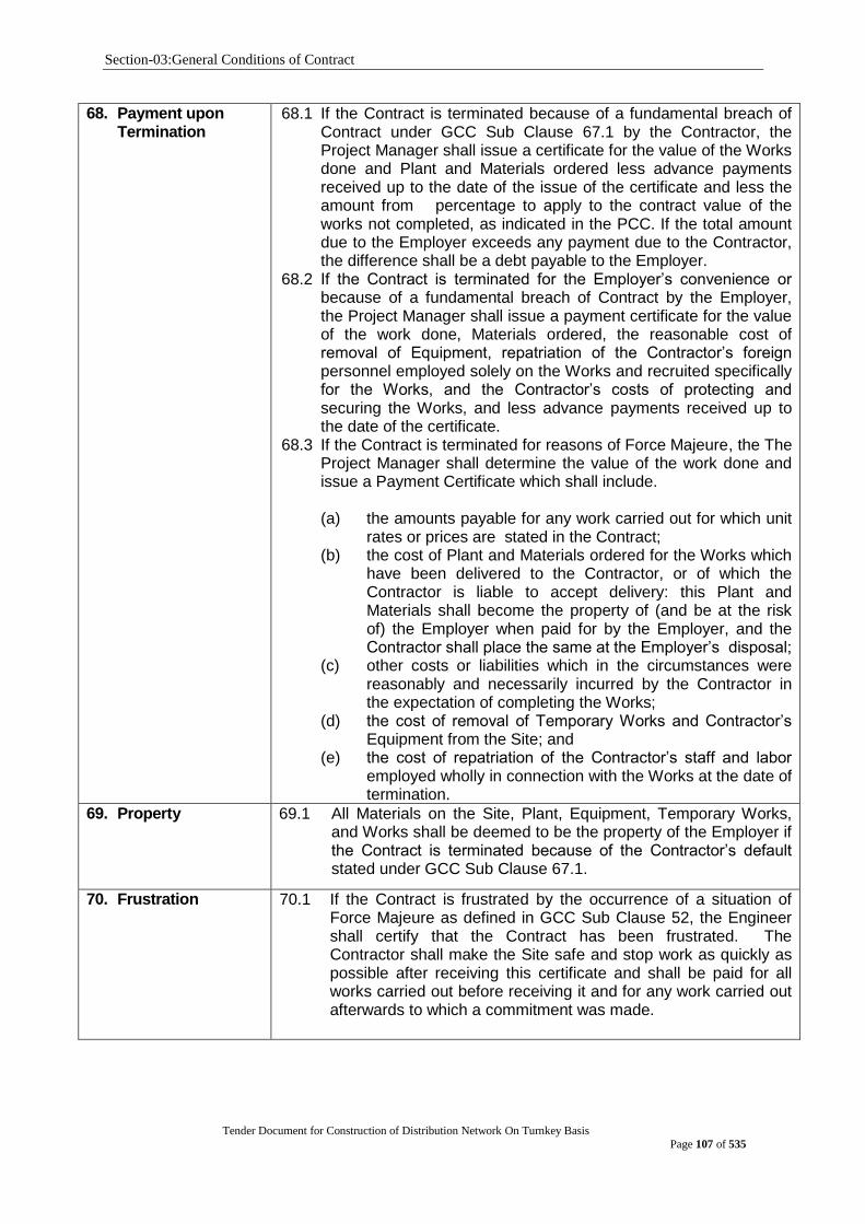
Section-03:General Conditions of Contract
Tender Document for Construction of Distribution Network On Turnkey Basis
Page 107 of 535
68. Payment upon Termination
68.1 If the Contract is terminated because of a fundamental breach of Contract under GCC Sub Clause 67.1 by the Contractor, the Project Manager shall issue a certificate for the value of the Works done and Plant and Materials ordered less advance payments received up to the date of the issue of the certificate and less the amount from percentage to apply to the contract value of the works not completed, as indicated in the PCC. If the total amount due to the Employer exceeds any payment due to the Contractor, the difference shall be a debt payable to the Employer.
68.2 If the Contract is terminated for the Employer‟s convenience or because of a fundamental breach of Contract by the Employer, the Project Manager shall issue a payment certificate for the value of the work done, Materials ordered, the reasonable cost of removal of Equipment, repatriation of the Contractor‟s foreign personnel employed solely on the Works and recruited specifically for the Works, and the Contractor‟s costs of protecting and securing the Works, and less advance payments received up to the date of the certificate.
68.3 If the Contract is terminated for reasons of Force Majeure, the The Project Manager shall determine the value of the work done and issue a Payment Certificate which shall include. (a) the amounts payable for any work carried out for which unit
rates or prices are stated in the Contract; (b) the cost of Plant and Materials ordered for the Works which
have been delivered to the Contractor, or of which the Contractor is liable to accept delivery: this Plant and Materials shall become the property of (and be at the risk of) the Employer when paid for by the Employer, and the Contractor shall place the same at the Employer‟s disposal;
(c) other costs or liabilities which in the circumstances were reasonably and necessarily incurred by the Contractor in the expectation of completing the Works;
(d) the cost of removal of Temporary Works and Contractor‟s Equipment from the Site; and
(e) the cost of repatriation of the Contractor‟s staff and labor employed wholly in connection with the Works at the date of termination.
69. Property 69.1 All Materials on the Site, Plant, Equipment, Temporary Works, and Works shall be deemed to be the property of the Employer if the Contract is terminated because of the Contractor‟s default stated under GCC Sub Clause 67.1.
70. Frustration 70.1 If the Contract is frustrated by the occurrence of a situation of Force Majeure as defined in GCC Sub Clause 52, the Engineer shall certify that the Contract has been frustrated. The Contractor shall make the Site safe and stop work as quickly as possible after receiving this certificate and shall be paid for all works carried out before receiving it and for any work carried out afterwards to which a commitment was made.
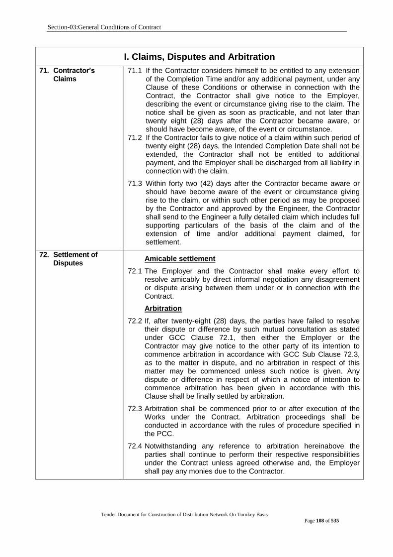
Section-03:General Conditions of Contract
Tender Document for Construction of Distribution Network On Turnkey Basis
Page 108 of 535
I. Claims, Disputes and Arbitration
71. Contractor‟s Claims
71.1 If the Contractor considers himself to be entitled to any extension of the Completion Time and/or any additional payment, under any Clause of these Conditions or otherwise in connection with the Contract, the Contractor shall give notice to the Employer, describing the event or circumstance giving rise to the claim. The notice shall be given as soon as practicable, and not later than twenty eight (28) days after the Contractor became aware, or should have become aware, of the event or circumstance.
71.2 If the Contractor fails to give notice of a claim within such period of twenty eight (28) days, the Intended Completion Date shall not be extended, the Contractor shall not be entitled to additional payment, and the Employer shall be discharged from all liability in connection with the claim.
71.3 Within forty two (42) days after the Contractor became aware or should have become aware of the event or circumstance giving rise to the claim, or within such other period as may be proposed by the Contractor and approved by the Engineer, the Contractor shall send to the Engineer a fully detailed claim which includes full supporting particulars of the basis of the claim and of the extension of time and/or additional payment claimed, for settlement.
72. Settlement of Disputes
Amicable settlement
72.1 The Employer and the Contractor shall make every effort to resolve amicably by direct informal negotiation any disagreement or dispute arising between them under or in connection with the Contract.
Arbitration
72.2 If, after twenty-eight (28) days, the parties have failed to resolve their dispute or difference by such mutual consultation as stated under GCC Clause 72.1, then either the Employer or the Contractor may give notice to the other party of its intention to commence arbitration in accordance with GCC Sub Clause 72.3, as to the matter in dispute, and no arbitration in respect of this matter may be commenced unless such notice is given. Any dispute or difference in respect of which a notice of intention to commence arbitration has been given in accordance with this Clause shall be finally settled by arbitration.
72.3 Arbitration shall be commenced prior to or after execution of the Works under the Contract. Arbitration proceedings shall be conducted in accordance with the rules of procedure specified in the PCC.
72.4 Notwithstanding any reference to arbitration hereinabove the parties shall continue to perform their respective responsibilities under the Contract unless agreed otherwise and, the Employer shall pay any monies due to the Contractor.
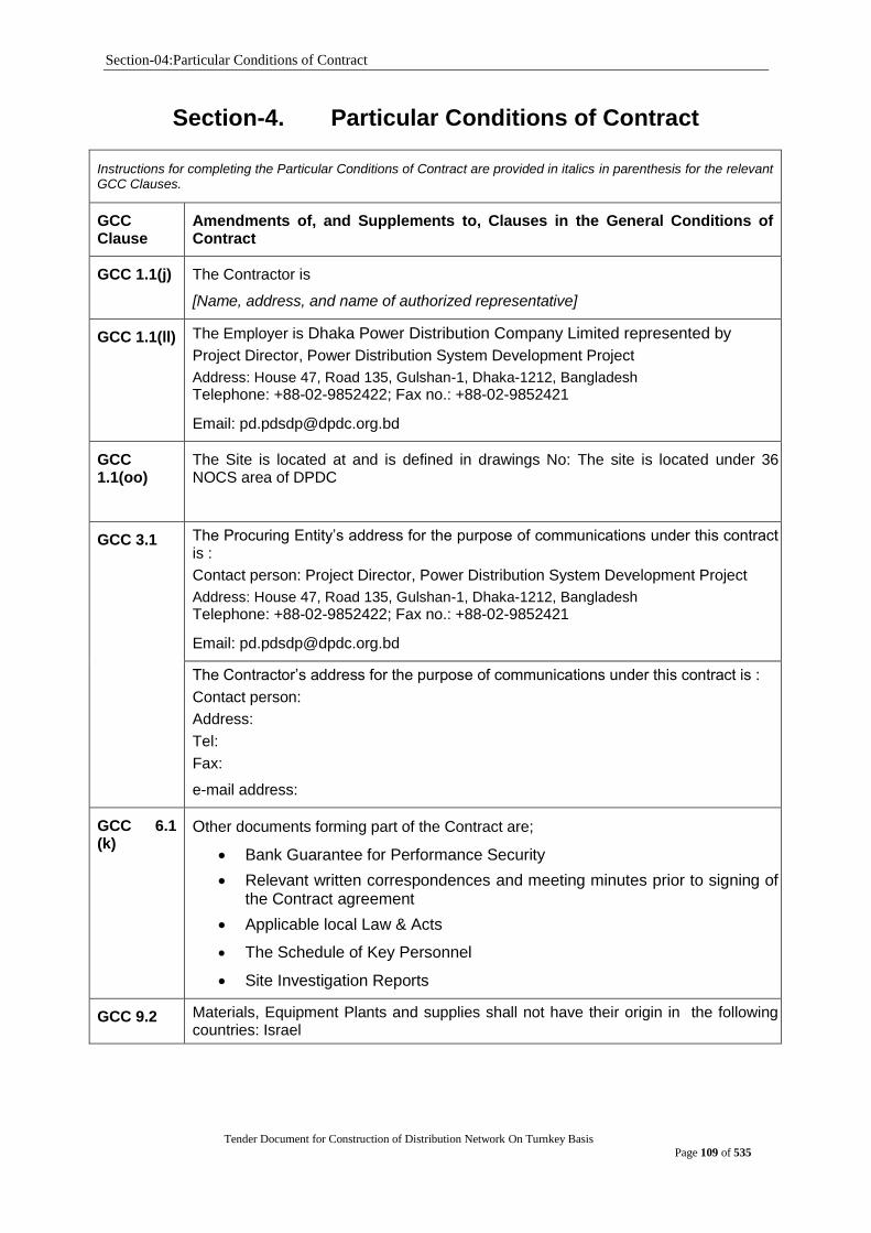
Section-04:Particular Conditions of Contract
Tender Document for Construction of Distribution Network On Turnkey Basis
Page 109 of 535
Section-4. Particular Conditions of Contract
Instructions for completing the Particular Conditions of Contract are provided in italics in parenthesis for the relevant GCC Clauses.
GCC Clause
Amendments of, and Supplements to, Clauses in the General Conditions of Contract
GCC 1.1(j) The Contractor is
[Name, address, and name of authorized representative]
GCC 1.1(ll) The Employer is Dhaka Power Distribution Company Limited represented by
Project Director, Power Distribution System Development Project
Address: House 47, Road 135, Gulshan-1, Dhaka-1212, Bangladesh
Telephone: +88-02-9852422; Fax no.: +88-02-9852421
Email: [email protected]
GCC 1.1(oo)
The Site is located at and is defined in drawings No: The site is located under 36 NOCS area of DPDC
GCC 3.1 The Procuring Entity‟s address for the purpose of communications under this contract is :
Contact person: Project Director, Power Distribution System Development Project
Address: House 47, Road 135, Gulshan-1, Dhaka-1212, Bangladesh
Telephone: +88-02-9852422; Fax no.: +88-02-9852421
Email: [email protected]
The Contractor‟s address for the purpose of communications under this contract is :
Contact person:
Address:
Tel:
Fax:
e-mail address:
GCC 6.1 (k)
Other documents forming part of the Contract are;
Bank Guarantee for Performance Security
Relevant written correspondences and meeting minutes prior to signing of the Contract agreement
Applicable local Law & Acts
The Schedule of Key Personnel
Site Investigation Reports
GCC 9.2 Materials, Equipment Plants and supplies shall not have their origin in the following countries: Israel
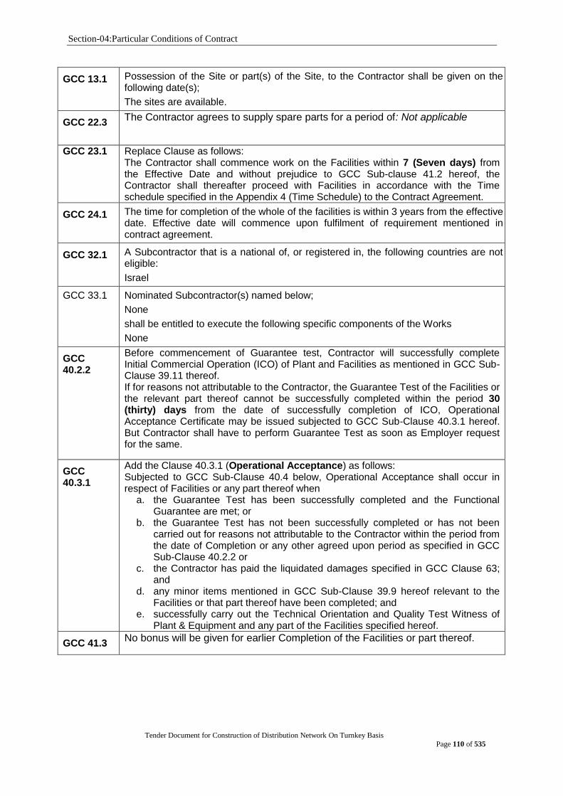
Section-04:Particular Conditions of Contract
Tender Document for Construction of Distribution Network On Turnkey Basis
Page 110 of 535
GCC 13.1
Possession of the Site or part(s) of the Site, to the Contractor shall be given on the following date(s);
The sites are available.
GCC 22.3 The Contractor agrees to supply spare parts for a period of: Not applicable
GCC 23.1 Replace Clause as follows: The Contractor shall commence work on the Facilities within 7 (Seven days) from the Effective Date and without prejudice to GCC Sub-clause 41.2 hereof, the Contractor shall thereafter proceed with Facilities in accordance with the Time schedule specified in the Appendix 4 (Time Schedule) to the Contract Agreement.
GCC 24.1 The time for completion of the whole of the facilities is within 3 years from the effective date. Effective date will commence upon fulfilment of requirement mentioned in contract agreement.
GCC 32.1 A Subcontractor that is a national of, or registered in, the following countries are not eligible:
Israel
GCC 33.1 Nominated Subcontractor(s) named below;
None
shall be entitled to execute the following specific components of the Works
None
GCC 40.2.2
Before commencement of Guarantee test, Contractor will successfully complete Initial Commercial Operation (ICO) of Plant and Facilities as mentioned in GCC Sub-Clause 39.11 thereof. If for reasons not attributable to the Contractor, the Guarantee Test of the Facilities or the relevant part thereof cannot be successfully completed within the period 30 (thirty) days from the date of successfully completion of ICO, Operational Acceptance Certificate may be issued subjected to GCC Sub-Clause 40.3.1 hereof. But Contractor shall have to perform Guarantee Test as soon as Employer request for the same.
GCC 40.3.1
Add the Clause 40.3.1 (Operational Acceptance) as follows: Subjected to GCC Sub-Clause 40.4 below, Operational Acceptance shall occur in respect of Facilities or any part thereof when
a. the Guarantee Test has been successfully completed and the Functional Guarantee are met; or
b. the Guarantee Test has not been successfully completed or has not been carried out for reasons not attributable to the Contractor within the period from the date of Completion or any other agreed upon period as specified in GCC Sub-Clause 40.2.2 or
c. the Contractor has paid the liquidated damages specified in GCC Clause 63; and
d. any minor items mentioned in GCC Sub-Clause 39.9 hereof relevant to the Facilities or that part thereof have been completed; and
e. successfully carry out the Technical Orientation and Quality Test Witness of Plant & Equipment and any part of the Facilities specified hereof.
GCC 41.3 No bonus will be given for earlier Completion of the Facilities or part thereof.

Section-04:Particular Conditions of Contract
Tender Document for Construction of Distribution Network On Turnkey Basis
Page 111 of 535
GCC 42.2 The warranty /defect liability period hereunder shall begin from the date of issuance of Operational Acceptance Certificate (OAC) by DPDC and shall end after 12 (twelve) months pursuant to GCC Sub-Clause 42.10.
GCC 42.3 The amount to be withheld for late submission of an updated Programme is: Not applicable.
GCC 42.9 “after Completion of the Facilities or any part thereof,” will be replaced by “after Operational Acceptance of Facilities,”
GCC 42.10 During the Defect Liability Period, if any Plant & Equipment is damaged and replaced by the Contractor, fresh Defect Liability Period for 12 (twelve) months of operation shall be counted for replaced Plant & Equipment from the date of repair, replacement, commissioning thereof.
GCC 42.11 (New Clause)
Final Acceptance Certificate (FAC): The “Final Acceptance Certificate (FAC)” shall mean the official notification by Employer to the Contractor, issued at the end of all the Defect Liability Period (if different guarantee periods to different parts of the work, after the expiration of the latest of such periods) which indicates that the Contractor has completed his obligation under the Contract.
GCC 45.1 (b)
The multiplier of the Contract Price is: 1(one)
GCC 47.1 “until the date of Completion of the Facilities pursuant to GCC Clause 39 or, where the Contract provides for Completion of the Facilities in parts, until the date of Completion of the relevant part” will be replaced by “until the date of Operational Acceptance of the Facilities pursuant to GCC Clause 40.3 or, where the Contract provides for Completion of the Facilities in parts, until the date of Operational Acceptance of the relevant part”
GCC 56.2 The Contract Price shall be adjusted in accordance with the provisions of the Appendix to the Contract Agreement titled Adjustment Clause: Not applicable for this tender
GCC 59.3.1
The amount of performance security, as a percentage of the Contract Price for the Facility or for the part of the Facility for which a separate Time for Completion is provided, shall be [10%]
GCC 59.3.3
The performance security shall not be reduced on the date of the Operational Acceptance.
GCC 59.3.3
The performance security shall be reduced to ten percent (10%) of the value of the component covered by the extended defect liability to cover the Contractor‟s extended defect liability in accordance with the provision in the PCC, pursuant to GCC Sub-Clause 42.10.
GCC 60.1 & 60.2
The Contractor shall be entirely responsible for all kinds of taxes, duties, fees, levies, and such other charges assessed on the Contractor, its Subcontractors or their employees by all municipal, state or national government authorities in connection with the Facilities in and outside of the country where the Site is located.
However, the employer shall pay all customs and import duties for the Plant specified in Price Schedule No. 1
If payment to the contractor is made in Bangladeshi taka, VAT, IT etc. shall be deducted from the payment as per Govt. policy of Bangladesh.
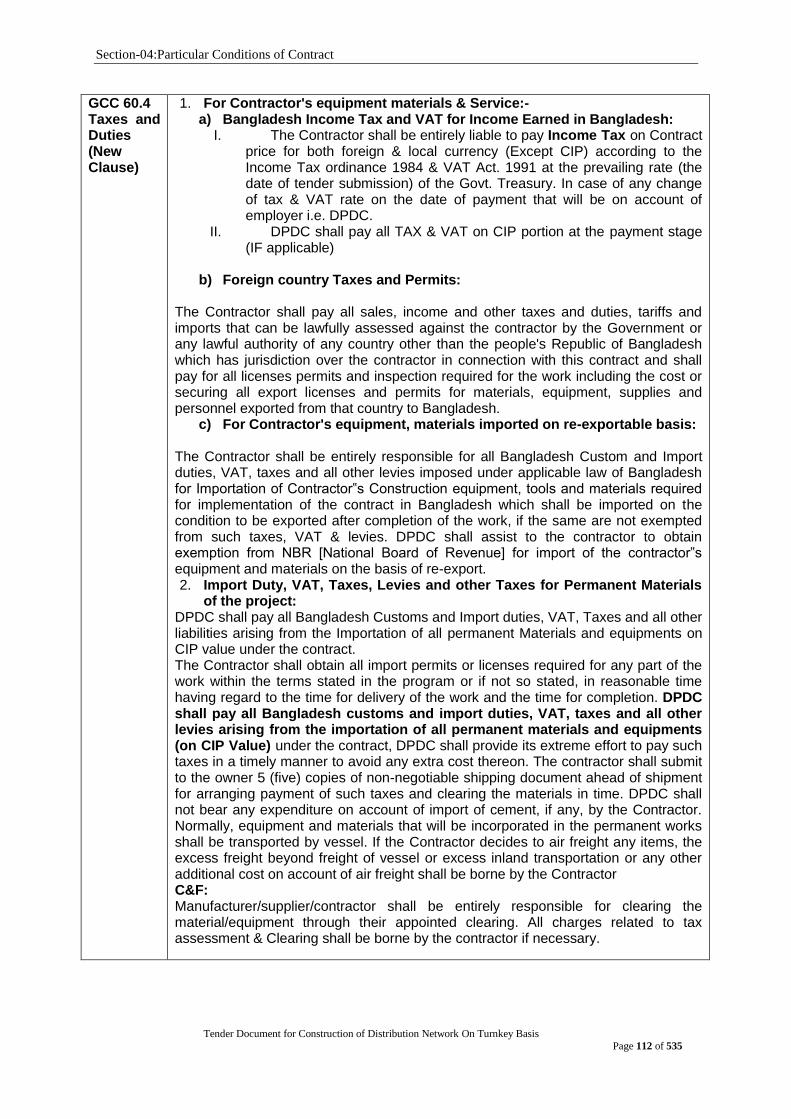
Section-04:Particular Conditions of Contract
Tender Document for Construction of Distribution Network On Turnkey Basis
Page 112 of 535
GCC 60.4 Taxes and Duties (New Clause)
1. For Contractor's equipment materials & Service:- a) Bangladesh Income Tax and VAT for Income Earned in Bangladesh:
I. The Contractor shall be entirely liable to pay Income Tax on Contract price for both foreign & local currency (Except CIP) according to the Income Tax ordinance 1984 & VAT Act. 1991 at the prevailing rate (the date of tender submission) of the Govt. Treasury. In case of any change of tax & VAT rate on the date of payment that will be on account of employer i.e. DPDC.
II. DPDC shall pay all TAX & VAT on CIP portion at the payment stage (IF applicable)
b) Foreign country Taxes and Permits:
The Contractor shall pay all sales, income and other taxes and duties, tariffs and imports that can be lawfully assessed against the contractor by the Government or any lawful authority of any country other than the people's Republic of Bangladesh which has jurisdiction over the contractor in connection with this contract and shall pay for all licenses permits and inspection required for the work including the cost or securing all export licenses and permits for materials, equipment, supplies and personnel exported from that country to Bangladesh.
c) For Contractor's equipment, materials imported on re-exportable basis: The Contractor shall be entirely responsible for all Bangladesh Custom and Import duties, VAT, taxes and all other levies imposed under applicable law of Bangladesh for Importation of Contractor‟s Construction equipment, tools and materials required for implementation of the contract in Bangladesh which shall be imported on the condition to be exported after completion of the work, if the same are not exempted from such taxes, VAT & levies. DPDC shall assist to the contractor to obtain exemption from NBR [National Board of Revenue] for import of the contractor‟s equipment and materials on the basis of re-export. 2. Import Duty, VAT, Taxes, Levies and other Taxes for Permanent Materials
of the project: DPDC shall pay all Bangladesh Customs and Import duties, VAT, Taxes and all other liabilities arising from the Importation of all permanent Materials and equipments on CIP value under the contract. The Contractor shall obtain all import permits or licenses required for any part of the work within the terms stated in the program or if not so stated, in reasonable time having regard to the time for delivery of the work and the time for completion. DPDC shall pay all Bangladesh customs and import duties, VAT, taxes and all other levies arising from the importation of all permanent materials and equipments (on CIP Value) under the contract, DPDC shall provide its extreme effort to pay such taxes in a timely manner to avoid any extra cost thereon. The contractor shall submit to the owner 5 (five) copies of non-negotiable shipping document ahead of shipment for arranging payment of such taxes and clearing the materials in time. DPDC shall not bear any expenditure on account of import of cement, if any, by the Contractor. Normally, equipment and materials that will be incorporated in the permanent works shall be transported by vessel. If the Contractor decides to air freight any items, the excess freight beyond freight of vessel or excess inland transportation or any other additional cost on account of air freight shall be borne by the Contractor C&F: Manufacturer/supplier/contractor shall be entirely responsible for clearing the material/equipment through their appointed clearing. All charges related to tax assessment & Clearing shall be borne by the contractor if necessary.

Section-04:Particular Conditions of Contract
Tender Document for Construction of Distribution Network On Turnkey Basis
Page 113 of 535
GCC 63.1 The amount of Liquidated Damages for Delay Damages or Delay to Completion Date of the uncompleted Works (Plant & Services) or any part to complete the Completion Date for the work thereof is: At the rate of zero point one percent (0.1%) of relevant part per day.
GCC 63.2 The maximum amount of Liquidated Damages is: Ten percent (10%) of the final Contract price.
GCC 72.2 (i) In the case of a dispute between the Employer and the foreign Contractor
Any dispute, controversy or claim arising out of or relating to this Contract, or
breach, termination or invalidity thereof, shall be settled by arbitration in accordance with the United Nations Commission on International Trade Law (UNCITRAL) Arbitration Rules of 1976 as at present in force.
GCC 72.3 As per Bangladesh Arbitration Act. Place: Dhaka, Bangladesh
GCC 73.1 List Delivery Document (New Clause)
Subject to GCC Clause 64, the Delivery of the Plants and Services shall be in accordance with the Delivery and Completion Schedule specified in the Section 6: Schedule of Requirements. Details of shipping and documents to be furnished by the Contractor/Supplier shall be: “For Schedule No. 1 - Plant and Equipment Supplied from Abroad / Goods supplied from abroad as per INCOTERM CIP: Upon shipment, the Contractor/Supplier shall notify the Purchaser by telex or fax the full details of the shipment, including Contract number, description of Goods, quantity, the vessel, the bill of lading number and date, port of loading, date of shipment, port of discharge, etc. The Contractor/Supplier shall send the following documents to the Project Director who is also the project manager of this project, with a copy to the Insurance Company:
(a) 7 copies of the Supplier‟s invoice showing the description of the Goods, quantity, unit price, and total amount;
(b) original and 8 copies of the negotiable, clean, on-board bill of lading marked “freight prepaid” and 8 copies of non-negotiable bill of lading where applicable;
(c) 8 copies of the packing list identifying contents of each package; (d) insurance certificate; (e) Manufacturer‟s or Supplier‟s warranty certificate; (f) inspection certificate, issued by the nominated inspection agency or
purchaser inspection team, and the Supplier‟s factory inspection report; and
(g) Certificate of origin. (h) Shipping advice issued by the Consignee (i) Truck Challan:
The Employer/Consignee shall receive the above documents at least one week before arrival of Goods at the port and, if not received, the Supplier will be responsible for any consequent expenses. The negotiable sets of documents shall be originals signed by the Supplier. The Commercial Invoice is to show material value plus freight as applicable. The Employer/Consignee shall receive the shipping documents at the latest one-week before arrival of cargoes at the airport of Dhaka or any sea/land port of entry in Bangladesh. The shipping documents shall be supplied to as follows:
01. Project Director Power Distribution System Development Project Under DPDC
03 (Three) Sets
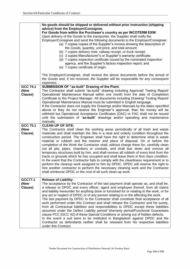
Section-04:Particular Conditions of Contract
Tender Document for Construction of Distribution Network On Turnkey Basis
Page 114 of 535
No goods should be shipped or delivered without prior instruction (shipping advice) from the Employer/Consignee. For Goods from within the Purchaser‟s country as per INCOTERM EXW: Upon delivery of the Goods to the transporter, the Supplier shall notify the Employer/Consignee and send the following documents to the Employer/Consignee:
(a) 7 copies copies of the Supplier‟s invoice showing the description of the Goods, quantity, unit price, and total amount;
(b) 7 copies delivery note, railway receipt, or truck receipt; (c) 3 copies Manufacturer‟s or Supplier‟s warranty certificate; (d) 7 copies inspection certificate issued by the nominated inspection
agency, and the Supplier‟s factory inspection report; and (e) 7 copies certificate of origin.
The Employer/Consignee, shall receive the above documents before the arrival of the Goods and, if not received, the Supplier will be responsible for any consequent expenses.
GCC 74.1 (New Clause)
SUBMISSION OF “as-built” Drawing of the Plant: The Contractor shall submit “as-build” drawing including Approval/ Testing Report/ Operational/ Maintenance Manual within one month from the date of Completion Certificate to the Project Manager. All documents including Drawing/ Testing Report/ Operational/ Maintenance Manual must be submitted in English language. If the Contractor does not supply the Drawings and/or Manuals by the dates specified above or they do not receive the Engineer‟s approval, than No money will be withheld but Operational Acceptance Certificates (OAC) or FAC shall not be issued until the submission of “as-built” drawings and/or operating and maintenance manuals.
GCC 75.1 (New Clause)
CLEAN UP OF SITE: The Contractor shall clean the working areas periodically of all trash and waste materials and shall maintain the Site in a neat and orderly condition throughout the construction period. The Engineer shall have the right to determine what is waste material or rubbish and the manner and place of disposal. On or before the completion of the Work the Contractor shall, without charge there for, carefully clean out all pits, pipes, chambers or conduits, and shall tear down and remove all temporary structures built by him, and shall remove all rubbish of every kind from the tracts or grounds which he has occupied and shall leave them in first class condition. In the event that the Contractor fails to comply with the cleanliness requirement or to perform the cleanup work assigned to him by DPDC. DPDC will reserve the right to hire another contractor to perform the necessary cleaning work and the Contractor shall reimburse DPDC or the cost of all such clean-up work.
GCC77.1 (New Clause)
Release of Liability: The acceptance by the Contractor of the last payment shall operate as, and shall be, a release to DPDC and every officer, agent and employee thereof, from all claims and liability hereunder for anything done or furnished for or relating to the work, or for any act or neglect of DPDC or of any person relating to or the affecting the work. The last payment by DPDC to the Contractor shall constitute final acceptance of all work performed under this Contract and shall release the Contractor and his surety, from all Contractual liabilities and responsibilities to DPDC except these liabilities assumed under the Defect Liability period/ Warranty period/Functional Guarantees clause PCC [GCC 42] of these Special Conditions or arising out of hidden defects. In the event a suit were to be instituted in Bangladesh against DPDC and the Contractor as defendants neither shall be released from his respective liabilities under this Contract.

Section-05: Tender and Contract Forms
Tender Document for Construction of Distribution Network On Turnkey Basis
Page 115 of 535
Appendix to the Tender
[In Tables below, the Procuring Entity shall indicate the source and base values with dates of Indexes, unless otherwise instructed to be quoted by the Tenderer, for the different Cost Components and mention its Weightings or Coefficients]
Table 1.1: Price Adjustment Data: Not applicable for this tender
[ ITT Sub Clause 26.9: To be provided by the Procuring Entity]
Index Descriptions Base Value Sources of Index
Note:
1. The sources of Indexes and its values with dates shall be Bangladesh Bureau of Statistics (BBS) unless otherwise mentioned by the Procuring Entity or instructed to be quoted by the Tenderer.
2. The Procuring Entity may require the Tenderer to justify its proposed Indexes, if quoted by the Tenderer.
3. The Base Value of the Indexes shall be those prevailing twenty eight (28) days prior to the deadline for submission of the Tenders.
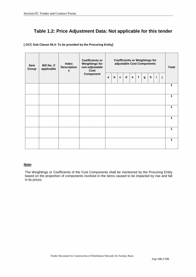
Section-05: Tender and Contract Forms
Tender Document for Construction of Distribution Network On Turnkey Basis
Page 116 of 535
Table 1.2: Price Adjustment Data: Not applicable for this tender
[ GCC Sub Clause 56.4: To be provided by the Procuring Entity]
Item Group
Bill No. if applicable
Index Description
s
Coefficients or Weightings for non-adjustable
Cost Component
Coefficients or Weightings for adjustable Cost Components
Total
a b c d e f g h i j
1
1
1
1
1
1
Note: The Weightings or Coefficients of the Cost Components shall be mentioned by the Procuring Entity based on the proportion of components involved in the items caused to be impacted by rise and fall in its prices.

Section-05: Tender and Contract Forms
Tender Document for Construction of Distribution Network On Turnkey Basis
Page 117 of 535
APPENDICES [This appendixes shall be the part of the contract] Appendix 1 - Terms and Procedures of Payment
Appendix 2 - Price Adjustment
Appendix 3 - Insurance Requirements
Appendix 4 - Time Schedule
Appendix 5 - List of Major Items of Plant and services and List of Approved Subcontractors
Appendix 6 - Scope of Works and Supply by the Employer
Appendix 7 - List of Documents for Approval or Review
Appendix 8 - Functional Guarantees
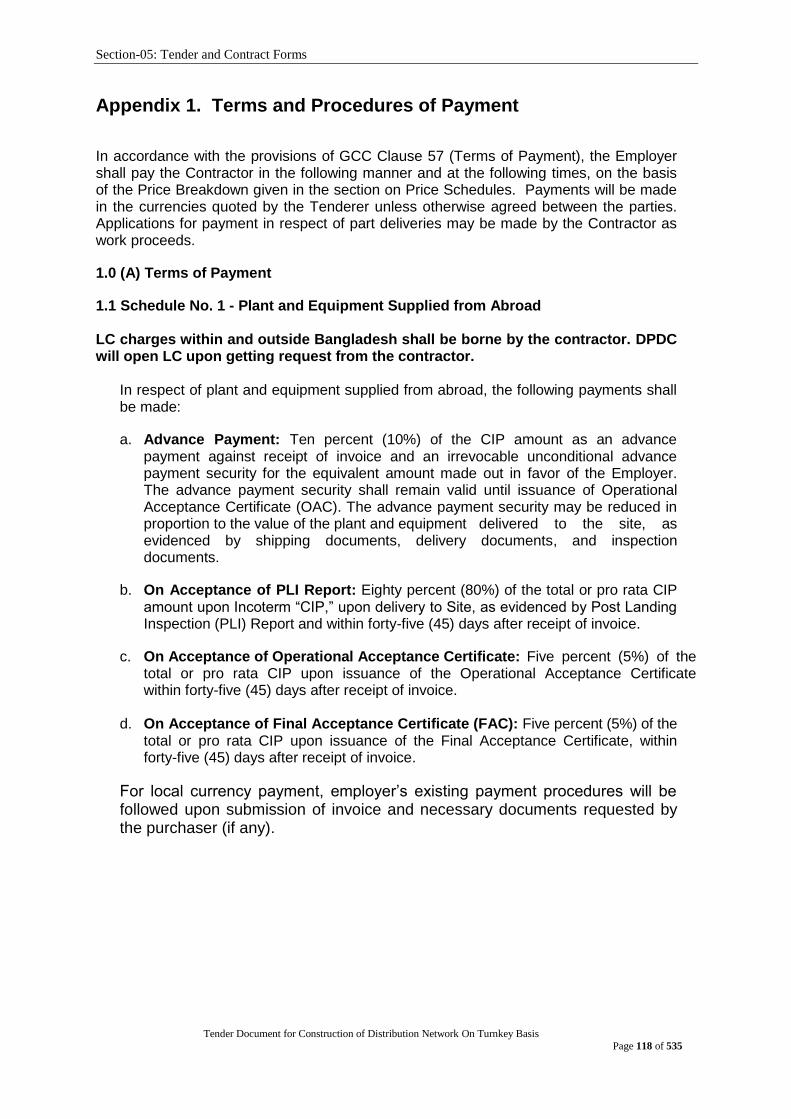
Section-05: Tender and Contract Forms
Tender Document for Construction of Distribution Network On Turnkey Basis
Page 118 of 535
Appendix 1. Terms and Procedures of Payment
In accordance with the provisions of GCC Clause 57 (Terms of Payment), the Employer shall pay the Contractor in the following manner and at the following times, on the basis of the Price Breakdown given in the section on Price Schedules. Payments will be made in the currencies quoted by the Tenderer unless otherwise agreed between the parties. Applications for payment in respect of part deliveries may be made by the Contractor as work proceeds.
1.0 (A) Terms of Payment
1.1 Schedule No. 1 - Plant and Equipment Supplied from Abroad LC charges within and outside Bangladesh shall be borne by the contractor. DPDC will open LC upon getting request from the contractor.
In respect of plant and equipment supplied from abroad, the following payments shall be made:
a. Advance Payment: Ten percent (10%) of the CIP amount as an advance payment against receipt of invoice and an irrevocable unconditional advance payment security for the equivalent amount made out in favor of the Employer. The advance payment security shall remain valid until issuance of Operational Acceptance Certificate (OAC). The advance payment security may be reduced in proportion to the value of the plant and equipment delivered to the site, as evidenced by shipping documents, delivery documents, and inspection documents.
b. On Acceptance of PLI Report: Eighty percent (80%) of the total or pro rata CIP amount upon Incoterm “CIP,” upon delivery to Site, as evidenced by Post Landing Inspection (PLI) Report and within forty-five (45) days after receipt of invoice.
c. On Acceptance of Operational Acceptance Certificate: Five percent (5%) of the total or pro rata CIP upon issuance of the Operational Acceptance Certificate within forty-five (45) days after receipt of invoice.
d. On Acceptance of Final Acceptance Certificate (FAC): Five percent (5%) of the
total or pro rata CIP upon issuance of the Final Acceptance Certificate, within forty-five (45) days after receipt of invoice.
For local currency payment, employer‟s existing payment procedures will be followed upon submission of invoice and necessary documents requested by the purchaser (if any).
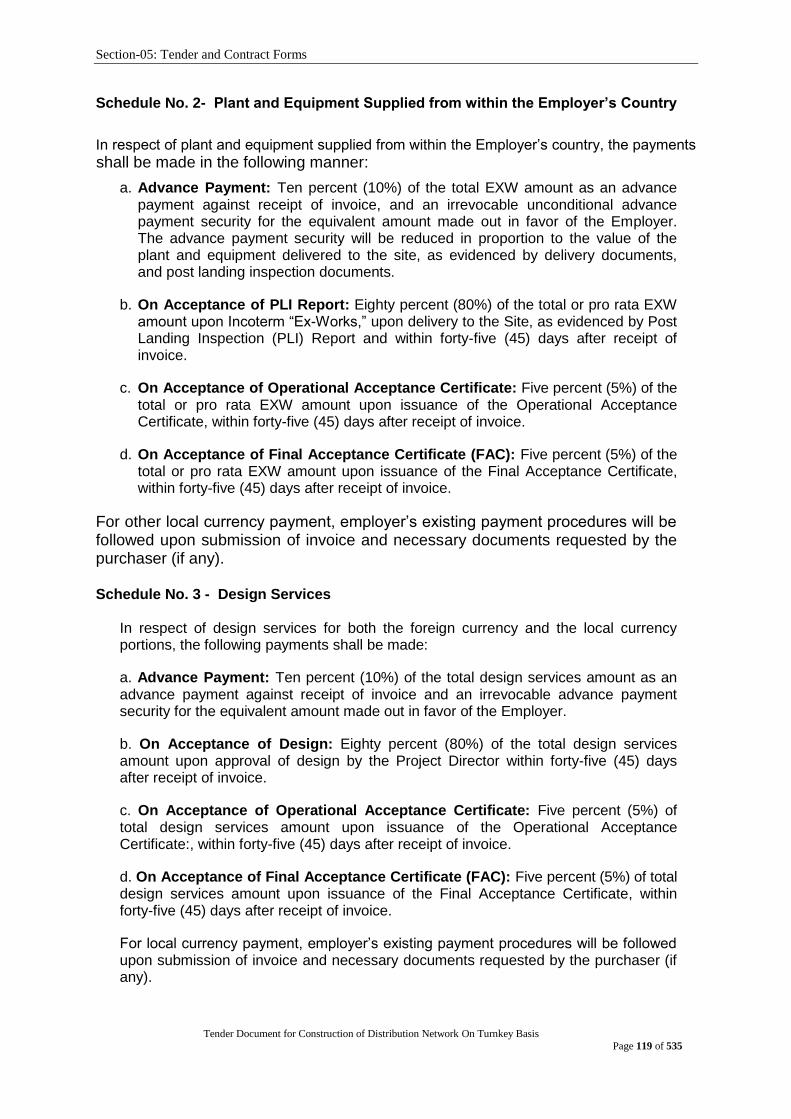
Section-05: Tender and Contract Forms
Tender Document for Construction of Distribution Network On Turnkey Basis
Page 119 of 535
Schedule No. 2- Plant and Equipment Supplied from within the Employer‟s Country
In respect of plant and equipment supplied from within the Employer‟s country, the payments
shall be made in the following manner:
a. Advance Payment: Ten percent (10%) of the total EXW amount as an advance payment against receipt of invoice, and an irrevocable unconditional advance payment security for the equivalent amount made out in favor of the Employer. The advance payment security will be reduced in proportion to the value of the plant and equipment delivered to the site, as evidenced by delivery documents, and post landing inspection documents.
b. On Acceptance of PLI Report: Eighty percent (80%) of the total or pro rata EXW amount upon Incoterm “Ex-Works,” upon delivery to the Site, as evidenced by Post Landing Inspection (PLI) Report and within forty-five (45) days after receipt of invoice.
c. On Acceptance of Operational Acceptance Certificate: Five percent (5%) of the total or pro rata EXW amount upon issuance of the Operational Acceptance Certificate, within forty-five (45) days after receipt of invoice.
d. On Acceptance of Final Acceptance Certificate (FAC): Five percent (5%) of the total or pro rata EXW amount upon issuance of the Final Acceptance Certificate, within forty-five (45) days after receipt of invoice.
For other local currency payment, employer‟s existing payment procedures will be followed upon submission of invoice and necessary documents requested by the purchaser (if any). Schedule No. 3 - Design Services
In respect of design services for both the foreign currency and the local currency portions, the following payments shall be made:
a. Advance Payment: Ten percent (10%) of the total design services amount as an advance payment against receipt of invoice and an irrevocable advance payment security for the equivalent amount made out in favor of the Employer.
b. On Acceptance of Design: Eighty percent (80%) of the total design services amount upon approval of design by the Project Director within forty-five (45) days after receipt of invoice.
c. On Acceptance of Operational Acceptance Certificate: Five percent (5%) of total design services amount upon issuance of the Operational Acceptance Certificate:, within forty-five (45) days after receipt of invoice.
d. On Acceptance of Final Acceptance Certificate (FAC): Five percent (5%) of total design services amount upon issuance of the Final Acceptance Certificate, within forty-five (45) days after receipt of invoice.
For local currency payment, employer‟s existing payment procedures will be followed upon submission of invoice and necessary documents requested by the purchaser (if any).

Section-05: Tender and Contract Forms
Tender Document for Construction of Distribution Network On Turnkey Basis
Page 120 of 535
Schedule No. 4 - Civil work
In respect of civil work for both the foreign and local currency portions, the following payments shall be made:
Ten percent (10%) of the total civil work amount as an advance payment against receipt of invoice and an irrevocable unconditional advance payment security for the equivalent amount made out in favor of the Employer. The advance payment security may be reduced in proportion to the value of work performed by the Contractor as evidenced by the invoices for installation services.
Eighty percent (80%) of the measured value of work performed by the Contractor, as identified in the said Program of Performance, during the preceding month, as evidenced by the Employer‟s authorization of the Contractor‟s application, will be made monthly within forty-five (45) days after receipt of invoice.
Five percent (5%) of total civil work amount upon issuance of the Operational Acceptance Certificate, within forty-five (45) days after receipt of invoice.
Five percent (5%) of total civil work amount upon issuance of the Final Acceptance Certificate, within forty-five (45) days after receipt of invoice.
For local currency payment, employer‟s existing payment procedures will be followed upon submission of invoice and necessary documents requested by the purchaser (if any).
Schedule No. 5 - Installation and other Services
In respect of installation services for both the foreign and local currency portions, the following payments shall be made:
Ten percent (10%) of the total installation and other services amount as an advance payment against receipt of invoice and an irrevocable advance payment security for the equivalent amount made out in favor of the Employer. The advance payment security may be reduced in proportion to the value of work performed by the Contractor as evidenced by the invoices for installation and other services.
Eighty percent (80%) of the measured value of Installation and other Services performed by the Contractor, as identified in the said Program of Performance, during the preceding month, as evidenced by the Employer‟s authorization of the Contractor‟s application, will be made monthly within forty-five (45) days after receipt of invoice.
Five percent (5%) of total Installation and other Services amount upon issuance of the Operational Acceptance Certificate, within forty-five (45) days after receipt of invoice.
Five percent (5%) of total Installation and other Services amount upon issuance of the Final Acceptance Certificate, within forty-five (45) days after receipt of invoice.

Section-05: Tender and Contract Forms
Tender Document for Construction of Distribution Network On Turnkey Basis
Page 121 of 535
(B) Payment Procedures
The procedures to be followed shall be as follows:
Foreign Currency Payment: Payment of foreign currency portion shall be made
in USD within forty-five (45) days of presentation of claim supported by a certificate from the Purchaser declaring that the Goods/works/services have been delivered/performed. Payment shall be done through LC. Project Director/Engineer will certify the invoice and the payment advice will be issued by the employer‟s representative (Accounts Department). Invoice and necessary supporting documents as requested by the employer‟s representative are required to be submitted by the contractor.
Local currency payment: Payment of local currency portion shall be made in Bangladeshi Taka within forty-five (45) days of presentation of claim supported by
a certificate from the Purchaser declaring that the Goods/works/services have been
delivered/performed. For local currency payment, employer‟s existing payment procedures will be followed. VAT, IT etc. shall be deducted from the payment as per Govt. Policy of Bangladesh. Project Director/Engineer will certify the invoice and the payment advice will be issued by the employer‟s representative (Accounts Department). Invoice and necessary supporting documents as requested by the employer‟s representative are required to be submitted by the contractor.
Applicable CD, VAT etc. for „Schedule No. 1 - Plant and Equipment Supplied from
Abroad‟ shall be paid by the purchaser. C&F Agent will be engaged by the contractor informing the purchaser. The Contractor shall obtain insurance from Sadharan Bima Corporation of Bangladesh.

Section-05: Tender and Contract Forms
Tender Document for Construction of Distribution Network On Turnkey Basis
Page 122 of 535
Appendix 2. Price Adjustment : Not applicable for this tender
Prices payable to the Contractor, in accordance with the Contract, shall be subject to adjustment during performance of the Contract to reflect changes in the cost of labor and material components, in accordance with the following formula:
The Contract is subject to price adjustment applying the following formulae and the weightings or coefficients :
[Price Adjustment Formulae to be applicable if stated under ITT Sub Clause 26.9 shall be specified here]
Example:
P= A + a (Lm/Lo)+ b (BIm/BIo)+ c (CEm/CEo)+ d (RSm/RSo)+ e (STm/STo)+ f (BRm/BRo)+g (MIm/MIo) + h (FUm/FUo)+ etc
where;
L= Labor, BI=Bitumen, CE=Cement, RS=Reinforcing Steel, ST=Stone, BR=Bricks, MI=Miscellaneous, FU= Fuel ]
Weighting or Coefficient A equals between 0.10 and 0.15 and, B (a+b+c+d+e+f+g+h+etc) equals between 0.90 and 0.85.
[insert figure] non-adjustable component (coefficient A)
[insert figure] adjustable component (coefficient B)
[The sum of A+B shall equal ONE (1). It is usual to have value of A between 0.10 and 0.15 and that of B between 0.90 and 0.85. Breakdown of Bshall be provided in Appendix to the Tender.]
[delete as appropriate]
The date of adjustment shall be the mid-point of the period of manufacture or installation of component or Plant.
The following conditions shall apply:
(a) No price increase will be allowed beyond the original delivery date unless covered by an extension of time awarded by the Employer under the terms of the Contract. No price increase will be allowed for periods of delay for which the Contractor is responsible. The Employer will, however, be entitled to any price decrease occurring during such periods of delay.
(c) No price adjustment shall be payable on the portion of the Contract price paid to the Contractor as an advance payment.
For complex plant supply and installation involving several sources of supply and/or a substantial amount of installation works, a family of formulas may be necessary, with provision for the usage of Contractor’s equipment in the works formula.

Section-05: Tender and Contract Forms
Tender Document for Construction of Distribution Network On Turnkey Basis
Page 123 of 535
Appendix 3. Insurance Requirements
The Contractor shall obtain insurance from Sadharan Bima Corporation of
Bangladesh.
Insurances To Be Taken Out By The Contractor
In accordance with the provisions of GCC Clause 49, the Contractor shall at its expense take out
and maintain in effect, or cause to be taken out and maintained in effect, during the performance
of the Contract, the insurances set forth below in the sums and with the deductibles and other
conditions specified. The identity of the insurers and the form of the policies shall be subject to
the approval of the Employer, such approval not to be unreasonably withheld.
The minimum insurance cover shall be 110% (Hundred Ten). The insurance policy would be
furnished from Bangladesh Sadharan Bima Corporation.
The Contractor/Supplier shall secure and maintain throughout the duration of the contract
insurance of such types and in such amounts as may be necessary to protect himself and
the interest of Purchaser against hazards of risk or loss at Supplier‟s cost. Failure of the
Supplier to maintain such coverage shall not relieve him of any contractual responsibility or
obligations for transportation and ocean cargo insurance from port of loading to port of
unloading and from warehouse to warehouse in Bangladesh.
As Marine/Cargo insurance as well as Local Insurance shall be from Sadharan Bima
Corporation, 139, Motijheel Commercial Area, Dhaka, Bangladesh and the cost shall be paid
by Supplier/Contractor. Shipment of goods in any chartered vessel over 15(fifteen) years of
age and shipment of goods in the Deck are prohibited.
(a) Cargo Insurance
Covering loss or damage occurring, while in transit from the supplier‟s or manufacturer‟s works or
stores until arrival at the Site, to the Facilities (including spare parts therefore) and to the
construction equipment to be provided by the Contractor or its Subcontractors.
Amount Deductible
limits
Parties
insured From To
Hundred Ten Percent
(110%) of Contract Price
Dhaka Power
Distribution
Company
Limited.
supplier‟s or
manufacturer‟s
works or
stores
Contractor‟s
store in
Bangladesh
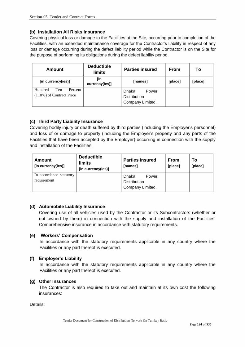
Section-05: Tender and Contract Forms
Tender Document for Construction of Distribution Network On Turnkey Basis
Page 124 of 535
(b) Installation All Risks Insurance
Covering physical loss or damage to the Facilities at the Site, occurring prior to completion of the
Facilities, with an extended maintenance coverage for the Contractor‟s liability in respect of any
loss or damage occurring during the defect liability period while the Contractor is on the Site for
the purpose of performing its obligations during the defect liability period.
Amount Deductible
limits Parties insured From To
[in currency(ies)] [in
currency(ies)] [names] [place] [place]
Hundred Ten Percent
(110%) of Contract Price
Dhaka Power
Distribution
Company Limited.
(c) Third Party Liability Insurance
Covering bodily injury or death suffered by third parties (including the Employer‟s personnel)
and loss of or damage to property (including the Employer‟s property and any parts of the
Facilities that have been accepted by the Employer) occurring in connection with the supply
and installation of the Facilities.
Amount
[in currency(ies)]
Deductible
limits
[in currency(ies)]
Parties insured
[names]
From
[place]
To
[place]
In accordance statutory
requirement
Dhaka Power
Distribution
Company Limited.
(d) Automobile Liability Insurance
Covering use of all vehicles used by the Contractor or its Subcontractors (whether or
not owned by them) in connection with the supply and installation of the Facilities.
Comprehensive insurance in accordance with statutory requirements.
(e) Workers‟ Compensation
In accordance with the statutory requirements applicable in any country where the
Facilities or any part thereof is executed.
(f) Employer‟s Liability
In accordance with the statutory requirements applicable in any country where the
Facilities or any part thereof is executed.
(g) Other Insurances
The Contractor is also required to take out and maintain at its own cost the following
insurances:
Details:

Section-05: Tender and Contract Forms
Tender Document for Construction of Distribution Network On Turnkey Basis
Page 125 of 535
Amount Deductible limits Parties insured From To
[in currency(ies)] [in currency(ies)] [names] [place] [place]
The Employer shall be named as co-insured under all insurance policies taken out by the
Contractor pursuant to GCC Sub-Clause 49.1, except for the Third Party Liability, Workers‟
Compensation and Employer‟s Liability Insurances, and the Contractor‟s Subcontractors
shall be named as co-insured‟s under all insurance policies taken out by the Contractor
pursuant to GCC Sub-Clause49.1, except for the Cargo, Workers‟ Compensation and
Employer‟s Liability Insurances. All insurer‟s rights of subrogation against such co-insureds
for losses or claims arising out of the performance of the Contract shall be waived under
such policies.

Section-05: Tender and Contract Forms
Tender Document for Construction of Distribution Network On Turnkey Basis
Page 126 of 535
Insurances to be Taken Out By The Employer
The Employer shall at its expense take out and maintain in effect during the performance of the Contract the following insurances.
Details:
Amount Deductible limits Parties insured From To
[in currency(ies)] [in currency(ies)] [names] [place] [place]
Nil - - - -

Section-05: Tender and Contract Forms
Tender Document for Construction of Distribution Network On Turnkey Basis
Page 127 of 535
Appendix 4. Time Schedule
Time(s) for Completion as stated in the PCC24.1.
The Tenderer are required to submit with its tender a detailed program, normally in the form of a bar chart, showing how and the order in which it intends to perform the Contract and showing the key events requiring action or decision by the Employer. In preparing this Program, the Tenderer shall adhere to the Time(s) for Completion given in the Tender Data Sheet.
Except under exceptional circumstances, the Time Schedule should indicate periods of time (e.g., weeks or months) and not specify calendar dates. All periods should be shown from the Effective Date of the Contract. The Bidder shall be required to submit with its bid a detailed program, normally in the form of a bar chart & CPM, showing how and the order in which it intends to perform the Contract and showing the key events requiring action or decision by the Employer. In preparing this Program, the Bidder shall adhere to the Time(s) for Completion given in the Bid Data Sheet or give its reasons for not adhering thereto. The Time Schedule submitted by the selected Bidder and amended as necessary prior to award of Contract shall be included as Appendix to the Contract Agreement before the Contract is signed. If bidders, pursuant to the provisions of the Instructions to Bidders, are to be permitted to offer an Alternative Bid based on a different Time Schedule, details of this and any resulting reduction in Price from their conforming bid based on the Time Schedule included in the bidding documents shall be submitted as an Attachment to their bid.
Section-05: Tender and Contract Forms
Tender Document for Construction of Distribution Network On Turnkey Basis
Page 128 of 535
Appendix 5. List of Major Items of Plant and Services and List of Approved Subcontractors
A list of major items of plant and services is provided below.
The following Subcontractors and/or manufacturers are approved for carrying out the item of the facilities indicated. Where more than one Subcontractor is listed, the Employer is free to choose between them. In accordance with GCC Sub-Clause 32.1, the Contractor is free to submit proposals for Subcontractors for additional items from time to time. No Subcontracts shall be placed with any such Subcontractors for additional items until the Subcontractors have been approved in writing by the Employer and their names have been added to this list of Approved Subcontractors.
Major Items of Plant and Services
Approved Subcontractors/Manufacturers
Nationality
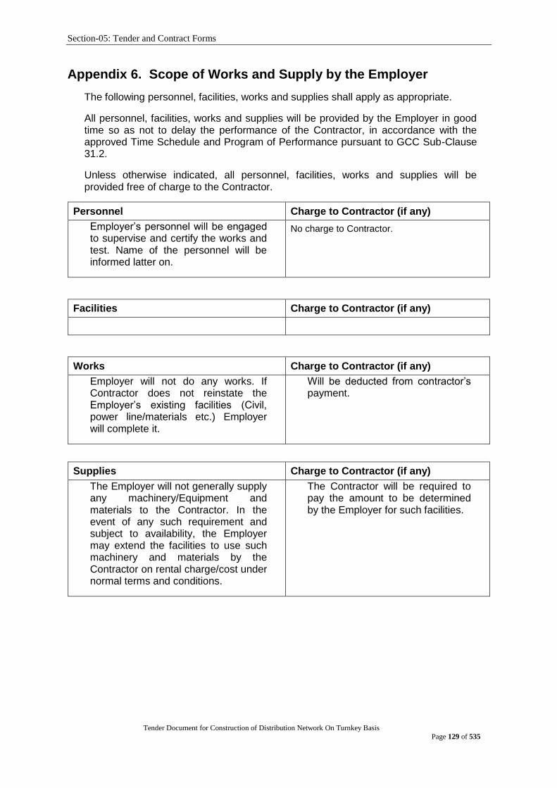
Section-05: Tender and Contract Forms
Tender Document for Construction of Distribution Network On Turnkey Basis
Page 129 of 535
Appendix 6. Scope of Works and Supply by the Employer
The following personnel, facilities, works and supplies shall apply as appropriate.
All personnel, facilities, works and supplies will be provided by the Employer in good time so as not to delay the performance of the Contractor, in accordance with the approved Time Schedule and Program of Performance pursuant to GCC Sub-Clause 31.2.
Unless otherwise indicated, all personnel, facilities, works and supplies will be provided free of charge to the Contractor.
Personnel Charge to Contractor (if any)
Employer‟s personnel will be engaged to supervise and certify the works and test. Name of the personnel will be informed latter on.
No charge to Contractor.
Facilities Charge to Contractor (if any)
Works Charge to Contractor (if any)
Employer will not do any works. If Contractor does not reinstate the Employer‟s existing facilities (Civil, power line/materials etc.) Employer will complete it.
Will be deducted from contractor‟s payment.
Supplies Charge to Contractor (if any)
The Employer will not generally supply any machinery/Equipment and materials to the Contractor. In the event of any such requirement and subject to availability, the Employer may extend the facilities to use such machinery and materials by the Contractor on rental charge/cost under normal terms and conditions.
The Contractor will be required to pay the amount to be determined by the Employer for such facilities.

Section-05: Tender and Contract Forms
Tender Document for Construction of Distribution Network On Turnkey Basis
Page 130 of 535
Appendix 7. List of Documents for Approval or Review
Pursuant to GCC Sub-Clause 35.3.1, the Contractor shall prepare, or cause its Subcontractor to prepare, and present to the Project Manager in accordance with the requirements of GCC Sub-Clause 31.2 (Program of Performance), the following documents for
(A) Approval (not limited to)
1. All detail Specification, GTP, General Arrangement, Electrical, Mechanical, Dimensional, Cross-Sectional, Connection Drawing for equipment described in Price Schedule.
2. Installation drawings, lay out, grounding/earthing design etc.
3. As Built Drawings.
4. Others as required.
(B) Review
1. Additional documents (If any) required to match with design and technical requirements.
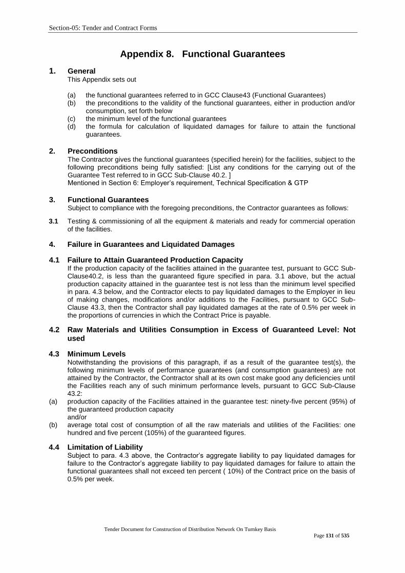
Section-05: Tender and Contract Forms
Tender Document for Construction of Distribution Network On Turnkey Basis
Page 131 of 535
Appendix 8. Functional Guarantees
1. General This Appendix sets out
(a) the functional guarantees referred to in GCC Clause43 (Functional Guarantees) (b) the preconditions to the validity of the functional guarantees, either in production and/or
consumption, set forth below (c) the minimum level of the functional guarantees (d) the formula for calculation of liquidated damages for failure to attain the functional
guarantees.
2. Preconditions
The Contractor gives the functional guarantees (specified herein) for the facilities, subject to the following preconditions being fully satisfied: [List any conditions for the carrying out of the Guarantee Test referred to in GCC Sub-Clause 40.2. ] Mentioned in Section 6: Employer‟s requirement, Technical Specification & GTP
3. Functional Guarantees
Subject to compliance with the foregoing preconditions, the Contractor guarantees as follows:
3.1 Testing & commissioning of all the equipment & materials and ready for commercial operation of the facilities.
4. Failure in Guarantees and Liquidated Damages
4.1 Failure to Attain Guaranteed Production Capacity If the production capacity of the facilities attained in the guarantee test, pursuant to GCC Sub-Clause40.2, is less than the guaranteed figure specified in para. 3.1 above, but the actual production capacity attained in the guarantee test is not less than the minimum level specified in para. 4.3 below, and the Contractor elects to pay liquidated damages to the Employer in lieu of making changes, modifications and/or additions to the Facilities, pursuant to GCC Sub-Clause 43.3, then the Contractor shall pay liquidated damages at the rate of 0.5% per week in the proportions of currencies in which the Contract Price is payable.
4.2 Raw Materials and Utilities Consumption in Excess of Guaranteed Level: Not used
4.3 Minimum Levels Notwithstanding the provisions of this paragraph, if as a result of the guarantee test(s), the following minimum levels of performance guarantees (and consumption guarantees) are not attained by the Contractor, the Contractor shall at its own cost make good any deficiencies until the Facilities reach any of such minimum performance levels, pursuant to GCC Sub-Clause 43.2:
(a) production capacity of the Facilities attained in the guarantee test: ninety-five percent (95%) of the guaranteed production capacity and/or
(b) average total cost of consumption of all the raw materials and utilities of the Facilities: one hundred and five percent (105%) of the guaranteed figures.
4.4 Limitation of Liability Subject to para. 4.3 above, the Contractor‟s aggregate liability to pay liquidated damages for
failure to the Contractor‟s aggregate liability to pay liquidated damages for failure to attain the functional guarantees shall not exceed ten percent ( 10%) of the Contract price on the basis of 0.5% per week.

Section-05: Tender and Contract Forms
Tender Document for Construction of Distribution Network On Turnkey Basis
Page 132 of 535
Appendix 9: Article(s)
Article 1
Contract Documents
Definitions (Reference GCC Clause 1)
Capitalized words and phrases used herein shall have the
same meanings as are ascribed to them in the General
Conditions.
Article 2
Contract Price and Terms of
Payment
2.1 Contract Price (Reference GCC Clause 56.1)
The Employer hereby agrees to pay to the Contractor the
Contract Price in consideration of the performance by the
Contractor of its obligations hereunder. The Contract Price
shall be the aggregate of: [. . . amounts of foreign currency
in words . . . ], [. . . amounts in figures. . . ] as specified in
Price Schedule No. 5 (Grand Summary), [. . . amounts of
local currency in words . . . ], [. . . amounts in figures. . . ], or
such other sums as may be determined in accordance with
the terms and conditions of the Contract.
2.2 Terms of Payment (Reference GCC Clause 57)
The terms and procedures of payment according to which
the Employer will reimburse the Contractor are given in the
Appendix (Terms and Procedures of Payment) hereto.
In the event that the amount payable under Schedule No. 1
is adjusted in accordance with GCC 56.2 or with any of the
other terms of the Contract, the Employer shall arrange for
the documentary credit to be amended accordingly
Article 3
Effective Date
3.1 Effective Date (Reference GCC Clause 1)
The Effective Date upon which the period until the Time for
Completion of the Facilities shall be counted from is the
date when all of the following conditions have been
fulfilled:
(a) This Contract Agreement has been duly executed for
and on behalf of the Employer and the Contractor;
(b) The Contractor has submitted to the Employer the
performance security and the advance payment
guarantee;
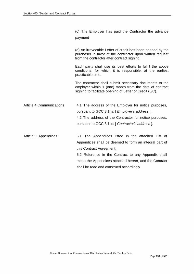
Section-05: Tender and Contract Forms
Tender Document for Construction of Distribution Network On Turnkey Basis
Page 133 of 535
(c) The Employer has paid the Contractor the advance
payment
(d) An irrevocable Letter of credit has been opened by the purchaser in favor of the contractor upon written request from the contractor after contract signing. Each party shall use its best efforts to fulfill the above conditions, for which it is responsible, at the earliest practicable time.
The contractor shall submit necessary documents to the employer within 1 (one) month from the date of contract signing to facilitate opening of Letter of Credit (L/C).
Article 4 Communications 4.1 The address of the Employer for notice purposes,
pursuant to GCC 3.1 is: [ Employer's address ].
4.2 The address of the Contractor for notice purposes,
pursuant to GCC 3.1 is: [ Contractor's address ].
Article 5. Appendices 5.1 The Appendices listed in the attached List of
Appendices shall be deemed to form an integral part of
this Contract Agreement.
5.2 Reference in the Contract to any Appendix shall
mean the Appendices attached hereto, and the Contract
shall be read and construed accordingly.
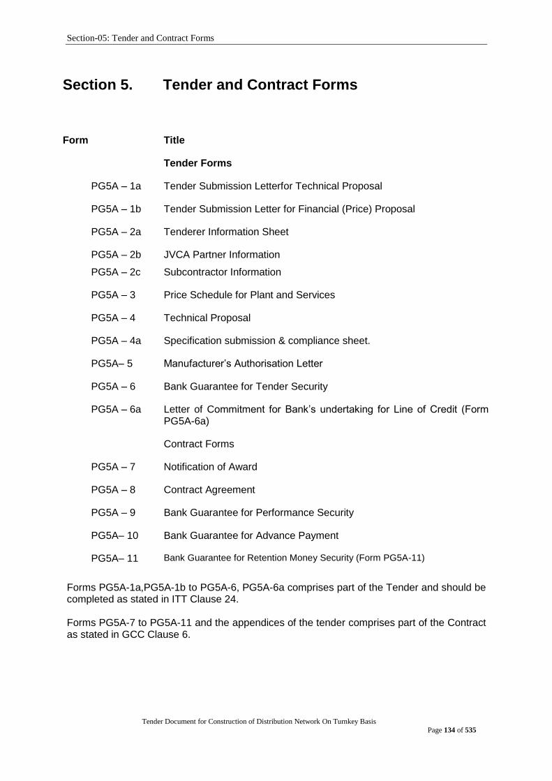
Section-05: Tender and Contract Forms
Tender Document for Construction of Distribution Network On Turnkey Basis
Page 134 of 535
Section 5. Tender and Contract Forms
Form Title
Tender Forms
PG5A – 1a Tender Submission Letterfor Technical Proposal
PG5A – 1b Tender Submission Letter for Financial (Price) Proposal
PG5A – 2a Tenderer Information Sheet
PG5A – 2b
PG5A – 2c
JVCA Partner Information
Subcontractor Information
PG5A – 3 Price Schedule for Plant and Services
PG5A – 4 Technical Proposal
PG5A – 4a Specification submission & compliance sheet.
PG5A– 5 Manufacturer‟s Authorisation Letter
PG5A – 6 Bank Guarantee for Tender Security
PG5A – 6a Letter of Commitment for Bank‟s undertaking for Line of Credit (Form PG5A-6a)
Contract Forms
PG5A – 7 Notification of Award
PG5A – 8 Contract Agreement
PG5A – 9 Bank Guarantee for Performance Security
PG5A– 10 Bank Guarantee for Advance Payment
PG5A– 11 Bank Guarantee for Retention Money Security (Form PG5A-11)
Forms PG5A-1a,PG5A-1b to PG5A-6, PG5A-6a comprises part of the Tender and should be completed as stated in ITT Clause 24. Forms PG5A-7 to PG5A-11 and the appendices of the tender comprises part of the Contract as stated in GCC Clause 6.

Section-05: Tender and Contract Forms
Tender Document for Construction of Distribution Network On Turnkey Basis
Page 135 of 535
Tender Submission Letter for Technical offer
(Form PG5A-1a) [This letter should be completed and signed by the Authorised Signatory preferably on the Letter-Head Pad of the Tenderer and be appended in the technical proposal envelope]
To:
[Contact Person]
[Name of Procuring Entity]
[Address of Procuring Entity]
Date:
Invitation for Tender No: [indicate IFT No]
Tender Package No: [indicate Package No]
This Package is divided into the following Number of
Lots
[indicate number of
Lot(s)]
We, the undersigned, offer to design, manufacture, test, deliver, install, pre-commission and commission in conformity with the Tender Document, the following Plant and Services, viz:
In signing this letter, and in submitting our Tender, we also confirm that: (a) our Tender shall be valid for the period stated in the Tender Data Sheet (ITT Sub
Clause 30.1) and it shall remain binding upon us and may be accepted at any time before the expiration of that period;
(b) a Tender Security is attached in the form of a [state pay order, bank draft, bank guarantee] in the amount stated in the Tender Data Sheet (ITT Sub Clause 32) and valid for a period of twenty eight (28) days beyond the Tender validity date;
(c) we have examined and have no reservations to the Tender Document, issued by you on [insert date]; including Addendum to Tender Document No(s) [state numbers] , issued in accordance with the Instructions to Tenderers (ITT Clause 11). [insert the number and issuing date of each addendum; or delete this sentence if no Addendum has been issued];
(d) we, including as applicable, any JVCA partner or Subcontractor for any part of the contract resulting from this Tender process, have nationalities from eligible countries, in accordance with ITT Sub Clause 5.1;
(e) we are submitting this Tender as a sole Tenderer in accordance with ITT Sub Clause 38.3
or we are submitting this Tender as the partners of a JVCA, comprising the following other partners in accordance with ITT Sub Clause 18.1;
Name of Partner Address of Partner
1
2
3
4
(f) we are not a Government owned entity as defined in ITT Sub Clause 5.3 or
we are a Government owned entity, and we meet the requirements of ITT Sub Clause 5.3; (delete one of the above as appropriate)
(g) we, including as applicable any JVCA partner, declare that we are not associated, nor have been associated in the past, directly or indirectly, with a consultant or

Section-05: Tender and Contract Forms
Tender Document for Construction of Distribution Network On Turnkey Basis
Page 136 of 535
any other entity that has prepared the design, specifications and other documents in accordance with ITT Sub Clause 5.5;
(h) we, including as applicable any JVCA partner or Subcontractor for any part of the contract resulting from this Tender process, have not been declared ineligible by the Government of Bangladesh on charges of engaging in corrupt, fraudulent, collusive or coercive practices in accordance with ITT Sub Clause 5.6;
(i) furthermore, we are aware of ITT Clause 4 concerning such practices and pledge not to indulge in such practices in competing for or in executing the Contract;
(j) we intend to subcontract an activity or part of the Works, in accordance with ITT Sub Clause 19.1, to the following Subcontractor(s);
Activity or part of the Plant and Services
Name of Subcontractor with Address
(k) we, including as applicable any JVCA partner, confirm that we do not have a record of poor performance, such as abandoning the works, not properly completing contracts, inordinate delays, or financial failure as stated in ITT Clause 5.7, and that we do not have, or have had, any litigation against us, other than that stated in the Tenderer Information (Form PG5A-2b);
(l) we are not participating as Tenderers in more than one Tender in this Tendering process. We understand that your written Notification of Award shall constitute the acceptance of our Tender and shall become a binding Contract between us, until a formal Contract is prepared and executed;
(m) we, including as applicable any JVCA partner, confirm that we do not have a record of insolvency, receivership, bankrupt or being wound up, our business activities were not been suspended, and it was not been the subject of legal proceedings in accordance with ITT Sub Clause 5.8;
(n) we, including as applicable any JVCA partner, confirm that we have fulfilled our obligations to pay taxes and social security contributions applicable under the relevant national laws and regulations of Bangladesh in accordance with ITT Sub Clause 5.9;
(o) we understand that you reserve the right to reject all the Tenders or annul the Tender proceedings, without incurring any liability to Tenderers, in accordance with ITT Clause 59.
Signature: [insert signature of authorised representative of the Tenderer]
Name: [insert full name of signatory with National ID Number, if applicable]
In the capacity of: [insert capacity of signatory]
Duly authorised to sign the Tender for and on behalf of the Tenderer
[If there is more than one (1) signatory, or in the case of a JVCA, add other boxes and sign accordingly].Attachment 1: [ITT Sub Clause 38.3] Written confirmation authorising the above signatory(ies) to commit the Tenderer [and, if applicable] Attachment 2: [ITT Sub Clause 29.2(b)] Copy of the JVCA Agreement / Letter of Intent to form JVCA with draft proposed Agreement

Section-05: Tender and Contract Forms
Tender Document for Construction of Distribution Network On Turnkey Basis
Page 137 of 535
Tender Submission Letter for Financial offer
(Form PG5A-1b) [This letter should be completed and signed by the Authorised Signatory preferably on the Letter-Head Pad of the Tenderer and be appended in the financial proposal envelope]
To:
[Contact Person]
[Name of Procuring Entity]
[Address of Procuring Entity]
Date:
Invitation for Tender No: [indicate IFT No]
Tender Package No: [indicate Package No]
This Package is divided into the following Number of Lots
[indicate number of Lot(s)]
We, the undersigned, offer to design, manufacture, test, deliver, install, pre-commission and commission in conformity with the Tender Document, the following Plant and Services, viz:
In accordance with ITT Clauses 26 and 27, the following prices and discounts apply to our Tender:
The Tender Price is:
(ITT Sub-Clause 26.1)
[state amount in figures]
and [state amount in words]
Plant (including Mandatory Spare Parts) Supplied from abroad
[state amount in figures]
and [state amount in words]
Plant (including Mandatory Spare Parts) supplied from within the Employer‟s Country
Taka[state amount in figures]
And Taka [state amount in words]
Design Services [state amount in figures]
and [state amount in words]
Installation and Other Services [state amount in figures]
and [state amount in words]
Recommended Spare parts Price
(If economic Factor is applicable)
[state amount in figures]
and [state amount in words]
The Unconditional discount is
(ITT Sub-Clause 23.11)
[state amount in figures]
and [state amount in words]
The methodology for Application of the discount is:
[state the methodology]
and we shall accordingly submit an Advance Payment Guarantee in the format shown in Form PG5A- 10.
In signing this letter, and in submitting our Tender, we also confirm that:

Section-05: Tender and Contract Forms
Tender Document for Construction of Distribution Network On Turnkey Basis
Page 138 of 535
a) our Tender shall be valid for the period stated in the Tender Data Sheet (ITT Sub Clause 30.1) and it shall remain binding upon us and may be accepted at any time before the expiration of that period;
b) a Tender Security is attached in the form of a [state pay order, bank draft, bank guarantee] in the amount stated in the Tender Data Sheet (ITT Sub Clause 32) and valid for a period of twenty eight (28) days beyond the Tender validity date;
c) if our Tender is accepted, we commit to furnishing a Performance Security within the time stated under ITT Sub Clause 65.1) and in the form specified in the Tender Data Sheet (ITT Sub Clause 66.1) valid for a period of twenty eight (28) days beyond the date of issue of the Completion Certificate of the Plants and Services;
d) we have examined and have no reservations to the Tender Document, issued by you on [insert date]; including Addendum to Tender Document No(s) [state numbers] , issued in accordance with the Instructions to Tenderers (ITT Clause 11). [insert the number and issuing date of each addendum; or delete this sentence if no Addendum has been issued];
e) we, including as applicable, any JVCA partner or Subcontractor for any part of the contract resulting from this Tender process, have nationalities from eligible countries, in accordance with ITT Sub Clause 5.1;
f) we are submitting this Tender as a sole Tenderer in accordance with ITT Sub Clause 38.3 or we are submitting this Tender as the partners of a JVCA, comprising the following other partners in accordance with ITT Sub Clause 18.1;
Name of Partner Address of Partner
1
2
3
4
g) we are not a Government owned entity as defined in ITT Sub Clause 5.3 or
we are a Government owned entity, and we meet the requirements of ITT Sub Clause 5.3;
(delete one of the above as appropriate)
h) we, including as applicable any JVCA partner, declare that we are not associated, nor have been associated in the past, directly or indirectly, with a consultant or any other entity that has prepared the design, specifications and other documentsin accordance with ITT Sub Clause 5.5;
i) we, including as applicable any JVCA partner or Subcontractor for any part of the contract resulting from this Tender process, have not been declared ineligible by the Government of Bangladesh on charges of engaging in corrupt, fraudulent, collusive or coercive practices in accordance with ITT Sub Clause 5.6;
j) furthermore, we are aware of ITT Clause 4 concerning such practices and pledge not to indulge in such practices in competing for or in executing the Contract;
k) we intend to subcontract an activity or part of the Works, in accordance with ITT Sub Clause 19.1, to the following Subcontractor(s);
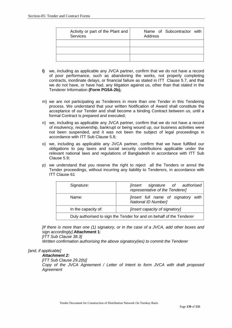
Section-05: Tender and Contract Forms
Tender Document for Construction of Distribution Network On Turnkey Basis
Page 139 of 535
Activity or part of the Plant and Services
Name of Subcontractor with Address
l) we, including as applicable any JVCA partner, confirm that we do not have a record of poor performance, such as abandoning the works, not properly completing contracts, inordinate delays, or financial failure as stated in ITT Clause 5.7, and that we do not have, or have had, any litigation against us, other than that stated in the Tenderer Information (Form PG5A-2b);
m) we are not participating as Tenderers in more than one Tender in this Tendering process. We understand that your written Notification of Award shall constitute the acceptance of our Tender and shall become a binding Contract between us, until a formal Contract is prepared and executed;
n) we, including as applicable any JVCA partner, confirm that we do not have a record of insolvency, receivership, bankrupt or being wound up, our business activities were not been suspended, and it was not been the subject of legal proceedings in accordance with ITT Sub Clause 5.8;
o) we, including as applicable any JVCA partner, confirm that we have fulfilled our obligations to pay taxes and social security contributions applicable under the relevant national laws and regulations of Bangladesh in accordance with ITT Sub Clause 5.9;
p) we understand that you reserve the right to reject all the Tenders or annul the Tender proceedings, without incurring any liability to Tenderers, in accordance with ITT Clause 61
Signature: [insert signature of authorised representative of the Tenderer]
Name: [insert full name of signatory with National ID Number]
In the capacity of: [insert capacity of signatory]
Duly authorised to sign the Tender for and on behalf of the Tenderer
[If there is more than one (1) signatory, or in the case of a JVCA, add other boxes and sign accordingly].Attachment 1: [ITT Sub Clause 38.3] Written confirmation authorising the above signatory(ies) to commit the Tenderer
[and, if applicable]
Attachment 2: [ITT Sub Clause 29.2(b)] Copy of the JVCA Agreement / Letter of Intent to form JVCA with draft proposed Agreement
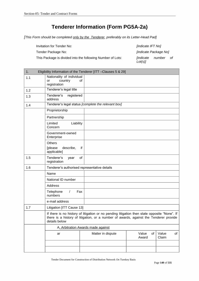
Section-05: Tender and Contract Forms
Tender Document for Construction of Distribution Network On Turnkey Basis
Page 140 of 535
Tenderer Information (Form PG5A-2a)
[This Form should be completed only by the Tenderer, preferably on its Letter-Head Pad]
Invitation for Tender No: [indicate IFT No]
Tender Package No: [indicate Package No]
This Package is divided into the following Number of Lots: [indicate number of Lot(s)]
1. Eligibility Information of the Tenderer [ITT –Clauses 5 & 29]
1.1 Nationality of individual or country of registration
1.2 Tenderer‟s legal title
1.3 Tenderer‟s registered address
1.4 Tenderer‟s legal status [complete the relevant box]
Proprietorship
Partnership
Limited Liability Concern
Government-owned Enterprise
Others
[please describe, if applicable]
1.5 Tenderer‟s year of registration
1.6 Tenderer‟s authorised representative details
Name
National ID number
Address
Telephone / Fax numbers
e-mail address
1.7 Litigation [ITT Cause 13]
If there is no history of litigation or no pending litigation then state opposite “None”. If there is a history of litigation, or a number of awards, against the Tenderer provide details below
A. Arbitration Awards made against
ar Matter in dispute Value of Award
Value of Claim

Section-05: Tender and Contract Forms
Tender Document for Construction of Distribution Network On Turnkey Basis
Page 141 of 535
B. Arbitration Awards pending
Year Matter in dispute Value of Claim
1.8 Tenderer to attach photocopies of the original documents mentioned aside
[All documents required under ITT Clauses 5 and 29]
The following two information are applicable for National Tenderers
1.9 Tenderer‟s Value Added Tax Registration (VAT) Number
1.10 Tenderer‟s Tax Identification Number(TIN)
[The foreign Tenderers, in accordance with ITT Sub Clause 5.1, shall provide evidence by a written declaration to that effect to demonstrate that it meets the criterion]
2. Qualification Information of the Tenderer [ITT Clause 29]
2.1 General Experience in Plant and Services of Tenderer
Start Month Year
End Month Year
Years Contract No and Name of Contract
Name and Address of Procuring Entity
Brief description of Plant and Services
Role of Tenderer
[Contractor/Subcontractor /Management Contractor]
2.2 Specific Experience in Key Activities
Contract No
Name of Contract
[ insert reference no] of [ insert year]
[insert name]
Role in Contract
[tick relevant box].
Contractor
Subcontractor
Management Contractor
\Award date
Completion date
Total Contract Value
[insert date]
[insert date]
[insert amount]
Procuring Entity‟s Name
Address
Tel / Fax
Brief description with justifications of the similarity compared to the Procuring Entity‟s requirements
[state justification in support of its similarity compared to the proposed works]

Section-05: Tender and Contract Forms
Tender Document for Construction of Distribution Network On Turnkey Basis
Page 142 of 535
2.3 Average annual turnover [ITT Sub Clause15.1(a)]
[amount invoiced to Procuring Entity(s) for each year of works in progress or completed, using rate of exchange at the end of the period reported]
Year Amount & Currency amount in figures
2.4 Financial Resources available to meet the cash flow [ITT Sub Clause 15.1(b)]
No Source of Financing Amount Available
In order to confirm the above statements the Tenderer shall submit , as applicable, the documents mentioned in ITT Sub Clause 14.1(a), (b) and 15.1 (a), (b) & (c)
2.5 Contact Details
Name, address, and other contact details of Tenderer Bankers and other Procuring Entity(s) that may provide references, if contacted by this Procuring Entity
2.6 Qualifications and experience of key technical and administrative personnel proposed for
Contract administration and management [ITT Sub Clause 16.1 ]
Position
Name
Years of General Experience
Years of Specific Experience
[Tenderer to complete details of as many personnel as are applicable.Each personnel listed
above should complete the Personnel Information (Form PG5A-5)]
2.7 Major Equipment proposed to carry out the Contract [ITT Sub Clause 17.1 ]
Item of Equipment
Condition
(new, good, average, poor)
Owned, leased or to be purchased
(state owner, lessor seller)
[Tenderer to list details of each item of major equipment, as applicable]
Name: [insert full name of signatory]
Signature with Date and Seal
In the capacity of:
[insert designation of signatory]
[ Sign]
Duly authorised to sign the Tender for and on behalf of the Tenderer
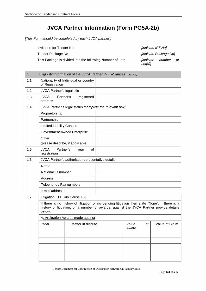
Section-05: Tender and Contract Forms
Tender Document for Construction of Distribution Network On Turnkey Basis
Page 143 of 535
JVCA Partner Information (Form PG5A-2b)
[This Form should be completed by each JVCA partner].
Invitation for Tender No: [indicate IFT No]
Tender Package No [indicate Package No]
This Package is divided into the following Number of Lots [indicate number of Lot(s)]
1. Eligibility Information of the JVCA Partner [ITT –Clauses 5 & 29]
1.1 Nationality of Individual or country of Registration
1.2 JVCA Partner‟s legal title
1.3 JVCA Partner‟s registered address
1.4 JVCA Partner‟s legal status [complete the relevant box]
Proprietorship
Partnership
Limited Liability Concern
Government-owned Enterprise
Other
(please describe, if applicable)
1.5 JVCA Partner‟s year of registration
1.6 JVCA Partner‟s authorised representative details
Name
National ID number
Address
Telephone / Fax numbers
e-mail address
1.7 Litigation [ITT Sub Cause 13]
If there is no history of litigation or no pending litigation then state “None”. If there is a history of litigation, or a number of awards, against the JVCA Partner provide details below:
A. Arbitration Awards made against
Year Matter in dispute Value of Award
Value of Claim
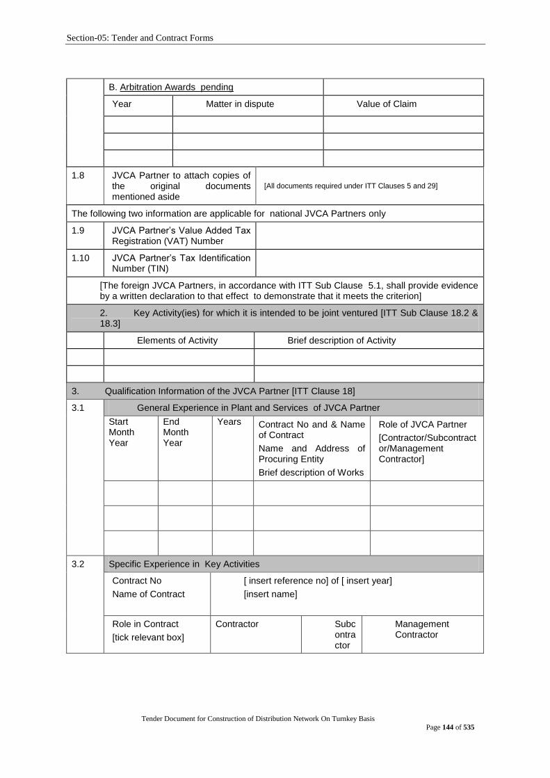
Section-05: Tender and Contract Forms
Tender Document for Construction of Distribution Network On Turnkey Basis
Page 144 of 535
B. Arbitration Awards pending
Year Matter in dispute Value of Claim
1.8 JVCA Partner to attach copies of the original documents mentioned aside
[All documents required under ITT Clauses 5 and 29]
The following two information are applicable for national JVCA Partners only
1.9 JVCA Partner‟s Value Added Tax Registration (VAT) Number
1.10 JVCA Partner‟s Tax Identification Number (TIN)
[The foreign JVCA Partners, in accordance with ITT Sub Clause 5.1, shall provide evidence by a written declaration to that effect to demonstrate that it meets the criterion]
2. Key Activity(ies) for which it is intended to be joint ventured [ITT Sub Clause 18.2 & 18.3]
Elements of Activity Brief description of Activity
3. Qualification Information of the JVCA Partner [ITT Clause 18]
3.1 General Experience in Plant and Services of JVCA Partner
Start Month Year
End Month Year
Years Contract No and & Name of Contract
Name and Address of Procuring Entity
Brief description of Works
Role of JVCA Partner
[Contractor/Subcontractor/Management Contractor]
3.2 Specific Experience in Key Activities
Contract No
Name of Contract
[ insert reference no] of [ insert year]
[insert name]
Role in Contract
[tick relevant box]
Contractor Subcontractor
Management Contractor
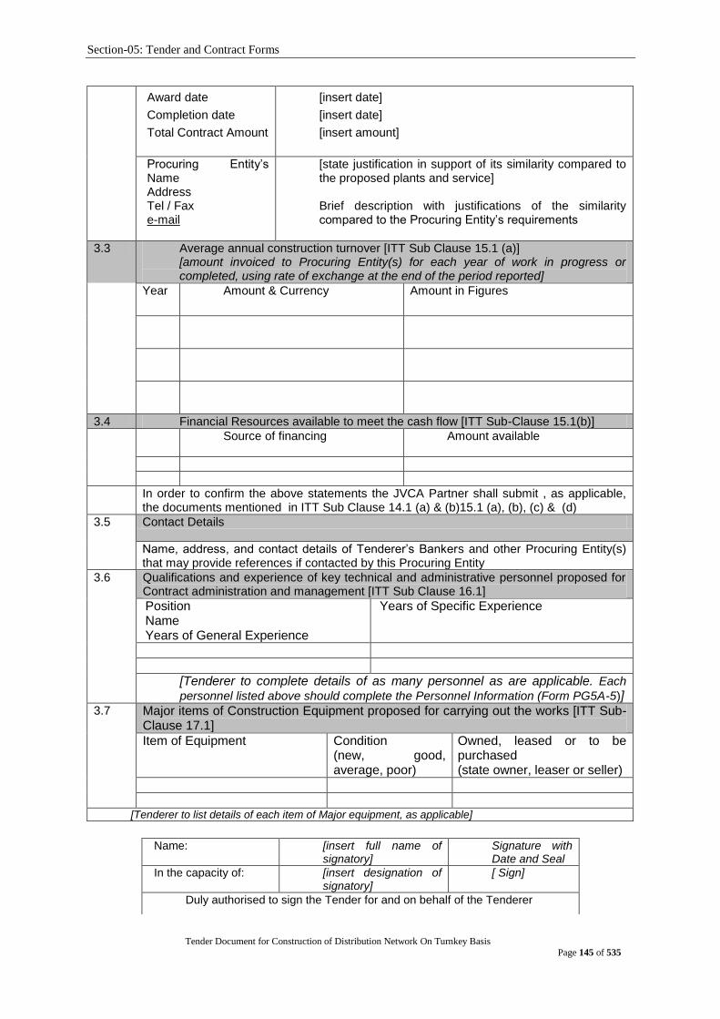
Section-05: Tender and Contract Forms
Tender Document for Construction of Distribution Network On Turnkey Basis
Page 145 of 535
Award date
Completion date
Total Contract Amount
[insert date]
[insert date]
[insert amount]
Procuring Entity‟s Name Address Tel / Fax e-mail
[state justification in support of its similarity compared to the proposed plants and service] Brief description with justifications of the similarity compared to the Procuring Entity‟s requirements
3.3 Average annual construction turnover [ITT Sub Clause 15.1 (a)] [amount invoiced to Procuring Entity(s) for each year of work in progress or completed, using rate of exchange at the end of the period reported]
Year Amount & Currency Amount in Figures
3.4 Financial Resources available to meet the cash flow [ITT Sub-Clause 15.1(b)]
No
Source of financing Amount available
In order to confirm the above statements the JVCA Partner shall submit , as applicable, the documents mentioned in ITT Sub Clause 14.1 (a) & (b)15.1 (a), (b), (c) & (d)
3.5 Contact Details
Name, address, and contact details of Tenderer‟s Bankers and other Procuring Entity(s) that may provide references if contacted by this Procuring Entity
3.6 Qualifications and experience of key technical and administrative personnel proposed for Contract administration and management [ITT Sub Clause 16.1]
Position Name Years of General Experience
Years of Specific Experience
[Tenderer to complete details of as many personnel as are applicable. Each
personnel listed above should complete the Personnel Information (Form PG5A-5)] 3.7 Major items of Construction Equipment proposed for carrying out the works [ITT Sub-
Clause 17.1]
Item of Equipment
Condition (new, good, average, poor)
Owned, leased or to be purchased (state owner, leaser or seller)
[Tenderer to list details of each item of Major equipment, as applicable]
Name: [insert full name of signatory]
Signature with Date and Seal
In the capacity of: [insert designation of signatory]
[ Sign]
Duly authorised to sign the Tender for and on behalf of the Tenderer
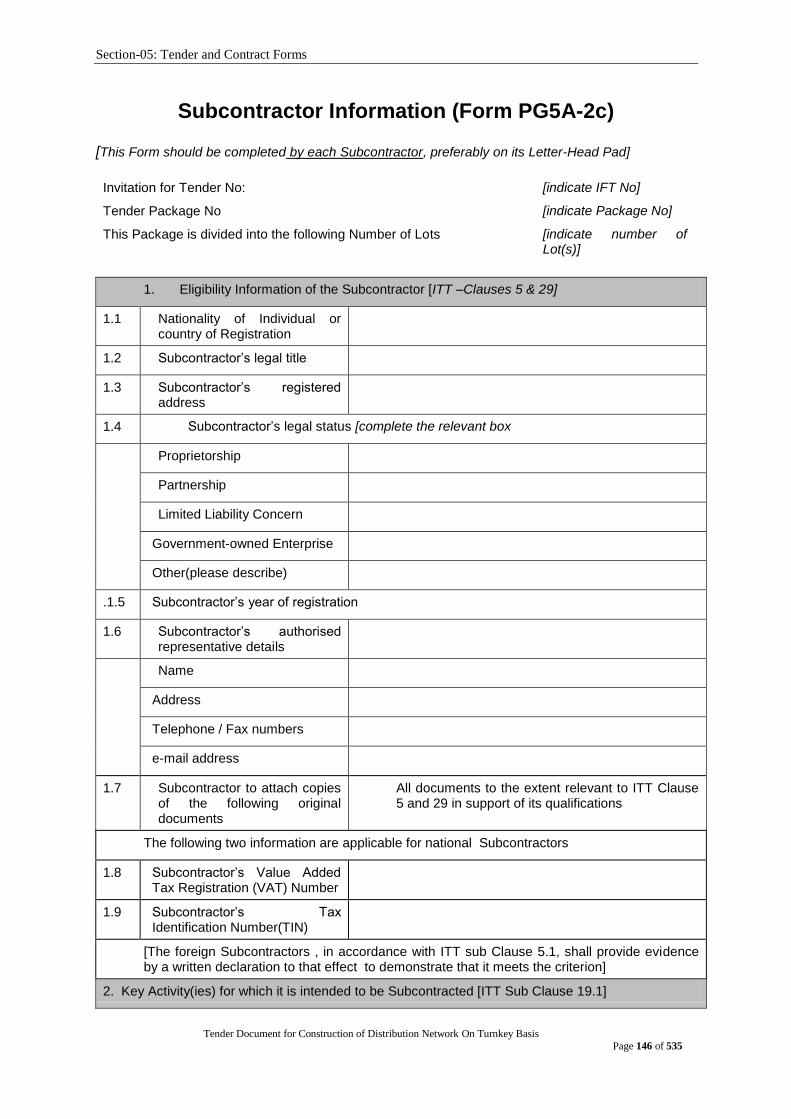
Section-05: Tender and Contract Forms
Tender Document for Construction of Distribution Network On Turnkey Basis
Page 146 of 535
Subcontractor Information (Form PG5A-2c)
[This Form should be completed by each Subcontractor, preferably on its Letter-Head Pad]
Invitation for Tender No: [indicate IFT No]
Tender Package No [indicate Package No]
This Package is divided into the following Number of Lots [indicate number of Lot(s)]
1. Eligibility Information of the Subcontractor [ITT –Clauses 5 & 29]
1.1 Nationality of Individual or country of Registration
1.2 Subcontractor‟s legal title
1.3 Subcontractor‟s registered address
1.4 Subcontractor‟s legal status [complete the relevant box
Proprietorship
Partnership
Limited Liability Concern
Government-owned Enterprise
Other(please describe)
.1.5 Subcontractor‟s year of registration
1.6 Subcontractor‟s authorised representative details
Name
Address
Telephone / Fax numbers
e-mail address
1.7 Subcontractor to attach copies of the following original documents
All documents to the extent relevant to ITT Clause 5 and 29 in support of its qualifications
The following two information are applicable for national Subcontractors
1.8 Subcontractor‟s Value Added Tax Registration (VAT) Number
1.9 Subcontractor‟s Tax Identification Number(TIN)
[The foreign Subcontractors , in accordance with ITT sub Clause 5.1, shall provide evidence by a written declaration to that effect to demonstrate that it meets the criterion]
2. Key Activity(ies) for which it is intended to be Subcontracted [ITT Sub Clause 19.1]
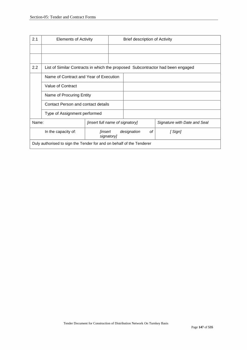
Section-05: Tender and Contract Forms
Tender Document for Construction of Distribution Network On Turnkey Basis
Page 147 of 535
2.1 Elements of Activity Brief description of Activity
2.2 List of Similar Contracts in which the proposed Subcontractor had been engaged
Name of Contract and Year of Execution
Value of Contract
Name of Procuring Entity
Contact Person and contact details
Type of Assignment performed
Name: [insert full name of signatory] Signature with Date and Seal
In the capacity of: [insert designation of signatory]
[ Sign]
Duly authorised to sign the Tender for and on behalf of the Tenderer

Section-05: Tender and Contract Forms
Tender Document for Construction of Distribution Network On Turnkey Basis
Page 148 of 535
Price Schedule for Plant and Service (Form PG5A-3) (This form should be completed and submitted by the tenderer and appended in the financial proposal envelope)
Invitation for Tender No: [indicate IFT No]
Tender Package No [indicate Package No]
This Package is divided into the following Number of Lots [indicate number of Lot(s)]
General
1. The Price Schedules are divided into separate Schedules as follows:
Schedule No. 1: Plant (including Mandatory Spare Parts) Supplied from Abroad
Schedule No. 2: Plant (including Mandatory Spare Parts) Supplied from within the Employer‟s Country
Schedule No. 3: Design Services
Schedule No. 4: Installation and Other Services
Schedule No. 5: Grand Summary
Schedule No. 6: Recommended Spare Parts
2. The Schedules do not generally give a full description of the plant to be supplied and the services to be performed under each item. Tenderers shall be deemed to have read the Employer‟s Requirements and other sections of the Tender Document and reviewed the Drawings to ascertain the full scope of the requirements included in each item prior to filling in the rates and prices. The entered rates and prices shall be deemed to cover the full scope as aforesaid, including overheads and profit.
3. If tenderers are unclear or uncertain as to the scope of any item, they shall seek clarification in accordance with ITT 9.1 prior to submitting their tender.
Pricing
4. Prices shall be filled in indelible ink, and any alterations necessary due to errors, etc., shall be initialed by the Tenderer.
As specified in the Tender Data Sheet and Special Conditions of Contract, prices shall be fixed and firm for the duration of the Contract, or prices shall be subject to adjustment in accordance with the corresponding Appendix (Price Adjustment) to the Contract Agreement.
5. Tender prices shall be quoted in the manner indicated and in the currencies specified in the Instructions to Tenderers in the Tender Document.
For each item, tenderers shall complete each appropriate column in the respective Schedules, giving the price breakdown as indicated in the Schedules.
Prices given in the Schedules against each item shall be for the scope covered by that item as detailed in Section 6 (Employer‟s Requirements) or elsewhere in the Tender Document.
6. Payments will be made to the Contractor in the currency or currencies indicated under each respective item.
7. When requested by the Employer for the purposes of making payments or partial payments, valuing variations or evaluating claims, or for such other purposes as the Employer may reasonably require, the Contractor shall provide the Employer with a breakdown of any composite or lump sum items included in the Schedules.
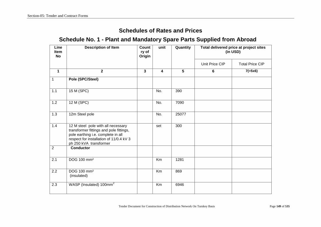
Section-05: Tender and Contract Forms
Tender Document for Construction of Distribution Network On Turnkey Basis Page 149 of 535
Schedules of Rates and Prices
Schedule No. 1 - Plant and Mandatory Spare Parts Supplied from Abroad
Line Item No
Description of Item Country of
Origin
unit Quantity Total delivered price at project sites (in USD)
Unit Price CIP Total Price CIP
1 2 3 4 5 6 7(=5x6)
1 Pole (SPC/Steel)
1.1 15 M (SPC)
No. 390
1.2 12 M (SPC)
No. 7090
1.3 12m Steel pole
No. 25077
1.4 12 M steel pole with all necessary transformer fittings and pole fittings, pole earthing i.e. complete in all respect for installation of 11/0.4 kV 3 ph 250 kVA transformer
set 300
2 Conductor
2.1 DOG 100 mm²
Km 1281
2.2 DOG 100 mm² (insulated)
Km 869
2.3 WASP (Insulated) 100mm2
Km 6946

Section-05: Tender and Contract Forms
Tender Document for Construction of Distribution Network On Turnkey Basis Page 150 of 535
Line Item No
Description of Item Country of
Origin
unit Quantity Total delivered price at project sites (in USD)
Unit Price CIP Total Price CIP
1 2 3 4 5 6 7(=5x6)
2.4 GOPHER 25 mm² PVC covered
Km 33
2.5 Bare Copper Conductor 1x35 mm² Km 90
2.6 Conductor 95 mm² Cu 1c PVC insulated
Km 193
2.7 MERLIN 180 mm²
Km 1773
3 Midspan Joint for Conductor
3.1 Joint midspan. DOG
No. 1743
3.2 Joint midspan. with cover WASP (Insulated)
No. 10743
3.3 Midspan Joint MERLIN
No. 2379
3.4 Joint midspan. with cover DOG (Insulated)
No. 1201
4 Conductor Jointing Material
4.1 Crimpit 100/25 No. 290336
4.2 Crimpit 100/100 No. 156016
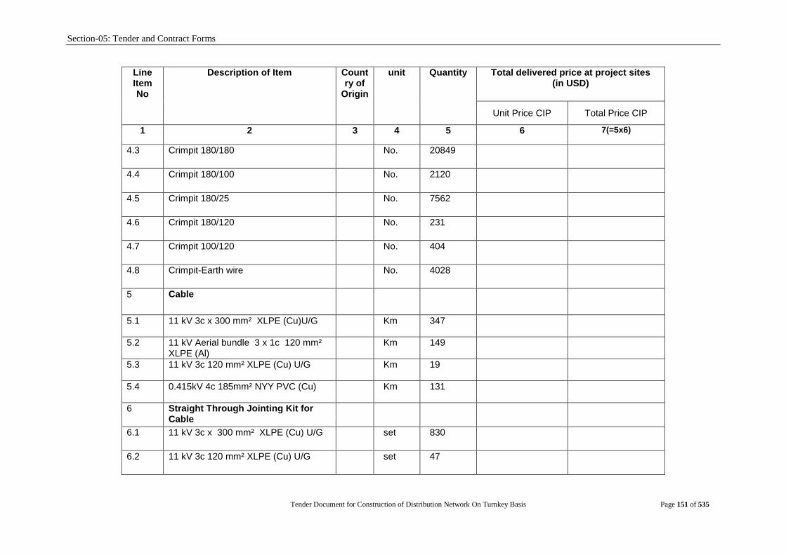
Section-05: Tender and Contract Forms
Tender Document for Construction of Distribution Network On Turnkey Basis Page 151 of 535
Line Item No
Description of Item Country of
Origin
unit Quantity Total delivered price at project sites (in USD)
Unit Price CIP Total Price CIP
1 2 3 4 5 6 7(=5x6)
4.3 Crimpit 180/180 No. 20849
4.4 Crimpit 180/100 No. 2120
4.5 Crimpit 180/25 No. 7562
4.6 Crimpit 180/120 No. 231
4.7 Crimpit 100/120 No. 404
4.8 Crimpit-Earth wire No. 4028
5 Cable
5.1 11 kV 3c x 300 mm² XLPE (Cu)U/G Km 347
5.2 11 kV Aerial bundle 3 x 1c 120 mm² XLPE (Al)
Km 149
5.3 11 kV 3c 120 mm² XLPE (Cu) U/G Km 19
5.4 0.415kV 4c 185mm² NYY PVC (Cu) Km 131
6 Straight Through Jointing Kit for Cable
6.1 11 kV 3c x 300 mm² XLPE (Cu) U/G set 830
6.2 11 kV 3c 120 mm² XLPE (Cu) U/G set 47

Section-05: Tender and Contract Forms
Tender Document for Construction of Distribution Network On Turnkey Basis Page 152 of 535
Line Item No
Description of Item Country of
Origin
unit Quantity Total delivered price at project sites (in USD)
Unit Price CIP Total Price CIP
1 2 3 4 5 6 7(=5x6)
6.3 0.415kV 4c 185mm² NYY PVC (Cu) set 45
7 Pole Kit Termination for cable
7.1 11 kV 3c x 300 mm² XLPE (Cu) set 686
7.2 11 kV Aerial bundle 3x1c 120 mm² XLPE (Al)
set 698
7.3 11 kV 3c 120 mm² XLPE (Cu) U/G set 30
7.4 0.415kV 4c 185mm² NYY PVC (Cu) set 81
8 Indoor Termination Kit for cable
8.1 11 kV 3c x 300 mm² XLPE (Cu) U/G set 737
8.2 11 kV 3c 120 mm² XLPE (Cu) U/G set 320
8.3 0.415kV 4c 185mm² NYY PVC (Cu) set 1252
9 Insulator
9.1 11 KV Pin Insulator Each 41292
9.2 11 KV Disc Insulator Each 51064
9.3 400V Shackle Insulator Each 188810

Section-05: Tender and Contract Forms
Tender Document for Construction of Distribution Network On Turnkey Basis Page 153 of 535
Line Item No
Description of Item Country of
Origin
unit Quantity Total delivered price at project sites (in USD)
Unit Price CIP Total Price CIP
1 2 3 4 5 6 7(=5x6)
10 Distribution Transformer & 11kV Ring Main Unit (RMU)
10.1 11/0.4kV 250kVA, 3-Ph, 50Hz Distribution Transformer
No. 2550
10.2 11/0.4kV 630kVA, 3-Ph, 50Hz Distribution Transformer with Kiosk
No. 10
10.3 LV Control; Box fitted on transformer kiosk
No. 10
10.4 11kV Ring Main Unit (RMU) - 5 Limb Set 168
11 Distribution Transformer and RMU Accessories
11.1 Fuse Mounting, Platform Support Angle, Cu Rod, Bare Cu Conductor, Tie Bolt, J Bolt etc.
Set 2745
11.2 Earthing of Distribution Transformer with all accessories
Set 5394
11.3 Earthing and Civil Works of 11kV RMU with all accessories
Set 178
12 Transformer Protection Equipment
12.1 DOFC (Set of 3 Nos.) Set 3028
12.2 11kV Surge Arrester (Set of 3 Nos.) Set 3028
12.3 Fuse 11 kV 20A/30A
No. 9069

Section-05: Tender and Contract Forms
Tender Document for Construction of Distribution Network On Turnkey Basis Page 154 of 535
Line Item No
Description of Item Country of
Origin
unit Quantity Total delivered price at project sites (in USD)
Unit Price CIP Total Price CIP
1 2 3 4 5 6 7(=5x6)
12.4 MCCB with box 200Amps
No. 1188
12.5 MCCB with box 250Amps
No. 2245
12.6 MCCB with box 300Amps
No. 714
12.7 MCCB with box 400Amps No. 1455
13 Pole Fitting for Overhead Line
13.1 11kV Cross Arm- Terminal
Set 741
13.2 11kV Cross Arm- Straight type
Set 429
13.3 11kV Cross Arm- tie strap
Set 1134
13.4 11kV Cross Arm- Diverter
Set 86
13.5 Top Mount Bracket
Set 5263
13.6 Side mount bracket (One Way)
Set 32271
13.7 Side mount bracket (Two Way)
Set 1879
13.8 5 Spool iron rack (Inline)
Set 21277
13.9 5 Spool iron rack (Dead end)
Set 17557

Section-05: Tender and Contract Forms
Tender Document for Construction of Distribution Network On Turnkey Basis Page 155 of 535
Line Item No
Description of Item Country of
Origin
unit Quantity Total delivered price at project sites (in USD)
Unit Price CIP Total Price CIP
1 2 3 4 5 6 7(=5x6)
13.10 Pole Band & pole clamp with stand Set 2269
13.11 Guy assembly excluding guy wire (Anchor, Stay Insu., Bolt & Nut etc.)
Set 1365
13.12 Wire stay 7/10 Km 14
14 Hardware Materials for Distribution System
14.1 Preform Dead End-AAC WASP (I) each 56833
14.2 Preform Dead End-ACSR Merlin
each 3116
14.3 Preform Dead End-ACSR DOG each 11720
14.4 Preform Dead End 7/10 Stay wire each 5460
14.5 Bracket Out rigger for 11KV each 821
14.6 Bracket Out rigger for 400V each 1053
14.7 Suspension Clamp ACSR Merlin each 854
14.8 Suspension Clamp ACSR DOG each 1548
14.9 Terminal Clamp ACSR Merlin
each 8203
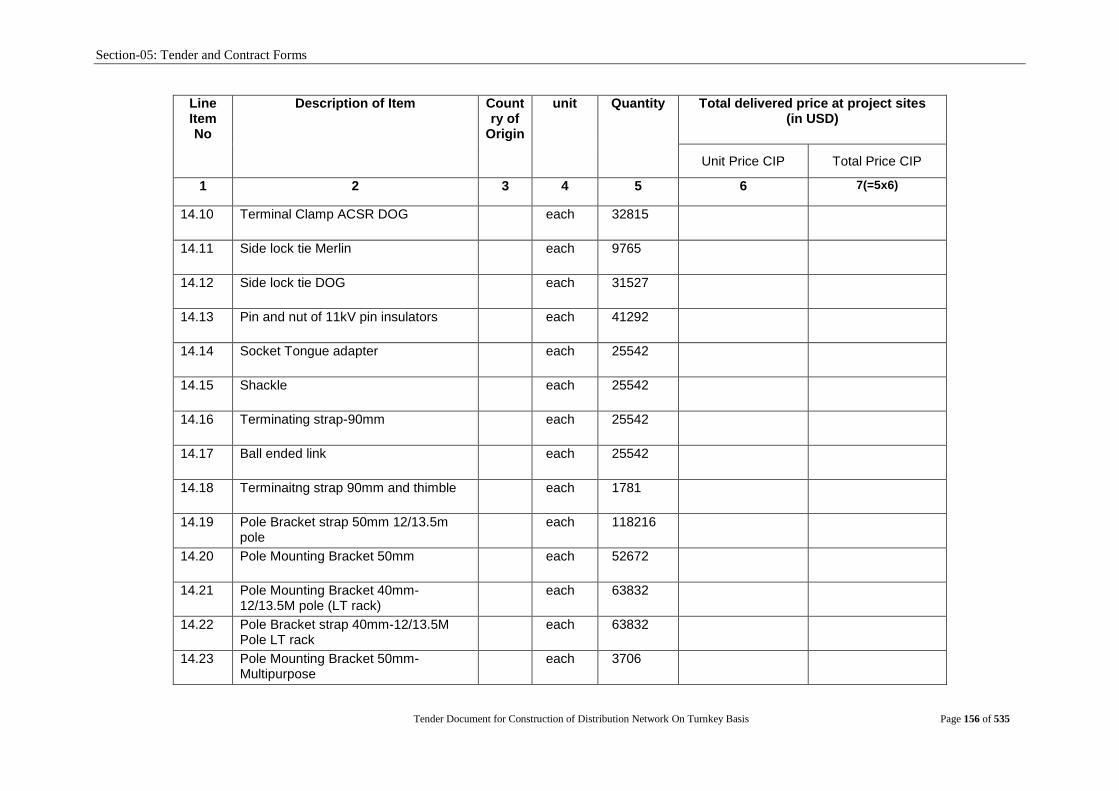
Section-05: Tender and Contract Forms
Tender Document for Construction of Distribution Network On Turnkey Basis Page 156 of 535
Line Item No
Description of Item Country of
Origin
unit Quantity Total delivered price at project sites (in USD)
Unit Price CIP Total Price CIP
1 2 3 4 5 6 7(=5x6)
14.10 Terminal Clamp ACSR DOG
each 32815
14.11 Side lock tie Merlin
each 9765
14.12 Side lock tie DOG each 31527
14.13 Pin and nut of 11kV pin insulators
each 41292
14.14 Socket Tongue adapter
each 25542
14.15 Shackle
each 25542
14.16 Terminating strap-90mm
each 25542
14.17 Ball ended link
each 25542
14.18 Terminaitng strap 90mm and thimble each 1781
14.19 Pole Bracket strap 50mm 12/13.5m pole
each 118216
14.20 Pole Mounting Bracket 50mm
each 52672
14.21 Pole Mounting Bracket 40mm- 12/13.5M pole (LT rack)
each 63832
14.22 Pole Bracket strap 40mm-12/13.5M Pole LT rack
each 63832
14.23 Pole Mounting Bracket 50mm- Multipurpose
each 3706
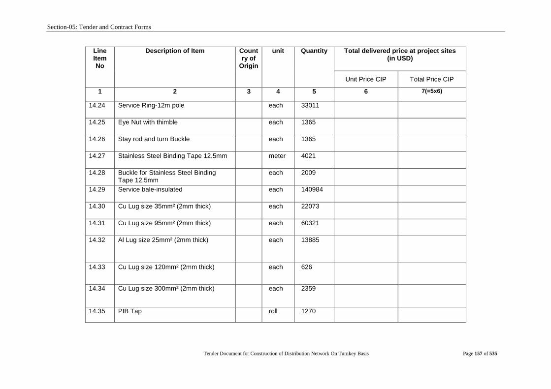
Section-05: Tender and Contract Forms
Tender Document for Construction of Distribution Network On Turnkey Basis Page 157 of 535
Line Item No
Description of Item Country of
Origin
unit Quantity Total delivered price at project sites (in USD)
Unit Price CIP Total Price CIP
1 2 3 4 5 6 7(=5x6)
14.24 Service Ring-12m pole
each 33011
14.25 Eye Nut with thimble
each 1365
14.26 Stay rod and turn Buckle
each 1365
14.27 Stainless Steel Binding Tape 12.5mm meter 4021
14.28 Buckle for Stainless Steel Binding Tape 12.5mm
each 2009
14.29 Service bale-insulated each 140984
14.30 Cu Lug size 35mm² (2mm thick) each 22073
14.31 Cu Lug size 95mm² (2mm thick) each 60321
14.32 Al Lug size 25mm² (2mm thick)
each 13885
14.33 Cu Lug size 120mm² (2mm thick) each 626
14.34 Cu Lug size 300mm² (2mm thick) each 2359
14.35 PIB Tap roll 1270
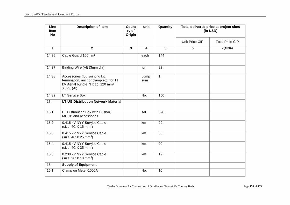
Section-05: Tender and Contract Forms
Tender Document for Construction of Distribution Network On Turnkey Basis Page 158 of 535
Line Item No
Description of Item Country of
Origin
unit Quantity Total delivered price at project sites (in USD)
Unit Price CIP Total Price CIP
1 2 3 4 5 6 7(=5x6)
14.36 Cable Guard 100mm² each 144
14.37 Binding Wire (Al) (3mm dia) ton 82
14.38 Accessories (lug, jointing kit, termination, anchor clamp etc) for 11 kV Aerial bundle 3 x 1c 120 mm² XLPE (Al)
Lump sum
1
14.39 LT Service Box No. 150
15 LT UG Distribution Network Material
15.1 LT Distribution Box with Busbar, MCCB and accessories
set 520
15.2 0.415 kV NYY Service Cable (size: 4C X 16 mm
2)
km 29
15.3 0.415 kV NYY Service Cable (size: 4C X 25 mm
2)
km 36
15.4 0.415 kV NYY Service Cable (size: 4C X 35 mm
2)
km 20
15.5 0.230 kV NYY Service Cable (size: 2C X 10 mm
2)
km 12
16 Supply of Equipment
16.1 Clamp on Meter-1000A
No. 10
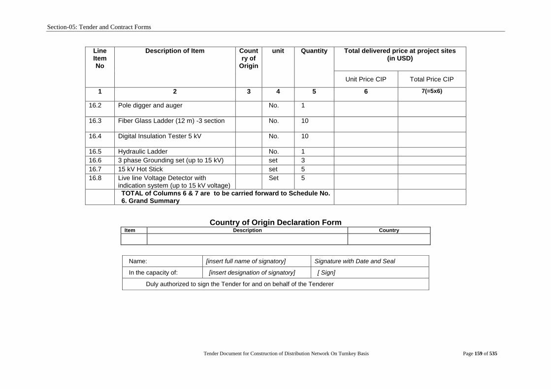
Section-05: Tender and Contract Forms
Tender Document for Construction of Distribution Network On Turnkey Basis Page 159 of 535
Line Item No
Description of Item Country of
Origin
unit Quantity Total delivered price at project sites (in USD)
Unit Price CIP Total Price CIP
1 2 3 4 5 6 7(=5x6)
16.2 Pole digger and auger
No. 1
16.3 Fiber Glass Ladder (12 m) -3 section
No. 10
16.4 Digital Insulation Tester 5 kV
No. 10
16.5 Hydraulic Ladder No. 1
16.6 3 phase Grounding set (up to 15 kV) set 3
16.7 15 kV Hot Stick set 5
16.8 Live line Voltage Detector with indication system (up to 15 kV voltage)
Set 5
TOTAL of Columns 6 & 7 are to be carried forward to Schedule No. 6. Grand Summary
Country of Origin Declaration Form Item Description Country
Name: [insert full name of signatory] Signature with Date and Seal
In the capacity of: [insert designation of signatory] [ Sign]
Duly authorized to sign the Tender for and on behalf of the Tenderer

Section-05: Tender and Contract Forms
Tender Document for Construction of Distribution Network On Turnkey Basis Page 160 of 535
Schedule No. 2 - Plant and Mandatory Spare Parts Supplied from within the Employer‟s Country
Line Item No.
Description of Item Unit Quantity Unit EXW Price
(USD or BDT)
Total EXW Price (USD or BDT)
Transportation and other cost
including VAT, IT up to delivery at
sites in BDT
Total delivered Price at project sites
USD BDT USD BDT BDT USD BDT
1 2 3 4 5 6 7 (=5 x 4)
8 (=4 x 6)
9 10= 7 11(=8+9)
1 Pole (SPC/Steel) `
1.1 15 M (SPC)
No. 390
1.2 12 M (SPC)
No. 7090
1.3 12m Steel pole
No. 25077
1.4 12 M steel pole with all necessary transformer and pole fittings, pole earthing i.e. complete in all respect for installation of 11/0.4 kV 3 ph 250 kVA transformer
set 300
2 Conductor
2.1 DOG 100 mm²
Km 1281
2.2 DOG 100 mm² (insulated)
Km 869
2.3 WASP (Insulated) 100mm2
Km 6946
2.4 GOPHER 25 mm² PVC covered
Km 33
2.5 Bare Copper Conductor 1x35 mm² Km 90
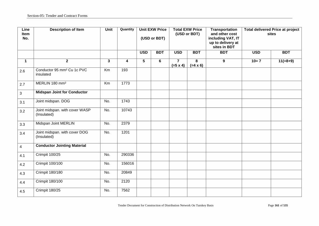
Section-05: Tender and Contract Forms
Tender Document for Construction of Distribution Network On Turnkey Basis Page 161 of 535
Line Item No.
Description of Item Unit Quantity Unit EXW Price
(USD or BDT)
Total EXW Price (USD or BDT)
Transportation and other cost
including VAT, IT up to delivery at
sites in BDT
Total delivered Price at project sites
USD BDT USD BDT BDT USD BDT
1 2 3 4 5 6 7 (=5 x 4)
8 (=4 x 6)
9 10= 7 11(=8+9)
2.6 Conductor 95 mm² Cu 1c PVC insulated
Km 193
2.7 MERLIN 180 mm²
Km 1773
3 Midspan Joint for Conductor
3.1 Joint midspan. DOG
No. 1743
3.2 Joint midspan. with cover WASP (Insulated)
No. 10743
3.3 Midspan Joint MERLIN
No. 2379
3.4 Joint midspan. with cover DOG (Insulated)
No. 1201
4 Conductor Jointing Material
4.1 Crimpit 100/25 No. 290336
4.2 Crimpit 100/100 No. 156016
4.3 Crimpit 180/180 No. 20849
4.4 Crimpit 180/100 No. 2120
4.5 Crimpit 180/25 No. 7562
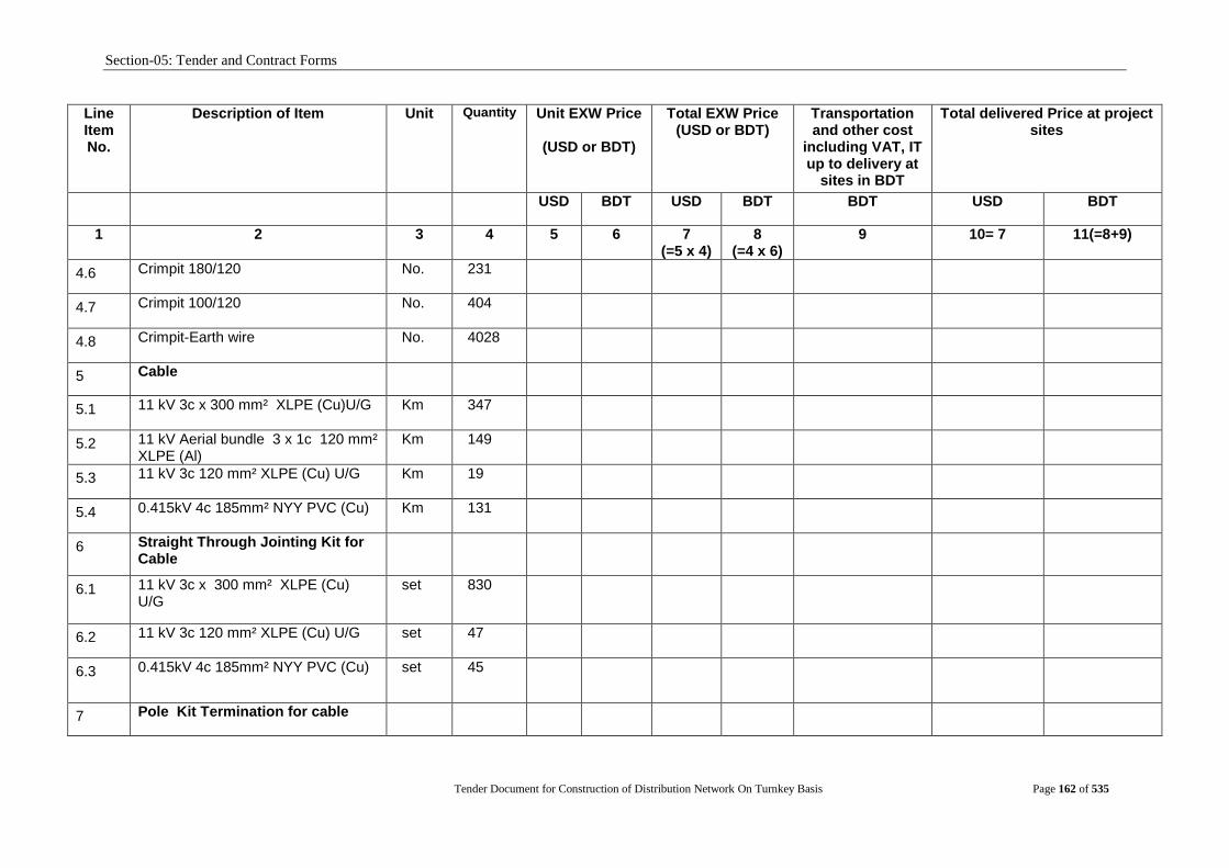
Section-05: Tender and Contract Forms
Tender Document for Construction of Distribution Network On Turnkey Basis Page 162 of 535
Line Item No.
Description of Item Unit Quantity Unit EXW Price
(USD or BDT)
Total EXW Price (USD or BDT)
Transportation and other cost
including VAT, IT up to delivery at
sites in BDT
Total delivered Price at project sites
USD BDT USD BDT BDT USD BDT
1 2 3 4 5 6 7 (=5 x 4)
8 (=4 x 6)
9 10= 7 11(=8+9)
4.6 Crimpit 180/120 No. 231
4.7 Crimpit 100/120 No. 404
4.8 Crimpit-Earth wire No. 4028
5 Cable
5.1 11 kV 3c x 300 mm² XLPE (Cu)U/G Km 347
5.2 11 kV Aerial bundle 3 x 1c 120 mm² XLPE (Al)
Km 149
5.3 11 kV 3c 120 mm² XLPE (Cu) U/G Km 19
5.4 0.415kV 4c 185mm² NYY PVC (Cu) Km 131
6 Straight Through Jointing Kit for Cable
6.1 11 kV 3c x 300 mm² XLPE (Cu) U/G
set 830
6.2 11 kV 3c 120 mm² XLPE (Cu) U/G set 47
6.3 0.415kV 4c 185mm² NYY PVC (Cu) set 45
7 Pole Kit Termination for cable
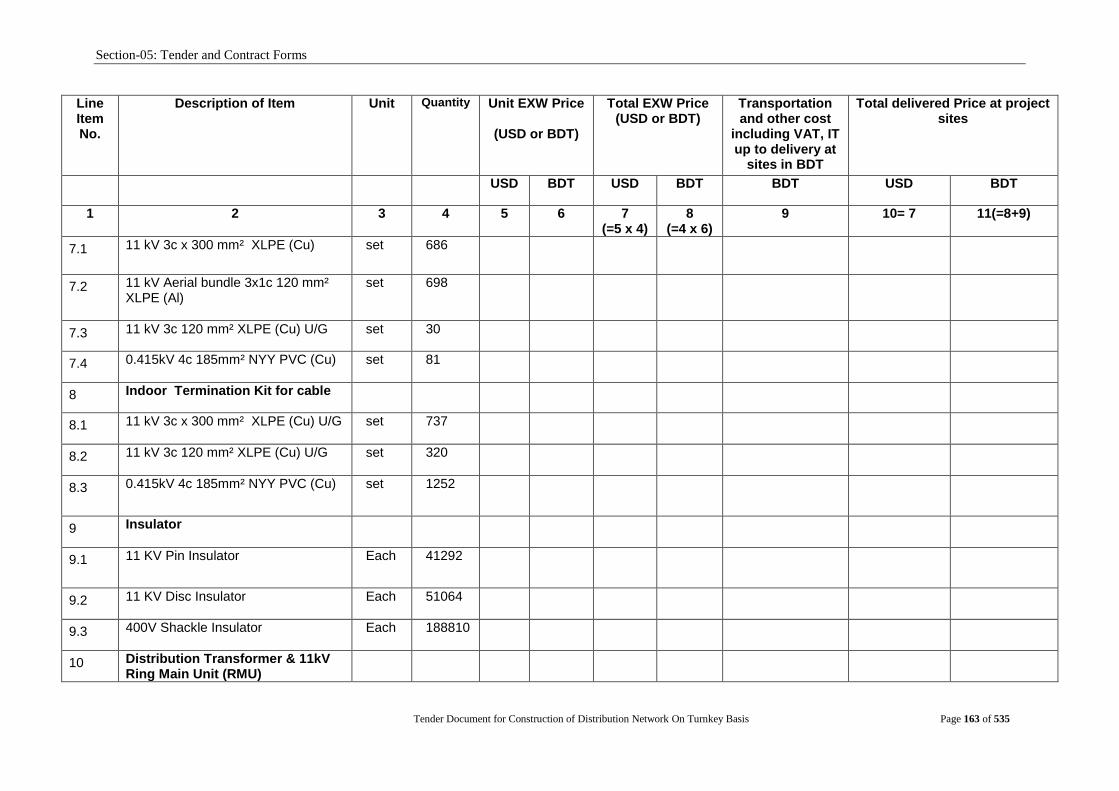
Section-05: Tender and Contract Forms
Tender Document for Construction of Distribution Network On Turnkey Basis Page 163 of 535
Line Item No.
Description of Item Unit Quantity Unit EXW Price
(USD or BDT)
Total EXW Price (USD or BDT)
Transportation and other cost
including VAT, IT up to delivery at
sites in BDT
Total delivered Price at project sites
USD BDT USD BDT BDT USD BDT
1 2 3 4 5 6 7 (=5 x 4)
8 (=4 x 6)
9 10= 7 11(=8+9)
7.1 11 kV 3c x 300 mm² XLPE (Cu) set 686
7.2 11 kV Aerial bundle 3x1c 120 mm² XLPE (Al)
set 698
7.3 11 kV 3c 120 mm² XLPE (Cu) U/G set 30
7.4 0.415kV 4c 185mm² NYY PVC (Cu) set 81
8 Indoor Termination Kit for cable
8.1 11 kV 3c x 300 mm² XLPE (Cu) U/G set 737
8.2 11 kV 3c 120 mm² XLPE (Cu) U/G set 320
8.3 0.415kV 4c 185mm² NYY PVC (Cu) set 1252
9 Insulator
9.1 11 KV Pin Insulator Each 41292
9.2 11 KV Disc Insulator Each 51064
9.3 400V Shackle Insulator Each 188810
10 Distribution Transformer & 11kV Ring Main Unit (RMU)

Section-05: Tender and Contract Forms
Tender Document for Construction of Distribution Network On Turnkey Basis Page 164 of 535
Line Item No.
Description of Item Unit Quantity Unit EXW Price
(USD or BDT)
Total EXW Price (USD or BDT)
Transportation and other cost
including VAT, IT up to delivery at
sites in BDT
Total delivered Price at project sites
USD BDT USD BDT BDT USD BDT
1 2 3 4 5 6 7 (=5 x 4)
8 (=4 x 6)
9 10= 7 11(=8+9)
10.1 11/0.4kV 250kVA, 3-Ph, 50Hz Distribution Transformer
No. 2550
10.2 11/0.4kV 630kVA, 3-Ph, 50Hz Distribution Transformer with Kiosk
No. 10
10.3 LV Control; Box fitted on transformer kiosk
No. 10
10.4 11kV Ring Main Unit (RMU) - 5 Limb Set 168
11 Distribution Transformer and RMU Accessories
11.1 Fuse Mounting, Platform Support Angle, Cu Rod, Bare Cu Conductor, Tie Bolt, J Bolt etc.
Set 2745
11.2 Earthing of Distribution Transformer with all accessories
Set 5394
11.3 Earthing and Civil Works of 11kV RMU with all accessories
Set 178
12 Transformer Protection Equipment
12.1 DOFC (Set of 3 Nos.) Set 3028
12.2 11kV Surge Arrester (Set of 3 Nos.) Set 3028
12.3 Fuse 11 kV 20A/30A
No. 9069
12.4 MCCB with box 200Amps
No. 1188
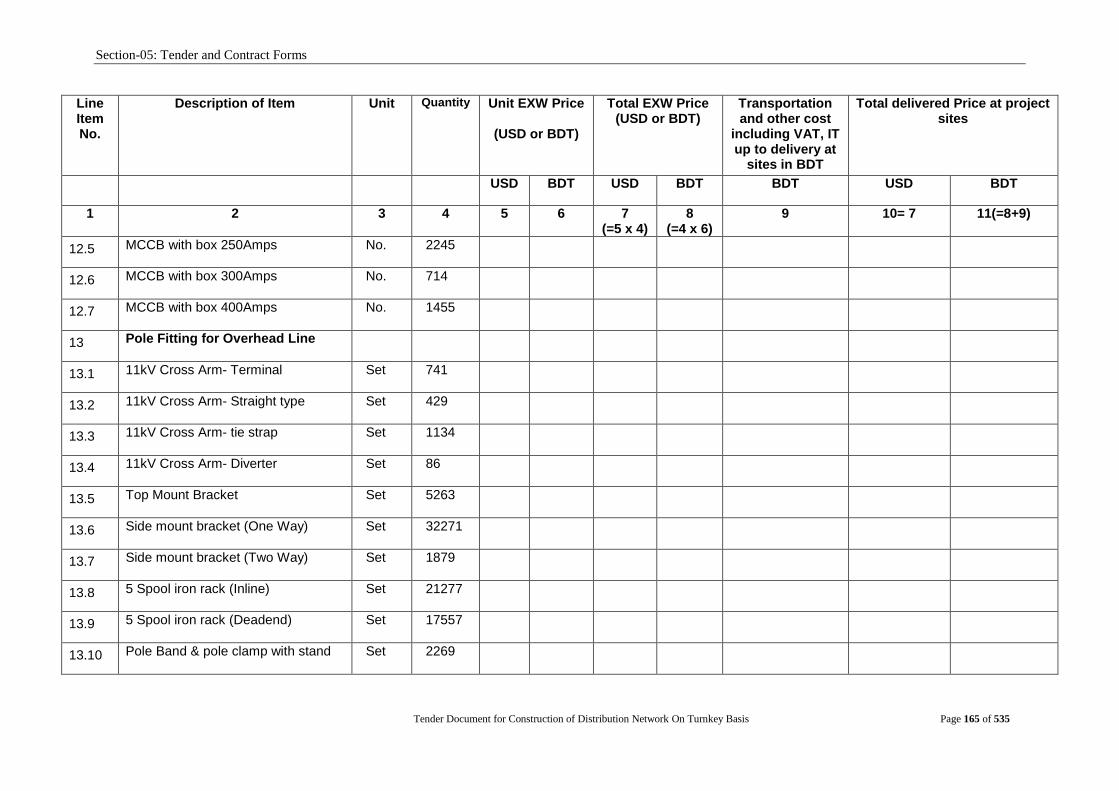
Section-05: Tender and Contract Forms
Tender Document for Construction of Distribution Network On Turnkey Basis Page 165 of 535
Line Item No.
Description of Item Unit Quantity Unit EXW Price
(USD or BDT)
Total EXW Price (USD or BDT)
Transportation and other cost
including VAT, IT up to delivery at
sites in BDT
Total delivered Price at project sites
USD BDT USD BDT BDT USD BDT
1 2 3 4 5 6 7 (=5 x 4)
8 (=4 x 6)
9 10= 7 11(=8+9)
12.5 MCCB with box 250Amps
No. 2245
12.6 MCCB with box 300Amps
No. 714
12.7 MCCB with box 400Amps No. 1455
13 Pole Fitting for Overhead Line
13.1 11kV Cross Arm- Terminal
Set 741
13.2 11kV Cross Arm- Straight type
Set 429
13.3 11kV Cross Arm- tie strap
Set 1134
13.4 11kV Cross Arm- Diverter
Set 86
13.5 Top Mount Bracket
Set 5263
13.6 Side mount bracket (One Way)
Set 32271
13.7 Side mount bracket (Two Way)
Set 1879
13.8 5 Spool iron rack (Inline)
Set 21277
13.9 5 Spool iron rack (Deadend)
Set 17557
13.10 Pole Band & pole clamp with stand Set 2269
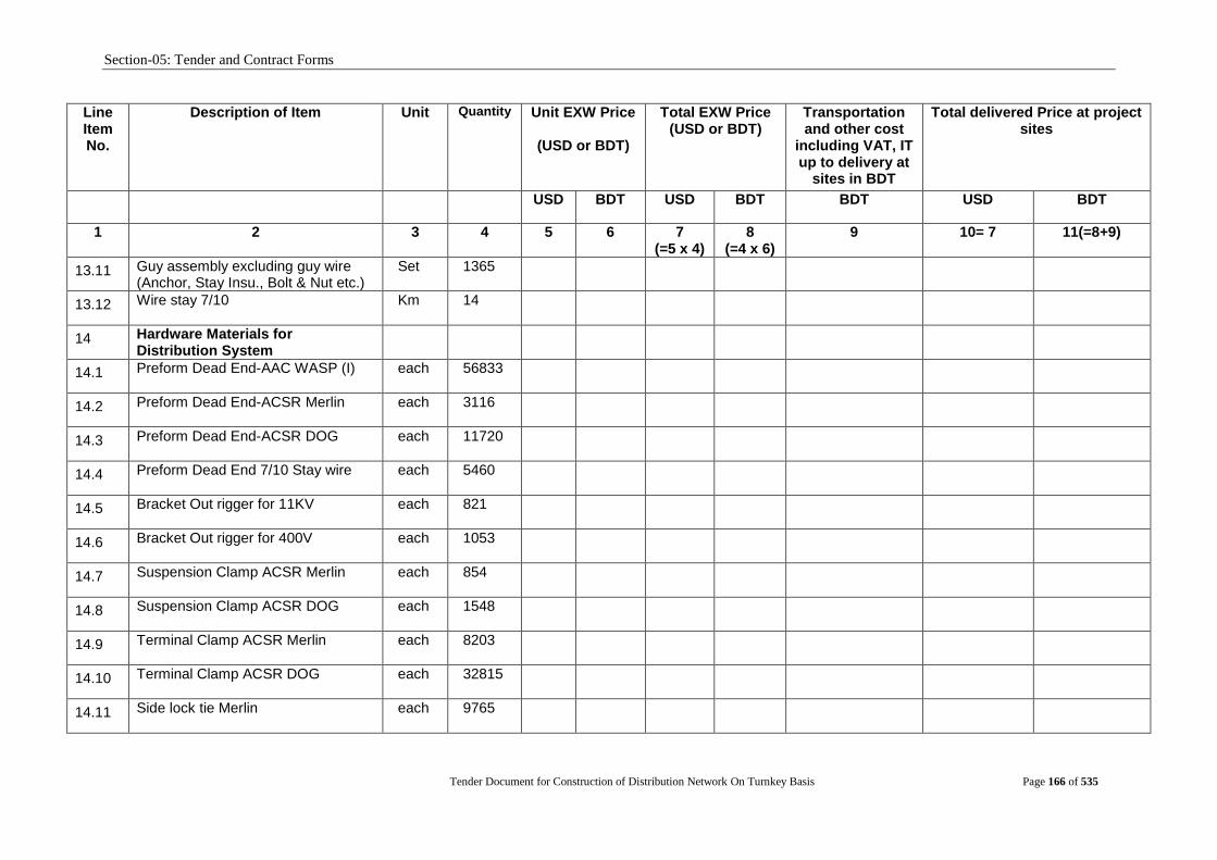
Section-05: Tender and Contract Forms
Tender Document for Construction of Distribution Network On Turnkey Basis Page 166 of 535
Line Item No.
Description of Item Unit Quantity Unit EXW Price
(USD or BDT)
Total EXW Price (USD or BDT)
Transportation and other cost
including VAT, IT up to delivery at
sites in BDT
Total delivered Price at project sites
USD BDT USD BDT BDT USD BDT
1 2 3 4 5 6 7 (=5 x 4)
8 (=4 x 6)
9 10= 7 11(=8+9)
13.11 Guy assembly excluding guy wire (Anchor, Stay Insu., Bolt & Nut etc.)
Set 1365
13.12 Wire stay 7/10 Km 14
14 Hardware Materials for Distribution System
14.1 Preform Dead End-AAC WASP (I) each 56833
14.2 Preform Dead End-ACSR Merlin
each 3116
14.3 Preform Dead End-ACSR DOG each 11720
14.4 Preform Dead End 7/10 Stay wire each 5460
14.5 Bracket Out rigger for 11KV each 821
14.6 Bracket Out rigger for 400V each 1053
14.7 Suspension Clamp ACSR Merlin each 854
14.8 Suspension Clamp ACSR DOG each 1548
14.9 Terminal Clamp ACSR Merlin
each 8203
14.10 Terminal Clamp ACSR DOG
each 32815
14.11 Side lock tie Merlin
each 9765
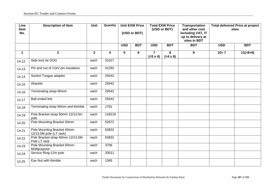
Section-05: Tender and Contract Forms
Tender Document for Construction of Distribution Network On Turnkey Basis Page 167 of 535
Line Item No.
Description of Item Unit Quantity Unit EXW Price
(USD or BDT)
Total EXW Price (USD or BDT)
Transportation and other cost
including VAT, IT up to delivery at
sites in BDT
Total delivered Price at project sites
USD BDT USD BDT BDT USD BDT
1 2 3 4 5 6 7 (=5 x 4)
8 (=4 x 6)
9 10= 7 11(=8+9)
14.12 Side lock tie DOG each 31527
14.13 Pin and nut of 11kV pin insulators
each 41292
14.14 Socket Tongue adapter
each 25542
14.15 Shackle
each 25542
14.16 Terminating strap-90mm
each 25542
14.17 Ball ended link
each 25542
14.18 Terminaitng strap 90mm and thimble each 1781
14.19 Pole Bracket strap 50mm 12/13.5m pole
each 118216
14.20 Pole Mounting Bracket 50mm
each 52672
14.21 Pole Mounting Bracket 40mm- 12/13.5M pole (LT rack)
each 63832
14.22 Pole Bracket strap 40mm-12/13.5M Pole LT rack
each 63832
14.23 Pole Mounting Bracket 50mm- Multipurpose
each 3706
14.24 Service Ring-12m pole
each 33011
14.25 Eye Nut with thimble
each 1365

Section-05: Tender and Contract Forms
Tender Document for Construction of Distribution Network On Turnkey Basis Page 168 of 535
Line Item No.
Description of Item Unit Quantity Unit EXW Price
(USD or BDT)
Total EXW Price (USD or BDT)
Transportation and other cost
including VAT, IT up to delivery at
sites in BDT
Total delivered Price at project sites
USD BDT USD BDT BDT USD BDT
1 2 3 4 5 6 7 (=5 x 4)
8 (=4 x 6)
9 10= 7 11(=8+9)
14.26 Stay rod and turn Buckle
each 1365
14.27 Stainless Steel Binding Tape 12.5mm
meter 4021
14.28 Buckle for Stainless Steel Binding Tape 12.5mm
each 2009
14.29 Service bale-insulated each 140984
14.30 Cu Lug size 35mm² (2mm thick) each 22073
14.31 Cu Lug size 95mm² (2mm thick) each 60321
14.32 Al Lug size 25mm² (2mm thick)
each 13885
14.33 Cu Lug size 120mm² (2mm thick) each 626
14.34 Cu Lug size 300mm² (2mm thick) each 2359
14.35 PIB Tap roll 1270
14.36 Cable Guard 100mm² each 144
14.37 Binding Wire (Al) (3mm dia) ton 82
14.38 Accessories (lug, jointing kit, termination, anchor clamp etc) for 11 kV Aerial bundle 3 x 1c 120 mm² XLPE (Al)
Lump sum
1
14.39 LT Service Box No. 150
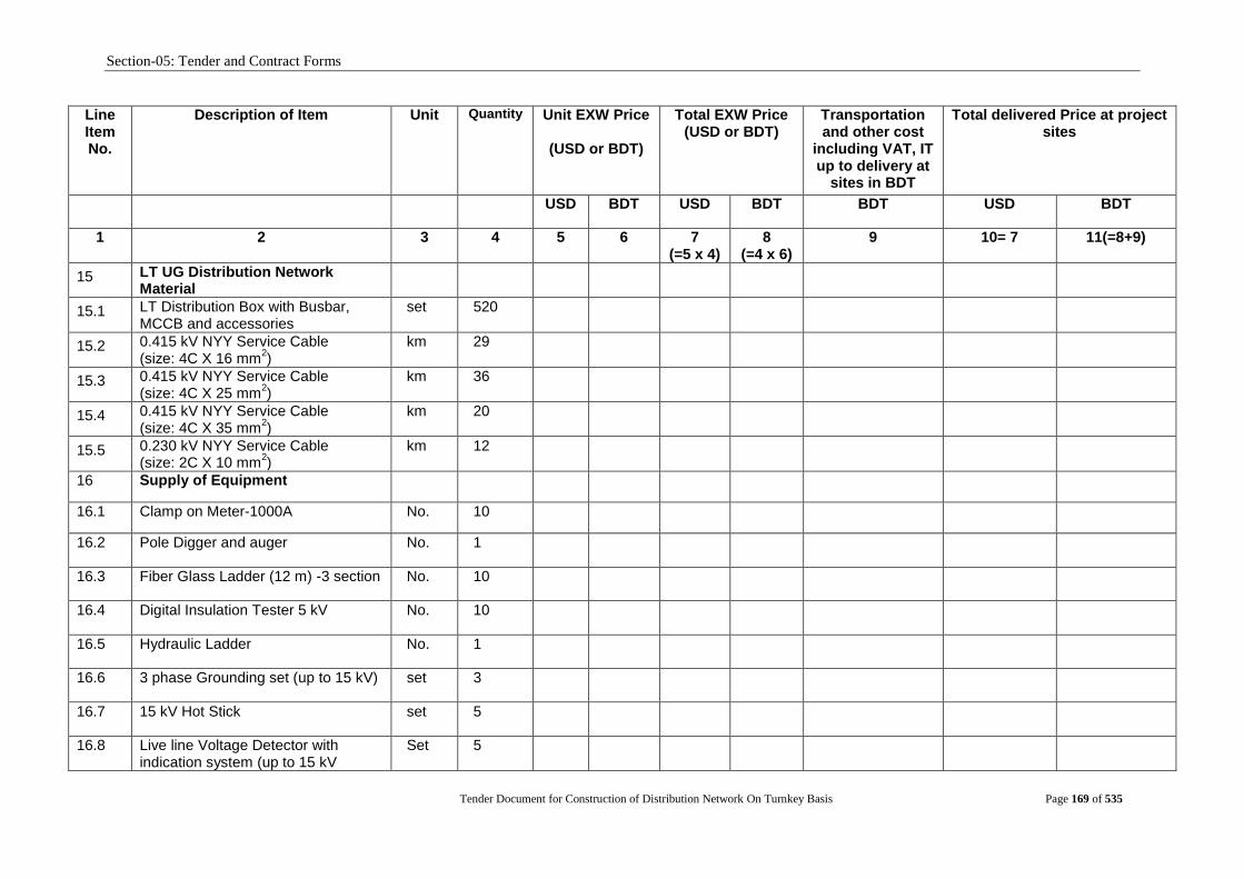
Section-05: Tender and Contract Forms
Tender Document for Construction of Distribution Network On Turnkey Basis Page 169 of 535
Line Item No.
Description of Item Unit Quantity Unit EXW Price
(USD or BDT)
Total EXW Price (USD or BDT)
Transportation and other cost
including VAT, IT up to delivery at
sites in BDT
Total delivered Price at project sites
USD BDT USD BDT BDT USD BDT
1 2 3 4 5 6 7 (=5 x 4)
8 (=4 x 6)
9 10= 7 11(=8+9)
15 LT UG Distribution Network Material
15.1 LT Distribution Box with Busbar, MCCB and accessories
set 520
15.2 0.415 kV NYY Service Cable (size: 4C X 16 mm
2)
km 29
15.3 0.415 kV NYY Service Cable (size: 4C X 25 mm
2)
km 36
15.4 0.415 kV NYY Service Cable (size: 4C X 35 mm
2)
km 20
15.5 0.230 kV NYY Service Cable (size: 2C X 10 mm
2)
km 12
16 Supply of Equipment
16.1 Clamp on Meter-1000A No. 10
16.2 Pole Digger and auger No. 1
16.3 Fiber Glass Ladder (12 m) -3 section No. 10
16.4 Digital Insulation Tester 5 kV No. 10
16.5 Hydraulic Ladder No. 1
16.6 3 phase Grounding set (up to 15 kV) set 3
16.7 15 kV Hot Stick set 5
16.8 Live line Voltage Detector with indication system (up to 15 kV
Set 5

Section-05: Tender and Contract Forms
Tender Document for Construction of Distribution Network On Turnkey Basis Page 170 of 535
Line Item No.
Description of Item Unit Quantity Unit EXW Price
(USD or BDT)
Total EXW Price (USD or BDT)
Transportation and other cost
including VAT, IT up to delivery at
sites in BDT
Total delivered Price at project sites
USD BDT USD BDT BDT USD BDT
1 2 3 4 5 6 7 (=5 x 4)
8 (=4 x 6)
9 10= 7 11(=8+9)
voltage)
TOTAL of Columns 10 and 11 to be carried forward to Schedule No. 6. Grand Summary
Name: [insert full name of signatory] Signature with Date and Seal
In the capacity of: [insert designation of signatory] [ Sign]
Duly authorised to sign the Tender for and on behalf of the Tenderer
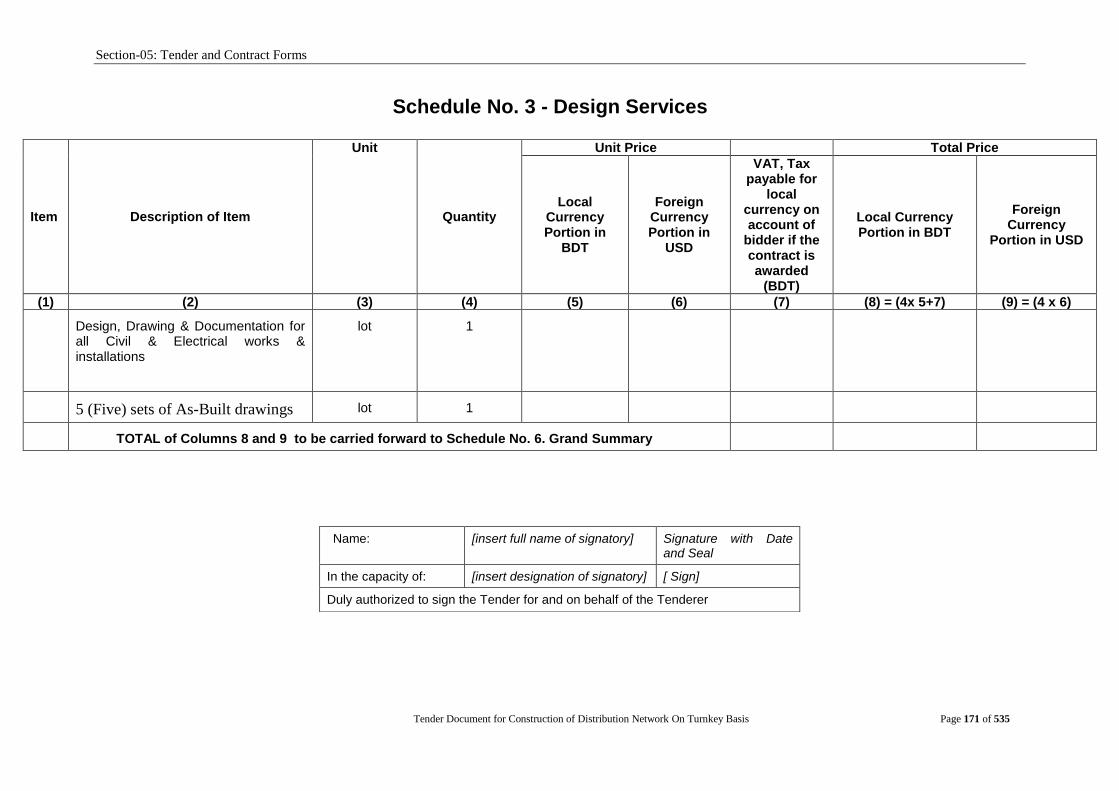
Section-05: Tender and Contract Forms
Tender Document for Construction of Distribution Network On Turnkey Basis Page 171 of 535
Schedule No. 3 - Design Services
Item Description of Item
Unit
Quantity
Unit Price Total Price
Local Currency Portion in
BDT
Foreign Currency Portion in
USD
VAT, Tax payable for
local currency on account of
bidder if the contract is awarded
(BDT)
Local Currency Portion in BDT
Foreign Currency
Portion in USD
(1) (2) (3) (4) (5) (6) (7) (8) = (4x 5+7) (9) = (4 x 6)
3. Design, Drawing & Documentation for all Civil & Electrical works & installations
lot 1
4. 5 (Five) sets of As-Built drawings lot 1
TOTAL of Columns 8 and 9 to be carried forward to Schedule No. 6. Grand Summary
Name: [insert full name of signatory] Signature with Date and Seal
In the capacity of: [insert designation of signatory] [ Sign]
Duly authorized to sign the Tender for and on behalf of the Tenderer
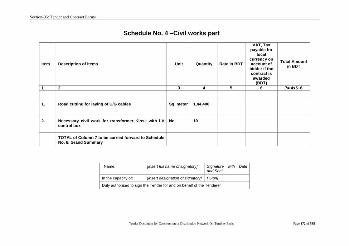
Section-05: Tender and Contract Forms
Tender Document for Construction of Distribution Network On Turnkey Basis Page 172 of 535
Schedule No. 4 –Civil works part
Item Description of items Unit Quantity Rate in BDT
VAT, Tax payable for
local currency on account of
bidder if the contract is awarded
(BDT)
Total Amount in BDT
1 2 3 4 5 6 7= 4x5+6
1. Road cutting for laying of U/G cables
Sq. meter
1,44,400
2. Necessary civil work for transformer Kiosk with LV control box
No. 10
TOTAL of Column 7 to be carried forward to Schedule No. 6. Grand Summary
Name: [insert full name of signatory] Signature with Date and Seal
In the capacity of: [insert designation of signatory] [ Sign]
Duly authorised to sign the Tender for and on behalf of the Tenderer

Section-05: Tender and Contract Forms
Tender Document for Construction of Distribution Network On Turnkey Basis Page 173 of 535
Schedule No. 5- Installation and Other Services
Item Description Unit Quantity Unit Price VAT, Tax payable for local currency
on account of bidder if the contract is awarded
(BDT)
Total Price
Local Currency Portion in BDT
Foreign Currency Portion in
USD
Local Currency Portion in BDT
Foreign Currency Portion in USD
1 2 3 4 5 6 7 = 3 x 4+6 8 = 3 x 5
Installation of new distribution lines and renovation/ rehabilitation of existing lines
1 Installation of new Pole (SPC/Steel) including pole earthing, required pole fittings items, pin/disc fittings with insulators, other necessary hardware materials etc. i.e complete Pole (SPC/ Steel) & necessary fittings installation work in all respect
1.1 15m SPC pole at different position (like as straight, angle, dead-end etc.)
No. 390
1.2 12 m SPC pole at different position (like as straight, angle, dead-end etc.)
No. 7087
1.3 12m Steel pole at different position (like as straight, angle, dead-end etc.)
No. 20677
1.4 12 M steel pole with all necessary fittings for installation of 11/0.4 kV 3 ph 250 kVA transformer including channel for DOFC & LA, LT rack, pole earthing, pin/disc fittings with insulators and complete in all respect
set 300
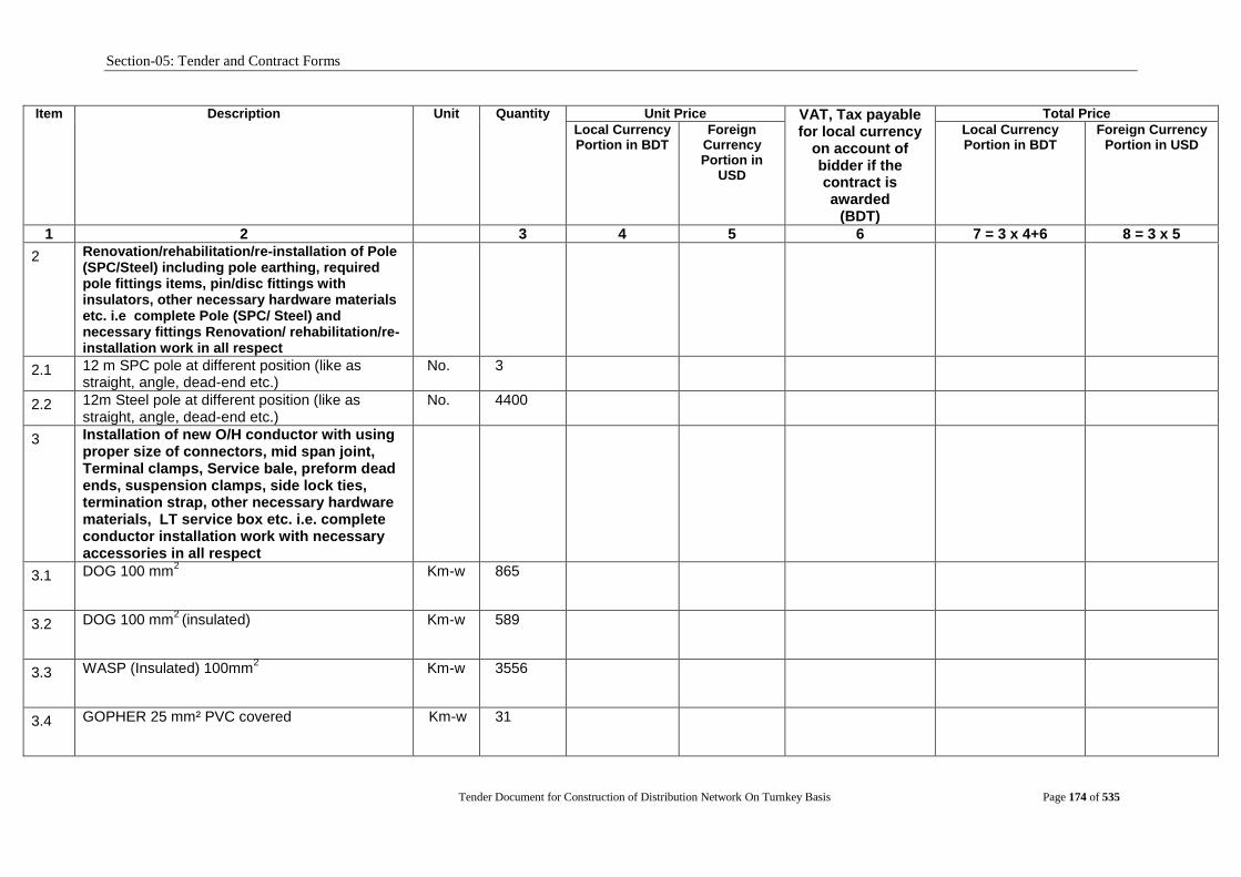
Section-05: Tender and Contract Forms
Tender Document for Construction of Distribution Network On Turnkey Basis Page 174 of 535
Item Description Unit Quantity Unit Price VAT, Tax payable for local currency
on account of bidder if the contract is awarded
(BDT)
Total Price
Local Currency Portion in BDT
Foreign Currency Portion in
USD
Local Currency Portion in BDT
Foreign Currency Portion in USD
1 2 3 4 5 6 7 = 3 x 4+6 8 = 3 x 5
2 Renovation/rehabilitation/re-installation of Pole (SPC/Steel) including pole earthing, required pole fittings items, pin/disc fittings with insulators, other necessary hardware materials etc. i.e complete Pole (SPC/ Steel) and necessary fittings Renovation/ rehabilitation/re-installation work in all respect
2.1 12 m SPC pole at different position (like as straight, angle, dead-end etc.)
No. 3
2.2 12m Steel pole at different position (like as straight, angle, dead-end etc.)
No. 4400
3 Installation of new O/H conductor with using proper size of connectors, mid span joint, Terminal clamps, Service bale, preform dead ends, suspension clamps, side lock ties, termination strap, other necessary hardware materials, LT service box etc. i.e. complete conductor installation work with necessary accessories in all respect
3.1 DOG 100 mm2
Km-w 865
3.2 DOG 100 mm2 (insulated)
Km-w 589
3.3 WASP (Insulated) 100mm2
Km-w 3556
3.4 GOPHER 25 mm² PVC covered
Km-w 31

Section-05: Tender and Contract Forms
Tender Document for Construction of Distribution Network On Turnkey Basis Page 175 of 535
Item Description Unit Quantity Unit Price VAT, Tax payable for local currency
on account of bidder if the contract is awarded
(BDT)
Total Price
Local Currency Portion in BDT
Foreign Currency Portion in
USD
Local Currency Portion in BDT
Foreign Currency Portion in USD
1 2 3 4 5 6 7 = 3 x 4+6 8 = 3 x 5
3.5 Bare Copper Conductor 1x35 mm²
Km-w 90
3.6 Conductor 95 mm² Cu 1c PVC insulated
Km-w 181
3.7 MERLIN 180 mm²
Km-w 492
4 Renovation/rehabilitation/re-installation of O/H conductor with using proper size of connectors, mid span joint, Terminal clamps, Service bale, preform dead ends, suspension clamps, side lock ties, termination strap, other necessary hardware materials, LT service box etc. i.e complete conductor renovation/ rehabilitation/ re-installation work with necessary accessories in all respect
4.1 DOG 100 mm2
Km-w 416
4.2 DOG 100 mm2 (insulated) Km-w 280
4.3 WASP (Insulated) 100mm2 Km-w 3390
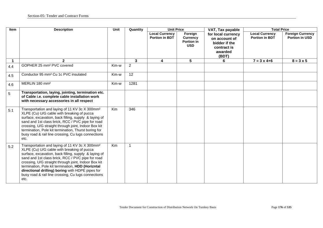
Section-05: Tender and Contract Forms
Tender Document for Construction of Distribution Network On Turnkey Basis Page 176 of 535
Item Description Unit Quantity Unit Price VAT, Tax payable for local currency
on account of bidder if the contract is awarded
(BDT)
Total Price
Local Currency Portion in BDT
Foreign Currency Portion in
USD
Local Currency Portion in BDT
Foreign Currency Portion in USD
1 2 3 4 5 6 7 = 3 x 4+6 8 = 3 x 5
4.4 GOPHER 25 mm² PVC covered
Km-w 2
4.5 Conductor 95 mm² Cu 1c PVC insulated
Km-w 12
4.6 MERLIN 180 mm² Km-w 1281
5 Transportation, laying, jointing, termination etc. of Cable i.e. complete cable installation work with necessary accessories in all respect
5.1 Transportation and laying of 11 KV 3c X 300mm² XLPE (Cu) U/G cable with breaking of pucca surface, excavation, back filling, supply & laying of sand and 1st class brick, RCC / PVC pipe for road crossing, U/G straight through joint, Indoor Box kit termination, Pole kit termination, Thurst boring for busy road & rail line crossing, Cu lugs connections etc.
Km 346
5.2 Transportation and laying of 11 KV 3c X 300mm² XLPE (Cu) U/G cable with breaking of pucca surface, excavation, back filling, supply & laying of sand and 1st class brick, RCC / PVC pipe for road crossing, U/G straight through joint, Indoor Box kit termination, Pole kit termination, HDD (Horizntal directional drilling) boring with HDPE pipes for busy road & rail line crossing, Cu lugs connections etc.
Km 1
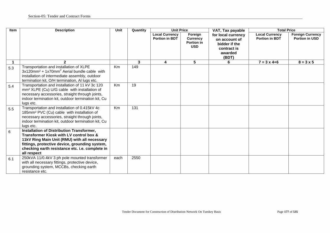
Section-05: Tender and Contract Forms
Tender Document for Construction of Distribution Network On Turnkey Basis Page 177 of 535
Item Description Unit Quantity Unit Price VAT, Tax payable for local currency
on account of bidder if the contract is awarded
(BDT)
Total Price
Local Currency Portion in BDT
Foreign Currency Portion in
USD
Local Currency Portion in BDT
Foreign Currency Portion in USD
1 2 3 4 5 6 7 = 3 x 4+6 8 = 3 x 5
5.3 Transportation and installation of XLPE 3x120mm² + 1x70mm
2 Aerial bundle cable with
installation of intermediate assembly, outdoor termination kit, O/H termination, Al lugs etc.
Km 149
5.4 Transportation and installation of 11 kV 3c 120 mm² XLPE (Cu) U/G cable with installation of necessary accessories, straight through joints, indoor termination kit, outdoor termination kit, Cu lugs etc.
Km 19
5.5 Transportation and installation of 0.415kV 4c 185mm² PVC (Cu) cable with installation of necessary accessories, straight through joints, indoor termination kit, outdoor termination kit, Cu lugs etc.
Km 131
6 Installation of Distribution Transformer, Transformer Kiosk with LV control box & 11kV Ring Main Unit (RMU) with all necessary fittings, protective device, grounding system, checking earth resistance etc. i.e. complete in all respect
6.1 250kVA 11/0.4kV 3 ph pole mounted transformer with all necessary fittings, protective device, grounding system, MCCBs, checking earth resistance etc.
each 2550

Section-05: Tender and Contract Forms
Tender Document for Construction of Distribution Network On Turnkey Basis Page 178 of 535
Item Description Unit Quantity Unit Price VAT, Tax payable for local currency
on account of bidder if the contract is awarded
(BDT)
Total Price
Local Currency Portion in BDT
Foreign Currency Portion in
USD
Local Currency Portion in BDT
Foreign Currency Portion in USD
1 2 3 4 5 6 7 = 3 x 4+6 8 = 3 x 5
6.2 11 kV 5 limb RMU with all necessary accessories, termination, grounding system, checking earth resistance etc.
each 178
6.3 630kVA 11/0.4kV 3 ph transformer with transformer Kiosk and LV control box, all necessary fittings, protective device, grounding system, MCCBs, checking earth resistance etc.
each 10
7 Installation of Distribution Transformer Accessories and RMU Accessories i.e. complete in all respect
7.1 Fuse Mounting, Platform Support Angle, Cu Rod, Bare Cu Conductor, Tie Bolt, J Bolt etc.
Set 2576
7.2 Earthing of Distribution Transformer with all accessories
Set 5056
7.3 Earthing and Civil Works of 11kV RMU with all accessories
Set 178
8 Renovation/rehabilitation/re-installation of Distribution Transformer Accessories with transformer protection equipment i.e. complete in all respect
8.1 Fuse Mounting, Platform Support Angle, Cu Rod, Bare Cu Conductor, Tie Bolt, J Bolt etc. along with necessary transform protection equipments
Set 169
8.2 Earthing of Distribution Transformer with all accessories
Set 338
9 Installation/laying of LT UG Distribution Network Material
9.1 LT Distribution Box with Busbar, MCCB and accessories i.e. complete in all respect
set 520
9.2 Installation of different sizes of LT Service Cable such as 4c x 16 mm
2 , 4c x 25 mm
2 , 4c x 35 mm
2 , 2c x
8mm2
with necessary accessories i.e. complete in all
Km 97
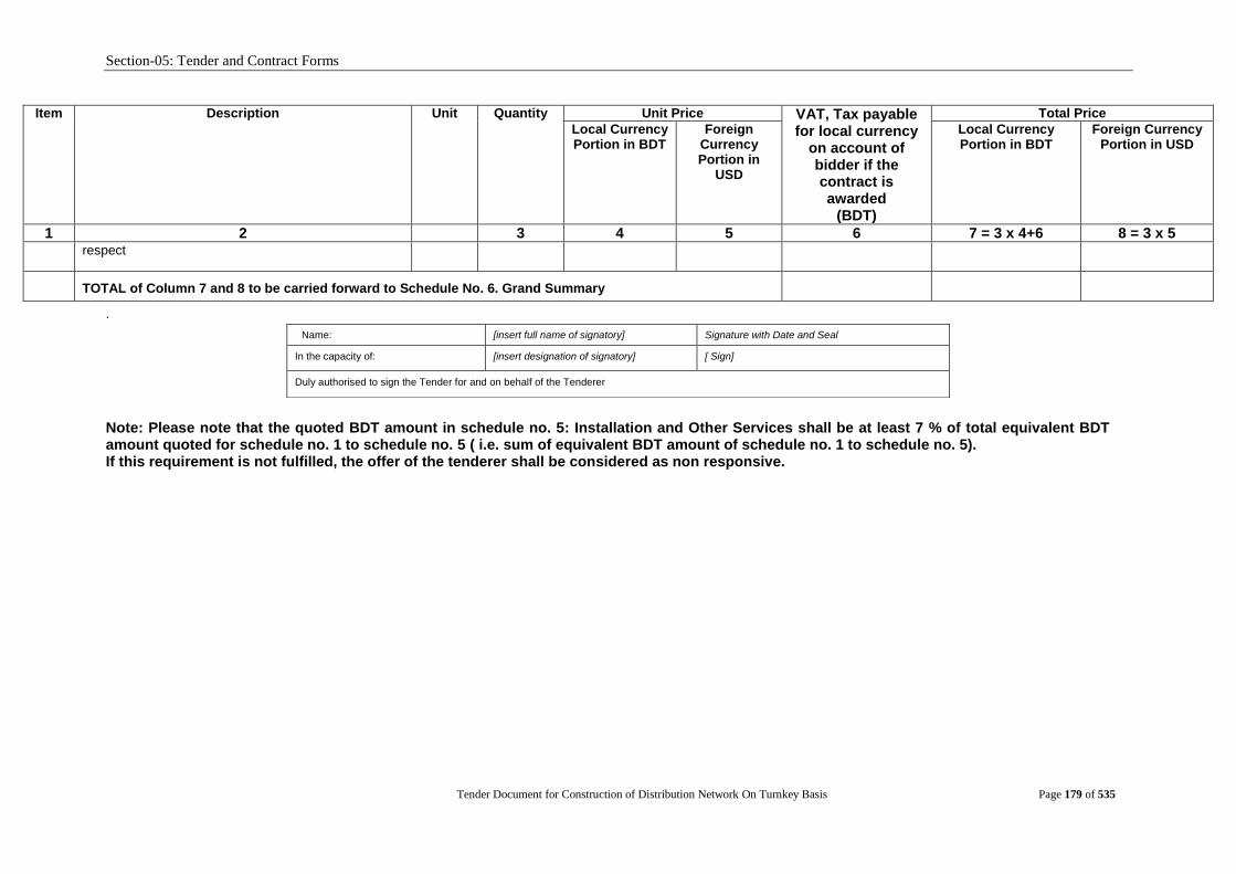
Section-05: Tender and Contract Forms
Tender Document for Construction of Distribution Network On Turnkey Basis Page 179 of 535
Item Description Unit Quantity Unit Price VAT, Tax payable for local currency
on account of bidder if the contract is awarded
(BDT)
Total Price
Local Currency Portion in BDT
Foreign Currency Portion in
USD
Local Currency Portion in BDT
Foreign Currency Portion in USD
1 2 3 4 5 6 7 = 3 x 4+6 8 = 3 x 5 respect
TOTAL of Column 7 and 8 to be carried forward to Schedule No. 6. Grand Summary
.
Note: Please note that the quoted BDT amount in schedule no. 5: Installation and Other Services shall be at least 7 % of total equivalent BDT amount quoted for schedule no. 1 to schedule no. 5 ( i.e. sum of equivalent BDT amount of schedule no. 1 to schedule no. 5). If this requirement is not fulfilled, the offer of the tenderer shall be considered as non responsive.
Name: [insert full name of signatory] Signature with Date and Seal
In the capacity of: [insert designation of signatory] [ Sign]
Duly authorised to sign the Tender for and on behalf of the Tenderer

Section-05: Tender and Contract Forms
Tender Document for Construction of Distribution Network On Turnkey Basis
Page 180 of 535
Schedule No. 6 - Grand Summary
Schedule No.
Title Total Price
Foreign Currency in
USD
Local Currency in BDT
1 Plant and Mandatory Spare Parts Supplied from Abroad
2 Plant and Mandatory Spare Parts Supplied from Within the Employer‟s Country
3 Design Services
4 Civil work
5 Installation and Other Services
GRAND TOTAL to be carried forward to Form PG5A-1b
Note: Please note that the quoted BDT amount in schedule no. 5: Installation and Other Services shall be at least 7 % of total equivalent BDT amount quoted for schedule no. 1 to schedule no. 5 ( i.e. sum of equivalent BDT amount of schedule no. 1 to schedule no. 5). If this requirement is not fulfilled, the offer of the tenderer shall be considered as non responsive.
Name: [insert full name of signatory] Signature with Date and Seal
In the capacity of: [insert designation of signatory] [ Sign]
Duly authorised to sign the Tender for and on behalf of the Tenderer

Section-05: Tender and Contract Forms
Tender Document for Construction of Distribution Network On Turnkey Basis
Page 181 of 535
Schedule No. 7 - Recommended Spare Parts
Item Description Qty
Unit Price Total Price
EXW Local Parts Local
Currency
CIP Imported
Parts Foreign
Currency
Local Currency Portion
Foreign Currency Portion
1 2 3 4 5 6 = 3 x 4 7 = 3 x 5
TOTAL
Name: [insert full name of signatory] Signature with Date and Seal
In the capacity of: [insert designation of signatory] [ Sign]
Duly authorized to sign the Tender for and on behalf of the Tenderer

Section-05: Tender and Contract Forms
Tender Document for Construction of Distribution Network On Turnkey Basis
Page 182 of 535
Technical Proposal (Form PG5A-4)
[The Revised Technical Proposal, if any, shall follow the same format and structure]
Site Organization
Method Statement
Mobilization Structure
Construction Structure
Plant
Safety Plan
Personnel
Equipment
Proposed subcontractors for Major Items of Plant and Services
Time Schedule

Section-05: Tender and Contract Forms
Tender Document for Construction of Distribution Network On Turnkey Basis
Page 183 of 535
Site Organization The Tenderer shall include in the tender an appropriate organization chart. This shall include
head office as well as site components and clearly demonstrate that the Tenderer possesses
the staff and organizational resources to complete the Supply and Installation of Plant &
Equipment.
Section-05: Tender and Contract Forms
Tender Document for Construction of Distribution Network On Turnkey Basis
Page 184 of 535
Method Statement
The Tenderer shall furnish an overall description covering all activities and processes from
inception to site works and commissioning.
In particular methods of minimizing the impact on the environment in accordance with the
relevant laws and regulations during the construction phase shall be described.

Section-05: Tender and Contract Forms
Tender Document for Construction of Distribution Network On Turnkey Basis
Page 185 of 535
Mobilization Schedule This shall be included in the overall time schedule to be provided by the Tenderer as per
“Time Schedule” in Section 5.Tendering Forms
Section-05: Tender and Contract Forms
Tender Document for Construction of Distribution Network On Turnkey Basis
Page 186 of 535
Construction Schedule This shall be included in the overall time schedule to be provided by the Tenderer as
per“Time Schedule” in Section5. Tendering Forms
Plant The Tenderer shall provide the plant and equipment it intends to use in the construction
process to demonstrate that it has the capability to complete the Supply and Installation of
Plant & Equipment.
Safety Plan The Tenderer shall demonstrate that it has a comprehensive safety system that will be used
during the construction and installation phase. This system shall meet all safety
requirements in accordance with all relevant laws, rules and regulations.

Section-05: Tender and Contract Forms
Tender Document for Construction of Distribution Network On Turnkey Basis
Page 187 of 535
Personnel Information
[This Form should be completed for each person proposed by the Tenderer on Form PG5A-2a& PG5A-2b, where applicable]
Invitation for Tender No: [indicate IFT No]
Tender Package No [indicate Package No]
This Package is divided into the following Number of Lots [indicate number of Lot(s)]
A. Proposed Position (tick the relevant box)
B. Personal Data
Name
Date of Birth
Years overall experience
Years of specific experience
National ID Number
Years of employment with the Tenderer
B. Professional Qualifications:
1.
2.
C. Present Employment [to be completed only if not employed by the Tenderer]
Name of Procuring Entity:
Address of Procuring Entity:
Present Job Title:
Years with present Procuring Entity:
Tel No:
Fax No: e-mail address:
Contact [manager/personnel officer]:
D. Professional Experience
Summarise professional experience over the last twenty years, in reverse chronological order. Indicate particular technical and managerial experience relevant to the project.
From To Company / Project / Position / Relevant technical and management experience.
1
2
3
Name: [insert full name of signatory]
Signature with Date and Seal
In the capacity of: [insert designation of signatory]
[ Sign]
Duly authorised to sign the Tender for and on behalf of the Tenderer
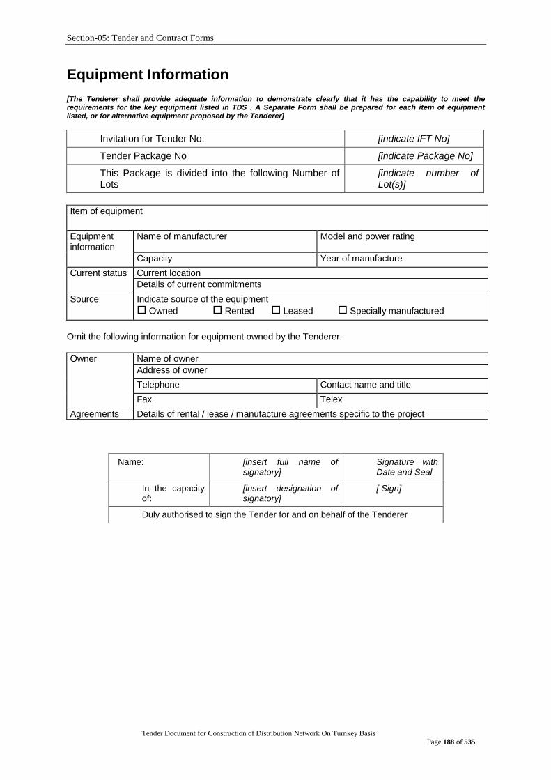
Section-05: Tender and Contract Forms
Tender Document for Construction of Distribution Network On Turnkey Basis
Page 188 of 535
Equipment Information [The Tenderer shall provide adequate information to demonstrate clearly that it has the capability to meet the requirements for the key equipment listed in TDS . A Separate Form shall be prepared for each item of equipment listed, or for alternative equipment proposed by the Tenderer]
Invitation for Tender No: [indicate IFT No]
Tender Package No [indicate Package No]
This Package is divided into the following Number of Lots
[indicate number of Lot(s)]
Item of equipment
Equipment information
Name of manufacturer Model and power rating
Capacity Year of manufacture
Current status Current location
Details of current commitments
Source Indicate source of the equipment
Owned Rented Leased Specially manufactured
Omit the following information for equipment owned by the Tenderer.
Owner Name of owner
Address of owner
Telephone Contact name and title
Fax Telex
Agreements Details of rental / lease / manufacture agreements specific to the project
Name: [insert full name of signatory]
Signature with Date and Seal
In the capacity of:
[insert designation of signatory]
[ Sign]
Duly authorised to sign the Tender for and on behalf of the Tenderer
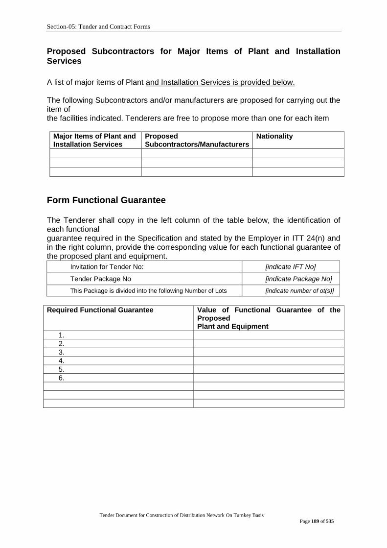
Section-05: Tender and Contract Forms
Tender Document for Construction of Distribution Network On Turnkey Basis
Page 189 of 535
Proposed Subcontractors for Major Items of Plant and Installation Services
A list of major items of Plant and Installation Services is provided below. The following Subcontractors and/or manufacturers are proposed for carrying out the item of the facilities indicated. Tenderers are free to propose more than one for each item
Major Items of Plant and Installation Services
Proposed Subcontractors/Manufacturers
Nationality
Form Functional Guarantee The Tenderer shall copy in the left column of the table below, the identification of each functional guarantee required in the Specification and stated by the Employer in ITT 24(n) and in the right column, provide the corresponding value for each functional guarantee of the proposed plant and equipment.
Invitation for Tender No: [indicate IFT No]
Tender Package No [indicate Package No]
This Package is divided into the following Number of Lots [indicate number of ot(s)]
Required Functional Guarantee Value of Functional Guarantee of the
Proposed Plant and Equipment
1.
2.
3.
4.
5.
6.
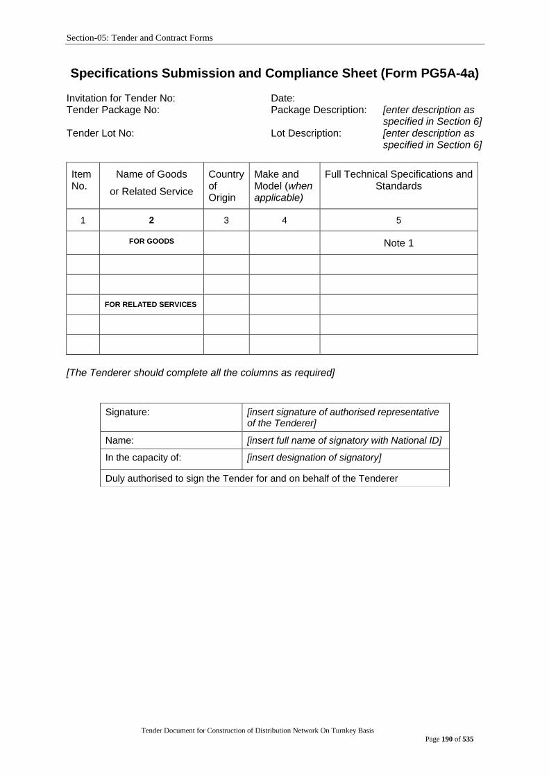
Section-05: Tender and Contract Forms
Tender Document for Construction of Distribution Network On Turnkey Basis
Page 190 of 535
Specifications Submission and Compliance Sheet (Form PG5A-4a) Invitation for Tender No: Date: Tender Package No: Package Description: [enter description as
specified in Section 6] Tender Lot No: Lot Description: [enter description as
specified in Section 6]
ItemNo.
Name of Goods
or Related Service
Country of Origin
Make and Model (when applicable)
Full Technical Specifications and Standards
1 2 3 4 5
FOR GOODS Note 1
FOR RELATED SERVICES
[The Tenderer should complete all the columns as required]
Signature: [insert signature of authorised representative of the Tenderer]
Name: [insert full name of signatory with National ID]
In the capacity of: [insert designation of signatory]
Duly authorised to sign the Tender for and on behalf of the Tenderer

Section-05: Tender and Contract Forms
Tender Document for Construction of Distribution Network On Turnkey Basis
Page 191 of 535
Manufacturer‟s Authorisation Letter (Form PG5A - 5)
[The Tenderer shall require the Manufacturer to fill in this Form in accordance with the instructions indicated. Thisletter of authorization should be on the letterhead of the Manufacturer and should be signed by a person with the proper authority to sign documents that are binding on the Manufacturer. The Tenderer shall include it in its tender, if so indicated in the TDS as stated under ITT Sub-Clause29.1(b)]
Invitation for Tender No:
Date:
Tender Package No:
Tender Lot No:
To: Name and address of Employer]
WHEREAS
We [insert complete name of Manufacturer], who are official manufacturers of[insert type of goods manufactured], having factories at [insert full address of Manufacturer’s factories], do hereby authorize[insert complete name of Tenderer] to supply the following Plant and Equipment, manufactured by us [insert name and or brief description of the Goods]. We hereby extend our full guarantee and as stated under GCC Clause 42 of the General Conditions of Contract and Warranty clause mentioned in Section 6: Employers Requirement, with respect to the Goods offered by the above Tenderer. Signed: [insert signature(s) of authorized representative(s) of the Manufacturer] Name: [insert complete name(s) of authorized representative(s) of the Manufacturer] Address: [insert full address including Fax and e-mail] Title: [insert title] Date: [insert date of signing]
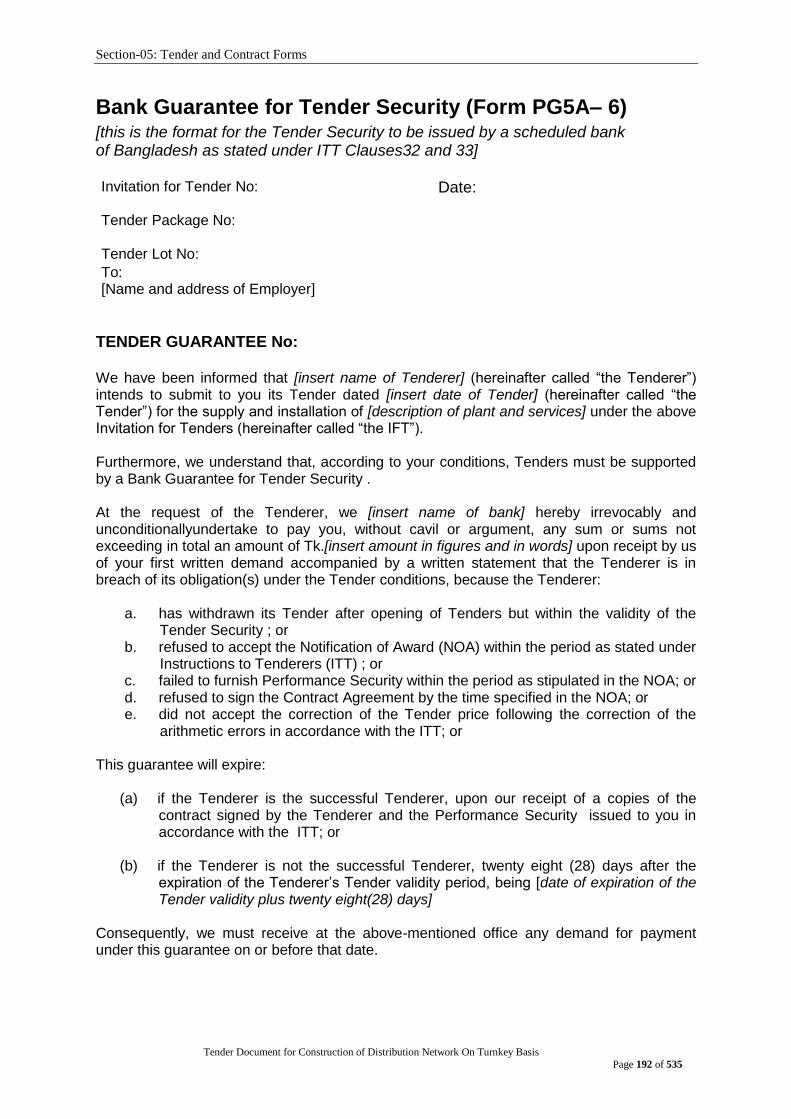
Section-05: Tender and Contract Forms
Tender Document for Construction of Distribution Network On Turnkey Basis
Page 192 of 535
Bank Guarantee for Tender Security (Form PG5A– 6) [this is the format for the Tender Security to be issued by a scheduled bank of Bangladesh as stated under ITT Clauses32 and 33] Invitation for Tender No:
Date:
Tender Package No:
Tender Lot No: To: [Name and address of Employer]
TENDER GUARANTEE No: We have been informed that [insert name of Tenderer] (hereinafter called “the Tenderer”) intends to submit to you its Tender dated [insert date of Tender] (hereinafter called “the Tender”) for the supply and installation of [description of plant and services] under the above Invitation for Tenders (hereinafter called “the IFT”). Furthermore, we understand that, according to your conditions, Tenders must be supported by a Bank Guarantee for Tender Security . At the request of the Tenderer, we [insert name of bank] hereby irrevocably and unconditionallyundertake to pay you, without cavil or argument, any sum or sums not exceeding in total an amount of Tk.[insert amount in figures and in words] upon receipt by us of your first written demand accompanied by a written statement that the Tenderer is in breach of its obligation(s) under the Tender conditions, because the Tenderer:
a. has withdrawn its Tender after opening of Tenders but within the validity of the Tender Security ; or
b. refused to accept the Notification of Award (NOA) within the period as stated under Instructions to Tenderers (ITT) ; or
c. failed to furnish Performance Security within the period as stipulated in the NOA; or d. refused to sign the Contract Agreement by the time specified in the NOA; or e. did not accept the correction of the Tender price following the correction of the
arithmetic errors in accordance with the ITT; or This guarantee will expire:
(a) if the Tenderer is the successful Tenderer, upon our receipt of a copies of the contract signed by the Tenderer and the Performance Security issued to you in accordance with the ITT; or
(b) if the Tenderer is not the successful Tenderer, twenty eight (28) days after the
expiration of the Tenderer‟s Tender validity period, being [date of expiration of the Tender validity plus twenty eight(28) days]
Consequently, we must receive at the above-mentioned office any demand for payment under this guarantee on or before that date.
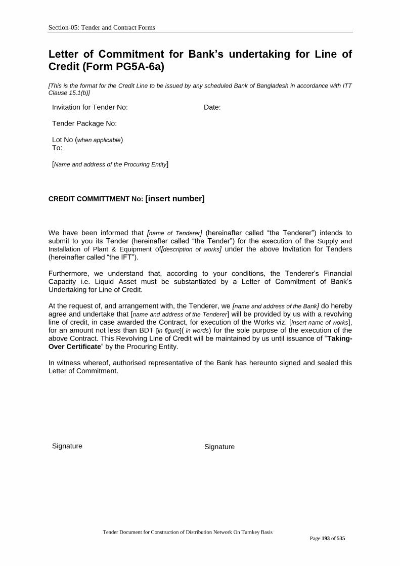
Section-05: Tender and Contract Forms
Tender Document for Construction of Distribution Network On Turnkey Basis
Page 193 of 535
Letter of Commitment for Bank‟s undertaking for Line of Credit (Form PG5A-6a) [This is the format for the Credit Line to be issued by any scheduled Bank of Bangladesh in accordance with ITT Clause 15.1(b)]
Invitation for Tender No:
Date:
Tender Package No:
Lot No (when applicable) To: [Name and address of the Procuring Entity]
CREDIT COMMITTMENT No: [insert number]
We have been informed that [name of Tenderer] (hereinafter called “the Tenderer”) intends to submit to you its Tender (hereinafter called “the Tender”) for the execution of the Supply and
Installation of Plant & Equipment of[description of works] under the above Invitation for Tenders (hereinafter called “the IFT”). Furthermore, we understand that, according to your conditions, the Tenderer‟s Financial Capacity i.e. Liquid Asset must be substantiated by a Letter of Commitment of Bank‟s Undertaking for Line of Credit. At the request of, and arrangement with, the Tenderer, we [name and address of the Bank] do hereby agree and undertake that [name and address of the Tenderer] will be provided by us with a revolving line of credit, in case awarded the Contract, for execution of the Works viz. [insert name of works], for an amount not less than BDT [in figure]( in words) for the sole purpose of the execution of the above Contract. This Revolving Line of Credit will be maintained by us until issuance of “Taking-Over Certificate” by the Procuring Entity. In witness whereof, authorised representative of the Bank has hereunto signed and sealed this Letter of Commitment.
Signature
Signature

Section-05: Tender and Contract Forms
Tender Document for Construction of Distribution Network On Turnkey Basis
Page 194 of 535
Notification of Award (Form PG5A - 7) Contract No: Date: To: [Name of Contractor]
This is to notify you that your Tender dated [insert date] for the supply and installation of plant and Services for [name of contract] for the Contract Price of [state amount in figures and in words] as corrected and modified in accordance with the Instructions to Tenderers, has been approved by [name of Employer]. You are thus requested to take following actions:
i. accept in writing the Notification of Award within seven (7) working days of its issuance pursuant to ITT Sub-Clause 64.1
ii. furnish a Performance Security in the specified format and in the amount of Tk.[state amount in figures and words] ,within Twenty-eight (28) days from issue of this Notification of Award but not later than (specify date), in accordance with ITT Clause 64.3
iii. sign the Contract within twenty eight (28 ) days of issuance of this Notification of Award but not later than (specify date), in accordance with ITT Clause 69.2
You may proceed with the execution of the supply of Plant and Services only upon completion of the above tasks. You may also please note that this Notification of Award shall constitute the formation of this Contract, which shall become binding upon you.
We attach the draft Contract and all other documents for your perusal and signature.
Signed
Duly authorised to sign for and on behalf of [name of Employer]
Date:
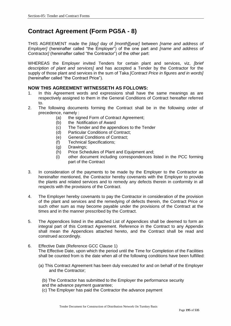
Section-05: Tender and Contract Forms
Tender Document for Construction of Distribution Network On Turnkey Basis
Page 195 of 535
Contract Agreement (Form PG5A - 8) THIS AGREEMENT made the [day] day of [month][year] between [name and address of Employer] (hereinafter called “the Employer”) of the one part and [name and address of Contractor] (hereinafter called “the Contractor”) of the other part: WHEREAS the Employer invited Tenders for certain plant and services, viz, [brief description of plant and services] and has accepted a Tender by the Contractor for the supply of those plant and services in the sum of Taka [Contract Price in figures and in words] (hereinafter called “the Contract Price”).
NOW THIS AGREEMENT WITNESSETH AS FOLLOWS: 1. In this Agreement words and expressions shall have the same meanings as are
respectively assigned to them in the General Conditions of Contract hereafter referred to.
2. The following documents forming the Contract shall be in the following order of precedence, namely :
(a) the signed Form of Contract Agreement; (b) the Notification of Award (c) The Tender and the appendices to the Tender (d) Particular Conditions of Contract; (e) General Conditions of Contract; (f) Technical Specifications; (g) Drawings; (h) Price Schedules of Plant and Equipment and; (i) other document including correspondences listed in the PCC forming
part of the Contract
3. In consideration of the payments to be made by the Employer to the Contractor as
hereinafter mentioned, the Contractor hereby covenants with the Employer to provide the plants and related services and to remedy any defects therein in conformity in all respects with the provisions of the Contract.
4. The Employer hereby covenants to pay the Contractor in consideration of the provision
of the plant and services and the remedying of defects therein, the Contract Price or such other sum as may become payable under the provisions of the Contract at the times and in the manner prescribed by the Contract.
5. The Appendices listed in the attached List of Appendices shall be deemed to form an
integral part of this Contract Agreement. Reference in the Contract to any Appendix shall mean the Appendices attached hereto, and the Contract shall be read and construed accordingly.
6. Effective Date (Reference GCC Clause 1)
The Effective Date, upon which the period until the Time for Completion of the Facilities shall be counted from is the date when all of the following conditions have been fulfilled: (a) This Contract Agreement has been duly executed for and on behalf of the Employer
and the Contractor;
(b) The Contractor has submitted to the Employer the performance security and the advance payment guarantee; (c) The Employer has paid the Contractor the advance payment

Section-05: Tender and Contract Forms
Tender Document for Construction of Distribution Network On Turnkey Basis
Page 196 of 535
(c) An irrevocable Letter of credit has been opened by the purchaser in favor of the contractor upon written request from the contractor after contract signing.
Each party shall use its best efforts to fulfill the above conditions, for which it is responsible, at the earliest practicable time. The contractor shall submit necessary documents to the employer within 1 (one) month from the date of contract signing to facilitate opening of Letter of Credit (L/C).
IN WITNESS whereof the Employer and the Contractor have caused this Agreement to be duly executed by their duly authorized representatives in accordance with the laws of Bangladesh on the day, month and year first written above. Signed by, for and on behalf of the Employer
For the Employer: For the Contractor:
Signature
Print Name
Title
In the presence of Name
Address
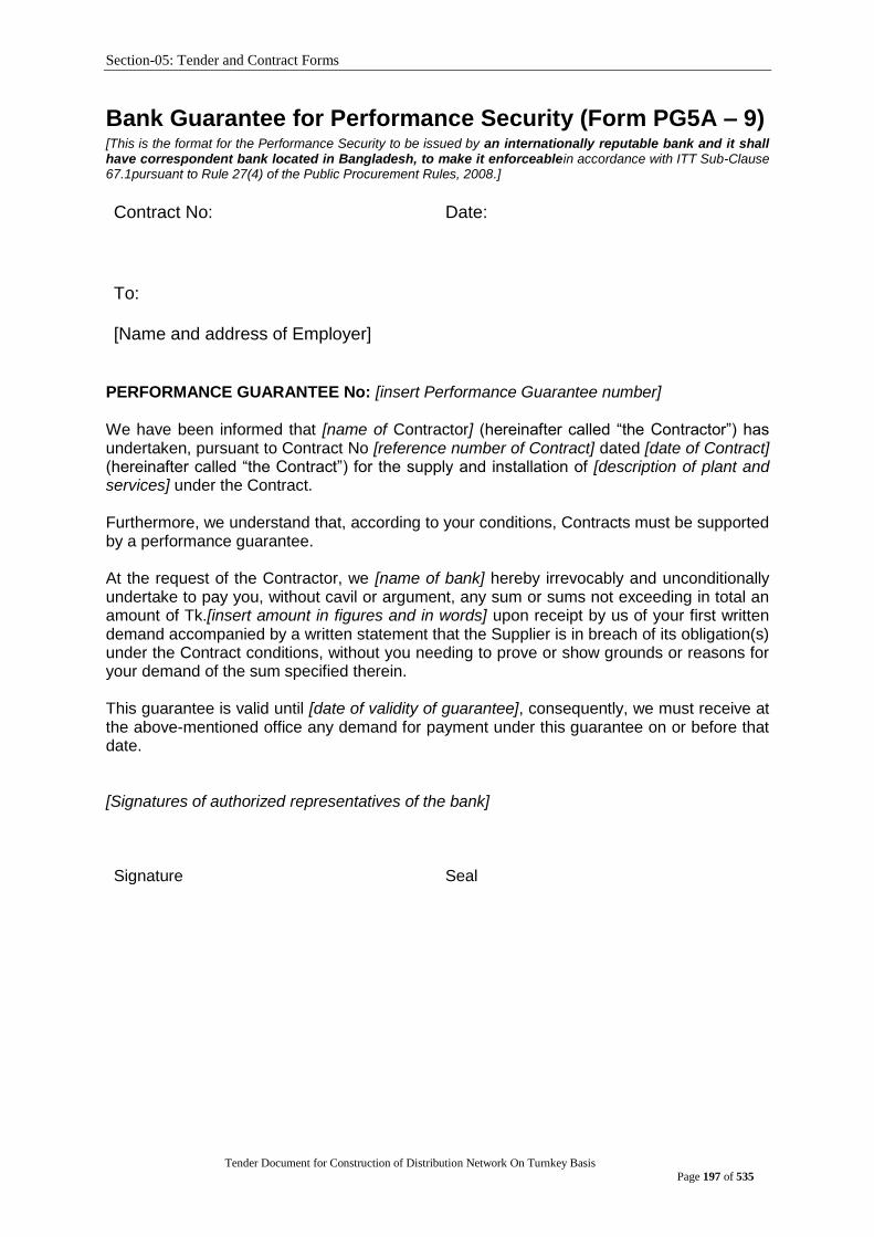
Section-05: Tender and Contract Forms
Tender Document for Construction of Distribution Network On Turnkey Basis
Page 197 of 535
Bank Guarantee for Performance Security (Form PG5A – 9) [This is the format for the Performance Security to be issued by an internationally reputable bank and it shall have correspondent bank located in Bangladesh, to make it enforceablein accordance with ITT Sub-Clause 67.1pursuant to Rule 27(4) of the Public Procurement Rules, 2008.]
Contract No:
Date:
To: [Name and address of Employer]
PERFORMANCE GUARANTEE No: [insert Performance Guarantee number] We have been informed that [name of Contractor] (hereinafter called “the Contractor”) has undertaken, pursuant to Contract No [reference number of Contract] dated [date of Contract] (hereinafter called “the Contract”) for the supply and installation of [description of plant and services] under the Contract. Furthermore, we understand that, according to your conditions, Contracts must be supported by a performance guarantee. At the request of the Contractor, we [name of bank] hereby irrevocably and unconditionally undertake to pay you, without cavil or argument, any sum or sums not exceeding in total an amount of Tk.[insert amount in figures and in words] upon receipt by us of your first written demand accompanied by a written statement that the Supplier is in breach of its obligation(s) under the Contract conditions, without you needing to prove or show grounds or reasons for your demand of the sum specified therein. This guarantee is valid until [date of validity of guarantee], consequently, we must receive at the above-mentioned office any demand for payment under this guarantee on or before that date. [Signatures of authorized representatives of the bank] Signature
Seal
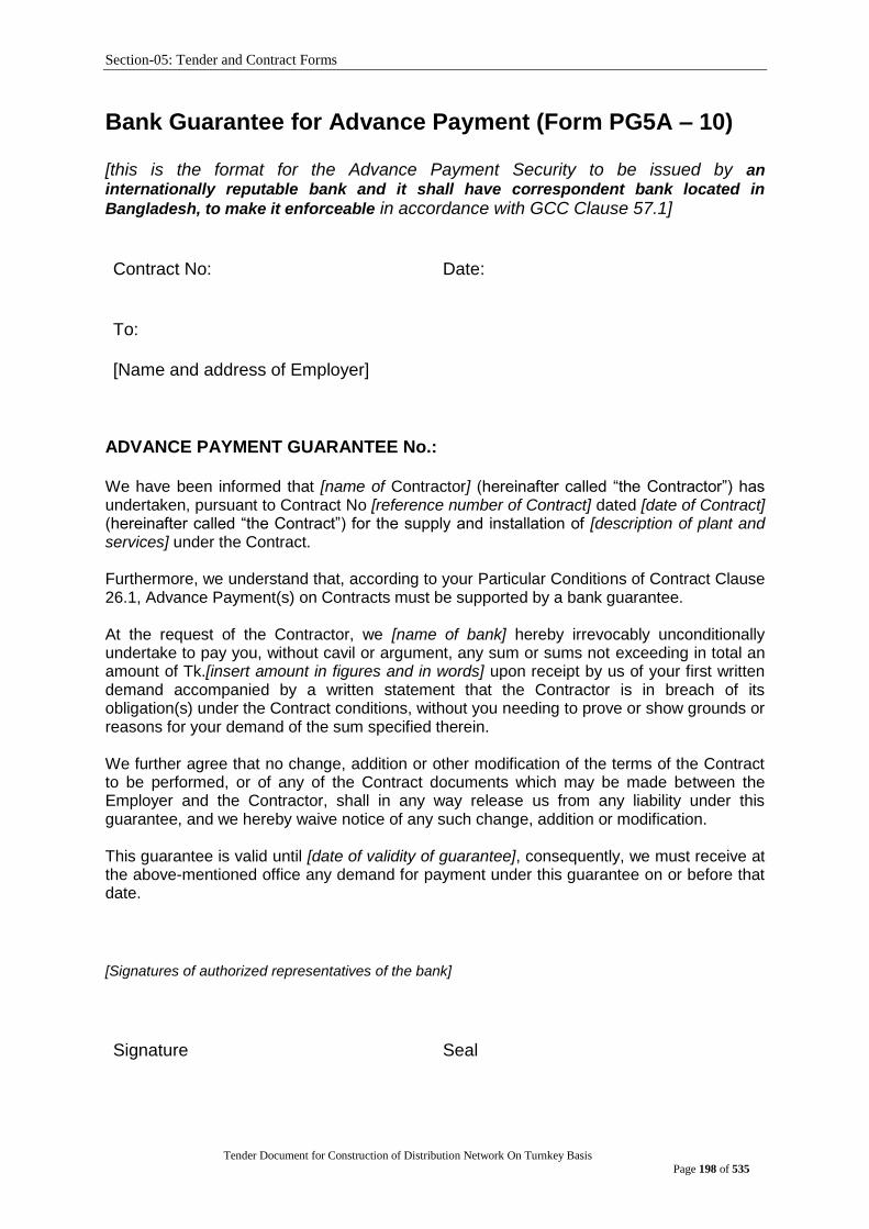
Section-05: Tender and Contract Forms
Tender Document for Construction of Distribution Network On Turnkey Basis
Page 198 of 535
Bank Guarantee for Advance Payment (Form PG5A – 10) [this is the format for the Advance Payment Security to be issued by an
internationally reputable bank and it shall have correspondent bank located in
Bangladesh, to make it enforceable in accordance with GCC Clause 57.1] Contract No:
Date:
To: [Name and address of Employer]
ADVANCE PAYMENT GUARANTEE No.: We have been informed that [name of Contractor] (hereinafter called “the Contractor”) has undertaken, pursuant to Contract No [reference number of Contract] dated [date of Contract] (hereinafter called “the Contract”) for the supply and installation of [description of plant and services] under the Contract. Furthermore, we understand that, according to your Particular Conditions of Contract Clause 26.1, Advance Payment(s) on Contracts must be supported by a bank guarantee. At the request of the Contractor, we [name of bank] hereby irrevocably unconditionally undertake to pay you, without cavil or argument, any sum or sums not exceeding in total an amount of Tk.[insert amount in figures and in words] upon receipt by us of your first written demand accompanied by a written statement that the Contractor is in breach of its obligation(s) under the Contract conditions, without you needing to prove or show grounds or reasons for your demand of the sum specified therein. We further agree that no change, addition or other modification of the terms of the Contract to be performed, or of any of the Contract documents which may be made between the Employer and the Contractor, shall in any way release us from any liability under this guarantee, and we hereby waive notice of any such change, addition or modification. This guarantee is valid until [date of validity of guarantee], consequently, we must receive at the above-mentioned office any demand for payment under this guarantee on or before that date.
[Signatures of authorized representatives of the bank]
Signature
Seal

Section-05: Tender and Contract Forms
Tender Document for Construction of Distribution Network On Turnkey Basis
Page 199 of 535
Bank Guarantee for Retention Money Security(Form PG5A-11) [This is the format for the Retention Money Guarantee to be issued by any scheduled Bank of Bangladesh in accordance with GCC Clause 57] Demand Guarantee
[Bank‟s Name, and Address of Issuing Branch or Office]
Beneficiary: [insert Name and Address of the Procuring Entity]
Date: [insert date]
RETENTION MONEY GUARANTEE No.: [insert number]
We have been informed that [insert name of Contractor] (hereinafter called "the Contractor") has entered into Contract Number [insert reference number of the Contract] dated [insert date] with you, for the execution of [insert name of Contract and brief description of Works] (hereinafter called "the Contract").
Furthermore, we understand that, according to the conditions of the Contract, when the Taking-Over Certificate has been issued for the Works and the first half of the Retention Money has been certified for payment, payment of Tk. [insert the amount of the second half of the Retention Money] which becomes due after the Defects Liability Period has passed and certified in the form of Defects Correction Certificate, is to be made against a Retention Money Guarantee.
At the request of the Contractor, we [insert name of Bank] hereby irrevocably unconditionally undertake to pay you any sum or sums not exceeding in total an amount of Tk. [insert amount in figures] (Taka [insert amount in words]) upon receipt by us of your first demand in writing accompanied by a written statement stating that the Contractor is in breach of its obligation under the Contract because the Contractor failed to properly correct the defects duly notified in respect of the Supply and Installation of Plant & Equipment.
It is a condition for any claim and payment under this guarantee to be made that the payment of the second half of the Retention Money referred to above must have been received by the Contractor on its account number[insert A/C no] at [name and address of Bank].
This guarantee is valid until [insert the date of validity of Guarantee that being twenty-eight (28) days beyond the Defects Liability Period]. Consequently, we must receive at the above-mentioned office any demand for payment under this guarantee on or before that date.
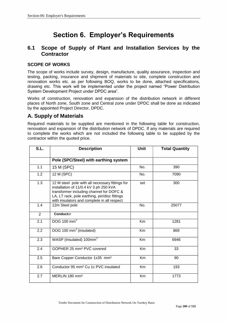
Section-06: Employer's Requirements
Tender Document for Construction of Distribution Network On Turnkey Basis
Page 200 of 535
Section 6. Employer‟s Requirements
6.1 Scope of Supply of Plant and Installation Services by the Contractor
SCOPE OF WORKS
The scope of works include survey, design, manufacture, quality assurance, inspection and testing, packing, insurance and shipment of materials to site, complete construction and renovation works etc. as per following BOQ, works to be done, attached specifications, drawing etc. This work will be implemented under the project named “Power Distribution System Development Project under DPDC area”.
Works of construction, renovation and expansion of the distribution network in different places of North zone, South zone and Central zone under DPDC shall be done as indicated by the appointed Project Director, DPDC.
A. Supply of Materials
Required materials to be supplied are mentioned in the following table for construction, renovation and expansion of the distribution network of DPDC. If any materials are required to complete the works which are not included the following table to be supplied by the contractor within the quoted price.
S.L. Description Unit Total Quantity
Pole (SPC/Steel) with earthing system
1.1 15 M (SPC) No. 390
1.2 12 M (SPC)
No. 7090
1.3 12 M steel pole with all necessary fittings for installation of 11/0.4 kV 3 ph 250 kVA transformer including channel for DOFC & LA, LT rack, pole earthing, pin/disc fittings with insulators and complete in all respect
set 300
1.4 12m Steel pole
No. 25077
2 Conductor
2.1 DOG 100 mm2
Km 1281
2.2 DOG 100 mm2 (insulated)
Km 869
2.3 WASP (Insulated) 100mm2
Km 6946
2.4 GOPHER 25 mm² PVC covered
Km 33
2.5 Bare Copper Conductor 1x35 mm²
Km 90
2.6 Conductor 95 mm² Cu 1c PVC insulated
Km 193
2.7 MERLIN 180 mm²
Km 1773
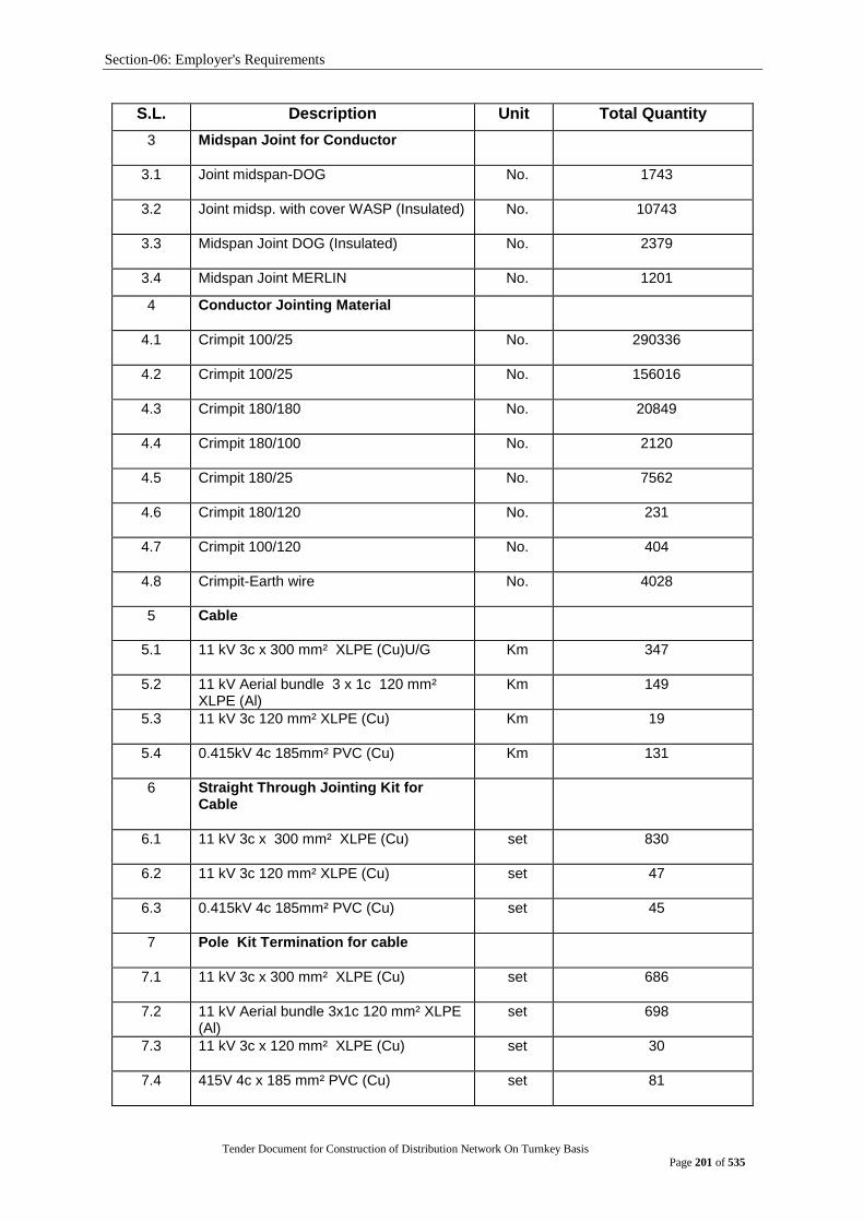
Section-06: Employer's Requirements
Tender Document for Construction of Distribution Network On Turnkey Basis
Page 201 of 535
S.L. Description Unit Total Quantity
3 Midspan Joint for Conductor
3.1 Joint midspan-DOG
No. 1743
3.2 Joint midsp. with cover WASP (Insulated)
No. 10743
3.3 Midspan Joint DOG (Insulated)
No. 2379
3.4 Midspan Joint MERLIN No. 1201
4 Conductor Jointing Material
4.1 Crimpit 100/25 No. 290336
4.2 Crimpit 100/25 No. 156016
4.3 Crimpit 180/180 No. 20849
4.4 Crimpit 180/100 No. 2120
4.5 Crimpit 180/25 No. 7562
4.6 Crimpit 180/120 No. 231
4.7 Crimpit 100/120 No. 404
4.8 Crimpit-Earth wire No. 4028
5 Cable
5.1 11 kV 3c x 300 mm² XLPE (Cu)U/G
Km 347
5.2 11 kV Aerial bundle 3 x 1c 120 mm² XLPE (Al)
Km 149
5.3 11 kV 3c 120 mm² XLPE (Cu)
Km 19
5.4 0.415kV 4c 185mm² PVC (Cu)
Km 131
6 Straight Through Jointing Kit for Cable
6.1 11 kV 3c x 300 mm² XLPE (Cu)
set 830
6.2 11 kV 3c 120 mm² XLPE (Cu)
set 47
6.3 0.415kV 4c 185mm² PVC (Cu)
set 45
7 Pole Kit Termination for cable
7.1 11 kV 3c x 300 mm² XLPE (Cu)
set 686
7.2 11 kV Aerial bundle 3x1c 120 mm² XLPE (Al)
set 698
7.3 11 kV 3c x 120 mm² XLPE (Cu)
set 30
7.4 415V 4c x 185 mm² PVC (Cu)
set 81
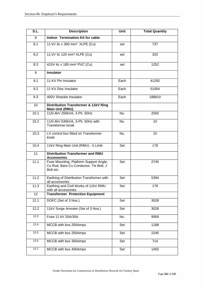
Section-06: Employer's Requirements
Tender Document for Construction of Distribution Network On Turnkey Basis
Page 202 of 535
S.L. Description Unit Total Quantity
8 Indoor Termination Kit for cable
8.1 11 kV 3c x 300 mm² XLPE (Cu)
set 737
8.2 11 kV 3c 120 mm² XLPE (Cu)
set 320
8.3 415V 4c x 185 mm² PVC (Cu)
set 1252
9 Insulator
9.1 11 KV Pin Insulator
Each 41292
9.2 11 KV Disc Insulator
Each 51064
9.3 400V Shackle Insulator
Each 188810
10 Distribution Transformer & 11kV Ring Main Unit (RMU)
10.1 11/0.4kV 250kVA, 3-Ph, 50Hz
No. 2550
10.2 11/0.4kV 630kVA, 3-Ph, 50Hz with Transformer kiosk
No. 10
10.3 LV control box fitted on Transformer kiosk
No. 10
10.4 11kV Ring Main Unit (RMU) - 5 Limb
Set 178
11 Distribution Transformer and RMU Accessories
11.1 Fuse Mounting, Platform Support Angle, Cu Rod, Bare Cu Conductor, Tie Bolt, J Bolt etc.
Set 2745
11.2 Earthing of Distribution Transformer with all accessories
Set 5394
11.3 Earthing and Civil Works of 11kV RMU with all accessories
Set 178
12 Transformer Protection Equipment
12.1 DOFC (Set of 3 Nos.)
Set 3028
12.2 11kV Surge Arrester (Set of 3 Nos.)
Set 3028
12.3 Fuse 11 kV 20A/30A
No. 9069
12.4 MCCB with box 200Amps
Set 1188
12.5 MCCB with box 250Amps
Set 2245
12.6 MCCB with box 300Amps
Set 714
12.7 MCCB with box 400Amps
Set 1455
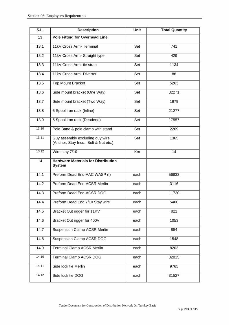
Section-06: Employer's Requirements
Tender Document for Construction of Distribution Network On Turnkey Basis
Page 203 of 535
S.L. Description Unit Total Quantity
13 Pole Fitting for Overhead Line
13.1 11kV Cross Arm- Terminal
Set 741
13.2 11kV Cross Arm- Straight type
Set 429
13.3 11kV Cross Arm- tie strap
Set 1134
13.4 11kV Cross Arm- Diverter
Set 86
13.5 Top Mount Bracket
Set 5263
13.6 Side mount bracket (One Way)
Set 32271
13.7 Side mount bracket (Two Way)
Set 1879
13.8 5 Spool iron rack (Inline)
Set 21277
13.9 5 Spool iron rack (Deadend)
Set 17557
13.10 Pole Band & pole clamp with stand
Set 2269
13.11 Guy assembly excluding guy wire (Anchor, Stay Insu., Bolt & Nut etc.)
Set 1365
13.12 Wire stay 7/10
Km 14
14 Hardware Materials for Distribution System
14.1 Preform Dead End-AAC WASP (I)
each 56833
14.2 Preform Dead End-ACSR Merlin
each 3116
14.3 Preform Dead End-ACSR DOG
each 11720
14.4 Preform Dead End 7/10 Stay wire
each 5460
14.5 Bracket Out rigger for 11KV
each 821
14.6 Bracket Out rigger for 400V
each 1053
14.7 Suspension Clamp ACSR Merlin
each 854
14.8 Suspension Clamp ACSR DOG
each 1548
14.9 Terminal Clamp ACSR Merlin
each 8203
14.10 Terminal Clamp ACSR DOG
each 32815
14.11 Side lock tie Merlin
each 9765
14.12 Side lock tie DOG
each 31527

Section-06: Employer's Requirements
Tender Document for Construction of Distribution Network On Turnkey Basis
Page 204 of 535
S.L. Description Unit Total Quantity
14.13 Pin and nut of 11kV pin insulators
each 41292
14.14 Socket Tongue adapter
each 25542
14.15 Shackle
each 25542
14.16 Terminating strap-90mm
each 25542
14.17 Ball ended link
each 25542
14.18 Terminaitng strap 90mm and thimble
each 1781
14.19 Pole Bracket strap 50mm 12/13.5m pole
each 118216
14.20 Pole Mounting Bracket 50mm
each 52672
14.21 Pole Mounting Bracket 40mm- 12/13.5M pole (LT rack)
each 63832
14.22 Pole Bracket strap 40mm-12/13.5M Pole LT rack
each 63832
14.23 Pole Mounting Bracket 50mm- Multipurpose
each 3706
14.24 Service Ring-12m pole
each 33011
14.25 Eye Nut with thimble
each 1365
14.26 Stay rod and turn Buckle
each 1365
14.27 Stainless Steel Binding Tape 12.5mm
meter 4021
14.28 Buckle for Stainless Steel Binding Tape 12.5mm
each 2009
14.29 Service bale-insulated
each 140984
14.30 Cu Lug size 35mm² (2mm thick)
each 22073
14.31 Cu Lug size 95mm² (2mm thick)
each 60321
14.32 Al Lug size 25mm² (2mm thick)
each 13885
14.33 Cu Lug size 120mm² (2mm thick)
each 626
14.34 Cu Lug size 300mm² (2mm thick)
each 2359
14.35 PIB Tap
roll 1270
14.36 Cable Guard 100mm²
each 144
14.37 Binding Wire (Al) (3mm dia)
ton 82
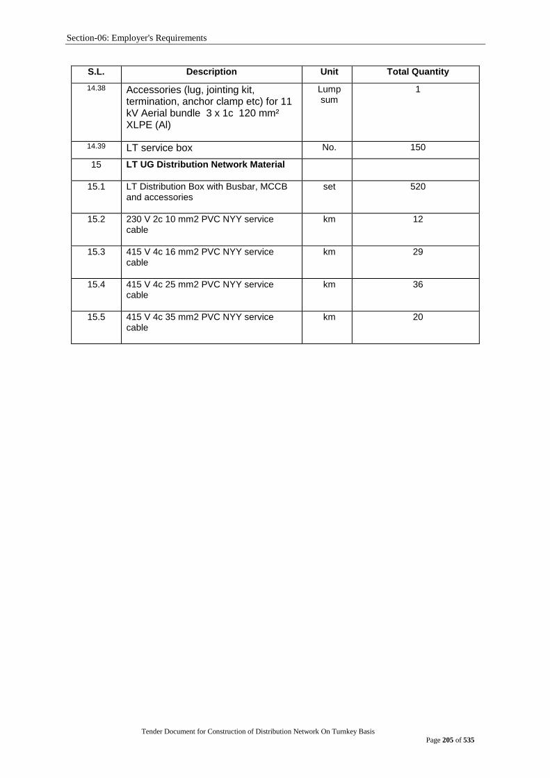
Section-06: Employer's Requirements
Tender Document for Construction of Distribution Network On Turnkey Basis
Page 205 of 535
S.L. Description Unit Total Quantity
14.38 Accessories (lug, jointing kit, termination, anchor clamp etc) for 11 kV Aerial bundle 3 x 1c 120 mm² XLPE (Al)
Lump sum
1
14.39 LT service box No. 150
15 LT UG Distribution Network Material
15.1 LT Distribution Box with Busbar, MCCB and accessories
set 520
15.2 230 V 2c 10 mm2 PVC NYY service cable
km 12
15.3 415 V 4c 16 mm2 PVC NYY service cable
km 29
15.4 415 V 4c 25 mm2 PVC NYY service cable
km 36
15.5 415 V 4c 35 mm2 PVC NYY service cable
km 20
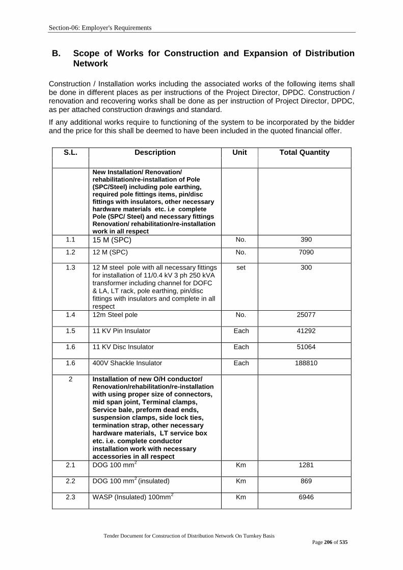
Section-06: Employer's Requirements
Tender Document for Construction of Distribution Network On Turnkey Basis
Page 206 of 535
B. Scope of Works for Construction and Expansion of Distribution Network
Construction / Installation works including the associated works of the following items shall be done in different places as per instructions of the Project Director, DPDC. Construction / renovation and recovering works shall be done as per instruction of Project Director, DPDC, as per attached construction drawings and standard.
If any additional works require to functioning of the system to be incorporated by the bidder and the price for this shall be deemed to have been included in the quoted financial offer.
S.L. Description Unit Total Quantity
New Installation/ Renovation/ rehabilitation/re-installation of Pole (SPC/Steel) including pole earthing, required pole fittings items, pin/disc fittings with insulators, other necessary hardware materials etc. i.e complete Pole (SPC/ Steel) and necessary fittings Renovation/ rehabilitation/re-installation work in all respect
1.1 15 M (SPC) No. 390
1.2 12 M (SPC)
No. 7090
1.3 12 M steel pole with all necessary fittings for installation of 11/0.4 kV 3 ph 250 kVA transformer including channel for DOFC & LA, LT rack, pole earthing, pin/disc fittings with insulators and complete in all respect
set 300
1.4 12m Steel pole
No. 25077
1.5 11 KV Pin Insulator
Each 41292
1.6 11 KV Disc Insulator
Each 51064
1.6 400V Shackle Insulator
Each 188810
2 Installation of new O/H conductor/ Renovation/rehabilitation/re-installation with using proper size of connectors, mid span joint, Terminal clamps, Service bale, preform dead ends, suspension clamps, side lock ties, termination strap, other necessary hardware materials, LT service box etc. i.e. complete conductor installation work with necessary accessories in all respect
2.1 DOG 100 mm2
Km 1281
2.2 DOG 100 mm2 (insulated)
Km 869
2.3 WASP (Insulated) 100mm2
Km 6946
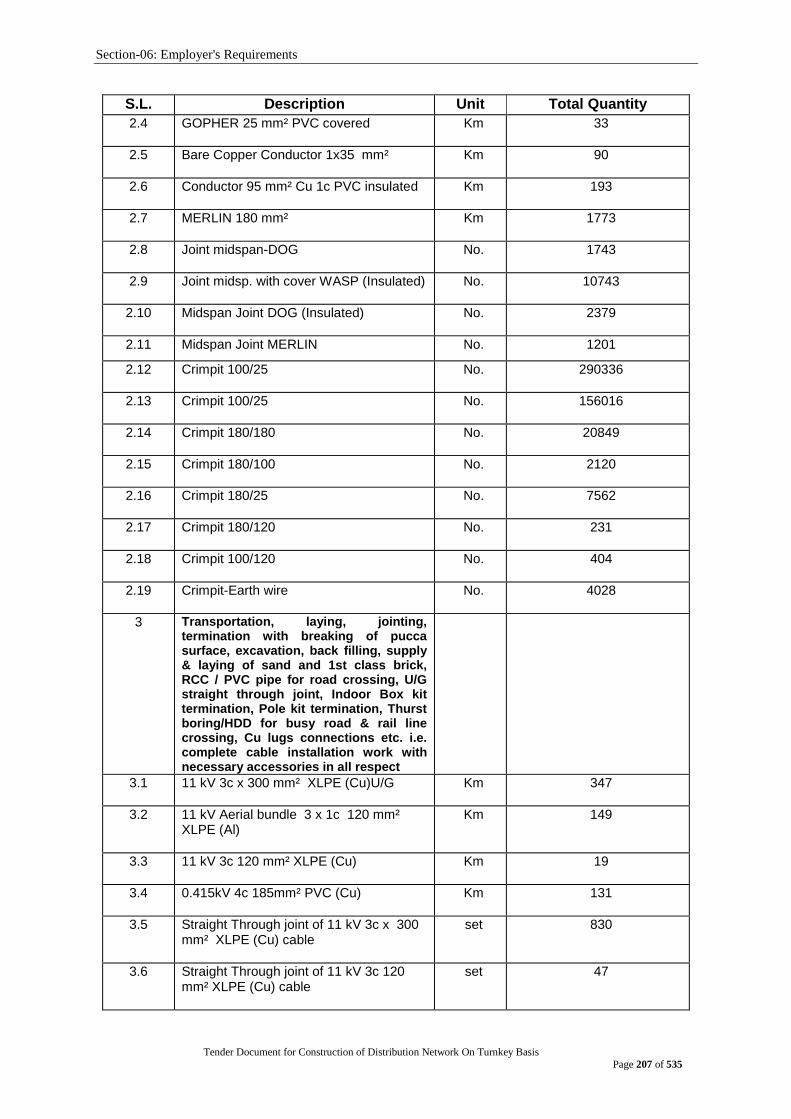
Section-06: Employer's Requirements
Tender Document for Construction of Distribution Network On Turnkey Basis
Page 207 of 535
S.L. Description Unit Total Quantity
2.4 GOPHER 25 mm² PVC covered
Km 33
2.5 Bare Copper Conductor 1x35 mm²
Km 90
2.6 Conductor 95 mm² Cu 1c PVC insulated
Km 193
2.7 MERLIN 180 mm²
Km 1773
2.8 Joint midspan-DOG
No. 1743
2.9 Joint midsp. with cover WASP (Insulated)
No. 10743
2.10 Midspan Joint DOG (Insulated)
No. 2379
2.11 Midspan Joint MERLIN No. 1201
2.12 Crimpit 100/25 No. 290336
2.13 Crimpit 100/25 No. 156016
2.14 Crimpit 180/180 No. 20849
2.15 Crimpit 180/100 No. 2120
2.16 Crimpit 180/25 No. 7562
2.17 Crimpit 180/120 No. 231
2.18 Crimpit 100/120 No. 404
2.19 Crimpit-Earth wire No. 4028
3 Transportation, laying, jointing, termination with breaking of pucca surface, excavation, back filling, supply & laying of sand and 1st class brick, RCC / PVC pipe for road crossing, U/G straight through joint, Indoor Box kit termination, Pole kit termination, Thurst boring/HDD for busy road & rail line crossing, Cu lugs connections etc. i.e. complete cable installation work with necessary accessories in all respect
3.1 11 kV 3c x 300 mm² XLPE (Cu)U/G
Km 347
3.2 11 kV Aerial bundle 3 x 1c 120 mm² XLPE (Al)
Km 149
3.3 11 kV 3c 120 mm² XLPE (Cu)
Km 19
3.4 0.415kV 4c 185mm² PVC (Cu)
Km 131
3.5 Straight Through joint of 11 kV 3c x 300 mm² XLPE (Cu) cable
set 830
3.6 Straight Through joint of 11 kV 3c 120 mm² XLPE (Cu) cable
set 47

Section-06: Employer's Requirements
Tender Document for Construction of Distribution Network On Turnkey Basis
Page 208 of 535
S.L. Description Unit Total Quantity
3.7 Straight Through joint of 0.415kV 4c 185mm² PVC (Cu) cable
set 45
3.8 Pole kit termination of 11 kV 3c x 300 mm² XLPE (Cu) cable
set 686
3.9 Pole kit termination of 11 kV Aerial bundle 3x1c 120 mm² XLPE (Al) cable
set 698
3.10 Pole kit termination of 11 kV 3c x 120 mm² XLPE (Cu) cable
set 30
3.11 Pole kit termination of 415V 4c x 185 mm² PVC (Cu) cable
set 81
3.12 Indoor termination kit of 11 kV 3c x 300 mm² XLPE (Cu) cable
set 737
3.13 Indoor termination kit of 11 kV 3c 120 mm² XLPE (Cu) cable
set 320
3.14 Indoor termination kit of 415V 4c x 185 mm² PVC (Cu) cable
set 1252
4 Installation of Distribution Transformer, Transformer Kiosk with LV control box & 11kV Ring Main Unit (RMU) with all necessary fittings, protective device, grounding system, checking earth resistance etc. i.e. complete in all respect
4.1 11/0.4kV 250kVA, 3-Ph, 50Hz
No. 2550
4.2 11/0.4kV 630kVA, 3-Ph, 50Hz with Transformer kiosk
No. 10
4.3 LV control box fitted on Transformer kiosk
No. 10
4.4 11kV Ring Main Unit (RMU) - 5 Limb
Set 168
5 Installation/Renovation/rehabilitation/re-installation of Distribution Transformer Accessories with transformer protection equipment i.e. complete in all respect
5.1 Fuse Mounting, Platform Support Angle, Cu Rod, Bare Cu Conductor, Tie Bolt, J Bolt etc.
Set 2745
5.2 Earthing of Distribution Transformer with all accessories
Set 5394
5.3 Earthing and Civil Works of 11kV RMU with all accessories
Set 178
5.4 DOFC (Set of 3 Nos.)
Set 3028
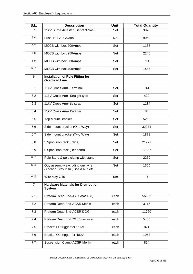
Section-06: Employer's Requirements
Tender Document for Construction of Distribution Network On Turnkey Basis
Page 209 of 535
S.L. Description Unit Total Quantity
5.5 11kV Surge Arrester (Set of 3 Nos.)
Set 3028
5.6 Fuse 11 kV 20A/30A
No. 9069
5.7 MCCB with box 200Amps
Set 1188
5.8 MCCB with box 250Amps
Set 2245
5.9 MCCB with box 300Amps
Set 714
5.10 MCCB with box 400Amps
Set 1455
6 Installation of Pole Fitting for Overhead Line
6.1 11kV Cross Arm- Terminal
Set 741
6.2 11kV Cross Arm- Straight type
Set 429
6.3 11kV Cross Arm- tie strap
Set 1134
6.4 11kV Cross Arm- Diverter
Set 86
6.5 Top Mount Bracket
Set 5263
6.6 Side mount bracket (One Way)
Set 32271
6.7 Side mount bracket (Two Way)
Set 1879
6.8 5 Spool iron rack (Inline)
Set 21277
6.9 5 Spool iron rack (Deadend)
Set 17557
6.10 Pole Band & pole clamp with stand
Set 2269
6.11 Guy assembly excluding guy wire (Anchor, Stay Insu., Bolt & Nut etc.)
Set 1365
6.12 Wire stay 7/10
Km 14
7 Hardware Materials for Distribution System
7.1 Preform Dead End-AAC WASP (I)
each 56833
7.2 Preform Dead End-ACSR Merlin
each 3116
7.3 Preform Dead End-ACSR DOG
each 11720
7.4 Preform Dead End 7/10 Stay wire
each 5460
7.5 Bracket Out rigger for 11KV
each 821
7.6 Bracket Out rigger for 400V
each 1053
7.7 Suspension Clamp ACSR Merlin
each 854

Section-06: Employer's Requirements
Tender Document for Construction of Distribution Network On Turnkey Basis
Page 210 of 535
S.L. Description Unit Total Quantity
7.8 Suspension Clamp ACSR DOG
each 1548
7.9 Terminal Clamp ACSR Merlin
each 8203
7.10 Terminal Clamp ACSR DOG
each 32815
7.11 Side lock tie Merlin
each 9765
7.12 Side lock tie DOG
each 31527
7.13 Pin and nut of 11kV pin insulators
each 41292
7.14 Socket Tongue adapter
each 25542
7.15 Shackle
each 25542
7.16 Terminating strap-90mm
each 25542
7.17 Ball ended link
each 25542
7.18 Terminaitng strap 90mm and thimble
each 1781
7.19 Pole Bracket strap 50mm 12/13.5m pole
each 118216
7.20 Pole Mounting Bracket 50mm
each 52672
7.21 Pole Mounting Bracket 40mm- 12/13.5M pole (LT rack)
each 63832
7.22 Pole Bracket strap 40mm-12/13.5M Pole LT rack
each 63832
7.23 Pole Mounting Bracket 50mm- Multipurpose
each 3706
7.24 Service Ring-12m pole
each 33011
7.25 Eye Nut with thimble
each 1365
7.26 Stay rod and turn Buckle
each 1365
7.27 Stainless Steel Binding Tape 12.5mm
meter 4021
7.28 Buckle for Stainless Steel Binding Tape 12.5mm
each 2009
7.29 Service bale-insulated
each 140984
7.30 Cu Lug size 35mm² (2mm thick)
each 22073
7.31 Cu Lug size 95mm² (2mm thick)
each 60321
7.32 Al Lug size 25mm² (2mm thick)
each 13885
7.33 Cu Lug size 120mm² (2mm thick)
each 626
7.34 Cu Lug size 300mm² (2mm thick)
each 2359

Section-06: Employer's Requirements
Tender Document for Construction of Distribution Network On Turnkey Basis
Page 211 of 535
S.L. Description Unit Total Quantity 7.35 PIB Tap roll 1270
7.36 Cable Guard 100mm² each 144
7.37 Binding Wire (Al) (3mm dia) ton 82
7.38 Accessories (lug, jointing kit, termination, anchor clamp etc) for 11 kV Aerial bundle 3 x 1c 120 mm² XLPE (Al)
Lump sum
1
7.39 LT service box No. 150
8 Installation/laying of LT UG Distribution Network Material
8.1 LT Distribution Box with Busbar, MCCB and accessories
set 520
8.2 230 V 2c 10 mm2 PVC NYY service cable
km 12
8.3 415 V 4c 16 mm2 PVC NYY service cable
km 29
8.4 415 V 4c 25 mm2 PVC NYY service cable
km 36
8.5 415 V 4c 35 mm2 PVC NYY service cable
km 20
Note:
1. Materials to be supplied and works to be done(for construction, renovation and expansion of the distribution network of under DPDC are included in the above tables. If any additional materials are required to complete the works which are not included in the above table to be supplied by the bidder within the quoted price.
2. Also if any additional works are required to functioning the system properly and as per standard to be incorporated by the bidder within the quoted price.
Description of the Proposed Project
General
In order to meet the future demand under DPDC area, DPDC has planned to undertake a new project; “Power Distribution System Development Project under DPDC area”.for power Distribution System Development. Based on the findings of the survey results and shortcoming of the existing system under DPDC, a preliminary planning has been done. Planning of 132kV and 33/11kV substations and distribution lines have been done based on the load forecast up to 2030.
Objective of the Project:
The main objectives of the project are as follows:
1. To develop and upgrade the distribution system under DPDC area
2. To provide quality and uninterrupted power supply to the consumers
3. To meet the growing demand in the DPDC area.
4. To improve the system loss
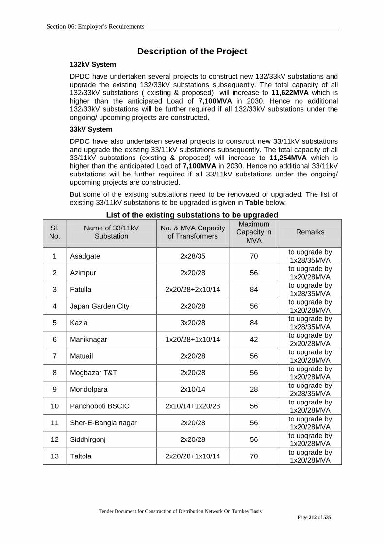
Section-06: Employer's Requirements
Tender Document for Construction of Distribution Network On Turnkey Basis
Page 212 of 535
Description of the Project
132kV System
DPDC have undertaken several projects to construct new 132/33kV substations and upgrade the existing 132/33kV substations subsequently. The total capacity of all 132/33kV substations ( existing & proposed) will increase to 11,622MVA which is higher than the anticipated Load of 7,100MVA in 2030. Hence no additional 132/33kV substations will be further required if all 132/33kV substations under the ongoing/ upcoming projects are constructed.
33kV System
DPDC have also undertaken several projects to construct new 33/11kV substations and upgrade the existing 33/11kV substations subsequently. The total capacity of all 33/11kV substations (existing & proposed) will increase to 11,254MVA which is higher than the anticipated Load of 7,100MVA in 2030. Hence no additional 33/11kV substations will be further required if all 33/11kV substations under the ongoing/ upcoming projects are constructed.
But some of the existing substations need to be renovated or upgraded. The list of existing 33/11kV substations to be upgraded is given in Table below:
List of the existing substations to be upgraded
Sl. No.
Name of 33/11kV Substation
No. & MVA Capacity of Transformers
Maximum Capacity in
MVA Remarks
1 Asadgate 2x28/35 70 to upgrade by 1x28/35MVA
2 Azimpur 2x20/28 56 to upgrade by 1x20/28MVA
3 Fatulla 2x20/28+2x10/14 84 to upgrade by 1x28/35MVA
4 Japan Garden City 2x20/28 56 to upgrade by 1x20/28MVA
5 Kazla 3x20/28 84 to upgrade by 1x28/35MVA
6 Maniknagar 1x20/28+1x10/14 42 to upgrade by 2x20/28MVA
7 Matuail 2x20/28 56 to upgrade by 1x20/28MVA
8 Mogbazar T&T 2x20/28 56 to upgrade by 1x20/28MVA
9 Mondolpara 2x10/14 28 to upgrade by 2x28/35MVA
10 Panchoboti BSCIC 2x10/14+1x20/28 56 to upgrade by 1x20/28MVA
11 Sher-E-Bangla nagar 2x20/28 56 to upgrade by 1x20/28MVA
12 Siddhirgonj 2x20/28 56 to upgrade by 1x20/28MVA
13 Taltola 2x20/28+1x10/14 70 to upgrade by 1x20/28MVA

Section-06: Employer's Requirements
Tender Document for Construction of Distribution Network On Turnkey Basis
Page 213 of 535
Distribution System (11kV & below)
Non-standard lines
From the survey results, it was observed that in some areas under DPDC, electricity
is being supplied using nonstandard line of bamboo and long service conductors.
The areas are as follows:
Kamrangir Char, Kajla Shanir Akhara
Bosila, Demra Shitalakdshya
Beribandh, Matuail Shahidnagar
Trimohini, Siddhirganj Char Sayedpur
Nandipara, Fatullah Muktarpur
Shekher Jaiga, Shyampur Char Baktabali
Manikdi Kadamtali Char Narsinghapur
The electrical lines in these areas are nonstandard and in a very bad condition
causing accidents very often leading to deaths. These lines need to be standardized
Use of Aerial Bundled Cables / Insulated Conductor:
There are narrow roads in Lalbagh and old Dhaka area and these areas are thickly
populated.. In these congested areas, it is better to use 11kV aerial bundled cables
or insulated conductors e.g insulated Dog etc. to avoid accidents and provide
uninterrupted and reliable power supply to the customers. It is estimated that about
115km aerial bundled conductor will be required for DPDC area out of which, 100km
will be required for Central zone and about 15km will be required for South zone.
Undergrounding:
11kV overhead lines along the main roads look very ugly and also cause frequent
accidents resulting power interruption. So, the overhead lines along these main roads
need to be converted to underground to beautify the main roads and to ensure safety,
reliability and uninterrupted power supply. Total requirement of 11kV underground
cables under DPDC area is given in Table below
Requirement of 11kV underground cable under DPDC Area
Zone Unit Quantity
North Zone km 144
Central Zone km 120
South Zone km 83
Total km 347

Section-06: Employer's Requirements
Tender Document for Construction of Distribution Network On Turnkey Basis
Page 214 of 535
Zone-wise requirements of underground cables to convert 11kV overhead lines to
underground are elaborated below:
a) North Zone:
The existing overhead distribution lines along the VIP road from Bangabhaban to
Jahangirgate comprising of the following sections look very ugly. The overhead lines
along these VIP roads need to be converted to underground to make the VIP road
beautiful and to ensure safety, reliability and uninterrupted power supply.
i) Bangabhaban-Ittefaq-Shapla Chattar,
ii) Shapla Chattar-Dainik Bangla-Palton,
iii) Palton-GPO-Stadium-Dilkusha-Bangabhaban,
iv) Dainik Bangla-Dilkusha-Palton,-Matsyabhaban,
v) GPO, Shikshya Bhaban-CIRDAP-Press club,
vi) Matsyabhaban-Shahbag,
vii) Matsyabhab-Kakrail-Sheraton,
viii) Shahbag-Jahangirgate
Also distribution transformers located along these roads look very ugly. These
distribution transformers need to be installed inside sub-lane of the above roads to
look the VIP roads beautiful and to ensure safety, reliability and uninterrupted power
supply.
Total length of 11kV overhead lines from Bangabhaban to Jahangirgate including
all connecting roads is about 15km need to be converted into underground. So, about
15kms 11kV underground cable will be required to convert the above 11kV overhead
lines. In addition, about 117 nos. distribution transformers need to be shifted from the
main roads to the adjoining roads. For this about 33kms 11kV underground cables
will be required. Hence, total 48kms 11kV underground cables will be required to
convert the above 11kV overhead lines including shifting of the distribution
transformers from main road to the adjoining roads.
Similarly, 11kV overhead lines from Azimpur to Gabtali having total length of
10kms need to be converted to underground and about 117 nos. distribution
transformers need to be shifted from the main roads to the adjoining roads. For this
about 33kms 11kV underground cables will be required. Hence, total 43kms 11kV
underground cables will be required to convert the above 11kV overhead lines
including shifting of the distribution transformers from main road to the adjoining
roads.
Apart from the above, about 60kms underground cables will be required for
bifurcation of the existing 11kV feeders.
The requirement of 11kV underground cables under North Zone is given in Table
below:
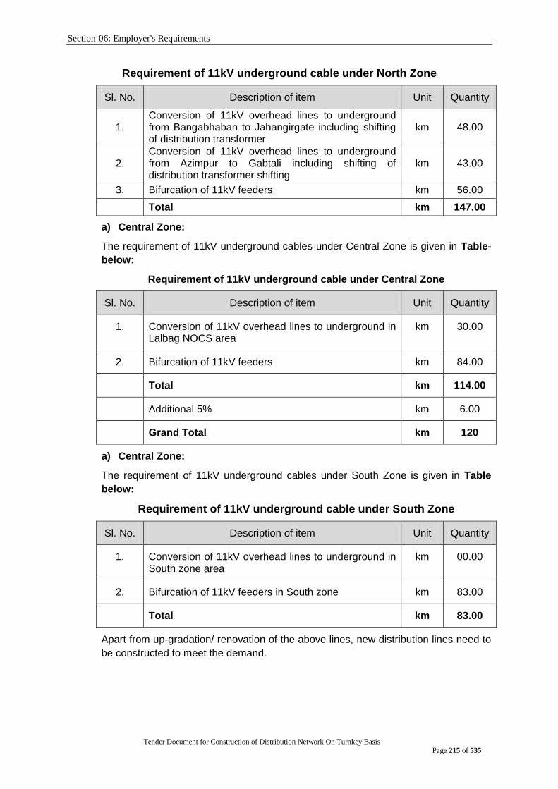
Section-06: Employer's Requirements
Tender Document for Construction of Distribution Network On Turnkey Basis
Page 215 of 535
Requirement of 11kV underground cable under North Zone
Sl. No. Description of item Unit Quantity
1. Conversion of 11kV overhead lines to underground from Bangabhaban to Jahangirgate including shifting of distribution transformer
km 48.00
2. Conversion of 11kV overhead lines to underground from Azimpur to Gabtali including shifting of distribution transformer shifting
km 43.00
3. Bifurcation of 11kV feeders km 56.00
Total km 147.00
a) Central Zone:
The requirement of 11kV underground cables under Central Zone is given in Table-
below:
Requirement of 11kV underground cable under Central Zone
Sl. No. Description of item Unit Quantity
1. Conversion of 11kV overhead lines to underground in Lalbag NOCS area
km 30.00
2. Bifurcation of 11kV feeders km 84.00
Total km 114.00
Additional 5% km 6.00
Grand Total km 120
a) Central Zone:
The requirement of 11kV underground cables under South Zone is given in Table
below:
Requirement of 11kV underground cable under South Zone
Sl. No. Description of item Unit Quantity
1. Conversion of 11kV overhead lines to underground in South zone area
km 00.00
2. Bifurcation of 11kV feeders in South zone km 83.00
Total km 83.00
Apart from up-gradation/ renovation of the above lines, new distribution lines need to
be constructed to meet the demand.

Section-06: Employer's Requirements
Tender Document for Construction of Distribution Network On Turnkey Basis
Page 216 of 535
Annexure C
The manufacturers for the following major items of supply or services must meet the following minimum criteria, herein listed for that item. Failure to comply with this requirement shall result in rejection of the tender proposal. However if more than one manufacturer is proposed for any item and if at least one manufacturer complies with the requirement for that particular item, then the tender proposal will be considered responsive for that particular item.
Item No. Description of Item Minimum Criteria to be met
1. 12 Meter and 15 Meter SPC Pole
At least last seven (7) years‟ experience in manufacturing minimum same or higher rating equipment and in satisfactory service for a minimum of three (3) years as on the date of bid opening.
The manufacturer shall have a minimum production capacity of SPC Pole is 25,00 nos/ annum & shall produce documentary evidence in support of production capacity.
2 12 Meter Steel Pole and 12 M Transformer pole (Steel) with RCC base foundation
At least last seven (7) years‟ experience in manufacturing minimum same or higher rating equipment and in satisfactory service for a minimum of three (3) years as on the date of bid opening.
The manufacturer shall have a minimum production capacity of 12 Meter Steel Pole is 8500 nos/ annum & shall produce documentary evidence in support of production capacity.
Type test reports for offered type pole from a reputed independent testing laboratory or Manufacturer‟s own testing laboratory witnesses by DPDC Engineers/representative of an independent testing laboratory.
3 ACSR Merlin, ACSR DOG (with & without insulation), ACSR GOPHER & AAC WASP Conductor (Insulated)
At least last seven (7) years‟ experience in manufacturing ACSr/AAC conductor and in satisfactory service for a minimum of three (3) years as on the date of bid opening.
The manufacturer shall have a minimum production capacity of ACSR/AAC Conductor is 3000km / annum & shall produce documentary evidence in support of production capacity.
Type Test Reports on offered ACSR Merlin, ACSR DOG ACSR GOPHER & AAC WASP Conductor (Insulated) Conductor. These tests shall be from an independent and well-known testing laboratory like KEMA, CESI, CPRI and BSTI & BUET. Manufacturer‟s Laboratories Type Test Report will be acceptable, if it has ISO 9000 or its equivalent certification from the competent authority, and if such tests are witnessed by an independent inspector;

Section-06: Employer's Requirements
Tender Document for Construction of Distribution Network On Turnkey Basis
Page 217 of 535
Item No. Description of Item Minimum Criteria to be met
4 1CX95 mm2 PVC (Cu) Conductor and 1CX35 mm2 (Cu) bare Conductor
At least last seven (7) years‟ experience in manufacturing of 1CX95 mm2 PVC (Cu) Cable and in satisfactory service for a minimum of three (3) years as on the date of bid opening.
The manufacturer shall have a minimum production capacity of 1CX95 mm2 PVC (Cu) Cable is 60 km / annum & shall produce documentary evidence in support of production capacity.
Type Test Reports on offered 1CX95 mm2 PVC (Cu) Cable. These tests shall be from an independent and well-known testing laboratory like KEMA, CESI, CPRI and BSTI & BUET. Manufacturer‟s Laboratories Type Test Report will be acceptable, if it has ISO 9000 or its equivalent certification from the competent authority, and if such tests are witnessed by an independent inspector;
5 Midspan Joint for Conductor
At least last seven (7) years‟ experience in manufacturing minimum same or higher rating equipment and in satisfactory service for a minimum of three (3) years as on the date of bid opening.
The manufacturer shall have a minimum production capacity of Midspan Joint for Conductor is 4500 nos / annum & shall produce documentary evidence in support of production capacity.
Type Test Reports on offered Mid Span Joint for Conductor.These tests shall be from an independent and well-known testing laboratory like KEMA, CESI, CPRI and BSTI & BUET. Manufacturer‟s Laboratories Type Test Report will be acceptable, if it has ISO 9000 or its equivalent certification from the competent authority, and if such tests are witnessed by an independent inspector.

Section-06: Employer's Requirements
Tender Document for Construction of Distribution Network On Turnkey Basis
Page 218 of 535
Item No. Description of Item Minimum Criteria to be met
6 Conductor jointing material (Crimpit)
At least last seven (7) years‟ experience in manufacturing minimum same or higher rating equipment and in satisfactory service for a minimum of three (3) years as on the date of bid opening.
The manufacturer shall have a minimum production capacity of Crimpit is 1,70,000 nos / annum & shall produce documentary evidence in support of production capacity
Type Test Reports on Crimpit. These tests shall be from BSTI & BUET/KUET/CUET/RUET/DUET etc. Manufacturer‟s Laboratories Type Test Report will be acceptable, if it has ISO 9000 or its equivalent certification from the competent authority, and if such tests are witnessed by an independent inspector.
7 11 kV 3c x 300 mm² XLPE (Cu) U/G and 3c x 120 mm² XLPE (Cu)
At least last seven (7) years‟ experience in manufacturing minimum same or higher rating equipment and in satisfactory service for a minimum of three (3) years as on the date of bid opening.
The manufacturer shall have a minimum production capacity is: 11 kV 3c x 300 mm² XLPE (Cu) U/G or higher voltage higher size is 110 km / annum & shall produce documentary evidence in support of production capacity
Type Test Reports on 11 kV 3x300 mm2 XLPE Cu Cable shall have to be submitted with bid. These tests shall be from an independent and well-known testing laboratory like KEMA, CESI, CPRI, Underwriters Laboratory etc. Manufacturer‟s Laboratories Type Test Report will be acceptable, if it has an ISO 9000 or its equivalent certification from the competent authority, and if such tests are witnessed by an independent inspector.
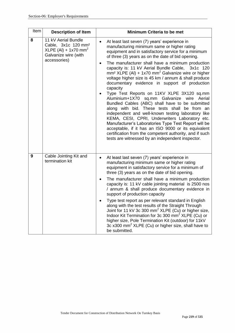
Section-06: Employer's Requirements
Tender Document for Construction of Distribution Network On Turnkey Basis
Page 219 of 535
Item No. Description of Item Minimum Criteria to be met
8 11 kV Aerial Bundle Cable, 3x1c 120 mm² XLPE (Al) + 1x70 mm2 Galvanize wire (with accessories)
At least last seven (7) years‟ experience in manufacturing minimum same or higher rating equipment and in satisfactory service for a minimum of three (3) years as on the date of bid opening.
The manufacturer shall have a minimum production capacity is: 11 kV Aerial Bundle Cable, 3x1c 120 mm² XLPE (Al) + 1x70 mm2 Galvanize wire or higher voltage higher size is 45 km / annum & shall produce documentary evidence in support of production capacity
Type Test Reports on 11KV XLPE 3X120 sq.mm Aluminium+1X70 sq.mm Galvanize wire Aerial Bundled Cables (ABC) shall have to be submitted along with bid. These tests shall be from an independent and well-known testing laboratory like KEMA, CESI, CPRI, Underwriters Laboratory etc. Manufacturer‟s Laboratories Type Test Report will be acceptable, if it has an ISO 9000 or its equivalent certification from the competent authority, and if such tests are witnessed by an independent inspector.
9 Cable Jointing Kit and termination kit
At least last seven (7) years‟ experience in manufacturing minimum same or higher rating equipment in satisfactory service for a minimum of three (3) years as on the date of bid opening.
The manufacturer shall have a minimum production capacity is: 11 kV cable jointing material is 2500 nos / annum & shall produce documentary evidence in support of production capacity
Type test report as per relevant standard in English along with the test results of the Straight Through Joint for 11 kV 3c 300 mm2 XLPE (Cu) or higher size, Indoor Kit Termination for 3c 300 mm2 XLPE (Cu) or higher size, Pole Termination Kit (outdoor) for 11kV 3c x300 mm2 XLPE (Cu) or higher size, shall have to be submitted.
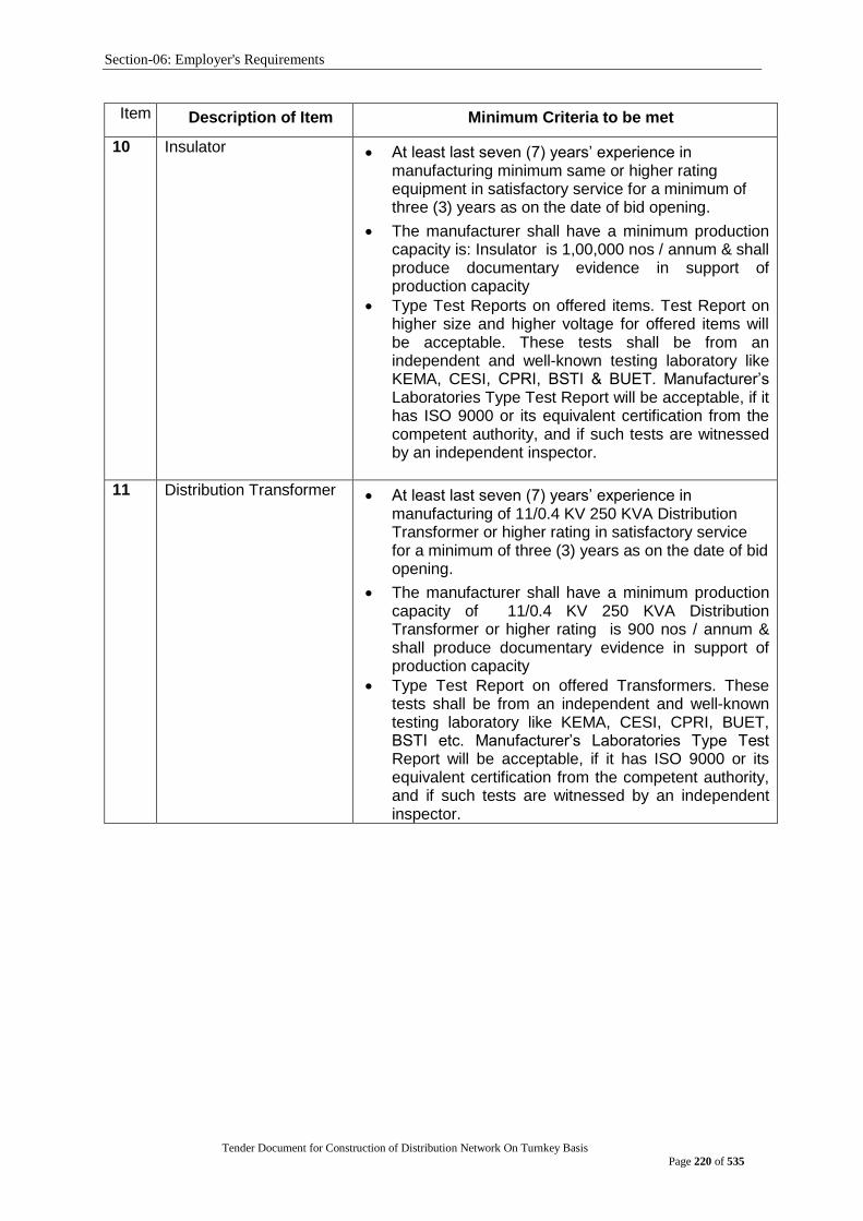
Section-06: Employer's Requirements
Tender Document for Construction of Distribution Network On Turnkey Basis
Page 220 of 535
Item No. Description of Item Minimum Criteria to be met
10 Insulator
At least last seven (7) years‟ experience in manufacturing minimum same or higher rating equipment in satisfactory service for a minimum of three (3) years as on the date of bid opening.
The manufacturer shall have a minimum production capacity is: Insulator is 1,00,000 nos / annum & shall produce documentary evidence in support of production capacity
Type Test Reports on offered items. Test Report on higher size and higher voltage for offered items will be acceptable. These tests shall be from an independent and well-known testing laboratory like KEMA, CESI, CPRI, BSTI & BUET. Manufacturer‟s Laboratories Type Test Report will be acceptable, if it has ISO 9000 or its equivalent certification from the competent authority, and if such tests are witnessed by an independent inspector.
11 Distribution Transformer At least last seven (7) years‟ experience in manufacturing of 11/0.4 KV 250 KVA Distribution Transformer or higher rating in satisfactory service for a minimum of three (3) years as on the date of bid opening.
The manufacturer shall have a minimum production capacity of 11/0.4 KV 250 KVA Distribution Transformer or higher rating is 900 nos / annum & shall produce documentary evidence in support of production capacity
Type Test Report on offered Transformers. These tests shall be from an independent and well-known testing laboratory like KEMA, CESI, CPRI, BUET, BSTI etc. Manufacturer‟s Laboratories Type Test Report will be acceptable, if it has ISO 9000 or its equivalent certification from the competent authority, and if such tests are witnessed by an independent inspector.
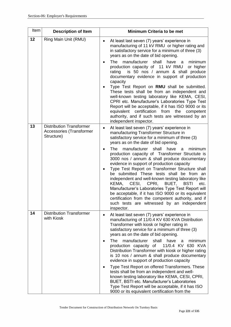
Section-06: Employer's Requirements
Tender Document for Construction of Distribution Network On Turnkey Basis
Page 221 of 535
Item No. Description of Item Minimum Criteria to be met
12 Ring Main Unit (RMU) At least last seven (7) years‟ experience in manufacturing of 11 kV RMU or higher rating and in satisfactory service for a minimum of three (3) years as on the date of bid opening.
The manufacturer shall have a minimum production capacity of 11 kV RMU or higher rating is 50 nos / annum & shall produce documentary evidence in support of production capacity
Type Test Report on RMU shall be submitted. These tests shall be from an independent and well-known testing laboratory like KEMA, CESI, CPRI etc. Manufacturer‟s Laboratories Type Test Report will be acceptable, if it has ISO 9000 or its equivalent certification from the competent authority, and if such tests are witnessed by an independent inspector.
13 Distribution Transformer Accessories (Transformer Structure)
At least last seven (7) years‟ experience in manufacturing Transformer Structure in satisfactory service for a minimum of three (3) years as on the date of bid opening.
The manufacturer shall have a minimum production capacity of Transformer Structute is 3000 nos / annum & shall produce documentary evidence in support of production capacity
Type Test Report on Transformer Structure shall be submitted These tests shall be from an independent and well-known testing laboratory like KEMA, CESI, CPRI, BUET, BSTI etc. Manufacturer‟s Laboratories Type Test Report will be acceptable, if it has ISO 9000 or its equivalent certification from the competent authority, and if such tests are witnessed by an independent inspector.
14 Distribution Transformer with Kiosk
At least last seven (7) years‟ experience in manufacturing of 11/0.4 KV 630 KVA Distribution Transformer with kiosk or higher rating in satisfactory service for a minimum of three (3) years as on the date of bid opening.
The manufacturer shall have a minimum production capacity of 11/0.4 KV 630 KVA Distribution Transformer with kiosk or higher rating is 10 nos / annum & shall produce documentary evidence in support of production capacity
Type Test Report on offered Transformers. These tests shall be from an independent and well-known testing laboratory like KEMA, CESI, CPRI, BUET, BSTI etc. Manufacturer‟s Laboratories Type Test Report will be acceptable, if it has ISO 9000 or its equivalent certification from the
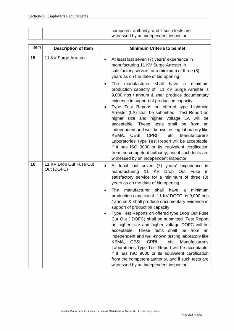
Section-06: Employer's Requirements
Tender Document for Construction of Distribution Network On Turnkey Basis
Page 222 of 535
competent authority, and if such tests are witnessed by an independent inspector.
Item No. Description of Item Minimum Criteria to be met
15 11 KV Surge Arrester At least last seven (7) years‟ experience in
manufacturing 11 KV Surge Arrester in
satisfactory service for a minimum of three (3)
years as on the date of bid opening.
The manufacturer shall have a minimum
production capacity of 11 KV Surge Arrester is
9,000 nos / annum & shall produce documentary
evidence in support of production capacity
Type Test Reports on offered type Lightning
Arrester (LA) shall be submitted. Test Report on
higher size and higher voltage LA will be
acceptable. These tests shall be from an
independent and well-known testing laboratory like
KEMA, CESI, CPRI etc. Manufacturer‟s
Laboratories Type Test Report will be acceptable,
if it has ISO 9000 or its equivalent certification
from the competent authority, and if such tests are
witnessed by an independent inspector;
16 11 KV Drop Out Fuse Cut Out (DOFC)
At least last seven (7) years‟ experience in
manufacturing 11 KV Drop Out Fuse in
satisfactory service for a minimum of three (3)
years as on the date of bid opening.
The manufacturer shall have a minimum
production capacity of 11 KV DOFC is 9,000 nos
/ annum & shall produce documentary evidence in
support of production capacity
Type Test Reports on offered type Drop Out Fuse
Cut Out ( DOFC) shall be submitted. Test Report
on higher size and higher voltage DOFC will be
acceptable. These tests shall be from an
independent and well-known testing laboratory like
KEMA, CESI, CPRI etc. Manufacturer‟s
Laboratories Type Test Report will be acceptable,
if it has ISO 9000 or its equivalent certification
from the competent authority, and if such tests are
witnessed by an independent inspector;
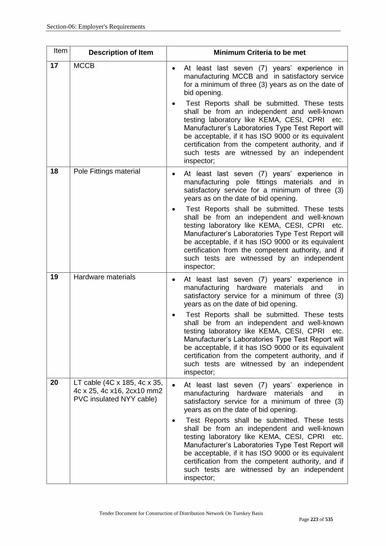
Section-06: Employer's Requirements
Tender Document for Construction of Distribution Network On Turnkey Basis
Page 223 of 535
Item No. Description of Item Minimum Criteria to be met
17 MCCB At least last seven (7) years‟ experience in manufacturing MCCB and in satisfactory service for a minimum of three (3) years as on the date of bid opening.
Test Reports shall be submitted. These tests shall be from an independent and well-known testing laboratory like KEMA, CESI, CPRI etc. Manufacturer‟s Laboratories Type Test Report will be acceptable, if it has ISO 9000 or its equivalent certification from the competent authority, and if such tests are witnessed by an independent inspector;
18 Pole Fittings material At least last seven (7) years‟ experience in manufacturing pole fittings materials and in satisfactory service for a minimum of three (3) years as on the date of bid opening.
Test Reports shall be submitted. These tests shall be from an independent and well-known testing laboratory like KEMA, CESI, CPRI etc. Manufacturer‟s Laboratories Type Test Report will be acceptable, if it has ISO 9000 or its equivalent certification from the competent authority, and if such tests are witnessed by an independent inspector;
19 Hardware materials At least last seven (7) years‟ experience in manufacturing hardware materials and in satisfactory service for a minimum of three (3) years as on the date of bid opening.
Test Reports shall be submitted. These tests shall be from an independent and well-known testing laboratory like KEMA, CESI, CPRI etc. Manufacturer‟s Laboratories Type Test Report will be acceptable, if it has ISO 9000 or its equivalent certification from the competent authority, and if such tests are witnessed by an independent inspector;
20 LT cable (4C x 185, 4c x 35, 4c x 25, 4c x16, 2cx10 mm2 PVC insulated NYY cable)
At least last seven (7) years‟ experience in manufacturing hardware materials and in satisfactory service for a minimum of three (3) years as on the date of bid opening.
Test Reports shall be submitted. These tests shall be from an independent and well-known testing laboratory like KEMA, CESI, CPRI etc. Manufacturer‟s Laboratories Type Test Report will be acceptable, if it has ISO 9000 or its equivalent certification from the competent authority, and if such tests are witnessed by an independent inspector;
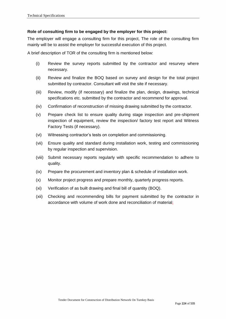
Technical Specifications
Tender Document for Construction of Distribution Network On Turnkey Basis
Page 224 of 535
Role of consulting firm to be engaged by the employer for this project:
The employer will engage a consulting firm for this project, The role of the consulting firm
mainly will be to assist the employer for successful execution of this project.
A brief description of TOR of the consulting firm is mentioned below:
(i) Review the survey reports submitted by the contractor and resurvey where
necessary.
(ii) Review and finalize the BOQ based on survey and design for the total project
submitted by contractor. Consultant will visit the site if necessary.
(iii) Review, modify (if necessary) and finalize the plan, design, drawings, technical
specifications etc. submitted by the contractor and recommend for approval.
(iv) Confirmation of reconstruction of missing drawing submitted by the contractor.
(v) Prepare check list to ensure quality during stage inspection and pre-shipment
inspection of equipment, review the inspection/ factory test report and Witness
Factory Tests (if necessary).
(vi) Witnessing contractor‟s tests on completion and commissioning.
(vii) Ensure quality and standard during installation work, testing and commissioning
by regular inspection and supervision.
(viii) Submit necessary reports regularly with specific recommendation to adhere to
quality.
(ix) Prepare the procurement and inventory plan & schedule of installation work.
(x) Monitor project progress and prepare monthly, quarterly progress reports.
(xi) Verification of as built drawing and final bill of quantity (BOQ).
(xii) Checking and recommending bills for payment submitted by the contractor in
accordance with volume of work done and reconciliation of material;

Technical Specifications
Tender Document for Construction of Distribution Network On Turnkey Basis
Page 225 of 535
Safety and security for stores of this Project The stores of the contractor are to be considered as designated stores of this project. It will
be responsibility of the contractor to ensure full proof Safety and security for stores of this
Project. Full time Armed security guard of required numbers shall be deployed at each store
to ensure the safety and security. Moreover, all stores of this project shall have 24x7 online
CCTV surveillance system.
The stores shall be well designed, built and equipped so that no equipment when kept in the
stores will be subjected to rough weather, improper loading and unloading etc.
Technical Specifications
Tender Document for Construction of Distribution Network On Turnkey Basis
Page 226 of 535
TECHNICAL SPECIFICATIONS
Schedule-A and Schedule-B
Tender Document for Construction of Distribution Network On Turnkey Basis
Page 227 of 535
Technical Specification for Distribution Materials
The Goods and Related Services shall comply with the following Specifications:
1.0 General
Where a Manufacturer‟s Standard or a national Standard equal to or better than the appropriate specified standard has been issued and is acceptable to the Purchaser, any material or equipment supplied shall be manufactured, installed and tested in accordance with the latest revision of the relevant standard unless otherwise specified.
Where any Standard referred to in this Specification has been superseded by a new standard prior to the date of the letter or invitation to tender, the reference shall be deemed to be to such superseding standard.
Deviations from this Specification or standards referred to above shall be given in the Tender and shall be accepted by the Purchaser before contract placement.
The works shall be designed to ensure continuity of service under all working condition at the site as the first consideration and to facilitate inspection, maintenance and repairs. All reasonable precautions shall be taken in the design of equipment and of the works, to ensure the safety of personnel concerned with the operation and maintenance of the works.
All equipment supplied shall be designed and be of such quality as to require the minimum or maintenance during service.
No welding, plugging or filling or defective parts shall be carried out without the prior sanction in writing of the Purchaser.
Corresponding parts of similar equipment, and equipment liable to renewal, shall be fully interchangeable and the Contractor will be required to demonstrate this feature to the Purchaser‟s satisfaction.
All equipment shall operate without under vibration and with the least practical amount of noise.
All equipment shall be designed to minimize corona or other electrical discharges.
All electrical components shall be adequately rated for their most onerous duty and the specified ambient temperature. When equipment is mounted in panels, cubicles etc., due account shall be taken of any heat generated by the equipment therein and the components shall be appropriately selected, rated or de-rated as necessary to suit the most onerous operating temperatures within the enclosure.
2.0 References
The recommendations and tests specified in the standards shall be adhered to. Equivalent standards established or approved in the country of manufacture may be used subject to the Purchasers approval.
It shall be the responsibility of the Contractor to demonstrate to the Purchaser that any proposed National Standard is equal to or superior to the equivalent IEC or BS. All costs for this demonstration are deemed included in the Contractors Tender Prices.

Schedule-A and Schedule-B
Tender Document for Construction of Distribution Network On Turnkey Basis
Page 228 of 535
3.0 Climatic Condition
The offered goods/material must be suitable for working in the climate conditions of Bangladesh as described below:
Altitude : 0-300 meters above the sea level
Maximum ambient temperature : 48C
Minimum ambient temperature : 2C
Humidity : 98%
Mean annual rainfall : 1500-3000 mm
No. of annual rainy days : 80-120 days
Average isokeraunic level : 80-120 days/year
Pollution of ambient air : dust, salt, chemical.
SYSTEM PARTICULARS
SL.
NO. SYSTEM CHARACTERISTICS VOLTAGE LEVEL
1 Normal System Voltage, KV (Voltage Class) 132 33 11
2 Maximum System Voltage, KV 145 36 12
3 System Frequency, Hz 50 50 50
4 Phase Rotation (Anti clockwise) RST RST RST
5 Type of System Grounding Solid
Solid Solid
6 Rated Fault Level (3-Phase Symmetrical), KA 3 sec.
40kA 31.5 kA 31.5 kA
7 Basic Insulation Level, KV 650 170 75
LOW VOLTAGE 415/ 240V CHARACTERISTICS:
8 Normal System Voltage, V 415/240
9 Type of System Grounding Solid
10 System Frequency, Hz 50
11 Number of Phase 3 phase 4 wire
Schedule-A and Schedule-B
Tender Document for Construction of Distribution Network On Turnkey Basis
Page 229 of 535
GROUP A. POLE (SPC/STEEL)
A1: TECHNICAL SPECIFICATIONS OF 15 Meter (550 daN) and 12 METER (450 daN) SPC POLE
The Goods and Related Services shall comply with following Technical Specifications:
1.0 General: The section covers the designs, manufacture, testing, supply and delivery on DPDC store of all the poles and poles fittings along with the lines hardware for the extending and reinforcing the overhead 11/0.4KV distribution Network.
1.1 General Design Condition Factor of Safety: Mínimum factor of safety is 2.5 and these factors shall be obtained under all working loads and conditions. Although all poles shall designs and shall proved by test. Bidders shall demonstrate that their offer has been carefully assessed and that their tendered proposed designs have been fully considered in accordance with the detailed requirements of this specification.
Reference Standards. The Goods and/or Standards referred to in specifications shall govern, in all cases wherever such reference is made, in case of a conflict between such codes and/or Standards and the Specifications, the latter shall govern. Such codes and/or standards, referred to shall mean the latest revisions, amendments/changes adopted and published by the relevant agencies.
Other internationally accepted Standards, which ensure equivalent or better performance than those specified will also, are accepted.
Compliance with specification
Notwithstanding any descriptive literature, drawings or illustrations which may have been submitted with the Tender, all detail other than those shown on the Schedule of Departures will be deemed to be in accordance with the Specification and Standard Specifications and codes referred to in the Specification. A Part from those shown in the Schedule of departures, no departures from the Specification are to be made without written approval of the Engineer.
Design Improvements. The Purchaser or the Supplier may propose changes in the Specification of the equipment or quality thereof and if the parties agree upon any such changes, the specification shall be modified accordingly.
Schedule-A and Schedule-B
Tender Document for Construction of Distribution Network On Turnkey Basis
Page 230 of 535
Designs Unless stated to the contrary in the Tender, together with a full supporting explanation, the Supplier/Manufacturer will be deemed to have accepted that the design and layout of the works are sufficient to ensure reliable and safe operation and freedom from under stressed. The Contract is to include the whole of the Works, which are described in or implied by the Contract Documents. Any items omitted from the Contract Documents, which are obviously necessary for the efficiency and correct operation of the works, shall be deemed to be included in the Contract price.
Suppliers/Manufacturers Responsibility The Supplier/Manufacturer is to familiarize himself with the Tender document, particularly in regard to the Conditions of contract and Supplier‟s responsibility.
1.2 Regulations, Standards, etc. Units of Measurement In all correspondence, in all technical schedules and on all drawings, Metric units of measurement (System International) shall exclusively be in degrees, with 90 degrees comprising one right angle.
International Standards All Poles under this Specification shall conform to the latest editions of IEC or equivalent Standard unless and otherwise stated herein. Poles offered from a country where the relevant standards to which the Poles and or Pole fittings better than IEC these are acceptable but appropriate standards must be quoted in the documents. Full details of references, which affect the design or performance of Poles, shall be stated in the Tender.
Special Conditions Poles supplied under this contract will be installed in tropical locations, which can be considered hostile to its proper operation. Particular problems, which shall receive special consideration, relate to operation in a hot humid environment, and the presence of insects and vermin.
Particulars and Guarantees
Tenderers shall furnish full technical information and set out all particulars required in the schedules. Drawings of all components shall be provided together with the Poles Fittings type & reference number to ensure their identification. Before the Engineer will issue approval of shipment, the manufacturer will be required to supply type test certificates and individual certificates for all goods supplied to testify that the goods comply with the applicable standards. If the test proves unsatisfactory, approval of shipment will not be issue
Schedule-A and Schedule-B
Tender Document for Construction of Distribution Network On Turnkey Basis
Page 231 of 535
1.3 Technical Specification for SPC Poles. This specification includes the design, manufacture, testing and delivery to Site of Spun Pre-stressed Concrete (SPC) poles.
The design working loads for the poles are specified in this specification.
The Supplier is responsible for calculations necessary to establish the cross-sectional dimensions of the poles and the required reinforcing so that the poles can resist the specified working loading in accordance with various requirements set out in this specification. The person responsible for such calculations shall be experienced in the structural use of concrete in general and in the design of pre-stressed concrete poles in particular.
Standards
The poles specified herein shall conform to the latest version of the appropriate recognized international standards. In particular: BS 8110 : 1985 Structural use of concrete, parts 1 and 2
BS 4449 Specification for hot rolled steel bars for the reinforcement of concrete.
BS 1881 Methods of Testing of Concrete
BS 812 Testing of Aggregates.
ASTM C39 Test Method for Compressive Strength of Cylindrical Concrete Specimens.
BS 12 Specification for Ordinary and Rapid Hardening Portland Cement. Specification for concrete Admixtures.
BS 5075 Specification for High Tensile Steel wire and strand for Pre-stressing of Concrete.
BS 5750 : 1979 Quality System.
Inspection and Testing
A representative team appointed by the Engineers of DPDC will inspect the manufactured items at the manufacturer‟s plant.
Tests shall be performed in accordance with the relevant standards unless otherwise specified in this specification.
Definitions and Abbreviations The following definitions and abbreviations apply to this Specification

Schedule-A and Schedule-B
Tender Document for Construction of Distribution Network On Turnkey Basis
Page 232 of 535
Definitions Failure Inability of the pole when under test to support further load or when
deformation or cracking of the pole renders it unserviceable.
Longitudinal Direction
The horizontal direction parallel to the run of the conductors.
Transverse Direction The horizontal direction at right angles to the fun of the conductors.
Ultimate The strength at which the pole will not accept any furthers applied force or when deformation or cracking of the pole renders it unserviceable.
Tendon Means any pre-stressing wire conforming to technical specification as described in this section or any discrete group of such wires stressed in one operation.
Abbreviation A.S.T.M. American Society for Testing and Materials.
B.S British Standard
Mpa Mega Pascal = 1N/sq. mm
1.4 Materials General All materials shall conform to the relevant standard specifications referred to in this Specification. Reinforcing Steel, pre-stressing steel and cement shall be new and undamaged. Aggregates for manufacturing concrete shall be clean and of their best respective kinds. Any materials found to be defective will be rejected by the Engineer and replaced with approved materials by the Supplier at his own expense.
Manufacturer‟s test certificates for all reinforcing and pre-stressing steel shall be supplied to the Engineer. These test certificates shall show compliance with the relevant Standard Specification in all respects and shall be issued by an independent testing laboratory acceptable to the Engineer. If the manufacturer‟s test certificates are not available and if the Engineer requires it then the Supplier is responsible for arranging all testing requested by the engineer.
The test information so obtained must be sufficient to satisfy the Engineer that the item being tested conforms to the relevant Standard Specification.
The Supplier shall allow for the cost of all such testing in his Tender price.
Reinforcing Steel
All reinforcing bars shall comply with B.S 4449. They shall have a minimum yield stress of 275 MPa (2800kg/cm).
Any longitudinal reinforcing bars shall have a deformed profile (surface of bar provided with lugs or protrusions). All reinforcing bars used to form ties or stirrups shall have a plain round profile only.
Schedule-A and Schedule-B
Tender Document for Construction of Distribution Network On Turnkey Basis
Page 233 of 535
Pre-stressing Steel
Pre-stressing steel shall be indented, cold drawn, low relaxation class stress relieved high tensile wire or 7-wire strand to B. S. 5869/1980 with a minimum diameter of 5mm. The steel shall have a minimum ultimate tensile stress of 1650 Mpa and a minimum 0.2% proof stress of 1400 Mpa. The 1000 hr relaxation at 70% initial stress shall be 2% maximum.
Cement
Cement shall be Ordinary Portland or Rapid Hardening, Portland complying with BS 12. Other cement types can be used only after receiving the Engineer‟s approval in writing.
Aggregates
Fine aggregate (sand) shall consist of clean material or manufactured sands and coarse aggregate shall consist of clean gravel, crused gravel, or crused stone. The maximum nominal size of the coarse aggregates shall be 10mm to 12mm. Both the fine and coarse aggregates shall comply with the requirements of BS 812.
Prohibited Aggregate Coming from feldspathic or schistous rock
Containing charcoal or their residue such as coke, ashes, clinkers, finders.
Brick Sulfate and sulfide must be in such quantities that the whole proportion, in sulfur trioxide, be less than 1 percent of the mass. Aggregates, which are dredged from the sea, shall be washed in fresh water before use.
Water
All water used for mixing of concrete shall clean and free of any dissolved or un-dissolved impurities likely to be harmful to the cement, aggregate or the steel reinforcement. The use of seawater is prohibited. The water shall contain less than:
2000 ppm of suspended matter
1500 ppm of dissolved SALT
Admixtures
No admixtures shall be added to the concrete mix unless the perior approval of the engineer has been obtained in writing. Under no circumstances shall calcium chloride or any admixtures containing calcium chloride be permitted in the concrete used to manufacture the pre-stressed concrete poles. All admixtures shall comply with BS 5075. Approval by the Engineer of the use of any admixtures shall in no way relieve the Supplier and his supplier of their responsibility in regard to a production in quality or durability of the concrete used in the manufacture of poles.
Form Release agent
All form of work shall be coated with a suitable form release agent. Under no circumstances shall waste engine oil or any other oil, which will affect the finished appearance of the pole, be used. Forms shall be coated before fixing in their final position and the release agent shall not come in contact with any reinforcing steel, pre-stressing steel or embedded items.
Coverage must be complete and uniform and any excess shall be removed from the lower section of the forms before placing and concrete.
Schedule-A and Schedule-B
Tender Document for Construction of Distribution Network On Turnkey Basis
Page 234 of 535
1.5 Storage and Protection of Materials
Cement
Cement shall be stored in a suitable weather tight enclosure on a board platform raised off the ground. The enclosure should be such that free circulation of air around the bags of cement is kept to minimum.
Any cement that has become damp, caked or lumpy shall not be used. Concrete bathing operations shall be organized that cement that has been longest at the place of manufacture of the poles is used first.
Aggregates
Both fine and coarse aggregates shall be stored so that they are kept clean and free from contamination and are not subjected to segregation. Where a clean hard surface is not a violable for the stockpiles the bottom 150 mm of the aggregate piles, which are in contact with the ground, shall not be used.
Reinforcing Steel
All reinforcing shall be stored in a clean dry place on platforms off the ground. Grease, oil, paint over any other substance that will effect the bond of the reinforcement shall not be allow to come in contact with it. If it does then all such substances shall be cleaned off the reinforcement before it is placed in the whole moulds.
Pre-stressing Steel
All pre-stressing tendons shall be stored in a clean dry place off the ground and must be kept dry at all times. All loose surface rust, and protective oil, or other contaminants that will effect the bond of the tendons shall be thoroughly removed before installing them in the pole moulds. Any part of the tendons that have become pitted, have any tears or nicks, or are permanently deformed or otherwise damaged shall be discarded.
If necessary, they Engineer shall instruct the Supplier to have sufficient mechanical tests carried out on the tendons to ensure that their strength has not been impaired in any way.
1.6 Reinforcement and Pre-stressing Steel Installation
Covers
The cover from the outermost reinforcing and/or pre-stressing steel to the nearest permanent surface of the concrete member, including the surface of holes cast in the member, shall be not less than 20mm, except for spun cast poles this minimum cover may be reduced to 12mm. Holes cast using UPVC sleeves permanently adhered to this concrete surface may have a cover of 5mm minimum to the surface of concrete protected by the UPVC sleeve.
All steel shall accurately place and shall be held in position during manufacture. Bar chairs shall be made of non-corrosive and impervious material.
Pre-stressing tendons shall pass through rigidly held guide plates at the ends of members to maintain the minimum covers.
Spacing.
The clear spacing between two parallel reinforcing bars of pre-stressing tendons shall be at least equal to the nominal bar diameter, 1.33 times the minimum nominal size of the aggregate or 10mm.
Tendons can be placed with different spacing to the above and in bundles provided that test results show satisfactory ultimate behavior with respect to:
i. Compression and tension stresses in the tendon anchorage zone.

Schedule-A and Schedule-B
Tender Document for Construction of Distribution Network On Turnkey Basis
Page 235 of 535
ii. Spelling of concrete. iii. Anchorage of pre-tensioned tendons. iv. Avoidance of corrosion of tendons at the end of the element. v. Placing the concrete between tendons and compaction of concrete around tendons.
Stirrups and Ties.
Bends in stirrups and ties shall have a diameter on the inside of the bar not less than the enclosure bar or 2 times the diameter of the stirrups or tie, whichever is the greater.
The ends of the stirrups ties shall be anchored with a minimum of 90 deg. Bend plus a straight extension of 8 bar diameter but not less than 65mm. They shall be firmly attached to the supporting tendons/reinforcement using soft wire ties.
Welding
Welding or Tack-welding of reinforcement or pre-stressing tendons will not be permitted.
Pre-stress in Tendon Stressing.
All stressing operations shall be carried out under the direct supervision of a person who is thoroughly experienced with all aspects pre-tensioned pre-stressed concrete construction.
The stressing procedure adopted shall ensure that the force in a tendon increases at reasonably constant rate. After stressing and anchoring, the force in a tendon shall be the initial force specified on the manufacturing drawings. During stressing the maximum force applied to a tendon shall not exceed 0.75 times its ultimate tensile strength.
The required amount of pre-stressing forced shall be measured by both tendon elongation and jack force and pressure. If the two measurements differ by more than 5 percent, the cause shall be ascertained and the appropriate corrections made.
Tendon elongation shall be calculated from the actual load/elongation gaps supplied by the steel manufacturer and where appropriate anchorage draw-in shall be accurately assessed and allowed for. A correction shall be applied to the total elongation observed to compensate for any initial and slackness.
Jack and anchorage friction shall be assessed and an appropriate correction made to the jacking pressure.
Records shall be kept off all stressing operations they shall include.
a) Amount of Tendon elongation up to the stage of anchoring the tendon. b) Allowance for anchorage draw-in. c) Jack force at anchorage. d) Allowance of jack friction. e) Manufacturer‟s identification for pre-stressing tendons used. f) Date and time stressing. g) Date and time of de-stressing. h) Curing sequence and concrete strength at time of de-stressing. i) Identification mark placed on each particular pole.
Time jacking force shall be measured to an accuracy of 0.025 times the pre-stressing force and the tendon elongation to an accuracy of 2mm.
Safety precautions during and after all stressing operations shall be taken to safeguard persons from injury and equipment from damage, which, may be caused by the sudden release of stored energy in the stressing system and tendons.
Schedule-A and Schedule-B
Tender Document for Construction of Distribution Network On Turnkey Basis
Page 236 of 535
If the tendons are stressed then; left for more than 2(two) weeks before being fully surrounded with concrete, they shall be removed from the moulds and discarded.
Pre-stressing equipment shall be maintained in a serviceable condition and its calibration and accuracy checked at least every 3 months.
Distressing.
The transfer of pre-stressed in to the harden concrete shall take place gradually and in such a determined order that tensile stresses sufficient to cause cracking are not induced in the concrete. Immediately after distressing, the minimum stress in the tendons shall not exceed 0.70 the ultimate tensile stress of those tendons.
If all the tendons are not to be released simultaneously than the releasing sequence shall be shown on the manufacturer‟s drawings.
Any releasing device shall be so designed that during the period between stressing and distressing, the tension in the pre-stressing tendons does not alter. It shall also be designed so that there is no increase in the stress in the tendons above the stress in the tendons just prior to distressing.
Cutting and Finishing Tendons.
After distressing is completed the ends of the tendons shall be cut off flush with the surface of the concrete.
If flame cutting is used, there shall be an excess of oxygen in the flame and the cutting shall take place as rapidly as possible.
The ends of the poles shall be coated with coal tar pitch epoxy paint after flush trimming the tendons.
1.7 Mixing, Placing and Curing Concrete.
Mix Design.
Full details of the components forming the concrete mix proposed to be used by the supplier/manufacturer shall be submitted to the engineer for his assessment at least 2(two) weeks before any concreting operations are commenced. Once the Engineer has approved the proposed mix, it shall not be varied by the supplier/manufacturer unless the Engineer‟s re-approval has been obtained. The concrete mix shall be designed and tested and their submission shall include the following information.
a) Source, nature and grading of both the fine and coarse aggregates. b) Type and supplier/manufacturer of the cement to be used. c) Protection by weight of both the fine and coarse aggregates. d) Weight of cement per cubic meter of concrete. e) Water-cement ration by weight. f) Estimated slump of the mix. g) Arithmetic mean compression strength of the mix at 7(seven) days and 28 (twenty
eight) days using cylinder compression test sample plus the standard deviation of the test strengths and the number of cylinders tested.
Any admixture specified for inclusion in the concrete mixes or that the supplier/manufacturer intends to use in his mixes (and they have had the prior approval of the Engineer) shall be included in this trial mixes.

Schedule-A and Schedule-B
Tender Document for Construction of Distribution Network On Turnkey Basis
Page 237 of 535
The ratio of weight of the fine aggregates (sand) to the total weight of aggregates shall be between 0.35 to 0.50. The minimum cement content shall be 400 kg/cub.m and the maximum water cement ration by weight shall be 0.45.
The supplier/manufacturer shall allow for the cost of all such testing in his tender as swell as any further testing and additional reporting that the engineer may required.
Mixing of Concrete.
All concrete shall be mixed in power driven mixers and the concrete making materials shall be accurately measured to ensure the production of uniform batches of concrete. Volume and the proportions in each batch adjusted to suit whole bags of cement may measure the materials. Only full-unbroken bags of cement may be used. Bags of cement which have practically set, contain any lumps, or have become wet any stage shall not be used.
Volume measurement shall be carried out using well-proportioned gauge boxes. Under no circumstances will shovels proportion the volumes. The gauge boxes shall be loose filled with the materials being measured then struck off level with a straight edge then discharges in to the mixer. The required volume of mixing water shall be adjusted to allow for the free moisture contained in the aggregates.
Personnel of in charge of the concrete mixing operations shall be trained and experienced in this method of concrete production.
All concrete shall be mixed for minimum of 1-1/2 minutes from the time the last of the materials have been placed in the mixing drum. The mixing shall continue until the materials are thoroughly and uniformly mixed and the concrete is uniform in color and texture. The entire batch must be discharged from the mixer before recharging commences. Each batch of the concrete shall have a similar appearance.
Conveying and placement of concrete.
Concrete shall be conveyed from the mixer to moulds by a method that prevents segregation or loss of the ingredients. It shall be placed as nearly practicable in its final position to avoid segregation due to re-handling of flowing.
Placement of concrete shall be at such a rate that the concrete is at all times plastic and flows readily into the spaces between the reinforcement. No concrete which has practically hardened or been contaminated by foreign materials shall be deposited in the moulds, nor shall be-tempered concrete or concrete that has been re-mixed after initial set be used.
The placement of concrete in the moulds shall be completed within ½ hour after the introduction of the mixing water to the cement and the aggregates in the concrete mixer. Each mould shall be filled with concrete as a continuous operation. Construction joint will not be permitted in the poles. Should there be an interruption during the placement of concrete into a mould such that initial set occurs to the deposited concrete then that pole shall be discarded.
Consolidation of Concrete.
All concrete shall be consolidated in the moulds using high frequency internal or external vibrators. The amount of vibrations shall be uniform along the length of the mould and shall be carefully controlled so that adequate consolidation of the concrete is achieved without causing segregation of the mix ingredients by over vibrations. Particular attention should be given to achieving adequate consolidation at the ends of the pre-stressed concrete poles to improve the bond between pre-stressing tendons and concrete.
If using external vibrators, they shall be rigidly clamped to the framework before commencing vibration and the concrete shall be placed in layers of suitable depth and vibrated sufficiently to expel all air before the next layer of concrete is placed.
Schedule-A and Schedule-B
Tender Document for Construction of Distribution Network On Turnkey Basis
Page 238 of 535
Protection and Curing Concrete
During the initial stage of hardening the concrete shall be protected from the direct rays of the sun and from drying winds. The moulds containing the hardened concrete shall not be disturbed or shifted unless it can be shown that such movements will not impart any damaging stress to the hardening concrete.
All concrete shall be cured in an area that ensures it stays saturated or nearly saturated during the curing period.
a) Moist Curing at Ambient Temperature. All surface of pole exposed to the atmosphere shall be constantly wet or damp for at least 7(seven) days after casting. Concrete manufactured from rapid hardening Portland cement shall be moist cured for at least 4(four) days.
b) Curing at Elevated Temperature.
Curing at elevated temperature is permitted subject to the following precaution.
i. Adequate means shall e provided to prevent moisture loss from the concrete from
the time to time of initial set to the end of the elevated temperature curing cycle.
ii. An initial maturing period shall be allowed after casting the concrete and before any increase above ambient temperature begins. This maturing period shall be measured from the time of completion of casting and shall be such that the product of time and ambient temperature at the place of casting the concrete is not less than 40 deg. C hours (e.g. 2 hours at 20 deg. C to 40 deg. C, hours). During this maturity period the surface of the concrete mass shall not exceed 30 deg. C.
iii. All pins used to form holes in the pole and other figments, which pass through the mould, and concrete shall be withdrawn to prevent damage to the concrete caused by differential expansion between the mould and the concrete.
iv. After the maturity period the heat may be introduced to the concrete at a rate that limits the temperature rise to a maximum of 24 deg. C hours. Under no circumstances shall the temperature rise during any 15 minutes period exceeds 6 deg. C.
v. The maximum temperature during the cycle shall not exceed 75 deg. C.
vi. The rate of cooling of the concrete and the removal of any steam covers, blankets, etc. shall be controlled to prevent any damage due to thermal shock or differential cooling.
vii. The heat source shall be well distributed to ensure that a uniform temperature distribution exists in the concrete and that no local overheating occurs to the concrete mass, the pre-casting moulds or to any test specimens.
Concrete test specimens shall be cured in exactly the same manner as the concrete poles. Temperature records shall be dept of the following.
i. The temperature during the initial maturing period. ii. At ½ hourly intervals during the temperature rise period.

Schedule-A and Schedule-B
Tender Document for Construction of Distribution Network On Turnkey Basis
Page 239 of 535
iii. At 3 hourly intervals during the maximum constant temperature period and at the end of this period after shirring off the heat source.
Elevated temperature cured concrete poles shall be moist cured for a further 4 days at ambient temperatures. During this period, all surface of the pole exposed to the atmosphere shall be kept constantly wet or dump.
The elevated temperature curing method chosen shall produce concrete with along term strength and durability at least equivalent to concrete, which has been moist curing at ambient temperatures.
1.8 Concrete Sampling and Testing.
Slump Test These shall be taken during all concrete placing operations. Any batch of concrete whose slump exceeds the value submitted with the mix design (as described earlier) by more than 25% or 25mm, which ever is the greater, shall be rejected and not placed in the moulds.
Slump test shall be carried out in accordance with BS 1881.
Compression strength samples. Samples for compression strength test shall be moulded in either 150mm cubes, 100mm diameter x 200mm high cylinders or 150mm diameter x 300mm high cylinders for the purposes of this specification to convert from cylindrical strength to cube strength divide the cylinder strength by the following factors:
Cylinder Strength Conversion Factor
15 Mpa and less 0.77
20 Mpa 0.82
25 Mpa 0.86
30 Mpa and more 0.91
A sample shall consist of 4 cubes of cylinder made concurrently from the same batch of concrete two (2) of the cubes of cylinders shall be used to establish the 28 days compression strength and two (2) of the cubes of cylinders shall be used to establish the rate of gain in strength of concrete before distressing the tendons (as described earlier).
All samples shall be taken moulded and cured in accordance with the procedures ib BS 1881 except that cylinders or cubes taken to check the rate of gain of compression strength before 28 days shall be cured in the same manner as the concrete poles from which the samples are taken.
A random sampling procedure shall be adopt and the minimum frequency of sampling of the concrete shall be 1(one) per 20 poles, which ever the greater number of samples but not less than 1(one) sample per day.
All samples shall be marked with the sampling date and an appropriate identification mark.
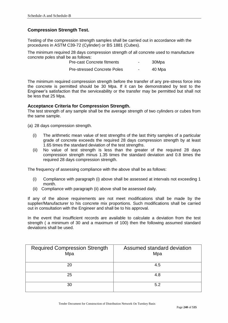
Schedule-A and Schedule-B
Tender Document for Construction of Distribution Network On Turnkey Basis
Page 240 of 535
Compression Strength Test. Testing of the compression strength samples shall be carried out in accordance with the procedures in ASTM C39-72 (Cylinder) or BS 1881 (Cubes).
The minimum required 28 days compression strength of all concrete used to manufacture concrete poles shall be as follows:
Pre-cast Concrete fitments - 30Mpa
Pre-stressed Concrete Poles - 40 Mpa
The minimum required compression strength before the transfer of any pre-stress force into the concrete is permitted should be 30 Mpa. If it can be demonstrated by test to the Engineer‟s satisfaction that the serviceability or the transfer may be permitted but shall not be less that 25 Mpa.
Acceptance Criteria for Compression Strength. The test strength of any sample shall be the average strength of two cylinders or cubes from the same sample.
(a) 28 days compression strength.
(i) The arithmetic mean value of test strengths of the last thirty samples of a particular grade of concrete exceeds the required 28 days compression strength by at least 1.65 times the standard deviation of the test strengths.
(ii) No value of test strength is less than the greater of the required 28 days compression strength minus 1.35 times the standard deviation and 0.8 times the required 28 days compression strength.
The frequency of assessing compliance with the above shall be as follows:
(i) Compliance with paragraph (i) above shall be assessed at intervals not exceeding 1
month. (ii) Compliance with paragraph (ii) above shall be assessed daily.
If any of the above requirements are not meet modifications shall be made by the supplier/Manufacturer to his concrete mix proportions. Such modifications shall be carried out in consultation with the Engineer and shall be to his approval. In the event that insufficient records are available to calculate a deviation from the test strength ( a minimum of 30 and a maximum of 100) then the following assumed standard deviations shall be used.
Required Compression Strength Mpa
Assumed standard deviation Mpa
20 4.5
25 4.8
30 5.2

Schedule-A and Schedule-B
Tender Document for Construction of Distribution Network On Turnkey Basis
Page 241 of 535
The calculated standard deviation shall be brought up to date after every change of mix design and at least once a month. a) Compression Strength to Measure early Strength Gain. Where samples are taken to measure the early strength gain of the concrete then the concrete shall be considered acceptable it the average strength of at least two cylinders or cubes exceeding any one specimen is not less than 0.85 times the required early compression strength. If any of the above requirements are not met then the transfer or pre-stress or the application of loading to the poles shall be delayed until the required early compression strength has been obtained. A Schmidt rebound hammer can be used to monitor such additional strength gain provided it has been properly calibrated beforehand.
Cost of Testing The supplier/manufacturer shall bear the cost of all testing necessary for concrete production control. This shall include where necessary or instructed by the Engineer, testing of all the components used to manufacturer the concrete to ensure they conform to the relevant BS standards. All such testing shall be carried out in an approved independent testing laboratory unless otherwise approved by the Engineer.
Pole moulds and Surface Finishes.
Moulds shall be designed, constructed and finished to ensure that they can be removed without damaging the hardened concrete, and they shall be securely braced and supported to prevent sagging and bulging during the deposition of the concrete. Joints in the materials used to manufacture the mould shall be tight and shall not permit any leakage of cement paste from the concrete mix. Adjacent faces of each joint shall be accurately aligned to prevent steps being formed in the finished surface of the pole. Holes in the walls of the moulds used for retaining pins, which from bolt holes in the finished poles shall be provided with flexible sales or some similar means to prevent the loss of any cement paste from the concrete mix.
If elevated temperature curing of the concrete is to be employed with the moulds in place around the hardened concrete then changes in cross-section of the moulds shall be carefully detailed to ensure that differential expansion between the mould and the hardened concrete does not cause any damage of cracking of the concrete reasonable profit shall be determined by the Purchaser‟s representative in accordance with the provisions of Sub-Clause 3.5 and shall be added to the Contract Price.
If, for reasons not attributable to the Contractor, a Test after Completion on the Works or any Section cannot be completed during the contract Period (or any other period agreed upon by the Purchaser and the Contractor), then the works or such Section shall be deemed to have passed such Test after Completion.
Re-testing
If the works, or a Section, fail to pass the Tests after Completion, the Purchaser or the Contractor may require such failed Tests, and the Tests after Completion on any related work, to be repeated under the same terms and conditions. If such failure and re-testing result from default of the contractor and cause the Purchaser to incur additional costs, such costs shall be recoverable from the Contractor by the Purchaser, and may be deducted by the Purchaser from any monies due, or to become due, to the Contractor.

Schedule-A and Schedule-B
Tender Document for Construction of Distribution Network On Turnkey Basis
Page 242 of 535
Failure to Pass tests after Completion
If the following conditions apply, namely:
(a) the Works, or a section, fail to pass any or all of the Tests after Completion, (b) The relevant sum payable as liquidated damages for such failure is stated (or its
method of calculation is defined) in the Appendix to Tender, and (c) the contractor pays such relevant sum to the Purchaser during the Contract Period,
Then the Works or such section shall be deemed to have passed such Tests after completion.
If the works, or a Section, fail to pass a Test after completion and the Contractor in consequence proposes to make any adjustment or modification thereto, the Purchaser does not wish such adjustment or modification to be made until a time that the convenient to the Purchaser. In such event, the Contractor shall remain liable to carry out the adjustment or modification, and to satisfy such Test within a reasonable time of being notified to do so by the Purchaser‟s Representative. If, however, the Purchaser‟s Representative fails to give any such notice during the Contract Period, the Contractor shall be relieved of any such obligation and the Works or Section (as the case may be) shall be deemed to have passed such Test after completion.
If the Contractor incurs additional cost as a result of any unreasonable delay by the Purchaser in permitting access to the Works or Plant by the Contractor, either to investigate the causes of failure to pass a Test after Completion, or to carry out any adjustments or modifications, then the Contractor shall be paid the additional cost, plus reasonable profit, caused by such delay.
Lifting and Handling
Poles shall not be lifted or handled until the concrete has attained strength of not less than twice the stress induced by the methods of handling and lifting.
The designer shall show on the construction drawings and the manufacturer shall show on the poles the points at which the poles are to be fitted and supported and only these points shall be used for lifting and supporting during manufacture and stockpiling. When stacked in stockpiles, timber bearers placed between each unit at shall separate each pole or adjacent to the designated lifting points. Timber, bearers shall be placedonly on lines vertically above each other.
1.9 Pole Length, Shape and Design Loading.
General
Included in the tender documents are schedules detailing the total number of each class of pole to be supplied under this contract and the required numbers that are to be delivered to the locations nominated in the schedule.
Pole Length and Shape
The standard overall length of poles manufactured under this contract shall be of 15 Meter and 12 Meters
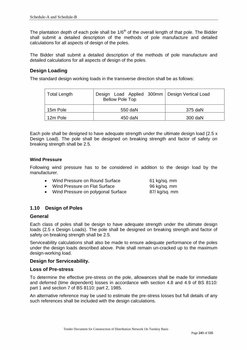
Schedule-A and Schedule-B
Tender Document for Construction of Distribution Network On Turnkey Basis
Page 243 of 535
The plantation depth of each pole shall be 1/6th of the overall length of that pole. The Bidder shall submit a detailed description of the methods of pole manufacture and detailed calculations for all aspects of design of the poles.
The Bidder shall submit a detailed description of the methods of pole manufacture and detailed calculations for all aspects of design of the poles.
Design Loading
The standard design working loads in the transverse direction shall be as follows:
Total Length Design Load Applied 300mm Bellow Pole Top
Design Vertical Load
15m Pole 550 daN 375 daN
12m Pole 450 daN 300 daN
Each pole shall be designed to have adequate strength under the ultimate design load (2.5 x Design Load). The pole shall be designed on breaking strength and factor of safety on breaking strength shall be 2.5.
Wind Pressure
Following wind pressure has to be considered in addition to the design load by the manufacturer.
Wind Pressure on Round Surface 61 kg/sq. mm
Wind Pressure on Flat Surface 96 kg/sq. mm
Wind Pressure on polygonal Surface 87/ kg/sq. mm
1.10 Design of Poles
General
Each class of poles shall be design to have adequate strength under the ultimate design loads (2.5 x Design Loads). The pole shall be designed on breaking strength and factor of safety on breaking strength shall be 2.5.
Serviceability calculations shall also be made to ensure adequate performance of the poles under the design loads described above. Pole shall remain un-cracked up to the maximum design-working load.
Design for Serviceability.
Loss of Pre-stress
To determine the effective pre-stress on the pole, allowances shall be made for immediate and deferred (time dependent) losses in accordance with section 4.8 and 4.9 of BS 8110: part 1 and section 7 of BS 8110: part 2, 1985.
An alternative reference may be used to estimate the pre-stress losses but full details of any such references shall be included with the design calculations.

Schedule-A and Schedule-B
Tender Document for Construction of Distribution Network On Turnkey Basis
Page 244 of 535
Permissible Concrete Stresses
The following are the maximum permissible concrete stresses allowed in the pre-stressed concrete poles when subjected to normal handling loads and loading up to the design working loads. When assessing the stress due to handling, transportation, and erection the actual strength of the concrete at the time of handling shall be substituted in the following formulae, if less than the 28 days cylinder compression strength.
(a) Comprehensive stress
Cube Cylinder
At transfer 0.55 f‟ci 0.6 f‟ ci
After allowing for all Pre-stressed losses 0.55 f‟c 0.55 f‟c
Where f‟ ci = Compression strength at transfer.
c = 28 days compression strength.
refer to clause 3.7.3 for specified concrete strength.
(b) Tensile Stress
Cube Cylinder
Immediately after transfer 0.45 sqr. f‟ci 0.5 sqr. f‟ ci
After allowing for all Pre-stressed losses 0.45 sqr. f‟ci 0.5 sqr. f‟c
Permissible Tendon stresses
Immediately after transfer of tendon forces in to the concrete the maximum permissible tension in the pre-stressing steel shall not exceed 0.70 x ultimate tensile stress of the pre-stressing steel.
Ultimate Strength Design
The ability of a cross section of any part of a pole to be able to resist the internal stresses generated by the design ultimate loads shall be calculated using the ultimate strength design method.
For pre-stressed concrete poles, the methods detailed in BS 8110: part 1, 1985 shall be
used.
Allowance may be made for any un-tensioned longitudinal reinforcing steel when calculating the effective ultimate strength of the pole.
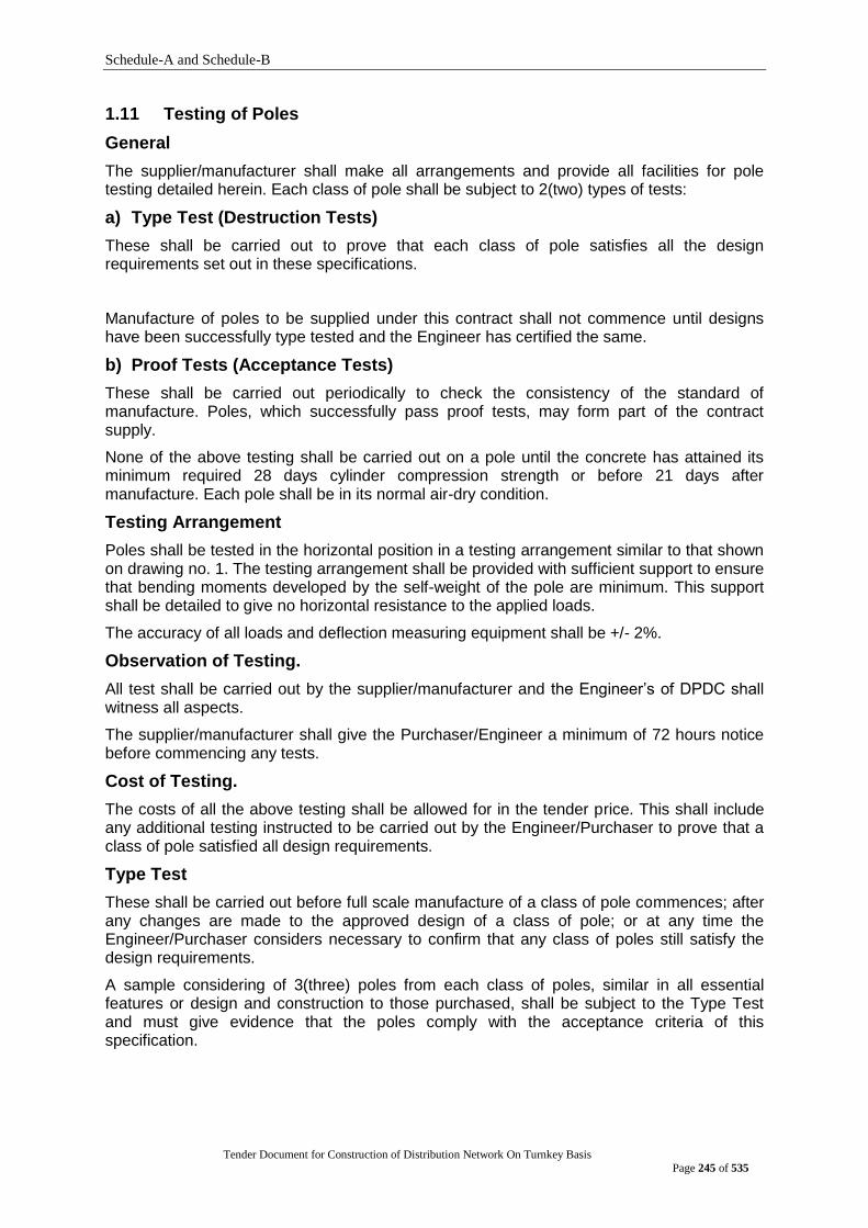
Schedule-A and Schedule-B
Tender Document for Construction of Distribution Network On Turnkey Basis
Page 245 of 535
1.11 Testing of Poles
General
The supplier/manufacturer shall make all arrangements and provide all facilities for pole testing detailed herein. Each class of pole shall be subject to 2(two) types of tests:
a) Type Test (Destruction Tests)
These shall be carried out to prove that each class of pole satisfies all the design requirements set out in these specifications.
Manufacture of poles to be supplied under this contract shall not commence until designs have been successfully type tested and the Engineer has certified the same.
b) Proof Tests (Acceptance Tests)
These shall be carried out periodically to check the consistency of the standard of manufacture. Poles, which successfully pass proof tests, may form part of the contract supply.
None of the above testing shall be carried out on a pole until the concrete has attained its minimum required 28 days cylinder compression strength or before 21 days after manufacture. Each pole shall be in its normal air-dry condition.
Testing Arrangement
Poles shall be tested in the horizontal position in a testing arrangement similar to that shown on drawing no. 1. The testing arrangement shall be provided with sufficient support to ensure that bending moments developed by the self-weight of the pole are minimum. This support shall be detailed to give no horizontal resistance to the applied loads.
The accuracy of all loads and deflection measuring equipment shall be +/- 2%.
Observation of Testing.
All test shall be carried out by the supplier/manufacturer and the Engineer‟s of DPDC shall witness all aspects.
The supplier/manufacturer shall give the Purchaser/Engineer a minimum of 72 hours notice before commencing any tests.
Cost of Testing.
The costs of all the above testing shall be allowed for in the tender price. This shall include any additional testing instructed to be carried out by the Engineer/Purchaser to prove that a class of pole satisfied all design requirements.
Type Test
These shall be carried out before full scale manufacture of a class of pole commences; after any changes are made to the approved design of a class of pole; or at any time the Engineer/Purchaser considers necessary to confirm that any class of poles still satisfy the design requirements.
A sample considering of 3(three) poles from each class of poles, similar in all essential features or design and construction to those purchased, shall be subject to the Type Test and must give evidence that the poles comply with the acceptance criteria of this specification.

Schedule-A and Schedule-B
Tender Document for Construction of Distribution Network On Turnkey Basis
Page 246 of 535
The test arrangement shall be similar to that in drawing no. 1. The test shall be carried out in 2(two) stages.
a) 1st Stage
The load shall be gradually and uniformly applied in increments of 20% of the Ultimate design load up to 120% of the design-working load. At each increment of load the deflection of the pole tip shall be measured. The 120% loading shall be maintained for a 5(five) minutes. The load shall then be gradually reduced to zero and the amount of permanent deflection of the pole tip recorded.
b) 2nd Stage
the test load shall gradually re-applied up to the working load and the deflection recorded. The load shall then be increased in 20% increments until failure occurs. At each load increment the load and deflection shall be recorded.
The following particulars shall be recorded for each test made:
(a) Manufacturer‟s name and plant location. (b) Pole classification and type (c) Dimension of the pole. (d) Date of manufacture (e) 28 days strength of concrete from which pole manufactured. (f) Tested date. (g) Increments of load (for both 1st and 2nd stage loading). (h) Deflection at each increment of load. (i) Permanent deflection after removal of 1st stage loading. (j) Record of all cracking that takes place on a plan and elevations of the pole. (k) Load at failure. (l) Nature of failure.
(m) Color photographs along the axis of the pole at design working and ultimate loads plus photographs of the failure zone on the pole.
The pole shall be considered acceptable if:
(a) No visible cracking occurs up to 125% of the design-working load in any of the poles tested. Cracking should be checked by magnifying glass as approved by Engineer.
(b) Permanent deflection of the tip of the pole, after the 1st stage test loading is removed, does not exceed 1mm per meter of the pole.
(c) The average failure load of the 3(three) poles tested equals or exceeds the ultimate design load and the failure load of any single pole is not less than 0.90 times the ultimate design load.
Proof Test
These shall be carried out on poles selected at random by the Engineer/Purchaser at the following rate:
Lot Size No. of Poles to be selected for tests.
Up to 500 Nos. 5 Nos.
501 to 1000 Nos. 8 Nos.
1001 to 2000 Nos. 13 Nos.
2001 to 3000 Nos. 18 Nos.
3001 and above nos. 20 Nos.

Schedule-A and Schedule-B
Tender Document for Construction of Distribution Network On Turnkey Basis
Page 247 of 535
In proof test at least one pole should be distracted by loading amount the poles tested by 125% design loading as per 1st and 2nd stage loading of type test. The test load shall be applied in the same increments as the type test 1st stage loading but only up to 125% of the design-working load.
The poles will be considered acceptable if the deflection at each load increment and permanent deflection upon removal of load does not exceed by more than 15% the average of the acceptable tests of the corresponding values for 1st Stage loading of the type tests. In addition, no visible cracking shall occur.
The poles will be considered acceptable if the deflection at each load increment and the permanent deflection upon removal of load does not exceed by more than 15% the average of the acceptable tests of the corresponding values for 1st stage loading of the Type tests the pole withstands at 250% working load without any type of failure.
Failure to satisfy Acceptable Criteria.
In the event that a pole does not satisfy any of the above acceptable criteria are not satisfied then at the discretion of the Engineer, any poles manufactured in the same manner as those that have failed the acceptance test may be rejected.
Quality Assurance.
The supplier/manufacturer shall submit with the bid an outline of the quality assurance practices that will be applied to all aspects of the pole manufacturing process.
Within one month of receipt of a letter of intent for supply of poles under this specification the supplier/manufacturer shall submit a detailed Quality Assurance Manual which conforms generally to the requirements of BS 5757: 1979 or equivalent standards. Approval to a proceeds with this Quality Assurance Manual has been received an approved by the Engineer/Purchaser. Delays to the contract completion due to non-compliance with this specification requirement will be the supplier/manufacturer‟s responsibility.
Major features of the Quality Assurance scheme practiced by the supplier/manufacturer and detailed in this Quality Assurance Manual shall be:
a) The Supplier/Manufacturer has defined all staff responsibilities and the Quality Assurance System operating within the Organization for the Purpose of ensuring adequate quality of the end product.
b) The Supplier/Manufacturer has a senior staff with the authority to resolve matters of Quality to the satisfaction of the engineer.
c) The Supplier/Manufacturer has adequate facilities under the control of properly trained staff to perform the quality control duties.
d) All production operations and test function are properly documented and available to any relevant member of the Supplier/Manufacturer‟s workforce.
e) A detailed inspection test plan has been prepared for the whole manufacturing operation.
f) Regular and systematic program of testing are carried out for all incoming raw materials.
g) Regular calibration checks are carried out on all measuring equipment used in the manufacturing operations.
h) That statistical analysis is carried out regularly on appropriate test results to confirm that all procedures are performing within the specified tolerance.
i) That adequate procedures are planned for corrective action in the event that quality checks show that performance is not satisfactory.
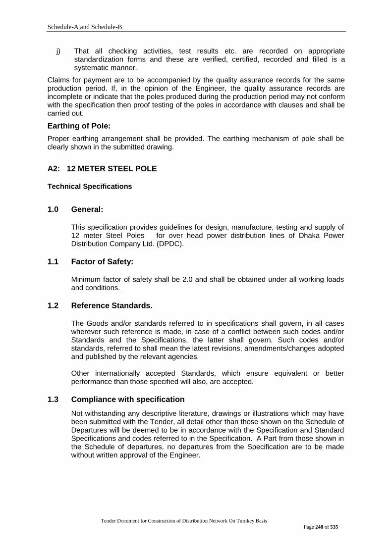
Schedule-A and Schedule-B
Tender Document for Construction of Distribution Network On Turnkey Basis
Page 248 of 535
j) That all checking activities, test results etc. are recorded on appropriate standardization forms and these are verified, certified, recorded and filled is a systematic manner.
Claims for payment are to be accompanied by the quality assurance records for the same production period. If, in the opinion of the Engineer, the quality assurance records are incomplete or indicate that the poles produced during the production period may not conform with the specification then proof testing of the poles in accordance with clauses and shall be carried out.
Earthing of Pole:
Proper earthing arrangement shall be provided. The earthing mechanism of pole shall be clearly shown in the submitted drawing.
A2: 12 METER STEEL POLE Technical Specifications
1.0 General:
This specification provides guidelines for design, manufacture, testing and supply of 12 meter Steel Poles for over head power distribution lines of Dhaka Power Distribution Company Ltd. (DPDC).
1.1 Factor of Safety:
Minimum factor of safety shall be 2.0 and shall be obtained under all working loads and conditions.
1.2 Reference Standards.
The Goods and/or standards referred to in specifications shall govern, in all cases wherever such reference is made, in case of a conflict between such codes and/or Standards and the Specifications, the latter shall govern. Such codes and/or standards, referred to shall mean the latest revisions, amendments/changes adopted and published by the relevant agencies. Other internationally accepted Standards, which ensure equivalent or better performance than those specified will also, are accepted.
1.3 Compliance with specification
Not withstanding any descriptive literature, drawings or illustrations which may have been submitted with the Tender, all detail other than those shown on the Schedule of Departures will be deemed to be in accordance with the Specification and Standard Specifications and codes referred to in the Specification. A Part from those shown in the Schedule of departures, no departures from the Specification are to be made without written approval of the Engineer.
Schedule-A and Schedule-B
Tender Document for Construction of Distribution Network On Turnkey Basis
Page 249 of 535
1.4 Design Improvements.
The Purchaser or the Supplier may propose changes in the Specification of the equipment or quality thereof and if the parties agree upon any such changes, the specification shall be modified accordingly.
1.5 Designs Unless stated to the contrary in the tender, together with a full supporting explanation, the Supplier/Manufacturer will be deemed to have accepted that the design and layout of the works are sufficient to ensure reliable and safe operation and freedom from under stressed. The Contract is to include the whole of the Works, which are described in or implied by the Contract Documents. Any items omitted from the Contract Documents, which are obviously necessary for the efficiency and correct operation of the works, shall be deemed to be included in the Contract price.
1.6 Suppliers/Manufacturers Responsibility
The Supplier/Manufacturer is to familiarize himself with the Conditions of contract and Supplier‟s responsibility.
2.1 Regulations, Standards, etc. 2.1.1 Language
The English language is to be used on all Contract documents and in all correspondence between the Supplier/Manufacturer and the Engineers of DPDC. All correspondence, drawings and Operating and Maintenance instructions shall also be written in English.
2.1.2 Units of Measurement
In all correspondence, in all technical schedules and on all drawings, Metric units of measurement (System International) shall exclusively be in degrees, with 90 degrees comprising one right angle.
2.1.3 International Standards
All Poles under this Specification shall conform to the latest editions of IEC or equivalent Standard unless and otherwise stated herein. Poles offered from a country where the relevant standards to which the Poles better than IEC these are acceptable but appropriate standards must be quoted in the documents. Full details of references, which affect the design or performance of poles shall be stated in the tender.
2.2.2 Special Conditions
Poles supplied under this contract will be installed in tropical locations, which can be considered hostile to its proper operation. Particular problems, which shall receive special consideration, relate to operation in a hot humid environment, and the presence of insects and vermin.
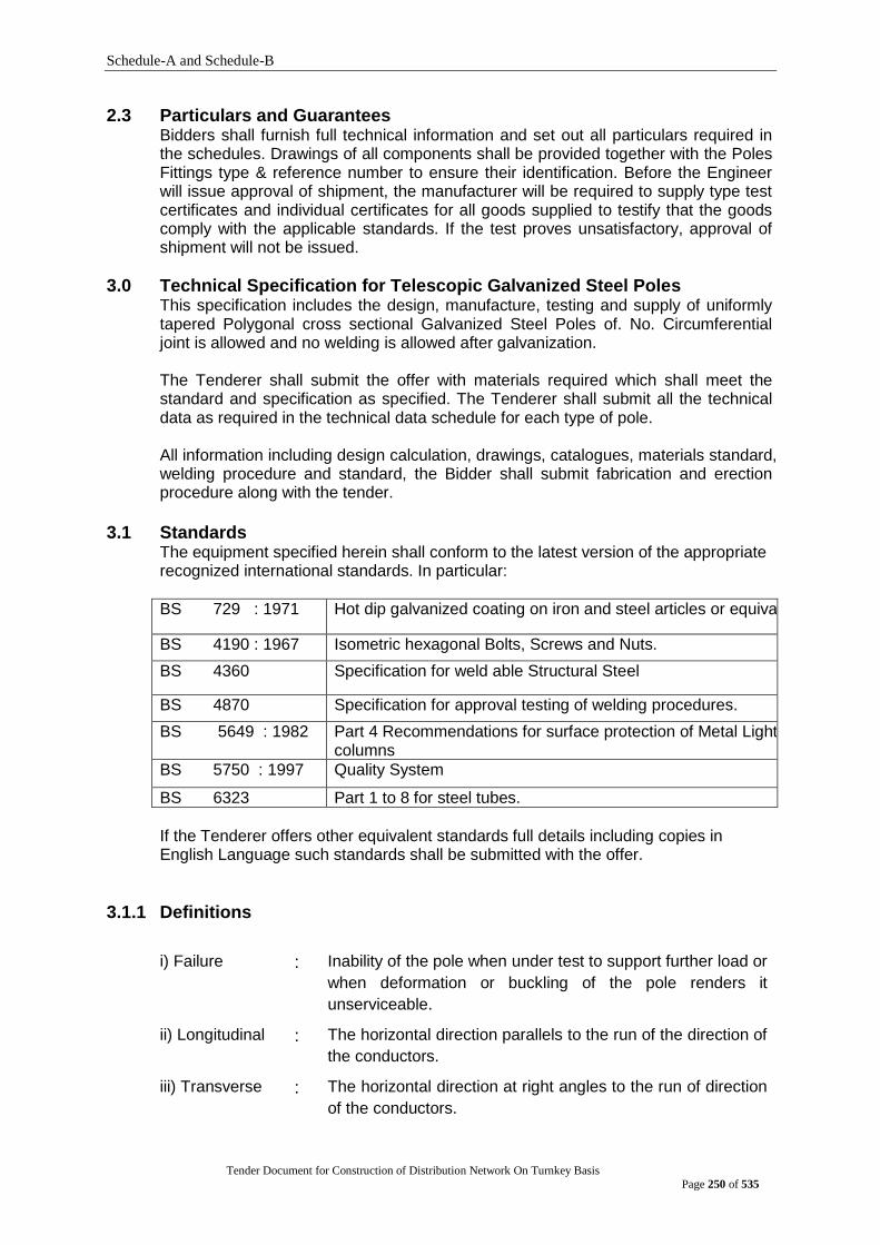
Schedule-A and Schedule-B
Tender Document for Construction of Distribution Network On Turnkey Basis
Page 250 of 535
2.3 Particulars and Guarantees Bidders shall furnish full technical information and set out all particulars required in the schedules. Drawings of all components shall be provided together with the Poles Fittings type & reference number to ensure their identification. Before the Engineer will issue approval of shipment, the manufacturer will be required to supply type test certificates and individual certificates for all goods supplied to testify that the goods comply with the applicable standards. If the test proves unsatisfactory, approval of shipment will not be issued.
3.0 Technical Specification for Telescopic Galvanized Steel Poles This specification includes the design, manufacture, testing and supply of uniformly tapered Polygonal cross sectional Galvanized Steel Poles of. No. Circumferential joint is allowed and no welding is allowed after galvanization. The Tenderer shall submit the offer with materials required which shall meet the standard and specification as specified. The Tenderer shall submit all the technical data as required in the technical data schedule for each type of pole. All information including design calculation, drawings, catalogues, materials standard, welding procedure and standard, the Bidder shall submit fabrication and erection procedure along with the tender.
3.1 Standards
The equipment specified herein shall conform to the latest version of the appropriate recognized international standards. In particular:
BS 729 : 1971 Hot dip galvanized coating on iron and steel articles or equivalent.
BS 4190 : 1967 Isometric hexagonal Bolts, Screws and Nuts.
BS 4360 Specification for weld able Structural Steel
BS 4870 Specification for approval testing of welding procedures.
BS 5649 : 1982 Part 4 Recommendations for surface protection of Metal Lighting columns
BS 5750 : 1997 Quality System
BS 6323 Part 1 to 8 for steel tubes.
If the Tenderer offers other equivalent standards full details including copies in English Language such standards shall be submitted with the offer.
3.1.1 Definitions
i) Failure : Inability of the pole when under test to support further load or
when deformation or buckling of the pole renders it
unserviceable.
ii) Longitudinal : The horizontal direction parallels to the run of the direction of
the conductors.
iii) Transverse : The horizontal direction at right angles to the run of direction
of the conductors.
Schedule-A and Schedule-B
Tender Document for Construction of Distribution Network On Turnkey Basis
Page 251 of 535
iv) Ultimate : The strength at which the pole will not accept any further
Applied force or when deformation or buckling or the pole
renders at unserviceable.
v) Pole Type : Assembled from a series of manufactured tapered sections,
which are fitted together, and then the total assembly is
axially loaded to force the tapered unit‟s together thus
providing friction connections between sections. The
Tenderer shall have mentioned the number of section for
each type of pole.
The taper shall be uniform throughout the length of the pole.
However the taper ratio for all the sections shall be same.
Assembly shall be by means of a simple slip joints without
the use of bolts. Site welding or other jointing device at time
of erection are not allowed and no circumferential joints are
allowed.
Jointing shall be designed for a minimum lap of 1.5 times the
largest inside diameter of the female section with allowances
for fabrication tolerance
3.1.2 Material and Manufactures
General
All materials shall be new and conform to the relevant standard refereed to this
specification.
Materials
The minimum yield strength of the materials of pole shall be 280 N/sq. mm as per BS
4360 or JIS G31301 GB/1912 Q345 SS540 or equivalent.
Manufacture
All welding of the poles shall be carried out at the manufacturer‟s plant and before
galvanization. Welding shall be carried out in accordance with the procedures of an
international standard approval by the Engineers of DPDC and this procedure shall be
tested in accordance with BS 4870 or equivalent standard. Welds parallel to the
longitudinal axis of the poles shall be fillet welds or full penetration but welds with
backing plates. All welds shall be capable of withstanding, without failure of cracking, the
stresses in a pole when subject to its ultimate design loads.
Dimensional Tolerances:
i) The tolerance on thickness : +/- 1%
ii) Outside Diameter : +/- 2%
iii) Length of Sections : +/- 0.05%

Schedule-A and Schedule-B
Tender Document for Construction of Distribution Network On Turnkey Basis
Page 252 of 535
The design of pole shall be on the basis of minimum values considering
tolerance.
Assembly of Pole
Each pole shall be assembled in the factory and prior to assembly all seam welds on joint
mating surfaces shall be ground flush. All right spots in the galvanizing on mating surface
shall be ground and or fired flat and if the galvanizing is damaged it shall be repaired. During
the application of the compressive load to force the sections together, the joints shall be
agitated by striking them with timber or rubber mallets or by any other method as approved
by the Engineer. The coating of galvanization shall not be damaged by this method of
assembly.
Corrosion Protection
All poles internally and externally are to be hot-dip galvanized in accordance with BS 729:
1971 or equivalent standard or latest revision thereof.
After galvanization of poles the external surface of all poles below ground level and 500mm
above ground level shall be painted as follows:
i. A clean brush and solvent degrease, then one coat of phosphoric acid based
etch primer internally and externally followed by,
ii. One coat airless spray of coal tar pitch epoxy paint for a dry film thickness of
1 x 100 microns on the inner surface of poles.
iii. Two successive coat airless spray of coal tar pitch epoxy paint for a dry film
thickness of 100 microns per layer ie. 2X100 microns on the outer surface of
poles.
Any galvanized surface of the pole damaged after delivery and within the warranty
period shall be scrapped back to a firm base and to full thickness. If required and
coats of Zinc rich primer applied to the damage to the galvanizing is extensive then
that pole shall be removed from site and re-galvanized.
Marking of Pole:
The following information shall be marked on the pole with indelible paint at 1/6th of the pole
height of the pole plus 2(two) meter from the bottom end:
i. Name of the manufacturer
ii. Name of the purchaser
iii. Contract No.
iv. Date of manufacture
v. Length of pole in meters and its design working load, as defined in this
specification.
The pole shall also be marked with a permanent horizontal line at a point 1/6th of the pole
height from the bottom end.
Earthing Lugs, Base Plate and Pole cap.
Each pole shall be provided with Earthing lugs at 300mm below ground level, Base plate
and Pole cap. The position of earthing lug at 300 mm below ground level (GL) is to be
shown in the drawing. The materials of the Base plate and Pole Cap shall be galvanized
steel and minimum thickness of pole cap shall be 3mm. The base plate shall have proper
fixing arrangements for easy fixing at site.
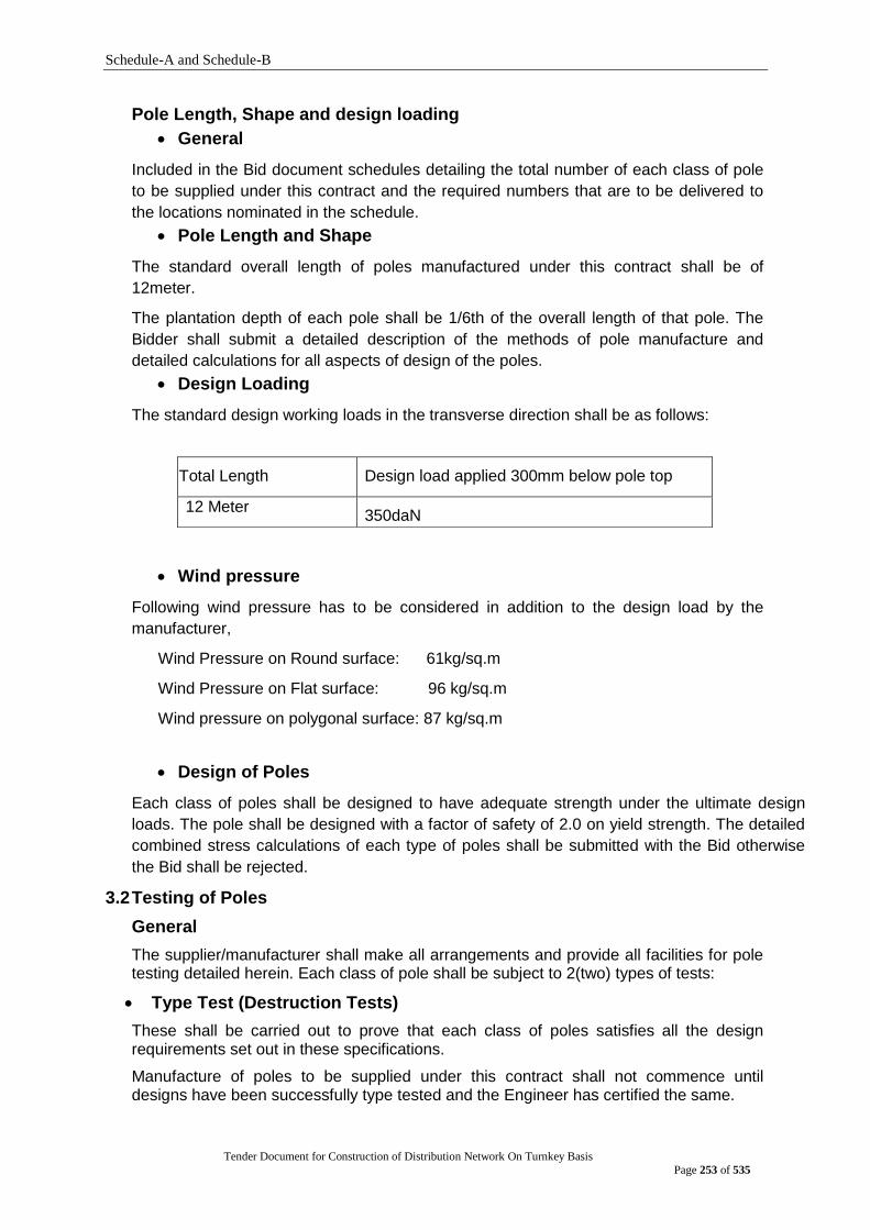
Schedule-A and Schedule-B
Tender Document for Construction of Distribution Network On Turnkey Basis
Page 253 of 535
Pole Length, Shape and design loading
General
Included in the Bid document schedules detailing the total number of each class of pole
to be supplied under this contract and the required numbers that are to be delivered to
the locations nominated in the schedule.
Pole Length and Shape
The standard overall length of poles manufactured under this contract shall be of
12meter.
The plantation depth of each pole shall be 1/6th of the overall length of that pole. The
Bidder shall submit a detailed description of the methods of pole manufacture and
detailed calculations for all aspects of design of the poles.
Design Loading
The standard design working loads in the transverse direction shall be as follows:
Wind pressure
Following wind pressure has to be considered in addition to the design load by the
manufacturer,
Wind Pressure on Round surface: 61kg/sq.m
Wind Pressure on Flat surface: 96 kg/sq.m
Wind pressure on polygonal surface: 87 kg/sq.m
Design of Poles
Each class of poles shall be designed to have adequate strength under the ultimate design
loads. The pole shall be designed with a factor of safety of 2.0 on yield strength. The detailed
combined stress calculations of each type of poles shall be submitted with the Bid otherwise
the Bid shall be rejected.
3.2 Testing of Poles
General
The supplier/manufacturer shall make all arrangements and provide all facilities for pole testing detailed herein. Each class of pole shall be subject to 2(two) types of tests:
Type Test (Destruction Tests)
These shall be carried out to prove that each class of poles satisfies all the design requirements set out in these specifications.
Manufacture of poles to be supplied under this contract shall not commence until designs have been successfully type tested and the Engineer has certified the same.
Total Length Design load applied 300mm below pole top
12 Meter 350daN
Schedule-A and Schedule-B
Tender Document for Construction of Distribution Network On Turnkey Basis
Page 254 of 535
Proof Tests (Acceptance Tests)
These shall be carried out periodically to check the consistency of the standard of manufacture. Poles, which successfully pass proof tests, may form part of the contract for supply.
Observation of testing
All tests shall be carried out by the supplier/manufacturer and the Engineer‟s of DPDC shall witness all aspects.
The supplier/manufacturer shall give the Purchaser/Engineer a minimum of 15(fifteen) days‟ notice before commencing any tests.
Cost of Testing
The costs of all the above testing shall be borne by the tenderer. This shall include any additional testing instructed to be carried out by the Engineer/Purchaser to prove that a class of pole satisfied all design requirements.
Type Test
These shall be carried out before full scale manufacture of a class of pole commences; after any changes are made to the approved design of a class of pole; or at any time the Engineer/Purchaser considers necessary modification to confirm that any class of poles still satisfy the design requirements.
A sample considering of 3(three) poles from each class of poles, similar in all essential features or design and construction to those purchased, shall be subject to the Type test and must give evidence that the poles comply with the acceptance criteria of this specification.
The test shall be carried out in 2 stages.
a) 1st Stage
The load shall be gradually and uniformly applied in increments of 20% of the Ultimate design load up to 120% of the design working load. At each increment of load the deflection of the pole tip shall be measured. The 120% loading shall be maintained for a 5(five) minutes. The load shall then be gradually reduced to zero and the amount of permanent deflection of the pole tip recorded.
b) 2nd Stage
The test load shall gradually re-apply up to the working load and the deflection recorded. The load shall then be increased in 20% increments until failure occurs. At each load increment the load and deflection shall be recorded.
The following particulars shall be recorded for each test made:
(a) Manufacturer‟s name and plant location. (b) Pole classification and type. (c) Dimension of the pole. (d) Date of manufacture. (e) Tested date. (f) Increments of load (for both 1st and 2nd stage loading). (g) Deflection at each increment of load. (h) Permanent deflection after removal of 1st stage loading. (i) Load at failure. (j) Nature of failure. (k) Color photographs along the axis of the pole at design working and ultimate loads
plus photographs of the failure zone on the pole.
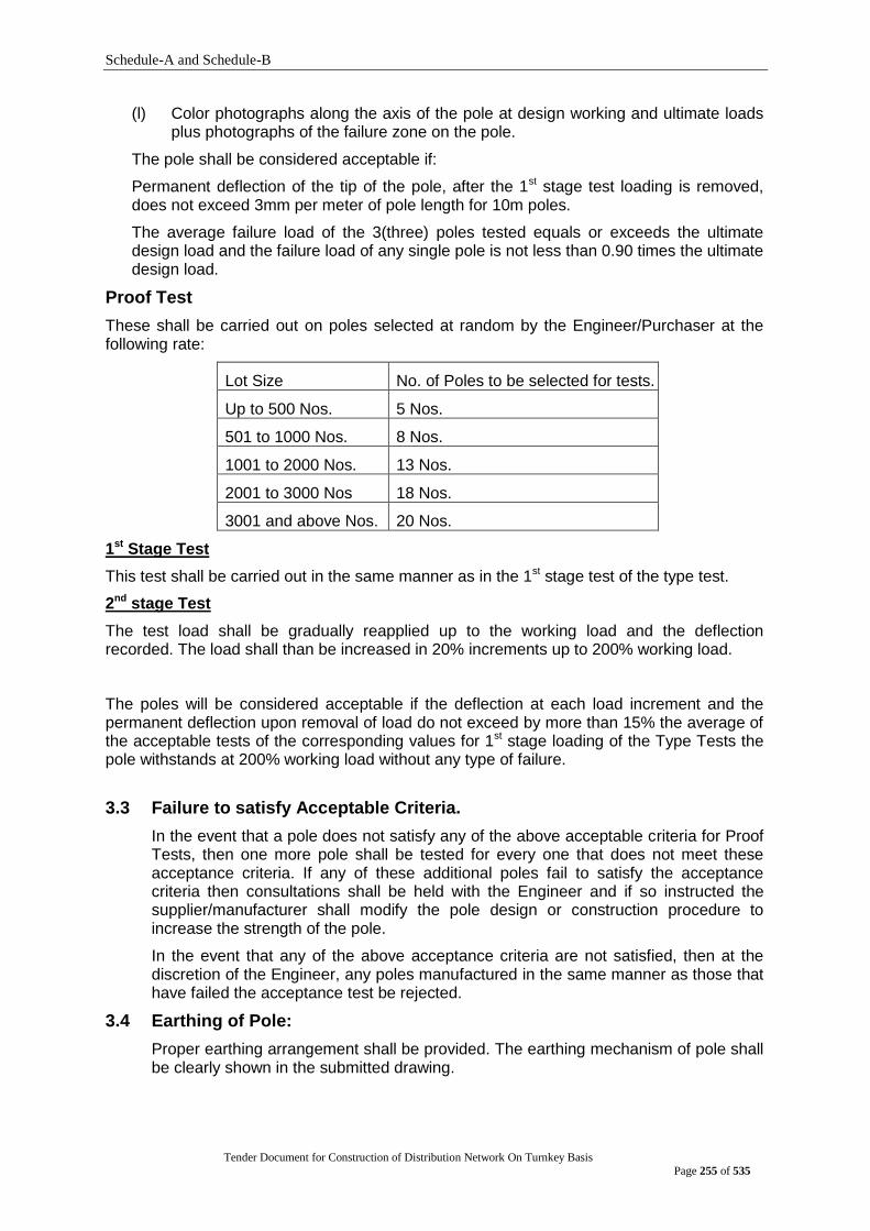
Schedule-A and Schedule-B
Tender Document for Construction of Distribution Network On Turnkey Basis
Page 255 of 535
(l) Color photographs along the axis of the pole at design working and ultimate loads plus photographs of the failure zone on the pole.
The pole shall be considered acceptable if:
Permanent deflection of the tip of the pole, after the 1st stage test loading is removed, does not exceed 3mm per meter of pole length for 10m poles.
The average failure load of the 3(three) poles tested equals or exceeds the ultimate design load and the failure load of any single pole is not less than 0.90 times the ultimate design load.
Proof Test
These shall be carried out on poles selected at random by the Engineer/Purchaser at the following rate:
Lot Size No. of Poles to be selected for tests.
Up to 500 Nos. 5 Nos.
501 to 1000 Nos. 8 Nos.
1001 to 2000 Nos. 13 Nos.
2001 to 3000 Nos 18 Nos.
3001 and above Nos. 20 Nos.
1st Stage Test
This test shall be carried out in the same manner as in the 1st stage test of the type test.
2nd stage Test
The test load shall be gradually reapplied up to the working load and the deflection recorded. The load shall than be increased in 20% increments up to 200% working load.
The poles will be considered acceptable if the deflection at each load increment and the permanent deflection upon removal of load do not exceed by more than 15% the average of the acceptable tests of the corresponding values for 1st stage loading of the Type Tests the pole withstands at 200% working load without any type of failure.
3.3 Failure to satisfy Acceptable Criteria.
In the event that a pole does not satisfy any of the above acceptable criteria for Proof Tests, then one more pole shall be tested for every one that does not meet these acceptance criteria. If any of these additional poles fail to satisfy the acceptance criteria then consultations shall be held with the Engineer and if so instructed the supplier/manufacturer shall modify the pole design or construction procedure to increase the strength of the pole.
In the event that any of the above acceptance criteria are not satisfied, then at the discretion of the Engineer, any poles manufactured in the same manner as those that have failed the acceptance test be rejected.
3.4 Earthing of Pole:
Proper earthing arrangement shall be provided. The earthing mechanism of pole shall be clearly shown in the submitted drawing.
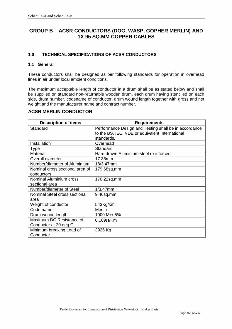
Schedule-A and Schedule-B
Tender Document for Construction of Distribution Network On Turnkey Basis
Page 256 of 535
GROUP B ACSR CONDUCTORS (DOG, WASP, GOPHER MERLIN) AND 1X 95 SQ.MM COPPER CABLES
1.0 TECHNICAL SPECIFICATIONS OF ACSR CONDUCTORS 1.1 General
These conductors shall be designed as per following standards for operation in overhead lines in air under local ambient conditions.
The maximum acceptable length of conductor in a drum shall be as stated below and shall be supplied on standard non-returnable wooden drum, each drum having stenciled on each side, drum number, codename of conductor, drum wound length together with gross and net weight and the manufacturer name and contract number.
ACSR MERLIN CONDUCTOR
Description of items Requirements
Standard Performance Design and Testing shall be in accordance to the BS, IEC, VDE or equivalent International standards.
Installation Overhead
Type Standard
Material Hard drawn Aluminium steel re-inforced
Overall diameter 17.35mm
Number/diameter of Aluminium 18/3.47mm
Nominal cross sectional area of conductors
179.68sq.mm
Nominal Aluminium cross sectional area
170.22sq.mm
Number/diameter of Steel 1/3.47mm
Nominal Steel cross sectional area
9.46sq.mm
Weight of conductor 543Kg/km
Code name Merlin
Drum wound length 1000 M+/-5%
Maximum DC Resistance of Conductor at 20 deg.C
0.169/Km
Minimum breaking Load of Conductor
3926 Kg
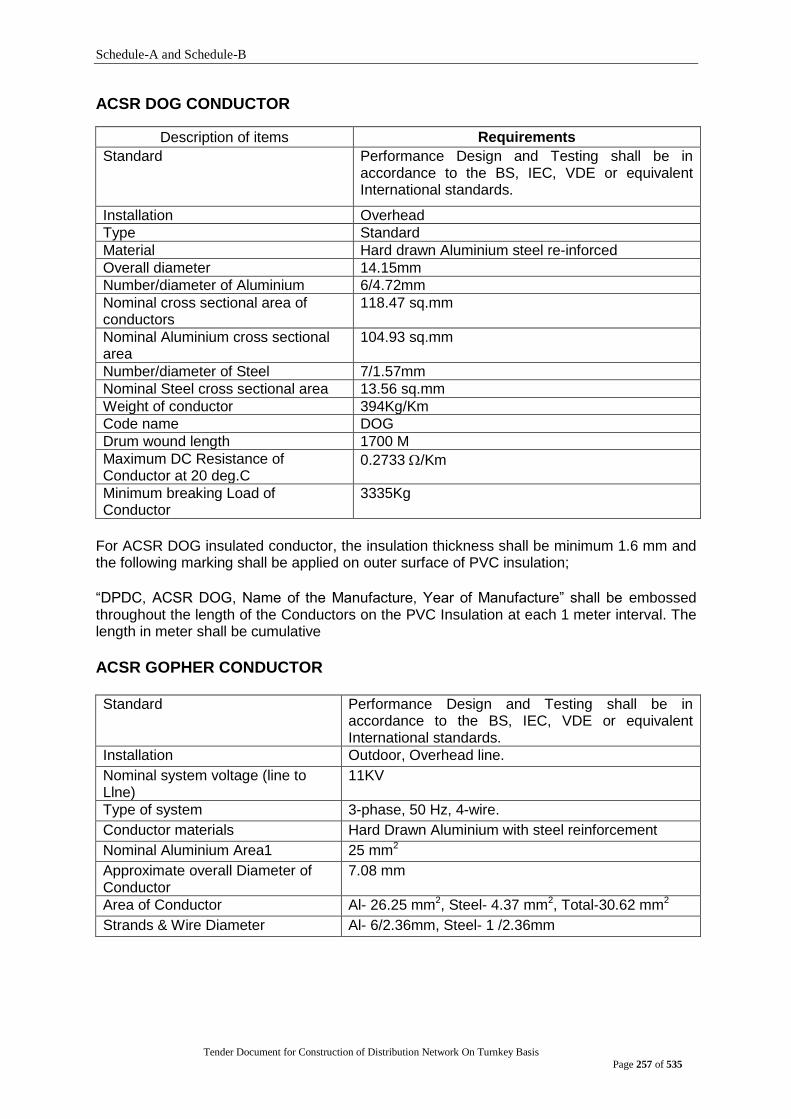
Schedule-A and Schedule-B
Tender Document for Construction of Distribution Network On Turnkey Basis
Page 257 of 535
ACSR DOG CONDUCTOR
Description of items Requirements
Standard Performance Design and Testing shall be in accordance to the BS, IEC, VDE or equivalent International standards.
Installation Overhead
Type Standard
Material Hard drawn Aluminium steel re-inforced
Overall diameter 14.15mm
Number/diameter of Aluminium 6/4.72mm
Nominal cross sectional area of conductors
118.47 sq.mm
Nominal Aluminium cross sectional area
104.93 sq.mm
Number/diameter of Steel 7/1.57mm
Nominal Steel cross sectional area 13.56 sq.mm
Weight of conductor 394Kg/Km
Code name DOG
Drum wound length 1700 M
Maximum DC Resistance of Conductor at 20 deg.C
0.2733 /Km
Minimum breaking Load of Conductor
3335Kg
For ACSR DOG insulated conductor, the insulation thickness shall be minimum 1.6 mm and the following marking shall be applied on outer surface of PVC insulation;
“DPDC, ACSR DOG, Name of the Manufacture, Year of Manufacture” shall be embossed throughout the length of the Conductors on the PVC Insulation at each 1 meter interval. The length in meter shall be cumulative
ACSR GOPHER CONDUCTOR Standard Performance Design and Testing shall be in
accordance to the BS, IEC, VDE or equivalent International standards.
Installation Outdoor, Overhead line.
Nominal system voltage (line to Llne)
11KV
Type of system 3-phase, 50 Hz, 4-wire.
Conductor materials Hard Drawn Aluminium with steel reinforcement
Nominal Aluminium Area1 25 mm2
Approximate overall Diameter of Conductor
7.08 mm
Area of Conductor Al- 26.25 mm2, Steel- 4.37 mm2, Total-30.62 mm2
Strands & Wire Diameter Al- 6/2.36mm, Steel- 1 /2.36mm
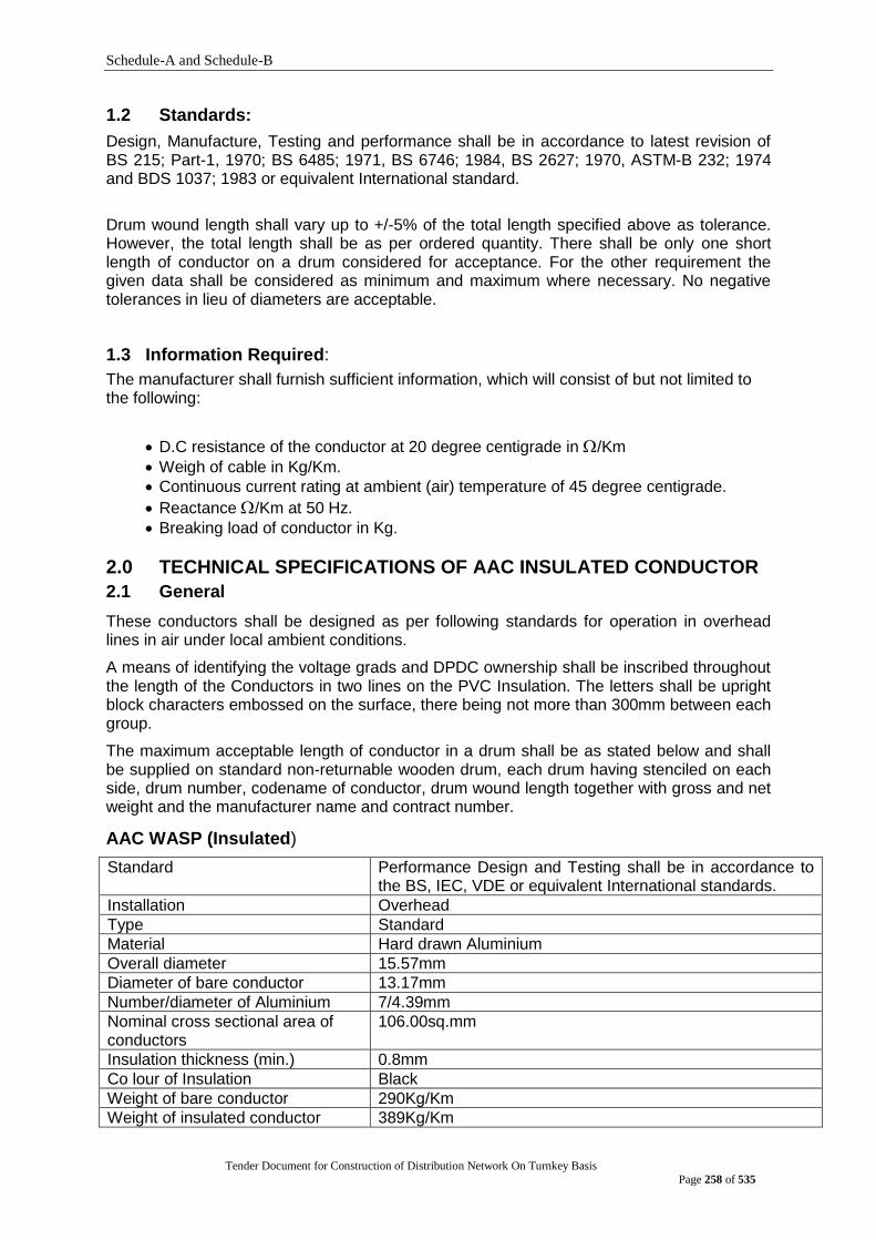
Schedule-A and Schedule-B
Tender Document for Construction of Distribution Network On Turnkey Basis
Page 258 of 535
1.2 Standards:
Design, Manufacture, Testing and performance shall be in accordance to latest revision of BS 215; Part-1, 1970; BS 6485; 1971, BS 6746; 1984, BS 2627; 1970, ASTM-B 232; 1974 and BDS 1037; 1983 or equivalent International standard.
Drum wound length shall vary up to +/-5% of the total length specified above as tolerance. However, the total length shall be as per ordered quantity. There shall be only one short length of conductor on a drum considered for acceptance. For the other requirement the given data shall be considered as minimum and maximum where necessary. No negative tolerances in lieu of diameters are acceptable.
1.3 Information Required:
The manufacturer shall furnish sufficient information, which will consist of but not limited to the following:
D.C resistance of the conductor at 20 degree centigrade in /Km
Weigh of cable in Kg/Km.
Continuous current rating at ambient (air) temperature of 45 degree centigrade.
Reactance /Km at 50 Hz.
Breaking load of conductor in Kg.
2.0 TECHNICAL SPECIFICATIONS OF AAC INSULATED CONDUCTOR
2.1 General
These conductors shall be designed as per following standards for operation in overhead lines in air under local ambient conditions.
A means of identifying the voltage grads and DPDC ownership shall be inscribed throughout the length of the Conductors in two lines on the PVC Insulation. The letters shall be upright block characters embossed on the surface, there being not more than 300mm between each group.
The maximum acceptable length of conductor in a drum shall be as stated below and shall be supplied on standard non-returnable wooden drum, each drum having stenciled on each side, drum number, codename of conductor, drum wound length together with gross and net weight and the manufacturer name and contract number.
AAC WASP (Insulated)
Standard Performance Design and Testing shall be in accordance to the BS, IEC, VDE or equivalent International standards.
Installation Overhead
Type Standard
Material Hard drawn Aluminium
Overall diameter 15.57mm
Diameter of bare conductor 13.17mm
Number/diameter of Aluminium 7/4.39mm
Nominal cross sectional area of conductors
106.00sq.mm
Insulation thickness (min.) 0.8mm
Co lour of Insulation Black
Weight of bare conductor 290Kg/Km
Weight of insulated conductor 389Kg/Km
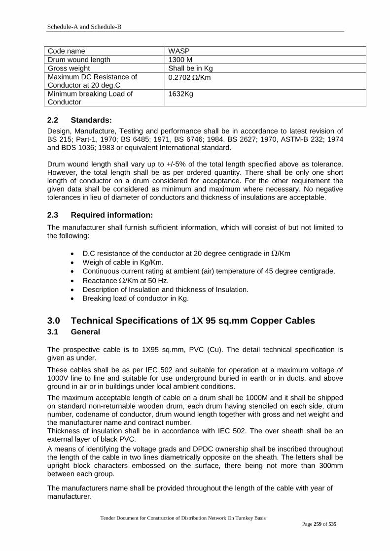
Schedule-A and Schedule-B
Tender Document for Construction of Distribution Network On Turnkey Basis
Page 259 of 535
Code name WASP
Drum wound length 1300 M
Gross weight Shall be in Kg
Maximum DC Resistance of Conductor at 20 deg.C
0.2702 /Km
Minimum breaking Load of Conductor
1632Kg
2.2 Standards:
Design, Manufacture, Testing and performance shall be in accordance to latest revision of BS 215; Part-1, 1970; BS 6485; 1971, BS 6746; 1984, BS 2627; 1970, ASTM-B 232; 1974 and BDS 1036; 1983 or equivalent International standard.
Drum wound length shall vary up to +/-5% of the total length specified above as tolerance. However, the total length shall be as per ordered quantity. There shall be only one short length of conductor on a drum considered for acceptance. For the other requirement the given data shall be considered as minimum and maximum where necessary. No negative tolerances in lieu of diameter of conductors and thickness of insulations are acceptable.
2.3 Required information:
The manufacturer shall furnish sufficient information, which will consist of but not limited to the following:
D.C resistance of the conductor at 20 degree centigrade in /Km
Weigh of cable in Kg/Km.
Continuous current rating at ambient (air) temperature of 45 degree centigrade.
Reactance /Km at 50 Hz.
Description of Insulation and thickness of Insulation.
Breaking load of conductor in Kg.
3.0 Technical Specifications of 1X 95 sq.mm Copper Cables
3.1 General The prospective cable is to 1X95 sq.mm, PVC (Cu). The detail technical specification is given as under.
These cables shall be as per IEC 502 and suitable for operation at a maximum voltage of 1000V line to line and suitable for use underground buried in earth or in ducts, and above ground in air or in buildings under local ambient conditions.
The maximum acceptable length of cable on a drum shall be 1000M and it shall be shipped on standard non-returnable wooden drum, each drum having stenciled on each side, drum number, codename of conductor, drum wound length together with gross and net weight and the manufacturer name and contract number. Thickness of insulation shall be in accordance with IEC 502. The over sheath shall be an external layer of black PVC.
A means of identifying the voltage grads and DPDC ownership shall be inscribed throughout the length of the cable in two lines diametrically opposite on the sheath. The letters shall be upright block characters embossed on the surface, there being not more than 300mm between each group.
The manufacturers name shall be provided throughout the length of the cable with year of manufacturer.
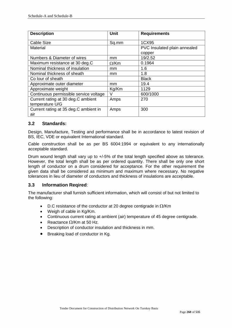
Schedule-A and Schedule-B
Tender Document for Construction of Distribution Network On Turnkey Basis
Page 260 of 535
Description Unit Requirements
Cable Size Sq.mm 1CX95
Material PVC Insulated plain annealed copper
Numbers & Diameter of wires mm 19/2.52
Maximum resistance at 30 deg.C /Km 0.1964
Nominal thickness of insulation mm 1.6
Nominal thickness of sheath mm 1.8
Co lour of sheath Black
Approximate outer diameter mm 19.4
Approximate weight Kg/Km 1129
Continuous permissible service voltage V 600/1000
Current rating at 30 deg.C ambient temperature U/G
Amps 270
Current rating at 35 deg.C ambient in air
Amps 300
3.2 Standards:
Design, Manufacture, Testing and performance shall be in accordance to latest revision of BS, IEC, VDE or equivalent International standard.
Cable construction shall be as per BS 6004:1994 or equivalent to any internationally acceptable standard.
Drum wound length shall vary up to +/-5% of the total length specified above as tolerance. However, the total length shall be as per ordered quantity. There shall be only one short length of conductor on a drum considered for acceptance. For the other requirement the given data shall be considered as minimum and maximum where necessary. No negative tolerances in lieu of diameter of conductors and thickness of insulations are acceptable.
3.3 Information Reqired:
The manufacturer shall furnish sufficient information, which will consist of but not limited to the following:
D.C resistance of the conductor at 20 degree centigrade in /Km
Weigh of cable in Kg/Km.
Continuous current rating at ambient (air) temperature of 45 degree centigrade.
Reactance /Km at 50 Hz.
Description of conductor insulation and thickness in mm.
Breaking load of conductor in Kg.

Schedule-A and Schedule-B
Tender Document for Construction of Distribution Network On Turnkey Basis
Page 261 of 535
GROUP C. MIDSPAN JOINT FOR CONDUCTOR
1.0 TECHNICAL SPECIFICATIONS FOR MIDSPAN JOINT (ACSR &AAC).
Installation: Overhead line with ACSR DOG (With & Without insulation) & MERLIN and AAC WASP (Insulated)
Construction: a) For ACSR: Mid-Span full tension compression type, comprising of inner steel sleeve
and outer aluminium alloy sleeve capable of taking full tension applied on the conductor.
b) For AAC: Same as for ACSR except there will be only aluminium alloy sleeve (No inner steel sleeve).
These mid-span joints shall be designed to develop 95% of the full rated breaking strength of the conductor on which they are fitted.
Size for ACSR: Suitable for ACSR DOG & MERLIN
Minimum length of Sleeve
Aluminium Steel
Dog (with & without insulation) 380 mm 115 mm
Merlin 450 mm 120 mm
Size for AAC: Suitable for AAC Wasp (Insulated) Minimum length of Sleeve
Aluminium Steel
Wasp 270 mm -
Heat shrinkable sleeve cover to insulate the jointing portion shall be provided for ACSR DOG (insulated) and AAC WASP (insulated) conductor. The length of this cover shall be greater than the length of the jointing sleeve. The cost of this item shall be deemed to have included in the financial offer of the tenderer.
Standards: Performance, design & testing shall be accordance to NEMA, BS,IEC or equivalent Standards.
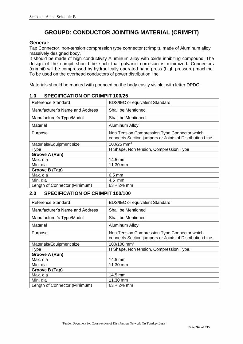
Schedule-A and Schedule-B
Tender Document for Construction of Distribution Network On Turnkey Basis
Page 262 of 535
GROUPD: CONDUCTOR JOINTING MATERIAL (CRIMPIT)
General: Tap Connector, non-tension compression type connector (crimpit), made of Aluminum alloy massively designed body. It should be made of high conductivity Aluminum alloy with oxide inhibiting compound. The design of the crimpit should be such that galvanic corrosion is minimized. Connectors (crimpit) will be compressed by hydraulically operated hand press (high pressure) machine. To be used on the overhead conductors of power distribution line
Materials should be marked with pounced on the body easily visible, with letter DPDC.
1.0 SPECIFICATION OF CRIMPIT 100/25
Reference Standard BDS/IEC or equivalent Standard
Manufacturer‟s Name and Address Shall be Mentioned
Manufacturer‟s Type/Model Shall be Mentioned
Material Aluminum Alloy
Purpose Non Tension Compression Type Connector which connects Section jumpers or Joints of Distribution Line.
Materials/Equipment size 100/25 mm2
Type H Shape, Non tension, Compression Type
Groove A (Run)
Max. dia 14.5 mm
Min. dia 11.30 mm
Groove B (Tap)
Max. dia 6.5 mm
Min. dia 4.5 mm
Length of Connector (Minimum) 63 + 2% mm
2.0 SPECIFICATION OF CRIMPIT 100/100
Reference Standard BDS/IEC or equivalent Standard
Manufacturer‟s Name and Address Shall be Mentioned
Manufacturer‟s Type/Model Shall be Mentioned
Material Aluminum Alloy
Purpose Non Tension Compression Type Connector which connects Section jumpers or Joints of Distribution Line.
Materials/Equipment size 100/100 mm2
Type H Shape, Non tension, Compression Type.
Groove A (Run)
Max. dia 14.5 mm
Min. dia 11.30 mm
Groove B (Tap)
Max. dia 14.5 mm
Min. dia 11.30 mm
Length of Connector (Minimum) 63 + 2% mm
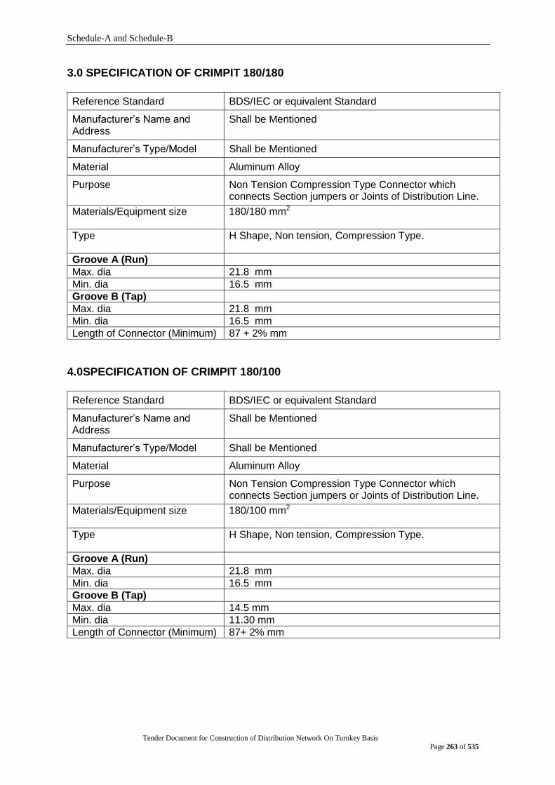
Schedule-A and Schedule-B
Tender Document for Construction of Distribution Network On Turnkey Basis
Page 263 of 535
3.0 SPECIFICATION OF CRIMPIT 180/180
Reference Standard BDS/IEC or equivalent Standard
Manufacturer‟s Name and Address
Shall be Mentioned
Manufacturer‟s Type/Model Shall be Mentioned
Material Aluminum Alloy
Purpose Non Tension Compression Type Connector which connects Section jumpers or Joints of Distribution Line.
Materials/Equipment size 180/180 mm2
Type H Shape, Non tension, Compression Type.
Groove A (Run)
Max. dia 21.8 mm
Min. dia 16.5 mm
Groove B (Tap)
Max. dia 21.8 mm
Min. dia 16.5 mm
Length of Connector (Minimum) 87 + 2% mm
4.0SPECIFICATION OF CRIMPIT 180/100
Reference Standard BDS/IEC or equivalent Standard
Manufacturer‟s Name and Address
Shall be Mentioned
Manufacturer‟s Type/Model Shall be Mentioned
Material Aluminum Alloy
Purpose Non Tension Compression Type Connector which connects Section jumpers or Joints of Distribution Line.
Materials/Equipment size 180/100 mm2
Type H Shape, Non tension, Compression Type.
Groove A (Run)
Max. dia 21.8 mm
Min. dia 16.5 mm
Groove B (Tap)
Max. dia 14.5 mm
Min. dia 11.30 mm
Length of Connector (Minimum) 87+ 2% mm
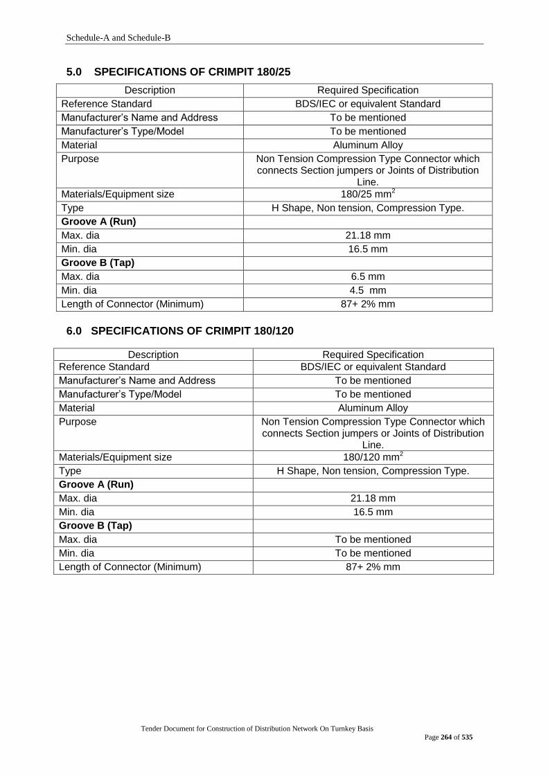
Schedule-A and Schedule-B
Tender Document for Construction of Distribution Network On Turnkey Basis
Page 264 of 535
5.0 SPECIFICATIONS OF CRIMPIT 180/25
Description Required Specification
Reference Standard BDS/IEC or equivalent Standard
Manufacturer‟s Name and Address To be mentioned
Manufacturer‟s Type/Model To be mentioned
Material Aluminum Alloy
Purpose Non Tension Compression Type Connector which connects Section jumpers or Joints of Distribution
Line.
Materials/Equipment size 180/25 mm2
Type H Shape, Non tension, Compression Type.
Groove A (Run)
Max. dia 21.18 mm
Min. dia 16.5 mm
Groove B (Tap)
Max. dia 6.5 mm
Min. dia 4.5 mm
Length of Connector (Minimum) 87+ 2% mm
6.0 SPECIFICATIONS OF CRIMPIT 180/120
Description Required Specification
Reference Standard BDS/IEC or equivalent Standard
Manufacturer‟s Name and Address To be mentioned
Manufacturer‟s Type/Model To be mentioned
Material Aluminum Alloy
Purpose Non Tension Compression Type Connector which connects Section jumpers or Joints of Distribution
Line.
Materials/Equipment size 180/120 mm2
Type H Shape, Non tension, Compression Type.
Groove A (Run)
Max. dia 21.18 mm
Min. dia 16.5 mm
Groove B (Tap)
Max. dia To be mentioned
Min. dia To be mentioned
Length of Connector (Minimum) 87+ 2% mm
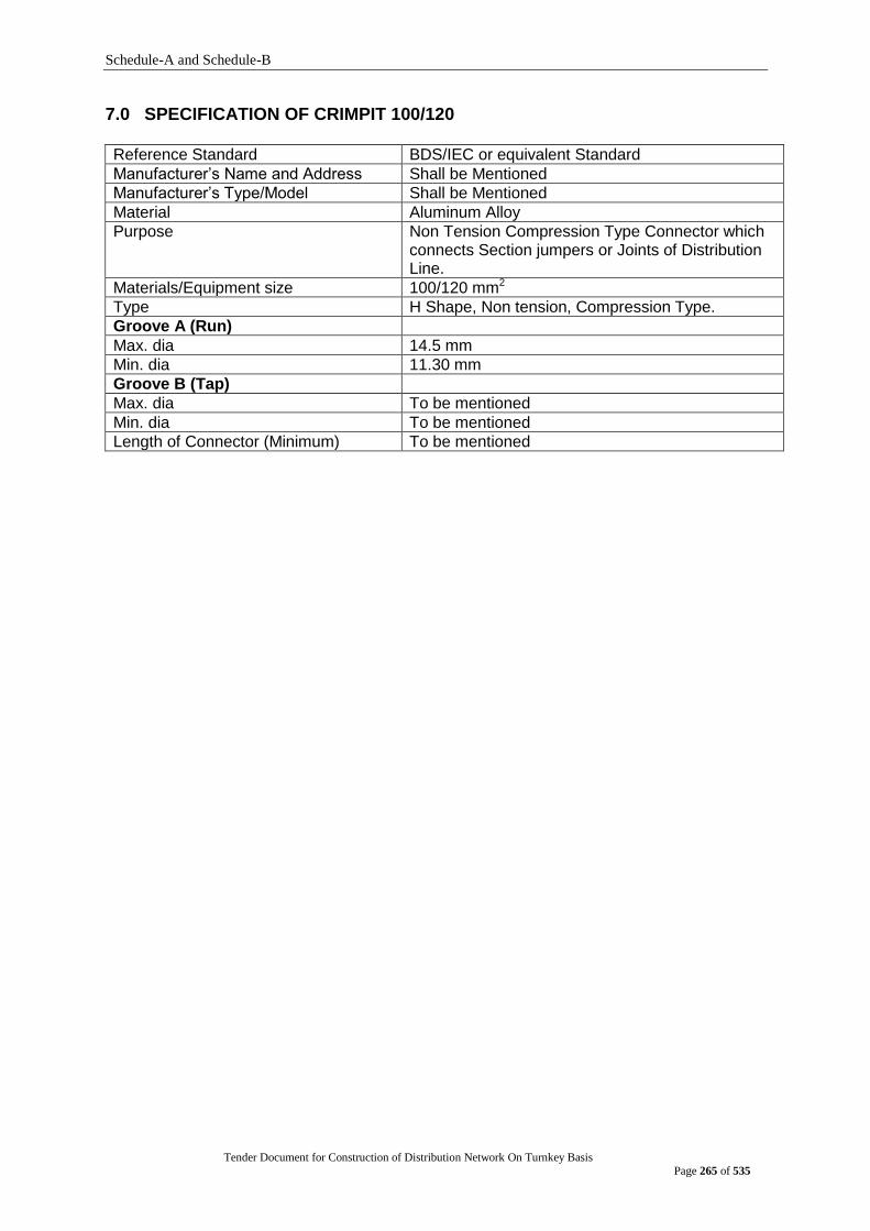
Schedule-A and Schedule-B
Tender Document for Construction of Distribution Network On Turnkey Basis
Page 265 of 535
7.0 SPECIFICATION OF CRIMPIT 100/120
Reference Standard BDS/IEC or equivalent Standard
Manufacturer‟s Name and Address Shall be Mentioned
Manufacturer‟s Type/Model Shall be Mentioned
Material Aluminum Alloy
Purpose Non Tension Compression Type Connector which connects Section jumpers or Joints of Distribution Line.
Materials/Equipment size 100/120 mm2
Type H Shape, Non tension, Compression Type.
Groove A (Run)
Max. dia 14.5 mm
Min. dia 11.30 mm
Groove B (Tap)
Max. dia To be mentioned
Min. dia To be mentioned
Length of Connector (Minimum) To be mentioned

Schedule-A and Schedule-B
Tender Document for Construction of Distribution Network On Turnkey Basis
Page 266 of 535
GROUP E. CABLE E1:11 KV 3C X 300 MM² XLPE (CU) U/G
1.1 General Technical Requirements: Cross Link Polyethylene (XLPE) cables shall be suitable for operation at voltage of 11KV
between phases at continuous maximum conductor temperatures of 90C. the cable shall be suitable in all respect for use on 11KV system with a nominal three phase fault level of 31.5 KA for 3 sec. The cables and associated fittings, joints and termination shall be so designed to prevent damage to the cable or fittings, except in the immediate vicinity of the fault, in the event of an installation failure at any point which results in a fault current to earth of 31.5KA for 3 sec.
The length of cable on a drum shall be 500M continuous or as specified by the Purchaser and it shall be shipped on standard non-returnable steel drum, each drum having stencilled on its side; size, type and length of cable, together with its gross weight, net weight and contract number.
1.1 Conductors
Copper and Aluminium conductors shall be stranded, circular and compacted and comply with IEC 228 and other relevant IEC standard. Cables shall be constructed with three cores of sizes 300 mm2 Copper and 95 mm2Copper and four cores of 185 mm2Copper and three cores of 120 mm2Aluminium conductors respectively.
1.3 Conductor Screening The conductor shall be screened with an extruded layer of semi-conducting material of 0.5mm thickness for both the Cu and Al cables.
1.4 Insulation The insulation shall consist of cross-linked polyethylene tightly extruded over the conductor screen. The insulation shall generally comply with IEC 502.
The highest possible purity of insulation material is required. The Tenderer shall confirm that adequate precautions are taken to remove contaminants and to eliminate the introduction of particles of contaminants during material handling or extrusion process.
The Cable shall be manufactured through VCV/CCV.
The insulation material shall be cross-linked by a dry process. A cross-linking process using steam curing will not be permitted.
1.5 Insulation Thickness
The thickness of insulation shall be determined by taking the average of number of measurements and shall be not less than the values tabulated in IEC Publication 502.
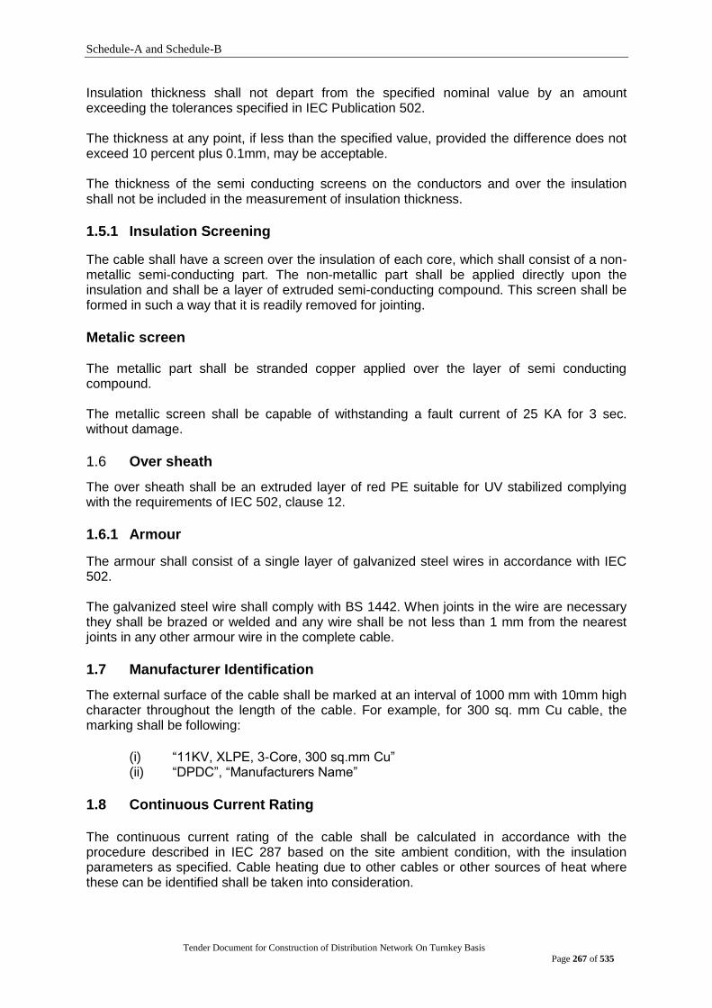
Schedule-A and Schedule-B
Tender Document for Construction of Distribution Network On Turnkey Basis
Page 267 of 535
Insulation thickness shall not depart from the specified nominal value by an amount exceeding the tolerances specified in IEC Publication 502.
The thickness at any point, if less than the specified value, provided the difference does not exceed 10 percent plus 0.1mm, may be acceptable.
The thickness of the semi conducting screens on the conductors and over the insulation shall not be included in the measurement of insulation thickness.
1.5.1 Insulation Screening
The cable shall have a screen over the insulation of each core, which shall consist of a non-metallic semi-conducting part. The non-metallic part shall be applied directly upon the insulation and shall be a layer of extruded semi-conducting compound. This screen shall be formed in such a way that it is readily removed for jointing.
Metalic screen The metallic part shall be stranded copper applied over the layer of semi conducting compound. The metallic screen shall be capable of withstanding a fault current of 25 KA for 3 sec. without damage.
1.6 Over sheath
The over sheath shall be an extruded layer of red PE suitable for UV stabilized complying with the requirements of IEC 502, clause 12.
1.6.1 Armour
The armour shall consist of a single layer of galvanized steel wires in accordance with IEC 502.
The galvanized steel wire shall comply with BS 1442. When joints in the wire are necessary they shall be brazed or welded and any wire shall be not less than 1 mm from the nearest joints in any other armour wire in the complete cable.
1.7 Manufacturer Identification
The external surface of the cable shall be marked at an interval of 1000 mm with 10mm high character throughout the length of the cable. For example, for 300 sq. mm Cu cable, the marking shall be following:
(i) “11KV, XLPE, 3-Core, 300 sq.mm Cu” (ii) “DPDC”, “Manufacturers Name”
1.8 Continuous Current Rating The continuous current rating of the cable shall be calculated in accordance with the procedure described in IEC 287 based on the site ambient condition, with the insulation parameters as specified. Cable heating due to other cables or other sources of heat where these can be identified shall be taken into consideration.
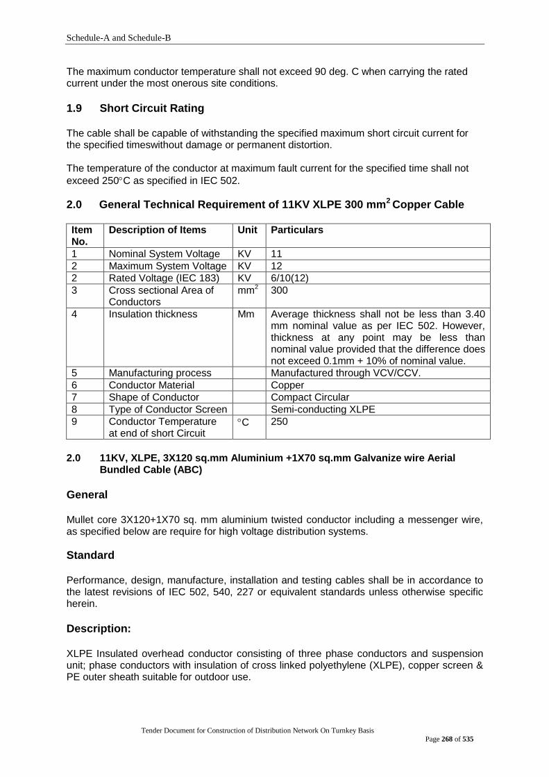
Schedule-A and Schedule-B
Tender Document for Construction of Distribution Network On Turnkey Basis
Page 268 of 535
The maximum conductor temperature shall not exceed 90 deg. C when carrying the rated current under the most onerous site conditions.
1.9 Short Circuit Rating The cable shall be capable of withstanding the specified maximum short circuit current for the specified timeswithout damage or permanent distortion.
The temperature of the conductor at maximum fault current for the specified time shall not
exceed 250C as specified in IEC 502.
2.0 General Technical Requirement of 11KV XLPE 300 mm2 Copper Cable Item No.
Description of Items Unit Particulars
1 Nominal System Voltage KV 11
2 Maximum System Voltage KV 12
2 Rated Voltage (IEC 183) KV 6/10(12)
3 Cross sectional Area of Conductors
mm2 300
4 Insulation thickness Mm Average thickness shall not be less than 3.40 mm nominal value as per IEC 502. However, thickness at any point may be less than nominal value provided that the difference does not exceed 0.1mm + 10% of nominal value.
5 Manufacturing process Manufactured through VCV/CCV.
6 Conductor Material Copper
7 Shape of Conductor Compact Circular
8 Type of Conductor Screen Semi-conducting XLPE
9 Conductor Temperature at end of short Circuit
C 250
2.0 11KV, XLPE, 3X120 sq.mm Aluminium +1X70 sq.mm Galvanize wire Aerial
Bundled Cable (ABC)
General
Mullet core 3X120+1X70 sq. mm aluminium twisted conductor including a messenger wire, as specified below are require for high voltage distribution systems.
Standard Performance, design, manufacture, installation and testing cables shall be in accordance to the latest revisions of IEC 502, 540, 227 or equivalent standards unless otherwise specific herein.
Description:
XLPE Insulated overhead conductor consisting of three phase conductors and suspension unit; phase conductors with insulation of cross linked polyethylene (XLPE), copper screen & PE outer sheath suitable for outdoor use.

Schedule-A and Schedule-B
Tender Document for Construction of Distribution Network On Turnkey Basis
Page 269 of 535
They may be used in all A.C single phase and three phase neutral earthed systems, resonant earthed or isolated neutral systems if a single phase to earth fault does not last longer than 8 hours and the total sum of all earth faults does not exceed 125 hours per year.
Highest continuous operating voltage Um = 12KV (Line to Line), and (a) both phase conductors‟ isolated 12KV and (b) one phase conductor earthed 7KV.
Technical Specification:
Single Core; Nominal cross sectional area of phase conductor : 120 sq.mm Diameter of phase conductor : 12.5 to 13.5 mm Stranding : 37/2.05 or 19/2.95 Thickness of insulation : 3.4mm Diameter over insulation, approximately : 23 mm Nominal cross sectional area of screen : 16 sq.mm Thickness of over sheath : 2.3 mm Overall diameter, approximately : 27 mm Suspension Unit: Galvanized Steel rope; Nominal cross sectional area of rope : 70 sq.mm Stranding : 7/3.57 Thickness of covering : 1.0mm Overall diameter of rope : 12.5 mm Bundled: Three cores stranded around suspension unit Diameter of stranded bundle, approximately : 64 mm Total weight approximately : 3000kg/km Electrical Data: Nominal Voltage rating, Uo/U : 6/10KV Maximum admissible continuous working voltage : 12KV Maximum D.C resistance at 20ºC : 0.253 ohm/km Working inductance : 0.38 ohm/km Working capacitance : 0.36µF/km Earth leakage current : 1.9A/km rent rating at ambient temp. of 40 deg. C : 304Amps. A.C Test Voltage : 15KV The values indicated for current capacity apply to the following side conditions: Laying in air; Continuous load, load factor : m = 1.0 Wind velocity : 0.6 m/s Ambient temperature : 35ºC Admissible Conductor Temperature : 90ºC Admissible short circuit conductor temperature : 250ºC Admissible short circuit screen temperature : 250ºC
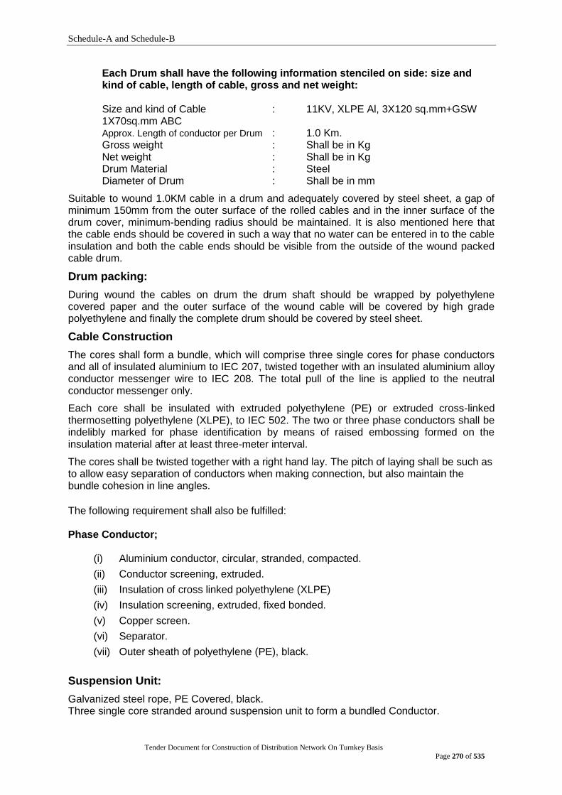
Schedule-A and Schedule-B
Tender Document for Construction of Distribution Network On Turnkey Basis
Page 270 of 535
Each Drum shall have the following information stenciled on side: size and kind of cable, length of cable, gross and net weight: Size and kind of Cable : 11KV, XLPE Al, 3X120 sq.mm+GSW 1X70sq.mm ABC Approx. Length of conductor per Drum : 1.0 Km.
Gross weight : Shall be in Kg Net weight : Shall be in Kg
Drum Material : Steel Diameter of Drum : Shall be in mm
Suitable to wound 1.0KM cable in a drum and adequately covered by steel sheet, a gap of minimum 150mm from the outer surface of the rolled cables and in the inner surface of the drum cover, minimum-bending radius should be maintained. It is also mentioned here that the cable ends should be covered in such a way that no water can be entered in to the cable insulation and both the cable ends should be visible from the outside of the wound packed cable drum.
Drum packing:
During wound the cables on drum the drum shaft should be wrapped by polyethylene covered paper and the outer surface of the wound cable will be covered by high grade polyethylene and finally the complete drum should be covered by steel sheet.
Cable Construction
The cores shall form a bundle, which will comprise three single cores for phase conductors and all of insulated aluminium to IEC 207, twisted together with an insulated aluminium alloy conductor messenger wire to IEC 208. The total pull of the line is applied to the neutral conductor messenger only.
Each core shall be insulated with extruded polyethylene (PE) or extruded cross-linked thermosetting polyethylene (XLPE), to IEC 502. The two or three phase conductors shall be indelibly marked for phase identification by means of raised embossing formed on the insulation material after at least three-meter interval.
The cores shall be twisted together with a right hand lay. The pitch of laying shall be such as to allow easy separation of conductors when making connection, but also maintain the bundle cohesion in line angles.
The following requirement shall also be fulfilled:
Phase Conductor;
(i) Aluminium conductor, circular, stranded, compacted.
(ii) Conductor screening, extruded.
(iii) Insulation of cross linked polyethylene (XLPE)
(iv) Insulation screening, extruded, fixed bonded.
(v) Copper screen.
(vi) Separator.
(vii) Outer sheath of polyethylene (PE), black.
Suspension Unit:
Galvanized steel rope, PE Covered, black. Three single core stranded around suspension unit to form a bundled Conductor.
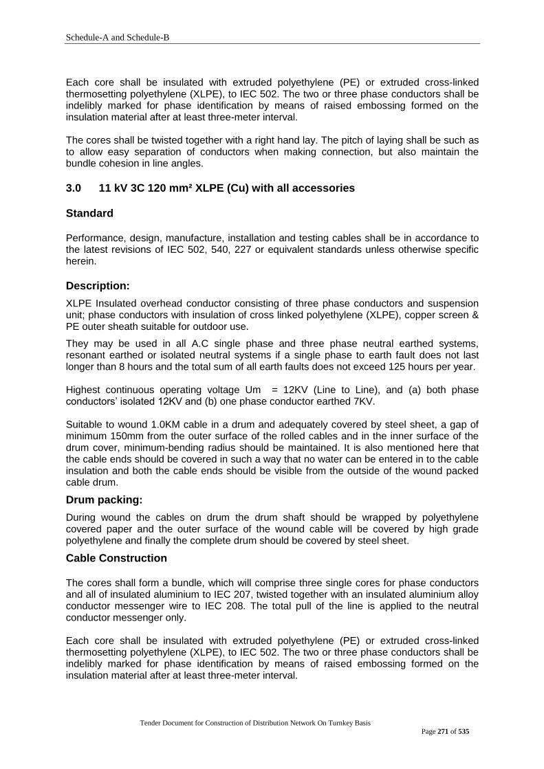
Schedule-A and Schedule-B
Tender Document for Construction of Distribution Network On Turnkey Basis
Page 271 of 535
Each core shall be insulated with extruded polyethylene (PE) or extruded cross-linked thermosetting polyethylene (XLPE), to IEC 502. The two or three phase conductors shall be indelibly marked for phase identification by means of raised embossing formed on the insulation material after at least three-meter interval. The cores shall be twisted together with a right hand lay. The pitch of laying shall be such as to allow easy separation of conductors when making connection, but also maintain the bundle cohesion in line angles.
3.0 11 kV 3C 120 mm² XLPE (Cu) with all accessories Standard Performance, design, manufacture, installation and testing cables shall be in accordance to the latest revisions of IEC 502, 540, 227 or equivalent standards unless otherwise specific herein.
Description:
XLPE Insulated overhead conductor consisting of three phase conductors and suspension unit; phase conductors with insulation of cross linked polyethylene (XLPE), copper screen & PE outer sheath suitable for outdoor use.
They may be used in all A.C single phase and three phase neutral earthed systems, resonant earthed or isolated neutral systems if a single phase to earth fault does not last longer than 8 hours and the total sum of all earth faults does not exceed 125 hours per year.
Highest continuous operating voltage Um = 12KV (Line to Line), and (a) both phase conductors‟ isolated 12KV and (b) one phase conductor earthed 7KV. Suitable to wound 1.0KM cable in a drum and adequately covered by steel sheet, a gap of minimum 150mm from the outer surface of the rolled cables and in the inner surface of the drum cover, minimum-bending radius should be maintained. It is also mentioned here that the cable ends should be covered in such a way that no water can be entered in to the cable insulation and both the cable ends should be visible from the outside of the wound packed cable drum.
Drum packing:
During wound the cables on drum the drum shaft should be wrapped by polyethylene covered paper and the outer surface of the wound cable will be covered by high grade polyethylene and finally the complete drum should be covered by steel sheet.
Cable Construction The cores shall form a bundle, which will comprise three single cores for phase conductors and all of insulated aluminium to IEC 207, twisted together with an insulated aluminium alloy conductor messenger wire to IEC 208. The total pull of the line is applied to the neutral conductor messenger only. Each core shall be insulated with extruded polyethylene (PE) or extruded cross-linked thermosetting polyethylene (XLPE), to IEC 502. The two or three phase conductors shall be indelibly marked for phase identification by means of raised embossing formed on the insulation material after at least three-meter interval.
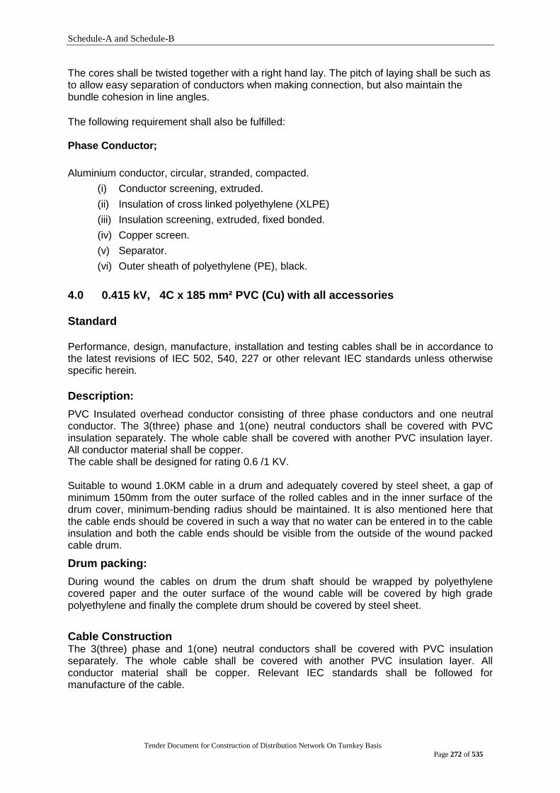
Schedule-A and Schedule-B
Tender Document for Construction of Distribution Network On Turnkey Basis
Page 272 of 535
The cores shall be twisted together with a right hand lay. The pitch of laying shall be such as to allow easy separation of conductors when making connection, but also maintain the bundle cohesion in line angles.
The following requirement shall also be fulfilled: Phase Conductor;
Aluminium conductor, circular, stranded, compacted.
(i) Conductor screening, extruded.
(ii) Insulation of cross linked polyethylene (XLPE)
(iii) Insulation screening, extruded, fixed bonded.
(iv) Copper screen.
(v) Separator.
(vi) Outer sheath of polyethylene (PE), black.
4.0 0.415 kV, 4C x 185 mm² PVC (Cu) with all accessories Standard Performance, design, manufacture, installation and testing cables shall be in accordance to the latest revisions of IEC 502, 540, 227 or other relevant IEC standards unless otherwise specific herein.
Description:
PVC Insulated overhead conductor consisting of three phase conductors and one neutral conductor. The 3(three) phase and 1(one) neutral conductors shall be covered with PVC insulation separately. The whole cable shall be covered with another PVC insulation layer. All conductor material shall be copper. The cable shall be designed for rating 0.6 /1 KV. Suitable to wound 1.0KM cable in a drum and adequately covered by steel sheet, a gap of minimum 150mm from the outer surface of the rolled cables and in the inner surface of the drum cover, minimum-bending radius should be maintained. It is also mentioned here that the cable ends should be covered in such a way that no water can be entered in to the cable insulation and both the cable ends should be visible from the outside of the wound packed cable drum.
Drum packing:
During wound the cables on drum the drum shaft should be wrapped by polyethylene covered paper and the outer surface of the wound cable will be covered by high grade polyethylene and finally the complete drum should be covered by steel sheet.
Cable Construction The 3(three) phase and 1(one) neutral conductors shall be covered with PVC insulation separately. The whole cable shall be covered with another PVC insulation layer. All conductor material shall be copper. Relevant IEC standards shall be followed for manufacture of the cable.
Schedule-A and Schedule-B
Tender Document for Construction of Distribution Network On Turnkey Basis
Page 273 of 535
GROUP F. CABLE JOINTING MATERIALS
1.0 Technical Specification of Cable Jointing Material 2.1 Design & Construction 2.1.1 General:
This specification covers design manufacture and supply of heat shrinkable components suitable for use in high voltage and low voltage cable joints. Components specified shall be suitable for cables as mentioned in the tender documents. Components shall not be adversely affected in any manner by contact with other materials normally used in the construction of cable joints and terminations, and shall not increase the rate of galvanic corrosion of any metal with which they may come into contact.
2.1.2 Design:
Adequate consideration shall be given in the design of straight through joints in respect of the following: a) Adequate stress relaxes at the screen out back in case of screened cables and in the
crutch region in case of belted cables.
b) Reinstatement of primary insulation with an extruded bonded screen to the primary
insulation (for joints).
c) Prevention of corrosion and sealing against ingress of moisture.
d) Provision of excellent electrical earth continuity across the straight through joints..
e) Sockets ferrules to be suitable for proper connection of conductor.
f) Compatibility of component materials.
i) Ensuring that proper clearances are maintained between cores and between each core and earthed parts.
j) Toxicity of compound. k) Adequate shelf life.
2.1.3 Ability to withstand load & Short Circuit Condition:
The ability to withstand electrical and mechanical stress that occur under normal, emergency and short circuit condition in the cable joints shall not be less than that of the cable.
2.1.4 Electrical Stress Relief:
Electrical Stress Control for the cable insulation screen in joints shall be achieved by means of a heat shrinkable tubing having a defined impedance characteristic, Volume, resistively and dielectric constant stable over time, in spite of variation in electrical stress and changes in temperature, when measured in accordance with IEC 93 and IEC 250. Electrical Stress relief shall be adequate enough so as to withstand voltages at twice the rated phase voltage to earth, which shall be proved by partial discharge testing. Partial Discharge measured at twice the rated voltage shall be less than 20% (Twenty percent). The materials shall withstand the maximum permissible overload temperature of the cable temperature of the cable concerned, thermal ageing and stress variation. The bidder shall submit test data on the effects of temperature variation and thermal aging on the impedance of the stress control tubing. In addition to the heat shrinkable stress control tubing some form of stress relief material shall be provided which shall fill up voids and force air out of critical regions in the screen cutback area to prevent discharge.

Schedule-A and Schedule-B
Tender Document for Construction of Distribution Network On Turnkey Basis
Page 274 of 535
2.1.5 Reinstatement of Primary Insulation (Joints):
A systematic build up of insulation shall be provided to reinstate the primary insulation. This shall be by means of a heat shrinkable tube made from a discharge resistant polymer. For 33 kV joints, additional insulation and reinstatement of the outer semiconductor screening whenever necessary shall be by dual wall extruded heat shrinkable tubing which comprises of an inner layer of insulation material and an outer coextruded conductive layer of a polymer. The metallic shield continuity over the joint core shall be reinstated by means of a fine mesh of tinned copper.
2.1.6 Mechanical Strength, Armour continuity and sealing (Joints):
In case of straight through joints, steps shall be taken to restore the mechanical strength over the joints. The material used shall be of galvanized steel and the design shall be of lightweight impact resistant and capable of wrapping around over the complete length of lightweight impact resistant and capable of wrapping around over the complete length of the joint. Heat shrinkable sleeves and filling materials to provide outer sealing against ingress of moisture and corrosion shall be provided and included in the kits for joints and terminations.
2.2 Basic Components:
2.2.1 General:
All components and materials used in the straight through joint kits shall conform to the
relevant IEC, or other acceptable international standards. They shall be compatible with
solid dielectric cable insulation and with each other and shall be non toxic. All heat
shrinkable tubings and moulded parts shall have printed on them:
- Name of original manufacturer
- Part number of item
- Manufacturing batch number (for tractability)
Heat Shrinkable Tubing & Moulded Parts:
The item ''Heat Shrinkable'' refers to extruded or moulded polymeric material, which are
cross-linked to develop elastic memory and supplied in an expanded or otherwise
deformed size and shape. Subsequent hearing in an unconstrained state to a
temperature above the shrink temperature results in the material recovering or shrinking
to its original shape. All heat shrinkable polymeric tubing exposed to direct sunlight shall
be ultra violet stable. Ii shall be suitable for operation in the presence of severe external
contamination and environmental pollution. Materials offered shall have good electrical
and environmental performance and comply with requirements IEC Publication 243 for 33
kV.
2.2.2 Tubing Components:
i) Internal Insulation Tubing:
Heat Shrinkable polymeric/porcelain tubing, having suitable thickness, dielectric strength,
elongation tensile strength, high permittivity, resistivity etc., for use in internal construction
of cable joints at installations where it is not be exposed to day light.

Schedule-A and Schedule-B
Tender Document for Construction of Distribution Network On Turnkey Basis
Page 275 of 535
ii) Stress Control Tubing:
Heat Shrinkable polymeric porcelain tubing possessing properties to provide electric
stress control over the insulated cores in cable joints installations where it will be exposed
to day light.
iii) Anti-track Tubing (Indoor Outdoor) Termination:
Heat shrinkable polymeric porcelain tubing, easily distinguishable by color from non-anti-
track material preferably coloured red, possessing anti-track and erosion resistance
properties for use as an external covering of insulated cores in cable in joints installations.
The anti-track tubing for terminations at its ends shall have adequate anti-track adhesive
scotching applied internally so as to provide sufficient bonding in order to prevent the
ingress of moisture.
The anti-track tubing shall also pass the following tests:
a) ASTM D 2303 Inclined plane Tracking and Erosion Resistance Test to be conducted
on the material in the form of a slab 125 mm x 50 mm x 6 mm, Test voltage shall be
2.5 kV for 1 hour, 2.75 kV for 1 hour, 3.0 kV for 1 hour and 3.5 kV for 1 hour. Addition
of 1% sugar solution to the contaminated solution flowing over the sample under test
should not produce any deterioration of the tracking or erosion behaviour.
b) Ontario Hydro Tracking Wheel test on the tubing: There should be no tracking or
significant erosion.
c) Xenon Arc I amp Weather meter Test: The material shall have a percentage
elongation to break in excess of 100% after 15,000 hours of 24 hours cycling, each
24 cycling, consisting of:
-9 periods of 102 minutes of UV light followed by 18 minutes of light plus water spray
i.e. 18 hours.
6 hours dark only.
iv) External Protective Tubing.
Heat shrinkable polymeric/porcelain tubing, preferably colored black, for protecting
exposed metallic sheaths and sheath/earth connections on cable joints installations.
2.2.3 Sealant:
Sealant shall be used in conjunction with heat-shrinkable components to effect seals in
joints and shall be able to accommodate the creep or relations that may occur with
recovered heat shrink materials.
The sealant shall have adhesive properties to maintain hermetic or oil seals between
components at all time when used on polymeric or paper insulated cables respectively.
2.2.4 Mechanical and Corrosion protection inner outer sleeve:
A wrap around joint casing shall provide the mechanical strength over the straight through
joint in order to prevent damage at the joint. It shall be of lightweight by design and made
out of galvanized steel in order to be impact resistive and to provide earth fault current
capacity. The metallic parts shall be protected against corrosion by heat shrinkable
sleeve internally and fully with adhesive so as to prevent the ingress of moisture.
Schedule-A and Schedule-B
Tender Document for Construction of Distribution Network On Turnkey Basis
Page 276 of 535
2.2.5 Cable Sockets (Lugs) and Ferrules (Links):
To be achieved by the use of a Roll Spring Wrapping over the lead sheath and Tinned
Copper braid of adequate length and shall withstand the short circuit current at the
symmetrical fault level stipulated under system parameters.
2.3 Storage:
Component shall be capable of being stored without deterioration within the temperature
range 50C to 500Cfor a minimum period of 2 years.
Components shall have the final date of use, prominently and permanently shown on all
packaging.
2.4 Description of Cables:
Characteristics of Cables for which the kits are to be offered:
a) Material of Conductor : Copper, Aluminium
b) Type of conductor : Stranded circular shaped.
2.5 Standards:
The equipment and components supplied shall be in accordance with the standards
specified below or equivalent or the later editions and or amendments hereto:
i) IEC 60/1 & 2 (1973) High voltage Test Techniques
ii) IEC 71/1 & 2 (1976) Insulation co-ordination.
iii) IEC 270 (1968) Partial discharge measurements.
iv) IEC 507 (1975) Artificial pollution test on H.V. Insulators to be
used on A. C. system.
v) IEC 243 (1967) Test for Electric Strength of solid insulation
Materials.
vi) IEC 466 Appendix-C Condensation Test.
vii) E.S.I 09-13 (1981) Performance specifications for high voltage Heat
Shrinkable components for use with high voltage solid
type cables up to 33,000 kV.
viii) VDE 0278 Power cable accessories with rated voltage upto 30 kV
ix) ASTMD 2303 Inclined Plane Tracking and Corrosion Resistance Test.
Straight through joint-box for 11 kV, 300 mm², XLPE, Three Core Copper Cable
01. Application : For 11 kV, 3-Core, XLPE Insulated 300 mm² underground Copper cable.
02. Installation : Underground horizontal mounting 03. Nominal System voltage : 11 kV (Phase to Phase) 04. Maximum System voltage : 12 kV (phase to Phase) 05. Impulse withstand voltage : 75 KV 06. Power frequency withstand
voltage : 28 KV
07. Number of core : 3 08. Type of insulation : XLPE 09. Type of screening : Copper tape or copper wire 10. Construction : The joint shall be proof against ingress of moisture and
water 11. System neutral Earthing : Effectively Earthed 12. Conductor cross section : 300 mm²
Schedule-A and Schedule-B
Tender Document for Construction of Distribution Network On Turnkey Basis
Page 277 of 535
13. Kit components :
Sl. no.
Description Qty. Dimension (minimum)
1. Stress Control Tube 6 L-400, T-2.8
2. Dual Wall Tube 6 L-390, IT-5.3, ST-0.9
3. Corrosion protection Tube 2 L-900, T-4.3
4. Compress Ferrule/Mechanical (Shear Head Bolt) Connector
3 -
5. Stress Grading/Relieving Mastic 6 L-50, W-25, T-2.3
6. Stress Grading/Relieving Mastic 7 L-300, W-25, T-2.3
7. Black Mastic Tape 6 L-200, W-35, T-2.3
8. Black Mastic Tape 8 L-400, W-35, T-2.3
9. Tinned copper Braid (25 Sqmm 1 L- 1300, W-25
10. Tinned Copper Wire Stocking 3 L- 750, W- 30
11. Tinned Copper Wire Mesh 2 L-1000, W-50
12. Silicone Grease 2 5GRMS
13. G.I. Wire wrap 1 L-1250, W-450
14. S.S. Hose Clip 4 -
15. Stainless Steel Roll Spring 6 21ID
16. Al. Oxide Cloth 150/240 Mesh 2 W-25, L-400
17. Cleaning Solvent Ampules 1 -
18. Cleaning Cloth 6 300 X 300
19. PVC Tape 1 W-19, L-5000
20. Polythene Tape 1 W-100, L-10000
21. Installation Instruction 1 -
22. Packing Slip/List 1 -
Note: The Tenderer will have to mention the items of his offered type of kits in the specification submission sheet, covering the above kit components (items) as applicable.
(ii) Technical Specification of Cable Termination Kit 3.1 Design & Construction 3.1.1 General
This specification covers design manufacture and supply of heat shrinkable components suitable for use in high voltage and low voltage cable termination for indoor or outdoor applications as required. Components specified shall be suitable for cables as mentioned in the tender documents. Components shall not be adversely affected in any manner by contact with other materials normally used in the construction of cable joints and terminations, and shall not increase the rate of galvanic corrosion of any metal with which they may come into contact.
3.1.2 Design
Adequate consideration shall be given in the design of termination in respect of the following: a) Adequate stress relaxes at the screen out back in case of screened cables and in
the crutch region in case of belted cables. b) Prevention of corrosion and sealing against ingress of moisture. c) Non-tracking erosion and weather resistant performance for termination. d) Compatibility of component materials. e) Toxicity of compound. f) Adequate shelf life.
Schedule-A and Schedule-B
Tender Document for Construction of Distribution Network On Turnkey Basis
Page 278 of 535
3.1.3 Ability to withstand load & Short Circuit Condition
The ability to withstand electrical and mechanical stress that occur under normal, emergency and short circuit condition in the terminations shall not be less than that of the cable.
3.1.4 Electrical Stress Relief
Electrical Stress Control for the cable insulation screen in terminations shall be achieved by means of a heat shrinkable tubing having a defined impedance characteristic, Volume, resistively and dielectric constant stable over time, inspite of variation in electrical stress and changes in temperature, when measured in accordance with IEC 93 and IEC 250. Electrical Stress relief shall be adequate enough so as to withstand voltages at twice the rated phase voltage to earth, which shall be proved by partial discharge testing. Partial Discharge measured at twice the rated voltage shall be less than 20% (Twenty percent). The materials shall withstand the maximum permissible overload temperature of the cable temperature of the cable concerned, thermal ageing and stress variation. The bidder shall submit test data on the effects of temperature variation and thermal aging on the impedance of the stress control tubing. In addition to the heat shrinkable stress control tubing some form of stress relief material shall be provided which shall fill up voids and force air out of critical regions in the screen cutback area to prevent discharge.
3.1.5 Types of Terminations
All termination kits shall be complete with all necessary components required for a complete termination. In the case of 33 kV termination, it shall include crimp type Ferrules.
a) Indoor cable terminations suitable for XLPE, U/G Cables. b) Outdoor cable terminations suitable for XLPE, U/G Cables. The completed in-line termination shall be designed to be used directly buried in ground and in water logged conditions. These joint enclosures shall have sufficient spaces, which will permit crossed core jointing. Terminations shall a have minimum core length (trifurcating of cable to lug) as follows: Indoor 33 kV termination : 650 mm Outdoor 33 kV termination : 1200 mm
3.2 Basic Components 3.2.1 General:
All components and materials used in the straight through joint kits and cable end terminations shall conform to the relevant IEC, or other acceptable international standards. They shall be compatible with solid dielectric cable insulation and with each other and shall be non toxic. All heat shrinkable tubings and moulded parts shall have printed on them:
Name of original manufacturer
Part number of item
Manufacturing batch number (for tractability)
Heat Shrinkable Tubing & Moulded Parts:
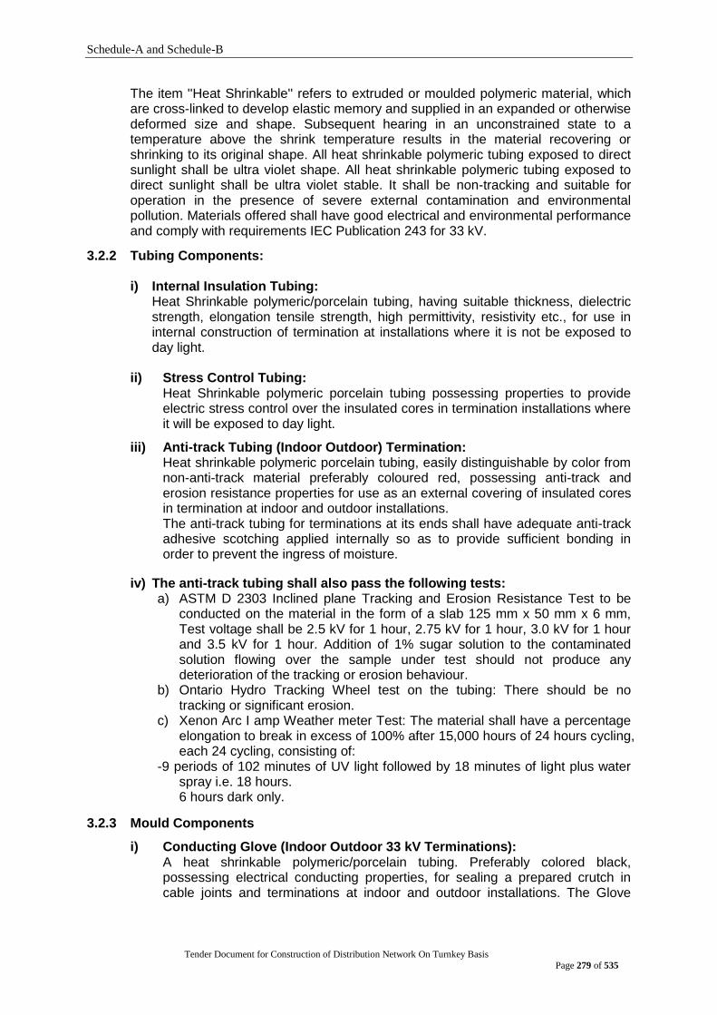
Schedule-A and Schedule-B
Tender Document for Construction of Distribution Network On Turnkey Basis
Page 279 of 535
The item ''Heat Shrinkable'' refers to extruded or moulded polymeric material, which are cross-linked to develop elastic memory and supplied in an expanded or otherwise deformed size and shape. Subsequent hearing in an unconstrained state to a temperature above the shrink temperature results in the material recovering or shrinking to its original shape. All heat shrinkable polymeric tubing exposed to direct sunlight shall be ultra violet shape. All heat shrinkable polymeric tubing exposed to direct sunlight shall be ultra violet stable. It shall be non-tracking and suitable for operation in the presence of severe external contamination and environmental pollution. Materials offered shall have good electrical and environmental performance and comply with requirements IEC Publication 243 for 33 kV.
3.2.2 Tubing Components:
i) Internal Insulation Tubing: Heat Shrinkable polymeric/porcelain tubing, having suitable thickness, dielectric strength, elongation tensile strength, high permittivity, resistivity etc., for use in internal construction of termination at installations where it is not be exposed to day light.
ii) Stress Control Tubing:
Heat Shrinkable polymeric porcelain tubing possessing properties to provide electric stress control over the insulated cores in termination installations where it will be exposed to day light.
iii) Anti-track Tubing (Indoor Outdoor) Termination: Heat shrinkable polymeric porcelain tubing, easily distinguishable by color from non-anti-track material preferably coloured red, possessing anti-track and erosion resistance properties for use as an external covering of insulated cores in termination at indoor and outdoor installations. The anti-track tubing for terminations at its ends shall have adequate anti-track adhesive scotching applied internally so as to provide sufficient bonding in order to prevent the ingress of moisture.
iv) The anti-track tubing shall also pass the following tests: a) ASTM D 2303 Inclined plane Tracking and Erosion Resistance Test to be
conducted on the material in the form of a slab 125 mm x 50 mm x 6 mm, Test voltage shall be 2.5 kV for 1 hour, 2.75 kV for 1 hour, 3.0 kV for 1 hour and 3.5 kV for 1 hour. Addition of 1% sugar solution to the contaminated solution flowing over the sample under test should not produce any deterioration of the tracking or erosion behaviour.
b) Ontario Hydro Tracking Wheel test on the tubing: There should be no tracking or significant erosion.
c) Xenon Arc I amp Weather meter Test: The material shall have a percentage elongation to break in excess of 100% after 15,000 hours of 24 hours cycling, each 24 cycling, consisting of:
-9 periods of 102 minutes of UV light followed by 18 minutes of light plus water spray i.e. 18 hours.
6 hours dark only.
3.2.3 Mould Components
i) Conducting Glove (Indoor Outdoor 33 kV Terminations): A heat shrinkable polymeric/porcelain tubing. Preferably colored black, possessing electrical conducting properties, for sealing a prepared crutch in cable joints and terminations at indoor and outdoor installations. The Glove
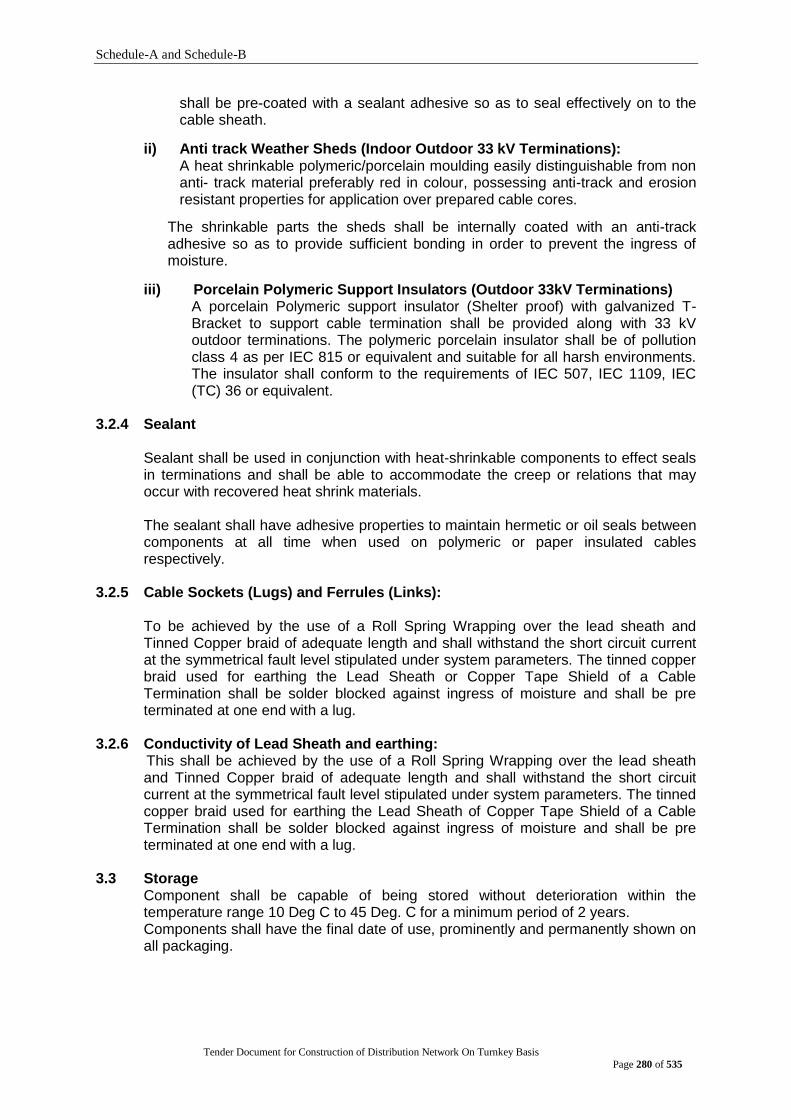
Schedule-A and Schedule-B
Tender Document for Construction of Distribution Network On Turnkey Basis
Page 280 of 535
shall be pre-coated with a sealant adhesive so as to seal effectively on to the cable sheath.
ii) Anti track Weather Sheds (Indoor Outdoor 33 kV Terminations): A heat shrinkable polymeric/porcelain moulding easily distinguishable from non anti- track material preferably red in colour, possessing anti-track and erosion resistant properties for application over prepared cable cores.
The shrinkable parts the sheds shall be internally coated with an anti-track adhesive so as to provide sufficient bonding in order to prevent the ingress of moisture.
iii) Porcelain Polymeric Support Insulators (Outdoor 33kV Terminations) A porcelain Polymeric support insulator (Shelter proof) with galvanized T-Bracket to support cable termination shall be provided along with 33 kV outdoor terminations. The polymeric porcelain insulator shall be of pollution class 4 as per IEC 815 or equivalent and suitable for all harsh environments. The insulator shall conform to the requirements of IEC 507, IEC 1109, IEC (TC) 36 or equivalent.
3.2.4 Sealant Sealant shall be used in conjunction with heat-shrinkable components to effect seals in terminations and shall be able to accommodate the creep or relations that may occur with recovered heat shrink materials. The sealant shall have adhesive properties to maintain hermetic or oil seals between components at all time when used on polymeric or paper insulated cables respectively.
3.2.5 Cable Sockets (Lugs) and Ferrules (Links):
To be achieved by the use of a Roll Spring Wrapping over the lead sheath and Tinned Copper braid of adequate length and shall withstand the short circuit current at the symmetrical fault level stipulated under system parameters. The tinned copper braid used for earthing the Lead Sheath or Copper Tape Shield of a Cable Termination shall be solder blocked against ingress of moisture and shall be pre terminated at one end with a lug.
3.2.6 Conductivity of Lead Sheath and earthing: This shall be achieved by the use of a Roll Spring Wrapping over the lead sheath
and Tinned Copper braid of adequate length and shall withstand the short circuit current at the symmetrical fault level stipulated under system parameters. The tinned copper braid used for earthing the Lead Sheath of Copper Tape Shield of a Cable Termination shall be solder blocked against ingress of moisture and shall be pre terminated at one end with a lug.
3.3 Storage
Component shall be capable of being stored without deterioration within the temperature range 10 Deg C to 45 Deg. C for a minimum period of 2 years. Components shall have the final date of use, prominently and permanently shown on all packaging.
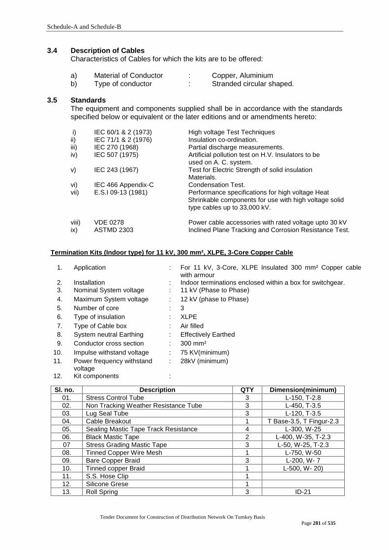
Schedule-A and Schedule-B
Tender Document for Construction of Distribution Network On Turnkey Basis
Page 281 of 535
3.4 Description of Cables Characteristics of Cables for which the kits are to be offered: a) Material of Conductor : Copper, Aluminium b) Type of conductor : Stranded circular shaped.
3.5 Standards
The equipment and components supplied shall be in accordance with the standards specified below or equivalent or the later editions and or amendments hereto:
i) IEC 60/1 & 2 (1973) High voltage Test Techniques ii) IEC 71/1 & 2 (1976) Insulation co-ordination. iii) IEC 270 (1968) Partial discharge measurements. iv) IEC 507 (1975) Artificial pollution test on H.V. Insulators to be
used on A. C. system. v) IEC 243 (1967) Test for Electric Strength of solid insulation
Materials. vi) IEC 466 Appendix-C Condensation Test. vii) E.S.I 09-13 (1981) Performance specifications for high voltage Heat
Shrinkable components for use with high voltage solid type cables up to 33,000 kV.
viii) VDE 0278 Power cable accessories with rated voltage upto 30 kV ix) ASTMD 2303 Inclined Plane Tracking and Corrosion Resistance Test.
Termination Kits (Indoor type) for 11 kV, 300 mm², XLPE, 3-Core Copper Cable
1. Application : For 11 kV, 3-Core, XLPE Insulated 300 mm² Copper cable with armour
2. Installation : Indoor terminations enclosed within a box for switchgear. 3. Nominal System voltage : 11 kV (Phase to Phase)
4. Maximum System voltage : 12 kV (phase to Phase)
5. Number of core : 3
6. Type of insulation : XLPE
7. Type of Cable box : Air filled
8. System neutral Earthing : Effectively Earthed
9. Conductor cross section : 300 mm²
10. Impulse withstand voltage : 75 KV(minimum)
11. Power frequency withstand voltage
: 28kV (minimum)
12. Kit components :
Sl. no. Description QTY Dimension(minimum)
01. Stress Control Tube 3 L-150, T-2.8
02. Non Tracking Weather Resistance Tube 3 L-450, T-3.5
03. Lug Seal Tube 3 L-120, T-3.5
04. Cable Breakout 1 T Base-3.5, T Fingur-2.3
05. Sealing Mastic Tape Track Resistance 4 L-300, W-25
06. Black Mastic Tape 2 L-400, W-35, T-2.3
07 Stress Grading Mastic Tape 3 L-50, W-25, T-2.3
08. Tinned Copper Wire Mesh 1 L-750, W-50
09. Bare Copper Braid 3 L-200, W- 7
10. Tinned copper Braid 1 L-500, W- 20)
11. S.S. Hose Clip 1
12. Silicone Grese 1
13. Roll Spring 3 ID-21
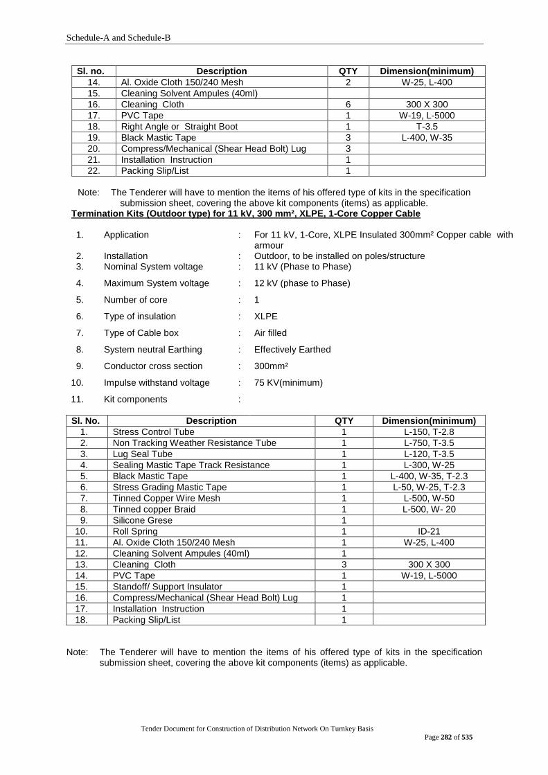
Schedule-A and Schedule-B
Tender Document for Construction of Distribution Network On Turnkey Basis
Page 282 of 535
Sl. no. Description QTY Dimension(minimum)
14. Al. Oxide Cloth 150/240 Mesh 2 W-25, L-400
15. Cleaning Solvent Ampules (40ml)
16. Cleaning Cloth 6 300 X 300
17. PVC Tape 1 W-19, L-5000
18. Right Angle or Straight Boot 1 T-3.5
19. Black Mastic Tape 3 L-400, W-35
20. Compress/Mechanical (Shear Head Bolt) Lug 3
21. Installation Instruction 1
22. Packing Slip/List 1
Note: The Tenderer will have to mention the items of his offered type of kits in the specification
submission sheet, covering the above kit components (items) as applicable. Termination Kits (Outdoor type) for 11 kV, 300 mm², XLPE, 1-Core Copper Cable 1. Application : For 11 kV, 1-Core, XLPE Insulated 300mm² Copper cable with
armour 2. Installation : Outdoor, to be installed on poles/structure 3. Nominal System voltage : 11 kV (Phase to Phase)
4. Maximum System voltage : 12 kV (phase to Phase)
5. Number of core : 1
6. Type of insulation : XLPE
7. Type of Cable box : Air filled
8. System neutral Earthing : Effectively Earthed
9. Conductor cross section : 300mm²
10. Impulse withstand voltage : 75 KV(minimum)
11. Kit components :
Sl. No. Description QTY Dimension(minimum)
1. Stress Control Tube 1 L-150, T-2.8
2. Non Tracking Weather Resistance Tube 1 L-750, T-3.5
3. Lug Seal Tube 1 L-120, T-3.5
4. Sealing Mastic Tape Track Resistance 1 L-300, W-25
5. Black Mastic Tape 1 L-400, W-35, T-2.3
6. Stress Grading Mastic Tape 1 L-50, W-25, T-2.3
7. Tinned Copper Wire Mesh 1 L-500, W-50
8. Tinned copper Braid 1 L-500, W- 20
9. Silicone Grese 1
10. Roll Spring 1 ID-21
11. Al. Oxide Cloth 150/240 Mesh 1 W-25, L-400
12. Cleaning Solvent Ampules (40ml) 1
13. Cleaning Cloth 3 300 X 300
14. PVC Tape 1 W-19, L-5000
15. Standoff/ Support Insulator 1
16. Compress/Mechanical (Shear Head Bolt) Lug 1
17. Installation Instruction 1
18. Packing Slip/List 1
Note: The Tenderer will have to mention the items of his offered type of kits in the specification
submission sheet, covering the above kit components (items) as applicable.
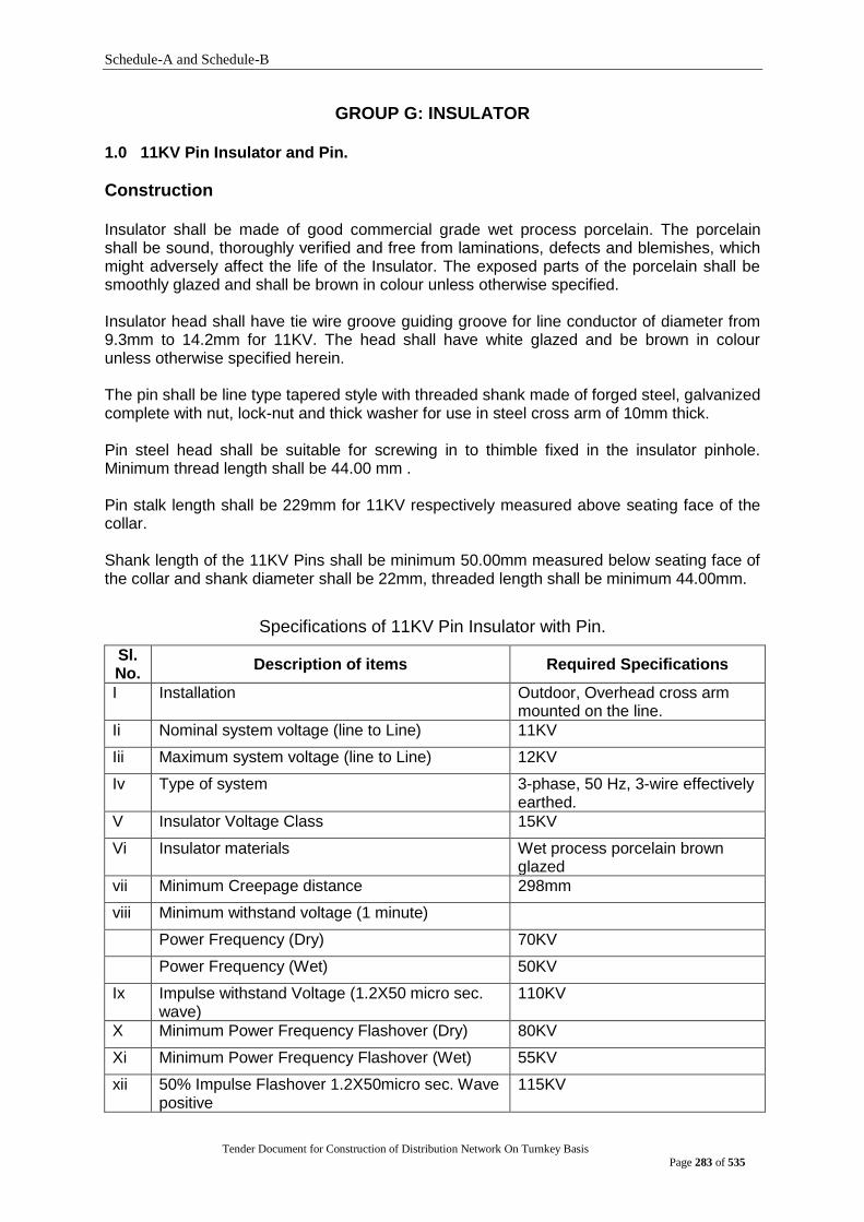
Schedule-A and Schedule-B
Tender Document for Construction of Distribution Network On Turnkey Basis
Page 283 of 535
GROUP G: INSULATOR 1.0 11KV Pin Insulator and Pin.
Construction
Insulator shall be made of good commercial grade wet process porcelain. The porcelain shall be sound, thoroughly verified and free from laminations, defects and blemishes, which might adversely affect the life of the Insulator. The exposed parts of the porcelain shall be smoothly glazed and shall be brown in colour unless otherwise specified.
Insulator head shall have tie wire groove guiding groove for line conductor of diameter from 9.3mm to 14.2mm for 11KV. The head shall have white glazed and be brown in colour unless otherwise specified herein.
The pin shall be line type tapered style with threaded shank made of forged steel, galvanized complete with nut, lock-nut and thick washer for use in steel cross arm of 10mm thick.
Pin steel head shall be suitable for screwing in to thimble fixed in the insulator pinhole. Minimum thread length shall be 44.00 mm .
Pin stalk length shall be 229mm for 11KV respectively measured above seating face of the collar.
Shank length of the 11KV Pins shall be minimum 50.00mm measured below seating face of the collar and shank diameter shall be 22mm, threaded length shall be minimum 44.00mm.
Specifications of 11KV Pin Insulator with Pin.
Sl. No.
Description of items Required Specifications
I Installation Outdoor, Overhead cross arm mounted on the line.
Ii Nominal system voltage (line to Line) 11KV
Iii Maximum system voltage (line to Line) 12KV
Iv Type of system 3-phase, 50 Hz, 3-wire effectively earthed.
V Insulator Voltage Class 15KV
Vi Insulator materials Wet process porcelain brown glazed
vii Minimum Creepage distance 298mm
viii Minimum withstand voltage (1 minute)
Power Frequency (Dry) 70KV
Power Frequency (Wet) 50KV
Ix Impulse withstand Voltage (1.2X50 micro sec. wave)
110KV
X Minimum Power Frequency Flashover (Dry) 80KV
Xi Minimum Power Frequency Flashover (Wet) 55KV
xii 50% Impulse Flashover 1.2X50micro sec. Wave positive
115KV

Schedule-A and Schedule-B
Tender Document for Construction of Distribution Network On Turnkey Basis
Page 284 of 535
Sl. No.
Description of items Required Specifications
xiii 50% Impulse Flashover 1.2X50micro sec. Wave negative
140KV
xiv Power Frequency Puncher Voltage 130KV
Xv Minimum Dry Arching Distance 133mm
xvi Power Frequency Test Voltage RMS to ground 15KV
xvii Minimum Radio Influence Voltage (RIV) at 1000kc in micro volt
As per BS 137.2
xviii Minimum Neck Diameter 76mm
xix Minimum Diameter of Insulator 150mm
Xx Minimum height of the insulator 150mm
xxi Minimum Grove diameter 22mm
xxii Minimum Mechanical failing load 10KN
2.0 11 kV Disc Insulator with fittings. Construction
Insulator shall be made of good commercial grade wet process porcelain. The porcelain/silicon rubber shall be sound, thoroughly verified and free from laminations, defects and blemishes, which might adversely affect the life of the Insulator. The exposed parts of the porcelain shall be smoothly glazed and shall be brown in colour unless otherwise specified.
Specifications of 11KV Disc Insulator
Sl. No. Description of items 11KV tension disc set
i Installation Outdoor, Overhead cross arm mounted.
Ii Nominal system voltage (line to Line) 11KV
Iii Maximum system voltage (line to Line) 12KV
Iv Type of system 3-phase, 50-Hz, 3-wire effectively earthed.
V Insulator Voltage Class 15KV
Vi Insulator materials Wet process porcelain brown glazed
Vii Type of Insulator Ball ended socket type disc, security clip made of stainless steel on phosphor bronzed/red brass alloy
viii Diameter of Insulator 255 mm
Ix Minimum Unit spacing 140 mm
X Coupling size 16 mm
Xi Minimum Creepage distance 292 mm
Xii Minimum withstand voltage (1 minutes)
Power Frequency (Dry) 70 KV
Power Frequency (Wet) 45 KV
Xiii Impulse withstand Voltage (1.2X50 micro sec. wave)
110 KV
Xiv Minimum Power Frequency Flashover (Dry)
78 KV

Schedule-A and Schedule-B
Tender Document for Construction of Distribution Network On Turnkey Basis
Page 285 of 535
Sl. No. Description of items 11KV tension disc set
Xv Minimum Power Frequency Flashover (Wet)
45 KV
Xvi 50% Impulse Flashover 1.2X50micro sec. Wave positive
120 KV
Xvii 50% Impulse Flashover 1.2X50micro sec. Wave negative
125 KV
Xviii Power Frequency Puncher Voltage 110 KV
Xix Minimum Dry Arching Distance 171/280 mm
Xx Power Frequency Test Voltage RMS to ground
15 KV
Xxi Minimum Radio Influence Voltage (RIV) at 1000kc in micro volt
As per BS 137.2
Xxii Minimum electromechanical strength 70 KN
Xxiii Minimum Mechanical failing load 70 KN
Specifications of 11KV Disc fittings (for 1 set)
-Disc Insulator- 6 no -Anchor Shackle-3 no -Ball Eye-3 no -Socket Eye- 3 no -Strain Clamp-3 no -Terminating strap -3 no
A Anchor Shackle
I Material Forged Steel galvanized complete with cotter bolt and pin
II Ultimate Tensile Strength
70KN
III Galvanization Shall be as per BS 729, part 1 or ASTM A-153
B Ball Eye
I Material Forged Steel galvanized complete with cotter bolt and pin
II Ultimate Tensile Strength
70KN
III Galvanization Shall be as per BS 729 part 1 or ASTM A-153
C Socket Eye
I Material Malleable iron galvanized complete with cotter bolt and pin
II Ultimate Tensile Strength
70KN
III Galvanization Shall be as per BS 729 part 1 or ASTM A-153
D Strain Clamp for ACSR (DOG)
I Material Malleable iron galvanized or Aluminium alloy suitable for accommodating ACSR Conductor of diameter from 9.3 mm to 14.2 mm complete with bolts, nuts, washers and aluminium liner etc.
II Minimum Grove diameter
18mm
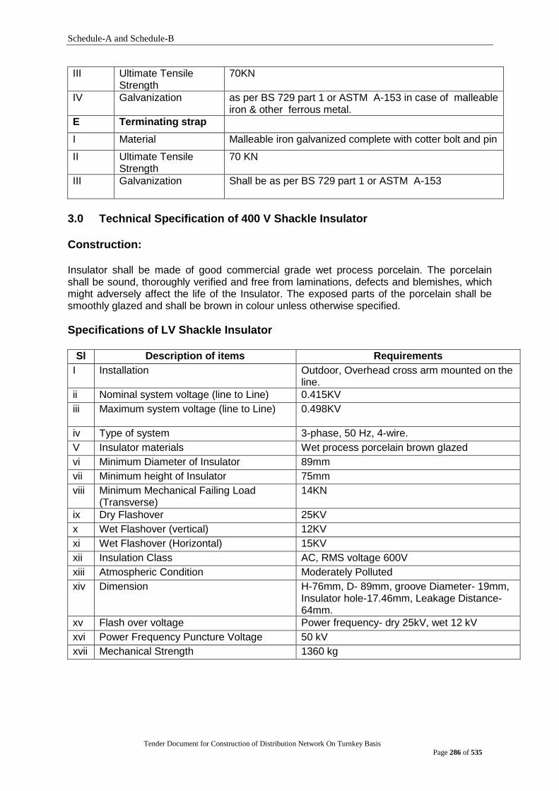
Schedule-A and Schedule-B
Tender Document for Construction of Distribution Network On Turnkey Basis
Page 286 of 535
III Ultimate Tensile Strength
70KN
IV Galvanization as per BS 729 part 1 or ASTM A-153 in case of malleable iron & other ferrous metal.
E Terminating strap
I Material Malleable iron galvanized complete with cotter bolt and pin
II Ultimate Tensile Strength
70 KN
III Galvanization
Shall be as per BS 729 part 1 or ASTM A-153
3.0 Technical Specification of 400 V Shackle Insulator Construction:
Insulator shall be made of good commercial grade wet process porcelain. The porcelain shall be sound, thoroughly verified and free from laminations, defects and blemishes, which might adversely affect the life of the Insulator. The exposed parts of the porcelain shall be smoothly glazed and shall be brown in colour unless otherwise specified.
Specifications of LV Shackle Insulator
Sl Description of items Requirements
I Installation Outdoor, Overhead cross arm mounted on the line.
ii Nominal system voltage (line to Line) 0.415KV
iii Maximum system voltage (line to Line)
0.498KV
iv Type of system 3-phase, 50 Hz, 4-wire.
V Insulator materials Wet process porcelain brown glazed
vi Minimum Diameter of Insulator 89mm
vii Minimum height of Insulator 75mm
viii Minimum Mechanical Failing Load (Transverse)
14KN
ix Dry Flashover 25KV
x Wet Flashover (vertical) 12KV
xi Wet Flashover (Horizontal) 15KV
xii Insulation Class AC, RMS voltage 600V
xiii Atmospheric Condition Moderately Polluted
xiv Dimension H-76mm, D- 89mm, groove Diameter- 19mm, Insulator hole-17.46mm, Leakage Distance- 64mm.
xv Flash over voltage Power frequency- dry 25kV, wet 12 kV
xvi Power Frequency Puncture Voltage 50 kV
xvii Mechanical Strength 1360 kg
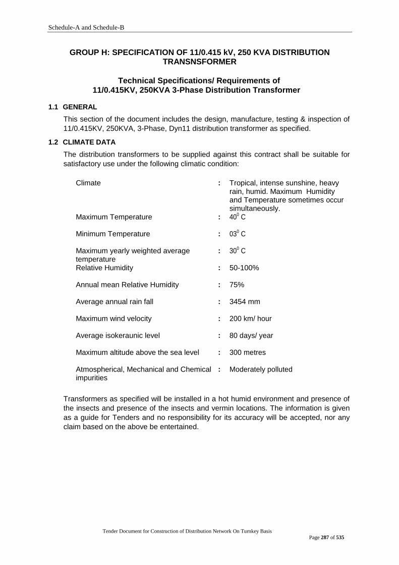
Schedule-A and Schedule-B
Tender Document for Construction of Distribution Network On Turnkey Basis
Page 287 of 535
GROUP H: SPECIFICATION OF 11/0.415 kV, 250 KVA DISTRIBUTION TRANSNSFORMER
Technical Specifications/ Requirements of
11/0.415KV, 250KVA 3-Phase Distribution Transformer 1.1 GENERAL
This section of the document includes the design, manufacture, testing & inspection of
11/0.415KV, 250KVA, 3-Phase, Dyn11 distribution transformer as specified. 1.2 CLIMATE DATA
The distribution transformers to be supplied against this contract shall be suitable for
satisfactory use under the following climatic condition:
Climate : Tropical, intense sunshine, heavy
rain, humid. Maximum Humidity and Temperature sometimes occur simultaneously.
Maximum Temperature : 400 C
Minimum Temperature : 030 C
Maximum yearly weighted average temperature
: 300 C
Relative Humidity : 50-100%
Annual mean Relative Humidity : 75%
Average annual rain fall : 3454 mm
Maximum wind velocity : 200 km/ hour
Average isokeraunic level : 80 days/ year
Maximum altitude above the sea level : 300 metres
Atmospherical, Mechanical and Chemical impurities
: Moderately polluted
Transformers as specified will be installed in a hot humid environment and presence of
the insects and presence of the insects and vermin locations. The information is given
as a guide for Tenders and no responsibility for its accuracy will be accepted, nor any
claim based on the above be entertained.
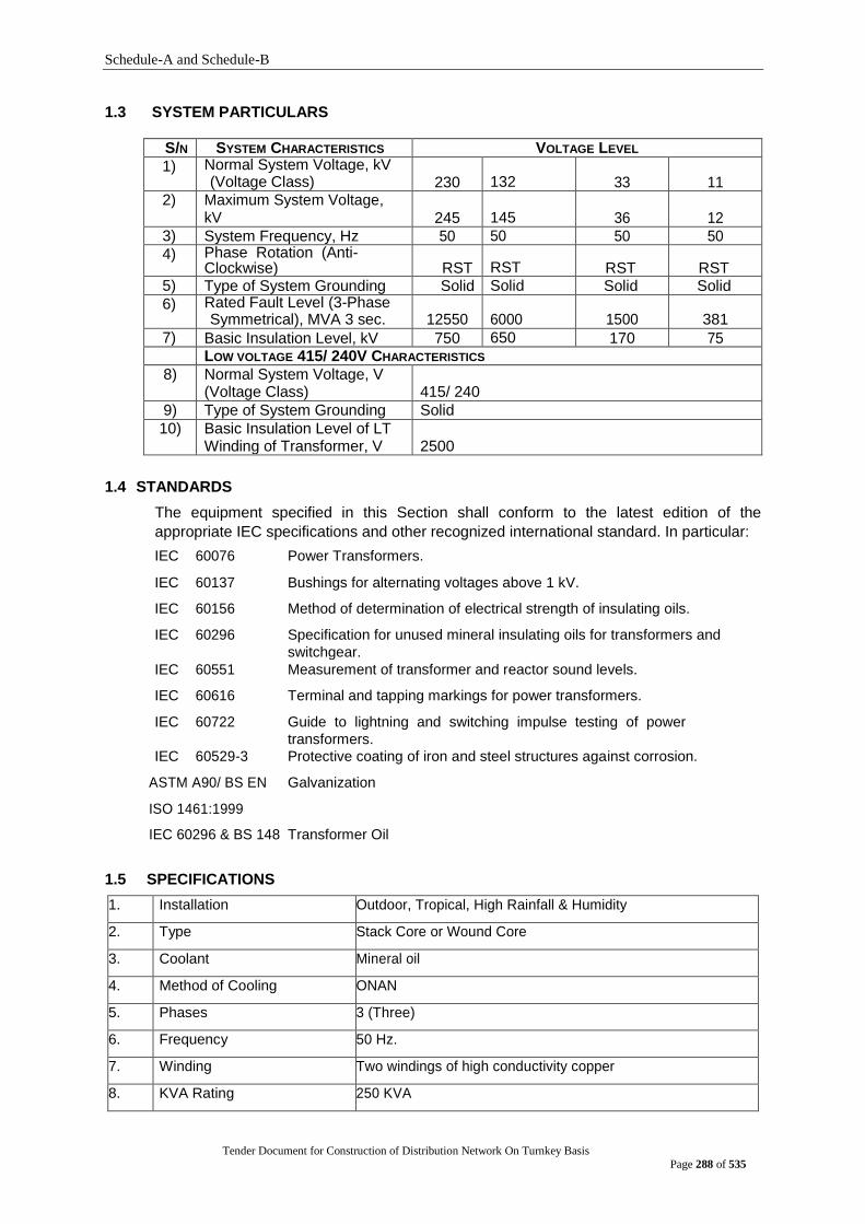
Schedule-A and Schedule-B
Tender Document for Construction of Distribution Network On Turnkey Basis
Page 288 of 535
1.3 SYSTEM PARTICULARS
S/N SYSTEM CHARACTERISTICS VOLTAGE LEVEL
1) Normal System Voltage, kV (Voltage Class) 230 132 33 11
2) Maximum System Voltage, kV 245 145 36 12
3) System Frequency, Hz 50 50 50 50 4) Phase Rotation (Anti-
Clockwise) RST RST RST RST 5) Type of System Grounding Solid Solid Solid Solid
6) Rated Fault Level (3-Phase Symmetrical), MVA 3 sec. 12550 6000 1500 381
7) Basic Insulation Level, kV 750 650 170 75 LOW VOLTAGE 415/ 240V CHARACTERISTICS
8) Normal System Voltage, V (Voltage Class) 415/ 240
9) Type of System Grounding Solid
10) Basic Insulation Level of LT Winding of Transformer, V 2500
1.4 STANDARDS
The equipment specified in this Section shall conform to the latest edition of the
appropriate IEC specifications and other recognized international standard. In particular:
IEC 60076 Power Transformers.
IEC 60137 Bushings for alternating voltages above 1 kV.
IEC 60156 Method of determination of electrical strength of insulating oils.
IEC 60296 Specification for unused mineral insulating oils for transformers and
switchgear.
IEC 60551 Measurement of transformer and reactor sound levels.
IEC 60616 Terminal and tapping markings for power transformers.
IEC 60722 Guide to lightning and switching impulse testing of power
transformers.
IEC 60529-3 Protective coating of iron and steel structures against corrosion.
ASTM A90/ BS EN Galvanization
ISO 1461:1999
IEC 60296 & BS 148 Transformer Oil
1.5 SPECIFICATIONS 1. Installation Outdoor, Tropical, High Rainfall & Humidity
2. Type Stack Core or Wound Core
3. Coolant Mineral oil
4. Method of Cooling ONAN
5. Phases 3 (Three)
6. Frequency 50 Hz.
7. Winding Two windings of high conductivity copper
8. KVA Rating 250 KVA
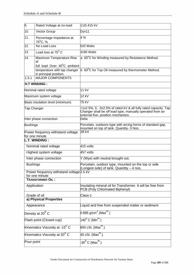
Schedule-A and Schedule-B
Tender Document for Construction of Distribution Network On Turnkey Basis
Page 289 of 535
9. Rated Voltage at no-load 11/0.415 kV
10. Vector Group Dyn11
11. Percentage Impedance at
750C, %
4 %
12. No Load Loss 520 Watts
13. Load loss at 750 C 3180 Watts
14. Maximum Temperature Rise at
full load Over 400C ambient
a 650C for Winding measured by Resistance Method.
temperature with tap changer
in principal position.
b 600C for Top Oil measured by thermometer Method.
1.5.1 MAJOR COMPONENTS
H.T WINDING :
Nominal rated voltage 11 kV
Maximum system voltage 12 kV
Basic insulation level (minimum) 75 kV
Tap Changer +1x2.5%, 0, -3x2.5% of rated kV & all fully rated capacity. Tap Changer shall be off load type, manually operated from an external five- position mechanism.
Inter phase connection Delta
Bushings Porcelain, outdoors type with arcing horns of standard gap, mounted on top of tank. Quantity- 3 Nos.
Power frequency withstand voltage for one minute
28 kV
L.T. WINDING :
Nominal rated voltage 415 volts
Highest system voltage 457 volts
Inter phase connection Y (Wye) with neutral brought out.
Bushings Porcelain, outdoor type, mounted on the top or side (Longest side) of tank. Quantity – 4 nos.
Power frequency withstand voltage for one minute
2.5 kV
TRANSFORMER OIL :
Application Insulating mineral oil for Transformer. It will be free from PCB (Poly Chlorinated Biphenyl)
Grade of oil Class-1 a) Physical Properties
Appearance Liquid and free from suspended matter or sediment
Density at 200 C 0.895 g/cm
3 (Max
m.)
Flash point (Closed cup) 1400 C (Min
m.)
Kinematics Viscosity at -150 C 800 cSt. (Max
m.)
Kinematics Viscosity at 200 C 40 cSt. (Max
m.)
Pour point -300 C (Max
m.)

Schedule-A and Schedule-B
Tender Document for Construction of Distribution Network On Turnkey Basis
Page 290 of 535
b) Electrical Properties
Dielectric Strength at 50 Hz (with
New untreated oil, shall go through filtration
2.5 mm standard gap and 40 mm standard depth)
treatment before the oils are introduced into the apparatus or equipment. The break down voltage of this oil shall be more than 50 kV.
Loss tangent/Dielectric dissipation factor at temp. 90
0C, stress
500V/mm to 1000 V/mm and frequency 40 Hz to 62 Hz.
0.005 (Maxm
.)
c) Chemical Properties
Neutralization value 0.03 mg KOH/g (Maxm
.)
Neutralization value after oxidation 0.40 mg KOH/g (Maxm
.)
Total sludge after oxidation 0.10% weight (Maxm
.)
PCB Content Free from PCB (Poly Chlorinated Biphenyl)
d) Standards Performance and testing of oil shall comply with the latest revision of the relevant standards BS 148 : 1972, IEC-60296 or latest revision there on.
1.6 FEATURES AND ACCESSORIES
a) All bolts and nuts connected with transformer tank, conservator, radiator etc. shall
be of non-ferrous metal. If it is ferrous metal, it shall be hot dip galvanized as per
standard ASTM A90/ BS EN ISO 1461:1999. b) Lugs for lifting & towing complete unit. c) Facilities for lifting core & coil assembly. d) Base designed for platform mounting on poles. e) First filling of new oil shall comply to the latest revision of IEC-60296 standard or
other equivalent standards. f) Each H.T. bushing shall have bolted type bimetallic connector suitable for
accommodating ACSR conductor having Dia. range from 9mm to 14.5mm. g) Each L.T. bushing shall have bolted type bimetallic connector for accommodating
copper/AAC of area range 2x95mm2 to 2x120mm2 depending upon the KVA rating of the transformer.
h) The L.T. bushing shall be installed on the top or side of tank lengthwise of the
transformer body. i) Dial thermometer for oil temperature mounted on L.T. side of the tank. j) Earthing terminals at the bottom corners of Tank. k) Name plate with transformer rating & winding diagram made of stainless steel shall
have engraved letters filled with black enamel and shall be continuously welded in
the transformer body. l) The tank & radiator or flanged radiator shall be painted with two coats of gray
finishing paint on suitable prime coats. m) Transformer capacity with Sl.No. and (INSERT THE NAME OF THE
ORGANIZATION) Contract No. should be marked with emboss/ engrave on the transformer tank adjacent to name plate easily visible from ground as per tender clause-1.14.6.

Schedule-A and Schedule-B
Tender Document for Construction of Distribution Network On Turnkey Basis
Page 291 of 535
FOR CONSERVATOR :
a) Transformer tank completes with covers, necessary openings & gaskets. b) Complete oil preservation system consisting of an oil conservator with shut-off
valve oil level gauge. The system shall have valve for filter press inlet & oil drain.
The oil sampling valve & dehydrating breather shall be provided.
1.7 INFORMATION REQUIRED
The Bidder/ Manufacturer as per tender requirements shall provide all information.
Besides these, the following information has to be submitted: a) Manufacturer‟s Printed Catalogue describing specification and technical data for
crucial components of offered 11/0.415KV, 250KVA, 3-Phase, Dyn11 distribution
transformer.
b) Detail dimensional drawings of offered 11/0.415KV, 250KVA, 3-Phase, Dyn11
distribution transformer. c) The Bidder/ Manufacturer shall submit the list of available testing/ measuring
equipment, meters, etc., along with valid Calibration Certificate(s) from competent authority used in manufacturer's laboratory for performing Routine Test as per IEC
standard. d) Manufacturer's valid ISO 9001 Certificate.
1.8 DOCUMENTATION
The following documents are to be submitted by the Tenderer along with the Tender for
the similar KVA rating of same voltage class of offered 11/0.415KV Distribution
Transformer; otherwise the bid will be rejected:
A. COMMERCIAL
Tenderer shall be eligible as per ITT Clause No. 5 and they should submit Bid validity, Bid Bond, Bid Bond validity, Price Schedule, Delivery Schedule, Authorisation of the signatory, Tender Submission Sheet, Tenderer Information Sheet & Documentary evidence for establishing the Tenderer‟s Qualifications, etc. and all other documents including information related to rejection clause as per Tender Document.
B. TECHNICAL
1) Guaranteed Technical Particulars (GTP) shall be properly filled up and signed by both
Manufacturer & Tenderer; 2) Letter of authorization from the Manufacturers, in case, the Bidder is not the
manufacturer, in the prescribed Form 3) 2 nos. of Manufacturer's Supply Record for similar or higher KVA rating of same
voltage class of offered type Distribution Transformer within the last 5 (five) years from the date of bid opening in the following format (The supply record covering 25% of the tendered quantity in a single Contract will be considered only.
Sl. No.
Name, Address, Phone No., e-mail & Fax No. of the Purchaser
Contract No. & Date
Contract Value
Description of Material with Quantity
Date of Completion of Supply
4) At Least 2(two) nos. of Satisfactory Performance Certificate from Electricity utility as
End User for similar or higher KVA rating of same voltage class of offered type Distribution Transformer within the last 5 (five) years from the year of Tender Notice. The Satisfactory Performance certificate should be in End User's letterhead Pad in English stating at least one year satisfactory operation from the date of installation of
Schedule-A and Schedule-B
Tender Document for Construction of Distribution Network On Turnkey Basis
Page 292 of 535
the said transformer and shall contain end-user's full mailing address/ e-mail address, website address/fax and phone no for convenience of authentication.
5) Type test & Special test along with Routine test report as per clause no. 1.9 for similar KVA rating of same voltage class of offered type Distribution Transformer from an independent testing laboratory as per IEC 60076. All Type Test & Special test shall be done on the same transformer (having same serial number) from an independent testing laboratory.
6) Local manufacturers, who have supplied the same offered item to [INSERT THE NAME
OF THE ORGANIZATION] within the last 5 (five) years from the date of bid opening, need not to submit any Manufacturer's Supply Record with the tender proposal. In that case, they have to submit one Satisfactory Performance Certificate (within last three years) from [INSERT THE NAME OF THE OFFICE AND ORGANIZATION] for the same offered item covering 25% of the tendered quantity in a single Contract.
7) The following provision will be applicable for purchasing less or equal to 50 nos.
transformers from new manufacturers.
At least 30 (thirty) nos. of Satisfactory Performance Certificate from end users (public/private) for similar or higher KVA rating of same voltage class of offered type Distribution Transformers within last 3 (three) years from the date of bid opening. The Satisfactory Performance certificate shall be from End User's stating at least one year satisfactory operation from the date of installation of the said transformer and shall contain end-user's full mailing address/ e-mail address, website address/fax and phone no for convenience of authentication. Factory shall be inspected by TEC as per following guide lines.
1) Location of the Factory & layout plan. 2) List of Capital Machineries (Related to manufacturer of the Tendered goods)
3) Factory Project Profile 4) Production Capacity (Yearly 5) Production Line description 6) List of Key Personnel (with Bio-data) 7) Provide sample of the Tendered product manufactured in the Factory for evaluation of
TEC during factory Inspection. 8) Testing Facilities as per IEC 60076 9) Warranty period 24 months from R&I issuing date 10) Trade License, TIN & VAT certificate 11) Source of raw materials 12) sample of the offered type Distribution Transformer shall be tested by TEC at
manufacturer‟s testing laboratory.
All other clauses of the specification and Guaranteed Technical Particulars (GTP) except Supply record & Performance Certificate (Clause no. 1.8 B 3 & 4) shall be applicable for Bid Submission and Evaluation
. 1.9 TEST REPORTS
Tenderer's shall include in their offer the following routine tests, type tests and Short
circuit withstands tests as prescribed in IEC-60076 for 11/0.415KV, 250KVA, 3-Phase,
Dyn11 Distribution Transformer.
ROUTINE TESTS
1) Measurement of turn ratio test. 2) Vector group test. 3) Measurement of winding resistance.

Schedule-A and Schedule-B
Tender Document for Construction of Distribution Network On Turnkey Basis
Page 293 of 535
4) Measurement of insulation resistance. 5) Measurement of no-load loss & no-load current. 6) Measurement of impedance voltage & load loss. 7) Dielectric withstands Tests. 8) Transformer oil tests.
TYPE TESTS
1) Impulse Voltage withstands test. 2) Temperature rise test.
SPECIAL TESTS
Short circuit withstand test and detail calculation along with thermal & mechanical on
the basis of design data.
1.10 EVALUATION CRITERIA
a) The Tenders will be evaluated on the basis of relevant ITT clauses. The capitalized
cost of the Transformer losses will be considered for evaluation purposes.
Distribution transformers will be evaluated on the basis of following
formula: O = CP + 65,432 × e × PO + 26,173 × e × PFL
Where: O = Evaluated Price in BDT
CP = Quoted Price in BDT PO
= Iron loss in KW PFL = Copper loss in KW at full load at 75 C
Guaranteed loss values must be supported by test reports from independent
testing laboratory. In case of difference between the loss value declared in the
offer and the loss value to be found in the type test report, the higher loss value
will be taken into account for the purpose of loss capitalization.
b) Bidder's declared/ guaranteed no load loss and load loss value shall be within the
specified value, otherwise the bid will be rejected. c) Bidders declared/ guaranteed percentage impedance value shall be within the
specified value; otherwise the bid will be rejected.
1.11 ACCEPTANCE CRITERIA OF TRANSFORMER LOSS AND PERCENTAGE IMPEDANCE DURING FACTORY TEST WITNESS
Transformer will be tested during factory test witness and will be accepted if the
measured transformer losses are within the offered value or within the following
tolerance with deduction of money from the contract price as below :
i) Each component loss (No load loss or Full load loss) shall not exceed up to 15%
of the offered component loss, provided that the total losses cannot be exceeded
10% of the offered total losses. ii) Percentage Impedance may vary up to ± 10 % of the specified value. iii) The purchaser can carryout the testing of any transformers during pre-delivery
inspection. The testing of transformers during pre-delivery inspection will not be less than 10% at random basis of the transformer ready for inspection but in any case it will not be less than 5 nos. The manufacturer will provide all arrangements for the testing of transformers desired by the purchaser in his factory.
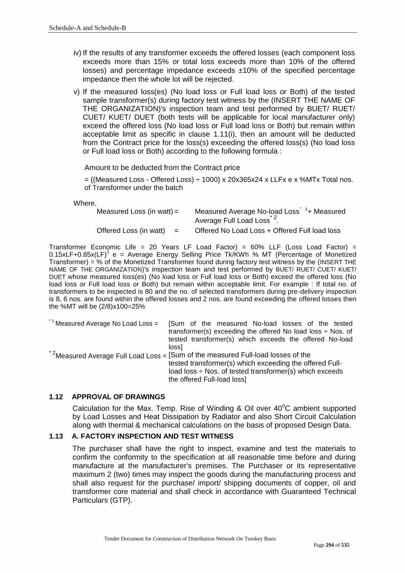
Schedule-A and Schedule-B
Tender Document for Construction of Distribution Network On Turnkey Basis
Page 294 of 535
iv) If the results of any transformer exceeds the offered losses (each component loss
exceeds more than 15% or total loss exceeds more than 10% of the offered losses) and percentage impedance exceeds ±10% of the specified percentage
impedance then the whole lot will be rejected. v) If the measured loss(es) (No load loss or Full load loss or Both) of the tested
sample transformer(s) during factory test witness by the (INSERT THE NAME OF THE ORGANIZATION)'s inspection team and test performed by BUET/ RUET/ CUET/ KUET/ DUET (both tests will be applicable for local manufacturer only) exceed the offered loss (No load loss or Full load loss or Both) but remain within acceptable limit as specific in clause 1.11(i), then an amount will be deducted from the Contract price for the loss(s) exceeding the offered loss(s) (No load loss or Full load loss or Both) according to the following formula :
Amount to be deducted from the Contract price
= {(Measured Loss - Offered Loss) ÷ 1000} x 20x365x24 x LLFx e x %MTx Total nos. of Transformer under the batch
Where, Measured Loss (in watt) = Measured Average No-load Loss
* 1+ Measured
Average Full Load Loss* 2
.
Offered Loss (in watt) = Offered No Load Loss + Offered Full load loss
Transformer Economic Life = 20 Years LF Load Factor) = 60% LLF (Loss Load Factor) = 0.15xLF+0.85x(LF)
2 e = Average Energy Selling Price Tk/KWh % MT (Percentage of Monetized
Transformer) = % of the Monetized Transformer found during factory test witness by the (INSERT THE
NAME OF THE ORGANIZATION)'s inspection team and test performed by BUET/ RUET/ CUET/ KUET/
DUET whose measured loss(es) (No load loss or Full load loss or Both) exceed the offered loss (No load loss or Full load loss or Both) but remain within acceptable limit. For example : If total no. of transformers to be inspected is 80 and the no. of selected transformers during pre-delivery inspection is 8, 6 nos. are found within the offered losses and 2 nos. are found exceeding the offered losses then the %MT will be (2/8)x100=25% * 1
Measured Average No Load Loss = [Sum of the measured No-load losses of the tested transformer(s) exceeding the offered No load loss ÷ Nos. of tested transformer(s) which exceeds the offered No-load loss]
* 2Measured Average Full Load Loss = [Sum of the measured Full-load losses of the
tested transformer(s) which exceeding the offered Full-load loss ÷ Nos. of tested transformer(s) which exceeds the offered Full-load loss]
1.12 APPROVAL OF DRAWINGS
Calculation for the Max. Temp. Rise of Winding & Oil over 400C ambient supported by Load Losses and Heat Dissipation by Radiator and also Short Circuit Calculation along with thermal & mechanical calculations on the basis of proposed Design Data.
1.13 A. FACTORY INSPECTION AND TEST WITNESS
The purchaser shall have the right to inspect, examine and test the materials to confirm the conformity to the specification at all reasonable time before and during manufacture at the manufacturer's premises. The Purchaser or its representative maximum 2 (two) times may inspect the goods during the manufacturing process and shall also request for the purchase/ import/ shipping documents of copper, oil and transformer core material and shall check in accordance with Guaranteed Technical Particulars (GTP).
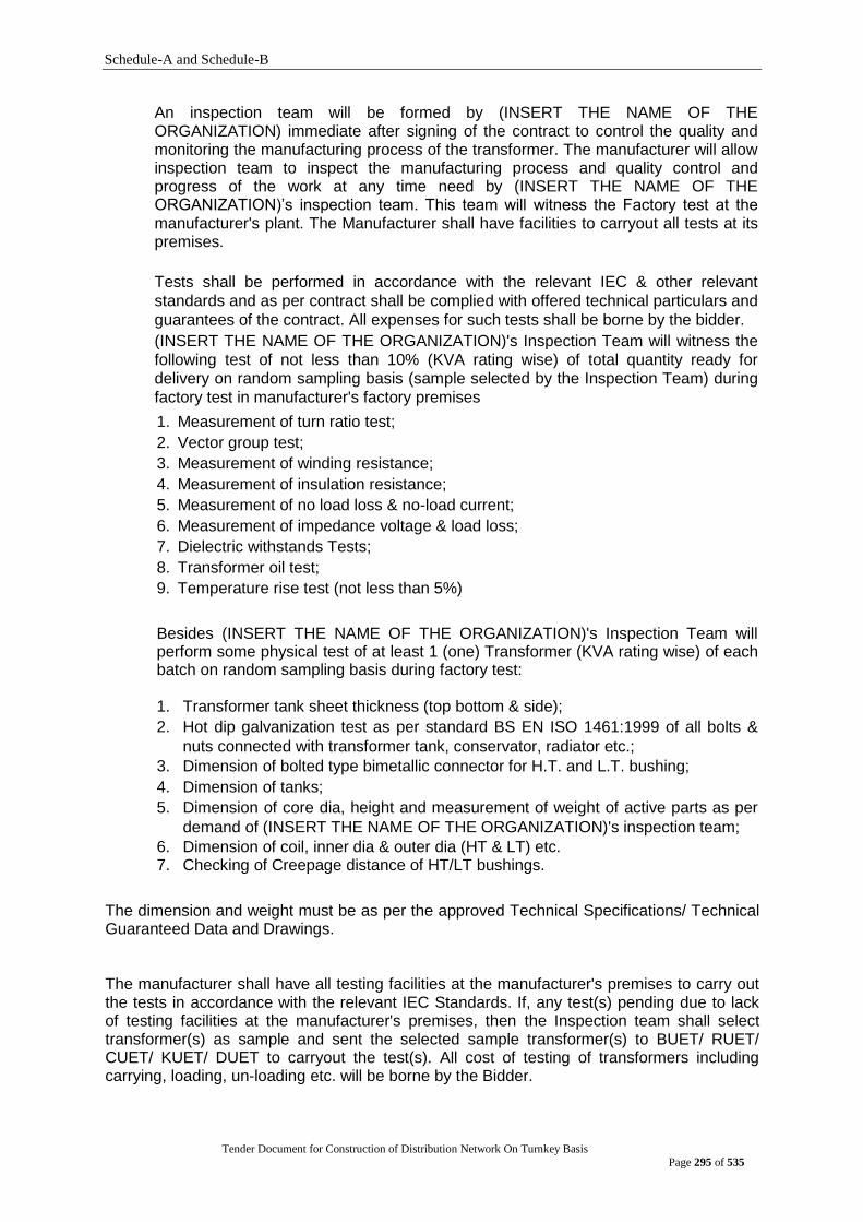
Schedule-A and Schedule-B
Tender Document for Construction of Distribution Network On Turnkey Basis
Page 295 of 535
An inspection team will be formed by (INSERT THE NAME OF THE ORGANIZATION) immediate after signing of the contract to control the quality and monitoring the manufacturing process of the transformer. The manufacturer will allow inspection team to inspect the manufacturing process and quality control and progress of the work at any time need by (INSERT THE NAME OF THE ORGANIZATION)‟s inspection team. This team will witness the Factory test at the manufacturer's plant. The Manufacturer shall have facilities to carryout all tests at its premises.
Tests shall be performed in accordance with the relevant IEC & other relevant
standards and as per contract shall be complied with offered technical particulars and
guarantees of the contract. All expenses for such tests shall be borne by the bidder. (INSERT THE NAME OF THE ORGANIZATION)'s Inspection Team will witness the
following test of not less than 10% (KVA rating wise) of total quantity ready for delivery on random sampling basis (sample selected by the Inspection Team) during
factory test in manufacturer's factory premises
1. Measurement of turn ratio test; 2. Vector group test; 3. Measurement of winding resistance; 4. Measurement of insulation resistance; 5. Measurement of no load loss & no-load current; 6. Measurement of impedance voltage & load loss; 7. Dielectric withstands Tests; 8. Transformer oil test; 9. Temperature rise test (not less than 5%)
Besides (INSERT THE NAME OF THE ORGANIZATION)'s Inspection Team will perform some physical test of at least 1 (one) Transformer (KVA rating wise) of each batch on random sampling basis during factory test: 1. Transformer tank sheet thickness (top bottom & side); 2. Hot dip galvanization test as per standard BS EN ISO 1461:1999 of all bolts &
nuts connected with transformer tank, conservator, radiator etc.; 3. Dimension of bolted type bimetallic connector for H.T. and L.T. bushing; 4. Dimension of tanks; 5. Dimension of core dia, height and measurement of weight of active parts as per
demand of (INSERT THE NAME OF THE ORGANIZATION)'s inspection team;
6. Dimension of coil, inner dia & outer dia (HT & LT) etc. 7. Checking of Creepage distance of HT/LT bushings.
The dimension and weight must be as per the approved Technical Specifications/ Technical Guaranteed Data and Drawings. The manufacturer shall have all testing facilities at the manufacturer's premises to carry out the tests in accordance with the relevant IEC Standards. If, any test(s) pending due to lack of testing facilities at the manufacturer's premises, then the Inspection team shall select transformer(s) as sample and sent the selected sample transformer(s) to BUET/ RUET/ CUET/ KUET/ DUET to carryout the test(s). All cost of testing of transformers including carrying, loading, un-loading etc. will be borne by the Bidder.
Schedule-A and Schedule-B
Tender Document for Construction of Distribution Network On Turnkey Basis
Page 296 of 535
The Bidder/ Manufacturer shall submit with the bid the testing procedure & list of testing/ measuring equipment, meters etc. used for Factory test witness. The Bidder /Manufacturer shall submit the valid Calibration Certificate from competent authority of the testing/ measuring equipments, meters etc. used for Factory test with the tender. The Bidder /Manufacturer shall also submit the following documents along with the request letter for Pre-delivery inspection:
I. Updated valid Calibration Certificates of the testing/ measuring equipments, meters etc. used for Factory test.
II. The factory test report (Routine test report) of each transformer to be supplied under
the contract. Failing to submit the above documents, the inspection team will not perform the Pre-delivery Inspection and all the liabilities along with delay (if any) will be borne by the Bidder/Manufacturer. It is noted that at the time of Factory Test witness (INSERT THE NAME OF THE ORGANIZATION)'s Inspection team will check the calibration seal/ certificate of the testing/ measuring equipment, meters etc. by the competent authority. If the calibration seal/ certificate of the testing/ measuring equipment, meters etc. are not found and the calibration not done within the due date then (INSERT THE NAME OF THE ORGANIZATION)'s Inspection team will not witness the test. In that case the Bidder/ Manufacturer shall complete the calibration of the testing/ measuring equipment, meters etc. from the competent authority within a reasonable period without any delay in delivery period.
B. RANDOM SAMPLE TEST DURING FACTORY INSPECTION AND WITNESS:
During Pre-delivery Inspection & Factory Test Witnessing of the goods to be supplied under the Contract, the Inspection Team will witness the tests as per Clauses No. 1.11 & 1.13(A) of the Tender Document. Besides that the Inspection Team will select 1 (one) Transformer (KVA rating wise) from each batch (if the total contract quantity is permitted to inspect in several batches) on random sampling basis. The selected Transformer will be sent to BUET/ RUET/ CUET/ KUET/ DUET (applicable for local manufacturer only) for performing relevant tests as per IEC Standard. The Tests will be performed as per clause 1.13A at BUET/ RUET/ CUET/ KUET/ DUET as per IEC standard and contract. All cost of testing of Transformer(s) including carrying, loading, un-loading etc. will be borne by the Bidder.
C. ACCEPTANCE OF TRANSFORMER:
If the test results of the tested sample(s) transformer(s) during factory test witness by the (INSERT THE NAME OF THE ORGANIZATION)'s inspection team and test performed by BUET/ RUET/ CUET/ KUET/ DUET fail to confirm the specification, the full consignment will be rejected. A formal delivery order will be issued after satisfactory pre-delivery inspection & test report by INSERT THE NAME OF THE ORGANIZATION)'s inspection team and test performed by BUET/ RUET/ CUET/ KUET/ DUET. D. POST-DELIVERY INSPECTION & TESTING The Inspection team of (INSERT THE NAME OF THE ORGANIZATION) shall performed
post-delivery inspection in presence of bidder's representative after the delivery of the
transformers at the designated store of (INSERT THE NAME OF THE ORGANIZATION).
Schedule-A and Schedule-B
Tender Document for Construction of Distribution Network On Turnkey Basis
Page 297 of 535
The Bidder shall arrange the program of such inspection. Any defect or damage have been
found at post-delivery inspection, the defective or damaged Transformers/ materials/ goods
to be repaired/ replaced by the Bidder/ supplier at his own cost. The purchaser‟s right to inspect, test (where necessary) and reject the transformer(s) after
delivery at the designated store of (INSERT THE NAME OF THE ORGANIZATION) shall in no way be limited or waived by reason of the goods having previously been inspected,
tested and passed by the purchaser prior to the good's delivery. The Inspection team will check the physical conditions and quantity of the goods delivered. If necessary the inspection team may select 1% of the transformer (minimum 1 no. KVA rating wise) from the quantity inspected (if the total contract quantity is permitted to inspect in several batches) on random sampling basis and sent the selected sample transformer(s) to BUET/ RUET/ CUET/ KUET/ DUET to carryout the test(s) as per Clause 1.13(A). All cost of testing of Transformer(s) including carrying, loading, un-loading etc. will be borne by the Bidder. If the tests of transformer(s) are not satisfactory then the inspection team will randomly select double of the earlier sample size and carryout the test as per Clause 1.13(A) from the same laboratory. If the test of any one of the selected sample fails, the batch under this inspection will be rejected and the delivered quantity will be taken back from the store by the supplier at his own cost. 1.14 TRANSFORMER CONSTRUCTION 1.14.1 GENERAL
The transformers shall be double-wound, oil immersed naturally air cooled and
conventional type with tank breathers.
The core shall be high-grade cold rolled electrical sheet steel/Amorphos. The primary
and secondary windings shall be constructed form high conductivity copper. All turns
of windings shall be adequately supported to prevent movement. In cases where
turns are spaced out, suitable inter-turn packing shall be provided.
No material, which can be deleteriously affected by the action of oil under the
operating conditions of the transformers, shall be used in the transformers or leads or
bushings. Construction features shall permit local repairs to be easily carried out in
the event of equipment failure. 1.14.2 TRANSFORMER TANK
The transformer tank shall be fabricated from steel and be of robust construction; all
welds shall be made by the electrical arc welding process and the slag carefully
removed after each run.
With the exception of radiator elements, all external joints shall be welded properly.
Cooling radiators shall be of robust and simple construction. Complicated shapes
shall not be acceptable, and horizontal stiffeners on tanks should be avoided. The
bearing surface of the tank to which bushings are clamped shall be substantially flat.
All matching faces or joints to be made oil tight shall be finished with a smooth
surface to ensure that the gasketing material will make a satisfactory joint material will
make a satisfactory joint.
Flanges and covers of tanks shall be of sufficient thickness to prevent any depression
occurring, which would retain water around the bolts.
Schedule-A and Schedule-B
Tender Document for Construction of Distribution Network On Turnkey Basis
Page 298 of 535
Bolts shall be spaced at sufficiently close intervals to avoid buckling of either flange
or covers and provide reasonably uniform compression of the gasket.
Each transformer shall be provided with a minimum of two closed lifting lugs. The
minimum diameter of the hole or width of the slot shall be 25 mm. The two lifting lugs
shall be located such that there will be a minimum of 50 mm between the lifting chain
and the nearest part of the bushings.
All transformers shall be suitable for outdoor mounting on pole platforms and shall
have four mounting lugs with 19 mm dia holes suitable for bolting the transformer to
the platform. The two lifting lugs shall be located 150 mm on each side of the centre
line of the longest sides of the transformers.
The oil conservator shall be fitted with oil draining and oil filling gate valves, and a
breather. The breather shall consist of a looped pipe fitted to the top of the
transformer. The LT Bushings shall be mounted on one of the longest side of the transformer tank.
An oil level sight glass shall be fitted and marked with minimum & maximum oil level
mark at ambient temperature. All the transformer shall have the hole (dia 3mm) on the top cover and tank in 2 (two)
corners for sealing purpose.
1.14.3 TRANSFORMER CORE AND COILS
Transformers core and coils must be new, unused, and clean. Supporting frames of the core and coils of transformers shall be designed to
accommodate variations in tank height. The core and coil assembly shall have the core and coils rigidly connected to the
tank and suitably closed lugs shall be provided for removing the core and coil
assembly from the tank. Transformer Sl. no. should be marked with emboss on the Supporting frames of the
core and coils of each transformers minimum in 2(two) places. 1.14.4 TRANSFORMER SEALING
A satisfactory lid-sealing gasket shall be provided on each of these transformers to
maintain the seal at extremes of operating temperature. A cold oil level (COL) mark
shall be provided inside each transformer marked COL.
1.14.5 FINISHES
a) Painting
Painting ferrous metal work is to be provided with an effective vapour sealing paint
finish, applied generally in accordance with BS 5493 and /or other recognised
international standard. Paint shall be applied to produce a uniform film. Edges corners, crevices, welds,
bolts, and rivets shall receive special attention to maintain the required thickness.

Schedule-A and Schedule-B
Tender Document for Construction of Distribution Network On Turnkey Basis
Page 299 of 535
Before painting or filling with oil or compound, all un-galvanised parts shall be
completely clean and free from rust, scale and grease and all external rough metal
surfaces on the casting shall be filled. The paint system shall be in accordance with best practice for hot and humid locations in a highly aggressive environment. A description of the paint system to be used and the proposed method of application shall be fully described in the Tender.
All external surfaces shall receive a minimum of three coats of paint. The primary
coat shall contain an approved rust inhibitor and shall be applied as soon as possible
after the completion of the surface preparation. The second coat shall be of oil and
weather resisting nature and have a shade of colour easily distinguishable from the
primary. The final coat shall be of oil and weather resisting and non-fading glossy
paint of a colour agreed by the Engineer. b) Non-ferrous parts and Bright Steel parts All exposed metal liable iron corrosion during transport is to be appropriately
protected by casting with an approved anti-rusting composition. Other non -ferrous
parts shall be adequately protected against corrosion during shipment or in service.
c) Galvanizing Galvanizing where applicable shall be applied by the hot dipped process generally in
accordance with ASTM A90/ BS EN ISO 1461:1999 or equivalent standard of metal
surface unless specified otherwise. The zinc coating shall be smooth clean and of uniform thickness and free from
defects. The preparation of galvanizing itself shall not adversely affect the
mechanical properties of the coated material. All drilling, punching, cutting, shaping and welding of parts shall be completed and all
burrs shall be removed before the galvanizing process is applied. Surfaces that are in contact with oil shall not be galvanized or cadmium plated.
1.14.6 RATING PLATE A brass or stainless steel rating plate shall be fitted to each transformer. The information shall deeply etched including the diagram of the connections of the windings, the vector diagram showing the general phase relations of the transformer, and a diagrammatic plan of the transformer cover showing the terminal positions and marking and other essential particulars. The plate shall be mounted in an accessible position and preferably adjacent to the tapping switch if this is located on the side of the tank. The rating plate shall be fitted below the LV terminals. Rating and diagram plates shall be attached by a 5 mm brass screw in each corner to 20 mm mild steel brackets continuously welded horizontally approximately 20 mm from the tank side. The following information is to be provided on the rating and diagram plate in the English language – clearly and indelibly marked.
Transformer type ٭ Manufacture‟s name and country of origin ٭ Manufacturer‟s serial number ٭ Year of Manufacture ٭ Number of phases ٭ Rated power ٭ Rated frequency ٭ Rated voltages ٭

Schedule-A and Schedule-B
Tender Document for Construction of Distribution Network On Turnkey Basis
Page 300 of 535
Rated currents ٭ Connection symbol ٭ Impedance voltage at rated current ٭ Type of cooling ٭ Total mass ٭ Mass of insulating oil ٭ Insulation levels ٭ Details regarding tapings ٭
Each Transformer should be marked with emboss or welded on the body easily
visible from the ground, with letters of size mentioned against each word(s)/
sentence(s) below:
(INSERT THE NAME OF THE ORGANIZATION) (40 mm)
Contract No & Date: (20 mm)29 Country of Origin: Sl. No. :--------- of ------------KVA ---------- (20 mm)
Note :
a) Sl. No. ......................of ..............KVA ...... is meant for particular No. of the Transformer
out of the contracted quantity under this contract. The above marking on the body of the transformer shall be done in addition to the normal nameplate of the transformer. The nameplate shall be continuous. b) welded on the body of the Transformer before Pre-delivery inspection.
1.14.7 TERMINAL MARKING All transformers shall have the primary and secondary terminal markings plainly and indelibly marked on the transformer adjacent to the relevant terminal. These markings shall preferably be 25 mm in height. The terminal marking shall be embossed on the body of the Transformer with respective color code. 1.14.8 TERMINAL LEADS Outgoing leads shall be brought out through bushings. The leads shall be such that the core and coils may be removed with the least possible interference with these leads, and they shall be specially supported inside the transformer to withstand the effects of vibration and short circuits. 1.14.9 BUSHINGS All bushings shall be porcelain clad, and shall be of the highest quality. They shall be sealed in a manner to prevent ingress of moisture and to facilitate removal. The neutral bushings and stems shall be identical to those provided for phase terminations. Bushing stems, nuts and washers shall be made of brass. 1.14.10 EARTHING CONNECTIONS Earthing connections shall be provided with connection facilities for 2x50 mm2 copper stranded conductor. The bolts shall be located on the lower side of the transformer and be of M12 size; each shall be clearly indicated with an engraved „earth symbol‟. Two earthing connections are required on each transformer.
Schedule-A and Schedule-B
Tender Document for Construction of Distribution Network On Turnkey Basis
Page 301 of 535
1.14.11 GASKETS Any gaskets provided with the transformers shall be suitable for making oil tight joints, and there shall be no deleterious effects of either gaskets or oil when the gaskets are continuously in contact with hot oil. No gaskets shall be used in which the material of the material of the gasket is mounted on a textile backing. Exterior gaskets shall be weatherproof and shall not be affected by strong sunlight. All gaskets shall be closed design (without open ends) and shall be one piece only. 1.14.12 OIL All transformers shall be filled to the required level with new, unused, clean, standard mineral oil after treatment in compliance with IEC 60296 & BS 148. 1.14.13 TAPINGS Five voltage tapings shall be provided on the primary side of each transformer and shall give: + 2.5%, 0,- 2.5%, – 5% and –7.5% steps of the primary nominal voltage. The tapings shall be selected by an „off load‟ tapping switch with an external hand wheel with provision for looking onto a selected tapping. The switch shall have a positive action designed to eliminate the possibility of stopping in an intermediate position. The shaft shall be adequately sealed so that no seepage of oil occurs under all conditions of service. The voltage operating positions, together with tap change positions shall be clearly and indelibly marked.
Schedule-A and Schedule-B
Tender Document for Construction of Distribution Network On Turnkey Basis
Page 302 of 535
SPECIFICATION OF 11KV RING MAIN UNIT (RMU)
The Goods and Related Services shall comply with following Technical Specifications: 1.1 General
Where a Manufacturer‟s Standard or a national Standard equal to or better than the appropriate specified standard has been issued and is acceptable to the Purchaser, any material or equipment supplied shall be manufactured, installed and tested in accordance with the latest revision of the relevant standard unless otherwise specified. Where any Standard referred to in this Specification has been superseded by a new standard prior to the date of the letter or invitation to tender, the reference shall be deemed to be to such superseding standard. Deviations from this Specification or standards referred to above shall be given in the Tender and shall be accepted by the Purchaser before contract placement. The works shall be designed to ensure continuity of service under all working condition at the site as the first consideration and to facilitate inspection, maintenance and repairs. All reasonable precautions shall be taken in the design of equipment and of the works, to ensure the safety of personnel concerned with the operation and maintenance of the works. All equipment supplied shall be designed and be of such quality as to require the minimum or maintenance during service. Corresponding parts of similar equipment, and equipment liable to renewal, shall be fully interchangeable and the Contractor will be required to demonstrate this feature to the Purchaser‟s satisfaction. All electrical components shall be adequately rated for their most onerous duty and the specified ambient temperature. When equipment is mounted in panels, cubicles etc., due account shall be taken of any heat generated by the equipment therein and the components shall be appropriately selected, rated or de-rated as necessary to suit the most onerous operating temperatures within the enclosure.
1.2 References
1.2.1 British Standards
BS 159 Specifications for HV bus bars and bus bar connections
BS 1977 Specifications for high conductivity copper tubes for electrical purposes
BS 2898 Specifications for wrought aluminum for electrical purposes. Strip with drawn or rolled edges.
BS 3938 Specification for current transformers.
BS 5253 Specifications for AC disconnectors and earthing switches
BS 6651 Lightning Protection
BS 7354 Code of practice for design of HV open terminal stations
Schedule-A and Schedule-B
Tender Document for Construction of Distribution Network On Turnkey Basis
Page 303 of 535
1.2.2 IEC Standards
IEC 56 HV AC circuit breakers.
IEC 694 Common clauses for high-voltage switchgear and control gear standards
IEC 62271
A.C. metal-enclosed switchgear and control gear for rated voltages above 1KV and up to and including 52 KV.
IEC 376 Specification and acceptance of new sulphur hexafluoride
IEC 480 Guide to checking of sulphur hexafluoride taken from electrical equipment.
IEC 60 High Voltage test techniques.
IEC 71 Insulation Co-ordination
IEC 99 Surge arresters
IEC 129 AC disconnectors (isolators) and earthing switches.
IEC 99 Surge arresters
IEC 185 Current transformers
IEC 186 Voltage transformers.
IEC 233 Tests on hollow insulators for use in electrical equipment.
IEC 265 HV switches.
IEC 273 Characteristics of indoor and outdoor post insulators for systems with nominal voltages greater than 1000V.
IEC 801 Monitoring and control
IEC 529 Degrees of protection procured by enclosures (IP code)
IS 13118 BS 5311 HV AC circuit breakers
IS/BS 5463
High Voltage switches
IS/BS 5227 Metal enclosed AC switchgear
2.1 Technical Specifications of 12KV SF6 Insulated Compact Ring Main Unit (RMU):
The scope of supply shall include design, manufacture, testing and supply of the following 12KV SF6 Insulated Compact Ring Main Unit with Vacuum Circuit Breakers & 12KV Terminal Protectors for RMU:
A. Following the combination of 5 (Five) Function Outdoor compatible plug-in type Compact Ring Main Unit comprising of:
- 02Nos. 630A Incoming/Outgoing Vacuum Circuit Breakers with microprocessor
based IDMT 3 O/C + E/F Self Powered relays.
- 03 Nos. 630A Feeder Vacuum Circuit Breakers with microprocessor based IDMT 3
O/C + E/F Self Powered relays and Transformer Auxiliary Protection.
- 12KV Termination kits for Compact Switchgear Suitable for 630 A rating.
- MS Frame to be fixed below the Compact Switchgear Units (As per suitability).
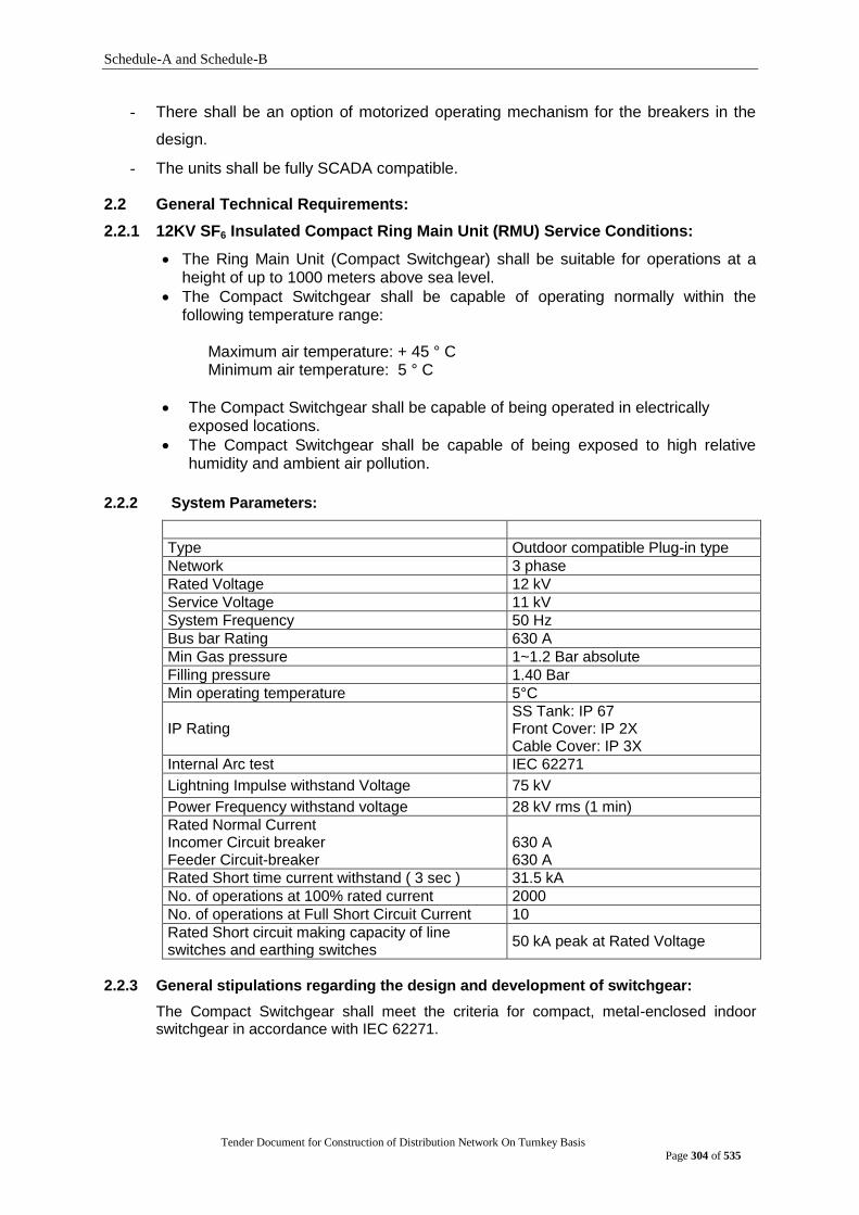
Schedule-A and Schedule-B
Tender Document for Construction of Distribution Network On Turnkey Basis
Page 304 of 535
- There shall be an option of motorized operating mechanism for the breakers in the
design.
- The units shall be fully SCADA compatible.
2.2 General Technical Requirements:
2.2.1 12KV SF6 Insulated Compact Ring Main Unit (RMU) Service Conditions:
The Ring Main Unit (Compact Switchgear) shall be suitable for operations at a height of up to 1000 meters above sea level.
The Compact Switchgear shall be capable of operating normally within the following temperature range:
Maximum air temperature: + 45 ° C Minimum air temperature: 5 ° C
The Compact Switchgear shall be capable of being operated in electrically exposed locations.
The Compact Switchgear shall be capable of being exposed to high relative humidity and ambient air pollution.
2.2.2 System Parameters:
Type Outdoor compatible Plug-in type
Network 3 phase
Rated Voltage 12 kV
Service Voltage 11 kV
System Frequency 50 Hz
Bus bar Rating 630 A
Min Gas pressure 1~1.2 Bar absolute
Filling pressure 1.40 Bar
Min operating temperature 5°C
IP Rating SS Tank: IP 67 Front Cover: IP 2X Cable Cover: IP 3X
Internal Arc test IEC 62271
Lightning Impulse withstand Voltage 75 kV
Power Frequency withstand voltage 28 kV rms (1 min)
Rated Normal Current Incomer Circuit breaker Feeder Circuit-breaker
630 A 630 A
Rated Short time current withstand ( 3 sec ) 31.5 kA
No. of operations at 100% rated current 2000
No. of operations at Full Short Circuit Current 10
Rated Short circuit making capacity of line switches and earthing switches
50 kA peak at Rated Voltage
2.2.3 General stipulations regarding the design and development of switchgear:
The Compact Switchgear shall meet the criteria for compact, metal-enclosed indoor switchgear in accordance with IEC 62271.
Schedule-A and Schedule-B
Tender Document for Construction of Distribution Network On Turnkey Basis
Page 305 of 535
2.2.3.1 Switchboards
The switchgear and busbar shall all be contained in a robotically welded stainless
steel enclosure filled with SF6 gas. The enclosure should meet the "sealed pressure
system" criterion in accordance with the IEC 62271 standard (i.e a system for which
no handling of gas is required throughout the 30 years of service life), so that refilling
is not required. In addition, manufacturer shall confirm that maximum leakage rate is
lower than 0.1 % per year. It should provide full insulation, making the switchgear
insensitive to the environment (temporary flooding, high humidity), IP67 degree of
protection in accordance with recommendation IEC 529. The active parts of the
switchgear shall be maintenance-free and the switchboard shall be low-maintenance.
The switchboards shall have an IP2X protection index.
The tank shall be made of at least 3 mm AISI 304 unpainted stainless steel. The
switchboards shall be suitable for mounting on a trench, utilities space or base.
Each switchboard shall be identified by an appropriately sized label which clearly
indicates the functional units and their electrical characteristics.
The switchgear and switchboards shall be designed so that the position of the
different devices is visible to the operator on the front of the switchboard and
operations are visible as well.
In accordance with the standards in effect, the switchboards shall be designed so as
to prevent access to all live parts during operation without the use of tools.
2.2.3.2 Dielectric medium
SF6 gas will be used as dielectric medium for MV Compact Switchgears. SF6 gas
used for the filling of the Compact Switchgear shall be in accordance with IEC 376.
Gas will only be used for insulation and no interruption will take place inside the gas.
2.2.3.3 Earthing of metallic parts
There shall be continuity between the metallic parts of the switchboard and cables so that there is no electric field pattern in the surrounding air, thereby ensuring the safety of people.
The substation frames shall be connected to the main earth busbar without dismantling any busbars.
2.2.3.4 Earthing of the main circuit
The cables shall be earthed by an earthing switch with short-circuit making capacity, in compliance with IEC 129 standard. The earthing switch can only be operated when the main Isolator & Circuit Breaker are open.
The earthing switch shall be fitted with its own operating mechanism and manual closing shall be driven by a fast-acting mechanism, independent of operator action.
Mechanical interlocking systems shall prevent access to the operating shaft to avoid all operator errors such as closing the earthing switch when the switch is closed.
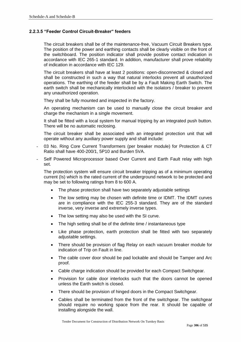
Schedule-A and Schedule-B
Tender Document for Construction of Distribution Network On Turnkey Basis
Page 306 of 535
2.2.3.5 “Feeder Control Circuit-Breaker" feeders
The circuit breakers shall be of the maintenance-free, Vacuum Circuit Breakers type. The position of the power and earthing contacts shall be clearly visible on the front of the switchboard. The position indicator shall provide positive contact indication in accordance with IEC 265-1 standard. In addition, manufacturer shall prove reliability of indication in accordance with IEC 129.
The circuit breakers shall have at least 2 positions: open-disconnected & closed and shall be constructed in such a way that natural interlocks prevent all unauthorized operations. The earthing of the feeder shall be by a Fault Making Earth Switch. The earth switch shall be mechanically interlocked with the isolators / breaker to prevent any unauthorized operation.
They shall be fully mounted and inspected in the factory.
An operating mechanism can be used to manually close the circuit breaker and charge the mechanism in a single movement.
It shall be fitted with a local system for manual tripping by an integrated push button. There will be no automatic reclosing.
The circuit breaker shall be associated with an integrated protection unit that will operate without any auxiliary power supply and shall include:
- 03 No. Ring Core Current Transformers (per breaker module) for Protection & CT Ratio shall have 400-200/1, 5P10 and Burden 5VA.
- Self Powered Microprocessor based Over Current and Earth Fault relay with high set.
The protection system will ensure circuit breaker tripping as of a minimum operating current (Is) which is the rated current of the underground network to be protected and may be set to following ratings from 8 to 600 A.
The phase protection shall have two separately adjustable settings
The low setting may be chosen with definite time or IDMT. The IDMT curves are in compliance with the IEC 255-3 standard. They are of the standard inverse, very inverse and extremely inverse types.
The low setting may also be used with the SI curve.
The high setting shall be of the definite time / instantaneous type
Like phase protection, earth protection shall be fitted with two separately adjustable settings.
There should be provision of flag Relay on each vacuum breaker module for indication of Trip on Fault in line.
The cable cover door should be pad lockable and should be Tamper and Arc proof.
Cable charge indication should be provided for each Compact Switchgear.
Provision for cable door interlocks such that the doors cannot be opened unless the Earth switch is closed.
There should be provision of hinged doors in the Compact Switchgear.
Cables shall be terminated from the front of the switchgear. The switchgear should require no working space from the rear. It should be capable of installing alongside the wall.
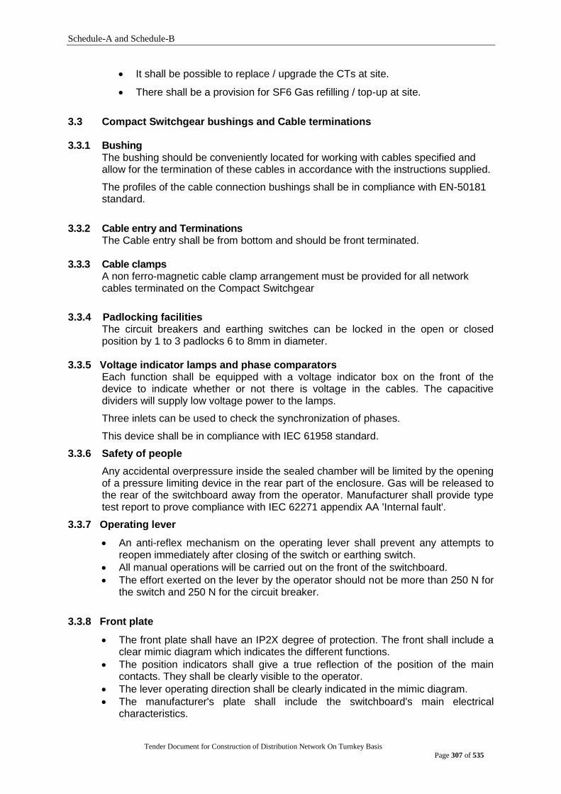
Schedule-A and Schedule-B
Tender Document for Construction of Distribution Network On Turnkey Basis
Page 307 of 535
It shall be possible to replace / upgrade the CTs at site.
There shall be a provision for SF6 Gas refilling / top-up at site.
3.3 Compact Switchgear bushings and Cable terminations 3.3.1 Bushing
The bushing should be conveniently located for working with cables specified and allow for the termination of these cables in accordance with the instructions supplied.
The profiles of the cable connection bushings shall be in compliance with EN-50181 standard.
3.3.2 Cable entry and Terminations
The Cable entry shall be from bottom and should be front terminated. 3.3.3 Cable clamps
A non ferro-magnetic cable clamp arrangement must be provided for all network cables terminated on the Compact Switchgear
3.3.4 Padlocking facilities The circuit breakers and earthing switches can be locked in the open or closed position by 1 to 3 padlocks 6 to 8mm in diameter.
3.3.5 Voltage indicator lamps and phase comparators
Each function shall be equipped with a voltage indicator box on the front of the device to indicate whether or not there is voltage in the cables. The capacitive dividers will supply low voltage power to the lamps.
Three inlets can be used to check the synchronization of phases.
This device shall be in compliance with IEC 61958 standard.
3.3.6 Safety of people
Any accidental overpressure inside the sealed chamber will be limited by the opening of a pressure limiting device in the rear part of the enclosure. Gas will be released to the rear of the switchboard away from the operator. Manufacturer shall provide type test report to prove compliance with IEC 62271 appendix AA 'Internal fault'.
3.3.7 Operating lever
An anti-reflex mechanism on the operating lever shall prevent any attempts to reopen immediately after closing of the switch or earthing switch.
All manual operations will be carried out on the front of the switchboard.
The effort exerted on the lever by the operator should not be more than 250 N for the switch and 250 N for the circuit breaker.
3.3.8 Front plate
The front plate shall have an IP2X degree of protection. The front shall include a clear mimic diagram which indicates the different functions.
The position indicators shall give a true reflection of the position of the main contacts. They shall be clearly visible to the operator.
The lever operating direction shall be clearly indicated in the mimic diagram.
The manufacturer's plate shall include the switchboard's main electrical characteristics.

Schedule-A and Schedule-B
Tender Document for Construction of Distribution Network On Turnkey Basis
Page 308 of 535
Test:
A.TYPE TEST:
The Tenderer should, along with the tender, submit copies of all Type test certificate
of their make in full shape as confirming to relevant IEC of latest issue obtain from
STL or their member laboratory.
TYPE TESTS
1 Impulse Test with breaker inside the cubicle
2 Temperature rise test with breaker inside the cubicle.
3 Short Circuit Test with breaker inside the Cubicle
4 Dielectric Test
5 Test of Apparatus Ie circuit breaker and earthing switches.
6 Arc Fault Test
B. ACCEPTANCE AND ROUTINE TESTS:
All acceptance and routine test as stipulated in the latest IEC- shall be carried out by
the supplier. The supplier shall give at least 7 days advance intimation to enable to
depute our representative for witnessing the tests.
C. ROUTINE TESTS:
STANDARD IEC 62271
1. Withstand Voltage at power Frequency for all current carrying parts including
wiring.
2. Measurement of Resistence of the Main Circuit.
3. Gas Leakage Test
4. PARTIAL DISCHARGE TEST
5. Withstand voltage on Auxiliary circuit.
6. Operation of Function Locks, Interlocks, Signaling Devices and Auxiliary Devices.
7. Suitable & correct operation of protection, Control Instruments and electrical
connection of the circuit breaker operating mechanism (PRIMARY &
SECONDARY INJECTION)
8. Verification of Wiring.
9. Visual Inspection.
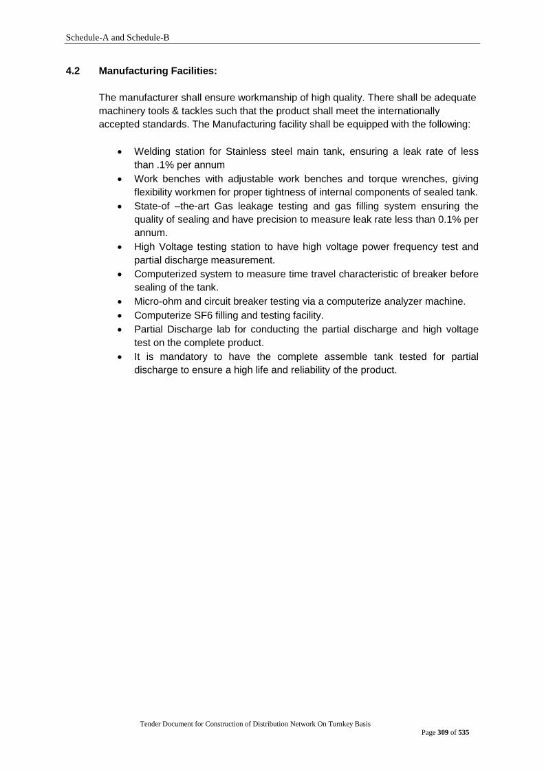
Schedule-A and Schedule-B
Tender Document for Construction of Distribution Network On Turnkey Basis
Page 309 of 535
4.2 Manufacturing Facilities:
The manufacturer shall ensure workmanship of high quality. There shall be adequate
machinery tools & tackles such that the product shall meet the internationally
accepted standards. The Manufacturing facility shall be equipped with the following:
Welding station for Stainless steel main tank, ensuring a leak rate of less
than .1% per annum
Work benches with adjustable work benches and torque wrenches, giving
flexibility workmen for proper tightness of internal components of sealed tank.
State-of –the-art Gas leakage testing and gas filling system ensuring the
quality of sealing and have precision to measure leak rate less than 0.1% per
annum.
High Voltage testing station to have high voltage power frequency test and
partial discharge measurement.
Computerized system to measure time travel characteristic of breaker before
sealing of the tank.
Micro-ohm and circuit breaker testing via a computerize analyzer machine.
Computerize SF6 filling and testing facility.
Partial Discharge lab for conducting the partial discharge and high voltage
test on the complete product.
It is mandatory to have the complete assemble tank tested for partial
discharge to ensure a high life and reliability of the product.
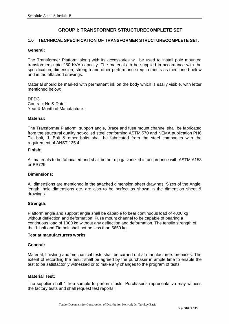
Schedule-A and Schedule-B
Tender Document for Construction of Distribution Network On Turnkey Basis
Page 310 of 535
GROUP I: TRANSFORMER STRUCTURECOMPLETE SET
1.0 TECHNICAL SPECIFICATION OF TRANSFORMER STRUCTURECOMPLETE SET. General: The Transformer Platform along with its accessories will be used to install pole mounted transformers upto 250 KVA capacity. The materials to be supplied in accordance with the specification, dimension, strength and other performance requirements as mentioned below and in the attached drawings.
Material should be marked with permanent ink on the body which is easily visible, with letter mentioned below:
DPDC Contract No & Date: Year & Month of Manufacture:
Material: The Transformer Platform, support angle, Brace and fuse mount channel shall be fabricated from the structural quality hot-colled steel conforming ASTM 570 and NEMA publication PH6. Tie bolt, J. Bolt & other bolts shall he fabricated from the steel companies with the requirement of ANST 135.4.
Finish: All materials to be fabricated and shall be hot-dip galvanized in accordance with ASTM A153 or BS729.
Dimensions: All dimensions are mentioned in the attached dimension sheet drawings. Sizes of the Angle, length, hole dimensions etc. are also to be perfect as shown in the dimension sheet & drawings.
Strength: Platform angle and support angle shall be capable to bear continuous load of 4000 kg without deflection and deformation. Fuse mount channel to be capable of bearing a continuous load of 1000 kg without any deflection and deformation. The tensile strength of the J. bolt and Tie bolt shall not be less than 5650 kg.
Test at manufacturers works General:
Material, finishing and mechanical tests shall be carried out at manufacturers premises. The extent of recording the result shall be agreed by the purchaser in ample time to enable the test to be satisfactorily witnessed or to make any changes to the program of tests.
Material Test:
The supplier shall 1 free sample to perform tests. Purchaser‟s representative may witness the factory tests and shall request test reports.
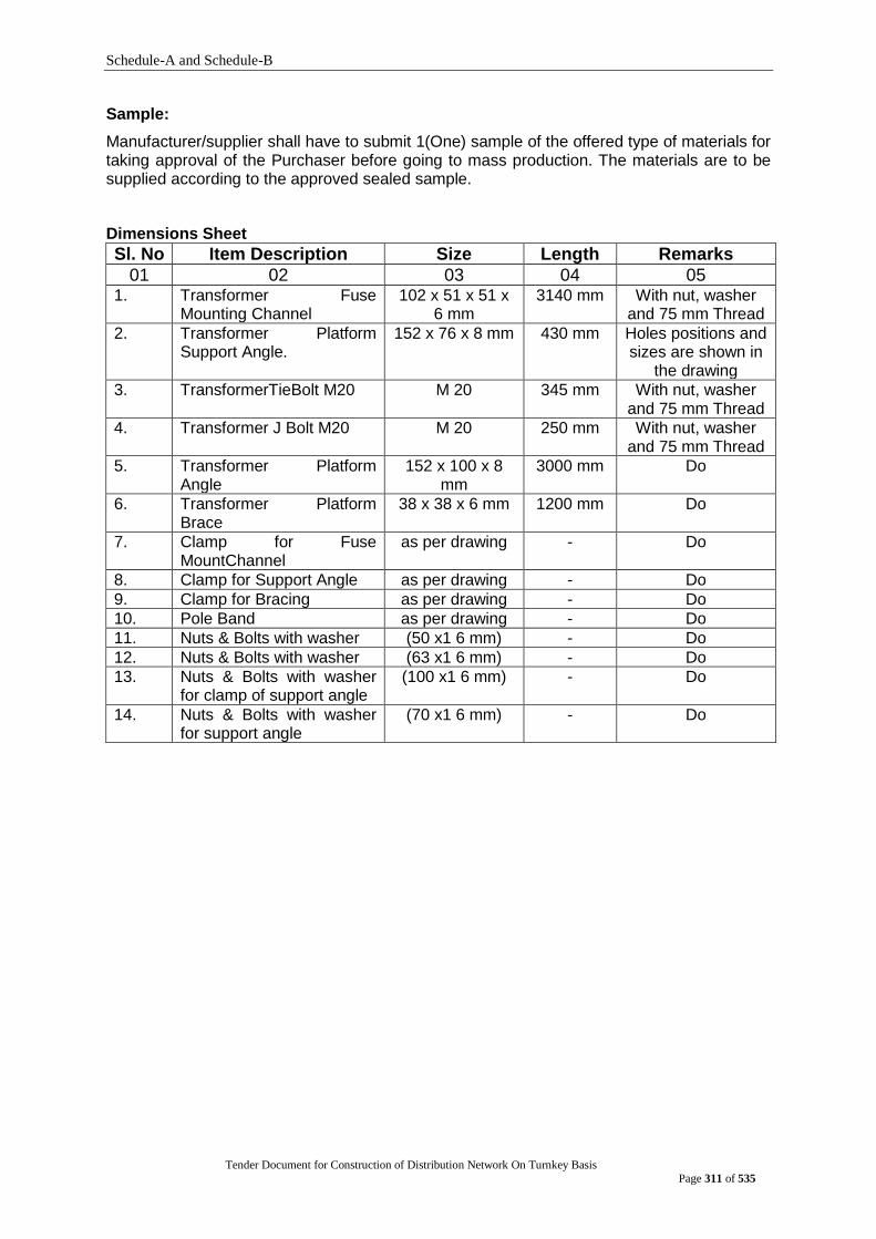
Schedule-A and Schedule-B
Tender Document for Construction of Distribution Network On Turnkey Basis
Page 311 of 535
Sample:
Manufacturer/supplier shall have to submit 1(One) sample of the offered type of materials for taking approval of the Purchaser before going to mass production. The materials are to be supplied according to the approved sealed sample.
Dimensions Sheet
Sl. No Item Description Size Length Remarks
01 02 03 04 05 1. Transformer Fuse
Mounting Channel 102 x 51 x 51 x
6 mm 3140 mm With nut, washer
and 75 mm Thread
2. Transformer Platform Support Angle.
152 x 76 x 8 mm 430 mm Holes positions and sizes are shown in
the drawing
3. TransformerTieBolt M20 M 20 345 mm With nut, washer and 75 mm Thread
4. Transformer J Bolt M20 M 20 250 mm With nut, washer and 75 mm Thread
5. Transformer Platform Angle
152 x 100 x 8 mm
3000 mm Do
6. Transformer Platform Brace
38 x 38 x 6 mm 1200 mm Do
7. Clamp for Fuse MountChannel
as per drawing - Do
8. Clamp for Support Angle as per drawing - Do
9. Clamp for Bracing as per drawing - Do
10. Pole Band as per drawing - Do
11. Nuts & Bolts with washer (50 x1 6 mm) - Do
12. Nuts & Bolts with washer (63 x1 6 mm) - Do
13. Nuts & Bolts with washer for clamp of support angle
(100 x1 6 mm) - Do
14. Nuts & Bolts with washer for support angle
(70 x1 6 mm) - Do

Schedule-A and Schedule-B
Tender Document for Construction of Distribution Network On Turnkey Basis
Page 312 of 535
GROUP J: TRANSFORMER PROTECTION 1.0 Specification of 11KV Pole/Structure Mounted LA or Surge Arrester
Standard : Design, Manufacturing, Testing and performance shall be in accordance to IEC 99-4 or equivalent international standards.
General
Installation : Outdoor pole/cross arm angle/channel/structure mounted.
Type/Model : Zinc oxide (ZnO)
Construction : As per relevant IEC standard
Application : Protection of 11/0.415KV distribution Transformers.
Nominal rated Voltage : 11KV
Maximum System Voltage
: 12KV
System Frequency : 50Hz
Type of System : 3–Phase with effectively earthed neutral.
Rated Arrester voltage : 10.5KV RMS
Class : 1
Rated Arrester current : 10.5KA (8/20 micro second wave)
High current withstand : 100KA
Pressure relief class : 20KA (rms Symmetrical)
Basic Insulation level (BIL) at 1.2/50 micro sec impulses.
: 75KV crest
Lightning impulse Residual Voltage at 8/20 micro sec. Current wave
: 39KV crest
Creepage distance : 30mm/KV
1.1 Features and Accessories: The Arrester shall be ZnO type, basically consisting of gap-less hermetically sealed in with nonlinear volt-ampere characteristics with high-energy capacity. The earthing terminal shall be suitable to accommodate AAC/ACSR Copper Conductor of diameter from 10mm to 15mm.
ZnO type Arrester shall be excellent thermal stability for high-energy surge external pollution & temporary over voltage.
Lightning Arrester with nominal discharge current of 10KA will be used to the protection of 11/0.415KV distribution transformers and shall be supplied complete with galvanized steel brackets and fixing bolts, nuts, washers for mounting. Brackets shall be provided for steel cross-arm mounting. All ferrous parts exposed to atmosphere shall be hot galvanized after fabrication as per latest revision of BS-729 or equivalent standard.
Line lead and earthing terminals with clamps to shall be suitable to accommodate AAC/ACSR/Copper Conductor of diameter from 6mm to 12mm.
Lightning Arrester shall be suitable for mounting vertically. The housing shall be as per latest version of IEC 99.4.
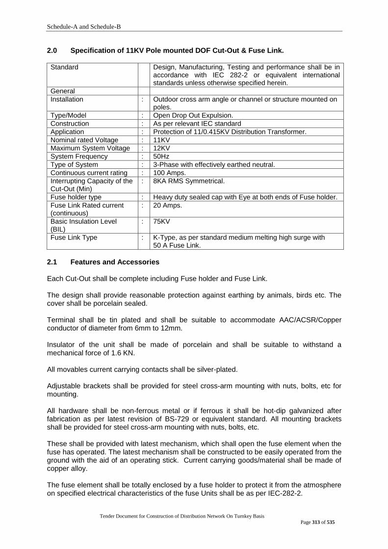
Schedule-A and Schedule-B
Tender Document for Construction of Distribution Network On Turnkey Basis
Page 313 of 535
2.0 Specification of 11KV Pole mounted DOF Cut-Out & Fuse Link. Standard Design, Manufacturing, Testing and performance shall be in
accordance with IEC 282-2 or equivalent international standards unless otherwise specified herein.
General
Installation : Outdoor cross arm angle or channel or structure mounted on poles.
Type/Model : Open Drop Out Expulsion.
Construction : As per relevant IEC standard
Application : Protection of 11/0.415KV Distribution Transformer.
Nominal rated Voltage : 11KV
Maximum System Voltage : 12KV
System Frequency : 50Hz
Type of System : 3-Phase with effectively earthed neutral.
Continuous current rating : 100 Amps.
Interrupting Capacity of the Cut-Out (Min)
: 8KA RMS Symmetrical.
Fuse holder type : Heavy duty sealed cap with Eye at both ends of Fuse holder.
Fuse Link Rated current (continuous)
: 20 Amps.
Basic Insulation Level (BIL)
: 75KV
Fuse Link Type : K-Type, as per standard medium melting high surge with 50 A Fuse Link.
2.1 Features and Accessories Each Cut-Out shall be complete including Fuse holder and Fuse Link.
The design shall provide reasonable protection against earthing by animals, birds etc. The cover shall be porcelain sealed.
Terminal shall be tin plated and shall be suitable to accommodate AAC/ACSR/Copper conductor of diameter from 6mm to 12mm.
Insulator of the unit shall be made of porcelain and shall be suitable to withstand a mechanical force of 1.6 KN.
All movables current carrying contacts shall be silver-plated.
Adjustable brackets shall be provided for steel cross-arm mounting with nuts, bolts, etc for mounting.
All hardware shall be non-ferrous metal or if ferrous it shall be hot-dip galvanized after fabrication as per latest revision of BS-729 or equivalent standard. All mounting brackets shall be provided for steel cross-arm mounting with nuts, bolts, etc.
These shall be provided with latest mechanism, which shall open the fuse element when the fuse has operated. The latest mechanism shall be constructed to be easily operated from the ground with the aid of an operating stick. Current carrying goods/material shall be made of copper alloy.
The fuse element shall be totally enclosed by a fuse holder to protect it from the atmosphere on specified electrical characteristics of the fuse Units shall be as per IEC-282-2.
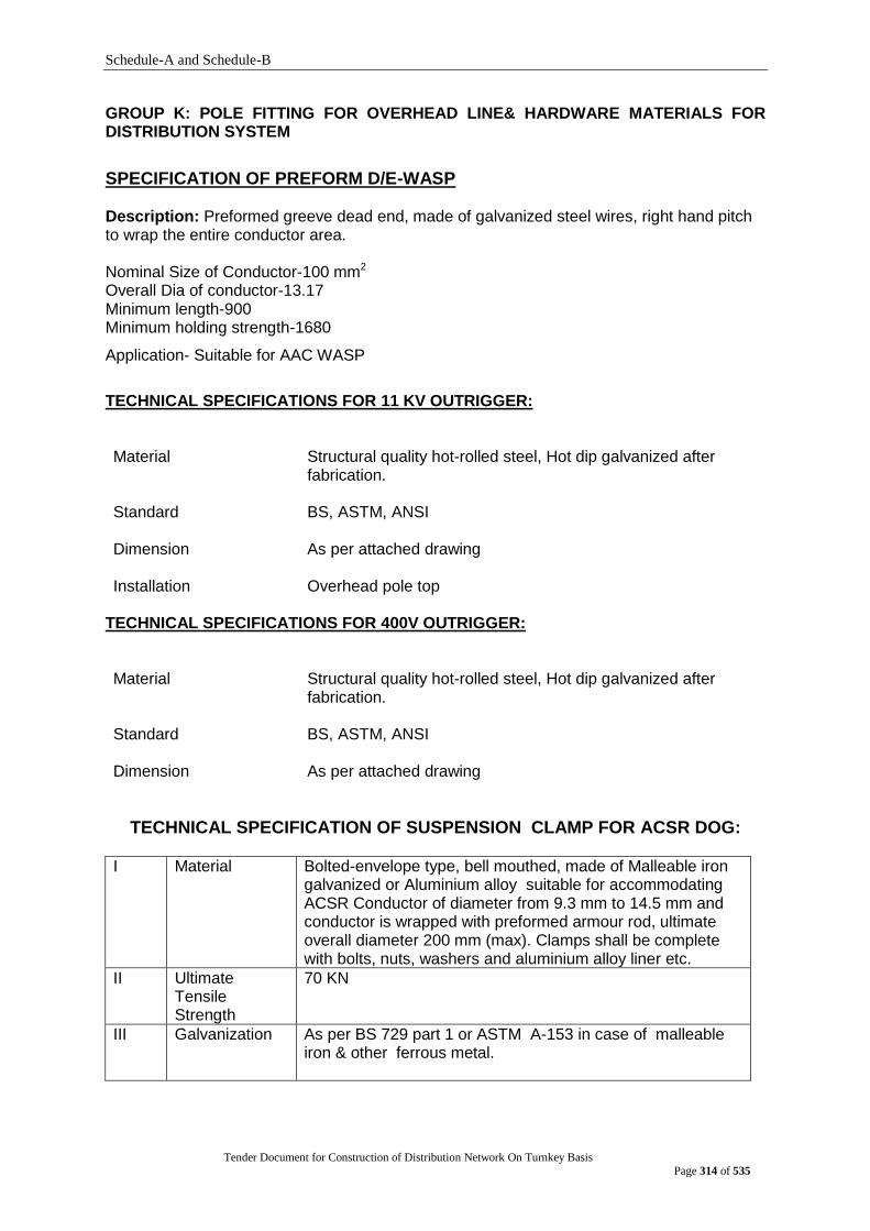
Schedule-A and Schedule-B
Tender Document for Construction of Distribution Network On Turnkey Basis
Page 314 of 535
GROUP K: POLE FITTING FOR OVERHEAD LINE& HARDWARE MATERIALS FOR DISTRIBUTION SYSTEM
SPECIFICATION OF PREFORM D/E-WASP
Description: Preformed greeve dead end, made of galvanized steel wires, right hand pitch to wrap the entire conductor area. Nominal Size of Conductor-100 mm2 Overall Dia of conductor-13.17 Minimum length-900 Minimum holding strength-1680
Application- Suitable for AAC WASP
TECHNICAL SPECIFICATIONS FOR 11 KV OUTRIGGER: Material
Structural quality hot-rolled steel, Hot dip galvanized after fabrication.
Standard BS, ASTM, ANSI
Dimension As per attached drawing
Installation Overhead pole top
TECHNICAL SPECIFICATIONS FOR 400V OUTRIGGER: Material
Structural quality hot-rolled steel, Hot dip galvanized after fabrication.
Standard BS, ASTM, ANSI
Dimension As per attached drawing
TECHNICAL SPECIFICATION OF SUSPENSION CLAMP FOR ACSR DOG:
I Material Bolted-envelope type, bell mouthed, made of Malleable iron galvanized or Aluminium alloy suitable for accommodating ACSR Conductor of diameter from 9.3 mm to 14.5 mm and conductor is wrapped with preformed armour rod, ultimate overall diameter 200 mm (max). Clamps shall be complete with bolts, nuts, washers and aluminium alloy liner etc.
II Ultimate Tensile Strength
70 KN
III Galvanization As per BS 729 part 1 or ASTM A-153 in case of malleable iron & other ferrous metal.

Schedule-A and Schedule-B
Tender Document for Construction of Distribution Network On Turnkey Basis
Page 315 of 535
TECHNICAL SPECIFICATION OF TERMINAL CLAMP-MERLIN
Material Malleable iron galvanized or Aluminium alloy, complete with
cotter bolts, nut washers and aluminium alloy liner etc suitable for accommodating ACSR Conductor of dia from 14.3 mm to 118.2 mm
Type Bolted (3 bolt)
Diameter 14.3 mm to 118.2 mm
Ultimate Tensile Strength 70KN
Galvanization All ferrous parts Shall be galvanized as per BS 729 part1
TECHNICAL SPECIFICATION OF STRAIN CLAMP FOR ACSR (DOG)
I Material Bolted type made of Malleable iron galvanized or Aluminium alloy suitable for accommodating ACSR Conductor of diameter from 9.3 mm to 14.2 mm complete with bolts, nuts, washers and aluminium liner etc.
II Minimum Grove diameter
18mm
III Ultimate Tensile Strength
70KN
IV Galvanization As per BS 729 part 1 or ASTM A-153 in case of malleable iron & other ferrous metal.
TECHNICAL SPECIFICATIONS FOR STAY WIRE 7/10:
Description:
Stay wire shall conform to the requirement of BS 183: 1971 or other approved equivalent
standard. Galvanized Steel Stay wire shall be 7/3.15mm, 63 KN. The grade of guy wire shall
be 700.
Construction:
a) The galvanized stay wire shall be of 7-wire construction. The wires shall be so stranded together that when an evenly distributed pull is applied at the ends of completed strand, each wire shall take an equal share of the pull.
b) The wire shall be circular and free from scale, irregularities, imperfection,
flaws, splits and other defects. Tests on Wires before Manufacture: The wires shall be subjected to the following tests in accordance with IS : 2141 a) Ductility Test b) Tolerance on Wire Diameter
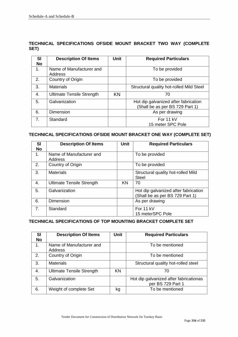
Schedule-A and Schedule-B
Tender Document for Construction of Distribution Network On Turnkey Basis
Page 316 of 535
TECHNICAL SPECIFICATIONS OFSIDE MOUNT BRACKET TWO WAY (COMPLETE SET)
Sl No
Description Of Items Unit Required Particulars
1. Name of Manufacturer and Address
To be provided
2. Country of Origin To be provided
3. Materials Structural quality hot-rolled Mild Steel
4. Ultimate Tensile Strength KN 70
5. Galvanization Hot dip galvanized after fabrication (Shall be as per BS 729 Part 1)
6. Dimension As per drawing
7. Standard For 11 kV 15 meter SPC Pole
TECHNICAL SPECIFICATIONS OFSIDE MOUNT BRACKET ONE WAY (COMPLETE SET)
Sl No
Description Of Items Unit Required Particulars
1. Name of Manufacturer and Address
To be provided
2. Country of Origin To be provided
3. Materials Structural quality hot-rolled Mild Steel
4. Ultimate Tensile Strength KN 70
5. Galvanization Hot dip galvanized after fabrication (Shall be as per BS 729 Part 1)
6. Dimension As per drawing
7. Standard For 11 kV 15 meterSPC Pole
TECHNICAL SPECIFICATIONS OF TOP MOUNTING BRACKET COMPLETE SET
Sl No
Description Of Items Unit Required Particulars
1. Name of Manufacturer and Address
To be mentioned
2. Country of Origin To be mentioned
3. Materials Structural quality hot-rolled steel
4. Ultimate Tensile Strength KN 70
5. Galvanization Hot dip galvanized after fabricationas per BS 729 Part 1
6. Weight of complete Set kg To be mentioned

Schedule-A and Schedule-B
Tender Document for Construction of Distribution Network On Turnkey Basis
Page 317 of 535
TECHNICAL SPECIFICATIONS OFSIDE LOCK TIE MERLIN
Sl No Description Of Items Unit Required Particulars
1 Manufacturer Name & address To be mentioned
2 Materials Mild Steel
3 Standard Hot Dip Galvanized as per BS 729
4 Ultimate Tensile Strength kg 1680
SPECIFICATION OF SERVICE BALE-INSULATED
Construction Bi-metallic insulated bale with Al & Copper Wire, Crimped Joint
Diameter Both Aluminium & Copper Wire SWG-6(4.92mm, Dia)
Insulation PVC Insulation,0.8 mm thick on wire & crimp joint
Dimension As per attached drawing
SPECIFICATION OF TENSION CLAMP FOR ACSR (DOG)
Material Malleable iron galvanized or Aluminium alloy suitable for accommodating ACSR Conductor of diameter from 9.3 mm to 14.2 mm complete with bolts, nuts, washers and aluminium liner etc.
Minimum Grove diameter 18 mm
Ultimate Tensile Strength 70 KN
Galvanization as per BS 729 part 1 or ASTM A-153 in case of malleable iron & other ferrous metal.
SPECIFICATION OF BOLTS & NUTS 16MM DIA X 25 MM LENGTH , HOT DIP GALVANIZED
2 Materials Structural quality hot-rolled Mild Steel
3 Standard Hot Dip Galvanized as per BS 729
4 Ultimate Tensile Strength
70 KN
5 Diameter 16 mm
5 Length 25 mm
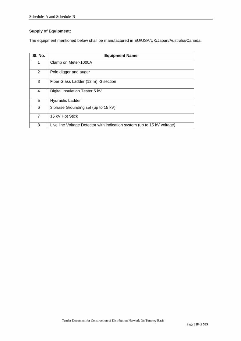
Schedule-A and Schedule-B
Tender Document for Construction of Distribution Network On Turnkey Basis
Page 318 of 535
Supply of Equipment: The equipment mentioned below shall be manufactured in EU/USA/UK/Japan/Australia/Canada.
Sl. No. Equipment Name
1 Clamp on Meter-1000A
2 Pole digger and auger
3 Fiber Glass Ladder (12 m) -3 section
4 Digital Insulation Tester 5 kV
5 Hydraulic Ladder
6 3 phase Grounding set (up to 15 kV)
7 15 kV Hot Stick
8 Live line Voltage Detector with indication system (up to 15 kV voltage)

Schedule-A and Schedule-B
Tender Document for Construction of Distribution Network On Turnkey Basis
Page 319 of 535
2.2 Technical Requirement and Guarantee Schedule to be filled
up by the Bidder
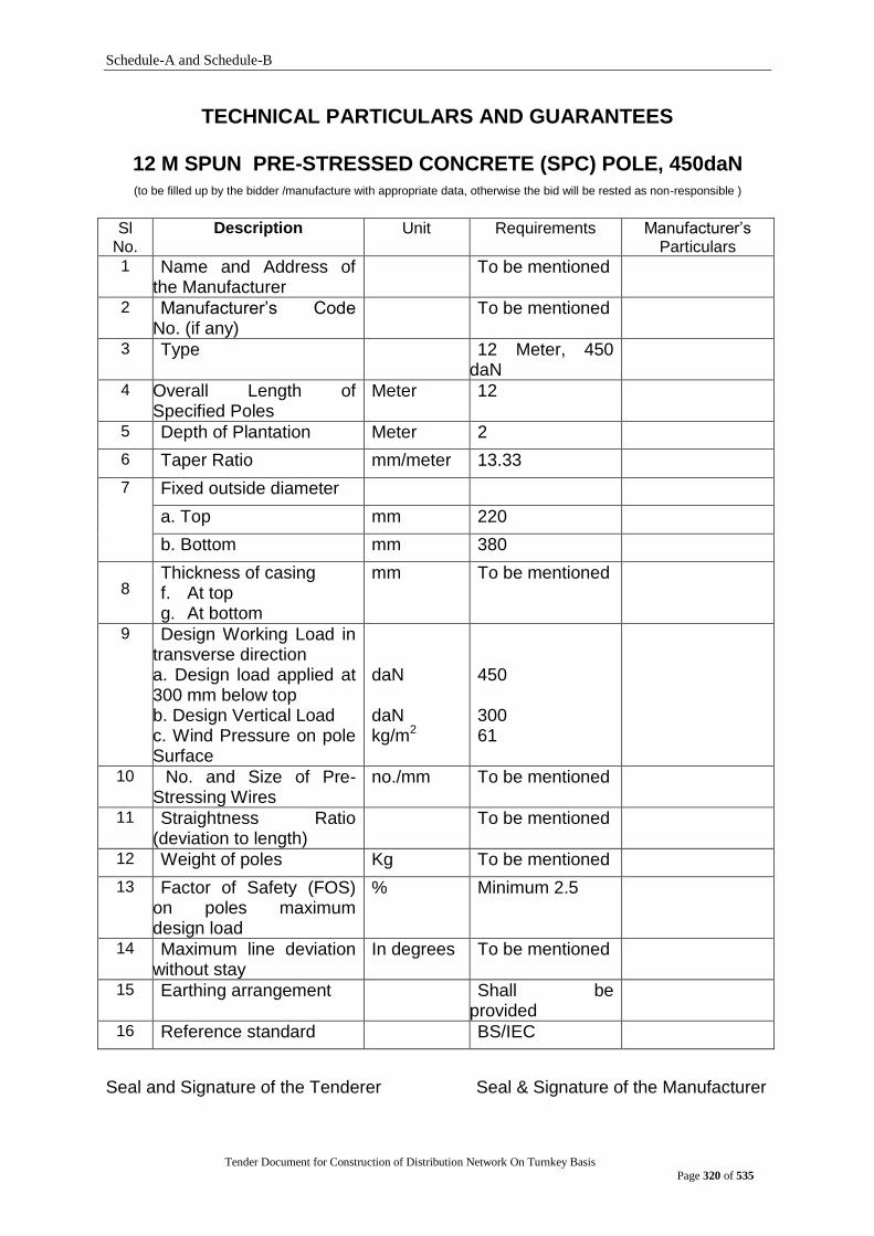
Schedule-A and Schedule-B
Tender Document for Construction of Distribution Network On Turnkey Basis
Page 320 of 535
TECHNICAL PARTICULARS AND GUARANTEES
12 M SPUN PRE-STRESSED CONCRETE (SPC) POLE, 450daN (to be filled up by the bidder /manufacture with appropriate data, otherwise the bid will be rested as non-responsible )
Sl
No. Description Unit Requirements Manufacturer‟s
Particulars
1 Name and Address of the Manufacturer
To be mentioned
2 Manufacturer‟s Code No. (if any)
To be mentioned
3 Type 12 Meter, 450 daN
4 Overall Length of Specified Poles
Meter 12
5 Depth of Plantation Meter 2
6 Taper Ratio mm/meter 13.33
7
Fixed outside diameter
a. Top mm 220
b. Bottom mm 380
8 Thickness of casing f. At top g. At bottom
mm To be mentioned
9 Design Working Load in transverse direction a. Design load applied at 300 mm below top b. Design Vertical Load c. Wind Pressure on pole Surface
daN daN kg/m2
450 300 61
10 No. and Size of Pre-Stressing Wires
no./mm To be mentioned
11 Straightness Ratio (deviation to length)
To be mentioned
12 Weight of poles Kg To be mentioned
13 Factor of Safety (FOS) on poles maximum design load
% Minimum 2.5
14 Maximum line deviation without stay
In degrees To be mentioned
15 Earthing arrangement Shall be provided
16 Reference standard BS/IEC
Seal and Signature of the Tenderer Seal & Signature of the Manufacturer
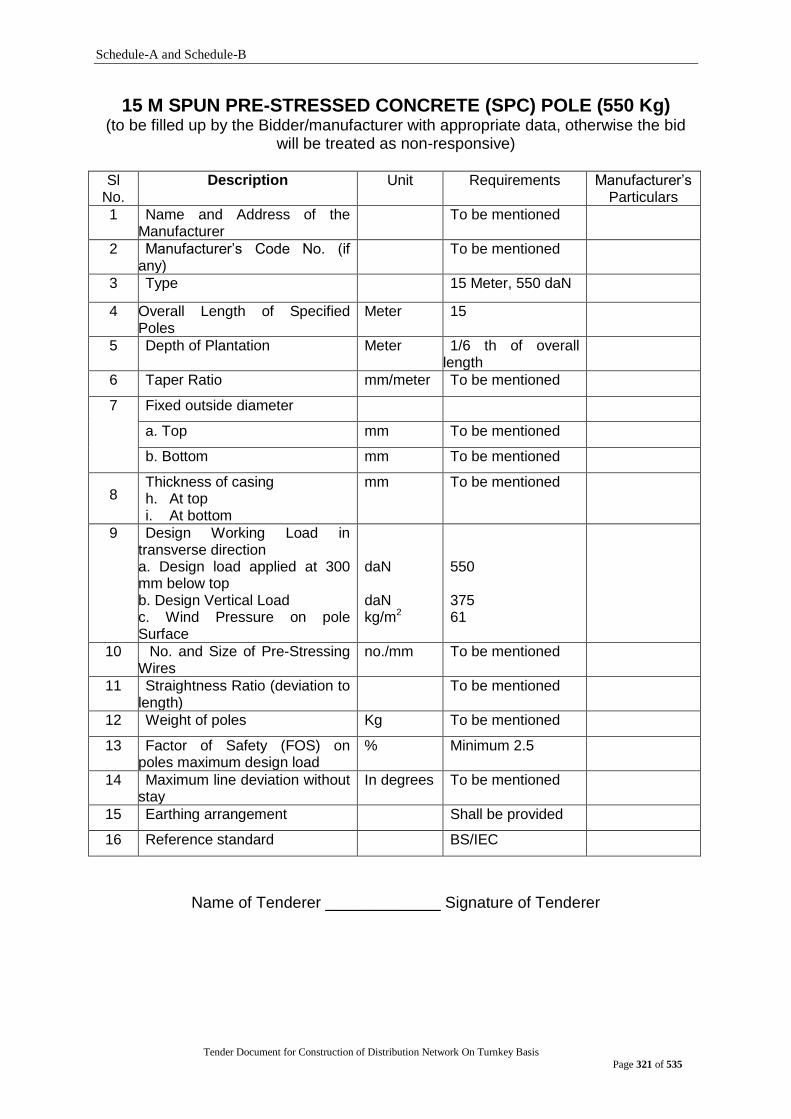
Schedule-A and Schedule-B
Tender Document for Construction of Distribution Network On Turnkey Basis
Page 321 of 535
15 M SPUN PRE-STRESSED CONCRETE (SPC) POLE (550 Kg) (to be filled up by the Bidder/manufacturer with appropriate data, otherwise the bid
will be treated as non-responsive)
Sl No.
Description Unit Requirements Manufacturer‟s Particulars
1 Name and Address of the Manufacturer
To be mentioned
2 Manufacturer‟s Code No. (if any)
To be mentioned
3 Type 15 Meter, 550 daN
4 Overall Length of Specified Poles
Meter 15
5 Depth of Plantation Meter 1/6 th of overall length
6 Taper Ratio mm/meter To be mentioned
7
Fixed outside diameter
a. Top mm To be mentioned
b. Bottom mm To be mentioned
8 Thickness of casing h. At top i. At bottom
mm To be mentioned
9 Design Working Load in transverse direction a. Design load applied at 300 mm below top b. Design Vertical Load c. Wind Pressure on pole Surface
daN daN kg/m2
550 375 61
10 No. and Size of Pre-Stressing Wires
no./mm To be mentioned
11 Straightness Ratio (deviation to length)
To be mentioned
12 Weight of poles Kg To be mentioned
13 Factor of Safety (FOS) on poles maximum design load
% Minimum 2.5
14 Maximum line deviation without stay
In degrees To be mentioned
15 Earthing arrangement Shall be provided
16 Reference standard BS/IEC
Name of Tenderer _____________ Signature of Tenderer

Schedule-A and Schedule-B
Tender Document for Construction of Distribution Network On Turnkey Basis
Page 322 of 535
12 M Transformer pole (Steel), 550 daN with RCC base foundation and necessary fittings
(To be filled up by the tenderer/manufacturer with appropriate data, otherwise the bid will be treated as non-responsive)
Sl. No.
Description of parameters Unit Guaranteed
Technical Data
To be filled up by the manufacturer/
tenderer
1. Reference Standard - Latest revision of BS: 729, 4190, 4360, 4870, 5649, 5750, 6323 and all other
related international standards.
2. Name of the Manufacturer - To be mentioned
3. Address of the Manufacturer - To be mentioned
4. Country of Manufacture - To be mentioned
5. Manufacturer‟s Code No. (if any)
- To be mentioned
6. Type - 12m, 550 daN
7. Shape of the Pole - To be mentioned
8. Overall Length of Poles Meter 12
9. Depth of Plantation Meter 1/6 th of overall length
10. Planted portion of the pole should have anticorrosive painting
- To be confirmed
11. Number of Sections Nos. 03 (maximum)
12. Taper ratio mm/
meter
15mm to 25mm per meter
13. Length of Sections:
Section - I Meter To be mentioned
Section - II Meter To be mentioned
Section - III Meter To be mentioned
14. Tolerance in Section Length mm ±0.05%
15. Overlapping of each section mm To be mentioned
16. Outside Diameter(Top & Bottom) of each section
mm To be mentioned
17. Tolerance in Outside Diameter
- 2%
18. Thickness of each section mm To be mentioned
19. Tolerance in Thickness mm ±1%

Schedule-A and Schedule-B
Tender Document for Construction of Distribution Network On Turnkey Basis
Page 323 of 535
Sl. No.
Description of parameters Unit Guaranteed
Technical Data
To be filled up by the manufacturer/
tenderer
20. Minimum Tensile Strength of steel
Kg/ mm2 To be mentioned
21. Yield strength of steel N/ mm2 280 (Minimum)
22. Weight of pole Kg To be mentioned
23. Tolerance in Section Length Size of base plate
- ± 1%
24. Depth of galvanized finish g/mm2 To be mentioned
25. Depth of anti corrosive treatment:
a. Outside Micron 2x100
b. Inside Micron 1X100
26. Type of anti corrosive treatment
- To be mentioned
27. Factor of Safety (FOS) of poles on yield strength
- 2.50 (Minimum)
28. Maximum line deviation without stay
In degrees To be mentioned
29. Number of Longitudinal Joint per section
Nos 2(maximum)
30. Fittings and base required for each pole for installation of 250 KVA 3 phase transformer in the pole along with DOFC and LA channel
Required Fittings and base To be provided
List of fittings set The list to be mentioned
Number and dimension of each fitting item
set Number and dimension of each fitting item to be
mentioned
Name of manufacturer of fitting item
To be mentioned
31.
Earhting arrangement set To be provided
Name & Signature of Tenderer _________ Name & Signature of Manufacturer ________ Date ____________________ Date ____________________

Schedule-A and Schedule-B
Tender Document for Construction of Distribution Network On Turnkey Basis
Page 324 of 535
12M Steel Pole, 350 daN
(To be filled up by the tenderer/manufacturer with appropriate data, otherwise the bid will be treated as non-responsive)
Sl. No.
Description of parameters Unit Guaranteed Technical
Data
To be filled up by the
manufacturer/ tenderer
1. Reference Standard - Latest revision of BS: 729, 4190, 4360, 4870, 5649, 5750, 6323 and all other
related international standards.
2. Name of the Manufacturer - To be mentioned
3. Address of the Manufacturer - To be mentioned
4. Country of Manufacture - To be mentioned
5. Manufacturer‟s Code No. (if any) - To be mentioned
6. Type - 12m, 350 daN
7. Shape of the Pole - Octagonal
8. Overall Length of Poles Meter 12
9. Depth of Plantation Meter 1/6 th of overall length
10. Planted portion of the pole should have anticorrosive painting
- To be confirmed
11. Number of Sections Nos. 03 (maximum)
12. Taper ratio mm/
meter
15mm to 25mm per meter
13. Length of Sections:
Section - I Meter To be mentioned
Section - II Meter To be mentioned
Section - III Meter To be mentioned
14. Tolerance in Section Length mm ±0.05%
15. Overlapping of each section mm To be mentioned
16. Outside Diameter(Top & Bottom) of each section
mm To be mentioned
17. Tolerance in Outside Diameter - 2%
18. Thickness of each section mm To be mentioned
19. Tolerance in Thickness mm ±1%
20. Minimum Tensile Strength of steel Kg/ mm
2
To be mentioned
21. Yield strength of steel N/ mm2 280 (Minimum)
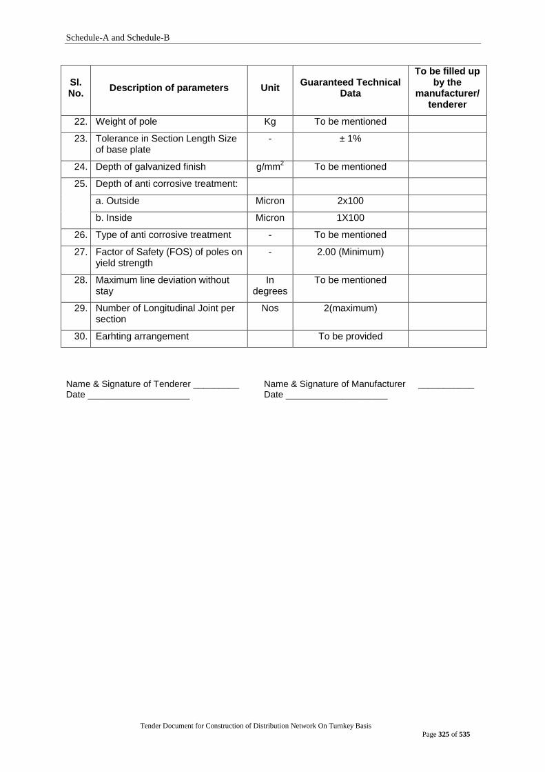
Schedule-A and Schedule-B
Tender Document for Construction of Distribution Network On Turnkey Basis
Page 325 of 535
Sl. No.
Description of parameters Unit Guaranteed Technical
Data
To be filled up by the
manufacturer/ tenderer
22. Weight of pole Kg To be mentioned
23. Tolerance in Section Length Size of base plate
- ± 1%
24. Depth of galvanized finish g/mm2 To be mentioned
25. Depth of anti corrosive treatment:
a. Outside Micron 2x100
b. Inside Micron 1X100
26. Type of anti corrosive treatment - To be mentioned
27. Factor of Safety (FOS) of poles on yield strength
- 2.00 (Minimum)
28. Maximum line deviation without stay
In degrees
To be mentioned
29. Number of Longitudinal Joint per section
Nos 2(maximum)
30. Earhting arrangement To be provided
Name & Signature of Tenderer _________ Name & Signature of Manufacturer ___________ Date ____________________ Date ____________________
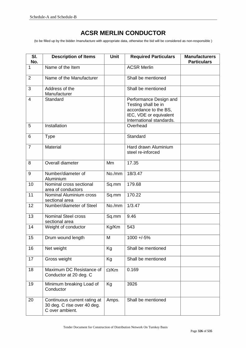
Schedule-A and Schedule-B
Tender Document for Construction of Distribution Network On Turnkey Basis
Page 326 of 535
ACSR MERLIN CONDUCTOR (to be filled up by the bidder /manufacture with appropriate data, otherwise the bid will be considered as non-responsible )
Sl. No.
Description of Items Unit Required Particulars Manufacturers Particulars
1 Name of the Item ACSR Merlin
2 Name of the Manufacturer Shall be mentioned
3 Address of the Manufacturer
Shall be mentioned
4 Standard Performance Design and Testing shall be in accordance to the BS, IEC, VDE or equivalent International standards.
5 Installation Overhead
6 Type Standard
7 Material Hard drawn Aluminium steel re-inforced
8 Overall diameter Mm 17.35
9 Number/diameter of Aluminium
No./mm 18/3.47
10 Nominal cross sectional area of conductors
Sq.mm 179.68
11 Nominal Aluminium cross sectional area
Sq.mm 170.22
12 Number/diameter of Steel No./mm 1/3.47
13 Nominal Steel cross sectional area
Sq.mm 9.46
14 Weight of conductor Kg/Km 543
15 Drum wound length M 1000 +/-5%
16 Net weight Kg Shall be mentioned
17 Gross weight Kg Shall be mentioned
18 Maximum DC Resistance of Conductor at 20 deg. C
/Km 0.169
19 Minimum breaking Load of Conductor
Kg 3926
20 Continuous current rating at 30 deg. C rise over 40 deg. C over ambient.
Amps. Shall be mentioned
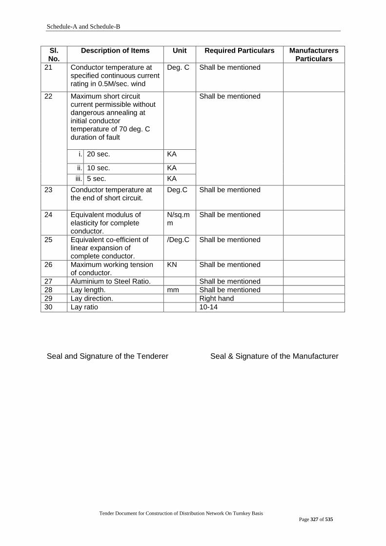
Schedule-A and Schedule-B
Tender Document for Construction of Distribution Network On Turnkey Basis
Page 327 of 535
Sl. No.
Description of Items Unit Required Particulars Manufacturers Particulars
21 Conductor temperature at specified continuous current rating in 0.5M/sec. wind
Deg. C Shall be mentioned
22 Maximum short circuit current permissible without dangerous annealing at initial conductor temperature of 70 deg. C duration of fault
Shall be mentioned
i. 20 sec. KA
ii. 10 sec. KA
iii. 5 sec. KA
23 Conductor temperature at the end of short circuit.
Deg.C Shall be mentioned
24 Equivalent modulus of elasticity for complete conductor.
N/sq.mm
Shall be mentioned
25 Equivalent co-efficient of linear expansion of complete conductor.
/Deg.C Shall be mentioned
26 Maximum working tension of conductor.
KN Shall be mentioned
27 Aluminium to Steel Ratio. Shall be mentioned
28 Lay length. mm Shall be mentioned
29 Lay direction. Right hand
30 Lay ratio 10-14
Seal and Signature of the Tenderer Seal & Signature of the Manufacturer

Schedule-A and Schedule-B
Tender Document for Construction of Distribution Network On Turnkey Basis
Page 328 of 535
ACSR DOG CONDUCTOR (to be filled up by the bidder /manufacture with appropriate data, otherwise the bid will be rested as non-responsible )
Sl. No.
Description of Items Unit Required Particulars Manufacturers Particulars
1 Name of the
Manufacturer
Shall be mentioned
2 Address of the Manufacturer
Shall be mentioned
3 Standard Performance Design and Testing shall be in accordance to the BS, IEC, VDE or equivalent International standards.
4 Installation Overhead
5 Type Standard
6 Material Hard drawn Aluminium steel re-inforced
7 Overall diameter Mm 14.15
8 Number/diameter of Aluminium
No./mm 6/4.72
9 Nominal cross sectional area of conductors
Sq.mm 118.47
10 Nominal Aluminium cross sectional area
Sq.mm 104.93
11 Number/diameter of Steel
No./mm 7/1.57
12 Nominal Steel cross sectional area
Sq.mm 13.56
13 Weight of conductor Kg/Km 394
14 Drum wound length M 1700 +/-5%
15 Net weight Kg Shall be mentioned
16 Gross weight Kg Shall be mentioned
17 Maximum DC Resistance of Conductor at 20 deg. C
/Km 0.2733
18 Minimum breaking Load of Conductor
Kg 3335
19 Continuous current rating at 30 deg. C rise over 40 deg. C over ambient
Amps. Shall be mentioned
20 Conductor temperature at specified continuous current rating in 0.5M/sec. wind
Deg. C Shall be mentioned
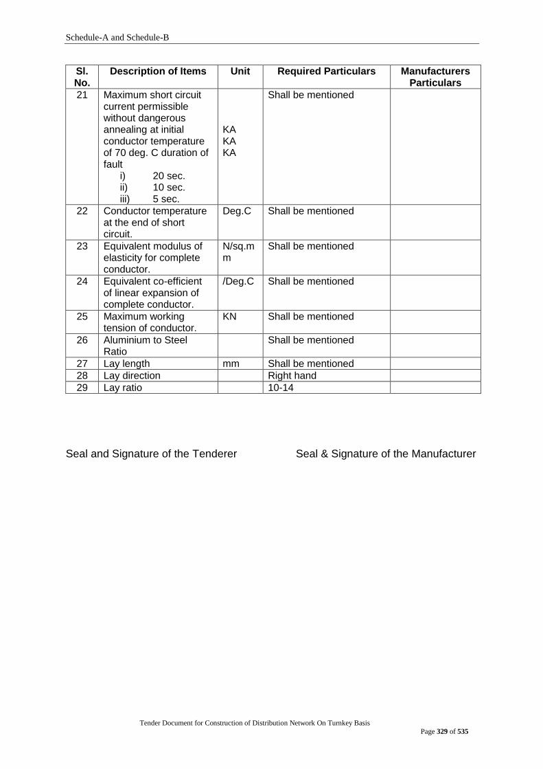
Schedule-A and Schedule-B
Tender Document for Construction of Distribution Network On Turnkey Basis
Page 329 of 535
Sl. No.
Description of Items Unit Required Particulars Manufacturers Particulars
21 Maximum short circuit current permissible without dangerous annealing at initial conductor temperature of 70 deg. C duration of fault
i) 20 sec. ii) 10 sec. iii) 5 sec.
KA KA KA
Shall be mentioned
22 Conductor temperature at the end of short circuit.
Deg.C Shall be mentioned
23 Equivalent modulus of elasticity for complete conductor.
N/sq.mm
Shall be mentioned
24 Equivalent co-efficient of linear expansion of complete conductor.
/Deg.C Shall be mentioned
25 Maximum working tension of conductor.
KN Shall be mentioned
26 Aluminium to Steel Ratio
Shall be mentioned
27 Lay length mm Shall be mentioned
28 Lay direction Right hand
29 Lay ratio 10-14
Seal and Signature of the Tenderer Seal & Signature of the Manufacturer
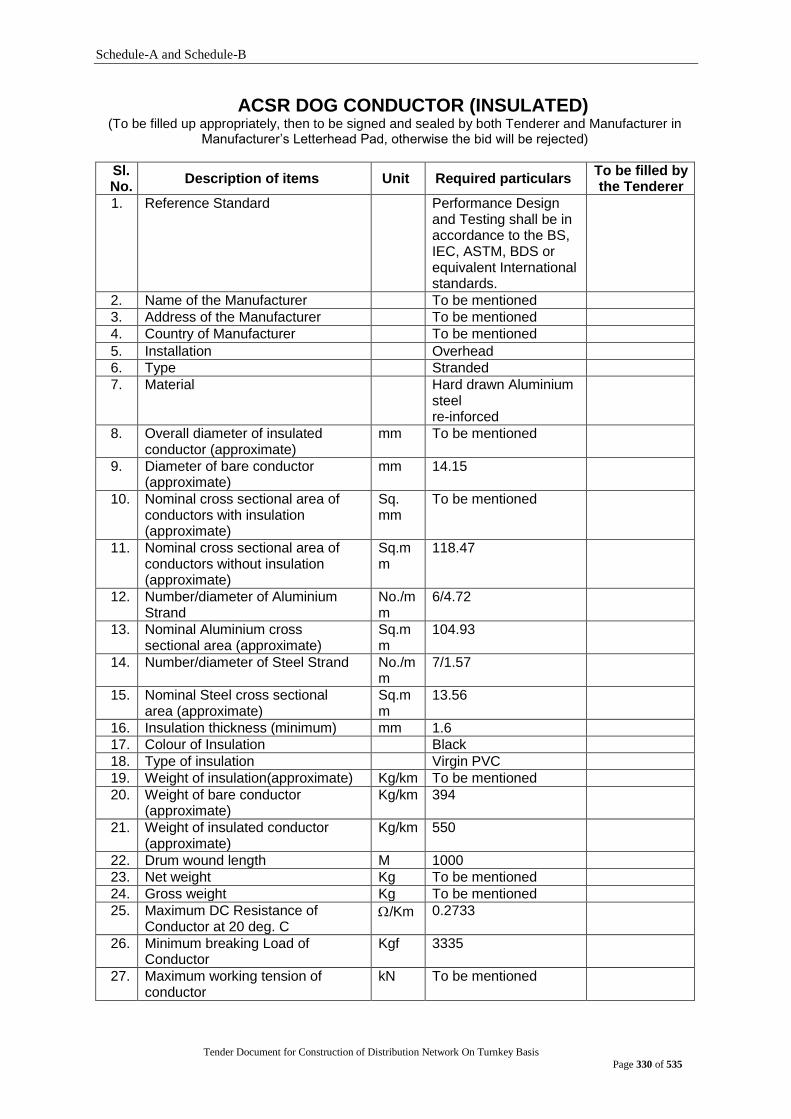
Schedule-A and Schedule-B
Tender Document for Construction of Distribution Network On Turnkey Basis
Page 330 of 535
ACSR DOG CONDUCTOR (INSULATED) (To be filled up appropriately, then to be signed and sealed by both Tenderer and Manufacturer in
Manufacturer‟s Letterhead Pad, otherwise the bid will be rejected)
Sl. No.
Description of items Unit Required particulars To be filled by the Tenderer
1. Reference Standard Performance Design and Testing shall be in accordance to the BS, IEC, ASTM, BDS or equivalent International standards.
2. Name of the Manufacturer To be mentioned
3. Address of the Manufacturer To be mentioned
4. Country of Manufacturer To be mentioned
5. Installation Overhead
6. Type Stranded
7. Material Hard drawn Aluminium steel re-inforced
8. Overall diameter of insulated conductor (approximate)
mm To be mentioned
9. Diameter of bare conductor (approximate)
mm 14.15
10. Nominal cross sectional area of conductors with insulation (approximate)
Sq. mm
To be mentioned
11. Nominal cross sectional area of conductors without insulation (approximate)
Sq.mm
118.47
12. Number/diameter of Aluminium Strand
No./mm
6/4.72
13. Nominal Aluminium cross sectional area (approximate)
Sq.mm
104.93
14. Number/diameter of Steel Strand No./mm
7/1.57
15. Nominal Steel cross sectional area (approximate)
Sq.mm
13.56
16. Insulation thickness (minimum) mm 1.6
17. Colour of Insulation Black
18. Type of insulation Virgin PVC
19. Weight of insulation(approximate) Kg/km To be mentioned
20. Weight of bare conductor (approximate)
Kg/km 394
21. Weight of insulated conductor (approximate)
Kg/km 550
22. Drum wound length M 1000
23. Net weight Kg To be mentioned
24. Gross weight Kg To be mentioned
25. Maximum DC Resistance of Conductor at 20 deg. C
/Km 0.2733
26. Minimum breaking Load of Conductor
Kgf 3335
27. Maximum working tension of conductor
kN To be mentioned
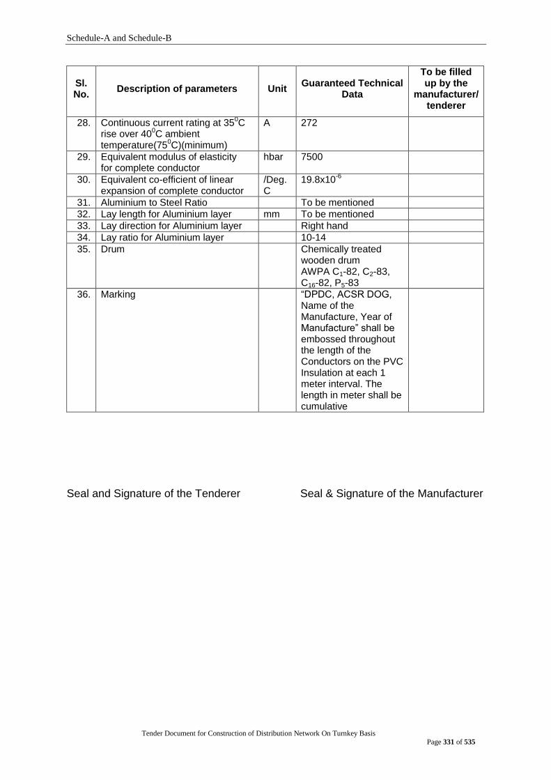
Schedule-A and Schedule-B
Tender Document for Construction of Distribution Network On Turnkey Basis
Page 331 of 535
Sl. No.
Description of parameters Unit Guaranteed Technical
Data
To be filled up by the
manufacturer/ tenderer
28. Continuous current rating at 350C
rise over 400C ambient
temperature(750C)(minimum)
A 272
29. Equivalent modulus of elasticity for complete conductor
hbar 7500
30. Equivalent co-efficient of linear expansion of complete conductor
/Deg.C
19.8x10⁻⁶
31. Aluminium to Steel Ratio To be mentioned
32. Lay length for Aluminium layer mm To be mentioned
33. Lay direction for Aluminium layer Right hand
34. Lay ratio for Aluminium layer 10-14
35. Drum Chemically treated wooden drum AWPA C1-82, C2-83, C16-82, P5-83
36. Marking “DPDC, ACSR DOG, Name of the Manufacture, Year of Manufacture” shall be embossed throughout the length of the Conductors on the PVC Insulation at each 1 meter interval. The length in meter shall be cumulative
Seal and Signature of the Tenderer Seal & Signature of the Manufacturer
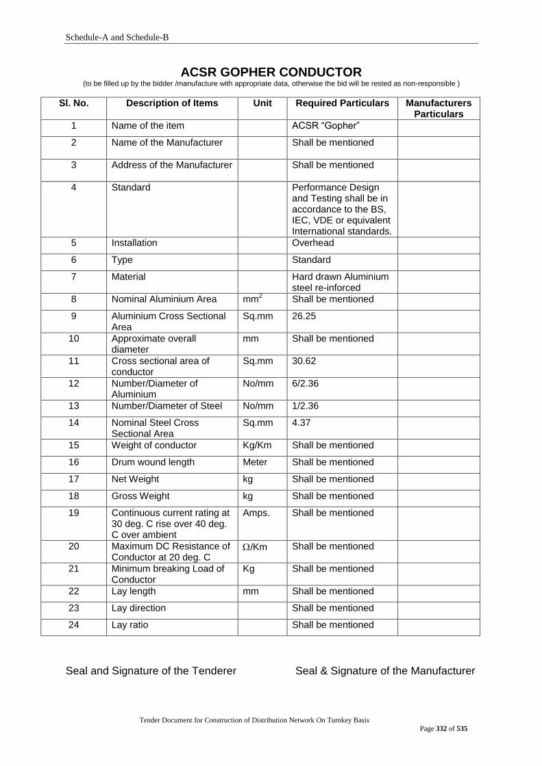
Schedule-A and Schedule-B
Tender Document for Construction of Distribution Network On Turnkey Basis
Page 332 of 535
ACSR GOPHER CONDUCTOR (to be filled up by the bidder /manufacture with appropriate data, otherwise the bid will be rested as non-responsible )
Sl. No. Description of Items Unit Required Particulars Manufacturers Particulars
1 Name of the item ACSR “Gopher”
2 Name of the Manufacturer Shall be mentioned
3 Address of the Manufacturer
Shall be mentioned
4 Standard Performance Design and Testing shall be in accordance to the BS, IEC, VDE or equivalent International standards.
5 Installation Overhead
6 Type Standard
7 Material Hard drawn Aluminium steel re-inforced
8 Nominal Aluminium Area mm2 Shall be mentioned
9 Aluminium Cross Sectional Area
Sq.mm 26.25
10 Approximate overall diameter
mm Shall be mentioned
11 Cross sectional area of conductor
Sq.mm 30.62
12 Number/Diameter of Aluminium
No/mm 6/2.36
13 Number/Diameter of Steel No/mm 1/2.36
14 Nominal Steel Cross Sectional Area
Sq.mm 4.37
15 Weight of conductor Kg/Km Shall be mentioned
16 Drum wound length Meter Shall be mentioned
17 Net Weight kg Shall be mentioned
18 Gross Weight kg Shall be mentioned
19 Continuous current rating at 30 deg. C rise over 40 deg. C over ambient
Amps. Shall be mentioned
20 Maximum DC Resistance of Conductor at 20 deg. C
/Km Shall be mentioned
21 Minimum breaking Load of Conductor
Kg Shall be mentioned
22 Lay length mm Shall be mentioned
23 Lay direction Shall be mentioned
24 Lay ratio Shall be mentioned
Seal and Signature of the Tenderer Seal & Signature of the Manufacturer
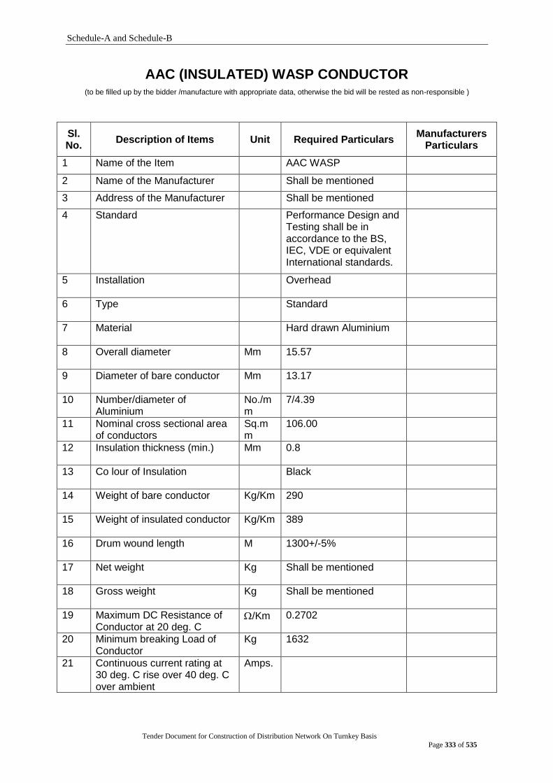
Schedule-A and Schedule-B
Tender Document for Construction of Distribution Network On Turnkey Basis
Page 333 of 535
AAC (INSULATED) WASP CONDUCTOR (to be filled up by the bidder /manufacture with appropriate data, otherwise the bid will be rested as non-responsible )
Sl. No.
Description of Items Unit Required Particulars Manufacturers
Particulars
1 Name of the Item AAC WASP
2 Name of the Manufacturer Shall be mentioned
3 Address of the Manufacturer Shall be mentioned
4 Standard Performance Design and Testing shall be in accordance to the BS, IEC, VDE or equivalent International standards.
5 Installation Overhead
6 Type Standard
7 Material Hard drawn Aluminium
8 Overall diameter Mm 15.57
9 Diameter of bare conductor Mm 13.17
10 Number/diameter of Aluminium
No./mm
7/4.39
11 Nominal cross sectional area of conductors
Sq.mm
106.00
12 Insulation thickness (min.) Mm 0.8
13 Co lour of Insulation Black
14 Weight of bare conductor Kg/Km 290
15 Weight of insulated conductor Kg/Km 389
16 Drum wound length M 1300+/-5%
17 Net weight Kg Shall be mentioned
18 Gross weight Kg Shall be mentioned
19 Maximum DC Resistance of Conductor at 20 deg. C
/Km 0.2702
20 Minimum breaking Load of Conductor
Kg 1632
21 Continuous current rating at 30 deg. C rise over 40 deg. C over ambient
Amps.
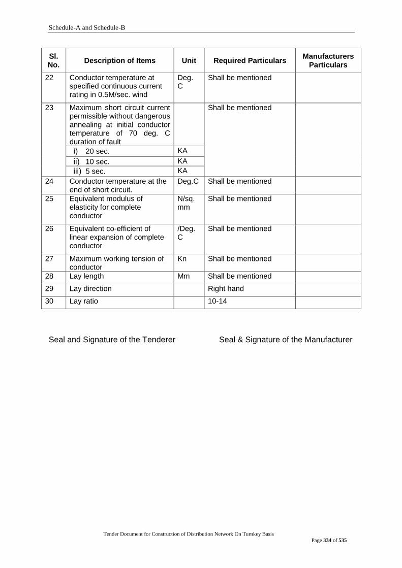
Schedule-A and Schedule-B
Tender Document for Construction of Distribution Network On Turnkey Basis
Page 334 of 535
Sl. No.
Description of Items Unit Required Particulars Manufacturers
Particulars
22 Conductor temperature at specified continuous current rating in 0.5M/sec. wind
Deg. C
Shall be mentioned
23 Maximum short circuit current permissible without dangerous annealing at initial conductor temperature of 70 deg. C duration of fault
Shall be mentioned
i) 20 sec. KA
ii) 10 sec. KA
iii) 5 sec. KA
24 Conductor temperature at the end of short circuit.
Deg.C Shall be mentioned
25 Equivalent modulus of elasticity for complete conductor
N/sq.mm
Shall be mentioned
26 Equivalent co-efficient of linear expansion of complete conductor
/Deg.C
Shall be mentioned
27 Maximum working tension of conductor
Kn Shall be mentioned
28 Lay length Mm Shall be mentioned
29 Lay direction Right hand
30 Lay ratio 10-14
Seal and Signature of the Tenderer Seal & Signature of the Manufacturer
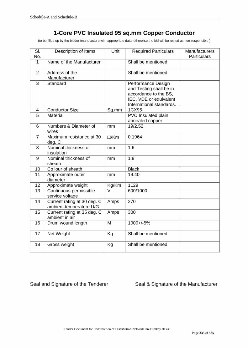
Schedule-A and Schedule-B
Tender Document for Construction of Distribution Network On Turnkey Basis
Page 335 of 535
1-Core PVC Insulated 95 sq.mm Copper Conductor (to be filled up by the bidder /manufacture with appropriate data, otherwise the bid will be rested as non-responsible )
Sl. No.
Description of Items Unit Required Particulars Manufacturers Particulars
1 Name of the Manufacturer Shall be mentioned
2 Address of the Manufacturer
Shall be mentioned
3 Standard Performance Design and Testing shall be in accordance to the BS, IEC, VDE or equivalent International standards.
4 Conductor Size Sq.mm 1CX95
5 Material PVC Insulated plain annealed copper.
6 Numbers & Diameter of wires
mm 19/2.52
7 Maximum resistance at 30 deg. C
/Km 0.1964
8 Nominal thickness of insulation
mm 1.6
9 Nominal thickness of sheath
mm 1.8
10 Co lour of sheath Black
11 Approximate outer diameter
mm 19.40
12 Approximate weight Kg/Km 1129
13 Continuous permissible service voltage
V 600/1000
14 Current rating at 30 deg. C ambient temperature U/G
Amps 270
15 Current rating at 35 deg. C ambient in air
Amps 300
16 Drum wound length M 1000+/-5%
17 Net Weight Kg Shall be mentioned
18 Gross weight Kg Shall be mentioned
Seal and Signature of the Tenderer Seal & Signature of the Manufacturer
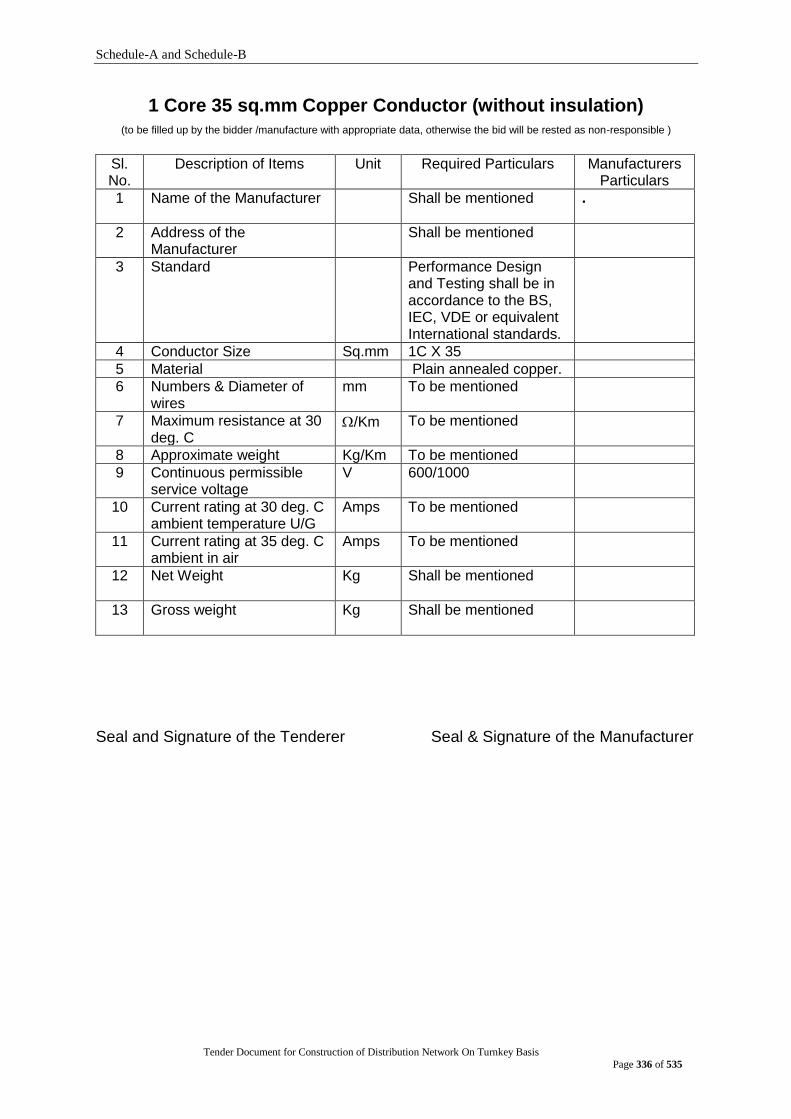
Schedule-A and Schedule-B
Tender Document for Construction of Distribution Network On Turnkey Basis
Page 336 of 535
1 Core 35 sq.mm Copper Conductor (without insulation) (to be filled up by the bidder /manufacture with appropriate data, otherwise the bid will be rested as non-responsible )
Sl. No.
Description of Items Unit Required Particulars Manufacturers Particulars
1 Name of the Manufacturer Shall be mentioned
.
2 Address of the Manufacturer
Shall be mentioned
3 Standard Performance Design and Testing shall be in accordance to the BS, IEC, VDE or equivalent International standards.
4 Conductor Size Sq.mm 1C X 35
5 Material Plain annealed copper.
6 Numbers & Diameter of wires
mm To be mentioned
7 Maximum resistance at 30 deg. C
/Km To be mentioned
8 Approximate weight Kg/Km To be mentioned
9 Continuous permissible service voltage
V 600/1000
10 Current rating at 30 deg. C ambient temperature U/G
Amps To be mentioned
11 Current rating at 35 deg. C ambient in air
Amps To be mentioned
12 Net Weight Kg Shall be mentioned
13 Gross weight Kg Shall be mentioned
Seal and Signature of the Tenderer Seal & Signature of the Manufacturer

Schedule-A and Schedule-B
Tender Document for Construction of Distribution Network On Turnkey Basis
Page 337 of 535
MIDSPAN JOINT-DOG (to be filled up by the bidder /manufacture with appropriate data, otherwise the bid will be rested as non-responsible )
Sl. No
Description Required Specification To be Filled By the Tenderer
1 Name & address of the Manufacturer
To be mentioned
2 Manufacturer‟s Code No. To be mentioned
3 Applicable Standard Design, Testing & Performance shall be in
accordance to BS, IEC, BDS, ANSI, ASTM, NEMA or equivalent international
standards.
4 Installation Overhead lines constructed with ACSR DOG
5 Type Tube Type
6 Material Aluminium Alloy and Steel
7 Minimum Continuous Current rating at 35ºC rise over 40ºC ambient temperature (75ºC)
272 Amps (min)
8 Breaking Strength To be mentioned
9 Minimum Length Aluminium L=380 mm Steel L=115
10 Weight in kg. To be mentioned
Seal and Signature of the Tenderer Seal & Signature of the Manufacturer
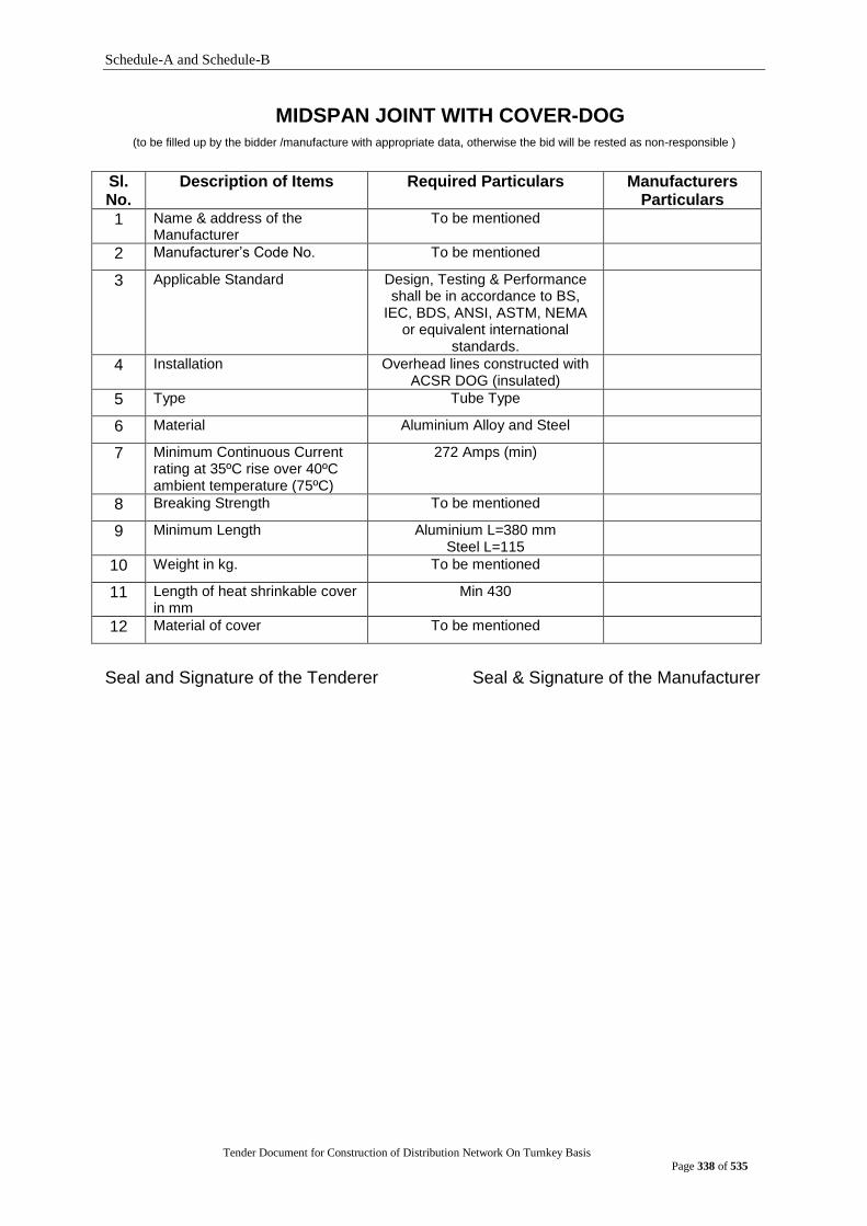
Schedule-A and Schedule-B
Tender Document for Construction of Distribution Network On Turnkey Basis
Page 338 of 535
MIDSPAN JOINT WITH COVER-DOG (to be filled up by the bidder /manufacture with appropriate data, otherwise the bid will be rested as non-responsible )
Sl. No.
Description of Items Required Particulars Manufacturers Particulars
1 Name & address of the Manufacturer
To be mentioned
2 Manufacturer‟s Code No. To be mentioned
3 Applicable Standard Design, Testing & Performance shall be in accordance to BS,
IEC, BDS, ANSI, ASTM, NEMA or equivalent international
standards.
4 Installation Overhead lines constructed with ACSR DOG (insulated)
5 Type Tube Type
6 Material Aluminium Alloy and Steel
7 Minimum Continuous Current rating at 35ºC rise over 40ºC ambient temperature (75ºC)
272 Amps (min)
8 Breaking Strength To be mentioned
9 Minimum Length Aluminium L=380 mm Steel L=115
10 Weight in kg. To be mentioned
11 Length of heat shrinkable cover in mm
Min 430
12 Material of cover To be mentioned
Seal and Signature of the Tenderer Seal & Signature of the Manufacturer

Schedule-A and Schedule-B
Tender Document for Construction of Distribution Network On Turnkey Basis
Page 339 of 535
JOINT MIDSPAN WITH COVER-WASP (to be filled up by the bidder /manufacture with appropriate data, otherwise the bid will be rested as non-responsible )
Sl. No.
Description of Items Required Particulars Manufacturers Particulars
1 Name & address of the Manufacturer
To be mentioned
2 Manufacturer‟s Code No. To be mentioned
3 Applicable Standard Design, Testing & Performance shall be in accordance to BS,
IEC, BDS, ANSI, ASTM, NEMA or equivalent international
standards.
4 Installation Overhead lines constructed with AAC Wasp (insulated)
5 Type Tube Type
6 Material Aluminum Alloy
7 Minimum Continuous Current rating at 35ºC rise over 40ºC ambient temperature (75ºC)
To be mentioned
8 Breaking Strength To be mentioned
9 Minimum Length Aluminum L=270 mm
10 Weight in kg. To be mentioned
11 Length of heat shrinkable cover (min) in mm
Min 320
12 Material of cover To be mentioned
Seal and Signature of the Tenderer Seal & Signature of the Manufacturer
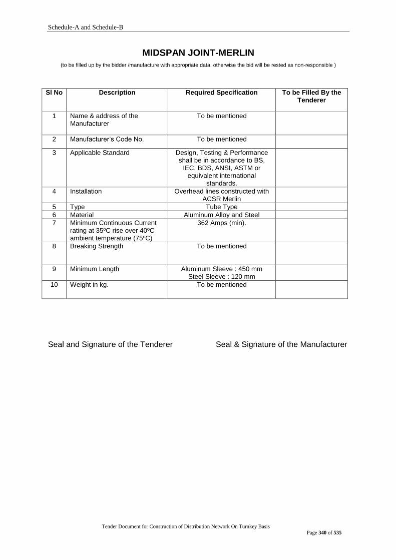
Schedule-A and Schedule-B
Tender Document for Construction of Distribution Network On Turnkey Basis
Page 340 of 535
MIDSPAN JOINT-MERLIN (to be filled up by the bidder /manufacture with appropriate data, otherwise the bid will be rested as non-responsible )
Sl No Description Required Specification To be Filled By the Tenderer
1 Name & address of the Manufacturer
To be mentioned
2 Manufacturer‟s Code No. To be mentioned
3 Applicable Standard Design, Testing & Performance shall be in accordance to BS,
IEC, BDS, ANSI, ASTM or equivalent international
standards.
4 Installation Overhead lines constructed with ACSR Merlin
5 Type Tube Type
6 Material Aluminum Alloy and Steel
7 Minimum Continuous Current rating at 35ºC rise over 40ºC ambient temperature (75ºC)
362 Amps (min).
8 Breaking Strength To be mentioned
9 Minimum Length
Aluminum Sleeve : 450 mm Steel Sleeve : 120 mm
10 Weight in kg. To be mentioned
Seal and Signature of the Tenderer Seal & Signature of the Manufacturer
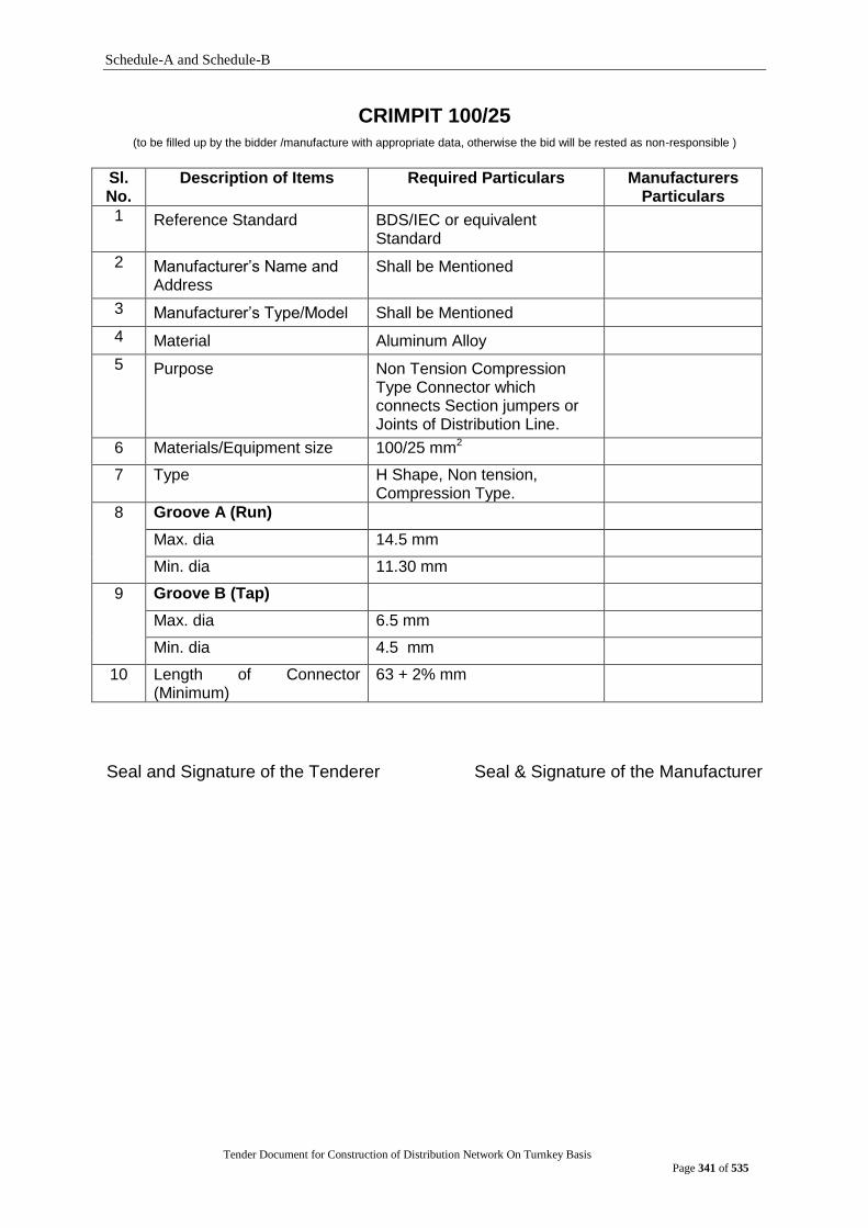
Schedule-A and Schedule-B
Tender Document for Construction of Distribution Network On Turnkey Basis
Page 341 of 535
CRIMPIT 100/25 (to be filled up by the bidder /manufacture with appropriate data, otherwise the bid will be rested as non-responsible )
Sl. No.
Description of Items Required Particulars Manufacturers Particulars
1 Reference Standard BDS/IEC or equivalent Standard
2 Manufacturer‟s Name and Address
Shall be Mentioned
3 Manufacturer‟s Type/Model Shall be Mentioned
4 Material Aluminum Alloy
5 Purpose Non Tension Compression Type Connector which connects Section jumpers or Joints of Distribution Line.
6 Materials/Equipment size 100/25 mm2
7 Type H Shape, Non tension, Compression Type.
8 Groove A (Run)
Max. dia 14.5 mm
Min. dia 11.30 mm
9 Groove B (Tap)
Max. dia 6.5 mm
Min. dia 4.5 mm
10 Length of Connector (Minimum)
63 + 2% mm
Seal and Signature of the Tenderer Seal & Signature of the Manufacturer

Schedule-A and Schedule-B
Tender Document for Construction of Distribution Network On Turnkey Basis
Page 342 of 535
CRIMPIT 100/100 (to be filled up by the bidder /manufacture with appropriate data, otherwise the bid will be rested as non-responsible )
Sl. No.
Description of Items Required Particulars Manufacturers Particulars
1 Reference Standard BDS/IEC or equivalent Standard
2 Manufacturer‟s Name and Address
Shall be Mentioned
3 Manufacturer‟s Type/Model
Shall be Mentioned
4 Material Aluminum Alloy
5 Purpose Non Tension Compression Type Connector which connects Section jumpers or Joints of Distribution Line.
6 Materials/Equipment size 100/100 mm2
7 Type H Shape, Non tension, Compression Type.
8 Groove A (Run)
Max. dia 14.5 mm
Min. dia 11.30 mm
9 Groove B (Tap)
Max. dia 14.5 mm
Min. dia 11.30 mm
10 Length of Connector (Minimum)
63 + 2% mm
Seal and Signature of the Tenderer Seal & Signature of the Manufacturer

Schedule-A and Schedule-B
Tender Document for Construction of Distribution Network On Turnkey Basis
Page 343 of 535
CRIMPIT 180/180 (to be filled up by the bidder /manufacture with appropriate data, otherwise the bid will be rested as non-responsible )
Sl. No.
Description of Items Required Particulars Manufacturers Particulars
1 Reference Standard BDS/IEC or equivalent Standard
2 Manufacturer‟s Name and Address
Shall be Mentioned
3 Manufacturer‟s Type/Model
Shall be Mentioned
4 Material Aluminum Alloy
5 Purpose Non Tension Compression Type Connector which connects Section jumpers or Joints of Distribution Line.
6 Materials/Equipment size 180/180 mm2
7 Type H Shape, Non tension, Compression Type.
8 Groove A (Run)
Max. dia 21.8 mm
Min. dia 16.5 mm
9 Groove B (Tap)
Max. dia 21.8 mm
Min. dia 16.5 mm
10 Length of Connector (Minimum)
87 + 2% mm
Seal and Signature of the Tenderer Seal & Signature of the Manufacturer
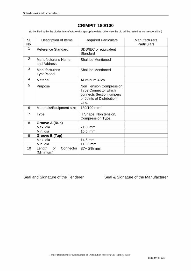
Schedule-A and Schedule-B
Tender Document for Construction of Distribution Network On Turnkey Basis
Page 344 of 535
CRIMPIT 180/100 (to be filled up by the bidder /manufacture with appropriate data, otherwise the bid will be rested as non-responsible )
Sl. No.
Description of Items Required Particulars Manufacturers Particulars
1 Reference Standard BDS/IEC or equivalent Standard
2 Manufacturer‟s Name and Address
Shall be Mentioned
3 Manufacturer‟s Type/Model
Shall be Mentioned
4 Material Aluminum Alloy
5 Purpose Non Tension Compression Type Connector which connects Section jumpers or Joints of Distribution Line.
6 Materials/Equipment size 180/100 mm2
7 Type H Shape, Non tension, Compression Type.
8 Groove A (Run)
Max. dia 21.8 mm
Min. dia 16.5 mm
9 Groove B (Tap)
Max. dia 14.5 mm
Min. dia 11.30 mm
10 Length of Connector (Minimum)
87+ 2% mm
Seal and Signature of the Tenderer Seal & Signature of the Manufacturer

Schedule-A and Schedule-B
Tender Document for Construction of Distribution Network On Turnkey Basis
Page 345 of 535
CRIMPIT 180/25 (to be filled up by the bidder /manufacture with appropriate data, otherwise the bid will be rested as non-responsible )
Sl. No. Description of Items Required Particulars Manufacturers Particulars
1 Reference Standard BDS/IEC or equivalent Standard
2 Manufacturer‟s Name and Address
To be mentioned
3 Manufacturer‟s Type/Model To be mentioned
4 Material Aluminum Alloy
5 Purpose Non Tension Compression Type Connector which
connects Section jumpers or Joints of Distribution
Line.
6 Materials/Equipment size 180/25 mm2
7 Type H Shape, Non tension, Compression Type.
8 Groove A (Run)
Max. dia 21.18 mm
Min. dia 16.5 mm
9 Groove B (Tap)
Max. dia 6.5 mm
Min. dia 4.5 mm
10 Length of Connector (Minimum)
87+ 2% mm
Seal and Signature of the Tenderer Seal & Signature of the Manufacturer
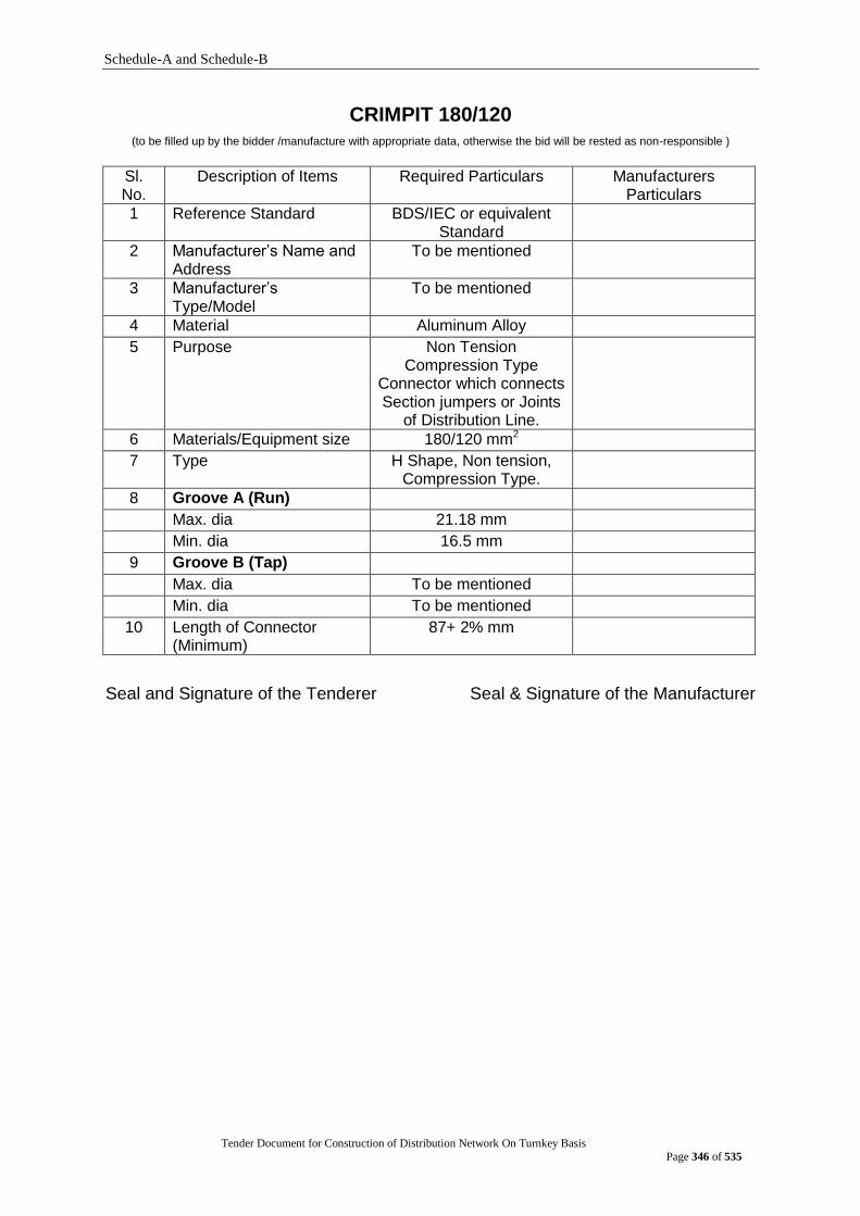
Schedule-A and Schedule-B
Tender Document for Construction of Distribution Network On Turnkey Basis
Page 346 of 535
CRIMPIT 180/120 (to be filled up by the bidder /manufacture with appropriate data, otherwise the bid will be rested as non-responsible )
Sl. No.
Description of Items Required Particulars Manufacturers Particulars
1 Reference Standard BDS/IEC or equivalent Standard
2 Manufacturer‟s Name and Address
To be mentioned
3 Manufacturer‟s Type/Model
To be mentioned
4 Material Aluminum Alloy
5 Purpose Non Tension Compression Type
Connector which connects Section jumpers or Joints
of Distribution Line.
6 Materials/Equipment size 180/120 mm2
7 Type H Shape, Non tension, Compression Type.
8 Groove A (Run)
Max. dia 21.18 mm
Min. dia 16.5 mm
9 Groove B (Tap)
Max. dia To be mentioned
Min. dia To be mentioned
10 Length of Connector (Minimum)
87+ 2% mm
Seal and Signature of the Tenderer Seal & Signature of the Manufacturer

Schedule-A and Schedule-B
Tender Document for Construction of Distribution Network On Turnkey Basis
Page 347 of 535
CRIMPIT 100/120
(to be filled up by the bidder /manufacture with appropriate data, otherwise the bid will be rested as non-responsible )
Sl. No. Description of Items Required Particulars Manufacturers Particulars
1 Reference Standard BDS/IEC or equivalent Standard
2 Manufacturer‟s Name and Address
Shall be Mentioned
3 Manufacturer‟s Type/Model Shall be Mentioned
4 Material Aluminum Alloy
5 Purpose Non Tension Compression Type Connector which connects Section jumpers or Joints of Distribution Line.
6 Materials/Equipment size 100/120 mm2
7 Type H Shape, Non tension, Compression Type.
8 Groove A (Run)
Max. dia 14.5 mm
Min. dia 11.30 mm
9 Groove B (Tap)
Max. dia To be mentioned
Min. dia To be mentioned
10 Length of Connector (Minimum)
To be mentioned
Seal and Signature of the Tenderer Seal & Signature of the Manufacturer

Schedule-A and Schedule-B
Tender Document for Construction of Distribution Network On Turnkey Basis
Page 348 of 535
CRIMPIT 100/100 (to be filled up by the bidder /manufacture with appropriate data, otherwise the bid will be rested as non-responsible )
Sl. No.
Description of Items Required Particulars Manufacturers Particulars
1 Reference Standard BDS/IEC or equivalent Standard
2 Manufacturer‟s Name and Address
Shall be Mentioned
3 Manufacturer‟s Type/Model
Shall be Mentioned
4 Material Aluminum Alloy
5 Purpose Non Tension Compression Type Connector which connects Section jumpers or Joints of Distribution Line.
6 Materials/Equipment size 100/100 mm2
7 Type H Shape, Non tension, Compression Type.
8 Groove A (Run)
Max. dia 14.5 mm
Min. dia 11.30 mm
9 Groove B (Tap)
Max. dia 14.5 mm
Min. dia 11.30 mm
10 Length of Connector (Minimum)
63 + 2% mm
Seal and Signature of the Tenderer Seal & Signature of the Manufacturer
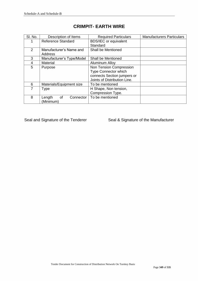
Schedule-A and Schedule-B
Tender Document for Construction of Distribution Network On Turnkey Basis
Page 349 of 535
CRIMPIT- EARTH WIRE
Sl. No. Description of Items Required Particulars Manufacturers Particulars
1 Reference Standard BDS/IEC or equivalent Standard
2 Manufacturer‟s Name and Address
Shall be Mentioned
3 Manufacturer‟s Type/Model Shall be Mentioned
4 Material Aluminum Alloy
5 Purpose Non Tension Compression Type Connector which connects Section jumpers or Joints of Distribution Line.
6 Materials/Equipment size To be mentioned
7 Type H Shape, Non tension, Compression Type.
8 Length of Connector (Minimum)
To be mentioned
Seal and Signature of the Tenderer Seal & Signature of the Manufacturer
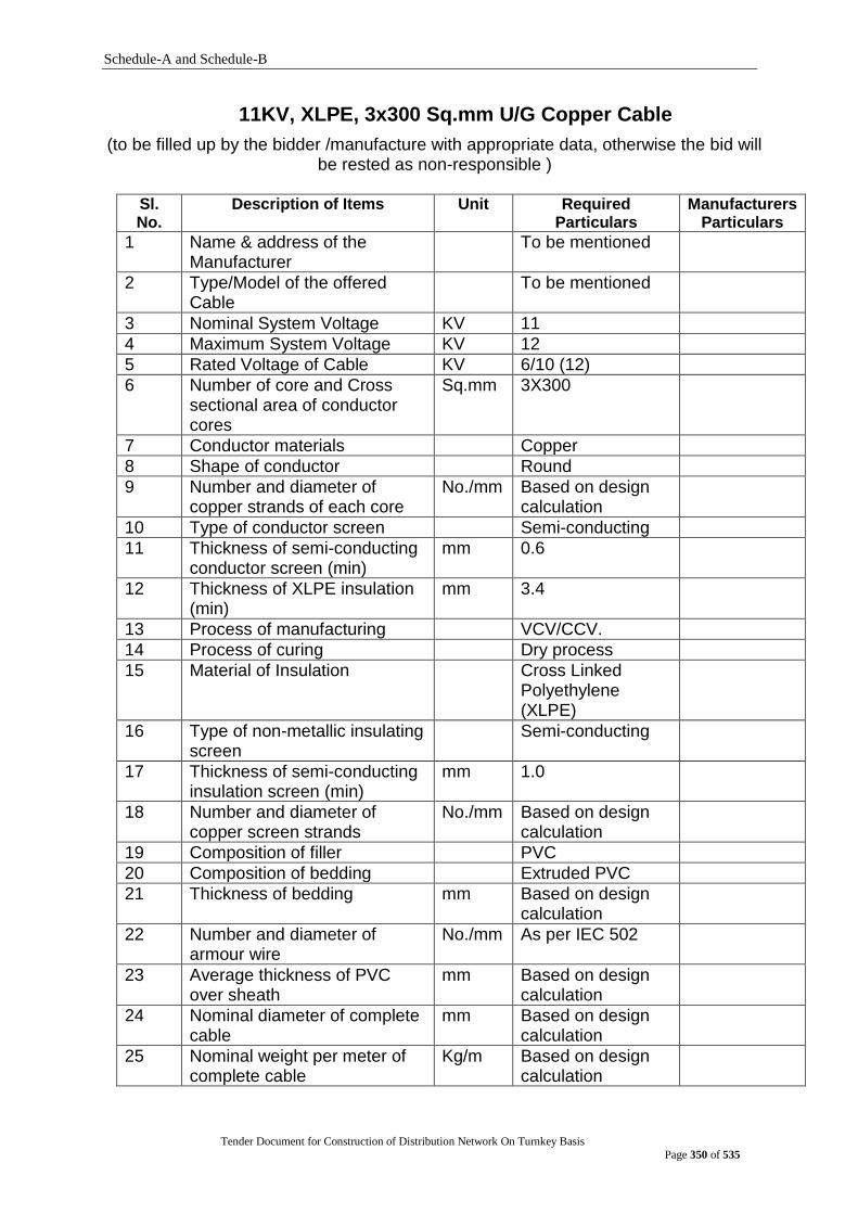
Schedule-A and Schedule-B
Tender Document for Construction of Distribution Network On Turnkey Basis
Page 350 of 535
11KV, XLPE, 3x300 Sq.mm U/G Copper Cable
(to be filled up by the bidder /manufacture with appropriate data, otherwise the bid will be rested as non-responsible )
Sl. No.
Description of Items Unit Required Particulars
Manufacturers Particulars
1 Name & address of the Manufacturer
To be mentioned
2 Type/Model of the offered Cable
To be mentioned
3 Nominal System Voltage KV 11
4 Maximum System Voltage KV 12
5 Rated Voltage of Cable KV 6/10 (12)
6 Number of core and Cross sectional area of conductor cores
Sq.mm 3X300
7 Conductor materials Copper
8 Shape of conductor Round
9 Number and diameter of copper strands of each core
No./mm Based on design calculation
10 Type of conductor screen Semi-conducting
11 Thickness of semi-conducting conductor screen (min)
mm 0.6
12 Thickness of XLPE insulation (min)
mm 3.4
13 Process of manufacturing VCV/CCV.
14 Process of curing Dry process
15 Material of Insulation Cross Linked Polyethylene (XLPE)
16 Type of non-metallic insulating screen
Semi-conducting
17 Thickness of semi-conducting insulation screen (min)
mm 1.0
18 Number and diameter of copper screen strands
No./mm Based on design calculation
19 Composition of filler PVC
20 Composition of bedding Extruded PVC
21 Thickness of bedding mm Based on design calculation
22 Number and diameter of armour wire
No./mm As per IEC 502
23 Average thickness of PVC over sheath
mm Based on design calculation
24 Nominal diameter of complete cable
mm Based on design calculation
25 Nominal weight per meter of complete cable
Kg/m Based on design calculation
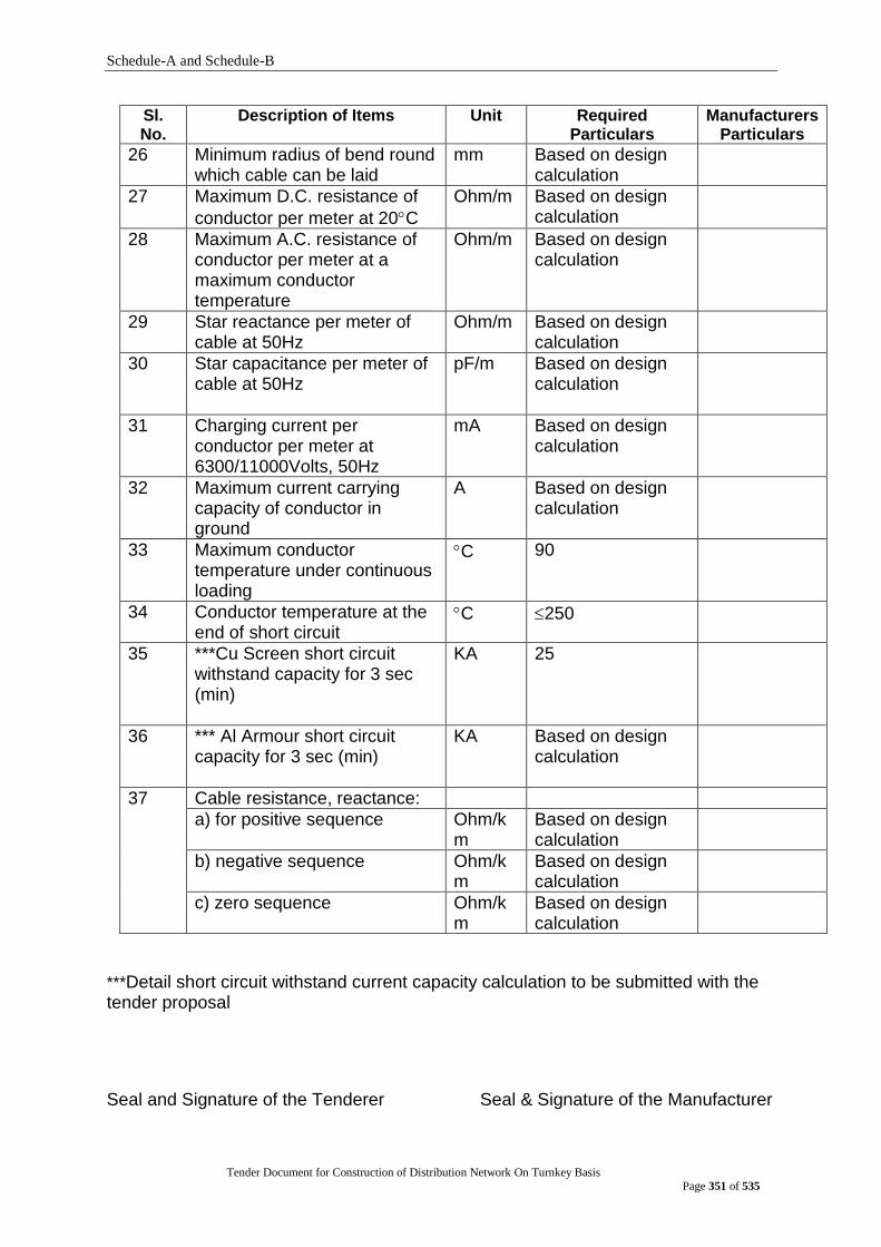
Schedule-A and Schedule-B
Tender Document for Construction of Distribution Network On Turnkey Basis
Page 351 of 535
Sl. No.
Description of Items Unit Required Particulars
Manufacturers Particulars
26 Minimum radius of bend round which cable can be laid
mm Based on design calculation
27 Maximum D.C. resistance of
conductor per meter at 20C
Ohm/m Based on design calculation
28 Maximum A.C. resistance of conductor per meter at a maximum conductor temperature
Ohm/m Based on design calculation
29 Star reactance per meter of cable at 50Hz
Ohm/m Based on design calculation
30 Star capacitance per meter of cable at 50Hz
pF/m Based on design calculation
31 Charging current per conductor per meter at 6300/11000Volts, 50Hz
mA Based on design calculation
32 Maximum current carrying capacity of conductor in ground
A Based on design calculation
33 Maximum conductor temperature under continuous loading
C 90
34 Conductor temperature at the end of short circuit
C 250
35 ***Cu Screen short circuit withstand capacity for 3 sec (min)
KA 25
36 *** Al Armour short circuit capacity for 3 sec (min)
KA Based on design calculation
37 Cable resistance, reactance:
a) for positive sequence Ohm/km
Based on design calculation
b) negative sequence Ohm/km
Based on design calculation
c) zero sequence Ohm/km
Based on design calculation
***Detail short circuit withstand current capacity calculation to be submitted with the tender proposal
Seal and Signature of the Tenderer Seal & Signature of the Manufacturer
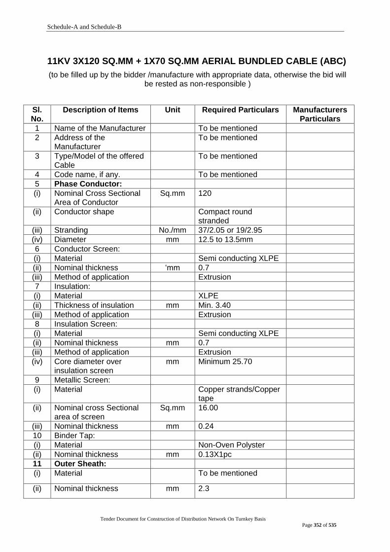
Schedule-A and Schedule-B
Tender Document for Construction of Distribution Network On Turnkey Basis
Page 352 of 535
11KV 3X120 SQ.MM + 1X70 SQ.MM AERIAL BUNDLED CABLE (ABC)
(to be filled up by the bidder /manufacture with appropriate data, otherwise the bid will be rested as non-responsible )
Sl. No.
Description of Items Unit Required Particulars Manufacturers Particulars
1 Name of the Manufacturer To be mentioned
2 Address of the Manufacturer
To be mentioned
3 Type/Model of the offered Cable
To be mentioned
4 Code name, if any. To be mentioned
5 Phase Conductor:
(i) Nominal Cross Sectional Area of Conductor
Sq.mm
120
(ii) Conductor shape Compact round stranded
(iii) Stranding No./mm 37/2.05 or 19/2.95
(iv) Diameter mm 12.5 to 13.5mm
6 Conductor Screen:
(i) Material Semi conducting XLPE
(ii) Nominal thickness „mm 0.7
(iii) Method of application Extrusion
7 Insulation:
(i) Material XLPE
(ii) Thickness of insulation mm Min. 3.40
(iii) Method of application Extrusion
8 Insulation Screen:
(i) Material Semi conducting XLPE
(ii) Nominal thickness mm 0.7
(iii) Method of application Extrusion
(iv) Core diameter over insulation screen
mm Minimum 25.70
9 Metallic Screen:
(i) Material Copper strands/Copper tape
(ii) Nominal cross Sectional area of screen
Sq.mm 16.00
(iii) Nominal thickness mm 0.24
10 Binder Tap:
(i) Material Non-Oven Polyster
(ii) Nominal thickness mm 0.13X1pc
11 Outer Sheath:
(i) Material To be mentioned
(ii) Nominal thickness mm 2.3

Schedule-A and Schedule-B
Tender Document for Construction of Distribution Network On Turnkey Basis
Page 353 of 535
Sl. No.
Description of Items Unit Required Particulars Manufacturers Particulars
12 Suspension Unit:
(i) Material of suspension unit
Galvanized Steel Wire
(ii) Nominal cross Sectional area of rope
Sq.mm 70.00
(ii) Stranding No./mm 7/3.57
(iii) Thickness of covering mm Min. 1.00
(iv) Overall diameter of rope mm Approx. 12.00
(v) Ultimate minimum breaking strength
KN 80.0 Min.
13 Bundled/complete cable Three cores stranded around suspension unit
(i) Diameter of stranded suspension unit
mm To be mentioned
(ii) Per unit weight Kg/m To be mentioned
(iii) Drum wound length meter 1000
(iv) Material of drum Steel
(v) Gross Weight Kg To be mentioned
(vi) Net Weight Kg To be mentioned
14 Electrical Data:
(i) Nominal Voltage Rating (Uo/U)
KV 6/10
(ii) Maximum admissible continuous working voltage
KV 12.00
(iii) Maximum permissible conductor temperature
C 90
(iv) Maximum DC resistance
at 20C
Ohm/Km 0.253
(v) Working inductance Ohm/Km 0.380
(vi) Working capacitance F/Km 0.360
(vii) Earth leakage current A 1.90
(viii) Short circuit current: - Conductor - Screen
KA KA
11.3 2.4
(ix) Current rating at Ambient
Temperature of 40C
A 304
(x) AC Test Voltage KV 15.00
15 Other properties:
(i) Minimum bending radius mm To be mentioned
Seal and Signature of the Tenderer Seal & Signature of the Manufacturer
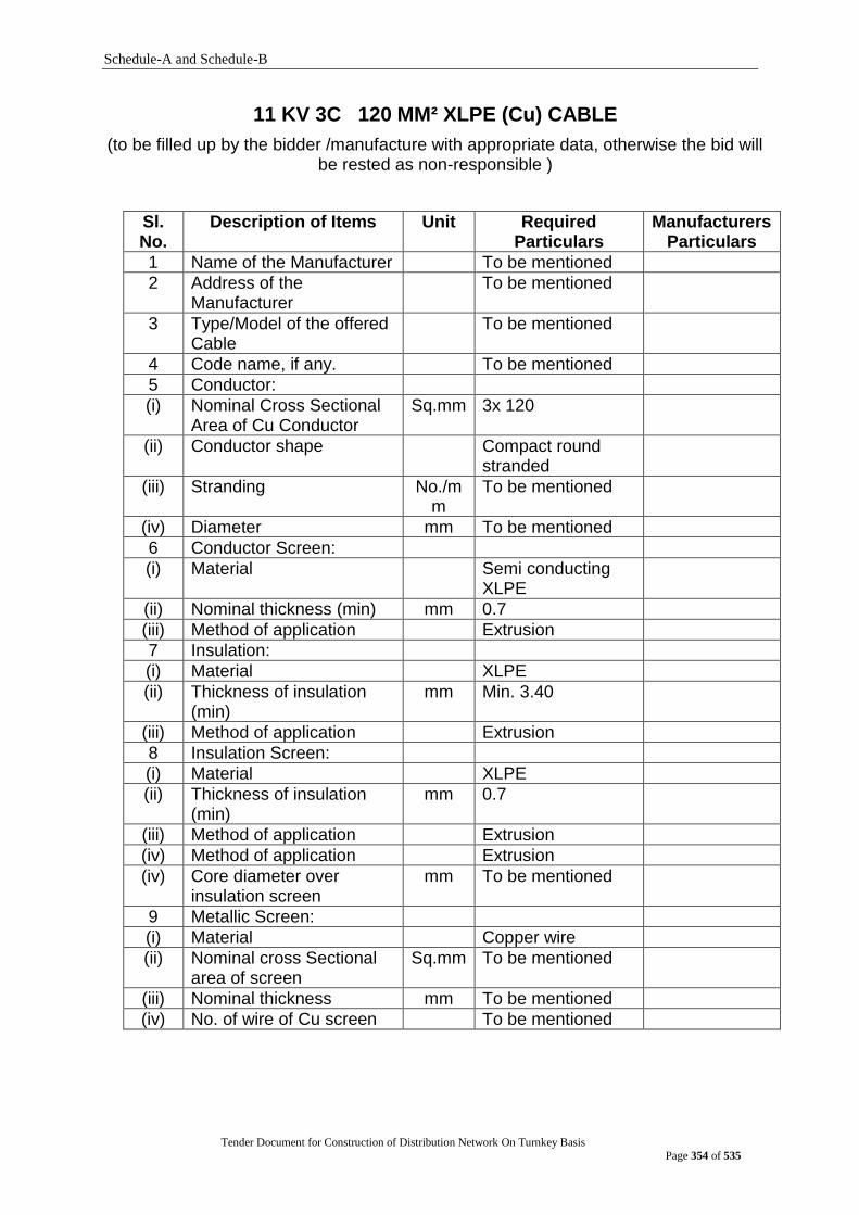
Schedule-A and Schedule-B
Tender Document for Construction of Distribution Network On Turnkey Basis
Page 354 of 535
11 KV 3C 120 MM² XLPE (Cu) CABLE
(to be filled up by the bidder /manufacture with appropriate data, otherwise the bid will be rested as non-responsible )
Sl. No.
Description of Items Unit Required Particulars
Manufacturers Particulars
1 Name of the Manufacturer To be mentioned
2 Address of the Manufacturer
To be mentioned
3 Type/Model of the offered Cable
To be mentioned
4 Code name, if any. To be mentioned
5 Conductor:
(i) Nominal Cross Sectional Area of Cu Conductor
Sq.mm
3x 120
(ii) Conductor shape Compact round stranded
(iii) Stranding No./mm
To be mentioned
(iv) Diameter mm To be mentioned
6 Conductor Screen:
(i) Material Semi conducting XLPE
(ii) Nominal thickness (min) mm 0.7
(iii) Method of application Extrusion
7 Insulation:
(i) Material XLPE
(ii) Thickness of insulation (min)
mm Min. 3.40
(iii) Method of application Extrusion
8 Insulation Screen:
(i) Material XLPE
(ii) Thickness of insulation (min)
mm 0.7
(iii) Method of application Extrusion
(iv) Method of application Extrusion
(iv) Core diameter over insulation screen
mm To be mentioned
9 Metallic Screen:
(i) Material Copper wire
(ii) Nominal cross Sectional area of screen
Sq.mm To be mentioned
(iii) Nominal thickness mm To be mentioned
(iv) No. of wire of Cu screen To be mentioned
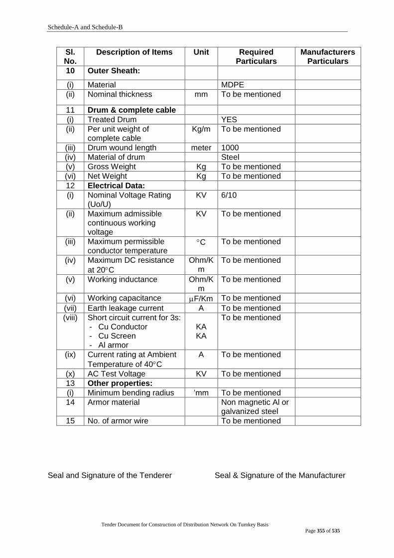
Schedule-A and Schedule-B
Tender Document for Construction of Distribution Network On Turnkey Basis
Page 355 of 535
Sl. No.
Description of Items Unit Required Particulars
Manufacturers Particulars
10 Outer Sheath:
(i) Material MDPE
(ii) Nominal thickness mm To be mentioned
11 Drum & complete cable
(i) Treated Drum YES
(ii) Per unit weight of complete cable
Kg/m To be mentioned
(iii) Drum wound length meter 1000
(iv) Material of drum Steel
(v) Gross Weight Kg To be mentioned
(vi) Net Weight Kg To be mentioned
12 Electrical Data:
(i) Nominal Voltage Rating (Uo/U)
KV 6/10
(ii) Maximum admissible continuous working voltage
KV To be mentioned
(iii) Maximum permissible conductor temperature
C To be mentioned
(iv) Maximum DC resistance
at 20C
Ohm/Km
To be mentioned
(v) Working inductance Ohm/Km
To be mentioned
(vi) Working capacitance F/Km To be mentioned
(vii) Earth leakage current A To be mentioned
(viii) Short circuit current for 3s: - Cu Conductor - Cu Screen - Al armor
KA KA
To be mentioned
(ix) Current rating at Ambient
Temperature of 40C
A To be mentioned
(x) AC Test Voltage KV To be mentioned
13 Other properties:
(i) Minimum bending radius „mm To be mentioned
14 Armor material Non magnetic Al or galvanized steel
15 No. of armor wire To be mentioned
Seal and Signature of the Tenderer Seal & Signature of the Manufacturer

Schedule-A and Schedule-B
Tender Document for Construction of Distribution Network On Turnkey Basis
Page 356 of 535
4-Core, 16 mm2 PVC Insulated and PVC Sheathed NYY Copper Cable (to be filled up by the Bidder/manufacturer with appropriate data, otherwise the bid will be treated as non-
responsive)
SL NO
DESCRIPTION Unit Required Specification To be filled by the Tenderer
1 Name of the Manufacturer Shall be mentioned
2 Address of the
Manufacturer
Shall be mentioned
3 Standard Performance Design and Testing shall be in accordance to the BS, IEC, VDE or equivalent International standards.
4 Cable Size Sq.mm 4CX16
5 Material PVC Insulated and PVC Sheathed plain annealed copper.
6 Numbers & Diameter of wires
No./mm 7/1.71
7 Maximum resistance at 20 deg. C
/Km 1.15
8 Nominal thickness of insulation
mm 1.0 (Minimum)
9 Nominal thickness of sheath mm 1.8 (Minimum)
10 Colour of sheath Shall be mentioned
11 Approximate outer diameter mm Shall be mentioned
12 Approximate weight Kg/Km Shall be mentioned
13 Continuous permissible service voltage
V 600/1000
14 Current rating at 30 deg. C ambient temperature U/G
Amps 83
15 Current rating at 35 deg. C ambient in air
Amps 75
16 Drum wound length M 1000+/-5%
17 Net Weight Kg Shall be mentioned
18 Gross weight Kg Shall be mentioned
Seal and Signature of the Tenderer Seal & Signature of the Manufacturer
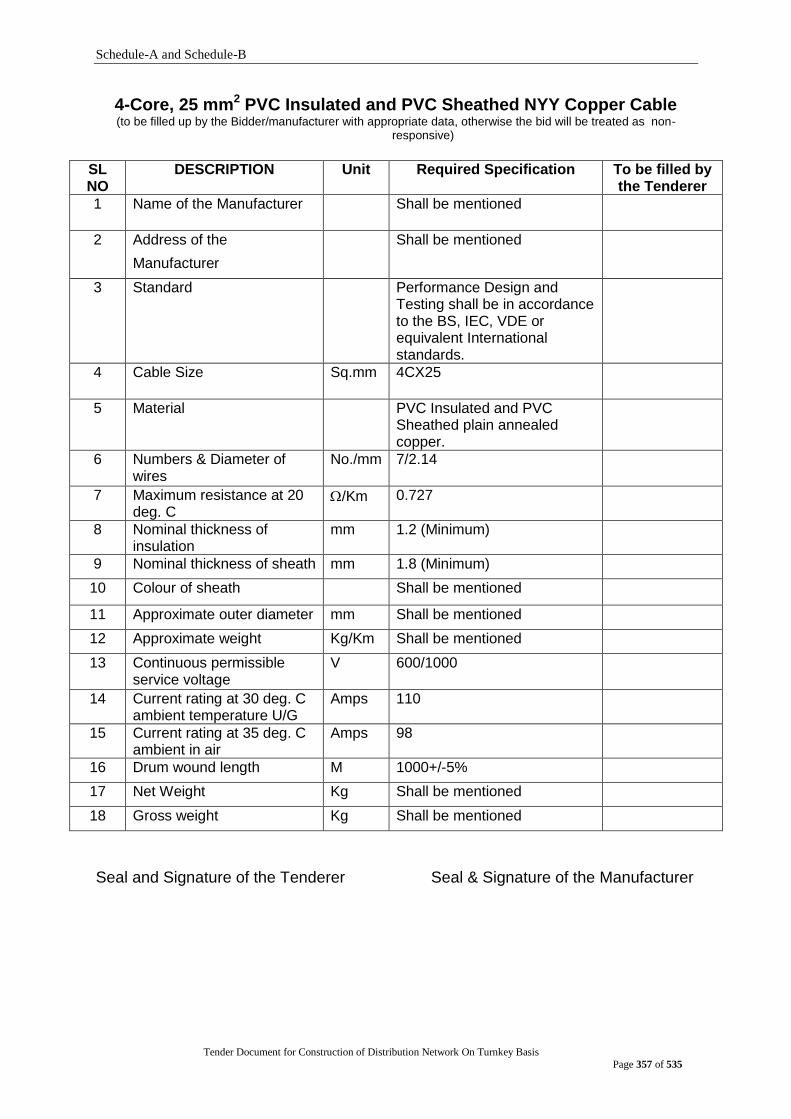
Schedule-A and Schedule-B
Tender Document for Construction of Distribution Network On Turnkey Basis
Page 357 of 535
4-Core, 25 mm2 PVC Insulated and PVC Sheathed NYY Copper Cable (to be filled up by the Bidder/manufacturer with appropriate data, otherwise the bid will be treated as non-
responsive)
SL NO
DESCRIPTION Unit Required Specification To be filled by the Tenderer
1 Name of the Manufacturer Shall be mentioned
2 Address of the
Manufacturer
Shall be mentioned
3 Standard Performance Design and Testing shall be in accordance to the BS, IEC, VDE or equivalent International standards.
4 Cable Size Sq.mm 4CX25
5 Material PVC Insulated and PVC Sheathed plain annealed copper.
6 Numbers & Diameter of wires
No./mm 7/2.14
7 Maximum resistance at 20 deg. C
/Km 0.727
8 Nominal thickness of insulation
mm 1.2 (Minimum)
9 Nominal thickness of sheath mm 1.8 (Minimum)
10 Colour of sheath Shall be mentioned
11 Approximate outer diameter mm Shall be mentioned
12 Approximate weight Kg/Km Shall be mentioned
13 Continuous permissible service voltage
V 600/1000
14 Current rating at 30 deg. C ambient temperature U/G
Amps 110
15 Current rating at 35 deg. C ambient in air
Amps 98
16 Drum wound length M 1000+/-5%
17 Net Weight Kg Shall be mentioned
18 Gross weight Kg Shall be mentioned
Seal and Signature of the Tenderer Seal & Signature of the Manufacturer
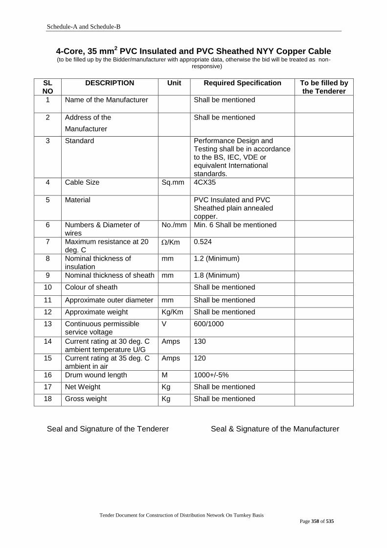
Schedule-A and Schedule-B
Tender Document for Construction of Distribution Network On Turnkey Basis
Page 358 of 535
4-Core, 35 mm2 PVC Insulated and PVC Sheathed NYY Copper Cable (to be filled up by the Bidder/manufacturer with appropriate data, otherwise the bid will be treated as non-
responsive)
SL NO
DESCRIPTION Unit Required Specification To be filled by the Tenderer
1 Name of the Manufacturer Shall be mentioned
2 Address of the
Manufacturer
Shall be mentioned
3 Standard Performance Design and Testing shall be in accordance to the BS, IEC, VDE or equivalent International standards.
4 Cable Size Sq.mm 4CX35
5 Material PVC Insulated and PVC Sheathed plain annealed copper.
6 Numbers & Diameter of wires
No./mm Min. 6 Shall be mentioned
7 Maximum resistance at 20 deg. C
/Km 0.524
8 Nominal thickness of insulation
mm 1.2 (Minimum)
9 Nominal thickness of sheath mm 1.8 (Minimum)
10 Colour of sheath Shall be mentioned
11 Approximate outer diameter mm Shall be mentioned
12 Approximate weight Kg/Km Shall be mentioned
13 Continuous permissible service voltage
V 600/1000
14 Current rating at 30 deg. C ambient temperature U/G
Amps 130
15 Current rating at 35 deg. C ambient in air
Amps 120
16 Drum wound length M 1000+/-5%
17 Net Weight Kg Shall be mentioned
18 Gross weight Kg Shall be mentioned
Seal and Signature of the Tenderer Seal & Signature of the Manufacturer

Schedule-A and Schedule-B
Tender Document for Construction of Distribution Network On Turnkey Basis
Page 359 of 535
4-Core, 185 mm2 PVC Insulated and PVC Sheathed NYY Copper Cable (to be filled up by the Bidder/manufacturer with appropriate data, otherwise the bid will be treated as non-
responsive)
SL NO
DESCRIPTION Unit Required Specification To be filled by the Tenderer
1 Name of the Manufacturer Shall be mentioned
2 Address of the
Manufacturer
Shall be mentioned
3 Standard Performance Design and Testing shall be in accordance to the BS, IEC, VDE or equivalent International standards.
4 Cable Size Sq.mm 4CX185
5 Material PVC Insulated and PVC Sheathed plain annealed copper.
6 Numbers & Diameter of wires
No./mm Shall be mentioned
7 Maximum resistance at 20 deg. C
/Km 0.0991
8 Nominal thickness of insulation
mm 2.0 (Minimum)
9 Nominal thickness of sheath mm 2.7 (Minimum)
10 Colour of sheath Shall be mentioned
11 Approximate outer diameter mm Shall be mentioned
12 Approximate weight Kg/Km Shall be mentioned
13 Continuous permissible service voltage
V 600/1000
14 Current rating at 30 deg. C ambient temperature U/G
Amps 330
15 Current rating at 35 deg. C ambient in air
Amps 350
16 Drum wound length M 1000+/-5%
17 Net Weight Kg Shall be mentioned
18 Gross weight Kg Shall be mentioned
Seal and Signature of the Tenderer Seal & Signature of the Manufacturer

Schedule-A and Schedule-B
Tender Document for Construction of Distribution Network On Turnkey Basis
Page 360 of 535
2-Core, 10 mm2 PVC Insulated and PVC Sheathed NYY Copper Cable (to be filled up by the Bidder/manufacturer with appropriate data, otherwise the bid will be treated as non-
responsive)
SL NO
DESCRIPTION Unit Required Specification To be filled by the Tenderer
1 Name of the Manufacturer Shall be mentioned
2 Address of the
Manufacturer
Shall be mentioned
3 Standard Performance Design and Testing shall be in accordance to the BS, IEC, VDE or equivalent International standards.
4 Cable Size Sq.mm 2CX10
5 Material PVC Insulated and PVC Sheathed plain annealed copper.
6 Numbers & Diameter of wires
No./mm 7/1.35
7 Maximum resistance at 20 deg. C
/Km 1.83
8 Nominal thickness of insulation
mm 1.0 (Minimum)
9 Nominal thickness of sheath mm 1.8 (Minimum)
10 Colour of sheath Shall be mentioned
11 Approximate outer diameter mm Shall be mentioned
12 Approximate weight Kg/Km Shall be mentioned
13 Continuous permissible service voltage
V 600/1000
14 Current rating at 30 deg. C ambient temperature U/G
Amps 74
15 Current rating at 35 deg. C ambient in air
Amps 62
16 Drum wound length M 1000+/-5%
17 Net Weight Kg Shall be mentioned
18 Gross weight Kg Shall be mentioned
Seal and Signature of the Tenderer Seal & Signature of the Manufacturer

Schedule-A and Schedule-B
Tender Document for Construction of Distribution Network On Turnkey Basis
Page 361 of 535
STRAIGHT THROUGH JOINT FOR 11 KV, 300 MM², XLPE, THREE CORE COPPER CABLE
(To be filled up by the bidder/manufacturer with appropriate data, otherwise the bid will be treated as non-responsive)
Sl. No. Description Required Specification To be filled by the tenderer
1. Name of the Manufacturer To be mentioned
2. Address of the Manufacturer
To be mentioned
3. Type/Model To be mentioned
4. Country of Origin UK/USA/ Germany /France/ Switzerland/ Sweden/ Canada/ Japan
5. Country of Manufacture UK/USA/ Germany /France/ Switzerland/ Sweden/ Canada/ Japan
6. Application For 11 kV, 3-Core, XLPE Insulated 300mm² underground Copper cable
7. Installation Underground horizontal mounting
8. Nominal System voltage 11 kV (Phase to Phase)
9. Maximum System voltage 12 kV (phase to Phase)
10. Impulse withstand voltage(minimum)
75 KV
11. Power frequency withstand voltage(minimum)
28 KV for 5 minutes
12. Number of core 3
13. Type of insulation XLPE
14. Type of screening Copper tape or Copper wire
15. Construction The joint shall be proof against ingress of moisture and water
16. System neutral Earthing Effectively Earthed
17. Conductor cross section 300 mm²
18. Kit components Stress Control Tube- 6Nos. Dimension(minimum)- L-400, T-2.8
Dual Wall Tube- 6Nos. Dimension(minimum)- L-390, IT-5.3, ST-0.9
Corrosion protection Tube- 2Nos. Dimension(minimum)- L-900, T-4.3
Compress Ferrule/Mechanical (Shear Head Bolt) Connector - 3 Nos
Stress Grading/Relieving Mastic- 6Nos. Dimension(minimum)- L-50, W-25, T-2.3
Stress Grading/Relieving Mastic- 7Nos. Dimension(minimum)- L-300, W-25, T-2.3
Black Mastic Tape- 6Nos. Dimension(minimum)- L-200, W-35, T-2.3
Black Mastic Tape- 8Nos. Dimension(minimum)- L-400, W-35, T-2.3
Tinned copper Braid (25 Sqmm)- 1No. Dimension(minimum)- L- 1300, W-25
Tinned Copper Wire Stocking- 3Nos. Dimension(minimum)- L- 750, W- 30
Tinned Copper Wire Mesh- 2Nos. Dimension(minimum)- L-1000, W-50
Silicone Grease- 2Nos., 5GRMS
G.I. Wire wrap- 1No. Dimension(minimum)- L-1250, W-450
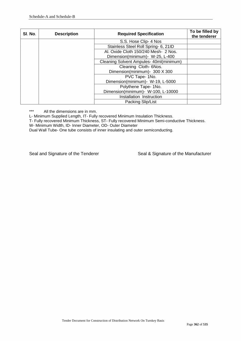
Schedule-A and Schedule-B
Tender Document for Construction of Distribution Network On Turnkey Basis
Page 362 of 535
Sl. No. Description Required Specification To be filled by the tenderer
S.S. Hose Clip- 4 Nos
Stainless Steel Roll Spring- 6, 21ID
Al. Oxide Cloth 150/240 Mesh- 2 Nos. Dimension(minimum)- W-25, L-400
Cleaning Solvent Ampules- 40ml(minimum)
Cleaning Cloth- 6Nos. Dimension(minimum)- 300 X 300
PVC Tape- 1No. Dimension(minimum)- W-19, L-5000
Polythene Tape- 1No. Dimension(minimum)- W-100, L-10000
Installation Instruction
Packing Slip/List *** All the dimensions are in mm. L- Minimum Supplied Length, IT- Fully recovered Minimum Insulation Thickness. T- Fully recovered Minimum Thickness, ST- Fully recovered Minimum Semi-conductive Thickness. W- Minimum Width, ID- Inner Diameter, OD- Outer Diameter Dual Wall Tube- One tube consists of inner insulating and outer semiconducting.
Seal and Signature of the Tenderer Seal & Signature of the Manufacturer

Schedule-A and Schedule-B
Tender Document for Construction of Distribution Network On Turnkey Basis
Page 363 of 535
TERMINATION KITS (INDOOR TYPE) FOR 11 KV, 300 MM², XLPE, 3-CORE COPPER CABLE
(To be filled up by the bidder/manufacturer with appropriate data, otherwise the bid will be treated as non-responsive)
Sl. No.
Description Required Specification To be filled by the tenderer
1. Name of the Manufacturer To be mentioned
2. Address of the Manufacturer To be mentioned
3. Country of Origin UK/USA/ Germany /France/ Switzerland/ Sweden/ Canada/ Japan
4. Country of Manufacture UK/USA/ Germany /France/ Switzerland/ Sweden/ Canada/ Japan
5. Type/Model To be mentioned
6. Application For 11 kV, 3-Core, XLPE Insulated 300 mm² Copper cable with armour
7. Installation Indoor terminations enclosed within a box for switchgear/other equipments
8. Nominal System voltage 11 kV (Phase to Phase)
9. Maximum System voltage 12 kV (phase to Phase)
10. Impulse withstand voltage (minimum)
75 kV
11. Power frequency withstand voltage (minimum)
28 kV for 5 minutes
12. Number of core 3
13. Type of insulation XLPE
14. Type of Cable box Air filled
15. System neutral Earthing Effectively Earthed
16. Conductor cross section 300 mm²
17. Kit components Stress Control Tube- 3Nos. Dimension(minimum)- L-150, T-2.8
Non Tracking Weather Resistance Tube- 3Nos. Dimension(minimum)- L-450, T-3.5
Lug Seal Tube- 3Nos. Dimension(minimum)- L-120, T-3.5
Cable Breakout- 1No. Dimension(minimum)- T Base-3.5, T Fingur-2.3
Sealing Mastic Tape Track Resistance-4Nos. Dimension(minimum)- L-300, W-25
Black Mastic Tape-2Nos. Dimension(minimum)- L-400, W-35, T-2.3
Stress Grading Mastic Tape-3Nos. Dimension(minimum)- L-50, W-25, T-2.3
Tinned Copper Wire Mesh- 1No. Dimension(minimum)- L-750, W-50
Bare Copper Braid- 3Nos. Dimension(minimum)- L-200, W- 7
Tinned copper Braid (25 Sqmm)- 1No. Dimension(minimum)- L-500, W- 20
S.S. Hose Clip- 1 No
Silicone Grese- 1No. 5 grms
Roll Spring- 3Nos., ID-21
Al. Oxide Cloth 150/240 Mesh- 2Nos. Dimension(minimum)- W-25, L-400
Cleaning Solvent Ampules (40ml)(minimum)
Cleaning Cloth- 6Nos. Dimension(minimum)- 300 X 300
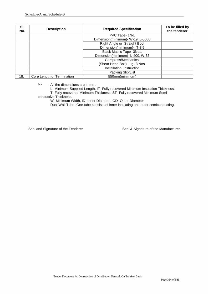
Schedule-A and Schedule-B
Tender Document for Construction of Distribution Network On Turnkey Basis
Page 364 of 535
Sl. No.
Description Required Specification To be filled by the tenderer
PVC Tape- 1No. Dimension(minimum)- W-19, L-5000
Right Angle or Straight Boot Dimension(minimum)- T-3.5
Black Mastic Tape- 3Nos. Dimension(minimum)- L-400, W-35
Compress/Mechanical (Shear Head Bolt) Lug- 3 Nos.
Installation Instruction
Packing Slip/List
18. Core Length of Termination 550mm(minimum)
*** All the dimensions are in mm.
L- Minimum Supplied Length, IT- Fully recovered Minimum Insulation Thickness. T- Fully recovered Minimum Thickness, ST- Fully recovered Minimum Semi-
conductive Thickness. W- Minimum Width, ID- Inner Diameter, OD- Outer Diameter Dual Wall Tube- One tube consists of inner insulating and outer semiconducting.
Seal and Signature of the Tenderer Seal & Signature of the Manufacturer
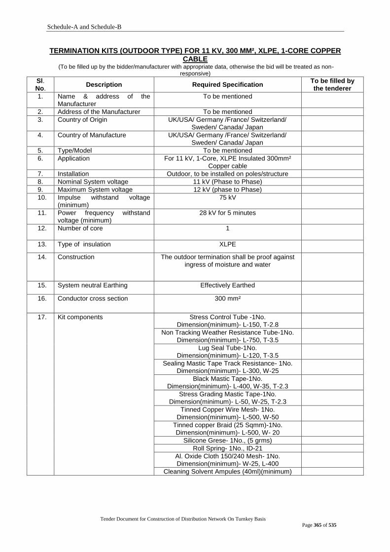
Schedule-A and Schedule-B
Tender Document for Construction of Distribution Network On Turnkey Basis
Page 365 of 535
TERMINATION KITS (OUTDOOR TYPE) FOR 11 KV, 300 MM², XLPE, 1-CORE COPPER CABLE
(To be filled up by the bidder/manufacturer with appropriate data, otherwise the bid will be treated as non-responsive)
Sl. No.
Description Required Specification To be filled by the tenderer
1. Name & address of the Manufacturer
To be mentioned
2. Address of the Manufacturer To be mentioned
3. Country of Origin UK/USA/ Germany /France/ Switzerland/ Sweden/ Canada/ Japan
4. Country of Manufacture UK/USA/ Germany /France/ Switzerland/ Sweden/ Canada/ Japan
5. Type/Model To be mentioned
6. Application For 11 kV, 1-Core, XLPE Insulated 300mm² Copper cable
7. Installation Outdoor, to be installed on poles/structure
8. Nominal System voltage 11 kV (Phase to Phase)
9. Maximum System voltage 12 kV (phase to Phase)
10. Impulse withstand voltage (minimum)
75 kV
11. Power frequency withstand voltage (minimum)
28 kV for 5 minutes
12. Number of core 1
13. Type of insulation XLPE
14. Construction The outdoor termination shall be proof against ingress of moisture and water
15. System neutral Earthing Effectively Earthed
16. Conductor cross section 300 mm²
17. Kit components Stress Control Tube -1No. Dimension(minimum)- L-150, T-2.8
Non Tracking Weather Resistance Tube-1No. Dimension(minimum)- L-750, T-3.5
Lug Seal Tube-1No. Dimension(minimum)- L-120, T-3.5
Sealing Mastic Tape Track Resistance- 1No. Dimension(minimum)- L-300, W-25
Black Mastic Tape-1No. Dimension(minimum)- L-400, W-35, T-2.3
Stress Grading Mastic Tape-1No. Dimension(minimum)- L-50, W-25, T-2.3
Tinned Copper Wire Mesh- 1No. Dimension(minimum)- L-500, W-50
Tinned copper Braid (25 Sqmm)-1No. Dimension(minimum)- L-500, W- 20
Silicone Grese- 1No., (5 grms)
Roll Spring- 1No., ID-21
Al. Oxide Cloth 150/240 Mesh- 1No. Dimension(minimum)- W-25, L-400
Cleaning Solvent Ampules (40ml)(minimum)

Schedule-A and Schedule-B
Tender Document for Construction of Distribution Network On Turnkey Basis
Page 366 of 535
Sl. No.
Description Required Specification To be filled by the tenderer
Cleaning Cloth- 3Nos. Dimension(minimum)- 300 X 300
PVC Tape-1No. Dimension(minimum)- W-19, L-5000
Compress/Mechanical (Shear Head Bolt) Lug- 01 No.
Standoff/ Support insulator- 1No.
Installation Instruction
Packing Slip/List
18. Core Length of Termination (trifurcating of cable to lug)
800mm(minimum)
*** All the dimensions are in mm.
L- Minimum Supplied Length, IT- Fully recovered Minimum Insulation Thickness. T- Fully recovered Minimum Thickness, ST- Fully recovered Minimum Semi-
conductive Thickness. W- Minimum Width, ID- Inner Diameter, OD- Outer Diameter Dual Wall Tube- One tube consists of inner insulating and outer semiconducting.
Seal and Signature of the Tenderer Seal & Signature of the Manufacturer
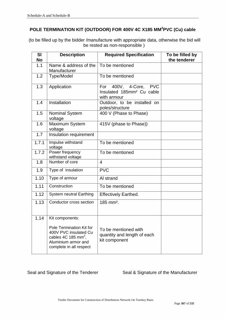
Schedule-A and Schedule-B
Tender Document for Construction of Distribution Network On Turnkey Basis
Page 367 of 535
POLE TERMINATION KIT (OUTDOOR) FOR 400V 4C X185 MM2PVC (Cu) cable
(to be filled up by the bidder /manufacture with appropriate data, otherwise the bid will be rested as non-responsible )
Sl No
Description Required Specification To be filled by the tenderer
1.1 Name & address of the Manufacturer
To be mentioned
1.2 Type/Model
To be mentioned
1.3 Application For 400V, 4-Core, PVC Insulated 185mm² Cu cable with armour
1.4 Installation Outdoor, to be installed on poles/structure
1.5 Nominal System voltage
400 V (Phase to Phase)
1.6 Maximum System voltage
415V (phase to Phase))
1.7 Insulation requirement
1.7.1 Impulse withstand voltage
To be mentioned
1.7.2 Power frequency withstand voltage
To be mentioned
1.8 Number of core 4
1.9 Type of insulation PVC
1.10 Type of armour Al strand
1.11 Construction To be mentioned
1.12 System neutral Earthing Effectively Earthed.
1.13 Conductor cross section 185 mm².
1.14 Kit components: Pole Termination Kit for 400V PVC insulated Cu cables 4C 185 mm2, Aluminium armor and complete in all respect
To be mentioned with quantity and length of each kit component
Seal and Signature of the Tenderer Seal & Signature of the Manufacturer
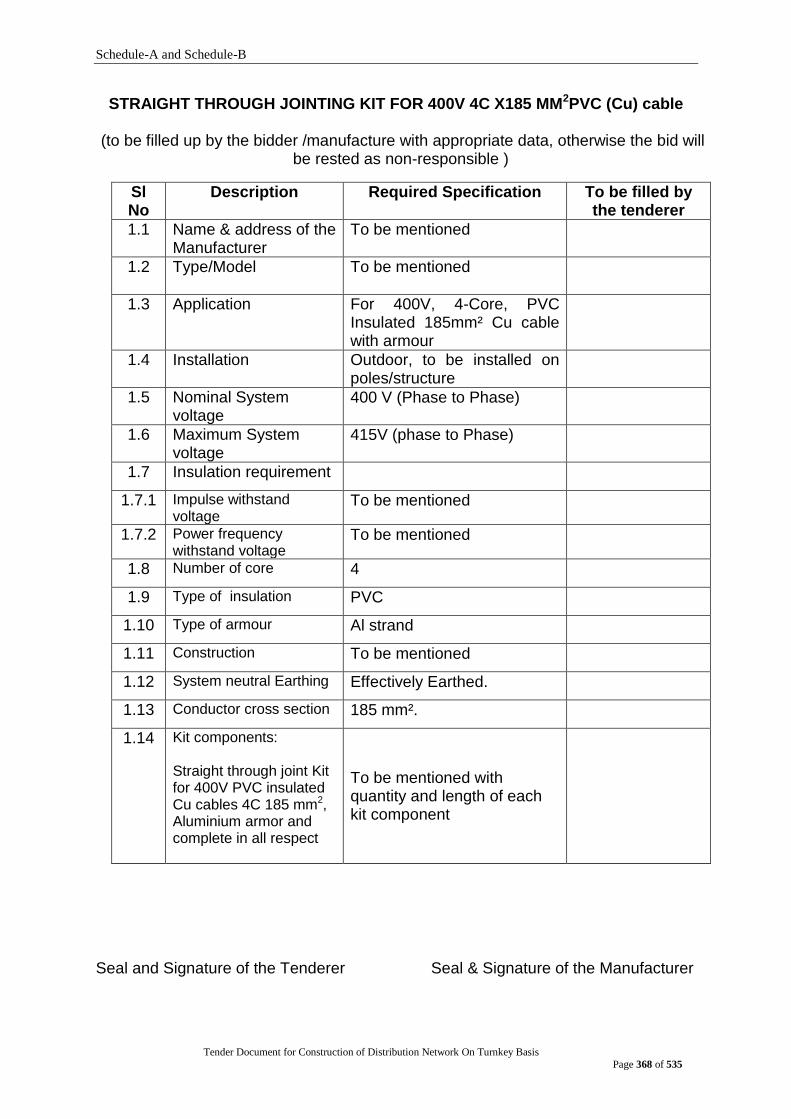
Schedule-A and Schedule-B
Tender Document for Construction of Distribution Network On Turnkey Basis
Page 368 of 535
STRAIGHT THROUGH JOINTING KIT FOR 400V 4C X185 MM2PVC (Cu) cable
(to be filled up by the bidder /manufacture with appropriate data, otherwise the bid will be rested as non-responsible )
Sl No
Description Required Specification To be filled by the tenderer
1.1 Name & address of the Manufacturer
To be mentioned
1.2 Type/Model
To be mentioned
1.3 Application For 400V, 4-Core, PVC Insulated 185mm² Cu cable with armour
1.4 Installation Outdoor, to be installed on poles/structure
1.5 Nominal System voltage
400 V (Phase to Phase)
1.6 Maximum System voltage
415V (phase to Phase)
1.7 Insulation requirement
1.7.1 Impulse withstand voltage
To be mentioned
1.7.2 Power frequency withstand voltage
To be mentioned
1.8 Number of core 4
1.9 Type of insulation PVC
1.10 Type of armour Al strand
1.11 Construction To be mentioned
1.12 System neutral Earthing Effectively Earthed.
1.13 Conductor cross section 185 mm².
1.14 Kit components: Straight through joint Kit for 400V PVC insulated Cu cables 4C 185 mm2, Aluminium armor and complete in all respect
To be mentioned with quantity and length of each kit component
Seal and Signature of the Tenderer Seal & Signature of the Manufacturer
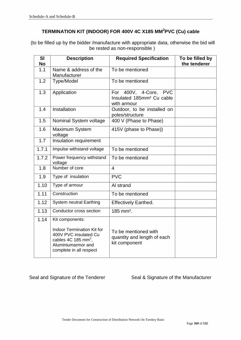
Schedule-A and Schedule-B
Tender Document for Construction of Distribution Network On Turnkey Basis
Page 369 of 535
TERMINATION KIT (INDOOR) FOR 400V 4C X185 MM2PVC (Cu) cable
(to be filled up by the bidder /manufacture with appropriate data, otherwise the bid will be rested as non-responsible )
Sl No
Description Required Specification To be filled by the tenderer
1.1 Name & address of the Manufacturer
To be mentioned
1.2 Type/Model
To be mentioned
1.3 Application For 400V, 4-Core, PVC Insulated 185mm² Cu cable with armour
1.4 Installation Outdoor, to be installed on poles/structure
1.5 Nominal System voltage 400 V (Phase to Phase)
1.6 Maximum System voltage
415V (phase to Phase))
1.7 Insulation requirement
1.7.1 Impulse withstand voltage To be mentioned
1.7.2 Power frequency withstand voltage
To be mentioned
1.8 Number of core 4
1.9 Type of insulation PVC
1.10 Type of armour Al strand
1.11 Construction To be mentioned
1.12 System neutral Earthing Effectively Earthed.
1.13 Conductor cross section 185 mm².
1.14 Kit components: Indoor Termination Kit for 400V PVC insulated Cu cables 4C 185 mm2, Aluminiumarmor and complete in all respect
To be mentioned with quantity and length of each kit component
Seal and Signature of the Tenderer Seal & Signature of the Manufacturer

Schedule-A and Schedule-B
Tender Document for Construction of Distribution Network On Turnkey Basis
Page 370 of 535
Pole Termination Kit (outdoor) for 11kV Aerial Bundle Cable 3x1c 120mm2 XLPE (Al) + 1x70 mm2 Galvanize wire
(to be filled up by the bidder /manufacture with appropriate data, otherwise the bid will
be rested as non-responsible )
Sl No Description Required Specification To be filled by the tenderer
1.1 Name & address of the Manufacturer
To be mentioned
1.2 Type/Model
To be mentioned
1.5 Nominal System voltage 11 kV (Phase to Phase)
1.6 Maximum System voltage 12 kV (phase to Phase))
1.7 Insulation requirement
1.7.1 Impulse withstand voltage To be mentioned
1.7.2 Power frequency withstand voltage
To be mentioned
1.9 Type of insulation XLPE
1.10 Type of screening Copper tape or copper
wire
1.11 Construction To be mentioned
1.12 System neutral Earthing Effectively Earthed.
1.14 Kit components: complete in all respect
To be mentioned with quantity and length of each kit component
Seal and Signature of the Tenderer Seal & Signature of the Manufacturer
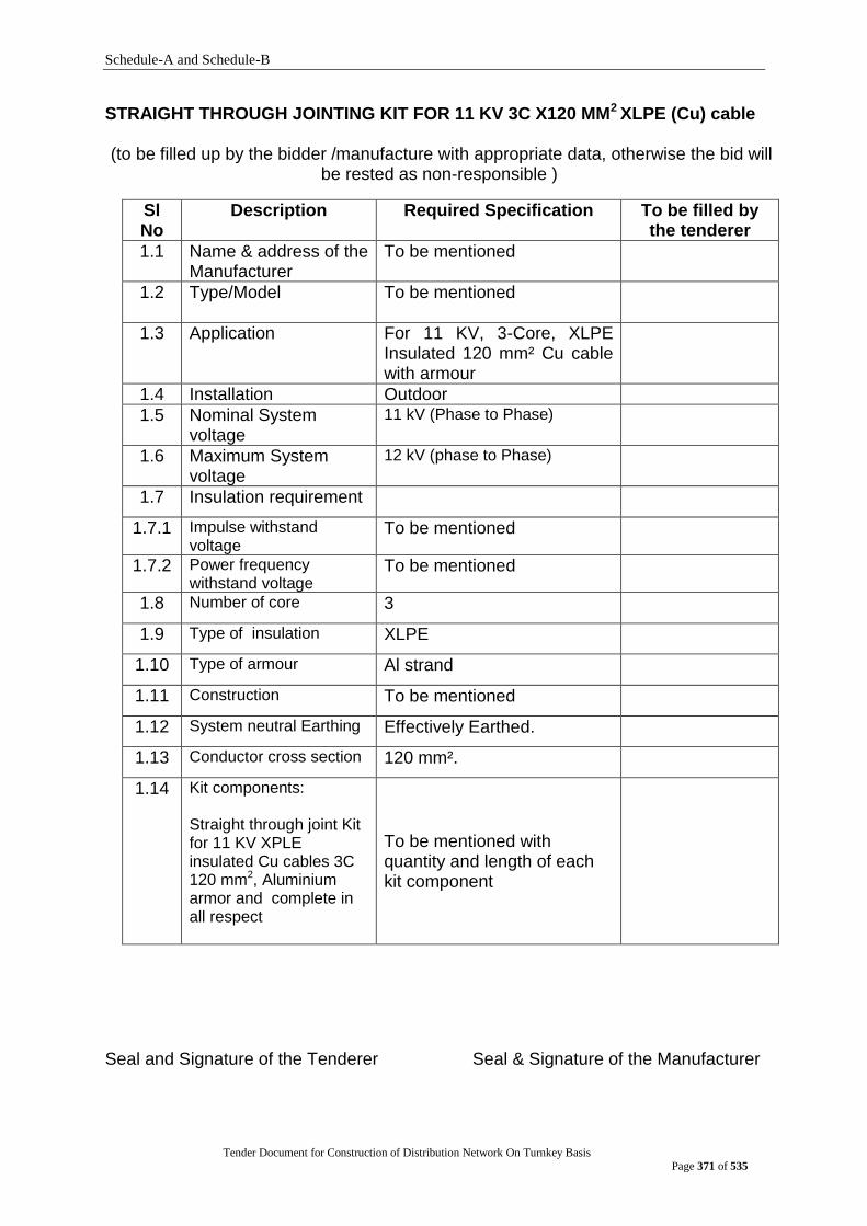
Schedule-A and Schedule-B
Tender Document for Construction of Distribution Network On Turnkey Basis
Page 371 of 535
STRAIGHT THROUGH JOINTING KIT FOR 11 KV 3C X120 MM2 XLPE (Cu) cable
(to be filled up by the bidder /manufacture with appropriate data, otherwise the bid will be rested as non-responsible )
Sl No
Description Required Specification To be filled by the tenderer
1.1 Name & address of the Manufacturer
To be mentioned
1.2 Type/Model
To be mentioned
1.3 Application For 11 KV, 3-Core, XLPE Insulated 120 mm² Cu cable with armour
1.4 Installation Outdoor
1.5 Nominal System voltage
11 kV (Phase to Phase)
1.6 Maximum System voltage
12 kV (phase to Phase)
1.7 Insulation requirement
1.7.1 Impulse withstand voltage
To be mentioned
1.7.2 Power frequency withstand voltage
To be mentioned
1.8 Number of core 3
1.9 Type of insulation XLPE
1.10 Type of armour Al strand
1.11 Construction To be mentioned
1.12 System neutral Earthing Effectively Earthed.
1.13 Conductor cross section 120 mm².
1.14 Kit components: Straight through joint Kit for 11 KV XPLE insulated Cu cables 3C 120 mm2, Aluminium armor and complete in all respect
To be mentioned with quantity and length of each kit component
Seal and Signature of the Tenderer Seal & Signature of the Manufacturer

Schedule-A and Schedule-B
Tender Document for Construction of Distribution Network On Turnkey Basis
Page 372 of 535
TERMINATION KIT (INDOOR) FOR 11 KV 3C X120 MM2 XLPE (Cu) cable
(to be filled up by the bidder /manufacture with appropriate data, otherwise the bid will be rested as non-responsible )
Sl No
Description Required Specification To be filled by the tenderer
1.1 Name & address of the Manufacturer
To be mentioned
1.2 Type/Model
To be mentioned
1.3 Application For 11KV, 3-Core, XLPE Insulated 120mm² Cu cable with armour
1.4 Installation Outdoor
1.5 Nominal System voltage 11 kV (Phase to Phase)
1.6 Maximum System voltage
12 kV (phase to Phase)
1.7 Insulation requirement
1.7.1 Impulse withstand voltage To be mentioned
1.7.2 Power frequency withstand voltage
To be mentioned
1.8 Number of core 3
1.9 Type of insulation XLPE
1.10 Type of armour Al strand
1.11 Construction To be mentioned
1.12 System neutral Earthing Effectively Earthed.
1.13 Conductor cross section 120 mm².
1.14 Kit components: Indoor Termination Kit for 11 KV XLPE insulated Cu cables 3C 120 mm2, Aluminium armor and complete in all respect
To be mentioned with quantity and length of each kit component
Seal and Signature of the Tenderer Seal & Signature of the Manufacturer
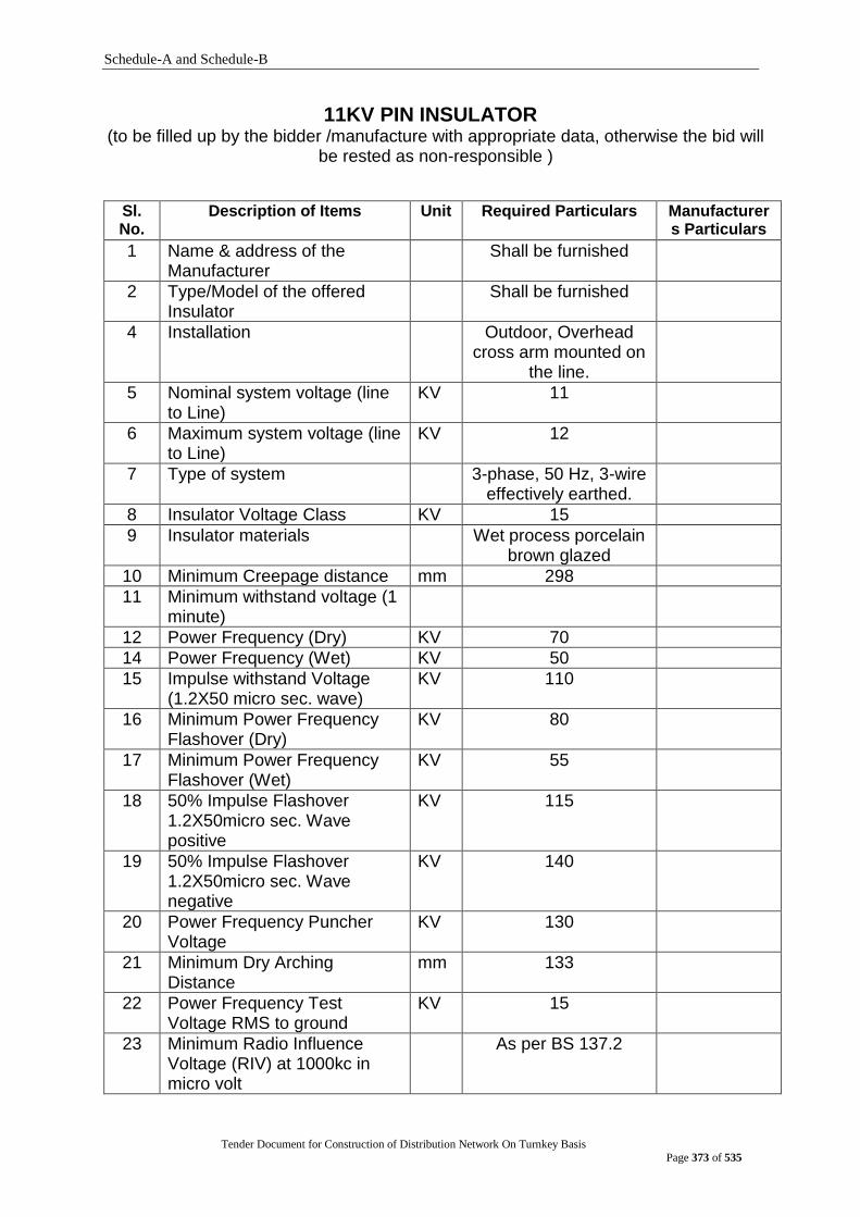
Schedule-A and Schedule-B
Tender Document for Construction of Distribution Network On Turnkey Basis
Page 373 of 535
11KV PIN INSULATOR (to be filled up by the bidder /manufacture with appropriate data, otherwise the bid will
be rested as non-responsible )
Sl. No.
Description of Items Unit Required Particulars Manufacturers Particulars
1 Name & address of the Manufacturer
Shall be furnished
2 Type/Model of the offered Insulator
Shall be furnished
4 Installation Outdoor, Overhead cross arm mounted on
the line.
5 Nominal system voltage (line to Line)
KV 11
6 Maximum system voltage (line to Line)
KV 12
7 Type of system 3-phase, 50 Hz, 3-wire effectively earthed.
8 Insulator Voltage Class KV 15
9 Insulator materials Wet process porcelain brown glazed
10 Minimum Creepage distance mm 298
11 Minimum withstand voltage (1 minute)
12 Power Frequency (Dry) KV 70
14 Power Frequency (Wet) KV 50
15 Impulse withstand Voltage (1.2X50 micro sec. wave)
KV 110
16 Minimum Power Frequency Flashover (Dry)
KV 80
17 Minimum Power Frequency Flashover (Wet)
KV 55
18 50% Impulse Flashover 1.2X50micro sec. Wave positive
KV 115
19 50% Impulse Flashover 1.2X50micro sec. Wave negative
KV 140
20 Power Frequency Puncher Voltage
KV 130
21 Minimum Dry Arching Distance
mm 133
22 Power Frequency Test Voltage RMS to ground
KV 15
23 Minimum Radio Influence Voltage (RIV) at 1000kc in micro volt
As per BS 137.2
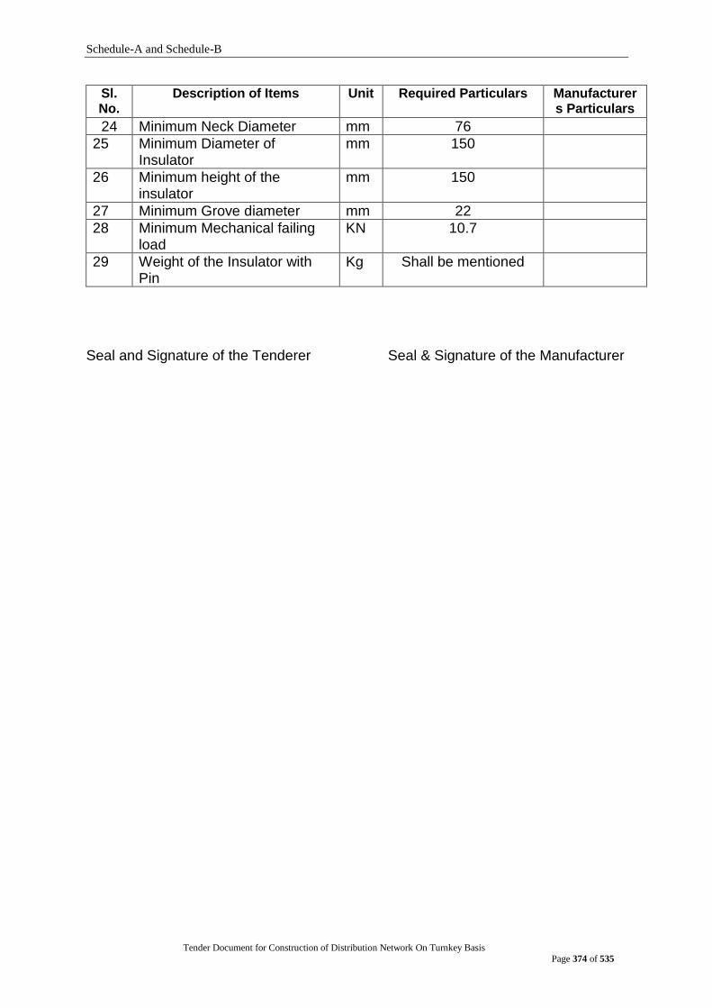
Schedule-A and Schedule-B
Tender Document for Construction of Distribution Network On Turnkey Basis
Page 374 of 535
Sl. No.
Description of Items Unit Required Particulars Manufacturers Particulars
24 Minimum Neck Diameter mm 76
25 Minimum Diameter of Insulator
mm 150
26 Minimum height of the insulator
mm 150
27 Minimum Grove diameter mm 22
28 Minimum Mechanical failing load
KN 10.7
29 Weight of the Insulator with Pin
Kg Shall be mentioned
Seal and Signature of the Tenderer Seal & Signature of the Manufacturer
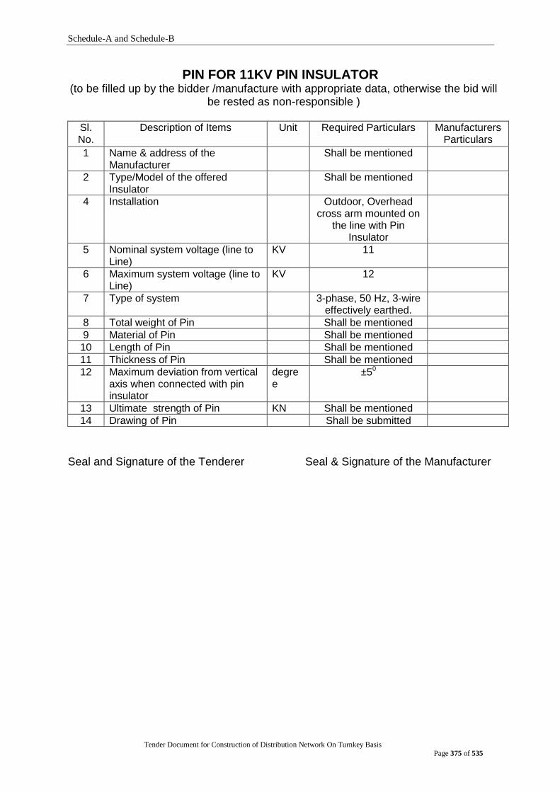
Schedule-A and Schedule-B
Tender Document for Construction of Distribution Network On Turnkey Basis
Page 375 of 535
PIN FOR 11KV PIN INSULATOR (to be filled up by the bidder /manufacture with appropriate data, otherwise the bid will
be rested as non-responsible )
Sl. No.
Description of Items Unit Required Particulars Manufacturers Particulars
1 Name & address of the Manufacturer
Shall be mentioned
2 Type/Model of the offered Insulator
Shall be mentioned
4 Installation Outdoor, Overhead cross arm mounted on
the line with Pin Insulator
5 Nominal system voltage (line to Line)
KV 11
6 Maximum system voltage (line to Line)
KV 12
7 Type of system 3-phase, 50 Hz, 3-wire effectively earthed.
8 Total weight of Pin Shall be mentioned
9 Material of Pin Shall be mentioned
10 Length of Pin Shall be mentioned
11 Thickness of Pin Shall be mentioned
12 Maximum deviation from vertical axis when connected with pin insulator
degree
±50
13 Ultimate strength of Pin KN Shall be mentioned
14 Drawing of Pin Shall be submitted
Seal and Signature of the Tenderer Seal & Signature of the Manufacturer

Schedule-A and Schedule-B
Tender Document for Construction of Distribution Network On Turnkey Basis
Page 376 of 535
11KV DISC INSULATOR (to be filled up by the bidder /manufacture with appropriate data, otherwise the bid will
be rested as non-responsible )
Sl. No.
Description of Items Unit Required Particulars Manufacturers Particulars
1
Name & address of the Manufacturer
Shall be furnished
2 Type/Model of the offered Insulator
Shall be furnished
3 Installation Outdoor, Overhead cross arm mounted.
4 Nominal system voltage (line to Line)
kV
11
5 Maximum system voltage (line to Line)
kV
12
6 Type of system 3-phase, 50-Hz, 3-wire effectively earthed.
7 Insulator Voltage Class KV
15
8 Insulator materials Wet process porcelain brown glazed
9 Type of Insulator Ball ended socket type disc, security clip made of stainless steel on phosphor bronzed/red brass alloy
10 Diameter of Insulator mm
255
11 Minimum Unit spacing mm
145
12 Coupling size mm
16
13 Minimum Creep age distance
mm
292
14 Minimum withstand voltage (1 minutes)
14.1 Power Frequency (Dry)
KV 70
14.2 Power Frequency (Wet)
KV 40
15 Impulse withstand Voltage (1.2X50 micro sec. wave)
KV 110
16 Minimum Power Frequency Flashover (Dry)
KV 78
17 Minimum Power Frequency Flashover (Wet)
KV 45
18 50% Impulse Flashover 1.2X50micro sec. Wave positive
KV 120
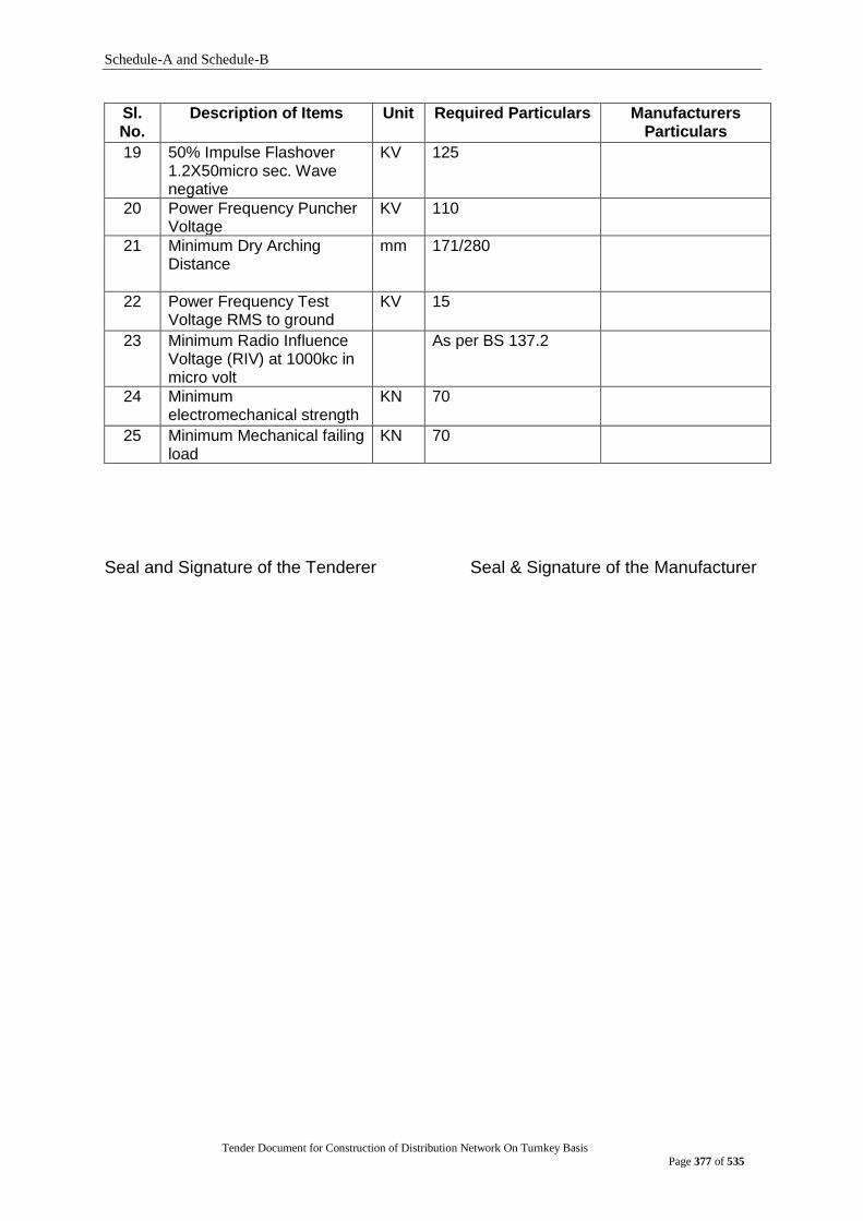
Schedule-A and Schedule-B
Tender Document for Construction of Distribution Network On Turnkey Basis
Page 377 of 535
Sl. No.
Description of Items Unit Required Particulars Manufacturers Particulars
19 50% Impulse Flashover 1.2X50micro sec. Wave negative
KV 125
20 Power Frequency Puncher Voltage
KV 110
21 Minimum Dry Arching Distance
mm 171/280
22 Power Frequency Test Voltage RMS to ground
KV 15
23 Minimum Radio Influence Voltage (RIV) at 1000kc in micro volt
As per BS 137.2
24 Minimum electromechanical strength
KN 70
25 Minimum Mechanical failing load
KN 70
Seal and Signature of the Tenderer Seal & Signature of the Manufacturer
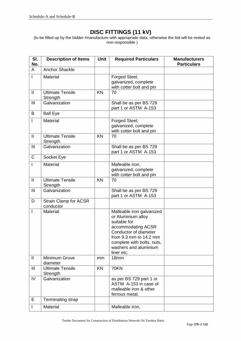
Schedule-A and Schedule-B
Tender Document for Construction of Distribution Network On Turnkey Basis
Page 378 of 535
DISC FITTINGS (11 kV) (to be filled up by the bidder /manufacture with appropriate data, otherwise the bid will be rested as
non-responsible )
Sl. No.
Description of Items Unit Required Particulars Manufacturers Particulars
A Anchor Shackle
I Material Forged Steel, galvanized, complete with cotter bolt and pin
II Ultimate Tensile Strength
KN 70
III Galvanization Shall be as per BS 729 part 1 or ASTM A-153
B Ball Eye
I Material Forged Steel, galvanized, complete with cotter bolt and pin
II Ultimate Tensile Strength
KN 70
III Galvanization Shall be as per BS 729 part 1 or ASTM A-153
C Socket Eye
I Material Malleable iron, galvanized, complete with cotter bolt and pin
II Ultimate Tensile Strength
KN 70
III Galvanization
Shall be as per BS 729 part 1 or ASTM A-153
D Strain Clamp for ACSR conductor
I Material Malleable iron galvanized or Aluminium alloy suitable for accommodating ACSR Conductor of diameter from 9.3 mm to 14.2 mm complete with bolts, nuts, washers and aluminium liner etc.
II Minimum Grove diameter
mm 18mm
III Ultimate Tensile Strength
KN 70KN
IV Galvanization as per BS 729 part 1 or ASTM A-153 in case of malleable iron & other ferrous metal.
E Terminating strap
I Material Malleable iron,
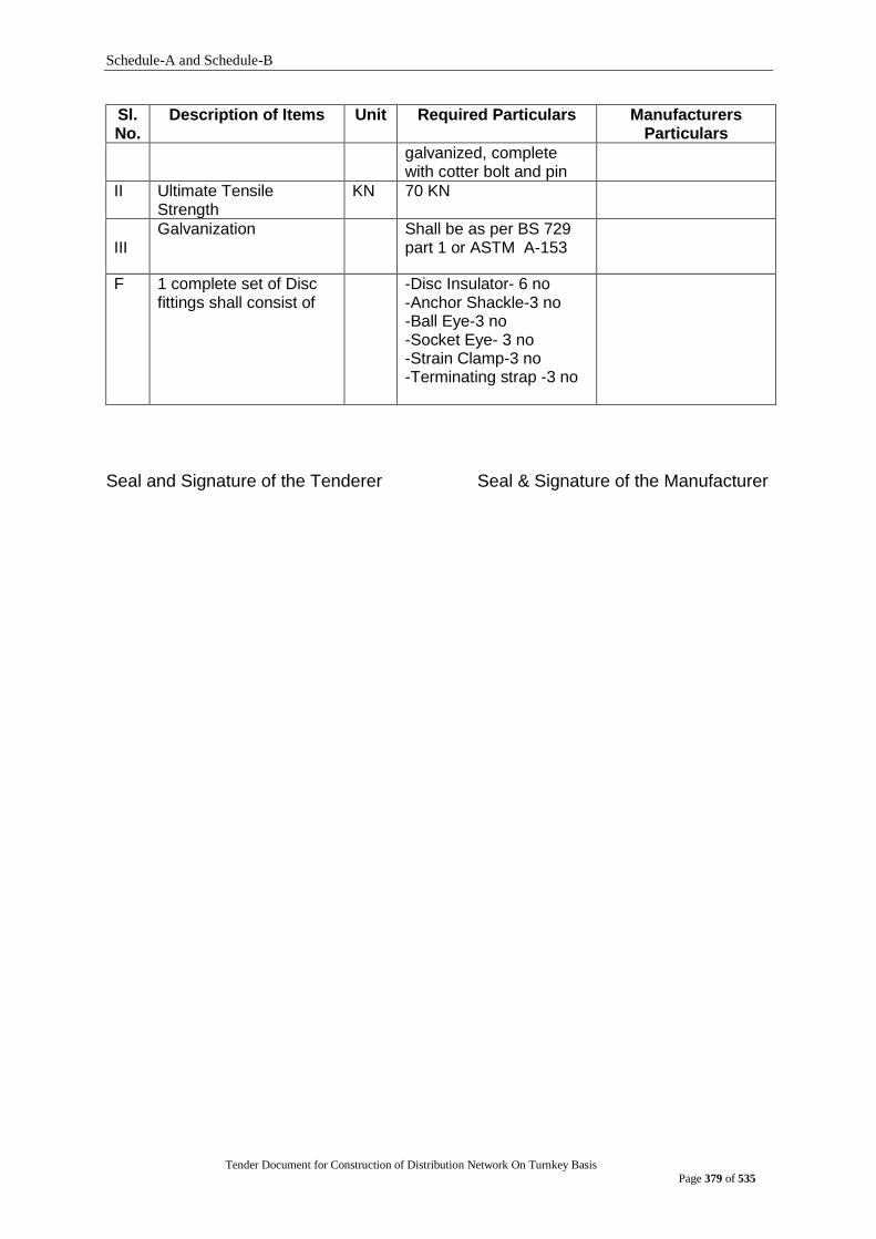
Schedule-A and Schedule-B
Tender Document for Construction of Distribution Network On Turnkey Basis
Page 379 of 535
Sl. No.
Description of Items Unit Required Particulars Manufacturers Particulars
galvanized, complete with cotter bolt and pin
II Ultimate Tensile Strength
KN 70 KN
III
Galvanization
Shall be as per BS 729 part 1 or ASTM A-153
F 1 complete set of Disc fittings shall consist of
-Disc Insulator- 6 no -Anchor Shackle-3 no -Ball Eye-3 no -Socket Eye- 3 no -Strain Clamp-3 no -Terminating strap -3 no
Seal and Signature of the Tenderer Seal & Signature of the Manufacturer

Schedule-A and Schedule-B
Tender Document for Construction of Distribution Network On Turnkey Basis
Page 380 of 535
400V SHACKLE INSULATOR (to be filled up by the bidder /manufacture with appropriate data, otherwise the bid will
be rested as non-responsible )
Sl. No.
Description of Items Unit Required Particulars Manufacturers Particulars
I Installation Outdoor, Overhead cross arm mounted on the line.
ii Standard Performance , Design & testing shall be accordance to ANSIC-29 or equivalent.
iii Nominal system voltage (line to Line)
KV 0.415
iv Maximum system voltage (line to Line)
KV 0.456
V Type of system 3-phase, 50 Hz, 4-wire.
vi Insulator materials Wet process porcelain brown glazed
vii Minimum Diameter of Insulator
mm 89
viii Minimum height of Insulator mm 75
ix Minimum Mechanical Failing Load (Transverse)
KN 14
x Dry Flashover KV 25
xi Wet Flashover (vertical) KV 12
xii Wet Flashover (Horizontal) KV 15
xiii Insulation Class AC, RMS voltage 600V
xiv Atmospheric Condition Moderately Polluted
xv Dimension mm H-76mm, D- 89mm, groove Diameter- 19mm, Insulator hole-17.46mm, Leakage Distance- 64mm.
xvi Flash over voltage kV Power frequency- dry 25kV, wet 12 kV
xvii Power Frequency Puncture Voltage
kV 50 kV
xvii Mechanical Strength kg 1360 kg
Seal and Signature of the Tenderer Seal & Signature of the Manufacturer

Schedule-A and Schedule-B
Tender Document for Construction of Distribution Network On Turnkey Basis
Page 381 of 535
11/.415 KV 250 KVA DISTRIBUTION TRANSFORMER
(to be filled up by the bidder/manufacturer with appropriate data, otherwise the bid will be treated as non-responsive)
Sl. No.
Description Insert the name Of the Organization's
Requirement
Manufacturer's Guaranteed
Data
1 Manufacturer‟s Name & Address To be mentioned
2 Manufacturer's Type/ Model No. To be mentioned
3 KVA Rating 250
4 Number of Phases 3
5 Rated frequency, Hz 50
6 Rated primary voltage, KV 11
7 Rated no load sec. voltage, V 415
8 Vector group Dyn11
9 Highest system voltage of :
a) Primary winding, KV 12
b) Secondary winding, V 457
10 Basic insulation level, KV 75
11 Power frequency withstand voltage, KV 28
a) HT Side
b) LT Side 2.5
12 Type of cooling ONAN 13 Max. Temp. Rise over 40
0C of ambient supported by Calculation (to be submitted) of Load
Loss, Temperature Rise and Heat Dissipation by Radiator on the basis of Design Data: a) Windings deg. C 65
b) Top oil deg. C 60
14 Type of primary tapping off load, % +1x2.5%, 0, -3x 2.5%
15 Percentage Impedance at 75o C, %
(supported by type test report)
4%
16 No-load loss, Watts (supported by type test report)
520
17 Load losses at rated full load at 750C, Watts
(supported by type test report) 3180
18 Magnetising current at normal voltage,
Amps
To be mentioned
19 Efficiency at 750C and 100% load :
a) at 1.0 power factor, % To be mentioned
b) at 0.8 power factor, % To be mentioned
20 Efficiency at 750C and 75% load :
a) at 1.0 power factor, % To be mentioned
b) at 0.8 power factor, % To be mentioned
21 Efficiency at 750C and 50% load :
a) at 1.0 power factor, % To be mentioned
b) at 0.8 power factor, % To be mentioned
22 Efficiency at 750C and 25% load :
a) at 1.0 power factor, % To be mentioned
b) at 0.8 power factor, % To be mentioned
23 Regulation at full load :
a) at 1.0 power factor, % To be mentioned
b) at 0.8 power factor, % To be mentioned
Transformer Oil :
24 a) Type of oil Mineral Insulating Oil
b) Manufacturer‟s Name & Address To be mentioned

Schedule-A and Schedule-B
Tender Document for Construction of Distribution Network On Turnkey Basis
Page 382 of 535
Sl. No.
Description Insert the name Of the Organization's
Requirement
Manufacturer's Guaranteed
Data
25 Total weight of oil, Kg To be mentioned
26 Breakdown Voltage at 2.5mm gap between electrodes
> 50 kV
Transformer Core (Stack Core or Wound Core):
27 Manufacturer‟s Name & Address To be mentioned
28 Total weight of core, Kg To be mentioned
29 Material of core & grading
(CRGO/Amorphos)
To be mentioned
30 Core Loss/ Kg, supported by Characteristic Curve&
To be mentioned
Core Manufacturer's Brochure To be mentioned
31 Thickness of core, mm To be mentioned
32 Core Dia, mm To be mentioned
33 Max. magnetic flux density, Tesla To be mentioned
Transformer Windings :
34 Copper Conductor's Manufacturer Name & Address
To be mentioned
35 Material of windings copper
36 Winding resistance of :
a) H.T. winding, Ohm. (per phase at 75o C) To be mentioned
b) L.T. winding, milli-Ohm. (per phase at 75o
C)
To be mentioned
37 Current density of :
a) H.T. winding, Amps/sq. mm To be mentioned
b) L.T. winding, Amps/sq. mm To be mentioned
38 Outer, Inner & Mean dia of copper winding:
a) H.T. winding, mm To be mentioned
b) L.T. winding, mm To be mentioned
39 Size of Copper Conductor :
a) H.T. winding SWG, dia. in mm & area in
mm2
To be mentioned
b) L.T. winding SWG, area in mm2
To be mentioned
40 Number of Turns :
a) HT winding, nos. To be mentioned
b) LT winding, nos. To be mentioned
41 Copper weight of windings :
a) HT winding, Kg To be mentioned
b) LT winding, Kg To be mentioned
42 Total weight of copper windings, Kg To be mentioned
43 Dimension of Transformer :
a) Width, mm (supported by type test
report)
To be mentioned
b) Length, mm (supported by type test
report)
To be mentioned
c) Height, mm (supported by type test
report)
To be mentioned
d) Tank Sheet thickness of top, bottom &
side, mm
5, 5 & 4
e) Total weight of transformer tank, Kg To be mentioned
44 a) Total weight of active part (core, coil and other accessories), Kg
To be mentioned
b) Total weight of complete Transformer including fittings & oil, Kg (supported by type test report
45 Type of breathings
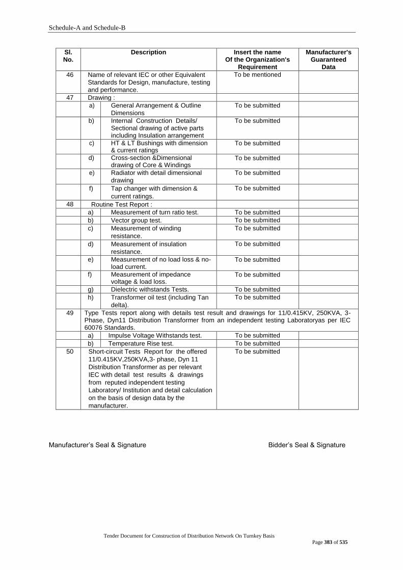
Schedule-A and Schedule-B
Tender Document for Construction of Distribution Network On Turnkey Basis
Page 383 of 535
Sl. No.
Description Insert the name Of the Organization's
Requirement
Manufacturer's Guaranteed
Data
46 Name of relevant IEC or other Equivalent
Standards for Design, manufacture, testing and performance.
To be mentioned
47 Drawing :
a) General Arrangement & Outline
Dimensions
To be submitted
b) Internal Construction Details/ Sectional drawing of active parts including Insulation arrangement
To be submitted
c) HT & LT Bushings with dimension & current ratings
To be submitted
d) Cross-section &Dimensional drawing of Core & Windings
To be submitted
e) Radiator with detail dimensional
drawing
To be submitted
f) Tap changer with dimension &
current ratings.
To be submitted
48 Routine Test Report :
a) Measurement of turn ratio test. To be submitted
b) Vector group test. To be submitted
c) Measurement of winding
resistance.
To be submitted
d) Measurement of insulation
resistance.
To be submitted
e) Measurement of no load loss & no-load current.
To be submitted
f) Measurement of impedance voltage & load loss.
To be submitted
g) Dielectric withstands Tests. To be submitted
h) Transformer oil test (including Tan
delta).
To be submitted
49 Type Tests report along with details test result and drawings for 11/0.415KV, 250KVA, 3-Phase, Dyn11 Distribution Transformer from an independent testing Laboratoryas per IEC 60076 Standards.
a) Impulse Voltage Withstands test. To be submitted
b) Temperature Rise test. To be submitted
50 Short-circuit Tests Report for the offered
11/0.415KV,250KVA,3- phase, Dyn 11
Distribution Transformer as per relevant
IEC with detail test results & drawings
from reputed independent testing
Laboratory/ Institution and detail calculation
on the basis of design data by the
manufacturer.
To be submitted
Manufacturer‟s Seal & Signature Bidder‟s Seal & Signature
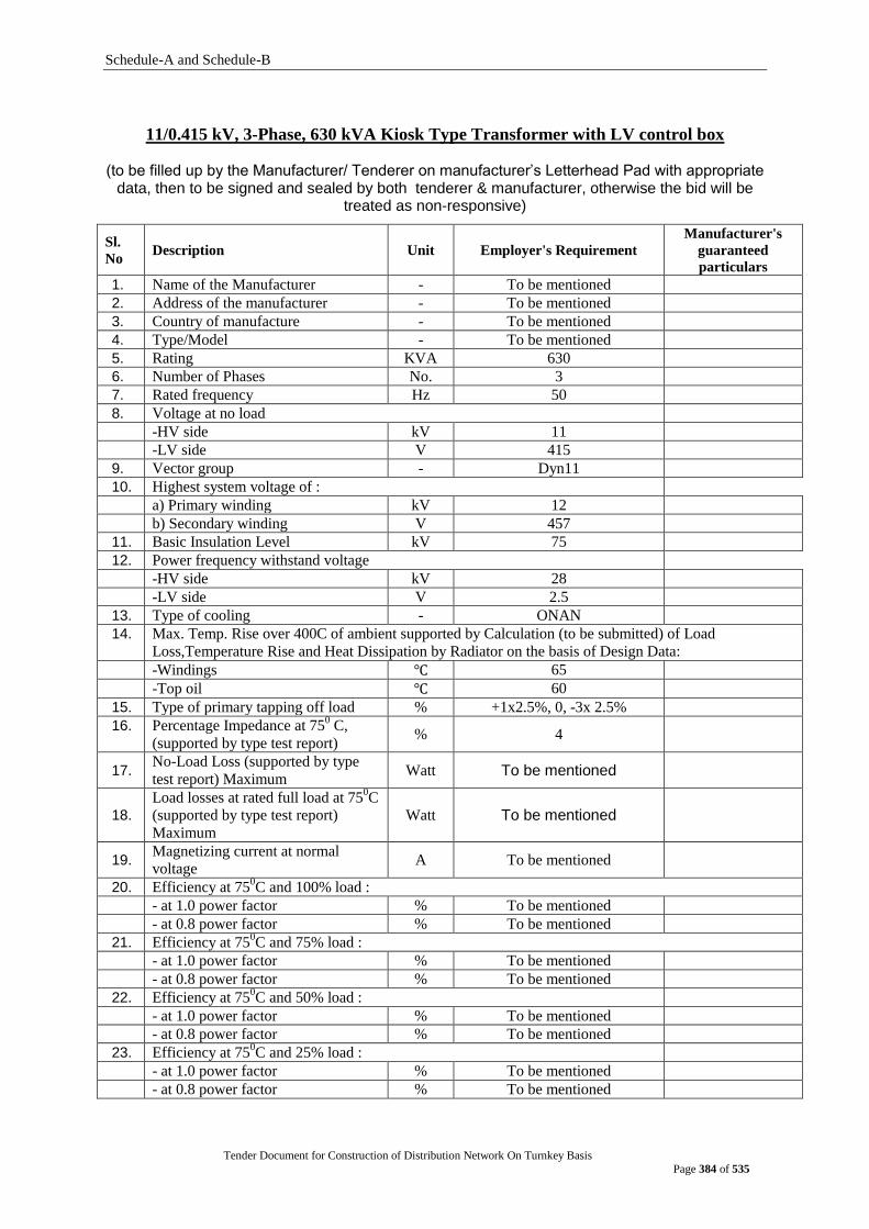
Schedule-A and Schedule-B
Tender Document for Construction of Distribution Network On Turnkey Basis
Page 384 of 535
11/0.415 kV, 3-Phase, 630 kVA Kiosk Type Transformer with LV control box
(to be filled up by the Manufacturer/ Tenderer on manufacturer‟s Letterhead Pad with appropriate data, then to be signed and sealed by both tenderer & manufacturer, otherwise the bid will be
treated as non-responsive)
Sl.
No Description Unit Employer's Requirement
Manufacturer's
guaranteed
particulars
1. Name of the Manufacturer - To be mentioned
2. Address of the manufacturer - To be mentioned
3. Country of manufacture - To be mentioned
4. Type/Model - To be mentioned
5. Rating KVA 630
6. Number of Phases No. 3
7. Rated frequency Hz 50
8. Voltage at no load
-HV side kV 11
-LV side V 415
9. Vector group - Dyn11
10. Highest system voltage of :
a) Primary winding kV 12
b) Secondary winding V 457
11. Basic Insulation Level kV 75
12. Power frequency withstand voltage
-HV side kV 28
-LV side V 2.5
13. Type of cooling - ONAN
14. Max. Temp. Rise over 400C of ambient supported by Calculation (to be submitted) of Load
Loss,Temperature Rise and Heat Dissipation by Radiator on the basis of Design Data:
-Windings ℃ 65
-Top oil ℃ 60
15. Type of primary tapping off load % +1x2.5%, 0, -3x 2.5%
16. Percentage Impedance at 750 C,
(supported by type test report) % 4
17. No-Load Loss (supported by type
test report) Maximum Watt To be mentioned
18.
Load losses at rated full load at 750C
(supported by type test report)
Maximum
Watt To be mentioned
19. Magnetizing current at normal
voltage A To be mentioned
20. Efficiency at 750C and 100% load :
- at 1.0 power factor % To be mentioned
- at 0.8 power factor % To be mentioned
21. Efficiency at 750C and 75% load :
- at 1.0 power factor % To be mentioned
- at 0.8 power factor % To be mentioned
22. Efficiency at 750C and 50% load :
- at 1.0 power factor % To be mentioned
- at 0.8 power factor % To be mentioned
23. Efficiency at 750C and 25% load :
- at 1.0 power factor % To be mentioned
- at 0.8 power factor % To be mentioned

Schedule-A and Schedule-B
Tender Document for Construction of Distribution Network On Turnkey Basis
Page 385 of 535
Sl.
No Description Unit Employer's Requirement
Manufacturer's
guaranteed
particulars
24. Regulation at full load :
- at 1.0 power factor % To be mentioned
- at 0.8 power factor % To be mentioned
Transformer Oil
25. Type of oil Mineral Insulating Oil
26. Name & Address of the
manufacturer
- To be mentioned
27. Total weight of oil Kg To be mentioned
28. Breakdown Voltage at 2.5mm gap between electrodes
kV >50
Transformer Core (Stack Core or Wound Core)
29. Name & Address of the
manufacturer
- To be mentioned
30. Total weight of core Kg To be mentioned
31. Material of core & grading
(CRGO/amorphous) - To be mentioned
32. Core Loss/ Kg, supported by
Characteristic Curve & Core
Manufacturer's Brochure
To be mentioned
33. Thickness of core mm To be mentioned
34. Core Dia mm To be mentioned
35. Max. magnetic flux density Tesla To be mentioned
Transformer Windings
36. Copper Conductor's Manufacturer Name & Address
- To be mentioned
37. Material of windings - Copper
38. Winding resistance of :
-HV winding (per phase at 75o C) Ohm To be mentioned
-LV winding (per phase at 75o C) Milli-ohm To be mentioned
39. Current density of :
-HV winding A/mm2 To be mentioned
-LV winding A/mm2 To be mentioned
40. Outer, Inner & Mean dia of copper winding:
-HV winding mm To be mentioned
-LV winding mm To be mentioned
41. Size of Copper Conductor :
-HV winding SWG mm To be mentioned
-LV winding SWG mm To be mentioned
42. Number of Turns :
-HV winding Nos. To be mentioned
-LV winding Nos To be mentioned
43. Copper weight of windings :
-HV winding kg To be mentioned
-LV winding kg To be mentioned
44. Total weight of copper windings kg To be mentioned
45. Dimension of Transformer :
-Width mm To be mentioned
-Length mm To be mentioned
-Height mm To be mentioned
-Total weight of transformer Tank kg To be mentioned

Schedule-A and Schedule-B
Tender Document for Construction of Distribution Network On Turnkey Basis
Page 386 of 535
Sl.
No Description Unit Employer's Requirement
Manufacturer's
guaranteed
particulars
46. Total weight of active part (core,
coil and other accessories kg To be mentioned
47. Total weight of complete
Transformer including fittings & oil kg To be mentioned
48. Type of breathing - To be mentioned
49. Name of relevant IEC or other
Equivalent Standards for Design,
manufacture, testing and
performance
- To be mentioned
50. Drawing:
- General Arrangement & Outline
Dimensions
- To be submitted
- Internal Construction Details/
Sectional drawing of active parts
including Insulation arrangement
- To be submitted
- HT & LT Bushings with dimension
& current ratings
- To be submitted
- Cross-section &Dimensional
drawing of Core & Windings - To be submitted
Radiator with detail dimensional
drawing
- To be submitted
Tap changer with dimension &
current ratings. - To be submitted
51. Following tests shall be done from reputed independent testing Laboratory/
Institution and Detail test report shall be provided:
(for 11/0.415 kV, 3-Phase, 630 kVA or higher kVA rating with same voltage level
i.e, 11/0.415kV)
TYPE TESTS
a) Temperature Rise Test - To be submitted
b) Impulse voltage withstand Test
- To be submitted
ROUTINE TESTS
a) Measurement of insulation resistance.
- To be submitted
b) Measurement of turn ratio test. - To be submitted
c) Measurement of winding resistance
- To be submitted
d) Vector group test (Check of phase sequence)
- To be submitted
e) Measurement of no-load loss & no-load current.
- To be submitted
f) Measurement of impedance voltage and load loss.
- To be submitted
g) Dielectric withstand test - To be submitted
h) Transformer oil test - To be submitted
i) Noise level Test - To be submitted
j) Vacuum Test - To be submitted
SPECIAL TEST
Short circuit withstands test report of HV-LV.
- To be submitted
52. Full guarantee for 03 (three) years - yes

Schedule-A and Schedule-B
Tender Document for Construction of Distribution Network On Turnkey Basis
Page 387 of 535
Sl.
No Description Unit Employer's Requirement
Manufacturer's
guaranteed
particulars
53. KIOSK BOX
Name of the Manufacturer - To be mentioned
Address of the manufacturer - To be mentioned
Country of manufacture - To be mentioned
Type/Model - To be mentioned
Material - galvanized sheet steel/
Stainless steel/ Aluminum
Thickness of material (minimum) mm 3 mm
Dimension
-Width mm To be mentioned
-Length mm To be mentioned
-Height mm To be mentioned
-Weight kg To be mentioned
54 LV control box
Accessories To be mentioned
Protection equipment To be mentioned
55 Total dimension including Kiosk
and LV control box To be mentioned
56 Total weight including Kiosk and
LV control box To be mentioned
Seal and Signature of the Tenderer Seal & Signature of the Manufacturer
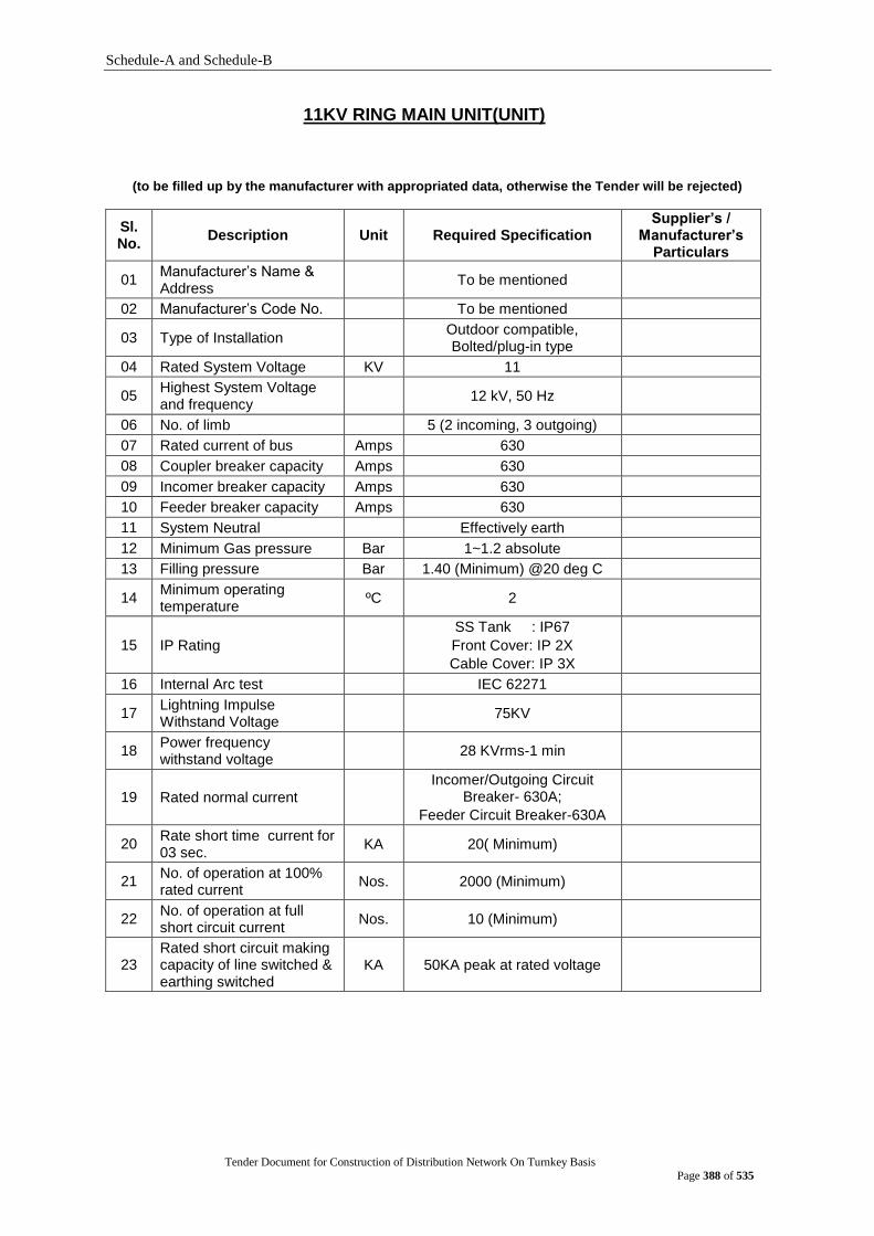
Schedule-A and Schedule-B
Tender Document for Construction of Distribution Network On Turnkey Basis
Page 388 of 535
11KV RING MAIN UNIT(UNIT)
(to be filled up by the manufacturer with appropriated data, otherwise the Tender will be rejected)
Sl. No.
Description Unit Required Specification Supplier‟s /
Manufacturer‟s Particulars
01 Manufacturer‟s Name & Address
To be mentioned
02 Manufacturer‟s Code No. To be mentioned
03 Type of Installation Outdoor compatible, Bolted/plug-in type
04 Rated System Voltage KV 11
05 Highest System Voltage and frequency
12 kV, 50 Hz
06 No. of limb 5 (2 incoming, 3 outgoing)
07 Rated current of bus Amps 630
08 Coupler breaker capacity Amps 630
09 Incomer breaker capacity Amps 630
10 Feeder breaker capacity Amps 630
11 System Neutral Effectively earth
12 Minimum Gas pressure Bar 1~1.2 absolute
13 Filling pressure Bar 1.40 (Minimum) @20 deg C
14 Minimum operating temperature
ºC 2
15 IP Rating
SS Tank : IP67
Front Cover: IP 2X
Cable Cover: IP 3X
16 Internal Arc test IEC 62271
17 Lightning Impulse Withstand Voltage
75KV
18 Power frequency withstand voltage
28 KVrms-1 min
19 Rated normal current
Incomer/Outgoing Circuit Breaker- 630A;
Feeder Circuit Breaker-630A
20 Rate short time current for 03 sec.
KA 20( Minimum)
21 No. of operation at 100% rated current
Nos. 2000 (Minimum)
22 No. of operation at full short circuit current
Nos. 10 (Minimum)
23 Rated short circuit making capacity of line switched & earthing switched
KA 50KA peak at rated voltage
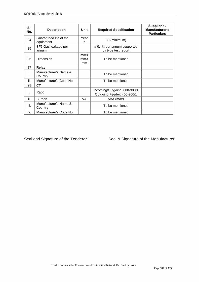
Schedule-A and Schedule-B
Tender Document for Construction of Distribution Network On Turnkey Basis
Page 389 of 535
Sl. No.
Description Unit Required Specification Supplier‟s /
Manufacturer‟s Particulars
24 Guaranteed life of the equipment
Years
30 (minimum)
25 SF6 Gas leakage per annum
≤ 0.1% per annum supported
by type test report
26 Dimension mmXmmXmm
To be mentioned
27 Relay
i. Manufacturer‟s Name & Country
To be mentioned
ii. Manufacturer‟s Code No. To be mentioned
28 CT
i. Ratio Incoming/Outgoing: 600-300/1
Outgoing Feeder: 400-200/1
ii. Burden VA 5VA (max)
iii. Manufacturer‟s Name & Country
To be mentioned
iv. Manufacturer‟s Code No. To be mentioned
Seal and Signature of the Tenderer Seal & Signature of the Manufacturer
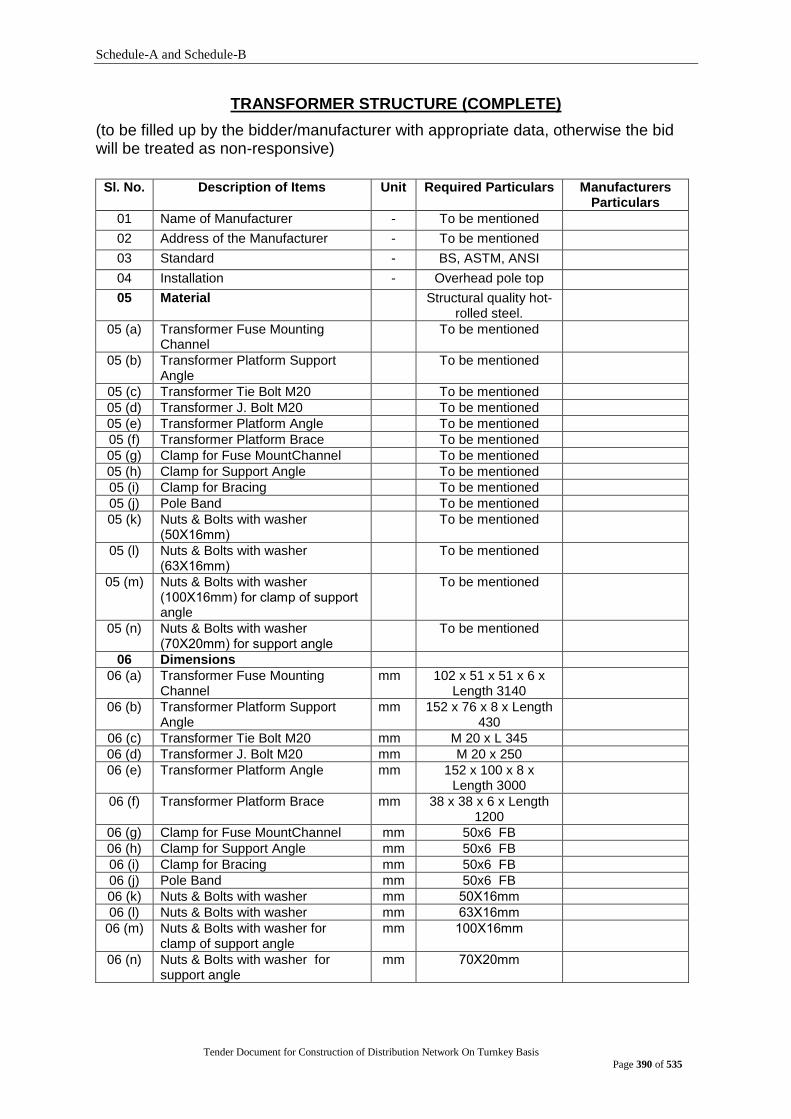
Schedule-A and Schedule-B
Tender Document for Construction of Distribution Network On Turnkey Basis
Page 390 of 535
TRANSFORMER STRUCTURE (COMPLETE)
(to be filled up by the bidder/manufacturer with appropriate data, otherwise the bid will be treated as non-responsive)
Sl. No. Description of Items Unit Required Particulars Manufacturers Particulars
01 Name of Manufacturer - To be mentioned
02 Address of the Manufacturer - To be mentioned
03 Standard - BS, ASTM, ANSI
04 Installation - Overhead pole top
05 Material Structural quality hot-rolled steel.
05 (a) Transformer Fuse Mounting Channel
To be mentioned
05 (b) Transformer Platform Support Angle
To be mentioned
05 (c) Transformer Tie Bolt M20 To be mentioned
05 (d) Transformer J. Bolt M20 To be mentioned
05 (e) Transformer Platform Angle To be mentioned
05 (f) Transformer Platform Brace To be mentioned
05 (g) Clamp for Fuse MountChannel To be mentioned
05 (h) Clamp for Support Angle To be mentioned
05 (i) Clamp for Bracing To be mentioned
05 (j) Pole Band To be mentioned
05 (k) Nuts & Bolts with washer (50Χ16mm)
To be mentioned
05 (l) Nuts & Bolts with washer (63Χ16mm)
To be mentioned
05 (m) Nuts & Bolts with washer (100Χ16mm) for clamp of support angle
To be mentioned
05 (n) Nuts & Bolts with washer (70Χ20mm) for support angle
To be mentioned
06 Dimensions
06 (a) Transformer Fuse Mounting Channel
mm 102 x 51 x 51 x 6 x Length 3140
06 (b) Transformer Platform Support Angle
mm 152 x 76 x 8 x Length 430
06 (c) Transformer Tie Bolt M20 mm M 20 x L 345
06 (d) Transformer J. Bolt M20 mm M 20 x 250
06 (e) Transformer Platform Angle mm 152 x 100 x 8 x Length 3000
06 (f) Transformer Platform Brace mm 38 x 38 x 6 x Length 1200
06 (g) Clamp for Fuse MountChannel mm 50x6 FB
06 (h) Clamp for Support Angle mm 50x6 FB
06 (i) Clamp for Bracing mm 50x6 FB
06 (j) Pole Band mm 50x6 FB
06 (k) Nuts & Bolts with washer mm 50Χ16mm
06 (l) Nuts & Bolts with washer mm 63Χ16mm
06 (m) Nuts & Bolts with washer for clamp of support angle
mm 100Χ16mm
06 (n) Nuts & Bolts with washer for support angle
mm 70Χ20mm

Schedule-A and Schedule-B
Tender Document for Construction of Distribution Network On Turnkey Basis
Page 391 of 535
Sl. No. Description of Items Unit Required Particulars Manufacturers Particulars
07 Strength
07 (a) Transformer Fuse Mounting Channel
Kg To be mentioned
07 (b) Transformer Platform Support Angle
Kg To be mentioned
07 (c) Transformer Tie Bolt M20 Kg To be mentioned
07 (d) Transformer J. Bolt M20 Kg To be mentioned
07 (e) Transformer Platform Angle Kg To be mentioned
07 (f) Transformer Platform Brace Kg To be mentioned
07 (g) Clamp for Fuse MountChannel Kg To be mentioned
07 (h) Clamp for Support Angle Kg To be mentioned
07 (i) Clamp for Bracing Kg To be mentioned
07 (j) Pole Band Kg To be mentioned
07 (k) Nuts & Bolts with washer (50Χ16mm)
Kg To be mentioned
07 (l) Nuts & Bolts with washer (63Χ16mm)
Kg To be mentioned
07 (m) Nuts & Bolts with washer (100Χ16mm) for clamp of support angle
Kg To be mentioned
07 (n) Nuts & Bolts with washer (70Χ20mm) for support angle
Kg To be mentioned
Seal and Signature of the Tenderer Seal & Signature of the Manufacturer
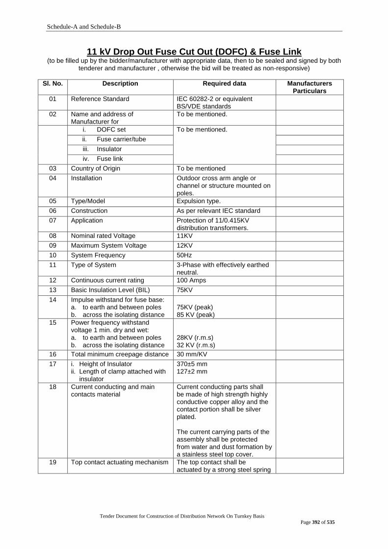
Schedule-A and Schedule-B
Tender Document for Construction of Distribution Network On Turnkey Basis
Page 392 of 535
11 kV Drop Out Fuse Cut Out (DOFC) & Fuse Link (to be filled up by the bidder/manufacturer with appropriate data, then to be sealed and signed by both
tenderer and manufacturer , otherwise the bid will be treated as non-responsive)
Sl. No. Description Required data Manufacturers Particulars
01 Reference Standard IEC 60282-2 or equivalent BS/VDE standards
02 Name and address of Manufacturer for
To be mentioned.
i. DOFC set To be mentioned.
ii. Fuse carrier/tube
iii. Insulator
iv. Fuse link
03 Country of Origin To be mentioned
04 Installation Outdoor cross arm angle or channel or structure mounted on poles.
05 Type/Model Expulsion type.
06 Construction As per relevant IEC standard
07 Application Protection of 11/0.415KV distribution transformers.
08 Nominal rated Voltage 11KV
09 Maximum System Voltage 12KV
10 System Frequency 50Hz
11 Type of System 3-Phase with effectively earthed neutral.
12 Continuous current rating 100 Amps
13 Basic Insulation Level (BIL) 75KV
14 Impulse withstand for fuse base: a. to earth and between poles b. across the isolating distance
75KV (peak) 85 KV (peak)
15 Power frequency withstand voltage 1 min. dry and wet: a. to earth and between poles b. across the isolating distance
28KV (r.m.s) 32 KV (r.m.s)
16 Total minimum creepage distance 30 mm/KV
17 i. Height of Insulator ii. Length of clamp attached with
insulator
370±5 mm 127±2 mm
18 Current conducting and main contacts material
Current conducting parts shall be made of high strength highly conductive copper alloy and the contact portion shall be silver plated. The current carrying parts of the assembly shall be protected from water and dust formation by a stainless steel top cover.
19 Top contact actuating mechanism The top contact shall be actuated by a strong steel spring

Schedule-A and Schedule-B
Tender Document for Construction of Distribution Network On Turnkey Basis
Page 393 of 535
Sl. No. Description Required data Manufacturers Particulars
20 Rated minimum interrupting capacity (symmetrical)
8KA
21 Insulator material strength. 6 KN
22 Material of support insulator Polymer
23 Colour of insulator Glazed brown/Grey
24 Dimension in mm x mm x mm To be mentioned
25 Total Weight in Kg. To be mentioned
26
Fuse carrier/Fuse tube
i. The fuse carrier top contact shall have a solid replaceable cap made from highly conductive, anti-corrosive copper alloy and the contact portion shall be silver plated. The fuse carrier shall be provided with a cast bronze opening eye (pull ring) suitable for operation with a hook stick from the ground level. The fuse carrier bottom assembly shall be made of bronze castings with silver plating at the contact points
ii. The fuse tube shall be made of fibre glass coated with ultraviolet inhibitor on the outer surface and having arc quenching bone fibre liner inside. The tube shall have high bursting strength to sustain high pressure of the gases during fault interruption.
27
Cut out type The cut out shall be of single vent type (downward) having a front connected fuse carrier suitable for angle mounting.
28 Fuse Link
i. Construction button head type
ii. Continuous current rating of fuse link.
30 Amps
iii. Fuse link type K-type as per NEMA standard medium melting high surge
iv. Time- current characteristics curve
To be furnished
29 Fittings & Accessories to be supplied
Yes
30 Fittings & Accessories: complete in all respect
To be mentioned the list of Fittings & Accessories
Seal and Signature of the Tenderer Seal & Signature of the Manufacturer

Schedule-A and Schedule-B
Tender Document for Construction of Distribution Network On Turnkey Basis
Page 394 of 535
11 kV Lightning Arrester (to be filled up by the bidder/manufacturer with appropriate data, then to be sealed and signed by both
tenderer and manufacturer, otherwise the bid will be treated as non-responsive)
Sl. No. Description Required data Manufacturers Particulars
01 Reference Standard IEC 60099-4 or equivalent BS/VDE standards
02 Name of Manufacturer To be mentioned.
03 Address of Manufacturer To be mentioned.
04 Country of Origin To be mentioned
05 Installation Outdoor pole/cross arm angle/channel/structure mounted.
06 Type/Model Gapless Zinc Oxide (ZnO)
07 Construction As per relevant IEC standard
08 Application Protection of 11/0.415KV distribution Transformers.
09 Nominal rated Voltage 11KV
10 Maximum System Voltage 12KV
11 System Frequency 50Hz
12 Type of System 3–Phase with effectively earthed neutral.
13 Rated Arrester voltage 10.5KV RMS
14 Long duration discharge class Discharge Class-1
15 Maximum continuous operating voltage
10 KV (r.m.s)
16 Nominal discharge current (8/20 micro second wave)
10 KA
17 High current withstand 100KA
18 Pressure relief class 20KA (rms Symmetrical)
19 Basic Insulation level (BIL) at 1.2/50 micro sec impulses.
75KV crest
20 Lightning impulse Residual Voltage at 8/20 micro sec. Current wave
39KV crest
21 minimum Creepage distance 30 mm/KV
22 Weight in Kg. To be mentioned
23 Housing material of Arrester Polymer
24 Minimum clearance between arrester and adjoining earthed objects
200 mm
25 Overall dimensions a. Height from mounting plane b. Diameter of shed
210±5 mm 145±5 mm
26 Year of manufacture To be mentioned
27 Fittings & Accessories to be supplied
Yes
28 Fittings & Accessories: complete in all respect
To be mentioned the list of Fittings & Accessories
Seal and Signature of the Tenderer Seal & Signature of the Manufacturer

Schedule-A and Schedule-B
Tender Document for Construction of Distribution Network On Turnkey Basis
Page 395 of 535
400 Volts MCCB (400 Amps)
(to be filled up by the bidder/manufacturer with appropriate data, then to be sealed and signed by both
tenderer and manufacturer, otherwise the bid will be treated as non-responsive)
SI. No. Description DPDC‟s Requirements Manufacturer‟s Particulars
A. Three Phase 400 Amps LV MCCB
1. Manufacturer‟s name & address To be mentioned
2. Country of manufacturer EU/USA/UK/Japan/Australia/Canada
3. Manufacturer‟s model no. To be mentioned
4. Application For 11 kV 250KVA Transformer secondary and/or feeder protection
5. Installation Outdoor panel/box mounted
6. Operating Voltage 415 V AC
7. Max System Voltage 690 V AC
8. Rated Continuous Current 400 A
9. Number of poles (Phase) 3
10. Rated insulation voltage i.e. maximum system voltage (Ui)
800 V AC
11. Rated impulse withstands voltage i.e. Uimp
8 KV
12. Utilization Category A
13. Degree of Pollution III
14. Operational Frequency (Hz) 50
15. Frame Current Size 400 Amps
16. Rated Short circuit Breaking Capacity at 415 V AC (Ics = 100% Icu)
36 KA At 415 V AC
(Ics = 100% Icu)
17. Operating Condition The climatic condition as specified below:
The climate is humid and tropical. Maximum humidity and temperature
occur simultaneously. Relative humidity 100% maximum. Altitude less
than 300 meters above sea level. Ambient temperature variation + 3ºC to
+ 45ºC degree Celsius.
18. Trip Micro Processor Based Electronic/Mechanical Trip Unit with a display unit to see actual current flow.
Magnetic Adjustable: Magnetic element setting provision for short
circuit protection variable from ≤400%
to 1000%.
19. Thermal element setting 40% to 100% of rated continuous current
20. Magnetic element setting Magnetic element setting provision for short circuit protection variable from
≤400% to 1000%.
21. Inbuilt Instantaneous Protection Shall have the features
22. Inbuilt ground fault protection from 20% - 50% of In without external additional CT, PT
Shall have the features
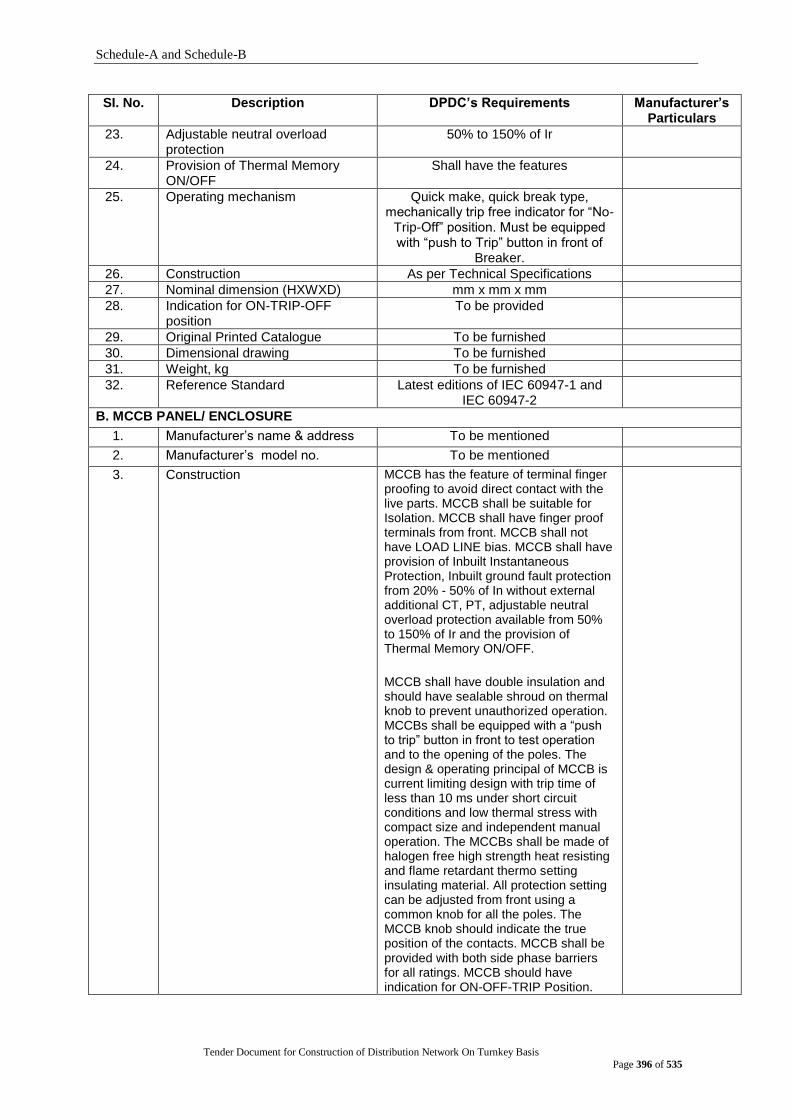
Schedule-A and Schedule-B
Tender Document for Construction of Distribution Network On Turnkey Basis
Page 396 of 535
SI. No. Description DPDC‟s Requirements Manufacturer‟s Particulars
23. Adjustable neutral overload protection
50% to 150% of Ir
24. Provision of Thermal Memory ON/OFF
Shall have the features
25. Operating mechanism Quick make, quick break type, mechanically trip free indicator for “No-
Trip-Off” position. Must be equipped with “push to Trip” button in front of
Breaker.
26. Construction As per Technical Specifications
27. Nominal dimension (HXWXD) mm x mm x mm
28. Indication for ON-TRIP-OFF position
To be provided
29. Original Printed Catalogue To be furnished
30. Dimensional drawing To be furnished
31. Weight, kg To be furnished
32. Reference Standard Latest editions of IEC 60947-1 and IEC 60947-2
B. MCCB PANEL/ ENCLOSURE
1. Manufacturer‟s name & address To be mentioned
2. Manufacturer‟s model no. To be mentioned
3. Construction MCCB has the feature of terminal finger proofing to avoid direct contact with the live parts. MCCB shall be suitable for Isolation. MCCB shall have finger proof terminals from front. MCCB shall not have LOAD LINE bias. MCCB shall have provision of Inbuilt Instantaneous Protection, Inbuilt ground fault protection from 20% - 50% of In without external additional CT, PT, adjustable neutral overload protection available from 50% to 150% of Ir and the provision of Thermal Memory ON/OFF.
MCCB shall have double insulation and should have sealable shroud on thermal knob to prevent unauthorized operation. MCCBs shall be equipped with a “push to trip” button in front to test operation and to the opening of the poles. The design & operating principal of MCCB is current limiting design with trip time of less than 10 ms under short circuit conditions and low thermal stress with compact size and independent manual operation. The MCCBs shall be made of halogen free high strength heat resisting and flame retardant thermo setting insulating material. All protection setting can be adjusted from front using a common knob for all the poles. The MCCB knob should indicate the true position of the contacts. MCCB shall be provided with both side phase barriers for all ratings. MCCB should have indication for ON-OFF-TRIP Position.

Schedule-A and Schedule-B
Tender Document for Construction of Distribution Network On Turnkey Basis
Page 397 of 535
SI. No. Description DPDC‟s Requirements Manufacturer‟s Particulars
MCCB should have CE marking. All poles shall operate simultaneously for circuit breaker opening, closing and tripping. MCCBs shall be actuated by a handle that clearly indicated the three positions: ON, OFF and TRIP. In order to ensure suitability for isolation complying with IEC 60947-2.The operating mechanism is designed such that the handle can only be in OFF position (O) if the power contacts are all actually separated. In OFF position, the handle shall indicate the isolation position. MCCBs shall be able to receive a device for locking in the "isolated" position, with padlocks.
4. Overall dimension (HXWXD) To be mentioned
5. Enclosure The enclosure shall be made of 2mm galvanized steel sheet water proof powder coated Box. Provision for 3mm sheet base to accommodate the Breaker and proper sealing arrangement.
The enclosures shall have hinged type front door with a cylindrical built-in-lock. The enclosure shall be rain, dust and weather proof in accordance to IP55. The design & material used for the enclosure must be shock proof and fire retardant.
The Outdoor type enclosure shall be provided with adequate means for outdoor pole mounting and shall be supplied complete with all necessary fitting facilities by clamping or stainless steel strap & buckles arrangement with Poles.
The unit shall have slanted roof and rain shed for Outdoors type. The unit shall have bottom entry for incoming of 95mm² PVC insulated, PVC sheathed Copper cable through rubber glands.
The following designations shall be printed on the front door as follows : 400A MCCB 400 Volts Sl. No: DPDC with Monogram.
6. Necessary fixing channels with adjustable hole including nuts, bolts etc.
Shall be provided
7. Standard Latest revision of ASTM A90/ BS EN ISO 1461:2009 standard
Seal and Signature of the Tenderer Seal & Signature of the Manufacturer

Schedule-A and Schedule-B
Tender Document for Construction of Distribution Network On Turnkey Basis
Page 398 of 535
400 Volts MCCB (300 Amps)
(to be filled up by the bidder/manufacturer with appropriate data, then to be sealed and signed by both
tenderer and manufacturer, otherwise the bid will be treated as non-responsive)
SI. No. Description DPDC‟s Requirements Manufacturer‟s Particulars
A. Three Phase 300 Amps LV MCCB
1. Manufacturer‟s name & address
To be mentioned
2. Country of manufacturer EU/USA/UK/Japan/Australia/Canada
3. Manufacturer‟s model no. To be mentioned
4. Application For 11 kV 250KVA Transformer secondary and/or feeder protection
5. Operating Voltage 415 V AC
6. Max System Voltage 690 V AC
7. Rated Continuous Current 300 A
8. Number of poles (Phase) 3
9. Rated insulation voltage i.e. maximum system voltage (Ui)
800 V AC
10. Rated impulse withstands voltage i.e. Uimp
8 KV
11. Utilization Category A
12. Degree of Pollution III
13. Operational Frequency (Hz) 50
14. Frame Current Size 400 Amps
15. Rated Short circuit Breaking Capacity at 415 V AC (Ics = 100% Icu)
36 KA At 415 V AC
(Ics = 100% Icu)
16. The climatic condition as specified below:
The climate is humid and tropical. Maximum humidity and temperature
occur simultaneously. Relative humidity 100% maximum. Altitude less than 300
meters above sea level. Ambient temperature variation + 3ºC to + 45ºC
degree Celsius.
17. Trip Micro Processor Based Electronic/Mechanical Trip Unit with a display unit to see actual current flow.
Magnetic Adjustable: Magnetic element setting provision for short circuit
protection variable from ≤400% to
1000%.
18. Thermal element setting 40% to 100% of rated continuous current
19. Magnetic element setting 150% to 800% of rated continuous current
20. Inbuilt Instantaneous Protection
Shall have the features

Schedule-A and Schedule-B
Tender Document for Construction of Distribution Network On Turnkey Basis
Page 399 of 535
SI. No. Description DPDC‟s Requirements Manufacturer‟s Particulars
21. Inbuilt ground fault protection from 20% - 50% of In without external additional CT, PT
Shall have the features
22. Adjustable neutral overload protection
50% to 150% of Ir
23. Provision of Thermal Memory ON/OFF
Shall have the features
24. Operating mechanism As per Technical Specifications
25. Construction As per Technical Specifications
26. Nominal dimension (HXWXD)
mm x mm x mm
27. Indication for ON-TRIP-OFF position
To be provided
28. Original Printed Catalogue To be furnished
29. Dimensional drawing To be furnished
30. Weight, kg To be furnished
31. Reference Standard Latest editions of IEC 60947-1 and IEC 60947-2
B. MCCB PANEL/ ENCLOSURE
1. Manufacturer‟s name & address
To be mentioned
2. Manufacturer‟s model no. To be mentioned
3. Construction MCCB has the feature of terminal finger proofing to avoid direct contact with the live parts. MCCB shall be suitable for Isolation. MCCB shall have finger proof terminals from front. MCCB shall not have LOAD LINE bias. MCCB shall have provision of Inbuilt Instantaneous Protection, Inbuilt ground fault protection from 20% - 50% of In without external additional CT, PT, adjustable neutral overload protection available from 50% to 150% of Ir and the provision of Thermal Memory ON/OFF. MCCB shall have double insulation and should have sealable shroud on thermal knob to prevent unauthorized operation. MCCBs shall be equipped with a “push to trip” button in front to test operation and to the opening of the poles. The design & operating principal of MCCB is current limiting design with trip time of less than 10 ms under short circuit conditions and low thermal stress with compact size and independent manual operation. The MCCBs shall be made of halogen free high strength heat resisting and flame retardant thermo setting insulating material. All protection setting can be adjusted from front using a common knob for all the poles. The MCCB knob should indicate the true position of the contacts. MCCB shall be provided with both side phase barriers for all ratings. MCCB should have indication for ON-OFF-TRIP Position.
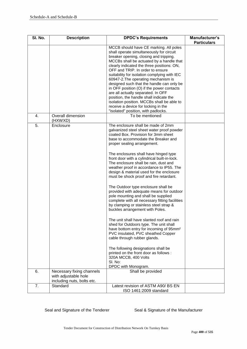
Schedule-A and Schedule-B
Tender Document for Construction of Distribution Network On Turnkey Basis
Page 400 of 535
SI. No. Description DPDC‟s Requirements Manufacturer‟s
Particulars
MCCB should have CE marking. All poles shall operate simultaneously for circuit breaker opening, closing and tripping. MCCBs shall be actuated by a handle that clearly indicated the three positions: ON, OFF and TRIP. In order to ensure suitability for isolation complying with IEC 60947-2.The operating mechanism is designed such that the handle can only be in OFF position (O) if the power contacts are all actually separated. In OFF position, the handle shall indicate the isolation position. MCCBs shall be able to receive a device for locking in the "isolated" position, with padlocks.
4. Overall dimension (HXWXD)
To be mentioned
5. Enclosure The enclosure shall be made of 2mm galvanized steel sheet water proof powder coated Box. Provision for 3mm sheet base to accommodate the Breaker and proper sealing arrangement.
The enclosures shall have hinged type front door with a cylindrical built-in-lock. The enclosure shall be rain, dust and weather proof in accordance to IP55. The design & material used for the enclosure must be shock proof and fire retardant.
The Outdoor type enclosure shall be provided with adequate means for outdoor pole mounting and shall be supplied complete with all necessary fitting facilities by clamping or stainless steel strap & buckles arrangement with Poles.
The unit shall have slanted roof and rain shed for Outdoors type. The unit shall have bottom entry for incoming of 95mm² PVC insulated, PVC sheathed Copper cable through rubber glands.
The following designations shall be printed on the front door as follows : 320A MCCB, 400 Volts Sl. No: DPDC with Monogram.
6. Necessary fixing channels with adjustable hole including nuts, bolts etc.
Shall be provided
7. Standard Latest revision of ASTM A90/ BS EN ISO 1461:2009 standard
Seal and Signature of the Tenderer Seal & Signature of the Manufacturer
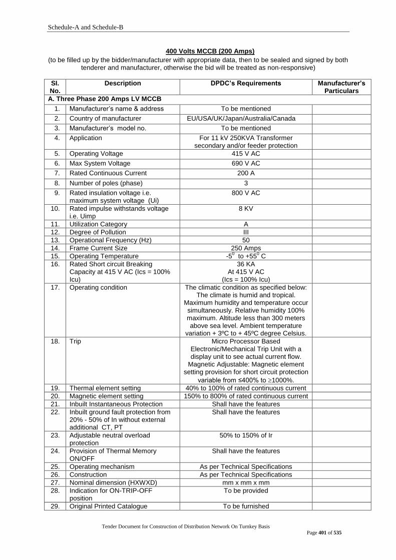
Schedule-A and Schedule-B
Tender Document for Construction of Distribution Network On Turnkey Basis
Page 401 of 535
400 Volts MCCB (200 Amps)
(to be filled up by the bidder/manufacturer with appropriate data, then to be sealed and signed by both tenderer and manufacturer, otherwise the bid will be treated as non-responsive)
SI. No.
Description DPDC‟s Requirements Manufacturer‟s Particulars
A. Three Phase 200 Amps LV MCCB
1. Manufacturer‟s name & address To be mentioned
2. Country of manufacturer EU/USA/UK/Japan/Australia/Canada
3. Manufacturer‟s model no. To be mentioned
4. Application For 11 kV 250KVA Transformer secondary and/or feeder protection
5. Operating Voltage 415 V AC
6. Max System Voltage 690 V AC
7. Rated Continuous Current 200 A
8. Number of poles (phase) 3
9. Rated insulation voltage i.e. maximum system voltage (Ui)
800 V AC
10. Rated impulse withstands voltage i.e. Uimp
8 KV
11. Utilization Category A
12. Degree of Pollution III
13. Operational Frequency (Hz) 50
14. Frame Current Size 250 Amps
15. Operating Temperature -50 to +55
0 C
16. Rated Short circuit Breaking Capacity at 415 V AC (Ics = 100% Icu)
36 KA At 415 V AC
(Ics = 100% Icu)
17. Operating condition The climatic condition as specified below: The climate is humid and tropical.
Maximum humidity and temperature occur simultaneously. Relative humidity 100% maximum. Altitude less than 300 meters above sea level. Ambient temperature
variation + 3ºC to + 45ºC degree Celsius.
18. Trip Micro Processor Based Electronic/Mechanical Trip Unit with a display unit to see actual current flow.
Magnetic Adjustable: Magnetic element setting provision for short circuit protection
variable from ≤400% to 1000%.
19. Thermal element setting 40% to 100% of rated continuous current
20. Magnetic element setting 150% to 800% of rated continuous current
21. Inbuilt Instantaneous Protection Shall have the features
22. Inbuilt ground fault protection from 20% - 50% of In without external additional CT, PT
Shall have the features
23. Adjustable neutral overload protection
50% to 150% of Ir
24. Provision of Thermal Memory ON/OFF
Shall have the features
25. Operating mechanism As per Technical Specifications
26. Construction As per Technical Specifications
27. Nominal dimension (HXWXD) mm x mm x mm
28. Indication for ON-TRIP-OFF position
To be provided
29. Original Printed Catalogue To be furnished
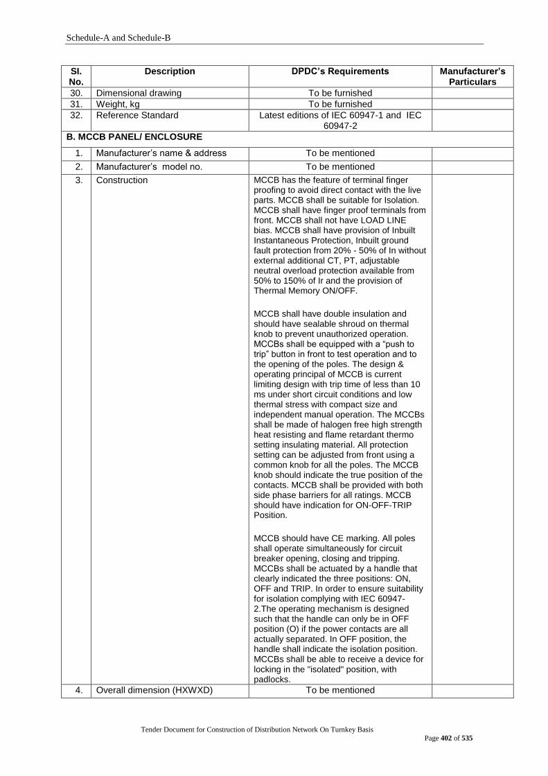
Schedule-A and Schedule-B
Tender Document for Construction of Distribution Network On Turnkey Basis
Page 402 of 535
SI. No.
Description DPDC‟s Requirements Manufacturer‟s Particulars
30. Dimensional drawing To be furnished
31. Weight, kg To be furnished
32. Reference Standard Latest editions of IEC 60947-1 and IEC 60947-2
B. MCCB PANEL/ ENCLOSURE
1. Manufacturer‟s name & address To be mentioned
2. Manufacturer‟s model no. To be mentioned
3. Construction MCCB has the feature of terminal finger proofing to avoid direct contact with the live parts. MCCB shall be suitable for Isolation. MCCB shall have finger proof terminals from front. MCCB shall not have LOAD LINE bias. MCCB shall have provision of Inbuilt Instantaneous Protection, Inbuilt ground fault protection from 20% - 50% of In without external additional CT, PT, adjustable neutral overload protection available from 50% to 150% of Ir and the provision of Thermal Memory ON/OFF.
MCCB shall have double insulation and should have sealable shroud on thermal knob to prevent unauthorized operation. MCCBs shall be equipped with a “push to trip” button in front to test operation and to the opening of the poles. The design & operating principal of MCCB is current limiting design with trip time of less than 10 ms under short circuit conditions and low thermal stress with compact size and independent manual operation. The MCCBs shall be made of halogen free high strength heat resisting and flame retardant thermo setting insulating material. All protection setting can be adjusted from front using a common knob for all the poles. The MCCB knob should indicate the true position of the contacts. MCCB shall be provided with both side phase barriers for all ratings. MCCB should have indication for ON-OFF-TRIP Position.
MCCB should have CE marking. All poles shall operate simultaneously for circuit breaker opening, closing and tripping. MCCBs shall be actuated by a handle that clearly indicated the three positions: ON, OFF and TRIP. In order to ensure suitability for isolation complying with IEC 60947-2.The operating mechanism is designed such that the handle can only be in OFF position (O) if the power contacts are all actually separated. In OFF position, the handle shall indicate the isolation position. MCCBs shall be able to receive a device for locking in the "isolated" position, with padlocks.
4. Overall dimension (HXWXD) To be mentioned

Schedule-A and Schedule-B
Tender Document for Construction of Distribution Network On Turnkey Basis
Page 403 of 535
SI. No.
Description DPDC‟s Requirements Manufacturer‟s Particulars
5. Enclosure The enclosure shall be made of 2mm galvanized steel sheet water proof powder coated Box. Provision for 3mm sheet base to accommodate the Breaker and proper sealing arrangement.
The enclosures shall have hinged type front door with a cylindrical built-in-lock. The enclosure shall be rain, dust and weather proof in accordance to IP55. The design & material used for the enclosure must be shock proof and fire retardant.
The Outdoor type enclosure shall be provided with adequate means for outdoor pole mounting and shall be supplied complete with all necessary fitting facilities by clamping or stainless steel strap & buckles arrangement with Poles.
The unit shall have slanted roof and rain shed for Outdoors type. The unit shall have bottom entry for incoming of 95mm² PVC insulated, PVC sheathed Copper cable through rubber glands.
The following designations shall be printed on the front door as follows : 200A MCCB 400 Volts Sl. No: DPDC with Monogram.
6. Necessary fixing channels with adjustable hole including nuts, bolts etc.
Shall be provided
7. Standard Latest revision of ASTM A90/ BS EN ISO 1461:2009 standard
Seal and Signature of the Tenderer Seal & Signature of the Manufacturer
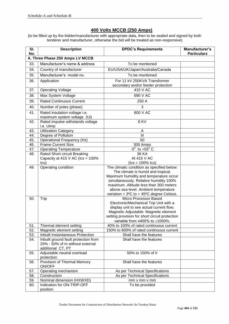
Schedule-A and Schedule-B
Tender Document for Construction of Distribution Network On Turnkey Basis
Page 404 of 535
400 Volts MCCB (250 Amps) (to be filled up by the bidder/manufacturer with appropriate data, then to be sealed and signed by both
tenderer and manufacturer, otherwise the bid will be treated as non-responsive)
SI. No.
Description DPDC‟s Requirements Manufacturer‟s Particulars
A. Three Phase 250 Amps LV MCCB
33. Manufacturer‟s name & address To be mentioned
34. Country of manufacturer EU/USA/UK/Japan/Australia/Canada
35. Manufacturer‟s model no. To be mentioned
36. Application For 11 kV 250KVA Transformer secondary and/or feeder protection
37. Operating Voltage 415 V AC
38. Max System Voltage 690 V AC
39. Rated Continuous Current 250 A
40. Number of poles (phase) 3
41. Rated insulation voltage i.e. maximum system voltage (Ui)
800 V AC
42. Rated impulse withstands voltage i.e. Uimp
8 KV
43. Utilization Category A
44. Degree of Pollution III
45. Operational Frequency (Hz) 50
46. Frame Current Size 300 Amps
47. Operating Temperature -50 to +55
0 C
48. Rated Short circuit Breaking Capacity at 415 V AC (Ics = 100% Icu)
36 KA At 415 V AC
(Ics = 100% Icu)
49. Operating condition The climatic condition as specified below: The climate is humid and tropical.
Maximum humidity and temperature occur simultaneously. Relative humidity 100% maximum. Altitude less than 300 meters above sea level. Ambient temperature
variation + 3ºC to + 45ºC degree Celsius.
50. Trip Micro Processor Based Electronic/Mechanical Trip Unit with a display unit to see actual current flow.
Magnetic Adjustable: Magnetic element setting provision for short circuit protection
variable from ≤400% to 1000%.
51. Thermal element setting 40% to 100% of rated continuous current
52. Magnetic element setting 150% to 800% of rated continuous current
53. Inbuilt Instantaneous Protection Shall have the features
54. Inbuilt ground fault protection from 20% - 50% of In without external additional CT, PT
Shall have the features
55. Adjustable neutral overload protection
50% to 150% of Ir
56. Provision of Thermal Memory ON/OFF
Shall have the features
57. Operating mechanism As per Technical Specifications
58. Construction As per Technical Specifications
59. Nominal dimension (HXWXD) mm x mm x mm
60. Indication for ON-TRIP-OFF position
To be provided

Schedule-A and Schedule-B
Tender Document for Construction of Distribution Network On Turnkey Basis
Page 405 of 535
SI. No.
Description DPDC‟s Requirements Manufacturer‟s Particulars
61. Original Printed Catalogue To be furnished
62. Dimensional drawing To be furnished
63. Weight, kg To be furnished
64. Reference Standard Latest editions of IEC 60947-1 and IEC 60947-2
B. MCCB PANEL/ ENCLOSURE
8. Manufacturer‟s name & address To be mentioned
9. Manufacturer‟s model no. To be mentioned
10. Construction MCCB has the feature of terminal finger proofing to avoid direct contact with the live parts. MCCB shall be suitable for Isolation. MCCB shall have finger proof terminals from front. MCCB shall not have LOAD LINE bias. MCCB shall have provision of Inbuilt Instantaneous Protection, Inbuilt ground fault protection from 20% - 50% of In without external additional CT, PT, adjustable neutral overload protection available from 50% to 150% of Ir and the provision of Thermal Memory ON/OFF.
MCCB shall have double insulation and should have sealable shroud on thermal knob to prevent unauthorized operation. MCCBs shall be equipped with a “push to trip” button in front to test operation and to the opening of the poles. The design & operating principal of MCCB is current limiting design with trip time of less than 10 ms under short circuit conditions and low thermal stress with compact size and independent manual operation. The MCCBs shall be made of halogen free high strength heat resisting and flame retardant thermo setting insulating material. All protection setting can be adjusted from front using a common knob for all the poles. The MCCB knob should indicate the true position of the contacts. MCCB shall be provided with both side phase barriers for all ratings. MCCB should have indication for ON-OFF-TRIP Position.
MCCB should have CE marking. All poles shall operate simultaneously for circuit breaker opening, closing and tripping. MCCBs shall be actuated by a handle that clearly indicated the three positions: ON, OFF and TRIP. In order to ensure suitability for isolation complying with IEC 60947-2.The operating mechanism is designed such that the handle can only be in OFF position (O) if the power contacts are all actually separated. In OFF position, the handle shall indicate the isolation position. MCCBs shall be able to receive a device for locking in the "isolated" position, with padlocks.
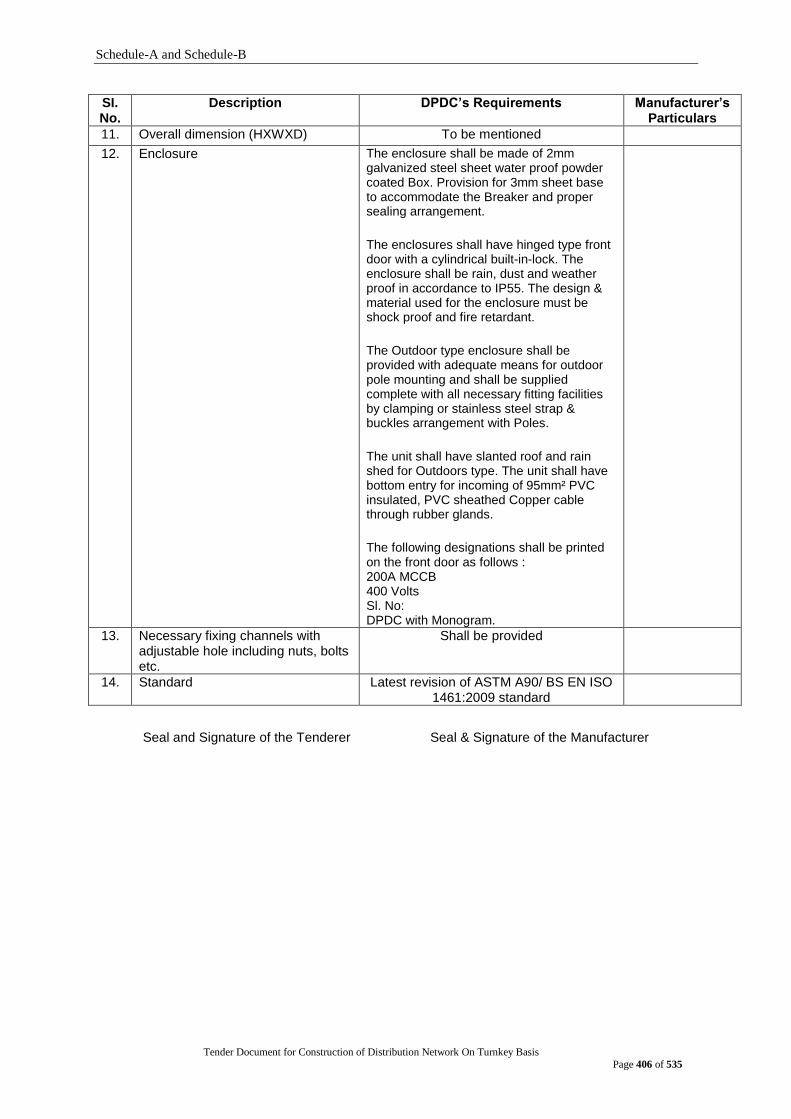
Schedule-A and Schedule-B
Tender Document for Construction of Distribution Network On Turnkey Basis
Page 406 of 535
SI. No.
Description DPDC‟s Requirements Manufacturer‟s Particulars
11. Overall dimension (HXWXD) To be mentioned
12. Enclosure The enclosure shall be made of 2mm galvanized steel sheet water proof powder coated Box. Provision for 3mm sheet base to accommodate the Breaker and proper sealing arrangement.
The enclosures shall have hinged type front door with a cylindrical built-in-lock. The enclosure shall be rain, dust and weather proof in accordance to IP55. The design & material used for the enclosure must be shock proof and fire retardant.
The Outdoor type enclosure shall be provided with adequate means for outdoor pole mounting and shall be supplied complete with all necessary fitting facilities by clamping or stainless steel strap & buckles arrangement with Poles.
The unit shall have slanted roof and rain shed for Outdoors type. The unit shall have bottom entry for incoming of 95mm² PVC insulated, PVC sheathed Copper cable through rubber glands.
The following designations shall be printed on the front door as follows : 200A MCCB 400 Volts Sl. No: DPDC with Monogram.
13. Necessary fixing channels with adjustable hole including nuts, bolts etc.
Shall be provided
14. Standard Latest revision of ASTM A90/ BS EN ISO 1461:2009 standard
Seal and Signature of the Tenderer Seal & Signature of the Manufacturer
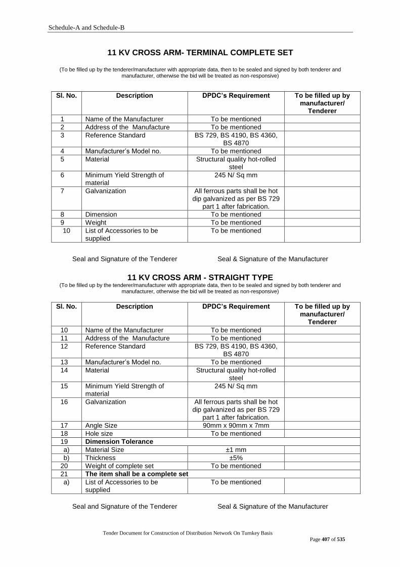
Schedule-A and Schedule-B
Tender Document for Construction of Distribution Network On Turnkey Basis
Page 407 of 535
11 KV CROSS ARM- TERMINAL COMPLETE SET
(To be filled up by the tenderer/manufacturer with appropriate data, then to be sealed and signed by both tenderer and manufacturer, otherwise the bid will be treated as non-responsive)
Sl. No. Description DPDC‟s Requirement To be filled up by manufacturer/
Tenderer
1 Name of the Manufacturer To be mentioned
2 Address of the Manufacture To be mentioned
3 Reference Standard BS 729, BS 4190, BS 4360, BS 4870
4 Manufacturer‟s Model no. To be mentioned
5 Material Structural quality hot-rolled steel
6 Minimum Yield Strength of material
245 N/ Sq mm
7 Galvanization All ferrous parts shall be hot dip galvanized as per BS 729
part 1 after fabrication.
8 Dimension To be mentioned
9 Weight To be mentioned
10 List of Accessories to be supplied
To be mentioned
Seal and Signature of the Tenderer Seal & Signature of the Manufacturer
11 KV CROSS ARM - STRAIGHT TYPE (To be filled up by the tenderer/manufacturer with appropriate data, then to be sealed and signed by both tenderer and
manufacturer, otherwise the bid will be treated as non-responsive)
Sl. No. Description DPDC‟s Requirement To be filled up by manufacturer/
Tenderer
10 Name of the Manufacturer To be mentioned
11 Address of the Manufacture To be mentioned
12 Reference Standard BS 729, BS 4190, BS 4360, BS 4870
13 Manufacturer‟s Model no. To be mentioned
14 Material Structural quality hot-rolled steel
15 Minimum Yield Strength of material
245 N/ Sq mm
16 Galvanization All ferrous parts shall be hot dip galvanized as per BS 729
part 1 after fabrication.
17 Angle Size 90mm x 90mm x 7mm
18 Hole size To be mentioned
19 Dimension Tolerance
a) Material Size ±1 mm
b) Thickness ±5%
20 Weight of complete set To be mentioned
21 The item shall be a complete set
a) List of Accessories to be supplied
To be mentioned
Seal and Signature of the Tenderer Seal & Signature of the Manufacturer
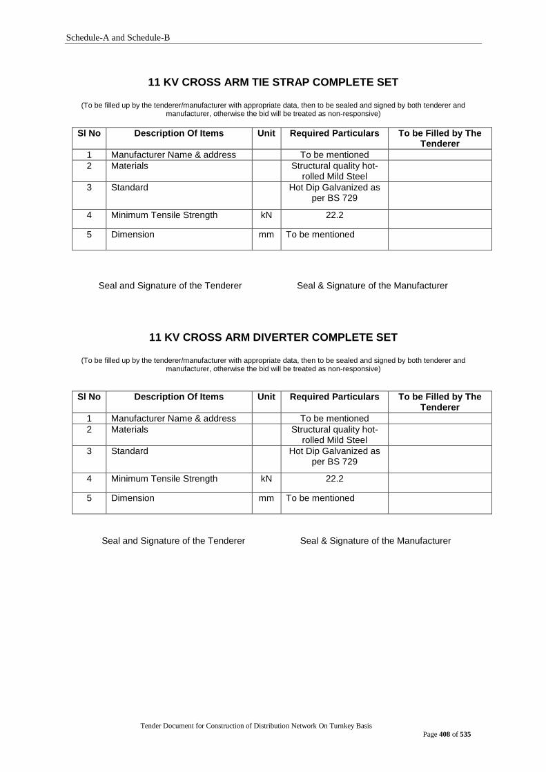
Schedule-A and Schedule-B
Tender Document for Construction of Distribution Network On Turnkey Basis
Page 408 of 535
11 KV CROSS ARM TIE STRAP COMPLETE SET
(To be filled up by the tenderer/manufacturer with appropriate data, then to be sealed and signed by both tenderer and manufacturer, otherwise the bid will be treated as non-responsive)
Sl No Description Of Items Unit Required Particulars To be Filled by The Tenderer
1 Manufacturer Name & address To be mentioned
2 Materials
Structural quality hot-rolled Mild Steel
3 Standard Hot Dip Galvanized as per BS 729
4 Minimum Tensile Strength kN 22.2
5 Dimension mm To be mentioned
Seal and Signature of the Tenderer Seal & Signature of the Manufacturer
11 KV CROSS ARM DIVERTER COMPLETE SET
(To be filled up by the tenderer/manufacturer with appropriate data, then to be sealed and signed by both tenderer and manufacturer, otherwise the bid will be treated as non-responsive)
Sl No Description Of Items Unit Required Particulars To be Filled by The Tenderer
1 Manufacturer Name & address To be mentioned
2 Materials
Structural quality hot-rolled Mild Steel
3 Standard Hot Dip Galvanized as per BS 729
4 Minimum Tensile Strength kN 22.2
5 Dimension mm To be mentioned
Seal and Signature of the Tenderer Seal & Signature of the Manufacturer
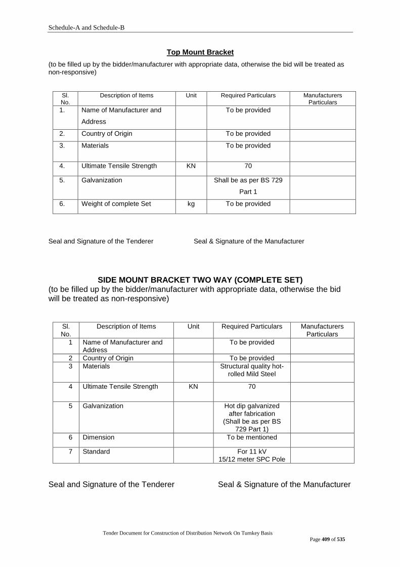
Schedule-A and Schedule-B
Tender Document for Construction of Distribution Network On Turnkey Basis
Page 409 of 535
Top Mount Bracket
(to be filled up by the bidder/manufacturer with appropriate data, otherwise the bid will be treated as non-responsive)
Sl. No.
Description of Items Unit Required Particulars Manufacturers Particulars
1. Name of Manufacturer and
Address
To be provided
2. Country of Origin To be provided
3. Materials To be provided
4. Ultimate Tensile Strength KN 70
5. Galvanization Shall be as per BS 729
Part 1
6. Weight of complete Set kg To be provided
Seal and Signature of the Tenderer Seal & Signature of the Manufacturer
SIDE MOUNT BRACKET TWO WAY (COMPLETE SET) (to be filled up by the bidder/manufacturer with appropriate data, otherwise the bid will be treated as non-responsive)
Sl. No.
Description of Items Unit Required Particulars Manufacturers Particulars
1 Name of Manufacturer and Address
To be provided
2 Country of Origin To be provided
3 Materials Structural quality hot-rolled Mild Steel
4 Ultimate Tensile Strength KN 70
5 Galvanization Hot dip galvanized after fabrication
(Shall be as per BS 729 Part 1)
6 Dimension To be mentioned
7 Standard For 11 kV 15/12 meter SPC Pole
Seal and Signature of the Tenderer Seal & Signature of the Manufacturer
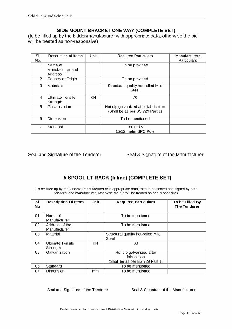
Schedule-A and Schedule-B
Tender Document for Construction of Distribution Network On Turnkey Basis
Page 410 of 535
SIDE MOUNT BRACKET ONE WAY (COMPLETE SET) (to be filled up by the bidder/manufacturer with appropriate data, otherwise the bid will be treated as non-responsive)
Sl. No.
Description of Items Unit Required Particulars Manufacturers Particulars
1 Name of Manufacturer and Address
To be provided
2 Country of Origin To be provided
3 Materials Structural quality hot-rolled Mild Steel
4 Ultimate Tensile Strength
KN 70
5 Galvanization Hot dip galvanized after fabrication (Shall be as per BS 729 Part 1)
6 Dimension To be mentioned
7 Standard For 11 kV 15/12 meter SPC Pole
Seal and Signature of the Tenderer Seal & Signature of the Manufacturer
5 SPOOL LT RACK (Inline) (COMPLETE SET)
(To be filled up by the tenderer/manufacturer with appropriate data, then to be sealed and signed by both
tenderer and manufacturer, otherwise the bid will be treated as non-responsive)
Sl No
Description Of Items Unit Required Particulars To be Filled By The Tenderer
01 Name of Manufacturer
To be mentioned
02 Address of the Manufacturer
To be mentioned
03 Material Structural quality hot-rolled Mild Steel
04 Ultimate Tensile Strength
KN 63
05 Galvanization Hot dip galvanized after fabrication
(Shall be as per BS 729 Part 1)
06 Standard To be mentioned
07 Dimension mm To be mentioned
Seal and Signature of the Tenderer Seal & Signature of the Manufacturer

Schedule-A and Schedule-B
Tender Document for Construction of Distribution Network On Turnkey Basis
Page 411 of 535
5 SPOOL LT RACK (dead end) (COMPLETE SET)
(To be filled up by the tenderer/manufacturer with appropriate data, then to be sealed and signed by both tenderer and manufacturer, otherwise the bid will be treated as non-responsive)
Sl No
Description Of Items Unit Required Particulars To be Filled By The Tenderer
01 Name of Manufacturer
To be mentioned
02 Address of the Manufacturer
To be mentioned
03 Material Structural quality hot-rolled Mild Steel
04 Ultimate Tensile Strength
KN 63
05 Galvanization Hot dip galvanized after fabrication
(Shall be as per BS 729 Part 1)
06 Standard To be mentioned
07 Dimension mm To be mentioned
Seal and Signature of the Tenderer Seal & Signature of the Manufacturer
POLE CLAMP (8 INCH)
(To be filled up by the tenderer/manufacturer with appropriate data, then to be sealed and signed by both tenderer and manufacturer, otherwise the bid will be treated as non-responsive)
Sl. No. Description Unit Required data To be filled up by
manufacturer/ Tenderer
1 Name of Manufacturer - To be mentioned
2 Address of the Manufacturer
- To be mentioned
3 Material - Structural quality hot-rolled Mild Steel (Ductile iron)
4 Size mm 50/6 mm(Flat bar)
5 Reference Standard - BS, ASTM, ANSI
6 Galvanization - Hot dip galvanized after fabrication (Shall be as per BS 729 Part 1)
7 The item shall be a complete set
8 List of Accessories to be supplied
- To be mentioned
Seal and Signature of the Tenderer Seal & Signature of the Manufacturer
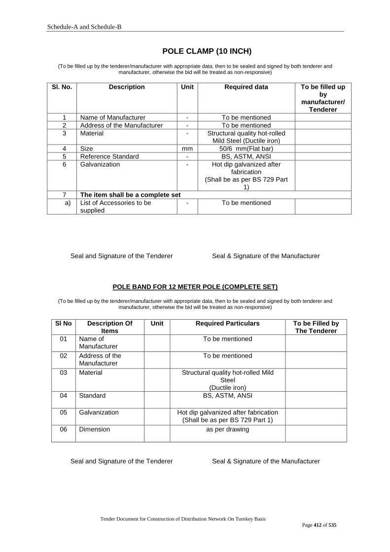
Schedule-A and Schedule-B
Tender Document for Construction of Distribution Network On Turnkey Basis
Page 412 of 535
POLE CLAMP (10 INCH)
(To be filled up by the tenderer/manufacturer with appropriate data, then to be sealed and signed by both tenderer and manufacturer, otherwise the bid will be treated as non-responsive)
Sl. No. Description Unit Required data To be filled up by
manufacturer/ Tenderer
1 Name of Manufacturer - To be mentioned
2 Address of the Manufacturer - To be mentioned
3 Material - Structural quality hot-rolled Mild Steel (Ductile iron)
4 Size mm 50/6 mm(Flat bar)
5 Reference Standard - BS, ASTM, ANSI
6 Galvanization - Hot dip galvanized after fabrication
(Shall be as per BS 729 Part 1)
7 The item shall be a complete set
a) List of Accessories to be supplied
- To be mentioned
Seal and Signature of the Tenderer Seal & Signature of the Manufacturer
POLE BAND FOR 12 METER POLE (COMPLETE SET)
(To be filled up by the tenderer/manufacturer with appropriate data, then to be sealed and signed by both tenderer and manufacturer, otherwise the bid will be treated as non-responsive)
Sl No Description Of
Items Unit Required Particulars To be Filled by
The Tenderer
01 Name of Manufacturer
To be mentioned
02 Address of the Manufacturer
To be mentioned
03 Material Structural quality hot-rolled Mild Steel
(Ductile iron)
04 Standard BS, ASTM, ANSI
05 Galvanization Hot dip galvanized after fabrication (Shall be as per BS 729 Part 1)
06 Dimension as per drawing
Seal and Signature of the Tenderer Seal & Signature of the Manufacturer
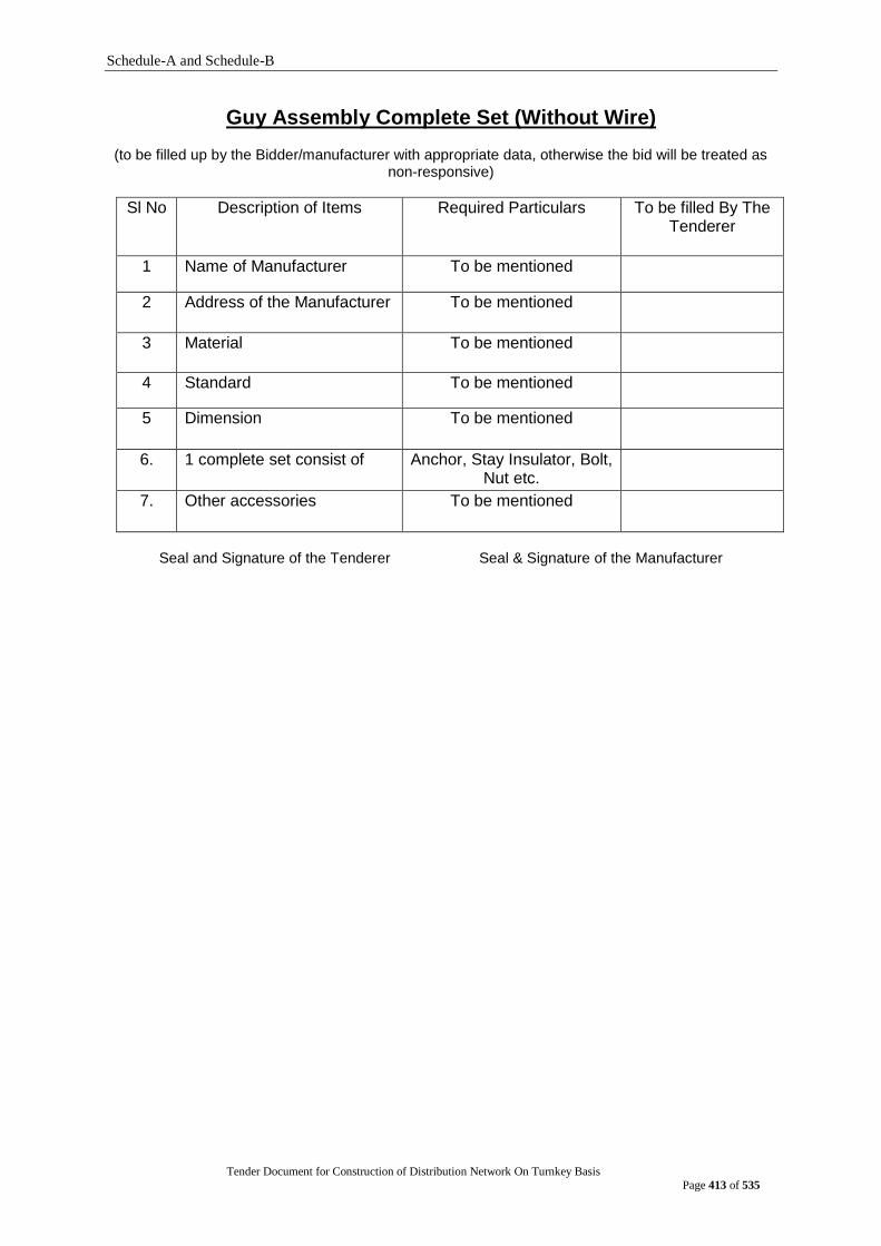
Schedule-A and Schedule-B
Tender Document for Construction of Distribution Network On Turnkey Basis
Page 413 of 535
Guy Assembly Complete Set (Without Wire)
(to be filled up by the Bidder/manufacturer with appropriate data, otherwise the bid will be treated as non-responsive)
Sl No Description of Items Required Particulars To be filled By The Tenderer
1 Name of Manufacturer To be mentioned
2 Address of the Manufacturer To be mentioned
3 Material
To be mentioned
4 Standard To be mentioned
5 Dimension To be mentioned
6. 1 complete set consist of Anchor, Stay Insulator, Bolt, Nut etc.
7. Other accessories To be mentioned
Seal and Signature of the Tenderer Seal & Signature of the Manufacturer
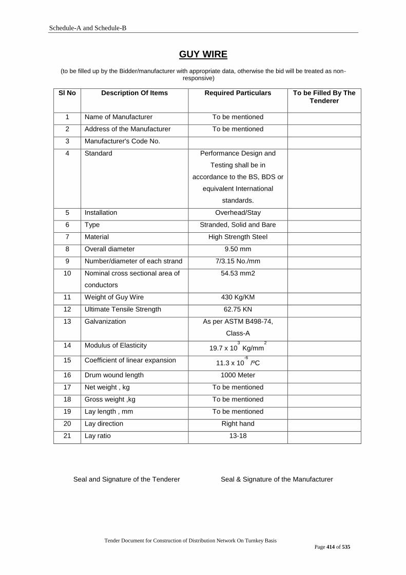
Schedule-A and Schedule-B
Tender Document for Construction of Distribution Network On Turnkey Basis
Page 414 of 535
GUY WIRE
(to be filled up by the Bidder/manufacturer with appropriate data, otherwise the bid will be treated as non-responsive)
Sl No Description Of Items Required Particulars To be Filled By The Tenderer
1 Name of Manufacturer To be mentioned
2 Address of the Manufacturer To be mentioned
3 Manufacturer's Code No.
4 Standard
Performance Design and
Testing shall be in
accordance to the BS, BDS or
equivalent International
standards.
5 Installation Overhead/Stay
6 Type Stranded, Solid and Bare
7 Material High Strength Steel
8 Overall diameter 9.50 mm
9 Number/diameter of each strand 7/3.15 No./mm
10 Nominal cross sectional area of
conductors
54.53 mm2
11 Weight of Guy Wire 430 Kg/KM
12 Ultimate Tensile Strength 62.75 KN
13 Galvanization As per ASTM B498-74,
Class-A
14 Modulus of Elasticity 19.7 x 10³
Kg/mm2
15 Coefficient of linear expansion 11.3 x 10⁻⁶
/ºC
16 Drum wound length 1000 Meter
17 Net weight , kg To be mentioned
18 Gross weight ,kg To be mentioned
19 Lay length , mm To be mentioned
20 Lay direction Right hand
21 Lay ratio 13-18
Seal and Signature of the Tenderer Seal & Signature of the Manufacturer
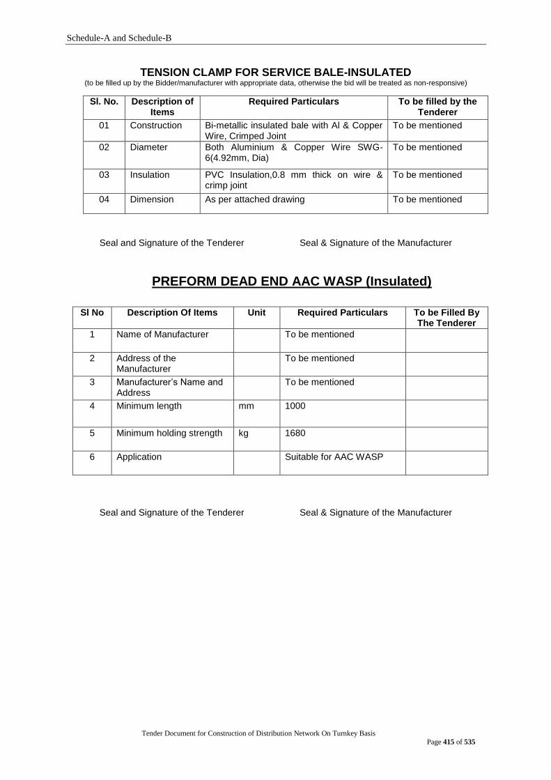
Schedule-A and Schedule-B
Tender Document for Construction of Distribution Network On Turnkey Basis
Page 415 of 535
TENSION CLAMP FOR SERVICE BALE-INSULATED (to be filled up by the Bidder/manufacturer with appropriate data, otherwise the bid will be treated as non-responsive)
Sl. No. Description of Items
Required Particulars
To be filled by the Tenderer
01 Construction Bi-metallic insulated bale with Al & Copper Wire, Crimped Joint
To be mentioned
02 Diameter Both Aluminium & Copper Wire SWG-6(4.92mm, Dia)
To be mentioned
03 Insulation PVC Insulation,0.8 mm thick on wire & crimp joint
To be mentioned
04 Dimension As per attached drawing To be mentioned
Seal and Signature of the Tenderer Seal & Signature of the Manufacturer
PREFORM DEAD END AAC WASP (Insulated)
Sl No Description Of Items Unit Required Particulars To be Filled By The Tenderer
1 Name of Manufacturer
To be mentioned
2 Address of the Manufacturer
To be mentioned
3 Manufacturer‟s Name and Address
To be mentioned
4 Minimum length
mm 1000
5 Minimum holding strength kg 1680
6 Application Suitable for AAC WASP
Seal and Signature of the Tenderer Seal & Signature of the Manufacturer
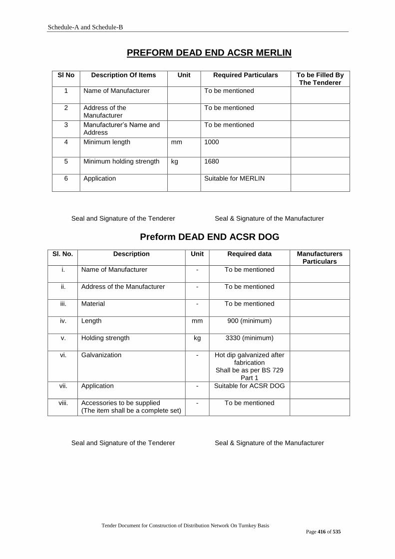
Schedule-A and Schedule-B
Tender Document for Construction of Distribution Network On Turnkey Basis
Page 416 of 535
PREFORM DEAD END ACSR MERLIN
Sl No Description Of Items Unit Required Particulars To be Filled By The Tenderer
1 Name of Manufacturer
To be mentioned
2 Address of the Manufacturer
To be mentioned
3 Manufacturer‟s Name and Address
To be mentioned
4 Minimum length
mm 1000
5 Minimum holding strength kg 1680
6 Application Suitable for MERLIN
Seal and Signature of the Tenderer Seal & Signature of the Manufacturer
Preform DEAD END ACSR DOG
Sl. No. Description Unit Required data Manufacturers Particulars
i. Name of Manufacturer
- To be mentioned
ii. Address of the Manufacturer - To be mentioned
iii. Material - To be mentioned
iv. Length mm 900 (minimum)
v. Holding strength kg 3330 (minimum)
vi. Galvanization - Hot dip galvanized after fabrication
Shall be as per BS 729 Part 1
vii. Application - Suitable for ACSR DOG
viii. Accessories to be supplied (The item shall be a complete set)
- To be mentioned
Seal and Signature of the Tenderer Seal & Signature of the Manufacturer
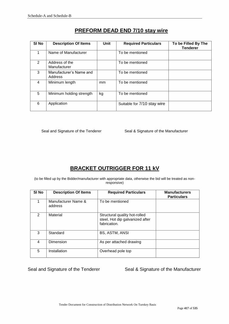
Schedule-A and Schedule-B
Tender Document for Construction of Distribution Network On Turnkey Basis
Page 417 of 535
PREFORM DEAD END 7/10 stay wire
Sl No Description Of Items Unit Required Particulars To be Filled By The Tenderer
1 Name of Manufacturer
To be mentioned
2 Address of the Manufacturer
To be mentioned
3 Manufacturer‟s Name and Address
To be mentioned
4 Minimum length
mm To be mentioned
5 Minimum holding strength kg To be mentioned
6 Application Suitable for 7/10 stay wire
Seal and Signature of the Tenderer Seal & Signature of the Manufacturer
BRACKET OUTRIGGER FOR 11 kV
(to be filled up by the Bidder/manufacturer with appropriate data, otherwise the bid will be treated as non-responsive)
Sl No Description Of Items Required Particulars Manufacturers
Particulars
1 Manufacturer Name & address
To be mentioned
2 Material
Structural quality hot-rolled steel, Hot dip galvanized after fabrication.
3 Standard BS, ASTM, ANSI
4 Dimension As per attached drawing
5 Installation Overhead pole top
Seal and Signature of the Tenderer Seal & Signature of the Manufacturer
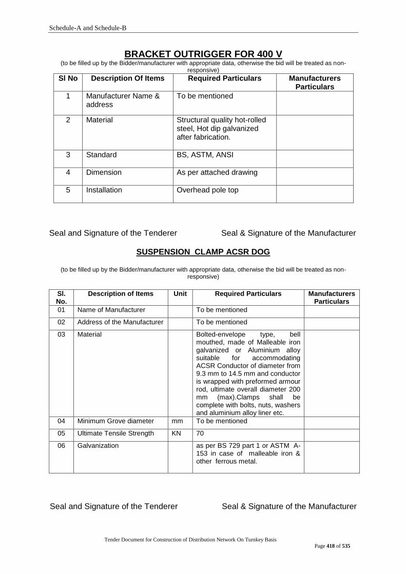
Schedule-A and Schedule-B
Tender Document for Construction of Distribution Network On Turnkey Basis
Page 418 of 535
BRACKET OUTRIGGER FOR 400 V (to be filled up by the Bidder/manufacturer with appropriate data, otherwise the bid will be treated as non-
responsive)
Sl No Description Of Items Required Particulars Manufacturers Particulars
1 Manufacturer Name & address
To be mentioned
2 Material
Structural quality hot-rolled steel, Hot dip galvanized after fabrication.
3 Standard BS, ASTM, ANSI
4 Dimension As per attached drawing
5 Installation Overhead pole top
Seal and Signature of the Tenderer Seal & Signature of the Manufacturer
SUSPENSION CLAMP ACSR DOG
(to be filled up by the Bidder/manufacturer with appropriate data, otherwise the bid will be treated as non-responsive)
Sl. No.
Description of Items Unit Required Particulars Manufacturers Particulars
01 Name of Manufacturer To be mentioned
02 Address of the Manufacturer To be mentioned
03 Material Bolted-envelope type, bell mouthed, made of Malleable iron galvanized or Aluminium alloy suitable for accommodating ACSR Conductor of diameter from 9.3 mm to 14.5 mm and conductor is wrapped with preformed armour rod, ultimate overall diameter 200 mm (max).Clamps shall be complete with bolts, nuts, washers and aluminium alloy liner etc.
04 Minimum Grove diameter mm To be mentioned
05 Ultimate Tensile Strength KN 70
06 Galvanization as per BS 729 part 1 or ASTM A-153 in case of malleable iron & other ferrous metal.
Seal and Signature of the Tenderer Seal & Signature of the Manufacturer
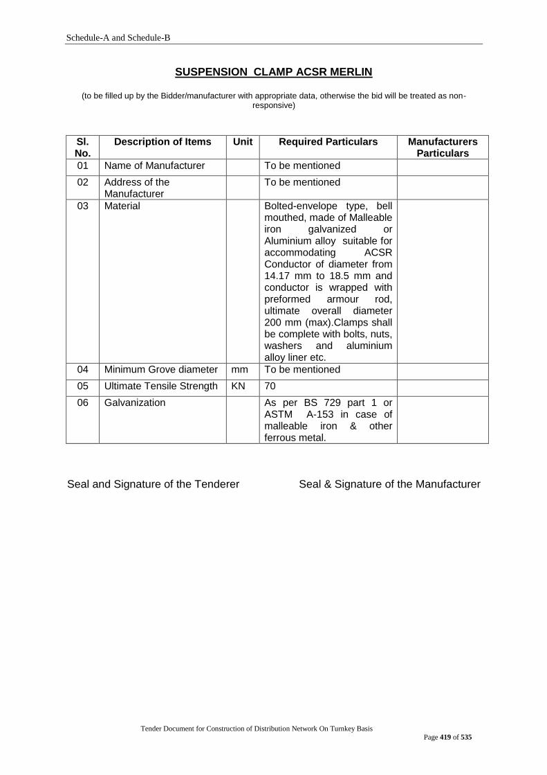
Schedule-A and Schedule-B
Tender Document for Construction of Distribution Network On Turnkey Basis
Page 419 of 535
SUSPENSION CLAMP ACSR MERLIN
(to be filled up by the Bidder/manufacturer with appropriate data, otherwise the bid will be treated as non-responsive)
Sl. No.
Description of Items Unit Required Particulars Manufacturers Particulars
01 Name of Manufacturer To be mentioned
02 Address of the Manufacturer
To be mentioned
03 Material Bolted-envelope type, bell mouthed, made of Malleable iron galvanized or Aluminium alloy suitable for accommodating ACSR Conductor of diameter from 14.17 mm to 18.5 mm and conductor is wrapped with preformed armour rod, ultimate overall diameter 200 mm (max).Clamps shall be complete with bolts, nuts, washers and aluminium alloy liner etc.
04 Minimum Grove diameter mm To be mentioned
05 Ultimate Tensile Strength KN 70
06 Galvanization As per BS 729 part 1 or ASTM A-153 in case of malleable iron & other ferrous metal.
Seal and Signature of the Tenderer Seal & Signature of the Manufacturer

Schedule-A and Schedule-B
Tender Document for Construction of Distribution Network On Turnkey Basis
Page 420 of 535
SIDE LOCKTIE MERLIN (to be filled up by the bidder/manufacturer with appropriate data, otherwise the bid will be treated as non-responsive)
Sl. No.
Description of Items
Unit Required Particulars Manufacturers Particulars
1 Manufacturer Name & address
To be mentioned
2 Materials
Mild Steel
3 Standard Hot Dip Galvanized as per BS 729
4 Ultimate Tensile Strength
kg 1680
5 Dimension mm As per attached drawing
Seal and Signature of the Tenderer Seal & Signature of the Manufacturer
TERMINAL CLAMP MERLIN
(to be filled up by the bidder/manufacturer with appropriate data, otherwise the bid will be treated as non-responsive)
Sl. No.
Description Unit Required data Manufacturers Particulars
i. Name of the manufacturer - To be mentioned
ii. Address of the manufacturer - To be mentioned
iii. Material - Mild Steel
iv. Standard - BS 729
v. Ultimate Tensile Strength KN 63
vi. Angle Size mm To be mentioned
vii. Dimension mm To be mentioned
viii. Galvanization - Hot dip galvanized after
fabrication
Shall be as per BS 729 Part
1
ix. Application - Suitable for MERLIN conductor
x. Accessories to be supplied (The item shall be a complete set)
- To be mentioned
Seal and Signature of the Tenderer Seal & Signature of the Manufacturer
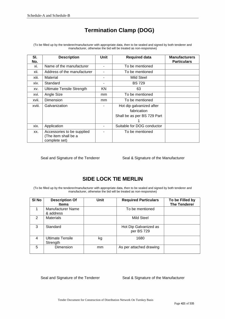
Schedule-A and Schedule-B
Tender Document for Construction of Distribution Network On Turnkey Basis
Page 421 of 535
Termination Clamp (DOG)
(To be filled up by the tenderer/manufacturer with appropriate data, then to be sealed and signed by both tenderer and manufacturer, otherwise the bid will be treated as non-responsive)
Sl. No.
Description Unit Required data Manufacturers Particulars
xi. Name of the manufacturer - To be mentioned
xii. Address of the manufacturer - To be mentioned
xiii. Material - Mild Steel
xiv. Standard - BS 729
xv. Ultimate Tensile Strength KN 63
xvi. Angle Size mm To be mentioned
xvii. Dimension mm To be mentioned
xviii. Galvanization - Hot dip galvanized after
fabrication
Shall be as per BS 729 Part
1
xix. Application - Suitable for DOG conductor
xx. Accessories to be supplied (The item shall be a complete set)
- To be mentioned
Seal and Signature of the Tenderer Seal & Signature of the Manufacturer
SIDE LOCK TIE MERLIN
(To be filled up by the tenderer/manufacturer with appropriate data, then to be sealed and signed by both tenderer and manufacturer, otherwise the bid will be treated as non-responsive)
Sl No Description Of Items
Unit Required Particulars To be Filled by The Tenderer
1 Manufacturer Name & address
To be mentioned
2 Materials
Mild Steel
3 Standard Hot Dip Galvanized as per BS 729
4 Ultimate Tensile Strength
kg 1680
5 Dimension mm As per attached drawing
Seal and Signature of the Tenderer Seal & Signature of the Manufacturer
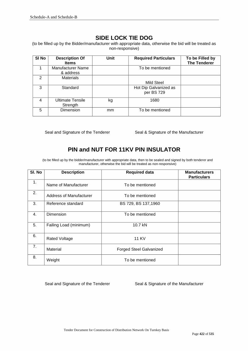
Schedule-A and Schedule-B
Tender Document for Construction of Distribution Network On Turnkey Basis
Page 422 of 535
SIDE LOCK TIE DOG (to be filled up by the Bidder/manufacturer with appropriate data, otherwise the bid will be treated as
non-responsive)
Sl No Description Of Items
Unit Required Particulars To be Filled by The Tenderer
1 Manufacturer Name & address
To be mentioned
2 Materials
Mild Steel
3 Standard Hot Dip Galvanized as per BS 729
4 Ultimate Tensile Strength
kg 1680
5 Dimension mm To be mentioned
Seal and Signature of the Tenderer Seal & Signature of the Manufacturer
PIN and NUT FOR 11KV PIN INSULATOR
(to be filled up by the bidder/manufacturer with appropriate data, then to be sealed and signed by both tenderer and manufacturer, otherwise the bid will be treated as non-responsive)
Sl. No Description Required data Manufacturers Particulars
1. Name of Manufacturer To be mentioned
2. Address of Manufacturer To be mentioned
3. Reference standard BS 729, BS 137,1960
4. Dimension To be mentioned
5. Failing Load (minimum) 10.7 kN
6. Rated Voltage 11 KV
7. Material Forged Steel Galvanized
8. Weight To be mentioned
Seal and Signature of the Tenderer Seal & Signature of the Manufacturer
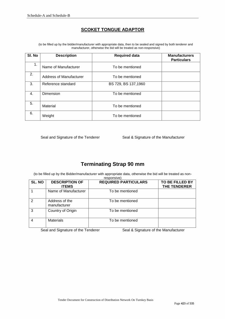
Schedule-A and Schedule-B
Tender Document for Construction of Distribution Network On Turnkey Basis
Page 423 of 535
SCOKET TONGUE ADAPTOR
(to be filled up by the bidder/manufacturer with appropriate data, then to be sealed and signed by both tenderer and manufacturer, otherwise the bid will be treated as non-responsive)
Sl. No Description Required data Manufacturers Particulars
1. Name of Manufacturer To be mentioned
2. Address of Manufacturer To be mentioned
3. Reference standard BS 729, BS 137,1960
4. Dimension To be mentioned
5. Material To be mentioned
6. Weight To be mentioned
Seal and Signature of the Tenderer Seal & Signature of the Manufacturer
Terminating Strap 90 mm
(to be filled up by the Bidder/manufacturer with appropriate data, otherwise the bid will be treated as non-responsive)
SL. NO DESCRIPTION OF ITEMS
REQUIRED PARTICULARS TO BE FILLED BY THE TENDERER
1 Name of Manufacturer To be mentioned
2 Address of the manufacturer
To be mentioned
3 Country of Origin To be mentioned
4 Materials To be mentioned
Seal and Signature of the Tenderer Seal & Signature of the Manufacturer
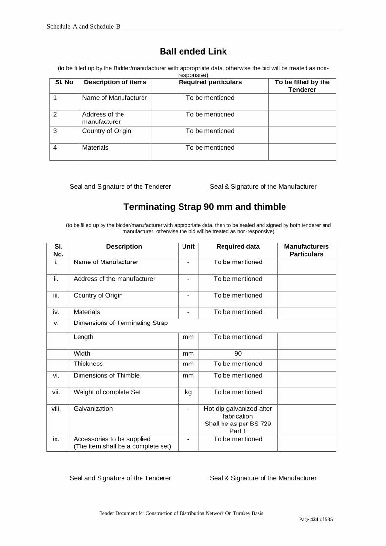
Schedule-A and Schedule-B
Tender Document for Construction of Distribution Network On Turnkey Basis
Page 424 of 535
Ball ended Link
(to be filled up by the Bidder/manufacturer with appropriate data, otherwise the bid will be treated as non-responsive)
Sl. No Description of items Required particulars To be filled by the Tenderer
1 Name of Manufacturer To be mentioned
2 Address of the manufacturer
To be mentioned
3 Country of Origin To be mentioned
4 Materials To be mentioned
Seal and Signature of the Tenderer Seal & Signature of the Manufacturer
Terminating Strap 90 mm and thimble
(to be filled up by the bidder/manufacturer with appropriate data, then to be sealed and signed by both tenderer and
manufacturer, otherwise the bid will be treated as non-responsive)
Sl. No.
Description Unit Required data Manufacturers Particulars
i. Name of Manufacturer - To be mentioned
ii. Address of the manufacturer - To be mentioned
iii. Country of Origin - To be mentioned
iv. Materials - To be mentioned
v. Dimensions of Terminating Strap
Length mm To be mentioned
Width mm 90
Thickness mm To be mentioned
vi. Dimensions of Thimble mm To be mentioned
vii. Weight of complete Set kg To be mentioned
viii. Galvanization - Hot dip galvanized after fabrication
Shall be as per BS 729 Part 1
ix. Accessories to be supplied (The item shall be a complete set)
- To be mentioned
Seal and Signature of the Tenderer Seal & Signature of the Manufacturer
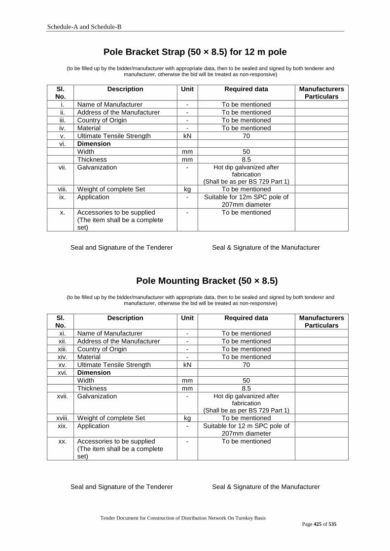
Schedule-A and Schedule-B
Tender Document for Construction of Distribution Network On Turnkey Basis
Page 425 of 535
Pole Bracket Strap (50 × 8.5) for 12 m pole
(to be filled up by the bidder/manufacturer with appropriate data, then to be sealed and signed by both tenderer and manufacturer, otherwise the bid will be treated as non-responsive)
Sl. No.
Description Unit Required data Manufacturers Particulars
i. Name of Manufacturer - To be mentioned
ii. Address of the Manufacturer - To be mentioned
iii. Country of Origin - To be mentioned
iv. Material - To be mentioned
v. Ultimate Tensile Strength kN 70
vi. Dimension
Width mm 50
Thickness mm 8.5
vii. Galvanization - Hot dip galvanized after fabrication
(Shall be as per BS 729 Part 1)
viii. Weight of complete Set kg To be mentioned
ix. Application - Suitable for 12m SPC pole of 207mm diameter
x. Accessories to be supplied (The item shall be a complete set)
- To be mentioned
Seal and Signature of the Tenderer Seal & Signature of the Manufacturer
Pole Mounting Bracket (50 × 8.5)
(to be filled up by the bidder/manufacturer with appropriate data, then to be sealed and signed by both tenderer and manufacturer, otherwise the bid will be treated as non-responsive)
Sl. No.
Description Unit Required data Manufacturers Particulars
xi. Name of Manufacturer - To be mentioned
xii. Address of the Manufacturer - To be mentioned
xiii. Country of Origin - To be mentioned
xiv. Material - To be mentioned
xv. Ultimate Tensile Strength kN 70
xvi. Dimension
Width mm 50
Thickness mm 8.5
xvii. Galvanization - Hot dip galvanized after fabrication
(Shall be as per BS 729 Part 1)
xviii. Weight of complete Set kg To be mentioned
xix. Application - Suitable for 12 m SPC pole of 207mm diameter
xx. Accessories to be supplied (The item shall be a complete set)
- To be mentioned
Seal and Signature of the Tenderer Seal & Signature of the Manufacturer

Schedule-A and Schedule-B
Tender Document for Construction of Distribution Network On Turnkey Basis
Page 426 of 535
Pole Mounting Bracket (40 × 8.5) (to be filled up by the bidder/manufacturer with appropriate data, then to be sealed and signed by both tenderer and
manufacturer, otherwise the bid will be treated as non-responsive)
Sl. No. Description Unit Required data Manufacturers Particulars
i. Name of Manufacturer - To be mentioned
ii. Address of the Manufacturer
- To be mentioned
iii. Country of Origin - To be mentioned
iv. Material - To be mentioned
v. Ultimate Tensile Strength
kN 70
vi. Dimension
Width mm 40
Thickness mm 8.5
vii. Galvanization - Hot dip galvanized after fabrication
(Shall be as per BS 729 Part 1)
viii. Weight of complete Set kg To be mentioned
ix. Application - Suitable for 12 m SPC pole of 207mm diameter
x. Accessories to be supplied (The item shall be a complete set)
- To be mentioned
Seal and Signature of the Tenderer Seal & Signature of the Manufacturer
Pole Bracket Strap (40 × 8.5) for 12 m Pole LT rack
(to be filled up by the bidder/manufacturer with appropriate data, then to be sealed and signed by both tenderer and
manufacturer, otherwise the bid will be treated as non-responsive)
Sl. No.
Description Unit Required data Manufacturers Particulars
i. Name of Manufacturer - To be mentioned
ii. Address of the Manufacturer - To be mentioned
iii. Country of Origin - To be mentioned
iv. Material - To be mentioned
v. Ultimate Tensile Strength kN 70
vi. Dimension
Width mm 40
Thickness mm 8.5
vii. Galvanization - Hot dip galvanized after fabrication
(Shall be as per BS 729 Part 1)
viii. Weight of complete Set kg To be mentioned
ix. Application - Suitable for LT rack of 12m SPC pole of 207mm diameter
x. Accessories to be supplied (The item shall be a complete set)
- To be mentioned
Seal and Signature of the Tenderer Seal & Signature of the Manufacturer
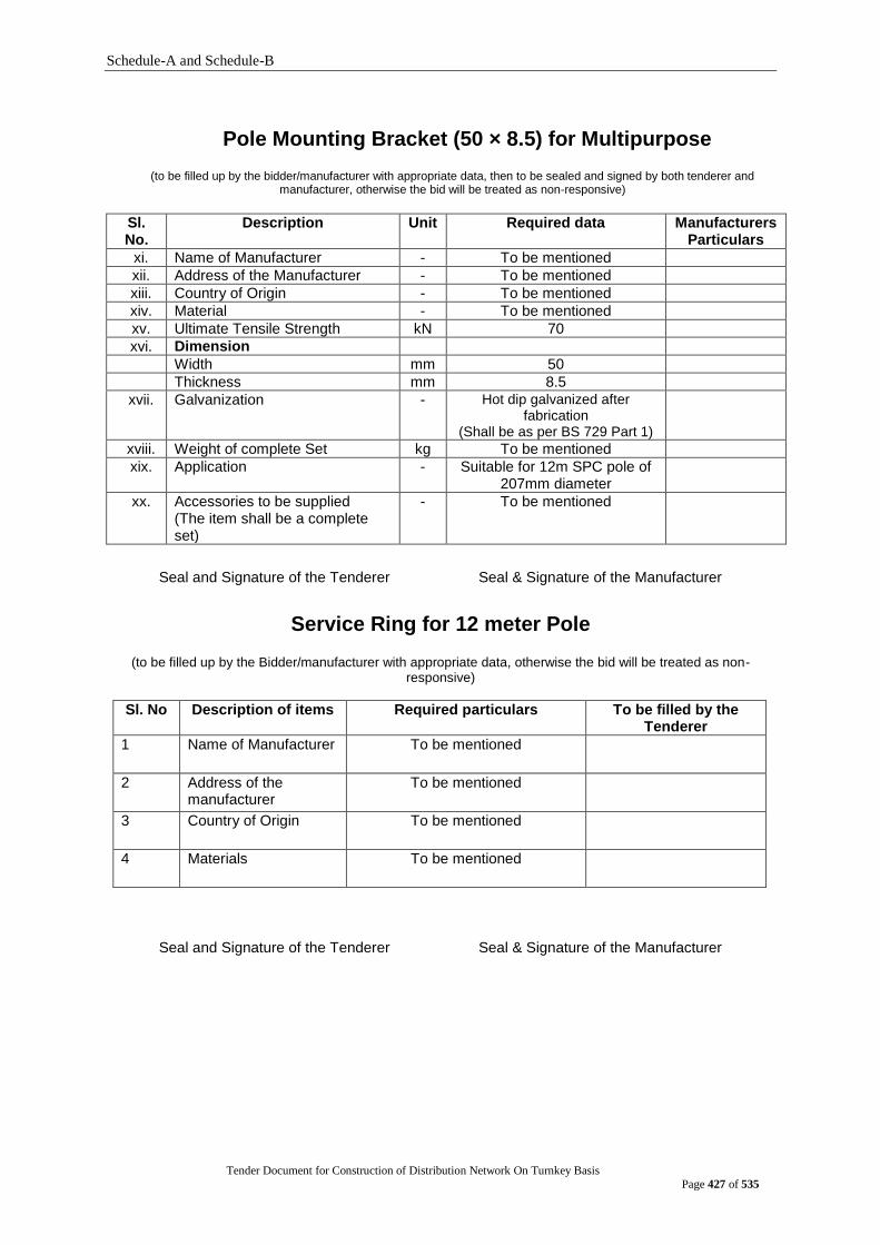
Schedule-A and Schedule-B
Tender Document for Construction of Distribution Network On Turnkey Basis
Page 427 of 535
Pole Mounting Bracket (50 × 8.5) for Multipurpose
(to be filled up by the bidder/manufacturer with appropriate data, then to be sealed and signed by both tenderer and manufacturer, otherwise the bid will be treated as non-responsive)
Sl. No.
Description Unit Required data Manufacturers Particulars
xi. Name of Manufacturer - To be mentioned
xii. Address of the Manufacturer - To be mentioned
xiii. Country of Origin - To be mentioned
xiv. Material - To be mentioned
xv. Ultimate Tensile Strength kN 70
xvi. Dimension
Width mm 50
Thickness mm 8.5
xvii. Galvanization - Hot dip galvanized after fabrication
(Shall be as per BS 729 Part 1)
xviii. Weight of complete Set kg To be mentioned
xix. Application - Suitable for 12m SPC pole of 207mm diameter
xx. Accessories to be supplied (The item shall be a complete set)
- To be mentioned
Seal and Signature of the Tenderer Seal & Signature of the Manufacturer
Service Ring for 12 meter Pole
(to be filled up by the Bidder/manufacturer with appropriate data, otherwise the bid will be treated as non-
responsive)
Sl. No Description of items Required particulars To be filled by the Tenderer
1 Name of Manufacturer To be mentioned
2 Address of the manufacturer
To be mentioned
3 Country of Origin To be mentioned
4 Materials To be mentioned
Seal and Signature of the Tenderer Seal & Signature of the Manufacturer

Schedule-A and Schedule-B
Tender Document for Construction of Distribution Network On Turnkey Basis
Page 428 of 535
Eye Nut with thimble
(to be filled up by the Bidder/manufacturer with appropriate data, otherwise the bid will be treated as non-responsive)
Sl. No Description of items Required particulars To be filled by the Tenderer
1 Name of Manufacturer To be mentioned
2 Address of the manufacturer
To be mentioned
3 Country of Origin To be mentioned
4 Materials To be mentioned
Seal and Signature of the Tenderer Seal & Signature of the Manufacturer
Stay Rod and turn Buckle
(to be filled up by the Bidder/manufacturer with appropriate data, otherwise the bid will be treated as non-responsive)
Sl. No Description of items Required particulars To be filled by the Tenderer
1 Name of Manufacturer To be mentioned
2 Address of the manufacturer
To be mentioned
3 Country of Origin To be mentioned
4 Materials To be mentioned
Seal and Signature of the Tenderer Seal & Signature of the Manufacturer
Stainless steel binding tape 12.5 mm
(to be filled up by the Bidder/manufacturer with appropriate data, otherwise the bid will be treated as non-responsive)
Sl. No Description of items Required particulars To be filled by the Tenderer
1 Name of Manufacturer To be mentioned
2 Address of the manufacturer
To be mentioned
3 Country of Origin To be mentioned
4 Materials To be mentioned
Seal and Signature of the Tenderer Seal & Signature of the Manufacturer
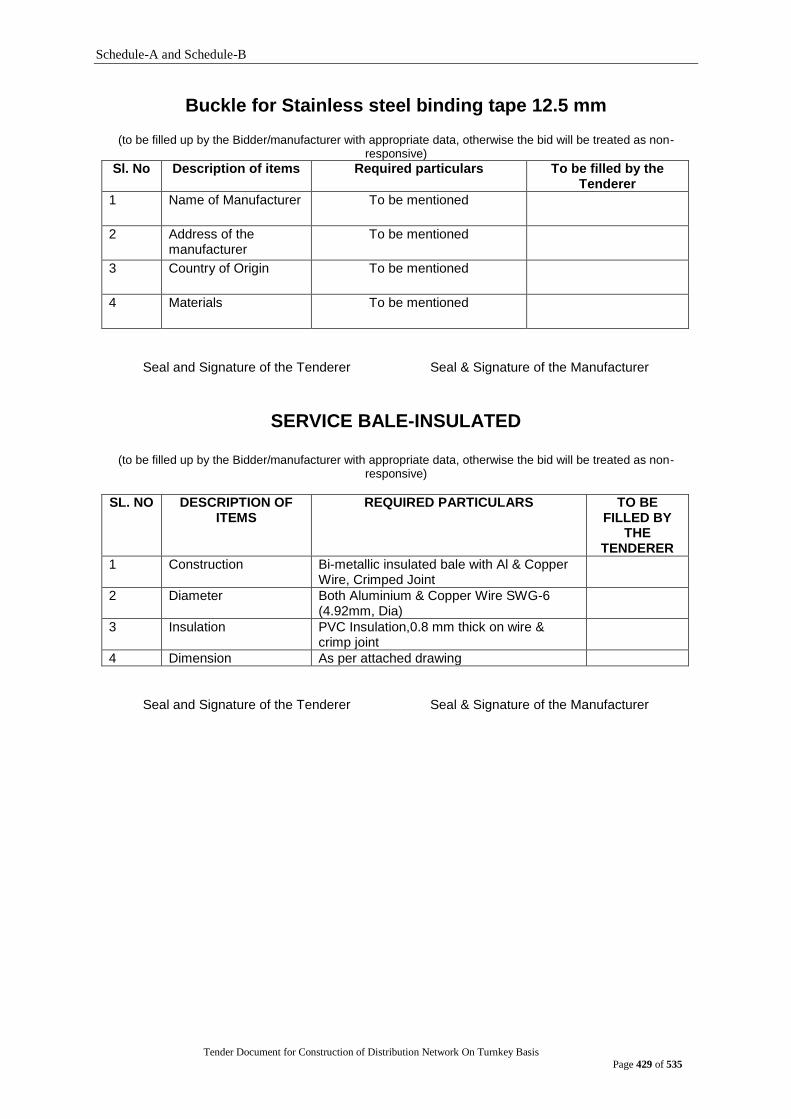
Schedule-A and Schedule-B
Tender Document for Construction of Distribution Network On Turnkey Basis
Page 429 of 535
Buckle for Stainless steel binding tape 12.5 mm
(to be filled up by the Bidder/manufacturer with appropriate data, otherwise the bid will be treated as non-responsive)
Sl. No Description of items Required particulars To be filled by the Tenderer
1 Name of Manufacturer To be mentioned
2 Address of the manufacturer
To be mentioned
3 Country of Origin To be mentioned
4 Materials To be mentioned
Seal and Signature of the Tenderer Seal & Signature of the Manufacturer
SERVICE BALE-INSULATED
(to be filled up by the Bidder/manufacturer with appropriate data, otherwise the bid will be treated as non-responsive)
SL. NO DESCRIPTION OF ITEMS
REQUIRED PARTICULARS TO BE FILLED BY
THE TENDERER
1 Construction Bi-metallic insulated bale with Al & Copper Wire, Crimped Joint
2 Diameter Both Aluminium & Copper Wire SWG-6 (4.92mm, Dia)
3 Insulation PVC Insulation,0.8 mm thick on wire & crimp joint
4 Dimension As per attached drawing
Seal and Signature of the Tenderer Seal & Signature of the Manufacturer
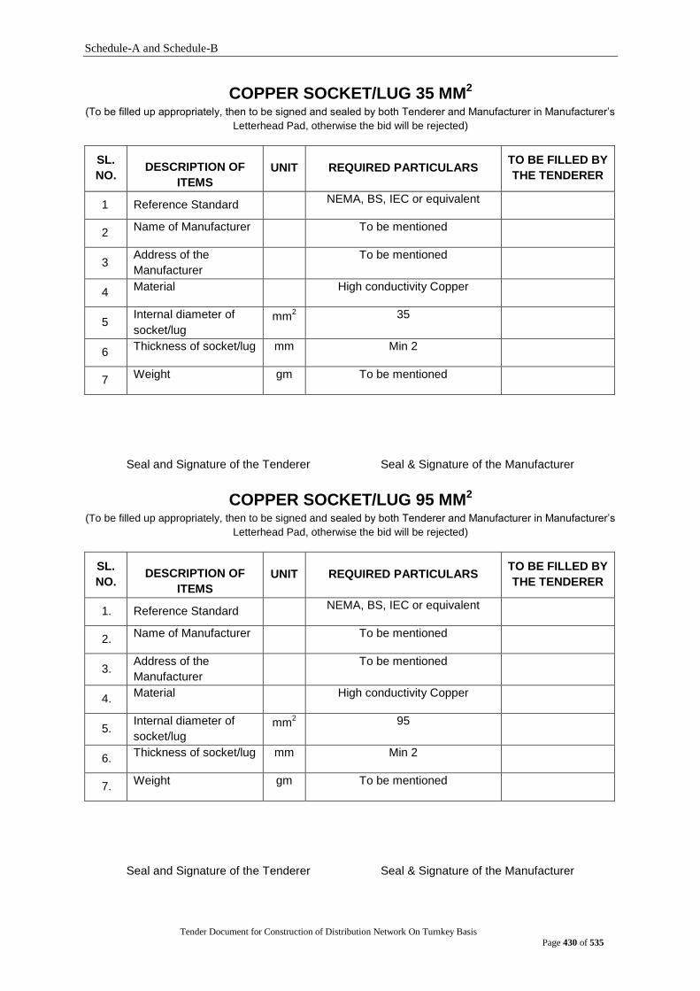
Schedule-A and Schedule-B
Tender Document for Construction of Distribution Network On Turnkey Basis
Page 430 of 535
COPPER SOCKET/LUG 35 MM2 (To be filled up appropriately, then to be signed and sealed by both Tenderer and Manufacturer in Manufacturer‟s
Letterhead Pad, otherwise the bid will be rejected)
SL.
NO. DESCRIPTION OF
ITEMS
UNIT REQUIRED PARTICULARS TO BE FILLED BY
THE TENDERER
1 Reference Standard NEMA, BS, IEC or equivalent
2 Name of Manufacturer To be mentioned
3 Address of the
Manufacturer To be mentioned
4 Material High conductivity Copper
5 Internal diameter of
socket/lug mm
2 35
6 Thickness of socket/lug mm Min 2
7 Weight gm To be mentioned
Seal and Signature of the Tenderer Seal & Signature of the Manufacturer
COPPER SOCKET/LUG 95 MM2 (To be filled up appropriately, then to be signed and sealed by both Tenderer and Manufacturer in Manufacturer‟s
Letterhead Pad, otherwise the bid will be rejected)
SL.
NO. DESCRIPTION OF
ITEMS
UNIT REQUIRED PARTICULARS TO BE FILLED BY
THE TENDERER
1. Reference Standard NEMA, BS, IEC or equivalent
2. Name of Manufacturer To be mentioned
3. Address of the
Manufacturer To be mentioned
4. Material High conductivity Copper
5. Internal diameter of
socket/lug mm
2 95
6. Thickness of socket/lug mm Min 2
7. Weight gm To be mentioned
Seal and Signature of the Tenderer Seal & Signature of the Manufacturer

Schedule-A and Schedule-B
Tender Document for Construction of Distribution Network On Turnkey Basis
Page 431 of 535
Al SOCKET/LUG 25 MM2 (To be filled up appropriately, then to be signed and sealed by both Tenderer and Manufacturer in Manufacturer‟s
Letterhead Pad, otherwise the bid will be rejected)
SL.
NO. DESCRIPTION OF
ITEMS
UNIT REQUIRED PARTICULARS TO BE FILLED BY
THE TENDERER
1. Reference Standard NEMA, BS, IEC or equivalent
2. Name of Manufacturer To be mentioned
3. Address of the
Manufacturer To be mentioned
4. Material High conductivity Al
5. Internal diameter of
socket/lug mm
2 25
6. Thickness of socket/lug mm Min 2
7. Weight gm To be mentioned
Seal and Signature of the Tenderer Seal & Signature of the Manufacturer
COPPER SOCKET/LUG 120 MM2 (To be filled up appropriately, then to be signed and sealed by both Tenderer and Manufacturer in Manufacturer‟s
Letterhead Pad, otherwise the bid will be rejected)
SL.
NO. DESCRIPTION OF
ITEMS
UNIT REQUIRED PARTICULARS TO BE FILLED BY
THE TENDERER
1. Reference Standard NEMA, BS, IEC or equivalent
2. Name of Manufacturer To be mentioned
3. Address of the
Manufacturer To be mentioned
4. Material High conductivity Al
5. Internal diameter of
socket/lug mm
2 120
6. Thickness of socket/lug mm Min 2
7. Weight gm To be mentioned
Seal and Signature of the Tenderer Seal & Signature of the Manufacturer
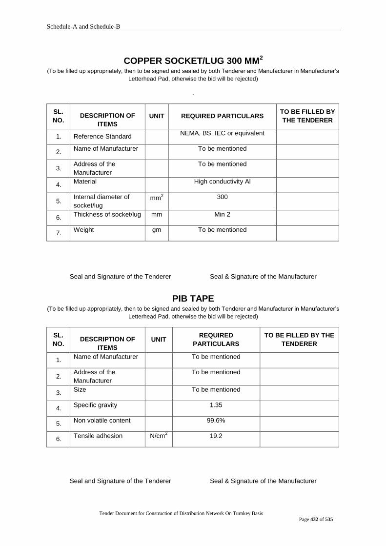
Schedule-A and Schedule-B
Tender Document for Construction of Distribution Network On Turnkey Basis
Page 432 of 535
COPPER SOCKET/LUG 300 MM2 (To be filled up appropriately, then to be signed and sealed by both Tenderer and Manufacturer in Manufacturer‟s
Letterhead Pad, otherwise the bid will be rejected)
.
SL.
NO. DESCRIPTION OF
ITEMS
UNIT REQUIRED PARTICULARS TO BE FILLED BY
THE TENDERER
1. Reference Standard NEMA, BS, IEC or equivalent
2. Name of Manufacturer To be mentioned
3. Address of the
Manufacturer To be mentioned
4. Material High conductivity Al
5. Internal diameter of
socket/lug mm
2 300
6. Thickness of socket/lug mm Min 2
7. Weight gm To be mentioned
Seal and Signature of the Tenderer Seal & Signature of the Manufacturer
PIB TAPE (To be filled up appropriately, then to be signed and sealed by both Tenderer and Manufacturer in Manufacturer‟s
Letterhead Pad, otherwise the bid will be rejected)
SL.
NO. DESCRIPTION OF
ITEMS
UNIT REQUIRED
PARTICULARS
TO BE FILLED BY THE
TENDERER
1. Name of Manufacturer To be mentioned
2. Address of the
Manufacturer To be mentioned
3. Size To be mentioned
4. Specific gravity 1.35
5. Non volatile content 99.6%
6. Tensile adhesion N/cm
2 19.2
Seal and Signature of the Tenderer Seal & Signature of the Manufacturer
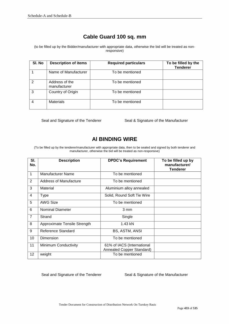
Schedule-A and Schedule-B
Tender Document for Construction of Distribution Network On Turnkey Basis
Page 433 of 535
Cable Guard 100 sq. mm
(to be filled up by the Bidder/manufacturer with appropriate data, otherwise the bid will be treated as non-
responsive)
Sl. No Description of items Required particulars To be filled by the Tenderer
1 Name of Manufacturer To be mentioned
2 Address of the manufacturer
To be mentioned
3 Country of Origin To be mentioned
4 Materials To be mentioned
Seal and Signature of the Tenderer Seal & Signature of the Manufacturer
Al BINDING WIRE
(To be filled up by the tenderer/manufacturer with appropriate data, then to be sealed and signed by both tenderer and manufacturer, otherwise the bid will be treated as non-responsive)
Sl. No.
Description DPDC‟s Requirement To be filled up by manufacturer/
Tenderer
1 Manufacturer Name To be mentioned
2 Address of Manufacture To be mentioned
3 Material Aluminium alloy annealed
4 Type Solid, Round Soft Tie Wire
5 AWG Size To be mentioned
6 Nominal Diameter 3 mm
7 Strand Single
8 Approximate Tensile Strength 1.43 kN
9 Reference Standard BS, ASTM, ANSI
10 Dimension To be mentioned
11 Minimum Conductivity 61% of IACS (International Annealed Copper Standard)
12 weight To be mentioned
Seal and Signature of the Tenderer Seal & Signature of the Manufacturer
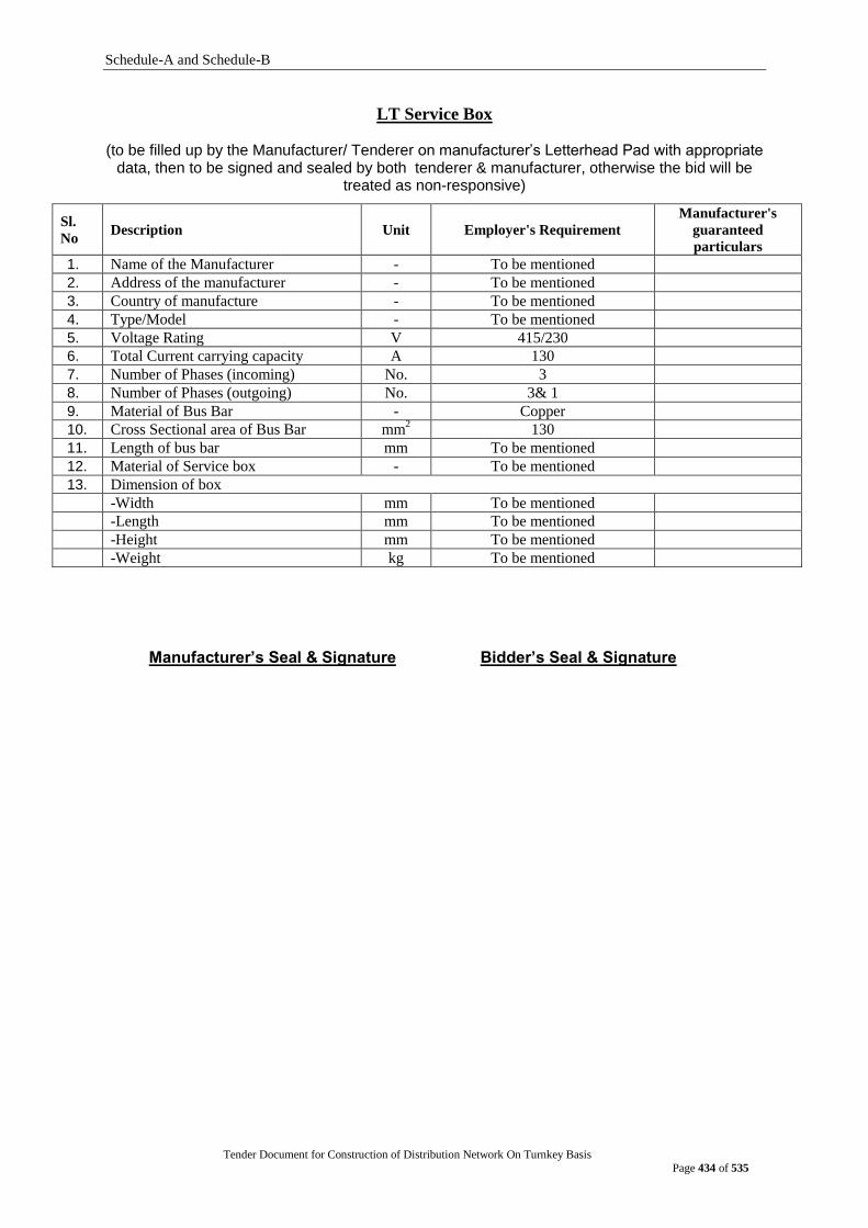
Schedule-A and Schedule-B
Tender Document for Construction of Distribution Network On Turnkey Basis
Page 434 of 535
LT Service Box
(to be filled up by the Manufacturer/ Tenderer on manufacturer‟s Letterhead Pad with appropriate data, then to be signed and sealed by both tenderer & manufacturer, otherwise the bid will be
treated as non-responsive)
Sl.
No Description Unit Employer's Requirement
Manufacturer's
guaranteed
particulars
1. Name of the Manufacturer - To be mentioned
2. Address of the manufacturer - To be mentioned
3. Country of manufacture - To be mentioned
4. Type/Model - To be mentioned
5. Voltage Rating V 415/230
6. Total Current carrying capacity A 130
7. Number of Phases (incoming) No. 3
8. Number of Phases (outgoing) No. 3& 1
9. Material of Bus Bar - Copper
10. Cross Sectional area of Bus Bar mm2 130
11. Length of bus bar mm To be mentioned
12. Material of Service box - To be mentioned
13. Dimension of box
-Width mm To be mentioned
-Length mm To be mentioned
-Height mm To be mentioned
-Weight kg To be mentioned
Manufacturer‟s Seal & Signature Bidder‟s Seal & Signature
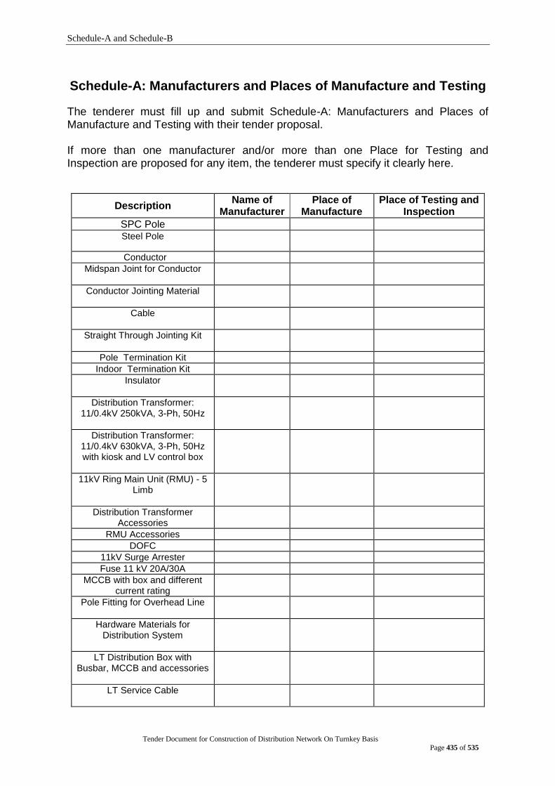
Schedule-A and Schedule-B
Tender Document for Construction of Distribution Network On Turnkey Basis
Page 435 of 535
Schedule-A: Manufacturers and Places of Manufacture and Testing
The tenderer must fill up and submit Schedule-A: Manufacturers and Places of Manufacture and Testing with their tender proposal. If more than one manufacturer and/or more than one Place for Testing and Inspection are proposed for any item, the tenderer must specify it clearly here.
Description Name of
Manufacturer Place of
Manufacture Place of Testing and
Inspection
SPC Pole
Steel Pole
Conductor
Midspan Joint for Conductor
Conductor Jointing Material
Cable
Straight Through Jointing Kit
Pole Termination Kit
Indoor Termination Kit
Insulator
Distribution Transformer: 11/0.4kV 250kVA, 3-Ph, 50Hz
Distribution Transformer: 11/0.4kV 630kVA, 3-Ph, 50Hz with kiosk and LV control box
11kV Ring Main Unit (RMU) - 5 Limb
Distribution Transformer Accessories
RMU Accessories
DOFC
11kV Surge Arrester
Fuse 11 kV 20A/30A
MCCB with box and different current rating
Pole Fitting for Overhead Line
Hardware Materials for Distribution System
LT Distribution Box with Busbar, MCCB and accessories
LT Service Cable
Schedule-A and Schedule-B
Tender Document for Construction of Distribution Network On Turnkey Basis
Page 436 of 535
Schedule- B: Drawings and Documents to be submitted with Tender
POLE (SPC/STEEL)
12 METER (450 daN) & 15 METER (550 daN) SPC POLE
Bidder shall provide the followings additional documents along with their bid:
i) Outline dimension & drawings along with pole earthing system
ii) All data schedules (Guaranteed Technical Particulars) to be filled up with appropriate technical data.
iii) Detailed design calculations
iv)
Type Test report of same or higher size SPC pole with same or higher daN. Type test shall be done at any Independent testing laboratory. Manufacturer‟s Laboratories Type Test Report will be acceptable, if it has ISO 9001 or its equivalent certification from the competent authority, and if such tests are witnessed by an independent inspector;
v) Valid ISO 9001 certificate of manufacturer
vi) Manufacturer‟s Authorization letter
vii) Supply record of last 5 years
viii) Necessary documents to establish the eligibility of the manufacturer as mentioned in Section 2: qualification criteria
ix) Manufacturer‟s Printed Catalogues If more than one manufacturer is proposed, the bidder must provide the above documents for each manufacturer.
12 METER STEEL POLE (350 daN)
Bidder shall provide the followings additional documents along with their bid:
i) Outline dimension & drawings along with pole earthing system
ii) All data schedules (Guaranteed Technical Particulars) to be filled up with appropriate technical data.
iii) Detailed design calculations
iv)
Type Test report of same or higher size Octagonal steel pole with same or higher daN. Type test shall be done at any Independent testing laboratory. Manufacturer‟s Laboratories Type Test Report will be acceptable, if it has ISO 9001 or its equivalent certification from the competent authority, and if such tests are witnessed by an independent inspector;
v) Valid ISO 9001 certificate of manufacturer
vi) Manufacturer‟s Authorization letter
vii) Supply record of last 5 years
viii) Necessary documents to establish the eligibility of the manufacturer as mentioned in Section 2: qualification criteria
ix) Manufacturer‟s Printed Catalogues
If more than one manufacturer is proposed, the bidder must provide the above documents for each manufacturer.

Schedule-A and Schedule-B
Tender Document for Construction of Distribution Network On Turnkey Basis
Page 437 of 535
Schedule-A and Schedule-B
Tender Document for Construction of Distribution Network On Turnkey Basis
Page 438 of 535
12 M TRANSFORMER POLE (STEEL) WITH RCC BASE FOUNDATION
Bidder shall provide the followings additional documents along with their bid:
i) Outline dimension & drawings along with pole earthing system
ii) All data schedules (Guaranteed Technical Particulars) to be filled up with appropriate technical data.
iii) Detailed design calculations
iv)
Type Test report of same or higher size transformer pole (steel) with same or higher daN. Type test shall be done at any Independent testing laboratory. Manufacturer‟s Laboratories Type Test Report will be acceptable, if it has ISO 9001 or its equivalent certification from the competent authority, and if such tests are witnessed by an independent inspector;
v) Valid ISO 9001 certificate of manufacturer
vi) Manufacturer‟s Authorization letter
vii) Supply record of last 5 years
viii) Necessary documents to establish the eligibility of the manufacturer as mentioned in Section 2: qualification criteria
ix) Manufacturer‟s Printed Catalogues
If more than one manufacturer is proposed, the bidder must provide the above documents for each manufacturer.
ACSR and AAC CONDUCTOR
Documentation for Conductor:
Bidder shall provide the followings additional documents along with their bid:
i) Outline dimension & drawings of each AAC and ACSR conductor
ii) All data schedules (Guaranteed Technical Particulars) to be filled up with
appropriate technical data.
iii) Manufacturer‟s Printed Catalogues
iv)
Type Test Reports on offered ACSR and AAC Conductors. Test Report on higher
sized ACSR and AAC Conductors will also be acceptable. Type test shall be done at
any Independent testing laboratory. Manufacturer‟s Laboratories Type Test Report
will be acceptable, if it has ISO 9001 or its equivalent certification from the
competent authority, and if such tests are witnessed by an independent inspector;
v) Valid ISO 9001 certificate of manufacturer
vi) Manufacturer‟s Authorization letter
vii) Supply record of last 5 years
viii) Necessary documents to establish the eligibility of the manufacturer as mentioned in
Section 2: qualification criteria
Schedule-A and Schedule-B
Tender Document for Construction of Distribution Network On Turnkey Basis
Page 439 of 535
11 KV and 0.415 KV CABLE
Documentation for cable:
Bidder shall provide the followings additional documents along with their bid:
i) Outline dimension & drawings of each cable (11 kV 3x300 sq.mm XLPE, 11 KV 3x
120 sq. mm XLPE, 11 kV 3x95 sq. mm XLPE, 0.415 KV 4x 185 sq. mm PVC, LT
service cable)
ii) All data schedules (Guaranteed Technical Particulars) to be filled up with
appropriate technical data.
iii) Manufacturer‟s Printed Catalogues
iv)
Type Test Reports on offered 11 kV Cables (11 kV 3x300 sq.mm XLPE, 11 KV 3x
120 sq. mm XLPE, 11 kV 3x95 sq. mm XLPE) and 0.415 kV cables (0.415 KV 4x
185 sq. mm PVC, LT service cable). Test Report on higher sized but of same type
11 kV Cables and 0.415 KV cables will also be acceptable. Type test shall be done
at any Independent testing laboratory. Manufacturer‟s Laboratories Type Test
Report will be acceptable, if it has ISO 9001 or its equivalent certification from the
competent authority, and if such tests are witnessed by an independent inspector;
v) Valid ISO 9001 certificate of manufacturer
vi) Manufacturer‟s Authorization letter
vii) Supply record of last 5 years
viii) Necessary documents to establish the eligibility of the manufacturer as mentioned in
Section 2: qualification criteria
ix) Detail short circuit withstand capacity of metallic sheath as per requirement.
MIDSPAN JOINT FOR ACSR and AAC CONDUCTOR
Bidder shall provide the followings additional documents along with their bid:
i) Outline dimension & drawings of each ACSR and AAC midspan joint for conductor
ii) All data schedules (Guaranteed Technical Particulars) to be filled up with appropriate technical data.
iii) Manufacturer‟s Printed Catalogues
iv)
Test report from any Independent testing laboratory. Manufacturer‟s Laboratories Type Test Report will be acceptable, if it has ISO 9000 or its equivalent certification from the competent authority, and if such tests are witnessed by an independent inspector;
v) Valid ISO 9001 certificate of manufacturer
vi) Manufacturer‟s Authorization letter
vii) Supply record of last 5 years
viii) Necessary documents to establish the eligibility of the manufacturer as mentioned in Section 2: qualification criteria

Schedule-A and Schedule-B
Tender Document for Construction of Distribution Network On Turnkey Basis
Page 440 of 535
CABLE JOINTING MATERIALS
Bidder shall provide the followings additional documents along with their bid:
i) Outline dimension & drawings of each cable jointing material
ii) All data schedules (Guaranteed Technical Particulars) to be filled up with appropriate technical data.
iii) Manufacturer‟s Printed Catalogues
iv)
Test report from any Independent testing laboratory. Manufacturer‟s Laboratories Type Test Report will be acceptable, if it has ISO 9000 or its equivalent certification from the competent authority, and if such tests are witnessed by an independent inspector;
v) Valid ISO 9001 certificate of manufacturer
vi) Manufacturer‟s Authorization letter
vii) Supply record of last 5 years
viii) Necessary documents to establish the eligibility of the manufacturer as mentioned in Section 2: qualification criteria
INSULATOR
Bidder shall provide the followings additional documents along with their bid:
i) Outline dimension & drawings of each type of insulator
ii) All data schedules (Guaranteed Technical Particulars) to be filled up with appropriate technical data.
iii) Manufacturer‟s Printed Catalogues
iv)
Test report from any Independent testing laboratory. Manufacturer‟s Laboratories Type Test Report will be acceptable, if it has ISO 9000 or its equivalent certification from the competent authority, and if such tests are witnessed by an independent inspector;
v) Valid ISO 9001 certificate of manufacturer
vi) Manufacturer‟s Authorization letter
vii) Supply record of last 5 years
viii) Necessary documents to establish the eligibility of the manufacturer as mentioned in Section 2: qualification criteria
Pin for 11 KV Pin Insulator
Bidder shall provide the followings additional documents along with their bid:
i) Outline dimension & drawings
ii) All data schedules (Guaranteed Technical Particulars) to be filled up with appropriate technical data.
iii
Test report from any Independent testing laboratory. Manufacturer‟s Laboratories Type Test Report will be acceptable, if it has ISO 9000 or its equivalent certification from the competent authority, and if such tests are witnessed by an independent inspector;
iv) Valid ISO 9001 certificate of manufacturer
v) Manufacturer‟s Authorization letter

Schedule-A and Schedule-B
Tender Document for Construction of Distribution Network On Turnkey Basis
Page 441 of 535
250 kVA TRANSFORMER & 630 KVA TRANSFORMER with kiosk
Documentation:
The following documents must be submitted along with the tender, without which the tender shall be considered as non-responsive: (i) Printed catalogue with detail technical information. (ii) Transformers outline drawings showing general arrangement, outline
dimensionand weight.
(iii) Type Test Report on offered Transformers. These tests shall be from an independent and well-known testing laboratory like KEMA, CESI, CPRI, BUET, BSTI etc. Manufacturer‟s Laboratories Type Test Report will be acceptable, if it has ISO 9000 or its equivalent certification from the competent authority, and if such tests are witnessed by an independent inspector.
(iv) Data schedule to be filled up with appropriate technical data; and
(v) ISO Certification: ISO Certification on offered goods/equipment shall be
furnished. (vi) Detail calculation for no load loss, full load loss, heat dissipation.
RING MAIN UNIT (RMU)
Bidder shall provide the followings additional documents along with their bid:
i) Outline dimension & drawings
ii) All data schedules (Guaranteed Technical Particulars) to be filled up with appropriate technical data.
iii) Manufacturer‟s Printed Catalogues
iv)
Test report from any Independent testing laboratory. Manufacturer‟s Laboratories Type Test Report will be acceptable, if it has ISO 9000 or its equivalent certification from the competent authority, and if such tests are witnessed by an independent inspector;
v) Valid ISO 9001 certificate of manufacturer
vi) Manufacturer‟s Authorization letter
vii) Supply record of last 5 years
viii) Necessary documents to establish the eligibility of the manufacturer as mentioned in Section 2: qualification criteria
Schedule-A and Schedule-B
Tender Document for Construction of Distribution Network On Turnkey Basis
Page 442 of 535
TRANSFORMER STRUCTURE
Bidder shall provide the followings additional documents along with their bid:
i) Outline dimension & drawings of each item of transformer structure
ii) All data schedules (Guaranteed Technical Particulars) to be filled up with appropriate technical data.
iii) Manufacturer‟s Printed Catalogues
iv)
Test report from any Independent testing laboratory. Manufacturer‟s Laboratories Type Test Report will be acceptable, if it has ISO 9000 or its equivalent certification from the competent authority, and if such tests are witnessed by an independent inspector;
v) Valid ISO 9001 certificate of manufacturer
vi) Manufacturer‟s Authorization letter
vii) Supply record of last 5 years
viii) Necessary documents to establish the eligibility of the manufacturer as mentioned in Section 2: qualification criteria
RING MAIN UNIT (RMU) STRUCTURE
Bidder shall provide the followings additional documents along with their bid:
i) Outline dimension & drawings of each item of RMU structure
ii) All data schedules (Guaranteed Technical Particulars) to be filled up with appropriate technical data.
iii) Manufacturer‟s Printed Catalogues
iv)
Test report from any Independent testing laboratory. Manufacturer‟s Laboratories Type Test Report will be acceptable, if it has ISO 9000 or its equivalent certification from the competent authority, and if such tests are witnessed by an independent inspector;
v) Valid ISO 9001 certificate of manufacturer
vi) Manufacturer‟s Authorization letter
vii) Supply record of last 5 years
viii) Necessary documents to establish the eligibility of the manufacturer as mentioned in Section 2: qualification criteria
LIGHTNING ARRESTER
Bidder shall provide the followings additional documents along with their bid:
i) Outline dimension & drawings
ii) All data schedules (Guaranteed Technical Particulars) to be filled up with appropriate technical data.
iii) Manufacturer‟s Printed Catalogues
iv)
Test report from any Independent testing laboratory. Manufacturer‟s Laboratories Type Test Report will be acceptable, if it has ISO 9000 or its equivalent certification from the competent authority, and if such tests are witnessed by an independent inspector;
v) Valid ISO 9001 certificate of manufacturer
vi) Manufacturer‟s Authorization letter
vii) Supply record of last 5 years
viii) Necessary documents to establish the eligibility of the manufacturer as mentioned in Section 2: qualification criteria
Schedule-A and Schedule-B
Tender Document for Construction of Distribution Network On Turnkey Basis
Page 443 of 535
DOFC
Bidder shall provide the followings additional documents along with their bid:
i) Outline dimension & drawings
ii) All data schedules (Guaranteed Technical Particulars) to be filled up with
appropriate technical data.
iii) Manufacturer‟s Printed Catalogues
iv)
Test report from any Independent testing laboratory. Manufacturer‟s
Laboratories Type Test Report will be acceptable, if it has ISO 9000 or its
equivalent certification from the competent authority, and if such tests are
witnessed by an independent inspector;
v) Valid ISO 9001 certificate of manufacturer
vi) Manufacturer‟s Authorization letter
vii) Supply record of last 5 years
viii) Necessary documents to establish the eligibility of the manufacturer as
mentioned in Section 2: qualification criteria
FUSE
Bidder shall provide the followings additional documents along with their bid:
i) Drawings of different rating of Fuse
ii) All data schedules (Guaranteed Technical Particulars) to be filled up with
appropriate technical data.
iii) Manufacturer‟s Printed Catalogues
iv)
Test report from any Independent testing laboratory. Manufacturer‟s
Laboratories Type Test Report will be acceptable, if it has ISO 9000 or its
equivalent certification from the competent authority, and if such tests are
witnessed by an independent inspector;
v) Valid ISO 9001 certificate of manufacturer
vi) Manufacturer‟s Authorization letter
vii) Supply record of last 5 years
viii) Necessary documents to establish the eligibility of the manufacturer as
mentioned in Section 2: qualification criteria
Schedule-A and Schedule-B
Tender Document for Construction of Distribution Network On Turnkey Basis
Page 444 of 535
MCCB
Bidder shall provide the followings additional documents along with their bid:
i) Outline dimension & drawings of different rating of MCCB box
ii) All data schedules (Guaranteed Technical Particulars) to be filled up with
appropriate technical data.
iii) Manufacturer‟s Printed Catalogues
iv)
Test report from any Independent testing laboratory. Manufacturer‟s
Laboratories Type Test Report will be acceptable, if it has ISO 9000 or its
equivalent certification from the competent authority, and if such tests are
witnessed by an independent inspector;
v) Valid ISO 9001 certificate of manufacturer
vi) Manufacturer‟s Authorization letter
vii) Supply record of last 5 years
viii) Necessary documents to establish the eligibility of the manufacturer as
mentioned in Section 2: qualification criteria
STRAIGHT THROUGH JOINTING KIT AND TERMINATION KIT
Bidder shall provide the followings additional documents along with their bid:
i) Outline dimension & drawings of straight through jointing kit and termination
kit (indoor & outdoor)
ii) All data schedules (Guaranteed Technical Particulars) to be filled up with
appropriate technical data.
iii) Manufacturer‟s Printed Catalogues
iv)
Test report from any Independent testing laboratory. Manufacturer‟s
Laboratories Type Test Report will be acceptable, if it has ISO 9000 or its
equivalent certification from the competent authority, and if such tests are
witnessed by an independent inspector;
v) Valid ISO 9001 certificate of manufacturer
vi) Manufacturer‟s Authorization letter
vii) Supply record of last 5 years
viii) Necessary documents to establish the eligibility of the manufacturer as
mentioned in Section 2: qualification criteria
Schedule-A and Schedule-B
Tender Document for Construction of Distribution Network On Turnkey Basis
Page 445 of 535
POLE FITTING FOR OVERHEAD LINE
Bidder shall provide the followings additional documents along with their bid:
i) Outline dimension & drawings of each pole fitting item
ii) All data schedules (Guaranteed Technical Particulars) to be filled up with appropriate technical data.
iii) Manufacturer‟s Printed Catalogues
iv)
Test report from any Independent testing laboratory. Manufacturer‟s Laboratories Type Test Report will be acceptable, if it has ISO 9000 or its equivalent certification from the competent authority, and if such tests are witnessed by an independent inspector;
v) Valid ISO 9001 certificate of manufacturer
vi) Manufacturer‟s Authorization letter
vii) Supply record of last 5 years
viii) Necessary documents to establish the eligibility of the manufacturer as mentioned in Section 2: qualification criteria
HARDWARE MATERIALS FOR DISTRIBUTION SYSTEM
Bidder shall provide the followings additional documents along with their bid:
i) Outline dimension & drawings of each hardware material for distribution system
ii) All data schedules (Guaranteed Technical Particulars) to be filled up with appropriate technical data.
iii) Manufacturer‟s Printed Catalogues
iv)
Test report from any Independent testing laboratory. Manufacturer‟s Laboratories Type Test Report will be acceptable, if it has ISO 9000 or its equivalent certification from the competent authority, and if such tests are witnessed by an independent inspector;
v) Valid ISO 9001 certificate of manufacturer
vi) Manufacturer‟s Authorization letter
vii) Supply record of last 5 years
viii) Necessary documents to establish the eligibility of the manufacturer as mentioned in Section 2: qualification criteria
Schedule-A and Schedule-B
Tender Document for Construction of Distribution Network On Turnkey Basis
Page 446 of 535
Inspection and Testing The Purchaser shall appoint its own engineers as Inspector (s) and they shall be entitled at all reasonable time during manufacture (stage inspection) and/or pre-delivery/pre-shipment to inspect and test the goods/materials, to confirm their conformity to the specification, at the manufacturers‟ premises, workmanship and performance. The contractor shall, after consulting the Purchaser, give the Purchaser reasonable notice in writing of the date on and the place at which any material or equipment will be ready for testing as provided in the contract and unless the Purchaser shall attend at the place so named on date, which the contractor has stated in his notice, the contractor may proceed with the tests, which shall be deemed to have been made in the Purchaser‟s presence, and shall forthwith forward to the Purchaser duly certified copies of test readings.
In case the Purchaser intends to attend the test, the contractor shall be informed accordingly in writing, so that the contractor can take action.
The tests, as agreed upon by the purchaser and the contractor shall be performed as per relevant IEC/BS Standard or equivalent.
As and when the Purchaser is satisfied that any materials/equipment shall have passed the relevant tests, the Purchaser shall notify the contractor in writing to that effect.
Should any inspected/tested goods fail to conform to the specification, the Purchaser shall have the right to reject any of the items or complete batch if necessary. In that case the contractor shall have to replace the goods and to make good of them without any financial involvement to the Purchaser.
Nothing in this clause shall in any way release the contractor from any warranty or other obligations under the contract. If total quantity of any item is delivered in different time in piecemeal form during the contract period, stage inspection (where applicable) and pre-shipment/pre-delivery inspection of that item shall take place each time. The contractor shall provide inspection fee of USD 200 per day to each inspector during inspection period. For locally manufactured item, the inspection period will be three days excluding travel time.
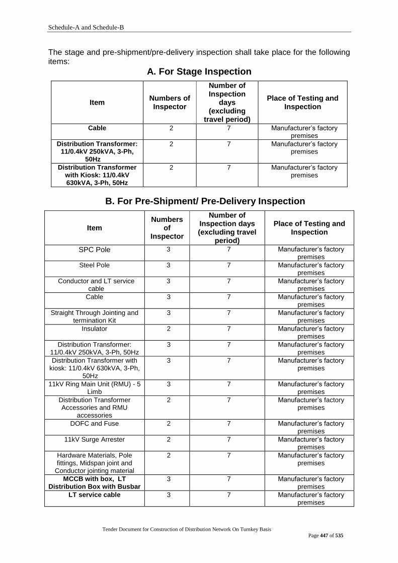
Schedule-A and Schedule-B
Tender Document for Construction of Distribution Network On Turnkey Basis
Page 447 of 535
The stage and pre-shipment/pre-delivery inspection shall take place for the following items:
A. For Stage Inspection
Item Numbers of Inspector
Number of Inspection
days (excluding
travel period)
Place of Testing and Inspection
Cable
2 7
Manufacturer‟s factory premises
Distribution Transformer: 11/0.4kV 250kVA, 3-Ph,
50Hz
2 7 Manufacturer‟s factory premises
Distribution Transformer with Kiosk: 11/0.4kV 630kVA, 3-Ph, 50Hz
2 7 Manufacturer‟s factory premises
B. For Pre-Shipment/ Pre-Delivery Inspection
Item Numbers
of Inspector
Number of Inspection days (excluding travel
period)
Place of Testing and Inspection
SPC Pole 3 7 Manufacturer‟s factory premises
Steel Pole
3 7 Manufacturer‟s factory premises
Conductor and LT service cable
3 7 Manufacturer‟s factory premises
Cable
3 7 Manufacturer‟s factory premises
Straight Through Jointing and termination Kit
3 7 Manufacturer‟s factory premises
Insulator
2 7 Manufacturer‟s factory premises
Distribution Transformer: 11/0.4kV 250kVA, 3-Ph, 50Hz
3 7 Manufacturer‟s factory premises
Distribution Transformer with kiosk: 11/0.4kV 630kVA, 3-Ph,
50Hz
3 7 Manufacturer‟s factory premises
11kV Ring Main Unit (RMU) - 5 Limb
3 7 Manufacturer‟s factory premises
Distribution Transformer Accessories and RMU
accessories
2 7 Manufacturer‟s factory premises
DOFC and Fuse 2 7 Manufacturer‟s factory premises
11kV Surge Arrester 2 7 Manufacturer‟s factory premises
Hardware Materials, Pole fittings, Midspan joint and
Conductor jointing material
2 7 Manufacturer‟s factory premises
MCCB with box, LT Distribution Box with Busbar
3 7 Manufacturer‟s factory premises
LT service cable 3 7 Manufacturer‟s factory premises
Schedule-A and Schedule-B
Tender Document for Construction of Distribution Network On Turnkey Basis
Page 448 of 535
C. Post Landing Inspection (PLI)/Post Delivery Inspection (PDI):
Post Landing/Post Delivery Inspection of all delivered goods shall be done by a PLI/PDI committee of DPDC immediately after arrival of the goods at the designated store of DPDC. The program of such inspection shall be intimated to the employer by the contractor for presence of their representative during the PLI/PDI. The PLI/PDI committee in its report shall mention the exact/assessed quantity of goods. The Post Landing Inspection/Post Delivery Inspection of goods shall generally cover the following, but not limited to it:
(i) Visual Inspection of goods;
(ii) Conformance with approved drawings with respect to dimensions/type/size.
(iii) Quantity of supplied goods.
D. Costs related to inspection and testing
Where the contractor provides facility for tests/inspection at the premises of the contractor (for post landing/delivery inspection) or of any manufacturer of the contractor (for stage and pre shipment/pre-delivery inspection), except where otherwise specified, shall provide free of charge required support and facilities such as assistance, labour, materials, electricity, fuel, stores, apparatus and instruments as may be requisite and as may be reasonably demanded to carry out such test by the inspection team. All costs pertaining to Inspector's fees, travel, lodging and other incidental expenses shall be borne by the Contractor.
E. Approval of Drawings: The contractor shall submit five (5) sets of Drawings and Guaranteed Technical Particulars of the offered goods to the office of the Project Director. This drawing will be approved by the office of Superintending Engineer (Design), DPDC provided that the drawings are submitted as per requirement. The contractor may be required to give presentations on their submitted design and drawing before approval. No work shall be performed in connection with the fabrication and manufacture of the offered goods until the drawings and technical data have been approved. The cost of supplying drawing shall be borne by the Contractor.
F. Packing: The complete goods/materials are to be export-packed and properly protected for shipment, rough transportation and storage. Specific care shall be taken for protection in store and reference is made to the climatic condition prevailing in Bangladesh. Each item shall be protected by wrapping of suitable gauge polyethylene and packed in non-returnable wooden carat. It is mentioned here that no damage of wooden cartoon shall be acceptable during transportation, handling, loading, un-loading, carrying, storing. If damaged, it should be repair by the suppliers‟ own arrangement without extra charge from the Purchaser. If any item can‟t be packed in wooden carat, this item shall be properly protected for shipment, rough transportation and storage. No damage to any item shall be acceptable. The contractor shall be responsible for damages due to inadequate packing. A packing list showing the contents of each packing shall be enclosed in a waterproof envelope secured to the outside of the packing case. A copy of the packing list shall also be enclosed inside the package.

Schedule-A and Schedule-B
Tender Document for Construction of Distribution Network On Turnkey Basis
Page 449 of 535
All packages are liable to be opened for Customs examination and packing shall therefore be designed to facilitate opening and re-packing thereafter, if imported In addition, each package shall be clearly marked or stencilled in red on two sides. The shipping mark is inscribed within a triangle marked as shown below:
On the other two sides arrow marking with the wording “THIS SIDE UP” and “FRAGILE” shall be clearly marked or stencilled to indicate the face of the package to be kept upward
THIS SIDE UP FRAGILE
DPDC
BANGLADESH
Drawings
Tender Document for Construction of Distribution Network On Turnkey Basis
Page 450 of 535
DRAWINGS
The drawings attached here are indicative drawings. The contractor shall generally follow the standards as indicated in the attached drawings for construction, expansion and renovation works. The tenderer shall submit drawing of each item mentioned in price schedule along with installation drawing.

Drawings
Tender Document for Construction of Distribution Network On Turnkey Basis
Page 451 of 535

Drawings
Tender Document for Construction of Distribution Network On Turnkey Basis
Page 452 of 535
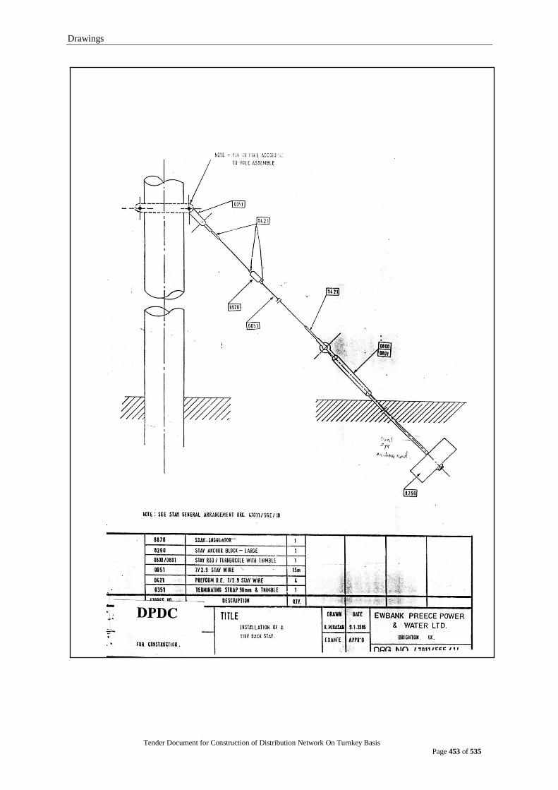
Drawings
Tender Document for Construction of Distribution Network On Turnkey Basis
Page 453 of 535
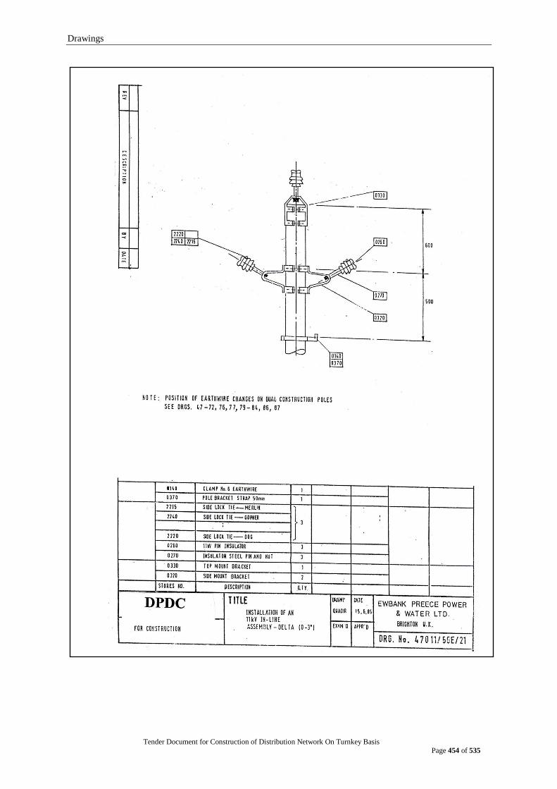
Drawings
Tender Document for Construction of Distribution Network On Turnkey Basis
Page 454 of 535
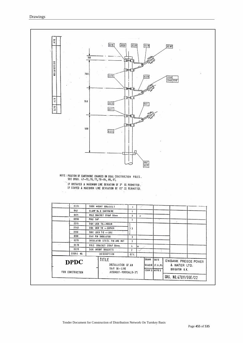
Drawings
Tender Document for Construction of Distribution Network On Turnkey Basis
Page 455 of 535

Drawings
Tender Document for Construction of Distribution Network On Turnkey Basis
Page 456 of 535
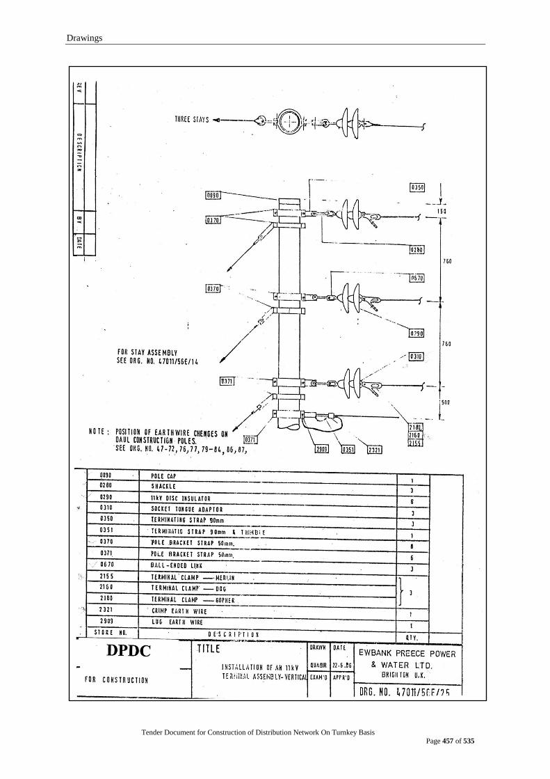
Drawings
Tender Document for Construction of Distribution Network On Turnkey Basis
Page 457 of 535
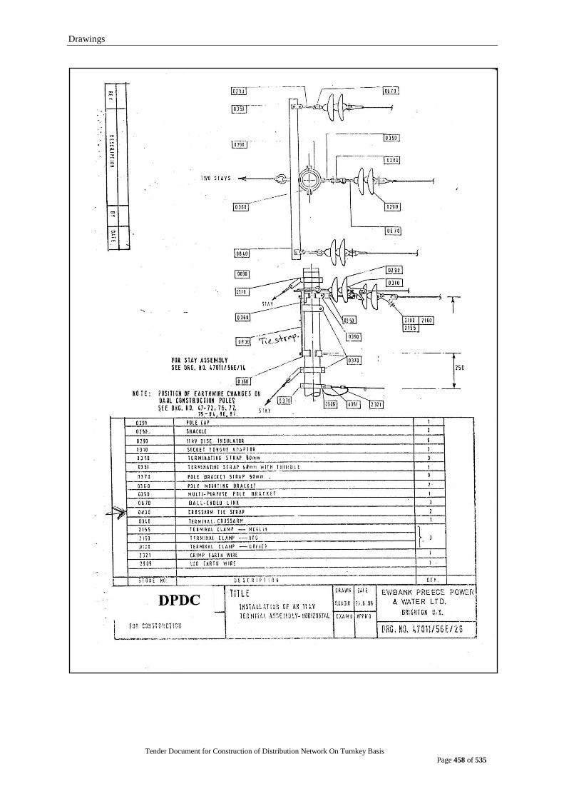
Drawings
Tender Document for Construction of Distribution Network On Turnkey Basis
Page 458 of 535
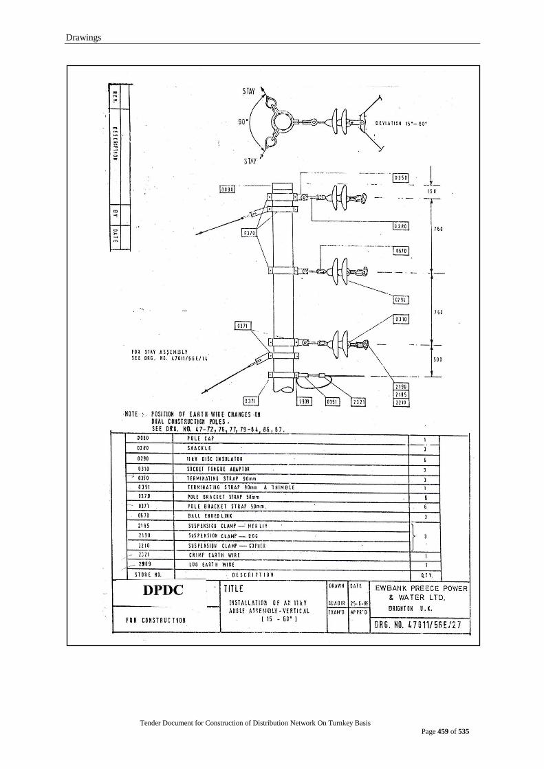
Drawings
Tender Document for Construction of Distribution Network On Turnkey Basis
Page 459 of 535
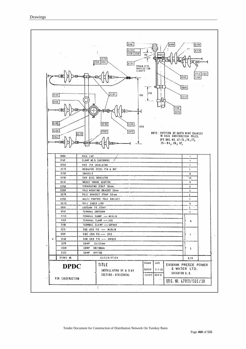
Drawings
Tender Document for Construction of Distribution Network On Turnkey Basis
Page 460 of 535

Drawings
Tender Document for Construction of Distribution Network On Turnkey Basis
Page 461 of 535

Drawings
Tender Document for Construction of Distribution Network On Turnkey Basis
Page 462 of 535

Drawings
Tender Document for Construction of Distribution Network On Turnkey Basis
Page 463 of 535

Drawings
Tender Document for Construction of Distribution Network On Turnkey Basis
Page 464 of 535

Drawings
Tender Document for Construction of Distribution Network On Turnkey Basis
Page 465 of 535

Drawings
Tender Document for Construction of Distribution Network On Turnkey Basis
Page 466 of 535
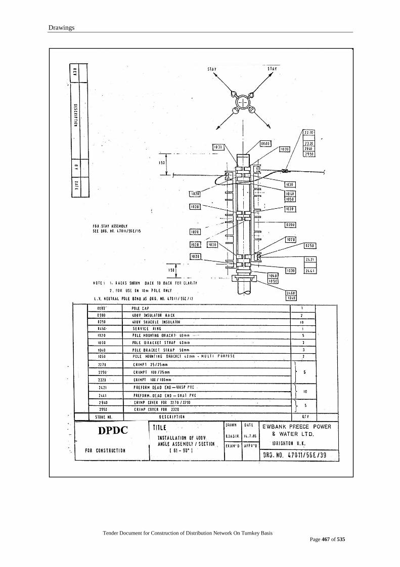
Drawings
Tender Document for Construction of Distribution Network On Turnkey Basis
Page 467 of 535

Drawings
Tender Document for Construction of Distribution Network On Turnkey Basis
Page 468 of 535

Drawings
Tender Document for Construction of Distribution Network On Turnkey Basis
Page 469 of 535
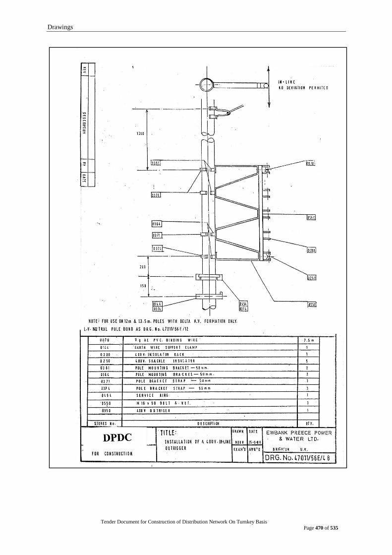
Drawings
Tender Document for Construction of Distribution Network On Turnkey Basis
Page 470 of 535
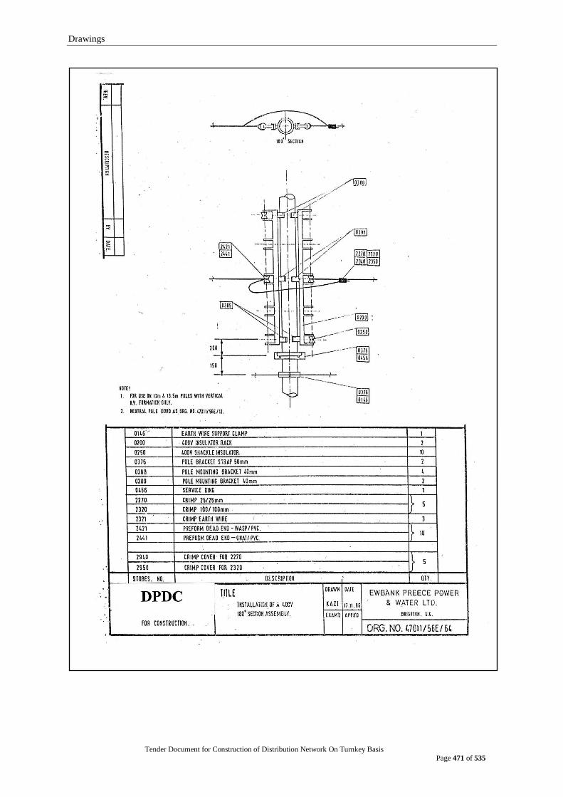
Drawings
Tender Document for Construction of Distribution Network On Turnkey Basis
Page 471 of 535

Drawings
Tender Document for Construction of Distribution Network On Turnkey Basis
Page 472 of 535
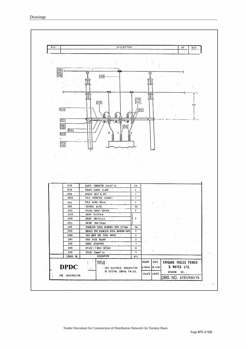
Drawings
Tender Document for Construction of Distribution Network On Turnkey Basis
Page 473 of 535
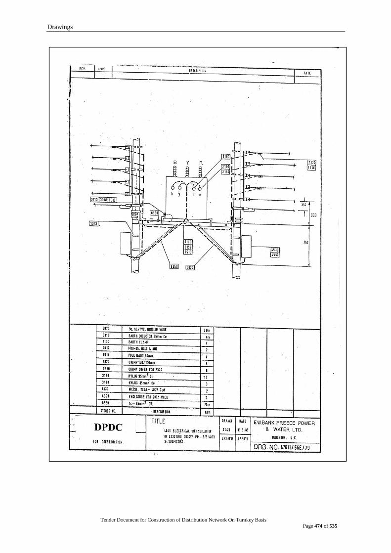
Drawings
Tender Document for Construction of Distribution Network On Turnkey Basis
Page 474 of 535
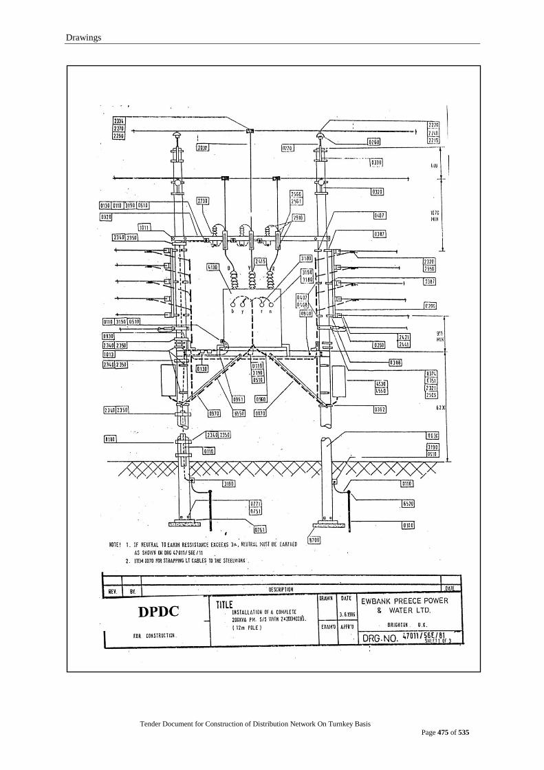
Drawings
Tender Document for Construction of Distribution Network On Turnkey Basis
Page 475 of 535
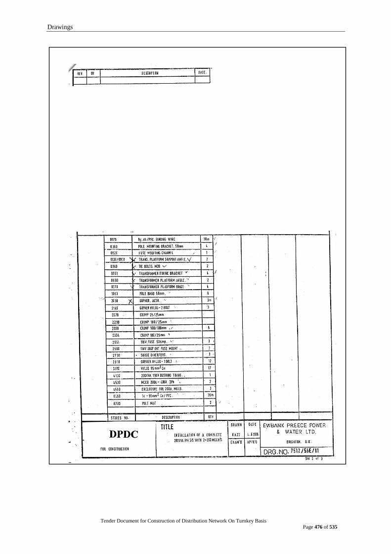
Drawings
Tender Document for Construction of Distribution Network On Turnkey Basis
Page 476 of 535

Drawings
Tender Document for Construction of Distribution Network On Turnkey Basis
Page 477 of 535
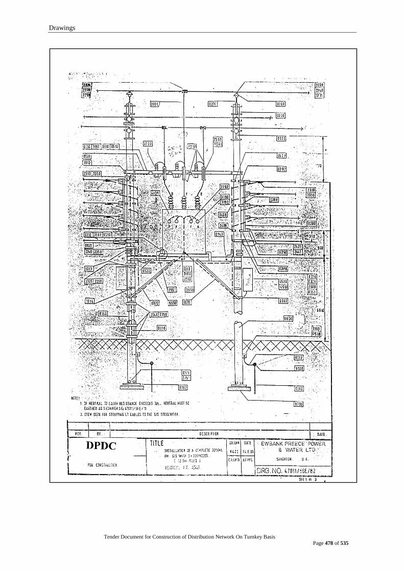
Drawings
Tender Document for Construction of Distribution Network On Turnkey Basis
Page 478 of 535
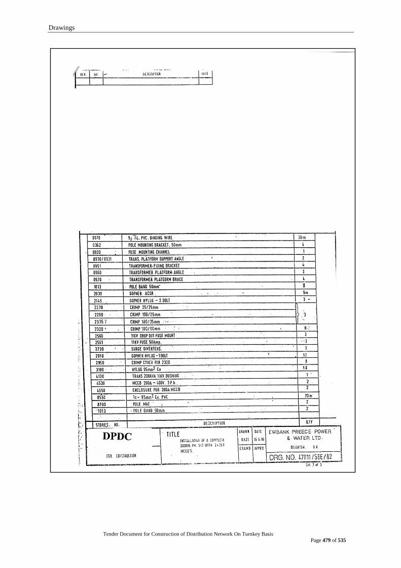
Drawings
Tender Document for Construction of Distribution Network On Turnkey Basis
Page 479 of 535

Drawings
Tender Document for Construction of Distribution Network On Turnkey Basis
Page 480 of 535
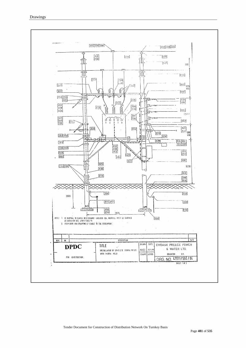
Drawings
Tender Document for Construction of Distribution Network On Turnkey Basis
Page 481 of 535
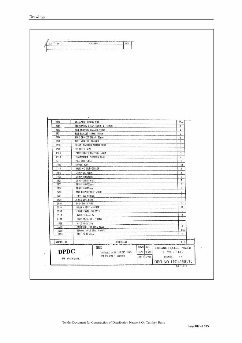
Drawings
Tender Document for Construction of Distribution Network On Turnkey Basis
Page 482 of 535
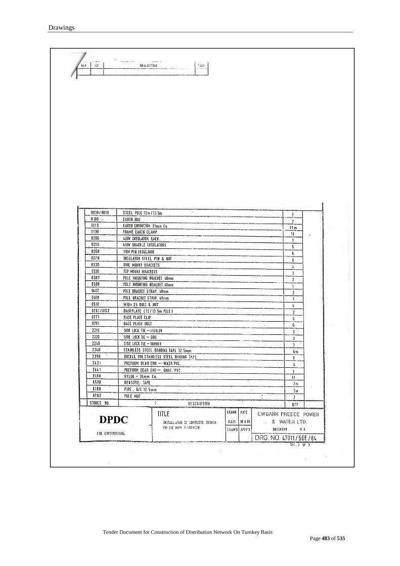
Drawings
Tender Document for Construction of Distribution Network On Turnkey Basis
Page 483 of 535
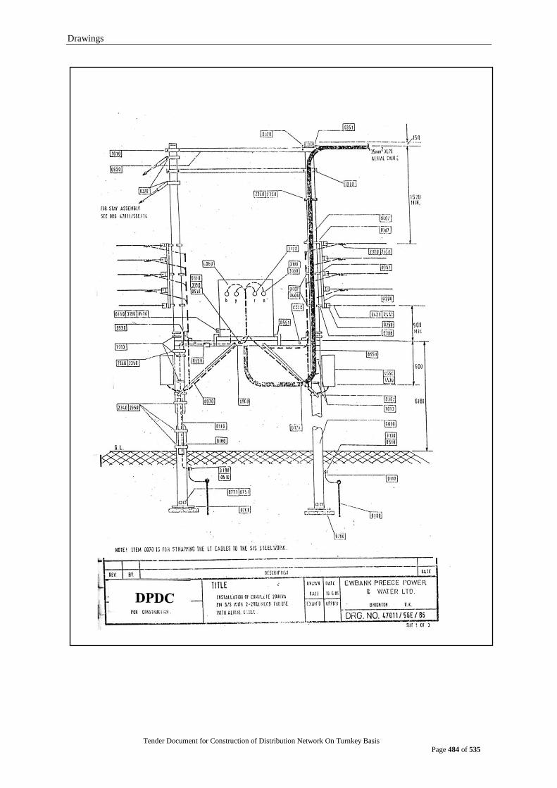
Drawings
Tender Document for Construction of Distribution Network On Turnkey Basis
Page 484 of 535
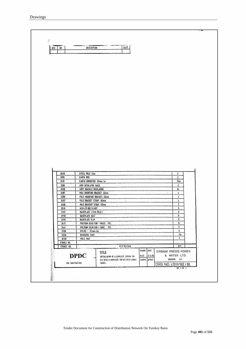
Drawings
Tender Document for Construction of Distribution Network On Turnkey Basis
Page 485 of 535

Drawings
Tender Document for Construction of Distribution Network On Turnkey Basis
Page 486 of 535
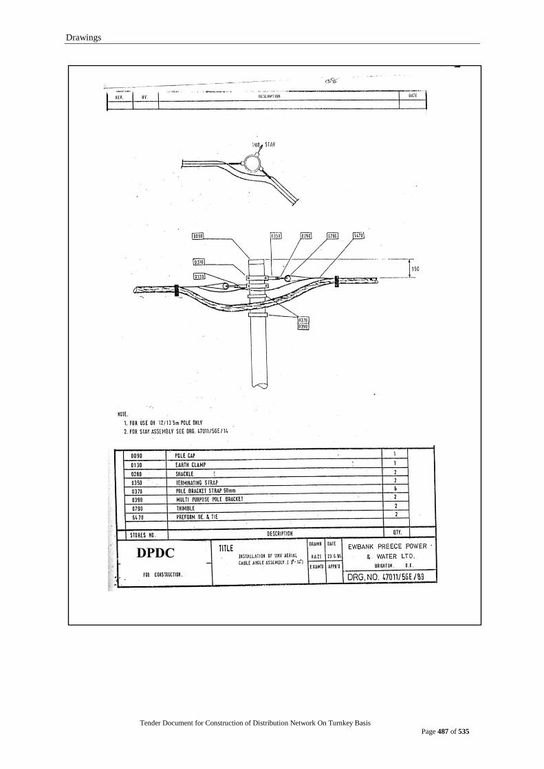
Drawings
Tender Document for Construction of Distribution Network On Turnkey Basis
Page 487 of 535
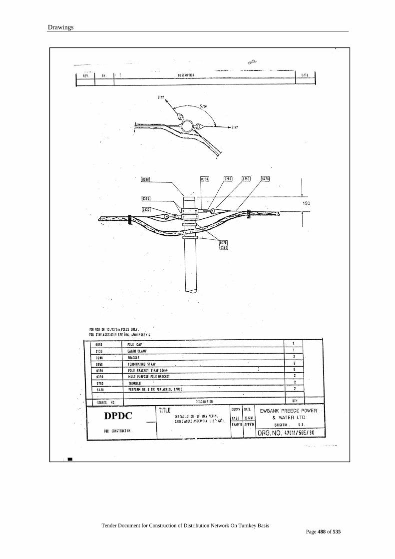
Drawings
Tender Document for Construction of Distribution Network On Turnkey Basis
Page 488 of 535
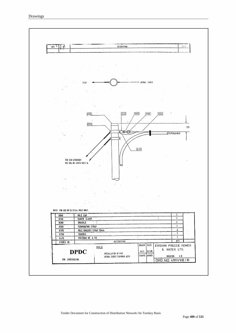
Drawings
Tender Document for Construction of Distribution Network On Turnkey Basis
Page 489 of 535
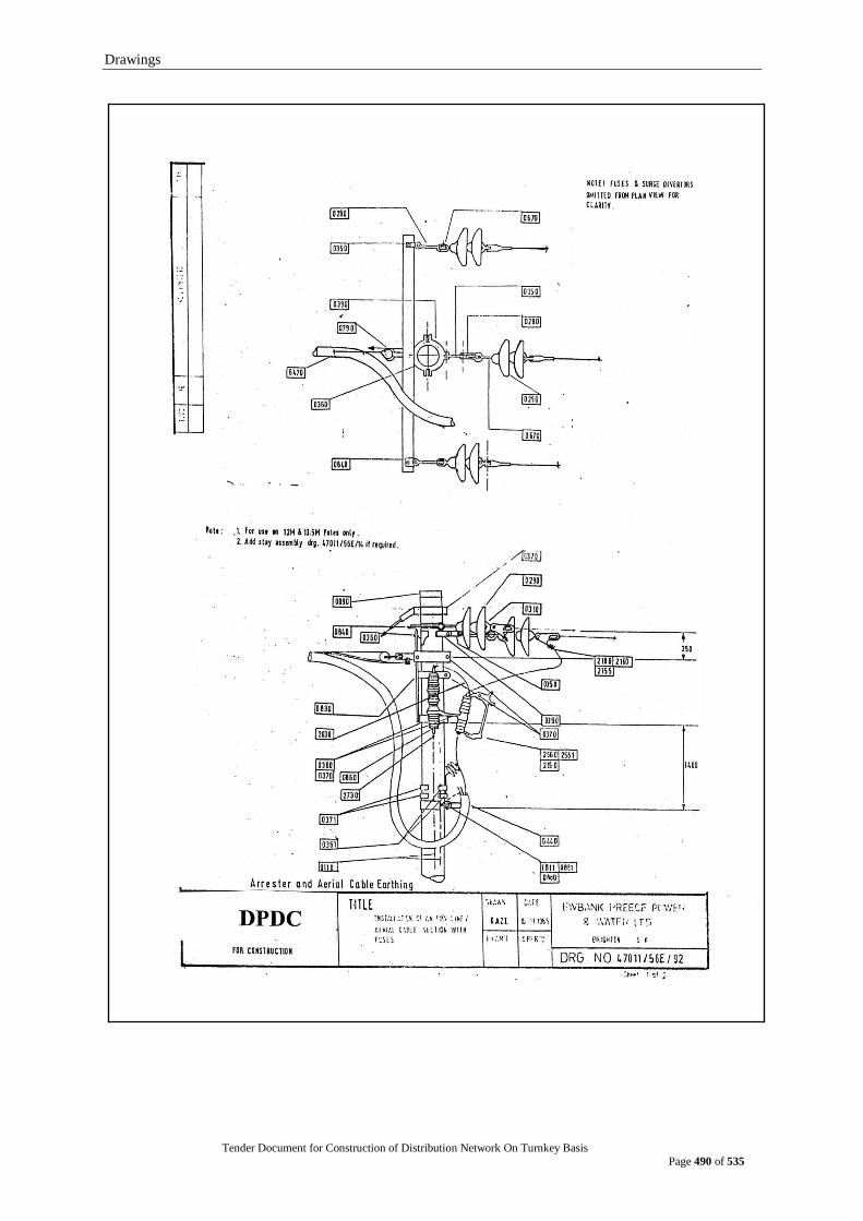
Drawings
Tender Document for Construction of Distribution Network On Turnkey Basis
Page 490 of 535
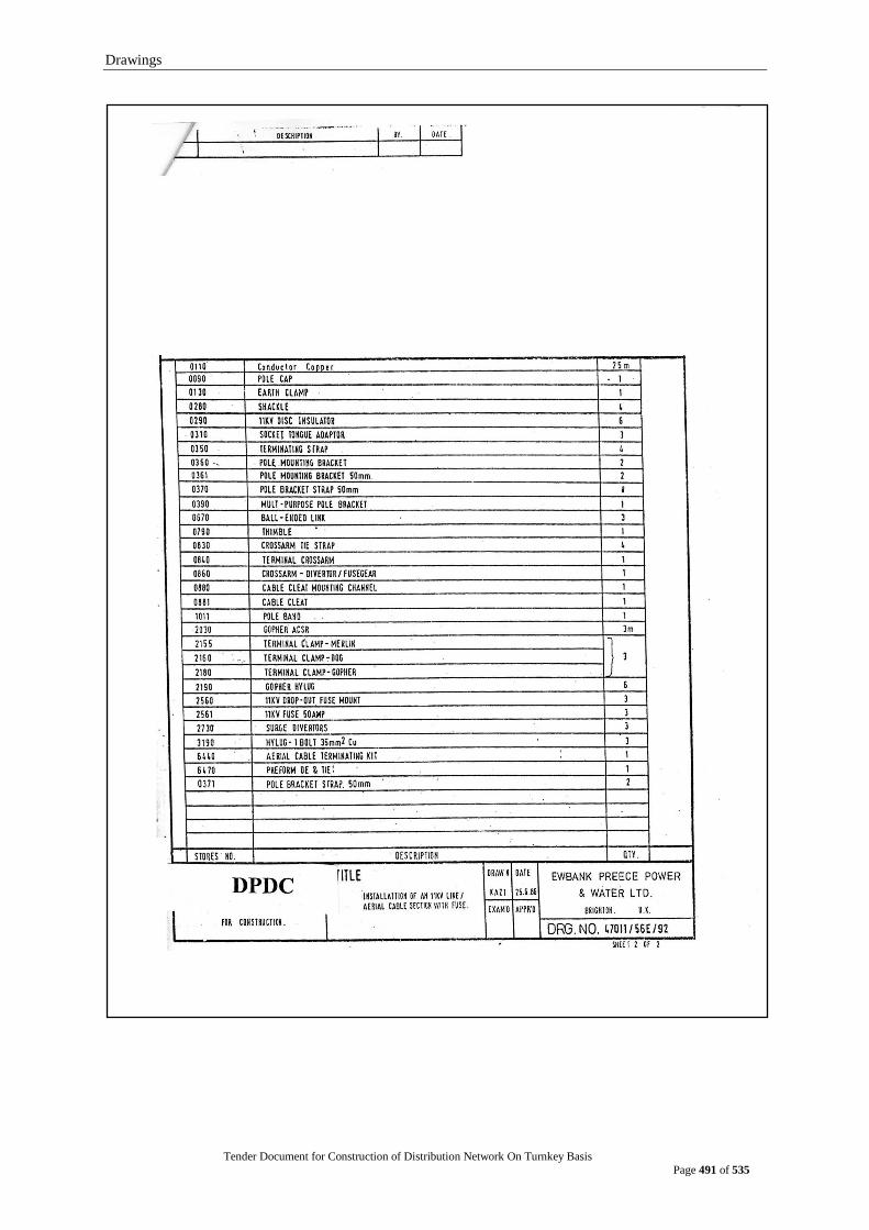
Drawings
Tender Document for Construction of Distribution Network On Turnkey Basis
Page 491 of 535
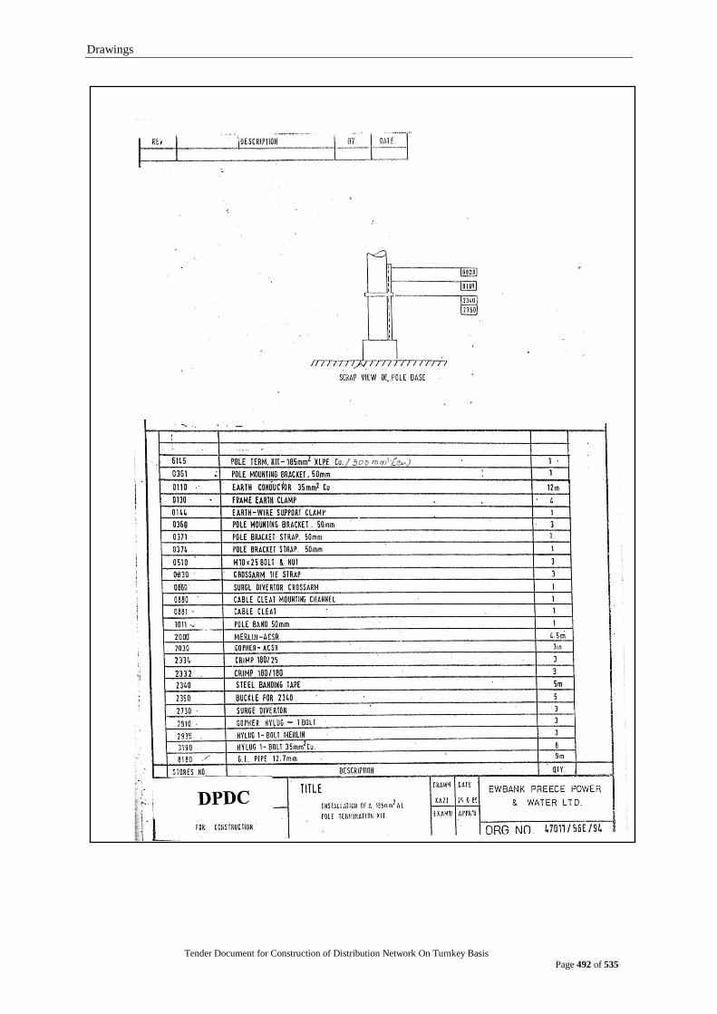
Drawings
Tender Document for Construction of Distribution Network On Turnkey Basis
Page 492 of 535

Drawings
Tender Document for Construction of Distribution Network On Turnkey Basis
Page 493 of 535

Drawings
Tender Document for Construction of Distribution Network On Turnkey Basis
Page 494 of 535

Drawings
Tender Document for Construction of Distribution Network On Turnkey Basis
Page 495 of 535

Drawings
Tender Document for Construction of Distribution Network On Turnkey Basis
Page 496 of 535
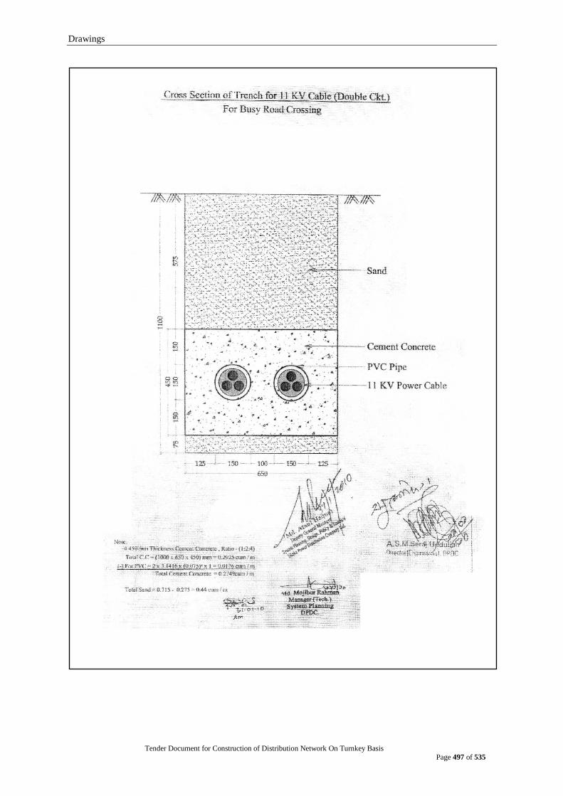
Drawings
Tender Document for Construction of Distribution Network On Turnkey Basis
Page 497 of 535
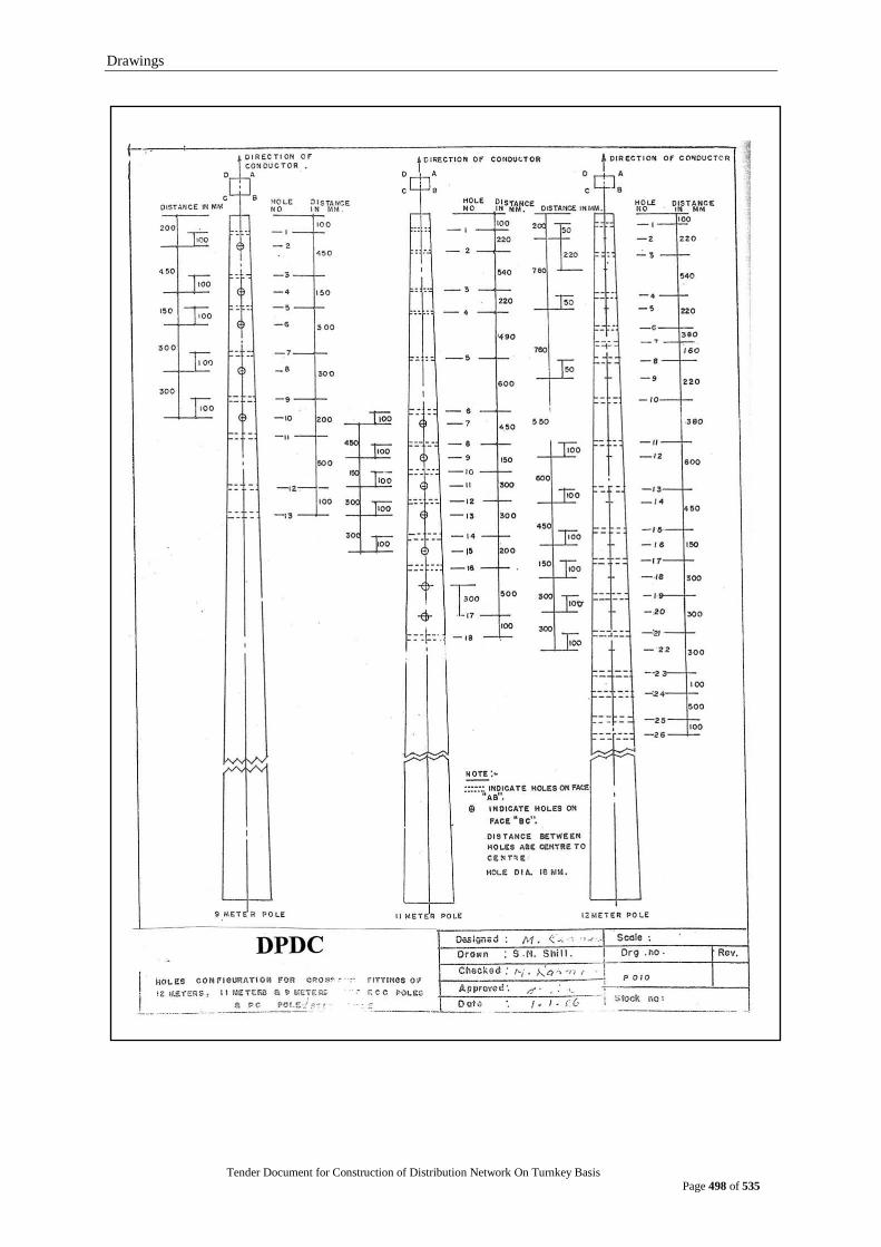
Drawings
Tender Document for Construction of Distribution Network On Turnkey Basis
Page 498 of 535
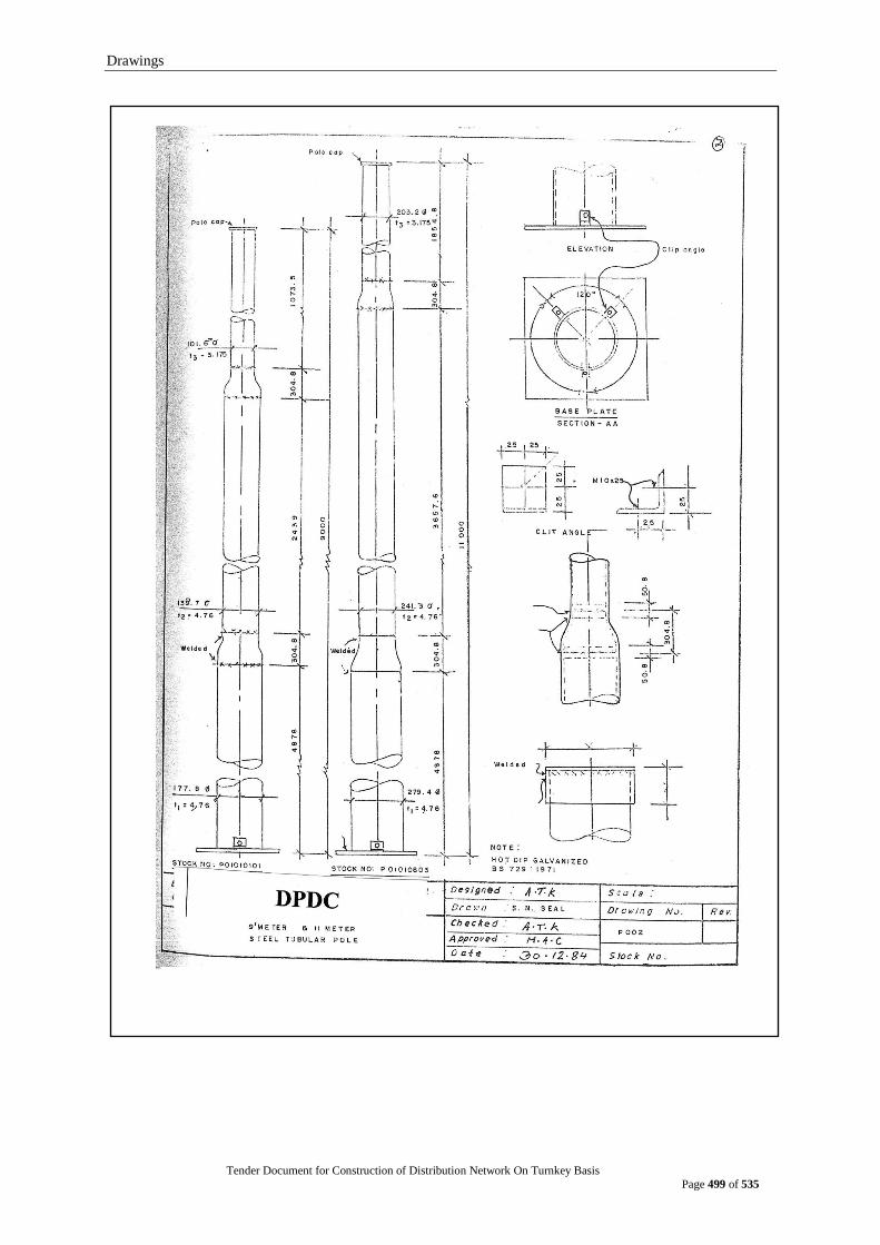
Drawings
Tender Document for Construction of Distribution Network On Turnkey Basis
Page 499 of 535

Drawings
Tender Document for Construction of Distribution Network On Turnkey Basis
Page 500 of 535
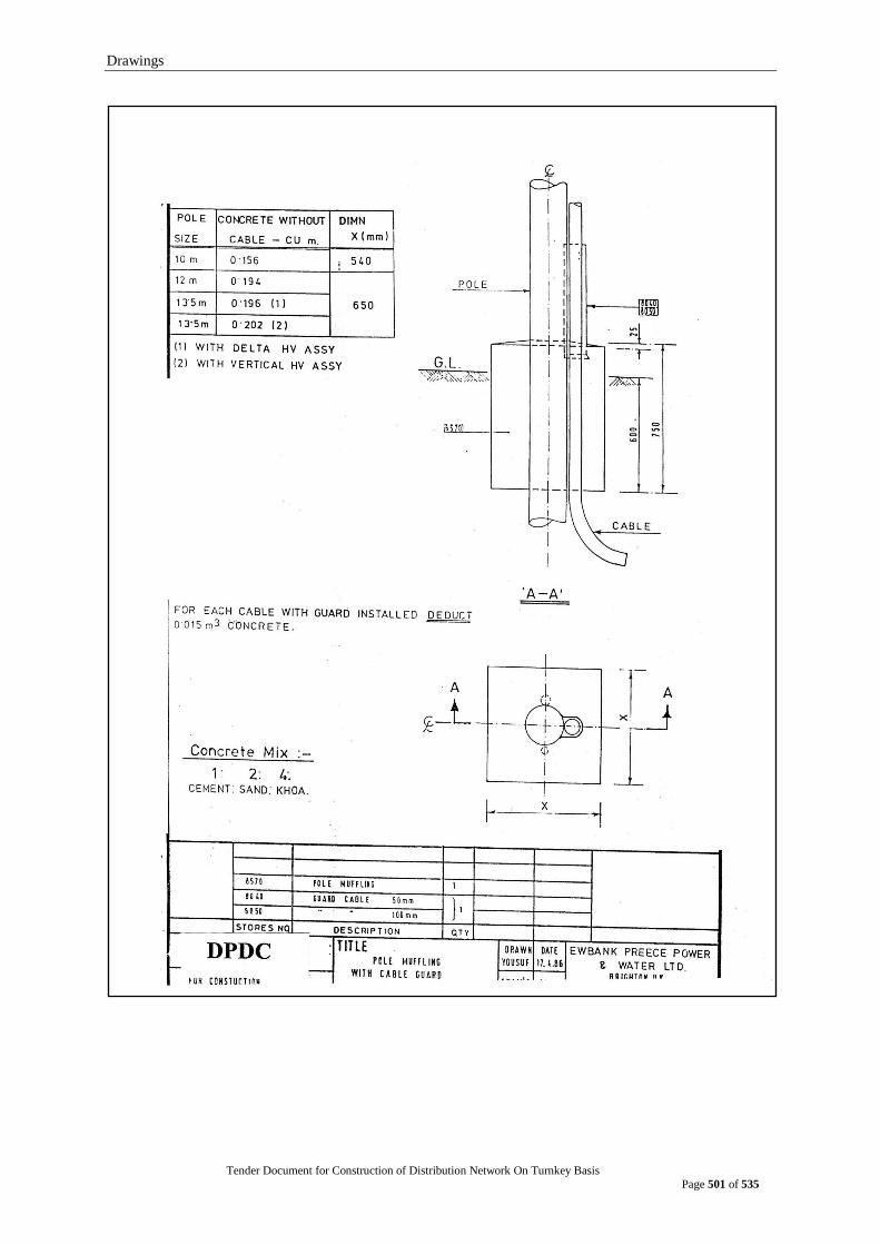
Drawings
Tender Document for Construction of Distribution Network On Turnkey Basis
Page 501 of 535
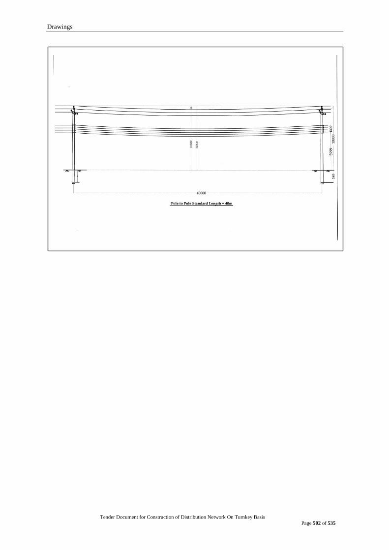
Drawings
Tender Document for Construction of Distribution Network On Turnkey Basis
Page 502 of 535
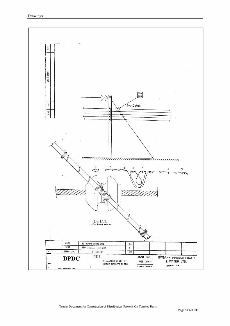
Drawings
Tender Document for Construction of Distribution Network On Turnkey Basis
Page 503 of 535
Civil Work Provision
Tender Document for Construction of Distribution Network On Turnkey Basis
Page 504 of 535
CIVIL WORK PROVISION All civil works must conform to BS, BNBC standard. Where BS and BNBC standard conflicts, BNBC standard shall prevail.
1. SEALING AND DRUMMING
Immediately after tests at the Manufacturer‟s Works, both ends of every length of metal sheathed cable shall be sealed with a metal cap which shall be plumbed to the sheath. Non-metal sheathed cables shall have both ends of the cable sealed with a suitable cap which shall not become punctured during transportation. The ends of the factory lengths shall be marked “A” and “Z”, “A” being the end at which the sequence of core numbers is clockwise. Both cable ends shall be kept within the drum flanges and battens. The cables shall be wound on strong steel cable drums provided with wooden battens to protect the cable form damage. The drums shall be arranged to take a round spindle and shall be marked to indicate the direction of unwinding. Timber shall be impregnated against termites. Any cable required to be recovered is to be capped, connected to oil tanks if necessary and re-drummed following lifting.
2. NATURE OF GROUND
It is the bidder‟s responsibility to ensure that he acquaints himself with the nature of the ground conditions prevailing in Bangladesh and in particular with the proposed cable routes. The installation rates of the cables to be quoted in the schedule shall include for any and all types of excavation and backfill on the “As found” basis. Where cable routes pass along narrow roads the Contractor shall allow for removal of trench spoil as it is excavated to avoid blocking access to the trench and to local houses and shops. If the road is surfaced backfill is required to be sand of approved quality. All measurements shall be made in linear meters.
3. EXCAVATION OF TRENCHES
The exact location of each trench shall be approved by the Engineer. Trenches shall be kept as straight as possible and each trench shall be excavated to an approved formation and dimensions and shall have vertical sides which shall be timbered where necessary so as to avoid subsidence and damage.
The contractor shall excavate up to depth of at least 100mm below the depth of cable laying. The bottom of each trench shall be firm and of smooth contour. Where trenches pass from a footway to a roadway or at other positions where a change of level is necessary, the bottom of the trench shall rise or fall gradually. Minimum width shall be at least 700mm for a single circuit. For multiple circuit, the trench width shall be determined from the minimum separation specified and diameter of cables and approved by the Engineer.
The contractor shall take reasonable precautions to prevent damage to the highway or ground surface from a slip or breaking away of the sides of the trench. The rate of rise or fall shall be approved.
The contractor shall deal with and dispose of water so as to prevent any risk of the cables and other materials to be laid in the trenches being affected detrimentally. He shall provide all pumps and appliances required and shall carry out the necessary pumping and bailing. All pumping costs shall be included in the installation rates.
Unless otherwise agreed, provision shall be made during excavation for reasonable access of persons and vehicles to property or places adjacent to the route. This provision shall be maintained until restoration has been completed.

Civil Work Provision
Tender Document for Construction of Distribution Network On Turnkey Basis
Page 505 of 535
Before each excavation is commenced the contractor shall make written application to the Engineer seven days prior to starting work attaching with his application a dimensioned sketch detailing and positioning the proposed excavation. No work shall be commenced until the Engineer has issued a “Permit to Excavate When the excavation for trenches have been accurately executed, notice shall be given by the contractor to the Engineer, Laying of cables or building of structures shall not be started until the contractor has obtained the Engineer‟s sanction to proceed with the work. After any cable has been laid and until the whole of the cables to be laid in the trench , the protective covers shall be kept near the trench or placed in such a position that they may not fall into the trench. Rollers used during the laying of cables shall have no sharp projecting parts liable to damage the cables. After back filling is complete the contractor will clear and level the works so that the finished reinstated ground level shall be the same as that which pertained prior to commencement of the works.
4. DAMAGE
The contractor shall take all reasonable precautions to avoid damage to buried services, existing surface and other encumbrances land, property, roads, fences, walls, gates etc., and sahll ensure that the work is adequately supervised so that unavoidable damage is reduced to the minimum. The contractor will be liable for all damage arising by or in consequence of the works and shall pay compensation or make good at the option of the Employer. The contractor shall remove all spoil and surplus material after installation.
The removal of obstruction such as trees will be undertaken by the contractor.
5. THRUST BORINGS, HEADING AND TUNNELS
Work on thrust borings headings or tunnels shall be carried out as and when the Engineer may instruct or approve at the schedule rates. The contractor shall take all reasonable steps to ascertain the position of all sewers, drains, pipes and structures and these shall be recorded on a drawing showing the cross section and levels or the proposed works for approval before operations are commences.
6. OBSTRUCTIONS
When in the course of the contractor works obstructions are encountered which necessitate diversions of or alteration to other underground works or alterations to buildings or foundations or when conditions necessitate the adoption of a special form of trench the contractor shall immediately notify the engineer further work shall not proceed until written instruction have been obtained from the Engineer.
7. EXCAVATED MATERIAL
The material excavated from each trench shall be placed so as to prevent nuisance or damage. Where this is not possible, the excavated material shall be removed from the site and returned for refilling the trench on completion of laying without cost to the employer. Surplus material shall be disposed of by and at the cost of the contractor.
8. CABLE AND JOINT ROUTE MARKERS
Cable markers of an approved type shall be provided along the route of buried cables as required by the Engineer and shall be erected as reinstatement is being carried out.
Markers shall be installed vertically over each cable at maximum 50 m intervals at all road crossings and joint positions.
9. PROTECTIVE COVERS
Protective covers shall be made of R.C. slab each 75 mm thick, 300 mm wide and length as required. The slab shall be provided at top and at each side of trench.

Civil Work Provision
Tender Document for Construction of Distribution Network On Turnkey Basis
Page 506 of 535
10. GENERAL METHODS OF CABLE INSTALLATIONS
The arrangement of cables and the method of laying shall be approved by the Engineer. The installation rates of the cables specified in the schedules are to include allowance for the excavation of the ground strutting shuttering and pumping laying in backfill of the specified quality protective covers drawing in ducts reinstatement of the original surface without variation for type of rock shattered rock sand backfill footpath and roadway. Cable shall be laid direct in the ground with protective covers drawn into pipes or ducts laid in troughs or on racks or supported on trays or cleats as may be required by the engineer in accordance with the following clauses. Cables necessarily brought above ground shall be protected mechanically and by sun shield.
10.1 CABLES LAID DIRECT IN GROUND
The contractor shall be responsible for informing the police or any other state or Municipal Authority of his intention to commence and complete excavation.
The contractor shall be responsible for all public safety by providing temporary traffic lights, warning notices flagmen picket fences and ropes along the route of any open trench and providing and adequate number of and maintain approved red flasher warring lights during the hours of darkness.
Filling in of trenches shall not be commenced until the Engineer has inspected and approved the cables accessories in situ and the backfill material.
The contractor shall lay the cables 1.1m deep direct in the ground in the following manner.
At least 100mm of builders fine sand graded and washed shall be placed and compacted to form a bed for the cables.
After the cables have been laid they shall be covered with additional sieved sand well punned over and around the cables to a level of 250 mm above the top the uppermost cable. Mechanical runners shall not be used for this work. Protective covers are to be laid so that they completely cover the full width of the excavation.
Where in the opinion of the Engineer the soil on the site is unsuitable for backfilling the contractor shall arrange for the importation of suitable material. All backfill shall have a thermal resistively value of not greater the 1.5oC m/w.
Where cables are laid in surfaced roads the backfill shall be wholly sand to 100 mm below grounds level. The final sub-layer shall be of broken hardcore from selected spoil. Temporary reinstatement with bricks shall be carried out by the contractor and shall match the level of existing road surface, while permanent reinstatement will be done by city corporation / owner of the road cost of which shall be borne by the contractor at per rates of the owner of road.
Where more than one horizontal layer of cables is laid the level of the upper layers of cable shall be gauged from the level of the finished bottom of the trench and marked on the side of the trench at frequent intervals before the installation of the lower layers to ensure that the correct vertical spacing is maintained.
Civil Work Provision
Tender Document for Construction of Distribution Network On Turnkey Basis
Page 507 of 535
Unless otherwise specified all power cables shall be laid as follows. - Spacing between inner phases of single core cables laid flat of adjacent
three phase circuits 750 mm. Single core cable phase spacing 300 mm. - Spacing between trefoil groups of adjacent circuits 700 mm. Trefoil
grouping shall be secured by plastic ties or approved means every one metre of route length.
- Spacing between three core cables 700 mm.
10.2 CABLES DRAWN INTO DUCTS
Unless otherwise specified ducts and pipes will be provided by the contractor. Immediately before pulling in the cables the duct should be cleared by drawing through a mandrel of slightly less diameter than the duct. Any lubricant used shall have no deleterious effect on the cables.
Cable ducts shall be completely smooth internally and of approved material diameter adn thickness. Ducts may be of high impact PVC glazed earthenware or pitch fiber. In all the above cases the ducts shall be completely covered on top and sides with 150 mm of concrete 1.2.4 mix. All occupied ducts except those for pilot cables shall be fitted with Bentonite (fulbent 570) to ESI 09-2 clause-4.16 and prices in the tender shall allow for this.
Ducts shall have an internal diameter appropriate to the cables to be installed but shall be not less than 100mm internal diameter. The minimum internal diameter otherwise shall be the sum of the cable diameter (s) plus 35 mm.
Cable duct shall be only on straight rout and where the route should deviate, manhole shall be used to pull in cable and re-direct it in to successive duct.
Plastic spacers shall be sued between the layers of cables when encasing the cables in concrete.
Each spare duct shall be provided with a galvanized draw wire left in situ.
Any ducts or pipes not used shall be sealed by plugs supplied by the contractor before backfilling.
All ducts whether occupied or not shall be water and vermin proof sealed by an approved method and material (s).
10.3 ROADS AND DITCH CROSSINGS
Cables shall be drawn into underground ducts at all road crossings. All ducts shall be supplied and laid by the contractor.
The ducts extend at least one meter beyond the edge of the road. Separate ducts shall be installed for each main power cable. Each duct cluster shall contain 100% spare ways. Each spare duct shall be provided with a glavanised draw wire loft in situ.
Excavations shall be carried in half of the road only at any time.
Where cables have to cross ditches culverts bridges and irrigation channels etc., the contractor shall provide suitable supports for the cables details of which shall be agreed with the Engineer.
Civil Work Provision
Tender Document for Construction of Distribution Network On Turnkey Basis
Page 508 of 535
10.4 CABLES INSTALLED IN CONCRETE TRENCHES
In substations concrete trenches and cable ducts will be provided and installed for the cabling limited to the substation area. These trenches will not be filled with sand. All cable duct entries to buildings must be bell mouthed and whether in use or not for cables shall be sealed against entry of water oil and vermin with a suitable semi-plastic compound supplied and installed by the contractor to the approval of the Engineer.
All cables routed in concrete trenches shall be suitably supported by means of cleats or racks and raised from the trench floor by means of suitable spacers. All cables shall be run in neat and orderly manner and the crossing of cables within the trench shall be avoided as far as possible.
The contractor will be responsible for removing and replacing the trench covers free of charge during the execution of his work as directed by the Engineer. All trenches and troughs outside the substations shall be provided by the contractor and shall be filled with clean riddled sand well punned around whenthe Engineer‟s written permission has been obtained.
10.5 CABLES SUPPORTED ON RACKS, TRAYS ETC.
All single core main power cables shall be installed in cleats fixed at distances to the approval of the Engineer.
All control cables shall be installed on trays and shall be neatly tied to the tray work by means of plastic straps at lest every 2 meters.
The whole of the cable supporting steelwork including all cleats clamps nuts bolts washers fixings and other items to complete the installation for cables supplied on this contract shall be supplied by the contractor. The cable supporting steel work shall be earthed properly.
All cables are to be run with a particular regard to neatness of appearance. Multiple runs are to be arranged so that cables entering or leaving the run do so in a logical manner.
11. CLEATS AND SADDLES
Three core cables shall be secured using claw type or multi core unit cleats. Wooden cleats shall not be used. Every non – flexible type cable shall be securely supported at a point more than 1m from its terminal gland to prevent stressing the termination and on vertical runs passing through floors immediately above the floor. For single core cables carrying three – phase alternating current non-magnetic trefoil cleats shall be used. The cleating arrangements shall be adequate to withstand the short circuit forces.
Civil Work Provision
Tender Document for Construction of Distribution Network On Turnkey Basis
Page 509 of 535
12. TERMINATIONS
12.1 General The contractor is to terminate and connect up the cables in accordance with diagrams or details approved by the Engineer.
For control wiring the cable tails shall be so bound that each wire may be traced back to its associated cable without difficulty; cores in twisted pairs or groups shall be kept together; any spare cores shall be numbered and terminated on spare terminals.
12.2 POWER CABLES The contractor is to be responsible for the correct phase rotation and connections in accordance with information approved by the Engineer. Particular care is to be taken in the case of these cables, where sub-sequent correction may be difficult. Phase tests will be carried out by the contractor to the satisfaction of the Engineer. All equipment required to carry out these tests shall be provided under this contract.
Where insulated glands are provided the Contractor is to ensure that the insulation is maintained after jointing the cable and shall demonstrate this to the satisfaction of the Engineer.
13. TERMINATION AND JOINTING CONDUCTORS
The use of either welded soldered or compression type lugs and ferrules is permitted. If compression lugs and ferrules are used the tools for making compression joints must be those recommended by the manufacturer of the lugs and ferrules and also approved by the Engineer.
Tenders are to submit their proposals to the Engineer for approval for any jointing of copper to aluminum conductors.
On stud type terminals approved compression lugs or claw type washers shall be used. All conductors excluding those terminated into clamp type terminals shall be connected in the foregoing manner.
14. CORE IDENTIFICATION FERRULES
The contractor shall provide core identification ferrules of a type approved by the Engineer for terminating pilot cores in the marshalling boxes. The ferrules or sleeves shall be of insulating materials which shall be white and shall have glossy finish. The ferrules or sleeves shall be unaffected by oil or damp. Characters shall be suitably marked in black. Additional red ferrules or sleeves marked “ TRIP” in white shall be fitted on all wires associated with trip circuits.
15. CABLE IDENTIFICATION
Each end of a cable run shall be provided with markers for identification. The markers to be fitted in a suitable position under the cable termination. Where cables enter and leave ducts and at cable joints suitable identification markers shall be fitted. The material of the markers and of the labels and fastenings shall be such as to avoid corrosion due to incompatibility of materials, and to ensure permanent legibility.
Civil Work Provision
Tender Document for Construction of Distribution Network On Turnkey Basis
Page 510 of 535
16. PULLING IN CABLES
XLPE and pilot cables may be hand pulled or nose pulled provided that for nose pulling the power winches used shall be fitted with a safe tension automatic trip limiting device. A sufficient number of rollers over which the cable can ride without tendency to rotate or twist on its longitudinal axis shall be used. Particular attention shall be given to the provision and placing of rollers at bends to ensure that the minimum bending radius of the cable in not reached. Details of proposed pulling in methods and cable laying equipment shall be supplied to the Engineer. 17. POWER CABLE TERMINATIONS
17.1 Sealing Ends Power cables shall be terminated into outdoor sealing ends, cable boxes or heat shrink type pole terminations as appropriate. Termination designs are subject to approval by the Engineer.
17.2 Porcelains All cable sealing end porcelains shall be of the one piece type and be sound, free from defects and thoroughly vitrified so that the glaze is not depended upon for insulation. Cable sealing ends assembled from multiple porcelain elements will not be acceptable. The glaze shall be smooth and hard, completely cover all exposed parts of the porcelain and be of a uniform shade of brown. Outdoor sealing ends and fittings shall be unaffecte3d by atmospheric conditions proximity to the coast, funs, ozone, acids, alkalis, dust or rapid changes of air temperature between 4ºC and 40º C under working conditions. Porcelain must not engage directly with hard metal and where necessary, gaskets shall be interposed between the porcelain and the free fittings. All porcelain clamping surfaces in contact with gaskets shall be accurately ground and free from glaze. A minimum creep age distance of 30 mm/kV of rated service voltage is required.
17.3 INSULATION OF SEALING END GLANDS Unless otherwise specified, all cable sealing end bases shall be insulated from the surrounding metalwork by means of porcelain or molded resin insulators interposed between the sealing end based and the supporting structure. Phase colours shall be indicated in an approved manner.
17.4 ARCHING HORNS All outdoor type sealing ends shall be provided with adjustable displace double gap arcing horns.
18. STRAIGHT THROUGH JOINTS
Each cable is to be run in one continuous length except where the run of cable exceeds the normal manufactured lengths. No other straight joints will be permitted unless specifically authorised by the Engineer.
The outer sheath of all joints buried in the ground shall be contained in a glass fiber or similar box filled with compound or other approved method.
The XLPE cable shall be provided with section alisation on the sheaths on every sixth joint or 3 km whichever is less, with links and earthing provided for the earth screen. Normal operation will be with the sheath bonding links closed and the earth link open.
All XLPE joints and terminations shall be carried out under strictly controlled conditions by cable jointers for the XLPE cable manufacture. The joint insulation shall be of the vulcanized type or other approved type.

Civil Work Provision
Tender Document for Construction of Distribution Network On Turnkey Basis
Page 511 of 535
The installation rates of the joints specified in schedule IV are to include allowance for the complete joint bay installation including excavation civil work jointing earthing and ancillary equipment.
Where the armour wires of plastic insulated cables constitute the earthed metallic shield such wires shall be efficiently bonded across the joint in a approved manner. The electrical resistance of such bonds shall not exceed that of an equal length of the cable armour wires. Suitable care shall be taken to ensue that the bond contacts do not deteriorate in service.
19. BONDING AND EARTHING
Surge protection shall be provided at all joints and terminations not permanently connected to earth to limit in induced voltages to (specified limits). The surge limiting device shall limit the peak voltage as specified for a peak current of 10 kA. These devices shall also withstand the specified a c. r. m. s. maximum voltages without injurious heating.
All cable screens, bonding leads earth conductors earth links etc. shall be capable of withstanding the prospective fault current appropriate to the relevant system voltage for 3.0 second without injurious heating, distortion or damage.
The contractor shall install the minimum number of joints in the cable route, consistent with the specification requirements and sound practice.
The tenderer shall state, in Tender, the philosophy of and details of the screen earthing leads and shall route these conductors in a manner such as to minimise or eliminate circulating currents. The contractor shall ensure that the voltage on exposed metalwork or earth conductor arising from ht passage of load or fault current does not constitute a hazard to personnel, livestock or equipment (including building structures etc.) and shall if required by the Engineer, furnish full information and calculations to demonstrate compliance with this clause.
The contractor design of the system shall take into account the requirement that regular testing of insulation integrity will take place. Connections to earth shall therefore be made through bolted links or by other means to the approval of the Engineer, permitting isolation of cable sheaths and all associated insulated conductors for testing purposes.
Cable sheaths joints and terminations and all associated conductors shall be insulated for voltage likely to arise in operation and shall in any case withstand the specified test voltages.
The contractor is to provide earthing and earthing electrodes for all equipment supplied under this contract in accordance with the requirements of the specification and the tender drawings.
Extensible solid copper earth rod electrodes 1220 mm long 16 mm diameter shall be driven in sufficient number to ensure that the electrode resistance dose not exceed 10 ohms for ancillary equipment and 2 ohms at cable sealing ends remote from substation. All earth electrodes shall be electrically bonded together using copper taps 50 mm x 4 mm. The tops of all electrodes shall be at least 500 mm below the surface of the normal reinstated ground level and the joint between the electrode and the copper tape shall be immersed in asphaltic coating.
The cable contractor is to provide and terminate the earthing 50 mm x 4 mm copper tape from the link box at the outdoor sealing ends or the splitter box to the switchyard or substation main earth. Ancillary equipment shall be earthed to the substation main earth by the cable contractor, earth. Ancillary equipment shall be earthed to the substation main earth by the cable contractor.
Civil Work Provision
Tender Document for Construction of Distribution Network On Turnkey Basis
Page 512 of 535
20. Civil Works
20.1 General This section of the works covers the design construction and maintenance of the civil works as required.
i. Manholes for cable joints
ii. Manholes for oil pressure systems
iii. Road crossings and ducts
iv. Cable protective covers and route markers.
v. Foot paths
Rates for supply and installation of equipment quoted in the appropriate Schedules shall be inclusive of all forms of foundations and ancillary equipment as fully completed covering excavation, ground preparation, installation testing and reinstatement and shall be deemed to have included all material guarding and all temporary and access works.
20.2 Contractor to Satisfy Himself As to All Conditions
The Contractor will be held to have satisfied himself as to means of access to the Site of the Works, transport of labour, materials and plant to and from and over the works, construction problems, nature of ground on site and other relative contingencies.
20.3 Access and Transport
The Contractor will in consultation with the Engineer make all enquiries and arrangements with the proper authorities as regards access to the site of the works.
20.4 Setting Out and Levels
The Contractor is responsible for setting out the Works in accordance with the location shown on drawings. The Contractor shall relate all his route profiles to the National Geodetic Level (ordnance datum) and be responsible for all leveling necessary to achieve this. The nearest benchmarks may be some distance from the cable routes.
20.5 Ground Conditions
It is the responsibility of the Contractor to carry out his own investigations to the satisfaction of the Engineer to determine the nature of ground conditions prior to the design of the foundations by soil tests and investigations. The results and interpretation of all such tests and investigations together with the said characteristics proposed to be assumed for the design of each of the foundations, shall be submitted to the Engineer for approval before preparation of foundation working drawings and no foundation working drawings will be approved by the Engineer until such data has been submitted and approved by the Engineer. No claim by the Contractor for extra payment will be considered for carrying out these detailed soil investigations and tests.
20.5.1 Design and Drawings
The Contractor will be responsible for the design and detailing of all civil works and shall submit all drawings and calculation for the Engineer‟s approval before commencement of construction.
The Contractor shall allow for a phase out submission of drawings for approval by the Engineer and at least 2 weeks from the date for receipt by the Engineer of each batch of drawings is to be allowed for detail checking.
Civil Work Provision
Tender Document for Construction of Distribution Network On Turnkey Basis
Page 513 of 535
Unless specified otherwise, design and details shall accord with the latest published editions of B.S., I. E. C. or other approved standard
Reinforced concrete shall be designed in accordance with British Standard Code of Practice BS 8110: loading including wind loading shall be in accordance with British Standard Code of Practice G.P.3 Chapter V Parts I and II with factors as appropriate to each location, structural steelwork where used designed to British Standard 5950: Foundations designed to British Standard Code of Practice G.P.8004.
20.6 STRUCTURE BASES
Base for the sealing and structures shall preferably be combined with the foundations of other sub-station equipment being installed
20.7 Civil Works-Materials and Workmanship
20.7.1 Standards and Samples
All materials shall be of the best quality of the respective kinds specified or described in the Specification and Drawings and shall comply in all respects with the latest edition or amendment of the relevant British Standard except and insofar as that Standard is amended by this specification or Drawings.
20.7.2 Tolerances
The Works are to be constructed to lines, levels, graded and dimension set out in the Drawing and no payment will be made for work departing from these lines, levels, grade and dimensions unless authorized or agreed by the Engineer.
20.7.3 Samples
Samples of materials and workmanship which it is proposed to employ in the execution of the Works shall be submitted with the detail to the Engineer for his approval. Should any material or workmanship be employed which do not correspond in quality and character with samples the Engineer may at his discretion order their replacement at the Contractor‟s own cost.
20.7.4 Testing of Materials
The testing of cement, concrete, brick, soil samples or other materials as required in connection with the construction of the Works shall be carried out in laboratories approved by the Engineer. The Contractor shall pay all costs incurred in making, transporting, testing and providing equipment for the testing of materials.
20.7.5 Keeping Work Free From Water
The contractor shall keep his Works free from water so that all the work may be carried out in the dry and he shall construct any temporary dams, water courses and other Works and provide operate and maintain pumps as may be necessary for this purpose, all at his own expense.

Civil Work Provision
Tender Document for Construction of Distribution Network On Turnkey Basis
Page 514 of 535
20.7.6 Soil Disposal
Throughout the period of construction of the Works the Contractor shall maintain the whole area of his operation in a clean, tidy and safe condition by arranging his materials in an orderly manner. All rubbish, waste materials, spoil, debris etc. shall be systematically cleared off the working areas as it accumulated and shall be deposited at connection points allocated by the Engineer pending removal from site by the Contractor at his own expense. No mining or quarrying right are included in this Contact, but surplus soil may be sold by the Contractor after agreement with the Engineer that the employer has no use for that soil. Access must be maintained during trenching works and removal, and return of soil from and to site to allow for this is deemed to be included in the excavation rates.
20.8 Excavations
20.8.1 Clearing and Grading
The routes of all cable excavations shall be cleared and leveled so that on completion of the works the finished reinstated ground level shall be the same as that which obtained prior to commencement of the Works.
20.8.2 Foundation Pits
Excavation for foundations to a greater depth or width than is directed or required shall be made good with concrete or with other suitable material to the satisfaction of the Engineer. No concrete shall be placed until the excavations have been inspected and approved by the Engineer. All replacement of unauthorized excavations shall be to the Contractor expense.
20.8.3 Surface to be Dry
Importance is attached to keeping dry and clean the excavated surfaces upon or against which concrete has to be deposited or built and no concrete is to be deposited until such surfaces are properly drained. Special precautions are to be taken to prevent water from washing out mortar whilst setting or in any way injuring the work. No reinforcement steel shall be placed in water and no water shall be permitted to rise over the reinforcement steel until the concrete has been placed. Blinding concrete shall be placed the same day the excavation is bottomed.
20.8.4 Shoring
The Contractor shall provide to the satisfaction of the Engineer all timbering or other approved supports and shore the sides of excavations, pits, in such a way as will be sufficient to secure them from falling and to prevent any movement. All responsibility connected with such shoring shall rest with the Contractor.
20.8.5 Backfilling and Foundations
Refilling of foundation pits shall be carried out only after the foundations and structural Works within the excavations have been inspected and approved by the Engineer.
Unless otherwise directed all filling shall be approved excavated material and shall be deposited and compacted, using approval

Civil Work Provision
Tender Document for Construction of Distribution Network On Turnkey Basis
Page 515 of 535
20.8.6 Settlement
The contractor shall be responsible for making good all settlements of filling due to any cause whatever which may occur up to the end of the period of maintenance.
20.8.7 Surplus Material
All material surplus to the requirements of fill and all debris and rubbish shall be removed and deposited as directed by the Engineer.
20.8.8 Explosives and Blasting No blasting will be permitted on the site of the works.
20.9 CIVIL WORKS CEMENT
20.9.1 Ordinary Portland Cement
Ordinary Portland cement shall comply with BS 12 or and approved equivalent standard. The source from which ordinary Portland cement is obtained shall be to the Engineers approval.
20.9.2 Sulphate Resisting Portland Cement
Sulphate Resisting Portland Cement shall be in accordance with British Standard 4027, Sulphate Resisting Portland Cement, obtained from a source approved by the Engineer. The Contractor shall certify that the proposed cement is of the required quality regarding resistance to corrosion due to sulphates methods of testing this quality shall be included in the Tender. The use of alimonies cements will not be permitted.
20.9.3 Delivery and Storage All accepted cement shall be delivered in sound and properly sealed bags and shall be stored in dry weatherproof shade at least 300 mm off the ground. Cement shall be delivered in quantities sufficient to ensure continuity of the Works and to enable all the necessary tests to be carried out before it is used.
The Contractor shall ensure that each consignment is accompanied by a certificate from the manufacturer certifying that the cement in that consignment is in accordance with the physical requirements of the appropriate British Standard. Furthermore each certificate shall be furnished to the Engineer before any use is made of the cement in that particular consignment.
Storage shall be on brick mats so that the inclusion of foreign material is prevented. Surface drainage shall be kept away from the aggregate by suitable dykes or ditches.
20.9.4 Tests after Delivery
Each consignment of cement may, after delivery on the site and at the discretion of the Engineer, be subjected to the whole of the tests and analyses required by the British Standard Specification.
The Contractor shall arrange for these tests to be carried out at his own expense.
Civil Work Provision
Tender Document for Construction of Distribution Network On Turnkey Basis
Page 516 of 535
20.9.5 Rejection of Cement
The Engineer may reject any cement as a result of any tests thereof, notwithstanding the manufacturer‟s certificate. He may also reject cement which has deteriorated owing to inadequate protection or others cause, or in any case where the cement is not to his satisfaction.
The Contractor must remove all rejected cement from the site without delay.
20.10 CIVIL WORKS-AGGREGATES
20.10.1 General Aggregates for all concrete shall be to the approval of the Engineer. Un-reinforced mass cement may use first class broken brick, aggregate. Reinforced concrete shall use only stone aggregate.
They must be hard, strong, durable, clean and free from adherent coatings and shall be protected from contact with any deleterious mater whatsoever.
20.10.2 Delivery and Storage
Sufficient quantities of each grade of aggregate shall be kept on the site to ensure continuity of work. Aggregate of different sizes shall be stored in different stacks and the arrangements for storage shall be subject to the approval of the Engineer.
20.10.3 Aggregates for Reinforced Concrete
For reinforced concrete work the fine aggregate shall consist of clean well graded Sunarganj, Jaladia or Savar sand.
The coarse aggregate for reinforced concrete shall consist of well graded Sylhet shingles.
The fine and coarse aggregate shall be kept well separated during storage on Site and during mixing, measured separately and mixed in the proportions specified or permitted. The individual and combined grading shall be to the satisfaction of the Engineer.
20.10.4 Aggregates for Mass Concrete
All brick aggregate shall be tested periodically and as often as the Engineer shall decide to be necessary, to ascertain the proportions of the sand contents. In such testing the following conditions shall be observed:
(i) All material passing a 5mm square mesh shall be defined as sand and the residue on such a sieve as coarse aggregate.
(ii) The sand and coarse aggregate are to be separated by sifting a dry sample and the proportion of each ascertained.
(iii) The proportions by volume in a shaken measure are to be approximately one part sand and two parts coarse aggregate.
20.10.5 Aggregate for cement Mortar
The aggregate for cement mortar shall consist of natural sand as specified in British Standard 1200; sands for mortar for plain and reinforced brickwork. Mortar for brickwork shall generally consist of 1 part cement to 0.5 part to 4 or 4.5 parts of sand BS 5628.

Civil Work Provision
Tender Document for Construction of Distribution Network On Turnkey Basis
Page 517 of 535
20.10.6 Water for Concrete
Water for concrete, cement mortar and grout shall be free from salt, oil, alkali, organic matter or other deleterious substances and the Engineer‟s approval must be obtained prior to its use. Any tests required by the Engineer on the suitability of the water shall be carried out in accordance with BS. 3148.
20.11 CIVIL WORKS MIXED
20.11.1 Normal Reinforced Concrete-Class-A
Concrete for normal reinforced concrete work shall comply with requirements of the British Standard Code of practice for the structural use of normal reinforced concrete in buildings CP. 8110 a minimum cement content of 360 kg/m3
20.11.2 Batching of Concrete
The means of batching and control of quality of concrete shall be approved by the Engineer.
20.11.3 Mortar and Grout
Mortar and grout shall comply with BS 5625.
20.11.4 Strength of Mixes
The cement aggregate and water for concrete work shall be mixed in such proportions as to comply with the following table in which the expression „Works Test‟ and „Preliminary Test‟ shall have the meanings ascribed to them in BS 1881 „Methods of Testing Concrete.‟
Nominal Mix Minimum Cube Strength Requirements in N/mm2
Works Tests at 7 days
Preliminary Tests at 28 days
Works Test at 28 days
Class-A 14.0 (2000 lbs sq.in)
28.0 (4000 lbs sq.in)
21.0 (3000 lbs sq.in)
20.11.5 Water Cement Ratio
The quantity of water is to be the minimum necessary to ensure a workable and compact mass. Due allowance shall be made for the moisture content of the available aggregates and the Contractor must ensure that the water/cement ratio is not excessive and produces concrete to the strength requirements. The Water/cement ratio shall not exceed 0.55 in any case.
20.11.6 Minimum Quantity of Cement
Class A- Any reinforced concrete to be used in the Works shall contain not less than 360 kg of cement in each cubic meter of concrete.
20.12 Civil Works Reinforcing
20.12.1 Reinforcing Bars
The steel reinforcing bars shall be in the form of round or deformed bars and shall be made by approved manufacturers in accordance with the requirements of B.S. 4449, B.S 4461 and B.S. 4483 as applicable and bent to comply with B.S. 4466. The minimum bar size to be used shall be 8 mm diameter. Welding of bars for extensions shall not be permitted. Bend tests shall be carried out on site to cheek the quantity of rebar.
Civil Work Provision
Tender Document for Construction of Distribution Network On Turnkey Basis
Page 518 of 535
20.12.2 Binding Wire
Metal reinforcement is to be secured against displacement by using N. 16 SWG annealed iron wire ties or suitable clips at inter-sections. Tails of all wire ties shall be bent away from adjacent concrete surfaces. All rebar shall be held rigidly in place so that it cannot move during concreting.
20.12.3 Stores
All reinforcing bars shall be stored on the site on timber supports at least 200 mm clear of the ground.
20.12.4 Fixing
The number size form and position of all the reinforcement shall unless otherwise directed or authorized by the Engineer be strictly in accordance with the Contractor‟s approved drawings. Nothing is to be allowed to interfere with the disposition of the reinforcing bars and the Contractor is to make a particular point of seeing that they are placed correctly in every respect. The minimum cover to any reinforced bar shall be at least 75 mm when below ground.
20.12.5 Cleaning
All reinforcing steel shall be free from heavy rust loose scale oil and grease or other deleterious material immediately before the concrete is placed in forms.
20.12.6 Approval
The Contractor must obtain the written approval of the Engineer to the reinforcement when placed before any concrete is placed.
20.13 Civil Work Formwork
20.13.1 Definition
Formwork shall include all temporary moulds for forming the concrete to the required shape.
20.13.2 Construction
Timber forms shall be constructed of sound well seasoned timber or prefabricated steel forms may be used.
The formwork shall be fixed in perfect alignment sufficiently rigid and strong and securely braced so as to be able to withstand without appreciable displacement deflection or movement of any kind the weight of the construction and the movement of persons, materials and plant. All joints are to be grout tight to prevent leakage of liquid from the concrete, wedges and clamps are to be used wherever practicable.
All forms shall be aligned to a tolerance of ± 3 mm.
Civil Work Provision
Tender Document for Construction of Distribution Network On Turnkey Basis
Page 519 of 535
20.13.3 Preparation
Before any concreting is commenced forms and centering shall be carefully examined and the space to be occupied by the pour thoroughly cleansed out. The inside of forms shall be treated with a coating of an approved substance to prevent adhesion and the forms shall be thoroughly wetted shortly before concreting is commenced.
No concreting shall be commenced in any portion of the Works until the preparations have been approved by the Engineer.
20.13.4 Striking
Forms shall be removed in such a manner as will not injure the concrete and no formwork until the concrete has sufficiently set and hardened.
20.13.5 Damage to Concrete
The Contractor shall make good at his own expense any injury to the concrete work and any damage caused by or arising from the removal and striking of forms and supports. The attention of the Engineer must be drawn to any damage so caused and no repair work carried out without the prior approval of the Engineer.
20.14 Civil Works Construction
20.14.1 Batching
The proposed batching of cement shall be submitted to the Engineer for approval.
20.14.2 Mixing
The concrete shall be mixed in approved mixing machines. The time allowed for mixing (after all the ingredients have been placed in the machine) shall be as ordered by the Engineer but shall not be less than two minutes. Mixers shall be maintained in first class condition throughout the Contract and shall be cleaned before fresh concrete in mixed if the drum has been out to use for more than 30 minutes.
20.14.3 Testing
As the work proceeds test cubes shall be made by the Contractor as directed by the Engineer for each batch of concrete mixed. Six test cubes shall be taken three shall be tested at 7 days and three at 28 days if required. These cubes shall be composed of concrete taken from the actual mixes for the work. Cubes so tested shall comply with relative standard of this Specification which shall be approved by the Engineer, The failure of any one cube of a particular mix to satisfy thee requirements shall render that mix unfit and it shall be condemned.
Those cubes made on the Site of the Works in advance of the pouring of permanent works and using materials which the Contractor proposes to use for the permanent works shall comply with the strength requirements for „Works Tests‟.
Civil Work Provision
Tender Document for Construction of Distribution Network On Turnkey Basis
Page 520 of 535
20.14.4 Transport and placing
During the transport and depositing, mixing concrete shall be protected from
contamination by rain, spray, dust and dirt, etc. and every precaution shall be
taken to avoid the segregation of the constituent materials.
Concreting of any unit or section shall be carried out in one continuous operation
and no interruption allowed except with the Engineer‟s approval.
20.14.5 Compacting
Concrete is to be worked up hard against every surface that it adjoins. The
thorough compaction of the concrete is essential to ensure that it is in immediate
contact throughout with ground, form and embedded stub anchors; therefore the
method of carrying out this work and the number and type of punners, vibrators,
etc., to be employed on any particular section of the work are to be to the entire
satisfaction of the Engineer.
The compacting is not to be confined to the upper surface of the layer deposited,
but the whole must be thoroughly well punned and vibrated and brought up in
layers so as to become consolidated, with the mass, assuming a jelly-like
consistency and the water just appearing on the surface.
20.14.6 Commencement
No concreting shall be commenced in any portion of the Works until the
preparations have been approved and permission granted by the Engineer.
20.14.7 Protection and Curing
During windy weather efficient protection shall be provided to prevent, cement
from being blown away during the process of batching and mixing.
During wet weather adequate precautions shall be taken to protect the cement
and to ensure proper mixing.
No concreting shall be commenced during periods of heavy rain.
All concrete shall be protected during hardening from the harmful effects of
sunshine, moisture, drying winds and cold.
All exposed surface of concrete shall be kept continuously moist for a period of
not less than 10 days after pouring by means approved by the Engineer.
20.14.8 Concrete Placing and finishing During Hot Weather
Concrete placing and finishing operations during hot weather shall be done as
quickly as possible. Ample personnel shall be available to handle and place the
concrete immediately after its mixing and shall be placed in layers thin enough to
ensure complete bond and union of adjacent layers and thus prevent “cold
joints”. Concrete shall not be placed when temperature of the mix exceeds 32ºC,
or when above 25ºC and subjected to hot drying winds.
Civil Work Provision
Tender Document for Construction of Distribution Network On Turnkey Basis
Page 521 of 535
The quantity of cement used in the approved concrete design mix shall be
increased when and as necessary to maintain the specified maximum water-
cement ratio in all case where additional water is added to compensate for loss
of slump during handling or placing.
All exposed surfaces of concrete shall be kept continuously moist for a period of
not less than 10 days after pouring by means approved by the Engineer.
20.14.9 Ducts and Holes
Ducts and holes shall be moulded in the concrete as may be required.
20.14.10 Faulty Work
No reconstruction or repairs to faulty works shall be done without the permission of the Engineer and then only in such manner as he may direct or approve.
20.14.11 Surface Treatment
All concrete surfaces shall be reasonably true and smooth. Any fines which may occur between boards or panels shall be removed and air holes filled with 1:1 mortar. Any area requiring treatment after stripping, as outlined above, shall afterwards be worked smooth with a wooden float and washed perfectly clean.
On completion of final surfaces treatment, as outlined above, all surface exposed to backfill shall be treated with an approved asphaltic emulsion in not less than 2 coats applied at a minimum of 24 hours between coats. Emulsified asphaltic coating shall be of a make similar to „Texacoat‟ or „Flintokote,‟ must resist attack by acids and shall be applied cold with a brush.
20.14.12 Manholes
These shall be of 230 mm wide buckworth internally rendered with 12mm cement lime mortar and externally rendered with 3mm spatter dash, 12mm cement lime mortar and two coats of broomstick paint.

Tender Document for Construction of Distribution Network On Turnkey Basis
Page 522 of 535
6.3 Form of Completion Certificate
Contract No: Date: To: [Name of Contractor]
Pursuant to GCC Clause 39 (Completion of the Facilities) of the General Conditions of the Contract entered into between yourselves and the Employer dated [insert date], for the supply and installation of plant and Services for [name of contract], we hereby notify you that the following part(s) of the Facilities was (were) complete on the date specified below, and that, in accordance with the terms of the Contract, the Employer hereby takes over the said part(s) of the Facilities, together with the responsibility for care and custody and the risk of loss thereof on the date mentioned below. 1. Description of the Facilities or part thereof: ______________________________ 2. Date of Completion: __________________ However, you are required to complete the outstanding items listed in the attachment hereto as soon as practicable. This letter does not relieve you of your obligation to complete the execution of the Facilities in accordance with the Contract nor of your obligations during the Defect Liability Period. Very truly yours,
for and on behalf of the Employer
[ Signature ] [ Title of the Project Manager ]

Tender Document for Construction of Distribution Network On Turnkey Basis
Page 523 of 535
6.4 Form of Operational Acceptance Certificate
Contract No: Date: To: [Name of Contractor]
Pursuant to GCC Clause 40.3 (Operational Acceptance) of the General Conditions of the Contract entered into between yourselves and the Employer dated [insert date], for the supply and installation of plant and Services for [name of contract], we hereby notify you that the Functional Guarantees of the following part(s) of the Facilities were satisfactorily attained on the date specified below. 1. Description of the Facilities or part thereof: _______________________________ 2. Date of Operational Acceptance: _______________________ This letter does not relieve you of your obligation to complete the execution of the Facilities in accordance with the Contract nor of your obligations during the Defect Liability Period. Very truly yours, for and on behalf of the Employer
[ Signature ] [ Title of the Project Manager ]
Tender Document for Construction of Distribution Network On Turnkey Basis
Page 524 of 535
6.5 Form of Change Order Procedure and Forms Contract No: Date: To: [Name of Contractor]
CONTENTS 1. General 2. Change Order Log 3. References for Changes ANNEXES Annex 1 Request for Change Proposal Annex 2 Estimate for Change Proposal Annex 3 Acceptance of Estimate Annex 4 Change Proposal Annex 5 Change Order Annex 6 Pending Agreement Change Order Annex 7 Application for Change Proposal
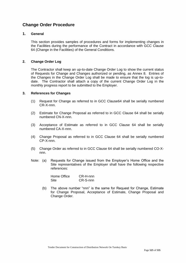
Tender Document for Construction of Distribution Network On Turnkey Basis
Page 525 of 535
Change Order Procedure 1. General
This section provides samples of procedures and forms for implementing changes in the Facilities during the performance of the Contract in accordance with GCC Clause 64 (Change in the Facilities) of the General Conditions.
2. Change Order Log The Contractor shall keep an up-to-date Change Order Log to show the current status of Requests for Change and Changes authorized or pending, as Annex 8. Entries of the Changes in the Change Order Log shall be made to ensure that the log is up-to-date. The Contractor shall attach a copy of the current Change Order Log in the monthly progress report to be submitted to the Employer.
3. References for Changes (1) Request for Change as referred to in GCC Clause64 shall be serially numbered
CR-X-nnn. (2) Estimate for Change Proposal as referred to in GCC Clause 64 shall be serially
numbered CN-X-nnn. (3) Acceptance of Estimate as referred to in GCC Clause 64 shall be serially
numbered CA-X-nnn. (4) Change Proposal as referred to in GCC Clause 64 shall be serially numbered
CP-X-nnn. (5) Change Order as referred to in GCC Clause 64 shall be serially numbered CO-X-
nnn. Note: (a) Requests for Change issued from the Employer‟s Home Office and the
Site representatives of the Employer shall have the following respective references:
Home Office CR-H-nnn Site CR-S-nnn
(b) The above number “nnn” is the same for Request for Change, Estimate
for Change Proposal, Acceptance of Estimate, Change Proposal and Change Order.
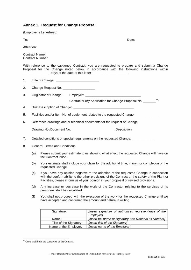
Tender Document for Construction of Distribution Network On Turnkey Basis
Page 526 of 535
Annex 1. Request for Change Proposal
(Employer‟s Letterhead) To: Date: Attention: Contract Name: Contract Number: With reference to the captioned Contract, you are requested to prepare and submit a Change Proposal for the Change noted below in accordance with the following instructions within _______________ days of the date of this letter ____________________. 1. Title of Change: ________________________ 2. Change Request No. __________________ 3. Originator of Change: Employer: _______________________________
Contractor (by Application for Change Proposal No. _______16
:
4. Brief Description of Change: __________________________________ 5. Facilities and/or Item No. of equipment related to the requested Change: _____________ 6. Reference drawings and/or technical documents for the request of Change:
Drawing No./Document No. Description
7. Detailed conditions or special requirements on the requested Change: ____________ 8. General Terms and Conditions:
(a) Please submit your estimate to us showing what effect the requested Change will have on
the Contract Price.
(b) Your estimate shall include your claim for the additional time, if any, for completion of the requested Change.
(c) If you have any opinion negative to the adoption of the requested Change in connection with the conformability to the other provisions of the Contract or the safety of the Plant or Facilities, please inform us of your opinion in your proposal of revised provisions.
(d) Any increase or decrease in the work of the Contractor relating to the services of its personnel shall be calculated.
(f) You shall not proceed with the execution of the work for the requested Change until we have accepted and confirmed the amount and nature in writing.
Signature: [insert signature of authorised representative of the Employer]
Name: [insert full name of signatory with National ID Number]
Title of the Signatory: [insert title of the Signatory]
Name of the Employer: [insert name of the Employer]
16 Costs shall be in the currencies of the Contract.
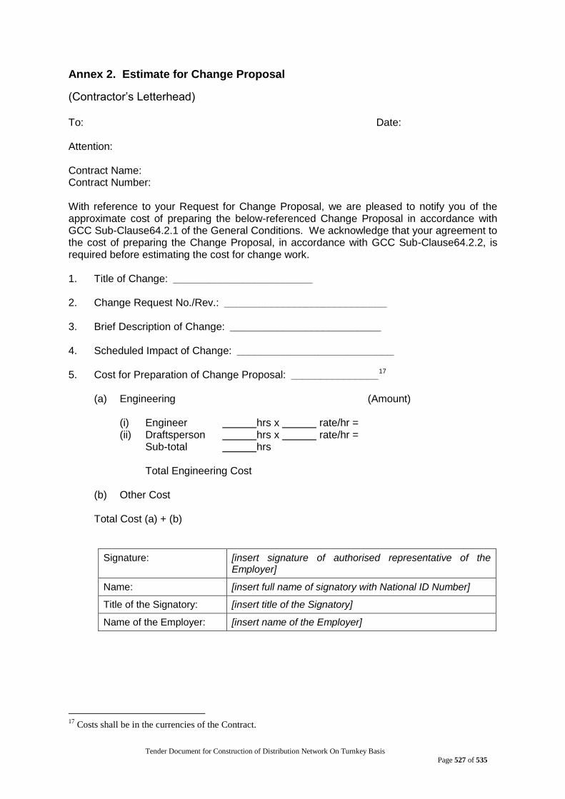
Tender Document for Construction of Distribution Network On Turnkey Basis
Page 527 of 535
Annex 2. Estimate for Change Proposal
(Contractor‟s Letterhead) To: Date: Attention: Contract Name: Contract Number: With reference to your Request for Change Proposal, we are pleased to notify you of the approximate cost of preparing the below-referenced Change Proposal in accordance with GCC Sub-Clause64.2.1 of the General Conditions. We acknowledge that your agreement to the cost of preparing the Change Proposal, in accordance with GCC Sub-Clause64.2.2, is required before estimating the cost for change work. 1. Title of Change: ________________________ 2. Change Request No./Rev.: ____________________________ 3. Brief Description of Change: __________________________ 4. Scheduled Impact of Change: ___________________________ 5. Cost for Preparation of Change Proposal: _______________17
(a) Engineering (Amount)
(i) Engineer hrs x rate/hr = (ii) Draftsperson hrs x rate/hr =
Sub-total hrs Total Engineering Cost
(b) Other Cost
Total Cost (a) + (b)
Signature: [insert signature of authorised representative of the Employer]
Name: [insert full name of signatory with National ID Number]
Title of the Signatory: [insert title of the Signatory]
Name of the Employer: [insert name of the Employer]
17
Costs shall be in the currencies of the Contract.
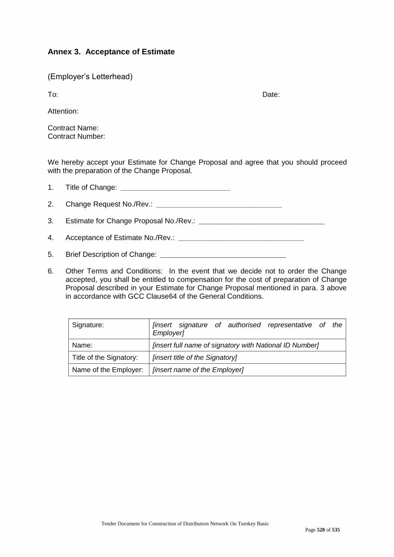
Tender Document for Construction of Distribution Network On Turnkey Basis
Page 528 of 535
Annex 3. Acceptance of Estimate
(Employer‟s Letterhead) To: Date: Attention: Contract Name: Contract Number:
We hereby accept your Estimate for Change Proposal and agree that you should proceed with the preparation of the Change Proposal. 1. Title of Change: ___________________________ 2. Change Request No./Rev.: _______________________________ 3. Estimate for Change Proposal No./Rev.: _______________________________ 4. Acceptance of Estimate No./Rev.: _______________________________ 5. Brief Description of Change: _______________________________ 6. Other Terms and Conditions: In the event that we decide not to order the Change
accepted, you shall be entitled to compensation for the cost of preparation of Change Proposal described in your Estimate for Change Proposal mentioned in para. 3 above in accordance with GCC Clause64 of the General Conditions.
Signature: [insert signature of authorised representative of the Employer]
Name: [insert full name of signatory with National ID Number]
Title of the Signatory: [insert title of the Signatory]
Name of the Employer: [insert name of the Employer]

Tender Document for Construction of Distribution Network On Turnkey Basis
Page 529 of 535
Annex 4. Change Proposal
(Contractor‟s Letterhead) To: Date: Attention: Contract Name: Contract Number: In response to your Request for Change Proposal No. _______________________________, we hereby submit our proposal as follows: 1. Title of Change: _______________________________ 2. Change Proposal No./Rev.: _______________________________ 3. Originator of Change: Employer: [_______________________________
Contractor: _______________________________ 4. Brief Description of Change: _______________________________ 5. Reasons for Change: _______________________________ 6. Facilities and/or Item No. of Equipment related to the requested Change:
_______________________________ 7. Reference drawings and/or technical documents for the requested Change:
Drawing/Document No. Description
8. Estimate of increase/decrease to the Contract Price resulting from Change Proposal:18 (Amount)
(a) Direct material (b) Major construction equipment (c) Direct field labor (Total hrs) (d) Subcontracts (e) Indirect material and labor (f) Site supervision (g) Head office technical staff salaries
18
Costs shall be in the currencies of the Contract.
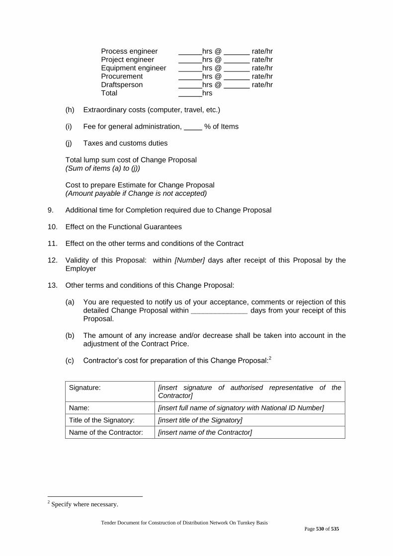
Tender Document for Construction of Distribution Network On Turnkey Basis
Page 530 of 535
Process engineer hrs @ rate/hr Project engineer hrs @ rate/hr Equipment engineer hrs @ rate/hr Procurement hrs @ rate/hr Draftsperson hrs @ rate/hr Total hrs
(h) Extraordinary costs (computer, travel, etc.) (i) Fee for general administration, % of Items (j) Taxes and customs duties Total lump sum cost of Change Proposal (Sum of items (a) to (j)) Cost to prepare Estimate for Change Proposal (Amount payable if Change is not accepted)
9. Additional time for Completion required due to Change Proposal 10. Effect on the Functional Guarantees 11. Effect on the other terms and conditions of the Contract 12. Validity of this Proposal: within [Number] days after receipt of this Proposal by the
Employer 13. Other terms and conditions of this Change Proposal:
(a) You are requested to notify us of your acceptance, comments or rejection of this detailed Change Proposal within ______________ days from your receipt of this Proposal.
(b) The amount of any increase and/or decrease shall be taken into account in the
adjustment of the Contract Price. (c) Contractor‟s cost for preparation of this Change Proposal:2
Signature: [insert signature of authorised representative of the Contractor]
Name: [insert full name of signatory with National ID Number]
Title of the Signatory: [insert title of the Signatory]
Name of the Contractor: [insert name of the Contractor]
2 Specify where necessary.
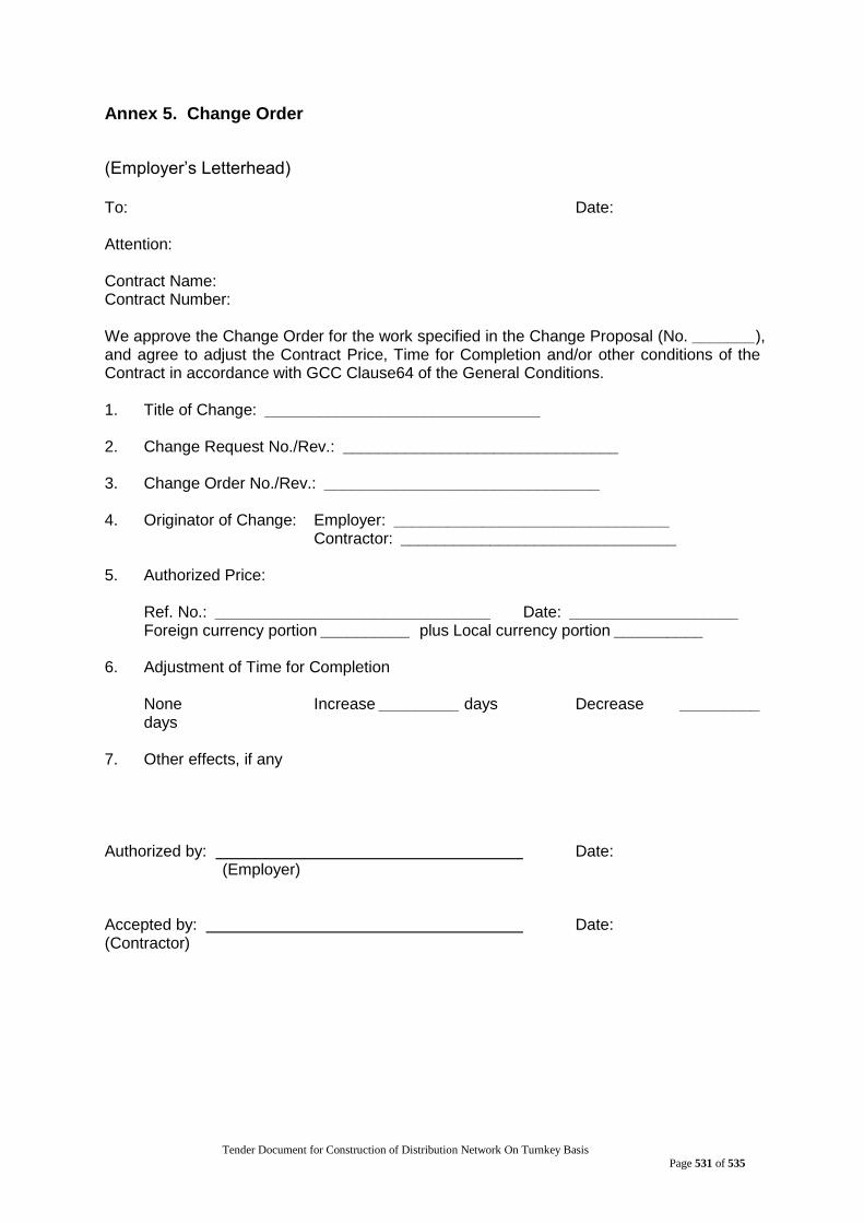
Tender Document for Construction of Distribution Network On Turnkey Basis
Page 531 of 535
Annex 5. Change Order
(Employer‟s Letterhead) To: Date: Attention: Contract Name: Contract Number: We approve the Change Order for the work specified in the Change Proposal (No. _______), and agree to adjust the Contract Price, Time for Completion and/or other conditions of the Contract in accordance with GCC Clause64 of the General Conditions. 1. Title of Change: _______________________________ 2. Change Request No./Rev.: _______________________________ 3. Change Order No./Rev.: _______________________________ 4. Originator of Change: Employer: _______________________________
Contractor: _______________________________ 5. Authorized Price:
Ref. No.: _______________________________ Date: ___________________ Foreign currency portion __________ plus Local currency portion __________
6. Adjustment of Time for Completion
None Increase _________ days Decrease _________ days
7. Other effects, if any Authorized by: Date:
(Employer) Accepted by: Date: (Contractor)
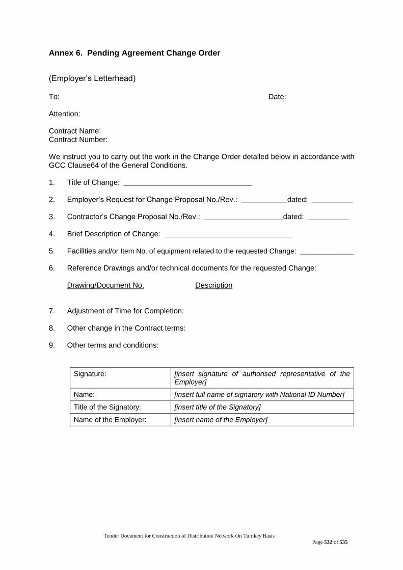
Tender Document for Construction of Distribution Network On Turnkey Basis
Page 532 of 535
Annex 6. Pending Agreement Change Order
(Employer‟s Letterhead) To: Date: Attention: Contract Name: Contract Number: We instruct you to carry out the work in the Change Order detailed below in accordance with GCC Clause64 of the General Conditions. 1. Title of Change: _______________________________ 2. Employer‟s Request for Change Proposal No./Rev.: ___________dated: __________ 3. Contractor‟s Change Proposal No./Rev.: ___________________dated: __________ 4. Brief Description of Change: _______________________________ 5. Facilities and/or Item No. of equipment related to the requested Change: _____________ 6. Reference Drawings and/or technical documents for the requested Change:
Drawing/Document No. Description 7. Adjustment of Time for Completion: 8. Other change in the Contract terms: 9. Other terms and conditions:
Signature: [insert signature of authorised representative of the Employer]
Name: [insert full name of signatory with National ID Number]
Title of the Signatory: [insert title of the Signatory]
Name of the Employer: [insert name of the Employer]
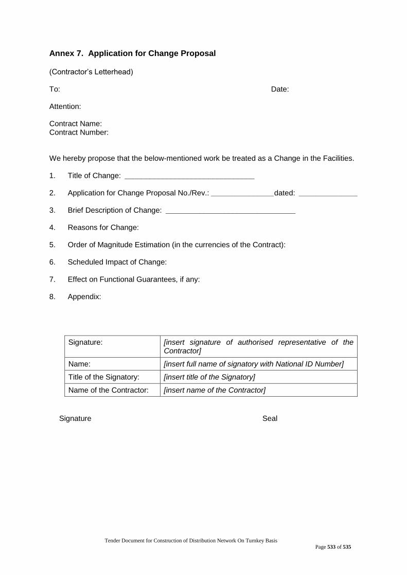
Tender Document for Construction of Distribution Network On Turnkey Basis
Page 533 of 535
Annex 7. Application for Change Proposal (Contractor‟s Letterhead) To: Date: Attention: Contract Name: Contract Number: We hereby propose that the below-mentioned work be treated as a Change in the Facilities. 1. Title of Change: _______________________________ 2. Application for Change Proposal No./Rev.: _______________dated: ______________ 3. Brief Description of Change: _______________________________ 4. Reasons for Change: 5. Order of Magnitude Estimation (in the currencies of the Contract): 6. Scheduled Impact of Change: 7. Effect on Functional Guarantees, if any: 8. Appendix:
Signature: [insert signature of authorised representative of the Contractor]
Name: [insert full name of signatory with National ID Number]
Title of the Signatory: [insert title of the Signatory]
Name of the Contractor: [insert name of the Contractor]
Signature
Seal
Tender Document for Construction of Distribution Network On Turnkey Basis
Page 534 of 535
6.6 Supplementary Information

Tender Document for Construction of Distribution Network On Turnkey Basis
Page 535 of 535
Section 7. Drawings The tenderer shall submit detail drawing of the items mentioned in price schedule. Moreover, the tenderer shall also submit installation drawing.