development of the machine shop instruction and the stirling
TRANSCRIPT
Development of the Machine Shop Instructionand the Stirling Engine Project for 2.670: ME Tools
byStacy J. Morris
SUBMITTED TO THE DEPARTMENT OFMECHANICAL ENGINEERING IN PARTIAL FULFILLMENT
OF THE REQUIREMENTS FOR THE DEGREE OF
BACHELOR OF SCIENCE IN MECHANICAL ENGINEERINGAT THE MASSACHUSETTS INSTITUTE OF TECHNOLOGY
JUNE 1996
(©1996 Stacy J. Morris. All rights reserved.
The author hereby grants M.I.T. permission to reproduceand to distribute publicly paper and electronic
copies of this thesis document in whole or in part.
Signature of Author ................... ..............
Certified by ................ ......................
.. ..... . f M echan ...... .. .. ...' Dep'nent of Mechanical EngineeringMay 10, 1996
.................................
Douglas P. Hartassistant ProfessorThesis Supervisor
Certified by ................... ........-... L-'.-.. ............... ................Kevin N. Otto
Assistant ProfessorThesis Supervisor
Accepted by . ...... - --v . .. - ............... -.-.- , ........................
-. HSr r /A; ·'·, UI'J/ Professor Peter GriffithOF TECHNt!m'! C-"' Chaifnan of the Undergraduate Thesis Committee
AUG 0 21996
L!,'I r" ':F r
Development of the Machine Shop Instructionand the Stirling Engine Project for 2. 670: ME Tools
byStacy J. Morris
Submitted to the Department of Mechanical Engineering on May 10, 1996in partial fulfillment of the requirements for the
Degree of Bachelor of Science in Mechanical Engineering
ABSTRACT
A new class called 2.670: ME. Tools, was added to the undergraduate MechanicalEngineering curriculum in 1995. 2.670 is only offered during I.A.P. and is intended forsophomore students. The purpose of the course is to provide an introduction to machiningin the Pappalardo Lab and the Lab for Manufacturing and Productivity, and toengineering computer skills on Project Athena.
In June 1995, the development 2.670: M.E. Tools began, and in less than sevenmonth;, the first class met, on January 8, 1996. This thesis will cover the development ofthe curriculum and instruction for the machining half of the class, as well as thedevelopment and production of the student project, a miniature Stirling Engine.
Thesis Supervisors: Douglas Hart, Assistant Professor of Mechanical EngineeringKevin Otto, Assistant Professor of Mechanical Engineering

ACIKNOWLEDGMENTS
I sincerely thank everyone who gave me their help, time and advice during thisentire last year of planning. Thanks for making 2.670 a resounding success!
Liv Galendez, my partner through thick and thin, thanks so much for everything,and best of luck, you're terrific to work with! Federico Frigerio, thanks for all your helpand for keeping me sane throughout all of January. Phil Houdek, thanks for all the lastminute drawings and the engine advice.
Kevin Baron, thank you for taking the time to explain everything, for all your helpand advice, and for always believing we'd somehow pull it all off!!
Fred Cote, thank you for helping with the Building 35 process plans (and tellingme their origin) and for the lever shafts. Jerry Wentworth, thank you for the alcohol caps,and for the first working M.I.T. Stirling Engines. Norm Berube, thank you for all yourhelp with the Building 3 process plans, and for innumerable parts. Norm MacAskill,thanks for all the cheer! Bob Nuttall, thanks for always asking me why I'm still in lab.Wayne Bidstrup, thanks for always stopping by to check things out. Dick Fenner, thankyou for all your help and for giving me the key to the Pappalardo Lab!
Roger Howes, at the Thayer School of Engineering, at Dartmouth University,thank you for all of your advice and help.
Peggy Garlick, thank you very much for helping us track down the students toregister, and for all your support throughout the class and at all other times!! MaureenDeCourcey, thank you for helping us order everything.
The students of the first session of 2.670, thank you for being cooperative when Isuggested you come to class on a snow day! And to the students of both sessions, thankyou so much for your patience with all the little bugs in the class, and for your wonderfulsuggestions on how to improve it!
The Undergraduate Assistants, thank you for volunteering so many hours of yourown I.A.P. time to help us out and to help make 2.670 a success!
Doug Hart and Kevin Otto, thank you both so much for all your support, guidanceand patience, for everything you've taught me, and for being a great pair of people towork for!
Lastly, I would like to dedicate this thesis to my parents, Steve and Nancy Morris.Thank you both so much for your endless supply of encouragement!!!
TABLE OF CONTENTS
1. Introduction . . . . . . . . . . . . . . . . . . . . . . . . . . . . . . . . . . . . . . 71.1 Origin ................... 7..................71.2 Goals ..................................... 71.3 Instruction .. . . . . . . . . . . . . . . . . . . . . . . . . . . . . . . . 7
1.3.1 Computer Lab . . . . . . . . . . . . . . . . . . . . . . . . . 71.3.2 Machine Shop ................... 8........ 81.3.3 Stirling Engine .. ................. ........ 8
1.4 Requirements .. . . . . . . . . . . . . . . . . . . . . . . . . . . . 91.5 Schedule .................................... 9
1.5.1 Sessions ............................... 91.5.2 Groups ............................... 10
1.6 Registration . . . . . . . . . . . . . . . . . . . . . . . . . . . . . . . . . 12
2. The Project: A Miniature Working Stirling Engine .................. 132.1 The History of the Stirling Engine . . . . . . . . . . . . . . . . . ... 132.2 The Origins of the Current M.I.T. Stirling Engine. . . . . . . . . . . . . .142.3 The M.I.T. Stirling Engine ......................... 14
2.3.1 Alcohol Burner (#001) ...................... 152.3.2 Displacer Cylinder (#002). . . . . . . . . . . . . . . . 152.3.3 Cylinder Plate (#004) . . . . . . . . . . . . . . . . . . . . . . . .152.3.4 Power Cylinder (#005) and Power Piston (#006) . . . . . . ... 152.3.5 Gudgeon Block (#007) . . . . . . . . . . . . . . . . . . ... 152.3.6 Power Connecting Lever (#008), Lever Connector (#009), . . . 16
Levers 11 & 12 (#011, #012)2.3.7 Lever Shaft (#010) and Levers 11 & 12 (#01 1, #012) ....... 162.3.8 Levers 11 & 12 (#011,#012) ................... . 162.3.9 Connector Link (#013) .. . . . . . . . . . . . . . .. . . 162.3.10 Displacer Piston Rod (#014) ................... 172.3.11 Transfer Piston Guide Bushing (#015) . . . . . . . . ... 172.3.12 Main Bearing Bushings (#019, #020) . . . . . . . . . . . . 172.313 Flywheel (#021) .. . . . . . . . . . . . . . . . . 172.3.14 Bearing Plates (#022, 023) .................... 18
2.4 The 2.670 Stirling Spin-Off Contest . . . . . . . . . . . . . . . . . .. 182.4.1 Winners of the 1996 Stirling Spin-Off . . . . . . . . . . . .. 18
3. The Machine Shop . . . . . . . . . . . . . . . . . . . . . . . . . . . . . . . . . 193.1 Division of Parts. . . . . . . . . . . . . . . . . . . . . . . . . . . . . . . 193.2 Division of Part Processes and the Process Plans . . . . . . . . . .. 19
3.2.1 The 2.670 Process Plans . . . . . . . . . . . . . . . . . ... 203.2.2 The History of the 2.670 Process Plan . . . . . . . . . . .... 21
3.2.3 Recommended Changes to the Process Plans ............... 22

3. The Machine Shop, cont.3.3 Division of Students . . . . . . . . . . . . . . . . .. . . . . . . . . 223.4 Division of Instructors . . . . . . . . . . . . . . . .. . . . . . 23
3.4.1 Comments on Instructors during 1996 and . . . . . . . . . . . . . 25Recommendations for Future 2.670 Classes
3.5 Recommended Changes to the M.I.T. Stirling Engine . . . . . . . . . 263.5.1 Alcohol Burner (#001) . . . . . . . . . . . . . . . . . . . . . . 263.5.2 Displacer Piston (#003) .................... 263.5.3 Displacer Cylinder (#002) and Cylinder Plate (#004) . ...... 263.5.4 Power Connecting Lever (#008), Lever Connector (#009), .... 26
Levers 11 & 12 (#011, #012)3.5.5 Lever Connector (#009) and Levers 11 & 12 (#011, #012) . . . . 273.5.6 Displacer Piston Rod (#014) . .. ................. 273.5.7 Crank Web (#016) ......................... 273.5.8 Bearing Plates (#022, 023) ............. .. ... 27
4. Preparation for the Course .. ........................... 284.1 Vendor Information . . . . . . . . . . . . . . . . .. . . . . . 284.2 The Stirling Engine Components . . . . . . . . . . . . . . . . . . . . . . . 314.3 Fasteners for the Stirling Engine . . . . . . . . . . . . . . . . . . . . . 334.4 The Student Tool Kit . . ... . . . . ........ . . . .334.5 Tools Purchased for Use in the Pappalardo Lab ............... 364.6 The Supplies ................................. 364.7 The Start-Up Supplies Supplies ....................... 36
5. Surveys . . . . . . . . . . . . . . . . . . . . . . . . . . . . . . . . . . . . . . . . 395.1 Overall .................................... 395.2 Machine Shop ................... ............. 39
5.21 Pappalardo Lab . .... ...... 405.22 Lab for Manufacturing and Productivity .............. 40
5.3 Computer Labs . . . . . . . . . . . . . . . . . . . . . . . . . . . .. . . 415.31 XESS .......... .... . ............ 415.32 Matlab . ........ . . ..........425.33 Pro/Engineer. . . . . .. . . . . . . . . . . . . 42
5.4 Safety . . . . . . . . . . . . . . . . . . . . . . . . . ..... . . . . 425.5 Schedule . . . . . . . . . . . . . . . . . . . . . . . . . . . . . . . . . . 43
6. The Course Manual .................................. 44Table of Contents (for Course Manual) .. . . . . . . . . . . . . . . . . . . 46
7. Conclusions and Recommendations .. ....................... . . 111
Appendix 1. Notification Memos . . . . . . . . . . . . . . . . . . . . . . . . . . . .112Appendix 2. Student Survey . . . . . . . . . . . . . . . . . . . . . 116

TABLE OF FIGURES
The M.I.T. Stirling Engine .The 2.670 Session Schedule, I.A.P. 1996 .The 2.670 Group Schedule, I.A.P. 1996 .The 1816 Stirling Engine .The M.I.T. Stirling Engine.The 1996 Beauty Contest and Stirling Spin-Off WinnersDivision of Student-made Parts Between Machine Shops.A Generic Process Plan.The 2.670 Process Plans and Page Location in this Thesis .A 1920 Process Plan for Machining a Square Thread Nut .Division of Students between Machine Shops and ProcessesDivision of Instructors between each Machine Shop .Vendor Information (A-L) .Vendor Information (M-Z).Information for the Stirling Engine Components.The Starting Materials for the Stirling Engine .The Finished Parts of the Stirling Engine.Information for the Stirling Engine Fasteners.Information for the Tool Kits .The 1996 Tool Kit.Information for the Student-Used Tools in the Pappalardo LabInformation for the SuppliesInformation on the Start-Up Materials .Students' Self-Ratings .
Figure 1.Figure 2.Figure 3.Figure 4.Figure 5.Figure 6.Figure 7.Figure 8.Figure 9.Figure 10.Figure 11.Figure 12.Figure 13.Figure 14.Figure 13.Figure 16.Figure 17.Figure 18.Figure 19.Figure 20.Figure 21.Figure 22.Figure 23.Figure 24.
. 810
.111314181920
· 2021
.23· 24
29· 30
3231
.313435333738
. . . 3839

1. INTRODUCTION
1.1 ORIGIN
2. 670: ME Tools was created during the revisions of the undergraduate curriculum
in 1995. The development of 2.670 started in June 1995. It was first taught during the
Independent Activities Period (I.A.P.) of the 1995-1996 M.I.T. academic year, and was
added as a required course to the undergraduate curriculum effective for the graduating
class of 1998. It is the first required course at M.I.T. which is offered only during I.A.P.
This thesis will cover what is required in the development and administration of the
machine shop half of this course.
1.2 GOALS
The purpose of creating this new class was to provide students with the tools
needed for interactive learning in their future classes. The new curriculum revisions
sought to teach students with less straight lecture and more interaction between the
faculty and the students. As this would require different skills on the part of the students,
2. 670:ME Tools was created to give the students a thorough introduction to several of the
tools necessary for an undergraduate education in the Mechanical Engineering
Department at M.I.T.
1.3 INSTRUCTION
There are two distinct parts of 2.670, computer lab instruction and machine shop
instruction. This thesis will address the issues concerned with the preparation for and the
instruction in the machine shop (for information on the computer lab instruction, see
Galendez [1]).
1.3.1 Computer Lab
In the computer lab, students were introduced to several of the computing
programs available on the Athena system. They spent one day on an overview of Project
Athena (the M.I.T. campus-wide computing system) and the World Wide Web, and one
7

day on XESS (the spreadsheet on Athena designed for science and engineering
computing); the instruction for these first two days was in lecture halls, followed by
homework assignments on Athena. The students then received instruction on Matlab and
Pro/Engineer, for three days consecutive days each, in computer classrooms.
1.3.2 Machine Shop
On the first day of the class, the students were introduced to safety issues in both
the shop and in engineering practice. Starting on the second day, they learned, throughout
the course, how to use the drill press, the beltsand.:r, th,: bandsaw, the lathe, the vertical
and horizontal mills. as well as how to read use tap/die and drill sizes, and how to layout
(mark and scribe). They also observed the Cincinnati Millicron and the Daewoo Lathe.
Both the Pappalardo Lab in Building 3 and the Lab for Manufacturing and Productivity
(LMP) in Building 35 were utilized to teach the students.
1.3.3 The Stirling Engine
A Stirling engine was used as a teaching tool in both aspects of the course. In the
machine shop, every student made slightly more than half the parts of a miniature
working Stirling engine, as shown in Figure 1. The students were provided with the other
parts, and assembled and debugged their own engine. In the computer lab, students
analyzed the Stirling engine in their Xess and Matlab homework assignments.
Figure 1. The M.I.T. Stirling Engine [2]
8

1.4 REQUIREMENTS
The students received six units of pass/fail credit for completion of the course. In
order to pass, the students had to attend (or be excused from) all of the class hours,
complete all homework (assigned during the World Wide Web, the Xess, and the Matlab
sessions), and make all of the required Stirling engine parts. A working Stirling Engine
was not a requirement; however, only three students were unable to get their engines
running by the end of the class.
1.5 SCHEDULE
Due to the large number of students who needed to take the class (the maximum
was set at 160 students), the class was split into two sessions of 80 students each, and
within each session, the students were split into four groups of 20 students each.
1.5.1 Sessions
There were two sessions of 2.670 offered, each of which met for nine days over a
two week period, with the second Monday as a day off (Martin Luther King Day during
the first session). Session 1 met on 1/8/96 - 1/12/96 and on 1/16/96 - 1/19/96, and Session
2 met on 1/22/96 - 1/26/96 and on 1/30/96 - 2/2/96, as shown in Figure 2. Each day, the
class met for eight hours, from 8 AM - 12 NOON and from 1 PM - 5 PM.
9

Figure 2. The 2.670 Session Schedule, I.A.P. 1996
1.52 Groups
Within each session, the students were divided into four groups (the students were
assigned alphabetically). Two of these groups were in the machine shop in the morning
and in the computer lab in the afternoon, and the other two were in the computer lab in
the morning and the machine shop in the afternoon, as shown in Figure 3.
Each pair of groups met together during the first two days of computer instruction
and then met separately for Pro/Engineer and Matlab instruction (three consecutive days
of each). Similarly, they also met separately in the L.M.P. and the Pappalardo Lab (again,
three consecutive days of each), until the last two days of class, when they both met in the
Pappalardo Lab for assembly of the engines. In order to distinguish between the groups,
each group was given a planet name (Mercury, Mars, Venus, Jupiter in Session 1, and
Saturn, Uranus, Neptune, Pluto in Session 2).
10
Monday Tuesday Wednesday Thursday Friday Saturday Sunday
1/8 1/9 1/10 1/11 1/12 1/13 1/14
Session 1 Session 1 Session 1 Session I Session I no class no class
Day I Day 2 Day 3 Day 4 Day 5
first day of IAP
1/15 1/16 1/17 1/18 1/19 1/20 1/21
no class Session I Session I Session I Session I no class no class
[MLK Day] Day 7 Day 8 Day 9 Day 10
1/22 1/23 1/24 1/25 1/26 1/27 1/28
Session 2 Session 2 Session 2 Session 2 Session 2 no class no class
Day I Day 2 Day 3 Day 4 Day 5
1/29 1/30 1/31 2/1 2/2 2/3 2/4
no class Session 2 Session 2 Session 2 Session 2 no class no class
Day 7 Day 8 Day 9 Day 10
last day of lAP

8 -9 AM
9 - 10:30 AM
10:30 -12 NOON
I -3 Px
3 - P.
8 - 12 NOON
I - 5 P-M
PaplroLb .PMtabPoEge
Introductionfor all groups
8 - 12 NOON
I - 5 P\M
8 - 12 \OON
I - 5 PM1
8- 12 NOON
I - 5 P\
8 - 12 NOON
I - 5 p\M
8 - 12 ooN
- 3 Pr
3 -5 Pm
ii
Pappalardo Lab (engine assemb i ::j'""~'',~.'..I' I *, _ 01 j
Pappalardo Lab open to all four groupsforfinal engine assembl)
All four groups meet for final lecture and Pt Tau Sgma evaluations
All four groups meet in Pappalardo Labfor the Stirling Spm Contest
Figure 3. The 2.670 Group Schedule, I.A.P. 1996
11
Day 1
Day 2
Day 3
Day 4
Day 5
Day 6
Day 7
Day 8
i
Day 9
Day 10
I 1
| I _ _ _
I
Illl
I
--- --~~~~~~
I
Pappalardo Lab I L.M.P | Matlab IPro/Engineer
1.6 REGISTRATION
As the first required class during I.A.P., there was no previously established
protocol for registration for the class. For traditional I.A.P. classes, students informally
register either late in the Fall Semester or on the first day of the class during I.A.P.
However, as a required class with two separate sessions, session assignments (which
affected many students travel arrangements) and the total number of students in each
session had to be completed prior to the first day of the first session. In order to
accomodate these needs, registration for the class was carried out on the World Wide
Web during the first week of school in the fall semester. All advisors were sent letters
(Appendix 1) notifying them to remind their sophomore students to register for the
course. and the students were sent similar letters (see Appendix 1), as well as instructions
for starting a web browser and registering for the class (see Appendix 1). The list of
students who registered was checked against the list of sophomore students who were
registered in October and November as "Course 2", and any "missing" students were
notified and asked to register.
12

2 THE PROJECT: . MINIATURE WORKINGSTIRLING ENGINE
2.1 THE HISTORY OF THE STIRLING ENGINE
On September 27, 1816, Robert Stirling applied for a patent for an engine, as
shown in Figure 4, at the Chancery in Edinburgh, Scotland. By trade, Robert Stirling was
a minister in the Church of Scotland and he continued to give services until he was
eighty-six years old. In his spare time, however, he built heat engines in his home
workshop. Lord Kelvin used one of the working models during some of his university
classes. In 1850, the simple and elegant dynamics of the engine were first explained by
Professor McQuorne Rankine. Approximately one hundred years later, the term Stirling
engine was coined by Rolf Meijer in order to describe all types of closed cycle
regenerative gas engines.
Figure 4. The 1816 Stirling Engine [3]
Stirling engines are unique heat engines because their theoretical efficiency is
nearly equal to their theoretical maximum efficiency, known as the Carnot Cycle
efficiency. Stirling engines are powered by the expansion of a gas when heated, which is
followed by the compression of the gas when cooled. The Stirling engine contains a fixed
amount of gas which is transferred back and forth between a "cold" end (often room
temperature) and a "hot" end (often heated by a kerosene or alcohol burner). The
"displacer piston" moves the gas be:ween the two ends and the "power piston" changes
the internal volume as the gas expands and contracts.
13

2.2 THE ORIGINS OF THE CURRENT M.I.T. STIRLING ENGINE
The current M.I.T. Stirling Engine was first featured in an article in Popular
Science. It was developed at Dartmouth University by Roger Howes for use in an Thayer
School of Engineering class, ES 61 Thermodynamics. The class was first taught in the
early eighties, and became a required class for engineering majors in 1994. Roger Howes
estimated that at least 1 100 engines were built between the inception of the class and the
spring of 1996.
2.3 THE M.I.T. STIRLING ENGINE
The Stirling engine was further adapted, during the Summer and Fall of 1995, to
fit the needs of 2.670. Each part was designed to teach the students about a different
aspect of machining. The final version of the engine is shown in Figure 5 (individual part
drawings can be found on pages 70-105; page 65 contains a list of parts and numbers).
This section will discuss the teaching benefits several parts of the M.I.T. Stirling Engine.
i
Figure 5. The M.I.T. Stirling Engine [4]
14
ir
W

2.3.1 Alcohol Burner (#001)
The alcohol burner consisted of a glass jar and a brass cap. The glass jar was used
to store all of the fasteners which the students received. The brass cap was manufactured
on the Daewoo Lathe, and had a groove cut for an o-ring. The use of an o-ring insured a
tight fit with the glass jar, and showed the students how to obtain a leak-proof fit.
2.3.2 Displacer Cylinder (#002)
The displacer cylinder was silver-soldered, which prevented the application of
extremely high temperatures (such as those generated by a blow-torch) at the hot end of
the piston.
2.3.3 Cylinder Plate (#004)
This was made by the students in Building 3, where they used a jig to drill five
holes in the face, and rounded two of the corners on the beltsander. Since the cylinder
plate was made of brass and is 3/8" thick in the direction of drilling, the necessity of
applying drilling fluid and "peck" drilling (backing the drill off) was readily apparent.
The students traced rounded corners onto their piece, using blue die and a scribe, and then
cut off the corners outside of the traced mark on the bandsaw. They finished off the
curves on the beltsander, which gave them a feel for the hardness of brass.
2.3.4 Power Cylinder (#005) and Power Piston (#006)
These parts demonstrated Computer Numerical Controlled (CNC) programming
and the rapid cycle time which is possible on the Daewoo Lathe.
2.3.5 Gudgeon Block (#007)
This is one of the more difficult parts which the students made on the lathe;
because of its small size. After facing and turning the part and drilling a hole through the
center on the lathe, the students used the horizontal mill to make the slot.
15
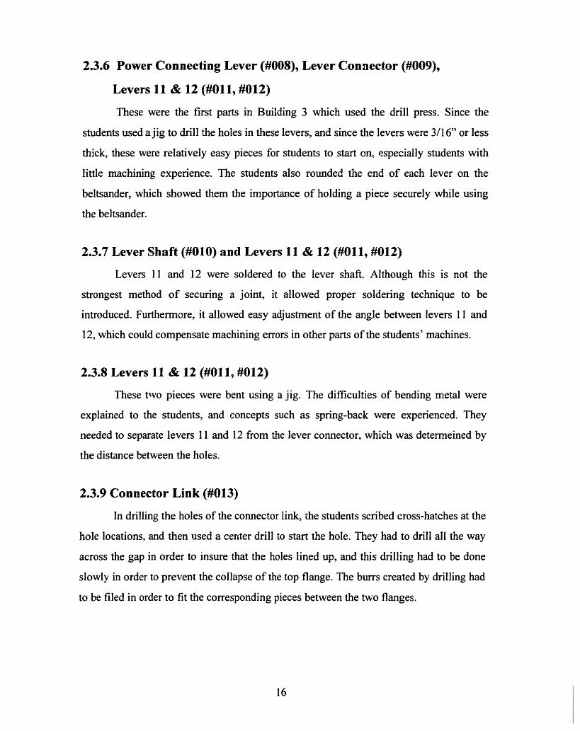
2.3.6 Power Connecting Lever (#008), Lever Connector (#009),
Levers 11 & 12 (#011, #012)
These were the first parts in Building 3 which used the drill press. Since the
students used ajig to drill the holes in these levers, and since the levers were 3/16" or less
thick, these were relatively easy pieces for students to start on, especially students with
little machining experience. The students also rounded the end of each lever on the
beltsander, which showed them the importance of holding a piece securely while using
the beltsander.
2.3.7 Lever Shaft (#010) and Levers 11 & 12 (#011, #012)
Levers 11 and 12 were soldered to the lever shaft. Although this is not the
strongest method of securing a joint, it allowed proper soldering technique to be
introduced. Furthermore, it allowed easy adjustment of the angle between levers 11 and
12, which could compensate machining errors in other parts of the students' machines.
2.3.8 Levers 11 & 12 (#011, #012)
These two pieces were bent using a jig. The difficulties of bending metal were
explained to the students, and concepts such as spring-back were experienced. They
needed to separate levers 11 and 12 from the lever connector, which was determeined by
the distance between the holes.
2.3.9 Connector Link (#013)
In drilling the holes of the connector link, the students scribed cross-hatches at the
hole locations, and then used a center drill to start the hole. They had to drill all the way
across the gap in order to insure that the holes lined up, and this drilling had to be done
slowly in order to prevent the collapse of the top flange. The burrs created by drilling had
to be filed in order to fit the corresponding pieces between the two flanges.
16
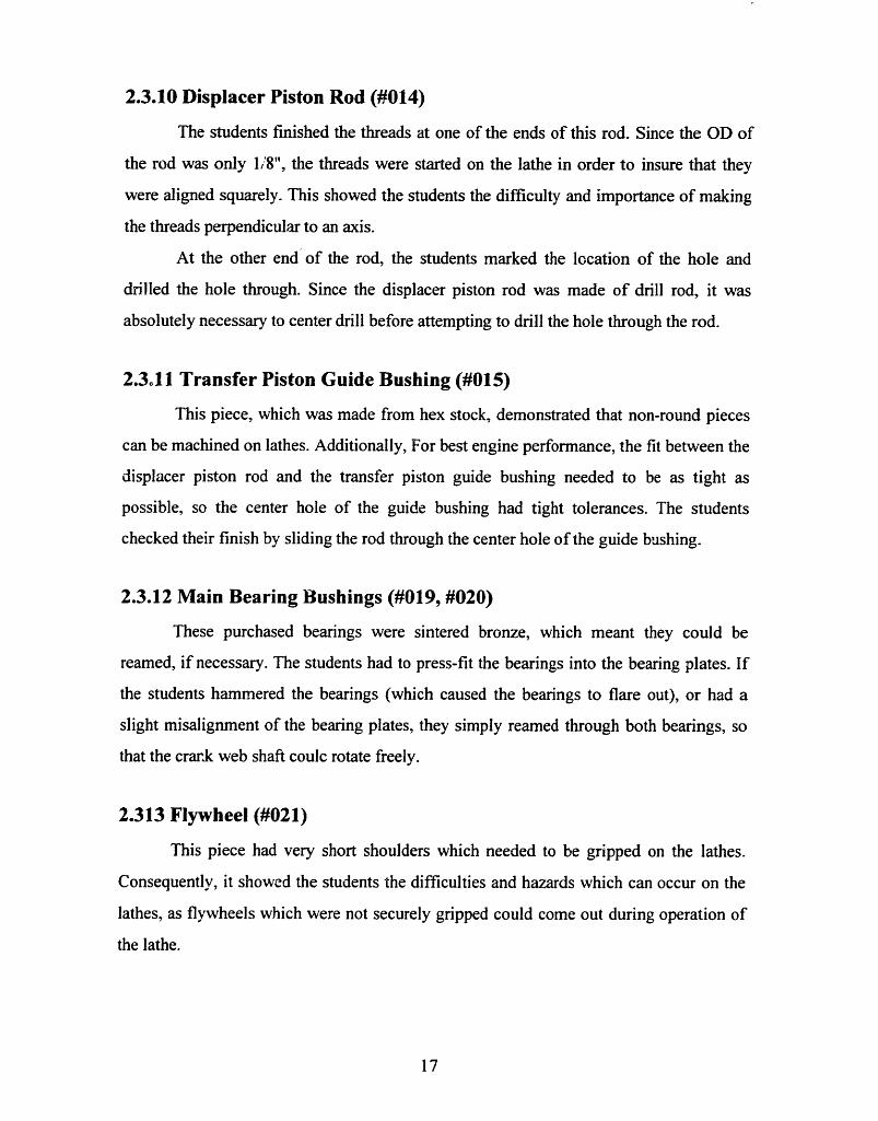
2.3.10 Displacer Piston Rod (#014)
The students finished the threads at one of the ends of this rod. Since the OD of
the rod was only 1/8", the threads were started on the lathe in order to insure that they
were aligned squarely. This showed the students the difficulty and importance of making
the threads perpendicular to an axis.
At the other end of the rod, the students marked the location of the hole and
drilled the hole through. Since the displacer piston rod was made of drill rod, it was
absolutely necessary to center drill before attempting to drill the hole through the rod.
2.3l11 Transfer Piston Guide Bushing (#015)
This piece, which was made from hex stock, demonstrated that non-round pieces
can be machined on lathes. Additionally, For best engine performance, the fit between the
displacer piston rod and the transfer piston guide bushing needed to be as tight as
possible, so the center hole of the guide bushing had tight tolerances. The students
checked their finish by sliding the rod through the center hole of the guide bushing.
2.3.12 Main Bearing Bushings (#019, #020)
These purchased bearings were sintered bronze, which meant they could be
reamed, if necessary. The students had to press-fit the bearings into the bearing plates. If
the students hammered the bearings (which caused the bearings to flare out), or had a
slight misalignment of the bearing plates, they simply reamed through both bearings, so
that the crank web shaft coulc rotate freely.
2.313 Flywheel (#021)
This piece had very short shoulders which needed to be gripped on the lathes.
Consequently, it showed the students the difficulties and hazards which can occur on the
lathes, as flywheels which were not securely gripped could come out during operation of
the lathe.
17
2.3.14 Bearing Plates (#022, 023)
These were the only pieces which the students used with the vertical mill. Due to
time and machine constraints, they only used the mill to drill two holes, but this gave
them exposure to the digital read outs, finding a precise location, as well as the operation
of the vertical mill.
The students layed out two perpendicular lines on each bearing plate, and used the
bandsaw to cut along the lines. They used the beltsander to round the corners, and as with
the cylinder plate, this gave them a feeling for the hardness of aluminum.
2.4 THE 2.670 STIRLING SPIN-OFF CONTEST
A contest was held on the last afternoon of class. This included a "Beauty
Contest" to determine the best-looking engines, and the "Stirling Spin-off' to determine
the fastest engines. Certificates were awarded to winners in two categories, "modified"
and "unmodified" engines. "Unmodified" engines were those which were made exactly
according to the process plans, and "modified" engines were those which had any
modifications from the process plans.
Since the class was developed as an introductory class, some of the students who
had prior machine shop experience finished their parts more quickly, so they were
encouraged to design and build modifications, such as heat sinks, to improve the
efficiency of their engines.
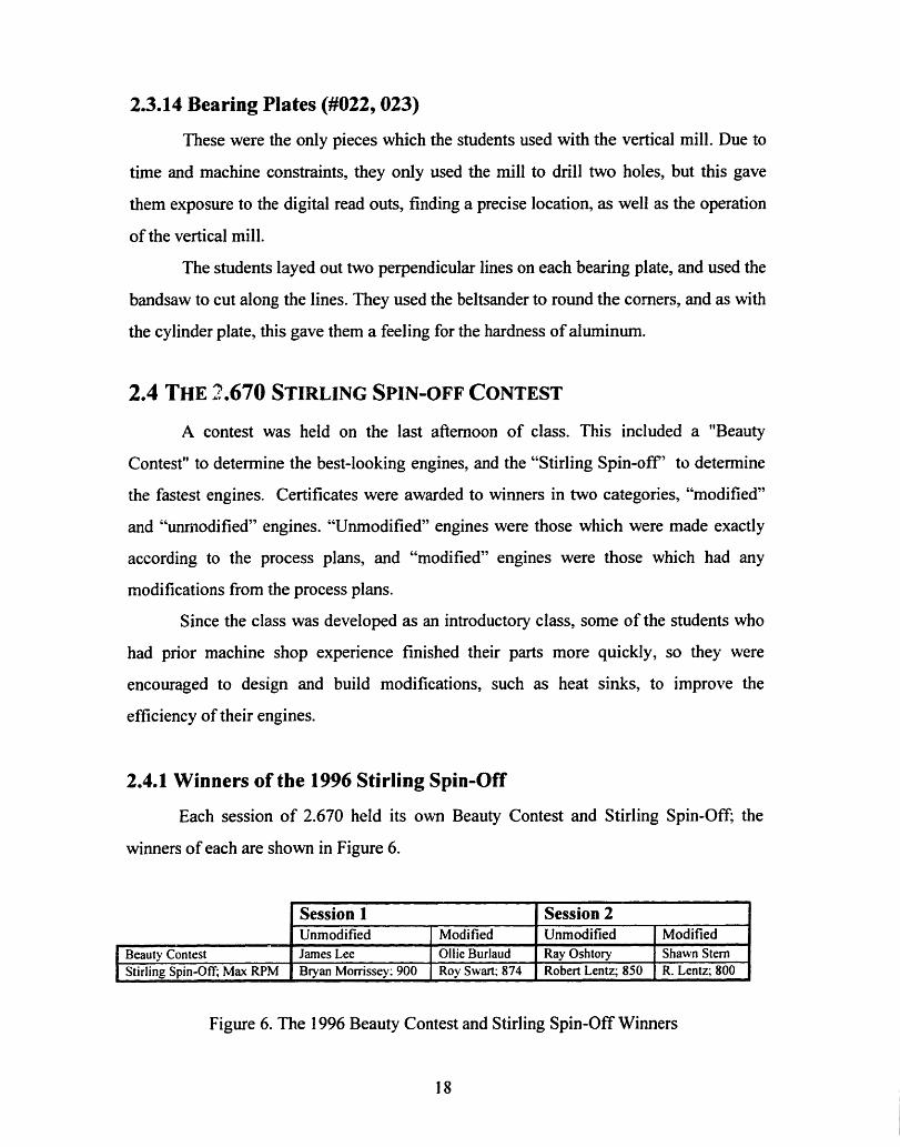
2.4.1 Winners of the 1996 Stirling Spin-Off
Each session of 2.670 held its own Beauty Contest and Stirling Spin-Off; the
winners of each are shown in Figure 6.
Session 1 Session 2Unmodified Modified Unmodified Modified
Beauty Contest James Lee Ollie Burlaud Ray Oshtory Shawn SternStirling Spin-Off; Max RPM Bryan Morrissey; 900 Roy Swart; 874 Robert Lentz; 850 R. Lentz; 800
Figure 6. The 1996 Beauty Contest and Stirling Spin-Off Winners
18

3. THE MACHINE SHOP
In order to meet the requirement of teaching 80 students machining skills in less than 36
hours over two weeks (twice). such that each student could successfully assemble an engine, the
optimal schedule which would allow the most learning to take place had to be determined. This
included determining the division of student-made parts between machine shops, the division of
part fabrication and the "process plans" of each part in both machine shops, the student division
between machine shops and within each machine shop, as well as the division of instructors.
As described in Section 1.5.2 Groups. within each session, the students were divided into
four groups of twenty students each, so that, utilizing both machine shops in the morning and
afternoon,on most days the maximum number of students in either machine shop was twenty
students.
3.1 DIVISION OF PARTS
After deciding which parts would be made by the students, the parts were split
between the two machine shops as shown in Figure 7.
Pappalardo Lab L.M.P.
Cylinder Plate (004) Gudgeon Block (007)
Power Connecting Lever (008) Transfer Piston Guide Bushing (015)
Lever Connector (009) Crank Web (01 7)
Levers 11 & 12 (011, 012) Flywheel (#020)
Connector Link (013)
Displacer Piston Rod (014)
Bearing Plates (021, 022)
Figure 7. Division of Student-Made Parts between Machine Shops
3.2 DIVISION OF PART PROCESSES AND THE PROCESS PLANS
As mentioned above, the parts needed to be made by the students in such a
manner as to minimize waiting time and maximize learning time.
19

3.2.1 The 2.670 Process Plans
The manufacturing of the parts was divided into separate processes, and process
plans were developed for each process by the author, in conjuction with Kevin Baron and
Fred Cote in the L.M.P, and with Norman Berube and Federico Frigerio in the
Pappalardo Lab. A generic process plan is shown in Figure 8.
Figure 8. A Generic Process Plan
The process plans for each process, as listed in Figure 9, can be found in section 6. The
Course Manual, on pages 69-94.
Pappalardo Lab Process Plans L.M.P. Process Plans
Process Part(s) Invoved in Process Page Process Part Invoved in Process Page
3-A Cylinder Plate, Connector 69 35-A Transfer Piston Guide Bushing 85Link, and Bearing Plates
3-B Bearing Plates 71-72 35-B Gudgeon Block 87-883-C Power Connecting Lever 75 35-C Crank Web 89,91
Lever Connector, andLevers I1 and 12
3-D Cylinder Plate 77 35-D Flywheel 93,943-E Displacer Piston Rod 793-F Connector Link 81
3-G Cylinder Plate and 82Bearing Plates
Figure 9. The 2.670 Process Plans and Page Location in this Thesis
20
Part Name Part Number Buildingpart name here part number here X'
Material Start Size Processmaterial of part here start size of part here
Op # Workplaces Tools Drawings Instructions and Parameters Completeor Part (,check)
010 Machine or Tool or part Sketch for Detailed instructions and cautionary notesstation for this name needed clarification of for each operationoperation for this this operation,
operation as necessary
020 'In Building" and Process, X is either "3"forthe Pappalardo Lab, or 35" for the L.M.P.
030-In 'Process, N is a letter, which is used to
etc. distinguish the process plans in each shop.

3.2.2 The History of the 2.670 Process Plan
The format of the process plans used in 2.670 was developed from a plan used in
2.86: Introduction to Manufacturing (now 2.008). The origins of this format, however,
stretch back many years. As shown in Figure 10, plan organization by separation of
operations, tools, and instructions was in use in 1910, the time of the first copyright of the
Textbook of Advanced Machine Tools [5].
SQUARE THREAD NUT 519
29. To make a Square thread nut, Fig. 27.
TAP I OtA. 5 THDS. TO t
ToA11_n
r
Fla. 27.- ScaEDu. I)na&tnar oF SQUAR, THREAD NUT.
Specifications: Preparing nut blank. Rough threading. Tapping.Material, iron casting, cored; weight, 1 lb. 6 oz.Hardnew, 29 to 31 (clerocope).Hligh-sped steel or stellite cutting tools.Time: Study drawing and schedule in advance, 5 min. --Oil lathe, 4 min.--Bore, thrt-nd, and tap nut, 40 min.-Square, turn, and nurl nut, 2 min. - (All tools furnished.)Clean lathe, 3 min. -Total, I h. 20 min.
SCHEDULE OF OPERTIONS, IA(CIIINFS AND) TOOLS
Mount in chuck, true up andclamp hard in chuck.
Rough sluare. (1), one or twocuts. Feed inward.
Rough bore hole to about1.03', (2), two or three cuts.
Finish bore hole, (2), two orthree cuts.
Or omit boring, bevel cornerof hole and drill to size.
MACHLLVS, SPrF r,Fr. ims.
Enrine lathe, 12 to16'. 3d speed, or20(o R.P.M.
2d or 3d speed, or 40F.P.M. Hand orpower feed.
1st or 2d speed, or 40F.P.M. Mediumpower feed - 80 to1'.
3d speed, or 60 F.P.M.fine power feed -140 to 1'.
2d or 3d spd, or 60F.P.M.
Toots.
Independent chuck,chalk.
Round-nose tool, orholder and cutter,15' rake.
Boring Lool, see p. 604.Inside calipers, rule.
3 or 4-gronve high-speed steel twistdrll (I.0-3';.
S,'e p. 41n o:d Prtn., 1 . of tfte
' o,..
Figure 10. A 1910 Process Plan for Machining a Square Thread Nut [5]
21
3.2.3 Recommended Changes to the Process Plans
The Drawings heading on the process plans should be changed to Photos, and
pictures of each step (as necessary) should be inserted. This was the original purpose of
this column, but was implementation for the 1996 class was impossible due to time
constraints. Additionally, perhaps reference numbers could be added for clarity to both
the process plans and the part drawings, as in the process plan from 1920.
The process plans for each part should be reviewed each year following the
completion of the course, and should be confirmed each year with the machine shop staff
who will be helping with the instruction of the students. In particular, the process plans
for the displacer piston rod should be revised to minimize accidental bending of the rod.
As well, the process plan listed for the crank web has instructions for making the crank
web from aluminum stock of 1.5" OD. In 1996, the students were actually given a part
which was nearly completed on the Daewoo Lathe. The original process plan was left in
this thesis in the event that the option of manufacturing the entire part is given to the
students in a following year.
3.3 DiviSION OF STUDENTS
The division of the 160 students into eight groups of twenty (four groups per two-
week session) allowed for a maximum of twenty students, in general, to be present in
each machine shop. Additionally, the students worked with partners in both machine
shops, which reduced the number of actual student operations to ten. As shown in Figure
11, the students were split into two groups on their first two days in the Pappalardo Lab,
to adjust for the number of vertical milling machines, so each half of the students did the
processes of the first two days in one of two possible orders, in the Pappalardo Lab.
However, in the L.M.P., there were enough lathes to accomodate each pair of students, so
the students went through all the processes in parallel, in the L.M.P.
22

Day 1 9- 10:30AM
10:30- 12 NOON
I -3 PM
3 - 5 Pl
Day 2 8 - 12 NooN
I - 5 Pm
Day 3 8 - 12 NooN
I - 5 PM
Day 4 8 - 12 NOONI - 5 PM
Day 5 8 - 12 NOON
I -5 PM
Day 6
Day 7 8 -12 NN
I -5 PM
Day 8 8- 12 NOONI - 5 PM
Day 9 8-12 NOONI -5 PM
Day 10 8- 12 NooN3-5 PM
Pappalardo LabInstruction
Introduction. Demos.SafetyLectureIntroduction. Demos.SafetyLectureIntroduction. Demos.SafetyLectureIntroduction. Demos.SafetyLectureProcesses 3-A & 3-BOR Processes 3-C. 3-D & 3-EProcesses 3-A & 3-BOR Processes 3-C., 3-D & 3-EProcesses 3-C. 3-D & 3-EOR Processes 3-A & 3-BProcesses 3-C. 3-D. & 3-EOR Processes 3-A & 3-BProcesses 3-F & 3-G
Processes 3-F & 3-G
Processes 3-A & 3-BOR Processes 3-C. 3-D & 3-EProcesses 3-A & 3-BOR Processes 3-C, 3-D & 3-E
Max #Students
20
20
20
20
101010101010101020
20
10101010
L.M.P.Instruction
Introduction. Demos
Introduction. Demos
Introduction. Demos
Introduction, Demos
Process 35-BStart 35-AProcess 35-BStart 35-AFinish Process 35-A,Start 35-DFinish Process 35-A.Start 35-DFinish Process 35-D. 35-C
Finish Process 35-D, 35-C
Process 35-BStart 35-AProcess 35-BStart 35-A
Max
Students20
20
20
20
20
20
20
20
20
20
20
20
NO CLASS
Processes 3C. 3-D & 3-E 10 Finish Process 35-A, 20OR Processes 3-A & 3-B 10 Start 35-DProcesses 3-C. 3-D, & 3-E 10 Finish Process 35-A. 20OR Processes 3-A & 3-B 10 Start 35-DProcesses 3-F & 3-G 20 Finish Process 35-D, 35-C 20Processes 3-F & 3-G 20 Finish Process 35-D. 35-C 20
Engine Assembly 40 Open for fixing/remaking parts 40
Engine Assembly 40 Open for fixing/remaking parts 40Final Assembly 80 Open for fixing/remaking parts 80Stirling Spin-Off 80 0
Figure 11. Division of Students between Machine Shops and Processes
3.4 DIVISION OF INSTRUCTORS
With twenty students in each machine shop at one time, at least 4 instructors were
needed in each machine shop, in order to have one instructor for every 5 students. This
was accomplished by using two technical instructors in each machine shop, two
Undergraduate Assistants (UA's) in each shop, and assigning each professor to two of the
groups in each session. The professors and the UA's remained with the same groups
23
!
l
-

throughout each session, rotating between machine shops with the students. Additionally,
there was a grad TA in the Pappalardo Lab, to assist with instruction on the vertical mill,
and the author, who was one of the two Head UA's (the other Head UA, Liv Galendez,
was in charge of the computer instruction) also remained in the Pappalardo Lab, in order
to assist in the non-mill instruction and oversee the 2.670 office, which was located at one
end of the Pappalardo Lab.
The recommended instructor load for each machine shop is shown in Figure 12,
along a record of the instructors from 2.670, 1996.
Figure 12. Division of Instructors between each Machine Shop
24
RECOMMENDED DUTIES INSTRUCTORS DURING 2.670, 1996
INSTRUCTORS NAME TITLE
Pappalardo Lab
2 Technical Instructors Each at one of the three Dick Fenner General Managervertical mills to instruct a pair Norman Berube Project Machinistof students.
2 TA's One at the 3rd vertical mill. Federico Frigerio Grad TA(or I TA and One in charge of the "office", Stacy Morris Head UA (one of two)I Head UA) oversees non-mill processes,
and coordination of UA's.2 UA's Rotate between shops with 1-2 undergrads UA
students. In charge of aparticular process.
I Professor Rotates between shops with Doug Hart or Professorstudents, in shop as possible. Kevin Otto Professor
L.M.P.2 Technical Instructors Oversee all the operations in Kevin Baron Technical Instructors
the L.M.P. Fred Cote Research Specialist2 TA's Assist the techinical (none)(or 1 TA and instructors in overseeing theI Head UA) LMP, and coordinate the
UA's2 UA's Rotate between shops with 1-2 undergrads UA
students. In charge of aparticular process.
I Professor Rotates between shops with Doug Hart or Professorstudents, in shop as possible. Kevin Otto Professor

3.4.1 Comments on Instructors during 1996 andRecommendations for Future 2.670 Classes
The UA's in 1996 were volunteers from the M.I.T. chapter of Pi Tau Sigma (the
Mechanical Engineering National Honor Society. They were juniors and seniors who had
not taken the class before, and, unfortunately, time did not permit much instruction before
commencement of the class. The UA's all put a great deal of effort into helping 2.670 run
smoothly, and undoubtedly assisted a great deal in spite of not having had a chance to go
over all of the process plans before the class started. Thus, undergraduate assistants in
following years should probably be students who have taken 2.670 in a previous year (or
who were UA's in a previous year), so that the necessary instruction of the UA's is
minimal, and they can spend their time helping the 2.670 students instead of learning the
process plans.
Each of the two professors, Doug Hart and Kevin Otto, were assigned to a
morning and afternoon group, and as their schedules allowed, assisted in the instruction
in the machine shop (they were each also involved with teaching parts of the computer
instruction). They were both in the Pappalardo Lab throughout the entire day on Days 9
and 10, when more than twenty students were present for assembly.
The number of instructors in the Pappalardo Lab was sufficient to insure a 4:1
ratio of students:instructors at all times; however,. additional support in the L.M.P in the
form of two TA's or a TA/Head UA combination, comparable to that in the Pappalardo
Lab, is necessary to insure the same safe student/instructor ratio at all times in tile L.M.P.
The author highly recommends ensuring that a Head UA is always stationed in the
Pappalardo Lab, in order to deal with all the little things which will inevitably occur
during the month of the course.
25

3.5 RECOMMENDED CHANGES TO THE M.I.T. STIRLING ENGINE
3.5.1 Alcohol Burner (#001)
Although the glass jar of the alcohol burner was extremely useful during
production to store the fasteners, several of the jars were broken during the last couple
days when students were walking around the shop with their engines in hand. This could
be averted by providing each student with a piece of two-sided sticky tape or small pieces
of Velcro with sticky tape on each side so that the jars could be securely fastened inside
the indentation in the base.
3.5.2 Displacer Piston (#003)
These were manufactured out-of-house. The displacer piston could be improved
by making it out of a material which would act more like a heat exchanger than brass.
3.5.3 Displacer Cylinder (#002) and Cylinder Plate (#004)
The four holes in the cylinder plate which support the bolts which attach the
displacer cylinder should be adjusted slightly to form an exact square, so the displacer
cylinder would have four possible orientations instead of only two.
3.5.4 Power Connecting Lever (#008), Lever Connector (#009),
Levers 11 & 12 (#011, #012)
These parts are made in Building 3 and use a jig for drilling the holes, which
makes them great starting parts, especially for students with little machining experience.
Unforttmately, because of the rotating schedule of students, the jig makes this process too
simple for most of the students who come to Building 3 after Building 35. Students
should be given the option to layout the holes and drill the holes using a vise, instead of
using the jig, in order to teach them a little more about layout and drilling without jigs.
26
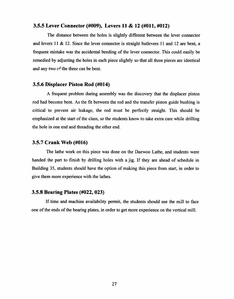
3.5.5 Lever Connector (#009), Levers 11 & 12 (#011, #012)
The distance between the holes is slightly different between the lever connector
and levers 11 & 12. Since the lever connector is straight butlevers 11 and 12 are bent, a
frequent mistake was the accidental bending of the lever connector. This could easily be
remedied by adjusting the holes in each piece slightly so that all three pieces are identical
and any two ef the three can be bent.
3.5.6 Displacer Piston Rod (#014)
A frequent problem during assembly was the discovery that the displacer piston
rod had become bent. As the fit between the rod and the transfer piston guide bushing is
critical to prevent air leakage, the rod must be perfectly straight. This should be
emphasized at the start of the class, so the students know to take extra care while drilling
the hole in one end and threading the other end.
3.5.7 Crank Web (#016)
The lathe work on this piece was done on the Daewoo Lathe, and students were
handed the part to finish by drilling holes with a jig. If they are ahead of schedule in
Building 35, students should have the option of making this piece from start, in order to
give them more experience with the lathes.
3.5.8 Bearing Plates (#022, 023)
If time and machine availability permit, the students should use the mill to face
one of the ends of the bearing plates, in order to get more experience on the vertical mill.
27

4. PREPARATION FOR THE COURSE
By the end of the Fall Semester, all of the components necessary to run 2.670
should be at M.I.T. There are several categories of materials which must be ordered; the
engine components, the fasteners for the engine, the tool kit materials, extra tools for the
machine shops, general supplies. In addition, there are a few necessary items which were
purchased as start-up materials. Although these do not need to be purchased each year,
they should be located prior to the end of the Fall Semester.
4.1 VENDOR INFORMATION
The materials for 2.670 were purchased from a variety of vendors during 1995.
The current information for each vendor is listed in Figures 13 (A-L), and 14 (M-Z). In
the following sections, vendors may be referred to only by the first part of their name.
28

Company Name Mailing Address Phone/Fax Contact CommentsAce Trophy & 469 Wahington Street 617-542-2424 Dean They will print upAtlantic Engraver Boston MA 02110-2409 name plates from a
[Downtown Crossing] list of registeredstudents.
Admiral Metals 11 Forbes Road 617-933-8300Service Center Co Woburn, MA 01801-2103 fax 617-932-3947Automatic PO Box 3990 800-527-3091 Benjamin Does not accept 30Tubing Co. 888 Lorimer Street Kaufman day terms for
Brooklyn, NY 11222-3990 payment for specialmaterials; requirescheck up front.
Charles Casting PO Box 451 603-934-9370 Lincoln Does not acceptFranklin, NH 03235 Charles M.I.T. PO#;
requires check.Cole-Parmer 625 East Bunker Court 800-323-4340Instrument Co. Vernon Hills, IL 60061 fax 708-647-7600Dave Nugent 575 Province Rd 603-528-0141 David Does not accept
L onia, NH 03246 (fax same) Nugent M.I.T. PO#;requires check.
Edgcomb Steel PO Box 260 603-883-7731Brookline, NH 03033-0260
Home Depot 75 Mystic Avenue 617-623-0001Somerville, MA 02145
Industrial 341 Second Ave 800-243-1343Aluminum Waltham, MA 02154 fax 617-890-1343Kaufman Co. Inc. 110 Second St. 617-491-5500 Dick Fenner should
Cambridge MA 02141 fax 617-491-5526 contact to arrange forthe tools; the moneyfor the tools isprovided by FordMotor Co.
Kaman Industries A Street 508-752-1976Auburn, MA 01501
LaVerde's Market Stratton Student Center 617-621-0733 Mech E Dept has a"standing PO" withLaVerde's.
Lehigh-Armstrong 12 Dunham Road 508-663-0010Incorporated Billerica MA 01821-5727L.S. Starrett Co. 121 Crescent St 508-249-3551 Donated Decimal
Athol MA 01331-1919 Equivalents and Tap& Drill Sizes andTools & Rules forPrecision Measuring,Kevin Baron shouldcontact for donations.
Figure 13. Vendor Information (A-L)
29

Company Name Mailing Address Phone/Fax Contact CommentsMcMaster Carr PO Box 440 908-329-3200Supply Co. New Brunswick NJ fax 908-329-3772
08903-0440Millard Metal PO Box 9054 617-848-1400 Bob SenaService Center Inc 116 Lindquist Drive fax 617-848-337?
Braintree MA 02184-9054M.I.T. Coop Kendall Square 617-499-3200MSC Industrial 15 Cabot Road 800-753-7990 M.I.T. Account #Supply Co. Woburn, MA 01801-1003 39577North End 31 Harrison St. 617-542-2763 Does not acceptFabrics Boston, MA M.I.T. PO#.
requires cash orcheck.
Physics MIT Room 4-355 617-499-3200 T. Coleman Accepts only M.I.T.Stock Room five-digit account
number.Pills True 743 Massachusetts Ave. 617-876-8310Value Hardware Cambridge, MA 02141Small Parts Inc. 13980 NW 58th Court 305-558-1038
PO Box 4650Miami Lakes FL
33014-3115Valenite Inc. 750 Stephenson Highway Literature: Donated pocket
PO Box 3950 800-544-3336 protectors andTroy, Ml 48007-3950 Tools: Handy Reference
800-488-8695 Guide, Kevin Baronshould contact fordonations.
VWR M.I.T. Rm. 18-B90 800-947-4270 x4250 MaddyM.I.T. x31881
Walmart 343 Loudon Road 603-226-9312 LenConcord, NH 03301 Morrill
Woolworths 350 Washington Street 617-357-5353Boston MA 02108[Downtown Crossing]
Zen Machine 1568 Steamboat Valley Rd 303-823-5842 Marty GouldShop PO Box 1658 (fax same)
Lyons CO 80540-1658
Figure 14. Vendor Information (M-Z)
30

4.2 THE STIRLING ENGINE COMPONENTS
For the 1996 sessions of 2.670, each of the parts of the engine were ordered and
produced individually. Although plans are currently underway to have one vendor (Zen
Machine Shop) provide all of the parts as a single kit, the information for ordering the
parts individually is provided in Figure 15 for future reference. The starting materials of
the kit are shown in Figure 16, and the finished parts are shown in Figure 17 (ready to be
assembled). The total cost of all the parts, as listed, is $13398.89, which comes out to
approximately $61 each for 220 kits.
Figure 16. The Starting Materials for the Stirling Engine [2]
Figure 17. The Finished Parts of the Stirling Engine [2]
31

0 V0000V ~0000 0000 0000 0
q c, 0 tn C= =W) 0 0C) Q C CI I r . r=CD C I CDO O C U ' I- Jc-i \O I\1 I1 Iv I I IL I -i
-Nr I ~ - ~- le Ic N INIcQ- 0 10 Cl0 0 0 Cl 0 Cl0 0N O0 00
U ; 10 1· 0 1C Clolo o llo-i 00T 10 W) 4 0 r-:0C;C6 (6 CWI C (\O I I I M W I en en 0 0M ldq I I o) I c W) C)CO -c o V~- r - - V
CC CD C Cl- 0 06 r~ 0 0 00 00 C -000 CD 0.- 000 " V 0 000
-- 'IOcl I 00 cl V -
'Tr g- Cl . ) C ICO UU1u) U)" c 0o0J 0 09 ccc = - = CD W WI _CO ~ O..... CO " 0.1) 0 0 ) C OC OC
C h e T Y, a tn i C- \o M M t n en ) 1 WI Co 4 lc 4 cl lCO oo'ro 00000" 10 C Cl a-- 0 r0CaI(l)l
c~~~~~~~~~~~~~~~~~S I C
~~~~~~~~~~~~= -- A,d O~~~~~~~~ I T It r ( rlOQ00O0 0~ e, r-tO 4n 2Cl 0C C N 00I o (21 as a 0o C 0- 0 :: 0r:
C O a, 00 0000 0 0 0
U)
I O -~ COEE2 C 2 COC
LZ> O C C . 0O U) .noo 0 o C.CU)~Z Z n e u o nPIUIEI~ E ' -o .U:
a- = °. "O N -CZ -
~~ID ~ Er rl I Ir I I IE E m ~~~~~~ a ~ t'", (~16- 03~e ~-o 0
C O U)~~~~~~~C O~~~~ CO ~~~~~~00 Q ~
_Im c e O~ el0J , %O M 2 MI UCO CO, COJ~ CO COl~ 3 m)C 6C CO *COld _lcl cOCO
oo M 0) 00
a- -~~~~~~~~X E u10 a mv, m rp lu 0 X
Cn e n I I I I I IC) -- a Fq I -) -0- I c aen - t: - n M n
~~~~ - -~~~~~~~~~~I
E~~~~~~~~~~~~~~CZ CZ x Ln _X
E E-~~~~~~~~~~~~~~~-U E:UX~X I~f ~luC-0 U OD tocC
0. CL 72L~0 C'U C O0)0)1 ~ol, - 0)0 O C~ Olaa CMO CO CO ) C1= C) 0 D o o ro.~~~~C Cl Cl' Cl
C
0
0o,
0
to
.
-.
,-L.
C
,U.

4.3 FASTENERS FOR THE STIRLING ENGINE
The fasteners for the Stirling Engine were also all purchased individually. and
were mainly provided to the students stored in the alcohol jar. Large excess quantities of
the small fasteners should be purchased as these were easily lost on the floor. The
information for ordering the fasteners is provided in Figure 18. The total cost for the
fasteners, as listed, is $1089.66, or approximately $5 for each of the 220 kits.
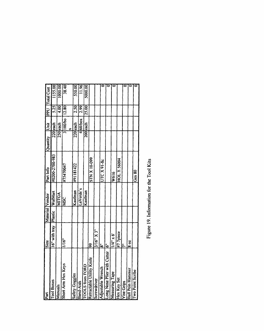
4.4 THE STUDENT TOOL KIT
As part of the Stirling Engine Kit, the students also received a tool box with tools.
These were mainly provided for the students by a generous donation from Ford Motor
Company. In addition, some literature material was provided by Starrett and Valenite. As
noted in Figure 13, Dick Fenner should contact Kaufman, Inc. in order to arrange for the
tools. The information on the tools is shown in Figure 19, and the 1996 Tool Kit is shown
in Figure 20. The total cost of the tool kit in 1996 was $7755.38, or about $35 for each of
the 220 kits ($10 with Ford Motor Company's donation).
Figure 20. The 1996 Tool Kit [2]
33

Mn o N mo tn W %O r- Sri cu ~ _ tm 00 X0 O. " O. O. O. o v,4_v D£u 0 Nr t S mO
O O - C4 CU v 00 N P N U 4n
, m m m , : o ¢: :: t', , , m
0 00 0 0 0 00t CZ8 e n O O O SI o 8 ex x x x x x y. --
O O O O O O O OQ C O C5co IoT OO 0f CA O XoX
W: v C r n u=v - -
oo oql o o o oo o ot
t. g O/ . ' O r. / ' O 0N O , \0 IA o0o 00 o . .__ 90 wnu oO _o O (
O Or O, Or O, O, O Do4 x t 4t k t tt 4 4t 4t _ t _
PN0 Z t s 2 Q 2 Q Q .j .j t0° 2 s
_ III II UI .Q Q Q .v O Q
~<<<< < <~ i .6
VX _ _ _ t X N _ _ x O _ _)> E or of E oZ lr IE fo o1 o= o r o .o.s _ n v, Ol On O rO 00 X _p x x x x188
: I _ Rn o _ _ - O O O t en W U Ch 0~~,-
3A (L1 )= tcn V a:. M 0 co n° e X nn
oo v = X E EW0 0 - u~~~~~~~,~
ctO C'nU n, y Cn C)n 0 ce O°~ ~. ldd 0 g)0m~~~~~~r ~Ztnl i lld~~ ~
&nSe
UC:U(ncu
._
co-
._
ullc
n-
oV)U
MS.
oor-
.co
Q 0
CU - --- _
CN n e C1 C
0'
c r el 0 0
CU CZ00 0
0 d 4-
c 0 C 0 0
4,~j t ~I-

4.5 TOOLS PURCHASED FOR USE IN THE PAPPALARDO LAB
Most of the tools used by the students for their fabrication of the Stirling Engines
were purchased by the staff in the machine shop and charged to 2.670. Some of the tools
in the Pappalardo Lab, however, were kept at the "2.670 Office" at one end of the
Pappalardo Lab. These purchasing information for these tools is listed in Figure 21. The
total cost of these tools listed was $139.08, which is $.63 for each of the 220 kits.
4.6 THE SUPPLIES
There are many important supplies which were kept at the 2.670 Office, such as
RTV, lubricant and thread locker, as well as the denatured alcohol, which was kept in
safety bottles for the students to use. Additionally, posterboard was purchased in order to
put signs up to help the students find the teaching locations, and many rolls of film were
used to document the class. These supplies are listed in Figure 22. The total price of all of
these supplies is $564.42, which is $2.56 for each of the 220 kits.
4.7 THE START-UP SUPPLIES
Finally, there were some necessary items which were purchased that will not be
needed to be purchased every year. These items are listed in Figure 23, and should be
located or purchased prior to the end of the Fall Semester. The start-up costs amounted to
$2958.39, due to the high price of the casting patterns, which comes out to $13.50 for
each of the 220 kits, but this cost will not recur each year.
36

0
La.
al0.
0-
o0c0
.omCA
I-
-ac
to
-
C
0.
C:
-
C
au
L-
C
OC6
.0UcJ
CuU)00
r-eer
00U073:IuV)7t
-Um20lu0
U)0
S-
z1.u
0U)0ra..
U
Cun
qQ9U
C3U)
0
00
0:m
uLI)v,
U)z0vU)
U)0,I-CEr.
to
i
a0-It
5
QR
U-:
r0
c
.0u
coV(9
enI-)co00
4t
U02
z2
Cu0
'Eelu
I-
-7
Cunm
9r)tt
-,I-
c
"I
oiO0
U
U)
Q2U)
U)c0
U)CL
0
b
ZxCu0
n
CC1;'CU-
RC1-
C)U)
(Orl
0UItu,LO2~
U)
0
CD
CZ1:
th0
D1)
F,
;nEd
nRD
CN
co
(9
2
zU)
0
U)'E
co010z
RTz
Cm0a.Ur
51)M:
'-.)U)CuCZ
N
L.
.-
L L

o)*0 C D = 0 0 0 00 oo t- oo .on I_ Io 00' O . O` u *
-o . a, o o ,~ o o ,.. a ,o
!c _ eq , ' .o
_- .- ~ '" C =-D - _ - ,,_0
O
0. __0 - _ Ie _it a 8 8 8.. u a a = a a 8 a 0.a _ C! _ _ _0.0. ~ ~ o 'I)r- 0.r u ~ I0O~~~0U)~t _~ ~ ~
u, ~ ~ C C, I
.- CO~~~. ~U)O -. COCO0
CO- *-ZO g
o.
,
cU
I.
oI~l~Olrooe-t a00e 0 Ir- (00
0 0r'[[-.
o , o3 -,
WI ) U) C.)CO0 WICO C C C-;
CO
~~~~~~~~~~~~~~~~~~,=.
CO 00 rN~
V ao oaCO Q 00le
~o 0
'c r ,-
CO~~~~~~~~I
CA 0E Z COcdc 00- a. 0*
E~n CO . )
CO C O CU C \ CO CO0.m
=.
0
-.
C*
I-
0

5. STUDENT SURVEYS
5.1 OVERALL
At the end of each session, the students were asked to fill out both the Pi Tau
Sigma evaluation and a 2.670-specific survey (see Appendix 2). The students were asked
to rate their knowledge of the machine shop and of each of the computer programs before
and after the class, as shown in Figure 24.
Machine Shop
Xess
Matlab
Pro/Engineer
Session I
Before
2.3
2.1
2.0
1.6
After
4.2
3.6
3.4
3.8
Change
+1.9
+1.5
+1.4
+2.2
Session 2
Before
2.2
2.1
2.1
1.4
After
4.1
3.5
3.8
3.71
Change
+1.9
+1.4
+1.7
+2.3
The rating scale was from I (no knowledge) to 5 (complete mastery).
Figure 24. Students' Self-Ratings
The students rated themselves on a scale of 1-5 and overall, rated themselves as most
improved in Pro/Engineer, followed closely by machining, XESS and Matlab. The
improvements were nearly identical in both sessions for Pro/Engineer, machining and
Xess, but quite different in Matlab. Some changes were made between the first session
and the second in the teaching of Matlab, due to the expressed dissatisfaction of several
students during the first session.
The students had many thoughtful comments and suggestions for improvement in
all areas of the course, which will be discussed in the remainder of this section.
5.2 Machine Shop
On the surveys, the students were asked to comment on each machine shop
individually.
39
. . .

5.2.1 Pappalardo Lab
The students learned many new skills in the Pappalardo Lab, "Soldering, milling,
sanding, drilling, scribing, tapping, and reaming. I think it wvil be extremely useful in the
future." (2.1)1 Overall, students found the pace slow, but they liked being able to set their
own pace. As one student wrote, "The pace was excellent - you made your own! For
some people, there was too much time allotted for machining, but it was that extra time
that gave me the freedom to go slow." (2.55) As described in Section 3, the pace was
designed so that students with no prior machine shop experience would be able to
successfully complete all of the tasks, and the option of heat sinks or other modifications
was added for students who were a bit ahead. One student commented, "I also liked
having a full extra day to do extra design and machining. The pace was slow, but we were
able to do extra stuff so it was cool." (2.37)
Students suggested having the option to make more of the engine parts, or perhaps
making the levers from stock instead of using the jigs. Many students expressed a wish to
learn more about the milling machine, such as how to use an end-mill, or how to mill a
slot, especially since there was so much extra time. Some students were frustrated by all
of the jig work, while others appreciated seeing the precision and time-saving benefits of
jigs.
5.2.2 Lab for Manufacturing and Productivity
The students were also exposed to many new skills in the LMP. One student
proclaimed, "It was incredible. LMP taught me so much, I went in there expecting to
seriously hurt myself and I came out know how to turn, to face, rill, tap, thread, shift
gear, and band saw." (2.38) Overall, the pace was just right. Again, students liked being
able to set their own pace, but were frustrated by the "bottlenecks" caused by having to
wait to use the lathes and other machines.
All survey comments are numberd (X,Y). where X is the session number. and Y is the number of the survey. for referencepurposes.
40

Most students appreciated that they made their parts with less help from jigs; one
student philosophically wrote, "It seemed like the success of our actions depended on us a
little more; fewer jigs, more room for error. Perhaps I learned a little more." (1.36) They
also appreciated being shown how to set the lathes, "I learned how to set spindle speed
and feed rate... Allowing us to play with those settings really took the mystery out of the
machine." (2.28)
Students would have liked to have been allowed to have machined the crank web
entirely from stock if they were ahead of schedule. The students loved seeing the CNC
Daewoo Mill and Lathe, but would have liked to learn even more about these or even
have a chance to try using them.
5.3 Computer Labs
As with the machine shops, students were asked to comment on each individual
section of the computer instruction.
5.3.1 XESS
There were four very different views on XESS. Students who were already
familiar with a spreadsheet were either bored or enjoyed learning about the more complex
applications of XESS. Students who were unfamiliar with spreadsheets were either lost or
found it to be an excellent intro. Many students suggested adding more than one example
in class, so as to introduce more basic/common applications, as well as having the
homework differ from the class examples, since most students learned mainly from doing
the homework. In particular, students would have liked to have seen how to import data,
and how they might use XESS in their future classes. After their Matlab course, several
students viewed XESS as obsolete, and many wondered why XESS was taught instead of
a more common application such as Microsoft Excel. Also, many students suggested
teaching XESS in a computer cluster, so that students could follow along on computers
during the lecture. A few students even suggested expanding the XESS instruction to two
days.
41

5.3.2 Matlab
Students found the pace of Matlab to be very fast, but most conceded that they
would eventually find it useful. Students were rather unhappy with the Matlab
instruction, for a few basic reasons. First, it assumed too much prior knowledge on the
part of the students. Second, the teaching format was two hours of lecture followed by
homework problems. There was a definite consensus among the students that it should
have been taught with shorter, more interactive lectures spaced throughout the four hour
period so that students could get help on the homework while the instructor was still
there. Also, the students found difficult to follow along on the overhead screen, and
would have liked to have documentation of the class lectures, so that they could have
something to refer to while doing the homework. While many students wrote that the
homework problems were painfully long and difficult, they also said that the homework
helped them learn the material. Overall, it could be greatly improved by starting with the
basics, providing the students with documentation, by teaching less material at one time,
and allowing students to work on homework while the instructor was there to help.
5.3.3 Pro/Engineer
Overall, students were very happy with the Pro/Engineer instruction, found the
pace to be just right, and basically, had a lot of "fun". Although several students
expressed satisfaction that the "homework" was all finished in class, some students also
expressed a desire to have had homework outside of class, in order to help them learn the
program without the option of easy help. Also, many students would have liked to have
done some modeling of their engines in Pro/Engineer. Overall, nearly all students seemed
to feel that they learned a great deal in this section of 2.670.
5.4 Safety
Nearly all students thought that the learning environment in both the machine
shops was safe, and many students commented that "safety was well-emphasized" (2.27)
and that the instructors "always stressed safety first" (2.32). One person with previous
shop experience claimed that "During all my time in wood shops and machine shops, the
42

last two weeks were easily the safest." (1.36) However, although one student thought that
"Both labs were very safe. To hurt yourself you would have to actively try. They gave
good instructions," (1.15) another student reported that "Instructions was adequate, but
didn't stop me from soldering my leg and breaking a reamer and having a jig fly across
the room because my drill bit broke and getting a piece of metal in my finger." (2.34)
Perhaps some additional safety instruction was needed, as other comments from students
indicated that students should be given more thorough safety instructions in the
Pappalardo Lab, particularly on how to grip material while sanding and bandsawing, as
well as instructions on using clamps while drilling.
5.5 Schedule
While many students complained about the early class time, they also recognized
the need for as much time as possible in order to complete the class within two weeks.
Additionally, nearly all the students found the schedule to be "clear and structured."
(2.21) Interestingly, three students in three out of the four possible combinations of
machine shop and computer lab order made a point of writing down their group name and
saying that they thought their order was perfect, but that they were worried that it might
have been less so for the other groups! There were three main suggestions: 1)change the
hours from 8-5 to 9-6. 2)offer the course for half a day over the four weeks, 3)switch
between Matlab and Pro/Engineer in order to give students a chance to let the instruction
sink in and finish the Matlab homework. Although the first suggestion is unlikely, since
there are too many athletic team practices from 5-7, the four-week-half-day idea could be
offered as an option to students, and all interested students could simply be balanced out
between all of the other sections. The third suggestion could also work, but it would need
to be discussed with the Matlab and Pro/Engineer instructors in order to insure that no
continuity would be broken as a result.
43

6. THE 2.670 COURSE MANUAL
The following pages contain the 2.670 Course Manual from the 1996 session of
2.670, exactly as the students received it. The part drawings should be updated and
perhaps done in Pro/Engineer. The process plans should be revised and updated yearly, as
discussed in Section 3.2.3. The numbers at the left and right sides of the pages are the
numbers of the pages in the actual manual (any missing page numbers refer to blank
pages), and the numbers in the center are the page number in this thesis.
Finally, the transfer piston guide bushing should be renamed the displacer piston
guide bushing, in order to be consistent with the rest of the naming scheme. For
consistency, however, it was called the transfer piston guide bushing throughout this
document.
44

26 a 70
E tCHAN1 C'AL
£ N G 4~~~~~~~~~~: NEERJN
0OL
IAP 199645
11

TABLE OF CONTENTS
Instructors 1Course Objectives & Grading 3Students 4Schedules by Section:
Mercury 5Venus 6Mars 7Jupiter 8Saturn 9Uranus 10Neptune 11Pluto 12
Stirling Engine Cycle 13The Four Steps in the Stirling Engine Cycle 14The MIT Stirling Engine 16Lab Etiquette & Safety 17Material Safety Data for Denatured Ethyl Alcohol 19Stirling Engine Part Numbers & Names 21Stirling Engine Kit Materials 22Student Tools 23Building 3 Part Drawings and Process Plans 25Building 35 Part Drawings and Process Plans 41Drawings of Supplied Parts 53Engine Assembly 65Troubleshooting 69Engine Maintenance 70
46

INSTRUCTORSProfessors
Doug P. Hart, 3-246, X3-2178, dphart~mit.eduKevin N. Otto, 3-449B, X3-8 199, [email protected]
Pappalardo Lab Personnel (Building 3)Norm Berube, Project Machinist / Instrument MakerDick Fenner, General Manager
Lab for Manufacturing and Productivity (LMP) Personnel (Building 35)Kevin Baron, Technical InstructorFred Cote, Research Specialist
Matlab, Xess & Athena InstructionSteve Ellis, [email protected]
Machine Shop Graduate Teaching AssistantsFederico Frigerio, frigerio(mit.edu
Pro/Engineer Graduate Teaching AssistantsPhil Houdek, [email protected]
Head Undergraduate AssistantsLiv Galendez, [email protected] Morris, [email protected]
Undergraduate AssistantsMachine Shop
J.D. Albert, jdalbertmit.eduJohnny Chang, tjtcgmit.eduNash Chulamorkodt, nashgmit.eduMark Cooper, mjcooper~mit.eduJennifer Dickson, [email protected] Dulik, jddulikgmit.eduJeffrey Gourde, jeffreyggmit.eduCarlos Herrera, caha-mit.eduDon Hyun, dhyun~mit.eduNaomi Korn, naomikgmit.eduPeter Lee, ptleermit.eduJason Melvin, jwmelvinm it.eduAlexander Moskovitz, admosomit.eduAdrian Percer, melricgmit.eduIsela Villanueva, [email protected] Workeneh, ytworkengmit.edu
MatlabBob Apodaca, [email protected] Cohen, abbe~mit.eduJason Hintersteiner, jdhinter(mit.eduBrian Hoffman, [email protected]/EngineerCamilo Cepeda, choatiegmit.eduStacey Chang, stachanggmit.eduJennifer Dickson, jlynndgmit.eduSieu Dong, stdgmit.eduJeffrey Dulik, jddulik~mit.eduAlexander Goodwin, goodwin mit.eduNaomi Korn, naomikwmit.eduPeter Lee, ptleeamit.eduAdrian Percer, melricmit.eduPenny Pliskin, penniegmit.eduIsela Villanueva, iselasgmit.eduYedel Workeneh, ytworkengmit.edu
47I

COURSE OBJECTIVESThe objective of this course is very simple: to give you the opportunity to equip yourself with theskills and the tools you will need in your subsequent Mechanical Engineering courses. Thiscourse will introduce you to the fundamentals of both machine tool and computer tool use. Youwill work with a variety of machine tools including the bandsaw, milling machine, and lathe, andwith a variety of the Athena network and Athena-based software packages, including Matlab,Xess, and Pro/Engineer.
The emphasis will be on giving you the opportunity to learn by self paced problem solving. Youwill get as much out of this experience as you put into this course. The material will focus uponusing computer tools, not programming or developing algorithms. You will find, however, thatthis destinction between using and programming computer tools is rather fuzzy, as you usuallyhave to do both.
GRADINGThe grading for this course is pass/fail. Passing is determined by completing the material. Aftereach four hour period, we will assess whether you passed the material of that period. Passing thematerial means completing the material in the manner prescribed by the instructors. Forcomputer assignments, this means completing the assignments so that the output of theassignment is well formatted and correct. For the machining assignments, this means completingthe assignments so that the shape, tolerances and finish are within specification. You do not haveto have a complete working engine by the end of the two week session. A honest effort at each 4hour period is what is required, as determined by your section instructor.
You must pass all four hour periods, no exceptions. If you fail a 4 hour period, you must makearrangements to pass it later during the sixth day make-up period or on the tenth day. Failingmore than two of the four hour periods is beyond the means of most students to pass the course.There is no makeup beyond your two week session.
This course is designed to be completed within the allotted time. You will have ample time andresources to easily complete the material of each 4 hour period within that period. Therefore, itis very important to be in class, and to always BE ON TIME. If you choose to arrive late toclass, you are stealing from yourself. This is an in-class learning experience, and we will notwait for individuals who choose to arrive late. Please help yourself and the others in yoursection, and be on time.
48

SESSION 1 STUDENTS
MACHINING AM / COMPUTER PM COMPUTER AM / MACHINING PMMERCURYHolly AllenSeth BirnbaumMichael ButvilleWendy ChengKathleen CoffeyAdalberto DiazDennis EvangelistaJoel FordReginald GreenPeter JaffeLeonard KimbleAlex LianChristopher McMillanJohn MillerLong PhanNathaniel RileyMatthew SlayterRoy SwartPriscilla WangMelodyYung
VENUSChrista AnsbergsMelanie BornKelly ChanHao ChienGareth CooteDaniel DobbsWinston FanPhilipp FreiShantel HansenSteven JensCatherine KohEileen LiuAndrew MccraithBryan MorrisseyKearne PrendergastJeffrey RosenLuke SosnowskiCharles TamRobert WhiteMatt Ziskin
MARSAmy BanzhafNathaniel BowerHeidi ChangHubert ChoiRebecca DaileyBrendan DonovanJoseph FerreiraJesse GeraciSeppo HelavaMaria KamvysselisEugene LeeJason MartinezNorman MetcalfeBenjamin NunesGisele ProulxDavid SchillerNathan St. MichelTroy ThorsonJames Williams
JUPITERGeorge BensonOlivier BurlaudKhanmisay ChanthabounAllison ChristensonDavid DayLawrence DurantJoseph FoleyAnthony GonzalezDon HyunJoseph KimJames LeeYoussef MarzoukAnna MierzejewskaTimocin PervaneIndran RatnathicamCourtney ShileyLara SuhKevin TrexlerStacey Wong
SESSION 2 STUDENTS
MACHINING AM /SATURNLauren AquinoDamon BrambleCatalina ButtzLawrence ChaoAlex ChuRichard ConwayRoland DesrochersDavid EstradaBrett JohnsonDavid KurdMiguel LopezBaldemar MejiaVictor MoralesEric NielsenHector PadillaCecilia PrietoAngel SanchezKirk SewardDuane StevensAriatna Villegas-Vazquez
COMPUTER PMURANUSAntonio AvilaChristopher BruceDiana ButtzAlankar ChhabraSandra ChungTimothy DelfausseJohn DibaccoKeith FifeAaron JulinZachary LeeGilberto MarquezGarth MitchellDavid NaffzigerWill Nielsenlan PeirJeralyn ReeseJaime SarabiaJennifer ShinTokeem TalbotScott Whitehead
COMPUTER AM / MACHINING PMNEPTUNE PLUTOJarrod Beglinger Sabrina BirnbaumFabio Brunet Sami BuschLuis Cardenas Brandon CarrusJungYoon Choi Sally ChouPaul Collins Allison ConnerSigfrido Delgado Juan DenizDennis Dougherty Janis EisenbergHector Godinez Nicholas HirschiDaniel Keating Yvonne KimRobert Lentz Jorge LopezChristina Martinez Brett MckeoneKenneth Michlitsch Jose Montes de OcaLinda Nguyen Thao NguyenRayshad Oshtory Megan OwensKeith Perry Lisa PoyneerAntonio Reyes Luis RomeroTye Schlegelmilch Mads SchmidtMolly Sims Shawn SternHelen Trapp Paula Valdivia y Alvarado
449
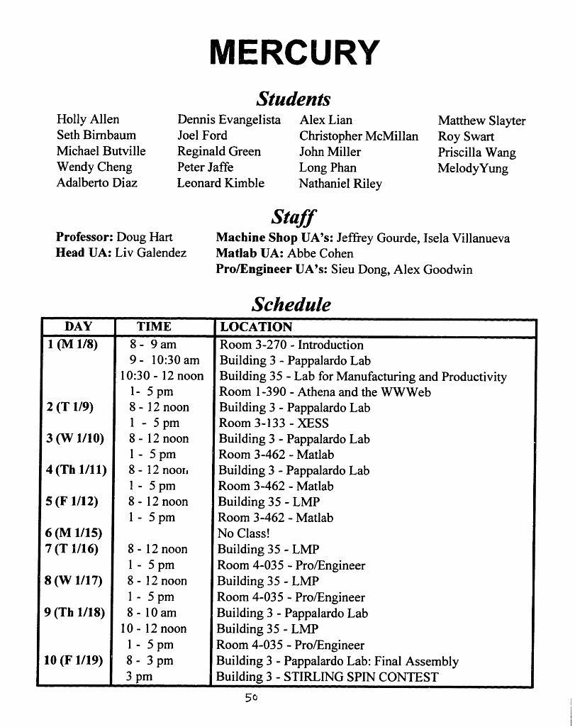
MERCURY
Holly AllenSeth BimbaumMichael ButvilleWendy ChengAdalberto Diaz
StudentsDennis Evangelista Alex LianJoel Ford Christopher McMillanReginald Green John MillerPeter Jaffe Long PhanLeonard Kimble Nathaniel Riley
Matthew SlayterRoy SwartPriscilla WangMelodyYung
Professor: Doug HartHead UA: Liv Galendez
StaffMachine Shop UA's: Jeffrey Gourde, Isela VillanuevaMatlab UA: Abbe CohenPro/Engineer UA's: Sieu Dong, Alex Goodwin
ScheduleDAY TIME LOCATION
1 (M 1/8) 8 - 9 am Room 3-270 - Introduction9- 10:30 am Building 3 - Pappalardo Lab
10:30 - 12 noon Building 35 - Lab for Manufacturing and Productivity1- 5 pm Room 1-390 - Athena and the WWWeb
2 (T 1/9) 8 - 12 noon Building 3 - Pappalardo Lab1 - 5 pm Room 3-133 - XESS
3 (W 1/10) 8 - 12 noon Building 3 - Pappalardo Lab1 - 5 pm Room 3-462 - Matlab
4 (Th 1/11) 8 - 12 noorh Building 3 - Pappalardo Lab1 - 5 pm Room 3-462 - Matlab
5 (F 1/12) 8 - 12 noon Building 35 - LMP1 - 5 pm Room 3-462 - Matlab
6 (M 1/15) No Class!7 (T 1/16) 8 - 12 noon Building 35 - LMP
1 - 5 pm Room 4-035 - Pro/Engineer8 (W 1/17) 8 - 12 noon Building 35 - LMP
1 - 5 pm Room 4-035 - Pro/Engineer9 (Th 1/18) 8 - 10 am Building 3 - Pappalardo Lab
10 - 12 noon Building 35 - LMP1 - 5 pm Room 4-035 - Pro/Engineer
10 (F 1/19) 8 - 3 pm Building 3 - Pappalardo Lab: Final Assembly3 pm Building 3 - STIRLING SPIN CONTEST
50

VENUS
Christa AnsbergsMelanie BornKelly ChanHao ChienGareth Coote
StudentsDaniel Dobbs Catherine KohWinston Fan Eileen LiuShantel Hansen Andrew MccraithSteven Jens Bryan MorrisseyMaria Kamvysselis Kearne Prendergast
Jeffrey RosenLuke SosnowskiCharles TamRobert WhiteMatt Ziskin
Professor: Kevin OttoHead UA: Stacy Morris
StaffMachine Shop UA's: Jeffrey Dulik, Naomi KornMatlab UA: Abbe CohenPro/Engineer UA's: Sieu Dong, Alex Goodwin
ScheduleDAY TIME LOCATION
1 (M 1/8) 8 - 9 am Room 3-270 - Introduction9 - 10:30 am Building 35 - Lab for Manufacturing and Productivity
10:30 - 12 noon Building 3 - Pappalardo Lab1- 5 pm Room 1-390 - Athena and the WWWeb
2 (T 1/9) 8 - 12 noon Building 35 - LMP1 - 5 pm Room 3-133 - XESS
3 (W 1/10) 8 - 12 noon Building 35- LMP1 - 5 pm Room 4-035 - Pro/Engineer
4 (Th 1/11) 8 - 12 noon Building 35 - LMP1 - 5 pm Room 4-035 - Pro/Engineer
5 (F 1/12) 8 - 12 noon Building 3 - Pappalardo Lab1 - 5 pm Room 4-035 - Pro/Engineer
6 (M 1/15) No Class!7 (T 1/16) 8 - 12 noon Building 3 - Pappalardo Lab
1 - 5 pm Room 3-462 - Matlab8 (W 1/17) 8 - 12 noon Building 3 - Pappalardo Lab
1 - 5 pm Room 3-462 - Matlab9 (Th 1/18) 8 - 10 am Building 35 - LMP
10 - 12 noon Building 3 - Pappalardo Lab1 - 5 pm Room 3-462 - Matlab
10 (F 1/19) 8 - 3 pm Building 3 - Pappalardo Lab: Final Assembly3 pm Building 3 - STIRLING SPIN CONTEST

MARSStudents
Amy BanzhafNathaniel BowerHeidi ChangHubert ChoiKathleen Coffey
Rebecca DaileyBrendan DonovanJoseph FerreiraPhilipp FreiJesse Geraci
Seppo HelavaEugene LeeJason MartinezNorman MetcalfeBenjamin Nunes
Gisele ProulxDavid SchillerNathan St. MichelTroy ThorsonJames Williams
Professor: DougHead UA: Stacy
HartMorris
StaffMachine Shop UA's: Yedel Workeneh, Mark CooperMatlab UA: Brian HoffmanPro/Engineer UA's: Camilo Cepeda, Jennifer Dickson, Penny Pliskin
ScheduleDAY TIME LOCATION
1 (M 1/8) 8 - 9 am Room 3-270 - Introduction9 - 12 noon Room 1-390 - Athena and the WWWeb1 - 3 pm Building 3 - Pappalardo Lab3 - 5 pm Building 35 - Lab for Manufacturing and Productivity
2 (T 1/9) 8 - 12 noon Room 1-390- XESS1 - 5 pm Building 3 - Pappalardo Lab
3 (W 1/10) 8 - 12 noon Room 3-462 - Matlab1 - 5 pm Building 3 - Pappalardo Lab
4 (Th 1/11) 8 - 12 noon Room 3-462 - Matlab1 - 5 pm Building 3 - Pappalardo Lab
5 (F 1/12) 8 - 12 noon Room 3-462 - Matlab1 - 5 pm Building 35 - LMP
6 (M 1/15) No Class!7 (T 1/16) 8 - 12 noon Room 4-035 - Pro/Engineer
1 - 5 pm Building 35 - LMP8 (W 1/17) 8 - 12 noon Room 4-035 - Pro/Engineer
1 - 5 pm Building 35 - LMP9 (Th 1/18) 8 - 12 noon Room 4-035 - Pro/Engineer
I - 3 pm Building 3 - Pappalardo Lab3 - 5 pm Building 35 - LMP
10 (F 1/19) 8 - 3 pm Building 3 - Pappalardo Lab: Final Assembly3 pm Building 3 - STIRLING SPIN CONTEST
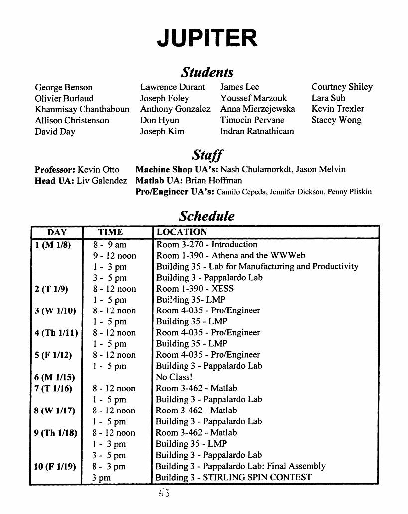
JUPITER
George BensonOlivier BurlaudKhanmisay ChanthabounAllison ChristensonDavid Day
StudentsLawrence Durant James LeeJoseph Foley Youssef MarzoukAnthony Gonzalez Anna MierzejewskaDon Hyun Timocin PervaneJoseph Kim Indran Ratnathicam
Courtney ShileyLara SuhKevin TrexlerStacey Wong
Professor: Kevin OttoHead UA: Liv Galendez
StaffMachine Shop UA's: Nash Chulamorkdt, Jason MelvinMatlab UA: Brian HoffmanPro/Engineer UA's: Camilo Cepeda, Jennifer Dickson, Penny Pliskin
ScheduleDAY TIME LOCATION
1 (M 1/8) 8 - 9 am Room 3-270 - Introduction9 - 12 noon Room 1-390 - Athena and the WWWeb1 - 3 pm Building 35 - Lab for Manufacturing and Productivity3 - 5 pm Building 3 - Pappalardo Lab
2 (T 1/9) 8- 12 noon Room 1-390- XESS1 - 5 pm Buil'ing 35- LMP
3 (W 1/10) 8 - 12 noon Room 4-035 - Pro/Engineer1 - 5 pm Building 35 - LMP
4 (Th 1/11) 8 - 12 noon Room 4-035 - Pro/Engineer1 - 5 pm Building 35 - LMP
5 (F 1/12) 8 - 12 noon Room 4-035 - Pro/Engineer1 - 5 pm Building 3 - Pappalardo Lab
6 (M 1/15) No Class!7 (T 1/16) 8 - 12 noon Room 3-462 - Matlab
1 - 5 pm Building 3 - Pappalardo Lab8 (W 1/17) 8 - 12 noon Room 3-462 - Matlab
I - 5 pm Building 3 - Pappalardo Lab9 (Th 1/18) 8 - 12 noon Room 3-462 - Matlab
I - 3 pm Building 35 - LMP3 - 5 pm Building 3 - Pappalardo Lab
10 (F 1/19) 8 - 3 pm Building 3 - Pappalardo Lab: Final Assembly3 pm Building 3 - STIRLING SPIN CONTEST
I 3

SATURN
Lauren AquinoDamon BrambleCatalina ButtzLawrence ChaoAlex Chu
Richard ConwayRoland DesrochersDavid EstradaBrett JohnsonDavid Kurd
StudentsMiguel LopezBaldemar MejiaVictor MoralesEric NielsenHector Padilla
Cecilia PrietoAngel SanchezKirk SewardDuane StevensAriatna Villegas-Vazquez
Professor: Doug HartHead UA: Stacy Morris
StaffMachine Shop UA's: Peter Lee, Adrian PercerMatlab UA: Jason HintersteinerPro/Engineer UA's: Stacey Chang, Naomi Korn, Peter Lee, Adrian Percer
ScheduleDAY TIME LOCATION
1 (M 1/22) 8 - 9 am Room 3-270 - Introduction9- 10:30 am Building 3 - Pappalardo Lab
10:30 - 12 noon Building 35 - Lab for Manufacturing and Productivity1- 5 pm Room 1-390 - Athena and the WWWeb
2 (T 1/23) 8 - 12 noon Building 3 - Pappalardo Lab1- 5pm Room 26-100 - XESS
3 (W 1/24) 8 - 12 noon Building 3 - Pappalardo Lab1 - 5 pm Room 3-462 - Matlab
4 (Th 1/25) 8 - 12 noon Building 3 - Pappalardo Lab1 - 5 pm Room 3-462 - Matlab
5 (F 1/26) 8 - 12 noon Building 35 - LMP1 - 5 pm Room 3-462 - Matlab
6 (M 1/29) No Class!7 (T 1/30) 8 - 12 noon Building 35 - LMP
1 - 5 pm Room 4-035 - Pro/Engineer8 (W 1/31) 8 - 12 noon Building 35 - LMP
1 - 5 pm Room 4-035 - Pro/Engineer9 (Th 2/1) 8 - 10 am Building 3 - Pappalardo Lab
10 - 12 noon Building 35 - LMP1 - 5 pm Room 4-035 - Pro/Engineer
10 (F 2/2) 8 - 3 pm Building 3 - Pappalardo Lab: Final Assembly3 pm Building 3 - STIRLING SPIN CONTEST

URANUS
Antonio AvilaChristopher BruceDiana ButtzAlankar ChhabraSandra Chung
StudentsTimothy Delfausse Gilberto MarquezJohn Dibacco Garth MitchellKeith Fife David NaffzigerAaron Julin Will NielsenZachary Lee Ian Peir
Jeralyn ReeseJaime SarabiaJennifer ShinTokeem TalbotScott Whitehead
Professor: Kevin OttoHead UA: Liv Galendez
StaffMachine Shop UA's: Carlos Herrera, Alex MoskovitzMatlab UA: Jason HintersteinerPro/Engineer UA's: Stacey Chang, Naomi Korn, Peter Lee, Adrian Percer
ScheduleDAY TIME LOCATION
1 (M 1/22) 8 - 9 am Room 3-270 - Introduction9- 10:30 am Building 35 - Lab for Manufacturing and Productivity
10:30 - 12 noon Building 3 - Pappalardo Lab1- 5 pm Room 1-390 - Athena and the WWWeb
2 (T 1/23) 8 - 12 noon Building 35 - LMP1 - 5 pm Room 26-100 - XESS
3 (W 1/24) 8 - 12 noon Building 35- LMP1 - 5 pm Room 4-035 - Pro/Engineer
4 (Th 1/25) 8 - 12 noon Building 35 - LMP1 - 5 pm Room 4-035 - Pro/Engineer
5 (F 1/26) 8 - 12 noon Building 3 - Pappalardo Lab1 - 5 pm Room 4-035 - Pro/Engineer
6 (M 1/29) No Class!7 (T 1/30) 8 - 12 noc;: Building 3 - Pappalardo Lab
1 - 5 pm Room 3-426- Matlab8 (W 1/31) 8 - 12 noon Building 3 - Pappalardo Lab
1 - 5 pm Room 3-426- Matlab9 (Th 2/1) 8 - 10 am Building 35 - LMP
10- 12 noon Building 3 - Pappalardo Lab1 - 5 pm Room 3-426- Matlab
10 (F 2/2) 8 - 3 pm Building 3 - Pappalardo Lab: Final Assembly3 pm Building 3 - STIRLING SPIN CONTEST
_ I

NEPTUNE
Jarrod BeglingerFabio BrunetLuis CardenasJungYoon ChoiPaul Collins
StudentsSigfrido Delgado Christina MartinezDennis Dougherty Kenneth MichlitschHector Godinez Linda NguyenDaniel Keating Rayshad OshtoryRobert Lentz Keith Perry
Antonio ReyesTye SchlegelmilchMolly SimsHelen Trapp
Professor: Doug HartHead UA: Liv Galendez
StaffMachine Shop UA's: J.D. Albert, Don HyunMatlab UA: Bob ApodacaPro/Engineer UA's: Jeffrey Dulik, Isela Villanueva, Yedil Workeneh
ScheduleDAY TIME LOCATION
1 (M 1/22) 8 - 9 am Room 3-270 - Introduction9 - 12 noon Room 1-390 - Athena and the WWWeb1 - 3 pm Building 3 - Pappalardo Lab3 - 5 pm Building 35 - Lab for Manufacturing and Productivity
2 (T 1/23) 8 - 12 noon Room 3-133 - XESSI - 5 pm Building 3 - Pappalardo Lab
3 (W 1/24) 8 - 12 noon Room 3-462 - Matlab1 - 5 pm Building 3 - Pappalardo Lab
4 (Th 1/25) 8 - 12 noon Room 3-462 - Matlab1 - 5 pm Building 3 - Pappalardo Lab
5 (F 1/26) 8 - 12 noon Room 3-462 - Matlab1 - 5 pm Building 35 - LMP
6 (M 1/29) No Class!7 (T 1/30) 8 - 12 noon Room 4-035 - Pro/Engineer
1 - 5 pm Building 35 - LMP8 (W 1/31) 8 - 12 noon Room 4-035 - Pro/Engineer
1 - 5 pm Building 35 - LMP9 (Th 2/1) 8 - 12 noon Room 4-035 - Pro/Engineer
1 - 3 pm Building 3 - Pappalardo Lab3 - 5 pm Building 35 - LMP
10 (F 2/2) 8 - 3 pm Building 3 - Pappalardo Lab: Final Assembly3 pm Building 3 - STIRLING SPIN CONTEST

PLUTOStudents
Sabrina BirnbaumSami BuschBrandon CarrusSally ChouAllison ConnerJuan Deniz
Janis EisenbergNicholas HirschiYvonne KimJorge LopezBrett Mckeone
Jose Montes deOcaThao NguyenMegan Owen;&_Lisa PoyneerLuis Romero
Mads SchmidtShawn SternPaula Valdivia y
Alvarado
Professor: Kevin OttoHead UA: Stacy Morris
StaffMachine Shop UA's: Jennifer Dickson, Johnny ChangMatlab UA: Bob ApodacaPro/Engineer UA's: Jeffrey Dulik, Isela Villanueva, Yedil Workeneh
ScheduleDAY TIME LOCATION
1 (M 1/22) 8 - 9 am Room 3-270 - Introduction9 - 12 noon Room 1-390 - Athena and the WWWeb1 - 3 pm Building 35 - Lab for Manufacturing and Productivity3 - 5 pm Building 3 - Pappalardo Lab
2 (T 1/23) 8 - 12 noon Room 3-133- XESS1 - 5 pm Building 35- LMP
3 (W 1/24) 8 - 12 noon Room 4-035 - Pro/Engineer1 - 5 pm Building 35 - LMP
4 (Th 1/25) 8 - 12 noon Room 4-035 - Pro/Engineer1 - 5 pm Building 35 - LMP
5 (F 1/26) 8 - 12 noon Room 4-035 - Pro/EngineerI - 5 pm Building 3 - Pappalardo Lab
6 (M 1/29) No Class!7 (T 1/30) 8 - 12 noon Room 3-426 - Matlab
1 - 5 pm Building 3 - Pappalardo Lab8 (W 1/31) 8 - 12 noon Room 3-426 - Matlab
1 - 5 pm Building 3 - Pappalardo Lab9 (Th 2/1) 8 - 12 noon Room 3-426 - Matlab
1 - 3 pm Building 35 - LMP3 - 5 pm Building 3 - Pappalardo Lab
10 (F 2/2) 8 - 3 pm Building 3 - Pappalardo Lab: Final Assembly3 pm Building 3 - STIRLING SPIN CONTEST
5lI

STIRLING ENGINE CYCLE
Your engine operates on a closed regenerative thermodynamic cycle, theStirling cycle. Unlike an internal combustion engine, your engine has novalves and does not intake or exhaust gas. The air inside your engine istrapped. Heat is converted to mechanical work by alternately pushing theair from the cold side of the engine to the hot side. On the hot side, the airheats, increasing the pressure inside the engine. On the cold side, the aircools, decreasing the pressure inside the engine. This change in internalpressure pushes the power piston back and forth in the power cylindercausing the flywheel to rotate. The flywheel, in turn, pushes the displacerpiston back and forth, moving air from the cold side of the engine to the hotside and back.
The efficiency of your Stirling cycle engine is improved over moreconventional engine cycles through the use of thermodynamic regenerativeprocesses. The displacer piston fits loosely in the displacer cylinder. As airmoves past it from the hot side to the cold side, the displacer piston absorbssome of the heat from the air. As the air moves back from the cold side tothe hot side, the displacer piston releases this heat back to the air. In thisway, some of the energy that would otherwise be lost is reclaimed duringeach engine cycle. In principle, a Stirling cycle engine can have near ideal(Carnot cycle) efficiency. Your engine, however, will lose energy fromfriction, from poor heat transfer between the flame and the air inside theengine, and from heat conduction between the hot side of the engine and thecold side, through the walls of the displacer piston and cylinder.
13
58

THE FOUR STEPS OF THE STIRLING ENGINE CYCLE
I. ExpansionII. Transfer of airfrom HOT to COLD sideIII. ContractionIV. Transfer of airfrom COLD to HOT side
<;7,~
Q\
HOT
Heat Tan
COLDPower Piston
I. Expansion - The air is heated by tipiston outward and turning the flywheel.
he flame and expands, pushing the power
HOT
Heat Transf
Pnwer Pifnn
COLD
II. Transfer of Air from HOT to COLD Side - The hot air is pushed to the coldside of the engine by the displacer piston. Some of the heat of the air is absorbedby the displacer piston as the air moves by it.
14
59
I

-teat Transfer Piston
I
7
Heat Transfer Cylinderventhole
rowler rlson
COLD
III. Contraction - The air cools and contracts, pullingand turning the flywheel.
Heat Transfer Piston
HOT
Heat Transfer Cylinderventhole
COLD
IV. Transfer of Air from COLD to HOT Side - The cold air is pushed back tothe hot side of the engine by the displacer piston, completing the cycle. Thedisplacer piston releases some of its stored heat and warms the air, as it moves tothe hot side.
*Note that the flywheel cranks (levers 011 and 012) for the displacer piston andthe power piston are offset 90 ° from each other.
I
EE 05
o 00
0z
-1
I. II. III. IV.Expansion Hot to Cold Contraction Cold to Hot
15
60
HOT
Flywheel/
Power Cylinder_._ Dne_-..
the power piston inward
Power Pistonder
Pston
gle
m
I
9I
m
-
---- w
I:1
J

THE MIT STIRLING ENGINE
1 Z" , " " I
1661

LAB SAFETYSAFETY GLASSES MUST BE WORN AT ALL TIMES!!
' Long hair must be tied back.
6- Appropriate clothing must always be worn:
No open shoes, sandals, or rollerblades.
No baggy or loose clothing.
Always wear safety glasses!
t- NO running in lab.
6' Always ask an instructor to help you find the tools you need.
6- Never EVER operate a machine which you haven't been taught to operate.
' Never EVER operate a machine when you feel tired or sick.
6 When in doubt, AL WA YS ASK for help.
6- And once again, safety glasses MUST be worn at ALL times.
ENGINE SAFETYPLEASE READ THIS AND THE DENATURED ETHYL ALCOHOL SAFETY
SHEET ON PAGES 19-20 BEFORE ATTEMPTING TO START YOUR ENGINE!!
6- Always let your engine cool before attempting to pick it up.6- Always run your engine in a well ventilated area.6-' Never burn anything other than stove grade alcohol in your engine.6- Never attempt to fill your the alcohol burner while it is hot.6' Never run your engine near any flammable material.6- Never let your engine run unattended.' Never store your engine with alcohol in it.
6- NOTE - Never EVER heat your engine with a torch to try and get it to run. The torchwill melt the solder which holds the heat transfer cylinder together (don't laugh - we haveseen this happen a number of times!). You can, however, place a wet cloth or ice cube onthe cold side of the engine, which will greatly improve its performance.
1762

0
A
aS
aa a
- o
_ Co tiU' U0F
o o
_
- ~ ~ ~ ~ a -*. .sa AL0 L nc
=4)O
0o
0~~~~~5
-' 4 0
a r.
0. E
<0P ~
.. ia
A.0
3 E~- 8
'Za .0= =a LOv
2 '
a eE a
, ' I -
-;
~ .O .1
;C . ! q *i t22
IU
'L
'9a10
a
8'S80
0
_
t P n
a -c ;
.. tU
AkgI E
E i;
I o0 in 0. b. ..
>0;
U
ac-
E OE C< IPS (
c
sO;'5.28ElE2-aw
- .I'
6 EaH W < a
-
.. C
0C
0 3
j S G Z
, 1E e
._ A D',-~z ~._
ab
S2
A a- :2
't i %.- S
3 I 2 - -S .5 la2, 4
'a i
I n o . g OCL5
co
a;
n
.4
0
c-6 0o ,
6 5uI' s
X _ c.0 X -D
9.> 05 0
S -I. w, 6
6 S-
g ;-t0. x -0.! - 0
" s_ -.Z ! - 0 _ U 0 0 0
3 y3 >
.-,.
_ O _- Y--, u
s = =
e ,· Co 0 -
_ 5ZS:C- 0
a
o0
0
0I(31fll
z
WE.
LLLL
>-
rn
'4A
A.
zC
El
t
0
i:.0C.
E
AuC0za
EW'I
IU
0'4
aa
!t
0Ao.
8
4)
7
U-la1!
aa
C:0o
zWPr:
00u
n-Irir
zCP
tCI--
a
E
C
o
z a
.. .. W.E
E 80U 4
0e 1
WQi:a!12w
>0
IC:
6Ce_.
11
Y)P---4
(1)
t1;
ac0a
8 S
:3 a
:E, miE*Gir :z:
iiII.C9, -
a
laOs
.4).0
co
EC)
a
I-00
i-4ro
o
0
[l00
e.5
LrJ
0
W
wEL0w&
I
I
2
IJa
i.t-

E0 '
_..
o O -C.,x
a_o E ~
9 ' °3, Z
ozofC
.2Sa 0 C ._ -E .3 ,* e e ': E
- Ro- 8 ,
" 0
°O ,
as-
*- E
.
CC
a
EiSCcciW.ICCa
LT.1W~
z)
0
00
,.-
'A
._
C
E a
U7 I
'o
Eci
_!.go
C"-
E
' C: F o 0 e-i
t11E2Vf-ZCEV,
C -
. '8. , .,,4m
.E', ~ E
-
-
.e
o0
M .
-cE 7 tcZa. a
_ E
.ba=
E0 C_0 6.
<2 a :g._ _:
R = o., E
0 .
_C _ 1 -
- I
.0 C_
_ to
.S-,,, =
aN .
9 =
a111111aeCrtCccL
CC
EC.,C
ICZC
Er-11
.
ZJ
C . .. - _ .-~. = <;> <.c:
en
Ec
_.
c WC6
8E-EO~ C .'C o'~o _?-
., D~'o
O L,
oE
c -c '--
t",F._E s
0
o
to
-c
E
E£
3 2
oesaV
la0
t,1.
0U.o..
esCz
0
20
9CIEISCI.IC
9
e4111
4n
Z
0
0
W
EWE
..
la.Ca

STIRLING ENGINE PARTNUMBERS AND NAMES
1 Alcohol Burner Cap2 Displacer Cylinder3 Displacer Piston4 Cylinder Plate5 Power Cylinder6 Power Piston7 Gudgeon Block8 Power Connecting Lever9 Lever Connector
10 Lever Shaft11 Lever 01112 Lever 01213 Connector Link14 Displacer Piston Rod15 Transfer Piston Guide Bushing16 Crank Pin17 Crank Web18 Crank Web Shaft19 Main Bearing Bushings20 Flywheel21 Bearing Plate 02122 Bearing Plate 02223 Base
2165

STIRLING ENGINE KIT MATERIALSYou will be equipped with the materials necessary to fabricate a working miniature Stirling engine.Some of the engine parts are supplied already finished (ready for assembly), some of the engine parts aresupplied as castings (require further machining), and some of the engine parts are supplied as raw stock(also require further machining). Your kit should include the materials listed below; please see thefollowing page for a list of the tools included in your kit.
PART NAMEAlcohol Burner CapDisplacer CylinderDisplacer PistonCylinder PlatePower CylinderPower PistonGudgeon BlockPower Connecting LeverLever ConnectorLever ShaftLever 011Lever 012Connector LinkDisplacer Piston RodTransfer Piston GuideCrank PinCrank WebCrank Web ShaftMain Bearing Bushings (2)FlywheelBearing Plate 21Bearing Plate 22Base
MATERIALBrassStainless SteelStainless SteelBrass StockBrassCold Rolled SteelAluminum RodBrass StockBrass StockDrill RodBrass StockBrass StockBrass H StockDrill RodBrass Hex StockDrill RodAluminum RodDrill RodBrassBrass CastingAluminum StockAluminum StockZinc/Aluminum Casting
KIT SIZE1.06" O.D. x 3/4"1 1/8"O.D.x3 1/2"1 1/16" O.D. x 2"5/8" x 2" x 4"3/4" O.D. x 2"5/8" O.D. x 7/8"1/2" O.D. (stock in LMP)3/32" x 1/4" x 3"1/16 x 1/4 x 2"3/16" O.D. 1, 1/8" O.D.2 x 2"1/16 x 1/4 x 2"1/16 x 1/4 x 2"1/4" x 1/4" x 3/4"1/8" O.D. x 5.14"3/8" HEX (stock in LMP)1/8" O.D. x 5/8"1 1/2" O.D.(stock in LMP)3/16" O.D. x 2 3/4"3/16" I.D., 5/16" O.D. x 3/8"3 1/2" O.D.1, 1" O.D.2 x 1"5/8" x 2" x 3 1/2"5/8" x2" x3 1/2"1/2" x 3" x 7"
16mL Specimen Jar GlassWick Material CanvasPrecision Dowel Pin Stainless SteelFlathead Socket Head Cap Screw Steel AlloyCup Point Socket Set Screw Steel AlloyCup Point Socket Set Screw Steel AlloySocket Head Cap Screws (6) Steel AlloySocket Head Cap Screws (2) Steel AlloySocket Head Cap Screws (2) Steel AlloySocket Head Cap Screws (2) Steel AlloySocket Head Cap Screw Steel AlloyHex Nuts (3) Stainless SteelWashers (2) Stainless SteelName Plate Brass
(You will be given your name plate and 2 brass screws on6622
1/2" O.D. x 1"1/2" x2"1/16" O.D. x 1/4"5-40 x 3/8"6-32 x 1/8"5-40 x 1/8"10-24 x 3/4"10-32 x 1/2"10-32 x 5/8"0-80 x 5/16"0-80 x 1/4"0-801/4" O.D. x 1/32"3/4" x 3"
Day 10)
PART #1234567891011121314151617181920212223

STUDENT TOOLS
You will be equipped with a tool box complete with measuring instruments andhand tools. You are expected to keep these in good working condition and toupgrade and replace them as needed throughout your stay at MIT. Subsequentcourses in Mechanical Engineering may expect you to have these tools and makeassignments presuming you have this equipment..
These following tools were made possible through a generous donation from FordMotor Company; in addition, other materials have been provided by two local toolcompanies, GTE Valenite and Starrett Precision Tools. They realize the criticalimportance of having you understand material processing, measurement, and theway machines are designed and work. These tools will be your personal means tounderstanding mechanical systems. They are "text books" to assist you inlearning about Mechanical Engineering and about standard machining andmeasurement techniques. Your toolbox should contain the tools listed below.
TOOL DONATED BY:
Utility Knife3/16" X 3" Screwdriver8" Adjustable WrenchLong Pliers (6") with Cutter1/4" X 6' Tape MeasureHex Key SetVise Grips (7")Ball Pein Hammer2 Point Scribe
FordFordFordFordFordFordFordFordFord
Decimal Equivalents and Tap & Drill Sizes ChartTools & Rules for Precision Measuring
Handy Reference GuidePocket Protector, containing:
Ball point pen and mechanical pencilFeed-Speed CalculatorHorsepower Requirements
67
MotorMotorMotorMotorMotorMotorMotorMotorMotor
CompanyCompanyCompanyCompanyCompanyCompanyCompanyCompanyCompany
Starrett Precision ToolsStarrett Precision Tools
GTE ValeniteGTE Valenite
23

BUILDING 3 (PAPPALARDO LAB)PART DRAWINGS AND PROCESS PLANS
PART DRAWINGS
PART (PART NUMBER) PAGEBearing Plate 021 (021) 28Bearing Plate 022 (022) [identical to Bearing Plate 021]Power Connecting Lever (008) 31Lever Connector (009) 31Lever 011 (011) 32Lever 012 (012) [identical to Lever 011]Cylinder Plate (004) 34Displacer Piston Rod (014) 36Connector Link (013) 38
PROCESS PLANS
PROCESS3-A3-B3-C3-D3-E3-F3-G
PART(S)Cylinder Plate, Connector Link and Bearing PlatesBearing PlatesPower Connecting Lever, Lever Connector, LeversCylinder PlateDisplacer Piston RodConnector LinkCylinder Plate and Bearing Plates
PAGE(S)2729-303335373940
2568

Part Name Part Numbers BuildingCylinder Plate, Connector Link, and Bearing Plates 004, 013, 021, 022 3
Material Start Size Process1/4" X 1/4" X 3/4" (013); 5/16" X 2" X 4" (004)
Brass (013, 004) and Aluminum (021, 022) 5/16" X 2" X 3 1/2" (021, 022) 3-AOp # Workplaces Tools Drawings Instructions and Parameters Complete
(check)
010 Bench Blue die Cover area of interest with blue die on all fourpieces.
020 Height gauge Set height gauge to 1.75"; with the bearing plates inan upright position, scribe a line from the edge tothe large hole. Repeat this step for ALL the bearingplates in your group.
030 Set height gauge to 0.75"; with the bearing plates ontheir side, scribe a line from the edge to the largehole. Repeat this step for ALL the bearing plates inyour group.
040 Set height gauge to 0.125"; with the connector linklying on its side, scribe a line across its entirelength. With the height gauge still set at 0.125",place the connector link upright, and scribe a lineperpendicular to the centerline. Rotate link 1800, andscribe another perpendicular line at this end. Repeatthis step for ALL the links in your group.
050 Bearing plate Place template on bearing plate, and scribe curvedtemplate comers on both pieces.
060 Cylinder plate Place template on cylinder plate, and scribe curvedtemplate comers on the piece.

mUI =
LI~o
m-
117
('U
FZen d--i
LLJ3
I II I II i I I I I --
I
iD'= dI
_A
ID
Lni
Z l-
I
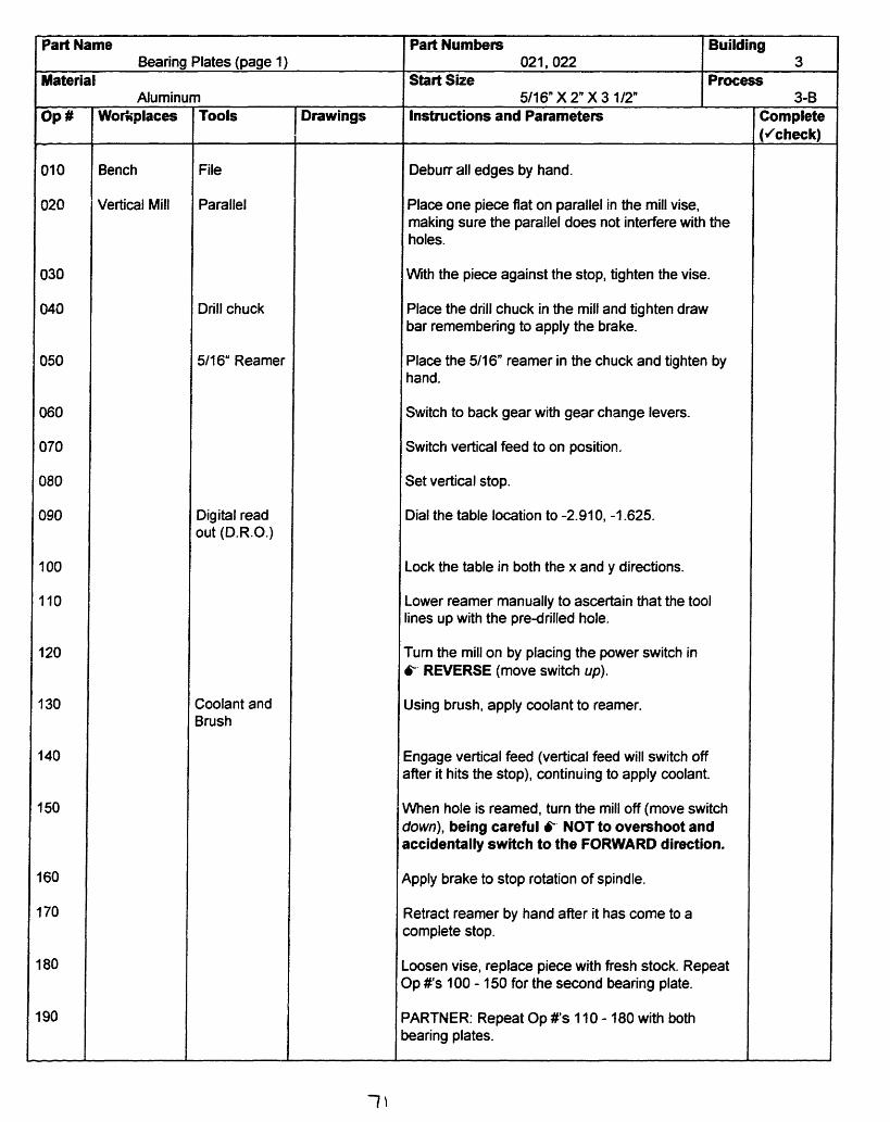
Tools
File
Parallel
Drill chuck
5/16" Reamer
Digital readout (D.R.O.)
Coolant andBrush
Drawings
Part Numbers Building021, 022 3
Start Size Process5/16" X 2" X 3 1/2" 3-B
Instructions and Parameters
Deburr all edges by hand.
Place one piece flat on parallel in the mill vise,making sure the parallel does not interfere with theholes.
With the piece against the stop, tighten the vise.
Place the drill chuck in the mill and tighten drawbar remembering to apply the brake.
Place the 5/16" reamer in the chuck and tighten byhand.
Switch to back gear with gear change levers.
Switch vertical feed to on position.
Set vertical stop.
Dial the table location to -2.910, -1.625.
Lock the table in both the x and y directions.
Lower reamer manually to ascertain that the toollines up with the pre-drilled hole.
Turn the mill on by placing the power switch in-- REVERSE (move switch up).
Using brush, apply coolant to reamer.
Engage vertical feed (vertical feed will switch offafter it hits the stop), continuing to apply coolant.
When hole is reamed, turn the mill off (move switchdown), being careful 6- NOT to overshoot andaccidentally switch to the FORWARD direction.
Apply brake to stop rotation of spindle.
Retract reamer by hand after it has come to acomplete stop.
.oosen vise, replace piece with fresh stock. Repeat)p 's 100 - 150 for the second bearing plate.
'ARTNER: Repeat Op #'s 110 - 180 with both)earing plates.
-I
Part NameBearing Plates (page 1)
MaterialAluminum
Op# Workplaces
Bench
Vertical Mill
Complete(,'check)
010
020
030
040
050
060
070
080
090
100
110
120
130
140
150
160
170
180
190

Part NameBearing Plates (page 2)
MaterialAluminum
200
210
220
230
240
250
260
270
280
290
300
310
320
330
340
WorkplacesW.~l.~
Vertical Mill
Tools
#10 Drill
D.R.O.
Brush andCoolant
Countersink
Drawings
Part Numbers Building021, 022 3
Start Size Process5/16" X 2" X 3 1/2" 3-B
Instructions and Parameters
Loosen chuck by hand and remove reamer.
Place drill in chuck and tighten by hand.
Switch to forward gear with gear change levers,turn chuck by hand to engage the gear.
Switch vertical feed to the off position.
Unlock the table in both the x and y directions.
Dial the table location to -1.500, -0.245.
Lock the table in both the x and y directions.
Lower drill manually to ascertain that the toollines up with the pre-drilled hole.
Turn the mill on by placing the power switch in the6- FORWARD (move switch down).
Lower drill manually and 6- PECK DRILL (lowerdrill 1/16" into material, raise and brush off chips,repeat until hole is drilled through), applying coolantto drill throughout this step.
When the hole is drilled through, turn the mill off,(move switch up), being carefulf-* NOT toovershoot and accidentally switch to theREVERSE direction.
Apply brake to stop rotation of spindle.
Loosen vise, replace piece with fresh stock. RepeatOp 's 250 - 300 for the second bearing plate.
PARTNER: Repeat Op Us 270 - 320 with bothbearing plates.
Deburr all holes by turning countersink in the holeby hand.
72
Op # Complete(./check)
-

8 i 7 S 6 _ 5
2 7/8
2 5/8
#52 Orl I I
#30 [illThru
Thru
413 211
I 9-am Edges
-- fJ eEC a ,,i 'i1
_" EBass. e, I 1 . I
*_ArCI J m 'I LA O* ceG
u w. ah I I ISUSF
-U._
1 K. Rarn
,a
Pover Ccrrectr LeverAl I" 03-08''E e! 9 r
1' A8 1 7 1 6 1 5 T i 1 3 1 2 r 1
8 I 7 1 6 1 5 1 1 3 1 2 I 1
/8
Notes AR-Eak AI
1iW~ .aFWr MROs g * X
- BrassW8
1i? I
AlI
1/8
l C 1/ 16
-- -A
i Srp Edges
Carnctcr LeverST'; I FID M L
TArE U I1M Om a3-9 IJ v.
A
2
8 1 7 1 6 1 5 t i 1 3 31
[
C
-
1/80
C
R2
,/ I
1/8P a Cas
NItes::omk Al B
I
C
3
I _ _ _ I- , J
t. IAL I] eD Wl A U DG
V ---- I-
l
:B
____ .
_ ._ _- _emu ! w_. i
_ : A__!__ _
! . _
I I. ..
.- = I
l
I . . . ! _ I
I a III --Mu.9 I r m I FMS LM
,,� ,� _ -
--r _ .._ III . ,_. - - r. -X
|-
---
I .-·----.I · [ 'T - - - I
._ _ .
1 2 1I 1iI
I
I
3
I
I
1
P
I
II, I 0-0 K. I A
II
lFeLI:rl
II
._ _ .

C-) V
Ln
Us
I II
unH/u
5"1 ,
C-) A
U,CuC!
cuJ
mC
cu
CO
4-
LI-)
I
CD
(1I___
cn
ryc
LnMU6d
U,
ro
%D0R
l
i- l w- --
II
--i- -m
* __ I
I vCD,
I~T
_
I

Part NamesPower Connecting Lever, Lever Connector, Levers
Material
BrassWorkplaces
Bench
Drill Press
Beltsander
Tools
Lever jig
#52 Drill
#30 Drill
Countersink
Bending Jig
Drawings
Part Numbers Building008, 009, 011,012 3
Start Size Process3/32' X 1/4" X 3" (008)1/16" X 5/16" X 2" (009, 011, 012) 3-C
Instructions and Parameters
Place two sets of lever stock in jig; tighten jig wingnuts.
Place #52 drill bit in drill chuck; tighten with key.
Drill through all eight holes marked #52 on jig; besure to align drill bit with hole before drilling.
Replace #52 drill bit with #30 drill bit; tighten drillchuck with key.
Drill through all eight holes marked #30 on jig; besure to align drill bit with hole before drilling.
Remove #30 drill bit; return drill bits.
Loosen wing nuts and remove levers; separatelevers 011 and 012.
Deburr ALL holes by turning countersink in the holeby hand.
Slide one lever 011 into the triangle of 1/8" dowelsin the lower half of the bending jig, with the smallerhole of the lever in the triangle.
Place the 3/8" dowel sticking out of the top half ofthe bending jig in the drill chuck and tighten.
Carefully slide the two halves of the bending jigtogether, close completely using drill press.
Remove lever 011 from the bending jig.
Repeat OP #'s 090 to 120 with PARTNER's lever)11 and both partners' levers 012.
Round ends of ALL levers carefully.
Complete(,check)
Op #
010
020
030
040
050
060
070
080
090
100
110
120
130
140- ---- -- ----- --

3 1
1 1/ >#7 I DiilI ThruR .5 T - S P aces
2
1 1/8
5/16
,
1/4 -
1 3/16
r I
0
o
It-hII IIII IIII II
0
irl'IIIII
1 1/2-
1/2
--hIIII'i
5/16-18 28 TreadD T7ru
5 7/nL //U
Ir
10-2 2 Thread1/2 Deep2 Places
fI 5/1 6
O
C
c-
B
I I i
rPwcnn acwu #= .
. /5_ __
'"ras Bm K,. B 1295 Cy IndE P I ateFM_ _ __ica 12_ S. 1n.. l me.
_______ - mI -mu I
m lOT __: _1__i_ I 'VIE 9 'T· II -- A'% & , I 4
'tI
D
C
B
A A
I -i A - I A - · -
--r
i I
. . . . . ..
t
i
I
I A 2 I 1
,.,,,I_
I
t I d , ! I
J .

--77
Part Name Part Number BuildingCylinder Plate 004 3
Material Start Size ProcessBrass 5/16" X 2" X 4" 3-D
Op # Workplaces Tools Drawings Instructions and Parameters Complete(Vcheck)
010 Bench Cylinder plate Place piece in jig; tighten wing nuts.jig
020 Drill Press #7 Drill Place #7 drill bit in drill chuck; tighten with key.
030 t: PECK DRILL (lower drill 1/16" into material,raise and brush off chips, repeat until hole is drilledthrough) through all five holes marked #7 on jig; besure to align drill bit with hole before drilling.
040 F Drill (0.257") Replace #7 drill bit with F drill bit; tighten drillchuck with key.
050 6' PECK DRILL through the hole marked F on jig;be sure to align drill bit with hole before drilling.
060 Remove F drill bit; return drill bits.
070 Loosen wing nuts and remove piece.
080 PARTNER: Repeat Op #'s 010 - 070
090 Bench Countersink Deburr all holes by turning countersink in the holeby hand.
100 Vise Tighten piece (lightly) horizontally in vise.
110 5/16" - 18 Tap Place tap through tapping block, align with theand Tapping F hole and tap through the piece; 6-' ADD a dropblock of tapping fluid to tap.
120 PARTNER: Repeat Op #'s 100 - 110

I i
D LO -I-, Ll "-
Ln
Eat-
Hl I
Lo (DF_171
clEF
_
7LOWq-4L""
-A-Un
Iw
!L'YT cnq~~.._
-J-J
i
I
HlE2jNX
r
!

Part NameDisplacer Piston Rod
Material1/8" Drill Rod
Workplaces
Bench
Drill Press
Bench
Tools
File
Blue dye andcalipers
Vise
File andcalipers
Blue dye andcalipers
Rod jig
Center drill
#52 Drill
Countersink
Blue dye andcalipers
Vise and5-40 Die
Drawings
Part Number Building014 3
Start Size Process1/8" OD, 5.14" Length 3-E
Instructions and Parameters
Remove burrs from end without thread, file this endface flat.
Apply blue die to this end of piece, make a mark0.31" from this end.
Place piece horizontally in vise, with only themarked distance showing; tighten vise.
File the first flat until remaining material is .094"+0.000, -0.001 thick.
Loosen vise and remove piece.
Holding the first flat against the bench, file thesecond flat on other side until remaining material is0.062" +0.000, -0.001 thick.
Scribe a line on the flat 0.125" from the end of thepiece.
Place piece in jig with scribed line facing up;tighten jig.
Place center drill in drill chuck; tighten with key.
Carefully align center drill with the center of thescribed line, turn drill on and make the center hole.
Replace center drill with #52 drill bit; tighten drillchuck with key.
Drill through the piece.
Deburr all holes by turning countersink in the holeby hand.
Make a mark 0.25" from the end without the thread.
Tighten the piece vertically in the vise so that thenark is visible.Thread to the 0.25" mark usinghe 5-40 die.
-7ct
Op # Complete(check)
010
020
030
040
050
060
070
090
100
120
130
140
150
---

1T~Z1I
Ln
6
TbI I
C'J
I-(~--
r-
r
NoJ=tt=('\i
C,
0-
Id-.--a ',�
't
-- II

Part Name Part Number BuildingConnector Link 013 3
Material Start Size ProcessBrass 1/4" X 1/4" )( 3/4" 3-F
Op # Workplaces Tools Drawing Instructions and Parameters Complete(_check)
010 Bench File Deburr all edges.
020 Drill Press Connector Slide connector link into the jig, with the scribedlink jig side facing upwards.
030 Center drill Place center drill in drill chuck; tighten with key.
040 Carefully align center drill with the scribed holelocation; turn drill on, and make the center hole.Repeat at the second hole location.
050 PARTNER: Repeat Op As 020 - 040
060 #52 Drill Replace center drill with #52 drill bit, carefullyalign the drill with the center hole.
070 Drill ' VERY, VERY CAREFULLYthroughpiece, going slowly to avoid collapsing the link.
i Repeat at the second hole location.
080 Remove link from jig.
090 PARTNER: Repeat Op #s 060 - 080.
100 Bench Countersink Deburr ALL holes by turning countersink in the holeby hand.
110 File Round ends of each lever by hand (6' DO NOTuse beltsander!).
120 Sandpaper Remove internal burrs.

Part Names Part Numbers BuildingCylinder Plate and Bearing Plates 004, 020, 021 3
Material Start Size Process5/16" X 2" X 4" (004)
Aluminum (020, 021) and Brass (004) 5/16" X 2" X 3 1/2" (021, 022) 3-GOp # Workplaces Tools Drawings Instructions and Parameters Complete
or Part (Vcheck)
010 Bandsaw Cylinder plate 6-' VERY, VERY CAREFULLY cut the comers ofthe cylinder plate off, OUTSIDE (leave the linesvisible on the piece after it has been cut) thescribed radii. Repeat this step for ALL cylinderplates in your group.
020 Bearing plate 6' VERY, VERY CAREFULLY cut the corners ofthe bearing plate off, OUTSIDE the scribed radii.Repeat this step for ALL bearing plates in yourgroup.
030 6-' VERY, VERY CAREFULLY cut to the largehole in the bearing plate, OUTSIDE the scribedlines on the bearing plate (set the guide to ensure astraight cut). Repeat this step for ALL the bearingplates in your group.
040 Bench File File bearing plate to scribed straight lines by hand.
050 Beltsander Cylinder plate, Round comers of cylinder plate and bearing plates.Bearing plates

BUILDING 35 (LMP)PART DRAWINGS AND PROCESS PLANS
PART DRAWINGS
PART (PART NUMBER) PAGETransfer Piston Guide Bushing (015) 42Gudgeon Block (007) 44Crank Web (017) 48Flywheel (020) 50
PROCESS PLANS
PROCESS35-A35-B35-C35-D
PARTTransfer Piston Guide BushingGudgeon BlockCrank WebFlywheel
PAGE(S)4345-4647,4951-52
4183

~~~~li [' CO-I I
IDa A-
A- IIP ii Ll
I _II
q-M4
QJ
n/ ~ ~ -
02
t l )
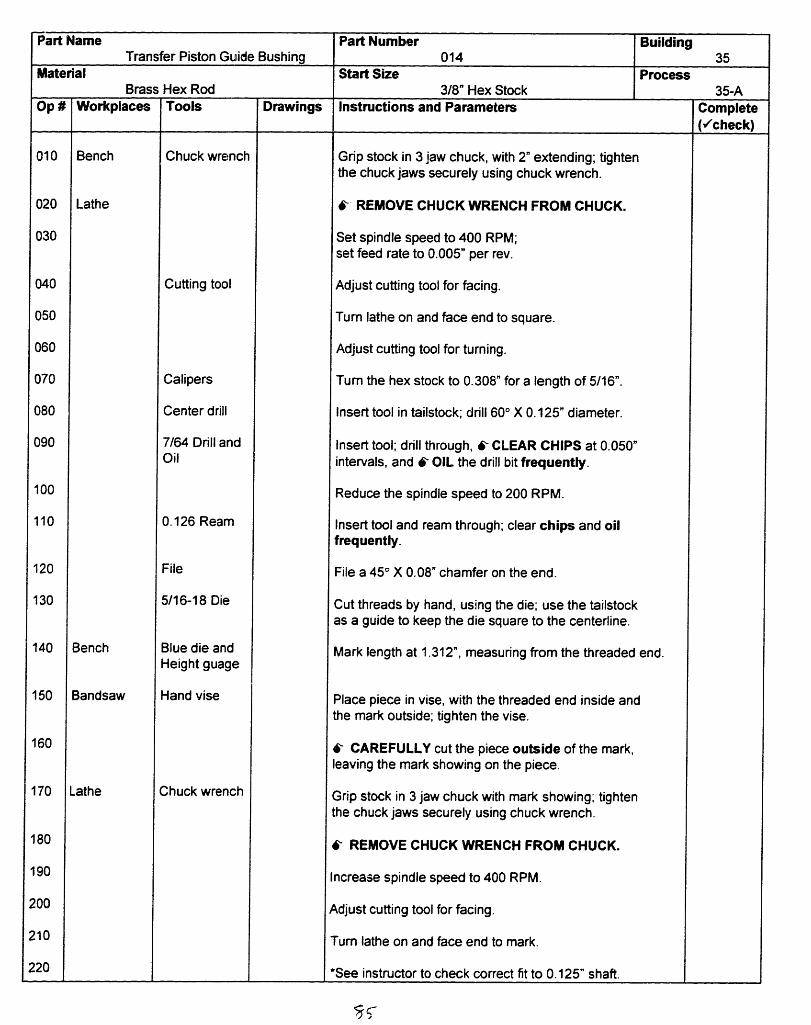
Part NameTransfer Piston Guide Bushing
MaterialBrass Hex Rod
Workplaces
Bench
Lathe
Bench
Bandsaw
.athe
Tools
Chuck wrench
Cutting tool
Calipers
Center drill
7/64 Drill andOil
0.126 Ream
File
5/16-18 Die
Blue die andHeight guage
Hand vise
Chuck wrench
Drawings
Part Number Building014 35
Start Size Process3/8" Hex Stock 35-A
Instructions and Parameters
Grip stock in 3 jaw chuck, with 2" extending; tightenthe chuck jaws securely using chuck wrench.
6- REMOVE CHUCK WRENCH FROM CHUCK.
Set spindle speed to 400 RPM;set feed rate to 0.005" per rev.
Adjust cutting tool for facing.
Turn lathe on and face end to square.
Adjust cutting tool for turning.
Turn the hex stock to 0.308" for a length of 5/16".
Insert tool in tailstock; drill 600 X 0.125" diameter.
Insert tool; drill through, 6- CLEAR CHIPS at 0.050"intervals, and 6- OIL the drill bit frequently.
Reduce the spindle speed to 200 RPM.
Insert tool and ream through; clear chips and oilfrequently.
File a 45 ° X 0.08" chamfer on the end.
Cut threads by hand, using the die; use the tailstockas a guide to keep the die square to the centerline.
Mark length at 1.312", measuring from the threaded end.
Place piece in vise, with the threaded end inside andthe mark outside; tighten the vise.
6 CAREFULLY cut the piece outside of the mark,eaving the mark showing on the piece.
Grip stock in 3 jaw chuck with mark showing; tightenthe chuck jaws securely using chuck wrench.
k- REMOVE CHUCK WRENCH FROM CHUCK.
ncrease spindle speed to 400 RPM.
,djust cutting tool for facing.
rum lathe on and face end to mark.
See instructor to check correct fit to 0.125" shaft.
Complete(,/check)
010
020
030
040
050
060
070
080
090
100
110
120
130
140
150
160
180
190
200
?10
220
Op
..
--~~~~~~~~~~~~~~~~~~~~~~---

O
X II
B I n (D
Il II I IIl IIl II li1 iiII I I

Part NameGudgeon Block (page 1)
MaterialAluminum Rod
Workplaces
Lathe
Bandsaw
Layout Bench
Lathe
Tools
Chuck wrench
Cutting tool
Calipers
Center drill
#38 Drill
Hand vise
Blue die andHeight guage
Chuck wrench
Cutting tool
Drawings
Part Number Building007 35
Start Size Process1/2" OD Stock 35-B
Instructions and Parameters
Grip stock in 3 jaw chuck, with 1.5" extending;tighten the chuck jaws securely using chuck wrench.
6- REMOVE CHUCK WRENCH FROM CHUCK.
Set spindle speed to 400 RPM;set feed rate to 0.005" per rev.
Adjust cutting tool for facing.
Turn lathe on and face end to square.
Adjust cutting tool for turning.
Turn the outer diameter to 0.375" +0.00, - 0.005 fora length of 0.75".
Insert tool in tailstock; center drill 600 X 0.125"diameter.
Insert tool; drill to a depth of 0.4".
Place piece in vise, with the machined shoulderoutside; tighten the vise.
6- CAREFULLY cut the piece off at the shoulder.
Using the height guage, scribe a line 0.625" from thesquared (faced on the lathe) end.
Grip stock in the 3 jaw chuck, with the squared endinside and the scribed line showing; tighten thechuck jaws securely using chuck wrench.
6- REMOVE CHUCK WRENCH FROM CHUCK.
Set spindle speed to 400 RPM,set feed rate to 0.005" per rev.
Adjust cutting tool for facing.
Turn lathe on and face to the scribed line.
7
Op #
010
020
030
040
050
060
070
080
090
100
110
120
130
140
150
160
170
Complete(,check)
45

Part Name Part Number BuildingGudgeon Block (page 2) 007 35
Material Start Size ProcessAluminum Rod 1/2" OD Stock 35-B
Op # Workplaces Tools Drawings Instructions and Parameters Complete_____._____. (vcheck)
180 Drill Press Collet fixture Locate piece in collet fixture
190 0.062" Drill Insert tool and tighten with key.
200 Cutting oil Drill through piece. 6- USE CUTTING OIL andCLEAR CHIPS frequently.
210 {LEAVE PART IN COLLET FIXTURE.
220 Horizontal Mill Remove drill guide ONLY from collet fixture.
230 Locate collet fixture against stops.
240 Mill 3/32" slot to a depth of 5/16".
260 Bench Die files Deburr rough edges by hand.
270 Hand vise Place piece in vise, with the slot inside and thedrilled hole outside; tighten the vise.
280 5-40 Tap Cut threads by hand, using the tap.

Part NameCrank Web (page 1)
MaterialAluminum Rod
Workplaces
Lathe
Layout Bench
Bandsaw
Tools
Chuck wrench
Cutting tool
Calipers
Micrometerstop
Center drill
11/64" Drill,Oil
0.1 885 Ream
Blue die andHeight guage
Hand vise
Drawings
Part Number Building017 35
Start Size Process1.5" OD Stock 35-C
Instructions and Parameters
Grip stock in 3 jaw chuck, with 2" extending; tightenthe chuck jaws securely using chuck wrench.
6-- REMOVE CHUCK WRENCH FROM CHUCK.
Set spindle speed to 400 RPM;set feed rate to 0.005" per rev.
Adjust cutting tool for facing.
Turn lathe on and face end to square.
Adjust cutting tool for turning.
Turn the outer diameter to 1.25" for a length of 0.35"
With the cutting tool at end of the piece, set the stopoffset 0.062" from the carriage.
Turn the diameter to 5/8" for a length of 1/16"(to the stop).
Insert tool in tailstock; drill 600 X 0.125" diameter.
Insert tool; drill to a depth of 5/16", 6 CLEAR CHIPSand 6 OIL the drill bit frequently.
Ream through drilled hole; clear chips and oilfrequently.
Using the height guage, scribe a line 0.25" from thesquared end.
Place the piece in vise, with the scribed line outside;tighten the vise.
6- CAREFULLY cut the piece outside of the mark,leaving the mark on the piece.
83'
010
020
030
040
050
060
070
080
090
100
110
120
130
140
150
Complete(Vcheck)
47
.-
Op #
- ._

I--- cj-cFcJ-
rn La-- J
LO"I-
C
-U
Q'-CO
CU
1
CD
,l I4
LLn

49
Part Name Part Number BuildingCrank Web (page 2) 017 35
Material Start Size ProcessAluminum Rod 1.5" OD Stock 35-C
Op # Workplaces Tools Drawings Instructions and Parameters Complete(-check)
160 Lathe 1 1/4" Collet Grip stock in collet, with cut end extending andthe mark outside; tighten the collet securely.
170 Set spindle speed to 400 RPM;set feed rate to 0.005" rer rev.
180 Cutting tool Adjust cutting tool for facing.
190 Turn lathe on and face end to square.
200 Calipers Check size.
210 C.Web jig Place piece in the jig and close tightly.
220 Drill Press 0.120" Drill Insert drill bit and tighten with key.
230 Drill through the piece (on the face of the piece; for thepress fit of the crank pin).
240 0.1247" Ream Insert ream; ream through the drilled hole.
250 9/64" Drill Insert drill bit; drill to a depth of 3/8" (on the side ofpiece; for the set screw).
260 #38 Drill Insert drill bit; drill to the center hole (in the 9/64" hole).
270 5-40 Tap Cut threads by hand, using tap; make sure the tap isperpendicular to the part.
280 Countersink Deburr all holes and sharp corners.and File
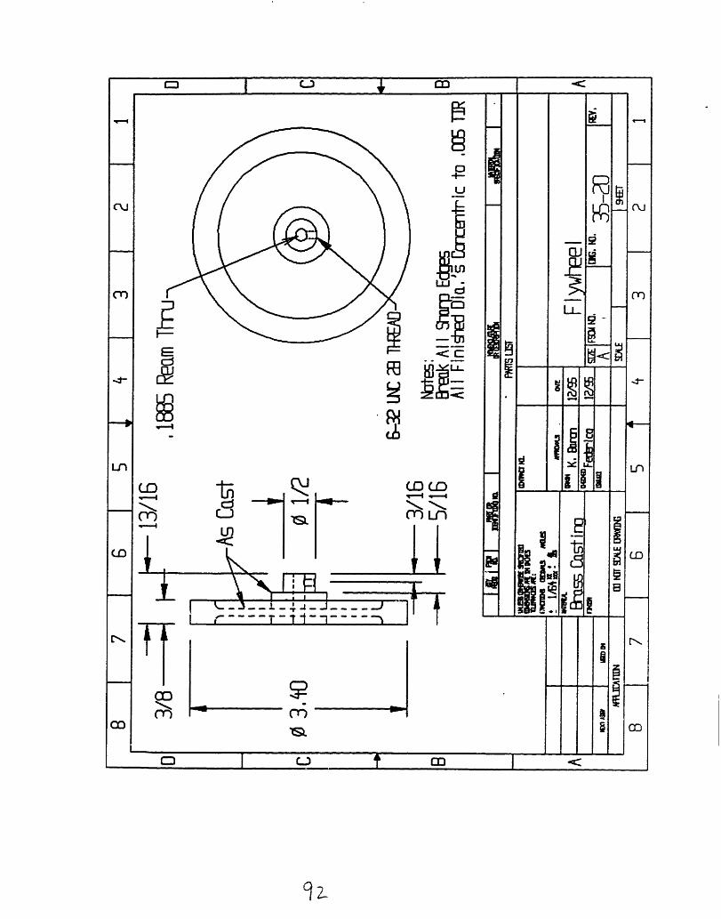
u
Lne' DI
P=
NC
LOD D(D0LO1-4
l
t9
Li
-

51
Part Name Part Number BuildingFlywheel (page 1) 019 35
Material Start Size ProcessBrass Casting 3 1/2" OD1, 1" OD2 X 1" Length 35-D
Op # Workplaces Tools Drawings Instructions and Parameters Complete(,Vcheck)
010 Lathe Chuck wrench Grip casting in 3 jaw chuck, with the small diameter(OD2) inside; using the tailstock, apply light pressure tohold the casting square to the chuck jaws, and thentighten the chuck jaws securely using chuck wrench.
020 6- REMOVE CHUCK WRENCH FROM CHUCK
030 Set surface speed to 600 RPM,set feed rate to 0.0037" per rev.
040 Cutting tool Adjust cutting tool for facing.
050 Turn lathe on and face large rim (not indentation) clean.
060 Adjust cutting tool for turning.
070 Calipers Turn large diameter (OD1) to 3.400 for the entire lengthof OD1, taking 0.03" passes.
080 #2 Center drill Insert tool in tailstock; drill to create conical starting hole.
090 5/32" Drill Insert tool; drill through piece. Withdraw drill every1/8" to clear chips and oil frequently.
100 0. 1885" Ream Insert tool; ream through piece. Withdraw reamer every1/8" to remove chips.
110 Countersink Deburr holes by turning countersink in the holeby hand.

Part NameFlywheel (page 2)
MaterialBrass Casting
Workplaces
Lathe
Drill Press
Bench
Tools
Chuck wrench
Cutting tool
7/16" Spacer
1/8" Spacer
File
Drill jigHand vise
#36 Drill
Long #2center drill
6-32 Tap
Drawings
Part Number Building019 35
Start Size Process3 1/2" OD1, 1" OD2 X 1" Length 35-D
Instructions and Parameters~~~~~~~~~~~~~~~~~~. ,
Grip casting in soft jaws, with the machined face in(clean the chuck jaws first), gripping the outer diameter(OD1); tighten securely using chuck wrench.
6-- REMOVE CHUCK WRENCH FROM CHUCK
Set surface speed to 600 RPM,set feed rate to 0.0037" per rev.
Adjust cutting tool for facing.
Turn lathe on and face large rim (not indentation) untilthe large diameter is 3/8" wide; set the carriage stopwhen done.
With the 7/16" spacer beween the stop and the carriage,face the small diameter until the overall length of theentire flywheel is 13/16"; remove the 7/16" spacer
Adjust cutting tool for turning.
With the 1/8" spacer between the stop and the carriage,turn the small diameter to 0.500" +0.000, -0.005 for alength of 5/16" (the tolerance must be held in order forthe flywheel to fit into the drill jig).
Deburr sharp comers.
Place jig over the small diameter and put the piece andig in the vise (make sure there are no chips in the vise orthe jig); tighten vise.
nsert tool and tighten with key
Drill through ONE wall of the small diameter.
nsert tool; chamfer the drilled hole.
Cut threads by hand, using tap; make sure the tap isperpendicular to the part.
Complete(check)
Op#
120
130
140
150
160
170
200
210
220
240
250
.
--

DRAWINGS OF SUPPLIED PARTS
PART DRAWINGS
PART (PART NUMBER) PAGEAlcohol Burner Cap (001) 54Base (023) 55Crank Pin (016) 56Crank Web Shaft (004) 57Displacer Cylinder (002) 58Displacer Piston (003) 59Lever Shaft (010) 60Main Bearing Bushings (019) 61Power Cylinder (005) 62Power Piston (006) 63
5395

I

U2
MA
N.o.
fl-,5g
�U�ft <I--2:22-31
cii
01.0
m

Ln
w
-- -
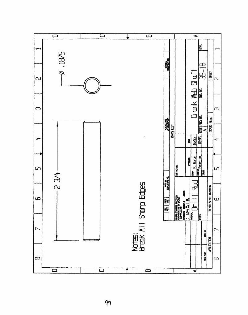
I
7
n
, . I
w
II
c
.
49

1 60

L
oC!C.
ilI

C0
r1l
16z
I

I-) V
r.
i~~
L,
mu, 1l O Ai tC~ c
L-)
Ir'3
I
j-i
, Ics
I~i I
!I
cu
N
C'i s.
OS
Ul
VIC
c
C
c
5-
Cu
4-
LflL-
r-.
JoLf)V0
zl1j
-y w-- -
C_� ____ -- w- l-
- S- l- .- -
l -b I-r{
1 · - - --
Vo
I
i"
--P
I
rl_
co
I

K-m
---.
I
I II II II II II II II II II II {i I I I I i I
C0
'-4
I- uEl,-y(
=tRC
l
I__ ..
............ ~~~~ ,!
D_·
{ b, L
tst�C�ti�
I
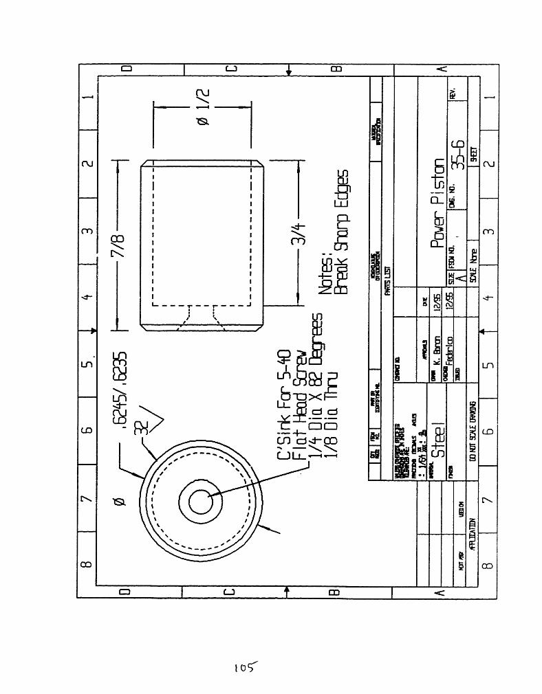
C
I I E
I I JI I
I ~~~~~~II I
c r II I ~ Cr U)
I II II II I a
I I~~~9I I
I''I11-t -r
I~~~~i
t~~~~~ 2~E~

ENGINE ASSEMBLY
PRE-ASSEMBLY1. Use a file to clean all sharp edges and burrs from your parts. Burrs canincrease the friction in your engine, preventing it from running.
FLYWHEEL ASSEMBLYBearing Plate Assembly
1. Press fit main bearing bushings into bearing plates.
2. Push crank web shaft through bearings to align bearing plates whilebolting them to the base.
3. Bolt bearing plates to the base so that the bearings are near the edge andthe ends of the bushings are facing inward.
4. Test fit crank web shaft in bearings and, ONLY IF NECESSARY, lineream bearings with a 0.1885" reamer to allow the crank web shaft torotate freely.
5. Test fit lever shaft in bearing plates and, ONLY IF NECESSARY, lineream bearing plates with a 0. 1885" reamer to allow the lever shaft torotate freely.
Crank Web Assembly
1. Press fit the crank pin into the crank web. If the hole in the crank web is toolarge, use a small amount of super glue to hold the crank pin in the crankweb.
2. Push the crank web onto the crank web shaft such that the end of theshaft is flush with the crank pin side of the crank web and tighten the setscrew to hold the crank web in place.
3. Install the flywheel between the bearing plates on the crank web shaftsuch that the crank web is on the power cylinder side of the bearingplates.
4. Tighten the set screw to hold the flywheel to the crank web shaft.65
106

CYLINDER PLATE ASSEMBLY
Guide Bushing Assembly
1. Place a small amount of RTV on the threads of the transfer piston guidebushing and screw the bushing into the cylinder plate.
Displacer Piston Assembly
1. Screw the displacer piston onto the displacer piston rod
2. Push the displacer piston rod into the transfer piston guide bushing with thedisplacer piston on the opposite side of the cylinder plate from the guidebushing. The displacer piston shaft should move freely in the guide bushing.
3. Clean the power cylinder with alcohol to remove all traces of oil inside thecylinder.6 'Note - you must NOT have any trace of oil in the power cylinder or on thepower piston otherwise your engine will not run.
4. Coat the base of the displacer cylinder and the power piston cylinder with athin coat of RTV and bolt them in place on the cylinder plate.
Power Piston Assembly
1. Fasten the gudgeon block to the power connecting lever with the 1/16" dowelpin.
2. Clean the power piston with alcohol to remove all traces of oil.
3. Place a small amount of Loctite on the end of the gudgeon block and in thethreads of the gudgeon block and screw assembly to the power piston.
4. Push the power piston into the power cylinder.
Cylinder Plate Installation
1. Place the 1/32" washer and then the free end of the power connecting lever onthe crank pin.and loosely bolt the cylinder plate to the base.
2. Align the cylinder plate so that the flywheel can rotate without the powerpiston link rubbing against the crank web and tighten the cylinder plate bolts.
66
107

LEVERS AND DISPLACER PISTON ROD ASSEMBLY1. Place the lever shaft in the bearing plates.
2. Using solder, tin the end with the big hole on both lever 011 and lever012.
3. Fasten the displacer piston rod to the connector link using a 0-80 X 5/16"screw and nut. Place a drop of Loctite on the nut to prevent loosening.
4. Put the other 1/32" washer outside the power connecting lever and thenplace the lever connector on the crank pin.
5. Place lever 011 on the lever shaft and fasten its other end to theconnector link using a 0-80 X 5/16" screw and nut. Place a drop ofLoctite on the nut to prevent loosening.
6. Place lever 012 on the lever shaft and fasten to the lever connector usinga 0-80 X 1/4" screw and nut. Do not overtighten (the levers must rotatewith respect to each other), but do place a drop of Loctite on the nut toprevent loosening.
7. Rotate the crank web so that the crank pin is at 6 o'clock and pull thedisplacer piston until it touches the cylinder plate, and then back it off byan ITTY BITTY fraction. While maintaining this position, heat levers01 1 and 012 at the lever shaft so that they solder together.
8. Test to make sure the flywheel rotates freely.
BURNER ASSEMBLY
1. Place the o-ring in the groove on the alcohol burner cap.
2. Roll the wick material and push it up through the burner cap, leavingabout 1/8" exposed for lighting.
3. Place the burner cap on the glass bottle and place the bottle on the base.
FINAL ASSEMBLY
1. Clean the botom of the base with alcohol and stick the three small padson the bottom - one to the left and two to the right.
2. Screw your name plate onto the base with the two brass screws.
67
108

TROUBLESHOOTING IF YOUR ENGINE DOES NOT RUN
Let your engine cool.
Make sure that it is assembled correctly and that there is very little friction in themoving parts. These engines do not have a lot of power. Even a small amount offriction will prevent them from running. The major sources of friction are: thetransfer piston guide bushing, the lever shaft, and the connector link and levers,.
Make sure the displacer piston rod travels easily through the transfer piston guidebushing and oil as necessary.
Make sure the levers do not bind inside the connector link and bend the levers ifnecessary.
Make sure the lever shaft rotates smoothly and oil as necessary.
Make sure there is no oil or dirt in the power cylinder. 6 Do NOT get ANY oil inthe power piston cylinder. Your engine will not run if there is any oil in thepower cylinder. Wash the piston and cylinder with alcohol as needed.
Make sure the heat transfer piston does not "bottom out" (hit the cylinder plate) asthe flywheel rotates. You can adjust this by heating the soldered link joint andmoving the links relative to each other.
Make sure the heat transfer cylinder and power cylinder do not leak air. You cantest this by wetting the RTV'd joints and spinning the flywheel. You will see verysmall bubbles if there is a leak.
Try your engine again, letting it warm up thoroughly before attempting to run itagain.
69109

ENGINE MAINTENANCE
GENERAL MAINTENANCE
Periodically check all screws and links to make sure they are tight. Loctite can beused to help prevent these parts from working their way loose.
You should oil the moving parts of your engine occasionally. Never, however, oilthe power piston unless you do not plan on running your engine in the near future.
Many people prefer the hue that brass takes on as it oxidizes. If you want to keepyour engine looking shiny, however, you can periodically polish it with a goodmetal polish. Do not coat your engine with lacquer to prevent oxidation. Thelacquer could burn and will inhibit heat transfer, degrading engine performance.
You occasionally may have to remove the power piston from your engine andclean the piston and cylinder. The power piston is made of steel and will rust. Ifrust forms, remove it from the power cylinder and clean the rust from it with finesandpaper or steel wool. Do NOT oil the power piston unless you do not plan onrunning your engine.
STORAGE
If you plan on storing your engine for a long period without using it, you maywant to coat the power piston with a light oil such as WD-40 to prevent rust. Alltraces of this oil should be removed with alcohol from both the power piston andthe cylinder before attempting to run your engine again. If rust does form on yourengine, it can be removed with fine sandpaper or steel wool. Never store yourengine with alcohol in it.
70110

7. CONCLUSIONS
The intent in the machine shop instruction was to provide the students with an
introduction to machining and safety issues. Nearly all students were able to build
running Stirling engines by the end of the class, and the three remaining engines needed
only a little more time to be coaxed into running.
The information provided in this thesis is meant as a documentation of the first
iteration of 2.670, so that it can be built upon year after year. With two weeks and eighty
mechanical engineers (twice!), there are limitless possiblities to the machining project.
There is no uncertainty in the author's mind that the project will evolve year after year,
(but always with the original goals of elementary instruction in mind).
The first year of 2.670 went extraordinarily well, due to the efforts of many, many
people. The class got off to a snowy start, early in the morning on Monday, January 8,
1996, the first day of I.A.P. Nearly two-thirds of the class showed up, despite the
inclement weather, and in spite of this potentially ominous sign, the students seemed to
enjoy the class immensely, appreciating the chance to take a hands-on introductory class
during I.A.P. And it is perhaps safe to say that the instructors enjoyed it even more!
111

APPENDIX 1
In order to ensure that all students were aware of the registration process, all
undergraduate Mechanical Engineering Advisors were sent the memo shown on page
113, and all sophomore students received the memo on page 114 and the World Wide
Web instructions on page 115.
112

*IMPORTANT*
To: Mechanical Engineering AdvisorsFrom: Doug Hart ([email protected]; x32178)
Kevin Otto ([email protected]; x38199)Date: Monday, August 28, 1995Re: Registration for 2.670: M.E. Tools
2.670: M.E. Tools is a new requirement and a prerequisite for 2.007 (2.70) under therevised Mechanical Engineering curriculum. It is intended for sophomores and will onlybe offered during IAP. There will be two sessions; both sessions will meet from 8 am to 5pm, Monday through Friday. Session 1 will meet Jan. 8 - Jan. 19 (first two weeks of IAP)and Session 2 will meet Jan. 22 - Feb. 2 (second two weeks of IAP).
Registration and session assignments will be carried out using a form on the World WideWeb. The form should be submitted between 8 am on Tuesday, September 5, 1995(Registration Day) and 11:59 pm on Sunday, September 10. We will ignore allsubmissions made before Sept. 5 and if the form is not submitted by 11:59 pm on Sept.10, the student will not be able to take this course (with very few exceptions).
There are information pages regarding registration for 2.670 in the packets for yoursophomore advisees. Please alert your advisees to these pages and emphasize that theymust register using the World Wide Web by 11:59 pm on Sunday, September 10. Extracopies are available in the Mechanical Engineering Undergraduate Office, Room 3-154.
Thank you!
Kevin OttoDoug Hart

*IMPORTANT*
To: Mechanical Engineering UndergraduatesFrom: The 2.670 AdministrationDate: Monday August 28, 1995Re: Registration for 2.670: M.E. Tools
2.670: M.E. Tools is a new requirement and is a prerequisite for 2.007 under the revisedMechanical Engineering curriculum and is intended for sophomores. Introductorymachine shop techniques and introductory computer programs will be taught. It will onlybe offered during AP; the two sessions will both meet from 8 am to 5 pm, Mondaythrough Friday. Session 1 will meet Jan. 8 - Jan. 19 (first two weeks of LAP) and Session2 will meet Jan. 22 - Feb. 2 (second two weeks of IAP). Each session can accomodate nomore than 80 students.
Registration and session assignments will be carried out using a form on the World WideWeb. Please submit the form between 8 am on Tuesday, September 5, 1995(Registration Day) and 11:59 pm on Sunday, September 10. Section assignments willbe made on a first come, first serve basis. We will ignore all submissions made beforeSept. 5 and if the form is not submitted by 11:59 pm on Sept. 10, you will not be able totake this course (with very few exceptions).
The URL for the 2.670 homepage is "http: / /me.mit .edu/ 2. 670/". The link forthe registration form is on this page. The attached sheet explains how to start Mosaic andhow to find this homepage. The section assignments will be available over the WorldWide Web by 8 am, Monday, September 18, 1995. You will then be notified by emailof your section assignment.
If you have any questions, please send email to [email protected]. Extra copies of thismemo are available in the Mechanical Engineering Undergraduate Office, Room 3-154.
Thank you!
The 2.670 Administration
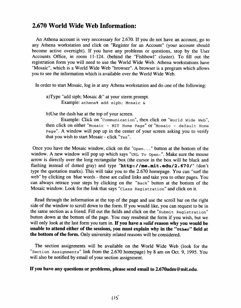
2.670 World Wide Web Information:
An Athena account is very neccessary for 2.670. If you do not have an account, go toany Athena workstation and click on "Register for an Account" (your account shouldbecome active overnight). If you have any problems or questions, stop by the UserAccounts Office, in room 11-124. (behind the "Fishbowl" cluster). To fill out theregistration form you will need to use the World Wide Web. Athena workstations have"Mosaic", which is a World Wide Web "browser". A browser is a program which allowsyou to see the information which is available over the World Wide Web.
In order to start Mosaic, log in at any Athena workstation and do one of the following:
a)Type "add sipb; Mosaic &" at your xterm prompt.Example: athena% add sipb; Mosaic &
b)Use the dash bar at the top of your screen.Example: Click on "Communication", then click on "World Wide Web",
then click on either "Mosaic - MIT Home Page" or "Mosaic - default Home
Page". A window will pop up in the center of your screen asking you to verifythat you wish to start Mosaic - click "Yes".
Once you have the Mosaic window, click on the 'Open..." button at the bottom of thewindow. A new window will pop up which says "URL To Open:". Make sure the mousearrow is directly over the long rectangular box (the cursor in the box will be black andflashing instead of dotted gray) and type "http://me.mit.edu/2.670/" (don'ttype the quotation marks). This will take you to the 2.670 homepage. You can "surf theweb" by clicking on blue words - these are called links and take you to other pages. Youcan always retrace your steps by clicking on the "Back" button at the bottom of theMosaic window. Look for the link that says "Class Registration" and click on it.
Read through the information at the top of the page and use the scroll bar on the rightside of the window to scroll down to the form. If you would like, you can request to be inthe same section as a friend. Fill out the fields and click on the "Submit Registration"
button down at the bottom of the page. You may resubmit the form if you wish, but wewill only look at the last form you turn in. If you have a valid reason why you would beunable to attend either of the sessions, you must explain why in the "Other" field atthe bottom of the form. Only university related reasons will be considered.
The section assignments will be available on the World Wide Web (look for the"Section Assignments" link from the 2.670 homepage) by 8 am on Oct. 9, 1995. Youwill also be notified by email of your section assignment.
If you have any questions or problems, please send email to [email protected].
I f

APPENDIX 2
In order to elicit specific responses on the different parts of the class, as well as to
attempt to determine the level of competency of the students both before and after the
class, the survey found on pages 117-119 was distributed along with the Pi Tau. Sigma
Evaluations on the last day of class (the results of the survey are discussed in Section 5.
Surveys).
116

2.670 SESSION I EVALUATIONHi! As the first set of students ever to take 2.670, we'd appreciate your input on the class. Your response iscompletely anonymous and will not be read until grades have been assigned. If you already answered any ofthese questions on the PTS Evaluation form, you do not have to repeat your answer here. Thank you!!
Machine Shop1. Please rate your familiarity with machining before and after the class.
A1What's a drill press?
1 A
5I could build a Boeing 747with my own two hands!
-------5
2. Pappalardo Lab - Please comment on your three days in the Pappalardo Lab. In particular, what didyou learn? Was it useful? Was the pace too fast/too slow? What should we add/remove next year?
3. L.M.P. - Please comment on your three days in the L.M.P. In particular, what did you learn?Was it useful? Was the pace too fast/too slow? What should we add/remove next year?
Computer Lab4. XESS
a) Please rate your familiarity with XESS before and after the class.
I--------- 2What's a cell?
2z A
A'2
------------5I used XESS to analyze the velocity ofthe air flow around the wings of my 747!----------- 5
b) Please comment on the XESS instruction and homework. In particular, what did you learn?Was it useful? Was the pace too fast/too slow? What should we add/remove next year?
117
BEFORE
AFTER
BEFORE
AFTER
---------------- I ----- --------------- - ----------------
------------ ---- --------------- - I ----------------- ----- -----
--- ------ ----- - ------------- --- --
1 - ------------- ----- ------ -- --------------------
11 1)-
r, "I-
1

5. Matlaba) Please rate your familiarity with Matlab before and after the class.
1 '2 A
What's a matrix?
1 '2 A
5I used Matlab to graph the air speed ofmy 747 vs. the total passenger weight!
5
b) Please comment on the Matlab instruction and homework. In particular, what did you learn?Was it useful? Was the pace too fast/too slow? What should we add/remove next year?
6. Pro/Engineera) Please rate your familiarity with Pro/Engineer before and after the class.
A
What's CAD stand for?
---------------- 2----------------3----------------4-
-------5I did a Pro/Engineermodel of my 747!
-------5
b) Please comment on the Pro/Engineer instruction and homework.Was it useful? Was the pace too fast/too slow? What should we
In particular, what did you learn?add/remove next year?
Safety7. Please comment on the safety instruction and on the safety in the machine shop. Was the instruction
adequate/inadequate? Did you have a safe working environment in the machine shop?
The Schedule8. Please comment on the schedule. Was it helpful for learning the material?
Was it confusing? How should we modify it?
118
BEFORE
AFTER
BEFORE 1
AFTER 1
~~~~L""~~' ~~3~'~"~~"~'~Lt'-------------- ----
--- - - -- -- -- z- -- -- -- -- - --j -- -- - - -- -- - - -- -- --
1 -------------------------------------------
-

The Stirling Engine9. Please comment on the Stirling Engine project. Was it a good learning tool for the machine shop?
For the computer lab? How should we modify it?
The Web Pages10. How often did you refer to the web pages? Which pages did you find particularly useful? Which pages
should we definitely keep next year? What should we add?
The Green Handout11. Process Plans - How often did you refer to the process plans? Did you find them useful? Confusing?
How should we modify them next year?
12. Other - Did you use the rest of the pages in your handout? Which ones were particularly useful? Whichones did you ignore? What should we add or remove next year?
Other13. Please comment on any other aspect of the class. What did you like most/least about the class? What
should definitely be kept/added/removed in/to/from the class for next year?
119

REFERENCES
[1] Galendez, Liv C., Development of an Introductory Hands-on Machineand Computer Analysis Course, © 1996
[2] Photographs courtesy of Kevin Otto
[3] Senfl, James, Ringbom Stirling Engines, p. 1,Oxford University Press, New York, ©1993
[4] Pro/Engineer rendering of the Stirling Engine courtesy of Phil Houdek
[5] Smith, Robert H. (M.I.T.), Textbook ofAdvancedMachine Work, p. 519,Industrial Education Book Company, Boston, USA, 1930
Also:West, C.D., Principles and Applications of Stirling Engines
Van Nostrand Rein Hold Co., New York, ©1986
120
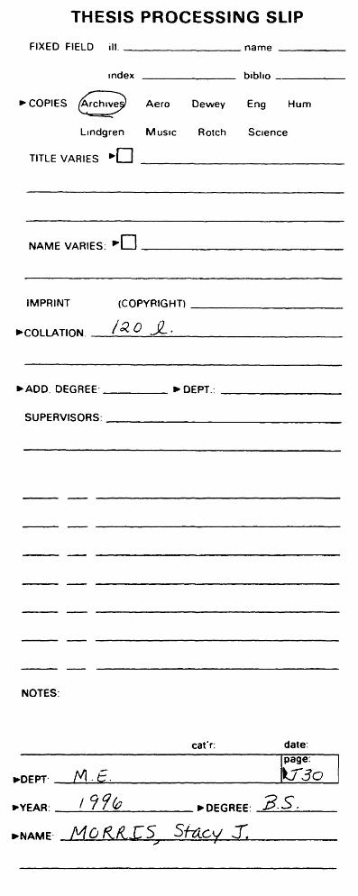
THESI
FIXED FIELD ill.
Ind
"COPIES rchvec
Lindgrer
TITLE VARIES E
NAME VARIES:
IMPRINT
*COLLATION
S PROCESSING SLIP
name
ex biblio -
' Aero Dewey Eng Hum
Music Rotch Science
]
Ir-
(COPYRIGHT)
ia0o ..
BADD. DEGREE * DEPT.:
SUPERVISORS:
NOTES:
cat'r: date:page:
.DEPT' M/ . /30
-YEAR: / ?9 DEGREE: 3.S,
'NAME- MRXZS Scy JM ~/4~/~.~' I -c
-
- -
-
-
-
--
.