development of cost effective swimming pools
TRANSCRIPT
DEVELOPMENT OF COST E F F E C T I V E
SWIMMING POOLS FOR SRI L A N K A
THIS THESIS IS SUBMITTED TO THE DEPARTMENT OF CIVIL
ENGINEERING IN PARTIAL FULFILMENT OF THE REQUIREMENT
FOR THE DEGREE OF MASTER OF ENGINEERING IN STRUCTURAL
ENGINEERING DESIGN
E. M. WIJESINGHE
Supervised By
By
Dr. M. T. R. JAYASINGHE
Associate Professor
Department of Civil Engineering
7/5- ?0 <-s
DEPARTMENT OF CIVIL ENGINEERING
UNIVERSITY OF MORATUWA
University of Moratuwa SRI LANKA MM Thesis coll
77705 77705 11105 JANUARY 2003
DECLARATION
I, Ernest Merrill Wijesinghe, hereby declare that the content of this thesis is
the original work carried out for a period of one year by me. Whenever
others' work is included in this thesis, it is appropriately acknowledged as a
reference.
i
Abstract
Swimming is an ideal recreational activity in Sri Lanka since it is a tropical
country. The island is blessed with beautiful sea beaches right round. However due to the V
financial limitations and other restrictions, majority of Sri Lankans are not so fortunate to
have ready access to the sea coast. Thus, people really interested in swimming are
directed to swimming pools constructed inland. As can be seen in recent t imes, Sri
Lankan sport has gained some rejmarkable achievements. Once the facilities are provided, i
Sri Lanka may reach international level in swimming too. The main obstacle for all these
is the non-availability of adequate .number of swimming pools in Sri Lanka due to high
capital cost involved.
This exercise is to achieye cost effective structural forms for the construction of i
swimming pools for Sri Lanka. .[Conventional type pools are constructed using cantilever
type retaining walls as vertical n u m b e r s designed to retain water limiting the crack width
exerted by the water pressure. Highest cost is involved in the materials and workmanship
associated with the walls. If this is reduced, many of the citizens will be able to afford to
construct their own private swimming pools. The middle level schools may collect a
nominal sum of money from parents and build the school swimming pool. Sports clubs
and other institutions will also be interested to have their own pools. The operational and
maintenance cost compared to the capital cost is very low and can be collected from the
users of the pools very easily. ' •
First of all, a comprehensive literature survey was conducted to determine the
alternative structural forms used in other countries. These alternatives were compared
with the conventional forms. It was observed that there are more effective methods still
not widely used in Sri Lanka. Direct application of these will not be suitable to Sri Lankan
context. Hence certain modifications were made to match to our conditions. When these
alternatives were still behind the expected effectiveness, further desk studies were carried
out to invent more effective methods. The methods developed will not be suitable for sites
with higher level of ground watfer. Construction of pools using this method without deep
ends will be possible if the ground water table is l m below the pool top level. Similarly
pools with deep ends will be possible using this method when the ground water level is 2m
below the pool top level. Again the soil needs to be firm for the use of this method.
The structures needed for water treatment process were also studied to observe the
effectiveness by changing the structural forms.
11

Acknowledgements
First, I wish to express my gratitude and thanks to the Vice Chancellor of the University. And I wish to thank the Dean, Faculty of Engineering and Head of the Department of Civil Engineering of the University.
Next, I would like to express my sincere gratitude to the staff of the University of Moratuwa who taught me Engineering since the day I entered as an undergraduate to this excellent institution. Then I wish to give my thanks to all the staff of the structural Engineering Division of Department of Civil Engineering at the University of Moratuwa for teaching me throughout the Post Graduate course fruitfully.
It is my duty to give my special thanks to Dr.M.T.R.Jayasinghe, Associate Professor at the Dept. of Civil Engineering who guided me throughout this research work with excellent comments and suggestions. He was always enriched to create new things over conventional patterns to make this research a useful one. His continuous monitoring work for last fifteen months with valuable additions to this work is indispensable.
I am very much grateful to Mrs.D.Nanayakkara, the course coordinator of the Post.Graduate.Diploma course, who conducted the course with great devotion. It is my thanks to Dr. (Mrs.) M.T.P.Hettiarachchi, the research coordinator who monitored the progress of the research work timely and coordinated effectively.
Finally I must be thankful to National Water Supply & Drainage Board for giving me this valuable opportunity to follow the Master of Engineering course.
iii
T A B L E OF CONTENTS
Declaration
Abstract
Acknowledgements
Contents
List of Tables
List of figures
IV
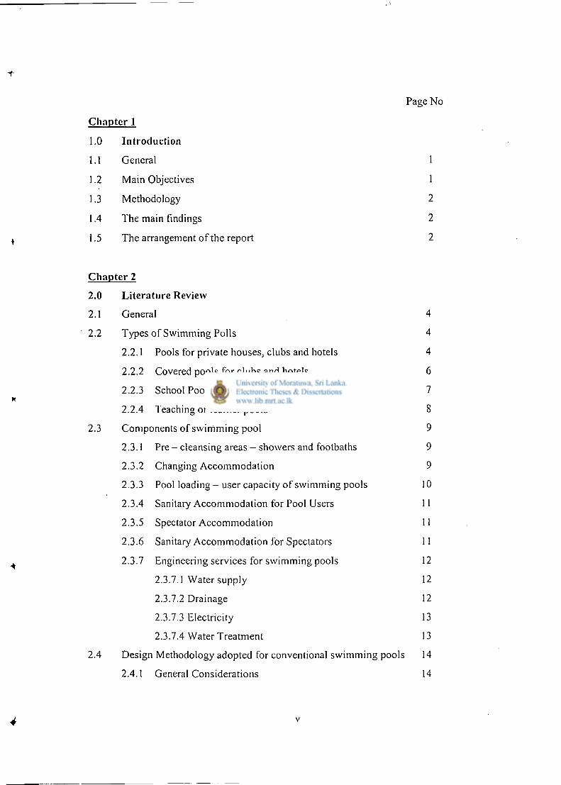
Page No
Chapter 1
1.0 Introduction
1.1 General 1
1.2 Main Objectives 1
1.3 Methodology 2
1.4 The main findings 2
1.5 The arrangement of the report 2
Chapter 2
2.0 Literature Review
2.1 General 4
2.2 Types of Swimming Polls 4
2.2.1 Pools for private houses, clubs and hotels 4
2.2.2 Covered pools for clubs and hotels 6
2.2.3 School Pools 7
2.2.4 Teaching or learner pools 8
2.3 Components of swimming pool 9
2.3.1 Pre - cleansing areas - showers and footbaths 9
2.3.2 Changing Accommodation 9
2.3.3 Pool loading - user capacity of swimming pools 10
2.3.4 Sanitary Accommodation for Pool Users 11
2.3.5 Spectator Accommodation 11
2.3.6 Sanitary Accommodation for Spectators 11
2.3.7 Engineering services for swimming pools 12
2.3.7.1 Water supply 12
2.3.7.2 Drainage 12
2.3.7.3 Electricity 13
2.3.7.4 Water Treatment 13
2.4 Design Methodology adopted for conventional swimming pools 14
2.4.1 General Considerations 14
•i
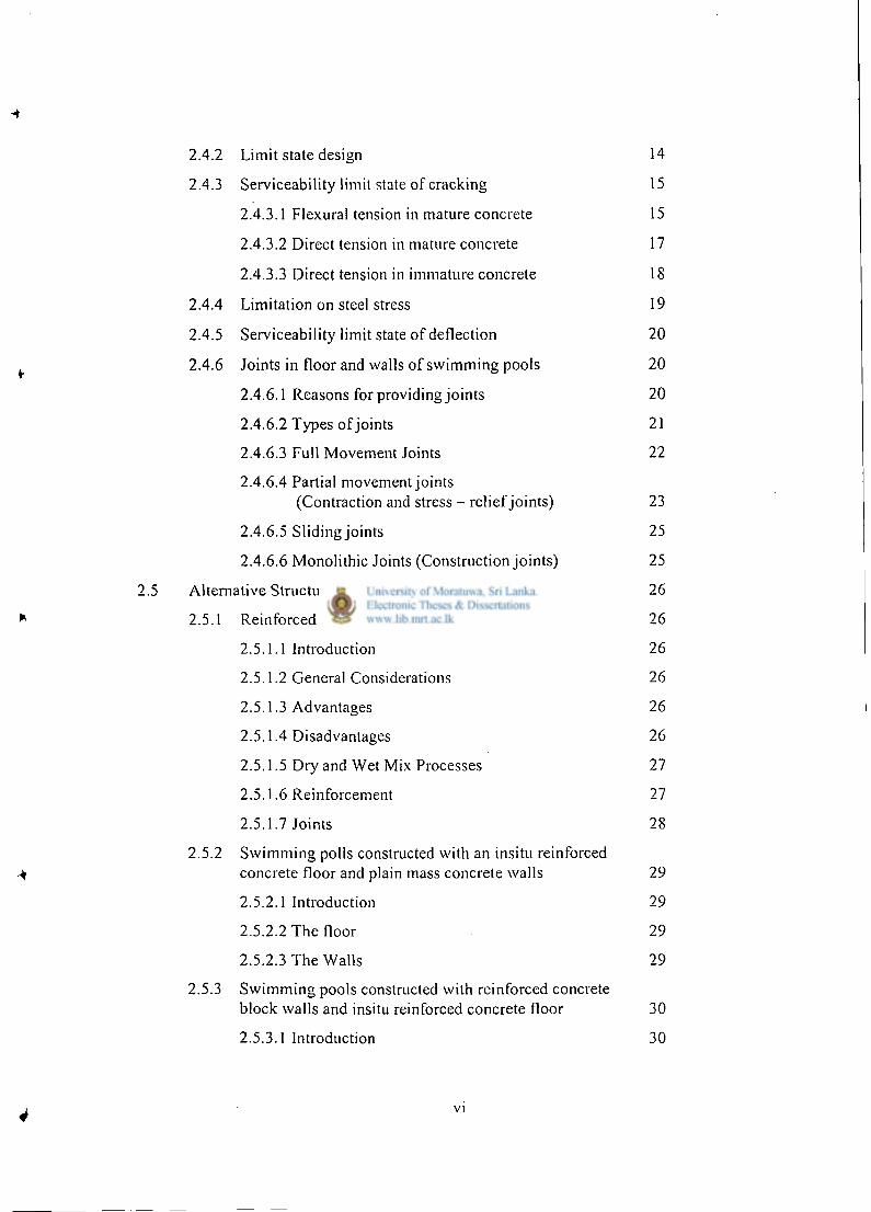
2.4.2 Limit state design 14
2.4.3 Serviceability limit state of cracking 15
2.4.3.1 Flexural tension in mature concrete 15
2.4.3.2 Direct tension in mature concrete 17
2.4.3.3 Direct tension in immature concrete 18
2.4.4 Limitation on steel stress 19
2.4.5 Serviceability limit state of deflection 20
^ 2.4.6 Joints in floor and walls of swimming pools 20
2.4.6.1 Reasons for providing joints 20
2.4.6.2 Types of joints 21
2.4.6.3 Full Movement Joints 22
2.4.6.4 Partial movement joints
(Contraction and stress - relief joints) 23
2.4.6.5 Sliding joints 25
2.4.6.6 Monolithic Joints (Construction joints) 25
2.5 Alternative Structural Forms 26
* 2.5.1 Reinforced Sprayed Concrete 26
2.5.1.1 Introduction 26
2.5.1.2 General Considerations 26
2.5.1.3 Advantages 26
2.5.1.4 Disadvantages 26
2.5.1.5 Dry and Wet Mix Processes 27
2.5.1.6 Reinforcement 27
2.5.1.7 Joints 28
2.5.2 Swimming polls constructed with an insitu reinforced
+ concrete floor and plain mass concrete walls 29
2.5.2.1 Introduction 29
2.5.2.2 The floor 29
2.5.2.3 The Walls 29
2.5.3 Swimming pools constructed with reinforced concrete block walls and insitu reinforced concrete floor 30 2.5.3.1 Introduction 30
4 vi
-i
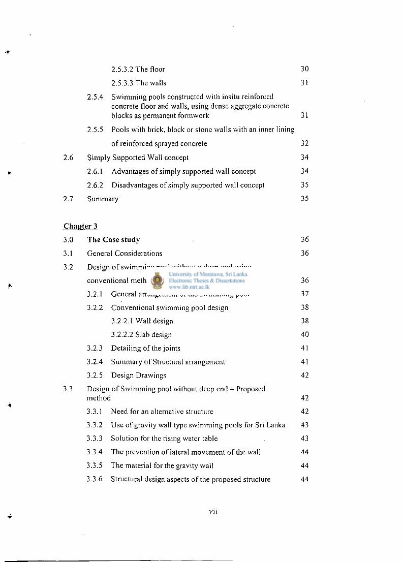
2.5.3.2 The floor 30
2.5.3.3 The walls 31
2.5.4 Swimming pools constructed with insitu reinforced concrete floor and walls, using dense aggregate concrete blocks as permanent formwork 31
2.5.5 Pools with brick, block or stone walls with an inner lining
of reinforced sprayed concrete 32
2.6 Simply Supported Wall concept 34
«, 2.6.1 Advantages of simply supported wall concept 34
2.6.2 Disadvantages of simply supported wall concept 35
2.7 Summary 35
Chapter 3
3.0 The Case study 36
3.1 General Considerations 36
3.2 Design of swimming pool without a deep end using
conventional method 36
3.2.1 General arrangement of the swimming pool 37
3.2.2 Conventional swimming pool design 38
3.2.2.1 Wall design 38
3.2.2.2 Slab design 40
3.2.3 Detailing of the joints 41
3.2.4 Summary of Structural arrangement 41
3.2.5 Design Drawings 42
3.3 Design of Swimming pool without deep end - Proposed
method 42
3.3.1 Need for an alternative structure 42
3.3.2 Use of gravity wall type swimming pools for Sri Lanka 43
3.3.3 Solution for the rising water table 43
3.3.4 The prevention of lateral movement of the wall 44
3.3.5 The material for the gravity wall 44
3.3.6 Structural design aspects of the proposed structure 44
vii
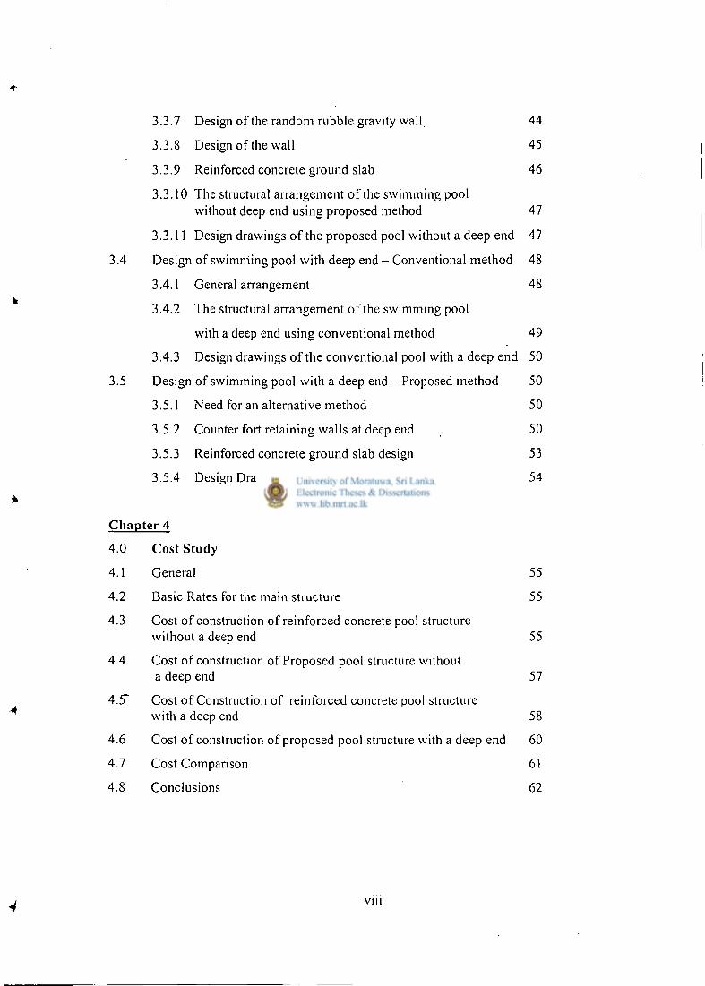
3.3.7 Design of the random rubble gravity wall 44
3.3.8 Design of the wall 45
3.3.9 Reinforced concrete ground slab 46
3.3.10 The structural arrangement of the swimming pool
without deep end using proposed method 47
3.3.11 Design drawings of the proposed pool without a deep end 47
3.4 Design of swimming pool with deep end - Conventional method 48
3.4.1 General arrangement 48
3.4.2 The structural arrangement of the swimming pool
with a deep end using conventional method 49
3.4.3 Design drawings of the conventional pool with a deep end 50
3.5 Design of swimming pool with a deep end - Proposed method 50
3.5.1 Need for an alternative method 50
3.5.2 Counter fort retaining walls at deep end 50
3.5.3 Reinforced concrete ground slab design 53
3.5.4 Design Drawings 54
Chapter 4
4.0 Cost Study
4.1 General 55
4.2 Basic Rates for the main structure 55
4.3 Cost of construction of reinforced concrete pool structure without a deep end 55
4.4 Cost of construction of Proposed pool structure without a deep end 57
4.5" Cost of Construction of reinforced concrete pool structure
with a deep end 58
4.6 Cost of construction of proposed pool structure with a deep end 60
4.7 Cost Comparison 61
4.8 Conclusions 62
4 viu
Chapter 5
5.0 Alternatives for associated structures 63
5.1 Introduction 63
5.2 Methods of removal of pollution 63
5.2.1 Removal of surface pollution 63
5.2.2 Removal of dissolved pollution 64
5.2.3 Removal of suspended pollution 64
5.2.4 Removal of deposited insoluble pollution 64
5.2.5 Removal of the biological pollution in the swimming pool 64
5.3 Structural forms for water treatment 64
5.3.1 Traditional swimming pool forms for water treatment 64
5.3.2 Alternative forms - Aerators built using ferro - cement technology 65
5.4 Cost study 65
5.4.1 Cost for pool without deep end 65
5.4.2 Cost for pool with deep end 66
5.5 Cost savings 66
5.6 Summary 67
Chapter 6 68
6.0 Conclusions and Recommendations 68
6.1 General 68
6.1.1 Main features of Swimming pools without deep ends 68
6.1.2 Main features of Swimming pools with deep ends 68
References 71
Appendices
Appendix A : Design calculations for conventional swimming pool with deep end.
Appendix B : Design calculations for proposed swimming pool with deep end.
Appendix C : Design drawings of conventional swimming pool without deep end.
Appendix D : Design drawings for proposed swimming pool without deep end.
IX
Appendix E : Design drawings for conventional swimming pool with deep end.
Appendix F : Design drawings for proposed swimming pool with deep end.
LIST OF TABLES
Page
2.1 Dimensions of swimming pools for private houses 6
2.2 Dimensions of swimming pools for clubs and. hotels 6
2.3 Dimensions of swimming pools for schools 7
2.4 Dimensions of teaching pools 8
2.5 Area required in swimming pools per person according to
depth of water and use 9
2.6 Gradients of pipes for self cleansing 13
2.7 Variation in temperature due to seasonal changes 19
2.8 Allowable steel stresses in direct or flexural tension for Serviceability limit state 19
3.1 Summary of reinforcement for pool without a deep end 42
3.2 Structural arrangement of the conventional pool with
a deep end 49
4.1 Cost calculation of reinforced concrete pool structure without a deep end 56
4.2 Cost calculation of proposed pool structure without a deep end 58
4.3 Cost calculation of reinforced concrete pool structure with a deep end 60
4.4 Cost calculation of proposed pool structure with
a deep end 61
4.5 Cost comparison of different swimming pools 62
6.1 Structural costs, cost saving and cost saving as a percentage 69
6.2 Total costs, cost saving and cost saving as a percentage 70
LIST OF FIGURES
P a g e
2.1 Dimensions of a typical 25m long pool 7
2.2 Reinforcement arrangement for crack width calculations 16
2.3 Section subjected to combined bending and tension 17
2.4 Full movement joint in reinforced concrete wall 22
ir 2.5 Full movement joint in reinforced concrete floor slab 23
2.6 Stress relief joint in reinforced concrete floor slab showing recommended proportion for crack inducement 23
2.7 Stress - relief joint in reinforced concrete wall showing recommended proportion for crack inducement 24
2.8 Possible arrangement of joints in floor and walls of the reinforced concrete swimming pools 24
2.9 Diagram of mass (gravity) type wall of pool with reinforced sprayed concrete lining and floor 33
2.10 Diagram of mass (gravity) type wall of pool with reinforced + sprayed insitu lining and reinforced insitu concrete floor 33
3.1 Plan and section of a swimming pool for a school without
a deep end 37
3.2 The possible arrangement of joints in floor and walls 38
3.3 Arrangement used for the study 39
3.4 Fixed joint between wall and base slab 41
3.5 Section of wall of 1.5m deep 45
3.6 Plan and section of a conventional swimming pool for a school
with a deep end 48
3.7 Dimensions of the counter fort retaining wall used to retain water
at deep end 51
3.8 General arrangement of the counter forts 51
3.9 Dimensions of the counter fort 52
3.10 Section of pool showing slab thicknesses for design 53
3.11 Base slab arrangement 54
3.12 Base slab reinforcement arrangement 54
XI

5.1 Water pollution zones in pools 63
5.2 Schematic diagram of an aerator 65
X l l
Chapter 1
Introduction
1.1 General
Water is the blessing to the mankind as one of the fundamental needs to live with. By and
large, it takes the body heat away and neutralizes the physical fatigue of the human when
immersed in. Ancient Ceylon, as for many other trades, was in fore front using this
natural resource for pleasure by designing surprising models of swimming pools such as
twin ponds in Anuradhapura. It is surprising to see a swimming pool on a huge stone as
on "Sigiriya" using clay bricks. Sinhalese Kings were so engineered to craft things to be
named as wonders of the 2 1 s t Century.
Today, Swimming pools are considered as luxurious components for private houses,
institutions and schools in Sri Lanka due to high cost of capital investment.
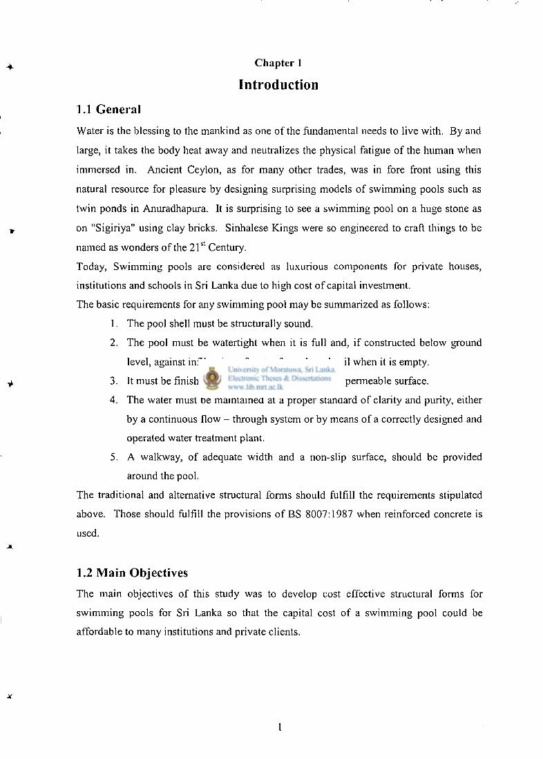
The basic requirements for any swimming pool may be summarized as follows:
1. The pool shell must be structurally sound.
2. The pool must be watertight when it is full and, if constructed below ground
level, against infiltration of water from the subsoil when it is empty.
3. It must be finished with an attractive, smooth, impermeable surface.
4. The water must be maintained at a proper standard of clarity and purity, either
by a continuous flow - through system or by means of a correctly designed and
operated water treatment plant.
5. A walkway, of adequate width and a non-slip surface, should be provided
around the pool.
The traditional and alternative structural forms should fulfill the requirements stipulated
above. Those should fulfill the provisions of BS 8007:1987 when reinforced concrete is
used.
1.2 Main Objectives
The main objectives of this study was to develop cost effective structural forms for
swimming pools for Sri Lanka so that the capital cost of a swimming pool could be
affordable to many institutions and private clients.
1
1.3 Methodology
The following methodology was used to achieve the above objective:
1. A detailed literature review was carried out to determine the various structural
concepts and materials adopted in other countries. The alternatives that could
be cost effective were identified.
2. These concepts were further investigated to determine the applicability to the
soil types and ground water available in Sri Lanka.
3. Detailed structural designs were used to determine the suitability of the proposed
concepts.
4. Detailed Survey was carried out to collect alternative water treatment processes
in Sri Lanka to be used for water purification system in the swimming pool.
1.4 The main findings
The main findings of this study are listed below.
1. Cost of traditional swimming pools could be reduced significantly using
alternative methods.
2. The reduction is mainly achieved by changing the structural forms used in the
construction of structural walls and base slab of the swimming pools.
3. The reduction of the cost of water treatment process of the swimming pool is not
in considerable magnitude. This is because the structural components used for
treatment process is only the aerator of the system. Traditional methods to
construct the structures and pressure filters can therefore be used for
purification.
1.5 The arrangement of the report
The report is arranged in the following manner.
Chapter 2 gives a detailed literature review including design methodologies and
construction details
Chapter 3 presents the design calculations and detailed drawings of traditional swimming
pools and the alternative structural forms
Chapter 4 describes the cost calculations and comparisons of the traditional swimming
pool with alternative structural forms to show the effectiveness of the alternative structural
forms.
Chapter 5 deals with alternatives for associated structures mainly in water purification
systems of swimming pools to obtain any cost savings using alternatives.
Chapter 6 presents the conclusions and recommendations
Chapter 2
Literature Review
2.1 General
The literature review was mainly focused upon different types of structural forms used for
swimming pools in other countries to select cost effective options. Reference was also made
to different structural engineering concepts to transfer the loads excerted on pool walls and
ground slab electively. Further references were made on water purification systems and soil
stabilization methods.
Generally the size of a swimming pool must be large enough for a swimmer to take several
strokes, and the minimum effective size is likely about 5.0m long by 2.5m wide with a
minimum depth of water of 1.0m. However, a depth of 1.0m would not be sufficient for even
a very flat drive. An experienced swimmer can make a flat drive from 0.30m above water
level in to 1.20m of water. It is recommended that for public pools a minimum of 2.0m 2 of
pool water area is required per person in the pool. For comfort, an allowance should be made
of about 3.5m 2 for each person who wishes to swim. In other words, the swimming area of the
pool should be based on 3.5m 2 per swimmer. For proper swimming, a 'lane' at least 2.0m
wide and 5.0m long is required. This means that to accomodate four people who really wish
to swim, a pool 10.0m x 4.0m is required.
The pools, which are intended only for swimming, and not for diving and water polo, the
maximum depth of water need not exceed about 1.5m. The provision of a depth in excess of
this figure really serves little useful purpose, but adds significantly to the capital cost and
running expenses of the pool.
2.2 Types of Swimming Pools
2.2.1 Pools for private houses, clubs and hotels (Perkins, 1988)
With pools in this category there is generally a limited choice of site since they usually have
to be built on the same plot as the main building. However, clubs and hotels are likely to be
better off in this respect than private houses, because the plot area is greater. The larger the
garden the more scope there is for selecting the most favorable position for the pool. Even
with a comparatively small garden there are certain factors, which should be taken into
account, and these apply to all open-air pools in countries with a temperate climate like Sri
Lanka. These factors are (Perkins-1988):
1. Select a position, which will receive as much sun as possible preferably in the
afternoon.
2. Avoid the vicinity of large trees.
3. If there is an existing wind - break, in the form of an attractive stone, brick or
block wall, or thick hedge, it would be advantageous to utilize this if at all
possible.
4. Provision has to be made for emptying the pool and for disposing of the wash -
water from filters.
5. The location of existing services - water, electricity.
6. Following on from the provision of services to the pool is the location of a small
building to house the plant and equipment such as circulating pump, water
treatment and heating installations, and ancillary equipment required for cleaning
and maintenance of the pool
7. There should be reasonable access for plant and materials to build the pool.
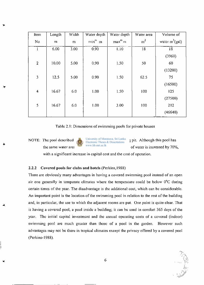
Item Length Width Water depth Water depth Water area Volume of
No m m • m min m
m max m m 2 water m 3 (gal)
1 6.00 3.00 0.90 1.10 18 18
(3960)
2 10.00 5.00 0.90 1.50 50 60
(13200)
3 12.5 5.00 0.90 1.50 62.5 75
(16500)
4 16.67 6.0 1.00 1.50 100 125
(27500)
5 16.67 6.0 1.00 3.00 100 212
(46640)
Table 2 .1: Dimensions of swimming pools for private houses
NOTE: The pool described in Item 5 is provided with a diving pit. Although this pool has
the same water area as the pool in Item 4, the volume of water is increased by 70%,
with a significant increase in capital cost and the cost of operation.
2.2.2 Covered pools for clubs and hotels (Perkins, 1988)
There are obviously many advantages in having a covered swimming pool instead of an open
air one generally in temperate climates where the temperature could be below 0°C during
certain times of the year. The disadvantage is the additional cost, which can be considerable.
An important point is the location of the swimming pool in relation to the rest of the building
and, in particular, the use to which the adjacent rooms are put. One point is quite clear. That
is having a covered pool, a pool inside a building; it can be used in comfort 365 days of the
year. The initial capital investment and the annual operating costs of a covered (indoor)
swimming pool are much greater than those of a pool in the garden. However such
advantages may not be there in tropical climates except the privacy offered by a covered pool
(Perkins-1988).
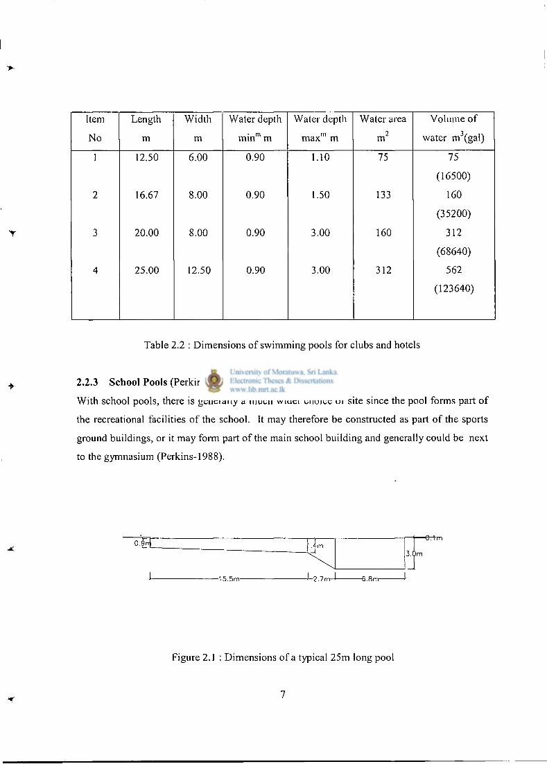
Item Length Width Water depth Water depth Water area Volume of
No m m m i n m m max" 1 m m 2 water m 3 (gal)
1 12.50 6.00 0.90 1.10 75 75
(16500)
2 16.67 8.00 0.90 1.50 133 160
(35200)
3 20.00 8.00 0.90 3.00 160 312
(68640)
4 25.00 12.50 0.90 3.00 312 562
(123640)
Table 2.2 : Dimensions of swimming pools for clubs and hotels
2.2.3 School Pools (Perkins, 1988)
With school pools, there is generally a much wider choice of site since the pool forms part of
the recreational facilities of the school. It may therefore be constructed as part of the sports
ground buildings, or it may form part of the main school building and generally could be next
to the gymnasium (Perkins-1988).
O.fnJ 1 .4m
1
3.0m
J 15.5m J - 2 . 7 m J 6.8m-
Figure 2.1 : Dimensions of a typical 25m long pool
7
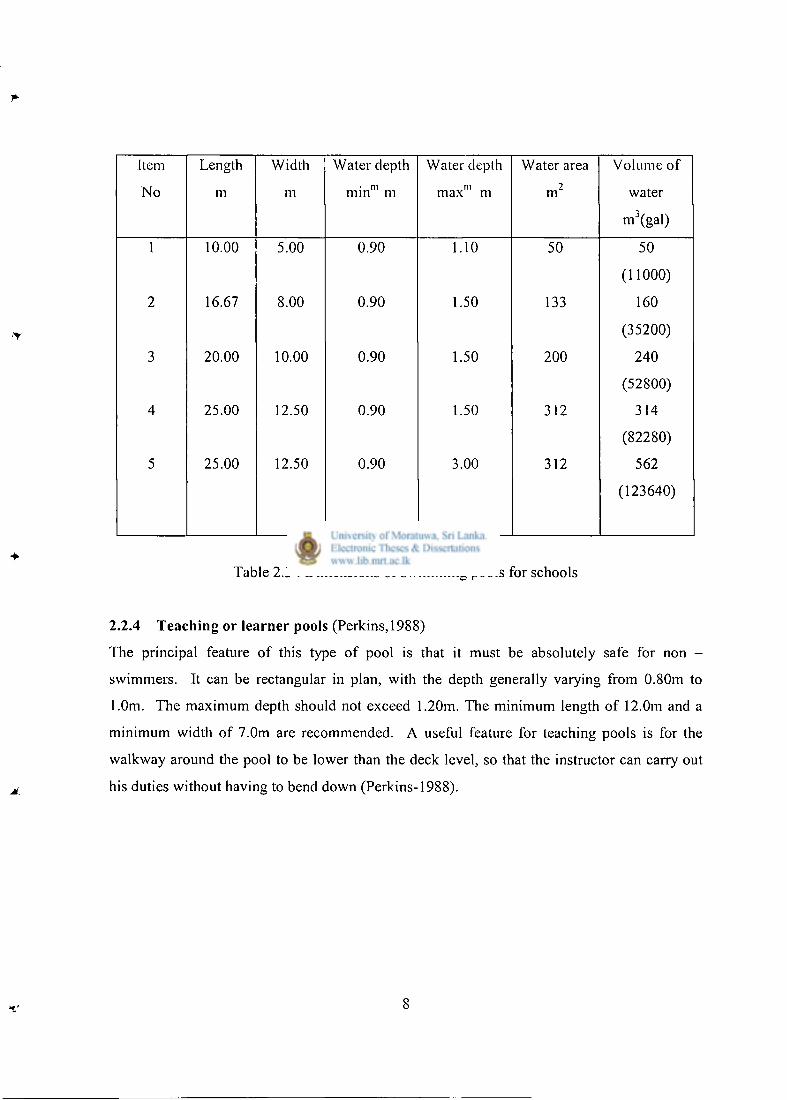
Item Length Width Water depth Water depth Water area Volume of
No m m m i n m m m max m m 2 water
m 3 (gal)
1 10.00 5.00 0.90 1.10 50 50
2 16.67 8.00 0.90 1.50 133
(11000)
160
3 20.00 10.00 0.90 1.50 200
(35200)
240
4 25.00 12.50 0.90 1.50 312
(52800)
314
5 25.00 12.50 0.90 3.00 312
(82280)
562
(123640)
Table 2.3 : Dimensions of swimming pools for schools
2.2.4 Teaching or learner pools (Perkins, 1988)
The principal feature of this type of pool is that it must be absolutely safe for non -
swimmers. It can be rectangular in plan, with the depth generally varying from 0.80m to
1.0m. The maximum depth should not exceed 1.20m. The minimum length of 12.0m and a
minimum width of 7.0m are recommended. A useful feature for teaching pools is for the
walkway around the pool to be lower than the deck level, so that the instructor can carry out
his duties without having to bend down (Perkins-1988).
8
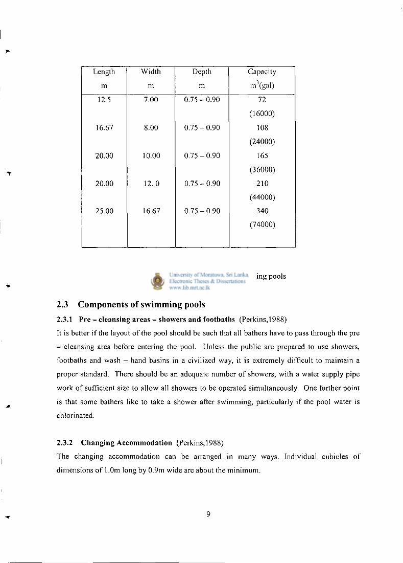
Length Width Depth Capacity
m m m m 3 (gal)
12.5 7.00 0 . 7 5 - 0 . 9 0 72
(16000)
16.67 8.00 0 . 7 5 - 0 . 9 0 108
(24000)
20.00 10.00 0 . 7 5 - 0 . 9 0 165
(36000)
20.00 12. 0 0 . 7 5 - 0 . 9 0 210
(44000)
25.00 16.67 0.75 - 0.90 340
(74000)
Table 2.4 : Dimensions of teaching pools
2.3 Components of swimming pools
2.3.1 Pre - cleansing areas - showers and footbaths (Perkins, 1988)
It is better if the layout of the pool should be such that all bathers have to pass through the pre
- cleansing area before entering the pool. Unless the public are prepared to use showers,
footbaths and wash - hand basins in a civilized way, it is extremely difficult to maintain a
proper standard. There should be an adequate number of showers, with a water supply pipe
work of sufficient size to allow all showers to be operated simultaneously. One further point
is that some bathers like to take a shower after swimming, particularly if the pool water is
chlorinated.
2.3.2 Changing Accommodation (Perkins, 1988)
The changing accommodation can be arranged in many ways. Individual cubicles of
dimensions of 1.0m long by 0.9m wide are about the minimum.
Pools, which cater specially for family activities, provision should be made for a limited
number of family changing cubicles, so that very young children can change with their
parents.
The reasonable changing accommodation would be as follows:
1. One changing place for each 8.0m 2 of pool area for normal swimming pools. This
is increased to one place for each 6.5m 2 in leisure centre pools.
2. For learner pools one place for each 4 .0m 2 of water area.
3. When there is a separate diving pool, extra two places should be provided.
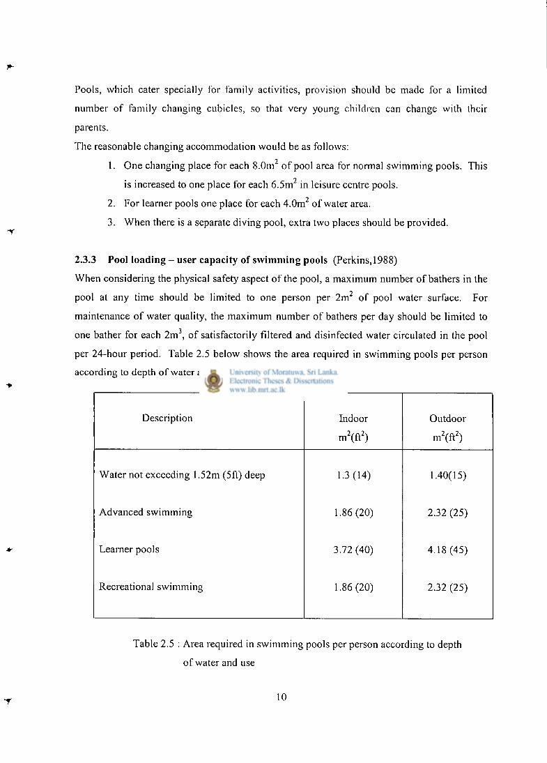
2.3.3 Pool loading - user capacity of swimming pools (Perkins, 1988)
When considering the physical safety aspect of the pool, a maximum number of bathers in the
pool at any time should be limited to one person per 2m 2 of pool water surface. For
maintenance of water quality, the maximum number of bathers per day should be limited to
one bather for each 2m 3 , of satisfactorily filtered and disinfected water circulated in the pool
per 24-hour period. Table 2.5 below shows the area required in swimming pools per person
according to depth of water and use (Perkins-1988).
Description Indoor Outdoor
m 2 (f t 2 ) m 2 (f t 2 )
Water not exceeding 1.52m (5ft) deep 1.3(14) 1.40(15)
Advanced swimming 1.86 (20) 2.32 (25)
Learner pools 3.72 (40) 4.18 (45)
Recreational swimming 1.86 (20) 2.32 (25)
Table 2.5 : Area required in swimming pools per person according to depth
of water and use
10
2.3.4 Sanitary Accommodation for Pool Users (Perkins, 1988)
The following sanitary accommodation can be recommended.
Women: I WC for each 30 up to the first 90 and one for each additional 40, with a minimum
of 3 WCs. Provide 1 WHB for each WC
Men: I W C for each 50 up to the first 100 and then one for each additional 75, with 1 WHB
for each WC. 1 urinal stall for each 30 with a minimum of 4 stalls.
2.3.5 Spectator Accommodation (Perkins, 1988)
Accommodation for spectators can be divided into two categories.
1. Standing and / or seating for friends and relatives of bathers.
2. Permanent seating for galas and competitions.
It is desirable that part of accommodation under (1) should be located as near as possible to
the learner pool, as many parents like to watch their children under instruction.
Fixed seating for spectators watching competitions requires special planning and the capital
cost can be considerable. A valid question is therefore the extent to which this seating is
really needed that is, the use that will be made of it. This can be expressed in the number of
times a year that the accommodation will be utilized on a percentage basis, i.e. 100% (a "full
house"), 75%, 60%, 50%, 40%., etc., of maximum capacity. The result of such an
investigation may cause a more realistic approach to the problem. In a tropical country, this
accommodation could be steps formed using rubblework as in open-air theaters so that the
cost can be minimized.
2.3.6 Sanitary Accommodation for Spectators (Perkins, 1988)
Separate sanitary accommodation for spectators of both sexes must be provided. The
recommendations for this accommodation is as follows:
Men : WCs, minimum 2; 1 for each 100 up to 500, then 1 for each 200: Urinals, minimum
3 stalls; 1 stall for each 40 up to 300, then 1 stall for each 50:
WHBs, 1 for each WC.
Women: WCs, minimum 3;1 for each 50 up to 300, then 1 for each 75: WHBs, l for each WC.
11
2.3.7 Engineering services for swimming pools
The Engineering services of the pool and ancillary buildings will vary according to the size
and complexity of the pool. But the smallest pool will require the following services.
1. Water Supply
2. Drainage
3. Electricity
4. Water treatment and disinfection
2.3.7.1 Water Supply
This is usually taken from the mains of a public supply, and in this case it can usually be
assumed to be satisfactory. If the source is a private one from a well or borehole, it should be
tested chemically and bacteriological at regular intervals. Apart from quality, the supply must
be adequate in quantity for topping up the pool and washing the filters. In Sri Lanka, it is
advisable to rely on well if it is possible since the cost of water above 2 5 m 3 per month is quite
high even for homes.
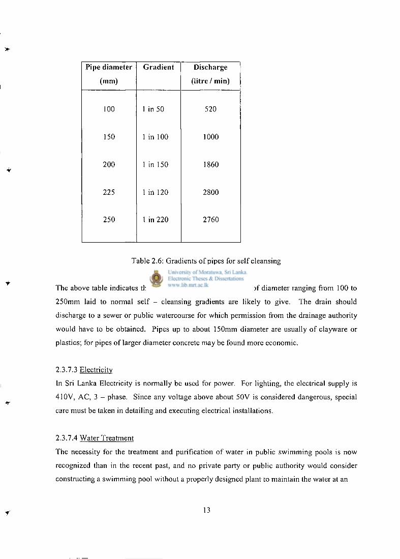
2.3.7.2 Drainage
Some satisfactory arrangement must be made for the disposal of the wash water from the
filters, and the pool itself when it is emptied for cleaning and maintenance. The quantities of
water to be disposed of, will vary according to the type, size and number of filters installed.
Table 2.6 gives self-cleansing discharges with respective pipe diameters and gradients.
12
Pipe diameter
(mm)
Gradient Discharge
(litre / min)
100 1 in 50 520
150 1 in 100 1000
200 1 in 150 1860
225 1 in 120 2800
250 1 in 220 2760
Table 2.6: Gradients of pipes for self cleansing
The above table indicates the sort of discharge, which pipes of diameter ranging from 100 to
250mm laid to normal self - cleansing gradients are likely to give. The drain should
discharge to a sewer or public watercourse for which permission from the drainage authority
would have to be obtained. Pipes up to about 150mm diameter are usually of clayware or
plastics; for pipes of larger diameter concrete may be found more economic.
2.3.7.3 Electricity
In Sri Lanka Electricity is normally be used for power. For lighting, the electrical supply is
410V, AC, 3 - phase. Since any voltage above about 50V is considered dangerous, special
care must be taken in detailing and executing electrical installations.
2.3.7.4 Water Treatment
The necessity for the treatment and purification of water in public swimming pools is now
recognized than in the recent past, and no private party or public authority would consider
constructing a swimming pool without a properly designed plant to maintain the water at an
13
adequate standard of purity. The method for purification of water will depend on a number of
factors; some methods are better than others, but they may be classified under two main
headings.
1. Continuous flow - through, or intermittent flow - through, without treatment.
2. Continuous circulation with filtration and treatment.
2.4 Design Methodology adopted for conventional swimming pools
2.4.1 General Considerations
The conventional swimming pools in Sri Lanka are built in insitu reinforced concrete and
generally follow the recommendations in BS 8007, British standard code of practice for
Design of concrete structures for retaining aqueous liquids;
This is generally known as the code of practice for water retaining structures.
The design of water - retaining structures may be carried out using either
1. a limit state design, as recommended by BS 8007, or
2. an elastic design, which is not now covered by the British code of practice.
A limit state design is based on both ultimate and serviceability limit states. As the restraint
of cracking is of prime importance with water retaining structures, the simplified rules for
minimum steel areas and maximum spacing are no longer adequate. It is necessary to check
the concrete strains and crack widths. The calculations tend to be lengthy and depend on
factors such as the degree of restraint, shrinkage and creep which are difficult to assess
accurately.
2.4.2 Limit state design
The principal steps for the limit state design of a reinforced concrete structure are:
1. Ultimate limit state design calculations.
2. Serviceability limit state design calculations with either
a. Calculation of crack widths
b. "Deemed to satisfy" requirements for applied loading effects on the
mature concrete. These are based on maximum service stresses in the
reinforcement.
14
For the ultimate limit state the procedures followed are exactly the same as for any other
reinforced concrete structure. The partial factor of safety on imposed loading due to
contained liquid should be taken as 1.4 for strength calculations to reflect degree of accuracy
with which hydrostatic loading may be predicted. Calculations for the analysis of the
structure subject to the most severe load combinations will then proceed in the usual way.
Serviceability design will involve the classification of each member according to its crack
width category. External members not in contact with the liquid can be designed using
criteria in BS 8110 for normal reinforced concrete work.
There are two basic concepts regarding the formation of cracks in concrete, i.e. tensile
strength and tensile strain capacity of concrete. Tensile strain capacity of concrete is more
relevant in case of cracking in plastic stage whereas cracking of hardened concrete can be
explained by tensile strength capacity of concrete. BS 8007 recommends a maximum design
surface crack width of 0.2mm for severe or very severe exposure condition and 0.1mm for
surfaces where critical aesthetic appearance is important. These limitations imply that all
surface cracks less than 0.2mm will prove to be water tight under all circumstances. When
water percolates through cracks it dissolves calcium hydroxide from the hydrated cement
matrix and then, on contact with carbon dioxide in the atmosphere deposits calcium
carbonate. This action can be very effective at sealing cracks although the process is likely to
produce unsightly white deposits on the surface.
The maximum likely crack widths may be calculated using the methods given in the
appendices of the code and then checked for compliance with the allowable values.
Alternatively, reinforcement stresses due to bending or direct tension may be calculated and
checked for compliance with the deemed to satisfy limits.
2.4.3 Serviceability limit state of cracking
Serviceability calculations will be required to consider three specific cases (Nanayakkara,2000):
2.4.3.1 Flexural tension in mature concrete.
This may result form both dead and imposed loads.
15
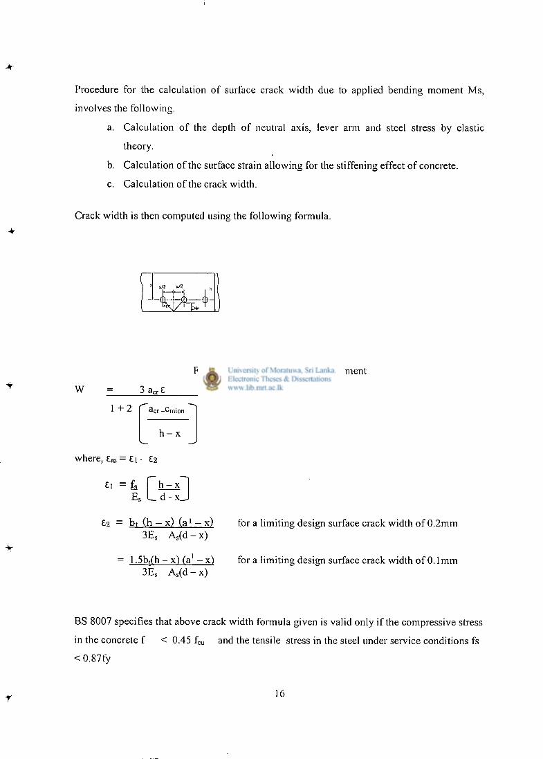
Procedure for the calculation of surface crack width due to applied bending moment Ms,
involves the following.
a. Calculation of the depth of neutral axis, lever arm and steel stress by elastic
theory.
b. Calculation of the surface strain allowing for the stiffening effect of concrete.
c. Calculation of the crack width.
Crack width is then computed using the following formula.
w Figure 2.2 : Reinforcement arrangement
3 a c r £
1 + 2 ^cr -Cmion
h - x
where, £ m = £i • £2
£1 = £ is E s
h - x . d - x_.
£2 — bt (h — x) ( a 1 — x) for a limiting design surface crack width of 0.2mm 3E S A s (d - x)
1.5b,fh-x') f a ' - x ) 3E S A s (d - x)
for a limiting design surface crack width of 0.1mm
BS 8007 specifies that above crack width formula given is valid only if the compressive stress
in the concrete f < 0.45 fcu and the tensile stress in the steel under service conditions fs
<0.87fy
r 16
Where al -Distance from the compression face to the point at which the crack width is being calculated
a c r -distance from the point considered to the surface of the nearest longitudinal bar
A s width of the section at the centroid of the tension steel
Cmin -minimum cover to the tension steel
d -effective depth
E s -modulus of elasticity of reinforcement
h -overall depth of member
W -design crack width
x -depth of neutral axis
£ m -average strain at the level where the cracking is being considered.
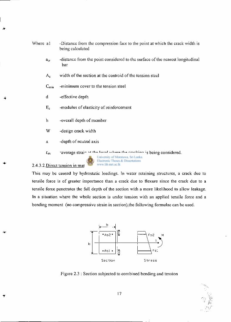
2.4.3.2.Direct tension in mature concrete.
This may be caused by hydrostatic loadings. In water retaining structures, a crack due to
tensile force is of greater importance than a crack due to flexure since the crack due to a
tensile force penetrates the full depth of the section with a more likelihood to allow leakage.
In a situation where the whole section is under tension with an applied tensile force and a
bending moment (no compressive strain in section),the following formulae can be used.
• A s 2 '
• As l •
S e c t i o n S t r e s s
Figure 2.3 : Section subjected to combined bending and tension
17
W = 3 a c r e m
where, s m = si • 62
61 = fs l + (fal - fs2) x a E s ( h - 2a) x Es)
E2 - 2 b h for 0.2mm crack width 3E S A s
= bh for 0.1mm crack width Es A s
fs. = M + _ T _ 2 b h p , ( 0 . 5 h - a ) 2bhp,
fs2 = I J T - Pi fsi P2 I bh
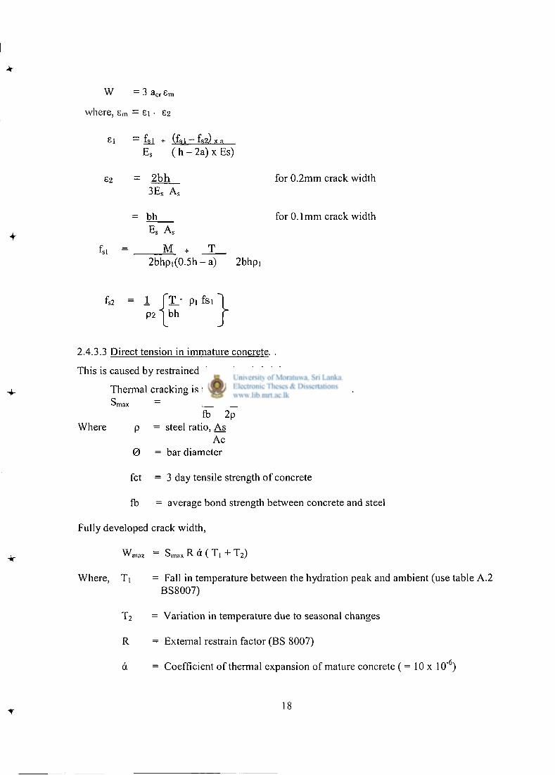
2.4.3.3 Direct tension in immature concrete. .
This is caused by restrained thermal and shrinkage movement.
Thermal cracking is taken to have a maximum spacing. S m a x = fax 0
fb 2p Where p = steel ratio, As
Ac 0 = bar diameter
fct = 3 day tensile strength of concrete
fb = average bond strength between concrete and steel
Fully developed crack width,
W m a 2 = S m a x R d ( T, + T 2 )
Where, Ti = Fall in temperature between the hydration peak and ambient (use table A.2 BS8007)
T2 = Variation in temperature due to seasonal changes
R = External restrain factor (BS 8007)
& = Coefficient of thermal expansion of mature concrete ( = 10 x 10"6)
18
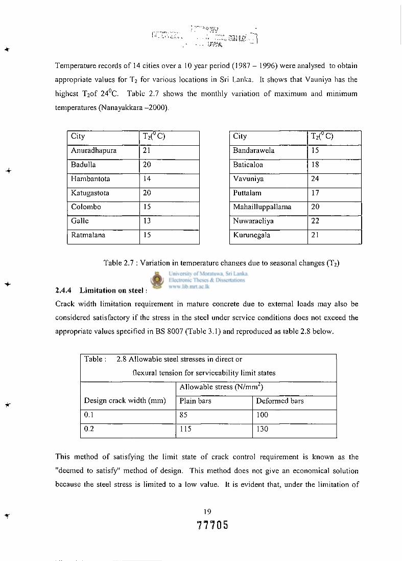
Temperature records of 14 cities over a 10 year period (1987 - 1996) were analysed to obtain
appropriate values for T2 for various locations in Sri Lanka. It shows that Vauniya has the
highest 'I^of 24°C. Table 2.7 shows the monthly variation of maximum and minimum
temperatures (Nanayakkara -2000) .
City T 2 ( °C)
Anuradhapura 21
Badulla 20
Hambantota 14
Katugastota 20
Colombo 15
Galle 13
Ratmalana 15
City T 2 ( °C)
Bandarawela 15
Baticaloa 18
Vavuniya 24
Puttalam 17
Mahailluppallama 20
Nuwaraeliya 22
Kurunegala 21
Table 2.7 : Variation in temperature changes due to seasonal changes (T 2 )
2.4.4 Limitation on steel stress
Crack width limitation requirement in mature concrete due to external loads may also be
considered satisfactory if the stress in the steel under service conditions does not exceed the
appropriate values specified in BS 8007 (Table 3.1) and reproduced as table 2.8 below.
Table : 2.8 Allowable steel stresses in direct or
flexural tension for serviceability limit states
Design crack width (mm)
Allowable stress (N/mm 2 )
Design crack width (mm) Plain bars Deformed bars
0.1 85 100
0.2 115 130
This method of satisfying the limit state of crack control requirement is known as the
"deemed to satisfy" method of design. This method does not give an economical solution
because the steel stress is limited to a low value. It is evident that, under the limitation of
19
77705
steel stress, the crack width is far below the allowable value and the steel requirement is much
higher.
2.4.5 Serviceability limit state of deflection
The recommendations for span / effective depth ratios given in BS8110 : Parti : 1985 apply to
horizontal members carrying uniformly distributed loads. For a cantilever wall which tapers
uniformly away from the support and which is loaded with a triangular pressure, a net
reduction factor should be applied to the above ratios if the thickness at the top is less than 0.6
times the thickness at the base. This reduction factor can be assumed to vary linearly between
1.0 and 0.78 where the thickness of the top varies between 0.6 and 0.3 times the thickness at
the bottom. In addition, allowance should be made for the significant additional deflection,
which occurs at the top of the wall due to rotation, if the pressure distribution under the base
is triangular or very asymmetrically trapezoidal. Limits for deflection will normally be those
for non - liquid - retaining structures since only in exceptional circumstances will deflections
be more critical with regard to freeboard, drainage or redistribution of load. Retaining walls
should be backfilled in even layers around the structure, the thickness of the layers being
specified by the designer. Over compaction adjacent to the wall should be avoided otherwise
large differential deflections (and sliding) of the wall may occur. At least 7 5 % of the liquid
load should be considered as permanent when calculating deflections (BS 8007-1987).
2.4.6 Joints in floor and walls of swimming pools
It is to be noted that the BS 8007 allows, in the design, options for continuous construction
with full restraint. Nevertheless, it is normally necessary to provide construction joints but
these are treated in the design as "Calculated cracks" and the concrete is considered, at least in
theory, to be monolithic at these joints.
2.4.6.1 Reasons for providing joints
There are a number of important reasons why joints are normally provided in the reinforced
concrete shell of a swimming pool, and these include the following:
20
a. Unless the pool is very small one, the shell cannot be cast in one continuous
operation, and even with small pools this does present certain practical difficulties.
b. It may be necessary for structural reasons to make provision for movement in the
shell of the pool.
The expression "Provision for movement" is used in this context in its widest sense and
includes thermal contraction and drying shrinkage, which takes place as the concrete matures,
as well as thermal expansion and contraction, creep and foundation movements that may
occur during the lifetime of the pool.
2.4.6.2 Types of joint
Joints are considered essentially of two basic types, construction joints and movement joints.
Construction joints are introduced as a convenience in construction. Movement joints are
intended to accommodate relative movement between the adjoining parts, but special
provision has to be made to ensure that the joints are watertight (BS 8007-1987).
Division of the structure into suitable lengths separated by movement joints may be required
to control cracking of the mature concrete. Approximately, the tensile strength should exceed
the resistance to sliding of one half the length of the wall (or slab). Spacing of expansion
joints at about 70m centres should generally be more than adequate and even longer lengths
may be considered if necessary before making a definite division. However, the desirability
of introducing movement joints at closer spacing to resist cracking in immature concrete
depends on the design philosophy adopted; whether to restrain, or to permit, thermal
contraction in walls and slabs. At one extreme control is provided by substantial distribution
reinforcement in the form of small diameter bars, preferably of the high - bond type, at close
spacing with no joints in the concrete other than construction joints. At the other extreme,
control is provided by closely spaced movement joints, which permit movement in the
member and reduce the requirement for reinforcement to a very small amount. Between these
two extremes intermediate options exist whereby a change in joint spacing can be
compensated for by a change in the amount of reinforcement required. The three main
choices are summarized in Table 5.1 in BS 8007.
21
The following are the principal types of joints used in reinforced concrete swimming pools.
a) Full movement joints; these are often called expansion joints.
b) Partial movement joints, also known as contraction joints, semi contraction joints
and stress - relief joints.
c) Sliding joints, where one structural member slides over an adjacent member that is
in close contact.
d) Monolithic joints, also known as construction joints.
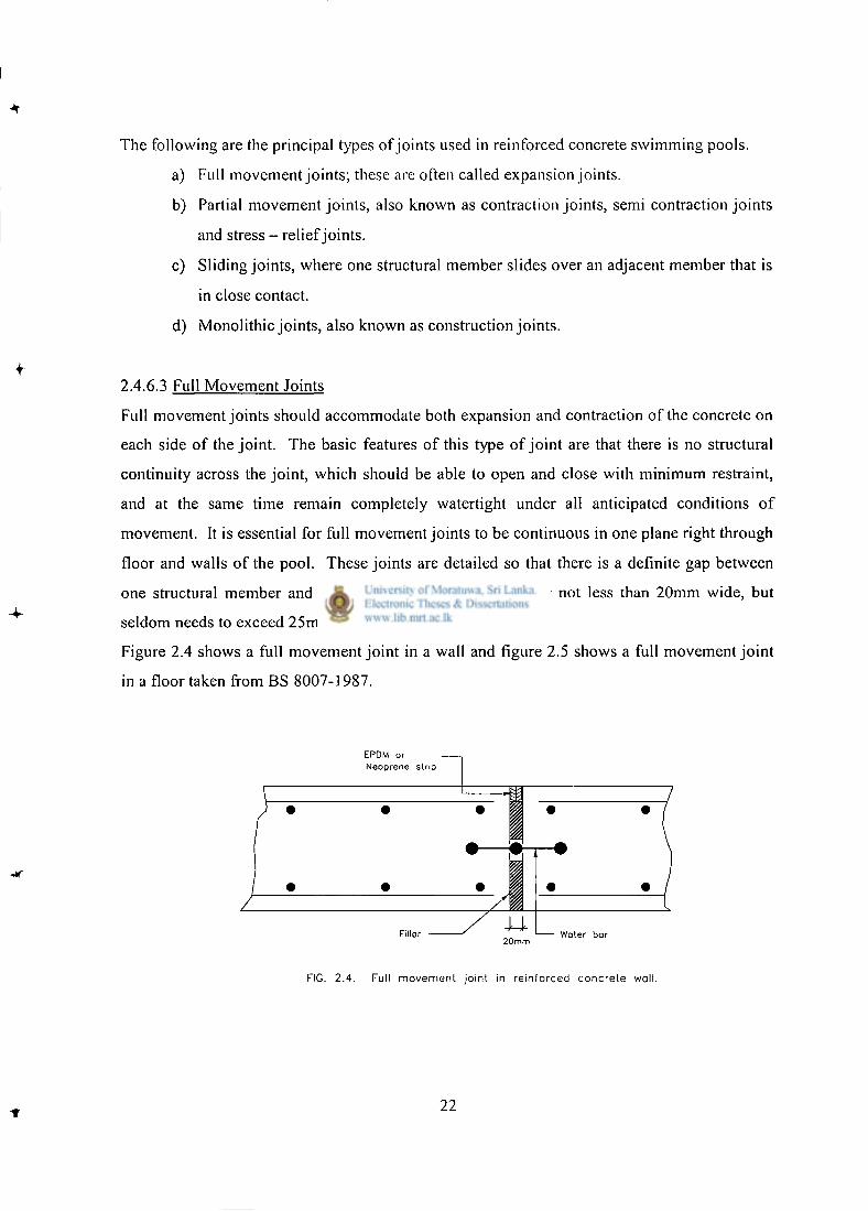
2.4.6.3 Full Movement Joints
Full movement joints should accommodate both expansion and contraction of the concrete on
each side of the joint. The basic features of this type of joint are that there is no structural
continuity across the joint, which should be able to open and close with minimum restraint,
and at the same time remain completely watertight under all anticipated conditions of
movement. It is essential for full movement joints to be continuous in one plane right through
floor and walls of the pool. These joints are detailed so that there is a definite gap between
one structural member and the next one; this gap is usually not less than 20mm wide, but
seldom needs to exceed 25mm.
Figure 2.4 shows a full movement joint in a wall and figure 2.5 shows a full movement joint
in a floor taken from BS 8007-1987.
EPOM or Neoprene strip
20mm
FIG. 2.4. Full movement joint in reinforced concrete wall.
22
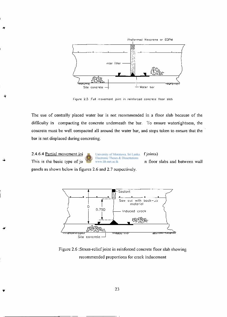
Preformed Neoprene or EDPM I
Figure 2.5 :FuII movement joint in reinforced concrete floor slab
The use of centrally placed water bar is not recommended in a floor slab because of the
difficulty in compacting the concrete underneath the bar. To ensure watertightness, the
concrete must be well compacted all around the water bar, and steps taken to ensure that the
bar is not displaced during concreting.
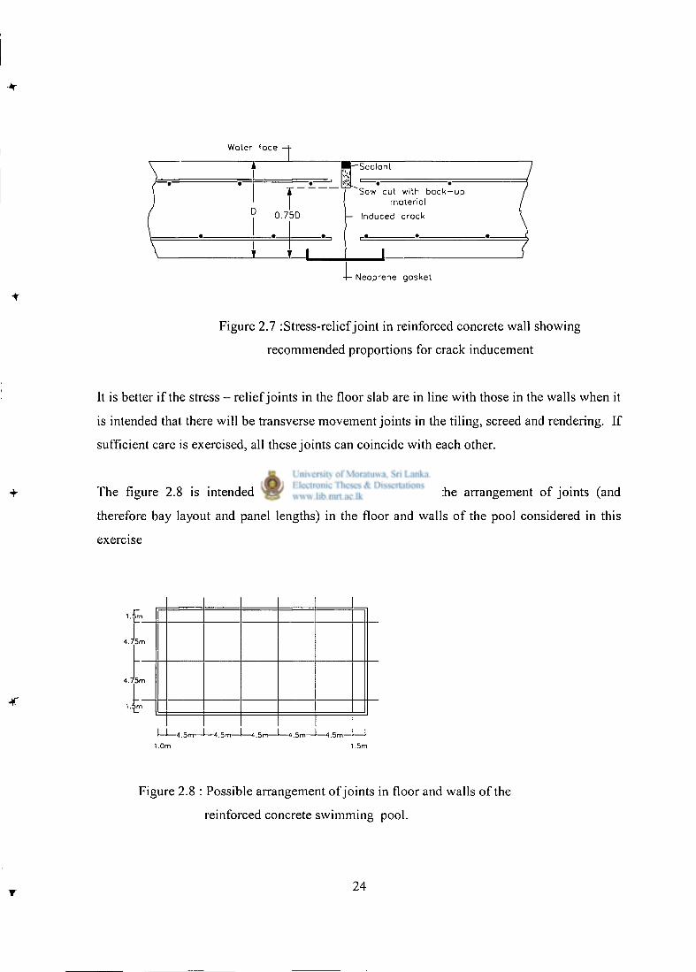
2.4.6.4 Partial movement joints (Contraction and stress - relief joints)
This is the basic type of joint recommended between bays in floor slabs and between wall
panels as shown below in figures 2.6 and 2.7 respectively.
Site c o n c r e t e — '
Figure 2.6 : Stress-relief joint in reinforced concrete floor slab showing
recommended proportions for crack inducement
23
Water face 1 l-^Seolant
u 0.750
~Saw cut with b a c k - u p material
Induced crack
j _ L Neoprene gasket
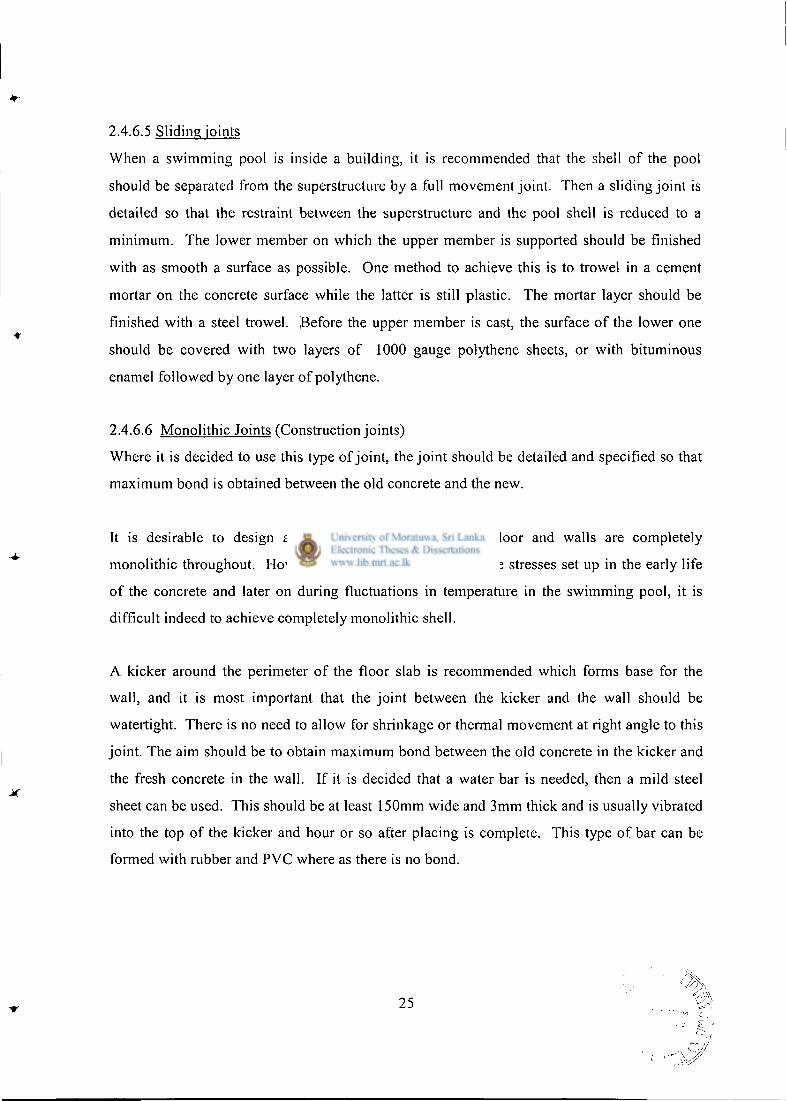
Figure 2.7 : Stress-relief joint in reinforced concrete wall showing
recommended proportions for crack inducement
It is better if the stress - relief joints in the floor slab are in line with those in the walls when it
is intended that there will be transverse movement joints in the tiling, screed and rendering. If
sufficient care is exercised, all these joints can coincide with each other.
-4- The figure 2.8 is intended to illustrate in diagram form the arrangement of joints (and
therefore bay layout and panel lengths) in the floor and walls of the pool considered in this
exercise
4.75rr
4.75m
.^m
-4.5m—1—4.5m—I—4.5m—I—4.5m—J—4.5m—I 1 1.0m 1.5m
Figure 2.8 : Possible arrangement of joints in floor and walls of the
reinforced concrete swimming pool.
24
2.4.6.5 Sliding joints
When a swimming pool is inside a building, it is recommended that the shell of the pool
should be separated from the superstructure by a full movement joint. Then a sliding joint is
detailed so that the restraint between the superstructure and the pool shell is reduced to a
minimum. The lower member on which the upper member is supported should be finished
with as smooth a surface as possible. One method to achieve this is to trowel in a cement
mortar on the concrete surface while the latter is still plastic. The mortar layer should be
finished with a steel trowel. Before the upper member is cast, the surface of the lower one
should be covered with two layers of 1000 gauge polythene sheets, or with bituminous
enamel followed by one layer of polythene.
2.4.6.6 Monolithic Joints (Construction joints)
Where it is decided to use this type of joint, the joint should be detailed and specified so that
maximum bond is obtained between the old concrete and the new.
It is desirable to design a swimming pool so that the floor and walls are completely
monolithic throughout. However , in practice, because of the stresses set up in the early life
of the concrete and later on during fluctuations in temperature in the swimming pool, it is
difficult indeed to achieve completely monolithic shell.
A kicker around the perimeter of the floor slab is recommended which forms base for the
wall, and it is most important that the joint between the kicker and the wall should be
watertight. There is no need to allow for shrinkage or thermal movement at right angle to this
joint. The aim should be to obtain maximum bond between the old concrete in the kicker and
the fresh concrete in the wall. If it is decided that a water bar is needed, then a mild steel
sheet can be used. This should be at least 150mm wide and 3mm thick and is usually vibrated
into the top of the kicker and hour or so after placing is complete. This type of bar can be
formed with rubber and PVC where as there is no bond.
25
2.5 Alternative Structural Forms
2.5.1 Reinforced Sprayed Concrete (Perkins, 1988)
2.5.1.1 Introduction
Sprayed Concrete was previously known as 'gunite ' in the UK and 'shotcrete' in the USA.
Sprayed concrete is mainly divided in to two distinct materials; one is a sprayed mortar,
consisting of cement, fine aggregate (sand) and water, the other consists of cement, fine
aggregate, coarse aggregate and water. The inclusion of the coarse aggregate converts the
mortar to a concrete.
2.5.1.2 General Considerations
There are a number of advantages in using sprayed concrete for the construction of a
swimming pool shell; there are also some disadvantages. The position may be summarized as
follows.
2.5.1.3 Advantages
a. High speed of construction; a swimming pool 18.0 x 12.0m with a depth of 1.0 -
2.5m can be constructed from a prepared excavation in about 20 working days.
This is all the work necessary for the structural shell, but does not include finishing
and pipe work, etc.
b. The pool can be built on a congested site where access for equipment and
materials is severely restricted because the delivery hose to the gun can be at least
100m long.
c. The only joints in a normal sprayed concrete pool are plain built joints that do not
require sealing.
d. For pools larger than about 12 x 6m it is often cheaper than reinforced concrete.
e. It is cheaper than reinforced concrete for 'free - formed' pools.
f. Little or no formwork is required.
2.5.1.4 Disadvantages
a. For a successful job it should be entrusted to specialist firms.
26
b. Size for size, a sprayed concrete pool is appreciably lighter than one in reinforced
concrete and is therefore more liable to flotation unless special precautions are
taken.
c. The usual design incorporates a wide cove angle between the wall and the floor. If
the pool is to have a finish of ceramic tiles, this cove angle must be changed to a
right angle.
d. The quality of the finish of the pool shell is more dependent on the skill of the
'gun ' operator than on the concreting gang when insitu concrete is used.
e. Particular care and skill are required to ensure that the sprayed material properly
surrounds all the rebars as voids behind the rebars are difficult to eliminate
completely; this is a criticism frequently met when discussing sprayed concrete.
2.5.1.5 Dry and Wet Mix Processes.
a. The 'dry mix ' in which the cement and aggregate is weigh or volume - batched
without the addition of water, and this is then conveyed pneumatically to the 'gun '
which consists of a mixing manifold and nozzle. It is here that the gun operator
admits water.
b. The 'wet mix ' in which the constituents are normally weigh - batched and mixed
with a predetermined amount of water. The mix is then pumped to the nozzle
where compressed air is admitted which conveys the mix at high velocity into
place.
Tests performed showed that, the compressive strength of cores taken from dry mix sprayed
concrete were in the range 50 - 72 N / m m , whereas cores from wet mix material were in the
range 3 7 - 4 0 N / m m
2 .
2.5.1.6 Reinforcement
High tensile steel is generally used; often in the form of a fabric for smaller pools, with
vertical bars to hold the mesh in position. The cover to reinforcement is usually accepted as
25mm instead the 40mm required for reinforced concrete.
27
Cover in excess of 40mm is undesirable, as crack control is reduced with increase in distance
from the surface. The wall reinforcement must be securely anchored into the floor slab and
carried up into the ring beam at the top of the wall.
2.5.1.7 Joints
Full movement joints are not provided in normally designed sprayed concrete pools.
However, even the smallest private pool is unlikely to be gunned in one continuous operation
and therefore construction joints are required. A plain butt joint is tapered. The factors to
describe why sprayed concrete pool is satisfactory without any contraction joints are:
a. Usually the walls of a sprayed concrete shell are thinner than with insitu concrete.
This, together with the absence of formwork at least on one side, results in less
built - up of heat. Consequently lower thermal stresses are developed, and thermal
strain is correspondingly reduced.
b. Sprayed concrete is generally reinforced with heavy high tensile steal fabric and
the amount of distribution (horizontal) steel is likely to be greater than is normally
provided in a reinforced concrete wall. This results in the design being similar in
effect to Option 1, continuous construction with full restraint, recommended in BS
8007.
c. Good quality sprayed concrete has a low water/ cement ratio (0.35 0.40) while
concrete used for a similar purpose is likely to have a water/ cement ratio in the
range 0 . 4 5 - 0 . 5 5 .
d. The compressive strength of high quality sprayed concrete will depend on whether
the dry mix or wet mix is used.
The factors mentioned above will tend to reduce the tendency for thermal contraction
cracking to occur. This does not mean that such cracking (including drying shrinkage
cracking) does not take place. It is experienced that the drying shrinkage cracking is not
28
unusual in sprayed concrete pools, such cracks are less likely to penetrate below the level of
the reinforcement.
2.5.2 Swimming pools constructed with an insitu reinforced concrete floor and plain
mass concrete walls (Perkins, 1988)
2.5.2.1 Introduction
In theory there is no limit to the size of pool that can be constructed by this method.
However, owing to the thickness of the walls and the number of joints or crack - inducers
required, a size larger than about 10 x 6m with a depth of 1 - 1.5m is unlikely to be an
economic proposition.
2.5.2.2 The floor
The floor slab should have a minimum thickness of 150mm and be laid in bays of convenient
size to suit the pool dimensions. If the wall is constructed on the floor slab, the slab should be
thickened below the wall to 250mm. The reinforcement should consist of high-tensile mesh,
placed 40 - 50mm from the top surface of the slab. The mesh should be rectangular, with a
minimum weight of 3.41kg/m and the main wires running Longitudinally.
It should be noted that because the walls derive their stability from their mass, there is no
reinforcement connecting the floor slab with the walls, as was the case with walls of
reinforced concrete. This, of course, greatly simplifies the construction of the floor slab. All
joints should be provided with sealing groove and properly sealed. If the depth of water
exceeds about 2.0m, an external type water bar should be used below the joint.
2.5.2.3 The Walls
The external and internal loading is resisted by the weight (or mass) of the wall itself. This is
the theoretical idea; in practice, the end walls provide some restraint to the sidewalls and the
materials used to possess some tensile and shear strength, as well as considerable compressive
strength.
29
In view of the fact that there is no reinforcement in the wall to take thermal and drying
shrinkage stresses, the wall must be cast in short lengths to its full height; the length of the
wall panels should not exceed 3.0m.
The joints between the panels should be considered as contraction joints. The provision of a
water bar, and sealing grooves on both faces of the wall, is recommended. The contraction
joints can be detailed with crack inducers so as to reduce the number of stop ends and this
speed up the casting of the wall.
The vertical ducts extend for the full height of the wall and can be formed by an inflatable
former. The holes should be carefully plodded as soon as the former is removed, and the final
filling of the voids should be carried out as late in the construction process as possible.
The water bar between the wall and the floor slab can be a mild steel flat measuring 150mm x
3 mm.
2.5.3 Swimming pools constructed with reinforced concrete block walls and insitu
reinforced concrete floor (Perkins, 1988).
2.5.3.1 Introduction
The use of reinforced concrete block work for the walls of swimming pools can be considered
as satisfactory basically sound provided the pool shell is properly designed and constructed.
It should be noted that pool shell constructed in this way would not comply the
recommendations in BS 8007 because this code covers only reinforced insitu and pre stressed
concrete.
2.5.3.2 The floor
The insitu reinforced concrete floor slab is constructed with the reinforcement for the walls
securely fixed in position so as to be firmly anchored into the floor slab before the latter is
cast.
30
2.5.3.3 The walls
The concrete blocks for the walls should comply with BS 6073, Precast concrete masonry
units, with a minimum compressive strength of 10N/mm 2 , and should be made with natural
aggregates complying with the relevant clauses in BS 882.
The mortar should have mix proportions of 1:4 by weight, and a plasticiser should be used to
improve workability. It should preferably be mixed in a pan mixer. The plasticiser can, with
advantage, be a styrene butadiene rubber emulsion added to the mix in the proportion of 10
liters to 50kg cement.
The infill concrete should be batched by weight and have mix proportions of about 1 part
cement, 2 parts clean concreting sand (coarse to medium, BS 882) and 2 parts coarse
aggregate, 10mm maximum size (BS 882). The water/ cement ratio should not exceed 0.5
and the slump should be in the range of 150 - 200mm; to secure such a slump, a plasticiser
would have to be used.
Two rows of vertical bars are likely to be needed to ensure an adequate factor of safety when
the pool is full and when it is empty.
It is advisable to provide vertical movement joints at about 6.0m centers (these are contraction
joints), and these should be provided with greased dowels in alternate courses to resist lateral
movement.
2.5.4Swimming pools constructed with insitu reinforced concrete floor and walls, using
dense aggregate concrete blocks as permanent formwork (Perkins, 1988).
This method gives entirely satisfactory results when properly designed and constructed. A
question, which arises with the design of the walls, is whether the concrete blocks (which act
as permanent formwork) can be considered as structurally part of the wall for the purpose of
the design calculations. The answer must be in the negative because the concrete of the
31 "^7 c
blocks does not comply with the recommendations in the Code of Practice for water-retaining
structures, BS 8007.
Many private pools (houses, clubs and hotel) are what is known as free formed, that is, the
walls are curved on plan. By using concrete blocks for the formwork there is a very
substantial saving in cost compared with timber formwork.
2.5.5Pools with brick, block or stone walls with an inner lining of reinforced sprayed
concrete (Perkins, 1988)
In this case the walls must be stable by their own weight when under pressure from the
ground when the pool is empty, and from the water in the pool when it is full; in other words,
they are gravity type retaining walls and the sprayed concrete provides a structural watertight
lining.
This type of wall, built in mass concrete, follows the basic principles of stability with regard
to retaining walls. With mass concrete the wall itself should be watertight, but with bricks,
blocks or masonry reliance for water tightness must be placed on the sprayed concrete.
Either the walls can be built on independent foundations, and the floor constructed separately,
or the floor can be of insitu reinforced concrete and the wall supported on that. In the latter
case the edge of the slab should be thickened. Sections through the two types of wall support
are shown in figures 2.9 and 2.10.
Pools built in this way can be very successful provided the water table does not raise much
above the floor of the pool. A small external head can be tolerated because, if the work is
properly executed, the sprayed concrete lining will bond strongly to the walls, and with a
large cove angle and mesh reinforcement quite considerable pressure would be needed to
force it off the wall.
32
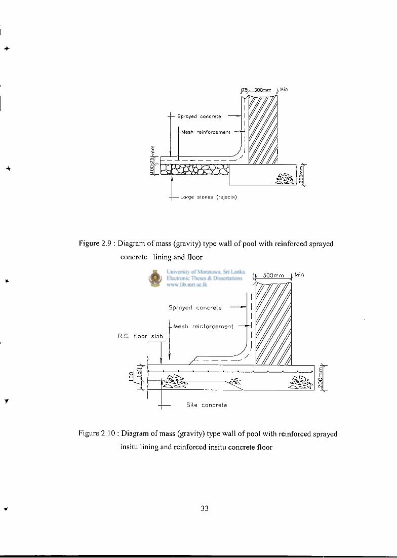
I, 300mm u M i n
Sprayed concrete —
-Mesh reinforcement —*~\
-Large stones (rejects)
Figure 2.10 : Diagram of mass (gravity) type wall of pool with reinforced sprayed
insitu lining and reinforced insitu concrete floor
33
The sprayed concrete lining should be applied to a thickness of 75mm, reinforced with a
medium - weight steel fabric - A 193 (BS 4483). It is usual to fix the reinforcement with
steel pins driven into joints in the wall, and for the joints in the wall to be raked out to assist
bond. In fact there is no objection to the wall being built as a dry stone one (without mortar).
The cover to the reinforcement should be about 25mm. If the walls are on an independent
foundation, than it is better to construct the floor of 'rejects' , covered with 150mm of sprayed
concrete, and to bring the wall reinforcement down round the cove and into the floor. The
sprayed concrete floor should also have a similar layer of steel fabric to the walls. One of the
attractions of this method is that a considerable part of the whole job can be carried out by a
comparatively inexperienced contractor, and only the sprayed concrete lining need be put on
by a specialist firm.
2.6 Simply Supported Wall concept (Wamsley, l982)
Walls of conventional swimming pools are designed as cantilevers fixed at the wall/ slab
joint. The change of the concept of this cantilever to simply supported wall economizes the
design considerably. The simply supported wall has a number of advantages and few
disadvantages when compared with the cantilever and propped cantilever walls.
2.6.1 Advantages of s imply supported wall concept
The following are the advantages this type.
1. Economics
2. Elimination of flexural tensile stresses on the water face when the wall is subjected
to internal water pressure.
3. Removal of any risk of over turning owing to external water pressure developing
under the reservoir.
4. Smaller sliding and shear forces at the base of the wall than in corresponding
cantilever and propped cantilever walls.
5. Ready accommodation of thermal movement of the roof (unlike the propped
cantilever wall)
6. Avoidance of high foundation pressures normally associated with cantilever and
propped cantilever walls.
34
7. Absence of the crack at the junction of the underside of the roof and wall
commonly seen in propped cantilever walls.
2.6.2 Disadvantages of simply supported wall concept
The following are the disadvantages.
1. Expense of the wall / roof joint.
2. Initial increased design/drawing office costs. On balance, there is little difference
in design time between the three types of wall. The simple wall can be designed
very quickly; the additional time spent on the roof / wall joint and generally
stability calculations will usually equate with the longer stability calculations
required for the cantilever and propped cantilever walls.
2.7 Summary
Apart from the conventional method of designing of the swimming pool, there are numerous
ways of designing the pool. From the above it is seen that there are more economical means
for designing. But all will not be applicable to the Sri Lankan context. Certain concepts were
adopted with modifications and fresh methods were introduced to obtain the most economical
form for the design of the swimming pool. Next chapter describes the conventional
swimming pool design against the proposed methods to prove the economy in developing a
new concept for the design of swimming pools.
r
35
Chapter 3
The Case Study
3.1 General Considerations
In this case study, two different areas were considered. They are:-
1. Swimming pools without a deep end
2. Swimming pools with a deep end
For each of the above cases designs were performed in conventional method and in the
proposed method. These are presented separately.
3.2 Design of swimming pool without a deep end using conventional
method
As explained in details in chapter 2.2 there are different types of swimming pools.
This case study covers the design aspects of a swimming pool for a school, which is
25m in length and 12.5m in width. The water depths of the pool at the ends are 0.9m
and 1.5m (Figure 3.1). There is a freeboard of O.lm.Thus the heights of the walls at
the ends are 1.0m and 1.6m respectively The design shall include all stability
considerations, analysis of the structure to all possible load cases, design the structure
for the ultimate load cases and finally checking of the structure for serviceability limit
states.
It is to be noted that this study is aimed on swimming pools built on firm ground and
the ground water table is lm below the ground level. The following design data was
used in the design of the swimming pool.
Density of water = lOkN/m 3
Density of earth = 18kN/m 3
Density of concrete = 25kN/m 3
Grade of concrete = 30N/mm 2
Grade of reinforcement = 460N/mm 2
Superimposed dead load on earth = 5kN/m 2
36
2
Bearing capacity of soil = 150kN/m
Friction angle = 30°
Service moment from water = 10 x 3 3 = 45kNm/m 2
Horizontal pressure from earth = 18 rT-Sin30' 1+Sin30
6kN/m 2
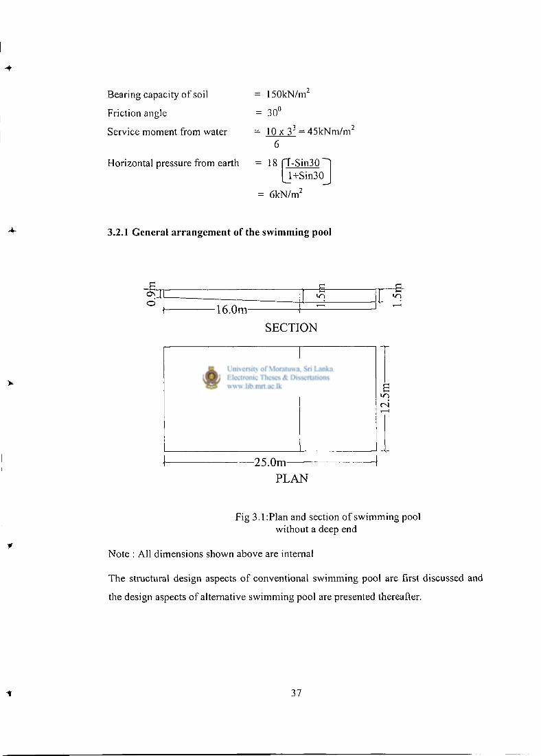
3.2.1 General arrangement of the swimming pool
T B 1 o
1 16.0m
SECTION
PLAN
Fig 3.1:Plan and section of swimming pool without a deep end
Note : All dimensions shown above are internal
The structural design aspects of conventional swimming pool are first discussed and
the design aspects of alternative swimming pool are presented thereafter.
37
3.2.2 Conventional swimming pool design
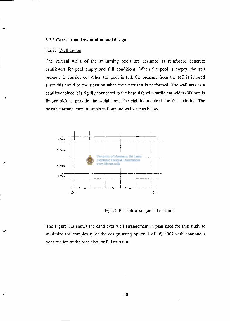
3.2.2.1 Wall design
The vertical walls of the swimming pools are designed as reinforced concrete
cantilevers for pool empty and full conditions. When the pool is empty, the soil
pressure is considered. When the pool is full, the pressure from the soil is ignored
since this could be the situation when the water test is performed. The wall acts as a
cantilever since it is rigidly connected to the base slab with sufficient width (300mm is
favourable) to provide the weight and the rigidity required for the stability. The
possible arrangement of joints in floor and walls are as below.
1 .£m
4.75m
4.75m
1.£m 1.£m
1_ — 4 . 5 m — — 4 . 5 m — — 4 . 5 m — • — 4 . 5 m — — 4 . 5 m —
1.0m 1.5m
Fig 3.2:Possible arrangement of joints
The Figure 3.3 shows the cantilever wall arrangement in plan used for this study to
minimize the complexity of the design using option 1 of BS 8007 with continuous
construction of the base slab for full restraint.
38
-21m-
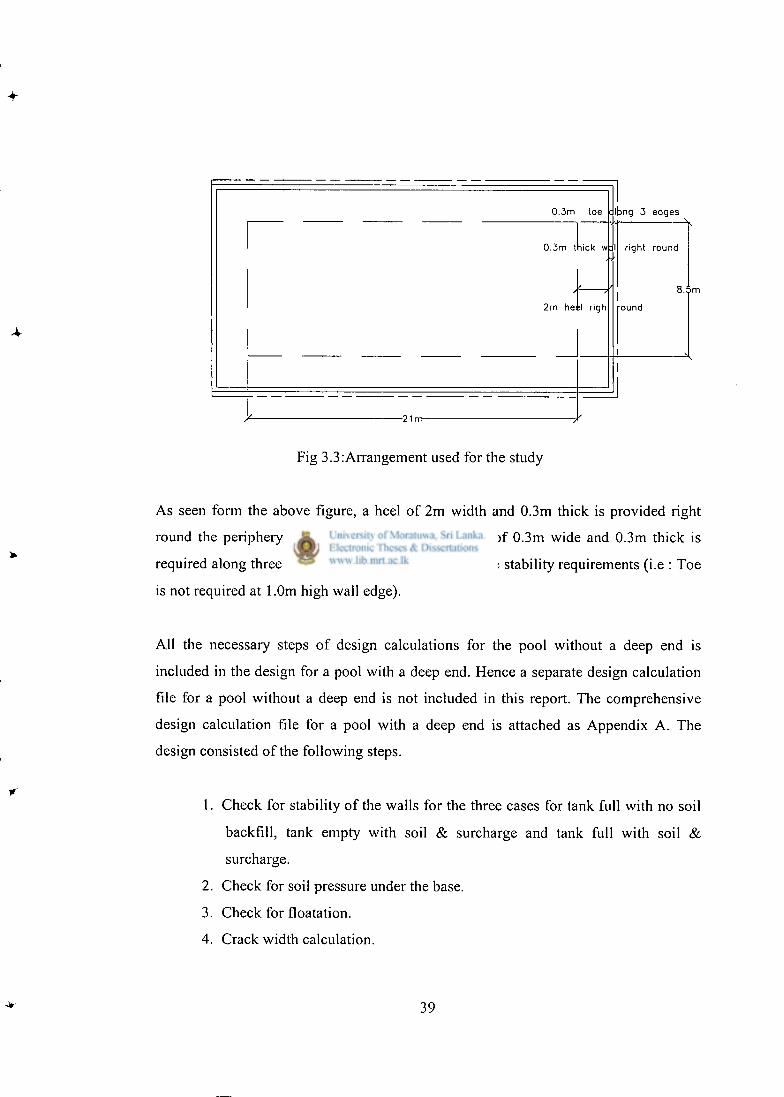
Fig 3.3:Arrangement used for the study
As seen form the above figure, a heel of 2m width and 0.3m thick is provided right
round the periphery of the pool from inside. A toe of 0.3m wide and 0.3m thick is
required along three edges of the pool for fulfilling the stability requirements (i.e : Toe
is not required at 1.0m high wall edge).
All the necessary steps of design calculations for the pool without a deep end is
included in the design for a pool with a deep end. Hence a separate design calculation
file for a pool without a deep end is not included in this report. The comprehensive
design calculation file for a pool with a deep end is attached as Appendix A. The
design consisted of the following steps.
1. Check for stability of the walls for the three cases for tank full with no soil
backfill, tank empty with soil & surcharge and tank full with soil &
surcharge.
2. Check for soil pressure under the base.
3. Check for floatation.
4. Crack width calculation.
39
5. Design for ultimate moment.
6. Design for ultimate shear.
7. Check minimum areas of reinforcement for BS 8007 & BS 8110
8. Check for deflection.
9. Footing reinforcement.
10. Detailing of the joints.
The design calculation show that the walls require T 12 @ 200 c/c vertical and
horizontal in each face. The heel along all the four edges and toe along the three
edges require T 12 @ 200 c/c both ways top and bottom. The detailed drawings are
given in Appendix C.
3.2.2.2 Slab design
As can be seen from Fig 3.3, base slab is 21m long and 8.5m wide and the base slab
thickness is 0.3m to prevent floatation effects. The base slab is connected to the heel
of the wall as a hinge along all four edges. When the pool is full, total downward
pressure is resisted by soil pressure under the base. When the pool is empty, net
pressure applied on the slab is due to the difference of self-weight of the base slab
acting downwards and uplift force due to ground water. Upward force is less than the
weight of the slab. Hence the slab is designed without taking the uplift force and it will
be the most critical case to design the base slab. (i.e. the case if the pool is emptied for
some reason during dry season where no upward pressure due to ground water).
This yields T12@175 c/c in short span direction at top of the slab. This reinforcement
is sufficient for the prevention of the thermal and shrinkage cracking according to
figure A.2 of BS 8007.. Prevention of thermal & shrinkage cracking in long span
requires T12@175 c/c as the top reinforcement.
The slab is 300mm thick which needs the bottom surface zone of 100mm thick to be
considered to resist thermal and shrinkage cracking according to figure A.2 of BS
8007. The bottom r/f of T 10 @ 200 c/c both ways will be sufficient for bottom
surface zone.
40
Horizontal ties (T12 @ 200) are provided to take the vertical reaction between base
slab and the heel of the wall. These same ties provide resistance to horizontal
movement of the wall due to horizontal force on the wall due to water pressure
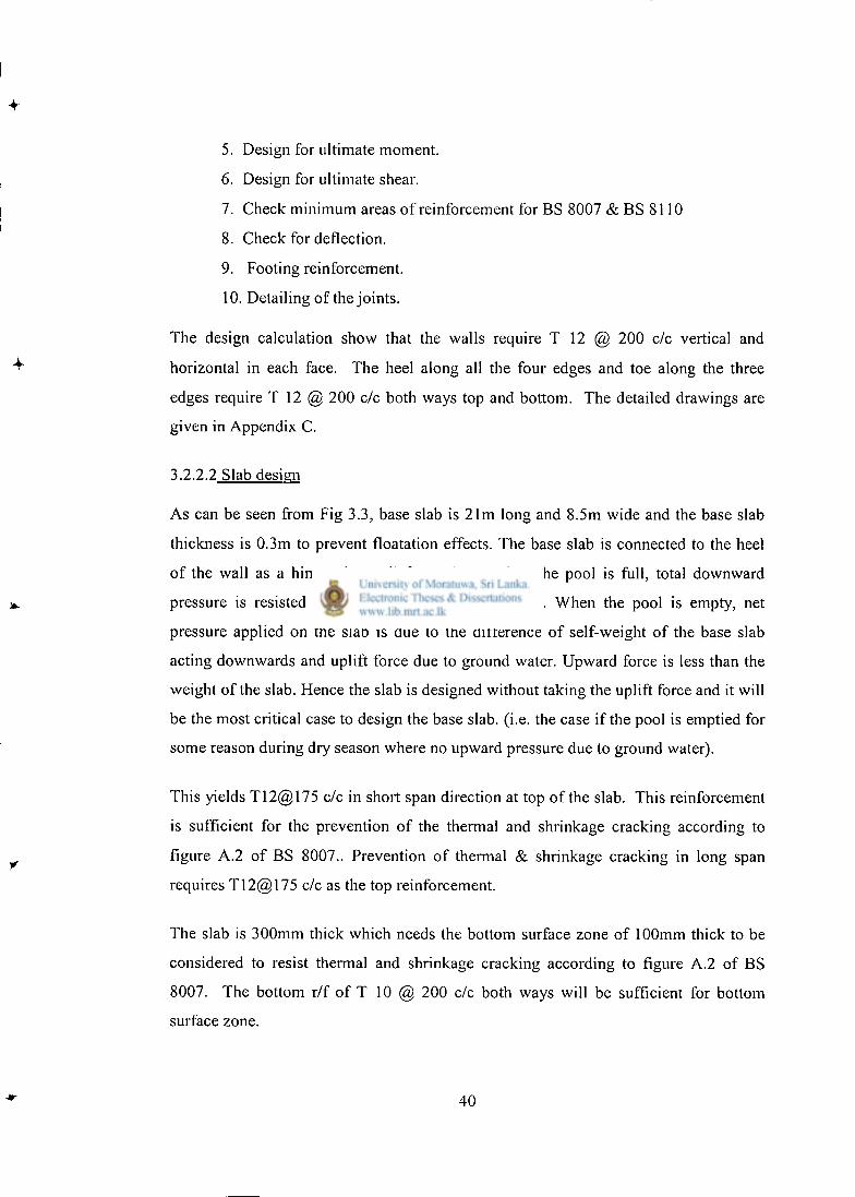
3.2.3 Detailing of the joints
All the wall and base slab joints are detailed as fixed joints as shown in Appendix C.
Sample drawing of a joint between wall and base slab is shown in Fig 3.4 below.
rn—
Fig 3.4:Fixed joint between wall and base slab
3.2.4 Summary of Structural arrangement
As mentioned in paragraph 3.2.2, detailed calculations for the pool without a deep end
is not included in this report since all the design steps are presented in the calculation
file for the pool with deep end which is annexed as Appendix A. Summary of the
calculations are tabulated in Table 3.1.The design was performed to following codes
of practice
BS 8110:1985 British standard code of practice for
Structural use of concrete
BS 8007:1987 British standard code of practice for
Design of concrete structures for retaining aqueous liquids
41
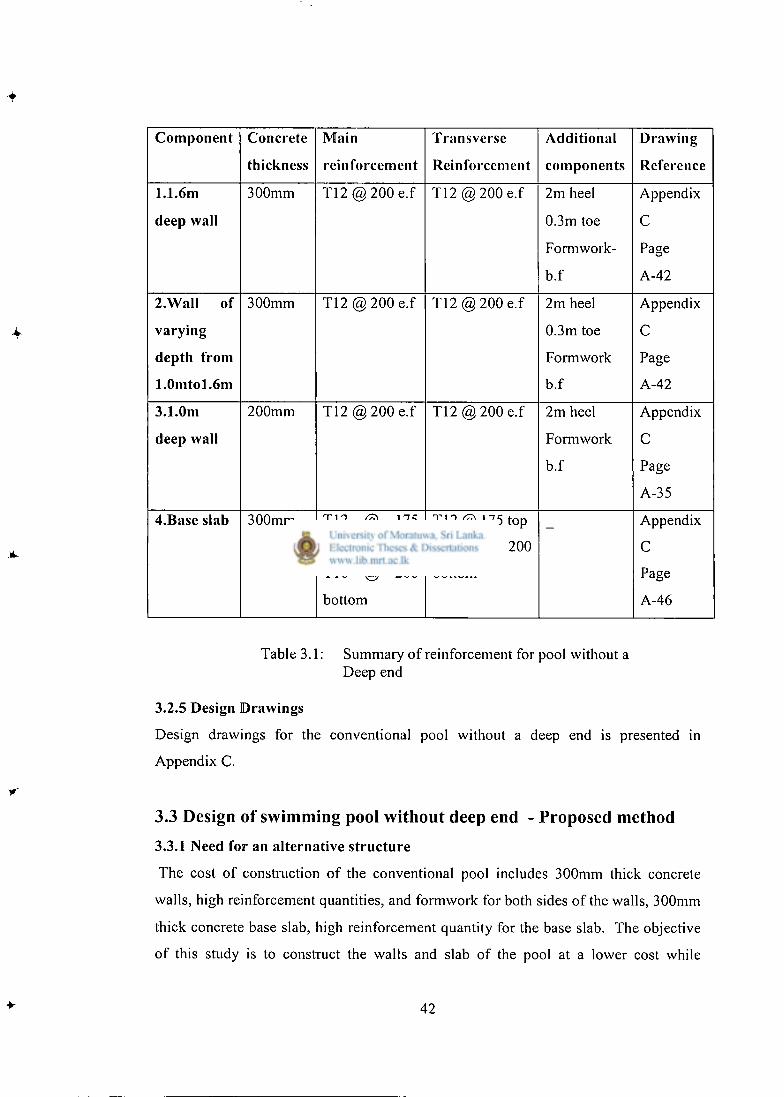
Component Concrete
thickness
Main
reinforcement
Transverse
Reinforcement
Additional
components
Drawing
Reference
1.1.6m
deep wall
300mm T 1 2 @ 2 0 0 e.f T 1 2 @ 2 0 0 e.f 2m heel
0.3m toe
Formwork-
b.f
Appendix
C
Page
A-42
2.Wall of
varying
depth from
1.0mtol.6m
300mm T 1 2 @ 2 0 0 e.f T 1 2 @ 2 0 0 e.f 2m heel
0.3m toe
Formwork
b.f
Appendix
C
Page
A-42
3.1.0m
deep wall
200mm T 1 2 @ 2 0 0 e.f T 1 2 @ 2 0 0 e.f 2m heel
Formwork
b.f
Appendix
C
Page
A-35
4.Base slab 300mm T12 @ 175
top
T10 @ 200
bottom
T12 @ 175 top
T10 @ 200
bottom
Appendix
C
Page
A-46
Table 3.1: Summary of reinforcement for pool without a Deep end
3.2.5 Design Drawings
Design drawings for the conventional pool without a deep end is presented in
Appendix C.
3.3 Design of swimming pool without deep end - Proposed method
3.3.1 Need for an alternative structure
The cost of construction of the conventional pool includes 300mm thick concrete
walls, high reinforcement quantities, and formwork for both sides of the walls, 300mm
thick concrete base slab, high reinforcement quantity for the base slab. The objective
of this study is to construct the walls and slab of the pool at a lower cost while
42
satisfying the basic requirements for a swimming pool as mentioned in section 1.1.
Generally gravity type retaining walls would be sufficient to fulfill the structural
requirements of the walls. Random rubble masonry is used as material of gravity type
retaining walls as described in Appendix B. The specific requirement of the walls to
be watertight will be met by constructing reinforced concrete lining wall from inside
the random rubble masonry walls. Random rubble masonry walls act as outside
formwork to these walls. As explained in the next paragraphs, base slab for this
proposed pool will be 150mm thick with relatively less reinforcement amount
compared to the base slab of the conventional type swimming pool. The base slab of
this proposed alternative has no discontinuity of the slab as required for the heel/slab
hinge arrangement in the conventional pool as describe in section 3.2.2.2.
3.3.2 Use of gravity wall type swimming pools for Sri Lanka
When gravity type swimming pools are designed, the following issues should be
addressed (Jayasinghe,2001):
1. The possibility of water table rising outside.
2. The prevention of any lateral (outward or inward) movement of gravity
walls.
3. The type of materials suitable for gravity walls.
3.3.3 Solution for the rising water table
In the gravity type swimming pools, the ground floor slab is not designed to withstand
the hydrostatic pressure exerted by the high water table. Therefore, it is necessary to
ensure that the water table remains sufficiently below the swimming pool floor.
Ensuring a part of the swimming pool is located above the ground can quite easily
satisfy this condition. For example, for a depth of 1.6m, 0.6m could be below ground.
The remainder can be above ground. It is quite unlikely for the water table to rise to
within 0.6m in laterite soil, unless in a low-lying area. Even if it rises, the self-weight
of the base, which consists of 75mm screed, 150mm base and further 25mm for
finishes, would be able to balance the upward thrust. This weight is about 6kN/m 2
whereas the upward pressure is also 6kN/m 2 .
43
3.3.4 The prevention of lateral movement of the wall
Since any minute inward or outward movement of the gravity wall can cause leakage
of water, it has to be prevented. The easiest way is to firmly anchor the wall by
locating it over the ground concrete slab. Having a projecting key below the retaining
wall can further enhance the anchoring effect. The starter bars for the concrete walls
also can be fixed prior to laying of concrete for the ground floor slab.
3.3.5 The material for the gravity wall
One material that could become a strong candidate for the gravity wall is random
rubble masonry. It is recommended by Chandrakeerthi (1998) that the random rubble
masonry walls should be constructed with 1:5 cement sand mortar. The characteristic
compressive strength that can be expected is about 2.0N/mm 2 . It is not advisable to
rely on the tensile strength. It is also not possible to rely on the random rubble
masonry for impermeability since it could be quite permeable through the mortar joint.
Therefore, the concrete lining should be constructed with adequate precautions to
avoid any weak or honeycombed concrete.
3.3.6 Structural design aspects of the proposed structure
The main structural components of the proposed arrangement consist of the following:
1. The random rubble masonry gravity retaining wall.
2. The reinforced concrete ground slab.
3. The reinforced concrete sidewalls.
The structural concepts and the additional precautions to be taken for each component
are described in detail.
3.3.7 Design of the random rubble gravity wall.
The random rubble gravity wall has to be designed for the lateral pressure due to
water. The size of the retaining wall is selected so that no tension will occur in it due
to the flexural stresses induced as a result of lateral loads. The dimensions of the wall
suitable for 1.5m depth indicated in Fig 3.5 were selected on this basis.
44
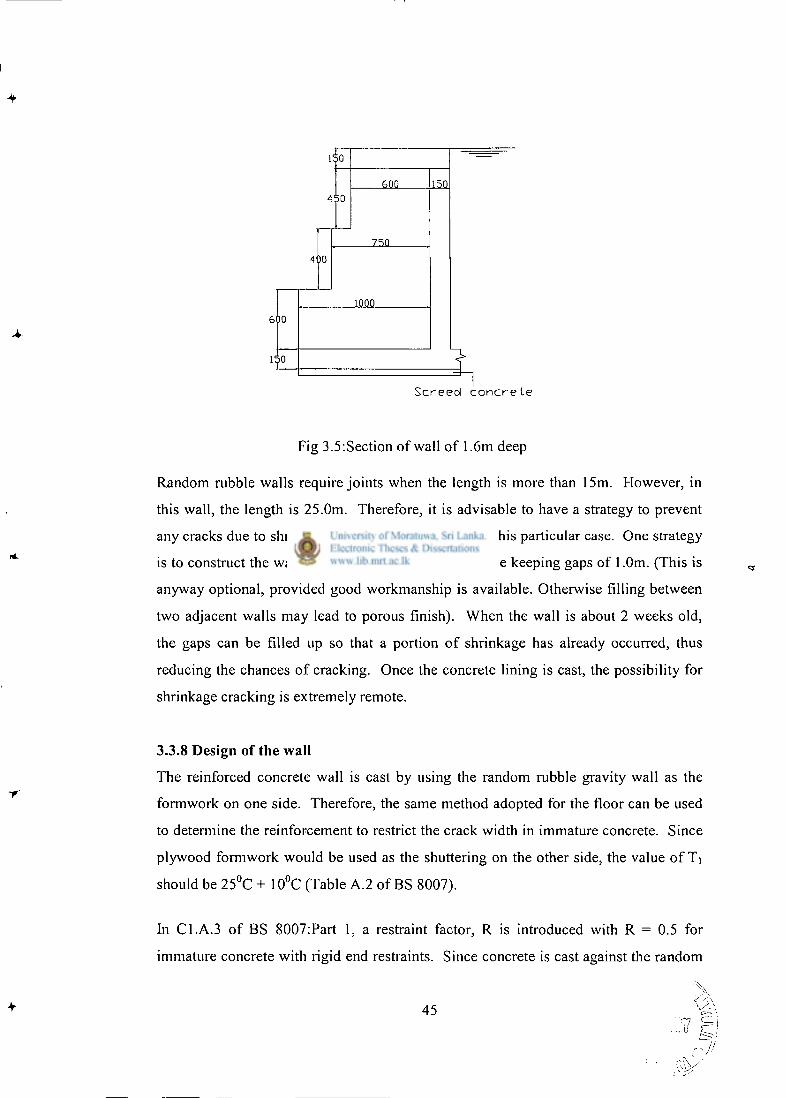
600 450
750
400
10QQ
600
150
S c r e e d c o n c r e t e
Fig 3.5:Section of wall of 1.6m deep
Random rubble walls require joints when the length is more than 15m. However, in
this wall, the length is 25.0m. Therefore, it is advisable to have a strategy to prevent
any cracks due to shrinkage although it is unlikely in this particular case. One strategy
is to construct the wall in lengths of about 12.0m while keeping gaps of 1.0m. (This is
anyway optional, provided good workmanship is available. Otherwise filling between
two adjacent walls may lead to porous finish). When the wall is about 2 weeks old,
the gaps can be filled up so that a portion of shrinkage has already occurred, thus
reducing the chances of cracking. Once the concrete lining is cast, the possibility for
shrinkage cracking is extremely remote.
3.3.8 Design of the wall
The reinforced concrete wall is cast by using the random rubble gravity wall as the
formwork on one side. Therefore, the same method adopted for the floor can be used
to determine the reinforcement to restrict the crack width in immature concrete. Since
plywood formwork would be used as the shuttering on the other side, the value of Ti
should be 25°C + 10°C (Table A.2 of BS 8007).
In C1.A.3 of BS 8007:Part 1, a restraint factor, R is introduced with R = 0.5 for
immature concrete with rigid end restraints. Since concrete is cast against the random
45 _ ^
7/
rubble wall, it is advisable to use the value of R as 0.5. It was suggested by Fonseka
(1995) that the use of the maximum value for R would be beneficial in Sri Lanka since
any error in estimating the value of T l would be adequately compensated. The use of
minimum steel ratio of 0.0035 would result in a crack width of 0.167mm (<0.2mm).
Therefore, the provision of 0.0035 as the reinforcement ratio is sufficient.
3.3.9 Reinforced concrete ground slab
The reinforced concrete ground slab need not have any flexural strength since the
weight of water can be resisted by the soil below. Therefore, it needs reinforcement
only to prevent early thermal cracks in immature concrete. BS 8007: 1987 allows the
prevention of early thermal cracks in continuously cast concrete member by the
provision of adequate amount of small diameter bars. It also allows the provision of
this reinforcement in a single layer. In this type of construction, it is advisable to
compact the soil below the ground floor slab thoroughly to avoid any weak pockets of
soil prior to laying the screed concrete.
For the design of the reinforcement in the slab, the crack width allowed should be
taken as 0.2mm. Equation 1 gives the maximum spacing of the cracks:
fa x Eq. 1
fb 2p
For deformed b a r s , ^ t , the ratio of the tensile strength of concrete to average bond
strength is equal to 0.67 (Table A. l of BS 8007: 1987). When a minimum steel ratio,
p, of 0.0035 is used with 10mm diameter bars,
Smax = 0.67 x 10 = 957mm
2 x 0.0035
The corresponding maximum crack width can be found from Equation 2.
46
fmax = Smax x a x J j Eq. 2
2
The value of Ti for the ground floor slab is 17° + 10° = 27°C. The value
recommended in BS 8007: 1987 for T, is 17°C (Table A.2). An additional 10° C is
allowed for seasonal variations.
Wmax = 957 x 10 x 10' 6 x 27°C = 0.129 < 0.2mm
2
Hence, the provision of 0.0035 on the reinforcement ratio is sufficient.
3.3.10 The structural arrangement of the swimming pool without deep end
using proposed method
On the basis of the calculations described above , the structural arrangement is shown
in Appendix D. The reinforcement details are also given. Since, it is necessary to
have a walkway of adequate width around the swimming pool, an embankment can be
formed using the excavated soil. This embankment should be paved at the top to
ensure that all the water collected will be drained and removed from the location of the
swimming pool in order to avoid any build-up of hydrostatic pressure.
Using the cement stabilization can further enhance the stability of the earth
embankment. It was reported by Jayasinghe & Perera (1999) that it is possible to
achieve compressive strengths in excess of 1.0 N / m m 2 for blocks when about 2 %
cement is used for stabilization of laterite soil. Therefore, the use of cement stabilized
properly compacted embankment would give a long lasting solution which is a pre
requisite for a swimming pool. The soil excavated from the site can be used for this
purpose. For the cost calculation, this is not considered since the use of cement
stabilized soil is optional.
3.3.11 Design drawings of the proposed pool without a deep end
Design drawings of the proposed pool without a deep end is presented in Appendix D.
47
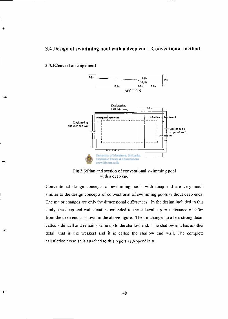
3.4 Design of swimming pool with a deep end -Conventional method
3.4.1General arrangement
SECTION
Designed as side w a l l — ,
Designed as • shallow end wall
:m long heel right round r— 1
PLAN
-!-2.7m-L —6.8m-
I.Jm
0.3m thick w
1 > ght round
lot g
Designed as deep end wall
;toe
Fig 3.6:Plan and section of conventional swimming pool with a deep end
Conventional design concepts of swimming pools with deep end are very much
similar to the design concepts of conventional of swimming pools without deep ends.
The major changes are only the dimensional differences. In the design included in this
study, the deep end wall detail is extended to the sidewall up to a distance of 9.5m
from the deep end as shown in the above figure. Then it changes to a less strong detail
called side wall and remains same up to the shallow end. The shallow end has another
detail that is the weakest and it is called the shallow end wall. The complete
calculation exercise is attached to this report as Appendix A.
48
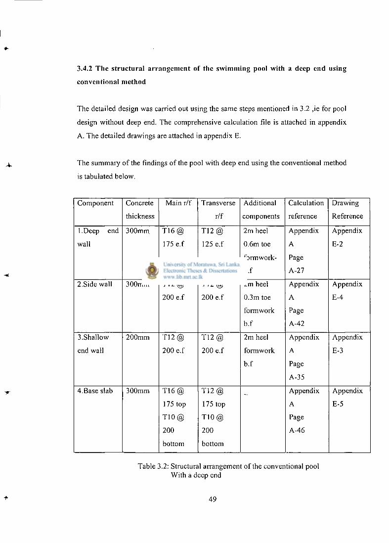
3.4.2 The structural arrangement of the swimming pool with a deep end using
conventional method
The detailed design was carried out using the same steps mentioned in 3.2 ,ie for pool
design without deep end. The comprehensive calculation file is attached in appendix
A. The detailed drawings are attached in appendix E.
The summary of the findings of the pool with deep end using the conventional method
is tabulated below.
Component Concrete Main r/f Transverse Additional Calculation Drawing
thickness r/f components reference Reference
1 .Deep end 300mm T 1 6 @ T12 @ 2m heel Appendix Appendix
wall 175 e.f 125 e.f 0.6m toe A E-2
formwork- Page
b.f A-27
2.Side wall 300mm T12 @ T 1 2 @ 2m heel Appendix Appendix
200 e.f 200 e.f 0.3m toe A E-4
formwork Page
b.f A-42
3.Shallow 200mm T12 @ T12 @ 2m heel Appendix Appendix
end wall 200 e.f 200 e.f formwork A E-3
b.f Page
A-35
4.Base slab 300mm T 1 6 @ T 1 2 @ — Appendix Appendix
175 top 175 top A E-5
T 1 0 @ T 1 0 @ Page
200 200 A-46
bottom bottom
Table 3.2: Structural arrangement of the conventional pool With a deep end
49
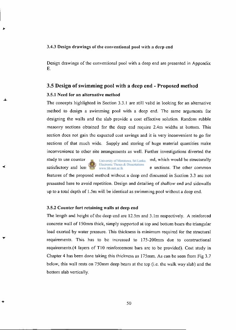
3.4.3 Design drawings of the conventional pool with a deep end
50
Design drawings of the conventional pool with a deep end are presented in Appendix E.
3.5 Design of swimming pool with a deep end - Proposed method
3.5.1 Need for an alternative method
The concepts highlighted in Section 3.3.1 are still valid in looking for an alternative
method to design a swimming pool with a deep end. The same arguments for
designing the walls and the slab provide a cost effective solution. Random rubble
masonry sections obtained for the deep end require 2.4m widths at bottom. This
section does not gain the expected cost savings and it is very inconvenient to go for
sections of that much wide. Supply and storing of huge material quantities make
inconvenience to other site arrangements as well. Further investigations diverted the
study to use counter fort retaining walls for the deep end, which would be structurally
satisfactory and less inconvenient than larger rubble sections. The other common
features of the proposed method without a deep end discussed in Section 3.3 are not
presented here to avoid repetition. Design and detailing of shallow end and sidewalls
up to a total depth of 1.5m will be identical as swimming pool without a deep end.
3.5.2 Counter fort retaining walls at deep end
The length and height of the deep end are 12.5m and 3.1m respectively. A reinforced
concrete wall of 150mm thick, simply supported at top and bottom bears the triangular
load exerted by water pressure. This thickness is minimum required for the structural
requirements. This has to be increased to 175-200mm due to constructional
requirements.(4 layers of T10 reinforcement bars are to be provided). Cost study in
Chapter 4 has been done taking this thickness as 175mm. As can be seen from Fig 3.7
below, this wall rests on 750mm deep beam at the top (i.e. the walk way slab) and the
bottom slab vertically.
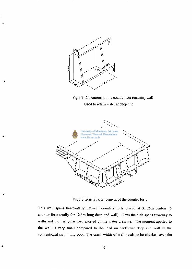
Fig 3.7:Dimentions of the counter fort retaining wall
Used to retain water at deep end
Fig 3.8:General arrangement of the counter forts
This wall spans horizontally between counters forts placed at 3.125m centers (5
counter forts totally for 12.5m long deep end wall). Thus the slab spans two-way to
withstand the triangular load exerted by the water pressure. The moment applied to
the wall is very small compared to the load on cantilever deep end wall in the
conventional swimming pool. The crack width of wall needs to be checked over the
51
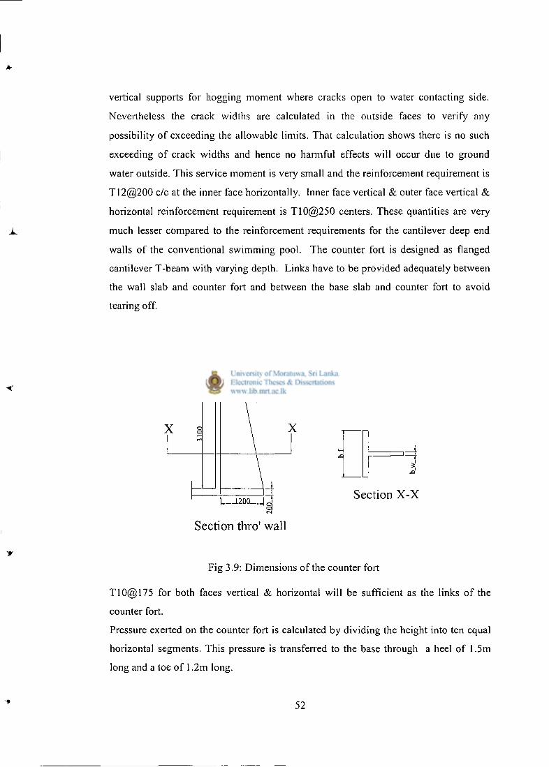
vertical supports for hogging moment where cracks open to water contacting side.
Nevertheless the crack widths are calculated in the outside faces to verify any
possibility of exceeding the allowable limits. That calculation shows there is no such
exceeding of crack widths and hence no harmful effects will occur due to ground
water outside. This service moment is very small and the reinforcement requirement is
T12@200 c/c at the inner face horizontally. Inner face vertical & outer face vertical &
horizontal reinforcement requirement is T10@250 centers. These quantities are very
much lesser compared to the reinforcement requirements for the cantilever deep end
walls of the conventional swimming pool. The counter fort is designed as flanged
cantilever T-beam with varying depth. Links have to be provided adequately between
the wall slab and counter fort and between the base slab and counter fort to avoid
tearing off.
750
Section thro' wall
Fig 3.9: Dimensions of the counter fort
T10@175 for both faces vertical & horizontal will be sufficient as the links of the
counter fort.
Pressure exerted on the counter fort is calculated by dividing the height into ten equal
horizontal segments. This pressure is transferred to the base through a heel of 1.5m
long and a toe of 1.2m long.
52
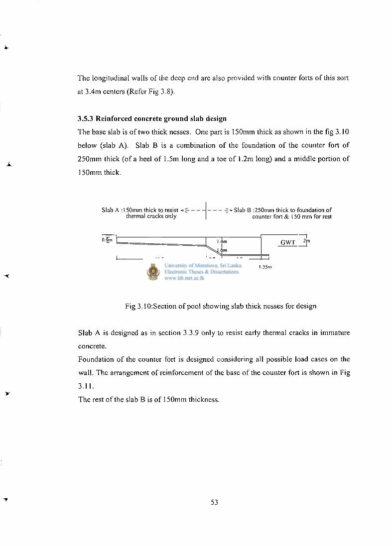
The longitudinal walls of the deep end are also provided with counter forts of this sort
at 3.4m centers (Refer Fig 3.8).
3.5.3 Reinforced concrete ground slab design
The base slab is of two thick nesses. One part is 150mm thick as shown in the fig 3.10
below (slab A). Slab B is a combination of the foundation of the counter fort of
250mm thick (of a heel of 1.5m long and a toe of 1.2m long) and a middle portion of
150mm thick.
Slab A : 150mm thick to resist « S-thermal cracks only
-5* Slab B :250mm thick to foundation of counter fort & 150 mm for rest
0.9m 1.4m
"m
GWT 2 j "
-15.5m- -2.7m 1 6.8m 1 ^ 1.35m
Fig 3.10:Section of pool showing slab thick nesses for design
Slab A is designed as in section 3.3.9 only to resist early thermal cracks in immature
concrete.
Foundation of the counter fort is designed considering all possible load cases on the
wall. The arrangement of reinforcement of the base of the counter fort is shown in Fig
3.11. y
The rest of the slab B is of 150mm thickness.
53
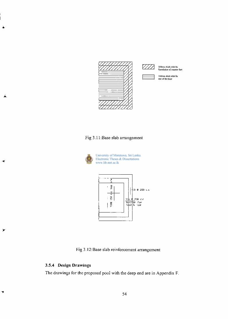
250mm ihick slab for foundation of counter fort
150mm thick slab for rest of the base
Fig 3.1 l:Base slab arrangement
hi -el
io e aoo c.c
Yl£ 8 £00 c.c 1jon f o r
•toe
Fig 3.12:Base slab reinforcement arrangement
3.5.4 Design Drawings
The drawings for the proposed pool with the deep end are in Appendix F.
54
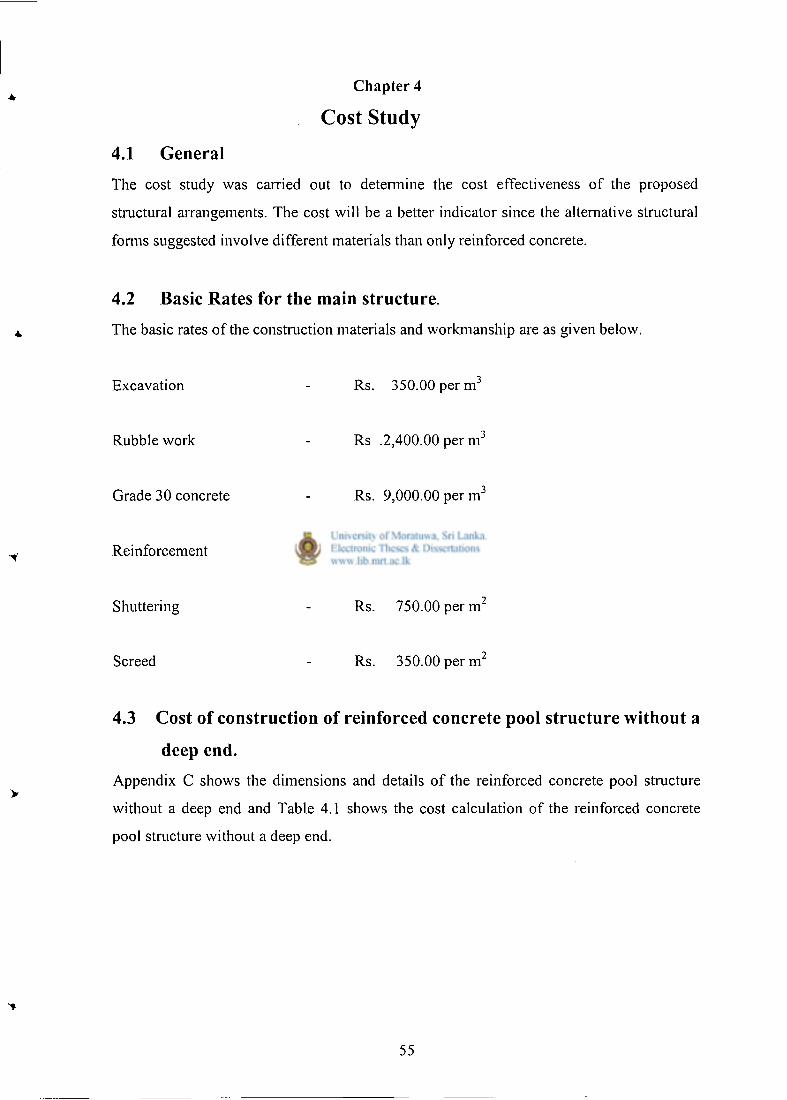
Chapter 4
Cost Study
4.1 General
The cost study was carried out to determine the cost effectiveness of the proposed
structural arrangements. The cost will be a better indicator since the alternative structural
forms suggested involve different materials than only reinforced concrete.
4.2 Basic Rates for the main structure.
The basic rates of the construction materials and workmanship are as given below.
Excavation
Rubble work
Grade 30 concrete
Reinforcement
Shuttering
Screed
Rs. 350.00 p e r m 3
Rs .2,400.00 per m 3
Rs. 9,000.00 per m 3
Rs.75,000.00 per M T
Rs. 750.00 per m 2
Rs. 350.00 per m 2
4.3 Cost of construction of reinforced concrete pool structure without a
deep end.
Appendix C shows the dimensions and details of the reinforced concrete pool structure
without a deep end and Table 4.1 shows the cost calculation of the reinforced concrete
pool structure without a deep end.
55
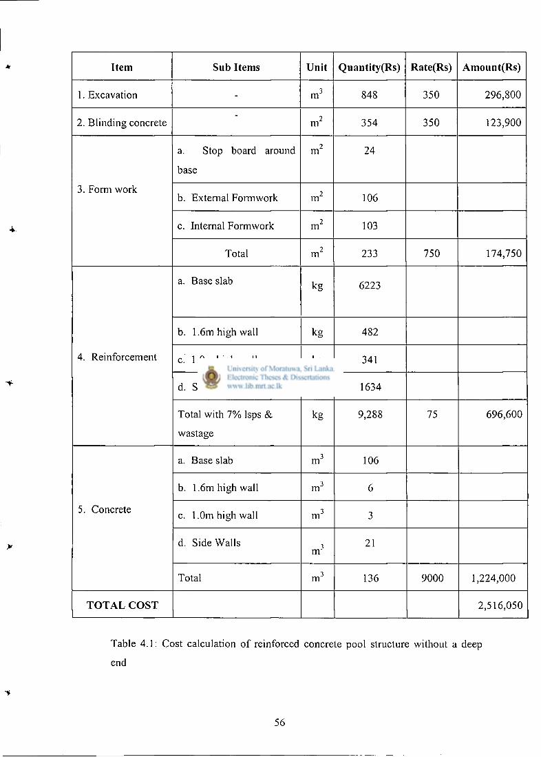
Item Sub Items Unit Quantity (Rs) Rate(Rs) AmountfRs)
1. Excavation - m 3 848 350 296,800
2. Blinding concrete -
m 2 354 350 123,900
3. Form work
a. Stop board around
base
m 2 24
3. Form work b. External Formwork m 2 106
3. Form work
c. Internal Formwork m 2 103
3. Form work
Total m 2 233 750 174,750
4. Reinforcement
a. Base slab kg 6223
4. Reinforcement
b . 1.6m high wall kg 482
4. Reinforcement c. 1.0m high wall kg 341 4. Reinforcement
d. Side walls kg 1634
4. Reinforcement
Total with 7 % lsps &
wastage
kg 9,288 75 696,600
5. Concrete
a. Base slab m 3 106
5. Concrete
b. 1.6m high wall m 3 6
5. Concrete c. 1.0m high wall m 3 3 5. Concrete
d. Side Walls m 3
21
5. Concrete
Total m 3 136 9000 1,224,000
T O T A L C O S T 2,516,050
Table 4 .1 : Cost calculation of reinforced concrete pool structure without a deep
end
56
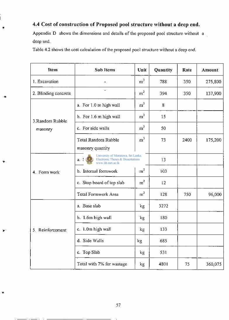
4.4 Cost of construction of Proposed pool structure without a deep end.
Appendix D shows the dimensions and details of the proposed pool structure without a
deep end.
Table 4.2 shows the cost calculation of the proposed pool structure without a deep end.
Item S u b Items Unit Quantity Rate Amount
1. Excavation - m 3 788 350 275,800
2. Blinding concrete -
m 2 394 350 137,900
3.Random Rubble
masonry
a. For 1.0 m high wall m 3 8
3.Random Rubble
masonry
b. For 1.6 m high wall m 3 15 3.Random Rubble
masonry c. For side walls m 3 50
3.Random Rubble
masonry
Total Random Rubble
masonry quantity
m 3 73 2400 175,200
4. Form work
a. Stop board around base m 2 13
4. Form work b. Internal formwork m 2 103 4. Form work
c. Stop board of top slab m 2 12
4. Form work
Total Formwork Area m 2 128 750 96,000
5. Reinforcement
a. Base slab kg 3272
5. Reinforcement
b . 1.6m high wall kg 180
5. Reinforcement c. 1.0m high wall kg 133 5. Reinforcement
d. Side Walls kg 685
5. Reinforcement
e. Top Slab kg 531
5. Reinforcement
Total with 7 % for wastage kg 4801 75 360,075
57
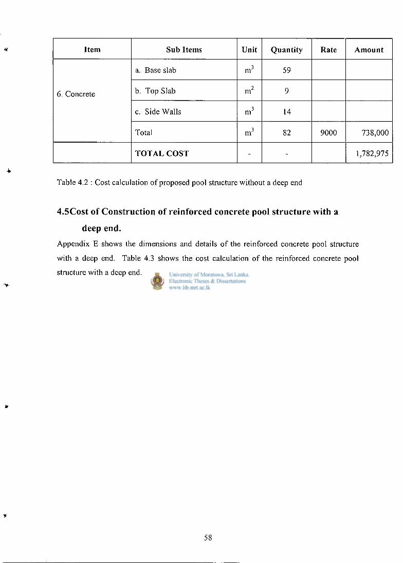
Item Sub Items Unit Quantity Rate Amount
6. Concrete
a. Base slab m 3 59
6. Concrete b. Top Slab m 2 9 6. Concrete
c. Side Walls m 3 14
6. Concrete
Total m 3 82 9000 738,000
T O T A L C O S T - - 1,782,975
Table 4.2 : Cost calculation of proposed pool structure without a deep end
4.5Cost of Construction of reinforced concrete pool structure with a
deep end.
Appendix E shows the dimensions and details of the reinforced concrete pool structure
with a deep end. Table 4.3 shows the cost calculation of the reinforced concrete pool
structure with a deep end.
58
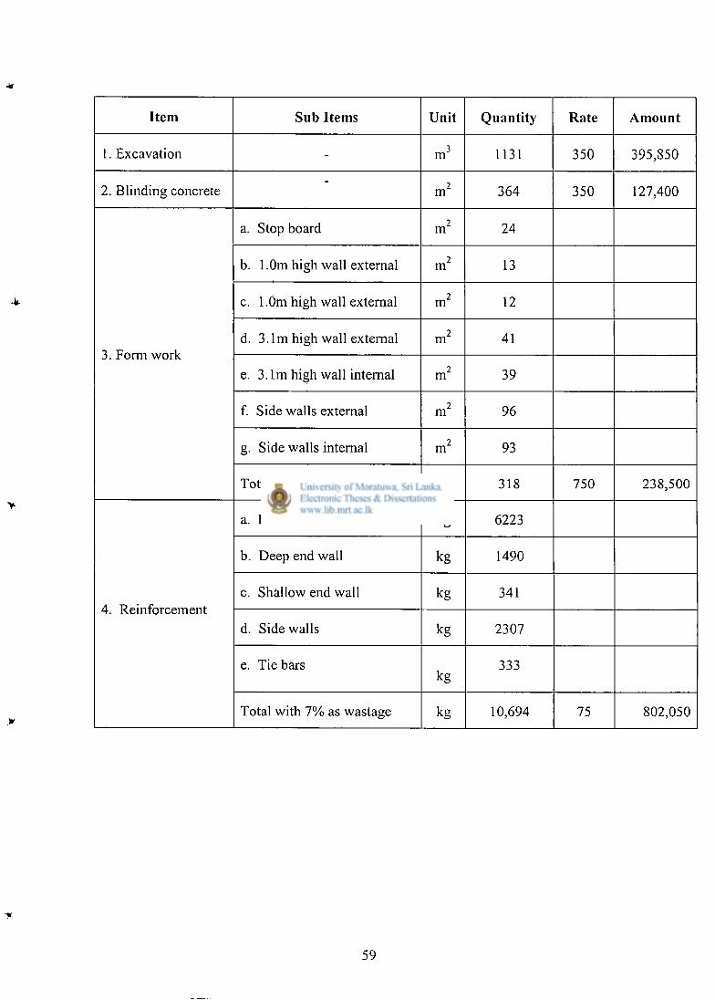
Item Sub Items Unit Quantity Rate Amount
1. Excavation - m 3 1131 350 395,850
2. Blinding concrete -
m 2 364 350 127,400
a. Stop board m 2 24
b. 1 .Om high wall external m 2 13
c. 1.0m high wall external m 2 12
3. Form work d. 3.1m high wall external m 2 41
3. Form work e. 3.1m high wall internal m 2 39
f. Side walls external m 2 96
g. Side walls internal m 2 93
Total m 2 318 750 238,500
a. Base slab kg 6223
b. Deep end wall kg 1490
4. Reinforcement c. Shallow end wall kg 341
4. Reinforcement d. Side walls kg 2307
e. Tie bars kg
333
Total with 7% as wastage kg 10,694 75 802,050
59
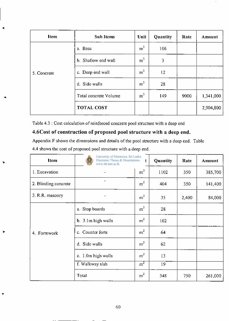
Item Sub Items Unit Quantity Rate Amount
a. Base m 3 106
b. Shallow end wall m 3 3
5. Concrete c. Deep end wall m 3 12
d. Side walls m 3 28
Total concrete Volume m 3 149 9000 1,341,000
T O T A L C O S T 2,904,800
Table 4.3 : Cost calculation of reinforced concrete pool structure with a deep end
4.6Cost of construction of proposed pool structure with a deep end.
Appendix F shows the dimensions and details of the pool structure with a deep end. Table
4.4 shows the cost of proposed pool structure with a deep end.
Item Sub Items Unit Quantity Rate Amount
1. Excavation - m 3 1102 350 385,700
2. Blinding concrete -
m 2 404 350 141,400
3. R.R. masonry - m 3 35 2,400 84,000
a. Stop boards m 2 28
b. 3.1m high walls m 2 162
4. Formwork c. Counter forts m 2 64
d. Side walls m 2 62
e. 1.0m high walls m 2 13
f. Walkway slab m 2 19
Total m 2 348 750 261,000
60
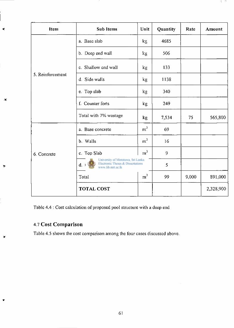
Item Sub Items Unit Quantity Rate Amount
a. Base slab kg 4685
b. Deep end wall kg 506
5. Reinforcement
c. Shallow end wall kg 133
5. Reinforcement d. Side walls kg 1138
e. Top slab kg 340
f. Counter forts kg 249
Total with 7% wastage kg 7,534 75 565,800
a. Base concrete m 3 69
b. Walls m 3 16
6. Concrete c. Top Slab m 3 9
d. Counterfor ts m 3 5
Total m 3 99 9,000 891,000
T O T A L C O S T 2,328,900
Table 4.4 : Cost calculation of proposed pool structure with a deep end
4.7 Cost Comparison
Table 4.5 shows the cost comparison among the four cases discussed above.
61
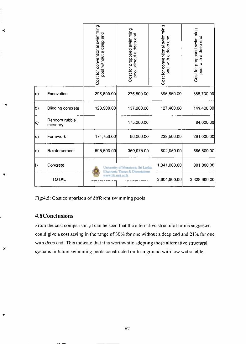
Cos
t fo
r co
nven
tion
al s
wim
min
g po
ol w
itho
ut a
dee
p en
d
Cos
t fo
r pr
opos
ed s
wim
min
g po
ol w
itho
ut a
dee
p en
d
Cos
t fo
r co
nven
tion
al s
wim
min
g po
ol w
ith a
dee
p e
nd
Cos
t fo
r pr
opos
ed s
wim
min
g po
ol w
ith a
dee
p e
nd
a) Excavation 296,800.00 275,800.00 395,850.00 385,700.00
b) Blinding concrete 123,900.00 137,900.00 127,400.00 141,400.00
c) Random rubble masonry 175,200.00 84,000.00
d) Formwork 174,750.00 96,000.00 238,500.00 261,000.00
e) Reinforcement 696,600.00 360,075.00 802,050.00 565,800.00
f) Concrete 1,224,000.00 738,000.00 1,341,000.00 891,000.00
T O T A L 2,516,050.00 1,782,975.00 2,904,800.00 2,328,900.00
Fig:4.5: Cost comparison of different swimming pools
4.8Conclusions
From the cost comparison ,it can be seen that the alternative structural forms suggested
could give a cost saving in the range of 3 0 % for one without a deep end and 2 1 % for one
with deep end. This indicate that it is worthwhile adopting these alternative structural
systems in future swimming pools constructed on firm ground with low water table.
62
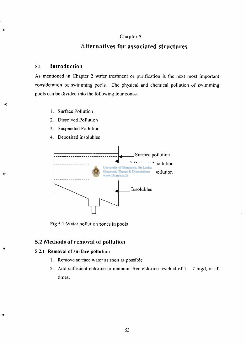
Chapter 5
Alternatives for associated structures
5.1 Introduction
As mentioned in Chapter 2 water treatment or purification is the next most important
consideration of swimming pools. The physical and chemical pollution of swimming
pools can be divided into the following four zones.
1. Surface Pollution
2. Dissolved Pollution
3. Suspended Pollution
4. Deposited insolubles
. Surface pollution
\ D i s s o l v e d pollution
Suspended pollution
Insolubles
Fig 5.1: Water pollution zones in pools
5.2 Methods of removal of pollution
5.2.1 Removal of surface pollution
1. Remove surface water as soon as possible
2. Add sufficient chlorine to maintain free chlorine residual of 1 - 2 mg/L at all
t imes.
63
5.2.2 Removal of dissolved pollution
1. Provide adequate filtration cycle
2. Add sufficient chlorine to breakdown, nitrogenous matter and render it
harmless
5.2.3 Removal of suspended pollution
1. Use minimum quantity of chemicals
2. Maintain balanced water in the pool
3. Maintain careful control of pH and Alkalinity
4. Use chemicals which do not produce suspended solids.
5.2.4 Removal of deposited insoluble pollution
1. Adopt vacuum cleaning of the pool bottom daily.
5.2.5 Removal of the biological pollution in the swimming pool
1. Maintain free chlorine residual of 1 - 2 mg/L in the pool water at all times,
chlorine will kill - off all the bacteria immediately and render the pool water
safe for public bathing.
2. Provide an efficient top water drew - off system
3. Provide an efficient filtration system
5.3 Structural forms for water treatment
5.3.1 Traditional swimming pool forms for water treatment
The study made on the system shows no important structural components are present
within it
But for removal of dissolved gases and for aesthetics of swimming pools cascade aerators
are part of several pools. Figure 5.2 shows a schematic diagram of an aerator. The aerator
is generally made using reinforced concrete. This is now built using ferro - cement
technology which is cheaper to reinforced concrete structure.
64
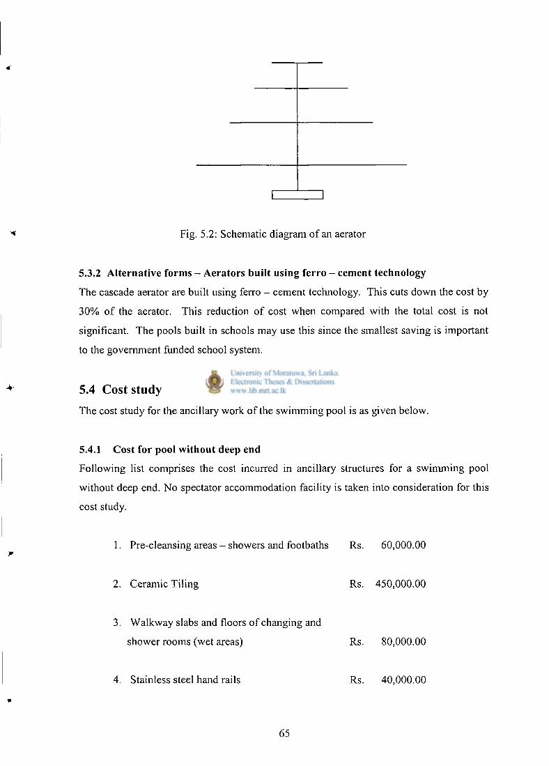
Fig. 5.2: Schematic diagram of an aerator
5.3.2 Alternative forms - Aerators built using ferro - cement technology
The cascade aerator are built using ferro - cement technology. This cuts down the cost by
3 0 % of the aerator. This reduction of cost when compared with the total cost is not
significant. The pools built in schools may use this since the smallest saving is important
to the government funded school system.
5.4 Cost study
The cost study for the ancillary work of the swimming pool is as given below.
5.4.1 Cost for pool without deep end
Following list comprises the cost incurred in ancillary structures for a swimming pool
without deep end. N o spectator accommodation facility is taken into consideration for this
cost study.
1. Pre-cleansing areas - showers and footbaths Rs. 60,000.00
2 Ceramic Tiling Rs . 450,000.00
3 Walkway slabs and floors of changing and
shower rooms (wet areas) Rs. 80,000.00
4 Stainless steel hand rails Rs. 40,000.00
65
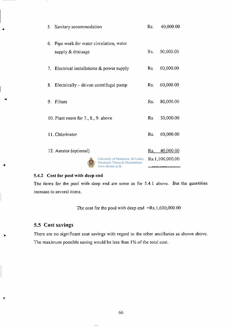
5. Sanitary accommodation Rs. 40,000.00
6. Pipe work for water circulation, water
supply & drainage Rs. 50,000.00
7. Electrical installations & power supply
8. Electrically - driven centrifugal pump
Rs. 60,000.00
Rs. 60,000.00
9. Filters Rs . 80,000.00
10. Plant room for 7., 8., 9. above Rs. 30,000.00
11. Chlorinator Rs . 60,000.00
12. Aerator (optional)
Total
Rs . 40.000.00
Rs. 1,100,000.00
5.4.2 Cost for pool with deep end
The items for the pool with deep end are some as for 5.4.1 above. But the quantities
increase in several items.
The cost for the pool with deep end =Rs. 1,600,000.00
5.5 Cost savings
There are no significant cost savings with regard to the other ancillaries as shown above.
The maximum possible saving would be less than 1% of the total cost.
66
5.6 Summary
The cost study carried out for other ancillary structures and facilities shows that a
significant cost is involved for providing these.
These need to be further studied with respect to modern technological findings with the
aspect of water purification to minimize the cost incurred.
•A
7 f:\
67
Chapter 6
Conclusions and Recommendations
6.1 General
For developing countries, it is useful to promote cost effective structural solutions for most
of the civil engineering activities in order to make the maximum use of limited resources
since most of the cost effective solutions tend to use less materials. The same is true for
swimming pools as well.
In this study, alternative solutions were developed for swimming pools without and with
deep ends.
The following are the main features of these alternative solutions:
6.1.1 Main features of Swimming pools without deep ends
1. The swimming pool without deep end does not have any cantilever walls. But
its walls act as gravity retaining walls to withstand the forces exerted by water
pressure and earth pressure when the pool is full and empty respectively. The
material used is Random rubble masonry.
2. The walls have inner lining of reinforced concrete to eliminate any possibility
of water leaking through the random rubble masonry wall.
3. The base slab is designed to resist only thermal and shrinkage cracking.
6.1.2 Main features of Swimming pools with deep ends
1. Gravity retaining wall concept is still valid. But the deep end requires very
wide random rubble sections. Hence deep end was designed using counter fort
retaining walls. The service moment applied on the wall is of small magnitude
making reinforcement requirement to a lesser value.
68
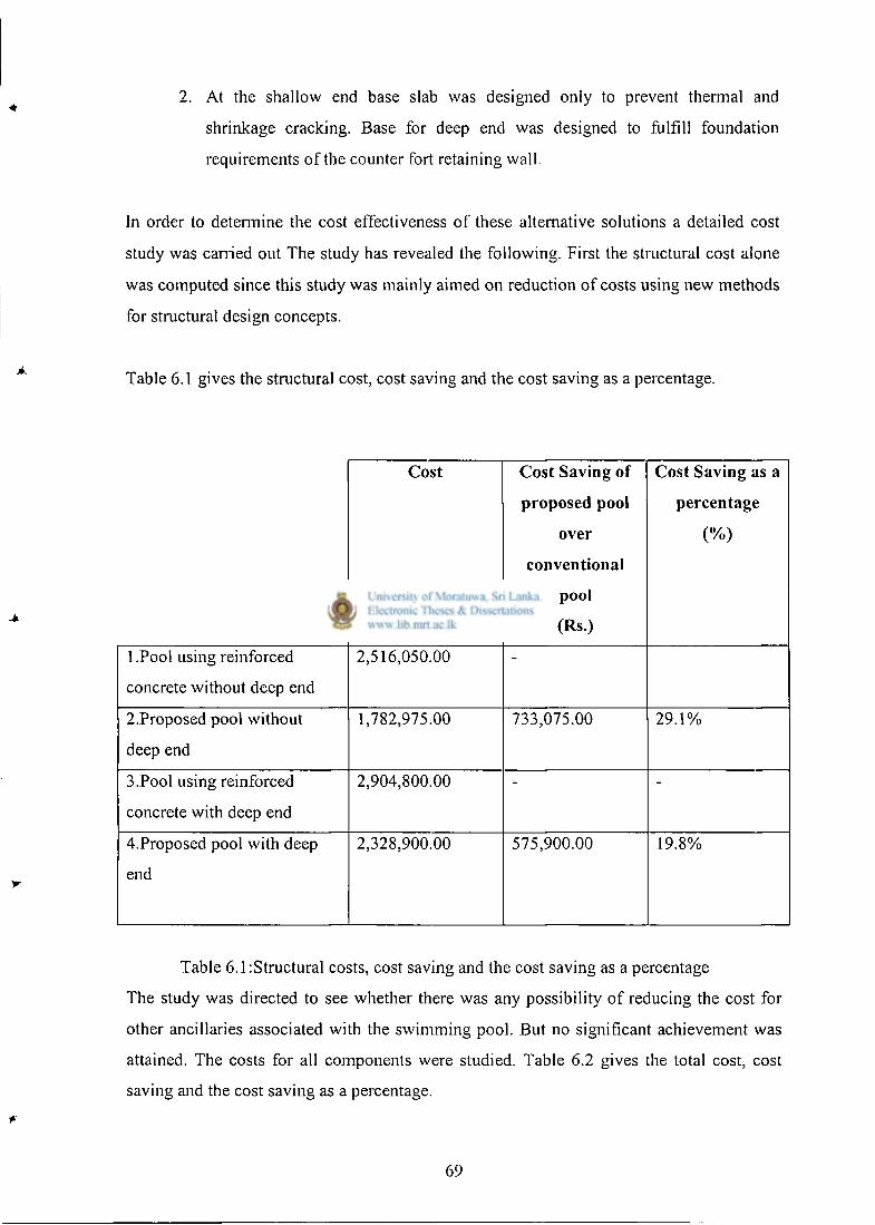
2. At the shallow end base slab was designed only to prevent thermal and
shrinkage cracking. Base for deep end was designed to fulfill foundation
requirements of the counter fort retaining wall.
In order to determine the cost effectiveness of these alternative solutions a detailed cost
study was carried out The study has revealed the following. First the structural cost alone
was computed since this study was mainly aimed on reduction of costs using new methods
for structural design concepts.
Table 6.1 gives the structural cost, cost saving and the cost saving as a percentage.
Cost Cost Saving of
proposed pool
over
conventional
pool
(Rs.)
Cost Saving as a
percentage
(%)
1 .Pool using reinforced
concrete without deep end
2,516,050.00
2.Proposed pool without
deep end
1,782,975.00 733,075.00 2 9 . 1 %
3.Pool using reinforced
concrete with deep end
2,904,800.00
4.Proposed pool with deep
end
2,328,900.00 575,900.00 19.8%
Table 6.1 :Structural costs, cost saving and the cost saving as a percentage
The study was directed to see whether there was any possibility of reducing the cost for
other ancillaries associated with the swimming pool. But no significant achievement was
attained. The costs for all components were studied. Table 6.2 gives the total cost, cost
saving and the cost saving as a percentage.
69
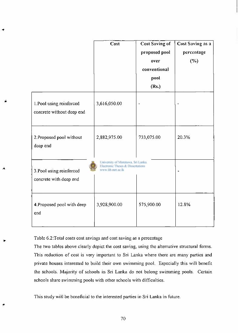
Cost Cost Saving of
proposed pool
over
conventional
pool
(Rs.)
Cost Saving as a
percentage
(%)
1 .Pool using reinforced
concrete without deep end
3,616,050.00 - -
2.Proposed pool without
deep end
2,882,975.00 733,075.00 2 0 . 3 %
3.Pool using reinforced
concrete with deep end
4,504,800.00 - -
4.Proposed pool with deep
end
3,928,900.00 575,900.00 12.8%
Table 6.2:Total costs cost savings and cost saving as a percentage
The two tables above clearly depict the cost saving, using the alternative structural forms.
This reduction of cost is very important to Sri Lanka where there are many parties and
private houses interested to build their own swimming pool. Especially this will benefit
the schools. Majority of schools in Sri Lanka do not belong swimming pools. Certain
schools share swimming pools with other schools with difficulties.
This study will be beneficial to the interested parties in Sri Lanka in future.
70
REFERENCES: -
1 .Cost effective structural forms for swimming pools Dr.M.T.R Jayasinghe
2.Design for controlled cracking of water retaining structures based on Bs 8007 - 2000 Dr. S.M.A.Nanayakkara
3.Swimming P o o l s - 1 9 8 8 Philip. H. Perkins
4.British standard code of Practice Structural use of Concrete BS 8110:part 1: 1985
5.British standard code of Practice for Design of concrete structures for retaining aqueous liquids BS 8007: 1987
6.The design of water retaining structures Ian Batty & Roger Westbrook
7.Reinforced Concrete Design's Handbook Charles E. Reynolds & James C. Steedman
8.Reinforced Concrete Design Mosley and Bungay
9.Reinforced Concrete Design theory and Examples T.J. McGinley & B.S. Choo
10.Design and Planning of Swimming Pools-1979 John Dawes
11 .Chandrakeerthy, S.R.De. S. (1998) " A study of random rubble masonry construction in Sri Lanka", Transactions- 1998, Part B, Volume 1, pp 124-149.
12.Fonseka, M.C.M. (1995), "On Bs 8007 recommendation for reinforcement to control thermal and shrinkage cracking", Engineer - Journal of institution of Engineers-Sri Lanka, Vol: XXDINo: l,pp 5-12.
13.Jayasinghe, C. & Perera A.A.D.A.J. (1999), "Studies on load bearing characteristics of cement stabilized soil blocks", Transactions-1999, Vol: 1, part B, pp 63-72.
14.Foundation Analysis and Design Joseph E. Bowles
15.Design of Liquid Retaining Concrete Structures R.D Anchor & Edward Arnold
16. Water Supply Engineering Santosh Kumar Garg
17.Service reservoir design ,with particular reference to economics and the 'Simple Supported Wall' concept J.WamesleyThe Structural Engineer /Volume 59A/No.9 September 1981
71
Appendix A
Design calculations of the conventional swimming
With Deep End
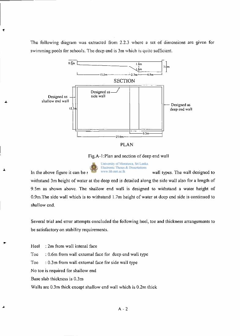
The following diagram was extracted from 2.2.3 where a set of dimensions are given for
swimming pools for schools. The deep end is 3m which is quite sufficient.
0.<5m
Designed as • shallow end wall
I2.5n
1.4m i
-15.5m- -L2.7m-J 6.8m-
S E C T I O N
Designed as-side wall
-9.5m--25.0m-
3.0m
- Designed as deep end wall
P L A N
Fig.A-1 :Plan and section of deep end wall
In the above figure it can be seen that there are three different wall types. The wall designed to
withstand 3m height of water at the deep end is detailed along the side wall also for a length of
9.5m as shown above. The shallow end wall is designed to withstand a water height of
0.9m.The side wall which is to withstand 1.7m height of water at deep end side is continued to
shallow end.
Several trial and error attempts concluded the following heel, toe and thickness arrangements to
be satisfactory on stability requirements.
Heel : 2m from wall intenal face
Toe : 0.6m from wall external face for deep end wall type
Toe : 0.3m from wall external face for side wall type
No toe is required for shallow end
Base slab thickness is 0.3m
Walls are 0.3m thick except shallow end wall which is 0.2m thick
A - 2
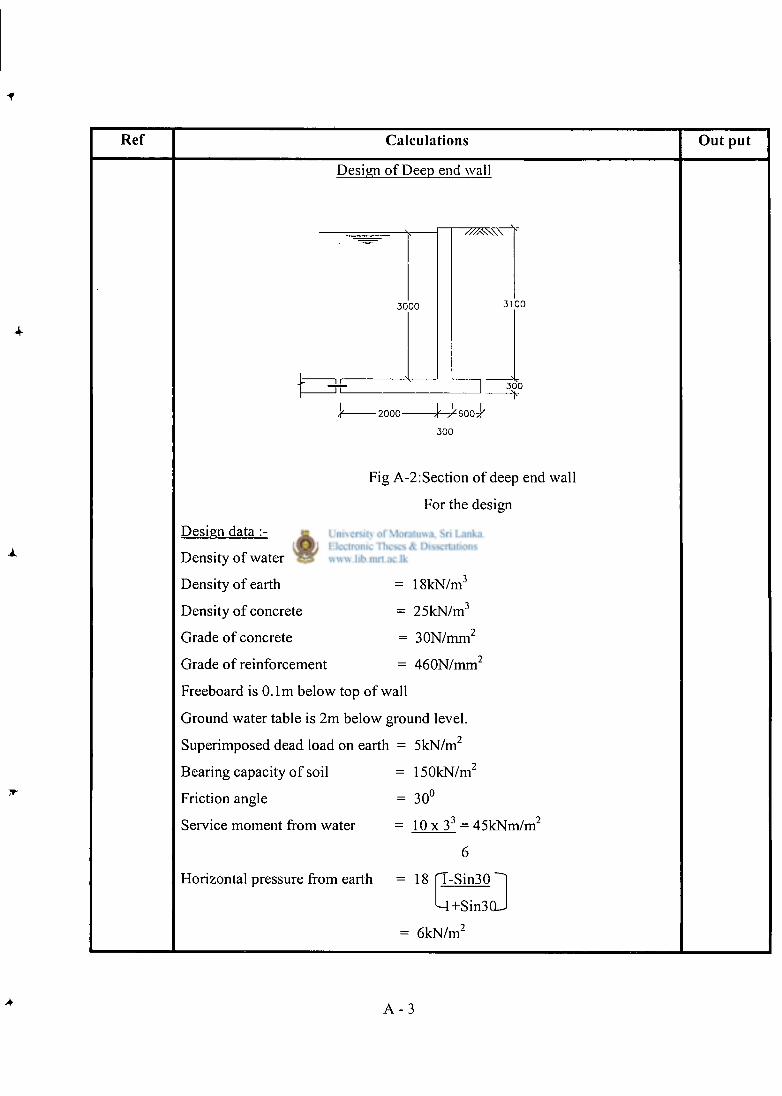
Ref Calculat ions O u t put
Design of Deep end wall
3000
3 E -2000- - 4 ^ 6 0 0 ^
300
Fig A-2: Section of deep end wall
For the design
Design data :-
Density of water = 10kN/m 3
Density of earth = 18kN/m 3
Density of concrete = 25kN/m 3
Grade of concrete = 30N/mm 2
Grade of reinforcement = 460N/mm 2
Freeboard is 0.1m below top of wall
Ground water table is 2m below ground level.
Superimposed dead load on earth = 5kN/m 2
Bearing capacity of soil
Friction angle
Service moment from water
= 150kN/m'
= 30°
= 1 0 x 3 3 = 45kNm/m 2
6
Horizontal pressure from earth = 18 rT-Sin30
M + S i n 3 0 J
6kN/m 2
A - 3
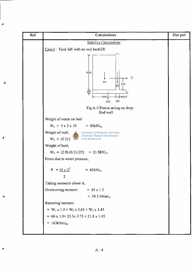
Ref Calculat ions Ou t pu t
Case
Stability Calculations
Tank full with no soil backfill
3000
W3 3 0 0
Fig A-3:Forces acting on deep End wall
Weight of water on heel
W, = 3 x 2 x 10 = 60kN/ m
Weight of wall,
W 2 = (0.3) (3.1) (25) = 23 .3kN/ m
Weight of heel,
W 3 = (2.9) (0.3) (25) = 21.8kN/ n
Force due to water pressure,
P = 1 0 x 3 z = 45kN/ m
2
Taking moments about A,
Overturning moment = 45 x 1.3
= 5 8 . 5 k N m / n
Restoring moment
= W, x 1.9 + W 2 x 0.65 + W 3 x 1.45
= 60 x 1.9+ 23.3x 0.75 + 21.8 x 1.45
= 163kNm/ m
A- A - 4
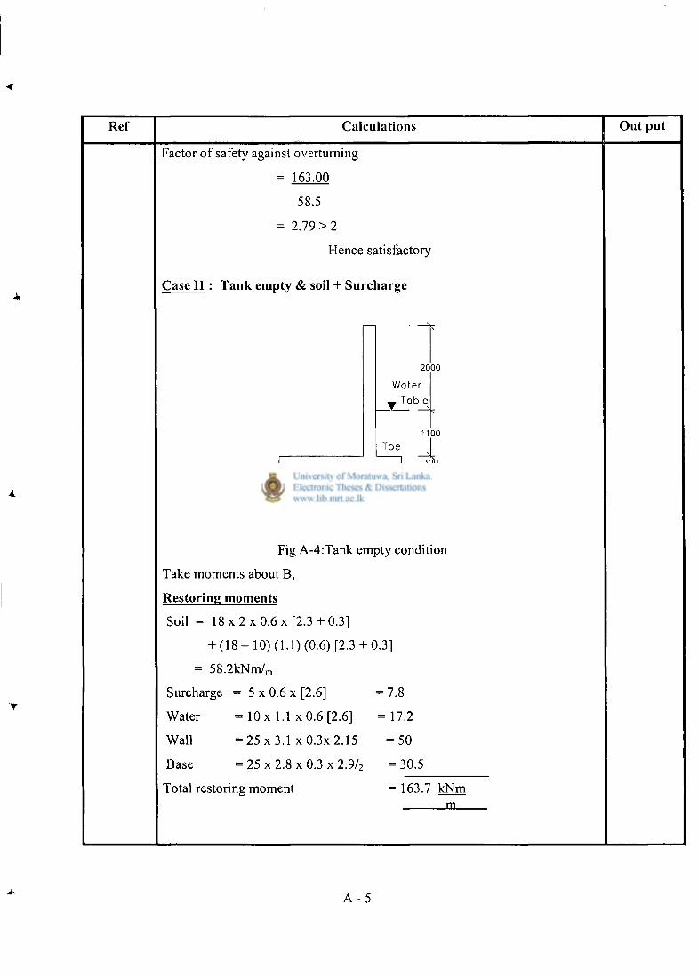
Ref Calculations Out put
Factor of safety against overturning
= 163.00
58.5
= 2.79 > 2
Hence satisfactory
Case I I : Tank empty & soil + Surcharge
2 0 0 0
Water _ Table
Toe 1 1 0 0
4 , )f 2 0 0 0 ^ ^ S O O T C
3 0 0
Fig A-4:Tank empty condition
Take moments about B,
Restoring moments
Soil = 1 8 x 2 x 0 . 6 x [ 2 . 3 + 0.3]
+ ( 1 8 - 1 0 ) (1.1) (0.6) [2.3 + 0.3]
= 58.2kNm/ m
Surcharge = 5 x 0.6 x [2.6] = 7.8
Water = 10 x 1.1 x 0.6 [2.6] = 1 7 . 2
Wall = 2 5 x 3 . 1 x 0 . 3 x 2 . 1 5 = 5 0
Base = 25 x 2.8 x 0.3 x 2.9/ 2 = 30.5
Total restoring moment = 163.7 kNm in
A - 5
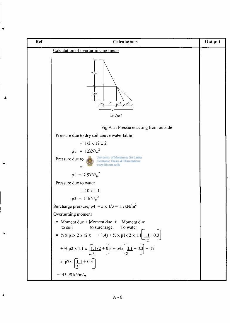
Ref Calculat ions O u t put
Calculation of overturning moments
V r—K
K N / m 2
Fig A-5: Pressures acting from outside
Pressure due to dry soil above water table
= 1/3 x 1 8 x 2
p i = 12kN/ m
2
Pressure due to submerged soil
= 1/3 ( 1 8 - 1 0 ) (1.1)
p i = 2 .9kN/ m
2
Pressure due to water
= l O x 1.1
p3 = l l k N / m
2
Surcharge pressure, p4 = 5 x 1 / 3 = 1.7kN/m
Overturning moment
= Moment due + Moment due. + Moment due to soil to surcharge. To water
= ' / 2 x p l x 2 x ( 2 x + 1.4) + ! / 2 x p l x 2 x 1.1
+ ' / 2 p 2 x 1.1 x 7.1x2 + 0 3 + p 4 x 3 J . + 0.3
1.3 - J ^2 J
U +0.3 " ~ 2
+ lA
x p3x
= 45.98 kNm/,
U . + 0.3 13
A - 6
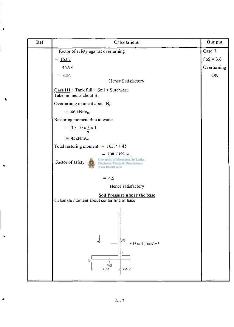
Ref Calculat ions O u t p u t
Factor of safety against overturning
= 163.7
45.98
= 3.56 Hence Satisfactory
Case I I I : Tank full + Soil + Surcharge Take moments about B,
Overturning moment about B,
= 4 6 k N m / m
Restoring moment due to water
= 3 x 1 0 x 3 x 1 2
= 45kNm/ m
Total restoring moment = 163.7 + 45
= 208.7 kNm/„ Factor of safety = 208.7
46
= 4.5
Hence satisfactory
Soil Pressure under the base
Case II
FoS = 3.6
Overturning
OK
Calculate moment about center line of base
I W1 • P = 4 5 K N / m 2
W3 - 2 1 5 0 - 7 5 0 - 7 '
A - 7
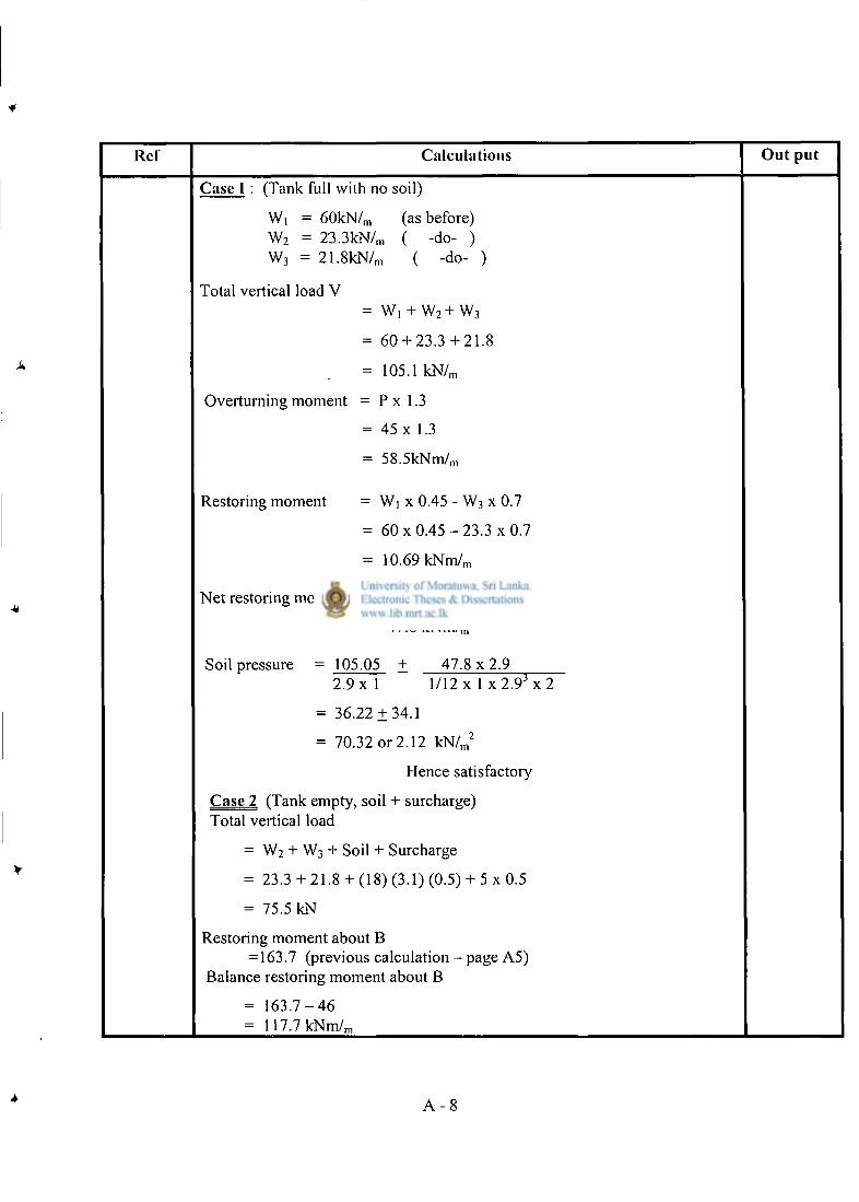
Rcf Calculat ions O u t p u t
Case I : (Tank full with no soil)
W, = 60kN/ m (as before) W 2 = 23 .3kN/ m ( -do- ) W 3 = 21 .8kN/ m ( -do- )
Total vertical load V = Wi + w 2 + w 3
= 60 + 23.3 + 21.8
= 105.1 k N / m
Overturning moment = P x 1.3
= 45 x 1.3
= 58.5kNm/ m
Restoring moment = Wi x 0.45 - W 3 x 0.7
= 6 0 x 0 . 4 5 - 2 3 . 3 x 0.7
= 10.69 k N m / m
Net restoring moment = 1 0 . 6 9 - 5 8 . 5
= - 4 7 . 8 k N m / m
Soil pressure = 105.05 + 4 7 . 8 x 2 . 9 2 . 9 x 1 1/12 x 1 x 2 . 9 J x 2
= 36.22 ± 3 4 . 1
= 70.32 or 2.12 k N / m
2
Hence satisfactory
Case 2 (Tank empty, soil + surcharge) Total vertical load
= W 2 + W 3 + Soil + Surcharge
= 23.3 + 21.8 + (18) (3.1) (0.5) + 5 x 0.5
= 75.5 kN
Restoring moment about B = 163.7 (previous calculation - page A5)
Balance restoring moment about B
= 1 6 3 . 7 - 4 6 = 117 .7kNm/ m
A - 8
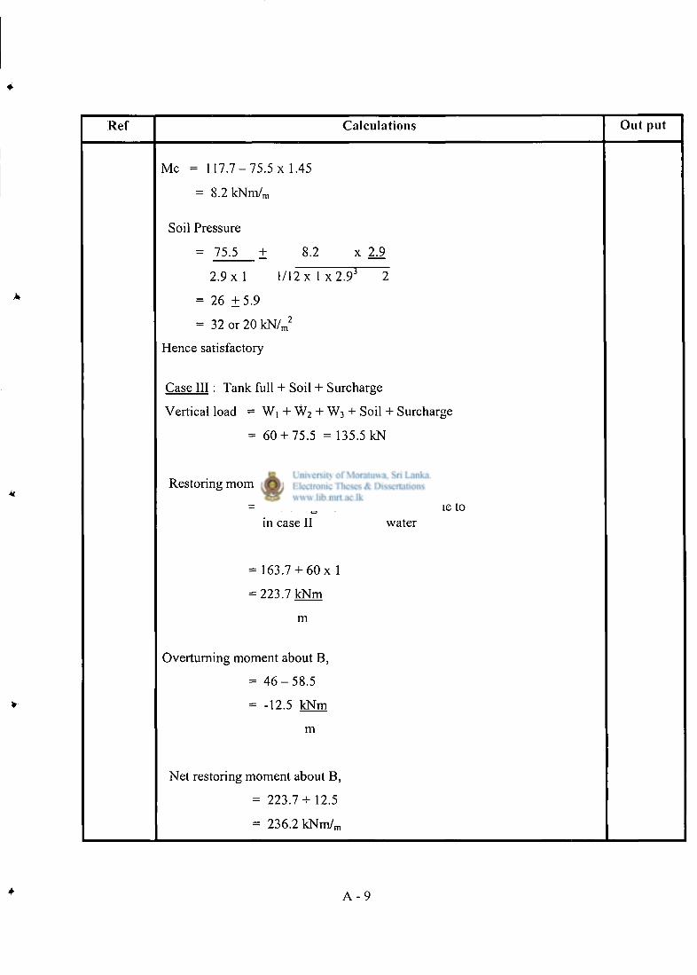
Ref Calculat ions Ou t put
Mc = 1 1 7 . 7 - 7 5 . 5 x 1.45
= 8 .2kNm/ m
Soil Pressure
= 75.5 ± 8.2 x 2j)
2 . 9 x 1 1 / 1 2 x 1 x 2 . 9 ' 2
= 26 ± 5 . 9
= 32 or 20 k N / m
2
Hence satisfactory
Case I I I : Tank full + Soil + Surcharge
Vertical load = W, + W 2 + W 3 + Soil + Surcharge
= 60 + 75.5 = 135.5 kN
Restoring moment about B
= Restoring moment + Moment due to in case II water
= 163.7 + 6 0 x 1
= 223.7 kNm
m
Overturning moment about B,
= 4 6 - 5 8 . 5
= -12.5 kNm
m
Net restoring moment about B,
= 2 2 3 . 7 + 12.5
= 236.2 k N m / m
4 A - 9
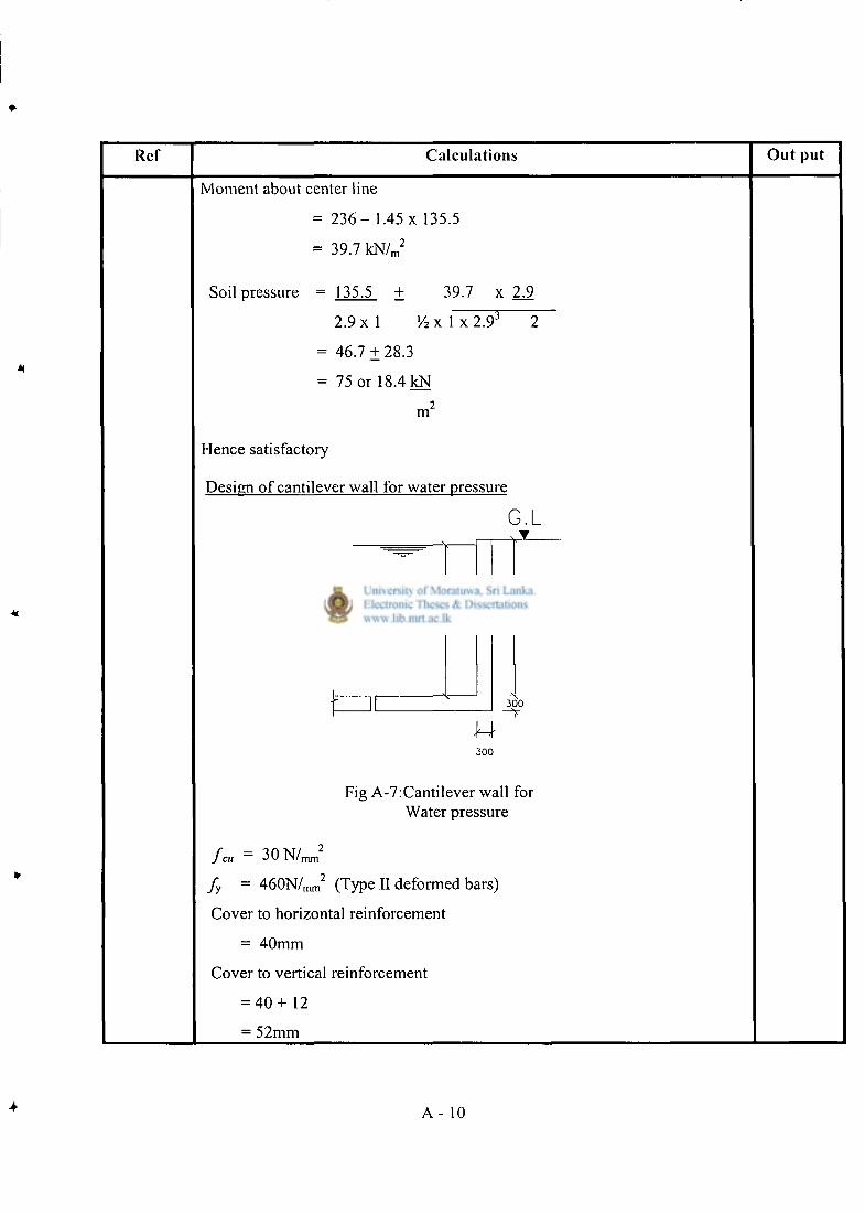
Ref Calculat ions O u t p u t
Moment about center line
= 2 3 6 - 1.45 x 135.5
= 39.7 k N / m
2
Soil pressure = 135.5 ± 39.7 x 2/9
2.9 x 1 V2 x 1 x 2 .9 '
= 46.7 ± 2 8 . 3
= 75 or 18.4 kN
m
Hence satisfactory
Design of cantilever wall for water pressure
G.L
3 0 0 0 3 1 0 0
J4 3 0 0
3 0 0
Fig A-7:Cantilever wall for Water pressure
fa, = 3 0 N / n
fy = 4 6 0 N / m m (Type II deformed bars)
Cover to horizontal reinforcement
= 40mm
Cover to vertical reinforcement
= 4 0 + 1 2
= 52mm
A - 10
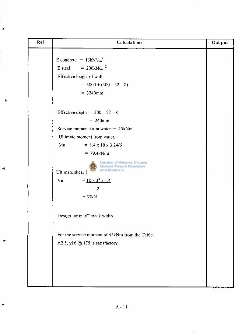
Ref Calcula t ions O u t put
E concrete = OkN/mm
E steel = 2 0 0 k N / m m
2
Effective height of wall
= 3 0 0 0 + ( 3 0 0 - 5 2 - 8 )
= 3240mm
Effective depth = 3 0 0 - 5 2 - 8
= 240mm
Sorvice moment from water = 45 kNm
Ultimate moment from water,
Mu = 1.4 x 10x3 .24 /6
= 79.4kN/m
Ultimate shear from water,
Vu = 1 0 x 3 2 x l . 4
2
= 63 kN
Design for m a x m crack width
For the service moment of 45kNm from the Table,
A2.5, y l 6 @ 175 is satisfactory.
A - 11
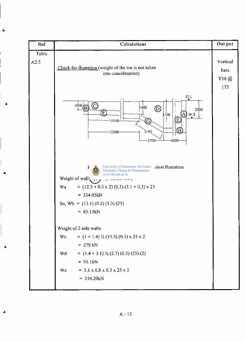
Ref Calculat ions Ou t pu t
Table
A2.5 Check for floatation (weight of the toe is not taken
into consideration)
Vertical
bars
Y 1 6 @
175
Fig A-8: Weight of the structure against floatation
Weight of wall (with no heel)
Wa = (12.5 + 0.3 x 2) (0.3) (3.1 + 0.3) x 25
= 334.05kN
S o , W b = (13.1) (0.2) (1.3) (25)
= 85.15kN
Weight of 2 side walls
Wc = (1 + 1.4) Y2 (15.5) (0.3) x 2 5 x 2
= 279 kN
Wd = (1.4 + 3.1) (2.7) (0.3) (25) (2)
= 91.1kN
We = 3.1 x 6 . 8 x 0 . 3 x 2 5 x 2
= 316.20kN
A - 12
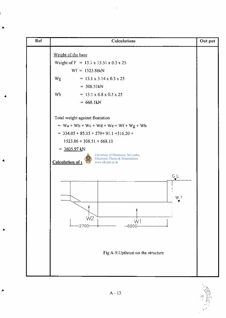
Ref Calculations O u t pu t
Weight of the base
Weight of F = 1 3 . 1 x 1 5 . 5 1 x 0 . 3 x 2 5
Wf = 1523.86kN
Wg = 13.1 x 3 . 1 4 x 0 . 3 x 2 5
= 308.51kN
Wh = 1 3 . 1 x 6 . 8 x 0 . 3 x 2 5
= 668.1kN
Total weight against floatation
= Wa + Wb + Wc + Wd + We + Wf + Wg + Wh
= 334.05 + 85.15 + 279+91.1 +316.20 +
1523.86 + 308.51 +668 .10
= 3605.97 kN
Calculation of upthrust
G . L
W1
W.T •
2 7 0 0 •6800-
Fig A-9:Upthrust on the structure
A - 13
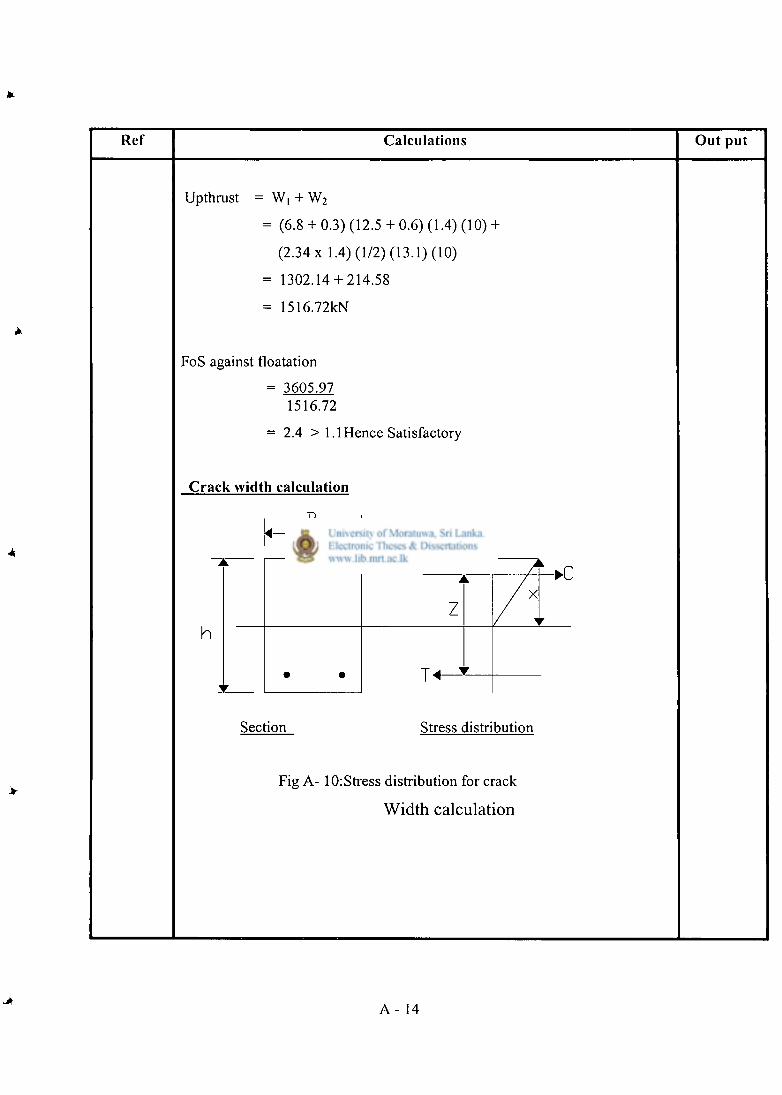
Ref Calculations Out put
Upthrust = W, + W 2
= (6.8 + 0.3) (12.5 + 0.6) (1.4) (10) +
(2.34 x 1.4) (1/2) (13.1) (10)
= 1302.14 + 214.58
= 1516.72kN
FoS against floatation
= 3605.97 1516.72
= 2.4 > 1.1 Hence Satisfactory
Crack width calculation
B
h
Z
-•C x
Section Stress distribution
Fig A- 10: Stress distribution for crack
Width calculation
A - 14
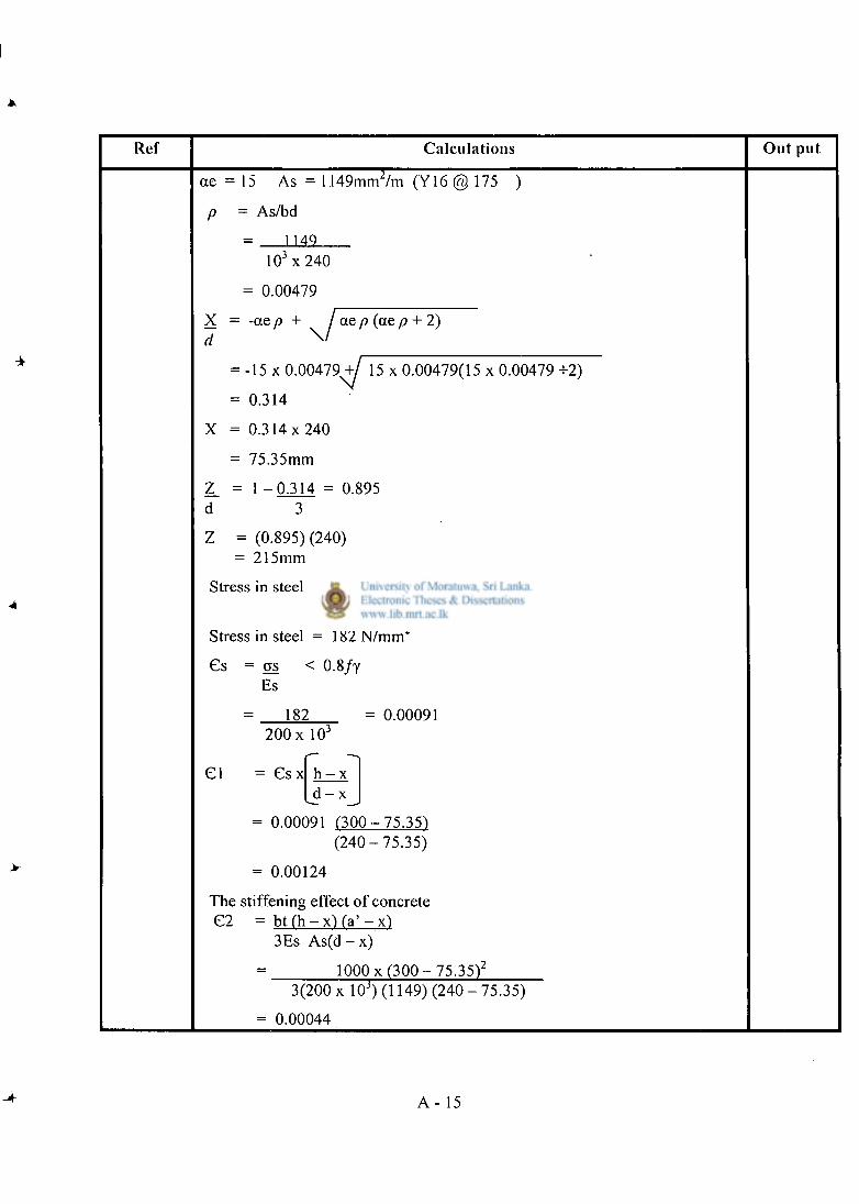
Ref Calculat ions Ou t put
ae = 15 As = 1149mm 2/m (Y16 @ 175 )
P '-= As/bd
1 14.0
1 0 3 x 240
= 0.00479
X = d
-ae/? + / ae \ /
p (ae p + 2)
- -15 x 0 . 0 0 4 7 9 ^ / 15 x 0.00479(15 x 0.00479 +2)
= 0.314
X = 0 . 3 1 4 x 2 4 0
- - 75.35mm
Z_ = 1 - 0 . 3 1 4 = 0.895 d 3
Z = = (0.895) (240) : 215mm
Stress in steel = M = 4 S v 1 n 6
A s x Z 1 1 4 9 x 2 1 5
Stress in steel = 182 N / m m 2
Cs = as < 0.8/y Es
182 = 0.00091 200 x 10 3
CI = C s x h - x ^ d - x _
= 0.00091 ( 3 0 0 - 7 5 . 3 5 ) ( 2 4 0 - 7 5 . 3 5 )
= 0.00124
The stiffening effect of concrete C2 = b t ( h - x ) (a' - x )
3Es A s ( d - x)
= 1000 x ( 3 0 0 - 7 5 . 3 5 ) 2
3(200 x 10 3) (1149) (240 - 75.35)
= 0.00044
-A A - 15
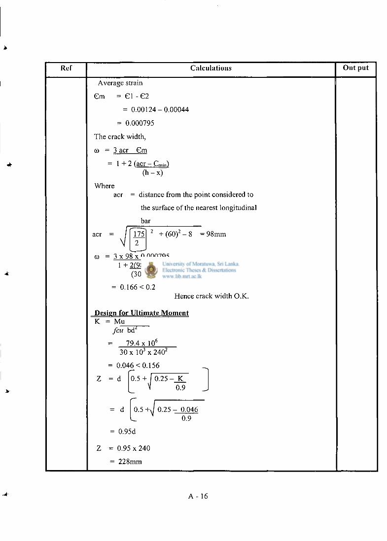
Ref Calculations Out put
Average strain
Cm = CI - C 2
= 0 . 0 0 1 2 4 - 0 . 0 0 0 4 4
= 0.000795
The crack width,
© = 3 acr Cm
= 1 + 2 (acr - Cmin) ( h - x )
Where
acr =
acr = distance from the point considered to
the surface of the nearest longitudinal
bar
98mm 175 2 + ( 6 0 ) 2 8
to = 3 x 98 x 0.000795 1 + 2(98 - 52)
( 3 0 0 - 7 5 . 3 5 )
= 0.166 < 0.2 Hence crack width O.K.
Design for Ultimate Moment K = Mu
fcuW
79.4 x 10 6
30 x 1 0 3 x 2 4 0 2
= 0.046 < 0.156
= d 0.5 + 0.25 - K 0.9
= d 0.5 0.25 - 0.046 0.9
= 0.95d
= 0.95 x 240
= 228mm
A - 16
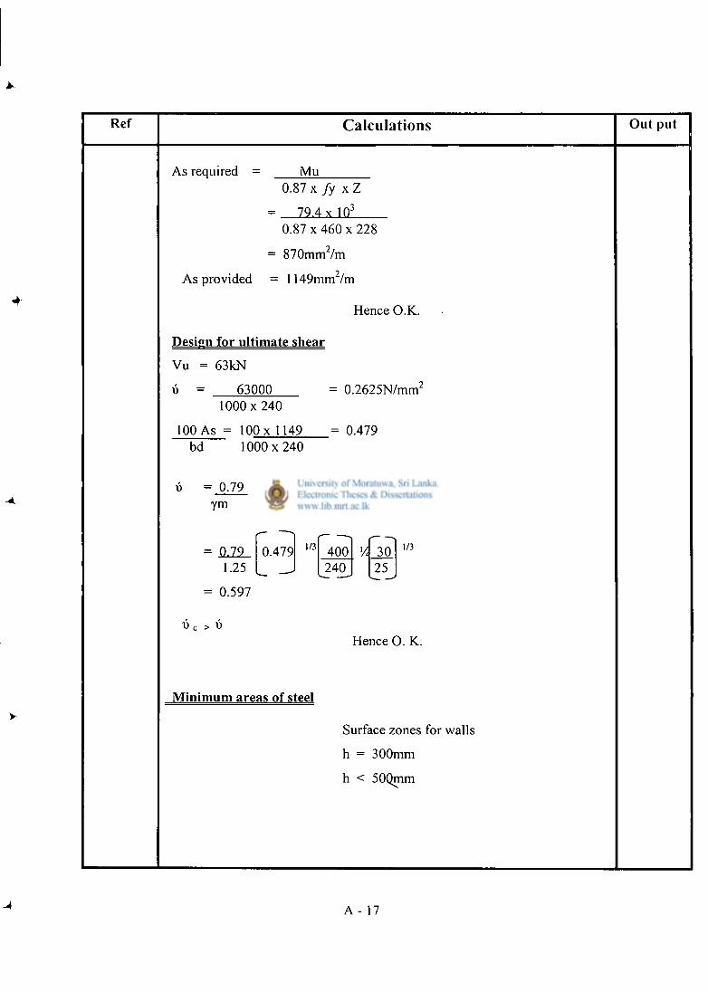
Ref Calculations Out put
As required = Mu 0.87 x fy x Z
= 79.4 x 10 3
0.87 x 460 x 228
= 870mm 2 /m
As provided = 1149mm/m
Hence O.K.
Design for ultimate shear
Vu = 63kN
t. = 63000 1 0 0 0 x 2 4 0
100 As = 100 x 1149
0.2625N/mm 2
0.479 bd 1 0 0 0 x 2 4 0
0.79 ym
100 As bd
1/3 40C
0.79 0.479 1/3 400 V. 30 1.25 ^240_ 25
25
1/3
1/3
= 0.597
W c > D
Hence O. K.
Minimum areas of steel
Surface zones for walls
h = 300mm
h < 50Qmm
A - 17
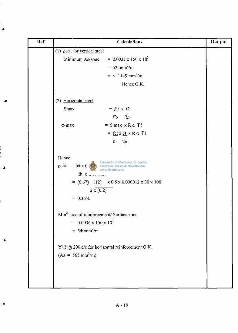
•4
Ref Calculat ions O u t p u t
(1) peril for vertical steel
Minimum As/zone = 0.0035 x 150 x 10 3
= 525mm /m
= < 1149mm 2 /m
Hence O.K.
(21 Horizontal steel
Smax = Jct_ x 0
Fb 2p
co max = S max x R a T1
= f c t x 0 _ x R a T l
fb 2p
Hence,
ocrit = fc tx 0 x R a Tl x 100
fb x 2 co max
= (0.67) (12) x 0.5 x 0.000012 x 30 x 100
2 x (0.2)
= 0.36%
M i n m area of reinforcement/ Surface zone
= 0.0036 x 150 x 10 3
= 540mm 2 /m
Y12 @ 200 c/c for horizontal reinforcement O.K.
(As = 565 mm 2 /m)
A - 18
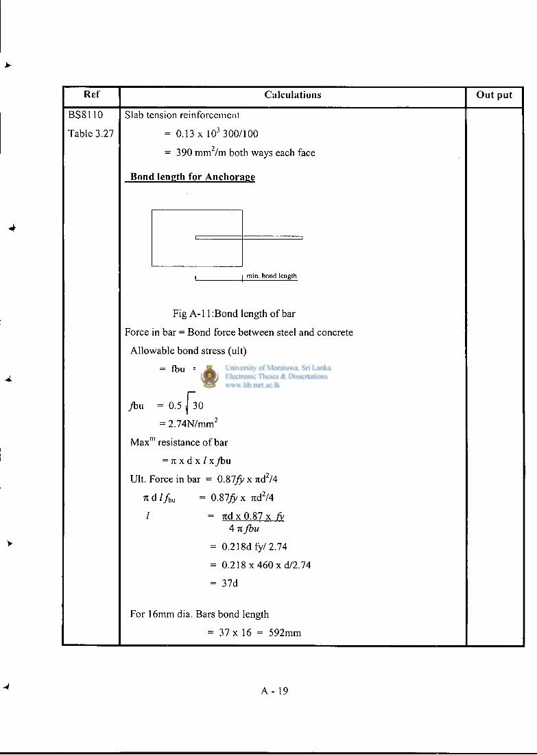
Ref Calculations Out put
BSS110 Slab tension reinforcement
Table 3.27 = 0.13 x 10 3 3 00/100 2 = 390 mm /m both ways each face
Bond length for Anchorage
min. bond length
Fig A-l 1 :Bond length of bar
Force in bar = Bond force between steel and concrete
Allowable bond stress (ult)
= fbu = B J feu
Jbu = 0.5 j 30
= 2.74N/mm 2
M a x m resistance of bar
= n x d x / xybu
Ult. Force in bar = 0.87/5/ * " d 2 / 4
n d / / b u = 0.87)5/ x 7 i d 2 / 4
/ = 7 t d x 0 . 8 7 x fy 4 7t fbu
= 0 .218dfy/2 .74
= 0.218 x 460 xd /2 .74
= 37d
For 16mm dia. Bars bond length
= 37 x 16 = 592mm
A - 19
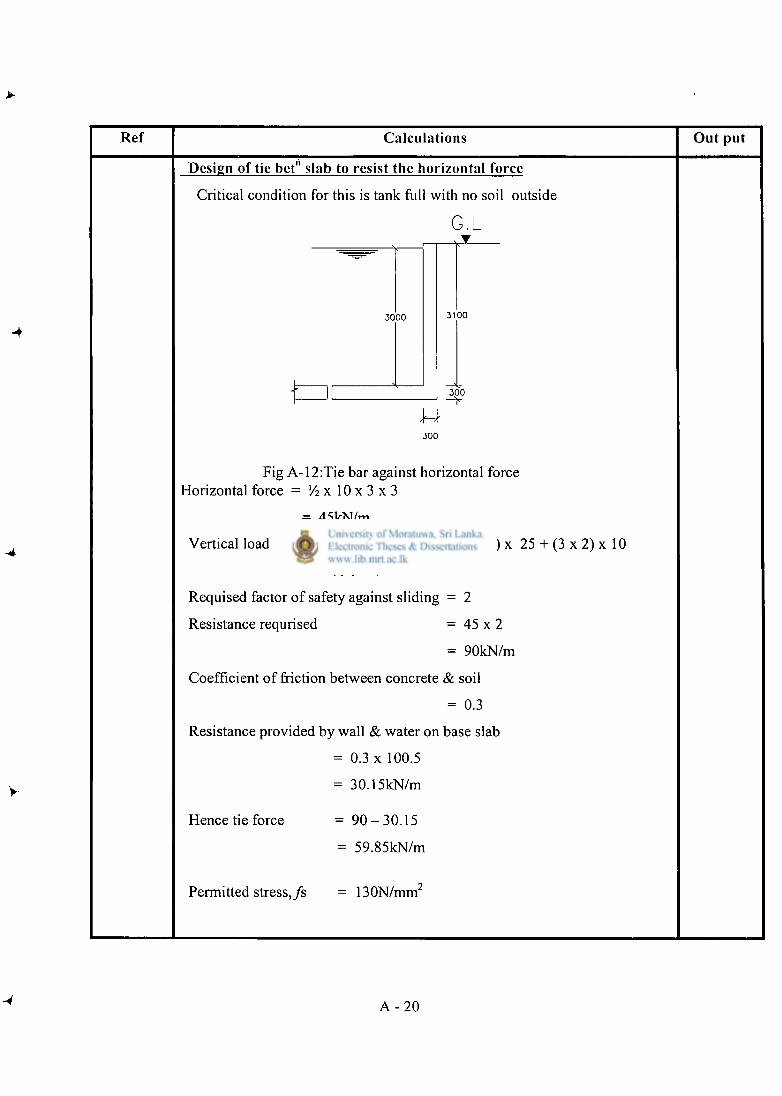
Ref Calculations Out put
Design of tie bet" slab to resist the horizontal force
Critical condition for this is tank full with no soil outside
G.L
3 0 0 0 3 1 0 0
3 0 0
3 0 0
Fig A-12:Tie bar against horizontal force Horizontal force = Vi x 10 x 3 x 3
= 45kN/m
Vertical load = (3.1 x 0.3) x 25 + (2.3 x 0.3) x 25 + (3 x 2) x 10
= 100.5kN/m
Requised factor of safety against sliding = 2
Resistance requrised = 45 x 2
= 90kN/m
Coefficient of friction between concrete & soil
= 0.3
Resistance provided by wall & water on base slab
= 0.3 x 100.5
= 30.15kN/m
Hence tie force = 9 0 - 3 0 . 1 5
= 59.85kN/m
Permitted stress, /s = 130N/mm
A - 2 0
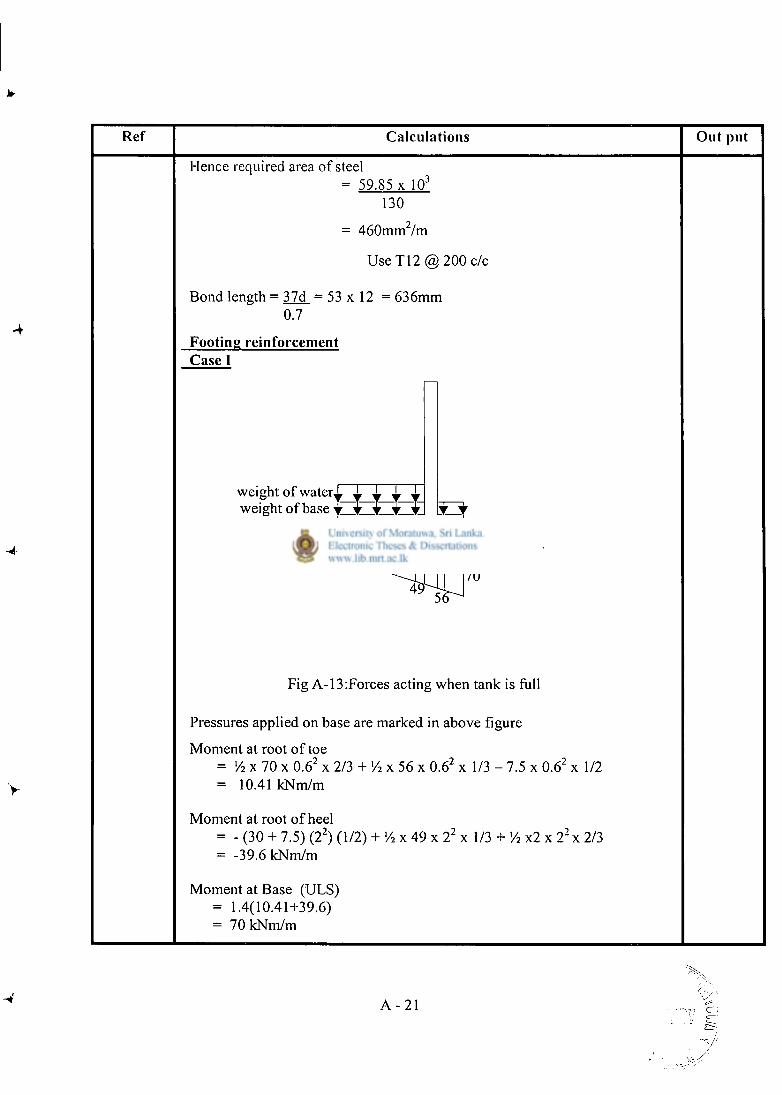
Ref Calculations Out pu t
Hence required area of steel = 59.85 x 10 3
130
= 460mm 2 /m
U s e T 1 2 @ 2 0 0 c/c
Bond length = 37d_ = 53 x 12 = 636mm 0.7
Footing reinforcement Case I
weight of water^ ^ weight of base
heel 2
toe
Fig A-13:Forces acting when tank is full
Pressures applied on base are marked in above figure
Moment at root of toe = Vi x 70 x 0.6 2 x 2/3 + Vi x 56 x 0.6 2 x 1/3 - 7.5 x 0.6 2 x 1/2 = 10.41 kNm/m
Moment at root of heel = - (30 + 7.5) (2 2 ) (1/2) + y2 x 49 x 2 2 x 1/3 + Vi x2 x 2 2 x 2/3 = -39.6 kNm/m
Moment at Base (ULS) = 1.4(10.41+39.6) = 70 kNm/m
A - 2 1
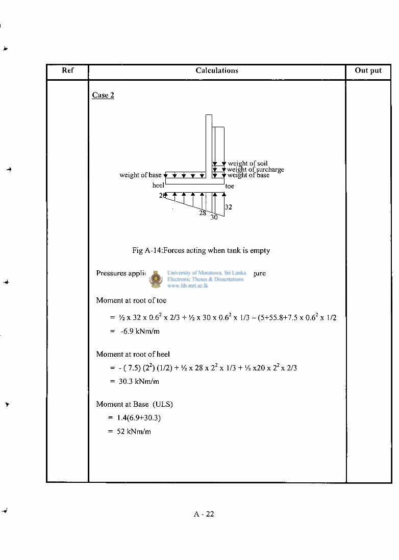
Ref Calculat ions O u t put
Case 2
weight of base v •
weight of soil weight of surcharge weight of base
Fig A-14:Forces acting when tank is empty
Pressures applied on base are marked in above figure
Moment at root of toe
= V2 x 32 x 0.6 2 x 2/3 + «/2 x 30 x 0.6 2 x 1/3 - (5+55.8+7.5 x 0.6 2 x 1/2
= -6.9 kNm/m
Moment at root of heel
= - ( 7.5) (2 2 ) (1/2) + l/ 2 x 28 x 2 2 x 1/3 + >/> x20 x 2 2 x 2/3
= 30.3 kNm/m
Moment at Base (ULS)
= 1.4(6.9+30.3)
= 52 kNm/m
A - 2 2
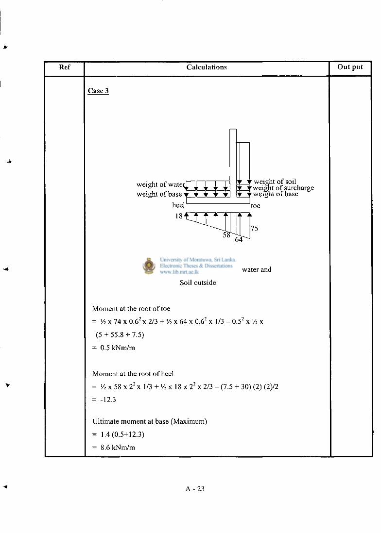
Ref Calculat ions O u t pu t
Case 3
weight of wate weight of base
heel 18
weight of soil weight of surcharge weight of base
Fig A-15:Forces acting due to water and
Soil outside
Moment at the root of toe
= y2 x 74 x 0.6 2 x 2/3 + V2 x 64 x 0.6 2 x 1/3 - 0 .5 2 x 7 2 x
(5 + 55.8 + 7.5)
= 0.5 kNm/m
Moment at the root of heel
= y2 x 58 x 2 2 x 1/3 + l/ 2 x 18 x 2 2 x 2/3 - (7.5 + 30) (2) (2)/2
= -12.3
Ultimate moment at base (Maximum)
= 1.4(0.5+12.3)
= 8.6 kNm/m
A - 2 3
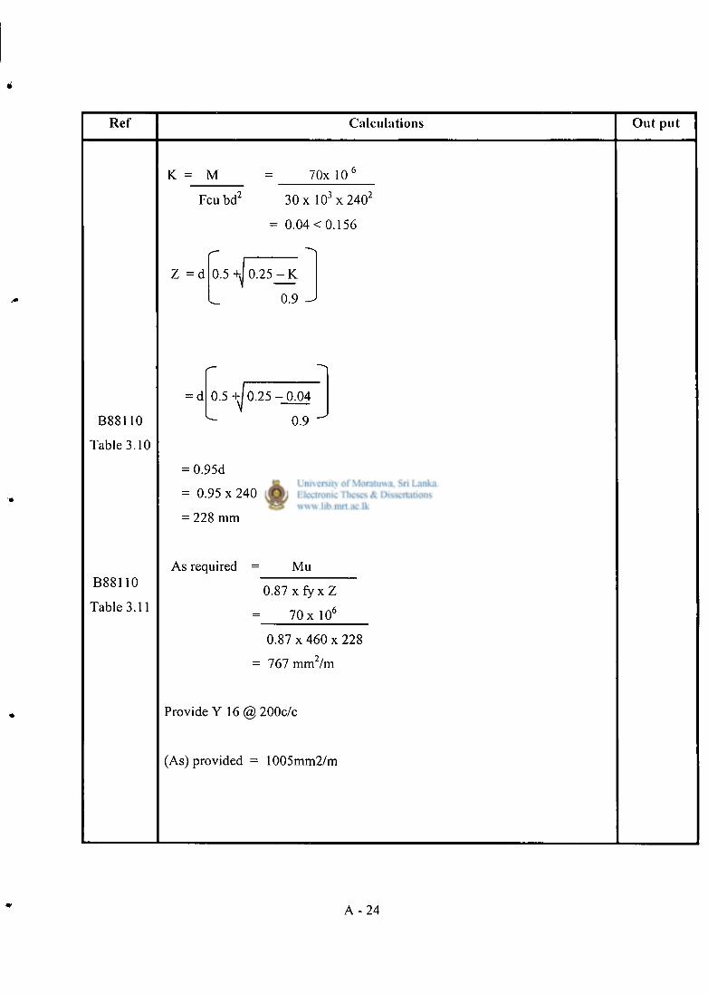
Ref Calculat ions O u t p u t
K = M 70x 10
Feu brT 30 x 1 0 3 x 2 4 0 2
= 0.04 < 0.156
Z = d 0.5 +J 0 . 2 5 - K
0.9
B88110
Table 3.10
B88110
Table 3.11
= d 0.5 +/ 0.25 - 0 . 0 4
0.9
= 0.95d
= 0.95 x 240
= 228 mm
As required = Mu
0 . 8 7 x f y x Z
70 x 10"
0 . 8 7 x 4 6 0 x 2 2 8
= 767 mm /m
Provide Y 16 @ 200c/c
(As) provided = 1005mm2/m
A - 2 4
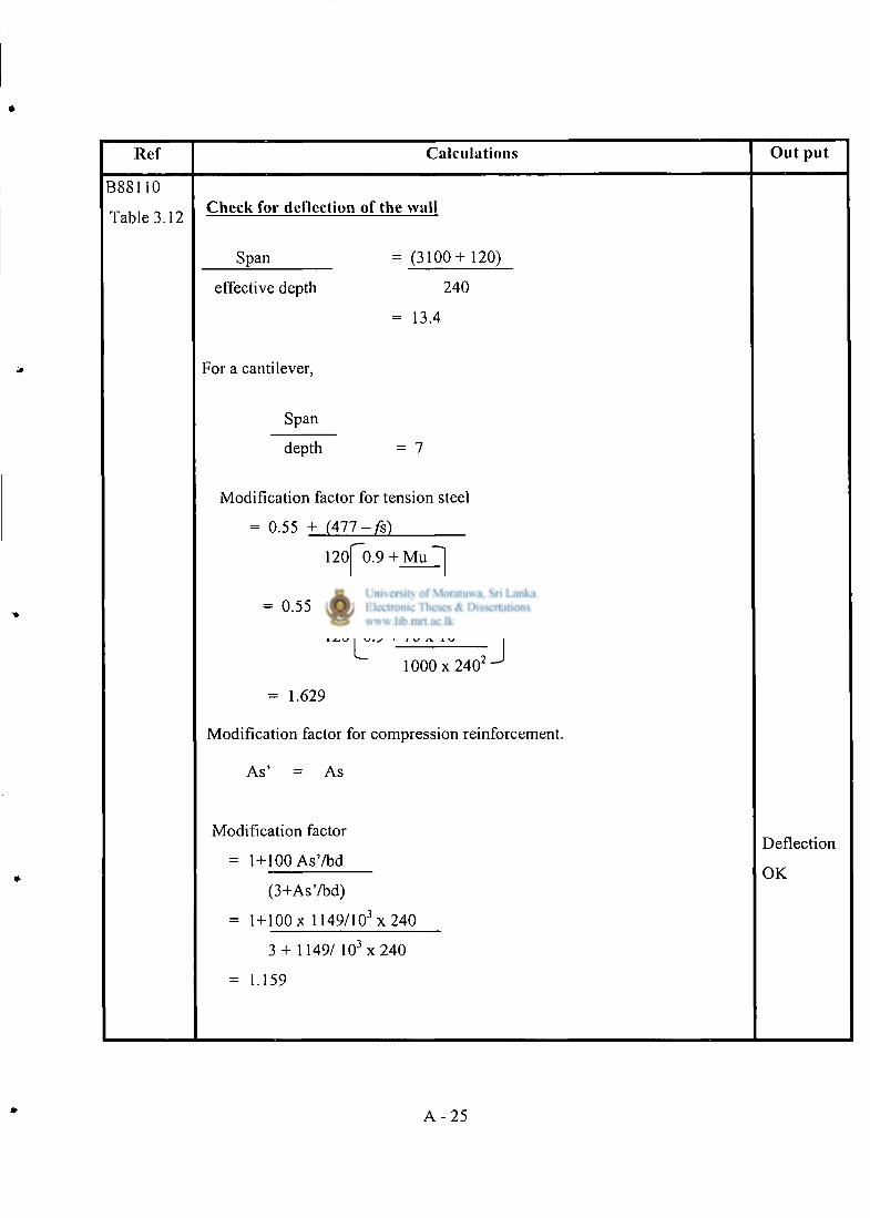
Ref Calculations Out put
B8S110
Table 3.12 Check for deflection of the wall
Span = ( 3 1 0 0 + 120)
effective depth
For a cantilever.
240
= 13.4
Span
depth = 7
Modification factor for tension steel
= 0.55 + ( 4 7 7 - / s )
120 0.9 + Mu
0.55 + ( 4 7 7 - 182)
120 0.9 + 7 0 x 10 b
1 0 0 0 x 2 4 0 '
= 1.629
Modification factor for compression reinforcement.
A s ' = As
Modification factor
= 1+100 As' /bd
(3+As'/bd)
= 1+100 x 1149/10 3 x 240
3 + 1149/ 10 3 x 240
= 1.159
Deflection
OK
A - 2 5
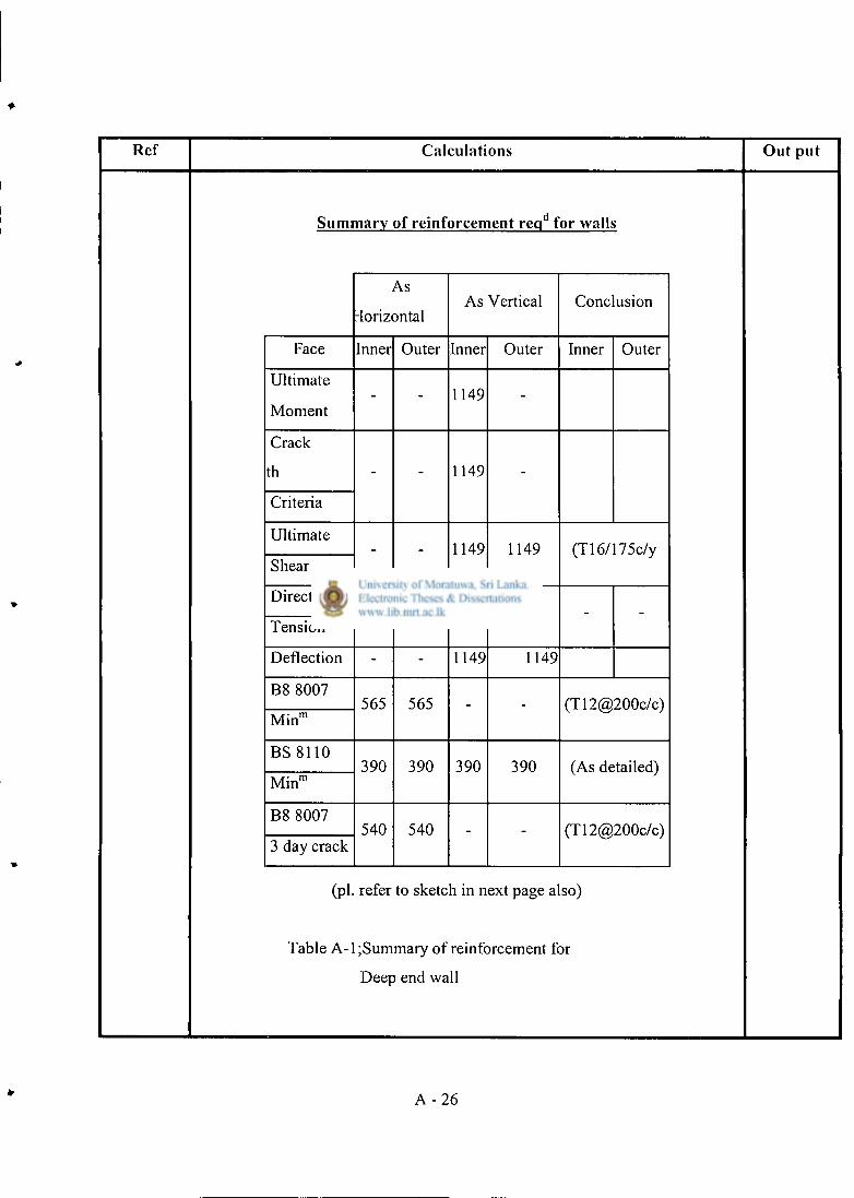
Ref Calculations Out put
Summary of reinforcement req d for walls
As
-forizontal As Vertical Conclusion
Face Inner Outer Inner Outer Inner Outer
Ultimate
Moment 1149
Crack
th 1149
Criteria
Ultimate 1149 1149
Shear (T16/175c/y
Direct
Tension
Deflection 1149 1149
B8 8007 565 565
Min" (T12@200c/c)
BS 8110 390 390 390 390
Min" (As detailed)
B8 8007 540 540
3 day crack (T12@200c/c)
(pi. refer to sketch in next page also)
Table A-l ;Summary of reinforcement for
Deep end wall
A - 2 6
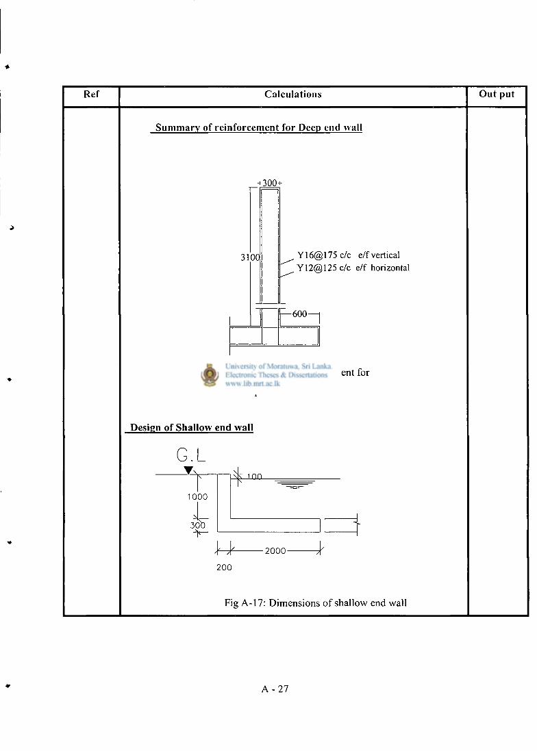
Ref Calculations Out put
Summary of reinforcement for Deep end wall
+ 30(K
3100 Y16@175c / c e/f vertical Y12@125 c/c e/f horizontal
— 6 0 0 —
Fig A-16:Summary of reinforcement for
Deep end wall
Design of Shallow end wall
G.L
1000
30C
100
\ 4 - - 2 0 0 0 -
200
Fig A-17: Dimensions of shallow end wall
A - 2 7
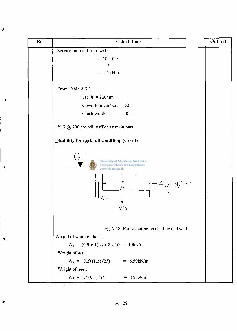
Ref Calculations Out put
Service moment from water
= 1 0 x 0 . 9 3
6
= 1.2kNm
From Table A 2 .1 ,
Use h - 200mm
Cover to main bars = 52
Crack width = 0.2
Y12 @ 200 c/c will suffice as main bars.
Stability for tank full condition (Case I)
G . L
W1 P = 4 5 K N / m 2
W2-
W3
Fig A-18: Forces acting on shallow end wall
Weight of water on heel,
W, = (0.9 + 1) Y2 x 2 x 10 = 19kN/m
Weight of wall,
W 2 = (0.2) (1.3) (25) = 6.50kN/m
Weight of heel,
W 3 = (2) (0.3) (25) = 15kN/m
A - 2 8
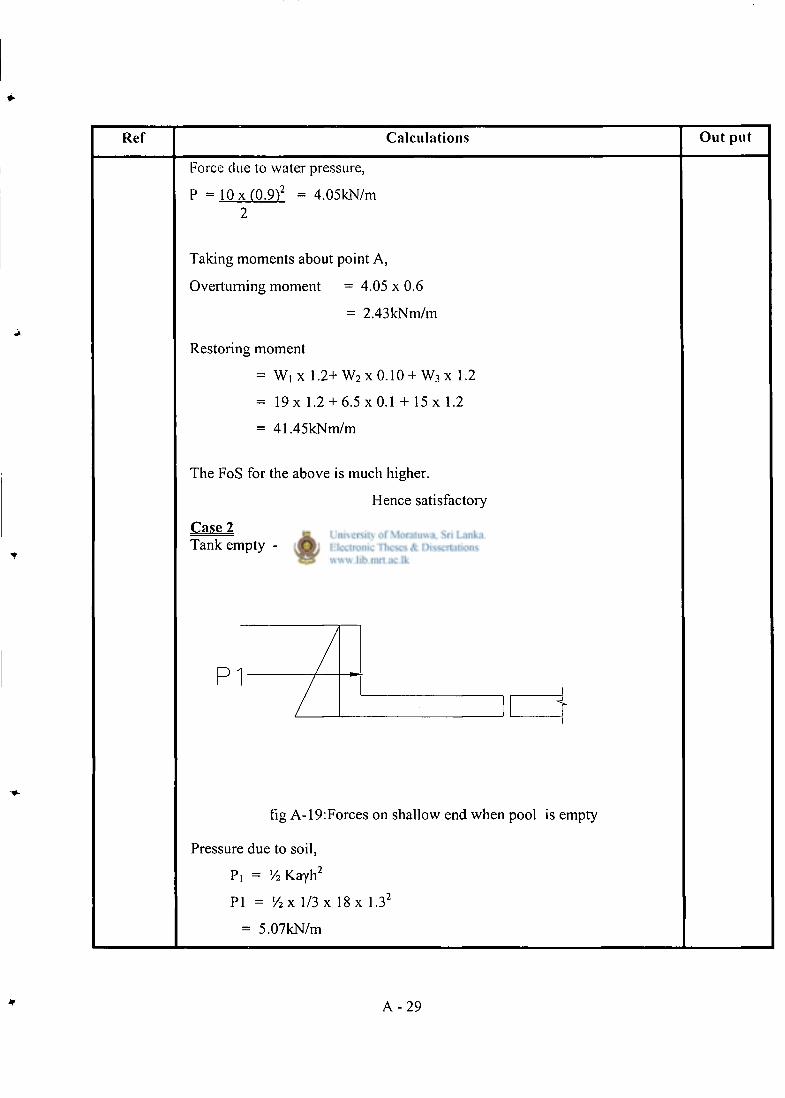
Ref Calculat ions O u t pu t
Force due to water pressure,
P = 10 x (0.9V2 = 4.05kN/m 2
Taking moments about point A,
Overturning moment = 4.05 x 0.6
= 2.43 kNm/m
Restoring moment
= Wi x 1 . 2 + W 2 x 0.10 + W 3 x 1.2
= 1 9 x 1.2 + 6 . 5 x 0 . 1 + 1 5 x 1.2
- 41.45kNm/m
The FoS for the above is much higher.
Hence satisfactory
Case 2 Tank empty - Soil & surcharge
fig A-19:Forces on shallow end when pool is empty
Pressure due to soil,
P, = 7 2 K a y h 2
PI = V2x 1/3 x 18 x 1.32
= 5.07kN/m
A - 2 9
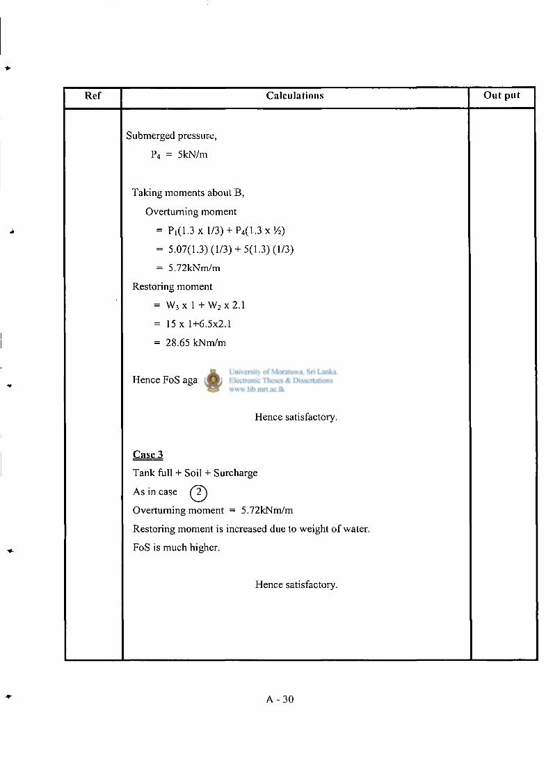
Ref Calculat ions O u t p u t
Submerged pressure,
P 4 = 5kN/m
Taking moments about B,
Overturning moment
= P , (1 .3x l/3) + P 4 ( 1 . 3 x ' / 2 )
= 5.07(1.3) (1 /3 )+ 5(1.3) (1/3)
= 5.72kNm/m
Restoring moment
= W 3 x 1 + W 2 x 2 . 1
= 15 x 1+6.5x2.1
= 28.65 kNm/m
Hence FoS against overturning is much higher.
Hence satisfactory.
Case 3
Tank full + Soil + Surcharge
As in case (2^
Overturning moment = 5.72kNm/m
Restoring moment is increased due to weight of water.
FoS is much higher.
Hence satisfactory.
A - 3 0
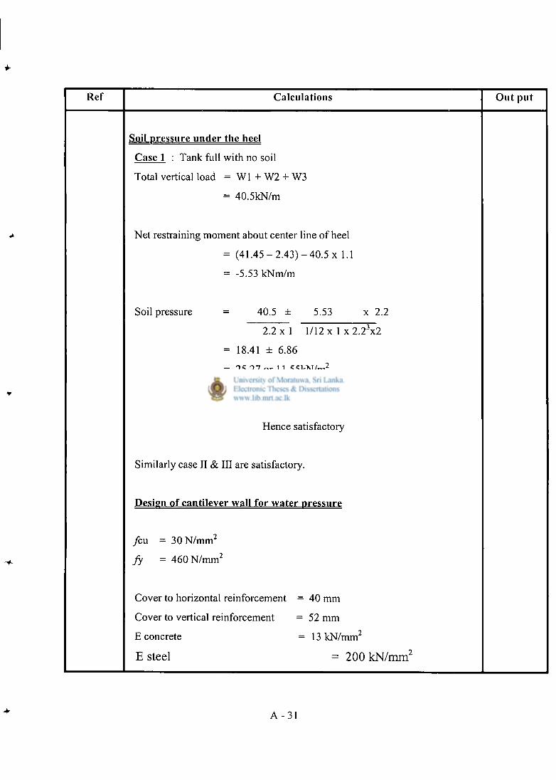
Ref Calculations Out put
Soil Dressure under the heel
Case 1 : Tank full with no soil
Total vertical load = WI + W2 + W3
= 40.5kN/m
Net restraining moment about center line of heel
= ( 4 1 . 4 5 - 2 . 4 3 ) - 4 0 . 5 x 1.1
= -5.53 kNm/m
Soil pressure = 40.5 ± 5.53 x 2.2
2.2 x 1 1/12 x 1 x 2.2 3 x2
= 18.41 ± 6.86
= 25.27 or 11.55kN/m 2
< 150 kN/m 2
Hence satisfactory
Similarly case II & III are satisfactory.
Design of cantilever wall for water pressure
feu = 30 N / m m 2
fy = 460 N / m m 2
Cover to horizontal reinforcement = 40 mm
Cover to vertical reinforcement = 52 mm
E concrete = 13 kN/mm 2
E steel = 200 kN/mm2
A - 3 1
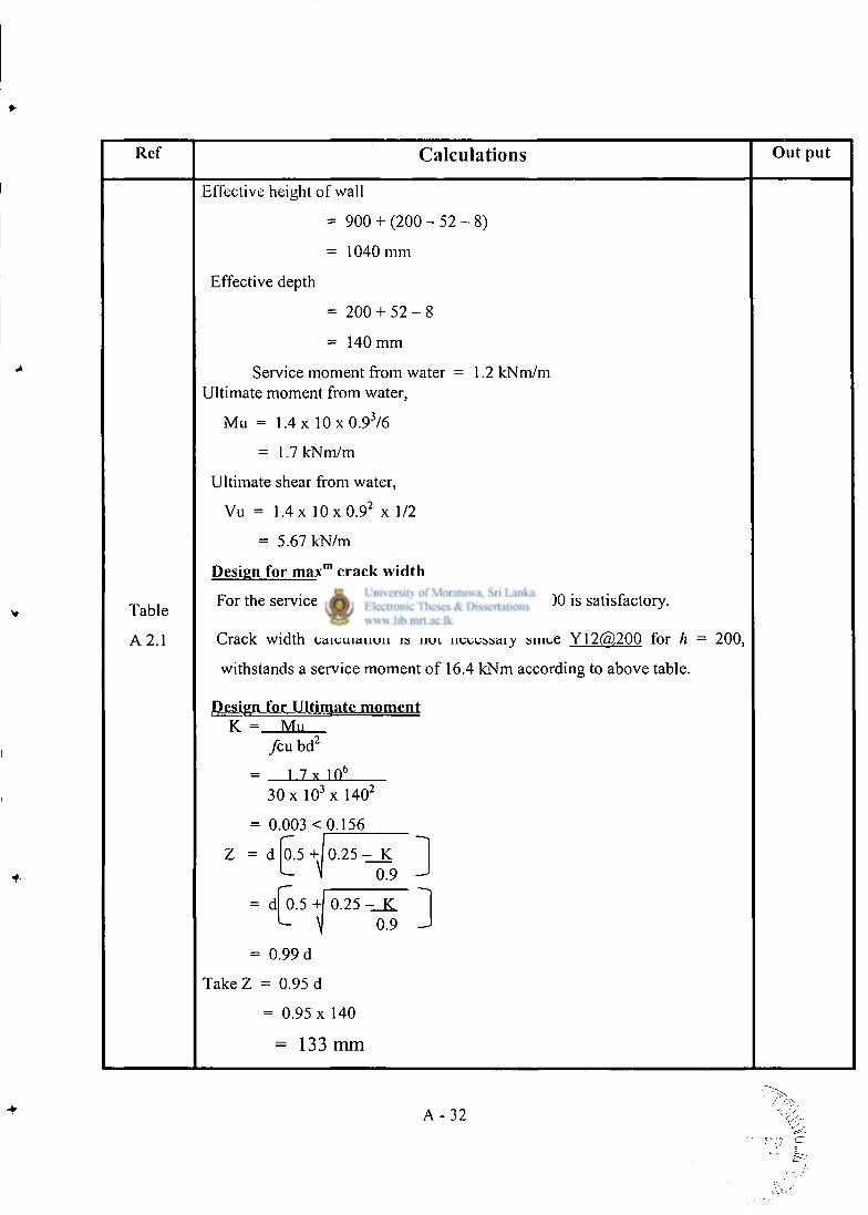
Ref Calculations Out put
Effective height of wall
= 9 0 0 + (200-- 5 2 - 8 )
= 1040 mm
Effective depth
= 200 + 5 2 - 8
= 140 mm
Service moment from water = 1.2 kNm/m Ultimate moment from water,
Mu = 1.4 x 1 0 x 0 . 9 3 / 6
= 1.7 kNm/m
Ultimate shear from water,
Vu = 1 . 4x 1 0 x 0 . 9 2 x 1/2
= 5.67 kN/m
Design for max"1 crack width
Table For the service moment of 1.2 kNm/m Y12 @ 200 is satisfactory.
A 2 . 1 Crack width calculation is not necessary since Yl 2(5)200 for h = 200,
withstands a service moment of 16.4 kNm according to above table.
Design for Ultimate moment K = Mu
fcxx bd 2
1 7 x 10 6
30 x 1 0 3 x 140 2
= 0.003 < 0.156
Z = d 0.5 + 0 . 2 5 - K ^ " 0.9 - 1
= d 0.5 +| 0.25 -_JL - i 0.9 -
= 0.99 d
Take Z = 0.95 d
= 0.95 x 140
= 133 mm
A - 3 2
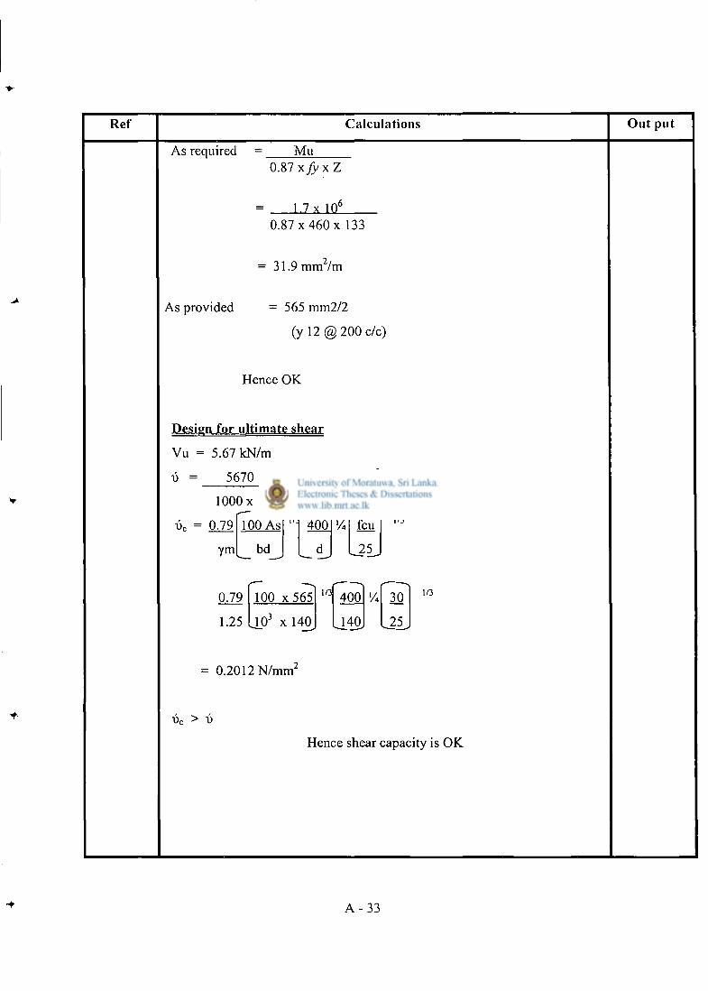
Ref Calculations Out put
As required Mu 0.87 xJyxZ
1.7 x 10" 0.87 x 460 x 133
= 3 1 . 9 m m 7 m
As provided = 565 mm2/2
(y 12 @ 200 c/c)
Hence OK
Design for ultimate shear
Vu = 5.67 kN/m
D 5670 = 0.0405N/mm i
lOOOx 140
0.79 100 A7 ym bd
i/: 400 feu
25
1/3
0.79
1.25
100 x 5 6 5
10 J x 1 4 0
1/3 400
140
30
25
1/3
= 0.2012 N / m m 2
x>c > v
Hence shear capacity is OK
A - 3 3
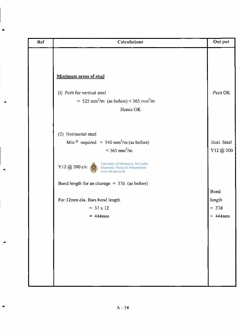
Ref Calcula t ions Out put
M i n i m u m areas of steel
(i) Pcrit for vertical steel 2 2
- 525 mm /m (as before) < 565 mm /m
Hence OK
Pcrit OK
(2) Horizontal steel
Min m required = 540 m m 2 / m (as before)
< 565 mm 2 /m
Hori. Steel
Y 1 2 @ 2 0 0
Y12 @ 200 c/c for horizontal reinforcement OK
Bond length for an chorage = 37d (as before)
For 12mm dia. Bars bond length
= 37 x 12
= 444mm
Bond
length
= 37d
= 444mm
A - 3 4
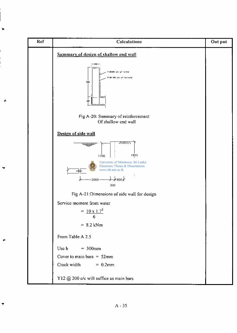
Ref Calculations Out put
Summary of design of shallow end wall
. Y12O200 c / c e / ( verticol
. Y120 200 c / c e / f horizontal
Fig A-20: Summary of reinforcement Of shallow end wall
Design of side wall
1 7 0 0
\- 2000 J ^ 6 0 0 7 | ' '
3 0 0
Fig A-21:Dimensions of side wall for design
Service moment from water
= l O x 1.73
= 8.2 kNm
From Table A 2.5
U s e h = 300mm
Cover to main bars = 52mm
Crack width = 0.2mm
Y12 @ 200 c/c will suffice as main bars
A - 3 5
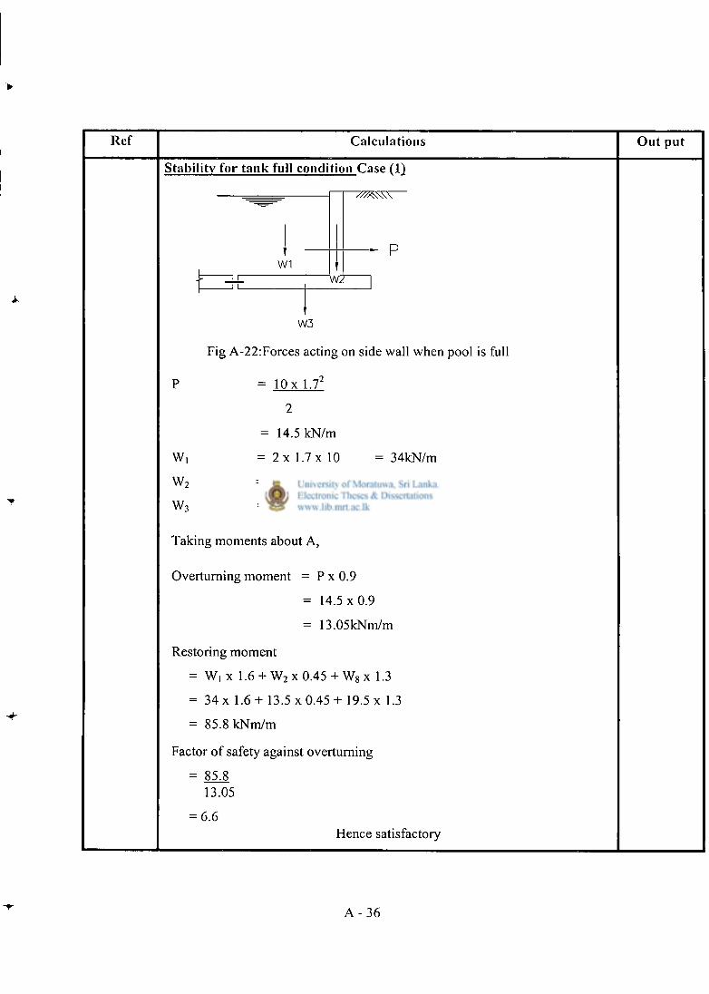
Ref Calculations Out put
Stability for tank full condition Case (1)
W1 WZ
W3
Fig A-22:Forces acting on side wall when pool is full
= l O x l.T
W,
W 2
W 3
= 14.5 kN/m
= 2 x 1.7 x 10
= 0.3 x 1 .8x25
= 2 . 6 x 0 . 3 x 25
= 34kN/m
= 13.5kN/m
- 19.5kN/m
Taking moments about A,
Overturning moment = P x 0.9
= 1 4 . 5 x 0 . 9
= 13.05kNm/m
Restoring moment
= W, x 1.6 + W 2 x 0.45 + W 8 x 1.3
= 34 x 1.6+ 13.5 x 0.45 + 19.5 x 1.3
= 85.8 kNm/m
Factor of safety against overturning
= 85J* 13.05
= 6.6 Hence satisfactory
A - 3 6
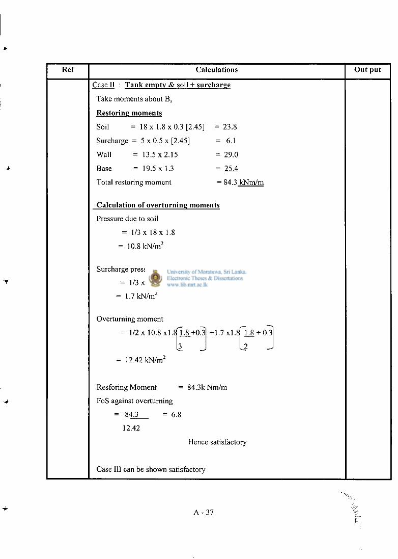
Ref Calculations Out put
Case II : Tank empty & soil + surcharge
Take moments about B,
Restoring moments
Soil = 18 x 1 .8x0.3 [2.45] = 23.8
Surcharge = 5 x 0.5 x [2.45] = 6.1
Wall = 13.5 x 2.15 = 29.0
Base = 19.5 x 1.3 = 25.4
Total restoring moment = 84.3 kNm/m
Calculation of overturning moments
Pressure due to soil
= 1/3 x 18 x 1.8
= 10.8 kN/m 2
Surcharge pressure
= 1 / 3 x 5
= 1.7 kN/m 2
Overturning moment
= 1/2 x 10.8x1.8|L8_+03] +1.7 x l .SFJJJ + OJL
[3 J L? J = 12.42 kN/m 2
Resforing Moment = 84.3k Nm/m
FoS against overturning
= 84.3 = 6.8
12.42
Hence satisfactory
Case III can be shown satisfactory
A - 3 7
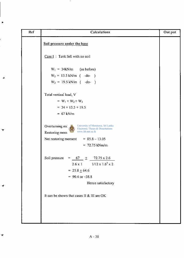
Ref Calculat ions O u t pu t
Soil p ressure unde r the base
Case I : Tank full with no soil
Wi = 34kN/m (as before)
W 2 = 13.5 kN/m ( -do- )
W 3 = 19.5 kN/m ( -do- )
Total vertical load, V
= w, + w2+w3
= 3 4 + 1 3 . 5 + 19.5
= 67 kN/m
Overturning moment = 13.05kNm/m
Restoring moment = 85.8kNm/m
Net restoring moment = 8 5 . 8 - 1 3 . 0 5
= 72.75 kNm/m
Soil pressure 67 + 72.75 x 2.6
2 . 6 x 1 1 / I 2 x l . 6 3 x 2
= 25.8 ± 6 4 . 6
= 90.4 o r - 3 8 . 8
Hence satisfactory
It can be shown that cases II & III are OK
A - 3 8
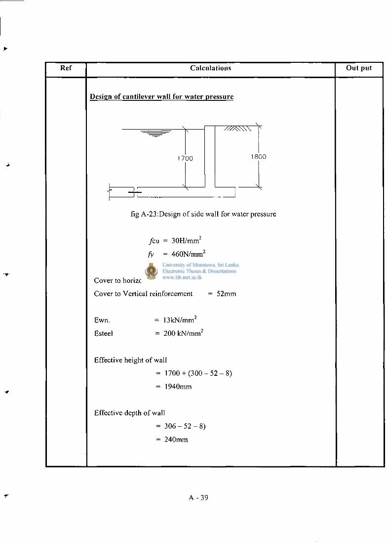
Ref Calculations Out put
Design of cantilever wall for water pressure
fig A-23:Design of side wall for water pressure
/ cu = 30H/mm 2
fy = 460N/mm 2
Cover to horizontal reinforcement = 40mm
Cover to Vertical reinforcement = 52mm
Ewn.
Esteel
- 13 kN/m ni
= 2 0 0 k N / m m 2
Effective height of wall
1700+ ( 3 0 0 - 5 2 - 8 )
1940mm
Effective depth of wall
= 3 0 6 - 5 2 - 8 )
= 240mm
A - 3 9
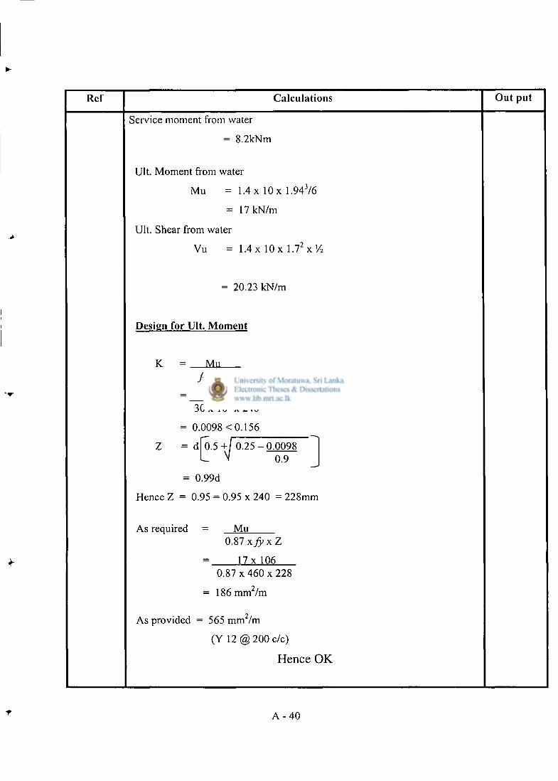
Ref Calculat ions Ou t pu t
Service moment from water
= 8.2kNm
Ult. Moment from water
Mu = 1.4 x 10 x 1.943/6
= 17 kN/m
Ult. Shear from water
Vu = 1.4 x 10 x 1 . 7 2 x ' / 2
= 20.23 kN/m
Design for Ult. M o m e n t
K = MM
feu bd 2
= 17 x 10 6
30 x 10 3 x 2 4 0 2
= 0.0098 < 0.156
Z = d 0.5 + / 0 . 2 5 - 0 . 0 0 9 8
I V 0.9 J = 0.99d
Hence Z = 0.95 = 0.95 x 240 = 228mm
As required Mu 0.87 xJyxZ
1 7 x 1 0 6 0.87 x 460 x 228
= 186 mm 2 /m
As provided = : 565 m m 2 / m
(Y 12 @ 200 c/c)
Hence OK
A - 4 0
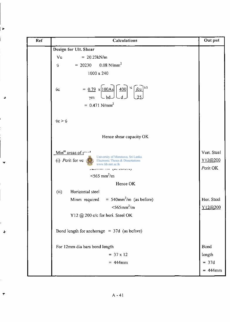
Ref Calculations Out put
Design for Ult. Shear
Vu = 20.23kN/m
x> = 20230 0.08 N / m m 2
1 0 0 0 x 2 4 0
DC = 0.79 x
ym
lOOAs 400 v. feu 1/3
- b c U
= 0.471 N / m m '
l i e > v
Hence shear capacity OK
Min" 1 areas of steel
(i) Pcrit for vertical steel
= 525mm 2 /m (as before)
<565 mm /m
Hence OK
(ii) Horizontal steel
Minm required = 540mm /m (as before)
<565mm /m
Y12 @ 200 c/c for hori. Steel O K
Bond length for anchorage = 37d (as before)
For 12mm dia bars bond length
= 37 x 12
= 444mm
Vert. Steel
Y12@200
Pcrit OK
Hor. Steel
Y12(5),200
Bond
length
= 37d
= 444mm
A - 4 1
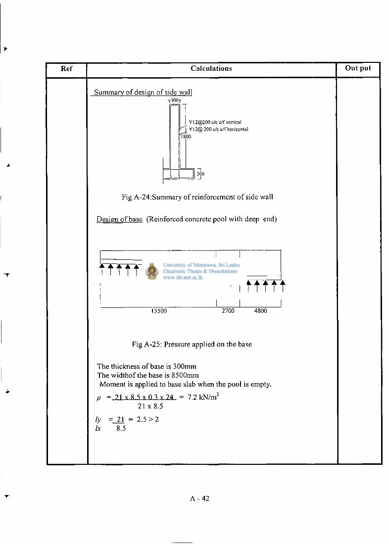
Ref Calculations Out put
Summary of design of side wall •f300f
Y12@200 c/c e/f vertical Y12@ 200 c/c e/f horizontal
1800
300
Fig A-24: Summary of reinforcement of side wall
Design of base (Reinforced concrete pool with deep end)
11111 ITtTfTrTtf^ 1 I n • • • •
13500 2700 4800
Fig A-25: Pressure applied on the base
The thickness of base is 300mm The widthof the base is 8500mm Moment is applied to base slab when the pool is empty.
p = 21 x 8 5 x 0 3 x 7 4 = 7.2 kN/m 2
21 x 8.5
ly = 21 = 2.5 > 2 Ix 8.5
A - 4 2
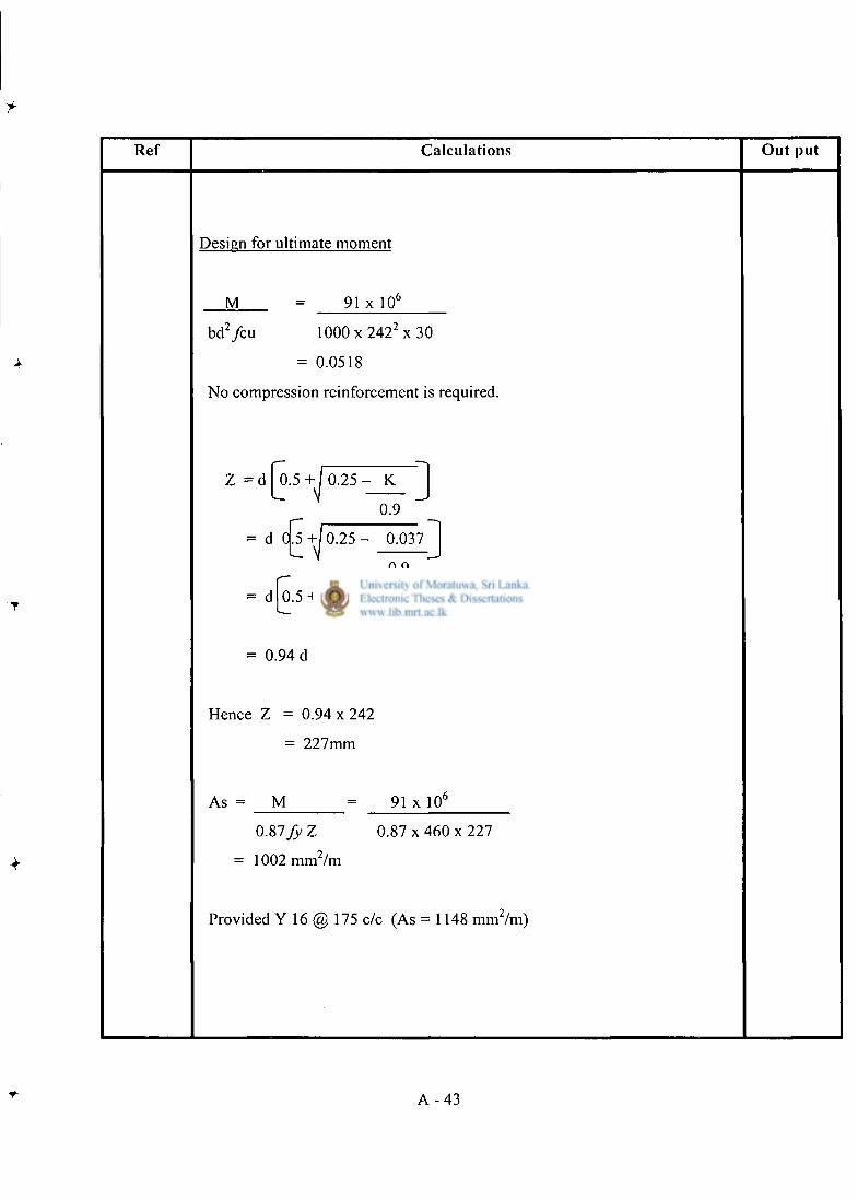
Ref Calculat ions O u t put
Design for ultimate moment
M
b d 2 / c u
91 x 10 b
1000 x 2 4 2 ' x 30
= 0.0518
No compression reinforcement is required.
Z = d 0 . 5 + 0 . 2 5 - K
0.9
= d C .5 + 0 . 2 5 - 0.037
0.9
= d 0.5 + 0.44
= 0.94 d
Hence Z = 0 . 9 4 x 2 4 2
= 227mm
As = M 91 x 10 6
O.ZlfyZ 0 . 8 7 x 4 6 0 x 2 2 7
= 1002 mm 2 /m
Provided Y 16 @ 175 c/c (As = 1148 mm 2 /m)
A - 4 3
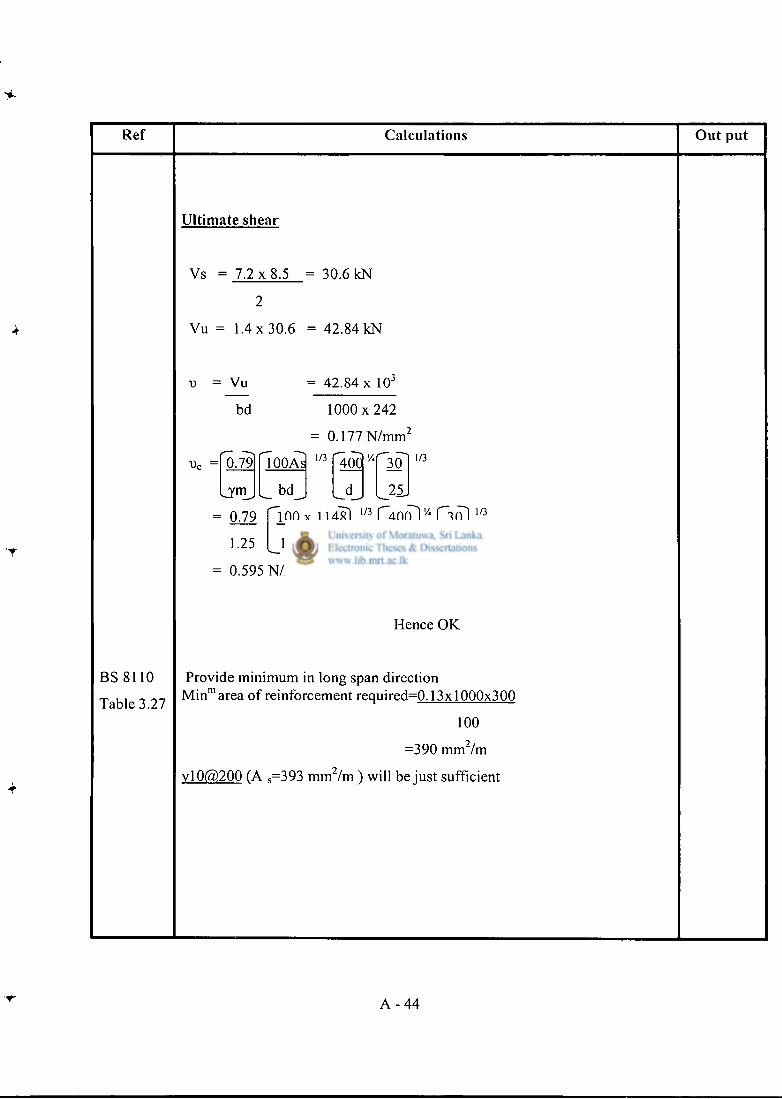
Ref Calculations Out put
BS 8110
Table 3.27
Ultimate shear
Vs = 7 . 2 x 8 . 5 30.6 kN
Vu = 1 .4x30.6 = 42.84 kN
v = Vu
bd
0.79
= 42.84 x 10 3
1 0 0 0 x 2 4 2
= 0.177 N / m m 2
Urn
lOOAs
bd
1/3 400 30
25.
1/3
0.79 " lOOx 114? 1/3 "~400~~ "30
1.25 _1000x24_2 _242^ _25_
1/3
= 0.595 N / m m 2 > 0.177
Hence OK
Provide minimum in long span direction M i n m area of reinforcement required=0.13x1000x300
100
=390 m m 2 / m
v l0@200 (A s =393 m m 2 / m ) will be just sufficient
A - 4 4
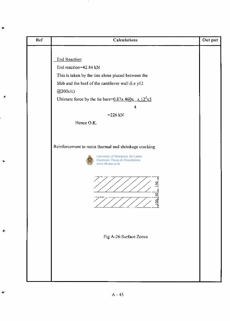
Ref Calculat ions O u t p u t
End Reaction
End reaction=42.84 kN
This is taken by the ties alone placed between the
Slab and the heel of the cantilever wall (i.e y l 2
@200c/c)
Ultimate force by the tie bars=0.87x 460x x 12 2x5
4
=226 kN
Hence O.K.
Reinforcement to resist thermal and shrinkage cracking
Fig A-26:Surface Zones
A - 45
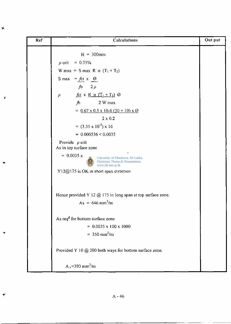
Ref Calculat ions Ou t put
H = 300mm
p c r i t = 0.35%
W max = S max R a (T, + T 2 )
S max =_fa x _ 0 _
fb 2 p
p ^ t x R a ( T , + T Z ) 0
Jb 2 W max
= 0 . 6 7 x 0 . 5 x 10⁻⁶ ( 3 0 + 1 O U 0
2 x 0 . 2
= (3.35 x 10" 5)x 16
= 0.000536 < 0.0035
Provide p crit As in top surface zone
= 0.0035 x 300 x 1000 = 525 m m 2 / m
2
Y12@175 is OK in short span direction
Hence provided Y 12 @ 175 in long span at top surface zone.
As = 646 mm Im
As req- for bottom surface zone
= 0.0035 x 100 x 1000
- 350 mm Im
Provided Y 10 @ 200 both ways for bottom surface zone.
A s =393 mm 2 /m
A - 4 6

4
Appendix B
Design calculations for proposed alternative with a deep end
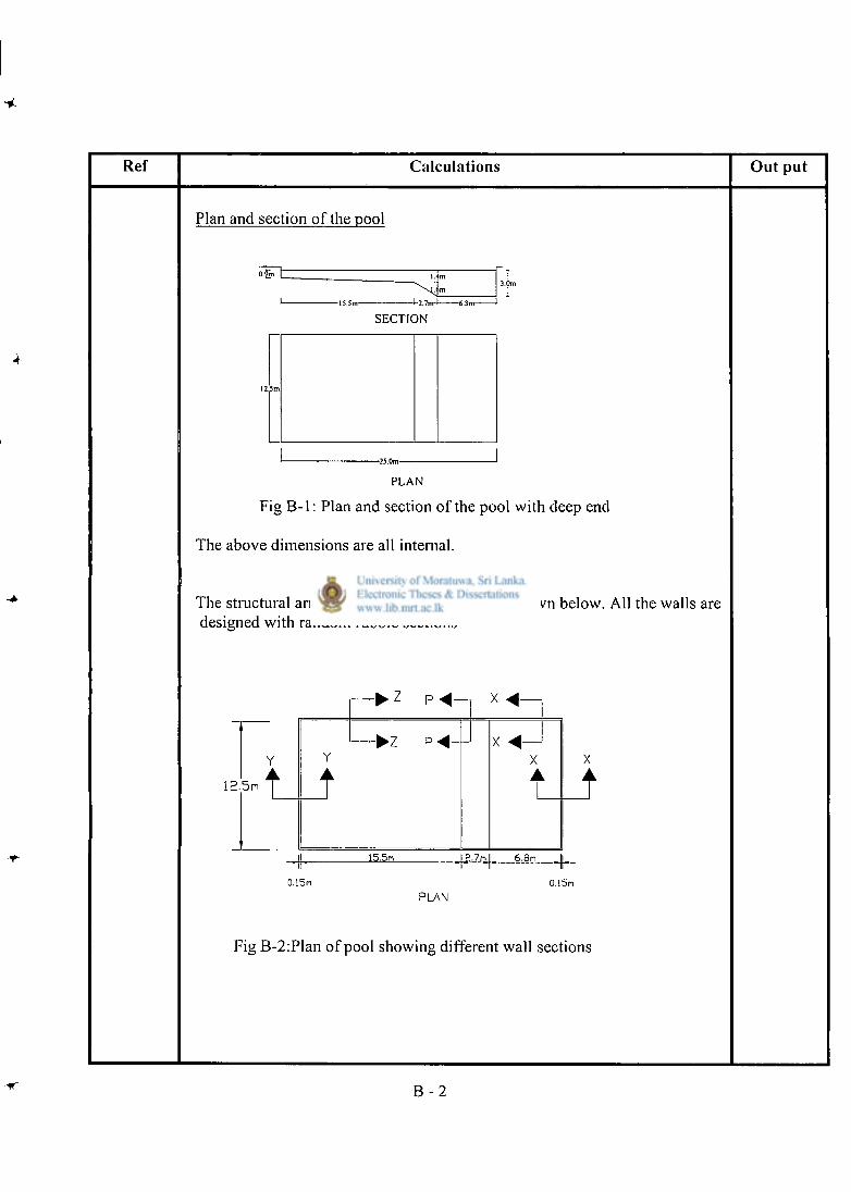
Ref Calculat ions O u t pu t
Plan and section of the pool
O.gn
-l-2.7m-l 6.8m-
!.Jm
S E C T I O N
P L A N
Fig B - l : Plan and section of the pool with deep end
The above dimensions are all internal.
The structural arrangement of the walls are as shown below. All the walls are designed with random rubble sections
12.5m
Y
•
-•z p <«—1
Y
•
15.5n
t g.7rjl 6.8n
X •
0.15n 0.15n PLAN
Fig B-2:Plan of pool showing different wall sections
B - 2
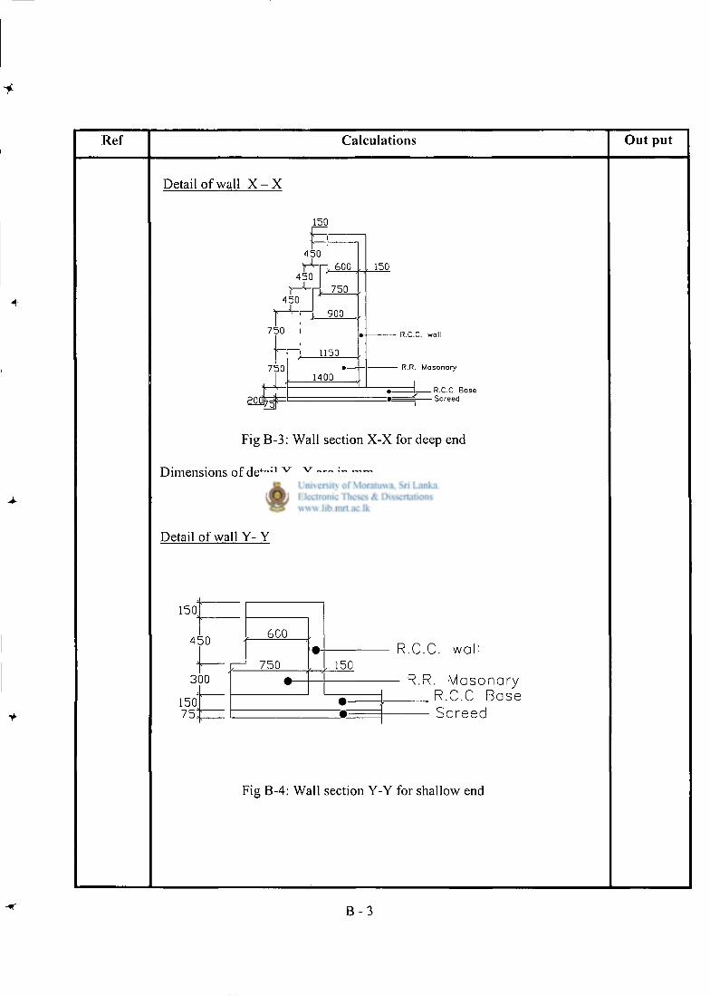
Ref Calculat ions O u t p u t
Detail of wall X - X
150
450 r ^ H - 6oo
450
450 - 4
750
750
T ^ r j 750
> 9 0 0
1150
1400
150
R.C.C. wall
R.R. Masonory
zL R.C.C Base Screed
Fig B-3: Wall section X-X for deep end
Dimensions of detail X - X are in mm.
Detail of wall Y- Y
1 5 0
4 5 0
3 0 0
1 5 0
7 5
6 0 0
7 5 0 1 5 0
R.C.C. wall
- R.R. Masonary R.C.C Base Screed
Fig B-4: Wall section Y-Y for shallow end
B - 3
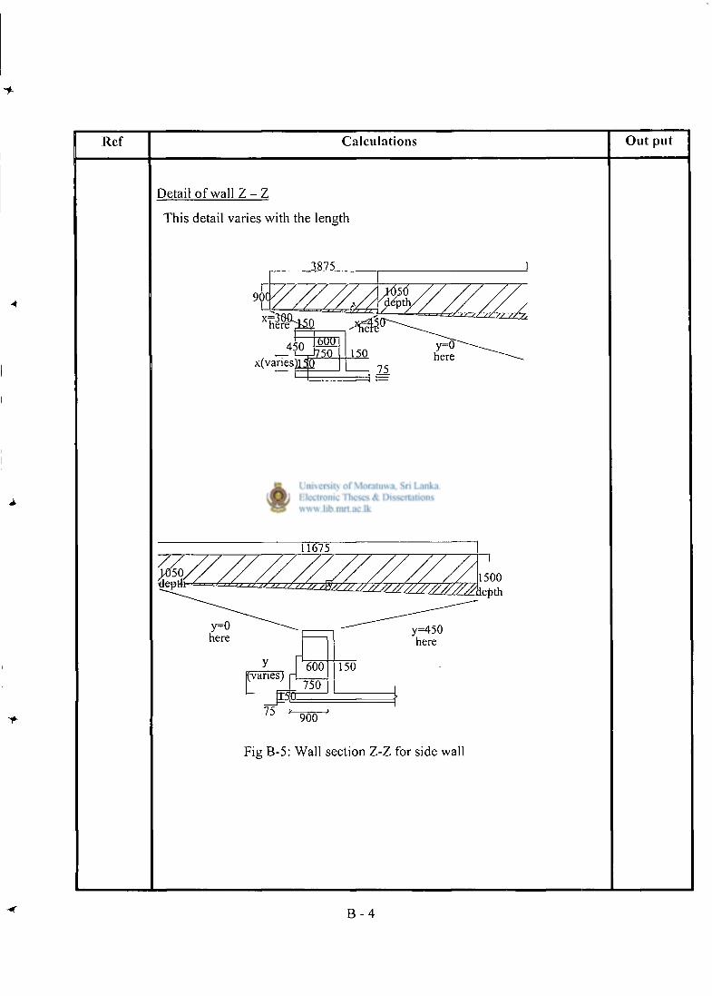
Ref Calculat ions Ou t put
Detail of wall Z - Z
This detail varies with the length
3875
B - 4
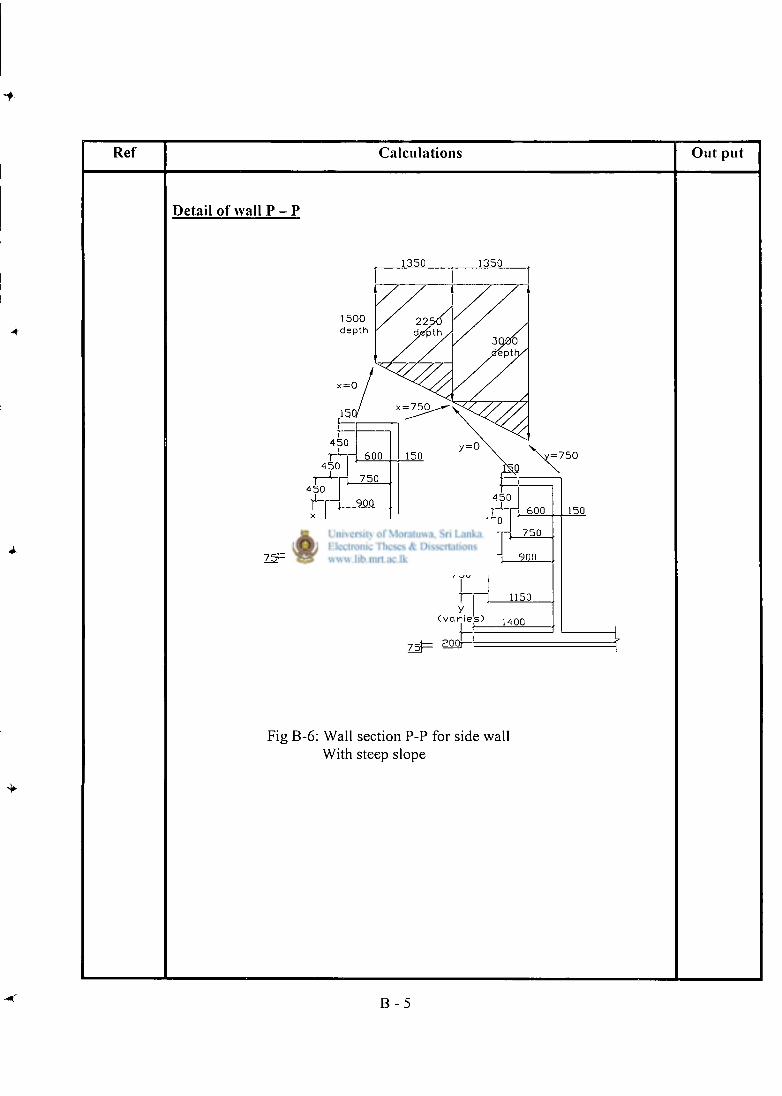
Ref Calculat ions Ou t put
Detail of wall P - P
1350 1350
1500 depth
Fig B-6: Wall section P-P for side wall With steep slope
B - 5
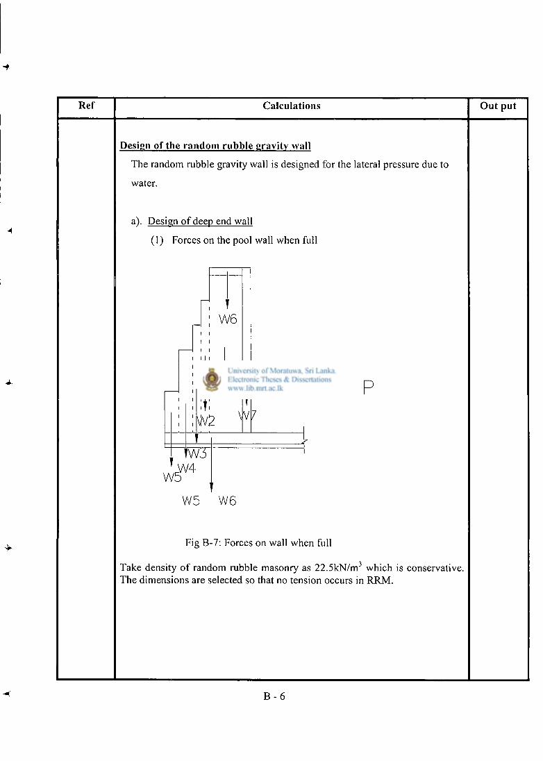
R e f Calculations Out put
Design of the random rubble gravity wall
The random rubble gravity wall is designed for the lateral pressure due to
water.
a). Design of deep end wall
(1) Forces on the pool wall when full
W6
t W1
W2 W7
p
W: 4
W5 W6
Fig B-7: Forces on wall when full
Take density of random rubble masonry as 22.5kN/m 3 which is conservative. The dimensions are selected so that no tension occurs in RRM.
B - 6
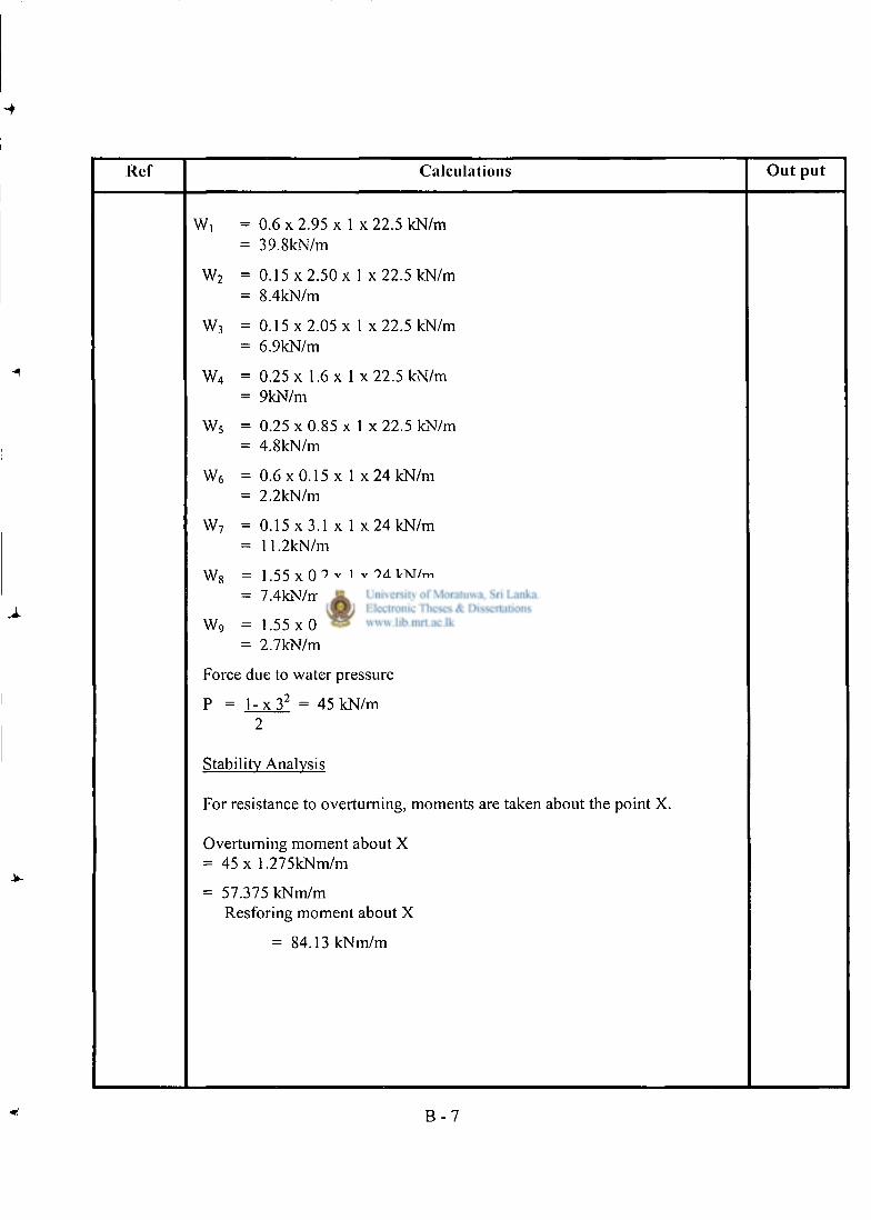
Ref Calculat ions O u t p u t
Wi = 0 . 6 x 2 . 9 5 x 1 x 2 2 . 5 kN/m = 39.8kN/m
W 2 = 0.15 x 2 .50x 1 x 2 2 . 5 kN/m = 8.4kN/m
W 3 = 0.15 x 2.05 x 1 x 22.5 kN/m = 6.9kN/m
W 4 = 0.25 x 1.6 x 1 x 2 2 . 5 kN/m = 9kN/m
W 5 = 0.25 x 0.85 x 1 x 22.5 kN/m = 4.8kN/m
W 6 = 0.6 x 0.15 x 1 x 24 kN/m = 2.2kN/m
W 7 = 0 . 1 5 x 3 . 1 x 1 x 24 kN/m = 11.2kN/m
W 8 = 1.55 x 0.2 x 1 x 24 kN/m = 7.4kN/m
W 9 = 1.55 x 0.075 x 1 x 2 3 . 5 kN/m = 2.7kN/m
Force due to water pressure
P = l - x 3 2 = 45 kN/m 2
Stability Analysis
For resistance to overturning, moments are taken about the point X.
Overturning moment about X = 45 x 1.275kNm/m
= 57.375 kNm/m Resforing moment about X
= 84.13 kNm/m
B - 7
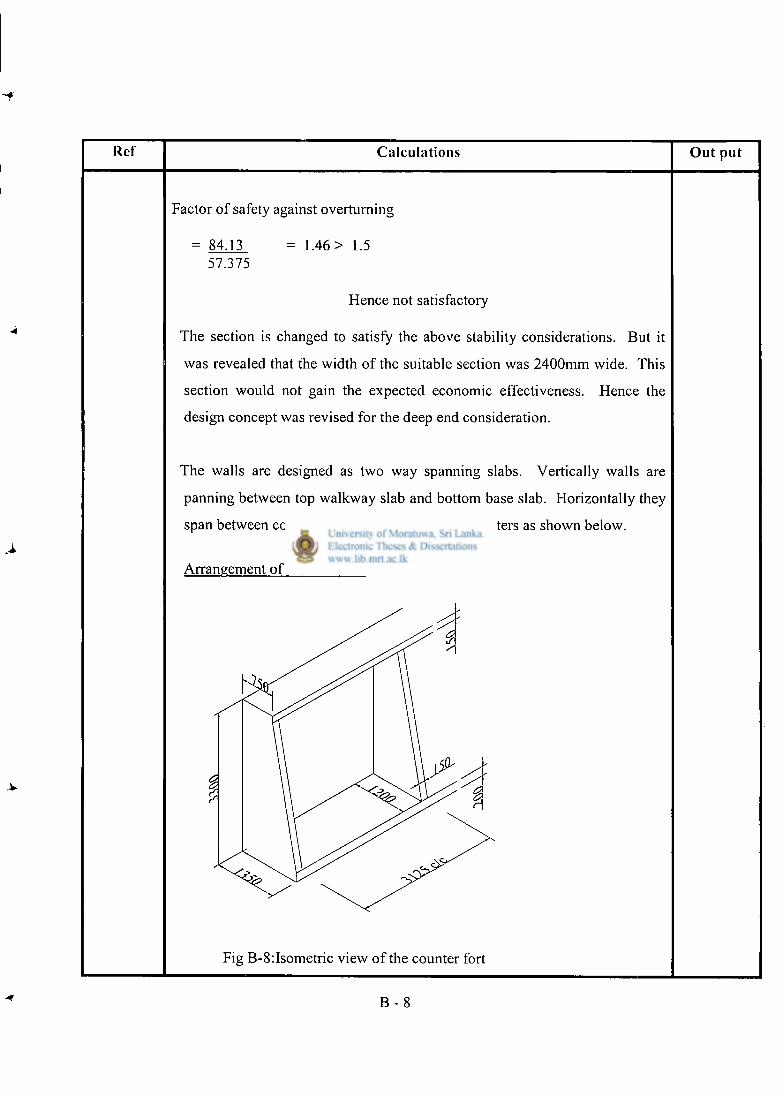
Ref Calculat ions Ou t put
Factor of safety against overturning
= 84.13 57.375
= 1.46 > 1.5
Hence not satisfactory
The section is changed to satisfy the above stability considerations. But it
was revealed that the width of the suitable section was 2400mm wide. This
section would not gain the expected economic effectiveness. Hence the
design concept was revised for the deep end consideration.
The walls are designed as two way spanning slabs. Vertically walls are
panning between top walkway slab and bottom base slab. Horizontally they
span between counter forts placed at 3125mm centers as shown below.
Arrangement of counter forts
Fig B-8:Isometric view of the counter fort
B - 8
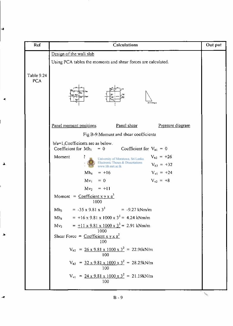
Ref Calcula t ions O u t p u t
Table 9.24 PCA
Design of the wall slab
Using PCA tables the moments and shear forces are calculated.
2
r
Panel moment positions Panel shear Pressure diagram
Fig B-9:Moment and shear coefficients
b/a=l,Coefficients are as below. Coefficient for Mhi
Moment M h 2
M h 3
Mh4
Mvi
M v 2
= 0
= 0
Coefficient for V n i = 0
shear
-35
+ 16
= 0
= +1
V h 2 = +26
V h 3 = +32
V V | = +24
V v 2 = +8
Moment
M h 3
Coefficient x y x a 3
1000
-35 x 9.81 x 3 3 -9.27 kNm/m
Mll4 + 1 6 x 9.81 x 1000 x 3 3 = 4.24 kNm/m
M v 2 = +11 x 9.81 x 1000 x 3 3 = 2.91 kNm/m
Shear Force 1000
= Coefficient x y x a 100
v n 2 = 2 6 x 9 . 8 1 x 1000 x 3 2 = 22.96kN/m 100
v h 3 = 3 2 x 9 . 8 1 x 1000 x 3 2 = 28.25kN/m
100
Vvl = 2 4 x 9 . 8 1 x 1000 x 3 2 = 21.19kN/m 100
B - 9
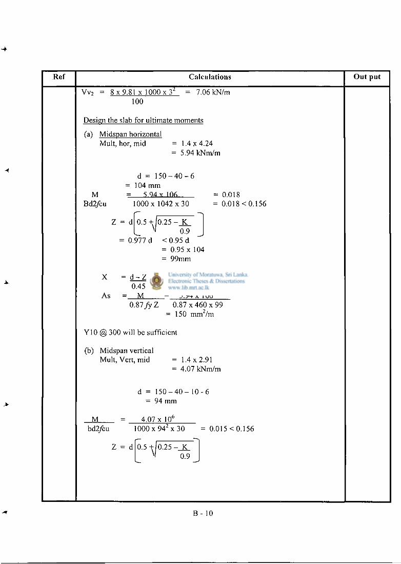
Ref Calculat ions O u t pu t
r Vv 2 = 8 x 9.81 x 1000 x 3 100
7.06 kN/m
Design the slab for ultimate moments
(a) Midspan horizontal Mult, hor, mid = 1 .4x4.24
= 5.94 kNm/m
M Bd2/cu
d = 1 5 0 - 4 0 - 6 = 104 mm
5 Q 4 x 1nfi lOOOx 1042 x 3 0
0.5 +^|0.25 - J C
= 0.977 d 0.9
< 0.95 d = 0.95 x 104 = 99mm
0.018 0.018 < 0.156
X
As
d - Z = 11mm
= 5 . 9 4 x 1 0 6 0.45
M O.SlfyZ 0 . 8 7 x 4 6 0 x 9 9
150 mm /m
Y10 @ 300 will be sufficient
(b) Midspan vertical Mult, Vert, mid = 1 .4x2.91
= 4.07 kNm/m
d = 1 5 0 - 4 0 - 1 0 - 6 = 94 mm
M bd2/cu
4.07 x 10° I 0 0 0 x 9 4 z x 3 0 = 0.015 < 0.156
Z = d 0.5 + 0 . 2 5 - K M 0.9
B - 10
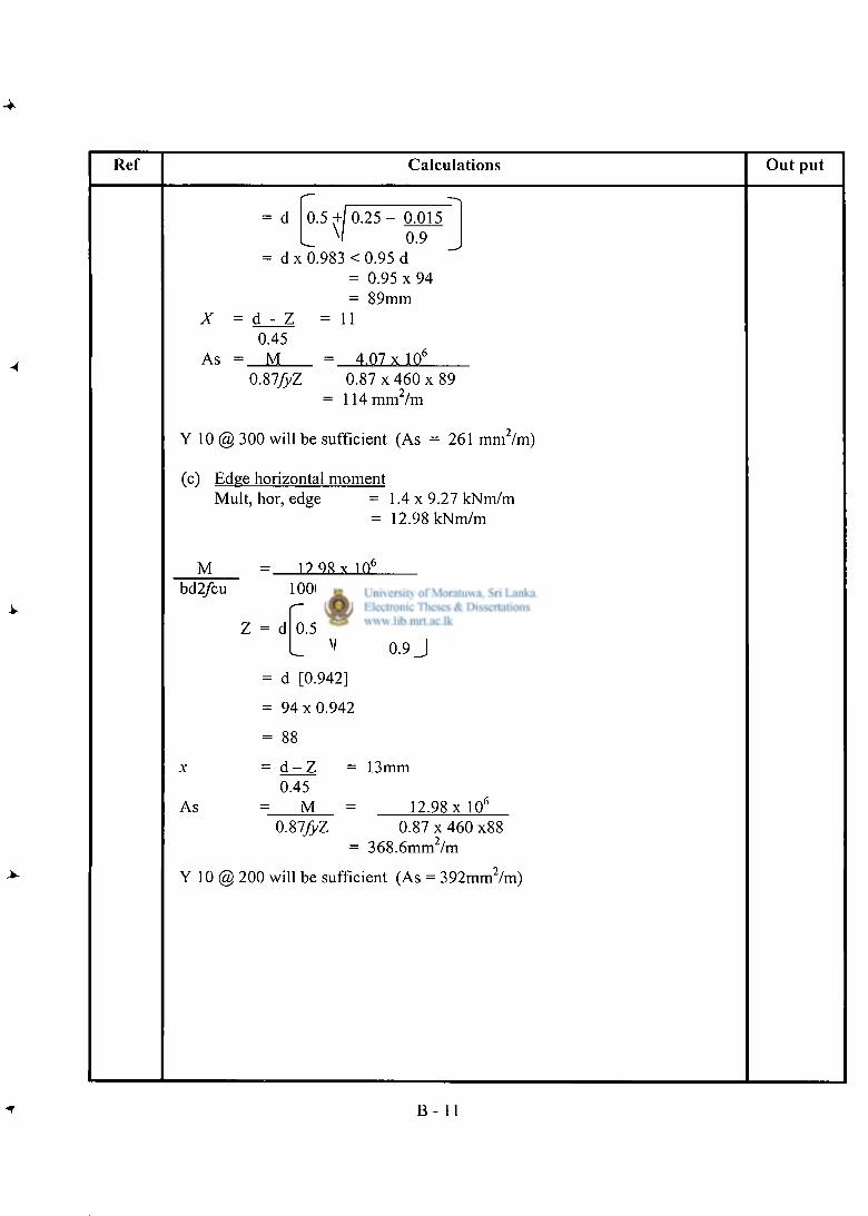
Ref Calculat ions O u t p u t
= d 0 .5+/ 0 . 2 5 - 0.015 L ^ ' 0.9 J = d x 0.983 < 0.95 d
= 0.95 x 94 = 89mm
X = d - Z = 1 1 0.45
As = M = 4.07 x 10 6
0.87/yZ 0.87 x 460 x 89 = 1 1 4 m m 2 / m
Y 10 @ 300 will be sufficient (As = 261 mm 2 /m)
(c) Edge horizontal moment Mult, hor, edge = 1 .4x9 .27 kNm/m
= 12.98 kNm/m
M = 1 ? Q R Y 1 0 6
bd2/cu 1 0 0 0 x 9 4 ^ x 3 0 = 0.049 < 0.156
Z = d 0.5 + |0 .25 - K
L X> 0.9 J = d [0.942]
= 9 4 x 0 . 9 4 2
= 88
x = d - Z = 13mm 0.45
As M 12.98 x 10 6
0.87/yZ 0.87 x 460 x88 = 368.6mm Im
Y 10 @ 200 will be sufficient (As = 392mm 2 /m)
B - 11
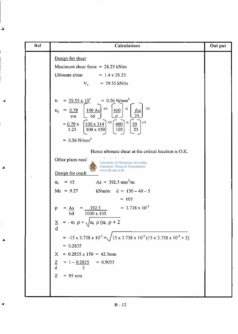
Ref Calcula t ions Ou t put
Design for shear
Maximum shear force
Ultimate shear
V u
= 28.25 kN/m
= 1 .4x28.25
= 39.55 kN/m
1) = 39.55 x 10 J = 0.26 N / m m 2
-- ~" = 0.79
ym 100 As L bd _
1/3 400 _d J
%
_ 2 5 _
1/3
= 0.79 x 1.25
1 0 0 x 3 1 4 1 0 0 x 1 5 0
1/3 400 105
V4 30 25
1/3
= 0.56 N / m m 2
Hence ultimate shear at the critical location is O.K.
Other plans need cost to check for shear.
Design for crack width
a, =
Ms =
P =
15
9.27
As bd
As = 392.5 m m 7 m
kNm/m d = 1 5 0 - 4 0 - 5
= 105
392.5 3.738 x 10" 1 0 0 0 x 1 0 5
X = - at p + v la/ p (a/ p + 2 d
-3
X = z =
d
-15 x 3.738 x 10
0.2835
0.2835 x 150 = 42.5mm
1 - 0 . 2 8 3 5 = 0.9055
15 x 3.738 x 10"3 (15 x 3.738 x 10"3 + 2)
Z = 9 5 mm
B - 12
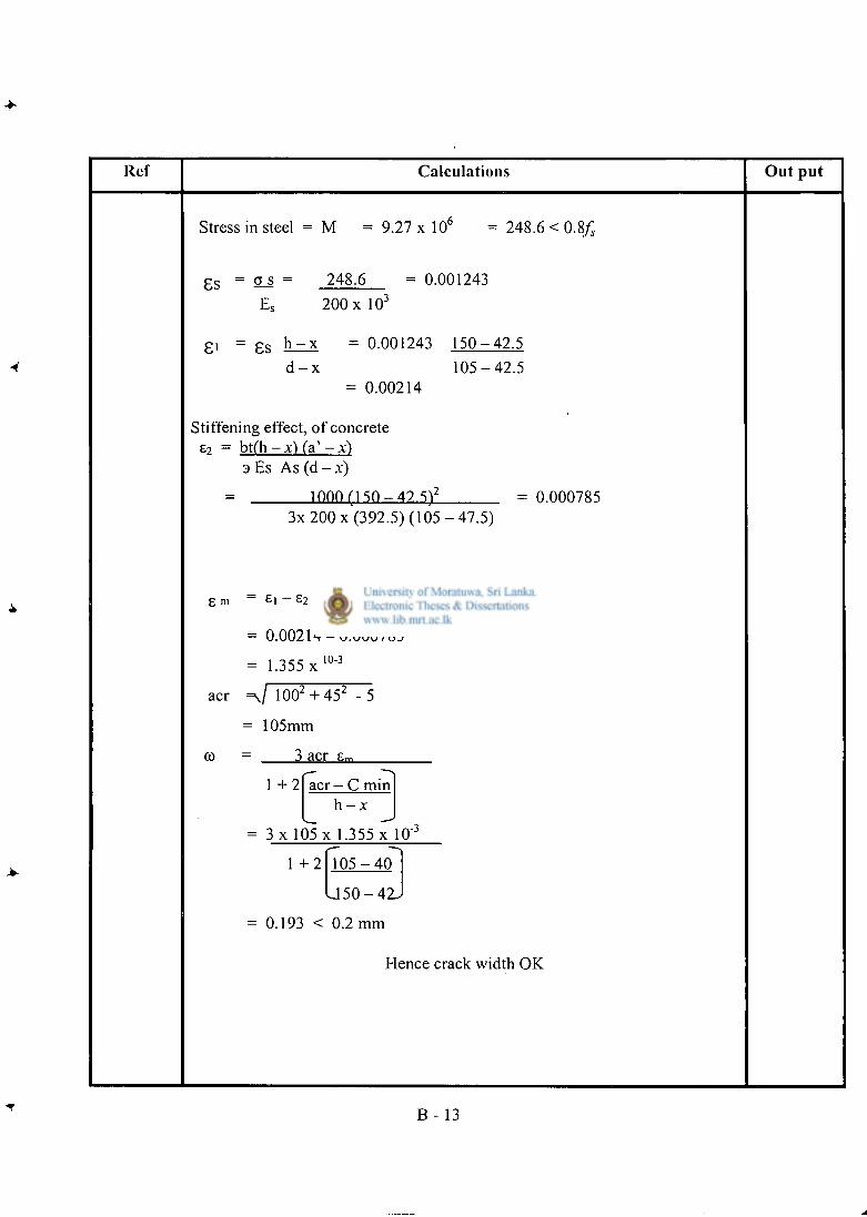
Ref Calculat ions O u t p u t
Stress in steel = M = 9 . 2 7 x l 0 6 = 248.6 < 0.8/;
8s = S_s = 248.6 = 0.001243
E s 200 x 10 3
8 ' = 8s h " - X = 0.001243 1 5 0 - 4 2 . 5
d - - X 1 0 5 - 4 2 . 5 = 0.00214
Stiffening effect, of concrete £ 7 = b t ( h - x ) Ca' -x)
3 Es As (d --x) = 1000 M S O - 47.W = 0 000785
3x 200 x (392.5) ( 1 0 5 - 4 7 . 5 )
g m = £ | - £2
= 0.00214 - 0.000785
= 1.355 X 1 0 " 3
acr = J 100 2 + 4 5 2 - 5
= 105mm
co = 3 acr £ m
1 + 2 acr - C min h - x
—' = 3 x 105 x 1.355 x 10"J
1 + 2 1 0 5 - 4 0
J 5 0 - 4 2 -
= 0.193 < 0.2 mm
Hence crack width OK
B - 13
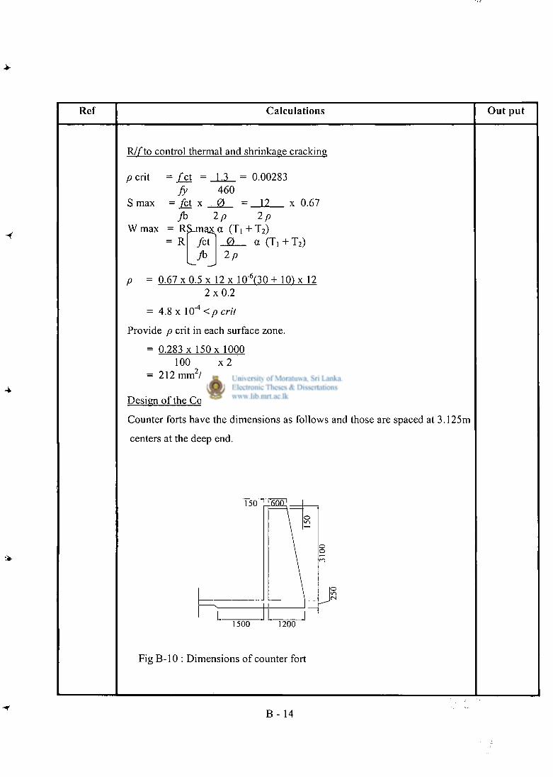
Ref Calculat ions O u t pu t
RJf to control thermal and shrinkage cracking
p crit = £ c t = 1.3 = 0.00283 fy 460
S max = j e t x 0 = 12 x 0.67 yb 2p 2p
W max - RS_max a (Ti + T 2 ) = R / c t 0 a (T, + T 2 )
2p
p = 0.67 x 0.5 x 12 x 1(T(30 + 10) x 12 2 x 0 . 2
= 4.8 x 1 0 " 4 < p e r i l
Provide p crit in each surface zone.
= 0.283 x 150 x 1000 100 x 2
= 212 mm 2 /m
Design of the Counter forts
Counter forts have the dimensions as follows and those are spaced at 3.125m
centers at the deep end.
1500 1200
Fig B-10 : Dimensions of counter fort
B - 14
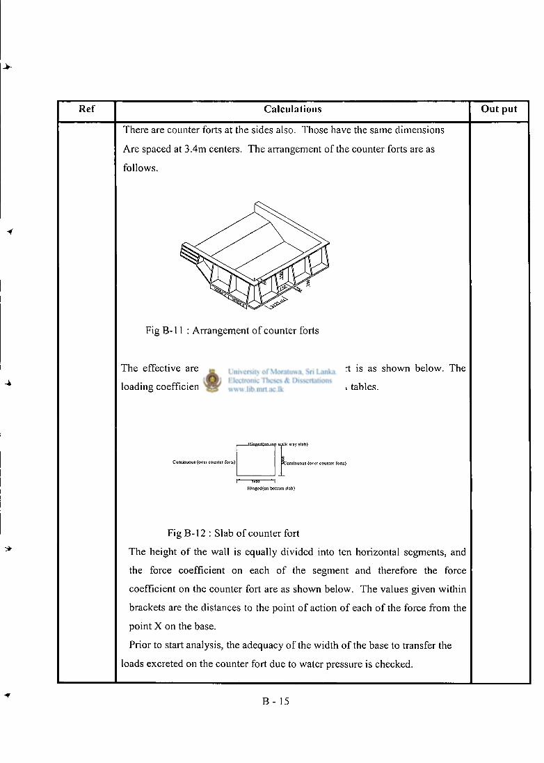
Ref Calculat ions Ou t put
There are counter forts at the sides also. Those have the same dimensions
Are spaced at 3.4m centers. The arrangement of the counter forts are as
follows.
Fig B-l 1 : Arrangement of counter forts
The effective area for loading of one counter fort is as shown below. The
loading coefficients for the slab are taken from PCA tables.
. HinjTnH(nn tnp UJllk Way Slab)
3 Conitnuous (over counter forts) C o n t i n u o u s (over counter forts)
1" 3i(H) " 1
Hingcd(on bottom slab)
Fig B-l 2 : Slab of counter fort
The height of the wall is equally divided into ten horizontal segments, and
the force coefficient on each of the segment and therefore the force
coefficient on the counter fort are as shown below. The values given within
brackets are the distances to the point of action of each of the force from the
point X on the base.
Prior to start analysis, the adequacy of the width of the base to transfer the
loads excreted on the counter fort due to water pressure is checked.
B - 15
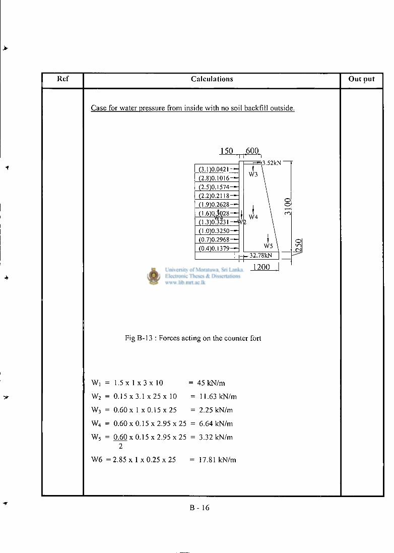
Ref Calculat ions O u t put
Case for water pressure from inside with no soil backfill outside.
150 6 0 0
(3.1)0.0421 — (2.8)0.1016— (2.5)0.1574— (2.2)0.2118— (1.9)0.2628 — (1.6)0jQ28-~ (1.3)03231—WlZ (1.0)0.3250— (0.7)0.2968 — (0.4)0.1379—
1500
W6
Fig B-13 : Forces acting on the counter fort
W, = 1.5 x 1 x 3 x 10 = 45 kN/m
W 2 = 0.15 x 3.1 x 25 x 10 = 11.63 kN/m
W 3 = 0.60 x 1 x 0.15 x 2 5 = 2.25 kN/m
W 4 = 0 . 6 0 x 0 . 1 5 x 2 . 9 5 x 2 5 = 6.64 kN/m
W 5 = 0 6 0 x 0 . 1 5 x 2 . 9 5 x 2 5 = 3.32 kN/m 2
W6 = 2.85 x 1 x 0.25 x 25 = 17.81 kN/m
B - 16
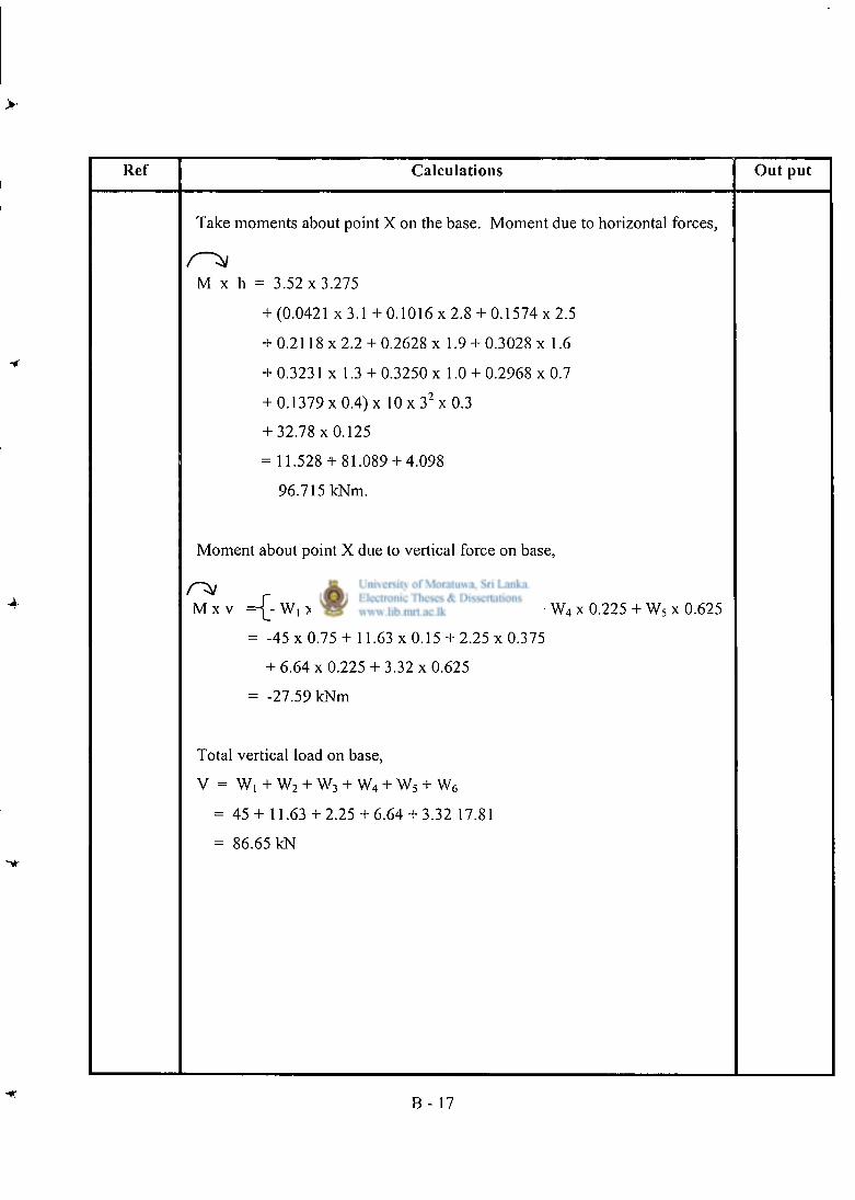
>
4
Ref Calculat ions Ou t put
Take moments about point X on the base. Moment due to horizontal forces,
M x h = 3.52 x 3.275
+ (0.0421 x 3.1 + 0.1016 x 2.8 + 0.1574 x 2.5
+ 0.2118 x 2.2 + 0.2628 x 1.9 + 0.3028 x 1.6
+ 0.3231 x 1.3 + 0.3250 x 1.0 + 0.2968 x 0.7
+ 0.1379 x 0.4) x 10 x 3 2 x 0.3
+ 3 2 . 7 8 x 0 . 1 2 5
= 11.528 + 81.089 + 4.098
96.715 kNm.
Moment about point X due to vertical force on base,
M x v = \ - W, x 0.75 + W 2 x 0.15 + W 3 x 0.375 + W 4 x 0.225 + W 5 x 0.625
= -45 x 0.75 + 11.63 x 0.15 + 2.25 x 0.375
+ 6 .64x 0.225 + 3 . 3 2 x 0 . 6 2 5
= -27.59 kNm
Total vertical load on base,
V = Wi + w2 + w3 + w4 + w5 + w6
= 45 + 11.63 + 2.25 + 6.64 + 3.32 17.81
= 86.65 kN
B - 17
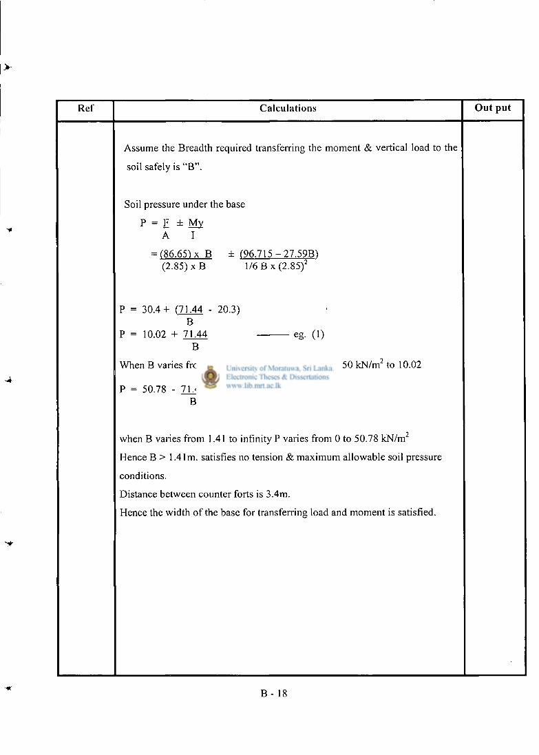
>-
Ref Calculat ions O u t p u t
Assume the Breadth required transferring the moment & vertical load to the
soil safely is " B " .
Soil pressure under the base
P = F ± My A I
= (86.65) x B ± (96.715 - 27.59B) (2.85) x B 1/6 B x (2.85) 2
P = 3 0 . 4 + (71.44 - 20.3) B
P = 10.02 + 71.44 eg. (1) B
When B varies from 0.51 to infinity P varies from 150 kN/m 2 to 10.02
P = 50.78 - 71.44 eg. (2) B
when B varies from 1.41 to infinity P varies from 0 to 50.78 kN/m 2
Flence B > 1.41m. satisfies no tension & maximum allowable soil pressure
conditions.
Distance between counter forts is 3.4m.
Hence the width of the base for transferring load and moment is satisfied.
B - 18
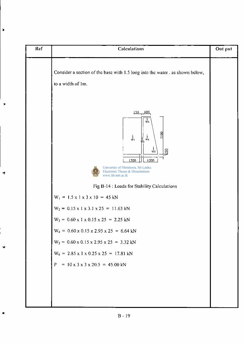
Ref Calculat ions Ou t pu t
Consider a section of the base with 1.5 long into the water . as shown below,
to a width of lm.
Fig B-14 : Loads for Stability Calculations
W, = 1.5 x 1 x 3 x 10 = 45 kN
W 2 = 0.15 x 1 x 3.1 x 2 5 = 11.63 kN
W 3 = 0.60 x 1 x 0.15 x 25 = 2.25 kN
W 4 = 0.60 x 0.15 x 2.95 x 25 = 6.64 kN
W 5 = 0 . 6 0 x 0 . 1 5 x 2 . 9 5 x 25 = 3.32 kN
W 6 = 2.85 x 1 x 0.25 x 25 = 17.81 kN
P = 1 0 x 3 x 3 x 2 0 . 5 = 45.00 kN
B - 19
Ref Calculations Out put
Stability Calculations
Case 1 : Tank full with no soil backfill
Take moments about A,
Overturning moment = P x 1.2
= 45 x 1.2
= 54 kNm/m
Restoring moment
= W1 x 2 . 1 + W 2 x 1.275+ W 3 x 0.9
W4 x 0.9 + W5 x 0.4 + W6 x 1.425
= 45 x 2.1 + 11.63 x 1.275 + 2.25 x 0 . 9 + 6 . 6 4 x 0 . 9 + 3 . 3 2 x 0 . 4
+ 17.81 x 1.425
= 144.04 kNm/m
Factor of safety against overturning
= 144.4 54
= 2.67 > 2
Hence satisfactory.
B - 2 0
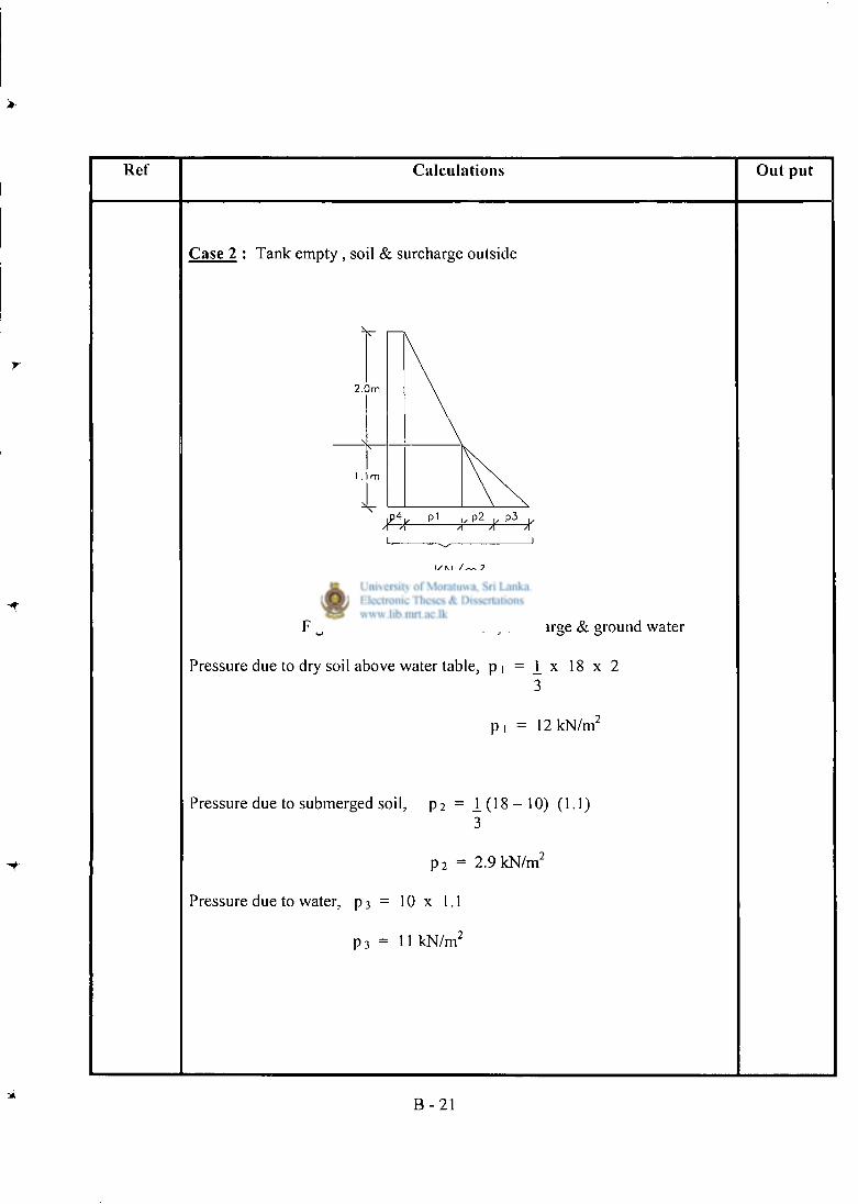
Ref Calcula t ions Out pu t
Case 2 : Tank empty , soil & surcharge outside
K N / m :
Fig B- l5 : Forces due to soil, surcharge & ground water
Pressure due to dry soil above water table, p i = 1 x 18 x 2 3
p , = 12 kN/m 2
Pressure due to submerged soil, p 2 = 1 ( 1 8 - 1 0 ) (1.1)
3
p 2 = 2.9 kN/m 2
Pressure due to water, p 3 = 10 x 1.1 p 3 = 11 kN/m 2
B - 2 1
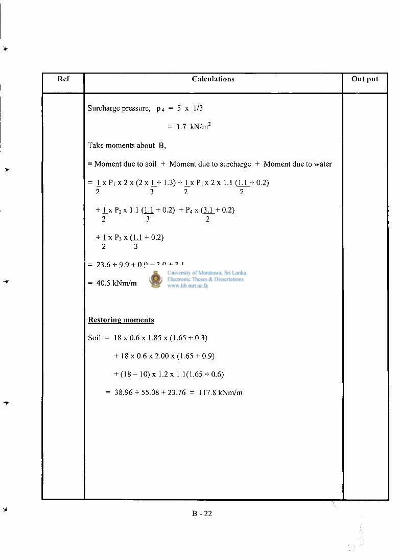
1 Ref Calculat ions Ou t put
Surcharge pressure, p 4 = 5 x 1/3
= 1.7 kN/m 2
Take moments about B,
= Moment due to soil + Moment due to surcharge + Moment due to water
= i x P i x 2 x ( 2 x J_+ 1.3) + J _ x P i x 2 x 1.1 ( 1 . 1 + 0 . 2 ) 2 3 2 2
+ l x P 2 x 1.1 CLi + 0.2) + P 4 x ( 3 . 1 + 0 . 2 ) 2 3 2
+1 x P 3 x ( U . + 0.2) 2 3
= 23.6 + 9.9 + 0.9 + 3.0 + 3.1
= 40.5 kNm/m
Res tor ing moments
Soil = 18 x 0.6 x 1.85 x (1.65 + 0.3)
+ 18 x 0.6 x 2.00 x (1.65 + 0.9)
+ ( 1 8 - 10) x 1.2 x 1.1(1.65 + 0.6)
= 38.96 + 55.08 + 23.76 = 117.8 kNm/m
B - 2 2
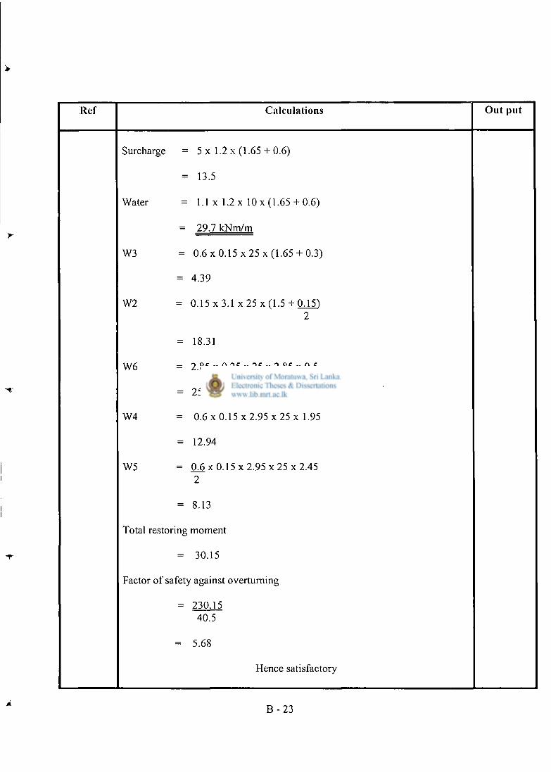
Ref Calculat ions O u t pu t
Surcharge = 5 x 1.2 x (1 .65+ 0.6)
= 13.5
Water = 1.1 x 1.2 x 10 x (1 .65+ 0.6)
- 29.7 kNm/m
W3 = 0.6 x 0.15 x 25 x (1.65 + 0.3)
= 4.39
W2 = 0 . 1 5 x 3 . 1 x 25 x (1 .5+ 0.15) 2
= 18.31
W6 = 2 . 8 5 x 0 . 2 5 x 2 5 x 2 . 8 5 x 0 . 5
= 25.38
W4 = 0 .6x 0 . 1 5 x 2 . 9 5 x 2 5 x 1.95
= 12.94
W5 = 0 6 x 0 . 1 5 x 2 . 9 5 x 2 5 x 2 . 4 5 2
= 8.13
Total restoring moment
= 30.15
Factor of safety against overturning
= 230.15 40.5
= 5.68
Hence satisfactory
B - 2 3
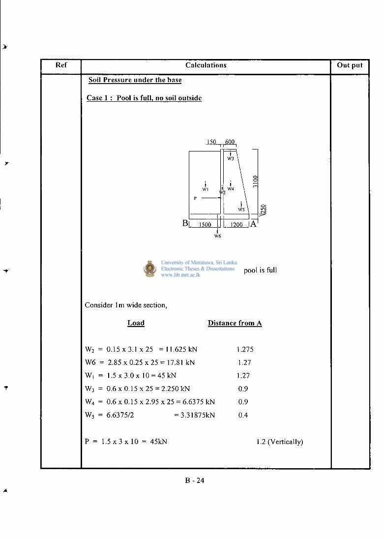
Ref Calculations O u t put
Soil Pressure under the base
Case 1 : Pool is full, no soil outside
Fig B-16 : Forces on wall when pool is full
Consider l m wide section,
Load Distance from A
w2 = 0.15 x 3.1 x 25 = 11.625 kN 1.275
W6 = 2 . 8 5 x 0 . 2 5 x 2 5 = 17.81 kN 1.27
w, = 1.5 x 3.0 x 10 = 4 5 k N 1.27
w3 = 0.6 x 0.15 x 25 = 2.250 kN 0.9
w4 = 0.6 x 0.15 x 2.95 x 25 = 6.6375 kN 0.9
w5 = 6.6375/2 =3 .31875kN 0.4
P = 1 . 5 x 3 x 1 0 = 45kN 1.2 (Vertically)
B - 2 4
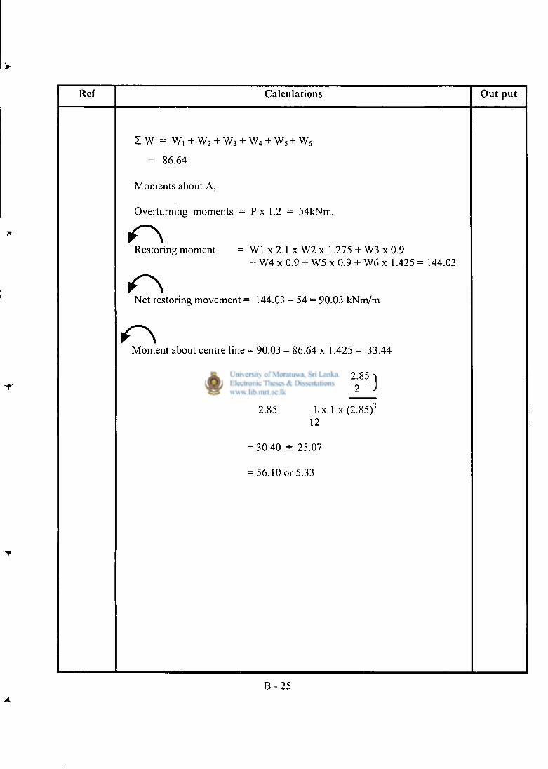
Ref Calculat ions Ou t pu t
1 w = w , + w2 + w3 + w4 + w5 + w6
= 86.64
Moments about A,
Overturning moments = P x 1.2 = 54kNm.
Restoring moment = W l x 2.1 x W2 x 1.275 + W3 x 0.9 + W4 x 0.9 + W5 x 0.9 + W6 x 1.425 = 144.03
Net restoring movement = 144.03 - 54 = 90.03 kNm/m
Moment about centre line = 90.03 - 86.64 x 1.425 = "33.44
= 86.64 ± 33.44 xj" 2^85 j
2.85 l x l x ( 2 . 8 5 ) 3
12
= 30.40 ± 25.07
= 56.10 or 5.33
B - 2 5
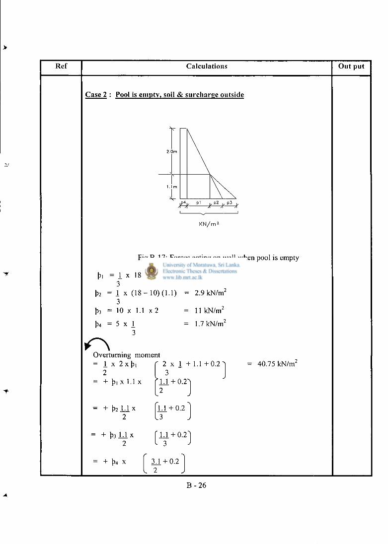
Ref Calculations Out put
Case 2 : Pool is empty, soil & surcharge outside
K N / m :
Fig B-17: Forces acting on wall when pool is empty
pi = I x 18 x 2 12 kN/m 2
3 p 2 = I x ( 1 8 - 10) (1.1) = 2.9 kN/m 2
3 p 3 = 10 x 1.1 x 2 11 kN/m 2
P4 = 5 x 1 = 1.7 kN/m 2
3
Overturning moment = 1 x 2 x pi ' 2 x 1 + 1 . 1 + 0 . 2 1
2 3 = + pi X 1.1 X > L i + 0.2-
2
= + p2 L i x 1.1 + 0 . 2 " 2 . 3
= + p 3 L i X ' 1 .1 + 0 . 2 " 2 I 3 J
40.75 kN/m'
= + p 4 x 3 J . + 0.2 I 2
B - 2 6
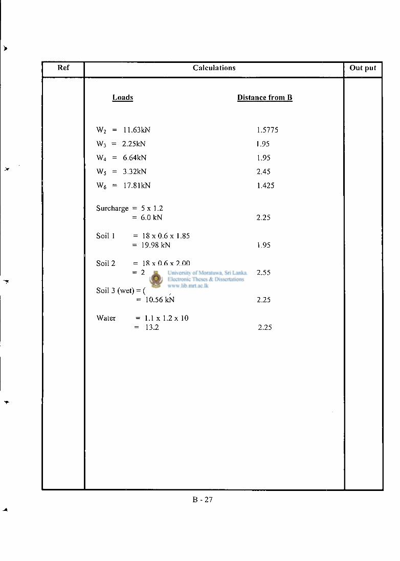
Ref Calculat ions Ou t put
Loads Distance from B
W 2 = 11.63kN 1.5775
W 3 = 2.25kN 1.95
W 4 = 6.64kN 1.95
W 5 = 3.32kN 2.45
W 6 = 17.81kN 1.425
Surcharge = 5 x 1.2 = 6.0 kN 2.25
Soil 1 = 1 8 x 0 . 6 x 1.85 = 19.98 kN 1.95
Soil 2 = 1 8 x 0 . 6 x 2 . 0 0 = 21.6 kN 2.55
Soil 3 (wet) = ( 1 8 - 10) x 1.2 x 1.1 = 10.56 kN 2.25
Water = 1.1 x 1.2 x 10 = 13.2 2.25
B - 2 7
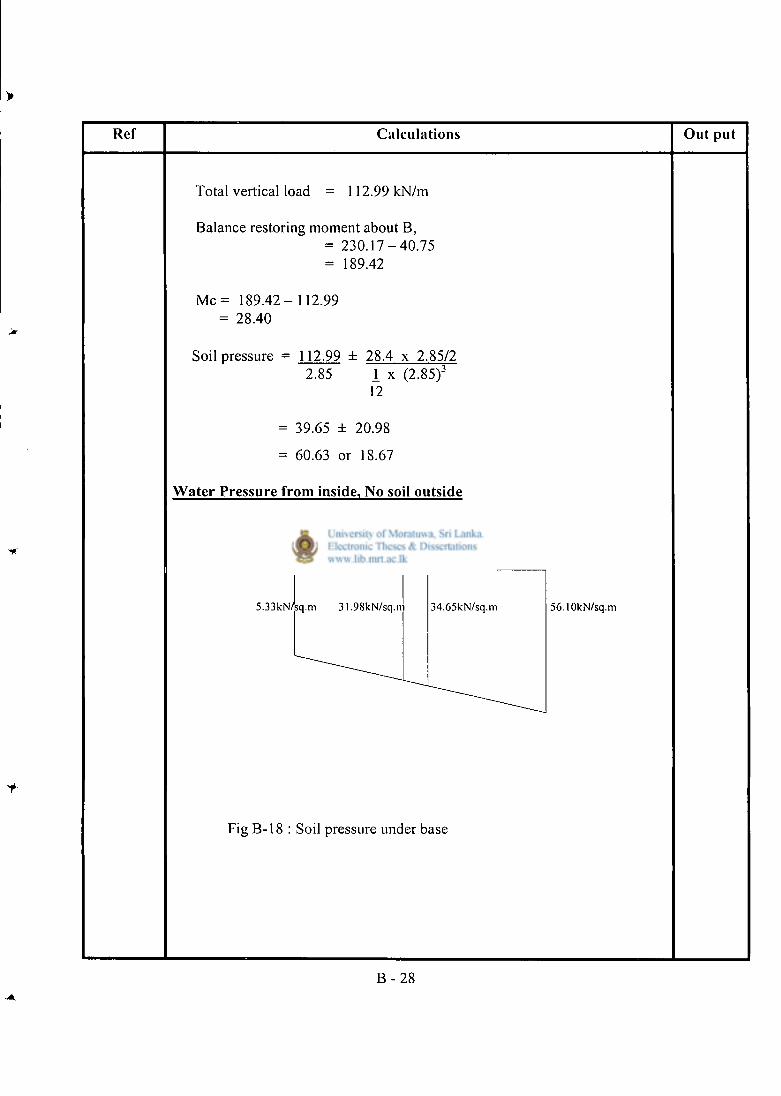
> Ref Calculations Out put
Total vertical load = 112.99 kN/m
Balance restoring moment about B, = 2 3 0 . 1 7 - 4 0 . 7 5 = 189.42
M c = 1 8 9 . 4 2 - 112.99 = 28.40
Soil pressure = 112.99 ± 28.4 x 2.85/2 2.85 I x (2.85) 3
12
= 39.65 ± 20.98
= 60.63 or 18.67
Water Pressure from inside, No soil outside
5.33kN/;q.m 31.98kN/sq.m 34.65kN/sq.m 56.10kN/sq.m
Fig B-18 : Soil pressure under base
B - 2 8
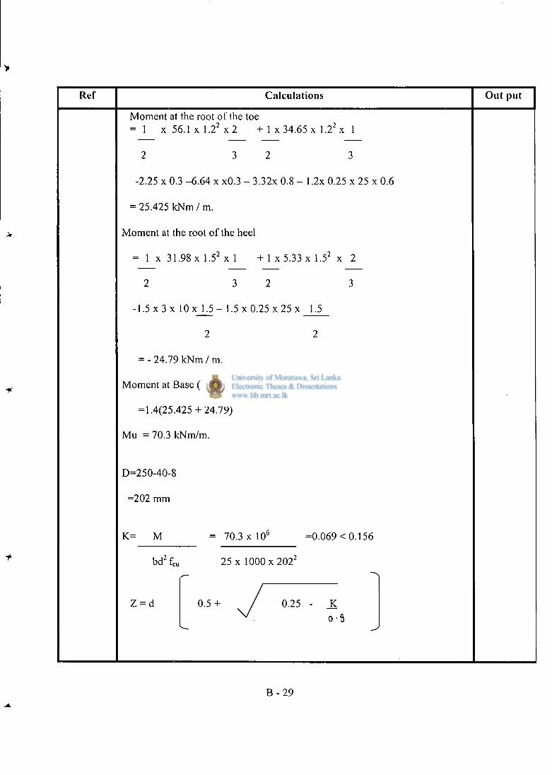
>
Ref Calculat ions O u t p u t
Moment at the root of the toe = 1 x 5 6 . 1 x l . 2 2 x 2 + 1 x 34.65 x 1.22 x 1
2 3 2 3
-2.25 x 0.3 -6 .64 x x0.3 - 3.32x 0.8 - 1.2x 0.25 x 25 x 0.6
= 25.425 k N m / m .
Moment at the root of the heel
= 1 x 31.98 x l . 5 2 x l + 1 x 5 . 3 3 x l . 5 2 x 2
2 3 2 3
- 1 . 5 x 3 x l O x 1.5 - 1.5 x 0.25 x 25 x 1.5
2 2
= - 24.79 kNm / m.
Moment at Base (ULS)
=1.4(25.425 + 24.79)
Mu = 70.3 kNm/m.
D=250-40-8
=202 mm
K= M = 70.3 x 10 6 =0.069 < 0.156
bd 2 f c u 25 x 1000 x 202 2
Z = d 0 . 5 + / 0.25 - K v . V-i
B - 2 9
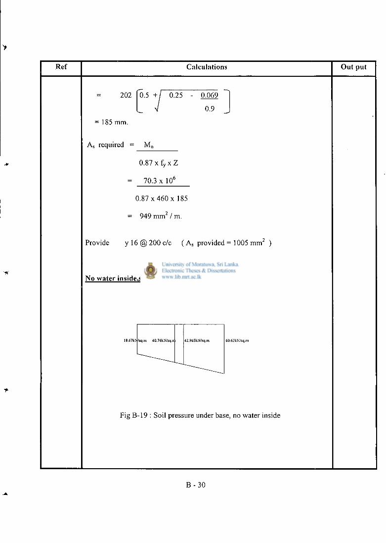
Ref Calculations Out put
202
= 185 mm.
0.5 + / 0.25 - 0.069
V 0.9
A s required = M u
0 . 8 7 x f y x Z
= 70.3 x 10 e
0.87 x 460 x 185
949 m m 2 / m.
Provide y 16 @ 200 c/c ( A s provided = 1005 m m 2 )
No water inside,soil and surcharge outside
l8.67kN/sq.m 40.76kN/sq.n 42.965kN/sq.m 60.63kN/sq.m
Fig B-19 : Soil pressure under base, no water inside
B - 3 0
> Ref Calculat ions O u t put
Moment at the root of the toe = 1 x 60.63 x 1.22 x 2 + 1 x 42.97 x 1.22 x 1
2 3 2 3
-2.25 x 0.3 -6 .64 x x0.3 - 3.32x 0 . 4 - 1.2x 0.25 x 2 5 x 0 . 6
- 6 x 0 . 6 - 1 9 . 9 8 x 0 . 3 - 21.6 x 0.9 - 10.56 x 0.6 - 13.2 x 0.6
= -6.04 kNm / m.
Moment at the root of the heel
= 1 x 18.67 x 1.52 x 2 + 1 x40 .76x 1.52 x 1
2 3 2 3
- 1.5 x 0 . 2 5 x 25 x 0.75
= - 22.26 kNm / m.
Moment at Base (ULS)
= 1.4(22.26 + 6.04)
Mu = 3 9 . 6 2 kNm/m.
Reinforcement in previous case will suffice.
B - 31
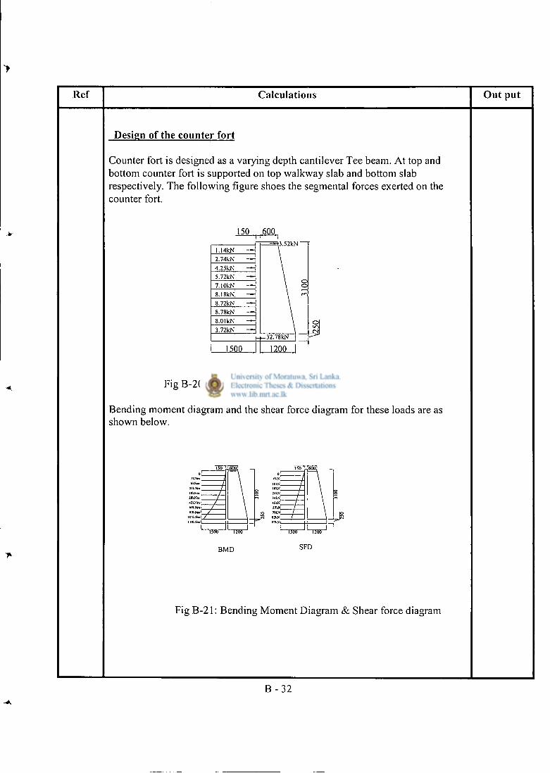
Ref Calculations Out put
Design of the counter fort
Counter fort is designed as a varying depth cantilever Tee beam. At top and bottom counter fort is supported on top walkway slab and bottom slab respectively. The following figure shoes the segmental forces exerted on the counter fort.
150 600
l.!4kN 2.74kN — 4.25kN — 5.72kN — 7.10kN — 8.18kN, — 8.72kN — 8.78kN — 8.01kN — 3.72kN —
1500
Fig B-20 : Forces on counter fort
Bending moment diagram and the shear force diagram for these loads are as shown below.
1200
BMD SFD
Fig B-21: Bending Moment Diagram & Shear force diagram
B - 3 2
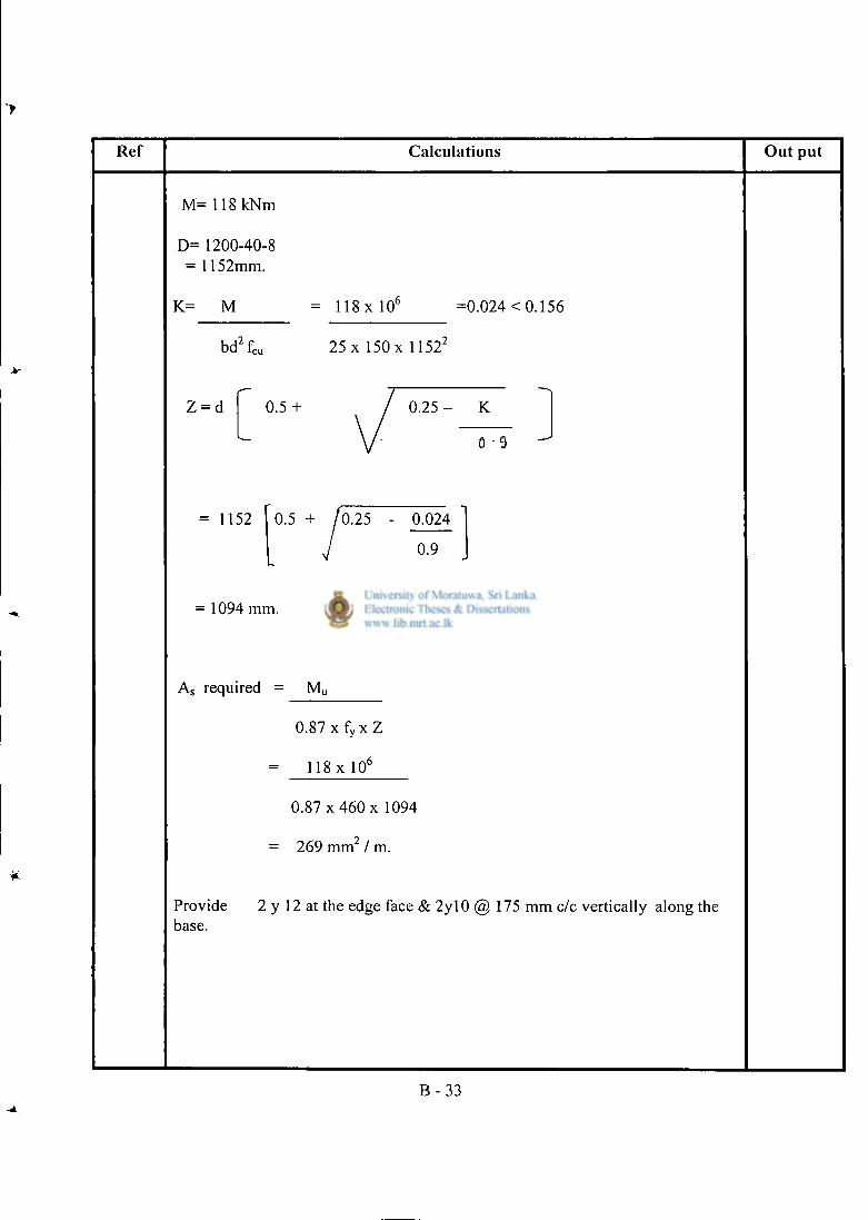
Ref Calculat ions Ou t pu t
M= 118 kNm
D= 1200-40-8 = 1152mm.
K= M = 118 x 10 6 =0.024 < 0.156
bd 2 f c u 2 5 x l 5 0 x l l 5 2 2
Z = d f 0 . 5 + / 0 . 2 5 - K 1
L V . . . J
= 1152 0.5 + /0.25 - 0.024
[J °"9 J
= 1094 mm.
A s required = M u
0.87 x fy x Z
= 118 x 10 6
0.87 x 460 x 1094
= 269 mm / m.
Provide 2 y 12 at the edge face & 2y l0 @ 175 mm c/c vertically along the base.
B - 3 3
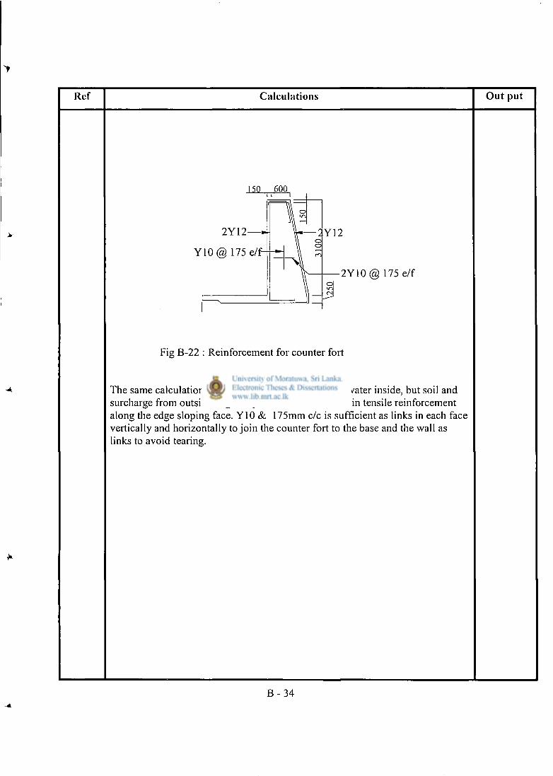
Ref Calculat ions O u t pu t
150 .600
2 Y 1 2 — J
Y 1 0 @ 175 e/
2Y12
2Y10(ffi 175 e/f
Fig B-22 : Reinforcement for counter fort
The same calculation is carried out for the case of no water inside, but soil and surcharge from outside. Again 2y l2 is sufficient as main tensile reinforcement along the edge sloping face. Y10 & 175mm c/c is sufficient as links in each face vertically and horizontally to join the counter fort to the base and the wall as links to avoid tearing.
B - 34
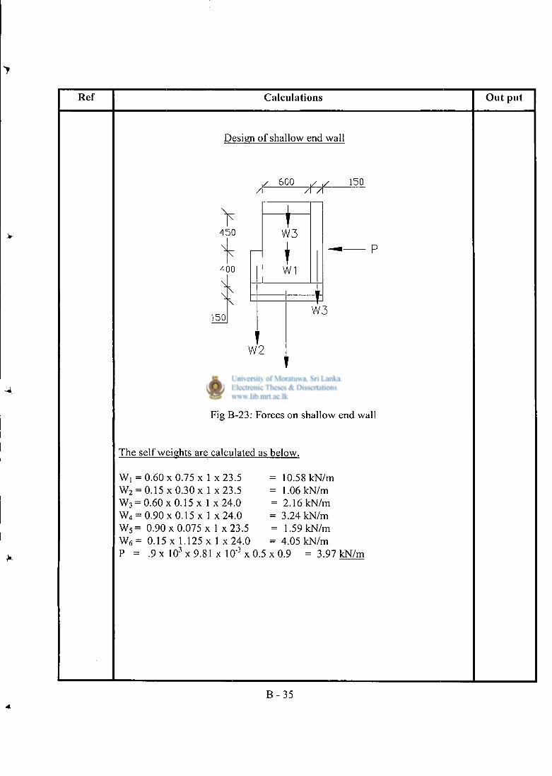
Ref Calculat ions O u t put
Design of shallow end wall
/ 6 0 0 // 1 5 0
4 5 0
4 0 0
1 5 0
W 3 I T
W1
W 2
W 3
W 4 & W 5
P
Fig B-23: Forces on shallow end wall
The self weights are calculated as below.
w, = 0.60 x 0.75 x 1 x 2 3 . 5 = 10.58 kN/m
w2 = 0.15 x 0.30 x 1 x 2 3 . 5 = 1.06 kN/m
w3 = 0 . 6 0 x 0 . 1 5 x 1 x 2 4 . 0 = 2.16 kN/m
w4 = 0.90 x 0.15 x 1 x 2 4 . 0 = 3.24 kN/m
w5= 0.90 x 0.075 x 1 x23 .5 = 1.59 kN/m
w6 = 0.15 x 1.125 x 1 x 2 4 . 0 = 4.05 kN/m p = . 9 x 1 0 3 x 9 . 8 1 x 10" 3 x0 .5 x 0 . 9 = 3.97 kN/m
B - 3 5
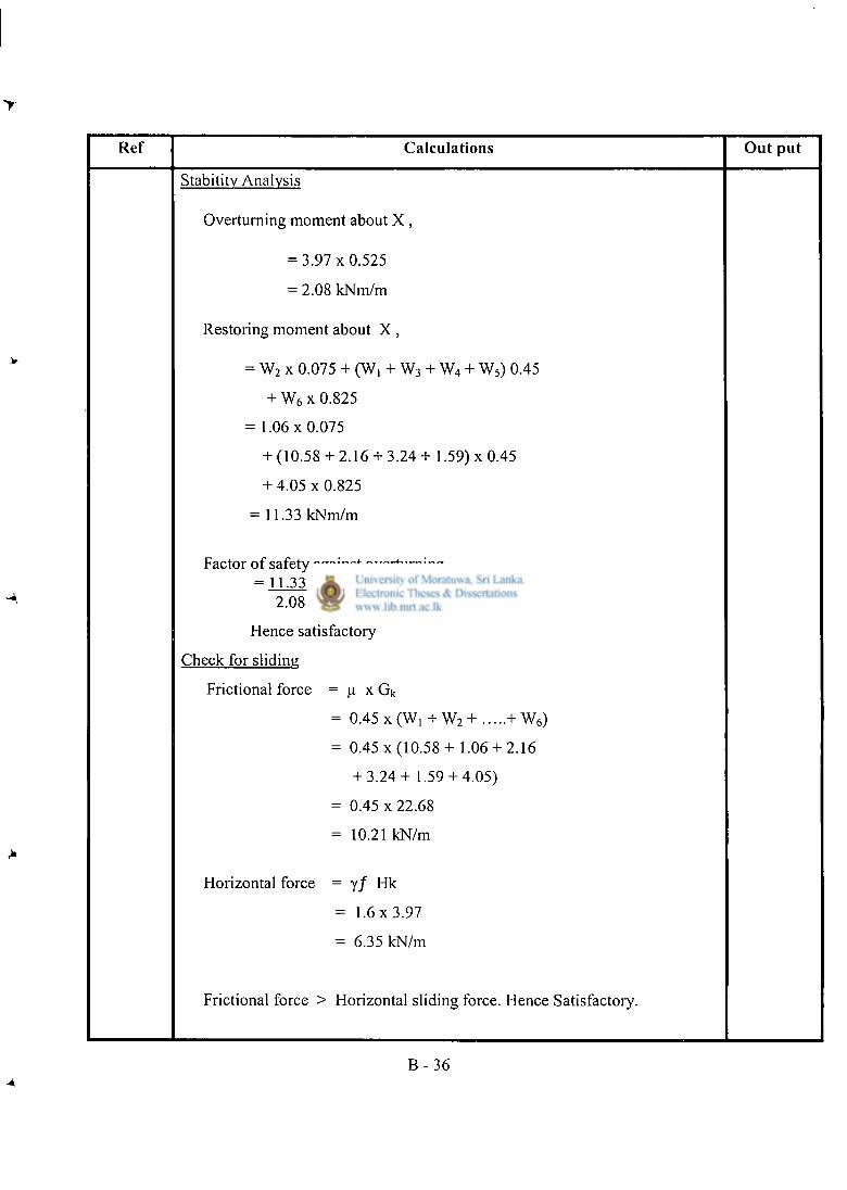
Ref Calculat ions O u t pu t
Stability Analysis
Overturning moment about X ,
= 3 . 9 7 x 0 . 5 2 5
- 2.08 kNm/m
Restoring moment about X ,
= W 2 x 0.075 + (W, + W 3 + W 4 + W 5 ) 0.45
+ W 6 x 0.825
= 1 .06x0.075
+ (10.58 + 2.16 + 3 .24+ 1.59) x 0.45
+ 4.05 x 0 . 8 2 5
= 11.33 kNm/m
Factor of safety against overturning = 11.33 = 5.4 » 2
2.08
Hence satisfactory
Check for sliding
Frictional force = u x Gk
= 0.45 x (Wi + W 2 + + W 6 )
= 0.45 x (10 .58+ 1.06 + 2.16
+ 3 .24+ 1.59 + 4.05)
= 0.45 x 22.68
= 10.21 kN/m
Horizontal force = yf Hk
= 1 .6x3 .97
= 6.35 kN/m
Frictional force > Horizontal sliding force. Hence Satisfactory.
B - 3 6
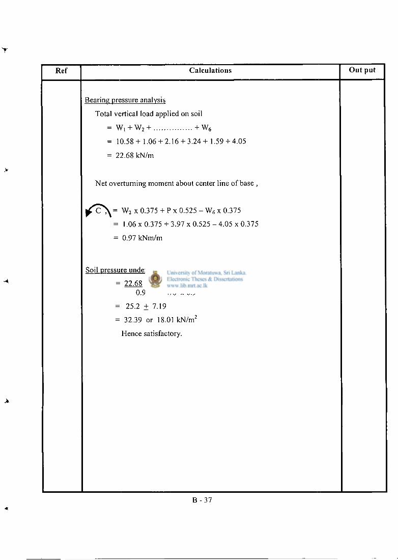
Ref Calculat ions O u t pu t
Bearing pressure analysis
Total vertical load applied on soil
= W, + W 2 + + W 6
= 10 .58+ 1.06 + 2.16 + 3 .24+ 1.59 + 4.05
= 22.68 kN/m
Net overturning moment about center line of base ,
^ C ^ = W 2 x 0.375 + P x 0.525 - W 6 x 0.375
= 1.06 x 0.375 + 3.97 x 0.525 - 4.05 x 0.375
= 0.97 kNm/m
Soil pressure under base
= 22.68 + 0.97 0.9 1/6 x 0 . 9 2
= 25.2 + 7.19
= 32.39 or 18.01 kN/m 2
Hence satisfactory.
B - 3 7
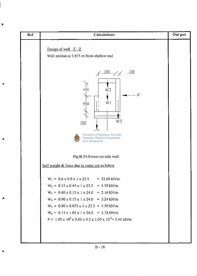
Ref Calculat ions O u t pu t
Design of wall Z - Z
Wall section at 3.875 m from shallow end
4 5 0
5 5 0
1 5 0
/ 600 XX
W 2
1 5 0
I
W 3 I T
W1
W 3
W 4 & W 5
Fig B-24:Forces on side wall
Self weight & force due to water are as below
w, = 0.6 x 0.9 x 1 x 2 3 . 5 = 12.69 kN/m
w2 = 0.15 x 0.45 x 1 x 2 3 . 5 = 1.59 kN/m
w3 = 0.60 x 0.15 x 1 x 2 4 . 0 = 2.16 kN/m
w4 = 0.90 x 0.15 x 1 x 2 4 . 0 = 3.24 kN/m
w5 = 0 . 9 0 x 0 . 0 7 5 x 1 x 2 3 . 5 = 1.59 kN/m
w6 = 0.15 x 1.05 x 1 x 2 4 . 0 = 3.78 kN/m
p = 1 .05 x 1 0 3 x 9 . 8 1 x 0.5 x 1.05 x 10"3= 5.41 kN/m
B - 3 8
Ref Calculat ions Ou t put
Stability Analysis
Overturning moment about X ,
= 5.41 x 0.575
= 3.11 kNm/m
Restoring moment about X ,
= W 2 x 0.075 + (W, + W 3 + W 4 + W 5 ) x 0.45
+ W 6 x 0.825
= 1 .59x0.075
+ ( 12.69 + 2.16 + 3.24 + 1.59 ) x 0.45
+ 3 .78x 0.825
= 12.09 kNm/m
Factor of safety against overturning
= 12.09 = 3.9 > 2 3.11
Hence satisfactory.
Check for sliding
Frictional force = u Gk
= 0.45 x ( W , + W 2 + + W 6 )
= 0.45 x (12 .69+ 1.59 + 2.16
+ 3 . 2 4 + 1.59 + 3.78)
= 0.45 x 25.05
= 11.27 kN/m
Horizontal force = yf Hk
= 1.6 x 5.41
= 8.66 kN/m
Frictional force > Horizontal sliding force
Hence satisfactory.
B - 3 9
T
Ref Calcula t ions Ou t put
Bearing pressure analysis
Total vertical load applied on soil
= W, + W 2 + + W 6
= 12.69+ 1.59 + 2.16 + 3 .24+ 1.59 + 3.78
- 25.05 kN/m
Net overturning moment about center line of base ,
/^T\ = W 2 x 0.375 + P x 0 . 5 7 5 - W 6 x 0.375
= 1 .59x0.375 + 5.41 x0 .575
- 3.78 x 0.375
- 2.29 kNm/m
Soil pressure under base
= 25.05 + 2.29
0.9 1/6 x 0.9 2
= 27.83 ± 16.96
= 44.79 or 10.87 kN/m 2
Hence satisfactory
B - 4 0 A.
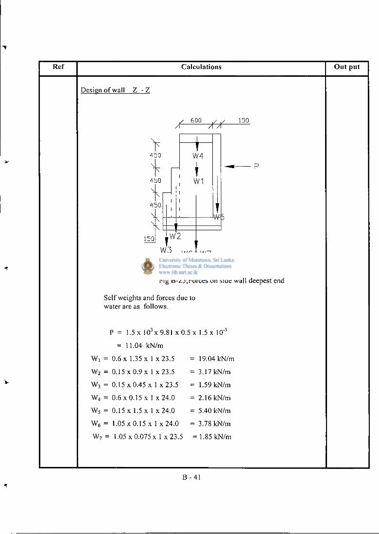
Ref Calculat ions O u t pu t
Design of wall Z - Z
6 0 0
-fit-1 5 0
4 5 0
4 5 0
4 5 0
1 5 0 W 2
I
T" W 4
I T W1
W 3 W 6 & W 7
Fig B-25;Forces on side wall deepest end
Self weights and forces due to water are as follows.
P = 1.5 x 1 0 3 x 9.81 x 0.5 x 1.5 x 10"3
= 11.04 kN/m
Wi = 0.6 x 1.35 x 1 x 2 3 . 5 = 19.04 kN/m
w2 = 0.15 x 0.9 x 1 x 2 3 . 5 = 3.17 kN/m
w3 = 0.15 x 0.45 x 1 x 2 3 . 5 = 1.59 kN/m
w4 = 0 . 6 x 0 . 1 5 x 1 x 2 4 . 0 = 2.16 kN/m
w5 = 0.15 x 1.5 x 1 x 2 4 . 0 = 5.40 kN/m
w6 = 1.05 x 0.15 x 1 x 2 4 . 0 = 3.78 kN/m
w7 = 1.05 x 0.075 x 1 x 2 3 . 5 = 1.85 kN/m
B - 4 1
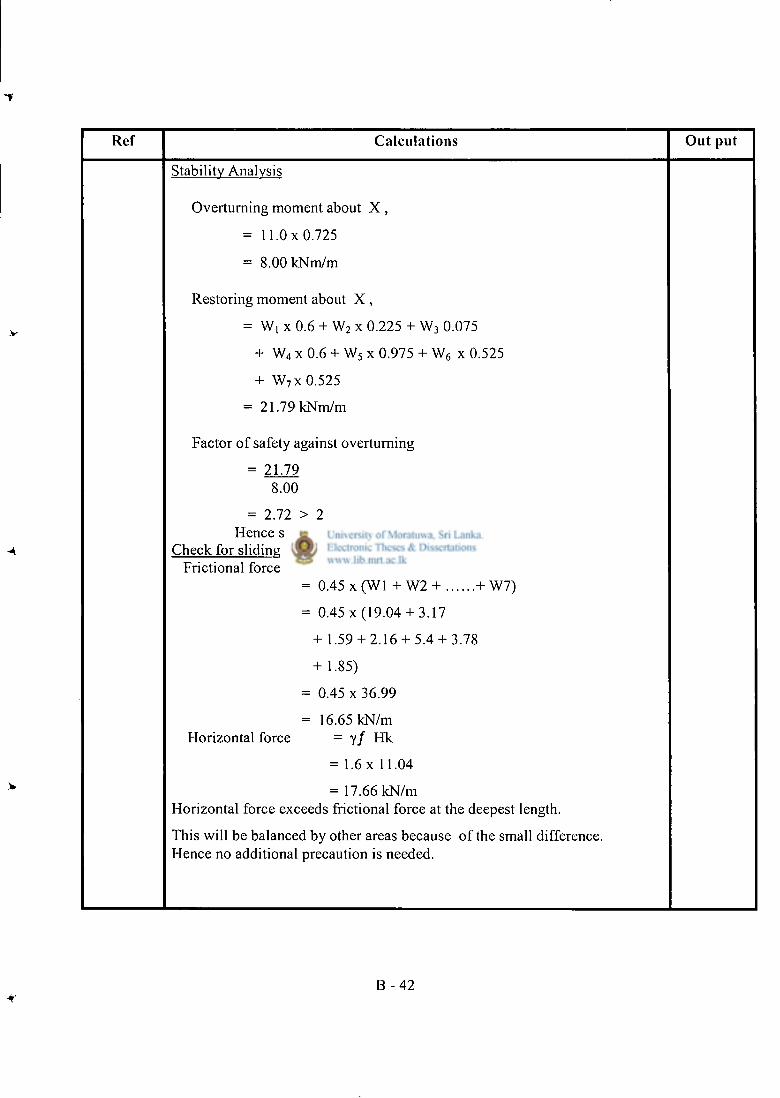
Ref Calcula t ions Ou t put
Stability Analysis
Overturning moment about X ,
= 11 .0x0 .725
= 8.00 kNm/m
Restoring moment about X ,
= Wi x 0.6 + W 2 x 0.225 + W 3 0.075
+ W 4 x 0.6 + W 5 x 0.975 + W 6 x 0.525
+ W 7 x 0.525
= 21.79 kNm/m
Factor of safety against overturning
= 21.79 8.00
= 2.72 > 2 Hence satisfactory.
Check for sliding Frictional force = p. Gk
= 0.45 x (WI + W2 + + W7)
= 0.45 x (19 .04+ 3.17
+ 1.59 + 2.16 + 5.4 + 3.78
+ 1.85)
= 0.45 x 36.99
= 16.65 kN/m Horizontal force = yf Hk
= 1.6 x 11.04
= 17.66 kN/m Horizontal force exceeds frictional force at the deepest length.
This will be balanced by other areas because of the small difference. Hence no additional precaution is needed.
B - 4 2
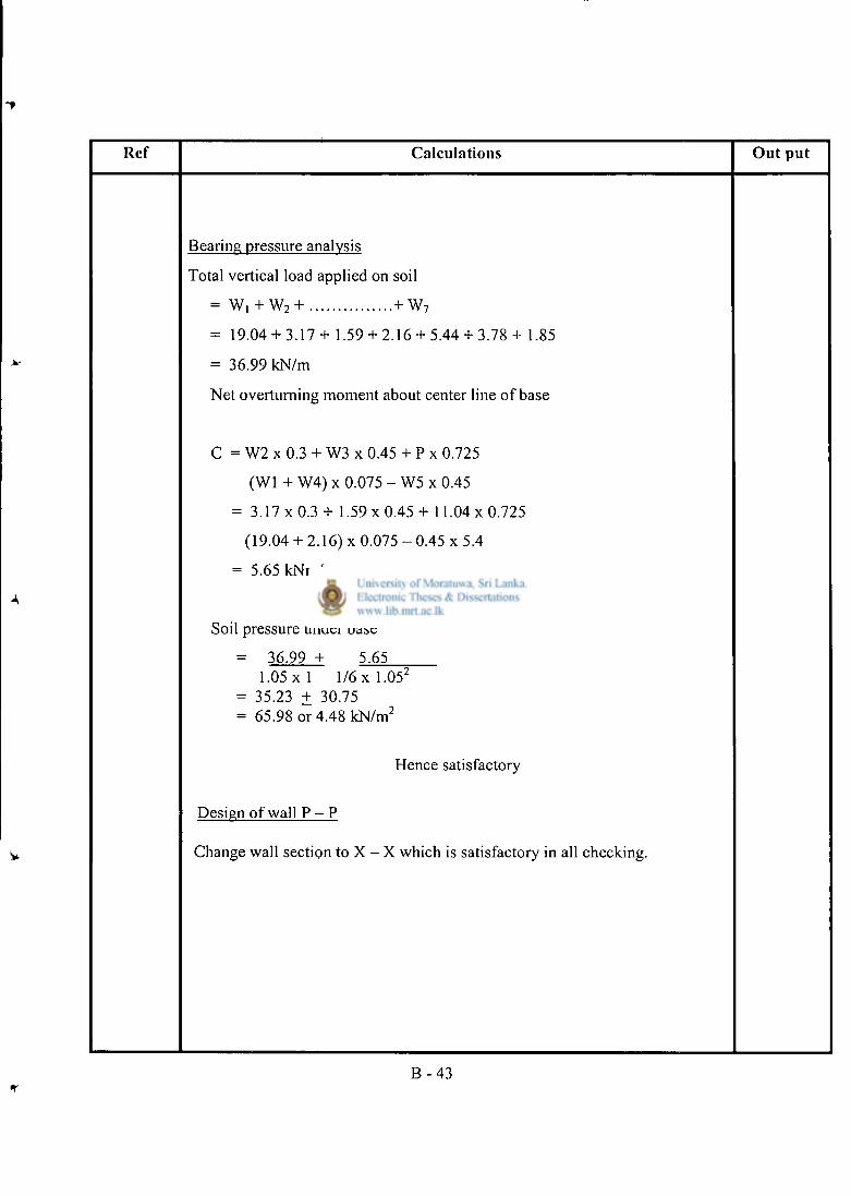
Ref Calculat ions O u t pu t
Bearing pressure analysis
Total vertical load applied on soil
= W, + W 2 + + W 7
= 19.04 + 3 .17+ 1.59 + 2.16 + 5.44 + 3 .78+ 1.85
= 36.99 kN/m
Net overturning moment about center line of base
C = W2 x 0.3 + W3 x 0.45 + P x 0.725
(WI + W4) x 0.075 - W5 x 0.45
= 3 . 1 7 x 0 . 3 + 1 .59x0.45 + 11 .04x0 .725
(19.04 + 2.16) x 0.075 - 0.45 x 5.4
= 5.65 kNm/m
Soil pressure under base
= 36.99 + 5.65 1 .05x1 l / 6 x l . 0 5 2
= 35.23 + 30.75 = 65.98 or 4.48 kN/m 2
Hence satisfactory
Design of wall P - P
Change wall section to X - X which is satisfactory in all checking.
B - 4 3
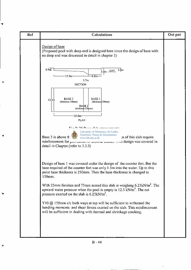
Ref Calculat ions O u t put
Design of base (Proposed pool with deep end is designed here since the design of base with no deep end was discussed in detail in chapter 3)
0.9r£"t
-15.5m- J 1—6.8m-5.6m GWT 2.ym
2.7m SECTION
12.5r BASE 3 (thickness-150mm)
(thickne; BASE 2
s-2S0inm)
BASE 1 (thickness 250mm)
-25.0m-PLAN
Fig B-26:Base slab arrangements
Base 3 is above the ground water table. Hence design of this slab require reinforcement for prevention of thermal cracks. This design was covered in detail in Chapter.(refer to 3.3.9)
Design of base 1 was covered under the design of the counter fort. But the base required of the counter fort was only 1.5m into the water. Up to this point base thickness is 250mm. Then the base thickness is changed to 150mm.
With 25mm finishes and 75mm screed this slab is weighing 6.25kN/m 2 . The upward water pressure when the pool is empty is 12.5 kN/m . The net pressure exerted on the slab is 6.25kN/m 2 .
Y10 @ 150mm c/c both ways at top will be sufficient to withstand the bending moments and shear forces exerted on the slab. This reinforcement will be sufficient in dealing with thermal and shrinkage cracking.
B - 4 4
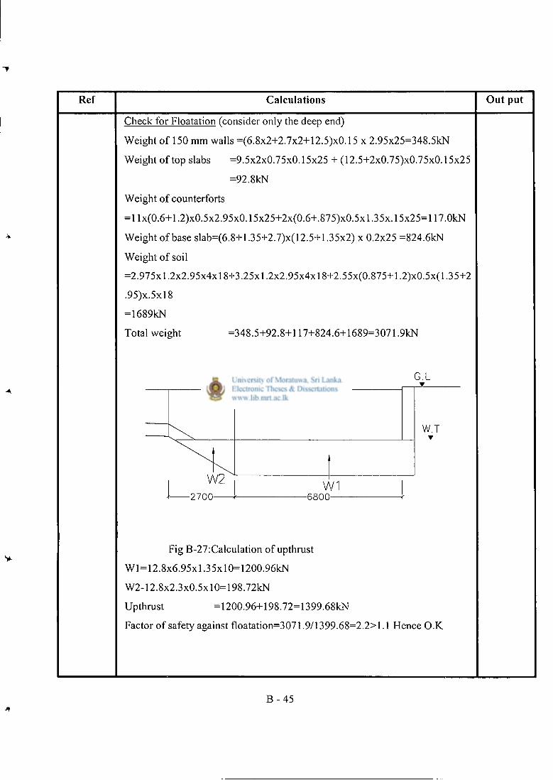
Ref Calculat ions O u t pu t
Check for Floatation (consider only the deep end)
Weight of 150 mm walls =(6.8x2+2.7x2+12.5)x0.15 x 2.95x25=348.5kN
Weight of top slabs =9.5x2x0.75x0.15x25 + (12.5+2x0.75)x0.75x0.15x25
=92.8kN
Weight of counterforts
=Hx(0.6+1.2)x0.5x2.95x0.15x25+2x(0.6+.875)x0.5xl .35x.l5x25=117.0kN
Weight of base slab=(6.8+l.35+2.7)x(12.5+l.35x2) x 0.2x25 =824.6kN
Weight of soil
=2.975x1.2x2.95x4x18+3.25x1.2x2.95x4x18+2.55x(0.875+1.2)x0.5x(l.35+2
.95)x.5xl8
=1689kN
Total weight =348.5+92.8+117+824.6+1689=3071.9kN
Fig B-27:Calculation of upthrust
W l = 12.8x6.95xl .35xl0=1200.96kN
W2-12.8x2.3x0.5xl0=198.72kN
Upthrust =1200.96+198.72=1399.68kN
Factor of safety against floatation=3071.9/1399.68=2.2>1.1 Hence O.K
B - 4 5
Appendix C
Design drawings of conventional swimming pool without deep end
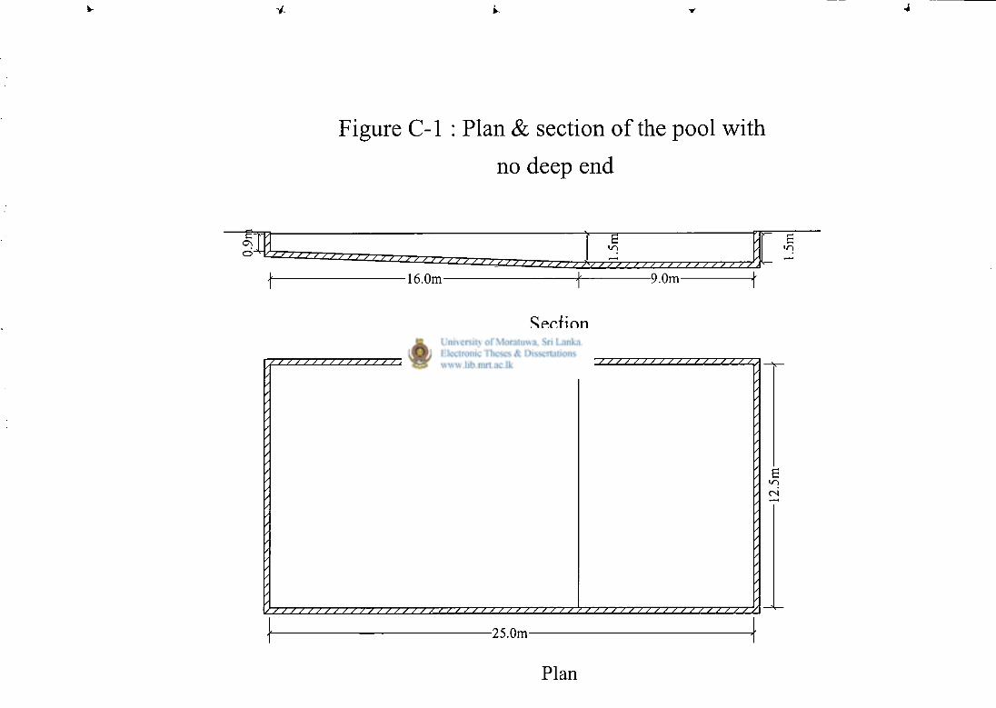
Figure C-l : Plan & section of the pool with no deep end
c O n
J / / <> / •> •> J > > > ) T
-16.0m- -9.0m-
Section
• / •
/ /
/ /
/ /
/ /
' /
/ /
/ /
/ /
/ /
/ /
/ ' / /
• /
• /
/ /
/ /
• /
/ /
/ /
/ /
/ /
/ /
/ /
/ /
/ /
/ /
/ •
/
25.0m
Plan
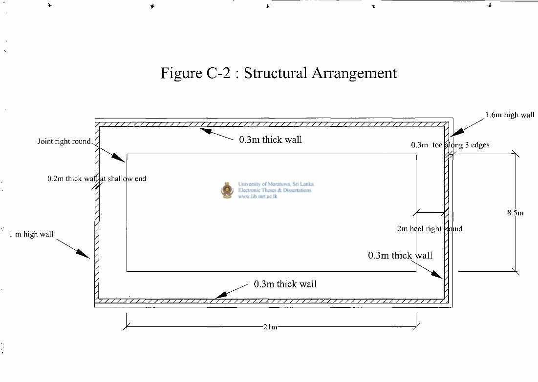
F i g u r e C - 2 : S t r u c t u r a l A r r a n g e m e n t
Joint right round.
0.2m thick v/af
/
1 m high wall
0.3m thick wa l l 0.3m toe
at shallow end
2 m heel r ight
0.3m th ick w a l l
0.3m th ick wa l l
/ // // ; / / ; / ; / / / / / / / ; / // ; / // // // // // / ; / / / / / / / / / / / / / / / / /
A 21m
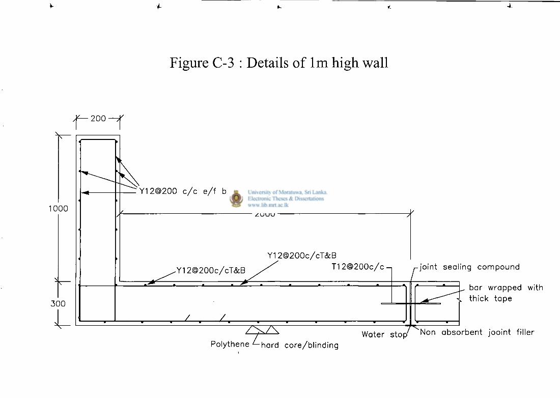
4- 4.
F i g u r e C - 3 : D e t a i l s o f l m h i g h w a l l
200
1000
300
Y12@200 c / c e / f b / w
2000
Y12@200c/cT&B .Y12@200c/cT&B / T 1 2 @ 2 0 0 c / c n
joint sealing compound
/ \ / \
Polythene ^-hard core/blinding
bar wrapped with thick t ape
Water s top Non absorben t jooint filler
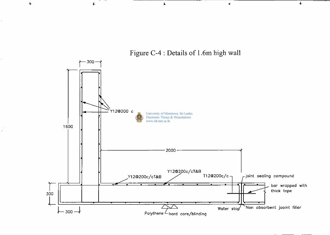
j ^ 3 0 0 - j
1 6 0 0
3 0 0
J ^ 3 0 0 ^ r
Figure C-4 : Details o f 1.6m high wa l l
Y 1 2 O 2 0 0 c / c e / f b / w
2 0 0 0 •
Y 1 2 @ 2 0 0 c / c T & B Y1 2 @ 2 0 0 c / c T & B
T 1 2 @ 2 0 0 c / c - | joint sea l ing c o m p o u n d
Polythene ^-hard core /b l ind ing
bar wrapped with thick t a p e
Water s t o p ^ N o n a b s o r b e n t jooint filler
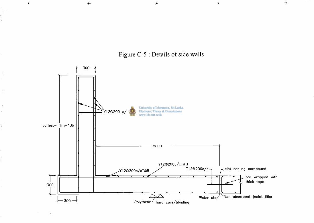
4-
Figure C-5 : Details of side walls
j — 3 0 0 — j
varies:— 1m —1.6m
3 0 0
L
'Y12O200 c / c e / f b /w
2000 •
Y12@200c/cT&B
-Y12@200c/cT<5cB T 1 2 @ 2 0 0 c / c - i r-joint sealing compound
_* _ • *_ _• • • •_
\— 300—If 7 ^ 7 \
Polythene ^-hard core/blinding
bar wrapped with thick tape
Water sto p / ^ N o n absorbent jooint filler
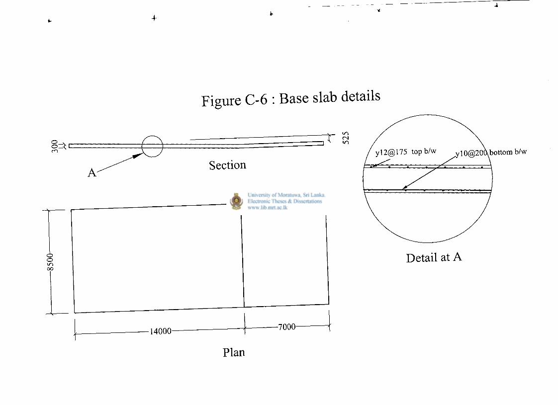
4-
Figure C-6 : Base slab details
Plan

Appendix D
Design drawings of proposed swimming pool without deep end
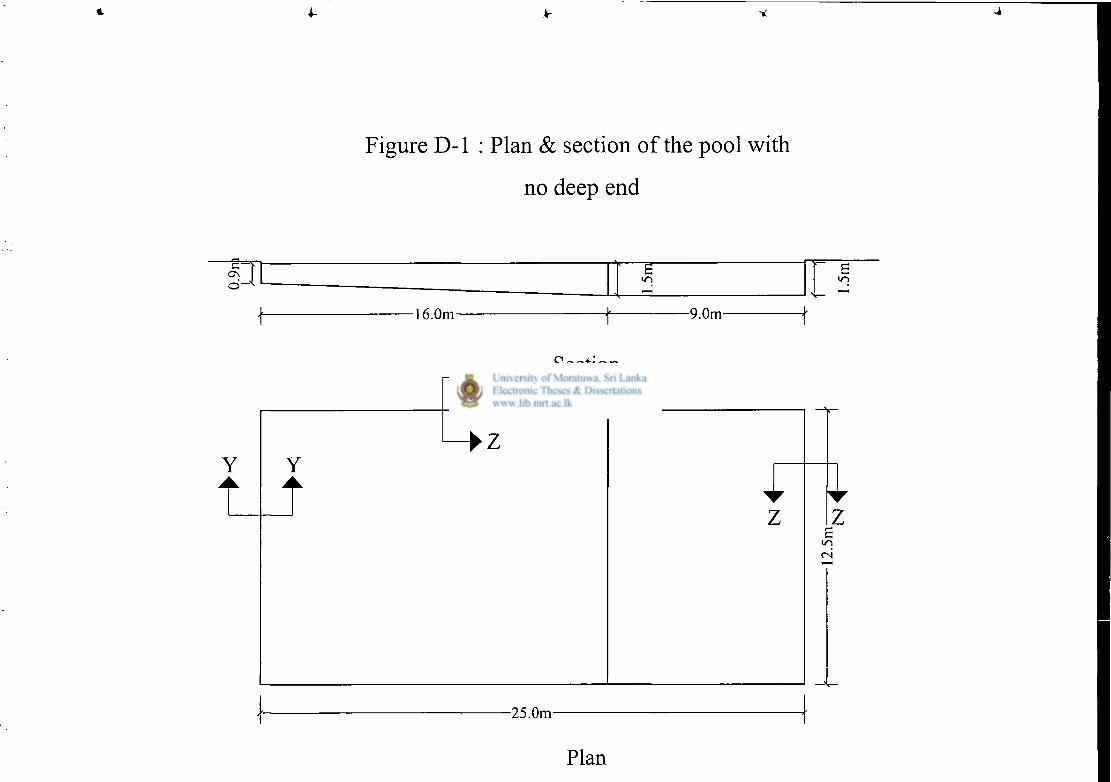
4-
Figure D-1 : Plan & section of the pool with
no deep end
© I 1 £ —
i n
16.0m- -9.0m-
2 Section
Plan
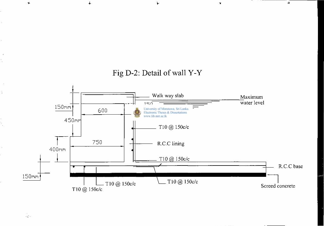
4
F i g D - 2 : D e t a i l o f w a l l Y - Y
150nm
4 5 0 n r
400mm
600
750
150mm
Walk way slab
150 mm
T10@ 150c/c
R.C.C lining
T10@ 150c/c
I
T10(a} 150c/c \ T10@ 150c/c T10(2) 150c/c
Maximum water level
R.C.C base
Screed concrete
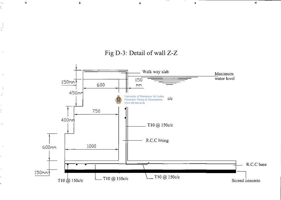
4-
Fig D-3 : Detail of wall Z-Z
150mm
450mr
400mri
600mm
150mm
600
750
1000
f • r
T10@ 150c/c
Walk way slab
150 mm
T10@ 150c/c
T10(S) 150c/c
R.C.C lining
T10@ 150c/c T10@ 150c/c
Maximum water level
R.C.C base
Screed concrete
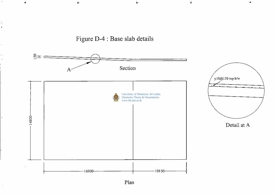
1
Appendix E
Design drawings of conventional swimming pool with deep end
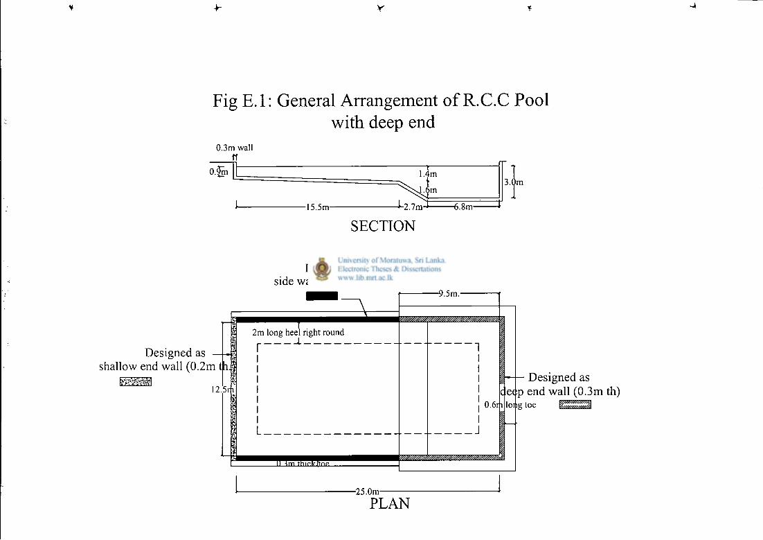
Fig E.l: General Arrangement of R.C.C Pool with deep end
0.3m wall ff
0.§n m r i m
m
-15.5m- J-2.7m-J 6.8m-
SECTION
3 . 0 m
Designed as shallow end wall (0.2m
[J
th It
•I 12.5n
Designed as side wall (0.3m thick)
f 2m long heel right round
a
II < m t h i r l f J t n p
-9.5m.
0.6n I
c e e p Designed as end wall (0.3m
long toe
•25.0m
PLAN
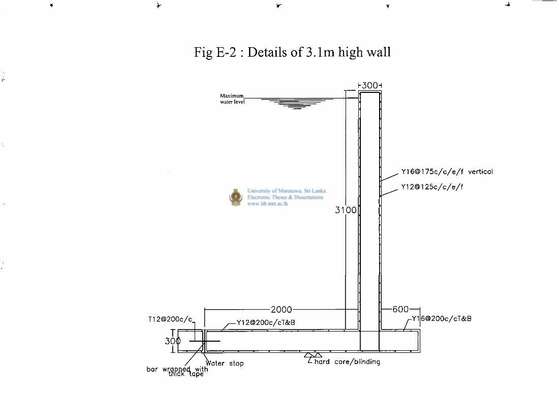
Fig E-2 : Details of 3.1m high wall
T 1 2 @ 2 0 0 c / c
T 30<D
1
I -300H Maximum_ water level
7 1
3100
-2000-- Y 1 2 @ 2 0 0 c / c T & B
Y 1 6 ® 1 7 5 c / c / e / f vertical
Y 1 2 @ 1 2 5 c / c / e / f
— 6 0 0 — | 6 ® 2 0 0 c / c T & B
bar wwpRea^with Water s t o p
itr pe
hard c o r e / b l i n d i n g
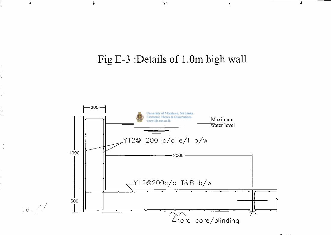
y
Fig E-3 :Details of 1 .Om high wall
| — 2 0 0 — |
1000
3 0 0
Maximum "water level
,Y12@ 2 0 0 c / c e / f b / w
2 0 0 0
Y 1 2 @ 2 0 0 c / c T&B b / w
^-hard c o r e / b l i n d i n g
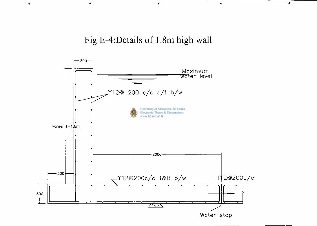
Fig E-4:Details of 1.8m high wall
J—300—|
varies 1 — 1
• 3 0 0
3 0 0
m
Maximum "water level
,Y12@ 200 c / c e / f b /w
2 0 0 0 -
X Y12@200c/c T&B b/w r-T 2@200c /c
V V / \ / \
Water stop
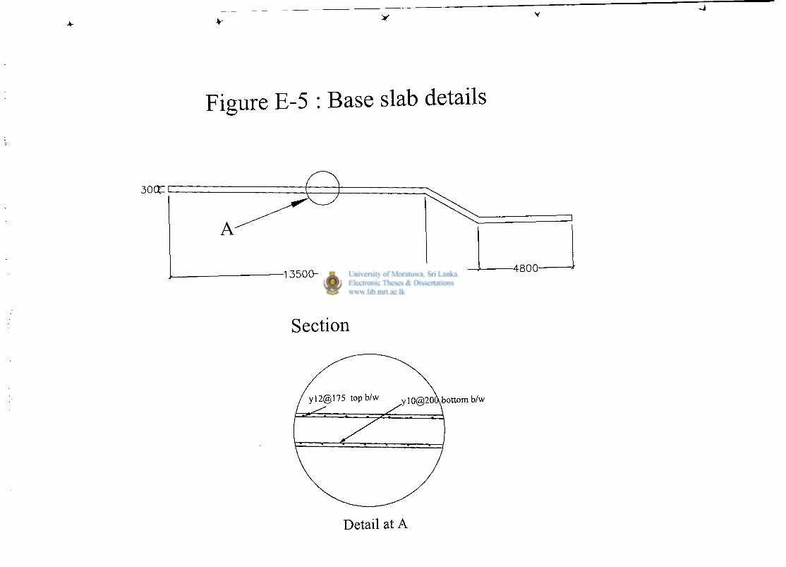
Figure E-5 : Base slab details
3 0 C t [
• 4 8 0 0
Detail at A
A p p e n d i x F
Design drawings of proposed swimming pool with deep
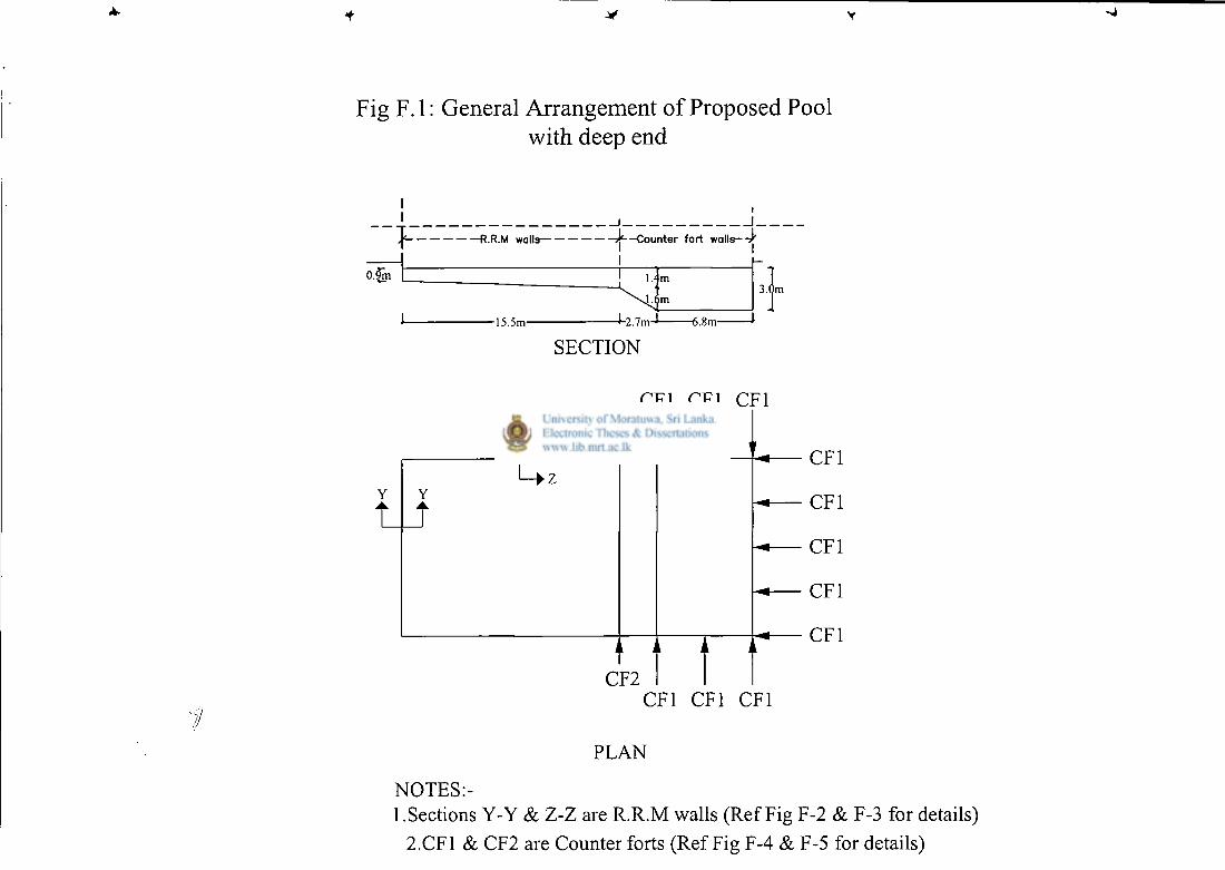
Fig F.l: General Arrangement of Proposed Pool with deep end
R.R.M walls
0.5m
j j*--Counter fort walls-TJ'
I 1.4m
m
-15.5m- -J-2.7m-l 6.8m-
3.0m
SECTION
CF2
CF1
CF1
CF1
CF1
CF1
CF1 CF1 CF1
PLAN
NOTES:-1.Sections Y-Y & Z-Z are R.R.M walls (Ref Fig F-2 & F-3 for details)
2.CF1 & CF2 are Counter forts (Ref Fig F-4 & F-5 for details)
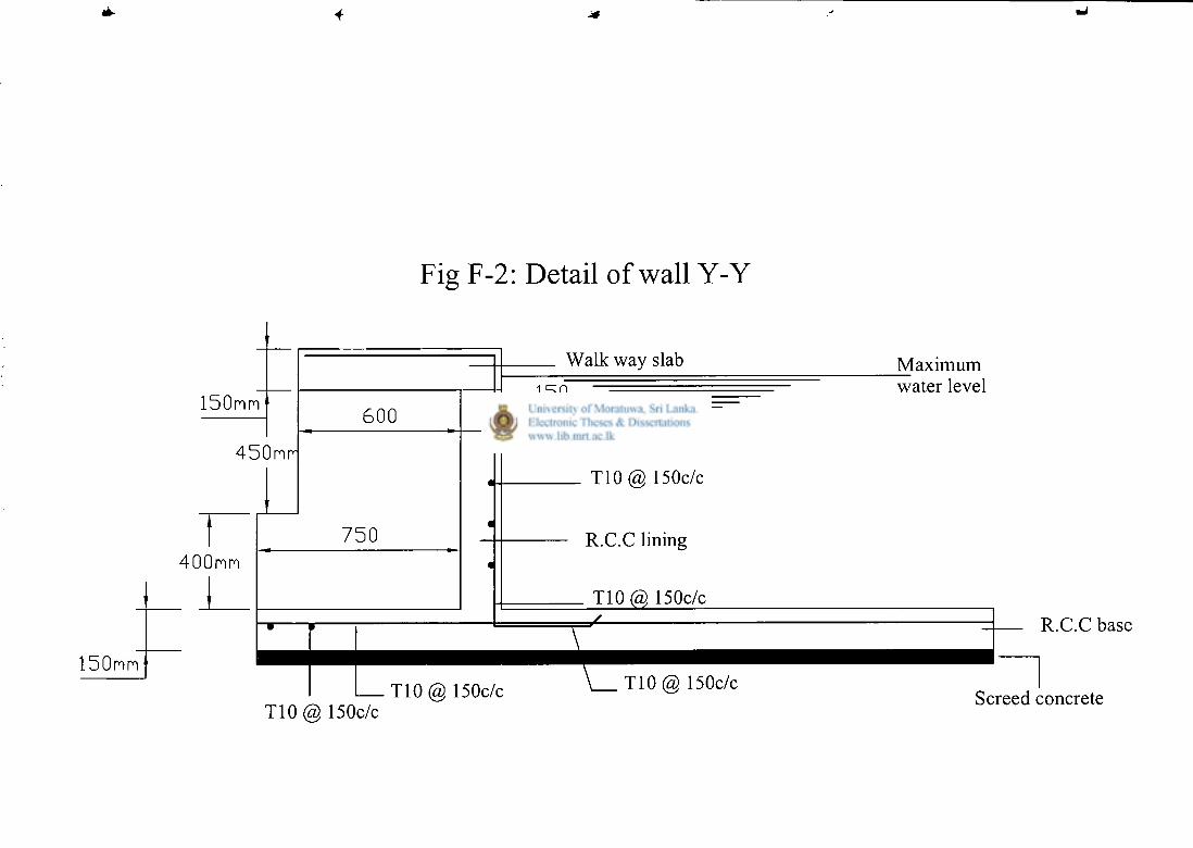
Fig F-2: Detail of wall Y-Y
150mm
450mr
400mm
_ J _
150mm
600
7 5 0
Walk way slab
150 mm
T10@ 150c/c
R.C.C lining
T10@ 150c/c
I
T10 (2), 150c/c T10@ 150c/c \ T10@ 150c/c
_Maximum water level
R.C.C base
Screed concrete
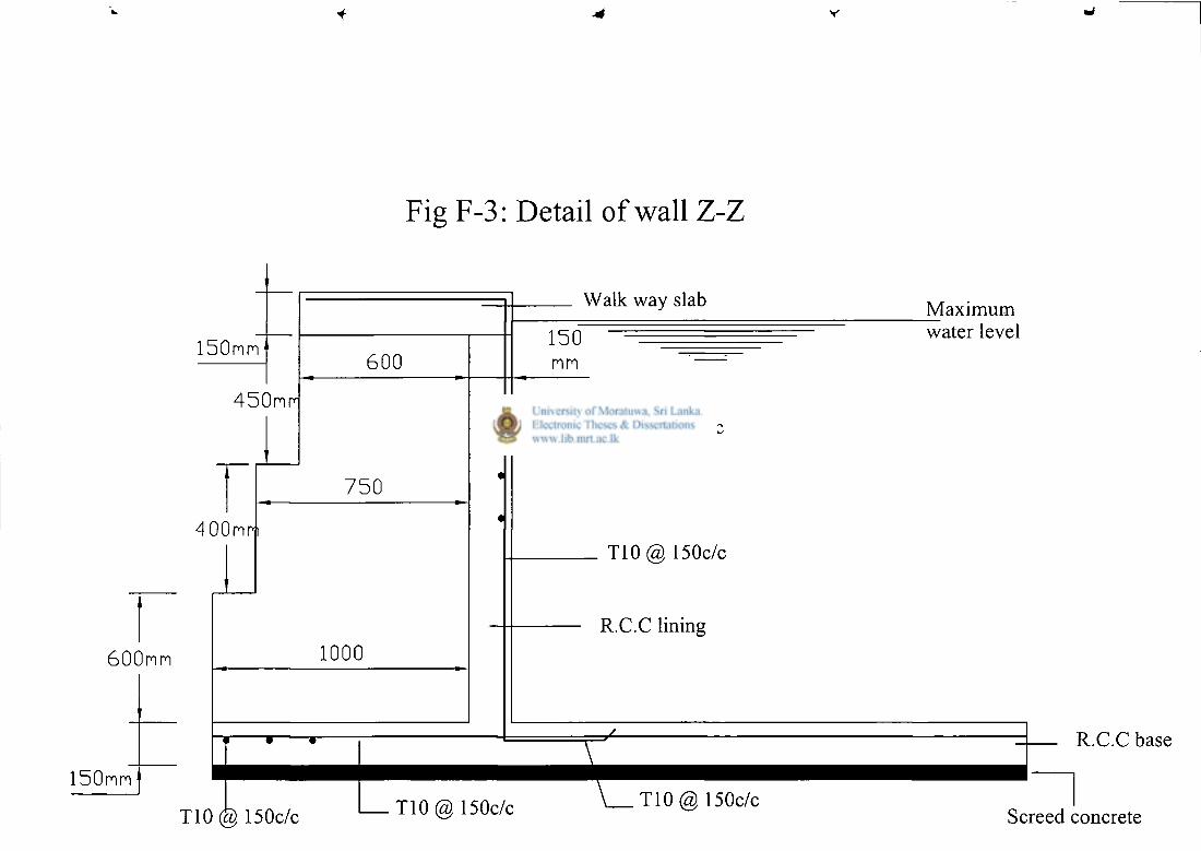
V
Fig F-3: Detail of wall Z-Z
150mm
450mm
400mm
600mm
150mm
600
7 5 0
1000
i r-
T10 150c/c
Walk way slab
150 mm
T10(£) 150c/c
T10@ 150c/c
R.C.C lining
I T 1 0 @ 150c/c \ T 1 0 @ 150c/c
Maximum water level
R.C.C base
Screed concrete
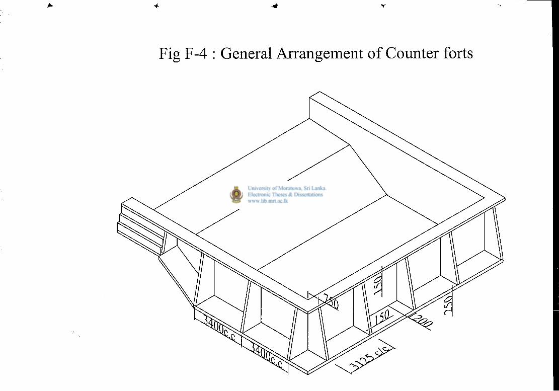
Fig F-4 : General Arrangement of Counter forts
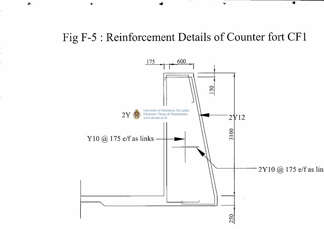
I F-5 : Reinforcement Details of Counter fort CF1
600
2 Y 1 2 -
Y 1 0 @ 1 7 5 e / f a s l i n k s
2 Y 1 0 ( 2 > 1 7 5 e / f a s
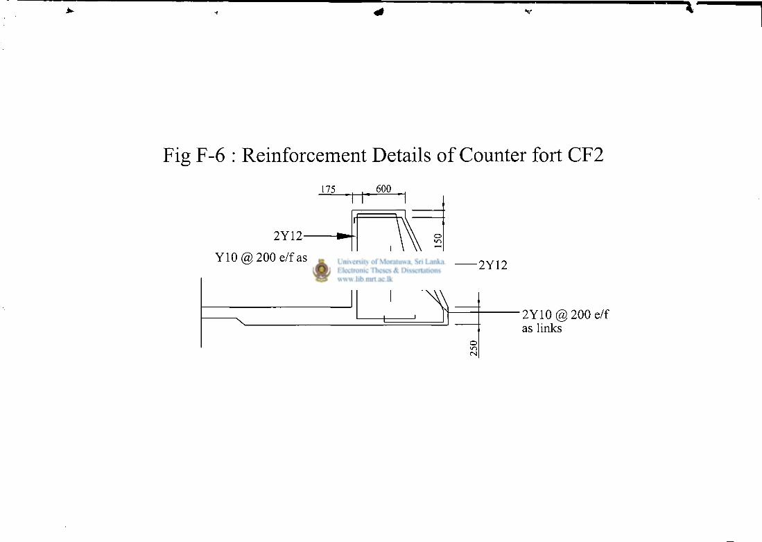
V
Fig F-6 : Reinforcement Details of Counter fort CF2
2Y12-
Y10(5>200 e/f as links 2Y12
2 Y 1 0 @ 2 0 0 e/f as links
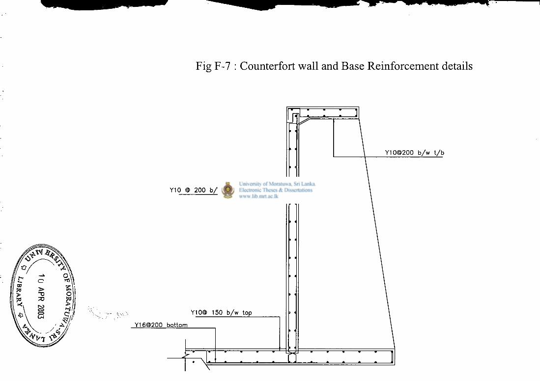
Fig F-7 : Counterfort wall and Base Reinforcement details