climbing, walking and swimming robots ... - core
TRANSCRIPT
(SBU-1)
A SET OF MOBILE AND PORTABLE ROBOTS FOR NONDESTRUCTIVE
INSPECTION WHICH COVER CRITICAL APPLICATIONS ACROSS ALL THE KEY USE
INDUSTRIES
B.Bridge, S.Chen, T.Sattar and Z.Zhao [email protected], [email protected] [email protected] and [email protected]
Research Centre for Automated and Robotic Non-destructive Testing
Faculty of Engineering, Science and Technology, London South Bank University
103 Borough Road, London SE1 OAA, UK
http://www.eeie.sbu.ac.uk/research/ndt/index.html
Tel + 44 20 7815 7598 / 7554, Fax + 44 20 7815 7599
[email protected], [email protected], [email protected]
This paper describes the prototyping of some world first designs of mobile,
portable robots which between them cover important safety critical applications
across the spectrum of key civil and industrial engineering structures such as
aircraft, ships, dams, nuclear power plant and storage tanks located in hazardous
environments. The systems include novel features such as being able to climb over
surfaces of complex contour to deploy the inspection sensors at each test point,
ability to change surfaces, to work submerged in hazardous liquids and to scan
large test areas. The rationale for using a robotic approach to NDT data
acquisition is presented, given that it does involve some complexity in
instrumentation design compared with current practice. A modular approach
using as great a proportion of off-the-shelf components as possible has been used
to greatly reduce the prototyping time.
1. INTRODUCTION
Some essential inspection tasks require automation when the risk to human life of
manual inspection is unacceptable. There are also many other areas of inspection
where human operatives are still used at the inspection site when remote and
automated data acquisition would be preferable. Examples are inspection sites that
are very hazardous because of radiation, toxic fumes and danger of fire or explosion.
Lesser hazards arise when there is bad weather or excessively high or low
temperatures which causes human operatives to under-perform. Finally there are
cases in which the amount of data to be collected is so huge that human tedium
prejudices the quality of the data.
brought to you by COREView metadata, citation and similar papers at core.ac.uk
provided by LSBU Research Open
(SBU-2)
When these conditions arise at present, much manual inspection is still carried out
by using many operatives for a short period to lower the hazard exposure for each
individual, but this increases the inspection costs.
In other cases automated testing has been introduced but these usually take the
form of large fixed robotic gantry systems or smaller jigs fixed round the test-object
and carrying multi-axis manipulators to deploy the sensors. Examples of the former
are assembly line inspection in many manufacturing industries and steel plate
inspection in rolling mills. Examples of the former are inspection jigs fitted round
nodal joints in nuclear power plant coolant circuits and pressure vessels.
These systems have the common characteristic that they are limited in the range of
tasks that can be performed, being limited to one physical location and having a
small in-service time with associated high inspection costs. For examples
manipulators bespoke designed for a specific nodal geometry at a specific nuclear
power plant nodal joints in nuclear inspection are out of service for most of the time,
i.e. between outages.
In contrast human operatives, for all their limitations, have the virtue of flexibility,
being able to move around to different locations on a test object and between
different geographical locations.
Our research philosophy is thus to design new generation inspection systems base
on mobile (walking, climbing and swimming) robots that combine the best features
of automation with the complimentary advantages of human versatility that derive
from their dexterity of their arms, hands and feet, whilst also improving on that
dexterity. An overall economic aim is to produce systems that improve cost
effectiveness of inspection by having a high in-service time that stems from their
versatility. On the other hand in some cases these systems will also be the only
means of carrying out an inspection in a remote and hazardous location and cost is
not then the key issue.
We describe here, only briefly because of the space available, representative
examples of our prototype systems for application in the nuclear, shipping,
aerospace oil and petrochemical storage tanks.
2. WALL CLIMBING ROBOTS SUITABLE FOR INSPECTION OF FLAT
OR SLIGHTLY CURVED SURFACES SUCH AS WALLS AND CEILINGS
ON STORAGE TANKS AND LARGE SHIPS
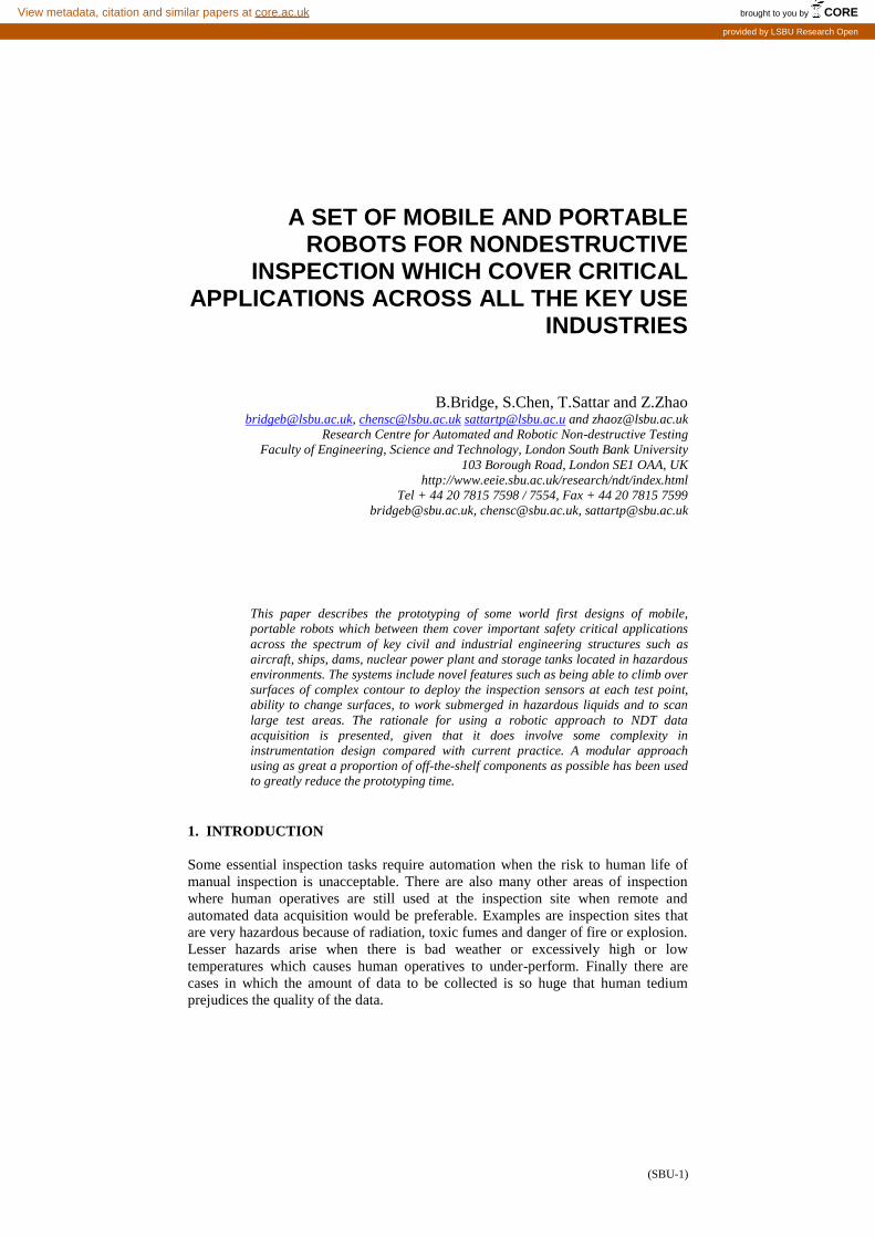
Working with pneumatic suction theses are our simplest robot designs (Figure 1)
which need only rigid ankles to climb flat or slightly curved surfaces. Many design
factors combine to make the payload capability (including mass of hanging
umbilical) increase roughly in proportion to the chassis cross sectional area. The
largest, weighing 37kg, is shown carrying a 6-axis Puma arm weighing 13.5 Kg
deploying an ultrasonic sensor and it can climb to a height of 30 metres with a safety
factor of 3, given an umbilical mass of 0.5 kg per metre. A linear walking
mechanism combined with a turntable allow movement in any direction and power
is provided entirely by compressed air to permit operation in safety critical areas.
These systems are readily put in their starting position by two operatives working
within manual handling regulations (which advise no more than 15kg per person)
(SBU-3)
Figure 1 - Three prototypes of wall climbing robots for inspection of flat surfaces
showing the trade-off between robot size and payload capability: the greater the
payload the less compact and light the system can be
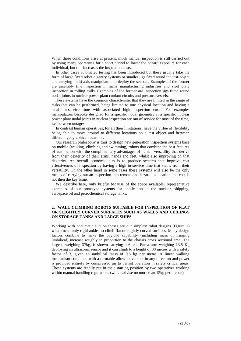
3. ROBOT FOR CLIMBING ON 3D SURFACES SUCH AS SPHERICAL
STORAGE TANKS FILLED WITH AMMONIA AND OTHER INDUSTRIAL
CHEMICALS
This robot (Figure 2), photographed with an empty payload platform, can climb over
3D Surfaces such as spherical storage tanks. This is achieved by means of two
orthogonal walking (striding) mechanisms, 4 thigh joints and 8 universal flexible
ankle joints, all operating under pneumatic power. The joints are made alternatively
flexible for curved surface walking and rigid for carrying out inspection tasks, by
means of a novel vacuum locking mechanism integrated into the control software for
the walking mechanism. The 3D climbing facility limits the payload to about 13kg
with a safety factor of 3. Pneumatic suction means that non-magnetic spherical
objects such as ammonia storage tanks can be inspected.
The robot illustrated can climb over spheres with radius as small as 860 mm.
However there is a severe trade off between payload and the introduction of this
degree of adaptability to curved surfaces. Not only does the ankle joint have to be
flexible but to complete a single walking step the thigh joint must be rotated and the
feet must move forward. The length of the step cannot be too long otherwise the
thigh joint rotation becomes excessive and is taken too far away from the curved
surface, reducing the rigidity of the overall system and increasing the overturning
moments, thus reducing the payload. The consequence of short steps is a slow
moving vehicle. The multiple axis thigh and ankle joint mechanism also adds to the
system weight and the complexity of the on board electronic and pneumatic control
system. In summary this research has shown that load bearing robots can be made to
circumnavigate very highly curved surfaces made of any material composition (for
ferrous structures magnetic rather than vacuum adhesion would make for a much
simpler robot) but only at slow speeds and with much less payload capability than is
possible with rigid ankle robots.
(SBU-4)
Figure 2 - Robot for climbing on 3D surfaces
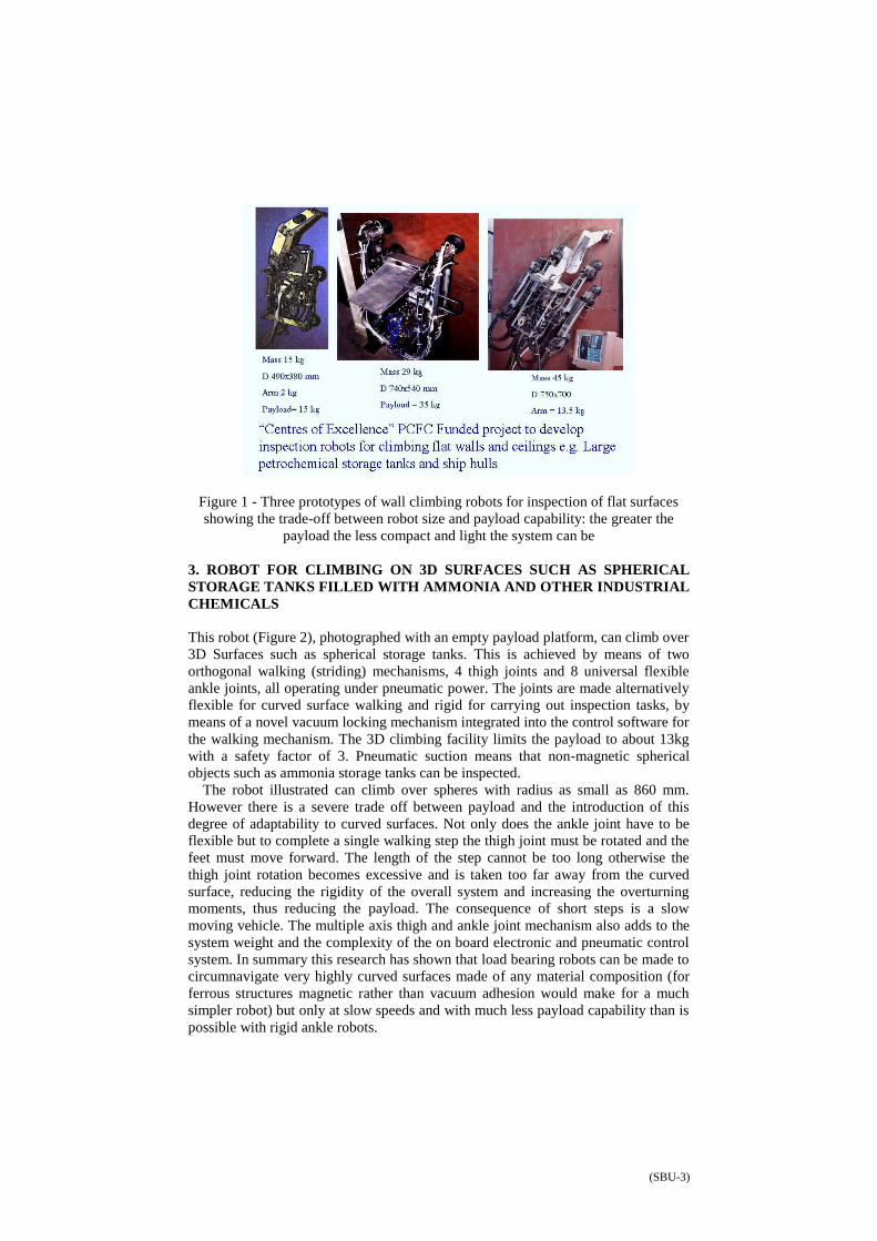
Figure 3 - Pipe climbing robot for weld inspection in lab tests
3. PIPE CLIMBING ROBOT FOR WELD INSPECTION IN NUCLEAR
POWER PLANT
This robot (Figures 3-4) carries a 7-axis arm which deploys an ultrasonic sensor
array at its end effector. This produces an inspection versatility greater than the
human arm and wrist, permitting scans round very small pipe diameters. Also the
arm can be programmed to perform an infinite variety of test scans such as TOFD,
phased array. The vehicle itself is derived from the generic robot described in
section 3. Two thigh joints have been removed and ankle joint movement restricted
to one plane to permit greater suction feet area and rigidity and hence greater
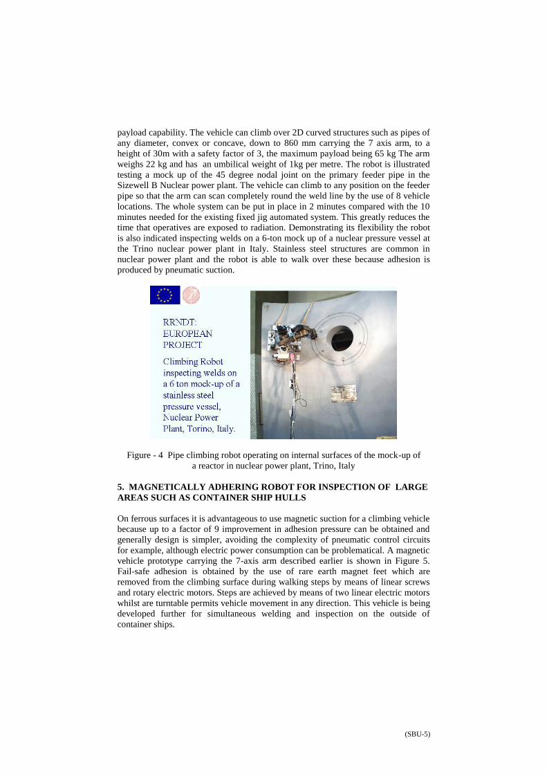
(SBU-5)
payload capability. The vehicle can climb over 2D curved structures such as pipes of
any diameter, convex or concave, down to 860 mm carrying the 7 axis arm, to a
height of 30m with a safety factor of 3, the maximum payload being 65 kg The arm
weighs 22 kg and has an umbilical weight of 1kg per metre. The robot is illustrated
testing a mock up of the 45 degree nodal joint on the primary feeder pipe in the
Sizewell B Nuclear power plant. The vehicle can climb to any position on the feeder
pipe so that the arm can scan completely round the weld line by the use of 8 vehicle
locations. The whole system can be put in place in 2 minutes compared with the 10
minutes needed for the existing fixed jig automated system. This greatly reduces the
time that operatives are exposed to radiation. Demonstrating its flexibility the robot
is also indicated inspecting welds on a 6-ton mock up of a nuclear pressure vessel at
the Trino nuclear power plant in Italy. Stainless steel structures are common in
nuclear power plant and the robot is able to walk over these because adhesion is
produced by pneumatic suction.
Figure - 4 Pipe climbing robot operating on internal surfaces of the mock-up of
a reactor in nuclear power plant, Trino, Italy
5. MAGNETICALLY ADHERING ROBOT FOR INSPECTION OF LARGE
AREAS SUCH AS CONTAINER SHIP HULLS
On ferrous surfaces it is advantageous to use magnetic suction for a climbing vehicle
because up to a factor of 9 improvement in adhesion pressure can be obtained and
generally design is simpler, avoiding the complexity of pneumatic control circuits
for example, although electric power consumption can be problematical. A magnetic
vehicle prototype carrying the 7-axis arm described earlier is shown in Figure 5.
Fail-safe adhesion is obtained by the use of rare earth magnet feet which are
removed from the climbing surface during walking steps by means of linear screws
and rotary electric motors. Steps are achieved by means of two linear electric motors
whilst are turntable permits vehicle movement in any direction. This vehicle is being
developed further for simultaneous welding and inspection on the outside of
container ships.
(SBU-6)
Figure - 5 Magnetically adhering robot for inspection of large
areas such as weld lines on container ship hulls. In the illustration an ultrasonic
sensor deployed by a 7-axis arm can be seen engaging a weld line.
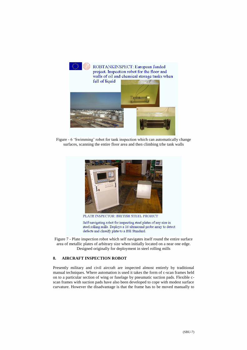
6. TANK INSPECTION ROBOT
There is a need to inspect large petrochemical storage tanks without emptying them
as at present as it is very expensive to empty a tank just for that purpose (£500,000 -
£1,000,000). Figure 6 shows our prototype robot for inspection of the wall and
floors of tanks from the inside whilst full of oil. Designed to intrinsic safety
legislation this robot is small enough to fit through the smallest access hole in the
world supply of storage tanks (300mm). With an estimated 400,000 large tanks in
the world this provides a large potential inspection market and opportunities for
environmental protection. There has been a case of a major tank leak which led to
the evacuation of a medium sized town in the USA. It can move on wheels over the
entire floor area of a tank in programmed paths, avoiding tank furniture with an on
board navigation system. It can also change surfaces and climb tank walls up to the
liquid surface by balancing propeller suction forces against buoyancy. An array of
20 ultrasound probes including two long-range probes, carry out the corrosion
inspection of the entire structure including welds and overlapping plate join.
7. PLATE INSPECTION ROBOT
Presently steel plate in rolling mills is carried out by placing the plate under a large
gantry inspection system which is a fixed installation. Our prototype mobile plate
inspection robot shown in Figure 7 has the advantage that it can be moved around to
any plate in any factory. When placed on the edge of a plate it navigates itself round
the entire surface area of the plate in a raster scan, an on board eddy current edge
detection system preventing it from falling over the sides of the plate. A linear
wheel mechanism and a turntable allow movement in any direction. An array of 16
ultrasound probes along the back and front edges of the vehicle chassis captures the
corrosion and delamination data.
(SBU-7)
Figure - 6 ‘Swimming’ robot for tank inspection which can automatically change
surfaces, scanning the entire floor area and then climbing trhe tank walls
Figure 7 - Plate inspection robot which self navigates itself round the entire surface
area of metallic plates of arbitrary size when initially located on a near one edge.
Designed originally for deployment in steel rolling mills
8. AIRCRAFT INSPECTION ROBOT
Presently military and civil aircraft are inspected almost entirely by traditional
manual techniques. Where automation is used it takes the form of c-scan frames held
on to a particular section of wing or fuselage by pneumatic suction pads. Flexible c-
scan frames with suction pads have also been developed to cope with modest surface
curvature. However the disadvantage is that the frame has to be moved manually to
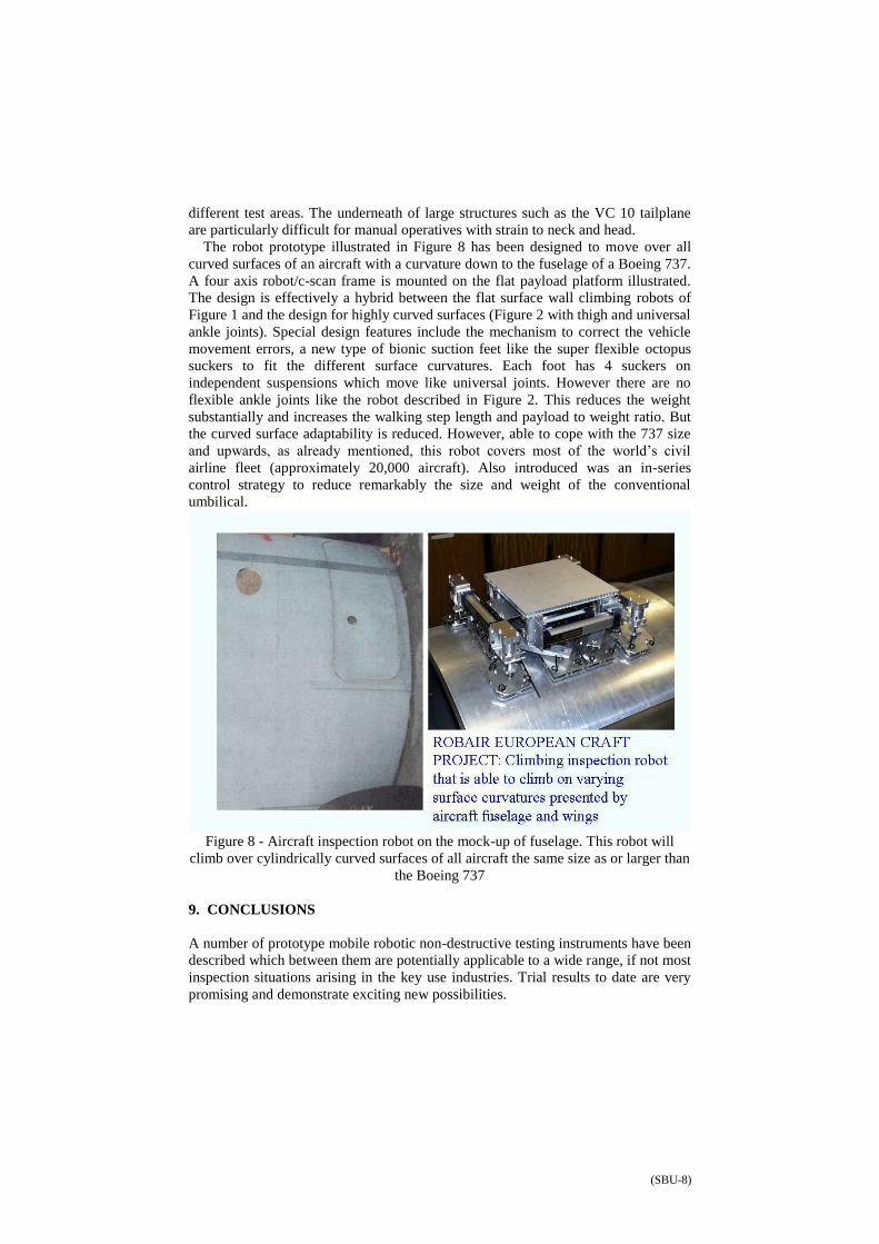
(SBU-8)
different test areas. The underneath of large structures such as the VC 10 tailplane
are particularly difficult for manual operatives with strain to neck and head.
The robot prototype illustrated in Figure 8 has been designed to move over all
curved surfaces of an aircraft with a curvature down to the fuselage of a Boeing 737.
A four axis robot/c-scan frame is mounted on the flat payload platform illustrated.
The design is effectively a hybrid between the flat surface wall climbing robots of
Figure 1 and the design for highly curved surfaces (Figure 2 with thigh and universal
ankle joints). Special design features include the mechanism to correct the vehicle
movement errors, a new type of bionic suction feet like the super flexible octopus
suckers to fit the different surface curvatures. Each foot has 4 suckers on
independent suspensions which move like universal joints. However there are no
flexible ankle joints like the robot described in Figure 2. This reduces the weight
substantially and increases the walking step length and payload to weight ratio. But
the curved surface adaptability is reduced. However, able to cope with the 737 size
and upwards, as already mentioned, this robot covers most of the world’s civil
airline fleet (approximately 20,000 aircraft). Also introduced was an in-series
control strategy to reduce remarkably the size and weight of the conventional
umbilical.
Figure 8 - Aircraft inspection robot on the mock-up of fuselage. This robot will
climb over cylindrically curved surfaces of all aircraft the same size as or larger than
the Boeing 737
9. CONCLUSIONS
A number of prototype mobile robotic non-destructive testing instruments have been
described which between them are potentially applicable to a wide range, if not most
inspection situations arising in the key use industries. Trial results to date are very
promising and demonstrate exciting new possibilities.
(SBU-9)
In their design modularity principles have been applied, using off the shelf
components as far as possible for cost effectiveness and speed in the design stages.
A general performance principle is that the simpler the structure to be inspected the
greater is the possible inspection speed (i.e. step speed) and/or sensor payload that
can be deployed, for a given chassis size. All other things being equal payloads can
be increased at the expense of vehicle chassis size and weight. In some situations
very heavy sensors such as X ray tubes, Gamma ray imaging collimators for
Compton scatter imaging, magnetic flux leakage coils and SQUID magnetometers
could be deployed. Climbing over highly curved surfaces, however payloads for a
given chassis size and also reduces inspection speed. Much research remains to be
done to seek better compromises between the many design variables, especially in
the design of dedicated sub components, especially ones with lighter weight.
Indeed the production of materials with greatly enhanced strength to weight ratio, is
one of the greatest challenges. This is also the gaol of nanotechnology as applied to
structural materials. Whilst the key aim of such nanotechnolgy research is to
produce improved i.e. more economical airframes, as a spin off the kind of robotic
ndt solutions that we have proposed could be revolutionised.
10. ACKNOWLEDGEMENTS
The projects described above were funded by the EU under the projects REMOTE
ROBOTIC NDT, ROBTANKINSPEC, ROBAIR, and by British Steel (plates
division) and the PCFCE (Centres of Excellence Award) and by the EPSRC.
11. REFERENCES
1. Sattar TP, Chen SC, Bridge B and Shang J. Robair: Mobile Robotic System to Inspect Aircraft Wings
and fuselage, CARs & FOF, Kuala Lumpur, Malaysia, July 2003; 795-802.
2. Sattar TP, Zhao Z, Bridge B, et al. Internal In-service Inspection of the Floor and Walls of Oil, Petroleum, and Chemical Storage Tanks with a Mobile Robot. Proceedings of the Fifth International
Conference on Climbing and Walking Robots and their supporting Technologies, CLAWAR 2002; 947-54.
3. Chen SC, Bridge B, Sattar TP. Analysis and Calculation of Payload Carrying Capacity for Climbing
Robotic Non-destructive Testing System, IEEE International Conference on Machatronics and Machine Vision in Practice, City University of Hong Kong, Hong Kong 2001; 393-98.
4. Chen SC, Sattar TP, Bridge B. Mechanics Analysis and Design Methodology of Enhancing the Climbing Vehicle Structure, IEEE International Conference on Mechatronics and Machine Vision in
Practice, City University of Hong Kong, Hong Kong 2001; 404-407.
5. Sattar TP, Bridge B, Chen SC. A Magnetically Adhering Wall Climbing Robot to Perform Continuous Welding of Long Seams and Non-Destructively Test the Welds on the Hull of a Container Ship,
IEEE International Conference on Mechatronics and Machine Vision in Practice, City University of Hong Kong, Hong Kong 2001; 408-14.
6. Sattar TP, Bridge B, Chen SC. Design of a versatile robot for inspection of welds with complex
contours in nuclear power plant. Proceedings of the Second International Conference on NDE in Relation to Structural Integrity of Nuclear and Pressurized Components, New Orleans Vol.2, 2000;
35-56.
(SBU-10)
7. Bridge B, Sattar TP, Chen SC. Pneumatic wall and ceiling climbing inspection robot able to handle diameters down to one metre with high payload capacity. Proceedings of the 2nd International
Conference on Climbing and Walking Robots (funded by European Commission ’s the 4th
Framework programme),1999; 35-56.
8. Bridge B. The Centre for Automated and Robotic NDT at South Bank University (UK): Development
of Novel Climbing Robot Technology for Non-destructive Testing in Hazardous Environments, Proceedings of the Conference on Non-destructive Testing: an Eastern-western European Perspective,
Varna (September 1998), published by the British Institute of NDT 1998, 304-320.
9. Bridge B, Sattar TP, Chen SC. On the design of multi-task, compact, climbing robotic NDT systems for remote operation on large surfaces and in hazardous environments, Non-destructive Testing and
Evaluation, Vol.13,1997; 85-111.