determining the three-dimensional convex hull of a polyhedron
TRANSCRIPT

A. AppelP. M. Will
Determining the Three-dimensional Convex Hull of aPolyhedron
Abstract: A method is presented for determining the three-dimensional convex hull of a real object that is approximated in computerstorage by a polyhedron. Essentially, this technique tests all point pairs of the polyhedron for convex edges of the convex hull andthen assembles the edges into the polygonal boundaries of each of the faces of the convex hull. Various techniques for optimizing thisprocess are discussed. A computer program has been written. and typical output shapes are illustrated. Finding the three-dimensionalconvex hull is approximately the same computer burden as eliminating hidden lines.
Figure 1 Typical polygon (a) and its convex hull (b).
Two-dimensional solutionsA body is defined as being convex if a line joining anytwo points on the n-dimensional figure is entirely contained within the body. One can consider the polygon to
IntroductionThe determination of convex hulls and their propertieshas been of continuous interest in linear programmingand pattern recognition [I 6]. Freeman has discussedthe use of the two-dimensional convex hull for the stockcutting or allocation problem [7]; Balinski has describeda method for finding all vertices of an n-dimensionalconvex polyhedral set defined by a system of linear inequalities [8]; and Nagy and Tuong have normalizedtwo-dimensional data by transforming the convex hull ofa pattern into a square [9, 10]. This paper describes amethod for determining the three-dimensional convexhull of an object.
I. Find a point definitely outside the point set. This isthe initial origin.
be a set of edge points. and the convex polygon can beobtained from operations on this set; but it is more convenient, as in computer graphics, to consider the sets tobe ordered lists. When the order of points on a polygonis given as a list, the lines on the polygon are drawnbetween successive points in this list. A convex point ina two-dimensional list can be defined as the intersectionof two lines that form an internal angle less than 1800
• Anonconvex point has an internal angle equal to or greaterthan 180°.
A polygon with an interesting boundary and its twodimensional convex hull are shown in Fig. 1. A twodimensional convex hull is a polygon formed only ofconvex points. Points on the original polygon list can beinspected to delete all nonconvex points. The new listmust then be tested again for convex points since thedeletion of some points may create new nonconvexpoints. The iterative nature of this procedure is illustratedin Fig. 2.
The identification of the convex hull of unorderedtwo-dimensional points has been described by Graham[11] and Jarvis [12]. Graham's approach is to order theoriginal data set on the basis of polar angles about aninterior point and then use an angle measurementscheme similar to that shown in Fig. 2. Jarvis contendsthat this ordering procedure is itself expensive in termsof comparison tests and that it is not necessary. Withreference to Fig. 3, Jarvis's method is as follows:
R
2
(b)
9
10
(a)
9
13
,~/' 11 12
10
590
A. APPEL AND P. M. WILL IBM J. RES. DEVELOP.
2 l¥C< 1800
2 2l¥NC;C> 1800
13 Delete l¥C Delete
fj~Multiple l¥NC
10 loop mark 10
} Deleteinternal -1
loop9 End of 9 9
loop mark
(a) (b) (c)
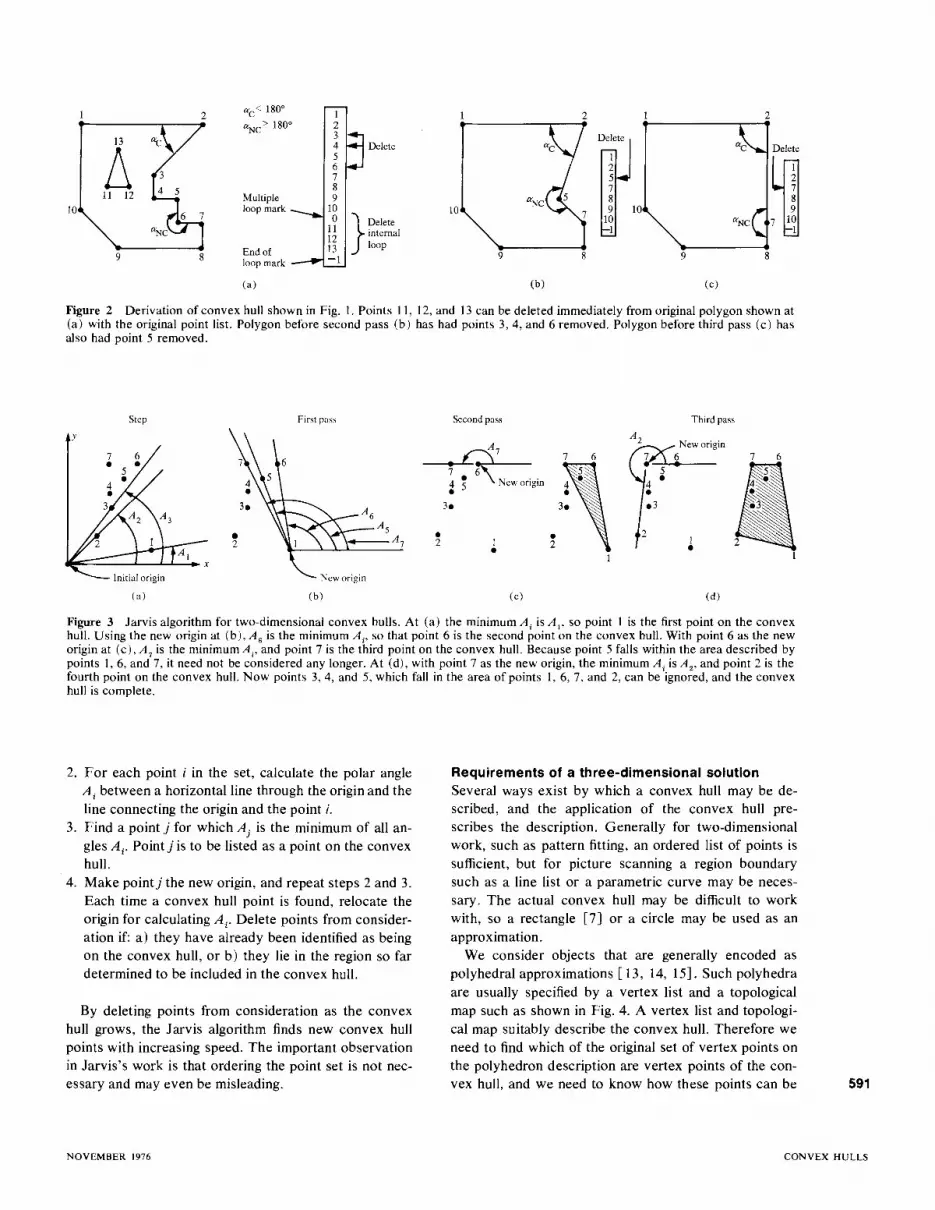
Figure 2 Derivation of convex hull shown in Fig. I. Points II, 12, and 13 can be deleted immediately from original polygon shown at(a) with the original point list. Polygon before second pass (b) has had points 3, 4, and 6 removed. Polygon before third pass (c) hasalso had point 5 removed.
y
Step First pass Second pass
A 7
A2
~NeWOrigin7 6•7 ,4 4 ••
1,:3•
•2 1•
Third pass
II
(a) (b) (c) (d)
Figure 3 Jarvis algorithm for two-dimensional convex hulls. At (a) the minimum Ai is A!, so point I is the first point on the convexhull. Using the new origin at (b), A 6 is the minimum Ai' so that point 6 is the second point on the convex hull. With point 6 as the neworigin at (c), A 7 is the minimum A i' and point 7 is the third point on the convex hull. Because point 5 falls within the area described bypoints 1,6, and 7, it need not be considered any longer. At (d), with point 7 as the new origin, the minimum Ai is A
2, and point 2 is the
fourth point on the convex hull. Now points 3,4, and 5, which fall in the area of points 1,6,7, and 2, can be ignored, and the convexhull is complete.
2. For each point i in the set, calculate the polar angleAi between a horizontal line through the origin and theline connecting the origin and the point i.
3. Find a point j for which A j is the minimum of all angles Ai' Point j is to be listed as a point on the convexhull.
4. Make pointj the new origin, and repeat steps 2 and 3.Each time a convex hull point is found, relocate theorigin for calculating Ai' Delete points from consideration if: a) they have already been identified as beingon the convex hull, or b) they lie in the region so fardetermined to be included in the convex hull.
By deleting points from consideration as the convexhull grows, the Jarvis algorithm finds new convex hullpoints with increasing speed. The important observationin Jarvis's work is that ordering the point set is not necessary and may even be misleading.
Requirements of a three-dimensional solutionSeveral ways exist by which a convex hull may be described, and the application of the convex hull prescribes the description. Generally for two-dimensionalwork, such as pattern fitting, an ordered list of points issufficient, but for picture scanning a region boundarysuch as a line list or a parametric curve may be necessary. The actual convex hull may be difficult to workwith, so a rectangle [7J or a circle may be used as anapproximation.
We consider objects that are generally encoded aspolyhedral approximations [ 13, 14, 15J. Such polyhedraare usually specified by a vertex list and a topologicalmap such as shown in Fig. 4. A vertex list and topological map suitably describe the convex hull. Therefore weneed to find which of the original set of vertex points onthe polyhedron description are vertex points of the convex hull, and we need to know how these points can be 591
NOVEMBER 1976 CONVEX HULLS

Vertex list connected together to form the boundaries of the planesurfaces of the convex hull. In the two-dimensional con-
Point x y zvex hull problem, points of the original data set had to
1 1 0 2 be eliminated and lines that were not part of the original2 0 0 2 polygon had to be found. In the three-dimensional prob-3 0 1 1 lem, points have to be eliminated, and new lines and4 1 1 15 0 2 1 planes must be found.
6 1 2 17 0 0 0 Properties of convex polyhedra8 I 0 0
Original9 1 2 0 Several properties of a convex polyhedron can serve as
polyhedron10 0 2 0 a basis for determining the convex hull of points in
three-dimensional space. For example:
Figure 4 Typical original data and required specification of aconvex hull. Points 3 and 4 have been deleted from the vertexlist, and surfaces I and II have been deleted fromthe topologicalmap. Surface VIII with connectivity 1, 2, 5, 6 must be added,and surfaces VI and VII must be respecified.
Topological map
I 1,2,3,4II 3,4,6,5III 5,6,10,9IV 1,2,7,8V 7,8,9,10VI 1,4,6,9,8VII 2,3,5,10,7
1. Any point inside the convex polyhedron is on thematerial side of all planes of the polyhedron.
2. Each convex point of the convex hull is a vertex of aconvex cone of the convex polyhedron.
3. Each convex edge of the convex hull is the intersection of exactly two convex planes and has an internaldihedral angle less than 1800
•
4. The boundary of any plane surface is a convexpolygon.
5. Any projection of a convex polyhedron is a convexpolygon.
6. In any projection of a convex polyhedron, the edgesthat produce the outline are a closed curve in threedimensional space.
7. A convex polyhedron encloses the given points inspace with minimum surface area.
PointsSurface
9
Convexhull ---~
Figure 5 Determination of convex edges from a projectionplane perpendicular to the edge. The point projection of lines(1,2), (5,6), (7,8), and (9, 10) are convex points, hence theselines are convex edges. The point projection of line (3,4) is nota convex point, and this line is not a convex edge.
592
Convex hull ofprojection oforiginal object
Point projectionofline 1,2
Pointprojectionof line 3, 4
Doubtless, this list of properties can be extended.Properties 1 and 2 are most frequently used in linearprogramming. Properties I and 6 can be used for hiddenline elimination [16]. Properties 3 and 4 are the onlycharacteristics that make it possible to delete some givenpoints on the basis of local measurements. All of theother properties are characteristics of the entire objectand are expensive to determine.
Algorithm for determining the three-dimensionalconvex hullThe algorithm to be described attempts to find the edgesof the convex hull. Identifying the edges of the threedimensional convex hull seems to be most appealing fortwo reasons: I) Ifthe edges are known, vertex points onthe convex hull can be identified, and with small effortthe topological map can be constructed; 2) the probability of wasteful testing for convex edges is less than theprobability of wasteful testing for convex planes. Withregard to this last reason, the number of two-combinations of N things is usually smaller than the number ofthree-combinations of N things:
C(N, r) = (Nl)!(r!)(N - r)!
C(6, 2) = 15, C(6, 3) = 20.
A. APPEL AND P. M. WILL IBM J. RES. DEVELOP.

Figure 6 Points I, 2, 3, 4, 5, 6, 7, 8, 9, and 10 are obviouslynot convex hull vertex points because they lie on inside corners.
Figure 7 A characteristic of convex edges. At top line (3,4) isdetermined to be a convex since its point projection liesoutside of the convex hull the projections of all the otherpoints on the object. At bottom line (5,6) is not a convex edge.since its point projection lies inside the convex hull of theprojection of all the other points on the object. Line (lJ, 12) didnot have to be projected because it is an inside corner, andpoints II and 12 need never be projected.
Projection ofpoints 7, 8
Projection ofpoints 9,10
Convex hull ofall points except 3, 4
_---__ Typical externalcorners
_------Projection of points 1,2
Projection of points 3. 4also point projectionof line 34
Projection planeperpendicular toline 34 -
1. Test all possible pair combinations of the vertex listto identify convex edges. The test for convex edges isbased on the property that if all points are projectedparallel to this edge, the edge projects as a convexpoint on the polygon image. See Fig. 5. Convex edgesare not collinear.
2. Form loops in three-dimensional space of convexedges. Each edge must be used twice, and all theedges used in any particular loop must lie on thesame convex plane. A convex plane has the propertythat all points of the object in three-dimensionalspace lie in the plane or are only on one side of thisplane (property 1).
the basic algorithm is as follows:
For objects that are known a priori to be "well behaved," a preprocessing step may be added. (Well behaved is defined later). This preprocessing deletes fromthe original vertex list any point that lies on an edge thatis an inside corner. Such edges and any points on themcannot contribute to the description of the convex hull(properties 3 and 4). Identifying inside corners is a common capability of three-dimensional modeling programs[ 17]. See Fig. 6.
Determination of convex hull edgesThe problem now is to find pairs of points on the vertexlist that are end points of lines in three-dimensionalspace that are, in turn, edges of the three-dimensionalconvex hull. The key characteristic of a convex hulledge is shown in Fig. 7: If the entire set of points on theobject is projected onto a plane perpendicular to a convex edge, the convex edge projects as a point that is aconvex point on the projection.
An alternative, and what has proved to be a more useful, definition of a convex edge is also shown in Fig. 7.The convex edge is seen as projecting as a point outsideof the two-dimensional convex hull of all the otherpoints projected onto the projection plane. Step I istherefore: Choose pairs of vertex points, project orthogonally to them, and test for containment. A test is thenneeded for the containment of a point in a polygon.
Polygon star testA useful property of three points on a plane is the senseof implied vorticity of these points [18]. In the matrixequation for area of a triangle:
Projection plane..---- perpendicular to line 3b
~ ~ ...__--- Point projection~ ofline 3b
Convex hull ofall points except 5, 6
593
NOVEMBER 1976 CONVEX HULLS
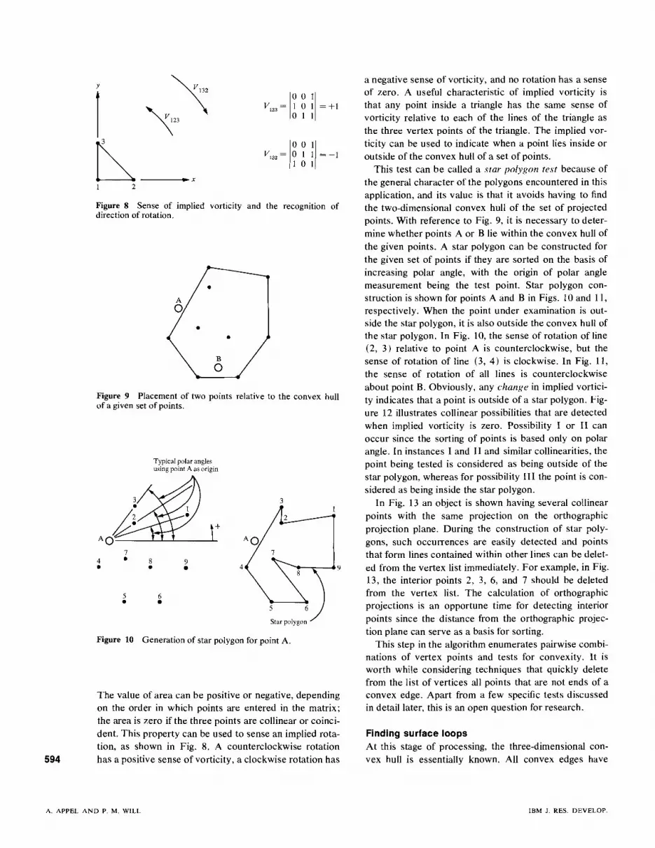
Figure 10 Generationof star polygon for point A.
Finding surface loopsAt this stage of processing, the three-dimensional convex hull is essentially known. All convex edges have
a negative sense of vorticity, and no rotation has a senseof zero. A useful characteristic of implied vorticity isthat any point inside a triangle has the same sense ofvorticity relative to each of the lines of the triangle asthe three vertex points of the triangle. The implied vorticity can be used to indicate when a point lies inside oroutside of the convex hull of a set of points.
This test can be called a star polygon test because ofthe general character of the polygons encountered in thisapplication, and its value is that it avoids having to findthe two-dimensional convex hull of the set of projectedpoints. With reference to Fig. 9, it is necessary to determine whether points A or B lie within the convex hull ofthe given points. A star polygon can be constructed forthe given set of points if they are sorted on the basis ofincreasing polar angle, with the origin of polar anglemeasurement being the test point. Star polygon construction is shown for points A and B in Figs. 10 and II,respectively. When the point under examination is outside the star polygon, it is also outside the convex hull ofthe star polygon. In Fig. 10, the sense of rotation of line(2, 3) relative to point A is counterclockwise, but thesense of rotation of line (3, 4) is clockwise. In Fig. 11,the sense of rotation of all lines is counterclockwiseabout point B. Obviously, any change in implied vorticity indicates that a point is outside of a star polygon. Figure 12 illustrates collinear possibilities that are detectedwhen implied vorticity is zero. Possibility I or II canoccur since the sorting of points is based only on polarangle. In instances I and II and similar collinearities, thepoint being tested is considered as being outside of thestar polygon, whereas for possibility III the point is considered as being inside the star polygon.
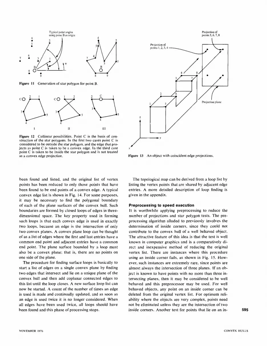
In Fig. 13 an object is shown having several collinearpoints with the same projection on the orthographicprojection plane. During the construction of star polygons, such occurrences are easily detected and pointsthat form lines contained within other lines can be deleted from the vertex list immediately. For example, in Fig.13, the interior points 2, 3,6, and 7 should be deletedfrom the vertex list. The calculation of orthographicprojections is an opportune time for detecting interiorpoints since the distance from the orthographic projection plane can serve as a basis for sorting.
This step in the algorithm enumerates pairwise combinations of vertex points and tests for convexity. It isworth while considering techniques that quickly deletefrom the list of vertices all points that are not ends of aconvex edge. Apart from a few specific tests discussedin detail later, this is an open question for research.
~-~-949•
Typical polar anglesusing point A as origin
8•
7•
5 6• •
The value of area can be positive or negative, dependingon the order in which points are entered in the matrix;the area is zero if the three points are collinear or coincident. This property can be used to sense an implied rotation, as shown in Fig. 8. A counterclockwise rotationhas a positive sense of vorticity, a clockwise rotation has
4•
Figure 9 Placement of two points relative to the convex hullof a givenset of points.
Figure 8 Sense of implied vorticity and the recognition ofdirectionof rotation.
y "\I 10 0 11V'23 = 1 0 1 = +1"\23 011
~/0 0 I)V'32 = 0 1 1 =-1101
.. x2
594
A. APPEL AND P. M. WILL IBM J. RES. DEVELOP.
•
Projection ofpoints 5, 6, 7, 8
r---"Y
Figure 13 An object with coincident edge projections.
x
Projection ofpoints 1,2,3,4
9
III
4
Typical polar anglesusing point B as origin
•98•
II
Figure 11 Generation of star polygon for point B.
67 ••
Figure 12 Collinear possibilities. Point C is the basis of construction of the star polygons. In the first two cases point C isconsidered to be outside the star polygon, and the edge that projects as point C is taken to be a convex edge. In the third casepoint C is taken to be inside the star polygon and is not treatedas a convex edge projection.
been found and listed, and the original list of vertexpoints has been reduced to only those points that havebeen found to be end points of a convex edge. A typicalconvex edge list is shown in Fig. 14. For some purposes,it may be necessary to find the polygonal boundaryof each of the plane surfaces of the convex hull. Suchboundaries are formed by closed loops of edges in threedimensional space. The key property used in formingsuch loops is that each convex edge is used in exactlytwo loops, because an edge is the intersection of onlytwo convex planes. A convex plane loop can be thoughtof as a list of edges where the first and last entries have acommon end point and adjacent entries have a commonend point. The plane surface bounded by a loop mustalso be a convex plane; that is, there are no points onone side of the plane.
The procedure for finding surface loops is basically tostart a list of edges on a single convex plane by findingtwo edges that intersect and lie on a unique plane of theconvex hull and then add coplanar connected edges tothis list until the loop closes. A new surface loop list cannow be started. A count of the number of times an edgeis used is made and continually updated, and as soon asan edge is used twice it is no longer considered. Whenall edges have been used twice, all loops should havebeen found and this phase of processing stops.
The topological map can be derived from a loop list bylisting the vertex points that are shared by adjacent edgeentries. A more detailed description of loop finding isgiven in the appendix.
Preprocessing to speed executionIt is worthwhile applying preprocessing to reduce thenumber of projections and star polygon tests. The preprocessing algorithm alluded to previously involves thedetermination of inside corners, since they could notcontribute to the convex hull of a well behaved object.The attractive feature of this idea is that the test is wellknown in computer graphics and is a comparatively direct and inexpensive method of reducing the originalvertex list. There are instances where this procedureusing an inside corner fails, as shown in Fig. 15. However, such instances are extremely rare, since points arealmost always the intersection of three planes. If an object is known to have points with no more than three intersecting planes, then it may be considered to be wellbehaved and this preprocessor may be used. For wellbehaved objects, any point on an inside corner can bedeleted from the original vertex list. For optimum reliability where the objects are very complex, points neednot be eliminated unless they are the intersection of twoinside corners. Another test for points that lie on an in- 595
NOVEMBER 1976 CONVEX HULLS

Figure 14 A convex edge list for a single convex polyhedron.The line label is L, and the ends of the line are LC 1 and LC2indexed by L.
side edge is to determine whether the point is a concavepoint on any polygonal face of the object. Checkingtechniques are illustrated in Fig. 16 but are assumed tobe unnecessary for most objects.
It may be argued that no point should be kept in thevertex list if it does not lie on a convex plane of theoriginal polyhedron. To the contrary, Fig. 17 illustratesthree instances in which convex points do not lie on anyconvex planes of the original object.
We assume it is not worthwhile to form the convexhull of each polygonal face of the original polyhedronbecause such a procedure is indirect and for some pointswould be at least triply redundant. There does not seemto be any simple relation between the two-dimensionalconvex hull of points on each face of the original polyhedron and the three-dimensional convex hull of thetotal polyhedron. Whereas a given polyhedron has aunique convex hull, an infinitude of polyhedra can havethe same convex hull.Automatic identification of inside cornersAs illustrated in Fig. 3, the minimum data required tospecify a polyhedron is a vertex list and a topologicalmap of vertex connectivity. The topological map is alist of which points are on each surface and also is a seriesof points connected by lines. Say that a typical line iconnects point (x., Yl' Zl) to point (x 2' Y2, Z2)' The parametric equations of each line i are calculated and stored:
3
(b)(a)
Typical convex edge list
Line label First Secondpoint point 4
L LC1(L) LC2(L)
1 1 2 6
2 1 33 1 44 2 35 2 66 3 57 4 58 4 69 5 6
Figure 15 Instances where a point of an inside comer shouldnot be deleted. At (a) point 2 can be deleted but point 1 shouldnot be deleted. There are many inside comers at (b), and point3 should not be deleted. where
Figure 16 Two checking techniques for points that are detected as being on inside comers: 1)Any point that lies on the intersection of two inside comers and only one outside cornercannot be a convex hull vertex. 2) A point that is on an insidecorner should also be a concave point on a polygon face in order to be deleted.
where k and I are the intersecting line labels. The normalto surface j has the parametric equation
GjX + bjy + cjz + dj = 0,
where Gj , bj , cj are found from the cross product of anytwo lines on plane j that intersect with an angle less than1800 as determined by the condition:
ai = (x 2 - Xl) / Ii'
bi = (y2-yl ) / Ii'
ci = (Z2 - Zl) / Ii'
2 22 1li=[(X2 - X I ) + (Y2-YI ) + (Z2- ZI) ]2.
Parameters Gi' bi' Ci' Ii are stored and indexed by the linelabel. The equation of each plane surface j of the polyhedron is calculated and stored:
Point 1 is a convexpoint on surface A
Surface A
Point 2 isa concave pointon surface B (in back)
Point 1 is intersectionof two inside corners
596
A. APPEL AND P. M. WILL IBM J. RES. DEVELOP.

III
~---/
//
//
//
z
Figure 17 Three polyhedra in which a convex hull vertex isinitially not on any polygon face that is a convex plane. Thereare no points of the object on the spatial side of a convex plane.
dj =-(Qj Xo+ bj Yo + Gj zo)·
It is important that each surface normal should point intothe volume enclosed by the polyhedron. If not, the signsof Qj' bj , and cj must be reversed. A method for ensuringthe correct sign has been described previously [ 19] . Eachline of the polyhedron can be taken as a vector (Qi' bi'
ci ) , and a normal vector (Qj' bj , cj ) can be found for eachsurface. If line i is the intersection of two surfaces, sayk and l, line i is an inside corner when the scalar tripleproduct of the line i, the normal vector k, and the normalvector l is negative:
2 b 2 2 1Q j + j + cj = .
Also,
Z = Cjt + zo'
where xo' Yo' and Zo are any point on the plane j, and
r.--------------y
x
Figure 18 Use of scalar triple product to detect inside (concave) corners.
597
inside corner
outside corner
[-100][723]= 0-10 =-1
o 0-1
[ 1 0 0][643] = 0 -1 0 = 1
o 0-1
where line i isoriented to runcounterclockwiseon surface k.
[512] = [-b g-~] = 1 outside corner0-1 0
SummaryWe have described some techniques for determining thethree-dimensional convex hull of real objects. Findingthe convex edges of the convex hull is, the essential stepin this procedure. Toward this end, we have introducedthe concept of identifying convex edges by projectingthe entire object parallel to an edge and observingwhether the point projection of the edge fell outside itsassociated star polygon. The star polygon test avoidsthe problem of having to find the two-dimensional convex
Some simple instances are illustrated in Fig. 18.
Details of implementationThe techniques described have been reduced to practicewith a FORTRAN program operating under VM!370 onan IBM System/370, model 168. A series of polyhedraand their convex hulls is shown in Fig. 19. Inside cornersare found during hidden line elimination by the previouslydescribed program LEGER [18]. The convex hulls aredrawn as soon as the edge list is known. It is not possible to measure the convex hull calculation times exactly because of the operating system overhead, but ingeneral the convex hull determination takes about asmuch time as a hidden line elimination. Convex hulldetermination for the test figures shown varied from 0.20to 0.84 second total CPU time, including drawing a wireframe picture and listing intermediate results. Time required increases approximately with the length of theconvex point list and the number of surface loops inthe convex hull, but we cannot yet show or estimatetime requirements. A complex original object does notnecessarily imply a complex convex hull. It has beenobserved that a simple object with a complex convexhull took more time for analysis than a complex objectwith a simple convex hull.
NOVEMBER 1976 CONVEX HULLS

598
Figure 19 Computer generated examples of convex hulls.
hull of the projection of the original object. It is interesting that no two-dimensional convex hulls were ever required for this three-dimensional probletn. Tactics forminimizing computation by culling the original vertexlist have been presented but have been implemented toonly a limited extent. Use of the present program forthe determination of the three-dimensional convex hullof real objects presents no logistical burden in computerstorage or time. Solving for a convex hull of a simpleobject is apparently as costly in total computationaloverhead as eliminating hidden lines.
Appendix: Finding plane surface loops of a convexpolyhedron given the edges of the polyhedronThe task of finding the bounding loops of each planesurface of the three-dimensional convex hull given acomplete list of convex edges is similar to certain prob-
lems in graph theory [20- 22]. The edge list of a convexpolyhedron can be used to construct a graph that is obviously isomorphic to a planar graph. The set of circuitsthat outline each face of this planar graph is the surfaceloop description of the convex hull. It is possible to findthe faces of a planar graph without specific dimensionalknowledge of the vertex points in space, but a descriptionof this technique is beyond the scope of this paper. Ourapproach is more mechanistic. That is, while assemblingedges to form surface loops, the convex edges beingjoined together are continually tested for coplanarityin three-dimensions. It has not been necessary to checkthat the loops are convex polygons.
1. Initialize an edge use array IUC(L) to all zeros. Everytime an edge is used in a loop its corresponding IDC
entry is increased by 1. As soon as a particular IUC
A. APPEL AND P. M. WILL IBM J. RES. DEVELOP.

Figure 20 Classification of the intersection of edges L I andL2. The common point is LCOM, SP is the starting point, andMP is the current match point.
Figure 21 Initial entries in the loop table based on the type ofinitial intersection. First loop table entry for the object shown inFig. 14 would be type I.
step 1. If LE3 is not sr, ascertain that point LE3 isin the plane of Ll, L2; if it is not, go back to step 9.If point LE3 is in the plane of Ll, L2, add line L3 tothe list of lines in the current loop. If LCJ(L3) = MP,
")<-S~I= LCI(LI)
0<- LCOM = LC2(LI) = LCI(L2)
L2
"<- MP = LC2(L2)
599
SH
Type 2
~I
Type 4
-L2
~ SP = LC2(L1)
"",L1
/
" <- LCOM = LCI(LI) = LC2(L2)
L2
o<-MP=LCI(L2)
" <- SP = LC2(L1)
~L1
ii<- LCOM = LCI(LI) = LCI(L2)
L2
<- MP = LC2(L2)
5SP = LCI(LI)
LI
0<- LCOM = LC2(LI) = LC2(L2)
L2
<- MP = LCI(L2)
SH
~I
Type 3
L2
Type I
Type I
Type 2
Type 4
Type 3
attains a value of 2, the associated edge cannot beused for any other loops. As soon as all elements inthe array IUC(L) attain a value of 2, processing shouldstop.
2. Take an edge Ll from the list of edges. If the edge hasan associM~p IUC(LI) = 2, take another edge. Processing stops when all IUC elements attain a value of2 or all edges were addressed in this step once.
3. Choose some other edge L2 from the list of edgeswhere IUC(L2) is less than 2.
4. Check each end point of edge Ll and edge L2 for acommon vertex point. If edge L2 does not have anend point that is also 011 Ll, go back to step 4. Whenedge q and edge L2 have a common vertex point,obviously these two edge~ intersect and form a planein space.
5. The vertex point common to edges LI and L2 and theother two points on these edges should not coexistsimultaneously on any other loop, since this wouldimply coplanar loops, which is not possible on aconvex polyhedron. Check that the three vertexpoints on Ll and L2 do not coexist on any other loopif any are yet identified. If coexistence occurs, goback to step 2.
6. Calculate the equation of the plane P in space formedby the intersecting edges LI and L2.
7. Make certain that points on the vertex list lie eitherin or are to only one side of plane P. A convex planecan have no points on its spatial side. If points arefound to lie on both sides of plane P, this indicatesthat P is not a convex plane so go back to step 2. Alist of points in plane P can be stored at this time tospeed up later steps in this procedure.
8. Classify the intersection of edges Ll and L2 according to type as shown in Fig. 20. At this time, twoentries can be made in the loop table as shown inFig. 21, and two vertex points have been identified:1) the starting points SP of the loop, 2) the nextmatch point MP on the loop. The starting point of theloop is the first point on the loop and is used to determine when a loop is finished. The match point isused to find the next line on the loop. Entries inthe loop table are positive or negative and indicatethe direction a line takes as it is used in a loop. Whenthe line runs from LCI to LC2, the direction is takento be positive.
9. Take an edge L3 from the list of convex edges withIUC(L3) less than 2 and where L3 is not Ll or L2.
10. Determine whether any end point of L3 is MP. Ifno end of L3 is MP, repeat step 9. If an end of L3 isMP, determine whether the other end point (LE3)
of L3 is SP, and if it is, add L3 to the loop table, endthe current loop, increase the ruc value by one foreach line used in the loop, and start another ioop at
NOVEMBER 1976 CONVEX HULLS

600
First loop Second loop Third loop
N LUP( I, Nl N LUP(2, Nl N LUP(3, N)
I -I -I I 22 2 2 3 2 63 -4 3 8 3 -7
4 -5 4 -3
L iuc n.. L rue (Ll L rue (Ll
I 2 22 I 2 I 2 23 0 3 I 3 24 I 4 I 4 I5 () 5 I 5 I6 () 6 () 6 I7 0 7 0 7 I8 0 8 I 8 I9 0 9 0 9 0
Fourth loop Fifth loop
N LUP(4, N) N LUP(5, N)
4 I -72 6 2 83 9 3 -94 -5
L IUC(L) L rue (L)
1 2 I 22 2 2 23 2 3 24 2 4 2 All 2's indicate5 2 5 2 end of processing6 2 6 27 I 7 28 I 8 29 I 9 2
Figure 22 Growth of loop table for the object shown in Fig. 14.
the entry is positive, and if LC2(L3) = MP, the entryis negative. Reset the label MP to the vertex pointI.E3, and go back to step 9 to find a new line on thecurrent loop.
The growth of a loop table for a simple object is shownin Fig. 22. It is advisable during debugging and in anticipation of calculation errors to prevent indefinite processing by limiting the number of times step 9 can be executedfor a particular set of LI and LZ. In general, the entirelist of convex edges should not be searched more oftenthan the number of lines in the list.
Given convexedge list
L LCI(L) LC2(L)
I 1 22 1 53 I 64 I 75 2 36 2 57 2 88 3 4 6
9 3 810 4 5II 4 612 6 713 7 8
Figure 23 Evolution of a convex edge list (above) to aloop table (facing page 1 to a topological map. If LUP(K, N)=+, then SURFACE(K. N) = LC](LUP(K, Nj I. IfLUP(K, N 1=-, then SURFACE(K. N) = LC2(LUP(K, N)).
After all edge loops of the convex planes have beenfound, a topological map can be easily derived from theloop table. The topological map is a list of all points ona surface in the order in which these points are connected together. Such a map is a listing of end points ofthe loop table where one point is taken from each line.When the entry is positive, the first point on the line istaken, t.ciu.i. and where the line entry is negative, thesecond point on the line is taken, LC2(1.). A typical topological map is shown in Fig. 23.
ReferencesI. G. Hadley, Linear Algebra, Addison-Wesley Publishing
Co., Inc., Reading, Massachusetts, 1961, ch. 6.2. R. O. Duda and P. E. Hart, Pattern Classification and
Scene Analysis, John Wiley and Sons, New York, 1973,ch.9.
3. A. Rosenfeld, Picture Processing by Computer, AcademicPress, New York. 1969.
4. P. F. Lambert. "Designing Pattern Categorizers with Extremel Paradigm Information," Methodologies of PatternRecognition, edited by S. Watanabe, Academic Press. NewYork. 1969.
5. G. -A. Burdet, "Generating All the Faces of a Polyhedron," SIAM J. Appl. Math. 26,479 (1974).
6. B. F. Mitchell, V. F. Dem' Yanov, and V. N. Malozemov,"Finding the Point of a Polyhedron Closest to the Origin,"SIA!t-1 J. COIl/m/12, xxx t 19741.
7. H. Freeman, "Computer Processing of Line-Drawing Images," Comput . Surveys 6.57 (1974l.
8. M. L Balinsky. "An Algorithm for Finding All Vertices ofConvex Polyhedral Sets," J. Soc. l ndust, Appl. Math. 9, 72(1961 ).
9. N. Tuong, L'Empioi des Projections Coniques Dans LaReconnaisance des Formes (The Use of Conic Projectionsin Pattern Recognition), Department d'Informatique, Universite de Montreal, March 1969.
10. G. Nagy and N. Tuong, "Normalization Techniques forHandprinted Numerals," Commun. ACM 13,475 ! I97Q),
A. APPEL AND P. M. WILL IBM J. RES. DEVELOP.

Loop table
N LUP(I, N) LUP(2, N) LUP(3, N) LUP(4, N) LUP(5, N) LUP(6, N) LUP(7, N)
1 -1 -I 2 -3 -5 -5 -R2 2 4 -10 4 6 7 93 -6 13 11 -12 -10 -9 -134 -7 -3 -8 -125 -II
Topological map
N SURFACE SURFACE 2 SURFACE 3 SURFACE 4 SURFACE 5 SURFACE 6 SURFACE 7
I 2 2 I 6 3 3 42 1 I 5 1 2 2 33 5 7 4 7 5 8 84 8 6 4 75 6
Figure 23 (Continued from facing page.)
11. R. L. Graham, "An Efficient Algorithm for Determiningthe Convex Hull of a Finite Planar Set." Inf. Process. Lett.1,123 (1972).
12. A. A. Jarvis, "On the Indentification of a Convex Hull of aFinite Set of Points in the Plane," In], Process. Lett. 2, 18(1973).
13. 1. C. Braid, Designing with Volumes, Cantab Press, Cambridge, England, 1973.
14. J. Encarnacao and W. Giloi, "PRADIS-An Advanced Programming System for 3-D Display," AFlPS Conf. Proc. 40,1969, p. 985.
15. A. Appel and A. Stein, "The Interactive Design of Polyhedra," Proc, ONLINE 72 Conference, Volume 2, OnlineComputer Systems Ltd., Brunei University, England, 1972,p.383.
16. P. Loutrel, "Determination of Hidden Edges in PolyhedralFigures: Convex Case," Technical Report 400-145, Department of Electrical Engineering, New York University,September 1966.
17. A. Appel, "Modeling in Three Dimension," IBM Svst, J. 7,310 (1968).
NOVEMBER 1976
18. A. Appel, "The Notion of Quantitative Invisibility and theMachine Rendering of Solids," Proc, ACM Nat. Meeting,1967, P. 387.
19. A. Appel and A. J. Stein, "Effecting Fast Correction ofSurface Normals in Computer Generated Three-Dimensional Depictions," IBM Tech Disclosure Bull. 17, 599(1974).
20. F. Rubin, "A Search Procedure for Hamilton Paths andCircuits," J. Assoc. Comput. Mach. 21, 576 (1974).
21. J. Hopcroft and R. Tarjan, "Efficient Planarity Testing," J.Assoc. Comput, Mach. 21, 549 (1974).
22. T. Kamal, "A Systematic Method of Finding All DirectedCircuits and Enumerating All Directed Paths," IEEETrans. Circuit Theory CT.14, 166 (1967).
Received June 19, 1975; revised June 15, 1976
The authors are located at the IBM Thomas J. WatsonResearch Center, Yorktown Heights, New York 10598.
601
CONVEX HULLS