desulfurization of gasoline and diesel fuels, using non
TRANSCRIPT
Desulfurization of Gasoline and Diesel Fuels, Using
Non-Hydrogen Consuming Techniques.
Abdullah Al-Malki Master of Science
October 2004
King Fahad University of Petroleum and Minerals
Chemistry Department
1
CHAPTER 1
INTRODUCTION
Crude oil is the largest and most widely used source of energy in the world.
Major portions of the crude oils are used as transportation fuels such as gasoline,
diesel and jet fuel. However, such crudes contain sulfur, typically in the form of
organic sulfur compounds. The sulfur content and the API gravity are two
properties which have a great influence on the value of the crude oil. The sulfur
content is expressed as a percentage of sulfur by weight and varies from less than
0.1% to greater than 5% depending on the type and source of crude oils [1]. Sulfur
compounds exist in various forms and can be classified into four main groups:
mercaptans, sulfides, disulfides and thiophenes. It is well known that the sulfur
compounds are undesirable in refining process as they tend to deactivate some
catalysts used in crude oil processing. Sulfur compounds can cause several
corrosion problems in pipeline, pumping, and refining equipment, as well as the
premature failure of combustion engines and poisoning of the catalytic converters
that are used in automotive engines. Today, the strongest motivation for the
reduction of sulfur in fuels is due to environmental regulation which is imposing
stringent limits for sulfur levels in transportation fuels. Sulfur is responsible for the
emission of sulfur oxides (SOx) resulting from the combustion of fuels used in
transportation. High sulfur content is also responsible for the particulate emissions
from trucks and buses. It also precludes the use of advanced after treatment
systems which cannot work with such high sulfur content.
2
LITERATURE REVIEW
Removing organic sulfur from hydrocarbon fuels is becoming an increasingly
challenging task for refineries. This is due to the stringent environmental
regulations which are placing considerable pressure on refinery operators to
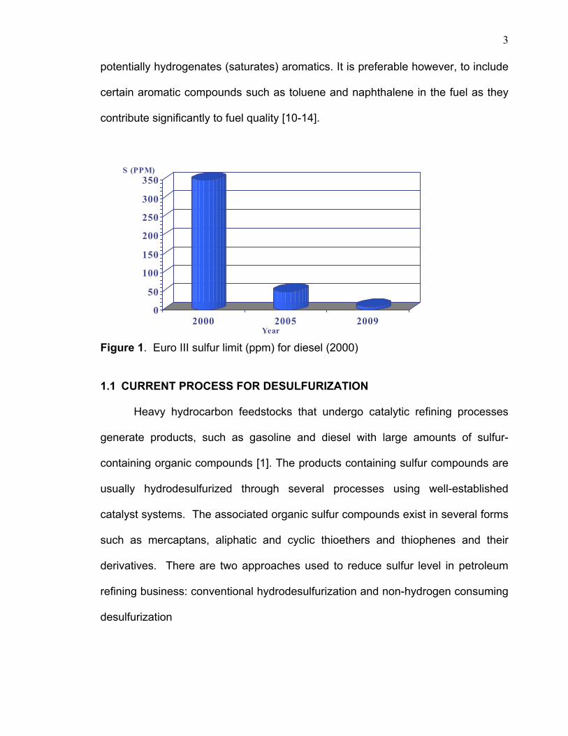
reduce sulfur below 10 ppm by the year 2010 [2] (figure 1). The current
specification in Europe and the USA calls for a maximum sulfur content of 50 ppm
in gasoline and diesel by 2005 [2-3]. Sulfur compounds are present in crude oil in
a wide range of both aliphatic and aromatic forms and mainly concentrated in the
heavy part of the crude oil [4-5]. To meet the demand for gasoline, catalytic
cracking processes are employed industrially to convert these heavy low value
heavy cuts to products of high value. During these processes, major sulfur
compounds are removed by conventional hydrodesulphurization (HDS) catalytic
processes [5]. However, the catalysts are not active in removing refractory sulfur-
compounds that are sterically hindered. This is particularly true in the case of
sulfur compounds like thiophenes and multi ring aromatic sulfur compounds, such
as dibenzothiophene (DBT) and its derivatives especially 4,6-
dimethyldibenzothiophene (4,6-DMDBT). In order to meet future fuel specifications,
such sulfur-compounds must be removed or reduced to target limits within a
regulatory period. Much effort has been devoted to developing techniques that
can reduce or remove such refractory sulfur compounds by oxidation/extraction
and biodesulfurization [7-16]. In general, diesel fuel and gasoline contain 20 to 30
percent aromatics but less than 1 percent sulfur, so removing the sulfur without
removing the aromatics is difficult, particularly in the HDS process which also
3
potentially hydrogenates (saturates) aromatics. It is preferable however, to include
certain aromatic compounds such as toluene and naphthalene in the fuel as they
contribute significantly to fuel quality [10-14].
Figure 1. Euro III sulfur limit (ppm) for diesel (2000)
1.1 CURRENT PROCESS FOR DESULFURIZATION
Heavy hydrocarbon feedstocks that undergo catalytic refining processes
generate products, such as gasoline and diesel with large amounts of sulfur-
containing organic compounds [1]. The products containing sulfur compounds are
usually hydrodesulfurized through several processes using well-established
catalyst systems. The associated organic sulfur compounds exist in several forms
such as mercaptans, aliphatic and cyclic thioethers and thiophenes and their
derivatives. There are two approaches used to reduce sulfur level in petroleum
refining business: conventional hydrodesulfurization and non-hydrogen consuming
desulfurization
0
50
100
150
200
250
300
350
2000 2005 2009
S (PPM)
Year
4
1.1.1 Conventional hydrodesulfurization (HDS).
Conventional hydrodesulfurization (HDS) with Mo, Ni or W-based catalysts
are widely used to reduce sulfur content. Mercaptans, thioethers, and disulfides,
for example, can be removed relatively easy using this process. Other sulfur-
bearing organic compounds such as aromatic, cyclic, and condensed multicyclic
compounds are more difficult to remove [15]. Thiophene, benzothiophene,
dibenzothiophene, other condensed-ring thiophenes, and substituted forms of
these compounds are particularly difficult to remove by hydrodesulfurization.
Typically, the hydrodesulfurization process involves catalytic treatment with
hydrogen to convert the various sulfur compounds to hydrogen sulfide [16-17]. The
kinetics investigation into the behavior of 4,6-alkyldibenzothiophene (4,6-DADBT)
led to two contradictory explanations. First, the transformation of 4,6-DADBT is
limited by the adsorption step via sulfur atom. The second hypothesis suggests
that the adsorption occurs through π-electrons of the aromatic system [8]. In
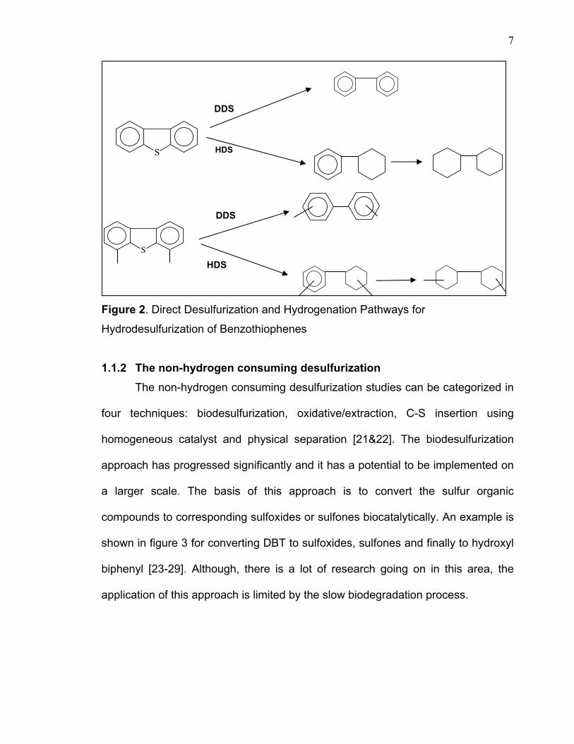
general, the reaction mechanism of DBT and 4,6-DMDBT through HDS process
was suggested to proceed via two main pathways (Figure 2). One is a direct
desulfurization pathway where sulfur is removed without affecting the aromatic
rings. The other is via a hydrogenation pathway, in which aromatic rings of DBT
compounds are preferentially hydrogenated to 4H- or 6H-DBT intermediates and
are subsequently desulfurized [16]. Thus, the desulfurization rate of hindered
compounds is greatly increased through the hydrogenation route. Without one or
both of the rings, the molecule is much more flexible and the sulfur atom can
approach the catalyst surface much more easily. However, the “hard sulfur
compounds” like benzothiophenes and its derivatives are the most sterically
5
hindered compounds that have been identified in diesel fractions after
conventional hydrodesulfurization (HDS) ranging in concentration from 0.2-0.3
wt.%. This would indicate that these catalysts are not efficient enough to
desulfurize the most refractory sulfur-containing compounds e.g. DBT and its
derivatives [16-17]. However, the HDS is limited in treating benzothiophenes (BTs)
and dibenzothiophenes (DBTs),especially DBTs having alkyl substituents on 4
and/or 6 positions. The production of light oil, with very low levels of sulfur-
containing compounds, therefore requires inevitably the application of severe
operating conditions and the use of especially active catalysts [18-20]
HDS is a commercially proven refining process that passes a mixture of
heated feedstock and hydrogen over catalysts to remove sulfur. Refineries can
desulfurize distillate streams by hydrotreating the straight run streams that
generated from direct distillation of crude oil, hydrotreating streams coming out
from conversion units such as fluid catalytic cracking (FCC) and hydrocracker
units.
By controlling the hydrotreating conditions and selecting the appropriate
catalysts, refineries may meet the ultra low sulfur diesel (ULSD) on fuels that are
produced from straight runs streams. The difficulty however, arises in the
desulfurization of other steams that come from the conversion units, which mostly
include the refractory sulfur compounds. Meeting the sulfur requirement for
gasoline is believed to be the greatest challenge for the refining business requiring
substantial revamps to equipment or even construction of new units. This is due
to the fact that most of the gasoline production in the market today is coming from
6
cracked stocks that contain a larger concentration of compounds with aromatic
rings and high olefin content, thus making sulfur removal more difficult. The need
to desulfurize the cracked stocks in addition to the straight-run streams will direct
the refiners to choose the most cost-effective technology [16-21].
In essence, refiners must desulfurize all diesel-blending components in
order to meet the 10 ppm ULSD specification that will take effect from 2009. In the
case of diesel, a two-stage deep desulfurization process will most probably be
sufficient to meet the 10 ppm sulfur target. The first stage can reduce the sulfur
level to below 250 ppm with a second stage that could produce diesel product with
10 ppm sulfur or less. In some cases the first stage could be a conventional
hydrotreating unit with moderate adjustments to the operating parameters. The
second stage would require substantial modification of the desulfurization process,
primarily through use of higher pressure, increasing hydrogen flow rate and purity,
reducing space velocity, and choice of catalyst. Such operational requirements to
deep desulfurize cracked stocks also need a higher reactor pressure [5&21].
7
Figure 2. Direct Desulfurization and Hydrogenation Pathways for
Hydrodesulfurization of Benzothiophenes
1.1.2 The non-hydrogen consuming desulfurization The non-hydrogen consuming desulfurization studies can be categorized in
four techniques: biodesulfurization, oxidative/extraction, C-S insertion using
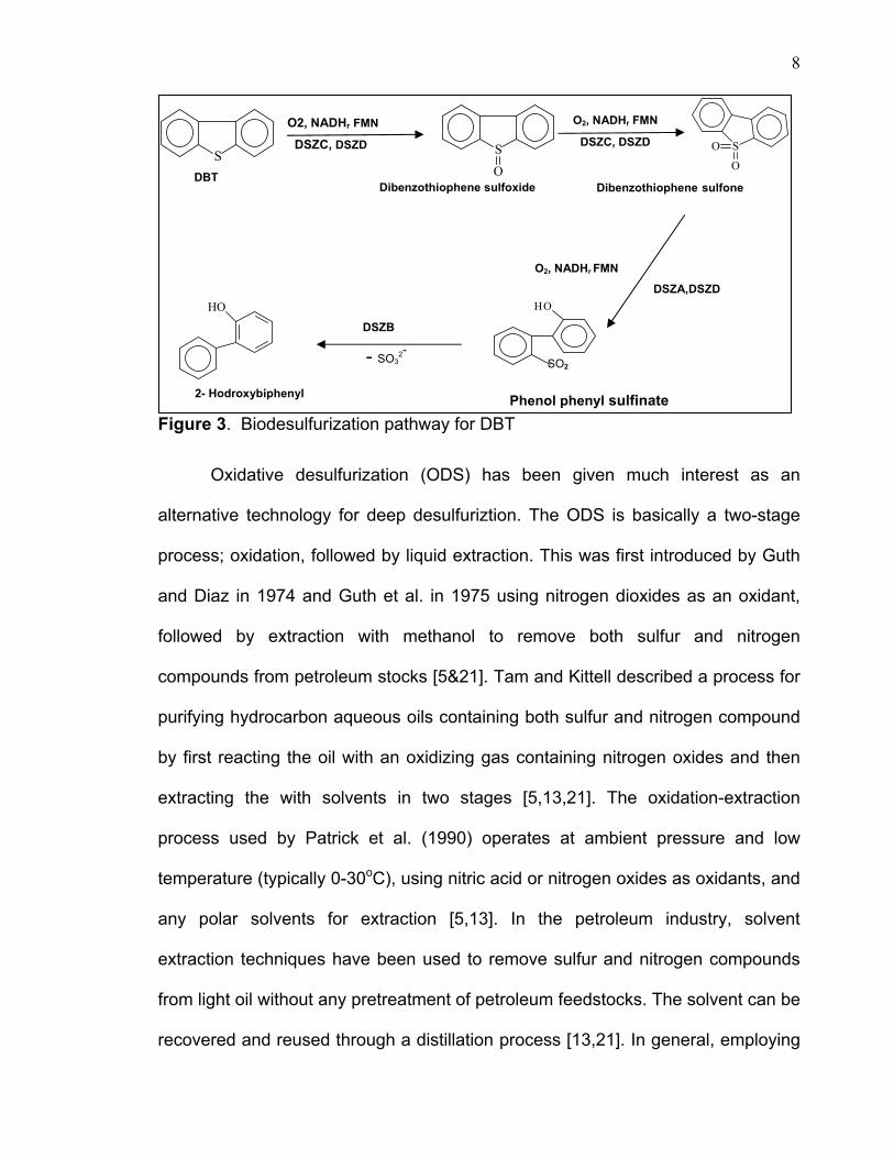
homogeneous catalyst and physical separation [21&22]. The biodesulfurization
approach has progressed significantly and it has a potential to be implemented on
a larger scale. The basis of this approach is to convert the sulfur organic
compounds to corresponding sulfoxides or sulfones biocatalytically. An example is
shown in figure 3 for converting DBT to sulfoxides, sulfones and finally to hydroxyl
biphenyl [23-29]. Although, there is a lot of research going on in this area, the
application of this approach is limited by the slow biodegradation process.
S
DDS
HDS
S
DDS
HDS
8
Figure 3. Biodesulfurization pathway for DBT
Oxidative desulfurization (ODS) has been given much interest as an
alternative technology for deep desulfuriztion. The ODS is basically a two-stage
process; oxidation, followed by liquid extraction. This was first introduced by Guth
and Diaz in 1974 and Guth et al. in 1975 using nitrogen dioxides as an oxidant,
followed by extraction with methanol to remove both sulfur and nitrogen
compounds from petroleum stocks [5&21]. Tam and Kittell described a process for
purifying hydrocarbon aqueous oils containing both sulfur and nitrogen compound
by first reacting the oil with an oxidizing gas containing nitrogen oxides and then
extracting the with solvents in two stages [5,13,21]. The oxidation-extraction
process used by Patrick et al. (1990) operates at ambient pressure and low
temperature (typically 0-30oC), using nitric acid or nitrogen oxides as oxidants, and
any polar solvents for extraction [5,13]. In the petroleum industry, solvent
extraction techniques have been used to remove sulfur and nitrogen compounds
from light oil without any pretreatment of petroleum feedstocks. The solvent can be
recovered and reused through a distillation process [13,21]. In general, employing
S S
O
SO
O
SO2
HOHO
O2, NADHr FMN
DSZC, DSZD
O2, NADHr FMN
DSZC, DSZD
O2, NADHr FMN
DSZA,DSZD
DSZB
DBT Dibenzothiophene sulfoxide Dibenzothiophene sulfone
- SO32-
Phenol phenyl sulfinate 2- Hodroxybiphenyl
9
only solvent extraction of petroleum products to remove sulfur creates an
associated loss of useful hydrocarbons, in addition to poor sulfur removal [5,21,30].
This is probably due to the small difference in the polarity between sulfur
compounds and other aromatic hydrocarbons. Therefore, the selective oxidation
approach of increasing the polarity of sulfur compounds , then removing them by
selective extraction, has received much great attention recently with some success,
particularly in diesel fuel. The greatest advantages of the ODS process are low
reaction temperature and pressure, and removing the need for expensive
hydrogen that is used in the conventional HDS process. Another feature of ODS is
that the refractory sulfur compounds in ODS are easily converted by oxidation [35-
34]. Therefore, ODS has great potential to be a complementary process to
traditional HDS for achieving deep desulfurization [13,35-37].
In the ODS process, the sulfur-containing compounds are oxidized using
appropriate oxidants to convert these compounds to their corresponding sulfoxides
and sulfones. These are preferentially extracted from light oil due to their
increased relative polarity [5,11,13, 21]. Any unused oxidant that remains in the
light oil can be removed by water washing and extracting. The oxidized
compounds can be extracted from the light oil by using a non-miscible solvent.
Depending on the solvents used for extraction, the oxidized compounds and
solvent are separated from the light oil by gravity separation or centrifugation. The
light oil is water washed to recover any traces of dissolved extraction solvent and
polished using other methods, such as absorption using silica gel and aluminum
oxide. The solvent is separated from the mixture of solvent and oxidized
10
compounds by a simple distillation for recycling and re-use. By using this process,
the maximum sulfur removal is achieved with minimum impact on the fuel quality
[21,22,36-38].
Many oxidants have been investigated which include peroxy organic acids,
catalyzed hydroperoxides, inorganic oxidants such as inorganic peroxy acids,
peroxy salts and O3, etc [21,36].
The second step of this process is the removal of the oxidized compounds
by contacting the distillate with a selective extraction solvent. As reported in the
literature, the liquid-liquid extraction technique using water-soluble polar solvents
(DMSO, DMF, and acetonitrile) is usually used [5,21,36-38]. The former two
solvents have a high extractability for sulfones but also have a high boiling point at
573K. This is close to the boiling point of the sulfones, thus creating difficulty in
separation and reuse for further extraction [5,13,21]. Yasuhiro Shiraishi et al, have
used acetonitrile in their work as the extraction solvent, since it has a relatively low
boiling point (355K) and can be easily separated from the sulfones by distillation
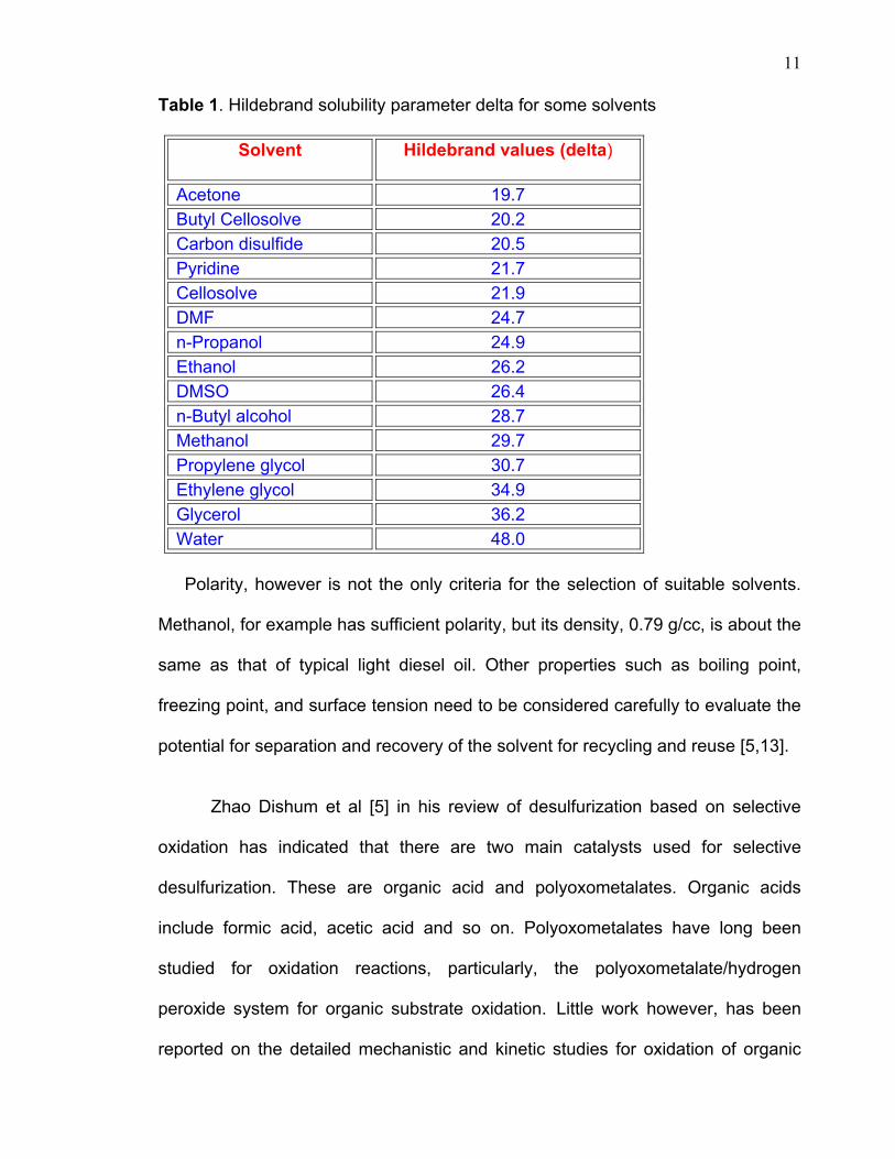
[30]. The extraction efficiency depends on the solvent’s polarity, which have to be
sufficient to remove sulfur compounds. Examples of polar solvents include those
with high values of the Hildebrand solubility parameter deltas as shown below in
Tabel1. Liquids with a delta higher than about 22 have been successfully used to
extract these compounds [5,13].
11
Table 1. Hildebrand solubility parameter delta for some solvents
Solvent Hildebrand values (delta)
Acetone 19.7 Butyl Cellosolve 20.2 Carbon disulfide 20.5 Pyridine 21.7 Cellosolve 21.9 DMF 24.7 n-Propanol 24.9 Ethanol 26.2 DMSO 26.4 n-Butyl alcohol 28.7 Methanol 29.7 Propylene glycol 30.7 Ethylene glycol 34.9 Glycerol 36.2 Water 48.0
Polarity, however is not the only criteria for the selection of suitable solvents.
Methanol, for example has sufficient polarity, but its density, 0.79 g/cc, is about the
same as that of typical light diesel oil. Other properties such as boiling point,
freezing point, and surface tension need to be considered carefully to evaluate the
potential for separation and recovery of the solvent for recycling and reuse [5,13].
Zhao Dishum et al [5] in his review of desulfurization based on selective
oxidation has indicated that there are two main catalysts used for selective
desulfurization. These are organic acid and polyoxometalates. Organic acids
include formic acid, acetic acid and so on. Polyoxometalates have long been
studied for oxidation reactions, particularly, the polyoxometalate/hydrogen
peroxide system for organic substrate oxidation. Little work however, has been
reported on the detailed mechanistic and kinetic studies for oxidation of organic
12
sulfur compounds in a polyoxometalate/hydrogen peroxide system. One recent
example was the oxidation of thioether by polyoxometalate/t-butyl hydrogen
peroxide in a non-aqueous system [5,21]. More recently, some work reported the
following trend for sulfur compound oxidation reactivity in a formic acid/H2O2
system [5,64]:
methylphenylsulfide> thiophenol>diphenylsulfide >4,6-dimethyldibenzothiophene >
4-methydibenzothiophene > dibenzothiophene > benzothiophene > Thiophenes.
The catalytic oxidation process includes various oxidants such as nitrogen
oxides, nitric acid, hydrogen peroxide, ozone, t-BuOOH, oxygen, air, peracids, etc.
The oxidation of thiophene derivatives with H2O2 is known to take place over
various catalytic systems, such as HCOOH, CCl3COOH, CF3COOH,
methyltrioxorhenium(VII), and phosphotungstic acid [30-38].
Yen, et al. reported in, USA 6,402,939 that organic sulfur compounds can
be removed from a fossil (or petroleum-derived) fuel by a process that combines
oxidative desulfurization with the use of ultrasound. The oxidative desulfurization is
achieved by combining the fossil fuel with a hydroperoxide oxidizing agent in the
presence of an aqueous fluid, and the ultrasound is applied to the resulting mixture
to increase the reactivity of the species in the mixture [33].
Recently there has been much interest in the deep desulfurization of
different fuels by photochemical reaction and liquid-liquid extraction. Some papers
have been published looking at this approach where some model compounds
such as DBTs were photodecomposed by UV light in the organic phase and the
resulting sulfur compounds being removed in to water or acetonitrile phase [39-
42].
13
There has also been some work conducted on a process based on the
formation and subsequent precipitation of S-alkylsulfonium salts. This is
accomplished by reacting sulfur–containing compounds such as DBTs and BTs
with alkylating agents, CH3I and AgBF4 in the presence of dichloromethane. The
products were removed as precipitates under moderate conditions. Such reactions
suffer from selectivity where other aromatic hydrocarbons can also undergo
methylation [43-45]
Some work has been reported on desulfurization of light oils based on the
formation and subsequent adsorption of N-tosylsulfimides, produced by the
reaction of the sulfur compounds in the light oils, with chloramine T (sodium N-
chloro-p-toluenesulfonamide) [46]. In this work the dibenzothiophenes (DBTs) are
converted by the reaction with chloramine T dissolved in methanol, to form the
corresponding sulfimides. The sulfimides of alkyl-substituted DBTs, formed during
the reaction, remained in the resulting light oil, such that the deep desulfurization
(0.05 wt%) failed to achieve. These compounds however were removed
successfully by the addition of aluminum oxide adsorbent and the sulfur
concentration of the light oil was decreased to less than 0.05 wt%. The
desulfurization of high-aromatic-content light oil is relatively more difficult, because
the aromatic hydrocarbons are chlorinated by reaction with chloramine T,
proceeding competitively with chlorination of the sulfur compounds.
Y. Shiraishi et al. have reported their work on removing sulfur and nitrogen
of light oils based on the chemical oxidation using hydrogen peroxide and acetic
acid. Sulfur and nitrogen compounds, when dissolved in n-tetradecane and xylene,
were oxidized under moderate conditions and removed successfully. They were
14
successful in reducing nitrogen to < 22% of the corresponding feed values.
However, sulfur content failed to be reduced to the required deep desulfurization
level (0.05 wt %). This is because the alkyl-substituted sulfones, produced during
the oxidation of sulfur compounds, remain in the resulting light oils, owing to their
high hydrophobicity. These, however, could be removed from the light oils by
subsequent extraction, using an acetonitrile/water azeotropic mixture, such that
the sulfur contents of the light oils were decreased to < 0.05 wt %, while
maintaining a high oil recovery yield [47]. They also reported some work on the
desulfurization of light oil based on chemical oxidation of sulfur-containing
compounds over Ti-containing molecular sieve catalysts. Sulfur compounds were
oxidized by catalysts and H2O2 to the corresponding sulfoxides and sulfones and
removed successfully from the oil. However, by use of this basic process, the
sulfur concentration of actual light oil failed to be reduced to the required deep
desulfurization level (0.05 wt %). They indicated that this maybe due to adsorption
of alkyl-substituted sulfoxides and sulfones on the surface of the catalyst, thus
decreasing the catalytic activity. When desulfurization was carried out in the
presence of polar acetonitrile solvent, the adsorption of these compounds onto the
catalyst was suppressed significantly and deep desulfurization was achieved
successfully [48].
Some work has been reported on using a catalytic system consisting of
metal–sulfophthalocyanines (MPcS) and monopersulfate or hydrogenperoxide as
oxidants for the dibenzothiophene oxidative desulfurization. Oxidations were
conducted at room temperature in acetonitrile–water mixed solvent. The
dibenzothiophene oxidation involved formation of dibenzothiophene dioxide and
15
biphenylsultone (dibenzo-1,2-oxathiine 2,2-dioxide), followed by hydrolysis to
2(20-hydroxybiphenyl)sulfonate and finally catalytic desulfurization to 2-
hydroxybiphenyl (2-phenylphenol) and sulfuric acid;. Moreover, catalytic over-
oxidation of 2-hydroxybiphenyl, with ring fission and formation of various oxidation
products, among them carbon dioxide, oxalic and benzoic acid, was also
observed. Among the various MPcS catalysts examined (M = Fe, Co and Ru), the
ruthenium derivative exhibited the best performance with persulfate and iron
derivative and hydrogen peroxide; in both cases the slow step of the process was
the oxidation of dibenzothiophene dioxide to biphenylsultone [49]
The physical separation by adsorption and then solvent extraction offers a
lower capital and operation cost approach. However, this approach suffers from
inefficiencies due to the limited polarity difference between the sulfur organic
compounds and the rest of the fuel [5,21]. There is some available technology
such as S Zorb sulfur removal technology which uses a proprietary sorbent that
attracts sulfur-containing molecules and removes the sulfur atom from the
molecule. The sulfur atom is retained on the sorbent while the hydrocarbon portion
of the molecule is released back into the process stream [21].
Song et al. at Penn State University are experimenting with a new approach
called selective adsorption for removing sulfur (SARS) for ultra deep removal of
sulfur from liquid hydrocarbon fuels. In this process the refractory sulfur
compounds are selectively adsorbed onto the surface of the solid adsorbent but
leave the coexisting hydrocarbons untouched. Also, the adsorbent should be easy
to regenerate for repeated use. The adsorbent used was prepared from transition
metal oxides supported on alumina [50].
16
There is also some literature published on the use of homogenous catalysts
to cleave the C-S bond in some hindered compounds. This approach, however,
suffers from the practical difficulties in separating the catalysts from the products
after completion of the reaction [51-54].
A literature search indicated that little work has been done using complex
metals to separate the highly sulfur hindered compounds physically. Robert J.
Angelici J, Iowa State University, Department of Chemistry, indicated that there
are no fully characterized metal complexes that have been previously reported for
removing 4,6 DMDBT. He indicated that Ru (II) in the form of Ru(NH3)5(OH2)2+
reacts with thiophene, benzothiophene, and dibenzothiophene to produce Ru
complexes [55]. Angelici's approach still requires more studies to assess the
removal of hindered dibenzothiophenes. Ru (II) complex undergoes oxidation in
presence of air which is limiting its potential for applicability [55]. Such an
approach needs to satisfy two crucial requirements to achieve successful sulfur
removal. One is to make a very stable complex product of metal-organic sulfur
compounds and the other one is to be able to separate this complex by some
means. These requirements are very challenging which probably explains the lack
of interest in this technique.
Overall, with all these developments, some work remains to be done to
address the suitability of future approaches to meet the sulfur limit requirements.
There are two major problems associated with ODS. First, the oxidants chosen do
not always perform selectively. Some oxidants cause unwanted side reactions that
reduce the quantity and quality of the light oil. The second problem is the selection
of a suitable solvent for the extraction of the sulfur compounds. Using the wrong
17
solvent may result in removing desirable compounds from the fuel or extracting
less than a desired amount of the sulfur compounds from the fuel, in either case,
the consequences can be costly.
There is also no detailed work to define the appropriate conditions in terms
of the optimum temperature, oxidants, catalysts, solvents/fuel ratio for extraction,
and the impact of such solvents extraction on fuel quality. So the ODS approach
still needs further research, especially in the area of designing the appropriate
selective catalysts. Therefore the objective this study is to address such concerns
and provide a detailed mechanism of the above mild oxidization-extraction method.
The study will explore the possibility of developing means of forming metals-sulfur
organic compounds complex for sulfur removal without using hydrogen at lower
operation conditions. Such a method offers a very cost effective route if proven to
be successful.
18
CHAPTER 2
EXPERIMENTAL WORK
Materials
2.1 Fuels
A sample of hydrotreated diesel was obtained from Rabigh Refinery, whilst
an FCC gasoline sample was obtained from Jeddah refinery
2.2 Chemicals and solvents
Dibeznothiophene (DBT) (98% produced by ALDRICH with molecular
formula C12H8S and molecular weight 184.26). Formic acid 85% and hydrogen
peroxide 30% were obtained from Riedel-de Haen. Hydrochloric acid 47%, acetic
acid 98% hexane HPLC grade and toluene HPLC grade were purchased from
fisher scientific. 1- Hexene 97% with was obtained from ALDRICH Chemicals.
Sulfur standards were purchased from Sigma-Aldrich, Chem Sources, Antek,
Chiron, and Phillips Petroleum.
2.3 Instrumentations.
The following analytical tools and techniques were used for identification
and quantification purpose of sulfur components before the oxidation and further
during the experiments.
Total Sulfur Determination. An Antek 9000 was used to quantify the total sulfur
in diesel and model compounds. A three-point linear curve fit was applied for
calibration using dibenzothiophene in HPLC grade toluene. A correlation
coefficient of 0.994 was obtained. Quality check reference standards were
obtained from Accua standard Corporation
19
Sulfur speciation. A Hewlett-Packard model HP-6890 N series gas
chromatograph was used for sulfur speciation. It was equipped with a split/splitless
injector, HP- G1512AX automatic sampler and HP atomic emission detector G-
2350A (GC-AED). The chromatograph was fitted with a 30 m X 0.25 mm X 0.25
mm J&W column. Injector temperature was kept constant at 300oC and the split
ratio used was 1:100 with a sample amount of 1µl. The oven temperature was
started at 50OC, and raised to 250OC at a rate of 10oC/min. and then held for 10
min. The sulfur emission line at 181 nm was used for detection. The recipe
requires both hydrogen and oxygen reagent gasses. The cavity and water
temperatures were 250OC. Solvent back flushing was used for model compounds
and the diesel work.
A Hewlet Packard model 6890N Gas Chromatography/ Mass Spectroscopy
Detector system (GC-MSD) was used for the identification of sulfur and
corresponding sulfones formed during the oxidation process. The GC-MSD was
set up with column DB-1, 60m, 0.25mm ID, 0.25mm film thickness. The GC
temperature program used was Ti=80°C for 3 minutes. The temperature was then
ramped @3°C/min to 320 °C and held for 20 minutes. The carrier gas used was
Helium at 1.3ml/min. Injection temp was set at 250°C. The MS parameters were
as follows: total scan from 20 to 600 mass units at a scan rate of
2.56scan/sec, EIectrical energy 70eV, MS source temp 230°C.
Model compound characterization. A Differential Scanning Calorimetry (DSC
2920) instrument from TA instruments was used to study the melting behavior of
the original DBT and its oxidized products, sulfones. The DSC scan was recorded
20
by heating approximately 5 mg of each sample from room temperature to 350°C at
a rate of 10°C/min under a helium atmosphere. A Nicolet Magna 860 Fourier
Transform Infrared spectrophotometer (FTIR), with beam splitters and detectors
covering the range from 4,000 cm-1 to 400 cm-1.was used for IR analysis. The
samples were analyzed as a powder using the DRIFT Accessory. NMR 13C NMR
analysis was performed on an instrument manufactured by Varian instruments 400
MHZ at ambient temperature. Chloroform was used as the solvent. ChemWindow
6.0 Spectroscopy from Bio-Rad Laboratories, was used to predict the C13 chemical
shift for DBT and oxidized DBT. The FEI-Philips Field-Emission XL30
Environmental Scanning Electron Microscope (ESEM-FEG) was used to
determine elemental composition of compounds formed during oxidation of model
compounds. The sample was submitted as is and no pretreatment was performed
for the analysis. GC-Mass Spectrometry on the Micromass AutoSpec-Q
(Manchester, UK) was used to determine the molecular weight. The MS was
tuned at a minimum resolution of 1000 on a 10% valley. The MS source
temperature was set at 200°C and the electron energy was at 70eV, while the trap
current was set to 300mA. The MS was run in a magnet mode where the mass
was scanned from 20- 600 amu at a scan rate of 1.5 second/decay
2.4 Preparation of the model compound and hydrogen peroxide mixture
A mixture of 0.5g of DBT, 40g of toluene and 59.5g of hexane was prepared.
Hydrogen peroxide and formic acid mixtures for all experiments were freshly
prepared each time. A mixture of 11g of 98% hydrogen peroxide and 21.6g of 30%
formic acid was prepared. Oxidation of the model compound was carried out at
21
room temperature, 50 °C and 80 °C. The reaction of the DBT model was
conducted initially at 50°C using formic acid and hydrogen peroxide for about 2
hours whilst stirring. Then, during the cooling process a white precipitate was
formed. After washing and drying, the product was analyzed to determine the
composition and structure of the product.
2.5 The temperature effect
A mixture of 200ml consisting of 0.5% DBT, 40% toluene and 59.5%
hexane (all w/w) was prepared. Three 50ml samples were run separately under
reflux in order to eliminate any possible evaporation. These samples were run in a
sequence to be able to collect the samples and run them in a timely manner. First,
the sample at room temperature was run then followed by samples at 50°C and
80°C respectively. Samples were collected at different times: 0, 10, 50, and 90
minutes and subjected to GC-MS analysis. The peak area of DBT was monitored
and used as an indicator for any change. At time zero the area account of DBT
was used as 100 % as baseline for all these experiments. The reduction of the
DBT area was compared to zero time and plotted against time.
2.6 Acid selectivity
Three experiments using HCL, formic acid and acetic acid were conducted
at 50oC. In these experiments, acids were prepared and premixed in a 1:1 mole
ratio, then immediately added to 50 ml of the DBT model compound and heated at
50oC with continuous stirring. Samples were collected at different time intervals
and analyzed by GC-MS. The DBT consumption was used to monitor the oxidation
process.
22
2.7 Solvent selectivity
2.6g of a mixture of 11g of 98% hydrogen peroxide, and 21.6g of 30%
formic acid were added to two samples of 100ml of hydrotreated diesel. The two
samples were heated at 50°C for 90 minutes. Then both samples were extracted
with 15ml of distilled water. The upper layer was submitted for total sulfur
determination. Then, the top layer of each sample was separated. One sample
was washed again with acetonitrile and one with methanol and the diesel layer of
both samples were submitted to total sulfur determination.
2.8 Olefin effect
Two samples of the model compound, one including hexane and the other
including 1-hexene, were used at the same weight percent of 59.5%. 2.6g of a
mixture of hydrogen peroxide and formic acid were added to both samples and
heated at 50oC. Samples were collected at different times: 0, 10, 50, and 90
minutes and subjected to GC-MS analysis. The percent ratio of the oxidized DBT
over the non-reacted DBT was monitored at different times at a temperature of
50oC
2.9 The effect of metal salts on the oxidation of DBT
One gram of each metal salt, ferric chloride, cadmium (II) chloride, cobalt
(II) acetate and copper metal was added to 50ml of DBT model compound. All
experiments were heated at 50°C and samples were collected at 0,5,15,30,50,90
minutes and submitted to GC-MS analysis.
2.10 Hydrogen peroxide/formic acid mixture concentration effect
Six experiments were carried out to study the effect of H2O2/formic acid
mixture concentrations on sulfone formation. Concentrations used were 0, 1.3%,
23
2.6%, 3.9%, 5.2% and 6.5% and mixed with 50ml of hydrotreated diesel containing
1022ppm of sulfur. All the samples were heated at 50°C for 90 minutes. Then, the
samples were cooled down and washed with 50ml of distilled water to remove any
remaining acid/H2O2 mixture. The samples again washed with 10ml of acetonitrile
and mixed well and left for 30 minutes to settle down. The diesel layer of each
sample was separated and washed again with another 10ml acetonitrile. The
acetonitrile layers were discarded and the diesel samples were washed one more
time with 10ml of acetonitrile and the diesel layers samples were submitted for
total sulfur determination. Three more experiments were run at 100°C using 1.3%,
3.9%, 6,5% acid/H2O2 mixtures for 90 minutes.
2.11 Sulfones speciation in diesel
Hydrotreated Gas Oil (Diesel) (100ml) was treated with 2.6g of a mixture
containing 21g of 95% formic acid and 11g of 30% hydrogen peroxide. The
mixture was stirred and heated at 50ºC for 120 minutes. The aqueous acid phase
was separated in a 150ml separatory funnel and discarded. The oil phase was
extracted with 100ml of acetonitrile. The acetonitrile extract was washed twice
with 50ml of reagent grade hexane, and the washings discarded. The washed
100ml extract was evaporated overnight in a stream of nitrogen.
2.12 The effect of acetonitrile on diesel quality
10, 20 and 50ml of acetonitrile were added to three 50ml samples of
hydrotreated diesel separately. All were mixed well and left at room temperature
for settling down for one hour. The samples were separated and the volume of
each layer was determined. The same experiments were repeated and left for
settling down overnight and the volume for each layer was measured again.
24
CHAPTER 3
RESULTS AND DISCUSSIONS
The world-wide trend for cleaner fuel has imposed increasingly severe
specifications on transportation fuel. Meeting future requirements of less than
50ppm sulfur requires a deep desulfurization process. Therefore, sulfur speciation
becames a necessary stage in order to provide good knowledge of the sulfur types
and to gain an understanding of their chemical and physical behavior during the
desulfurization process. Generally, gas chromatography equipped with selective
sulfur detectors and gas chromatography/mass spectrometry are used to identify
the sulfur compounds in hydrocarbon fuels. Previous studies have described
methods for sulfur speciation in petroleum products [56-62]. The American Society
established a standard method for Testing and Materials (ASTM D-5623) that
covers the determination of volatile sulfur-containing compounds in light
petroleum.
3.1 Sulfur Speciation of FCC Gasoline
The major finished gasoline component in some European countries and in
North America comes from Fluid Catalytic Cracked (FCC) gasoline. It is
documented that FCC gasoline contributes about 98% of the sulfur that is
contained in today's finished gasoline. The octane of full boiling range (C5 – 200
°C) FCC gasoline comes from the olefins in the light FCC portion (C5 – 70 °C) and
the aromatics in the heavy FCC portion (70 – 200 °C). Fortunately, for the light
FCC gasoline, the sulfur can be removed by caustic treating process, which does
25
not affect the olefins in anyway. The heavy FCC gasoline extraction can affect the
olefin content and consequently reducing the octane of the finished product.
Therefore, the need to identify the sulfur in gasoline becomes essential to design
the appropriate approach to deep desulfurization [63-66].
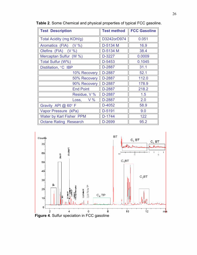
Sulfur speciation of FCC Gasoline has been completed using GC-AED and
GC-MS, and by analyzing reference materials and standards including
mercaptans, sulfides, thiophene, 2-methyl and 3-methyl thiophenes,
benzothiophene, and methyl benzothiophenes.
As mentioned above some work has been done to identify the sulfur
compounds in gasoline. The purpose of this step is to look at the certain gasoline
that is produced from specific process to design the experimental approach for the
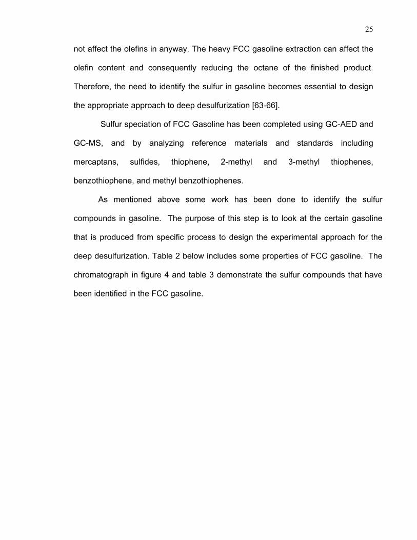
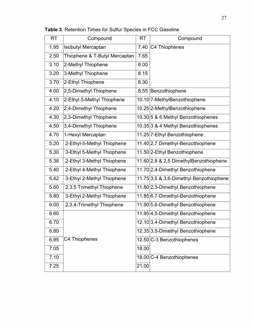
deep desulfurization. Table 2 below includes some properties of FCC gasoline. The
chromatograph in figure 4 and table 3 demonstrate the sulfur compounds that have
been identified in the FCC gasoline.
26
Table 2. Some Chemical and physical properties of typical FCC gasoline.
Test Description Test method FCC Gasoline
Total Acidity (mg KOH/g) D3242orD974 0.051
Aromatics (FIA) (V %) D-5134 M 16.9 Olefins (FIA) (V %) D-5134 M 38.4 Mercaptan Sulfur (W %) D-3227 0.0009 Total Sulfur (W%) D-5453 0.1045 Distillation, °C IBP D-2887 31.1 10% Recovery D-2887 52.1 50% Recovery D-2887 112.0 90% Recovery D-2887 178.9 End Point D-2887 218.2 Residue, V % D-2887 1.5 Loss, V % D-2887 2.0 Gravity API @ 60° F D-4052 58.9 Vapor Pressure (kPa) D-5191 9.0 Water by Karl Fisher PPM D-1744 122 Octane Rating Research D-2699 95.2
Figure 4. Sulfur speciation in FCC gasoline
27
Table 3. Retention Times for Sulfur Species in FCC Gasoline
RT Compound RT Compound
1.95 Isobutyl Mercaptan 7.40
2.50 Thiophene & T-Butyl Mercaptan 7.65
3.10 2-Methyl Thiophene 8.00
3.20 3-Methyl Thiophene 8.15
3.70 2-Ethyl Thiophene 8.30
C4 Thiophenes
4.00 2,5-Dimethyl Thiophene 8.55 Benzothiophene
4.10 2-Ethyl 5-Methyl Thiophene 10.10 7-MethylBenzothiophene
4.20 2,4-Dimethyl Thiophene 10.25 2-MethylBenzothiophene
4.30 2,3-Dimethyl Thiophene 10.30 5 & 6 Methyl Benzothiophenes
4.50 3,4-Dimethyl Thiophene 10.35 3 & 4 Methyl Benzothiophenes
4.70 1-Hexyl Mercaptan 11.25 7-Ethyl Benzothiophene
5.20 2-Ethyl-5-Methyl Thiophene 11.40 2,7 Dimethyl-Benzothiophene
5.30 3-Ethyl 5-Methyl Thiophene 11.50 2-Ethyl Benzothiophene
5.38 2-Ethyl 3-Methyl Thiophene 11.60 2,8 & 2,5 DimethylBenzothiophene
5.40 2-Ethyl 4-Methyl Thiophene 11.70 2,4-Dimethyl Benzothiophene
5.42 3-Ethyl 2-Methyl Thiophene 11.75 3,5 & 3,6-Dimethyl Benzothiophene
5.60 2,3,5 Trimethyl Thiophene 11.80 2,3-Dimethyl Benzothiophene
5.80 3-Ethyl 2-Methyl Thiophene 11.85 6,7-Dimethyl-Benzothiophene
6.00 2,3,4-Trimethyl Thiophene 11.90 5,6-Dimethyl Benzothiophene
6.60 11.95 4,5-Dimethyl Benzothiophene
6.70 12.10 3,4-Dimethyl Benzothiophene
6.80 12.35 3,5-Dimethyl Benzothiophene
6.95 12.50
7.05 18.00
C-3 Benzothiophenes
7.10 18.00
7.25
C4 Thiophenes
21.00
C-4 Benzothiophenes
28
3.2 Sulfur speciation in hydrotreated diesel.
Hydrotreated diesel was used specifically to eliminate most of the easy
sulfur compounds that are usually removed by the conventional
hydrodesulfurization process. Table 4 shows some properties of diesel used in this
study. The higher the boiling range of the hydrocarbon products, the more
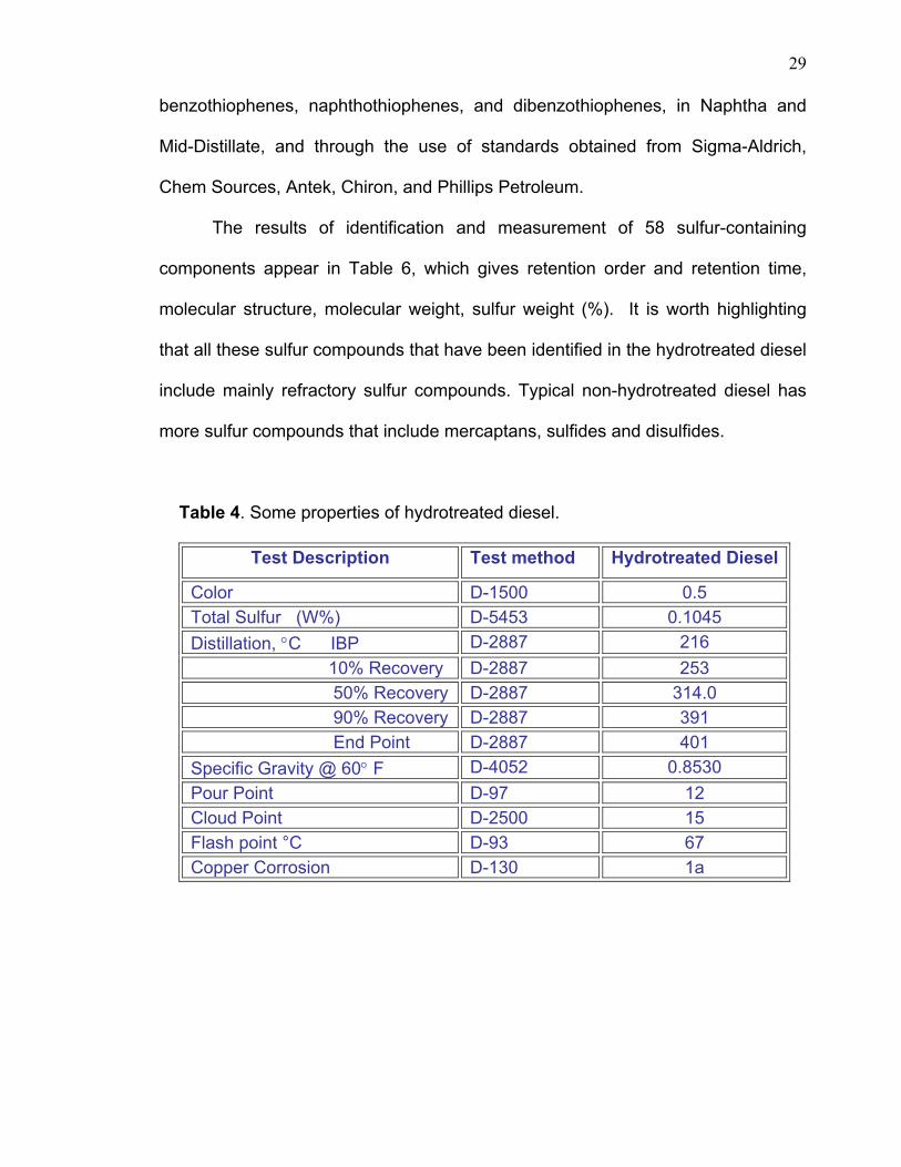
complex sulfur identification becomes. Previous work on sulfur identification of
some commercial diesel fuel [30] has identified the existence of both alkyl
benzothiophenes and alkyl dibenzothiophenes. The graph in figure 5 indicates
existing derivatives, the majority of them being alkyl dibenzothiophenes. Some of
these isomers are co-eluted and it became very difficult to separate them for
identification. Another problem is that the diesel includes high concentrations of
aromatic hydrocarbons in relation to their sulfur concentrations. This represented
a challenge to devise a method that could separate the sulfur aromatics from the
remaining hydrocarbon aromatics. However, there has been some work on the
sulfur speciation in diesel where some of the sulfur compounds have been
identified [48,59-60].
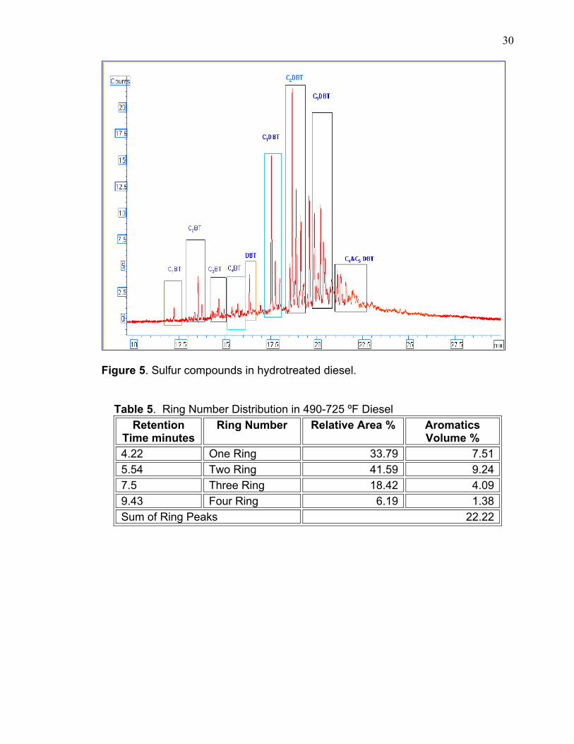
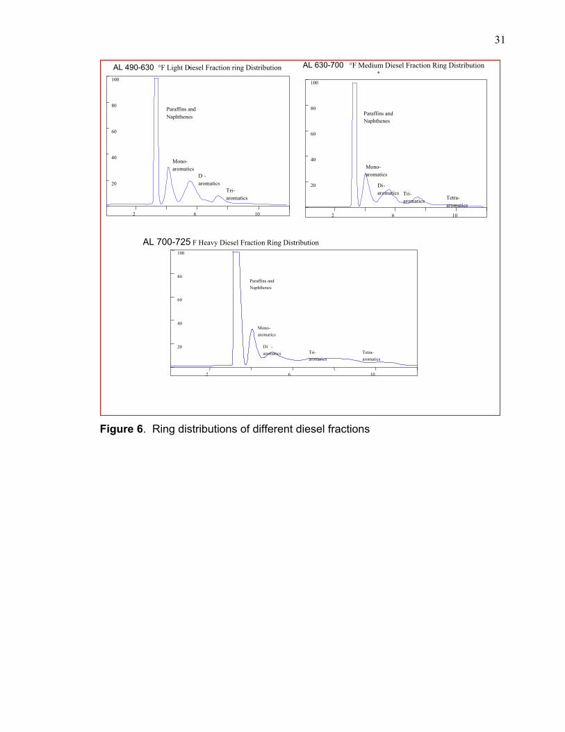
To illustrate the complexity of existing types of ring distributions of
hydrocarbons, including sulfur aromatic rings, Supercritical Fluid Chromatography
(SFC) was used. The method is based on the procedure given by the ASTM D-
5186. Table 5 demonstrates the ring number distributions of typical diesel of
Arabian light crude oil. The graph in Figure 6 shows the ring distributions of light,
medium and heavy diesel fractions of Arabian light crude.
The identification was based on literature references motioned earlier
listing the exact identification of individual isomers of alkylated thiophenes,
29
benzothiophenes, naphthothiophenes, and dibenzothiophenes, in Naphtha and
Mid-Distillate, and through the use of standards obtained from Sigma-Aldrich,
Chem Sources, Antek, Chiron, and Phillips Petroleum.
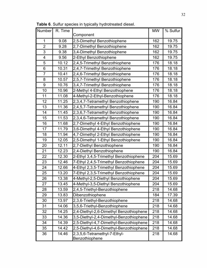
The results of identification and measurement of 58 sulfur-containing
components appear in Table 6, which gives retention order and retention time,
molecular structure, molecular weight, sulfur weight (%). It is worth highlighting
that all these sulfur compounds that have been identified in the hydrotreated diesel
include mainly refractory sulfur compounds. Typical non-hydrotreated diesel has
more sulfur compounds that include mercaptans, sulfides and disulfides.
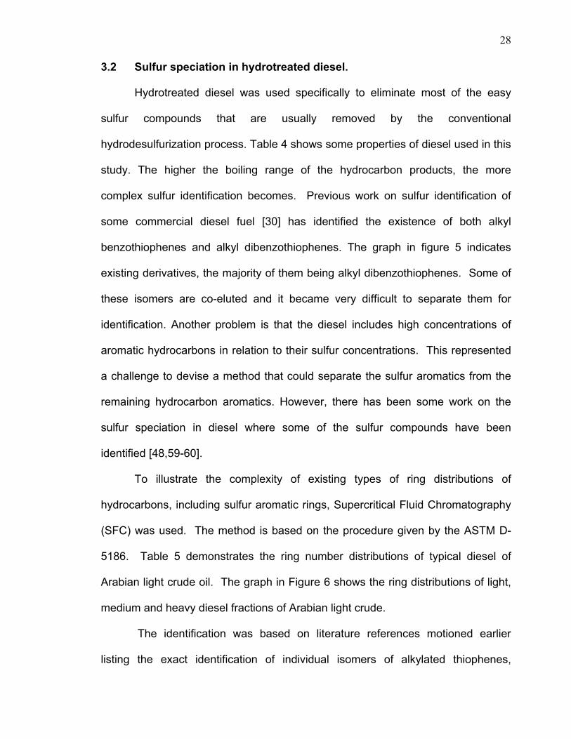
Table 4. Some properties of hydrotreated diesel.
Test Description Test method Hydrotreated Diesel
Color D-1500 0.5 Total Sulfur (W%) D-5453 0.1045 Distillation, °C IBP D-2887 216 10% Recovery D-2887 253 50% Recovery D-2887 314.0 90% Recovery D-2887 391 End Point D-2887 401 Specific Gravity @ 60° F D-4052 0.8530 Pour Point D-97 12 Cloud Point D-2500 15 Flash point °C D-93 67 Copper Corrosion D-130 1a
30
Figure 5. Sulfur compounds in hydrotreated diesel. Table 5. Ring Number Distribution in 490-725 ºF Diesel
Retention Time minutes
Ring Number Relative Area % Aromatics Volume %
4.22 One Ring 33.79 7.51 5.54 Two Ring 41.59 9.24 7.5 Three Ring 18.42 4.09 9.43 Four Ring 6.19 1.38 Sum of Ring Peaks 22.22
31
Figure 6. Ring distributions of different diesel fractions
100
40
60
20
80
2 6 10
° AL 490-630 °F Light Diesel Fraction ring Distribution
Paraffins and Naphthenes
Mono- aromatics
Tri-aromatics
D - aromatics
100
40
60
20
80
2 6 10
°AL 630-700 °F Medium Diesel Fraction Ring Distribution
Paraffins andNaphthenes
Mono-aromatics
Tri- aromatics Tetra-
aromatics
Di-aromatics
100
40
60
20
80
2 6 10
AL 700-725 F Heavy Diesel Fraction Ring Distribution
Paraffins andNaphthenes
Mono-aromatics
Tri-aromatics
Tetra-aromatics
Di -aromatics
32
Table 6. Sulfur species in typically hydrotreated diesel. Number R. Time
Component MW % Sulfur
1 9.08 2,5-Dimethyl Benzothiophene 162 19.75 2 9.28 2,7-Dimethyl Benzothiophene 162 19.75 3 9.38 3,4-Dimethyl Benzothiophene 162 19.75 4 9.56 2-Ethyl Benzothiophene 162 19.75 5 10.12 2,4,5-Trimethyl Benzothiophene 176 18.18 6 10.31 2,4,7-Trimethyl Benzothiophene 176 18.18 7 10.41 2,4,6-Trimethyl Benzothiophene 176 18.18 8 10.57 2,5,7-Trimethyl Benzothiophene 176 18.18 9 10.76 3,4,7-Trimethyl Benzothiophene 176 18.18 10 10.96 2-Methyl 4-Ethyl Benzothiophene 176 18.18 11 11.08 4-Methyl-2-Ethyl-Benzothiophene 176 18.18 12 11.25 2,3,4,7-Tetramethyl Benzothiophene 190 16.84 13 11.36 2,4,5,7-Tetramethyl Benzothiophene 190 16.84 14 11.45 2,3,6,7-Tetramethyl Benzothiophene 190 16.84 15 11.53 2,3,4,6-Tetramethyl Benzothiophene 190 16.84 16 11.68 2,7-Dimethyl 4-Ethyl Benzothiophene 190 16.84 17 11.79 3,6-Dimethyl 4-Ethyl Benzothiophene 190 16.84 18 11.94 4,7-Dimethyl 2-Ethyl Benzothiophene 190 16.84 19 12.05 2,5-Dimethyl 1-Ethyl Benzothiophene 190 16.84 20 12.11 2,7-Diethyl Benzothiophene 190 16.84 21 12.23 2,4-Diethyl Benzothiophene 190 16.84 22 12.30 2-Ethyl 3,4,5-Trimethyl Benzothiophene 204 15.69 23 12.46 7-Ethyl 2,4,5-Trimethyl Benzothiophene 204 15.69 24 12.66 4-Ethyl 2,3,5-Trimethyl Benzothiophene 204 15.69 25 13.20 7-Ethyl 2,3,5-Trimethyl Benzothiophene 204 15.69 26 13.38 4-Methyl-2,5-Diethyl Benzothiophene 204 15.69 27 13.45 4-Methyl-3,5-Diethyl Benzothiophene 204 15.69 28 13.59 2,4,5-Triethyl-Benzothiophene 218 14.68 29 13.83 Dibenzothiophene 184 17.39 30 13.97 2,3,6-Triethyl-Benzothiophene 218 14.68 31 14.06 3,5,6-Triethyl-Benzothiophene 218 14.68 32 14.25 2,4-Diethyl-2,6-Dimethyl Benzothiophene 218 14.68 33 14.36 3,5-Diethyl-2,4-Dimethyl-Benzothiophene 218 14.68 34 14.39 2,5-Diethyl-4,7-Dimethyl-Benzothiophene 218 14.68 35 14.42 2,5-Diethyl-4,6-Dimethyl-Benzothiophene 218 14.68 36 14.46 2,3,5,6-Tetramethyl-7-Ethyl-
Benzothiophene 218 14.68
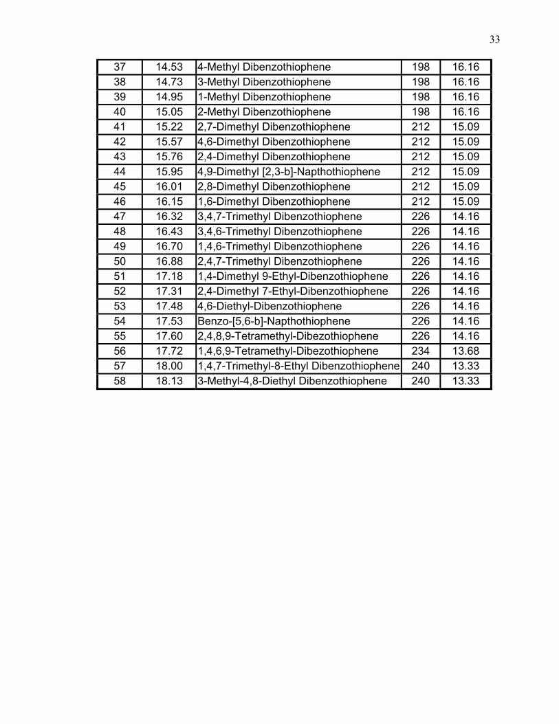
33
37 14.53 4-Methyl Dibenzothiophene 198 16.16 38 14.73 3-Methyl Dibenzothiophene 198 16.16 39 14.95 1-Methyl Dibenzothiophene 198 16.16 40 15.05 2-Methyl Dibenzothiophene 198 16.16 41 15.22 2,7-Dimethyl Dibenzothiophene 212 15.09 42 15.57 4,6-Dimethyl Dibenzothiophene 212 15.09 43 15.76 2,4-Dimethyl Dibenzothiophene 212 15.09 44 15.95 4,9-Dimethyl [2,3-b]-Napthothiophene 212 15.09 45 16.01 2,8-Dimethyl Dibenzothiophene 212 15.09 46 16.15 1,6-Dimethyl Dibenzothiophene 212 15.09 47 16.32 3,4,7-Trimethyl Dibenzothiophene 226 14.16 48 16.43 3,4,6-Trimethyl Dibenzothiophene 226 14.16 49 16.70 1,4,6-Trimethyl Dibenzothiophene 226 14.16 50 16.88 2,4,7-Trimethyl Dibenzothiophene 226 14.16 51 17.18 1,4-Dimethyl 9-Ethyl-Dibenzothiophene 226 14.16 52 17.31 2,4-Dimethyl 7-Ethyl-Dibenzothiophene 226 14.16 53 17.48 4,6-Diethyl-Dibenzothiophene 226 14.16 54 17.53 Benzo-[5,6-b]-Napthothiophene 226 14.16 55 17.60 2,4,8,9-Tetramethyl-Dibezothiophene 226 14.16 56 17.72 1,4,6,9-Tetramethyl-Dibezothiophene 234 13.68 57 18.00 1,4,7-Trimethyl-8-Ethyl Dibenzothiophene 240 13.33 58 18.13 3-Methyl-4,8-Diethyl Dibenzothiophene 240 13.33
34
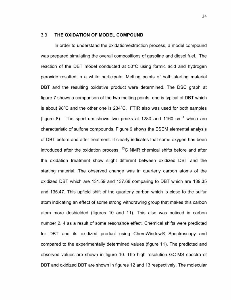
3.3 THE OXIDATION OF MODEL COMPOUND
In order to understand the oxidation/extraction process, a model compound
was prepared simulating the overall compositions of gasoline and diesel fuel. The
reaction of the DBT model conducted at 50°C using formic acid and hydrogen
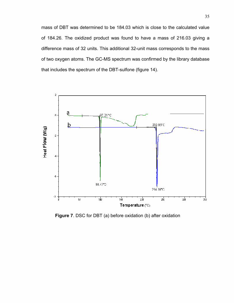
peroxide resulted in a white participate. Melting points of both starting material
DBT and the resulting oxidative product were determined. The DSC graph at
figure 7 shows a comparison of the two melting points, one is typical of DBT which
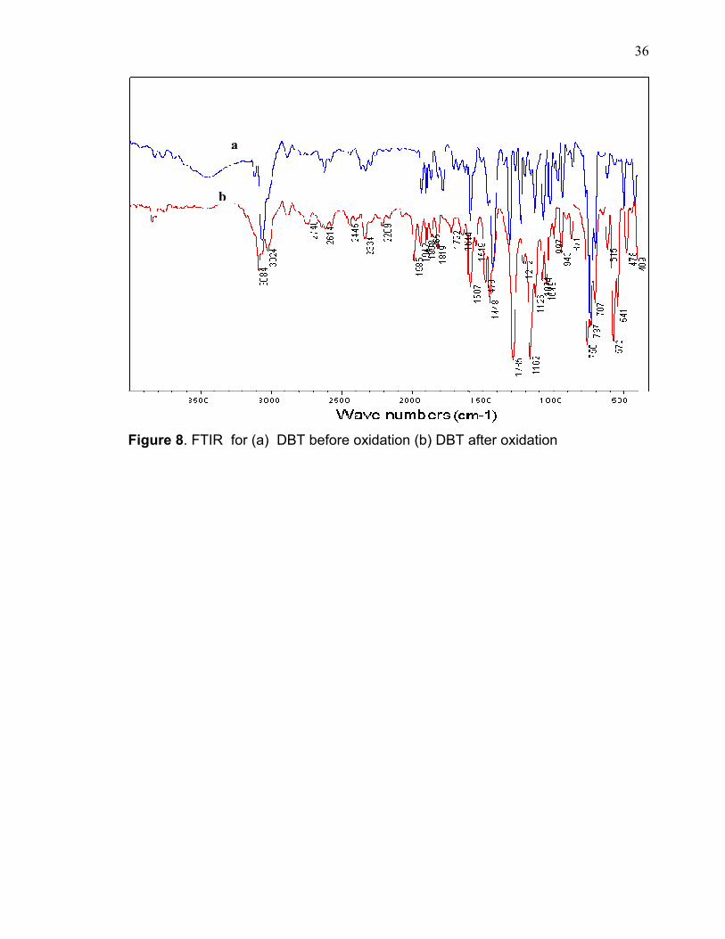
is about 98ºC and the other one is 234ºC. FTIR also was used for both samples
(figure 8). The spectrum shows two peaks at 1280 and 1160 cm-1 which are
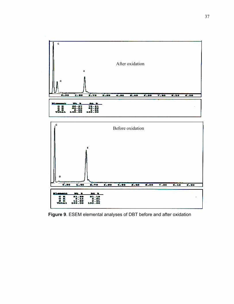
characteristic of sulfone compounds. Figure 9 shows the ESEM elemental analysis
of DBT before and after treatment. It clearly indicates that some oxygen has been
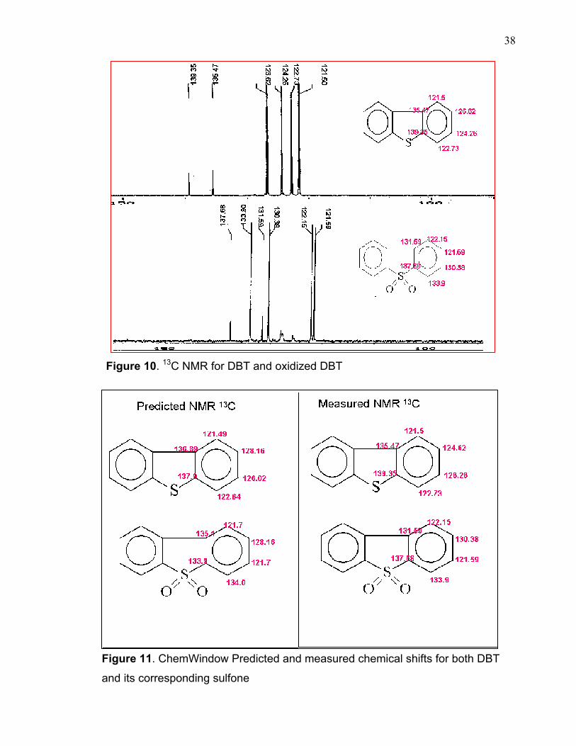
introduced after the oxidation process. 13C NMR chemical shifts before and after
the oxidation treatment show slight different between oxidized DBT and the
starting material. The observed change was in quarterly carbon atoms of the
oxidized DBT which are 131.59 and 137.68 comparing to DBT which are 139.35
and 135.47. This upfield shift of the quarterly carbon which is close to the sulfur
atom indicating an effect of some strong withdrawing group that makes this carbon
atom more deshielded (figures 10 and 11). This also was noticed in carbon
number 2, 4 as a result of some resonance effect. Chemical shifts were predicted
for DBT and its oxidized product using ChemWindow® Spectroscopy and
compared to the experimentally determined values (figure 11). The predicted and
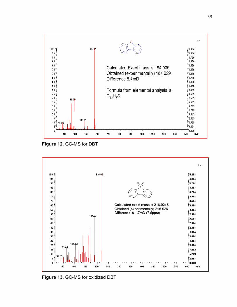
observed values are shown in figure 10. The high resolution GC-MS spectra of
DBT and oxidized DBT are shown in figures 12 and 13 respectively. The molecular
35
mass of DBT was determined to be 184.03 which is close to the calculated value
of 184.26. The oxidized product was found to have a mass of 216.03 giving a
difference mass of 32 units. This additional 32-unit mass corresponds to the mass
of two oxygen atoms. The GC-MS spectrum was confirmed by the library database
that includes the spectrum of the DBT-sulfone (figure 14).
Figure 7. DSC for DBT (a) before oxidation (b) after oxidation
36
Figure 8. FTIR for (a) DBT before oxidation (b) DBT after oxidation
a
b
37
Figure 9. ESEM elemental analyses of DBT before and after oxidation
Before oxidation
After oxidation
38
Figure 10. 13C NMR for DBT and oxidized DBT
Figure 11. ChemWindow Predicted and measured chemical shifts for both DBT
and its corresponding sulfone
39
Figure 12. GC-MS for DBT
Figure 13. GC-MS for oxidized DBT
40
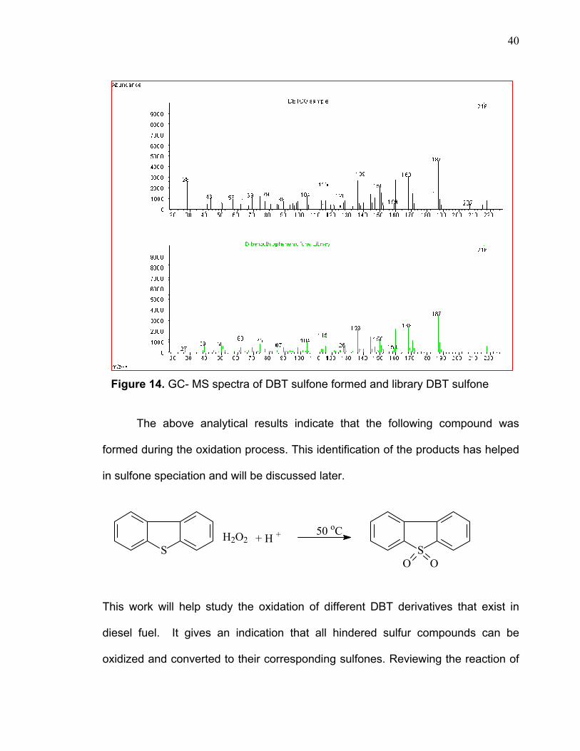
Figure 14. GC- MS spectra of DBT sulfone formed and library DBT sulfone
The above analytical results indicate that the following compound was
formed during the oxidation process. This identification of the products has helped
in sulfone speciation and will be discussed later.
This work will help study the oxidation of different DBT derivatives that exist in
diesel fuel. It gives an indication that all hindered sulfur compounds can be
oxidized and converted to their corresponding sulfones. Reviewing the reaction of
S SOO
H2O2 + H + 50 oC
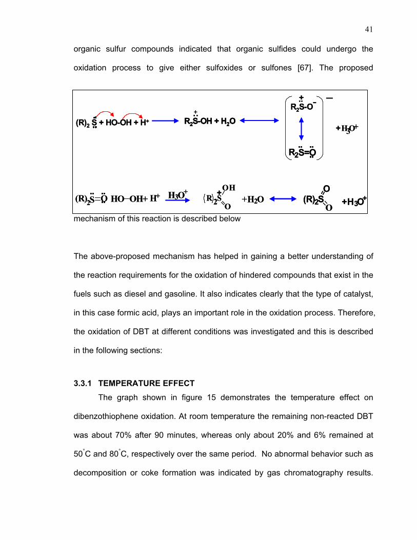
41
organic sulfur compounds indicated that organic sulfides could undergo the
oxidation process to give either sulfoxides or sulfones [67]. The proposed
mechanism of this reaction is described below
The above-proposed mechanism has helped in gaining a better understanding of
the reaction requirements for the oxidation of hindered compounds that exist in the
fuels such as diesel and gasoline. It also indicates clearly that the type of catalyst,
in this case formic acid, plays an important role in the oxidation process. Therefore,
the oxidation of DBT at different conditions was investigated and this is described
in the following sections:
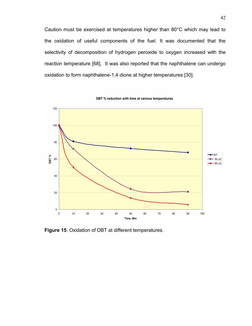
3.3.1 TEMPERATURE EFFECT The graph shown in figure 15 demonstrates the temperature effect on
dibenzothiophene oxidation. At room temperature the remaining non-reacted DBT
was about 70% after 90 minutes, whereas only about 20% and 6% remained at
50°C and 80°C, respectively over the same period. No abnormal behavior such as
decomposition or coke formation was indicated by gas chromatography results.
(R)2 S + HO-OH + H++H3O+
R2S=O
OH O
R2S-OH + H2O..+ R2S-O
..+ -
(R)2S O HO OH+ H+ H3O+R 2S
O+H2O (R) 2S
O +H3 O++
(R)2 S + HO-OH + H++H3O+
R2S=O
OH O
R2S-OH + H2O..+
R2S-OH + H2O..+ R2S-O
..+ -
(R)2S O HO OH+ H+ H3O+R 2S
O+H2O (R) 2S
O +H3 O++
42
Caution must be exercised at temperatures higher than 80°C which may lead to
the oxidation of useful components of the fuel. It was documented that the
selectivity of decomposition of hydrogen peroxide to oxygen increased with the
reaction temperature [68]. It was also reported that the naphthalene can undergo
oxidation to form naphthalene-1,4 dione at higher temperatures [30].
DBT % reduction with time at various temperatures
0
20
40
60
80
100
120
0 10 20 30 40 50 60 70 80 90 100
Time, Min
DB
T % RT
50 oC 80 oC
Figure 15. Oxidation of DBT at different temperatures.
43
3.3.2 ACID SELECTIVITY Continuous bubbling was noticed when hydrolcloric acid and acetic acid
were used. In the case of HCl, the bubbling was more vigorous and did not last
long whereas in the case of acetic acid it persisted over a longer period of time.
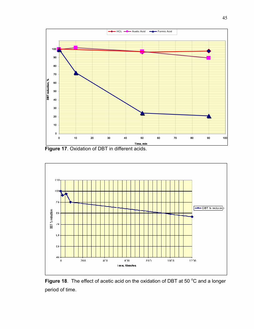
The results as showed in figure 16&17 indicate that the formic acid has a greater
oxidating effect than in the case of both acetic acid and HCl. There is some
oxidation in presence of HCl however; it is insignificant compared to the formic
acid sample. This clearly indicates that a strong acid may accelerate the
decomposition of H2O2 to oxygen and water resulting in a poor yield of oxidized
DBT. Therefore, the result after 15 minutes in HCL sample was not included in
graph 17 due to the difficulty of producing good results that could be compared to
the rest of the samples. In the case of acetic acid, the reaction rate is very slow
and requires a longer period of time to produce satisfactory results. The acetic
acid is a relatively week acid compared to formic acid (the dissociation constant of
acetic acid is 1.74 X10⁻⁵ and formic acid is 1.78 X10⁻⁴ at room temperature).
Therefore, the reaction probably requires longer time for oxidation to occur,
however during this time, the H2O2 can undergo decomposition which is a well
known phenomenon, even at lower temperatures. This requires addition of further
quantities of H2O2 to produce a satisfactory result.
It has been documented that acetic acid has been used successfully to
oxidize sulfur compounds to sulfones [5,21,48]. In view of this, the effect of acetic
acid was re-examined with a different approach. In this experiment a premixed
amount of hydrogen peroxide and 50ml of DBT model compound using the same
quantities and conditions as the previous experiment were prepared. During the
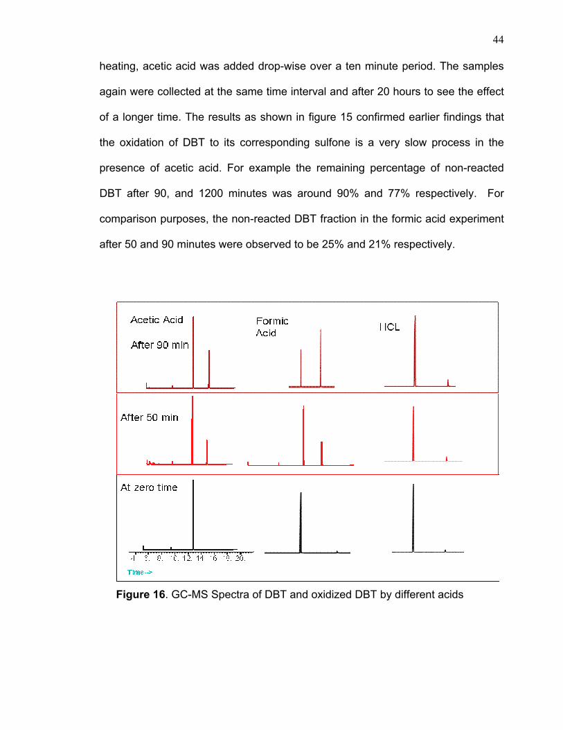
44
heating, acetic acid was added drop-wise over a ten minute period. The samples
again were collected at the same time interval and after 20 hours to see the effect
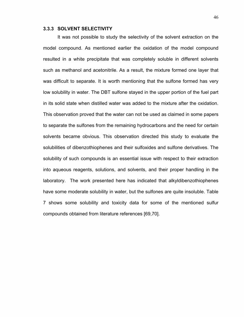
of a longer time. The results as shown in figure 15 confirmed earlier findings that
the oxidation of DBT to its corresponding sulfone is a very slow process in the
presence of acetic acid. For example the remaining percentage of non-reacted
DBT after 90, and 1200 minutes was around 90% and 77% respectively. For
comparison purposes, the non-reacted DBT fraction in the formic acid experiment
after 50 and 90 minutes were observed to be 25% and 21% respectively.
Figure 16. GC-MS Spectra of DBT and oxidized DBT by different acids
45
Figure 17. Oxidation of DBT in different acids.
Figure 18. The effect of acetic acid on the oxidation of DBT at 50 oC and a longer
period of time.
0
10
20
30
40
50
60
70
80
90
100
0 10 20 30 40 50 60 70 80 90 100
Time, min
DB
T re
duct
ion,
%
HCL Acetic Acid Formic Acid
0
10
20
30
40
50
60
70
80
90
100
0 10 20 30 40 50 60 70 80 90 100
Time, min
DB
T re
duct
ion,
%
HCL Acetic Acid Formic Acid
46
3.3.3 SOLVENT SELECTIVITY It was not possible to study the selectivity of the solvent extraction on the
model compound. As mentioned earlier the oxidation of the model compound
resulted in a white precipitate that was completely soluble in different solvents
such as methanol and acetonitrile. As a result, the mixture formed one layer that
was difficult to separate. It is worth mentioning that the sulfone formed has very
low solubility in water. The DBT sulfone stayed in the upper portion of the fuel part
in its solid state when distilled water was added to the mixture after the oxidation.
This observation proved that the water can not be used as claimed in some papers
to separate the sulfones from the remaining hydrocarbons and the need for certain
solvents became obvious. This observation directed this study to evaluate the
solubilities of dibenzothiophenes and their sulfoxides and sulfone derivatives. The
solubility of such compounds is an essential issue with respect to their extraction
into aqueous reagents, solutions, and solvents, and their proper handling in the
laboratory. The work presented here has indicated that alkyldibenzothiophenes
have some moderate solubility in water, but the sulfones are quite insoluble. Table
7 shows some solubility and toxicity data for some of the mentioned sulfur
compounds obtained from literature references [69,70].
47
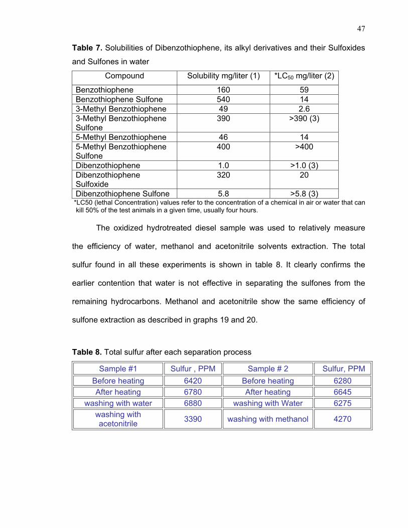
Table 7. Solubilities of Dibenzothiophene, its alkyl derivatives and their Sulfoxides
and Sulfones in water
Compound Solubility mg/liter (1) *LC50 mg/liter (2)
Benzothiophene 160 59 Benzothiophene Sulfone 540 14 3-Methyl Benzothiophene 49 2.6 3-Methyl Benzothiophene Sulfone
390 >390 (3)
5-Methyl Benzothiophene 46 14 5-Methyl Benzothiophene Sulfone
400 >400
Dibenzothiophene 1.0 >1.0 (3) Dibenzothiophene Sulfoxide
320 20
Dibenzothiophene Sulfone 5.8 >5.8 (3) *LC50 (lethal Concentration) values refer to the concentration of a chemical in air or water that can
kill 50% of the test animals in a given time, usually four hours.
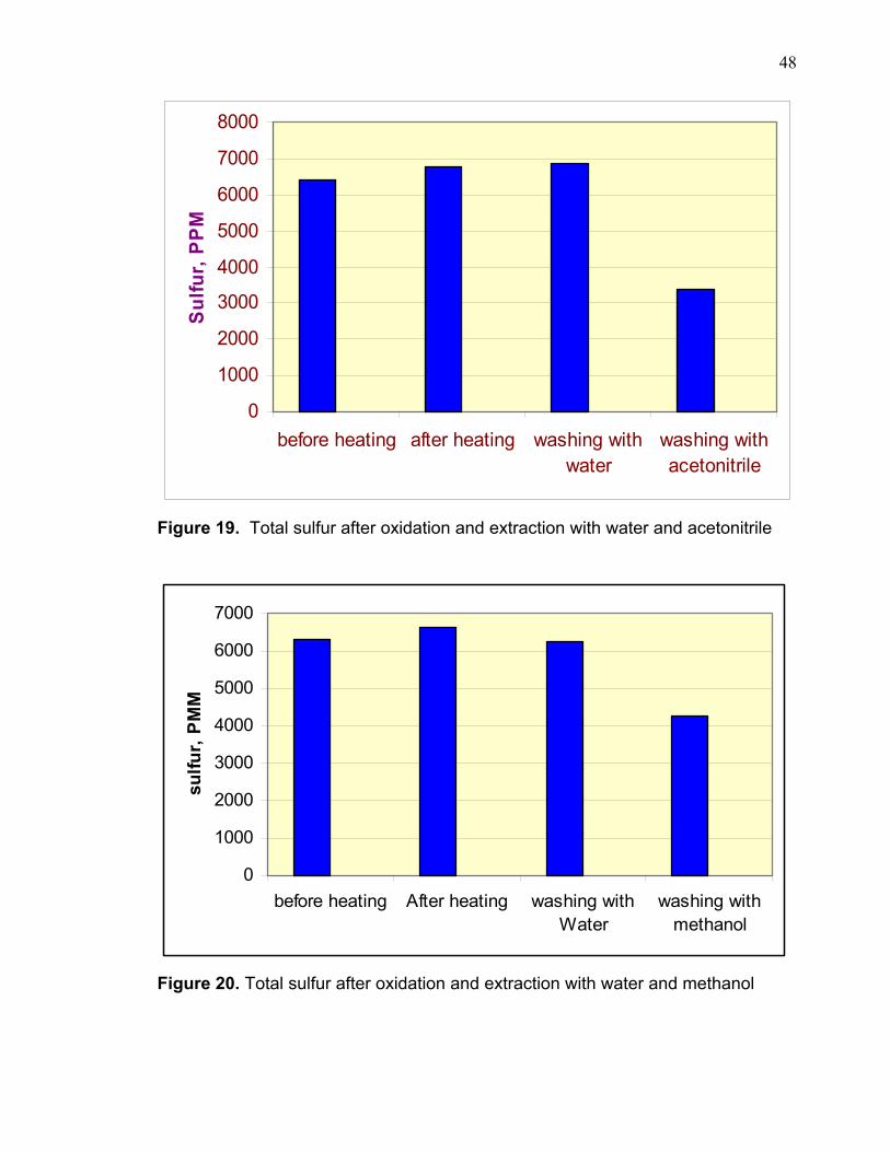
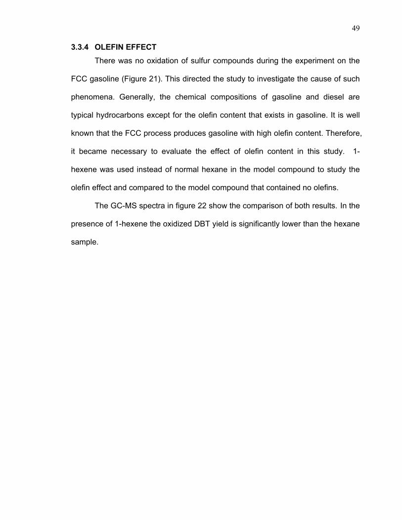
The oxidized hydrotreated diesel sample was used to relatively measure
the efficiency of water, methanol and acetonitrile solvents extraction. The total
sulfur found in all these experiments is shown in table 8. It clearly confirms the
earlier contention that water is not effective in separating the sulfones from the
remaining hydrocarbons. Methanol and acetonitrile show the same efficiency of
sulfone extraction as described in graphs 19 and 20.
Table 8. Total sulfur after each separation process
Sample #1 Sulfur , PPM Sample # 2 Sulfur, PPM Before heating 6420 Before heating 6280 After heating 6780 After heating 6645
washing with water 6880 washing with Water 6275 washing with acetonitrile 3390 washing with methanol 4270
48
0
1000
2000
3000
4000
5000
6000
7000
8000
before heating after heating washing withwater
washing withacetonitrile
Sulfu
r, P
PM
Figure 19. Total sulfur after oxidation and extraction with water and acetonitrile
0
1000
2000
3000
4000
5000
6000
7000
before heating After heating washing withWater
washing withmethanol
sulfu
r, P
MM
Figure 20. Total sulfur after oxidation and extraction with water and methanol
49
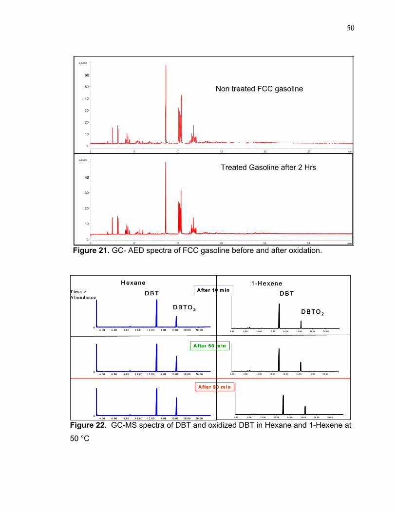
3.3.4 OLEFIN EFFECT There was no oxidation of sulfur compounds during the experiment on the
FCC gasoline (Figure 21). This directed the study to investigate the cause of such
phenomena. Generally, the chemical compositions of gasoline and diesel are
typical hydrocarbons except for the olefin content that exists in gasoline. It is well
known that the FCC process produces gasoline with high olefin content. Therefore,
it became necessary to evaluate the effect of olefin content in this study. 1-
hexene was used instead of normal hexane in the model compound to study the
olefin effect and compared to the model compound that contained no olefins.
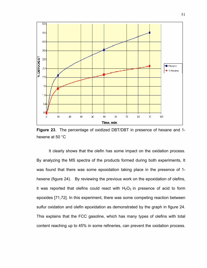
The GC-MS spectra in figure 22 show the comparison of both results. In the
presence of 1-hexene the oxidized DBT yield is significantly lower than the hexane
sample.
50
Figure 21. GC- AED spectra of FCC gasoline before and after oxidation.
Figure 22. GC-MS spectra of DBT and oxidized DBT in Hexane and 1-Hexene at
50 °C
D B TT im e >A bundance
4.00 6 .00 8 .00 10 .00 12 .00 14 .00 16 .00 18 .00 20 .000
4.00 6 .00 8 .00 10 .00 12 .00 14 .00 16 .00 18 .00 20 .000
4.00 6 .00 8 .00 10 .00 12 .00 14 .00 16 .00 18 .00 20 .000
D B T O 2
A fter 10 m in
A fter 50 m in
A fter 90 m in
6.00 8.00 10 .0 0 12 .0 0 14 .0 0 16.00 18.00 2 0.00
6.00 8.00 1 0.00 12.00 14 .0 0 16 .0 0 18 .0 0 20 .0 0
6.00 8 .0 0 1 0.00 1 2.00 1 4.00 1 6.00 18 .0 0 20 .0 0
D B T
D B T O 2
H exane 1-H exeneD B TT im e >
A bundance
4.00 6 .00 8 .00 10 .00 12 .00 14 .00 16 .00 18 .00 20 .000
4.00 6 .00 8 .00 10 .00 12 .00 14 .00 16 .00 18 .00 20 .000
4.00 6 .00 8 .00 10 .00 12 .00 14 .00 16 .00 18 .00 20 .000
D B T O 2
A fter 10 m in
A fter 50 m in
A fter 90 m in
6.00 8.00 10 .0 0 12 .0 0 14 .0 0 16.00 18.00 2 0.00
6.00 8.00 1 0.00 12.00 14 .0 0 16 .0 0 18 .0 0 20 .0 0
6.00 8 .0 0 1 0.00 1 2.00 1 4.00 1 6.00 18 .0 0 20 .0 0
D B T
D B T O 2
H exane 1-H exene
Fig; FCC gasoline after 60 min of oxidation
min0 5 10 15 20 25
Counts
0
10
20
30
40
50
60
min0 5 10 15 20 25
Counts
0
10
20
30
40
Non treated FCC gasoline
Treated Gasoline after 2 Hrs
Fig; FCC gasoline after 60 min of oxidation
min0 5 10 15 20 25
Counts
0
10
20
30
40
50
60
min0 5 10 15 20 25
Counts
0
10
20
30
40
min0 5 10 15 20 25
Counts
0
10
20
30
40
50
60
min0 5 10 15 20 25
Counts
0
10
20
30
40
50
60
min0 5 10 15 20 25
Counts
0
10
20
30
40
min0 5 10 15 20 25
Counts
0
10
20
30
40
Non treated FCC gasoline
Treated Gasoline after 2 Hrs
51
Figure 23. The percentage of oxidized DBT/DBT in presence of hexane and 1-
hexene at 50 °C
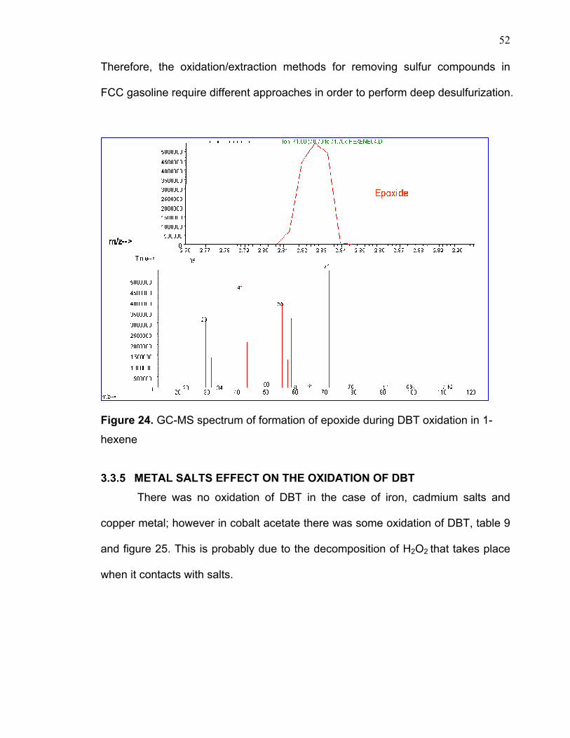
It clearly shows that the olefin has some impact on the oxidation process.
By analyzing the MS spectra of the products formed during both experiments, It
was found that there was some epoxidation taking place in the presence of 1-
hexene (figure 24). By reviewing the previous work on the epoxidation of olefins,
it was reported that olefins could react with H2O2 in presence of acid to form
epoxides [71,72]. In this experiment, there was some competing reaction between
sulfur oxidation and olefin epoxidation as demonstrated by the graph in figure 24.
This explains that the FCC gasoline, which has many types of olefins with total
content reaching up to 45% in some refineries, can prevent the oxidation process.
52
Therefore, the oxidation/extraction methods for removing sulfur compounds in
FCC gasoline require different approaches in order to perform deep desulfurization.
Figure 24. GC-MS spectrum of formation of epoxide during DBT oxidation in 1-
hexene
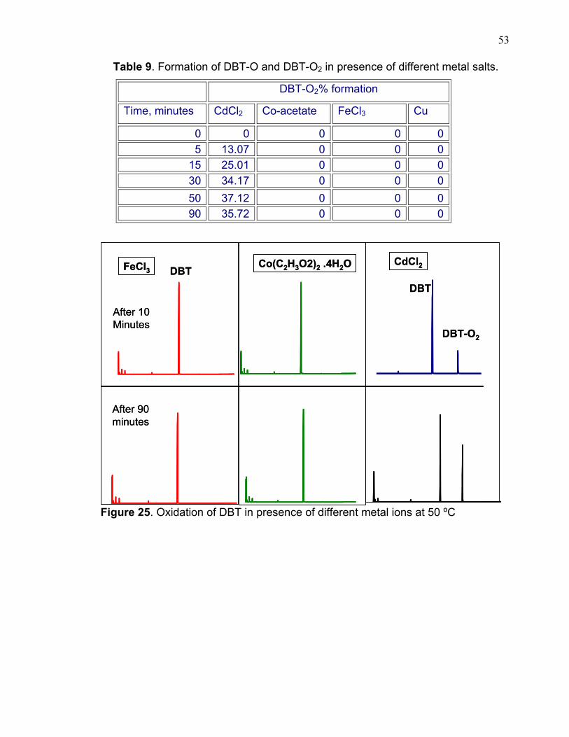
3.3.5 METAL SALTS EFFECT ON THE OXIDATION OF DBT There was no oxidation of DBT in the case of iron, cadmium salts and
copper metal; however in cobalt acetate there was some oxidation of DBT, table 9
and figure 25. This is probably due to the decomposition of H2O2 that takes place
when it contacts with salts.
53
Table 9. Formation of DBT-O and DBT-O2 in presence of different metal salts.
DBT-O2% formation
Time, minutes CdCl2 Co-acetate FeCl3 Cu
0 0 0 0 0 5 13.07 0 0 0
15 25.01 0 0 0 30 34.17 0 0 0 50 37.12 0 0 0 90 35.72 0 0 0
Figure 25. Oxidation of DBT in presence of different metal ions at 50 ºC
After 10 Minutes
After 90 minutes
FeCl3 Co(C2H3O2)2 .4H2O CdCl2DBT
DBT-O2
DBT
After 10 Minutes
After 90 minutes
FeCl3 Co(C2H3O2)2 .4H2O CdCl2DBT
DBT-O2
DBT
54
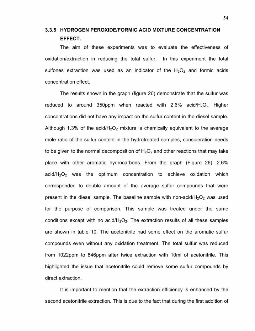
3.3.5 HYDROGEN PEROXIDE/FORMIC ACID MIXTURE CONCENTRATION EFFECT. The aim of these experiments was to evaluate the effectiveness of
oxidation/extraction in reducing the total sulfur. In this experiment the total
sulfones extraction was used as an indicator of the H2O2 and formic acids
concentration effect.
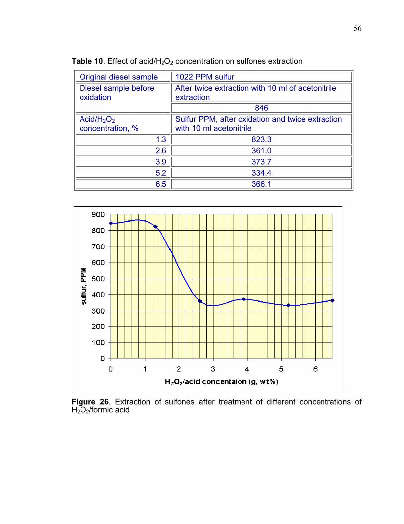
The results shown in the graph (figure 26) demonstrate that the sulfur was
reduced to around 350ppm when reacted with 2.6% acid/H2O2. Higher
concentrations did not have any impact on the sulfur content in the diesel sample.
Although 1.3% of the acid/H2O2 mixture is chemically equivalent to the average
mole ratio of the sulfur content in the hydrotreated samples, consideration needs
to be given to the normal decomposition of H2O2 and other reactions that may take
place with other aromatic hydrocarbons. From the graph (Figure 26), 2.6%
acid/H2O2 was the optimum concentration to achieve oxidation which
corresponded to double amount of the average sulfur compounds that were
present in the diesel sample. The baseline sample with non-acid/H2O2 was used
for the purpose of comparison. This sample was treated under the same
conditions except with no acid/H2O2. The extraction results of all these samples
are shown in table 10. The acetonitrile had some effect on the aromatic sulfur
compounds even without any oxidation treatment. The total sulfur was reduced
from 1022ppm to 846ppm after twice extraction with 10ml of acetonitrile. This
highlighted the issue that acetonitrile could remove some sulfur compounds by
direct extraction.
It is important to mention that the extraction efficiency is enhanced by the
second acetonitrile extraction. This is due to the fact that during the first addition of
55
10ml of acetonitrile the diesel layer became a hazy cloudy mixture after one hour
whereas in the second extraction the diesel layer became very clear. Therefore
the sulfur value was obtained after the second extraction of acetonitrile to
determine precisely the degree of sulfur removal.
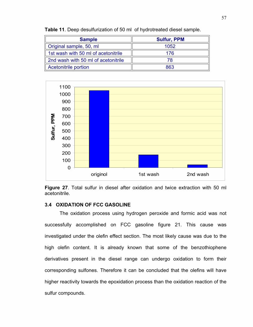
Deep desulfurization was achieved by increasing H2O2/ formic acid
concentration and heating the samples for a longer period of time (about two
hours). Then, the sample was extracted twice with 1:1 ratio of acetonitrile to the
diesel sample. The sulfur content in diesel layer was determined and found to be
176ppm and 41ppm after each extraction. Table 11 and graph 27 demonstrate
such extraction.
56
Table 10. Effect of acid/H2O2 concentration on sulfones extraction
Original diesel sample 1022 PPM sulfur After twice extraction with 10 ml of acetonitrile extraction
Diesel sample before oxidation
846 Acid/H2O2 concentration, %
Sulfur PPM, after oxidation and twice extraction with 10 ml acetonitrile
1.3 823.3 2.6 361.0 3.9 373.7 5.2 334.4 6.5 366.1
Figure 26. Extraction of sulfones after treatment of different concentrations of H2O2/formic acid
57
Table 11. Deep desulfurization of 50 ml of hydrotreated diesel sample.
Sample Sulfur, PPM Original sample, 50, ml 1052 1st wash with 50 ml of acetonitrile 176 2nd wash with 50 ml of acetonitrile 78 Acetonitrile portion 863
0100200300400500600700800900
10001100
originol 1st wash 2nd wash
Sulfu
r, P
PM
Figure 27. Total sulfur in diesel after oxidation and twice extraction with 50 ml acetonitrile. 3.4 OXIDATION OF FCC GASOLINE The oxidation process using hydrogen peroxide and formic acid was not
successfully accomplished on FCC gasoline figure 21. This cause was
investigated under the olefin effect section. The most likely cause was due to the
high olefin content. It is already known that some of the benzothiophene
derivatives present in the diesel range can undergo oxidation to form their
corresponding sulfones. Therefore it can be concluded that the olefins will have
higher reactivity towards the epoxidation process than the oxidation reaction of the
sulfur compounds.
58
3.5 Oxidation of hydrotreated diesel
Hydrotreated diesel was submitted to several experimental approaches to
study the oxidation process. Some of these experiments have been explained in
the previous sections such as solvent selectivity, acid/H2O2 concentration affect
etc. The discussions here will focus on some of the important observations related
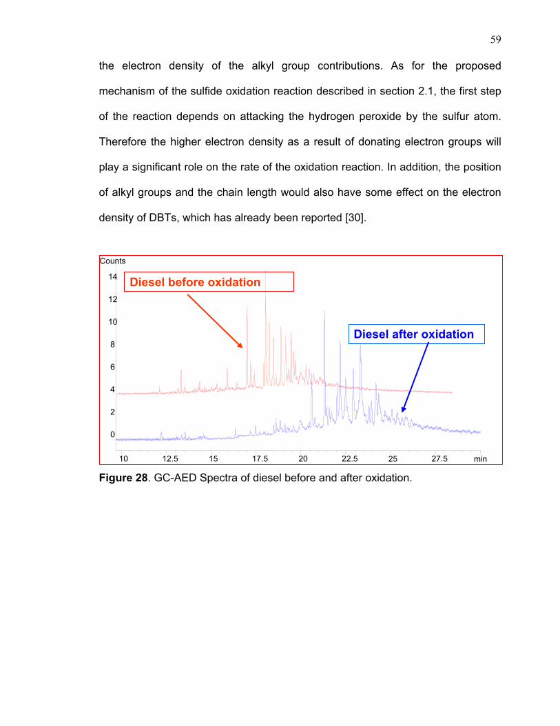
to the sulfur oxidations process. From the DBT module, it was concluded that all
hindered sulfur compounds can undergo the oxidation process to lead to the
corresponding sulfoxide and sulfones (figure 28). In the presence of excess
acid/H2O2, the reaction will go completely to the final sulfones products as has
been observed in the model compound. This was confirmed by the GC-MS data
(figure 14) where the mass fragmentation pattern of pure sulfone DBT-O2 did not
give any mass ions of 200. However, in the reaction of the DBT model compound
with olefin and some diesel samples, it produced both products with mass ions of
200 and 216 that correspond to sulfoxide and sulfone, respectively. The
incomplete reaction to sulfoxides and sulfones was due to the insufficient
acid/H2O2 concentration or not enough time given to the reaction.
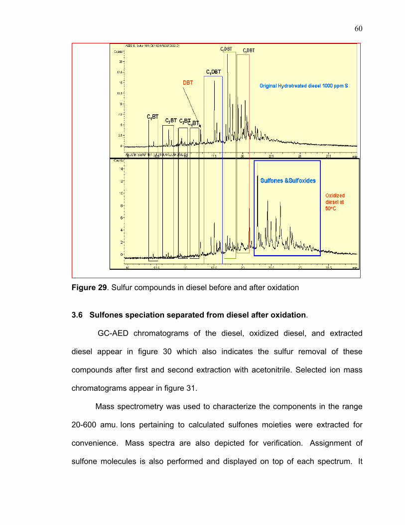
Another point worth mentioning here is the reactivity of different sulfur
compounds in the diesel samples. Figure 29 shows the sulfur compounds in both
original diesel and the treated sample. On closer inspection of the sulfur speciation
of these samples in terms of their peaks heights, the following observations can be
drawn: The reactivity of sulfur compounds depends on the position of alkyl groups
on the DBT. The peaks of C4DBT, C3DBT, C4BT, C3BT almost disappeared, while
the peaks of C1BT, C2BT, DBT, C1DBT, C2DBT compounds did not react
completely. This can be explained by the reactivity of the sulfur DBT as a result of
59
the electron density of the alkyl group contributions. As for the proposed
mechanism of the sulfide oxidation reaction described in section 2.1, the first step
of the reaction depends on attacking the hydrogen peroxide by the sulfur atom.
Therefore the higher electron density as a result of donating electron groups will
play a significant role on the rate of the oxidation reaction. In addition, the position
of alkyl groups and the chain length would also have some effect on the electron
density of DBTs, which has already been reported [30].
Figure 28. GC-AED Spectra of diesel before and after oxidation.
min10 12.5 15 17.5 20 22.5 25 27.5
Counts
0
2
4
6
8
10
12
14 Diesel before oxidation
Diesel after oxidation
60
Figure 29. Sulfur compounds in diesel before and after oxidation
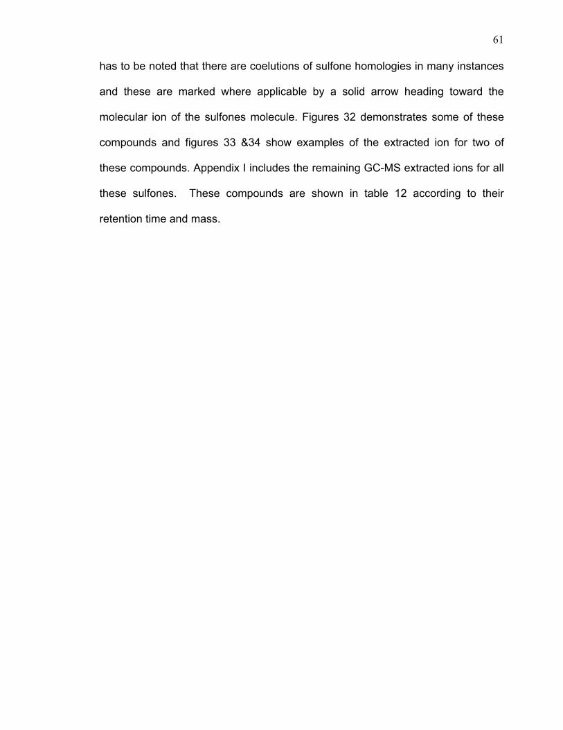
3.6 Sulfones speciation separated from diesel after oxidation.
GC-AED chromatograms of the diesel, oxidized diesel, and extracted
diesel appear in figure 30 which also indicates the sulfur removal of these
compounds after first and second extraction with acetonitrile. Selected ion mass
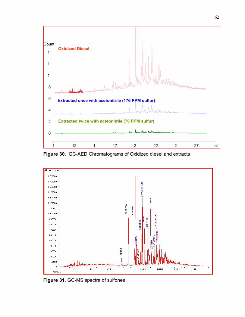
chromatograms appear in figure 31.
Mass spectrometry was used to characterize the components in the range
20-600 amu. Ions pertaining to calculated sulfones moieties were extracted for
convenience. Mass spectra are also depicted for verification. Assignment of
sulfone molecules is also performed and displayed on top of each spectrum. It
61
has to be noted that there are coelutions of sulfone homologies in many instances
and these are marked where applicable by a solid arrow heading toward the
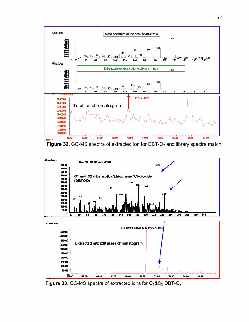
molecular ion of the sulfones molecule. Figures 32 demonstrates some of these
compounds and figures 33 &34 show examples of the extracted ion for two of
these compounds. Appendix I includes the remaining GC-MS extracted ions for all
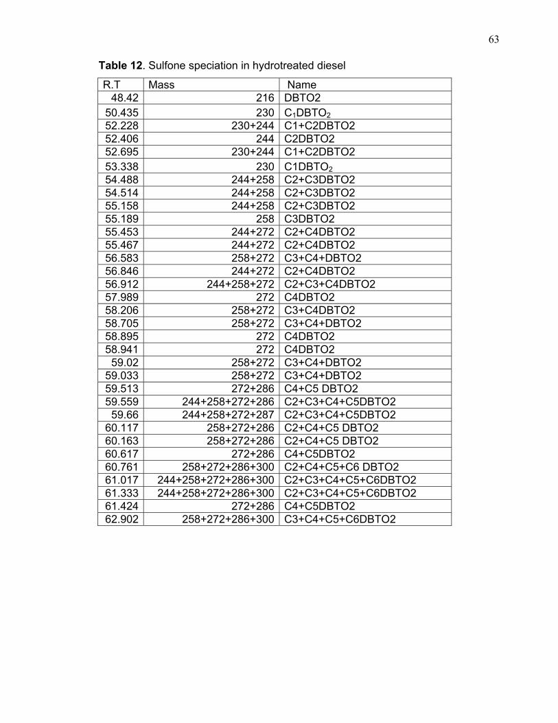
these sulfones. These compounds are shown in table 12 according to their
retention time and mass.
62
Figure 30. GC-AED Chromatograms of Oxidized diesel and extracts
Figure 31. GC-MS spectra of sulfones
mi1 12. 1 17. 2 22. 2 27.
Count
0
2
4
6
8
1
1
1Oxidized Diesel
Extracted once with acetonitrile (176 PPM sulfur)
Extracted twice with acetonitrile (78 PPM sulfur)
63
Table 12. Sulfone speciation in hydrotreated diesel
R.T Mass Name 48.42 216 DBTO2
50.435 230 C1DBTO2 52.228 230+244 C1+C2DBTO2 52.406 244 C2DBTO2 52.695 230+244 C1+C2DBTO2 53.338 230 C1DBTO2 54.488 244+258 C2+C3DBTO2 54.514 244+258 C2+C3DBTO2 55.158 244+258 C2+C3DBTO2 55.189 258 C3DBTO2 55.453 244+272 C2+C4DBTO2 55.467 244+272 C2+C4DBTO2 56.583 258+272 C3+C4+DBTO2 56.846 244+272 C2+C4DBTO2 56.912 244+258+272 C2+C3+C4DBTO2 57.989 272 C4DBTO2 58.206 258+272 C3+C4DBTO2 58.705 258+272 C3+C4+DBTO2 58.895 272 C4DBTO2 58.941 272 C4DBTO2 59.02 258+272 C3+C4+DBTO2
59.033 258+272 C3+C4+DBTO2 59.513 272+286 C4+C5 DBTO2 59.559 244+258+272+286 C2+C3+C4+C5DBTO2 59.66 244+258+272+287 C2+C3+C4+C5DBTO2
60.117 258+272+286 C2+C4+C5 DBTO2 60.163 258+272+286 C2+C4+C5 DBTO2 60.617 272+286 C4+C5DBTO2 60.761 258+272+286+300 C2+C4+C5+C6 DBTO2 61.017 244+258+272+286+300 C2+C3+C4+C5+C6DBTO2 61.333 244+258+272+286+300 C2+C3+C4+C5+C6DBTO2 61.424 272+286 C4+C5DBTO2 62.902 258+272+286+300 C3+C4+C5+C6DBTO2
64
Figure 32. GC-MS spectra of extracted ion for DBT-O2 and library spectra match
Figure 33. GC-MS spectra of extracted ions for C1&C2 DBT-O2
216
187168139115
63 1517539 87 12751 102 202 24422927 262 288274
20 40 60 80 100 120 140 160 180 200 220 240 260 2800100020003000400050006000700080009000
m/z-->
Abundance
216
18716813611563 1507539 51 87 10227
Dibenzothiophene sulfone Library match
Mass spectrum of the peak at 48.42min
Total ion chromatogram
Abundance
20 40 60 80 100 120 140 160 180 200 220 240 260 2800100020003000400050006000700080009000
m/z-->
Abundance
Time-->46.50 47.00 47.50 48.00 48.50 49.00 49.50 50.00 50.50 51.00
1000000120000014000001600000180000020000002200000240000026000002800000 TIC: A11C.D
216
187168139115
63 1517539 87 12751 102 202 24422927 262 288274
216
187168139115
63 1517539 87 12751 102 202 24422927 262 288274
20 40 60 80 100 120 140 160 180 200 220 240 260 2800100020003000400050006000700080009000
m/z-->
Abundance
20 40 60 80 100 120 140 160 180 200 220 240 260 2800100020003000400050006000700080009000
m/z-->
Abundance
216
18716813611563 1507539 51 87 10227
Dibenzothiophene sulfone Library match
Mass spectrum of the peak at 48.42min
Total ion chromatogram
Abundance
20 40 60 80 100 120 140 160 180 200 220 240 260 2800100020003000400050006000700080009000
m/z-->
Abundance
Time-->46.50 47.00 47.50 48.00 48.50 49.00 49.50 50.00 50.50 51.00
1000000120000014000001600000180000020000002200000240000026000002800000 TIC: A11C.D
20 40 60 80 100 120 140 160 180 200 220 240 260 2800100020003000400050006000700080009000
m/z-->
Abundance
20 40 60 80 100 120 140 160 180 200 220 240 260 2800100020003000400050006000700080009000
m/z-->
Abundance
Time-->46.50 47.00 47.50 48.00 48.50 49.00 49.50 50.00 50.50 51.00
1000000120000014000001600000180000020000002200000240000026000002800000 TIC: A11C.D
Time-->46.50 47.00 47.50 48.00 48.50 49.00 49.50 50.00 50.50 51.00
1000000120000014000001600000180000020000002200000240000026000002800000 TIC: A11C.D
40.00 42.00 44.00 46.00 48.00 50.00 52.00 54.00 56.00 58.000
50000
100000
150000
200000
250000300000350000
400000
450000
500000
Time-->
Abundance
Ion 230.00 (229.70 to 230.70): A11C.D
500010000150002000025000300003500040000450005000055000600006500070000
m/z-->
Abundance
20 40 60 80 100 120 140 160 180 200 220 240 260 280 300 320 3400
230
165181
201115
24414143 9128
7763 215
264 278 298 355
Scan 7481 (52.228 min): A11C.D
C1 and C2 dibenzo[b,d]thiophene 5,5-dioxide (DBTOO)
Extracted m/z 230 mass chromatogram
40.00 42.00 44.00 46.00 48.00 50.00 52.00 54.00 56.00 58.000
50000
100000
150000
200000
250000300000350000
400000
450000
500000
Time-->
Abundance
Ion 230.00 (229.70 to 230.70): A11C.D
40.00 42.00 44.00 46.00 48.00 50.00 52.00 54.00 56.00 58.000
50000
100000
150000
200000
250000300000350000
400000
450000
500000
Time-->
Abundance
Ion 230.00 (229.70 to 230.70): A11C.D
500010000150002000025000300003500040000450005000055000600006500070000
m/z-->
Abundance
20 40 60 80 100 120 140 160 180 200 220 240 260 280 300 320 3400
230
165181
201115
24414143 9128
7763 215
264 278 298 355
Scan 7481 (52.228 min): A11C.D
500010000150002000025000300003500040000450005000055000600006500070000
m/z-->
Abundance
500010000150002000025000300003500040000450005000055000600006500070000
m/z-->
Abundance
20 40 60 80 100 120 140 160 180 200 220 240 260 280 300 320 3400
230
165181
201115
24414143 9128
7763 215
264 278 298 355
Scan 7481 (52.228 min): A11C.D
20 40 60 80 100 120 140 160 180 200 220 240 260 280 300 320 3400 20 40 60 80 100 120 140 160 180 200 220 240 260 280 300 320 3400
230
165181
201115
24414143 9128
7763 215
264 278 298 355
Scan 7481 (52.228 min): A11C.D
C1 and C2 dibenzo[b,d]thiophene 5,5-dioxide (DBTOO)
Extracted m/z 230 mass chromatogram
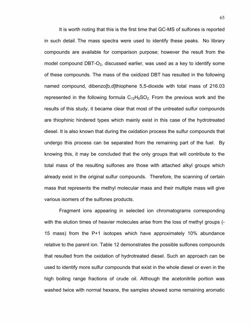
65
It is worth noting that this is the first time that GC-MS of sulfones is reported
in such detail. The mass spectra were used to identify these peaks. No library
compounds are available for comparison purpose; however the result from the
model compound DBT-O2, discussed earlier, was used as a key to identify some
of these compounds. The mass of the oxidized DBT has resulted in the following
named compound, dibenzo[b,d]thiophene 5,5-dioxide with total mass of 216.03
represented in the following formula C12H8SO2. From the previous work and the
results of this study, it became clear that most of the untreated sulfur compounds
are thiophinic hindered types which mainly exist in this case of the hydrotreated
diesel. It is also known that during the oxidation process the sulfur compounds that
undergo this process can be separated from the remaining part of the fuel. By
knowing this, it may be concluded that the only groups that will contribute to the
total mass of the resulting sulfones are those with attached alkyl groups which
already exist in the original sulfur compounds. Therefore, the scanning of certain
mass that represents the methyl molecular mass and their multiple mass will give
various isomers of the sulfones products.
Fragment ions appearing in selected ion chromatograms corresponding
with the elution times of heavier molecules arise from the loss of methyl groups (-
15 mass) from the P+1 isotopes which have approximately 10% abundance
relative to the parent ion. Table 12 demonstrates the possible sulfones compounds
that resulted from the oxidation of hydrotreated diesel. Such an approach can be
used to identify more sulfur compounds that exist in the whole diesel or even in the
high boiling range fractions of crude oil. Although the acetonitrile portion was
washed twice with normal hexane, the samples showed some remaining aromatic
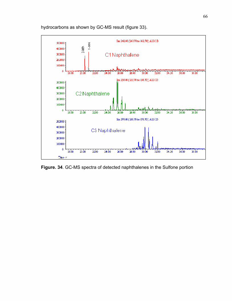
66
hydrocarbons as shown by GC-MS result (figure 33).
Figure. 34. GC-MS spectra of detected naphthalenes in the Sulfone portion
67
CHAPTER 4
THE EFFECT OF ACETONITRILE EXTRACTION IN DIESEL QUALITY
This experiment was conducted to study the effect of direct acetonitrile
extraction on the quality of diesel in terms of quantity lost. The diesel sample was
submitted to direct acetonitrile extraction without any oxidation. The GC-MS data
(figure 34) confirmed that some aromatic hydrocarbons were removed along with
sulfones during the acetonitrile extraction. The results of these experiments
revealed some useful information about the extraction process. First, the
experiment with 10ml acetonitrile required overnight to produce a better
separation. The volume of this experiment after one hour showed that there was
about 0.5ml of acetonitrile remaining in the diesel layer; while overnight 0.5ml of
diesel was found in the acetonitrile portion. The experiments using 20ml and 50ml
of acetonitrile gave the same results after one hour and overnight. This probably
has to do with the solubility and phase separation of different hydrocarbons in
diesel which may depend on the volume ratio of solvent to solute. The smaller the
ratio of acetonitrile to the diesel the more difficult and longer time is required to
achieve a good separation. However a greater volume of acetonitrile means a
higher cost in terms of the extraction and recovery process. In addition the
quantity of diesel lost increases with increasing volume of acetonitrile. Table 13
and figure 35 summarize the results of these experiments. The acetonitrile alone
has a great effect on sulfur removal without any pretreatment process. The sulfur
content was reduced from its original value of about 1041ppm to about 563ppm
after the second extraction of 50ml of acetonitrile. Table 14 and figure 36
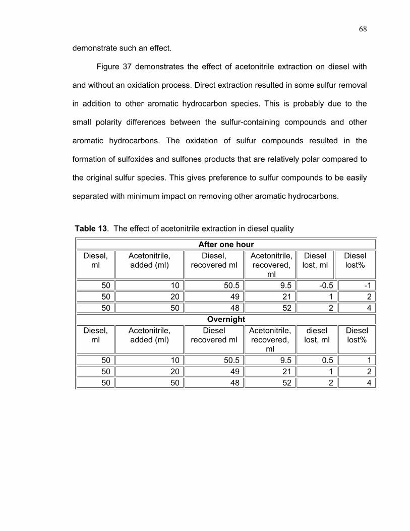
68
demonstrate such an effect.
Figure 37 demonstrates the effect of acetonitrile extraction on diesel with
and without an oxidation process. Direct extraction resulted in some sulfur removal
in addition to other aromatic hydrocarbon species. This is probably due to the
small polarity differences between the sulfur-containing compounds and other
aromatic hydrocarbons. The oxidation of sulfur compounds resulted in the
formation of sulfoxides and sulfones products that are relatively polar compared to
the original sulfur species. This gives preference to sulfur compounds to be easily
separated with minimum impact on removing other aromatic hydrocarbons.
Table 13. The effect of acetonitrile extraction in diesel quality
After one hour Diesel,
ml Acetonitrile, added (ml)
Diesel, recovered ml
Acetonitrile, recovered,
ml
Diesel lost, ml
Diesel lost%
50 10 50.5 9.5 -0.5 -1 50 20 49 21 1 2 50 50 48 52 2 4
Overnight Diesel,
ml Acetonitrile, added (ml)
Diesel recovered ml
Acetonitrile, recovered,
ml
diesel lost, ml
Diesel lost%
50 10 50.5 9.5 0.5 1 50 20 49 21 1 2 50 50 48 52 2 4
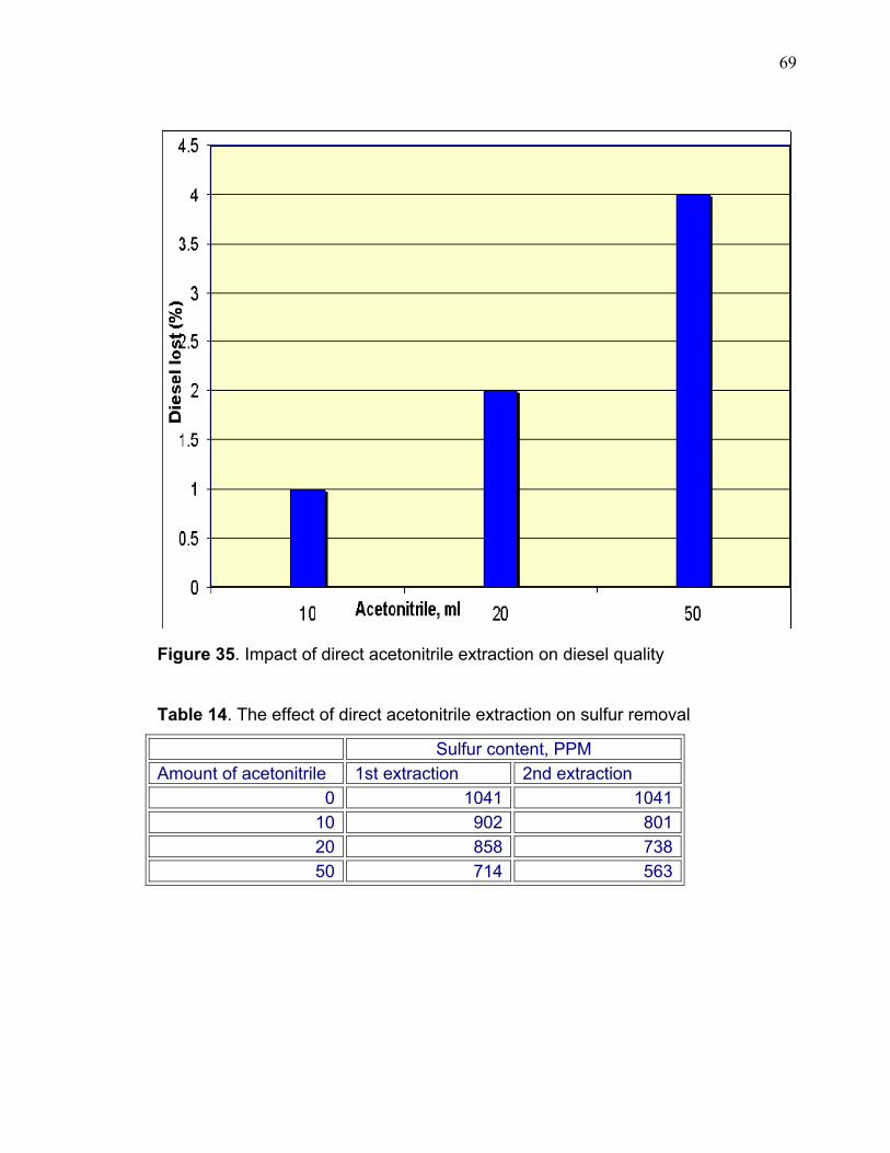
69
Figure 35. Impact of direct acetonitrile extraction on diesel quality
Table 14. The effect of direct acetonitrile extraction on sulfur removal
Sulfur content, PPM Amount of acetonitrile 1st extraction 2nd extraction
0 1041 1041 10 902 801 20 858 738 50 714 563
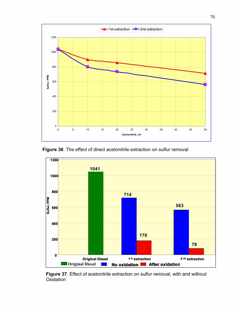
70
Figure 36. The effect of direct acetonitrile extraction on sulfur removal
Figure 37. Effect of acetonitrile extraction on sulfur removal, with and without Oxidation
0
200
400
600
800
1000
1200
0 5 10 15 20 25 30 35 40 45 50
Acetonitrile, ml
Sulfu
r, PP
M
1st extraction 2nd extraction
No oxidation After oxidation
0
200
400
600
800
1000
1200
Original Diesel 1 st extraction 2 nd extraction
Sulfu
r, PP
M
1041
714
176
563
78
No oxidation After oxidationNo oxidation After oxidation
0
200
400
600
800
1000
1200
Original Diesel 1 st extraction 2 nd extraction
Sulfu
r, PP
M
1041
714
176
563
78
Original Diesel
71
CHAPTER 5
DEEP DESULFURIZATION USING METAL IONS
Several mono and bi-metal salts with different ligands have been tested to
physically adsorb and separate sulfur compounds. The purpose of this work is to
remove the hindered compounds by reacting the thiophinic compounds with metal
salts to be able to separate them physically by extraction. This method is
considered to be the most cost effective approach to deep desulfurization. The
model compound used comprises of DBT, hexane, and toluene.
No sulfur detection was observed in all the samples from the experiments
indicating that such complex formation is not possible under the experimental
conditions. Angelici at,Iowa State University, Department of Chemistry has been
working for the last few years in developing a catalyst that is able to react with
sulfur thiophinic compounds using Ru (II) in the form of Ru(NH3)5(OH2)2+. He
indicated that some reactions have been accomplished under certain conditions,
however the practicality of such an approach needs further investigation. This is
probably due to the instability of complex formation with thiophinic hindered
compounds in the very complicated mixture of hydrocarbons compounds that exist
in such fuel.
In addition, the hindered sulfur compounds remained untouched in the
hydrodesulfurization process after severe reaction conditions. This indicates that
adsorption with catalyst via electron pairs of the sulfur atom is very difficult even at
high temperature and pressure. It seems that designing a catalyst for physical
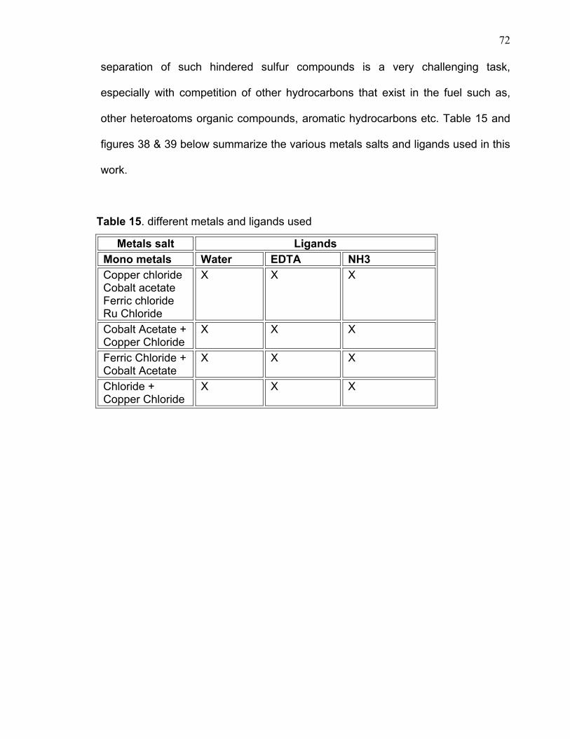
72
separation of such hindered sulfur compounds is a very challenging task,
especially with competition of other hydrocarbons that exist in the fuel such as,
other heteroatoms organic compounds, aromatic hydrocarbons etc. Table 15 and
figures 38 & 39 below summarize the various metals salts and ligands used in this
work.
Table 15. different metals and ligands used
Metals salt Ligands Mono metals Water EDTA NH3 Copper chloride Cobalt acetate Ferric chloride Ru Chloride
X X X
Cobalt Acetate + Copper Chloride
X X X
Ferric Chloride + Cobalt Acetate
X X X
Chloride + Copper Chloride
X X X
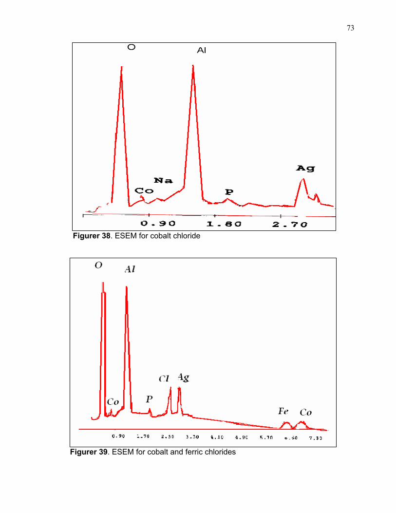
73
Figurer 38. ESEM for cobalt chloride
Figurer 39. ESEM for cobalt and ferric chlorides
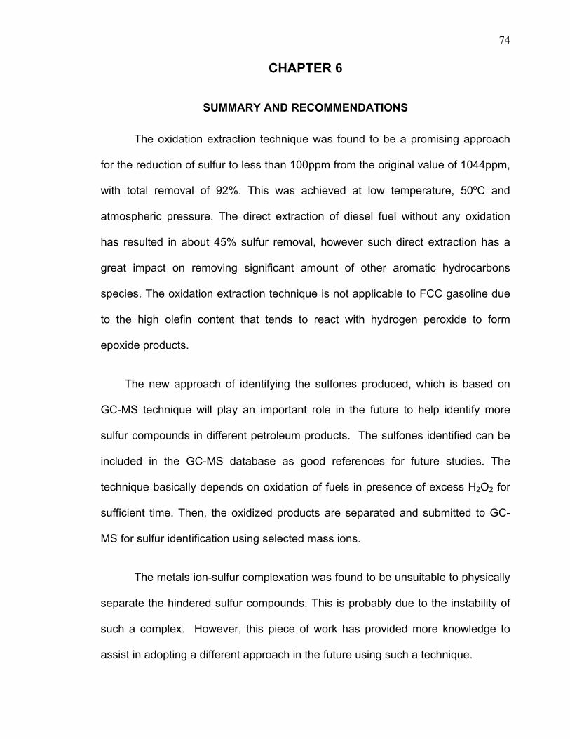
74
CHAPTER 6
SUMMARY AND RECOMMENDATIONS
The oxidation extraction technique was found to be a promising approach
for the reduction of sulfur to less than 100ppm from the original value of 1044ppm,
with total removal of 92%. This was achieved at low temperature, 50ºC and
atmospheric pressure. The direct extraction of diesel fuel without any oxidation
has resulted in about 45% sulfur removal, however such direct extraction has a
great impact on removing significant amount of other aromatic hydrocarbons
species. The oxidation extraction technique is not applicable to FCC gasoline due
to the high olefin content that tends to react with hydrogen peroxide to form
epoxide products.
The new approach of identifying the sulfones produced, which is based on
GC-MS technique will play an important role in the future to help identify more
sulfur compounds in different petroleum products. The sulfones identified can be
included in the GC-MS database as good references for future studies. The
technique basically depends on oxidation of fuels in presence of excess H2O2 for
sufficient time. Then, the oxidized products are separated and submitted to GC-
MS for sulfur identification using selected mass ions.
The metals ion-sulfur complexation was found to be unsuitable to physically
separate the hindered sulfur compounds. This is probably due to the instability of
such a complex. However, this piece of work has provided more knowledge to
assist in adopting a different approach in the future using such a technique.
75
In summary, the study recommends that the oxidation extraction technique
be used as an additional process to the hydrodesulfurization to enable the refiners
to meet the future environmental sulfur regulations. Conventional
hydrodesulfurization can be used to lower the sulfur content to few hundreds ppm
sulfur. Then, the oxidation/extraction approach needs to be used to go for ultra-
deep desulfurization as it may provide better mean and cost effective way in order
to meet the future sulfur environmental requirements.