designing with curved creases - vdf hochschulverlag ag an
TRANSCRIPT

82
Digital and Analog Constraints
Duks Koschitz
D. Koschitz School of Architecture, Pratt Institute, USA
Designing with Curved Creases
S. Adriaenssens, F. Gramazio, M. Kohler, A. Menges, M. Pauly (eds.): Advances in Architectural Geometry 2016 © 2016 vdf Hochschulverlag AG an der ETH Zürich, DOI 10.3218/3778-4_8, ISBN 978-3-7281-3778-4 http://vdf.ch/advances-in-architectural-geometry-2016.html

83
AbstractThis paper defines and describes ways of designing with curved-crease paper-folding. Curved creases are mathematically underexplored, and while many new analytic results exist, we still have no general way to geometrically predict how an arbitrary curved crease folds in 3D. We can, however, use and exploit several well-known subsets in geometry and expand on folding gadgets that include rul-ings or deploy analogue design methods that cannot be simulated. The paper is an investigation into four ways of designing with curved creases. The first uses developable surfaces such as cones, cylinders, and tangent surfaces, which can be manipulated in CAD software. The second focusses on ‘refraction gadgets’ I have derived from David Huffman’s work. These sets of curves and rulings form the smallest tile of a crease pattern and can be used for digital simulation. The last two approaches focus on manual folding with the option of controlling crease patterns at the beginning or the end of a design process. The ways in which knowledge in geometry is used and to some extent abused is opportunistic in nature as the main goal consists of defining design approaches, not adequately defined mathematical models. This is important to note as many of the results may consist of ill-defined creased surfaces, for example, surface configurations made with elastic sheet materials. In this paper I introduce useful characteris-tics and ‘design representations’, the control mechanism to manipulate certain types of curved creases, for digital and analogue methods that make the design process more clear. These characteristics allow for an evaluation of the present-ed design approaches. This facilitates ways to teach rigorous explorations for designers and educators.
Keywords: curved crease paperfolding, origami, developable surfaces, design
S. Adriaenssens, F. Gramazio, M. Kohler, A. Menges, M. Pauly (eds.): Advances in Architectural Geometry 2016 © 2016 vdf Hochschulverlag AG an der ETH Zürich, DOI 10.3218/3778-4_8, ISBN 978-3-7281-3778-4 http://vdf.ch/advances-in-architectural-geometry-2016.html
84
IntroductionIn order to learn how curved creases have been used, we need to investigate works in art, design, science, and engineering. Contemporary artists such as Robert Sweeney (2009), Yuko Nishimura (2009), and Matthew Shilan (2009) tend to expose personal aspects of the creative process (Klanten 2007; Nolan 1995) and don’t necessarily provide productive references for defining a way of designing. Paul Jackson has published work with curved creases (Thomas & Jackson 2001), which has in-spired me to try to define ways of designing rather than collecting crease pattern.
Curved creases have been explored in science and engineering with signif-icant achievements. Regarding the foundational work, we need to acknowledge David Huffman (1976), Ron Resch and Ephriam Cohen (1970s), and Richard Riesen-feld (1974), and Dmitry Fuchs and Sergei Tabachnikov (1999). More recent work by Erik and Martin Demaine and Tomohiro Tachi (2014), Robert Geretschlaeger (2009), Jun Mitani (2009), Jeannine Mosely (2008; 2009), and Saadya Sternberg (2009) inspect-ed specific configurations. Significant results in post-rationalising paper models exist by the team of Martin Kilian, Simon Flöry, Zhonggui Chen, Niloy Mitra, Alla Sheffer, and Helmut Pottmann (2008). Works in engineering by the teams of Simon Guest and Sergio Pellegrino (1992), Yannick Kergosien, Gotoda Hironoba, and Kunii Tosiyasu (1994) as well as Marcelo Dias and Christian Santangelo (2012) have also explored specific aspects of curved folding. Examining the work by these math-ematicians and computer scientists provides insight into geometric aspects, but may not be easy to use for a designer. As the behavior of curved creases is not yet fully understood, designers face a lack of available digital tools. Investigating historical examples in art, design, and education helps to locate the time and discipline of a specific type of curved crease design, but it is not obvious how to derive design methods as we can only rely on limited documentation (Demaine
& Demaine 2010), (Demaine et al. 2011).In order to make curved creases accessible to a broader audience, includ-
ing design students, I propose four design approaches that expand on specific aspects of protagonists in the field and combine them with contemporary digital tools. In order to elucidate advantages and shortcomings, I define design repre-sentations and characteristics for each approach. The relevance for architectural design is based on the convention that many building materials are manufactured as flat sheet-goods. Forming such surfaces with curved creases may have eco-nomic and energy efficiencies compared to stamping processes with molds, for example (Shelden 2002), which has been explored among others by Gregory Epps and Robofold.
S. Adriaenssens, F. Gramazio, M. Kohler, A. Menges, M. Pauly (eds.): Advances in Architectural Geometry 2016 © 2016 vdf Hochschulverlag AG an der ETH Zürich, DOI 10.3218/3778-4_8, ISBN 978-3-7281-3778-4 http://vdf.ch/advances-in-architectural-geometry-2016.html
85
Problem StatementHow can designers learn to use curved-crease paperfolding? And which tools should be involved? Which design approaches can be included if we allow the use of surfaces that are mathematically defined in an inappropriate way? Lastly, which kind of metric can be used to qualify the proposed design approaches?
Regarding the methodology, I collected case studies in the history of curved creases and identified general design problems. I subsequently matched tools to the problems and field-tested them with students. I conducted the following workshops and seminars as a proof of concept: a 1-day workshop at the Massa-chusetts Institute of Technology, a 2-day workshop at Southern Polytechnic State University, Marietta, Georgia, and a seminar in the Architecture Department at Pratt Institute. The evidence is qualitative as the students had different education-al backgrounds, some courses were short, and some were long. The evaluation considers and compares characteristics of each design approach. It is important to note that every design approach has intrinsic limitations and constraints, which is in part due to missing mathematical knowledge. However, if we understand the relevant constraints, as the examples demonstrate, we can still invent ways of designing with them.
S. Adriaenssens, F. Gramazio, M. Kohler, A. Menges, M. Pauly (eds.): Advances in Architectural Geometry 2016 © 2016 vdf Hochschulverlag AG an der ETH Zürich, DOI 10.3218/3778-4_8, ISBN 978-3-7281-3778-4 http://vdf.ch/advances-in-architectural-geometry-2016.html

86
1. Defining Design Approaches1.1 Design Approaches and their
Design RepresentationIf we want to define ways of designing with this geometry, which control mech-anisms can we find? How can we define useful representations for designers? It is necessary to formalize characteristics and what I call ‘design representations’ for each design approach? These representations are abstractions of a curved crease design and are always related to its crease pattern. The approaches use digital and analogue methods and the rigorous definitions of representation in computer science and mathematics may not be suitable for analogue methods, for example.
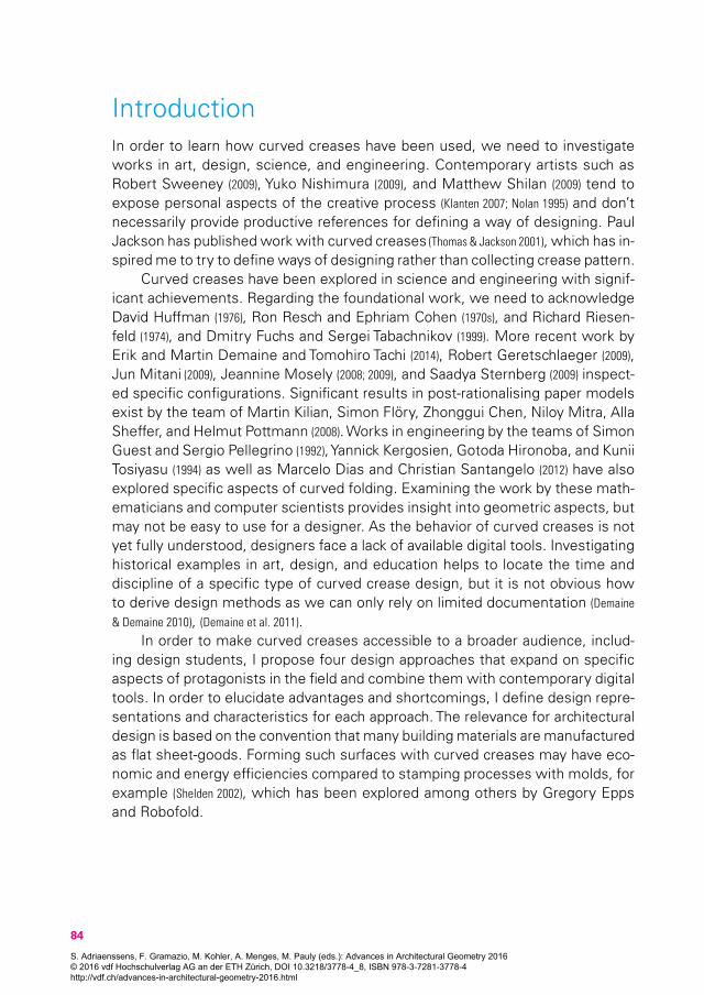
The design representation of a paperfolding consists of the control mecha-nism that is constrained by geometric, digital, or material aspects. It is the ab-straction a designer can use and manipulate in order to modify a design. These design representations relate to the crease pattern in different ways as not all geometric subsets for curved creases are well-defined. The design approaches, two fully digital and two mostly analogue, each have their own design represen-tations (Fig. 1).
Developable surface reflection uses well-known configurations of cones cylin-ders and tangent surfaces. The ‘direct digital’ representation uses mirror reflec-tions of developable surfaces in CAD software. The crease pattern is constructed at the end of the design process for fabrication.
Refraction gadgets is based on gadgets I have derived from David Huffman’s method of drawing creases and rulings together, which can be used in simulation software. The ‘indirect digital’ representation relies on fixed rulings within the gad-gets. The crease pattern is constructed at the beginning of the design process.
Drawing open and closed curves expands on the ‘Bauhaus model’, a design used by students of Josef Albers, and on the work of T. Roy Iwaki. A designer can draw curves and explore variations without exactly knowing what the outcome will be. The ‘direct analogue’ representation consists of the crease pattern that is constructed at the beginning of the design process.
Sculpting and post-rationalising surfaces expands on Ron Resch’s crinkling by using curved creases. A designer sculpts paper or more flexible materials and defines a notational system. The ‘indirect analogue’ representation is based on material constraints. The crease pattern is constructed whenever a new material is introduced in the design process.
S. Adriaenssens, F. Gramazio, M. Kohler, A. Menges, M. Pauly (eds.): Advances in Architectural Geometry 2016 © 2016 vdf Hochschulverlag AG an der ETH Zürich, DOI 10.3218/3778-4_8, ISBN 978-3-7281-3778-4 http://vdf.ch/advances-in-architectural-geometry-2016.html
87
1.2 The Characteristics of a Design Approach
The design approaches and their explorations are presented in comparison in order for us to be able to evaluate them. The questions that arise are: Which de-sign goals can s/he define before starting? How much knowledge is required and which digital tools are involved? The following different characteristics were used as a heuristic. In some cases, the characteristics may overlap as their bound- aries can become blurry.
Bottom-up/top-downThe first characteristic distinguishes between designing in a top-down or bottom-up way. In the case of a bottom-up approach, the designer reacts to what the curved crease gives him or her. The logics of the crease pattern and rulings drive the design process and the designer evaluates the result. The material constraints of physical paper are identified in a separate characteristic. A top-down approach demands decision making beforehand, meaning that the designer has to have made up his or her mind about what the model is supposed to look like before beginning the design process. This can in some cases represent a strong design goal, but it can also become less relevant in the process.
A priori knowledge of geometryThe second characteristic relates to a priori knowledge of geometry, the reason-ing related to previously acquired knowledge in geometry. It can play a signifi-cant role in a design approach, as a designer’s decision can be influenced by the knowledge of mathematical models, for example. This knowledge is different to knowledge obtained from observation and experience, and can help in charac-terising a design approach.
Figure 1. (from left to right). Developable Surface Reflection (direct digital representation). Refraction Gadgets (indirect digital representation). Drawing Open and Closed Curves (direct analogue representation). Sculpting and Post-Rationalising Surfaces (indirect analogue representation).
S. Adriaenssens, F. Gramazio, M. Kohler, A. Menges, M. Pauly (eds.): Advances in Architectural Geometry 2016 © 2016 vdf Hochschulverlag AG an der ETH Zürich, DOI 10.3218/3778-4_8, ISBN 978-3-7281-3778-4 http://vdf.ch/advances-in-architectural-geometry-2016.html
88
Exploiting material propertiesThe third characteristic lies in exploiting material properties. Paper resists when one folds it and the pressure in the material can guide design decisions. A de-signer can start to manipulate paper or felt and ‘let the material fold the way it wants to fold’. The material driven process requires little mathematical knowl-edge, but relies heavily on tacit tactile knowledge, the knowledge that is trans-ferred via the repeated physical manipulation or folding of paper. This can also be described as a bottom-up approach based on material logics.
Use of digital toolsThe fourth characteristic relates to the use of digital tools. The two subcatego-ries relate to the representations defined above. The first uses direct geometric manipulation of static 3D objects in CAD software, which means that a designer looks at a static model while working on it. The second is related to the simu-lation of folding crease patterns that include rulings. A designer can see how a discrete version of a curved crease folds in real-time.
In the following section I discuss the design approaches in similar ways using the common headlines ‘Geometry and Design Representation’, ‘Historical refer-ences and precedents’, and ‘Definition of the Design Approach’.
2. The Four Design Approaches2.1 Developable Surface Reflection
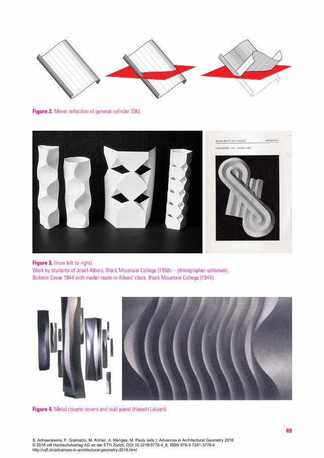
Geometry and design representationWe can imagine a general cylinder that is cut with a plane. We subsequently mirror and rotate the remaining part (Fig. 2). The rulings are all parallel in the crease pattern. Cones can be manipulated in a similar way, but their rulings converge in an apex. The well-known geometry includes tangent surfaces, which can be used in digital 3D models. The direct digital design representation consists of the 3D surfaces in CAD software, which are unrolled to construct the crease pattern for fabrication.
Historical references and precedentsStudents of Josef Albers made models based on general cylinders at Black Moun-tain College (Fig. 3 left). We can assume that the design goal consisted of creating a cylindrical shape or enclosure, which can be achieved with cylinder reflections. Haresh Lalvani provides many variations of similar configurations in the work that has been built by Milgo/Bufkin using large sheets of steel (Fig. 4) (2003). Tim Herok and Markus Schein’s ‘Liegengenerator’ makes use of a discretised approach (2002). Their process starts by defining the constraints for input surfaces, namely, the
S. Adriaenssens, F. Gramazio, M. Kohler, A. Menges, M. Pauly (eds.): Advances in Architectural Geometry 2016 © 2016 vdf Hochschulverlag AG an der ETH Zürich, DOI 10.3218/3778-4_8, ISBN 978-3-7281-3778-4 http://vdf.ch/advances-in-architectural-geometry-2016.html
89
Figure 3. (from left to right) Work by students of Josef Albers, Black Mountain College (1950s – photographer unknown). Bulletin Cover 1944 with model made in Albers’ class, Black Mountain College (1944).
Figure 4. Metal column covers and wall panel (Haresh Lalvani).
Figure 2. Mirror reflection of general cylinder (DK).
S. Adriaenssens, F. Gramazio, M. Kohler, A. Menges, M. Pauly (eds.): Advances in Architectural Geometry 2016 © 2016 vdf Hochschulverlag AG an der ETH Zürich, DOI 10.3218/3778-4_8, ISBN 978-3-7281-3778-4 http://vdf.ch/advances-in-architectural-geometry-2016.html
90
two edges of a bench that touch the ground (Trebbi 2008). Schein sets up a digital model with user inputs for height and undulation that uses a genetic algorithm (2002). Regarding reflected cones, we can find examples by students of Josef Al-bers at Black Mountain College (Fig. 3 left). David Huffman based some of his de-signs on cone reflections such as ‘Cone reflected seven times’ with a gradually rotating main axis (Wertheim, 2004). The designer Poul Christiansen also uses cone reflections in one of his lamp designs (Klint 1943). Ron Resch worked with 2 cones without cutting the paper in ‘Yellow Folded Cones: Kissing’.
Definition of the design approachRegarding cylinders, the designers begins with a 3D model of a general cylin-der in any CAD software and then places a plane to cut it with. The subsequent step consists of reflecting the cut-off part and placing it on the resulting curved crease. The designer continues this process step-by-step. The approach can also be applied to cones and tangent surfaces.
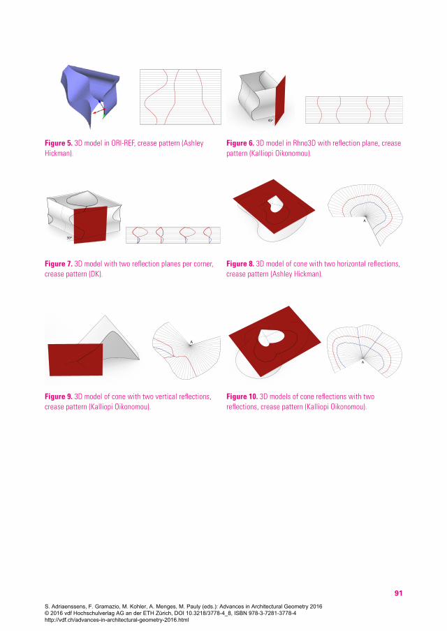
I used two types of software ‘ORI-REF: A Design Tool for Curved Origami based on Reflection’ by the Japanese geometer Jun Mitani (2011) and Rhino3D in my seminar. ORI-REF takes cylinders, cones, and tangent surfaces as input surfaces, and the user then manipulates a local coordinate system to orient the reflection plane. The red spline in the example below with several reflections by Ashley Hickman indicates the profile of the input surface (Fig. 5). Students con-structed the planes and reflections themselves in Rhino3D. Closed configurations with single and double reflections can be seen below (Fig. 6 and 7).
Corresponding examples with cones by Ashley Hickman and Kalliopi Oikonomou were made using Rhino 3D (Figures 8 to 10). The cones are cut with planes parallel to the base or the axis. The last example shows a tiling of partial cones that share an apex A.
2.2 Refraction GadgetsGeometry and design representationHuffman’s gadgets determine the position of curves and rulings in a crease pat-tern. If the curves are abstracted as line segments, we can create a discrete version of the gadget (Koschitz 2013), which can be used in simulation software such as ‘FreefromOrigami’ by Tomohiro Tachi (2013). The indirect digital design repre-sentation consists of the crease pattern that includes fixed rulings, mountain and valley folds. The crease pattern must be constructed at the beginning of the design process.
Historical references and precedentsHuffman drew what I call ‘refraction gadgets’ for his designs. He interpreted rays in optics as rulings and exploited the refractive properties of the conics
S. Adriaenssens, F. Gramazio, M. Kohler, A. Menges, M. Pauly (eds.): Advances in Architectural Geometry 2016 © 2016 vdf Hochschulverlag AG an der ETH Zürich, DOI 10.3218/3778-4_8, ISBN 978-3-7281-3778-4 http://vdf.ch/advances-in-architectural-geometry-2016.html
91
Figure 5. 3D model in ORI-REF, crease pattern (Ashley Hickman).
A
Figure 9. 3D model of cone with two vertical reflections, crease pattern (Kalliopi Oikonomou).
45o
Figure 6. 3D model in Rhno3D with reflection plane, crease pattern (Kalliopi Oikonomou).
A
Figure 10. 3D models of cone reflections with two reflections, crease pattern (Kalliopi Oikonomou).
30o
Figure 7. 3D model with two reflection planes per corner, crease pattern (DK).
A
Figure 8. 3D model of cone with two horizontal reflections, crease pattern (Ashley Hickman).
S. Adriaenssens, F. Gramazio, M. Kohler, A. Menges, M. Pauly (eds.): Advances in Architectural Geometry 2016 © 2016 vdf Hochschulverlag AG an der ETH Zürich, DOI 10.3218/3778-4_8, ISBN 978-3-7281-3778-4 http://vdf.ch/advances-in-architectural-geometry-2016.html
92
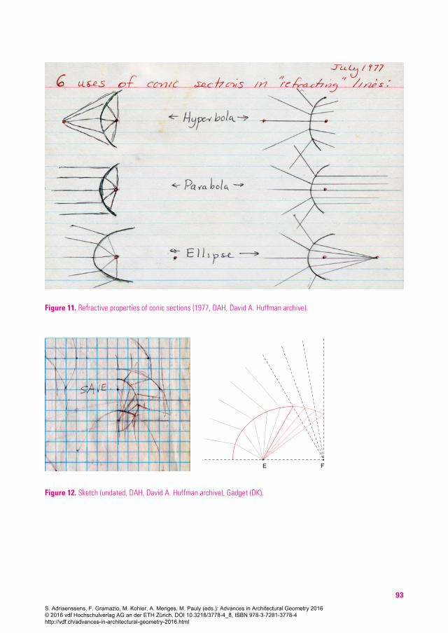
to redirect the rulings. The three available curves are ellipses, parabolas and hyperbolas and he drew all available refraction cases (Fig. 11). The diagrams on the left show how rulings get refracted, if they start in the focal point of a hy-perbola, parabola, or ellipse. The cases on the right display inversions of the corresponding examples.
The foci of a hyperbola can be used to refract rays on either side of the curve (on the left). Rulings can be made to fan out on both sides of the curve (on the right). Parallel rays on the concave side of a parabola refract toward its focus (on the left). The inverse configuration pushes rulings away from the focus (on the right). Rays converging towards one focus of an ellipse get refracted to the sec-ond focus (on the left). The roles of the foci are inverted (on the right).
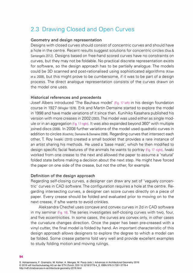
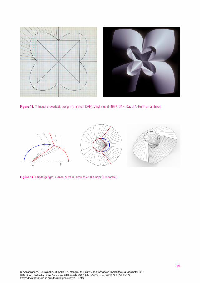
A rare hand-drawn sketch reveals that Huffman has the rulings in mind when designing a new model (Fig. 12 left). Huffman uses the corresponding gadget for the inner ellipse (Fig. 12 right) four times in one of his final designs (Fig. 13).
His approach can be seen as a constraint propagation system, in which ‘the paper is the computer’. He sets up his designs the way a computer scientist would, namely, as a problem to be solved. Every crease pattern has the equiva-lent to a base case or initialisation procedure of an algorithm, in which the rulings have to follow an initial rule. He assigns the refraction scheme that will get exe-cuted on the first crease and then lets the individual rays follow the constraints given by all consecutive curves.
Definition of the design approachI expand on Huffman’s interpretation of optics by asking a designer to use any of the gadgets and to subsequently simulate them using FreefromOrigami. A designer can alter and/or tessellate any of the gadgets. The design can be folded in software in real-time.
Many cases for which Huffman might have had a wrong mathematical con-jecture can be used for simulation. The discrete representation is an approxima-tion and thus does not necessarily follow mathematical constraints. Additionally, folding physical paper is more forgiving than its mathematically defined equivalent. The flexibility of the material allows us to create models of ill-defined mathemat-ical foldings. This means that all of Huffman’s gadgets are available for designers to explore and experiment with.
The designs produced by Kalliopi Oikonomou in my seminar consist of re-fraction gadgets with ellipses, parabolas, and hyperbolas. In the first example, a single ellipse is divided into two parts, one used as mountain and the other as valley (Fig. 14).
The figure below shows two examples with the same parabola gadget. A cylindrical configuration could be achieved in the bottom example (Fig. 15). The last example in this section consists of a regular tiling made with a hyperbola gadget (Fig. 16).
S. Adriaenssens, F. Gramazio, M. Kohler, A. Menges, M. Pauly (eds.): Advances in Architectural Geometry 2016 © 2016 vdf Hochschulverlag AG an der ETH Zürich, DOI 10.3218/3778-4_8, ISBN 978-3-7281-3778-4 http://vdf.ch/advances-in-architectural-geometry-2016.html
93
Figure 11. Refractive properties of conic sections (1977, DAH, David A. Huffman archive).
FE
Figure 12. Sketch (undated, DAH, David A. Huffman archive), Gadget (DK).
S. Adriaenssens, F. Gramazio, M. Kohler, A. Menges, M. Pauly (eds.): Advances in Architectural Geometry 2016 © 2016 vdf Hochschulverlag AG an der ETH Zürich, DOI 10.3218/3778-4_8, ISBN 978-3-7281-3778-4 http://vdf.ch/advances-in-architectural-geometry-2016.html
94
2.3 Drawing Closed and Open Curves
Geometry and design representationDesigns with closed curves should consist of concentric curves and should have a hole in the centre. Recent results suggest solutions for concentric circles (Dias &
Santangelo 2012). Designs based on free-hand scored curves have no constraints on curves, but they may not be foldable. No practical discrete representation exists for software, so the design approach has to be partially analogue. The models could be 3D scanned and post-rationalised using sophisticated algorithms (Kilian
et a. 2008), but this might prove to be cumbersome, if it was to be part of a design process. The direct analogue representation consists of the curves drawn on the model one uses.
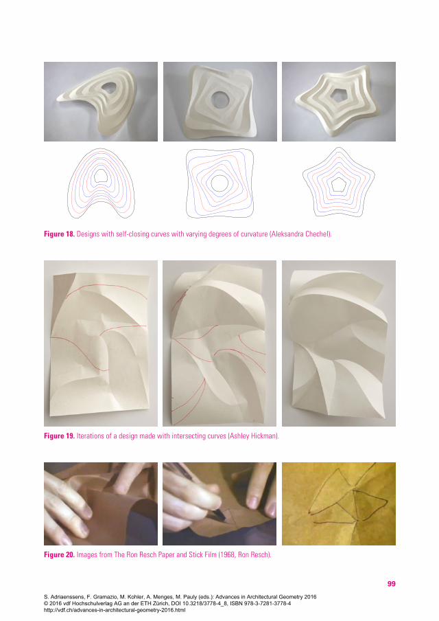
Historical references and precedentsJosef Albers introduced ‘The Bauhaus model’ (Fig. 17 left) in his design foundation course in 1927 (Wingler 1978). Erik and Martin Demaine started to explore the model in 1998 and have made variations of it since then. Kunihiko Kasahara published his version with more creases in 2002 (2003). The model was used either as single mod-ule or in an aggregation (Fig. 17 right). It was also expanded beyond 360° with multiple joined discs (2006). In 2008 further variations of the model used quadratic curves in addition to circles (Koschitz, Demaine & Demaine 2008). Regarding curves that intersect each other, T. Roy Iwaki (2010) created a small booklet that provides a rare instance of an artist sharing his methods. He used a ‘base mask’, which he then modified to design specific facial features of the animals he wants to portray (Fig. 17 right). Iwaki worked from one crease to the next and allowed the paper to assume a ‘natural’ folded state before making a decision about the next step. He might have forced the paper on one side of the crease, but not the other, for example.
Definition of the design approachRegarding self-closing curves, a designer can draw any set of ‘vaguely concen-tric’ curves in CAD software. The configuration requires a hole at the centre. Re-garding intersecting curves, a designer can score curves directly on a piece of paper. Every crease should be folded and evaluated prior to moving on to the next crease, if s/he wants to avoid crinkles.
Aleksandra Chechel uses concave and convex curves in 2d in CAD software in my seminar (Fig. 18). The series investigates self-closing curves with two, four, and five eccentricities. In some cases, the curves are convex only, in other cases the curvature changes direction. Once the paper has been pre-creased with a vinyl cutter, the final model is folded by hand. An important characteristic of this design approach allows designers to explore the degree to which a model can be folded. Some crease patterns fold very well and provide excellent examples to study folding motion and moving rulings.
S. Adriaenssens, F. Gramazio, M. Kohler, A. Menges, M. Pauly (eds.): Advances in Architectural Geometry 2016 © 2016 vdf Hochschulverlag AG an der ETH Zürich, DOI 10.3218/3778-4_8, ISBN 978-3-7281-3778-4 http://vdf.ch/advances-in-architectural-geometry-2016.html
95
Figure 13. ’4-lobed, cloverleaf, design’ (undated, DAH), Vinyl model (1977, DAH, David A. Huffman archive).
Figure 14. Ellipse gadget, crease pattern, simulation (Kalliopi Oikonomou).
P1
FE
H J
h
S. Adriaenssens, F. Gramazio, M. Kohler, A. Menges, M. Pauly (eds.): Advances in Architectural Geometry 2016 © 2016 vdf Hochschulverlag AG an der ETH Zürich, DOI 10.3218/3778-4_8, ISBN 978-3-7281-3778-4 http://vdf.ch/advances-in-architectural-geometry-2016.html

96
Ashley Hickman, another student in my seminar, used the design approach with intersecting curves and simply started by making a model with several creases rather than working from one to the next (Fig. 19). She made new decisions about altering regions of paper that are wrinkled by marking options for creases in red. She subsequently folded the marked creases in the next iteration and repeats these steps until the result is satisfactory. Other students followed the initial suggestion of working step-by-step and achieved similar results.
2.4 Sculpting and Post-rationalising SurfacesGeometry and design representationFor this design approach creases and paper surfaces are created through an it-erative analogue process similar to Iwaki’s approach. No curve types or surface types can be defined in any practical way. Similar to the previous design approach, 3D-scanning and analytically deriving an appropriate mathematical model would slow down the process significantly. The indirect analogue design representation consists of re-constructed crease patterns on the folded model.
Historical references and precedents‘The Ron Resch Paper and Stick Film’ (Resch 1968) features a sequence in the be-ginning, in which he explains how he discovered paperfolding for himself. He starts with a sheet of brown paper on a table and slowly crumples it while pushing it down to the table with his fingers. Once he has achieved a desired folded shape, he flattens it, and draws simplified versions of the creases with a pen (Fig. 20). He modifies the crease pattern and tries to find regularities to eventually create tilings made of straight creases. Gregory Epps, a British de-signer and curved folding expert, has published similar ways of post rational-ising creases (Vysivoti 2008).
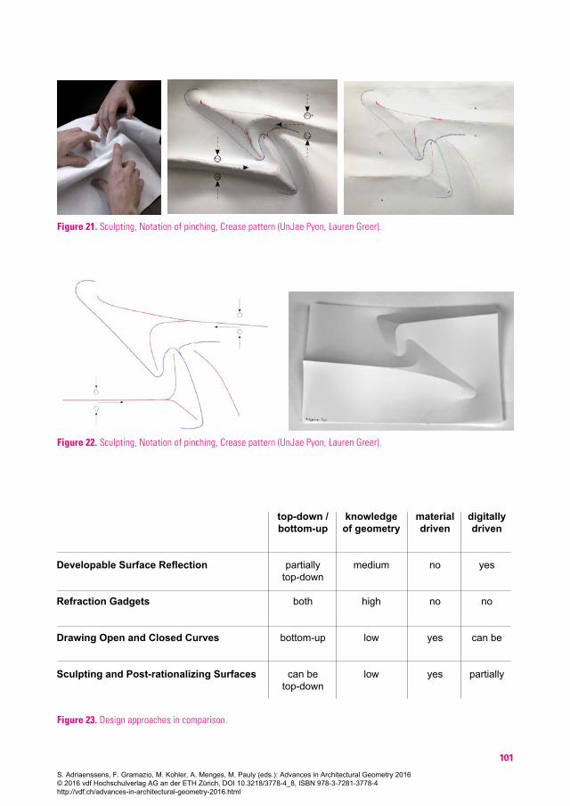
Definition of the design approachI extend Resch’s approach by using curved creases and developing a notational system to keep track of changes. The process starts with crumpling or sculpt-ing a sheet of soft paper or felt into a desired shape (Fig. 21 and 22). A designer then marks mountains and valleys and subsequently flattens the sheet to digitize the crease pattern. The digital image needs to be traced with vector-based software. The designer can use vinyl cutters to pre-crease paper with the digitised version of the marked scan. As the model may not fold the way a flexible material might, a designer might have to go through several iterations of this process until s/he obtains a desirable result.
During my seminar, UnJae Pyon and Lauren Greer sculpt a desired shape and then mark mountain and valley creases with two different colours (Fig. 21 centre). I asked them to use a notational system that would allow them to document the
S. Adriaenssens, F. Gramazio, M. Kohler, A. Menges, M. Pauly (eds.): Advances in Architectural Geometry 2016 © 2016 vdf Hochschulverlag AG an der ETH Zürich, DOI 10.3218/3778-4_8, ISBN 978-3-7281-3778-4 http://vdf.ch/advances-in-architectural-geometry-2016.html

97
H J
h
Figure 16. Simulations of gadgets with parabolas and hyperbolas, crease patterns (Kalliopi Oikonomou).
Figure 17. Bauhaus model, extended discs (Josef Albers Foundation), Horse head (Roy Iwaki).
P
p
p1
P1
FE
H J
Figure 15. Simulations of gadgets with parabolas and hyperbolas, crease patterns (Kalliopi Oikonomou).
S. Adriaenssens, F. Gramazio, M. Kohler, A. Menges, M. Pauly (eds.): Advances in Architectural Geometry 2016 © 2016 vdf Hochschulverlag AG an der ETH Zürich, DOI 10.3218/3778-4_8, ISBN 978-3-7281-3778-4 http://vdf.ch/advances-in-architectural-geometry-2016.html

98
necessary finger motion, if they needed to recreate the model. They photograph the drawn crease pattern in its flat state (Fig. 21 right).
The next step consists of transferring the crease pattern to CAD software (Fig. 22 left). Further steps involve making new models in paper or plastic and con-tinuously refining the crease pattern until the paper finds an (almost) ideal con-figuration (Fig. 22 right).
3. Results and AnalysisThe workshops and seminars yielded interesting observations that might be useful for instructors and designers in general. The table below shows the re-lationships between the design approaches and their characteristics (Fig. 23). The proposed design representations aid in identifying how a designer can work with the given constraints of the design approaches. The presented results include a brief summary of the design approach and used tools, a comment on the design process, issues relative to scalability and notes on design pedagogy.
Because developable surface reflection uses well-known configurations of cones cylinders and tangent surfaces, 3D models can easily be made with CAD software. The designer is visually confronted with the result of every cut while working on the computer, which provides constant visual feedback during this step-by-step process. The crease pattern is usually only necessary for production. Physical models can be made easily, and scaling should not be an issue. Formal explorations are limited as the designer is bound by the initial developable sur-face. In terms of design pedagogy, only little knowledge in geometry is required and there is no element of surprise in this approach.
In refraction gadgets the designer needs to be in full command of the crease pattern as it is designed first. The opportunity for designers lies in using simula-tion software to observe the folding process in real-time. The constraints produce cylinders and cones, but no tangent surfaces. The smaller mathematical solution space reduces opportunities for expressive designs as the rulings are forced to remain in their relative position, which is not how paper folds. Additionally, tan-gent surfaces are not represented in the gadgets. It is unclear whether this ap-proach would scale well. The simulation may result in ill-defined surfaces, and one may have to rely on the elasticity of materials to realize these designs. The design approach is very systematic and demands a moderate level of knowledge of geometry. As a result, mastering the approach might only be suitable for a more computationally inclined designer. The exploratory potential of the design approach lies in trying out different kinds of tilings and in some cases using more or less curvature for the folded model.
For drawing open and closed curves a designer needs to draw simple curves. The direct analogue representation consists of the crease pattern that has to be
S. Adriaenssens, F. Gramazio, M. Kohler, A. Menges, M. Pauly (eds.): Advances in Architectural Geometry 2016 © 2016 vdf Hochschulverlag AG an der ETH Zürich, DOI 10.3218/3778-4_8, ISBN 978-3-7281-3778-4 http://vdf.ch/advances-in-architectural-geometry-2016.html
99
Figure 18. Designs with self-closing curves with varying degrees of curvature (Aleksandra Chechel).
Figure 19. Iterations of a design made with intersecting curves (Ashley Hickman).
Figure 20. Images from The Ron Resch Paper and Stick Film (1968, Ron Resch).
S. Adriaenssens, F. Gramazio, M. Kohler, A. Menges, M. Pauly (eds.): Advances in Architectural Geometry 2016 © 2016 vdf Hochschulverlag AG an der ETH Zürich, DOI 10.3218/3778-4_8, ISBN 978-3-7281-3778-4 http://vdf.ch/advances-in-architectural-geometry-2016.html
100
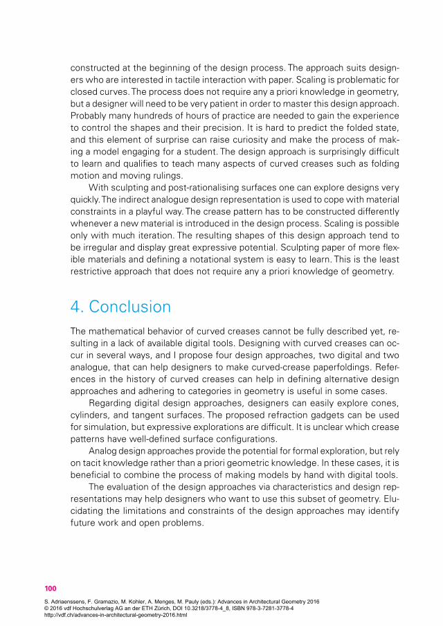
constructed at the beginning of the design process. The approach suits design-ers who are interested in tactile interaction with paper. Scaling is problematic for closed curves. The process does not require any a priori knowledge in geometry, but a designer will need to be very patient in order to master this design approach. Probably many hundreds of hours of practice are needed to gain the experience to control the shapes and their precision. It is hard to predict the folded state, and this element of surprise can raise curiosity and make the process of mak-ing a model engaging for a student. The design approach is surprisingly difficult to learn and qualifies to teach many aspects of curved creases such as folding motion and moving rulings.
With sculpting and post-rationalising surfaces one can explore designs very quickly. The indirect analogue design representation is used to cope with material constraints in a playful way. The crease pattern has to be constructed differently whenever a new material is introduced in the design process. Scaling is possible only with much iteration. The resulting shapes of this design approach tend to be irregular and display great expressive potential. Sculpting paper of more flex-ible materials and defining a notational system is easy to learn. This is the least restrictive approach that does not require any a priori knowledge of geometry.
4. ConclusionThe mathematical behavior of curved creases cannot be fully described yet, re-sulting in a lack of available digital tools. Designing with curved creases can oc-cur in several ways, and I propose four design approaches, two digital and two analogue, that can help designers to make curved-crease paperfoldings. Refer-ences in the history of curved creases can help in defining alternative design approaches and adhering to categories in geometry is useful in some cases.
Regarding digital design approaches, designers can easily explore cones, cylinders, and tangent surfaces. The proposed refraction gadgets can be used for simulation, but expressive explorations are difficult. It is unclear which crease patterns have well-defined surface configurations.
Analog design approaches provide the potential for formal exploration, but rely on tacit knowledge rather than a priori geometric knowledge. In these cases, it is beneficial to combine the process of making models by hand with digital tools.
The evaluation of the design approaches via characteristics and design rep-resentations may help designers who want to use this subset of geometry. Elu-cidating the limitations and constraints of the design approaches may identify future work and open problems.
S. Adriaenssens, F. Gramazio, M. Kohler, A. Menges, M. Pauly (eds.): Advances in Architectural Geometry 2016 © 2016 vdf Hochschulverlag AG an der ETH Zürich, DOI 10.3218/3778-4_8, ISBN 978-3-7281-3778-4 http://vdf.ch/advances-in-architectural-geometry-2016.html
101
Figure 21. Sculpting, Notation of pinching, Crease pattern (UnJae Pyon, Lauren Greer).
Figure 22. Sculpting, Notation of pinching, Crease pattern (UnJae Pyon, Lauren Greer).
Figure 3.1 Design approaches in comparison
Developable Surface Reflection
Refraction Gadgets
Drawing Open and Closed Curves
Sculpting and Post-rationalizing Surfaces
top-down /bottom-up
partiallytop-down
both
bottom-up
can betop-down
knowledgeof geometry
medium
high
low
low
material driven
no
no
yes
yes
digitally driven
yes
no
can be
partially
Scaling is problematic for closed curves. The process does not require any a priori knowledge in geometry, but a designer will need to be very patient in order to master this design approach. Probably many hundreds of hours of practice are needed to gain the experience to control the shapes and their precision. It is hard to predict the folded state and this element of surprise can raise curiosity and make the process of making a model engaging for a student. The design ap
Figure 23. Design approaches in comparison.
S. Adriaenssens, F. Gramazio, M. Kohler, A. Menges, M. Pauly (eds.): Advances in Architectural Geometry 2016 © 2016 vdf Hochschulverlag AG an der ETH Zürich, DOI 10.3218/3778-4_8, ISBN 978-3-7281-3778-4 http://vdf.ch/advances-in-architectural-geometry-2016.html
102
ReferencesDemaine, E. D, M. L Demaine, David A. Huffman, Duks Koschitz, and Tomohiro Tachi. 2014. Designing Curved-Crease Tes-
sellations of Lenses: Qualitative Properties of Rulings. Forthcoming.
Demaine, E. D, M. L Demaine, Duks Koschitz, and Tomihiro Tachi. 2011. “Curved Crease Folding: A Review on Art, Design and Mathematics.” In Taller, Longer, Lighter – Meeting Growing Demand with Limited Resources. London, UK: (IABSE-IASS 2011 London Symposium Report).
Demaine, Erik, and Martin Demaine. 2010. “History of Curved Origami Sculpture.” Accessed at http://erikdemaine.org/curved/history/
Dias, Marcelo A., and Christian D. Santangelo. 2012. “The Shape and Mechanics of Curved Fold Origami Structures.” EPL (Europhysics Letters) 100, 5: 54005. doi: 10.1209/0295-5075/100/54005
Fuchs, Dmitry, and Tabachnikov, Sergei. 1999. “More on Paperfolding.” The American Mathematical Monthly 106, 1: 27–35.
Geretschlaeger, Robert. 2009. “Folding Curves.” Origami 4: 151–64.
Guest, S.D., and S. Pellegrino. 1992. “Inextensional Wrapping of Flat Membranes.” First International Conference on Struc-tural Morphology, Montpellier, R. Motro and T. Wester, Eds., 203–15.
Herok, Tim. 2002. “Foldtex_think Around the Corner: ‘Liegengenerator.’” Accessed at http://foldtexdesign.blogspot.com/2009/09/liegengenerator.html
Horowitz, F. A., 2006 “Albers as a Teacher”. In Frederick A. Horowitz and Brenda Danilowitz, Josef Albers: To Open Eyes. The Bauhaus. Black Mountain College and Yale. N. Y. and London: Phaidon
Huffman, David A. 1976. “Curvature and Creases: A Primer on Paper.” IEEE Transactions on Computers 25, 10: 1010–19.
Iwaki, T. Roy. 2010. The Mask Unfolds. Cavex Round Folding. Artisans Gallery. Accessed at http://www.caroladrienne.com/roy_iwaki/the_NEW_FOLD/THE_MASK_UNFOLDS.html
Kasahara, Kunihiko. 2003. Extreme Origami. New York: Sterling.
Kergosien, Yannick L., Hironoba Gotoda, and Tosiyasu L. Kunii. 1994. “Bending and Creasing Virtual Paper.” IEEE Computer Graphics and Applications 14, 1: 40–48.
Kilian, Martin, Simon Flöry, Zhonggui Chen, Niloy J. Mitra, Alla Sheffer, and Helmut Pottmann. 2008. “Curved Folding.” In ACM SIGGRAPH 2008 Papers, 75: 1–75:9. SIGGRAPH ’08. New York, NY, USA: ACM. doi: 10.1145/1399504.1360674
Klanten, Robert, Sven Ehmann, and Matthias Hubner. 2007. Tactile: High Touch Visuals. Dgv.
Klint, P.V. Jensen. 1943. “P.V. Jensen Klint/Le Klint Lighting.” Accessed at www.ylighting.com/search/field_brand/brand-23242
Koschitz, Duks, Erik D. Demaine, and Martin Demaine. 2008. “Curved Crease Origami.” In Advances in Architectural Ge-ometry, 29–32. Vienna, Austria.
Koschitz, Duks. 2013. Computational Design with Curved Creases: David Huffman’s Approach to Paperfolding. Dissertation Massachusetts Institute of Technology.
Lalvani, Hashesh. 2003. “Bend the Rules of Structure.” Metropolis Magazine June 2003. Accessed at http://www.metrop-olismag.com/html/content_0603/mgo/
Mitani, Jun. 2009. “A Design Method for 3D Origami Based on Rotational Sweep.” Computer-Aided Design & Applications 6: 69–79. doi: 10.3722/cadaps.2009.69-79
Mitani, Jun. 2011. “ORI-REF: A Design Tool for Curved Origami Based on Reflection.” Accessed at http://mitani.cs.tsuku-ba.ac.jp/ori_ref/
Mosely, Jeannine. 2008. “Curved Origami.” ACM SIGGRAPH 2008 Art Gallery, 60–61. SIGGRAPH ’08. New York, NY, USA: ACM. doi: 10.1145/1400385.1400421
Mosely, Jeannine. 2009. “Surface Transitions in Curved Origami.” Origami 4, edited by Robert J. Lang, 143. AWellesley, MA: A K Peters Ltd.
Nolan, J.C. 1995. Creating Origami, An Exploration into the Process of Designing Paper Sculpture. Haverhill, MA: Alex-ander Blace & Co.
Resch, Ron, and Ephriam Cohen. 1970s. Untitled. (David A. Huffman Archive).
S. Adriaenssens, F. Gramazio, M. Kohler, A. Menges, M. Pauly (eds.): Advances in Architectural Geometry 2016 © 2016 vdf Hochschulverlag AG an der ETH Zürich, DOI 10.3218/3778-4_8, ISBN 978-3-7281-3778-4 http://vdf.ch/advances-in-architectural-geometry-2016.html
103
Resch, Ron. 1968. “The Paper and Stick Film.” Accessed at http://ww2.ronresch.com/
Resch, Ron, Robert E. Barnhill, and Richard F. Riesenfeld. 1974. “The Space Curve as a Folded Edge.” Computer-Aided Geometric Design, 255–258. Sand Francisco: Academic Press, Inc.
Schein, Markus. 2002. “Applied Generative Procedures in Furniture Design.” In Proceedings of the 5th International Con-ference GA 2002.
Schmidt, Petra, and Nicola Stattmann. 2009. Unfolded: Paper in Design, Art, Architecture and Industry. Basel, Boston, Berlin: Birkhäuser.
Shelden, Dennis R. 2002. Dissertation: Digital Surface Representation and the Constructibility of Gehry’s Architecture. Massachusetts Institute of Technology.
Smith, Raven. 2009. Paper: Tear, Fold, Rip, Crease, Cut. London: Black Dog Publishing.
Sternberg, Saadya. 2009. “Curves and Flats.” Origami 4, edited by Robert J. Lang, 9–20. Wellesley, MA: A K Peters Ltd. A K Peters Ltd.
Tachi, Tomohiro. 2013. “Designing Freeform Origami Tessellations by Generalizing Resch’s Patterns.” Journal of Mechanical Design 135, 11: 111006–111016. doi: 10.1115/1.4025389
Thomas, Jane, and Paul Jackson. 2001. On Paper: New Paper Art. illustrated edition. London: Merrell Holberton.
Trebbi, Jean-Charles. 2008. L’art Du Pli – Design et Décoration. Paris: Editions Alternatives.
Vysivoti, Sophia. 2008. Supersurfaces (4th ed.). Amsterdam: BIS Publishers.
Wertheim, Margaret. 2004. “Cones, Curves, Shells, Towers: He Made Paper Jump to Life.” New York Times, June 22. Ac-cessed at http://www.theiff.org/press/NYThuffman.html
Wingler, Hans M. 1978. Bauhaus: Weimar, Dessau, Berlin, Chicago. Cambridge: MIT Press.
S. Adriaenssens, F. Gramazio, M. Kohler, A. Menges, M. Pauly (eds.): Advances in Architectural Geometry 2016 © 2016 vdf Hochschulverlag AG an der ETH Zürich, DOI 10.3218/3778-4_8, ISBN 978-3-7281-3778-4 http://vdf.ch/advances-in-architectural-geometry-2016.html