designing low cost autonomous robots in unknown environments
TRANSCRIPT
Designing Low Cost Autonomous Robots in Unknown Environments
Ali T. Alouani and Aravind M. Sri
Department of Electrical & Computer Engineering Tennessee Technological University
Cookeville, TN 38505
ABSTRACT
This paper documents the design and development of a low cost robot capable of autonomous navigation in unknown indoor environments. The proposed design uses only two complementary rotating sensors for navigation. The use of real time mapping allows for detection and avoidance of obstacles. The fusion of the sensors data helped improve accuracy of the online map of the robot environment. The robot builds an online map of its environment, and then automatically plans its navigation path. The feedback control keeps the robot moving along its planned path. The robot has been successfully tested in a cluttered environment in the Advanced Systems Lab. Preliminary tests carried out have shown the success of the robot in navigating autonomously.
Keywords: Robot, autonomous, real time mapping, data fusion, control system, random obstacles.
1. INTRODUCTION Mobile Robotics existed since the late 40’s [1, 2]. The first robots, Elmer and Elsie, used phototube eyes and vacuum tubes amplifiers. Such robots did not have the ability to remember and learn.
In the 1960’s John Hopkins developed the self feeding Hopkins Beast [3] that used transistors for control and sonar to navigate. The environment of the robot was limited to white hallways. Its main autonomous task was to locate the power plug for the purpose of recharging its battery.
In the 1970’s, Stanford’s Research Institute (SRI) developed the "Stanford Cart"[4]. It was the first computer-controlled autonomous robot. It used stereovision for navigation. The robot performed well for short traveling distance tests. However, it was extremely slow. A 20 m course took about five hours. In addition, the estimate of the obstacle position was quite inaccurate. Due to this error the Cart slammed through obstacles on longer runs. Laboratory of Analysis and Architecture of Systems developed one of the first European autonomous robots [5]. It uses a camera, laser range finders, and ultrasonic sensors to navigate in its environment. For this robot, the scene analysis was rather slow. It was carried out every 10 sec. Nearby obstacles were avoided using ultrasonic sensors. Robart I was the first successful commercial prototype indoor security robot [6]-[8]. It was built by Naval Postgraduate School in Monterey in California. The robot used a beacon positioning system and near-infrared proximity sensors to navigate. It did not keep track of its position as it navigates. Robart II used multiprocessor architecture to enable real time parallel operation [9]. It was capable of keeping track of its position with respect to an absolute reference frame. This robot used 132 sensors. The first outdoor surveillance robot was the programmable robot observer with logical enemy response (PROWLER). It was originally a purely tele-operated machine that evolved into an autonomous vehicle in later designs. Other autonomous robot designs follow as summarized in Table 1 [10].
Unmanned Systems Technology X, edited by Grant R. Gerhart, Douglas W. Gage, Charles M. ShoemakerProc. of SPIE Vol. 6962, 69621E, (2008) · 0277-786X/08/$18 · doi: 10.1117/12.776706
Proc. of SPIE Vol. 6962 69621E-12008 SPIE Digital Library -- Subscriber Archive Copy

Table 1. A chronology of robotic security development efforts [10].
System Time Frame Affiliated Organization
ROBART I 1980-1982 Naval Postgraduate School
ROBART II 1982-1992 SPAWAR Systems Center
PROWLER 1983-1986 Robot Defense Systems
SENTRY 1983-1990 Denning Mobile Robots
MDARS-Interior 1988-present SPAWAR Systems Center, Cyber motion
CYBERGUARD 1990-present Cyber motion
ROBART III 1992-present SPAWAR Systems Center
MDARS-Exterior 1993-present SPAWAR Systems Center, RST
Many of the available autonomous robots use multiple arrays [5]-[9] of ultrasonic sensors for navigation. The main reason for having a sonar array is to extract the maximum information describing the environment of the robot. Ideally the larger the number of independent sensors, the more information is available. A major limitation of the use of sonar arrays is the appearance of phantom targets. This is caused by the multiple reflections of the sonar beams on planar surfaces. In this paper, only an infrared range (IR) detector and ultrasonic sensor mounted on a rotating shaft are used for navigation. The advantage is to reduce the number of sensors needed and reduce the phantom target effect without sacrificing the quality of navigation. The peripheral extended interface (PXI) used in this application contains a high speed processor that performs real-time processing of sensor data to allow for real-time navigation and control.
This paper is organized as follows. Section 2 contains a brief description of the mechanical design of the robot. Section 3 provides the conceptual design of the navigation and control system. The conclusions of this work and some future recommendations are given in Section4.
2. MECHANICAL DESIGN OF THE ROBOT A mobile robot needs a locomotion mechanism that enables it to move in its environment. The selection of the
type of locomotion is an important aspect of mobile robot design. The maneuverability and controllability of a mobile robot is determined by the physical arrangement of the drive components in relation to the chassis and the type of steering system employed. The weight distribution on the chassis also determines the maneuverability of the robot. The drive motors and gearing will determine the power supply requirements of the device. The factors which determine the specification of the motor include the payload capacity of the robot, the speed at which it should move and the diameter of the wheel. A gear train is employed with the motors to increase their torque.
2.1 Drive System Two design options were considered in this work: The tricycle drive, Figure 1, and the differential drive,
Figure 2.
Proc. of SPIE Vol. 6962 69621E-2

LEFT WHEEL RIGHT WHEEL
STEERING WHEEL
LINEAR FORCE
ROTATIONAL TORQUE
NEUTRALAXIS
Figure 1. Tricycle Drive
It was determined that the differential drive configuration is preferred to the tricycle for the following reasons:
• Smaller turning radius: - This is imperative for the robot to move in a constrained space.
• Lesser stress forces: - In comparison to the tricycle arrangement, lesser stress forces are developed in a differential drive system. In a tricycle system, large stresses are forced on the steering components while turning.
• Control logic is far less complicated: - The control of the tricycle system becomes complicated when it is required to execute sharp turns. In comparison, the differential drive system has fairly simple control system to negotiate sharp turns.
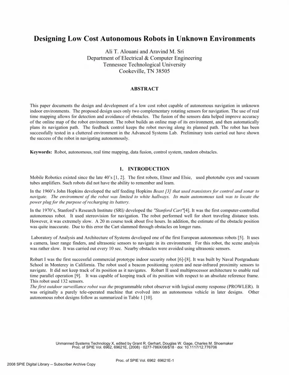
2.2. Drive Train The main components of the drive train are the motors and the gear assembly. The driving motors must have sufficient torque to drive the payload of the robot. For the gear assembly, a spur gear, Figure 3, or a drive belt system, Figure 4, can be used. In this work, the drive belt system was used. 2.3. The Chassis Design
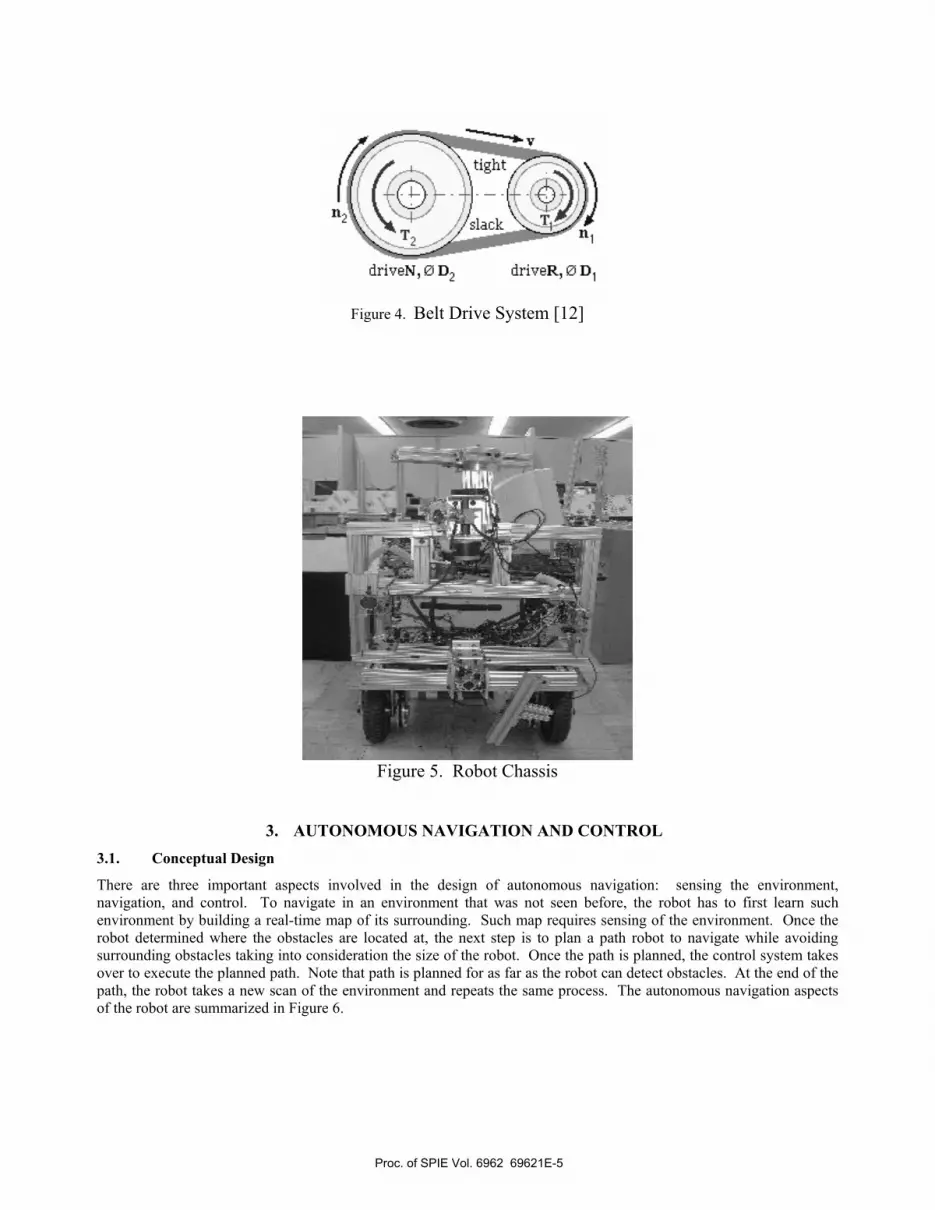
The chassis has been designed in a modular fashion. It is based on a two level design. The 2 levels or racks are bolted directly on the chassis. The upper rack houses the DAQ(Data Acquisition) cards and the monitor while the lower rack, houses the interfacing boards, range sensors, H-bridge boards, batteries and the PXI system. The back of the chassis holds the power distribution board. The modular design allows for future expansion. The frame of the robot is constructed with aluminum to reduce the weight of the robot. The two drive motors are clamped beneath the chassis on a 24” X
Proc. of SPIE Vol. 6962 69621E-3

10” steel plate. The motor is screwed on to a circular plate, which is welded to the steel plate. The shaft of the motor is connected to a gear head that drives the belt drive system, Figure 5.
LEFT MOTOR RIGHT MOTOR
W HEELCASTORS
REAR W HEELS-SupportW heels
FRAME
Figure 2. Differential Drive System Design
Figure 3. Spur Gear Train [11]
Proc. of SPIE Vol. 6962 69621E-4
V
ni
driveN, 0 D1 driveR, 0 D1
Figure 4. Belt Drive System [12]
Figure 5. Robot Chassis
3. AUTONOMOUS NAVIGATION AND CONTROL 3.1. Conceptual Design
There are three important aspects involved in the design of autonomous navigation: sensing the environment, navigation, and control. To navigate in an environment that was not seen before, the robot has to first learn such environment by building a real-time map of its surrounding. Such map requires sensing of the environment. Once the robot determined where the obstacles are located at, the next step is to plan a path robot to navigate while avoiding surrounding obstacles taking into consideration the size of the robot. Once the path is planned, the control system takes over to execute the planned path. Note that path is planned for as far as the robot can detect obstacles. At the end of the path, the robot takes a new scan of the environment and repeats the same process. The autonomous navigation aspects of the robot are summarized in Figure 6.
Proc. of SPIE Vol. 6962 69621E-5

C
C
CC
C
i,jsb nq!ua
UiU fjJ UiJLOUUJU
Figure 6. Conceptual Design of the Information Processing and Navigation an Autonomous Robot
3.2 Sensing the Environment
In order for the robot to learn its environment and navigates autonomously, it has to be equipped with sensing devices that will allow the robot to identify all the obstacles in its neighborhood. Existing designs use arrays of sonars [5]-[9], while others use stereo vision [13]-[15]. As discussed previously, a major limitation of the use of sonar arrays is the appearance of phantom targets beside the cumbersomeness and maintenance cost of the hardware. On the other hand, the use of stereovision technique is limited in terms of its accuracy in long range. The computational aspects of this technique are another limiting factor.
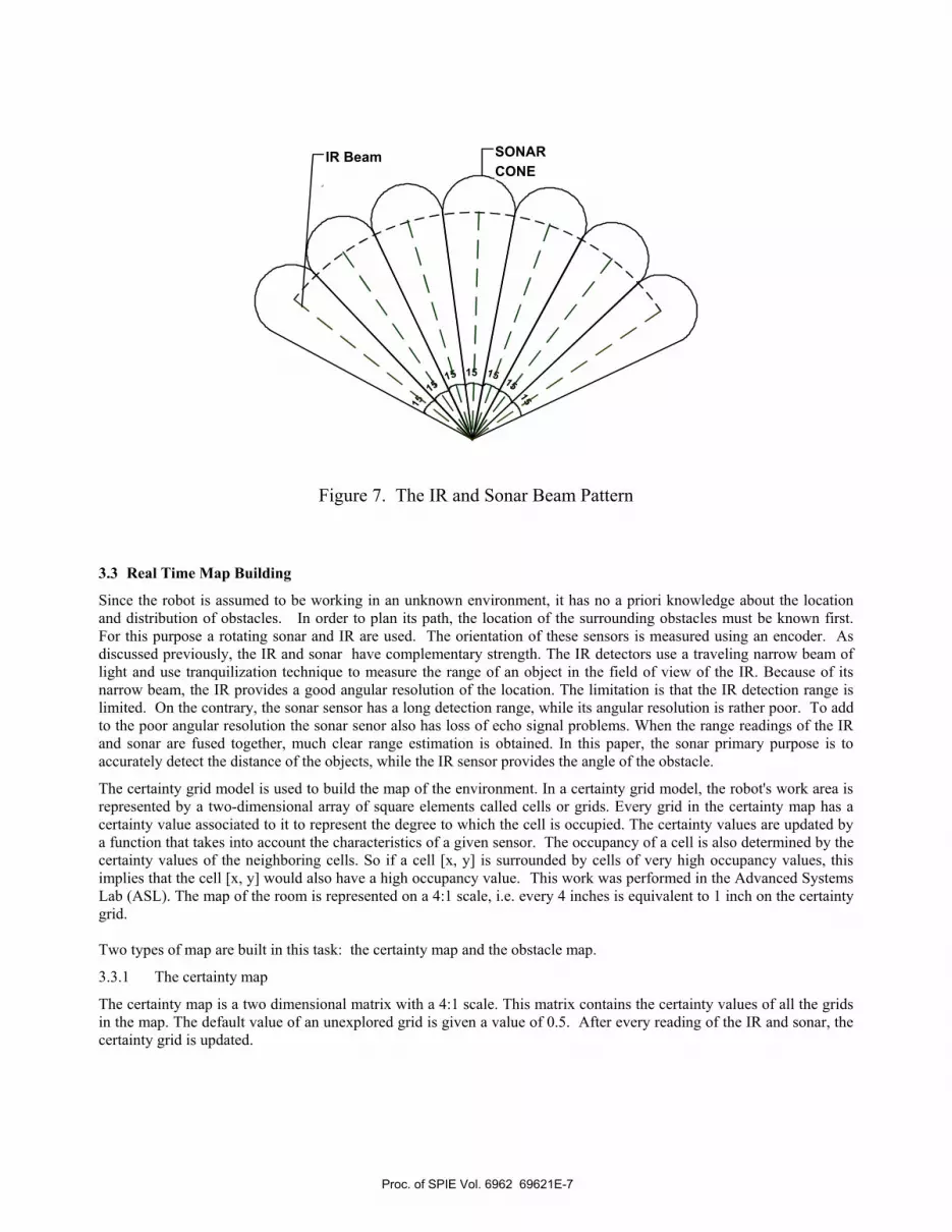
In this paper, sensing the environment is accomplished using two rotating dissimilar sensors: a sonar and IR sensors. The use of rotating sensors limits the number of sensors needed to scan the environment of the robot. The sonar is known to have long coverage range with low accuracy of target position. On the other hand, the IR has short range detection capability and accurate directional finding. Using the data of the two sensors allows for accurate estimation of the location of obstacles around the robot. The beam patterns of the sonar, continuous line, and IR, dashed line, are shown in Figure 7.
Proc. of SPIE Vol. 6962 69621E-6
151515
15
15 15
15
IR Beam SONARCONE
Figure 7. The IR and Sonar Beam Pattern
3.3 Real Time Map Building
Since the robot is assumed to be working in an unknown environment, it has no a priori knowledge about the location and distribution of obstacles. In order to plan its path, the location of the surrounding obstacles must be known first. For this purpose a rotating sonar and IR are used. The orientation of these sensors is measured using an encoder. As discussed previously, the IR and sonar have complementary strength. The IR detectors use a traveling narrow beam of light and use tranquilization technique to measure the range of an object in the field of view of the IR. Because of its narrow beam, the IR provides a good angular resolution of the location. The limitation is that the IR detection range is limited. On the contrary, the sonar sensor has a long detection range, while its angular resolution is rather poor. To add to the poor angular resolution the sonar senor also has loss of echo signal problems. When the range readings of the IR and sonar are fused together, much clear range estimation is obtained. In this paper, the sonar primary purpose is to accurately detect the distance of the objects, while the IR sensor provides the angle of the obstacle.
The certainty grid model is used to build the map of the environment. In a certainty grid model, the robot's work area is represented by a two-dimensional array of square elements called cells or grids. Every grid in the certainty map has a certainty value associated to it to represent the degree to which the cell is occupied. The certainty values are updated by a function that takes into account the characteristics of a given sensor. The occupancy of a cell is also determined by the certainty values of the neighboring cells. So if a cell [x, y] is surrounded by cells of very high occupancy values, this implies that the cell [x, y] would also have a high occupancy value. This work was performed in the Advanced Systems Lab (ASL). The map of the room is represented on a 4:1 scale, i.e. every 4 inches is equivalent to 1 inch on the certainty grid. Two types of map are built in this task: the certainty map and the obstacle map.
3.3.1 The certainty map
The certainty map is a two dimensional matrix with a 4:1 scale. This matrix contains the certainty values of all the grids in the map. The default value of an unexplored grid is given a value of 0.5. After every reading of the IR and sonar, the certainty grid is updated.
Proc. of SPIE Vol. 6962 69621E-7

3.3.2. Obstacle Map: The obstacle map is obtained by thresholding the certainty map. The threshold value is estimated by a trial and error
method. The obstacle map is a binary map, in which 1 represents the presence of obstacle in a grid and 0 represents free space. An example obstacle map is shown in Figure 9. A global path-planning method is employed iteratively as the map is incrementally updated.
0
0
000
00
00 0
00 0
0
0 1
10
0 1
1
1
10000
0
000
0 0
0
0000
0 0 0 0 0
000000
00 0 0 0 0
00000000 000 0
0
Figure 9. Certainty map after thresholding
3.4. Path Planning
Given the obstacles location with respect to the robot, two cases are considered. In the first case, the robot knows the location to travel to. In the second case, the robot is performing random patrol. In each case, the robot determines the set of feasible gaps first. A feasible gap is a gap that is big enough for the robot to pass through. In case where the robot knows where it is going, it chooses the gap that is in the direction of its final destination. Otherwise, the robot uses the closest feasible gap. The next step in the path planning algorithm is to estimate the mid point of the gap and make it its next destination in such a way that the robot approaches the gap along the orthogonal line to that gap. Once its gets to the gap, the robot takes a new scan, updates its obstacles map, and repeats the same steps.
3.5. Control Systems
The objective of the control system is to use the previously planned path as the reference signal to accomplish the mission as fast and accurate as possible.
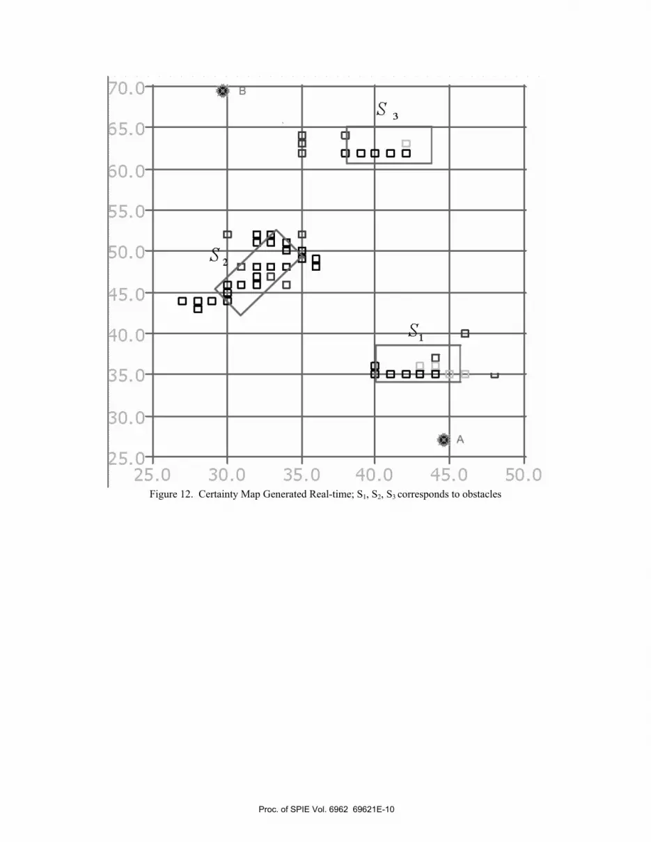
To illustrate the autonomous navigation of the robot, consider the scenario of obstacles shown in Figure 10. The dimensional layout of the obstacles is shown in Figure 11. Figure 12 shows the obstacle map, while Figure 13 shows the planned path used by the robot in moving from location A to location B.
Proc. of SPIE Vol. 6962 69621E-8
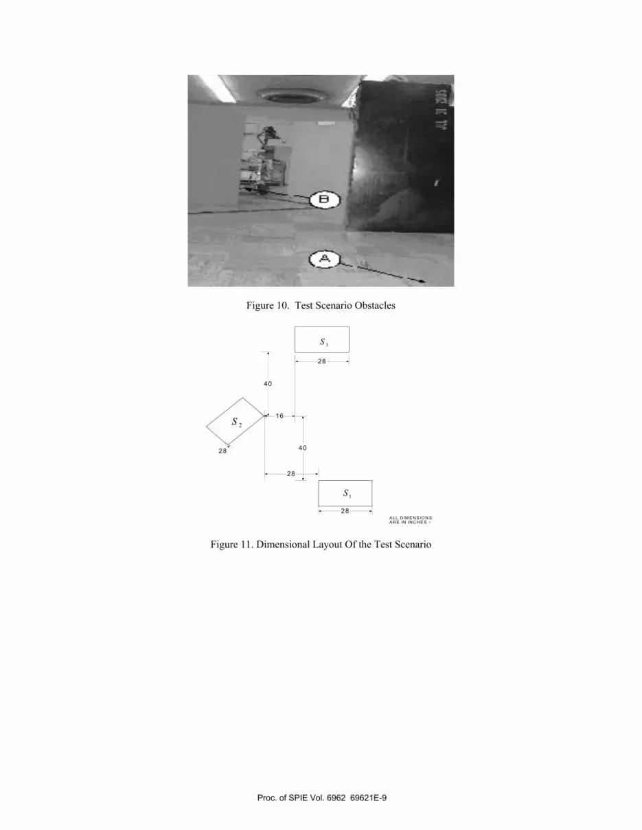
Figure 10. Test Scenario Obstacles
40
40
28
28
28
1S
2S
3S
ALL DIM E NS IO N SAR E IN IN C HE S +
16
28
Figure 11. Dimensional Layout Of the Test Scenario
Proc. of SPIE Vol. 6962 69621E-9
Ui
0 U
I 0
Ui
0 U
I 0
UI
0
Figure 12. Certainty Map Generated Real-time; S1, S2, S3 corresponds to obstacles
Proc. of SPIE Vol. 6962 69621E-10

Figure 13. Map showing obstacles location and path taken by the robot from A to B
4. CONCLUSIONS
This paper discussed some of the design aspects of a low cost mobile robot capable of autonomous navigation in an unknown environment. This required many engineering disciplines. These include mechanical design, electronics, signal processing, automatic control, instrumentation, and software development. Not all aspects have been covered in this paper due to space limitations. One main innovation in the design of the autonomous robot consists of using the least number of sensors when compared to existing autonomous robots. This has led to a much simpler and less expensive design. The use of a sonar and IR has tremendously improved the quality of the obstacle map. The current model is capable of navigating through aisles as narrow as 36 inches and greater. The robot has been successfully tested in a cluttered and distributed environment. Preliminary testing using reasonably cluttered environments (obstacles are at least 40 inches apart from each other) have shown the success of the robot in navigating autonomously indoors.
Proc. of SPIE Vol. 6962 69621E-11
To further improve the quality of the obstacle map, the sonar may be replaced with a laser ranging system. A gyroscope can be used to keep tack with the absolute position of the robot. Finally, other chassis shapes, such as round shape, can be investigated to further improve the maneuverability and passage between narrow objects.
REFERENCES [1] Pickering, A. “The Tortoise against Modernity: Cybernetics as Science and Technology, Art and Entertainment” Experimental Cultures: Configurations of Life Sciences, Art, and Technology, Max Planck Institute for the History of Science, Berlin, December 6-9, 2001. [2] Walter, G., “A Machine That Learns”, Scientific American, Vol.185, pg: 60–63, 1951. [3] Eduardo R. Torres-Jara “Self-Feeding Robot”, M.S. Thesis, Massachusetts Institute Of Technology, January 2002. [4] Hans Moravec, “The Stanford CART and the CMU Rover”, Report, The Robotics Institute, Carnegie-Mellon University, February 1983. [5] Alami R, Augilar L, Bulata H, Fluery S, Herrb M, Ingrand F, Khatib M and Robert F “A general framework for multi-robot cooperation and its implementation on a set of three Hilare robots” IV th International Symposium on Experimental Robotics (ISER'95), Stanford (USA), pg: 26-35, 30 June - 2 July 1995. [6] Everett H.R. and Gilbreath G.A. “A Supervised Autonomous Security Robot,” Robotics and Autonomous Systems, Vol.4, No.3, pg: 209-232, November 1988. [7] Ciccimaro D.A., Everett H.R., Gilbreath G.A., and Tran T.T., “An Automated Security Response Robot,” SPIE Proc. 3525: Mobile Robots XIII and Intelligent Transportation Systems, pg: 50-61, Boston, Massachusetts, 1-5 November 1998. [8] Gilbreath G.A., Ciccimaro D.A., and Everett H.A., "An Advanced Tele-reflexive Tactical Response Robot," Autonomous Robots, Vol.11 , No.1, pg: 39 - 47 ,July 2001. [9] Commander H.R. (Bart) Everett (Rtd),”A Brief History of Robotics in Physical Security”, Report, Space and Naval Warfare Systems Center, San Diego, 1998. [10] http://www.spawar.navy.mil/robots/land/robart/history.html [11] www.mitcalc.com/ en/pr_spurgear.htm [12] www.mech.uwa.edu.au/.../ V-belts/intro/intro.html. [13] Matthies, L. and P. Grandjean, “ Stochastic Performance Modeling and Evaluation of Obstacle Delectability with Imaging Range Sensors,” IEEE Trans. Robotics and Automation, vol. 10, n0. 6, 1994. [14] Gennery, D.B., “ Traversability Analysis and Path Planning for a Planetary Rover,” Autonomous Robots, vol. 6, no. 2, 1999. [15] Mokri,Y. and Jamzad, M., “Omni-stereo vision system for an autonomous robot using neural networks,” Canadian Conference on Electrical and Computer Engineering, 2005.
Proc. of SPIE Vol. 6962 69621E-12