design principles of fret-based dye-sensitized solar cells with buried quantum dot donors
TRANSCRIPT
626
FULL
PAPER
www.MaterialsViews.comwww.advenergymat.de
Stella Itzhakov, Sophia Buhbut, Elad Tauber, Thomas Geiger, Arie Zaban, and Dan Oron*
Design Principles of FRET-Based Dye-Sensitized Solar Cells with Buried Quantum Dot Donors
In this article, the physics of FRET is demonstrated for an architecture of dye-sensitized solar cells, in which the quantum dot “antennas” that serve as donors are incorporated into the solid titania electrode, providing isola-tion from electrolyte quenching, and potentially increased photostability. The energy transferred to the dye acceptor from the quantum dot donor, in addition to the direct light absorption by the dye, fi nally induce dye excitation and electron injection to the metal oxide semiconductor electrode. We use time-resolved photoluminescence measurements to directly show achieve-ment of FRET effi ciencies of up to 70%, corresponding to over 80% internal quantum effi ciency when considering radiative energy transfer as well. The various parameters governing the FRET effi ciency and the requirements for high effi ciency FRET-based cells are discussed. Since both buried donors inside the electrode and donors solubilized in the electrolyte have both been shown to achieve high energy transfer effi ciencies, and as the two methods take advantage of different available volumes of the electrode to introduce donors providing the excess absorption, synergy of the two methods is highly promising for achieving panchromatic absorption within a thin electrode.
1. Introduction
Förster resonance energy transfer (FRET) has become widely used in a variety of opto-electronic devices, [ 1 ] and recently also in dye sensitized solar cells (DSSCs) [ 2–8 ] and in organic photo-voltaics. [ 9 ] By using donor species that both absorb the short wavelengths of the solar spectrum and effi ciently transfer the energy to the acceptor acting as a sensitizer, better cell perform-ance can potentially be achieved.
The traditional organic dyes used in DSSCs suffer from narrow absorption spectra or low molar extinction coeffi -cients. [ 10 ] The utilization of FRET to transfer energy from a
© 2011 WILEY-VCH Verlag GmbH & Co. KGaA, Weinhwileyonlinelibrary.com
DOI: 10.1002/aenm.201100110
S. Itzhakov , Dr. D. Oron Department of Physics of Complex SystemsWeizmann Institute of ScienceRehovot, 76100, Israel E-mail: [email protected] S. Buhbut , E. Tauber , Prof. A. Zaban Institute of Nanotechnology and Advanced MaterialsBar Ilan UniversityRamat-Gan, 52900, Israel Dr. T. Geiger Empa, Swiss Federal Laboratories for Materials Testing and Research Laboratory for Functional PolymersÜberlandstrasse 129, 8600 Dübendorf, Switzerland
donor to a sensitizing dye introduces new degrees of freedom in the design of DSSCs. In particular, dyes with a high molar extinction coeffi cient and with good charge injection abilities that were not considered previously due to a narrow absorption spectrum can become effi cient sensitizers. [ 11 , 12 ] This is of par-ticular interest when considering dyes which are photoactive in the deep red or the near-IR spectral regions. [ 13 ] Ideally, the higher energy components of the solar spectrum will be highly absorbed by a donor, and transferred effi ciently to the acceptor. This can be done either via FRET, or by radiative recombination and re-absorption by an acceptor. In addition, the fact that the donor is not involved in charge injection can open a way towards utilization of new materials for which the band alignment is not restricted to match that of the wide band gap electrode. Since relay donors do not have to be adsorbed
on the electrode surface, and hence do not occupy the same volume as the sensitizer dye, a higher volume concentration of absorbers within the cell can be achieved. This implies that a large external quantum effi ciency (EQE) can be reached for thinner electrodes provided that the both the extinction coef-fi cient of the donor and the energy transfer effi ciency to the acceptor are high enough. Working with thinner electrodes is benefi cial from several aspects; most importantly the ability to incorporate solid electrolytes in the cells. [ 14 , 15 ]
Two different systems were realized in previous experiments. One used an organic relay dye dissolved in either the solid [ 4–6 ] or liquid electrolyte, [ 7 , 8 ] occupying the pores of the electrode. Alternatively, donor quantum dots (QDs) were embedded inside the titania electrode, a few nanometers below the monolayer of sensitizing dye. [ 16 ] In both approaches, there are limitations to the donor loading. When dissolved in the electrolyte, the donor concentration is limited by its solubility product. [ 8 ] High con-centrations lead to aggregation and quenching of the excited state by the electrolyte. [ 2 ] In the embedded QD design, where the QDs are fi rst adsorbed on the electrode and then overcoated by an inorganic layer, the donor loading is controlled mainly by the ratio between the pore size of the electrode and the QD dimensions, as well as by diffusion dynamics of QDs inside the porous electrode. As is commonly observed in quantum dot sensitized solar cells (QDSSCs), [ 18–23 ] these factors practically limit the achievable donor loading.
eim Adv. Energy Mater. 2011, 1, 626–633
FULL P
APER
www.MaterialsViews.comwww.advenergymat.de
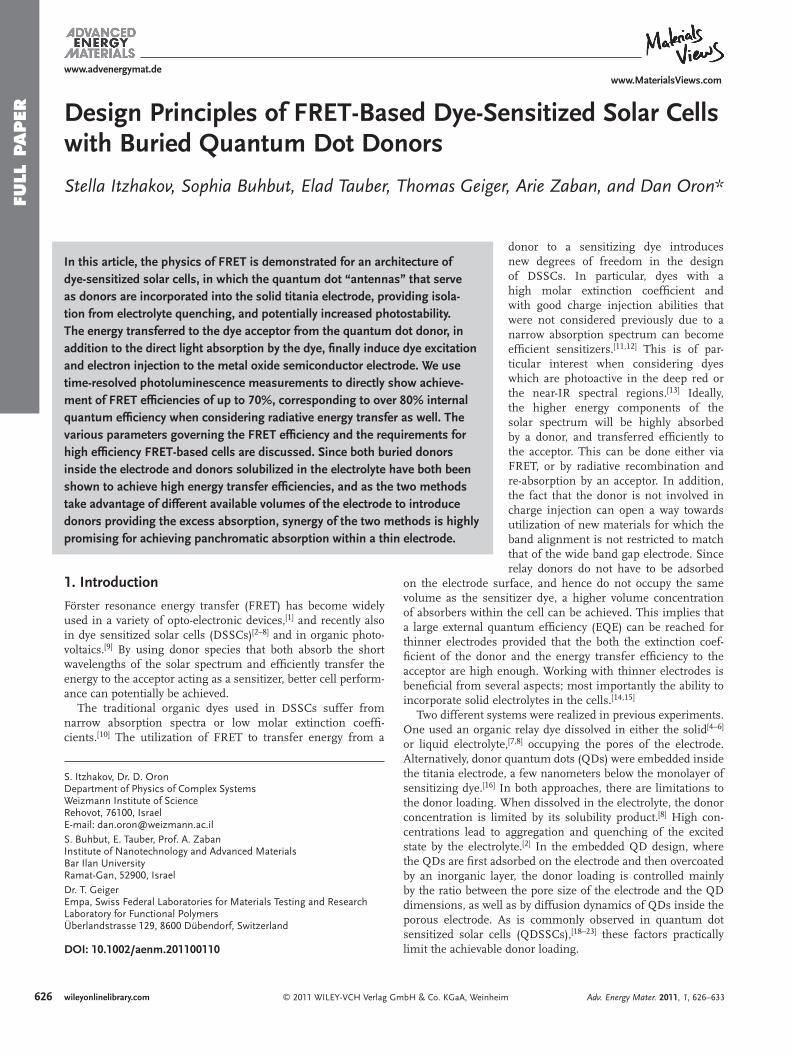
Figure 1 . ( a ) Schematic presentation of the FRET based DSSC. The system consists of a transparent conducting oxide (TCO) on which nc-TiO 2 (off-white big circles) is grown. QDs (red circles) bound to nc-TiO 2 via a MPA linker (not shown) and covered by a thin layer of a-TiO 2 (gray coating) to which SQ02 dye molecules (small blue circles) are connected. This entire structure is immersed in a liquid redox electrolyte (I − /I 3 − ). ( b ) HR-TEM image showing a CdSe/CdS/ZnS QD bound to the nc-TiO 2 and fully covered by an a-TiO 2 coating.
TCO
(a)
Photons absorbed by the donor can be transferred to an acceptor by means of FRET, or via radiative recombination and re-absorption by an acceptor. Both pathways, in addition to direct light absorption by the acceptor, contribute to the excitation of the dye acceptor and to the photocurrent pro-duction. EQE measurements cannot distinguish between the three photocurrent generating pathways. Differential measurements between cells containing the relay dyes and ones that do not contain them provide a way to differentiate between the donor-mediated response and direct absorption by the acceptor (assuming that the two are non-interacting via other means). Differentiation between radiative and non-radiative energy transfer from the donor to the acceptor can be done via transient fl uorescence measurements of the donor in the presence and in the absence of the acceptor. The FRET effi ciency can be directly extracted from such measurements.
Most previous studies did not measure the ratio between FRET and radiative energy transfer in the relay (or antenna) based DSSC. A common practice is to estimate the FRET effi ciency from the overall contribution of the donor to the EQE. From an application point of view, it is only the overall effi ciency of both which matters. In fact, various approaches to photovoltaic (PV) cells using relay dyes, particularly those associated with luminescent solar concentrators rely entirely on radiative decay of the donor. Yet, in the context of DSSCs, it is important to differentiate between the two processes since different parameters affect their effi ciencies: radiative energy transfer requires high optical density of the entire electrode at the donor emission wavelength. In contrast, FRET depends only on the local parameters of the electrode (e.g. acceptor surface concentration and distances) and can thus remain effi cient even for thinner, more transparent elec-trodes. In addition, being a faster process, FRET reduces the loss associated with non-radiative decay of the donor. In the following, we use time-resolved photoluminescence measure-ments to directly demonstrate the achievement of FRET effi -ciencies of up to 70% in a geometry utilizing embedded QDs
© 2011 WILEY-VCH Verlag GmAdv. Energy Mater. 2011, 1, 626–633
in mesoporous titania electrodes. We proceed to consider the various parameters governing the FRET effi ciency, and dis-cuss the requirements for high effi ciency FRET-based cells.
2. Results and Discussion
2.1. The System
A schematic presentation of the FRET based DSSC is pre-sented in Figure 1 a. The QD “antennas” are buried below an amorphous titania (a-TiO 2 ) layer [ 24 ] to become part of the solid electrode which is coated with a SQ02 dye [ 13 ] mono layer. The structure is further demonstrated in the high resolution trans-mission electron microscopy (HR-TEM) image of Figure 1 b. The CdSe/CdS/ZnS QD (wurtzite crystal structure) bound to the nanocrystalline TiO 2 (nc-TiO 2 ) is fully covered by an a-TiO 2 layer that isolates it from the electrolyte to prevent exciton quenching and photo-electrochemical degradation. [ 25 , 26 ] In addition, the type-I heterostructure of QDs that contains an encapsulating wide band gap ZnS shell prevents the injection of photoelectrons from the QD to the TiO 2 . [ 16 ] The geometry, resembling a parallel donor-acceptor layer with a short distance between them ( ∼ 7 nm) provides the necessary conditions for high FRET effi ciencies.
2.2. HR-TEM
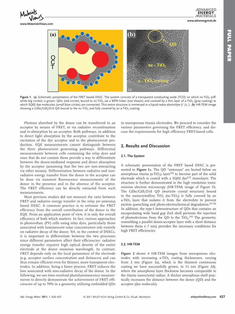
Figure 2 shows 4 HR-TEM images from mesoporous elec-trodes with increasing a-TiO 2 coating thicknesses, varying from 2 nm (Figure 2 a), which is the thinnest continuous coating we have successfully grown, to 11 nm (Figure 2 d), where the amorphous layer thickness becomes comparable to the titania nanocrystal radius. A thicker amorphous shell prac-tically increases the distance between the donor (QD) and the acceptor (dye molecule).
627bH & Co. KGaA, Weinheim wileyonlinelibrary.com
628
FULL
PAPER
www.MaterialsViews.comwww.advenergymat.de
Figure 2 . HR-TEM images of electrodes with increasing amorphous titania coating thickness. The layer thickness is 2 nm, 4 nm, 7 nm and 11 nm, as shown in ( a ), ( b ), ( c ) and ( d ), respectively.
2.3. Lifetime Measurements and FRET Effi ciency
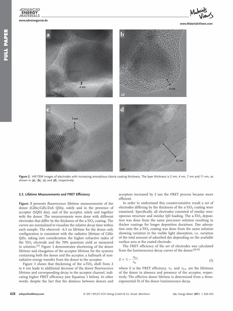
Figure 3 presents fl uorescence lifetime measurements of the donor (CdSe/CdS/ZnS QDs), solely and in the presence of acceptor (SQ02 dye), and of the acceptor, solely and together with the donor. The measurements were done with different electrodes that differ by the thickness of the a-TiO 2 coating. The curves are normalized to visualize the relative decay time within each sample. The observed ∼ 6.5 ns lifetime for the donor only confi guration is consistent with the radiative lifetime of CdSe QDs, taking into consideration the higher refractive index of the TiO 2 electrode and the 70% quantum yield as measured in solution. [ 27 ] Figure 3 demonstrates shortening of the donor lifetime and elongation of the acceptor lifetime for the systems containing both the donor and the acceptor, a hallmark of non-radiative energy transfer from the donor to the acceptor.
Figure 3 shows that thickening of the a-TiO 2 shell from 2 to 4 nm leads to additional decrease of the donor fl uorescence lifetime and corresponding decay in the acceptor channel, indi-cating higher FRET effi ciency (see Equation 1 below). In other words, despite the fact that the distance between donors and
© 2011 WILEY-VCH Verlag Gwileyonlinelibrary.com
acceptors increased by 2 nm the FRET process became more effi cient.
In order to understand this counter-intuitive result a set of electrodes differing by the thickness of the a-TiO 2 coating were examined. Specifi cally, all electrodes consisted of similar mes-oporous structure and similar QD loading. The a-TiO 2 deposi-tion was done from the same precursor solution resulting in thicker coatings for longer deposition durations. Dye adsorp-tion onto the a-TiO 2 coating was done from the same solution showing variation in the visible light absorption, i.e. variation of the total amount of adsorbed dye depending on the available surface area at the coated electrode.
The FRET effi ciency of the set of electrodes was calculated from the luminescence decay curves of the donor: [ 28 , 29 ]
E = 1 − JDA
JD (1)
where E is the FRET effi ciency, JD and JDA are the lifetimes of the donor in absence and presence of the acceptor, respec-tively. The effective donor lifetime is determined from a three-exponential fi t of the donor luminescence decay.
mbH & Co. KGaA, Weinheim Adv. Energy Mater. 2011, 1, 626–633
FULL P
APER
www.MaterialsViews.comwww.advenergymat.de
Figure 3 . Time resolved photoluminescence decay measurements of the donor ( a ) and the acceptor ( b ). The lifetime of a donor (with 2 nm thick a-TiO 2 coating) and an acceptor only in ( a ) and ( b ) are represented by a blue solid line and a black dashed line, respectively. The red and the green curves are for 2 nm and 4 nm shell thickness, respectively, for donor in presence of an acceptor ( a ), and for acceptor in presence of a donor ( b ).
Table 1 summarizes the fi tted lifetimes of a donor only ( JD ) and in a presence of an acceptor ( JDA ), the full cell absorb-ance at the acceptor absorption peak, and the corresponding FRET effi ciency for each shell thickness. The lower part of the table presents the results of two additional electrodes having an a-TiO 2 coating of 4 nm thickness but different dye coverage, and will be discussed below.
Clearly, upon further growth of the a-TiO 2 layer, several physical factors which control the FRET rate are being modi-fi ed simultaneously. The most dominant ones are: (i) A longer donor-acceptor distance; (ii) Modifi cation of the effective dye surface concentration, Ce f f
A , which depends on the electrode surface area following the a-TiO 2 coating. (The term: effective dye surface concentration, describes the amount of acceptor dye molecules per area unit of the QD donor layer, irrespective of the coating thickness or morphology. Ce f f
A is calculated uti-lizing the optical density of the electrode at the absorption peak of the dye and the geometrical parameters of the electrode prior to the a-TiO 2 coating. Since prior to the a-TiO 2 coating all elec-trodes and QD loadings are similar, we use the cell absorbance as a relative value for comparison between samples that differ by Ce f f
A ); (iii) Higher effective refractive index in proximity to the QDs, leading to a modifi cation of the radiative decay rate. Hence, the trend due to which the overall FRET effi ciency
© 2011 WILEY-VCH Verlag GAdv. Energy Mater. 2011, 1, 626–633
fi rst increases, reaching a maximal value of nearly 70%, then decreases with increasing amorphous shell thickness is not easily explained.
2.4. FRET Effi ciency Analysis
In order to elucidate the reasons for the changes in FRET effi ciency, as well as to identify possible modifi cations which could lead to yet higher FRET effi ciencies, we consider fi rst the simple model of FRET between a single donor and a planar layer of acceptors with areal density C A located a ver-tical distance z away from it. In this case, the FRET rate is given by [ 1 ]
K F RE T =P2
CAB R20
JD·(
R0
z
)4
=P2
CA
C0·(
R0
z
)4
· K D
(2)
where R 0 is the Förster radius, K D is a luminescence rate of the donor in absence of the acceptor (accounting for both radia-tive and nonradiative recombination), χ is a correction factor of order unity due to the relative polarization orientation of donors and acceptors, [ 30 ] and C 0 is a characteristic acceptor con-centration in molecules nm − 2 . This concentration is related to the Förster distance by
Co = (BR20)− 1
(3)
Hence (CA/C0) is thus seen to be the number of acceptor molecules in an area equal to B R2
0 , that of a circle with radius R 0 . For our parameters, we can reasonably estimate for the highest FRET effi ciency sample, corresponding to a layer thickness of ∼ 4 nm, that z ∼ R 0 ∼ 6.6 nm. [ 16 ] The vertical distance z is composed of a radius of the QD ( ∼ 3 nm) and the thick-ness of the a-TiO 2 coating. In this case, the observed FRET effi ciency of 67% corresponds to an areal density of ∼ 0.1 dye molecules nm − 2 , which is in the range of typical quoted litera-ture values. [ 8 , 17 ]
We fi rst tested the relation between the dye absorbance and the FRET effi ciency. Table 1 shows a correlation between these parameters among the various samples having a different a-TiO 2 thickness coating.
To test both the applicability of the single donor-multiple acceptor model as well as to quantify the weight of Ce f f
A within the parameters governing the FRET effi ciency, we conducted additional experiments with constant coating thickness (4 nm) varying only the dye concentration. In these experiments we utilized undecenoic acid, an optically inac-tive molecule having a carboxylic group as a coadsorbent. Undecenoic acid thus competes with the SQ02 dye on the binding sites at the a-TiO 2 surface, effectively reducing the dye concentration. By mixing the dye and the coadsorbent in different ratios, three different dye concentrations on the 4 nm titania coating surface were achieved. The parameters of this electrode set and the measured FRET effi ciencies are also presented in Table 1.
629mbH & Co. KGaA, Weinheim wileyonlinelibrary.com
630
FULL
PAPER
www.MaterialsViews.comwww.advenergymat.de
Table 1. Summary of lifetimes, dye absorbance and FRET effi ciencies for different shell thicknesses and dye concentrations.
Shell Thickness [nm] τ D [ ns ] τ DA [ ns ] Dye Absorbance [a.u.] FRET Effi ciency [%]
Varying the a-TiO 2 Coating Thickness
0 6.6 ± 0.3 - -
2 6.1 ± 0.3 3.0 ± 0.12 0.17 51 ± 4
4 4.9 ± 0.2 1.6 ± 0.06 0.8 67 ± 2
7 4.7 ± 0.2 1.8 ± 0.07 0.6 62 ± 3
11 5 ± 0.2 2.9 ± 0.12 0.17 42 ± 5
Varying The Dye Concentration
4 6.7 ± 0.3 4.6 ± 0.2 0.09 32 ± 5
4 5.7 ± 0.2 4.9 ± 0.2 0.07 14 ± 6
From the simple model of Equation 2 one expects that in this case K FRET will vary linearly with the areal density of the dye. The FRET effi ciency is calculated by Equation 4
E =K F RE T
K F RE T + K R + K N R
=1
1 + (K R+ K N R)(K F RE T )
=1
1 + K DK F RE T
(4)
where K R and K NR are radiative and non-radiative rate of the donor, respectively. For this particular sample, where z ∼ R 0 , Equation 4 and 2 show that the FRET effi ciency should scale as
E = 1
1 + 2C0PCA (5)
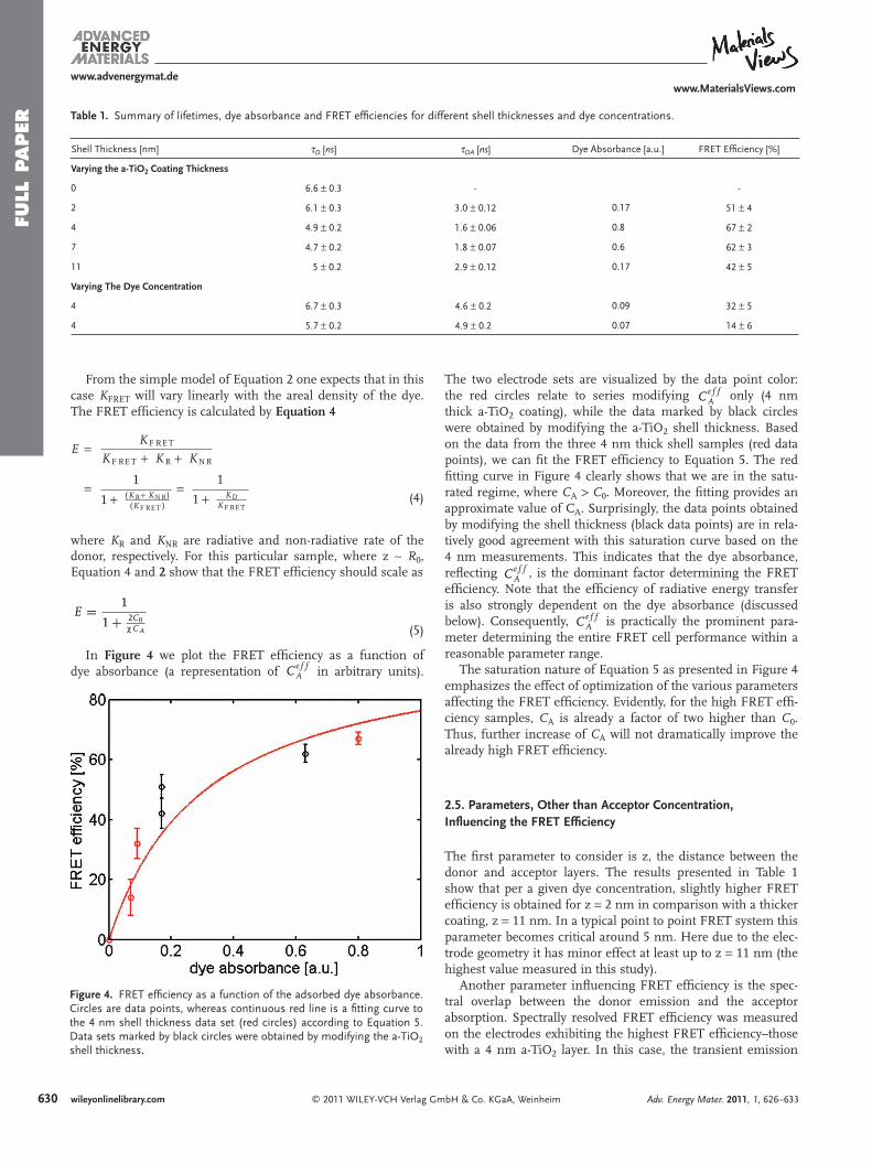
In Figure 4 we plot the FRET effi ciency as a function of dye absorbance (a representation of Ce f f
A in arbitrary units).
© 2011 WILEY-VCH Verlag Gwileyonlinelibrary.com
Figure 4 . FRET effi ciency as a function of the adsorbed dye absorbance. Circles are data points, whereas continuous red line is a fi tting curve to the 4 nm shell thickness data set (red circles) according to Equation 5 . Data sets marked by black circles were obtained by modifying the a-TiO 2 shell thickness.
The two electrode sets are visualized by the data point color: the red circles relate to series modifying Ce f f
A only (4 nm thick a-TiO 2 coating), while the data marked by black circles were obtained by modifying the a-TiO 2 shell thickness. Based on the data from the three 4 nm thick shell samples (red data points), we can fi t the FRET effi ciency to Equation 5 . The red fi tting curve in Figure 4 clearly shows that we are in the satu-rated regime, where C A > C 0 . Moreover, the fi tting provides an approximate value of C A . Surprisingly, the data points obtained by modifying the shell thickness (black data points) are in rela-tively good agreement with this saturation curve based on the 4 nm measurements. This indicates that the dye absorbance, refl ecting Ce f f
A , is the dominant factor determining the FRET effi ciency. Note that the effi ciency of radiative energy transfer is also strongly dependent on the dye absorbance (discussed below). Consequently, Ce f f
A is practically the prominent para-meter determining the entire FRET cell performance within a reasonable parameter range.
The saturation nature of Equation 5 as presented in Figure 4 emphasizes the effect of optimization of the various parameters affecting the FRET effi ciency. Evidently, for the high FRET effi -ciency samples, C A is already a factor of two higher than C 0 . Thus, further increase of C A will not dramatically improve the already high FRET effi ciency.
2.5. Parameters, Other than Acceptor Concentration, Infl uencing the FRET Effi ciency
The fi rst parameter to consider is z, the distance between the donor and acceptor layers. The results presented in Table 1 show that per a given dye concentration, slightly higher FRET effi ciency is obtained for z = 2 nm in comparison with a thicker coating, z = 11 nm. In a typical point to point FRET system this parameter becomes critical around 5 nm. Here due to the elec-trode geometry it has minor effect at least up to z = 11 nm (the highest value measured in this study).
Another parameter infl uencing FRET effi ciency is the spec-tral overlap between the donor emission and the acceptor absorption. Spectrally resolved FRET effi ciency was measured on the electrodes exhibiting the highest FRET effi ciency–those with a 4 nm a-TiO 2 layer. In this case, the transient emission
mbH & Co. KGaA, Weinheim Adv. Energy Mater. 2011, 1, 626–633
FULL P
APER
www.MaterialsViews.comwww.advenergymat.de
was measured through a monochromator, transmitting a 2 nm spectral band centered at 615, 630, 645 and 660 nm, in absence and in the presence of the acceptor dye. Each spectral band corresponds to a different size range within the inhomogene-ously broadened QD ensemble. We found that the FRET effi -ciency increased from 61% at 615 nm detection to above 70% at 660 nm. This is consistent with the higher spectral overlap with the dye absorption which peaks at about 660 nm providing means to improve FRET effi ciency via QD synthesis.
In addition, the quantum yield (QY) of QDs (donors) can be increased (by decreasing the non-radiative recombination rate) for higher FRET effi ciency. The non-radiative recombination rate is very important for those photons that were not trans-ferred by FRET to acceptors. As the non-radiative recombina-tion rate is slower compared to the radiative recombination rate, the photon will have larger probability to be emitted radiatively and absorbed by the acceptor via this second route. Thus, QDs with higher QY should give higher internal quantum effi ciency (IQE).
By increasing the molar extinction coeffi cient of the acceptor, the FRET effi ciency can be also increased, although this para-meter, together with the spectral overlap and the QY of the donor, weakly infl uence the FRET effi ciency due to the sixth-root dependence of R 0 .
The acceptor concentration has a strong infl uence on the FRET effi ciency at relatively low concentrations. However, because we are already in the saturation regime, increase by a factor of 2 in the acceptor concentration will increase the FRET effi ciency by less than 20%.
2.6. Differentiation between Radiative and Non-Radiative Energy Transfer
Above, we have considered possible pathways to increase the FRET effi ciency. However, in order to adequately compare the effi ciency of our design with that of relay dyes added in the electrolyte, [ 7 ] we fi nd that it is important to differentiate between the observables of these experiments and the FRET effi ciency. The observable in all experiments using relay dyes in the electrolyte was the external quantum effi ciency, from which the excitation transfer effi ciency (e.g. the probability for transfer of the absorbed energy between the relay dye and the acceptor) was extracted. The latter is a global measurement, accounting
© 2011 WILEY-VCH Verlag GmbAdv. Energy Mater. 2011, 1, 626–633
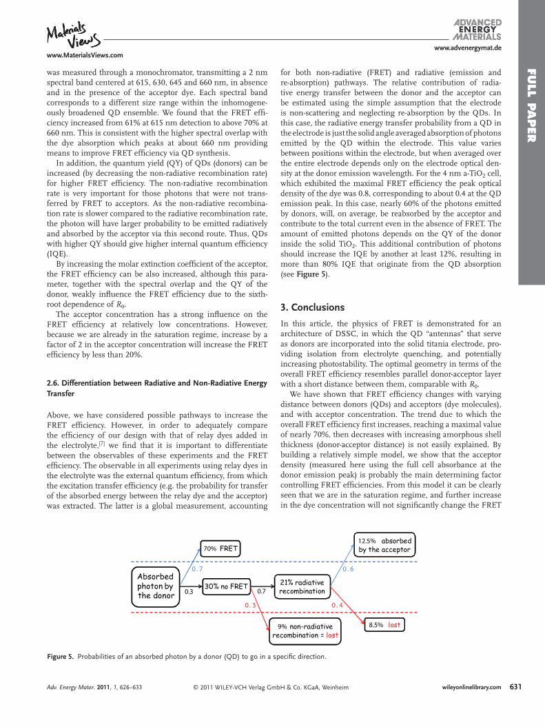
Figure 5 . Probabilities of an absorbed photon by a donor (QD) to go in a sp
for both non-radiative (FRET) and radiative (emission and re-absorption) pathways. The relative contribution of radia-tive energy transfer between the donor and the acceptor can be estimated using the simple assumption that the electrode is non-scattering and neglecting re-absorption by the QDs. In this case, the radiative energy transfer probability from a QD in the electrode is just the solid angle averaged absorption of photons emitted by the QD within the electrode. This value varies between positions within the electrode, but when averaged over the entire electrode depends only on the electrode optical den-sity at the donor emission wavelength. For the 4 nm a-TiO 2 cell, which exhibited the maximal FRET effi ciency the peak optical density of the dye was 0.8, corresponding to about 0.4 at the QD emission peak. In this case, nearly 60% of the photons emitted by donors, will, on average, be reabsorbed by the acceptor and contribute to the total current even in the absence of FRET. The amount of emitted photons depends on the QY of the donor inside the solid TiO 2 . This additional contribution of photons should increase the IQE by another at least 12%, resulting in more than 80% IQE that originate from the QD absorption (see Figure 5 ).
3. Conclusions
In this article, the physics of FRET is demonstrated for an architecture of DSSC, in which the QD “antennas” that serve as donors are incorporated into the solid titania electrode, pro-viding isolation from electrolyte quenching, and potentially increasing photostability. The optimal geometry in terms of the overall FRET effi ciency resembles parallel donor-acceptor layer with a short distance between them, comparable with R 0 .
We have shown that FRET effi ciency changes with varying distance between donors (QDs) and acceptors (dye molecules), and with acceptor concentration. The trend due to which the overall FRET effi ciency fi rst increases, reaching a maximal value of nearly 70%, then decreases with increasing amorphous shell thickness (donor-acceptor distance) is not easily explained. By building a relatively simple model, we show that the acceptor density (measured here using the full cell absorbance at the donor emission peak) is probably the main determining factor controlling FRET effi ciencies. From this model it can be clearly seen that we are in the saturation regime, and further increase in the dye concentration will not signifi cantly change the FRET
631H & Co. KGaA, Weinheim wileyonlinelibrary.com
ecifi c direction.
632
FULL
PAPER
www.MaterialsViews.comwww.advenergymat.de
effi ciency. Other factors and their relative value in determining FRET effi ciency are also discussed.
Another important issue that is discussed in the article is the differentiation between the FRET process and emission-re-absorption one. Both will contribute to the dye excitation (in addition to the direct light absorption by the dye), photo-current generation, and thus to the EQE increase. The relative contribution of the FRET can be determined by conducting lifetime measurements of the donor in absence and presence of the acceptor. We also found that those photons that were not transferred to the acceptor via FRET and were emitted will be absorbed by the acceptor in a probability of 60%. This very important fi nding means that for relatively high donor quantum yields, an effi cient energy transfer from donors to acceptors does not require that the FRET rate is signifi cantly faster than the radiative decay rate.
The assessed 82% IQE of our electrodes (corresponding to ∼ 70% FRET and ∼ 12% radiative transfer) is comparable to the best relay dye experiments with dyes dissolved in the electro-lyte, assuming that the amorphous titania layer does not sig-nifi cantly reduce charge injection effi ciency. While the latter issue is beyond the scope of the present work, we have already succeeded in achieving high effi ciency injection through the amorphous layer, and the entire issue can perhaps be circum-vented by using a more chemically compatible electrolyte. Since both buried donors inside the electrode and donors solubilized in the electrolyte have both been shown to achieve high energy transfer effi ciencies, and as the two methods take advantage of different available volumes of the electrode to introduce donors providing the excess absorption, synergy of the two methods is highly promising for achieving panchromatic absorption within a thin electrode, and should probably be pursued.
4. Experimental Section nc-TiO 2 Preparation: Mesoporous TiO 2 fi lms were prepared by
electrophoretic deposition (EPD) of Degussa P-25 particles with an average diameter of 25 nm onto a fl uorine-doped tin oxide (FTO)-covered glass substrates (Pilkington TEC 15) with a 15 Ω � − 1 sheet resistance. Films were deposited in two consecutive cycles for 30 s at a constant current density of 0.4 mA cm − 2 (which corresponds to ∼ 70 V at an electrode distance of 50 mm) and dried at 120 ° C for ∼ 5 min in between the cycles. Following the EPD process, all the electrodes were dried in air at 120 ° C for 30 min and sintered at 550 ° C for 1 h.
QD Synthesis : The synthesis of CdSe/CdS/ZnS nanocrystals was performed by following the noncoordinating solvent procedure suggested by Peng and coworkers [ 31 ] with minor modifi cations as described previously. [ 16 ] The whole synthesis was carried out using a Schlenk technique. To briefl y summarize the procedure, a mixture of cadmium oxide, tetradecylphosphonic acid and technical grade 1-octadecene (ODE) was dried and degassed under vacuum at 120 ° C for 30 min. in a 50 mL three-neck fl ask. Following, the solution was heated under argon to 280 ° C, and the stock solution of trioctylphosphine-selenium was quickly injected to the hot solution under vigorous stirring. The growth temperature was then reduced to 250 ° C until the dots reached the desired diameter (about 20 min.). Typically, this reaction generates CdSe nanocrystals of about 3.7 nm in size with the fi rst absorption peak around 577 nm.
The CdS and ZnS shells were synthesized using a layer-by-layer growth [ 32 ] technique in a one pot synthesis. The injection solutions used for the CdS shell growth are cadmium oleate and sulfur in ODE. The
© 2011 WILEY-VCH Verlag Gwileyonlinelibrary.com
injection solutions used for the ZnS shell growth are zinc acetate in oleic acid and ODE and sulfur in ODE. For each injection, a calculated amount of a given injection solution was taken and injected in a dropwise manner to the solution containing CdSe cores. Four layers of CdS, two layers of ZnS and one additional layer of Zn were grown. After each shell growth, the nanocrystals were annealed at 240 ° C for 20 min. Following the last annealing, the solution was cooled to room temperature and stored in a freezer till precipitation procedure.
Precipitation Procedure: Separation of unreacted precursors from the nanocrystals was performed by repeated precipitation (twice for most cases) and redispersion with acetone/methanol and toluene, respectively. Finally the particles were stored in toluene.
nc-TiO 2 /QDs Films: For CdSe/CdS/ZnS (core/shell/shell) QD deposition, the electrodes were immersed in a 10% vol. 3-mercaptopropionic acid in acetonitrile solution for 24 h. After washing them with acetonitrile and toluene, the electrodes were immersed into the QDs’ dispersion in toluene overnight. The electrodes were then washed with toluene and dried with Ar.
a-TiO 2 Coating: In the fi nal step a thin a-TiO 2 coating of the nc-TiO 2 /QDs electrodes was made by electrophoretic deposition of stabilized TiO 2 precursor, titanium isopropoxide, for various times (120, 240, 360, 480, 600 sec.) (current 2 mA). In order to control the thickness of the layer, the titania coating was deposited for varying numbers of 120 sec. cycles. [ 24 ] Mild heat treatment of the coated electrodes at 80 ° C for 30 min was used to stabilize the a-TiO 2 .
Dye Loading: For the FRET structure, the QD electrodes were immersed in 0.1 mM SQ02 dye and 10 m M chenodeoxycholic acid in ethanol for 4 h.
Time-Resolved Measurements: Time resolved PL decay measurements were done with a PicoQuant Microtime 200 time-resolved confocal microscope system with 150 ps resolution. Excitation was provided by 470 nm picosecond pulses. The decays were recorded with a 20 MHz repetition rate. Broad band-fi lters at 633 ± 30 and long pass-fi lter at 720 nm were used to measure the time-resolved emission signals of the donor and acceptor pair, respectively.
Experiments with the Coadsorbent : We conducted experiments with a constant a-TiO 2 coating thickness (4 nm) and an artifi cially reduced dye concentration by introducing a competing coadsorbent, undecenoic acid, which adsorbs well to the titania surface. These molecules have carboxylic group which compete with the SQ02 dye molecules on the binding sites of the a-TiO 2 surface. The ratio between the dye molecules and the coadsorbent were 1:250, 1:500. By mixing the dye and the coadsorbent in different ratios, three different dye concentrations on the 4 nm a-TiO 2 coating surface were achieved (including the one with no coadsorbent). Time resolved PL decays were measured for these four electrodes and FRET effi ciency was calculated. It can be clearly seen that the FRET effi ciency of the cell decreases with increasing coadsorbent concentration, and thus decrease in dye concentration.
HR-TEM Analysis: nc-TiO 2 /QDs/a-TiO 2 electrode was scratched to a vial containing ethanol (3 mL) and sonicated for 5 min. Few drops of this solution were applied to a carbon lacey grid and dried in air. TEM imaging analysis of the samples was performed using high resolution transmission electron microscope, JEOL JEM-2100, operated at 200 kV accelerating voltage.
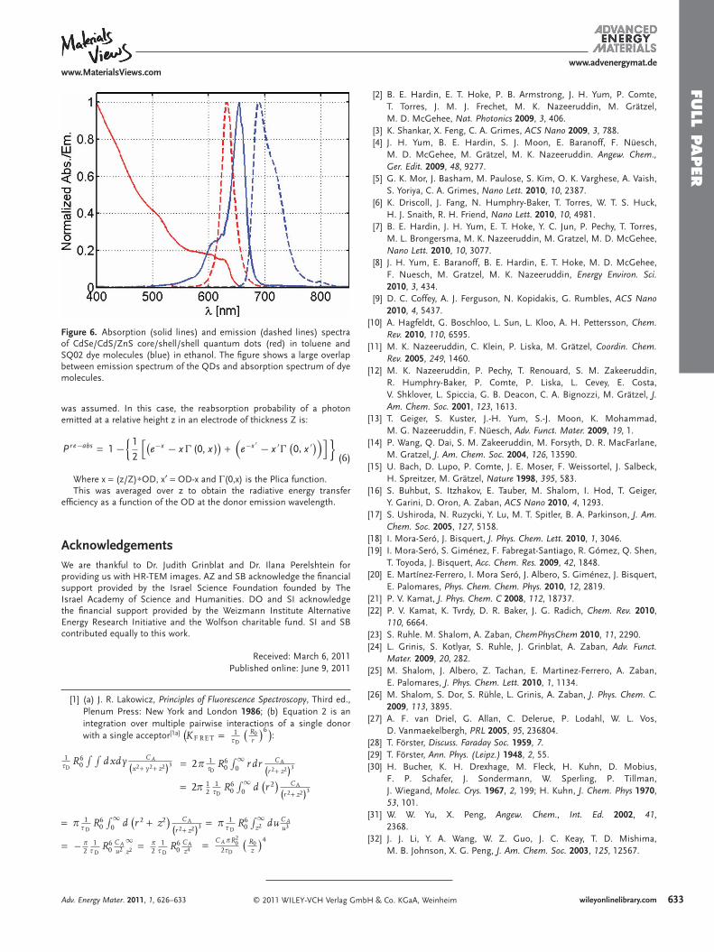
Spectral Data: The absorption and emission spectra of both the QDs and the SQ02 dye molecules were recorded using a JASCO V-630 and a StellarNet UV-VIS-NIR fi ber optic spectrometers and are shown in Figure 6 .
SQ02 solution shows an absorption max at 655 nm with high molar extinction coeffi cient ( ε = 319,000 M − 1 cm − 1 ). The absorption matches the emission of QDs (CdSe/CdS/ZnS) with maximum at 632 nm. Figure 6 shows a signifi cant overlap between emission spectrum of the donor and absorption spectrum of the acceptor, an important parameter for effi cient FRET process.
Contribution of Radiative Energy Transfer: Radiative energy transfer probability was calculated using a geometrical model neglecting scattering in the electrode and reabsorption by QD donors. A homogeneous spatial distribution of both QD donors and dye acceptors
mbH & Co. KGaA, Weinheim Adv. Energy Mater. 2011, 1, 626–633
FULL P
APER
www.MaterialsViews.comwww.advenergymat.de
Figure 6 . Absorption (solid lines) and emission (dashed lines) spectra of CdSe/CdS/ZnS core/shell/shell quantum dots (red) in toluene and SQ02 dye molecules (blue) in ethanol. The fi gure shows a large overlap between emission spectrum of the QDs and absorption spectrum of dye molecules.
was assumed. In this case, the reabsorption probability of a photon emitted at a relative height z in an electrode of thickness Z is:
P r e−abs = 1 − 1
2
[e−x − x � (0, ,x )
)+
(e−x ′ − x ′� 0 x ′))]{ } (6)
Where x = (z/Z) ∗ OD, x ′ = OD-x and Γ (0,x) is the Plica function. This was averaged over z to obtain the radiative energy transfer
effi ciency as a function of the OD at the donor emission wavelength.
Acknowledgements We are thankful to Dr. Judith Grinblat and Dr. Ilana Perelshtein for providing us with HR-TEM images. AZ and SB acknowledge the fi nancial support provided by the Israel Science Foundation founded by The Israel Academy of Science and Humanities. DO and SI acknowledge the fi nancial support provided by the Weizmann Institute Alternative Energy Research Initiative and the Wolfson charitable fund. SI and SB contributed equally to this work .
Received: March 6, 2011Published online: June 9, 2011
[ 1 ] (a) J. R. Lakowicz , Principles of Fluorescence Spectroscopy , Third ed. , Plenum Press : New York and London 1986 ; (b) Equation 2 is an integration over multiple pairwise interactions of a single donor with a single acceptor [1a] K F RE T = 1
JD
R0r
) )6 :
1JD
R60
∫ ∫dxdy CA
(x2+ y2+ z2)3 = 2B 1JD
R60
∫ ∞0 r dr CA
(r 2+ z2)3
= 2B 12
1JD
R60
∫ ∞0 d r 2
) CA
(r 2+ z2)3
= B 1J D
R60
∫ ∞0 d r 2 + z2
) CA
(r 2+ z2)3 = B 1J D
R60
∫ ∞z2 du CA
u3
= B2
1J D
R60
CAu2
∞z2 = B
21
J DR6
0CAz4 = CABR2
02JD
R0z
)4−
© 2011 WILEY-VCH Verlag GmbAdv. Energy Mater. 2011, 1, 626–633
[ 2 ] B. E. Hardin , E. T. Hoke , P. B. Armstrong , J. H. Yum , P. Comte , T. Torres , J. M. J. Frechet , M. K. Nazeeruddin , M. Grätzel , M. D. McGehee , Nat. Photonics 2009 , 3 , 406 .
[ 3 ] K. Shankar , X. Feng , C. A. Grimes , ACS Nano 2009 , 3 , 788 . [ 4 ] J. H. Yum , B. E. Hardin , S. J. Moon , E. Baranoff , F. Nüesch ,
M. D. McGehee , M. Grätzel , M. K. Nazeeruddin . Angew. Chem., Ger. Edit. 2009 , 48 , 9277 .
[ 5 ] G. K. Mor , J. Basham , M. Paulose , S. Kim , O. K. Varghese , A. Vaish , S. Yoriya , C. A. Grimes , Nano Lett. 2010 , 10 , 2387 .
[ 6 ] K. Driscoll , J. Fang , N. Humphry-Baker , T. Torres , W. T. S. Huck , H. J. Snaith , R. H. Friend , Nano Lett. 2010 , 10 , 4981 .
[ 7 ] B. E. Hardin , J. H. Yum , E. T. Hoke , Y. C. Jun , P. Pechy , T. Torres , M. L. Brongersma , M. K. Nazeeruddin , M. Gratzel , M. D. McGehee , Nano Lett. 2010 , 10 , 3077 .
[ 8 ] J. H. Yum , E. Baranoff , B. E. Hardin , E. T. Hoke , M. D. McGehee , F. Nuesch , M. Gratzel , M. K. Nazeeruddin , Energy Environ. Sci. 2010 , 3 , 434 .
[ 9 ] D. C. Coffey , A. J. Ferguson , N. Kopidakis , G. Rumbles , ACS Nano 2010 , 4 , 5437 .
[ 10 ] A. Hagfeldt , G. Boschloo , L. Sun , L. Kloo , A. H. Pettersson , Chem. Rev. 2010 , 110 , 6595 .
[ 11 ] M. K. Nazeeruddin , C. Klein , P. Liska , M. Grätzel , Coordin. Chem. Rev. 2005 , 249 , 1460 .
[ 12 ] M. K. Nazeeruddin , P. Pechy , T. Renouard , S. M. Zakeeruddin , R. Humphry-Baker , P. Comte , P. Liska , L. Cevey , E. Costa , V. Shklover , L. Spiccia , G. B. Deacon , C. A. Bignozzi , M. Grätzel , J. Am. Chem. Soc. 2001 , 123 , 1613 .
[ 13 ] T. Geiger , S. Kuster , J.-H. Yum , S.-J. Moon , K. Mohammad , M. G. Nazeeruddin , F. Nüesch , Adv. Funct. Mater. 2009 , 19 , 1 .
[ 14 ] P. Wang , Q. Dai , S. M. Zakeeruddin , M. Forsyth , D. R. MacFarlane , M. Gratzel , J. Am. Chem. Soc. 2004 , 126 , 13590 .
[ 15 ] U. Bach , D. Lupo , P. Comte , J. E. Moser , F. Weissortel , J. Salbeck , H. Spreitzer , M. Grätzel , Nature 1998 , 395 , 583 .
[ 16 ] S. Buhbut , S. Itzhakov , E. Tauber , M. Shalom , I. Hod , T. Geiger , Y. Garini , D. Oron , A. Zaban , ACS Nano 2010 , 4 , 1293 .
[ 17 ] S. Ushiroda , N. Ruzycki , Y. Lu , M. T. Spitler , B. A. Parkinson , J. Am. Chem. Soc. 2005 , 127 , 5158 .
[ 18 ] I. Mora-Seró , J. Bisquert , J. Phys. Chem. Lett. 2010 , 1 , 3046 . [ 19 ] I. Mora-Seró , S. Giménez , F. Fabregat-Santiago , R. Gómez , Q. Shen ,
T. Toyoda , J. Bisquert , Acc. Chem. Res. 2009 , 42 , 1848 . [ 20 ] E. Martínez-Ferrero , I. Mora Seró , J. Albero , S. Giménez , J. Bisquert ,
E. Palomares , Phys. Chem. Chem. Phys. 2010 , 12 , 2819 . [ 21 ] P. V. Kamat , J. Phys. Chem. C 2008 , 112 , 18737 . [ 22 ] P. V. Kamat , K. Tvrdy , D. R. Baker , J. G. Radich , Chem. Rev. 2010 ,
110 , 6664 . [ 23 ] S. Ruhle . M. Shalom , A. Zaban , ChemPhysChem 2010 , 11 , 2290 . [ 24 ] L. Grinis , S. Kotlyar , S. Ruhle , J. Grinblat , A. Zaban , Adv. Funct.
Mater. 2009 , 20 , 282 . [ 25 ] M. Shalom , J. Albero , Z. Tachan , E. Martinez-Ferrero , A. Zaban ,
E. Palomares , J. Phys. Chem. Lett. 2010 , 1 , 1134 . [ 26 ] M. Shalom , S. Dor , S. Rühle , L. Grinis , A. Zaban , J. Phys. Chem. C.
2009 , 113 , 3895 . [ 27 ] A. F. van Driel , G. Allan , C. Delerue , P. Lodahl , W. L. Vos ,
D. Vanmaekelbergh , PRL 2005 , 95 , 236804 . [ 28 ] T. Förster , Discuss. Faraday Soc. 1959 , 7 . [ 29 ] T. Förster , Ann. Phys. (Leipz.) 1948 , 2 , 55 . [ 30 ] H. Bucher , K. H. Drexhage , M. Fleck , H. Kuhn , D. Mobius ,
F. P. Schafer , J. Sondermann , W. Sperling , P. Tillman , J. Wiegand , Molec. Crys. 1967 , 2 , 199 ; H. Kuhn , J. Chem. Phys 1970 , 53 , 101 .
[ 31 ] W. W. Yu , X. Peng , Angew. Chem., Int. Ed. 2002 , 41 , 2368 .
[ 32 ] J. J. Li , Y. A. Wang , W. Z. Guo , J. C. Keay , T. D. Mishima , M. B. Johnson , X. G. Peng , J. Am. Chem. Soc. 2003 , 125 , 12567 .
633H & Co. KGaA, Weinheim wileyonlinelibrary.com