design of prestressed concrete to eurocode 2 - taylor
TRANSCRIPT


Design of Prestressed Concrete to Eurocode 2
Second Edition

Design of Prestressed Concrete to Eurocode 2
Second Edition
Raymond Ian GilbertNeil Colin Mickleborough
Gianluca Ranzi
CRC PressTaylor & Francis Group6000 Broken Sound Parkway NW, Suite 300Boca Raton, FL 33487-2742
© 2017 by Raymond Ian Gilbert, Neil Colin Mickleborough, and Gianluca RanziCRC Press is an imprint of Taylor & Francis Group, an Informa business
No claim to original U.S. Government works
Printed on acid-free paperVersion Date: 20161209
International Standard Book Number-13: 978-1-4665-7310-9 (Hardback)International Standard Book Number-13: 978-1-3153-8952-3 (eBook)
This book contains information obtained from authentic and highly regarded sources. Reasonable efforts have been made to publish reliable data and information, but the author and publisher cannot assume responsibility for the validity of all materials or the consequences of their use. The authors and publishers have attempted to trace the copyright holders of all material reproduced in this publication and apologize to copyright holders if permission to publish in this form has not been obtained. If any copyright material has not been acknowledged please write and let us know so we may rectify in any future reprint.
Except as permitted under U.S. Copyright Law, no part of this book may be reprinted, reproduced, transmitted, or utilized in any form by any electronic, mechanical, or other means, now known or hereafter invented, including photocopying, microfilming, and recording, or in any information storage or retrieval system, without written permission from the publishers.
For permission to photocopy or use material electronically from this work, please access www.copyright.com (http://www.copyright.com/) or contact the Copyright Clearance Center, Inc. (CCC), 222 Rosewood Drive, Danvers, MA 01923, 978-750-8400. CCC is a not-for-profit orga-nization that provides licenses and registration for a variety of users. For organizations that have been granted a photocopy license by the CCC, a separate system of payment has been arranged.
Trademark Notice: Product or corporate names may be trademarks or registered trademarks, and are used only for identification and explanation without intent to infringe.
Library of Congress Cataloging‑in‑Publication Data
Visit the Taylor & Francis Web site athttp://www.taylorandfrancis.com
and the CRC Press Web site athttp://www.crcpress.com
v
Contents
Preface xvAuthors xixAcknowledgements xxiNotation and sign convention xxiii
1 Basic concepts 1
1.1 Introduction 11.2 Methods of prestressing 4
1.2.1 Pretensioned concrete 41.2.2 Post-tensioned concrete 51.2.3 Other methods of prestressing 6
1.3 Transverse forces induced by draped tendons 71.4 Calculation of elastic stresses 10
1.4.1 Combined load approach 101.4.2 Internal couple concept 121.4.3 Load balancing approach 131.4.4 Introductory example 13
1.4.4.1 Combined load approach 141.4.4.2 Internal couple concept 151.4.4.3 Load balancing approach 15
1.5 Introduction to structural behaviour: Initial to ultimate loads 16
2 Design procedures and applied actions 21
2.1 Limit states design philosophy 212.2 Structural modelling and analysis 23
2.2.1 Structural modelling 232.2.2 Structural analysis 24
vi Contents
2.3 Actions and combinations of actions 262.3.1 General 262.3.2 Load combinations for the strength limit states 292.3.3 Load combinations for the stability
or equilibrium limit states 312.3.4 Load combinations for the
serviceability limit states 322.4 Design for the strength limit states 33
2.4.1 General 332.4.2 Partial factors for materials 33
2.5 Design for the serviceability limit states 342.5.1 General 342.5.2 Deflection limits 352.5.3 Vibration control 372.5.4 Crack width limits 372.5.5 Partial factors for materials 38
2.6 Design for durability 382.7 Design for fire resistance 402.8 Design for robustness 43References 44
3 Prestressing systems 47
3.1 Introduction 473.2 Types of prestressing steel 473.3 Pretensioning 493.4 Post-tensioning 513.5 Bonded and unbonded post-tensioned construction 583.6 Circular prestressing 593.7 External prestressing 60
4 Material properties 63
4.1 Introduction 634.2 Concrete 63
4.2.1 Composition of concrete 644.2.2 Strength of concrete 654.2.3 Strength specifications in Eurocode 2 68
4.2.3.1 Compressive strength 684.2.3.2 Tensile strength 694.2.3.3 Design compressive and tensile strengths 70
Contents vii
4.2.3.4 Compressive stress–strain curves for concrete for non-linear structural analysis 72
4.2.4 Deformation of concrete 734.2.4.1 Discussion 734.2.4.2 Instantaneous strain 744.2.4.3 Creep strain 764.2.4.4 Shrinkage strain 81
4.2.5 Deformational characteristics specified in Eurocode 2 824.2.5.1 Introduction 824.2.5.2 Modulus of elasticity 834.2.5.3 Creep coefficient 844.2.5.4 Shrinkage strain 864.2.5.5 Thermal expansion 87
4.3 Steel reinforcement 874.3.1 General 874.3.2 Specification in Eurocode 2 88
4.3.2.1 Strength and ductility 884.3.2.2 Elastic modulus 894.3.2.3 Stress–strain curves:
Design assumptions 904.3.2.4 Coefficient of thermal
expansion and density 914.4 Steel used for prestressing 91
4.4.1 General 914.4.2 Specification in Eurocode 2 94
4.4.2.1 Strength and ductility 944.4.2.2 Elastic modulus 944.4.2.3 Stress–strain curve 964.4.2.4 Steel relaxation 96
References 98
5 Design for serviceability 101
5.1 Introduction 1015.2 Concrete stresses at transfer and under full service loads 1025.3 Maximum jacking force 1055.4 Determination of prestress and
eccentricity in flexural members 1065.4.1 Satisfaction of stress limits 1065.4.2 Load balancing 114
viii Contents
5.5 Cable profiles 1165.6 Short-term analysis of uncracked cross-sections 118
5.6.1 General 1185.6.2 Short-term cross-sectional analysis 120
5.7 Time-dependent analysis of uncracked cross-sections 1365.7.1 Introduction 1365.7.2 The age-adjusted effective modulus method 1365.7.3 Long-term analysis of an uncracked
cross-section subjected to combined axial force and bending using AEMM 138
5.7.4 Discussion 1565.8 Short-term analysis of cracked cross-sections 158
5.8.1 General 1585.8.2 Assumptions 1605.8.3 Analysis 160
5.9 Time-dependent analysis of cracked cross-sections 1705.9.1 Simplifying assumption 1705.9.2 Long-term analysis of a cracked cross-section
subjected to combined axial force and bending using the AEMM 170
5.10 Losses of prestress 1755.10.1 Definitions 1755.10.2 Immediate losses 176
5.10.2.1 Elastic deformation losses 1765.10.2.2 Friction in the jack and anchorage 1775.10.2.3 Friction along the tendon 1775.10.2.4 Anchorage losses 1795.10.2.5 Other causes of immediate losses 180
5.10.3 Time-dependent losses of prestress 1815.10.3.1 Discussion 1815.10.3.2 Simplified method specified
in EN 1992-1-1:2004 1825.10.3.3 Alternative simplified method 183
5.11 Deflection calculations 1875.11.1 General 1875.11.2 Short-term moment–curvature
relationship and tension stiffening 1905.11.3 Short-term deflection 1955.11.4 Long-term deflection 200
5.11.4.1 Creep-induced curvature 2015.11.4.2 Shrinkage-induced curvature 202
Contents ix
5.12 Crack control 2085.12.1 Minimum reinforcement 2085.12.2 Control of cracking without direct calculation 2115.12.3 Calculation of crack widths 2135.12.4 Crack control for restrained shrinkage
and temperature effects 2155.12.5 Crack control at openings and discontinuities 216
References 216
6 Flexural resistance 219
6.1 Introduction 2196.2 Flexural behaviour at overloads 2196.3 Design flexural resistance 222
6.3.1 Assumptions 2226.3.2 Idealised compressive stress blocks for concrete 2236.3.3 Prestressed steel strain components
(for bonded tendons) 2266.3.4 Determination of MRd for a singly
reinforced section with bonded tendons 2286.3.5 Determination of MRd for sections containing
non-prestressed reinforcement and bonded tendons 232
6.3.6 Members with unbonded tendons 2396.4 Design calculations 241
6.4.1 Discussion 2416.4.2 Calculation of additional non-prestressed
tensile reinforcement 2426.4.3 Design of a doubly reinforced cross-section 245
6.5 Flanged sections 2486.6 Ductility and robustness of prestressed concrete beams 254
6.6.1 Introductory remarks 2546.6.2 Calculation of hinge rotations 2576.6.3 Quantifying ductility and
robustness of beams and slabs 257References 260
7 Design resistance in shear and torsion 261
7.1 Introduction 2617.2 Shear in beams 261
7.2.1 Inclined cracking 261
x Contents
7.2.2 Effect of prestress 2627.2.3 Web reinforcement 2647.2.4 Design strength of beams without
shear reinforcement 2677.2.5 Design resistance of beams with
shear reinforcement 2687.2.6 Summary of design requirements for shear 2737.2.7 The design procedure for shear 2757.2.8 Shear between the web and flange of a T-section 281
7.3 Torsion in beams 2827.3.1 Compatibility torsion and equilibrium torsion 2827.3.2 Effects of torsion 2847.3.3 Design provisions for torsion 285
7.4 Shear in slabs and footings 2917.4.1 Punching shear 2917.4.2 The basic control perimeter 2927.4.3 Shear resistance of critical shear perimeters 2947.4.4 Design for punching shear 296
References 307
8 Anchorage zones 309
8.1 Introduction 3098.2 Pretensioned concrete: Force transfer by bond 3108.3 Post-tensioned concrete anchorage zones 315
8.3.1 Introduction 3158.3.2 Methods of analysis 319
8.3.2.1 Single central anchorage 3218.3.2.2 Two symmetrically
placed anchorages 3228.3.3 Reinforcement requirements 3258.3.4 Bearing stresses behind anchorages 326
8.4 Strut-and-tie modelling 3428.4.1 Introduction 3428.4.2 Concrete struts 343
8.4.2.1 Types of struts 3438.4.2.2 Strength of struts 3448.4.2.3 Bursting reinforcement in
bottle-shaped struts 3448.4.3 Steel ties 3468.4.4 Nodes 346
References 348

Contents xi
9 Composite members 351
9.1 Types and advantages of composite construction 3519.2 Behaviour of composite members 3529.3 Stages of loading 3549.4 Determination of prestress 3579.5 Methods of analysis at service loads 359
9.5.1 Introductory remarks 3599.5.2 Short-term analysis 3609.5.3 Time-dependent analysis 362
9.6 Flexural resistance 3929.7 Horizontal shear transfer 392
9.7.1 Discussion 3929.7.2 Design provisions for horizontal shear 394
References 398
10 Design procedures for determinate beams 399
10.1 Introduction 39910.2 Types of sections 39910.3 Initial trial section 401
10.3.1 Based on serviceability requirements 40110.3.2 Based on strength requirements 402
10.4 Design procedures: Fully-prestressed beams 40410.4.1 Beams with varying eccentricity 40510.4.2 Beams with constant eccentricity 422
10.5 Design procedures: Partially-prestressed beams 432Reference 440
11 Statically indeterminate members 441
11.1 Introduction 44111.2 Tendon profiles 44311.3 Continuous beams 446
11.3.1 Effects of prestress 44611.3.2 Determination of secondary
effects using virtual work 44711.3.3 Linear transformation of a tendon profile 45311.3.4 Analysis using equivalent loads 455
11.3.4.1 Moment distribution 45611.3.5 Practical tendon profiles 46511.3.6 Members with varying cross-sectional properties 46811.3.7 Effects of creep 470
xii Contents
11.4 Statically indeterminate frames 47411.5 Design of continuous beams 478
11.5.1 General 47811.5.2 Service load range: Before cracking 47911.5.3 Service load range: After cracking 48211.5.4 Overload range and design resistance in bending 483
11.5.4.1 Behaviour 48311.5.4.2 Permissible moment redistribution
at the ultimate limit state condition 48411.5.4.3 Secondary effects at the ultimate
limit state condition 48511.5.5 Steps in design 486
References 499
12 Two‑way slabs: Behaviour and design 501
12.1 Introduction 50112.2 Effects of prestress 50412.3 Balanced load stage 50712.4 Initial sizing of slabs 509
12.4.1 Existing guidelines 50912.4.2 Serviceability approach for the
calculation of slab thickness 51012.4.2.1 Slab system factor, K 512
12.4.3 Discussion 51412.5 Other serviceability considerations 516
12.5.1 Cracking and crack control in prestressed slabs 51612.5.2 Long-term deflections 517
12.6 Design approach: General 51912.7 One-way slabs 51912.8 Two-way edge-supported slabs 520
12.8.1 Load balancing 52012.8.2 Methods of analysis 522
12.9 Flat plate slabs 53312.9.1 Load balancing 53312.9.2 Behaviour under unbalanced load 53512.9.3 Frame analysis 53712.9.4 Direct design method 53912.9.5 Shear resistance 54012.9.6 Deflection calculations 54112.9.7 Yield line analysis of flat plates 555
Contents xiii
12.10 Flat slabs with drop panels 55912.11 Band-beam and slab systems 560References 561
13 Compression and tension members 563
13.1 Types of compression members 56313.2 Classification and behaviour of compression members 56413.3 Cross-section analysis: Compression and bending 566
13.3.1 Strength interaction diagram 56613.3.2 Strength analysis 56813.3.3 Biaxial bending and compression 579
13.4 Slenderness effects 58013.4.1 Background 58013.4.2 Slenderness criteria 58413.4.3 Moment magnification method 585
13.5 Reinforcement requirements for compression members 59113.6 Transmission of axial force through a floor system 59113.7 Tension members 593
13.7.1 Advantages and applications 59313.7.2 Behaviour 594
References 600
14 Detailing: Members and connections 601
14.1 Introduction 60114.2 Principles of detailing 602
14.2.1 When is steel reinforcement required? 60214.2.2 Objectives of detailing 60314.2.3 Sources of tension 604
14.2.3.1 Tension caused by bending (and axial tension) 604
14.2.3.2 Tension caused by load reversals 60414.2.3.3 Tension caused by shear and torsion 60514.2.3.4 Tension near the supports of beams 60514.2.3.5 Tension within the supports
of beams or slabs 60614.2.3.6 Tension within connections 60714.2.3.7 Tension at concentrated loads 60714.2.3.8 Tension caused by directional
changes of internal forces 60814.2.3.9 Other common sources of tension 610
xiv Contents
14.3 Anchorage of deformed bars 61014.3.1 Introductory remarks 61014.3.2 Design anchorage length 61314.3.3 Lapped splices 617
14.4 Stress development and coupling of tendons 61914.5 Detailing of beams 619
14.5.1 Anchorage of longitudinal reinforcement: General 619
14.5.2 Maximum and minimum requirements for longitudinal steel 623
14.5.3 Curtailment of longitudinal reinforcement 62414.5.4 Anchorage of stirrups 62514.5.5 Detailing of support and loading points 630
14.6 Detailing of columns and walls 63414.6.1 General requirements 63414.6.2 Transverse reinforcement in columns 63514.6.3 Longitudinal reinforcement in columns 63814.6.4 Requirements for walls 638
14.7 Detailing of beam–column connections 63814.7.1 Introduction 63814.7.2 Knee connections (or two-member connections) 639
14.7.2.1 Closing moments 64014.7.2.2 Opening moments 640
14.7.3 Exterior three-member connections 64214.7.4 Interior four-member connections 645
14.8 Detailing of corbels 64614.9 Joints in structures 647
14.9.1 Introduction 64714.9.2 Construction joints 64814.9.3 Control joints (contraction joints) 64914.9.4 Shrinkage strips 65114.9.5 Expansion joints 65214.9.6 Structural joints 652
References 654
Index 655
xv
Preface
For the design of prestressed concrete structures, a sound understanding of structural behaviour at all stages of loading is essential. Also essential is a thorough knowledge of the design criteria specified in the relevant design standard, including the rules and requirements and the background to them. The aim of this book is to present a detailed description and expla-nation of the behaviour of prestressed concrete members and structures both at service loads and at ultimate loads and, in doing so, provide a comprehensive guide to structural design. Much of the text is based on first principles and relies only on the principles of mechanics and the prop-erties of concrete and steel, with numerous worked examples. Where the design requirements are code specific, this book refers to the provisions of Eurocode 2 (EN 1992–1–1:2004) and other relevant EN Standards, and, where possible, the notation is the same as in the Eurocode. A companion edition in accordance with the requirements of the Australian Standard for Concrete Structures AS 3600–2009 is also available, with the same nota-tion as in the Australian Standard.
The first edition of the book was published over 25 years ago, so a com-prehensive update and revision is long overdue. This edition contains the most up-to-date and recent advances in the design of modern prestressed concrete structures, as well as the fundamental aspects of prestressed con-crete behaviour and design that were well received in the first edition. The text is written for senior undergraduate and postgraduate students of civil and structural engineering and also for practising structural engineers. It retains the clear and concise explanations and the easy-to-read style of the first edition.
Between them, the authors have almost 100 years of experience in the teaching, research and design of prestressed concrete structures, and this book reflects this wealth of experience.
The scope of the work ranges from an introduction to the fundamentals of prestressed concrete to in-depth treatments of the more advanced topics in modern prestressed concrete structures. The basic concepts of prestressed
xvi Preface
concrete are introduced in Chapter 1, and the limit states design philoso-phies used in European practice are outlined in Chapter 2. The hardware required to pretension and post-tension concrete structures is introduced in Chapter 3, including some construction considerations. Material properties relevant to design are presented and discussed in Chapter 4. A comprehen-sive treatment of the design of prestressed concrete beams for serviceability is provided in Chapter 5. The instantaneous and time-dependent behaviour of cross-sections under service loads are discussed in considerable detail, and methods for the analysis of both uncracked and cracked cross-sections are considered. Techniques for determining the section size, the magnitude and eccentricity of prestress, the losses of prestress and the deflection of members are outlined. Each aspect of design is illustrated by numerical examples.
Chapters 6 and 7 deal with the design of members for strength in bend-ing, shear and torsion, and Chapter 8 covers the design of the anchorage zones in both pretensioned and post-tensioned members. A guide to the design of composite prestressed concrete beams is provided in Chapter 9 and includes a detailed worked example of the analysis of a composite through girder footbridge. Chapter 10 discusses design procedures for stat-ically determinate beams. Comprehensive self-contained design examples are provided for fully-prestressed and partially prestressed, post-tensioned and pretensioned concrete members.
The analysis and design of statically indeterminate beams and frames is covered in Chapter 11 and provides guidance on the treatment of second-ary effects at all stages of loading. Chapter 12 provides a detailed discus-sion of the analysis and design of two-way slab systems, including aspects related to both strength and serviceability. Complete design examples are provided for panels of an edge-supported slab and a flat slab. The behav-iour of axially loaded members is dealt with in Chapter 13. Compression members, members subjected to combined bending and compression, and prestressed concrete tension members are discussed, and design aspects are illustrated by examples. Guidelines for successful detailing of the structural elements and connections in prestressed concrete structures are outlined in Chapter 14.
As in the first edition, the book provides a unique focus on the treatment of serviceability aspects of design. Concrete structures are prestressed to improve behaviour at service loads and thereby increase the economi-cal range of concrete as a construction material. In conventional pre-stressed structures, the level of prestress and the position of the tendons are usually based on considerations of serviceability. Practical methods for accounting for the non-linear and time-dependent effects of cracking, creep, shrinkage and relaxation are presented in a clear and easy-to-follow format.
Preface xvii
The authors hope that Design of Prestressed Concrete to Eurocode 2 will be a valuable source of information and a useful guide for students and practitioners of structural design.
Ian GilbertNeil Mickleborough
Gianluca Ranzi

xix
Authors
Raymond Ian Gilbert is emeritus professor of civil engineering at the University of New South Wales (UNSW) and deputy director of the UNSW Centre for Infrastructure Engineering and Safety. He has more than 40 years of experience in structural design and is a specialist in the analy-sis and design of reinforced and prestressed concrete structures. Professor Gilbert has taught successive generations of civil engineering students in Australia on subjects related to structural engineering, ranging from statics and structural analysis to the design of reinforced and prestressed concrete structures. His research activities are in the field of concrete structures, with a particular interest in serviceability. Professor Gilbert has published six books, including Structural Analysis: Principles, Methods and Modelling and Time-Dependent Behaviour of Concrete Structures which are also published by CRC Press, and more than 350 technical papers and reports. He was awarded Honorary Life Membership of the Concrete Institute of Australia in 2011.
Neil Colin Mickleborough is professor of civil engineering and the direc-tor of the Center for Engineering Education Innovation at Hong Kong University of Science and Technology. He has been actively involved in the research, development and teaching of prestressed and reinforced concrete, structural analysis and tall building and bridge design in Australia, Asia and the Middle East for the past 30 years. He has acted as an expert design consultant on tall buildings and long-span bridge projects in both Dubai and Hong Kong. In addition, he is a chartered structural engineer and a Fellow of the Hong Kong Institution of Engineers.
Gianluca Ranzi is professor of civil engineering, ARC Future Fellow and director of the Centre for Advanced Structural Engineering at the University of Sydney. Gianluca’s research interests range from the field of structural engineering, with focus on computational mechanics and the service behaviour of composite steel–concrete and concrete structures, to architectural science.

xxi
Acknowledgements
The authors acknowledge the support given by their respective institutions and by the following individuals and organisations for their assistance:
Mr Brian Lim (VSL International Limited, Hong Kong)Mr Brett Gibbons (VSL Australia, Sydney)

xxiii
Notation and sign convention
All symbols are also defined in the text where they first appear. Throughout the book we have assumed that tension is positive and compression is nega-tive and that positive bending about a horizontal axis causes tension in the bottom fibres of a cross-section.
Latin upper-case letters
A Cross-sectional area or accidental actionAc Cross-sectional area of concreteAc,eff Effective area of concrete in tension surrounding the
tendons with depth hc,ef equal to the lesser of 2.5(h-d), (h-x)/3 or h/2
Act Area of the concrete in the tensile zone just before cracking
Ac0 Bearing areaAc1 Largest area of the concrete supporting surface that is
geometrically similar to and concentric with Ac0
Ag Gross cross-sectional areaAk Area of the age-adjusted transformed section at time tk
Ap Cross-sectional area of prestressing steelAp(i) Cross-sectional area of the prestressing steel at the
i-th levelApc Cross-sectional area of the precast memberAs Cross-sectional area of non-prestressed steel rein-
forcement or cross-sectional area of a single bar being anchored
As(i) Cross-sectional areas of non-prestressed steel reinforce-ment at the i-th level
Asb Area of transverse reinforcement in the end zone of a pretensioned member (Equation 8.6)
Asc Cross-sectional area of non-prestressed steel reinforce-ment in the compressive zone
xxiv Notation and sign convention
Ast Cross-sectional area of non-prestressed transverse steel reinforcement or cross-sectional area of non-prestressed reinforcement in the tension zone
As,min The minimum area of bonded longitudinal reinforcement in the tensile zone (Equation 14.9) or minimum area of longitudinal reinforcement in a column (Equation 14.16)
Asw Cross-sectional area of the vertical legs of each stirrup or area of the single leg of transverse steel in each wall of the idealised thin-walled section in torsion
Asw,max Maximum cross-sectional area of shear reinforcement (Equations 7.13 and 7.14)
Asw,min Minimum cross-sectional area of shear reinforcement (Equation 7.17)
A0 Area of the transformed section at time t0
Bc First moment of the concrete part of the cross-section about the reference axis
Bk First moment of the age-adjusted transformed section at time tk
B0 First moment of area of the transformed section about the reference axis at time t0
C Strength class of concrete or carry-over factor or CelsiusD0 Matrix of cross-sectional rigidities at time t0 (Equation
5.42)E (subscript) Effect of actionsEc,eff(t, t0), Ec,eff Effective modulus of concrete at time t for concrete first
loaded at t0 (Equations 4.23 and 5.56)E t t Ec,eff c,eff( , ),0 Age-adjusted effective modulus of concrete at time t for
concrete first loaded at t0 (Equations 4.25 and 5.57)Ecm Secant modulus of elasticity of concreteEcm,0 Secant modulus of elasticity of concrete at time t0
Ep Design value of modulus of elasticity of prestressing steelEp(i) Design value of modulus of elasticity of the i-th level of
prestressed steelEs Design value of modulus of elasticity of reinforcing
steelEs(i) Design value of modulus of elasticity of the i-th level of
non-prestressed steelFbc Transverse compressive force due to bursting moment in
a post-tensioned end blockFbt Transverse tensile force due to bursting in a post-tensioned
end block (the bursting force)Fc Force carried by the concreteFcc Compressive force carried by the concreteFcd Design force carried by the concrete or design compres-
sive force in a strut
Notation and sign convention xxv
Fcdf Design force carried by the concrete flange (Equation 6.36)Fcdw Design force carried by the concrete web of a flanged
beam (Equation 6.37)Fe,0 Age-adjusted creep factor (Equation 5.60)Fpt Tensile force carried by the prestressing steelFptd Design tensile force carried by the prestressing steel at
the ultimate limit stateFs Force carried by non-prestressed steel reinforcementFsc Force carried by non-prestressed compressive steel
reinforcementFsd Design force carried by non-prestressed steel
reinforcementFst Force carried by non-prestressed tensile steel
reinforcementFt Resultant tensile force carried by the steel reinforcement
and tendonsFk Matrix relating applied actions to strain at time tk
(Equation 5.102)F0 Matrix relating applied actions to strain at time t0
(Equation 5.46)G Permanent actionGk Characteristic permanent actionI Second moment of area (moment of inertia) of the
cross-sectionIav Average second moment of area after crackingIc Second moment of area of the concrete part of the
cross-section about the reference axisIcr Second moment of area of a cracked cross-sectionIef Effective second moment of area after crackingIg Second moment of area of the gross cross-sectionIk Second moment of area of the age-adjusted transformed
section at time tkIuncr Second moment of area of the uncracked cross-sectionI0 Second moment of area of the transformed section about
reference axis at time t0
J(t,t0) Creep function at time t due to a sustained unit stress first applied at t0
K Slab system factor or factor that accounts for the position of the bars being anchored with respect to the transverse reinforcement (Figure 14.14)
Ldi Length of draw-in line adjacent to a live-end anchorage (Equation 5.150)
M Bending momentM Virtual momentMb Bursting moment in a post-tensioned anchorage zone
xxvi Notation and sign convention
Mc,0 Moment resisted by the concrete at time t0
Mcr Cracking momentMEd Design value of the applied internal bending momentMEd.x, MEd.y Design moments in a two-way slab spanning in the
x- and y-directions, respectivelyMext,0 Externally applied moment about reference axis at time t0
Mext,k Externally applied moment about reference axis at time tk
MG Moment caused by the permanent loadsMint Internal moment about reference axisMint,k Internal moment about reference axis at time tk
Mint,0 Internal moment about reference axis at time t0
Mo Total static moment in a two-way flat slab or decom-pression moment
MQ Moment caused by the live loadsMRd Design moment resistanceMs Spalling moment in a post-tensioned anchorage zoneMsus Moment caused by the sustained loadsMsw Moment caused by the self-weight of a memberMT Moment caused by total service loadsMu Ultimate moment capacityMvar Moment caused by variable loadsM0 Moment at a cross-section at transferN Axial forceNc,k Axial forces resisted by the concrete at time tk
Nc,0 Axial forces resisted by the concrete at time t0
NEd Design value of the applied axial force (tension or compression)
Next Externally applied axial forceNext,k Externally applied axial force at time tk
Next,0 Externally applied axial force at time t0
Nint Internal axial forceNint,k Internal axial force at time tk
Nint,0 Internal axial force at time t0
Np,k Axial force resisted by the prestressing steel at time tk
Np,0 Axial force resisted by the prestressing steel at time t0
NRd Design axial resistance of a columnNRd,t Design axial resistance of a tension memberNs,k Axial force resisted by the non-prestressed reinforce-
ment at time tk
Ns,0 Axial force resisted by the non-prestressed reinforce-ment at time t0
P Prestressing force; applied axial load in a columnPh Horizontal component of prestressing forcePinit (i) Initial prestressing force at the i-th level of prestressing steel
Notation and sign convention xxvii
Pj Prestressing force during jacking (the jacking force)Pm,t Effective force in the tendon at time t after the long-term
lossesPm0 Initial force in the tendon immediately after transfer
after the short-term lossesPx, Py Prestressing forces in a slab in the x- and y-directions,
respectivelyPv Vertical component of prestressing forceP0 Initial force at the active end of the tendon immediately
after stressingQ Variable actionQk Characteristic variable actionRA,k, RB,k, RI,k Cross-sectional rigidities at time tk (Equations 5.84,
5.85 and 5.89)RA,p, RB,p, RI,p Contribution to section rigidities provided by the bonded
tendons (Equations 5.125 through 5.127)RA,s, RB,s, RI,s Contribution to section rigidities provided by the steel
reinforcement (Equations 5.122 through 5.124)RA,0, RB,0, RI,0 Cross-sectional rigidities at time t0 (Equations 5.35, 5.36
and 5.39)S First moment of areaT Torsional momentTEd Design value of the applied torsional momentTRd,c Torsion required to cause first cracking in an otherwise
unloaded beamTRd,max Maximum design torsional resistance (Equation 7.34)U Internal workV Shear forceVccd Shear component of compressive force in an inclined
compression chordVEd Nett design shear forceVRd Design strength in shearVRd,c Design shear strength of a beam without shear rein-
forcement (Equations 7.2 and 7.4)VRd,max Maximum design shear strength for a beam with shear
reinforcement (Equation 7.8)VRd,s Design strength provided by the yielding shear reinforce-
ment (Equation 7.7)W External workW1 Elastic energy (Figure 6.20)W2 Plastic energy (Figure 6.20)Z Section modulus of uncracked cross-sectionZbtm Bottom fibre section modulus (I/ybtm)Ztop Top fibre section modulus (I/ytop)
xxviii Notation and sign convention
Latin lower-case letters
a, a Distanceb Overall width of a cross-section or actual flange width
in a T or L beambeff Effective width of the flange of a flanged cross-sectionbw Width of the web on T, I or L beamsc Concrete coverd Effective depth of a cross-section, that is the depth from
the extreme compressive fibre to the resultant tensile force in the reinforcement and tendons at the ultimate limit state
dn Depth to neutral axisdn,0 Depth to neutral axis at time t0
do Depth from the extreme compressive fibre to the centroid of the outermost layer of tensile reinforcement
dp Depth from the top fibre of a cross-section to the p restressing steel
dp(i) Depth from the top fibre of a cross-section to the i-th level of prestressing steel
dref Depth from the top fibre of a cross-section to the refer-ence axis
ds Depth from the top fibre of a cross-section to the non-prestressed steel reinforcement
ds(i) Depth from the top fibre of a cross-section to the i-th level of non-prestressed steel reinforcement
dx, dy Effective depths to the tendons in the orthogonal x- and y-directions, respectively
e Eccentricity of prestress; eccentricity of axial load in a column; axial deformation
fbd Design value of the average ultimate bond stress (Equation 14.5)
fc Compressive strength of concretefcc,t Compressive stress limits for concrete under full loadfcc,0 Compressive stress limits for concrete immediately after
transferfcd Design value of the compressive strength of concretefck Characteristic compressive cylinder strength of concrete
at 28 daysfcm Mean value of concrete cylinder compressive strengthfct Uniaxial tensile strength of concretefctd Design value of the tensile strength of concretefctm.fl Mean flexural tensile strength of concretefctk,0.05 Lower characteristic axial tensile strength of concretefctk,0.95 Upper characteristic axial tensile strength of concrete
Notation and sign convention xxix
fctm Mean value of axial tensile strength of concretefct,t Tensile stress limits for concrete under full loadfct,0 Tensile stress limits for concrete immediately after transferfp Tensile strength of prestressing steelfpk Characteristic tensile strength of prestressing steelfp0,1k Characteristic 0.1% proof-stress of prestressing steelft Tensile strength of reinforcementfy Yield strength of reinforcementfyd Design yield strength of reinforcementfyk Characteristic yield strength of reinforcementfywd Design yield strength of shear reinforcementfcp,0 Vector of actions to account for unbonded tendons at
time t0 (Equation 5.100)fcr,k Vector of actions at time tk that accounts for creep dur-
ing previous time period (Equation 5.96)fcs,k Vector of actions at time tk that accounts for shrinkage
during previous time period (Equation 5.97)fp,init Vector of initial prestressing forces (Equation 5.44)fp.rel,k Vector of relaxation forces at time tk (Equation 5.99)h Overall depth of a cross-sectionhe Depth of the symmetric prismhp Dimension of a post-tensioning anchorage plateh0 Notional size or hypothetical thicknessi Radius of gyrationi, j, k Integersk Coefficient or factor or angular deviation (in radians/m)
or stiffness coefficientkr Shrinkage curvature coefficientl Length or spanlbpd Anchorage length required to develop the design stress
in a tendon at the ultimate limit statelb,rqd Required anchorage length (Equation 14.4)leff Effective span of a slab strip; longer of the two effective
spans on either side of a columnlh Length of plastic hingeln Clear span as defined in Figure 2.1lpt Transmission lengthlt Transverse spanlx, ly Longer and shorter orthogonal span lengths, respec-
tively, in two-way slabsl0 Distance along a beam between the points of zero moment
or effective length of a column or design lap lengthmp Number of layers of prestressed steelms Number of layers of non-prestressed reinforcement
xxx Notation and sign convention
qk Characteristic uniformly distributed variable actionrext,k Vector of applied actions at time tk (Equation 5.75)rext,0 Vector of applied actions at time t0 (Equation 5.41)rint,k Vector of internal actions at time tk (Equation 5.76)s Spacing between fitmentssf Spacing between transverse reinforcement in a flange
(Figure 7.10)sl,max Maximum spacing between stirrups (or stirrup assem-
blies) measured along the longitudinal axis of the member (Equation 14.13)
st Stirrup spacing required for torsionsv Stirrup spacing required for shearsr,max Maximum crack spacing (Equation 5.201)st,max Maximum transverse spacing of the legs of a stirrup
(Equation 14.14)t Thickness or timet0 The age of concrete at the time of loadingu Perimeter of concrete cross-sectionv Deflection or shear stressvcc Deflection due to creepvcs Deflection due to shrinkagevcx, vmx Deflection of the column strip and the middle strip in the
x-directionvcy, vmy Deflection of the column strip and the middle strip in the
y-directionv0 Deflection immediately after transfervmax Maximum permissible total deflection or maximum
final total deflectionvmin Minimum shear stressvsus,0 Short-term deflection at transfer caused by the sustained
loadsvtot Total deflectionw Uniformly distributed load or crack widthwbal Uniformly distributed balanced loadwEd Factored design load at the ultimate limit statewG Uniformly distributed permanent loadwk Calculated crack width; design crack widthwp Distributed transverse load exerted on a member by a
draped tendon profilewpx, wpy Transverse loads exerted by tendons in the x- and
y-directions, respectivelywQ Uniformly distributed live loadws Uniformly distributed service loadwsw Uniformly distributed load due to self-weight of the
member
Notation and sign convention xxxi
wu Collapse loadwunbal Uniformly distributed unbalanced loadwunbal.sus Sustained part of the uniformly distributed unbalanced
loadx Neutral axis depth at the ultimate limit statex,y,z Coordinatesybtm Distance from the centroidal axis to the bottom fibre of
a cross-sectionyc Distance from reference axis to centroid of the concrete
cross-sectionyn,0 Distance from the reference axis to the neutral axis at
time t0
yp(i) y-coordinate of i-th level of prestressed steelys(i) y-coordinate of i-th level of non-prestressed reinforcementytop Distance from the centroidal axis to the top fibre of a
cross-sectionz Lever arm between internal forceszd Sag (or drape) of a parabolic tendon in a span
Greek lower-case letters
α Angle or ratio or index or factorαc Modular ratio (Ecm2/Ecm1) in a composite memberαep(i),0 Effective modular ratio (Ep(i)/Ec,eff) of the i-th layer of
prestressing steel at time t0
αes(i),0 Effective modular ratio (Es(i)/Ec,eff) of the i-th layer of non-prestressed steel at time t0
αep(i),k Age-adjusted effective modular ratio (Ep(i)/Ec,eff ) of the i-th layer of prestressing steel at time tk
αes(i),k Age-adjusted effective modular ratio (Es(i)/Ec,eff ) of the i-th layer of non-prestressed steel at time tk
αp(i),0 Modular ratio (Ep(i)/Ecm,0) of the i-th layer of prestress-ing steel at time t0
αs(i),0 Modular ratio (Es(i)/Ecm,0) of the i-th layer of non-prestressed steel at time t0
α1, α2 Creep modification factors for cracked and uncracked cross-section (Equations 5.184 and 5.185), respectively, or fractions of the span l shown in Figure 11.14
β Angle or ratio or coefficient or slopeβcc(t) Function describing the development of concrete
strength with time (Equation 4.2)βx, βy Moment coefficients (Table 12.3)χ(t,t0) Aging coefficient for concrete at time t due to a stress
first applied at t0
xxxii Notation and sign convention
γ Partial factorγC Partial factor for concreteγG Partial factor for permanent actions, GγP Partial factor for actions associated with prestressing, PγQ Partial factor for variable actions, QγS Partial factor for reinforcing or prestressing steelΔ Increment or changeΔslip Slip of the tendon at an anchorage (Equation 5.148)ΔPc+s+r Time-dependent loss of prestress due to creep, shrinkage
and relaxationΔPel Loss of prestress due to elastic shortening of the member
(Equation 5.146)ΔPdi Loss of prestress due to draw-in at the anchorage
(Equation 5.151)ΔPμ Loss of prestress due to friction along the duct (Equation
5.148)Δtk Time interval (tk − t0)Δσp,c+s+r Time-dependent change of stress in the tendon due to
creep, shrinkage and relaxation (Equation 5.152)Δσp,c Change in stress in the tendon due to creepΔσp,r Change in stress in the tendon due to relaxationΔσp,s Change in stress in the tendon due to shrinkageΔσp,0 Change in stress in the tendon immediately after transferη Ratio of uniform compressive stress intensity of the
idealised rectangular stress block to the design com-pressive strength of concrete (fcd)
ε Strainεc Compressive strain in the concreteεca Autogenous shrinkage strainεcc Creep strain component in the concreteεcd Drying shrinkage strainεce Instantaneous strain component in the concreteεcs Shrinkage strain component in the concreteεk Strain at time tk
εk Vector of strain at time tk (Equations 5.94 and 5.101)εp(i),init Initial strain in the i-th layer of prestressing steel pro-
duced by the initial tensile prestressing force Pinit(i)
εp.rel(i),k Tensile creep strain in the i-th prestressing tendon at time tk (Equation 5.73)
εpe Strain in the prestressing steel caused by the effective prestress (Equation 6.13)
εptd Concrete strain at the level of the tendon (Equation 6.14)εpud Strain in the bonded tendon at the design resistance
(Equation 6.15)
Notation and sign convention xxxiii
εr Strain at the level of the reference axisεr,k Strain at the level of the reference axis at time tk
εr,0 Strain at the level of the reference axis at time t0
εsd Design strain in the non-prestressed steel reinforcementεuk Characteristic strain of reinforcement or prestressing
steel at maximum loadεyk Characteristic yield strain of reinforcement or prestress-
ing steelε0 Strain at time t0
ε0 Vector of strain components at time t0 (Equations 5.43 and 5.45)
ϕ Diameter of a reinforcing bar or of a prestressing ductφ(t,t0) Creep coefficient of concrete, defining creep between
times t and t0, related to elastic deformation at 28 daysφ(∞,t0) Final value of creep coefficient of concreteφp(i) Creep coefficient of the prestressing steel at time tk
κ Curvatureκcc, κcc(t) Creep-induced curvature (Equation 5.183)κcr Curvature at first crackingκcs, κcs(t) Curvature induced by shrinkage (Equation 5.187)κef Instantaneous effective curvature on a cracked sectionκk Long-term curvature at time tk
κp Curvature of prestressing tendonκsus Curvature caused by the sustained loadsκsus,0 Curvature caused by the sustained loads at time t0
κud Design curvature at the ultimate limit state (Equation 6.10)
(κud)min Minimum design curvature at the ultimate limit state (Equation 6.22)
κuncr Curvature on the uncracked cross-sectionκ0 Initial curvature at time t0
λ Ratio of the depth of the rectangular compressive stress block to the depth of the neutral axis at ultimate limit state
ν Poisson’s ratioθ Angle or sum in radians of the absolute values of succes-
sive angular deviations of the tendon over the length x or slope
θp Angle of inclination of prestressing tendonθs Rotation available at a plastic hingeθv Angle between the axis of the concrete compression
strut and the longitudinal axis of the memberρ Reinforcement ratio for the bonded steel (As + Ap)/bdo
ρcw Longitudinal compressive reinforcement ratio related to the web width Asc/(bw d)
xxxiv Notation and sign convention
ρw Longitudinal reinforcement ratio for the tensile steel related to the web width (As + Apt)/(bw d) or shear rein-forcement ratio
σ Stressσc Compressive stress in the concreteσc,btm Stress in the concrete at the bottom of a cross-sectionσc0, σc(t0) Stress in the concrete at time t0
σc,k, σc(tk) Stress in the concrete at time tk
σcp Compressive stress in the concrete from axial load or prestressing
σcs Maximum shrinkage-induced tensile stress on the uncracked section (Equation 5.179)
σc,top Stress in the concrete at the top of a cross-section (in positive bending)
σcy, σcz Normal compressive stresses on the control section in the orthogonal y- and z-directions, respectively
σp Stress in the prestressing steelσp(i),0 Stress in the i-th layer of prestressing steel at time t0
σp(i),k Stress in the i-th layer of prestressing steel at time tk
σpi Initial stress in the prestressing steel immediately after tensioning
σpj Stress in the prestressing steel at the jack (before losses)σp,max Maximum permissible stress in the prestressing during
jacking (Equation 5.1)σpud Design stress in the prestressing steelσp0 Initial stress in the prestressing steel immediately after
transferσs Stress in the non-prestressed steel reinforcementσs(i),k Stress in the i-th layer of non-prestressed steel at time tk
σs(i),0 Stress in the i-th layer of non-prestressed steel at time t0
σsd Design stress in a steel reinforcement barσ1, σ2 Principal stresses in concreteΩ A factor that depends on the time-dependent loss of
prestress in the concrete (Equation 5.112)ψ, ψ0, ψ1, ψ2 Factors defining representative values of variable actionsζ A distribution coefficient that accounts for the moment
level and the degree of cracking on the effective moment of inertia (Equation 5.181)
1
Chapter 1
Basic concepts
1.1 INTRODUCTION
For the construction of mankind’s infrastructure, reinforced concrete is the most widely used structural material. It has maintained this position since the end of the nineteenth century and will continue to do so for the foresee-able future. Because the tensile strength of concrete is low, steel bars are embedded in the concrete to carry the internal tensile forces. Tensile forces may be caused by imposed loads or deformations, or by load-independent effects such as temperature changes and shrinkage.
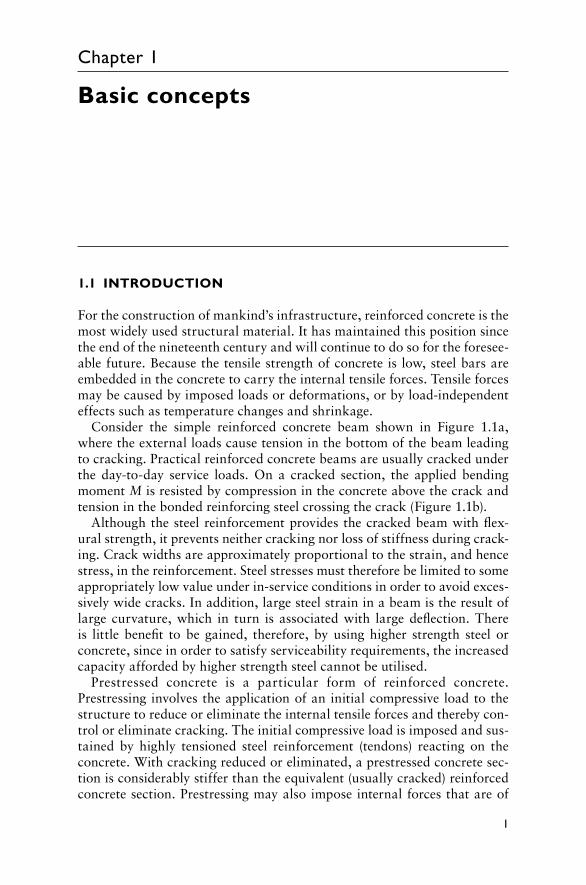
Consider the simple reinforced concrete beam shown in Figure 1.1a, where the external loads cause tension in the bottom of the beam leading to cracking. Practical reinforced concrete beams are usually cracked under the day-to-day service loads. On a cracked section, the applied bending moment M is resisted by compression in the concrete above the crack and tension in the bonded reinforcing steel crossing the crack (Figure 1.1b).
Although the steel reinforcement provides the cracked beam with flex-ural strength, it prevents neither cracking nor loss of stiffness during crack-ing. Crack widths are approximately proportional to the strain, and hence stress, in the reinforcement. Steel stresses must therefore be limited to some appropriately low value under in-service conditions in order to avoid exces-sively wide cracks. In addition, large steel strain in a beam is the result of large curvature, which in turn is associated with large deflection. There is little benefit to be gained, therefore, by using higher strength steel or concrete, since in order to satisfy serviceability requirements, the increased capacity afforded by higher strength steel cannot be utilised.
Prestressed concrete is a particular form of reinforced concrete. Prestressing involves the application of an initial compressive load to the structure to reduce or eliminate the internal tensile forces and thereby con-trol or eliminate cracking. The initial compressive load is imposed and sus-tained by highly tensioned steel reinforcement (tendons) reacting on the concrete. With cracking reduced or eliminated, a prestressed concrete sec-tion is considerably stiffer than the equivalent (usually cracked) reinforced concrete section. Prestressing may also impose internal forces that are of
2 Design of Prestressed Concrete to Eurocode 2
opposite sign to the external loads and may therefore significantly reduce or even eliminate deflection.
With service load behaviour improved, the use of high-strength steel reinforcement and high-strength concrete becomes both economical and structurally efficient. As we will see subsequently, only steel that can accom-modate large initial elastic strains is suitable for prestressing concrete. The use of high-strength steel is therefore not only an advantage to prestressed concrete, it is a necessity. Prestressing results in lighter members, longer spans and an increase in the economical range of application of reinforced concrete.
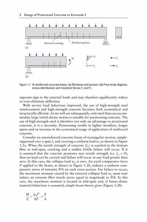
Consider an unreinforced concrete beam of rectangular section, simply-supported over a span l, and carrying a uniform load w, as shown in Figure 1.2a. When the tensile strength of concrete (fct) is reached in the bottom fibre at mid-span, cracking and a sudden brittle failure will occur. If it is assumed that the concrete possesses zero tensile strength (i.e. fct = 0), then no load can be carried and failure will occur at any load greater than zero. In this case, the collapse load wu is zero. An axial compressive force P applied to the beam, as shown in Figure 1.2b, induces a uniform com-pressive stress of intensity P/A on each cross-section. For failure to occur, the maximum moment caused by the external collapse load wu must now induce an extreme fibre tensile stress equal in magnitude to P/A. In this case, the maximum moment is located at mid-span and, if linear-elastic material behaviour is assumed, simple beam theory gives (Figure 1.2b):
MZ
w lZ
PA
= =u2
8
Flexural cracking Reinforcing bars
(a)
(b)
Mσc
σs
Fc
Fs
Figure 1.1 A reinforced concrete beam. (a) Elevation and section. (b) Free-body diagram, stress distribution and resultant forces Fc and Fs.
Basic concepts 3
based on which the collapse load can be determined as:
w
Zl
PA
u =8
2
If the prestressing force P is applied at an eccentricity of h/6, as shown in Figure 1.2c, the compressive stress caused by P in the bottom fibre at mid-span is equal to:
PA
PeZ
PA
Phbh
PA
+ = + =//66
22
and the external load at failure wu must now produce a tensile stress of 2P/A in the bottom fibre. This can be evaluated as follows (Figure 1.2c):
MZ
w lZ
PA
= =u2
82
and rearranging gives:
w
Zl
PA
u =16
2
fct = 0A = bh; I = bh3/12; Z= bh2/6
h
bwu= 0 (collapse load)
w
l
wuh/2
P P
l PAwu = 8Z
l2
Due to wu
–– –=
++
P/A P/A + M/ZM/Z
Due to P ResultantConcrete stresses
P/A Pe/Z 2P/A
– ––
–– == + +++
2P/A M/Z
Due to wuDue to P ResultantConcrete stressesP
Awu =16Zl2
lPP
e = h/6wu
(a)
(b)
(c)
Figure 1.2 Effect of prestress on the load carrying capacity of a plain concrete beam. (a) Zero prestress. (b) Axial prestress (e = 0). (c) Eccentric prestress (e = h/6).
4 Design of Prestressed Concrete to Eurocode 2
By locating the prestressing force at an eccentricity of h/6, the load carrying capacity of the unreinforced plain concrete beam is effectively doubled.
The eccentric prestress induces an internal bending moment Pe which is opposite in sign to the moment caused by the external load. An improve-ment in behaviour is obtained by using a variable eccentricity of prestress along the member using a draped cable profile.
If the prestress counter-moment Pe is equal and opposite to the load-induced moment along the full length of the beam, each cross-section is subjected only to axial compression, i.e. each section is subjected to a uni-form compressive stress of P/A. No cracking can occur and, if the curvature on each section is zero, the beam does not deflect. This is known as the balanced load stage.
1.2 METHODS OF PRESTRESSING
As mentioned in the previous section, prestress is usually imparted to a con-crete member by highly tensioned steel reinforcement (in the form of wire, strand or bar) reacting on the concrete. The high-strength prestressing steel is most often tensioned using hydraulic jacks. The tensioning operation may occur before or after the concrete is cast and, accordingly, prestressed members are classified as either pretensioned or post-tensioned. More information on prestressing systems and prestressing hardware is provided in Chapter 3.
1.2.1 Pretensioned concrete
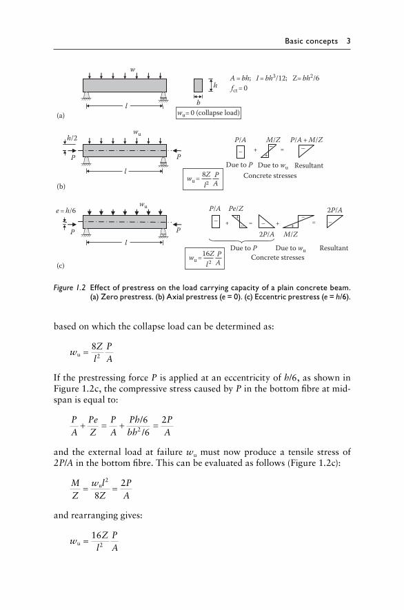
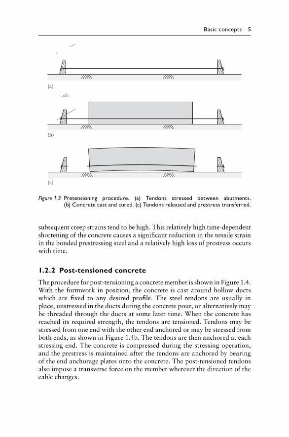
Figure 1.3 illustrates the procedure for pretensioning a concrete member. The prestressing tendons are initially tensioned between fixed abutments and anchored. With the formwork in place, the concrete is cast around the highly stressed steel tendons and cured. When the concrete has reached its required strength, the wires are cut or otherwise released from the abut-ments. As the highly stressed steel attempts to contract, it is restrained by the concrete and the concrete is compressed. Prestress is imparted to the concrete via bond between the steel and the concrete.
Pretensioned concrete members are often precast in pretensioning beds that are long enough to accommodate many identical units simultaneously. To decrease the construction cycle time, steam curing may be employed to facilitate rapid concrete strength gain, and the prestress is often transferred to the concrete within 24 hours of casting. Because the concrete is usu-ally stressed at such an early age, elastic shortening of the concrete and
Basic concepts 5
subsequent creep strains tend to be high. This relatively high time- dependent shortening of the concrete causes a significant reduction in the tensile strain in the bonded prestressing steel and a relatively high loss of prestress occurs with time.
1.2.2 Post-tensioned concrete
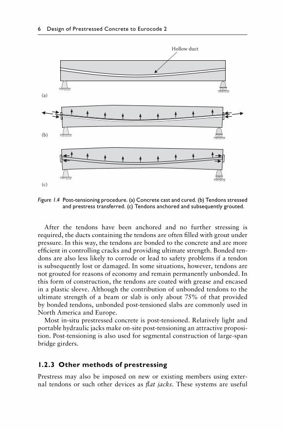
The procedure for post-tensioning a concrete member is shown in Figure 1.4. With the formwork in position, the concrete is cast around hollow ducts which are fixed to any desired profile. The steel tendons are usually in place, unstressed in the ducts during the concrete pour, or alternatively may be threaded through the ducts at some later time. When the concrete has reached its required strength, the tendons are tensioned. Tendons may be stressed from one end with the other end anchored or may be stressed from both ends, as shown in Figure 1.4b. The tendons are then anchored at each stressing end. The concrete is compressed during the stressing operation, and the prestress is maintained after the tendons are anchored by bearing of the end anchorage plates onto the concrete. The post-tensioned tendons also impose a transverse force on the member wherever the direction of the cable changes.
(a)
(b)
(c)
Figure 1.3 Pretensioning procedure. (a) Tendons stressed between abutments. (b) Concrete cast and cured. (c) Tendons released and prestress transferred.
6 Design of Prestressed Concrete to Eurocode 2
After the tendons have been anchored and no further stressing is required, the ducts containing the tendons are often filled with grout under pressure. In this way, the tendons are bonded to the concrete and are more efficient in controlling cracks and providing ultimate strength. Bonded ten-dons are also less likely to corrode or lead to safety problems if a tendon is subsequently lost or damaged. In some situations, however, tendons are not grouted for reasons of economy and remain permanently unbonded. In this form of construction, the tendons are coated with grease and encased in a plastic sleeve. Although the contribution of unbonded tendons to the ultimate strength of a beam or slab is only about 75% of that provided by bonded tendons, unbonded post-tensioned slabs are commonly used in North America and Europe.
Most in-situ prestressed concrete is post-tensioned. Relatively light and portable hydraulic jacks make on-site post-tensioning an attractive proposi-tion. Post-tensioning is also used for segmental construction of large-span bridge girders.
1.2.3 Other methods of prestressing
Prestress may also be imposed on new or existing members using exter-nal tendons or such other devices as flat jacks. These systems are useful
(a)
(b)
(c)
Hollow duct
Figure 1.4 Post-tensioning procedure. (a) Concrete cast and cured. (b) Tendons stressed and prestress transferred. (c) Tendons anchored and subsequently grouted.
Basic concepts 7
for temporary prestressing operations but may be subject to high time- dependent losses. External prestressing is discussed further in Section 3.7.
1.3 TRANSVERSE FORCES INDUCED BY DRAPED TENDONS
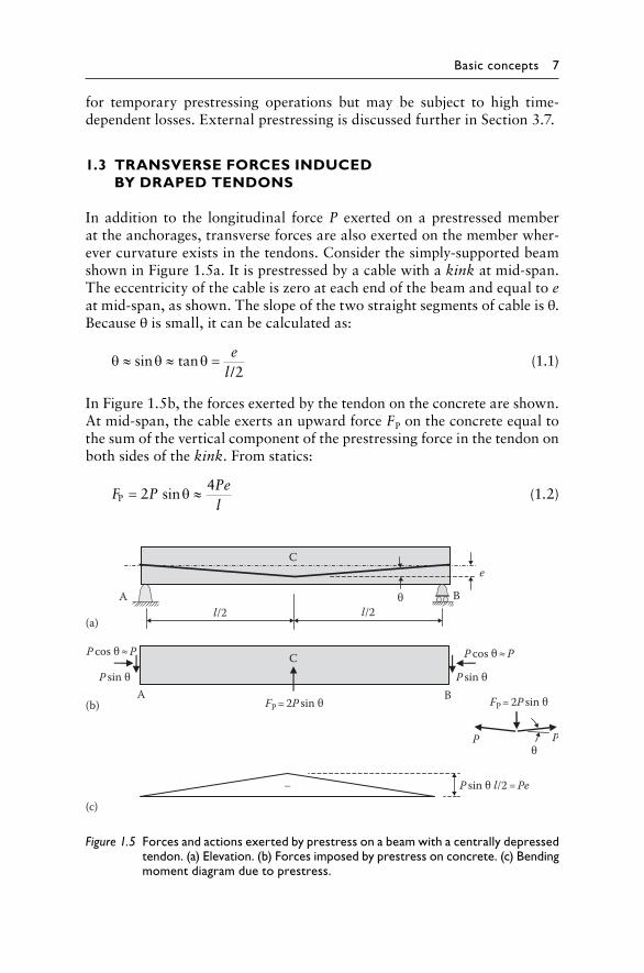
In addition to the longitudinal force P exerted on a prestressed member at the anchorages, transverse forces are also exerted on the member wher-ever curvature exists in the tendons. Consider the simply-supported beam shown in Figure 1.5a. It is prestressed by a cable with a kink at mid-span. The eccentricity of the cable is zero at each end of the beam and equal to e at mid-span, as shown. The slope of the two straight segments of cable is θ. Because θ is small, it can be calculated as:
θ θ θ≈ ≈ =sin tan
/e
l 2 (1.1)
In Figure 1.5b, the forces exerted by the tendon on the concrete are shown. At mid-span, the cable exerts an upward force FP on the concrete equal to the sum of the vertical component of the prestressing force in the tendon on both sides of the kink. From statics:
F P
Pel
P sin= ≈24θ (1.2)
e
Bθl/2l/2
A
(a)
C
(b)
CP cos θ ≈ P
P sin θA
FP = 2P sin θ B
P cos θ ≈ P
P sin θ
FP = 2P sin θ
P Pθ
(c)
P sin θ l/2 = Pe–
Figure 1.5 Forces and actions exerted by prestress on a beam with a centrally depressed tendon. (a) Elevation. (b) Forces imposed by prestress on concrete. (c) Bending moment diagram due to prestress.
8 Design of Prestressed Concrete to Eurocode 2
At each anchorage, the cable has a horizontal component of P cos θ (which is approximately equal to P for small values of θ) and a vertical component equal to P sin θ (approximated by 2Pe/l).
Under this condition, the beam is said to be self-stressed. No external reactions are induced at the supports. However, the beam exhibits a non-zero curvature along its length and deflects upward owing to the internal bending moment caused by the prestress. As illustrated in Figure 1.5c, the internal bending moment at any section can be calculated from statics and is equal to the product of the prestressing force P and the eccentricity of the tendon at that cross-section.
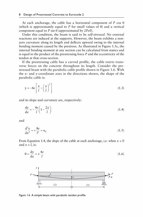
If the prestressing cable has a curved profile, the cable exerts trans-verse forces on the concrete throughout its length. Consider the pre-stressed beam with the parabolic cable profile shown in Figure 1.6. With the x- and y-coordinate axes in the directions shown, the shape of the parabolic cable is:
y e
xl
xl
= − −
42
(1.3)
and its slope and curvature are, respectively:
dd
yx
el
xl
= − −
41
2 (1.4)
and
dd
2
py
xe
l2 2
8= + = κ (1.5)
From Equation 1.4, the slope of the cable at each anchorage, i.e. when x = 0 and x = l, is:
θ = = ±d
dyx
el
4 (1.6)
e
l/2l/2
xP
y
θP
Figure 1.6 A simple beam with parabolic tendon profile.
Basic concepts 9
and, provided the tendon slope is small, the horizontal and vertical compo-nents of the prestressing force at each anchorage may therefore be taken as P and 4Pe/l, respectively.
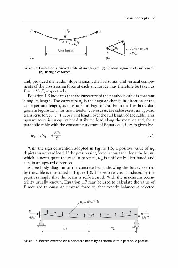
Equation 1.5 indicates that the curvature of the parabolic cable is constant along its length. The curvature κp is the angular change in direction of the cable per unit length, as illustrated in Figure 1.7a. From the free-body dia-gram in Figure 1.7b, for small tendon curvatures, the cable exerts an upward transverse force wp = Pκp per unit length over the full length of the cable. This upward force is an equivalent distributed load along the member and, for a parabolic cable with the constant curvature of Equation 1.5, wp is given by:
w P
Pel
p p= = +κ 82 (1.7)
With the sign convention adopted in Figure 1.6, a positive value of wp depicts an upward load. If the prestressing force is constant along the beam, which is never quite the case in practice, wp is uniformly distributed and acts in an upward direction.
A free-body diagram of the concrete beam showing the forces exerted by the cable is illustrated in Figure 1.8. The zero reactions induced by the prestress imply that the beam is self-stressed. With the maximum eccen-tricity usually known, Equation 1.7 may be used to calculate the value of P required to cause an upward force wp that exactly balances a selected
FP = 2Psin (κp/2)κp
κpP
P
P
Fp
Unit length
(a) (b)
P
≈ Pκp
Figure 1.7 Forces on a curved cable of unit length. (a) Tendon segment of unit length. (b) Triangle of forces.
4Pe/l
Pe
l/2l/2
4Pe/l
P
wp = 8Pe/l2 ( )
Figure 1.8 Forces exerted on a concrete beam by a tendon with a parabolic profile.
10 Design of Prestressed Concrete to Eurocode 2
portion of the external load. Under this balanced load, the beam exhibits no curvature and is subjected only to the longitudinal compressive force of magnitude P. This is the basis of a useful design approach, sensibly known as load balancing.
1.4 CALCULATION OF ELASTIC STRESSES
The components of stress on a prestressed cross-section caused by the pre-stress, the self-weight and the external loads are usually calculated using simple beam theory and assuming linear-elastic material behaviour. In addition, the properties of the gross concrete section are usually used in the calculations, provided the section is not cracked. Indeed, these assump-tions have already been made in the calculations of the stresses illustrated in Figure 1.2.
Concrete, however, does not behave in a linear-elastic manner. At best, linear-elastic calculations provide only an approximation of the state of stress on a concrete section immediately after the application of the load. Creep and shrinkage strains that gradually develop in the concrete usually cause a substantial redistribution of stresses with time, particularly on a section containing significant amounts of bonded reinforcement.
Elastic calculations are useful, however, in determining, for example, if tensile stresses occur at service loads, and therefore if cracking is likely, or if compressive stresses are excessive and large time-dependent shortening may be expected. Elastic stress calculations may therefore be used to indi-cate potential serviceability problems.
If an elastic calculation indicates that cracking may occur at service loads, the cracked section analysis presented subsequently in Section 5.8.3 should be used to determine appropriate section properties for use in serviceabil-ity calculations. A more comprehensive picture of the variation of concrete stresses with time can be obtained using the time analyses described in Sections 5.7 and 5.9 to account for the time-dependent deformations caused by creep and shrinkage of the concrete.
In the following sections, several different approaches for calculating elastic stresses on an uncracked concrete cross-section are described to pro-vide insight into the effects of prestressing. Tensile (compressive) stresses are assumed to be positive (negative).
1.4.1 Combined load approach
The stress distributions on a cross-section caused by prestress, self-weight and the applied loads may be calculated separately and summed to obtain the combined stress distribution at any particular load stage. We will first consider the stresses caused by prestress and ignore all other loads. On a cross-section, such as that shown in Figure 1.9, equilibrium requires that
Basic concepts 11
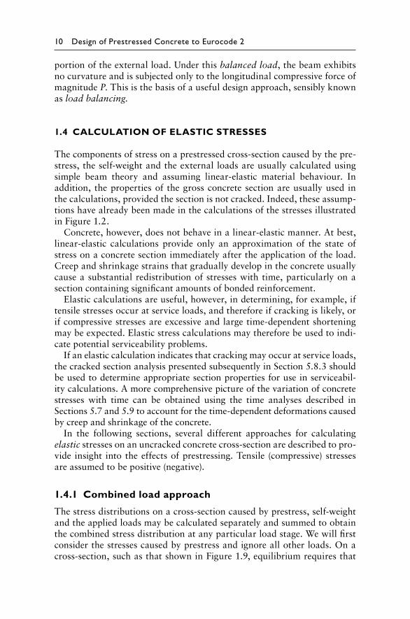
the resultant of the concrete stresses is a compressive force that is equal and opposite to the tensile force in the steel tendon and located at the level of the steel, i.e. at an eccentricity e below the centroidal axis. This is statically equivalent to an axial compressive force P and a moment Pe located at the centroidal axis, as shown.
The stresses caused by the prestressing force of magnitude P and the hogging (−ve) moment Pe are also shown in Figure 1.9. The resultant stress induced by the prestress is given by:
σ = − +P
APey
I (1.8)
where A and I are the area and second moment of area about the centroidal axis of the cross-section, respectively, and y is the distance from the centroi-dal axis (positive upwards).
It is common in elastic stress calculations to ignore the stiffening effect of the reinforcement and to use the properties of the gross cross-section. Although this simplification usually results in only small errors, it is not encouraged here. For cross-sections containing significant amounts of bonded steel reinforcement, the steel should be included in the determina-tion of the properties of the transformed cross-section.
Section Elevations
P
e Pe
Pytop
ytop
ybtme
ybtm
Centroidalaxis
Centroidalaxis
y
y
Section
e
Due to P Due to Pe ResultantStresses due to prestress
=+
–P/A + Pey/I+Pey/I–P/A
Figure 1.9 Concrete stress resultants and stresses caused by prestress.
12 Design of Prestressed Concrete to Eurocode 2
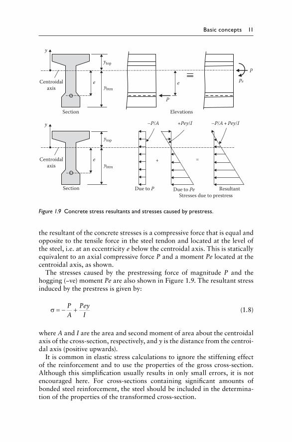
The elastic stresses caused by an applied positive moment M on the uncracked cross-section are:
σ = − My
I (1.9)
and the combined stress distribution due to prestress and the applied moment is shown in Figure 1.10 and given by:
σ = − + −P
APey
IMyI
(1.10)
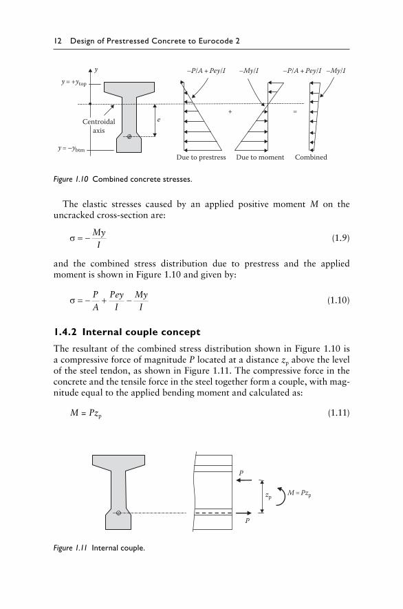
1.4.2 Internal couple concept
The resultant of the combined stress distribution shown in Figure 1.10 is a compressive force of magnitude P located at a distance zp above the level of the steel tendon, as shown in Figure 1.11. The compressive force in the concrete and the tensile force in the steel together form a couple, with mag-nitude equal to the applied bending moment and calculated as:
M = Pzp (1.11)
yy = +ytop
e
y = –ybtmDue to prestress Due to moment Combined
–My/I–P/A + Pey/I–My/I–P/A + Pey/I
=+Centroidal
axis
Figure 1.10 Combined concrete stresses.
P
P
zp M = Pzp
Figure 1.11 Internal couple.
Basic concepts 13
When the applied moment M = 0, the lever arm zp is zero and the resultant concrete compressive force is located at the steel level. As M increases, the compressive stresses in the top fibres increase and those in the bottom fibres decrease, and the location of the resultant compressive force moves upward.
It is noted that provided the section is uncracked, the magnitude of P does not change appreciably as the applied moment increases and, as a consequence, the lever arm zp is almost directly proportional to the applied moment. If the magnitude and position of the resultant of the concrete stresses are known, the stress distribution can be readily calculated.
1.4.3 Load balancing approach
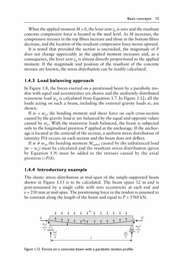
In Figure 1.8, the forces exerted on a prestressed beam by a parabolic ten-don with equal end eccentricities are shown and the uniformly distributed transverse load wp is calculated from Equation 1.7. In Figure 1.12, all the loads acting on such a beam, including the external gravity loads w, are shown.
If w = wp, the bending moment and shear force on each cross-section caused by the gravity load w are balanced by the equal and opposite values caused by wp. With the transverse loads balanced, the beam is subjected only to the longitudinal prestress P applied at the anchorage. If the anchor-age is located at the centroid of the section, a uniform stress distribution of intensity P/A occurs on each section and the beam does not deflect.
If w ≠ wp, the bending moment Munbal caused by the unbalanced load (w − wp) must be calculated and the resultant stress distribution (given by Equation 1.9) must be added to the stresses caused by the axial prestress (−P/A).
1.4.4 Introductory example
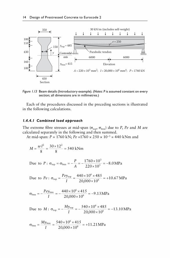
The elastic stress distribution at mid-span of the simply-supported beam shown in Figure 1.13 is to be calculated. The beam spans 12 m and is post-tensioned by a single cable with zero eccentricity at each end and e = 250 mm at mid-span. The prestressing force in the tendon is assumed to be constant along the length of the beam and equal to P = 1760 kN.
w
wp
wl2
wpl2
P
lwl2
wpl2
P
Figure 1.12 Forces on a concrete beam with a parabolic tendon profile.
14 Design of Prestressed Concrete to Eurocode 2
Each of the procedures discussed in the preceding sections is illustrated in the following calculations.
1.4.4.1 Combined load approach
The extreme fibre stresses at mid-span (σtop, σbtm) due to P, Pe and M are calculated separately in the following and then summed.
At mid-span: P = 1760 kN; Pe =1760 × 250 × 10–3 = 440 kNm and
M
wl= = × =2 2
830 12
8540 kNm
Due to MPatop btmP
PA
: .σ σ= = − = − ××
= −1760 10220 10
8 03
3
Due to
,MPatop
topPePey
I: .σ = = × ×
×= +440 10 485
20 000 1010 67
6
6
σbtm
btm
,MPa= − = − × ×
×= −Pey
I440 10 415
20 000 109 13
6
6 .
Due to
,MPatop
topMMy
I: .σ = − = − × ×
×= −540 10 485
20 000 1013 10
6
6
σbtm
btm
,MPa= = × ×
×= +My
I540 10 415
20 000 1011 21
6
6 .
350
150
y Centroidalaxis
ytop = 485
ybtm= 415
6000 6000
Elevation
e = 250
30 kN/m (includes self-weight)
Parabolic tendon
110100
430
160
100
450Section
A = 220 × 103 mm2; I = 20,000 × 106 mm4; P = 1760 kN
Figure 1.13 Beam details (Introductory example). (Notes: P is assumed constant on every section; all dimensions are in millimetres.)
Basic concepts 15
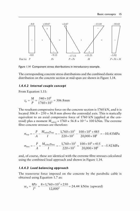
The corresponding concrete stress distributions and the combined elastic stress distribution on the concrete section at mid-span are shown in Figure 1.14.
1.4.4.2 Internal couple concept
From Equation 1.11:
z
MP
p mm= = ××
=540 101760 10
306 86
3 .
The resultant compressive force on the concrete section is 1760 kN, and it is located 306.8 − 250 = 56.8 mm above the centroidal axis. This is statically equivalent to an axial compressive force of 1760 kN (applied at the cen-troid) plus a moment Munbal = 1760 × 56.8 × 10–3 = 100 kNm. The extreme fibre concrete stresses are therefore:
σtop
unbal top ,,
= − − = − ××
− × ××
PA
M yI
1 760 10220 10
100 10 48520 000 1
3
3
6
0010 436 = − . MPa
σbtm
unbal btm ,,
= − + = − ××
+ × ××
PA
M yI
1 760 10220 10
100 10 41520 000 1
3
3
6
005 926 = − . MPa
and, of course, these are identical with the extreme fibre stresses calculated using the combined load approach and shown in Figure 1.14.
1.4.4.3 Load balancing approach
The transverse force imposed on the concrete by the parabolic cable is obtained using Equation 1.7 as:
w
Pel
p,
,kN/m (upward)= = × × × =8 8 1 760 10 250
12 00024 442
3
2 .
–10.43–13.10–8.0 +2.67+10.67
+ –
––
– – +
== ++
–5.92+11.21–17.13–9.13–8.0Due to: P + Pe P + Pe + MP Pe M
Figure 1.14 Component stress distributions in introductory example.
16 Design of Prestressed Concrete to Eurocode 2
The unbalanced load is therefore:
wunbal kN/m (downward)= − =30 0 24 44 5 56. . .
and the resultant unbalanced moment at mid-span is:
M
w lunbal
unbal kNm= = × =2 2
85 56 12
8100
.
This is identical to the moment Munbal calculated using the internal couple concept and, as determined previously, the elastic stresses at mid-span are obtained by adding the P/A stresses to those caused by Munbal:
σtop
unbal top MPa= − − = −PA
M yI
10 43.
σbtm
unbal btm MPa= − + = −PA
M yI
5 92.
1.5 INTRODUCTION TO STRUCTURAL BEHAVIOUR: INITIAL TO ULTIMATE LOADS
The choice between reinforced and prestressed concrete for the construc-tion of a particular structure is essentially one of economics. Aesthetics may also influence the choice. For relatively short-span beams and slabs, reinforced concrete is usually the most economical alternative. As spans increase, however, reinforced concrete design is more and more controlled by the serviceability requirements. Strength and ductility can still be eco-nomically achieved but, in order to prevent excessive deflection, cross-sectional dimensions become uneconomically large. Excessive deflection is usually the governing limit state.
For medium- to long-span beams and slabs, the introduction of pre-stress improves both serviceability and economy. The optimum level of prestress depends on the span, the load history and the serviceability requirements. The level of prestress is often selected so that cracking at service loads does not occur. However, in many situations, there is no valid reason why controlled cracking should not be permitted. Insisting on enough prestress to eliminate cracking frequently results in unnecessarily high initial prestressing forces and, consequently, uneconomical designs. In addition, the high initial prestress often leads to excessively large camber and/or axial shortening. Members designed to remain uncracked at service loads are commonly termed fully prestressed.
In building structures, there are relatively few situations in which it is necessary to avoid cracking under the full service loads. In fact, the most
Basic concepts 17
economic design often results in significantly less prestress than is required for a fully-prestressed member. Frequently, such members are designed to remain uncracked under the sustained or permanent load, with cracks open-ing and closing as the variable live load is applied and removed. Prestressed concrete members generally behave satisfactorily in the post-cracking load range, provided they contain sufficient bonded reinforcement to control the cracks. A cracked prestressed concrete section under service loads is signifi-cantly stiffer than a cracked reinforced concrete section of similar size and containing similar quantities of bonded reinforcement. Members that are designed to crack at the full service load are often called partially-prestressed.
The elastic stress calculations presented in the previous section are applicable only if material behaviour is linear-elastic and the principle of superposition is valid. These conditions may be assumed to apply on a pre-stressed section prior to cracking, but only immediately after the loads are applied. As was mentioned in Section 1.4, the gradual development of creep and shrinkage strains with time in the concrete can cause a marked redis-tribution of stress between the bonded steel and the concrete on the cross-section. The greater the quantity of bonded reinforcement, the greater is the time-dependent redistribution of stress. This is demonstrated subsequently in Section 5.7.3 and discussed in Section 5.7.4. For the determination of the long-term stress and strain distributions, elastic stress calculations are not meaningful and may be misleading.
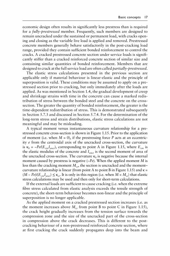
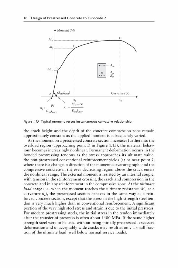
A typical moment versus instantaneous curvature relationship for a pre-stressed concrete cross-section is shown in Figure 1.15. Prior to the application of moment (i.e. when M = 0), if the prestressing force P acts at an eccentric-ity e from the centroidal axis of the uncracked cross-section, the curvature is κ0 = −Pe/(EcmIuncr), corresponding to point A in Figure 1.15, where Ecm is the elastic modulus of the concrete and Iuncr is the second moment of area of the uncracked cross-section. The curvature κ0 is negative because the internal moment caused by prestress is negative (−Pe). When the applied moment M is less than the cracking moment Mcr, the section is uncracked and the moment–curvature relationship is linear (from point A to point B in Figure 1.15) and κ = (M − Pe)/(EcmIuncr) ≤ κcr. It is only in this region (i.e. when M < Mcr) that elastic stress calculations may be used and then only for short-term calculations.
If the external loads are sufficient to cause cracking (i.e. when the extreme fibre stress calculated from elastic analysis exceeds the tensile strength of concrete), the short-term behaviour becomes non-linear and the principle of superposition is no longer applicable.
As the applied moment on a cracked prestressed section increases (i.e. as the moment increases above Mcr from point B to point C in Figure 1.15), the crack height gradually increases from the tension surface towards the compression zone and the size of the uncracked part of the cross-section in compression above the crack decreases. This is different to the post-cracking behaviour of a non-prestressed reinforced concrete section, where at first cracking the crack suddenly propagates deep into the beam and
18 Design of Prestressed Concrete to Eurocode 2
the crack height and the depth of the concrete compression zone remain approximately constant as the applied moment is subsequently varied.
As the moment on a prestressed concrete section increases further into the overload region (approaching point D in Figure 1.15), the material behav-iour becomes increasingly nonlinear. Permanent deformation occurs in the bonded prestressing tendons as the stress approaches its ultimate value, the non-prestressed conventional reinforcement yields (at or near point C where there is a change in direction of the moment curvature graph) and the compressive concrete in the ever decreasing region above the crack enters the nonlinear range. The external moment is resisted by an internal couple, with tension in the reinforcement crossing the crack and compression in the concrete and in any reinforcement in the compressive zone. At the ultimate load stage (i.e. when the moment reaches the ultimate resistance Mu at a curvature κu), the prestressed section behaves in the same way as a rein-forced concrete section, except that the stress in the high-strength steel ten-don is very much higher than in conventional reinforcement. A significant portion of the very high steel stress and strain is due to the initial prestress. For modern prestressing steels, the initial stress in the tendon immediately after the transfer of prestress is often about 1400 MPa. If the same higher strength steel were to be used without being initially prestressed, excessive deformation and unacceptably wide cracks may result at only a small frac-tion of the ultimate load (well below normal service loads).
Moment (M)
Mu
My
McrB
C
D
Asc
ApAst
A
κuκy
EcmIuncr
Mcr – Peκcr =
EcmIuncr
– Peκ0 =
Curvature (κ)(EcmIuncr)
Figure 1.15 Typical moment versus instantaneous curvature relationship.
Basic concepts 19
The ultimate strength of a prestressed section depends on the quantity and strength of the steel reinforcement and tendons. The level of pre-stress, however, and therefore the quantity of prestressing steel are deter-mined from serviceability considerations. In order to provide a suitable factor of safety for strength, additional conventional reinforcement may be required to supplement the prestressing steel in the tension zone. This is particularly so in the case of partially-prestressed members and may even apply for fully-prestressed construction. The avoidance of cracking at service loads and the satisfaction of selected elastic stress limits do not ensure adequate strength. Strength must be determined from a rational analysis which accounts for the nonlinear material behaviour of both the steel and the concrete. Flexural strength analysis is described and illus-trated in Chapter 6, and analyses for shear and torsional strength are presented in Chapter 7.

References
2 Design procedures and applied actions
1. EN 1991-1-1. 2002. Eurocode 1: Actions on structures –Part-1-1: General actions – Densities, self-weight,imposed loads on buildings. British Standards Institution,London, UK.
2. EN 1991-1-3. 2003. Eurocode 1: Actions on structures –Part 1-3: General actions – Snow loads. British StandardsInstitution, London, UK.
3. EN 1991-1-4. 2005 (+A1: 2010). Eurocode 1: Actions onstructures – Part 1-4: General actions – Wind actions.British Standards Institution, London, UK.
4. E N 1990. 2002 (+A1: 2005). Eurocode: Basis ofstructural design. British Standards Institution, London,UK.
5. EN 1992-1-1. 2004. Eurocode 2: Design of concretestructures – Part 1-1: General rules and rules forbuildings. British Standards Institution, London, UK.
6. EN 1991-1-2. 2002. Eurocode 1: Actions on structures –Part-1-2: General actions – Actions on structures exposedto fire. British Standards Institution, London, UK.
7. E N 1991-1-5. 2003. Eurocode 1: Actions on structures –Part 1-5: General actions – Thermal actions. BritishStandards Institution, London, UK.
8. E N 1991-1-6. 2005. Eurocode 1: Actions on structures –Part 1-6: General actions – Actions during execution.British Standards Institution, London, UK.
9. EN 1991-1-7. 2006. Eurocode 1: Actions on structures –Part 1-7: General actions – Accidental actions. BritishStandards Institution, London, UK.
10. EN 1992-1-2. 2004. Eurocode 2: Design of concretestructures – Part 1-2: General rules – Structural firedesign. British Standards Institution, London, UK.
11. R anzi, G. and Gilbert, R.I. 2014. Structural Analysis– Principles, Methods and Modelling. Boca Raton, FL: CRCPress.
12. Gilbert, R.I. and Ranzi, G. 2011. Time-Dependent
Behaviour of Concrete Structures. London, UK: Spon Press.
13. Mayer, H. and Rüsch, H. 1967. Building damage caused bydeflection of reinforced concrete building components.Technical Translation 1412, National Research Council,Ottawa, Ontario, Canada (Berlin, West Germany, 1967).
14. ISO 4356. 1977. Bases for the design of structures –Deformations of buildings at the serviceability limitstates. International Standards Organisation, Geneva,Switzerland.
15. A S3600-2009. 2009. Australian standard for concretestructures. Standards Australia, Sydney, New South Wales,Australia.
16. ACI318M-14. 2014. Building code requirements forstructural concrete and commentary. American ConcreteInstitute, Detroit, MI.
17. I rwin, A.W. 1978. Human response to dynamic motion ofstructures. The Structural Engineer, 56A(9), 237–244.
18. M ickleborough, N.C. and Gilbert, R.I. 1986. Control ofconcrete floor slab vibration by L/D limits. Proceedingsof the 10th Australasian Conference on the Mechanics ofStructures and Materials, University of Adelaide, Adelaide,South Australia, Australia.
19. S mith, A.L., Hicks, S.J. and Devine, P.J. 2009. Designof floors for vibration: A new approach – Revised edition(SCI P354). Steel Construction Institute, Berkshire, UK.
20. Willford, M.R. and Young, P. 2006. A design guide forfootfall induced vibration of structures (CCIP-016). TheConcrete Centre, Surrey, UK.
21. Murray, T.M., Allen, D.E. and Ungar, E.E. 1997. SteelDesign Guide Series 11 – Floor vibrations due to humanactivity. American Institute of Steel Construction,Chicago, IL.
22. ISO 10137. 2007. Bases for design of structures –Serviceability of buildings and walkways againstvibrations. International Standards Organisation, Geneva,Switzerland.
4 Material properties
1. EN 1992-1-1. 2004. Eurocode 2: Design of concretestructures – Part 1-1: General rules and rules forbuildings. British Standards Institution, London, UK.
2. EN 196-1. 1995. Method of testing cement – Part 1:Determination of strength. British Standards Institution,London, UK.
3. EN 197-1. 2011. Cement – Part 1: Composition,specifications and conformity criteria for common cements.British Standards Institution, London, UK.
4. EN 943-2. 2009. Admixtures for concrete, mortar andgrout. British Standards Institution, London, UK.
5. E N 206-1. 2000. Concrete. Specification, performance,production and conformity. British Standards Institution,London, UK.
6. BS 8500-1. 2006. Part 1: Method of specifying andguidance for the specifier. British Standards Institution,London, UK.
7. EN 12390:2. 2009. Testing hardened concrete: Making andcuring specimens for strength tests. British StandardsInstitution, London, UK.
8. EN 12390:3. 2009. Testing hardened concrete: Compressivestrength of test specimens. British Standards Institution,London, UK.
9. EN 12390:5. 2009. Testing hardened concrete: Flexuralstrength of test specimens. British Standards Institution,London, UK.
10. EN 12390:6. 2009. Testing hardened concrete: Tensilesplitting strength of test specimens. British StandardsInstitution, London, UK.
11. BS 1881-121. 1983. Testing concrete: Methods fordetermination of static modulus of elasticity incompression. British Standards Institution, London, UK.
12. E N 10080. 2005. Steel for the reinforcement ofconcrete, weldable, ribbed reinforcing steel. BritishStandards Institution, London, UK.
13. EN 10138-1. 2005. Prestressing steel. Part 1: General
requirements 1, EN 10138-2: Prestressing steels – Wire, EN10138-3: Prestressing steels – Strand, EN 10138-4:Prestressing steels – Bars. British Standards Institution,London, UK.
14. N eville, A.M. 1996. Properties of Concrete, 4th edn.London, UK: Wiley.
15. M etha, P.K. and Monteiro, P.J. 2014. Concrete:Microstructure, Properties and Materials, 4th edn. NewYork: McGraw-Hill Education.
16. Kupfer, H.B., Hilsdorf, H.K. and Rüsch, H. 1975.Behaviour of concrete under biaxial stresses. ACI Journal,66, 656–666.
17. T asuji, M.E., Slate, F.O. and Nilson, A.H. 1978.Stress-strain response and fracture of concrete in biaxialloading. ACI Journal, 75, 306–312.
18. D arwin, D. and Pecknold, D.A. 1977. Nonlinear biaxialstress-strain law for concrete. Journal of the EngineeringMechanics Division, 103, 229–241.
19. N eville, A.M. 1970. Creep of Concrete: Plain,Reinforced and Prestressed. Amsterdam, the Netherlands:North-Holland.
20. N eville, A.M., Dilger, W.H. and Brooks, J.J. 1983.Creep of Plain and Structural Concrete. London, UK:Construction Press.
21. G ilbert, R.I. 1988. Time Effects in ConcreteStructures. Amsterdam, the Netherlands: Elsevier.
22. G ilbert, R.I. and Ranzi, G. 2011. Time-DependentBehaviour of Concrete Structures. London, UK: Spon Press,426pp.
23. G hali, A. and Favre, R. 1986. Concrete Structures:Stresses and Deformations. London, UK: Chapman and Hall.
24. Ghali, A., Favre, R. and Eldbadry, M. 2002. ConcreteStructures: Stresses and Deformations, 3rd edn. London,UK: Spon Press, 584pp.
25. R üsch, H., Jungwirth, D. and Hilsdorf, H.K. 1983.Creep and Shrinkage – Their Effect on the Behaviour ofConcrete Structures. New York: SpringerVerlag, 284pp.
26. A CI 209R-92. 1992. Prediction of creep, shrinkage andtemperature effects in concrete structures. ACI Committee209, American Concrete Institute, Farmington Hills, MI,reapproved 2008.
27. A CI 209.1R-05. 2005. Report on factors affectingshrinkage and creep of hardened concrete. ACI Committee209, American Concrete Institute, Farmington Hills, MI.
28. A CI Committee 209. 2008. Guide for modeling andcalculating shrinkage and creep in hardened concrete (ACI209.2R-08). American Concrete Institute, Farmington Hills,MI, 44pp.
29. Trost, H. 1978. Creep and creep recovery of very oldconcrete. RILEM Colloquium on Creep of Concrete, Leeds,UK.
30. Trost, H. 1967. Auswirkungen des Superpositionsprinzipsauf Kriech- und Relaxations Probleme bei Beton undSpannbeton. Beton- und Stahlbetonbau, 62, 230–238,261–269.
31. Dilger, W. and Neville, A.M. 1971. Method of creepanalysis of structural members. Australasian Conference onInformation Security and Privacy, 27–17, 349–379.
32. B azant, Z.P. April 1972. Prediction of concrete creepeffects using ageadjusted effective modulus method. ACIJournal, 69, 212–217.
33. fib. 2013. Fib Model Code for Concrete Structures 2010.Fib – International Federation for Structural Concrete,Ernst & Sohn, Lausanne, Switzerland, 434pp.
34. O stergaard, L., Lange, D.A., Altouabat, S.A. andStang, H. 2001. Tensile basic creep of early-age concreteunder constant load. Cement and Concrete Research, 31,1895–1899.
35. C hu, K.H. and Carreira, D.J. 1986. Time-dependentcyclic deflections in R/C beams. Journal of StructuralEngineering, ASCE, 112(5), 943–959.
36. B azant, Z.P. and Oh, B.H. 1984. Deformation ofprogressively cracking reinforced concrete beams. ACIJournal, 81(3), 268–278.
37. G ilbert, R.I. 2002. Creep and Shrinkage Models forHigh Strength Concrete – Proposals for inclusion in

AS3600. Australian Journal of Structural Engineering,4(2), 95–106.
38. B rooks, J.J. 2005. 30-year creep and shrinkage ofconcrete. Magazine of Concrete Research, 57(9), 545–556.
39. L oov, R.E. 1988. A general equation for the steelstress for bonded prestressed concrete members. Journal ofthe Prestressed Concrete Institute, 33, 108–137.
5 Design for serviceability
1. EN 1992-1-1. 2004. Eurocode 2: Design of concretestructures. Part 1-1: General rules and rules forbuildings. British Standards Institution, London, UK.
2. ACI 318-14M. 2014. Building code requirements forreinforced concrete. American Concrete Institute, Detroit,MI.
3. M agnel, G. 1954. Prestressed Concrete, 3rd edn. London,UK: Concrete Publications Ltd.
4. Lin, T.Y. 1963. Prestressed Concrete Structures. NewYork: Wiley.
5. Warner, R.F. and Faulkes, K.A. 1979. PrestressedConcrete. Melbourne, Victoria, Australia: PitmanAustralia.
6. G ilbert, R.I. and Ranzi, G. 2011. Time-DependentBehaviour of Concrete Structures. London, UK: Spon Press.
7. Gilbert, R.I. 1988. Time Effects in Concrete Structures.Amsterdam, the Netherlands: Elsevier.
8. Ghali, A., Favre, R. and Elbadry, M. 2002. ConcreteStructures: Stresses and Deformations, 3rd edn. London,UK: Spon Press.
9. AS3600-2009. Australian standard concrete structures.Standards Australia, Sydney, New South Wales, Australia.
10. Branson, D.E. 1963. Instantaneous and time-dependentdeflection of simple and continuous reinforced concretebeams. Alabama Highway Research Report, No. 7. Bureau ofPublic Roads, Montgomery, AL.
11. Bischoff, P.H. 2005. Reevaluation of deflectionprediction for concrete beams reinforced with steel andFRP bars. Journal of Structural Engineering, ASCE, 131(5),752–767.
12. G ilbert, R.I. 2001. Deflection calculation and control– Australian code amendments and improvements (Chapter 4).ACI International SP 203, Code Provisions for DeflectionControl in Concrete Structures. Farmington Hills, MI:American Concrete Institute, pp. 45–78.
6 Flexural resistance
1. EN 1992-1-1. 2004. Eurocode 2: Design of concretestructures – Part 1-1: General rules and rules forbuildings. British Standards Institution, London, UK.
2. ACI 318M-14. 2014. Building code requirements forstructural concrete. Detroit, MI: American ConcreteInstitute.
3. Beeby, A.W. 1999. Safety of structures, a new approachto robustness. The Structural Engineer, 77(4), 16–21. 00.05 0.10 0.15 θ pl,d (mrad) 0.20 0.25 0.30 0.35 0.400.45 x/d 35 30 25 20 15 10 5 C90/105 Class C Class B ≤C50/60 ≤ C50/60 C90/105
Figure 6.23 Basic values of allowable rotation θ pl,dwhen λ = 3 [1].
7 Design resistance in shear and torsion
1. Ritter, W. 1899. Die Bauweise Hennebique (ConstructionMethods of Hennebique). Zurich, Switzerland:Schweizerische Bayzeitung.
2. Hognestad, E. 1952. What do we know about diagonaltension and web r einforcement in concrete? University ofIllinois Engineering Experiment Station, Circular SeriesNo. 64, Urbana, IL.
3. EN 1992-1-1. 2004. Eurocode 2: Design of concretestructures – Part 1-1: General rules and rules forbuildings. British Standards Institution, London, UK. Ineach of the eight lines of shear reinforcementperpendicular to the column face (as shown in Figure 7.26),the first vertical bar is located at about 0.5d eff =90 mm from the column face, the outermost bar must be atleast 656 mm from the column face. The shear reinforcementlayout is shown in Figure 7.27. 135 135 135 135 135 90 10mm shear links 300 600
(a) (b) 180 1 1 Figure 7.27 Sections through slab–columnconnection (Example 7.5). (a) Section perpendicular toslab edge. (b) Section 1–1.
8 Anchorage zones
1. Hoyer, E. 1939. Der Stahlsaitenbeton. Berlin, Germany:Elsner.
2. BS EN 1992-1-1. 2004. Eurocode 2: Design of concretestructures – Part 1-1: General rules and rules forbuildings. British Standards Institution, London, UK.
3. L ogan, D.R. 1997. Acceptance criteria for bond qualityof strand for pretensioned concrete applications. PCIJournal, 42(2), 52–90.
4. R ose, D.R. and Russell, B.W. 1997. Investigation ofstandardized tests to measure the bond performance ofprestressing strands. PCI Journal, 42(4), 56–80.
5. Martin, L. and Korkosz, W. 1995. Strength of prestressedmembers at sections where strands are not fully developed.PCI Journal, 40(5), 58–66.
6. MNL-120-4, Precast/Prestressed Concrete Institute. 2005.PCI Design Handbook: Precast And Prestressed Concrete, 6thedn. Chicago, IL: Precast/ Prestressed Concrete Institute,pp. 4-27–4-29.
7. Gilbert, R.I. 2012. Unanticipated bond failure oversupporting band beams in grouted post-tensioned slabtendons with little or no prestress. Bond in Concrete,Fourth International Symposium, 17–20 June, Brescia, Italy.
8. M arshall, W.T. and Mattock, A.H. 1962. Control ofhorizontal cracking in the ends of pretensionedprestressed concrete girders. Journal of the PrestressedConcrete Institute, 7(5), 56–74.
9. G uyon, Y. 1953. Prestressed Concrete, English edn.London, UK: Contractors Record and Municipal Engineering.
10. I yengar, K.T.S.R. 1962. Two-dimensional theories ofanchorage zone stresses in post-tensioned concrete beams.Journal of the American Concrete Institute, 59, 1443–1446.
11. I yengar, K.T.S.R. and Yogananda, C.V. 1966. A threedimensional stress distribution problem in the end zonesof prestressed beams. Magazine of Concrete Research, 18,75–84.
12. S argious, M. 1960. Beitrag zur Ermittlung derHauptzugspannungen am Endauflager vorgespannter
Betonbalken. Dissertation. Stuttgart, Germany: TechnischeHochschule.
13. F oster, S.J. and Rogowsky, D.M. 1997. Bursting forcesin concrete members resulting from in-plane concentratedloads. Magazine of Concrete Research, 49(180), 231–240.
14. M agnel, G. 1954. Prestressed Concrete, 3rd edn. NewYork: McGraw-Hill.
15. G ergely, P. and Sozen, M.A. 1967. Design of anchoragezone reinforcement in prestressed concrete beams. Journalof the Prestressed Concrete Institute, 12(2), 63–75.
16. W arner, R.F. and Faulkes, K.A. 1979. PrestressedConcrete, 1st edn. Melbourne, Victoria, Australia: PitmanAustralia.
17. M arti, P. 1985. Truss models in detailing. ConcreteInternational – American Concrete Institute, 7(1), 46–56.
18. M arti, P. 1985. Basic tools of reinforced concretebeam design. Concrete International – American ConcreteInstitute, 7(12), 66–73.
19. S chlaich J., Schäfer, K. and Jennewein, M. 1987.Towards a consistent design of structural concrete.Special Report. PCI Journal, 32(3), 74–150.
9 Composite members
1. EN 1992-1-1. 2004. Eurocode 2: Design of concretestructures – Part 1-1: General rules and rules forbuildings. British Standards Institution, London, UK.
2. Gilbert, R.I. and Ranzi, G. 2011. Time-DependentBehaviour of Concrete Structures. London, UK: Spon Press.The spacing can be increased further into the span, as theshear force V Ed decreases. It is important to ensure thatthese bars are fully anchored on each side of the shearplane. If the contact surface were not deliberatelyroughened, but screeded and trowelled, c = 0.25 and μ =0.5, and Equation 9.61 gives: v A Rdi s = × + × + × × × + ×= 0 25 1 2 0 5 0 0405 435 0 5 1 0 0 300 1000 0 3 . . . . (. . ) / ( ) . 2 0 725 10 3 + × × − . A s From Equation9.60: A s 2 mm /m≥ − × = − 1 59 0 32 0 725 10 1752 3 . . .and with 2–12 mm bars (226 mm 2 ) cross the shearinterface, one in each web, the required spacing s neareach support is: s ≤ × = 1000 226 1752 129 mm
11 Statically indeterminate members
1. Ranzi, G. and Gilbert, R I. 2015. Structural Analysis:Principles, Methods and Modelling. Boca Raton, FL: CRCPress, Taylor & Francis Group.
2. Cross, H. 1930. Analysis of continuous frames bydistributing fixed-end moments. Transactions of theAmerican Society of Civil Engineers, 96(1793), 1–10.
3. EN 1992-1-1. 2004. Eurocode 2: Design of concretestructures – Part 1-1: General rules and rules forbuildings. British Standards Institution, London, UK. Withthe effective prestress at C, P m,t = 3337 kN, the extremetop fibre stress under the unbalanced loads is: σ c,top =− × × + × × = − + = + 3337 10 645 10 2540 10 178 4 10 5 1714 24 9 0 3 3 6 6 . . . . 7 MPa With the tensile strengthtaken as f ctm = 3.5 MPa, cracking will occur under thefull unbalanced moment. The error associated with estimatesof the cracking moment based on elastic stress calculationmay be significantly large. As was discussed in Section5.7.3 and illustrated in Example 5.5, creep and shrinkagemay cause a large redistribution of stress on thecross-section with time, particularly when thecross-section contains significant quantities of nonprestressed reinforcement (as is the case here). If a moreaccurate estimate of stresses is required, a time analysisis recommended (see Section 5.7.3). A cracked sectionanalysis, similar to that outlined in Section 5.8.3, isrequired to calculate the loss of stiffness due to crackingand the increment of tensile steel stress, in order tocheck crack control. The maximum in-service moment at C isequal to the sum of the moment caused by the full externalservice loads and the secondary moment: M C = −80.9 × (25+ 15.5) + 20 × (−92.6) + 790 = −4338 kNm A cracked sectionanalysis reveals that the tensile stress in thenon-prestressed top steel at this moment is only 106 MPa,which is much less than the increment of 200 MPa specifiedin EN 1992-1-1 [3] and given in Table 5.5 for 25 mmdiameter bars if the maximum crack width is to be limitedto 0.3 mm. Crack widths should therefore be acceptablysmall. This design example is taken no further here.Deflections are unlikely to be excessive, but should bechecked using the procedures outlined in Section 5.11. Thedesign for shear and the design of the anchorage zones arein accordance with the discussions in Chapter 10.
4. Lin, T.Y. and Thornton, K. 1972. Secondary moments andmoment redistribution in continuous prestressed concretebeams. Journal of the Prestressed Concrete Institute,

17(1), 1–20.
5. M attock, A.H. 1972. Secondary moments and momentredistribution in continuous prestressed concrete beams.Discussion of Lin and Thornton 1972. Journal of thePrestressed Concrete Institute, 17(4), 86–88.
6. Nilson, A.H. 1978. Design of Prestressed Concrete. NewYork: Wiley.
7. Warner, R.F. and Faulkes, K.A. 1983. Overload behaviourand design of continuous prestressed concrete beams.Presented at the International Symposium on Non-Linearityand Continuity in Prestressed Concrete, University ofWaterloo, Waterloo, Ontario, Canada.
12 Two-way slabs: Behaviour and design
1. EN 1992-1-1. 2004. Eurocode 2: Design of concretestructures – Part 1–1: General rules and rules forbuildings. British Standards Institution, London, UK.
2. V SL Prestressing (Aust.) Pty. Ltd. 1988. Slab Systems,2nd edn. Sydney, New South Wales, Australia: V.S.L.
3. ACI 318-14M. 2014. Building code requirements forreinforced concrete. Detroit, MI: American ConcreteInstitute.
4. Post-Tensioning Institute. 1977. Design ofpost-tensioned slabs. Glenview, IL: Post-TensioningInstitute.
5. EN 1992-1-2. 2004. Eurocode 2: Design of concretestructures – Part 1-2: General rules – Structural firedesign. British Standards Institution, London, UK.
6. G ilbert, R.I. 1985. Deflection control of slabs usingallowable span to depth ratios. ACI Journal, Proceedings,82, 67–72.
Figure 12.26 Band-beam and slab floor system.
7. Gilbert, R.I. 1989. Determination of slab thickness insuspended posttensioned floor systems. ACI Journal,Proceedings, 86, 602–607.
8. Gilbert, R.I. 1979a. Time-dependent behaviour ofstructural concrete slabs. PhD Thesis. Sydney, New SouthWales, Australia: School of Civil Engineering, Universityof New South Wales.
9. Gilbert, R.I. 1979b. Time-dependent analysis ofreinforced and prestressed concrete slabs. ProceedingsThird International Conference in Australia on FiniteElements Methods. Sydney, New South Wales, Australia:University of New South Wales, Unisearch Ltd, pp. 215–230.
10. M ickleborough, N.C. and Gilbert, R.I. 1986. Control ofconcrete floor slab vibration by L/D limits. Proceedingsof the 10th Australian Conference on the Mechanics ofStructures and Materials, University of Adelaide, Adelaide,South Australia, Australia, pp. 51–56.
11. W ood, R.H. 1968. The reinforcement of slabs in
accordance with a pre- d etermined field of moments.Concrete, 2(2), 69–76.
12. A S3600. 2009. Australian standard for concretestructures. Standards Australia, Sydney, New South Wales,Australia.
13. Gilbert, R.I. 1984. Effect of reinforcementdistribution on the serviceability of reinforced concreteflat slabs. Proceedings of the Ninth AustralasianConference on the Mechanics of Structures and Materials,University of Sydney, Sydney, New South Wales, Australia,pp. 210–214.
14. Nilson, A.H. and Walters, D.B. 1975. Deflection oftwo-way floor systems by the equivalent frame method. ACIJournal, 72, 210–218.
15. Nawy, E.G. and Chakrabarti, P. 1976. Deflection ofprestressed concrete flat plates. Journal of the PCI, 21,86–102.
16. J ohansen, K.W. 1962. Yield-Line Theory. London, UK:Cement and Concrete Association.
17. Johansen, K.W. 1972. Yield-Line Formulae for Slabs.London, UK: Cement and Concrete Association.
18. R itz, P., Matt, P., Tellenbach, Ch., Schlub, P. andAeberhard, H.U. 1981. Post-Tensioned Concrete in BuildingConstruction – Post-Tensioned Slabs. Berne, Switzerland:Losinger.
13 Compression and tension members
1. Ranzi, G. and Gilbert, R.I. 2015. Structural Analysis:Principles, Methods and Modelling. Boca Raton, FL: CRCPress/Taylor & Francis Group, 562pp.
2. EN 1992-1-1. 2004. Eurocode 2: Design of concretestructures – Part 1-1: General rules and rules forbuildings. British Standards Institution, London, UK.
3. Bresler, B. 1960. Design criteria for reinforcedconcrete columns under axial load and biaxial bending. ACIJournal, 57, 481–490.
4. Ospina, C.E. and Alexander, S.D.B. 1997. Transmission ofhigh strength concrete column loads through concreteslabs, structural engineering, Report No. 214, Departmentof Civil Engineering, University of Alberta, Edmonton,Alberta, Canada.
5. Gilbert, R.I. and Ranzi, G. 2011. Time-DependentBehaviour of Concrete Structures. London, UK: Spon Press.and the elongation caused by N is given by Equation 13.48:e N = × × × × + × + × 1 000 10 10 000 120 670 11 670 1 1671 0 00848 17 14 0 3 , , , , ( . . . . ) . 00666 = 5 65 mmThe net effect is a shortening of the member by: e e e= − =− = P.cs N mm13 28 5 65 7 63. . .
14 Detailing: Members and connections
1. EN 1992-1-1. 2004. Eurocode 2: Design of concretestructures – Part 1-1: General rules and rules forbuildings. British Standards Institution, London, UK.
2. Park, R. and Paulay, T. 1975. Reinforced concretestructures. John Wiley & Sons, 769pp. (Chapter 13 – Theart of detailing).
3. Leonhardt, F. December 1965. Reducing the shearreinforcement in reinforced concrete beams and slabs.Magazine of Concrete Research, 17(53), 187–198.
4. L eonhardt, F. 1965. Über die Kunst des Bewehrens vonStahlbetontragwerken. Beton- und Stahlbetonbau, 60(8),181–192; 60(9), 212–220.
5. Leonhardt, F. 1971. Das Bewehren vonStahlbetontragwerken. BetonKalender. Berlin, Germany:Wilhelm Ernst & Sohn, Part II, pp. 303–398.
6. Leonhardt, F. and Teichen, K.T. 1972. Druck-Stösse vonBewehrungstäben. Deutscher Ausschuss für Stahlbeton,Bulletin No. 222, Wilhelm Ernst & Sohn, Berlin, Germany,pp. 1–53.
7. L eonhardt, F., Walther, R. and Dilger, W. 1964.Schubversuche an Durchlaufträgern. Deutscher Ausschuss fürStahlbeton. Heft 163. Berlin, Germany: Ernst & Sohn.
8. G oto, Y. 1971. Cracks formed in concrete arounddeformed tension bars. ACI Journal, 68(4), 244–251.
9. T epfers, R. 1979. Cracking of concrete cover alonganchored deformed reinforcing bars. Magazine of ConcreteResearch, 31(106), 3–12.
10. T epfers, R. 1982. Lapped tensile reinforcementsplices. Journal of the Structural Division, ASCE, 108(1),283–301.
11. Untrauer, R.E. and Henry, R.L. 1965. Influence ofnormal pressure on bond strength. ACI Journal, 62(5),577–586.
12. Mayfield, B., Kong, F.-K., Bennison A., and TristonDavies, J.C.D. 1971. Corner joint details in structurallightweight concrete. ACI Journal, 68(5), 366–372.
13. S wann, R.A. 1969. Flexural strength of corners ofreinforced concrete portal frames. Technical Report TRA434. Cement and Concrete Association, London, UK.
14. F ranz, G. and Niedenhoff, H. 1963. The Reinforcementof Brackets and Short Deep Beams. Library Translation No.114. London, UK: Cement and Concrete Association.
15. ACI 318-14M. 2014. Building Code Requirements forReinforced Concrete. Detroit, MI: American ConcreteInstitute.
16. F intel, M. 1974. Handbook of Concrete Engineering. NewYork: Van Nostrand Reinhold Company.