design of electric light utility vehicle - irjet
TRANSCRIPT
International Research Journal of Engineering and Technology (IRJET) e-ISSN: 2395-0056
Volume: 08 Issue: 09 | Sep 2021 www.irjet.net p-ISSN: 2395-0072
© 2021, IRJET | Impact Factor value: 7.529 | ISO 9001:2008 Certified Journal | Page 340
Design of Electric Light Utility Vehicle
Shane Fernandes1, Tejas Bane2, Tejas Anvekar3, Ganesh Patil4, Siddharth Salgude5, Farhan
Balekundri6
1, 2, 3Student, Dept. of Mechanical Engineering, KLS Gogte Institute of Technology, Karnataka, India 4, 5, 6Student, Dept. of Electronics and Communication Engineering, KLS GIT, Karnataka, India
---------------------------------------------------------------------***----------------------------------------------------------------------
Abstract - This paper addresses the technique, general design, analysis, performance characteristics of the designed Electric Light Utility Vehicle. The EV is a two-seater and has a 540 L load bin. The objective was to keep the vehicle lightweight, easy to manufacture, a model of innovation having good performance in varied terrain. The vehicle primarily runs on batteries and is supported by solar panels and regenerative braking. The objective of the design process is to create a solid, industry-standard design. The vehicle's specifications are detailed in calculations for the drivetrain, steering, batteries, and solar panels. The vehicle has been designed to carry loads in excess of 250 Kg. Power characteristics are also simulated to ascertain working conditions for battery discharge and powertrain response. Key Words: Electric Vehicle, LiFePO4 Batteries, Utility Truck, Vehicle Design, Solar, Electric Transmission, Calculations.
1. INTRODUCTION
This design iteration helps us work towards our Indian
dream of an Atmanirbhar Bharat by developing
indigenous Electric Vehicle Technology. The design is an
electric utility vehicle with a two-person seating capacity
that runs primarily on batteries and is supported by solar
panels. The goal of the design phase has been to design an
industry-standard design for a light electric vehicle that
can perform admirably in a variety of environments.
Initially, the task was to research literature and resources
to scour for the latest technology and developments in the
exponentially growing EV Industry. To build the most
competitive vehicle, all of the preset limitations, cost
concerns, as well as technical elements were borne in
mind when designing.
1.1 RESEARCH AND CONCEPTUAL DESIGN Over the last thirty years, the reduction of vehicle weight
has been an important factor for manufacturers. This is
due to two overbearing factors i.e. increase in prices of
fuels due to scarcity of crude oil and growing awareness
for environmental conservation and reduction of the
global carbon footprint. It is a simple formula: if the
weight of the vehicle is decreased, the energy
consumption by the motor is also decreased. A lighter
vehicle's emissions and fuel consumption will be lower
than a heavier vehicle due to the reduced energy
requirements. Alternative propulsion methods have been
developed as a result of the automotive industry's efforts
to reduce emissions and fuel consumption, and in
particular Electric mobility. Extensive R&D, new types of
batteries now have a higher power density than before,
permitting electric cars to travel farther than before. This
coupled with the fact that Electric vehicles have much
fewer moving parts than typical Internal combustion
Engine vehicles and thus require less service and
maintenance.
To begin with, EVs are non-polluting, even if their power
source, coal, is likely to be polluting. EVs are ecologically
beneficial since they don't emit exhaust gases, which are
harmful to the environment. Electric motors convert about
70 percent of the chemical energy from batteries to power
the vehicle's traction wheels, while internal combustion
engines (ICEs) only convert about 20 percent of the gas'
energy. Electric motors are indeed silent and additionally
reduce noise pollution.
Through multiple iterations, and trade studies, a concept
vehicle is developed and it is thoroughly analysed to
eliminate design flaws.
2. VEHICLE SPECIFICATIONS: Powered by lithium-ion batteries and solar energy, this
electric utility vehicle is a zero emission vehicle for
metropolitan areas. Fuel consumption management,
safety, new materials and economic safety are all
addressed by this vehicle, which is utilized as an
innovation platform for the development and testing of
new technology in the EV spectrum. After multiple
iterations, the vehicle specifications were set as follows:
Table-1: Vehicle Specifications
Vehicle Type
Light Utility vehicle
Occupants 2
Max Speed 25km/hr Bin carrying capacity
0.54m3 / 540lit
International Research Journal of Engineering and Technology (IRJET) e-ISSN: 2395-0056
Volume: 08 Issue: 09 | Sep 2021 www.irjet.net p-ISSN: 2395-0072
© 2021, IRJET | Impact Factor value: 7.529 | ISO 9001:2008 Certified Journal | Page 341
Dimensions 2963x1681x1805 mm
Solar panel specification
300W, 168.4cm x 92.2cm
WheelBase 2178 mm Aerodynamic Drag Coefficient
0.84
Track width 1465 mm Electric motor specifications
3000Rpm, 6.36Nm
Kerb Weight 258.43kg Charging Time
10hrs
Ground clearance
151 mm Range per charge
30 Km
3. DETAILED DESIGN DEVELOPMENT: A design is a plan for the construction of an object or
system for the implementation of a process, the result of
which forms a prototype, product, or process. The Vehicle
is designed keeping in mind the robustness of the design.
Major emphasis is laid on the following points throughout
the development phase:
1. “Safety and ergonomics
2. Standardization as per industry
3. Maneuverability
4. Safe engineering practices
5. High-quality cost ratio
6. Power and performance
7. Stability and long product life”
Features:
Taking references to Golf Cart models Such as the Polaris
Ranger EV and some other International designs, a
conceptual sketch was drawn finalizing the design of the
Vehicle by taking into consideration the set parameters
and the ease of manufacturing.
Frontal Section: The bonnet and the front bumper is of
the length 727mm which houses the front tyres and the
McPherson strut suspension. Under the hood, the main
connections to the steering system, electronics, headlights,
and the vehicle’s central control unit are placed. The hood
is easily openable, facilitating easy access to the inside.
Cabin: The dashboard acts as the main interface between
the passengers and the vehicle and it can be made of
Polypropylene and developed to house modern features
like a 7in touchscreen with Bluetooth and Wifi. It is easily
programmable to the user's needs and gives details about
the vehicle such as the battery charge percentage, vehicle
speed, distance traveled, distance to next charge,
infotainment, and many more. The steering is a simple
rack and pinion arrangement adopted from the TATA
Nano.
The total area of the cabin is 0.9m2. The cabin floor can be
made of chequered Aluminium of 4 mm thickness, giving
excellent loading strength.
Load Bin: The load bin is placed just behind the cabin and
is made of Aluminium sheets of thickness 5 mm.
Aluminum extruded rods and angles are used for support
and attachment. The tailgate is joined using Latches to the
base of the bin and for fastening.
The bin rests on the chassis with the help of fixtures as
shown in the subsequent figures.
The total volume of the bin is 540 Litres and can be used
to carry all types of loads up to 250 Kg.
Additional features: The vehicle can also have a toolbox
situated below the seats to store tools and accessories.
Handlebars are provided for easy access to the cabin.
The entire Design flow of the vehicle is also divided into:
● Chassis
● Transmission
● Brake
● Steering
● Suspension
● Fixtures
● Motor
● Battery
● Solar panel
3.1 CHASSIS: A chassis serves as a skeleton that structurally supports an
automobile in its construction and function. In addition, it
is responsible for connecting all the important
components, including suspension, brakes, and drive train
with the highest degree of safety. A factor of safety of 3
was considered to safeguard the vehicle from adverse
deformation or shearing. It was also important to ensure
the safety of the occupants, provide fixtures for mounting
of suspension and drivetrain, reduce noise, vibration and
harshness. Keeping the above points in mind, we found
that the ladder frame chassis is a perfect fit. All the load
members of the chassis were Box Beams made of AISI
4130 Steel. The material was selected after carefully
weighing up the cost, material properties, and testing
results obtained from various books and resources.
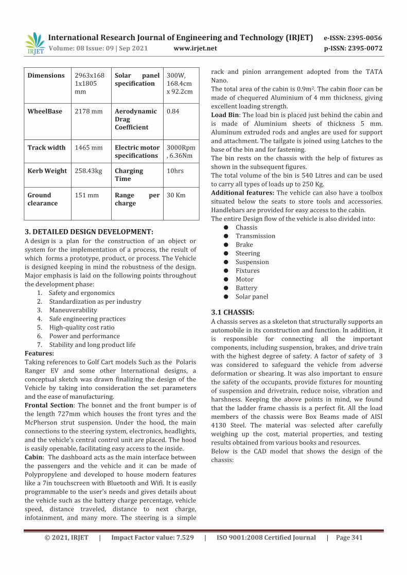
Below is the CAD model that shows the design of the
chassis:
International Research Journal of Engineering and Technology (IRJET) e-ISSN: 2395-0056
Volume: 08 Issue: 09 | Sep 2021 www.irjet.net p-ISSN: 2395-0072
© 2021, IRJET | Impact Factor value: 7.529 | ISO 9001:2008 Certified Journal | Page 342
Fig-1: Chassis Members
3.1.1 CHASSIS STRUCTURE AND MATERIAL SELECTION
The chassis can be built using a tubular space frame,
consisting of Rectangular tubes for a sturdy construction.
The chassis frame has two beams placed longitudinal (long
members) and connected with a number of cross
members ensuring stability and strength. The ladder
frame chassis is very durable and easy to construct. Since
the body is simply bolted to the ladder along with
everything else, parts and even whole sections can be
replaced relatively easily.
The longitudinal beams are Rectangular hollow tubes with
the following dimensions 60x40x3.6 mm and the cross
members are of dimensions 60x40x2.9 mm.
The frame for the seating arrangement and the loading bin are of square hollow tubes of dimensions 40x40x4 mm, at the front a U-channel of 75x40x5mm is added as a support member which also acts as an air dam. The Dimensions of the Vehicle chassis are 2887x1100x430mm (LxBxH). Selecting a Material with the most suitable properties was a challenging task. Properties, costs were mainly considered whilst designing the chassis. Materials of high strength yet lightweight and economical were thoroughly studied and AISI 4130 Alloy Steel was selected. In this alloy, Molybdenum and Chromium act as strengthening agents, which also has a low carbon content; the alloy also has excellent weldability. The mechanical properties of AISI 4130 are:
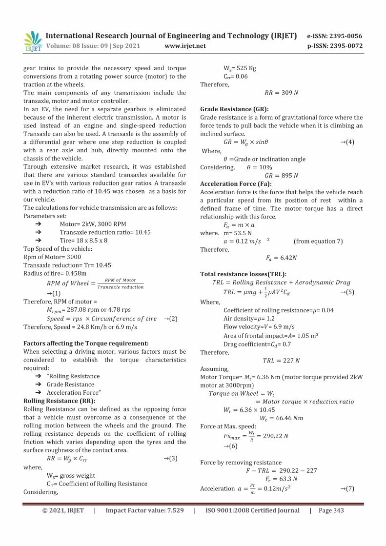
Table-2: AISI 4130 Mechanical Properties
Mechanical Properties Data
Density 7.7 g/cm3
Poisson's Ratio 0.3
Tensile Yield Strength 435 MPa
Ultimate Tensile strength 560 MPa
Elongations 28.2 mm
Bulk modulus 140GPa
Elastic modulus 210GPa
Shear modulus 80GPa
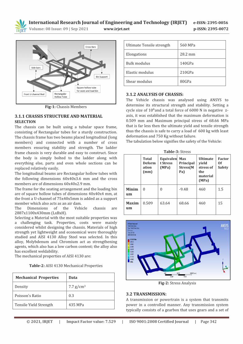
3.1.2 ANALYSIS OF CHASSIS: The Vehicle chassis was analysed using ANSYS to
determine its structural strength and stability. Setting a
cycle size of and a total force of 6000 N in negative z-
axis, it was established that the maximum deformation is
0.509 mm and Maximum principal stress of 68.66 MPa
that is far less then the ultimate yield and tensile strength
thus the chassis is safe to carry a load of 600 kg with least
deformation and 750 Kg without failure.
The tabulation below signifies the safety of the Vehicle:
Table-3: Stress
Total Deformation (mm)
Equivalent Stress (MPa)
Max Principal Stress(MPa)
Ultimate yield stress of the material (MPa)
Factor Of Safety
Minimum
0 0 -9.48 460 1.5
Maximum
0.509 63.64 68.66 460 15
Fig-2: Stress Analysis
3.2 TRANSMISSION: A transmission or powertrain is a system that transmits
power in a controlled manner. Any transmission system
typically consists of a gearbox that uses gears and a set of
International Research Journal of Engineering and Technology (IRJET) e-ISSN: 2395-0056
Volume: 08 Issue: 09 | Sep 2021 www.irjet.net p-ISSN: 2395-0072
© 2021, IRJET | Impact Factor value: 7.529 | ISO 9001:2008 Certified Journal | Page 343
gear trains to provide the necessary speed and torque
conversions from a rotating power source (motor) to the
traction at the wheels.
The main components of any transmission include the
transaxle, motor and motor controller.
In an EV, the need for a separate gearbox is eliminated
because of the inherent electric transmission. A motor is
used instead of an engine and single-speed reduction
Transaxle can also be used. A transaxle is the assembly of
a differential gear where one step reduction is coupled
with a rear axle and hub, directly mounted onto the
chassis of the vehicle.
Through extensive market research, it was established
that there are various standard transaxles available for
use in EV’s with various reduction gear ratios. A transaxle
with a reduction ratio of 10.45 was chosen as a basis for
our vehicle.
The calculations for vehicle transmission are as follows:
Parameters set:
➔ Motor= 2kW, 3000 RPM
➔ Transaxle reduction ratio= 10.45
➔ Tire= 18 x 8.5 x 8
Top Speed of the vehicle:
Rpm of Motor= 3000
Transaxle reduction= Tr= 10.45
Radius of tire= 0.458m
(1)
Therefore, RPM of motor = = 287.08 rpm or 4.78 rps
(2)
Therefore, Speed = 24.8 Km/h or 6.9 m/s
Factors affecting the Torque requirement:
When selecting a driving motor, various factors must be
considered to establish the torque characteristics
required:
➔ “Rolling Resistance
➔ Grade Resistance
➔ Acceleration Force”
Rolling Resistance.(RR):
Rolling Resistance can be defined as the opposing force
that a vehicle must overcome as a consequence of the
rolling motion between the wheels and the ground. The
rolling resistance depends on the coefficient of rolling
friction which varies depending upon the tyres and the
surface roughness of the contact area.
(3)
where,
Wg= gross weight
Crr= Coefficient of Rolling Resistance
Considering,
Wg= 525 Kg
Crr= 0.06
Therefore,
Grade.Resistance.(GR):
Grade resistance is a form of gravitational force where the
force tends to pull back the vehicle when it is climbing an
inclined surface.
(4)
Where,
Grade or inclination angle
Considering,
Acceleration.Force.(Fa):
Acceleration force is the force that helps the vehicle reach
a particular speed from its position of rest within a
defined frame of time. The motor torque has a direct
relationship with this force.
where. m= 53.5 N
(from equation 7)
Therefore,
Total resistance losses(TRL):
(5)
Where,
Coefficient of rolling resistance=𝜇= 0.04
Air density= = 1.2
Flow velocity= = 6.9 m/s
Area of frontal impact= = 1.05 mᒾ
Drag coefficient= = 0.7
Therefore,
Assuming,
Motor Torque= = 6.36 Nm (motor torque provided 2kW
motor at 3000rpm)
Force at Max. speed:
(6)
Force by removing resistance
Acceleration
(7)
International Research Journal of Engineering and Technology (IRJET) e-ISSN: 2395-0056
Volume: 08 Issue: 09 | Sep 2021 www.irjet.net p-ISSN: 2395-0072
© 2021, IRJET | Impact Factor value: 7.529 | ISO 9001:2008 Certified Journal | Page 344
(8)
Distance:
(9)
Therefore,
Total Tractive Effort.(TTE):
The Total Tractive Effort is the total force required to
move the vehicle.
(10)
In most conditions, the gradient force is neglected due to
the assumed driving conditions,
Torque required.at the.wheel: The torque that is required to overcome traction. (11) where,
Similarly, considering the Grade resistance,
Max Torque:
It is necessary to check if the wheels of the vehicle are
capable of transmitting the required torque. The
maximum torque that can be transmitted through the
vehicles wheels needs to be calculated and is given by:
(12)
For satisfactory performance of the vehicle,
As this condition is satisfied, there will be no slipping of
the wheels.
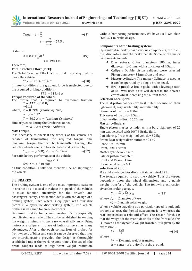
3.3 BRAKES: The braking system is one of the most important systems
in a vehicle as it is used to reduce the speed of the vehicle.
It must function effectively for the driver's and
passengers' safety. This section deals with the design of a
braking system, Each wheel is equipped with four disc
rotors in a hydraulic disc braking system. The vehicle
braking is designed for two-seater cars.
Designing brakes for a multi-seater EV is especially
complicated as a trade off has to be established in keeping
the weight minimum to increase overall efficiency. Using
motorcycle calipers in place of bulky calipers has many
advantages. After a thorough comparison of brakes for
front wheels of bikes and cars, it can be observed that they
are interchangeable provided the design is thoroughly
established under the working conditions . The use of bike
brake calipers leads to significant weight reduction,
without hampering performance. We have used Stainless
Steel 321 in brake design.
Components of the braking system:
Hydraulic disc brakes have various components, these are
the disc rotors and the brake pedals. Some of the major
components include:
➔ Disc rotors: Outer diameter= 180mm, inner
diameter= 140mm, with a thickness of 4.5mm.
➔ Caliper: Double piston calipers were selected.
Piston diameter= 34mm front and rear.
➔ Master cylinder: The master Cylinder is used as
it can be operated by a single brake pedal.
➔ Brake pedal: A brake pedal with a leverage ratio
of 6:1 was used as it will decrease the driver's
effort whilst increasing the output force.
Selection of calipers:
The dual-piston calipers are best suited because of their
lightweight, easy availability and reliability.
Diameter of the disc= 180mm
Thickness of the disc= 4.5mm
Effective disc radius= 56.25mm
Master cylinders:
Single piston master cylinder with a bore diameter of 22
mm was selected with DOT 3 Brake fluid.
Considering, Gross weight of vehicle= 525kg
Front: Rear weight distribution = 40 : 60
Rear, OD= 190mm
Front, OD= 170mm
Master cylinder= 22 mm
Caliper piston diameter:
Front and Rear= 34mm
Brake pedal ratio= 6:1
Selection of Rotor :
Material envisaged for discs is Stainless steel 321.
The torque required to stop the vehicle, Tb is the torque
dependent upon the wheel dimensions and dynamic
weight transfer of the vehicle. The following expression
gives the braking torque.
(13)
Where, Diameter.of tyre
Dynamic.axial weight
When a vehicle traveling at a particular speed is suddenly
brought to rest, the frontal suspension jolts whereas the
rear experiences a rebound effect. The reason for this is
that the weight of the rear axle shifts to the front axle, this
is known as the dynamic weight transfer. It is given by the
expression:
(14)
Where,
Dynamic weight transfer.
center of gravity from the ground.
International Research Journal of Engineering and Technology (IRJET) e-ISSN: 2395-0056
Volume: 08 Issue: 09 | Sep 2021 www.irjet.net p-ISSN: 2395-0072
© 2021, IRJET | Impact Factor value: 7.529 | ISO 9001:2008 Certified Journal | Page 345
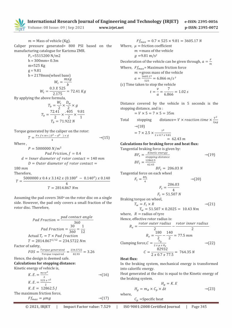
Mass of vehicle (Kg).
Caliper pressure generated= 800 PSI based on the
manufacturing catalogue for Karizma ZMR.
Pa =5515200 N/m2
h = 300mm= 0.3m
m=525 Kg
g = 9.81
b = 2178mm(wheel base)
By applying the above formula,
Torque generated by the caliper on the rotor:
(15)
Where ,
Therefore,
Assuming the pad covers 360o on the rotor disc on a single
side. However, the pad only covers a small fraction of the
rotor disc. Therefore,
Actual
Factor of safety,
Hence, the design is deemed safe.
Calculations for stopping distance:
Kinetic energy of vehicle is,
(16)
The maximum friction force,
(17)
Where, friction coefficient
mass of the vehicle
9.81 m/s2
Deceleration of the vehicle can be given through,
Where, = Maximum friction force
gross mass of the vehicle
ᒾ
(c) Time taken to stop the vehicle
Distance covered by the vehicle in 5 seconds is the
stopping distance, and is :
Total stopping distance
(18)
Calculations for braking force and heat flux:
Tangential braking force is given by:
(19)
Tangential force on each wheel
(20)
Braking torque on wheel,
(21)
where, radius of tyre
Hence, effective rotor radius is:
Clamping force,
(22)
Heat.flux:
In the braking system, mechanical energy is transformed
into calorific energy.
Heat generated at the disc is equal to the Kinetic energy of
the braking system.
(23)
where,
Specific heat
International Research Journal of Engineering and Technology (IRJET) e-ISSN: 2395-0056
Volume: 08 Issue: 09 | Sep 2021 www.irjet.net p-ISSN: 2395-0072
© 2021, IRJET | Impact Factor value: 7.529 | ISO 9001:2008 Certified Journal | Page 346
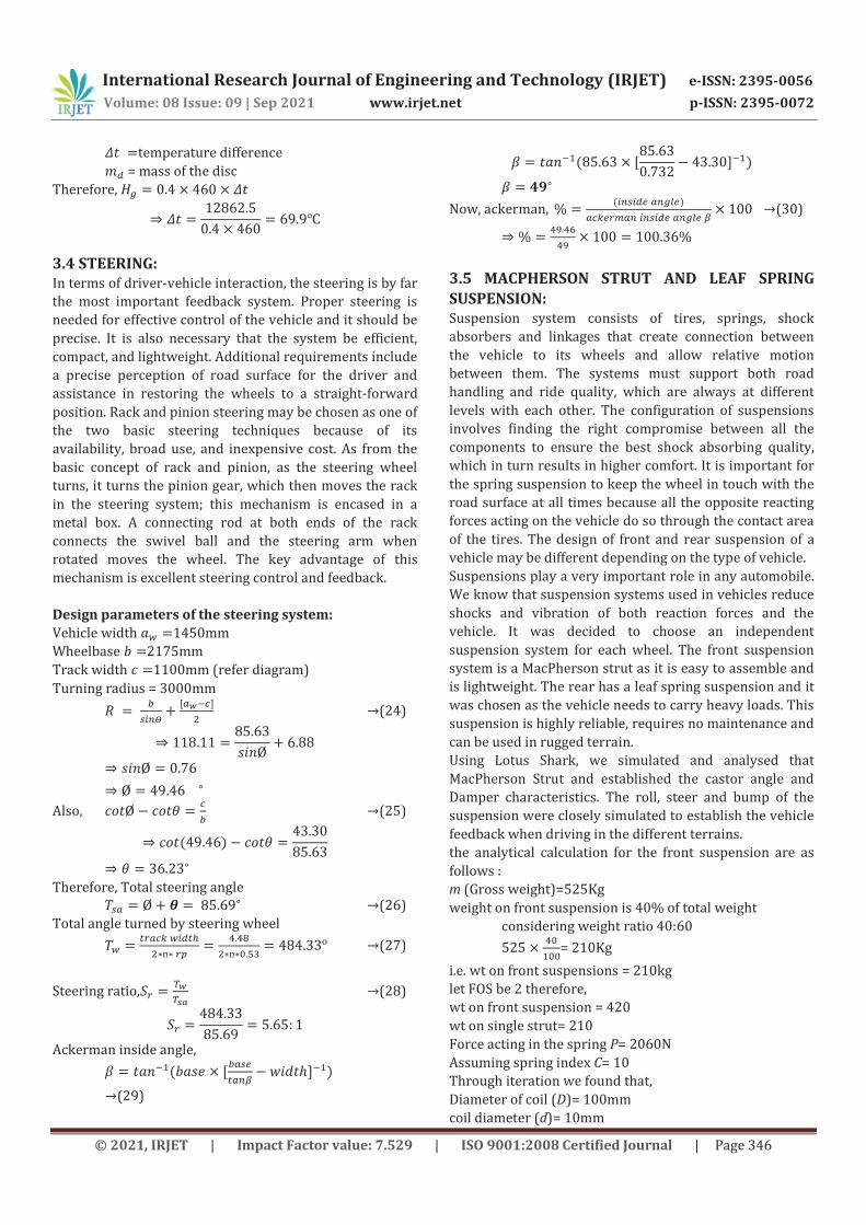
temperature difference
= mass of the disc
Therefore,
3.4 STEERING: In terms of driver-vehicle interaction, the steering is by far
the most important feedback system. Proper steering is
needed for effective control of the vehicle and it should be
precise. It is also necessary that the system be efficient,
compact, and lightweight. Additional requirements include
a precise perception of road surface for the driver and
assistance in restoring the wheels to a straight-forward
position. Rack and pinion steering may be chosen as one of
the two basic steering techniques because of its
availability, broad use, and inexpensive cost. As from the
basic concept of rack and pinion, as the steering wheel
turns, it turns the pinion gear, which then moves the rack
in the steering system; this mechanism is encased in a
metal box. A connecting rod at both ends of the rack
connects the swivel ball and the steering arm when
rotated moves the wheel. The key advantage of this
mechanism is excellent steering control and feedback.
Design parameters of the steering system:
Vehicle width 1450mm
Wheelbase 2175mm
Track width 1100mm (refer diagram)
Turning radius = 3000mm
(24)
Also,
(25)
Therefore, Total steering angle (26)
Total angle turned by steering wheel
(27)
Steering ratio,
(28)
Ackerman inside angle,
(29)
Now, ackerman,
(30)
3.5 MACPHERSON STRUT AND LEAF SPRING
SUSPENSION: Suspension system consists of tires, springs, shock
absorbers and linkages that create connection between
the vehicle to its wheels and allow relative motion
between them. The systems must support both road
handling and ride quality, which are always at different
levels with each other. The configuration of suspensions
involves finding the right compromise between all the
components to ensure the best shock absorbing quality,
which in turn results in higher comfort. It is important for
the spring suspension to keep the wheel in touch with the
road surface at all times because all the opposite reacting
forces acting on the vehicle do so through the contact area
of the tires. The design of front and rear suspension of a
vehicle may be different depending on the type of vehicle.
Suspensions play a very important role in any automobile.
We know that suspension systems used in vehicles reduce
shocks and vibration of both reaction forces and the
vehicle. It was decided to choose an independent
suspension system for each wheel. The front suspension
system is a MacPherson strut as it is easy to assemble and
is lightweight. The rear has a leaf spring suspension and it
was chosen as the vehicle needs to carry heavy loads. This
suspension is highly reliable, requires no maintenance and
can be used in rugged terrain.
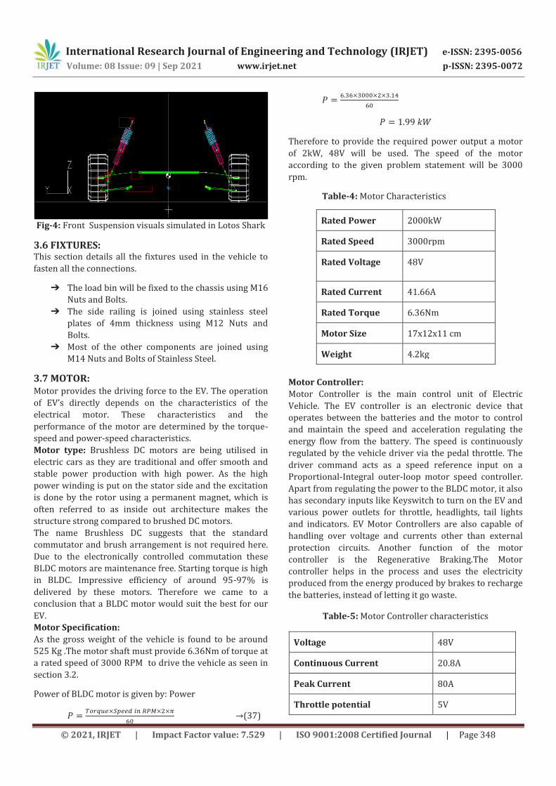
Using Lotus Shark, we simulated and analysed that
MacPherson Strut and established the castor angle and
Damper characteristics. The roll, steer and bump of the
suspension were closely simulated to establish the vehicle
feedback when driving in the different terrains.
the analytical calculation for the front suspension are as
follows :
m (Gross weight)=525Kg
weight on front suspension is 40% of total weight
considering weight ratio 40:60
= 210Kg
i.e. wt on front suspensions = 210kg
let FOS be 2 therefore,
wt on front suspension = 420
wt on single strut= 210
Force acting in the spring P= 2060N
Assuming spring index C= 10
Through iteration we found that,
Diameter of coil (D)= 100mm
coil diameter (d)= 10mm
International Research Journal of Engineering and Technology (IRJET) e-ISSN: 2395-0056
Volume: 08 Issue: 09 | Sep 2021 www.irjet.net p-ISSN: 2395-0072
© 2021, IRJET | Impact Factor value: 7.529 | ISO 9001:2008 Certified Journal | Page 347
and number of turns n= 8
Wahl’s factor,
(31)
Shear stress,
(32)
Material considered is spring steel which has shear
strength of 1380MPa, thus the dimensions assumed are
safe.
Solid length of
Free length of spring,
where is the Max Compression,
(33)
therefore, the Free length of spring is
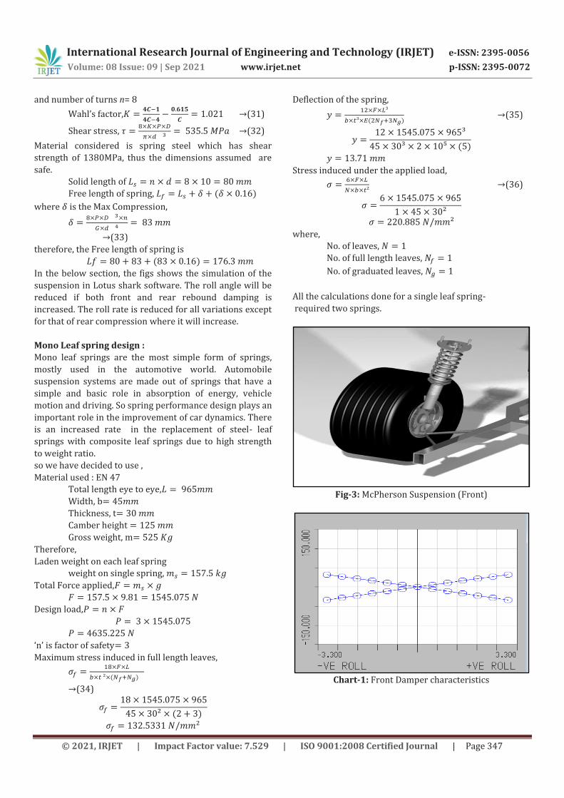
In the below section, the figs shows the simulation of the
suspension in Lotus shark software. The roll angle will be
reduced if both front and rear rebound damping is
increased. The roll rate is reduced for all variations except
for that of rear compression where it will increase.
Mono Leaf spring design :
Mono leaf springs are the most simple form of springs,
mostly used in the automotive world. Automobile
suspension systems are made out of springs that have a
simple and basic role in absorption of energy, vehicle
motion and driving. So spring performance design plays an
important role in the improvement of car dynamics. There
is an increased rate in the replacement of steel- leaf
springs with composite leaf springs due to high strength
to weight ratio.
so we have decided to use ,
Material used : EN 47
Total length eye to eye,
Width, b
Thickness, t
Camber height
Gross weight, m
Therefore,
Laden weight on each leaf spring
weight on single spring,
Total Force applied,
Design load,
‘n’ is factor of safety
Maximum stress induced in full length leaves,
(34)
Deflection of the spring,
(35)
Stress induced under the applied load,
(36)
where,
No. of leaves,
No. of full length leaves,
No. of graduated leaves,
All the calculations done for a single leaf spring-
required two springs.
Fig-3: McPherson Suspension (Front)
Chart-1: Front Damper characteristics
International Research Journal of Engineering and Technology (IRJET) e-ISSN: 2395-0056
Volume: 08 Issue: 09 | Sep 2021 www.irjet.net p-ISSN: 2395-0072
© 2021, IRJET | Impact Factor value: 7.529 | ISO 9001:2008 Certified Journal | Page 348
Fig-4: Front Suspension visuals simulated in Lotos Shark
3.6 FIXTURES: This section details all the fixtures used in the vehicle to
fasten all the connections.
➔ The load bin will be fixed to the chassis using M16
Nuts and Bolts.
➔ The side railing is joined using stainless steel
plates of 4mm thickness using M12 Nuts and
Bolts.
➔ Most of the other components are joined using
M14 Nuts and Bolts of Stainless Steel.
3.7 MOTOR: Motor provides the driving force to the EV. The operation
of EV’s directly depends on the characteristics of the
electrical motor. These characteristics and the
performance of the motor are determined by the torque-
speed and power-speed characteristics.
Motor type: Brushless DC motors are being utilised in
electric cars as they are traditional and offer smooth and
stable power production with high power. As the high
power winding is put on the stator side and the excitation
is done by the rotor using a permanent magnet, which is
often referred to as inside out architecture makes the
structure strong compared to brushed DC motors.
The name Brushless DC suggests that the standard
commutator and brush arrangement is not required here.
Due to the electronically controlled commutation these
BLDC motors are maintenance free. Starting torque is high
in BLDC. Impressive efficiency of around 95-97% is
delivered by these motors. Therefore we came to a
conclusion that a BLDC motor would suit the best for our
EV.
Motor Specification:
As the gross weight of the vehicle is found to be around
525 Kg .The motor shaft must provide 6.36Nm of torque at
a rated speed of 3000 RPM to drive the vehicle as seen in
section 3.2.
Power of BLDC motor is given by: Power
(37)
Therefore to provide the required power output a motor
of 2kW, 48V will be used. The speed of the motor
according to the given problem statement will be 3000
rpm.
Table-4: Motor Characteristics
Rated Power 2000kW
Rated Speed 3000rpm
Rated Voltage 48V
Rated Current 41.66A
Rated Torque 6.36Nm
Motor Size 17x12x11 cm
Weight 4.2kg
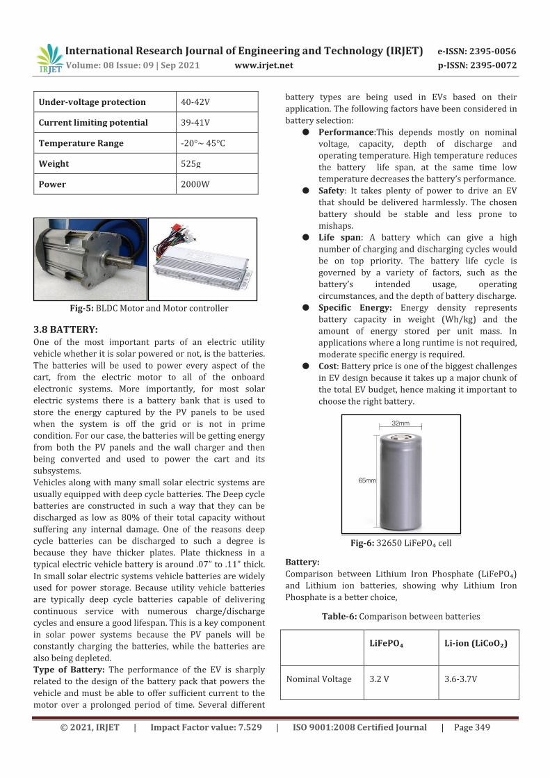
Motor Controller:
Motor Controller is the main control unit of Electric
Vehicle. The EV controller is an electronic device that
operates between the batteries and the motor to control
and maintain the speed and acceleration regulating the
energy flow from the battery. The speed is continuously
regulated by the vehicle driver via the pedal throttle. The
driver command acts as a speed reference input on a
Proportional-Integral outer-loop motor speed controller.
Apart from regulating the power to the BLDC motor, it also
has secondary inputs like Keyswitch to turn on the EV and
various power outlets for throttle, headlights, tail lights
and indicators. EV Motor Controllers are also capable of
handling over voltage and currents other than external
protection circuits. Another function of the motor
controller is the Regenerative Braking.The Motor
controller helps in the process and uses the electricity
produced from the energy produced by brakes to recharge
the batteries, instead of letting it go waste.
Table-5: Motor Controller characteristics
Voltage 48V
Continuous Current 20.8A
Peak Current 80A
Throttle potential 5V
International Research Journal of Engineering and Technology (IRJET) e-ISSN: 2395-0056
Volume: 08 Issue: 09 | Sep 2021 www.irjet.net p-ISSN: 2395-0072
© 2021, IRJET | Impact Factor value: 7.529 | ISO 9001:2008 Certified Journal | Page 349
Under-voltage protection 40-42V
Current limiting potential 39-41V
Temperature Range -20°~ 45°C
Weight 525g
Power 2000W
Fig-5: BLDC Motor and Motor controller
3.8 BATTERY: One of the most important parts of an electric utility
vehicle whether it is solar powered or not, is the batteries.
The batteries will be used to power every aspect of the
cart, from the electric motor to all of the onboard
electronic systems. More importantly, for most solar
electric systems there is a battery bank that is used to
store the energy captured by the PV panels to be used
when the system is off the grid or is not in prime
condition. For our case, the batteries will be getting energy
from both the PV panels and the wall charger and then
being converted and used to power the cart and its
subsystems.
Vehicles along with many small solar electric systems are
usually equipped with deep cycle batteries. The Deep cycle
batteries are constructed in such a way that they can be
discharged as low as 80% of their total capacity without
suffering any internal damage. One of the reasons deep
cycle batteries can be discharged to such a degree is
because they have thicker plates. Plate thickness in a
typical electric vehicle battery is around .07” to .11” thick.
In small solar electric systems vehicle batteries are widely
used for power storage. Because utility vehicle batteries
are typically deep cycle batteries capable of delivering
continuous service with numerous charge/discharge
cycles and ensure a good lifespan. This is a key component
in solar power systems because the PV panels will be
constantly charging the batteries, while the batteries are
also being depleted.
Type of Battery: The performance of the EV is sharply
related to the design of the battery pack that powers the
vehicle and must be able to offer sufficient current to the
motor over a prolonged period of time. Several different
battery types are being used in EVs based on their
application. The following factors have been considered in
battery selection:
● Performance:This depends mostly on nominal
voltage, capacity, depth of discharge and
operating temperature. High temperature reduces
the battery life span, at the same time low
temperature decreases the battery’s performance.
● Safety: It takes plenty of power to drive an EV
that should be delivered harmlessly. The chosen
battery should be stable and less prone to
mishaps.
● Life span: A battery which can give a high
number of charging and discharging cycles would
be on top priority. The battery life cycle is
governed by a variety of factors, such as the
battery’s intended usage, operating
circumstances, and the depth of battery discharge.
● Specific Energy: Energy density represents
battery capacity in weight (Wh/kg) and the
amount of energy stored per unit mass. In
applications where a long runtime is not required,
moderate specific energy is required.
● Cost: Battery price is one of the biggest challenges
in EV design because it takes up a major chunk of
the total EV budget, hence making it important to
choose the right battery.
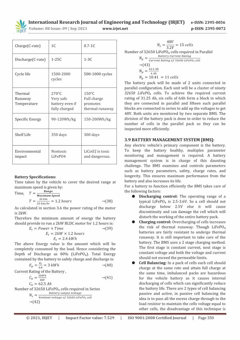
Fig-6: 32650 LiFePO₄ cell
Battery:
Comparison between Lithium Iron Phosphate (LiFePO₄)
and Lithium ion batteries, showing why Lithium Iron
Phosphate is a better choice,
Table-6: Comparison between batteries
LiFePO₄ Li-ion (LiCoO₂)
Nominal Voltage 3.2 V 3.6-3.7V
International Research Journal of Engineering and Technology (IRJET) e-ISSN: 2395-0056
Volume: 08 Issue: 09 | Sep 2021 www.irjet.net p-ISSN: 2395-0072
© 2021, IRJET | Impact Factor value: 7.529 | ISO 9001:2008 Certified Journal | Page 350
Charge(C-rate) 1C 0.7-1C
Discharge(C-rate) 1-25C 1-3C
Cycle life 1500-2000
cycles
500-1000 cycles
Thermal
Runaway
Temperature
270°C
Very safe
battery even if
fully charged
150°C
Full charge
promotes
thermal runaway
Specific Energy 90-120Wh/kg 150-200Wh/kg
Shelf Life 350 days 300 days
Environmental
impact
Nontoxic
LiFePO4
LiCoO2 is toxic
and dangerous.
Battery Specifications:
Time taken by the vehicle to cover the desired range at
maximum speed is given by:
Time,
(38)
As calculated in section 3.6 the power rating of the motor
is 2kW.
Therefore the minimum amount of energy the battery
should provide to run a 2kW BLDC motor for 1.2 hours is:
(39)
The above Energy value is the amount which will be
completely consumed by the load. Hence considering the
Depth of Discharge as 80% (LiFePO₄). Total Energy
contained by the battery to safely charge and discharge is:
(40)
Current Rating of the Battery ,
(41)
Number of 32650 LiFePO₄ cells required in Series
(42)
Number of 32650 LiFePO₄ cells required in Parallel
(43)
The battery pack will be made of 2 units connected in
parallel configuration. Each unit will be a cluster of ninety
32650 LiFePO₄ cells. To achieve the required current
rating of 31.25 Ah, six cells of 6Ah form a block in which
they are connected in parallel and fifteen such parallel
blocks are connected in series to add up the voltages to get
48V. Both units are monitored by two separate BMS. The
division of the battery pack is done in order to reduce the
number of cells in the parallel pack so they can be
inspected more efficiently.
3.9 BATTERY MANAGEMENT SYSTEM [BMS]: Any electric vehicle's primary component is the battery.
To keep the battery healthy, multiplex parameter
monitoring and management is required. A battery
management system is in charge of this daunting
challenge. The BMS examines and controls parameters
such as battery parameters, safety, charge rates, and
longevity. This ensures maximum performance from the
battery and also increases its life.
For a battery to function efficiently the BMS takes care of
the following factors:
● Discharging control: The operating range of a
typical LiFePO₄ is 2.5-3.6V. So a cell should not
discharge below 2.5V else it will cause
discontinuity and can damage the cell which will
disturb the working of the entire battery pack.
● Charging control: Overcharging of cells increases
the risk of thermal runaway. Though LiFePO₄
batteries are fairly resistant to undergo thermal
runaway. It is still important to take care of the
battery. The BMS uses a 2 stage charging method.
The first stage is constant current, next stage is
constant voltage and both the voltage and current
should not exceed the permeable limits.
● Cell Balancing: In a pack of cells each cell should
charge at the same rate and attain full charge at
the same time, imbalanced packs are hazardous
for the vehicle battery as it causes internal
discharging of cells which can significantly reduce
the battery life. There are 2 types of cell balancing
passive and active, in passive cell balancing the
idea is to pass all the excess charge through to the
load resistor to maintain the cells voltage equal to
other cells, the disadvantage of this technique is
International Research Journal of Engineering and Technology (IRJET) e-ISSN: 2395-0056
Volume: 08 Issue: 09 | Sep 2021 www.irjet.net p-ISSN: 2395-0072
© 2021, IRJET | Impact Factor value: 7.529 | ISO 9001:2008 Certified Journal | Page 351
that it only helps with the problem of
overcharging but while the cells are discharging if
a cell reaches its limit early then BMS will cut off
the supply thus the remaining charges in battery
are gone to waste but this method is very cheap
as compared to active technique and in active cell
balancing cells with higher voltages are used to
charge cells at lower voltages this is better when
compared to passive cell balancing as it also
solves the problem of discharging at the same
value.
● State of charge: The current level of charge
remaining in the battery in relation to its capacity
is referred to as the battery's state of charge. Its
limit is defined by the depth of discharge. For
LiFePO₄ battery the maximum DoD is 80%.
● Temperature monitoring: Temp of the battery is
directly correlated to performance of the battery.
The battery temp increases when the battery is
being charged or discharged hence should be
constantly monitored and maintained within the
safety limits.
● State of health: As the battery ages the
performance of the battery depletes. If a high
current is drawn, discharge is much quicker and
also the temperature rises.
After acquiring the battery and current requirements from
section 3.7 we are using a 15S LiFePO₄ BMS which
supports up to 50A continuous current. The BMS comes
with 2 temperature sensors to keep a track of the
temperature at two different points in the battery pack.
The BMS cut off the battery supply from the main system
in case of overcurrent of order 100-120A. Additionally the
chosen BMS can be coupled with a Bluetooth module and
the inspected factors can be seen on a mobile application.
3.10 SOLAR PANEL: A photovoltaic (PV) or thin silicon film panel is mounted
on top of the car roof, or a PV panel is used as the roof
itself, to power solar EVs. Solar Panels are an effective way
to harness energy from the sun and help power the utility
vehicle along with the charge from a wall outlet. The
vehicle we obtained for this project is already equipped
with two Grape Solar at High Efficiency Mono-Crystalline
Photovoltaic panels. Unfortunately, these two panels alone
will not be strong enough to completely charge the battery
bank, but the idea is that they will at the least help prolong
the discharge time of the batteries. Realistically, this
should considerably help with the power consumption
from all of our onboard electronic subsystems as well. The
two roof-mounted solar panels will be used to convert the
photonic energy from the sun into usable electricity. These
panels will be used to charge the batteries in order to
provide power to the utility vehicle. In order to harness as
much energy as possible from these solar panels, the
wiring configuration to the motor and subsystems is
critical. Wiring these panels in series yields the most
voltage to charge the batteries. Another option would be
to wire these panels in parallel to produce a higher
current, however; this could cause power loss due to one
of the panels receiving less sunlight.
A Monocrystalline Type Solar panel is used which has
higher efficiency as compared to other panel types (i.e
20% whereas other panels have around 15%-17% eg:
polycrystalline type).
We will be using a 300W/60V solar panel with dimensions
as 168.4cm x 92.2cm which can easily fit on our EV. Higher
wattage will charge faster but it will occupy more space
and weigh more.
4. ELECTRONICS: Charge Controller: The type of Charge Controller we will
be using is Maximum Power Point Tracking (MPPT), which
is 30% more efficient than PWM controllers, the maximum
power point tracker sweeps across the panel voltage to
locate the optimal or best combination of voltage and
current for maximum power generation. The MPPT is
deviced to continuously monitor and fine-tune the output
voltage to generate maximal power in different weather
conditions. The solar controller auto severs the output
when the intensity of sunlight is not adequate.
SMPS charger: Switch Mode Power Supply shows higher
efficiency than conventional rectifier circuit. The rectified
mains are broken up into small pulses by SMPS, which
charge a capacitor. The pulse width can be varied to
control current demand and regulate output voltage. They
are capable of handling high input voltage fluctuations and
can provide constant current as well as constant voltage
charging hence able to charge in CV-CC configuration. The
rating of the charger used to charge the battery is 48V
15A SMPS charger.
Microcontroller Unit: The MCU takes control of all the
minor activities running throughout the vehicle as an
alarm unit, communication between components and
safety measures.
Electronic Thermal Overload Relay: Thermal overload
relays are connected in the current path. When the current
value surpasses a fixed threshold for a certain amount of
time, a thermally triggered mechanism opens the relay
contacts to interrupt current flow from the battery. Trip
class of a thermal overload relay determines the amount of
time for which the overload occurs before the relay
reciprocates the change. Electronic sensing of current
makes these relays more accurate and avoids false
tripping.
International Research Journal of Engineering and Technology (IRJET) e-ISSN: 2395-0056
Volume: 08 Issue: 09 | Sep 2021 www.irjet.net p-ISSN: 2395-0072
© 2021, IRJET | Impact Factor value: 7.529 | ISO 9001:2008 Certified Journal | Page 352
Wires: The majority of power flow in the EV takes place
between the Battery, Motor Controller, Motor and the
charger. To accomplish this task of withstanding high
currents without heating up, high grade silicone wires of
4-6 AWG rating are used. The silicone rubber coating
makes them fire resistant and ensures circuit integrity.
Regenerative Braking: The braking system in a vehicle is
a disc arrangement that helps to slow down the vehicle
and converts the kinetic energy into electric energy via
regenerative braking. Basically in the braking system
friction is produced between the brake pads and the disc,
this is the kinetic energy converted to heat which goes to
waste. However, in regenerative braking, some of the
energy is recovered, which is used to charge a battery. The
small scale electric vehicle has a small drivetrain
technology that harvests a lesser amount of braking
energy through regenerative braking. This system has
been brought up with low cost, Since it is designed to store
only a relatively small capacity of the braking energy, and
for a short period.
Calculations:
Work done by the brakes, Dk (Dk describes the energy
dissipated during braking per unit time)
(44)
Now,
(45)
A and B are standard constants: ;
β : 0.93 for normal driving (according to our specified
terrain of operation) on a plain path.
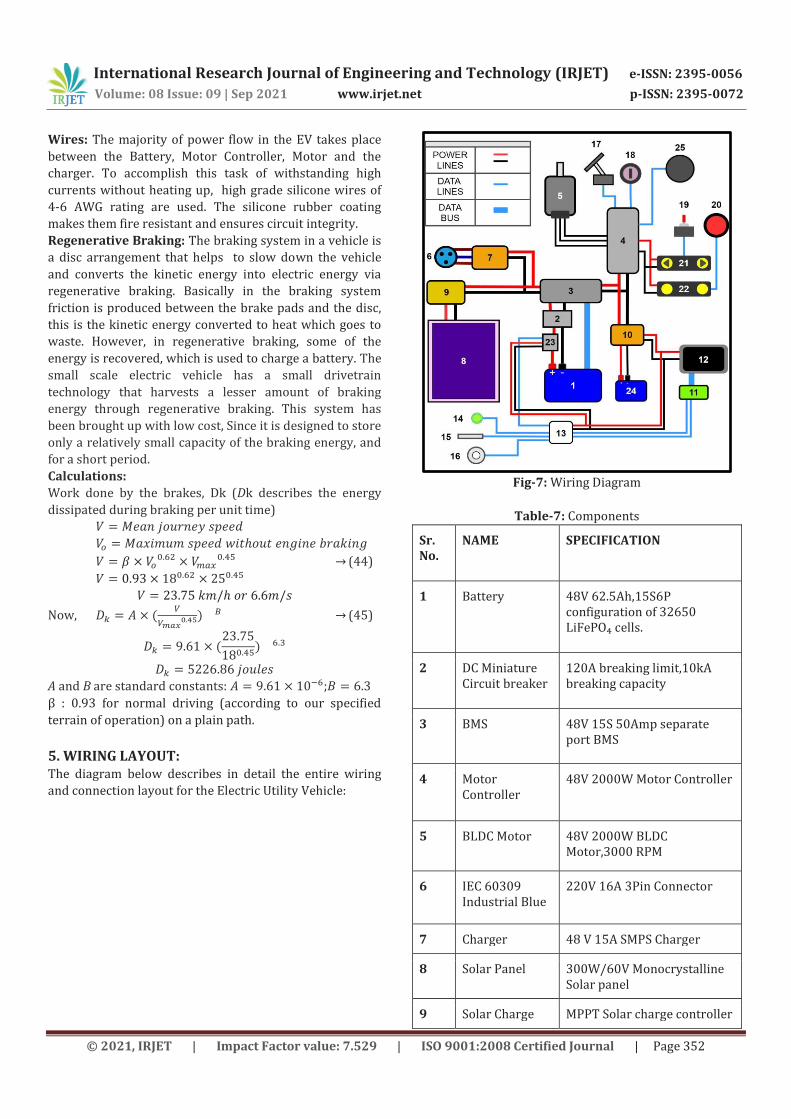
5. WIRING LAYOUT: The diagram below describes in detail the entire wiring
and connection layout for the Electric Utility Vehicle:
Fig-7: Wiring Diagram
Table-7: Components
Sr. No.
NAME SPECIFICATION
1 Battery 48V 62.5Ah,15S6P configuration of 32650 LiFePO₄ cells.
2 DC Miniature Circuit breaker
120A breaking limit,10kA breaking capacity
3 BMS 48V 15S 50Amp separate port BMS
4 Motor Controller
48V 2000W Motor Controller
5 BLDC Motor 48V 2000W BLDC Motor,3000 RPM
6 IEC 60309 Industrial Blue
220V 16A 3Pin Connector
7 Charger 48 V 15A SMPS Charger
8 Solar Panel 300W/60V Monocrystalline Solar panel
9 Solar Charge MPPT Solar charge controller
International Research Journal of Engineering and Technology (IRJET) e-ISSN: 2395-0056
Volume: 08 Issue: 09 | Sep 2021 www.irjet.net p-ISSN: 2395-0072
© 2021, IRJET | Impact Factor value: 7.529 | ISO 9001:2008 Certified Journal | Page 353
Controller
10 DC-DC Stepdown Converter
48V to 6V,3A Stepdown Converter
11 Touchscreen Display
7” Touchscreen Display
12 Display controller
-
13 Microcontroller Unit
MSP430G2553 Low power Microcontroller
14 Ambient Light Sensor
CJMCU-TEMT6000
15 Temperature Sensor
DS18B20 Waterproof Temperature Sensor
16 Odometer Rotary Encoder
17 Pedal Throttle -
18 Key Switch -
19 Indicator Toggle Switch
6A SPDT Toggle Switch
20 Push Button Self-Lock Non-Momentary Switch
21 Indicator Lights 12V Led Indicator Lights
22 Head Light 12V Led Headlights
23 Electronic Thermal Overload Relay
120A
24 Auxiliary Battery
12V 7Ah
25 Tyre brake set Disc brakes
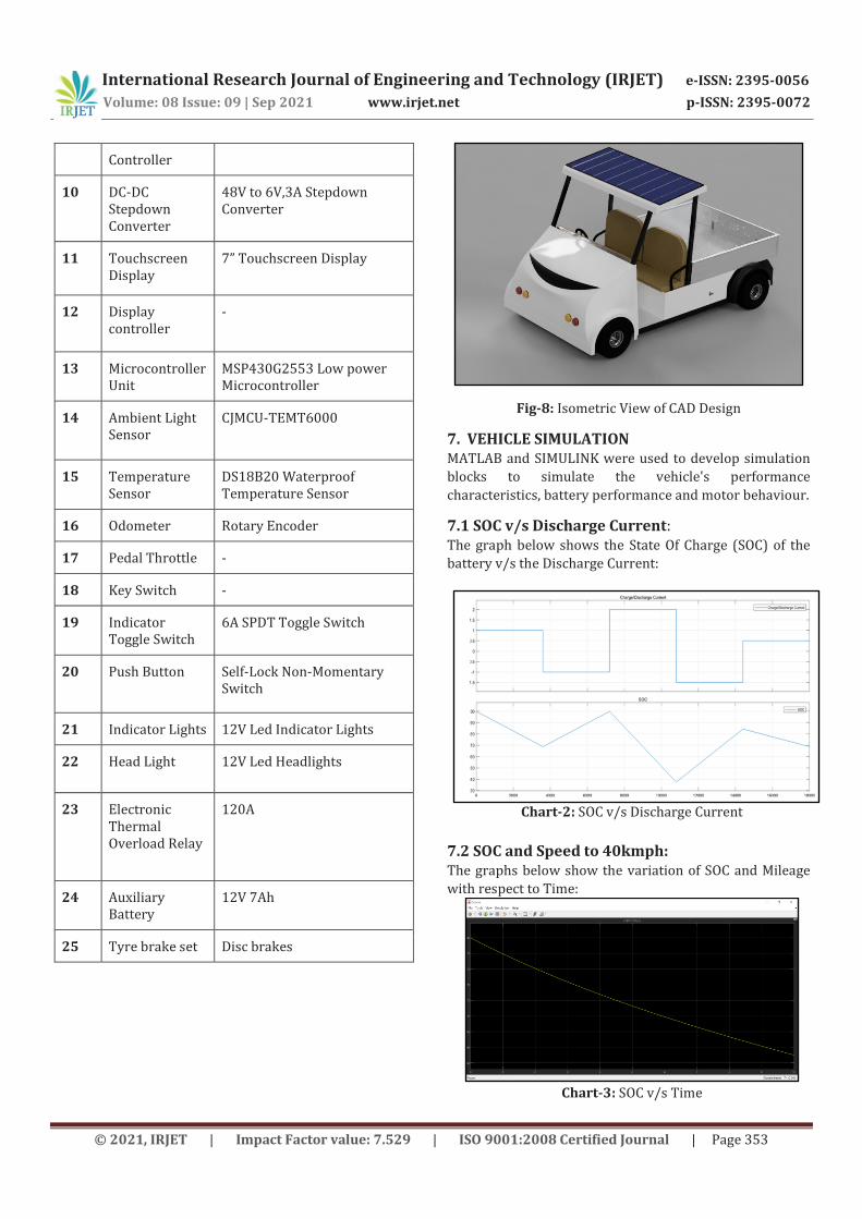
Fig-8: Isometric View of CAD Design
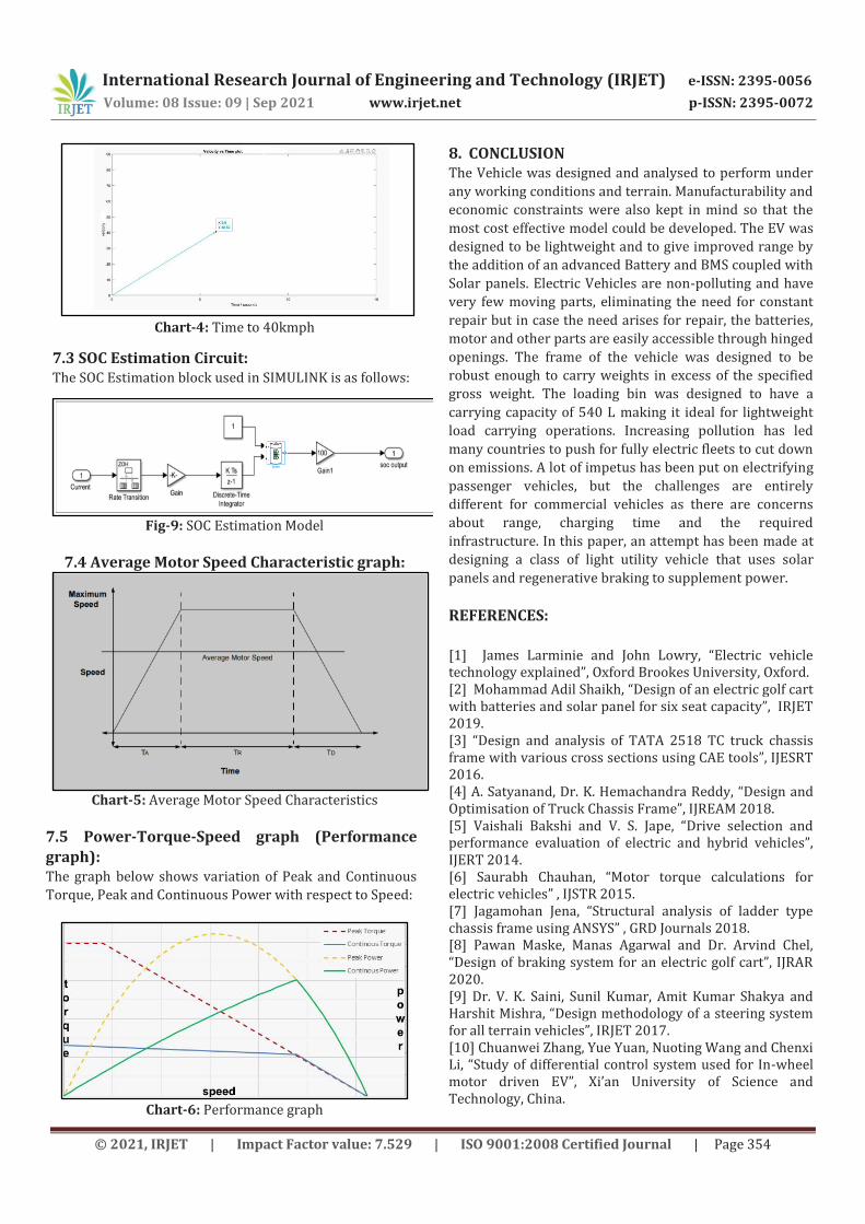
7. VEHICLE SIMULATION MATLAB and SIMULINK were used to develop simulation
blocks to simulate the vehicle's performance
characteristics, battery performance and motor behaviour.
7.1 SOC v/s Discharge Current: The graph below shows the State Of Charge (SOC) of the
battery v/s the Discharge Current:
Chart-2: SOC v/s Discharge Current
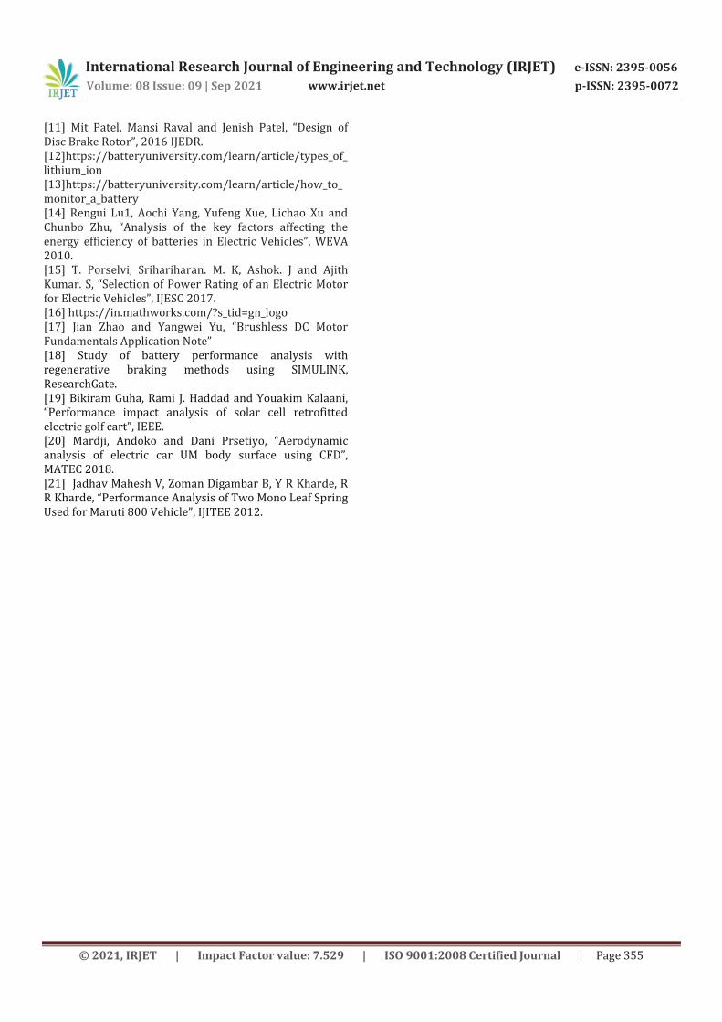
7.2 SOC and Speed to 40kmph: The graphs below show the variation of SOC and Mileage
with respect to Time:
Chart-3: SOC v/s Time
International Research Journal of Engineering and Technology (IRJET) e-ISSN: 2395-0056
Volume: 08 Issue: 09 | Sep 2021 www.irjet.net p-ISSN: 2395-0072
© 2021, IRJET | Impact Factor value: 7.529 | ISO 9001:2008 Certified Journal | Page 354
Chart-4: Time to 40kmph
7.3 SOC Estimation Circuit: The SOC Estimation block used in SIMULINK is as follows:
Fig-9: SOC Estimation Model
7.4 Average Motor Speed Characteristic graph:
Chart-5: Average Motor Speed Characteristics
7.5 Power-Torque-Speed graph (Performance
graph): The graph below shows variation of Peak and Continuous
Torque, Peak and Continuous Power with respect to Speed:
Chart-6: Performance graph
8. CONCLUSION The Vehicle was designed and analysed to perform under
any working conditions and terrain. Manufacturability and
economic constraints were also kept in mind so that the
most cost effective model could be developed. The EV was
designed to be lightweight and to give improved range by
the addition of an advanced Battery and BMS coupled with
Solar panels. Electric Vehicles are non-polluting and have
very few moving parts, eliminating the need for constant
repair but in case the need arises for repair, the batteries,
motor and other parts are easily accessible through hinged
openings. The frame of the vehicle was designed to be
robust enough to carry weights in excess of the specified
gross weight. The loading bin was designed to have a
carrying capacity of 540 L making it ideal for lightweight
load carrying operations. Increasing pollution has led
many countries to push for fully electric fleets to cut down
on emissions. A lot of impetus has been put on electrifying
passenger vehicles, but the challenges are entirely
different for commercial vehicles as there are concerns
about range, charging time and the required
infrastructure. In this paper, an attempt has been made at
designing a class of light utility vehicle that uses solar
panels and regenerative braking to supplement power.
REFERENCES:
[1] James Larminie and John Lowry, “Electric vehicle technology explained”, Oxford Brookes University, Oxford. [2] Mohammad Adil Shaikh, “Design of an electric golf cart with batteries and solar panel for six seat capacity”, IRJET 2019. [3] “Design and analysis of TATA 2518 TC truck chassis frame with various cross sections using CAE tools”, IJESRT 2016. [4] A. Satyanand, Dr. K. Hemachandra Reddy, “Design and Optimisation of Truck Chassis Frame”, IJREAM 2018. [5] Vaishali Bakshi and V. S. Jape, “Drive selection and performance evaluation of electric and hybrid vehicles”, IJERT 2014. [6] Saurabh Chauhan, “Motor torque calculations for electric vehicles” , IJSTR 2015. [7] Jagamohan Jena, “Structural analysis of ladder type chassis frame using ANSYS” , GRD Journals 2018. [8] Pawan Maske, Manas Agarwal and Dr. Arvind Chel, “Design of braking system for an electric golf cart”, IJRAR 2020. [9] Dr. V. K. Saini, Sunil Kumar, Amit Kumar Shakya and Harshit Mishra, “Design methodology of a steering system for all terrain vehicles”, IRJET 2017. [10] Chuanwei Zhang, Yue Yuan, Nuoting Wang and Chenxi Li, “Study of differential control system used for In-wheel motor driven EV”, Xi’an University of Science and Technology, China.
International Research Journal of Engineering and Technology (IRJET) e-ISSN: 2395-0056
Volume: 08 Issue: 09 | Sep 2021 www.irjet.net p-ISSN: 2395-0072
© 2021, IRJET | Impact Factor value: 7.529 | ISO 9001:2008 Certified Journal | Page 355
[11] Mit Patel, Mansi Raval and Jenish Patel, “Design of Disc Brake Rotor”, 2016 IJEDR. [12]https://batteryuniversity.com/learn/article/types_of_lithium_ion [13]https://batteryuniversity.com/learn/article/how_to_monitor_a_battery [14] Rengui Lu1, Aochi Yang, Yufeng Xue, Lichao Xu and Chunbo Zhu, “Analysis of the key factors affecting the energy efficiency of batteries in Electric Vehicles”, WEVA 2010. [15] T. Porselvi, Srihariharan. M. K, Ashok. J and Ajith Kumar. S, “Selection of Power Rating of an Electric Motor for Electric Vehicles”, IJESC 2017. [16] https://in.mathworks.com/?s_tid=gn_logo [17] Jian Zhao and Yangwei Yu, “Brushless DC Motor Fundamentals Application Note” [18] Study of battery performance analysis with regenerative braking methods using SIMULINK, ResearchGate. [19] Bikiram Guha, Rami J. Haddad and Youakim Kalaani, “Performance impact analysis of solar cell retrofitted electric golf cart”, IEEE. [20] Mardji, Andoko and Dani Prsetiyo, “Aerodynamic analysis of electric car UM body surface using CFD”, MATEC 2018. [21] Jadhav Mahesh V, Zoman Digambar B, Y R Kharde, R R Kharde, “Performance Analysis of Two Mono Leaf Spring Used for Maruti 800 Vehicle”, IJITEE 2012.