design for disassembly and augmented reality applied to a
TRANSCRIPT
actuators
Article
Design for Disassembly and Augmented RealityApplied to a Tailstock
Marco Freddi and Leonardo Frizziero *
Department of Industrial Engineering, ALMA MATER STUDIORUM University of Bologna,viale Risorgimento, 2, 40136 Bologna, Italy; [email protected]* Correspondence: [email protected]
Received: 11 September 2020; Accepted: 10 October 2020; Published: 13 October 2020�����������������
Abstract: The work here described aims to offer a starting point for improving and making a genericmaintenance process more efficient, first of all thanks to the use of a cutting-edge technology such asaugmented reality, as a key tool that makes it possible and immediate to communicate to operatorswhich are the fundamental stages of the maintenance process to be followed in the working area.Furthermore, thanks to the use of two methods applied in the context of the Design for Disassembly(later described), we also propose to search for all the possible sequences to get to the removal of atarget component to be adjusted—in particular the optimal one (if it exists, in terms of time and costs)to be subsequently applied in an augmented reality “self-disassembly” model that can be viewed andfollowed by the operator, in a way that is still very little used today.
Keywords: CAD; augmented reality; optimization; DFD; industrial maintenance
1. Introduction
In engineering, the abbreviation DFD indicates the Design for Disassembly, meaning all theactivities dedicated to the project of a disassembly sequence of the parts that make up a mechanicalassembly of any kind, in order to obtain a list of tasks that maintenance operators have to carry outto optimize the timing and costs of this procedure [1]. Assuming that it is needed to remove a worncomponent inside an industrial machinery, we can understand how easy it is to waste time if thelist of operations to be carried out is not clear. Especially with an assembly consisting of thousandsof components, there are more possible ways to get to the “target” (a specific part that needs to beanalyzed and repaired). This maintenance process can be in general preventive or corrective. In thefirst case, as can be guessed, its replacement occurs before it is faulty and unusable. This is the idealform of maintenance, because it allows the long-term use of the machinery without breaking one of itscomponents, avoiding possibly serious consequences both for its other elements and the surroundingenvironment (including the operators). Corrective maintenance, on the other hand, is performed oncethe damage has occurred. Often a part breakage damages many other components in the closestarea—a classic chain effect. This is due, for example, to the presence of eccentricities during the motionof unbalanced masses, rotating shafts or gears, such as toothed wheels, or due to a piece breakagewhich can violently impact the surrounding parts or, in the worst case, the working operators inuncontrolled conditions. As can be understood, this second form of maintenance should be avoidedas much as possible. There are several other disassembly methodologies today capable of exploitingautomated and computer-controlled processes; for these, please refer to the bibliography, these themesdiffer slightly from the focus of the article [2–4].
In general, a mechanical piece can be repaired and reused in the assembly’s future life, or replaced.In many cases, it is possible to recover part of the construction materials for a new components’manufacture [5]. DFD allows a better recovery of parts and materials, considerably efficient
Actuators 2020, 9, 102; doi:10.3390/act9040102 www.mdpi.com/journal/actuators
Actuators 2020, 9, 102 2 of 14
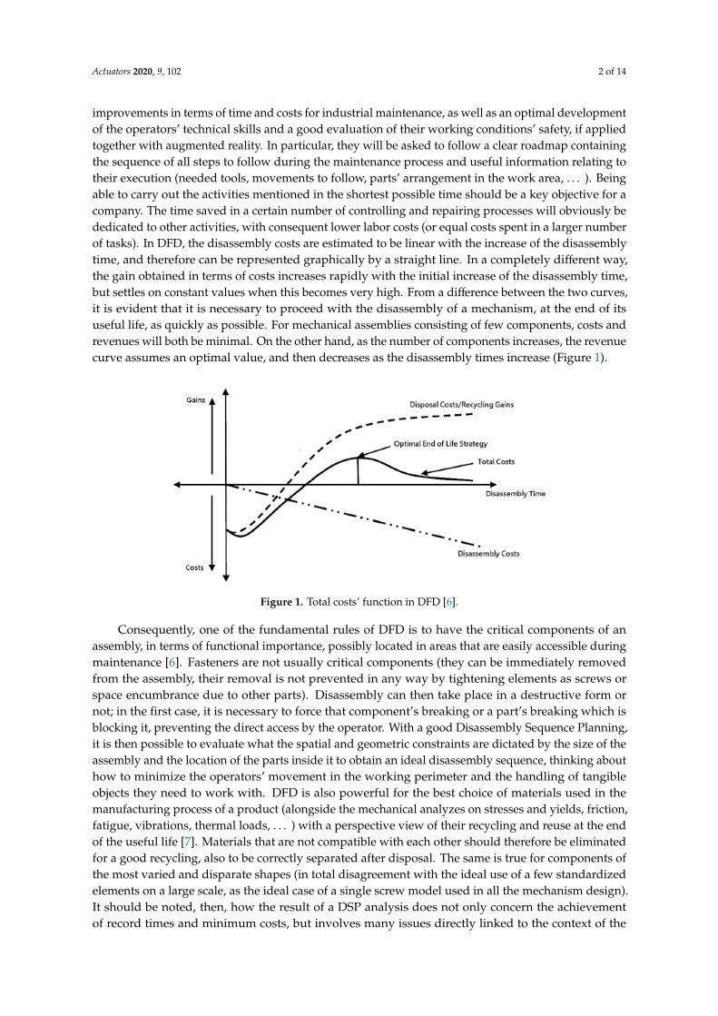
improvements in terms of time and costs for industrial maintenance, as well as an optimal developmentof the operators’ technical skills and a good evaluation of their working conditions’ safety, if appliedtogether with augmented reality. In particular, they will be asked to follow a clear roadmap containingthe sequence of all steps to follow during the maintenance process and useful information relating totheir execution (needed tools, movements to follow, parts’ arrangement in the work area, . . . ). Beingable to carry out the activities mentioned in the shortest possible time should be a key objective for acompany. The time saved in a certain number of controlling and repairing processes will obviously bededicated to other activities, with consequent lower labor costs (or equal costs spent in a larger numberof tasks). In DFD, the disassembly costs are estimated to be linear with the increase of the disassemblytime, and therefore can be represented graphically by a straight line. In a completely different way,the gain obtained in terms of costs increases rapidly with the initial increase of the disassembly time,but settles on constant values when this becomes very high. From a difference between the two curves,it is evident that it is necessary to proceed with the disassembly of a mechanism, at the end of itsuseful life, as quickly as possible. For mechanical assemblies consisting of few components, costs andrevenues will both be minimal. On the other hand, as the number of components increases, the revenuecurve assumes an optimal value, and then decreases as the disassembly times increase (Figure 1).
Actuators 2020, 9, x FOR PEER REVIEW 2 of 14
efficient improvements in terms of time and costs for industrial maintenance, as well as an optimal development of the operators’ technical skills and a good evaluation of their working conditions’ safety, if applied together with augmented reality. In particular, they will be asked to follow a clear roadmap containing the sequence of all steps to follow during the maintenance process and useful information relating to their execution (needed tools, movements to follow, parts’ arrangement in the work area, …). Being able to carry out the activities mentioned in the shortest possible time should be a key objective for a company. The time saved in a certain number of controlling and repairing processes will obviously be dedicated to other activities, with consequent lower labor costs (or equal costs spent in a larger number of tasks). In DFD, the disassembly costs are estimated to be linear with the increase of the disassembly time, and therefore can be represented graphically by a straight line. In a completely different way, the gain obtained in terms of costs increases rapidly with the initial increase of the disassembly time, but settles on constant values when this becomes very high. From a difference between the two curves, it is evident that it is necessary to proceed with the disassembly of a mechanism, at the end of its useful life, as quickly as possible. For mechanical assemblies consisting of few components, costs and revenues will both be minimal. On the other hand, as the number of components increases, the revenue curve assumes an optimal value, and then decreases as the disassembly times increase (Figure 1).
Figure 1. Total costs’ function in DFD [6].
Consequently, one of the fundamental rules of DFD is to have the critical components of an assembly, in terms of functional importance, possibly located in areas that are easily accessible during maintenance [6]. Fasteners are not usually critical components (they can be immediately removed from the assembly, their removal is not prevented in any way by tightening elements as screws or space encumbrance due to other parts). Disassembly can then take place in a destructive form or not; in the first case, it is necessary to force that component’s breaking or a part’s breaking which is blocking it, preventing the direct access by the operator. With a good Disassembly Sequence Planning, it is then possible to evaluate what the spatial and geometric constraints are dictated by the size of the assembly and the location of the parts inside it to obtain an ideal disassembly sequence, thinking about how to minimize the operators’ movement in the working perimeter and the handling of tangible objects they need to work with. DFD is also powerful for the best choice of materials used in the manufacturing process of a product (alongside the mechanical analyzes on stresses and yields, friction, fatigue, vibrations, thermal loads, …) with a perspective view of their recycling and reuse at the end of the useful life [7]. Materials that are not compatible with each other should therefore be eliminated for a good recycling, also to be correctly separated after disposal. The same is true for components of the most varied and disparate shapes (in total disagreement with the ideal use of a few standardized elements on a large scale, as the ideal case of a single screw model used in all the mechanism design). It should be noted, then, how the result of a DSP analysis does not only concern the achievement of record times and minimum costs, but involves many issues directly linked to the context of the environmental protection and sustainable economy, operator, and people’s health,
Figure 1. Total costs’ function in DFD [6].
Consequently, one of the fundamental rules of DFD is to have the critical components of anassembly, in terms of functional importance, possibly located in areas that are easily accessible duringmaintenance [6]. Fasteners are not usually critical components (they can be immediately removedfrom the assembly, their removal is not prevented in any way by tightening elements as screws orspace encumbrance due to other parts). Disassembly can then take place in a destructive form ornot; in the first case, it is necessary to force that component’s breaking or a part’s breaking which isblocking it, preventing the direct access by the operator. With a good Disassembly Sequence Planning,it is then possible to evaluate what the spatial and geometric constraints are dictated by the size of theassembly and the location of the parts inside it to obtain an ideal disassembly sequence, thinking abouthow to minimize the operators’ movement in the working perimeter and the handling of tangibleobjects they need to work with. DFD is also powerful for the best choice of materials used in themanufacturing process of a product (alongside the mechanical analyzes on stresses and yields, friction,fatigue, vibrations, thermal loads, . . . ) with a perspective view of their recycling and reuse at the endof the useful life [7]. Materials that are not compatible with each other should therefore be eliminatedfor a good recycling, also to be correctly separated after disposal. The same is true for components ofthe most varied and disparate shapes (in total disagreement with the ideal use of a few standardizedelements on a large scale, as the ideal case of a single screw model used in all the mechanism design).It should be noted, then, how the result of a DSP analysis does not only concern the achievementof record times and minimum costs, but involves many issues directly linked to the context of the
Actuators 2020, 9, 102 3 of 14
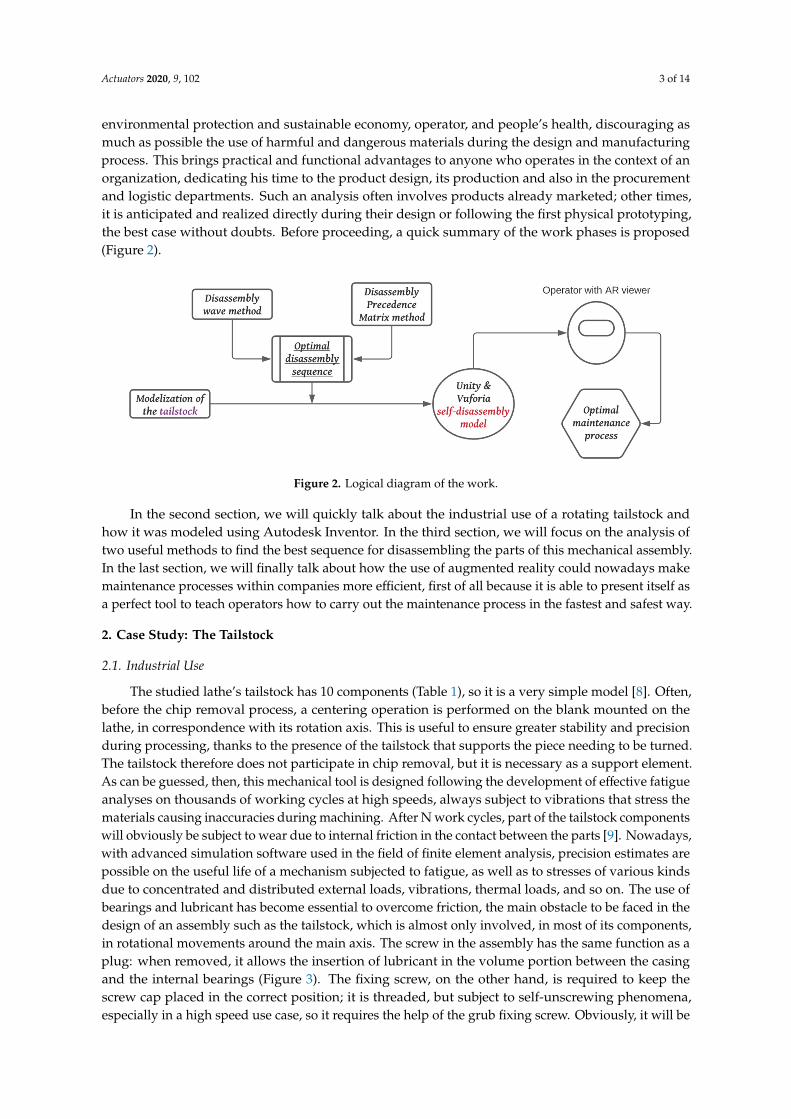
environmental protection and sustainable economy, operator, and people’s health, discouraging asmuch as possible the use of harmful and dangerous materials during the design and manufacturingprocess. This brings practical and functional advantages to anyone who operates in the context of anorganization, dedicating his time to the product design, its production and also in the procurementand logistic departments. Such an analysis often involves products already marketed; other times,it is anticipated and realized directly during their design or following the first physical prototyping,the best case without doubts. Before proceeding, a quick summary of the work phases is proposed(Figure 2).
Actuators 2020, 9, x FOR PEER REVIEW 3 of 14
discouraging as much as possible the use of harmful and dangerous materials during the design and manufacturing process. This brings practical and functional advantages to anyone who operates in the context of an organization, dedicating his time to the product design, its production and also in the procurement and logistic departments. Such an analysis often involves products already marketed; other times, it is anticipated and realized directly during their design or following the first physical prototyping, the best case without doubts. Before proceeding, a quick summary of the work phases is proposed (Figure 2).
Figure 2. Logical diagram of the work.
In the second section, we will quickly talk about the industrial use of a rotating tailstock and how it was modeled using Autodesk Inventor. In the third section, we will focus on the analysis of two useful methods to find the best sequence for disassembling the parts of this mechanical assembly. In the last section, we will finally talk about how the use of augmented reality could nowadays make maintenance processes within companies more efficient, first of all because it is able to present itself as a perfect tool to teach operators how to carry out the maintenance process in the fastest and safest way.
2. Case Study: The Tailstock
2.1. Industrial Use
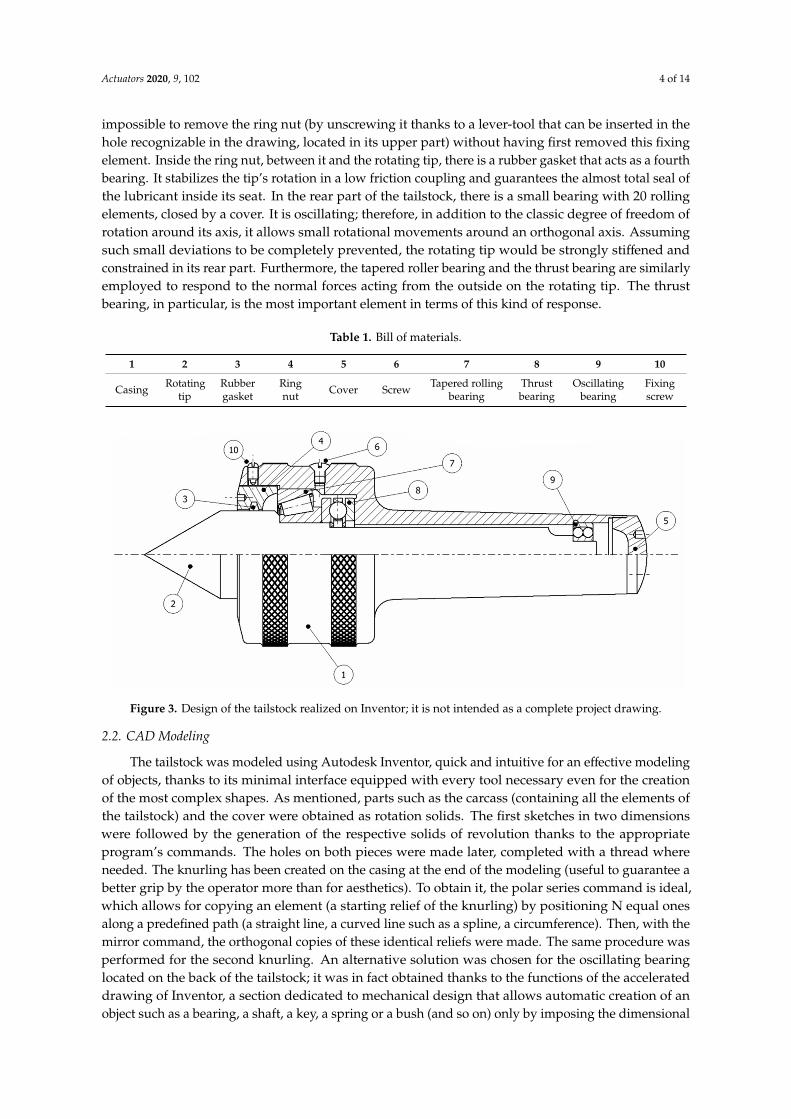
The studied lathe’s tailstock has 10 components (Table 1), so it is a very simple model [8]. Often, before the chip removal process, a centering operation is performed on the blank mounted on the lathe, in correspondence with its rotation axis. This is useful to ensure greater stability and precision during processing, thanks to the presence of the tailstock that supports the piece needing to be turned. The tailstock therefore does not participate in chip removal, but it is necessary as a support element. As can be guessed, then, this mechanical tool is designed following the development of effective fatigue analyses on thousands of working cycles at high speeds, always subject to vibrations that stress the materials causing inaccuracies during machining. After N work cycles, part of the tailstock components will obviously be subject to wear due to internal friction in the contact between the parts [9]. Nowadays, with advanced simulation software used in the field of finite element analysis, precision estimates are possible on the useful life of a mechanism subjected to fatigue, as well as to stresses of various kinds due to concentrated and distributed external loads, vibrations, thermal loads, and so on. The use of bearings and lubricant has become essential to overcome friction, the main obstacle to be faced in the design of an assembly such as the tailstock, which is almost only involved, in most of its components, in rotational movements around the main axis. The screw in the assembly has the same function as a plug: when removed, it allows the insertion of lubricant in the volume portion between the casing and the internal bearings (Figure 3). The fixing screw, on the other hand, is required to keep the screw cap placed in the correct position; it is threaded, but subject to self-unscrewing phenomena, especially in a high speed use case, so it requires the help of the grub fixing screw. Obviously, it will be impossible to remove the ring nut (by unscrewing it thanks to a lever-tool that can be inserted in the hole recognizable in the drawing, located in its upper part)
Figure 2. Logical diagram of the work.
In the second section, we will quickly talk about the industrial use of a rotating tailstock andhow it was modeled using Autodesk Inventor. In the third section, we will focus on the analysis oftwo useful methods to find the best sequence for disassembling the parts of this mechanical assembly.In the last section, we will finally talk about how the use of augmented reality could nowadays makemaintenance processes within companies more efficient, first of all because it is able to present itself asa perfect tool to teach operators how to carry out the maintenance process in the fastest and safest way.
2. Case Study: The Tailstock
2.1. Industrial Use
The studied lathe’s tailstock has 10 components (Table 1), so it is a very simple model [8]. Often,before the chip removal process, a centering operation is performed on the blank mounted on thelathe, in correspondence with its rotation axis. This is useful to ensure greater stability and precisionduring processing, thanks to the presence of the tailstock that supports the piece needing to be turned.The tailstock therefore does not participate in chip removal, but it is necessary as a support element.As can be guessed, then, this mechanical tool is designed following the development of effective fatigueanalyses on thousands of working cycles at high speeds, always subject to vibrations that stress thematerials causing inaccuracies during machining. After N work cycles, part of the tailstock componentswill obviously be subject to wear due to internal friction in the contact between the parts [9]. Nowadays,with advanced simulation software used in the field of finite element analysis, precision estimates arepossible on the useful life of a mechanism subjected to fatigue, as well as to stresses of various kindsdue to concentrated and distributed external loads, vibrations, thermal loads, and so on. The use ofbearings and lubricant has become essential to overcome friction, the main obstacle to be faced in thedesign of an assembly such as the tailstock, which is almost only involved, in most of its components,in rotational movements around the main axis. The screw in the assembly has the same function as aplug: when removed, it allows the insertion of lubricant in the volume portion between the casingand the internal bearings (Figure 3). The fixing screw, on the other hand, is required to keep thescrew cap placed in the correct position; it is threaded, but subject to self-unscrewing phenomena,especially in a high speed use case, so it requires the help of the grub fixing screw. Obviously, it will be
Actuators 2020, 9, 102 4 of 14
impossible to remove the ring nut (by unscrewing it thanks to a lever-tool that can be inserted in thehole recognizable in the drawing, located in its upper part) without having first removed this fixingelement. Inside the ring nut, between it and the rotating tip, there is a rubber gasket that acts as a fourthbearing. It stabilizes the tip’s rotation in a low friction coupling and guarantees the almost total seal ofthe lubricant inside its seat. In the rear part of the tailstock, there is a small bearing with 20 rollingelements, closed by a cover. It is oscillating; therefore, in addition to the classic degree of freedom ofrotation around its axis, it allows small rotational movements around an orthogonal axis. Assumingsuch small deviations to be completely prevented, the rotating tip would be strongly stiffened andconstrained in its rear part. Furthermore, the tapered roller bearing and the thrust bearing are similarlyemployed to respond to the normal forces acting from the outside on the rotating tip. The thrustbearing, in particular, is the most important element in terms of this kind of response.
Table 1. Bill of materials.
1 2 3 4 5 6 7 8 9 10
Casing Rotatingtip
Rubbergasket
Ringnut Cover Screw Tapered rolling
bearingThrustbearing
Oscillatingbearing
Fixingscrew
Actuators 2020, 9, x FOR PEER REVIEW 4 of 14
without having first removed this fixing element. Inside the ring nut, between it and the rotating tip, there is a rubber gasket that acts as a fourth bearing. It stabilizes the tip’s rotation in a low friction coupling and guarantees the almost total seal of the lubricant inside its seat. In the rear part of the tailstock, there is a small bearing with 20 rolling elements, closed by a cover. It is oscillating; therefore, in addition to the classic degree of freedom of rotation around its axis, it allows small rotational movements around an orthogonal axis. Assuming such small deviations to be completely prevented, the rotating tip would be strongly stiffened and constrained in its rear part. Furthermore, the tapered roller bearing and the thrust bearing are similarly employed to respond to the normal forces acting from the outside on the rotating tip. The thrust bearing, in particular, is the most important element in terms of this kind of response.
Table 1. Bill of materials.
1 2 3 4 5 6 7 8 9 10
Casing Rotating
tip Rubber gasket
Ring nut
Cover Screw Tapered rolling bearing
Thrust bearing
Oscillating bearing
Fixing screw
Figure 3. Design of the tailstock realized on Inventor; it is not intended as a complete project drawing.
2.2. CAD Modeling
The tailstock was modeled using Autodesk Inventor, quick and intuitive for an effective modeling of objects, thanks to its minimal interface equipped with every tool necessary even for the creation of the most complex shapes. As mentioned, parts such as the carcass (containing all the elements of the tailstock) and the cover were obtained as rotation solids. The first sketches in two dimensions were followed by the generation of the respective solids of revolution thanks to the appropriate program’s commands. The holes on both pieces were made later, completed with a thread where needed. The knurling has been created on the casing at the end of the modeling (useful to guarantee a better grip by the operator more than for aesthetics). To obtain it, the polar series command is ideal, which allows for copying an element (a starting relief of the knurling) by positioning N equal ones along a predefined path (a straight line, a curved line such as a spline, a circumference). Then, with the mirror command, the orthogonal copies of these identical reliefs were made. The same procedure was performed for the second knurling. An alternative solution was chosen for the oscillating bearing located on the back of the tailstock; it was in fact obtained thanks to the functions of the accelerated drawing of Inventor, a section dedicated to mechanical design that allows automatic creation of an object such as a bearing, a shaft, a key, a spring or a bush (and so on) only by imposing the dimensional and design constraints known at the outset. For example, knowing the diametrical dimensions of the rotating tip and of the interior of the casing in the location area of
Figure 3. Design of the tailstock realized on Inventor; it is not intended as a complete project drawing.
2.2. CAD Modeling
The tailstock was modeled using Autodesk Inventor, quick and intuitive for an effective modelingof objects, thanks to its minimal interface equipped with every tool necessary even for the creationof the most complex shapes. As mentioned, parts such as the carcass (containing all the elements ofthe tailstock) and the cover were obtained as rotation solids. The first sketches in two dimensionswere followed by the generation of the respective solids of revolution thanks to the appropriateprogram’s commands. The holes on both pieces were made later, completed with a thread whereneeded. The knurling has been created on the casing at the end of the modeling (useful to guarantee abetter grip by the operator more than for aesthetics). To obtain it, the polar series command is ideal,which allows for copying an element (a starting relief of the knurling) by positioning N equal onesalong a predefined path (a straight line, a curved line such as a spline, a circumference). Then, with themirror command, the orthogonal copies of these identical reliefs were made. The same procedure wasperformed for the second knurling. An alternative solution was chosen for the oscillating bearinglocated on the back of the tailstock; it was in fact obtained thanks to the functions of the accelerateddrawing of Inventor, a section dedicated to mechanical design that allows automatic creation of anobject such as a bearing, a shaft, a key, a spring or a bush (and so on) only by imposing the dimensional
Actuators 2020, 9, 102 5 of 14
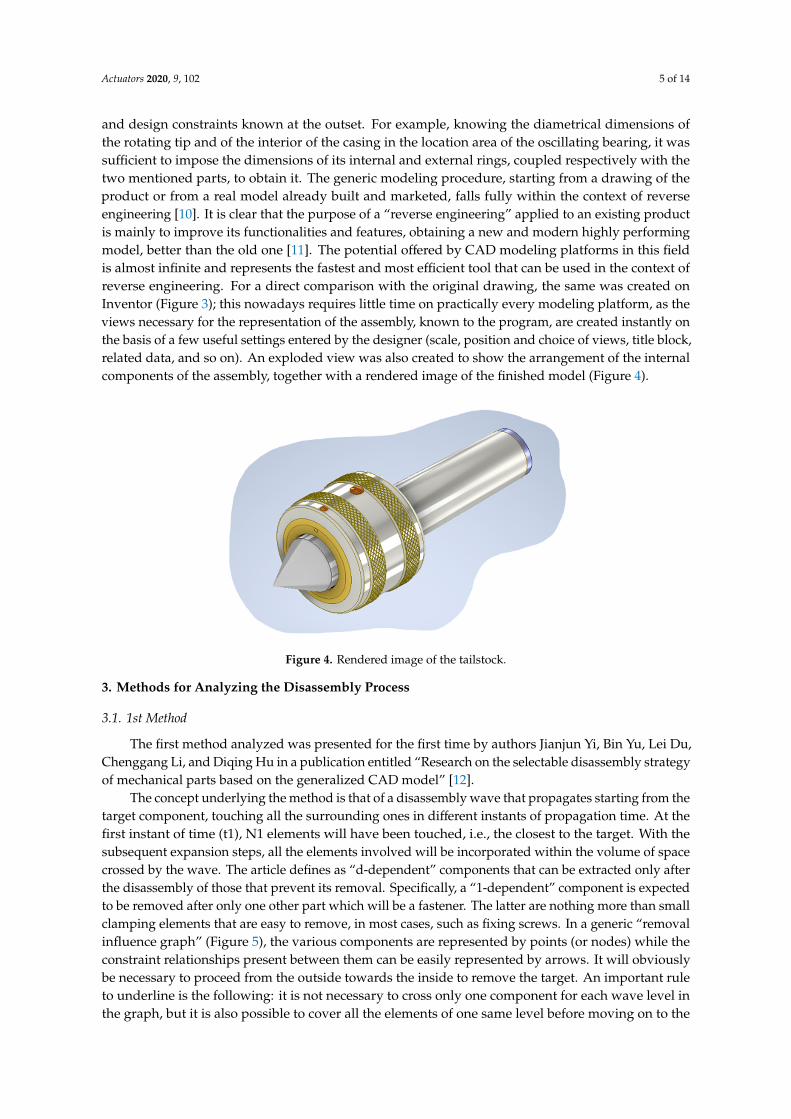
and design constraints known at the outset. For example, knowing the diametrical dimensions ofthe rotating tip and of the interior of the casing in the location area of the oscillating bearing, it wassufficient to impose the dimensions of its internal and external rings, coupled respectively with thetwo mentioned parts, to obtain it. The generic modeling procedure, starting from a drawing of theproduct or from a real model already built and marketed, falls fully within the context of reverseengineering [10]. It is clear that the purpose of a “reverse engineering” applied to an existing productis mainly to improve its functionalities and features, obtaining a new and modern highly performingmodel, better than the old one [11]. The potential offered by CAD modeling platforms in this fieldis almost infinite and represents the fastest and most efficient tool that can be used in the context ofreverse engineering. For a direct comparison with the original drawing, the same was created onInventor (Figure 3); this nowadays requires little time on practically every modeling platform, as theviews necessary for the representation of the assembly, known to the program, are created instantly onthe basis of a few useful settings entered by the designer (scale, position and choice of views, title block,related data, and so on). An exploded view was also created to show the arrangement of the internalcomponents of the assembly, together with a rendered image of the finished model (Figure 4).
Actuators 2020, 9, x FOR PEER REVIEW 5 of 14
the oscillating bearing, it was sufficient to impose the dimensions of its internal and external rings, coupled respectively with the two mentioned parts, to obtain it. The generic modeling procedure, starting from a drawing of the product or from a real model already built and marketed, falls fully within the context of reverse engineering [10]. It is clear that the purpose of a “reverse engineering” applied to an existing product is mainly to improve its functionalities and features, obtaining a new and modern highly performing model, better than the old one [11]. The potential offered by CAD modeling platforms in this field is almost infinite and represents the fastest and most efficient tool that can be used in the context of reverse engineering. For a direct comparison with the original drawing, the same was created on Inventor (Figure 3); this nowadays requires little time on practically every modeling platform, as the views necessary for the representation of the assembly, known to the program, are created instantly on the basis of a few useful settings entered by the designer (scale, position and choice of views, title block, related data, and so on). An exploded view was also created to show the arrangement of the internal components of the assembly, together with a rendered image of the finished model (Figure 4).
Figure 4. Rendered image of the tailstock.
3. Methods for Analyzing the Disassembly Process
3.1. 1st Method
The first method analyzed was presented for the first time by authors Jianjun Yi, Bin Yu, Lei Du, Chenggang Li, and Diqing Hu in a publication entitled “Research on the selectable disassembly strategy of mechanical parts based on the generalized CAD model” [12].
The concept underlying the method is that of a disassembly wave that propagates starting from the target component, touching all the surrounding ones in different instants of propagation time. At the first instant of time (t1), N1 elements will have been touched, i.e., the closest to the target. With the subsequent expansion steps, all the elements involved will be incorporated within the volume of space crossed by the wave. The article defines as “d-dependent” components that can be extracted only after the disassembly of those that prevent its removal. Specifically, a “1-dependent” component is expected to be removed after only one other part which will be a fastener. The latter are nothing more than small clamping elements that are easy to remove, in most cases, such as fixing screws. In a generic “removal influence graph” (Figure 5), the various components are represented by points (or nodes) while the constraint relationships present between them can be easily represented by arrows. It will obviously be necessary to proceed from the outside towards the inside to remove the target. An important rule to underline is the following: it is not necessary to cross only one component for each wave level in the graph, but it is also possible to cover all the elements of one same level before moving on to the next (innermost) one. This is due to how the disassembly wave is generated: at every instant of time (t1, t2, t3, …), it crosses several components together placed on the same wave
Figure 4. Rendered image of the tailstock.
3. Methods for Analyzing the Disassembly Process
3.1. 1st Method
The first method analyzed was presented for the first time by authors Jianjun Yi, Bin Yu, Lei Du,Chenggang Li, and Diqing Hu in a publication entitled “Research on the selectable disassembly strategyof mechanical parts based on the generalized CAD model” [12].
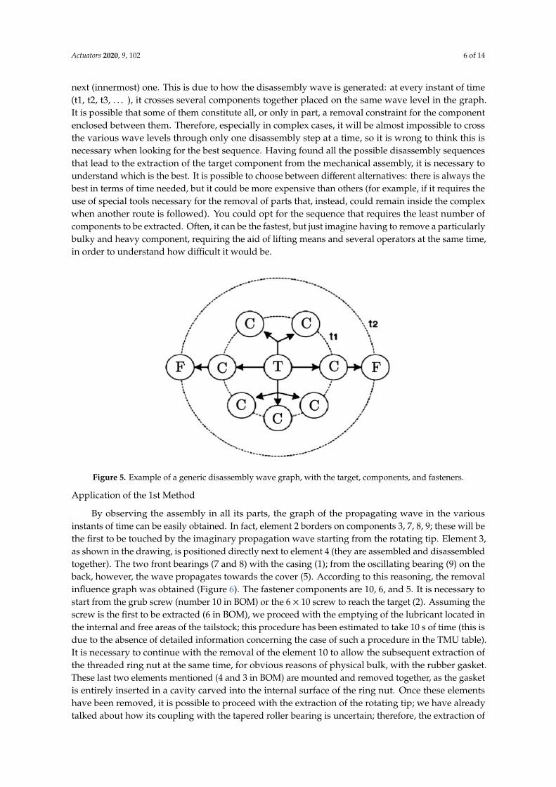
The concept underlying the method is that of a disassembly wave that propagates starting from thetarget component, touching all the surrounding ones in different instants of propagation time. At thefirst instant of time (t1), N1 elements will have been touched, i.e., the closest to the target. With thesubsequent expansion steps, all the elements involved will be incorporated within the volume of spacecrossed by the wave. The article defines as “d-dependent” components that can be extracted only afterthe disassembly of those that prevent its removal. Specifically, a “1-dependent” component is expectedto be removed after only one other part which will be a fastener. The latter are nothing more than smallclamping elements that are easy to remove, in most cases, such as fixing screws. In a generic “removalinfluence graph” (Figure 5), the various components are represented by points (or nodes) while theconstraint relationships present between them can be easily represented by arrows. It will obviouslybe necessary to proceed from the outside towards the inside to remove the target. An important ruleto underline is the following: it is not necessary to cross only one component for each wave level inthe graph, but it is also possible to cover all the elements of one same level before moving on to the
Actuators 2020, 9, 102 6 of 14
next (innermost) one. This is due to how the disassembly wave is generated: at every instant of time(t1, t2, t3, . . . ), it crosses several components together placed on the same wave level in the graph.It is possible that some of them constitute all, or only in part, a removal constraint for the componentenclosed between them. Therefore, especially in complex cases, it will be almost impossible to crossthe various wave levels through only one disassembly step at a time, so it is wrong to think this isnecessary when looking for the best sequence. Having found all the possible disassembly sequencesthat lead to the extraction of the target component from the mechanical assembly, it is necessary tounderstand which is the best. It is possible to choose between different alternatives: there is always thebest in terms of time needed, but it could be more expensive than others (for example, if it requires theuse of special tools necessary for the removal of parts that, instead, could remain inside the complexwhen another route is followed). You could opt for the sequence that requires the least number ofcomponents to be extracted. Often, it can be the fastest, but just imagine having to remove a particularlybulky and heavy component, requiring the aid of lifting means and several operators at the same time,in order to understand how difficult it would be.
Actuators 2020, 9, x FOR PEER REVIEW 6 of 14
level in the graph. It is possible that some of them constitute all, or only in part, a removal constraint for the component enclosed between them. Therefore, especially in complex cases, it will be almost impossible to cross the various wave levels through only one disassembly step at a time, so it is wrong to think this is necessary when looking for the best sequence. Having found all the possible disassembly sequences that lead to the extraction of the target component from the mechanical assembly, it is necessary to understand which is the best. It is possible to choose between different alternatives: there is always the best in terms of time needed, but it could be more expensive than others (for example, if it requires the use of special tools necessary for the removal of parts that, instead, could remain inside the complex when another route is followed). You could opt for the sequence that requires the least number of components to be extracted. Often, it can be the fastest, but just imagine having to remove a particularly bulky and heavy component, requiring the aid of lifting means and several operators at the same time, in order to understand how difficult it would be.
Figure 5. Example of a generic disassembly wave graph, with the target, components, and fasteners.
Application of the 1st Method
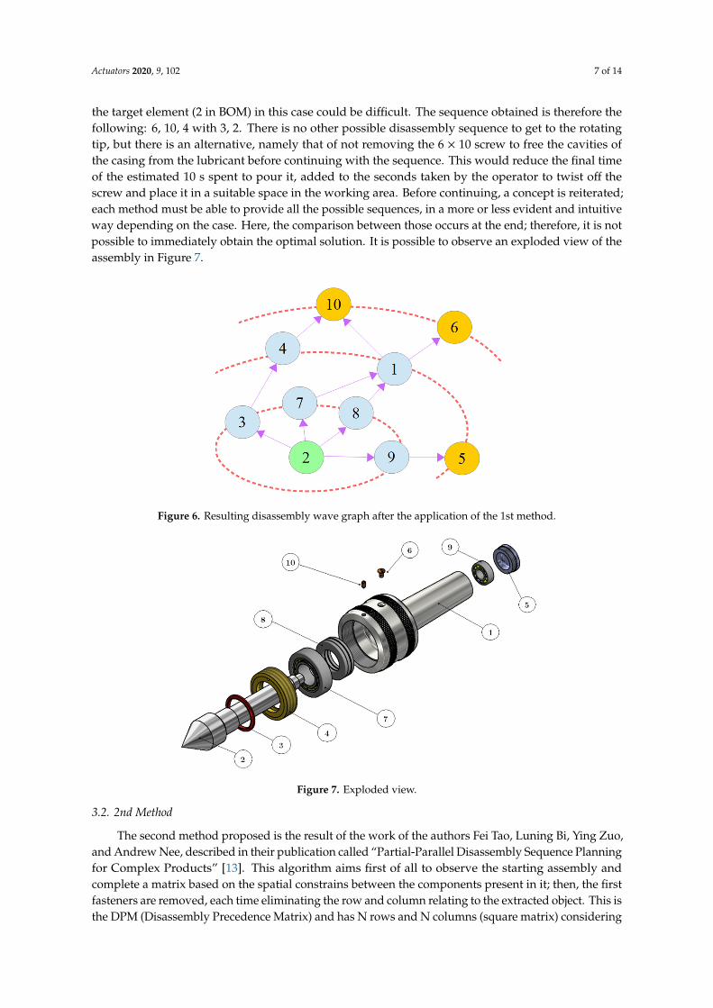
By observing the assembly in all its parts, the graph of the propagating wave in the various instants of time can be easily obtained. In fact, element 2 borders on components 3, 7, 8, 9; these will be the first to be touched by the imaginary propagation wave starting from the rotating tip. Element 3, as shown in the drawing, is positioned directly next to element 4 (they are assembled and disassembled together). The two front bearings (7 and 8) with the casing (1); from the oscillating bearing (9) on the back, however, the wave propagates towards the cover (5). According to this reasoning, the removal influence graph was obtained (Figure 6). The fastener components are 10, 6, and 5. It is necessary to start from the grub screw (number 10 in BOM) or the 6 × 10 screw to reach the target (2). Assuming the screw is the first to be extracted (6 in BOM), we proceed with the emptying of the lubricant located in the internal and free areas of the tailstock; this procedure has been estimated to take 10 s of time (this is due to the absence of detailed information concerning the case of such a procedure in the TMU table). It is necessary to continue with the removal of the element 10 to allow the subsequent extraction of the threaded ring nut at the same time, for obvious reasons of physical bulk, with the rubber gasket. These last two elements mentioned (4 and 3 in BOM) are mounted and removed together, as the gasket is entirely inserted in a cavity carved into the internal surface of the ring nut. Once these elements have been removed, it is possible to proceed with the extraction of the rotating tip; we have already talked about how its coupling with the tapered roller bearing is uncertain; therefore, the extraction of the target element (2 in BOM) in this case could be difficult. The sequence obtained is therefore the following: 6, 10, 4 with 3, 2. There is no other possible disassembly sequence
Figure 5. Example of a generic disassembly wave graph, with the target, components, and fasteners.
Application of the 1st Method
By observing the assembly in all its parts, the graph of the propagating wave in the variousinstants of time can be easily obtained. In fact, element 2 borders on components 3, 7, 8, 9; these will bethe first to be touched by the imaginary propagation wave starting from the rotating tip. Element 3,as shown in the drawing, is positioned directly next to element 4 (they are assembled and disassembledtogether). The two front bearings (7 and 8) with the casing (1); from the oscillating bearing (9) on theback, however, the wave propagates towards the cover (5). According to this reasoning, the removalinfluence graph was obtained (Figure 6). The fastener components are 10, 6, and 5. It is necessary tostart from the grub screw (number 10 in BOM) or the 6 × 10 screw to reach the target (2). Assuming thescrew is the first to be extracted (6 in BOM), we proceed with the emptying of the lubricant located inthe internal and free areas of the tailstock; this procedure has been estimated to take 10 s of time (this isdue to the absence of detailed information concerning the case of such a procedure in the TMU table).It is necessary to continue with the removal of the element 10 to allow the subsequent extraction ofthe threaded ring nut at the same time, for obvious reasons of physical bulk, with the rubber gasket.These last two elements mentioned (4 and 3 in BOM) are mounted and removed together, as the gasketis entirely inserted in a cavity carved into the internal surface of the ring nut. Once these elementshave been removed, it is possible to proceed with the extraction of the rotating tip; we have alreadytalked about how its coupling with the tapered roller bearing is uncertain; therefore, the extraction of
Actuators 2020, 9, 102 7 of 14
the target element (2 in BOM) in this case could be difficult. The sequence obtained is therefore thefollowing: 6, 10, 4 with 3, 2. There is no other possible disassembly sequence to get to the rotatingtip, but there is an alternative, namely that of not removing the 6 × 10 screw to free the cavities ofthe casing from the lubricant before continuing with the sequence. This would reduce the final timeof the estimated 10 s spent to pour it, added to the seconds taken by the operator to twist off thescrew and place it in a suitable space in the working area. Before continuing, a concept is reiterated;each method must be able to provide all the possible sequences, in a more or less evident and intuitiveway depending on the case. Here, the comparison between those occurs at the end; therefore, it is notpossible to immediately obtain the optimal solution. It is possible to observe an exploded view of theassembly in Figure 7.
Actuators 2020, 9, x FOR PEER REVIEW 7 of 14
to get to the rotating tip, but there is an alternative, namely that of not removing the 6 × 10 screw to free the cavities of the casing from the lubricant before continuing with the sequence. This would reduce the final time of the estimated 10 s spent to pour it, added to the seconds taken by the operator to twist off the screw and place it in a suitable space in the working area. Before continuing, a concept is reiterated; each method must be able to provide all the possible sequences, in a more or less evident and intuitive way depending on the case. Here, the comparison between those occurs at the end; therefore, it is not possible to immediately obtain the optimal solution. It is possible to observe an exploded view of the assembly in Figure 7.
Figure 6. Resulting disassembly wave graph after the application of the 1st method.
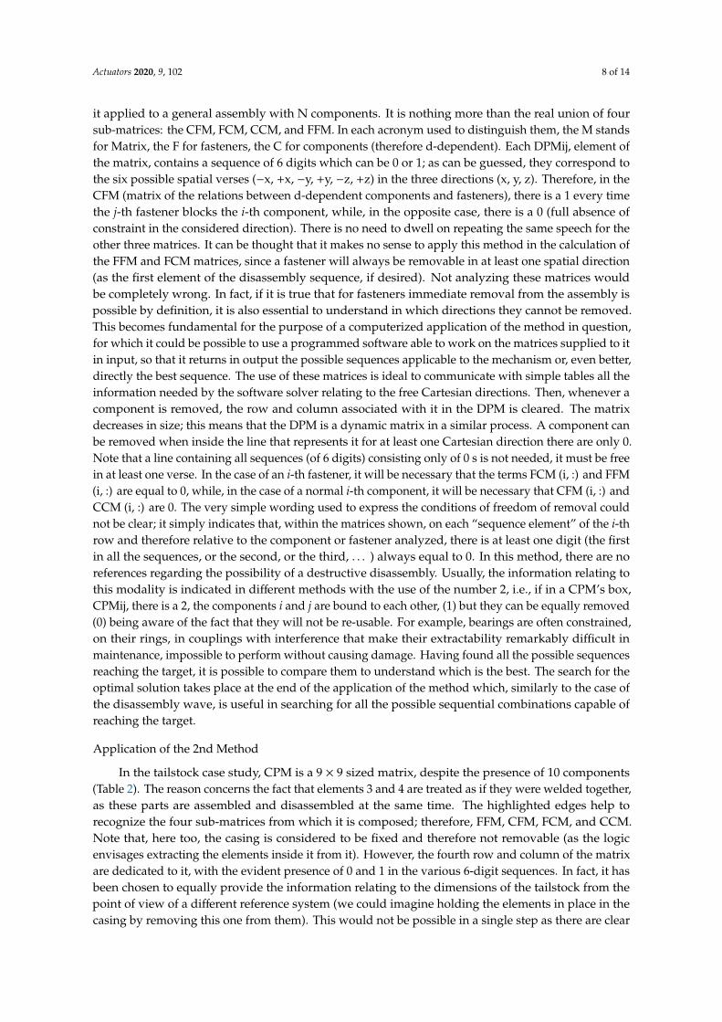
Figure 7. Exploded view.
3.2. 2nd Method
The second method proposed is the result of the work of the authors Fei Tao, Luning Bi, Ying Zuo, and Andrew Nee, described in their publication called “Partial-Parallel Disassembly Sequence Planning for Complex Products” [13]. This algorithm aims first of all to observe the starting assembly and complete a matrix based on the spatial constrains between the components present in it; then, the first fasteners are removed, each time eliminating the row and column relating to the extracted object. This is the DPM (Disassembly Precedence Matrix) and has N rows and N columns (square matrix) considering it applied to a general assembly with N components. It is nothing more than the real union of four sub-matrices: the CFM, FCM, CCM, and FFM. In each acronym used to distinguish them, the M stands for Matrix, the F for fasteners, the C for components (therefore d-dependent). Each DPMij, element of the matrix, contains a sequence of 6 digits which can be 0 or 1; as can be
Figure 6. Resulting disassembly wave graph after the application of the 1st method.
Actuators 2020, 9, x FOR PEER REVIEW 7 of 14
to get to the rotating tip, but there is an alternative, namely that of not removing the 6 × 10 screw to free the cavities of the casing from the lubricant before continuing with the sequence. This would reduce the final time of the estimated 10 s spent to pour it, added to the seconds taken by the operator to twist off the screw and place it in a suitable space in the working area. Before continuing, a concept is reiterated; each method must be able to provide all the possible sequences, in a more or less evident and intuitive way depending on the case. Here, the comparison between those occurs at the end; therefore, it is not possible to immediately obtain the optimal solution. It is possible to observe an exploded view of the assembly in Figure 7.
Figure 6. Resulting disassembly wave graph after the application of the 1st method.
Figure 7. Exploded view.
3.2. 2nd Method
The second method proposed is the result of the work of the authors Fei Tao, Luning Bi, Ying Zuo, and Andrew Nee, described in their publication called “Partial-Parallel Disassembly Sequence Planning for Complex Products” [13]. This algorithm aims first of all to observe the starting assembly and complete a matrix based on the spatial constrains between the components present in it; then, the first fasteners are removed, each time eliminating the row and column relating to the extracted object. This is the DPM (Disassembly Precedence Matrix) and has N rows and N columns (square matrix) considering it applied to a general assembly with N components. It is nothing more than the real union of four sub-matrices: the CFM, FCM, CCM, and FFM. In each acronym used to distinguish them, the M stands for Matrix, the F for fasteners, the C for components (therefore d-dependent). Each DPMij, element of the matrix, contains a sequence of 6 digits which can be 0 or 1; as can be
Figure 7. Exploded view.
3.2. 2nd Method
The second method proposed is the result of the work of the authors Fei Tao, Luning Bi, Ying Zuo,and Andrew Nee, described in their publication called “Partial-Parallel Disassembly Sequence Planningfor Complex Products” [13]. This algorithm aims first of all to observe the starting assembly andcomplete a matrix based on the spatial constrains between the components present in it; then, the firstfasteners are removed, each time eliminating the row and column relating to the extracted object. This isthe DPM (Disassembly Precedence Matrix) and has N rows and N columns (square matrix) considering
Actuators 2020, 9, 102 8 of 14
it applied to a general assembly with N components. It is nothing more than the real union of foursub-matrices: the CFM, FCM, CCM, and FFM. In each acronym used to distinguish them, the M standsfor Matrix, the F for fasteners, the C for components (therefore d-dependent). Each DPMij, element ofthe matrix, contains a sequence of 6 digits which can be 0 or 1; as can be guessed, they correspond tothe six possible spatial verses (−x, +x, −y, +y, −z, +z) in the three directions (x, y, z). Therefore, in theCFM (matrix of the relations between d-dependent components and fasteners), there is a 1 every timethe j-th fastener blocks the i-th component, while, in the opposite case, there is a 0 (full absence ofconstraint in the considered direction). There is no need to dwell on repeating the same speech for theother three matrices. It can be thought that it makes no sense to apply this method in the calculation ofthe FFM and FCM matrices, since a fastener will always be removable in at least one spatial direction(as the first element of the disassembly sequence, if desired). Not analyzing these matrices wouldbe completely wrong. In fact, if it is true that for fasteners immediate removal from the assembly ispossible by definition, it is also essential to understand in which directions they cannot be removed.This becomes fundamental for the purpose of a computerized application of the method in question,for which it could be possible to use a programmed software able to work on the matrices supplied to itin input, so that it returns in output the possible sequences applicable to the mechanism or, even better,directly the best sequence. The use of these matrices is ideal to communicate with simple tables all theinformation needed by the software solver relating to the free Cartesian directions. Then, whenever acomponent is removed, the row and column associated with it in the DPM is cleared. The matrixdecreases in size; this means that the DPM is a dynamic matrix in a similar process. A component canbe removed when inside the line that represents it for at least one Cartesian direction there are only 0.Note that a line containing all sequences (of 6 digits) consisting only of 0 s is not needed, it must be freein at least one verse. In the case of an i-th fastener, it will be necessary that the terms FCM (i, :) and FFM(i, :) are equal to 0, while, in the case of a normal i-th component, it will be necessary that CFM (i, :) andCCM (i, :) are 0. The very simple wording used to express the conditions of freedom of removal couldnot be clear; it simply indicates that, within the matrices shown, on each “sequence element” of the i-throw and therefore relative to the component or fastener analyzed, there is at least one digit (the firstin all the sequences, or the second, or the third, . . . ) always equal to 0. In this method, there are noreferences regarding the possibility of a destructive disassembly. Usually, the information relating tothis modality is indicated in different methods with the use of the number 2, i.e., if in a CPM’s box,CPMij, there is a 2, the components i and j are bound to each other, (1) but they can be equally removed(0) being aware of the fact that they will not be re-usable. For example, bearings are often constrained,on their rings, in couplings with interference that make their extractability remarkably difficult inmaintenance, impossible to perform without causing damage. Having found all the possible sequencesreaching the target, it is possible to compare them to understand which is the best. The search for theoptimal solution takes place at the end of the application of the method which, similarly to the case ofthe disassembly wave, is useful in searching for all the possible sequential combinations capable ofreaching the target.
Application of the 2nd Method
In the tailstock case study, CPM is a 9 × 9 sized matrix, despite the presence of 10 components(Table 2). The reason concerns the fact that elements 3 and 4 are treated as if they were welded together,as these parts are assembled and disassembled at the same time. The highlighted edges help torecognize the four sub-matrices from which it is composed; therefore, FFM, CFM, FCM, and CCM.Note that, here too, the casing is considered to be fixed and therefore not removable (as the logicenvisages extracting the elements inside it from it). However, the fourth row and column of the matrixare dedicated to it, with the evident presence of 0 and 1 in the various 6-digit sequences. In fact, it hasbeen chosen to equally provide the information relating to the dimensions of the tailstock from thepoint of view of a different reference system (we could imagine holding the elements in place in thecasing by removing this one from them). This would not be possible in a single step as there are clear
Actuators 2020, 9, 102 9 of 14
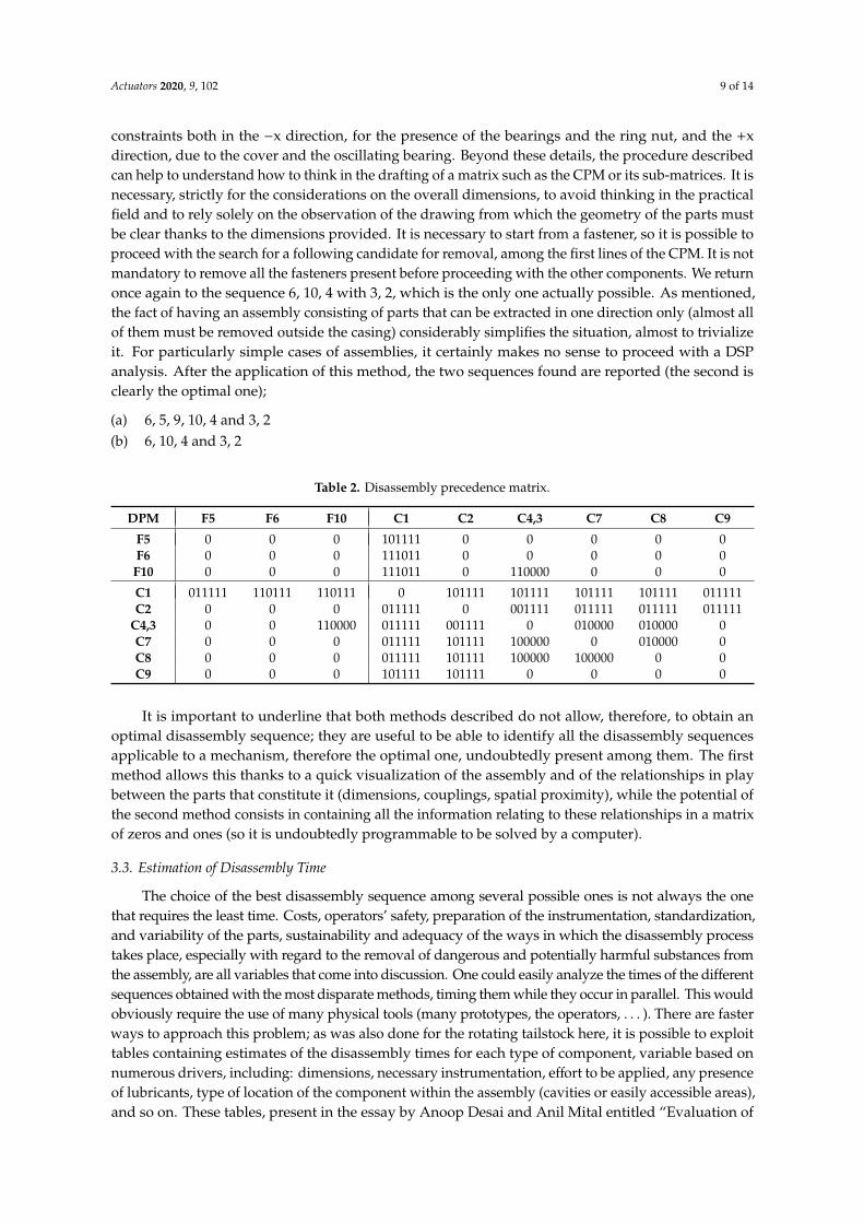
constraints both in the −x direction, for the presence of the bearings and the ring nut, and the +xdirection, due to the cover and the oscillating bearing. Beyond these details, the procedure describedcan help to understand how to think in the drafting of a matrix such as the CPM or its sub-matrices. It isnecessary, strictly for the considerations on the overall dimensions, to avoid thinking in the practicalfield and to rely solely on the observation of the drawing from which the geometry of the parts mustbe clear thanks to the dimensions provided. It is necessary to start from a fastener, so it is possible toproceed with the search for a following candidate for removal, among the first lines of the CPM. It is notmandatory to remove all the fasteners present before proceeding with the other components. We returnonce again to the sequence 6, 10, 4 with 3, 2, which is the only one actually possible. As mentioned,the fact of having an assembly consisting of parts that can be extracted in one direction only (almost allof them must be removed outside the casing) considerably simplifies the situation, almost to trivializeit. For particularly simple cases of assemblies, it certainly makes no sense to proceed with a DSPanalysis. After the application of this method, the two sequences found are reported (the second isclearly the optimal one);
(a) 6, 5, 9, 10, 4 and 3, 2(b) 6, 10, 4 and 3, 2
Table 2. Disassembly precedence matrix.
DPM F5 F6 F10 C1 C2 C4,3 C7 C8 C9
F5 0 0 0 101111 0 0 0 0 0F6 0 0 0 111011 0 0 0 0 0F10 0 0 0 111011 0 110000 0 0 0
C1 011111 110111 110111 0 101111 101111 101111 101111 011111C2 0 0 0 011111 0 001111 011111 011111 011111
C4,3 0 0 110000 011111 001111 0 010000 010000 0C7 0 0 0 011111 101111 100000 0 010000 0C8 0 0 0 011111 101111 100000 100000 0 0C9 0 0 0 101111 101111 0 0 0 0
It is important to underline that both methods described do not allow, therefore, to obtain anoptimal disassembly sequence; they are useful to be able to identify all the disassembly sequencesapplicable to a mechanism, therefore the optimal one, undoubtedly present among them. The firstmethod allows this thanks to a quick visualization of the assembly and of the relationships in playbetween the parts that constitute it (dimensions, couplings, spatial proximity), while the potential ofthe second method consists in containing all the information relating to these relationships in a matrixof zeros and ones (so it is undoubtedly programmable to be solved by a computer).
3.3. Estimation of Disassembly Time
The choice of the best disassembly sequence among several possible ones is not always the onethat requires the least time. Costs, operators’ safety, preparation of the instrumentation, standardization,and variability of the parts, sustainability and adequacy of the ways in which the disassembly processtakes place, especially with regard to the removal of dangerous and potentially harmful substances fromthe assembly, are all variables that come into discussion. One could easily analyze the times of the differentsequences obtained with the most disparate methods, timing them while they occur in parallel. This wouldobviously require the use of many physical tools (many prototypes, the operators, . . . ). There are fasterways to approach this problem; as was also done for the rotating tailstock here, it is possible to exploittables containing estimates of the disassembly times for each type of component, variable based onnumerous drivers, including: dimensions, necessary instrumentation, effort to be applied, any presenceof lubricants, type of location of the component within the assembly (cavities or easily accessible areas),and so on. These tables, present in the essay by Anoop Desai and Anil Mital entitled “Evaluation of
Actuators 2020, 9, 102 10 of 14
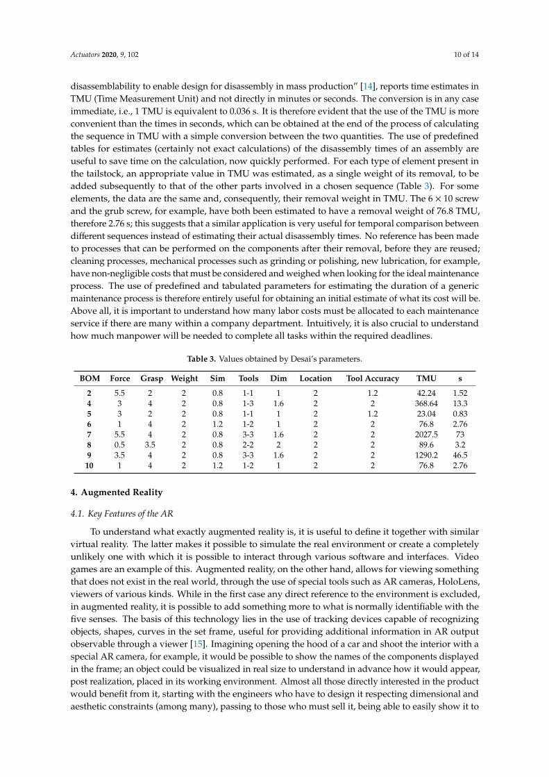
disassemblability to enable design for disassembly in mass production” [14], reports time estimates inTMU (Time Measurement Unit) and not directly in minutes or seconds. The conversion is in any caseimmediate, i.e., 1 TMU is equivalent to 0.036 s. It is therefore evident that the use of the TMU is moreconvenient than the times in seconds, which can be obtained at the end of the process of calculatingthe sequence in TMU with a simple conversion between the two quantities. The use of predefinedtables for estimates (certainly not exact calculations) of the disassembly times of an assembly areuseful to save time on the calculation, now quickly performed. For each type of element present inthe tailstock, an appropriate value in TMU was estimated, as a single weight of its removal, to beadded subsequently to that of the other parts involved in a chosen sequence (Table 3). For someelements, the data are the same and, consequently, their removal weight in TMU. The 6 × 10 screwand the grub screw, for example, have both been estimated to have a removal weight of 76.8 TMU,therefore 2.76 s; this suggests that a similar application is very useful for temporal comparison betweendifferent sequences instead of estimating their actual disassembly times. No reference has been madeto processes that can be performed on the components after their removal, before they are reused;cleaning processes, mechanical processes such as grinding or polishing, new lubrication, for example,have non-negligible costs that must be considered and weighed when looking for the ideal maintenanceprocess. The use of predefined and tabulated parameters for estimating the duration of a genericmaintenance process is therefore entirely useful for obtaining an initial estimate of what its cost will be.Above all, it is important to understand how many labor costs must be allocated to each maintenanceservice if there are many within a company department. Intuitively, it is also crucial to understandhow much manpower will be needed to complete all tasks within the required deadlines.
Table 3. Values obtained by Desai’s parameters.
BOM Force Grasp Weight Sim Tools Dim Location Tool Accuracy TMU s
2 5.5 2 2 0.8 1-1 1 2 1.2 42.24 1.524 3 4 2 0.8 1-3 1.6 2 2 368.64 13.35 3 2 2 0.8 1-1 1 2 1.2 23.04 0.836 1 4 2 1.2 1-2 1 2 2 76.8 2.767 5.5 4 2 0.8 3-3 1.6 2 2 2027.5 738 0.5 3.5 2 0.8 2-2 2 2 2 89.6 3.29 3.5 4 2 0.8 3-3 1.6 2 2 1290.2 46.5
10 1 4 2 1.2 1-2 1 2 2 76.8 2.76
4. Augmented Reality
4.1. Key Features of the AR
To understand what exactly augmented reality is, it is useful to define it together with similarvirtual reality. The latter makes it possible to simulate the real environment or create a completelyunlikely one with which it is possible to interact through various software and interfaces. Videogames are an example of this. Augmented reality, on the other hand, allows for viewing somethingthat does not exist in the real world, through the use of special tools such as AR cameras, HoloLens,viewers of various kinds. While in the first case any direct reference to the environment is excluded,in augmented reality, it is possible to add something more to what is normally identifiable with thefive senses. The basis of this technology lies in the use of tracking devices capable of recognizingobjects, shapes, curves in the set frame, useful for providing additional information in AR outputobservable through a viewer [15]. Imagining opening the hood of a car and shoot the interior with aspecial AR camera, for example, it would be possible to show the names of the components displayedin the frame; an object could be visualized in real size to understand in advance how it would appear,post realization, placed in its working environment. Almost all those directly interested in the productwould benefit from it, starting with the engineers who have to design it respecting dimensional andaesthetic constraints (among many), passing to those who must sell it, being able to easily show it to
Actuators 2020, 9, 102 11 of 14
the customers, arriving at these latter subjects that can take more advantage of the potential offeredby technology like this. The visualization of the product in the context of destination related to itsindustrial application does not offer advantages only from the points of view related to costs (it avoidsas much as possible the construction of a physical prototype), design, dimensioning, maintenance,but allows a decisive improvement concerning the safety conditions of operators who need, for example,to work near an automated robot. The observation of this model in 1:1 scale allows for studying itsmovements and tracing its dimensions (understood as areas and volumes of space involved by thefixed and mobile parts of the machinery), consequently being able to evaluate in the most appropriateway the methods of flanking of the operator to the machine. Considering the increasingly frequent useof cobots, robots designed to work alongside humans as an additional workforce, according to theprogramming of their work cycle, the use of augmented reality undoubtedly provides an advantageobtainable with a few efforts. The AR technology used here is of the marker based type, thereforefollowing the recognition of an object in two or three dimensions, framed through an appropriateviewer, it places the virtual object in the relative spatial position. It will be an image, in the case studied.Other kinds of augmented reality are cited: marker-less, projection based, superimposition based,and so on. The first mentioned, in particular, differs from the marker-based AR as it is not based onthe recognition of an object; on the other hand, it uses various means, primarily GPS, to allow virtualobjects to appear in the image displayed by those who are moving, for example, through the streets ofa city based on their spatial position.
4.2. Case Study of the Tailstock with Unity and Vuforia
Vuforia is the first software to be used if you have the aim of making a video of the exploded viewof the assembly in augmented reality. It is an online platform on which it is possible to quickly andeasily create a database to be downloaded as a package for Unity, the details of which will be explainedshortly. First you need to create a license; it is very easy and free; after registering with Vuforia [16],it is possible to obtain one automatically generated by the platform in the form of a code to copy and,subsequently, paste in a special section of Unity [17], dedicated to the settings of augmented reality.
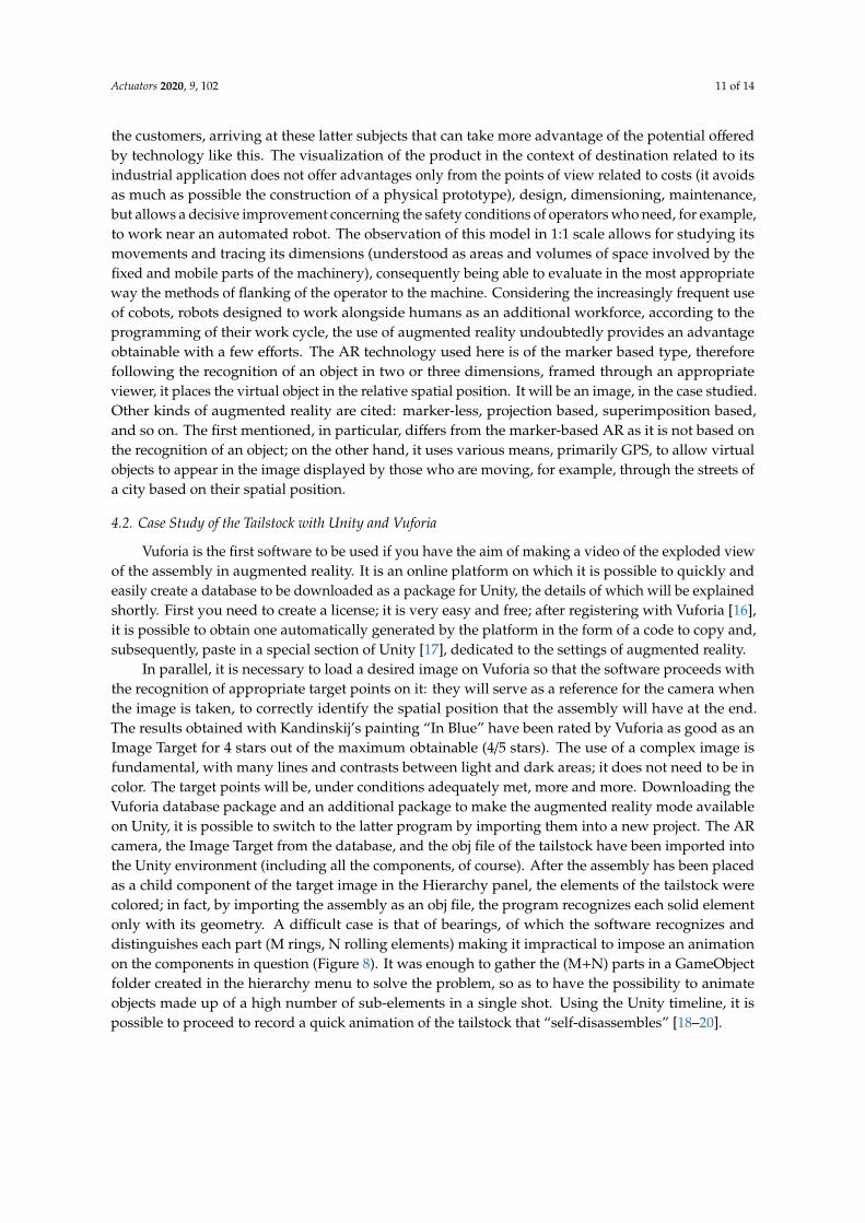
In parallel, it is necessary to load a desired image on Vuforia so that the software proceeds withthe recognition of appropriate target points on it: they will serve as a reference for the camera whenthe image is taken, to correctly identify the spatial position that the assembly will have at the end.The results obtained with Kandinskij’s painting “In Blue” have been rated by Vuforia as good as anImage Target for 4 stars out of the maximum obtainable (4/5 stars). The use of a complex image isfundamental, with many lines and contrasts between light and dark areas; it does not need to be incolor. The target points will be, under conditions adequately met, more and more. Downloading theVuforia database package and an additional package to make the augmented reality mode availableon Unity, it is possible to switch to the latter program by importing them into a new project. The ARcamera, the Image Target from the database, and the obj file of the tailstock have been imported intothe Unity environment (including all the components, of course). After the assembly has been placedas a child component of the target image in the Hierarchy panel, the elements of the tailstock werecolored; in fact, by importing the assembly as an obj file, the program recognizes each solid elementonly with its geometry. A difficult case is that of bearings, of which the software recognizes anddistinguishes each part (M rings, N rolling elements) making it impractical to impose an animationon the components in question (Figure 8). It was enough to gather the (M+N) parts in a GameObjectfolder created in the hierarchy menu to solve the problem, so as to have the possibility to animateobjects made up of a high number of sub-elements in a single shot. Using the Unity timeline, it ispossible to proceed to record a quick animation of the tailstock that “self-disassembles” [18–20].
Actuators 2020, 9, 102 12 of 14
Actuators 2020, 9, x FOR PEER REVIEW 12 of 14
Figure 8. Display of two bearings in the Unity environment.
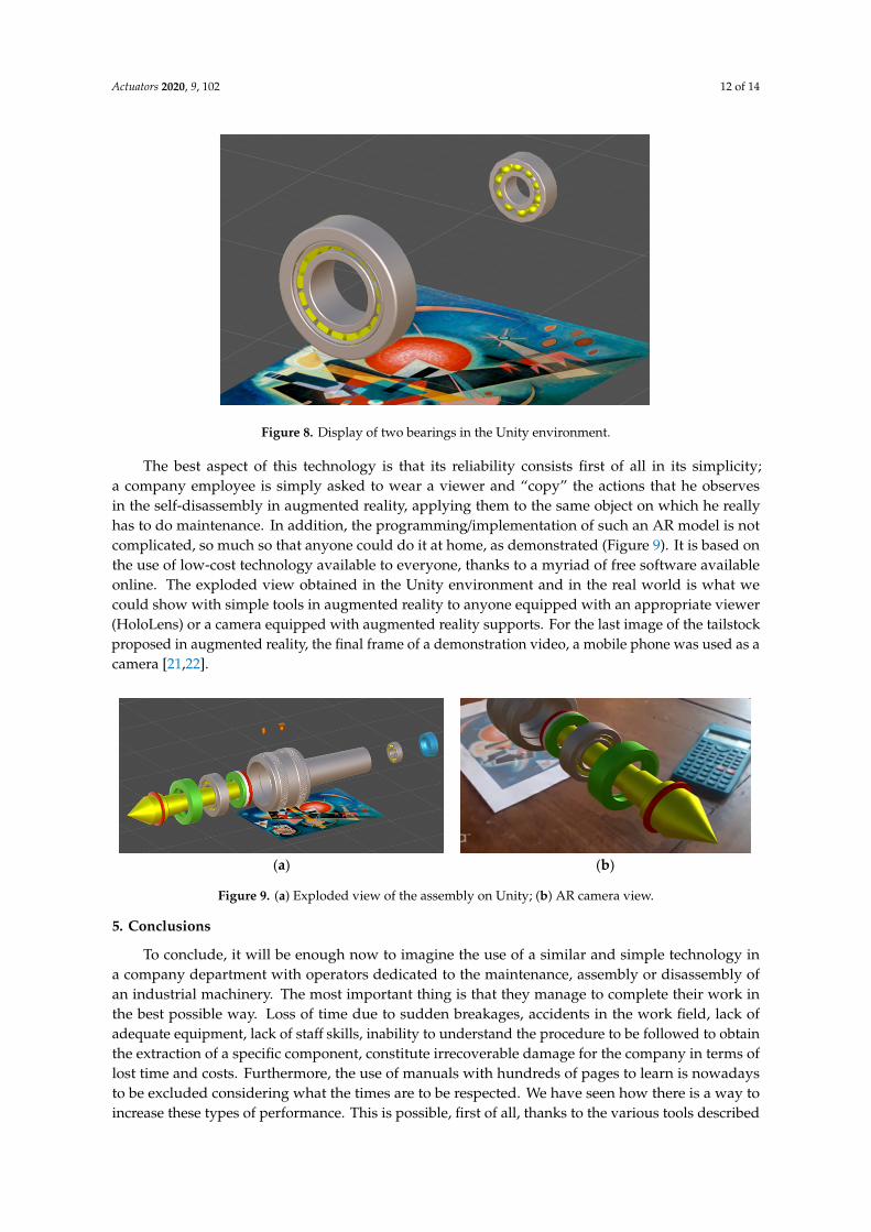
The best aspect of this technology is that its reliability consists first of all in its simplicity; a company employee is simply asked to wear a viewer and “copy” the actions that he observes in the self-disassembly in augmented reality, applying them to the same object on which he really has to do maintenance. In addition, the programming/implementation of such an AR model is not complicated, so much so that anyone could do it at home, as demonstrated (Figure 9). It is based on the use of low-cost technology available to everyone, thanks to a myriad of free software available online. The exploded view obtained in the Unity environment and in the real world is what we could show with simple tools in augmented reality to anyone equipped with an appropriate viewer (HoloLens) or a camera equipped with augmented reality supports. For the last image of the tailstock proposed in augmented reality, the final frame of a demonstration video, a mobile phone was used as a camera [21,22].
(a) (b)
Figure 9. (a) Exploded view of the assembly on Unity; (b) AR camera view.
5. Conclusions
To conclude, it will be enough now to imagine the use of a similar and simple technology in a company department with operators dedicated to the maintenance, assembly or disassembly of an industrial machinery. The most important thing is that they manage to complete their work in the best possible way. Loss of time due to sudden breakages, accidents in the work field, lack of adequate equipment, lack of staff skills, inability to understand the procedure to be followed to obtain the extraction of a specific component, constitute irrecoverable damage for the company in terms of lost time and costs. Furthermore, the use of manuals with hundreds of pages to learn is nowadays to be excluded considering what the times are to be respected. We have seen how there is a way to increase these types of performance. This is possible, first of all, thanks to the various tools described in the article, as the use of any CAD software for the modeling of a product to be industrialized, the application of the concepts of “design for disassembly” with a view to re-using materials and future savings on disposal costs, in addition to research efficient and optimal methodologies on the basis of
Figure 8. Display of two bearings in the Unity environment.
The best aspect of this technology is that its reliability consists first of all in its simplicity;a company employee is simply asked to wear a viewer and “copy” the actions that he observesin the self-disassembly in augmented reality, applying them to the same object on which he reallyhas to do maintenance. In addition, the programming/implementation of such an AR model is notcomplicated, so much so that anyone could do it at home, as demonstrated (Figure 9). It is based onthe use of low-cost technology available to everyone, thanks to a myriad of free software availableonline. The exploded view obtained in the Unity environment and in the real world is what wecould show with simple tools in augmented reality to anyone equipped with an appropriate viewer(HoloLens) or a camera equipped with augmented reality supports. For the last image of the tailstockproposed in augmented reality, the final frame of a demonstration video, a mobile phone was used as acamera [21,22].
Actuators 2020, 9, x FOR PEER REVIEW 12 of 14
Figure 8. Display of two bearings in the Unity environment.
The best aspect of this technology is that its reliability consists first of all in its simplicity; a company employee is simply asked to wear a viewer and “copy” the actions that he observes in the self-disassembly in augmented reality, applying them to the same object on which he really has to do maintenance. In addition, the programming/implementation of such an AR model is not complicated, so much so that anyone could do it at home, as demonstrated (Figure 9). It is based on the use of low-cost technology available to everyone, thanks to a myriad of free software available online. The exploded view obtained in the Unity environment and in the real world is what we could show with simple tools in augmented reality to anyone equipped with an appropriate viewer (HoloLens) or a camera equipped with augmented reality supports. For the last image of the tailstock proposed in augmented reality, the final frame of a demonstration video, a mobile phone was used as a camera [21,22].
(a) (b)
Figure 9. (a) Exploded view of the assembly on Unity; (b) AR camera view.
5. Conclusions
To conclude, it will be enough now to imagine the use of a similar and simple technology in a company department with operators dedicated to the maintenance, assembly or disassembly of an industrial machinery. The most important thing is that they manage to complete their work in the best possible way. Loss of time due to sudden breakages, accidents in the work field, lack of adequate equipment, lack of staff skills, inability to understand the procedure to be followed to obtain the extraction of a specific component, constitute irrecoverable damage for the company in terms of lost time and costs. Furthermore, the use of manuals with hundreds of pages to learn is nowadays to be excluded considering what the times are to be respected. We have seen how there is a way to increase these types of performance. This is possible, first of all, thanks to the various tools described in the article, as the use of any CAD software for the modeling of a product to be industrialized, the application of the concepts of “design for disassembly” with a view to re-using materials and future savings on disposal costs, in addition to research efficient and optimal methodologies on the basis of
Figure 9. (a) Exploded view of the assembly on Unity; (b) AR camera view.
5. Conclusions
To conclude, it will be enough now to imagine the use of a similar and simple technology ina company department with operators dedicated to the maintenance, assembly or disassembly ofan industrial machinery. The most important thing is that they manage to complete their work inthe best possible way. Loss of time due to sudden breakages, accidents in the work field, lack ofadequate equipment, lack of staff skills, inability to understand the procedure to be followed to obtainthe extraction of a specific component, constitute irrecoverable damage for the company in terms oflost time and costs. Furthermore, the use of manuals with hundreds of pages to learn is nowadaysto be excluded considering what the times are to be respected. We have seen how there is a way toincrease these types of performance. This is possible, first of all, thanks to the various tools described
Actuators 2020, 9, 102 13 of 14
in the article, as the use of any CAD software for the modeling of a product to be industrialized,the application of the concepts of “design for disassembly” with a view to re-using materials andfuture savings on disposal costs, in addition to research efficient and optimal methodologies on thebasis of which maintenance must be carried out—thus the use of augmented reality to teach operatorsthe optimal working methods, thanks to the very visual mode offered by this still little used, low-cost,and rare technology.
Author Contributions: Conceptualization, L.F.; methodology, L.F.; software, M.F.; validation, L.F. and M.F.; formalanalysis, M.F.; writing—original draft preparation, M.F.; visualization, M.F.; supervision, L.F. All authors haveread and agreed to the published version of the manuscript.
Funding: This research received no external funding.
Conflicts of Interest: The authors declare no conflict of interest.
References
1. Kalpakjian, S.; Schmid, S.R. Manufacturing Engineering and Technology; Prentice Hall: A Pearson EducationCompany: Upper Saddle River, NJ, USA, 2010.
2. Feldmann, K.; Trautner, S.; Lohrmann, H.; Melzer, K. Computer based product structure analysis for technicalgoods regarding optimal end-of-life strategies. Proc. Inst. Mech. Eng. B J. Eng. Manuf. 2001, 215, 684–693.[CrossRef]
3. Gonza’lez, B.; Adenso-Dı´az, B. A scatter search approach to the optimum disassembly sequence problem.Comp. Oper. Res. 2006, 33, 1776–1793. [CrossRef]
4. Tian, G.; Liu, Y.; Tian, Q.; Chu, J. Evaluation model and algorithm of product disassembly process withstochastic feature. Clean Technol. Environ. Policy 2012, 14, 345–356. [CrossRef]
5. Kroll, E.; Carver, B. Disassembly analysis through time estimation and other metrics. Robot. Comput. Integr. Manuf.1999, 15, 191–200. [CrossRef]
6. Frizziero, L.; Liverani, A.; Caligiana, G.; Donnici, G.; Chinaglia, L. Design for Disassembly (DfD) andAugmented Reality (AR): Case Study Applied to a Gearbox. Machines 2019, 7, 29. [CrossRef]
7. Grandi, A. Gestione dei Progetti d’Innovazione; McGraw Hill Education: Bologna, Italy, 2017.8. Manfè, G.; Pozza, R.; Scarato, G. Disegno Meccanico; Principato Editore: Bologna, Italy, 2013.9. Funaioli, E.; Maggiore, A.; Meneghetti, U. Lezioni di Meccanica Applicata Alle Macchine; Pitagora Editore:
Bologna, Italy, 2006.10. Raja, V.; Fernandes, K. Reverse Engineering: A Industrial Perspective; Springer Science & Business Media:
Berlin, Germany, 2008. [CrossRef]11. Soh, S.; Ong, S.K.; Nee, A. Application of Design for Disassembly from Remanufacturing Perspective.
Procedia CIRP 2015, 26, 577–582. [CrossRef]12. Yi, J.; Yu, B.; Du, L.; Li, C.; Hu, D. Research on the selectable disassembly strategy of mechanical parts based
on the generalized CAD model. Int. J. Adv. Manuf. Technol. 2008, 37, 599–604. [CrossRef]13. Tao, F.; Luning, B.; Zuo, Y.; Nee, A. Partial/Parallel Disassembly Sequence Planning for Complex Products.
J. Manuf. Sci. Eng. 2017, 140. [CrossRef]14. Desai, A.; Mital, A. Evaluation of disassemblability to enable design for disassembly in mass production.
Int. J. Ind. Ergon. 2003, 32, 265–281. [CrossRef]15. Alkhamisi, A.; Monowar, M.M. Rise of Augmented Reality: Current and Future Application Areas. Int. J.
Internet Distrib. Syst. 2013, 1, 25–34. [CrossRef]16. Vuforia. Available online: https://developer.vuforia.com/ (accessed on 1 July 2020).17. Unity. Available online: https://unity3d.com/get-unity/download (accessed on 1 July 2020).18. Piancastelli, L.; Frizziero, L.; Bombardi, T. Bézier based shape parameterization in high speed mandrel design.
Int. J. Heat Technol. 2014, 32, 57–63.19. Frizziero, L.; Liverani, A. Disassembly sequence planning (DSP) applied to a gear box: Comparison between
two literature studies. Appl. Sci. 2020, 10, 4591. [CrossRef]

Actuators 2020, 9, 102 14 of 14
20. Francia, D.; Seminerio, D.; Caligiana, G.; Frizziero, L.; Liverani, A.; Donnici, G. Virtual Design for AssemblyImproving the Product Design of a Two-Way Relief Valve, Lecture Notes in Mechanical Engineering 2020.In Proceedings of the International Conference on Design Tools and Methods in Industrial Engineering,ADM 2019, Modena, Italy, 9–10 September 2019; pp. 304–314.
21. Francia, D.; Ponti, S.; Frizziero, L.; Liverani, A. Virtual mechanical product disassembly sequences based ondisassembly order graphs and time measurement units. Appl. Sci. 2019, 9, 3638. [CrossRef]
22. Donnici, G.; Frizziero, L.; Francia, D.; Liverani, A.; Caligiana, G. A preliminary evaluation to support DFD ofhandcrafted products. Int. J. Mech. Prod. Eng. Res. Dev. 2019, 9, 1033–1050.
© 2020 by the authors. Licensee MDPI, Basel, Switzerland. This article is an open accessarticle distributed under the terms and conditions of the Creative Commons Attribution(CC BY) license (http://creativecommons.org/licenses/by/4.0/).