dependability assessment of by-wire control systems using fault injection
TRANSCRIPT

Journal of Systems Architecture 55 (2009) 102–113
Contents lists available at ScienceDirect
Journal of Systems Architecture
journal homepage: www.elsevier .com/locate /sysarc
Dependability assessment of by-wire control systems using fault injection
S. Blanc a,b,*, A. Bonastre a, P.J. Gil a
a Fault Tolerant Systems Group, Department of Computer Systems and Computation, Universidad Politécnica de Valencia, Spainb Higher Technical School of Applied Computer Science (Escuela técnica superior de informática aplicada), Universidad Politécnica de Valencia, Camino de Vera s/n,Valencia 46022, Spain
a r t i c l e i n f o a b s t r a c t
Article history:Received 7 November 2005Received in revised form 13 August 2008Accepted 29 September 2008Available online 8 October 2008
Keywords:DependabilityTTA architecturesBy-wire systemsTTPFault injection
1383-7621/$ - see front matter � 2008 Elsevier B.V. Adoi:10.1016/j.sysarc.2008.09.003
* Corresponding author. Address: Higher TechnicalScience (Escuela técnica superior de informática aplicde Valencia, Camino de Vera s/n, Valencia 46022, Sp00x75722; fax: +00 34 96 387 75 79.
E-mail addresses: [email protected] (S. Bla(A. Bonastre), [email protected] (P.J. Gil).
This paper is focused on the validation by means of physical fault injection at pin-level of a time-triggeredcommunication controller: the TTP/C versions C1 and C2. The controller is a commercial off-the-shelfproduct used in the design of by-wire systems. Drive-by-wire and fly-by-wire active safety controlsaim to prevent accidents. They are considered to be of critical importance because a serious situationmay directly affect user safety. Therefore, dependability assessment is vital in their design.
This work was funded by the European project ‘Fault Injection for TTA’ and it is divided into two parts.In the first part, there is a verification of the dependability specifications of the TTP communication pro-tocol, based on TTA, in the presence of faults directly induced in communication lines. The second partcontains a validation and improvement proposal for the architecture in case of data errors. Such errorsare due to faults that occurred during writing (or reading) actions on memory or during data storage.
� 2008 Elsevier B.V. All rights reserved.
1. Introduction
Embedded systems are becoming increasingly complex. Theirtechnological advance has allowed results that were inconceivablesome years ago. This is the case of the ‘by-wire’ concept in theautomotive industry – with a constant increase in the number ofelectronic control units (ECUs) with each new car model. The num-ber of ECUs is not negligible and they are normally distributedthroughout the vehicle and share a required fail-safe communica-tion network.
Dependability assessment is vital in the design of by-wire activesafety controls for preventing accidents. Both reliability and safetyare critical attributes of dependability in these control systems be-cause a serious situation may directly affect user safety. Reliabilityconcerns the continuity of a correct service during a time interval,while safety is the probability that a catastrophic failure does nothappen.
An architecture considered as dependable will give the systemthe ability to detect errors and recover in time to continue offeringa correct service. An example is the Time-Triggered Architecture(TTA) [1] that places reliability and safety as the most important is-sues. However, although the TTA provides a worthy structure in
ll rights reserved.
School of Applied Computerada), Universidad Politécnicaain. Tel.: +00 34 96 387 70
nc), [email protected]
the development of by-wire systems, the fulfilment of the expecta-tions concerning reliability and safety mainly depend upon com-munication protocols. There are several protocols based on TTAsuch as: FlexRay [2]; TTCAN [3]; FTT-CAN [4]; Time-TriggeredEthernet [5]; or Time-Triggered Protocol (TTP) [6]. TTP was origi-nally focused on backbone communication buses for automotivesystems and is now open to the high safety standards required inthe aerospace industry.
TTP has been comprehensively verified by formal methods [6]and surpasses the other protocols because it uses fault injectiontechniques to achieve a precise dependability validation. TwoEuropean Commission projects: PDCS (‘Predictably DependableComputing Systems’ 1992–1993); and FIT (‘Fault Injection forTTA’ 2000–2002)1 funded research into fault injection. The FIT pro-ject is the most recent project and presented tools with improvedtechnology for validating distributed systems. It helped to improvethe TTP–C1 and the TTP–C2 communication-controller chips withcost-optimal safe solutions. The TTP/C chips are commercial off-the-shelf products, hence the importance of their validation. Tech-niques used during the project were: Software Implemented FaultInjection by the Vienna University of Technology; Heavy Ion Radia-tion by Chalmers University in Sweden; C-Sim Simulation by theCzech Technical University in Prague and the University of WestBohemia; VHDL-based Fault Injection and Physical Fault Injection atPin-level, both by the Universidad Politécnica de Valencia in Spain.All the techniques have been demonstrated to be compatible andsufficiently enriching to merit individual study.
1 ‘Fault Injection for TTA’: IST-1999-10748 FIT
TTP/C chip
TxD RxD GB
TTP/C chip
TxD RxD GB
TTP/C chip
TxD RxD GB
TTP/C chip
TxD RxD GB
Node D Node C Node B Node A
TDMA rounds:
TDMA i
TDMA i +1
Channel 0
Channel 1
Channel 0
Channel 1
Window j Window j+1 Window j+2 Window j+3
t
IFG GFIGFI IFG
DATA FRAME
SPECIAL FRAME
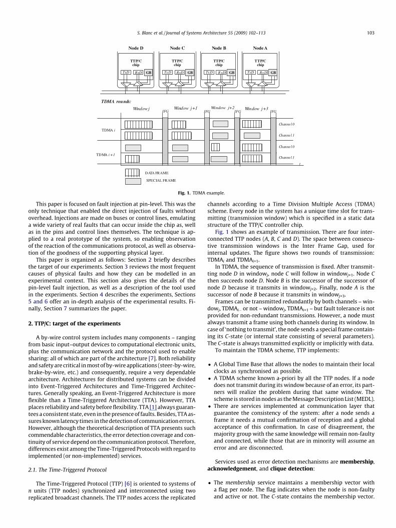
Fig. 1. TDMA example.
S. Blanc et al. / Journal of Systems Architecture 55 (2009) 102–113 103
This paper is focused on fault injection at pin-level. This was theonly technique that enabled the direct injection of faults withoutoverhead. Injections are made on buses or control lines, emulatinga wide variety of real faults that can occur inside the chip as, wellas in the pins and control lines themselves. The technique is ap-plied to a real prototype of the system, so enabling observationof the reaction of the communications protocol, as well as observa-tion of the goodness of the supporting physical layer.
This paper is organized as follows: Section 2 briefly describesthe target of our experiments. Section 3 reviews the most frequentcauses of physical faults and how they can be modelled in anexperimental context. This section also gives the details of thepin-level fault injection, as well as a description of the tool usedin the experiments. Section 4 describes the experiments, Sections5 and 6 offer an in-depth analysis of the experimental results. Fi-nally, Section 7 summarizes the paper.
2. TTP/C: target of the experiments
A by-wire control system includes many components – rangingfrom basic input–output devices to computational electronic units,plus the communication network and the protocol used to enablesharing: all of which are part of the architecture [7]. Both reliabilityand safety are critical in most of by-wire applications (steer-by-wire,brake-by-wire, etc.) and consequently, require a very dependablearchitecture. Architectures for distributed systems can be dividedinto Event-Triggered Architectures and Time-Triggered Architec-tures. Generally speaking, an Event-Triggered Architecture is moreflexible than a Time-Triggered Architecture (TTA). However, TTAplaces reliability and safety before flexibility. TTA [1] always guaran-tees a consistent state, even in the presence of faults. Besides, TTA as-sures known latency times in the detection of communication errors.However, although the theoretical description of TTA presents suchcommendable characteristics, the error detection coverage and con-tinuity of service depend on the communication protocol. Therefore,differences exist among the Time-Triggered Protocols with regard toimplemented (or non-implemented) services.
2.1. The Time-Triggered Protocol
The Time-Triggered Protocol (TTP) [6] is oriented to systems ofn units (TTP nodes) synchronized and interconnected using tworeplicated broadcast channels. The TTP nodes access the replicated
channels according to a Time Division Multiple Access (TDMA)scheme. Every node in the system has a unique time slot for trans-mitting (transmission window) which is specified in a static datastructure of the TTP/C controller chip.
Fig. 1 shows an example of transmission. There are four inter-connected TTP nodes (A, B, C and D). The space between consecu-tive transmission windows is the Inter Frame Gap, used forinternal updates. The figure shows two rounds of transmission:TDMAi and TDMAi+1.
In TDMA, the sequence of transmission is fixed. After transmit-ting node D in windowj, node C will follow in windowj+1. Node Cthen succeeds node D. Node B is the successor of the successor ofnode D because it transmits in windowj+2. Finally, node A is thesuccessor of node B because it transmits in windowj+3.
Frames can be transmitted redundantly by both channels – win-dowj, TDMAi� or not – windowj, TDMAi+1 – but fault tolerance is notprovided for non-redundant transmissions. However, a node mustalways transmit a frame using both channels during its window. Incase of ‘nothing to transmit’, the node sends a special frame contain-ing its C-state (or internal state consisting of several parameters).The C-state is always transmitted explicitly or implicitly with data.
To maintain the TDMA scheme, TTP implements:
� A Global Time Base that allows the nodes to maintain their localclocks as synchronised as possible.
� A TDMA scheme known a-priori by all the TTP nodes. If a nodedoes not transmit during its window because of an error, its part-ners will realize the problem during that same window. Thescheme is stored in nodes as the Message Description List (MEDL).
� There are services implemented at communication layer thatguarantee the consistency of the system: after a node sends aframe it needs a mutual confirmation of reception and a globalacceptance of this confirmation. In case of disagreement, themajority group with the same knowledge will remain non-faultyand connected, while those that are in minority will assume anerror and are disconnected.
Services used as error detection mechanisms are membership,acknowledgement, and clique detection:
� The membership service maintains a membership vector witha flag per node. The flag indicates when the node is non-faultyand active or not. The C-state contains the membership vector.

104 S. Blanc et al. / Journal of Systems Architecture 55 (2009) 102–113
When a frame is transmitted, the controller compares its vec-tor with the vector received from the successor. In case of dis-agreement, it compares both with the successor of thesuccessor. In case of agreement between successors, the nodeassumes that it has made an error; otherwise, it assumes asuccessor error.
� When a node transmits a frame, it needs a global acknowl-edgement from at least half of the connected nodes. When aframe is incorrectly received (for example, the CRC does notmatch), the receiving node sets the node transmitter as non-active in its membership vector. Acknowledgment is thengiven only if the membership vectors from receiver and trans-mitter agree.
� A clique division means that there is not a common knowledgeof the system: membership vectors differ among the nodes. Cli-que detection executed individually by each node will avoid thissituation if it is assumed that the majority knowledge groupalways prevails.
2.2. The TTP/C controller
In a TTP system, one TTP node consists of the host processor, theTTP/C controller, and the Communication Network Interface (CNI)[6]. The host processor has three software layers: the time-trig-gered operating system, the fault-tolerant communication layer(FTcom), and the application layer. The FTcom layer is responsiblefor reading/writing redundant messages to/from the CNI. It per-forms the mapping of redundant messages (frames sent redun-dantly by both channels) on to a single message, thus making themessage redundancy transparent to the application. The CNI is adata exchange interface between the host and the communicationcontroller and it is implemented using a dual ported RAM.
The static communication schedule is stored in the MEDL –which stores information about message size, message type, mes-sage sending/receiving point in time, and other information relatedto the communication schedule and configuration of the node. TheMEDL is prepared off line and cannot be changed at runtime.
Several versions such as TTP/C–C1 and TTP/C–C2 controllers de-ploy an additional unit called Bus Guardian (BG). The BG enablesand disables the transmission accesses to the bus. The BG preventsa faulty node from sending a message outside its transmission win-dow, avoiding collisions in the bus.
TTP/C–C1 is a 16-bit controller organized around the ProtocolControl Unit (PCU). The PCU executes high level protocol mecha-nisms such as message redundancy, membership, etc. – and con-trols the interaction of some internal blocks such as the TimeControl Unit (TCU) and the CRC Unit. The TCU maintains the GlobalTime Base algorithms, and the CRC unit supports the calculation ofcyclic redundancy check sums. The CRC unit allows the concurrentcalculation of two checksums, one for each channel. The frame datais added to the check sum word or byte wise.
The main changes in the TTP/C–C2 version are the extendedlength of the frames, the MEDL on chip, and the addition of somenew blocks.
3. Validation by fault injection
To carry out a consistent experimental validation with regard tophysical faults, we need previously to analyze which are theirsources in current sub-micron technologies.
Firstly, this section summarizes the most frequent causes ofphysical faults and how they can be experimentally modelled. Sec-ondly, the details for the pin-level fault injection are summed up,as well as the description of the tool used in the experiments.
3.1. Physical faults in current semiconductors
Most electronic devices are designed taking into account thepossibility of physical disturbances due to electromagnetic inter-ferences (EMI), power variations, radiation, and other possiblecauses. Moreover, higher operational frequencies and integrationdensities combined with the lower power voltages of technolog-ically advanced semiconductor devices make them more suscep-tible to the effects of neutron and alpha particles [8–10]. Thesources of radiation are cleverly and concisely described in[11]. For example, the U-238 and Th-232 radioactive isotopes,being natural alpha emitting particles in semiconductors, arethe cause of soft errors in the form of transient bit-flips in mem-ory. The special case of Pb-210 must be taken into account as asource of alpha particles from the solder bumps in flip chippackages, but only for a limited period of time. Some soft errors,and less probable hard errors [12], are also caused by cosmicradiation. A relevant phenomenon is the induction of secondaryparticles; the nature, energy, and direction of which could resultin complex chain reactions [13,14], as for example, the case ofthe B-10 isotope [15]. Due to a neutron incidence, this isotopeis capable of fission into a Li-7 recoil nucleus, a gamma photon,and an alpha particle.
The number of transistors belonging to different memory cellswhich are upset by a single incidence increases with integrationdensity. Besides the possibility of multiple incidences, high energyions can induce multiple bit upsets if crossing through sensitiveadjacent regions – either due to a single ion track or secondary par-ticles caused by an ion collision [16,17].
Apart from radiation, the environmental working conditions ofsome critical systems, and the resulting degradation as a result ofdevice wear are also sources of physical faults [18,19].
A challenge for experimental validation is the modelling ofharmful environmental effects (crosstalk, junction defects, badconnectors, coupling, etc.), degradation problems, as well as radia-tion. In this field, a recent study regarding fault models can befound in the documentation of the European funded projectDBench (‘Dependability Benchmarking’ 2001–2004) [20,21]. Bothpermanent and intermittent faults, as well as transient faults, aremodelled at the Logic and Register Transfer (RT) levels. The studytraces the representation of the electrical stress, hot e-trapping, io-nic contamination, electromigration, thin-oxide breakdown, radia-tion or temperature variation effects in the form of permanent andintermittent faults modelled as shorts, open-lines, stuck-at, stuck-open, indetermination in voltage values, and delays in transmittedsignals. Causes of transient faults are radiation, interconnectionshrinking at high frequencies, transients in power lines, crosstalk,or temperature variation.
In addition to this study, there are several relevant consider-ations concerning solder joints and metallizations:
– The risk of shorts due to undesirable whiskers produced byelectromigration and thermal coefficient mismatches injunction elements increases with new packages and deepsubmicron circuits that feature smaller pad distances andinternal metallizations.
– Excessive intermetallic compound formation or silicon cra-tering [22], and mechanical stress are manufacturing defectswhich produce coarse junctions.
High current density and junction temperatures, as well asmoisture and ionic contamination, are factors which speed up sol-der fatigue and metal migration and result in microcracks andopen-lines – regardless of whether manufacturing defects are pres-ent. Microcracks increase the resistance of a junction in a signaltransmission and would be likely to cause a delayed reception.
S. Blanc et al. / Journal of Systems Architecture 55 (2009) 102–113 105
The problem is significant at high frequencies where wire distanceshrinkage worsens the coupling capacities. The variation of resis-tance and capacity at high frequencies could result in signal atten-uation at indeterminate voltage values.
With improved understanding of the causes of faults, and themethods in which these can be modelled in an experimental envi-ronment, the next step is to look for techniques and tools whichenable us to work with these models.
3.2. Fault injection at pin-level
There are three general categories of fault injection (FI): (i) Sim-ulated FI; (ii) Software Implemented FI (SWIFI); and (iii) HardwareImplemented FI (HWIFI).
� Simulated FI mainly refers to tools that model the system usinghigh level languages. Hardware description languages such asVerilog or VHDL are currently often used. An example isVHDL-based fault injection [23], a powerful technique with awide range of fault models.
� SWIFI consists in reproducing, at software-accessible RT level,errors caused by physical faults in the hardware or by hiddenbugs in the software. It provides a relatively cost effective andsimple methodology.
� HWIFI tools disturb the electrical properties of hardware compo-nents, and indirectly affecting the software components as well.Some examples are heavy ion radiation, laser radiation, electro-magnetic interferences, and pin-level FI. An advantage is theapplication of the technique on a real system prototype. Itenables us to observe both the reaction of the software andthe goodness of the hardware.
Two HWIFI tools were applied in the FIT project: heavy ion FI,and FI at pin-level. Together they provide the effect of faults in-jected with laser radiation or electromagnetic interferences. FI atpin-level is a technique based on the notion of perturbing inte-grated circuits: usually by means of shorts on the pins or by stick-ing them at a predefined value. Pins belong to address or data
CNI Communication Memory
Protocol Control Unit PCU
RxD RxD
TxD TxD
Host microcontroller
DRIVERS
Faults at pin-host le
Faults at pin-communication level
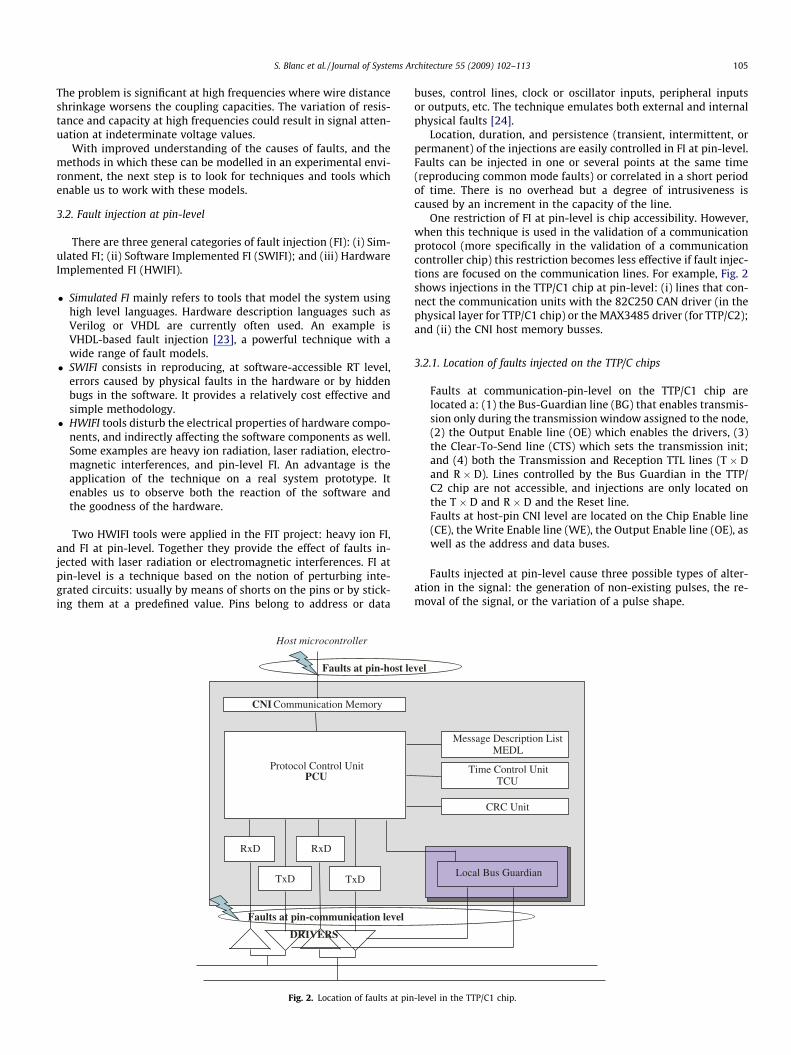
Fig. 2. Location of faults at pin
buses, control lines, clock or oscillator inputs, peripheral inputsor outputs, etc. The technique emulates both external and internalphysical faults [24].
Location, duration, and persistence (transient, intermittent, orpermanent) of the injections are easily controlled in FI at pin-level.Faults can be injected in one or several points at the same time(reproducing common mode faults) or correlated in a short periodof time. There is no overhead but a degree of intrusiveness iscaused by an increment in the capacity of the line.
One restriction of FI at pin-level is chip accessibility. However,when this technique is used in the validation of a communicationprotocol (more specifically in the validation of a communicationcontroller chip) this restriction becomes less effective if fault injec-tions are focused on the communication lines. For example, Fig. 2shows injections in the TTP/C1 chip at pin-level: (i) lines that con-nect the communication units with the 82C250 CAN driver (in thephysical layer for TTP/C1 chip) or the MAX3485 driver (for TTP/C2);and (ii) the CNI host memory busses.
3.2.1. Location of faults injected on the TTP/C chips
Faults at communication-pin-level on the TTP/C1 chip arelocated a: (1) the Bus-Guardian line (BG) that enables transmis-sion only during the transmission window assigned to the node,(2) the Output Enable line (OE) which enables the drivers, (3)the Clear-To-Send line (CTS) which sets the transmission init;and (4) both the Transmission and Reception TTL lines (T � Dand R � D). Lines controlled by the Bus Guardian in the TTP/C2 chip are not accessible, and injections are only located onthe T � D and R � D and the Reset line.Faults at host-pin CNI level are located on the Chip Enable line(CE), the Write Enable line (WE), the Output Enable line (OE), aswell as the address and data buses.
Faults injected at pin-level cause three possible types of alter-ation in the signal: the generation of non-existing pulses, the re-moval of the signal, or the variation of a pulse shape.
Message Description ListMEDL
Time Control UnitTCU
CRC Unit
Local Bus Guardian
vel
-level in the TTP/C1 chip.

Table 1FI at pin-communication level: Fault Models.
Location Persistence Type of alteration Fault Model
BG, OE Transient,Intermittent
Non-existingpulses
Pulses
TxD Transient Non-existingpulses
Bit-flips
Any line Permanent Signal removal Stuck-atT � D,
R � DTransient Signal shape
variationDelay, Indeterminatevoltage at high frequency
Anycontrolline
Transient Signal shapevariation
Delay
Table 2FI at pin-host CNI level: Fault Models.
Location Persistence Type of alteration Fault Model
CNI buses Transient Non-existing pulses Bit-flipsCNI WE, CE, OE Transient Signal removal Transient faults at RT levelAny line Permanent Signal removal Stuck-atAny control
lineTransient Signal shape
variationDelay
106 S. Blanc et al. / Journal of Systems Architecture 55 (2009) 102–113
Depending on the location, persistence of the injected fault andtype of alteration observed in the signal fault models reached by FIat pin level are shown in Tables 1 and 2.
For example, Fig. 3A shows two examples of non-existing pulsesgenerated in a control signal. Fig. 3B shows the effect of a stuck-at-0 in a memory bus line.
It depicts a transient fault injected over a short time, but longenough to modify the original signal in consecutive memory acces-ses, thereby distorting the information (bit-flips) of several words.Likewise, a transient on the T � D line can flip one or several bitsthat belong to the transmitted frame.
Besides, any pin permanently stuck-at-0 or at-1 will removethe original signal maintaining the line at the injected value.But if it is a transient fault, the pin-level fault injection emulatesthose transient faults at RT level that may cause an executionerror.
Finally, the variation of a pulse shape is focused on yielding vio-lations of set-up and hold times.
3.3. The injection tool: AFIT
Three processes are involved in an experimental validation:fault injection, data acquisition, and the analysis of results [25].
Fault injection: In the FIT project, the injection process at pin-level was in charge of AFIT: Advanced Physical Fault InjectionTool at pin-level. AFIT was developed at the Universidad Polité-cnica de Valencia [30] with several updates [24]. The tool iscompletely external and, it is not necessary to halt or delaythe target execution. AFIT runs automatically, enabling manyexperiments to be conducted without supervision. Faults areinjected by sticking the lines at-0 or at-1 logic values.
Original signal
Generation of non-existing
pulses
Fig. 3. Generation of n
Data acquisition: The last version of AFIT was designed for dis-tributed systems [25]. This version incorporates a monitor asacquisition tool – combined with software tasks running inthe host processors of the TTP nodes. The tasks obtain read-outsof the detected errors and failures. Failures can appear in eitherthe injected node or another node connected to the network,which is known as ‘error propagation’. Injection and acquisitionare synchronized. Each experiment lasts from the injection tothe last reaction of the system (i.e., fault effectiveness, erroractivation, error detection, error treatment including diagnos-tics, isolation and recovery, error propagation and failure). Faulteffectiveness has a special importance in physical fault injection.It determines whether the fault has caused a real perturbation.The injected fault is not always effective, for example, if westuck-at-1 a line whose logic value was already 1 the fault willbe ineffective and the experiment is useless. The collection andstructured storage of system events in the presence of a fault,together with required measured latencies from the error acti-vation to its detection or failure, are all parts of the acquisitionprocess.Analysis of results: It would be desirable to have an automaticprocessing of the ‘injection-acquisition’ that takes up the small-est possible period of time per experiment (i.e., up to one sec-ond in the TTP/C experiments). Post-processing these results,which is usually a time consuming task, would then be acceptedif data storage is well-conducted during the campaign and gen-erate databases which contain all the required information fortracing back an observed event. An analysis of results mayreveal defects in the injection and data acquisition processesthat could be rectified in a new injection campaign (feedback).
4. Experimental description
The experimental system was a cluster of four TTP nodes withtwo configurations:
(A) TTP nodes with a TTP/CTM–C1 controller and a MotorolaMC68360 used as host.
(B) TTP nodes with a TTP/CTM–C2 and a Motorola power PCPPC555.
The workload was a brake-by-wire (BBW) simulation programdesigned by Volvo Technological Development. It was a distributedcontrol system that required four TTP nodes:
� The pedal brake: Angled to calculate the brake force.� The vehicle: Calculates the speed of the vehicle body in m/s, the
speed of the four wheels, and the distance covered by the vehi-cle. It uses two parameters, the acceleration torque on one wheel,and the frictional force on one side of the wheel brake disc. Thevehicle sends the speed of the vehicle body and the speed ofthe front left wheel.
� The front left wheel: Implements the ABS control algorithm –requiring as inputs the speed of the front left wheel in rad/s dur-ing the last cycle, the speed of the vehicle body in m/s, and the
Original signal
Memory access cyclesInjected value (0) expected value (1)
on-existing pulses.
S. Blanc et al. / Journal of Systems Architecture 55 (2009) 102–113 107
pedal force. As outputs, the node sends the pressure applied toone wheel brake pad’s piston and the new speed of the front leftwheel, and resends the received data from the vehicle node.
� The replica of the left wheel: The injection takes place in the frontleft wheel node. The replica runs free of faults. Messages trans-mitted by the replica are compared with those transmitted bythe ‘front left wheel’ node in order to detect communication fail-ures or errors propagated in the message data.
Experiments are divided into two groups: (i) at the communica-tion-pin level and, (ii) at the host-pin CNI level.
4.1. Experiments at pin-communication level
In general, failures at the communication level are grouped un-der a limited number of modes. For example, the loss of connectioneither due to a crash in a unit or a communication-link-fault, bothof which cause the unit to omit messages; babbling-idiot transmis-sions including commission failures [26] and physical distur-bances; the Slightly-Off-Specifications (SOS) problems [27,28];Byzantine messages [29], and masquerading failures that occurwhen a unit assumes the identity of another unit and damagesthe system. In safety-critical systems, the communications proto-col must guarantee a dependable behaviour despite failure or shut-down and reinstatement actions.
The TTP detection mechanisms used by TTP to ensure consis-tency at the communication layer are membership, acknowledg-ment, and clique detection. Experiments evaluate theireffectiveness in the presence of faults shown in Table 1.
4.2. Experiments at pin-host CNI level
The distribution of control algorithms in by-wire applicationsinvolves exposing the data values to physical faults during a longperiod. TTP guarantees the consistency of the system and the con-tinuity of service at the communication layer. However, physicalfaults can also appear at the application level or during the trans-ference of data between the application and the TTP/C chip.
Because dependability should be achieved at every level in thearchitecture, the experiments carried out in this section try toidentify error patterns caused in the presence of faults in Table 2.It also analyses error detection coverage with Error DetectionCodes.
5. Results at communication-pin-level
The TTA bus topology admits a network with channel redun-dancy. Therefore, TTP uses two channels. It sends a copy of theframe can be sent through each of the channels. If one copy doesnot arrive or is disrupted, the receiver will use the second copy –as both arrive at the same time.
In a sample of 3000 injection experiments on BG, OE, CTS, T � Dand R � D (see Section 3.2), TTP correctly accomplished the ‘singlefault’ hypothesis. In other words, the protocol maintains its consis-tency in the presence of any single fault at pin-level.
But, double faults were also injected: one fault per channelsimultaneously.
Table 3Emulated failures with faults at BG and OE lines.
Description of the emulated failure Signal alteration Synchronism
Message omission Signal removal Frame transmHalts an on-going transmission Signal shape variation Frame transmBabbling-idiot spurious pulses Non-existing pulses Frame recept
5.1. Control lines
Table 3 shows the failures that FI at pin-level can explicitly in-duce. Faults are located in BG and OE lines.
Failures occurring during the frame transmission were solvedwith the TTP membership service. Because frames were not re-ceived or not correctly received by the receivers (and all nodesare receivers in TTP), they will set the transmitter as faulty andoutside the membership vector. Since the membership vector is al-ways sent as part of the message, the transmitter only needs tocompare its own vector with its successors to recognise the failure.
A special case of failures are the babbling-idiot spurious pulses.These pulses emulate a faulty node that tries to transmit outside itstransmission window. In the experiments, faults were synchron-ised with a frame reception. Ten out of every 500 single injectionsresulted in common-mode faults: frames received by both chan-nels became disrupted. In these cases, failure should be detectedby the clique avoidance algorithm. The faulty receiver sees theframes as invalid, but failed to coincide with the majority (it onlyneeded to compare the membership vectors). However, cliqueavoidance did not detect the failure if the fault was injected duringa reception just before its own transmission. The faulty node trans-mits and does not recognise the failure until the execution of themembership service. Therefore, both mechanisms are needed toachieve 100% detection coverage.
5.2. T � D and R � D lines
FI at pin-level can change correct frames into syntactically orsemantically incorrect frames. Faults are overlapped with thetransmission of real frames, emulating internal errors to the con-troller, and defects in the communication channel or in the physi-cal layer. Faults frequently cause syntactically incorrect frames.Only rarely (1 in 1000 instances) does the frame remain syntacti-cally correct. Mechanisms used to detect these erroneous framesare CRC and message replication.
FI at pin-level can speed up the validation in the case of physicalfaults which cause errors in both channels. When injecting faults ineither T � D signals or R � D signals, Slightly-Off-Specificationsfailures appear. SOS indicates that the effect of the fault is mar-ginal: it is detected as a fault by some components but acceptedas a non-fault by others [28].
An SOS failure is not necessarily produced by a malicious or ‘ab-sent-minded’ node. Its origin is diverse, and ranges from an inco-herency between system design and system integration toarchitectural weaknesses. Coherency will be achieved by replacingor redesigning some components. However, architectural weak-nesses require conceptual change. For example, TTP/C developershave appealed for a change in the network topology towards a cen-tral star unit.
SOS failures in a bus topology are divided into: SOS in time do-main and SOS in value domain.
5.2.1. SOS in time domainIn a TTP system, nodes have slight differences in their reception
windows, i.e., because the precision of the oscillators drift awayfrom each other.
Persistence and multiplicity TTP Activated mechanisms
ission Double transient faults Membershipission Double transient faults Membership
ion Single transient faults Clique avoidance membership
108 S. Blanc et al. / Journal of Systems Architecture 55 (2009) 102–113
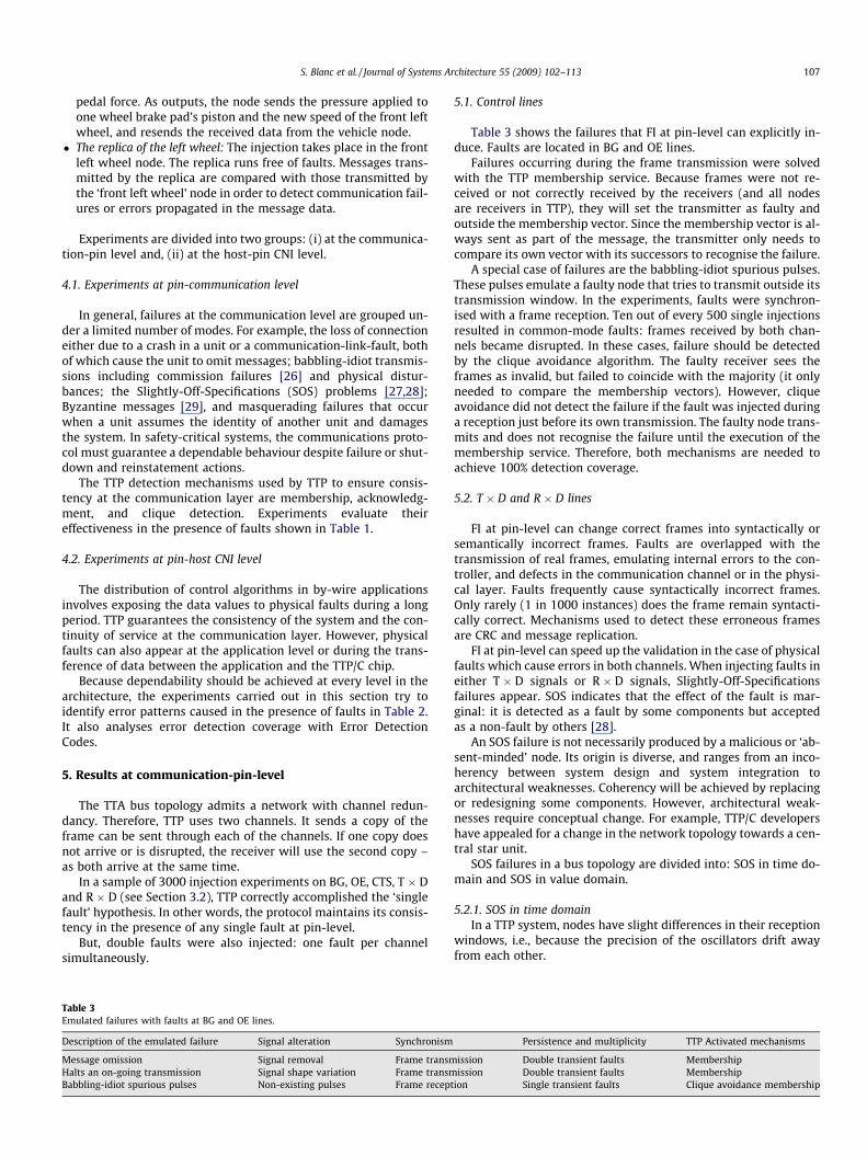
There are several parameters in a TTP window. For example, inFig. 4 (in TTP/C specifications), a sender opens its window at tAT s
but starts the transmission at time t0ATs: it waits for any receiverto open its window. Drw r defines the limits of valid receptions.In the middle, the frame is expected at tAT 0r , while treception r indi-cates the real reception init.
Spurious short pulses between tAT s and Drw r left limit, can gen-erate SOS failures in the time domain.
Differences in the window openings divide the cluster into: (1)nodes that receive the fault and the real frame, and (2) nodes thatonly receive the real frame.
TTP avoids clique formation by comparing the number of validreceived frames with the number of invalid frames. Before trans-mission, valid frames should exceed the number of invalid framesand silences (non-receptions during a window).
In the experiments, it was observed that nodes in case (1) inTTP/C–C1 (version 0.1) increased the invalid frames counter bytwo (the fault and the frame). Subsequently, in a four TTP node sys-tem it was possible to observe the consecutive shutdown of thefour nodes due to the fact that none were able to count more validthan invalid frames. Version 1.1 in TTP/C–C2 changes the conceptof the valid frames counter into an agreed slots counter. By limitingthe number of potential invalid receptions to one per window,shutdowns can be avoided and the protocol can be made morereliable.
5.2.2. SOS in value domainSOS failures in value domain are those generated by a marginal
incorrect encoding or by an indeterminate value, for example, asignal attenuated below the established threshold.
The experiments emulate SOS failures with double faults. Forexample, the R � D lines of Nodes 1 and 2 are stuck-at-0 whileNode 3 receives the signal free of faults. Faults are aimed to causediscrepancies and the behaviour of the protocol is observed.
In the experiments, it was seen that the TTP always avoids dis-crepancy by means of a Never Give Up strategy [6] that forces aclean restart and recovery. Such a strategy enables the system to
Δ r
Δ s
Δrw r
Treception r
tAT r
tAT s
tAT’ s
tAT’ r
Fig. 4. Some parameters in a TTP frame transmission.
015 ...
0 0 0 1 1 1 1 0 1 1 0 0 1 0 1 0
0 1 1 1 0 0 1 0 1 1 1 0 1 0 1 1
0 1 0 0 1 0 0 1 0 1 0 0 1 1 1 1
Sequence free of faults
Vertical combination3
015 ...
0 0 0 1 1 1 1 0 1 1 0 0 1 0 1 0
0 1 1 1 0 0 1 0 1 1 1 0 1 0 1 1
0 1 0 0 1 0 0 1 0 1 0 0 1 1 1 1
Sequence free of faults
Vertical combination3
Fig. 5. Unidirect
work degradedly, maintaining minimal functionality which re-duces the system recovery latency.
The SOS experiments were carried out with AFIT and repro-duced positively with VFIT [33]. It produces more reliable results.
5.3. Reinstatement actions
After a node or nodes recover their functionality, they may per-form reinstatement actions. In the context of validation, it isimportant to verify that reinstatement actions are safe and donot involve any correlated failure.
We observed a new sample of 5000 experiments on the resetline. The reinstatement of one or more nodes did not result inany frame collision. Nevertheless, only 4 out of every 1500achieved reinstatement in just one TDMA. A faster reinstatementis a difficult challenge for any communication protocol. For thisreason, it is recommended to replicate nodes with critical functionsin the system.
6. Results at host-pin CNI level
When variables calculated by the application are available (forexample, the wheel speed) the host writes these in a dedicated partof the CNI memory: the message memory. Message memory writ-ing (or reading) is susceptible to electromagnetic interferences,radiation, solder joint degradation, etc. Likewise, data stored inthe message memory can be exposed to single event upsets (i.e.,radiation) that cause bit-flip errors.
In TTP network transmission, frames are protected with a CyclicRedundant Check (CRC) code. However, before the CRC calculation,data is not protected either during writing (or reading) actions onthe message memory, or during data storage in the memory. More-over, multiple faults are possible, and these would be correlatedbut not necessarily common-mode faults.
6.1. Errors patterns
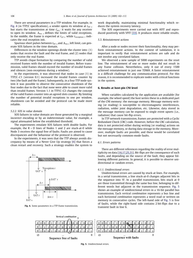
There are different references regarding the reality of error mul-tiplicity on data [16,17,25,31]. Bit-flips are the consequence of suchfaults, and depending on the source of the fault, they appear fol-lowing different patterns. In general, it is possible to observe uni-directional or random errors.
6.1.1. Unidirectional errorsUnidirectional errors are caused by stuck-at lines. For example,
in a serial transmission, a line stuck-at-0 changes adjacent bits inthe sequence into ‘0’. In a parallel transmission, bits stuck at 0are those transmitted through the same bus line, belonging to dif-ferent words but adjacent in the transmission sequence. Fig. 5shows an example of unidirectional errors in a 16-bit parallel bustransmission. Each vertical combination represents a bus line andeach horizontal combination represents a word read or written onmemory in consecutive cycles. The left-hand side of Fig. 5 is freeof faults, while the right-hand side contains 2 bit-flips due to atransient fault in line 6.
015 ...
0 0 0 1 1 1 1 0 1 1 0 0 1 0 1 0
0 1 1 1 0 0 1 0 1 0 1 0 1 0 1 1
0 1 0 0 1 0 0 1 0 0 0 0 1 1 1 1
Sequence with faults015 ...
0 0 0 1 1 1 1 0 1 1 0 0 1 0 1 0
0 1 1 1 0 0 1 0 1 0 1 0 1 0 1 1
0 1 0 0 1 0 0 1 0 0 0 0 1 1 1 1
Sequence with faults
ional errors.
Update j
015 ...
1 1 0 0 0 1 0 0 1 0 1 0 1 0 1 0
0 0 1 0 1 0 1 0 1 1 0 1 1 0 1 0
0 0 1 0 0 1 0 0 1 1 1 0 1 0 1 1
015 ...
0 0 0 1 1 1 1 0 1 1 0 0 1 0 1 0
0 0 1 0 1 0 1 0 1 1 0 1 1 0 1 0
0 0 1 0 0 1 0 0 1 1 1 0 1 0 1 1
Missingupdates
015 ...
1 1 0 0 0 1 0 0 1 0 1 0 1 0 1 0
0 0 1 0 1 0 1 0 1 1 0 1 1 0 1 0
0 0 1 0 0 1 0 0 1 1 1 0 1 0 1 1
15 ...
0 0 0 1 1 1 1 0 1 1 0 0 1 0 1 0
0 1 1 1 0 0 1 0 1 1 1 0 1 0 1 1
0 1 0 0 1 0 0 1 0 0 0 0 1 1 1 1
Sequence free of faults Sequence with faults
Update j + 1
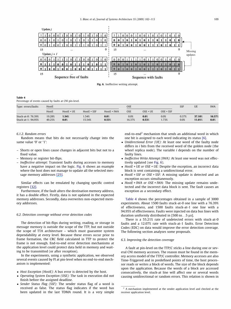
Fig. 6. Ineffective writing attempt.
Table 4Percentage of events caused by faults at CNI pin-level.
Type: errors/faults HostE OSE SSF UE IWA
HostE HostE + UE HostE + SSF HostE + IWA OSE OSE + UE OSE + SSF
Stuck-at-0: 76.39% 19.28% 1.54% 1.54% 0.0% 0.0% 0.0% 0.0% 0.37% 37.10% 16.57%Stuck-at-1: 94.95% 49.25% 0.0% 15.54% 0.53% 16.37% 0.53% 1.73% 0.0% 11.01% 0.0%
S. Blanc et al. / Journal of Systems Architecture 55 (2009) 102–113 109
6.1.2. Random errorsRandom means that bits do not necessarily change into the
same value ‘0’ or ‘1’:
– Shorts or open lines cause changes in adjacent bits but not to afixed value.
– Memory or register bit-flips.– Ineffective attempt: Transient faults during accesses to memory
have a negative impact on the logic. Fig. 6 shows an examplewhere the host does not manage to update all the selected mes-sage memory addresses [25].
Similar effects can be emulated by changing specific controlregisters [32].
Furthermore, if the fault alters the destination memory address,it has a double effect. Firstly, data is not updated in the expectedmemory addresses. Secondly, data overwrites non-expected mem-ory addresses.
2 A mechanism implemented at the sender application level and checked at thereceiver application level.
6.2. Detection coverage without error detection codes
The detection of bit-flips during writing, reading, or storage inmessage memory is outside the scope of the TTP, but not outsidethe scope of TTA architecture – which must guarantee systemdependability at every level. Because these errors occur prior toframe formation, the CRC field calculated in TTP to protect theframe is not enough. End-to-end error detection mechanisms atthe application level could protect data held in memory and wait-ing to be transmitted (or after reception).
In the experiments, using a synthetic application, we observedseveral events caused by FI at pin-level when no end-to-end mech-anism is implemented:
� Host Exception (HostE): A bus error is detected by the host.� Operating System Exception (OSE): The task in execution did not
finish before the assigned deadline.� Sender Status Flag (SSF): The sender status flag of a word is
received as false. The status flag indicates if the word hasbeen updated in the last TDMA round. It is a very simple
end-to-end2 mechanism that sends an additional word in whichone bit is assigned to each word indicating its status [6].
� Unidirectional Error (UE): At least one word of the faulty nodediffers in i bits from the received word of the golden node (thewheel replica node). The variable i depends on the number offaulty lines.
� Ineffective Write Attempt (IWA): At least one word was not effec-tively updated (see Fig. 6).
� HostE + UE or OSE + UE: Despite the exception, an incorrect datablock is sent containing a unidirectional error.
� HostE + SSF or OSE + SSF: A missing update is detected and anexception occurs simultaneously.
� HostE + IWA or OSE + IWA: The missing update remains unde-tected and the incorrect data block is sent. The fault causes anexception as a secondary effect.
Table 4 shows the percentages obtained in a sample of 3000experiments. About 1500 faults stuck-at-0 one line with a 76.39%of effectiveness, and 1500 faults stuck-at-1 one line with a94.95% of effectiveness. Faults were injected on data bus lines withduration uniformly distributed in [500 ns. . .5 ls].
There is a 55.21% rate of undetected errors with stuck-at-0faults and a 12.07% rate with stuck-at-1 faults. Error DetectionCodes (EDC) on data would improve the error detection coverage.The following section analyses some proposals.
6.3. Improving the detection coverage
A fault at pin-level on the TTP/C sticks a line during one or sev-eral CNI memory accesses. The reason must be found in the mem-ory access model of the TTP/C controller. Memory accesses are alsoTime-Triggered and in predefined points of time, the host proces-sor reads or writes a block of words. The size of the block dependsupon the application. Because the words of a block are accessedconsecutively, the stuck-at line will affect one or several wordscausing unidirectional or random errors. This relation is shown in
1 2 3 4
5 6 7
Bit-flip
1 2 3 4
5 6 7
Bit-flip
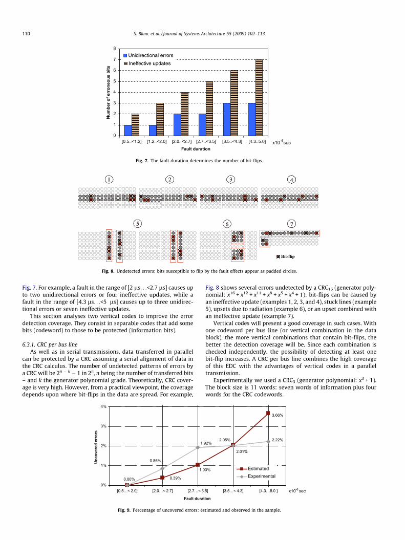
Fig. 8. Undetected errors; bits susceptible to flip by the fault effects appear as padded circles.
[0.5..<1.2]Fault duration
x10-6 sec[4.3..5.0][3.5..<4.3][2.7..<3.5][2.0..<2.7][1.2..<2.0]0
1
2
3
4
5
6
7
8
Num
ber o
f err
oneo
us b
its
Unidirectional errors
Ineffective updates
Fig. 7. The fault duration determines the number of bit-flips.
110 S. Blanc et al. / Journal of Systems Architecture 55 (2009) 102–113
Fig. 7. For example, a fault in the range of [2 ls. . .<2.7 ls] causes upto two unidirectional errors or four ineffective updates, while afault in the range of [4.3 ls. . .<5 ls] causes up to three unidirec-tional errors or seven ineffective updates.
This section analyses two vertical codes to improve the errordetection coverage. They consist in separable codes that add somebits (codeword) to those to be protected (information bits).
6.3.1. CRC per bus lineAs well as in serial transmissions, data transferred in parallel
can be protected by a CRC assuming a serial alignment of data inthe CRC calculus. The number of undetected patterns of errors bya CRC will be 2n � k � 1 in 2n, n being the number of transferred bits– and k the generator polynomial grade. Theoretically, CRC cover-age is very high. However, from a practical viewpoint, the coveragedepends upon where bit-flips in the data are spread. For example,
1.0
0.39%0.00%
0.86%
1.
0%
1%
2%
3%
4%
[0.5…< 2.0] [2.0…< 2.7] [2.7…< 3
Fault durat
Unc
over
ed e
rror
s
Fig. 9. Percentage of uncovered errors: es
Fig. 8 shows several errors undetected by a CRC16 (generator poly-nomial: x16 + x12 + x11 + x8 + x5 + x4 + 1); bit-flips can be caused byan ineffective update (examples 1, 2, 3, and 4), stuck lines (example5), upsets due to radiation (example 6), or an upset combined withan ineffective update (example 7).
Vertical codes will present a good coverage in such cases. Withone codeword per bus line (or vertical combination in the datablock), the more vertical combinations that contain bit-flips, thebetter the detection coverage will be. Since each combination ischecked independently, the possibility of detecting at least onebit-flip increases. A CRC per bus line combines the high coverageof this EDC with the advantages of vertical codes in a paralleltransmission.
Experimentally we used a CRC3 (generator polynomial: x3 + 1).The block size is 11 words: seven words of information plus fourwords for the CRC codewords.
3.66%
2.05%
3%
2.01%
2.22%92%
.5] [3.5…< 4.3] [4.3…8.0 ]
ion
EstimatedExperimental
x10-6 sec
timated and observed in the sample.

S. Blanc et al. / Journal of Systems Architecture 55 (2009) 102–113 111
The experimental sample produced 1376 single effective faultsand 1411 double effective faults. About 1758 messages were trans-mitted with errors, both UE and IWA.
Fig. 9 compares the estimated percentage of uncovered errorswith the percentage observed in the sample.
The optimistic coverage observed in the sample with faults long-er than 4.3 ls is due to the low variation in the transferred values:the variables calculated by the control algorithms are normally sta-bilized at fixed values (although these vary according to how thevehicle is driven). The estimated coverage includes every undetect-able error in 2n combinations (211 in the example), but many ofthese undetectable errors never appear in the experiments, and dif-ferences are produced between estimated and observed.
However, percentages of uncovered errors, both estimated andexperimental, are still high. Detection coverage near of 99% wouldbe advisable.
6.3.2. A vertical parity codeThe simplest EDC is a parity code of a bit per memory bus line.
However, the effectiveness of the code decreases with the faultduration (Fig. 7).
It may be possible to improve our experimental coverage bearingin mind the parity. For example, a Berger code can detect any unidi-rectional error and many random errors. We presented in [25] a sep-arable error detection vertical code, based on Berger code. The codeis focused on covering unidirectional errors but with a good coveragefor random errors. It is based on two definitions:
Definition. With m being the number of bits to be protected by acodeword, where C is the set of 2m binary m-tuples. C can be
structured as the [mi¼0Ci, in such a way that Ci ¼ c0
i ; c1i ; . . . ; c
m!ðm�iÞ!i!i
� �,
denoting i the number of 1s in the information bits, whereCi \ Cj = ;, if i – j.
Definition. With n being the number of bits which form the code-word, where Un denotes the set of 2n binary n-tuples. Each n-tupleis a codeword. uk denotes the set of codewords with k number of0s, for all k from 0 to n. Codewords that belong to Un can be orderedin a vector Y. For example, Y ¼ ½y0; y1; . . . ; yð2n�1Þ�. To order the vector,we consider that if yi belongs to uk and yj belongs to up where k – p,then yi < yj if it is satisfied that k < p. But, if yi and yj belong to the sameuk, their relative position within their own group is insignificant.Thus, it is possible to obtain several vectors. From these, the chosenvector must accomplish the following condition in the assignment.
Assignment. One codeword yi that belongs to a vector Y isassigned to all combinations included in Ck 2 C, and k number of1s in the information bits.
0.86%
1
0.45%
0
0.00%
0%
1%
2%
3%
[0.5…< 2.0] [2.0…< 2.7] [2.7…< 3
Fault dura
Und
etec
ted
erro
rs
CRC3 mixed solutions
Fig. 10. Detection coverage: C
Condition. yi, yj being two codewords that belong to a Y vector,then 0 < i < j < 2n � 1. yi can be assigned to Ck, with k number of1s, and yj can be assigned to Ck+1 if the minimum Hamming dis-tance (yi,yj) P 2.
Algorithm (m information bits, n code bits):(1) If 2n � 1 = m, go to step 4.(2) If 2n � 1 > m, and m odd. Then, 2n � (m + 1) consecutive codewords have
to be removed from the used vector Y taking into account the Condition.Go to step 4.
(3) If 2n � 1 > m, and m even, go to step 7.(4) With Y being the used vector, m codewords are needed; the codeword
y0 is assigned to c00 2 C0
(5) y1 is assigned to all combinations included in C1, y2 is assigned to allcombinations included in C2, and so on so that yi is assigned to all com-binations included in Ci, i = 1, . . ., m � 1.
(6) The codeword ym is assigned to c0m 2 Cm . Break.
(7) Being Y the used vector, m + 1 codewords are needed, the codeword y0 isassigned to c0
0 2 C0.(8) There is a Ck for k = 0, . . . ,m where the number of 0s in any combination
ck that belong to Ck is equal to the number of 1s. Ck is the biggest groupof C and can be divided into two subgroups C0k and C00k . Assignments aremade following step 5 by taking into account that Condition is a strongrequirement. Thus, because of the necessary use of two codewords forC0k and C00k , then, with yi, yj being two codewords that belong to a vectorY, 0 < i < j < 2n � 1, yi can be assigned to C0k and yj can be assigned to C00k , ifthe distance (yi,yj) = 1, such that, being yu the codeword of Ck�1 and yv
the codeword of Ck+1, the minimum distance between either (yu, yi),(yu, yj), (yv, yi), (yv, yj), is P2.2n � (m + 2) codewords of the used vectorY are unused.
(9) The codeword ym+1 is assigned to c0m 2 Cm. Break.
Apart from unidirectional bit errors, a codeword covers manyrandom bit-flips. ci 2 Ci could reach another valid cj 2 Cj, beingi – j, only if the non-unidirectional inversion of at least three bitsoccurs. This means that three bits should change to different ‘0’or ‘1’ values. This is useful because it enables a satisfactory mixof solutions, one of which consists in using the code together witha couple of additional bits to cover any random change in threeconsecutive bits.
Two additional bits have been added to every y codeword.These are calculated in a similar manner to the CRC3, but onlyLSB and (LSB-1) are needed.
The experimental sample produced 1497 single effective faultsand 1575 double effective faults. About 1969 messages were trans-mitted with errors, both UE and IWA. Fig. 10 shows the improve-ment in the detection coverage.
Percentages of undetected errors in the graph of mixed solu-tions are below 1%. This is a good result and means detection cov-erage is higher than 99%.
2.22%
2.01%.92%
0.78%.75% 0.75%
.5] [3.5…< 4.3] [4.3…8.0]
tionx10-6 sec
RC3 and mixed solutions.

112 S. Blanc et al. / Journal of Systems Architecture 55 (2009) 102–113
However, in general, vertical codes entail a considerable over-head in the message. The final decision must be made by the humanintegrator. References for making a balanced decision are the criti-cality of the data and the dedicated field length within the frame.
7. Summary
This paper is part of the work carried out in the Europeanfunded project FIT (‘Fault Injection for TTA’). The objective wasthe validation by means of fault injection techniques of a commer-cial-off-the-shelf product: the Time-Triggered Protocol chip, ver-sions TTP/C–C1 and C2, used in the automotive and aerospaceindustries.
TTP/C chips are used in active safety controls implemented invehicles. Nowadays, these are implemented under the ‘by-wire’concept using specific dependable architectures as the Time-Trig-gered Architecture (TTA).
Critical distributed systems need to be validated with tech-niques such as fault injection before manufacture. This paper is fo-cused on the validation of a TTP/C chip controller by means of faultinjection at pin-level. Firstly, the paper traces the representative-ness of the injected faults by looking for their causes in currentsub-micron technologies and how they can be emulated in anexperimental environment with different fault models. Secondly,experiments are divided into two groups, those oriented towardsprotocol communication and those oriented towards message data.
Faults at communication-pin-level help enable observation ofprotocol service behaviour in the presence of failures in messageomission, on-going transmission halting, babbling-idiot spuriouspulses, SOS failures, and reinstatement actions. In the first threecases, an experimental coverage of 100% was obtained. In the caseof SOS failures, a defect in the TTP/C–C1 chip controller solved inversion 1.1. of TTP/C–C2 chip was observed. Experiments alsotested the worthiness of strategies such as Never Give Up or thereinstatement implemented in TTP/C. In general, results high-lighted the importance of avoiding the clique formation, as wellas the improved reliability provided by a membership serviceimplemented at the data link level to maintain system consistency.
The set of experiments oriented to message data have been con-centrated on the CNI message memory. Injections are synchronisedwith memory accesses causing multiple bit-flips. The detection ofthese bit-flips caused by physical faults during writing, reading,or storage in message memory is outside the scope of TTP, butnot outside the scope of the TTA architecture – which must guar-antee system dependability at every level. Because these errors oc-cur prior to frame formation, the CRC field, calculated in TTP toprotect the frame, is not enough.
Two EDCs have been considered in this paper and evaluatedexperimentally: a cyclic redundant check per bus line; and verticalparity code. The second proposal produces detection coveragehigher than 99%. However, since data bytes increase with errordetection codes, the final decision about data protection rests withhuman integrators searching for a balanced solution.
References
[1] H. Kopetz, The time-triggered architecture, in: Proceedings of FirstInternational Symposium on Object-Oriented Real-Time DistributedComputing (ISORC), 1998.
[2] BMW AG, DaimlerChrysler AG, Robert Bosch GmbH, General Motors/Opel AG.FlexRay Requirements Specification. v. 2.0.2.2000, <www.flexray.com>.
[3] T. Führer, B. Müller, W. Dierterle, F. Hartwich, R. Hugel, M. Walther, RobertBosch GmbH, Time-triggered communication on CAN (time triggered CAN –TTCAN), CAN in Automation, 2002. <www.can-cia.de/can/ttcan/>.
[4] M.J. Calha, J. Fonseca, Adapting FTT-CAN for the joint dispatching of tasks andmessages, in: Proceedings of Fourth International Workshop on FactoryCommunication Systems, 2002, pp. 117–124.
[5] H. Kopetz, A. Ademaj, P. Grillinger, K. Steinhammer, The time-triggeredethernet (TTE) design, in: Proceedings of Eighth ISORC, 2005, pp. 22–33.
[6] Time-Triggered Protocol TTP/C High-Level Specification Document ProtocolVersion 1.1 and other documents and papers (public access).<www.tttech.com>.
[7] X-By-Wire Consortium, Safety Related Fault Tolerant Systems in Vehicle,Project No. BE 95/1329, Contract No. BRPR-CT95-0032, Final Report.
[8] P. Hazucha, C. Svensson, Impact of CMOS technology scaling on theatmospheric neutron soft error rate, IEEE Transactions on Nuclear Science 47(6) (2000) 2586–2594.
[9] C. Constantinescu, Impact of deep submicron technology on dependability ofVLSI circuits, in: Proceedings of International Conference on DependableSystems and Networks (DSN), 2002, pp. 205–209.
[10] P. Sivakumar, M. Kistler, S.W. Keckler, D. Burger, L. Alvisi, Modelling the effectof technology trends on the soft error rate of combinational logic, in:Proceedings of DSN, 2002, pp. 389–398.
[11] R. Baumann, J. Borel, E. Daly, J. Gasiot, J. Gautier, J.L. Leray, J.F. Ziegler, Earthand space single-events: in present and future electronics, RADECS ShortCourse (2001).
[12] R. Koga, S. Crain, K. Crawford, P. Yu, Heavy ion induce hard errors in memorydevices with sub-micron feature sizes, in: Proceedings of Sixth EuropeanConference on Radiation and Its Effects on Components and Systems, 2001, pp.423–430.
[13] F. Wrobel, J.M. Palau, C.M. Calvet, O. Bersillon, H. Duarte, Simulation ofnucleon-induced nuclear reactions in a simplified SRAM structure: scalingeffects on SEU and MBU cross sections, IEEE Transactions on Nuclear Science48 (6) (2001) 1946–1952.
[14] K. Castellani-Coulié, J.M. Palau, G. Hubert, M.C. Calvet, P.E. Dodd, F. Sexton,Various SEU conditions in SRAM studied by 3-D device simulation, IEEETransactions on Nuclear Science 48 (6) (2001) 1931–1936.
[15] R.C. Baumann, E.B. Smith, Neutron-induced boron fission as a major source ofsoft errors in deep submicron SRAM devices, in: Proceedings of 38th AnnualInternational Reliability Physics Symposium, 2000, pp. 152–157.
[16] O. Musseau, F. Gardic, P. Roche, T. Corbière, R.A. Reed, S. Buchner, P.McDonald, J. Melinger, L. Tran, A.B. Campbell, Analysis of multiple-bitupsets (MBU) in a CMOS SRAM, IEEE Transactions on Nuclear Science 43(6) (1996).
[17] R.A. Reed, M.A. Carts, P.W. Marshall, C.J. Marshall, O. Musseau, P.J. McNulty,D.R. Roth, S. Buchner, J. Melinger, T. Corbière, Heavy ion and proton-inducedsingle event multiple upset, IEEE Transactions on Nuclear Science 44 (6)(1997).
[18] J.A. Abraham, V.K. Agarwal, B. Bose, Y. Levendel, E.J. McCluskey, P.R. Menon, J.Metzner, Y. Tohma, in: D.K. Pradhan (Ed.), Fault-Tolerant Computing: Theoryand Techniques, Prentice-Hall, 1986.
[19] E.A. Amerasekera, F.N. Najm, Failure Mechanisms in Semiconductor Devices,second ed., Wiley, 1997.
[20] Fault Representativeness, ETIE2 of Dependability Benchmarking Project,2002.
[21] J. Gracia, D. Gil, J.C. Baraza, P.J. Gil, Using VHDL-Based Fault Injection toexercise Error Detection Mechanisms in the Time-Triggered Architecture, in:Proceedings of Pacific Rim International Symposium on DependableComputing, 2002, pp. 316–320.
[22] D.S. Patterson, Understanding Reliability Criteria for Solder Bumped Devices,Meptec Report (January–February 2002) 25–28.
[23] J.C. Baraza, J. Gracia, D. Gil, P.J. Gil, A prototype of a VHDL-based fault injectiontool: description and application, Jornal of Systems Architecture 47 (10) (2002)847–867.
[24] P.J. Gil, S. Blanc, J.J. Serrano, Pin-level hardware fault injection techniques, in:A. Bensoy, P. Prinetto (Eds.), Handbook of Fault Injection Techniques and Toolsfor Embedded Systems Reliability Evaluation, Frontiers in Electronic Testing,vol. 23, Kluwer Academic Press, pp. 63-80.
[25] S. Blanc, P.J. Gil, Improving the multiple error detection coverage in distributedembedded systems, in: Proceedings of 22nd International Symposium onReliable Distributed Systems, 2003, pp. 303–312.
[26] A. Burns, A. Wellings (Eds.), Real-Time Systems and Programming Languages,Addison-Wesley, 2001.
[27] J. Rushby, Bus architectures for safety-critical embedded systems, in:Proceedings of First Workshop on Embedded Software, 2001, pp. 8–10.
[28] A. Ademaj, Slightly-off-specification failures in the time-triggeredarchitecture, in: Proceedings of Seventh Annual IEEE International Workshopon High Level Design Validation and Test, 2002, pp. 7–12.
[29] L. Lamport, R. Shostak, M. Pease, The byzantine generals problem, ACMTransactions on Programming Languages and Systems 4 (3) (1982) 382–401.
[30] R.J. Martı́nez, P.J. Gil, G. Martı́n, C. Pérez, J.J. Serrano, Experimental Validationof High-Speed Fault-Tolerant Systems Using Physical Fault Injection, in:Proceedings of DCCA-7, 1999, pp. 233–249.
[31] J. Barak, J.L. Barth, C.M. Seidleck, C.J. Marshall, M.A. Carts, R.A. Reed, Singleevent upset in the dual-port-board SRAMs of the MPTB experiement, IEEETransactions on Nuclear Science 47 (3) (2000) 712–717.
[32] A. Ademaj, H. Sivencrona, G. Bauer, J. Torin, Evaluation of fault handling of thetime-triggered architecture with bus and start topology, in: Proceedings ofDSN, 2003, pp. 123–132.
[33] S. Blanc, J. Gracia, P.J. Gil, A fault hypothesis study on the TTP/C using VHDL-based and pin-level fault injection techniques, in: Proceedings of IEEE 17thInternational Symposium on Defect and Fault Tolerance in VLSI Systems, 2002,pp. 254–263.
s A
Sara Blanc is member of the Fault–Tolerant SystemsResearch Group (GSTF) of the Universidad Politècnica de
Valencia (UPV), Spain. She received a M.Sc. in ComputerEngineering from the UPV in 1998, and she successfullydefended her Ph.D. in 2004. Currently, she teachescourses in Digital Design and Computers Technology.Her research interests include design and implementa-tion of digital systems, design and validation of Fault–Tolerant Systems and Fault Injection Techniques.S. Blanc et al. / Journal of System
Alberto Bonastre is Associate Professor at the Uni-versidad Politècnica de Valencia (UPV), Spain, andmember of the Fault–Tolerant Systems Research Group(GSTF). He obtained a M.Sc. in Computer Engineeringfrom the UPV in 1991, and the Ph.D. degree in 2001. Heis currently teaching Computer Networks and WirelessSensor Networks. His research is centred on WirelessSensor Networks, being specially invoked in Fault–Tol-erance on these systems.
Pedro Gil-Vicente is Professor at the UniversidadPolitècnica de Valencia (UPV), Spain, in the Departmentof Computer Engineering (DISCA). He obtained the B.S.degree in Electrical and Electronic Engineering and thePh.D. degree in Computer Engineering from the UPV in1985 and 1992, respectively. Professor Gil teachescourses in Digital Design, Computer Networks and FaultTolerant Systems. His research interests include thedesign and implementation of Real-Time Fault–TolerantSystems, the validation of Fault–Tolerant Systems byFault Injection and the design and implementation ofdigital systems (including hardware–software co-
design). He has authored or co-authored more than 50 research papers in theseareas.
rchitecture 55 (2009) 102–113 113