department of environmental protection
TRANSCRIPT
261-0300-101 / March 27, 2021 / Page i
DEPARTMENT OF ENVIRONMENTAL PROTECTION
Bureau of Environmental Cleanup and Brownfields
DOCUMENT NUMBER: 261-0300-101
TITLE: Land Recycling Program Technical Guidance Manual
EFFECTIVE DATE: March 27, 2021
AUTHORITY: The Land Recycling and Environmental Remediations Standards Act
(Act 2 of 1995) (35 P.S. §§ 6026.101 et seq.) and the regulations issued
pursuant to that legislation at 25 Pa. Code Chapter 250.
POLICY: It is the policy of the Department of Environmental Protection (DEP or
Department) to implement Act 2 in accordance with the regulations
contained in 25 Pa. Code Chapter 250 and as described in this guidance
manual.
PURPOSE: DEP has developed this manual to assist remediators in satisfying the
requirements of Act 2 and the regulations published in Chapter 250 of the
Pa. Code. The manual provides suggestions and examples of how to best
approach site characterization, remediation and demonstration of
attainment. This document replaces the “Land Recycling Program
Technical Guidance Manual” dated June 8, 2002, in its entirety.
APPLICABILITY: The guidance in this manual is applicable to any person or persons
conducting a site remediation under Act 2 and who wish to receive the
liability protection afforded by Chapter 5 of that Act (35 P.S.
§§ 6026.501-6026.506).
DISCLAIMER: The policies and procedures outlined in this guidance are intended to
supplement existing requirements. Nothing in the policies or procedures
shall affect regulatory requirements.
The policies and procedures herein are not an adjudication or a regulation.
DEP does not intend to give this guidance that weight or deference. This
document establishes the framework, within which DEP will exercise its
administrative discretion in the future. DEP reserves the discretion to
deviate from this policy statement if circumstances warrant.
PAGE LENGTH: 509 pages
261-0300-101 / March 27, 2021 / Page ii
TABLE OF CONTENTS
SECTION I: OVERVIEW .................................................................................................................... I-1
A. What the Land Recycling Program Offers.................................................................................... I-1 1. Benefits of Involvement Through the Land Recycling Program ...................................... I-1 2. How to Use this Manual ................................................................................................... I-1
B. The Voluntary Nature of Act 2 ..................................................................................................... I-3 C. Improving Service through Program Consistency ........................................................................ I-4
1. DEP Implementation of Standard Operating Procedures (SOPs) ..................................... I-4 2. Initiation and Final Execution of Reopeners .................................................................... I-4 3. Non-Routine Waivers ....................................................................................................... I-5 4. Issue Resolution ................................................................................................................ I-5 5. Frequently Asked Questions (FAQs) ................................................................................ I-5
D. Resources and Assistance ............................................................................................................. I-6
1. Program Contacts .............................................................................................................. I-6 2. Financial Assistance.......................................................................................................... I-6
SECTION II: ACT 2 REMEDIATION PROCESS .......................................................................... II-1
A. Applying Land Recycling Remediation Standards to Your Property ..........................................II-1 1. Classifying your Site and Considering Options for Remediation ....................................II-1 2. Immediate Response ........................................................................................................II-3
3. Notice Requirements and Procedures ..............................................................................II-4 4. Site Characterization ......................................................................................................II-11
B. Remediation Standards ..............................................................................................................II-27 1. Background Standard .....................................................................................................II-27 2. Statewide Health Standard .............................................................................................II-49
3. Site-Specific Standard ....................................................................................................II-93
4. Special Industrial Areas ...............................................................................................II-131
APPENDIX II-A: THE USE OF CAPS AS ACTIVITY AND USE LIMITATIONS ............... II-145
SECTION III: TECHNICAL AND PROCEDURAL GUIDANCE ...............................................III-1
A. Fate and Transport Analysis ...................................................................................................... III-1 1. Fate and Transport Analysis in the Unsaturated Zone ................................................... III-3 2. Fate and Transport Analysis in the Saturated Zone ....................................................... III-7
3. Impacts to Surface Water from Diffuse Flow of Contaminated
Groundwater ................................................................................................................ III-18 B. Guidance for Attainment Demonstration with Statistical Methods ......................................... III-41
1. Introduction .................................................................................................................. III-41
2. Data Review for Statistical Methods ........................................................................... III-42 3. Statistical Inference and Hypothesis Statements ......................................................... III-43 4. Selection of Statistical Methods................................................................................... III-45
5. Additional Information on Statistical Procedures ........................................................ III-59 6. Calculation of UCL of Mean When the Distribution of the Sampling Mean
is Normal ...................................................................................................................... III-62 7. Calculation of UCL of Mean of a Lognormal Distribution ......................................... III-63 8. Procedure and Example for Conducting the Wilcoxon Rank Sum Test ...................... III-66 9. Procedure and Example for Conducting the Quantile Test ......................................... III-70
C. Storage Tank Program Guidance ............................................................................................. III-80 1. Corrective Action Process............................................................................................ III-80
261-0300-101 / March 27, 2021 / Page iii
2. Corrective Action Process Checklist ........................................................................... III-80
3. Use of the Short List of Regulated Substances for Releases of Petroleum
Products........................................................................................................................ III-87 4. Maximum Extent Practicable ....................................................................................... III-88 5. Management of Light Nonaqueous Phase Liquids (LNAPL) under Act 32 ................ III-92 6. References .................................................................................................................. III-103
D. Mass Calculations .................................................................................................................. III-104
1. Groundwater Mass Calculation.................................................................................. III-104 2. Soil Mass Calculation ................................................................................................ III-104
E. Long-Term Stewardship ........................................................................................................ III-105 1. Introduction ................................................................................................................ III-105 2. Uniform Environmental Covenants Act .................................................................... III-105
3. Institutional versus Engineering Controls .................................................................. III-109 4. Postremediation Care Plan ......................................................................................... III-109
5. Postremediation Monitoring ...................................................................................... III-110
6. Postremediation Care Attainment .............................................................................. III-111 F. One Cleanup Program ............................................................................................................ III-112
1. Purpose ....................................................................................................................... III-112 2. Provisions and Applicability ...................................................................................... III-112
3. Implementation .......................................................................................................... III-113 4. Benefits ...................................................................................................................... III-113
G. Data Quality and Practical Quantitation Limits ..................................................................... III-114 1. Data Quality Objectives Process, Sampling, and Data Quality Assessment
Process ....................................................................................................................... III-114
2. Preliminary Data Review ........................................................................................... III-116 3. Practical Quantitation Limit (25 Pa. Code § 250.4)................................................... III-116
H. Site-Specific Human Health Risk Assessment Guidance ...................................................... III-118 1. Introduction ................................................................................................................ III-118
2. When to Perform a Risk Assessment ......................................................................... III-118 3. Risk Assessment for Human Health (25 Pa. Code § 250.602(c)) .............................. III-119
4. References for Human Health Risk Assessment ....................................................... III-132 I. Site-Specific Ecological Risk Assessment Guidance ............................................................ III-136
1. Introduction ................................................................................................................ III-136
2. Ecological Risk Assessment Process ......................................................................... III-136 3. References .................................................................................................................. III-141
SECTION IV: VAPOR INTRUSION ............................................................................................... IV-1
A. Introduction ................................................................................................................................ IV-1 B. Definition and Use of Important Terms ..................................................................................... IV-3
C. Overview of the VI Evaluation Process ..................................................................................... IV-7 1. VI Conceptual Site Model ............................................................................................. IV-7 2. Screening Values and Points of Application (POA) .................................................... IV-10 3. Guidelines for Evaluating VI Using a Combination of Standards ............................... IV-11
D. Preferential Pathway Evaluation .............................................................................................. IV-14
1. External Preferential Pathways .................................................................................... IV-15 2. Significant Foundation Openings ................................................................................ IV-18
E. Use of Proximity Distances ..................................................................................................... IV-21
F. Soil and Groundwater VI Screening ........................................................................................ IV-24 1. Soil and Groundwater Screening Values ..................................................................... IV-24
261-0300-101 / March 27, 2021 / Page iv
2. Soil and Groundwater Screening Methods .................................................................. IV-25
G. Alternative VI Assessment Options ......................................................................................... IV-28
1. Soil Gas and Indoor Air Screening Values .................................................................. IV-28 2. Soil Gas and Indoor Air Screening Methods ............................................................... IV-29 3. Vapor Intrusion Modeling............................................................................................ IV-32
H. Mitigation and Activity and Use Limitations .......................................................................... IV-33 I. Remediating and Reassessing the VI Pathway ........................................................................ IV-35
J. Addressing 25 Pa. Code Chapter 250 Requirements ............................................................... IV-36 K. Evaluating the VI Pathway Under the Site-Specific Standard................................................. IV-37
1. Overview ...................................................................................................................... IV-37 2. Preferential Pathway Evaluation .................................................................................. IV-38 3. Use of Proximity Distances ......................................................................................... IV-38
4. Site-Specific Standard VI Screening ........................................................................... IV-38 5. Performing a VI Risk Assessment and Modeling ........................................................ IV-40
6. Mitigation and Remediation ........................................................................................ IV-41
7. Using an OSHA Program to Address VI ..................................................................... IV-41 8. Addressing Chapter 250 Requirements ....................................................................... IV-42
L. References ................................................................................................................................ IV-48 M. Tables ....................................................................................................................................... IV-54
APPENDIX IV-A: METHODOLOGY FOR DEVELOPING SHS VAPOR
INTRUSION SCREENING VALUES ................................................................................. IV-62
1. Indoor Air..................................................................................................................... IV-62 2. Sub-Slab Soil Gas ........................................................................................................ IV-64 3. Near-Source Soil Gas ................................................................................................... IV-65
4. Soil ............................................................................................................................... IV-65
5. Groundwater ................................................................................................................ IV-67 6. Building Foundation Openings .................................................................................... IV-68 7. Attenuation Factor Summary ....................................................................................... IV-68
APPENDIX IV-B: VAPOR INTRUSION MODELING GUIDANCE ........................................ IV-70 1. Background .................................................................................................................. IV-70
2. Assumptions ................................................................................................................. IV-71
3. J&E Model Parameter Adjustments ............................................................................. IV-71 4. Site-Specific Standard Parameter Adjustments ........................................................... IV-77
5. Petroleum Hydrocarbons ............................................................................................. IV-78 6. Attenuation Factor Risk Calculations .......................................................................... IV-78 7. Report Contents ........................................................................................................... IV-79
APPENDIX IV-C: VAPOR INTRUSION SAMPLING METHODS .......................................... IV-80 1. Introduction .................................................................................................................. IV-80
2. Sampling Locations ..................................................................................................... IV-82 3. Near-Source Soil Gas Sampling .................................................................................. IV-86 4. Sub-Slab Soil Gas Sampling ........................................................................................ IV-87 5. Indoor Air Sampling .................................................................................................... IV-88 6. Sampling Soil Gas for Oxygen Content....................................................................... IV-90 7. Sampling Separate Phase Liquids ................................................................................ IV-90 8. Quality Assurance and Quality Control Procedures and Methods .............................. IV-92 9. Active Sub-Slab Depressurization System Testing ..................................................... IV-99
261-0300-101 / March 27, 2021 / Page v
APPENDIX IV-D: OSHA PROGRAM VAPOR INTRUSION CHECKLIST ......................... IV-101
SECTION V: RELATIONSHIP TO OTHER ENVIRONMENTAL STATUTES ....................... V-1
A. Solid Waste Facilities ................................................................................................................. V-1 1. Movement of Excavated Contaminated Media and Other Solids ................................... V-1 2. Disposal Prior to September 7, 1980 .............................................................................. V-2 3. Disposal after September 7, 1980, for Residual Waste and
Construction/Demolition Waste, and between September 7, 1980, and
October 9, 1993, for Municipal Waste............................................................................ V-2 4. Disposal of Hazardous Waste after September 7, 1980, or Municipal
Waste after October 9, 1993, Subject to Federal Closure Requirements ........................ V-3 B. Clean Streams Law Interface ...................................................................................................... V-6
1. Point Source Discharges ................................................................................................. V-6
2. Nonpoint Source Discharges........................................................................................... V-7
3. Erosion and Sedimentation (E&S) Control..................................................................... V-7 C. Clean Air Act and Air Pollution Control Act Interface ............................................................ V-10
D. Regulated Storage Tank Release Sites ...................................................................................... V-11
1. Introduction ................................................................................................................... V-11 2. Short List of Petroleum Products .................................................................................. V-11 3. Management of Separate Phase Liquid (SPL) under Act 2 and Act 32........................ V-12
E. HSCA/CERCLA Remediation.................................................................................................. V-16 1. Hazardous Sites Cleanup Act (HSCA) Sites ................................................................ V-16
2. Comprehensive Environmental Response Compensation Liability Act
(CERCLA) Sites ........................................................................................................... V-17 F. References ................................................................................................................................. V-18
SECTION VI: RELATED DOCUMENTS AND WEBSITES OF INTEREST ........................... VI-1
APPENDIX A: GROUNDWATER MONITORING GUIDANCE ................................................ A-1 A. Overview ..................................................................................................................................... A-1
1. Introduction ..................................................................................................................... A-1
2. References ....................................................................................................................... A-2 B. Monitoring Well Types and Construction .................................................................................. A-3
1. Objectives of Monitoring Wells...................................................................................... A-3
2. Types of Groundwater Monitoring Systems ................................................................... A-3 3. Choice of Monitoring System ......................................................................................... A-7 4. Minimum Construction Standards .................................................................................. A-7 5. Direct Push Technology ................................................................................................ A-12 6. References ..................................................................................................................... A-13
C. Locations and Depths of Monitoring Wells .............................................................................. A-15 1. Importance .................................................................................................................... A-15
2. Approach to Determining Monitoring Locations and Depths ...................................... A-15 3. Factors in Determining Target Zones for Monitoring .................................................. A-16 4. Areal Placement of Wells ............................................................................................. A-23 5. Well Depths, Screen Lengths, and Open Intervals ....................................................... A-24 6. Number of Wells ........................................................................................................... A-26 7. Well Yield ..................................................................................................................... A-26 8. References ..................................................................................................................... A-28
261-0300-101 / March 27, 2021 / Page vi
D. Groundwater Sampling Techniques .......................................................................................... A-30
1. Importance of Sampling Technique .............................................................................. A-30
2. Sample Collection Devices ........................................................................................... A-32 3. Sample Collection Procedures ...................................................................................... A-32 4. References ..................................................................................................................... A-45
E. Well Decommission Procedures ............................................................................................... A-47 1. Introduction ................................................................................................................... A-47
2. Well Characterization ................................................................................................... A-47 3. Well Preparation ........................................................................................................... A-48 4. Materials and Methods .................................................................................................. A-48 5. Recommendations ......................................................................................................... A-50 6. Existing Regulations and Standards.............................................................................. A-54
7. Reporting....................................................................................................................... A-54 8. References ..................................................................................................................... A-54
F. Quality Assurance/Quality Control Requirements ................................................................... A-55
1. Purpose .......................................................................................................................... A-55 2. Design ........................................................................................................................... A-55 3. Elements ........................................................................................................................ A-55 4. References ..................................................................................................................... A-58
261-0300-101 / March 27, 2021 / Page vii
ACRONYMS
AIHC American Industrial Health Council
ANOVA Analysis of Variance
AOC Area of Concern
API American Petroleum Institute
ASTM American Society for Testing and Materials
ATSDR Agency for Toxic Substances and Disease Registry
AUL Activity and Use Limitation
BMP Best Management Practices
BTAG Biological Technical Assistance Group
BTGS Pennsylvania Bureau of Topographic and Geologic Survey
BTEX Benzene, Toluene, Ethylbenzene, and Xylenes
CAP Corrective Action Process
CERCLA Comprehensive Environmental Response Compensation Liability Act
CERCLIS Comprehensive Environmental Response, Compensation and Liability
Information System
CO&A Consent Order & Agreement
CP Cleanup Plan
CPEC Constituents of Potential Ecological Concern
CPT Cone Penetration Technologies
Csat Carbon Saturation
CSM Conceptual Site Model
CSSAB Cleanup Standards Scientific Advisory Board
DCED Department of Community and Economic Development
DCNR Department of Conservation and Natural Resources
DEP or PADEP Pennsylvania Department of Environmental Protection
DNAPL Dense Non-Aqueous Phase Liquid
DPT Direct Push Technologies
DQA Data Quality Analysis
DQO Data Quality Objectives
E&S Erosion and Sedimentation
EC Environmental Covenant
ECB Environmental Cleanup and Brownfields
EMPR Equal Marginal Percent Reduction
EPA or USEPA U.S. Environmental Protection Agency
EQL Estimated Quantitation Limit
EZ Enterprise Zone
FR Final Report
FAQ Frequently Asked Question
GW Groundwater
GWMP Groundwater Management Plan
HEAST Health Effects Assessment Summary Tables
HHEM Human Health Evaluation Manual
HSA Hollow Stem Auger
HSCA Hazardous Sites Cleanup Act
HVAC Heating, Ventilation, and Air Conditioning
IEUBK Integrated Exposure Uptake Biokinetic Model
IQR Interquartile Range
261-0300-101 / March 27, 2021 / Page viii
IRIS EPA’s Integrated Risk Information Systems
ISRP Industrial Sites Reuse Program
ITRC Interstate Technology & Regulatory Council
J&E Johnson and Ettinger
KIZ Keystone Innovation Zone
KOZ Keystone Opportunity Zone
LCSM LNAPL Conceptual Site Model
LIF Laser-Induced Fluorescence
LNAPL Light Non-Aqueous Phase Liquid
LNAPL Tn LNAPL Transmissivity
LOQ Limit of Quantitation
LRP Land Recycling Program
LSWC Lowest Surface Water Quality Criterion
MDL Method Detection Limit
MEP Maximum Extent Practicable
MGD Million Gallons per Day
MLE Most Likely Exposure
MOA Memorandum of Agreement
MRF Mutagenic Risk Adjustment Factor
MSC Medium-Specific Concentration
MSDS Material Safety Data Sheet
msl Mean Sea Level
NAPL Non-Aqueous Phase Liquid
NCEA National Center for Environmental Assessment
ND Nondetect
NFA No Further Action
NGVD National Geodetic Vertical Datum
NIOSH National Institute for Occupational Safety and Health
NIR Notice of Intent to Remediate
NOAA National Oceanic and Atmospheric Administration
NPDES National Pollutant Discharge Elimination System
NPL National Priority List
NR Non-residential
NRCS Natural Resources Conservation Service
NSZD Natural Source Zone Depletion
NWI National Wetlands Inventory
O&M Operation and Maintenance
OPP EPA Office of Pesticide Programs
OSHA Occupational Safety and Health Administration
OSWER EPA Office of Solid Waste and Emergency Response
PaGIS Pennsylvania Geographic Information Systems Mapping Tools
PAH Polyaromatic Hydrocarbons
PAPL Pennsylvania Priority List
PCSM Post-Construction Stormwater Management
PDB Polyethylene (or passive) Diffusion Bags
PID Photoionization Detector
PNDI Pennsylvania Natural Diversity Inventory
POA Point of Application
POC Point of Compliance
261-0300-101 / March 27, 2021 / Page ix
PPE Personal Protective Equipment
PPRTV Provisional Peer-Reviewed Toxicity Values
PQL Practical Quantitation Limit
PRCP Postremediation Care Plan
QA Quality Assurance
QC Quality Control
QD Quick Domenico
RA Risk Assessment
RAR Risk Assessment Report
RACR Remedial Action Completion Report
RAGS Risk Assessment Guidance for Superfund
RAP Remedial Action Plan
RCRA Resource Conservation and Recovery Act
RFD Request for Determination
RIR Remedial Investigation Report
RL Reporting Limit
RME Reasonable Maximum Exposure
RSL EPA Regional Screening Level
RT Regulatory Threshold
SCS Soil Classification System
SDS Safety Data Sheet
SHS Statewide Health Standard
SIA Special Industrial Area
SMCL Secondary Maximum Contaminant Level
SMP Soil Management Plan
SOP Standard Operating Procedure
SPL Separate Phase Liquid
SPLP Synthetic Precipitation Leaching Procedure
SQuiRT Screening Quick Reference Table
SSD Sub-slab Depressurization
SSL Soil Screening Level
SSS Site-specific Standard
SV Soil Vapor
SVGW Groundwater Screening Values
SVIA Indoor Air Screening Values
SVNS Near-source Soil Gas Screening Values
SVSOIL Soil Screening Values
SVSS Sub-slab Soil Gas Screening Values
SVOC Semi-volatile Organic Compound
SWL5 SWLOAD5 Spreadsheet
SWMA Solid Waste Management Act
TC Total Concentration
TCLP Toxicity Characteristic Leaching Procedure
TDS Total Dissolved Solids
TGM Technical Guidance Manual
TPH Total Petroleum Hydrocarbons
TSCA Toxic Substances Control Act
UCL Upper Confidence Limit
UECA Uniform Environmental Covenants Act

261-0300-101 / March 27, 2021 / Page x
USGS United States Geological Survey
UST Underground Storage Tank
VI Vapor Intrusion
VOC Volatile Organic Compound
WRS Mann-Wilcoxon Rank Sum
261-0300-101 / March 27, 2021 / Page I-i
TABLE OF CONTENTS
SECTION I: OVERVIEW .................................................................................................................... I-1 A. What the Land Recycling Program Offers.................................................................................... I-1
1. Benefits of Involvement Through the Land Recycling Program ...................................... I-1 2. How to Use this Manual ................................................................................................... I-1
B. The Voluntary Nature of Act 2 ..................................................................................................... I-3
C. Improving Service through Program Consistency ........................................................................ I-4 1. DEP Implementation of Standard Operating Procedures (SOPs) ..................................... I-4 2. Initiation and Final Execution of Reopeners .................................................................... I-4 3. Non-Routine Waivers ....................................................................................................... I-5 4. Issue Resolution ................................................................................................................ I-5
5. Frequently Asked Questions (FAQs) ................................................................................ I-5
D. Resources and Assistance ............................................................................................................. I-6 1. Program Contacts .............................................................................................................. I-6
2. Financial Assistance.......................................................................................................... I-6
261-0300-101 / March 27, 2021 / Page I-1
SECTION I: OVERVIEW
A. What the Land Recycling Program Offers
1. Benefits of Involvement Through the Land Recycling Program
The Land Recycling Program is the result of a bipartisan legislative effort to solve the
problem of unused and abandoned industrial sites within the Commonwealth. The
program has three purposes: to clean up contaminated sites based on sound science, to
return these sites to productive reuse, and to preserve farmland and greenspace. The
Land Recycling Program (LRP) promotes voluntary partnerships among local businesses,
government, financial institutions and the Department of Environmental Protection
(Department or DEP).
The four cornerstones of the program are uniform cleanup standards based on health and
environmental risks, standardized review procedures, relief from liability, and financial
assistance. The establishment of uniform standards enables the remediator to clearly
understand the extent and cost of site cleanup. The selection of standards assures that a
site is protective of its reuse. A property used for industrial development need not be as
clean as a playground or residential site. Consistent reporting requirements and
standardized review procedures provide a definite time frame for remediation. Relief
from liability, which extends to future owners, addresses the concerns that previously
inhibited site redevelopment and sale of properties. Financial assistance, available to
those who did not cause or contribute to contamination at the site, reduces the cost of site
assessment and remediation.
2. How to Use this Manual
The Department has developed this manual to assist remediators in satisfying the
requirements of the Land Recycling and Environmental Remediation Standards Act
(35 P.S. §§ 6026.101-6026.908), commonly known as Act 2, and the regulations at 25 Pa.
Code Chapter 250 (regulations). The manual provides suggestions and examples of how
to best approach site characterization and remediation. The manual is divided into
six sections:
• Section I provides an overview of the program and summarizes the role of Central
Office.
• Section II outlines the procedures for determining which cleanup standard may be
applicable to your site and how to meet the requirements of each standard. As
each standard is discussed, references to other sections are provided for additional
information or clarification.
• Section III provides general technical guidance augmenting the information in
Section II.
• Section IV contains the Vapor Intrusion Assessment Guidance.
• Section V discusses the appropriate interfaces with other applicable statutes.

261-0300-101 / March 27, 2021 / Page I-2
• Section VI contains references to other helpful documents.
The Department of Environmental Protection staff is another valuable resource available
to assist in clarifying the information provided herein or to address any questions
regarding issues specific to a certain site. Regional office contacts are provided on the
Land Recycling website.
261-0300-101 / March 27, 2021 / Page I-3
B. The Voluntary Nature of Act 2
Act 2 establishes the environmental remediation standards for cleanups related to certain
environmental laws (35 P.S. § 6026.106). Remediation and the resulting liability relief under
Chapter 5 of Act 2 is specific to the contamination identified as part of a specific site or sites in
the approved final report. Thus, there may be multiple sites on a property, or a single site may
include all or part of one or more properties. Examples of sites are an area of specific
contamination related to a metal processing unit, or a specific environmental release such as a
tank release. Although the liability protection is NOT necessarily universal to the entire
property, remediators may voluntarily submit multiple Notices of Intent to Remediate (NIRs), or
amend the scope of a single NIR, to address any or all contamination they believe is present on
the property. It is strongly advised that the remediator postpone drafting the NIR until sufficient
characterization has been completed on the property to distinguish the site or sites desired for
inclusion in the NIR.
If the Department is aware of contamination on the property which is not part of a proposed
remediation under a voluntarily submitted NIR, the Department may suggest that the remediator
include that contamination as part of a subsequent or amended NIR. However, if the remediator
declines to include that contamination, the Department will still approve a final report for the
contamination described in the NIR if it meets the requirements of Act 2. The Department
always reserves the right, as a separate action, to exercise its enforcement discretion under the
environmental laws of the Commonwealth to require remediation of any known spill or release
of a regulated substance on the property which was not addressed by voluntary cleanup through
the Act 2 process or where the voluntary remediation fails to proceed through the Act 2 process.
The exercise of enforcement discretion is based on DEP’s knowledge of site contamination that
may represent a threat to human health and/or the environment, requiring Department oversight.
This information may be obtained from several sources, including but not limited to citizen
complaints, DEP inspections, sampling results, or spill reporting requirements under applicable
regulations. The execution of an enforcement action under Act 2 includes consultation and
concurrence between Central Office and the regional office program managers and counsel.
261-0300-101 / March 27, 2021 / Page I-4
C. Improving Service through Program Consistency
Despite more than 20 years of success, the LRP is always exploring additional ways to improve
the program. The Department understands that the consistency of application of the program
rules and regulations across its six regional offices is an important issue. The following sections
describe the Department’s approach to maintaining consistency within the program.
1. DEP Implementation of Standard Operating Procedures (SOPs)
LRP staff follow a Department-wide standardized process for receiving, prioritizing,
accepting, reviewing, denying, and approving any Act 2 submittal in order to achieve
greater efficiency, clarity, and consistency across all regions. This process, known as the
SOPs, was adopted in response to the DEP’s goal of standardizing all regulatory
procedures for timely, efficient, and consistent operations across all programs. This
endeavor was collectively known as the Permit Decision Guarantee. SOP manuals were
generated to detail all aspects of the LRP process and expected responses by LRP staff.
2. Initiation and Final Execution of Reopeners
A reopener occurs when the Department requires a remediator to undertake additional
remediation actions after an Act 2 (35 P.S. § 6026.505) standard has been attained. This
only happens when the Department demonstrates that one of the reopener conditions in
Section 505 of Act 2 are present at a site. The initiation and execution of a reopener
includes consultation and concurrence between Central Office and the regional office
program managers and counsel. The reopener conditions in Section 505 of the Act
include the following:
• Fraud was committed in demonstrating attainment of a standard at the site that
resulted in avoiding the need for further cleanup of the site.
• New information confirms the existence of an area of previously unknown
contamination which contains regulated substances that have been shown to
exceed the standards applied to previous remediation at the site.
• The remediation method failed to meet one or a combination of the three cleanup
standards.
• The level of risk is increased beyond the acceptable risk range at a site due to
substantial changes in exposure conditions, such as in a change in land use from
nonresidential to a residential use, or new information is obtained about a
regulated substance associated with the site which revises exposure assumptions
beyond the acceptable range.
• A release occurred after the effective date of the Act on a site not used for
industrial activity prior to the effective date of the Act; the remedy relied in whole
or in part upon institutional or engineering controls instead of treatment or
removal of contamination; and treatment, removal, or destruction has become
technically and economically feasible on that part.
261-0300-101 / March 27, 2021 / Page I-5
3. Non-Routine Waivers
The Department may waive certain requirements based on site-specific circumstances.
An example would be the Department waiving the need for an environmental covenant
requiring a groundwater use restriction on a downgradient property if that downgradient
property is a railway, highway, or stream. More common waiver requests are handled
directly by the regional office. Unusual or complex waiver requests under Section 902 of
Act 2 (35 P.S. § 6026.902) or 25 Pa. Code §§ 250.406 and 253.4 include the regional
office program staff consulting with and potentially obtaining concurrence from Central
Office prior to issuance or denial of the waiver request.
4. Issue Resolution
When a remediator disagrees with the decisions of the regional case manager, the proper
procedure for resolving the issue is to go through the regional office staff management
hierarchy first. The issue should be brought to the attention of the regional LRP Group
Manager. If the issue cannot be resolved at that level, the issue may be taken to the
regional Environmental Cleanup and Brownfields Program Manager. If an agreement
still cannot be reached, the remediator can then bring the issue to the attention of the
Central Office Program Manager for resolution. Following this orderly progression will
result in issue resolution in the timeliest manner possible.
5. Frequently Asked Questions (FAQs)
The Department realizes that the LRP is not static and that from time to time the answers
to technical issues that arise will be of general interest to the regulated community. The
program periodically posts such FAQs and their answers to the LRP website to provide
this information to a wide audience.
261-0300-101 / March 27, 2021 / Page I-6
D. Resources and Assistance
1. Program Contacts
Information on contacts within DEP is listed on the LRP website under “How to Contact
Us.”
2. Financial Assistance
Act 2 established an account known as the Industrial Sites Cleanup Fund. The purpose of
this fund is to provide financial assistance to persons assessing and remediating property
used for industrial activity and who did not cause or contribute to the contamination. The
Industrial Sites Environmental Assessment Act 35 P.S. §§ 6028.1-6028.5 (Act 4 of
1995), was enacted concurrently with Act 2 and provides money for environmental
assessments of industrial sites.
Act 4 provides financial assistance to municipalities, municipal authorities,
redevelopment authorities, economic authorities, development agencies, and eligible
members of the public for assessment and remediation of contaminated sites. Applicants
may be eligible for a grant and/or loan from the fund for up to 75 percent of the site
characterization and remediation costs, subject to additional eligibility requirements
established by Act 2 and the Department of Community and Economic Development
(DCED). Act 4 provides grants to municipalities, local authorities, and economic
development agencies for sites located in distressed communities and provides grants to
specified classes of cities for environmental assessment of industrial sites. The maximum
amount to be awarded for any remediation project will not exceed 75 percent of the total
cost of remediation or $1,000,000 for grant recipients, whichever is less, in a single fiscal
year. To qualify, a party must not have caused or contributed to the contamination on the
property and must be performing a voluntary cleanup. To administrate these funds,
DCED created the Industrial Sites Reuse Program (ISRP). Grant and loan eligibility
requirements are specified in Section 702 of Act 2 and in Act 4. Eligibility and
application procedures are also specified in the ISRP guidelines on the DCED website.
261-0300-101 / March 27, 2021 / Page II-i
TABLE OF CONTENTS
SECTION II: ACT 2 REMEDIATION PROCESS .......................................................................... II-1 A. Applying Land Recycling Remediation Standards to Your Property ..........................................II-1
1. Classifying your Site and Considering Options for Remediation ....................................II-1 a) Background Standard ...........................................................................................II-2 b) Statewide Health Standard ...................................................................................II-2
c) Site-specific Standard ..........................................................................................II-2 d) Combination of Standards....................................................................................II-2 e) Special Industrial Areas .......................................................................................II-3
2. Immediate Response ........................................................................................................II-3 3. Notice Requirements and Procedures ..............................................................................II-4
a) Notice of Intent to Remediate ..............................................................................II-4
b) Notice of Proposal for Nonuse Aquifer Determination .......................................II-6 c) Public Involvement Plan ......................................................................................II-6
d) Remediation Report Notification Requirements ..................................................II-7
i) Background and Statewide Health Standards ..........................................II-7 ii) Site-specific Standard ..............................................................................II-9 iii) Special Industrial Areas .........................................................................II-10
e) Fees ....................................................................................................................II-10 4. Site Characterization ......................................................................................................II-11
a) Importance of Site Characterization Step ..........................................................II-11 b) Scope of Characterization ..................................................................................II-11
i) Soils........................................................................................................II-12
ii) Groundwater ..........................................................................................II-15
iii) Sediment ................................................................................................II-16 iv) Conceptual Site Model Including Soil and Groundwater ......................II-16 v) Conceptual Site Model Example ...........................................................II-17
c) Applying Site Characterization to an Act 2 NIR – Example .............................II-21 B. Remediation Standards ..............................................................................................................II-27
1. Background Standard .....................................................................................................II-27 a) Introduction ........................................................................................................II-27 b) Process Checklist for the Background Standard ................................................II-28
c) Point of Compliance (POC) for the Background Standard ................................II-29 d) Establishing Background Concentration(s) .......................................................II-30
i) Background from a Known Upgradient Release of a
Regulated Substance ..............................................................................II-35 (a) Groundwater ..............................................................................II-35
(b) Soil .............................................................................................II-35 ii) Background from Naturally Occurring or Area-wide
Contamination ........................................................................................II-36 (a) Groundwater ..............................................................................II-36 (b) Soil .............................................................................................II-36
(c) Historic Fill ................................................................................II-37 e) Final Report Requirements for the Background Standard .................................II-37
i) Summary ................................................................................................II-39
ii) Site Description ......................................................................................II-39 iii) Site Characterization ..............................................................................II-39
261-0300-101 / March 27, 2021 / Page II-ii
iv) Background Standard .............................................................................II-43
v) Remediation ...........................................................................................II-44
vi) Attainment..............................................................................................II-44 (a) Soil Background Standards ........................................................II-45 (b) Groundwater Background Standards .........................................II-45
vii) Fate and Transport Analysis ..................................................................II-46 viii) Postremediation Care Plan (if applicable) .............................................II-47
ix) References ..............................................................................................II-48 x) Attachments ...........................................................................................II-48 xi) Signatures ...............................................................................................II-49
2. Statewide Health Standard .............................................................................................II-49 a) Introduction ........................................................................................................II-49
b) Process Checklist for Remediations Under the Statewide Health
Standard .............................................................................................................II-49
c) Selection of MSCs .............................................................................................II-51
i) Determining Groundwater MSCs ..........................................................II-51 ii) Determining Soil MSCs .........................................................................II-51
(a) Choosing the Soil-To-Groundwater Numeric Value .................II-53 (b) Considering Direct Contact Value in Relation to the
Soil-to-Groundwater Value and Soil Depth ...............................II-54 (c) Selecting Applicable MSCs – Example .....................................II-54
d) Nonuse Aquifer Determinations ........................................................................II-60 i) General ...................................................................................................II-60 ii) Request Initiated by a Remediator as Part of an NIR ............................II-61
iii) Nonuse Aquifer Conditions to be Met in the Area of
Geographic Interest ................................................................................II-61
iv) Request for Certification of a Nonuse Aquifer Area
Initiated by a Local Government ...........................................................II-62
v) Example .................................................................................................II-63 e) Ecological Screening .........................................................................................II-63
i) Step 1: Presence of Light Petroleum Product Constituents ..................II-69 ii) Step 2: Site Size ....................................................................................II-69 iii) Step 3: Obvious Pathway Elimination ..................................................II-70
iv) Step 4: Presence of Constituents of Potential Ecological
Concern ..................................................................................................II-70 v) Step 5: Preliminary Onsite Evaluation ..................................................II-71
vi) Step 6: Detailed Onsite Evaluation and Identification of
Species and Habitats of Concern ...........................................................II-72
vii) Step 7: Identification of Completed Exposure Pathways .....................II-75 viii) Step 8: Attainment of Standard and Mitigative Measures ....................II-75 ix) Step 9: Final Report - No Further Ecological Evaluation
Required .................................................................................................II-76 f) Final Report Requirements for the Statewide Health Standard .........................II-77
i) Summary ................................................................................................II-80 ii) Site Description ......................................................................................II-80 iii) Site Characterization ..............................................................................II-80 iv) Selection of the Applicable Statewide Health Standard ........................II-82 v) Ecological Screening .............................................................................II-83 vi) Remediation ...........................................................................................II-83
261-0300-101 / March 27, 2021 / Page II-iii
vii) Attainment..............................................................................................II-84
(a) Point of Compliance ..................................................................II-85
(b) Statistical Tests ..........................................................................II-86 viii) Fate and Transport Analysis ..................................................................II-89 ix) Postremediation Care Plan (if applicable) .............................................II-90 x) References ..............................................................................................II-91 xi) Attachments ...........................................................................................II-91
xii) Signatures ...............................................................................................II-92 g) References ..........................................................................................................II-92
3. Site-Specific Standard ....................................................................................................II-93 a) Introduction ........................................................................................................II-93 b) Process Checklist for the Site-Specific Standard ...............................................II-96
c) Site Investigation ...............................................................................................II-98 i) Site Characterization ..............................................................................II-98
ii) Pathway Identification (§ 250.404 of the Regulations) .......................II-101
(a) Groundwater ............................................................................II-102 (b) Soil ...........................................................................................II-103 (c) Cases Where No Complete Current or Future
Exposure Pathway Exists .........................................................II-103
(d) Cases Where Institutional or Engineering Controls
Are Needed to Eliminate Pathways .........................................II-104
d) Risk Assessment and Development of Site-Specific Standards
(§ 250.402) .......................................................................................................II-105 e) Cleanup Plan ....................................................................................................II-110
f) Remediation and Demonstration of Attainment ..............................................II-111 g) General Report Guidelines for the Site-Specific Standard ..............................II-113
i) Remedial Investigation Report (25 Pa. Code § 250.408) ....................II-113 ii) Cleanup Plan (25 Pa. Code § 250.410) ................................................II-114
iii) Final Report (25 Pa. Code § 250.411) .................................................II-114 iv) Combined Remedial Investigation Report/Final Report ......................II-114
v) Risk Assessment Report (25 Pa. Code § 250.409) ..............................II-114 h) Detailed Report Requirements for the Site-Specific Standard ........................II-115
i) Summary (RIR, FR, RIR/FR) ..............................................................II-115
ii) Introduction (CP, RA) ..........................................................................II-115 iii) Site Description (RIR, RIR/FR) ...........................................................II-115 iv) Site Characterization (RIR, RIR/FR, RA) ...........................................II-115
v) Source and Identification of Constituents of Concern (Part
of Characterization) .............................................................................II-115
vi) Nature and Extent of Contamination (Part of
Characterization) ..................................................................................II-116 vii) Other Information Required Under the Site-Specific
Standard (RIR, RIR/FR) ......................................................................II-116 viii) List of Contacts (ALL).........................................................................II-116
ix) Remedial Alternative (CP) ...................................................................II-116 x) Treatability studies (CP) ......................................................................II-117 xi) Design plans and Specifications (CP) ..................................................II-117 xii) Remediation (FR).................................................................................II-118 xiii) Attainment (FR) ...................................................................................II-118 xiv) Fate and Transport Analysis (RIR, FR, RIR/FR, RA) .........................II-120
261-0300-101 / March 27, 2021 / Page II-iv
xv) Conclusions and Recommendations (RIR, RIR/FR) ...........................II-121
xvi) Postremediation care plan (if applicable) and other
postremedial obligations (such as monitoring or
institutional controls) (CP, FR, RIR/FR) .............................................II-121 xvii) Cooperation or Agreement of Third Party (CP) ..................................II-122 xviii) Public comments (ALL) ......................................................................II-122 xix) References (ALL) ................................................................................II-122
xx) Attachments (ALL) ..............................................................................II-122 xxi) Signatures (ALL) .................................................................................II-123
4. Special Industrial Areas ...............................................................................................II-131 a) Introduction ......................................................................................................II-131 b) Eligibility Determination .................................................................................II-131
c) Process Checklist for Special Industrial Areas ................................................II-132 d) Aspects of Special Industrial Areas .................................................................II-134
i) Immediate, Direct, or Imminent Threats to Human Health
and the Environment ............................................................................II-134 ii) Consideration of Chronic Exposure in Evaluation of the
Reuse of a Special Industrial Area .......................................................II-135 iii) Contaminant Migration Off-Property ..................................................II-136
iv) Contamination Identified Subsequent to Remediation and
Agreement Conditions .........................................................................II-136
v) Storage Tank Closure and Corrective Action at Special
Industrial Areas ....................................................................................II-136 vi) Consent Orders and Agreements .........................................................II-136
vii) Remediation .........................................................................................II-137 viii) Environmental Covenant .....................................................................II-137
e) Work Plan for Baseline Remedial Investigation and Baseline
Environmental Report ......................................................................................II-138
i) Work Plan for Baseline Remedial Investigation ..................................II-138 ii) Baseline Environmental Report ...........................................................II-139
APPENDIX II-A: THE USE OF CAPS AS ACTIVITY AND USE LIMITATIONS ............... II-145
Figure II-1: Site Characterization Decision Tree ................................................................................. II-14
Figure II-2: Graphic Example of Conceptual Site Model .................................................................... II-19 Figure II-3: Flow Chart Example of Conceptual Site Model .............................................................. II-20 Figure II-4: Site Characterization of Soil Contamination .................................................................... II-23
Figure II-5: Site Characterization of Groundwater Contamination No Off-Property
Groundwater Concentrations > MSC ............................................................................... II-24
Figure II-6: Site Characterization of Groundwater Contamination Under Statewide
Health Standard ................................................................................................................ II-25 Figure II-7: Point of Compliance for the Background Standard Compliance with
Background Standard from Upgradient Release with No On-Property
Release .............................................................................................................................. II-31
Figure II-8: Point of Compliance for the Background Standard Off-Property Migration
with an Upgradient Groundwater Source Area Release ................................................... II-32 Figure II-9A and 9B: Areawide Contamination Scenarios .................................................................. II-33
Figure II-10: Background Standard Attainment with Areawide Fill ................................................... II-38
261-0300-101 / March 27, 2021 / Page II-v
Figure II-11: Decision Tree for Selecting Statewide Health Standard MSCs for
Groundwater and Soil ....................................................................................................... II-52
Figure II-12: Application of the MSC Selection Process .................................................................... II-55 Figure II-13: Nonuse Aquifer Screening Area (Parallel Flow) ........................................................... II-65 Figure II-14: Nonuse Aquifer Screening Area (Convergent Flow) ..................................................... II-66 Figure II-15: Nonuse Aquifer Screening Area (Divergent Flow) ........................................................ II-67 Figure II-16: Ecological Screening Decision Tree .............................................................................. II-68
Figure II-17: Site-Specific Assessment Decision Tree ........................................................................ II-95
Table II-1: Suggested Outline for a Final Report under the Background Standard............................. II-40 Table II-2: Suggested Outline for a Final Report under the Statewide Health Standard ..................... II-78 Table II-3: List of Ecological Risk Assessment Guidances............................................................... II-109
Table II-4: Suggested Outline for Remedial Investigation Report under the Site-Specific
Standard ........................................................................................................................... II-124
Table II-5: Suggested Outline for a Cleanup Plan under the Site-Specific Standard ........................ II-125
Table II-6: Suggested Outline for a Final Report under the Site-Specific Standard ......................... II-126 Table II-7: Suggested Outline for the Combined Remedial Investigation Report/Final
Report under the Site-Specific Standard When No Current and Future
Complete Exposure Pathways Exist ................................................................................ II-128
Table II-8: Suggested Outline for a Risk Assessment Report under the Site-Specific
Standard ........................................................................................................................... II-129
261-0300-101 / March 27, 2021 / Page II-1
SECTION II: ACT 2 REMEDIATION PROCESS
A. Applying Land Recycling Remediation Standards to Your Property
1. Classifying your Site and Considering Options for Remediation
To select a standard for your site, a site assessment is needed to determine site conditions
that may require remediation of a release. Characterization of a release includes the
identification of specific contaminant concentrations throughout soil and groundwater
media, discharges to surface water and air, and any other conditions that may pose a risk
to human health and the environment associated with the release. The site
characterization may reveal that the remediator needs to interface with other
environmental laws and/or Act 2. Under Act 2, the appropriate standard or combination
of standards (i.e., background, Statewide health or site-specific) must be determined. The
Department will accept notices of intent to remediate (NIRs) for properties on which a
release of regulated substances can be documented, or for properties affected by off-
property releases of regulated substances for which the remediator is not responsible.
The background, Statewide health and site-specific standards may be used at any site.
Only certain sites qualify as Special Industrial Areas (SIA).
A person with a property with multiple distinct areas of contamination may submit an
NIR for a single area or for multiple individual areas and for one or more than one
medium. A distinct area of contamination includes the volume of all media affected by
the release causing the contamination. An Act 2 “site” consists of the entire vertical and
horizontal area impacted by a release of regulated substance(s). The Act 2 site may cross
property boundaries. For example, if soils were contaminated and that contamination
migrated to groundwater, both the contaminated soil and groundwater would be part of
the distinct area of contamination associated with the release.
In some cases, the Department may agree that characterizing all contaminated media as a
distinct area is not practical and may approve a site characterization limited to a single
medium. One example of this situation is when a remediator completes a soil media
cleanup and an associated groundwater cleanup will take a period of years before
attainment can be demonstrated. In this case, the remediator could receive approval of a
final report for soils alone (and the associated liability relief), and later when the
groundwater is remediated to a point where attainment can be demonstrated, the
remediator could submit a separate final report for the groundwater. A second example is
the case where a remediator may be approaching multiple areas of concern (AOCs) on
the property over a period of years such as multiple soil AOCs, and a groundwater unit
which is a combination of the effects of the various soil AOCs. Here the remediator
could submit NIRs/final reports for individual soil areas of concern and, at some time in
the future when the source areas (all the soil AOCs) have been remediated, submit an
NIR for the groundwater unit. The liability protection afforded under Chapter 5 of Act 2
is for contamination from a release identified in the approved final report. Therefore, the
more extensive and thorough site characterization is, the more extensive the liability
protection. This is true in terms of both size of area included as the site and in the listing
of regulated substances which are a part of the site. By example, the lower the censoring
level chosen in the site characterization, a larger area and more regulated substances
261-0300-101 / March 27, 2021 / Page II-2
would likely be included in the site (see Section II.A.4 for an example of applying site
characterization to a site).
The Department will specify details of the site in the final report approval letter and
attachments, which describe the extent of the liability protection provided under Act 2.
a) Background Standard
A remediator cleaning up a site to the background standard must document that
the concentration of any regulated substances remaining are at a level not related
to any release of regulated substances at the site. Samples are required both in the
area shown to be contaminated by onsite releases (i.e., the site) and in an
appropriate background reference area to demonstrate attainment of the
background standard. This standard is useful in cases of releases migrating from
off-property, for widespread contamination, or naturally occurring conditions.
b) Statewide Health Standard
Chapter 250 establishes Statewide health standards (SHS) for regulated
substances in each environmental medium. These standards are referred to as
medium-specific concentrations (MSCs), and they must be achieved to
demonstrate attainment of the SHS. In addition to demonstrating that a site has
attained MSCs based on human health, an ecological screen to demonstrate
protection of ecological receptors and a vapor intrusion analysis are part of the
SHS.
c) Site-specific Standard
Cleanup levels may be developed which pertain specifically to the unique
exposure pathways at a site. This is a more detailed process, both technically and
administratively. The human and ecological receptors at the site need to be
addressed either through the elimination of the exposure pathways or a risk
assessment. A site-specific cleanup also provides an opportunity for public
participation.
d) Combination of Standards
A cleanup may be performed by using any combination of the three standards.
The remediator may select any one or a combination of standards by regulated
substance, by medium of concern, or by distinct area of contamination (see
Section II.A.1). Combinations must satisfy all of the requirements of each
standard used. For example, in using any combination of standards which
includes the site-specific standard, the risk assessment should include only those
regulated substances for which site-specific numeric standards are being
developed, and for these substances, the cumulative risk requirements of
Section 304 of Act 2 (35 P.S. § 6026.304) must be met. Attainment of these site-
specific numeric standards must be demonstrated in the final report. In addition,
all of the requirements of the site-specific standard, including the reporting
requirements, apply. All regulated substances, media, or distinct areas of
261-0300-101 / March 27, 2021 / Page II-3
contamination meeting another standard (e.g., the SHS) must meet the
requirements of that standard. Therefore, in addition to a combination of
numerical standards there will be combinations of requirements for reporting,
attainment tests, and points of compliance.
e) Special Industrial Areas
A common misconception by users of the land recycling program (LRP) is that
there is a separate special industrial area SIA standard. This is not the case.
Attainment of one of the three available standards (background, Statewide health
or site-specific) can be demonstrated for properties being remediated as SIA sites.
However, the focus of the SIA requirements is on characterizing the
contamination within the property boundary and addressing immediate, direct or
imminent threats to human health and the environment. For further details please
refer to Section II.B.4(d)(vii) of this manual.
The SIA designation was created by Act 2 to provide special remediation
requirements for a distinct set of properties that were used for industrial activity.
SIAs are properties where there is no financially viable responsible party, or
where the property is located within an enterprise zone (EZ). EZs are a certain
type of distressed property designated by the Department of Community and
Economic Development (DCED). Since DCED programs change over time, other
property designations may also qualify a property to be an SIA. Remediators are
encouraged to consult with DCED to verify that a specific property lies within an
established EZ.
The remediator and the reuser afforded these special requirements must
demonstrate that he/she did not cause or contribute to releases of regulated
substances at the property. The remediator must enter into a Consent Order and
Agreement (CO&A) with the Department in order to make use of the SIA
designation.
2. Immediate Response
If an immediate hazard exists or is discovered at a site, prompt action is necessary to
abate the hazardous condition and prevent future or further release of regulated
substances. Leaking tanks or drums, conditions presenting a fire or explosion threat, or a
situation involving a threat to human health or the environment warrant a prompt
response. Act 2 does not prevent or impede an immediate response to such emergencies.
Section 307 of Act 2 (35 P.S. § 6026.307) provides that the provisions under Chapter 3 of
the statute, relating to remediation standards and review procedures including SIA
cleanups, shall not prevent or impede applicable emergency or interim responses. Final
remediation shall comply with that chapter, which will not be prejudiced by the
mitigation measures (emergency or interim response) undertaken to that. It is the
responsibility of the appropriate person to act in a timely manner to abate immediate
threats. The remediator still needs to follow the notification requirements of the Clean
Streams Law or Solid Waste Management Act. However, if the final report
demonstrating attainment of a standard is submitted within 90 days of the release, the
NIR is not required to be filed, and no public notice is required.
261-0300-101 / March 27, 2021 / Page II-4
3. Notice Requirements and Procedures
a) Notice of Intent to Remediate
Intent to perform a site remediation under the provisions of Act 2 requires
municipal, public, and Department notification. The formal process for
conducting remediation under Act 2 is initiated with submission of the NIR to the
Department. The NIR and instructions are available online at the Land Recycling
web page under “Forms and Lists.” Submission of the NIR will initiate the
notification procedures.
Act 2 provides that any person, firm, corporation, or other entity that proposes or
is required to respond to the release of a regulated substance at a site shall comply
with public notification requirements except for certain situations defined in
Act 2.
The NIR provides basic information on the applicant and the site. The NIR shall
include a brief description of the site, ownership information, a listing of the
contaminants involved and media affected, proposed remediation (if applicable),
and the proposed future use of the site. The NIR may address all of the affected
property or may only address those distinct areas of contamination which the
remediator chooses to address, which then become sites. Some site
characterization is recommended prior to submission of an NIR to obtain
sufficient site information to determine the scope of any site contamination and
select the remediation standard. Communication with DEP Regional Office staff
regarding procedures, assessment, and aspects of remediation is encouraged. The
following are the procedures for an NIR:
• Municipal and public notification of the NIR should be submitted at the
same time the NIR is submitted to the Department. These notices are
accomplished by:
− Sending a copy of the NIR with an accompanying cover letter to
the municipality, or municipalities, where the site is located.
− Publishing or arranging for the publication of a summary of the
NIR in a newspaper of general circulation in the area of the site.
This summary should be a legal notice and developed following
the model format on the Land Recycling web page under “Forms
& Lists.”
• At the same time as the submittal of the NIR to the Department, provide
the Department with reasonable proof of the public and municipal
notification of the NIR. An example of reasonable proof of municipal
notification is a copy of the letter mailed to the municipality with the
certified mail receipt. A copy of the proposed text of the newspaper notice
and expected publication date is an example of proof of public
notification. Submit the NIR and reasonable proof of public and
261-0300-101 / March 27, 2021 / Page II-5
municipal notification to the Department’s Environmental Cleanup and
Brownfields Program (ECB) office in the region where the site is located.
Provide the name and address of a contact person to whom
correspondence or communication can be addressed. Provide a copy of
the NIR to the owner of the property if the NIR is being prepared and/or
submitted by someone other than the property owner. Liability protection
is provided to owners of a property. All owners of the properties affected
should be included if the area of contamination includes more than
one property.
• A 30-day period following submission of the NIR indicating use of the
site-specific standard or the SIA process is required by Act 2. The
municipality can request to be involved in the development of remediation
and reuse plans for the site during this period. The applicant shall inform
the municipality of the 30-day comment period when submitting the NIR
and should inform the municipality of the provision of Act 2 for
requesting a public involvement plan. The newspaper notice shall also
provide a statement about the 30-day comment period and the right of a
municipality to request involvement in the development of the remediation
and reuse plan for the site. The municipality will have received notice
prior to publication. The remediator must implement a public
involvement plan if the municipality requests involvement in the
remediation. The publication date of the NIR notice in the newspaper
starts the 30-day comment period. If the model format previously
mentioned is used, it will ensure the 30-day comment period and public
involvement plan information have been provided. The DEP will not
accept reports until after the 30-day comment period. Comments received
from the public or a public involvement plan, along with the remediator’s
responses to the comments, must be submitted with the appropriate final
report. A public involvement plan is described below in Section II.A.3(c).
The municipal and public notification requirements of each standard used apply if
an NIR is submitted for a combination of standards.
Persons submitting an NIR for background, Statewide health, or a combination of
these standards, who later decide to pursue cleanup to a site-specific standard or
as an SIA, must re-notice the cleanup according to the appropriate notice
provisions.
There are additional public notification requirements for sites being addressed
under the One Cleanup Program. If a remediator chooses to enter the One
Cleanup Program with coordinated reviews by EPA and DEP, the Memorandum
of Agreement (MOA) has established specific site notification requirements. A
remediator should submit NIRs to the municipality and a newspaper for
publishing. The NIR should include a provision informing the public that any
individual may request to receive a copy of the cleanup plan and comment on it
prior to its approval and implementation.
261-0300-101 / March 27, 2021 / Page II-6
Additionally, NIRs submitted for One Cleanup Program sites should include a
provision informing the public that any person affected by the release that is the
subject of the NIR may request that DEP conduct a site assessment. A DEP
official will consider each of these requests and respond as appropriate.
Additional information regarding the One Cleanup Program can be found in
Section III.F and in the One Cleanup Program Memorandum of Agreement
located on the Land Recycling Program website.
The Department regional ECB office may acknowledge receipt of the NIR and
will publish acknowledgment of receipt of the NIR in the Pennsylvania Bulletin.
The Department may comment on an NIR if the form is incomplete. An
incomplete NIR may not have sufficient information to initiate the Act 2 process.
The Department has enforcement authority to require assessment and remediation
on sites for which a person does not voluntarily initiate a cleanup under Act 2.
Public notification of submission of the NIR to the Department, the municipality,
and the public via the newspaper notice, and publication in the Pennsylvania
Bulletin, are not required for background or Statewide health standard
remediations if the final report demonstrating attainment of the standard is
submitted within 90 days of the release.
b) Notice of Proposal for Nonuse Aquifer Determination
Any time a person is proposing to the Department that a site be eligible for a
Nonuse Aquifer Determination, notice must be given to the associated
municipalities and local water suppliers servicing that area. The notice is similar
to that of an NIR in that it is a letter format and identifies the associated “who”
and “where” of the proposal. In addition, a copy of the proposal sent to the
Department for approval should be attached to these notice letters. Under general
conditions, the municipalities and community water suppliers will have 45 days to
review this material and, if desired, provide the Department with any information
relative to the nonuse aquifer determination requirements specified in Section
250.303(c) of the regulations. These conditions will be those upon which the
Department will base its approval decision. In the specific case where a
municipality has in place an ordinance meeting the performance criteria of this
Technical Guidance Manual (TGM), Section III.E.3 (relating to institutional vs.
engineering controls), the 45-day review period may be waived.
c) Public Involvement Plan
All remediators conducting cleanups are encouraged to develop programs with a
proactive approach to involving communities in their plans. Remediators
selecting the site-specific standard or pursuing remediation as an SIA must
provide an NIR to the Department and the municipality, and to the public via
notice in a newspaper serving the general area of the site. A 30-day comment
period is to be included as part of the initial notice to solicit comments on whether
the municipality wishes to be involved in the development of the cleanup and
261-0300-101 / March 27, 2021 / Page II-7
reuse plans for the site. The remediator of the property shall prepare a public
involvement plan which meets the provisions of Section 304(o) of Act 2 if the
municipality requests involvement during the comment period (35 P.S.
§ 6026.304(o)). If requested by a municipality, the remediator is encouraged to
collaborate with the municipality in the development of the public involvement
plan. This plan shall propose measures to involve the public in the development
and review of the remedial investigation report, risk assessment report, cleanup
plan, and final report for site-specific standard remediations, and the baseline
remedial investigation for SIAs. Public involvement measures may include:
• Development of a proactive community information and consultation
program that includes doorstep notice of relevant activities.
• Public meetings located within the county where the site is located.
• Roundtable discussions.
• Public access for document review and discussion, and designation of a
single contact person to address questions from the community. Such
access should be at locations adjacent to primary highways for the
convenience of the public wishing to review the material.
• Formation of a community-based group to solicit suggestions and
comments.
• Where needed, retention of a qualified independent third party to facilitate
meetings and discussions and to perform mediation services.
The remediator can use these or other appropriate methods, such as a website or
social media, to ensure the community has ample notice of intended
remedial/reuse actions and the appropriate public concerns are properly
addressed. The remediator must submit a copy of the public involvement plan to
the Department as outlined in Section 250.6(d) of the regulations. DEP does not
approve or disapprove public involvement plans. The reports and plans submitted
to the Department must include the comments received from the public and the
municipality as well as responses to those comments. The Department will
consider these comments as part of its review of the plans and reports.
d) Remediation Report Notification Requirements
i) Background and Statewide Health Standards
When a final report is submitted under the background and Statewide
health standards the remediator should provide two copies of the final
report to the Department’s ECB Program regional office where the site is
located. One should be a paper copy and the other can be submitted in
another format (CD, flash drive, etc.). A complete submission consists of
the report, a Transmittal Sheet, a printout of the online final report
summary, the checklist (optional), and the appropriate fee. The
261-0300-101 / March 27, 2021 / Page II-8
Transmittal Sheet and checklist are available on the Land Recycling
website under “Forms and Lists.” The name and address of a contact
person to whom correspondence or communication can be addressed shall
be provided. The Department will acknowledge receipt of the final report.
The remediator shall provide municipal and public notification that a final
report has been submitted when the final report is submitted to the
Department. This notification is accomplished by:
• Sending a notice to the municipality that a final report has been
submitted to the Department. (A model format for this notification
is available on the Land Recycling website under “Forms and
Lists.”)
• Providing a notice of submission of the final report to a newspaper
of general circulation in the area of the site. This notice shall be a
legal notice and developed following the model format (available
on the website) or other appropriate format provided by the
newspaper and provide the required information.
• Providing the Department with reasonable proof of the public and
municipal notification by submitting a copy of the proposed text of
the newspaper notice and the anticipated publication date or a
photocopy of the published notification showing the publication
date. Proof of municipal notification of submission of the final
report may be accomplished by submitting a copy of the certified
mail receipt and cover letter of the municipal notice to the
Department.
The Department has a 60-day review period for the final report and shall
notify the remediator of deficiencies. It is the intent of the Department to
notify the remediator of both approvals and deficiencies of the final report.
The final report shall be deemed approved if the Department does not
respond within 60 days.
Other reports that fall outside of the scope of the typical reporting
guidelines are reviewed on a case-by-case basis and timeframes for such
reviews will vary based on the complexity of the site.
The Department’s regional ECB office will publish acknowledgment of
receipt of the final report in the Pennsylvania Bulletin.
Public notification of submission of the final report to the Department, the
municipality, the public via the newspaper notice, and publication in the
Pennsylvania Bulletin is not required for background or Statewide health
standard remediations if the final report demonstrating attainment of the
standard is submitted within 90 days of the release.
261-0300-101 / March 27, 2021 / Page II-9
ii) Site-specific Standard
Under the site-specific standard, when a remedial investigation report, risk
assessment report, cleanup plan, or a final report is submitted, the
remediator should provide two copies of the document to the
Department’s ECB Program Regional Office where the site is located.
One should be a paper copy, and the other can be submitted in another
format (CD, flash drive, etc.). A complete submission consists of the
document, a Transmittal Sheet, the checklist (optional) and the appropriate
fee(s). The Transmittal Sheet and checklist are available on the Land
Recycling website under “Forms and Lists.” In addition, the submission
of a final report should include a printout of the online final report
summary. The name and address of a contact person to whom
correspondence or communication can be addressed shall be provided.
The Department will acknowledge receipt of the submission. The
remediator shall provide municipal and public notification of the
submission when the plan and/or reports are submitted to the Department.
This notification is accomplished by:
• Sending a notice by certified mail to the municipality that a
specific plan and/or report has been submitted to the Department.
(A model format for this notification is available on the Land
Recycling website under “Forms and Lists.”)
• Providing a notice summarizing the findings and recommendations
of the plan or report, along with the comments and responses, to a
newspaper of general circulation in the area of the site. This notice
shall be a legal notice or other appropriate format provided by the
newspaper and provide the required information.
• Providing the Department with reasonable proof of the public and
municipal notification by submitting a copy of the proposed text of
the newspaper notice and the anticipated publication date or a
photocopy of the published notification showing the publication
date. Proof of municipal notification of submission of the final
report may be accomplished by submitting a copy of the certified
mail receipt and cover letter of the municipal notice to the
Department.
Remedial investigation reports, cleanup plans, and risk assessment reports
may be submitted together or separately. It is recommended that the risk
assessment be submitted individually because risk assessment reports are
considered stand-alone reports with separate fees and are reviewed
independently of other reports.
The Department has a 90-day review period for the plan and/or report and
shall notify the remediator of deficiencies. It is the intent of the
Department to notify the remediator of both approvals and deficiencies of
261-0300-101 / March 27, 2021 / Page II-10
the final report. The plan and/or report shall be deemed approved if the
Department does not respond within 90 days.
Other reports that fall outside the scope of the typical reporting guidelines
are reviewed on a case-by-case basis, and timeframes for such reviews
will vary based on the complexity of the site.
iii) Special Industrial Areas
Municipal and public notification is required for submission of an NIR to
the Department, but it is not required for submission of a baseline
environmental report.
e) Fees
The Department is required to collect fees to cover some of the costs of the LRP.
Section 703 of Act 2 specifies the appropriate fees involved for submission of
plans and reports (35 P.S. § 6026.703). The regulations provide further
specification on fees (25 Pa. Code § 250.7).
A fee of $250 is required for the review of final reports for the background and
Statewide health standards, and $250 for each remedial investigation, risk
assessment report, and cleanup plan for the site-specific standard. A fee of $500
is required at the time of submission of the final report for site-specific standard
remediations. No fee is required for submission of the work plan or baseline
environmental report required for SIA remediation. It is important to note that
submitting a combination of reports under the site-specific standard requires a fee
for EACH report submitted. For example, if one report containing a remedial
investigation/risk assessment/cleanup plan for a site undergoing a site-specific
cleanup is submitted to the Department, then $750 is required to be submitted
with the report. A final report submitted under a combination of cleanup
standards should be accompanied with a fee representing the higher of the
two standards’ final report fee.
Resubmission of any of the above required plans and reports will require payment
of the above fee upon resubmission. The Department may disapprove a plan or
report that does not have the appropriate fee.
Checks are to be made payable to the Commonwealth of Pennsylvania.
A Transmittal Sheet for Plan/Report Submission is available for remitting the
appropriate fee with the submittal and should be used with all plan/report
submissions to the Department. This form may be obtained from the LRP web
site under “Forms and Lists,” or a copy may be requested from the Department’s
Regional office where the site is located or from the Department’s Central office.
261-0300-101 / March 27, 2021 / Page II-11
4. Site Characterization
a) Importance of Site Characterization Step
Site characterization under Act 2 is a description of contaminated media,
including geology and chemical and physical characteristics, that affect
movement of regulated substances in environmental media. Site characterization
is the process for determining the site under Act 2; i.e., the volume of
contaminated media resulting from an environmental release of regulated
substances within which attainment of one or a combination of standards will be
demonstrated. The site is, in turn, the basis for liability protection under
Chapter 5 of Act 2 when the final report is approved. In brief, the liability
protection is only as good as the site characterization.
The site characterization activities conducted must result in a thorough
investigation which meets the requirements of Pa. Code § 250.204. A complete
and accurate site characterization, including fate and transport analysis, and
its documentation in the final report is very important, as it is the basis for
making remediation decisions and is used later in identifying the appropriate
area for demonstrating attainment. Except for sites involving the excavation
option for petroleum-contaminated soil (see 25 Pa. Code § 250.707(b)(1)(iii)),
without a proper site characterization, attainment requirements cannot be
met and the final report will be disapproved by the Department.
A remediator must keep in mind the definition of a site under Act 2. As defined
in Act 2, a site is “[t]he extent of contamination originating within the property
boundaries and all areas in close proximity to the contamination necessary for the
implementation of remediation activities to be conducted under the act” (35 P.S.
§ 6026.103). Thus, a site often does not coincide with a property. A site may
occupy several properties, and, conversely, a property may contain more than
one site. In this manual, whenever the term “site” is used in connection with the
LRP, it is used strictly in the sense as defined in Act 2.
DEP Regional Office staff are a valuable resource and want to assist as needed in
evaluating site characterization information. Although not required, working with
the Department can help to facilitate approval of the submitted reports.
Remediators should always feel free to contact the Department’s Regional ECB
Program staff when there are questions about site characterization requirements of
a property under the LRP.
b) Scope of Characterization
The scope of the site characterization should be designed to help the remediator
select an appropriate remedy that will meet the attainment requirements of the
selected Act 2 standard. The requirements that a site characterization must meet
are described in the regulations at 25 Pa. Code § 250.204. During this phase of
the application of Act 2, the remediator should evaluate other applicable
regulatory requirements (see Section V of this manual), since information
required by other programs may be best collected during the site characterization
261-0300-101 / March 27, 2021 / Page II-12
phase. The reporting requirements for the selected standard (background,
Statewide health or site-specific in Act 2 and Chapter 250 of the regulations) must
be met by the person conducting the cleanup. Section II of this TGM describes in
detail the reporting requirements for each of the standards available under Act 2.
The procedures, documents, and required fees for each standard are summarized
in Section II.A.3 (Notice Requirements and Procedures).
Characterization of sites which may require remediation begins with an evaluation
of any existing historical information about the release that identifies specific
regulated substances. The data objectives of the site characterization will differ
somewhat depending on whether soil or groundwater is being investigated.
Depending on the size and complexity of the site, the investigation portion of the
site characterization is typically an iterative process which expands and builds as
the information is gathered (see Figure II-1).
i) Soils
Soils must be characterized horizontally and vertically to concentrations
below the selected numeric standards, or to where it can be demonstrated
that the pathway elimination measure is adequate to protect human health
and the environment. This ensures that all soils containing regulated
substances at or above the selected numeric standards have been
adequately characterized to support a fate and transport analysis which
shows where the contamination is currently located and those areas to
which it is moving. The remediator determines the concentration level for
characterization beyond the minimal level stated above. The remediator
must state what factors were used in determining the level used to define
the site boundaries.
A thorough site characterization for soil should be able to provide the
following information:
• The types of regulated substances associated with a release that are
present, their concentrations, and the spatial variation in
concentration of the regulated substances both horizontally and
vertically.
• The physical characteristics of the soil in which the regulated
substances associated with a release are present and through which
they may be moving. These include the soil type (texture), dry
bulk density, permeability, organic carbon content, porosity, and
moisture content. Documentation of these properties and any
significant variability over the site may be very important later in
developing a fate and transport analysis.
Soil characterization samples should be collected from the areas with
anticipated highest levels of contamination (i.e., biased sampling). This
sampling method identifies the areas of concern (AOC) and helps to
261-0300-101 / March 27, 2021 / Page II-13
determine the applicability of any proposed remedial action or soil
handling and disposal requirements during remediation.
It is important to remember that liability relief is afforded by Act 2 only
for the distinct areas of contamination identified and evaluated in reports
submitted to and approved by the Department. This is explained in
Section 501(a) of Act 2. Thus, liability relief applies to specific releases
regardless of when the release occurred or when the data associated with
that release was collected. Liability relief is not provided for the entire
property unless the entire property is identified as the site. If an additional
release has occurred at the site, liability relief is not provided for that
release until an Act 2 standard is attained for contamination associated
with that specific release. Historical data (i.e., data more than two years
old) can be used during site characterization if there is no reasonable
expectation that the site conditions associated with the release being
investigated have changed (e.g., changes in property use resulting in
changes in exposure). Historical data should be provided in the final
report as required by 25 Pa. Code § 250.204(c).
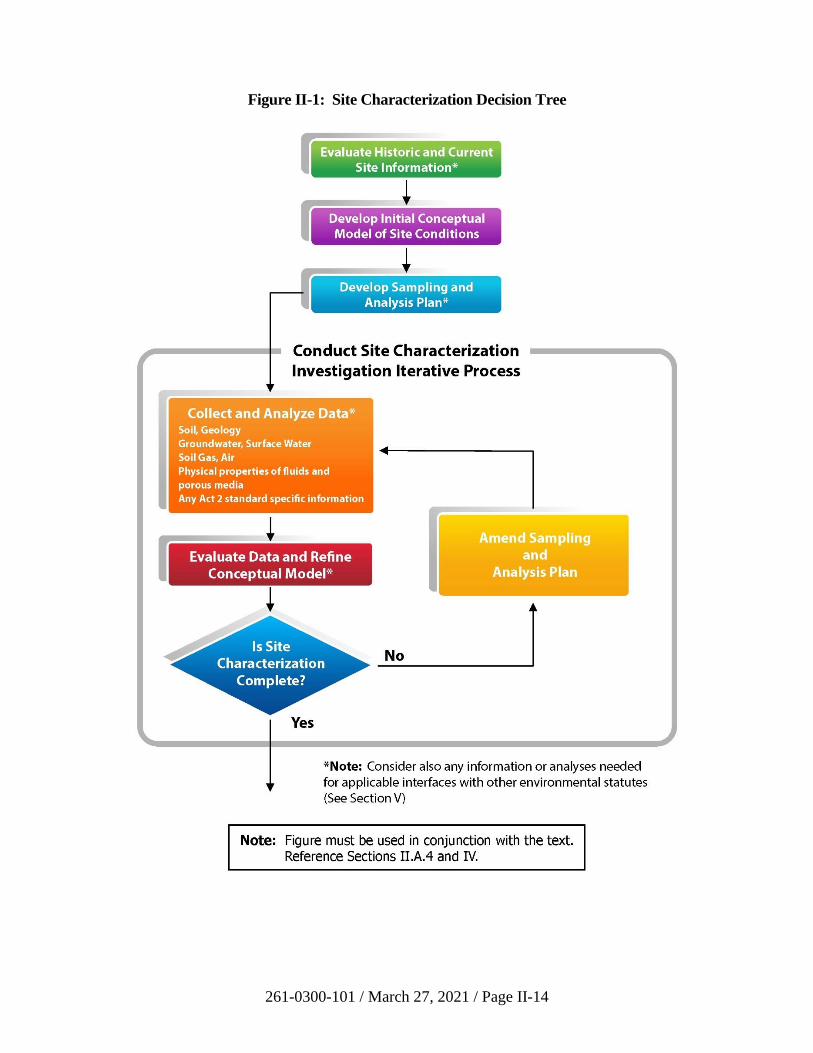
261-0300-101 / March 27, 2021 / Page II-14
Figure II-1: Site Characterization Decision Tree
261-0300-101 / March 27, 2021 / Page II-15
ii) Groundwater
If groundwater is known to be impacted by a release based on knowledge
of the site or as a result of soil sampling, a similar process as that used for
soils to determine the extent of the release into groundwater may be
employed based on knowledge of the site, groundwater monitoring, and
fate and transport analysis. A common mistake is to take a limited set of
groundwater measurements from a single sampling event, and if the
concentrations are below the SHS, conclude that no further Act 2 work is
needed. This is not true. Proper characterization requires more than one
round of sampling [25 Pa. Code § 250.204(e)]. For further guidance, see
Section III.B.
Where groundwater is a medium of concern, the following information at
a minimum should be provided by a thorough site characterization:
• The direction of groundwater flow.
• The hydraulic gradient.
• The permeability of the aquifer material(s) through which the
groundwater moves.
• The porosity of the aquifer.
• The types of regulated substances present, their concentrations, and
the spatial variation in concentration of the regulated substances
both horizontally and vertically.
This information is not only necessary to describe and evaluate conditions
at the site, but also is often vital to fate and transport analysis, especially
when it requires a quantitative approach.
Fate and transport analysis often is an important part of site
characterization and demonstration of attainment and is frequently
required under all three Act 2 standards. See Section III.A for guidance
for conducting fate and transport analyses.
Historic groundwater monitoring data can be useful for establishing trends
and under certain circumstances, delineating groundwater COCs.
Remediators can use historic data for identifying trends at sites that are not
reasonably expected to have changes in site conditions associated with the
release being investigated (e.g., natural attenuation or degradation).
Historic groundwater data can be used to delineate contaminants from a
specific release provided the groundwater quality has remained consistent
and no product degradation has occurred. However, be careful in the use
of groundwater data collected prior to remediation for attainment
purposes. This data may over estimate concentrations of COCs that have
261-0300-101 / March 27, 2021 / Page II-16
degraded or underestimate the concentrations of daughter products
generated by degradation.
iii) Sediment
Act 2 allows for liability relief to be granted for regulated substances in
sediment. Specifically, Section 302(b)(1) of Act 2 allows for
demonstration of attainment of media of concern which may include
sediment.
A remediator may demonstrate attainment of the background standard as
described in Subchapter B of the Chapter 250 regulations, and in 25 Pa.
Code § 250.707(a). The point of compliance for sediment is not
specifically discussed in the regulations but remediators are generally
expected to demonstrate attainment throughout the area of the sediment
that has become contaminated due to releases on the property.
The LRP has not established numeric cleanup standards for sediments.
However, sediment is sometimes only a concern to ecological receptors in
which case remediators can address sediment under the SHS through the
application of the ecological screening process described in Pa. Code
§ 250.311. The numeric soil standards published in the regulations cannot
be used for sediments, as the exposure assumptions used to develop those
values are not applicable to sediments. For remediations under the site-
specific standard, the site-specific ecological risk assessment process
should be used to demonstrate attainment for sediment.
iv) Conceptual Site Model Including Soil and Groundwater
A complete and comprehensive site characterization will enable the
development of a conceptual site model (CSM). The CSM is a
representation of the site environmental system and the processes that
control the transport and movement of regulated substances through the
environmental media and how they interact. The CSM assists in
organizing the site investigation by identifying uncertainties and data gaps
and focusing data collection efforts. Information from the CSM can also
be used in the development of a vapor intrusion analysis or a risk
assessment.
The CSM can be depicted in different ways such as written text, a graphic
illustration, or a flow chart. The investigation portion of the site
characterization is typically an iterative process which expands and builds
as information is gathered. Consequentially, the CSM is a dynamic tool to
be updated as new information becomes available during site
characterization.
The level of complexity of the CSM and the level of detail needed is
directly related to the level of complexity of the site, the selected
remediation standard and the applicable media of concern. Less complex
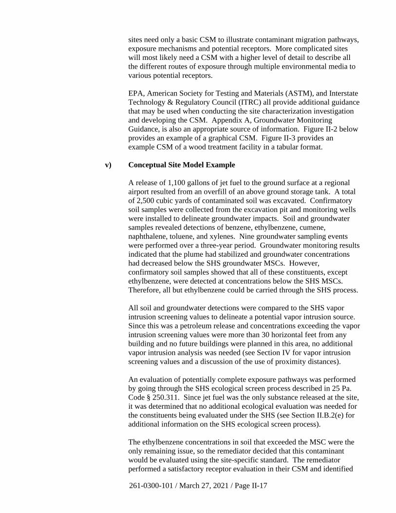
261-0300-101 / March 27, 2021 / Page II-17
sites need only a basic CSM to illustrate contaminant migration pathways,
exposure mechanisms and potential receptors. More complicated sites
will most likely need a CSM with a higher level of detail to describe all
the different routes of exposure through multiple environmental media to
various potential receptors.
EPA, American Society for Testing and Materials (ASTM), and Interstate
Technology & Regulatory Council (ITRC) all provide additional guidance
that may be used when conducting the site characterization investigation
and developing the CSM. Appendix A, Groundwater Monitoring
Guidance, is also an appropriate source of information. Figure II-2 below
provides an example of a graphical CSM. Figure II-3 provides an
example CSM of a wood treatment facility in a tabular format.
v) Conceptual Site Model Example
A release of 1,100 gallons of jet fuel to the ground surface at a regional
airport resulted from an overfill of an above ground storage tank. A total
of 2,500 cubic yards of contaminated soil was excavated. Confirmatory
soil samples were collected from the excavation pit and monitoring wells
were installed to delineate groundwater impacts. Soil and groundwater
samples revealed detections of benzene, ethylbenzene, cumene,
naphthalene, toluene, and xylenes. Nine groundwater sampling events
were performed over a three-year period. Groundwater monitoring results
indicated that the plume had stabilized and groundwater concentrations
had decreased below the SHS groundwater MSCs. However,
confirmatory soil samples showed that all of these constituents, except
ethylbenzene, were detected at concentrations below the SHS MSCs.
Therefore, all but ethylbenzene could be carried through the SHS process.
All soil and groundwater detections were compared to the SHS vapor
intrusion screening values to delineate a potential vapor intrusion source.
Since this was a petroleum release and concentrations exceeding the vapor
intrusion screening values were more than 30 horizontal feet from any
building and no future buildings were planned in this area, no additional
vapor intrusion analysis was needed (see Section IV for vapor intrusion
screening values and a discussion of the use of proximity distances).
An evaluation of potentially complete exposure pathways was performed
by going through the SHS ecological screen process described in 25 Pa.
Code § 250.311. Since jet fuel was the only substance released at the site,
it was determined that no additional ecological evaluation was needed for
the constituents being evaluated under the SHS (see Section II.B.2(e) for
additional information on the SHS ecological screen process).
The ethylbenzene concentrations in soil that exceeded the MSC were the
only remaining issue, so the remediator decided that this contaminant
would be evaluated using the site-specific standard. The remediator
performed a satisfactory receptor evaluation in their CSM and identified

261-0300-101 / March 27, 2021 / Page II-18
airport workers, construction workers, utility workers, and travelers all as
individual receptors with different exposure parameters.
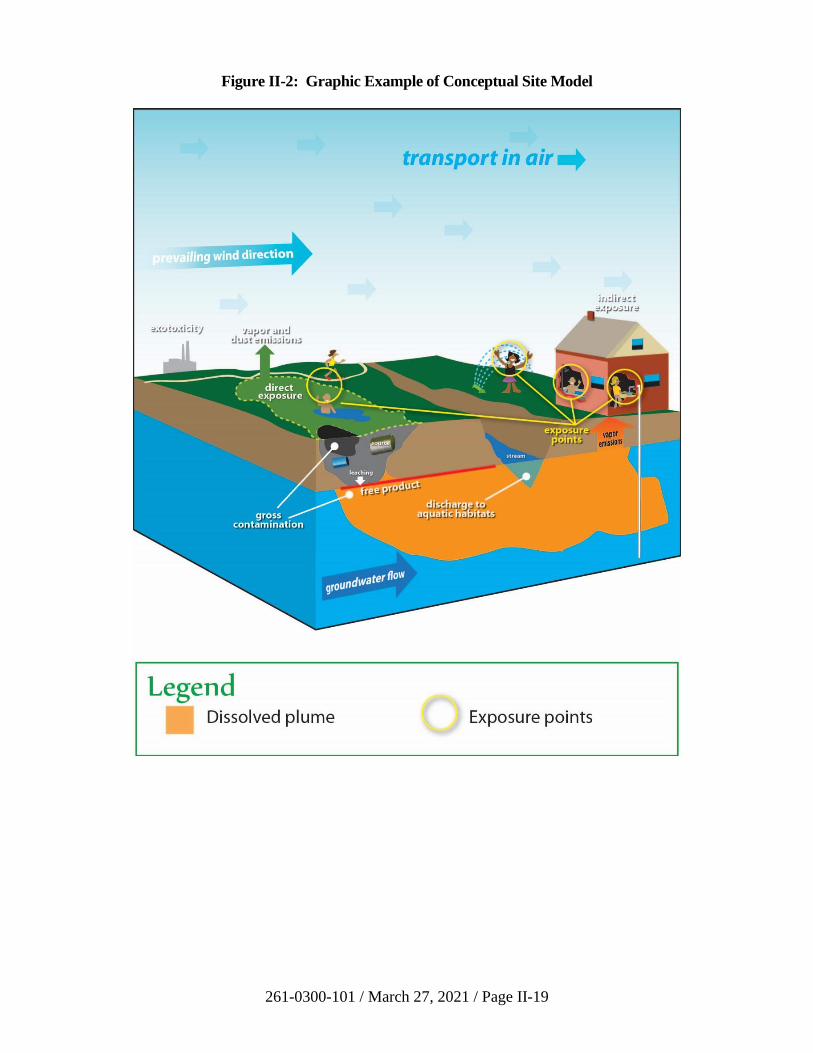
261-0300-101 / March 27, 2021 / Page II-19
Figure II-2: Graphic Example of Conceptual Site Model
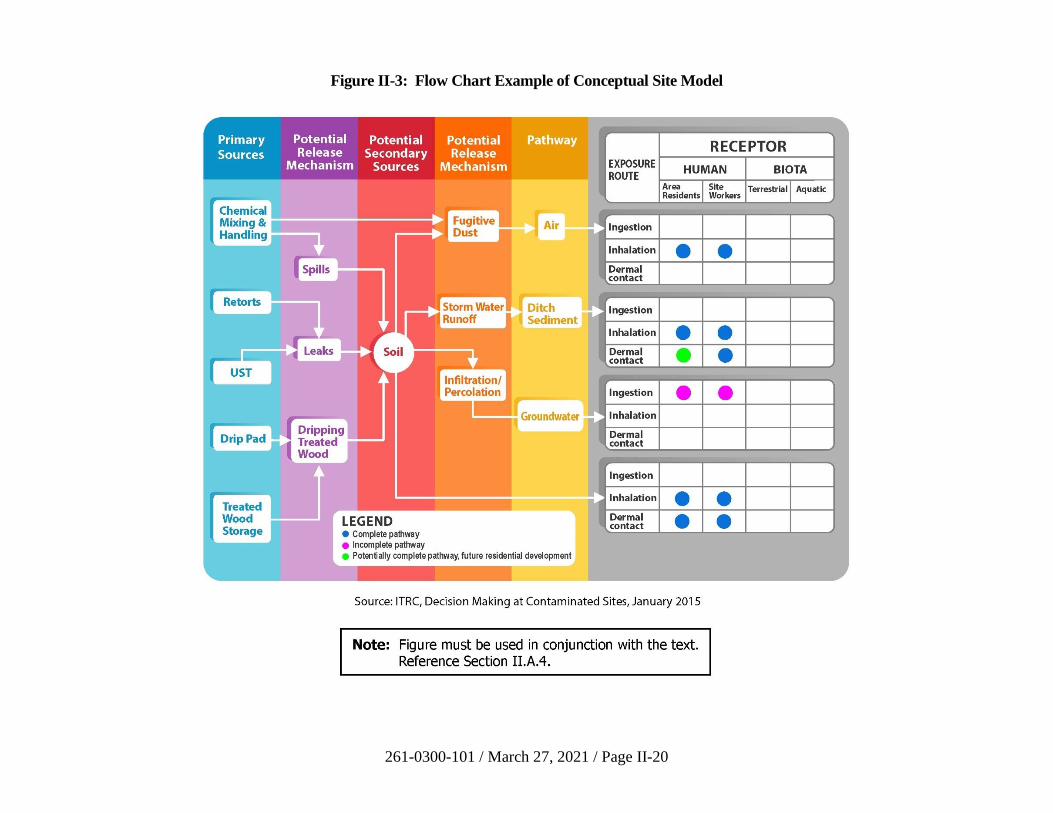
261-0300-101 / March 27, 2021 / Page II-20
Figure II-3: Flow Chart Example of Conceptual Site Model
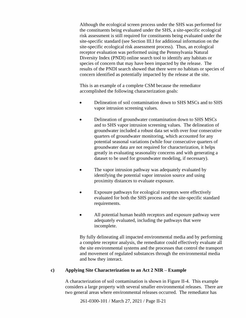
261-0300-101 / March 27, 2021 / Page II-21
Although the ecological screen process under the SHS was performed for
the constituents being evaluated under the SHS, a site-specific ecological
risk assessment is still required for constituents being evaluated under the
site-specific standard (see Section III.I for additional information on the
site-specific ecological risk assessment process). Thus, an ecological
receptor evaluation was performed using the Pennsylvania Natural
Diversity Index (PNDI) online search tool to identify any habitats or
species of concern that may have been impacted by the release. The
results of the PNDI search showed that there were no habitats or species of
concern identified as potentially impacted by the release at the site.
This is an example of a complete CSM because the remediator
accomplished the following characterization goals:
• Delineation of soil contamination down to SHS MSCs and to SHS
vapor intrusion screening values.
• Delineation of groundwater contamination down to SHS MSCs
and to SHS vapor intrusion screening values. The delineation of
groundwater included a robust data set with over four consecutive
quarters of groundwater monitoring, which accounted for any
potential seasonal variations (while four consecutive quarters of
groundwater data are not required for characterization, it helps
greatly in evaluating seasonality concerns and with generating a
dataset to be used for groundwater modeling, if necessary).
• The vapor intrusion pathway was adequately evaluated by
identifying the potential vapor intrusion source and using
proximity distances to evaluate exposure.
• Exposure pathways for ecological receptors were effectively
evaluated for both the SHS process and the site-specific standard
requirements.
• All potential human health receptors and exposure pathway were
adequately evaluated, including the pathways that were
incomplete.
By fully delineating all impacted environmental media and by performing
a complete receptor analysis, the remediator could effectively evaluate all
the site environmental systems and the processes that control the transport
and movement of regulated substances through the environmental media
and how they interact.
c) Applying Site Characterization to an Act 2 NIR – Example
A characterization of soil contamination is shown in Figure II-4. This example
considers a large property with several smaller environmental releases. There are
two general areas where environmental releases occurred. The remediator has
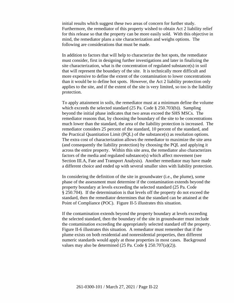
261-0300-101 / March 27, 2021 / Page II-22
initial results which suggest these two areas of concern for further study.
Furthermore, the remediator of this property wished to obtain Act 2 liability relief
for this release so that the property can be more easily sold. With this objective in
mind, the remediator plans a site characterization and weighs options. The
following are considerations that must be made.
In addition to factors that will help to characterize the hot spots, the remediator
must consider, first in designing further investigations and later in finalizing the
site characterization, what is the concentration of regulated substance(s) in soil
that will represent the boundary of the site. It is technically more difficult and
more expensive to define the extent of the contamination to lower concentrations
than it would be to define hot spots. However, the Act 2 liability protection only
applies to the site, and if the extent of the site is very limited, so too is the liability
protection.
To apply attainment in soils, the remediator must at a minimum define the volume
which exceeds the selected standard (25 Pa. Code § 250.703(b)). Sampling
beyond the initial phase indicates that two areas exceed the SHS MSCs. The
remediator reasons that, by choosing the boundary of the site to be concentrations
much lower than the standard, the area of the liability protection is increased. The
remediator considers 25 percent of the standard, 10 percent of the standard, and
the Practical Quantitation Limit (PQL) of the substance(s) as resolution options.
The extra cost of characterization allows the remediator to maximize the site area
(and consequently the liability protection) by choosing the PQL and applying it
across the entire property. Within this site area, the remediator also characterizes
factors of the media and regulated substance(s) which affect movement (see
Section III.A, Fate and Transport Analysis). Another remediator may have made
a different choice and ended up with several smaller sites with liability protection.
In considering the definition of the site in groundwater (i.e., the plume), some
phase of the assessment must determine if the contamination extends beyond the
property boundary at levels exceeding the selected standard (25 Pa. Code
§ 250.704). If the determination is that levels off the property do not exceed the
standard, then the remediator determines that the standard can be attained at the
Point of Compliance (POC). Figure II-5 illustrates this situation.
If the contamination extends beyond the property boundary at levels exceeding
the selected standard, then the boundary of the site in groundwater must include
the contamination exceeding the appropriately selected standard off the property.
Figure II-6 illustrates this situation. A remediator must remember that if the
plume exists on both residential and nonresidential properties, then different
numeric standards would apply at those properties in most cases. Background
values may also be determined (25 Pa. Code § 250.707(a)(2)).
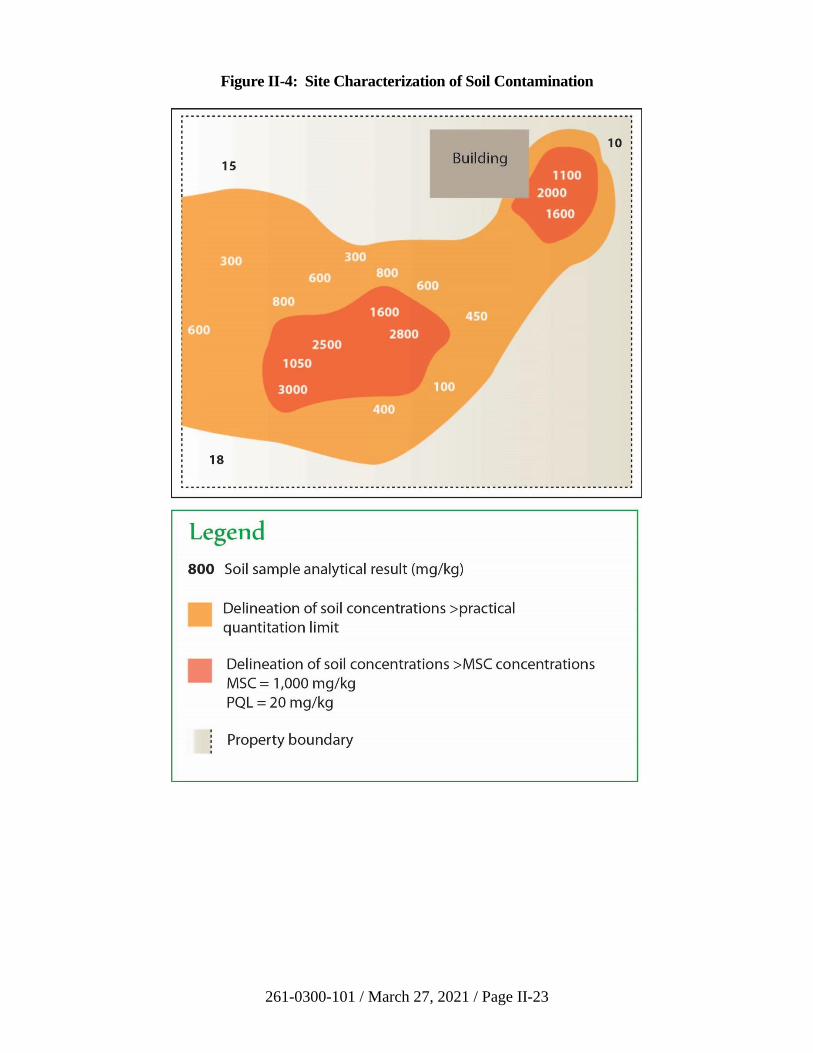
261-0300-101 / March 27, 2021 / Page II-23
Figure II-4: Site Characterization of Soil Contamination
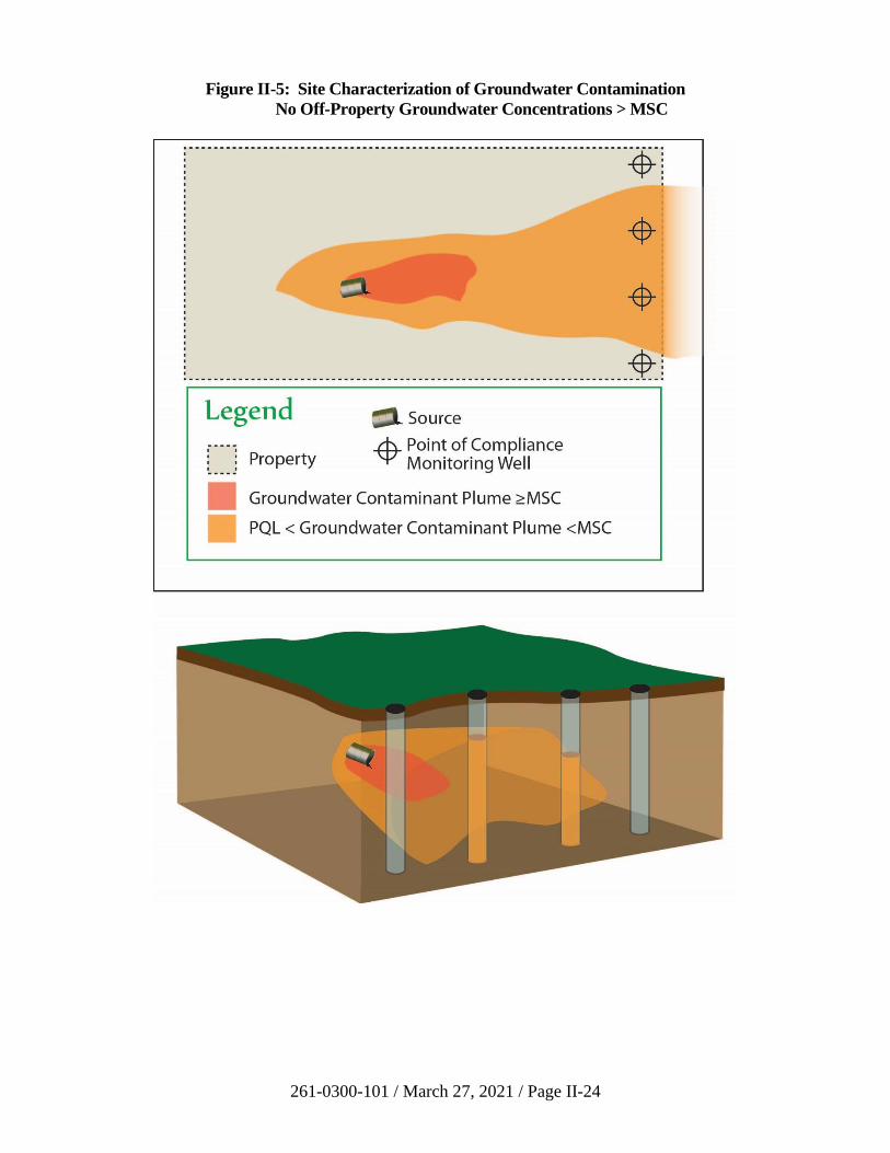
261-0300-101 / March 27, 2021 / Page II-24
Figure II-5: Site Characterization of Groundwater Contamination
No Off-Property Groundwater Concentrations > MSC
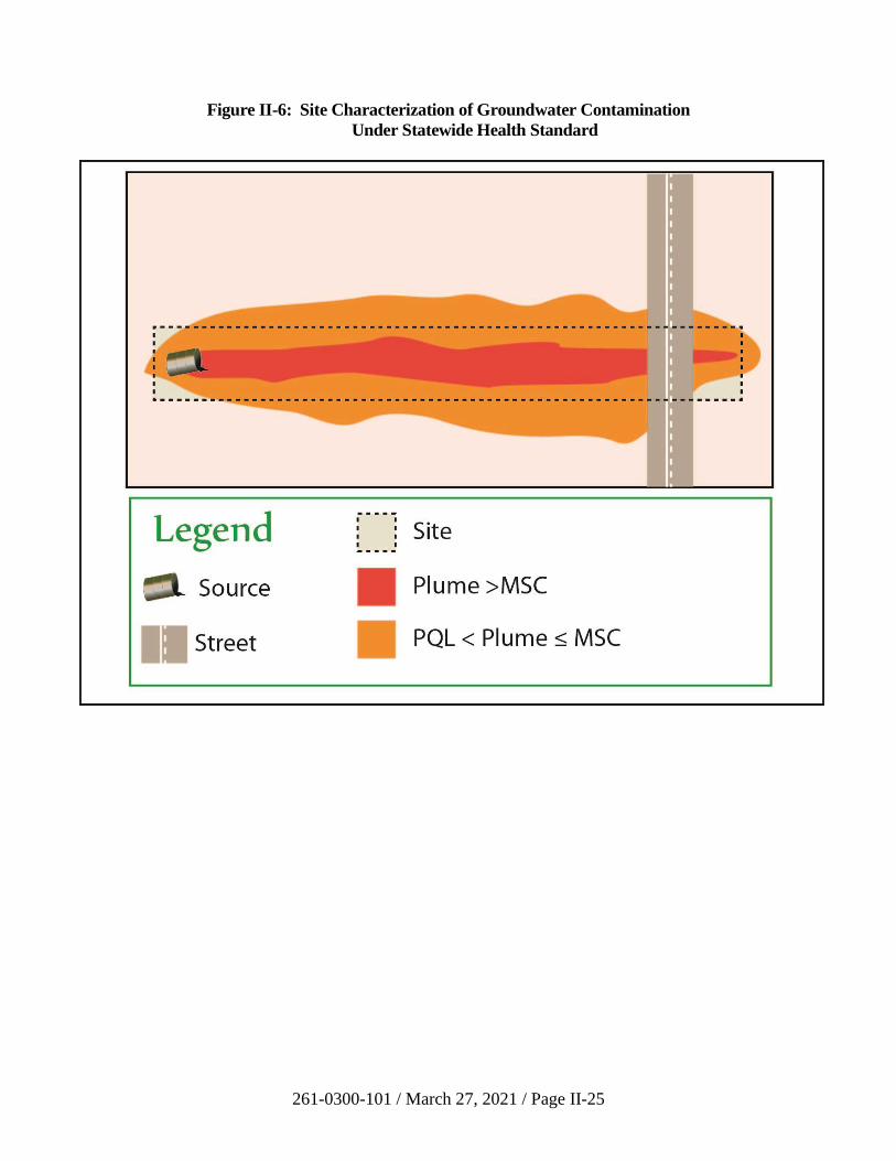
261-0300-101 / March 27, 2021 / Page II-25
Figure II-6: Site Characterization of Groundwater Contamination
Under Statewide Health Standard

261-0300-101 / March 27, 2021 / Page II-26
Two or more rounds of sampling and analysis must be performed once the extent
of contamination in groundwater is established utilizing properly constructed
monitoring wells (25 Pa. Code § 250.204(e)).
If no groundwater remediation is needed (e.g., both rounds of sampling are below
the selected standard), the remediator may use the site characterization sampling
as part of the required attainment demonstration. The Department may approve a
reduction in the number of quarters of sampling needed to demonstrate attainment
provided there is appropriate justification under 25 Pa. Code § 250.704(d).
261-0300-101 / March 27, 2021 / Page II-27
B. Remediation Standards
1. Background Standard
a) Introduction
This chapter presents procedures to be used in assessing site contamination and
demonstrating attainment of the background standard. Use of this guidance and
data submission formats should simplify reporting on the site and reduce delays in
obtaining final report approval by the Department. This chapter is designed to
help those involved understand and meet the requirement of the background
standard under Act 2 and the regulations in 25 Pa. Code Chapter 250.
Environmental Cleanup and Brownfields Program staff in the Regional Offices
are a valuable resource and will assist in answering questions on the background
standard.
Background is the concentration of a regulated substance that is present at a site,
but is not related to the release of regulated substances at the property.
Attainment of the background standard for a regulated substance may be
demonstrated by an analysis of environmental media within and around the site
(35 P.S. § 6026.302). Establishing the background concentration is discussed in
Subsection II.B.1(d) of this manual. Subchapter B under Chapter 250 of the
regulations also discusses the background standard requirements.
The background standard may result in higher than health-based level
contamination (e.g. SHS MSCs) moving onto the property from an adjacent
property or from constituents which are naturally occurring. Background quality
is the concentration of substances which are unrelated to the release on the site.
In order to demonstrate compliance with the background standard, remediators
should demonstrate that onsite media do not exceed the background standard for a
regulated substance(s) by statistically developing representative contaminant
concentrations through onsite and background reference samples of the
environmental media. Subchapter G under Chapter 250 of the regulations
establishes statistical tests recognized by the Department for the demonstration of
attainment. Background statistical attainment requirements are in 25 Pa. Code
§ 250.707(a)(1) for background soils and Pa. Code § 250.707(a)(2) or (3) for
background groundwater. Demonstration of attainment for background is
discussed in Subsection II.B.1.e.vi of this manual.
Reporting the completion of a remediation to the Department requires a final
report that contains a detailed description of the process taken to reach the
background standard and the reasoning for choosing media for testing.
Section 250.204 of the regulations discusses the requirements for a final report.
Section II.B.1(e) of this manual also contains a discussion on the final report
requirements for the background standard. Summaries of sampling methodology
and analytical results showing attainment should be included with the report
35 P.S. § 6026.302(b)(2).
261-0300-101 / March 27, 2021 / Page II-28
Institutional controls such as fencing and future land use restrictions on a site may
not be used to attain the background standard. Institutional controls may be used
to maintain the background standard after remediation occurs 25 P.S.
§ 6026.302(b)(4).
If the initial remediation chosen by the remediator fails to attain the background
standard, the remediator may choose instead to meet the Statewide health or site-
specific standards 35 P.S. § 6026.302(c). Sites attaining and demonstrating
compliance with the background standard are not required to meet the deed
acknowledgment requirements of the Solid Waste Management Act (SWMA) or
the Hazardous Site Cleanup Act (HSCA) or the Uniform Environmental
Covenants Act (UECA). An existing acknowledgment contained in a deed prior
to demonstrating compliance with the background standard may be removed.
b) Process Checklist for the Background Standard
☐ Review the historic and current information and present use of regulated
substances at the property.
☐ Begin the site investigation/characterization and gather information about
the area on and around the property.
☐ As an option, begin using the completeness list (see LRP website) to help
verify that all requirements have been met.
☐ Determine if property/site is affected by regulated substances not
originating from the property.
For the groundwater background concentration, establish if it is naturally
occurring/area-wide or from an upgradient source (see 25 Pa. Code
§ 250.707).
☐ For the soils background concentration, establish if it is a naturally
occurring or area-wide problem. The Department has not established
background concentrations for naturally occurring substances as they may
vary considerably across the Commonwealth. Geochemical references are
available for certain rock and soil types in Pennsylvania and should be
cited as appropriate. Background concentrations should be determined on
a site-by-site basis.
☐ If using the naturally occurring/area-wide background distinction, request
in writing and receive back in writing the Department’s approval that the
site is indeed in an area of widespread contamination for the regulated
substance on your property/site before submitting the NIR (see 25 Pa.
Code § 250.707(a)(3)(i)).
☐ Continue with the site characterization and required activities needed to
complete the final report (see 25 Pa. Code § 250.204).
261-0300-101 / March 27, 2021 / Page II-29
☐ Submit an NIR for the background standard. Also, send a notice to the
municipality, publish a notice in a local newspaper, and attach reasonable
proof of required notices for inclusion with the final report to the
Department 35 P.S. § 6026.302(e)(1). Procedures for submittal of
notifications are contained in Section II.A.3 of this manual. Links to
sample forms are located on the LRP website.
☐ Remediate the site to the background standard.
☐ Demonstrate attainment of the background standard pursuant to 25 Pa.
Code § 250.203.
☐ Calculate mass of contaminants remediated using the procedure in
Section III.D of this manual.
☐ Complete the final report summary and submit electronically as instructed
on the LRP website.
☐ Prepare and submit the final report, along with the optional completeness
list (if used) to the appropriate DEP Regional Office. See
Section 302(b)(2) of Act 2, 35 P.S. § 6026.302(b)(2), 25 Pa. Code
§ 250.204, and Section II.B.1(e) of this manual.
☐ If the final report is approved, the liability protection set forth in Chapter 5
of Act 2 automatically applies.
☐ If engineering controls were used and postremediation care is required to
maintain the standard, continue with the postremediation care program
detailed in the final report. Postremediation care would not normally be
used for the background standard.
☐ When the background standard can be maintained without engineering
controls operating, document this to the Department and receive approval
to terminate the postremediation care program.
☐ Submit an environmental covenant, if applicable, to the Department.
c) Point of Compliance (POC) for the Background Standard
For the background standard, the POC for groundwater is throughout the area of
contamination (plume) both from the offsite (upgradient) release that migrates
onto the property and another release within the property, including areas to
which the onsite release has migrated off the property above the background
standard as determined by the site characterization (see Figures II-7 and II-8).
This differs from the groundwater POC for the Statewide health and site-specific
standards. (See 25 Pa. Code § 250.203(a)).
261-0300-101 / March 27, 2021 / Page II-30
For a property located within areawide contamination, the minimum required
POC is the extent of plume contamination on and off the property from an on-
property release, as shown in Figures II-9A and II-9B. A remediator may choose
to use a larger point of compliance by including all areas on the property which
have been affected by an upgradient release. In this example, the remediator
could choose to use the entire area shown as being affected by the upgradient
release as the POC. In such a case, the remediator would receive liability
protection for the entire area affected by the upgradient release.
The POC for the background standard in soil is throughout the area of the soil that
has been contaminated (see 25 Pa. Code § 250.203(b)).
For surface water, point source discharges shall be measured at the point of
discharge in accordance with limits in the National Pollutant Discharge
Elimination System (NPDES) permit (see 25 Pa. Code § 250.203(c)). For spring
or diffuse groundwater flow to surface waters, attainment of the background
standard for groundwater will satisfy Act 2.
d) Establishing Background Concentration(s)
Background concentrations are determined using analysis of samples of regulated
substances present at the property under investigation but not related to any
release at the property. If all areas on the property are affected by a release at the
property, then background samples will be taken in an area free of contamination
from any release at the site, including representative off-property areas. Persons
may not obtain Chapter 5 cleanup liability protection by using a contaminated
area as a background reference area when they are responsible for the
contamination.
Background soil sampling locations must be representative of background
conditions for the site, including soil type; physical, chemical, or biological
characteristics; and depth below ground surface. Randomization of sampling at
background and onsite locations must be comparable (see 25 Pa. Code
§ 250.204(f)(7)).
Any wells that are used to establish groundwater concentration(s) must be
hydrogeologically upgradient or otherwise justified from the groundwater onsite
that is affected by any release at the property and that characterizes the flow onto
the site. Upgradient wells may not be appropriate to detect movement of a dense
non-aqueous phase liquid (DNAPL) since geologic structure rather than
hydrogeologic gradient may influence DNAPL movement.
Background concentrations determination will be by a statistically valid method
that is consistent with the methods used to demonstrate attainment. Statistical
methods are included in 25 Pa. Code § 250.707 and in Section II.B.1(e)(vi) of this
manual.
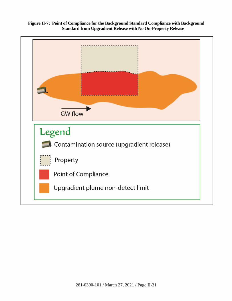
261-0300-101 / March 27, 2021 / Page II-31
Figure II-7: Point of Compliance for the Background Standard Compliance with Background
Standard from Upgradient Release with No On-Property Release
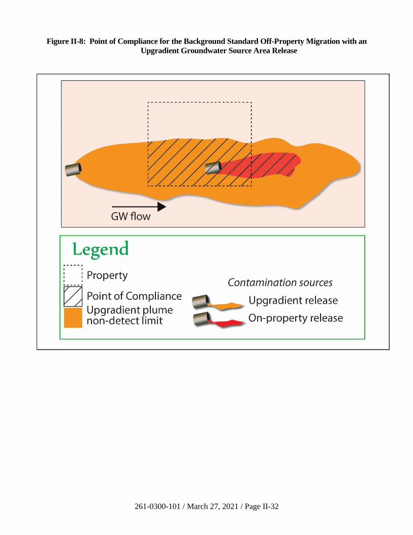
261-0300-101 / March 27, 2021 / Page II-32
Figure II-8: Point of Compliance for the Background Standard Off-Property Migration with an
Upgradient Groundwater Source Area Release
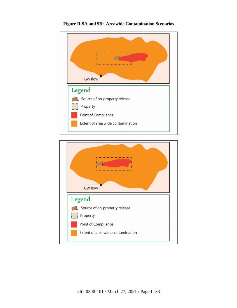
261-0300-101 / March 27, 2021 / Page II-33
Figure II-9A and 9B: Areawide Contamination Scenarios
261-0300-101 / March 27, 2021 / Page II-34
For non-naturally occurring regulated substances (primarily organic compounds)
the affected area shall be shown to be related to sources other than the release of
regulated substance on the site. This may include transport of regulated
substances onto the property in the gaseous, liquid, or solid phases and associated
mixing with or partitioning to onsite gaseous, liquid, or solid-phase media. For
background conditions that are related to ongoing flux onto the site (e.g.,
regulated substances dissolved in groundwater flowing onto the site or soil vapor
transport onto the site), the background concentrations shall be determined by
monitoring the concentrations of regulated substances associated with this flux
where it enters the property. For background conditions that are not related to a
continuing source of chemical flux onto the property (e.g., historical accumulation
of airborne contaminants including particulate and associated deposition in
surficial soils), the determination of background concentrations shall include the
identification of the source(s), if possible, and a demonstration that the areal
distribution of the background conditions extends beyond the limits of the
property.
These same determinations should be made for naturally occurring regulated
substances. However, an additional determination should be made as to the
naturally occurring concentrations of these regulated substances independent of
impacts from the release(s) or other background sources. Therefore, for naturally
occurring regulated substances, the background standard would include the
naturally occurring concentration plus contributions from sources not on the
property.
Use of breakdown products of a regulated substance from offsite which form on
the site undergoing remediation can be included in the assessment of attainment
of the background standard. The Department is willing to consider breakdown
products of substances released upgradient of the property. The remediator
should submit historical information and fate and transport analyses to
demonstrate that the substances onsite are a result of chemical breakdown and not
a result of a release on the property. Likewise, a conclusion that contamination
entering a subject property which transforms or degrades to a compound similar
to a spill which occurred on the subject property will be supported by the
combined sample analysis and fate and transport analysis determination. The
remediator must demonstrate that the concentrations are the result of
transformation or direct migration of chemicals from the background area.
The establishment of the groundwater background concentrations for a site using
sampling and analysis allows for two different background conditions, as
described in 25 Pa. Code § 250.707(a):
• Background from a known upgradient release of regulated substance.
• Background from naturally occurring or areawide contamination (this can
also apply to soils).
The Department provides different procedures to establish the background
groundwater concentration depending on which background condition is present
261-0300-101 / March 27, 2021 / Page II-35
upgradient and adjacent to the property. The method used when establishing
background and determining attainment of the background standard for a site
must be the same.
i) Background from a Known Upgradient Release of a Regulated
Substance
(a) Groundwater
This groundwater distinction occurs when an adjacent or nearby
property has had a release of the same regulated substance that
flows onto the property under consideration for an Act 2
remediation. One option for determining background conditions is
through the use of monitoring wells sampled during the site
characterization to establish the well with the highest concentration
of the groundwater migrating onto the site. Another option is to
compare the statistical distribution of the background area with the
impacted area onsite. Section 250.707(a)(2) in the regulations,
Section II.B.1.e.vi of this manual, and the statistical requirements
in Section III.B of this manual discuss the handling of the
statistical requirements for groundwater attainment in the
background standard.
A remediator who believes that a site meets the conditions for
reducing the timeframe for implementing eight groundwater
sampling events as found in 25 Pa. Code § 250.707(a)(2)(x), and
already has eight or more samples collected in four quarters or less,
may request that the Department accept fewer than eight quarters
of sampling. The request may be submitted with supporting
information to the Regional ECB Program Manager. If the
Department is not satisfied that these conditions are met, the
remediator shall continue to monitor for the remainder of the
eight quarters.
The time frame for taking the background samples when
remediation is not undertaken may start before the site
characterization is completed. This will allow a remediator who
has existing data to establish background without the need to
monitor for an additional four or eight quarters if all the
consecutive quarterly data total four or eight quarters, as applicable
to that background condition.
If remediation action is undertaken, the attainment sampling is
done after remediation is completed.
(b) Soil
Soils where a large area was affected by a release of regulated
substances off-property do not typically move from one location to
261-0300-101 / March 27, 2021 / Page II-36
another in comparison with the movement of groundwater.
Natural movement of soil in Pennsylvania normally involves
surface water transporting sediment, landslides, or airborne
transport of soil or contaminants.
ii) Background from Naturally Occurring or Area-wide Contamination
Some areas of the Commonwealth have naturally occurring or widespread
contamination. A remediator should obtain a written agreement from the
Department if they plan to demonstrate that their site is in an area of
naturally occurring or widespread contamination. This decision will be
based on evidence presented to the Department in writing by the
remediator seeking the determination. When the Department agrees,
through written acknowledgment to the remediator that the property under
investigation is within a location of areawide contamination, the following
approach for establishing background is allowed.
(a) Groundwater
When the background groundwater condition is due to naturally
occurring or areawide contamination, a minimum of 12 samples
should be collected offsite and 12 samples collected onsite. The
number of wells sampled onsite and offsite must be the same in
each round of sampling. For example, if three wells are sampled
offsite, three wells must be sampled onsite. In this example, each
of the wells must be sampled a minimum of four times. The
samples must be independent of one another. The onsite and
offsite samples must be collected at the same time. The time frame
for establishing this condition is not predetermined, as it is in the
upgradient release. By increasing the number of wells onsite and
offsite, the number of sampling events necessary to meet the
minimum of 12 samples can be reduced (two wells will require
six sampling events, six wells will require two sampling events).
The offsite wells must be located upgradient of the site. The
number of wells and the horizontal and vertical location of the
wells onsite must be adequate to characterize any release of
regulated substance at each site. All sampling data must be
reported to the Department.
(b) Soil
When the background soil condition is due to naturally occurring
or areawide contamination, the remediator shall compare the
analytical results of background reference samples that are
representative of naturally occurring or areawide contamination of
substances on the site, with the analytical results of onsite
concentrations. A minimum of 10 samples should be collected
offsite or at the background referenced area, and 10 samples
collected onsite. The comparison should be conducted using the
261-0300-101 / March 27, 2021 / Page II-37
statistical methods summarized in 25 Pa. Code § 250.707(a)(1) and
in Section III.B of this manual.
(c) Historic Fill
Some sites may be located in an area where there has been
widespread use of fill (Figure II-10). This fill may contain
regulated substances. If a spill or discharge of a regulated
substance occurs on a site that received fill long ago (historic fill),
the remediator can limit his remediation to the discharge that he or
she has recently caused. In this case, the remediator would obtain
relief from liability only for cleaning up what the remediator has
recently spilled. This includes contamination resulting from the
onsite release to the soil and groundwater. Remediators who wish
to limit their cleanup to the levels that were already present in the
fill should provide information to the Department indicating that
the fill was historical (placed prior to 1980), not placed at their
direction, and widespread or involved more than the subject
property.
An example of contamination that may have occurred through
airborne transport comes from the time when leaded gasoline was
commonly used in automobiles. The surface and near-surface soils
of properties along highways have been found to have elevated
levels of lead. Samples taken from a number of properties near
and along the highways would be required to compare the onsite
and offsite conditions.
e) Final Report Requirements for the Background Standard
For a site remediated under the background standard, the remediator shall submit
a final report to the Department which documents attainment of the selected
standard. Section 250.204 of the regulations discusses final report requirements.
A complete final report is prepared in accordance with scientifically recognized
principles, standards, and procedures. The report will present a thorough
understanding of the site conditions. It will provide a detailed discussion on the
AOC and a conceptual site model based on the results of the site characterization.
Support for interpretations and conclusions will be based on data collected during
all of the investigations at the site. The level of detail in the investigation and
methods selected need to be sufficient to define the rate, extent, and movement of
the contaminants to assure continued attainment of the remediation standard. In
accordance with 25 Pa. Code § 250.204(a), all interpretations of geologic and
hydrogeologic data shall be prepared by a professional geologist licensed in
Pennsylvania.
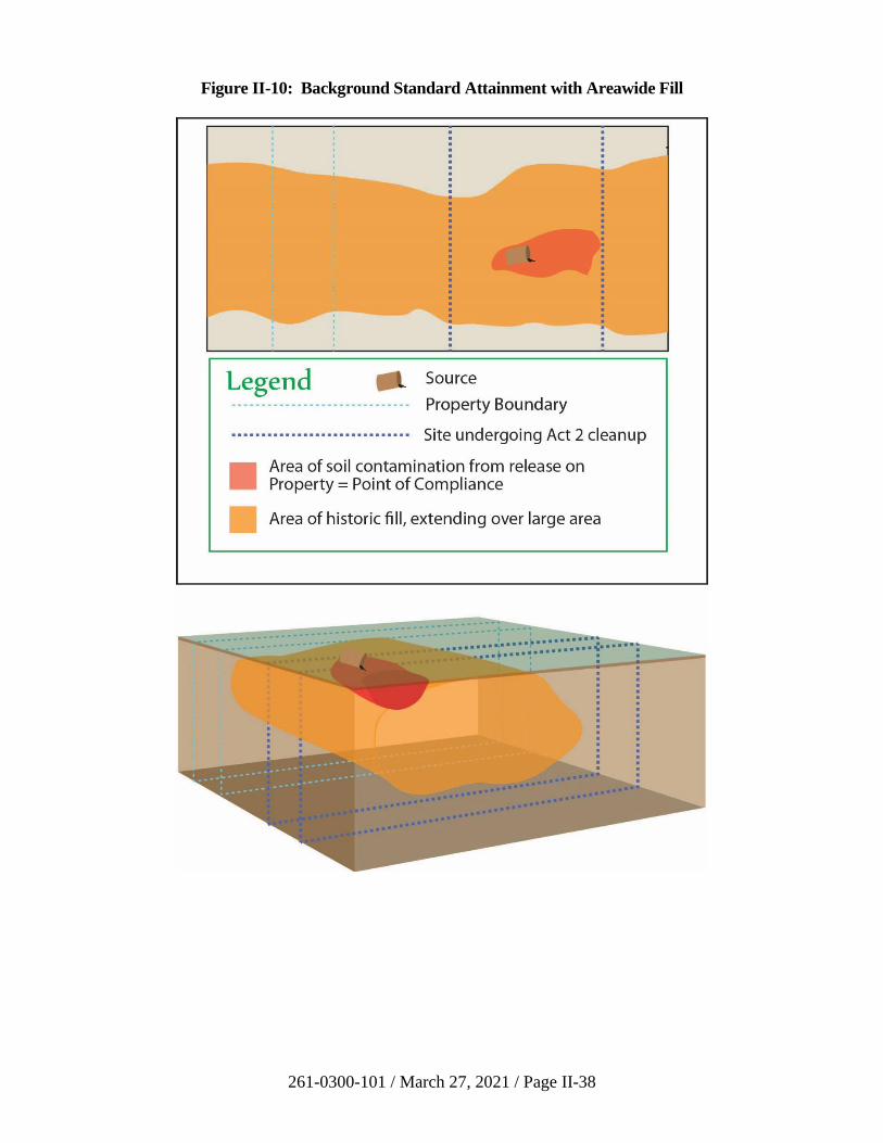
261-0300-101 / March 27, 2021 / Page II-38
Figure II-10: Background Standard Attainment with Areawide Fill
261-0300-101 / March 27, 2021 / Page II-39
Two copies of the final report should be submitted for the Department’s review.
One should be a paper copy and the other should be submitted in another format
(CD, flash drive, etc.). The final report must include the information in
paragraphs (i)-(xi) of this section, and it should be organized according to the
outline in Table II-1, below.
The following paragraphs describe the information to be included in the final
report:
i) Summary
The Final Report Summary form should be filled in and submitted to the
Department electronically. The summary submitted with the final report
should be a copy of that completed form.
ii) Site Description
Provide a description of the site in sufficient detail to give the reviewer an
overall understanding of the site and its location, and the types of
operations that are currently and/or were formerly conducted on the site.
As appropriate to the site, the description should include location, physical
description of the property, ownership history, site use history, and
regulatory action history (past cleanups).
iii) Site Characterization
The site characterization provides important information documenting the
current conditions at the site and shall be based on 25 Pa. Code § 250.204.
The two principal objectives of an investigation under the background
standard are to determine what constitutes background for each of the
regulated substances associated with the release, and to characterize the
nature, extent, direction, volume and composition of regulated substances
that have been released. Considerations for establishing the background
concentrations are found in Section II.B.1.d. Section 250.204 of the
regulations provides reporting requirements for the background standard.
For sites where there are multiple distinct areas of contamination, the site
characterization process should be applied to each area individually.
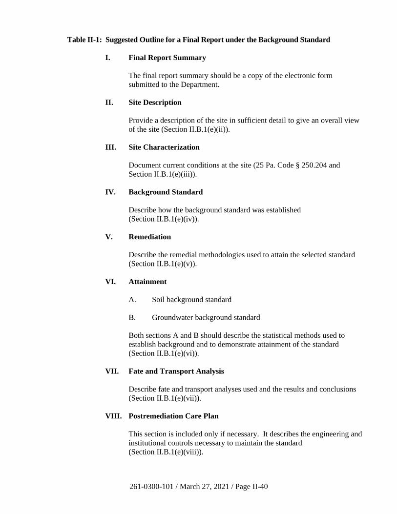
261-0300-101 / March 27, 2021 / Page II-40
Table II-1: Suggested Outline for a Final Report under the Background Standard
I. Final Report Summary
The final report summary should be a copy of the electronic form
submitted to the Department.
II. Site Description
Provide a description of the site in sufficient detail to give an overall view
of the site (Section II.B.1(e)(ii)).
III. Site Characterization
Document current conditions at the site (25 Pa. Code § 250.204 and
Section II.B.1(e)(iii)).
IV. Background Standard
Describe how the background standard was established
(Section II.B.1(e)(iv)).
V. Remediation
Describe the remedial methodologies used to attain the selected standard
(Section II.B.1(e)(v)).
VI. Attainment
A. Soil background standard
B. Groundwater background standard
Both sections A and B should describe the statistical methods used to
establish background and to demonstrate attainment of the standard
(Section II.B.1(e)(vi)).
VII. Fate and Transport Analysis
Describe fate and transport analyses used and the results and conclusions
(Section II.B.1(e)(vii)).
VIII. Postremediation Care Plan
This section is included only if necessary. It describes the engineering and
institutional controls necessary to maintain the standard
(Section II.B.1(e)(viii)).

261-0300-101 / March 27, 2021 / Page II-41
IX. References
(Section II.B.1(e)(ix))
X. Attachments
(Section II.B.1(e)(x))
XI. Signatures
(Section II.B.1(e)(xi))
261-0300-101 / March 27, 2021 / Page II-42
Along with a narrative, the results from the site characterization and all
sampling and analysis work should be provided on map(s) illustrating, to
the extent possible, the interrelationship of the following:
• All physical site characteristics.
• All groundwater, soil, sediment, and other sample locations,
including sample depth and contaminant concentration.
• The surveyed locations for all assessment structures (monitoring
wells, soil borings, test pits, etc.). All elevations should be
reported in reference to mean sea level (msl), where practical.
• Appropriate number of stratigraphic cross sections that adequately
depict site stratigraphy, well locations, well depths, groundwater
flow directions, equipotential lines, flow lines, hydraulic
conductivity intervals and values, sampling intervals and
concentrations. All elevations should be reported in reference to
msl, where practical.
• Variation in potentiometric surfaces(s), potentiometric surface
map(s), hydraulic gradients, and groundwater flow directions.
• All identified sources of releases.
• The extent and concentrations of contaminant plumes in all media.
The horizontal and vertical extent of contaminant plumes,
including the relative density and thickness of any separate phase
liquids (SPL) present.
• Top of bedrock contour (if encountered).
A conceptual site model should be developed and refined as information is
gathered during the site characterization. The conceptual site model
provides a description of the site and extent of contamination. Some of
the information and data used to develop the site model would include:
• The type, estimated volume, composition, and nature of the
released materials, chemicals or chemical compounds (include all
calculations and assumptions).
• Source(s) and extent of release(s).
• Background concentrations for constituents of concern.
• The horizontal and vertical extent of contamination.
261-0300-101 / March 27, 2021 / Page II-43
• Affected aquifer(s) or water bearing formation(s)/member(s),
hydrostratigraphic units.
• All existing and potential migration pathways.
• The estimated volume of contaminated soil and water (include all
calculations and any assumptions).
For soils, include information on samples and measurements used to
characterize the horizontal and vertical extent of contamination, and the
direction and rate of contaminant movement based on factors in the soil
and the contaminant(s) which affect migration. Soil and boring
descriptions should be included as an attachment.
For groundwater, include information on samples and measurements used
to characterize the horizontal and vertical extent of contamination, and the
direction and velocity of contaminant movement based on factors of the
groundwater and the contaminant(s) which affect migration. Geologic
boring descriptions and as-built drawings of wells should be included as
an attachment. Text, tables, graphics, figures, maps, and cross sections, as
appropriate, can be utilized to describe the nature, location, and
composition of the regulated substances at the site. Providing the data in
an appropriate format will expedite the review of the report.
iv) Background Standard
• How the background concentration was established.
• Type of background condition: upgradient release or area-wide
contamination.
• Identify on a map the location of background soil samples and
background groundwater wells.
• Document that POC attainment for groundwater is throughout the
plume.
• Attainment for each medium is to be determined by the same
method as the method used to establish background levels.
• Summary of sampling methodology and analytical results relating
to determination of background.
261-0300-101 / March 27, 2021 / Page II-44
v) Remediation
Provide a description of the remedial methodologies used to attain the
selected standard. Examples of the types of information typically included
in this section include:
• Identification of areas remediated based on results of site
characterization.
• Descriptions of treatment, removal, or decontamination procedures
performed in remediation. Description of removal, what was
removed, and amount removed. Results of any treatability, bench
scale, or pilot scale studies, or other data collected to support the
remedial action(s).
• Description of the methodology and analytical results used to
direct the remediation and determine the cessation of remediation.
This description should document how the remediator determined
that remediation was performed to address all areas that exceed the
standard.
• Description of treatment technologies.
• Documentation of handling of remediation wastes in accordance
with applicable regulations.
• Specific characteristics of the site that affected the implementation
or effectiveness of the remedial action, including such
characteristics as topography, geology, depth of bedrock,
potentiometric surfaces, and the existence of utilities.
• All other site information relevant to the conceptual design,
construction, or operation of the remedial action.
In addition to the above, this section should also include the calculation of
the mass of contaminants addressed during the remediation of soil and/or
groundwater, using the methodology in Section III.D.
vi) Attainment
Appropriate statistical methods, discussed in Section III.B, will confirm
the attainment of cleanup under the background standard. Not all the
statistical tests discussed in the manual are appropriate for the background
standard attainment tests. Section 250.707(a) of the regulations describes
statistical tests for the background standard. The following information
shall be documented in a final report when a statistical method is applied,
except for the highest measurement comparison test described in
§ 250.707(a)(1)(i) of the regulations:
261-0300-101 / March 27, 2021 / Page II-45
• Description of the statistical method and the underlying
assumptions of the method.
• A clear statement of the applicable decision rule in the form of a
statistical hypothesis for each spatial unit and temporal boundary,
including the applicable statistical parameter of interest and the
specific cleanup standard.
• Documentation showing that the sample data set meets the
underlying assumptions of the method and explaining why the
method is appropriate to apply to the data.
• Specification of false positive and false negative rates.
• Documentation of input and output data for the statistical test,
presented in table and figures, or both, as appropriate; and
identification, by medium, contamination levels remaining onsite.
• An interpretation and conclusion of the statistical test.
In demonstrating attainment of the background standard, concentrations of
regulated substances are not required to be less than the limit related to the
PQL for that substance as provided for in § 250.701(c) of the regulations.
(a) Soil Background Standards
The determination of attainment of soil background standards will
be based on a comparison of the distributions of the background
concentrations of a regulated substance with the concentrations in
an impacted area. Act 2 regulations allow a person to use highest
measurement comparison, combination of Mann-Wilcoxon Rank
Sum (WRS) test and Quantile test, or other appropriate methods to
demonstrate attainment of background standards. No matter which
method is used, Act 2 regulations require that the minimum
number of soil samples to be collected is 10 from the background
reference area and 10 from each cleanup unit. This requirement of
10 samples is to ensure that any selected statistical test has
sufficient power to detect contamination.
(b) Groundwater Background Standards
There are two general categories of background conditions for
groundwater. The first is naturally occurring background or area-
wide contamination. The second is background associated with a
release of regulated substances at a location upgradient from the
site that may be subject to such patterns and trends.
For naturally occurring background or areawide contamination, it
is recommended that a minimum of 12 samples be collected from
261-0300-101 / March 27, 2021 / Page II-46
any combination of upgradient monitoring wells, provided that all
data collected are used in determination of background
concentrations. This same number of samples must then be
collected from monitoring wells impacted by a release on the site
during the same sampling event. In both cases, this sampling may
be accelerated such that all samples are collected as quickly as
possible so long as the frequency does not result in serial
correlation in the data. The resulting values may be compared
using either nonparametric or parametric methods to compare the
two populations, such as using the combination of the WRS test
and the Quantile test. When comparing with the background
results, the sampling results in the plume onsite should not exceed
the sum of the arithmetic average and three times standard
deviation calculated for the background reference area 25 Pa. Code
§ 250.707(a)(3)(vii).
For background associated with a release of regulated substances
at a location upgradient from a property, the background
groundwater concentrations will be determined at the
hydrogeologically upgradient property line of the property, or a
point hydrogeologically upgradient from the upgradient property
line that is unaffected by the release.
Section 250.707(a)(2) of the regulations allows the use of the
nonparametric tolerance limit procedure for background associated
with an upgradient release of regulated substances. The
nonparametric tolerance limit procedure requires at least
eight samples from each well over eight quarters in order to have
sufficient power to detect contamination. Once the nonparametric
upper tolerance limit is established for upgradient data, data from
downgradient compliance wells can be compared to the limit. A
resampling strategy can be used when an analyte exceeds the
nonparametric upper tolerance limit. The well is retested for the
analyte of concern and the value is compared to the nonparametric
upper prediction limit. These two-phase testing strategies can be
very effective tools for controlling the facility-wide false positive
rate while maintaining a high power of detecting contamination.
See Chapter 19 of the EPA Unified Guidance (EPA 530-R-09-007,
U.S. EPA, March 2009), which describes the procedures to use.
vii) Fate and Transport Analysis
The Fate and Transport Section (Section III.A) of this manual provides a
discussion on fate and transport analysis. The amount of detail in the fate
and transport analysis will vary from a simple narrative description to a
very extensive detailed model with quantitative modeling as appropriate to
the circumstances of the site. Whenever a model is used, the Department
must be provided with the assumptions, data, and information on the
model necessary for Department staff to evaluate and run the model. Any
261-0300-101 / March 27, 2021 / Page II-47
parameters used in the analysis or models should use data obtained from
the site during the site characterization.
The following are examples of situations where a fate and transport
model/analysis is used to justify a special condition when attaining the
background standard:
• When shortening the number of groundwater samples for
establishing an upgradient release in the background determination
(25 Pa. Code § 250.707(a)(2)(x)), it is required that fate and
transport be fully evaluated.
• When contamination remains in the unsaturated soil, fate and
transport must demonstrate that the contamination in the soils will
not impact the groundwater and raise the level of regulated
substances above the groundwater standard. This would apply to
both the soils and groundwater attaining the background standard
or when using a combination of standards; for example,
background standard in the groundwater and SHS in the soils.
• When the contamination on the site is the result of chemical
transformations (e.g., parent to daughter), fate and transport must
demonstrate that the concentrations of regulated substances onsite
were the result of offsite releases.
While the previous examples will require detailed evaluation, when the
source and any regulated substance that could have migrated from the
source are removed before contamination reached the groundwater, the
fate and transport analysis could be very short and non-quantitative.
When the background standard is attained in all media, the fate and
transport analysis will confirm that no cross-media contamination will
cause contamination in one medium to raise the contamination in another
medium above the standard.
If the standard will be exceeded in the future, a postremediation care plan
is required.
viii) Postremediation Care Plan (if applicable)
If engineering or institutional controls are needed to maintain the standard,
a postremediation care plan must be documented in the final report in
accordance with 25 Pa. Code § 250.204(g). The plan should include
reporting of any instances of non-attainment; reporting of any measure to
correct non-attainment conditions; periodic reporting of monitoring;
sampling and analysis as required by the Department; maintenance of
records at the property where the remediation is being conducted for
monitoring, sampling and analysis; and a schedule for operation and
maintenance of the controls and submission of any proposed changes. The
261-0300-101 / March 27, 2021 / Page II-48
Department may ask for documentation of financial ability to implement
the remedy and to maintain the postremediation care controls. When the
standard can be maintained without the controls operating and
documentation of such is provided, the Department will approve
termination of the postremediation care program.
ix) References
Any references mentioned in the final report.
x) Attachments
Attachments may include but are not limited to:
• Tables – monitoring well construction summary, groundwater
gauging data (including elevation and non-aqueous phase liquid
(NAPL) thicknesses), analytical data, historical data.
• Figures – including groundwater elevation maps, extent of NAPL,
concentration data for soil/groundwater/surface water, cross-
sections.
• Monitoring well construction diagrams, boring logs, stratigraphic
logs (including soil/rock characteristics).
• Sampling and analysis plan(s).
• Quality Assurance (QA) and Quality Control (QC)Plan.
• Well search documentation (from PaGWIS).
• Field data sheets, such as low flow purging monitoring.
• Statistical worksheets, software outputs, graphs, etc.
• Disposal documentation of soil/groundwater.
• Remediation system operation, maintenance, monitoring data;
mass removal estimates.
• Before and after remediation photographs.
• Copy of municipal notification, reasonable proof of newspaper
notice publication, Department acknowledgement of natural or
area-wide contamination.
261-0300-101 / March 27, 2021 / Page II-49
xi) Signatures
If any portions of the submitted report were prepared or reviewed by or
under the responsible charge of a registered professional geologist or
engineer, the professional geologist or engineer in charge must sign and
seal the report.
2. Statewide Health Standard
a) Introduction
The SHS is established by Sections 301 and 303 of Act 2 (35 P.S. §§ 6026.301
and 6026.303) and includes MSCs that must be attained to achieve the liability
protection provided for in the Act. The MSCs are calculated in accordance with
the methodologies in § 250.304 through 250.310 of the regulations.
The numerical MSCs are contained in Appendix A to Chapter 250, Tables 1
through 6. Cleanup liability protection provided under Act 2 is contingent upon
the attainment of the appropriate MSCs determined using the procedure described
in Section II.B.2(c) below.
This guidance presents the procedures to be used in assessing site contamination
and demonstrating attainment of the SHS. Use of this guidance and data
submission formats should simplify reporting on the site and reduce delays in
obtaining final report approval by the Department. This guidance is designed to
aid in understanding and meeting the requirements of the SHS under Act 2 and
the regulations in Chapter 250. ECB staff in the Regional Office are a valuable
resource and will assist as requested in answering questions on the SHS.
Failure to demonstrate attainment of the SHS may result in the Department
requiring additional remediation measures to be taken to meet the SHS; or the
remediator may elect to attain one of the other standards.
b) Process Checklist for Remediations Under the Statewide Health Standard
☐ Review the historical information and present use of regulated substances
at the property.
☐ Begin site investigation/characterization and gather information about the
area on and around the property.
☐ Optional: Begin using the completeness list (see LRP webpage) to help
verify that all requirements have been met.
☐ Optional: Determine if the property/site is affected by regulated
substances not from the property to determine if the background standard
may be appropriate. Contact DEP Regional Office for information.
261-0300-101 / March 27, 2021 / Page II-50
☐ Submit an NIR for the SHS. Also, provide notice to the municipality,
publish a notice in a local newspaper, and obtain reasonable proof of
submittal for inclusion with the final report. Procedures for submittal of
notifications are contained in Section II.A.3 of this manual.
☐ Continue with the site characterization and required activities, including
vapor intrusion evaluation (see Section IV of this manual), needed to
complete the final report.
☐ Remediate the site to the SHS.
☐ Demonstrate attainment of the SHS. Methods for demonstrating
attainment are described in 25 Pa. Code § 250.707(b) and in Section III.B
of this manual.
☐ Calculate the mass of contaminants remediated using the procedure in
Section III.D of this manual.
☐ Complete the Final Report Summary electronically in accordance with the
instructions on the LRP webpage.
☐ Prepare and submit final report, along with the optional completeness list
(if used), to the Department. Reporting requirements are established by
25 Pa. Code § 250.312 and are described in Section II.B.2(f) of this
manual.
☐ A postremediation care program must be implemented and documented in
the final report including the information required by § 250.204(g) of the
regulations if: (1) engineering controls are needed to attain or maintain
the SHS; (2 institutional controls are needed to maintain the standard;
(3) the fate and transport analysis indicates that the remediation standard,
including the solubility limitation, may be exceeded at the POC in the
future; (4) the remediation relies on natural attenuation; (5) a postremedy
use is relied upon but is not implemented to eliminate complete exposure
pathways to ecological receptors; or, (6) mitigative measures are used.
☐ Submit an environmental covenant, if applicable, to the Department.
☐ Receive approval of the final report from the Department, if the final
report documents that the person has demonstrated compliance with the
substantive and procedural requirements of the SHS (which automatically
confers the Act 2 liability protection as set forth in Chapter 5 of Act 2).
☐ Except for the special case of a nonuse aquifer standard (See
Section II.B.4(c), when the SHS can be maintained without engineering
controls operating, document this to the Department and receive approval
to terminate the postremediation care program.
261-0300-101 / March 27, 2021 / Page II-51
c) Selection of MSCs
The appropriate MSC for each regulated substance present at a site is determined
for each environmental medium, particularly groundwater and soil. The decision
tree in Figure II-11 illustrates the thought process that goes into the selection of
the appropriate MSCs for groundwater and soil. If values for the compounds on a
given site cannot be found in Tables 1 through 4, please check Table 6:
Threshold of Regulation Compounds.
The values shown in the MSC tables are generally rounded to two significant
figures. Due to rounding the numeric values for placement in the tables, the
remediator is also permitted to round the concentrations reported by the
laboratory to two significant figures for comparison to the MSC values.
For example: The chosen MSC value for a certain compound is 2.6 µg/L. If the
laboratory reports a result of 2.629 µg/L, the remediator is permitted to round the
laboratory’s reported value to 2.6 µg/L and thus is able to attain the standard.
However, if the laboratory’s reported concentration is 2.678 µg/L, rounding to
two significant figures results in a concentration of 2.7 µg/L and thus exceeds the
MSC and is not able to attain the standard.
i) Determining Groundwater MSCs
MSCs for regulated substances in groundwater are found in Appendix A
to Chapter 250, Table 1 for organic substances, and Table 2 for inorganic
substances. To use the tables, the remediator needs to know the use status
of the aquifer under the site, the naturally occurring level of Total
Dissolved Solids (TDS) in the aquifer, and the land use of the site.
ii) Determining Soil MSCs
In determining the applicable soil standard, the remediator must compare
the appropriate soil-to-groundwater numeric value to the direct contact
numeric value for the corresponding depth interval within 15 feet from the
ground surface. The lower of these two values is the applicable MSC for
soil. If either the soil buffer distance (described in 25 Pa. Code
§ 250.308(b) and (c)) or the equivalency demonstration (described in
25 Pa. Code § 250.308(d)) is met, the soil-to-groundwater numeric value
will be deemed to be satisfied, and the soil MSC will be the direct contact
numeric value. The soil-to-groundwater numeric value is the MSC for soil
at depths below 15 feet, unless either the soil buffer distance or the
equivalency demonstration is met. These values are determined in the
following manner:
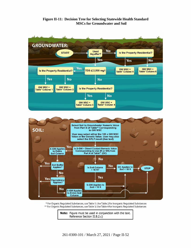
261-0300-101 / March 27, 2021 / Page II-52
Figure II-11: Decision Tree for Selecting Statewide Health Standard
MSCs for Groundwater and Soil
261-0300-101 / March 27, 2021 / Page II-53
(a) Choosing the Soil-To-Groundwater Numeric Value
The remediator should begin by determining the appropriate soil-
to-groundwater numeric value from Part B of Table 3 for organics
or Table 4 for inorganics. The numbers in the table include both
the value which is 100 times the appropriate groundwater MSC
and the number resulting from application of the soil-to-
groundwater equation in the regulations (the “generic value”). The
remediator must determine the use status of the aquifer underlying
the site, its naturally occurring TDS level, and the land use
characteristics of the site. The numeric value may then be selected
from the appropriate column on the table and compared to the
value for the Synthetic Precipitation Leaching Procedure (SPLP),
if appropriate. Since the remediator has the choice of which soil-
to-groundwater numeric value to use, the remediator may choose
the highest of these three values (i.e., 100x GW MSC, the generic
value, or the SPLP result) as the soil-to-groundwater numeric
value. The remediator must keep in mind that for periodically
saturated soils, the generic value to use in this selection process is
one-tenth the value listed in the table (see § 250.308(a)(2)(ii)
and (a)(4)(ii) of the regulations). The intent of the one-tenth of the
generic numeric value provision in the soil-to-groundwater
numeric value calculation is to account for the dilution in
contaminant concentrations that occurs in soils that are periodically
saturated which does not occur in unsaturated soil. For
permanently saturated soils, contamination becomes a groundwater
contamination issue as the soil is in constant contact with the
groundwater rather than being only periodically saturated.
The value for the SPLP is the concentration of a regulated
substance in soil at the site that does not produce a leachate in
which the concentration of the regulated substance exceeds the
groundwater MSC. Values for the SPLP could not be published in
the tables of MSCs in the regulations because this test must be
conducted on the actual site soil. The following procedure should
be used to determine the alternative soil-to-groundwater value
based upon the SPLP:
• During characterization, the remediator should obtain a
minimum of ten samples from within the impacted soil
area. The four samples with the highest total concentration
of the regulated substance should be submitted for SPLP
analysis. Samples obtained will be representative of the
soil type and horizon impacted by the release of the
regulated substance.
• Determine the lowest total concentration (TC) that
generates a failing (leachate concentration greater than the
261-0300-101 / March 27, 2021 / Page II-54
groundwater MSC) SPLP result. The alternative soil-to-
groundwater standard will be the next lowest TC.
• If all samples have a passing (leachate concentration less
than the groundwater MSC) SPLP result, the alternative
soil-to-groundwater standard will be the TC corresponding
to the highest SPLP result. The remediator has the option
of obtaining additional samples.
• If all samples have a nondetect SPLP result, the alternative
soil-to-groundwater standard will be the TC corresponding
to the highest concentration of each contaminant. The
remediator has the option of obtaining additional samples.
• If none of the samples generates a passing SPLP, the
remediator can obtain additional samples and perform
concurrent TC/SPLP analyses to satisfy the above
requirements for establishing an alternative soil-to-
groundwater standard.
(b) Considering Direct Contact Value in Relation to the Soil-to-
Groundwater Value and Soil Depth
The number selected according to the process outlined in
Section II.B.3.b.i of this TGM for the soil-to-groundwater pathway
numeric value must then be compared to the appropriate residential
or nonresidential, surface or subsurface, direct contact numeric
value from Part A of Table 3 or Table 4. The lower of the
two numbers is the appropriate MSC for the regulated substance.
If the soil buffer distance requirements are met or the equivalency
demonstration has been made, then the soil-to-groundwater
numeric value is deemed to be satisfied and the MSC is the
appropriate direct contact numeric value for the regulated
substance. The soil buffer approach incorporates fate and transport
considerations; therefore, meeting the soil buffer requirements will
not require any additional fate and transport analysis.
(c) Selecting Applicable MSCs – Example
The process for selecting the appropriate MSCs for a site is
illustrated in Figure II-12. This figure represents the cross section
of a nonresidential site with soil contaminated with a petroleum
product. The aquifer does not qualify as a nonuse aquifer. The
remediator is interested in determining and applying the soil MSCs
under the SHS. This example shows the process applied to one of
the regulated substances: cumene.
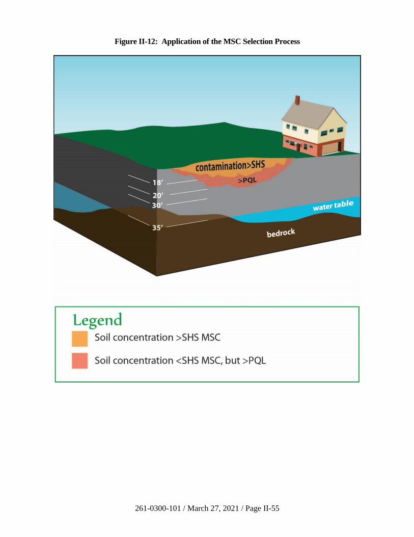
261-0300-101 / March 27, 2021 / Page II-55
Figure II-12: Application of the MSC Selection Process
261-0300-101 / March 27, 2021 / Page II-56
Details of the site determined during the site characterization are as
follows (see also Figure II-12).
• Soil characterized as contaminated with regulated
substances from the petroleum product, including cumene
(concentration values > PQL, see Section III.G), is shown
and extends to a depth of 20 feet. For this example, the
remediator characterized the soil to the level of the PQL,
but could have selected any concentration level between the
SHS and the PQL, with the appropriate justification.
• Soil contaminated at levels greater than the applicable SHS
is shown as a subset of the contaminated area and extends
to a depth of 18 feet.
• Samples collected and analyzed according to the
methodology in Section II.B.2(c)(ii)(a) established an
alternative soil-to-groundwater value of 20 mg/kg.
• SPLP testing of site soil was established at 400 mg/kg.
• Shale bedrock is present at varying depths between 30 and
35 feet.
• The groundwater level is approximately 35 feet, but
fluctuates (annual high and low) between 28 to 40 feet and
the natural total dissolved solids level in the groundwater is
80 mg/L.
• The vertical distance from the bottom of the contaminated
area to groundwater is h = 15 feet.
Scenario #1 - the above conditions apply, and in addition,
the results of sample analysis of the groundwater show no
values greater than 3,500 g/L.
Scenario #2 - the above conditions apply, and in addition,
free floating product (approximately 1 inch) is found on top
of the groundwater level, and the concentration of cumene
below the groundwater level is 5,000 g/L.
261-0300-101 / March 27, 2021 / Page II-57
The remediator takes the following steps to determine appropriate
MSCs for cumene at this site.
Groundwater MSC:
1) For Scenario #1 AND Scenario #2: As a first step, turn to
LRP regulations, Chapter 250, Appendix A, Table 1 -
Medium-Specific Concentrations (MSCs) for Organic
Substances in groundwater. The remediator looks for the
row for cumene, under the headings “Used Aquifers,”
“TDS2500 mg/L,” “NR” (for Nonresidential). The
groundwater MSC is 3,500 g/L.
Under Scenario #1, the remediator concludes that there is
no aquifer area which exceeds the groundwater MSC
(3,500 g/L) and, therefore, no attainment demonstration is
needed.
Under Scenario #2, the remediator concludes that the
aquifer area exceeds the groundwater MSC (3,500 g/L)
and, therefore, attainment demonstration is needed.
Soil MSC:
2) The remediator turns to Chapter 250, Appendix A,
Table 3 – Medium-Specific Concentrations (MSCs) for
Organic Substances in Soil, Part B, Soil to Groundwater
Numeric Values. The remediator looks for the row for
cumene, under the Headings “Used Aquifers,” “TDS
2500 mg/L,” “Nonresidential.” The two values listed are:
• 100x GW MSC – 350 mg/kg
• Generic Value - 2,500 mg/kg
The remediator then looks over to the last column on the
right for the soil buffer distance – 15 feet.
3) The remediator assesses the use of numeric soil-to-
groundwater values. Three options exist under the
regulations (§ 250.308).
• 100x GW MSC – 350 mg/kg
• Generic Value – 2,500 mg/kg
• SPLP value – 400 mg/kg (from analysis of site
soil—see site characterization.
261-0300-101 / March 27, 2021 / Page II-58
Among the three acceptable values, the generic value of
2,500 mg/kg is the highest. The remediator considers using
this option, but first wants to see if the site could qualify for
the remaining two options for satisfying the soil-to-
groundwater numeric value, the soil buffer and
groundwater equivalency options.
4) In examining the soil buffer option, the remediator checks
to see if the site meets the three regulatory conditions under
25 Pa. Code § 250.308(b), which states:
(b) The soil-to-groundwater pathway soil buffer
is the entire area between the bottom of the area of
contamination and the groundwater or bedrock and shall
meet the following criteria:
(1) The soil depths established in
Appendix A, Tables 3B and 4B for each regulated
substance.
(2) The concentration of the regulated
substance cannot exceed the limit related to the PQL or
background throughout the soil buffer.
(3) No karst carbonate formation
underlies or is within 100 feet of the perimeter of the
contaminated soil area. Karst carbonate formations are
limestone or carbonate formations where the formations are
greater than 5 feet thick and present at the topmost geologic
unit. Areas mapped by the Pennsylvania Geologic Survey
as underlain by carbonate formations are considered karst
areas unless geologic studies demonstrate the absence of
the formations underlying or within 100 feet of the
perimeter of the contaminated soil area.
Scenario #1 - The remediator concludes that the site meets
the conditions for use of the soil buffer alternative to satisfy
the soil-to-groundwater numeric value and, therefore, only
the direct contact numeric value applies and becomes the
soil MSC for cumene.
Alternatively, the remediator could have considered use of
the groundwater equivalency option [§ 250.308(d)], but this
includes the condition that he/she monitor the groundwater
for 8 quarters prior to submitting the final report. The
remediator instead chooses the soil buffer option above.
261-0300-101 / March 27, 2021 / Page II-59
Scenario #2 - The remediator concludes the site DOES
NOT meet the conditions for use of the soil buffer
alternative because h=0 since soil contamination extends to
the water level and, therefore, there is no depth of clean soil
between the bottom of contamination and the groundwater
level.
The remediator then checks to see if the site meets the
requirements for use of the groundwater equivalency
option. (25 Pa. Code § 250.308(d) and Section II.B.6(d) of
the Technical Manual). The site does NOT qualify because
groundwater is contaminated above SHS and background.
Therefore, the remediator should consider BOTH the soil-
to-groundwater numeric value and the direct contact (DC)
value.
Chapter 250, Appendix A, Table 3A—Medium-Specific
Concentrations (MSCs) for Organic Regulated Substances
in Soil, Direct Contact Numeric Values states that the
nonresidential numeric value for cumene is:
10,000 mg/kg applied to the 0’-2’ zone in soil
10,000 mg/kg applied to the 2’-15’ zone in soil.
The remediator chooses the soil-to-groundwater numeric
value based on the generic value of 2,500 mg/kg, which
applies to the zone(s) of the soil contaminated above this
value:
Zone 1—0-18’ (see Figure II-12)
Zone 2 – the “smear zone” in the soil
column created by groundwater level
movement – 28’--40.’ Note that this
zone also is considered saturated soil
under Chapter 250.
Next, the remediator checks to see where each numeric
value is applied:
DC value Soil-to-GW value Resulting Soil MSC
Zone 0’-2’ 10,000 mg/kg 2,500 mg/kg 2,500 mg/kg
Zone 2’-15’ 10,000 mg/kg 2,500 mg/kg 2,500 mg/kg
Zone 15’-18’ NA 2,500 mg/kg 2,500 mg/kg
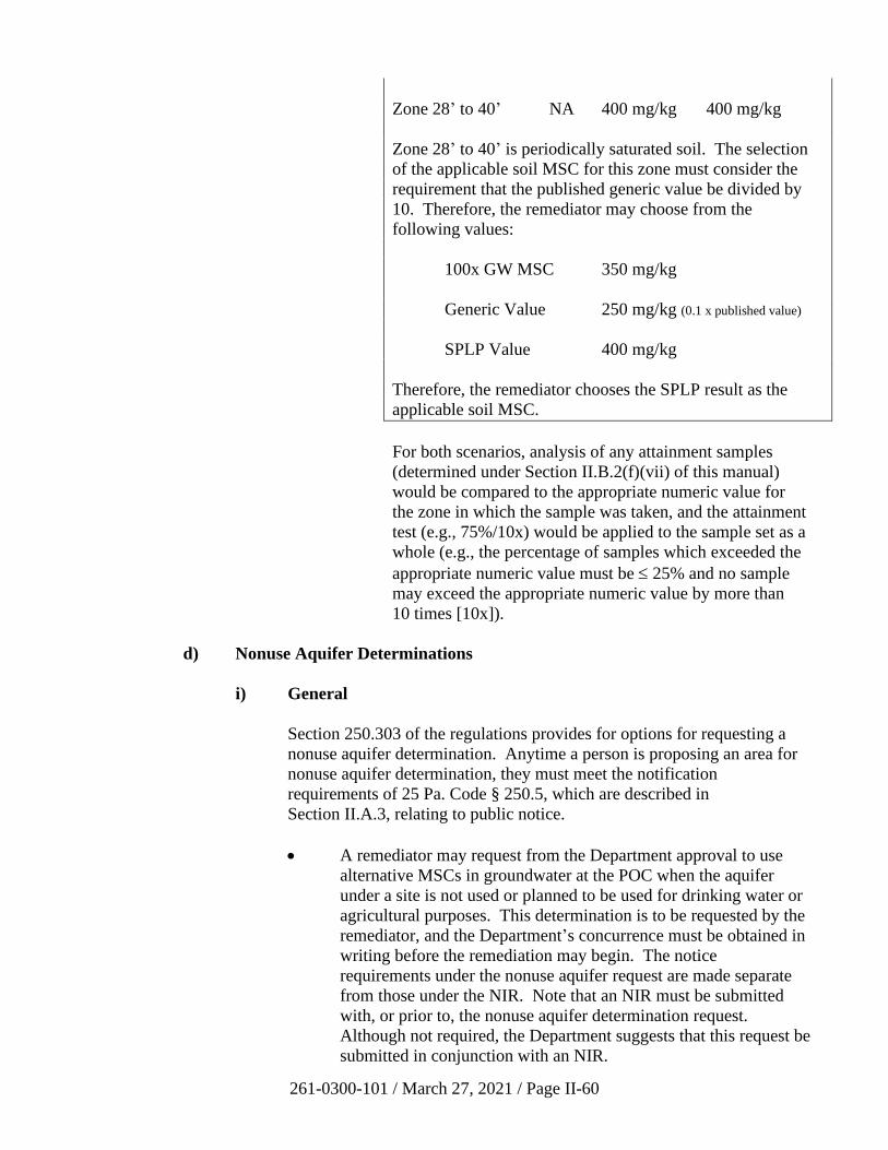
261-0300-101 / March 27, 2021 / Page II-60
Zone 28’ to 40’ NA 400 mg/kg 400 mg/kg
Zone 28’ to 40’ is periodically saturated soil. The selection
of the applicable soil MSC for this zone must consider the
requirement that the published generic value be divided by
10. Therefore, the remediator may choose from the
following values:
100x GW MSC 350 mg/kg
Generic Value 250 mg/kg (0.1 x published value)
SPLP Value 400 mg/kg
Therefore, the remediator chooses the SPLP result as the
applicable soil MSC.
For both scenarios, analysis of any attainment samples
(determined under Section II.B.2(f)(vii) of this manual)
would be compared to the appropriate numeric value for
the zone in which the sample was taken, and the attainment
test (e.g., 75%/10x) would be applied to the sample set as a
whole (e.g., the percentage of samples which exceeded the
appropriate numeric value must be 25% and no sample
may exceed the appropriate numeric value by more than
10 times [10x]).
d) Nonuse Aquifer Determinations
i) General
Section 250.303 of the regulations provides for options for requesting a
nonuse aquifer determination. Anytime a person is proposing an area for
nonuse aquifer determination, they must meet the notification
requirements of 25 Pa. Code § 250.5, which are described in
Section II.A.3, relating to public notice.
• A remediator may request from the Department approval to use
alternative MSCs in groundwater at the POC when the aquifer
under a site is not used or planned to be used for drinking water or
agricultural purposes. This determination is to be requested by the
remediator, and the Department’s concurrence must be obtained in
writing before the remediation may begin. The notice
requirements under the nonuse aquifer request are made separate
from those under the NIR. Note that an NIR must be submitted
with, or prior to, the nonuse aquifer determination request.
Although not required, the Department suggests that this request be
submitted in conjunction with an NIR.
261-0300-101 / March 27, 2021 / Page II-61
A remediator may rely on a “nonuse aquifer certification area” (see
below) as documentation that they have satisfied 25 Pa. Code
§ 250.303(c)(1), (2) and (3) FOR THE SPECIFIC AREA defined
as a “nonuse aquifer certification area.” If the area they are
required to document extends beyond the nonuse aquifer
certification area, the remediator still has the obligation to
document those requirements in the area NOT covered by the
nonuse aquifer certification area.
Another option a remediator may have is using the presence of a
municipal ordinance meeting the performance requirements of
Section III.E (relating to institutional controls and other
postremedial measures) as documentation that the use restriction
meets the requirements of 25 Pa. Code § 250.303(c)(1), (2) and (3)
IN THE AREA SUBJECT TO THE ORDINANCE.
• Municipal authorities and political subdivisions may request
determination that a specific geographic area meets the conditions
of 25 Pa. Code § 250.303(c)(1), (2) and (3). The area in question
is then referred to as a nonuse aquifer certification area.
ii) Request Initiated by a Remediator as Part of an NIR
This option would be used by a remediator who desires to use the
alternative nonuse aquifer MSCs at a specific property. As detailed in
25 Pa. Code § 250.303(b) of the regulations, the area in which the
determination is to be made includes the property itself, all areas within a
radius of 1,000 ft. downgradient of the property boundary, and all areas
where the contamination has migrated, or may reasonably be expected to
migrate, at concentrations exceeding the MSC for groundwater used or
currently planned to be used. In making the request, the remediator should
provide the fate and transport analysis used to determine the area to which
the contamination has migrated and is likely to migrate. The Department
will accept or reject the remediator’s request based primarily upon the
adequacy of this analysis. The area determined is the area of geographic
interest to which the conditions of 25 Pa. Code § 250.303(c) apply. A
form, Request for Nonuse Aquifer Determination, is available on the
Department’s website to be used by a remediator to expedite the
Department’s review of a nonuse aquifer demonstration. Use of this form
is optional.
iii) Nonuse Aquifer Conditions to be Met in the Area of Geographic
Interest
The requirements for demonstrating that an aquifer is not used are
contained in 25 Pa. Code § 250.303(c) of the regulations. The remediator
may make this demonstration by conducting door-to-door surveys of all
downgradient properties or by using other appropriate survey methods,
261-0300-101 / March 27, 2021 / Page II-62
and by contacting all community water suppliers downgradient of the
property for service area information, including plans for future water
supply well development and service area expansion. If all of the
requirements are met, the Department may determine that the aquifer is
not used for drinking water or agricultural purposes. The remediator may
use the MSCs for groundwater in aquifers not used for drinking water or
agricultural purposes in Tables 1 and 2 of Appendix A to the regulations if
the nonuse aquifer determination is made. In some cases, there may be a
significant lapse in time between the nonuse aquifer determination
approval and the submission of the final report. It is the intent of DEP to
ensure that the nonuse aquifer conditions are still representative when the
final report is submitted to the Department. Therefore, at the time the
final report is submitted to the Department for sites which have a nonuse
aquifer determination approval, the DEP may require basic assessment of
any changes which may have taken place since the nonuse aquifer
determination approval was granted. This assessment would be similar to
that applied under the postremediation care plan described below.
A postremediation care plan is required to provide reasonable confidence
that the appropriate geographic area continues to meet the conditions of
25 Pa. Code § 250.303(c) if a final report has been submitted to the
Department which includes the use of a nonuse aquifer area. Typical
elements of such a postremediation care plan, which are relevant to the
nonuse aquifer status, would include review of Department of
Conservation and Natural Resources (DCNR) records to see if any well
drilling reports have been received for the area included in the nonuse
aquifer determination, inquiry to the water supplier of the area to
determine if properties are still being billed for water, or communication
with the municipalities to understand what changes may have taken place
which may have an effect on the water use patterns in the area. The
ecological screening process and the demonstration of compliance with
surface water quality standards continue to apply in the area where the
aquifer is determined not to be used for drinking water or agricultural
purposes. Furthermore, as described in 25 Pa. Code § 250.303(d)(3), an
environmental covenant should include the requirements of the
postremediation care plan. This will ensure that subsequent landowners
are aware of their responsibilities for postremediation care and monitoring.
The postremediation care obligation will continue only until the property
owner demonstrates to the Department, by fate and transport analysis, that
the MSC for groundwater in aquifers used or currently planned for use is
not exceeded at the property boundary and all points downgradient
therefrom.
iv) Request for Certification of a Nonuse Aquifer Area Initiated by a
Local Government
This option would be used by municipal authorities and political
subdivisions which desire to receive certification that a given geographic
area meets the conditions of 25 Pa. Code § 250.303(c) (i.e., nonuse aquifer
261-0300-101 / March 27, 2021 / Page II-63
area conditions) where no specific property to be remediated has been
identified. These conditions are based on 25 Pa. Code § 250.303(f), which
requires an ordinance prohibiting groundwater use and requires every
property to be connected to the public water supply.
v) Example
The following figures illustrate the process for determining the area in
which the conditions of 25 Pa. Code § 250.303(c) must be met for a site to
qualify for a nonuse aquifer designation. The requirements of 25 Pa. Code
§ 250.303(c) must be met “within the site on the property and within a
radius of 1,000 feet downgradient of the points of compliance, plus any
additional areas to which the contamination has migrated and might
reasonably be expected to migrate.”
Figure II-13 shows this area for an idealized site with a property line
parallel to the ground water contour. Note that the area includes, first, all
points within 1,000 feet of all compliance points that are at a lower
groundwater elevation (downgradient) of the property line compliance
point itself, plus any additional area to which the plume has migrated or
may be expected to migrate, as determined by site characterization and
fate and transport analysis.
Figure II-14 shows the screening area for a site where the site
characterization has determined that there is convergent groundwater flow.
In this case the screening area is somewhat smaller than in the first figure
because the area 1,000 feet downgradient (lower groundwater elevation)
from the compliance points is smaller.
Figure II-15 shows the screening area for an idealized site where the site
characterization has determined there is divergent groundwater flow. In
this case the screening area is somewhat larger than the other figures
because the area 1,000 feet downgradient (lower groundwater elevation)
from the compliance points is larger.
In areas with complex groundwater flow or other special features, the
Department should be consulted to determine the appropriate screening
area prior to conducting the required surveys.
e) Ecological Screening
All sites remediated to the SHS must be screened for impacts to the ecological
receptors identified in 25 Pa. Code § 250.311(a). The presence of threatened or
endangered species as, designated by the U.S. Fish and Wildlife Service under the
Endangered Species Act, requires that all requirements of that Act be met in
addition to the requirements of 25 Pa. Code § 250.311. The remediator has the
option of either remediating the site to one-tenth of the applicable Statewide
health MSCs from Tables 3 and 4 of Appendix A to the regulations, as described
in 25 Pa. Code § 250.311(b), or using the ecological screening process described
Source
100 0 ft
100
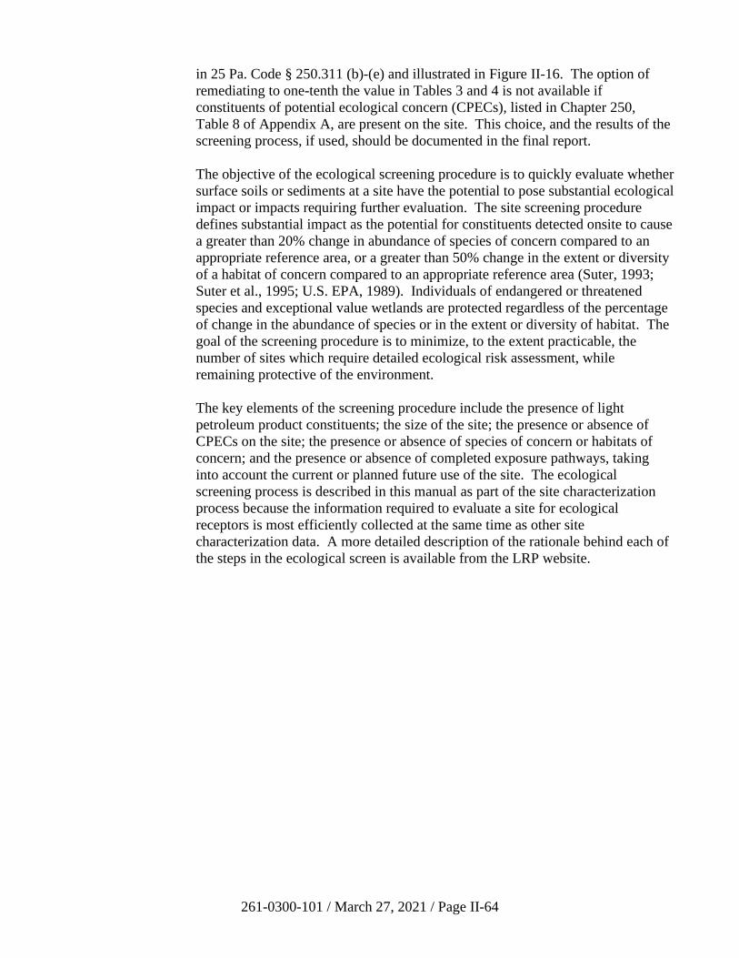
261-0300-101 / March 27, 2021 / Page II-64
in 25 Pa. Code § 250.311 (b)-(e) and illustrated in Figure II-16. The option of
remediating to one-tenth the value in Tables 3 and 4 is not available if
constituents of potential ecological concern (CPECs), listed in Chapter 250,
Table 8 of Appendix A, are present on the site. This choice, and the results of the
screening process, if used, should be documented in the final report.
The objective of the ecological screening procedure is to quickly evaluate whether
surface soils or sediments at a site have the potential to pose substantial ecological
impact or impacts requiring further evaluation. The site screening procedure
defines substantial impact as the potential for constituents detected onsite to cause
a greater than 20% change in abundance of species of concern compared to an
appropriate reference area, or a greater than 50% change in the extent or diversity
of a habitat of concern compared to an appropriate reference area (Suter, 1993;
Suter et al., 1995; U.S. EPA, 1989). Individuals of endangered or threatened
species and exceptional value wetlands are protected regardless of the percentage
of change in the abundance of species or in the extent or diversity of habitat. The
goal of the screening procedure is to minimize, to the extent practicable, the
number of sites which require detailed ecological risk assessment, while
remaining protective of the environment.
The key elements of the screening procedure include the presence of light
petroleum product constituents; the size of the site; the presence or absence of
CPECs on the site; the presence or absence of species of concern or habitats of
concern; and the presence or absence of completed exposure pathways, taking
into account the current or planned future use of the site. The ecological
screening process is described in this manual as part of the site characterization
process because the information required to evaluate a site for ecological
receptors is most efficiently collected at the same time as other site
characterization data. A more detailed description of the rationale behind each of
the steps in the ecological screen is available from the LRP website.
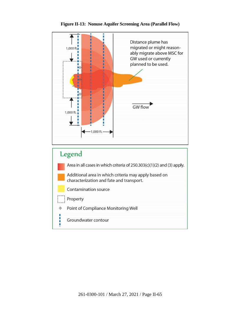
261-0300-101 / March 27, 2021 / Page II-65
Figure II-13: Nonuse Aquifer Screening Area (Parallel Flow)
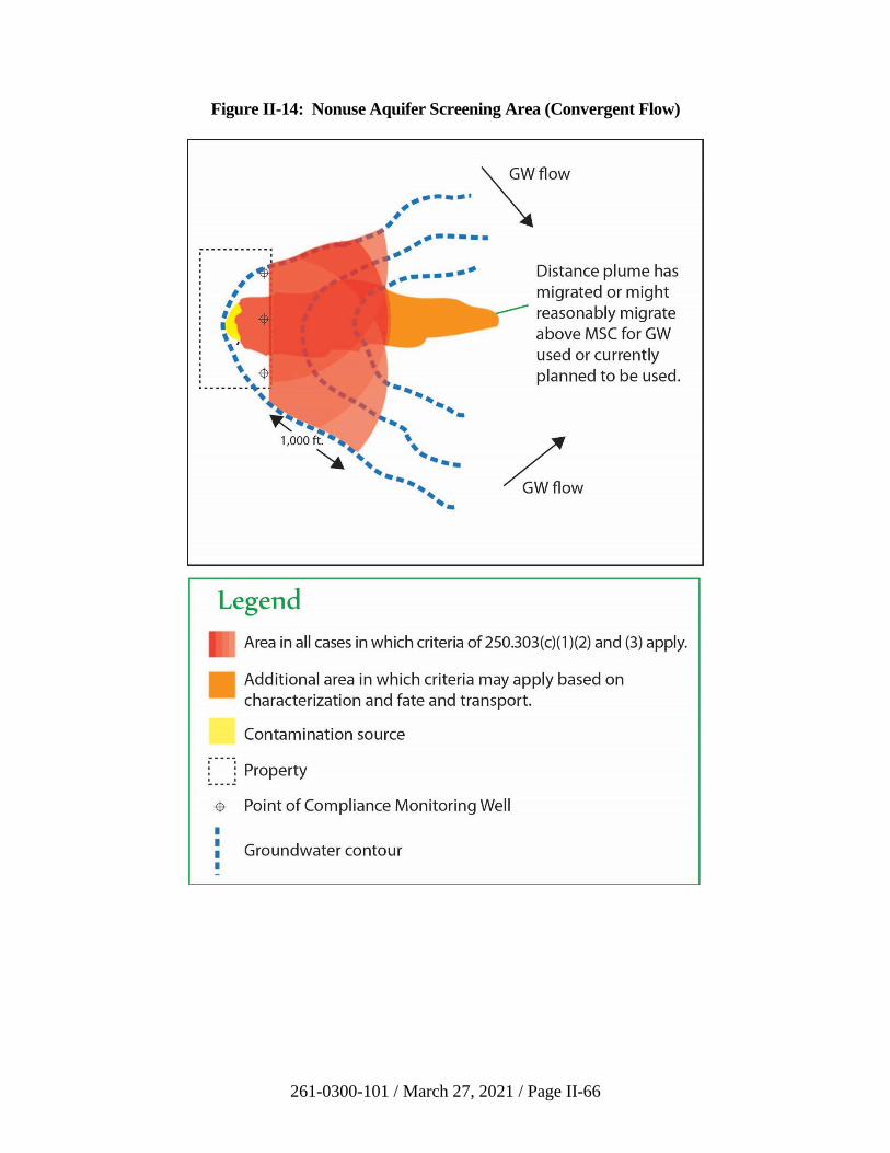
261-0300-101 / March 27, 2021 / Page II-66
Figure II-14: Nonuse Aquifer Screening Area (Convergent Flow)
261-0300-101 / March 27, 2021 / Page II-67
Figure II-15: Nonuse Aquifer Screening Area (Divergent Flow)
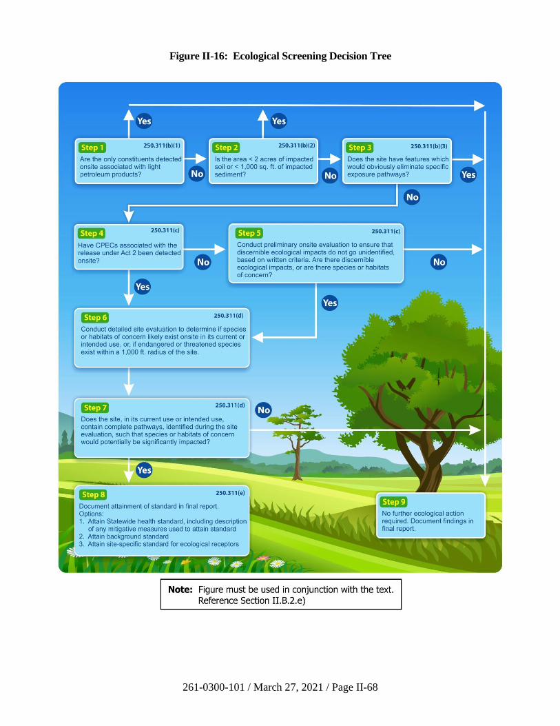
261-0300-101 / March 27, 2021 / Page II-68
Figure II-16: Ecological Screening Decision Tree
261-0300-101 / March 27, 2021 / Page II-69
Regardless of the outcome of the ecological screening, the results are documented
in a written report. It is important to note that if all of the first three steps are not
met, i.e., there is contamination other than light petroleum products; the impacted
area of surface soil is equal to or greater than 2 acres, the impacted area of
sediments is greater than or equal to 1000 square feet; and all pathways are not
obviously eliminated, completion of the site ecological screening process requires
an onsite evaluation. Using a streamlined set of guidelines, this onsite evaluation
is a critical component of the means of identifying those sites that may pose
substantial ecological impacts, and of documenting the lack of ecological impacts
at other sites. Without such a site evaluation, a weight of evidence-based
evaluation cannot be achieved, as required by EPA guidance (e.g., EPA’s
Framework for Ecological Risk Assessment, 1992) and ASTM standards (ASTM
Designation: E1706-95). In addition, this screening procedure is consistent with
the initial steps of EPA’s ecological risk assessment guidelines for contaminated
sites (U.S. EPA, 1997). The remainder of this section discusses each of the steps
of the ecological screening procedure in more detail.
i) Step 1: Presence of Light Petroleum Product Constituents
The first step in the site ecological screening process is to determine
whether the constituents present in surface soils (soils at a depth of up to
two feet) or sediments are related only to light petroleum products (i.e.,
gasoline, jet fuel A, kerosene, #2 fuel oil/diesel fuel), which have
relatively low polyaromatic hydrocarbon (PAH) content (American
Society for Testing and Materials (ASTM) Designation: E1739-95). If
light petroleum product constituents (including benzene, toluene,
ethylbenzene, and xylenes (BTEX)) are the only constituents detected
onsite, then the screening process moves to Step 9 (Final Report - No
Further Ecological Evaluation Required). If constituents in addition to or
other than light petroleum product constituents are present, the screening
process continues to Step 2 (Site Size).
The purpose of this step is to eliminate from further evaluation those sites
at which the only detected constituents are residual compounds from a
release of light petroleum products. In general, remediation of light
petroleum product release sites to prevent substantial ecological impacts is
not required because the SHSs for these compounds are generally
protective of ecological receptors.
ii) Step 2: Site Size
The second step in the ecological screening process is determining the
area of exposed and contaminated surface soil (soils at a depth of up to
two feet) and sediments that are of potential ecological concern. The
minimum areas are 2 acres of exposed and contaminated surface soil, and
1,000 square feet of contaminated sediment.
Sediments are those mineral and organic materials situated beneath an
aqueous layer for durations sufficient to permit development of benthic
261-0300-101 / March 27, 2021 / Page II-70
assemblages. Indicators of benthic assemblages would include
macroscopic algae, aquatic invertebrates, or aquatic plants. The aqueous
layer may be static, as in lakes, ponds, or other water-covered surface
depressions greater than or equal to 1,000 square feet but necessarily
contiguous (excluding permitted open water management units), or
flowing, as in rivers and streams located on a site (U.S. EPA, 1993b; U.S.
EPA, 1991a).
If a site exceeds these specified minimum areas, then the screening
process continues to Step 3 (Obvious Pathway Elimination). If the area of
the site is smaller than the specified minimum areas, then the screening
process moves to Step 9 (Final Report - No Further Ecological Evaluation
Required).
iii) Step 3: Obvious Pathway Elimination
The third step accounts for those sites where features such as buildings,
paving, or other development of the site are sufficiently extensive as to
eliminate specific exposure pathways to ecological receptors. This
primarily applies to sites in heavily industrialized or otherwise developed
areas such that habitats or species of concern could not occur onsite or
within a reasonable distance. Any site with features that obviously
eliminate exposure pathways will drop out of the screening process at this
point and proceed to Step 9 (Final Report - No Further Ecological
Evaluation Required).
iv) Step 4: Presence of Constituents of Potential Ecological Concern
The fourth step in the ecological screening process is the determination of
whether any of the constituents detected at the site and related to releases
at the site are considered to be CPECs. CPECs are identified in
Chapter 250, Table 8 of Appendix A..
In this and the following step, available site information would be
reviewed to determine if CPECs are likely to have been released into the
environment. If CPECs are not detected at the site, then the screening
process continues to Step 5 (Preliminary Onsite Evaluation). If one or
more CPECs, either individually or in combination, are detected at the
site, then the screening process moves to Step 6 (Detailed Onsite
Evaluation and Identification of Species and Habitats of Concern).
The ecological evaluation process that has been developed includes
additional evaluation criteria for sites where CPECs are not found. Step 5
is an evaluation of adverse chemical effects that may result from regulated
substances other than CPECs, and as such reduces the probability that
substantive adverse environmental impacts will go undetected. Also,
surface water regulations and standards will remain applicable to those
sites, adding to the overall protection of the environment at any site, as
261-0300-101 / March 27, 2021 / Page II-71
will other regulations applicable to species of concern, such as the
Endangered Species Act.
v) Step 5: Preliminary Onsite Evaluation
Prior to performing onsite evaluations, it is recommended that remediators
perform internet-based habitat and species of concern searches using
online tools such as the Pennsylvania Natural Heritage Program’s PNDI
and the U.S. Fish and Wildlife Service’s National Wetlands Inventory
(NWI) mapper. The fifth step of the site ecological screening process is a
preliminary onsite evaluation, to be conducted by a qualified
environmental scientist (common practice would use a person with a
bachelor’s degree in an environmental science field and 5 years of
experience in an environmental field), using the criteria presented in this
guidance. If, after conducting the preliminary onsite evaluation, the
qualified environmental scientist determines that substantial ecological
impacts are not probable or evident based on the weight of evidence
available for the site, the screening process moves to Step 9 (Final
Report – No Further Ecological Evaluation Required). It must also
document the presence of any endangered or threatened species within a
radius of 2,500 ft. of the site or exceptional value wetlands onsite. If after
conducting the preliminary onsite evaluation, the qualified environmental
scientist determines that substantial ecological impacts or impacts
requiring further evaluation are or may be present, the screening process
continues to Step 6 (Detailed Onsite Evaluation and Identification of
Species and Habitats of Concern).
The objective of the ecological evaluation conducted during the
preliminary onsite evaluation is to ensure that ecological impacts resulting
from regulated substances which are not CPECs are detected. The
preliminary onsite evaluation involves three steps:
1. Review of readily available site information, including the
operational history, chemicals used, and probable sources of
releases of regulated substances; and, environmental setting with
emphasis on physical, chemical and biological factors that would
influence the nature and extent of contamination.
2. A preliminary onsite investigation to identify physical and habitat
features of the area and to identify nearby reference areas without
contamination (if available) that are outside of the probable site
(area of contamination associated with a particular release). The
following should be noted during the evaluation:
• signs of stressed or dead vegetation (e.g., chlorotic
vegetation),
• discolored soil, sediment or water (i.e., a sheen),
261-0300-101 / March 27, 2021 / Page II-72
• presence of non-native materials in sediments resulting
from seeps or other discharges emanating from the subject
site,
• presence of deformed organisms (if encountered),
• presence of exceptional value wetlands,
• presence of federally designated threatened or endangered
species.
3. Preparation of a brief written summary of findings including
sketches of the suspected area of contamination and reference
areas. To the extent practicable, differences of greater than 50% in
the density of species of concern or in the diversity and extent of
habitats of concern shall be regarded as potentially substantive
(Suter, et al., 1995; U.S. EPA, 1989). However, the presence of
federally endangered or threatened species within a 2,500-ft. radius
of the site or exceptional value wetlands onsite would trigger
further evaluation.
Based on all of the information collected as part of the preliminary onsite
evaluation, the investigator makes a determination as to whether
substantial ecological impacts exist or are probable even though CPECs
were not detected on the site. The conclusion, which documents the
weight of evidence from the onsite evaluation, is summarized in bulleted
format.
vi) Step 6: Detailed Onsite Evaluation and Identification of Species and
Habitats of Concern
The sixth step in the ecological screening process is a detailed onsite
evaluation and a determination of whether species or habitats of concern
exist on the site or, for endangered and threatened species, if those species
exist on the site or within a 2,500-foot radius of the border of the site in its
current or intended use or if exceptional value wetlands exist onsite.
Species of concern are identified in the PNDI on the PA DCNR webpage.
If, during the detailed onsite evaluation, no species or habitats of concern
are identified on the site, no threatened or endangered species exist within
a 2,500-ft. radius of the border of the site, and no exceptional value
wetlands occur onsite, the screening process moves to Step 9 (Final
Report – No Further Ecological Evaluation Required). If species or
habitats of concern are identified on the site, the screening process
continues to Step 7 (Identification of Completed Exposure Pathways).
Identification of species and habitats of concern requires a detailed onsite
evaluation. Common practice is to have a certified ecologist, or a trained
environmental biologist perform this evaluation. At a minimum, the
person conducting the detailed onsite evaluation should be a certified
261-0300-101 / March 27, 2021 / Page II-73
ecologist or hold a college degree in ecology or environmental science and
have at least 5 years of experience conducting ecological field work and
risk assessments.
The objective of the detailed onsite evaluation is to identify species or
habitats of concern and to make observations that will permit a
determination of whether complete exposure pathways are present at the
site, as required by Step 7 of the ecological screening process. If the
detailed onsite evaluation is being conducted as the result of potential
impacts being identified during a preliminary onsite evaluation, the
information from the preliminary onsite evaluation may be used at this
stage where the information requested duplicates efforts of the previous
evaluation. However, depending on the nature of the particular site, it
may be necessary to supplement this previously developed information.
The detailed onsite evaluation has the following components:
1. Review of readily available site background information including:
• operational history, chemicals used, and probable sources
of releases of CPECs,
• environmental setting with emphasis on physical, chemical
and biological factors that would influence the nature and
extent of contamination, and
• readily available literature and other relevant documents
related to recognition of species and habitats of concern,
including endangered and threatened species.
2. The qualified investigator shall conduct the following evaluation:
• complete an onsite investigation to identify physical and
habitat features of the area, then identify nearby reference
areas, if available, which are outside of the probable site
(area of contamination associated with a particular
property),
• qualitatively evaluate whether species or habitats of
concern are present at the site and in the reference area, and
• in comparison to reference areas, the qualified investigator
shall evaluate the following to the extent that they can be
readily evaluated at a site:
− signs of stressed or dead vegetation (e.g., chlorotic
vegetation),
− discolored soil, sediment, or water,
261-0300-101 / March 27, 2021 / Page II-74
− presence of non-native materials in sediments
resulting from seeps or other discharges emanating
from the subject property,
− community composition differences readily
distinguished by U.S. EPA protocols such as the
Rapid Bioassessment procedures (U.S. EPA, 1989),
− absence of biota (especially keystone species and
ecological dominants) compared with similar areas
of the same system,
− presence of non-native or exotic species compared
with reference areas (e.g., Phragmites),
− presence of deformed organisms (if encountered),
and
− potential for residual contamination of habitats of
concern and areas utilized by species of concern.
3. A brief written summary of findings including sketches of the
suspected area of contamination and reference areas. Differences
of greater than 20% in the density of species of concern or greater
than 50% in the diversity or the extent of habitats of concern shall
be regarded as potentially substantive (Suter, 1993; Suter, et al.,
1995; U.S. EPA, 1989). However, the presence of exceptional
value wetlands or federally designated endangered or threatened
species would trigger further evaluation.
4. The site ecological screening process defines as species of concern
those that have been designated as either of special concern,
endangered, threatened or candidate by the Pennsylvania Game
Commission, Pennsylvania Fish & Boat Commission, and the
DCNR Bureau of Forestry. Links to current lists of such species
are summarized on their respective webpages.
5. The ecological screening process defines as habitats of concern:
• typical wetlands with identifiable function and value,
except for exceptional value wetlands, as defined by
DCNR,
• breeding areas for species of concern,
• migratory stopover areas for species of concern (e.g.,
migrant shorebirds, raptors or passerines),
261-0300-101 / March 27, 2021 / Page II-75
• wintering areas for species of concern,
• habitat for State endangered plant and animal species,
• Federal, State, and local parks and wilderness areas,
• areas designated1 as wild, scenic, recreational, and
• areas otherwise designated as critical or of concern by the
Pennsylvania Game Commission, Pennsylvania Fish &
Boat Commission, and DCNR.
vii) Step 7: Identification of Completed Exposure Pathways
The seventh step in the ecological screening process is a determination of
whether a completed exposure pathway from CPECs to species or habitats
of concern exists at the site in its current or intended use. The existence of
a completed exposure pathway2 is determined during the detailed onsite
evaluation, as described above for Step 6. Note that the CPECs in soil
beneath a paved parking lot or below the root zone (top two feet) are not
accessible to most species and habitats of concern, and therefore this
pathway is classified as incomplete. If a complete pathway exists at the
site, then the screening process moves to Step 8 (Attainment of Standard
and Mitigative Measures). If no complete exposure pathways are
identified during the detailed site evaluation, then the screening process
continues to Step 9 (Final Report – No Further Ecological Evaluation
Required).
viii) Step 8: Attainment of Standard and Mitigative Measures
If the results of Steps 1 through 7 above do not result in the site being
eliminated from further ecological consideration, the person conducting
the remediation must demonstrate one of the following:
• attainment of the SHS is protective of ecological receptors,
• if the remediator cannot demonstrate that the SHS MSCs are
protective of ecological receptors, the person shall demonstrate
either that the postremedy use will result in the elimination of all
complete exposure pathways at the time of the final report, or in
accordance with a postremediation care plan, or that mitigative
measures have been implemented and a postremediation care
program has been instituted,
1 as defined by guidance. 2 Exposure pathway - the course a regulated substance(s) takes from the source area(s) to an exposed organism of a species of concern
including absorption or intake into the organism. Each complete exposure pathway must include a source or release from a source, a point
of exposure, and an exposure route into the organism. The mere presence of a regulated substance in the proximity of a receptor does not
constitute a completed pathway. The receptor of concern must contact the regulated substance in such a way that there is high probability
that the chemical is absorbed into the organism (ASTM E1739-95; modified to accommodate provisions of Act 2).
261-0300-101 / March 27, 2021 / Page II-76
• attainment of the background standard, or
• that the procedures of 25 Pa. Code § 250.402(c) and 250.409 and
Sections II.B.3 and III.H. of this manual have been followed to
demonstrate attainment of a site-specific standard for protection of
ecological receptors.
Mitigative measures that may be used to demonstrate attainment of the
SHS are identified in Section 25 Pa. Code 250.311(f). These mitigative
measures may only be used if no exceptional value wetlands have been
identified by the screening process, and no state or federal laws or
regulations prohibit the destruction of the habitats or species identified in
the screening process.
The following mitigative measures may be used, and in the indicated order
of preference:
• Restoration onsite of species and habitats identified in the
screening process.
• Replacement onsite of species and habitats identified in the
screening process.
• Replacement on an area adjacent to the site of species and habitats
identified in the screening process.
• Replacement at a location within the municipality where the site is
located of species and habitats identified in the screening process.
The Department shall review and approve any proposed mitigative
measures prior to implementation to ensure that the intended use of the
site minimizes the impact to ecological receptors identified in the
screening process. In addition, the postremediation care plan requirements
in 25 Pa. Code § 250.312(e) or 250.411(f) and Section III.D of this manual
must be implemented.
ix) Step 9: Final Report - No Further Ecological Evaluation Required
The ninth step of the ecological screening process requires that a report be
written documenting the findings of the completed steps of the screening
process, the basis for the conclusion that a substantial ecological impact
does not exist, and that further ecological evaluation is not required. The
conclusion that substantial ecological impact does not exist is based on
one of the following:
• The presence of light petroleum-related constituents only (findings
from Step 1).
261-0300-101 / March 27, 2021 / Page II-77
• The area of impacted surface soil or sediment is less than the
minimum size criterion (findings from Steps 1 and 2).
• All pathways are obviously eliminated by specific site features
(findings from Steps 1 through 3).
• No CPECs are present onsite and the preliminary site evaluation
indicates that substantial ecological impacts have not been
overlooked (findings from Steps 1 through 5).
• No species or habitats of concern, threatened or endangered
species, or exceptional value wetlands were identified on the site
during the detailed site evaluation (findings from Steps 1 through
6).
• No complete exposure pathways from CPECs or other
contaminants onsite to species or habitats of concern were
identified during the detailed site evaluation (findings from Steps 1
through 7).
• Complete exposure pathways from CPECs or other contaminants
onsite to species or habitats of concern were identified, but no
significant impacts were observed during the detailed site
evaluation.
f) Final Report Requirements for the Statewide Health Standard
To receive the liability protection afforded under Chapter 5 of Act 2 for sites
remediated under the SHS, the remediator shall submit a final report to the
Department which documents attainment of the standard. Section 250.312 of the
regulations discusses final report requirements.
The final report shall be prepared in accordance with scientifically recognized
principles, standards, and procedures. The report should present a thorough
understanding of the site conditions. It should provide a detailed discussion on
the areas for concern and a conceptual site model based on the results of the site
work. The report should support interpretations and conclusions with data
collected during all of the investigations at the site. The level of detail in the
investigation and the methods selected shall sufficiently define the rate, extent and
movement of contaminants to assure continued attainment of the remediation
standard. All interpretations of geologic and hydrogeologic data shall be prepared
by a professional geologist licensed in Pennsylvania.
Two copies of the final report should be submitted to the Department for review.
One should be a paper copy, and the other copy may be submitted in another
format (CD, flash drive, etc.). The final report must include the information in
Table II-2, and the organization shown in the following outline is preferred:
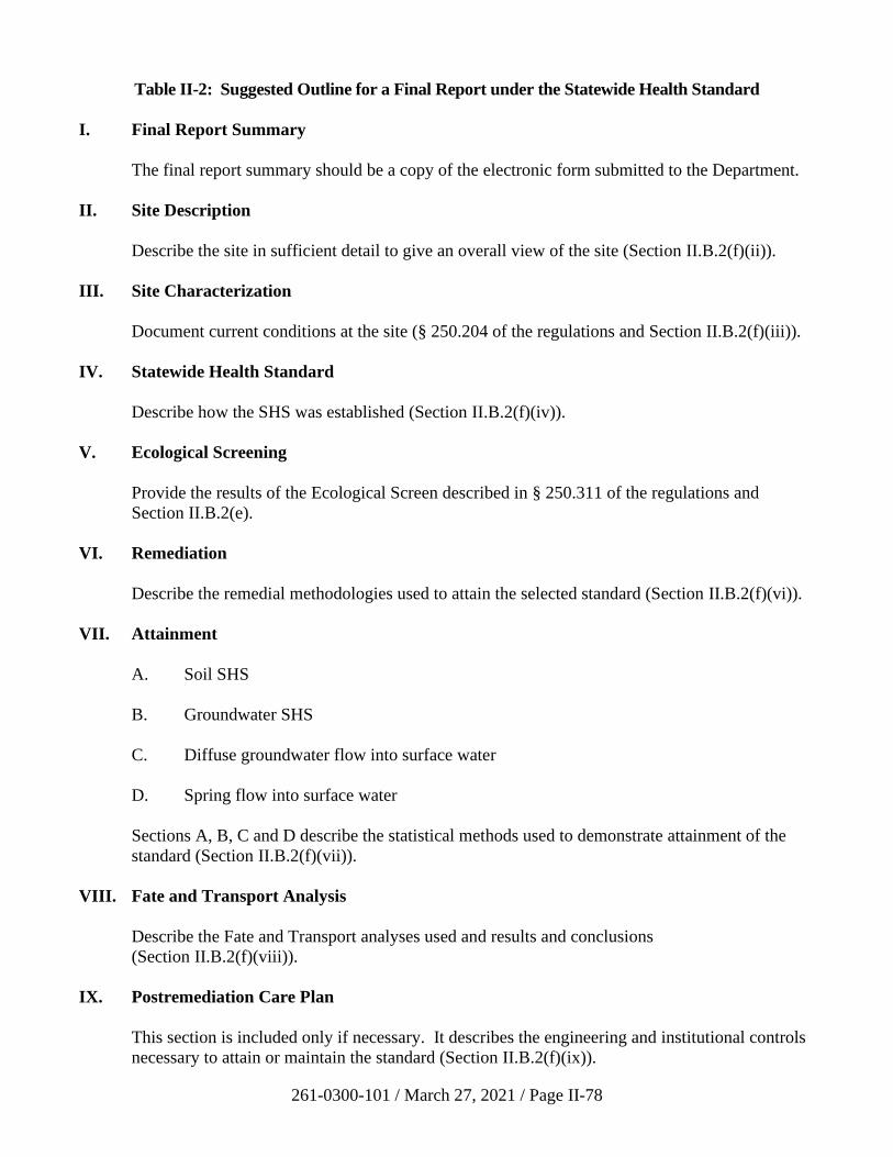
261-0300-101 / March 27, 2021 / Page II-78
Table II-2: Suggested Outline for a Final Report under the Statewide Health Standard
I. Final Report Summary
The final report summary should be a copy of the electronic form submitted to the Department.
II. Site Description
Describe the site in sufficient detail to give an overall view of the site (Section II.B.2(f)(ii)).
III. Site Characterization
Document current conditions at the site (§ 250.204 of the regulations and Section II.B.2(f)(iii)).
IV. Statewide Health Standard
Describe how the SHS was established (Section II.B.2(f)(iv)).
V. Ecological Screening
Provide the results of the Ecological Screen described in § 250.311 of the regulations and
Section II.B.2(e).
VI. Remediation
Describe the remedial methodologies used to attain the selected standard (Section II.B.2(f)(vi)).
VII. Attainment
A. Soil SHS
B. Groundwater SHS
C. Diffuse groundwater flow into surface water
D. Spring flow into surface water
Sections A, B, C and D describe the statistical methods used to demonstrate attainment of the
standard (Section II.B.2(f)(vii)).
VIII. Fate and Transport Analysis
Describe the Fate and Transport analyses used and results and conclusions
(Section II.B.2(f)(viii)).
IX. Postremediation Care Plan
This section is included only if necessary. It describes the engineering and institutional controls
necessary to attain or maintain the standard (Section II.B.2(f)(ix)).

261-0300-101 / March 27, 2021 / Page II-79
X. References
(Section II.B.2(f)(x))
XI. Attachments
(Section II.B.2(f)(xi))
XII. Signatures
(Section II.B.2(f)(xii))
261-0300-101 / March 27, 2021 / Page II-80
i) Summary
The Final Report Summary form is to be filled in and submitted to the
Department electronically. The summary submitted with the final report
should be a copy of that completed electronic form.
ii) Site Description
Provide a description of the site in sufficient detail to give the reviewer an
overall understanding of the site and its location and the types of
operations that are currently and were formerly conducted on the site. The
description should include location, physical description of the property,
ownership history, site use history, and regulatory action history (past
cleanups) as appropriate to the site.
iii) Site Characterization
The site characterization provides important information documenting the
current conditions at the site, information required by 25 Pa. Code
§ 250.312, and information required for the proper demonstration of
attainment. Information developed during site characterization is
primarily intended to describe the nature, extent and potential for
movement of all contaminants present on the site or that may have
migrated from the site; the information is also used as input for developing
a conceptual site model and for the fate and transport analysis. For sites
where there are multiple distinct areas of contamination, the site
characterization process should be applied to each area individually.
Along with a narrative, the results from the site characterization and all
sampling and analysis work should be provided on map(s) illustrating, to
the extent possible, the interrelationship of the following:
• All physical site characteristics.
• All groundwater, soil, sediment and other sample locations,
including sample depth and contaminant concentration.
• The surveyed locations for all assessment structures (monitoring
wells, soil borings, test pits, etc.). All elevations should be
reported in reference to mean sea level (msl), where practical.
• Appropriate number of stratigraphic cross sections that adequately
depict site stratigraphy, well locations, well depths, groundwater
flow directions, equipotential lines, flow lines, hydraulic
conductivity intervals and values, sampling intervals and
concentrations. All elevations should be reported in reference to
msl, where practical.
261-0300-101 / March 27, 2021 / Page II-81
• Variation in potentiometric surfaces(s), potentiometric surface
map(s), hydraulic gradients, and groundwater flow directions.
• All identified sources of releases.
• The extent and concentrations of contaminant plumes in all media.
The horizontal and vertical extent of contaminant plumes including
density and thickness of any SPL present.
• Top of bedrock contour (if encountered).
A conceptual site model should be developed and refined as information is
gathered during the site characterization. The conceptual site model
provides a description of the site and extent of contamination.
Recommended information and data used to develop the site model
include:
• The type, estimated volume, composition, and nature of the
released materials, chemicals or chemical compounds (include all
calculations and assumptions).
• Source(s) and extent of release(s).
• Background concentrations for constituents of concern.
• The horizontal and vertical extent of contamination.
• The portion of the horizontal and vertical extent of contamination
which exceeds the selected standard.
• Affected aquifer(s) or water bearing formation(s)/member(s),
hydrostratigraphic units.
• All existing and potential migration pathways.
• The estimated volume of contaminated soil and water (include all
calculations and any assumptions).
For soils, include information on samples and measurements used to
characterize the horizontal and vertical extent of contamination, and
direction and rate of contaminant movement based on factors in the soil
and the contaminant which affect migration. Soil and boring descriptions
should be included as an attachment.
For groundwater, include information on samples and measurements used
to characterize the horizontal and vertical extent of contamination and
direction and velocity of contaminant movement based on factors of the
groundwater and the contaminant(s) which affect migration. Geologic
261-0300-101 / March 27, 2021 / Page II-82
boring descriptions and as-built drawings of wells should be included as
an attachment. Text, tables, graphics, figures, maps, and cross sections, as
appropriate, can be utilized to describe the nature, location, and
composition of the regulated substances at the site. Providing the data in
an appropriate format will expedite the review of the report.
iv) Selection of the Applicable Statewide Health Standard
Documentation of the basis for selecting residential or nonresidential
standards and for selecting the applicable MSCs according to the
procedure in Section II.B.2(c) of this manual should be included in this
section of the final report.
If the site is in an area where groundwater is not used or planned to be
used for drinking water or agricultural purposes, provide the following
documentation:
• That no groundwater derived from wells or springs is used or
currently planned to be used for drinking water or agricultural
purposes.
• That all downgradient properties are connected to a community
water system.
• That the nonuse area does not intersect a radius of 0.5 mile from a
community water supply well and does not intersect an area
designated by the Department as a Zone 2 wellhead protection area
as established under Chapter 109.
• Results of the fate and transport analysis used to establish the
nonuse area.
• A copy of the letter from the Department approving the use of the
nonuse aquifer MSCs, as described in Section II.B.2(d) of this
manual.
If the soil buffer option is used to meet the requirements of the soil to
groundwater numeric value, submit the following:
• Information demonstrating that the actual site soil column
thickness below the contaminated soil is at least the thickness
identified in Tables 3B and 4B of Appendix A to the regulations.
This information should be taken from soil sample borings
conducted during the site characterization.
• Laboratory analyses demonstrating that the contaminant
concentrations in the entire soil column below the contaminated
zone do not exceed either the limit related to the PQL or
background.
261-0300-101 / March 27, 2021 / Page II-83
• The boring logs and all other data presented in appropriate maps,
cross sections, figures, and tables.
If an equivalency demonstration is used to meet the requirements of the
soil-to-groundwater numeric value, submit the following:
• Information describing the actual site soil column below the
contaminated soil. This information should be taken from soil
sample borings conducted during the site characterization.
• Information, including laboratory analyses, gathered during the site
characterization that demonstrates that the groundwater is not
impacted at levels exceeding either the groundwater MSC or
background.
• The boring logs and all other data presented in appropriate maps,
cross sections, figures, and tables.
• Sampling data, in a tabular format, that shows no exceedance for
eight quarters of groundwater MSCs or the background standard,
in accordance with 25 Pa. Code § 250.308(d)(2).
• Results of the fate and transport analysis that demonstrate that the
regulated substance(s) will not migrate to bedrock or the
groundwater within 30 years at concentrations exceeding the
greater of the groundwater MSC or background in groundwater as
the end point in soil pore water directly under the site.
v) Ecological Screening
Provide documentation of the implementation of the ecological screen
described in 25 Pa. Code § 250.311 and Section II.B.2(e) of this manual.
vi) Remediation
Remediation should be planned to remediate all areas to the selected
standard.
Provide a description of the remedial methodologies used to remediate that
portion of the contamination which exceeds the selected standard as
determined by the site characterization. Examples of the types of
information typically included in this section include:
• Identification of areas remediated based on results of site
characterization.
• Descriptions of treatment, removal, or decontamination procedures
performed in remediation. Description of removal, what was
261-0300-101 / March 27, 2021 / Page II-84
removed, and amount removed. Results of any treatability, bench
scale, or pilot scale studies or other data collected to support the
remedial action(s).
• Description of treatment technologies.
• Description of the methodology and analytical results used to
direct the remediation and determine the cessation of remediation.
This description should document how the remediator determined
that remediation was performed to address all areas known to
exceed the standard.
• Documentation of handling of remediation wastes in accordance
with applicable regulations.
• Specific characteristics of the site that affected the implementation
or effectiveness of the remedial action including such
characteristics as topography, geology, depth of bedrock,
potentiometric surfaces, and the existence of utilities.
• All other site information relevant to the conceptual design,
construction, or operation of the remedial action.
In addition to the above, this section should also include the calculation of
the mass of contaminants addressed during the remediation of soil and/or
groundwater, using the methodology in Section III.C.
Remediation of surface water will typically be accomplished by
eliminating or reducing the discharge of regulated substances into surface
water to the level where surface water quality standards are being
achieved. Given that the usual source of regulated substance discharge to
surface water will be via non-point source groundwater discharge, the
measures necessary to attain the surface water standard should be
incorporated into the design of any groundwater remediation system.
Abatement of air quality discharges associated with the remediation (e.g.,
vapor discharges from air stripping towers) shall be handled in accordance
with the applicable air quality statutes and regulations.
During the implementation of any remediation plan, appropriate record
keeping must be performed to provide ample documentation of the
remedial actions taken, any changes made from the preplanned activities,
and any sampling performed as field controls during implementation.
vii) Attainment
Provide documentation that the remediation has attained the selected
standard at the POC and that the standard will not be violated in the future
as a result of remaining contamination. The demonstration of attainment,
261-0300-101 / March 27, 2021 / Page II-85
like the site characterization, should be applied to each distinct area of
contamination. Attainment must meet the requirements of Chapter 250
Subchapter G (Demonstration of Attainment).
If the Statewide health standard is numerically less than the background
standard, the remediator may elect the background standard, and
attainment of the background standard should be demonstrated according
to Section 302 of Act 2.
(a) Point of Compliance
(i) Groundwater
The POC for groundwater under SHS is the property
boundary. Under certain circumstances the POC may be
moved, as described below. Prior approval from the
Department to move the POC is required.
The remediator may request the movement of the POC for
situations described in § 250.302(a) of the regulations. If
any of those conditions exist, the remediator must request,
in writing, that the Department approve moving the POC.
The Department will respond in writing to the request, and
the response must be obtained before the adjusted POC
may be used and the final report submitted.
For substances with a Secondary Maximum Contaminant
Level (SMCL) established by EPA under the National
Secondary Drinking Water Regulations, the remediator
may request that the POC be moved for those substances
with SMCLs. The Department will consider moving the
POC in a range anywhere from the property boundary up to
the point of use. Therefore, demonstration of attainment at
a site may involve POCs for SMCLs which are different
from the POCs applicable to the other identified regulated
substances.
(ii) Soil
The POC for soil is the entire area of contamination.
Demonstration of attainment of the appropriate standard is
to be made in the entire volume shown in the site
characterization to be contaminated by regulated substances
at concentrations exceeding the SHS. Some sites may have
different SHS values for varying depths or conditions of
soil. For example, on a nonresidential site, if the soil-to-
groundwater numeric value is lower than the direct contact
number, there may be one standard for the 0-2 foot interval,
another for the 2-15 foot interval, and a third for the soil at
261-0300-101 / March 27, 2021 / Page II-86
depths greater than 15 feet. In addition, if any of these
depths are in the periodically saturated zone, the
appropriate standard may be different because of the
requirement for reducing the generic value of the soil-to-
groundwater numeric value by a factor of 10 (see
Section II.B.2(c)(ii)(a)). For the purpose of demonstrating
attainment, the saturated zone is considered to extend
below the seasonal high water table level.
(iii) Spring flow into surface water
Unless an NPDES permit is required for purposes of
complying with surface water quality in a spring, the POC
is the point of first designated or existing use as defined in
25 Pa. Code §§ 93.1, 93.4, and 93.9. This could mean right
by the spring itself or some point downstream from the
spring discharge. Determining the point of first designated
use is necessary because it establishes the point where
Chapter 93 water quality standards apply.
Technical guidance to determine point of first use is found
in Policy and Procedure for Evaluating Wastewater
Discharges to Intermittent and Ephemeral Streams,
Drainage Channels and Swales, and Storm Sewers, DEP
document # 391-2000-014, revised April 2008. In essence
this guidance relies on biological techniques to determine
the first downstream point where aquatic life can be
documented. It applies to both perennial and intermittent
streams with definable bed and banks, but not to ephemeral
streams, that is, areas of overland runoff which occur only
during or immediately following rainfall events and where
there is no defined stream channel and stream substrate.
(b) Statistical Tests
Attainment tests appropriate for SHS are described in 25 Pa. Code
§ 250.707(b) and in Section III.B of this manual and include:
• The 75%/10x rule for soil and groundwater at the POC, and
the 75%/2x rule for groundwater off the property.
• For groundwater, no exceedance of SHS.
• The 95% upper confidence limit (UCL) test.
• For sites that are remediated without prior full site
characterization, a “no exceedance” of SHS.
261-0300-101 / March 27, 2021 / Page II-87
• A method that meets the performance requirements of
25 Pa. Code § 250.707(d).
If the 75%/10x rule is not used, appropriate statistical tests must be
employed to demonstrate attainment of SHS. The following
information should be documented in a final report:
• Description of the statistical method, and the underlying
assumptions of the method.
• Documentation showing that the sample data set meets the
underlying assumptions of the method and explaining why
the method is appropriate to apply to the data.
• Specification of false positive rates.
• Documentation of input and output data for the statistical
test, presented in table and figures, or both, as appropriate;
and identify, by media, contamination levels remaining
onsite.
• An interpretation and conclusion of the statistical test.
In addition to the attainment tests described above, the remediator
must demonstrate, for groundwater remediated to the SHS, that the
standard has been attained and that it will continue to be attained in
the future as indicated by a fate and transport analysis.
In demonstrating attainment of SHS, concentrations of regulated
substances are not required to be less than the limit related to the
PQL for that substance as provided for in 25 Pa. Code § 250.4 and
250.701(c) and as listed in Section III.F of this manual. Where the
plume of contamination currently impacts or may impact
properties with different land use categories (i.e., residential and
nonresidential), the SHS appropriate for the impacted property
must be attained and maintained. For example, where a plume of
contamination emanating from a nonresidential property adjoins a
residential property that will be impacted by the plume, the
nonresidential SHS must be attained and maintained at the
downgradient boundary of the nonresidential property (see 25 Pa.
Code § 250.702), and the residential SHS applies at the residential
property. Demonstration that the appropriate standard will be
attained and maintained must be demonstrated by a combination of
sampling and fate and transport analysis.
In demonstrating attainment of the SHS in groundwater in aquifers
not currently used or planned to be used, the remediator must show
that the nonuse aquifer MSC has been met at the POC using the
appropriate tests for demonstrating attainment described in 25 Pa.
261-0300-101 / March 27, 2021 / Page II-88
Code § 250.707(b)(2) and further described in Section III.B of this
manual. In addition, the requirements of 25 Pa. Code § 250.705
must be met regarding the use of a fate and transport analysis to
show that the MSC for groundwater in aquifers used or currently
planned to be used will not be exceeded at and beyond all points
on a radius of 1,000 feet downgradient from the property boundary
within 30 years. This fate and transport analysis should meet the
requirements specified in Section III.A of this manual.
(i) 75%/10x rule
The 75%/10x rule is a statistical ad hoc rule that determines
if the true site median concentration is below the cleanup
standard. This rule requires that 75% of the samples
collected for demonstration of attainment be equal to or
below the cleanup standard and that no single sample result
exceeds the standard by more than ten times.
For the 75%/10x rule, the number of soil sample points
required for each distinct area of contamination is specified
in the Act 2 regulations and is as follows:
• For soil volumes equal to or less than 125 cubic
yards, at least eight samples.
• For soil volumes up to 3,000 cubic yards, at least
12 sample points.
• For each additional volume of up to 3,000 cubic
yards, an additional 12 sample points.
• Additional sampling points may be required based
on site-specific conditions.
These soil volumes may be comprised of zones where
different MSCs apply (e.g., depths of 0-15 feet and greater
than 15 feet). For purposes of demonstrating attainment,
the analysis of samples, based on their physical location by
the systematic random sampling method (Section III.B),
must be compared to the applicable MSC for that physical
location.
To use this rule for demonstrating attainment of
groundwater MSCs, eight samples from each compliance
well must be obtained during eight consecutive quarters. If
a shorter sampling period is to be used, there must be
written approval (preapproval is recommended) from the
Department and the no exceedance rule 25 Pa. Code
§ 250.704(d)(3) must be used rather than the 75%/10x rule.
261-0300-101 / March 27, 2021 / Page II-89
In groundwater monitoring wells beyond the property
boundary, the rule is slightly modified. The attainment
criteria are that 75% of the sampling results must be below
the standard, with no individual value being more than
2 times the standard (75%/2x rule). This rule would have
to be met in each individual monitoring well.
(ii) 95% UCL rule
The minimum number of samples is as specified in
Section III.B of this manual.
(iii) No exceedance rule
Per § 250.707(b)(1)(iii) of the regulations: for sites with a
release of petroleum products, soil remediation is often
conducted based on visual observations or field screening
without having conducted a full site characterization.
These sites may demonstrate attainment of the SHS using
the procedure described in Section III.B.5(b)(i)(c) of this
Manual.
viii) Fate and Transport Analysis
The Fate and Transport Section (Section III.A of this manual) provides a
discussion on fate and transport analysis. The amount of detail in the fate
and transport analysis may vary from a simple description to a very
extensive detailed model with quantitative modeling. Whenever a model
is used, the Department must be provided with the assumptions, data, and
information on the model necessary for Department staff to evaluate and
run the model. Any parameters used in the analysis or models used should
utilize data obtained from the site during the site characterization.
Following are examples of situations when the SHS will require a fate and
transport analysis/model:
• The demonstration of attainment of a standard at the POC includes
a fate and transport analysis to show that the standard will not be
violated in the future.
• In an area where the groundwater is not used for drinking water or
agricultural purposes, a fate and transport analysis is required to
show that the used aquifer MSCs are not exceeded at and beyond a
radius of 1,000 feet downgradient from the property boundary
within 30 years.
• In using the equivalency demonstration to meet the soil-to-
groundwater numeric value, a fate and transport analysis is
261-0300-101 / March 27, 2021 / Page II-90
required to show that soils remediated to the direct contact numeric
value will not result in regulated substances migrating to
groundwater at concentrations exceeding either the groundwater
MSC or background.
ix) Postremediation Care Plan (if applicable)
A postremediation care plan (PRCP), which includes the information
required by 25 Pa. Code § 250.204(g), must be documented in the final
report in accordance with that section of the regulations if:
(1) engineering controls are needed to attain or maintain the SHS;
(2) institutional controls are needed to maintain the standard; (3) a nonuse
aquifer designation has been approved for the site; (4) the fate and
transport analysis indicates that the remediation standard, including the
solubility limitation, may be exceeded at the POC in the future; (5) the
remediation relies on natural attenuation; (6) a postremedy use is relied
upon but is not implemented to eliminate complete exposure pathways to
ecological receptors; or (7) mitigative measures are used. The PRCP must
comply with the applicable deed acknowledgment requirements under
SWMA or HSCA, Section 304(m) of Act 2, as well as the requirements of
25 Pa. Code Chapter 253 regarding the application of environmental
covenants. Section III.D of this manual provides additional information
regarding the application of covenants and deed notices. The plan
typically should include:
• Reporting of any instance of nonattainment.
• Reporting of any measures to correct nonattainment conditions.
• Periodic reporting of monitoring, sampling and analysis as
required by the Department.
• Maintenance of records at the property where the remediation is
being conducted for monitoring, sampling and analysis.
• A schedule for operation and maintenance of the controls and
submission of any proposed changes.
If the postremediation care plan is being used to document the continuing
applicability of an approved nonuse aquifer designation, the following are
required:
• Procedures for documenting that the nonuse criteria continue to be
met after the original request is approved.
• Report details and schedule for submittal to the Department.
See Section III.D for the range of institutional controls available to a
remediator.
261-0300-101 / March 27, 2021 / Page II-91
The Department may ask for documentation of financial ability to
implement the remedy and to maintain the postremediation care controls.
Except for the special case of a nonuse aquifer designation under 25 Pa.
Code § 250.303 (c) and (d), when the standard can be maintained without
the controls operating, and the fate and transport analysis shows that the
standard will not be exceeded in the future, the Department will approve
termination of the postremediation care program.
Some remediators choose to use soil management plans (SMPs) and
groundwater management plans (GWMPs) in place of PRCPs. This
practice can be problematic because PRCPs are intended to be a plan to
care for and maintain a remedy which utilizes engineering or institutional
controls, while SMPs/GWMPs are often intended to address changes to a
remedy that may occur at some point in the future. These plans are based
on current waste management or water quality regulations or guidance.
The Department cannot grant pre-approval of future soil or groundwater
management plans since those guidances or regulations may change at
some point in the future, therefore invalidating the SMP or GWMP.
Remediators should avoid using SMPs and GWMPs in place of PRCPs.
They should instead have the PRCP and the environmental covenant
address how to handle potential changes to a remedy. Any planned
change to a remedy would require the approval of the Department at the
time of the proposed change.
x) References
Any references cited in the final report.
xi) Attachments
Attachments may include but are not limited to:
• Tables – monitoring well construction summary, groundwater
gauging data (including elevation and NAPL thicknesses),
analytical data, historical data.
• Figures – including groundwater elevation maps, extent of NAPL,
concentration data for soil/groundwater/surface water/vapor or
indoor air, cross-sections.
• Monitoring well construction diagrams, boring logs, stratigraphic
logs, including soil/rock characteristics.
• Sampling and analysis plan(s).
• QA and QC Plan.
261-0300-101 / March 27, 2021 / Page II-92
• Ecological survey documentation (from PNDI).
• Well search documentation (from Pa. Geographic Information
Systems Mapping Tools (PaGIS).
• Field data sheets, such as low flow purging monitoring.
• Statistical worksheets, software outputs, graphs; modeling
inputs/outputs.
• Disposal documentation of soil/groundwater.
• Remediation system operation, maintenance, monitoring data;
mass removal estimates.
• Before and after remediation photographs.
• Copy of municipal notification, reasonable proof of newspaper
notice publication.
• Laboratory reports and any voluminous attachments may be
enclosed on a CD.
xii) Signatures
If any portions of the submitted report were prepared or reviewed by or
under the responsible charge of a registered professional geologist or
engineer, the professional geologist or engineer in charge must sign and
seal the report.
g) References
ASTM Designation: E 1706-05. Standard Test Methods for Measuring the
Toxicity of Sediment-Associated Contaminants with Fresh Water Invertebrates.
Section 5.1.7.
ASTM Designation: E 1739-95. Standard Guide for Risk-Based Corrective
Action Applied at Petroleum Release Sites.
Feenstra, S., D.M. Mackay, and J.A. Cherry. 1991. A Method for Assessing
Residual NAPL Based on Organic Chemical Concentrations in Soil Samples.
GWMR. Spring.
Suter II, G.W. 1993. Ecological Risk Assessment. Lewis Publishers. Chelsea,
MI.
Suter II, G.W., B.W. Cornaby, C.T. Haddne, R.N. Hull, M. Stack, and F.A.
Zafran. 1995. An Approach for Balancing Health and Ecological Risks at
Hazardous Waste Sites. Risk Analysis 15(2).
261-0300-101 / March 27, 2021 / Page II-93
U.S. EPA. 1999. Rapid Bioassessment Protocols for Use in Streams and
Wadeable Rivers: Periphyton, Benthic Macroinvertebrates, and Fish Second
Edition. Office of Water. EPA 841-B-99-002.
U.S. EPA. 1991a. Compendium of ERT Surface Water and Sediment Sampling
Procedures. EPA/540/P-91/005.
U.S. EPA. 1991b. Risk Assessment Guidance for Superfund: Volume I, Human
Health Evaluation manual, Part B: Development of Risk-based Preliminary
Remediation Goals. Office of Emergency and Remedial Response. Publication
no. 9285.7-01B.
U.S. EPA. 1998. Guidelines for Ecological Risk Assessment. Risk Assessment
Forum. EPA/630/R-95/002F.
U.S. EPA. 1993a. Wildlife Exposure Factors Handbook. Office of Research and
Development. EPA/600/R-93/187.
U.S. EPA. 1993b. Sediment Quality Criteria for the Protection of Benthic
Organisms: Acenaphthene. EPA-822-R-93-013.
U.S. EPA. 1994b. BTAG Forum. EPA/540/F-94/048.
U.S. EPA. 1996. Ecotox Thresholds. Eco Update vol. 3, no. 2. EPA
540/F-95/038. January.
U.S. EPA. 1997. Ecological Risk Assessment Guidance for Superfund: Process
for Designing and Conducting Ecological Risk Assessments. EPA/540-R-97-006.
PB97-963211. June 16, 1997.
Wild Resource Conservation Fund. 1995. Endangered and Threatened Species of
Pennsylvania. Published in cooperation with Pennsylvania Game Commission,
Pennsylvania Fish & Boat Commission, and Bureau of Forestry.
3. Site-Specific Standard
a) Introduction
The objective of the site-specific standard is to develop and evaluate detailed site
information using a rigorous scientific evaluation of a remedy to provide a
protective cleanup standard unique to that site. Use of this standard requires the
Department’s review and approval (as required by statute) of the remedial
investigation report, risk assessment report (if necessary), cleanup plan (if
necessary) and final report. The relationship of these steps in the site-specific
assessment process is illustrated in Figure II-17. The remedial investigation
report, risk assessment report, and cleanup plan may be submitted at the same
time. In some cases, only a remedial investigation report and final report are
required, and these can be combined (see Section II.B.3.g of this manual). In
261-0300-101 / March 27, 2021 / Page II-94
other cases (such as simple pathway elimination of all present and future exposure
pathways), the risk assessment report and cleanup plan can be simplified. Note
that if one part of a combined report is disapproved, then all other parts of the
combined report that depend on the disapproved part will also require
re-submittal, with new notices and payment of fees. For example, if a cleanup
plan is disapproved, then the cleanup plan and final report must be re-submitted.
However, if one part of a combined report is deficient, the remediator may have a
chance to correct the deficiency in a prescribed timeframe to avoid re-submittal of
notices and payment of fees.
All pathways of exposure are evaluated and the past, current, and future use of the
land is considered. The resulting cleanup remedy selected to meet site-specific
soil and groundwater standards may be a combination of treatment/removal
efforts and engineering and institutional controls. The extent to which treatment
and removal efforts are balanced with engineering and institutional controls is
determined by the factors used in remedy selection. These factors are described
in Section 304(j) of Act 2.
Remediators utilizing the site-specific standards must comply with the applicable
deed acknowledgment requirements under the SWMA or HSCA (35 P.S.
§ 6026.304(m)), notice and review (35 P.S. § 6026.304(n)), and community
involvement requirements (35 P.S. § 6026.304(o)) of Act 2 as well as the
requirements of 25 Pa. Code Chapter 253 regarding the application of
environmental covenants. Section III.D of this manual provides additional
information regarding the application of covenants and deed notices.
The site-specific standard is a risk management approach. It offers more
flexibility to the person than background or Statewide health standards because
detailed site-specific information is collected for the evaluation. The guidance
contained in Section II.A.2 of this manual provides a structure and process for this
data collection or remedial investigation. The additional information does involve
more time and effort to collect, and additional reviews are required by the
Department under Act 2. This approach differs in that full and total use of the site
may not be possible to the extent that specific land uses were presumed and
engineering and institutional controls are used in the final remedy. The site-
specific standard approach addresses future use limitations by environmental
covenant. Also, use of the site-specific standard requires public involvement if
the municipality requests to be involved in the remediation.
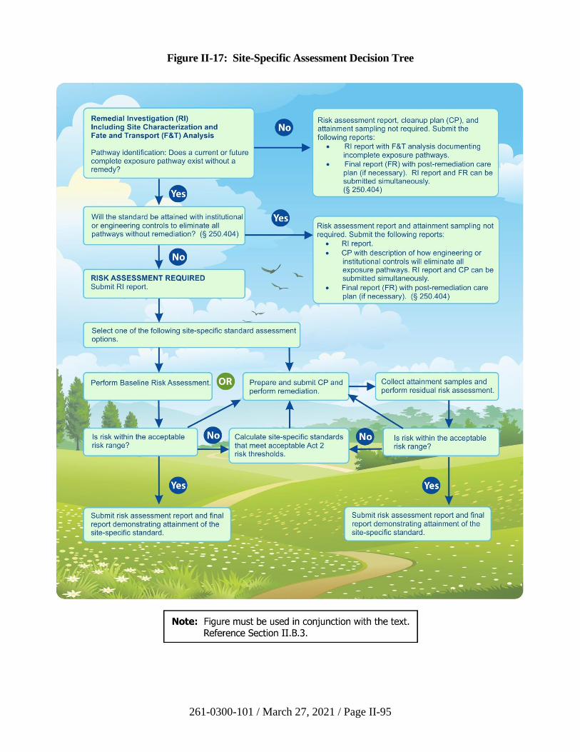
261-0300-101 / March 27, 2021 / Page II-95
Figure II-17: Site-Specific Assessment Decision Tree
261-0300-101 / March 27, 2021 / Page II-96
In determining soil and groundwater standards, consideration should be given to
appropriate exposure factors to receptors based on land use of the site, the
effectiveness of institutional or other controls placed on the future land use,
potential pathways for human exposure, and appropriate statistical techniques.
b) Process Checklist for the Site-Specific Standard
A checklist for the site-specific standard is provided below and can be used to
ensure administrative completeness.
☐ Submit an NIR for the site-specific standard to the Department. Also send
a copy of the NIR to the municipality, publish a summary of the notice in
a newspaper of general circulation serving the area in which the site is
located, and provide reasonable proof of publication to the Department.
Procedures are in Section II.A.3 of this manual.
☐ Notify the municipality, publish a notice in a local newspaper, and provide
proof of submittal to the Department each time a remedial investigation
report, risk assessment report, cleanup plan or final report is submitted to
the Department. Procedures are in Section II.A.3 of this manual.
☐ Prepare and submit public involvement plan if requested by municipality.
Procedures are in Section II.A.3 of this manual.
☐ Begin the remedial investigation. See Sections II.B.3(c) and II.A.4 of this
manual for guidance.
☐ As an option, begin using the completeness list (see LRP web page) to
help verify that all requirements have been met.
☐ Prepare and submit a remedial investigation report which includes fate and
transport analysis to determine if any exposure pathways including vapor
intrusion (Section IV of this manual) exist at the site. A fee of $250 is
required. Reporting requirements are established by 25 Pa. Code
§ 250.404 and 250.408 and are described in Section II.B.3.g of this
manual.
☐ Prepare and submit a risk assessment report (baseline risk assessment
report and/or risk assessment report to develop site-specific standards)
along with a fee of $250 to the Department. A baseline risk assessment
report is not required if the Department, in its remedial investigation report
or cleanup plan approval, determines that a specific remedial alternative
that eliminates all pathways can be implemented to attain the site-specific
standard (25 Pa. Code § 250.405(c)). A simplified risk assessment
describing how the pathways are eliminated by the remedial alternative
should be included in the remedial investigation report. This does not
include a no-action remedial alternative. A baseline risk assessment report
261-0300-101 / March 27, 2021 / Page II-97
is not required if no present or future exposure pathways exist, as
documented by a fate and transport analysis. Risk assessment
requirements are established by 25 Pa. Code §§ 250.402-407 and 250.409
and Subchapter F. Guidance is provided in Sections III.G and III.H of this
manual. Reporting requirements are described in Section II.B.3(g)(v) of
this manual.
☐ Prepare a cleanup plan. A cleanup plan is not required if no present or
future exposure pathways exist. The cleanup plan is also not required if
the approved baseline risk assessment report indicates that the site does
not pose unacceptable risks to human health and the environment under
current and planned future conditions. Cleanup plan requirements are
established by Section 304(j) and (l)(3) of the Act and 25 Pa. Code
§ 250.410. Guidance on the cleanup plan is provided in
Section II.B.3(g)(ii) of this manual.
☐ Submit the cleanup plan, if required, and a fee of $250.
☐ Remediate the site to the site-specific standard in accordance with the
approved cleanup plan. A remedy is not required if no present or future
exposure pathways exist.
☐ Establish attainment of the site-specific standard in accordance with the
requirements in Chapter 250, Subchapter G, of the regulations. Guidance
is provided in Sections II.B.3(g) and III.B of this manual.
☐ Calculate the mass of contaminants remediated using the procedure in
Section III.C of this manual.
☐ Complete the Final Report Summary and submit electronically as
instructed on the LRP web page.
☐ Submit final report, along with the optional completeness list (if used),
and a fee of $500 to the Department. Include information in 25 Pa. Code
§§ 250.411 and 250.204(f)(1)-(5). Include postremediation care plan in
accordance with § 250.204(g) as appropriate. Document cooperation of
third parties where access is needed for remediation or monitoring.
Reporting requirements for the final report are described in
Section II.B.3(g) of this manual.
☐ Upon the Department’s approval of the final report demonstrating
compliance with substantive and procedural requirements of the site-
specific standard, the site is automatically afforded the liability protection
as outlined in Chapter 5 of Act 2.
☐ If engineering controls are used and postremediation care is needed to
maintain the standard; if fate and transport analysis indicates the standard
may be exceeded at the POC in the future; if remediation relies on natural
261-0300-101 / March 27, 2021 / Page II-98
attenuation; or if mitigation measures are implemented in accordance with
25 Pa. Code § 250.311(f), continue with the postremediation care program
detailed in the final report. If areas of the source property were shown to
have no current or future complete exposure pathway, the postremediation
controls described in Section III.D are needed.
☐ Submit an environmental covenant, if applicable, to the Department.
☐ When the site-specific standard can be maintained without engineering
controls operating and mitigation measures have been successfully
sustained, document this to the Department and receive approval to end
the postremediation care program.
c) Site Investigation
The principal objectives of an investigation under the site-specific standard are to
characterize the nature, extent, direction, volume and composition of regulated
substances that have been released and to obtain detailed site information,
including identification of exposure pathways, in order to develop a protective
cleanup standard unique to that site.
Important tasks during the site investigation include site characterization and
pathway identification. The development of a conceptual site model and
identification of contaminants of concern are also important steps in the site
investigation process. This section provides specific information and procedures
regarding site characterization and pathway identification. At the conclusion of
the site investigation, a remedial investigation report should be submitted to the
Department for review and approval (35 P.S. § 6026.304(l)(1)). Section II.A.4 of
this manual describes specific information required to be included in the remedial
investigation report.
i) Site Characterization
The site characterization should be conducted in accordance with
scientifically recognized principles, standards, and procedures. The level
of detail in the investigation needs to sufficiently characterize the nature,
extent, and composition of the regulated substances that have been
released. The determination of the site conditions will be used to select
the remedy used to clean up the site. All interpretations of geologic and
hydrogeologic data should be prepared by a professional geologist
licensed in Pennsylvania.
Methodologies presented in Section II.A.4 of this manual should be
followed while conducting the site investigation. When evaluating the
nonpoint source groundwater discharge to surface water, a person may
consult EPA guidances in “A Review of Methods for Assessing Nonpoint
Source Contaminated Ground-Water Discharge to Surface Water, EPA
570/9-91-010, April 1991,” and “Handbook: Stream Sampling for Waste
Load Allocation Applications. EPA/625/6-86/013.” Section III.A.3 of
261-0300-101 / March 27, 2021 / Page II-99
this manual provides guidance to evaluate impacts on surface water from
diffuse flow of contaminated groundwater.
As directed from specific knowledge of the subject property, including
historic use or chemical usage information, and based upon the guidance
in Section II.A.4 of this manual, an appropriate number of sample
locations should be investigated. These sample locations should be from
the identified media of concern in order to characterize the nature and
composition of the contaminants, including the characterization of the
source of the regulated substances. This will allow for development of a
conceptual site model taking into account the vertical and horizontal
extent of contamination; the direction, rate, extent and fate of contaminant
movement within each medium of concern; and to identify the appropriate
remedial technology options for each medium of concern.
When determining the relative location of soil or groundwater samples
necessary to characterize the horizontal and vertical extent of
contamination, factors such as hydraulic conductivity of the soils,
heterogeneity of the soils, and the nature of the contaminants should be
considered.
If groundwater is determined to be a medium of concern, adequate
characterization of the effects of a release on groundwater will require a
hydrogeologic study (as summarized in 25 Pa. Code § 250.204), which
should include the study of the geological nature and physical properties
of the underlying formation and aquifer. This study will determine how
naturally occurring physical and geochemical characteristics define the
hydrostratigraphy (position of aquifers, aquitards, and aquicludes) of the
site, which includes an assessment of the homogeneity and isotropy of
aquifer materials based on hydraulic conductivity values (measured or
published), and local and regional groundwater flow directions as well as
any influence from pumping centers.
Characterizing the horizontal extent of contamination of regulated
substance(s) will be defined by a minimum of two rounds of groundwater
sampling from properly constructed and developed monitoring wells. In
some instances, additional rounds of quarterly sampling may be needed to
evaluate seasonal impacts on groundwater contamination and to validate
fate and transport assumptions. Please refer to Appendix A, Groundwater
Monitoring Guidance, for additional information on construction and
development of wells. The initial sampling event should be conducted no
less than 14 days from the date of the most recent well development. A
shorter time frame is permissible if it is demonstrated that, through
development, pH and conductivity of the groundwater has stabilized. The
second and subsequent sampling events should ideally occur sixty to
ninety days from the preceding sampling event. Site-specific
considerations may require adjustments to the time frame. Decisions
regarding the duration of groundwater sampling should be made by
261-0300-101 / March 27, 2021 / Page II-100
communicating with your DEP Project Officer prior to establishing a
sampling plan.
When characterizing the vertical extent of groundwater contamination,
consider the specific gravity of the regulated substances identified and the
potential for naturally occurring or induced downward vertical hydraulic
gradients. If characterizing the vertical extent of groundwater
contamination is necessary, properly constructed monitoring wells or
nested monitoring wells should be utilized to focus groundwater sampling
in zones of potential contaminant accumulation (i.e., directly above a
confining layer).
The determination of the use of groundwater is also an important task of
site characterization. The uses of groundwater may include drinking water
use, agricultural use, industrial uses, etc. As mandated by Act 2,
groundwater will not be considered a current or potential source of
drinking water where groundwater has a background TDS concentration
greater than 2,500 milligrams per liter. Other than that mandate, current
and future uses of groundwater must be determined on a site-specific
basis. Current drinking water or agricultural uses of groundwater, at the
time contamination was discovered, should be identified for protection.
Additional requirements on the determination of the use of groundwater
are in 25 Pa. Code § 250.403.
Development of a conceptual site model is an important step in identifying
additional data needs and defining exposure. A conceptual site model
identifies all potential or suspected sources of contamination, types and
concentrations of contaminants detected at the site, potentially
contaminated media, potential exposure pathways, and receptors. Many
components of exposure (such as the source, receptors, migration
pathways, and routes of exposure) are determined on a site-specific basis.
The conceptual site model provides a systematic way to identify and
summarize this information to ensure that potential exposures at the site
are accounted for accurately.
The conceptual site model may be graphical, tabular or narrative but
should provide an accurate understanding of all exposure pathways
(complete and incomplete) for the site. Examples of conceptual site
models may be found in EPA or ASTM guidance documents, including
Section 4.2 of U.S. EPA Risk Assessment Guidance for Superfund,
Volume I, Human Health Evaluation Manual (RAGS/HHEM), Part A,
ASTM E-1739 RBCA, Tier 2 Guidance Manual, and ASTM E1689-95,
Standard Guide for Developing Conceptual Site Models for Contaminated
Sites. It is suggested that the development of the conceptual site model be
coordinated with the regional project officer to ensure that potential
pathways are adequately and appropriately addressed prior to performing
the assessment.
261-0300-101 / March 27, 2021 / Page II-101
ii) Pathway Identification (§ 250.404 of the Regulations)
Once the development of the conceptual site model is completed, current
and future exposure pathways should be identified based on this
conceptual site model. An exposure pathway describes the course a
chemical or physical agent takes from the source to the exposed receptor.
An exposure pathway analysis links the sources, locations, and types of
environmental releases with population locations and activity patterns to
determine the significant pathways of exposure.
A potentially complete exposure pathway generally consists of
four elements:
• a source and mechanism of chemical release,
• a retention or transport medium (or media in cases involving media
transfer of chemicals),
• a point of potential receptor contact with the contaminated medium
(the exposure point), and
• an exposure route (e.g., ingestion) at the exposure point.
The person should consult the most recent U.S EPA or ASTM guidances
to identify any potential current and future exposure pathways for both
human and environmental receptors. The pathway identification should
consider current pathways and the effects of engineering and institutional
controls. Future exposure pathways should be based on currently planned
and/or probable future land use. Guidance on land use considerations can
be found in the USEPA Office of Solid Waste and Emergency Response
(OSWER) Directive: Land Use in The CERCLA Remedy Selection
Process. DEP guidance entitled Site-Specific Human Health Risk
Assessment Procedures in Section III.G of this manual provides more
information on pathway identification for human exposure. Guidance
such as described in Sections 6.2 and 6.3 (relating to characterization of
exposure setting and relating to identification of exposure pathways) of
U.S. EPA’s Risk Assessment Guidance for Superfund, Volume I, Human
Health Evaluation Manual (RAGS/HHEM), Part A, provides a framework
for pathway identification for human exposure. Subsection 6.3.2 of Risk
Assessment Guidance for Superfund/Human Health Evaluation Manual
(RAGS/HHEM), Part A in particular, provides guidance to perform fate
and transport analysis.
Prior to the identification of exposure routes, a remediator must identify
sources and receiving media, evaluate fate and transport in release media,
and identify exposure points and potential receptors. The following
exposure scenarios contain examples of what should be considered:
261-0300-101 / March 27, 2021 / Page II-102
(a) Groundwater
The remediator shall identify routes of exposure for groundwater
such as human exposure to groundwater by ingestion, inhalation,
or dermal exposure routes. The remediator should consider effects
of discharge of groundwater into surface water and the effects on
ecological receptors. When evaluating the indoor exposure
pathways, a remediator needs to address impacts of volatile
organic compounds (VOCs) from soil and groundwater, not
extraneous sources.
With respect to the groundwater ingestion pathway, the following
guidance is provided. When determining whether groundwater on
or off the source property must be protected under the site-specific
standard for drinking water uses, the following will be applied
(from 35 P.S. § 6026.304(d)):
• The current and probable future use of groundwater shall
be identified and protected. Groundwater that has a
background TDS content greater than 2,500 milligrams per
liter or is not capable of transmitting water in usable
quantities shall not be considered a current or potential
source of drinking water.
• Site-specific sources of contaminants and potential
receptors shall be identified.
• Natural environmental conditions affecting the fate and
transport of contaminants, such as natural attenuation, shall
be determined by appropriate scientific methods.
From 25 Pa. Code § 250.403 of the regulations, the following
apply:
• Except for groundwater excluded by the TDS limitation
described above, current and probable future use of
groundwater shall be determined on a site-specific basis.
• Drinking water use of groundwater shall be made suitable
by at least meeting the primary and secondary MCLs at all
points of exposure identified in § 250.404 (relating to
pathway identification and elimination) of the regulations.
• Current drinking water or agricultural uses of groundwater,
at the time contamination was discovered, shall be
protected.
As an example: within a city with an established public water
system and groundwater contamination extending off-property, the
261-0300-101 / March 27, 2021 / Page II-103
complete exposure pathways depend on volatilization potential of
contamination and the current use or “probability” that future
groundwater ingestion may occur. If surrounding properties are
currently developed and have public water service, then it may be
assumed that the probability is that those established patterns of
water use will continue into the future. Therefore, there are no
current or probable future uses of groundwater as a drinking water
source; and the groundwater ingestion pathway may (all other
information supporting) be determined to be incomplete.
Note that even in cases where the groundwater ingestion pathway
is determined to be incomplete, the final report must include one or
a combination of institutional controls or postremedial measures
which provide assurance that this status continues to exist in the
future. See Section III.E.3 of this manual for the range of
institutional controls or postremedial measures available to a
remediator. If a complete groundwater ingestion pathway is found
to exist in the future, then the responsible person must demonstrate
attainment of one of the three Act 2 standards.
(b) Soil
The person shall consider current and probable future exposure
scenarios, such as human ingestion, dermal contact, inhalation of
volatiles and particulates, and leaching to groundwater. When
evaluating the indoor exposure pathways, a person needs to
address impacts of VOCs from soil and groundwater, not
extraneous sources.
(c) Cases Where No Complete Current or Future Exposure
Pathway Exists
If no current or probable future complete exposure pathways exist
without remediation, then a risk assessment report (RA), cleanup
plan (CP), or attainment sampling is not required (see
Figure II-17). These cases are distinct from using pathway
elimination, which requires a remedy (such as an engineering
and/or an institutional control) to attain the standard (see
Section II.B.3(c)(ii)(d) below).
A complete exposure pathway is one in which a receptor may be
exposed to contamination at any level, even if that concentration
equates to an acceptable risk. If the contaminant of concern is a
VOC and occupied buildings are present, then the vapor intrusion
pathway must be evaluated for buildings within the applicable
proximity distances and for preferential pathways (Section IV of
this manual). The inhalation pathway would be complete even if
vapor intrusion screening values were satisfied.
261-0300-101 / March 27, 2021 / Page II-104
If no complete exposure pathways exist, then no remedy is
required, and a risk assessment is unnecessary. Attainment
sampling is also not required because there is no specific numeric
concentration value (standard) applied to the site. To demonstrate
attainment of the site-specific standard, a pathway elimination
analysis described in 25 Pa. Code § 250.702(b)(3)(i) needs to be
included in the final report. When no complete current or future
exposure pathways exist, it is recommended that the remedial
investigation report and the final report be combined following the
suggested outline provided in Table II-7.
For groundwater, a discussion of the fate and transport analyses
used during site characterization to evaluate contaminant trends for
plume stability needs to be provided in the final report as required
by 25 Pa. Code § 250.702(b)(2). This discussion should confirm
the finding of the fate and transport analysis that the absence of
complete exposure pathways will remain and that continued future
attainment of the site-specific standard will be maintained. A
postremediation care plan may be necessary to ensure all pathways
remain incomplete and to therefore maintain attainment of the site-
specific standard. The postremediation care plan, if necessary,
should be submitted with the final report.
(d) Cases Where Institutional or Engineering Controls Are
Needed to Eliminate Pathways
Neither a risk assessment report nor attainment sampling is
required if an institutional or engineering control is used as a
remedy to eliminate all complete exposure pathways. However, a
cleanup plan describing how the engineering or institutional
control will eliminate all complete exposure pathways is required
(see Figure II-17). A suggested outline for a cleanup plan is
provided in Table II-5. The cleanup plan, the remedial
investigation report, and the final report can be submitted
simultaneously. Fate and transport analysis descriptions and final
report requirements as described in Section II.B.3(c)(ii)(c) also
apply in this scenario. Note that if one part of a combined report is
disapproved, then all other parts of the combined report that
depend on the disapproved part will also require re-submittal, with
new notices and payment of fees. For example, if a cleanup plan is
disapproved, then the cleanup plan and final report must be
re-submitted. However, if one part of a combined report is
deficient, the remediator may have a chance to correct the
deficiency in a prescribed timeframe to avoid re-submittal of
notices and payment of fees.
261-0300-101 / March 27, 2021 / Page II-105
d) Risk Assessment and Development of Site-Specific Standards (§ 250.402)
This section provides general information on risk assessment, developing site-
specific standards, and pathway elimination. Sections III.G and H of this manual
provide guidance on site-specific human health and ecological risk assessment
procedures. This guidance should be followed to conduct a baseline risk
assessment or to develop site-specific standards.
Any remediator selecting the site-specific standard established by Section 304 of
Act 2 should submit a risk assessment report to the Department for review and
approval unless no present or future complete exposure pathways exist as
demonstrated by a fate and transport analysis when the site was characterized. If
no such complete exposure pathways exist, a person only needs to submit a
combined remedial investigation report and final report (see Table II-7). If
complete exposure pathways exist, the fate and transport analysis, which is a part
of the exposure assessment performed during site characterization, should be
documented in the exposure assessment section of the risk assessment report.
Although it might be helpful in some cases to establish the leaching potential of
constituents in soil, meeting toxicity characteristic leaching procedure (TCLP)
limits does not automatically indicate attainment of the site-specific standard.
TCLP analysis is used for Resource Conservation and Recovery Act (RCRA)
hazardous waste determinations to simulate leaching in a landfill. These results
determine if a waste is hazardous and can or cannot be disposed of in a landfill.
TCLP analysis does not provide useful data for calculation of site-specific risk
values. The risk associated with the regulated substances is considered in the site-
specific risk assessment under Act 2.
To determine if a site-specific risk assessment is necessary, a conceptual site
model should be developed that defines potential exposure scenarios and
pathways. The exposure scenario (e.g., residential, industrial, recreational), which
will define the exposure pathways, must be based on site-specific land use
considerations. The pathways, which describe the mechanism by which receptors
may be exposed to a source, are also site-specific. Engineering or institutional
controls that are to be implemented which will eliminate exposure pathways must
be incorporated into the conceptual site model. Then, a risk assessment only
needs to be performed if complete exposure pathways for humans and/or
ecological receptors exist under current or future planned conditions.
A complete exposure pathway exists if there is a receptor to be exposed through
an exposure route. For ecological receptors, a pathway is complete even if the
current ecological receptors are not present as a result of the contamination. A
pathway is not complete if there is no reasonable exposure route; i.e., the
contaminant is not in an available form to affect the receptors.
However, before getting into the mechanics of performing the risk assessment, it
is important to clearly define the problem that is to be addressed, the objectives of
the study, and how the results will be used to meet these objectives. This initial
step is critical to ensure a successful outcome (accurate, protective, timely, cost-
261-0300-101 / March 27, 2021 / Page II-106
effective evaluation) and that the level of effort is commensurate with the scope
of the problem.
Under Act 2, a risk assessment report may include the following:
• A baseline risk assessment report that describes the potential adverse
effects to both human and ecological receptors, under both current and
planned and/or probable future conditions that are caused by the presence
of regulated substances in the absence of any further control, remediation,
or mitigation measures.
• A risk assessment report that documents which exposure pathways will be
eliminated by a pathway elimination measure so that any substantial
present or probable future risk to human health or the environment is
eliminated.
• A risk assessment report that describes the methods used to develop a
concentration level at which human health and the environment are
protected.
• The comments obtained as a result of a public comment period, if any, and
the responses to those public comments.
If an unacceptable risk is identified at a site, a person may develop site-specific
standards based on a site-specific risk assessment. A baseline risk assessment
report is not required if the Department, in its remedial investigation report or
cleanup plan approval, determines that a specific remediation measure, other than
a no-action remedial alternative, can be implemented to attain the site-specific
standard (see 35 P.S. § 6026.304; 25 Pa. Code § 250.405(c)). A baseline risk
assessment is that portion of a risk assessment that evaluates a risk in the absence
of the proposed site-specific measure.
In developing site-specific standards, a person may use the toxicological data
presented in Tables 5a and 5b of Appendix A, Chapter 250, refer to the toxicity
database on the Land Recycling website, or refer to the sources listed in 25 Pa.
Code § 250.605 for the most up-to-date values.
As an alternative to developing site-specific numerical cleanup standards and
remediation, individuals may choose to perform a combination of engineering and
institutional controls to achieve pathway elimination for regulated substances of
concern. Common methodologies used to eliminate exposure pathways include
permanent capping of contaminated soils with parking lots or building slab
construction, groundwater and land use restrictions, vapor barriers, or sub-slab
depressurization systems.
Remediation measures may require interface with the SWMA (see Section V.A of
this manual), particularly for offsite removal of contaminated media or
management of existing waste onsite.
261-0300-101 / March 27, 2021 / Page II-107
To prepare the development of the site-specific standards risk assessment report,
all current and probable future complete exposure pathways as identified in the
fate and transport analysis should be addressed. When pathway elimination
measures are planned and preapproved, the remaining pathways and the
eliminated pathways under the postremedial conditions should be identified in the
site-specific standard risk assessment report. Site-specific cleanup levels should
be developed to address the risks associated with these remaining pathways.
Where all pathways have not been eliminated, a risk assessment report is required.
In addition to human health protection, the risk assessment must evaluate
ecological receptors. An ecological risk assessment should be conducted with
considerations of the site-specific ecological risk assessment procedure provided
in Section III.H of this manual and the most recent U.S. EPA or ASTM
guidances, including those listed in Table II-4 to determine whether an impact has
occurred or will occur if a release goes unabated, to establish acceptable
remediation levels or alternative remedies based on current or probable future
land use that are protective of the ecological receptors.
Ecological receptors include:
• Individuals of threatened or endangered species as designated by the U.S.
Fish and Wildlife Service under the Endangered Species Act.
• Exceptional value wetlands as defined in 25 Pa. Code § 105.17 (relating to
wetlands).
• Habitats of concern as defined in 25 Pa. Code § 250.1.
• Species of concern as identified in the PNDI.
At the conclusion of the risk assessment, a risk assessment report should be
submitted to the Department for review and approval. Section II.B.3(g) (v) of this
manual describes specific information required to be included in the risk
assessment report.
To ensure that any substantial present or probable future risk to the environment
is eliminated, both human health and ecological risk evaluations are necessary.
The objective of the Preliminary Ecological Screening is to quickly evaluate
whether surface soil or sediments at a site have the potential to pose significant
ecological impact or impacts requiring further evaluation. The site-specific initial
screening procedure described in Section III.H of this manual may be used during
or immediately after the site characterization process to assess the potential for
significant ecological impact. It should be noted that the ecological screening
procedures under the SHS (in Section II.B.2(e) of this manual) should not be used
to replace the site-specific initial screen procedure (Steps 1-2 in Section III.H of
this manual) when the site-specific standard is selected to protect human health
and the environment. This is because the assumption to use the ecological
screening procedures under the SHS is that the site has met SHS values to protect
261-0300-101 / March 27, 2021 / Page II-108
human health. This underlying assumption cannot be made when the site-specific
standard is selected to protect human health.
• When conducting an ecological screening under the site-specific standard,
a screening level ecological risk assessment to determine if an impact has
occurred or will occur if the release of a regulated substance goes
unabated should be performed. If this risk assessment shows that an
impact has or will occur, the following are then necessary: an ecological
risk assessment conducted in accordance with Department-approved EPA
or ASTM guidance to establish acceptable remediation levels or
alternative remedies based on current and future use that are protective of
ecological receptors.
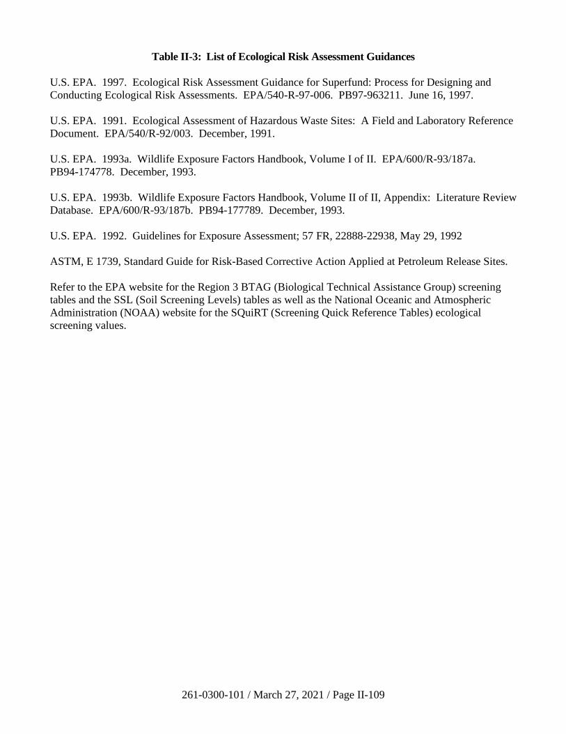
261-0300-101 / March 27, 2021 / Page II-109
Table II-3: List of Ecological Risk Assessment Guidances
U.S. EPA. 1997. Ecological Risk Assessment Guidance for Superfund: Process for Designing and
Conducting Ecological Risk Assessments. EPA/540-R-97-006. PB97-963211. June 16, 1997.
U.S. EPA. 1991. Ecological Assessment of Hazardous Waste Sites: A Field and Laboratory Reference
Document. EPA/540/R-92/003. December, 1991.
U.S. EPA. 1993a. Wildlife Exposure Factors Handbook, Volume I of II. EPA/600/R-93/187a.
PB94-174778. December, 1993.
U.S. EPA. 1993b. Wildlife Exposure Factors Handbook, Volume II of II, Appendix: Literature Review
Database. EPA/600/R-93/187b. PB94-177789. December, 1993.
U.S. EPA. 1992. Guidelines for Exposure Assessment; 57 FR, 22888-22938, May 29, 1992
ASTM, E 1739, Standard Guide for Risk-Based Corrective Action Applied at Petroleum Release Sites.
Refer to the EPA website for the Region 3 BTAG (Biological Technical Assistance Group) screening
tables and the SSL (Soil Screening Levels) tables as well as the National Oceanic and Atmospheric
Administration (NOAA) website for the SQuiRT (Screening Quick Reference Tables) ecological
screening values.
261-0300-101 / March 27, 2021 / Page II-110
• Implementation of the selected remedy, which may include mitigation
measures under § 250.311(f), that is protective of ecological receptors.
e) Cleanup Plan
Section II.B.3.g.ii and Table II-5 of this manual describe information required to
be included in the cleanup plan. A cleanup plan is not required, and no remedy is
required to be proposed or completed if neither current nor future exposure
pathways exist. Subject to the Department’s approval of the baseline risk
assessment report, a cleanup plan is also not required if the baseline risk
assessment indicates the site is within the human health and environmental
protection goals specified in 25 Pa. Code § 250.402 under both current and
currently planned future site conditions. After the site has been characterized
using the suggested guidelines (or some equivalent technique) and a risk
assessment performed to develop site-specific standards for soil and groundwater,
a remediation (cleanup) plan should be developed, which consists of identification
and evaluation of remedial alternatives, selection of a proposed remedy, and plans
for the development, construction, and initial operation of the proposed remedy.
A number of factors required by Act 2 for consideration in selecting the remedy
are set forth in Section 304(j) of Act 2. As described in Section 304(i) of Act 2,
remediation to site-specific standards may include treatment, removal,
engineering or institutional controls as well as innovative or other demonstrated
measures. However, fences or warning signs generally may not be used as the
sole means to address a complete exposure pathway.
To evaluate the short-term and long-term effectiveness of a remedial alternative,
the potential risk associated with implementation of the alternative and the risk
associated with exposure to the remediated media must be evaluated. The
pathways and exposure factors that were defined in the exposure assessment
should be used to characterize these potential risks.
The risk characterization associated with short-term effectiveness considers the
exposure of workers at the site and exposure of receptors in the vicinity
surrounding the site to migrating media during the implementation of the remedial
alternative. A comparison of a focused list of remedial alternatives may help
predict the risks associated with the implementation of the remedial alternative or
whether the implementation of alternatives may have any significant impact to
human health and the environment.
The risk characterization associated with long-term effectiveness evaluates
whether the remedial alternative may attain the remedial objectives (site-specific
standards) and whether postremedial risks may achieve the acceptable levels of
risk. At times, a specific cleanup goal for one constituent may not be attained, but
the overall postremedial risk may be within acceptable levels. Evaluation of the
postremedial risk is based on a prediction of what the postremedial exposure
concentration would be. If bioremediation is considered, the remedial objective
would be the concentration that provides the basis for characterization of the
261-0300-101 / March 27, 2021 / Page II-111
postremedial risk. If the calculated postremedial risk is within the acceptable
range, the remedial alternative would be considered a viable solution.
A remediator evaluating long-term and short-term risks of remedial alternatives
should consider EPA’s Risk Assessment Guidance for Superfund (RAGS),
Volume 1, Part C, Chapter 2 for additional guidance. It should be noted that a
quantitative risk assessment of remedial alternatives will not need to be conducted
for all sites. In most cases, a qualitative rather than a detailed quantitative
evaluation of both long-term and short-term risks is all that is needed to select the
most appropriate alternative. However, the Department may require a
quantitative risk assessment of the selected remedy if a quantitative risk
assessment is needed to select the most appropriate remedy or a perceived risk of
a selected remedy is high. No matter whether the risk evaluation is qualitative or
quantitative, the cleanup plan should always discuss the degree of uncertainty
associated with the risk assessment of the selected remedy.
Where there are imminent or immediate threats to human health or the
environment, such as waste releasing from corroding tanks or drums, mitigating
measures should be undertaken to prevent releases and further exposure as soon
as these threats are identified.
The cleanup plan must document the evaluation of the factors listed in
Section 304(j) of Act 2. The Department will review the alternative evaluated,
the evaluation of the selected remedy in terms of the Section 304(j) criteria, public
comments, and response to the comments in the cleanup plan. The Section 304(j)
criteria address a few general areas, such as the effectiveness of the remedy
(long/short term) to manage risk; the extent to which the risks are being reduced;
the ability to implement the remedy; reduction of toxicity, mobility, or volume of
regulated substances; reliability and postremediation care; and cost-benefit
considerations.
The Department may require further evaluation of the selected remedy or of one
or more alternative remedies on its own analysis of Section 304(j) factors in Act 2
or in response to comments received from the community surrounding the site as
a result of the implementation of the community involvement plan or as a result of
the Department’s review of the cleanup plan. Remediators shall submit to the
Department, upon request, such additional information as may reasonably be
required to complete the evaluation. A final report cannot be approved prior to a
remedy being in place as specified in 25 Pa. Code § 250.411(b).
f) Remediation and Demonstration of Attainment
Remediation to the site-specific standards should be implemented in accordance
with the approved cleanup plan.
The POC for demonstration of the attainment of site-specific standards is
described in 25 Pa. Code § 250.407. Site-specific standards shall be attained at
and beyond the POC, where the plume has migrated beyond the property
boundary. For groundwater, the POC is the property boundary that existed at the
261-0300-101 / March 27, 2021 / Page II-112
time the contamination was discovered. The remediator may request the
movement of the POC in certain circumstances described in 25 Pa. Code
§ 250.407(a). If any of those conditions exist, the remediator must request
moving the POC in writing prior to or at the time of submission of the cleanup
plan. The Department will provide a written response to the request. The
Department’s written approval must be obtained before using the adjusted POC.
Unless an NPDES permit is required for purposes of complying with surface
water quality in a spring, the POC is the point of first designated or existing use as
defined in 25 Pa. Code §§ 93.1, 93.4, and 93.9. This could mean in close
proximity to the spring itself or some point downstream from the spring
discharge. Determining the point of first designated use is required because it
establishes the point where Chapter 93 water quality standards apply.
Technical guidance to determine point of first use is found in Policy and
Procedure for Evaluating Wastewater Discharges to Intermittent and Ephemeral
Streams, Drainage Channels and Swales, and Storm Sewers, DEP document
# 391-2000-014, revised April 2008. In essence, this guidance relies on
biological techniques to determine the first downstream point where aquatic life
can be documented. It applies to both perennial and intermittent streams with
definable bed and banks, but not to ephemeral streams, that is, areas of overland
runoff which occur only during or immediately following rainfall events and
where there is no defined stream channel and stream substrate.
The site characterization will be the basis on which the vertical and horizontal
extent of contamination above the standard is determined. Once this volume of
the site is determined and remediation, if necessary, has been performed, then
attainment of the standard will focus on the environmental media contained
within that volume of the site. Where multiple releases occur on a property which
produce distinctly separate zones of contamination, the characterization and
subsequent attainment demonstrations will apply individually to the separate
releases.
The three methods to demonstrate that the site-specific standard has been met are
pathway elimination using an engineering/geologic evaluation, the 95% UCL of
the arithmetic mean or other appropriate statistical methods to show that the site
meets numerical site-specific standards, or a residual risk assessment following
implementation of the remedy to demonstrate that the risk associated with the site
following remediation falls within the allowable risk range in Act 2. The residual
risk assessment will be based on resampling and a reassessment of the cumulative
risks associated with concentrations occurring following remediation.
If this residual risk assessment is nothing more than a presentation of the
recalculation of risk values that were previously presented in an approved risk
assessment report, the presentation of these calculations can be considered as part
of the final report and are not subject to the fees and notification requirements of a
risk assessment. However, if the residual risk assessment is following
remediation done prior to approval of a risk assessment report, or following a
change in pathway and exposure factors due to remedial measures not addressed
261-0300-101 / March 27, 2021 / Page II-113
in the prior report, this must be a full report as defined in § 250.602 of the
regulations and explained further in Section III.H of this manual. This type of
residual risk assessment is subject to the fees and reporting requirements
associated with a risk assessment.
In demonstrating attainment of the site-specific standard, concentrations of
regulated substances are not required to be less than the limit related to the PQL
for that substance as provided for in 25 Pa. Code § 250.701(c) and as described in
Section III.F of this manual.
In demonstrating attainment of the site-specific standard, the removal of SPL is
not required if attainment can be demonstrated in accordance with the
requirements of 25 Pa. Code § 250.702(b)(3).
If the site-specific standard is numerically less than the background standard, the
remediator may select the background standard, and attainment of the background
standard should be demonstrated according to Section 303 of Act 2.
To ensure that contaminant concentration at the POC will not exceed the selected
standard in the future, a statistical time trend analysis, knowledge of the plume
stability, or other acceptable method must be provided in the final report to the
Department for review and approval.
Guidance on applying statistical methods to demonstrate attainment can be found
in Section III.B of this manual. A remediator should consider the general
guidelines of risk assessment in Sections III.H and III.I of this manual to perform
the residual risk assessment. When submitting the final report, a remediator
should ensure that the items identified in Section II.B.3(g) and Table II-6 of this
manual are included.
g) General Report Guidelines for the Site-Specific Standard
The remedial investigation report, risk assessment report, cleanup plan, and final
report detailed below are not to be submitted to the Department until the 30-day
public and municipal comment period has expired.
i) Remedial Investigation Report (25 Pa. Code § 250.408)
The site characterization shall be conducted in accordance with
scientifically recognized principles, standards and procedures. The level
of detail in the investigation and the selected methods and analyses, which
may include models, shall sufficiently define the rate of movement and the
present and future extent and fate of contaminants to ensure continued
attainment of the remediation standard. All interpretations of geologic and
hydrogeologic data shall be prepared by a professional geologist licensed
in Pennsylvania. A suggested outline for a remedial investigation report is
provided in Table II-4.
261-0300-101 / March 27, 2021 / Page II-114
ii) Cleanup Plan (25 Pa. Code § 250.410)
The cleanup plan is not required if no current and probable future
exposure pathways exist. The cleanup plan is also not required if the
approved baseline risk assessment report indicates that the site does not
pose unacceptable risks to human health and the environment under
current and planned or probable future conditions. A suggested outline for
a cleanup plan is provided in Table II-5.
iii) Final Report (25 Pa. Code § 250.411)
A suggested outline for a final report under the site-specific standard is
provided in Table II-6.
iv) Combined Remedial Investigation Report/Final Report
The site characterization shall be conducted in accordance with
scientifically recognized principles, standards and procedures. The level
of detail in the investigation and the selected methods and analyses, that
may include models, shall sufficiently define the rate of movement and the
present and future extent and fate of contaminants to ensure continued
attainment of the remediation standard. All interpretations of geologic and
hydrogeologic data shall be prepared by a professional geologist licensed
in Pennsylvania. A suggested outline for the combined remedial
investigation report/final report under the site-specific standard is provided
in Table II-7.
v) Risk Assessment Report (25 Pa. Code § 250.409)
A baseline risk assessment report is not required if the Department, in its
remedial investigation report or cleanup plan approval, concurs that a
specific remediation measure that eliminates all pathways, other than a no-
action remedial alternative, can be implemented to attain the site-specific
standard (see 25 Pa. Code § 250.405(c)). A risk assessment report is not
required if no present or future exposure pathways exist, as documented in
the remedial investigation report by a fate and transport analysis.
A suggested outline for a risk assessment report is provided in Table II-8.
The items in the outline are suggested as minimum requirements for
inclusion in the report; the order and titles are not mandatory. If a baseline
risk assessment is not required and a remediator submits the development
of site-specific standard numerical values as a stand-alone document, more
detailed risk assessment information should be provided in the
development of the site-specific standard numerical values document.
261-0300-101 / March 27, 2021 / Page II-115
h) Detailed Report Requirements for the Site-Specific Standard
The following are detailed descriptions of what should to be included in each
section of a report. Not all sections are necessary for each report. Please refer to
the outlines in the previous section for detailed information.
i) Summary (RIR, FR, RIR/FR)
Provide a summary paragraph(s) which will provide the reviewer with an
overview of the site. This will serve to highlight the important issues and
conclusion which will be presented in the report.
The Final Report Summary form should be filled in and submitted to the
Department electronically. The summary submitted with the final report
should be a copy of that electronic form.
ii) Introduction (CP, RA)
Provide a summary of the investigation report(s) and risk assessment
report and an interpretation of the conditions at the site (refined conceptual
site model). Discuss the chosen method(s) of remediation. The remedy
should be evaluated in accordance with the requirements of Section 304(j)
of Act 2.
iii) Site Description (RIR, RIR/FR)
Provide a description of the site in sufficient detail to inform the reviewer
of the site location and the types of operations that are currently and/or
were formerly conducted on the site. As appropriate to the site, the
description should include location, physical description of the property,
ownership history, site use history, and regulatory action history (past
cleanups).
iv) Site Characterization (RIR, RIR/FR, RA)
The site characterization provides important information documenting the
current conditions at the site. Information developed during the site
characterization is primarily intended to describe the nature,
concentrations, extent, and potential for movement of all contaminants
present on the site or that may have migrated from the site. For sites
where there are multiple distinct areas of contamination, the site
characterization process should be applied to each area individually.
v) Source and Identification of Constituents of Concern (Part of
Characterization)
For the area being investigated include a description of source
characterization, which may be in the form of a conceptual site model.
261-0300-101 / March 27, 2021 / Page II-116
vi) Nature and Extent of Contamination (Part of Characterization)
Information needed to meet the requirements below should be included
here. For soil and groundwater, include information on samples and
measurements used to characterize the horizontal and vertical, present and
future extent and fate of contamination. Direction and velocity of
contaminant movement should be based on factors of the groundwater and
soil as well as the contaminant(s) which affect migration.
Text, tables, graphics, figures, maps and cross sections should be used to
describe the nature, location, and composition of the regulated substances
at the site. Providing the data in an appropriate format will expedite the
review of the report.
vii) Other Information Required Under the Site-Specific Standard (RIR,
RIR/FR)
Description of the existing or potential public benefits of the use or reuse
of the property for employment opportunities, housing, open space,
recreation or other uses. Describe the past, present, and future use of the
site.
Information obtained from attempts to comply with the background or
Statewide health standards, such as background concentrations for
constituents of concern.
viii) List of Contacts (ALL)
Name, address, and telephone number of the project manager responsible
for submittal of the cleanup plan.
Names, addresses, and telephone numbers of consultants or other persons
responsible for preparing the cleanup plan.
Names, addresses, and telephone numbers of the property owner and party
responsible for the remediation cost.
ix) Remedial Alternative (CP)
Identify remediation alternatives considered and evaluate the ability and
effectiveness of the selected remedy to achieve the site-specific standards,
based on the factors set forth in Section 304(j) of Act 2. The cleanup plan
must document how each of the factors set forth in Section 304 (j) of
Act 2 was evaluated. The evaluation should include an evaluation of the
short-term and long-term risks and effectiveness of the proposed remedy.
In evaluating the other alternatives, no risk evaluation is required; rather, a
narrative describing the consideration of Section 304(j) factors relative to
the proposed remedy should be included.
261-0300-101 / March 27, 2021 / Page II-117
x) Treatability studies (CP)
Provide results of any treatability, bench scale, or pilot scale studies or
other data collected to support the remedial action(s).
All other site information relevant to the conceptual design, construction,
or operation of the remedial action.
Specific characteristics of the site that may affect the implementation or
effectiveness of the remedial action including such characteristics as
topography, geology, depth of bedrock, potentiometric surfaces, and the
existence of utilities.
xi) Design plans and Specifications (CP)
Consists of adequate design plans and specifications sufficient to evaluate
the proposed remedy including, but not limited to:
• Detailed description of the remedial action (treatment and/or
removal) and remedial technology to be implemented. Adequate
design plans and specifications for all remedial activities, including
remedial design, onsite treatment, storage, removal and disposal
activities.
• Estimated volume of each medium to be treated and/or removed.
Provide methodology and calculations used to estimate
contaminant mass.
• Remedial Action Status Plan - To evaluate the short-term and long-
term effectiveness of the remedial action to include, but not limited
to, the following:
− Location and construction details of all monitoring points.
− Sampling and Analysis Plan, including QA/QC Plan.
− Other site-specific monitoring as appropriate.
• Construction QA/QC Plan including engineering certification.
• Locations, telephone numbers, and contacts of offsite disposal
facilities, including names, addresses, and telephone numbers of
waste transportation companies.
• Site-specific Health & Safety Plan which includes adherence to all
applicable Occupational Safety and Health Administration
(OSHA) and National Institute for Occupational Safety and Health
(NIOSH) regulations and recommendation.
261-0300-101 / March 27, 2021 / Page II-118
• Erosion and Sedimentation Control Plan consistent with
Chapter 102 (Erosion Control) relating to earth disturbance during
remedial activities.
• Site Security Plan.
• A schedule for implementation of the proposed remedial action.
• Operation and Maintenance Plan which shall describe:
− Startup testing, inspection and maintenance over the first
year and subsequent years of operation.
− Identification of equipment necessary for operation and
maintenance.
− Specification of the type, frequency, and duration of testing
or maintenance to verify optimal remedial system
performance.
• All federal, State and local permits and approvals and any
agreements necessary for the construction and operation of the
approved remedial action shall be identified.
xii) Remediation (FR)
Documentation of the methodologies used to attain the site-specific
standard. Including removal and/or treatment technologies used, and any
engineering and/or institutional controls used to attain or maintain the
selected standard. This section should also include the calculation of the
mass of contaminants addressed during the remediation of soil and/or
groundwater, using the methodology in Section III.C.
xiii) Attainment (FR)
Documentation that the remedy has been completed in accordance with an
approved cleanup plan.
• Descriptions of treatment, removal, or decontamination procedures
performed in remediation. Documentation of handling of
remediation wastes in accordance with applicable regulations.
• Descriptions of the sampling methodology and analytical results.
• All sampling data, including QA/QC data.
The demonstration of attainment should be applied separately for each
distinct area of contamination. Demonstration of attainment in a final
261-0300-101 / March 27, 2021 / Page II-119
report should include one or more of the following three types of
information:
• Demonstration of attainment of a numerical standard:
The information includes demonstration that the calculated
numerical site-specific standards have been met through the
application of appropriate statistical tests, and demonstration that
shows contaminant concentration at the POC will not exceed the
selected standard. The following information shall be documented
in a final report when a statistical method is applied:
− A description of the statistical method.
− A clear statement of the applicable decision rule in the form
of statistical hypothesis for each spatial unit and temporal
boundary including the applicable statistical parameter of
interest and the cleanup standard.
− A description of the underlying assumptions of the method.
− Documentation showing that the sample data set meets the
underlying assumptions of the method and demonstrate that
the method is appropriate to apply to the data.
− Specification of false positive rates.
− Documentation of input and output data for the statistical
test, presented in tables, figures or both, as appropriate.
− An interpretation and conclusion of the statistical test.
Demonstration that contaminant concentration at the POC will not
exceed the selected standard should be based on a statistical time
trend analysis, knowledge of the plume stability or other
acceptable method.
• Demonstration of pathway elimination:
This demonstration should be based on either an engineering or
hydrogeologic analysis, or both, which includes fate and transport
analysis that some or all of the exposure pathways have been
eliminated. The eliminated pathways and the remaining pathways
should be clearly identified. The pathway elimination
demonstration should include the following:
261-0300-101 / March 27, 2021 / Page II-120
− Identifying all exposure pathways prior to the
implementation of pathway elimination technology, based
on fate and transport analysis.
− Identifying all exposure pathways after the implementation
of pathway elimination technology, based on fate and
transport analysis.
• Residual Risk Assessment
As an alternative to demonstrating the attainment of numerical
standards, a person may perform a residual risk assessment to
show that the risk which remains at a site following remediation is
within the acceptable risk range specified in Act 2. The residual
risk assessment should be based on resampling and a reassessment
of the cumulative risks associated with concentrations occurring
following remediation.
If this residual risk assessment is nothing more than a presentation
of the recalculation of risk values that were previously presented in
an approved risk assessment report, the presentation of these
calculations can be considered as part of the final report and are
not subject to the fees and notification requirements of a risk
assessment. However, if the residual risk assessment is following
remediation done prior to approval of a risk assessment report, or
following a change in pathway and exposure factors due to
remedial measures not addressed in the prior report, this must be a
full report as defined in 25 Pa. Code § 250.602 and explained
further in Section III.H of this manual. This type of residual risk
assessment is subject to the fees and reporting requirements
associated with a risk assessment.
xiv) Fate and Transport Analysis (RIR, FR, RIR/FR, RA)
The Fate and Transport Section (Section III.A of this manual) provides a
discussion on fate and transport analysis. The amount of detail in the fate
and transport analysis may vary from a basic description to a very
extensive detailed model with quantitative modeling. Whenever a model
is used, the assumptions, data, and information on the model necessary for
Department staff to evaluate and run the model should be included. Any
parameters used in the analysis or models used should use data from the
site obtained during the site characterization. This includes identified
ecological receptors.
Modeling (optional) - Data Interpretation:
• Identify any programs or modeling used to interpret site conditions
or predict plume migration. Identify codes used and any
modifications made.
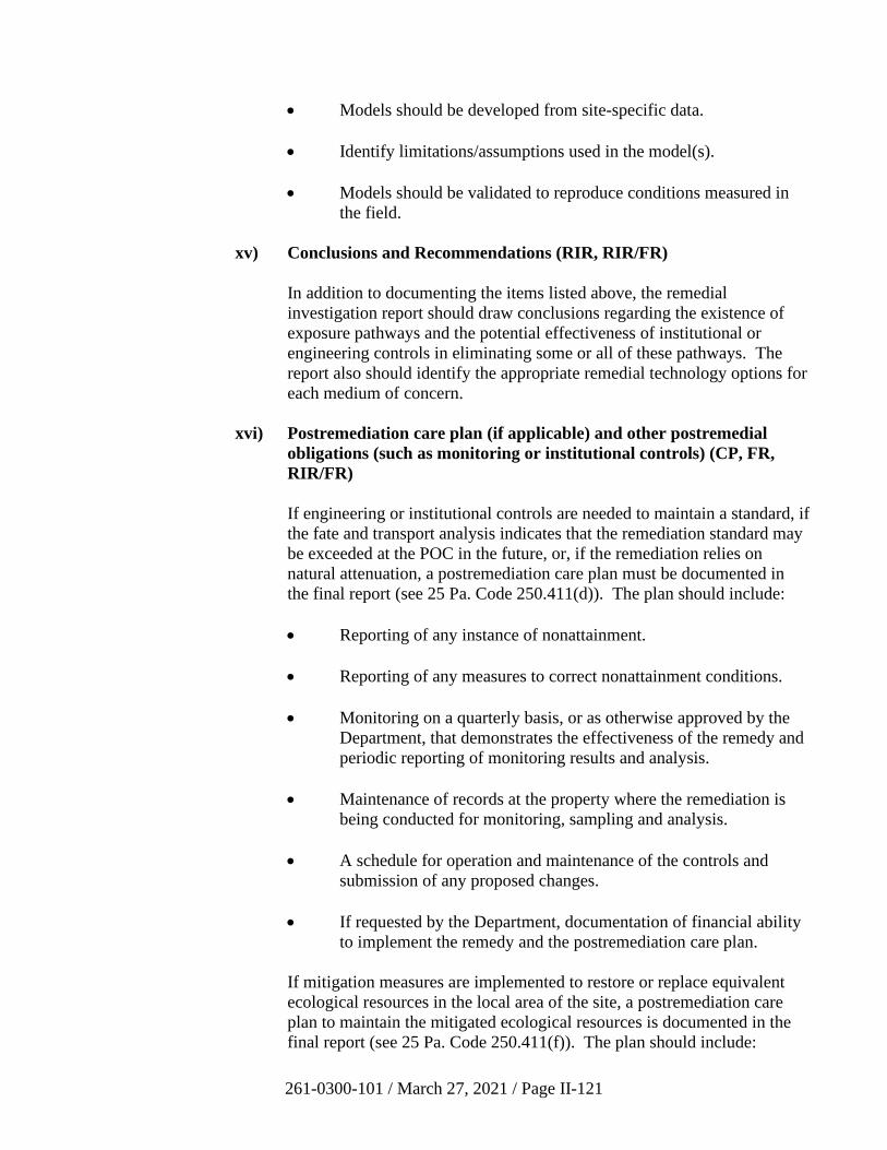
261-0300-101 / March 27, 2021 / Page II-121
• Models should be developed from site-specific data.
• Identify limitations/assumptions used in the model(s).
• Models should be validated to reproduce conditions measured in
the field.
xv) Conclusions and Recommendations (RIR, RIR/FR)
In addition to documenting the items listed above, the remedial
investigation report should draw conclusions regarding the existence of
exposure pathways and the potential effectiveness of institutional or
engineering controls in eliminating some or all of these pathways. The
report also should identify the appropriate remedial technology options for
each medium of concern.
xvi) Postremediation care plan (if applicable) and other postremedial
obligations (such as monitoring or institutional controls) (CP, FR,
RIR/FR)
If engineering or institutional controls are needed to maintain a standard, if
the fate and transport analysis indicates that the remediation standard may
be exceeded at the POC in the future, or, if the remediation relies on
natural attenuation, a postremediation care plan must be documented in
the final report (see 25 Pa. Code 250.411(d)). The plan should include:
• Reporting of any instance of nonattainment.
• Reporting of any measures to correct nonattainment conditions.
• Monitoring on a quarterly basis, or as otherwise approved by the
Department, that demonstrates the effectiveness of the remedy and
periodic reporting of monitoring results and analysis.
• Maintenance of records at the property where the remediation is
being conducted for monitoring, sampling and analysis.
• A schedule for operation and maintenance of the controls and
submission of any proposed changes.
• If requested by the Department, documentation of financial ability
to implement the remedy and the postremediation care plan.
If mitigation measures are implemented to restore or replace equivalent
ecological resources in the local area of the site, a postremediation care
plan to maintain the mitigated ecological resources is documented in the
final report (see 25 Pa. Code 250.411(f)). The plan should include:
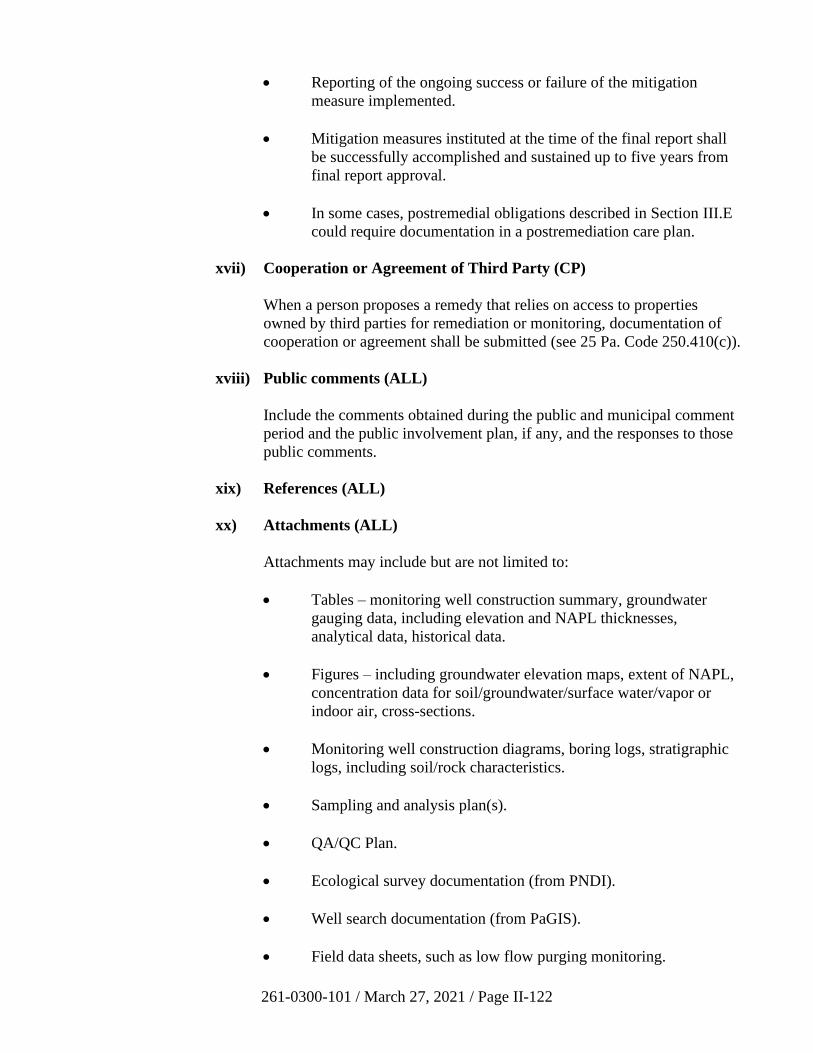
261-0300-101 / March 27, 2021 / Page II-122
• Reporting of the ongoing success or failure of the mitigation
measure implemented.
• Mitigation measures instituted at the time of the final report shall
be successfully accomplished and sustained up to five years from
final report approval.
• In some cases, postremedial obligations described in Section III.E
could require documentation in a postremediation care plan.
xvii) Cooperation or Agreement of Third Party (CP)
When a person proposes a remedy that relies on access to properties
owned by third parties for remediation or monitoring, documentation of
cooperation or agreement shall be submitted (see 25 Pa. Code 250.410(c)).
xviii) Public comments (ALL)
Include the comments obtained during the public and municipal comment
period and the public involvement plan, if any, and the responses to those
public comments.
xix) References (ALL)
xx) Attachments (ALL)
Attachments may include but are not limited to:
• Tables – monitoring well construction summary, groundwater
gauging data, including elevation and NAPL thicknesses,
analytical data, historical data.
• Figures – including groundwater elevation maps, extent of NAPL,
concentration data for soil/groundwater/surface water/vapor or
indoor air, cross-sections.
• Monitoring well construction diagrams, boring logs, stratigraphic
logs, including soil/rock characteristics.
• Sampling and analysis plan(s).
• QA/QC Plan.
• Ecological survey documentation (from PNDI).
• Well search documentation (from PaGIS).
• Field data sheets, such as low flow purging monitoring.
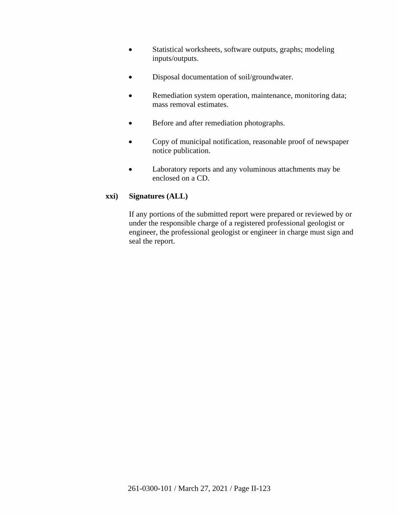
261-0300-101 / March 27, 2021 / Page II-123
• Statistical worksheets, software outputs, graphs; modeling
inputs/outputs.
• Disposal documentation of soil/groundwater.
• Remediation system operation, maintenance, monitoring data;
mass removal estimates.
• Before and after remediation photographs.
• Copy of municipal notification, reasonable proof of newspaper
notice publication.
• Laboratory reports and any voluminous attachments may be
enclosed on a CD.
xxi) Signatures (ALL)
If any portions of the submitted report were prepared or reviewed by or
under the responsible charge of a registered professional geologist or
engineer, the professional geologist or engineer in charge must sign and
seal the report.
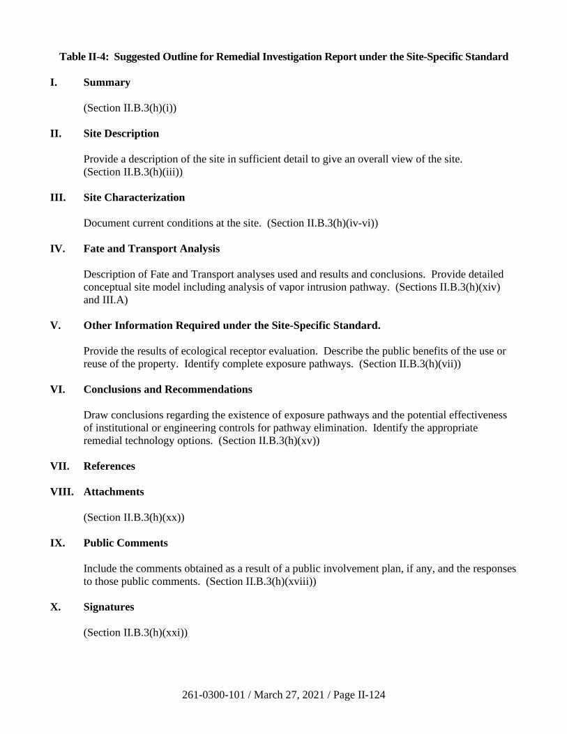
261-0300-101 / March 27, 2021 / Page II-124
Table II-4: Suggested Outline for Remedial Investigation Report under the Site-Specific Standard
I. Summary
(Section II.B.3(h)(i))
II. Site Description
Provide a description of the site in sufficient detail to give an overall view of the site.
(Section II.B.3(h)(iii))
III. Site Characterization
Document current conditions at the site. (Section II.B.3(h)(iv-vi))
IV. Fate and Transport Analysis
Description of Fate and Transport analyses used and results and conclusions. Provide detailed
conceptual site model including analysis of vapor intrusion pathway. (Sections II.B.3(h)(xiv)
and III.A)
V. Other Information Required under the Site-Specific Standard.
Provide the results of ecological receptor evaluation. Describe the public benefits of the use or
reuse of the property. Identify complete exposure pathways. (Section II.B.3(h)(vii))
VI. Conclusions and Recommendations
Draw conclusions regarding the existence of exposure pathways and the potential effectiveness
of institutional or engineering controls for pathway elimination. Identify the appropriate
remedial technology options. (Section II.B.3(h)(xv))
VII. References
VIII. Attachments
(Section II.B.3(h)(xx))
IX. Public Comments
Include the comments obtained as a result of a public involvement plan, if any, and the responses
to those public comments. (Section II.B.3(h)(xviii))
X. Signatures
(Section II.B.3(h)(xxi))
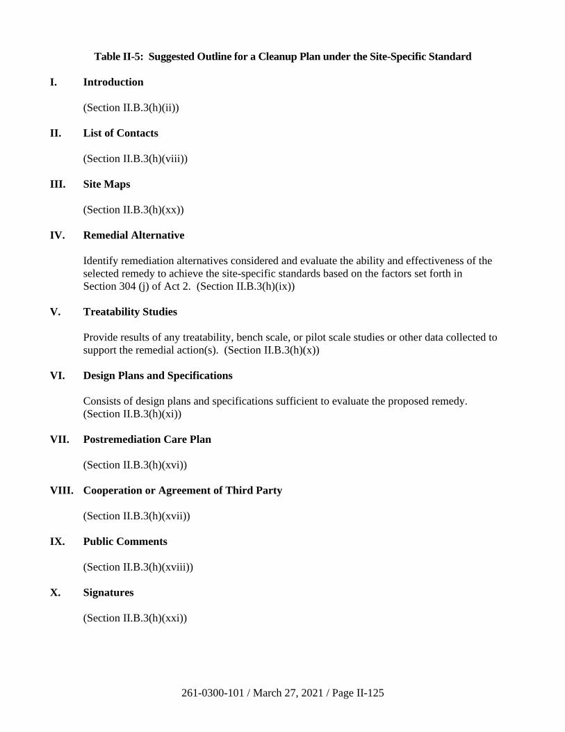
261-0300-101 / March 27, 2021 / Page II-125
Table II-5: Suggested Outline for a Cleanup Plan under the Site-Specific Standard
I. Introduction
(Section II.B.3(h)(ii))
II. List of Contacts
(Section II.B.3(h)(viii))
III. Site Maps
(Section II.B.3(h)(xx))
IV. Remedial Alternative
Identify remediation alternatives considered and evaluate the ability and effectiveness of the
selected remedy to achieve the site-specific standards based on the factors set forth in
Section 304 (j) of Act 2. (Section II.B.3(h)(ix))
V. Treatability Studies
Provide results of any treatability, bench scale, or pilot scale studies or other data collected to
support the remedial action(s). (Section II.B.3(h)(x))
VI. Design Plans and Specifications
Consists of design plans and specifications sufficient to evaluate the proposed remedy.
(Section II.B.3(h)(xi))
VII. Postremediation Care Plan
(Section II.B.3(h)(xvi))
VIII. Cooperation or Agreement of Third Party
(Section II.B.3(h)(xvii))
IX. Public Comments
(Section II.B.3(h)(xviii))
X. Signatures
(Section II.B.3(h)(xxi))
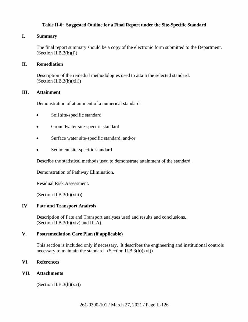
261-0300-101 / March 27, 2021 / Page II-126
Table II-6: Suggested Outline for a Final Report under the Site-Specific Standard
I. Summary
The final report summary should be a copy of the electronic form submitted to the Department.
(Section II.B.3(h)(i))
II. Remediation
Description of the remedial methodologies used to attain the selected standard.
(Section II.B.3(h)(xii))
III. Attainment
Demonstration of attainment of a numerical standard.
• Soil site-specific standard
• Groundwater site-specific standard
• Surface water site-specific standard, and/or
• Sediment site-specific standard
Describe the statistical methods used to demonstrate attainment of the standard.
Demonstration of Pathway Elimination.
Residual Risk Assessment.
(Section II.B.3(h)(xiii))
IV. Fate and Transport Analysis
Description of Fate and Transport analyses used and results and conclusions.
(Section II.B.3(h)(xiv) and III.A)
V. Postremediation Care Plan (if applicable)
This section is included only if necessary. It describes the engineering and institutional controls
necessary to maintain the standard. (Section II.B.3(h)(xvi))
VI. References
VII. Attachments
(Section II.B.3(h)(xx))

261-0300-101 / March 27, 2021 / Page II-127
VIII. Public Comments
(Section II.B.3(h)(xviii))
IX. Signatures
(Section II.B.3(h)(xxi))
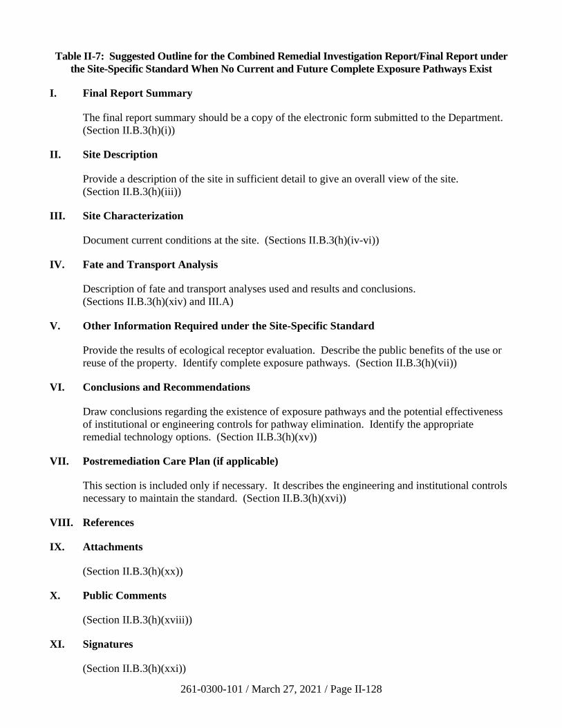
261-0300-101 / March 27, 2021 / Page II-128
Table II-7: Suggested Outline for the Combined Remedial Investigation Report/Final Report under
the Site-Specific Standard When No Current and Future Complete Exposure Pathways Exist
I. Final Report Summary
The final report summary should be a copy of the electronic form submitted to the Department.
(Section II.B.3(h)(i))
II. Site Description
Provide a description of the site in sufficient detail to give an overall view of the site.
(Section II.B.3(h)(iii))
III. Site Characterization
Document current conditions at the site. (Sections II.B.3(h)(iv-vi))
IV. Fate and Transport Analysis
Description of fate and transport analyses used and results and conclusions.
(Sections II.B.3(h)(xiv) and III.A)
V. Other Information Required under the Site-Specific Standard
Provide the results of ecological receptor evaluation. Describe the public benefits of the use or
reuse of the property. Identify complete exposure pathways. (Section II.B.3(h)(vii))
VI. Conclusions and Recommendations
Draw conclusions regarding the existence of exposure pathways and the potential effectiveness
of institutional or engineering controls for pathway elimination. Identify the appropriate
remedial technology options. (Section II.B.3(h)(xv))
VII. Postremediation Care Plan (if applicable)
This section is included only if necessary. It describes the engineering and institutional controls
necessary to maintain the standard. (Section II.B.3(h)(xvi))
VIII. References
IX. Attachments
(Section II.B.3(h)(xx))
X. Public Comments
(Section II.B.3(h)(xviii))
XI. Signatures
(Section II.B.3(h)(xxi))
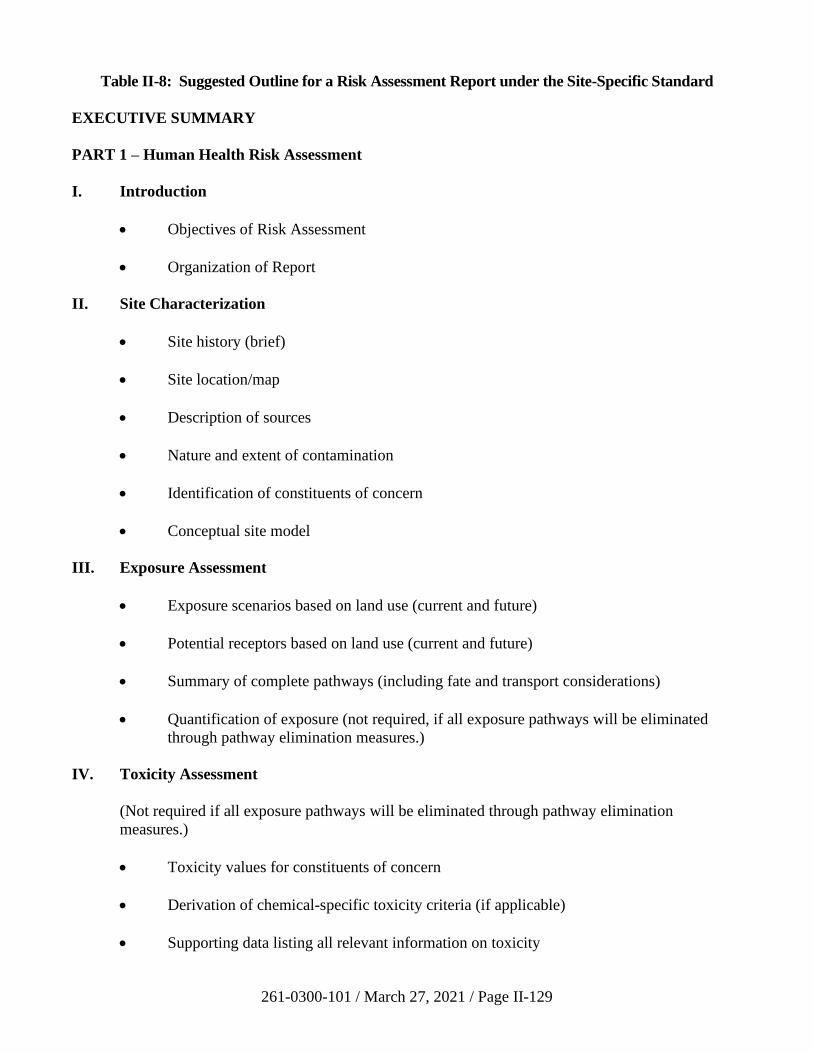
261-0300-101 / March 27, 2021 / Page II-129
Table II-8: Suggested Outline for a Risk Assessment Report under the Site-Specific Standard
EXECUTIVE SUMMARY
PART 1 – Human Health Risk Assessment
I. Introduction
• Objectives of Risk Assessment
• Organization of Report
II. Site Characterization
• Site history (brief)
• Site location/map
• Description of sources
• Nature and extent of contamination
• Identification of constituents of concern
• Conceptual site model
III. Exposure Assessment
• Exposure scenarios based on land use (current and future)
• Potential receptors based on land use (current and future)
• Summary of complete pathways (including fate and transport considerations)
• Quantification of exposure (not required, if all exposure pathways will be eliminated
through pathway elimination measures.)
IV. Toxicity Assessment
(Not required if all exposure pathways will be eliminated through pathway elimination
measures.)
• Toxicity values for constituents of concern
• Derivation of chemical-specific toxicity criteria (if applicable)
• Supporting data listing all relevant information on toxicity
261-0300-101 / March 27, 2021 / Page II-130
V. Risk Characterization
• Algorithms (not required if all exposure pathways will be eliminated through pathway
elimination measures.)
• Calculations and Results (not required if all exposure pathways will be eliminated
through pathway elimination measures.)
• Description and fulfillment of risk assessment objectives
• Discussion of uncertainty for all sections of report, including uncertainties associated
with site characterization, toxicity assessment, exposure assessment and risk
characterization
VI. References
PART 2 – Ecological Risk Assessment
This section reports the results of the ecological risk assessment conducted using the guidance in
Section III.I and, as applicable, EPA guidance.
Public Comments
Include the comments obtained as a result of a public involvement plan, if any, and the responses to
those public comments.
Signatures
If any portions of the submitted report were prepared or reviewed by or under the responsible charge of
a registered professional geologist or engineer, the professional geologist or engineer in charge should
sign and seal the report.
261-0300-101 / March 27, 2021 / Page II-131
4. Special Industrial Areas
a) Introduction
The SIA provision established in Section 305 of Act 2 creates incentives to reuse
industrial properties. Cleanups at these SIAs have reduced remediation
requirements which are intended to allow these sites to be put back into
productive use in the community. Act 2 established this provision to encourage
the redevelopment of properties used for industrial activities. The remediator,
reuser, and the property must meet eligibility requirements to be considered as an
SIA under Act 2. Under the SIA provision, necessary remediation will be
performed, and required notification and reporting requirements will be met.
b) Eligibility Determination
Specific eligibility requirements in § 250.502 of the regulations provide for
qualification of a property for reuse as an SIA and for the qualification of a
remediator to use this special provision of Act 2. The property must have been
used for industrial activity. The extent of industrial activity is defined very
broadly and is detailed in Section 103 of Act 2. If the property qualifies as having
been used for industrial activity, the following additional qualifications must be
met:
• The property must be one where there is no financially viable responsible
person, or it is located within a designated EZ.
• The remediator must not have caused or contributed to releases at the
property. A person who is interested in purchasing a property and
undertaking a reuse of that property should contact the Department before
the reuser purchases the property.
• The term “responsible person” includes the owner of the property,
regardless of whether he has or has not caused or contributed to the
contamination. Therefore, prospective purchasers of property which could
be eligible as an SIA are recommended to contact the Department prior to
the purchase of the property.
• Actions in themselves that do not cause or contribute to contamination
taken under Section 307 of Act 2 relating to emergency and interim
responses will not prejudice eligibility determinations under the SIA
designation.
• It is the responsibility of the reuser to demonstrate to the Department that
the reuser has not had an environmental impact on the property, just as it
is the responsibility of the remediator to document that the property meets
the other eligibility criteria for an SIA. To accomplish this, certain
information must be presented to the Department regarding the above
eligibility requirements:
261-0300-101 / March 27, 2021 / Page II-132
− Documentation that the property has been used for industrial
activities by including information on the ownership and
operational history of the property as part of the work plan for the
baseline remedial investigation.
− Verification that no financially viable responsible party exists to
address the contamination on the property. Financial information
for existing responsible parties must be included in the ownership
and operational history. “Financially viable” is generally defined
as having sufficient financial resources to be able to perform part
or all of the cleanup required at a particular property.
To qualify as a property within an EZ or Keystone Opportunity Zone (KOZ), the
municipality where the property is located must be designated by DCED as an
EZ, KOZ, or Keystone Innovation Zone (KIZ). To determine whether a particular
property is within an EZ, KOZ, or KIZ, contact DCED or the appropriate local
contact person. If a remediator wants to determine the eligibility of a site for the
SIA provisions, when a financially viable responsible party is present, the
remediator will need to verify the existence of the EZ, KOZ, or KIZ designation
for the area where the site is located.
A letter from either DCED or the appropriate zone contact person should be
provided with the work plan to verify the status of the property. Persons
remediating a site in an EZ where a viable responsible party may still exist are
only responsible for remediation of contamination identified in the baseline
environmental report and specified in the CO&A with the Department as required
for remediation prior to the new use of the property. Additional remediation may
be pursued by the Department with the responsible person. Responsible persons
under HSCA must resolve their liability to the Department pursuant to HSCA.
See Section V.E of this manual.
c) Process Checklist for Special Industrial Areas
☐ Evaluate the property potential for redevelopment.
☐ Determine if the property was used previously for industrial activity or if it
is located within an EZ (35 P.S. 6026.305(a) and 25 Pa. Code § 250.502).
☐ Determine if there is a financially viable responsible party. If the property
is located within an EZ, financial viability is not a requirement for SIA use
(35 P.S. 6026.305(a) and 25 Pa. Code § 250.502).
☐ The remediator must demonstrate to the Department that he did not cause
or contribute to contamination on the property (35 P.S. 6026.305(a) and
25 Pa. Code § 250.502).
☐ Review the historical information and present use of regulated substances
at the property.
261-0300-101 / March 27, 2021 / Page II-133
☐ Prepare a work plan for a baseline remedial investigation
(35 P.S. 6026.305(b) and 25 Pa. Code § 250.503(b)).
☐ The work plan must be approved by the Department prior to performing
the investigation (35 P.S. 6026.305(b) and 25 Pa. Code § 250.503(b)).
☐ Begin baseline remedial investigation (use Section II.B.4.e of this manual,
35 P.S. 6026.305(b) and 25 Pa. Code § 250.503(c)).
☐ Submit NIR for the SIA to the Department. Also provide notice to the
municipality, publish a notice of submission of the NIR in a local
newspaper, and provide reasonable proof of required notices to the
Department.
☐ Prepare public involvement plan (if requested by municipality).
☐ Prepare baseline environmental report based on baseline remedial
investigation (35 P.S. 6026.305(b) and 25 Pa. Code § 250.503(d)).
☐ Department review of baseline environmental report.
☐ Meet with the Department and concur on CO&A. The prospective
purchaser should enter into the CO&A prior to purchasing the property
(35 P.S. 6026.305(e) and 502(a)).
☐ Remediate the property to the SIA requirements specified in the baseline
environmental report and agreed to in the CO&A (35 P.S. 6026.502(b)).
☐ Calculate the mass of contaminants remediated using the procedure in
Section III.C of this manual.
☐ Complete the Final Report Summary and submit electronically as per the
instructions on the Land Recycling Program web page.
☐ Protection from liability occurs upon the signing of the CO&A with the
Department, subject to the remediator’s compliance with the CO&A
demonstrating attainment of the SIA requirements in accordance with
Chapters 3 and 5 of Act 2.
☐ Submit an environmental covenant, if applicable, to the Department.
261-0300-101 / March 27, 2021 / Page II-134
d) Aspects of Special Industrial Areas
i) Immediate, Direct, or Imminent Threats to Human Health and the
Environment
One of the significant aspects of Act 2 is the cleanup liability protection
provided for SIAs. The cleanup liability for the person undertaking
remediation and reuse of an SIA is dependent upon the person performing
remediation of immediate, direct or imminent threats to public health or
the environment which would prevent the property from being occupied
for the remediator’s intended purpose.
The immediate, direct, or imminent threats are to be determined by the
baseline remedial investigation and defined in the baseline environmental
report. The baseline environmental report will become the basis for the
CO&A between the Department and the remediator. The exposures, and
potential exposures, presented by an SIA site must be identified in the
baseline remedial investigation. Defining immediate, direct, or imminent
threats is relevant to the remediator’s intended use of the property.
Therefore, it is necessary for the remediator to specify the intended use of
the property. The identification of these threats needs to be addressed at
the time of the baseline remedial investigation work plan and in
performance of the investigation. Only concerns identified in the baseline
environmental report and included in the agreement can be considered in
any relief from liability afforded to the remediator by Act 2. For this
reason, it is paramount that the remediator performs a comprehensive
investigation of an SIA.
Immediate and imminent threats are pending threats likely to happen
without delay or momentarily in time. Direct threats, though sometimes
similar in immediacy, also include chronic exposure. At a minimum,
immediate, direct, or imminent threats will entail:
• Contained wastes which present immediate, direct or imminent
threats. Examples are regulated substances in drums, barrels,
tanks, or other bulk storage containers; and contained wastes, such
as wastes in drums, above or below ground tanks, and small
containers.
• All wastes which are not containerized, and which present a direct
threat to workers or other persons on the property. These may
include, but are not limited to, open containers, pits, waste piles
and other situations that allow wastes to be exposed and accessible
on the site.
• In addition to situations listed above, actual exposure for onsite
human populations to any regulated substances.
261-0300-101 / March 27, 2021 / Page II-135
• Actual contamination of drinking water by regulated substances.
Also, contaminated groundwater, if groundwater use will expose
persons on the property to contaminants.
• Contaminated soil presenting a direct contact threat to workers or
other persons on the property. Direct contact may occur in a zone
of soil at and below the surface. The depth of consideration of
surface soil shall be the first two feet from the ground surface,
unless reuse of the property presents exposure threats at depths
greater than two feet.
• Regulated substances presenting a threat of fire or explosion.
• Surface water and sediments contaminated with regulated
substances, if persons are or may become exposed to these
contaminants.
• Regulated substances contained as product may remain on the
property if maintained according to appropriate regulations. The
remediator is responsible for releases occurring as a result of the
remediator’s actions.
ii) Consideration of Chronic Exposure in Evaluation of the Reuse of a
Special Industrial Area
25 Pa. Code Section 250.503(c)(5) pertains to property to be reused and
states, “Evaluation of exposure conditions within the portion of the
property to be reused to identify existing contamination that poses an
immediate, direct or imminent threat to public health or the environment
which is inconsistent with the intended reuse of that portion of the
property.” Initially, the determination of property use for nonresidential or
residential purposes will focus on determination of direct contact
exposure. In the use of the definition of “immediate, direct or imminent,”
the word “direct” includes chronic exposure. In the scope of chronic
exposure, workers or other persons using a property with existing
contamination are to be protected from chronic exposure levels of
contaminants as well as to acute exposure levels. Direct contact includes
contamination which persons may come in contact with when working,
living at, or visiting a site. Direct contact may occur by several routes.
Some examples are ingestion of soil, contact with soil, or inhalation of soil
particles or vapor from the soil. Additional direct contact pathways may
be caused by leaching from the soil to groundwater, vapor intrusion into
buildings, inhalation of contaminated process water, surface water run-off
to water bodies, and exposure of wildlife and ecosystems. Soil available
for direct contact must meet the human health and environmental
protection standards established by Act 2.
261-0300-101 / March 27, 2021 / Page II-136
iii) Contaminant Migration Off-Property
There are no obligations or liability for off-property contamination placed
upon an innocent person using the SIA provision. For cases where the off-
property pollution is significant, there may be other available options for
addressing these risks. If there is an existing viable responsible party
(property located within an EZ), the viable responsible party would
continue to be responsible for off-property contamination. For sites where
there is no viable responsible party, the cleanup may either be remediated
by a purchaser of the property (voluntary cleanup) or addressed under
other State or federal programs. In either case, the innocent purchaser
would not be responsible for off-property contamination, as long as he or
she did not cause or contribute to that contamination. Although
assessment at the time of the baseline remedial investigation is not
required off-property, the remediator should determine whether
contamination is moving off the property.
If contamination which requires remediation is found at a future date, and
the nature, concentration, and location were not identified in the baseline
environmental report, the remediator may be liable to perform cleanup of
the contamination to one of the three standards.
iv) Contamination Identified Subsequent to Remediation and Agreement
Conditions
Under Section 502(b) of Act 2 the remediator is only relieved from
liability for contamination which was identified in the baseline
environmental report. For this reason, it is to the remediator’s benefit to
conduct a comprehensive investigation.
v) Storage Tank Closure and Corrective Action at Special Industrial
Areas
Remediators are only responsible for addressing the immediate, direct or
imminent threats posed at SIAs. In all cases this includes removal of
waste in containers. Materials remaining in tanks must be removed and
handled in accordance with applicable laws and regulations. Product may
remain in the tanks if it is rendered inert and poses no risk. The actual
tanks are required to be removed or rendered safe. The remediator should
follow the Storage Tank Program regulations and guidance to achieve a
safe closure of tanks. Smaller containers will likely be required to be
removed. Releases from tanks that occur after the remediator becomes the
owner or operator are the responsibility of the remediator.
vi) Consent Orders and Agreements
Remediation of all threats relevant to an SIA reuse which were detailed in
the baseline environmental report will be detailed in a CO&A.
261-0300-101 / March 27, 2021 / Page II-137
Contamination not identified in the baseline environmental report will
become the responsibility of the remediator.
A change in use of the property, from that defined in the Agreement, may
necessitate a change in the Agreement or modification of the proposed
property reuse. A land use change for an SIA may trigger a reopener
under Section 505(4) of Act 2. The CO&A with the Department will
require the remediator or reuser to provide the Department with written
notice of any change in the use of the property and to remediate any
contamination which would prevent the use of the property for its new
purpose.
vii) Remediation
Remediation in SIAs must meet the following requirements:
• Cleanup may utilize treatment, containment, removal, control
methods, or any combination of the above.
• Cleanup must address all containerized waste at the property in
accordance with applicable regulations.
• Soil available for direct contact must meet one of the
three remediation standards.
• Cleanup of any wastes or cleanup of any medium contaminated
with regulated substances which pose an immediate, direct, or
imminent threat to human health or the environment based on the
intended use of the property must be to one of the
three remediation standards.
If groundwater is to be used at the property, the groundwater must either
be remediated in-ground or at the point of use so that it is safe for its
intended use and occupation of the property.
viii) Environmental Covenant
An environmental covenant is necessary for SIA remediations that require
an activity and use limitation. The environmental covenant may also
fulfill any deed acknowledgement requirements specified by SWMA and
HSCA. Future activity and use limitations due to disposal of hazardous
wastes or regulated substances may be required as part of the remedy and
may be identified as part of the environmental covenant.
261-0300-101 / March 27, 2021 / Page II-138
e) Work Plan for Baseline Remedial Investigation and Baseline Environmental
Report
i) Work Plan for Baseline Remedial Investigation
A baseline remedial investigation is required for evaluation of a property
that will be part of an SIA agreement. The objective of the baseline
remedial investigation is to establish a reference point documenting
contamination that existed prior to the redevelopment. A work plan for
the baseline remedial investigation is required to be prepared by the
remediator and approved by the Department prior to initiation of the
investigation. The findings and conclusions of the baseline remedial
investigation shall be documented in a report known as a baseline
environmental report.
The work plan for the baseline remedial investigation shall be designed
considering the unique considerations of SIAs and tailored for the specific
property. The work plan shall address how the remediator will perform
the baseline remedial investigation and shall address the items below and
any additional items determined to be appropriate by the person proposing
remediation or requested by the Department. The work plan for the
remedial investigation shall include the steps to be taken to document the
following:
• A description of the property and detailed ownership history.
• Identification of the historical regulated substance use, handling
and disposal activities on the property, and any known or
suspected releases associated with these activities. This is obtained
by conducting an environmental site characterization, a review of
historical records, and interviews with persons who may have
knowledge of the property.
• Characterization of the regulated substances on the property.
Identification of existing contamination that poses an immediate,
direct or imminent threat to public health or the environment which
would prevent the property from being occupied for the intended
use.
• Identification of potential migration pathways off the property, or
onto the property, and any potential receptors from any release on
the property. Where migration pathways and receptors have been
identified, the remediator shall perform environmental sampling of
the groundwater at the downgradient property boundary to
determine if regulated substances from releases on the property
have migrated off the property.
261-0300-101 / March 27, 2021 / Page II-139
• In addition to the above, environmental sampling, if indicated by
the investigation, in all potential media of concern to confirm
whether releases have occurred.
ii) Baseline Environmental Report
The baseline environmental report shall provide the results of the baseline
remedial investigation and describe the historical use, location of areas of
contamination, the intended reuse, sampling results, contaminant
migration occurrence or potential, and the proposed remediation measures
to ensure that the SIA requirements are met. Portions of the baseline
environmental report containing information about geologic or
hydrogeologic investigations shall be prepared and certified by a
registered professional geologist licensed in Pennsylvania. The baseline
environmental report shall be submitted without binding. The following is
a recommended scope of a baseline environmental report:
Summary: Provide a summary paragraph(s) that will give the reviewer
an overview of the property. This will serve to highlight the important
issues and conclusion that will be presented in the report.
Description of Property: Provide a description of the property in
sufficient detail to give the reader an overall idea of the property and its
location. Describe the following:
• Buildings and other site features such as lagoons, tanks, treatment
plants, and other structures on the property. Include a site map
(scale of 1 inch = 200 feet).
• The location of all onsite wells, septic systems, floor drains, sumps
and associated piping, storage areas, and chemicals or chemical
compounds used, stored, treated or disposed.
• A description of present conditions at the property including any
evidence of a release, contaminated media, tanks, and
identification of areas of uncontained and/or SPL.
• The location and name of any public or private water supply on or
near the property.
• The location, name and elevation of surface water bodies (springs,
streams, lakes, ponds, wetlands) within 2,500 feet of the property.
• The location of utility lines at and near the area of investigation
including any municipal or private water supply lines or natural
gas lines, sanitary or sewer lines, and any other subsurface utilities.
• The location of active and inactive oil and gas wells, injection
wells, surface and underground coal and non-coal mines, mine
261-0300-101 / March 27, 2021 / Page II-140
pool discharge points, landfills, and surface disposal areas within
2,500 feet of the property.
• Identify sensitive features within 2,500 feet of the property, such as
threatened or endangered species habitat, recreational river
corridors, state and federal forests and parks, historic and
archaeological sites, national wildlife refuges, state natural areas,
prime farm land, wetlands, special protection watersheds
designated under Chapter 93 and other features.
Ownership History: Provide a detailed property ownership history since
the release of regulated substances onsite. Include company or individual
name and address (if available), ownership period, and the general
operational use of the property during each ownership period.
Site Use History: Provide detail on past and current uses of property and
adjoining properties; including treatment, storage, and disposal of
regulated substances. Indicate the type, estimated volume, composition,
and nature of the released materials, chemicals or chemical compounds.
Indicate the sources of regulated substances; description of spills, leaks,
releases on the property; and migration or migration potential to adjacent
properties; and remedial action to date. Include a brief description of
agency actions such as violation notices, administrative orders, and
environmental permits.
Site Characterization: The site characterization provides important
information documenting the current conditions at the property.
Information developed during the site characterization is primarily
intended to describe the nature, extent, and potential for movement of all
contaminants present on the property, or that may have migrated from the
property. For sites where there are multiple distinct areas of
contamination, the site characterization process should be applied to each
area individually. The remediator must use scientifically recognized
principles, standards and procedures.
Geology/Hydrogeology: Description should be based on existing
literature and data (Soil Classification System (SCS) soil surveys, geologic
maps, Water Resource reports, reports on nearby properties and sampling)
including:
• Descriptions of the soils, fill materials, geologic, hydrologic and
hydrogeologic conditions at and surrounding the property. These
descriptions should be detailed enough to provide an understanding
of the site with respect to local geologic conditions and to
determine if property groundwater is in an aquifer as defined by
Act 2.
261-0300-101 / March 27, 2021 / Page II-141
• A local stratigraphic column including lithology, physical
characteristics and the approximate thickness of each stratum,
include location and depth of aquifer(s) (if known).
• The geologic structure within the property boundaries and its
relation to the regional geologic structure (if known).
• The location(s) of sinkholes, fracture traces, outcrops, and
lineaments (if known).
• Screening of soils, sediments and water (as appropriate). Submit
all results, include QA/QC documentation. Identify field screening
methods and sampling procedures. Cone Penetration Technologies
(CPT) and other direct push technologies (DPT) may be used for
sampling of solids, soil gases, and groundwater. CPT and DPT
results should be useful to more accurately site permanent
monitoring wells in areas of concern. Vapor intrusion assessments
should be conducted in accordance with Section IV of this manual.
All sample locations should be depicted on a site map. Incorporate
results from past sampling, if applicable.
Soil investigations shall be performed to establish baseline quality of
surface, shallow, and subsurface soils at the site. Investigations will
involve actual, as well as potential, sources of contamination, underground
storage tanks, stained soils, and building drains, sumps, and storm/sewer
systems. Investigations of underground storage tanks will identify any
potential impacts from possible leakage of the tanks. Sampling will be
performed. Property boundary soil sampling may also be performed to
assess soil quality conditions and compared to the appropriate residential
or nonresidential standards based on the proposed use of the property.
Groundwater investigations shall be performed to establish baseline
quality of the shallow and aquifer groundwater conditions. Investigations
will involve wells (both monitoring and supply, and including appropriate
off-property wells), sample analysis and water quality, and groundwater
level measurement.
Identified Contamination: Characterize the source and nature,
concentration, location, and extent of the regulated substances. Text,
tables, graphics, figures, maps and cross sections may be used to describe
the nature, location, and composition of the contaminants on the property.
Determine the extent, if any, of regulated substances that have migrated
beyond the property boundary. Indicate all existing and potential
migration pathways. Indicate the direction and rate of contaminant
movement within each medium of concern.
Proposed Remediation Measures: The baseline environmental report
shall include the proposed plan for remediation of the property and will
serve as the basis for the CO&A. Therefore, the remedial action must be
fully defined and described. The remediation of all threats relevant to the

261-0300-101 / March 27, 2021 / Page II-142
special industrial area reuse will be reiterated in the CO&A. Identification
of contamination is very important in establishing what the remediator will
be obligated to cleanup, and the extent of the cleanup liability protection
afforded by Act 2.
Public Notice: Provide information concerning all public notifications
performed. Supply copies of the notifications and reasonable proof of
required notices of the NIR in a newspaper of general circulation serving
the area where the property is located. Indicate if a municipality requested
a public involvement, and if so, include the public involvement plan and
all comments received, and responses to those comments.
Public Benefits: The baseline environmental report should include a
description of the existing or potential public benefits of the use or reuse
of the property for employment opportunities, housing, open space,
recreation or other uses. An estimate of the potential employment
anticipated by the reuse of the property is also requested.
Signatures: If any portion of the submitted report were prepared or
reviewed by or under the responsible charge of a registered professional
geologist or engineer, the professional geologist or engineer in charge
must sign and seal the report.
Attachments:
Attachments may include but are not limited to:
• Tables – monitoring well construction summary, groundwater
gauging data (including elevation and NAPL thicknesses),
analytical data, historical data.
• Figures – including groundwater elevation maps, extent of NAPL,
concentration data for soil/groundwater/surface water/vapor or
indoor air, cross-sections.
• Monitoring well construction diagrams, boring logs, stratigraphic
logs, including soil/rock characteristics.
• Sampling and analysis plan(s).
• QA/QC Plan.
• Ecological survey documentation (from PNDI).
• Well search documentation (from PaGIS).
• Field data sheets, such as low flow purging monitoring.
261-0300-101 / March 27, 2021 / Page II-143
• Statistical worksheets, software outputs, graphs; modeling
inputs/outputs.
• Disposal documentation of soil/groundwater.
• Remediation system operation, maintenance, monitoring data;
mass removal estimates.
• Before and after remediation photographs.
• Copy of municipal notification, reasonable proof of newspaper
notice publication.
• Laboratory reports and any voluminous attachments may be
enclosed on a CD.

261-0300-101 / March 27, 2021 / Page II-144
APPENDIX
261-0300-101 / March 27, 2021 / Page II-145
Appendix II-A: The Use of Caps as Activity and Use Limitations
Caps are one of the most common mechanisms used by remediators to eliminate exposure pathways at
sites with subsurface contamination. As the term is used in this document, caps encompass a broad
array of physical features that cover underlying contamination. Capping prevents exposure via direct
contact by acting as a barrier between a human receptor and the underlying contaminated media. Low
permeability caps can also help limit vertical movement of contaminants via stormwater infiltration or
vapor migration. Different caps work more effectively in certain situations, so site-specific information
should be used to determine which cap system to select.
The conceptual site model (see the site characterization discussion in Section II of this manual) should
be used to identify potential receptors and related contaminant migration and exposure pathways. The
receptors and pathways to be addressed should be evaluated before cap construction takes place to
ensure that installation of the cap will achieve the desired result. Remediators should clearly understand
the nature and extent of contaminants at their site and the current and projected future conditions.
The guidance provided in this addendum applies solely to the use of caps in attaining an Act 2 standard.
Caps used at landfills, RCRA sites, or other non-Act 2 sites may have requirements that differ from the
guidance provided in this addendum and should follow the relevant regulations of the program/entity
regulating the facility. Additionally, this addendum is intended to supplement existing guidance; it is
not regulation and should not be interpreted as such. This addendum is provided to inform remediators
of pertinent information to consider when selecting cap systems and some of the options that are
available. Remediators may choose to consider alternative technologies other than those discussed
herein when addressing their specific situation. Remediators may need to develop a different approach
than what is described in this guidance to provide the best fit for their specific situation.
A cap is a barrier over contaminated media that eliminates an exposure pathway, controls contaminant
migration, or a combination of both. Thus, a cap can be used as an engineering control and/or an
institutional control (i.e., an activity and use limitation) to attain an Act 2 standard. As such, remedies
that use a cap require a cleanup plan which describes the selected remedy. If a cap already exists at the
site (e.g., a parking lot) and needs to be preserved as part of the remedy, then the cleanup plan should
describe the way the cap will be maintained. Since a cap is used as an activity and use limitation, a
remediator must properly record an environmental covenant pursuant to the Uniform Environmental
Covenants Act to ensure the cap is properly maintained in the future. If applicable, the final report
should include as-built plans and details of the cap construction and photographs documenting
installation of the cap, when available. The post-remediation care plan and environmental covenant
should include a map depicting the extent of the cap as well as monitoring and maintenance
requirements.
All components of cap utilization for the purpose of attaining an Act 2 standard, including but not
limited to, design, construction, and inspection, may be governed by the Engineer, Land Surveyor, and
Geologist Registration Law (63 P.S. §§ 148-158.2).
General Goals for Caps – Caps are generally used to address contamination at concentrations resulting
in an unacceptable risk for the following purposes:
• Protection from direct contact with contaminated soil.
261-0300-101 / March 27, 2021 / Page II-146
• Prevention or reduction of the migration of contamination throughout the subsurface (upward,
downward, and laterally).
• Prevention of the migration of contamination to surface water via stormwater runoff.
Cap Construction Considerations – The following factors should be considered during the design,
construction and maintenance of most caps, where appropriate:
• Erosion from precipitation, surface water flow or wind.
• Cracking and deterioration from natural influences including water saturation and freeze/thaw
cycles.
• Expected human activities on the land covered by the cap.
• Settlement and shifting of the cap and subsurface.
• Potential damage from migration of groundwater into the cap.
• Contaminant migration, including migration to the surface of the cap and potential vapor
migration. Refer to Section IV of this manual when evaluating the vapor intrusion pathway.
• Construction impacts to site development including storm water management.
Protection from Direct Contact with Contaminants
Design Goals – In addition to the cap construction considerations presented previously, the design
should prevent direct contact exposure to contaminated soil for as long as the contaminant
concentrations remain at unacceptable levels. Cap designs should consider site-specific factors,
including, but not limited to:
• Current and anticipated future land use (anticipated future activities that could result in creating
an exposure pathway to the soil should be addressed with land use restrictions).
• The nature of the contaminants (concentrations, mobility, toxicity, etc.).
• The types of potential exposure pathways (e.g., ingestion or inhalation).
• Contaminant degradation and daughter products resulting from such degradation, if any.
• The specifications of the capping material, the quality control of the cap construction, and the
operation and maintenance (O&M) and inspection requirements.
• The reliability of the assurances that O&M, and inspections will be performed for as long as
direct contact exposure to, or migration through or from the contaminants in soil beneath the cap
would result in an unacceptable risk.
261-0300-101 / March 27, 2021 / Page II-147
Soil Caps – Soil caps can be used to prevent direct contact exposure to contaminated soils. Soil
containing regulated substances, at concentrations that do not constitute an unacceptable risk to human
health by the direct contact pathway may be used as cap material. Cap thickness depends on various
factors including the type and intensity of the land use above the cap and the contours/slope of the area
being capped.
In general, it is recommended that caps used to prevent direct contact with contaminated soil are
constructed with two feet of acceptable soil including a vegetated cover to prevent erosion and
deterioration. The vegetated cover usually consists of six inches of topsoil, with appropriate seeding or
sod to establish a good growth of grass. When a vegetated cover is used, consideration can be given to
reducing the thickness of the acceptable soil layer by the same amount as the vegetated cover thickness
(e.g., 1.5 feet of acceptable soil with an additional six inches of topsoil for a total cap thickness of
two feet).
Cap designs of less than two feet thickness may be appropriate when additional design features, such as
the use of warning fabrics, are considered or if the likelihood of deterioration is low (e.g. flat surfaces,
low foot/vehicle traffic, etc.). Other materials, such as gravel, may substitute for vegetated topsoil as
discussed below. Capping materials should be durable and meet the performance specifications required
for the site.
DEP recommends placement of a demarcation boundary (warning fabric) on top of the contaminated
soil and beneath the soil cap. The slope for an acceptable soil cap with vegetated topsoil cover should
normally not be steeper than a 3:1 horizontal-to-vertical ratio. Steeper slopes may be considered on a
case-by-case basis if it can be shown that erosion will be adequately controlled through additional
design features and/or O&M. Steeper slopes will generally call for an evaluation of the need for slope
reinforcement to provide long- term stability. However, cap design should use lower slopes when
possible and good cover vegetation to slow down stormwater runoff velocities to prevent erosion. If cap
material is suspected to have been impacted by a release, remediators should demonstrate that the
material was evaluated using DEP’s Management of Fill Policy (DEP ID 258-2182-773).
Pavement covers – Pavement systems may be used to prevent direct contact exposure to contaminated
soils. Contaminated soil particles can work their way up through pavement surfaces where pavement
settlement, shifting, cracking, freeze/thaw cycles, weathering, and deterioration are not adequately
addressed in the design, construction, and maintenance of the cap. Pavement material should have
appropriate bottom base soil preparation (grading, recompaction, dewatering, etc.) and sufficient base
course to minimize freeze/thaw, settling, and shifting problems, which can cause pavement
deterioration. Pavement thickness and overall design can be determined based on normal paving
procedures to ensure structural integrity. Generally accepted pavement construction guidance sources
should be used such as the American Association of State Highway Transportation Officials.
Buildings or Structures – An existing or new building or structure may be used to prevent direct contact
exposure to contaminated soils, provided the building slab or basement walls/floor are evaluated for the
general cap construction considerations discussed previously. Buildings with badly cracked slabs or
basement floors or walls in contact with contaminated soil should be repaired. Dirt floors in buildings
should be treated like any other portion of the site with bare soils.
Other Materials – The following materials, by themselves, might not be acceptable for a direct contact
cover system because of the potential for contaminated soil to migrate through them. However, they
261-0300-101 / March 27, 2021 / Page II-148
may be substituted for the vegetated topsoil portion of the soil direct contact cover system using the
thickness indicated:
• Gravel or stone – A layer of gravel or stone thick enough to prevent erosion (usually six inches)
is recommended.
Note: A permeable cap constructed entirely of gravel/stone may be used to prevent direct
contact if a mixed grade of aggregate is used and the layer of aggregate will pack sufficiently
tightly to keep soils from migrating upward or, if the gravel/stone is used in combination with a
geotextile layer to prevent soil particle migration and adequate maintenance is provided to retain
the intended thickness of the cap.
• Geomembranes – A synthetic membrane liner made from thin continuous polymeric sheets is
acceptable if the material is not considered an untreated geotextile. Geomembranes constructed
from low density polyethylene (LDPE), high density polyethylene (HDPE), or polyvinyl chloride
(PVC), are generally acceptable. If the geomembrane is not buried beneath a soil cover,
resistance of the material to degradation from exposure to ultra-violet light must be considered in
the design and postremediation care plan.
• Geotextiles – A woven or nonwoven geotextile is not acceptable for a direct contact cover by
itself except as a very short-term temporary cover to prevent erosion. A geotextile layer may be
used to:
o Prevent contaminated soil particles from migrating to layers with concentrations of
regulated substances that do not constitute an unacceptable risk.
o Provide a demarcation layer between the cap material and contaminated soil.
o Provide physical reinforcement and enhanced stability.
Note: Use of a geotextile warning fabric is encouraged for sites where future construction or
utility work is anticipated.
Horizontal Extent of Cap – The cap should be designed and constructed to provide adequate protection
from exposure to all areas that have contaminant concentrations that do not meet an acceptable risk
level. The cap design thickness should extend horizontally to a perimeter line beyond where
unacceptable contamination has been delineated to ensure adequate protection from direct contact.
Prevention of Migration of Contaminants
Design Goals – If the control of contaminant movement is necessary to meet the chosen Act 2 standard,
the cap design should minimize the migration of contaminants from contaminated soil to groundwater or
to the surface via soil moisture or vapor migration. The cap construction considerations presented
previously should also be considered for caps designed to prevent contaminant migration. The transport
of chemicals to receptors of concern could occur via upward or downward movement of dissolved
contamination in soil moisture and from volatile contaminant movement upward and downward in soil
gas by vapor diffusion or bulk soil-gas flow. The cap may require features to control these modes of
transport. If the infiltration of surface water, precipitation, or snow melt through contaminated soil
needs to be significantly minimized, then the cover system should include a layer or layers that reduce
261-0300-101 / March 27, 2021 / Page II-149
such infiltration to the extent necessary to achieve the required minimization. The design of these types
of cap systems should consider site-specific factors, including, but not limited to:
• The nature of the contaminants (concentrations, degradation, solubility, mobility, toxicity, etc.).
• Depth of the contamination. (Note: The horizontal extent of the cap may need to extend beyond
the direct contact footprint to address contamination in deeper soil horizons.)
• The quality of construction and the operation, maintenance and inspection program for the site.
• The reliability of O&M and inspections to maintain the remedy for as long as the unacceptable
soil contaminant concentrations persist.
• Construction impacts to site development including storm water management.
Low-permeability Cap Designs – Typical materials used in the construction of low-permeability caps for
reducing water infiltration include, but are not limited to, geomembranes, engineered mixtures of
properly compacted fine sand, silt and clay, clay barriers, geosynthetic clay liners, concrete, and
pavement. Typical materials used in the construction of vapor barriers include plastic membranes made
of polyethylene or propylene, and semisolid barriers that are applied by spraying or pumping.
Buildings or Structures – An existing or new building or structure may be used to prevent infiltration
into contaminated soils provided the building has a sound roof and roof runoff is managed to minimize
runoff infiltration into contaminated soils. Dirt floors in buildings should be treated like any other
portion of the site with bare soils. The potential for vapor intrusion into buildings should be evaluated in
accordance with the guidance provided in Section IV of this manual.
Multiple Pathway Designs – A cap that meets the requirements for prevention of infiltration will likely
be acceptable for prevention of direct contact. All cap systems should be designed and evaluated for the
pathways being addressed.
Horizontal Extent – The guidance provided previously on the horizontal extent of cap designs for
protection against direct contact exposure also applies to the prevention of contaminant migration to
groundwater using the applicable groundwater protection standards.
VOC (Volatile Organic Compounds) Migration – VOC concentrations in soil and shallow groundwater
may be a source of contaminant vapors that can migrate, transporting the VOCs to locations that may
not be currently contaminated. Certain types of caps, such as pavement, may limit the upward vertical
migration of vapors to the surface but may force them to migrate horizontally to create new
contamination in soil and groundwater. The cap may also direct vapors into buildings, increasing indoor
air contaminant concentrations. Vapors could migrate into the cap itself contaminating the previously
acceptable material and potentially damaging it (for example, certain VOCs can degrade asphalt or kill
vegetation). It may be necessary to treat or remove the sources of vapors or provide active or passive
venting below and/or adjacent to a cap to remove soil vapors and prevent vapor migration.
Inspections and Maintenance
Post-remediation care plans (PRCPs) and environmental covenants must contain appropriate conditions
to ensure that the integrity of the cap is maintained if the cap is used to attain an Act 2 standard. Please
261-0300-101 / March 27, 2021 / Page II-150
refer to Section III.E of this manual for information on long-term stewardship obligations for post-
remediation care plans and environmental covenants. Factors to consider and DEP’s recommended best
practices include the following:
• The extent of the cap should be well defined such that the owner, contractors, DEP, and other
parties can readily identify the restricted area. The cap boundaries should be clearly marked on a
map or site figure.
• A professional survey of the cap boundaries is beneficial, for instance when the cap is not readily
visible, landmarks used to define the boundaries change, the cap area is large, or the cap
boundaries are irregular.
• Caps should be inspected periodically depending on how likely they are expected to require
routine maintenance and the potential risks from cap disturbance. In cases where caps are more
likely to experience disturbance (e.g., on sloped surfaces or in high-use areas), inspections
should be more frequent.
• Inspections should take place during and after any activities that disrupt or penetrate the cap,
such as landscaping work, utility trenching, and construction.
• All inspections should be recorded in writing. Photographs are useful documentation of the cap
condition. Inspection records should be maintained for a period of three years and must be made
available for DEP review upon request.
• Contractors should consider the need to develop a health and safety plan to address potential
future exposures to contaminated soil beneath the cap by construction and utility workers.
• Qualitative or quantitative criteria may be developed in the PRCP to determine when disruptions
to cap integrity that could impair its effectiveness must be repaired.
• Disruptions of soil caps, including excavation, removal, penetration, erosion, loss of vegetated
topsoil, or any other cumulative thinning of the original cap thickness, should be repaired within
30 days of the date of discovery.
• Disruptions of pavement, buildings, and other structural caps, including removal, penetration,
significant cracking, erosion, or other opening(s), should be repaired within 30 days of the date
of discovery.
Both the discovery and repair of cap disruptions should be reported to DEP as required by the PRCP and
environmental covenant within one month of discovery. The reporting should describe the nature and
cause of the disruption, explain the corrective actions taken, and document that repairs were made (e.g.,
photographs).
261-0300-101 / March 27, 2021 / Page III-i
TABLE OF CONTENTS
SECTION III: TECHNICAL AND PROCEDURAL GUIDANCE ...............................................III-1 A. Fate and Transport Analysis ...................................................................................................... III-1
1. Fate and Transport Analysis in the Unsaturated Zone ................................................... III-3 a) General ............................................................................................................... III-3 b) Minimum Contaminant-Specific and Site-Specific Requirements .................... III-3
i) Contaminant-Specific Requirements for All Analytical
Tools ...................................................................................................... III-3 ii) Site-Specific Requirements for All Analytical Tools ............................ III-4 iii) Additional Requirements ....................................................................... III-5
c) Conditions for Use of Analytical Tools and Parameter Input
Values ................................................................................................................ III-6
d) Conclusion ......................................................................................................... III-7 2. Fate and Transport Analysis in the Saturated Zone ....................................................... III-7
a) Groundwater Solute Fate and Transport Modeling (General) ........................... III-9
b) Define Study Objectives .................................................................................. III-11 c) Data Collection ................................................................................................ III-11 d) Conceptual Model ............................................................................................ III-12
i) Geologic Data ...................................................................................... III-12 ii) Hydrologic Data ................................................................................... III-12
iii) Hydraulic Data ..................................................................................... III-13 iv) Chemical and Contaminant Data ......................................................... III-13
e) Model Selection ............................................................................................... III-14
f) Calibration and Sensitivity ............................................................................... III-15
g) Predictive Simulations ..................................................................................... III-16 h) Fate and Transport Model Report .................................................................... III-16
3. Impacts to Surface Water from Diffuse Flow of Contaminated
Groundwater ................................................................................................................ III-18 a) Conceptual Framework .................................................................................... III-18
b) Mathematical Framework ................................................................................ III-20 c) Application ....................................................................................................... III-21 d) Statewide Health Standard in Aquifers with 2,500 mg/L TDS or
Less .................................................................................................................. III-22 e) Examples .......................................................................................................... III-23
i) Example 1: Groundwater Source Very Near or Adjacent to
Surface Water Discharge ..................................................................... III-23 ii) Example 2: Groundwater Source at Distance from Surface
Water Discharge – Steady-State Conditions ........................................ III-32 B. Guidance for Attainment Demonstration with Statistical Methods ......................................... III-41
1. Introduction .................................................................................................................. III-41 2. Data Review for Statistical Methods ........................................................................... III-42
a) Summary Statistics........................................................................................... III-42
b) Graphical Procedures ....................................................................................... III-43 3. Statistical Inference and Hypothesis Statements ......................................................... III-43 4. Selection of Statistical Methods................................................................................... III-45
a) Factors Affecting the Selection of Statistical Methods.................................... III-45 b) Recommended Statistical Procedures .............................................................. III-47
261-0300-101 / March 27, 2021 / Page III-ii
i) Soil Risk-Based Standards ................................................................... III-47
(a) 75%/10X Rule .......................................................................... III-50
(b) The 95% Upper Confidence Limit (UCL) of
Arithmetic Mean ...................................................................... III-50 (c) No Exceedance Rule ................................................................ III-53
ii) Groundwater Risk-Based Standards .................................................... III-54 iii) Soil Background Standards .................................................................. III-55
(a) Wilcoxon Rank Sum Test ........................................................ III-55 (b) Quantile Test ............................................................................ III-56
iv) Groundwater Background Standards ................................................... III-57 5. Additional Information on Statistical Procedures ........................................................ III-59
a) Interval Tests .................................................................................................... III-59
b) Tests for Comparing Populations..................................................................... III-60 c) Trend Tests....................................................................................................... III-60
6. Calculation of UCL of Mean When the Distribution of the Sampling Mean
is Normal ...................................................................................................................... III-62 7. Calculation of UCL of Mean of a Lognormal Distribution ......................................... III-63 8. Procedure and Example for Conducting the Wilcoxon Rank Sum Test ...................... III-66 9. Procedure and Example for Conducting the Quantile Test ......................................... III-70
C. Storage Tank Program Guidance ............................................................................................. III-80 1. Corrective Action Process............................................................................................ III-80
2. Corrective Action Process Checklist ........................................................................... III-80 3. Use of the Short List of Regulated Substances for Releases of Petroleum
Products........................................................................................................................ III-87
4. Maximum Extent Practicable ....................................................................................... III-88 5. Management of Light Nonaqueous Phase Liquids (LNAPL) under Act 32 ................ III-92
6. References .................................................................................................................. III-103 D. Mass Calculations .................................................................................................................. III-104
1. Groundwater Mass Calculation.................................................................................. III-104 2. Soil Mass Calculation ................................................................................................ III-104
E. Long-Term Stewardship ........................................................................................................ III-105 1. Introduction ................................................................................................................ III-105 2. Uniform Environmental Covenants Act .................................................................... III-105
3. Institutional versus Engineering Controls .................................................................. III-109 4. Postremediation Care Plan ......................................................................................... III-109 5. Postremediation Monitoring ...................................................................................... III-110
a) Duration ......................................................................................................... III-110 b) Frequency ....................................................................................................... III-111
c) Cessation of Postremediation Monitoring ..................................................... III-111 6. Postremediation Care Attainment .............................................................................. III-111
F. One Cleanup Program ............................................................................................................ III-112 1. Purpose ....................................................................................................................... III-112 2. Provisions and Applicability ...................................................................................... III-112
3. Implementation .......................................................................................................... III-113 4. Benefits ...................................................................................................................... III-113
G. Data Quality and Practical Quantitation Limits ..................................................................... III-114 1. Data Quality Objectives Process, Sampling, and Data Quality Assessment
Process ....................................................................................................................... III-114 2. Preliminary Data Review ........................................................................................... III-116
261-0300-101 / March 27, 2021 / Page III-iii
3. Practical Quantitation Limit (25 Pa. Code § 250.4)................................................... III-116
H. Site-Specific Human Health Risk Assessment Guidance ...................................................... III-118
1. Introduction ................................................................................................................ III-118 2. When to Perform a Risk Assessment ......................................................................... III-118 3. Risk Assessment for Human Health (25 Pa. Code § 250.602(c)) .............................. III-119
a) Site Characterization [§ 250.602(c)(1)] ......................................................... III-119 i) Chemicals of Concern ........................................................................ III-119
ii) Conceptual Site Model ....................................................................... III-121 b) Exposure Assessment [§§ 250.603 and 250.604] .......................................... III-121
i) Exposure Scenarios and Exposure Pathways ..................................... III-122 ii) Exposure Characterization ................................................................. III-126 iii) Good Exposure Assessment Practices ............................................... III-127
c) Toxicity Assessment [Section 250.605] ........................................................ III-127 d) Risk Characterization ..................................................................................... III-129
e) Uncertainty Analysis ...................................................................................... III-130
4. References for Human Health Risk Assessment ....................................................... III-132 I. Site-Specific Ecological Risk Assessment Guidance ............................................................ III-136
1. Introduction ................................................................................................................ III-136 2. Ecological Risk Assessment Process ......................................................................... III-136
a) Step 1 - Fundamental Components ................................................................ III-136 b) Step 2 - Preliminary Exposure Estimate and Risk Assessment ..................... III-137
i) Decision Point .................................................................................... III-138 c) Step 3 - Problem Formulation: Assessment Endpoint Selection
and Testable Hypotheses................................................................................ III-138
d) Step 4 - Problem Formulation: Conceptual Site Model,
Measurement Endpoint Selection, and Study Design .................................... III-139
e) Step 5 - Site Assessment for Sampling Feasibility ........................................ III-139 f) Step 6 - Site Investigation .............................................................................. III-140
g) Step 7 - Risk Characterization ....................................................................... III-140 h) Step 8 - Risk Management ............................................................................. III-140
3. References .................................................................................................................. III-141
Figure III-1: Example 1 – PENTOXSD Model Inputs ....................................................................... III-34
Figure III-2: Example 1 –PENTOXSD Model Output ....................................................................... III-35 Figure III-3: Example 2 – Quick Domenico Model Output ............................................................... III-37 Figure III-4: Example 2 – SWLOAD Model Output .......................................................................... III-38
Figure III-5: Example 2 – PENTOXSD Model Inputs ....................................................................... III-39 Figure III-6: Example 2 – PENTOXSD Model Output ...................................................................... III-40
Figure III-7: Flow Chart of Recommended Statistical Methods ........................................................ III-49 Figure III-9: The Regulated Storage Tank Corrective Action Process Flowchart.............................. III-81 Figure III-10: Corrective Action Process Report/Plan Cover Sheet ................................................... III-89 Figure III-11: Site-Specific Ecological Risk Assessment Procedure ............................................... III-143
Table III-1: Compounds Excluded from Further Surface Water Evaluation on Attainment
of NR SHS for GW ≤ 2,500 TDS ................................................................................... III-24 Table III-2: Random Number Table ................................................................................................... III-76 Table III-3: Student’s t-Distribution for Selected Alpha and Degrees of Freedom ............................ III-78 Table III-4: Table of z for Selected Alpha .......................................................................................... III-79 Table III-5: Short List of Petroleum Products .................................................................................... III-90

261-0300-101 / March 27, 2021 / Page III-iv
Table III-6: LNAPL Conceptual Site Model (LCSM) Worksheet ..................................................... III-95
Table III-7: Postremediation Care Decision Matrix ......................................................................... III-107
261-0300-101 / March 27, 2021 / Page III-1
SECTION III: TECHNICAL AND PROCEDURAL GUIDANCE
A. Fate and Transport Analysis
Fate and transport analyses required under Act 2 may involve a wide spectrum of predictive
assumptions, calculations and simulations, ranging from the simple to the complex, depending
on the hydrogeologic characteristics of a site, future use scenarios, and the selection/applicability
of a particular cleanup standard.
Fate and transport analysis or modeling is a necessary part of site characterization and
demonstrating attainment of an Act 2 standard. However, the Chapter 250 regulations
governing Act 2 use the term “fate and transport analysis” as opposed to “fate and transport
model.” This particular distinction was made because it will not always be necessary to run an
analytical or numerical quantitative “fate and transport model” to achieve a standard.
Whether simple or complex, any fate and transport analysis must rely on having and/or obtaining
valid data. Reliable field data will be critical in supporting the professional conclusions
regarding any predictions of contaminant fate and transport and needs to be considered during
the site characterization.
Fate and transport analysis will be used in the Act 2 process to predict contaminant
concentrations migrating through the unsaturated zone and the saturated zone, including the
impact of soil contamination on groundwater. It will also include an analysis of diffuse
groundwater flow into surface water (e.g., a stream) for purposes of determining compliance
with surface water quality standards.
Generally, fate and transport analyses under Act 2 may be used for the following purposes:
• To predict the concentrations of one or more contaminants at one or more locations in the
future, often at a specific time (e.g., 30 years).
• To assess potential remediation alternatives.
• To evaluate natural attenuation remedies and associated monitoring requirements.
• To assure continued attainment of the relevant standard.
• To estimate groundwater chemical flux used in mass balance calculations for attainment
of surface water standards.
• To assess postremediation care requirements and termination.
Furthermore, fate and transport analysis is used in specific ways under the three remediation
standards.
BACKGROUND STANDARD
• To justify reduced duration for monitoring of upgradient release.
261-0300-101 / March 27, 2021 / Page III-2
• To combine the background groundwater standard with non-background soil standards.
• To assess the impact of transformations in the upgradient plume.
STATEWIDE HEALTH STANDARD
• To justify reduced duration of attainment monitoring at the point of compliance.
• To complete the equivalency demonstration for soil-to-groundwater attainment.
• To predict the extent of contamination above the standard in off-property nonuse
aquifers.
• To demonstrate attainment of the used aquifer standard at a point 1,000 feet
downgradient from the point of compliance (POC) for the nonuse aquifer standard.
• To demonstrate compliance with surface water standards where there is diffuse
groundwater flow to surface water.
SITE-SPECIFIC STANDARD
• To identify current completed pathways and related exposures.
• To predict future completed pathways and related exposures.
• To demonstrate pathway elimination.
• To establish numerical site-specific risk-based standards.
• To demonstrate compliance with surface water standards where there is diffuse
groundwater flow to surface water.
When applicable, the fate and transport analysis should also consider the degradation of a
particular chemical compound(s) into one or several “breakdown” compounds. This can occur in
the unsaturated or saturated zone at or below the point of release of a particular compound of
concern, or downgradient in the chemical plume. An example may include a scenario involving
a release of trichloroethylene from an upgradient source which has entered the saturated zone
and migrated downgradient under a site seeking a release under the background standard. The
site in question may exhibit dichloroethylene and vinyl chloride in wells on its property, but it
also may have never used chlorinated compounds. In this case, the remediator may be able to
demonstrate that there was no release of the regulated substance on the property and use fate and
transport analysis to demonstrate that the constituents result from breakdown of compounds from
the upgradient release.
261-0300-101 / March 27, 2021 / Page III-3
1. Fate and Transport Analysis in the Unsaturated Zone
a) General
In lieu of using the soil-to-groundwater medium-specific concentrations (MSCs)
from Tables 3 and4 in Appendix A of Chapter 250 as the Statewide health
standards (SHS), a person may also perform a site-specific demonstration. The
site-specific demonstration can be used to show that contaminant levels in soil
exceeding the SHS for one or more contaminants at that site are protective of
groundwater. Such a demonstration requires the use of fate and transport models,
equations, algorithms, or methods (hereafter “analytical tools”) applied to
contaminants in the soil of the unsaturated zone and may also include the use of
groundwater fate and transport analytical tools (e.g., using the results of an
unsaturated zone transport demonstration as input into a groundwater fate and
transport analysis).
The unsaturated zone fate and transport analytical tools may be very simple
equations requiring minimal input or may be more complex models requiring
much more detailed input. The choice of the analytical tool or tools used in
making site-specific demonstrations for contaminants in unsaturated zone soil
should be appropriate to the circumstances of the site. At a minimum, the
analytical tools used in making demonstrations in the unsaturated zone should
include certain contaminant-specific and site-specific parameters. Other
parameters may also be necessary depending on the analytical tools being used
and the overall goal of the demonstration. In addition, the analytical tools and
parameter input values themselves are subject to certain conditions.
b) Minimum Contaminant-Specific and Site-Specific Requirements
With very few exceptions, the analytical tools currently available for unsaturated
zone contaminant fate and transport demonstrations are based on equilibrium
partitioning equations. The equations that have been used in estimating the soil-
to-groundwater MSCs and the soil buffer distances in Tables 3 and 4 in
Appendix A of the regulations are equilibrium partitioning equations. These
equations can be used in a variety of different types of analytical tools.
Depending on the analytical tool being used, other parameter input values may be
necessary. At a minimum, input values are needed for each of the following
parameters for any unsaturated zone analytical tool:
i) Contaminant-Specific Requirements for All Analytical Tools
• Koc in L/kg or mL/g (for organic compounds only): this is the
organic carbon partition coefficient. Values for this parameter for
listed organic regulated substances can be found in Table 5A in
Appendix A of the regulations or in scientific literature. For
organic compounds not listed in Appendix A of the regulations,
values can be found in literature. Koc estimation methods (based
on other parameters such as aqueous solubility, octanol-water
261-0300-101 / March 27, 2021 / Page III-4
partition coefficient, bioconcentration factor, and molecular
structure) are also available in literature.
• Kd in L/kg or mL/g (primarily for inorganic contaminants and, in
some instances, organic compounds): this is the soil-to-water
partition coefficient. Values for this parameter for listed inorganic
regulated substances can be found in Table 5B in Appendix A of
Chapter 250. Some Kd values for inorganic contaminants can also
be found in scientific literature. In many instances, it may be
necessary to estimate Kd values based on soil analytical data at a
particular site. This can be done by using total contaminant
concentrations in soil in conjunction with leachable concentrations.
Generally, the Kd values for organic compounds are estimated
from Koc values and the fraction of organic carbon in soil (foc -
which is discussed later) or by using total contaminant
concentrations in soil in conjunction with leachable concentrations.
If Kd values are estimated in this manner, it is not necessary to
include or use a Koc value for the organic compound.
• Csoil in mg/kg: This is the dry weight concentration of a regulated
substance or contaminant in soil which is determined through use
of the site characterization data (if the demonstration is being done
to show that groundwater is protected under current site
conditions) or which is used as input (on a trial-and-error basis) to
estimate a concentration in soil that would be protective of
groundwater.
ii) Site-Specific Requirements for All Analytical Tools
• w (dimensionless): This is the water-filled porosity of the
unsaturated zone soil. Appropriate values for this parameter
generally range from 0.05 to 0.15 for sandy soils to 0.26 to 0.45 for
clays. A default value of 0.2 has been used in the estimation of the
soil to groundwater MSCs in Tables 3 and 4 in Appendix A of the
Chapter 250 regulations.
• b in kg/L or g/mL: This is dry bulk density of unsaturated zone
soil. Appropriate values for this parameter generally range from
1.3 to 2.0 for silts and clays to 1.6 to 2.2 for sandy soils to 1.8 to
2.3 for gravelly soils. A default value of 1.8 has been used in the
estimation of the soil to groundwater MSCs in Tables 3 and 4 in
Appendix A of the regulations.
• foc (dimensionless): This is the fraction of organic carbon in
unsaturated zone soil. This parameter applies only to
demonstrations being done for organic compounds where the Koc
values for the compounds are being used. For demonstrations for
organic compounds where Kd is being estimated or determined by
a means other than use of Koc, this parameter is not needed.
261-0300-101 / March 27, 2021 / Page III-5
Typical values for this parameter range from 0.001 to 0.006 for
subsurface soils to 0.01 to 0.03 for topsoil. A default value of
0.0025 has been used in the estimation of the soil to groundwater
MSCs in Table 3b in Appendix A of the regulations. A value of
0.005 has been used in estimation of the soil to groundwater buffer
distances in Table 3B in Appendix A of the regulations.
iii) Additional Requirements
The simplest unsaturated zone analytical tools are those that estimate
contaminant concentrations in unsaturated zone soil pore water from
equilibrium partitioning equations and utilize these aqueous
concentrations as source input into a groundwater fate and transport
analysis. Actual transport through the unsaturated zone is not estimated
with this type of analytical tool. This type of unsaturated zone analytical
tool would require input data for only those parameters discussed above.
Another type of unsaturated zone analytical tool that is commonly used
and is more complex is one that estimates the migration of contaminants
through the unsaturated zone. These are generally either infinite source or
finite source analytical tools. Both are more complicated than the one
previously discussed and, as such, require additional parameter input
values. Both of these analytical tools require the vertical depth to
groundwater or bedrock from the contaminated soil as well as a water
recharge rate so that pore water velocity can be estimated. An unsaturated
zone finite source analytical tool is particularly useful in demonstrating
how long it will take a contaminant to migrate from unsaturated zone soils
to groundwater (if at all) and what the contaminant concentration
(including the maximum concentration) will be in soil or soil pore water at
various depths and at various times as migration occurs. Finite source
models generally require input values for additional parameters such as
values for Csoil at different depths from the surface of the unsaturated zone.
This can ensure that mass balance constraints are met, i.e., the analytical
tool will not estimate migration of a greater mass of contaminant than the
amount that was originally in the source soil. The BUFFER1.XLS
spreadsheet model is available on the DEP website to assist in performing
this modeling.
In addition, more complex unsaturated zone analytical tools can take into
account other mechanisms that would affect the vertical migration of
contaminants toward groundwater. These mechanisms are generally ones
that result in loss of the contaminant through time, meaning that additional
input values are required. Two loss mechanisms are biodegradation and
volatilization. Analytical tools that consider biodegradation require either
a degradation rate constant (in units of reciprocal time) or a half-life value
(in units of time). In rare circumstances, an analytical tool may consider
loss from volatilization. This would require a volatilization rate constant
which can be calculated from several other parameters (such as Henry’s
261-0300-101 / March 27, 2021 / Page III-6
constant, vapor pressure, aqueous solubility, other partition coefficients as
well as soil property data) or can be estimated using onsite analytical data.
c) Conditions for Use of Analytical Tools and Parameter Input Values
Dozens of unsaturated zone analytical tools exist in the public domain, most of
which are based on equilibrium partitioning between the solid soil matrix and the
soil pore water. As such, most of these analytical tools are very similar with
respect to the parameters that require input values. In order to ensure validity of
the results of all unsaturated zone demonstrations submitted to the Department,
the following conditions should be met:
• Analytical tools used for unsaturated zone transport demonstrations should
be based on equilibrium partitioning concepts when possible. Although
analytical tools based on other concepts (such as metal speciation and
non-equilibrium desorption) exist and may be technically valid, their use
could cause significant delays in Department review time.
• The source of all values for all required input parameters (Koc, Kd, Csoil,
w, b, foc) should be provided. All data used as input for Csoil should be
representative of the area for which the demonstration is being made and
should meet all site characterization requirements.
• If analytical tools require input values for water recharge rate and vertical
depth to groundwater, the sources of those values should be provided.
• Any degradation rate constant or half-life used in any unsaturated zone
analytical tool should be based on site-specific data. Well-documented
degradation constants and half-life values may be used from the literature
or other studies only when it can be shown that the conditions at the site
are clearly similar to those from which the degradation rate constant or
half-life came. In addition, degradation products which may be toxic
(such as those from chlorinated alkenes) should be considered in the
demonstration. If these conditions are not met, the degradation rate
constant should be assumed to be zero.
• Any unsaturated zone analytical tool that incorporates loss of contaminant
from volatilization processes should base the volatilization rate constant
on volatilization data for soils existing at the site. Otherwise, loss due to
volatilization should be assumed to be zero.
• Any unsaturated zone analytical tool should be used only for soils in the
unsaturated zone and should not be used for saturated zone soils or
bedrock.
• For any unsaturated zone analytical tool that links to groundwater by
means of dilution directly under the area of contaminated soil, the entire
aquifer depth directly under the soil should not be used in dilution
calculations, i.e., as a mixing zone. The mixing zone should be calculated
261-0300-101 / March 27, 2021 / Page III-7
based on specific site parameters such as pore water velocity, groundwater
velocity and direction, depth of the entire aquifer under the site, and areal
extent of soil contamination.
d) Conclusion
This guidance is being provided to aid any person who is submitting results of a
fate and transport analysis for the unsaturated zone to do so in a manner that will
ensure validity of the analysis as well as timely and efficient review by the
Department. There are many unsaturated zone analytical tools available in the
public and private domains. Some of these are extremely complex, difficult to
use, and not readily available to Department staff while others are fairly simple,
easy to use, and are readily available to the Department. For unsaturated zone
fate and transport analysis submissions that rely on concepts other than
equilibrium partitioning (such as metal speciation and non-equilibrium
desorption), adequate supporting documentation must be submitted to the
Department.
2. Fate and Transport Analysis in the Saturated Zone
This section provides guidelines for the application of fate and transport analysis in the
saturated zone. As stated above, a “fate and transport analysis” is not necessarily a
highly complex computer simulation. It can be a range of analyses, based on physical,
structural, chemical and hydraulic factors. It is based on professional judgment and may
need to include the use of simulations.
Elements of fate and transport analysis include:
GROUNDWATER FLOW
• Direction
• Velocity
• Boundaries
CHEMICAL FATE AND TRANSPORT MECHANISIMS
• Leaching/dissolving
• Adsorption/desorption
• Matrix diffusion
• Degradation/transformations/reactions
• Volatilization
• Precipitation
261-0300-101 / March 27, 2021 / Page III-8
• Phase behavior
Depending on the characteristics of the site and the type of standard/remediation selected,
the fate and transport analysis can range from the simple to the complex, which can span
from qualitative “empirical” or simple conceptual models, up to quantitative simulation
(analytical and numerical) models.
Simple descriptive or conceptual models may be either qualitative or quantitative. A
particular example under this scenario might be a facility seeking a release of liability
under the background standard. This facility (facility “A”) is downgradient from
facility “B,” which has caused a release of a contaminant to groundwater. The fate and
transport analysis required under Section 250.204(f)(5) of the regulations could
conceivably be a simple qualitative demonstration of a conceptual site model which
employs the use of monitoring well data/measurements to clearly establish that
facility “A” is hydraulically downgradient of facility “B.” Data requirements would
include water level measurements from a sufficient number of properly located
monitoring wells and establishing the hydraulic gradient. Note, however, that simple
scenarios such as this can easily become more complicated by other factors including
water level fluctuations, pumping influences of wells, etc., which could require a more
detailed quantitative fate and transport analysis.
Another scenario could involve the use of simple extrapolation in predicting groundwater
plume movement or its relative stability over time. If groundwater monitoring samples
have been collected over a sufficiently long period of time, and the information consists
of reliable data, then certain predictions can be made using professional judgment as to
aspects of plume behavior. For example, monitoring over a number of years may
indicate that the contaminant plume has exhibited no movement over that time. In this
case, the use of professional judgment involving simple extrapolation of the data may be
a sufficient fate and transport analysis. The conclusion could be made, based on the
above merits, that the plume has reached a steady-state condition and would not migrate
further downgradient. In this case it may also be possible to determine that downgradient
surface water quality criteria may be met even though the concentrations in the
groundwater plume exceed the MSCs.
Quantitative fate and transport analysis may be needed in more complex situations, where
a demonstration of attainment would require additional data and calculations.
One example might be a facility seeking to demonstrate that very low groundwater
velocities in bedrock would preclude contaminated groundwater from the facility from
reaching the property boundary/POC. Data requirements in this case would need to
include calculation of hydraulic gradient, determination of hydraulic conductivity,
estimation/measurement of effective porosity, and calculation of groundwater velocity.
Note that this somewhat simple example could evolve into a more detailed quantitative or
simulated model given a variety of complicating factors, such as saturated flow in soil,
preferential fracture flow, etc. Another example of this type may be a demonstration of
groundwater discharge into a natural flow boundary, as in the case of a facility located
adjacent to a large river sustained by regional groundwater discharge. While in some
cases this might be a qualitative analysis, in other cases there would be a need to
261-0300-101 / March 27, 2021 / Page III-9
determine both vertical and horizontal gradients to demonstrate the stream is in fact a
discharge feature and not losing flow to the surrounding terrain.
Quantitative analysis may involve the use of more complicated fate and transport tools
involving various analytical equations up to the more complex numerical simulations of
groundwater flow, which collectively can help determine the spread of contamination in a
plume and predict its fate and concentration at specific future times and locations. The
simpler analytical equations are more appropriate where more uniform aquifer conditions
exist and there are no complex boundary conditions. An example might be a facility
seeking a release under Act 2 which is underlain by alluvium near a stream. Analytical
fate and transport equations can be used to help determine the concentration of a
groundwater contaminant at a downgradient location. In many cases the simple empirical
examples mentioned above may need to employ analytical equations, as conditions
warrant, to account for dilution, attenuation, degradation, and other physical and
chemical factors in contaminant fate and transport.
Numerical simulations are the most complex models used under the provisions of fate
and transport analysis under Act 2. They generally require use of a computer software
model due to the number of simultaneous equations to be solved. They are most
applicable where predictions of groundwater contamination need to be made at certain
locations in the future (e.g., property boundary, 1,000 feet downgradient from property
boundary, etc.), at sites which exhibit more heterogeneous geologic/hydrogeologic
characteristics and more complex boundary conditions (which are common in
Pennsylvania). As such, they will be useful tools for a variety of sites where such
predictions are required to demonstrate attainment of an Act 2 standard.
a) Groundwater Solute Fate and Transport Modeling (General)
The Department recommends that those with appropriate academic training and
practical experience in the field conduct fate and transport analysis, especially if it
involves more complex numerical models.
Except in cases where it is unnecessary to project or predict contaminant
concentrations in groundwater at various locations into the future, some sort of
quantitative fate and transport analysis such as groundwater modeling will very
likely be needed.
Some considerations:
− All models rely on input parameters that vary because of inherent
heterogeneity and anisotropy of the aquifer.
− Some of the required input parameters such as dispersivity are not
measured and need to be determined by model calibration to accurate
isoconcentration contour maps.
− Some important information such as the date of the release and mass
involved is often difficult to pin down.
261-0300-101 / March 27, 2021 / Page III-10
All of the above creates uncertainty that needs to be considered in how the results
of any model are used and their reliability. The uncertainty associated with
models can and should be reduced by collecting site-specific data for certain input
parameters that are representative of subsurface conditions.
Accurate isoconcentration contour maps of each parameter of concern, which are
constructed from data collected during the site characterization phase of the
remedial action, are especially important. These maps are the calibration targets
of the model. Adequate data to determine if a plume exhibits a centerline, and, if
so, its location and associated concentrations is fundamental to a fate and
transport analysis. It is good practice to install several transects (lines of wells)
downgradient from the source and perpendicular to the direction of groundwater
flow to accurately find and define any plume centerline and the spread of
contamination away from the centerline.
The following data are the minimum input requirements of many models, both
analytical and numerical. The following data should be derived from
measurements made at the site:
• Source Geometry and Concentration
• Hydraulic conductivity
• Hydraulic gradient
• Natural fraction of organic carbon in the aquifer
• Porosity
The following additional parameters are also often involved:
• Time source active – this is a very important parameter in calibrating any
model if transient plume conditions are suspected or involved and can be
one of the hardest to pin down unless good historical records are available.
• Koc – this value can be obtained from Appendix A-Table 5A of
Chapter 250.
• Lambda – this measure of biodegradation (as first order decay) varies
from site to site for each compound and is usually determined by model
calibration, or sometimes calculated from plume centerline data.
Published values such those in Appendix A, Table 5A of Chapter 250
should not be relied on as default values for site-specific modeling.
• Soil Bulk Density – often estimated as (2.65 g/cm3)(1-porosity).
• Dispersion – this parameter is used to simulate the spread of contaminants
in one, two, or three dimensions. Values are often initially derived using
261-0300-101 / March 27, 2021 / Page III-11
several published “rules of thumb” and then adjusted during model
calibration to fit plume isoconcentration contours.
After selection of the best values for input parameters, the model is run and
compared to the plume geometry portrayed by isoconcentration maps of each
parameter of concern. Adjustments may be needed for certain parameters such as
lambda, dispersion or others within reasonable ranges to obtain a better match to
site data. Measured site data should be utilized in conjunction with initial
modeling results to further calibrate the model using to ensure the most accurate
predictive results. Modeling efforts associated with a postremediation care plan
under an Act 2 standard should include a test of the predictive accuracy of the
model by comparing predictions to a future data set sometimes referred to as a
“post-audit,” followed by recalibration and retesting, if needed.
Readers are referred to ASTM Standard Guide D 5447-04 (2010) for an overview
of the basic elements involved in groundwater flow modeling effort. The same
general principles apply to fate and transport modeling. Since the ASTM
Standard Guide 5447-04 (2010) is intended as a general guide, covering both
analytical and numerical models, all elements discussed may not be applicable to
every modeling situation.
b) Define Study Objectives
In all cases the site characterization should be conducted with the objective of
providing the data necessary to demonstrate attainment of an Act 2 standard.
Prior to any computer modeling, an initial conceptual model of local
hydrogeologic conditions should be developed. The results of the
characterization/initial conceptual site model will influence what kind of fate and
transport model, if any, should be used, as well as many of the values for the input
parameters to that model. Some models require certain kinds or quantities of data
which is good to know ahead of time. To some extent this will be an iterative
process. As data are collected and evaluated, the selected Act 2 remediation
standard may change, and areas where additional data are needed may be
identified.
The acceptable tolerances for model calibration should also be defined in the
study objectives.
c) Data Collection
The data used for groundwater fate and transport modeling will come from the
site characterization, attainment monitoring, and in some cases, values published
in scientific literature or Table 5 in Appendix A to the regulations. Examples of
data that may need to be obtained from published values include first-order decay
coefficients and equilibrium partitioning coefficients. Once obtained, these
values may need to be adjusted within reasonable ranges to calibrate a model to
site conditions. Examples of data which should be obtained from the site
characterization, to name a few, include hydraulic conductivity, gradients,
porosity, organic carbon content and chemical concentrations. Some parameters
261-0300-101 / March 27, 2021 / Page III-12
such as dispersion coefficients, which are not available from the literature or site
characterization work, initially need to be estimated according to basic
assumptions and then adjusted during model calibration to match actual plume
shape and concentration data.
d) Conceptual Model
As stated in ASTM D 5447, “the purpose of the conceptual model is to
consolidate site and regional hydrogeologic and hydrologic data into a set of
assumptions and concepts that can be evaluated quantitatively.” The conceptual
model of the site will emerge from the data collected during the site
characterization. The site characterization work should be designed to assure that
the quantity and kind of data collected will, in the end, be sufficient for justifying
and completing the fate and transport analysis. Elements important to developing
the conceptual model of the site for any fate and transport analysis include
geologic, hydrologic, hydraulic and contaminant data (note that these are common
elements of some of the non-numerical conceptual models discussed above).
Data collection should be concentrated on the site, but offsite features that
influence contaminant fate and transport on the site should not be overlooked.
i) Geologic Data
• Thickness, continuity, lithology, and structural features of
consolidated geologic formations underlying the site.
• Thickness, texture, density, and organic carbon content of soil and
unconsolidated units.
• Information from review of published reports on the geology and
soils of the site and nearby areas, or previous work at the site.
• Information from any additional investigation needed to confirm or
refine existing data such as wells, borings, and backhoe pits, and
possibly geophysical methods.
ii) Hydrologic Data
• Water levels, hydraulic gradients and groundwater flow directions,
including seasonal variations; determining seasonal variations in
hydrologic data are extremely important for conceptual site model
development. Seasonal variations in hydrologic data are site
dependent and may not exist at every Act 2 site. Conceptual site
model development as well as fate and transport analysis should
take into account any seasonal variations that may exist at an Act 2
site.
• The presence and magnitude of vertical gradients at the site.
261-0300-101 / March 27, 2021 / Page III-13
• Recharge and discharge boundaries relevant to the site including
groundwater divides, streams, and drains.
• Sources and sinks, e.g., characteristics of any pumping or injection
wells, artificial recharge, ponds, etc.
• The presence of any confining units.
• For bedrock aquifers, the degree to which the aquifer system
departs from assumptions regarding flow in porous media.
• Data from review of available information as well as drilling of
wells, borings and piezometers, and water level measurements over
regular intervals.
iii) Hydraulic Data
• Hydraulic conductivity and transmissivity data for consolidated
and unconsolidated deposits.
• Porosity, effective porosity estimates, and storativity.
• The degree to which the aquifer(s) depart from assumptions of
isotropy or homogeneity.
• The degree of interconnection between different aquifer units and
leakage characteristics between different water-bearing units.
• Hydraulic data often is not available at the level of detail necessary
and may require pumping tests on wells to determine aquifer
anisotropy of bedrock systems and values for other hydraulic
parameters such as transmissivity. Slug tests may suffice in
bedrock wells where anisotropy is not a factor requiring
consideration.
iv) Chemical and Contaminant Data
• Location, age and current status of source areas to the extent
knowable.
• Types of contaminants and their chemical properties such as
viscosity, solubility, biodegradability, density, toxicity, Koc value,
decay rate, etc.
• The magnitude and vertical and horizontal extent of contamination
in soil and/or groundwater.
261-0300-101 / March 27, 2021 / Page III-14
• Dissolved oxygen content and other electron acceptors in
groundwater, if required by the model.
• Historical plume configuration based on existing monitoring data.
• Determination if the contaminant plume is at steady-state
conditions or is continuing to migrate. This is a critical piece of
information. Is the mass of contamination increasing, decreasing
or relatively constant? This should be determined by monitoring
the vertical and horizontal extent of groundwater contamination for
a period of time sufficient to reveal the trend. These data will be
useful in calibrating the model and making predictive simulations.
In some cases, the monitoring data alone may be all that is needed
to complete the fate and transport analysis, provided the
monitoring record is sufficiently long.
• Review of chemicals used at the facility, which will help identify
the chemicals of concern. Sampling soil, soil vapors, and
groundwater from appropriately constructed monitoring wells,
borings or excavations and checking for any free product will need
to be performed. Geophysical methods may be useful to delineate
areas needing further investigation or identifying sources.
e) Model Selection
When the site characterization is completed, and the conceptual model has been
developed, selection of an appropriate model can be made. At sites where there is
little variation in conditions over the model domain, with a simple plume
geometry or conceptual model, relatively simple analytical models should be
employed. At sites where the site characterization has determined significant
variation in important parameters, or where more complex questions are being
asked, a more sophisticated numerical solution may be needed.
The Department has prepared two spreadsheets that may be useful in completing a
fate and transport analysis. All spreadsheets are based on the following equation:
( ) ( )
( ) ( ) ( ) ( ) xZzerfxZzerfxYyerfxYyerf
vtvvtxerfcv
xCtzyxC
zzyy
xxx
x
o
2/2/22/2/2/2/2/
2/414112
exp)8
(),,,( /2
1
−−+−−+
+−
+−=
Reference: An Analytical Model for Multidimensional Transport of a Decaying
Contaminant Species, P.A. Domenico, 1987, Journal of Hydrology, 91, 49-58.
261-0300-101 / March 27, 2021 / Page III-15
The two spreadsheets are:
QUICK_DOMENICO.XLS
The Quick Domenico (QD) application spreadsheet calculates the concentration
anywhere in a plume of contamination at any time after a continuous, finite source
becomes active. A “User’s Manual for the Quick Domenico Groundwater Fate-
and-Transport Model” accompanies the spreadsheet model on the PA DEP
website.
SWLOAD.XLS
This spreadsheet uses a rearrangement of the Domenico equation to calculate
concentrations at different points in the cross section of a plume at any distance
from a continuous finite source at any time. The concentrations are then added
and multiplied by the groundwater flux and can be used to estimate the mass
loading of a particular contaminant from diffuse groundwater flow to a stream or
surface water body.
As mentioned above, these spreadsheets and documentation can be downloaded
from the PA DEP web site under “Standards, Guidance and Procedures,”
“Guidance and Technical Tools,” “Fate and Transport Analysis Tools.” These
spreadsheets will not be applicable to every situation involving modeling. The
remediator should thoroughly review the help documents for the spreadsheet
programs to determine if the modeling spreadsheets are suitable for the situation.
f) Calibration and Sensitivity
As stated in ASTM D 5447, calibration is the process of adjusting hydraulic
parameters, boundary conditions and initial conditions within reasonable ranges to
obtain a match between observed and simulated potentials, flow rates or other
calibration targets. In working with sites under Act 2, an obvious calibration
target is matching the model output to existing, and, if known, historical geometry
and concentration of plume contaminants. The Act 2 final report should include a
discussion of calibration targets, and an analysis and significance of residuals
(differences between modeled and actual contaminant concentrations).
Sensitivity analysis is an evaluation of which model parameters have the most
influence on model results. The parameters to which the model is most sensitive
should be identified. Those parameters which have the most influence on model
results are those which should be given the most attention in the data collection
phase.
261-0300-101 / March 27, 2021 / Page III-16
g) Predictive Simulations
Fate and transport models may be used in the Land Recycling Program (LRP) to
make predictions of future contaminant concentrations. Uses may include:
• Predicting the maximum concentrations that will occur at downgradient
compliance points (usually property boundaries) for the SHS in the case of
both used and nonuse aquifers.
• Predicting whether groundwater contamination above an MSC will extend
beyond 1,000 feet in the case of nonuse aquifers, and if it will be at or
below the MSC for groundwater in these areas within the next 30 years.
• In cases where the fate and transport analysis indicates that a standard may
not be maintained at some time in the future, a postremediation care plan
will be needed.
• If postremediation care is required, a “post-audit” of the fate and transport
model should be performed. In a post-audit, the fate and transport model’s
predictions are compared to continued monitoring data collected during
the postremediation care period to check the validity and accuracy of
previous model predictions. Monitoring wells for the post-audit must be
located at points where they would be sensitive to auditing the model.
This may not coincide with the property line compliance point if the
plume would not be expected to migrate to the compliance point by the
time of the post-audit.
• Post-audits should be performed on the model during the attainment
monitoring phase (usually a minimum of two years) as a check on model
predictions.
h) Fate and Transport Model Report
With the exception of those projects which do not require submission of a fate and
transport model, the following general report format should be used to the extent
applicable to adequately document the modeling effort:
1.0 Introduction
1.1 General Setting
1.2 Study Objectives - which Act 2 standard is being demonstrated and
what is the purpose of the modeling
2.0 Conceptual Model
2.1 Aquifer System Framework
2.2 Groundwater Flow Model
261-0300-101 / March 27, 2021 / Page III-17
2.3 Hydrologic Boundaries
2.4 Hydraulic Boundaries
2.5 Sources and Sinks
3.0 Analytical Model
3.1 Model Selection - justification for use of analytical, numerical or
other analysis
3.2 Model Description - name and version of analysis, model
assumptions and limitations, name of organization or person which
has developed the analysis
4.0 Groundwater Flow Model Construction
4.1 Model Grid - state if fixed by model
4.2 Hydraulic Parameters - state source such as field determined or
literature. Cite relevant section of Site Characterization report or
literature reference.
4.3 Boundary Conditions - state if fixed by model
4.4 Selection of Calibration Targets
5.0 Calibration
5.1 Residual Analysis
5.2 Sensitivity Analysis
5.3 Model Verification, if applicable
6.0 Predictive Simulations - Indicate relation to applicable Act 2 standard
7.0 Summary and Conclusions
7.1 Model Assumptions/Limitations
7.2 Model Predictions
7.3 Recommendations - including planned post-audit activities during
postremediation care plan if required
261-0300-101 / March 27, 2021 / Page III-18
8.0 Figures and Tables
8.1 Model grid or axes oriented on the site map
8.2 Input and output files
3. Impacts to Surface Water from Diffuse Flow of Contaminated Groundwater
Sections 250.309 and 250.406 of the regulations provide for determining compliance
with surface water quality standards from a diffuse surface or groundwater discharge.
The following types of sites that are impacted by diffuse flow of a dissolved groundwater
plume into a stream need to be analyzed incorporating the methods and models of DEP’s
Bureau of Clean Water:
• Some sites selecting the SHS for used aquifers with a total dissolved solids (TDS)
concentration of 2,500 mg/L or less;
• All sites selecting the Statewide health nonuse aquifer groundwater standard;
• All sites selecting the SHS for used aquifers with a TDS greater than 2,500 mg/L;
and
• All sites selecting the site-specific standard for groundwater.
All discharges involved with a remediation should be in compliance with the provisions
of Chapter 93 to demonstrate attainment of the Statewide health and site-specific
standards. This includes all applicable antidegradation requirements as outlined by
Chapter 93.4(a) including the protection of exceptional value and high-quality waters.
Any discharges to surface water should likewise be in compliance with the provisions
summarized in Chapter 93.6 (no presence of floating materials and sheens) in addition to
dissolved plumes.
a) Conceptual Framework
In order to understand how to evaluate the impact of diffuse groundwater plumes
on surface water quality, several important concepts must be understood. These
concepts apply to evaluating impacts of groundwater plumes on surface water
regardless of the standard selected.
The first is the concept of “maximum average concentration.” Surface water
impacts must be evaluated for the time that the “maximum average concentration”
in the groundwater plume is discharging into the stream. As a plume in
groundwater begins to encroach onto a stream, the average concentration entering
the stream will rise, and remain steady, or then fall depending on the nature of the
source (continuous or pulse). For a constant source with a decaying contaminant,
the maximum average concentration to the stream occurs when the plume has
reached a steady-state condition. For a constant source and non-decaying
contaminant, the maximum average concentration to the stream occurs when the
mass discharging into the stream equals the mass emanating from the source. For
261-0300-101 / March 27, 2021 / Page III-19
a pulse or slug source, the maximum average concentration will occur at the time
the peak concentrations in the pulse (or slug) pass into the stream. The
Department has prepared a spreadsheet, SWLOAD5B (SWL5B), which will
calculate the “maximum average concentration” for decaying and non-decaying
plumes emanating from a constant source.
A second concept to understand concerns what is termed the plume “edge
criterion.” The “edge criterion” is the concentration equal or above which the
maximum average concentration and associated flow will be determined for the
plume in question. This is needed to assure that concentrations below the
criterion will not be used and serve to dilute the average concentration and/or
increase the flow in the plume to a point where any and all discharges to surface
water become acceptable. The “edge criterion” is contaminant specific. The
following rules should be used in establishing the “edge criterion.” These rules
apply to selection of the “edge criterion” regardless of the standard selected:
• For those compounds on Table III-1 of the technical guidance manual
(TGM) which have established surface water criteria, further surface water
compliance evaluation is not necessary. Demonstrating that the MSC is
met at the POC or groundwater/surface water interface is sufficient to
address surface water concerns.
• For all other compounds, further surface water compliance evaluation is
necessary.
Maximum average concentrations and flow for input into Pennsylvania’s
PENTOXSD surface water mixing model should only be calculated for portions
of a groundwater plume that exceed the “edge criterion” for the compound being
evaluated. The Department has prepared a spreadsheet, SWL5B, which
incorporates the “edge criterion” for calculating inputs to PENTOXSD for
decaying and non-decaying plumes emanating from a constant source. If no
portion of a plume entering a stream at the time of maximum average
concentration exceeds the “edge criterion,” no further demonstration of surface
water attainment is needed.
A third concept to understand is that of “maximum modeled or measured
concentration.” It is important to understand that the maximum concentration
being referred to by this phrase is the maximum concentration in the plume at the
time and place that the maximum average concentration is discharging into the
stream. Therefore, a measured concentration is inappropriate, and a modeled
concentration should be used in cases where:
• The plume has not yet reached the stream;
• The plume is entering the stream, but has not yet reached its maximum
average concentration; or
• The number and/or location of wells is insufficient to assure the
Department that the maximum concentration has been found.
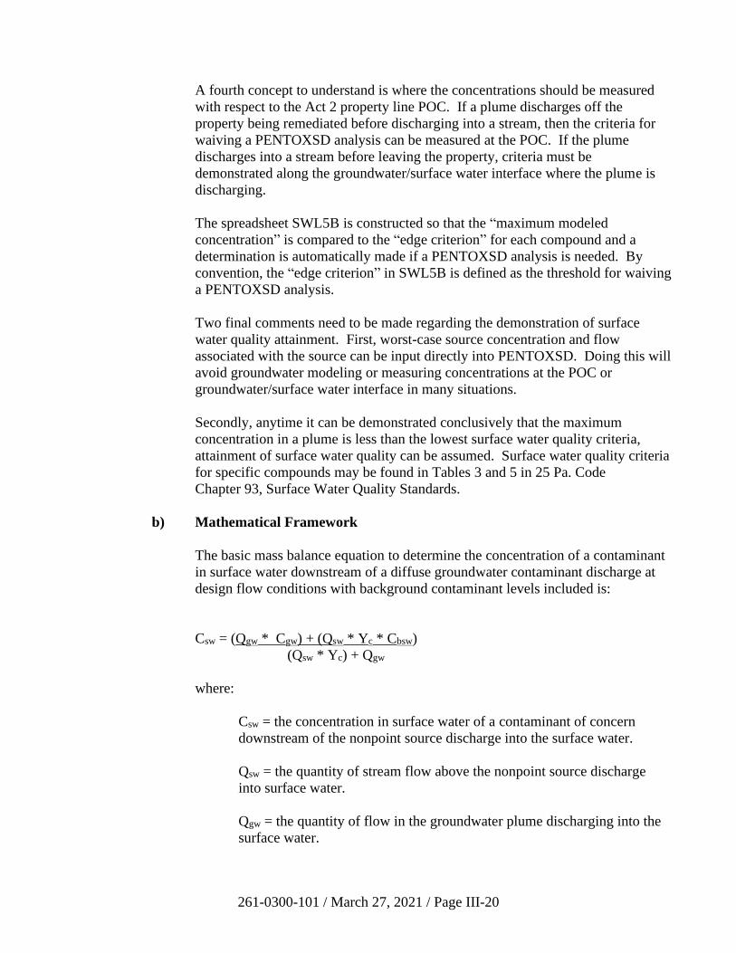
261-0300-101 / March 27, 2021 / Page III-20
A fourth concept to understand is where the concentrations should be measured
with respect to the Act 2 property line POC. If a plume discharges off the
property being remediated before discharging into a stream, then the criteria for
waiving a PENTOXSD analysis can be measured at the POC. If the plume
discharges into a stream before leaving the property, criteria must be
demonstrated along the groundwater/surface water interface where the plume is
discharging.
The spreadsheet SWL5B is constructed so that the “maximum modeled
concentration” is compared to the “edge criterion” for each compound and a
determination is automatically made if a PENTOXSD analysis is needed. By
convention, the “edge criterion” in SWL5B is defined as the threshold for waiving
a PENTOXSD analysis.
Two final comments need to be made regarding the demonstration of surface
water quality attainment. First, worst-case source concentration and flow
associated with the source can be input directly into PENTOXSD. Doing this will
avoid groundwater modeling or measuring concentrations at the POC or
groundwater/surface water interface in many situations.
Secondly, anytime it can be demonstrated conclusively that the maximum
concentration in a plume is less than the lowest surface water quality criteria,
attainment of surface water quality can be assumed. Surface water quality criteria
for specific compounds may be found in Tables 3 and 5 in 25 Pa. Code
Chapter 93, Surface Water Quality Standards.
b) Mathematical Framework
The basic mass balance equation to determine the concentration of a contaminant
in surface water downstream of a diffuse groundwater contaminant discharge at
design flow conditions with background contaminant levels included is:
Csw = (Qgw * Cgw) + (Qsw * Yc * Cbsw)
(Qsw * Yc) + Qgw
where:
Csw = the concentration in surface water of a contaminant of concern
downstream of the nonpoint source discharge into the surface water.
Qsw = the quantity of stream flow above the nonpoint source discharge
into surface water.
Qgw = the quantity of flow in the groundwater plume discharging into the
surface water.
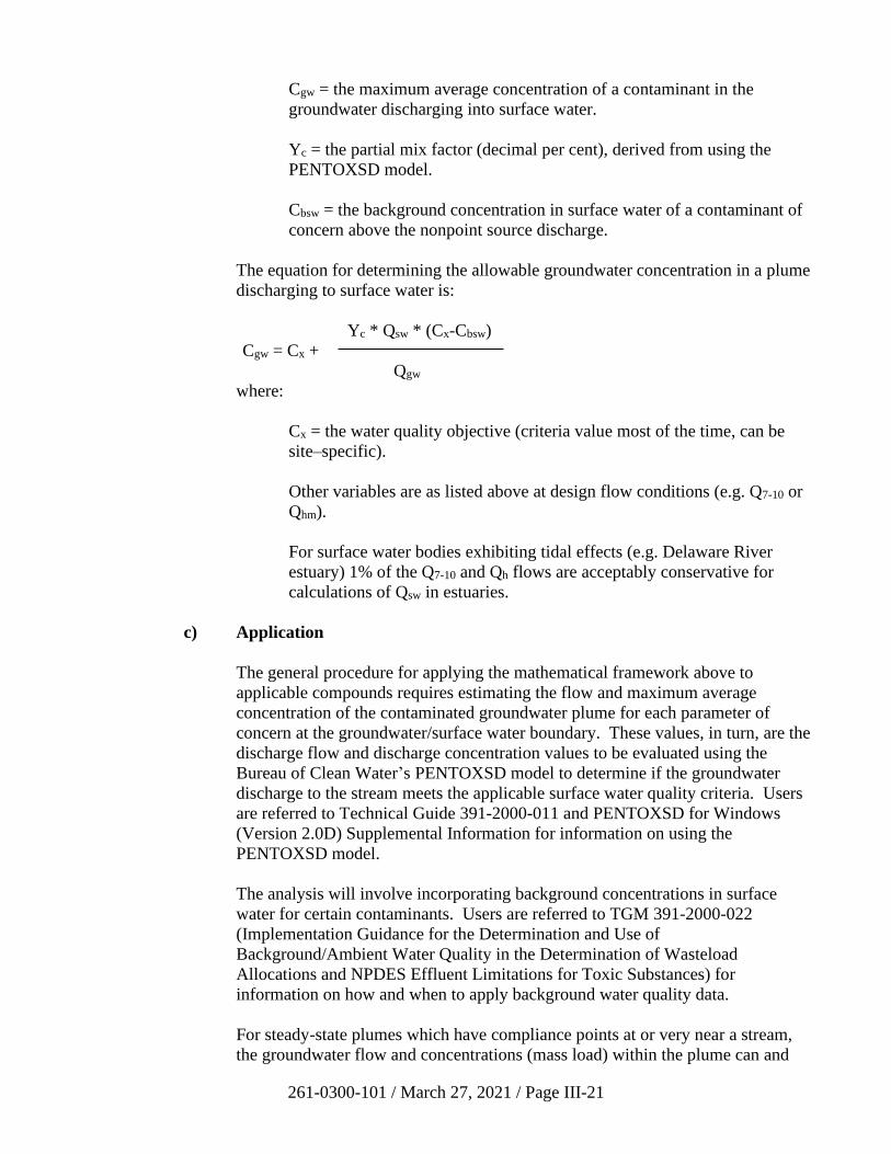
261-0300-101 / March 27, 2021 / Page III-21
Cgw = the maximum average concentration of a contaminant in the
groundwater discharging into surface water.
Yc = the partial mix factor (decimal per cent), derived from using the
PENTOXSD model.
Cbsw = the background concentration in surface water of a contaminant of
concern above the nonpoint source discharge.
The equation for determining the allowable groundwater concentration in a plume
discharging to surface water is:
Yc * Qsw * (Cx-Cbsw)
Cgw = Cx +
Qgw
where:
Cx = the water quality objective (criteria value most of the time, can be
site–specific).
Other variables are as listed above at design flow conditions (e.g. Q7-10 or
Qhm).
For surface water bodies exhibiting tidal effects (e.g. Delaware River
estuary) 1% of the Q7-10 and Qh flows are acceptably conservative for
calculations of Qsw in estuaries.
c) Application
The general procedure for applying the mathematical framework above to
applicable compounds requires estimating the flow and maximum average
concentration of the contaminated groundwater plume for each parameter of
concern at the groundwater/surface water boundary. These values, in turn, are the
discharge flow and discharge concentration values to be evaluated using the
Bureau of Clean Water’s PENTOXSD model to determine if the groundwater
discharge to the stream meets the applicable surface water quality criteria. Users
are referred to Technical Guide 391-2000-011 and PENTOXSD for Windows
(Version 2.0D) Supplemental Information for information on using the
PENTOXSD model.
The analysis will involve incorporating background concentrations in surface
water for certain contaminants. Users are referred to TGM 391-2000-022
(Implementation Guidance for the Determination and Use of
Background/Ambient Water Quality in the Determination of Wasteload
Allocations and NPDES Effluent Limitations for Toxic Substances) for
information on how and when to apply background water quality data.
For steady-state plumes which have compliance points at or very near a stream,
the groundwater flow and concentrations (mass load) within the plume can and
261-0300-101 / March 27, 2021 / Page III-22
should be determined from direct measurements. The mass loading of
groundwater plumes which have not yet reached the stream boundary, which are
not at steady state at the stream boundary, or for which data at the stream
boundary are not available, must be estimated in some way (e.g. using
groundwater solute transport models, or by assuming, conservatively, that the
highest concentrations measured in the plume are representative of those at the
stream boundary).
The general guidelines and example problems presented below in this guidance
apply to single source discharge analysis. If there is more than one source of a
pollutant in a stream reach, it may be necessary to evaluate the cumulative impact
of these sources. The stream reach is determined by the site-specific travel times,
stream flow, discharge flow dilution and potency of the pollutant as it moves
downstream. The term that describes this process is “multiple source discharge.”
The Bureau of Clean Water recommends that the Equal Marginal Percent
Reduction (EMPR) method of allocation be used for these situations.
EMPR is a two-step process:
• Baseline Analysis: this step evaluates each contributor individually to
determine if it would exceed the water quality objective by itself. This
step evaluates the contributor’s currently modeled load and compares it to
the water quality objective. If the modeled load is greater than the water
quality objective, the modeled load is reduced to the water quality
objective. A baseline value is determined for every contributor. This
baseline value is either the currently modeled load or the water quality
objective. This step assures that no contributor would cause an
exceedance of the water quality objective by itself.
• Multiple Analysis: this step evaluates the cumulative impact of multiple
sources on the stream. The analysis is carried out by systematically
moving downstream, adding the baseline pollutant loads, and determining
if the water quality objective is met at all locations. Through this process
the critical reach of the stream can be found and any further necessary
reductions from the baseline values can be made to meet the water quality
objective at all points in the stream. Any further reductions from the
baseline are made on an equal percentage basis.
Further information regarding the EMPR process can be found in the Technical
Reference Guide for the Wasteload Allocation Program for Dissolved Oxygen
and Ammonia-Nitrogen on the Bureau of Clean Water web page.
d) Statewide Health Standard in Aquifers with 2,500 mg/L TDS or Less
For certain compounds that have SHSs established in Chapter 250, simply
demonstrating attainment of the residential or nonresidential SHS MSC for
groundwater in used aquifers with TDS less than or equal to 2,500 mg/L at the
point of compliance, or at the groundwater/surface water interface when the
plume discharges to surface water prior to or instead of passing through the
property line POC, will satisfy the surface water criteria attainment
261-0300-101 / March 27, 2021 / Page III-23
demonstration. This is because either the MSC is equal to or below the lowest
surface water quality criterion (LSWC) or the compound in question does not
have any corresponding surface water criteria at this time. These compounds are
listed in Table III-1.
For all other compounds, surface water compliance analysis is required to the
compound’s edge criterion. These are compounds where the MSC exceeds the
LSWC. In some cases, the LSWC may be much lower than the laboratory PQL.
In this case, please contact the Act 2 site project officer for further guidance.
Regardless of the standard selected, whenever the maximum concentration of a
regulated substance in groundwater discharging to a stream at the time of
maximum mass loading to the stream is quantified at a level lower than the
LSWC, further demonstration of compliance with surface water criteria is not
required.
It is also important to note that if the fate and transport modeling or actual in-
stream sampling show that surface water quality criteria are exceeded, the
remediator may be able to demonstrate that the site-specific standard can be
attained by addressing the applicable exposure pathways. This would result in a
waiver of the provisions of Chapter 93 Water Quality Standards as described in
Section 250.406(c)(2) of the regulations.
e) Examples
i) Example 1: Groundwater Source Very Near or Adjacent to Surface
Water Discharge
A site with an accumulation of gasoline as a separate phase liquid lies
immediately adjacent to a small stream. Separate phase liquid is being
collected by an interceptor/skimmer system that prevents its discharge to
the stream. However, a dissolved phase hydrocarbon plume with
maximum concentrations of certain compounds near their solubility limit
is entering the stream. The remediator has selected the site-specific
standard for these contaminants and must determine if surface water
criteria are met without any treatment or removal of the dissolved phase
plume. Because the groundwater concentrations exceeding the lowest
surface water quality criteria are entering the stream, a PENTOXSD
analysis is required.
Because the site is located very near the surface water discharge point, no
opportunity for dispersion or decay of the groundwater plume prior to its
discharge is expected. Data from the site characterization and attainment
monitoring wells is assumed here to allow an accurate estimate of the
quantity and concentration of the groundwater plume entering the stream,
without any need for fate and transport modeling of groundwater. The
following characteristics of the groundwater plume have been determined:
Plume (source) width: 100 feet
Plume depth: 10 feet
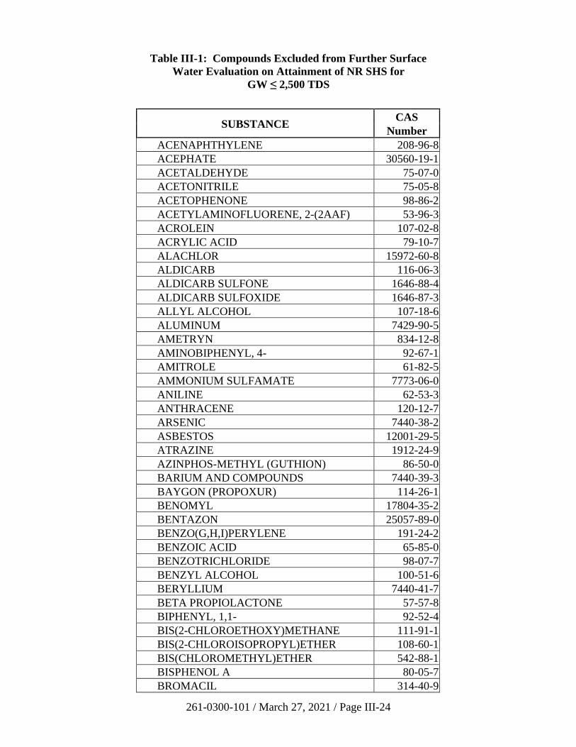
261-0300-101 / March 27, 2021 / Page III-24
Table III-1: Compounds Excluded from Further Surface
Water Evaluation on Attainment of NR SHS for
GW ≤ 2,500 TDS
SUBSTANCE CAS
Number
ACENAPHTHYLENE 208-96-8
ACEPHATE 30560-19-1
ACETALDEHYDE 75-07-0
ACETONITRILE 75-05-8
ACETOPHENONE 98-86-2
ACETYLAMINOFLUORENE, 2-(2AAF) 53-96-3
ACROLEIN 107-02-8
ACRYLIC ACID 79-10-7
ALACHLOR 15972-60-8
ALDICARB 116-06-3
ALDICARB SULFONE 1646-88-4
ALDICARB SULFOXIDE 1646-87-3
ALLYL ALCOHOL 107-18-6
ALUMINUM 7429-90-5
AMETRYN 834-12-8
AMINOBIPHENYL, 4- 92-67-1
AMITROLE 61-82-5
AMMONIUM SULFAMATE 7773-06-0
ANILINE 62-53-3
ANTHRACENE 120-12-7
ARSENIC 7440-38-2
ASBESTOS 12001-29-5
ATRAZINE 1912-24-9
AZINPHOS-METHYL (GUTHION) 86-50-0
BARIUM AND COMPOUNDS 7440-39-3
BAYGON (PROPOXUR) 114-26-1
BENOMYL 17804-35-2
BENTAZON 25057-89-0
BENZO(G,H,I)PERYLENE 191-24-2
BENZOIC ACID 65-85-0
BENZOTRICHLORIDE 98-07-7
BENZYL ALCOHOL 100-51-6
BERYLLIUM 7440-41-7
BETA PROPIOLACTONE 57-57-8
BIPHENYL, 1,1- 92-52-4
BIS(2-CHLOROETHOXY)METHANE 111-91-1
BIS(2-CHLOROISOPROPYL)ETHER 108-60-1
BIS(CHLOROMETHYL)ETHER 542-88-1
BISPHENOL A 80-05-7
BROMACIL 314-40-9
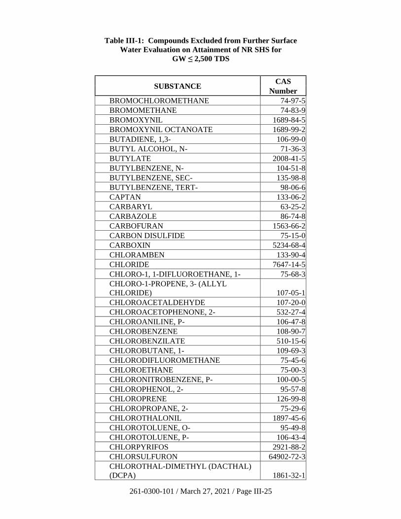
261-0300-101 / March 27, 2021 / Page III-25
Table III-1: Compounds Excluded from Further Surface
Water Evaluation on Attainment of NR SHS for
GW ≤ 2,500 TDS
SUBSTANCE CAS
Number
BROMOCHLOROMETHANE 74-97-5
BROMOMETHANE 74-83-9
BROMOXYNIL 1689-84-5
BROMOXYNIL OCTANOATE 1689-99-2
BUTADIENE, 1,3- 106-99-0
BUTYL ALCOHOL, N- 71-36-3
BUTYLATE 2008-41-5
BUTYLBENZENE, N- 104-51-8
BUTYLBENZENE, SEC- 135-98-8
BUTYLBENZENE, TERT- 98-06-6
CAPTAN 133-06-2
CARBARYL 63-25-2
CARBAZOLE 86-74-8
CARBOFURAN 1563-66-2
CARBON DISULFIDE 75-15-0
CARBOXIN 5234-68-4
CHLORAMBEN 133-90-4
CHLORIDE 7647-14-5
CHLORO-1, 1-DIFLUOROETHANE, 1- 75-68-3
CHLORO-1-PROPENE, 3- (ALLYL
CHLORIDE) 107-05-1
CHLOROACETALDEHYDE 107-20-0
CHLOROACETOPHENONE, 2- 532-27-4
CHLOROANILINE, P- 106-47-8
CHLOROBENZENE 108-90-7
CHLOROBENZILATE 510-15-6
CHLOROBUTANE, 1- 109-69-3
CHLORODIFLUOROMETHANE 75-45-6
CHLOROETHANE 75-00-3
CHLORONITROBENZENE, P- 100-00-5
CHLOROPHENOL, 2- 95-57-8
CHLOROPRENE 126-99-8
CHLOROPROPANE, 2- 75-29-6
CHLOROTHALONIL 1897-45-6
CHLOROTOLUENE, O- 95-49-8
CHLOROTOLUENE, P- 106-43-4
CHLORPYRIFOS 2921-88-2
CHLORSULFURON 64902-72-3
CHLOROTHAL-DIMETHYL (DACTHAL)
(DCPA) 1861-32-1
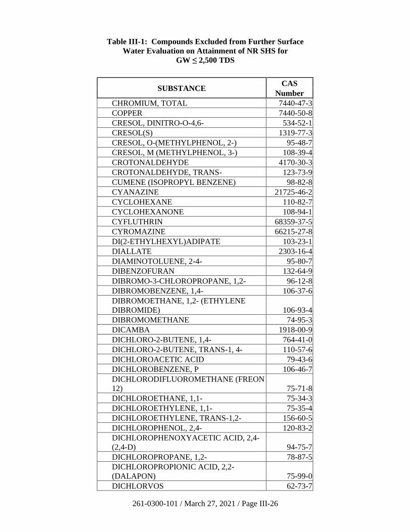
261-0300-101 / March 27, 2021 / Page III-26
Table III-1: Compounds Excluded from Further Surface
Water Evaluation on Attainment of NR SHS for
GW ≤ 2,500 TDS
SUBSTANCE CAS
Number
CHROMIUM, TOTAL 7440-47-3
COPPER 7440-50-8
CRESOL, DINITRO-O-4,6- 534-52-1
CRESOL(S) 1319-77-3
CRESOL, O-(METHYLPHENOL, 2-) 95-48-7
CRESOL, M (METHYLPHENOL, 3-) 108-39-4
CROTONALDEHYDE 4170-30-3
CROTONALDEHYDE, TRANS- 123-73-9
CUMENE (ISOPROPYL BENZENE) 98-82-8
CYANAZINE 21725-46-2
CYCLOHEXANE 110-82-7
CYCLOHEXANONE 108-94-1
CYFLUTHRIN 68359-37-5
CYROMAZINE 66215-27-8
DI(2-ETHYLHEXYL)ADIPATE 103-23-1
DIALLATE 2303-16-4
DIAMINOTOLUENE, 2-4- 95-80-7
DIBENZOFURAN 132-64-9
DIBROMO-3-CHLOROPROPANE, 1,2- 96-12-8
DIBROMOBENZENE, 1,4- 106-37-6
DIBROMOETHANE, 1,2- (ETHYLENE
DIBROMIDE) 106-93-4
DIBROMOMETHANE 74-95-3
DICAMBA 1918-00-9
DICHLORO-2-BUTENE, 1,4- 764-41-0
DICHLORO-2-BUTENE, TRANS-1, 4- 110-57-6
DICHLOROACETIC ACID 79-43-6
DICHLOROBENZENE, P 106-46-7
DICHLORODIFLUOROMETHANE (FREON
12) 75-71-8
DICHLOROETHANE, 1,1- 75-34-3
DICHLOROETHYLENE, 1,1- 75-35-4
DICHLOROETHYLENE, TRANS-1,2- 156-60-5
DICHLOROPHENOL, 2,4- 120-83-2
DICHLOROPHENOXYACETIC ACID, 2,4-
(2,4-D) 94-75-7
DICHLOROPROPANE, 1,2- 78-87-5
DICHLOROPROPIONIC ACID, 2,2-
(DALAPON) 75-99-0
DICHLORVOS 62-73-7
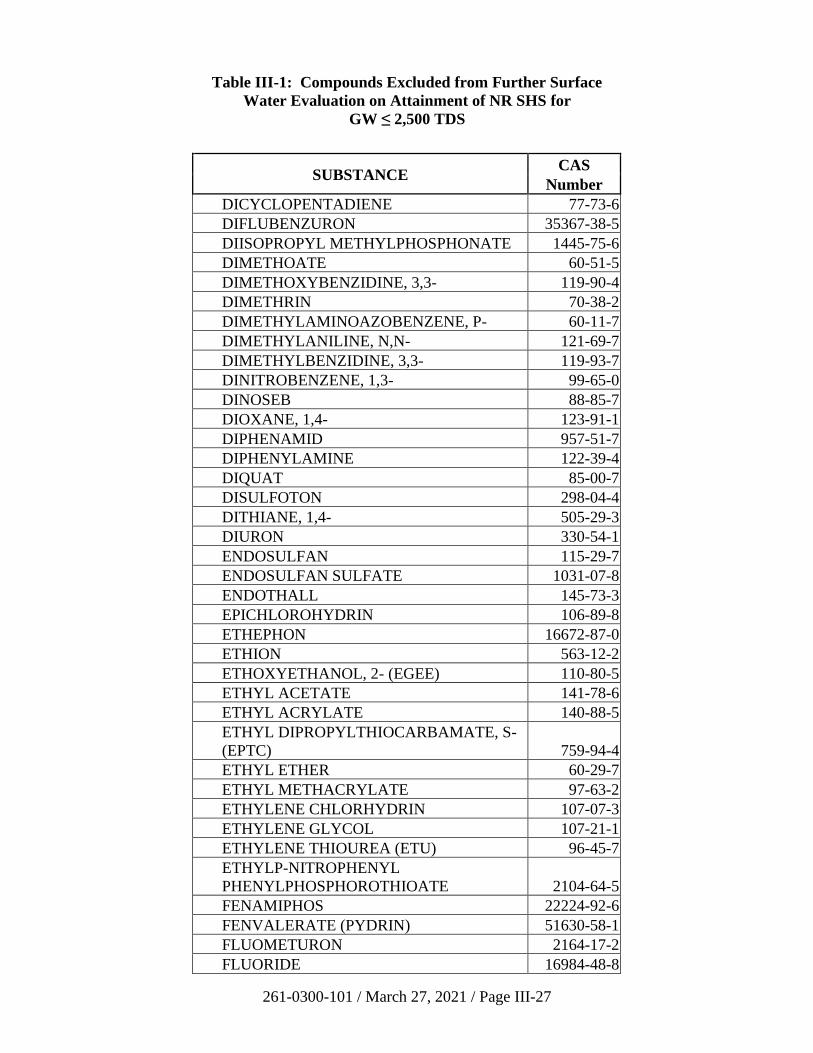
261-0300-101 / March 27, 2021 / Page III-27
Table III-1: Compounds Excluded from Further Surface
Water Evaluation on Attainment of NR SHS for
GW ≤ 2,500 TDS
SUBSTANCE CAS
Number
DICYCLOPENTADIENE 77-73-6
DIFLUBENZURON 35367-38-5
DIISOPROPYL METHYLPHOSPHONATE 1445-75-6
DIMETHOATE 60-51-5
DIMETHOXYBENZIDINE, 3,3- 119-90-4
DIMETHRIN 70-38-2
DIMETHYLAMINOAZOBENZENE, P- 60-11-7
DIMETHYLANILINE, N,N- 121-69-7
DIMETHYLBENZIDINE, 3,3- 119-93-7
DINITROBENZENE, 1,3- 99-65-0
DINOSEB 88-85-7
DIOXANE, 1,4- 123-91-1
DIPHENAMID 957-51-7
DIPHENYLAMINE 122-39-4
DIQUAT 85-00-7
DISULFOTON 298-04-4
DITHIANE, 1,4- 505-29-3
DIURON 330-54-1
ENDOSULFAN 115-29-7
ENDOSULFAN SULFATE 1031-07-8
ENDOTHALL 145-73-3
EPICHLOROHYDRIN 106-89-8
ETHEPHON 16672-87-0
ETHION 563-12-2
ETHOXYETHANOL, 2- (EGEE) 110-80-5
ETHYL ACETATE 141-78-6
ETHYL ACRYLATE 140-88-5
ETHYL DIPROPYLTHIOCARBAMATE, S-
(EPTC) 759-94-4
ETHYL ETHER 60-29-7
ETHYL METHACRYLATE 97-63-2
ETHYLENE CHLORHYDRIN 107-07-3
ETHYLENE GLYCOL 107-21-1
ETHYLENE THIOUREA (ETU) 96-45-7
ETHYLP-NITROPHENYL
PHENYLPHOSPHOROTHIOATE 2104-64-5
FENAMIPHOS 22224-92-6
FENVALERATE (PYDRIN) 51630-58-1
FLUOMETURON 2164-17-2
FLUORIDE 16984-48-8
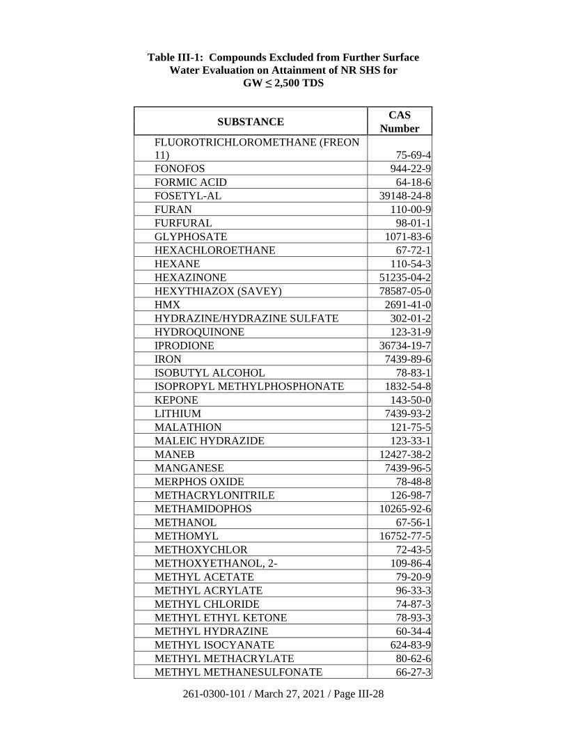
261-0300-101 / March 27, 2021 / Page III-28
Table III-1: Compounds Excluded from Further Surface
Water Evaluation on Attainment of NR SHS for
GW ≤ 2,500 TDS
SUBSTANCE CAS
Number
FLUOROTRICHLOROMETHANE (FREON
11) 75-69-4
FONOFOS 944-22-9
FORMIC ACID 64-18-6
FOSETYL-AL 39148-24-8
FURAN 110-00-9
FURFURAL 98-01-1
GLYPHOSATE 1071-83-6
HEXACHLOROETHANE 67-72-1
HEXANE 110-54-3
HEXAZINONE 51235-04-2
HEXYTHIAZOX (SAVEY) 78587-05-0
HMX 2691-41-0
HYDRAZINE/HYDRAZINE SULFATE 302-01-2
HYDROQUINONE 123-31-9
IPRODIONE 36734-19-7
IRON 7439-89-6
ISOBUTYL ALCOHOL 78-83-1
ISOPROPYL METHYLPHOSPHONATE 1832-54-8
KEPONE 143-50-0
LITHIUM 7439-93-2
MALATHION 121-75-5
MALEIC HYDRAZIDE 123-33-1
MANEB 12427-38-2
MANGANESE 7439-96-5
MERPHOS OXIDE 78-48-8
METHACRYLONITRILE 126-98-7
METHAMIDOPHOS 10265-92-6
METHANOL 67-56-1
METHOMYL 16752-77-5
METHOXYCHLOR 72-43-5
METHOXYETHANOL, 2- 109-86-4
METHYL ACETATE 79-20-9
METHYL ACRYLATE 96-33-3
METHYL CHLORIDE 74-87-3
METHYL ETHYL KETONE 78-93-3
METHYL HYDRAZINE 60-34-4
METHYL ISOCYANATE 624-83-9
METHYL METHACRYLATE 80-62-6
METHYL METHANESULFONATE 66-27-3
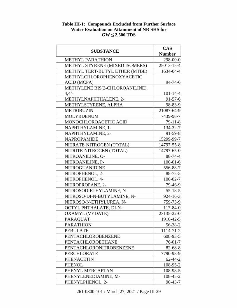
261-0300-101 / March 27, 2021 / Page III-29
Table III-1: Compounds Excluded from Further Surface
Water Evaluation on Attainment of NR SHS for
GW ≤ 2,500 TDS
SUBSTANCE CAS
Number
METHYL PARATHION 298-00-0
METHYL STYRENE (MIXED ISOMERS) 25013-15-4
METHYL TERT-BUTYL ETHER (MTBE) 1634-04-4
METHYLCHLOROPHENOXYACETIC
ACID (MCPA) 94-74-6
METHYLENE BIS(2-CHLOROANILINE),
4,4’- 101-14-4
METHYLNAPHTHALENE, 2- 91-57-6
METHYLSTYRENE, ALPHA 98-83-9
METRIBUZIN 21087-64-9
MOLYBDENUM 7439-98-7
MONOCHLOROACETIC ACID 79-11-8
NAPHTHYLAMINE, 1- 134-32-7
NAPHTHYLAMINE, 2- 91-59-8
NAPROPAMIDE 15299-99-7
NITRATE-NITROGEN (TOTAL) 14797-55-8
NITRITE-NITROGEN (TOTAL) 14797-65-0
NITROANILINE, O- 88-74-4
NITROANILINE, P- 100-01-6
NITROGUANIDINE 556-88-7
NITROPHENOL, 2- 88-75-5
NITROPHENOL, 4- 100-02-7
NITROPROPANE, 2- 79-46-9
NITROSODIETHYLAMINE, N- 55-18-5
NITROSO-DI-N-BUTYLAMINE, N- 924-16-3
NITROSO-N-ETHYLUREA, N- 759-73-9
OCTYL PHTHALATE, DI-N- 117-84-0
OXAMYL (VYDATE) 23135-22-0
PARAQUAT 1910-42-5
PARATHION 56-38-2
PEBULATE 1114-71-2
PENTACHLOROBENZENE 608-93-5
PENTACHLOROETHANE 76-01-7
PENTACHLORONITROBENZENE 82-68-8
PERCHLORATE 7790-98-9
PHENACETIN 62-44-2
PHENOL 108-95-2
PHENYL MERCAPTAN 108-98-5
PHENYLENEDIAMINE, M- 108-45-2
PHENYLPHENOL, 2- 90-43-7
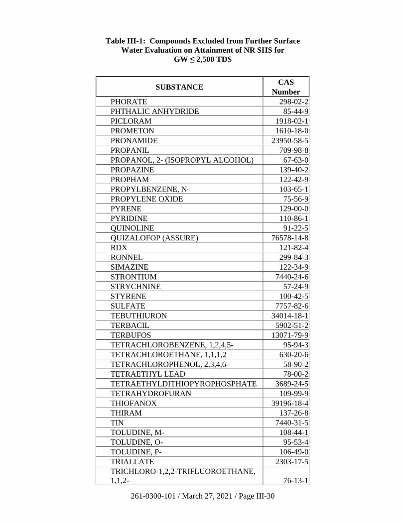
261-0300-101 / March 27, 2021 / Page III-30
Table III-1: Compounds Excluded from Further Surface
Water Evaluation on Attainment of NR SHS for
GW ≤ 2,500 TDS
SUBSTANCE CAS
Number
PHORATE 298-02-2
PHTHALIC ANHYDRIDE 85-44-9
PICLORAM 1918-02-1
PROMETON 1610-18-0
PRONAMIDE 23950-58-5
PROPANIL 709-98-8
PROPANOL, 2- (ISOPROPYL ALCOHOL) 67-63-0
PROPAZINE 139-40-2
PROPHAM 122-42-9
PROPYLBENZENE, N- 103-65-1
PROPYLENE OXIDE 75-56-9
PYRENE 129-00-0
PYRIDINE 110-86-1
QUINOLINE 91-22-5
QUIZALOFOP (ASSURE) 76578-14-8
RDX 121-82-4
RONNEL 299-84-3
SIMAZINE 122-34-9
STRONTIUM 7440-24-6
STRYCHNINE 57-24-9
STYRENE 100-42-5
SULFATE 7757-82-6
TEBUTHIURON 34014-18-1
TERBACIL 5902-51-2
TERBUFOS 13071-79-9
TETRACHLOROBENZENE, 1,2,4,5- 95-94-3
TETRACHLOROETHANE, 1,1,1,2 630-20-6
TETRACHLOROPHENOL, 2,3,4,6- 58-90-2
TETRAETHYL LEAD 78-00-2
TETRAETHYLDITHIOPYROPHOSPHATE 3689-24-5
TETRAHYDROFURAN 109-99-9
THIOFANOX 39196-18-4
THIRAM 137-26-8
TIN 7440-31-5
TOLUDINE, M- 108-44-1
TOLUDINE, O- 95-53-4
TOLUDINE, P- 106-49-0
TRIALLATE 2303-17-5
TRICHLORO-1,2,2-TRIFLUOROETHANE,
1,1,2- 76-13-1
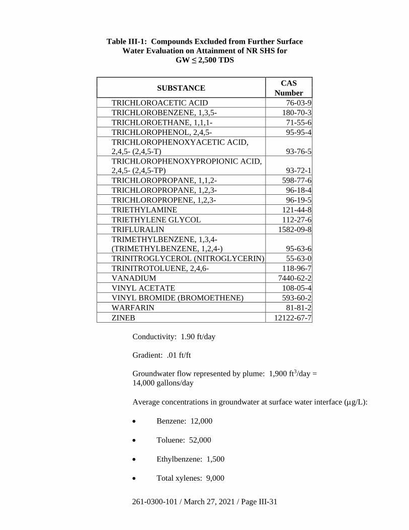
261-0300-101 / March 27, 2021 / Page III-31
Table III-1: Compounds Excluded from Further Surface
Water Evaluation on Attainment of NR SHS for
GW ≤ 2,500 TDS
SUBSTANCE CAS
Number
TRICHLOROACETIC ACID 76-03-9
TRICHLOROBENZENE, 1,3,5- 180-70-3
TRICHLOROETHANE, 1,1,1- 71-55-6
TRICHLOROPHENOL, 2,4,5- 95-95-4
TRICHLOROPHENOXYACETIC ACID,
2,4,5- (2,4,5-T) 93-76-5
TRICHLOROPHENOXYPROPIONIC ACID,
2,4,5- (2,4,5-TP) 93-72-1
TRICHLOROPROPANE, 1,1,2- 598-77-6
TRICHLOROPROPANE, 1,2,3- 96-18-4
TRICHLOROPROPENE, 1,2,3- 96-19-5
TRIETHYLAMINE 121-44-8
TRIETHYLENE GLYCOL 112-27-6
TRIFLURALIN 1582-09-8
TRIMETHYLBENZENE, 1,3,4-
(TRIMETHYLBENZENE, 1,2,4-) 95-63-6
TRINITROGLYCEROL (NITROGLYCERIN) 55-63-0
TRINITROTOLUENE, 2,4,6- 118-96-7
VANADIUM 7440-62-2
VINYL ACETATE 108-05-4
VINYL BROMIDE (BROMOETHENE) 593-60-2
WARFARIN 81-81-2
ZINEB 12122-67-7
Conductivity: 1.90 ft/day
Gradient: .01 ft/ft
Groundwater flow represented by plume: 1,900 ft3/day =
14,000 gallons/day
Average concentrations in groundwater at surface water interface (g/L):
• Benzene: 12,000
• Toluene: 52,000
• Ethylbenzene: 1,500
• Total xylenes: 9,000
261-0300-101 / March 27, 2021 / Page III-32
Using benzene for this example, the maximum average groundwater
concentration is 12,000 g/L and the plume flow is 14,000 gallons/day or
0.014 million gallons/day (MGD).
Assuming all groundwater discharges to the stream, an evaluation of the
plume discharge to the stream can now be made with the above data using
PENTOXSD for each of the contaminants. The approach is described and
shown below for benzene:
Figures III-1 and III-2 are printouts from the PENTOXSD model for
Example 1. PENTOXSD shows that the recommended effluent limit for
benzene in this case is 181 µg/L, which is less than the 329 µg/L
maximum effluent groundwater concentration daily limit expected for
benzene calculated for this example. Therefore, a release of liability
cannot be granted in this case until the maximum effluent groundwater
concentration daily limit is reduced to at least 181 µg/L and other
parameters in the example are shown to be at acceptable levels.
ii) Example 2: Groundwater Source at Distance from Surface Water
Discharge – Steady-State Conditions
In this example, all conditions are the same as for Example 1 except the
source is 100 feet from the stream. Additionally, one well is located
40 feet from the source in a downgradient direction toward the stream
containing benzene at a concentration of 6,500 µg/L. Assume that wells
cannot be drilled at the groundwater/surface water interface because of
existing buildings and other obstacles. However, enough onsite and
offsite data have been collected to reasonably calibrate a model and
establish that the plume is at or near steady-state conditions. A
groundwater solute transport model is chosen by the remediator to
estimate the flow and concentration of the contaminants into the river. For
purposes of this example, the QD and SWL5B spreadsheet applications
will be used. A plan view model such as QD is being used because it is
difficult or impossible to calibrate a cross-sectional model such as SWL5B
using isoconcentration map data. Isoconcentration contours are usually
developed and drawn in the plan-view or horizontal dimension. Once the
model input parameters are finalized using the plan view model, they are
easily transferred for use into the cross-sectional model. The Department
does not require the use of these particular models; however, if another
surface water loading model is used, the rules incorporated into selection
of SWL5B’s “edge criterion” for establishing the portion of the plume
flow and average concentration must be used.
In order to complete the analysis, input values for the following additional
parameters required by the model were developed during the site
characterization phase. Those parameters and how they were determined
for this example are as follows (See Figure III-3 for the actual values):
261-0300-101 / March 27, 2021 / Page III-33
Longitudinal and Transverse Dispersion – fitted to plume data
(isoconcentration map) using QD
Vertical Dispersion – set to 0.0001 because the entire plume is assumed to
discharge into the stream and any vertically dispersed contamination
would enter the stream.
Lambda – starting values may be found from Appendix A, Table 5A,
Chapter 250 (and converted to the correct units).
Time – 11 years-established from historical records. Note that this is fixed
at 1 x 1099 days in SWL5B to assure that output is at steady-state
conditions. This assures that SWL5B will yield the maximum average
concentration for plumes emanating from a constant source.
Porosity – determined by laboratory analysis of undisturbed samples.
Dry Bulk Density – estimated at 2.65 * (1-porosity).
Koc – from Appendix A, Table 5, Chapter 250.
Fraction Organic Carbon – Can be estimated (Section III.A.1.b.ii).
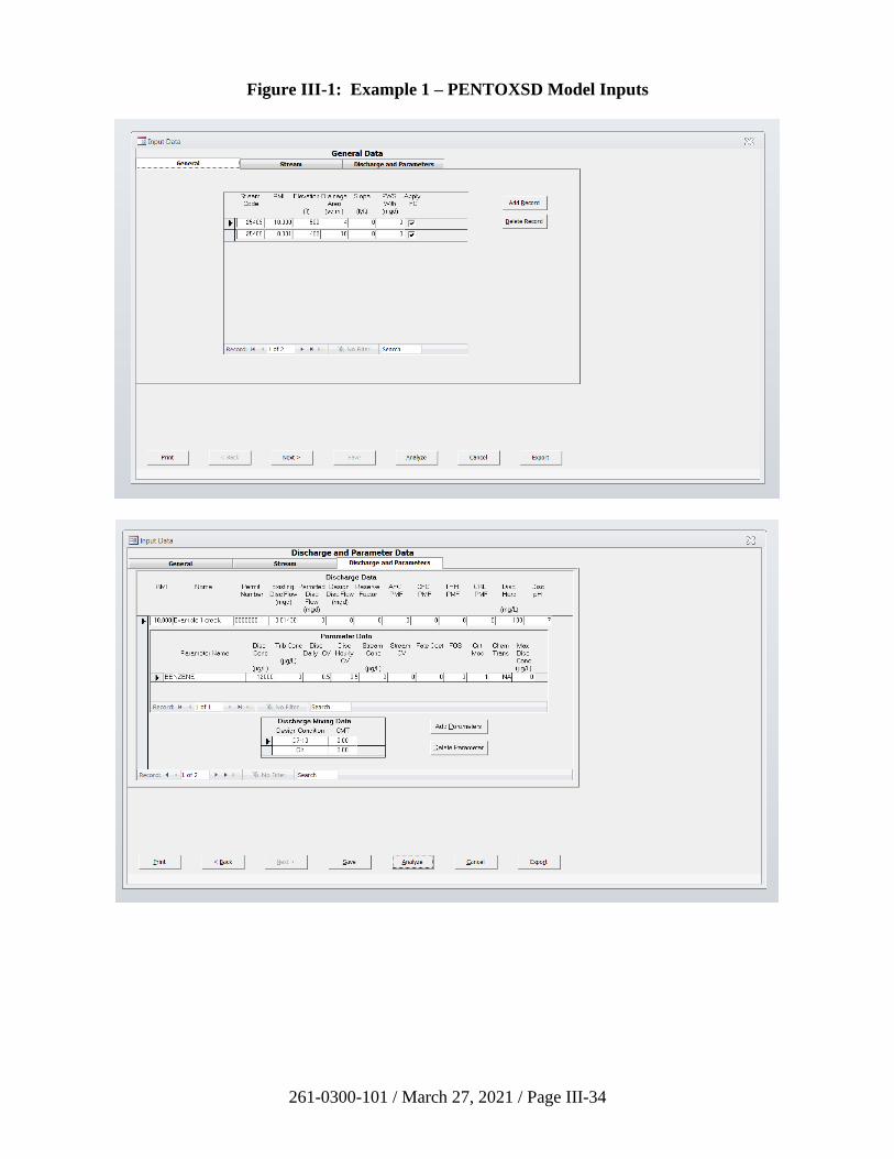
261-0300-101 / March 27, 2021 / Page III-34
Figure III-1: Example 1 – PENTOXSD Model Inputs
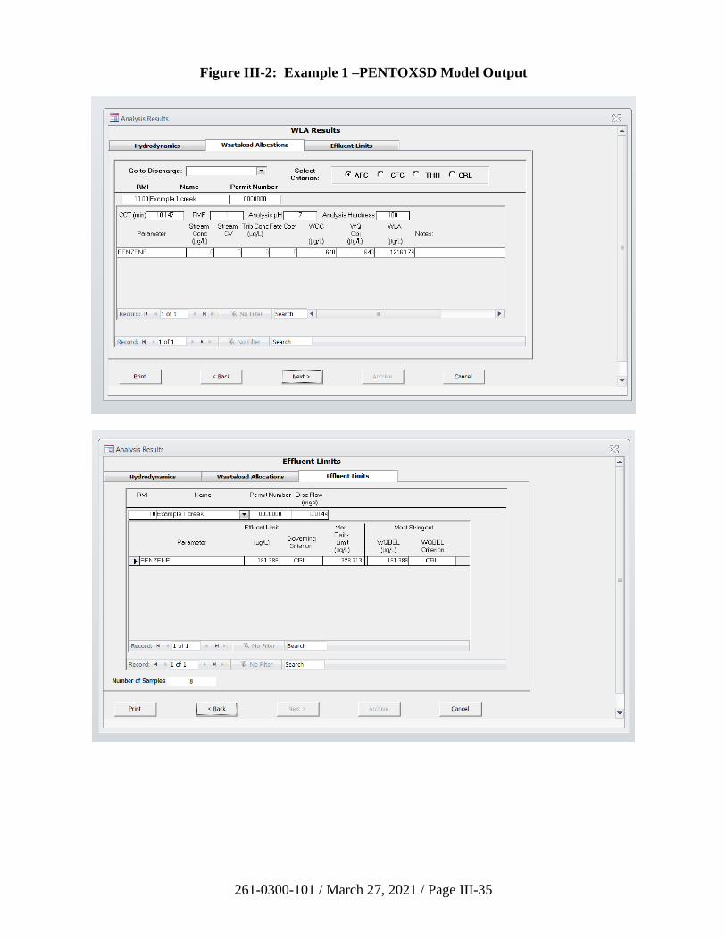
261-0300-101 / March 27, 2021 / Page III-35
Figure III-2: Example 1 –PENTOXSD Model Output
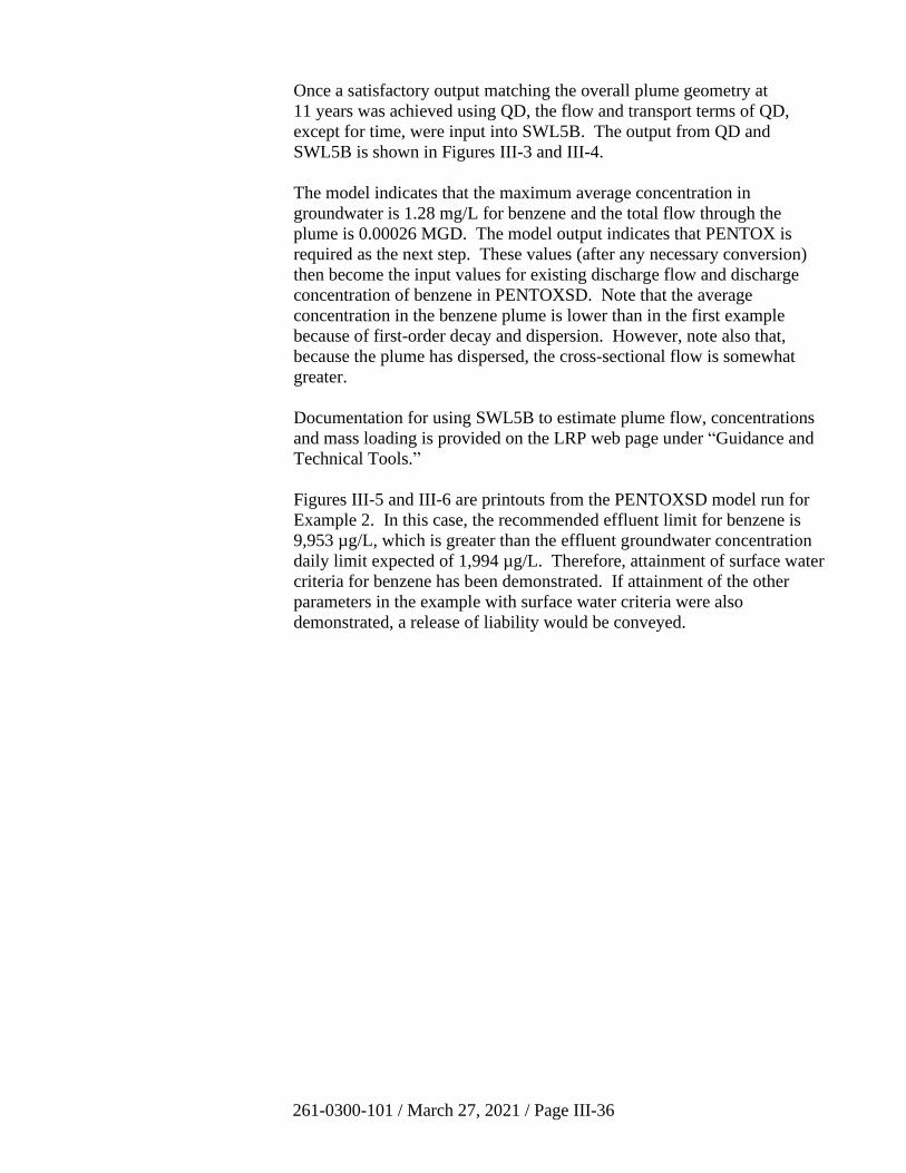
261-0300-101 / March 27, 2021 / Page III-36
Once a satisfactory output matching the overall plume geometry at
11 years was achieved using QD, the flow and transport terms of QD,
except for time, were input into SWL5B. The output from QD and
SWL5B is shown in Figures III-3 and III-4.
The model indicates that the maximum average concentration in
groundwater is 1.28 mg/L for benzene and the total flow through the
plume is 0.00026 MGD. The model output indicates that PENTOX is
required as the next step. These values (after any necessary conversion)
then become the input values for existing discharge flow and discharge
concentration of benzene in PENTOXSD. Note that the average
concentration in the benzene plume is lower than in the first example
because of first-order decay and dispersion. However, note also that,
because the plume has dispersed, the cross-sectional flow is somewhat
greater.
Documentation for using SWL5B to estimate plume flow, concentrations
and mass loading is provided on the LRP web page under “Guidance and
Technical Tools.”
Figures III-5 and III-6 are printouts from the PENTOXSD model run for
Example 2. In this case, the recommended effluent limit for benzene is
9,953 µg/L, which is greater than the effluent groundwater concentration
daily limit expected of 1,994 µg/L. Therefore, attainment of surface water
criteria for benzene has been demonstrated. If attainment of the other
parameters in the example with surface water criteria were also
demonstrated, a release of liability would be conveyed.
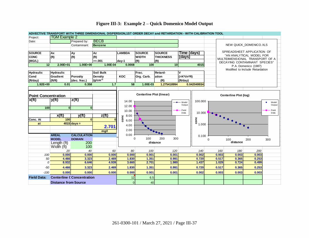
261-0300-101 / March 27, 2021 / Page III-37
Figure III-3: Example 2 – Quick Domenico Model Output
ADVECTIVE TRANSPORT WITH THREE DIMENSIONAL DISPERSION,1ST ORDER DECAY and RETARDATION - WITH CALIBRATION TOOL
Project: TGM Example 2Date: Prepared by: BECB
Contaminant: Benzene
SOURCE Ax Ay Az LAMBDA SOURCE SOURCE Time (days)CONC (ft) (ft) (ft) WIDTH THICKNESS (days)(MG/L) >=.001 day-1 (ft) (ft)
12 2.00E+01 1.00E+00 1.00E-04 0.0008 100 10 4015
Hydraulic Hydraulic Soil Bulk Frac. Retard- V
Cond Gradient Porosity Density KOC Org. Carb. ation (=K*i/n*R)
(ft/day) (ft/ft) (dec. frac.) (g/cm3) (R) (ft/day)
1.92E+00 0.01 0.358 1.7 58 1.00E-03 1.275418994 0.042049934
x(ft) y(ft) z(ft)
100 0 0
x(ft) y(ft) z(ft)Conc. At 100 0 0
at 4015 days =
mg/l
AREAL CALCULATION
MODEL DOMAIN
Length (ft) 200Width (ft) 100
20 40 60 80 100 120 140 160 180 200
100 0.000 0.000 0.000 0.000 0.001 0.001 0.002 0.003 0.003 0.003
50 4.466 3.323 2.469 1.830 1.351 0.991 0.720 0.517 0.365 0.253
0 8.932 6.646 4.939 3.660 2.701 1.980 1.437 1.029 0.724 0.499
-50 4.466 3.323 2.469 1.830 1.351 0.991 0.720 0.517 0.365 0.253
-100 0.000 0.000 0.000 0.000 0.001 0.001 0.002 0.003 0.003 0.003
Field Data: Centerline Conc.Concentration 12 6.5
Distance from Source 0 40
2.701
Point Concentration
NEW QUICK_DOMENICO.XLS
SPREADSHEET APPLICATION OF
"AN ANALYTICAL MODEL FOR MULTIDIMENSIONAL TRANSPORT OF A
DECAYING CONTAMINANT SPECIES"
P.A. Domenico (1987)Modified to Include Retardation
0.00
2.00
4.00
6.00
8.00
10.00
12.00
14.00
0 100 200 300
co
nc
distance
Centerline Plot (linear)
Model
Output
Field
Data
0.100
1.000
10.000
100.000
0 100 200 300
co
nc
distance
Centerline Plot (log)
Model
Output
Field
Data
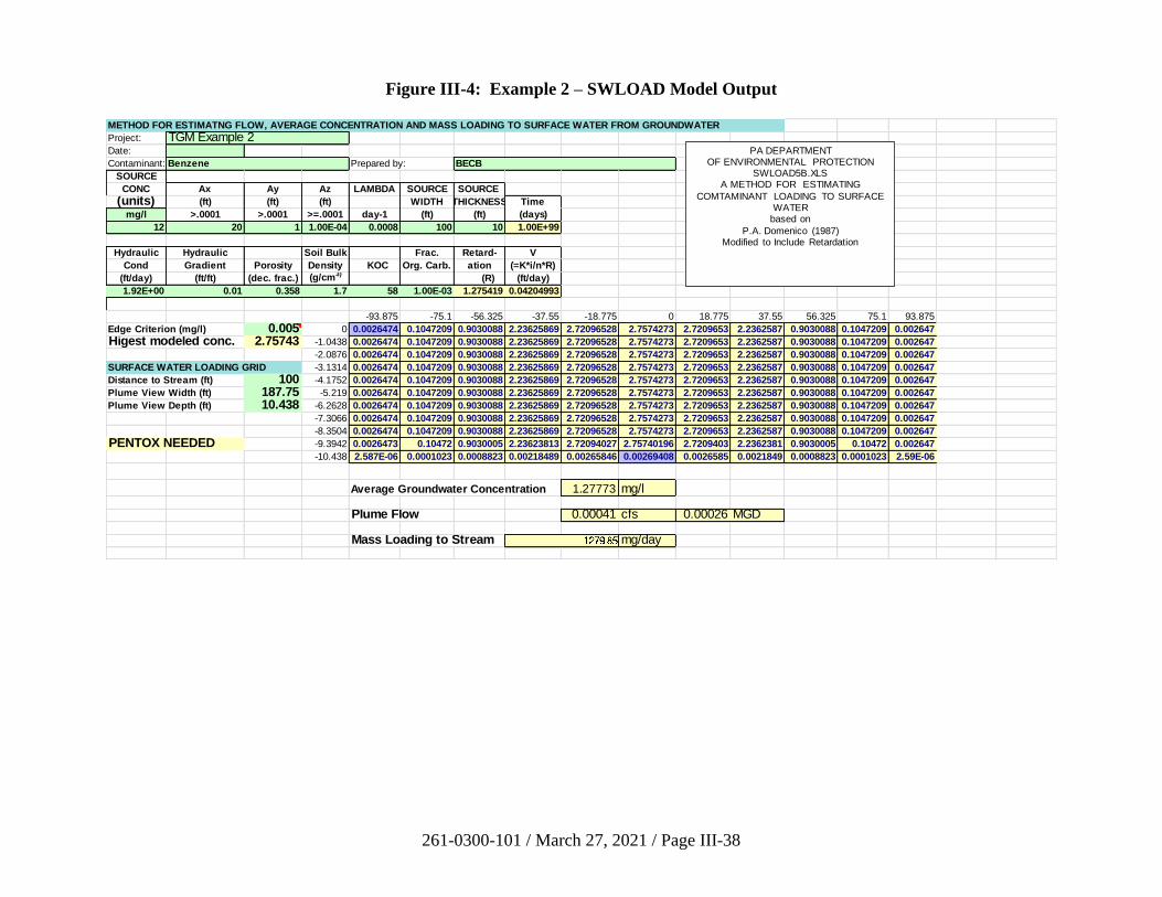
261-0300-101 / March 27, 2021 / Page III-38
Figure III-4: Example 2 – SWLOAD Model Output
METHOD FOR ESTIMATNG FLOW, AVERAGE CONCENTRATION AND MASS LOADING TO SURFACE WATER FROM GROUNDWATER
Project: TGM Example 2Date:
Contaminant: Benzene Prepared by: BECB
SOURCE
CONC Ax Ay Az LAMBDA SOURCE SOURCE
(units) (ft) (ft) (ft) WIDTH THICKNESS Time
mg/l >.0001 >.0001 >=.0001 day-1 (ft) (ft) (days)
12 20 1 1.00E-04 0.0008 100 10 1.00E+99
Hydraulic Hydraulic Soil Bulk Frac. Retard- V
Cond Gradient Porosity Density KOC Org. Carb. ation (=K*i/n*R)
(ft/day) (ft/ft) (dec. frac.) (g/cm3) (R) (ft/day)
1.92E+00 0.01 0.358 1.7 58 1.00E-03 1.275419 0.04204993
-93.875 -75.1 -56.325 -37.55 -18.775 0 18.775 37.55 56.325 75.1 93.875
Edge Criterion (mg/l) 0.005 0 0.0026474 0.1047209 0.9030088 2.23625869 2.72096528 2.7574273 2.7209653 2.2362587 0.9030088 0.1047209 0.002647
Higest modeled conc. 2.75743 -1.0438 0.0026474 0.1047209 0.9030088 2.23625869 2.72096528 2.7574273 2.7209653 2.2362587 0.9030088 0.1047209 0.002647
-2.0876 0.0026474 0.1047209 0.9030088 2.23625869 2.72096528 2.7574273 2.7209653 2.2362587 0.9030088 0.1047209 0.002647
SURFACE WATER LOADING GRID -3.1314 0.0026474 0.1047209 0.9030088 2.23625869 2.72096528 2.7574273 2.7209653 2.2362587 0.9030088 0.1047209 0.002647
Distance to Stream (ft) 100 -4.1752 0.0026474 0.1047209 0.9030088 2.23625869 2.72096528 2.7574273 2.7209653 2.2362587 0.9030088 0.1047209 0.002647
Plume View Width (ft) 187.75 -5.219 0.0026474 0.1047209 0.9030088 2.23625869 2.72096528 2.7574273 2.7209653 2.2362587 0.9030088 0.1047209 0.002647
Plume View Depth (ft) 10.438 -6.2628 0.0026474 0.1047209 0.9030088 2.23625869 2.72096528 2.7574273 2.7209653 2.2362587 0.9030088 0.1047209 0.002647
-7.3066 0.0026474 0.1047209 0.9030088 2.23625869 2.72096528 2.7574273 2.7209653 2.2362587 0.9030088 0.1047209 0.002647
-8.3504 0.0026474 0.1047209 0.9030088 2.23625869 2.72096528 2.7574273 2.7209653 2.2362587 0.9030088 0.1047209 0.002647
PENTOX NEEDED -9.3942 0.0026473 0.10472 0.9030005 2.23623813 2.72094027 2.75740196 2.7209403 2.2362381 0.9030005 0.10472 0.002647
-10.438 2.587E-06 0.0001023 0.0008823 0.00218489 0.00265846 0.00269408 0.0026585 0.0021849 0.0008823 0.0001023 2.59E-06
Average Groundwater Concentration 1.27773 mg/l
Plume Flow 0.00041 cfs 0.00026 MGD
Mass Loading to Stream mg/day
PA DEPARTMENTOF ENVIRONMENTAL PROTECTION
SWLOAD5B.XLSA METHOD FOR ESTIMATING
COMTAMINANT LOADING TO SURFACE WATER
based on
P.A. Domenico (1987)Modified to Include Retardation
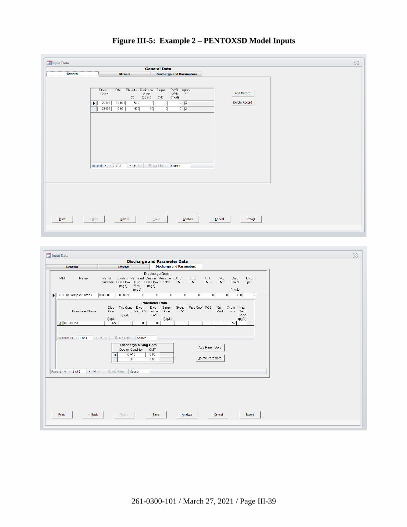
261-0300-101 / March 27, 2021 / Page III-39
Figure III-5: Example 2 – PENTOXSD Model Inputs
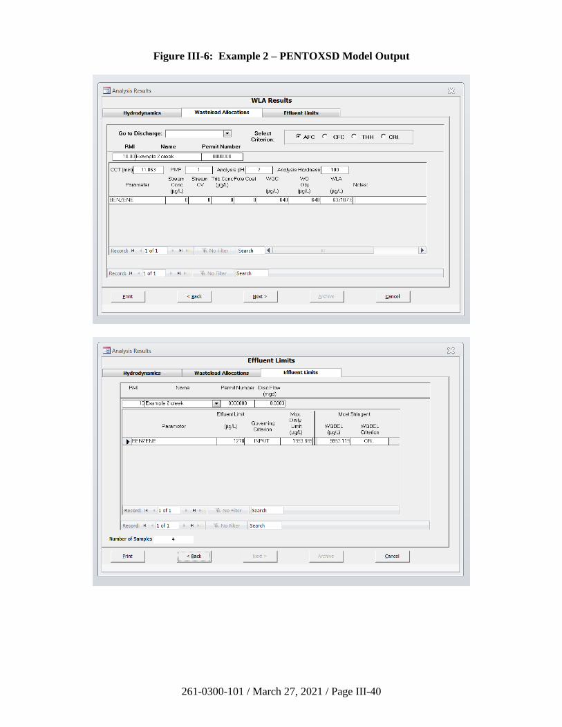
261-0300-101 / March 27, 2021 / Page III-40
Figure III-6: Example 2 – PENTOXSD Model Output
261-0300-101 / March 27, 2021 / Page III-41
B. Guidance for Attainment Demonstration with Statistical Methods
1. Introduction
The requirement to apply statistical methods to verify the cleanup of a site is emphasized
in Act 2. Sections 302, 303 and 304 of Act 2 (35 P.S. §§ 6026.302-304) require that
attainment of a standard be demonstrated by the collection and analysis of samples from
affected media (such as surface water, soil, groundwater in aquifers at the point of
compliance) through the application of statistical tests set forth in regulation. The Act
also requires the Department to recognize those methods of attainment demonstration
generally recognized as appropriate for that particular remediation.
Statistical methods are emphasized because there is a practical need to make decisions
regarding whether a site meets a cleanup standard in spite of uncertainty. The uncertainty
arises because we are able to sample and analyze only a small portion of the soil and
groundwater at a site, yet we have to make a decision regarding the entire site.
The purpose of this section is to provide guidance for the use of statistics to demonstrate
that a site has attained a cleanup standard under Act 2. It is intended to address certain
key issues pertinent to the sampling and statistical analysis under Act 2, to provide
references for proper statistical analysis and, if necessary, to provide examples of
applying statistical procedures in detail. It is not intended to address every statistical
issue.
For statistical attainment issues not addressed directly in this manual or in 25 Pa. Code
Chapter 250, a person may consult the latest ITRC and EPA documents for additional
guidance. The 2013 ITRC document Groundwater Statistics and Monitoring
Compliance and EPA guidance documents (EPA 1992b, 1992c, 1996, 2002b, 2009) are
particularly helpful. They provide detailed statistical procedures for demonstration of
attainment and data analysis.
For groundwater characterization, remediators should consult Appendix A of this manual
“Groundwater Monitoring Guidance” which provides general information on
groundwater monitoring and sampling issues, such as monitoring well construction,
locations and depths of monitoring wells, and well abandonment procedures. The
Groundwater Monitoring Guidance provides a good summary of various statistical
methods used for groundwater characterization.
For conducting statistical analyses, remediators may wish to utilize EPA’s ProUCL
Statistical Software for Environmental Applications. This free program is available on
EPA’s website and accompanied with a Technical Guide. ProUCL is able to run most of
the statistical applications summarized in this section of the TGM.
Other standard statistics-related tests may be used to perform the procedures to
demonstrate attainment as appropriate. If necessary, professional services should be
obtained.
261-0300-101 / March 27, 2021 / Page III-42
When we consider applying statistical methods to demonstrate the attainment of a risk-
based cleanup standard, it is important to realize that three components may influence the
overall stringency of this cleanup standard:
• The first component is the magnitude, level, or concentration that is deemed
protective of human health and the environment. The development of risk-based
cleanup standards is addressed in the regulations and Department’s risk
assessment guidances.
• The second component of the standard is the sampling that is done to evaluate
whether a site is above or below the standard.
• The final component is how the resulting data are compared with the standard to
decide whether the remedial action was successful (a statistical analysis).
Persons overseeing cleanup must look beyond the cleanup level and explore the sampling
and statistical analysis that will allow evaluation of the site relative to the cleanup level.
This guidance is intended to address statistical analysis and sampling components that
may affect the stringency of cleanup standards.
2. Data Review for Statistical Methods
Preliminary data review for statistical analysis (also known as exploratory data analysis
in the DEP Groundwater Monitoring Guidance Manual; PA DEP, 2001) includes the use
of graphical techniques and calculation of summary statistics. By reviewing the data both
numerically and graphically, one can learn the “structure” of the data and identify
limitations for using the data. Graphical methods include histograms, probability plots,
box charts, and time-series plots to visually review the data for trends or patterns. EPA
and most statistical texts recommend that time-series data should be graphed. This visual
approach allows for a quick assessment of the statistical features of the data.
Calculations of summary statistics are typically done to characterize the data and make
judgments on the central tendencies, symmetry, presence of outliers, etc. Preliminary
data review is critical in selecting additional appropriate mathematical procedures.
Graphical and parametric statistical procedures discussed here are included in many
introductory statistics textbooks (e.g., Iman and Conover, 1983 and Ott, 1988) and are
available in many computer statistics packages.
a) Summary Statistics
Basic summary statistics can be used to characterize groundwater monitoring
data. Summary statistics include median, interquartile range (IQR), mean,
standard deviation, and range. Median and IQR are determined from percentiles.
Median is the 50th percentile and IQR is the 25th to 75th percentile. Median
indicates the “center” of data values. The mean is another measure of center but
only if data are normally or symmetrically distributed. Mean and standard
deviation are required values with parametric procedures. Range is the minimum
to maximum values. Procedures for such summary statistics are found in
introductory statistics texts.
261-0300-101 / March 27, 2021 / Page III-43
b) Graphical Procedures
Refer to ITRC (2013) for a general reference on graphical procedures.
Histogram - A histogram is a graphic display of frequency distribution. The area
within the bar represents the relative density of the data.
Boxplots - A boxplot summarizes a data set by presenting the percentile
distribution of the data. The “box” portion indicates the median and interquartile
range (IQR). IQR is the middle 50 percent of data. Difference in the size of box
halves represents data skewness.
Normal and symmetrical distributions will have equal size box halves. Extreme
outliers are displayed as individual points that are recognized easily. Boxplots
can be constructed by hand; however, many computer statistical packages will
prepare them.
The boxplot of a lognormal distribution will have noticeably different-sized box
halves. Lack of IQR overlap for different data sets will indicate a probable
significant difference. Boxplots of seasonally grouped data can be used to detect
data seasonality.
Time Series Plots - A time series plot displays individual data points on a time
scale. A monthly scale can help to identify seasonal variation. A yearly scale
also can identify possible trends. Superimposing data from multiple sampling
locations may provide additional information. Improved trend information is
often available with data smoothing.
Control Charts - Control charts are used to define limits for an analyte that has
been monitored at an uncontaminated well over time. This procedure is a
graphical alternative to prediction limits.
A common technique is the Shewhart-CUSUM control chart that plots the data on
a time scale. Obvious features such as trends or sudden changes in concentration
levels could then be observed. With this method, if any compliance well has a
value or a sequence of values that lie outside the control limits for that analyte, it
may indicate statistically significant evidence of contamination.
The control chart approach is recommended only for uncontaminated wells, a
normal or lognormal data distribution with few nondetects, and for a dataset that
has at least eight independent samples over a one-year period. This baseline is
then used to judge the future samples. See the EPA Guidance (EPA, 2009,
Chapter 20).
3. Statistical Inference and Hypothesis Statements
A statistical procedure that is designed to allow the extrapolation from the results of a
few samples to a statement regarding the entire site is known as statistical inference.
261-0300-101 / March 27, 2021 / Page III-44
Statistical inference allows decision making under uncertainty and valid extrapolation of
information that can be defended and used with confidence to determine whether the site
meets the cleanup standard.
The goal of statistical inference, the process of extrapolating results from a sample to a
larger population, is to decide which of two complementary hypotheses, null hypothesis
and alternative hypothesis, is likely to be true.
In general, statistical inference procedures include the following steps:
(1) A null hypothesis and its alternative hypothesis are drawn up. The null
hypothesis is developed in such a way that the probability of Type I error can be
determined. The Type I error is an error that we falsely reject the null hypothesis,
when the null hypothesis is true. Type I error is also known as false positive
error.
(2) Decide the level of significance, . This controls the risk of committing a Type I
error.
(3) Establish a decision rule for each scale of decision making that is derived from
step 4 of the Data Quality Objectives (DQO) process. (See Section III.G for more
information on the DQO process).
(4) Determine the sample size, n. This is the number of environmental samples
needed to make decision. Obtain data through the implementation of sampling
and analysis plan.
(5) Apply the decision rule to the data. The null hypothesis is rejected or not
rejected. Rejection of the null hypothesis implies acceptance of the alternative
hypothesis.
Section 250.707(d)(1) of the regulations has specified the ground rules of hypothesis
statements under Act 2. For demonstration of attainment of Statewide health or site-
specific standards, the null hypothesis (Ho) is that the true site arithmetic average
concentration is at or above the cleanup standard, and the alternative hypothesis (Ha) is
that the true site arithmetic average concentration is below the cleanup standard. When
statistical methods are to be used to determine that the background standard is exceeded,
the null hypothesis (Ho) is that the background standard is achieved and the alternative
hypothesis (Ha) is that the background standard is not achieved.
To understand the rationale of hypothesis testing, let us consider a nonstatistical
hypothesis testing example - the process in which an accused individual is judged to be
innocent or guilty in a criminal court. Under our legal system, we feel that it is a more
grievous mistake to convict an innocent man than to let a guilty man go free. Therefore,
the accused person is presumed to be innocent under our legal system. The burden of
proof of his guilt rests upon the prosecution. The prosecutor must present sufficient
evidence to the jury in order to convict the defendant, while the defendant’s lawyer
would want to throw any reasonable doubt into the evidence presented by the prosecutor
in order to get an acquittal verdict for the defendant. Using the language of hypothesis
261-0300-101 / March 27, 2021 / Page III-45
testing, we want to test a null hypothesis (Ho) that the accused man is innocent. That
means that an alternative hypothesis (Ha) exists, that the defendant is guilty. The jury
will examine the evidence and decide whether the prosecution has demonstrated
sufficiently that the evidence is inconsistent with the null hypothesis (Ho) of innocent. If
the jurors decide that the evidence is inconsistent with Ho, they reject that hypothesis and
therefore accept the alternative hypothesis (Ha) that the defendant is guilty.
Similar to the above legal process example, because we feel that it is a more serious
mistake to declare a contaminated site to be uncontaminated than to declare an
uncontaminated site to be contaminated under the Statewide health and site-specific
standards, we choose the following null hypothesis statement: the true site arithmetic
average concentration is at or above the cleanup standard. The null hypothesis is
assumed to be true unless substantial evidence shows that it is false. The demonstration
of attainment must be presented with sufficient evidence in order to show that the
postremediation condition at the site is not consistent with the null hypothesis. We use
“true site arithmetic average concentration” here because arithmetic average
concentration is representative of the concentration that would be contacted at a site over
time and toxicity criteria that are used to develop cleanup standards are based on long-
term average exposure. The arithmetic average is appropriate regardless of the type of
statistical distribution that might best describe the sampling data. We do not use
geometric average concentration because the geometric mean of a set of sampling data
bears no logical connection to the cumulative intake that would result from long-term
contact with site contaminants.
It should be noted that the above hypothesis statements referring to the arithmetic average
concentration does not force everyone to use 95% upper confidence limit (UCL) to infer
the true site arithmetic average concentration. Methods other than the 95% UCL, such as
tests for percentiles or proportions, also may be used provided that a person can
document that high coverage of the true population mean occurs, (i.e., the value used in a
method equals or exceeds the true site arithmetic average concentration with high
probability).
For the background standard, the null hypothesis (Ho) is that the background standard is
achieved and the alternative hypothesis (Ha) is that the background standard is not
achieved. The background standard is not risk-based. These hypothesis statements will
allow some site concentrations to be higher than some background reference-area
measurements without rejecting the null hypothesis. These hypothesis statements are
consistent with EPA guidance documents (EPA, 2009). If we reverse the hypothesis
statements and presume that the background standard is not achieved, we would require
most site concentrations to be less than the reference measurements in order to declare a
site to be clean. In considering the cost of remediation, both the Department and EPA
believe that this requirement is unreasonable.
4. Selection of Statistical Methods
a) Factors Affecting the Selection of Statistical Methods
The selection of statistical methods for use in assessing the attainment of cleanup
standards depends on the characteristics of the environmental media. In soils,
261-0300-101 / March 27, 2021 / Page III-46
concentrations of contaminants change relatively slowly, with little variation from
season to season. In groundwater, the number of measurements available for
spatial characterization is limited and seasonal patterns may exist in the data. As
a result of these differences, separate procedures are recommended for the
differing problems associated with soils and groundwater.
The selection of statistical methods also depends on remediation standards. There
are three types of remediation standards under Act 2: background standards,
Statewide health standards, and site-specific standards. Background standards are
developed using background data. Many SHS and site-specific standards are risk-
based standards that are concentration limits based on risk assessment
methodologies. At some sites, a site-specific standard might use an engineering
control, such as capping a site to eliminate pathways. The cap must be designed
to meet certain engineering specifications prescribed in numerical levels. A
background standard is not a single number, but rather a range of numbers. A
statistical method used to demonstrate the attainment of the background standard
is used to compare the distribution of data for a background reference area to the
distribution of data for the impacted area. Different statistical methods are used to
demonstrate the attainment of a risk-based concentration limit.
As a result of the above factors, recommended statistical approaches are
addressed separately based on environment media and remediation standards.
The flowchart in Figure III-7 provides a summary of recommended statistical
methods described in the Chapter 250 regulations. Since Act 2 also requires the
Department to recognize those methods of attainment demonstration generally
recognized as appropriate for a particular remediation, the Department will also
accept other appropriate statistical methods that meet the performance standards
described in Section 250.707(d)(2) of the regulations.
Statistical methods generally can be classified into two categories: parametric
procedures and nonparametric procedures. The selection of a parametric or a
nonparametric procedure depends on the distribution of the data, the percentage of
nondetects, and the database size. However, both procedures have assumptions
that must be met to be considered valid analyses.
Parametric Procedure - Assumptions of parametric procedures include a
specific data distribution such as normal (also known as Gaussian or the bell-
shaped curve) or lognormal (normality achieved by log-transforming the data),
and data variances that are similar. In addition, the data are assumed to be
independent.
Nonparametric Procedure - Assumptions for nonparametric tests also are
important. Nonparametric procedures assume equal variances and that the type
(shape) of distribution of the population is the same. In other words,
nonparametric methods do not require a specific type of data distribution, which
is different from assuming a normal distribution when using parametric statistics.
261-0300-101 / March 27, 2021 / Page III-47
Nonparametric procedures may be preferred because they:
• are free from normal distribution assumptions, thereby eliminating the
need for normality tests and data transformations;
• are resistant to effects of outliers; and
• are usable when censored (i.e., less than detection values) data are present.
b) Recommended Statistical Procedures
In consideration of the factors described above, Section 250.707 of the regulations
provides recommended statistical procedures that can be used to demonstrate
attainment of cleanup standards. The following discussions provide background
information of these recommended methods.
Unless otherwise specified or approved by the Department, systematic sampling
(grid sampling) designs should be used in developing the sampling and analysis
plan for demonstrating attainment of soil cleanup standards. (See 25 Pa. Code
§ 250.703(c)). Systematic random sampling is a grid sampling design with a
random starting point. Systematic random sampling provides better coverage of
the soil study area than simple random sampling. Limitations and procedures to
implement systematic sampling can be found in Sections 5.3 and 6.5 of EPA
guidance (EPA, 1989b). A square grid and a triangular grid are two common
patterns used in systematic sampling. To avoid grid pattern corresponding to
patterns of contamination, EPA (EPA 1992c) recommended the use of unaligned
grid sampling design (Gilbert, 1987, p. 94). Unaligned grid sampling design
maintains the advantage of uniform coverage while incorporating an element of
randomness in the choice of sampling locations. To obtain an unbiased estimate
of the variance of the mean, the multiple systematic sampling approach (Gilbert,
1987, p. 97) may be needed.
To generate a grid sampling design, a computer random number generator or a
random number table may be used. To assist remediators with systematic random
sampling, a spreadsheet program which creates a grid covering a soil study area is
provided on the LRP web page.
i) Soil Risk-Based Standards
For risk-based standards, the selection of statistical parameters, such as
mean, median or an upper percentile, to use in the statistical assessment
decision depends on the toxicity criteria. Mean and median are useful for
cleanup standards based on carcinogenic or chronic health effects and
long-term average exposure. Upper proportion or percentile should be
used if the health effects of the contaminant are acute or worst-case
effects. Because the SHS values are based on the evaluation of
carcinogenic or chronic health effects and long-term average exposure, the
Cleanup Standards Scientific Advisory Board (CSSAB) has recommended
that mean or median should be the statistical parameter of choice. The
261-0300-101 / March 27, 2021 / Page III-48
regulations allow the remediator to use the 75%/10X rule or the 95% UCL
of arithmetic mean to demonstrate attainment of the SHS in soils. The
75%/10X rule is valid ONLY for the SHS. For UST release sites that
have only localized (soil) contamination as defined in the storage tank
program’s Underground Storage Tank Closure Guidance, and where the
confirmatory samples taken in accordance with this TGM result in fewer
samples being taken than otherwise required [including the sampling
procedure for petroleum contaminated soils outlined in
Section 250.707(b)(1)(iii)(B) of the regulations], all sample results must
meet the SHS. For the site-specific standard, the regulations recommend
the use of the 95% UCL of the arithmetic mean to demonstrate attainment
in soils. Sections 250.707(b) and (c) of the regulations discuss statistical
tests appropriate to demonstrating compliance of surface soils with the
Statewide health and site-specific standards.
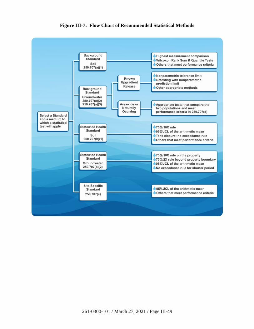
261-0300-101 / March 27, 2021 / Page III-49
Figure III-7: Flow Chart of Recommended Statistical Methods
261-0300-101 / March 27, 2021 / Page III-50
(a) 75%/10X Rule
The 75%/10X rule is a statistical ad hoc rule that tests whether the
true site median concentration is below the cleanup standard. This
rule requires that 75% of the samples collected for demonstration
attainment be equal to or below the risk-based cleanup standard
and that no single sample result exceeds the risk-based standard by
more than ten times. (See 25 Pa. Code § 250.707(b)(1)(i)).
For the 75%/10X rule, the number of sample points required for
each distinct area of contamination is specified in
Section 250.703(d) of the regulations and is as follows:
• For soil volumes equal to or less than 125 cubic yards, at
least eight (8) samples.
• For soil volumes up to 3,000 cubic yards, at least
twelve (12) sample points.
• For each additional volume of up to 3,000 cubic yards, an
additional twelve (12) sample points.
• Additional sampling points may be required based on site-
specific conditions.
This recommendation of 8 to 12 samples at minimum is based on a
simulation study using lognormal distributions (CSSAB 1996).
Because the heterogeneity of a volume of soil increases as the
volume increases, the number of samples required to accurately
demonstrate attainment would also increase.
In a situation where compliance with two different SHS MSCs are
required, such as an MSC for surface soil and another MSC for
subsurface soil, two separate attainment tests, each applying the
75%/10x rule, would be required (0-2 feet and 2-15 feet).
It should be noted that the 75%/10X rule should not be used to
demonstrate attainment of the site-specific standard. The site-
specific standard is based on site-specific risk assessment
methodology, including the assumption that a receptor’s long-term
exposure is related to the true site arithmetic average concentration
of a contaminant. Therefore, the 75%/10X rule is not appropriate
for the site-specific standard.
(b) The 95% Upper Confidence Limit (UCL) of Arithmetic Mean
Using 95% UCL of the arithmetic mean as described in
Sections 250.707(b)(1)(ii) and 250.707(c) of the regulations is well
documented in various EPA risk assessment or statistical
261-0300-101 / March 27, 2021 / Page III-51
guidances (EPA, 1989, 1992c, 1996, 2002a). It should be noted
that this statistical test may be applied to each distinct area of
contamination for demonstration of attainment at a site. Site
characterization data may not be suitable for inclusion in
determining a 95% UCL for attainment demonstration.
The following formula can be used for calculating sample size
(number of discrete soil samples) needed to estimate the mean:
nd = 2{(Z1- + Z1-)/(Cs - 1)}2
where is the false positive rate; is the false negative rate; Z1-
and Z1- are the critical values for the normal distribution with
probabilities of 1- and 1-; Cs is the cleanup standard; µ1 is the
value of population mean under the alternative hypothesis for
which the specific false negative rate () is to be controlled; is an
estimate of true standard deviation of the population.
Please note that the above equation may generate exceedingly
large sample size numbers (e.g., >>50). When some adjustments
of the sample size are necessary based on practical and cost
considerations, a person may use the equation to generate a smaller
sample size by increasing the false negative rate or the detection
difference Cs-µ1. Professional judgment should be used in
calculating sample size versus the reliability of the statistical test.
The false positive rate must not be greater than 0.20 for a
nonresidential site or 0.05 for a residential site (25 Pa. Code
§ 250.707(d)(2)(vii)).
Procedures to calculate 95% UCL of arithmetic mean are provided
in Sections III.B.6 and III.B.7 of this TGM.
The following decision rule is used to determine if a site meets the
cleanup standard:
• If 95% UCL of arithmetic mean is greater than or equal to
Cs, conclude that the sample results do not meet the
cleanup standard.
• If 95% UCL of arithmetic mean is less than Cs, conclude
that the sample results meet the cleanup standard.
Note that this rule uses the 95% UCL of the arithmetic mean to
estimate the limit of the population mean. The decision rule is
consistent with the hypothesis statements.
The primary assumptions of this method are independence of the
data, and sample mean is approximately normally distributed or
data are lognormally distributed. Examples of normal and
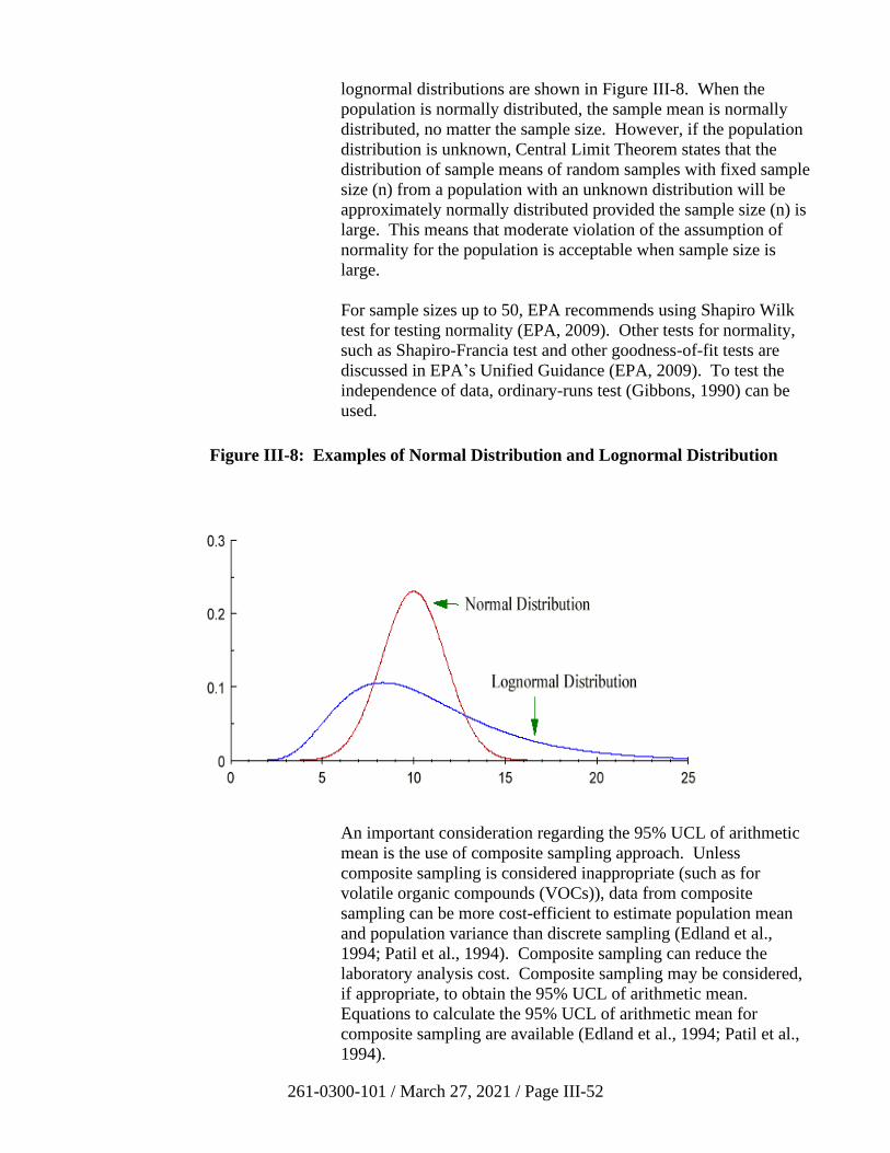
261-0300-101 / March 27, 2021 / Page III-52
lognormal distributions are shown in Figure III-8. When the
population is normally distributed, the sample mean is normally
distributed, no matter the sample size. However, if the population
distribution is unknown, Central Limit Theorem states that the
distribution of sample means of random samples with fixed sample
size (n) from a population with an unknown distribution will be
approximately normally distributed provided the sample size (n) is
large. This means that moderate violation of the assumption of
normality for the population is acceptable when sample size is
large.
For sample sizes up to 50, EPA recommends using Shapiro Wilk
test for testing normality (EPA, 2009). Other tests for normality,
such as Shapiro-Francia test and other goodness-of-fit tests are
discussed in EPA’s Unified Guidance (EPA, 2009). To test the
independence of data, ordinary-runs test (Gibbons, 1990) can be
used.
Figure III-8: Examples of Normal Distribution and Lognormal Distribution
An important consideration regarding the 95% UCL of arithmetic
mean is the use of composite sampling approach. Unless
composite sampling is considered inappropriate (such as for
volatile organic compounds (VOCs)), data from composite
sampling can be more cost-efficient to estimate population mean
and population variance than discrete sampling (Edland et al.,
1994; Patil et al., 1994). Composite sampling can reduce the
laboratory analysis cost. Composite sampling may be considered,
if appropriate, to obtain the 95% UCL of arithmetic mean.
Equations to calculate the 95% UCL of arithmetic mean for
composite sampling are available (Edland et al., 1994; Patil et al.,
1994).
261-0300-101 / March 27, 2021 / Page III-53
(c) No Exceedance Rule
For cleanup of releases of petroleum products where full site
characterization has not been conducted and remediation is guided
by visual observation and/or field screening, the no exceedance
rule must be used as described in Section 250.707(b)(1)(iii) of the
regulations as follows:
For sites where there is localized contamination as defined in the
document “Closure Requirements for Underground Storage Tank
Systems” (DEP technical document No. 263-4500-601), samples
shall be taken in accordance with that document.
For sites with contamination that does not qualify as localized
under that document, samples shall be taken from the bottom and
sidewalls of the excavation in a biased fashion that concentrates on
areas where any remaining contamination above the SHS would
most likely be found. The samples shall be taken from these
suspect areas based on visual observation and the use of field
instruments. If a sufficient number of samples has been collected
from all suspect locations and the minimum number of samples has
not been collected, or if there are no suspect areas, then the
locations to meet the minimum number of samples shall be based
on a random procedure. The number of sample points required
shall be determined in the following way:
• For 250 cubic yards or less of excavated contaminated soil,
five samples shall be collected.
• For each additional 100 cubic years of excavated
contaminated soil, one sample shall be collected.
• For excavation involving more than 1,000 cubic yards of
contaminated soil, the Department will approve the
confirmatory sampling plan.
• Where water is encountered in the excavation and no
obvious contamination is observed or indicated, a minimum
of two of the soil samples identified above shall be
collected just above the soil/water interface. These samples
shall meet the MSC determined by using the saturated soil
component of the soil-to-groundwater numeric value.
• Where water is encountered in the excavation and no
obvious contamination is observed or indicated, a minimum
of two water samples shall also be collected from the water
surface in the excavation.
261-0300-101 / March 27, 2021 / Page III-54
All sample results shall meet the SHS.
For sites where there is a release to surface soils resulting in
excavation of 50 cubic yards or less of contaminated soil, samples
shall be collected as described above, except that two samples shall
be collected.
ii) Groundwater Risk-Based Standards
Statistical tests appropriate to demonstrating compliance with groundwater
standards are presented in Section 250.707(b)(2) of the regulations.
Groundwater cleanup activities generally include site investigation,
groundwater remediation, a post-treatment period allowing the
groundwater to stabilize, sampling and analysis to assess attainment, and
possible post-cleanup monitoring. Different statistical procedures are
applicable at different stages in this cleanup process. The statistical
procedures used must account for the changes in the groundwater system
over time due to natural or man-induced causes. The specific statistical
procedures used depend on the goals and quality of the monitoring data.
The methods selected should be consistent with the goals of the
monitoring. For example, a remediator may want to use regression
analysis to decide when to stop treatment of groundwater. Regression
analysis can be used to detect trends in contaminant concentration levels
over time, to determine variables that influence concentration levels, and
to predict chemical concentrations at future points in time. After
terminating groundwater treatment, a remediator may want to use time
trend analysis or plotted data to find if the groundwater has stabilized.
After the groundwater has reached a steady state, the remediator may
compare monitoring well concentrations to background reference well
concentrations to determine whether the post-cleanup contamination
concentrations are acceptable compared to the cleanup standards and may
perform trend analysis or use plotted data to determine whether the post-
cleanup contamination concentrations are likely to remain acceptable.
Once the groundwater has stabilized, it is recommended to use the 95%
UCL of the mean (EPA, 2002a) or the following CSSAB ad hoc rule to
compare with groundwater risk-based standards: In monitoring wells
beyond the property boundary, the attainment criteria would be 75% of the
sampling results from any given well below the standard with no
individual value being more than 2 times the standard (75%/2X rule).
This rule would have to be met in each individual monitoring well.
To use the CSSAB ad hoc rule, eight samples from each compliance well
must be obtained during eight consecutive quarters. A shorter sampling
period (25 Pa. Code § 250.704(d)) requires the use of the no exceedance
rule (25 Pa. Code § 250.704(d)(3)) with written approval of the
Department.
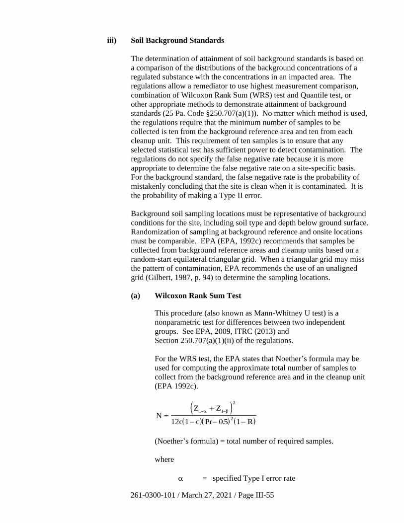
261-0300-101 / March 27, 2021 / Page III-55
iii) Soil Background Standards
The determination of attainment of soil background standards is based on
a comparison of the distributions of the background concentrations of a
regulated substance with the concentrations in an impacted area. The
regulations allow a remediator to use highest measurement comparison,
combination of Wilcoxon Rank Sum (WRS) test and Quantile test, or
other appropriate methods to demonstrate attainment of background
standards (25 Pa. Code §250.707(a)(1)). No matter which method is used,
the regulations require that the minimum number of samples to be
collected is ten from the background reference area and ten from each
cleanup unit. This requirement of ten samples is to ensure that any
selected statistical test has sufficient power to detect contamination. The
regulations do not specify the false negative rate because it is more
appropriate to determine the false negative rate on a site-specific basis.
For the background standard, the false negative rate is the probability of
mistakenly concluding that the site is clean when it is contaminated. It is
the probability of making a Type II error.
Background soil sampling locations must be representative of background
conditions for the site, including soil type and depth below ground surface.
Randomization of sampling at background reference and onsite locations
must be comparable. EPA (EPA, 1992c) recommends that samples be
collected from background reference areas and cleanup units based on a
random-start equilateral triangular grid. When a triangular grid may miss
the pattern of contamination, EPA recommends the use of an unaligned
grid (Gilbert, 1987, p. 94) to determine the sampling locations.
(a) Wilcoxon Rank Sum Test
This procedure (also known as Mann-Whitney U test) is a
nonparametric test for differences between two independent
groups. See EPA, 2009, ITRC (2013) and
Section 250.707(a)(1)(ii) of the regulations.
For the WRS test, the EPA states that Noether’s formula may be
used for computing the approximate total number of samples to
collect from the background reference area and in the cleanup unit
(EPA 1992c).
( )( )( ) ( )
NZ Z
c c R=
+
− − −
− −1 1
2
212 1 05 1
Pr .
(Noether’s formula) = total number of required samples.
where
= specified Type I error rate
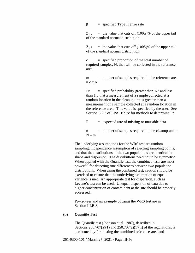
261-0300-101 / March 27, 2021 / Page III-56
= specified Type II error rate
Z1- = the value that cuts off (100)% of the upper tail
of the standard normal distribution
Z1- = the value that cuts off (100)% of the upper tail
of the standard normal distribution
c = specified proportion of the total number of
required samples, N, that will be collected in the reference
area
m = number of samples required in the reference area
= c x N
Pr = specified probability greater than 1/2 and less
than 1.0 that a measurement of a sample collected at a
random location in the cleanup unit is greater than a
measurement of a sample collected at a random location in
the reference area. This value is specified by the user. See
Section 6.2.2 of EPA, 1992c for methods to determine Pr.
R = expected rate of missing or unusable data
n = number of samples required in the cleanup unit =
N – m
The underlying assumptions for the WRS test are random
sampling, independence assumption of selecting sampling points,
and that the distributions of the two populations are identical in
shape and dispersion. The distributions need not to be symmetric.
When applied with the Quantile test, the combined tests are most
powerful for detecting true differences between two population
distributions. When using the combined test, caution should be
exercised to ensure that the underlying assumption of equal
variance is met. An appropriate test for dispersion, such as
Levene’s test can be used. Unequal dispersion of data due to
higher concentration of contaminant at the site should be properly
addressed.
Procedures and an example of using the WRS test are in
Section III.B.8.
(b) Quantile Test
The Quantile test (Johnson et al. 1987), described in
Sections 250.707(a)(1) and 250.707(a)(1)(ii) of the regulations, is
performed by first listing the combined reference-area and
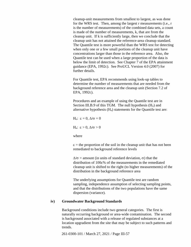
261-0300-101 / March 27, 2021 / Page III-57
cleanup-unit measurements from smallest to largest, as was done
for the WRS test. Then, among the largest r measurements (i.e., r
is the number of measurements) of the combined data sets, a count
is made of the number of measurements, k, that are from the
cleanup unit. If k is sufficiently large, then we conclude that the
cleanup unit has not attained the reference-area cleanup standard.
The Quantile test is more powerful than the WRS test for detecting
when only one or a few small portions of the cleanup unit have
concentrations larger than those in the reference area. Also, the
Quantile test can be used when a large proportion of the data is
below the limit of detection. See Chapter 7 of the EPA attainment
guidance (EPA, 1992c). See ProUCL Version 4.0 (2007) for
further details.
For Quantile test, EPA recommends using look-up tables to
determine the number of measurements that are needed from the
background reference area and the cleanup unit (Section 7.2 of
EPA, 1992c).
Procedures and an example of using the Quantile test are in
Section III.B.9 of this TGM. The null hypothesis (Ho) and
alternative hypothesis (Ha) statements for the Quantile test are:
Ho: = 0, / = 0
Ha: > 0, / > 0
where
= the proportion of the soil in the cleanup unit that has not been
remediated to background reference levels
/ = amount (in units of standard deviation, ) that the
distribution of 100% of the measurements in the remediated
cleanup unit is shifted to the right (to higher measurements) of the
distribution in the background reference area
The underlying assumptions for Quantile test are random
sampling, independence assumption of selecting sampling points,
and that the distributions of the two populations have the same
dispersion (variance).
iv) Groundwater Background Standards
Background conditions include two general categories. The first is
naturally occurring background or area-wide contamination. The second
is background associated with a release of regulated substances at a
location upgradient from the site that may be subject to such patterns and
trends.
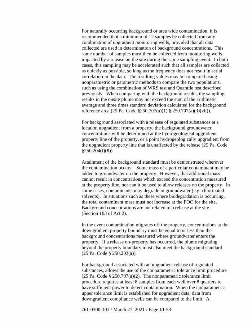
261-0300-101 / March 27, 2021 / Page III-58
For naturally occurring background or area wide contamination, it is
recommended that a minimum of 12 samples be collected from any
combination of upgradient monitoring wells, provided that all data
collected are used in determination of background concentrations. This
same number of samples must then be collected from monitoring wells
impacted by a release on the site during the same sampling event. In both
cases, this sampling may be accelerated such that all samples are collected
as quickly as possible, so long as the frequency does not result in serial
correlation in the data. The resulting values may be compared using
nonparametric or parametric methods to compare the two populations,
such as using the combination of WRS test and Quantile test described
previously. When comparing with the background results, the sampling
results in the onsite plume may not exceed the sum of the arithmetic
average and three times standard deviation calculated for the background
reference area (25 Pa. Code §250.707(a)(1) § 250.707(a)(3)(vii)).
For background associated with a release of regulated substances at a
location upgradient from a property, the background groundwater
concentrations will be determined at the hydrogeological upgradient
property line of the property, or a point hydrogeologically upgradient from
the upgradient property line that is unaffected by the release (25 Pa. Code
§250.204(f)(8)).
Attainment of the background standard must be demonstrated wherever
the contamination occurs. Some mass of a particular contaminant may be
added to groundwater on the property. However, that additional mass
cannot result in concentrations which exceed the concentration measured
at the property line, nor can it be used to allow releases on the property. In
some cases, contaminants may degrade in groundwater (e.g. chlorinated
solvents). In situations such as these where biodegradation is occurring,
the total contaminant mass must not increase at the POC for the site.
Background concentrations are not related to a release at the site
(Section 103 of Act 2).
In the event contamination migrates off the property, concentrations at the
downgradient property boundary must be equal to or less than the
background concentrations measured where groundwater enters the
property. If a release on-property has occurred, the plume migrating
beyond the property boundary must also meet the background standard
(25 Pa. Code § 250.203(a)).
For background associated with an upgradient release of regulated
substances, allows the use of the nonparametric tolerance limit procedure
(25 Pa. Code § 250.707(a)(2). The nonparametric tolerance limit
procedure requires at least 8 samples from each well over 8 quarters to
have sufficient power to detect contamination. When the nonparametric
upper tolerance limit is established for upgradient data, data from
downgradient compliance wells can be compared to the limit. A
261-0300-101 / March 27, 2021 / Page III-59
resampling strategy must be used when an analyte exceeds the
nonparametric upper tolerance limit. The well is retested for the analyte
of concern, and the value is compared to the nonparametric upper
prediction limit. These two-phase testing strategies can be very effective
tools for controlling the facility-wide false positive rate while maintaining
a high power of detecting contamination.
5. Additional Information on Statistical Procedures
This section provides an overview regarding various other statistical methods available to
use to determine if a cleanup activity is successful. The EPA Addendum (EPA, 1992a),
EPA Groundwater Attainment (EPA, 1992b), EPA Soil Reference-Based Standards
Attainment (EPA, 1992c), EPA QA/G-9 (EPA, 1996), and EPA Unified Guidance (2009)
describe and provide examples for both the parametric and nonparametric methods. See
additional discussions in Helsel and Hirsch (1992), Conover (1980), Gilbert (1987), and
Davis and McNichols (1994, Parts I and II), and ITRC’s Groundwater Statistics and
Monitoring Compliance (2013). It is important to note that EPA’s ProUCL, free
statistical software for environmental applications, can run all of the tests summarized in
the following sections.
a) Interval Tests
Statistical Intervals - Statistical interval tests can be used independently for
comparing with a numerical value or in combination with other tests for
comparing populations. Statistical intervals include three main types: tolerance
intervals, prediction intervals, and confidence intervals. Which ones are used
depend on the goals of the data analysis.
Tolerance Intervals - Tolerance intervals will typically be the most useful
interval test. They are used to determine the extent of data that is within a
standard (like an MCL) or ambient level. Parametric tolerance intervals can be
computed by assuming a lognormal distribution.
Prediction Intervals - Prediction intervals are used to determine if the next one
or more samples are within the existing data distribution at a certain confidence
level. The prediction interval contains 100 * (1- value) percent of the
distribution. A smaller value will include a larger range of data. Prediction
intervals are used for intrawell (single well) comparisons, and with comparison of
a compliance well with a background well.
Confidence Intervals - Confidence intervals contain a specified parameter of the
distribution (such as the mean of the data) at a specified confidence level.
Confidence intervals do not address extreme values. The step-by-step procedures
to calculate the upper confidence of mean are provided in Sections III.B.6
and III.B.7.
261-0300-101 / March 27, 2021 / Page III-60
b) Tests for Comparing Populations
The following tests are some of the EPA’s recommended tests for analysis of
groundwater data between upgradient and downgradient well groups,
downgradient wells and a health-based standard, or of intrawell (single well)
comparisons. This does not include all potentially satisfactory statistical tests.
Analysis of Variance (ANOVA) - ANOVA includes a group of procedures used
for comparing the means of multiple (3 or more) independent groups such as
upgradient wells and downgradient wells. The ANOVA methods are used to
determine if there is statistically significant evidence of contamination at
downgradient wells compared to an upgradient well, or groups of wells.
The one-way ANOVA method is described with examples in Section 17 of the
EPA Unified Guidance (EPA, 2009). This is the EPA recommended procedure
for comparing data that do not violate the assumptions of normal distribution and
approximately equal variances.
However, as the number of wells (or groups) increases at a site, the power of
ANOVA to detect individual instances of contamination decreases. For this
reason, tolerance and prediction intervals with retesting provisions are often much
better procedures to use.
Kruskal-Wallis Test - If assumptions of the one-way ANOVA test are “grossly”
violated, the nonparametric Kruskal-Wallis test is used for more than
2 independent groups of data. It can be used for comparison of upgradient water
quality to water quality from many downgradient wells in one procedure.
Alternatively, if the wells are grouped by some characteristic (e.g., depth,
geology, location, season), comparisons among other groups can be made.
If the null hypothesis (no change) is rejected by Kruskal-Wallis (i.e., the test
statistic exceeds the tabulated critical value), then pairwise comparisons should be
made to determine what wells are contaminated (see Gilbert (1987),
Section 18.2.2; the EPA Addendum (1992a), Section 3.1; and the EPA Unified
Guidance (2009), Section 17.1.2). The underlying assumptions are the
distributions of the independent populations are identical in shape (variance), but
the distributions need not to be symmetric.
t-test - The t-test is a parametric, ANOVA type of test used to assess differences
in means of two independent groups. This test assumes normal distributions and
equal variances for both groups. The t-test is best limited to situations where the
data sets are too small to use nonparametric procedures. For example, if
background water quality is limited to two or three samples, the t-test can be used
to test for differences between background and compliance data.
c) Trend Tests
Considerations - When monitoring data have been collected over several years or
more, trend tests allow the determination of the change in distribution of data over
261-0300-101 / March 27, 2021 / Page III-61
time. In addition to water quality trends, a time series of monitoring data may
contain characteristics of seasonality and serial correlation. Other complicating
factors include changes in laboratories or procedures involving the sampling and
analysis of the analyte.
Seasonality and serial correlation interfere with trend tests either by reducing the
power to detect trends or giving erroneous probabilities. Correction for
seasonality is available for tests presented here. Serial correlation exists if a data
point value is at least partially dependent on nearby data point values. For a given
data set, serial correlation decreases with increasing temporal distance between
samples. Harris, et al. (1987) reported difficulty detecting serial correlation in
10 years or less of quarterly groundwater data. Therefore, correction is not
recommended for quarterly data. Serial correlation correction is available for the
Seasonal Kendall trend test (Hirsch and Slack, 1984), but has reduced power with
small data sets and is not recommended for a monthly time series that is less than
5 years.
Parametric Trend Tests - Parametric trend tests are based on regression methods
and allow compensation for exogenous effects (outside influences). Regression
analysis between two variables can be used to calculate the correlation coefficient
(r). The closer r is to one, the closer the relationship is between the two variables.
A t-test of correlation can be done on r to see if it is significant (see Davis, 1987,
Chapter 2; EPA, 1996, Section 4.3.2; EPA, 2009).
Mixed (i.e., parametric and nonparametric methods) methods also are available
when removing the effects of exogenous variables. Helsel and Hirsch (1992)
present a thorough review of trend analysis. Methods for detecting trends also are
presented in Chapter 16 of Gilbert (1987).
Because regression techniques are based on the assumption of a normal
distribution of the data, a nonparametric approach may have to be used.
Nonparametric Trend Tests - The Mann-Kendall trend test is a nonparametric
test for monotonic (steadily upward or downward) trend. (Gilbert, 1987;
Section 4.3.4 of EPA, 1996; Section 17.3.2 of EPA, 2009).
This test requires constant variance in data. Non-constant variance may be
changed to constant variance with a power transformation. Logarithm
transformation is usually most appropriate. This transformation does not affect
the test statistic. Decision rules, exact test tables, normal approximation formulas,
and correction for ties can be found in Helsel and Hirsch (1992); Gilbert (1987)
and many introductory statistics texts. When a trend is present, the slope of fitted
line can be estimated using Sen’s estimator (see Gilbert, 1987; Section 4.3.3 of
EPA, 1996; Section 17.3.3 of EPA, 2009).
The Seasonal Kendall trend test is a seasonally corrected Mann-Kendall trend test.
This should be applied when time series graphs or boxplots of data indicate the
presence of seasonal variation. See Chapter 17 of Gilbert (1987).
261-0300-101 / March 27, 2021 / Page III-62
The following sections present the methodology of several statistical tests which
may be utilized in the course of demonstrating attainment of an Act 2 standard.
Again, it is worthwhile to note that statistical computer software, such as EPA’s
ProUCL, has been developed to perform these tests.
6. Calculation of UCL of Mean When the Distribution of the Sampling Mean is
Normal
The following is a step-by-step description of the approach used to calculate confidence
limits of an arithmetic mean when the distribution of the sampling mean is normal. For
data sets of lognormal distribution, the approach in Section III.B.7 should be used
instead.
1. Calculate the sample mean by dividing the sum of the total readings by the total
number of readings:
X = (X1 + X2 + Xn)/n
2. Calculate the sample variance (Sb2) by taking the sum of the squares of each
reading minus the mean and dividing by the degrees of freedom (df, the total
number of samples minus one):
Sb2 = [(X1 - X )2+ (X2 - X )2 + +(Xn- X )2]/(n-1)
3. Calculate the standard deviation (Sb) by taking the square root of the variance
(Sb2):
Sb =( )Sb2
4. Calculate the standard error of the mean (Sx). Standard error is inversely
proportional to the square root of the number of samples (increasing n from 4 to
16 reduces Sx by 50%) where Sx equals Sb/ n . [Note: The above procedure is
for simple random samples. For systematic sampling, the calculation of standard
error should follow instructions in Section 6.5 of EPA soil attainment guidance
(EPA, 1989b). For multiple systematic sampling, the equation to calculate
unbiased estimate of variance is also available (Gilbert, 1987, p. 97).]
5. Since the concern is only whether the upper limit of a confidence interval is below
or above the Act 2 regulatory threshold (RT), the lower confidence limit (LCL)
need not be considered. The upper confidence limit (UCL) can be calculated
using the one-tailed (one-sided) t values with n-1 degrees of freedom (df) derived
from a table of the student’s t distribution, t1-a, n-1 (Table III-3).
6. The 95% UCL (=0.05; one-sided) is calculated by using the following formula
and substituting the values determined above plus the appropriate t value obtained
from the student’s t table where UCL equals X +t1-a, n-1 *Sx.
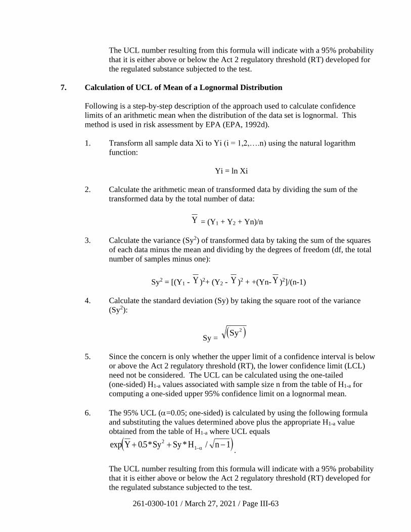
261-0300-101 / March 27, 2021 / Page III-63
The UCL number resulting from this formula will indicate with a 95% probability
that it is either above or below the Act 2 regulatory threshold (RT) developed for
the regulated substance subjected to the test.
7. Calculation of UCL of Mean of a Lognormal Distribution
Following is a step-by-step description of the approach used to calculate confidence
limits of an arithmetic mean when the distribution of the data set is lognormal. This
method is used in risk assessment by EPA (EPA, 1992d).
1. Transform all sample data Xi to Yi (i = 1,2,….n) using the natural logarithm
function:
Yi = ln Xi
2. Calculate the arithmetic mean of transformed data by dividing the sum of the
transformed data by the total number of data:
Y = (Y1 + Y2 + Yn)/n
3. Calculate the variance (Sy2) of transformed data by taking the sum of the squares
of each data minus the mean and dividing by the degrees of freedom (df, the total
number of samples minus one):
Sy2 = [(Y1 - Y )2+ (Y2 - Y )2 + +(Yn- Y )2]/(n-1)
4. Calculate the standard deviation (Sy) by taking the square root of the variance
(Sy2):
Sy = ( )Sy2
5. Since the concern is only whether the upper limit of a confidence interval is below
or above the Act 2 regulatory threshold (RT), the lower confidence limit (LCL)
need not be considered. The UCL can be calculated using the one-tailed
(one-sided) H1-a values associated with sample size n from the table of H1-a for
computing a one-sided upper 95% confidence limit on a lognormal mean.
6. The 95% UCL (=0.05; one-sided) is calculated by using the following formula
and substituting the values determined above plus the appropriate H1-a value
obtained from the table of H1-a where UCL equals
( )exp . * * /Y Sy Sy H n+ + −−05 12
1 .
The UCL number resulting from this formula will indicate with a 95% probability
that it is either above or below the Act 2 regulatory threshold (RT) developed for
the regulated substance subjected to the test.
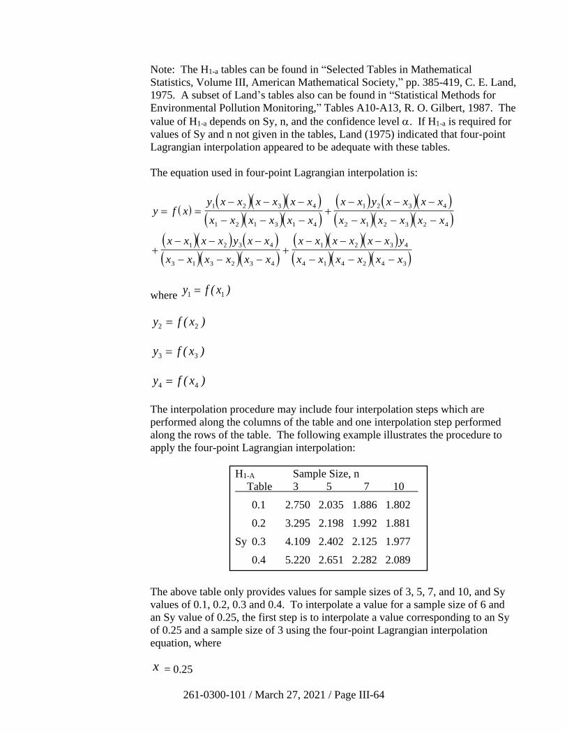
261-0300-101 / March 27, 2021 / Page III-64
Note: The H1-a tables can be found in “Selected Tables in Mathematical
Statistics, Volume III, American Mathematical Society,” pp. 385-419, C. E. Land,
1975. A subset of Land’s tables also can be found in “Statistical Methods for
Environmental Pollution Monitoring,” Tables A10-A13, R. O. Gilbert, 1987. The
value of H1-a depends on Sy, n, and the confidence level . If H1-a is required for
values of Sy and n not given in the tables, Land (1975) indicated that four-point
Lagrangian interpolation appeared to be adequate with these tables.
The equation used in four-point Lagrangian interpolation is:
( )( )( )( )
( )( )( )( ) ( )( )( )( )( )
( )( ) ( )( )( )( )
( )( )( )( )( )( )
y f xy x x x x x x
x x x x x x
x x y x x x x
x x x x x x
x x x x y x x
x x x x x x
x x x x x x y
x x x x x x
= =− − −
− − −+
− − −
− − −
+− − −
− − −+
− − −
− − −
1 2 3 4
1 2 1 3 1 4
1 2 3 4
2 1 2 3 2 4
1 2 3 4
3 1 3 2 3 4
1 2 3 4
4 1 4 2 4 3
where y f x1 1= ( )
y f x2 2= ( )
y f x3 3= ( )
y f x4 4= ( )
The interpolation procedure may include four interpolation steps which are
performed along the columns of the table and one interpolation step performed
along the rows of the table. The following example illustrates the procedure to
apply the four-point Lagrangian interpolation:
The above table only provides values for sample sizes of 3, 5, 7, and 10, and Sy
values of 0.1, 0.2, 0.3 and 0.4. To interpolate a value for a sample size of 6 and
an Sy value of 0.25, the first step is to interpolate a value corresponding to an Sy
of 0.25 and a sample size of 3 using the four-point Lagrangian interpolation
equation, where
x = 0.25
H1-A Sample Size, n
Table 3 5 7 10
0.1 2.750 2.035 1.886 1.802
0.2 3.295 2.198 1.992 1.881
Sy 0.3 4.109 2.402 2.125 1.977
0.4 5.220 2.651 2.282 2.089
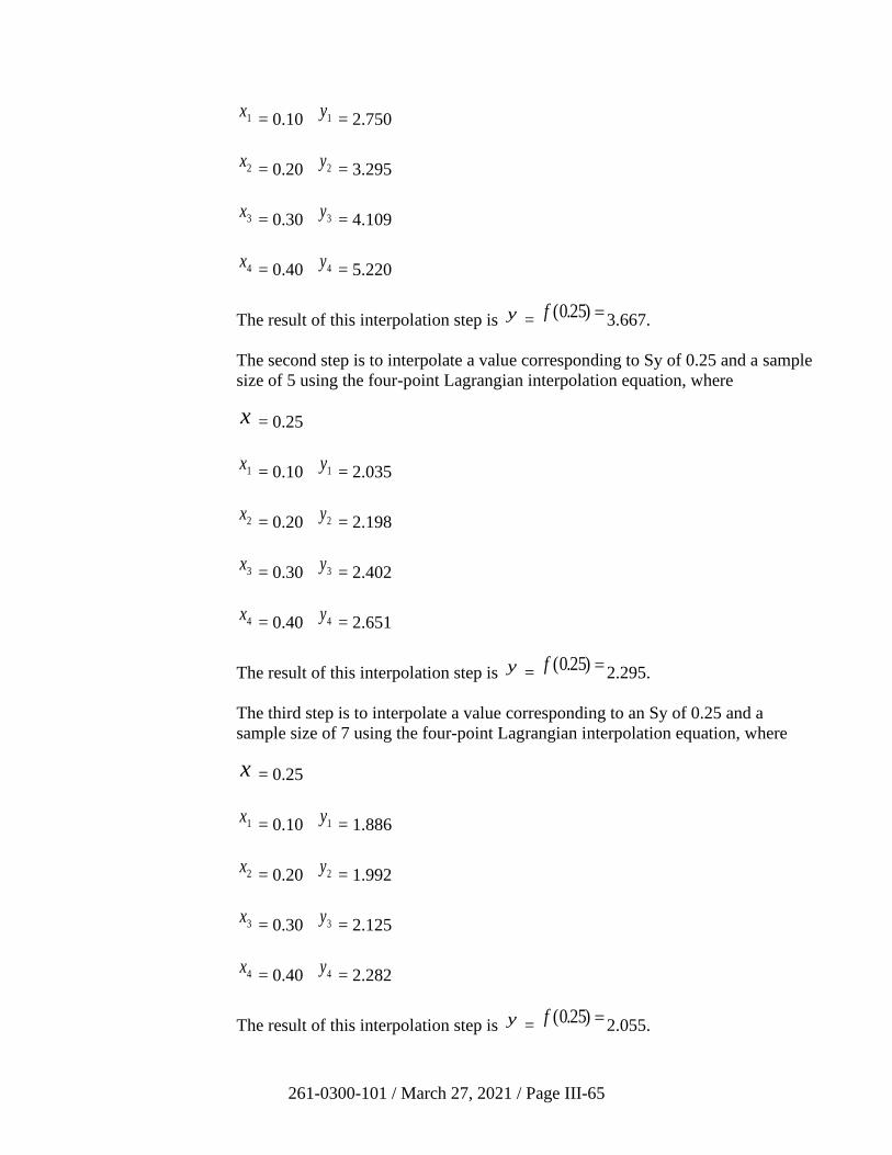
261-0300-101 / March 27, 2021 / Page III-65
x1 = 0.10 y1 = 2.750
x2 = 0.20 y2 = 3.295
x3 = 0.30 y3 = 4.109
x4 = 0.40 y4 = 5.220
The result of this interpolation step is y = f ( . )025 =
3.667.
The second step is to interpolate a value corresponding to Sy of 0.25 and a sample
size of 5 using the four-point Lagrangian interpolation equation, where
x = 0.25
x1 = 0.10 y1 = 2.035
x2 = 0.20 y2 = 2.198
x3 = 0.30 y3 = 2.402
x4 = 0.40 y4 = 2.651
The result of this interpolation step is y = f ( . )025 =
2.295.
The third step is to interpolate a value corresponding to an Sy of 0.25 and a
sample size of 7 using the four-point Lagrangian interpolation equation, where
x = 0.25
x1 = 0.10 y1 = 1.886
x2 = 0.20 y2 = 1.992
x3 = 0.30 y3 = 2.125
x4 = 0.40 y4 = 2.282
The result of this interpolation step is y = f ( . )025 =
2.055.
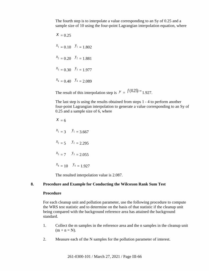
261-0300-101 / March 27, 2021 / Page III-66
The fourth step is to interpolate a value corresponding to an Sy of 0.25 and a
sample size of 10 using the four-point Lagrangian interpolation equation, where
x = 0.25
x1 = 0.10 y1 = 1.802
x2 = 0.20 y2 = 1.881
x3 = 0.30 y3 = 1.977
x4 = 0.40 y4 = 2.089
The result of this interpolation step is y = f ( . )025 =
1.927.
The last step is using the results obtained from steps 1 - 4 to perform another
four-point Lagrangian interpolation to generate a value corresponding to an Sy of
0.25 and a sample size of 6, where x = 6
x1 = 3 y1 = 3.667
x2 = 5 y2 = 2.295
x3 = 7 y3 = 2.055
x4 = 10 y4 = 1.927
The resulted interpolation value is 2.087.
8. Procedure and Example for Conducting the Wilcoxon Rank Sum Test
Procedure
For each cleanup unit and pollution parameter, use the following procedure to compute
the WRS test statistic and to determine on the basis of that statistic if the cleanup unit
being compared with the background reference area has attained the background
standard.
1. Collect the m samples in the reference area and the n samples in the cleanup unit
(m + n = N).
2. Measure each of the N samples for the pollution parameter of interest.
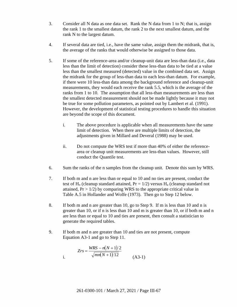
261-0300-101 / March 27, 2021 / Page III-67
3. Consider all N data as one data set. Rank the N data from 1 to N; that is, assign
the rank 1 to the smallest datum, the rank 2 to the next smallest datum, and the
rank N to the largest datum.
4. If several data are tied, i.e., have the same value, assign them the midrank, that is,
the average of the ranks that would otherwise be assigned to those data.
5. If some of the reference-area and/or cleanup-unit data are less-than data (i.e., data
less than the limit of detection) consider these less-than data to be tied at a value
less than the smallest measured (detected) value in the combined data set. Assign
the midrank for the group of less-than data to each less-than datum. For example,
if there were 10 less-than data among the background reference and cleanup-unit
measurements, they would each receive the rank 5.5, which is the average of the
ranks from 1 to 10. The assumption that all less-than measurements are less than
the smallest detected measurement should not be made lightly because it may not
be true for some pollution parameters, as pointed out by Lambert et al. (1991).
However, the development of statistical testing procedures to handle this situation
are beyond the scope of this document.
i. The above procedure is applicable when all measurements have the same
limit of detection. When there are multiple limits of detection, the
adjustments given in Millard and Deveral (1988) may be used.
ii. Do not compute the WRS test if more than 40% of either the reference-
area or cleanup unit measurements are less-than values. However, still
conduct the Quantile test.
6. Sum the ranks of the n samples from the cleanup unit. Denote this sum by WRS.
7. If both m and n are less than or equal to 10 and no ties are present, conduct the
test of Ho (cleanup standard attained, Pr = 1/2) versus Ha (cleanup standard not
attained, Pr > 1/2) by comparing WRS to the appropriate critical value in
Table A.5 in Hollander and Wolfe (1973). Then go to Step 12 below.
8. If both m and n are greater than 10, go to Step 9. If m is less than 10 and n is
greater than 10, or if n is less than 10 and m is greater than 10, or if both m and n
are less than or equal to 10 and ties are present, then consult a statistician to
generate the required tables.
9. If both m and n are greater than 10 and ties are not present, compute
Equation A3-1 and go to Step 11.
i.
( )
( ) 121
21
+
+−=
Nmn
NnWRSZrs
(A3-1)
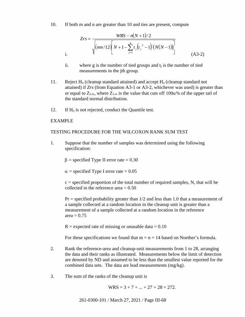
261-0300-101 / March 27, 2021 / Page III-68
10. If both m and n are greater than 10 and ties are present, compute
i.
( )
( ) ( ) ( )( )
−−−+
+−=
=
g
j
jj NNttNnm
NnWRSZrs
1
211112/
2/1
(A3-2)
ii. where g is the number of tied groups and tj is the number of tied
measurements in the jth group.
11. Reject Ho (cleanup standard attained) and accept Ha (cleanup standard not
attained) if Zrs (from Equation A3-1 or A3-2, whichever was used) is greater than
or equal to Z1-, where Z1- is the value that cuts off 100% of the upper tail of
the standard normal distribution.
12. If Ho is not rejected, conduct the Quantile test.
EXAMPLE
TESTING PROCEDURE FOR THE WILCOXON RANK SUM TEST
1. Suppose that the number of samples was determined using the following
specification:
= specified Type II error rate = 0.30
= specified Type I error rate = 0.05
c = specified proportion of the total number of required samples, N, that will be
collected in the reference area = 0.50
Pr = specified probability greater than 1/2 and less than 1.0 that a measurement of
a sample collected at a random location in the cleanup unit is greater than a
measurement of a sample collected at a random location in the reference
area = 0.75
R = expected rate of missing or unusable data = 0.10
For these specifications we found that m = n = 14 based on Noether’s formula.
2. Rank the reference-area and cleanup-unit measurements from 1 to 28, arranging
the data and their ranks as illustrated. Measurements below the limit of detection
are denoted by ND and assumed to be less than the smallest value reported for the
combined data sets. The data are lead measurements (mg/kg).
3. The sum of the ranks of the cleanup unit is
WRS = 3 + 7 + ... + 27 + 28 = 272.
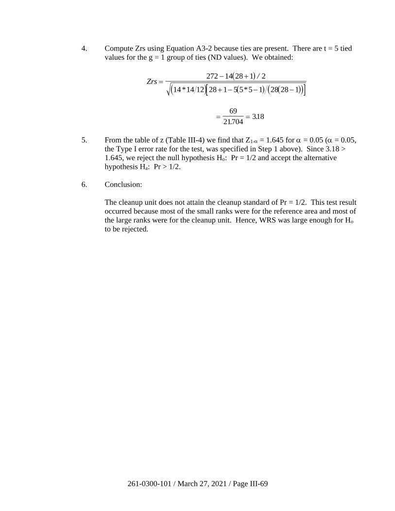
261-0300-101 / March 27, 2021 / Page III-69
4. Compute Zrs using Equation A3-2 because ties are present. There are t = 5 tied
values for the g = 1 group of ties (ND values). We obtained:
( )
( ) ( ) ( )( ) Zrs =
− +
+ − − −
272 14 28 1 2
14 14 12 28 1 5 5 5 1 28 28 1
/
* *
= =69
21704318
..
5. From the table of z (Table III-4) we find that Z1- = 1.645 for = 0.05 ( = 0.05,
the Type I error rate for the test, was specified in Step 1 above). Since 3.18 >
1.645, we reject the null hypothesis Ho: Pr = 1/2 and accept the alternative
hypothesis Ha: Pr > 1/2.
6. Conclusion:
The cleanup unit does not attain the cleanup standard of Pr = 1/2. This test result
occurred because most of the small ranks were for the reference area and most of
the large ranks were for the cleanup unit. Hence, WRS was large enough for Ho
to be rejected.
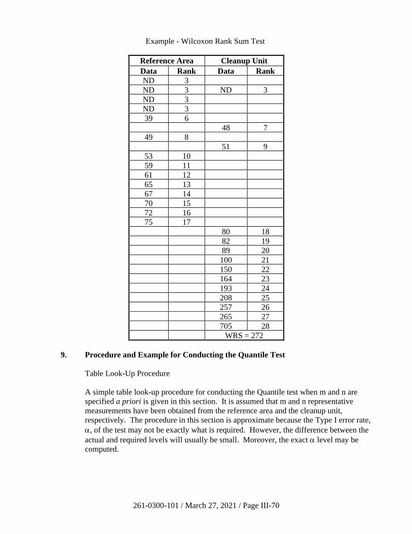
261-0300-101 / March 27, 2021 / Page III-70
Example - Wilcoxon Rank Sum Test
Reference Area Cleanup Unit
Data Rank Data Rank
ND 3
ND 3 ND 3
ND 3
ND 3
39 6
48 7
49 8
51 9
53 10
59 11
61 12
65 13
67 14
70 15
72 16
75 17
80 18
82 19
89 20
100 21
150 22
164 23
193 24
208 25
257 26
265 27
705 28
WRS = 272
9. Procedure and Example for Conducting the Quantile Test
Table Look-Up Procedure
A simple table look-up procedure for conducting the Quantile test when m and n are
specified a priori is given in this section. It is assumed that m and n representative
measurements have been obtained from the reference area and the cleanup unit,
respectively. The procedure in this section is approximate because the Type I error rate,
, of the test may not be exactly what is required. However, the difference between the
actual and required levels will usually be small. Moreover, the exact level may be
computed.
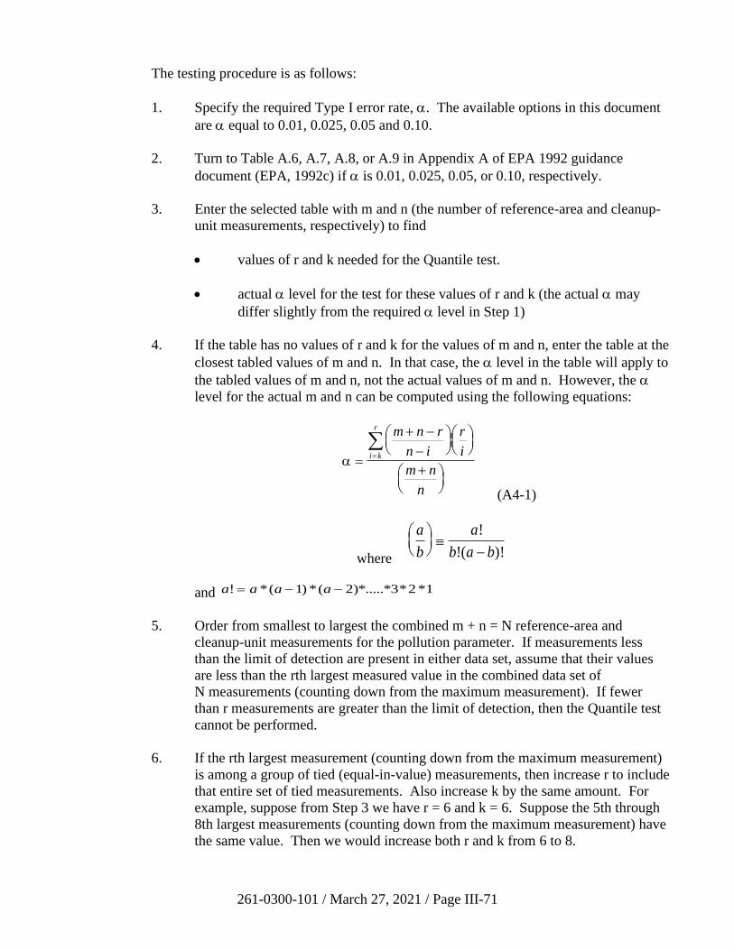
261-0300-101 / March 27, 2021 / Page III-71
The testing procedure is as follows:
1. Specify the required Type I error rate, . The available options in this document
are equal to 0.01, 0.025, 0.05 and 0.10.
2. Turn to Table A.6, A.7, A.8, or A.9 in Appendix A of EPA 1992 guidance
document (EPA, 1992c) if is 0.01, 0.025, 0.05, or 0.10, respectively.
3. Enter the selected table with m and n (the number of reference-area and cleanup-
unit measurements, respectively) to find
• values of r and k needed for the Quantile test.
• actual level for the test for these values of r and k (the actual may
differ slightly from the required level in Step 1)
4. If the table has no values of r and k for the values of m and n, enter the table at the
closest tabled values of m and n. In that case, the level in the table will apply to
the tabled values of m and n, not the actual values of m and n. However, the
level for the actual m and n can be computed using the following equations:
=
+ −
−
+
=
m n r
n i
r
i
m n
n
i k
r
(A4-1)
where
a
b
a
b a b
−
!
!( )!
and a a a a! *( ) *( )*.....*3* *= − −1 2 2 1
5. Order from smallest to largest the combined m + n = N reference-area and
cleanup-unit measurements for the pollution parameter. If measurements less
than the limit of detection are present in either data set, assume that their values
are less than the rth largest measured value in the combined data set of
N measurements (counting down from the maximum measurement). If fewer
than r measurements are greater than the limit of detection, then the Quantile test
cannot be performed.
6. If the rth largest measurement (counting down from the maximum measurement)
is among a group of tied (equal-in-value) measurements, then increase r to include
that entire set of tied measurements. Also increase k by the same amount. For
example, suppose from Step 3 we have r = 6 and k = 6. Suppose the 5th through
8th largest measurements (counting down from the maximum measurement) have
the same value. Then we would increase both r and k from 6 to 8.
261-0300-101 / March 27, 2021 / Page III-72
7. Count the number, k, of measurements from the cleanup unit that are among the r
largest measurements of the ordered N measurements, where r and k were
determined in Step 3 (or Step 6 if the rth largest measurement is among a group of
tied measurements).
8. If the observed k (from Step 7) is greater than or equal to the tabled value of k,
then reject Ho and conclude that the cleanup unit has not attained the reference
area cleanup standard ( = 0 and / = 0).
9. If Ho is not rejected, then do the WRS test. If the WRS test indicates the Ho
should be rejected, then additional remedial action may be necessary.
EXAMPLE
TABLE LOOK-UP TESTING PROCEDURE FOR THE QUANTILE TEST
1. We illustrate the Quantile test using the measurements listed in the example of
Section III.B.8. There are 14 measurements in both the reference area and the
cleanup unit. Suppose we specify = 0.05 for this Quantile test.
2. Turn to Table A.8 in EPA 1992 guidance (EPA, 1992c; because the table is for
= 0.05). We see that there are no entries in that table for m = n = 14. Hence,
we enter the table with n = m = 15, the values closest to 14. For n = m = 15 we
find r = 4 and k = 4. Hence, the test consists of rejecting the Ho if all 4 of the
4 largest measurements among the 28 measurements are from the cleanup unit.
3. The N = 28 largest measurements are ordered from smallest to largest in the
Example of Section III.B.8.
4. From the Example of Section III.B.8, we see that all 4 of the r = 4 largest
measurements are from the cleanup unit. That is, k = 4.
5. Conclusion:
Because k = 4, we reject the Ho and conclude that the cleanup unit has not
attained the cleanup standard of = 0 and / = 0. The Type I error level of this
test is approximately 0.05.
Note: The exact Type I error level, , for this test is not given in Table A.8 in EPA 1992
guidance (EPA, 1992c) because the table does not provide r, k, and for m = n = 14.
However, the exact level can be computed using Equation (A4-1).
The remediator is reminded that the Quantile Test can be run using EPA’s ProUCL free
statistical software, version 4.0.
REFERENCES
Cleveland, W.S., 1993, Visualization Data, Hobart Press, Summit, N.J., 360 pp.
261-0300-101 / March 27, 2021 / Page III-73
Cochran, W.G., 1977, Sampling Techniques, 3rd ed., John Wiley and Sons, New York.
Conover, N.J., 1980, Practical Nonparametric Statistics, 2nd ed., John Wiley and Sons,
New York, 493 pp.
Davis, C.B., and McNichols, R.J., 1994, Ground Water Monitoring Statistics Update:
Part I: Progress Since 1988, in Ground Water Monitoring and Remediation, pp. 148-158.
Davis, C.B., and McNichols, R.J., 1994, Ground Water Monitoring Statistics Update:
Part II: Nonparametric Prediction Limits, in Ground Water Monitoring and Remediation,
pp. 159-175.
Edland, S. D., and van Belle, G., 1994, Decreased Sampling Costs and Improved
Accuracy with Composite Sampling, in Chapter 2 of Environmental Statistics,
Assessment, and Forecasting, edited by Cothern, C. R., and Ross, N. P., Lewis
Publishers, Boca Raton, 418 pp.
Gibbons, J.D., 1990, Nonparametric Statistics, Chapter 11 of Handbook of Statistical
Methods for Engineers and Scientists, edited by Wadsworth, H.M., McGraw-Hill Inc.,
New York.
Gilbert, R.O., 1987, Statistical Methods for Environmental Pollution Monitoring, Van
Nostrand Reinhold, New York, 320 pp.
Harris, J., Loftis, J.C., and Montgomery, R.H., 1987, Statistical Methods for
Characterizing Ground Water Quality, Ground Water, v.25, no.2, pp. 185-193.
Helsel, D.R., and Hirsch, R.M., 1992, Statistical Methods in Water Resources, Elsevier,
New York, 522 pp.
Hirsch, R.M., and Slack, J.R., 1984, A Nonparametric Trend Test for Seasonal Data with
Serial Dependence, in Water Resources Research, v.20, no.6, pp. 727-735.
Iman, R.L., and Conover, W.J., 1983, A Modern Approach to Statistics, John Wiley and
Sons, New York, 497 pp.
ITRC (Interstate Technology & Regulatory Council), 2013. Groundwater Statistics and
Monitoring Compliance, Statistical Tools for the Project Life Cycle. GSMC-1.
Washington, D.C.: Interstate Technology & Regulatory Council, Groundwater Statistics
and Monitoring Compliance Team.
Johnson, R.A., Verrill, S., and Moore II, D.H., 1987, Two Sample Rank Tests for
Detecting Changes That Occur in a Small Proportion of the Treated Population, in
Biometrics, v.43, pp. 641-655.
Lambert, D., Peterson B., and Terpenning, I., 1991, Nondetects, Detection Limits, and
the Probability of detection, Journal of the American Statistical association, 86, 266-277.
261-0300-101 / March 27, 2021 / Page III-74
Millard, S. P., and Deveral, S. J., 1988, Nonparametric Statistical Methods for
Comparing Two Sites Based on Data with Multiple Nondetect Limits. Water Resources
Research 24(12), 2087-2098.
Ogden Environmental and Energy Services Co., Inc., 1997, Final Report, Act 2 Cleanup
Standards, Evaluation of Proposed Chapter 250, Work Assignment No. 20-031 under
PaDEP Contract No. ME 93936.
Ott, L., 1988, An Introduction to Statistical Methods and Data Analysis, 3rd ed., PWS-
KENT Publishing, Boston, 835 pp.
PA Applicability and Attainment Subcommittee (PA AASC). February 1996. PA
Applicability and Attainment Subcommittee Report for Meetings Held February 16, 1996
and February 26, 1996. Prepared for the Science Advisory Board and the PA Department
of Environmental Protection.
Patil, G. P., Gore, S. D., and Sinha, A. K., 1994. Environmental Chemistry, Statistical
Modeling, and Observational Economy, in Chapter 3 of Environmental Statistics,
Assessment, and Forecasting, edited by Cothern, C.R., and Ross, N. P., Lewis Publishers,
Boca Raton, 418 pp.
Pettyjohn, W.A., 1982, Cause and effect of Cyclic Changes in Ground Water Quality,
Ground Water Monitoring Review, pp. 43-49.
USEPA, 1989. Risk Assessment Guidance for Superfund: Volume 1 - Human Health
Evaluation Manual (Part A). Interim Final, Office of Emergency and Remedial
Response, Washington, DC. EPA/540/1-89/002.
USEPA 1992a, Statistical Analysis of Groundwater Monitoring Data at RCRA Facilities:
Addendum to Interim Final Guidance, Office of Solid Waste, EPA/530-R-93003.
USEPA 1992b, Methods for Evaluating the Attainment of Cleanup Standards. Volume 2.
Ground Water. Office of Policy, Planning, and Evaluation. EPA-230-R-92-14.
PB94-138815.
USEPA 1992c, Statistical Methods for Evaluating the Attainment of Cleanup Standards.
Volume 3. Reference-Based Standards for Soils and Solid Media. Office of Policy,
Planning, and Evaluation. EPA-230-R-94-004. PB94-176831.
USEPA, 1992d. Supplemental guidance to RAGS: Calculating the concentration term.
Washington, D.C.: Office of Solid Waste and Emergency Response.
Publication 9285.7-081. May.
USEPA 1993, Data Quality Objectives Process for Superfund, Interim Final Guidance.
Office of Solid Waste and Emergency Response. EPA540-R-93-071. PB94-963203.
USEPA 1996, Guidance for Data Quality Assessment, Practical Methods for Data
Analysis. EPA QA/G-9. Office of Research and Development. EPA/600/R-96/084.

261-0300-101 / March 27, 2021 / Page III-75
USEPA 2002a, Calculating Upper Confidence Limits for Exposure Point Concentrations
at Hazardous Waste Sites. Office of Emergency and Remedial Response. OSWER
9285.6-10.
USEPA 2002b, Guidance for Comparing Background and Chemical Concentrations in
Soil for CERCLA Sites. EPA 540-R-01-003.
USEPA 2009, Statistical Analysis of Groundwater Monitoring Data at RCRA Facilities.
Office of Resource Conservation and Recovery. EPA 530-R-09-007.
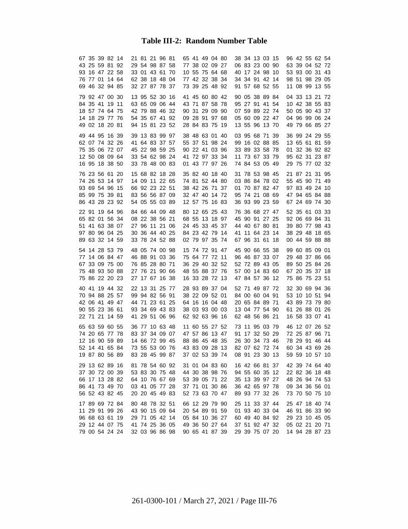
261-0300-101 / March 27, 2021 / Page III-76
Table III-2: Random Number Table
67 35 39 82 14 21 81 21 96 81 65 41 49 04 80 38 34 13 03 15 96 42 55 62 54
43 25 59 81 92 29 54 98 87 58 77 38 02 09 27 06 83 23 00 90 63 39 04 52 72
93 16 47 22 58 33 01 43 61 70 10 55 75 64 68 40 17 24 98 10 53 93 00 31 43
76 77 01 14 64 62 38 18 48 04 77 42 32 38 34 34 34 91 42 14 98 51 98 29 05
69 46 32 94 85 32 27 87 78 37 73 39 25 48 92 91 57 68 52 55 11 08 99 13 55
79 92 47 00 30 13 95 52 30 16 41 45 60 80 42 90 05 38 89 84 04 33 13 21 72
84 35 41 19 11 63 65 09 06 44 43 71 87 58 78 95 27 91 41 54 10 42 38 55 83
18 57 74 64 75 42 79 88 46 32 90 31 29 09 90 07 59 89 22 74 50 05 90 43 37
14 18 29 77 76 54 35 67 41 92 09 28 91 97 68 05 60 09 22 47 04 96 99 06 24
49 02 18 20 81 94 15 81 23 52 28 84 83 75 19 13 55 96 13 70 49 79 66 85 27
49 44 95 16 39 39 13 83 99 97 38 48 63 01 40 03 95 68 71 39 36 99 24 29 55
62 07 74 32 26 41 64 83 37 57 55 37 51 98 24 99 16 02 88 85 13 65 61 81 59
75 35 06 72 07 45 22 98 59 25 90 22 41 03 96 33 89 33 58 78 01 32 36 92 82
12 50 08 09 64 33 54 62 98 24 41 72 97 33 34 11 73 67 33 79 95 62 31 23 87
16 95 18 38 50 33 78 48 00 83 01 43 77 97 26 74 84 53 05 49 29 75 77 02 32
76 23 56 61 20 15 68 82 18 28 35 82 40 18 40 31 78 53 98 45 21 87 21 31 95
74 26 53 14 97 14 09 11 22 65 74 81 52 44 80 03 86 84 78 02 55 45 90 71 49
93 69 54 96 15 66 92 23 22 51 38 42 26 71 37 01 70 87 82 47 97 83 49 24 10
85 99 75 39 81 83 56 56 87 09 32 47 40 14 72 95 74 21 08 69 47 94 65 84 88
86 43 28 23 92 54 05 55 03 89 12 57 75 16 83 36 93 99 23 59 67 24 69 74 30
22 91 19 64 96 84 66 44 09 48 80 12 65 25 43 76 36 68 27 47 52 35 61 03 33
65 82 01 56 34 08 22 38 56 21 68 55 13 18 97 45 90 91 27 25 92 06 69 84 31
51 41 63 38 07 27 96 11 21 06 24 45 33 45 37 44 40 67 80 81 39 80 77 98 43
97 80 96 04 25 30 36 44 40 25 84 23 42 79 14 41 11 64 23 14 38 29 48 18 65
89 63 32 14 59 33 78 24 52 88 02 79 97 35 74 67 96 31 61 18 00 44 59 88 88
54 14 28 53 79 48 05 74 00 98 15 74 72 91 47 45 90 66 55 38 99 60 85 09 01
77 14 06 84 47 46 88 91 03 36 75 64 77 72 11 96 46 87 33 07 29 48 37 86 66
67 33 09 75 00 76 85 28 80 71 36 29 40 32 52 52 72 89 43 05 89 50 25 84 26
75 48 93 50 88 27 76 21 90 66 48 55 88 37 76 57 00 14 83 60 67 20 35 37 18
75 86 22 20 23 27 17 67 16 38 16 33 28 72 13 47 84 57 36 12 75 86 75 23 51
40 41 19 44 32 22 13 31 25 77 28 93 89 37 04 52 71 49 87 72 32 30 69 94 36
70 94 88 25 57 99 94 82 56 91 38 22 09 52 01 84 00 60 04 91 53 10 10 51 94
42 06 41 49 47 44 71 23 61 25 64 16 16 04 48 20 65 84 89 71 43 89 73 79 80
90 55 23 36 61 93 34 69 43 83 38 03 93 00 03 13 04 77 54 90 61 26 88 01 26
22 71 21 14 59 41 29 51 06 96 62 92 63 96 16 62 48 56 86 21 16 58 33 07 41
65 63 59 60 55 36 77 10 63 48 11 60 55 27 52 73 11 95 03 79 46 12 07 26 52
74 20 65 77 78 83 37 34 09 07 47 57 86 13 47 91 17 32 50 29 72 25 87 96 71
12 16 90 59 89 14 66 72 99 45 88 86 45 48 35 26 30 34 73 46 78 29 91 46 44
52 14 41 65 84 73 55 53 00 76 43 83 09 28 13 82 07 62 72 74 60 34 43 69 26
19 87 80 56 89 83 28 45 99 87 37 02 53 39 74 08 91 23 30 13 59 59 10 57 10
29 13 62 89 16 81 78 54 60 92 31 01 04 83 60 16 42 66 81 37 42 39 74 64 40
37 30 72 00 39 53 83 30 75 48 44 30 38 98 76 94 55 60 35 12 22 82 36 18 48
66 17 13 28 82 64 10 76 67 69 53 39 05 71 22 35 13 39 97 27 48 26 94 74 53
86 41 73 49 70 03 41 05 77 28 37 71 01 30 86 36 42 65 97 78 09 34 36 56 01
56 52 43 82 45 20 20 45 49 83 52 73 63 70 47 89 93 77 32 26 73 70 50 75 10
17 89 69 72 84 80 48 78 32 51 66 12 29 79 90 25 11 33 37 44 25 47 18 40 74
11 29 91 99 26 43 90 15 09 64 20 54 89 91 59 01 93 40 33 04 46 91 86 33 90
96 68 63 61 19 29 71 05 42 14 05 84 10 36 27 60 49 40 84 92 29 23 10 45 05
29 12 44 07 75 41 74 25 36 05 49 36 50 27 64 37 51 92 47 32 05 02 21 20 71
79 00 54 24 24 32 03 96 86 98 90 65 41 87 39 29 39 75 07 20 14 94 28 87 23
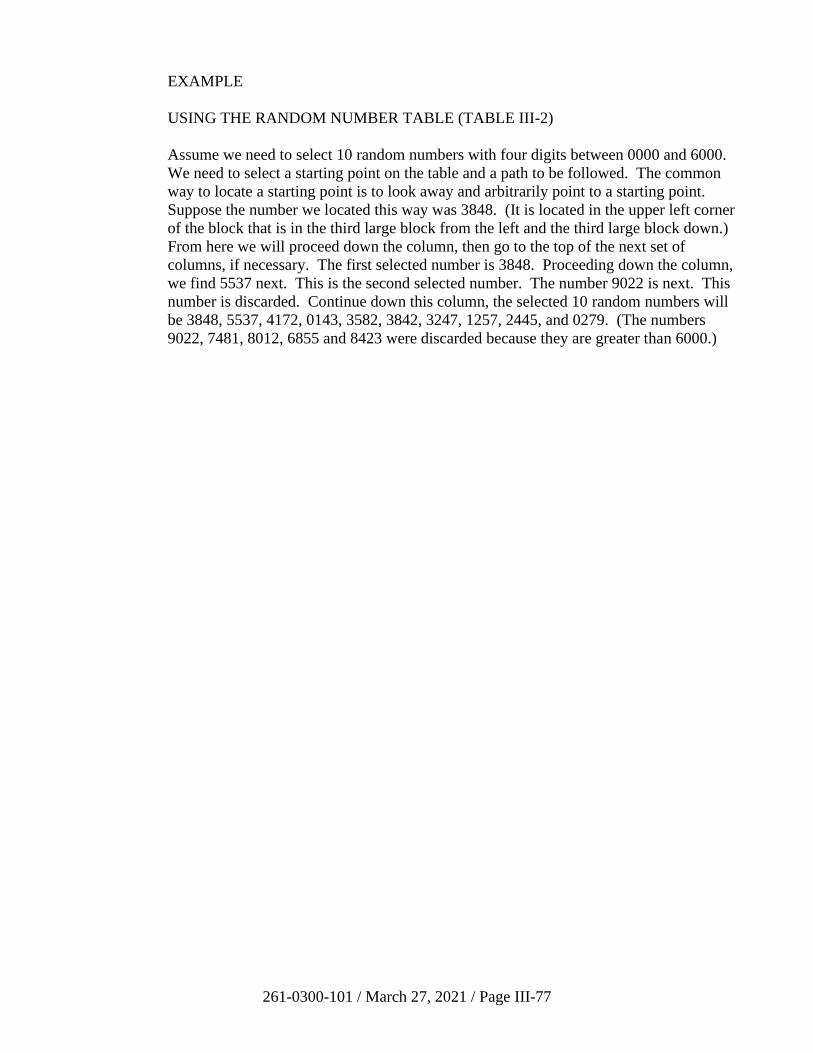
261-0300-101 / March 27, 2021 / Page III-77
EXAMPLE
USING THE RANDOM NUMBER TABLE (TABLE III-2)
Assume we need to select 10 random numbers with four digits between 0000 and 6000.
We need to select a starting point on the table and a path to be followed. The common
way to locate a starting point is to look away and arbitrarily point to a starting point.
Suppose the number we located this way was 3848. (It is located in the upper left corner
of the block that is in the third large block from the left and the third large block down.)
From here we will proceed down the column, then go to the top of the next set of
columns, if necessary. The first selected number is 3848. Proceeding down the column,
we find 5537 next. This is the second selected number. The number 9022 is next. This
number is discarded. Continue down this column, the selected 10 random numbers will
be 3848, 5537, 4172, 0143, 3582, 3842, 3247, 1257, 2445, and 0279. (The numbers
9022, 7481, 8012, 6855 and 8423 were discarded because they are greater than 6000.)
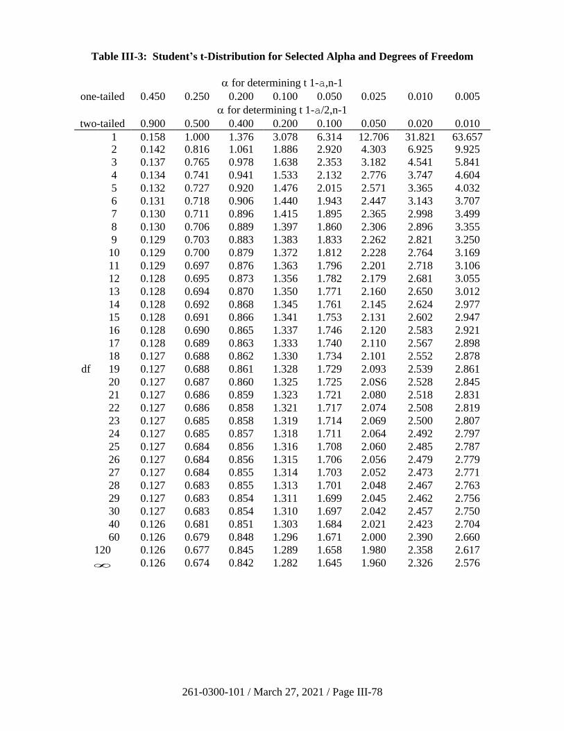
261-0300-101 / March 27, 2021 / Page III-78
Table III-3: Student’s t-Distribution for Selected Alpha and Degrees of Freedom
for determining t 1-a,n-1
one-tailed 0.450 0.250 0.200 0.100 0.050 0.025 0.010 0.005
for determining t 1-a/2,n-1
two-tailed 0.900 0.500 0.400 0.200 0.100 0.050 0.020 0.010
1 0.158 1.000 1.376 3.078 6.314 12.706 31.821 63.657 2 0.142 0.816 1.061 1.886 2.920 4.303 6.925 9.925
3 0.137 0.765 0.978 1.638 2.353 3.182 4.541 5.841
4 0.134 0.741 0.941 1.533 2.132 2.776 3.747 4.604
5 0.132 0.727 0.920 1.476 2.015 2.571 3.365 4.032
6 0.131 0.718 0.906 1.440 1.943 2.447 3.143 3.707
7 0.130 0.711 0.896 1.415 1.895 2.365 2.998 3.499
8 0.130 0.706 0.889 1.397 1.860 2.306 2.896 3.355
9 0.129 0.703 0.883 1.383 1.833 2.262 2.821 3.250
10 0.129 0.700 0.879 1.372 1.812 2.228 2.764 3.169
11 0.129 0.697 0.876 1.363 1.796 2.201 2.718 3.106
12 0.128 0.695 0.873 1.356 1.782 2.179 2.681 3.055
13 0.128 0.694 0.870 1.350 1.771 2.160 2.650 3.012
14 0.128 0.692 0.868 1.345 1.761 2.145 2.624 2.977
15 0.128 0.691 0.866 1.341 1.753 2.131 2.602 2.947
16 0.128 0.690 0.865 1.337 1.746 2.120 2.583 2.921
17 0.128 0.689 0.863 1.333 1.740 2.110 2.567 2.898
18 0.127 0.688 0.862 1.330 1.734 2.101 2.552 2.878
df 19 0.127 0.688 0.861 1.328 1.729 2.093 2.539 2.861
20 0.127 0.687 0.860 1.325 1.725 2.0S6 2.528 2.845
21 0.127 0.686 0.859 1.323 1.721 2.080 2.518 2.831
22 0.127 0.686 0.858 1.321 1.717 2.074 2.508 2.819
23 0.127 0.685 0.858 1.319 1.714 2.069 2.500 2.807
24 0.127 0.685 0.857 1.318 1.711 2.064 2.492 2.797
25 0.127 0.684 0.856 1.316 1.708 2.060 2.485 2.787
26 0.127 0.684 0.856 1.315 1.706 2.056 2.479 2.779
27 0.127 0.684 0.855 1.314 1.703 2.052 2.473 2.771
28 0.127 0.683 0.855 1.313 1.701 2.048 2.467 2.763
29 0.127 0.683 0.854 1.311 1.699 2.045 2.462 2.756
30 0.127 0.683 0.854 1.310 1.697 2.042 2.457 2.750
40 0.126 0.681 0.851 1.303 1.684 2.021 2.423 2.704
60 0.126 0.679 0.848 1.296 1.671 2.000 2.390 2.660
120 0.126 0.677 0.845 1.289 1.658 1.980 2.358 2.617
0.126 0.674 0.842 1.282 1.645 1.960 2.326 2.576
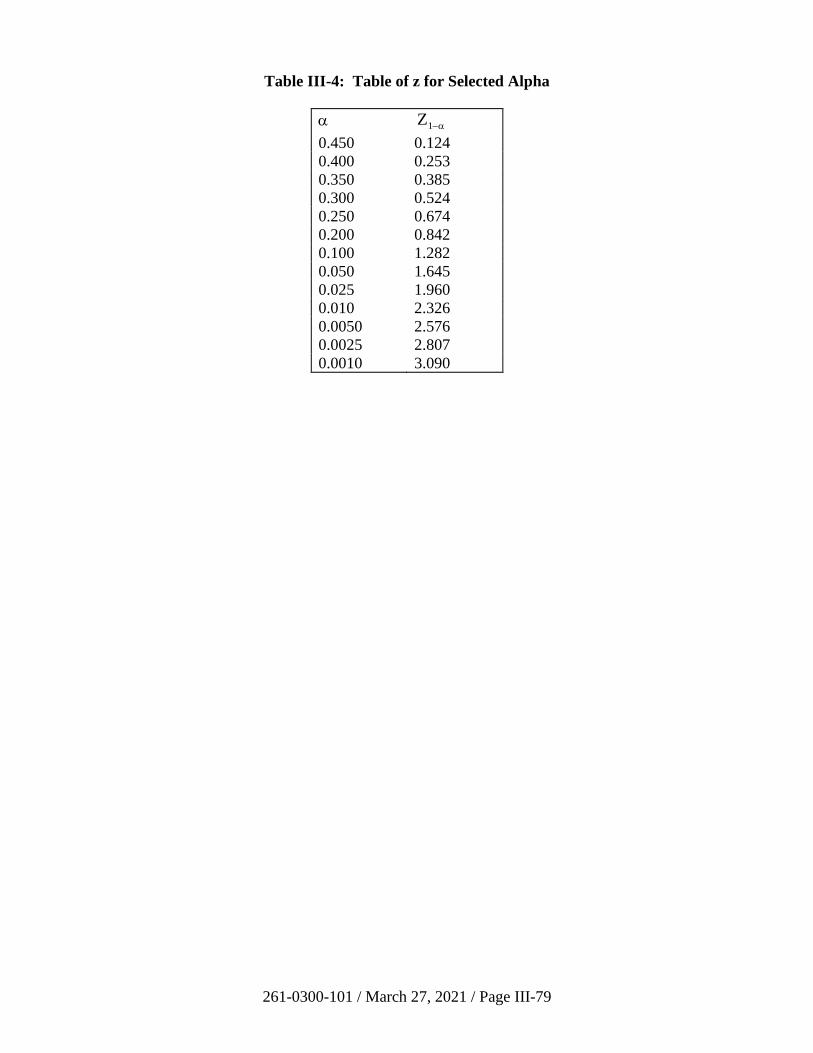
261-0300-101 / March 27, 2021 / Page III-79
Table III-4: Table of z for Selected Alpha
Z1− 0.450 0.124
0.400 0.253
0.350 0.385
0.300 0.524
0.250 0.674
0.200 0.842
0.100 1.282
0.050 1.645
0.025 1.960
0.010 2.326
0.0050 2.576
0.0025 2.807
0.0010 3.090
261-0300-101 / March 27, 2021 / Page III-80
C. Storage Tank Program Guidance
1. Corrective Action Process
The corrective action process (CAP) for storage tanks regulated under The Storage Tank
and Spill Prevention Act (35 P.S. §§ 6021.101-6021.2104) (“Storage Tanks Act”) was
established in 25 Pa. Code Chapter 245 Subchapter D on August 21, 1993
(23 Pa.B. 4033) and revised on December 1, 2001(31 Pa.B. 6615). These regulations
provide a streamlined and flexible approach to corrective action. In cases where interim
remedial actions (e.g., excavation of contaminated soil) can adequately address a release,
the person performing the cleanup is only required to submit one report (site
characterization) to the Department. Where localized contamination is associated with
the closure of a regulated storage tank system, the Department has offered a standardized
closure report form, which may be used to satisfy the site characterization report
requirements. The regulation is flexible in that it authorizes the Department to modify or
combine elements of the CAP based on the complexity of the release. For example, a
responsible party may submit the site characterization report and remedial action plan as
one report in some instances.
The CAP regulations allow Act 2 cleanup standards to be used to demonstrate
remediation of releases from regulated storage tanks. In order to facilitate cleanups, the
Department has identified those regulated substances, or “chemicals of concern,” that
should be quantified by the laboratory for commonly encountered petroleum products.
These substances and the accompanying methodologies should be utilized to demonstrate
attainment for storage tank remediations as well as other remediations involving
petroleum products. Only these substances need to be analyzed and evaluated when
petroleum products are released if they are not contaminated by other sources. These
analytical requirements appear in the Site Assessment Sampling Requirements at
Regulated Storage Tank System Closures booklet number 2630-BK-DEP4699 and as
Table III-5 in this manual. The Department does not recommend analysis for indicator
parameters such as total petroleum hydrocarbons, as they have no standards established
by Act 2.
For remediations conducted under the CAP, the person performing the remediation must
demonstrate attainment of an Act 2 standard (25 Pa. Code § 245.313(b)). Upon approval
by the Department of the report demonstrating attainment, the person is eligible for Act 2
liability protection.
2. Corrective Action Process Checklist
The flow chart in Figure III-9 shows the major steps and the decision-making process that
responsible parties must follow when a release from a regulated storage tank is
confirmed. This process was designed to be as flexible as possible in order to
accommodate the wide range of specific circumstances associated with releases. The
following are the major steps of the process:
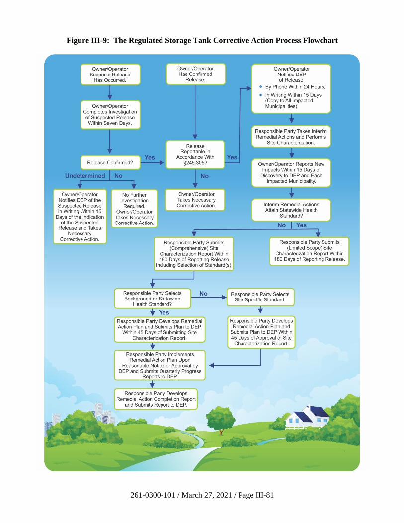
261-0300-101 / March 27, 2021 / Page III-81
Figure III-9: The Regulated Storage Tank Corrective Action Process Flowchart
261-0300-101 / March 27, 2021 / Page III-82
• If a release is confirmed, owners or operators must notify the DEP regional office
responsible for the county in which the release occurred, by telephone in
accordance with Section 245.305 of the regulations, within 24 hours of
confirmation of a release. In addition to basic facility and owner information, the
notice must provide, to the extent information is available:
− the regulated substance involved;
− the quantity of the regulated substance involved;
− when and where the release occurred;
− the affected environmental media;
− impacts to water supplies, buildings, sewer or other utility lines;
− interim remedial actions planned, initiated, or completed; and
− a description of the release.
• Within 15 days of the telephone notice, the owner or operator must follow up with
a written notification to the appropriate DEP regional office and any municipality
impacted by the release. This written notice must include the same information as
provided in the telephone notification and also should include any new
information obtained within the 15 days.
• The owner or operator must provide follow-up written notification to the
Department and any impacted municipality regarding new impacts to
environmental media or water supplies, buildings or sewer or other utility lines,
not previously reported, within 15 days of their discovery.
• The Department has prepared a form, number 2630-FM-BECB0082, which can
be used to satisfy the written notification requirements. In situations where the
release is small, contained and immediately cleaned up, this form may be all that
is necessary to complete the CAP.
• Also, upon confirmation of a release, responsible parties must immediately
initiate interim remedial actions. These are required response actions from the
time a release is confirmed until the time a formal long-term remedial action plan
is implemented. Interim remedial actions help maintain or restore public health
and safety and prevent the additional release of a regulated substance to the
environment and the spread of contamination.
Interim remedial actions may be all that are necessary to adequately address
certain releases. These releases may involve spills and overfills, and cases where
a release is confined to the excavation zone of an underground tank.
261-0300-101 / March 27, 2021 / Page III-83
While all appropriate interim remedial actions must be taken in order to bring a
release under control, the first priority at any release site is to identify and
eliminate any threat to the health and safety of onsite personnel or nearby
residents. See Section 245.306 of the regulations for requirements for interim
remedial actions. These interim actions can include:
− checking for and venting product vapors from sewer lines or buildings that
have been impacted;
− calling emergency personnel such as local fire and public safety officials
for assistance where fire, explosion or safety hazards exist;
− relocating residents until potentially explosive vapors have been reduced
to safe levels;
− restricting access to the site by nonessential personnel and establishing a
buffer area around the site;
− recovering free product leaking into subsurface structures such as
basements and sewers.
Attention should be turned to preventing any further release of the regulated
substance to the environment either concurrently with these emergency actions, or
as soon as any immediate threats to human health and safety have been eliminated
or reduced to acceptable levels. This may include:
− scheduling and conducting the necessary tests to identify and confirm all
sources of the release;
− removing product from the storage tanks;
− removing the storage tanks;
− excavating product-saturated soils when practicable;
− recovering free product on the water table;
− recovering product from the excavation;
− placing booms in, or interceptor trenches along, streams, gullies or
drainageways where surface water has been impacted or may be impacted;
and
− identifying and sampling affected water supplies or water supplies with
the potential to be affected, and reporting sampling results to the
Department and water supply owner within five days of receipt from the
laboratory.
261-0300-101 / March 27, 2021 / Page III-84
Interim remedial actions planned, initiated or completed are to be indicated during
the telephone notification and updated in the 15-day initial and any subsequent
written notification as required in Section 245.305 of the regulations. A more
detailed discussion of interim remedial actions conducted at the site of the release
is to be included in the site characterization report. This report is required to be
submitted to the Department within 180 days of reporting a release.
• Any responsible party that affects or diminishes a water supply as a result of a
release must restore or replace the affected or diminished water supply at no cost
to the owner of the supply (35 P.S. § 6021.1303(b)). A water supply is affected if
a measurable increase in a concentration of one or more contaminants occurs
(e.g., benzene or MTBE) in the water supply. A water supply is diminished if the
quantity of water provided by a water supply is decreased. For example, a water
supply well may lose flow as a result of groundwater pumping during a
remediation effort. (See definition of “affect or diminish” in 25 Pa. Code
§ 245.1). The requirement to restore or replace an affected or diminished water
supply remains with the responsible party regardless of attainment of an Act 2
standard.
The responsible party must provide a temporary water supply (e.g., bottled water
or water tank) to residents whose water supply is affected or diminished by the
release no later than 48 hours after the responsible party receives information, or
is notified by the Department, that a water supply has been affected or diminished
(25 Pa. Code § 245.307(c)).
The responsible party must provide a permanent water supply within 90 days after
the responsible party receives information, or is notified by the Department, that a
water supply has been affected or diminished (25 Pa. Code § 245.307(d)). A
permanent water supply may include a well or hookup to a public water supply or
treatment system. Where the responsible party provides the affected party with
access to a public system, the responsible party is not required to pay for the
quantity of water being supplied.
• Responsible parties must properly handle, store and manage excavated
contaminated soil which commonly results from tank closures and interim
remedial actions (25 Pa. Code § 245.308). In general, petroleum contaminated
soil is a residual waste regulated under the Solid Waste Management Act
(SWMA) (35 P.S. §§ 6018.101-6018.1003) and must:
− be stored in accordance with the Department’s residual waste management
regulations (25 Pa. Code Chapter 299) relating to standards for storage of
residual waste;
− be completely and securely covered for the duration of the storage period,
with an impermeable material of sufficient strength, anchoring or
weighting to prevent tearing or lifting of the cover, infiltration of
precipitation or surface water, and exposure of the soil to the atmosphere;
261-0300-101 / March 27, 2021 / Page III-85
− be stored in a manner to prevent public access to the storage area,
including use of fencing, security patrols or warning signs; and
− not present a threat to human health or the environment and must either be
undergoing active treatment or disposed of within 90 days from the first
day of storage. Active treatment includes methods such as enhanced
bioremediation in piles, soil vapor extraction and low-temperature thermal
desorption. Active treatment does not include letting the soil pile sit in
place.
• At the same time as the interim remedial actions are taking place, responsible
parties must conduct a site characterization to determine the extent and magnitude
of contamination which has resulted from the release. The CAP regulations
provide the objectives of any site characterization and a list of elements that may
be necessary or required to be conducted (25 Pa. Code § 245.309). This manual
also provides information which should be considered when conducting site
characterization work at storage tank release sites. A site characterization report
must be submitted to the appropriate DEP regional office within 180 days of
confirming the release (25 Pa. Code § 245.310(a)). It is very important that the
site characterization report identify the Act 2 cleanup standard selected for the
remediation. Interpretations of geologic and hydrogeologic data should be
prepared by a professional geologist licensed in Pennsylvania.
• Where interim remedial actions (e.g., removal of contaminated soil) have attained
the SHS, and soil is the only medium of concern, the responsible party may
submit a site characterization report to DEP limited to the elements in
Section 245.310(b) of the regulations. In this case, the site characterization report
should describe the entire CAP from site characterization to demonstration of
attainment of the SHS.
• Where soil contamination no more than three feet from the tank system is the only
contamination observed during the closure of a storage tank system, the
responsible party may submit the appropriate Storage Tank System Closure
Report Form to satisfy the requirements of the site characterization report
identified in Section 245.310(b) of the regulations. A completed closure report
form, including adherence to the confirmatory sampling protocol in the closure
guidance document appropriate for either aboveground or underground storage
tank systems, will be adequate to demonstrate that the requirements of the SHS
have been met. Note that the confirmatory sample locations in the closure
guidance do not apply if the contamination has extended more than three feet
from any part of the tank system. Also, because only limited sampling is required
in localized contamination situations, the most conservative medium-specific
concentrations (MSCs) are used as action levels. The most current action levels
are provided in Tables 3 and 4 in DEP Booklet number 2630-BK-DEP4699.
• Where a site-specific standard is being pursued and a risk assessment report is
required under Section 250.405 of the regulations, the report should be submitted
to the appropriate DEP regional office with the site characterization report and
261-0300-101 / March 27, 2021 / Page III-86
should contain those elements as described under the site-specific standard of this
manual.
• If the comprehensive site characterization report indicates that the interim
remedial actions did not adequately address the release, and the background or
SHS is selected, responsible parties must develop and submit a remedial action
plan to the appropriate DEP regional office within 45 days of submission of the
site characterization report. In cases where the site-specific standard is chosen,
the remedial action plan is due 45 days after the Department’s approval of the site
characterization report (25 Pa. Code § 245.311).
• The responsible party must implement the remedial action consistent with the
schedule in the remedial action plan upon reasonable notice or approval of the
remedial action plan by DEP. Remedial action progress reports must be
submitted quarterly to the appropriate DEP regional office (25 Pa. Code
§ 245.312).
• When the standard(s) established in the remedial action plan has/have been
achieved, the responsible party must submit a remedial action completion report.
The remedial action completion report must demonstrate that the requirements of
one or more of the Act 2 standards have been met and include, if applicable, a
postremediation care plan (25 Pa. Code § 245.313).
• In order to receive Act 2 liability protection, the cleanup standards for all
regulated substances stored in the tank system, as identified in the site
characterization report, must be achieved.
• Petroleum-contaminated media and debris associated with certain underground
storage tanks (e.g., soil and groundwater, but not free product) that fail the test for
D018-D043 TCLP only and are subject to the federal corrective action regulations
under 40 CFR Part 280 are specifically excluded as hazardous waste (40 CFR
§ 261.4(b)(10). This exclusion does not apply to contaminated media and debris
from aboveground tanks, farm and residential motor fuel underground storage
tanks of less than 1,100-gallon capacity, as well as heating oil underground
storage tanks used for consumptive purposes at the property where located (i.e.,
tanks not regulated under 40 CFR Part 280). Petroleum-contaminated media and
debris that are classified as hazardous waste are subject to the deed notice
requirements of SWMA (35 P.S. § 6018.405).
• While the CAP regulations specify when the Department is to receive the site
characterization report, remedial action plan and remedial action progress reports,
the regulations also provide the Department with the flexibility to shorten or
extend the timeframes based on the circumstances of a particular release.
• In addition, the CAP regulations establish Department review timeframes for site
characterization reports, remedial action plans and remedial action completion
reports. These reports are deemed approved if the Department does not take an
action within those timeframes unless the Department and the responsible party
261-0300-101 / March 27, 2021 / Page III-87
agree in writing to an alternative timeframe. The review timeframes are as
follows:
− The Department will review a site characterization report submitted under
Subsection 245.310(b) within 60 days of receipt, or a site characterization
report submitted under Subsection 245.310(a) selecting the site-specific
standard within 90 days of receipt.
− Site characterization reports submitted under Subsection 245.310(a) for
the background or Statewide health standard will be reviewed within
60 days of receipt of a remedial action plan designed to attain those
standards. The review will include the remedial action plan.
− Site characterization reports and remedial action plans for the background
or Statewide health standard which are submitted together will be
reviewed within 60 days of receipt.
− A remedial action plan designed to attain the site-specific standard will be
reviewed within 90 days of receipt by the Department.
− Remedial action completion reports for the background and Statewide
health standard will be reviewed within 60 days of receipt. A remedial
action completion report demonstrating attainment of the site-specific
standard will be reviewed within 90 days of receipt.
Responsible parties are strongly encouraged to properly identify the report or plan
being submitted in order to facilitate review of reports and plans by the
Department. Figure III-10 is a cover sheet which can be used with CAP
submissions.
3. Use of the Short List of Regulated Substances for Releases of Petroleum Products
Petroleum products contain many regulated substances. However, it is not always
practical to examine all the regulated substances in a petroleum product. The Department
has developed a “short list” of regulated substances for various petroleum products
(Table III-5) to be analyzed to demonstrate attainment under any of the Act 2 cleanup
standards when a release of these petroleum products occurs and is uncontaminated by
other sources.
The Department will accept use of the short list to demonstrate attainment of the SHS if
the following conditions are also met:
1. For soil media, no free liquids are left in the soil based on visual observation, and
the soil does not create an odor nuisance. The location and level of odor
remaining in soil must not result in an odor complaint to the Department, since
odor is an indicator which may be attributed to residual free product.
2. For groundwater media, no free-floating product exists at the point of compliance
(property line). Free-floating product must be recovered to the maximum extent
261-0300-101 / March 27, 2021 / Page III-88
practicable and any remaining product cannot pose an unacceptable risk to human
health or the environment.
The rationale for the application of these conditions is that the SHS numeric values
cannot exceed their saturation and solubility limits in soil and groundwater, respectively.
Since the Department is accepting an attainment demonstration for the short list of
regulated substances rather than all regulated substances contained in a particular
petroleum product, these conditions are necessary to assure that all SHSs applicable to
the petroleum product are met.
If the remediator chooses to use the short list, and meets these conditions, then the
Remedial Action Completion Report approval will stipulate that Act 2 liability coverage
is for the short list substances only.
The short list of petroleum products may be periodically revised as determined necessary
by the Department. For sites in the CAP for which a site characterization report has been
received, attainment demonstration will be made using the previous list of substances.
Sites which commence investigations to characterize or verify releases after the date the
new list becomes effective should use the new list for characterization and attainment
demonstration purposes to avoid a disapproval.
4. Maximum Extent Practicable
EPA has approved Pennsylvania’s UST program in 25 Pa. Code Chapter 245 as
consistent with federal law (68 FR 53520 (September 11, 2003)). EPA regulations under
40 CFR § 280.64 require owners and operators to remove “free product” to the maximum
extent practicable (MEP) as determined by the implementing agency. Section 280.64(b)
requires owners and operators to use abatement of “free product” migration as a
minimum objective for the design of the free product removal system. The Department
equates “free product,” as the EPA uses the term, to be equivalent to “separate phase
liquid” (SPL) as the Department has used that term in the past. Thus, to meet the
corrective action requirement for underground storage tanks in Pennsylvania, a
remediator must demonstrate the following two requirements, based upon technical data:
• SPL has been removed to the MEP, and
• the release has been demonstrated to attain an Act 2 cleanup standard.
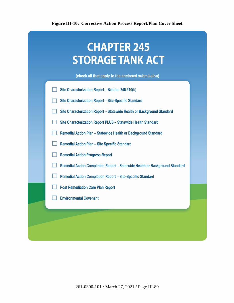
261-0300-101 / March 27, 2021 / Page III-89
Figure III-10: Corrective Action Process Report/Plan Cover Sheet
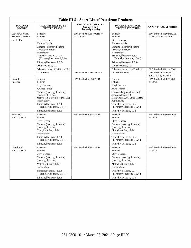
261-0300-101 / March 27, 2021 / Page III-90
Table III-5: Short List of Petroleum Products
PRODUCT STORED
PARAMETERS TO BE TESTED IN SOIL
ANALYTICAL METHOD (reported on a
dry weight basis)
PARAMETERS TO BE TESTED IN WATER
ANALYTICAL METHOD1
Leaded Gasoline, Benzene EPA Method 5035/8021B or Benzene EPA Method 5030B/8021B,
Aviation Gasoline, Toluene 5035/8260B Toluene 5030B/8260B or 524.2
and Jet Fuel Ethyl Benzene Ethyl Benzene
Xylenes (total) Xylenes (total)
Cumene (Isopropylbenzene) (Isopropylbenzene)
Cumene (Isopropylbenzene) (Isopropylbenzene)
Naphthalene Naphthalene Trimethyl benzene, 1,2,4-
(Trimethyl benzene, 1,3,4-)
Trimethyl benzene, 1,2,4-
(Trimethyl benzene, 1,3,4-)
Trimethyl benzene, 1,3,5- Trimethyl benzene, 1,3,5-
Dichloroethane, 1,2- Dichloroethane, 1,2-
Dibromoethane, 1,2- Dibromide) Dibromoethane, 1,2-(Ethylene
Dibromide)
EPA Method 8011 or 504.1
Lead (total) EPA Method 6010B or 7420 Lead (dissolved) EPA Method 6020, 7421,
200.7, 200.8, or 200.9
Unleaded Benzene EPA Method 5035/8260B Benzene EPA Method 5030B/8260B
Gasoline Toluene Toluene or 524.2
Ethyl Benzene Ethyl Benzene
Xylenes (total) Xylenes (total)
Cumene (Isopropylbenzene)
(Isopropylbenzene)
Cumene (Isopropylbenzene)
(Isopropylbenzene)
Methyl tert-Butyl Ether (MTBE) Methyl tert-Butyl Ether (MTBE) Naphthalene Naphthalene
Trimethyl benzene, 1,2,4-
(Trimethyl benzene, 1,3,4-)
Trimethyl benzene, 1,2,4-
(Trimethyl benzene, 1,3,4-)
Trimethyl benzene, 1,3,5- Trimethyl benzene, 1,3,5-
Kerosene, Benzene EPA Method 5035/8260B Benzene EPA Method 5030B/8260B
Fuel Oil No. 1 Toluene Toluene or 524.2
Ethyl Benzene Ethyl Benzene
Cumene (Isopropylbenzene)
(Isopropylbenzene)
Cumene (Isopropylbenzene)
(Isopropylbenzene)
Methyl tert-Butyl Ether Methyl tert-Butyl Ether
Naphthalene Naphthalene
Trimethyl benzene, 1,2,4-
(Trimethyl benzene, 1,3,4-)
Trimethyl benzene, 1,2,4-
(Trimethyl benzene, 1,3,4-)
Trimethyl benzene, 1,3,5- Trimethyl benzene, 1,3,5-
Diesel Fuel, Benzene EPA Method 5035/8260B Benzene EPA Method 5030B/8260B
Fuel Oil No. 2 Toluene Toluene or 524.2
Ethyl Benzene Ethyl Benzene
Cumene (Isopropylbenzene)
(Isopropylbenzene)
Cumene (Isopropylbenzene)
(Isopropylbenzene)
Methyl tert-Butyl Ether Methyl tert-Butyl Ether
Naphthalene Naphthalene
Trimethyl benzene, 1,2,4-
(Trimethyl benzene, 1,3,4-)
Trimethyl benzene, 1,2,4-
(Trimethyl benzene, 1,3,4-)
Trimethyl benzene, 1,3,5- Trimethyl benzene, 1,3,5-
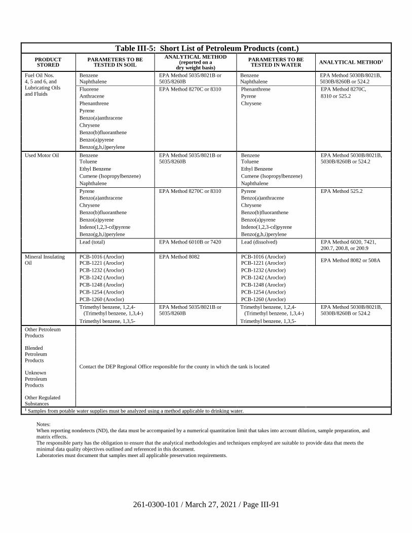
261-0300-101 / March 27, 2021 / Page III-91
Table III-5: Short List of Petroleum Products (cont.)
PRODUCT STORED
PARAMETERS TO BE TESTED IN SOIL
ANALYTICAL METHOD (reported on a
dry weight basis)
PARAMETERS TO BE TESTED IN WATER
ANALYTICAL METHOD1
Fuel Oil Nos. 4, 5 and 6, and
Lubricating Oils
and Fluids
Benzene EPA Method 5035/8021B or Benzene EPA Method 5030B/8021B,
Naphthalene 5035/8260B Naphthalene 5030B/8260B or 524.2
Fluorene EPA Method 8270C or 8310 Phenanthrene EPA Method 8270C,
Anthracene Pyrene 8310 or 525.2
Phenanthrene Chrysene
Pyrene
Benzo(a)anthracene
Chrysene
Benzo(b)fluoranthene
Benzo(a)pyrene
Benzo(g,h,i)perylene
Used Motor Oil Benzene EPA Method 5035/8021B or Benzene EPA Method 5030B/8021B,
Toluene 5035/8260B Toluene 5030B/8260B or 524.2
Ethyl Benzene Ethyl Benzene
Cumene (Isopropylbenzene) Cumene (Isopropylbenzene)
Naphthalene Naphthalene
Pyrene EPA Method 8270C or 8310 Pyrene EPA Method 525.2
Benzo(a)anthracene Benzo(a)anthracene
Chrysene Chrysene
Benzo(b)fluoranthene Benzo(b)fluoranthene
Benzo(a)pyrene Benzo(a)pyrene
Indeno(1,2,3-cd)pyrene Indeno(1,2,3-cd)pyrene
Benzo(g,h,i)perylene Benzo(g,h,i)perylene
Lead (total) EPA Method 6010B or 7420 Lead (dissolved) EPA Method 6020, 7421,
200.7, 200.8, or 200.9
Mineral Insulating Oil
PCB-1016 (Aroclor) EPA Method 8082 PCB-1016 (Aroclor) EPA Method 8082 or 508A
PCB-1221 (Aroclor) PCB-1221 (Aroclor)
PCB-1232 (Aroclor) PCB-1232 (Aroclor)
PCB-1242 (Aroclor) PCB-1242 (Aroclor)
PCB-1248 (Aroclor) PCB-1248 (Aroclor)
PCB-1254 (Aroclor) PCB-1254 (Aroclor)
PCB-1260 (Aroclor) PCB-1260 (Aroclor)
Trimethyl benzene, 1,2,4-
(Trimethyl benzene, 1,3,4-)
EPA Method 5035/8021B or
5035/8260B
Trimethyl benzene, 1,2,4-
(Trimethyl benzene, 1,3,4-)
EPA Method 5030B/8021B,
5030B/8260B or 524.2
Trimethyl benzene, 1,3,5- Trimethyl benzene, 1,3,5-
Other Petroleum Products
Blended Petroleum
Products
Contact the DEP Regional Office responsible for the county in which the tank is located Unknown
Petroleum
Products
Other Regulated Substances 1 Samples from potable water supplies must be analyzed using a method applicable to drinking water.
Notes:
When reporting nondetects (ND), the data must be accompanied by a numerical quantitation limit that takes into account dilution, sample preparation, and
matrix effects. The responsible party has the obligation to ensure that the analytical methodologies and techniques employed are suitable to provide data that meets the
minimal data quality objectives outlined and referenced in this document.
Laboratories must document that samples meet all applicable preservation requirements.
261-0300-101 / March 27, 2021 / Page III-92
As the implementing agency, the Department considers MEP under 40 CFR § 280.64 as
the extent of removal necessary to prevent migration of SPL to uncontaminated areas and
prevent or abate immediate threats to human health or the environment.
It is important to note that removing SPL to the MEP is not required under Chapter 250.
Although removal is not required, if groundwater and/or soil is impacted above a
standard, then removing SPL may greatly assist the remediator in attaining a standard. A
dissolved phase plume may not be stable if there is a migrating SPL body. Migrating
SPL is an SPL body and its associated phases that are documented to be spreading or
expanding laterally or vertically into previously uncontaminated areas. Residual and
mobile SPL and related terms are discussed further in Section V.D. of this guidance.
In the majority of cases, releases at regulated storage tank sites are liquids with a density
less than water, or light non-aqueous phase liquids (LNAPLs). Recent advances in the
understanding of LNAPL behavior have illustrated that in some cases, continued attempts
to reduce LNAPL to a measured thickness in a monitoring well (e.g., 0.01 ft. or less) may
not be practicable. Even in cases where the presence of LNAPL is the only reason for
remediation, continued recovery of LNAPL may provide little positive impact on the
environment.
5. Management of Light Nonaqueous Phase Liquids (LNAPL) under Act 32
LNAPL typically has been viewed as SPL that is less dense than water and can be
measured in a well or on a water surface. Even when measurable LNAPL is not detected
within a well, LNAPL can remain trapped in nearby soils or bedrock. Depending on site
conditions and how conditions can change, this residual LNAPL may remain trapped or
become mobile. Therefore, it is important to keep the following in mind:
• The absence of measurable LNAPL in a well does not definitively establish the
absence of mobile LNAPL at a site.
• The presence of measurable LNAPL in a well does not definitively establish the
size, volume, thickness, or recoverability of LNAPL at the site or in the vicinity
of the well.
• The measured LNAPL thickness in a well may not be indicative of the actual
LNAPL thickness or volume within the formation.
• The presence of recoverable LNAPL in a well may only indicate that mobile
LNAPL exists in the immediate vicinity of that well.
• The observation that LNAPL is no longer accumulating at a significant or
appreciable rate in a well may only indicate that the LNAPL in the vicinity of the
well is no longer mobile under the present conditions.
• The mass of residual LNAPL remaining in the soil and/or rock matrix after
recovery to the MEP may be orders of magnitude larger than the amount of
mobile LNAPL that was recovered at the site.
261-0300-101 / March 27, 2021 / Page III-93
• LNAPL may spread in many directions not necessarily coincident with
groundwater gradients (including but not limited to structural influences,
preferential pathways, permeability contrasts, and pumping well influences). See
“Sources and Pathways” in Section III.C.5(i).
• LNAPL migration rates may not be the same as the groundwater flow rates.
• Some mobile LNAPL is persistent and can be bailed, but quantities removed may
be relatively small. Product bailing alone rarely achieves significant LNAPL
recovery.
LNAPL exists in residual and non-residual (mobile) phase, so some LNAPL may remain
at the site after reaching removal to the MEP. Although the remaining LNAPL may take
years to degrade, the low recoverability along with a demonstration of low risk posed by
the LNAPL source may make recovery of remaining LNAPL infeasible or unnecessary.
In such instances, evaluating the site for terminating LNAPL recovery is warranted.
Information necessary to determine when LNAPL removal meets the MEP is identified
below.
a) Site Characterization and LNAPL Conceptual Site Model
Section 245.309 of the regulations requires completion of a site characterization.
A complete and concise site characterization is an important step in identifying
the presence, properties, distribution and migration of LNAPL. Simple visual
observations during site work and interpretation of analytical results can help
identify the presence of LNAPL. The characterization of a site with LNAPL
includes the development of an appropriate LNAPL Conceptual Site Model
(LCSM). The level of detail required for a given LCSM is site-specific and based
on the complexity of environmental conditions at each site. As the corrective
action progresses, the LCSM should be regularly re-evaluated in light of
additional site/LNAPL data, pilot test data, remedial technology performance
metrics, and monitoring data. A complete and up-to-date LCSM allows the best
possible decisions about application and operation of remedial technologies to be
made and when removal actions are no longer necessary. Documents that should
be used to guide the development of an LCSM are included in the list of
references in Sections III.C.6 and V.F. The LCSM may require revisions as site
conditions change due to remediation and other site factors. Table III-6 is a
worksheet that can be used when preparing an LCSM.
Older LNAPL cases which pre-date this guidance may require additional
assessment to update the LCSM for the purposes of making MEP decisions.
Results from an updated LCSM may provide additional information about
LNAPL recovery potential for the site. While technologies may appear costly or
overly complex, the use of these technologies may assist responsible parties,
consultants, and staff to develop the most cost-effective decision regarding
LNAPL recovery or case closure. Information needed to characterize LNAPL at
a site and develop a thorough LCSM typically includes, but is not limited to:
261-0300-101 / March 27, 2021 / Page III-94
• Delineation: LNAPL does not necessarily form a “pancake” on the
groundwater surface, but shares the pore space in the vadose zone, the
capillary fringe, and/or beneath the water table within the smear zone.
Different industry standard practices can be used to identify LNAPL
trapped in soils or bedrock (ranging from shake test to Laser-Induced
Fluorescence (LIF) in conjunction with core photography).
• Sources and Pathway: Geologic or manmade features such as fractures
in bedrock or clay and fill material adjacent to underground utilities may
also contain LNAPL and may serve as pathways for enhanced migration
of SPL vapor and dissolved phases. These features include fractures in
bedrock or clay and fill material adjacent to underground utilities, old
foundations, and old tank system cavities. Their presence may
significantly increase risk by accelerating potential migration to receptors.
Monitoring well placement should consider the movement and storage of
LNAPL in these features as part of the site characterization.
• Volume: Where possible, the volume (or plausible volume range) of
LNAPL within the subsurface should be established to allow the
development and selection of an appropriate recovery strategy as well as a
basis for the risk evaluation. Historic records for the site should be
reviewed to identify past releases that may have contributed to the volume
of LNAPL.
• Age and Chemical/Physical Character: LNAPL and groundwater can
be analyzed to identify or verify the type of product as well as assess if the
product poses a risk to receptors. As LNAPL weathers, the physical and
chemical properties of the LNAPL can change. Weathered LNAPL can be
more viscous and therefore less mobile and less recoverable than
unweathered LNAPL. LNAPL properties can also assist in determining a
probable date or timeframe for the product release. Knowing the amount
of time the product has been present compared to the known impacts (or
lack thereof) can provide valuable insight on whether case closure is
advisable.
• LNAPL Migration: LNAPL moving into previously uncontaminated
areas indicates that LNAPL is migrating. It is a condition requiring
immediate recovery as per Section 245.306(a)(3)(ii) of the regulations.
The potential for mobile LNAPL to migrate may depend on geologic
conditions, changing hydraulic or LNAPL gradients as well as
precipitation and groundwater recharge. The presence of other
contaminants may impact migration of LNAPL.
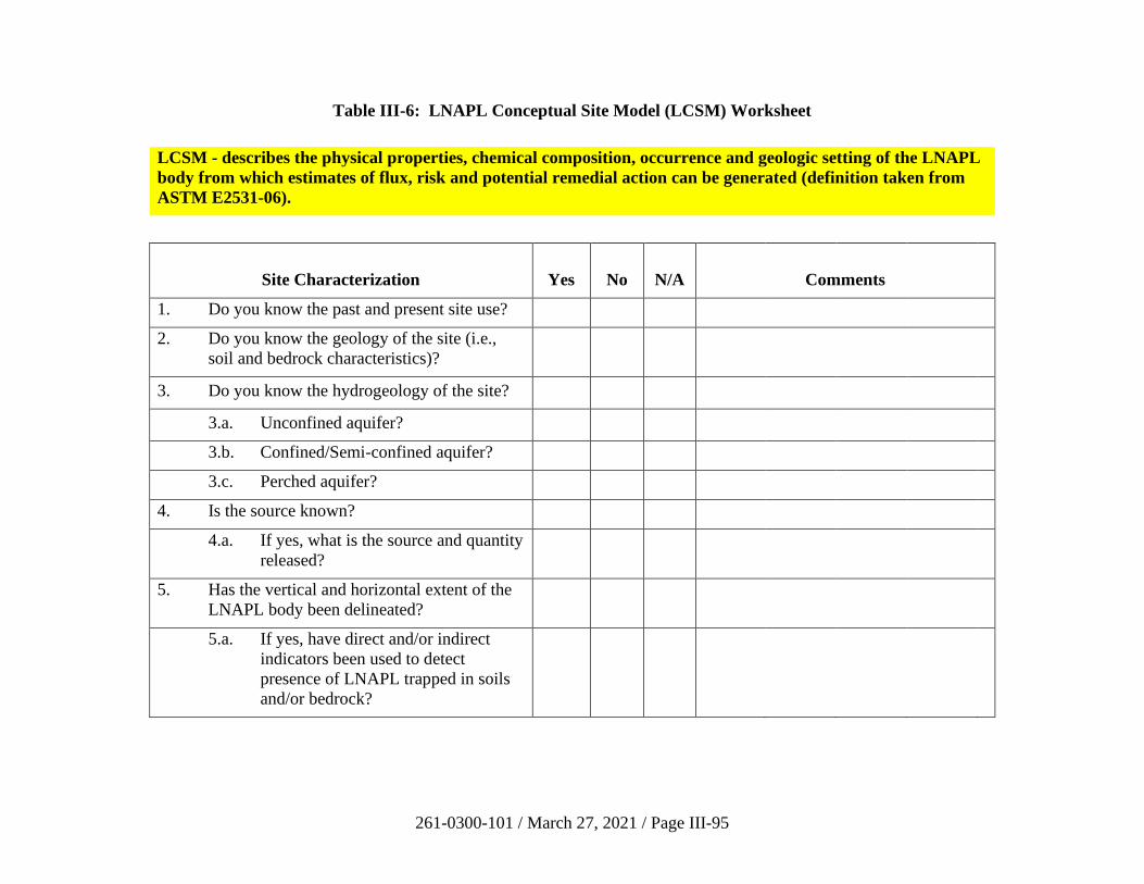
261-0300-101 / March 27, 2021 / Page III-95
Table III-6: LNAPL Conceptual Site Model (LCSM) Worksheet
LCSM - describes the physical properties, chemical composition, occurrence and geologic setting of the LNAPL
body from which estimates of flux, risk and potential remedial action can be generated (definition taken from
ASTM E2531-06).
Site Characterization Yes No N/A Comments
1. Do you know the past and present site use?
2. Do you know the geology of the site (i.e.,
soil and bedrock characteristics)?
3. Do you know the hydrogeology of the site?
3.a. Unconfined aquifer?
3.b. Confined/Semi-confined aquifer?
3.c. Perched aquifer?
4. Is the source known?
4.a. If yes, what is the source and quantity
released?
5. Has the vertical and horizontal extent of the
LNAPL body been delineated?
5.a. If yes, have direct and/or indirect
indicators been used to detect
presence of LNAPL trapped in soils
and/or bedrock?
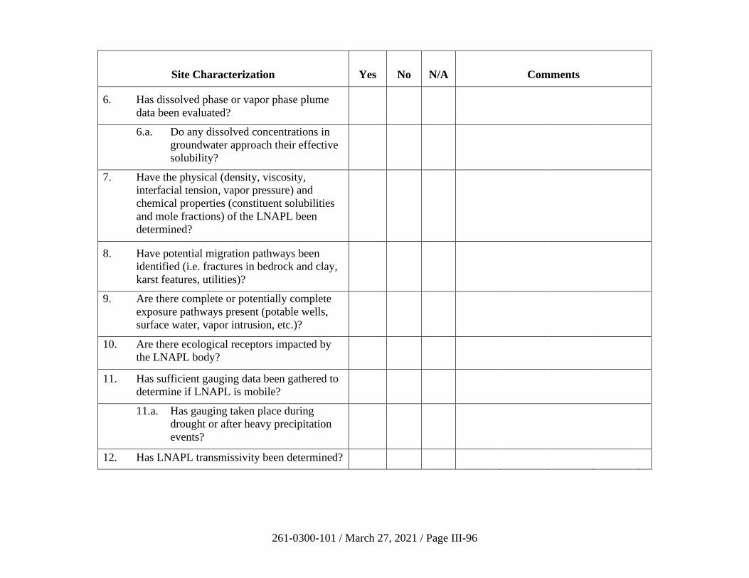
261-0300-101 / March 27, 2021 / Page III-96
Site Characterization Yes No N/A Comments
6. Has dissolved phase or vapor phase plume
data been evaluated?
6.a. Do any dissolved concentrations in
groundwater approach their effective
solubility?
7. Have the physical (density, viscosity,
interfacial tension, vapor pressure) and
chemical properties (constituent solubilities
and mole fractions) of the LNAPL been
determined?
8. Have potential migration pathways been
identified (i.e. fractures in bedrock and clay,
karst features, utilities)?
9. Are there complete or potentially complete
exposure pathways present (potable wells,
surface water, vapor intrusion, etc.)?
10. Are there ecological receptors impacted by
the LNAPL body?
11. Has sufficient gauging data been gathered to
determine if LNAPL is mobile?
11.a. Has gauging taken place during
drought or after heavy precipitation
events?
12. Has LNAPL transmissivity been determined?
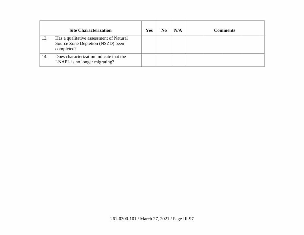
261-0300-101 / March 27, 2021 / Page III-97
Site Characterization Yes No N/A Comments
13. Has a qualitative assessment of Natural
Source Zone Depletion (NSZD) been
completed?
14. Does characterization indicate that the
LNAPL is no longer migrating?
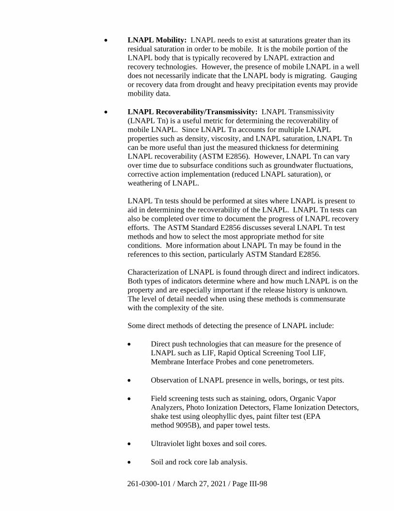
261-0300-101 / March 27, 2021 / Page III-98
• LNAPL Mobility: LNAPL needs to exist at saturations greater than its
residual saturation in order to be mobile. It is the mobile portion of the
LNAPL body that is typically recovered by LNAPL extraction and
recovery technologies. However, the presence of mobile LNAPL in a well
does not necessarily indicate that the LNAPL body is migrating. Gauging
or recovery data from drought and heavy precipitation events may provide
mobility data.
• LNAPL Recoverability/Transmissivity: LNAPL Transmissivity
(LNAPL Tn) is a useful metric for determining the recoverability of
mobile LNAPL. Since LNAPL Tn accounts for multiple LNAPL
properties such as density, viscosity, and LNAPL saturation, LNAPL Tn
can be more useful than just the measured thickness for determining
LNAPL recoverability (ASTM E2856). However, LNAPL Tn can vary
over time due to subsurface conditions such as groundwater fluctuations,
corrective action implementation (reduced LNAPL saturation), or
weathering of LNAPL.
LNAPL Tn tests should be performed at sites where LNAPL is present to
aid in determining the recoverability of the LNAPL. LNAPL Tn tests can
also be completed over time to document the progress of LNAPL recovery
efforts. The ASTM Standard E2856 discusses several LNAPL Tn test
methods and how to select the most appropriate method for site
conditions. More information about LNAPL Tn may be found in the
references to this section, particularly ASTM Standard E2856.
Characterization of LNAPL is found through direct and indirect indicators.
Both types of indicators determine where and how much LNAPL is on the
property and are especially important if the release history is unknown.
The level of detail needed when using these methods is commensurate
with the complexity of the site.
Some direct methods of detecting the presence of LNAPL include:
• Direct push technologies that can measure for the presence of
LNAPL such as LIF, Rapid Optical Screening Tool LIF,
Membrane Interface Probes and cone penetrometers.
• Observation of LNAPL presence in wells, borings, or test pits.
• Field screening tests such as staining, odors, Organic Vapor
Analyzers, Photo Ionization Detectors, Flame Ionization Detectors,
shake test using oleophyllic dyes, paint filter test (EPA
method 9095B), and paper towel tests.
• Ultraviolet light boxes and soil cores.
• Soil and rock core lab analysis.
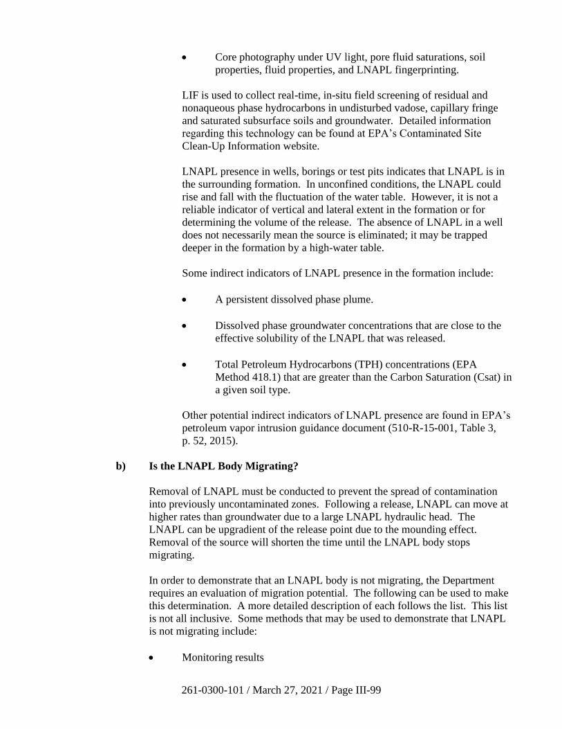
261-0300-101 / March 27, 2021 / Page III-99
• Core photography under UV light, pore fluid saturations, soil
properties, fluid properties, and LNAPL fingerprinting.
LIF is used to collect real-time, in-situ field screening of residual and
nonaqueous phase hydrocarbons in undisturbed vadose, capillary fringe
and saturated subsurface soils and groundwater. Detailed information
regarding this technology can be found at EPA’s Contaminated Site
Clean-Up Information website.
LNAPL presence in wells, borings or test pits indicates that LNAPL is in
the surrounding formation. In unconfined conditions, the LNAPL could
rise and fall with the fluctuation of the water table. However, it is not a
reliable indicator of vertical and lateral extent in the formation or for
determining the volume of the release. The absence of LNAPL in a well
does not necessarily mean the source is eliminated; it may be trapped
deeper in the formation by a high-water table.
Some indirect indicators of LNAPL presence in the formation include:
• A persistent dissolved phase plume.
• Dissolved phase groundwater concentrations that are close to the
effective solubility of the LNAPL that was released.
• Total Petroleum Hydrocarbons (TPH) concentrations (EPA
Method 418.1) that are greater than the Carbon Saturation (Csat) in
a given soil type.
Other potential indirect indicators of LNAPL presence are found in EPA’s
petroleum vapor intrusion guidance document (510-R-15-001, Table 3,
p. 52, 2015).
b) Is the LNAPL Body Migrating?
Removal of LNAPL must be conducted to prevent the spread of contamination
into previously uncontaminated zones. Following a release, LNAPL can move at
higher rates than groundwater due to a large LNAPL hydraulic head. The
LNAPL can be upgradient of the release point due to the mounding effect.
Removal of the source will shorten the time until the LNAPL body stops
migrating.
In order to demonstrate that an LNAPL body is not migrating, the Department
requires an evaluation of migration potential. The following can be used to make
this determination. A more detailed description of each follows the list. This list
is not all inclusive. Some methods that may be used to demonstrate that LNAPL
is not migrating include:
• Monitoring results
261-0300-101 / March 27, 2021 / Page III-100
• LNAPL velocity
• Recovery rate
• Age of the release
• Tracer test
Monitoring results are most important in evaluating migration potential.
Assuming that there is an adequate monitoring network and sufficient temporal
data, there are several factors that are evidence for a stable footprint, which
include a stable or decreasing thickness of LNAPL in monitoring wells, sentinel
wells outside of the LNAPL zone that remain free of SPL, and a shrinking or
stable dissolved phase plume.
Calculating the potential LNAPL velocity using Darcy’s Law is also important in
the evaluation. The key parameter is LNAPL conductivity, which may be
estimated from bail-down tests, or from the measured LNAPL thickness, soil
capillary parameters and a model that assumes static equilibrium. The American
Petroleum Institute (API) Interactive LNAPL Guide is one tool that may be used
to estimate the LNAPL velocity using this model. It is important to recognize that
use of Darcy’s Law would be precluded for some site conditions, such as a
fractured bedrock site.
The recovery rate that is observed as LNAPL is removed from a well is important
to the evaluation. Although not directly correlated to LNAPL migration,
declining recovery rates would generally indicate reduced potential for LNAPL to
migrate.
The age of the release, when known, aids in determining migration potential. If a
relatively long time has transpired since the release, there is reduced potential for
migration due to smearing of LNAPL within soil and weathering of LNAPL
through dissolution, volatilization, and biodegradation.
Tracer tests using hydrophobic dye can also be used for this evaluation. The
dilution rate of the dye gives an indication of the rate of movement of the
LNAPL. Monitoring wells need to have at least 0.2 feet of LNAPL for this
method to work.
c) Remedial Action Plan (RAP)
After a complete Site Characterization as outlined in Section 245.309 of the
regulations has been completed and when LNAPL recovery continues, a RAP
addressing the technologies and methods to remediate both the LNAPL and the
dissolved phase portion of the contamination is required under Section 245.311 of
the regulations. The RAP should specify remediation goals and endpoints that
can be obtained with the most cost-effective solutions/technologies currently
proven to remediate the identified contaminants.
261-0300-101 / March 27, 2021 / Page III-101
If the RAP recommends the ceasing of or no LNAPL recovery, the RAP should
clearly list the lines of evidence that demonstrate the LNAPL is not recoverable,
is stable, is not migrating and poses no risk to human health and the environment.
Once the soil and dissolved phase in groundwater have met attainment under the
selected remediation standard, a Remedial Action Completion Report (RACR)
can be submitted.
d) Demonstrating LNAPL Meets MEP Criteria
To determine when LNAPL recovery is no longer necessary or if a case with
LNAPL can be recommended for closure, several lines of evidence should show
that LNAPL has been recovered to the MEP and that the remaining LNAPL is not
migrating and poses no risk. These lines of evidence should also show that
natural attenuation processes are continuing, further demonstrating that the
LNAPL body is stable and not migrating. Lines of evidence should be
documented in the RAP and RACR for the Storage Tanks Act and in the Cleanup
Plan and/or FR for Act 2. Lines of evidence may include the following:
• An estimate, or supportable estimated range, of the total volume of
LNAPL released and present in the subsurface. Volume estimates help
determine dissolved plume longevity and the potential to migrate to new
areas.
• A discussion, including supporting data, regarding the importance of site-
specific soil structure, geology/hydrostratigraphy with an emphasis on the
possible existence of macropores, fractures, or conduits in karst. All
potential pathways for migration should be analyzed to ensure LNAPL
migration to new areas is not occurring.
• A discussion with supporting data that establishes whether LNAPL at the
site is a function of groundwater level or confined conditions. Since
LNAPL thicknesses are often exaggerated under confined conditions, the
LCSM must provide adequate characterization of hydrostratigraphy to
determine if confining layers are present.
• A demonstration that constituents in the vapor phase do not present a risk
to potential receptors. All potential pathways for vapor migration should
be analyzed to ensure migration to new areas is not occurring.
• Documentation that demonstrates the areal extent of the LNAPL plume at
the site is stable or decreasing. Monitoring of LNAPL thickness in wells
over time is needed to determine stability.
• Documentation that demonstrates the areal extent of the dissolved phase
plume at the site is stable or decreasing.
• Documentation that shows concentrations of chemicals of concern are
below the standards attained and dissolved plume is undergoing
attenuation.
261-0300-101 / March 27, 2021 / Page III-102
• An evaluation that shows the effective solubility of remaining LNAPL and
dissolved-phase concentrations are below the standards attained.
• LNAPL Tn data that documents LNAPL recoverability over a range of
aquifer conditions. If LNAPL Tn as measured by ASTM E2856 is below
0.1 ft2/day, then hydraulic recovery is not feasible. If values exceed
0.1 ft2/day, demonstrate that LNAPL body is not migrating or that Tn
values have been decreasing with recovery efforts and have reached
asymptotic conditions.
• A qualitative assessment of natural attenuation.
• A description of the removal methods and technologies which have been
used and/or evaluated. Evaluation of the results of product removal
including whether data shows asymptotic recovery trends through seasonal
water table variations. Data that demonstrates the technologies and
additional recovery are not effective.
• Supporting data which contains current site and area maps that show all
current receptors, preferential pathways (such as utilities), basements,
drinking water wells, and surface water bodies including High Quality and
Exceptional Value streams, wetlands, and sensitive ecological areas.
• Documentation that the NSZD (ITRC, LNAPL-1, 2009) of the LNAPL
body and natural attenuation of the dissolved-phase plume are continuing
at the site and are expected to further mitigate risk from the release.
e) Closure of Sites with LNAPL
For purposes of this guidance, recovery to MEP is considered complete if the
following have been demonstrated:
• LNAPL remains onsite, but the following have been achieved:
Receptor evaluation demonstrates that remaining LNAPL, dissolved phase
constituents, and associated vapors are not a risk to human health or the
environment, and the following:
i. Natural Source Zone Depletion of the LNAPL body and natural
attenuation of the dissolved-phase plume are documented as
occurring at the site and are expected to further mitigate risk from
the release;
ii. Multiple lines of evidence demonstrate that LNAPL had been
recovered to MEP;
261-0300-101 / March 27, 2021 / Page III-103
iii. For sites with active LNAPL recovery, evaluation of corrective
actions performed at the site shows asymptotic recovery trends
through seasonal water table variations; and
iv. Remaining LNAPL is not recoverable or has low
mobility/recoverability (as evidenced by LNAPL Tn tests).
Situations do exist in which LNAPL can justifiably remain at a site after case
closure. However, the Department should have a full understanding of the site-
specific geological, hydrogeological, and receptor risk factors before closing a
case with measurable LNAPL.
If an institutional or engineering control is needed to attain a standard, then an
environmental covenant would be needed.
Note: A closed case may be re-opened if significant previously unidentified
environmental problems related to the original release (for example, additional
LNAPL, extensive saturated soils, or an impacted receptor) are discovered.
6. References
ASTM E2856, Standard Guide for Estimation of LNAPL Transmissivity.
EPA. 2015. Technical Guide for Addressing Petroleum Vapor Intrusion at Leaking
Underground Storage Tank Sites. EPA 510-R-15-001.
ITRC (Interstate Technology & Regulatory Council) 2009. Evaluating Natural Source
Zone Depletion at Sites with LNAPL. LNAPL-1. Washington, D.C.: Interstate
Technology & Regulatory Council, LNAPLs Team. www.itrcweb.org
EPA. Contaminated Site Clean-Up Information. http://clu-
in.org/characterization/technologies/lif.cfm
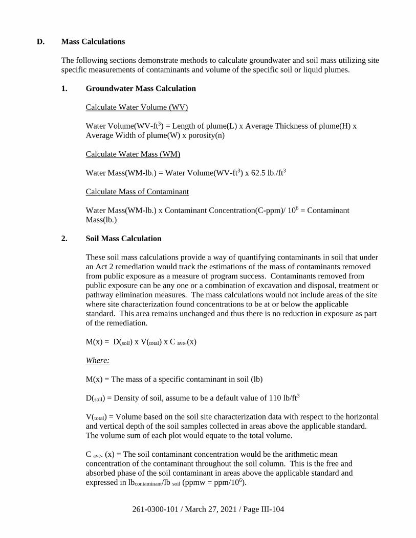
261-0300-101 / March 27, 2021 / Page III-104
D. Mass Calculations
The following sections demonstrate methods to calculate groundwater and soil mass utilizing site
specific measurements of contaminants and volume of the specific soil or liquid plumes.
1. Groundwater Mass Calculation
Calculate Water Volume (WV)
Water Volume(WV-ft3) = Length of plume(L) x Average Thickness of plume(H) x
Average Width of plume(W) x porosity(n)
Calculate Water Mass (WM)
Water Mass(WM-lb.) = Water Volume(WV-ft3) x 62.5 lb./ft3
Calculate Mass of Contaminant
Water Mass(WM-lb.) x Contaminant Concentration(C-ppm)/ 106 = Contaminant
Mass(lb.)
2. Soil Mass Calculation
These soil mass calculations provide a way of quantifying contaminants in soil that under
an Act 2 remediation would track the estimations of the mass of contaminants removed
from public exposure as a measure of program success. Contaminants removed from
public exposure can be any one or a combination of excavation and disposal, treatment or
pathway elimination measures. The mass calculations would not include areas of the site
where site characterization found concentrations to be at or below the applicable
standard. This area remains unchanged and thus there is no reduction in exposure as part
of the remediation.
M(x) = D(soil) x V(total) x C ave.(x)
Where:
M(x) = The mass of a specific contaminant in soil (lb)
D(soil) = Density of soil, assume to be a default value of 110 lb/ft3
V(total) = Volume based on the soil site characterization data with respect to the horizontal
and vertical depth of the soil samples collected in areas above the applicable standard.
The volume sum of each plot would equate to the total volume.
C ave. (x) = The soil contaminant concentration would be the arithmetic mean
concentration of the contaminant throughout the soil column. This is the free and
absorbed phase of the soil contaminant in areas above the applicable standard and
expressed in lbcontaminant/lb soil (ppmw = ppm/106).
261-0300-101 / March 27, 2021 / Page III-105
E. Long-Term Stewardship
1. Introduction
Long-term stewardship is generally accepted as the establishment and maintenance of
physical and non-physical controls that are necessary to maintain the effectiveness of an
approved remedy at cleanup sites where remaining regulated substances do not allow for
the unrestricted use of the property. It also includes any long-term obligations (e.g.,
sampling, operation and maintenance, etc.) that ensure the effectiveness of the remedy
after completion of the response action.
This section provides general guidelines on the methodology of long-term stewardship,
which includes the use of a postremediation care plan. The plan shall be submitted as
part of the final report and approved by the Department. The approved postremediation
care plan will become a condition of attainment of the chosen standard(s) under Act 2.
The plan shall identify the activities that will be conducted after closure and the
frequency of those activities.
Answer the questions from the matrix in Table III-7, relative to your chosen standard(s),
to determine when a postremediation care plan is required. The proposed
postremediation care requirements shall be included in the cleanup plan for Department
approval, as specified in Section 250.410(b)(5) of the regulations.
If any of the answers in the following matrix are yes, relative to the selected standard(s),
a postremediation care plan shall be included as part of the final report.
2. Uniform Environmental Covenants Act
On Dec. 18, 2007, the Uniform Environmental Covenants Act (UECA) (27 Pa. C.S.
§ 6501-6517) was signed into law, and was subsequently implemented via Chapter 253,
adopted November 19, 2010 (40 Pa.B. 6654). UECA provides a standardized process for
creating, documenting and assuring the enforceability of activity and use limitations
(AULs) on contaminated sites. Under UECA, an environmental covenant will be
required whenever an engineering or institutional control is used to demonstrate the
attainment of an Act 2 remediation standard. Environmental covenants are legal
documents affecting property rights so remediators are encouraged to seek legal counsel
with respect to the contents of the environmental covenant. For the purposes of Act 2,
environmental covenants will take the place of deed notices in relation to any restrictions
required to attain or maintain the standard.
A model environmental covenant is provided on the LRP website. The model is provided
as an example of what type of information should be provided in an environmental
covenant. However, it is important to note that each site is unique, so the content of each
covenant will vary from site to site.
At some sites additional AULs may be put in place but not included in the environmental
covenant, because they are not needed for attainment/maintenance of an Act 2 cleanup
standard. Environmental covenants are difficult to modify, so land use restrictions not
associated with the attainment/maintenance of an Act 2 standard may unnecessarily
impede the ability to redevelop a property. Thus, a mechanism other than an

261-0300-101 / March 27, 2021 / Page III-106
environmental covenant is recommended for any additional AULs on a site. Regardless,
the submitted postremediation care plan should only review the mechanisms required to
attain/maintain an Act 2 cleanup standard. Only those AULs that are necessary to attain
and/or maintain the selected standard are required for inclusion within the environmental
covenant. In addition, the property owner’s consent and signature are required to
implement an environmental covenant (27 Pa. C.S. § 6504).
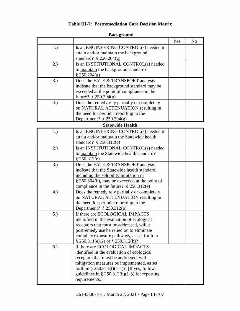
261-0300-101 / March 27, 2021 / Page III-107
Table III-7: Postremediation Care Decision Matrix
Background
Yes No
1.) Is an ENGINEERING CONTROL(s) needed to
attain and/or maintain the background
standard? § 250.204(g)
2.) Is an INSTITUTIONAL CONTROL(s) needed
to maintain the background standard?
§ 250.204(g)
3.) Does the FATE & TRANSPORT analysis
indicate that the background standard may be
exceeded at the point of compliance in the
future? § 250.204(g)
4.) Does the remedy rely partially or completely
on NATURAL ATTENUATION resulting in
the need for periodic reporting to the
Department? § 250.204(g)
Statewide Health
1.) Is an ENGINEERING CONTROL(s) needed to
attain and/or maintain the Statewide health
standard? § 250.312(e)
2.) Is an INSTITUTIONAL CONTROL(s) needed
to maintain the Statewide health standard?
§ 250.312(e)
3.) Does the FATE & TRANSPORT analysis
indicate that the Statewide health standard,
including the solubility limitation in
§ 250.304(b), may be exceeded at the point of
compliance in the future? § 250.312(e)
4.) Does the remedy rely partially or completely
on NATURAL ATTENUATION resulting in
the need for periodic reporting to the
Department? § 250.312(e)
5.) If there are ECOLOGICAL IMPACTS
identified in the evaluation of ecological
receptors that must be addressed, will a
postremedy use be relied on to eliminate
complete exposure pathways, as set forth in
§ 250.311(e)(2) or § 250.312(b)?
6.) If there are ECOLOGICAL IMPACTS
identified in the evaluation of ecological
receptors that must be addressed, will
mitigation measures be implemented, as set
forth in § 250.311(f)(1-4)? [If yes, follow
guidelines in § 250.312(b)(1-3) for reporting
requirements.]
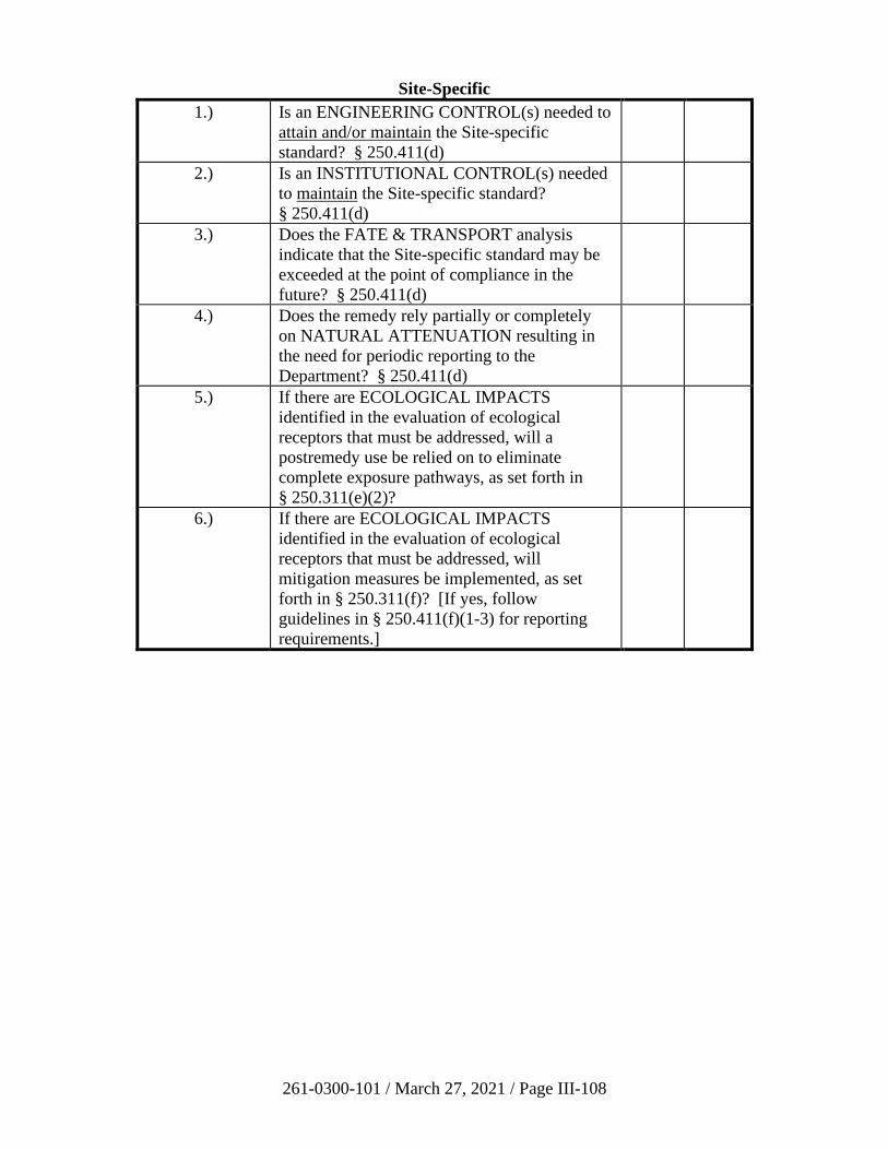
261-0300-101 / March 27, 2021 / Page III-108
Site-Specific
1.) Is an ENGINEERING CONTROL(s) needed to
attain and/or maintain the Site-specific
standard? § 250.411(d)
2.) Is an INSTITUTIONAL CONTROL(s) needed
to maintain the Site-specific standard?
§ 250.411(d)
3.) Does the FATE & TRANSPORT analysis
indicate that the Site-specific standard may be
exceeded at the point of compliance in the
future? § 250.411(d)
4.) Does the remedy rely partially or completely
on NATURAL ATTENUATION resulting in
the need for periodic reporting to the
Department? § 250.411(d)
5.) If there are ECOLOGICAL IMPACTS
identified in the evaluation of ecological
receptors that must be addressed, will a
postremedy use be relied on to eliminate
complete exposure pathways, as set forth in
§ 250.311(e)(2)?
6.) If there are ECOLOGICAL IMPACTS
identified in the evaluation of ecological
receptors that must be addressed, will
mitigation measures be implemented, as set
forth in § 250.311(f)? [If yes, follow
guidelines in § 250.411(f)(1-3) for reporting
requirements.]
261-0300-101 / March 27, 2021 / Page III-109
3. Institutional versus Engineering Controls
An institutional control, by definition of Act 2, is a measure taken to limit or prohibit
certain activities that may interfere with the integrity of a remedial action or result in
exposure to regulated substances at a site. These include, but are not limited to, fencing
or restrictions on the future use of the site (35 P.S. § 6026.103).
An engineering control, by definition of Act 2, is a remedial action directed exclusively
toward containing or controlling the migration of regulated substances through the
environment. These include, but are not limited to, permanent capping of contaminated
soils with parking lots or building slab construction, leachate collection systems,
groundwater recovery trenches, and vapor mitigation systems.
Example: A groundwater use restriction, as documented in an environmental covenant, is
an institutional control. An impermeable cap that prevents volatilization to the
atmosphere, controls contaminant migration via run-off and leaching to groundwater, and
limits dermal contact is an engineering control.
Institutional and engineering controls serve as AULs because they restrict the use of a
property. Institutional controls cannot be used to attain the background or Statewide
health standards (35 P.S. §§ 6026.302(b)(4) and 6026.302(e)(3)). Engineering and/or
institutional controls may be used to maintain all three standards. Attaining a standard
refers to steps or actions taken to complete the requirements, and therefore demonstrate
attainment, of an Act 2 standard. Maintaining a standard refers to steps or actions taken
to ensure the requirements of a standard that have already been completed continue to be
met in the foreseeable future. Table III-7 provides a decision matrix of postremediation
care requirements for each Act 2 standard.
Example of attaining vs. maintaining a cleanup standard: A property with a discharge of
regulated substances to the groundwater is able to attain the SSS under current conditions
because drinking water is supplied by the municipality. The SSS is then maintained in
the future by implementing an environmental covenant stating that groundwater is not to
be used on the property without treatment approved by the Department.
4. Postremediation Care Plan
The postremediation care plan should include the following:
• The reason(s) that the postremediation care plan is necessary (See 25 Pa. Code
§§ 250.204(g), 250.312, 250.411(d), and 250.708).
• A schedule of operation and maintenance of the controls. Include a description of
the planned maintenance activities and frequencies at which they will be
performed and future plans for submission of proposed changes.
• Information regarding the submission of monitoring results and analysis, or as
otherwise approved by the Department, that demonstrates the effectiveness of the
remedy. Include a description of the planned monitoring activities and
frequencies at which they will be performed. Monitoring activities in this case
261-0300-101 / March 27, 2021 / Page III-110
may include inspection and reporting requirements related to engineering
controls.
• The proposed method for reporting any instances of nonattainment of the selected
standard(s).
• The proposed measures to be taken to correct nonattainment conditions as they
occur. A postremediation care plan containing any language proposing any
potential future changes to the remedy will require the approval of the Department
at the time of the proposed change.
• Information regarding the maintenance of records at the property where the
remediation is being conducted for monitoring, sampling and analysis. Include
the name, address and telephone number of the person or office to contact about
the site during the postremediation care period. This person or office shall keep
an updated postremediation care plan during the postremediation care period.
• Documentation of a plan to maintain the mitigated ecological resource, report of
success or failure of the mitigation measure, and demonstration of sustaining the
measures up to five years from final report approval.
• If requested by the Department, documentation of financial ability to implement
the remedy and the postremediation care plan.
5. Postremediation Monitoring
In some situations, postremediation monitoring may be required as part of the
postremediation care plan. For example, postremediation monitoring is conducted to
determine any changes in groundwater quality after attainment of a standard(s). Unless
otherwise instructed by the Department, analytes to be included are those which were
monitored during assessment and remediation monitoring. All monitoring activities
should incorporate quality control and quality assurance provisions consistent with the
Chapter 250 regulations and policies.
Well locations for postremediation monitoring are generally selected from existing
monitoring wells used in the characterization and remediation phases. Where a source of
contamination is removed prior to impacting groundwater, postremediation monitoring
should continue at locations that will detect any residual contamination in the unsaturated
zone that might migrate to the groundwater.
a) Duration
In most cases, postremediation monitoring requirements will be developed on a
case-by-case basis. The factors determining the duration of postremediation
monitoring are the same factors that determine whether a postremediation care
plan is necessary.
261-0300-101 / March 27, 2021 / Page III-111
b) Frequency
As stated in Section 250.204(g) of the regulations, postremediation monitoring
will take place on a quarterly basis unless otherwise approved by the Department.
The interval between sampling events should be short enough to allow for
response and correction of any problems that may cause nonattainment at the
point of compliance.
Factors that could influence the need for an alternative postremediation
monitoring schedule include site size, groundwater velocity, contaminant
characteristics and the vulnerability of a site to pulses of contaminant migration
during precipitation events.
c) Cessation of Postremediation Monitoring
Postremediation monitoring may be terminated when monitoring provisions set
forth in the postremediation care plan are met, the engineering controls are no
longer needed, and it can be documented by fate and transport analysis that the
standard will not be exceeded in the future.
6. Postremediation Care Attainment
Remediators can end postremediation care if they can demonstrate through a documented
fate and transport analysis that the selected standard(s) will be met, and will continue to
be met in the future, after removal of engineering controls. An amendment to the
postremediation care plan shall be submitted for approval by the Department. The
postremediation care plan shall be amended whenever changes in operating plans or
facility design, or events that occur during postremediation care, affect the currently
approved postremediation care plan.
261-0300-101 / March 27, 2021 / Page III-112
F. One Cleanup Program
In March 2004, PA DEP and EPA Region 3 entered into a Memorandum of Agreement (MOA)
that outlines a procedure where sites remediated according to the LRP may also satisfy
requirements of several federal laws: the Resource Conservation and Recovery Act (RCRA)
(42 U.S.C. § 6901, et seq.), the Comprehensive Environmental Response Compensation Liability
Act (CERCLA) (42 U.S.C § 9601, et seq.), and the Toxic Substances Control Act (TSCA)
(15 U.S.C. § 2601, et seq.).
1. Purpose
DEP and EPA sought to promote the One Cleanup Program initiative by working
together to achieve cleanups that protect human health and the environment by making
greater use of all available authorities and selecting the optimum programmatic tools to
increase the pace, effectiveness, efficiency, and quality of cleanups. In effect, entering
into the One Cleanup Program can provide a remediator with a “one-stop shop” for state
and federal standards guiding the cleanup of brownfield sites.
2. Provisions and Applicability
EPA has reviewed and evaluated the LRP and has determined that the LRP, as
implemented under the MOA, includes each of the four elements of a state response
program listed in CERCLA Section 128(a)(2):
• Timely survey and inventory of brownfield properties.
• Oversight and enforcement authorities adequate to ensure that a response action
will protect human health and the environment.
• Mechanisms and resources to provide meaningful opportunities for public
participation.
• Mechanisms for approval and a requirement for verification and certification that
the response activity is complete.
The One Cleanup Program applies only to remediation of properties conducted pursuant
to Act 2 provisions. As determined by PA DEP and USEPA, the following properties are
not eligible to enter in the program:
• Permitted hazardous waste management units.
• Properties proposed in the Federal Register to be placed on the National Priorities
List.
• Properties that have been placed on the National Priorities List.
• Properties that have been permitted under the SWMA and the PA Clean Streams
Law for which cleanup standards are different than those of the LRP.
261-0300-101 / March 27, 2021 / Page III-113
3. Implementation
Under the MOA, DEP and EPA have agreed to work in a coordinated manner to avoid
possible duplication of efforts at properties, while ensuring that remediation of properties
continues in a timely fashion. DEP will notify EPA when properties are being addressed
under the LRP via written documentation for properties in Comprehensive Environmental
Response, Compensation and Liability Information System (CERCLIS) that are being
addressed under the LRP.
Participation in the One Cleanup Program entails some additional notification and public
involvement requirements upon submittal of the NIR and cleanup plan (see
Section II.A.3(a)).
For all RCRA Corrective Action Facilities being remediated under the LRP, the
remediator will provide EPA with copies of reports. DEP and EPA will work in teams to
accomplish cleanup goals in an appropriate and efficient use of both agencies’ resources.
EPA will review reports submitted to DEP under the LRP to determine if the site data
meets RCRA Corrective Action obligations. If EPA determines that the site
characterization or final decision is not sufficient to characterize the nature and extent of
contamination, the EPA and DEP intend to work together to resolve the matter. If EPA
determines the proposed cleanup objectives and corrective measures are sufficient, EPA
plans to proceed with remedy selection procedures, including providing opportunity for
public comment and review. Once the remedy is implemented and EPA determines that
the media cleanup measures are met and corrective measures are satisfied, EPA will,
where appropriate, acknowledge that the remediator has completed its Corrective Action
obligations.
RCRA facilities enrolled in the One Cleanup Program may be subject to UECA
requirements (Section III.E.2 of this TGM). As such, a model covenant for any activity
and use limitations which may be in effect for these facilities is located on the DEP
website on the ‘One Cleanup Program’ webpage.
4. Benefits
In summary, by entering into the One Cleanup Program, site owners or operators may be
able to satisfy federal RCRA obligations and obtain liability relief under the Act 2
program. Interested parties can review the historic MOA, RCRA Corrective Action
Baseline Facilities that have entered the One Cleanup Program, and other useful
information on the PA DEP website on the One Cleanup Program tab.
Any owner, operator, or remediator interested in entering the One Cleanup Program
should consult with their assigned DEP Project Officer about opportunities and eligibility
requirements.
261-0300-101 / March 27, 2021 / Page III-114
G. Data Quality and Practical Quantitation Limits
1. Data Quality Objectives Process, Sampling, and Data Quality Assessment Process
An important issue regarding sampling and statistical analysis is the quality assurance
(QA) management considerations associated with these activities. Steps for the QA
management process, in general, can be divided into three phases: planning,
implementation and assessment. During the planning phase, a sampling and analysis plan
is developed based on Data Quality Objectives (DQO). The implementation phase
includes sampling execution and sample analysis. The assessment phase includes Data
Quality Assessment (DQA) (See 25 Pa. Code § 250.702(a)).
To help remediators design scientific and resource-effective sampling programs, EPA
provides guidance on developing DQO (EPA 1993). The DQO process allows a person
to define the data requirements and acceptable levels of decision errors, before any data
are collected. The DQO process should be considered in developing the sampling and
analysis plan, including the QA plan.
As stated in the EPA guidance (EPA 1993), the DQO process includes the following
seven steps:
• State the problem.
• Identify the decision.
• Identify inputs to the decision.
• Define the spatial and temporal boundaries of the decision.
• Develop a decision rule.
• Specify limits on decision errors.
• Optimize the design for obtaining data.
Step 4 of the DQO process, defining the spatial and temporal boundaries of the decision,
is particularly important, because it prevents pooling and averaging data in a way that
could mask potentially useful information. Activities in this step include:
• Define the domain or geographic area within which all decisions must apply.
Some examples are property boundaries, operable units, and exposure areas.
• Specify the characteristics that define the population of interest. Identification of
multiple areas of concern—each with its own set of samples and descriptive
statistics—will help to reduce the total variability if the areas of concern (AOCs)
are defined so that they are very different in their contaminant concentration
profiles. For example, the top 2 feet of soil are defined as surface soil. Another
example is to define contaminated soil that has been impacted by SPL as SPL-
impacted soil.
261-0300-101 / March 27, 2021 / Page III-115
• When appropriate, divide the population into strata that have relatively
homogeneous characteristics. This helps to reduce the variability in each data set.
• Define the scale of decision making. The scale of decision making is the smallest
area, volume, or time frame of the media in which decision errors are to be
controlled. This is also the unit that will be assumed to generate a “statistical
unit” of possible measurements which allows the assessment and control of
decision errors. Examples are remediation units, exposure units, and hot spots.
• Determine the time frame to which the study data apply. It may not be possible to
collect data over the full time period to which the decision will apply. Therefore,
a decision should be made regarding the most appropriate time frame that the data
should reflect.
• Determine when to collect samples. Conditions at the site may vary due to
seasons, weather or other factors. Therefore, a decision should be made regarding
the most appropriate time period to collect data that will reflect the conditions that
are of interest.
• Identify any practical constraints on data collection, such as seasonal or
meteorological conditions, unavailability of personnel, time, or equipment.
At the completion of the DQO process, information obtained from the DQO process can
be used to develop a sampling and analysis plan, including a QA/QC plan.
After the environmental data have been collected and validated in accordance with the
sampling and analysis plan (including the QA/QC plan), data must be assessed to
determine whether the DQOs are met. This is the DQA process. EPA has developed
guidance on DQA (EPA, 1996).
The DQA process involves the following five steps (EPA, 1996):
• Review the DQOs and sampling design.
• Conduct a preliminary data review.
• Select the statistical test.
• Verify the underlying assumptions of the statistical test.
• Perform the statistical hypothesis test and draw conclusions that address the data
user’s objectives.
A properly implemented DQA process can help to determine if planning objectives were
achieved. The discussions in the statistics Section (III.B) will address key statistical
issues that are pertinent to Act 2 and are encountered during these DQO and DQA
processes.
261-0300-101 / March 27, 2021 / Page III-116
2. Preliminary Data Review
Preliminary data review should be performed whenever data are used. By reviewing the
data both numerically and graphically, one can learn the “structure” of the data and
identify limitations for using the data. Graphical methods include histograms, probability
plots, box charts, and time-series plots to visually review the data for trends or patterns.
Calculations of summary statistics are typically done to characterize the data and make
judgments on the central tendencies, symmetry, presence of outliers, etc. These statistical
methods are defined and explained in more detail in the statistical section of this
guidance. (Section III.B)
Chemical concentrations should initially be compared to laboratory blank concentrations.
If the blank samples contain detectable levels of common laboratory contaminants, then
the sample results should be considered as positive results only if the concentrations in
the sample exceed 10 times the maximum amount detected in the blank. If the
concentration is less than 10 times the blank contaminant level, it is concluded that the
chemical was not detected in the sample and the blank-related chemical concentration is
considered to be the quantitation limit for the chemical in that sample. If all samples
contain levels of a common laboratory contaminant that are less than 10 times the level of
contamination noted in the blank, then completely eliminate that chemical from the set of
sample results. Some common laboratory contaminants include acetone, 2-butanone
(methyl ethyl ketone), methylene chloride, toluene, and phthalate esters. This evaluation
is typically done during the laboratory data review process and anything that meets the
criteria to be included in data evaluation will typically be marked with a “B” qualifier.
The “B” flag is placed on data that is considered valid but could be affected by the
presence of the same compound in the blank sample.
If the blank samples contain constituents other than common laboratory contaminants,
then the sample results should be considered as positive results only if the concentrations
in the sample exceed five times the maximum amount detected in any laboratory blank.
As with the common laboratory contaminants, if the concentration is less than five times
the blank constituent level, it is concluded that the constituent was not detected in the
sample and the blank-related chemical concentration is considered to be the quantitation
limit for the chemical in that sample. Again, if all samples contain levels of a constituent
other than common laboratory contaminants that are less than five times the level of
contamination noted in the blank, then completely eliminate that chemical from the set of
sample results. As with common laboratory contaminants, this evaluation is typically
done during the laboratory data review process, and anything that meets the criteria to be
included in data evaluation will typically be marked with a “B” qualifier.
The details describing the five and 10 times the blank concentration evaluation is
described in many EPA laboratory methods.
3. Practical Quantitation Limit (25 Pa. Code § 250.4)
Practical quantitation limit (PQL), as defined in Act 2 (35 P.S. § 6026.103), is the lowest
limit that can be reliably achieved under normal laboratory conditions. Many of the
SW-846 (EPA’s hazardous waste test methods) analysis methods previously listed
261-0300-101 / March 27, 2021 / Page III-117
estimated quantitation limits (EQL) or method detection limits (MDL) to ensure that
laboratories were providing the data required to meet the needs of the data-user.
However, as technology has improved, the need to define a minimum value to be reached
has been reduced. The EQL was the limit set at the time the method was written as an
estimated value that could be detected using the given method. MDL is a value that is
calculated using statistics on laboratory data to provide the lowest value that can be
detected. The MDL is instrument-specific.
Some laboratory methods do continue to list EQL and/or MDL values; however, most
laboratories can now consistently achieve reporting limits (RL) or limits of quantitation
(LOQ) that are much lower than the EQL or MDL values defined in the method. These
RLs and LOQs are the lowest value that can be reliably quantified given a specific
method. Detections that fall between the RL and the MDL are “J” values. This indicates
that it is above the level that the instrument can reliably identify (MDL), but is below the
value that can be reliably quantified (RL) and is an estimate. “J”-flagged values are valid
data and can be used for screening, etc.
For the purposes of Act 2, if a laboratory’s RL value is above a constituent’s
corresponding MSC value due to a technological issue, remediators should contact their
regional project officer to discuss how to proceed. It is important to note that PQL values
should not be used for screening data (e.g. for a risk assessment or a VI evaluation) and
only apply for the purposes of attaining the standard.
261-0300-101 / March 27, 2021 / Page III-118
H. Site-Specific Human Health Risk Assessment Guidance
1. Introduction
This Section provides general guidelines on the methodology of risk assessment and the
risk assessment report for human health evaluation under Act 2. Regulations regarding
risk assessment are in Chapter 250, Subchapter F. This section of the guidance document
does not address issues related to ecological risk assessment. Ecological risk assessment
is addressed in Section III.I.
Prior to performing a risk assessment, it is important to clearly define the problem that is
to be addressed, the objectives of the study, and how the results will be used to meet
these objectives. This initial step is critical to ensure a successful outcome (accurate,
protective, timely, cost-effective evaluation) and that the level of effort is commensurate
with the scope of the problem.
Risk assessment procedures have been well defined in various EPA guidance documents.
The process does not need to be reiterated in this document. Instead, certain key issues
pertinent to site-specific evaluations under Act 2 are discussed subsequently.
For risk assessment issues not directly addressed in this document, remediators may
consult the most recent EPA and ASTM guidelines, such as those listed on Table III-11,
for additional guidance. For petroleum release sites, the risk assessment methodology in
ASTM E 1739-95 (2015) (Standard Guide for Risk-Based Corrective Action Applied at
Petroleum Release Sites) may be consulted for further guidance.
A suggested outline for the risk assessment report is provided in Section II.B.3(g)(v) of
this manual. The outline is intended to provide guidance on minimum requirements for
the report.
2. When to Perform a Risk Assessment
Remediators selecting the site-specific standard established by Section 304 of Act 2
(35 P.S. § 6026.304) should submit a risk assessment report to the Department for review
and approval unless no present or future complete exposure pathways exist as
demonstrated in the fate and transport analysis in the site-specific remedial investigation.
The exposure scenarios (e.g., residential, industrial, recreational), which will define the
exposure pathways, must be based on site-specific land use considerations (see 35 P.S.
§§ 6026.301(a)(3) and 6026.304(1)(2)). The pathways, which describe the mechanism
by which receptors may be exposed to a source, are also site-specific. Detailed guidance
on land use determination and identification of exposure scenarios and pathways are
addressed in Section III.H.3(b)(i) of this document and references cited therein. A risk
assessment only needs to be performed if complete exposure pathways for human
receptors exist under current or potential future conditions. If engineering or institutional
controls that are to be implemented will eliminate all exposure pathways, a risk
assessment report is not required (see 25 Pa. Code § 250.405(b)).
A baseline risk assessment report is not required if the Department, in its remedial
investigation report or cleanup plan approval, determines that a specific remedial
261-0300-101 / March 27, 2021 / Page III-119
alternative that eliminates all pathways, other than a no-action remedial alternative, can
be implemented to attain the site-specific standard (25 Pa. Code § 250.405(c)). A
baseline risk assessment is an evaluation of risk prior to, or in the absence of, a remedial
measure. When the remedial measure has been completed, a residual risk assessment that
evaluates risks posed by postremediation contamination, if present, is required in order to
demonstrate attainment of the site-specific standard.
3. Risk Assessment for Human Health (25 Pa. Code § 250.602(c))
A risk assessment for human exposure from contaminated sites consists of the following
four steps:
(1) Site characterization
(2) Exposure assessment
(3) Toxicity assessment
(4) Risk characterization that evaluates if the risks meet the human health protection
goals specified in Subsections 304(b) and (c) of Act 2.
The following discussions address key issues pertinent to these four steps of risk
assessment for human exposure:
a) Site Characterization [§ 250.602(c)(1)]
i) Chemicals of Concern
The initial steps of the site characterization are to review the analytical
data and to select the chemicals of concern that are identified in distinct
areas of contamination at the site. Under Act 2 there are two possible
situations in determining the chemicals of concern in a baseline risk
assessment under the site-specific standard: (1) strictly using the site-
specific standard, or (2) a combination of standards using site-specific and
Statewide health, site-specific and background, or all three standards.
These situations are discussed separately below.
In the first situation of using only the site-specific standard, the chemicals
of concern can be screened using the EPA Regional Screening Level
(RSL) screening procedures. The purpose of this screening procedure is
only for potential reduction of the number of chemicals carried through
the risk assessment. Those chemicals on the site whose maximum
concentration exceeds the RSL values for carcinogenic effects (10-6) or the
RSL values (HQ=0.1) for noncarcinogenic effects should be retained in
the risk assessment. Chemicals on the site at maximum concentration
below the RSL values for carcinogenic effects or the RSL values for
noncarcinogenic effects may be dropped from the risk assessment unless
other contaminant-specific or site-specific considerations suggest that the
inclusion of these constituents in the risk assessment is more appropriate
261-0300-101 / March 27, 2021 / Page III-120
to determine the total risk of the site. Chemicals that are not retained in
the risk assessment may be considered having minimal influence on total
risk. (Note that it is not permissible under the SSS to perform screening
using SHS MSCs.)
The second situation uses a combination of the site-specific standard with
one or both of the other two standards. The chemicals of concern to be
addressed in the risk assessment should include those chemicals that
cannot be addressed using either the SHS or the background standard.
The chemicals of concern identified for evaluation in the risk assessment
may then be screened using the same RSL screening procedures
mentioned above.
Three other factors should be considered when deciding to retain
constituents for the risk assessment. Specifically, these factors include the
constituent’s toxicity, mobility and persistence. Toxicity is a driving force
when determining if exposure to a site poses any adverse impact to human
health or the environment. Some constituents may be frequently detected
at a site, but may be considered relatively innocuous or toxicologically
inert. These constituents should not be retained for the risk assessment.
In contrast, some constituents may be infrequently detected, but may be
relatively more toxic than most constituents. Regardless of the
constituent’s frequency of detection, its presence (assuming it is not
anomalous) may deem it necessary to be retained as a constituent of
concern.
The mobility of a constituent dictates what receptors on and off site may
be potentially affected and consequently whether the constituent should be
retained in the assessment. Physical and chemical properties of a
compound control its transport and fate in the environment. For example,
these attributes determine whether a constituent will readily volatilize into
the air or be transported via advection or diffusion through the soil,
groundwater and surface water. These characteristics also describe a
chemical’s tendency to adsorb onto soil/sediment particles, in turn altering
its mobility through the environment.
Finally, the persistence of a chemical in the environment determines
whether further receptors would be impacted. The persistence of a
chemical in the environment depends on factors such as microbial content
of soil and water and the ability of these organisms to degrade the
chemical. In addition, chemical and photochemical degradation may
contribute to the elimination of a particular compound. Although the
parent compound may be eliminated, the byproducts of the degradation of
that compound must also be considered and evaluated. These chemical-
specific factors will also be used to determine whether a constituent and its
byproducts are retained for the risk assessment.
261-0300-101 / March 27, 2021 / Page III-121
In general, liability protection is not afforded under the site-specific
standard for those chemicals that are not identified as contamination at a
site and for which attainment has not been demonstrated.
ii) Conceptual Site Model
Development of a conceptual site model is an important step in identifying
additional data needs in site characterization and in defining exposure. A
conceptual site model identifies all potential or suspected sources of
contamination, types and concentrations of contaminants detected at the
site, potentially contaminated media, potential exposure pathways and
receptors. Many components of exposure (such as the source, receptors,
migration pathways and routes of exposure) are determined on a site-
specific basis. The conceptual site model provides a systematic way to
identify and summarize this information to ensure that potential exposures
at the site are accounted for accurately.
The conceptual site model may be graphical, tabular or narrative but
should provide an accurate understanding of complete exposure pathways
for the site. Examples of conceptual site models may be found in EPA,
ITRC, or ASTM guidance documents. It is recommended that the
development of the conceptual site model be coordinated with the regional
project officer to ensure that potential pathways and receptors are
adequately and appropriately addressed prior to performing the
assessment.
b) Exposure Assessment [§§ 250.603 and 250.604]
The exposure assessment determines or estimates (qualitatively or quantitatively)
the magnitude, frequency, duration and routes of exposure. The assessment is
typically performed in three steps:
(1) Characterization of the exposure setting including:
• the physical setting
• potential exposed populations
(2) Identification of complete exposure pathways which includes:
• sources and receiving media
• fate and transport in the release media
• exposure points and exposure routes
The information on sources, fate and transport (including biodegradation),
exposure points and exposure routes are then integrated to determine the potential
261-0300-101 / March 27, 2021 / Page III-122
exposure pathways. Complete pathways exist when all components are present.
Information for complete pathways should be summarized.
(3) Quantification of exposure of the receptor including:
• environmental concentration
• intake
The exposure assessment process is well defined in various guidance documents,
as cited in Section III.H.4, and is not reiterated here. This section discusses some
key issues pertaining to performing the site-specific exposure assessments.
i) Exposure Scenarios and Exposure Pathways
Exposure Pathways: The exposure pathway describes the mechanism by
which receptors (individuals, populations, and ecological receptors) may
be exposed to the source. Pathways consist of a source, receptor, route of
exposure and a transport mechanism, if the exposure point is not the same
as the source. The analysis of the fate and transport of the chemical can
help to predict future exposures, to link sources with currently
contaminated media, and to identify exposure pathways. The intent of the
fate and transport analysis at this stage is to identify media that are
receiving or may receive site-related chemicals. Further guidance on fate
and transport analysis can be found in Section III.A of this guidance
document.
As discussed above, the conceptual site model is useful in defining
potential exposure pathways. However, only complete pathways should
be advanced through the assessment process. The effects of engineering
or institutional controls that are to be implemented, which will eliminate
exposure pathways, must be considered for the conceptual model
development. The EPA provides guidance referenced in Section III.H.4 of
this manual on potential pathways for given land use scenarios.
Realistic current and future land use scenarios (e.g., residential, industrial,
agricultural, etc.) provide the basis for selecting the controlling exposure
scenarios/pathways. Guidance on land use considerations can be found in
the EPA OSWER Directive: Land Use in The CERCLA Remedy Selection
Process (1995) as well as earlier EPA guidance on exposure assessments
as referenced above. Sources and types of information that may aid in
determining the reasonably anticipated future land use include, but are not
limited to:
• Current land use.
• Zoning laws.
• Zoning maps.

261-0300-101 / March 27, 2021 / Page III-123
• Comprehensive community master plans.
• Local land use authorities.
• Local officials.
• Population growth patterns and Bureau of Census projections.
• Accessibility of site to existing infrastructure (such as
transportation and public utilities).
• Institutional controls currently in place.
• Site location in relation to urban, residential, commercial,
industrial, agricultural and recreational areas.
• Federal/State land use designation (such as state parks).
• Historical or recent development patterns.
• Cultural factors (such as historical sites).
• Natural resources information.
• Stakeholder input - allows for all affected parties to define land
use.
• Location of onsite or nearby wetlands.
• Proximity of site to a floodplain.
• Proximity of site to critical habitats of endangered or threatened
species.
• Geographic and geologic information
• Location of wellhead protection areas, recharge areas, and other
areas identified in the state’s Comprehensive Groundwater
Protection Program.
These types of information should be considered when developing the
assumptions about future land use.
Some direct pathways, such as direct ingestion of soil or groundwater and
direct inhalation of volatiles and/or particulates from soil, are fairly well
established and can be used routinely where they have been identified as
complete pathways. At issue would be defining appropriate exposure
261-0300-101 / March 27, 2021 / Page III-124
factors (such as intake rate for the given population) since these factors
exhibit a range of possible values. Typically, the choice of factors (high-
end exposure vs. average exposure) is defined by the level of conservatism
desired.
Dermal contact (with soil or groundwater), on the other hand, is less well
defined, particularly in terms of estimating intake (the mass of substance
in contact with the body per unit body weight per unit time) and, more
importantly, absorbed dose (intake multiplied by an absorption factor to
account for mass actually in the body). This pathway is best addressed at
a site-specific level when identified as relevant. Although there is some
guidance (EPA, 1991c), professional judgment may play a significant role
in estimating dermal exposure. The rationale behind these judgments (and
indeed professional judgments wherever they are used) and, as far as
possible, documented evidence in support of these judgments should be
clearly provided.
Some indirect pathways are also best addressed on a site-specific basis
because of the inherent uncertainty associated with defining the transport
from the source to the receptor. In the case of vapor intrusion into a
trench, for example, actual data from direct measurements, i.e., a
monitoring approach, would be preferred to the use of models which have
been shown to be imprecise. Vapor intrusion into an enclosed space is
discussed in detail in Section IV of this manual.
Other indirect pathways (e.g., soil leaching to groundwater and subsequent
ingestion of groundwater) can be addressed by simple analytical models.
Although site-specific data inputs to these models are typically favored as
producing a more realistic estimate of exposure, site-specific data may not
be accessible. The use of a combination of default and site-specific
parameters may be used provided the rationale for the choice of values is
included.
Receptors and Human Exposure Factors: Receptors should be defined on
a site-specific basis taking into account future land use considerations.
Guidance on potential receptors for given land use are provided in EPA
guidances (EPA 1989a, 1991a,b). Care should be taken to identify
potential sensitive subpopulations (e.g., children) as appropriate for site-
specific conditions.
Section 250.603 of the regulations specifies requirements to select
exposure factors. A risk assessment may use site-specific exposure factors
in accordance with EPA’s Final Guidelines for Exposure Assessment,
1992 (57 FR 22888-22938) or exposure factors used in the development of
the SHSs identified in Subchapter C of the regulations. Site-specific
exposure factors shall be clearly justified by supporting data (see 25 Pa.
Code § 25.603(b)).
261-0300-101 / March 27, 2021 / Page III-125
Human exposure factors may be divided into receptor physiologic
parameters (e.g., body weight, skin surface area); contact rate (e.g.,
consumption of water, soil ingestion rate); and time activity patterns (e.g.,
time spent indoors/outdoors, time spent at work). Some of these variables,
particularly the physiologic parameters, have been well characterized but
others such as time/activity patterns are less well documented. All
parameters are subject to variability (true heterogeneity) and/or
uncertainty (ignorance about a measurement). Thus, a range of values
may be available for any given parameter. The choice will depend to
some extent on the problem and the level of conservatism desired.
Typical sources for these parameters are the EPA Exposure Factors
Handbook (2011) and the American Industrial Health Council (AIHC)
Exposure Factors Sourcebook (AIHC, 1994).
Fate and Transport Parameters and Models: Constituents of concern can
both migrate (via leaching, advection, dispersion) and transform (via
biodegradation, hydrolysis, photolysis) in the environment. These
migration and transformation processes must be considered when
determining environmental concentration under indirect exposure (see
25 Pa. Code §§ 250.204(a), 250.312(a), 205.408(a). A range of fate and
transport models (from simple analytical to complex numerical) are
available to account for these processes. However, the level of site-
specific data needed to make proper use of the models also increases with
the level of sophistication of the model (i.e., the increase of model
technical capabilities). A tiered approach, based on level of model
complexity, is best, i.e., using the least resource intensive method to
achieve the objective of the evaluation. The selected model should
adequately represent the physical setting (e.g., the geometric configuration
of hydrogeological systems, soil profiles, river widths and depths, etc.)
and migration and transformation processes that affect the problem. Input
parameter values should be representative of field conditions. The choice
of model and input parameters will need to be justified as appropriate for
given site-specific conditions. Justifications should include why a model
is appropriate when limitations of the selected model are considered. In
addition, some measure of model validation may be required. This may be
as simple as corroborating the conservative assumptions with field
measurements. For guidance on selection of groundwater models refer to
Section III.A of this manual.
The use of monitoring methods may also be appropriate for defining
environmental fate, as in the case of natural attenuation. All supporting
data should be provided to support such an evaluation. For specific
guidance regarding the use of monitoring methods, check EPA, ITRC, and
other references listed in III.H.3(f).
Generic vs. Site-Specific Considerations: In general, risk assessments
should be based upon realistic exposure scenarios using current or planned
future land use, incorporating any changes from early response actions
known or planned. Site-specific information on exposure pathways,
261-0300-101 / March 27, 2021 / Page III-126
receptors and exposure factors, including actual data, should be used to the
maximum extent possible.
However, not all exposure parameters need to be site-specific. Certain
generic human physical parameters (e.g., body weight) that do not vary
significantly in the general human population, and thus from site to site,
are such exceptions. Default values, from single point estimates to
distributions for these parameters, are available from such sources as the
EPA Exposure Factors Handbook (EPA, 2011) and the AIHC Exposure
Factors Sourcebook (AIHC, 1994). Default values of single point
estimates for these parameters are also available from Subchapter C of the
regulations.
Factors affecting the choice of exposure scenario (land use), complete
exposure pathways, the distribution of contaminants in the media, the
characteristics of the media, and the activity patterns and demographics of
the surrounding populations should be considered, whenever possible, as
site-specific. For example, if the planned future land use is industrial, the
appropriate population would be adults and default physiological
information may be obtained from the above named sources. However, if
the concern is for a residential land use, children may be the population of
concern. Default physiological information is still available from the
above sources but the actual values would be different because the site-
specific considerations dictate a different land use and receptor population.
It is possible that a sensitive subpopulation may be of concern (e.g.,
pregnant women, subsistence fishermen) in certain situations. Some data
for these populations may be available from national or regional surveys
incorporated in the above sources, but in some instances the data may
need to be generated. The choice of data should be supported in the peer
review literature and proved to be appropriately applied. For information
generated on a site-specific basis, proper QA/QC measures should be
exercised and the data should be generated with the understanding of the
regulatory agency as to how the information will be used.
ii) Exposure Characterization
Exposure characterization is the quantification step in the process. In the
forward calculation of risk, both the environmental concentration and the
intake must be determined. In the reverse calculation of site-specific
standards, an acceptable concentration is derived based on intake and a
predetermined level of risk.
Exposure Point Concentration: This is the concentration expected to be
contacted over the exposure period. Since risk assessments are typically
performed for a chronic exposure scenario, i.e., the contact period is long
(typically 30-70 years), an upper confidence limit on the mean is used. It
is important, therefore, to assess the potential fate of the material in the
environment to provide the best estimate of its environmental
261-0300-101 / March 27, 2021 / Page III-127
concentration over time. In some instances, short-term exposure is to be
evaluated, in which case some other metric (e.g., maximum concentration)
may be more appropriate. EPA OSWER Directive 9285.7-081 provides
guidance on the concentration term.
Intake: Three types of variables are associated with defining intake:
chemical related variables, i.e., the concentration term and its associated
fate and transport parameters; variables that describe the exposed
population such as physiologic parameters, contact rate and time/activity
patterns; and an assessment-determined variable, i.e., the period over
which the exposure is averaged.
Since most exposure factors exhibit both variability and uncertainty, EPA
encourages the development of a range of exposure (and risk) descriptors.
The use of probabilistic analysis (such as Monte Carlo simulations) is one
way to account for variability and uncertainty. However, these
evaluations are resource intensive and may be inappropriate for simple
sites. Deterministic evaluations, i.e., point estimates, are useful
alternatives. If single point estimates are developed, it is recommended
that a most likely exposure (MLE) be quantified in addition to the typical
high-end exposure (comparable to the reasonable maximum exposure or
RME used in the generation of the SHSs). In this way, a range of
exposures can be provided as context for risk management decisions.
Thus, even within the site-specific evaluation, a tiered approach may be
useful (i.e., from point estimates to ranges) depending on the level of
sophistication required to address the problem at hand.
iii) Good Exposure Assessment Practices
As a fundamental practice, the methods and data used in the exposure
assessment should clearly support the conclusions within the known and
stated bounds of uncertainty. Documentation is a core principle of a good
exposure assessment. Hawkins, Jayjock and Lynch (1992) provided
eight general practices that make for good exposure assessments.
Burmaster and Anderson (1994) further defined good practice as it relates
to probabilistic assessments. It is suggested that exposure assessments be
consistent with these practices as appropriate.
c) Toxicity Assessment [Section 250.605]
The purpose of toxicity assessment is to collect and weigh the available evidence
regarding the potential for particular contaminants to cause adverse effects in
exposed individuals and to provide an estimate of the relationship between the
extent of exposure to a contaminant and the increase likelihood and/or severity of
adverse effects.
The carcinogenic and noncarcinogenic (systemic) effects of each chemical of
concern at the site should be evaluated.
261-0300-101 / March 27, 2021 / Page III-128
For toxicity assessment, the person should use appropriate toxicity values from
one of the following sources, in the order indicated:
i) Integrated Risk Information System (IRIS)/Office of Pesticide Programs
(OPP) Human Health Benchmarks for Pesticides;
ii) United States Environmental Protection Agency, National Center for
Environmental Assessment (NCEA) Provisional Peer-Reviewed Toxicity
Values (PPRTV).
iii) Other sources
(a) Health Effects Assessment Summary Tables (HEAST)
(b) Agency for Toxic Substances and Disease Registry (ATSDR)
Toxicological Profiles.
(c) California EPA, California Cancer Potency Factors and Chronic
Reference Exposure Levels.
(d) EPA criteria documents, including drinking water criteria
documents, drinking water health advisory summaries, ambient
water quality criteria documents and air quality criteria documents.
If no toxicity values are available from the sources identified above, the person
may develop, for the Department’s review in the risk assessment report, toxicity
values from appropriately justified surrogates or chemical-specific toxicity values
with consideration of the following:
• Available data should first be evaluated to determine the likelihood that
the agent is a carcinogen. If the chemical is determined to be likely or
possibly a human carcinogen, then a toxicity value (slope factor) should be
calculated based on the most recent and available information from peer
reviewed journals. EPA has developed its most recent approach for
defining carcinogens and developing slope factors in the Proposed
Guidelines for Carcinogen Risk Assessment (EPA, 1996b). This approach
should be applied when determining whether a chemical is a carcinogen
and determining its slope factors.
• A toxicity factor should also be developed for the potential
noncarcinogenic effects based on the most recent and available
information from peer reviewed journals. A reference dose is the toxicity
value used most often in evaluating noncarcinogenic effects. EPA’s Risk
Assessment Guidance for Superfund describes the protocol for developing
reference doses. Depending on the exposure duration anticipated at the
site, a chronic reference dose would be developed for exposure expected
to last 7 to 70 years; a subchronic reference dose would be calculated for
exposure less than 7 years (EPA, 1989a).
261-0300-101 / March 27, 2021 / Page III-129
• The toxicity value must be based on peer reviewed literature that includes
all relevant sources of data and must be a balanced description of both
positive and negative findings on the toxicity of the chemical, the weight
of evidence supporting the toxicity value, and the main sources of
uncertainty of the toxicity value documented in the risk assessment
report’s uncertainty section.
The toxicity of lead is not easily defined by the above approach. EPA has
developed the Integrated Exposure Uptake Biokinetic (IEUBK) Model to
determine cleanup numbers for children exposed to lead in soil under a
residential exposure scenario. For adult exposure in either the residential
or nonresidential scenario, the IEUBK model does not apply and other
models, such as EPA’s adult lead model, have been developed to
determine the effects of lead on adults and pregnant women. This model
or others, as appropriate, may be used to determine site-specific cleanup
numbers.
.
d) Risk Characterization
The risk characterization section summarizes the toxicity and exposure
assessments into either a quantitative estimate of risk or the development of
cleanup concentrations, if needed, for each of the chemicals of concern at the site.
The objectives of the risk assessment that were described in the introductory
paragraphs of this section should again be defined, and a description of how the
results of the report meet those objectives should be provided. The report should
exemplify the values of clarity, transparency, reasonableness and consistency as
stated in the Policy for Risk Characterization at the Environmental Protection
Agency (EPA, 1995b).
The conceptual model for the site should be described and, for each complete
pathway, the total cancer risk and non-cancer hazard quotient should be defined.
In addition, a cleanup concentration for that pathway should be determined if
necessary. In developing cleanup numbers for the site, cumulative excess risk
(across all exposure pathways and all chemicals of concern) to exposed
populations, including sensitive subgroups, shall not be greater than 1 in 10,000
for known or suspected carcinogens. The risks associated with carcinogens
should be cumulative if the same individuals are exposed to these carcinogens
consistently. For noncarcinogens (systemic toxicants), cleanup standards shall
represent the level to which an exposed human population could be exposed on a
daily basis without appreciable risk of deleterious effect. Where several systemic
toxicants affect the same target organ or act by the same method of toxicity, the
hazard index shall not exceed one (see 25 Pa. Code § 250.402(b)(2)). The risks
associated with systemic toxicants also should be cumulative in the toxicity
assessment if these toxicants affect the same target organ or act by the same
method of toxicity.
To evaluate the short-term and long-term effectiveness of a selected remedy, both
the potential risk associated with implementation of the remedy and the risk
associated with exposure to the remediated media must be evaluated. The
261-0300-101 / March 27, 2021 / Page III-130
algorithms that were defined in the exposure assessment should be used to
characterize these potential risks.
The risk characterization associated with short-term effectiveness considers the
exposure of workers at the site and the exposure of receptors in the vicinity
surrounding the site to migrating media during the implementation of the selected
remedy. A comparison of a focused list of remedial alternatives may help predict
the risks associated with the implementation of the selected remedy or whether
the implementation of alternatives may have any significant impact to human
health and the environment.
The risk characterization associated with long-term effectiveness demonstrates
whether the selected remedy attains the remedial objectives (site-specific cleanup
standards) and whether postremedial risks achieve the acceptable levels of risk.
There may be times when a specific cleanup level for one constituent may not be
attained, but the overall postremedial risk may be within acceptable levels.
Evaluation of the postremedial risk is based on a prediction of what the
postremedial exposure concentrations would be. For example, a cap would
eliminate exposure to surface soils, rendering the risk from surface soils to be
negligible. If bioremediation is considered, the remedial objective would be the
concentration that provides the basis for characterization of the postremedial risk.
If the calculated postremedial risk is within the acceptable range, the selected
remedy would be considered a viable solution.
e) Uncertainty Analysis
An often-forgotten component of the risk assessment process is the
characterization of uncertainty. Uncertainty represents ignorance (or lack of
perfect knowledge) about poorly characterized phenomena or models (Burmaster
and Anderson, 1994). The concept is important and indeed implicit in the risk-
based approach, but it is often ignored in practice. For example, the SHSs are
acknowledged to be conservative, and one of the rationales for being conservative
is to account for the uncertainty inherent in developing the standards. In the site-
specific evaluation, it is recommended that a tiered approach to addressing
uncertainty be used. In applying the tiered approach, the level of effort should be
commensurate with the magnitude of the decision to be made.
At an initial level, point estimates of exposure and risk (or site-specific standards)
may be developed that describe both the high-end individual (RME) and a mid-
range individual (MLE). If the level of risk is below the level of regulatory
concern, the analysis need go no further. At a minimum a qualitative evaluation
of the uncertainty should be included indicating what the most uncertain and most
sensitive parameters are and their likely impact on the results. It is important to
put in perspective any uncertainties inherent in the toxicity assessment as well as
the exposure assessment.
At some middle level of effort, statistical estimates (experimental estimates,
population variability, estimation error) should be listed and the impact of these
261-0300-101 / March 27, 2021 / Page III-131
on the results discussed. A more formal sensitivity analysis may be performed to
rank the input parameters on the basis of their contribution to the uncertainty.
At the highest level of effort, methods to quantitatively address variability and
uncertainty (including but not limited to probabilistic analysis) should be used to
carefully determine the overall precision of the risk estimates as they relate to
scenarios, models and inputs.
Probabilistic Analysis: Typically, risk assessments have used a deterministic
(single point) approach to estimating risk. However, risk is defined as a
probability of injury or damage. Further, exposure-related variables are generally
recognized as having a range of possible values. Thus, probabilistic analysis is a
useful tool for estimating risk since it can account for both variability and
uncertainty.
However, probabilistic analysis is resource intensive and may be inappropriate for
simple evaluations. Therefore, it is suggested that probabilistic analysis be used
as part of a tiered approach to risk assessment in the site remediation process.
Guidance relating to how to perform probabilistic analysis can be found in a
number of the references listed in Section III.H.4 including the Burmaster
document as well as the EPA Risk Assessment Guidance for Superfund.
If an uncertainty analysis includes Monte Carlo simulations, the person should
consider the following guidelines as described in EPA’s Guiding Principles for
Monte Carlo Analysis (EPA, 1997) to ensure high quality science:
• The purpose and scope of the assessment should be clearly articulated in a
“problem formulation” section that includes a full discussion of any highly
exposed or highly susceptible subpopulations evaluated (e.g., children, the
elderly, etc.). The questions the assessment attempts to answer are to be
discussed, and the assessment endpoints should be well defined.
• The methods used for the analysis (including all models used, all data
upon which the assessment is based, and all assumptions that have a
significant impact upon the results) should be documented and easily
located in the report. This documentation should include a discussion of
the degree to which the data used are representative of the population
under study. Also, this documentation should include the names of the
models and software used to generate the analysis. Sufficient information
should be provided to allow the results of the analysis to be independently
reproduced.
• The results of sensitivity analyses should be presented and discussed in the
report. Probabilistic techniques should be applied to the compounds,
pathways, and factors of importance to the assessment, as determined by
sensitivity analyses or other basic requirements of the assessment.
• The presence or absence of moderate to strong correlations or
dependencies between the input variables should be discussed and
261-0300-101 / March 27, 2021 / Page III-132
accounted for in the analysis, along with the effects these have on the
output distribution.
• Information for each input and output distribution should be provided in
the report. This includes tabular and graphical representations of the
distributions (e.g., probability density function and cumulative distribution
function plots) that indicate the location of any point estimates of interest
(e.g., mean, median, 95th percentile). The selection of distributions
should be explained and justified. For both the input and output
distributions, variability and uncertainty should be differentiated where
possible.
• The numerical stability of the central tendency and the higher end (i.e.,
tail) of the output distributions should be presented and discussed.
• Calculations of exposures and risks using deterministic (e.g., point
estimate) methods should be reported if possible. Providing these values
will allow comparisons between the probabilistic analysis and past or
screening level risk assessments. Further, deterministic estimates may be
used to answer scenario specific questions and to facilitate risk
communication. When comparisons are made, it is important to explain
the similarities and differences in the underlying data, assumptions, and
models.
• Since fixed exposure assumptions (e.g., exposure duration, body weight)
are sometimes embedded in the toxicity metrics (e.g., reference doses,
reference concentrations, unit cancer risk factors), the exposure estimates
from the probabilistic output distribution are to be aligned with the
toxicity metric.
4. References for Human Health Risk Assessment
American Industrial Health Council, 1994 Exposure Factors Sourcebook.
ASTM, 2014. American Society for Testing and Materials, Standard Guide for
Developing Conceptual Site Models for Contaminated Sites, E 1689. (2014).
ASTM, 2015. American Society for Testing and Materials, Standard Guide for Risk-
Based Corrective Action Applied at Petroleum Release Sites, E-1739, (2015)
Philadelphia, PA, Tier 2 Guidance Manual.
Bowers, T., B. D. Beck, H.S. Karam, 1994. Assessing the Relations Between
Environmental Lead Concentrations and Adult Blood Lead Levels, Risk Analysis,
Volume 14 p.183-189.
Burmaster, D. E., and P.D. Anderson, 1994. Principles of Good Practice for the Use of
Monte Carlo Techniques in Human Health and Ecological Risk Assessments, Risk
Analysis, Volume 14, Number 4, pp. 477-481.
261-0300-101 / March 27, 2021 / Page III-133
Burmaster, D. E., K.J. Lloyd and K.M. Thompson, 1995. The Need for New Methods to
Backcalculate Soil Cleanup Targets in Interval and Probabilistic Cancer Risk
Assessments. Human and Ecological Risk Assessment, Vol 1, No 1, pp. 89-100.
Burmaster, D. E. and K.M. Thompson, 1995. Backcalculating Cleanup Targets in
Probabilistic Risk Assessments When the Acceptability of Cancer Risk is Defined Under
Different Risk Management. Human and Ecological Risk Assessment, Vol. 1, No 1,
pp. 101-120.
EPA, 1986a. Guidelines for the Health Risk Assessment of Chemical Mixtures. Risk
Assessment Forum, Washington, DC. EPA/630/R-98/002.
EPA, 1986b. Guidelines for Mutagenicity Risk Assessment. Risk Assessment Forum,
Washington, DC. EPA/630/R-98/003.
EPA, 1988. Superfund Exposure Assessment Manual. Office of Remedial Response,
Washington, DC. EPA/540/1-88/001.
EPA, 1989a. Risk Assessment Guidance for Superfund: Volume 1 - Human Health
Evaluation Manual (Part A). Interim Final, Office of Emergency and Remedial
Response, Washington, DC. EPA/540/1-89/002.
EPA, 1989b. Interim Final Guidance for Soil Ingestion Rates. OSWER Directive
9850.4.
EPA, 1991a. Risk Assessment Guidance for Superfund: Volume 1 - Human Health
Evaluation Manual (Part B, Development of Risk-based Preliminary Remediation Goals).
Interim. EPA/540/R-92/003.
EPA, 1991b. Human Health Evaluation manual, Supplemental Guidance: Standard
Default Exposure Factors. Office of Solid Waste and Emergency Response
Directive 9285.6-03, March 25.
EPA, 1991c. Handbook, Ground Water, Volume II: Methodology, EPA/625/6-90/016b.
EPA, 1991d. Risk Assessment Guidance for Superfund: Volume 1 - Human Health
Evaluation Manual (Part C, Risk Evaluation of Remedial Alternatives). Interim.
Publication 9285.7-01C.
EPA, 1991e. US EPA Region III Technical Guidance Manual, Risk Assessment,
Chemical Concentration Data Near the Detection Limit. Office of Superfund Programs,
Philadelphia, PA. EPA/903/8-91/001.
EPA, 1991f. US EPA Region III Technical Guidance Manual, Risk Assessment,
Exposure Point Concentrations in Groundwater. Office of Superfund Programs,
Philadelphia, PA. EPA/903/8-91/002.
EPA, 1991g. Guidelines for Developmental Toxicity Risk Assessment. Risk Assessment
Forum, Washington, DC. EPA/600/FR-91/001.
261-0300-101 / March 27, 2021 / Page III-134
EPA, 1992a. Guidance on risk characterization for risk managers, and risk assessors.
Washington, D.C.: EPA Memorandum from F. Henry Habicht II, Deputy Administrator,
Feb 26, p. 6 with p. 34 attachment entitled Guidance for Risk Assessment.
EPA, 1992b. Guidelines for exposure assessment. Risk Assessment Forum, Washington,
DC. EPA/600/Z-92/001.
EPA, 1992c. Supplemental guidance to RAGS: Calculating the concentration term.
Washington, D.C.: Office of Solid Waste and Emergency Response.
Publication 9285.7-081. May.
EPA, 1992d. Guidance for Data Usability in Risk Assessment (Part A) Final. Office of
Research and Development, Washington, DC. EPA/540/R-92/003.
EPA, 1992e. Guidance for Data Usability in Risk Assessment (Part B) Final. Office of
Emergency and Remedial Response, Washington, DC. Publication 9285.7-09B.
EPA, 1993. US EPA Region III Technical Guidance Manual, Risk Assessment,
Selecting Exposure Routes and Contaminants of Concern by Risk-Based Screening.
EPA/903/R-93-001.
EPA, 1994. Use of Monte Carlo Simulations in Risk Assessments, EPA 903-F-94-001,
Region III, Philadelphia, PA, February.
EPA, 1995a. Land Use in the CERCLA Remedy Selection Process. OSWER
Directive 9355.7-04. March.
EPA, 1995b. Policy for Risk Characterization at the US Environmental Protection
Agency. Carol Browner, March.
EPA, 1995c. The Use of Monte Carlo Simulation in Risk Assessment. Region VIII
Superfund Technical Guidance, RA_10, Denver, CO, September.
EPA, 1995d. US EPA Region III Technical Guidance Manual, Risk Assessment,
Assessing Dermal Exposure from Soil. EPA/903-K-95-003.
EPA, 1996a. Soil Screening Guidance: Technical Background Document. Office of
Solid Waste and Emergency Response, Washington, DC. EPA/540/R95/128.
EPA, 1996b. Summary Report for the Workshop on Monte Carlo Analysis.
EPA/630/R-96/010. September.
EPA, 1996c. Guidelines for Reproductive Toxicity Risk Assessment. Risk Assessment
Forum, Washington, DC. EPA/630/R-96/009.
EPA, 1997. Guiding Principles for Monte Carlo Analysis, EPA/630/R-97/001, March.
261-0300-101 / March 27, 2021 / Page III-135
EPA, 1998. Guidelines for Neurotoxicity Risk Assessment. Risk Assessment Forum,
Washington, DC. EPA/630/R-95/001F.
EPA, 2000a. Risk Characterization Handbook. Science Policy Council, Office of
Research and Development, Washington, DC. December, 2000. EPA 100-B-00-002.
EPA, 2000b. Supplementary Guidance for Conducting Health Risk Assessment of
Chemical Mixtures. Risk Assessment Forum, Washington, DC. EPA/630/R-00/002.
EPA, 2004. Risk Assessment Guidance for Superfund: Volume 1 - Human Health
Evaluation Manual (Part E, Supplemental Guidance for Dermal Risk Assessment). Final.
EPA/540/R/99/005.
EPA, 2005. Guidelines for Carcinogen Risk Assessment, Risk Assessment Forum, US
Environmental Protection Agency, Washington DC. EPA/630/P-03/001F.
EPA, 2011. Exposure Factors Handbook. 2011 Edition (Final) US Environmental
Protection Agency, Washington, DC. EPA/600/R-09/052F.
EPA, 2014a. Human Health Evaluation Manual, Supplemental Guidance: Update of
Standard Default Exposure Factors. OSWER Directive 9200.1-120.
EPA, 2014b. Determining Groundwater Exposure Point Concentrations, Supplemental
Guidance. OSWER Directive 9283.1-42.
Hawkins, N.C., M.A. Jayjock, and J. Lynch, 1992. A rationale and framework for
establishing the quality of human exposure assessments. American Industrial Hygiene
Association Journal 53:34-41.
O’Flaherty, E.,1995. Physiologically-based models for bone-seeking elements. V: Lead
absorption and disposition in childhood. Toxicol. Appl. Pharmacol. 131:297-308.
O’Flaherty, E., 1997. PBKM Model Manual. Physiologically-based Model of Human
Lead Kinetics. University of Cincinnati, Cincinnati, Ohio.
PA Risk Assessment Subcommittee, 1996. Development of the Statewide Human Health
Standards and the Statewide Environmental Screening Approach. Draft Report of the
Risk Assessment Subcommittee. Prepared for the Science Advisory Board and the PA
Department of Environmental Protection. April 1996.
261-0300-101 / March 27, 2021 / Page III-136
I. Site-Specific Ecological Risk Assessment Guidance
1. Introduction
The objectives of the site-specific ecological risk procedure are to:
• Evaluate the threat posed by regulated substances to species and habitats of
concern through a series of steps which progressively focus the assessment with
an emphasis on developing site-specific empirical data and a weight-of-evidence.
• Compile a site-specific weight-of-evidence to determine if a substantial impact
has occurred to species or habitats of concern.
• Develop the information necessary to determine what remedial action, if any,
could be taken to reduce substantial impacts, if present, without causing greater
injury to species or habitats of concern than no further action or less disruptive
remedial alternatives.
The Department recommends the use of EPA’s interim final guidance on Ecological Risk
Assessment Guidance for Superfund (EPA, 1997), with some modification, as the process
for designing and conducting site-specific ecological risk assessments. To accommodate
the provisions of Act 2, points of emphasis and specific modifications of the EPA process
are detailed in this document. In addition, other EPA guidance on ecological risk
assessment and specific ASTM standards for ecological risk procedures and methods
should be utilized as appropriate to achieve the objectives noted above. This approach
contains the same fundamental concepts and components found in the Statewide health
ecological screen. However, the Statewide health ecological screen cannot be applied to
sites attaining the site-specific standard because that process assumes all of the SHS
MSCs have been met. If a site is directed to the site-specific ecological risk assessment
process in Step 8 of the Statewide health ecological screen, Steps 3 through 8 of the site-
specific ecological risk assessment process as described in Section III.I.2 of this guidance
should be applied to the evaluation.
2. Ecological Risk Assessment Process
The EPA ecological risk assessment process is comprised of eight steps. At the end of
Steps 2 and 7, the qualified investigators determine whether a substantial impact has
resulted from regulated substances. The initial screen (Steps 1 and 2) is necessary for all
sites which are to attain the site-specific standard.
a) Step 1 - Fundamental Components
The following items should be evaluated carefully in the context of site-specific
conditions:
• Environmental Setting and Site History.
261-0300-101 / March 27, 2021 / Page III-137
• An evaluation of wetlands via the wetlands mapping tool (national
wetlands inventory, NWI) provided by the US Fish and Wildlife Service
may be used to help investigate the environmental setting.
• Remediators may use the Pennsylvania Natural Diversity Inventory
(PNDI) Environmental Review Tool to search for habitats and species of
concern. The PNDI search tool can be accessed at the Pennsylvania
Natural Heritage Program’s Pennsylvania Conservation Explorer website.
• Site Visits - evaluate receptors and chemical migration pathways.
• Contaminant Fate and Transport - emphasize gradients of contamination.
• Preliminary Ecotoxicity Evaluation - focus on probable site-specific
toxicity mechanisms to species or habitats of concern.
• Preliminary Exposure Pathway Analysis - potential for completed
pathways to impact species or habitats of concern.
• Review of similar case studies to assist in the Preliminary Problem
Formulation (EPA, 1992; EPA, 1997).
• If any habitats or species of concern are identified; separate areas of
concern shall be distinguished where relatively distinct risk scenarios are
apparent. These areas of concern should be based on an evaluation of
distribution patterns of regulated chemicals, habitat changes along
contaminant migration pathways, and changes in species of concern across
a site.
• Choose a limited number of species or habitats of concern for assessment
endpoints (EPA, 1992; Suter, 1993; EPA, 1997).
b) Step 2 - Preliminary Exposure Estimate and Risk Assessment
If complete exposure pathways are identified, the regulated party has the option to
evaluate the exposure and risk to selected assessment endpoints (Step 1) by either:
• Community-based analysis such as Rapid Bioassessment Protocols for fish
or aquatic macroinvertebrates (EPA, 1989) or
• Hazard Quotient Method (EPA, 1997) with emphasis on representative
exposure conditions and toxicity data that most directly relate to the
assessment endpoints selected in Step 1. Refer to the EPA website for the
Region 3 BTAG (Biological Technical Assistance Group) screening tables
and the SSL (Soil Screening Levels) tables, as well as the NOAA website
for the SQuiRT (Screening Quick Reference Tables) ecological screening
values.
261-0300-101 / March 27, 2021 / Page III-138
In addition, the uncertainty associated with either of these approaches should be
discussed.
i) Decision Point
It is important that the qualified investigator understand that the
Scientific/Management Decision made at the end of the preliminary risk
calculation will not set a clean-up goal. Instead, one of the following will
be decided:
• The ecological risk assessment should be continued to develop a
site-specific clean-up goal, or to reduce uncertainty in the
evaluation of risk and impact;
• The preliminary screening is adequate to determine that no
substantial ecological risk exists; or
• There is substantial impact (de manifestis) and proceed to
remediation that can eliminate or reduce exposure to an acceptable
level (Suter, et al., 1995).
All steps are the same from this point whether the site started with the
Statewide Ecological Screen or Steps 1 and 2 of this process (flow chart,
Figure III-11). The qualified investigator shall follow the steps of the
EPA Guidance but take into account factors noted below which shall be
emphasized in Pennsylvania under Act 2.
c) Step 3 - Problem Formulation: Assessment Endpoint Selection and Testable
Hypotheses
Identify Constituents of Potential Ecological Concern (CPECs) with particular
emphasis on Table 8 in Appendix A of the regulations.
Further develop Assessment Endpoints that shall be based on evaluation of
keystone species and ecological dominants that influence the ecosystem’s
structure and function as they relate to species or habitats of concern (EPA, 1992;
Suter, 1993; EPA, 1997).
The conclusion of this step should integrate the available information into a
determination of which exposure pathways are most likely to result in a
substantial ecological impact (see Statewide Ecological Screen for discussion) to
habitats or species of concern. Only these prioritized pathways are evaluated in
detail in the following steps of the process. All hypotheses should be focused on
the prioritized pathways and selected assessment endpoints.
261-0300-101 / March 27, 2021 / Page III-139
d) Step 4 - Problem Formulation: Conceptual Site Model, Measurement
Endpoint Selection, and Study Design
The focus in this step should be on the prioritized exposure pathways identified in
Step 3, emphasizing development of a study design which will determine if there
is a causal relationship between a regulated substance and any substantial
ecological impact that may be detected at a site.
Regarding bioaccumulation and tissue studies, the regulated party has the option
of:
• Utilizing bioaccumulation factors reported in the literature which are most
relevant to habitats or species of concern at the site; or
• Measuring bioaccumulation directly through tissues analysis and
environmental media analysis.
Note that bioconcentration or bioaccumulation in and of itself is not evidence of
environmental injury or a substantial ecological impact. Tissue levels should be
related to a toxicity effect in a species of concern in order to be considered
relevant in the evaluation.
Since the habitats and species of concern are readily identified and evaluated
through field studies, the investigator should emphasize population/community
evaluations over less direct measures of potential impact such as laboratory
toxicity testing, literature references, or media chemistry, recognizing that a
combination of these evaluations is usually conducted. In addition, laboratory
toxicity testing should only be conducted with species that may potentially inhabit
or survive at the subject site.
The conclusion of this step should describe the measurement endpoints (EPA,
1992; Suter, 1993; EPA, 1997) for the prioritized exposure pathways and provide
a clear outline of the study design.
e) Step 5 - Site Assessment for Sampling Feasibility
Ensure that the measurement endpoints are present in sufficient quantity or
abundance so that sampling and analysis can be collected across a gradient of
contamination and include a representative reference area.1 If necessary, the
measurement endpoints should be modified to ensure the study objectives can be
met (EPA, 1997).
1 Reference area is defined as an area not contaminated by regulated substances originating on the site and used for
comparison to the site (EPA, 1997). In addition, a reference area should be near the site and have similar geochemical,
physical, and biological conditions, but be uncontaminated with regulated substances from the subject site (i.e., unimpacted
by the site).
261-0300-101 / March 27, 2021 / Page III-140
f) Step 6 - Site Investigation
Only persons qualified and experienced in ecological assessment2 methods can
direct field activities or make modifications of methods in the field.
g) Step 7 - Risk Characterization
The chemical data should be presented in a manner which illustrates the
contamination gradients at the site and areas of substantial environmental impact
distinguished, based on the site-specific weight-of-evidence. Hazard quotients
and/or population/community analysis data should be summarized on figures with
the analytical data. The uncertainties associated with either of these approaches
shall be discussed.
Similar to Step 2 of this process, one of two conclusions shall be reached for the
site or separate areas of concern within the site (if applicable, see Step 1), based
on the site-specific weight-of-evidence. The conclusion shall be:
• There is no substantial ecological impact; or
• There is a substantial ecological impact, and remediation options shall be
evaluated (Step 8).
h) Step 8 - Risk Management
Risk management is a balancing of factors (Figure III-11). Consistent with
current and intended future use, the risk manager should consider the following in
determining whether to remediate or allow natural attenuation processes to
complete the recovery:
• Only differences of greater than 20% in the density of species of concern
or greater than 50% in the diversity and habitats of concern should be
regarded as potentially substantive impacts (Suter, 1993; Suter, et al.,
1995).
• Where substantive impacts are determined, an evaluation of the risk
reduction and restoration options should be completed, taking into
account:
1. Environmental injury caused by any remedy should not exceed the
injury caused by regulated substances;
2. The primary source of the regulated substance release has been or
will be removed or controlled;
2 Qualified and experienced means: a certified ecologist or hold a college degree in ecology or environmental sciences or
natural resources and at least five years of experience conducting ecological field work and risk assessments.
261-0300-101 / March 27, 2021 / Page III-141
3. That at many sites, risks to native terrestrial organisms are likely to
be low because the current or intended future use is for human
activity (such as residential, industrial or commercial land use) and
consequently the probability of habitats of concern existing on the
site is low;
4. Natural physical and chemical attenuation mechanisms act on the
released regulated compounds resulting in degradation or
sequestration and consequent reduced bioavailability of remaining
chemical residuals;
5. The substantial acclimation capacity of natural populations to
exposure to low or moderate concentrations of chemical residuals;
6. That most remedial actions cause substantial injury to areas of
concern beyond the toxicological impacts, as well as impacts to
previously unimpacted areas along the perimeter of the
remediation area; and
7. That natural systems are self-organizing, and an attempt to manage
these processes to produce a particular result requires long-term
management, and even then can result in undesirable results.
• Implementation of the selected remedy that will reduce the risks and
restore the structure and function of the impacted ecological system to a
condition which is capable of sustaining species and habitats of concern
without substantial adverse effect from residual regulated substances.
• Sources of regulated substances will be removed and natural
attenuation/acclimation processes in relatively small areas will mitigate
impacts naturally to the point that they are no longer substantive.
• The restoration objective is to return the substantially impacted ecological
system to a structure and function which is capable of sustaining species
and habitats of concern without adverse effects, consistent with planned
future use of the site within a reasonable time frame. The restoration
objective is not to return to pre-stressed conditions but something that is
similar structurally and functionally.
3. References
EPA. 1989. Rapid Bioassessment Protocols for Use in Streams and Rivers.
EPA/444/4-89-001.
EPA. 1992. Framework for Ecological Risk Assessment. EPA/630/R-92/001.
EPA. 1997. Interim Final Ecological Risk Assessment Guidance for Superfund: Process
for Designing and Conducting Ecological Risk Assessments. EPA-540-R-97-006.
PB97-963211.

261-0300-101 / March 27, 2021 / Page III-142
Risk Assessment Subcommittee. 1996. Ecological Health Evaluation -- Screening
Procedure for Sites in Pennsylvania. Submitted to the Science Advisory Board.
Suter, II, G.W. 1993. Ecological Risk Assessment. Lewis Publishers. Ann Arbor, MI.
Suter, II, G.W., B.W. Cornaby, C.T. Haddne, R.N. Hull, M. Stack, and F.A. Zafran.
1995. An Approach for Balancing Health and Ecological Risks at Hazardous Waste
Sites. Risk Analysis 15(2)221-231.
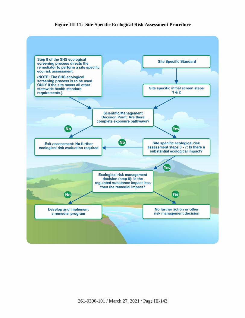
261-0300-101 / March 27, 2021 / Page III-143
Figure III-11: Site-Specific Ecological Risk Assessment Procedure
261-0300-101 / March 27, 2021 / Page IV-i
TABLE OF CONTENTS
SECTION IV: VAPOR INTRUSION ............................................................................................... IV-1 A. Introduction ................................................................................................................................ IV-1 B. Definition and Use of Important Terms ..................................................................................... IV-3 C. Overview of the VI Evaluation Process ..................................................................................... IV-7
1. VI Conceptual Site Model ............................................................................................. IV-7
2. Screening Values and Points of Application (POA) .................................................... IV-10 3. Guidelines for Evaluating VI Using a Combination of Standards ............................... IV-11
D. Preferential Pathway Evaluation .............................................................................................. IV-14 1. External Preferential Pathways .................................................................................... IV-15 2. Significant Foundation Openings ................................................................................ IV-18
E. Use of Proximity Distances ..................................................................................................... IV-21
F. Soil and Groundwater VI Screening ........................................................................................ IV-24 1. Soil and Groundwater Screening Values ..................................................................... IV-24
2. Soil and Groundwater Screening Methods .................................................................. IV-25
G. Alternative VI Assessment Options ......................................................................................... IV-28 1. Soil Gas and Indoor Air Screening Values .................................................................. IV-28 2. Soil Gas and Indoor Air Screening Methods ............................................................... IV-29
3. Vapor Intrusion Modeling............................................................................................ IV-32 H. Mitigation and Activity and Use Limitations .......................................................................... IV-33
I. Remediating and Reassessing the VI Pathway ........................................................................ IV-35 J. Addressing 25 Pa. Code Chapter 250 Requirements ............................................................... IV-36 K. Evaluating the VI Pathway Under the Site-Specific Standard................................................. IV-37
1. Overview ...................................................................................................................... IV-37
2. Preferential Pathway Evaluation .................................................................................. IV-38 3. Use of Proximity Distances ......................................................................................... IV-38 4. Site-Specific Standard VI Screening ........................................................................... IV-38
5. Performing a VI Risk Assessment and Modeling ........................................................ IV-40 6. Mitigation and Remediation ........................................................................................ IV-41
7. Using an OSHA Program to Address VI ..................................................................... IV-41 8. Addressing Chapter 250 Requirements ....................................................................... IV-42
L. References ................................................................................................................................ IV-48
M. Tables ....................................................................................................................................... IV-54
APPENDIX IV-A: METHODOLOGY FOR DEVELOPING SHS VAPOR
INTRUSION SCREENING VALUES ............................................................................................. IV-62
1. Indoor Air..................................................................................................................... IV-62
2. Sub-Slab Soil Gas ........................................................................................................ IV-64
3. Near-Source Soil Gas ................................................................................................... IV-65 4. Soil ............................................................................................................................... IV-65 5. Groundwater ................................................................................................................ IV-67 6. Building Foundation Openings .................................................................................... IV-68 7. Attenuation Factor Summary ....................................................................................... IV-68
APPENDIX IV-B: VAPOR INTRUSION MODELING GUIDANCE ........................................ IV-70 1. Background .................................................................................................................. IV-70 2. Assumptions ................................................................................................................. IV-71
261-0300-101 / March 27, 2021 / Page IV-ii
3. J&E Model Parameter Adjustments ............................................................................. IV-71
4. Site-Specific Standard Parameter Adjustments ........................................................... IV-77
5. Petroleum Hydrocarbons ............................................................................................. IV-78 6. Attenuation Factor Risk Calculations .......................................................................... IV-78 7. Report Contents ........................................................................................................... IV-79
APPENDIX IV-C: VAPOR INTRUSION SAMPLING METHODS .......................................... IV-80 1. Introduction .................................................................................................................. IV-80
a) Applicability .................................................................................................... IV-80 b) Conceptual Site Model Development .............................................................. IV-80 c) Spatial and Temporal Variability Considerations ............................................ IV-80
2. Sampling Locations ..................................................................................................... IV-82 3. Near-Source Soil Gas Sampling .................................................................................. IV-86
a) Description ....................................................................................................... IV-86
b) Sample Point Installation ................................................................................. IV-86 i) Installation of Temporary Points ......................................................... IV-86
ii) Installation and Construction of Semi-Permanent Points .................... IV-87
4. Sub-Slab Soil Gas Sampling ........................................................................................ IV-87 a) Description ....................................................................................................... IV-87 b) Location ........................................................................................................... IV-87
c) Sample Point Installation ................................................................................. IV-87 5. Indoor Air Sampling .................................................................................................... IV-88
a) Sampling Indoor Air ........................................................................................ IV-88 b) Outdoor Ambient Air Sampling....................................................................... IV-89
6. Sampling Soil Gas for Oxygen Content....................................................................... IV-90
7. Sampling Separate Phase Liquids ................................................................................ IV-90
8. Quality Assurance and Quality Control Procedures and Methods .............................. IV-92 a) Sampling Procedures and Methods .................................................................. IV-92
i) Pre-Sampling Survey ........................................................................... IV-92
ii) Sampling Equipment ............................................................................ IV-92 iii) Sampling Point Construction ............................................................... IV-93
iv) Equilibration ........................................................................................ IV-94 v) Leak Testing/Detection for Subsurface Sample Collection ................. IV-94 vi) Purging ................................................................................................. IV-95
vii) Sampling Rates .................................................................................... IV-95 viii) Sample Recordation ............................................................................. IV-96
b) Data Quality Objective (DQO) Process, Sampling and Data
Quality Assessment Process ............................................................................ IV-96 c) QA/QC Samples............................................................................................... IV-96
d) Analytical Methods .......................................................................................... IV-97 e) Data Evaluation ................................................................................................ IV-99
9. Active Sub-Slab Depressurization System Testing ..................................................... IV-99 a) Description ....................................................................................................... IV-99 b) Performance Testing Methods ....................................................................... IV-100
APPENDIX IV-D: OSHA PROGRAM VAPOR INTRUSION CHECKLIST ......................... IV-101
Figure IV-1: VI Screening Value POAs and Vertical Petroleum Proximity Distances ....................... IV-8
Figure IV-2: Representative Process to Evaluate VI with a Combination of Standards .................... IV-12
261-0300-101 / March 27, 2021 / Page IV-iii
Figure IV-3: The Role of an External Preferential Pathway in the VI Evaluation ............................. IV-16
Figure IV-4: Use of Proximity Distances to Evaluate Potential VI Sources ...................................... IV-23
Figure IV-5: Effect of Separate Phase Liquid on the Applicability of Screening Values .................. IV-27 Figure IV-6: Statewide Health Standard Vapor Intrusion Assessment Process ................................. IV-44 Figure IV-7: Site-Specific Standard Vapor Intrusion Assessment Process ........................................ IV-45 Figure IV-8: Process to Determine Site-Specific Standard Vapor Intrusion Screening
Values ............................................................................................................................ IV-46
Figure IV-9: Screening Value Use Restrictions.................................................................................. IV-47 Figure IV-B-1: USDA SCS Soil Classification Chart ........................................................................ IV-75 Figure IV-C-1: Sampling Location Options: Soil and Groundwater Sources ................................... IV-83 Figure IV-C-2: Sampling Location Options: External Preferential Pathway .................................... IV-84 Figure IV-C-3: Sampling Location Options: Significant Foundation Opening................................. IV-85
Table IV-6: Collection of Data for Vapor Intrusion Screening .......................................................... IV-55
Table IV-7: Application of Statewide Health Standard Vapor Intrusion Screening
Criteria ............................................................................................................................. IV-58 Table IV-A-2: Inhalation Risk Variables ............................................................................................ IV-64 Table IV-A-3: Soil Partitioning Parameters ....................................................................................... IV-67 Table IV-A-4: Attenuation Factors ..................................................................................................... IV-69
Table IV-B-1: Adjustable J&E Model Input Parameters and Default Values .................................... IV-72 Table IV-B-2: Pennsylvania Shallow Soil and Groundwater Temperatures ...................................... IV-74
Table IV-B-3: Guidance for the Selection of the J&E Model Soil Type ............................................ IV-75 Table IV-B-4: J&E Model Default Exposure Factors ........................................................................ IV-78 Table IV-C-1: Capillary Fringe Height Estimates .............................................................................. IV-86
Table IV-C-2: SPL Vapor Phase Parameters ...................................................................................... IV-91 Table IV-C-3: Analytical Methods for VOCs in Soil Gas, Indoor and Ambient Air
Samples ........................................................................................................................... IV-98
261-0300-101 / March 27, 2021 / Page IV-1
SECTION IV: VAPOR INTRUSION
A. Introduction
Releases of volatile and some semi-volatile regulated substances to soil or groundwater can
result in vapor-phase intrusion of these regulated substances into indoor air. The resulting
impacts to indoor air may pose a threat to human health in inhabited buildings. For this exposure
pathway to exist there must be a source of volatile substances in the unsaturated zone soil or
groundwater at the water table, current or future inhabited buildings, and a transport pathway
along which vapors may migrate from the source into the inhabited building(s). Inhabited
buildings are buildings with enclosed air space that are used or planned to be used for human
occupancy. In order to properly address this pathway, the remediator first develops a Conceptual
Site Model (CSM) based on the site characterization to guide further assessment and, if
necessary, mitigation or remediation.
This section provides guidance for addressing potential vapor intrusion (VI) of volatile organic
compounds (VOCs) and certain semi-volatile organic compounds (SVOCs) from soil and/or
groundwater sources, including those impacted by separate phase liquid (SPL), into inhabited
buildings at sites using the Statewide health standard (SHS) and the site-specific standard (SSS).
As such, this guidance establishes screening values and assessment options that can be used
under the SHS to address VI for existing or potential future inhabited buildings. The potential
VI impacts from volatile inorganic substances (e.g., mercury and cyanide) can only be addressed
using the SSS or mitigation. The VI screening value tables in this guidance are not meant to
evaluate VI under the SSS except under certain circumstances. Guidance on VI evaluations
under the SSS, including the use of a human health inhalation risk assessment, is provided in
Section IV.K.
25 Pa. Code § 250.312 requires an assessment of the VI exposure pathway in an SHS final report
(FR). An exposure pathway assessment that includes VI is required by 25 Pa. Code § 250.404,
and a risk assessment is required by 25 Pa. Code § 250.405 under the SSS. VI must be addressed
for existing inhabited buildings and undeveloped areas of the property where inhabited buildings
are planned to be constructed in the future. The VI pathway must be addressed for Special
Industrial Area (SIA) sites and for storage tank corrective action sites because cleanups at these
sites ultimately achieve either the SHS or the SSS. A VI evaluation is generally not required for
the background standard.
It is important to note that mitigation measures may be used for existing inhabited
buildings to eliminate unacceptable risks associated with VI under the SHS and SSS at any
time in the evaluation process. Mitigation can be used in lieu of a complete evaluation of
the VI pathway. When choosing preemptive mitigation, the remediator needs to implement
postremediation care to ensure: (1) that potential risks associated with VI will be evaluated
and addressed when an inhabited building is constructed in the future or (2) that
appropriate mitigation measures will be taken in lieu of a complete evaluation in buildings
that exist or are constructed on the property. Mitigation, even if preemptive, requires a
cleanup plan or remedial action plan (RAP). It is also important to note that any
unplanned change to a property’s use that results in a change in the VI exposure pathway
will require additional VI evaluation to account for that change in exposure. In order to
demonstrate attainment of an Act 2 standard for soil and/or groundwater, current or
future planned inhabited buildings need to be evaluated for VI in the FR. If there are no
261-0300-101 / March 27, 2021 / Page IV-2
plans for future construction of inhabited buildings at the site, the remediator may choose,
but is not required, to use an activity and use limitation (AUL) to address possible future
VI issues.
If there is a petroleum release to surface or subsurface soil and a full site characterization has not
been performed, a remediator may attain the SHS by following the requirements in 25 Pa. Code
§ 250.707(b)(1)(iii). Further VI analysis is not needed in these situations for soil if the following
conditions are also satisfied: (1) all requirements of 25 Pa. Code § 250.707(b)(1)(iii) have been
met; (2) at least one soil sample is collected on the sidewall nearest the inhabited building unless
there are substantially higher field instrument readings elsewhere; and (3) contamination has not
contacted or penetrated the building foundation based on observations of obvious contamination
and the use of appropriate field screening instruments. Evaluation of groundwater for
VI potential may still be necessary if groundwater contamination is identified as a potential
VI concern.
The Department will not require remediators to amend or resubmit reports that have been
approved under previous versions of this guidance.
This guidance provides multiple options for addressing VI including soil and groundwater
screening values, alternative assessment options, mitigation with an environmental covenant, and
remediation. The alternative assessment options consist of screening values for indoor air, sub-
slab soil gas, and near-source soil gas in addition to VI modeling. Use of the screening values
and other options as well as important terms is described below.
261-0300-101 / March 27, 2021 / Page IV-3
B. Definition and Use of Important Terms
Several of the terms used in this guidance may have multiple meanings within the context of the
Land Recycling Program (LRP) or other DEP programs. Therefore, it is important that their
intended use in this guidance be well-defined. The following definitions and uses are provided
only for application under this VI guidance. They are presented in the order that allows the
reader to make the best sense of each definition as opposed to alphabetical order.
• Hydrogeologic Zones:
o Definition - When used in this guidance, the following hydrogeologic terms are
related to one another as shown in Figure IV-1. In the saturated zone, all
interconnected voids are filled with water. In practice, the top of the saturated
zone is identified as the water table, which is the water surface at atmospheric
pressure in appropriately constructed monitoring wells. Groundwater refers to
water in the saturated zone, below the water table. The capillary fringe is the
zone of tension saturation directly above the water table and its thickness is
dependent on the soil type in which it occurs. The base of the capillary fringe is
saturated, and soil pore space becomes progressively less filled with water upward
from the water table. In the vadose zone above the capillary fringe the pores are
not filled with water. The capillary fringe and the vadose zone are not readily
distinguished in the field. The unsaturated zone is defined here as the zone above
the water table, including both the capillary fringe and the vadose zone.
o Use - These terms are used to define points of application for various screening
values as shown in Figure IV-1 and applicable sampling intervals for soil,
groundwater and near-source soil gas. They also pertain to the sources, fate, and
transport of vapors in the subsurface.
• Point of Application (POA):
o Definition - The locations in an inhabited building, the unsaturated zone, and the
saturated zone where screening values are applied to evaluate VI.
o Use - POAs guide the selection of indoor air, sub-slab soil gas, near-source soil
gas, soil, and groundwater sampling locations. See Section IV.C.2. The
relationship of the POAs to the building, the hydrogeologic zones, and the
contamination are displayed in Figure IV-1. Sampling guidance for each POA is
provided in Table IV-6 and Appendix IV-C.
• Acceptable Soil or Soil-like Material:
o Definition - Any unconsolidated material containing some amount of organic
material that occurs in the vadose zone above a potential VI source (soil and/or
groundwater) that does not exceed the saturated hydraulic conductivity of sand or
the net air-filled porosity of silt at residual water content, both as derived from
Table 13 in U.S. EPA (2017). Natural soils and fill (including gravel) coarser
than sand or with air-filled porosity greater than silt may not constitute acceptable
soil. Conversely, fill material that is otherwise soil-like and does not exceed the
261-0300-101 / March 27, 2021 / Page IV-4
characteristics described above may constitute acceptable soil-like material
(e.g., mixtures of granular material comprised predominantly of sand, silt and clay
with brick, block and concrete fragments where the granular material occupies
virtually all of the interstitial space between the fragments).
o Use - A minimum of five feet of acceptable soil or soil-like material needs to be
present between a potential VI source and foundation level to permit the use of
the calculated groundwater screening values. The presence of acceptable soil or
soil-like material is also a condition for using vertical proximity distances and
applying separation distances for preferential pathways. Acceptable soil or soil-
like material should NOT exhibit any of the following characteristics:
• obvious contamination by a regulated substance of VI concern
(e.g., staining or odors);
• readings from an appropriate field screening instrument in the headspace
above soil samples that are greater than 100 ppmv;
• evidence of SPL; and
• exceedances of soil screening values.
Material that is suspected to be contaminated (via observation or from field
equipment readings) may be sampled to determine if the soil screening values are
exceeded. If screening values are not exceeded, then that soil can be regarded as
an acceptable soil or soil-like material. Soil does not need to be sampled in areas
beyond where soil has been directly impacted by a release of regulated substances
to demonstrate an acceptable soil or soil-like material. For the purposes of the
petroleum substance vertical proximity distances described below, the
Department further defines acceptable soil or soil-like material as exhibiting
greater than 2% oxygen in soil gas near the building slab.
• Preferential Pathway:
o Definition - A natural or man‐made feature that enhances vapor migration
from a potential VI source to or into an inhabited building. An external
preferential pathway is a channel or conduit that allows for a greater vapor
flux than ordinary diffusion through vadose zone soil. A significant
foundation opening is a breach in a building foundation or basement wall
that may amplify the entry of subsurface vapors.
o Use - A feature must be proximal to both the contamination and a building
and have sufficient volume to be a preferential pathway. A significant
opening in a building foundation, such as a dirt basement floor, can also
act as a preferential pathway. A suspected preferential pathway should be
investigated to determine if it results in an excess VI risk. The presence of
a preferential pathway may preclude the use of proximity distances or
certain screening values. Significant foundation openings may be sealed
to inhibit vapor entry. Additional information regarding how to identify
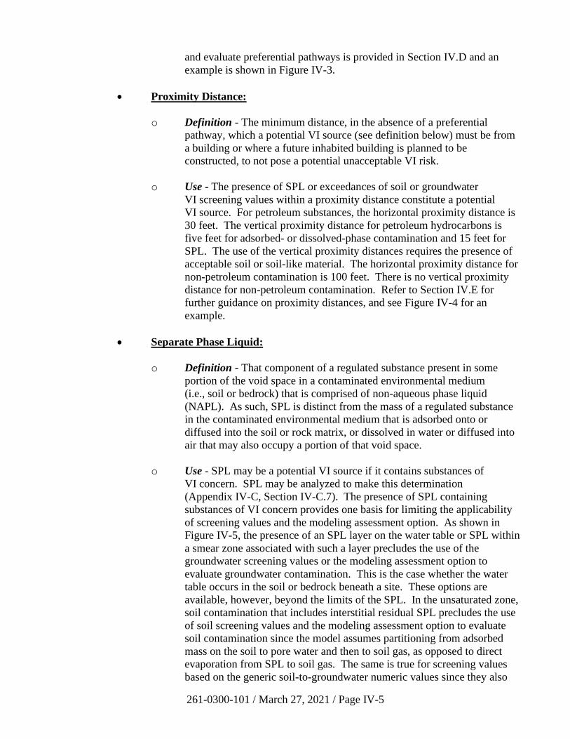
261-0300-101 / March 27, 2021 / Page IV-5
and evaluate preferential pathways is provided in Section IV.D and an
example is shown in Figure IV-3.
• Proximity Distance:
o Definition - The minimum distance, in the absence of a preferential
pathway, which a potential VI source (see definition below) must be from
a building or where a future inhabited building is planned to be
constructed, to not pose a potential unacceptable VI risk.
o Use - The presence of SPL or exceedances of soil or groundwater
VI screening values within a proximity distance constitute a potential
VI source. For petroleum substances, the horizontal proximity distance is
30 feet. The vertical proximity distance for petroleum hydrocarbons is
five feet for adsorbed- or dissolved-phase contamination and 15 feet for
SPL. The use of the vertical proximity distances requires the presence of
acceptable soil or soil-like material. The horizontal proximity distance for
non-petroleum contamination is 100 feet. There is no vertical proximity
distance for non-petroleum contamination. Refer to Section IV.E for
further guidance on proximity distances, and see Figure IV-4 for an
example.
• Separate Phase Liquid:
o Definition - That component of a regulated substance present in some
portion of the void space in a contaminated environmental medium
(i.e., soil or bedrock) that is comprised of non-aqueous phase liquid
(NAPL). As such, SPL is distinct from the mass of a regulated substance
in the contaminated environmental medium that is adsorbed onto or
diffused into the soil or rock matrix, or dissolved in water or diffused into
air that may also occupy a portion of that void space.
o Use - SPL may be a potential VI source if it contains substances of
VI concern. SPL may be analyzed to make this determination
(Appendix IV-C, Section IV-C.7). The presence of SPL containing
substances of VI concern provides one basis for limiting the applicability
of screening values and the modeling assessment option. As shown in
Figure IV-5, the presence of an SPL layer on the water table or SPL within
a smear zone associated with such a layer precludes the use of the
groundwater screening values or the modeling assessment option to
evaluate groundwater contamination. This is the case whether the water
table occurs in the soil or bedrock beneath a site. These options are
available, however, beyond the limits of the SPL. In the unsaturated zone,
soil contamination that includes interstitial residual SPL precludes the use
of soil screening values and the modeling assessment option to evaluate
soil contamination since the model assumes partitioning from adsorbed
mass on the soil to pore water and then to soil gas, as opposed to direct
evaporation from SPL to soil gas. The same is true for screening values
based on the generic soil-to-groundwater numeric values since they also
261-0300-101 / March 27, 2021 / Page IV-6
rely on this partitioning equation. However, near-source soil gas
screening values may be used provided the sampling is performed above
the SPL-impacted soil or groundwater (Figure IV-5). The soil gas version
of the Johnson and Ettinger (J&E) model (Appendix IV-B) may also be
used to evaluate near-source soil gas sampling results under the modeling
assessment option.
• Potential VI Source:
o Definition - Contamination by a regulated substance of VI concern under
any one of the following conditions constitutes a potential VI source:
• in the unsaturated zone, soil exceeding SHS screening values
within proximity distances;
• in the saturated zone, groundwater exceeding SHS screening
values within proximity distances;
• as SPL within proximity distances; and
• associated with a preferential pathway.
o Use - Identifies areas of a site where VI must be addressed through
alternative assessment options, remediation, mitigation, or restrictions
established in an environmental covenant. See Section IV.D and
Figure IV-3 for preferential pathways and Section IV.E and Figure IV-4
for proximity distances. When utilizing the SSS VI evaluation process, a
potential VI source is determined by exceedances of SHS soil and
groundwater screening values (Section IV.K.4.).
261-0300-101 / March 27, 2021 / Page IV-7
C. Overview of the VI Evaluation Process
This guidance offers a flexible VI evaluation process for the SHS and SSS that provides multiple
alternatives to the remediator. Figures IV-6 and IV-7 present flowcharts outlining the process
for each standard, which is described in detail in the following sections. It is important to note
that the purpose of Figures IV-6 and IV-7 is to illustrate how all of the steps in the VI evaluation
process fit together. Figures IV-6 and IV-7 should not be used as your sole guide for performing
a VI evaluation; rather, they should be used in conjunction with the text of this guidance.
The principal steps of a VI evaluation under the SHS (Figure IV-6) are:
• Develop the CSM and assess the presence of preferential pathways;
• Identify potential VI sources from exceedances of soil and groundwater screening values
within proximity distances and/or the occurrence of SPL;
• Utilize alternative assessment options including screening near-source soil gas, sub-slab
soil gas, or indoor air data, or conducting VI modeling;
• Mitigate buildings using activity and use limitations;
• Remediate the soil and/or groundwater contamination and reassess the pathway;
• Address the 25 Pa. Code Chapter 250 SHS requirements.
In most cases, all of the above steps will not be necessary and the remediator is not required to
follow the process sequentially. For instance, buildings with a potentially complete VI pathway
may be mitigated without the collection of soil gas or indoor air data. (See Section IV.K.1. for
an overview of the SSS process.)
If conditions are identified that pose an immediate threat to human health or safety at any
time in the VI evaluation process, prompt interim actions should be taken to protect
human health. Such conditions include, but are not limited to, those that may result in
injury or death resulting from inaction, such as acute toxicity to sensitive receptors (e.g.,
fetal cardiac malformations from TCE exposure (U.S. EPA, 2011a)), a fire or explosion
hazard, or atmospheres that cause marked discomfort or sickness.
1. VI Conceptual Site Model
The VI CSM is central to the VI evaluation. The CSM is a representation of contaminant
sources, migration pathways, exposure mechanisms, and potential receptors. The CSM
drives the design of a sampling plan (Appendix IV-C), and as the CSM is revised, data
gaps may be identified that will guide further sampling. The CSM is also a prerequisite
for VI modeling (Appendix IV-B). The source description and contaminants of concern
are components of the CSM supported by soil, groundwater, and possibly near-source
soil gas data. The CSM development may also rely on sampling the vapor migration
pathway (sub-slab soil gas) or receptor exposures (indoor air).
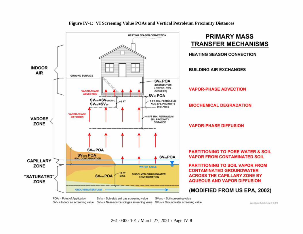
261-0300-101 / March 27, 2021 / Page IV-8
Figure IV-1: VI Screening Value POAs and Vertical Petroleum Proximity Distances
261-0300-101 / March 27, 2021 / Page IV-9
The goal of the VI CSM is to describe how site characteristics, such as subsurface and
building conditions, might influence both the distribution of substances of VI concern in
soil gas and the potential indoor air quality of structures in the vicinity of a soil or
groundwater source of substances of VI concern. Concentrations of substances of
VI concern in soil gas attenuate, or decrease, as the substances of VI concern move away
from the source, through the soil, through the foundation, and into indoor air. The extent
of attenuation is related to site conditions, building characteristics, and chemical
properties. The soil vapor attenuation is quantified in terms of an attenuation factor
defined as the ratio of indoor air concentration to source vapor concentration
(Appendix IV-A).
The level of detail of the CSM should be tailored to the complexity of the site, the
available data and the selected Act 2 remedial standard. For the VI pathway, complex
relationships exist among the many factors that influence VI. Hence, multiple lines of
evidence are often used to evaluate risks associated with the vapor pathway. Finally, it
should be remembered that the CSM is a dynamic tool to be updated as new information
becomes available during site characterization.
Some important elements of the VI CSM are included in the list below (California EPA,
2011a; Massachusetts DEP, 2011; U.S. EPA, 2012a, 2015a; Hawaii DoH, 2014). Some
elements may not be known or pertinent to the case, and this does not imply a deficient
CSM.
• Sources of contamination—origins, locations, substances, and concentrations;
presence of SPL
• Transport mechanisms—route from source to indoor air, potential preferential
pathways
• Subsurface and surface characteristics—soil type, depth to bedrock,
heterogeneities; ground cover
• Groundwater and soil moisture—depth to water, water level changes, capillary
fringe thickness, perennial clean water lens
• Fate and transport—biodegradation of petroleum hydrocarbons, transformation of
substances into regulated daughter products
• Weather—precipitation, barometric pressure changes, wind, frozen ground
• Building construction—basement, slab on grade, or crawl space; a garage that is
open to the atmosphere in between the ground surface and the occupied areas
• Foundation openings—cracks, gaps, sumps, French drains, floor drains
• Building heating and ventilation
• Background sources—indoor air contaminants, ambient air pollution
261-0300-101 / March 27, 2021 / Page IV-10
• Receptor types—residential, nonresidential, sensitive receptors; potential future
development
2. Screening Values and Points of Application (POA)
SHS screening values for regulated substances of VI concern are published in
Tables IV-1 through IV-5 for soil, groundwater, near-source soil gas, sub-slab soil gas
and indoor air. These tables can be accessed on the VI page of the LRP website.
Separate screening values are provided in these tables for residential and nonresidential
uses of potentially affected inhabited buildings. In addition, there are two distinct
nonresidential building categories: “nonresidential” and “converted residential.” The
first category refers to buildings constructed for nonresidential use, and the
second category refers to buildings that presently have a purely nonresidential use
although they were originally constructed for residential use. An example is a dentist’s
office in a converted home. The converted residential screening values are based on
attenuation factors representative of residential structures but exposure factors for
nonresidential settings. When a building has both residential and nonresidential uses
(e.g., apartments over a retail store), the remediator may need to evaluate VI with both
residential and nonresidential screening values.
The remediator should determine which structures at a site are inhabited and intended for
human occupancy. Structures that are not routinely occupied, such as storage sheds or
confined spaces, are not considered inhabited buildings. Structures that are not fully
enclosed (e.g., carports, shelters) are also not inhabited buildings. Basements are
generally regarded as an occupied space in a building; crawl spaces are not regarded as
occupied space.
The POA for each of the screening values is shown on Figure IV-1. Groundwater
screening values (SVGW) apply within the zone of groundwater saturation that will
exhibit concentrations of regulated substances representative of concentrations at the
water table. This is an interval within ten feet or less of the water table. Soil screening
values (SVSOIL) apply throughout the volume of contaminated soil in the unsaturated
zone. Near-source soil gas screening values (SVNS) apply just above an unsaturated
zone soil VI source and just above the capillary fringe for a groundwater VI source.
Near-source soil gas screening is also applicable to a preferential pathway, except in
some cases if it penetrates the building foundation (Section IV.D). Sub-slab soil gas
screening values (SVSS) apply immediately below the slab of a building potentially
impacted by VI, whether the building has a basement or is slab-on-grade construction.
Finally, indoor air screening values (SVIA) apply in the lowest occupied space of a
potentially impacted building.
Screening values cannot be calculated for substances that have no inhalation toxicity data
(Appendix A). Therefore, SHS and SSS VI evaluations are not required for substances
without screening values. However, the remediator could choose to address the
VI pathway by demonstrating that the concentrations for such substances are below
practical quantitation limits (PQLs) or by installing a mitigation system. If soil
concentrations are less than generic soil-to-groundwater numeric values and groundwater
concentrations are less than used aquifer medium-specific concentrations (MSCs), then
261-0300-101 / March 27, 2021 / Page IV-11
there is no potential VI source. In addition, proximity distances are applicable to
substances that do not have screening values (see Section IV.E). The remediator could
also evaluate VI using the SSS by developing toxicity values or utilizing published
information (§ 250.605).
Table IV-6 summarizes data collection conditions for VI screening and how to apply the
POAs. Methods for VI screening are described in Sections IV.F and IV.G and in
Table IV-7. Appendix IV-A describes the methodology for developing the screening
values. SSS screening is explained in Section IV.K.
3. Guidelines for Evaluating VI Using a Combination of Standards
The VI pathway can be evaluated under the SHS, the SSS or a combination of both
standards. When using a combination of standards, the VI pathway must be evaluated
along with all of the other requirements of each standard being used. The screening
values presented in Tables IV-1 through IV-5 were designed to be used only when
attaining the SHS. However, under specific circumstances, adjusted SHS VI screening
values can be used when evaluating VI under the site-specific standard. See
Section IV.K.4 for additional detail on using screening values under the SSS.
The VI pathway must be assessed to satisfactorily attain the SHS for soil and
groundwater (see 25 Pa. Code § 250.312(a)). Under the SHS, a remediator cannot
evaluate the VI pathway without also evaluating soil and/or groundwater because Act 2
does not define indoor air or soil gas as environmental media. However, when using a
combination of standards, a remediator can, for instance, evaluate soil under the SHS and
groundwater under the SSS then separately evaluate VI entirely under the SSS. This is
permissible because the SSS evaluates individual exposure pathways and Act 2 considers
VI to be an exposure pathway, not an environmental medium. Under the SSS, a risk
assessment is needed to evaluate the VI pathway if pathway elimination is not being
used. The SHS does not evaluate individual exposure pathways separately so
remediators cannot evaluate the VI pathway under the SHS if soil and groundwater are
being evaluated under the SSS. The remediator may also choose to evaluate VI for each
substance and medium using the process for the corresponding standard. Figure IV-2
shows how to treat substances independently with a combination of standards.
When using VI modeling under the SHS, the desired output is a predicted indoor air
concentration (Appendix IV-B). This modeled concentration should be used in the
evaluation of VI by comparing it to the associated indoor air screening value. The J&E
model (U.S. EPA, 2017) also calculates risk values which should not be used for SHS
evaluations. Use of risk calculations to evaluate VI is considered to be a risk assessment,
which is a tool to be used under the SSS and is subject to additional reporting
requirements and fees. If calculated risk values are used in the VI analysis, it will be
assumed that the site is being remediated under a combination of standards and all
associated fees and requirements of both standards will apply.
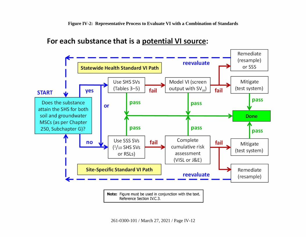
261-0300-101 / March 27, 2021 / Page IV-12
Figure IV-2: Representative Process to Evaluate VI with a Combination of Standards
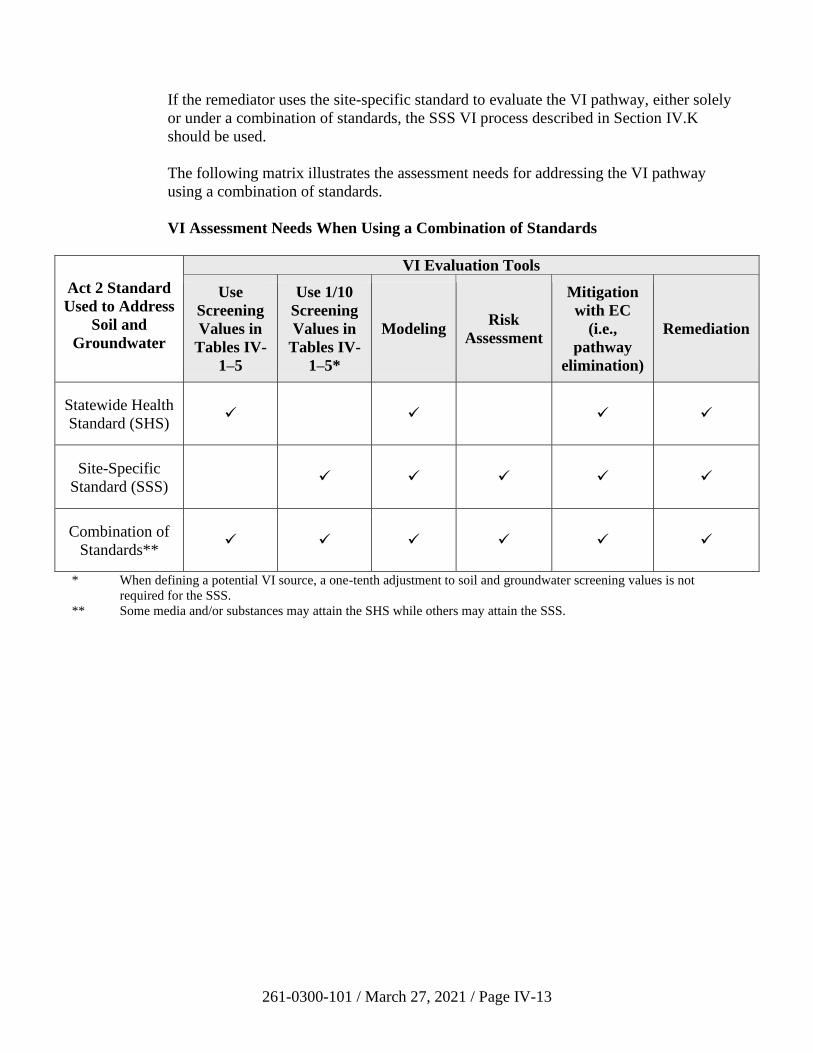
261-0300-101 / March 27, 2021 / Page IV-13
If the remediator uses the site-specific standard to evaluate the VI pathway, either solely
or under a combination of standards, the SSS VI process described in Section IV.K
should be used.
The following matrix illustrates the assessment needs for addressing the VI pathway
using a combination of standards.
VI Assessment Needs When Using a Combination of Standards
Act 2 Standard
Used to Address
Soil and
Groundwater
VI Evaluation Tools
Use
Screening
Values in
Tables IV-
1–5
Use 1/10
Screening
Values in
Tables IV-
1–5*
Modeling Risk
Assessment
Mitigation
with EC
(i.e.,
pathway
elimination)
Remediation
Statewide Health
Standard (SHS) ✓
✓ ✓ ✓
Site-Specific
Standard (SSS)
✓ ✓ ✓ ✓ ✓
Combination of
Standards** ✓ ✓ ✓ ✓ ✓ ✓
* When defining a potential VI source, a one-tenth adjustment to soil and groundwater screening values is not
required for the SSS.
** Some media and/or substances may attain the SHS while others may attain the SSS.
261-0300-101 / March 27, 2021 / Page IV-14
D. Preferential Pathway Evaluation
A preferential pathway is a feature that increases the rate of vapor migration between a source
and an inhabited building (see definition in Section IV.B). DEP defines two classes of
preferential pathways. An external preferential pathway is a channel or conduit that allows for
a greater vapor flux than ordinary diffusion through vadose zone soil (Figure IV-3). Significant
foundation openings are breaches in the building foundation and basement walls that may
enhance the entry of subsurface vapors. (Typical cracks, gaps, and utility line penetrations are
not generally significant foundation openings; see Section IV.D.2.) The presence and
significance of these features should be identified whenever possible during CSM development
(Section IV.C.1.). When building access is not possible, other preferential pathway assessment
and investigation techniques should be used, when available, to complete the CSM. Guidance
for assessing and investigating external preferential pathways and significant foundation
openings is provided in Sections IV.D.1. and IV.D.2., respectively. Guidance for using
screening values when external preferential pathways and significant foundation openings are
present is provided in Sections IV.F and IV.G.
Some recognized instances of preferential pathways include the following.
• An external preferential pathway that does not penetrate the building foundation.
External preferential pathways can impact buildings through VI even if they do not
penetrate the building foundation. If the external preferential pathway is not fully
enclosed, vapors can migrate into a building via typical cracks and gaps in building
foundations. An example is permeable backfill material (e.g., gravel or sand) around a
utility line close to a building slab or a basement wall. The vapors can travel through the
backfill material and then migrate through soil into the building via typical cracks and
gaps in the building foundation. If a utility trench is backfilled with native soil, then it is
unlikely to act as a preferential pathway. Another example is a drain line or cracked
sewer pipe (Guo et al., 2015). Water will travel through the line, but vapors can escape
through cracks in the pipe and can migrate through soil into a building. Natural features
such as open bedrock fractures could also transport vapors near a building.
• A conduit (external preferential pathway) that enters the building. This is when a
utility line itself, not the backfill material, acts as a conduit for vapors. For example,
liquid- and vapor-phase contamination can enter breaks in sewer and drain lines,
permitting vapors to pass into buildings through failed plumbing components (Jarvela et
al., 2003; Pennell et al., 2013).
• A significant foundation opening without an external preferential pathway. In this
case, vapors migrate by diffusion through soil from the source to the building. All
building foundations have minor cracks and gaps, but if there is a large opening—such as
a dirt basement floor—then that opening will amplify the flux of vapors into indoor air.
Sealing the opening(s) (e.g., pouring a concrete slab over the dirt floor) can eliminate the
preferential pathway.
• A combination of an external preferential pathway with a significant opening. For
example, vapors may migrate through gravel backfill around a utility line and then flow
through a gap where the line penetrates the foundation. Sealing the gap would resolve
VI through the significant opening but not the role of the external preferential pathway.
261-0300-101 / March 27, 2021 / Page IV-15
Reasonable effort should be made to determine whether external preferential pathways or
significant foundation openings are present. It is recommended that remediators discuss how
they plan to evaluate external preferential pathways and significant foundation openings with
their Department Project Officer to ensure that all parties agree on the proposed approach.
As described later in this guidance, a preferential pathway may be eliminated by appropriate site
remediation or mitigation actions.
1. External Preferential Pathways
Utility corridors and pipes are potential external preferential pathways common to most
sites (U.S. EPA, 2015a, Sections 5.4, 6.3.2). When a preferential pathway is external to a
building, the proximity distances to a source area (as described in Section IV.E) are
insufficient to eliminate the source from consideration because proximity distances are
based on the movement of vapors, and associated attenuation, through soil. Therefore, an
area of contamination that exceeds screening values beyond a proximity distance from a
building may be a potential VI source when an external preferential pathway is present
(Figure IV-3). Heightened attention should be paid to external preferential pathways
which may contain SPL.
For a subsurface feature that is external to a building, the following conditions allow it to
be excluded as an external preferential pathway:
• Soil and groundwater contamination exceeding VI screening values is at least
30 horizontal or five vertical feet from the feature, and any SPL is at least
30 horizontal or 15 vertical feet from the feature; OR
• The feature is at least five feet away from the building foundation.
To exclude a feature as a preferential pathway, soil between the subsurface feature and
the building foundation within the separation distances specified above should consist of
acceptable soil or soil-like material. (For SPL, a minimum of five vertical feet of
acceptable soil or soil-like material should be present within the overall 15-foot minimum
separation.) As an example, consider an area of contaminated soil exceeding screening
values which is beyond the horizontal proximity distance from a building. If a high-
permeability backfilled trench passes through the soil contamination and near the
building, but six feet of acceptable soil or soil-like material is present between the trench
and the building foundation, then no further VI analysis would be necessary.
Figure IV-3 illustrates the evaluation of a potential external preferential pathway
associated with a release from an underground storage tank (UST). (The assessment
described here is not limited to USTs or petroleum hydrocarbons.) As shown in the
separate map and side views, the distribution of contamination relative to the preferential
pathway is important both horizontally and with depth. Zone A, shown in both views, is
the volume of contaminated media identified in the site characterization. In the map
view, the contamination in Zones B and C exceeds the soil and/or groundwater screening
values, but these areas are beyond the horizontal proximity distance from the building.
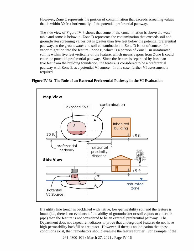
261-0300-101 / March 27, 2021 / Page IV-16
However, Zone C represents the portion of contamination that exceeds screening values
that is within 30 feet horizontally of the potential preferential pathway.
The side view of Figure IV-3 shows that some of the contamination is above the water
table and some is below it. Zone D represents the contamination that exceeds soil and
groundwater screening values but is greater than five feet below the potential preferential
pathway, so the groundwater and soil contamination in Zone D is not of concern for
vapor migration into the feature. Zone E, which is a portion of Zone C in unsaturated
soil, is within five feet vertically of the feature, which means vapors from Zone E could
enter the potential preferential pathway. Since the feature is separated by less than
five feet from the building foundation, the feature is considered to be a preferential
pathway with Zone E as a potential VI source. In this case, further VI assessment is
required.
Figure IV-3: The Role of an External Preferential Pathway in the VI Evaluation
If a utility line trench is backfilled with native, low-permeability soil and the feature is
intact (i.e., there is no evidence of the ability of groundwater or soil vapors to enter the
pipe) then the feature is not considered to be an external preferential pathway. The
Department does not expect remediators to prove that underground features do not have
high-permeability backfill or are intact. However, if there is an indication that these
conditions exist, then remediators should evaluate the feature further. For example, if the
261-0300-101 / March 27, 2021 / Page IV-17
underground feature is the trench for a large diameter water line which is likely to be
backfilled with gravel, it should be considered to be a potential external preferential
pathway. If the underground feature is a small diameter fiber optic line, it is likely to
have native soil backfill and the remediator could work under the assumption that it is not
an external preferential pathway.
The Department recommends a progressive approach to evaluating external preferential
pathways. The investigation can include sampling at the source (soil, groundwater, SPL,
near-source soil gas), within the preferential pathway (soil gas or vapor), under the
building (sub-slab soil gas), and within the building (indoor air). If a series of buildings
is associated with one underground feature (e.g., a sewer line servicing multiple buildings
along a street), then the buildings closest to the vapor source should be evaluated first. If
it is determined that there are no VI concerns with the first building along the potential
preferential pathway, then it is generally not necessary to evaluate the rest of the
buildings along the line since they are increasingly farther away from the source.
Access to buildings is not always necessary for the evaluation of external preferential
pathways because much of the pertinent information relates to their condition outside of
the building. Examples of non-intrusive investigation techniques include a visual
inspection of the exterior of the property for utility line entry points, an inspection of
nearby streets and sidewalks for signs of underground utility lines and vaults, a
Pennsylvania One Call notification, or a review of building plans.
The following recommendations pertain to assessing and screening external preferential
pathways. (See Appendix IV-C, Figure IV-C-2 for an illustration.) The evaluation is
described in terms of VI screening, but the remediator may also use the data with
appropriate attenuation factors (Appendix IV-A) to carry out an SSS risk assessment
(Section IV.K.5.). This is not a checklist of required evaluations; rather, if any of the
following items is satisfied such that screening values or risk thresholds are not exceeded,
then other items do not need to be examined.
• Use of soil and groundwater screening values – Contamination in the source
area may be screened using soil and groundwater screening values unless SPL is
present or contaminated groundwater enters the preferential pathway.
Groundwater that is within a preferential pathway may be screened with used
aquifer MSCs.
• Use of indoor air modeling – The default model for predicting indoor air
concentrations (see Appendix IV-B) using soil, groundwater, or soil gas data may
be used in the absence of an external preferential pathway. The default model
should not be used if an external preferential pathway is present because this
model is based on the diffusion of vapors through soil.
• Use of near-source soil gas screening values – If contaminated groundwater or
SPL does not enter the preferential pathway, then near-source soil gas samples
may be collected in the source area and the data screened with near-source soil
gas screening values. Near-source soil gas data can also be screened against sub-
slab soil gas screening values if an external preferential pathway or significant
foundation opening is present or if a potential VI source is less than five feet
261-0300-101 / March 27, 2021 / Page IV-18
below foundation level (see Section IV.G). This option is not available if the
source is less than five feet below grade.
• Soil gas sampling within a preferential pathway – Soil gas samples may be
collected in the preferential pathway (e.g., within trench backfill) between the
source area and the building. These are not near-source soil gas samples
(Section IV.G). They should be collected at a depth of at least 5 feet if the area is
not paved and satisfy the other soil gas sampling criteria in this guidance
(Table IV-6, Appendix IV-C). The data may be screened with sub-slab screening
values.
• Sampling within a sewer line – If the preferential pathway is a sewer line or
similar enclosed conduit that contains contamination, then the remediator may
consider analysis of SPL, water, and vapor in the line. Flows and concentrations
are likely to be highly variable, and there can be other sources of contamination in
sewer lines. For these reasons, such sampling can be used as an informational
line of evidence but not for screening.
• Sub-slab sampling – If the preferential pathway does not penetrate the
foundation (e.g., trench backfill without a significant opening or a conduit that
does not enter the building), then sub-slab samples through the foundation may be
obtained (Section IV.G). This data may be screened with sub-slab screening
values.
• Sealed utility penetrations – If the preferential pathway does penetrate the
building, then the remediator should examine potential entry routes to indoor air.
The basement or slab should be inspected for significant openings; foundation
openings can be sealed (see Section IV.D.2.). If vapors travel within a sewer or
drain line, then plumbing components could be inspected for integrity and
repaired if necessary. Sampling should be performed to demonstrate that the
pathway is incomplete, and this may require indoor air sampling.
• Indoor air sampling – Indoor air may be sampled at any time when there is an
external preferential pathway, and the data may be screened with indoor air
screening values (Section IV.G).
2. Significant Foundation Openings
Significant openings internal to a building’s structure, such as a dirt basement floor, may
enhance vapor entry (U.S. EPA, 2015a, Sections 2.3, 6.5.2). Typical cracks, gaps, and
utility line penetrations on their own are generally not considered to be significant
openings. In fact, all foundations, even new ones, will have these minor openings which
will permit the ingress of some vapors if a potential VI source or an external preferential
pathway comes close to a building foundation. Common foundation openings such as
sealed sumps, French drains, and floor drains are not necessarily significant openings.
261-0300-101 / March 27, 2021 / Page IV-19
Significant foundation openings will have any one of the following characteristics.
• The combined area of openings in the foundation surface is more than
five percent of the total foundation surface area (Appendix IV-A).
• There are direct indications of contaminant entry into the building through
openings, such as seepage of SPL or contaminated groundwater, chemical odors,
or elevated readings on a field screening instrument.
• An opening is connected directly to an external preferential pathway; for instance,
a gap around a utility line penetration permits unimpeded vapor entry from the
permeable backfill in the utility line trench.
The most effective way to evaluate a building for significant foundation openings is to
gain access to the building and visually inspect the foundation and basement walls for
utility penetrations and overall foundation condition. Remediators should try to access
buildings whenever possible so that they can get the best possible information when
evaluating significant foundation openings. However, visual inspections are not always
possible. Sometimes property owners do not grant access to buildings. It is also possible
for finished basements to have coverings on walls and floors (e.g., paneling, carpet, etc.)
making openings difficult to see. If the remediator cannot gain access to a building to
inspect for significant foundation openings, there are several assessment options
presented below that do not require building access.
The Department recommends sealing significant foundation openings to inhibit the
pathway (U.S. EPA, 2008, Section 3.2). Proper sealing should be done with durable
materials as a long-term solution such that the former openings are no more transmissive
to vapors than the rest of the foundation. Although sumps, when dry, are not generally
considered to be significant openings, if a sump contains contaminated groundwater it
may need to be sealed. Sealing openings is a building repair and is therefore not
considered an activity and use limitation.
The recommendations listed below concern the assessment and screening of significant
foundation openings. (See Appendix IV--C, Figure IV-C-3 for an illustration.) The
evaluation is described in terms of VI screening, but the remediator may also use the data
with appropriate attenuation factors (Appendix IV-A) to carry out an SSS risk assessment
(Section IV.K.5.). Unless otherwise noted, the methods below cannot be used if
contaminated soil, groundwater, or SPL is present within the building. This is not a
checklist of required evaluations; rather, if any of the following items is satisfied such
that screening values or risk thresholds are not exceeded, then other items do not need to
be examined.
Options to assess significant foundation openings that do not require building access
include the following.
• If there is no external preferential pathway, then the horizontal proximity
distances discussed in Section IV.E are applicable to the potential VI source.
Vertical proximity distances do not apply because they are based on attenuation
across an intact slab.
261-0300-101 / March 27, 2021 / Page IV-20
• Soil data may be screened using generic soil-to-groundwater numeric values.
Groundwater data may be screened with used aquifer MSCs. These screening
values are acceptable even if contaminated soil or groundwater is present inside
the building.
• Near-source soil gas samples may be collected in the source area. This data
should be screened with sub-slab screening values or modeled.
• Modeling of soil, groundwater, or near-source soil gas data may be performed by
assuming that no slab is present as a conservative scenario (as described in
Appendix IV-B).
Options to assess significant foundation openings when building access is available and
possible include the following.
• Sub-slab soil gas samples may be obtained if the building does not have a dirt
floor. Sub-slab data should be screened with indoor air screening values.
• If foundation openings are sealed, then soil and groundwater data may be
screened with standard screening values, near-source soil gas data may be
screened with near-source soil gas screening values, and sub-slab soil gas data
may be screened with sub-slab screening values (Sections IV.F and IV.G).
• Indoor air screening can be used at any time, even when contaminated soil,
groundwater, or SPL is present within the building.
261-0300-101 / March 27, 2021 / Page IV-21
E. Use of Proximity Distances
The remediator may use horizontal and vertical proximity distances from existing or planned
future inhabited buildings to identify potential VI sources (Figure IV-6). To accomplish this
step, existing and/or future inhabited buildings are located and proximity distances from each of
these buildings are delineated. Then, relying on the results of site characterization and/or
postremediation sampling, any areas of contaminated groundwater at the water table and
volumes of contaminated unsaturated zone soil that exceed applicable screening values within a
proximity distance from an existing or future inhabited building are identified (Figure IV-4).
Areas of SPL and areas predicted to exceed the screening values in a fate-and-transport analysis
are identified. If there is no SPL present or soil or groundwater screening values are not
exceeded within these proximity distances, then no VI sources are present to address under the
SHS.
If there is contamination both within a proximity distance (e.g., Figure IV-4) and near a potential
preferential pathway (e.g., Figure IV-3), then the remediator evaluates each area of
contamination separately. There may be potential VI sources in both locations. The process
outlined in Figure IV-6 would be repeated for each area of contamination and each potential
vapor migration route. The use of proximity distances should also account for future plume
migration as determined in a fate-and-transport analysis.
A proximity distance is the distance between an existing or future inhabited building and
contaminated groundwater or soil within which VI could pose a risk. Proximity distances are a
function of the mobility and persistence of the chemical as well as, in the case of petroleum
substances, the depth of the source and the characteristics of the subsurface materials. There are
distinct proximity distances for petroleum and non-petroleum regulated substances:
• For contamination associated with non-petroleum substances present in soil and/or
groundwater, a horizontal proximity distance of 100 feet applies between the building
and SPL or soil or groundwater screening value exceedances; and
• For soil and/or groundwater contamination associated with petroleum substances and
related hydrocarbons, a horizontal proximity distance of 30 feet and a vertical proximity
distance of five feet apply between the building and soil or groundwater screening value
exceedances. For petroleum SPL, a further vertical proximity distance of 15 feet applies
between the SPL and foundation level.
A vertical proximity distance is not applicable for non-petroleum substances. Proximity
distances are based on the attenuation of vapors caused by diffusion through soil. A
non-petroleum vertical proximity distance would be deeper than bedrock and groundwater at
many sites, and it would not account for vapor advection through fractures.
Note: The petroleum proximity distances apply to any petroleum substance, not just the
hydrocarbons listed on the Petroleum Short List from the LRP Technical Guidance Manual.
(Note that 1,2-dibromoethane, 1,2-dichloroethane, and MTBE are not petroleum hydrocarbons.)
Petroleum substances are either aliphatic or aromatic compounds. Aliphatic compounds are
composed of straight-chained, branched, or cyclic compounds and can be saturated (alkanes) or
unsaturated (alkenes, alkynes, and others). Aromatic compounds have one or more conjugated,
benzene or heterocyclic rings within their structures.
261-0300-101 / March 27, 2021 / Page IV-22
Petroleum substances are treated differently than non-petroleum substances in setting proximity
distances because their high rates of biodegradation play a key role in diminishing the effects of
VI (U.S. EPA, 2013, 2015b; ITRC, 2014). Petroleum hydrocarbons typically biodegrade under
both anaerobic and aerobic conditions, with aerobic degradation occurring much more rapidly.
Since soil oxygen content is generally higher in surface and shallow sub-surface soils, vapors
from petroleum hydrocarbons biodegrade rapidly as they migrate upward through the soil
column, reducing their concentrations prior to migrating into inhabited buildings. The
Department defines an acceptable soil or soil-like material as having greater than 2% oxygen for
purposes of applying proximity distances for petroleum substances. Measurement of soil oxygen
content is not required unless there is reason to believe the soil is anaerobic (see Appendix IV-C
for a recommended methodology). For instance, in the case of a large SPL plume or a large
building overlying SPL, oxygen may be depleted and the 15-foot vertical proximity distance
might not be protective for VI.
If only petroleum substances have been detected, the remediator determines the horizontal and
vertical distance of the building foundation to the groundwater plume or soil contamination. If a
current or future inhabited building is greater than or equal to 30 horizontal feet from an area of
petroleum substance SPL or screening value exceedance, then there is adequate distance for
aerobic biodegradation to occur to reduce the vapor concentrations to acceptable levels.
Likewise, if there is greater than or equal to five feet of acceptable soil or soil-like material
vertically between the bottom of a current and/or future inhabited building foundation and the
top of the dissolved phase contaminated groundwater plume or unsaturated zone area of soil
petroleum screening value exceedance, then there is adequate distance for biodegradation to
occur to reduce the vapor concentrations to acceptable levels. The minimum vertical proximity
distance is 15 feet for petroleum SPL, at least five feet of which should be acceptable soil or soil-
like material. Vertical distances are calculated using the maximum groundwater elevation and
the top of the measured or inferred SPL (smear zone or residual NAPL). If neither the horizontal
nor vertical proximity condition is met, the remediator must evaluate VI further.
An example of the application of proximity distances is shown in Figure IV-4. (The assessment
described here is not limited to USTs or petroleum hydrocarbons.) Zone A is the area of
contamination identified in the site characterization. Zones B and C include groundwater
contamination that exceeds screening values, and Zone G represents the horizontal proximity
distance from Zones B and C. Zone C is the area within the horizontal proximity distance from
the existing building, so it is the only portion of groundwater contamination that could pose a
VI problem. Therefore, Zone C is a potential VI source, at least for non-petroleum substances,
that requires additional assessment.
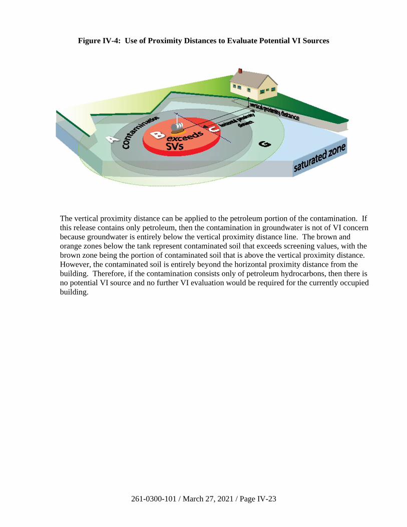
261-0300-101 / March 27, 2021 / Page IV-23
Figure IV-4: Use of Proximity Distances to Evaluate Potential VI Sources
The vertical proximity distance can be applied to the petroleum portion of the contamination. If
this release contains only petroleum, then the contamination in groundwater is not of VI concern
because groundwater is entirely below the vertical proximity distance line. The brown and
orange zones below the tank represent contaminated soil that exceeds screening values, with the
brown zone being the portion of contaminated soil that is above the vertical proximity distance.
However, the contaminated soil is entirely beyond the horizontal proximity distance from the
building. Therefore, if the contamination consists only of petroleum hydrocarbons, then there is
no potential VI source and no further VI evaluation would be required for the currently occupied
building.
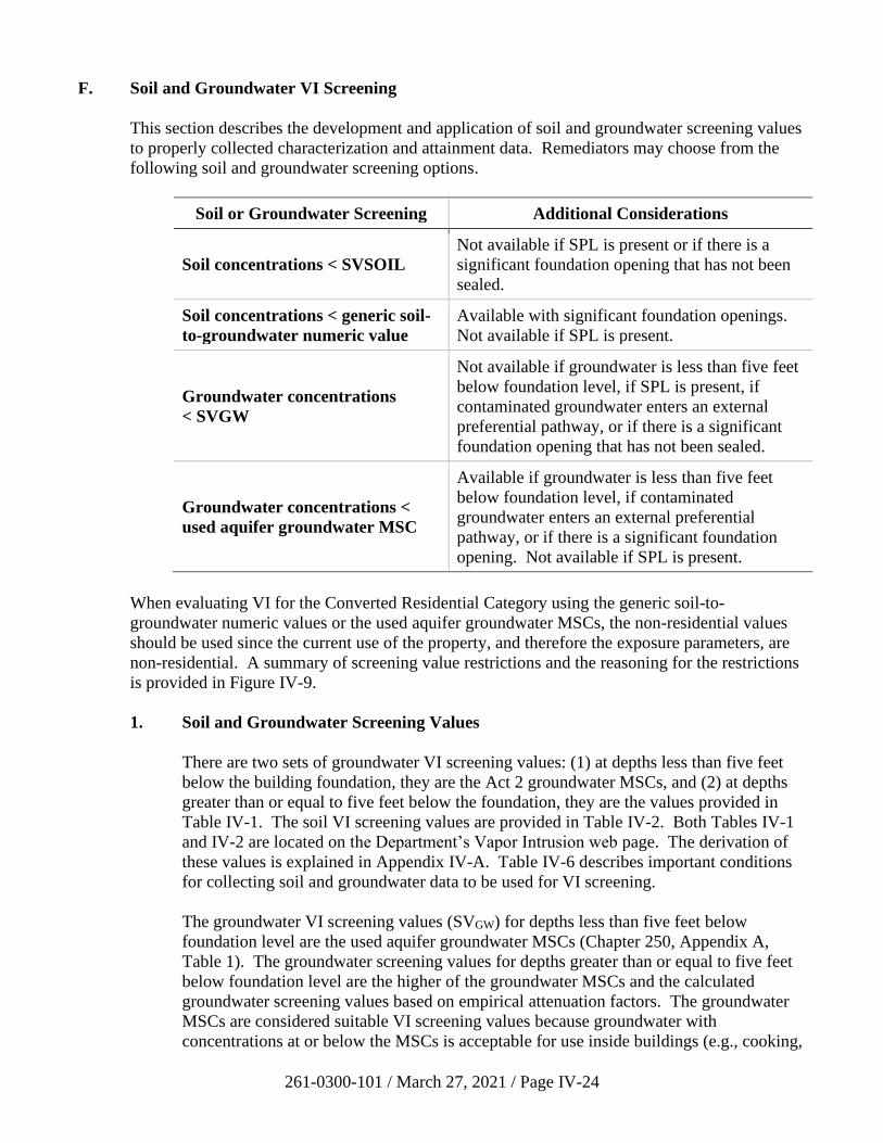
261-0300-101 / March 27, 2021 / Page IV-24
F. Soil and Groundwater VI Screening
This section describes the development and application of soil and groundwater screening values
to properly collected characterization and attainment data. Remediators may choose from the
following soil and groundwater screening options.
Soil or Groundwater Screening Additional Considerations
Soil concentrations < SVSOIL
Not available if SPL is present or if there is a
significant foundation opening that has not been
sealed.
Soil concentrations < generic soil-
to-groundwater numeric value
Available with significant foundation openings.
Not available if SPL is present.
Groundwater concentrations
< SVGW
Not available if groundwater is less than five feet
below foundation level, if SPL is present, if
contaminated groundwater enters an external
preferential pathway, or if there is a significant
foundation opening that has not been sealed.
Groundwater concentrations <
used aquifer groundwater MSC
Available if groundwater is less than five feet
below foundation level, if contaminated
groundwater enters an external preferential
pathway, or if there is a significant foundation
opening. Not available if SPL is present.
When evaluating VI for the Converted Residential Category using the generic soil-to-
groundwater numeric values or the used aquifer groundwater MSCs, the non-residential values
should be used since the current use of the property, and therefore the exposure parameters, are
non-residential. A summary of screening value restrictions and the reasoning for the restrictions
is provided in Figure IV-9.
1. Soil and Groundwater Screening Values
There are two sets of groundwater VI screening values: (1) at depths less than five feet
below the building foundation, they are the Act 2 groundwater MSCs, and (2) at depths
greater than or equal to five feet below the foundation, they are the values provided in
Table IV-1. The soil VI screening values are provided in Table IV-2. Both Tables IV-1
and IV-2 are located on the Department’s Vapor Intrusion web page. The derivation of
these values is explained in Appendix IV-A. Table IV-6 describes important conditions
for collecting soil and groundwater data to be used for VI screening.
The groundwater VI screening values (SVGW) for depths less than five feet below
foundation level are the used aquifer groundwater MSCs (Chapter 250, Appendix A,
Table 1). The groundwater screening values for depths greater than or equal to five feet
below foundation level are the higher of the groundwater MSCs and the calculated
groundwater screening values based on empirical attenuation factors. The groundwater
MSCs are considered suitable VI screening values because groundwater with
concentrations at or below the MSCs is acceptable for use inside buildings (e.g., cooking,
261-0300-101 / March 27, 2021 / Page IV-25
showering, cleaning, etc.). The maximum groundwater elevation should be compared to
the 5-ft. depth criterion when selecting the applicable groundwater SVs (Table 1 or
MSCs). Because the water table elevation changes over time, the VI investigation should
recognize that soil in the intermittently saturated zone may be a VI source.
The soil VI screening values (SVSOIL) are the higher of the generic soil-to-groundwater
numeric values (Chapter 250, Appendix A, Table 3B) and calculated soil screening
values. Soil screening values may be applied at any depth below a building foundation.
The calculated soil screening values are established using the acceptable risk-based
indoor air concentrations and model-derived attenuation factors. The generic soil-to-
groundwater numeric values are considered appropriate for VI screening because soil
contamination that is unable to impact aquifers in excess of groundwater MSCs is also
unlikely to pose an excess inhalation risk. Furthermore, VI sources associated with
contaminated soil are typically not directly beneath buildings and they do not have an
infinite lateral extent, making the assumptions of the model for calculating soil screening
values conservative.
If a preferential pathway or significant foundation opening restricts the use of soil or
groundwater screening values (Section IV.D), the remediator may still utilize
groundwater MSCs and generic soil-to-groundwater numeric values for VI screening
(unless SPL is present). These values may be applied even if contamination is present
within the building (e.g., contaminated groundwater in a sump or contaminated soil in a
dirt basement floor).
2. Soil and Groundwater Screening Methods
The presence of residual SPL in soil or mobile SPL in groundwater prevents the use of
soil or groundwater screening values (Figure IV-5). (Although Figure IV-5 illustrates a
UST, the criteria indicated are not limited to tank cases or petroleum hydrocarbon
contaminants.) Screening values for soil and groundwater may be used to address VI for
buildings beyond the appropriate horizontal proximity distance from SPL (Figure IV-6).
If there is a preferential pathway or a significant foundation opening, then additional
restrictions may apply (Section IV.D). The remainder of this subsection assumes that
neither SPL nor preferential pathways prevent the use of soil and groundwater screening
values. Potential sampling locations are illustrated in Appendix IV-C, Figures IV-C-1-3.
For purposes of screening soil and groundwater data to evaluate the VI pathway using
one or a combination of remediation standards, the concentration of a regulated substance
is not required to be less than the limits relating to the PQLs for a regulated substance in
accordance with 25 Pa. Code § 250.701(c).
VI can be addressed by screening either characterization data or postremediation data for
soil and groundwater. The soil and groundwater sampling results combined with
applicable proximity distances are used in the screening analysis to determine if any
potential VI sources are present (see Figure IV-4). Important conditions for screening are
listed in Table IV-6. Among these are that groundwater must be sampled at or near the
water table because it will be the source of vapors that can migrate to buildings.
261-0300-101 / March 27, 2021 / Page IV-26
Proper characterization of soil and groundwater contamination is required at all Act 2
sites and this data alone may be sufficient for the VI assessment. If the site soil and
groundwater characterization data are below MSCs without remediation being performed,
then the site characterization data may be used for VI screening (Tables IV-6 and IV-7).
No potential VI source exists if the applicable characterization data does not exceed soil
and groundwater VI screening values (SVSOIL, SVGW). If the characterization data
exceed MSCs but the remediator intends to pursue the SHS (i.e., by means of
remediation), then the characterization data should be used to identify potential VI
sources. If there are none, then no further VI evaluation is necessary.
When a potential VI source is remediated, VI screening may be performed with the soil
or groundwater attainment data in accordance with the sampling methodologies and
related statistical tests of Chapter 250, Subchapter G (Table IV-7). Note, however, that
the groundwater data evaluated for VI is within the horizontal proximity distance from
current or planned future inhabited buildings, not just at the point of compliance. For
example, when at least eight consecutive quarters of groundwater attainment data have
been collected, the remediator may apply the 75%/10x test to monitoring wells on the
property and the 75%/2x test for off-site monitoring wells for VI screening
(§ 250.707(b)(2)(i)). Fewer than eight consecutive quarters of data may be screened for
no exceedances with Department approval pursuant to § 250.704(d).
For soil remediated in situ, the POA is throughout the volume of soil originally
determined to exceed the soil screening value(s) (i.e., the potential VI source). For soil
excavated and removed from the site, the POA is the margins of the excavation.
The number and locations of groundwater monitoring wells are selected on the basis of
their representativeness with respect to water quality in the relevant portion of the plume.
For groundwater on developed properties, the POA is throughout the area of a plume that
has been identified as a potential VI source prior to VI assessment or remediation. For
groundwater on undeveloped properties or in undeveloped portions of properties where
future inhabited buildings may be constructed, the POA is throughout the area of a plume
that has been identified as a potential VI source prior to VI assessment or remediation
and is not within an area subject to an AUL restricting construction of future inhabited
buildings.
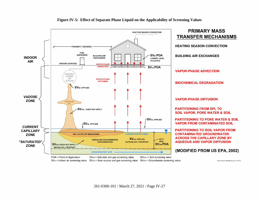
261-0300-101 / March 27, 2021 / Page IV-27
Figure IV-5: Effect of Separate Phase Liquid on the Applicability of Screening Values
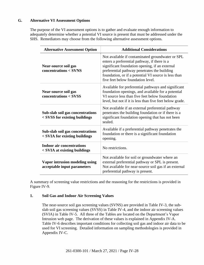
261-0300-101 / March 27, 2021 / Page IV-28
G. Alternative VI Assessment Options
The purpose of the VI assessment options is to gather and evaluate enough information to
adequately determine whether a potential VI source is present that must be addressed under the
SHS. Remediators may choose from the following alternative assessment options.
Alternative Assessment Option Additional Considerations
Near-source soil gas
concentrations < SVNS
Not available if contaminated groundwater or SPL
enters a preferential pathway, if there is a
significant foundation opening, if an external
preferential pathway penetrates the building
foundation, or if a potential VI source is less than
five feet below foundation level.
Near-source soil gas
concentrations < SVSS
Available for preferential pathways and significant
foundation openings, and available for a potential
VI source less than five feet below foundation
level, but not if it is less than five feet below grade.
Sub-slab soil gas concentrations
< SVSS for existing buildings
Not available if an external preferential pathway
penetrates the building foundation or if there is a
significant foundation opening that has not been
sealed.
Sub-slab soil gas concentrations
< SVIA for existing buildings
Available if a preferential pathway penetrates the
foundation or there is a significant foundation
opening.
Indoor air concentrations
< SVIA at existing buildings No restrictions.
Vapor intrusion modeling using
acceptable input parameters
Not available for soil or groundwater where an
external preferential pathway or SPL is present.
Not available for near-source soil gas if an external
preferential pathway is present.
A summary of screening value restrictions and the reasoning for the restrictions is provided in
Figure IV-9.
1. Soil Gas and Indoor Air Screening Values
The near-source soil gas screening values (SVNS) are provided in Table IV-3, the sub-
slab soil gas screening values (SVSS) in Table IV-4, and the indoor air screening values
(SVIA) in Table IV-5. All three of the Tables are located on the Department’s Vapor
Intrusion web page. The derivation of these values is explained in Appendix IV-A.
Table IV-6 describes important conditions for collecting soil gas and indoor air data to be
used for VI screening. Detailed information on sampling methodologies is provided in
Appendix IV-C.
261-0300-101 / March 27, 2021 / Page IV-29
The near-source soil gas screening values are based on attenuation factors derived from
modeling and endpoint concentrations equal to the acceptable indoor air screening values.
Near-source soil gas is measured within or directly above an unsaturated zone soil source
or directly above the capillary fringe for a groundwater source. Screening near-source
soil gas data against near-source soil gas screening values is an option when a preferential
pathway does not penetrate the building foundation (Section IV.D). Vapor
concentrations measured in near-source soil gas are theoretically the highest possible
concentrations because they are directly adjacent to the source.
The sub-slab soil gas screening values are based on EPA’s empirical attenuation factors
and endpoint concentrations equal to the acceptable indoor air screening values. As a
result, screening sub-slab soil gas data against sub-slab screening values cannot be done
in the presence of a preferential pathway that penetrates the building foundation
(Section IV.D). Sub-slab samples are collected immediately below the foundation, and
their proximity to the receptor makes them a reliable indicator of potential exposures.
Sub-slab sampling may also be done beneath intact paved areas large enough to be
representative of future inhabited buildings without basements.
The indoor air screening values (SVIA) are calculated using the inhalation risk equations
in EPA’s risk assessment guidance. Indoor air data represent conditions that are as close
to the receptor as possible and, therefore, provide the most accurate representation of
concentrations at the point of exposure. Indoor air can be influenced by other vapor
sources inside or outside of the structure not attributable to soil or groundwater
contamination. This can lead to false positive indoor air detections which increases
uncertainty in VI investigations. The likelihood of false negative indoor air detections is
relatively low. If the remediator suspects that there are indoor sources of vapor
contamination at the site, indoor air sampling is not recommended.
2. Soil Gas and Indoor Air Screening Methods
Near-source soil gas, sub-slab soil gas, and indoor air data may be acquired during the
site characterization phase or following soil or groundwater remediation. VI sampling
requirements and statistical tests are not specified in 25 Pa. Code Chapter 250.
Therefore, the number of sample points for addressing VI is determined based on the
CSM, professional judgment, and the guidance in this document. DEP recommends a
minimum of two sample locations per building for sub-slab soil gas, and indoor air
sampling and at least two near-source soil gas sample locations at the source. Potential
sampling locations are illustrated in Appendix IV-C, Figures IV-C-1-3.
The characterization data and CSM are used to determine the size and location of the area
of potential VI sources. For most sites, sampling should be biased toward the most
contaminated areas or the most appropriate locations for the sample type. When a large
number of samples is necessary, the sample locations should be determined by an
appropriate randomization method (e.g., systematic random sampling, stratified random
sampling, etc.) as described in the RCRA SW-846 manual (U.S. EPA, 2007, Chapter 9).
These decisions are made on a case-by-case basis. Other important conditions for
collecting data for the VI evaluation are listed in Table IV-6 and Appendix IV-C.
261-0300-101 / March 27, 2021 / Page IV-30
The presence of SPL does not prevent the use of near-source soil gas or sub-slab soil gas
screening values (Figure IV-5) unless the SPL has entered an external preferential
pathway or significant opening. Indoor air screening values are available even in
circumstances when SPL, an external preferential pathway, and/or a significant opening
are present.
The POA for near-source soil gas is at least five feet below grade (Figure IV-1). If near-
source soil gas samples are collected at least five feet below foundation level, then the
data may be screened using near-source soil gas screening values (SVNS). If near-source
soil gas samples are collected less than five feet below foundation level, then the data
may be screened using sub-slab soil gas screening values (SVSS). Acceptable soil or soil-
like material should be present between the sampling depth and the building foundation.
For near-source soil gas above a groundwater source, the number and locations of soil
gas vapor probes are selected on the basis of their representativeness with respect to
water quality in the relevant portion of the plume. When the water table occurs in soil,
the POA for near-source soil gas is nominally within one foot of the top of the capillary
fringe or as close to this interval as sampling can reasonably be performed given typical
fluctuations in groundwater levels. Theoretical capillary fringe thicknesses for different
soil types are provided in Appendix IV-C, Table IV-C-1. When the water table occurs
within bedrock, the POA for near-source soil gas is within one foot of the soil-bedrock
interface.
Sub-slab and indoor air samples should be biased toward areas of the building with the
greatest expected VI impact. Indoor air samples should be collected in the basement, if
present, or the lowest occupied floor. DEP recommends obtaining a concurrent ambient
air sample (in addition to at least two indoor samples) to account for potential
background contamination from outside the building.
The indoor air data collected for screening purposes should be collected when the daily
average outdoor temperature is at least 15°F (8°C) below the minimum indoor
temperature in the occupied space and when the heating system is operating normally.
Indoor air sampling can be performed during warmer seasons, but that data should be
used for informational purposes only and should not be used to screen out the
VI pathway. If a building is not heated, then indoor air samples collected at any time of
the year may be used for screening.
The remediator may initially characterize VI with a minimum of two rounds of near-
source soil gas, sub-slab soil gas, or indoor air sampling (Table IV-7). This data will
normally be collected during the site characterization, but it can also be obtained
following soil or groundwater remediation or during attainment monitoring. The
two sampling events should occur at least 45 days apart for statistical independence.
When preparing a sampling plan many factors should be considered (Appendix IV-C).
Two sample locations and two sampling rounds will not be sufficient at all sites and for
all buildings. Spatial and temporal variability of VI data is significant, and small data
sets have the potential of under-representing true mean concentrations and inhalation
risks. Larger buildings will likely require more sample locations as source
concentrations, vapor entry rates, and indoor ventilation rates will vary across the
261-0300-101 / March 27, 2021 / Page IV-31
structure. If an as-yet undeveloped area is being evaluated, then there will need to be
enough near-source soil gas points to encompass future building construction. Because
petroleum hydrocarbons tend to pose a relatively low risk for VI owing to bioattenuation,
DEP regards chlorinated VOCs as a greater concern for potential under-sampling.
If the near-source soil gas, sub-slab soil gas, or indoor air characterization data are equal
to or less than the screening values (SVNS, SVSS, SVIA), then no potential VI sources are
present to address under the SHS. (However, be aware of potential restrictions associated
with preferential pathways, as described above.) If there are screening value
exceedances, then the remediator has two options to continue evaluating the VI pathway.
One option is to collect sufficient near-source soil gas, sub-slab soil gas, or indoor air
data to apply statistical screening tests (Table IV-7). The other option is to select another
assessment or remedial alternative (Figure IV-6). For example, if sub-slab sample results
exceed screening values, then indoor air samples could be collected and screened, a
mitigation system could be installed, or a risk assessment could be performed under the
SSS. In this case, the remediator should not collect near-source soil gas samples because
they are farther from the point of exposure.
To screen near-source soil gas, sub-slab soil gas, and indoor air data using statistical tests,
at least eight data points must be obtained at the existing or planned future building. This
data can be a combination of sample locations and sampling rounds as long as there are at
least two rounds collected at all of the same points (e.g. two rounds of sampling at
four locations or four rounds of sampling at two locations). Sample locations should be
biased toward areas with the greatest expected VI impact. The following soil and
groundwater statistical tests of § 250.707(b) may be applied to the collective data from
the near-source soil gas, sub-slab soil gas, or indoor air sampling at each building:
• Seventy-five percent of all samples shall be equal to or less than the applicable VI
screening value with no individual sample exceeding ten times the screening
value on the property (75%/10x test) and two times the screening value beyond
the property boundary (75%/2x test).
• As applied in accordance with EPA-approved methods on statistical analysis of
environmental data, as identified in 25 Pa. Code § 250.707(e), the 95% upper
confidence limit of the arithmetic mean shall be at or below the applicable VI
screening value (95% UCL test). The minimum number of samples is specified
by the method documentation.
As an example, if there are two sub-slab sampling points in an onsite building that have
been sampled four times, the 75%/10x test may be applied to those eight sets of analytical
results. These tests should not be used for combinations of near-source and sub-slab data
or soil gas and indoor air data. Data should be collected concurrently from all sample
locations at the building.
Near-source soil gas, sub-slab soil gas, and indoor air sampling rounds should be
performed in subsequent quarters or twice per quarter. Samples should be collected at
least 45 days apart. DEP may allow alternative sampling frequencies with prior written
approval.
261-0300-101 / March 27, 2021 / Page IV-32
3. Vapor Intrusion Modeling
VI modeling can be used to predict indoor air concentrations in current or future
buildings. Modeling of any kind has an inherent amount of uncertainty involved, but, if
acceptable input parameters are used with measured data, it can be a useful tool. The
J&E model is currently the most widely used and accepted VI model available
(Appendix IV-B). The J&E model does have its limitations, namely it does not account
for bioattenuation of petroleum hydrocarbons in its predictions. As a result, other
models, such as BioVapor, can be used to predict indoor air concentrations at petroleum
VI sites. Each model has its own set of conservative default input parameters that should
be used when applicable. However, some parameters such as soil type, depth to the
source, and building size can be adjusted to site-specific conditions.
Soil and groundwater data cannot be used for modeling if an external preferential
pathway or SPL is present. In addition, near-source soil gas data may not be modeled
when there is an external preferential pathway. However, near-source data may be
collected above SPL and modeled. The J&E model also may be applied when a building
has significant foundation openings, such as a dirt floor, as described in Appendix IV-B.
For sites that are completely or partially undeveloped, many of the modeling input
parameters will have to be estimated. The remediator can use information from building
plans, if available, and conservative parameter values. A list of input parameters that can
be adjusted based on site conditions is provided in the modeling guidance presented in
Appendix IV-B.
Pennsylvania versions of EPA’s J&E model spreadsheets are available on DEP’s website.
They should be used for Act 2 and storage tank corrective action J&E modeling. These
versions have DEP default parameter inputs as well as physical/chemical properties and
toxicological values from Chapter 250, Appendix A, Table 5A. It is important to
remember that when using VI modeling under the SHS, the desired output is a predicted
indoor air concentration.
This modeled concentration should be used in the evaluation of VI by comparing it to the
associated indoor air screening value. The J&E model can calculate risk values, but these
should not be used for SHS evaluations. Use of risk calculations to evaluate VI is
considered to be a risk assessment, which is a tool to be used under the SSS, and is
subject to additional reporting requirements and fees. If calculated risk values are used in
the VI analysis, then the site is being remediated under a combination of standards and all
associated fees and requirements of both standards will apply.
261-0300-101 / March 27, 2021 / Page IV-33
H. Mitigation and Activity and Use Limitations
Properly installed and maintained mitigation measures eliminate or greatly reduce VI exposure
and therefore remain protective regardless of changes in subsurface concentrations or toxicity
levels. Many areas of Pennsylvania have high levels of naturally occurring radon gas, which can
pose a significant public health threat. VI mitigation systems not only address potential VI
concerns associated with the release of regulated substances at remediation sites, but also provide
additional public health benefits associated with reducing the significant threat caused by
naturally occurring radon gas. However, mitigation systems may not be feasible in all cases.
The feasibility of using a mitigation system to address VI impacts for existing buildings and
planned future buildings will depend on the specific details of the site, the building, and the
design of the system. Mitigation most commonly involves the installation of an active sub-slab
depressurization system (similar to a fan-driven radon abatement system) (U.S. EPA, 2008).
For residential buildings, standard radon-type mitigation systems should be installed by
individuals or firms certified by DEP for radon mitigation pursuant to 25 Pa. Code Chapter 240
of the regulations (Pennsylvania DEP, 1997). Standard residential systems do not need to be
designed or approved by a Licensed Professional Engineer. The remediator is not required to
perform indoor air confirmation sampling. Active sub-slab depressurization systems can be
tested by measuring pressure differentials to demonstrate depressurization throughout the slab or
by collecting one or more indoor air samples that do not exceed screening values. The system
should be tested following its installation, if a significant modification or repair is made, after a
change in ownership, or upon request by the Department. Performance and testing guidelines for
these systems are provided in Appendix IV-C, Section IV-C.9.
Other engineering controls that mitigate VI, such as the installation of a vapor barrier, can be
used to prevent VI. Vapor barriers should be designed and manufactured for use in VOC
mitigation. The material should be chemically resistant and have demonstrated low permeability
for the VOCs present. Moisture barriers typically do not meet these criteria. Vapor barriers
should be installed and tested pursuant to the manufacturer’s recommendations.
The following AULs can be used to maintain the attainment of the SHS.
• Using mitigation as a means of eliminating or reducing vapor migration
• Committing to mitigation (as described below) of currently planned future inhabited
buildings on the property.
• Committing to evaluate potential VI sources at the time currently planned future
inhabited buildings are constructed. The results of the evaluation should be submitted to
DEP for review.
• Prohibiting construction of basements or future residential and/or nonresidential
inhabited buildings in a specified area of the property where the VI pathway may be
complete.
If there are no plans for future construction of inhabited buildings at the site, the remediator may
still choose to use an AUL to address possible future VI issues. In this case, controls would not
be required to maintain the SHS, but the remediator may wish to have additional protection for
261-0300-101 / March 27, 2021 / Page IV-34
unplanned uses. Any combination of the above four conditions may be utilized. For example,
Figure IV-4 depicts the proximity distance evaluation for a current building (Section IV.E).
Groundwater contamination in Zones B and C and the soil contamination zone in orange also
represent potential VI sources at the site if a future inhabited building is constructed within the
applicable proximity distances from these areas. Zone G, indicated by the outer dotted
perimeter, is the area within the horizontal proximity distance from the potential VI source
(Zones B and C) which exceeds soil and/or groundwater screening values. The remediator could
evaluate VI within Zone G, for instance, with near-source soil gas sampling or modeling.
Alternatively, the remediator could incorporate AULs requiring future evaluation if a new
building is constructed, preemptive mitigation of new buildings, or the prohibition of occupied
buildings within Zone G.
As required by the Uniform Environmental Covenants Act (Act 68 of 2007, 27 Pa. C.S.
§§ 6501–6517, “UECA”) and the accompanying regulations (25 Pa. Code Chapter 253),
engineering and institutional controls needed to address the VI pathway to demonstrate
attainment of the SHS or SSS are to be in the form of an environmental covenant, unless waived
by DEP. The environmental covenant should include language that requires the property owner
to maintain the VI mitigation system. In most cases the environmental covenant does not need to
include language requiring periodic indoor air sampling or reporting to DEP. However,
mitigation systems that have electric motors or other moving parts, such as sub-slab
depressurization systems, will eventually break down or wear out and will need periodic
monitoring to ensure they are operating properly. DEP should be notified in the event of a
property transfer, if there is a problem with the system, or upon request by DEP.
Natural attenuation resulting in decreasing concentrations of soil and groundwater contamination
over time can occur at sites with releases of substances that naturally degrade in soil. At sites for
which an environmental covenant was used to address the VI pathway from potential VI
source(s), it may include a provision that allows for termination of the covenant or the AULs
related to VI if the remediator can demonstrate to DEP that the AUL(s) is/are no longer
necessary under current site conditions to comply with the selected standard.
The following language is provided as a guide for environmental covenants with only one AUL
related to VI:
This Environmental Covenant may be terminated if: (1) an evaluation is performed that
demonstrates that mitigation to address a complete or potentially complete vapor
intrusion pathway is no longer necessary and appropriate, and (2) the Department
reviews and approves the demonstration.
Alternatively, the following language is provided as a guide for environmental covenants with
multiple AULs including AULs unrelated to VI:
This Environmental Covenant may be modified with respect to the VI AUL if: (1) an
evaluation is performed that demonstrates that mitigation to address a complete or
potentially complete vapor intrusion pathway is no longer necessary and appropriate,
and (2) the Department reviews and approves the demonstration
261-0300-101 / March 27, 2021 / Page IV-35
I. Remediating and Reassessing the VI Pathway
Under some circumstances mitigation may not be practical or cost effective. The remediator
may choose to perform further soil and/or groundwater remediation to address the VI pathway.
Following the remediation, additional data must be collected for VI screening. This can include
new soil or groundwater attainment data, or it can consist of soil gas or indoor air sampling data.
The postremediation data is evaluated following the process illustrated in Figure IV-6 and
described in Sections IV.F and IV.G.
The timing of the remediation is an important consideration. If there is an excess VI risk but
remediation is a long-term action (such as a pump-and-treat system), then excess inhalation risks
may exist for an unacceptably long time. In such cases the remediator is responsible for
implementing interim measures to protect human health.
261-0300-101 / March 27, 2021 / Page IV-36
J. Addressing 25 Pa. Code Chapter 250 Requirements
The final step in the process flowchart on Figure IV-6 is to address the requirements of 25 Pa.
Code Chapter 250 with respect to VI. This step is necessary to demonstrate compliance with the
SHS in order to receive liability protection under Act 2. The submitted report should include a
description of the CSM for VI with a preferential pathway assessment. The flowchart endpoint
can be reached in the following three ways, and compliance should be documented in either the
FR (Chapter 250) or the site characterization and/or remedial action completion reports
(Chapter 245):
• Soil and Groundwater Screening. The remediator may screen soil and groundwater
concentration data within proximity distances of existing or planning buildings. If no
potential VI sources are identified, then no further analysis is necessary. Maps and cross
sections that show the spatial relationship between soil and groundwater data, any SPL,
any potential preferential pathways, and existing or planned future inhabited structures
should be used to document that no potential VI sources are present. Applicable
proximity distances should be shown on these exhibits. Soil and groundwater data should
be tabulated and compared to applicable screening values. If statistical methods for
screening the data are used, they should be explained.
• Alternative Assessment Options. The remediator may evaluate the VI pathway by
screening near-source soil gas, sub-slab soil gas, or indoor air data, or by performing
modeling. If the site data satisfy the screening criteria, then no further analysis is
necessary. Sampling locations relative to potential VI sources and existing or planned
future inhabited buildings should be shown on maps. The methodology for collecting the
samples should be described and the results tabulated with applicable screening values.
If statistical methods for screening the data are used, they should be explained. Refer to
Appendix IV-B for recommended modeling documentation.
• Mitigation and Environmental Covenants. The remediator may address the VI
pathway by installing a mitigation system or implementing activity and use limitations in
an environmental covenant. Installation of the mitigation system must be documented,
for instance, with plans, manufacturer specifications, and the installer’s certification.
Testing to demonstrate the system’s effectiveness should be performed (Appendix IV-C)
and the results described in the report. If mitigation is successful, no further analysis is
required. The conditions to be included in a covenant to maintain the remedy should be
detailed in the report.
When a potential VI source in soil or groundwater is remediated, new samples should be
collected to reevaluate the VI pathway and data should be presented as described above. If the
remediator chooses the SSS to address VI, then the remediator should follow the process and
reporting described in Section IV.K.
261-0300-101 / March 27, 2021 / Page IV-37
K. Evaluating the VI Pathway Under the Site-Specific Standard
1. Overview
A remediator may perform a SSS VI evaluation for one of three reasons:
• The remediator has selected the SSS for substances of VI concern in soil and/or
groundwater;
• Soil and groundwater attain the SHS MSCs, but the VI pathway is not
satisfactorily addressed by the SHS VI assessment process described previously in
this guidance;
• The remediator wishes to evaluate VI for substances to which the SHS process
cannot be applied, such as mercury, cyanide, or organics without inhalation
toxicity values.
The SSS VI evaluation process shares many elements with the SHS process, but the
screening values are not the same and a human health risk assessment is an option. The
SSS VI process is outlined in Figure IV-7. It is important to note that the purpose of
Figure IV-7 is to illustrate how all of the steps in the VI evaluation process under the SSS
fit together. Figure IV-7 should not be used as your sole guide for performing a
VI evaluation; rather, it should be used in conjunction with the text of this guidance. The
principal steps of a VI evaluation under the SSS are:
• Develop the CSM and assess the presence of preferential pathways.
• Identify potential VI sources from exceedances of SHS soil and groundwater
screening values within proximity distances and/or the occurrence of SPL.
• Screen near-source soil gas, sub-slab soil gas, or indoor air data.
• Perform a cumulative human health risk assessment, which may include
modeling.
• Mitigate buildings using activity and use limitations.
• Remediate the soil and/or groundwater contamination and reassess the pathway.
• Address the 25 Pa. Code Chapter 250 SSS requirements.
In most cases, all of the above steps will not be necessary, and the remediator is not
required to follow the process sequentially. For instance, buildings with a potentially
complete VI pathway may be mitigated without the collection of soil gas or indoor air
data.
The SHS VI screening values presented in this guidance are based on a carcinogenic
target risk level of 10-5 and a non-carcinogenic hazard quotient of 1.0. These screening
261-0300-101 / March 27, 2021 / Page IV-38
values are not appropriate for use in risk assessments being performed under the SSS
because the SHS target risk levels may not be sufficiently conservative to account for
cumulative risks to receptors from multiple contaminants and/or multiple pathways.
However, screening can be performed under the SSS for VI according to Section IV.K.4
below.
2. Preferential Pathway Evaluation
The remediator must assess potential preferential pathways and significant foundation
openings as part of the SSS CSM development. The presence of a preferential pathway
or significant opening may limit the use of proximity distances, screening values, and
modeling.
The conditions listed in Section IV.D to identify and evaluate preferential pathways and
significant openings also apply under the SSS. Specifically, contamination in soil and
groundwater that exceeds SHS screening values within 30 horizontal and five vertical
feet of a preferential pathway constitutes a potential VI source (Figure IV-3). Acceptable
soil or soil-like material is qualified by no exceedances of SHS soil screening values.
However, soil, groundwater, near-source soil gas, sub-slab, and indoor air sample data
should be screened with appropriate site-specific screening values as described in
Section IV.K.4.
3. Use of Proximity Distances
The remediator may utilize proximity distances to identify potential VI sources, as
described in Section IV.E. For non-petroleum substances, the horizontal proximity
distance is 100 feet, and for petroleum hydrocarbons it is 30 feet. When dissolved or
adsorbed petroleum hydrocarbons are at least five feet below a building foundation and
petroleum SPL is at least 15 feet below a building foundation, they are not considered to
be a potential VI source. These vertical proximity distances must encompass acceptable
soil or soil-like material.
Potential VI sources are established by the presence of SPL and exceedances of SHS soil
and groundwater screening values within the applicable horizontal proximity distance.
Appropriate site-specific screening values are explained in Section IV.K.4. For
petroleum vertical proximity distances to apply, there must be acceptable soil or soil-like
material (i.e., no exceedances of SHS soil screening values) in the upper five feet.
4. Site-Specific Standard VI Screening
Screening of soil, groundwater, near-source soil gas, sub-slab soil gas, and indoor air data
is available under the SSS. This step in the evaluation allows substances to be eliminated
prior to performing a risk assessment. Samples should be collected pursuant to the
guidance in Table IV-6 and Appendix IV-C. An assessment of external preferential
pathways, significant foundation openings, and the presence of SPL needs to be
performed prior to screening as these are conditions that can limit the use of screening
values.
261-0300-101 / March 27, 2021 / Page IV-39
If no limiting conditions exist, then soil and groundwater data may be screened using
appropriate screening values. If limiting conditions are present, near-source soil gas, sub-
slab soil gas, and indoor air may be screened with the following exceptions (Section IV.G
and Figure IV-9):
• Near-source soil gas screening values are not available if there is a source less
than five feet below the building foundation, if SPL or contaminated groundwater
has entered a preferential pathway, if an external preferential pathway penetrates
the building foundation, or if there is a significant foundation opening. Despite
these limitations, if the potential VI source is at least five feet below grade, then
near-source soil gas data may be screened with sub-slab screening values.
• Sub-slab soil gas screening may not be performed if an external preferential
pathway penetrates the building foundation or in the presence of a significant
foundation opening. In those cases, the data may be screened with indoor air
screening values.
The Department permits remediators to define potential VI sources using SHS soil and
groundwater screening values, even if the substances and media will be attaining the SSS.
However, when screening soil or groundwater attainment data to eliminate substances
from a risk assessment, the remediator must use SSS screening values as described
below.
The SHS VI screening values listed in Tables IV-1 through IV-5 may not be used as
is, without adjustment, for SSS screening. The SHS criteria are based on a 10-5 target
cancer risk and a 1.0 target hazard quotient, and on groundwater MSCs and soil-to-
groundwater numeric values (Appendix IV-A). Attainment for the SSS is demonstrated
for cumulative risks to receptors from all substances, media, and pathways.
VI evaluations using a combination of standards are discussed in Section IV.C.3.
As illustrated in Figure IV-8, substance-by-substance SSS VI risk screening values can
be determined using either of the following methods:
• Select the appropriate values for soil, groundwater, near-source soil gas, sub-slab
soil gas, or indoor air from Tables IV-1 through IV-5, or used aquifer
groundwater MSCs and generic soil-to-groundwater numeric values if limiting
conditions apply (see Section IV.F and Figure IV-9). Reduce each screening
value by a factor of 10.
• Use the current EPA residential or industrial indoor air Regional Screening Level
(RSL) values (based on a target cancer risk of 10-6 and a target hazard quotient
of 0.1) (U.S. EPA, 2018a). RSLs based on a 10-5 cancer risk may be used for
screening when it can be demonstrated that VI is the only complete exposure
pathway for a receptor. RSLs may be used for screening indoor air data or for
screening near-source or sub-slab soil gas data by using the following attenuation
factors (refer to Appendix IV-A):
261-0300-101 / March 27, 2021 / Page IV-40
Sample Type
Attenuation Factor
Residential Non-
Residential
Converted
Residential
Sub-slab soil gas 0.026 0.0078 0.026
Near-source soil gas 0.005 0.001 0.005
The methodology for soil and groundwater screening is described in Section IV.F.2, and
the methods for near-source soil gas, sub-slab soil gas, and indoor air are provided in
Section IV.G.2. Screening may be applied to characterization and postremediation data.
A sufficient number of sample locations and rounds must be collected to satisfactorily
evaluate the pathway. DEP recommends a minimum of two sample locations and
two sampling rounds for screening.
For the SSS, the only acceptable screening criterion is no exceedances of the applicable
screening values. Substances that screen out using either one-tenth of the SHS VI
screening values or the EPA RSLs do not need to be included in a VI risk assessment.
5. Performing a VI Risk Assessment and Modeling
In a risk assessment, the VI pathway should be considered when developing the CSM.
The CSM should use a qualitative fate and transport analysis to identify all current and
future potentially complete and incomplete exposure pathways, including source media,
transport mechanisms, and all potential receptors (25 Pa. Code § 250.404). The risks
associated with all complete exposure pathways must be combined for individual
receptors in order to evaluate the total cumulative risk to each receptor. For example, if
ingestion of contaminated soil, dermal contact with contaminated groundwater, and
inhalation of vapor-phase contamination via VI are all complete exposure pathways for
the same receptor, the calculated risk values for each of these pathways must be
combined to evaluate the total risk to the receptor. For the SSS, the cumulative excess
risk for known or suspected carcinogens may not be greater than 10-4 and the hazard
index may not exceed one for systemic toxicants (25 Pa. Code § 250.402).
Current toxicity values should be used in a SSS risk assessment (25 Pa. Code § 250.605).
Therefore, if a toxicity value has been updated since the last revision of the SHS
screening values, that new information must be included in a cumulative risk assessment.
This provision is consistent with DEP’s discretion in allowing screening to substitute for
a risk assessment.
VI modeling is one option for SSS risk assessments. DEP’s modeling guidance is
provided in Appendix IV-B. For SSS modeling, the user inputs soil, groundwater, or
near-source soil gas concentrations into the Pennsylvania versions of EPA’s J&E models.
The desired output is the incremental risks for each substance, not the predicted indoor
air concentrations. The model risk results are then incorporated into the cumulative risk
assessment.
The second option is to use indoor air, sub-slab soil gas, or near-source soil gas data for
the risk assessment. Soil gas data must be converted to estimated indoor air
concentrations using the conservative attenuation factors tabulated in Section IV.K.4.
261-0300-101 / March 27, 2021 / Page IV-41
Inhalation risks are calculated using standard equations. (See Appendices IV-A
and IV-B)
The VI risk assessment must be submitted in a risk assessment report meeting the
procedural and substantive requirements of Act 2. For regulated storage tank sites, the
risk assessment is provided in the site characterization and/or remedial action completion
reports. Human health risk assessment guidance is found in Section III.H. Screening of
chemicals of concern may follow the methodology described in Section IV.K.4.
6. Mitigation and Remediation
If site contamination does not screen out using the SSS screening values or the
cumulative risks are excessive, then the remediator may choose to mitigate the VI
pathway or remediate the VI sources. The remediator can also select these options before
screening field data or carrying out a risk assessment. Mitigation and remediation require
submittal of a cleanup plan.
Current and planned future inhabited buildings may be mitigated to eliminate the VI
pathway (Section IV.H). Mitigation measures that prevent the migration of vapor, such
as vapor barriers or sub-slab depressurization systems, are considered to be engineering
controls. The standard mitigation approach is an active sub-slab depressurization system
(U.S. EPA, 2008). Performance and testing guidelines are provided in Appendix IV-C.
Measures taken that limit or prohibit exposure are considered to be institutional controls.
Engineering or institutional controls used to mitigate the VI pathway must be addressed
in the postremediation care plan and must be memorialized in an environmental
covenant.
Remediation of soil and/or groundwater is also an alternative to address the VI pathway
(Section IV.I). Postremediation data must be collected and evaluated through screening
or a risk assessment. If remedial action is not completed promptly, then the remediator
may be responsible for employing interim measures to protect human health.
7. Using an OSHA Program to Address VI
VI can be difficult to evaluate when vapors from soil or groundwater sources enter
industrial (or commercial) facilities that use the same chemical(s) in their processes.
DEP does not regulate indoor air. Rather, worker exposure to chemical vapors associated
with an onsite industrial process is regulated by the Occupational Safety and Health
Administration (OSHA). It is nearly impossible to accurately isolate and measure the VI
component of the indoor air that can be attributed to soil and groundwater contamination
using indoor air sampling. As a result, workers who are not properly trained to work in
areas that contain these vapors can still be exposed to soil or groundwater related vapors
due to VI.
Therefore, an OSHA program can be used to address VI as an institutional control within
the SSS. The remediator should demonstrate that the substances in the soil or
groundwater contamination they are evaluating are currently being used in a regulated
industrial process inside the inhabited building(s) and that OSHA regulations are fully
implemented and documented in all areas of the building(s). This means that a hazard
261-0300-101 / March 27, 2021 / Page IV-42
communications plan is in place, including the posting of Safety Data Sheets [SDSs;
formerly known as Material Safety Data Sheets (MSDSs)], so that workers and others
who might be exposed to all chemicals of concern have full knowledge of the chemicals’
presence, have received appropriate health and safety training, and have been provided
with the appropriate protective equipment (when needed) to minimize exposure.
Remediators should not use an OSHA program to evaluate risk from VI in cases where
the regulated substances being evaluated for the VI pathway are not used in the work
place. It is also expected that a quantitative analysis of indoor air data using occupational
screening values will be included in the VI assessment. Data is needed to show that
OSHA worker protection measures are satisfied and also to demonstrate compliance and
attainment of the SSS. If OSHA implementation cannot be documented, then an OSHA
program cannot be used as a means of addressing VI. A checklist is included in
Appendix IV-D to help remediators and reviewers ensure that the OSHA program is
adequately documented. All items on the checklist should be provided to demonstrate
that a complete OSHA program is present to provide protection. Additional guidance
regarding the use of industrial hygiene/occupational health programs to address the VI
pathway can be found in EPA’s OSWER Technical Guide for Assessing and Mitigating
the Vapor Intrusion Pathway from Subsurface Vapor Sources to Indoor Air (U.S. EPA,
2015a).
The use of an OSHA program to address VI is an institutional control because it limits
exposure through the implementation of the OSHA requirements. If the future owner
does not use the same chemical(s) in their industrial process as the previous owner and/or
does not fully implement an OSHA program for the same chemical(s), then VI would
need to be reevaluated by the new owner.
8. Addressing Chapter 250 Requirements
The final step in the process flowchart on Figure IV-7 is to address the requirements of
Chapter 250 with respect to VI. This step is necessary to demonstrate compliance with
the SSS under Act 2. The submitted report should include a description of the CSM for
VI with a preferential pathway assessment. The flowchart endpoint can be reached in the
following four ways. Compliance should be documented in Act 2 (Chapter 250) or
storage tank corrective action (Chapter 245) reports:
• Soil and Groundwater Screening. The remediator may screen soil and
groundwater concentration data within proximity distances to existing or currently
planned inhabited buildings. If no potential VI sources are identified, then no
further analysis is necessary. Documenting this conclusion requires the
production of maps and cross sections that show the spatial relationship between
soil and groundwater data, any SPL, any potential preferential pathways, and
existing or planned future inhabited structures. Applicable proximity distances
should be shown on these exhibits. Soil and groundwater data should be tabulated
and compared to applicable screening values. This information is submitted in
the remedial investigation and FR or the site characterization and remedial action
completion reports, as appropriate.
• Alternative Assessment Options. The remediator may evaluate the VI pathway
by screening near-source soil gas, sub-slab soil gas, or indoor air data. If the site
261-0300-101 / March 27, 2021 / Page IV-43
data satisfy the screening criteria, then no further analysis is necessary. Sampling
locations relative to potential VI sources and existing or planned future inhabited
buildings should be shown on maps. The methodology for collecting the samples
should be described and the results tabulated with applicable screening values.
Supporting information is submitted in the remedial investigation and FR or the
site characterization and remedial action completion reports, as appropriate.
• Risk Assessment. If VI screening values are not applicable or they are exceeded,
then a human health risk assessment may be performed. If the site-specific risk
thresholds (cumulative 10-4 cancer risk and hazard index of 1.0) are satisfied, no
further analysis is required. Risk assessment requirements are described in 25 Pa.
Code § 250.409 and Section III.H. Documentation is supplied in a risk
assessment report or a risk assessment submitted as part of a site characterization
report and remedial action completion report, as appropriate. The risk evaluation
may include modeling, as described in Appendix IV-B.
• Mitigation and Activity and Use Limitations. The remediator may address the
VI pathway by installing a mitigation system or implementing AULs in an
environmental covenant. Submittal of a cleanup plan is required when an
engineering control is used to mitigate the exposure pathway for a current
receptor. Installation of the mitigation system must be documented, for instance,
with plans, manufacturer specifications, and the installer’s certification. Testing
to demonstrate the system’s effectiveness should be performed (Appendix IV-C)
and the results described in the report. The conditions to be included in a
covenant to maintain the remedy or eliminate the pathway should also be detailed
in a postremediation care plan. Documentation for mitigation systems and
covenant remedies is provided in the FR or remedial action completion report, as
appropriate.
When a potential VI source in soil or groundwater is remediated, new samples are
collected to reevaluate the VI pathway. That data is presented as described above for the
SSS or through the SHS process, as appropriate.
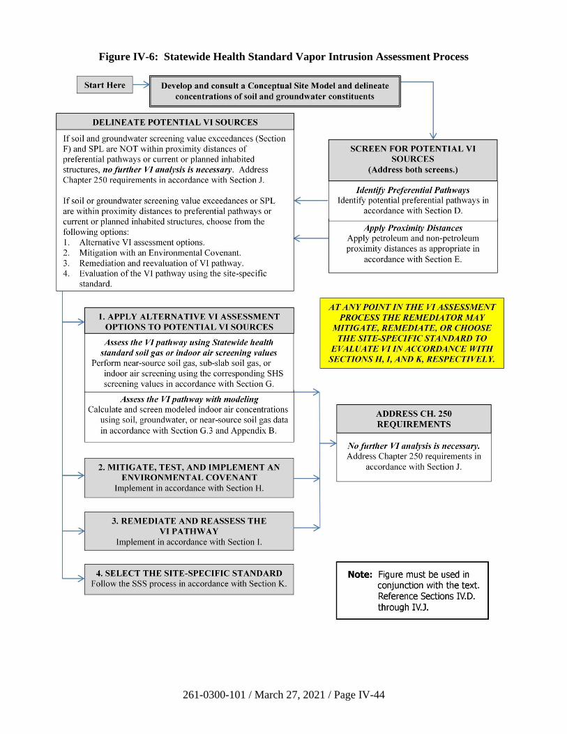
261-0300-101 / March 27, 2021 / Page IV-44
Figure IV-6: Statewide Health Standard Vapor Intrusion Assessment Process
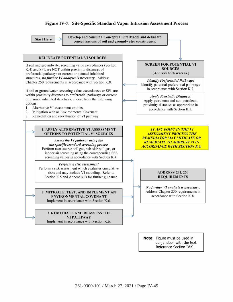
261-0300-101 / March 27, 2021 / Page IV-45
Figure IV-7: Site-Specific Standard Vapor Intrusion Assessment Process
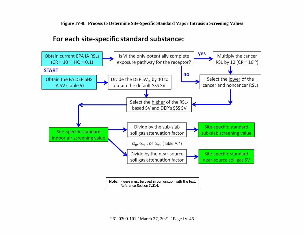
261-0300-101 / March 27, 2021 / Page IV-46
Figure IV-8: Process to Determine Site-Specific Standard Vapor Intrusion Screening Values
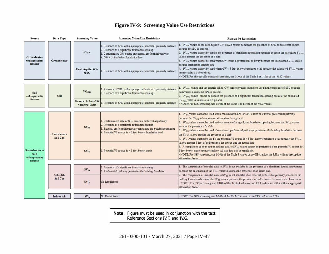
261-0300-101 / March 27, 2021 / Page IV-47
Figure IV-9: Screening Value Use Restrictions
261-0300-101 / March 27, 2021 / Page IV-48
L. References
American Petroleum Institute (API), 2005, Collecting and Interpreting Soil Gas Samples from
the Vadose Zone, Publication No. 4741, Washington, DC.
American Petroleum Institute (API), 2010, BioVapor User’s Manual, Washington, DC.
American Society for Testing and Materials (ASTM), 2007, Standard Test Method for Particle-
Size Analysis of Soils, D422-63(2007)e2, West Conshohocken, PA.
American Society for Testing and Materials (ASTM), 2008, Standard Practice for Radon Control
Options for the Design and Construction of New Low-rise Residential Buildings, E1465-08a,
West Conshohocken, PA.
American Society for Testing and Materials (ASTM), 2009, Standard Test Methods for
Laboratory Determination of Density (Unit Weight) of Soil Specimens, D7263-09, West
Conshohocken, PA.
American Society for Testing and Materials (ASTM), 2010a, Standard Test Method for Density
of Soil in Place by the Drive-Cylinder Method, D2937-10, West Conshohocken, PA.
American Society for Testing and Materials (ASTM), 2010b, Standard Test Methods for
Laboratory Determination of Water (Moisture) Content of Soil and Rock by Mass, D2216-10,
West Conshohocken, PA.
American Society for Testing and Materials (ASTM), 2011a, Standard Practice for Classification
of Soils for Engineering Purposes (Unified Soil Classification System), D2487-11, West
Conshohocken, PA.
American Society for Testing and Materials (ASTM), 2011b, Standard Guide for Assessing
Depressurization-Induced Backdrafting and Spillage from Vented Combustion Appliances,
E1998-11, West Conshohocken, PA.
American Society for Testing and Materials (ASTM), 2012a, Standard Practice for Active Soil
Gas Sampling in the Vadose Zone for Vapor Intrusion Evaluations, D7663-12, West
Conshohocken, PA.
American Society for Testing and Materials (ASTM), 2012b, Standard Test Method for Density,
Relative Density, or API Gravity of Crude Petroleum and Liquid Petroleum Products by
Hydrometer Method, D1298-12b, West Conshohocken, PA.
American Society for Testing and Materials (ASTM), 2013a, Standard Test Method for
Measurement of the Permeability of Unsaturated Porous Materials by Flowing Air, D6539-13,
West Conshohocken, PA.
American Society for Testing and Materials (ASTM), 2013b, Standard Practice for Installing
Radon Mitigation Systems in Existing Low-Rise Residential Buildings, E2121-13, West
Conshohocken, PA.
261-0300-101 / March 27, 2021 / Page IV-49
American Society for Testing and Materials (ASTM), 2014, Standard Test Method for
Estimation of Mean Relative Molecular Mass of Petroleum Oils from Viscosity Measurements,
D2502-14, West Conshohocken, PA.
American Society for Testing and Materials (ASTM), 2015a, Standard Practice for Analysis of
Reformed Gas by Gas Chromatography, D1946-90(2015)e1, West Conshohocken, PA.
American Society for Testing and Materials (ASTM), 2015b, Standard Guide for Application of
Engineering Controls to Facilitate Use or Redevelopment of Chemical-Affected Properties,
E2435-05(2015), West Conshohocken, PA.
California Environmental Protection Agency (EPA), 2011a, Guidance for the Evaluation and
Mitigation of Subsurface Vapor Intrusion to Indoor Air, Sacramento, CA.
California Environmental Protection Agency (EPA), 2011b, Vapor Intrusion Mitigation
Advisory, Sacramento, CA.
California Environmental Protection Agency (EPA), 2015, Advisory—Active Soil Gas
Investigations, Sacramento, CA.
Folkes, D., W. Wertz, J. Kurtz, and T. Kuehster, 2009, Observed spatial and temporal
distributions of CVOCs at Colorado and New York vapor intrusion sites, Ground Water
Monitoring & Remediation, 29, 70-80.
Guo, Y., C. Holton, H. Luo, P. Dahlen, K. Gorder, E. Dettenmaier, and P. Johnson, 2015,
Identification of alternative vapor intrusion pathways using controlled pressure testing, soil gas
monitoring, and screening model calculations, Environmental Science & Technology, 49,
13,472-13,482.
Hawaii Department of Health (DoH), 2014, Technical Guidance Manual for the Implementation
of the Hawaii State Contingency Plan—Soil Vapor and Indoor Air Sampling Guidance,
Honolulu, HI.
Hers, I., R. Zapf-Gilje, L. Li, and J. Atwater, 2001, The use of indoor air measurements to
evaluate intrusion of subsurface VOC vapors into buildings, Journal of the Air & Waste
Management Association, 51, 1318-1331.
Hers, I., R. Zapf-Gilje, P. C. Johnson, and L. Li, 2003, Evaluation of the Johnson and Ettinger
model for prediction of indoor air quality, Ground Water Monitoring & Remediation, 23,
119-133.
Holton, C., H. Luo, P. Dahlen, K. Gorder, E. Dettenmaier, and P. C. Johnson, 2013, Temporal
variability of indoor air concentrations under natural conditions in a house overlying a dilute
chlorinated solvent groundwater plume, Environmental Science & Technology, 47,
13,347-13,354.
The Interstate Technology & Regulatory Council (ITRC), 2007, Vapor Intrusion Pathway: A
Practical Guideline, Washington, DC.
261-0300-101 / March 27, 2021 / Page IV-50
The Interstate Technology & Regulatory Council (ITRC), 2014, Petroleum Vapor Intrusion:
Fundamentals of Screening, Investigation, and Management, Washington, DC.
Jarvela, S., K. Boyd, R. Gadinski, M. DiVincenzo, and T. Karlicek, 2003, Tranguch gasoline site
case history, International Oil Spill Conference Proceedings, 637-642, April 2003.
Johnson, P.C., and R. A. Ettinger, 1991, Heuristic model for predicting the intrusion rate of
contaminant vapors into buildings, Environmental Science & Technology, 25, 1445-1452.
Luo, H., P. Dahlen, P.C. Johnson, T. Peargin, and T. Creamer, 2009, Spatial variability of soil-
gas concentrations near and beneath a building overlying shallow petroleum hydrocarbon–
impacted soils, Groundwater Monitoring & Remediation, 29, 81-91.
Massachusetts Department of Environmental Protection (DEP), 1995, Guidelines for the Design,
Installation, and Operation of Sub-slab Depressurization Systems.
Massachusetts Department of Environmental Protection (DEP), 2011, Interim Final Vapor
Intrusion Guidance, Boston, MA.
McHugh, T.E., T.N. Nickels, and S. Brock, 2007, Evaluation of spatial and temporal variability
in VOC concentrations at vapor intrusion investigation sites, in Proceedings of Air & Waste
Management Association, Vapor Intrusion: Learning from the Challenges, September 26-28,
Providence, RI, 129-142.
New Jersey Department of Environmental Protection (DEP), 2013, Vapor Intrusion Technical
Guidance, Trenton, NJ.
New York Department of Health (DoH), 2006, Guidance for Evaluating Soil Vapor Intrusion in
the State of New York, Troy, NY.
Pennell, K.G., M. Kangsen Scammell, M.D. McClean, J. Ames, B. Weldon, L. Friguglietti, E.M.
Suuberg, R. Shen, P.A. Indeglia, and W.J. Heiger-Bernays, 2013, Sewer gas: An indoor air
source of PCE to consider during vapor intrusion investigations, Groundwater Monitoring &
Remediation, 33, 119-126.
Pennsylvania Department of Environmental Protection (DEP), 1997, Pennsylvania Radon
Mitigation Standards, Bureau of Radiation Protection, Harrisburg, PA, 294-2309-002.
Pennsylvania Department of Environmental Protection (DEP), 2014, User’s Manual for the
Quick Domenico Groundwater Fate-and-Transport Model, Bureau of Environmental Cleanup
and Brownfields, Harrisburg, PA.
Persily, A. K., and J. Gorfain, 2009, Analysis of Ventilation Data from the U.S. Environmental
Protection Agency Building Assessment Survey and Evaluation (BASE) Study, NIST
Interagency/Internal Report (NISTIR) 7145-R.
Provoost, J., L. Reijnders, F. Swartjes, J. Bronders, P. Seuntjens, and J. Lijzen, 2009, Accuracy
of seven vapour intrusion algorithms for VOC in groundwater, Journal of Soils and Sediments, 9,
62-73.
261-0300-101 / March 27, 2021 / Page IV-51
Provoost, J., A. Bosman, L. Reijnders, J. Bronders, K. Touchant, and F. Swartjes, 2010, Vapour
intrusion from the vadose zone—seven algorithms compared, Journal of Soils and Sediments,
10, 473-483.
Schuver H., Lutes C., Kurtz J., Holton C., Truesdale R. S., 2018, Chlorinated vapor intrusion
indicators, tracers, and surrogates (ITS): Supplemental measurements for minimizing the
number of chemical indoor air samples - Part 1: Vapor intrusion driving forces and related
environmental factors, Remediation, 28, 7-31.
Taylor, C. A., and H. G. Stefan, 2008, Shallow groundwater temperature response to
urbanization and climate change in the Twin Cities Metropolitan Area: Analysis of vertical heat
convection effects from the ground surface, University of Minnesota, St. Anthony Falls
Laboratory, Minneapolis, MN, Project Report No. 504.
U.S. Department of Agriculture (USDA), 1993, Soil Survey Manual, Soil Conservation Service,
USDA Handbook 18.
U.S. Environmental Protection Agency (EPA), 1991, Handbook: Sub-Slab Depressurization for
Low Permeability Fill Material—Design and Installation of a Home Radon Reduction System,
EPA/625/6-91/029.
U.S. Environmental Protection Agency (EPA), 1993, Radon Reduction Techniques for Existing
Detached Houses—Technical Guidance (Third Edition) for Active Soil Depressurization
Systems, EPA 625/R-93/011.
U.S. Environmental Protection Agency (EPA), 1994a, Model Standards and Techniques for
Control of Radon in New Residential Buildings, Air and Radiation (6604-J), EPA 402-R-94.
U.S. Environmental Protection Agency (EPA), 1994b, Radon Prevention in the Design and
Construction of Schools and Other Large Buildings, Office of Research and Development,
EPA/625/R-92/016.
U.S. Environmental Protection Agency (EPA), 2001, Building Radon Out: A Step-by-Step
Guide on how to build Radon-Resistant Homes, Office of Air and Radiation,
EPA/402-K-01-002.
U.S. Environmental Protection Agency (EPA), 2004, User’s Guide for Evaluating Subsurface
Vapor Intrusion into Buildings, Office of Emergency and Remedial Response, Washington, DC.
U.S. Environmental Protection Agency (EPA), 2006, Guidance on Systematic Planning Using
the Data Quality Objectives Process, EPA QA/G-4, Office of Environmental Information,
Washington, DC, EPA/240/B-06/001.
U.S. Environmental Protections Agency (EPA), 2007, Test Methods for Evaluating Solid Waste,
Physical/Chemical Methods (SW-846).
U.S. Environmental Protection Agency (EPA), 2008, Indoor Air Vapor Intrusion Mitigation
Approaches, Office of Research and Development, Cincinnati, OH, EPA/600/R-08-115.
261-0300-101 / March 27, 2021 / Page IV-52
U.S. Environmental Protection Agency (EPA), 2009, Risk Assessment Guidance for Superfund
(RAGS), Volume 1: Human Health Evaluation Manual (Part F, Supplemental Guidance for
Inhalation Risk Assessment), Office of Superfund Remediation and Technology Innovation,
Washington, DC, EPA-540-R-070-002.
U.S. Environmental Protection Agency (EPA), 2010, Temporal Variation of VOCs in Soils from
Groundwater to the Surface/Subslab, APM 349, Office of Research and Development,
Washington, DC, EPA/600/R-10/118.
U.S. Environmental Protection Agency (EPA), 2011a, Toxicological Review of
Trichloroethylene, National Center for Environmental Assessment, Washington, DC,
EPA/635/R-09/011F.
U.S. Environmental Protection Agency (EPA), 2011b, Exposure Factors Handbook, Office of
Research and Development, Washington, DC, EPA/600/R-09/052F.
U.S. Environmental Protection Agency (EPA), 2012a, Conceptual Model Scenarios for the
Vapor Intrusion Pathway, Office of Solid Waste and Emergency Response, Washington, DC,
EPA 530-R-10-003.
U.S. Environmental Protection Agency (EPA), 2012b, EPA’s Vapor Intrusion Database:
Evaluation and Characterization of Attenuation Factors for Chlorinated Volatile Organic
Compounds and Residential Buildings, Office of Solid Waste and Emergency Response,
Washington, DC, EPA 530-R-10-002.
U.S. Environmental Protection Agency (EPA), 2012c, Fluctuation of Indoor Radon and VOC
Concentrations Due to Seasonal Variations, Office of Research and Development, Washington,
DC, EPA/600/R/12/673.
U.S. Environmental Protection Agency (EPA), 2013, Evaluation of Empirical Data to Support
Soil Vapor Intrusion Screening Criteria for Petroleum Hydrocarbon Compounds, Office of
Underground Storage Tanks, Washington, DC, EPA 510-R-13-001.
U.S. Environmental Protection Agency (EPA), 2014a, Vapor Intrusion Screening Level (VISL)
Calculator, User’s Guide, Office of Superfund Remediation and Technology Innovation,
Washington, DC.
U.S. Environmental Protection Agency (EPA), 2014b, Human Health Evaluation Manual,
Supplemental Guidance: Update of Standard Default Exposure Factors, Office of Solid Waste
and Emergency Response, Washington, DC, OSWER Directive 9200.1-120, February 6, 2014.
U.S. Environmental Protection Agency (EPA), 2015a, OSWER Technical Guide for Assessing
and Mitigating the Vapor Intrusion Pathway from Subsurface Vapor Sources to Indoor Air,
Office of Solid Waste and Emergency Response, Washington, DC, OSWER
Publication 9200.2-1154.
261-0300-101 / March 27, 2021 / Page IV-53
U.S. Environmental Protection Agency (EPA), 2015b, Technical Guide for Addressing
Petroleum Vapor Intrusion at Leaking Underground Storage Tank Sites, Office of Underground
Storage Tanks, Washington, DC, EPA 510-R-15-001.
U.S. Environmental Protection Agency (EPA), 2015c, Assessment of Mitigation Systems on
Vapor Intrusion: Temporal Trends, Attenuation Factors, and Contaminant Migration Routes
under Mitigated and non-Mitigated Conditions, Office of Research and Development,
Washington, DC, EPA/600/R-13/241.
U.S. Environmental Protection Agency (EPA), 2015d, Simple, Efficient, and Rapid Methods to
Determine the Potential for Vapor Intrusion in the Home: Temporal Trends, Vapor Intrusion
Forecasting, Sampling Strategies, and Contaminant Migration Routes, Office of Research and
Development, Washington, DC, EPA/600/R-15/070.
U.S. Environmental Protection Agency (EPA), 2016a, Toxicological Review of
Trimethylbenzenes, National Center for Environmental Assessment, Washington, DC,
EPA/635/R-16/161Fa.
U.S. Environmental Protection Agency (EPA), 2016b, Petroleum Vapor Intrusion Modeling
Assessment with PVIScreen, Office of Research and Development, Washington, D.C.,
EPA/600/R-16/175.
U.S. Environmental Protection Agency (EPA), 2017, Documentation for EPA’s Implementation
of the Johnson and Ettinger Model to Evaluate Site Specific Vapor Intrusion into Buildings,
Version 6.0, Office of Superfund Remediation and Technology Innovation, Washington, DC.
U.S. Environmental Protection Agency (EPA), 2018a, Regional Screening Levels for Chemical
Contaminants at Superfund Sites—Generic Tables, Washington, DC.
U.S. Environmental Protection Agency (EPA), 2018b, Vapor Intrusion Screening Level (VISL)
Calculator, User’s Guide, Washington, DC (online).
U.S. Environmental Protection Agency (EPA), 2018c, Regional Screening Levels for Chemical
Contaminants at Superfund Sites—User’s Guide, Washington, DC.
Yao, Y., R. Hen, K. G. Pennell, and E. M. Suuberg, 2011, Comparison of the Johnson–Ettinger
vapor intrusion screening model predictions with full three-dimensional model results,
Environmental Science & Technology, 45, 2227-2235.

261-0300-101 / March 27, 2021 / Page IV-54
M. Tables
Tables IV-1 through IV-5 are located on the vapor intrusion web page of the DEP website.
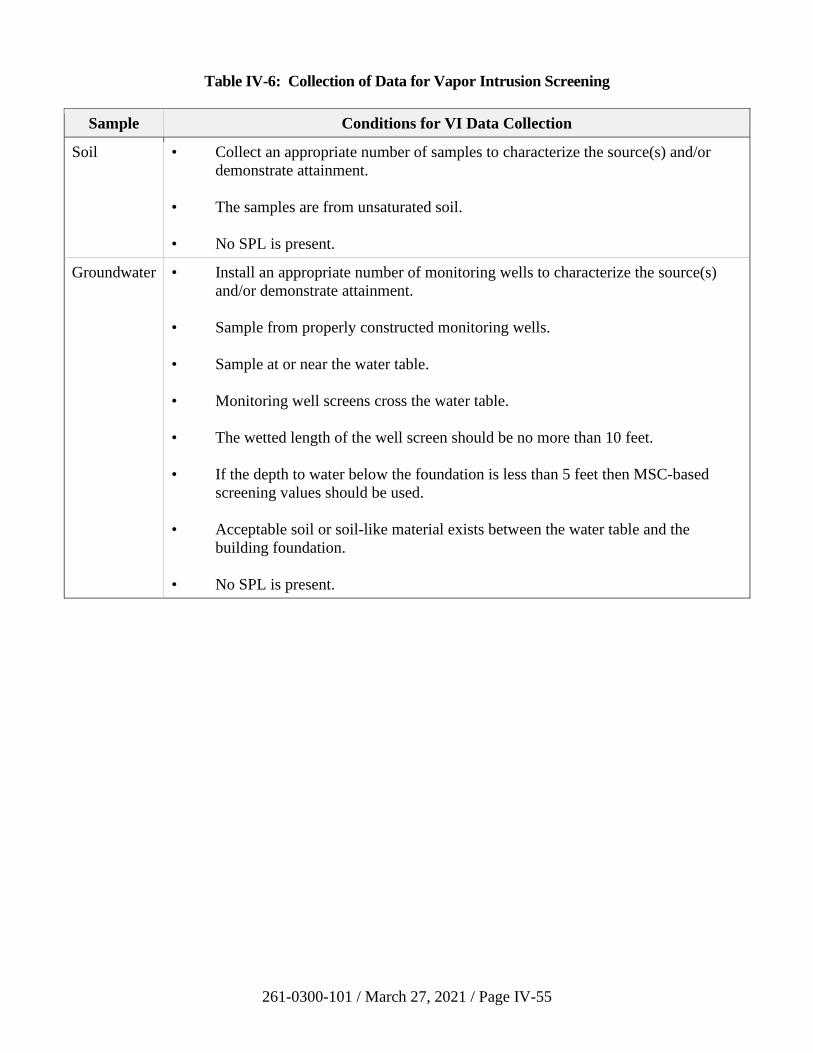
261-0300-101 / March 27, 2021 / Page IV-55
Table IV-6: Collection of Data for Vapor Intrusion Screening
Sample Conditions for VI Data Collection
Soil • Collect an appropriate number of samples to characterize the source(s) and/or
demonstrate attainment.
• The samples are from unsaturated soil.
• No SPL is present.
Groundwater • Install an appropriate number of monitoring wells to characterize the source(s)
and/or demonstrate attainment.
• Sample from properly constructed monitoring wells.
• Sample at or near the water table.
• Monitoring well screens cross the water table.
• The wetted length of the well screen should be no more than 10 feet.
• If the depth to water below the foundation is less than 5 feet then MSC-based
screening values should be used.
• Acceptable soil or soil-like material exists between the water table and the
building foundation.
• No SPL is present.
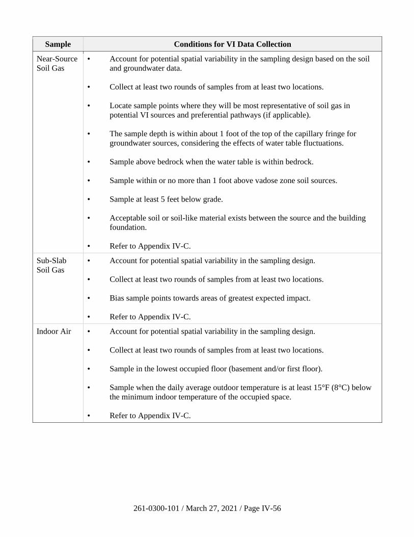
261-0300-101 / March 27, 2021 / Page IV-56
Sample Conditions for VI Data Collection
Near-Source
Soil Gas
• Account for potential spatial variability in the sampling design based on the soil
and groundwater data.
• Collect at least two rounds of samples from at least two locations.
• Locate sample points where they will be most representative of soil gas in
potential VI sources and preferential pathways (if applicable).
• The sample depth is within about 1 foot of the top of the capillary fringe for
groundwater sources, considering the effects of water table fluctuations.
• Sample above bedrock when the water table is within bedrock.
• Sample within or no more than 1 foot above vadose zone soil sources.
• Sample at least 5 feet below grade.
• Acceptable soil or soil-like material exists between the source and the building
foundation.
• Refer to Appendix IV-C.
Sub-Slab
Soil Gas
• Account for potential spatial variability in the sampling design.
• Collect at least two rounds of samples from at least two locations.
• Bias sample points towards areas of greatest expected impact.
• Refer to Appendix IV-C.
Indoor Air • Account for potential spatial variability in the sampling design.
• Collect at least two rounds of samples from at least two locations.
• Sample in the lowest occupied floor (basement and/or first floor).
• Sample when the daily average outdoor temperature is at least 15°F (8°C) below
the minimum indoor temperature of the occupied space.
• Refer to Appendix IV-C.

261-0300-101 / March 27, 2021 / Page IV-57
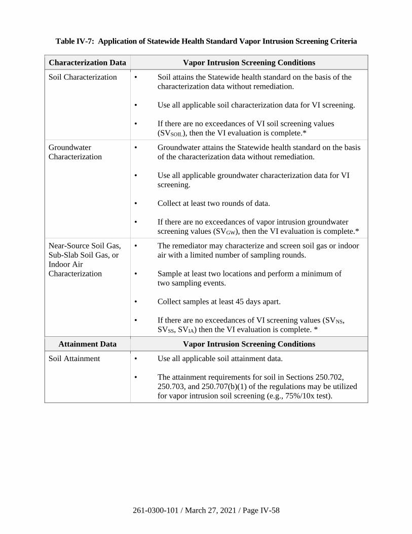
261-0300-101 / March 27, 2021 / Page IV-58
Table IV-7: Application of Statewide Health Standard Vapor Intrusion Screening Criteria
Characterization Data Vapor Intrusion Screening Conditions
Soil Characterization • Soil attains the Statewide health standard on the basis of the
characterization data without remediation.
• Use all applicable soil characterization data for VI screening.
• If there are no exceedances of VI soil screening values
(SVSOIL), then the VI evaluation is complete.*
Groundwater
Characterization
• Groundwater attains the Statewide health standard on the basis
of the characterization data without remediation.
• Use all applicable groundwater characterization data for VI
screening.
• Collect at least two rounds of data.
• If there are no exceedances of vapor intrusion groundwater
screening values (SVGW), then the VI evaluation is complete.*
Near-Source Soil Gas,
Sub-Slab Soil Gas, or
Indoor Air
Characterization
• The remediator may characterize and screen soil gas or indoor
air with a limited number of sampling rounds.
• Sample at least two locations and perform a minimum of
two sampling events.
• Collect samples at least 45 days apart.
• If there are no exceedances of VI screening values (SVNS,
SVSS, SVIA) then the VI evaluation is complete. *
Attainment Data Vapor Intrusion Screening Conditions
Soil Attainment • Use all applicable soil attainment data.
• The attainment requirements for soil in Sections 250.702,
250.703, and 250.707(b)(1) of the regulations may be utilized
for vapor intrusion soil screening (e.g., 75%/10x test).
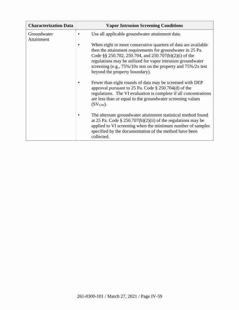
261-0300-101 / March 27, 2021 / Page IV-59
Characterization Data Vapor Intrusion Screening Conditions
Groundwater
Attainment
• Use all applicable groundwater attainment data.
• When eight or more consecutive quarters of data are available
then the attainment requirements for groundwater in 25 Pa.
Code §§ 250.702, 250.704, and 250.707(b)(2)(i) of the
regulations may be utilized for vapor intrusion groundwater
screening (e.g., 75%/10x test on the property and 75%/2x test
beyond the property boundary).
• Fewer than eight rounds of data may be screened with DEP
approval pursuant to 25 Pa. Code § 250.704(d) of the
regulations. The VI evaluation is complete if all concentrations
are less than or equal to the groundwater screening values
(SVGW).
• The alternate groundwater attainment statistical method found
at 25 Pa. Code § 250.707(b)(2)(ii) of the regulations may be
applied to VI screening when the minimum number of samples
specified by the documentation of the method have been
collected.
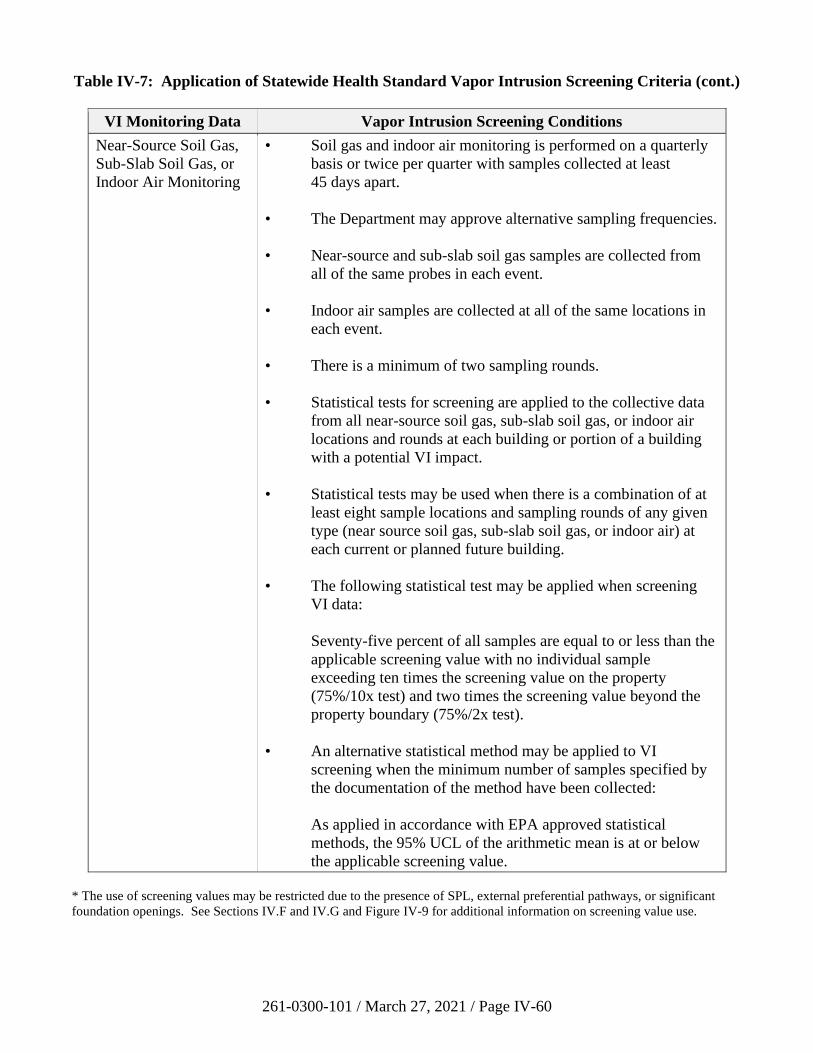
261-0300-101 / March 27, 2021 / Page IV-60
Table IV-7: Application of Statewide Health Standard Vapor Intrusion Screening Criteria (cont.)
VI Monitoring Data Vapor Intrusion Screening Conditions
Near-Source Soil Gas,
Sub-Slab Soil Gas, or
Indoor Air Monitoring
• Soil gas and indoor air monitoring is performed on a quarterly
basis or twice per quarter with samples collected at least
45 days apart.
• The Department may approve alternative sampling frequencies.
• Near-source and sub-slab soil gas samples are collected from
all of the same probes in each event.
• Indoor air samples are collected at all of the same locations in
each event.
• There is a minimum of two sampling rounds.
• Statistical tests for screening are applied to the collective data
from all near-source soil gas, sub-slab soil gas, or indoor air
locations and rounds at each building or portion of a building
with a potential VI impact.
• Statistical tests may be used when there is a combination of at
least eight sample locations and sampling rounds of any given
type (near source soil gas, sub-slab soil gas, or indoor air) at
each current or planned future building.
• The following statistical test may be applied when screening
VI data:
Seventy-five percent of all samples are equal to or less than the
applicable screening value with no individual sample
exceeding ten times the screening value on the property
(75%/10x test) and two times the screening value beyond the
property boundary (75%/2x test).
• An alternative statistical method may be applied to VI
screening when the minimum number of samples specified by
the documentation of the method have been collected:
As applied in accordance with EPA approved statistical
methods, the 95% UCL of the arithmetic mean is at or below
the applicable screening value.
* The use of screening values may be restricted due to the presence of SPL, external preferential pathways, or significant
foundation openings. See Sections IV.F and IV.G and Figure IV-9 for additional information on screening value use.

261-0300-101 / March 27, 2021 / Page IV-61
APPENDICES
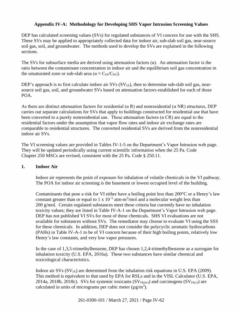
261-0300-101 / March 27, 2021 / Page IV-62
Appendix IV-A: Methodology for Developing SHS Vapor Intrusion Screening Values
DEP has calculated screening values (SVs) for regulated substances of VI concern for use with the SHS.
These SVs may be applied to appropriately collected data for indoor air, sub-slab soil gas, near-source
soil gas, soil, and groundwater. The methods used to develop the SVs are explained in the following
sections.
The SVs for subsurface media are derived using attenuation factors (α). An attenuation factor is the
ratio between the contaminant concentration in indoor air and the equilibrium soil gas concentration in
the unsaturated zone or sub-slab area (α ≡ CIA/CSG).
DEP’s approach is to first calculate indoor air SVs (SVIA), then to determine sub-slab soil gas, near-
source soil gas, soil, and groundwater SVs based on attenuation factors established for each of those
POA.
As there are distinct attenuation factors for residential (α R) and nonresidential (α NR) structures, DEP
carries out separate calculations for SVs that apply to buildings constructed for residential use that have
been converted to a purely nonresidential use. These attenuation factors (α CR) are equal to the
residential factors under the assumption that vapor flow rates and indoor air exchange rates are
comparable to residential structures. The converted residential SVs are derived from the nonresidential
indoor air SVs.
The VI screening values are provided in Tables IV-1-5 on the Department’s Vapor Intrusion web page.
They will be updated periodically using current scientific information when the 25 Pa. Code
Chapter 250 MSCs are revised, consistent with the 25 Pa. Code § 250.11.
1. Indoor Air
Indoor air represents the point of exposure for inhalation of volatile chemicals in the VI pathway.
The POA for indoor air screening is the basement or lowest occupied level of the building.
Contaminants that pose a risk for VI either have a boiling point less than 200°C or a Henry’s law
constant greater than or equal to 1 x 10⁻⁵ atm-m3/mol and a molecular weight less than
200 g/mol. Certain regulated substances meet these criteria but currently have no inhalation
toxicity values; they are listed in Table IV-A-1 on the Department’s Vapor Intrusion web page.
DEP has not published VI SVs for most of these chemicals. SHS VI evaluations are not
available for substances without SVs. The remediator may choose to evaluate VI using the SSS
for these chemicals. In addition, DEP does not consider the polycyclic aromatic hydrocarbons
(PAHs) in Table IV-A-1 to be of VI concern because of their high boiling points, relatively low
Henry’s law constants, and very low vapor pressures.
In the case of 1,3,5-trimethylbenzene, DEP has chosen 1,2,4-trimethylbenzene as a surrogate for
inhalation toxicity (U.S. EPA, 2016a). These two substances have similar chemical and
toxicological characteristics.
Indoor air SVs (SVIA) are determined from the inhalation risk equations in U.S. EPA (2009).
This method is equivalent to that used by EPA for RSLs and in the VISL Calculator (U.S. EPA,
2014a, 2018b, 2018c). SVs for systemic toxicants (SVIA(nc)) and carcinogens (SVIA(c)) are
calculated in units of micrograms per cubic meter (µg/m3).
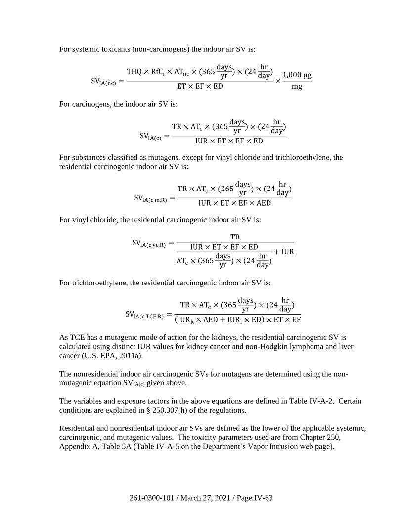
261-0300-101 / March 27, 2021 / Page IV-63
For systemic toxicants (non-carcinogens) the indoor air SV is:
SVIA(nc) =THQ × RfCi × ATnc × (365
daysyr ) × (24
hrday
)
ET × EF × ED×
1,000 μg
mg
For carcinogens, the indoor air SV is:
SVIA(c) =TR × ATc × (365
daysyr ) × (24
hrday
)
IUR × ET × EF × ED
For substances classified as mutagens, except for vinyl chloride and trichloroethylene, the
residential carcinogenic indoor air SV is:
SVIA(c,m,R) =TR × ATc × (365
daysyr ) × (24
hrday
)
IUR × ET × EF × AED
For vinyl chloride, the residential carcinogenic indoor air SV is:
SVIA(c,vc,R) =TR
IUR × ET × EF × ED
ATc × (365days
yr ) × (24hr
day)
+ IUR
For trichloroethylene, the residential carcinogenic indoor air SV is:
SVIA(c,TCE,R) =TR × ATc × (365
daysyr ) × (24
hrday
)
(IURk × AED + IURl × ED) × ET × EF
As TCE has a mutagenic mode of action for the kidneys, the residential carcinogenic SV is
calculated using distinct IUR values for kidney cancer and non-Hodgkin lymphoma and liver
cancer (U.S. EPA, 2011a).
The nonresidential indoor air carcinogenic SVs for mutagens are determined using the non-
mutagenic equation SVIA(c) given above.
The variables and exposure factors in the above equations are defined in Table IV-A-2. Certain
conditions are explained in § 250.307(h) of the regulations.
Residential and nonresidential indoor air SVs are defined as the lower of the applicable systemic,
carcinogenic, and mutagenic values. The toxicity parameters used are from Chapter 250,
Appendix A, Table 5A (Table IV-A-5 on the Department’s Vapor Intrusion web page).
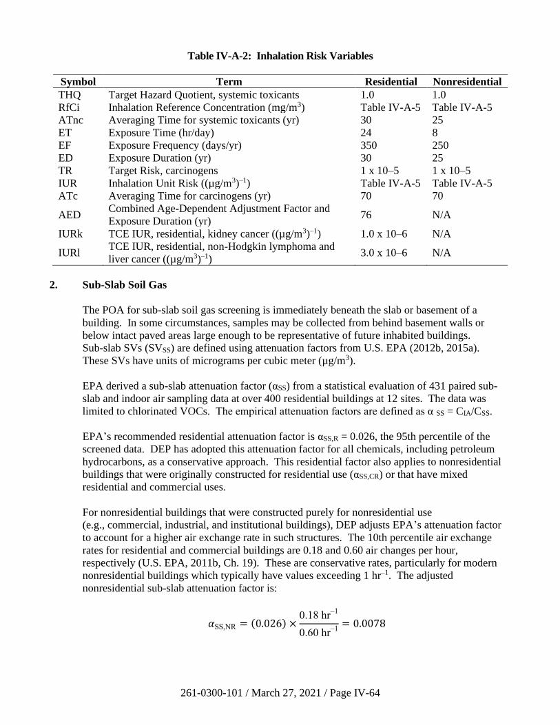
261-0300-101 / March 27, 2021 / Page IV-64
Table IV-A-2: Inhalation Risk Variables
Symbol Term Residential Nonresidential
THQ Target Hazard Quotient, systemic toxicants 1.0 1.0
RfCi Inhalation Reference Concentration (mg/m3) Table IV-A-5 Table IV-A-5
ATnc Averaging Time for systemic toxicants (yr) 30 25
ET Exposure Time (hr/day) 24 8
EF Exposure Frequency (days/yr) 350 250
ED Exposure Duration (yr) 30 25
TR Target Risk, carcinogens 1 x 10⁻⁵ 1 x 10⁻⁵
IUR Inhalation Unit Risk ((µg/m3)–1) Table IV-A-5 Table IV-A-5
ATc Averaging Time for carcinogens (yr) 70 70
AED Combined Age-Dependent Adjustment Factor and
Exposure Duration (yr) 76 N/A
IURk TCE IUR, residential, kidney cancer ((µg/m3)–1) 1.0 x 10⁻⁶ N/A
IURl TCE IUR, residential, non-Hodgkin lymphoma and
liver cancer ((µg/m3)–1) 3.0 x 10⁻⁶ N/A
2. Sub-Slab Soil Gas
The POA for sub-slab soil gas screening is immediately beneath the slab or basement of a
building. In some circumstances, samples may be collected from behind basement walls or
below intact paved areas large enough to be representative of future inhabited buildings.
Sub-slab SVs (SVSS) are defined using attenuation factors from U.S. EPA (2012b, 2015a).
These SVs have units of micrograms per cubic meter (µg/m3).
EPA derived a sub-slab attenuation factor (αSS) from a statistical evaluation of 431 paired sub-
slab and indoor air sampling data at over 400 residential buildings at 12 sites. The data was
limited to chlorinated VOCs. The empirical attenuation factors are defined as α SS = CIA/CSS.
EPA’s recommended residential attenuation factor is αSS,R = 0.026, the 95th percentile of the
screened data. DEP has adopted this attenuation factor for all chemicals, including petroleum
hydrocarbons, as a conservative approach. This residential factor also applies to nonresidential
buildings that were originally constructed for residential use (αSS,CR) or that have mixed
residential and commercial uses.
For nonresidential buildings that were constructed purely for nonresidential use
(e.g., commercial, industrial, and institutional buildings), DEP adjusts EPA’s attenuation factor
to account for a higher air exchange rate in such structures. The 10th percentile air exchange
rates for residential and commercial buildings are 0.18 and 0.60 air changes per hour,
respectively (U.S. EPA, 2011b, Ch. 19). These are conservative rates, particularly for modern
nonresidential buildings which typically have values exceeding 1 hr–1. The adjusted
nonresidential sub-slab attenuation factor is:
𝛼SS,NR = (0.026) ×0.18 hr
–1
0.60 hr–1
= 0.0078
261-0300-101 / March 27, 2021 / Page IV-65
Sub-slab SVs are calculated directly from the indoor air SVs using the applicable attenuation
factor:
SVSS =SVIA
𝛼SS
3. Near-Source Soil Gas
Near-source soil gas samples are collected proximal to the source to minimize the influence of
variable effects such as soil moisture, atmospheric conditions, and leakage from the surface into
the sample that can bias shallow soil gas measurements. For groundwater and SPL the POA is
immediately above the capillary zone throughout the area of the plume. For soil in the vadose
zone the POA is within or immediately above the contaminated soil. Screening may be applied
when at least a 5-foot vertical section of acceptable soil or soil-like material is present between
the bottom of the building foundation and the depth where the near-source soil gas sample is
obtained. (If a near-source soil gas sample is collected less than 5 feet below the foundation it
may be screened using sub-slab soil gas SVs.) Near-source soil gas SVs (SVNS) are defined
using attenuation factors derived from modeling as explained below. These SVs have units of
micrograms per cubic meter (µg/m3).
DEP estimated a near-source soil gas attenuation factor (α NS) by running numerous J&E model
simulations (Johnson and Ettinger, 1991; U.S. EPA, 2004). DEP utilized EPA’s advanced soil
model (version 3.1, February 2004) to determine soil gas source concentrations corresponding to
specified indoor air SVs. The simulations encompassed 12 to 16 different chemicals, the full
suite of soil types, and water-filled porosities ranging from residual saturation to the EPA default
values in the J&E manual. DEP made conservative assumptions of a shallow source (5 feet) and
a high vapor flow rate (Qsoil = 5 L/min). EPA’s default building characteristics for a small, slab-
on-grade building were retained. The models had low, 10th percentile values for the air
exchange rate (0.18 hr–1 residential, 0.60 hr–1 nonresidential; U.S. EPA, 2011b, Ch. 19).
The results of this modeling indicated that there is relatively little variability in the soil gas
attenuation factor for different conditions. The silt soil type has the highest attenuation factor
because of its low residual water content and relatively high air-filled porosity. Representative
factors are αNS,R = 0.005 and α NS,NR = 0.001 for residential and nonresidential scenarios. To
further assess these values DEP examined the soil gas data in EPA’s VI database (U.S. EPA,
2012b). Of 46 buildings at four sites with paired deep soil gas (> 10 feet) and indoor air
measurements, only one exceeded the modeled attenuation factor of 0.005. (This exception had
a calculated attenuation factor of 0.0075.)
Near-source SVs are calculated directly from the indoor air values using the applicable
attenuation factor:
SVNS =SVIA
𝛼NS
4. Soil
Soil samples may be collected in the unsaturated zone as part of the site characterization or a
demonstration of attainment following remediation. The POA is throughout the area of
261-0300-101 / March 27, 2021 / Page IV-66
contamination. Screening may be applied to samples collected at any depth below the building
foundation and above the water table. SPL should not be present. Soil SVs (SVSOIL) are defined
as the higher of a calculated SV and the generic soil-to-groundwater pathway numeric value for a
used aquifer in 25 Pa. Code Chapter 250. Soil SVs have units of milligrams per kilogram, dry
basis (mg/kg).
The calculated SVs are based on equilibrium partitioning of the contaminant between the sorbed
phase on soil, the dissolved phase in pore water, and the vapor phase in the pore space. This
relationship is given in § 250.308(a)(3) of the regulations, with the dilution factor set to 1:
SVSOIL′ = (𝑓oc𝐾oc +
𝜃w
𝜌b) 𝐶pw ×
1 mg
1,000 μg
where SV′SOIL is the calculated SV for soil (mg/kg) and Cpw is the concentration in pore water
(µg/L). The other parameters are defined in Table IV-A-3. The value of foc is from
§ 250.308(a)(3). The dry bulk density used is representative of typical soil types (U.S. EPA,
2004, 2017). DEP defines θw equal to 0.1 to represent relatively dry conditions, close to residual
saturation, beneath a building.
The pore water concentration is related to the pore vapor concentration (Cpv) by Henry’s law:
𝐶pw = 𝐶pv
𝐻′×
1 m3
1,000 L
where Cpv has units of micrograms per cubic meter (µg/m3). H′ is calculated at a soil
temperature of 16°C (61°F) (Appendix IV-B).
The value of the pore vapor concentration is determined from the SVIA by means of soil
attenuation factors:
𝐶pv =SVIA
𝛼SOIL
The soil attenuation factors were determined through testing with the J&E model as described in
Section IV-A.3 of this appendix, but with a source depth of 0.5 feet, directly below the slab. The
corresponding factors are αSOIL,R = 0.01 and αSOIL,NR = 0.002.
The soil SVs are limited by the residual saturation value of 10,000 mg/kg as defined in
§ 250.305(b).
Each calculated SV is compared to the generic soil-to-groundwater pathway numeric value for a
used aquifer with total dissolved solids less than or equal to 2,500 mg/L (25 Pa. Code
Chapter 250, Appendix A, Table 3B), and DEP defines the higher of the two values as the soil
SV for VI (SVSOIL). The generic soil-to-groundwater numeric values are considered appropriate
for VI screening because soil contamination that is unable to impact aquifers in excess of
groundwater MSCs is also unlikely to pose an excess inhalation risk. DEP also recognizes that
the infinite source assumption used to calculate SVs is very conservative, that soil contamination
commonly occurs outside the footprint of potentially impacted buildings, and that these SVs do
not account for the natural biological degradation of petroleum hydrocarbons in soil vapor.
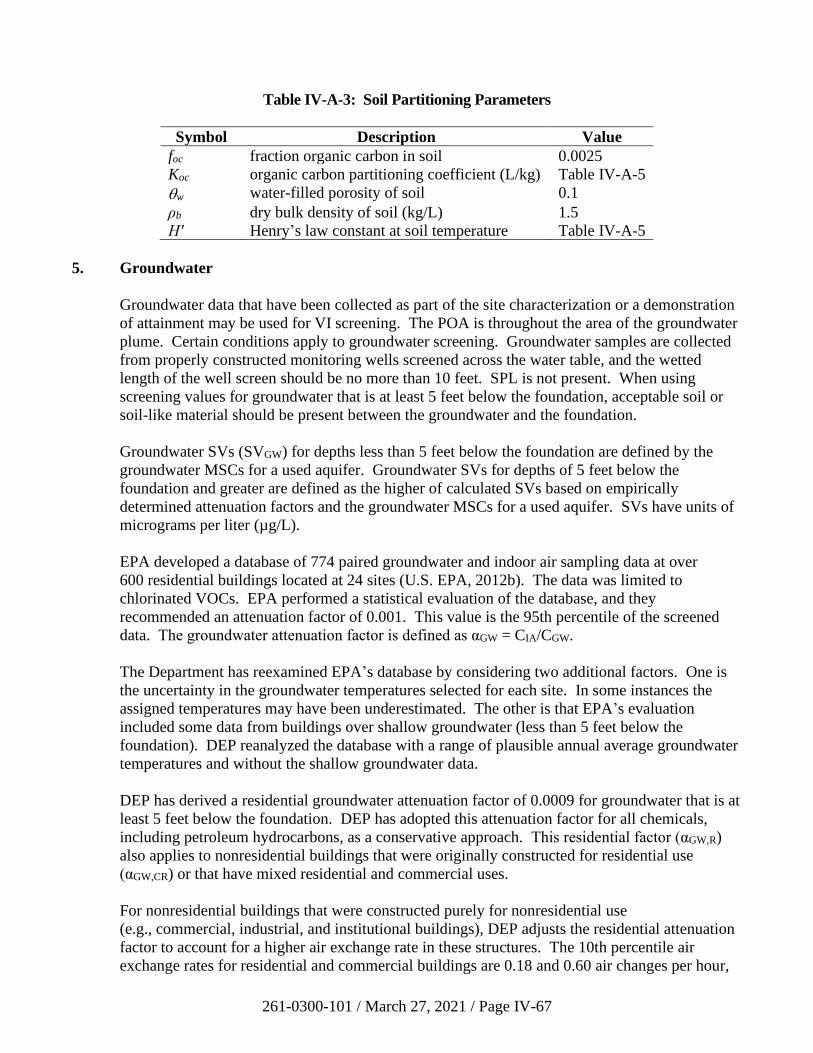
261-0300-101 / March 27, 2021 / Page IV-67
Table IV-A-3: Soil Partitioning Parameters
Symbol Description Value
foc fraction organic carbon in soil 0.0025
Koc organic carbon partitioning coefficient (L/kg) Table IV-A-5
w water-filled porosity of soil 0.1
ρb dry bulk density of soil (kg/L) 1.5
H′ Henry’s law constant at soil temperature Table IV-A-5
5. Groundwater
Groundwater data that have been collected as part of the site characterization or a demonstration
of attainment may be used for VI screening. The POA is throughout the area of the groundwater
plume. Certain conditions apply to groundwater screening. Groundwater samples are collected
from properly constructed monitoring wells screened across the water table, and the wetted
length of the well screen should be no more than 10 feet. SPL is not present. When using
screening values for groundwater that is at least 5 feet below the foundation, acceptable soil or
soil-like material should be present between the groundwater and the foundation.
Groundwater SVs (SVGW) for depths less than 5 feet below the foundation are defined by the
groundwater MSCs for a used aquifer. Groundwater SVs for depths of 5 feet below the
foundation and greater are defined as the higher of calculated SVs based on empirically
determined attenuation factors and the groundwater MSCs for a used aquifer. SVs have units of
micrograms per liter (µg/L).
EPA developed a database of 774 paired groundwater and indoor air sampling data at over
600 residential buildings located at 24 sites (U.S. EPA, 2012b). The data was limited to
chlorinated VOCs. EPA performed a statistical evaluation of the database, and they
recommended an attenuation factor of 0.001. This value is the 95th percentile of the screened
data. The groundwater attenuation factor is defined as αGW = CIA/CGW.
The Department has reexamined EPA’s database by considering two additional factors. One is
the uncertainty in the groundwater temperatures selected for each site. In some instances the
assigned temperatures may have been underestimated. The other is that EPA’s evaluation
included some data from buildings over shallow groundwater (less than 5 feet below the
foundation). DEP reanalyzed the database with a range of plausible annual average groundwater
temperatures and without the shallow groundwater data.
DEP has derived a residential groundwater attenuation factor of 0.0009 for groundwater that is at
least 5 feet below the foundation. DEP has adopted this attenuation factor for all chemicals,
including petroleum hydrocarbons, as a conservative approach. This residential factor (αGW,R)
also applies to nonresidential buildings that were originally constructed for residential use
(αGW,CR) or that have mixed residential and commercial uses.
For nonresidential buildings that were constructed purely for nonresidential use
(e.g., commercial, industrial, and institutional buildings), DEP adjusts the residential attenuation
factor to account for a higher air exchange rate in these structures. The 10th percentile air
exchange rates for residential and commercial buildings are 0.18 and 0.60 air changes per hour,
261-0300-101 / March 27, 2021 / Page IV-68
respectively (U.S. EPA, 2011b, Ch. 19). The adjusted nonresidential groundwater attenuation
factor is:
𝛼GW,NR = (0.0009) ×0.18 hr
–1
0.60 hr–1
= 0.0003
Calculated groundwater SVs (SVGW′ ) are determined from the indoor air SVs using the applicable
attenuation factor and a conversion from soil gas to a dissolved concentration via Henry’s law:
SVGW′ =
SVIA
𝛼GW
×1
(1,000 L/m3)𝐻′
where H′ is the nondimensional Henry’s law constant at the groundwater temperature
(Table IV-A-5 on the Department’s VI web page). DEP calculates the Henry’s law constant at a
groundwater temperature of 16°C (61°F) (Appendix IV-B).
DEP compares each calculated SV to the groundwater MSC for a used aquifer with total
dissolved solids less than or equal to 2,500 mg/L (Chapter 250, Appendix A, Table 1). DEP
defines the groundwater SV for VI (SVGW) for depths of 5 feet below the foundation and greater
as the maximum of the calculated SV (SV′GW) and the MSC, limited by the aqueous
solubility (S). DEP regards the groundwater MSCs as suitable for VI screening at any depth
because they are acceptable for water used inside homes, including inhalation exposures.
6. Building Foundation Openings
The sub-slab soil gas and groundwater attenuation factors are derived from EPA’s database of
residential VI sampling. DEP recognizes that many of the buildings used in EPA’s study likely
had typical foundation openings such as sumps, French drains, floor drains, and gaps around
utility penetrations. (For instance, over three-quarters of the homes included in the sub-slab
attenuation factor analysis had basements, and EPA did not filter the data for the presence of
foundation openings.) For this reason, DEP considers the attenuation factors and screening
values to be applicable to buildings with common openings. For a small house with a sump and
an open, interior French drain, the size of these openings would not be more than a few percent
of the foundation area. DEP’s threshold for significant openings, which preclude the use of the
attenuation factors and SVs, is 5% of the foundation area (Section IV.D.2).
DEP establishes attenuation factors for near-source soil gas and soil based on J&E model
simulations. These tests assume a conservative, high vapor flow rate into the building, which
would be representative of vapor entry through typical foundation openings. Therefore, the near-
source soil gas and soil attenuation factors and SVs are also applicable to buildings that do not
have foundation openings exceeding 5% of the foundation area.
7. Attenuation Factor Summary
The attenuation factors used to calculate the VI SVs are listed in Table IV-A-4. The sub-slab
and groundwater attenuation factors are based on EPA’s empirical database (U.S. EPA, 2012b).
The near source soil gas and soil attenuation factors are defined from DEP’s modeling studies.
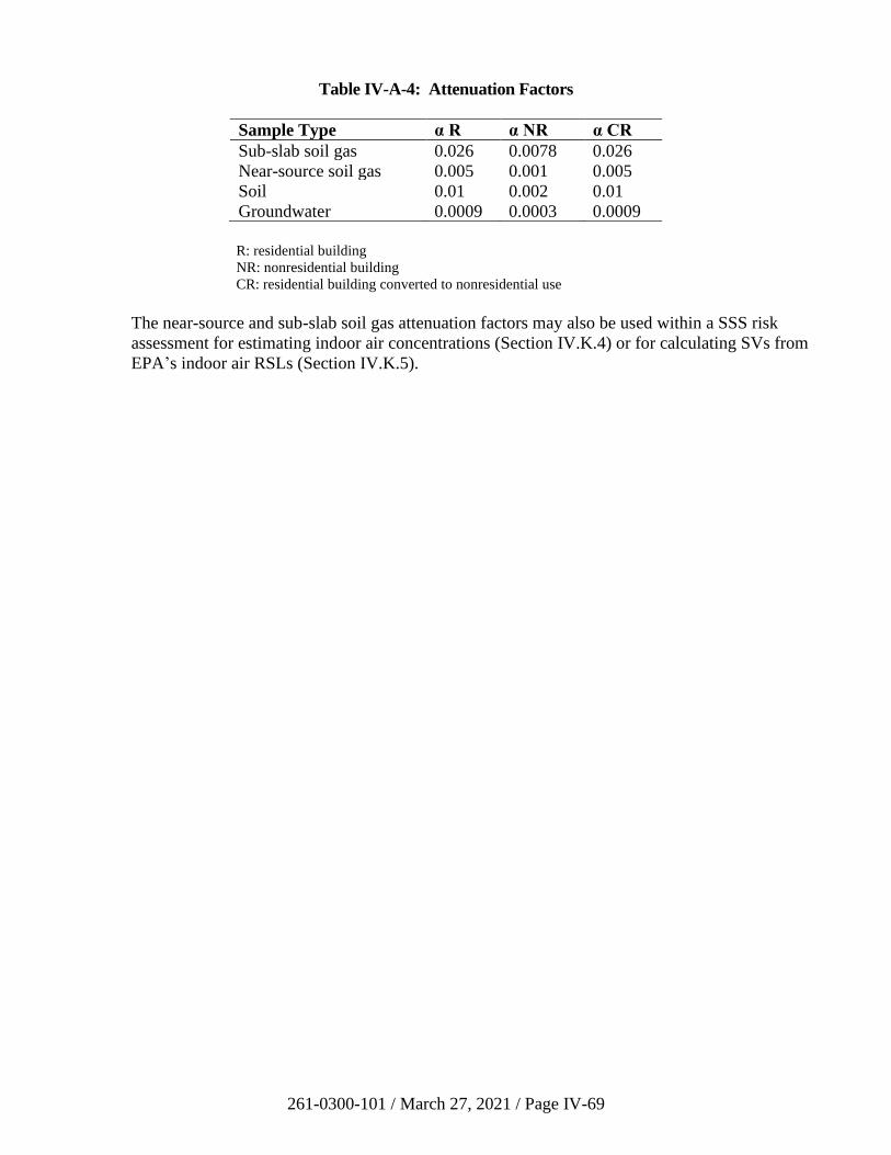
261-0300-101 / March 27, 2021 / Page IV-69
Table IV-A-4: Attenuation Factors
Sample Type α R α NR α CR
Sub-slab soil gas 0.026 0.0078 0.026
Near-source soil gas 0.005 0.001 0.005
Soil 0.01 0.002 0.01
Groundwater 0.0009 0.0003 0.0009
R: residential building
NR: nonresidential building
CR: residential building converted to nonresidential use
The near-source and sub-slab soil gas attenuation factors may also be used within a SSS risk
assessment for estimating indoor air concentrations (Section IV.K.4) or for calculating SVs from
EPA’s indoor air RSLs (Section IV.K.5).
261-0300-101 / March 27, 2021 / Page IV-70
Appendix IV-B: Vapor Intrusion Modeling Guidance
DEP recommends the use of EPA’s J&E model (U.S. EPA, 2004) for analyzing VI with the SHS and
SSS. Remediators may use DEP’s versions of the model which are based on EPA’s advanced model
version 3.1 spreadsheets. These versions are posted on DEP’s website, and they will be updated
periodically with the most recent toxicological and other model input parameters.
This appendix describes key assumptions and limitations of the J&E model, acceptable adjustments to
default input values, and the use of alternative models for petroleum hydrocarbons.
1. Background
The J&E model solves for the transport of vapor-phase contaminants into a building above the
source (Johnson and Ettinger, 1991; U.S. EPA, 2004, 2017). There are three spreadsheets for the
different source types: groundwater, soil, and soil gas. The model calculates the vaporization of
dissolved or adsorbed contaminants, the diffusion of these vapors toward the surface, their
advection through the foundation or slab into the occupied space, and their dilution in indoor air.
The calculations rely on five sets of parameters integral to this process and the inhalation risk
assessment:
• source description (e.g., depth)
• chemical properties
• toxicological properties
• capillary fringe and vadose zone properties (e.g., soil type)
• building characteristics (e.g., air exchange rate).
The J&E model is an approximation that is dependent on many parameters, not all of which are
well known. It is not easily calibrated; therefore, the user should input conservative values to
avoid underestimating inhalation risks. Users submitting J&E models to DEP are expected to be
familiar with EPA’s User’s Guide and should understand the model’s assumptions and
limitations (U.S. EPA, 2004, 2017).
Several studies have compared J&E model results to field data (Hers et al., 2003; Provoost et al.,
2009, 2010) and to numerical analyses (Yao et al., 2011). This research indicates that J&E gives
reasonable, conservative results in most cases, within about one order of magnitude. These
studies reinforce the need to use J&E with caution because the model is highly sensitive to some
parameters. It is essential to have adequate site data and a strong CSM when modeling VI.
The objective of VI modeling is to determine if an Act 2 standard is attained. Although the EPA
spreadsheets can calculate screening values, models submitted to DEP should not be used in this
manner. Users must instead input the contaminant concentration on the DATENTER worksheet
to calculate the incremental risk. The DEP versions give results in two forms, depending on the
Act 2 standard selected for the contaminant.
261-0300-101 / March 27, 2021 / Page IV-71
For SHS evaluations, the user compares the predicted indoor air concentration on the RESULTS
sheet to the SHS indoor air screening value (SVIA) (Table IV-5 on the Department’s VI web
page).
For SSS risk assessments, the user obtains the incremental carcinogenic and noncarcinogenic
inhalation risks from the RESULTS sheet, determines the cumulative risks for all SSS
contaminants of concern, and compares the cumulative risks to the Act 2 thresholds
(Section IV.K.5).
Under appropriate conditions in the SSS, predicted indoor air concentrations can be compared to
occupational limits (OSHA PELs) (Section IV.K.7).
2. Assumptions
Users are referred to EPA’s J&E User’s Guide for a complete description of the model
(U.S. EPA, 2004, 2017). It has several critical assumptions and limitations that all users must be
aware of.
• The source extent is horizontally and vertically infinite. Source mass does not diminish
with time. These are conservative assumptions.
• No SPL is present for soil and groundwater modeling.
• The solution is one-dimensional, accounting only for vertical vapor transport; lateral
migration of vapors is ignored.
• Soil properties are homogeneous.
• There is no biodegradation of contaminant vapors in the vadose zone, a conservative
assumption.
• There are no preferential pathways between the source and the building.
• The system is in steady state; that is, vapor transport is in equilibrium.
• The model does not account for the combined effects of multiple contaminants.
In addition, see U.S. EPA (2004, 2017) Section 2.4.
3. J&E Model Parameter Adjustments
Key input parameters and allowable changes to these values for VI modeling are explained in
this section. The Department’s conservative default model parameter values, as input on the
DATENTER sheet of the J&E spreadsheet, are given in Table IV-B-1. Most input values used
are EPA’s defaults.
EPA developed their J&E model as a screening tool, and they recommend against using it to
predict a unique indoor air concentration or risk (U.S. EPA, 2017). However, because DEP
accepts J&E model results as a single line of evidence when sufficient supporting information is
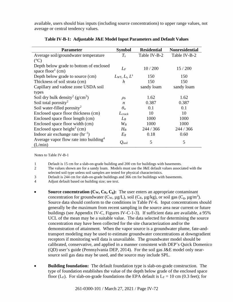
261-0300-101 / March 27, 2021 / Page IV-72
available, users should bias inputs (including source concentrations) to upper range values, not
average or central tendency values.
Table IV-B-1: Adjustable J&E Model Input Parameters and Default Values
Parameter Symbol Residential Nonresidential
Average soil/groundwater temperature
(°C)
Ts Table IV-B-2 Table IV-B-2
Depth below grade to bottom of enclosed
space floor1 (cm) LF 10 / 200 15 / 200
Depth below grade to source (cm) LWT, Lt, Ls 150 150
Thickness of soil strata (cm) h 150 150
Capillary and vadose zone USDA soil
types
sandy loam sandy loam
Soil dry bulk density2 (g/cm3) ρb 1.62 1.62
Soil total porosity2 n 0.387 0.387
Soil water-filled porosity2 θw 0.1 0.1
Enclosed space floor thickness (cm) Lcrack 10 10
Enclosed space floor length (cm) LB 1000 1000
Enclosed space floor width (cm) WB 1000 1000
Enclosed space height3 (cm) HB 244 / 366 244 / 366
Indoor air exchange rate (hr–1) ER 0.18 0.60
Average vapor flow rate into building4
(L/min) Qsoil 5 5
Notes to Table IV-B-1
1 Default is 15 cm for a slab-on-grade building and 200 cm for buildings with basements.
2 The values shown are for a sandy loam. Models must use the J&E default values associated with the
selected soil type unless soil samples are tested for physical characteristics.
3 Default is 244 cm for slab-on-grade buildings and 366 cm for buildings with basements.
4 Adjust default based on building size; see text.
• Source concentration (CW, CR, Cg): The user enters an appropriate contaminant
concentration for groundwater (CW, µg/L), soil (CR, µg/kg), or soil gas (Cg, µg/m3).
Source data should conform to the conditions in Table IV-6. Input concentrations should
generally be the maximum from recent sampling in the source area near current or future
buildings (see Appendix IV-C, Figures IV-C-1-3). If sufficient data are available, a 95%
UCL of the mean may be a suitable value. The data selected for determining the source
concentration may have been collected for the site characterization and/or the
demonstration of attainment. When the vapor source is a groundwater plume, fate-and-
transport modeling may be used to estimate groundwater concentrations at downgradient
receptors if monitoring well data is unavailable. The groundwater model should be
calibrated, conservative, and applied in a manner consistent with DEP’s Quick Domenico
(QD) user’s guide (Pennsylvania DEP, 2014). For the soil gas J&E model only near-
source soil gas data may be used, and the source may include SPL.
• Building foundation: The default foundation type is slab-on-grade construction. The
type of foundation establishes the value of the depth below grade of the enclosed space
floor (LF). For slab-on-grade foundations the EPA default is LF = 10 cm (0.3 feet); for
261-0300-101 / March 27, 2021 / Page IV-73
basements it is LF = 200 cm (6.6 feet). This value may be altered with supporting
documentation for the site building.
• Depth below grade to source (LWT, Lt, Ls): The default value is 150 cm (5 feet). The
user enters the actual minimum depth based on the site characterization and/or
monitoring data. For groundwater, it should be the seasonally high water table depth of
the contaminated aquifer (LWT). For soil, it should be the depth to the top of
contaminated soil (Lt). DEP recommends using the shallowest depth that either exceeds
the soil screening value (SVSOIL) or that is contaminated as indicated by field screening.
For soil gas the source depth is the top of the screen in the soil gas probe (Ls).
Acceptable soil or soil-like material should be present between the building foundation
and the contaminant source. Acceptable soil or soil-like material will not have the
following characteristics: obvious contamination (staining or odors), field instrument
readings in the head space above soil samples greater than 100 ppmv, evidence of SPLs,
or exceedances of soil screening values (refer to Section IV.B of the guidance). The
thickness of acceptable soil or soil-like material may be less than 5 feet.
Where there is a basement, the source must be entirely below the foundation as J&E does
not model lateral vapor transport. Soil or groundwater with concentrations exceeding
screening values cannot be in contact with the foundation. J&E simulates vapor diffusion
through homogeneous, isotropic porous media. Therefore, it cannot determine vapor
migration through fractured bedrock. If the water table is below the bedrock interface,
then the model groundwater source depth (LWT) should be input as the depth to bedrock.
A continuous layer of acceptable soil or soil-like material should be present between the
bedrock surface and the building foundation.
• Depth below grade to bottom of contamination (Lb): A finite source calculation is
allowed for the soil model if the depth to the bottom of the contaminated soil has been
delineated.
• Soil/groundwater temperature (TS): Long-term average subsurface temperatures
depend on the average air temperature of the locale and the nature of the surface material.
Ground temperatures are higher in developed areas with buildings and pavement than
where the land is undeveloped. DEP has compiled shallow groundwater temperature data
collected during low-flow purging of monitoring wells at sites in the Southeast Region of
Pennsylvania. In addition, DEP has examined continuous soil temperature data from
three U.S. Department of Agriculture, Natural Resources Conservation Service (NRCS),
Soil Climate Analysis Network stations (Mahantango Creek, PA; Rock Springs, PA; and
Powder Mill, MD). Each data set was compared to air temperature data collected from
weather stations during corresponding periods. This information was supplemented with
the study by Taylor and Stefan (2008).
Average shallow subsurface temperatures are typically ~4°C higher than local air
temperatures. DEP recommends using a model soil/groundwater temperature that is 4°C
greater than the long-term average air temperature for the region. Thirty-year average
temperatures for 1986–2015 available from the National Oceanic and Atmospheric
Administration’s (NOAA) NOWData application ranged from 50°F to 56°F (10–14°C)
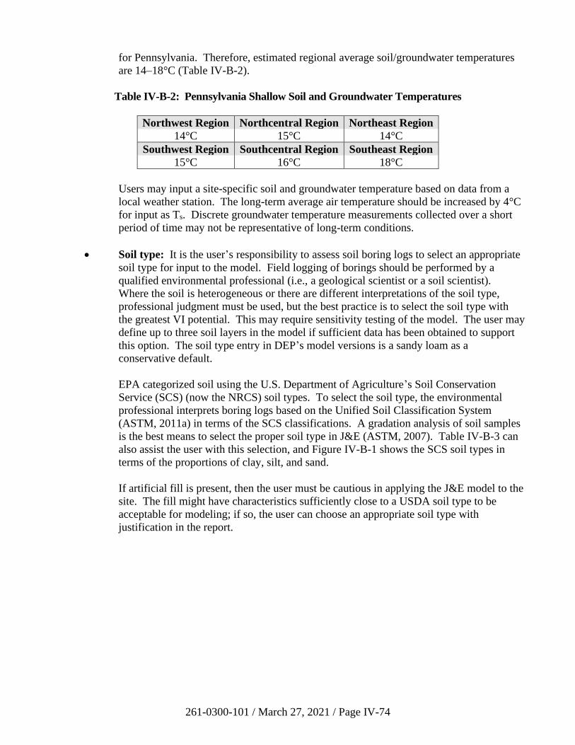
261-0300-101 / March 27, 2021 / Page IV-74
for Pennsylvania. Therefore, estimated regional average soil/groundwater temperatures
are 14–18°C (Table IV-B-2).
Table IV-B-2: Pennsylvania Shallow Soil and Groundwater Temperatures
Northwest Region Northcentral Region Northeast Region
14°C 15°C 14°C
Southwest Region Southcentral Region Southeast Region
15°C 16°C 18°C
Users may input a site-specific soil and groundwater temperature based on data from a
local weather station. The long-term average air temperature should be increased by 4°C
for input as Ts. Discrete groundwater temperature measurements collected over a short
period of time may not be representative of long-term conditions.
• Soil type: It is the user’s responsibility to assess soil boring logs to select an appropriate
soil type for input to the model. Field logging of borings should be performed by a
qualified environmental professional (i.e., a geological scientist or a soil scientist).
Where the soil is heterogeneous or there are different interpretations of the soil type,
professional judgment must be used, but the best practice is to select the soil type with
the greatest VI potential. This may require sensitivity testing of the model. The user may
define up to three soil layers in the model if sufficient data has been obtained to support
this option. The soil type entry in DEP’s model versions is a sandy loam as a
conservative default.
EPA categorized soil using the U.S. Department of Agriculture’s Soil Conservation
Service (SCS) (now the NRCS) soil types. To select the soil type, the environmental
professional interprets boring logs based on the Unified Soil Classification System
(ASTM, 2011a) in terms of the SCS classifications. A gradation analysis of soil samples
is the best means to select the proper soil type in J&E (ASTM, 2007). Table IV-B-3 can
also assist the user with this selection, and Figure IV-B-1 shows the SCS soil types in
terms of the proportions of clay, silt, and sand.
If artificial fill is present, then the user must be cautious in applying the J&E model to the
site. The fill might have characteristics sufficiently close to a USDA soil type to be
acceptable for modeling; if so, the user can choose an appropriate soil type with
justification in the report.
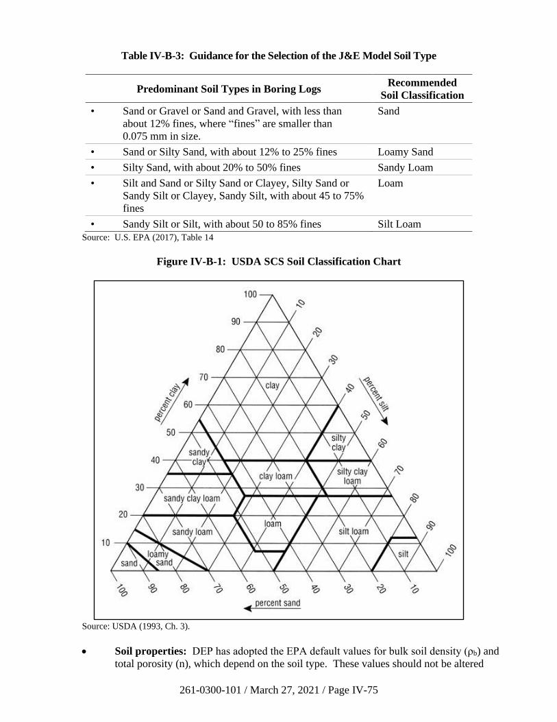
261-0300-101 / March 27, 2021 / Page IV-75
Table IV-B-3: Guidance for the Selection of the J&E Model Soil Type
Predominant Soil Types in Boring Logs Recommended
Soil Classification
• Sand or Gravel or Sand and Gravel, with less than
about 12% fines, where “fines” are smaller than
0.075 mm in size.
Sand
• Sand or Silty Sand, with about 12% to 25% fines Loamy Sand
• Silty Sand, with about 20% to 50% fines Sandy Loam
• Silt and Sand or Silty Sand or Clayey, Silty Sand or
Sandy Silt or Clayey, Sandy Silt, with about 45 to 75%
fines
Loam
• Sandy Silt or Silt, with about 50 to 85% fines Silt Loam
Source: U.S. EPA (2017), Table 14
Figure IV-B-1: USDA SCS Soil Classification Chart
Source: USDA (1993, Ch. 3).
• Soil properties: DEP has adopted the EPA default values for bulk soil density (ρb) and
total porosity (n), which depend on the soil type. These values should not be altered
261-0300-101 / March 27, 2021 / Page IV-76
unless properly collected samples (e.g., in thin-walled tubes) have been analyzed for
these parameters (ASTM, 2009, 2010a). DEP does not consider the EPA default water-
filled porosity values (w) to be sufficiently conservative because soil beneath buildings
is relatively dry. DEP’s default value is 0.1 or the residual saturation (r), whichever is
greater for the soil type. The user can change w only based on laboratory analyses of the
moisture content of properly collected soil samples from underneath the building or an
intact paved area large enough to be representative of a future inhabited building
(ASTM, 2010b).
• Fraction of organic carbon (foc): The default value is 0.0025 from EPA and
§ 250.308(a). The user may change this value for soil modeling only with laboratory
measurements of foc in site soils (e.g., U.S. EPA Method 9060A). However, the foc may
be set to zero if the material is not believed to contain any organic carbon.
• Floor thickness (Lcrack): The EPA default value is 10 cm (4 inches). This may be
changed by the user if the actual (or planned) slab thickness is known. A dirt floor may
be simulated with a value of zero.
• Building dimensions (LB, WB, HB): The EPA default residential floor space area is
1,080 ft2 (100 m2) for a 10- by 10-m home. Default enclosed space heights (HB) are
244 cm (8 feet) for slab-on-grade buildings and 366 cm (12 feet) for structures with
basements. Note, however, that if indoor air does not communicate efficiently between
the basement and the first floor, then the default value is not conservative and it should be
reduced. The user may input the actual (or planned) building dimensions.
• Air exchange rate (ER): Air exchange rates exhibit a large range for different buildings
and seasons. DEP adopts the current 10th percentile residential value of 0.18 hr–1
(U.S. EPA, 2011b, Ch. 19). The measured range in a study of 100 office buildings was
approximately 0.2–4.5 per hour (Persily and Gorfain, 2009). A 10th percentile
nonresidential value is 0.60 hr–1 (U.S. EPA, 2011b, Ch. 19). The user should input these
10th-percentile values for residential and nonresidential buildings. The actual air
exchange rate of an existing or planned building may be input to the J&E model if it has
been measured or is documented in the heating, ventilation and air conditioning (HVAC)
system design and settings.
• Vapor flow rate (Qsoil): The soil gas flow rate into buildings is highly uncertain, and it
depends on the material in contact with the foundation, the arrangement of cracks and
other foundation openings, the pressure differential, and other factors. The EPA default
value is 5 L/min based on tracer gas studies at five sites summarized by Hers et al.
(2003). In the absence of better information on this parameter, DEP’s default Qsoil is
5 L/min. If the user changes the building dimensions (LB and WB) then the value of Qsoil
should be scaled correspondingly. Assuming vapor entry through foundation perimeter
cracks, the scale factor is the ratio of the building perimeters. The default perimeter for
the 10- by 10-m building is 40 m (130 feet). For example, if the building dimensions are
50 feet by 100 feet, the perimeter is 300 feet, the scale factor is 2.3, and Qsoil = 12 L/min.
Another option is to enter a soil vapor permeability value and allow the model to
calculate Qsoil. This is permitted only if the user obtains vapor permeability test data for
the soil in contact with the foundation (ASTM, 2013a).
261-0300-101 / March 27, 2021 / Page IV-77
Although the prior version of J&E (U.S. EPA, 2004) provided for a calculation of Qsoil
based on the soil type, this option is no longer available in the DEP and EPA models
(U.S. EPA, 2017). The pressure differential (ΔP) and crack width (w) inputs were used
only for the Qsoil calculation and are therefore disabled in the DEP spreadsheets.
Chemical, physical, and toxicological properties for substances with VI potential are found in the
VLOOKUP sheet. DEP’s default values are listed in Table IV-A-5 on the Department’s VI web
page. These default properties and the default residential or nonresidential exposure factors
cannot be changed in SHS modeling. (Model-predicted indoor air concentrations for the SHS do
not depend on the exposure factors on the DATENTER sheet or the toxicological parameters in
the VLOOKUP sheet.)
The EPA J&E model versions do not account for the effect of mutagenic chemicals on the cancer
risks for residential exposure scenarios. The inhalation risk equations for mutagens are provided
in Appendix IV-A. DEP’s versions of the spreadsheets include a mutagenic risk adjustment
factor (MRF) that is applied when the exposure time is entered as 24 hr/day. For the default
conditions, MRF = 1.4 for trichloroethylene, 3.4 for vinyl chloride, and 2.5 for other mutagens.
4. Site-Specific Standard Parameter Adjustments
Users of the J&E model may change certain chemical and toxicological properties in the
VLOOKUP sheet for the SSS.
• Organic carbon partition coefficient (Koc): The default values are from Chapter 250,
Appendix A, Table 5A. The values may be changed only if the user obtains laboratory
test data of soil samples collected at the site.
• Toxicity parameters (IUR, RfCi): The inhalation unit risk (or unit risk factor, URF)
and the inhalation reference concentration are from Chapter 250, Appendix A, Table 5A.
For a SSS risk assessment, the user should determine if there is more recent toxicity
information available. Current values should be substituted for the Chapter 250 values, if
available.
Exposure factors are entered on the DATENTER sheet for SSS risk assessments. The default
values are listed in Table IV-B-4. Residential factors should not be changed. The user may
adjust nonresidential factors based on conditions at the site. For instance, the daily exposure
time could depend on the workplace shift length. EPA currently recommends a residential
exposure duration of 26 years (U.S. EPA, 2014b), which may be used in SSS models. (DEP’s
versions of the J&E spreadsheets include a field for the exposure time (ET), allowing it to be
altered from the residential default of 24 hr/day.)
261-0300-101 / March 27, 2021 / Page IV-78
Table IV-B-4: J&E Model Default Exposure Factors
Symbol Term Residential Nonresidential
ATnc Averaging Time for systemic toxicants (yr) 30 25
ET Exposure Time (hr/day) 24 8
EF Exposure Frequency (days/yr) 350 250
ED Exposure Duration (yr) 30 25
ATc Averaging Time for carcinogens (yr) 70 70
5. Petroleum Hydrocarbons
DEP can accept the use of models that account for biodegradation when evaluating petroleum
hydrocarbon VI. Examples include the American Petroleum Institute’s BioVapor (API, 2010)
and EPA’s PVIScreen (U.S. EPA, 2016b).
BioVapor and PVIScreen have several additional parameters that must be assessed in the
modeling. The user should test the model sensitivity to these values.
• Oxygen boundary condition: The user should normally select a constant air flow rate
(Qf), and this is typically set equal to the vapor flow rate through the foundation
(e.g., Qsoil = 5 L/min). If site data is collected to determine vertical profiles of oxygen,
carbon dioxide, and methane concentrations, then the user may estimate the depth of the
aerobic zone for model input.
• Baseline soil oxygen respiration rate: The model scales this rate with the fraction of
organic carbon (foc), which is not typically known for the site. A default value is
provided in PVIScreen.
• Biodegradation rate constants (kw): BioVapor selects default first-order, aqueous
phase, aerobic decay rates. Actual degradation rates are extremely variable, and
PVIScreen accounts for their uncertainty. Vertical profiling of contaminant
concentrations in soil gas may allow the user to estimate the decay rates.
EPA produced an NAPL version of the J&E model (U.S. EPA, 2004). This model was limited to
residual NAPL in soil; it was not applicable to mobile NAPL on groundwater. DEP has not
developed an updated version of EPA’s NAPL spreadsheet, and it is not available in EPA’s
current J&E version (U.S. EPA, 2017). DEP recommends the collection of near-source soil gas
data in areas of SPL (NAPL) for purposes of VI modeling.
6. Attenuation Factor Risk Calculations
SSS screening and risk assessments may also be performed under certain conditions with near-
source soil gas and sub-slab soil gas data by using conservative attenuation factors (α). An
attenuation factor is the ratio between the contaminant concentration in indoor air and the
equilibrium soil gas concentration in the unsaturated zone (α ≡ CIA/CSG). Therefore,
conservative indoor air concentrations may be estimated using a measured or calculated soil gas
concentration and an appropriate attenuation factor. Refer to Appendix IV-A for the relevant
equations and Table IV-A-4 for DEP’s default attenuation factors. The conditions for using
261-0300-101 / March 27, 2021 / Page IV-79
near-source soil gas attenuation factors are the same as those listed for the screening values in
Section IV, Table IV-6.
Other soil gas attenuation factors may be used with adequate justification for the SSS. For
instance, a tracer test could be used to determine a sub-slab attenuation factor (α SS) for the
building. The default attenuation factors may be scaled with actual air exchange rates (AER) for
the building. DEP’s default indoor air exchange rates are 0.18 hr–1 for residential properties and
0.60 hr–1 for nonresidential facilities. The adjusted attenuation factor (α ′) is the product of the
default attenuation factor and the ratio of the default AER and the actual AER. For example, if a
nonresidential building has a measured air exchange rate of 1.2 hr–1, then the sub-slab attenuation
factor may be reduced as follows:
𝛼SS,NR′ = 𝛼SS,NR
0.60 hr–1
1.2 hr–1
= (0.0078)0.60 hr
–1
1.2 hr–1
= 0.0039
7. Report Contents
The J&E modeling should be fully documented in the submitted report. The information
provided should be sufficient for DEP to understand how the modeling was performed and to
reproduce the results. The model description should include the following.
• An explanation for how the model is being used to evaluate the VI pathway; that is, for a
SHS prediction of indoor air concentrations or a SSS human health risk assessment.
• A list of the contaminants of concern being modeled and the source concentration inputs.
• An explanation of how source concentrations were selected (for example, the maximum
groundwater concentrations from monitoring well data).
• A table of all input parameters, such as source depth and soil type.
• The reasoning for any changes to default input values.
• References for any changes to toxicological values in SSS models.
• A table of the predicted indoor air concentrations for each contaminant of concern in SHS
reports, or a table of the individual and cumulative inhalation risks in SSS reports.
• A figure showing the source area, the locations of sample points used for the source
concentrations, any preferential pathways, and potentially impacted buildings.
• An appendix with J&E worksheet printouts for the modeling. The DATENTER and
RESULTS sheets should be provided for each contaminant of concern. One copy of the
VLOOKUP sheet should be included.
261-0300-101 / March 27, 2021 / Page IV-80
Appendix IV-C: Vapor Intrusion Sampling Methods
1. Introduction
This appendix provides guidance on sampling and testing procedures to support VI
investigations and mitigation. It describes recommendations for collecting VI-related samples,
but it is not meant to be a manual with step-by-step instructions for VI sampling requirements.
Professional judgment should be exercised during the development of sampling plans
considering that every site will have its own unique conditions. Remediators are encouraged to
communicate with the DEP Project Manager to determine the best path forward for VI sampling.
The information in Appendix IV-C includes descriptions of the methods and (QA) procedures to
be used when collecting and analyzing VI-related samples. DEP’s focus is on sampling with
Summa canisters and U.S. EPA Method TO-15 analyses. When other methods are used the
remediator should refer to alternative sources and consult with the laboratory. This appendix
also provides guidance on testing to confirm the effectiveness of sub-slab depressurization
systems which are the most commonly used VI mitigation technology for existing buildings.
a) Applicability
The guidance supplied by this appendix applies whenever sampling and analysis of soil
gas or indoor air is performed:
• During site characterization;
• During site monitoring following site characterization;
• Following remediation; or
• When mitigation is performed using sub-slab depressurization (SSD) systems.
The information provided herein may be used to address VI sampling or mitigation
activities under either the SHS or the SSS or under a combination of these two standards.
These procedures also apply regardless of the size or scope of the VI evaluation when
sampling and analysis of indoor air or soil gas is performed or a SSD System is used to
mitigate VI.
b) Conceptual Site Model Development
A comprehensive CSM is an important tool in the development of a sampling and
analysis plan. The CSM is needed to determine the locations and types of samples that
are to be taken. More information on the development of a comprehensive CSM can be
found in Section IV.C.1.
c) Spatial and Temporal Variability Considerations
When preparing a VI sampling plan it is important to consider the spatial and temporal
variability of contamination in soil gas and indoor air. Spatial variability refers to
non-uniform concentrations at different locations within or beneath the same building.
261-0300-101 / March 27, 2021 / Page IV-81
Temporal variability involves concentrations that change from one sampling event to the
next. Compared to groundwater concentrations, there are many complicating factors that
can cause significant variability in vapor data.
Some causes of spatial variability include:
• Distribution of the source in soil or groundwater;
• Natural heterogeneity (different soil types, soil moisture, bedrock fractures);
• Oxygen distribution in the soil (aerobic/anaerobic conditions);
• Subsurface building structures (footers, utilities);
• Surface features (pavement).
Some causes of temporal variability include:
• Wind, barometric pressure, temperature;
• Precipitation, infiltration, soil moisture, frozen ground;
• Building ventilation, heating, cooling;
• Ambient contaminants (indoor and outdoor sources);
• Sampling errors (equipment leaks).
Research studies have been conducted regarding the spatial variability of vapor
concentrations by collecting multiple samples beneath, around, or within buildings
(e.g., McHugh et al., 2007; Luo et al., 2009; U.S. EPA, 2012b, 2015c). The results of
these studies have shown that sub-slab and soil gas concentrations can span orders of
magnitude at a given building, even for moderately sized homes. Indoor air
concentrations tend to show less variability as indoor air is typically well mixed in homes
and smaller nonresidential buildings. Larger buildings may show greater room-to-room
variability influenced by spatial heterogeneity of VI in those areas, possible indoor
sources, and different ventilation conditions. For the same reasons, a sample collected at
one building may not be representative of conditions at a neighboring building.
Accounting for VI spatial variability in the sampling plan is similar to adequately
characterizing soil contamination at a site: a sufficient number of sample points must be
installed to evaluate representative concentrations. The CSM should be the guide for
choosing these locations. The horizontal and vertical distribution of the vapor source
relative to the building, the soil and bedrock conditions, likely pathways to and through
the foundation, and the building characteristics (construction, ventilation, etc.) should be
considered by the environmental professional developing the sampling approach. Based
on site-specific conditions, a single sample location may not be adequate.
261-0300-101 / March 27, 2021 / Page IV-82
Repeat sampling of the same location at several study sites has similarly demonstrated
substantial changes in vapor concentrations over time (e.g., Folkes et al., 2009;
U.S. EPA, 2010, 2012b, 2012c, 2015c, 2015d; Holton et al., 2013; Schuver et al., 2018).
Soil gas, sub-slab, and indoor air concentrations have been found to vary by up to three
orders of magnitude over periods of months to years. Shallow soil gas tends to have
much greater variability than deeper soil gas, making near-source soil gas a more reliable
measure of VI. Much of the variability of indoor air data can be attributed to conditions
other than VI.
Temporal and spatial variability in soil gas and indoor air sample results is addressed by
using a combination of multiple rounds of samples and multiple sample locations. The
goal is to collect sufficient data to determine representative concentrations beneath or
within the building. Refer to Section IV.G.2. and Table IV-7 for recommendations on the
appropriate number of sampling events and sample locations.
2. Sampling Locations
Figures IV-C-1 through IV-C-3 depict simplified VI scenarios that illustrate sampling location
options for the application of screening values and modeling. They include situations without
any preferential pathways (Figure IV-C-1), an external preferential pathway (Figure IV-C-2),
and a significant foundation opening (Figure IV-C-3). Vertical proximity distances are not
considered in these examples. (See Figures IV-3 and IV-4 for additional illustrations of the
relationships between sources and buildings in the context of preferential pathways and
proximity distances.) The information conveyed in Figures IV-C-1-IV-C-3 must be used in
association with the sampling and screening conditions discussed in Sections IV.D, IV.F, IV.G,
and IV.K.4., Tables IV-6 and IV-7, and the other parts of this appendix. Refer to Appendix IV-B
for further details on using sample data in VI models.
In Figure IV-C-1 a release has contaminated soil adjacent to one building, and the resultant
groundwater plume potentially affects it and a downgradient building. Building B is beyond the
horizontal proximity distance from the soil contamination, so potential VI from soil only needs
to be evaluated for Building A. Potential VI impacts from groundwater beneath Building B
should be evaluated with monitoring well data near or upgradient of that building. Note that if
the remediator chooses to sample near-source soil gas then distinct samples may be required for
the soil and groundwater sources near a given building.
Figure IV-C-2 illustrates an external preferential pathway, such as gravel backfill around a utility
line that allows vapors to migrate to a building from a source farther than the horizontal
proximity distance. (No significant foundation openings are present.) Modeling is not an
assessment option for the pathway to the existing building. The remediator may attempt to
collect soil gas samples from within the backfill (location 4); they should be evaluated with sub-
slab soil gas screening values. See Section IV.D.1. for additional information.
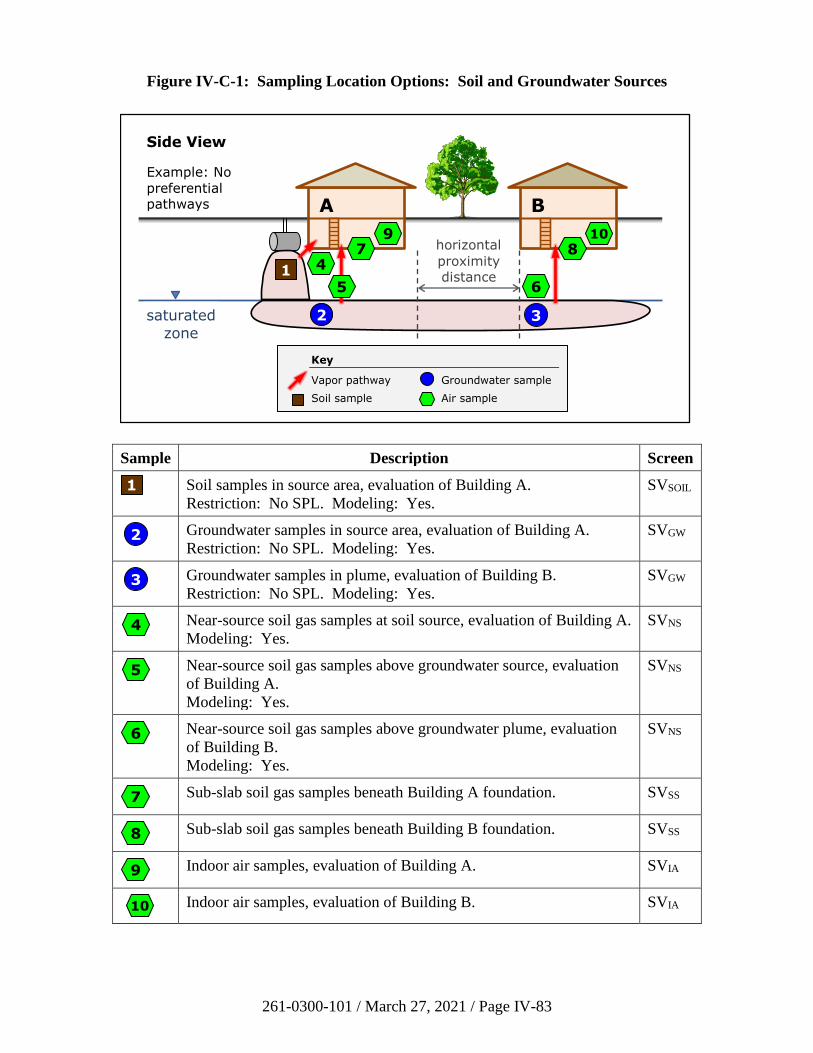
261-0300-101 / March 27, 2021 / Page IV-83
Figure IV-C-1: Sampling Location Options: Soil and Groundwater Sources
Sample Description Screen
Soil samples in source area, evaluation of Building A.
Restriction: No SPL. Modeling: Yes.
SVSOIL
Groundwater samples in source area, evaluation of Building A.
Restriction: No SPL. Modeling: Yes.
SVGW
Groundwater samples in plume, evaluation of Building B.
Restriction: No SPL. Modeling: Yes.
SVGW
Near-source soil gas samples at soil source, evaluation of Building A.
Modeling: Yes.
SVNS
Near-source soil gas samples above groundwater source, evaluation
of Building A.
Modeling: Yes.
SVNS
Near-source soil gas samples above groundwater plume, evaluation
of Building B.
Modeling: Yes.
SVNS
Sub-slab soil gas samples beneath Building A foundation. SVSS
Sub-slab soil gas samples beneath Building B foundation. SVSS
Indoor air samples, evaluation of Building A. SVIA
Indoor air samples, evaluation of Building B. SVIA
A
Side View
Example: No
preferential pathways
6
7
B
horizontal
proximity distance
3
2
1
8 10 9
5
4
Key
Vapor pathway Groundwater sample
Soil sample Air sample
saturated
zone
1
2
3
4
5
6
7
8
9
10
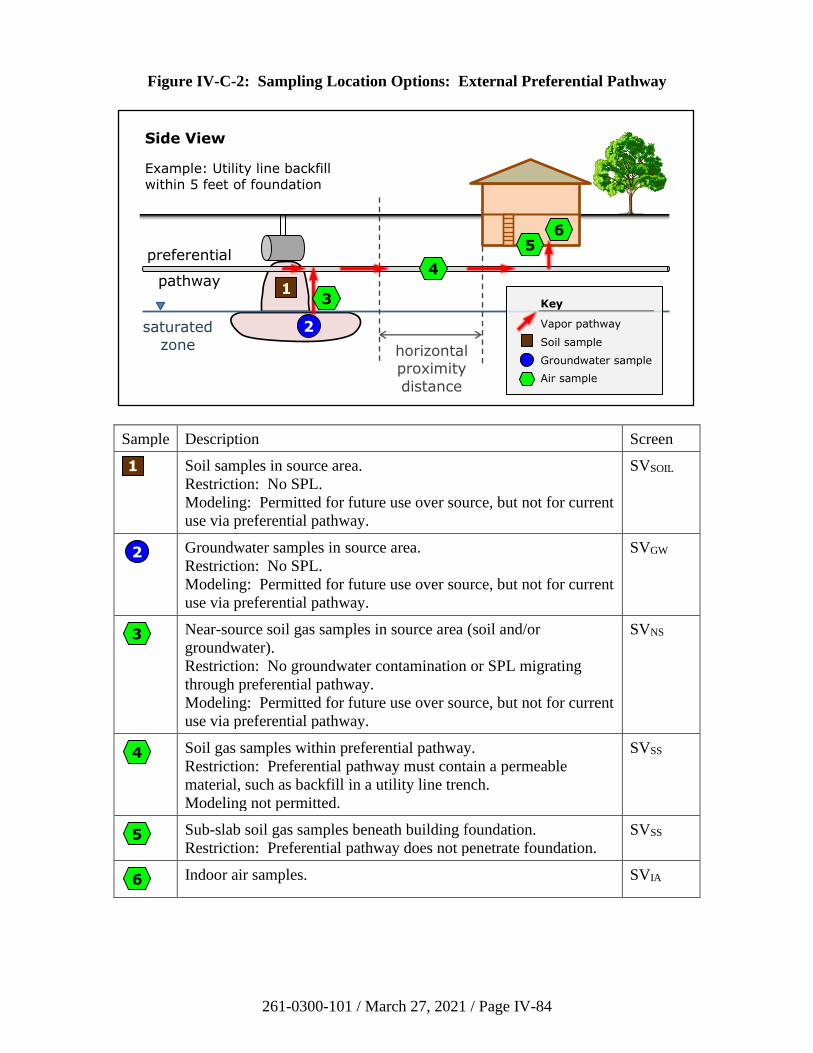
261-0300-101 / March 27, 2021 / Page IV-84
Figure IV-C-2: Sampling Location Options: External Preferential Pathway
Sample Description Screen
Soil samples in source area.
Restriction: No SPL.
Modeling: Permitted for future use over source, but not for current
use via preferential pathway.
SVSOIL
Groundwater samples in source area.
Restriction: No SPL.
Modeling: Permitted for future use over source, but not for current
use via preferential pathway.
SVGW
Near-source soil gas samples in source area (soil and/or
groundwater).
Restriction: No groundwater contamination or SPL migrating
through preferential pathway.
Modeling: Permitted for future use over source, but not for current
use via preferential pathway.
SVNS
Soil gas samples within preferential pathway.
Restriction: Preferential pathway must contain a permeable
material, such as backfill in a utility line trench.
Modeling not permitted.
SVSS
Sub-slab soil gas samples beneath building foundation.
Restriction: Preferential pathway does not penetrate foundation.
SVSS
Indoor air samples. SVIA
Side View
Example: Utility line backfill
within 5 feet of foundation
preferential
pathway
saturated
zone horizontal proximity
distance
1
2
4
5 6
3 Key
Vapor pathway
Soil sample
Groundwater sample
Air sample
1
2
3
4
5
6
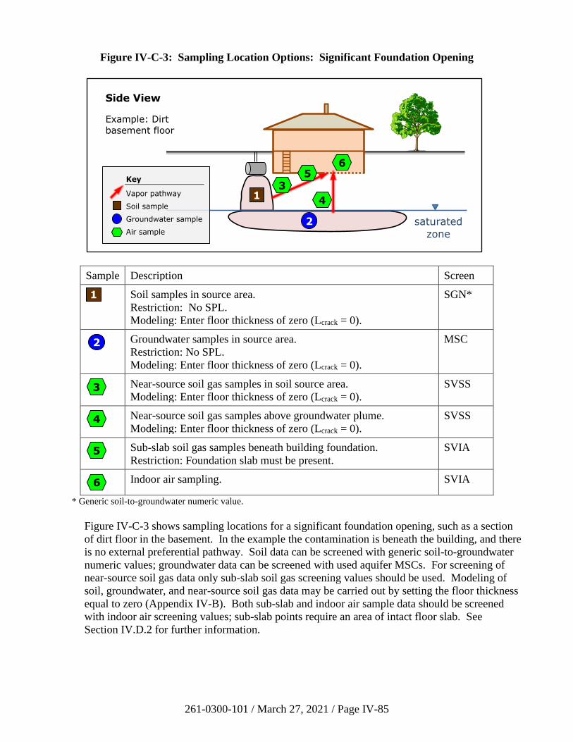
261-0300-101 / March 27, 2021 / Page IV-85
Figure IV-C-3: Sampling Location Options: Significant Foundation Opening
Sample Description Screen
Soil samples in source area.
Restriction: No SPL.
Modeling: Enter floor thickness of zero (Lcrack = 0).
SGN*
Groundwater samples in source area.
Restriction: No SPL.
Modeling: Enter floor thickness of zero (Lcrack = 0).
MSC
Near-source soil gas samples in soil source area.
Modeling: Enter floor thickness of zero (Lcrack = 0).
SVSS
Near-source soil gas samples above groundwater plume.
Modeling: Enter floor thickness of zero (Lcrack = 0).
SVSS
Sub-slab soil gas samples beneath building foundation.
Restriction: Foundation slab must be present.
SVIA
Indoor air sampling. SVIA
* Generic soil-to-groundwater numeric value.
Figure IV-C-3 shows sampling locations for a significant foundation opening, such as a section
of dirt floor in the basement. In the example the contamination is beneath the building, and there
is no external preferential pathway. Soil data can be screened with generic soil-to-groundwater
numeric values; groundwater data can be screened with used aquifer MSCs. For screening of
near-source soil gas data only sub-slab soil gas screening values should be used. Modeling of
soil, groundwater, and near-source soil gas data may be carried out by setting the floor thickness
equal to zero (Appendix IV-B). Both sub-slab and indoor air sample data should be screened
with indoor air screening values; sub-slab points require an area of intact floor slab. See
Section IV.D.2 for further information.
Side View
Example: Dirt basement floor
1
2
4
saturated zone
6
Key
Vapor pathway
Soil sample
Groundwater sample
Air sample
5 3
1
2
3
4
5
6
261-0300-101 / March 27, 2021 / Page IV-86
3. Near-Source Soil Gas Sampling
a) Description
Near-source soil gas is sampled from within the vadose zone, specifically from within
nominally one (1) foot of the contamination source (contaminated soil or groundwater).
For a groundwater source, near-source soil gas samples should be collected within
one (1) foot of the top of the capillary fringe if the water table occurs in soil. If the water
table occurs in bedrock, the near-source soil gas samples should be collected within
one (1) foot of the soil–bedrock interface.
The height of the capillary fringe is not readily determined in the field. The following
table provides theoretical estimates from U.S. EPA (2017, Table 13) which may be used
as a guide. (Refer also to Appendix IV-B, Section IV-B.3 for additional information on
soil type identification.)
Table IV-C-1: Capillary Fringe Height Estimates
Soil Type Lcz (cm) Lcz (ft)
Sand 17 0.6
Loamy Sand 19 0.6
Sandy Loam 25 0.8
Sandy Clay Loam 26 0.9
Sandy Clay 30 1.0
Loam 38 1.2
Clay Loam 47 1.5
Silt Loam 68 2.2
Clay 82 2.7
Silty Clay Loam 130 4.4
Silt 160 5.3
Silty Clay 190 6.3
Lcz: capillary fringe thickness
b) Sample Point Installation
Near-source soil gas sampling points can be temporary (used for one sampling event and
decommissioned) or semi-permanent (used for multiple sampling events).
Recommended resources for soil gas points include API (2005), California EPA (2015),
ASTM (2012a), Hawaii DoH (2014), and ITRC (2014).
i) Installation of Temporary Points
Installation and construction of temporary points may be less time and cost
sensitive. However, these potential savings may be offset over the life of the
project as new points must be installed for each round of sampling. In general,
temporary points rely on the use of boring advancement tools for the collection of
the soil gas sample and the sealing of the point from the atmosphere. This is
accomplished with the compression of the soil along the sides of the boring
261-0300-101 / March 27, 2021 / Page IV-87
against the boring advancement tools. Use of temporary points is not
recommended but may be necessary due to site conditions or site development.
Prior to the utilization of temporary points, the feasibility of the following factors
should be carefully considered:
• Proper sealing of the sampling interval from the surface;
• Isolation of the sampling interval within the boring;
• Potential of negative effects of boring advancement using drive-point
techniques (e.g., decrease of soil gas permeability due to smearing or
compression); and
• Unknown correlation of analytical results for multiple sampling rounds.
ii) Installation and Construction of Semi-Permanent Points
Semi-permanent points are generally constructed in borings advanced using
conventional drilling technologies and sealing of the point is accomplished using
bentonite or grout in the annulus of the boring. Boring advancement techniques
should attempt to minimize disturbance of the vadose zone geologic strata and
soil vapor column. Drilling methods that introduce air (e.g., air rotary) or liquid
(e.g., mud-rotary) should be avoided.
4. Sub-Slab Soil Gas Sampling
a) Description
Sub-slab soil gas is sampled immediately below the floor slab of a building. The slab can
be at grade (slab-on-grade) or below grade (basement).
b) Location
Sub-slab soil gas is located beneath the slab in the porosity of the native soil, ballast
stone, or gravel that the building slab was placed over. Sub-slab soil gas sampling
locations should be determined based on the specific characteristics of the building being
sampled and the objectives of the sampling plan. Whenever possible, sampling locations
should be biased toward areas of the building with the greatest expected VI impact, based
on a combination of the location of VI sources and building occupancy and use. In
general, sampling locations are at least 5 feet from perimeter foundation walls and
sampling next to footers, large floor cracks, and apparent slab penetrations (e.g., sumps,
floor drains) should be avoided.
c) Sample Point Installation
Sub-slab soil gas sampling points can be temporary (used for one sampling event and
decommissioned) or semi-permanent (used for multiple sampling events). The building
occupancy, use, and project goals are influential in the determination of which type of
sampling point to use. A pre-survey, as described in Section IV-C.8(a)(i) herein, can be
261-0300-101 / March 27, 2021 / Page IV-88
completed to assist in determining this information. Generally, installation and
construction of temporary points is less time and cost intensive. However, these potential
savings may be offset over the life of the project as new points must be installed for each
round of sampling.
Sub-slab soil gas sampling points are generally installed inside penetrations through the
building slab. Penetrating the floor slab can be accomplished using a hammer drill and
bit, a core drill, or direct-push technology. Care should be taken during the floor slab
penetration activities to avoid the creation of cracks in the slab. Additionally, the use of
water or other lubricants and coolants during the advancement of the floor slab
penetration should be compatible with the sampling analyte list and may result in the
need for additional point equilibration time (see Section IV-C.8(a)(iv) herein) or the need
to develop the sampling point to limit potential interaction of the sample with the water
or lubricants.
Recommended resources for sub-slab points include California EPA (2011a), New Jersey
DEP (2013), Hawaii DoH (2014), and ITRC (2014).
5. Indoor Air Sampling
a) Sampling Indoor Air
Indoor air sampling is performed when the potential for VI exists through other lines of
evidence, and other investigative tools are not able to eliminate the VI pathway. Indoor
air sampling may also be considered as a method for mitigation system verification.
When compared to the other investigative tools available, indoor air sampling represents
the most direct measure of exposure due to the VI pathway however it also can be heavily
influenced by background conditions.
Recommended resources for indoor air sampling include New York DoH (2006),
California EPA (2011a), New Jersey DEP (2013), Hawaii DoH (2014), and ITRC (2014).
When collecting indoor air samples, it is preferable to collect samples at a time and
location that will result in the highest potential concentrations. Samples should be
collected from the lowest level of the structure with appropriate accessibility where
vapors are expected to enter, including basements, crawl spaces, and where preferential
pathways have been identified. Existing environmental data (e.g., groundwater, soil,
sub-slab soil gas, etc.), site background information, building construction
(e.g., basement, slab-on-grade, or multiple types of foundations, elevator shafts, tunnels,
etc.), and building operation details (e.g., number and operation of HVAC systems) as
evaluated through the development of the CSM should be considered when selecting
locations within the building for indoor air sampling. Indoor air samples may be
collected concurrently and collocated with sub-slab soil gas sampling locations, and
concurrently with an outdoor ambient air sample.
To characterize contaminant concentrations trends and potential exposures, indoor air
samples are commonly collected:
• From the crawl space area;
261-0300-101 / March 27, 2021 / Page IV-89
• From the basement (where vapor infiltration is suspected, such as near sump
pumps or indoor wells, or in a central location);
• From the lowest level living space (in centrally located, high activity use areas);
• From multiple tenant spaces if in a commercial setting.
If the pre-survey (Section IV-C.8(a)(i) herein) determines that chemicals of concern for
VI are used, handled, or stored in the building being investigated, then those materials
should be removed prior to collecting indoor air samples, if possible. The building
should be ventilated for at least 24 hours following removal and before sampling. Other
lines of evidence may be necessary, such as collocated sub-slab soil gas and indoor air
samples, if the materials cannot be removed.
b) Outdoor Ambient Air Sampling
To understand potential background influences during indoor air sampling, an outdoor
ambient air sample is commonly collected. This sample provides background
concentrations outside of the building being investigated at the time of the indoor air
sampling event. The investigator commonly designates a sample location and the site
conditions at the time of sampling. The investigator also should be aware of the weather
conditions during the sampling event. The sampler should be placed in a secure outside
location.
Atmospheric pressure and temperature data from nearby weather reporting stations or
through portable meteorological equipment should be collected in conjunction with the
ambient air samples. Two web sites that may be useful to the investigator are NOAA’s
National Weather Service and the Weather Underground.
The following actions are commonly taken to document conditions during outdoor air
sampling and ultimately to aid in the interpretation of the sampling results:
• Outdoor plot sketches are drawn that include the building site, area streets,
outdoor air sampling location(s), the location of potential interferences
(e.g., gasoline stations, dry cleaners, factories, lawn mowers, etc.), compass
orientation (north), and paved areas;
• Weather conditions (e.g., precipitation and outdoor temperature) are reported;
• Predominant wind direction(s) during the sampling period are reported using wind
rose diagrams; and
• Pertinent observations, such as odors, readings from field instrumentation, and
significant activities in the vicinity are recorded.
261-0300-101 / March 27, 2021 / Page IV-90
6. Sampling Soil Gas for Oxygen Content
Note: This section of the guidance is intended only for remediators using the vertical proximity
distances for petroleum hydrocarbons.
If the remediator chooses to screen a site using the vertical proximity distances for petroleum
hydrocarbons, the acceptable soil or soil-like material should contain greater than 2% oxygen, on
a volumetric basis. Oxygen content above this level indicates an aerobic environment that
enables biodegradation of petroleum vapors. The investigator can measure the oxygen
concentration in the vadose zone at buildings that are potential receptors to demonstrate that the
aerobic soil condition is met.
DEP recommends collecting a soil gas sample beneath the building for oxygen content when
there is reason to suspect that the soil may be anaerobic (Section IV.E). Only one grab sample
collected at a single location is sufficient. A hole should be drilled approximately 12 inches into
acceptable soil or soil-like material (i.e., beneath any gravel or similar fill material underlying
the slab). Tubing with a probe tip is dropped into the hole, which is then filled with clean sand
(e.g., Hawaii DoH, 2014, Section 7.9.3).
When it is not feasible to obtain the soil gas sample beneath the building, a near-slab soil gas
sample may be collected. The sample point should be as close to the building as practical, and
no farther than 10 feet. It should be located in the area of greatest anticipated soil vapor
contamination. The screen depth should be above the top of the soil or groundwater
contamination (e.g., smear zone) and below the bottom of the building foundation. The screen
should also be at least 5 feet below the ground surface. The investigator may also collect
samples at multiple depths to obtain a concentration profile demonstrating biodegradation. The
sample probe should be allowed to equilibrate with the subsurface and purged.
In addition to analysis of oxygen (O2), additional compounds such as carbon dioxide (CO2) and
methane (CH4) can be measured to document biodegradation. One grab sample is sufficient to
demonstrate that the 2% O2 criterion is satisfied. The sample may be analyzed using a properly
calibrated portable instrument. Oxygen should be calibrated at around 2% and 21%.
Alternatively, the sample may be collected using a Tedlar bag or a Summa canister and analyzed
at a mobile or offsite laboratory using EPA Reference Method 3C.
7. Sampling Separate Phase Liquids
When SPL is present, soil and groundwater screening and modeling are not options available for
assessing VI. However, the remediator may obtain a sample of the SPL from a monitoring well
to determine if VOCs posing a VI risk are present. This section describes how to evaluate the
SPL data for VI.
The SPL sample should be analyzed with U.S. EPA Method 8260C. The results may be reported
in units of mass per volume (micrograms per liter, µg/L) or mass per mass (micrograms per
kilogram, µg/kg). If the data is reported on a volumetric basis, then the SPL density must be
estimated or measured to calculate the mass fraction of each volatile component (e.g.,
ASTM, 2012b). In addition, the molecular weight of the SPL must be estimated from reference
values or an analysis to calculate the mole fraction of each component (e.g., ASTM, 2014).
261-0300-101 / March 27, 2021 / Page IV-91
The vapor concentration (Cv) of each volatile component over the SPL, in units of micrograms
per cubic meter (µg/m3), equals:
𝐶v =𝑥i(VP)(MW)
𝑅𝑇× (109)
Where xi is the calculated liquid phase mole fraction of the component in the SPL, and the other
quantities are defined in Table IV-C-2. (The 109 factor converts from units of g/L to µg/m3.)
Table IV-C-2: SPL Vapor Phase Parameters
Symbol Description Value Units
VP vapor pressure VISL mm Hg
MW molecular weight Table IV-A-5 g/mol
R universal gas constant 62.4 L (mm Hg) mol–1 K–1
T temperature Table IV-B-2 K
VISL: U.S. EPA’s VISL Calculator spreadsheet (U.S. EPA, 2014a).
The vapor concentrations calculated for each substance of concern in the SPL using the above
equation are comparable to near-source soil gas concentrations. Therefore, they may be
evaluated with near-source soil gas screening values (Table IV-3 on the Department’s VI web
page for the SHS) to determine if each chemical poses a potential VI risk. Alternatively, the
calculated vapor concentrations may be used with a near-source soil gas attenuation factor in a
cumulative risk assessment under the SSS (Appendix IV-B, Section IV-B.6). If the SPL is less
than 5 feet below the building foundation, then one should apply sub-slab soil gas screening
values (Table IV-4 on the Department’s VI web page) and sub-slab soil gas attenuation factors.
As an example, consider SPL that is inferred to be No. 6 fuel oil present beneath a nonresidential
building. Analysis of a sample of the SPL finds that benzene is nondetect, with a quantification
limit of 50,000 µg/L. The density of the SPL is measured, and the result is 8.1 lb/gal
(0.97 kg/L). The molecular weight of benzene is 78 g/mol, and the approximate molecular
weight of No. 6 fuel oil is 300 g/mol. Therefore, using these values we first estimate an upper
bound on the mole fraction of benzene in the SPL, which equals xbenzene = 2.0 x 10⁻⁴. Next, given
a subsurface temperature of 18°C, the estimated maximum vapor concentration of benzene over
the SPL, calculated with the above equation, is Cv = 82,000 µg/m3.
The nonresidential SHS near-source soil gas screening value for benzene is SVNS =
16,000 µg/m3. The estimated benzene vapor concentration based on the detection limit in this
example exceeds the screening value. Therefore, at this analytical accuracy, sampling the SPL
cannot rule out benzene as a contaminant of VI concern. Possible alternative investigative
approaches include near-source soil gas, sub-slab soil gas, or indoor air sampling.
261-0300-101 / March 27, 2021 / Page IV-92
8. Quality Assurance and Quality Control Procedures and Methods
a) Sampling Procedures and Methods
i) Pre-Sampling Survey
Prior to the installation and construction of indoor air and sub-slab soil gas
sampling points and the collection of samples, a pre-sampling survey should be
conducted. The survey should include a short interview with a representative of
the owner/occupant of the building and a visual review of accessible portions of at
least the lowest level of the building (basement or first floor). Results of the
survey are documented and supplemented by sketch maps and photographs as
necessary. The investigator may also choose to use a photoionization detector
(PID) or flame ionization detector (FID) during the survey to screen for the
presence of VOCs in the building. (Note: The non-compound specific VOC
detection levels of PIDs and FIDs are much higher than compound-specific
laboratory reporting limits.) The pre-sampling survey should review
building-specific factors that could influence VOC concentrations in indoor air
including:
• Building construction characteristics;
• Building features, such as the condition of the floor slab, floor
penetrations, and floor cracks;
• Heating and ventilations systems;
• Items within the lowest level of the building that could serve as potential
VOC sources (paint cans, solvents, fuel containers, etc.);
• Occupant activities in the building (painting, smoking, etc.); and
• Exterior characteristics and items or occupant activities outside the
building that could serve as potential VOC sources (mowing, paving, etc.).
These observations and others should be documented on a building survey form.
For additional information see ITRC (2007), California EPA (2011a), and New
Jersey DEP (2013).
ii) Sampling Equipment
Near-source soil gas, sub-slab soil gas, and indoor air samples are commonly
collected in passivated stainless steel canisters (e.g., Summa) with
laboratory-calibrated flow controllers for U.S. EPA Method TO-15, or other
appropriate U.S. EPA methods if TO-15 is not applicable. Other types of
sampling containers (e.g., Tedlar bags, glass bulbs, syringes) may be used under
certain conditions, but stainless steel canisters are preferred.
261-0300-101 / March 27, 2021 / Page IV-93
Canister volumes should be selected to minimize sample volume while still
meeting data quality objectives. Minimizing sampling volumes for near-source
soil gas and sub-slab soil gas reduces the potential for ambient air entering around
the sampling point and limits the potential for migration of soil gas from
relatively long distances away from the sampling point during sample collection.
Generally, 1-L canisters are used for near-source soil gas and sub-slab soil gas
sample collection and 6-L canisters are used for indoor air and ambient sampling.
Canisters should be connected to the soil gas sampling point using small diameter
stainless steel, nylon (Nylaflow type LM), polytetrafluoroethylene (PTFE,
Teflon), or polyether ether ketone (PEEK) tubing and stainless steel
compression-type fittings. (Other appropriate non-reactive materials may be
used. Polyethylene, Tygon, and silicone are not acceptable tubing materials.)
The number of connections in the sampling system should be minimized to reduce
the number of locations where leaks could occur. Minimizing the length and
diameter of the tubing reduces the sample residence time and the required purge
volume.
iii) Sampling Point Construction
Near-source and sub-slab soil gas sampling point construction materials should be
selected to minimize potential interaction with the sample. The probe should be
connected to small diameter tubing; the tubing and all fittings should be clean and
dry. The tubing is recommended to be capped or plugged at the surface to isolate
the sample from the atmosphere or indoor air.
Sub-slab sample points are sealed in the penetration to eliminate short circuiting
of air from inside the building through the slab penetration and into the sample.
The materials and methods used to create this seal will depend on site-specific
factors such as the condition of the slab and the type and volume of traffic in the
building as well as the data quality objectives and planned QA and quality control
(QC) protocols. Temporary points may be sealed in the penetration with silicone
sleeves, silicone rubber stoppers, sculpting clay, putty, or wax. Semi-permanent
points may involve the drilling of nested holes in the slab and the use of hydraulic
cement or epoxy to seal the tubing and possibly additional fittings in the
penetration below the finished elevation. All materials used for construction and
completion of the sub-slab soil gas sampling point should be clean, dry and free
of materials that could affect the sampling or analysis.
The diameter of the floor slab penetration should be minimized (generally
between 3/8 and 1 inch). The surface and sidewalls of the penetration should be
cleaned with a stiff bristle brush to remove material created by the advancement
of the penetration. Removal of this material is important to limit entrainment of
dust in the sub-slab soil gas sample and to promote adherence of the sealing
materials to the sidewalls of the penetration or the surface of the slab. Care
should be taken to limit interaction with the sub-slab soil gas beneath the slab if a
vacuum is used to remove dust during/after advancement of the penetration. If a
vacuum is used, additional point equilibration time may be necessary.
261-0300-101 / March 27, 2021 / Page IV-94
Some manufacturers offer alternative sub-slab soil gas sampling point equipment
that relies on driving (hammering) a specialized barbed-metal fitting into the slab
penetration. The metal fitting is sealed inside the slab penetration by the
compression of a sleeve of flexible tubing between the fitting’s barbs and the
sidewalls of the penetration. These “hammer-in” points may be considered for
use during VI investigations.
For indoor and outdoor air sampling, the sampling port should be placed in the
breathing zone, approximately 3 to 5 feet above the floor. Mount the canister on a
stable platform or attach a length of inert tubing to the flow controller inlet and
support it such that the sample inlet will be at the proper height.
Ambient air samples should be collected at breathing zone height (if possible) and
in close proximity to the building being tested. For nonresidential buildings, the
investigator may elect to collect the ambient air sample near representative
HVAC intake locations (i.e., on the roof). Other locations for ambient sampling
could be upwind of the building to be sampled. The ambient air sample should
have the same sample collection time and be analyzed in the same manner as the
interior sample collection method.
iv) Equilibration
After installation, near-source and sub-slab soil gas points should be allowed to
equilibrate to natural conditions. This is commonly a minimum of 2 hours up to
24 hours.
v) Leak Testing/Detection for Subsurface Sample Collection
Leakage during soil gas sampling may dilute samples with ambient air resulting in
data that underestimates actual site concentrations or causes false negatives. A
shut-in check (sampling assembly integrity) and a leak check (surface seal
integrity) can be conducted to determine whether leakage is present and then
corrected in the field prior to collecting the sample. Recommended resources for
leak testing include ASTM (2012a), California EPA (2015), New Jersey DEP
(2013), Hawaii DoH (2014), and ITRC (2014).
A shut-in test of the sampling train is recommended to be completed at each
location and during each sampling event to verify aboveground fittings do not
contain leaks. A shut-in test consists of assembling the above-ground apparatus
(valves, lines, and fittings downstream of the top of the probe), and evacuating the
lines to a measured vacuum of about 15 inches mercury (200 inches water or
50,000 Pascals), then shutting the vacuum in with closed valves on opposite ends
of the sample train. The vacuum gauge is observed for at least 1 min, and if there
is a loss of vacuum greater than 0.5 inches mercury (7 inches water or
2000 Pascals), the fittings should be adjusted as needed to maintain the vacuum.
Leak check tests are recommended for near-source and sub-slab soil gas points
after construction and equilibration. One method employs a shroud placed over
the point. An inert tracer gas (such as helium) is released into the shroud with a
261-0300-101 / March 27, 2021 / Page IV-95
target concentration of 10–20%. With the canister valve closed, a soil gas sample
is collected from the sample point and measured with a portable helium detector.
A leak is occurring when the helium concentration is greater than 10% of the
concentration within the shroud. In this case, the leak must be fixed and the leak
check repeated.
Helium is the preferred tracer as it is readily available, non-toxic, and easily
measured in the field provided high methane levels are not present (false
positives). Helium may also be analyzed in the Summa canister sample at the
laboratory.
Note: Balloon-grade helium may contain hydrocarbons that could interfere with
sample analysis.
vi) Purging
Purging occurs after the sampling system has been assembled (i.e., the canister
has been connected to the flow controller and the sampling point has been
connected to the canister/flow controller). A “T” fitting can be placed in the
sampling train to allow for purging of the connected sampling system. The
purging leg of the “T” is commonly isolated from the rest of the sampling train
using a valve. There are several acceptable methods for purging the system. For
example, either a graduated syringe or a personal sampling pump can be used.
Purge rates for near source and sub-slab soil gas samples should be less than
200 mL/min to limit the potential for short-circuiting or desorbing VOCs from
soil particles. Purging volumes should be about three times the volume of the
total sampling system (i.e., the sampling point and tubing connected to the
sampling canister).
If water is encountered in the soil gas sampling point or observed in the sample
tubing during purging, then sampling of the point should not be performed.
Commonly, when water is encountered during purging an effort is made to
evacuate the water from the soil gas sampling point and then allow a minimum of
48 hours before reattempting purging and sampling.
vii) Sampling Rates
Sampling rates for near-source and sub-slab soil gas samples should be less than
200 mL/min. Sample rates are determined by the laboratory-calibrated flow
controller attached to the canister.
Vacuum levels during sampling should not exceed 7.5 inches mercury (100 inches
water or 25,000 Pascals). If low permeability materials are encountered during
point installation or if there are issues during purging or sampling that suggest
low permeability, testing should be performed to measure flow rates and vacuum
levels in the near-source soil gas sampling point to determine acceptable purging
and sampling flow rates.
261-0300-101 / March 27, 2021 / Page IV-96
Indoor air and ambient air samples are typically collected over a 24-hour period;
however, in a nonresidential setting an 8-hour sampling period may be used to
coincide with the hours of operation and thus the period of exposure. The
sampling flow rate should always be less than 200 mL/min.
With near-source or sub-slab soil gas sampling, the sample duration should be
determined by sample volume, but it is recommended to be at least 15 minutes.
If water is observed in the sample tubing during sampling, then sampling should
be discontinued. Commonly, when water is encountered during sampling an
effort is made to evacuate the water from the soil gas sampling point and then
allow a minimum of 48 hours before reattempting purging and sampling.
viii) Sample Recordation
The field sampling team should maintain a sample log sheet summarizing the
following:
• Sample identification;
• Date and time of sample collection;
• Sample location;
• Identity of sampler;
• Sampling methods and devices;
• Volume and duration of sample;
• Canister vacuum before and after sample is collected; and
• Chain of custody protocols and records used to track samples from
sampling point to analysis.
b) Data Quality Objective (DQO) Process, Sampling and Data Quality Assessment
Process
The DQO process (U.S. EPA, 2006) allows a person to define the data requirements and
acceptable levels of decision errors prior to data collection. The DQO process should be
considered in developing the sampling and analysis plan, including the QA plan. The
implementation phase includes sampling execution and sample analysis. The assessment
phase includes Data Quality Assessment (DQA). (See 25 Pa. Code § 250.702(a) of the
regulations and Section III.F.1.)
c) QA/QC Samples
Prior to using a canister, the integrity of the canister should be examined for damage due
to shipping. The canisters should be received in the field with the laboratory-measured
261-0300-101 / March 27, 2021 / Page IV-97
pressure as part of the documentation. Field check the pressure of the canister before
collecting the sample. The field-measured pressure should be within 10% of the
laboratory recorded value. If this is not the case, the canister should be rejected and
another canister used. There may be some minor difference in measured pressures (for
instance with changes in altitude and barometric pressure) of less than 5% that does not
reflect a canister integrity problem.
On completion of sample collection, the final pressure reading should be recorded. This
should be about 5 inches mercury (70 inches water or 20,000 Pascals). The reading
should be recorded on the chain of custody or other field documentation. If the final
pressure is zero (atmospheric), it should still be recorded and sent to the laboratory for
verification.
A field duplicate sample may be collected by using a “T” fitting at the point of collection
to divide the sample stream into two separate sample containers.
Trip blanks for canisters are not typically required.
Dependent on the sampling equipment it may be desirable to perform an equipment
blank. The sample collection media should be certified clean. Materials used in setting
up a sampling train should be VOC-free and stored and transported in a VOC-free
environment.
Field method blanks can be used to verify the effectiveness of decontamination
procedures and to detect any possible interference from ambient air. If samples are
collected using sorbent media, it is recommended that a blank media sample accompany
the batch of sample media to the field and be returned to the laboratory for analysis. This
demonstrates the media is free from compounds of concern from preparation through
shipping and handling.
d) Analytical Methods
A variety of analytical methods are available to measure vapor samples (subsurface
vapor, indoor and ambient air), all of which can provide useable data when reported with
QA/QC (Table IV-C-3). The laboratory QA/QC will include blanks, calibration, and
system performance samples that define and verify the quality of the data reported. The
laboratory engaged for air and vapor analysis should have NELAC or similar
accreditation for the methods reported. There may be cases where certification for the
method that will be used is not available. In this case, a laboratory standard operating
procedure should be available and appropriate QA/QC should be reported with the
results.
Communicate with the laboratory during the planning stages of the investigation to
ensure the appropriate analytical method is used. For the data assessment process, it is
suggested at a minimum for the laboratory to provide summary QA/QC results with the
data reported. A full validated data package can be requested if necessary.
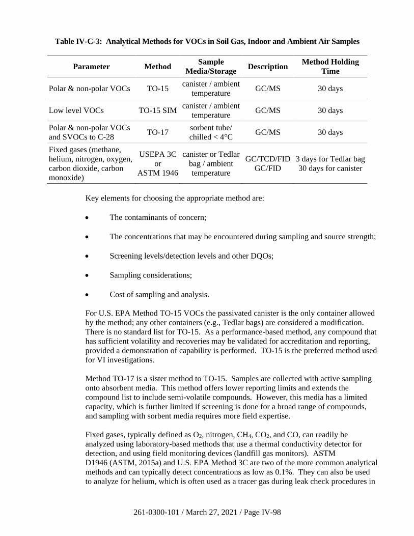
261-0300-101 / March 27, 2021 / Page IV-98
Table IV-C-3: Analytical Methods for VOCs in Soil Gas, Indoor and Ambient Air Samples
Parameter Method Sample
Media/Storage Description
Method Holding
Time
Polar & non-polar VOCs TO-15 canister / ambient
temperature GC/MS 30 days
Low level VOCs TO-15 SIM canister / ambient
temperature GC/MS 30 days
Polar & non-polar VOCs
and SVOCs to C-28 TO-17
sorbent tube/
chilled < 4°C GC/MS 30 days
Fixed gases (methane,
helium, nitrogen, oxygen,
carbon dioxide, carbon
monoxide)
USEPA 3C
or
ASTM 1946
canister or Tedlar
bag / ambient
temperature
GC/TCD/FID
GC/FID
3 days for Tedlar bag
30 days for canister
Key elements for choosing the appropriate method are:
• The contaminants of concern;
• The concentrations that may be encountered during sampling and source strength;
• Screening levels/detection levels and other DQOs;
• Sampling considerations;
• Cost of sampling and analysis.
For U.S. EPA Method TO-15 VOCs the passivated canister is the only container allowed
by the method; any other containers (e.g., Tedlar bags) are considered a modification.
There is no standard list for TO-15. As a performance-based method, any compound that
has sufficient volatility and recoveries may be validated for accreditation and reporting,
provided a demonstration of capability is performed. TO-15 is the preferred method used
for VI investigations.
Method TO-17 is a sister method to TO-15. Samples are collected with active sampling
onto absorbent media. This method offers lower reporting limits and extends the
compound list to include semi-volatile compounds. However, this media has a limited
capacity, which is further limited if screening is done for a broad range of compounds,
and sampling with sorbent media requires more field expertise.
Fixed gases, typically defined as O2, nitrogen, CH4, CO2, and CO, can readily be
analyzed using laboratory-based methods that use a thermal conductivity detector for
detection, and using field monitoring devices (landfill gas monitors). ASTM
D1946 (ASTM, 2015a) and U.S. EPA Method 3C are two of the more common analytical
methods and can typically detect concentrations as low as 0.1%. They can also be used
to analyze for helium, which is often used as a tracer gas during leak check procedures in
261-0300-101 / March 27, 2021 / Page IV-99
subsurface sampling. Analysis for these gases can be run from the same canister as
VOCs.
Contact your laboratory for analyte lists and reporting levels applicable to these methods,
and reference Section III.G.3 for information regarding PQLs.
e) Data Evaluation
If the project was planned using the DQO process or another standard project planning
process, the quantity and quality of data, including the measurement quality objectives,
will have been specified in the sampling and analysis plan. All of the data should be
examined for these types of issues to ensure the data set is of adequate quality prior to use
in evaluating the VI pathway.
9. Active Sub-Slab Depressurization System Testing
Details regarding the application, design, installation, and performance testing of SSD systems
and other VI mitigation systems are available in the following references: U.S. EPA (1991,
1993, 1994a, 1994b, 2001, 2008), Massachusetts DEP (1995), Pennsylvania DEP (1997),
California EPA (2011b), and ASTM (2008, 2011b, 2013b, 2015b).
a) Description
This section applies to recommended performance testing procedures for active sub-slab
depressurization systems installed as engineering controls on buildings where the VI
pathway is a potential concern. For existing buildings, active SSD systems are the VI
mitigation method preferred by DEP. However, the performance and testing
requirements described below may also apply for other active VI mitigation technologies
such as sub-membrane depressurization, sub-slab pressurization, and building
pressurization systems.
Installation of SSD systems includes the sealing of potential soil vapor infiltration points
combined with the use of a fan or blower that creates a continuous negative pressure field
(vacuum) beneath the concrete floor slab of the lowest level of the building (basement or
first floor). The fan or blower pulls the soil vapor from beneath the slab and vents it to
the atmosphere at a height well above the outdoor breathing zone (ITRC, 2014,
Appendix J). The presence of a continuous negative pressure field beneath the slab
results in the movement of indoor air down into the subsurface, thereby eliminating the
VI pathway as a potential concern.
Installation of SSD systems in existing buildings should be performed by qualified
professionals, and it is generally completed in the following three steps:
Step 1: Inspection and Design-Support Diagnostic Testing – This step typically
includes visual inspection of the lowest level of the building to assess the condition of the
foundation, to identify potential soil vapor entry points that require sealing, and to review
building-specific design considerations such as the location and type of construction of
extraction points, possible discharge piping routes, and exhaust fan locations. This step
also includes diagnostic testing to support siting of extraction points, sizing of the exhaust
261-0300-101 / March 27, 2021 / Page IV-100
fan/blower and piping, and evaluation of stack effects and the potential for back-drafting
of heating systems. The results of the diagnostic tests or communication tests are used to
confirm the ability of the SSD to depressurize beneath the entire building.
Step 2: Design and Construction of the SSD System – The mitigation contractor
prepares a design applicable to the building characteristics and results of diagnostic
testing. Elements of the construction include installation of extraction point(s), exhaust
piping, exhaust fans/blowers, and sealing of potential soil vapor entry points.
Step 3: Commissioning of the SSD System – The commissioning step includes
post-construction performance testing consisting of pressure differential measurements to
demonstrate the system is working as designed. During this step, smoke testing is also
performed to confirm operation of the SSD system does not result in back-drafting of
combustion appliances (heating systems). Adjustments to or augmentation of the SSD
system may be completed during this final installation step. Post-construction
performance testing methods completed as part of commissioning of active SSD systems
are described below.
b) Performance Testing Methods
The remediator should test the mitigation system after its installation. At a minimum, the
testing should follow the manufacturer’s or vendor’s recommendations. The mitigation
system should also be tested if a significant modification or repair is made, after a change
in ownership, or upon request by the Department.
The primary method of performance testing of active sub-slab depressurization systems
consists of differential pressure field extension tests that provide confirmation of a
continuous negative pressure field (vacuum) beneath the concrete floor slab of the lowest
level of the building. If the differential pressure field extension tests demonstrate the
operating SSD system is providing depressurization throughout the sub-slab, the
remediator is not required to perform indoor air confirmation sampling.
Differential pressure field extension tests are performed by operating the SSD system and
simultaneously measuring the sub-slab pressure at different locations across the floor slab
including, if accessible, building corners and building perimeters. The pressure
measurements should be performed by drilling a small hole through the slab
(e.g., 3/8-inch diameter) and measuring the differential pressure using a digital
micromanometer. In general, for active SSD systems a pressure differential of at least
0.01 inches water (2 Pascals) should be achieved when the heating system is operating
and 0.025 inches water (6 Pascals) otherwise (U.S. EPA, 1993). The minimum pressure
of 6 Pascals is a guideline that applies mostly to residential structures, but use of a lower
threshold may be considered (e.g. for larger commercial structures) on a case-by-case
basis if proper justification is provided. As such, a digital micromanometer with
sufficient sensitivity is necessary. Smoke testing can be performed as a qualitative test,
but it may not be as reliable with low vacuums.
As an alternative to differential pressure testing, the remediator may collect one or more
indoor air samples.
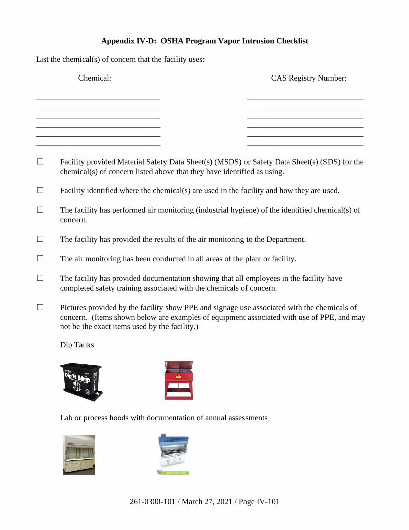
261-0300-101 / March 27, 2021 / Page IV-101
Appendix IV-D: OSHA Program Vapor Intrusion Checklist
List the chemical(s) of concern that the facility uses:
Chemical: CAS Registry Number:
_______________________________ _____________________________
_______________________________ _____________________________
_______________________________ _____________________________
_______________________________ _____________________________
_______________________________ _____________________________
_______________________________ _____________________________
☐ Facility provided Material Safety Data Sheet(s) (MSDS) or Safety Data Sheet(s) (SDS) for the
chemical(s) of concern listed above that they have identified as using.
☐ Facility identified where the chemical(s) are used in the facility and how they are used.
☐ The facility has performed air monitoring (industrial hygiene) of the identified chemical(s) of
concern.
☐ The facility has provided the results of the air monitoring to the Department.
☐ The air monitoring has been conducted in all areas of the plant or facility.
☐ The facility has provided documentation showing that all employees in the facility have
completed safety training associated with the chemicals of concern.
☐ Pictures provided by the facility show PPE and signage use associated with the chemicals of
concern. (Items shown below are examples of equipment associated with use of PPE, and may
not be the exact items used by the facility.)
Dip Tanks
Lab or process hoods with documentation of annual assessments
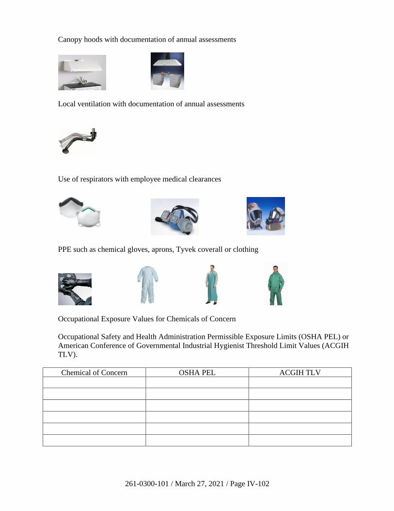
261-0300-101 / March 27, 2021 / Page IV-102
Canopy hoods with documentation of annual assessments
Local ventilation with documentation of annual assessments
Use of respirators with employee medical clearances
PPE such as chemical gloves, aprons, Tyvek coverall or clothing
Occupational Exposure Values for Chemicals of Concern
Occupational Safety and Health Administration Permissible Exposure Limits (OSHA PEL) or
American Conference of Governmental Industrial Hygienist Threshold Limit Values (ACGIH
TLV).
Chemical of Concern OSHA PEL ACGIH TLV

261-0300-101 / March 27, 2021 / Page IV-103
OSHA exposure limits are available at: 29 CFR Subpart Z; 29 CFR 1910.1000–1052
https://www.osha.gov/dsg/annotated-pels/index.html
ACGIH TLVs are available from the purchased publication. All of these values should be
available from the MSDS/SDS.
Status: (All of the above items must be included for the facility to qualify to use an OSHA
program to address VI.)
☐ Qualified: OSHA implementation is documented and can be used to address VI
☐ Not Qualified: OSHA implementation is NOT documented
Consultant or Reviewer:
(Print)______________________________________
(Signature)________________________________ Date:_________________
261-0300-101 / March 27, 2021 / Page V-i
TABLE OF CONTENTS
SECTION V: RELATIONSHIP TO OTHER ENVIRONMENTAL STATUTES ....................... V-1
A. Solid Waste Facilities ................................................................................................................. V-1 1. Movement of Excavated Contaminated Media and Other Solids ................................... V-1 2. Disposal Prior to September 7, 1980 .............................................................................. V-2 3. Disposal after September 7, 1980, for Residual Waste and
Construction/Demolition Waste, and between September 7, 1980, and
October 9, 1993, for Municipal Waste............................................................................ V-2 4. Disposal of Hazardous Waste after September 7, 1980, or Municipal
Waste after October 9, 1993, Subject to Federal Closure Requirements ........................ V-3 a) Hazardous Waste ................................................................................................ V-4 b) Municipal Waste ................................................................................................. V-5
B. Clean Streams Law Interface ...................................................................................................... V-6
1. Point Source Discharges ................................................................................................. V-6 2. Nonpoint Source Discharges........................................................................................... V-7
3. Erosion and Sedimentation (E&S) Control..................................................................... V-7
a) For Earth Disturbances Less Than 5,000 Square Feet (Ft2)................................ V-7 b) For Earth Disturbances 5,000 Ft2 to 1 Acre (and Discharge to
Special Protection Waters For Any Size of Earth Disturbance Less
Than 1 Acre) ....................................................................................................... V-7 c) For Earth Disturbances 1 Acre or Greater .......................................................... V-8
d) Post-Construction Stormwater Management (PCSM) ........................................ V-8 C. Clean Air Act and Air Pollution Control Act Interface ............................................................ V-10 D. Regulated Storage Tank Release Sites ...................................................................................... V-11
1. Introduction ................................................................................................................... V-11
2. Short List of Petroleum Products .................................................................................. V-11 3. Management of Separate Phase Liquid (SPL) under Act 2 and Act 32........................ V-12
a) Management of SPL under Act 32 and Chapter 245 ........................................ V-12
b) Management of SPL under Act 2 and Chapter 250 .......................................... V-13 c) Relationship of SPL to Compliance with Act 2 Standards ............................... V-14
i) Background Standard ............................................................................ V-14 ii) Statewide Health Standard (SHS) ......................................................... V-14
(a) Groundwater ............................................................................. V-14
(b) Soil ............................................................................................ V-14 iii) Site-Specific Standard (SSS) ................................................................ V-15
E. HSCA/CERCLA Remediation.................................................................................................. V-16
1. Hazardous Sites Cleanup Act (HSCA) Sites ................................................................ V-16 2. Comprehensive Environmental Response Compensation Liability Act
(CERCLA) Sites ........................................................................................................... V-17 F. References ................................................................................................................................. V-18
261-0300-101 / March 27, 2021 / Page V-1
SECTION V: RELATIONSHIP TO OTHER ENVIRONMENTAL STATUTES
Remediation under Act 2 sometimes involves relationships with other environmental statutes (e.g.,
closure of waste management facilities, groundwater pump and treat systems which discharge to a
surface water and require an NPDES permit). Although other Department programs (e.g., Bureau of
Clean Water) will be involved in requests and approvals, the regional Environmental Cleanup and
Brownfields Manager will coordinate these activities. Therefore, all correspondence necessary for the
Act 2 cleanup should be submitted to the attention of the regional Environmental Cleanup and
Brownfields Manager.
As a general rule, according to Section 902 of Act 2, a permit is not required for remediation activities
that occur entirely on a site if they are undertaken under Act 2. In addition, the Department may waive
the need for permits and other requirements when pursuing permits and other requirements result in
greater risk to human or environmental health or may interfere with natural or artificial structures or
features. The Department may also waive the need for permits and other requirements if the
remediation undertaken attains a standard equivalent to the applicable requirement, or if compliance
with the requirement will not provide for a cost-effective remedial action.
A. Solid Waste Facilities
This section provides a general overview of the interface between Act 2 and the Solid Waste
Management Act (SWMA) (35 P.S. §§ 6018.101-6018.1003). The sections that follow are
meant to provide a broad overview of the interrelationship between these statutes and programs;
they are not meant to be used as a substitute for specific regulations that apply to solid waste
processing or disposal facilities. Solid waste management facilities, including those facilities
that process and dispose of municipal, residual, or hazardous wastes, are primarily regulated
under SWMA. The permitting, bonding and compliance requirements of SWMA are
implemented through policies and regulations adopted as follows: Chapters 260(a) through
270(a) for hazardous waste, Chapters 271 through 285 for municipal waste, and Chapters 287
through 299 for residual waste.
The Management of Fill Policy (August 7, 2010 - Document Number 258-2182-773) provides
the Department’s procedures for determining whether material qualifies as clean fill or regulated
fill under SWMA, and it provides guidance as to whether a permit is required when using fill.
Also, please refer to the Management of Fill Questions and Answers page on the DEP website
for additional information regarding this policy and its interaction with Act 2.
1. Movement of Excavated Contaminated Media and Other Solids
Under 25 Pa. Code § 287.101(e), the Department will not require a permit for the
movement of residual waste within an Act 2 site (e.g., grading of the site, and placement
back into exploratory holes) so long as the site attains the site-specific standard (SSS) of
Act 2. This applies to Act 2 sites undergoing a site-specific cleanup. A permit is not
required when moving regulated fill or clean fill from one Act 2 site to a receiving site
that is being remediated to attain an Act 2 site-specific standard. Movement of regulated
fill between Act 2 sites must be documented in both the sending and the receiving sites’
cleanup plans and final reports (FR). Any regulated fill material normally would not be
moved until after DEP approves the Remedial Investigation Report (RIR) in the SSS
cleanup process. For clean fill, as defined by the Management of Fill Policy, there is no
261-0300-101 / March 27, 2021 / Page V-2
restriction of movement. The remediator is encouraged to review 25 Pa. Code
§ 287.101(e) to determine all restrictions regarding the movement of excavated
contaminated media and other solids. Regulated substances contained in the regulated
fill must be incorporated into the notice of intent to remediate (NIR). This includes sites
being remediated under the corrective action process (CAP) of 25 Pa. Code Chapter 245.
Excavated hazardous waste should be removed for proper disposal under the hazardous
waste generator requirements of 25 Pa. Code Chapter 262(a). Movement of any
contaminated media or solids offsite, other than to another Act 2 site, is the generation of
waste under 25 Pa. Code § 250.3. Under these circumstances, the remediator is subject to
the generator requirements of the SWMA.
2. Disposal Prior to September 7, 1980
Solid waste management areas or facilities that ceased disposal prior to September 7,
1980, that were not permitted or did not have an approved closure plan may be
remediated under 25 Pa. Code § 250.9(a) by either removing the non-media solids and
using any combination of Act 2 standards or closing in place. Closing in place may be
accomplished by grading the non-media solids (including both residual and municipal
waste) within the existing solid waste footprint to achieve a stable, compacted, and
properly sloped or level base (this may include movement and consolidation within the
solid waste footprint that does not exacerbate the release of a regulated substance),
covering the non-media solids with a suitable cover and using pathway elimination under
the SSS and any combination of Act 2 standards for soils and groundwater outside the
perimeter of the cover. The grading, covering, revegetation, and related closure activities
for waste left in place are to be consistent with best management practices (BMPs) to
prevent pollution, odors, and other public nuisances. Liability protection afforded under
Section 501 of Act 2 would be provided upon approval of the FR by the Department.
3. Disposal after September 7, 1980, for Residual Waste and Construction/Demolition
Waste, and between September 7, 1980, and October 9, 1993, for Municipal Waste
Municipal and residual waste disposal activities that occurred after September 7, 1980,
are subject to SWMA, the terms and conditions of permits issued pursuant to SWMA,
and to the municipal and residual waste regulations, including an approved closure plan.
Permitted facilities that are closed (prior to October 9, 1993 for municipal waste
facilities) may use any one or a combination of the remediation standards for releases into
soils or groundwater under 25 Pa. Code §§ 271.113(g), 271.342(b)(4) or 287.342(c). In
addition, the permitted facility may elect to proceed under Act 2 and, upon approval of
the FR obtain the liability protection afforded by Section 501 of Act 2 for the release
(35 P.S. 6026.501). The cause of the release or spill must be addressed in accordance
with the terms and conditions of the closure plan or permit. Any relief of liability
afforded under Act 2 relates only to the regulated substances identified and in no way is
to supersede the terms and conditions of the closure plan or permit.
An unauthorized municipal waste landfill that ceased disposal prior to October 9, 1993,
or an authorized construction/demolition waste landfill, residual waste landfill or an
unauthorized disposal impoundment that ceased after September 7, 1980, where the
Department has not required removal of the solid waste on the ground and use of Act 2
261-0300-101 / March 27, 2021 / Page V-3
for the remaining contaminated media, must be remediated in accordance with the
following:1
• Removal of the non-media solids and use of any one or a combination of Act 2
standards for the remaining contaminated media, or
• Closing in place by applying the applicable closure standards of the regulated
facility encountered that are specified in 25 Pa. Code Chapters 271, 273, 287, 288
and 289 as required by 25 Pa. Code § 250.9(b) of the regulations (unless
applicable operational standards are specifically waived by the Department under
the requirements of such waivers set forth at §§ 25 Pa. Code 271.113(d),
287.117(b) of the regulations and Section 902(b) of Act 2), pathway elimination
under the SSS and any one or a combination of Act 2 standards for soils and
groundwater outside the perimeter of the closure area.
In addition, the unauthorized facility can elect to proceed under Act 2 and, upon approval
of the FR, obtain the liability protection afforded by Section 501 of Act 2 for the release.
The Act 2 program would govern remediation at properties where solid or liquid
municipal or residual wastes such as metal, brick, block or debris were disposed without
permit, and became mixed with soil thereby becoming a part of the environmental media.
The remediator would choose the applicable BMPs to include covering, grading,
revegetation, and related activities to prevent pollution, odors and other nuisances that
would apply to the remediation of mixed media. Liability relief afforded by Act 2 would
only apply to the area characterized and to the contaminants identified in the Act 2 FR. If
the soil/waste mixture is moved offsite, the material must be managed as waste pursuant
to § 250.3 of the regulations and the municipal or residual waste regulations in
accordance with 25 Pa. Code § 287.2 or § 271.2.
4. Disposal of Hazardous Waste after September 7, 1980, or Municipal Waste after
October 9, 1993, Subject to Federal Closure Requirements
To ensure primacy and program authorizations under RCRA at properties where disposal
of hazardous waste occurred after September 7, 1980, or municipal waste disposal
occurred after October 9, 1993, regardless of whether a permit or approval was obtained,
the remediation and closure of such federally regulated waste management units are
governed by the appropriate SWMA regulations. Waivers of operational standards under
Section 902(b) of Act 2 are generally not applicable unless approved by EPA. The
Department will consult with EPA to ensure that federal closure requirements are
properly applied.
Hazardous waste sites that have RCRA Subtitle C corrective action obligations may
satisfy federal requirements by also participating in the voluntary cleanup process
provided by Act 2. For RCRA facilities with “low” or “medium” priority corrective
action obligations, Act 2 standards may be applied as described below to satisfy both
1 In each of these situations it is assumed that the Department would exercise its enforcement discretion. If the Department
determines that the responsible party/property owner conducted the intentional culpable long-term practice of placing waste
into the environment, Act 97 would apply.
261-0300-101 / March 27, 2021 / Page V-4
state and federal requirements concurrently. For “high” priority RCRA corrective action
facilities, application of Act 2 standards as described below may also be used, but with
greater interaction with EPA.
a) Hazardous Waste
If hazardous waste was disposed before September 7, 1980, and continued after
September 7, 1980, but before July 26, 1982 [see 40 CFR § 270.1(c) incorporated
by reference in 25 Pa. Code § 270a.1], without interim status, and the Department
has not required removal of the hazardous waste and use of Act 2 to remaining
contaminated media, the remediator must close the “existing” facility under
closure standards provided in 25 Pa. Code Chapter 265a of the hazardous waste
regulations for the facility unit encountered, and, upon approval of the FR by the
Department, obtain the liability protection afforded by Section 501(a) of Act 2
(35 P.S. 6026.501).
As examples, typical units encountered are surface impoundments and waste
piles. Closure requirements set forth in 40 CFR § 265.228 (surface impoundment
closure) and 40 CFR § 265.258 (waste pile closure), incorporated by reference in
25 Pa. Code Chapter 265a, require removal of the solids and contaminated
subsoils. To attain clean closure, the remediator should remove solids and
contaminated soils that are above the level of the listing; i.e., characteristically
hazardous solids and soils, and solids and soils contaminated by waste disposal
above the residential Statewide health standard (SHS) for used aquifers. Any soil
or groundwater contamination remaining after clean closure must be remediated
using any one or a combination of Act 2 standards. If clean closure is not
attained, the remediator must close the hazardous waste regulated unit in place
using the closure standards for landfills set forth in 40 CFR § 265.310 and use the
SSS for the in-place closed area. Any release into groundwater or soil outside the
approved in-place closure area is subject to any one or a combination of Act 2
standards (except the Statewide health nonuse aquifer standard).
Hazardous waste facilities created after September 7, 1980, and hazardous waste
facilities existing on September 7, 1980, which continued to receive waste after
July 26, 1982, are subject to the closure, post-closure and corrective action
requirements of 40 CFR Part 264, as incorporated by reference in Chapter 264a.
As examples, a surface impoundment in this category is subject to the closure
requirements of 40 CFR § 264.228 and a waste pile in this category is subject to
the closure requirements of 40 CFR § 264.258. If clean closure is not attained,
the remediator must close the regulated hazardous waste unit in place, using the
closure standards for landfills set forth in 40 CFR § 264.310 and use the site-
specific pathway elimination standard for the in-place closed area. Any release
into groundwater or soils outside the approved in-place closure area is subject to
one or a combination of Act 2 standards (except the Statewide health nonuse
aquifer standard as explained above) at a point of compliance (POC) for
groundwater set forth in 40 CFR § 264.95.
261-0300-101 / March 27, 2021 / Page V-5
b) Municipal Waste
If a permitted municipal waste landfill received waste between October 9, 1993,
and December 23, 2000, a release from the landfill of a regulated substance must
be remediated in accordance with a closure plan approved prior to December 23,
2000, or remediation standards in the municipal waste regulations that are similar
to the federal requirements under Subtitle D of RCRA.
A release of a regulated substance from a municipal waste landfill permitted on or
after December 23, 2000 must be remediated in accordance with the remediation
standards in the municipal waste regulations that are similar to the Subtitle D
requirements in § 271.342(b)(2).
At properties where the unauthorized disposal of municipal waste occurred after
October 9, 1993, remediation shall consist of removal of the non-media solids and
the use of any one or a combination of Act 2 standards for the remaining
contaminated media.
Where the Department determines that the removal of the waste, which was not
authorized disposal, is impracticable or will cause unacceptable impacts to public
health or the environment, the remediation shall consist of closing the facility in
place by applying the applicable closure standards of the regulated facility
encountered that are specified in Chapters 271 and 273, as required by 25 Pa.
Code § 250.9(b) and by using pathway elimination under the SSS for the non-
media solids on the ground, and any one or a combination of Act 2 standards for
soils and groundwater outside the perimeter of the closure area that is consistent
with the applicable requirements for groundwater remediation standards and POC
set forth in 25 Pa. Code § 271.342(b).
261-0300-101 / March 27, 2021 / Page V-6
B. Clean Streams Law Interface
The Department has developed a contaminant dependent hierarchical process described in
Section III.A.3 of this manual for demonstrating attainment of surface water quality criteria.
The waiver provision of 25 Pa. Code § 250.406 was included as part of the initial Chapter 250
Land Recycling Program regulations, as promulgated by the Environmental Quality Board on
August 16, 1997. The preamble of this rulemaking explains: “This section was added on final
rulemaking to clarify the relationship between the surface water quality standards and Act 2.”
The preamble further clarifies the intent of the waiver provision in the section stating:
“Section 902(b) of Act 2 authorizes the Department to waive applicable requirements where
responsible persons can demonstrate, among other things, that the proposed remedial action will
attain a standard of performance that is equivalent to that required under the otherwise applicable
requirement through use of an alternative method or approach.”
Act 2 allows for a waiver of certain requirements as specified in Section 902 of the Act (35 P.S.
§ 6026.902). The substance of this waiver provision is provided in 25 Pa. Code § 250.406(c).
The waiver provision of 25 Pa. Code Chapter 250.406 allows the remediator to apply to the
Department for a waiver of the otherwise applicable requirements of Chapter 93 relating to
human health criteria based on the use of alternative site-specific exposure factors or design
conditions associated with the surface water pathway.
In order for a remediator to “demonstrate to the Department that the proposed remedial
alternative will result in attainment of a concentration in the stream that does not exceed human
health criteria and aquatic life criteria” as stated in 25 Pa. Code § 250.406 (c)(2) for a waiver of
provisions in 25 Pa. Code Chapter 93, they would need to use alternative site-specific exposure
factors or design conditions that would demonstrate that human health exposures to the surface
water pathway are controlled. The remediator could make this demonstration using a qualitative
evaluation of alternative site-specific exposure factors. The remediator would not necessarily
need to use a quantitative risk assessment process or submit a risk assessment report.
In cases where the applicant can demonstrate to the Department that future human health
exposures to the surface water pathway will be highly unlikely, the Department may issue the
waiver. This would generally apply to small shallow flows of surface water where the possibility
of any future consumption of the surface water would be highly unlikely, and the possibility of
significant human exposure through direct contact, consumption of fish, or other pathways would
also be highly unlikely.
In cases where the remediator can demonstrate to the Department that future human health
exposures to the surface water pathway are controlled, the Department may issue the waiver.
1. Point Source Discharges
Surface water discharges associated with contaminated sites are classified as point and
nonpoint sources. A point source is a distinct conveyance from which pollutants are or
may be discharged into a surface water such as a leachate discharge from a disposal unit.
Such point source discharges are required to be permitted as a NPDES discharges. In
other situations, stormwater runoff from a contaminated site discharges through a storm
261-0300-101 / March 27, 2021 / Page V-7
sewer or surface water may be considered a point source discharge and may also be
subject to NPDES requirements.
2. Nonpoint Source Discharges
Act 2 requires that any site selecting the SHS or SSS must also demonstrate compliance
with surface water quality criteria when a nonpoint source discharge such as
contaminated groundwater discharges into surface water as summarized in § 250.309(a).
Within 25 Pa. Code § 93.6, Water Quality Standards, the remediator is reminded that
discharges to surface water should also be free of floating materials such as oil and grease
(aesthetic or visible nuisances) in addition to the dissolved-phase impact.
3. Erosion and Sedimentation (E&S) Control
In addition to evaluating the impact of discharges into surface water, the remediator must
carefully evaluate remedial activities to minimize E&S in conformance with the
requirements of 25 Pa. Code Chapter 102. In-place closures of unregulated and
unauthorized disposal units will satisfy these requirements through the development,
implementation, and maintenance of E&S control BMPs.
Remedial actions implemented during Act 2 cleanups that include any earth disturbance
activities should be undertaken using the following procedures:
a) For Earth Disturbances Less Than 5,000 Square Feet (Ft2)
If the proposed earth disturbance at an Act 2 cleanup site involves an area of less
than 5,000 ft2 and the potential discharge is to waters other than special
protection, the remediator should implement and maintain applicable E&S BMPs
as outlined in the BMP program guidance manual on the DEP website
(Pennsylvania Stormwater BMP Manual, December 2006). Chapter 7 of DEP’s
BMP manual is devoted to Special Management Areas, including Brownfields
sites.
If the earth disturbance involves an area of less than 5,000 ft2 and the potential
discharge is to waters that are Special Protection (for example, Exceptional Value
or High Quality Waters), then the requirements in the following section apply.
b) For Earth Disturbances 5,000 Ft2 to 1 Acre (and Discharge to Special
Protection Waters For Any Size of Earth Disturbance Less Than 1 Acre)
If the proposed earth disturbance at an Act 2 cleanup site involves an area
5,000 ft2 or greater, the remediator should prepare an E&S plan. All earth
disturbance activities should be conducted in accordance with the E&S plan. The
remediator should have a copy of the E&S plan and all subsequent inspection
reports and monitoring records onsite during all stages of the earth disturbance
activity. The remediator should contact the county conservation district for any
technical assistance prior to preparing the E&S plan. In some cases, the county
conservation district may wish to review the plan voluntarily, or it may require the
review on behalf of the local municipality. In addition, the county conservation
261-0300-101 / March 27, 2021 / Page V-8
district may inspect the site as a follow-up to the plan review, as part of routine
inspections, or in response to a complaint.
c) For Earth Disturbances 1 Acre or Greater
If the proposed earth disturbance at an Act 2 cleanup site involves an area of
one (1) acre or more, the planned action may require a general or individual
NPDES permit for stormwater discharges associated with construction activities.
In these cases, the remediator should contact the DEP regional Waterways and
Wetlands Program staff or assistant regional director to schedule a pre-application
meeting. At the pre-application meeting, DEP and county conservation district
staff will provide the remediator with the relevant information regarding the
permit procedures and requirements. It is important to note that in addition to the
development of an E&S Plan, the remediator will be required to develop a post-
construction stormwater management plan for any new structures (e.g. buildings,
parking lots, etc.). The remediator is not authorized to initiate any Act 2 earth
disturbance activities until DEP or the Conservation District issues the permit to
the remediator.
As previously detailed, a portion of Chapter 7 of the DEP’s BMP manual is
devoted to BMPs at Brownfield sites. The remediator should consult with the
manual and ECB regional office staff in the coordination of any required E&S
plan development and all permit applications.
Additional guidance may be found in DEP’s Erosion and Sediment Pollution
Control Program Manual, March 2012. The manual may be found on the DEP
website.
d) Post-Construction Stormwater Management (PCSM)
A remediator proposing a new earth disturbance activity that requires permit
coverage under 25 Pa. Code Chapter 102 or other Department permit that requires
compliance with E&S control shall be responsible to ensure that a written PCSM
Plan is developed, implemented, operated and maintained in accordance with the
requirements of 25 Pa. Code § 102.8.
The remediator should keep in mind that a completed Act 2 cleanup site may
contain existing site conditions which have public health or environmental
limitations. Because of such limitations, the remediator may be able to
demonstrate to the Department that it would not be practicable to complete all
aspects of the E&S PCSM BMPs as outlined and required within 25 Pa. Code
Chapter 102. 25 Pa. Code § 102.8(g)(iii) describes how an applicant who is
developing a Brownfield site with impervious conditions or conditions that
represent a concern to public health or environmental limitation, e.g., cannot
infiltrate stormwater due to residual impacts being addressed through the Act 2
SSS, can demonstrate to the Department that it is not practicable to satisfy the
PCSM requirements pertaining to stormwater volume and quality.

261-0300-101 / March 27, 2021 / Page V-9
Local municipalities and entities (e.g. Philadelphia Water Department) may have
separate regulations regarding stormwater management obligations post
construction. The remediator of an Act 2 site should be mindful of local
stormwater management compliance issues. These obligations are outside of
DEP’s authority and may require separate permitting application(s).
261-0300-101 / March 27, 2021 / Page V-10
C. Clean Air Act and Air Pollution Control Act Interface
One area of interface is the case of applying remediation technologies (e.g., air strippers or
incineration units) which result in air emissions. In such a situation, a remediator may be
required to obtain a general air quality plan approval and operating permit under 25 Pa. Code
Chapter 127, Subchapter H. Exemptions to the Air Quality permit requirements are listed and
explained in the Air Quality Permit Exemptions document (275-2101-003).
Some pertinent exemptions in this document include an exemption under 25 Pa. Code § 127.14(a) regarding the use and occupancy of a building. Other exemptions under
§ 127.14(a)(8) include those regarding sources of uncontrolled VOCs with limited emissions
increases, those considered as de minimis (25 Pa. Code § 127.449) increases, remediation
technologies meeting defined specifications, and any source granted an exemption via a request
and submittal of a Request for Determination (RFD). This exemption request is defined in the
exemptions document as well as on the Air Quality webpage.
Installation of radon-type vapor mitigation systems as part of an Act 2 remediation does not
require a permit if the emission will be of minor significance as defined in 25 Pa. Code §§ 127.3
and 127.14. These systems do not require testing after installation for purposes of determining
compliance with air emissions criteria. However, the installed radon-type vapor mitigation
systems will need to be tested to demonstrate that sub-slab depressurization is occurring (i.e., the
pressure gradient indicates that advective air flow is out of the structure, rather than into the
structure). Section IV of this manual (Vapor Intrusion) discusses this process in greater detail.
In cases other than remediation technology emissions, care should be taken to conduct the
remediation such that odor (25 Pa. Code § 123.31) and particulate (25 Pa. Code §§ 123.1, 123.2)
nuisances will be addressed.
Friable asbestos is regulated as a hazardous air pollutant under Section 112 of the Clean Air Act.
Asbestos in soil and groundwater can be addressed at Act 2 sites under 25 Pa. Code Chapter 250.
The only exception to this would be attaining the Statewide health standard in soil, as an MSC
for asbestos in soil has not been developed. Guidance for the management of asbestos is
available on the Department’s website as well as EPA’s website.
261-0300-101 / March 27, 2021 / Page V-11
D. Regulated Storage Tank Release Sites
1. Introduction
Storage tank cleanups conducted pursuant to the Storage Tank and Spill Prevention Act
(35 P.S. §§ 6021.104 – 6021.2104 Act 32 of 1989, as amended) are required to meet one
or more of the standards established under Act 2. Section 904(c) of Act 2 preserves the
CAP for the remediation of releases from storage tank systems regulated by Act 32
(35 P.S. 626.904(c)). Regulated storage tank systems include a wide range of
underground and aboveground tanks containing petroleum products and hazardous
substances. The CAP applies to releases from regulated tank systems for which
remediation (anything beyond notification) was initiated on or after August 5, 1989, the
effective date of Act 32. Remediators who take corrective action under Act 32 and
demonstrate attainment of one or more of the standards under Act 2 will be afforded
liability protection. Where Act 32 applies, remediators are not subject to the notice, fee
and approval provisions contained in Act 2, but reports submitted under the requirements
of Act 32 are subject to review times and deemed approval provisions of 25 Pa. Code
Chapter 245.
A remediator who initiated cleanup prior to a tank becoming deregulated by Act 16 of
1995 (which amended Act 32) should continue to implement the CAP, along with use of
the Act 2 remediation standards, to receive liability protection. Where a tank is not
governed by Act 32 (non-regulated tanks), adherence to the Act 2 administrative process
and cleanup standards is required to receive liability protection. When releases of
petroleum products occur at sites with both regulated and non-regulated storage tank
systems, the remediator may elect to address the releases together, or to address them
separately on a dual track of the Act 2 and Act 32 processes. If the remediator elects to
address the releases together, then combined reports and notices that satisfy the
requirements of each statute, as they apply to each particular tank system, may be
submitted. Department reviews will also be conducted to satisfy the requirements of both
statutes.
For example, a remediator may submit a combined site characterization/RIR that contains
the information required for regulated tank systems under the CAP and unregulated tanks
under Act 2, and it will serve a dual function under both Act 32 and Act 2. It should be
submitted on a timeframe that meets both statutes; thus, if there is no specific time
required to submit the RIR under Act 2, but a site characterization report under Act 32 is
required within 180 days of reporting the release, the site characterization/RIR should be
submitted within 180 days. Compliance with Act 2 notice and public participation
requirements is necessary to receive liability protection for non-regulated tank systems.
The remediator is reminded that the public notification process is abbreviated as
allowable if the FR demonstrating attainment of the background or SHSs for a tank
cleanup is submitted to DEP within 90 days of the release.
2. Short List of Petroleum Products
The Department has developed an abbreviated list (“short list”) of regulated substances
for specific petroleum products. The short list for releases of petroleum products is
261-0300-101 / March 27, 2021 / Page V-12
discussed in detail in this guidance document in Section III, Technical and Procedural
Guidance.
3. Management of Separate Phase Liquid (SPL) under Act 2 and Act 32
When a liquid (such as gasoline or chlorinated solvent), also referred to as free product, is
released to the environment, accumulations of the free product as a separate phase (SPL)
may occur within soil or bedrock. Depending on the density of the liquid relative to
water, the SPL may migrate under gravity through the subsurface and either remain on or
just below the water table or sink through the water column and accumulate on
impermeable surfaces lower in the aquifer. Substances that are less dense than water, like
most petroleum products, are called Light Nonaqueous Phase Liquids (LNAPL).
Substances that are denser than water, such as chlorinated substances, are called Dense
Nonaqueous Phase Liquids (DNAPL).
The presence of SPL may be found in various media and locations including the soil,
vadose zone, aquifer, surface water, or sediments. SPL may also be present in differing
phases. Residual SPL is SPL in the subsurface that is hydraulically disconnected in the
pore spaces in a porous media or fractures in bedrock/clay. The residual SPL may be
present at concentrations below saturation, may not extend great lateral distances from
the source of the release, and it tends to be relatively immobile. Mobile SPL is SPL that
is hydraulically connected in the pore space or fractures and has the potential to move
under the prevailing hydraulic conditions. Mobile SPL that is stable has the potential to
migrate if the prevailing hydraulic conditions are altered.
If not removed, the presence of SPL may be a long-term management concern at sites
undergoing remediation. SPL might constitute a continuing source of contamination and
could greatly increase the time and cost for post-closure care monitoring. The presence
of SPL introduces complex fate and transport issues and uncertainties regarding the
future migration of contamination and its impact. Remediation should be based on a
thorough site conceptual model.
SPL at contaminated sites should be addressed in the following manner:
a) Management of SPL under Act 32 and Chapter 245
Under Act 32 and 25 Pa. Code Chapter 245, Subchapter D, the corrective action
obligation for releases from regulated aboveground and underground tank systems
must include the removal of SPL from the environment to prevent migration into
uncontaminated areas (25 Pa. Code § 245.306(b)(1)). This obligation begins
immediately upon release as required under interim remedial action requirements
discussed below and continues until the SPL body is no longer capable of
migrating into uncontaminated areas.
U.S. EPA regulation 40 CFR § 280.64 requires owners and operators to remove
“free product” to the maximum extent practicable (MEP) as determined by the
implementing agency. As the implementing agency, the Department defines MEP
as the extent of removal necessary to prevent migration of SPL to uncontaminated
261-0300-101 / March 27, 2021 / Page V-13
areas and prevent or abate immediate threats to human health or the environment.
MEP is discussed further in this section and Section III of this guidance.
25 Pa. Code § 245.306(a)(3)(ii) requires that SPL recovery resulting from a
release from a regulated storage tank system be initiated IMMEDIATELY upon
its discovery to prevent or address an immediate threat to human health and the
environment. This may include the abatement or prevention of vapors from
entering structures and creating unacceptable health, fire or explosion risks.
25 Pa. Code § 245.306(b)(1) requires that SPL removal be conducted in a manner
that prevents the spread of contamination into uncontaminated areas. Interim
remedial actions that prevent the further migration of SPL into uncontaminated
areas include, but are not limited to, the following:
• Excavation of contaminated soils for treatment or disposal. Excavation
that intends to remove LNAPL with highly contaminated soil should
include any saturated contaminated soils and unconsolidated material at
and just below the water table, to the extent feasible, because a significant
volume of an LNAPL release is contained within and below the vadose
zone. Removal of this mass reduces both contaminant flux into
groundwater and plume migration.
• Rapid containment, absorption, and removal of surface releases.
• Installation of subsurface extraction or deployment of in-situ destruction
technologies to remove SPL that causes vapor migration or fire and
explosion hazards.
If a sufficient volume of SPL is released into the subsurface, then multiple phases
(e.g. soil, water, vapor) are generally present. As each of these phases behaves
differently, the ultimate remediation to a cleanup standard may require a
combination of corrective action technologies. Initial recovery of SPL is an
especially important aspect of site remediation because improper recovery
techniques may reduce the effectiveness of the treatment and transfer significant
portions of the contaminant mass into other phases.
b) Management of SPL under Act 2 and Chapter 250
While Act 2 and 25 Pa. Code Chapter 250 do not mandate SPL recovery within
the property, removal of SPL within the property to the MEP, as described above,
as an immediate or interim response may reduce long-term management concerns
at sites undergoing remediation. The extent of SPL removal will be determined
by the standard(s) selected by the remediator after immediate threats to human
health and safety and the environment have been mitigated. 25 Pa. Code § 250.702(b)(3) and (4) state that if SPL is present, attainment shall be
demonstrated in soil and groundwater where they are directly impacted by SPL.
For groundwater, attainment requires knowledge of plume stability such that
contaminant concentrations at the point of compliance will not exceed the
261-0300-101 / March 27, 2021 / Page V-14
selected standard per 25 Pa. Code § 250.702(b)(2). Removal of SPL may
simplify and shorten the timeframe necessary for attainment demonstration.
c) Relationship of SPL to Compliance with Act 2 Standards
i) Background Standard
The background standard is available at sites where SPL is migrating onto
the property from an offsite source. It should be demonstrated that
concentrations of regulated substances in both soil and groundwater at the
source property are not related to any release on the property. Once that is
established, attainment of the background standard should be
demonstrated within the soil and groundwater directly impacted by the
SPL at the POC.
ii) Statewide Health Standard (SHS)
Although not required for an Act 2 remediation using the SHS, removal of
SPL throughout the plume to the MEP, as described above, is extremely
beneficial.
(a) Groundwater
The Department has determined that the SHS is not available when
SPL, as LNAPL or DNAPL, is present in POC wells. The
rationale behind development of the saturation and solubility caps
under the promulgated SHS MSCs was that no SPL should be
present at the POC at attainment. At sites where SPL remains
within the interior of the property, attainment at the POC shall be
demonstrated within the groundwater impacted by the SPL.
(b) Soil
In addition, within the property, the lesser of the direct contact
number to a depth of 15 feet for chemicals of concern and the soil-
to-groundwater pathway number throughout the entire soil column
should be attained in soil that is saturated with the SPL. This soil
requirement applies to all sites including both those where the SPL
has been removed and those where some amount remains.
At sites where applicable soil standards have been attained and the
remediator has determined that unrecoverable SPL remains, a
release of liability under the SHS will not be conveyed until the
remediator has established through monitoring and fate and
transport modeling that any remaining SPL will not migrate to
compliance points.
261-0300-101 / March 27, 2021 / Page V-15
iii) Site-Specific Standard (SSS)
Under Act 2, attainment of the SSS when SPL is present at the POC may
be permissible as long as it has been demonstrated that any discharge to
surface water meets the requirements of 25 Pa. Code § 250.406, there is no
unacceptable risk-based exposure, and sufficient evidence exists to
demonstrate that SPL is unlikely to migrate to new areas and impact
offsite receptors. If the contamination is from a regulated tank site,
compliance with 25 Pa. Code § 245.306 to demonstrate the SPL has been
removed to the MEP. Activity and use limitations (AULs) that are part of
the postremediation care plan should be included in the environmental
covenant.
261-0300-101 / March 27, 2021 / Page V-16
E. HSCA/CERCLA Remediation
1. Hazardous Sites Cleanup Act (HSCA) Sites
HSCA is the state Hazardous Sites Cleanup Act (P.L. No. 108 of 1988; 35 P.S.
§§ 6020.101-6020.1305). HSCA is the state cleanup law that provides for the
remediation of sites contaminated with hazardous substances. HSCA provides the
Department with enforcement authorities to encourage parties who are responsible for the
release of hazardous substances to conduct the necessary response actions. HSCA also
provides the Department with the funding and the authority to conduct response actions
when the responsible parties are unwilling or unable to conduct the appropriate response
action. The responsible parties can then be held liable for those response costs.
HSCA sites are a limited set of sites that have been officially designated by the
Department as meeting the criteria for response action under HSCA. Some HSCA sites
are listed on the Pennsylvania Priority List (PAPL) for remedial response pursuant to
Section 502 of HSCA (35 P.S. § 6020.502). These are the HSCA sites where the
response is expected to cost more than $2 million or take more than one year to conduct.
Pursuant to Section 904(b) of Act 2, “any remediation on a site included on the state
priority list established under ... [HSCA], shall be performed in compliance with the
administrative record and other procedural and public review requirements of ...
[HSCA]” (35 P.S. § 6026.904(b)). For these listed sites, a party interested in conducting
a remedial response can submit a proposal to the Department and work with the
Department to reach a settlement. A proposal to conduct a remedial response should be
in the form of a letter to the regional ECB Manager, not an Notice of Intent to Remediate
(NIR). Responsible parties under HSCA are encouraged to propose an Act 2 remedy
they would like to perform on the HSCA site. The proposal will be evaluated and
published in accordance with HSCA. The Department is responsible for choosing a
remedy that satisfies Act 2, and that considers public comments and the Department’s
analysis of the alternatives, pursuant to Section 506(e) of HSCA. It is possible that the
Department will select an Act 2 remedy other than that proposed by a responsible party
based upon these considerations. Persons who wish to conduct the remediation may
follow the settlement procedures established under HSCA. The settlement process would
follow the procedures established under HSCA. This would result in a binding settlement
agreement which would be subject to the public notice and comment provisions of
HSCA.
Most HSCA sites are not listed on the PAPL for remedial response. These are sites
where a HSCA site study or a HSCA interim response is planned. For these HSCA sites
where the Department has not yet taken an interim response action or committed to a
remedy for the site, a party interested in conducting a voluntary response can submit an
NIR and proceed using the normal Act 2 procedures. The Department would monitor the
progress of the voluntary response action. If the Department determined that the pace
and the scope of the voluntary response was acceptable then no further action pursuant to
HSCA would be required. If the Department determined that the pace or the scope of the
voluntary response was not acceptable, then the Department could proceed with further
action pursuant to HSCA.
261-0300-101 / March 27, 2021 / Page V-17
2. Comprehensive Environmental Response Compensation Liability Act (CERCLA)
Sites
CERCLA is the federal Superfund law (42 U.S.C. §§ 9601, et seq.). Under CERCLA the
U.S. Environmental Protection Agency (EPA) can place sites on the National Priority
List (NPL) “Superfund List” for remedial response. For sites listed on the NPL, EPA
requires that all remedial response actions be conducted pursuant to the procedural
requirements of CERCLA. As a state law, Act 2 does not waive or supersede the
procedural requirements of the federal law, and therefore the Act 2 liability relief cannot
automatically confer release from CERCLA liability. However, the Act 2 remediation
standards may be considered applicable standards for remediations conducted at
CERCLA sites. EPA also has authority under CERCLA to conduct removal response
actions or take enforcement actions at sites that are not listed on the NPL.
261-0300-101 / March 27, 2021 / Page V-18
F. References
ASTM E2531, Standard Guide for Development of Conceptual Site Models and Remediation
Strategies for Light Nonaqueous Phase Liquids Released to the Subsurface.
EPA. 1996. How to Effectively Recover Free Product at Leaking Underground Storage Tank
Sites: A Guide for State Regulators. EPA 510-R-96-001.
ITRC (Interstate Technology & Regulatory Council) 2009. Evaluating LNAPL Remedial
Technologies for Achieving Project Goals. LNAPL-2. Washington, D.C.: Interstate
Technology & Regulatory Council, LNAPLs Team. www.itrcweb.org
API (American Petroleum Institute) Interactive LNAPL Guide.
http://www.api.org/environment-health-and-safety/clean-water/ground-water/lnapl/api-
interactive-lnapl-guide
EPA. http://www.epagov
261-0300-101 / March 27, 2021 / Page VI-1
SECTION VI: RELATED DOCUMENTS AND WEBSITES OF INTEREST
Throughout this Technical Guidance Manual, many references are made to related documents of interest
which may help the remediator navigate an Act 2 cleanup. The following presents a list of key related
documents listed in order of reference in this manual. Each of these documents may be found by
conducting a search on the DEP website or conducting a general Internet search.
• Act 2 of 1995 – Land Recycling and Environmental Remediation Standards Act
• 25 Pa. Code Chapter 250 – Administration of Land Recycling Program
• Notification Procedures
o Notice of Intent to Remediate
o Notification Correspondence Examples
o Transmittal Sheet for Plan/Report Submission
• Request for Determination of Non-use Aquifer
• Act 2 Site Completeness Checklists
• Final Report Summary – electronic submittal form and instructions
• Synthetic Precipitation Leaching Procedure (EPA SW-846 Method 1312) – USEPA website
• Request for Determination of Non-use Aquifer
• Pennsylvania Natural Diversity Index (PNDI) – endangered, threatened, or rare species, and
candidates for such listings as maintained by the Pennsylvania Natural Heritage Program
• Statewide Health Ecological Screening Process/Rationale
• Model Consent Order and Agreement for Special Industrial Areas
• PA Department of Community and Economic Development website – for information regarding
Enterprise Zones, Keystone Opportunity Zones, Keystone Innovation Zones, and zone contact
staff listings
• BUFFER1 spreadsheet model and instructions
• Quick Domenico and SWLOAD spreadsheet models and instructions
• PENTOXSD surface water mixing model and technical reference guide
• ProUCL Statistical Software for Environmental Applications – USEPA website
261-0300-101 / March 27, 2021 / Page VI-2
• Act 68 of 2007 – Uniform Environmental Covenants Act
• 25 Pa. Code Chapter 253 – Administration of the Uniform Environmental Covenants Act
• Memorandum of Agreement between PADEP and USEPA Region 3 (One Cleanup Program)
• Model Environmental Covenant
• Bureau of Waste Management’s Management of Fill Policy
• 25 Pa. Code Chapter 93 – Water Quality Standards
• 25 Pa. Code Chapter 102 – Erosion and Sedimentation Control
• Bureau of Watershed Management’s PA Stormwater Best Management Practices Manual
• Bureau of Waterways Engineering and Wetlands’ Erosion and Sediment Pollution Control
Program Manual
• Asbestos Guidance – USEPA website
• Act 32 of 1989 – Storage Tank and Spill Prevention Act
• 25 Pa. Code Chapter 245 – Administration of the Storage Tank and Spill Prevention Program
• PA Technical Guidance – Closure Requirements for Underground Storage Tank Systems
• PA Technical Guidance – Closure Requirements for Aboveground Storage Tank Systems
261-0300-101 / March 27, 2021 / Page A-i
Appendix A
Groundwater Monitoring Guidance
261-0300-101 / March 27, 2021 / Page A-ii
TABLE OF CONTENTS
APPENDIX A: GROUNDWATER MONITORING GUIDANCE ................................................ A-1 A. Overview ..................................................................................................................................... A-1
1. Introduction ..................................................................................................................... A-1 2. References ....................................................................................................................... A-2
B. Monitoring Well Types and Construction .................................................................................. A-3
1. Objectives of Monitoring Wells...................................................................................... A-3 2. Types of Groundwater Monitoring Systems ................................................................... A-3 3. Choice of Monitoring System ......................................................................................... A-7 4. Minimum Construction Standards .................................................................................. A-7
a) Materials ............................................................................................................. A-9
b) Assembly and Installation ................................................................................... A-9
c) Well Development ............................................................................................ A-10 d) Recordkeeping and Reporting........................................................................... A-11
5. Direct Push Technology ................................................................................................ A-12
a) Advantages of DPT ........................................................................................... A-12 b) Disadvantages of DPT ...................................................................................... A-13
6. References ..................................................................................................................... A-13
C. Locations and Depths of Monitoring Wells .............................................................................. A-15 1. Importance .................................................................................................................... A-15
2. Approach to Determining Monitoring Locations and Depths ...................................... A-15 a) Background Monitoring .................................................................................... A-16 b) Site Characterization Monitoring ...................................................................... A-16
c) Attainment and Postremedial Monitoring ......................................................... A-16
3. Factors in Determining Target Zones for Monitoring .................................................. A-16 a) Groundwater Movement ................................................................................... A-17
i) Geologic Factors ................................................................................... A-17
ii) Groundwater Barriers............................................................................ A-18 iii) Karst Terrane ........................................................................................ A-20
iv) Deep-Mined Areas ................................................................................ A-23 b) Contaminant Distribution.................................................................................. A-23
4. Areal Placement of Wells ............................................................................................. A-23
5. Well Depths, Screen Lengths, and Open Intervals ....................................................... A-24 6. Number of Wells ........................................................................................................... A-26 7. Well Yield ..................................................................................................................... A-26
a) Fractured Rock .................................................................................................. A-27 b) Heterogeneous Unconsolidated Formations ..................................................... A-27
c) Areas of Uniformly Low Yield ......................................................................... A-27 8. References ..................................................................................................................... A-28
D. Groundwater Sampling Techniques .......................................................................................... A-30 1. Importance of Sampling Technique .............................................................................. A-30 2. Sample Collection Devices ........................................................................................... A-32
3. Sample Collection Procedures ...................................................................................... A-32 a) Protective Clothing ........................................................................................... A-32 b) Water Levels ..................................................................................................... A-32
c) Field Measurements .......................................................................................... A-32 d) Purging .............................................................................................................. A-33
261-0300-101 / March 27, 2021 / Page A-iii
i) Criteria Based on the Number of Bore Volumes .................................. A-35
ii) Criteria Based on Stabilization of Indicator Parameters ....................... A-36
iii) Low Flow Purging ................................................................................ A-36 iv) Special Problems of Low-Yielding Wells ............................................ A-37 v) No-Purge Methods ................................................................................ A-38 vi) Summary on Purging ............................................................................ A-39
e) Management of Purge Water ............................................................................ A-40
f) Private Wells ..................................................................................................... A-41 g) Filtering ............................................................................................................. A-41 h) Sample Preservation.......................................................................................... A-42 i) Decontamination of Sampling Devices ............................................................ A-43 j) Field Sampling Logbook................................................................................... A-44
k) Chain-of-Custody .............................................................................................. A-45 4. References ..................................................................................................................... A-45
E. Well Decommission Procedures ............................................................................................... A-47
1. Introduction ................................................................................................................... A-47 2. Well Characterization ................................................................................................... A-47 3. Well Preparation ........................................................................................................... A-48 4. Materials and Methods .................................................................................................. A-48
a) Aggregate .......................................................................................................... A-48 b) Sealants ............................................................................................................. A-49
c) Bridge Seals ...................................................................................................... A-50 5. Recommendations ......................................................................................................... A-50
a) Casing Seal........................................................................................................ A-50
b) Wells in Unconfined or Semi-Confined Conditions ......................................... A-51 c) Wells at Contaminated Sites ............................................................................. A-51
d) Flowing Wells ................................................................................................... A-51 e) Wells with Complicating Factors at Contaminated Sites ................................. A-52
f) Monitoring Wells .............................................................................................. A-52 6. Existing Regulations and Standards.............................................................................. A-54
7. Reporting....................................................................................................................... A-54 8. References ..................................................................................................................... A-54
F. Quality Assurance/Quality Control Requirements ................................................................... A-55
1. Purpose .......................................................................................................................... A-55 2. Design ........................................................................................................................... A-55 3. Elements ........................................................................................................................ A-55
4. References ..................................................................................................................... A-58
Figure A-1: Recommended Construction of an Open Borehole Well ................................................... A-4 Figure A-2: Recommended Construction of a Single-Screened Well ................................................... A-5 Figure A-3: Example of a Well Cluster ................................................................................................. A-6 Figure A-4: Examples of Target Zones ................................................................................................. A-8 Figure A-5: Monitoring Well Screens Placed Too Deeply Below the Target Zone to
Detect Contamination ......................................................................................................... A-8 Figure A-6: Effect of Fractures on the Spread of Contamination ........................................................ A-19 Figure A-7: Ineffective Monitoring Wells in a Carbonate Aquifer ..................................................... A-21 Figure A-8: Summary of Procedures for Well Decommissioning....................................................... A-53

261-0300-101 / March 27, 2021 / Page A-iv
Table A-1: Advantages and Disadvantages of Different Sampling Devices ....................................... A-34
Table A-2: Procedure for the Management of Well Purge Water from Groundwater
Sampling ............................................................................................................................ A-42
261-0300-101 / March 27, 2021 / Page A-1
APPENDIX A: GROUNDWATER MONITORING GUIDANCE
When groundwater is an affected medium, monitoring it is an extremely important part of site
characterization, fate and transport assessment, and ultimately, demonstrating attainment of a cleanup
standard at Act 2 sites. Taking this under consideration, the Groundwater Monitoring Guidance
identifies technical considerations for performing detailed yet concise hydrogeologic investigations and
groundwater monitoring programs at Act 2 sites. The purpose of this guidance is to ensure consistency
within the Department and to inform the regulated community of DEP’s technical recommendations and
the basis for them.
The methods and practices described in this guidance are not intended to be the only methods and
practices available to a remediator for attaining compliance with Act 2 regulations. The procedures used
to meet requirements should be tailored to the specific needs of the individual site and Act 2 project and
based on the history, logistics, and unique circumstances of those sites. The guidance is not intended to
be a rigid step-by-step approach that is utilized in all situations. The Department recommends that site
remediators consult with DEP Regional Office staff for assistance in evaluating and understanding site
characterization information for a more efficient Act 2 cleanup.
A. Overview
1. Introduction
Monitoring of groundwater quality is an important component in the application of and
compliance with Act 2 of 1995, the Land Recycling and Environmental Remediation
Standards Act (Act 2, 35 P.S. §§ 6026.101-2026.908). The goal for monitoring
groundwater quality is to obtain reliable data and information that is representative of
aquifer characteristics, groundwater flow direction, and physical and chemical
characteristics of the groundwater.
Before beginning a hydrogeologic investigation at an Act 2 site, a conceptual site model
(CSM) should be developed based on site geology and hydrogeology and the
characteristics of the release. The CSM should estimate distribution of predominant
geologic units, flow conditions, location of aquifers and aquitards (if known), water table
surface and other pertinent hydrogeologic factors present at the site. Coupled with
hydrogeologic properties at the Act 2 site, the CSM should consider the type of
contaminant which has been released and its physical properties (e.g., petroleum-based or
solvent-based, weathered vs. fresh, etc.), the manner of release to the environment, and
the volume of the release as can best be determined.
Typical groundwater quality monitoring at Act 2 sites may include:
• Background monitoring: relating to determination of background conditions in
accordance with the Act 2 background cleanup standard (e.g. establishing if a
groundwater contaminant is naturally occurring, an areawide problem typically
resulting from historic, areawide releases, or from an upgradient source). The
results of background groundwater monitoring will form a basis against which
future monitoring results will be compared to established background values for
specific regulated substances of concern, develop groundwater quality trend
261-0300-101 / March 27, 2021 / Page A-2
analyses, or remediation effectiveness under Act 2 when the background cleanup
standard is selected.
• Site Characterization: During site characterization, groundwater monitoring wells
may be installed and sampled at an Act 2 site throughout the area(s) of
contamination, as well as in areas not affected by the release of any regulated
substance. Some of the data collected at the monitoring well locations may
include groundwater elevations, which are then used to calculate groundwater
flow direction and hydraulic gradient, permeability of aquifer materials, porosity
of the aquifer, the types of regulated substances present and their concentrations,
and the spatial variation in concentration, both horizontally and vertically. A fate
and transport assessment most likely should be implemented during this phase of
the Act 2 investigation.
• Attainment monitoring: Attainment monitoring of groundwater is performed to
demonstrate that the selected Act 2 cleanup standard has been attained at the Point
of Compliance (POC). Refer to Section II.B of this guidance for additional
information on this concept. Attainment monitoring is also utilized to determine
the effectiveness of groundwater cleanup activities.
• Postremedial monitoring: Postclosure monitoring is conducted to determine any
changes in groundwater quality after the cessation of a regulated activity or
activities. This monitoring may also be part of a postremedial care plan, such as
periodic monitoring of sentinel wells. Analytes most likely to be included are
those which were monitored during site characterization and/or attainment
monitoring.
2. References
Alaska Department of Environmental Conservation, September 2013, Division of Spill
Prevention and Response Contamination Sites Program, Monitoring Well Guidance.
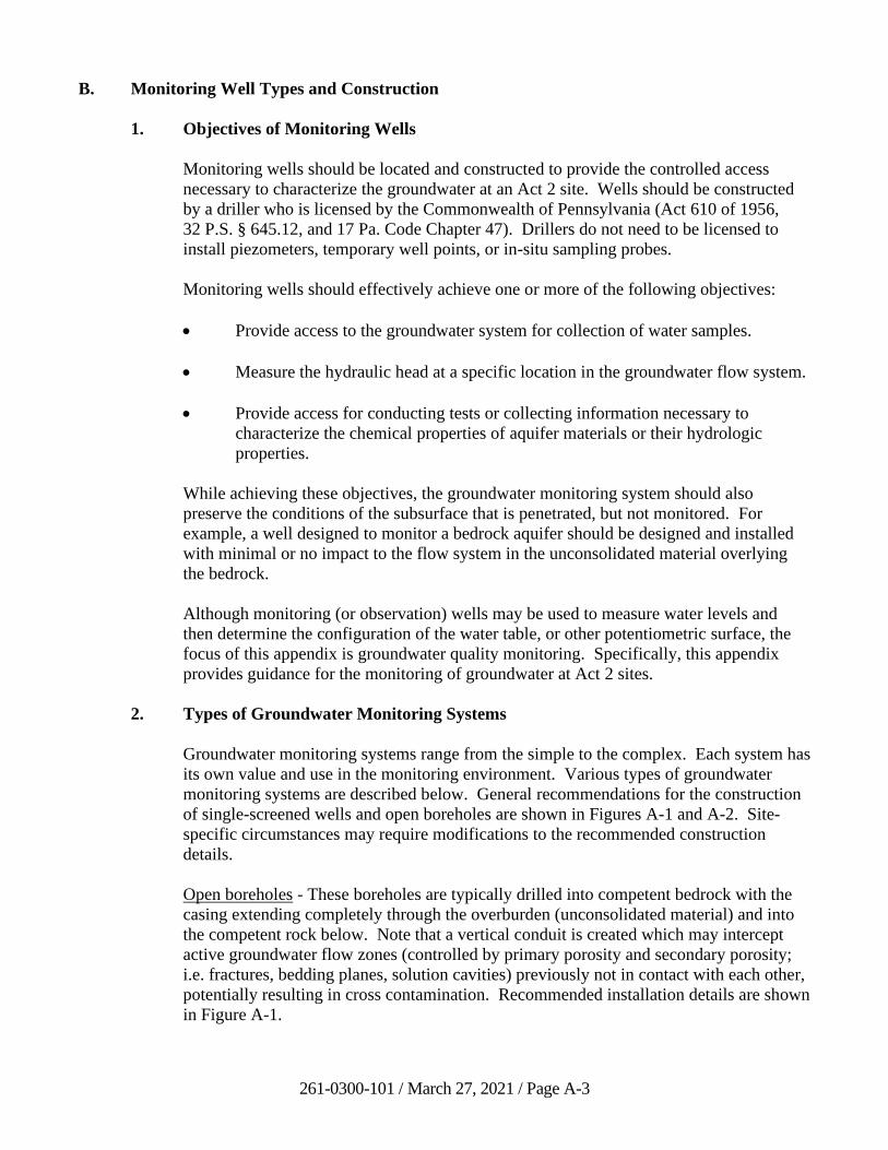
261-0300-101 / March 27, 2021 / Page A-3
B. Monitoring Well Types and Construction
1. Objectives of Monitoring Wells
Monitoring wells should be located and constructed to provide the controlled access
necessary to characterize the groundwater at an Act 2 site. Wells should be constructed
by a driller who is licensed by the Commonwealth of Pennsylvania (Act 610 of 1956,
32 P.S. § 645.12, and 17 Pa. Code Chapter 47). Drillers do not need to be licensed to
install piezometers, temporary well points, or in-situ sampling probes.
Monitoring wells should effectively achieve one or more of the following objectives:
• Provide access to the groundwater system for collection of water samples.
• Measure the hydraulic head at a specific location in the groundwater flow system.
• Provide access for conducting tests or collecting information necessary to
characterize the chemical properties of aquifer materials or their hydrologic
properties.
While achieving these objectives, the groundwater monitoring system should also
preserve the conditions of the subsurface that is penetrated, but not monitored. For
example, a well designed to monitor a bedrock aquifer should be designed and installed
with minimal or no impact to the flow system in the unconsolidated material overlying
the bedrock.
Although monitoring (or observation) wells may be used to measure water levels and
then determine the configuration of the water table, or other potentiometric surface, the
focus of this appendix is groundwater quality monitoring. Specifically, this appendix
provides guidance for the monitoring of groundwater at Act 2 sites.
2. Types of Groundwater Monitoring Systems
Groundwater monitoring systems range from the simple to the complex. Each system has
its own value and use in the monitoring environment. Various types of groundwater
monitoring systems are described below. General recommendations for the construction
of single-screened wells and open boreholes are shown in Figures A-1 and A-2. Site-
specific circumstances may require modifications to the recommended construction
details.
Open boreholes - These boreholes are typically drilled into competent bedrock with the
casing extending completely through the overburden (unconsolidated material) and into
the competent rock below. Note that a vertical conduit is created which may intercept
active groundwater flow zones (controlled by primary porosity and secondary porosity;
i.e. fractures, bedding planes, solution cavities) previously not in contact with each other,
potentially resulting in cross contamination. Recommended installation details are shown
in Figure A-1.
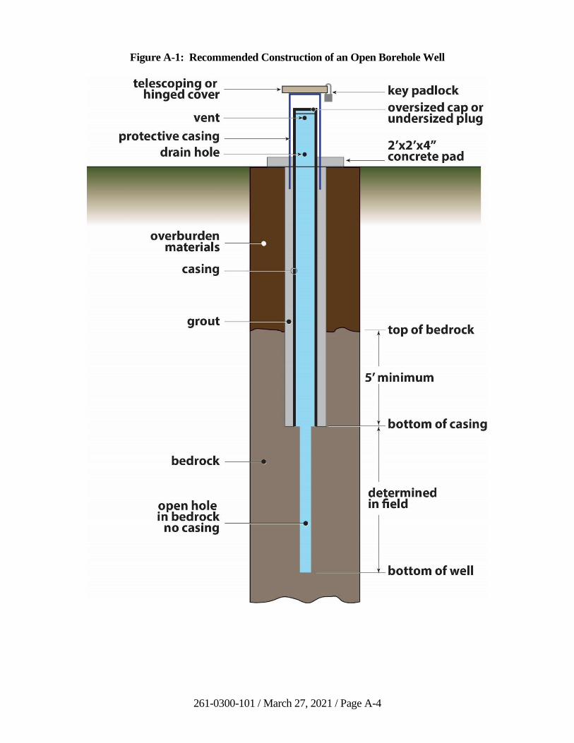
261-0300-101 / March 27, 2021 / Page A-4
Figure A-1: Recommended Construction of an Open Borehole Well
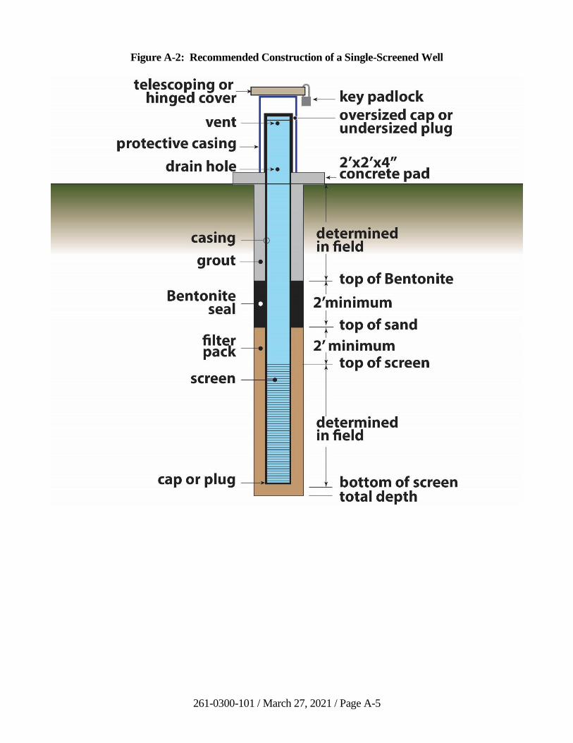
261-0300-101 / March 27, 2021 / Page A-5
Figure A-2: Recommended Construction of a Single-Screened Well

261-0300-101 / March 27, 2021 / Page A-6
Figure A-3: Example of a Well Cluster
Single screened wells - These wells consist of a prefabricated screen of polyvinylchloride
plastic, stainless steel, etc., that is inserted into an open borehole. Clean sand or gravel is
placed around the annular space of the screen for the entire vertical distance of the screen
length and slightly higher past the connecting screen and well casing. Recommended
installation details are shown in Figure A-2.
Well clusters - Well clusters, or a well nest, consist of the construction of open boreholes
or screened monitoring wells in a specific location, with each well monitoring a different
depth or zone of groundwater. An example of a well cluster is shown in Figure A-3.
Well points - Well points are usually short lengths (i.e., 1-3 feet) of screen attached to a
hardened metal point so that the entire unit can be driven, pushed, or drilled to the desired
depth for monitoring. (This method is usually limited to shallow, unconsolidated
formations.)
Piezometers - These are small diameter wells, generally non-pumping, with a very short
well screen or section of slotted pipe at the end that is used to measure the hydraulic head
at a certain point below the water table or other potentiometric surface.
261-0300-101 / March 27, 2021 / Page A-7
3. Choice of Monitoring System
The type of monitoring system chosen depends on the objectives of monitoring at the
site. Once the target zones, or areal locations and depths that are the most likely to be
impacted by the release are defined, monitoring is often adequately accomplished by
using open rock boreholes or single-screened wells that monitor the entire saturated
thickness, or a large portion of the target zone.
Where contamination has been detected and definition of vertical contaminant
stratification is desired, wells that monitor more discrete intervals of the target zone, or
individual aquifers, usually need to be constructed. In this case, well clusters such as
shown in Figure A-3 will often be the construction design of choice, although open holes
that monitor a short vertical interval or single water-bearing zone also may have
application. As the flow beneath the site is better understood, the monitoring system
typically will target more specific depths and locations.
Well points, or in-situ sampling probes (direct push technology), can be valuable
reconnaissance tools for preliminary site characterizations, or for determining the
locations of permanent monitoring wells (see EPA, 1993 and ITRC, 2006). However, in-
situ sampling probes can miss a light nonaqueous phase liquid (LNAPL) on the water
table and may have problems penetrating coarse sands and gravel (where contamination
may be located). Other potential problems include very slow fill times in clayey
sediments and significant capture of fines in the sample.
Special well construction will be needed to monitor for certain types of contaminants.
For example, if an LNAPL is a concern, the well screen should be open, bridging the
top of the water table and within the zone of fluctuation, so that the LNAPL
contaminants will not be cased-off.
4. Minimum Construction Standards
To properly meet the objectives listed in Section B.1, monitoring wells should be
designed and constructed using minimum standards in each of the following categories.
1) Materials
2) Assembly and installation
3) Well development
4) Recordkeeping and reporting
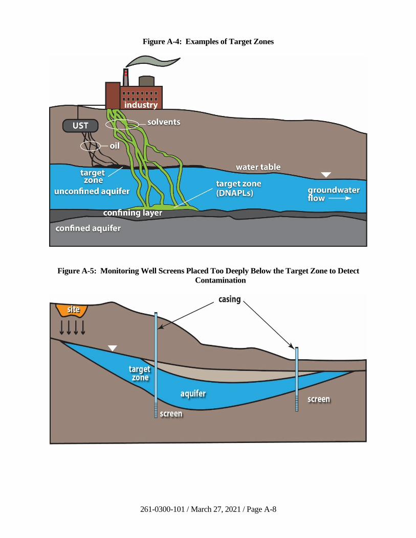
261-0300-101 / March 27, 2021 / Page A-8
Figure A-4: Examples of Target Zones
Figure A-5: Monitoring Well Screens Placed Too Deeply Below the Target Zone to Detect
Contamination
261-0300-101 / March 27, 2021 / Page A-9
Different standards and practices may be necessary depending upon the monitoring
objectives of an individual site. Monitoring wells constructed to meet multiple objectives
should employ the standards of the most rigorous objective. For instance, a well point
may be suitable for monitoring hydraulic head, but may not be optimum for collecting
samples. Therefore, a well proposed to monitor head and collect water samples should be
designed as a conventional, screened well and not as a well point. In addition,
construction methods, materials, and well development of each point in the plan must not
compromise the objective of other monitoring wells in the well system.
a) Materials
Materials that are used in construction of a monitoring well should not
contaminate the groundwater being monitored. A list of materials should include,
but not be limited to, the drilling tools and equipment, casing, riser pipe, well
screen, centralizers (if needed), annular sealant, filter pack, and drilling fluids or
additives. All materials should be of adequate size and of competent strength to
meet the objectives of the monitoring point. All materials introduced into the
boring should be free of chemicals or other contaminants that could compromise
the monitoring well or other downgradient wells. Practices must be employed to
minimize the potential for contamination of the materials during storage,
assembly, and installation. Specific cleaning procedures should be employed in
situations where the materials might introduce contaminants to the groundwater
system. Well screens and risers should be coupled using either water-tight flush-
joint threads or thermal welds. Solvent welded couplings are not recommended
for monitoring well construction.
b) Assembly and Installation
Equipment and techniques should be used that create a stable, open, vertical
borehole of large enough diameter to ensure that the monitoring well can be
installed as designed, while minimizing the impact on the zone(s) being
monitored. When drill cuttings and groundwater removed during construction
will likely be contaminated, procedures commensurate with the type and level of
contamination should be followed for the handling, storage, and disposal of the
contaminated material. Whenever feasible, drilling procedures that do not
introduce water or other liquids into the borehole should be utilized. When the
use of drilling fluids is unavoidable, the fluid should have as little impact on the
constituents of interest as possible. If air or other gas is used as the drilling fluid,
the compressor should be equipped with an oil air filter or an oil trap.
The well screen and riser assembly should be installed using procedures that
ensure the integrity of the assembly. If water or other ballast is used, it should be
of known and compatible chemistry with the water in the boring. Unless designed
otherwise, the assembly should be installed plumb and in the center of the boring.
Centralizers of proper spacing and diameter can be used. Depending upon the
physical environment, the well should be finished as a secure stick-up or
flushmount at the discretion of the project geologist. Either completed type of
well should be securely capped to prevent the entry of foreign material.
261-0300-101 / March 27, 2021 / Page A-10
Installation of the filter pack, sealants, or other materials in the annular space
should be done using tremie pipes or other accepted practices. Protective casing
and locking well caps must be installed, and any other necessary measures must
be taken to ensure that the monitoring well is protected from vandalism and
accidental damage. To reduce misidentification, all monitoring wells constructed
in developed areas, or in any location where they may be mistaken for other
structures (such as tank-fill tubes, drains, and breather tubes), should have a
locking cap conspicuously labeled “Monitoring Well” (preferably by the well-cap
manufacturer). In addition, locks for the monitoring wells should use a key
pattern different from locks on other structures at the site. It is also advisable that
the well identification number be placed on both the inside and outside of the
protective casing.
c) Well Development
After installation, groundwater monitoring wells should be developed to:
• Correct damage to the geological formation caused by the drilling process;
• Restore the natural water quality of the aquifer in and around the well;
• Optimize hydraulic communication between the geologic formation and
the well screen; and
• Create an effective filter pack around the well screen.
Well development is necessary to provide groundwater samples that represent
natural undisturbed hydrogeological conditions. When properly developed, a
monitoring well will produce samples of acceptably low turbidity (less than
10 Nephelometric Turbidity Units (NTUs) as recommended by U.S. EPA, 2013).
Low turbidity is desirable as turbidity may interfere with subsequent analyses,
especially for constituents that sorb to fine-grained materials, such as metals
(CEPA, 2014). Well development stresses the formation and filter pack so that
fine-grained materials are mobilized, pulled through the well screen into the well,
and removed by pumping.
Well development should continue until as much of the fine-grained materials
present in the well column have been removed as possible. It is important to
record pumping rates utilized during well development. Purging and sampling
rates should not exceed the maximum pumping rate used during well
development. When it is likely that the water removed during development will
be contaminated, procedures commensurate with the type and level of
contamination should be utilized and documented for the handling, storage, and
disposal of the contaminated material. Development methods should minimize
the introduction of materials that might compromise the objective of the
monitoring. If air is used, the compressor should have an oil air filter or oil trap.
261-0300-101 / March 27, 2021 / Page A-11
Repeated well development may be conducted as necessary at the discretion of
the project geologist, especially if clogged screens or biofouling are evident.
d) Recordkeeping and Reporting
Because interpretation of monitoring data from a monitoring well is spatially
dependent on both the activity being monitored and other monitoring wells in the
system, records and samples of the materials used to construct and drill the
monitoring well should be kept. Following construction, accurate horizontal and
vertical surveys should be performed. The surveys should be completed by
personnel knowledgeable in land surveying techniques. A permanent reference
point should be made by notching the riser pipe. Whenever possible, all reference
points should be established in relation to an established National Geodetic
Vertical Datum (NGVD). Monitoring well locations should be surveyed to
1 linear foot, and monitoring well elevations should be to the nearest .01 foot.
Elevations of the protective casing (with the cap off or hinged back), the well
casing, and the ground surface should be surveyed for each monitoring well (see
Nielsen, 1991). DEP-permitted facilities are generally required to record the
latitude and longitude for each monitoring well (this also is recommended for
non-permitted facilities).
A groundwater monitoring network report should be prepared. This report should
include copies of the well boring logs, test pit and exploratory borehole logs;
details on the construction of each monitoring point; maps, air photos or other
information necessary to fully describe the location and spatial relationship of the
points in the monitoring system; and a recommended decommissioning procedure
consistent with the applicable regulatory program and the well decommissioning
procedures recommended in Section E of this appendix.
Monitoring well logs should be prepared and should describe, at a minimum, the
date of construction; the thickness and composition of the geologic units
(identification of stratigraphic units should be completed on the well log using the
Unified Soil Classification System); the location and type of samples collected;
the nature of fractures and other discontinuities encountered; the nature and
occurrence of groundwater encountered during construction, including the depth
and yield of water-bearing zones; headspace of photoionization detector (PID)
readings collected; any observations of contamination (e.g. NAPL); and the static
water level upon completing construction.
A well completion plan should also be included in the monitoring network report.
Each plan should include information on the length, location, slot size, and nature
of filter pack for each screen; type, location and quantity of material used as
annular seals and filler; description of the type and effectiveness of well
development employed; and notes describing how the well, as constructed, differs
from its original design and/or location.
The reports described above do not relieve the driller from the obligation to
submit, for each well drilled, a Water Well Completion Report to the Department
261-0300-101 / March 27, 2021 / Page A-12
of Conservation and Natural Resources (DCNR), Bureau of Topographic and
Geologic Survey, as required by Act 610 (the Water Well Drillers License Act).
5. Direct Push Technology
Direct Push Technology (DPT) devices are investigative tools that drive or ‘push’ small-
diameter rods into the subsurface via hydraulic or percussive methods without the use of
conventional drilling. DPT has been in use in the environmental industry for more than
two decades and its utilization as a tool for performing subsurface investigations in
Pennsylvania and many other states has grown concurrently with its evolving technology.
Monitoring wells installed using DPT could either be field-constructed, similar to
conventionally drilled and installed wells, or installed using pre-packed well screens.
The pre-packed well screen assemblies consist of an inner slotted screen surrounded by a
wire mesh sleeve which acts as a support for filter media (sand). The sand is packed
between the slotted screen and the mesh. It is important to note that only DPT pre-
packed wells are considered suitable for Act 2 sites, due to quality assurance concerns
regarding field-construction and associated problems placing the filter pack around the
screens of small-diameter wells.
a) Advantages of DPT
Depending on site conditions, DPT offers an attractive alternative to conventional
auger drilling and split spoon sampling. The smaller size of DPT rigs enables
well installation and sampling in areas not accessible to traditional large auger
rigs.
As DPT methods utilize a smaller diameter boring than conventional drilling, less
solid waste is generated. Similarly, less liquid waste will be generated from
smaller diameter monitoring wells. Because less waste is generated, worker
exposures are reduced.
Overall, there is minimal disturbance to the natural formation using DPT in
comparison with auger drilling.
From an economic standpoint, DPT has several advantages versus conventional
drilling. In relation to project schedule and budget, the time-effectiveness of DPT
installation may enable the remediator to investigate more areas of a site than
traditional hollow stem auger (HSA) drilling would allow and in a shorter time.
Fewer well construction materials may enable a remediator to install additional
monitoring points on a limited budget.
Most importantly, short-term and long-term groundwater monitoring studies
conducted by others have produced results demonstrating that water samples
collected from DPT installed wells are comparable in quality to those obtained
from conventionally constructed wells.
261-0300-101 / March 27, 2021 / Page A-13
b) Disadvantages of DPT
DPT cannot completely replace the use of conventional drilling/monitoring well
installation as limitations of the technology are evident in certain situations. DPT
is only useful at generally shallow depths (less than 100 feet below surface grade)
and in unconsolidated formations. DPT is not suitable for formations containing
excessive gravel, cobbles, boulders, etc., or for bedrock drilling due to the
obvious lack of augering capabilities.
DPT may be utilized for monitoring well installation below confining layers or as
‘nested’ wells with extreme caution. DPT utilizing only a macrocore barrel and
drive rods may not provide for the advancement of casing to keep the borehole
open and seal off each separate zone of saturation, which therefore can potentially
allow for the mixing of separate zones of saturation when the push rods are
withdrawn from the borehole. Therefore, DPT may be utilized for this purpose
only if the project geologist can ensure that the threat of cross-contamination from
separate zones of saturation above clean zones of saturation will not occur.
If large volumes of aqueous sample are required, DPT installed monitoring wells
may not be suitable due to the small diameter of the well screen.
Since DPT causes smearing and compaction of the borehole sides, proper well
development techniques are vital to ensure that natural hydraulic permeabilities
are maintained. Several studies have demonstrated that hydraulic conductivities
can vary by an order of magnitude lower for wells installed by DPT versus wells
installed by conventional HSA. For this reason, DPT-installed wells may not be
suitable for aquifer characteristics testing, nor for efficient groundwater recovery.
Great care needs to be taken to ensure adequate well development when using
DPT for well installations.
6. References
Aller, L., and others, 1989, Handbook of Suggested Practices for the Design and
Installation of Ground-Water Monitoring Wells, National Water Well Association (This
publication covers nearly all aspects of design and construction of monitoring wells.
Each of the eight chapters has an extensive reference list.).
American Society for Testing and Materials, 2010, Standard Practice for Direct Push
Installation of Prepacked Screen Monitoring Wells in Unconsolidated Aquifers,
ASTM-D6725-04.
Anderson, K.E., 1993, Ground Water Handbook, National Ground Water Association (A
quick reference containing tables, formulas, techniques and short discussions covering,
among other things, drilling, well design, pipe and casing, and groundwater flow).
California Environmental Protection Agency, 2014, Well Design and Construction for
Monitoring Groundwater at Contaminated Sites.
261-0300-101 / March 27, 2021 / Page A-14
Driscoll, F.G., 1986, Groundwater and Wells, Second Edition, Johnson Filtration
Systems, Inc., St. Paul, Minnesota 55112, 1089 pp.
Gaber, M.S., and Fisher, B.O., 1988, Michigan Water Well Grouting Manual, Michigan
Department of Public Health (Very thorough coverage of grout and sealant formulation,
characteristics, handling, and placement.).
Interstate Technology Regulatory Council, 2006, The Use of Direct Push Well
Technology for Long-Term Environmental Monitoring in Groundwater Investigations.
Nielsen, D.M., (Editor), 1991, Practical Handbook of Ground-Water Monitoring,
NWWA, Lewis Publishers, Inc., Chelsea, Michigan 48118, 717 pp.
Ohio Environmental Protection Agency, 2016, Technical Guidance for Ground Water
Investigations, Chapter 15, Use of Direct Push Technologies for Soil and Ground Water
Sampling, Revision 1.
U.S. Environmental Protection Agency, 1993, Subsurface Characterization and
Monitoring Techniques-A Desk Reference Guide, Volume 1: Solids and Ground Water
(Largely 1 to 2-page thumbnail descriptions of methods and equipment.).
U.S. Environmental Protection Agency, 1997, Expedited Site Assessment Tools for
Underground Storage Tank Sites.
U.S. Environmental Protection Agency, 2005, Groundwater Sampling and Monitoring
with Direct Push Technologies.
261-0300-101 / March 27, 2021 / Page A-15
C. Locations and Depths of Monitoring Wells
1. Importance
The locations and depths of monitoring wells are the most important aspects of a
groundwater monitoring network. A monitoring point that is misplaced, or not
constructed properly to monitor constituents with unique physical characteristics, is of
little use and may misrepresent the quality of the groundwater migrating to or from a site.
On the other hand, a properly positioned and constructed monitoring well that detects the
earliest occurrence of contamination could save both time and money spent on cleanup of
a site. It is important to note that the placement and construction of a groundwater
monitoring network at an Act 2 site shall be conducted by a professional geologist
licensed in Pennsylvania (25 Pa. Code §§ 250.204(a), 250.312(a), and 250.408(a)).
2. Approach to Determining Monitoring Locations and Depths
Different approaches and efforts for determining the location and depth of wells may be
necessary based on the type of monitoring to be done. However, before well locations
are chosen for any type of monitoring, the existing data should be evaluated. This can
reduce the costs of implementing the monitoring program and can help to make
appropriate choices for three-dimensional monitoring locations.
The most efficient way to accomplish the location and depth of monitoring wells for an
Act 2 study is to formulate a CSM, or conceptual groundwater flow model. A conceptual
groundwater flow model is the illustrative delineation and formulation of the important
controlling components of groundwater flow and thus contaminant transport from
recharge areas to discharge zones or withdrawal points. Without a proper
conceptualization of groundwater flow, a groundwater model can give spurious results.
On the other hand, a well-developed conceptual model may allow groundwater flow to be
accurately approximated without using computer modeling or complex analytical
procedures. The groundwater conceptual model is an important tool in the study of
groundwater flow on both a local and even larger scale. The goal of the conceptual
model is to represent the controlling aspects of groundwater flow at the site being
investigated. Important controlling components of groundwater flow can include
geological characteristics, geologic structural and stratigraphic relationships, anisotropy,
calculated groundwater flow directions and recharge and discharge relationships.
Information may be obtained through site visits, site records and previous studies,
interviews with present and past workers, aerial photographs, scientific publications on
the local and regional hydrogeology, geophysical surveys, borings, wells, aquifer tests,
etc. If enough information is available, the designer can determine the groundwater flow
paths and design a complete monitoring network. However, actual testing of aquifer
parameters and borehole geophysics provides the best information to evaluate placement
and construction of monitoring wells, especially in newly established sites or facilities
where little site information is available.
261-0300-101 / March 27, 2021 / Page A-16
a) Background Monitoring
The determination of background water quality is paramount in understanding the
effect of an activity or site on groundwater quality. Often, insufficient site
information is available so that initial well locations may depend on casual
observations and assumptions regarding groundwater flow. If subsequent
information shows that monitoring wells are misplaced, new wells should be
installed.
b) Site Characterization Monitoring
Appropriately placed monitoring wells are necessary to detect groundwater
quality at an Act 2 site. The more that is known about the history of operations at
the site, (potential) contaminant flow paths, and the constituents that may have
been discharged to the environment, the more likely that monitoring wells
installed during the site characterization phase of the investigation will be
optimally placed and constructed to monitor the impact on groundwater quality.
Monitoring well locations should be concentrated in those areas that will most
likely first be impacted by the known discharges on the site, which typically will
be located within or comprise the uppermost aquifer. As groundwater data is
collected, additional monitoring wells may need to be installed to fully
characterize the groundwater contaminant plume(s) present. The greater the
complexity of the hydrogeology and the spread of contamination, the more
monitoring wells that may be necessary to characterize the contamination.
c) Attainment and Postremedial Monitoring
Any number of wells, including all installed during the site characterization
phase, may be used for attainment monitoring. These wells will demonstrate
attainment of the chosen cleanup standard at the POC. The impact of any
remediation conducted at the Act 2 site on the groundwater flow paths (e.g.
pumping the aquifer) should be considered for placement of attainment
monitoring wells. Postremedial monitoring would likely be conducted in the
same wells as attainment monitoring to monitor for any residual rebound
occurring in the aquifer after remediation activities have been completed.
3. Factors in Determining Target Zones for Monitoring
The prime requirement for a successful monitoring system is to determine the “target”
zones - the spatial locations and depths that are the most likely areas to be impacted by
the site being investigated. The dimensions of target zones depend on the vertical and
horizontal components of flow in the aquifers being monitored, the size of the Act 2 site,
the potential contaminants released, and the distance that contamination may have
traveled from the facility since being released. Figure A-4 shows how different target
zones could be formed based on these factors.
Horizontal and vertical components of groundwater flow are best determined by
constructing planar and cross-sectional flow nets based on the measurement of water
levels in piezometers. Where the vertical components of flow are negligible, wells, rather
261-0300-101 / March 27, 2021 / Page A-17
than piezometers, drilled into the aquifer to about the same depth, will allow preparation
of a contour map of water levels representing horizontal flow. This should be adequate to
prepare a planar flow net and determine the target zone.
With regard to upgradient wells, target zones (as defined above) do not exist. Upgradient
wells should be drilled to depths that are screened or open to intervals similar to that of
the downgradient wells, or to depths that yield water that is otherwise most representative
of the background quality of the water being monitored by the downgradient wells. In
other words, upgradient wells should be installed within the same hydrogeologic aquifer
to the respective downgradient wells.
The numerous site details to consider when establishing target zones may be grouped into
either groundwater movement or the spatial distribution of contamination.
a) Groundwater Movement
In what direction is groundwater flowing? If flow paths are not easily
determined, what will influence the direction of groundwater flow? The answers
to these questions are critical to selecting target zones and the optimal locations of
monitoring wells.
Using the groundwater levels from piezometers or wells at the site, the
groundwater flow direction and hydraulic gradient can be determined. At least
three monitoring points are needed to determine the horizontal flow direction and
hydraulic gradient; however, at some sites, knowledge of the vertical component
of flow may be important. This is best accomplished by using well pairs of
“shallow” and “deep” piezometers or short-screened wells.
It may appear to be a simple task to place monitoring wells in downgradient
positions using a map of the groundwater elevation contours, or by anticipating
the flow direction based on topography or discharge points. However, at many
sites, three-dimensional flow zones must be understood to install appropriate
monitoring points (see Section C.5 of this appendix). Figure A-5 shows how a
well can miss the vertical location of contamination at a site. Water level
measurements, piezometer and well construction logs, geologic well logs, and
groundwater flow direction maps should be reviewed carefully when assessing the
dimensions of target zones.
i) Geologic Factors
The geology of a site can complicate the selection of the target zones for
monitoring. Geologic factors can produce aquifers that are anisotropic. In
an anisotropic aquifer, the hydraulic conductivity is not uniform in all
directions so that groundwater moves faster in one direction than another
and oblique to the hydraulic gradient. Anisotropy can result from various
sedimentary or structural features such as buried channels, bedding planes,
folds, faults, voids, and fractures.
261-0300-101 / March 27, 2021 / Page A-18
In Pennsylvania, most of groundwater flow in bedrock is through fractured
rocks. Fracture flow in bedrock (or hardened sediments) requires
additional considerations compared to flow in unconsolidated materials.
Consolidated materials may exhibit small effective porosities and low
hydraulic conductivities that impede groundwater flow. However, the
development of secondary porosity may allow substantial flow of
groundwater through fractures, joints, voids, cleavage planes and
foliations. These features tend to be highly directional, exhibit varying
degrees of interconnection, and may produce local groundwater flow
regimes that are much different from the regional trends.
Geologic factors influence the direction of groundwater flow by
controlling the transmissivity. For example, Figure A-6 shows the effect
of fractures on the spread of contamination. Although the gradient
indicates flow to the north, groundwater also follows the major fractures
and spreads to the northeast. Monitoring wells “1” and “2” located to the
north of the site may detect contamination, but the lack of a monitoring
well to the northeast will miss an important direction of migration.
Common sedimentary bedding planes also could have a similar effect on
groundwater flow.
It is important to identify hydrostratigraphic intervals which may or may
not be interconnected at the site when conducting a groundwater
investigation. Monitoring wells should not be screened across
two intervals as groundwater flow and concentrations of contaminants
may differ significantly in each interval.
ii) Groundwater Barriers
The presence of hydrogeologic barriers should also be considered when
locating wells in a groundwater monitoring system. A groundwater
barrier is a natural geologic or artificial obstacle to the lateral movement
of groundwater. Groundwater barriers can be characterized by a
noticeable difference in groundwater levels on opposite sides of the
barrier. Geologic faults and dikes along with tight lithologic formations
such as shale and clay layers are common examples. Important types of
barriers include the following:
Geologic faults - Fault planes that contain gouge (soft rock material) or
bring rock bodies of widely differing hydraulic conductivity into
juxtaposition can influence groundwater flow direction and velocity.
Location of downgradient wells across fault zones or planes should not be
approved until the nature of the influence of the fault zone on groundwater
flow has been evaluated. One method of evaluating fault zones is to
conduct pumping tests with wells on either side of the fault plane to
evaluate the degree of hydraulic connection.
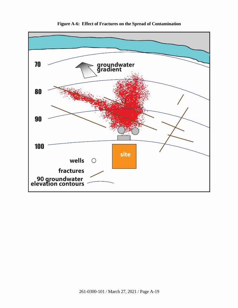
261-0300-101 / March 27, 2021 / Page A-19
Figure A-6: Effect of Fractures on the Spread of Contamination
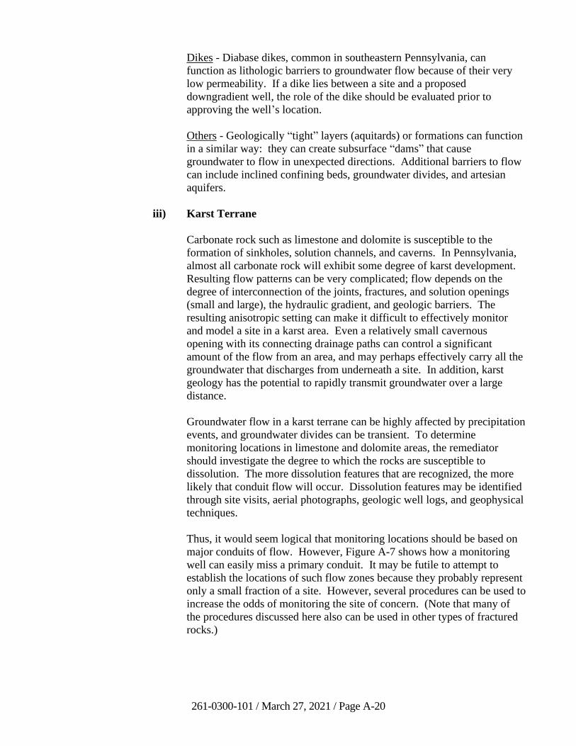
261-0300-101 / March 27, 2021 / Page A-20
Dikes - Diabase dikes, common in southeastern Pennsylvania, can
function as lithologic barriers to groundwater flow because of their very
low permeability. If a dike lies between a site and a proposed
downgradient well, the role of the dike should be evaluated prior to
approving the well’s location.
Others - Geologically “tight” layers (aquitards) or formations can function
in a similar way: they can create subsurface “dams” that cause
groundwater to flow in unexpected directions. Additional barriers to flow
can include inclined confining beds, groundwater divides, and artesian
aquifers.
iii) Karst Terrane
Carbonate rock such as limestone and dolomite is susceptible to the
formation of sinkholes, solution channels, and caverns. In Pennsylvania,
almost all carbonate rock will exhibit some degree of karst development.
Resulting flow patterns can be very complicated; flow depends on the
degree of interconnection of the joints, fractures, and solution openings
(small and large), the hydraulic gradient, and geologic barriers. The
resulting anisotropic setting can make it difficult to effectively monitor
and model a site in a karst area. Even a relatively small cavernous
opening with its connecting drainage paths can control a significant
amount of the flow from an area, and may perhaps effectively carry all the
groundwater that discharges from underneath a site. In addition, karst
geology has the potential to rapidly transmit groundwater over a large
distance.
Groundwater flow in a karst terrane can be highly affected by precipitation
events, and groundwater divides can be transient. To determine
monitoring locations in limestone and dolomite areas, the remediator
should investigate the degree to which the rocks are susceptible to
dissolution. The more dissolution features that are recognized, the more
likely that conduit flow will occur. Dissolution features may be identified
through site visits, aerial photographs, geologic well logs, and geophysical
techniques.
Thus, it would seem logical that monitoring locations should be based on
major conduits of flow. However, Figure A-7 shows how a monitoring
well can easily miss a primary conduit. It may be futile to attempt to
establish the locations of such flow zones because they probably represent
only a small fraction of a site. However, several procedures can be used to
increase the odds of monitoring the site of concern. (Note that many of
the procedures discussed here also can be used in other types of fractured
rocks.)
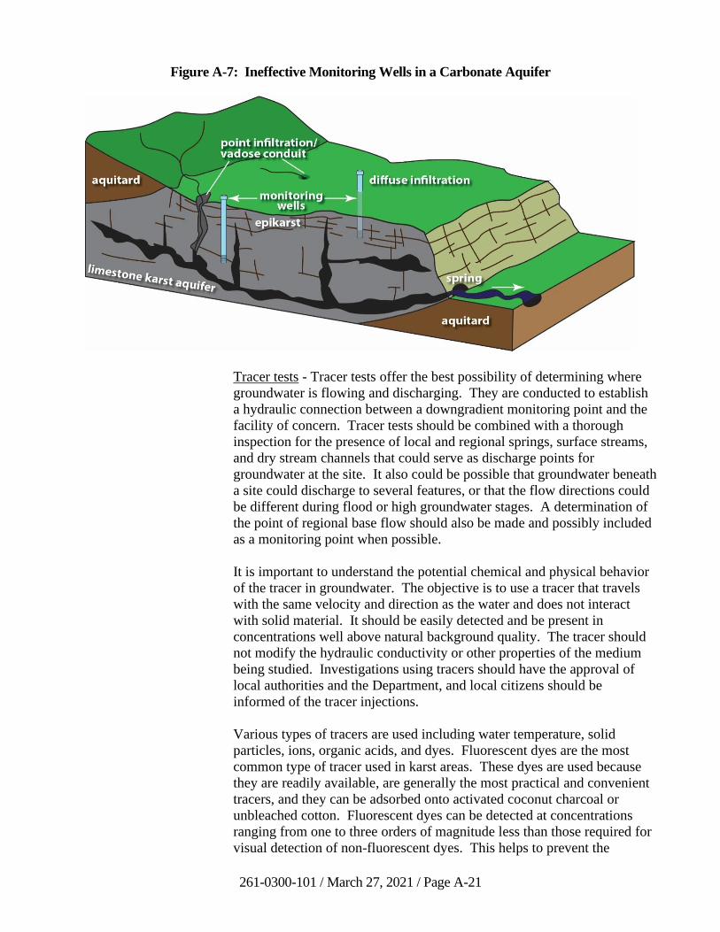
261-0300-101 / March 27, 2021 / Page A-21
Figure A-7: Ineffective Monitoring Wells in a Carbonate Aquifer
Tracer tests - Tracer tests offer the best possibility of determining where
groundwater is flowing and discharging. They are conducted to establish
a hydraulic connection between a downgradient monitoring point and the
facility of concern. Tracer tests should be combined with a thorough
inspection for the presence of local and regional springs, surface streams,
and dry stream channels that could serve as discharge points for
groundwater at the site. It also could be possible that groundwater beneath
a site could discharge to several features, or that the flow directions could
be different during flood or high groundwater stages. A determination of
the point of regional base flow should also be made and possibly included
as a monitoring point when possible.
It is important to understand the potential chemical and physical behavior
of the tracer in groundwater. The objective is to use a tracer that travels
with the same velocity and direction as the water and does not interact
with solid material. It should be easily detected and be present in
concentrations well above natural background quality. The tracer should
not modify the hydraulic conductivity or other properties of the medium
being studied. Investigations using tracers should have the approval of
local authorities and the Department, and local citizens should be
informed of the tracer injections.
Various types of tracers are used including water temperature, solid
particles, ions, organic acids, and dyes. Fluorescent dyes are the most
common type of tracer used in karst areas. These dyes are used because
they are readily available, are generally the most practical and convenient
tracers, and they can be adsorbed onto activated coconut charcoal or
unbleached cotton. Fluorescent dyes can be detected at concentrations
ranging from one to three orders of magnitude less than those required for
visual detection of non-fluorescent dyes. This helps to prevent the
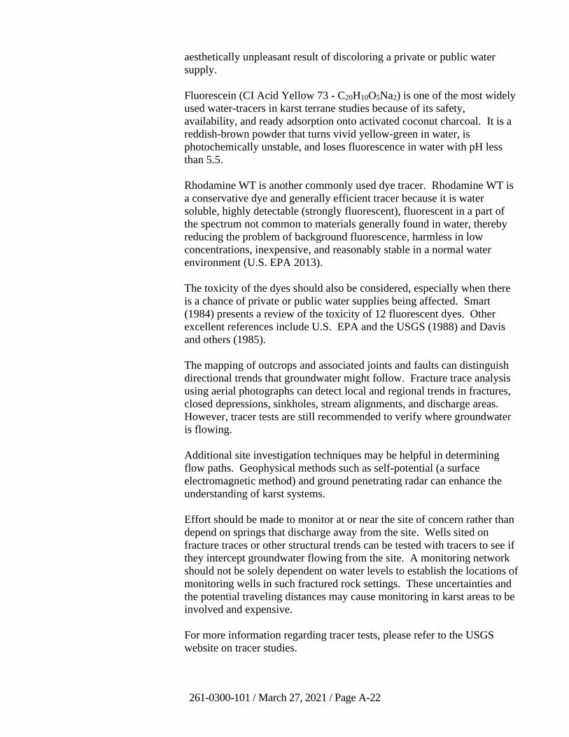
261-0300-101 / March 27, 2021 / Page A-22
aesthetically unpleasant result of discoloring a private or public water
supply.
Fluorescein (CI Acid Yellow 73 - C20H10O5Na2) is one of the most widely
used water-tracers in karst terrane studies because of its safety,
availability, and ready adsorption onto activated coconut charcoal. It is a
reddish-brown powder that turns vivid yellow-green in water, is
photochemically unstable, and loses fluorescence in water with pH less
than 5.5.
Rhodamine WT is another commonly used dye tracer. Rhodamine WT is
a conservative dye and generally efficient tracer because it is water
soluble, highly detectable (strongly fluorescent), fluorescent in a part of
the spectrum not common to materials generally found in water, thereby
reducing the problem of background fluorescence, harmless in low
concentrations, inexpensive, and reasonably stable in a normal water
environment (U.S. EPA 2013).
The toxicity of the dyes should also be considered, especially when there
is a chance of private or public water supplies being affected. Smart
(1984) presents a review of the toxicity of 12 fluorescent dyes. Other
excellent references include U.S. EPA and the USGS (1988) and Davis
and others (1985).
The mapping of outcrops and associated joints and faults can distinguish
directional trends that groundwater might follow. Fracture trace analysis
using aerial photographs can detect local and regional trends in fractures,
closed depressions, sinkholes, stream alignments, and discharge areas.
However, tracer tests are still recommended to verify where groundwater
is flowing.
Additional site investigation techniques may be helpful in determining
flow paths. Geophysical methods such as self-potential (a surface
electromagnetic method) and ground penetrating radar can enhance the
understanding of karst systems.
Effort should be made to monitor at or near the site of concern rather than
depend on springs that discharge away from the site. Wells sited on
fracture traces or other structural trends can be tested with tracers to see if
they intercept groundwater flowing from the site. A monitoring network
should not be solely dependent on water levels to establish the locations of
monitoring wells in such fractured rock settings. These uncertainties and
the potential traveling distances may cause monitoring in karst areas to be
involved and expensive.
For more information regarding tracer tests, please refer to the USGS
website on tracer studies.
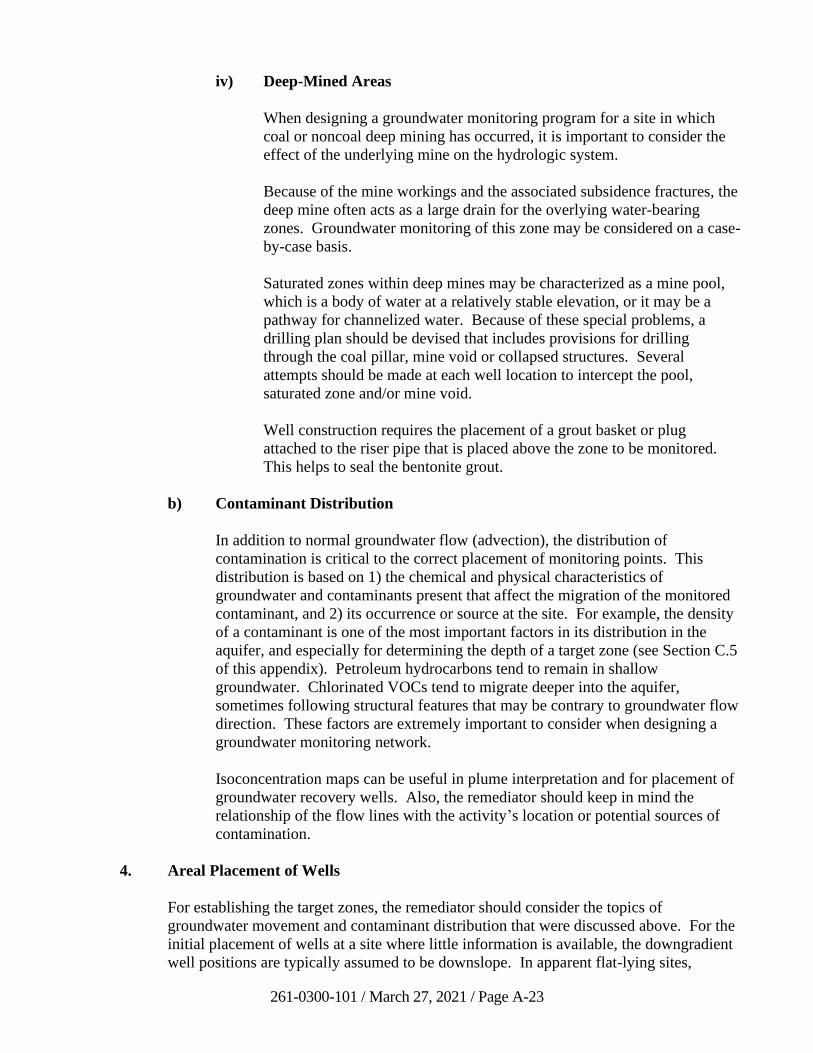
261-0300-101 / March 27, 2021 / Page A-23
iv) Deep-Mined Areas
When designing a groundwater monitoring program for a site in which
coal or noncoal deep mining has occurred, it is important to consider the
effect of the underlying mine on the hydrologic system.
Because of the mine workings and the associated subsidence fractures, the
deep mine often acts as a large drain for the overlying water-bearing
zones. Groundwater monitoring of this zone may be considered on a case-
by-case basis.
Saturated zones within deep mines may be characterized as a mine pool,
which is a body of water at a relatively stable elevation, or it may be a
pathway for channelized water. Because of these special problems, a
drilling plan should be devised that includes provisions for drilling
through the coal pillar, mine void or collapsed structures. Several
attempts should be made at each well location to intercept the pool,
saturated zone and/or mine void.
Well construction requires the placement of a grout basket or plug
attached to the riser pipe that is placed above the zone to be monitored.
This helps to seal the bentonite grout.
b) Contaminant Distribution
In addition to normal groundwater flow (advection), the distribution of
contamination is critical to the correct placement of monitoring points. This
distribution is based on 1) the chemical and physical characteristics of
groundwater and contaminants present that affect the migration of the monitored
contaminant, and 2) its occurrence or source at the site. For example, the density
of a contaminant is one of the most important factors in its distribution in the
aquifer, and especially for determining the depth of a target zone (see Section C.5
of this appendix). Petroleum hydrocarbons tend to remain in shallow
groundwater. Chlorinated VOCs tend to migrate deeper into the aquifer,
sometimes following structural features that may be contrary to groundwater flow
direction. These factors are extremely important to consider when designing a
groundwater monitoring network.
Isoconcentration maps can be useful in plume interpretation and for placement of
groundwater recovery wells. Also, the remediator should keep in mind the
relationship of the flow lines with the activity’s location or potential sources of
contamination.
4. Areal Placement of Wells
For establishing the target zones, the remediator should consider the topics of
groundwater movement and contaminant distribution that were discussed above. For the
initial placement of wells at a site where little information is available, the downgradient
well positions are typically assumed to be downslope. In apparent flat-lying sites,
261-0300-101 / March 27, 2021 / Page A-24
drainage patterns can be used to estimate the flow direction. The site boundary that is
closest to a body of water is a likely choice for downgradient well locations. An
upgradient well is typically placed upslope.
As more information is obtained about the site, groundwater gradients will be more
accurately defined. Upgradient and downgradient monitoring points may need to be
added or moved. However, even well-defined groundwater flow direction maps should
be evaluated carefully when choosing the target zones for upgradient and downgradient
wells. Because of structural controls in fracture flow described in Section C.3.a,
groundwater can move obliquely to the regional gradient. Some monitoring points may
need to be moved as target zones are refined.
In general, when comparing sites, intervals between monitoring wells probably should be
closer for a site that has one or more of the following:
• a small area
• complicated geology such as folding, faulting, closely spaced fractures, or
solution channels
• heterogeneous lithology and hydraulic conductivities
• steep or variable hydraulic gradient
• high seepage velocity
• had liquid contaminants
• tanks, buried pipes, trenches, etc.
• low dispersivity potential
Sites without these features may have well interval distances that are greater. See also
Section C.6 on the number of wells.
Reconnaissance tools and screening techniques such as surface geophysical techniques
and soil gas studies can help to locate plumes before wells are drilled and thus help to
determine optimal well locations. Methods for selecting sample locations range from
random yet logical picks to probability sampling (such as a grid pattern). Random
sampling is very inefficient. When selecting many monitoring points in an area where
little is known, such monitoring points should be placed in a grid or herringbone pattern.
5. Well Depths, Screen Lengths, and Open Intervals
The first zone of saturation is typically an unconfined or water-table aquifer, which is
recharged from direct infiltration of precipitation. Impacts to the aquifer under
unconfined conditions are more easily evaluated than under confined or semi-confined
conditions. The shallowest aquifer should be the target zone for chemicals and
substances that are less dense than water.
261-0300-101 / March 27, 2021 / Page A-25
Sites with confined aquifers that have the potential to be impacted will need to be
evaluated in combination with the unconfined aquifer. Such a situation would require
more detailed vertical and discrete zone monitoring.
Once the subsurface geometry of the monitoring target zone is determined, decisions can
be made with respect to the depth and screen lengths of individual wells that will be used.
Groundwater monitoring networks should monitor the entire saturated thickness of the
target zone, or a very large percentage of it. If large vertical intervals of the target zone
are unmonitored, chances are dramatically increased that groundwater contamination may
go undetected or be underestimated if detected.
Choosing the length of the open interval in a monitoring well is in many respects a
balancing act. Shorter open intervals or screen lengths provide better accuracy in
determining hydraulic head at a specific point in the flow system. If a sufficient number
of shorter well screens or open intervals are stacked or clustered vertically so that the
entire saturated thickness of the target zone is adequately monitored, they will, when
taken together, provide better resolution of the vertical distribution of any contamination
that may be detected. In addition, the possibility of cross-contamination is minimized.
Disadvantages of shorter intervals include reduced water volume from each well and the
increased cost of installing, sampling, analyzing, and interpreting the data from the more
numerous sampling points, which can be considerable.
Some disadvantages also are likely for longer screen lengths or open intervals.
Resolution of hydraulic head distribution in the aquifer decreases, contamination entering
the well at a specific point may be diluted by other less contaminated water, and there is
less certainty regarding where water is entering the well.
It would be preferable from a strictly technical point of view to monitor the entire
saturated thickness of any target zone with a number of individual, shorter-screened wells
drilled to different depths that, together, monitor the entire target zone. However, the
remediator/hydrogeologist designing the project must decide if the increased cost over
single, longer-screened wells is justified for background and compliance monitoring.
The goal is to establish screens and open intervals that will detect any contamination
emanating from any portion of the site as quickly as possible. A Pennsylvania-licensed
professional geologist should make all decisions related to the construction of monitoring
wells at Act 2 sites.
Care should be taken when monitoring target zones in bedrock formations. In this case,
by geologic necessity, the portion of the target zone which is monitored will be
determined by the location and number of water-producing fractures that are intercepted
by the well. Care must be taken not to drill wells too deeply below the target zone in
search of a water-producing fracture.
Where multiple aquifers exist, such as an unconsolidated aquifer overlying a bedrock
aquifer, or where two permeable aquifers are separated by a confining layer, the target
zones within each aquifer should be monitored separately.
261-0300-101 / March 27, 2021 / Page A-26
The specific gravity of a contaminant and whether it will most likely be introduced to the
environment as a free phase or in a dissolved phase also will influence how a well is
constructed. In conducting monitoring for an LNAPL or a petroleum-based dissolved
contaminant, such as gasoline, wells should be constructed with screens, or open
intervals, that intercept the water table surface at all times of the year during periods of
both high and low water table elevations. LNAPL can then accumulate into a distinct
layer and flow into the monitoring well. For materials that exhibit specific gravities
greater than water (such as many chlorinated solvents), it is desirable, though not always
possible, to locate subsurface boundaries on which such contaminants might accumulate
if released to the environment in a free phase.
6. Number of Wells
The number of wells needed depends on site-specific factors. In general, the spacing of
background or upgradient wells should be adequate to account for any spatial variability
in the groundwater quality. Downgradient wells should be positioned to adequately
monitor the activity and any other variability of the groundwater quality. Compliance
wells should be considered downgradient wells and positioned as close to the
downgradient boundary of the site. The estimate of the separation distance will depend
on the extent and type of activity, the geology, and the potential contaminants (see also
Section C.4 on the Areal Placement of Wells).
7. Well Yield
Monitoring wells should produce yields that are representative of the formation in which
they are drilled. Wells located in anomalously low-yielding zones are undesirable for
several reasons. First, flow lines tend to flow around low-permeability areas rather than
through them. In effect, this results in potential contaminants bypassing low-
permeability areas, consequently not being detected in representative concentrations. In
addition, by the time a potential contaminant shows up in a very low-yielding well that is
unrepresentative of the formation, other potential contamination may have traveled
extensively downgradient beyond the monitoring well. Therefore, in settings where well
yields are variable, the best monitoring wells will be those that are open to the highest
permeability flow lines that are potentially more likely to be contaminated by the site.
The best information regarding representative yield for the target zones selected for any
site should come from the wells and borings used in the investigation to characterize the
groundwater flow system for the site. Borehole geophysics can be a valuable tool for
determining the location of higher-yielding zones and the presence of contaminants. For
more detailed descriptions of borehole geophysical techniques and devices, see EPA
(1993) Chapter 3 - Geophysical Logging of Boreholes, and Nielsen (1991). Additional
regional hydrogeologic information may be obtained from:
• The Pennsylvania Bureau of Topographic and Geologic Survey (BTGS)
• The United States Geological Survey (USGS)
261-0300-101 / March 27, 2021 / Page A-27
Water Resource Reports have been published by the USGS and BTGS for select counties
and areas in Pennsylvania. Many of these reports are available electronically on their
respective websites.
In Pennsylvania, there are three general hydrogeologic settings that merit special
discussion from a well-yield perspective.
a) Fractured Rock
In aquifers composed of fractured bedrock, groundwater flow is generally
restricted primarily to the fractures. If a well fails to intersect any fractures or a
very few small fractures in this setting, the well will not detect potential
contamination, or it will be inefficient in detecting potential contamination. For
this reason, wells that fail to intersect fractures in the target zone that are
representative of the formation should be approved with caution, and wells that
are essentially dry are not acceptable. Such wells should be relocated nearby and
another attempt made to obtain a better yield when it is determined that it is likely
that more representative yields can be obtained. Likewise, wells drilled below the
proper target zone, strictly to increase yield, are not reliable for site
characterization purposes.
b) Heterogeneous Unconsolidated Formations
Low permeability, clay-rich formations with interbedded or lenticular, higher
permeability sand or gravel units can present a significant challenge to designers
and installers of monitoring wells. Wells need to be located so that they are open
to any high permeability zones within the target zone that are hydraulically
connected to the site being monitored. These wells will produce a higher yield
than wells drilled exclusively into the clay-rich portions of the site.
c) Areas of Uniformly Low Yield
Certain geologic formations and hydrogeologic settings are characterized by
exhibiting naturally low yield over a wide area. Other geologic formations may
exhibit low yield locally in certain settings such as ridge tops, steeply dipping
strata, or slopes. In these settings, a permanent or seasonal perched water table or
shallow flow system may develop on the relatively impermeable bedrock that
may or may not be hydraulically connected to the bedrock system. Depending on
the permeability of the soils and unconsolidated material overlying the solid, less
permeable bedrock, the shallow groundwater flow can express itself as a rather
rapid “subsurface storm flow” or a more sluggish, longer-lasting condition in
poorly drained soils.
It is important to be sure that the shallow systems are part of the target zone of the
site being monitored. In these cases, the shallow system may constitute the most
sensitive target zone for monitoring a facility. While wells drilled into the
bedrock system may be needed to monitor for vertical flow of contaminants, the
importance of sampling monitoring wells or springs in the shallow intermittent
flow system should not be underestimated, although the usual periodic monitoring
261-0300-101 / March 27, 2021 / Page A-28
schedules may not always be necessary in these settings. If the systems are
intermittent, one must be aware of when they are active (e.g. in Spring or after
significant or extended precipitation events) and be prepared to monitor the
systems at that time. Monitoring can be conducted in wells, springs that are
properly developed, or in some cases, by sampling man-made underdrain systems
that are constructed to collect the shallow flow system in some cases.
8. References
Davis, S.N. and others, 1985, Ground Water Tracers, through the U.S. EPA. Cooperative
Agreement CR-810036.
Dobrin, M.B., 1965, Introduction to Geophysical Prospecting, 3rd ed., McGraw-Hill,
New York, 583 pp.
Everett, L.G., 1980, Groundwater Monitoring, General Electric Company, 440 pp. [Note
Section 2 (“Groundwater Monitoring Methodology”) and Section 4 (“Monitoring in the
Zone of Saturation”)].
Ferguson, Colin, June 1992, The Statistical Basis for Spatial Sampling of Contaminated
Land, Ground Engineering, pp. 34-38.
Fetter, C.W. Jr., Fall 1981, Determination of the Direction of Ground Water Flow,
Ground Water Monitoring Review, pp. 28-31 (Discusses anisotropy in groundwater
flow.).
Giddings, Todd and Shosky, D.J. Jr, Spring 1987, Forum - What is an Adequate Screen
Length for Monitoring Wells? Ground Water Monitoring Review, pp. 96-103 (Pros and
cons of screen lengths.).
Grant, F.S. and West, G.F., 1965, Interpretation Theory in Applied Geophysics,
McGraw-Hill, New York, 583 pp.
Interstate Technology Regulatory Council, April 2015, Integrated DNAPL Site
Characterization and Tools Selection.
Kurtz, David and Parizek, R., 1986, “Complexity of Contaminant Dispersal in a Karst
Geological System,” in Evaluation of Pesticides in Ground Water, American Chemical
Society, Symposium Series, vol. 315, pp. 256-281.
Nielsen, D.M., (Editor), 1991, Practical Handbook of Ground-Water Monitoring,
NWWA, Lewis Publishers, Inc., Chelsea, Michigan 48118, 717 pp (Note especially
Chapter 2 on “Ground-Water Monitoring System Design” by Martin Sara.).
Ohio Environmental Protection Agency, 2015, Technical Guidance Manual for
Groundwater Investigations, Chapter 3, April 2015.
261-0300-101 / March 27, 2021 / Page A-29
Pfannkuch, H.O., Winter 1982, Problems of Monitoring Network Design to Detect
Unanticipated Contamination, Ground Water Monitoring Review, pp. 67-76 (Discusses
contamination release, propagation, and monitoring stages of unexpected releases.).
Quinlan, J.F., 1990, Special problems of ground-water monitoring in karst terranes:
Ground Water and Vadose Zone Monitoring, ASTM Special Technical Paper 1053,
pp. 275-304.
Quinlan, J.F., 1989, Ground-Water Monitoring in karst terranes: Recommended
protocols and implicit assumptions: US EPA, EPA/600/X-89/050, 78-pp.
Saines, M., Spring 1981, Errors in Interpretation of Ground Water Level Data, Ground
Water Monitoring Review, pp. 56-61 (Identifies common errors.).
Smart, D.L., 1984, A review of the toxicity of twelve fluorescent dyes used for water
tracing: National Speleological Society Bulletin, v. 46, no. 2, pp. 21-33.
U.S. Environmental Protection Agency, September 1986, RCRA Ground Water
Monitoring Technical Enforcement Guidance Document (Note Chapter 2, “Placement of
Detection Monitoring Wells.”).
U.S. Environmental Protection Agency and the U.S. Geological Survey, October 1988,
Application of Dye-Tracing Techniques for Determining Solute-Transport Characteristics
of Ground Water in Karst Terranes, EPA 904/6-88-001 (Note especially Chapter 2:
“Hydrogeology of Karst Terrane.”).
U.S. Environmental Protection Agency, May 1993, Subsurface Characterization and
Monitoring Techniques - A Desk Reference Guide, Volume 1: Solids and Ground Water.
EPA/625/R-93/003a (Complete description of geophysical techniques and their
advantages and disadvantages is included. Also, aquifer tests and sampling methods are
presented.).
U.S. Environmental Protection Agency, Science and Ecosystem Support Division,
May 2013, Dye Tracer Measurements. SESDPROC-514-R1.
U.S. Geological Survey, 1997, Guidelines and standard procedures for studies of ground-
water quality: Selection and installation of wells, and supporting documentation, Water-
Resources Investigations Report 96-4233.
Wilson, C.R., Einberger, C.M., Jackson, R.L., and Mercer, R.B., 1992, Design of
Ground-Water Monitoring Networks Using the Monitoring Efficiency Model (MEMO),
Ground Water, v.30, No.6, pp. 965-970.
261-0300-101 / March 27, 2021 / Page A-30
D. Groundwater Sampling Techniques
1. Importance of Sampling Technique
Proper sampling procedures which result in a representative measure of groundwater
quality are critical to any monitoring program. The accuracy of the sample analysis in
the laboratory is dependent upon the sampling methodology in the field. A laboratory
cannot generate reliable data if the sample was collected improperly. Therefore, taking
precautions and selecting the correct sampling methods are imperative to produce
accurate and representative analyses.
Some of the reasons groundwater samples may not be representative of aquifer conditions
include the following:
• The sample was taken from stagnant water in the well. Water standing in a well
and exposed to the atmosphere may undergo a gas exchange (oxygen and carbon
dioxide), allowing chemical reactions to occur. Biological organisms capable of
driving reactions might also be introduced. Obviously, such altered waters will
no longer be representative of the water within the aquifer and therefore should be
purged prior to sample collection.
• The sample was not collected at the appropriate time. The sample should be
collected as soon as possible after purging is completed. This reduces the
possibility of chemical reactions occurring because of gas exchange and
temperature variations. In addition, if the well is pumped too long, the sample
may be comprised of water far from the well site and not be representative of
groundwater chemistry for the site being monitored.
• The sample contained suspended or settleable solids. Groundwater is generally
free of suspended solids because of the natural filtering action and slow velocity
of most aquifers. However, even properly constructed monitoring wells will often
fail to produce samples that are free of sediment or settleable solids (turbidity).
When samples containing suspended solids are analyzed for metals, this sediment
is digested (dissolved) in the laboratory prior to performing the analysis.
Consequently, any of the metals present in the sediment (primarily iron,
manganese, and aluminum) will be included in the results of the analysis of the
water that includes these metals. The analysis of the water samples containing
sediment will result in certain analytes, such as these metals, being reported at
higher levels than the actual levels in groundwater.
In addition to common metals, other metals such as lead, chromium, arsenic, and
cadmium, which occur naturally in trace amounts may also show up in the analysis.
Additionally, the sediment content of the monitoring wells will often vary across a site,
so that samples collected from the same well at different times can vary in sediment
content. This problem can make analysis of monitoring well data for metals where
samples have not been filtered to remove turbidity an almost futile exercise.
• Release of carbon dioxide during pumping increased the pH, allowing many
metallic ions to come out of solution (i.e. iron, manganese, magnesium, cadmium,
261-0300-101 / March 27, 2021 / Page A-31
arsenic, selenium, and boron). Pumping can also cause volatilization of VOCs.
This emphasizes the importance of conducting field measurements such as pH,
specific conductance, temperature, etc., within the well before the sample is
brought to the surface.
• Chemical changes occurred from oxidation of the sample during sampling.
Dissolved oxygen is usually very limited within aquifers. Bringing the sample to
the surface allows oxygen to dissolve within the water sample. Oxidation also
can occur in the pump, or it can be caused by water cascading into a well installed
in “tight” formations. Depending on the chemical makeup of the sample, the
addition of dissolved oxygen may allow chemical reactions to occur. Some of the
changes that can be expected include oxidation of: 1) organics, 2) sulfide to
sulfate, 3) ferrous iron and precipitation of ferric hydroxide, 4) ammonium ion to
nitrate, and 5) manganese and precipitation of manganese dioxide or similar
hydrous oxide. In cases where oxidation would be expected to impact chemical
quality, precautions should be employed to reduce oxidation potential (e.g.
minimize agitation during purging and sample collection, minimize the length of
time the sample is exposed to air, fill the sample container completely to the top,
and promptly chill the sample).
• The sample was not preserved correctly. Increases in temperature will allow
certain chemical reactions to occur. Certain metals, especially iron, may coat the
inside of the sample container. If the sample is not properly preserved for
shipment to the laboratory, the sample arriving at the lab may be quite different
chemically from the sample which was collected in the field.
• The sample was contaminated by residues in sampling equipment. Residues may
cling to the sampling equipment if it is not properly cleaned or decontaminated.
Those residues may become mobile in successive samples, yielding unreliable
results. This becomes critical when the analytes being sampled are in the parts
per billion or parts per trillion range. As a result, all sample pumps, tubing, and
other associated materials should be properly decontaminated prior to sampling at
each monitoring well location.
• The sample was contaminated by the mishandling of bottleware. Care should be
taken to avoid contamination by mishandling bottleware, whether in the field or
during transport. All sample bottleware and coolers should be stored and
transported in clean environments to avoid potential contamination. In addition,
care should be taken when storing and transporting bottleware that already
contains a preservative. For example, the preservative may leak from a sample
bottle or be altered by extreme heat or cold.
• The sample was contaminated by residuals on the hands of the sampler. To avoid
contamination that may result from bare skin, protective sampling gloves should
be worn during sample collection. New gloves should be worn for each well
location.
DEP recommends utilizing a consistent sampling methodology throughout the
monitoring program.
261-0300-101 / March 27, 2021 / Page A-32
2. Sample Collection Devices
The most common devices available for the collection of water from monitoring wells
include bailers, suction-lift pumps, air-lift samplers, bladder pumps, submersible
centrifugal pumps, and passive samplers. Each has its advantages and disadvantages, as
shown in Table A-1, and should be considered before selecting the sample collection
device.
3. Sample Collection Procedures
The following are general procedures that should serve as a framework for sampling
groundwater. These procedures should be modified as necessary for each situation
encountered in the field and to conform to monitoring objectives. In addition,
appropriate health and safety measures should always be taken before, during, and after
sampling.
a) Protective Clothing
Protective clothing should be worn as dictated by the nature of the contaminants.
Different types of protective clothing are appropriate for different contaminants.
Protective sampling gloves should always be worn during sample collection to
ensure a representative sample and to protect the sampler.
b) Water Levels
Every effort should be made to determine and record the static water level of the
well prior to purging. Static water levels should be recorded in each well prior to
any well purging when part or all of a groundwater monitoring network is
sampled in one event. Water level measurements should also be measured and
recorded during well purging to document associated drawdown.
c) Field Measurements
In most cases, field measurements should be taken before and during the sampling
to gauge the purging of the well and to measure any changes between the time the
sample is collected compared to when it is analyzed in the laboratory.
Measurements in the field also provide a record of actual, onsite conditions that
may be useful for data analysis. The following measurements and observations
are often determined in the field:
• pH
• Eh
• water level (static and purged)
• temperature
261-0300-101 / March 27, 2021 / Page A-33
• specific conductance
• dissolved oxygen
• acidity/turbidity
• climatic conditions
The specific techniques for obtaining each of these measurements depend upon
the instruments used. The operator should carefully read and follow the
manufacturer’s instructions, including those for equipment maintenance and
calibration. A record of the calibration and maintenance checks should be kept.
Field measurements should always be made with properly calibrated
instrumentation.
d) Purging
The purpose of purging a well prior to sampling is to remove stagnant water from
the well bore and assure that the sample is representative of the groundwater in
the geologic formation. Stagnant water in the well bore results from the water’s
contact with the casing and atmosphere between sampling events. What might
seem to be a relatively simple and straightforward procedure, purging technique
has been the subject of considerable scientific investigation and discussion.
There are two basic approaches to purging a well. The first is to use dedicated
equipment in which the water is pumped from a fixed position in the well. This
technique eliminates the possibility of cross-contamination, but tends to purge
only the well section, or screen section opposite of the purge pump. (This is
especially a concern when purge rates are much lower than the yield of the water-
bearing zone supplying water to the purge pump.)
The second basic approach is to use a transportable pump and purge from the
water surface, or preferably by gradually lowering the pump in the well as
stagnant water is evacuated. This technique is considered as being more reliable
in terms of evacuating the entire well bore. However, the disadvantage is that the
equipment must be decontaminated between wells, which in turn increases the
potential for cross-contamination.
It is important to recognize the impact of equipment location in relation to the
well and other sampling equipment. Often purging and sampling equipment
require the use of generators to power pumps and other equipment. The engines
of vehicles and generators produce exhausts which contain VOCs as well as
various metals and particulates. If engines or generators need to be operating
while sampling, they should be located upwind from the well and sampling
equipment since water contacting these exhausts has been shown to contaminate
samples with various compounds.
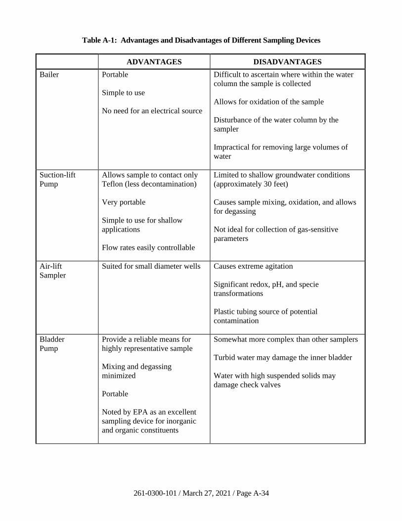
261-0300-101 / March 27, 2021 / Page A-34
Table A-1: Advantages and Disadvantages of Different Sampling Devices
ADVANTAGES DISADVANTAGES
Bailer Portable
Simple to use
No need for an electrical source
Difficult to ascertain where within the water
column the sample is collected
Allows for oxidation of the sample
Disturbance of the water column by the
sampler
Impractical for removing large volumes of
water
Suction-lift
Pump
Allows sample to contact only
Teflon (less decontamination)
Very portable
Simple to use for shallow
applications
Flow rates easily controllable
Limited to shallow groundwater conditions
(approximately 30 feet)
Causes sample mixing, oxidation, and allows
for degassing
Not ideal for collection of gas-sensitive
parameters
Air-lift
Sampler
Suited for small diameter wells Causes extreme agitation
Significant redox, pH, and specie
transformations
Plastic tubing source of potential
contamination
Bladder
Pump
Provide a reliable means for
highly representative sample
Mixing and degassing
minimized
Portable
Noted by EPA as an excellent
sampling device for inorganic
and organic constituents
Somewhat more complex than other samplers
Turbid water may damage the inner bladder
Water with high suspended solids may
damage check valves
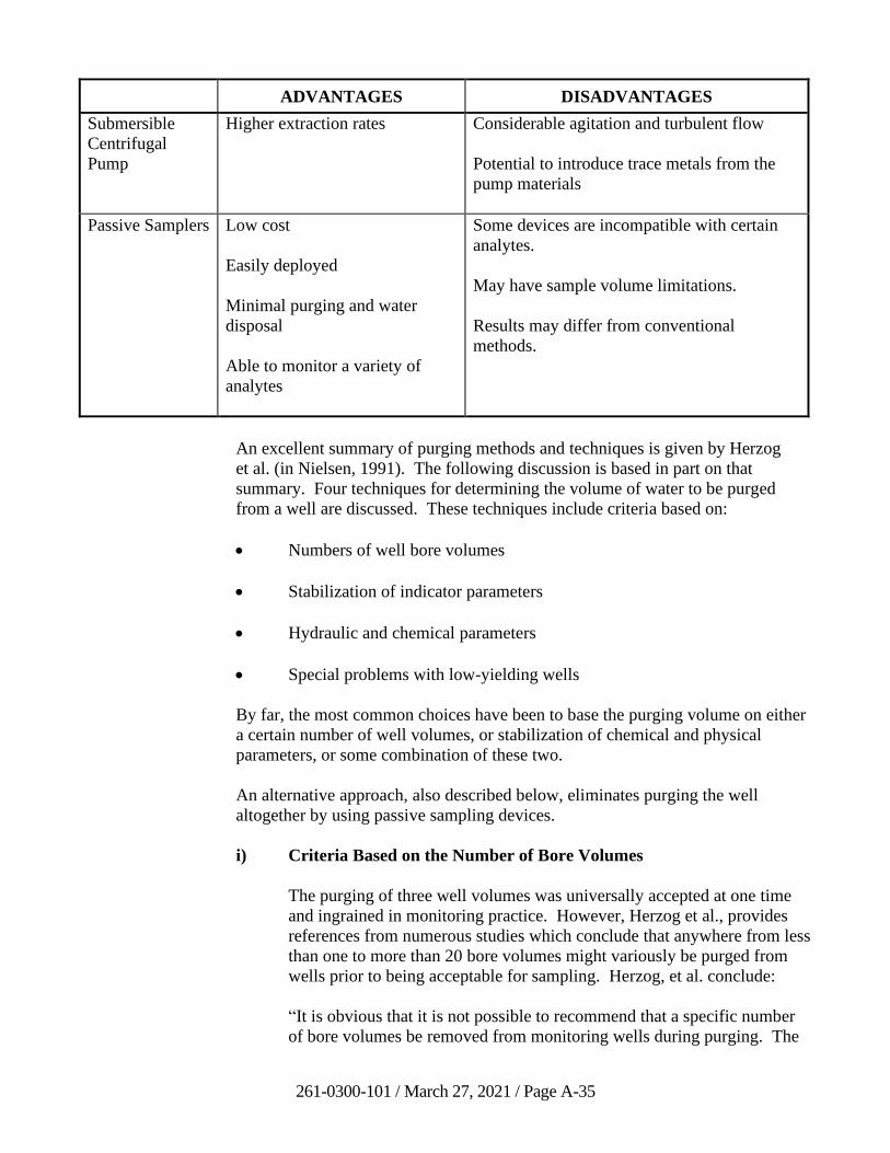
261-0300-101 / March 27, 2021 / Page A-35
ADVANTAGES DISADVANTAGES
Submersible
Centrifugal
Pump
Higher extraction rates Considerable agitation and turbulent flow
Potential to introduce trace metals from the
pump materials
Passive Samplers Low cost
Easily deployed
Minimal purging and water
disposal
Able to monitor a variety of
analytes
Some devices are incompatible with certain
analytes.
May have sample volume limitations.
Results may differ from conventional
methods.
An excellent summary of purging methods and techniques is given by Herzog
et al. (in Nielsen, 1991). The following discussion is based in part on that
summary. Four techniques for determining the volume of water to be purged
from a well are discussed. These techniques include criteria based on:
• Numbers of well bore volumes
• Stabilization of indicator parameters
• Hydraulic and chemical parameters
• Special problems with low-yielding wells
By far, the most common choices have been to base the purging volume on either
a certain number of well volumes, or stabilization of chemical and physical
parameters, or some combination of these two.
An alternative approach, also described below, eliminates purging the well
altogether by using passive sampling devices.
i) Criteria Based on the Number of Bore Volumes
The purging of three well volumes was universally accepted at one time
and ingrained in monitoring practice. However, Herzog et al., provides
references from numerous studies which conclude that anywhere from less
than one to more than 20 bore volumes might variously be purged from
wells prior to being acceptable for sampling. Herzog, et al. conclude:
“It is obvious that it is not possible to recommend that a specific number
of bore volumes be removed from monitoring wells during purging. The
261-0300-101 / March 27, 2021 / Page A-36
range of suggested volumes is too large and the cost of improper purging
is too great to permit such a recommendation.”
DEP recommends that if the borehole volume technique is going to be
used, the number of borehole volumes required for each well should have
a technical or scientific basis, such as stabilization of indicator parameters
(see following section) conducted at least once for each well during initial
sampling events, rather than being based on some arbitrary criterion such
as “three well volumes.”
When purging is based on some set number of borehole volumes, the
borehole volume calculation should take into account the entire original
borehole diameter, corrected for the porosity of any sand or filter pack,
and not be based just on the innermost casing diameter.
ii) Criteria Based on Stabilization of Indicator Parameters
Stagnant water in a well bore differs from formation water with respect to
many parameters. Field measurement of indicator parameters such as
temperature, pH, specific conductance, dissolved oxygen, and Eh has been
used as the criteria for determining the amount of water to purge and when
to sample a well. These parameters are measured in the purge water
during purging until they reasonably stabilize. DEP encourages the use of
this method.
DEP recommends that all of the above indicators be measured during the
initial and first few sampling events for the monitoring well. The data
should then be reviewed to determine which indicator parameters are the
most sensitive indicator that stagnant water has been evacuated from the
well. The most sensitive parameters will be those showing the greatest
changes and longest times to achieve stabilization. During the initial
sampling, the purging time should be extended beyond what initially
appears to be stabilization as a check to ensure that the parameter stability
is maintained.
iii) Low Flow Purging
Another purge method using the stabilization of indicator parameters is
low-flow (minimal drawdown) well purging. This technique is based
upon placing the pump intake at the screened interval, or in the case of
fractured rock, the water-bearing zone of interest. The well is pumped at a
very low rate, commonly less than 0.5 liters per minute, while producing
less than 0.1 meters of drawdown. Pumping continues until various
indicator parameters stabilize. The objective is to produce minimal
drawdown and less stress upon the aquifer while obtaining a sample from
the aquifer interval of interest. Lack of definitive well construction or
water-producing interval information negates the use of this purge method.
261-0300-101 / March 27, 2021 / Page A-37
Low-flow purging often creates much less purge water. Some purge water
contains various substances which cannot be disposed of on the ground
necessitating disposal. In these cases, low-flow purging can greatly
reduce the costs of disposal. In addition, purge time is often substantially
less. Set-up is usually more complex, and costs may therefore be higher
than when using other purge methods.
Indicator parameters typically include temperature, pH, redox potential,
conductivity, dissolved oxygen (DO), and turbidity. These common
stabilization parameters are often used to indicate that the water coming
from the pumped interval is aquifer water. Although often not very
sensitive to changes between borehole and aquifer water, temperature and
pH are usually included because they are easy to measure, and the data is
commonly used for other field analysis reasons. The minimum number of
parameters to measure should include pH, conductivity, and dissolved
oxygen. Stabilization is indicated after three successive readings taken at
3- to 5-minute intervals. Indicator parameters should show a change of
less than ± 0.1 for pH, ± 3% for conductivity, ± 10% mv for redox
potential, and ± 10% for turbidity and dissolved oxygen. The stabilization
rates put forth are a guideline. Experience may dictate the need for more
or less tolerance in particular wells or situations.
If a well has a history of water quality data produced using a different well
purging method, the result should be compared with the new low-flow
purge results. Significant variation in data will require justification of
continued use of the low-flow purge method. Depending upon the
situation, purge methods may need to return to the original method.
iv) Special Problems of Low-Yielding Wells
Low-yield wells present a special problem for the sampler in that they may
take hours, or even days, to recover after purging so that there is enough
water to sample. This waiting period not only increases the cost of
sampling, but also allows changes in water quality to occur between the
time the sample water enters the casing and the time it is collected. This is
especially problematic when sampling volatile constituents.
In practice, very low-yield wells are commonly pumped dry and sampled
the following day if necessary. This practice is believed to result in water
being sampled that is not representative of the aquifer being sampled from
the well due to the loss of volatiles and oxygenation of the water during
the waiting period. This results from pumping the well dry and exposing
the formation to the atmosphere. While there does not appear to be any
method uniformly agreed upon to eliminate these concerns, the following
considerations are suggested:
• Purge in such a way that the water level does not fall below the
well screen.
261-0300-101 / March 27, 2021 / Page A-38
• Evaluate the use of larger diameter wells that may deliver the
required amount of sample water more quickly than small diameter
wells.
• If full recovery cannot be achieved within two hours, collect the
required amount of water as it becomes available, collecting
samples for parameters in order of decreasing volatility.
v) No-Purge Methods
Passive samplers offer an alternative to traditional purge methods.
Commonly used technologies include polyethylene (or passive) diffusion
bags (PDBs) and HydraSleevesTM. Some sampler types operate through
diffusion of contaminants into the device; others collect a discrete grab
sample. A key advantage of passive samplers is that no purge water is
generated that requires treatment or disposal. Other advantages include
reduction of field sampling time and potentially less variability in sample
results. It should be noted that passive sampling methods that detect only
the presence or absence of contaminants may be utilized for
characterization, but are not recommended for attainment sampling.
Additionally, if the screening investigation indicates that regulated
substances are present, and if the aquifer recharge rate is reasonable,
conventional grab sampling should be performed to obtain quantitative
data on contaminant concentrations as part of a complete characterization
effort.
Some important limitations should be evaluated when considering the use
of passive samplers. The well construction, hydraulic properties of the
aquifer, and contaminant type and distribution should be known and
discussed with DEP prior to engaging in a full-scale sampling program
(see the references for further information).
• No-purge sampling methods rely on adequate groundwater flow
through the well screen. If the seepage velocity is low or the
screen is fouled, then the exchange rate of water in the well could
be slow, the water may be stagnant, and the sample may not be
representative of groundwater in the formation.
• Some devices are incompatible with certain analytes. For
example, most VOCs readily diffuse through polyethylene, but
some (such as MTBE) do not. Polyethylene diffusion bags cannot
be used to sample semi-volatile organic compounds (SVOCs) or
inorganics.
• Because passive samplers collect from a discrete interval, results
may be sensitive to the depth at which the device is placed. If flow
is stratified in the formation or localized at bedrock fractures, or if
the contaminant is density-stratified in the water column, then
deployment depth is important. Some sampler types allow
261-0300-101 / March 27, 2021 / Page A-39
multiple devices to be arrayed vertically on a tether, allowing the
remediator to better determine an optimal depth.
Passive samplers will not necessarily produce results equivalent to purge
methods. Ideally, a consistent purge and sampling methodology will be
used for all wells in the site network from the beginning of
characterization until the end of attainment. If a change in the sampling
method is being proposed midway through a monitoring program, then
sufficient side-by-side testing with the current approach should be
performed and discussed with DEP to determine if the change in method is
appropriate.
vi) Summary on Purging
The following general statements can be made with respect to purging:
• Every groundwater monitoring plan should contain a section
discussing how wells will be purged.
• It is often desirable to use the same device for sampling that was
used for purging. In this case the purge pump can be set within the
screened section of the well or across from the yielding zone being
monitored.
• If different devices are used for purging and sampling, purging
should begin at the static water surface and the device should be
lowered down the well at a rate proportional to water stored in the
well bore. Because of the better mixing of water in wells with
multiple yielding zones, this technique is considered preferable for
sampling wells with multiple yielding zones where a composite
sample of water in the yielding zones is desired (see Section C.5
on Well Depths, Screen Lengths, and Open Intervals).
• Where the same device is used to sample and purge a well, it
should be established that the sampling device will not change the
quality of the groundwater it contacts.
• In sampling for some analytes, such as volatile organics, it is
critical that the discharge be reduced to approximately
100 ml/minute to minimize degassing and aeration (Barcelona et
al., 1984). Flow control should be achieved by means of an
electric current using a rheostat rather than by valving or other
flow restrictors.
• Purging should be completed without lowering the water level in
the well below the well screen or water-bearing zone being
sampled.
261-0300-101 / March 27, 2021 / Page A-40
Never purge a well at a rate or in a way that causes water to cascade into
the well bore, resulting in increased degassing and volatilization.
e) Management of Purge Water
The first step in the management of monitoring well purge water is to minimize
its generation. Consideration should be given to techniques that minimize the
amount of purge water produced, such as low-flow or low-volume purging, or a
no-purge method. Purge water should be handled in a way that is
environmentally compatible with the volume generated, the type and
concentration of confirmed or suspected contaminants, and the specific site
conditions. A procedure that can be used is outlined in Table A-2. The procedure
is designed to ensure that potentially contaminated purge water is disposed
properly without contaminating other environmental media.
The following items should be considered when handling purge water:
• Purge water should be containerized until it is characterized by laboratory
analysis. Containers with purge water comingled from multiple wells
should use the highest concentration seen in any one of the wells from
which the comingled purge water was produced, unless the comingled
purge water is sampled.
• Purge water that has been characterized with no detections (i.e., with
analytical results less than method detection limits (MDLs)) may be
handled as uncontaminated groundwater under Table A-2.
• Purge water that has been characterized with detections of constituents
that do not exceed the Act 2 Residential, Used Aquifer Groundwater
MSCs may utilize any of the actions described in the contaminated
groundwater section of Table A-2. Discharging to the ground surface to
return water to the impacted groundwater plume (re-infiltration) under
action (d) is an option if it does not create runoff. Discharge to a surface
water, wetland, storm drain or paved surface that drains to a channel or
stormwater conveyance requires a permit or other appropriate regulatory
authorization.
• Purge water that has been characterized with detections of constituents
that exceed the residential used aquifer MSCs should be managed as
contaminated groundwater utilizing one of the actions described in (a), (b),
(d), or (e) of Table A-2. If action (e) is utilized, one of the approved
methods is as follows (for organic constituents only):
− Place up to 20 gallons/well of contaminated purge water onto the
ground surface of the site in a controlled manner for re-infiltration
after treatment with portable engineered carbon adsorption units
designed and operated to remove the organic contaminants to
levels below residential used aquifer MSCs according to the
following:
261-0300-101 / March 27, 2021 / Page A-41
▪ Re-infiltration may only occur within the area of
groundwater contamination exceeding Act 2 residential,
used aquifer MSCs;
▪ Placement on site should not create runoff that will enter
surface water, wetlands, storm drains or other water
conveyances to surface water;
▪ All contaminants should be capable of being treated by
carbon adsorption;
▪ Carbon adsorption units should be designed to provide
contact time for the amount of carbon at the expected levels
of raw water contamination to reach residential used
aquifer MSCs;
▪ A sample should be collected to demonstrate the unit has
functioned as intended. Samples should be collected at the
beginning and end of the filtration cycle; and
▪ Purge water should contain no free product.
f) Private Wells
If a well is a private water supply, sample as close to the well as physically
practical and prior to any treatment or filtering devices if possible and practical.
If sample collection must be from a holding tank, allow water to flow long
enough to flush the tank and the lines; when the pump in the well is triggered and
turned on, verification of tank flushing is provided. If a sample that passes
through a treatment tank must be taken, the type, size, and purpose of the unit
should be noted on the sample data sheet and in the field log book.
g) Filtering
When possible, avoid collecting samples which are turbid, colored, cloudy or
contain significant suspended matter. Exceptions to this include when the sample
site has been pumped and flushed or has been naturally flowing for a sufficient
time to confirm that these conditions are representative of the aquifer conditions.
Unless analysis of unfiltered samples for “total metals” is specifically required by
program regulation or guidance, all samples for metals analysis should be field-
filtered through a 0.45-micron filter prior to analysis. Filtering samples for SVOC
analysis is not appropriate to be conducted in the field as SVOCs have been
known to adhere to certain materials used during the filtration process.
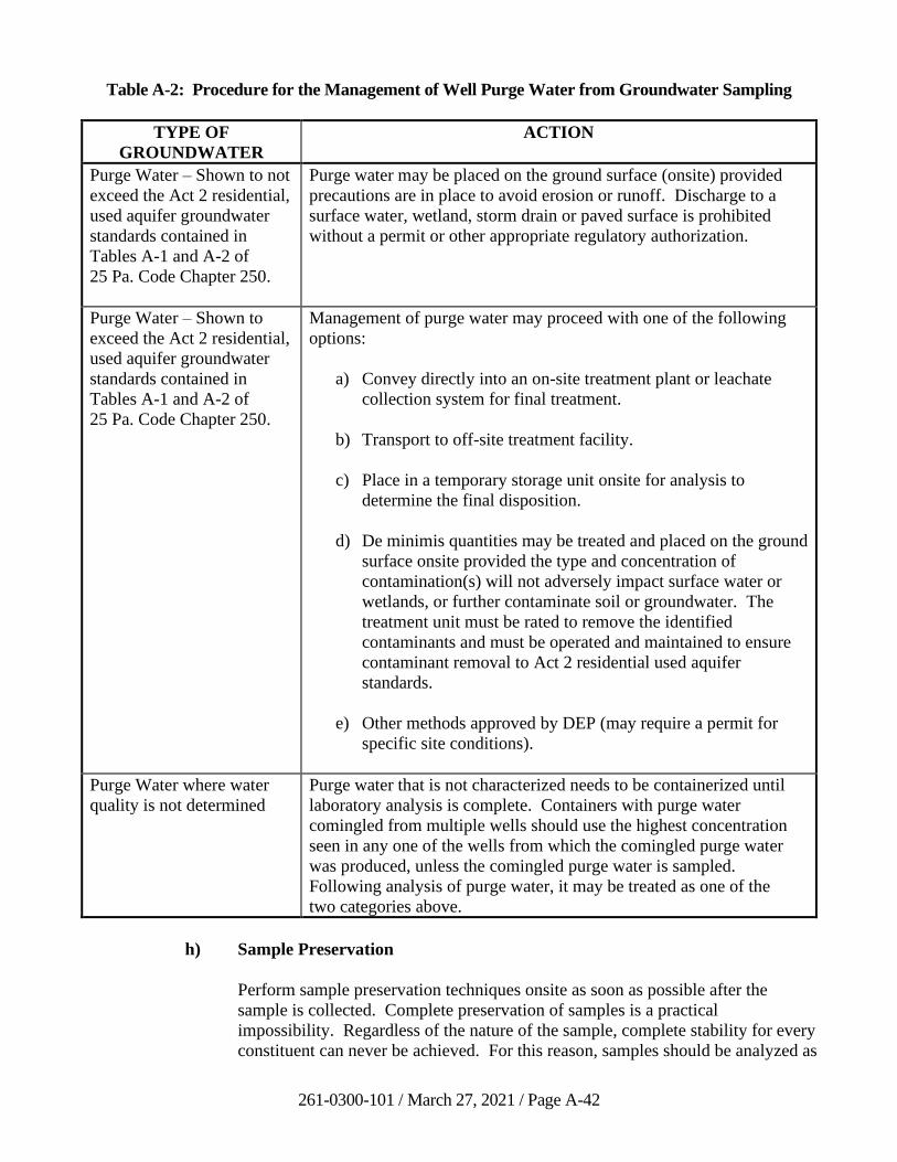
261-0300-101 / March 27, 2021 / Page A-42
Table A-2: Procedure for the Management of Well Purge Water from Groundwater Sampling
TYPE OF
GROUNDWATER
ACTION
Purge Water – Shown to not
exceed the Act 2 residential,
used aquifer groundwater
standards contained in
Tables A-1 and A-2 of
25 Pa. Code Chapter 250.
Purge water may be placed on the ground surface (onsite) provided
precautions are in place to avoid erosion or runoff. Discharge to a
surface water, wetland, storm drain or paved surface is prohibited
without a permit or other appropriate regulatory authorization.
Purge Water – Shown to
exceed the Act 2 residential,
used aquifer groundwater
standards contained in
Tables A-1 and A-2 of
25 Pa. Code Chapter 250.
Management of purge water may proceed with one of the following
options:
a) Convey directly into an on-site treatment plant or leachate
collection system for final treatment.
b) Transport to off-site treatment facility.
c) Place in a temporary storage unit onsite for analysis to
determine the final disposition.
d) De minimis quantities may be treated and placed on the ground
surface onsite provided the type and concentration of
contamination(s) will not adversely impact surface water or
wetlands, or further contaminate soil or groundwater. The
treatment unit must be rated to remove the identified
contaminants and must be operated and maintained to ensure
contaminant removal to Act 2 residential used aquifer
standards.
e) Other methods approved by DEP (may require a permit for
specific site conditions).
Purge Water where water
quality is not determined
Purge water that is not characterized needs to be containerized until
laboratory analysis is complete. Containers with purge water
comingled from multiple wells should use the highest concentration
seen in any one of the wells from which the comingled purge water
was produced, unless the comingled purge water is sampled.
Following analysis of purge water, it may be treated as one of the
two categories above.
h) Sample Preservation
Perform sample preservation techniques onsite as soon as possible after the
sample is collected. Complete preservation of samples is a practical
impossibility. Regardless of the nature of the sample, complete stability for every
constituent can never be achieved. For this reason, samples should be analyzed as
261-0300-101 / March 27, 2021 / Page A-43
soon as possible. However, chemical and biological changes occurring in the
sample may be slowed significantly by proper preservation techniques.
Chemical changes generally happen because of a shift in the physical conditions
of the sample. Under a fluctuation in reducing or oxidizing conditions, the
valence number of the cations or anions may change; other analytes may
volatilize or dissolve; metal cations may form complexes or precipitate as
hydroxides, or they may adsorb onto surfaces.
Biological changes can also alter the valence of a constituent. Organic processes
may bind soluble material into the cell structure, or cell material may be released
into solution.
Methods of preservation are relatively limited and are generally intended to:
1) retard biological activity, 2) retard hydrolysis of chemical compounds and
complexes, 3) reduce the volatility of constituents, and 4) reduce sorption effects.
Preservation methods are generally limited to pH control, chemical addition,
refrigeration, freezing, and selecting the type of material used to contain the
sample.
The best overall preservation technique is refrigeration at, or about, 4C.
Refrigeration primarily helps to inhibit bacteria. However, this method is not
always applicable to all types of samples.
Acids such as HNO3 and H2SO4 can be used to prevent precipitation and inhibit
the growth of bacteria. Preservation methods for any specific analysis should be
discussed with the accredited laboratory that is analyzing the samples.
i) Decontamination of Sampling Devices
All non-disposable and non-dedicated equipment that is submerged in a
monitoring well or contacts groundwater will need to be cleaned between
sampling additional wells to prevent cross-contamination. Generally, the level of
decontamination is dependent on the level and type of suspected or known
contaminants. Extreme care should be taken to avoid any decontamination
product from being introduced into a groundwater sample.
The decontamination area should be established upwind of sampling activities and
implemented on a layer of polyethylene sheeting to prevent surface soils from
contacting the equipment. The following steps summarize recommended
decontamination procedures for an Act 2 site:
• Wash with non-phosphate detergent and potable water. Use bristle brush
made from inert material to help remove visible soil;
• Rinse with potable water - pressure spray is recommended;
• If collecting samples for metals analysis, rinsing with 10% hydrochloric or
nitric acid;
261-0300-101 / March 27, 2021 / Page A-44
• Rinse liberally with deionized/distilled water –pressure spray is
recommended;
• If collecting samples for organics analysis, rinsing with solvent-grade
isopropanol, acetone, or methanol (should not be a solvent of potential
interest to the investigation);
• Rinse liberally with deionized/distilled water – pressure spray is
recommended;
• Air-dry;
• Wrap with inert material (such as aluminum foil) if equipment is not being
used promptly.
j) Field Sampling Logbook
A field logbook or field sampling forms should be completed and maintained for
all sampling events. The following list provides some examples of pertinent
information that should be documented:
• date/time of sample collection for each well
• well identification
• well depth
• presence of immiscible layers and detection method (i.e., an interface
probe)
• thickness of immiscible layers, if applicable
• estimated well yield (high, moderate, or low)
• purging device, purge volume, and pumping rate
• duration of well purging
• measured field parameters (see 4.3.3)
• sample appearance
• description on any abnormalities around the wellhead (standing/ponded
water, evidence of vandalization, etc.)
• description of any wellhead materials that were or need to be replaced
(sanitary well cap, well lid or well lid bolts, locking devices, etc.)
261-0300-101 / March 27, 2021 / Page A-45
k) Chain-of-Custody
A chain-of-custody record provides a legal document that traces sample
procession from time of collection to final laboratory analysis. The document
should account for all samples collected that require laboratory analyses and
provide the following information:
• sample identification number
• printed name and signature of sample collector(s)
• date/time of collection for each sample
• sample media type (i.e., groundwater)
• thickness of immiscible layers, if applicable
• well identification
• type and number of containers for each sample
• laboratory parameters requested for analyses
• type(s) of preservatives used
• carrier used, if applicable
• printed name and signature of person(s) involved in the chain of
possession
• date/time samples were relinquished by the sampler and received by the
laboratory
• presence/absence of ice in cooler or other sample holding device
• special handling instructions for the laboratory, if applicable
4. References
Barcelona, M.J., Helfrich, J.A., Garske, E.E., and Gibb, J.P., 1984, A Laboratory
Evaluation of Groundwater Sampling Mechanisms, Groundwater Monitoring Review,
v.4, No.2, pp. 32-41.
Driscoll, F.G., 1986, Groundwater and Wells, Second Edition, Johnson Filtration
Systems, Inc., St. Paul, Minnesota 55112, 1089 pp.
261-0300-101 / March 27, 2021 / Page A-46
Gibb, J.P., Schuller, R.M., and Griffin, R.A., 1981, Procedures for the Collection of
Representative Water Quality Data from Monitoring Wells, Cooperative Groundwater
Report 7, Illinois State Water Survey and Illinois State Geological Survey, Champaign,
IL.
Herzog, B., J. Pennino, and G. Nielsen, 1991, Ground-water sampling. In: Practical
Handbook of Ground-Water Monitoring. D. M. Nielsen, ed. Lewis Publishers. Chelsea,
Michigan. pp. 449-499
Interstate Technology Regulatory Council, 2004, Technical and Regulatory Guidance for
Using Polyethylene Diffusion Bag Samplers to Monitor Volatile Organic Compounds in
Groundwater.
Interstate Technology Regulatory Council, 2006, Technology Overview of Passive
Sampler Technologies.
Interstate Technology Regulatory Council, 2007, Protocol for Use of Five Passive
Samplers to Sample for a Variety of Contaminants in Groundwater, 121 pp.
Nielsen, D.M., (Editor), 1991, Practical Handbook of Ground-Water Monitoring,
NWWA, Lewis Publishers, Inc., Chelsea, Michigan 48118, 717 pp.
Nielsen, D.M., Nielsen, G., 2007, The Essential Handbook of Groundwater Sampling,
CRC Press.
Ohio Environmental Protection Agency, 2012, Technical Guidance Manual for
Groundwater Investigations, Chapter 10, Groundwater Sampling.
U.S. Environmental Protection Agency, 2010, Low Stress (Low Flow) Purging and
Sampling Procedure for the Collection of Groundwater Samples from Monitoring Wells,
30 pp.
U.S. Geological Survey, 2001, User’s Guide for Polyethylene-Based Passive Diffusion
Bag Samplers to Obtain Volatile Organic Compound Concentrations in Wells, Water-
Resources Investigations Report 01-4060.
U.S. Geological Survey, 2006, Collection of water samples (ver. 2.0): U.S. Geological
Survey Techniques of Water-Resources Investigations, book 9, chap. A4,
September 2006.
261-0300-101 / March 27, 2021 / Page A-47
E. Well Decommission Procedures
1. Introduction
Unsealed or improperly sealed wells may threaten public health and safety and the
quality of the groundwater resources. Therefore, the proper abandonment
(decommissioning) of a well is a critical final step in its service life.
Act 610, the Water Well Drillers License Act (32 P.S. § 645.1, et seq), includes a
provision for abandonment of wells. This legislation makes it the responsibility of a well
owner to properly seal an abandoned well in accordance with the rules and regulations of
DCNR. In the absence of more stringent regulatory standards, the procedures outlined in
this section represent minimum guidelines for proper decommissioning of wells and
borings. These procedures may be applicable for, but not limited to, public and domestic
water supply wells, monitoring wells, borings or drive points drilled to collect subsurface
information, test borings for groundwater exploration, and dry wells (drains or borings to
the subsurface).
Proper well decommissioning accomplishes the following: 1) eliminates the physical
hazard of the well (the hole in the ground and the wellhead protruding above surface
grade when applicable); 2) eliminates a pathway for the introduction and migration of
contamination; and 3) prevents hydrologic changes in the aquifer system, such as the
changes in hydraulic head and the mixing of water between aquifers. The proper
decommissioning method will depend on both the reason for abandonment and the
condition and construction details of the boring or well and the specific threat of existing
and potential contamination sources near the well bore.
An unused and decommissioned well could be the conduit for spread of contamination.
The lack of well decommissioning and a poorly sealed well could both result in the
spread of contamination into previously uncontaminated areas for which the well owner
or contractor may be responsible.
2. Well Characterization
Effective decommissioning depends on knowledge of the well construction, site geology,
and hydrogeology. The importance of a full characterization increases as the complexity
of the well construction, site geology, and the risk of aquifer contamination increases.
Construction information for wells drilled since 1966 may be available from the DCNR
BTGS PaGWIS database. Additional well construction data and information describing
the hydrologic characteristics of geologic formations may be available from reports
published by BTGS and the USGS. Site or program records also may exist. The well
should be positively identified before initiating the decommissioning. Field information
should be compared with any existing information.
Water levels and well depths can be measured with a well sounder, weighted tape
measure, or downhole camera. In critical situations, well construction details and
hydrogeology can be determined with borehole geophysics or a downhole camera. For
example, a caliper log, which is used to determine the borehole diameter, can be very
helpful in locating cavernous areas in open hole wells.
261-0300-101 / March 27, 2021 / Page A-48
3. Well Preparation
If possible, the borehole should be cleared of obstructions prior to decommissioning.
Obstructions such as pumps, pipes, wiring, and air lines must be pulled. Well preparation
also may involve “fishing” obstacles out of the borehole. An attempt should be made to
pull the casing when it will not jeopardize the integrity of the borehole. Before the casing
is pulled, the well should be grouted to near the bottom of the casing. This will at least
provide some seal if the well collapses after the casing is pulled.
The presence of nested or telescoped casing strings complicates well decommissioning.
Inner strings should be removed when possible, but only when removal will not
jeopardize the decommissioning of the well. If inner strings cannot be removed and
sealing of the annular space is required, then the inner string should be vertically split
(plastic-cased wells) or cut (metal-cased wells) at intervals necessary to ensure complete
filling of the annular space.
Damaged, poorly constructed or dilapidated wells may need to be re-drilled prior to
application of proper decommissioning techniques. Also, in situations where intermixing
of aquifers is likely, the borehole may need to be re-drilled.
4. Materials and Methods
a) Aggregate
Materials that eliminate the physical hazard and open space of the borehole, but
do not prevent the flow of water through the well bore, are categorized as
aggregate. Aggregates consist of sand, crushed stone or similar material that is
used to fill the well. Aggregates should be uncontaminated and of consistent size
to minimize bridging during placement.
Aggregate is usually not placed in wells smaller than two inches in diameter.
Nominal size of the aggregate should be no more than 1/4 of the minimum well
diameter through which it must pass during placement. Because aggregate is
usually poured from the top of the well, care should be taken to prevent bridging
by slowly pouring the aggregate and monitoring the progress with frequent depth
measurements. The volume of aggregate needed should be calculated prior to
placement into the well.
Aggregates may be used in the following circumstances: 1) there is no need to
penetrate or seal fractures, joints or other openings in the interval to be filled; 2) a
watertight seal is not required in the interval to be filled; 3) the hole is caving;
4) the interval does not penetrate a perched or confined aquifer; and 5) the interval
does not penetrate more than one aquifer. If aggregate is used, a casing seal
should be installed (see Section E.5.a). The use of aggregate and a casing seal
should be consistent with the future land use.
261-0300-101 / March 27, 2021 / Page A-49
b) Sealants
Sealants are used in well decommissioning to provide a watertight barrier and
prevent the migration of water in the well bore, in the annular spaces or in
fractures and openings adjacent to the well bore. Sealants usually consist of
Portland cement-based grouts, “bentonite” clay, or combinations of these
substances. Additives are frequently used to enhance or delay specific properties
such as viscosity, setting time, shrinkage, or strength.
Sealing mixtures should be formulated to minimize shrinkage and ensure
compatibility with the chemistry of the groundwater in the well.
To avoid the bridging of sealants in the well, sealing should be performed under
pressure from the bottom upward. A grout pump and tremie pipe are preferred for
delivering grout to the bottom of the well. This method ensures the positive
displacement of the water in the well and will minimize dilution or separation of
the grout.
If aggregate is to be placed above sealant, sufficient curing time should be allotted
before placing the aggregate above the seal. Curing time for grout using Type 1
cement is typically 24-48 hours, and 12 hours for Type III cement.
General types of sealants are defined as follows:
Neat cement grout: Neat cement grout is generally formulated using a ratio of
one 94-pound bag of Portland cement to no more than 6 gallons of water. This
grout is superior for sealing small openings, for penetrating any annular space
outside of the casings, and for filling voids in the surrounding rocks. When
applied under pressure, neat cement grout is strongly favored for sealing artesian
wells or those penetrating more than one aquifer. Neat cement grout is generally
preferred to concrete grout because it avoids the problem of separation of the
aggregate and the cement. Neat cement grout can be susceptible to shrinkage, and
the heat of hydration can possibly damage some plastic casing materials.
Concrete grout: Concrete grout consists of a ratio of not more than six gallons of
water, one 94-pound bag of Portland cement, and an equal volume of sand. This
grout is generally used for filling the upper part of the well above the water-
bearing zone, for plugging short sections of casings, or for filling large-diameter
wells.
Concrete grout, which makes a stronger seal than neat cement, may not
significantly penetrate seams, crevices or interstices. Grout pumps can handle
sand without being immediately damaged. Aggregate particles bigger than this
may damage the pump. If not properly emplaced, the aggregate is apt to separate
from the cement. Concrete grout should generally not be placed below the water
level in a well, unless a tremie pipe and a grout pump are used.
Grout additives: Some bentonite (2 to 8 percent) can be added to neat cement or
concrete grout to decrease the amount of shrinkage. Other additives can be used
261-0300-101 / March 27, 2021 / Page A-50
to alter the curing time or the permeability of the grout. For example, calcium
chloride can be used as a curing accelerator.
High-solids sodium bentonite: This type of grout is composed of 15-20 percent
solids content by weight of sodium bentonite when mixed with water. To
determine the percentage content, the weight of bentonite is divided by the weight
of the water plus the weight of the bentonite. For example, if 75 pounds of
powdered bentonite and 250 pounds of granular bentonite were mixed in
150 gallons of water (at 8.34 pounds per gallon), the percentage of high-solids
bentonite is approximately 20 percent [325/(1251+325)]. High-solids bentonite
must be pumped before its viscosity is lowered. Pumping pressures higher than
those used for cement grouts are usually necessary. Hydration of the bentonite
must be delayed until it has been placed down the well. This can be done by:
1) using additives with the dry bentonite or in the water; 2) mixing calcium
bentonite (it expands less) with sodium bentonite; or 3) using granular bentonite,
which has less surface area.
In addition, positive displacement pumps such as piston, gear, and moyno
(progressive cavity) pumps should be used because pumps that shear the grout
(such as centrifugal pumps) will accelerate congealing of the bentonite. A paddle
mixer is typically used to mix the grout. A high-solids bentonite grout is not
made from bentonite that is labeled as drilling fluid or gel.
c) Bridge Seals
A bridge seal can be used to isolate cavernous sections of a well, to isolate
two producing zones in the well, or to provide the structural integrity necessary to
support overlying materials, and thus protect underlying aggregate or sealants
from excessive compressive force. Bridge seals are usually constructed by
installing an expandable plug made of wood, neoprene, or a pneumatic or other
mechanical packer. Additional aggregate can be placed above the bridge.
5. Recommendations
The complexity of the decommissioning procedure depends primarily on the site
hydrogeology, geology, well construction, and the groundwater quality. Four principal
complicating factors have been identified, which include: 1) artesian conditions,
2) multiple aquifers, 3) cavernous rocks, and 4) the threat or presence of contamination.
The recommended procedures for abandoning wells will be more rigorous with the
presence of one or more complicating factors. The procedures may vary from a simple
casing seal above aggregate to entirely grouting a well using a tremie pipe after existing
casing has been ripped or perforated. Figure A-8 summarizes the general approach to
well decommissioning.
a) Casing Seal
The transition from well casing to open borehole is the most suspect zone for
migration of water. To minimize the movement of water (contaminated or
otherwise) from the overlying, less consolidated materials to the lower water-
261-0300-101 / March 27, 2021 / Page A-51
bearing units, this zone should be sealed. Generally, this can be accomplished by
filling at least the upper 10 feet of open borehole and the lower five feet of casing
with sealant. The length of open borehole sealed should be increased if
extenuating circumstances exist. Such circumstances would include a history of
bacterial contamination, saprolitic bedrock, or possibly deep fracture zones.
Water-bearing zones reported in the upper 20 feet or so of open borehole are
indications of fractures and warrant the use of additional sealant. Casing that is
deteriorated should be sealed along its entire length. If the casing is to be pulled,
the sealant used should remain fluid for an adequate time to permit removal of the
casing.
If the casing is to remain, then whenever feasible, it should be cut off below land
surface. After the casing seal discussed above achieves adequate strength, the
open casing should, at a minimum, be filled with aggregate. It is strongly
suggested that a sealant be used in the upper two to five feet of casing.
b) Wells in Unconfined or Semi-Confined Conditions
These are the most common well types in Pennsylvania. The geology may consist
of either unconsolidated or consolidated materials. When applicable, unconfined
wells in non-contaminated areas may be satisfactorily decommissioned using
aggregate materials up to 10-15 feet below the ground surface. Monitoring wells
located at sites with no known contamination might be decommissioned in this
manner. The casing seal should be installed above the aggregate. A sealant may
be used over the entire depth.
c) Wells at Contaminated Sites
A decommissioned, contaminated well often mixes contaminated groundwater
with uncontaminated groundwater. Complete and uniform sealing of the well
from the bottom to the surface is required. Therefore, proper well preparation
(Section E.3) should be accomplished before the well is sealed with a proper
sealant (Section E.4.b).
d) Flowing Wells
The sealing of artesian wells requires special attention. The flow of groundwater
may be sufficient to make sealing by gravity placement of concrete, cement grout,
neat cement, clay or sand impractical. In such wells, large stone aggregate (not
more than 1/4 of the diameter of the hole), or well packers (pneumatic or other)
will be needed to restrict the flow and thereby permit the gravity placement of
sealing material above the zone where water is produced. If plugs are used, they
should be several times longer than the diameter of the well to prevent tilting.
Seals should be designed to withstand the maximum anticipated hydraulic head of
the artesian aquifer.
Because it is very important in wells of this type to prevent circulation between
water yielding zones, or loss of water to the surface or annular spacing outside of
261-0300-101 / March 27, 2021 / Page A-52
the casing, it is recommended to pressure grout the well with cement using the
minimum volume of water during mixing that will permit handling.
For wells in which the hydrostatic head producing flow to the surface is low, the
movement of water may be stopped by extending the well casing to an elevation
above the artesian pressure surface.
e) Wells with Complicating Factors at Contaminated Sites
Wells with one or more of the above complicating factors that are to be
decommissioned in areas with contaminated groundwater, or in areas where the
groundwater is at a high risk for future contamination, require the most rigorous
decommissioning procedures. In general, the entire length of these wells should
be sealed.
When the threat of contamination has been established, the elimination of a
potential flowpath is critical. For example, a contaminated well in a karst terrane
must be carefully sealed to avoid exacerbating the situation. In general, the entire
lengths of these wells should be sealed. In some situations, a bridge seal may
need to be installed, and casing may have to be perforated. In each case, a
prudent method should be selected which will eliminate all potential vertical
flowpaths.
f) Monitoring Wells
Monitoring wells which are installed for an investigation, cleanup or other
monitoring in a program that has no rules or regulations for decommissioning,
such as the Act 2 program, should be decommissioned in accordance with the
following guidelines.
Monitoring wells that were installed and continue to function as designed can
usually be decommissioned in place after they are no longer needed. Exceptions
would include wells whose design precludes complete and effective placement of
sealant and wells in locations subject to future disturbance that could compromise
the decommissioning. In such instances, all tubing, screens, casings, aggregate,
backfilling, and sealant should be cleaned from the boring and the hole should be
completely filled with an appropriate sealant.
Monitoring wells that are abandoned in place should be completely filled with
sealant. Screened intervals can be backfilled with inert aggregate if sealant may
alter the groundwater chemistry, thereby jeopardizing ongoing monitoring at the
facility. Intervals between screens, and between the last screen and the surface,
must be filled with sealant. Generally, sealant should be emplaced from the
bottom of the interval being sealed to the top of that interval. Protective casings,
riser pipes, tubing, and other appurtenances at the surface which could not be
removed should be cut off below grade after the sealant has properly set. When
decommissioning will be completed below the finished grade, the area of the
boring should be covered with a layer of bentonite, grout, concrete, or other
sealant before backfilling to grade.
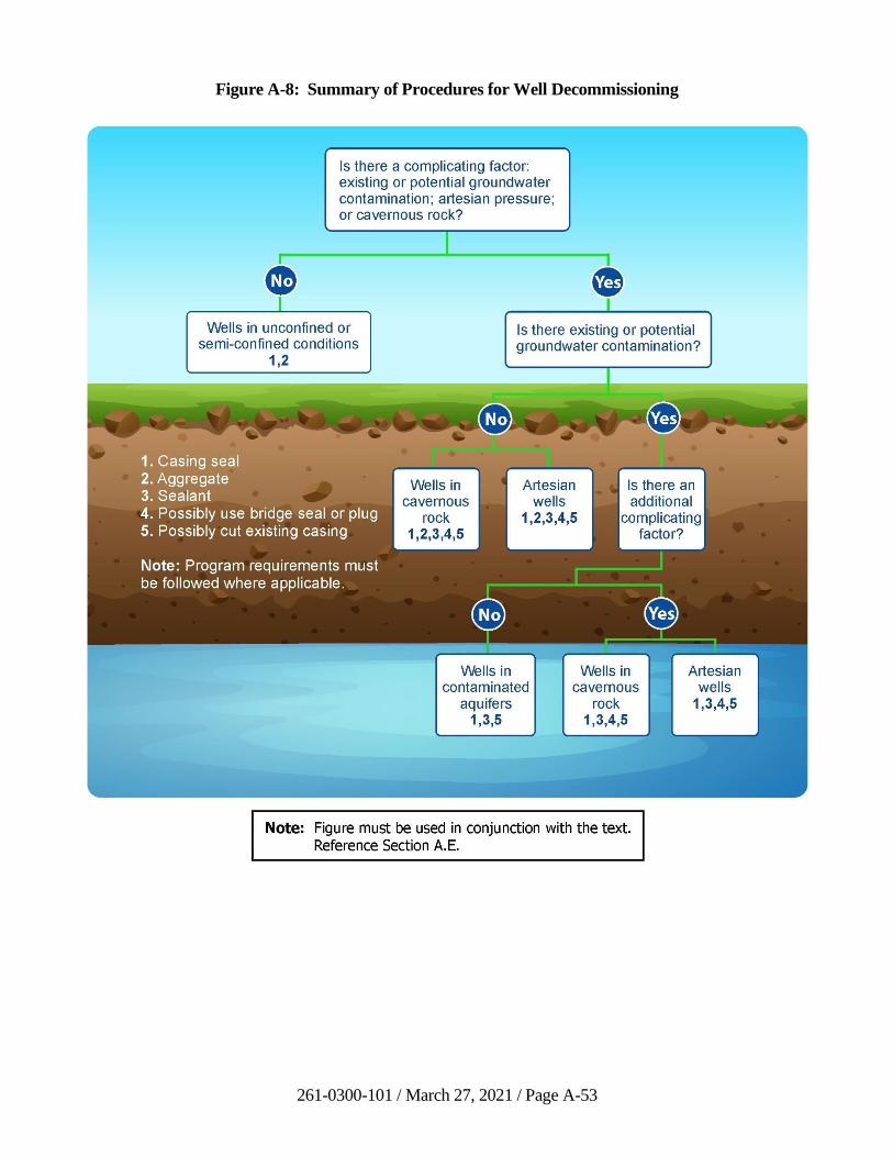
261-0300-101 / March 27, 2021 / Page A-53
Figure A-8: Summary of Procedures for Well Decommissioning
261-0300-101 / March 27, 2021 / Page A-54
6. Existing Regulations and Standards
17 Pa. Code § 47.8 requires that the owner or consultant who is to abandon the well notify
DCNR’s BTGS of the intent to decommission a well at least 10 days before the well is
sealed or filled.
7. Reporting
All decommissioned wells shall be reported to BTGS, along with any bureau that requires
a report, on forms required by BTGS (and any other pertinent forms). If available, the
original driller’s log should be included, along with the details of the well
decommissioning procedure. A photograph should be taken of the site, and a reference
map should be made, showing the location of the decommissioned well. It also may be
appropriate to survey the exact location of the well (if not already completed). Licensed
drillers may use the online application WebDriller to complete the well decommissioning
report.
8. References
American Water Works Association, 1990, Abandonment of Test Holes, partially
completed wells and completed wells: AWWA Standard for Water Wells, pp. 25-26.
Driscoll, F.G., 1986, Groundwater and Wells, 2nd ed., Johnson Filtration Systems, Inc.,
St. Paul, Minnesota 55112, 1089 pp.
Nye, J.D., September 1987, Abandoned Wells - How One State Deals with Them, Water
Well Journal, pp. 41-46
Renz, M.E., May 1989, In Situ Decommissioning of Ground Water Monitoring Wells,
Water Well Journal, pp. 58-60.
U.S. Environmental Protection Agency, 1975, Manual of Water Well Construction
Practices, Office of Water Supply, EPA-570/9-75-001.
261-0300-101 / March 27, 2021 / Page A-55
F. Quality Assurance/Quality Control Requirements
1. Purpose
A Quality Assurance/Quality Control Plan (QA/QC Plan) is a detailed account of
methods and procedures used for data collection (i.e., monitoring) activities. This plan,
when properly developed and implemented, ensures that adequate control and
documentation procedures are utilized, from initiation to completion of the monitoring,
so that the data generated is of the highest quality and can be used for the intended
purpose with confidence. A QA/QC plan is also an effective tool in assessing and
assuring the completeness and adequacy of the basic monitoring plan.
2. Design
A QA/QC plan should be designed to satisfy the objectives of the monitoring project.
Although the elements of each QA/QC plan described below will be similar, the intended
uses of the collected data will determine the requirements associated with the monitoring
activity. In most cases, there will be sufficient differences within monitoring activities
for each project to require a specific QA/QC plan.
The following paragraphs describe the basic elements of a QA/QC plan. In most cases,
the proper development and adherence to this format will be sufficient to ensure that the
data collection meets the objectives of a project. However, in some cases it may be
necessary to include additional considerations that may be unique to a specific site and/or
project.
3. Elements
• Project Name or Title: Provide the project identification and location.
• Project Required by: Provide the reason(s) or requirement(s) for the project.
• Date of Requirement: Provide date the project was required, either by legal or
other order.
• Date of Project Initiation: Provide date that the project was implemented.
• Project Officer(s): Provide name(s) of individual(s) responsible for managing or
overseeing the project.
• Quality Assurance Officer(s): Provide name(s) of individual(s) responsible for
development of and adherence to the QA/QC plan.
• Project Description: Provide the following: 1) an objective and scope statement
which comprehensively describes the specific objectives and goals of the project,
such as determining treatment technology effectiveness, or remediation
effectiveness for specific parameters; 2) a data usage statement that details how
the monitoring data will be evaluated, including any statistical or other methods;
3) a description of the location of monitoring stations and reasons for the
261-0300-101 / March 27, 2021 / Page A-56
locations, including geologic, hydrogeologic or other considerations; and 4) a
description of the monitoring analytes and frequency of sample collection,
including the expected number of samples to be collected for each analyte, the
sample matrix (i.e., water), the exact analytical method, reasons for selection of
analytes, and sample preservation method(s) and holding time(s).
• Project Organization and Responsibility: Provide a list of key personnel and their
corresponding responsibilities, including the position and/or individual in charge
of the following functions: field sampling operations, field sampling QA/QC,
laboratory analyses, laboratory analyses QA/QC, data processing activities, data
processing QA/QC and overall project coordination.
• Project Fiscal Information: Provide an estimate in work days of the project time
needed for data collection, laboratory support, data input, quality assurance and
report preparation in work days.
• Schedule of Tasks and Products: Provide a projected schedule for completing the
various tasks and developing the products associated with the project, such as
sample collections (monthly, quarterly, etc.), data analysis/reports (quarterly,
annual, biennial, etc.).
• Data Quality Requirements and Assessments: Provide a description of data
accuracy and precision, data representativeness, data comparability, and data
completeness.
• Sampling Procedures: Provide a description of the procedures and
equipment/hardware used to collect samples from monitoring wells or other sites,
including sampling containers and field preservation and transport procedures.
• Sampling Plan: A sampling plan should provide necessary guidance for the
number and types of sampling QCs to be used. The following is a list of common
sample QC types and the recommended minimum frequency if used. It is
important to remember that all QC samples should be treated with the same
dechlorination and/or preserving reagents as the associated field samples.
− Trip Blanks - These are appropriate sample containers filled with
laboratory-quality reagent water that are transported to and from the
sampling site(s) and shipped with the samples to the laboratory for
analysis. The intent of these samples is to determine whether cross
contamination occurred during the shipping process. They are also used to
validate that the sampling containers were clean. Each sampling event
that uses this type of QC should have a minimum of one trip blank for
each container type used.
− Field Blanks - These are appropriate sample containers that are filled with
laboratory-quality reagent water at the sampling site(s) and shipped with
the samples to the laboratory for analysis. These samples are intended to
determine if cross-contamination occurred during the sampling process
due to ambient conditions. They are also used to validate that the
261-0300-101 / March 27, 2021 / Page A-57
sampling containers were clean. Each sampling event that uses this type
of QC should have a minimum of one field blank for each sampling site
and of each container type used. This type of sampling QC is most useful
when sampling for VOC’s.
− Rinsate Blanks - These are samples of laboratory-quality reagent water
used to rinse the collection device, including filtration devices and filters,
which contact the same surfaces as the sample. The QC samples(s) are
then submitted with the field samples for analysis. This type of QC
sample helps to determine if the sample collection device is contributing
any detectable material to the sample. The minimum number of blanks
needed, if this type of QC is utilized, is dependent upon operational
considerations. A minimum of two rinsate blanks should be submitted
(one before sampling and one after sampling) if multiple samples are
being collected with the same decontaminated collection device. If you
are using disposable sample collection devices or multiple pre-cleaned
devices, then a single representative sample should suffice.
− Split/Duplicate Samples - This is a single, large sample that has been
homogenized, split into two or more individual samples, with each sample
submitted independently for analysis. This QC determines the amount of
variance in the entire sampling/analysis process. This type of QC is not
recommended for samples analyzed for analytes that would be adversely
affected by the homogenization process (i.e. VOC’s). The minimum
number of this type of sampling QC, if utilized, is one per sampling event,
with a rate of 5 percent to 10 percent commonly used.
− Replicate Samples - Comprised of two or more samples collected from the
same source, in a very short time frame (i.e., minutes), with each sample
submitted independently for analysis. This QC measure, like the
split/duplicate sample, determines the amount of variance in the entire
sampling/analysis process. The amount of variance determined by this
type of QC may be larger than that of a split/duplicate sample. The use of
this type of QC also presumes that the sample’s materials are already
homogenous. This type of QC is recommended for samples where
analytes could be adversely affected by an external homogenization
process (i.e. volatile organics). The minimum number of this type of
sampling QC, if utilized, is one per sampling event, with a rate of
5 percent to 10 percent commonly used.
− Known Samples - These are reference materials that have been
characterized as acceptable to the range of values for the analytes of
concern. These materials are available from commercial sources. This
type of QC helps determine if the analytical work is sufficiently accurate.
It must be noted that improper handling or storage of this type of reference
material can invalidate the materials characterization. The minimum
number of this type of QC, if used, is one per subject.
261-0300-101 / March 27, 2021 / Page A-58
− Spiked Samples - These are split/duplicate or replicate samples that have
been fortified with the analytes of concern. This QC is intended to
determine if there have been changes in concentration due to factors
associated with the sample or the shipping and analysis process. This type
of QC is very difficult to use in a field environment and routinely is done
as part of the analysis process. If this type of QC is necessary, the
minimum required is one per project.
• Sample Custody Procedures: Provide information which describes accountability
for sample chain-of-custody including sample collector identification, sample
location identification, sample number, date and time of collection, parameters to
be analyzed, preservatives and fixatives, identification of all couriers,
identification of laboratory and receiver, time and date of receipt at laboratory,
laboratory analyzer, and time and date of analysis.
• Calibration Procedures and Preventative Maintenance: Equipment maintenance
and calibration should be performed in accordance with manufacturer’s
instructions. Calibration and maintenance sheets should be maintained on file for
all equipment.
• Documentation, Data Reduction, and Reporting: Provide discussion on where
field data are recorded, reviewed, and filed.
• Data Validation: Provide a discussion and reference to the protocols used for
validation of chemical data and field instrumentation and calibration. Describe
procedure for validating database fields (i.e., through error checking routines,
automatic flagging of data outside of specified ranges, and manual review and
spot checking of data printouts against laboratory analytical results).
• Performance and Systems Audits: Provide a description of how field staff
performance is checked and how data files are verified for accuracy and
completeness.
• Corrective Action: Provide a discussion on what corrections are made when
errors are found and actions taken to prevent future recurrence of errors.
• Reports: Provide a list of the types and frequency of reports to be generated (i.e.,
performance and systems audits, compliance analyses, remediation effectiveness,
etc.).
4. References
U.S. Environmental Protection Agency, May 1984, Guidance for Preparation of
Combined Work/Quality Assurance Project Plans for Environmental Monitoring,
(OWRS QA-1), US EPA Office of Water Regulations and Standards.
Mueller, D.K., Schertz, T.L., Martin, J.D., and Sandstrom, M.W., 2015, Design, analysis,
and interpretation of field quality-control data for water-sampling projects: U.S.
Geological Survey Techniques and Methods, book 4, chap. C4, 54 p.
261-0300-101 / March 27, 2021 / Page A-59
U.S. Geological Survey, 2006, Collection of water samples (ver. 2.0): U.S. Geological
Survey Techniques of Water-Resources Investigations, book 9, chap. A4,
September 2006.
LAND RECYCLING PROGRAM TECHNICAL GUIDANCE MANUAL
(DEP ID: 261-0300-101)
COMMENT RESPONSE DOCUMENT
JANUARY 19, 2019
Pennsylvania Department of Environmental Protection
Bureau of Environmental Cleanup and Brownfields
261-0300-101 / January 19, 2019 / Page 1
INTRODUCTION
On December 16, 2017, the Pennsylvania Department of Environmental Protection, Bureau of
Environmental Cleanup and Brownfields, published a notice of public comment period on the proposed
amendments to the Land Recycling Program Technical Guidance Manual. The public comment period
opened on December 16, 2017 and closed on March 16, 2018.
This document summarizes the comments received during the public comment period. In assembling
this document, the Department has addressed all pertinent and relative comments associated with this
package. Comments of similar subject material have been grouped together and responded to
accordingly.
During the public comment period the Department received 96 comments from 9 different
organizations. The following table lists these commentators. The Commentator ID number is found in
parentheses following each comment in this document.
Commentators
1. Joe Skurka
Groundwater & Environmental Services, Inc.
301 Commerce Park Drive
Cranberry Twp., PA 16066
2. Jeffrey Hale
Kleinfelder
230 Executive Drive
Cranberry Twp., PA 16066
3. Jenny DeBoer
Stantec
400 Davis Drive, Suite 400
Plymouth Meeting, PA 19462
4. Mark Urbassik, P.E., and Sara Covolo
KU Resources, Inc.
22 South Linden Street
Duquesne, PA 15110
5. Craig Robertson, P.G.
Groundwater Sciences Corporation
2601 Market Place Street, Suite 310
Harrisburg, PA 17110
6. Chuck Campbell
Leidos
6310 Allentown Boulevard
Harrisburg, PA 17112
7. Michael M. Meloy
Manko Gold Katcher Fox LLP
401 City Avenue, Suite 901
Bala Cynwyd, PA 19004
8. Maya K. van Rossum
Delaware Riverkeeper Network
925 Canal Street, Suite 3701
Bristol, PA 19007
9. Stephen W. Klesic
United Environmental Group, Inc.
241 McAleer Road
Sewickley, PA 15143
261-0300-101 / January 19, 2019 / Page 2
Acronyms used in this Comment and Response Document
AUL Activity and Use Limitation
BGS Background Cleanup Standard
CAP Corrective Action Process
CO&A Consent Order & Agreement
CP Cleanup Plan
CSSAB Cleanup Standards Scientific Advisory Board
DAF Dilution Factor
DEP or PA DEP Pennsylvania Department of Environmental Protection
DPT Direct Push Technology
EC Environmental Covenant
ECB Environmental Cleanup and Brownfields
EPA or USEPA U.S. Environmental Protection Agency
EZ Enterprise Zone
FR Final Report
GW Groundwater
HAZWOPER Hazardous Waste Operations and Emergency Response
HQ Hazard Quotient
HSCA Hazardous Sites Cleanup Act
LNAPL Light Non-Aqueous Phase Liquid
LRP Land Recycling Program
MEP Maximum Extent Practicable
MSC Medium-Specific Concentration
NAPL Non-Aqueous Phase Liquid
NESHAP National Emission Standards for Hazardous Air Pollutants
NIR Notice of Intent to Remediate
NPDES National Pollutant Discharge Elimination System
OSHA Occupational Safety and Health Administration
PCB Polychlorinated Biphenyl
PCSM Post-Construction Stormwater Management
PE Professional Engineer
PG Professional Geologist
PID Photoionization Detector
PNDI Pennsylvania Natural Diversity Inventory
POC Point of Compliance
PPM Part Per Million
PRCP Postremediation Care Plan
RA Risk Assessment
RI Remedial Investigation
RSL EPA Regional Screening Level
SHS Statewide Health Standard
SIA Special Industrial Area
SOP Standard Operating Procedure
SPL Separate Phase Liquid
SSS Site-specific Standard
STSPA Storage Tank and Spill Prevention Act
SWMA Solid Waste Management Act
TGM Technical Guidance Manual

261-0300-101 / January 19, 2019 / Page 3
TSCA Toxic Substances Control Act
UECA Uniform Environmental Covenants Act
UST Underground Storage Tank
USTIF Underground Storage Tank Indemnification Fund
VI Vapor Intrusion
261-0300-101 / January 19, 2019 / Page 4
1. Comment: The commentator suggested eliminating the following on Page i: “DEP reserves the
discretion to deviate from this policy statement if circumstances warrant.” The commentator
suggests this statement can create problems and potential inconsistency between the regions
governing Act 2 cleanups. (9)
Response: The purpose of the referenced statement is to remind users that the proposed Land
Recycling Program TGM is a guidance document and, consistent with other guidance documents
that the Department publishes, does not change any existing statutes or Department regulations.
Instead, the Department publishes the guidance to assist any persons conducting a site
remediation under the Land Recycling and Environmental Remediation Standards Act (Act 2).
The Department may deviate from guidance to the extent that its actions are in conformity with
the Department’s statutory and regulatory authority. Ultimately, site remediations are governed
by Act 2 and 25 Pa. Code Chapter 250, and this TGM serves as a helpful supplement.
2. Comment: The commentator noted that one of the most concerning things about the Act 2
remediation process is captured by the following statement in the beginning of the guidance: “A
property used for industrial development need not be as clean as a playground or residential
site.” Yet, the use of the site can and often does change from the initial proposed usage. While
there are reopeners, they are not always used in instances where the site usage is changed, and
require the DEP to act subsequently, rather than mandating the site be clean to a higher standard
in the first place. Indeed, it is frightening that a site could have a changed use many years into
the future. For example, when a site has been remediated to a lower level, the land remediated to
only an industrial site standard could later become a playground. Sites are not being adequately
restored, and this can and does come back to harm and haunt the citizens of Pennsylvania. The
commentator went on to note that the Land Recycling and Remediation Standards Act, Act 2, is
about restoration of commercial and industrial lands. It was not intended to apply to residential
lands. For residential lands and natural open space, there is no reason why a responsible party is
not required to restore the land to its pre-existing conditions as opposed to some site-specific
standard that is less protective. Legally, when a property is harmed through negligence of a
party, it should be returned to its pre-existing condition. However, with a site-specific standard,
the property does not return to its pre-existing condition and may be returned to a condition in
which there are simply no current exposure pathways for health harms. When there is a
financially able responsible party, residential property should be returned to its original
(uncontaminated) state. Similarly, anti-degradation requirements should apply to remediation.
Special protection waterways, for example, should not be permitted to remain with
contamination but should be cleaned up to their pre-existing conditions. With respect to natural
resources, the Department has the constitutional duty of preventing and remedying the
degradation, diminution and depletion of our public natural resources. (reference Pennsylvania
Envtl. Def. Found. v. Commonwealth, 161 A.3d at 938, n.32, Pa. 2017). Restoration of
residential lands, open space and ecologic systems should be pursued to achieve pre-existing
conditions to the greatest possible extent. The TGM does not reflect this goal. (8)
Response: The Department appreciates the comment. It is important to note that the TGM
provides guidance on how to demonstrate attainment of an Act 2 remediation standard. The
Department’s development of the TGM does not affect any statutory or regulatory requirements.
The primary concern expressed here is addressed in the TGM in Section I, wherein the
Department provides a narrative of the benefits of the voluntary approaches to remediation
through the LRP. In Act 2, the General Assembly recognized that “[c]leanup plans should be
based on the actual risk that the contamination on a site may pose to public health and the
261-0300-101 / January 19, 2019 / Page 5
environment.” (35 P.S. § 6020.102(6)). In practice, this means that a site that has historically
been used for “non-residential” purposes may be remediated to a non-residential standard.
Similarly, a site that has been used for “residential” purposes must be remediated to a residential
standard.
In Act 2, the General Assembly created three remediation standards: 1) background standard;
2) Statewide health standard; and 3) site-specific standard. (35 P.S. § 6020.301(a) (1-3)). To
accommodate those standards, the Environmental Quality Board promulgates numerical
“residential” and “non-residential” health-based standards known as Medium-Specific
Concentrations (“MSCs”), which can be found in 25 Pa. Code Chapter 250 Appendix A. In
addition, Act 2 defines both “nonresidential” and “residential” in order to correlate the
appropriate remediation standard and the site’s intended use.
On occasion, a site may change use over time. Cleanup liability protection extends only to the
contamination identified in reports submitted to and approved by the Department. (35 P.S.
§ 6020.501(a)). A person that investigates and remediates a site to a non-residential standard is
relieved by Act 2 of the release of that contamination. If that person later chooses to use the site
for residential purposes, he or she will have to identify and address any remaining contamination
to a residential standard before obtaining liability protection. Note that 35 P.S. § 6020.505
allows the Department to reopen a site and revoke liability afforded by Act 2 in the event that
land use is changed in the future in a manner that could pose risk to human health or the
environment.
In regard to lands used for residential purposes, the Department has a variety of tools to ensure
that sites are remediated to the appropriate use. For instance, under the Act 2 site-specific
standard (SSS), environmental covenants may be used to ensure that institutional controls or
environmental controls are maintained to eliminate exposure to any contamination. An
environmental covenant may contain clauses that require notification to the Department of
proposed changes in use. (See 25 Pa. Code §§ 253.2(b)(1) and 253.4(a)).
In the context of discharges into surface waters, section 303(b)(1) of Act 2 states that MSC
concentrations regarding regulated discharges into surface waters shall comply with applicable
laws and regulations relating to those surface waters. (35 P.S. § 6020.303(b)(1)). Similarly,
pursuant to 25 Pa. Code § 250.707, “a person shall demonstrate attainment within the surface
water . . . by demonstrating compliance with the applicable State and Federal law and
regulations.” Therefore, a person that chooses to address discharges into an Exceptional Value
waterbody must demonstrate attainment with the applicable anti-degradation standards.
Finally, Act 2 permits a person to select one or a combination of standards to voluntarily address
contamination. Cleanup liability protection only extends to the contamination that a person
addresses as part of his or her Department-approved remediation. This contamination is
identified in a person’s Notice of Intent to Remediate. (35 P.S. §§ 6020.302(e)(1); 303(h)(1);
304(n)(1); 25 Pa. Code § 250.5(a)). Liability persists for any contamination that remains
unaddressed, and, as a result, the Department reserves the right in such an instance to address
that contamination pursuant to its authority under the environmental statutes identified in
section 106 of Act 2. (35 P.S. § 6020.106(a)).
3. Comment: The commentator asked if the SOPs are part of the public record. If so, instructions
on how and where the SOPs can be reviewed should be provided. (6)
261-0300-101 / January 19, 2019 / Page 6
Response: The SOPs are internal procedural guides which have no bearing on Act 2 technical
guidance. They are strictly guidance for DEP project officers on how to handle report submittals
and responses. The SOPs are located on the Land Recycling Program website in the “Policies
and Procedures” subpage.
4. Comment: The commentator remarked that it should be stated in Section I.C.2, on page I-4, that
a change in toxicity information alone should not result in a re-opener. (6)
Response: The referenced section discusses exposure changes that may result in reopeners. A
change in toxicity is not considered a change in exposure, and, therefore, adding this statement to
Section I.C.2 is not appropriate. In addition, although it is unlikely that a toxicity change will
result in a reopener, it remains a possibility.
5. Comment: The commentator noted that previous guidance indicated signatures (on the final
report) were required by the party seeking relief of liability. The current revision of the TGM
includes the signature and seal of the reviewing PG and/or PE, but the responsible party
signatures are not included. The commentator asked if the responsible party signatures are no
longer necessary. (3)
Response: If any portions of a submitted report were prepared and/or reviewed by or under a
PG or PE licensed in Pennsylvania, then the PG or PE must sign and seal the report. No other
signatures are required.
6. Comment: The commentator noted that the TGM states on page II-1 that the Department may
allow site characterization limited to a single media and a final report with liability protection for
that media alone. Such a practice disregards the fact that un-remediated contamination from one
media may migrate to impact other media. (8)
Response: Act 2 allows the remediator discretion to address the affected media of concern at a
site based on the release of a regulated substance (35 P.S. §§ 6020.302(b)(1), 303(e)(1),
and 304(k)(2)). Sections 302(b)(1), 303(e)(1), and 304(k)(2) of Act 2 offer attainment scenarios
for affected media of concern, as applicable. Cleanup liability protection only extends to the
contamination and by extension the associated media that a person addresses as part of his or her
Department-approved remediation. Liability persists for any contamination that remains
unaddressed in any unchosen media, and, as a result, the Department reserves the right in such an
instance to address that contamination pursuant to its authority under the environmental statutes
identified in section 106 of Act 2, 35 P.S. § 6020.106(a).
7. Comment: The commentator stated that Section II.A.1 of the revised version of the TGM
contains general statements about the need for a scope of work necessary to characterize releases
of regulated substances, such as the following: “Characterization of a release includes the
identification of specific contaminant concentrations throughout soil and groundwater media,
discharges to surface water and air, and any other conditions that may pose a risk to human
health and the environment associated with the release.” The commentator believes that
although these general statements are important in terms of framing a typical approach to
characterization activities, they may also be interpreted as suggesting in a prescriptive manner a
level of characterization that is inconsistent with the basic structure of Act 2. The commentator
is concerned that it appears PADEP is attempting to overturn the voluntary nature of Act 2 by
261-0300-101 / January 19, 2019 / Page 7
directing the performance of wide ranging characterization efforts in such a manner that a
remediator loses control over the scope of the liability relief that is being sought.
The commentator requests that the TGM be clarified to recognize that remediators retain the
option to complete Act 2 remediation projects separately for soil and groundwater and on an area
basis where appropriate. (7)
Response: Many of the discussions in the characterization section of the TGM, as is the case
with the entire TGM, deal with the most common scenarios encountered in Act 2 cleanup
projects. Since most remediators choose to address all applicable contaminated media (soil,
groundwater, sediment, surface water) for their site during a single investigation, the TGM is
written with that in mind. Regardless, additional clarification has been added to Section II.A.1
explaining that Act 2 allows for remediators to complete separate remediation projects for soil
and groundwater. While remediators may choose to evaluate different media in separate reports,
the area of an investigation should be evaluated based on the extent of contamination associated
with a release, not by which areas of contamination on the property meet, or do not meet, a
chosen standard.
8. Comment: In reference to Section II.A.1(e), a commentator asked if financially viable parties
can use the SIA (special industrial area) if their property has an EZ (enterprise zone) or similar
type of designation. (6)
Response: Yes, as stated in the text in Section II.B.4(b), on page II-130, in the first bullet point
under b), Eligibility Requirements, “the property must be one where there is no financially viable
responsible person, OR it is located within a designated EZ.”
9. Comment: The commentator asked for clarification regarding the process for the
public/municipality to request involvement regarding the NIR and inquired whether such a
request would go through the DEP or the remediator. (6)
Response: The public/municipality comment process is managed by the remediator, not DEP.
This process is summarized in Section II.A.3(c). As a reminder, the remediator shall submit, if
necessary, the public involvement plan as outlined in 25 Pa. Code § 250.6(d). This requirement
has been added to the TGM.
10. Comment: The commentator remarked that Section II.A.1(e) of the TGM correctly states that
the focus of requirements for SIAs is on addressing immediate, direct, or imminent threats to
human health and the environment. The TGM also indicates that the background, SHS or SSS
can be used to show that immediate, direct or imminent threats to human health and the
environment do not exist at an SIA; however, these standards are not the exclusive means for
addressing immediate, direct, or imminent threats at SIAs. The Consent Order and Agreement
that is the culmination of the SIA process will identify what measures need to be taken to address
immediate, direct, or imminent threats. We suggest that PADEP include additional language in
the TGM clarifying this point. (7)
Response: The Department agrees with this comment. A reference to Section II.B.4(d)(vii),
which summarizes the focus of SIA cleanups, was added to Section II.A.1(e).
261-0300-101 / January 19, 2019 / Page 8
11. Comment: The commentator is concerned that in Section II.A.3. the bullet points listed indicate
that municipal and public notification of an NIR is required before the NIR is submitted, and that
proof of the notification accompanies the submission of the NIR. Act 2 requires that municipal
and public notification take place “at the same time” that the NIR is submitted. Therefore, proof
of public notification should be allowed to be provided after the submission of the NIR. The
TGM should be updated to be consistent with the requirements in 25 Pa. Code § 250.5(f)
providing that submissions of reports to PADEP are to be accompanied by reasonable proof of
mailing of the municipal notices and arranging for the publication of newspaper notices, as
opposed to proof that those steps have already been fully completed. (7)
Response: The Department agrees that Act 2 provides that municipal and public notification are
to take place at the same time that the NIR is submitted. The bullet points in this section were
revised to reflect the requirements of the Chapter 250 regulations.
12. Comment: The commentator questioned the use of the term “effective solubility” in
Section III.A.3(e) and asked for a definition of this term. (6)
Response: The Department agrees that this is a confusing term that is not readily defined. This
term was replaced by “solubility limit,” which is clearly defined.
13. Comment: The commentator stated that the language in Section II.A.4(b) is confusing because
it suggests that liability relief can only be afforded for “distinct areas of contamination identified
and evaluated in reports,” and believes the reference to section 501(a) of Act 2 does not support
this restriction. The commentator also believes the statement “liability relief is not provided for
the entire property unless the entire property is identified as the site,” is self-contradictory. The
commentator also emphasizes that clarifying these statements is important since SSS risk
assessment demonstrations of attainment have been approved by the Department for entire
properties containing multiple release areas. (5)
Response: The purpose of the reference to section 501(a) of Act 2 is to emphasize that liability
relief is afforded by the Act only for contamination identified in reports submitted to, and
approved by, the Department. Demonstration of compliance of an Act 2 standard, i.e.,
demonstration of attainment of a standard, is performed for a “site” as defined by the Act.
Because a “site” is considered by the Act to be the extent of contamination that is associated with
a release, it is important for remediators to understand that liability relief applies only to the
contamination that they identify itself, which is not necessarily the entire property. Furthermore,
§ 250.702(a) states “Where multiple releases occur on a property which produce distinct separate
zones of contamination, the characterization and subsequent attainment demonstrations apply
individually to the separate zones.” The focus is clearly on the areas of contamination associated
with a release, not with the property boundary. Multiple releases that result in comingled
contamination can be considered one site, but distinct areas of contamination that are unrelated
should not be combined and evaluated as one site. This concept is explained in Section II.A.4(a)
of the TGM.
14. Comment: The commentator noted that in Section II.A.4.b) ii), on page II-14, the following
statement is made: “…attainment sampling and demonstration are required even if
characterization samples are below the SHS (25 Pa. Code § 250.704).” However, there is no
specific statement in § 250.704 regarding the need to perform attainment sampling if
characterization sampling does not identify groundwater concentrations of regulated substances
261-0300-101 / January 19, 2019 / Page 9
exceeding the SHS. There is a specific reference in § 250.704 to demonstrating attainment only
for concentrations exceeding the standard.
Furthermore, in § 250.204(e)(2), the following statement is made: “Defining the horizontal
extent of concentrations of regulated substances above the standard shall require more than
one round of groundwater sampling…”
Clearly the focus of characterization has always been to identify the volume of soil and
groundwater exceeding the selected standard, and not exclusively the SHS as stated in this
section of the TGM. The need for attainment demonstration is then focused on the volume of
soil and groundwater that have been demonstrated in the characterization to exceed the selected
standard. Although the regulations clearly state that characterization of groundwater requires
more than one sampling round, nowhere in the statute or the regulations is there a requirement to
perform attainment sampling for groundwater that does not exceed the selected standard. (5)
Response: The Department agrees that groundwater attainment sampling is not necessary when
data analyses from a sufficient number of rounds of groundwater characterization sampling show
no exceedance of the selected standard. Demonstration of attainment of the selected standard is
always required for relief of liability protection, but attainment sampling is not required if
sufficient groundwater characterization data show no exceedance of the selected standard. The
sentence in question has been removed from the TGM.
15. Comment: The commentator suggested that the Department consider removing the words “full”
and “robust” from Section II.A.4. (6)
Response: The Department reviewed the referenced section and revised language as deemed
applicable.
16. Comment: The commentator noted that this version of the TGM contains a number of
statements emphasizing the importance of characterizing a release of regulated substances. It is
agreed that site characterization is an important step, but it is critical to keep in mind that the site
characterization process will be affected by the remediation approach that is being selected. If an
area of impacted soils will be addressed by pathway elimination under the SSS, the objectives to
be achieved through the site characterization process are very different than if the same impacted
soils are to be remediated through excavation to achieve the SHS. The data quality objectives
that are to be met to support a risk assessment that encompasses part of or the entirety of a
property may be very different than the characterization necessary to show that impacts to soils
are reflective of background conditions. The degree of site characterization must remain flexible
to accommodate different remediation approaches that can be used. It is recommended that the
TGM be modified to ensure that these concepts are clearly included in tandem with the guidance
regarding the need for thorough characterization. (7)
Response: The first sentence of Section II.A.4(b) states “The scope of site characterization
should be designed to help the remediator select an appropriate remedy that will meet the
attainment requirements of the selected Act 2 standard.” A thorough site characterization is
required no matter what cleanup standard is chosen. Adding language suggesting a lesser
characterization effort may be warranted depending on the remedy would be inaccurate.
261-0300-101 / January 19, 2019 / Page 10
17. Comment: The commentator is concerned that the following sentence in Section II.A.4(b)(ii),
“In addition, attainment sampling and demonstration are required even if characterization
samples are below the SHS,” is out of place and confusing. The section in question is addressing
characterization of groundwater rather than demonstrating that groundwater attains a standard.
Attainment sampling may not be required where a pathway elimination approach is selected. It
is suggested that this statement be removed. In addition, the same section states that failure to
have a fate and transport analysis in a final report is a reason for disapproval. It is agreed that
fate and transport analysis can be an important component of the Act 2 process; however, the
individual characteristics of a site coupled with the cleanup standard that is selected may
significantly influence the type and complexity of the fate and transport analysis that must be
performed. (7)
Response: The Department agrees with this comment and has eliminated the sentences in
question.
18. Comment: The commentator remarked that, despite statements in Section II.A(b)(ii) of the
TGM to the contrary, historic data may provide very relevant and important information in the
context of characterizing groundwater conditions at a site even if natural attenuation is occurring
and biodegradation is taking place. The TGM suggests that changes from natural attenuation
would disqualify historic data from being used, but it is hard to envision a situation where natural
attenuation is not ongoing. In situations where biodegradation is taking place, the degradation
byproducts must be considered, but the mere fact that degradation is occurring should not
automatically disqualify the use of historic data. (7)
Response: The Department agrees with the comment and acknowledges that the sentences of
the fourth paragraph of Section II.A.4(b)(ii) required revision. The paragraph was reworded to
clarify these points.
19. Comment: Two commentators objected to the TGM referencing sediment as a media of
potential concern and, therefore, eligible for relief of liability under Act 2. To justify an entirely
new requirement under Act 2 to address sediments under the BGS, the text in II.A.4(b)(iii) states
that “Act 2 allows for liability relief to be granted for regulated substances in sediment.
Specifically, section 302(b)(1) of Act 2 allows for demonstration of attainment of media of
concern which includes sediment.” In fact, nowhere in 302(b)(1) does it state that for the
purposes of attainment of the BGS, media of concern includes sediment. This statement has
never appeared over the past 23 years in any version of the TGM, and statistical methods to
address the required demonstration of attainment for sediments have never been established. The
initial final regulations were published without establishing such methods for sediment, and the
Department has not required responsible persons to perform attainment demonstrations for
sediment using generally accepted methods under the BGS, SHS, or SSS other than as an
ecological risk. To include sediments now as a media of concern subject to attainment
demonstration requirements would be a major modification of the Act 2 program without
statutory or regulatory authority to do so. (5) (7)
Response: The Department disagrees that the language in Section II.A.4(b)(iii) has created an
entirely new requirement to demonstrate attainment of the background standard for sediment.
Nowhere in Section II.A.4(b)(iii) of the revised TGM is it stated or implied that remediators are
required to evaluate sediment in order to demonstrate attainment of the background standard.
Questions have arisen over the years regarding how to address sediment contamination during
261-0300-101 / January 19, 2019 / Page 11
Act 2 cleanups. The purpose of this section of the TGM is to address those questions and to
provide guidance on how to include sediment in the scope of characterization. The intent of this
section was never to add a new requirement. This section of the TGM simply discusses how
sediment can be included in the scope of site characterization and explains that Act 2 allows for
liability relief to be granted for regulated substances in sediment. The language in the referenced
section was modified to suggest that sediment can be voluntarily chosen as a media to meet an
Act 2 cleanup standard.
20. Comment: The commentator stated that Figure II-8 suggests that a release on a downgradient
property attains the Background Standard if it is enveloped by a release from an upgradient
source that is detected at any concentration even if the upgradient plume concentration is less
than that of the downgradient property release concentration or less than the Statewide Health
Standard. (2)
Response: The Department agrees with this comment. Figure II-8 was revised to show the
Point of Compliance (POC) symbol added to the site property affected by the upgradient release
as well as the onsite release.
21. Comment: The commentator noted that there is no foundation in the rationale presented in
Section II.B.2(c)(ii)(a) that, for periodically saturated soils, 1/10th of the value should be used in
the soil-to-groundwater numeric value calculation to provide for dilution of contaminant
concentrations. This ignores the effect of adsorbed mass on saturated soils that constitutes a
secondary source of mass transfer from the soil to groundwater. As originally included in the
regulations, the 1/10th factor was to recognize that this partitioning from soil to groundwater in
the saturated zone occurs without the full benefit of the 100 X DAF included in the calculation of
the soil-to-groundwater generic values for unsaturated soils. To further justify this limitation on
the basis that the soil in the permanently saturated zone is in constant contact with the
groundwater rather than being only periodically saturated ignores the fact that this distinction
means there is continuous impact from the permanently saturated soil versus only seasonal
impact from the seasonally saturated soil. During the time soil is not saturated, there is less
impact and more opportunity for attenuation in the vadose zone, so there should be greater
concern regarding impacts from permanently saturated soil than from seasonally saturated soil.
The concurrent inclusion of the buffer zone approach to soil to groundwater in the original
regulations and TGM reinforces the notion that at the time the Department and the CSSAB
recognized the importance of attenuation in the unsaturated zone and the 1/10th factor resulted
from the absence of that component of attenuation in the full saturated zone. Similarly, the
inclusion of the equivalency demonstration requires installation of monitoring wells in the
saturated zone, not just the seasonally saturated zone, demonstrating that the regulations were
written to address permanently saturated soil as well as seasonally saturated soil. There was no
focus at the time on the periodically saturated zone versus the permanently saturated zone other
than to be certain that the former was included in that volume of soil to which the 1/10th factor
applied. (5)
Response: The Department acknowledges that the soil column includes soil below the water
table. However, the Department believes that the intent of the 1/10th of the generic numeric
value provision in the soil-to-groundwater numeric value calculation is to account for soils that
are periodically saturated where dilution through unsaturated soil does not occur. This is
explained in Section II.B.2(c)(ii)(a) of the TGM. The Department also believes that the practical
implication of requiring soil characterization and, potentially, soil remediation all the way
261-0300-101 / January 19, 2019 / Page 12
through groundwater down to bedrock is simply not realistic. The additional time and expense
of sampling, laboratory analysis, excavation, de-watering, etc., would be extremely difficult for
remediators and property owners to absorb.
22. Comment: The commentator is concerned that there is a confusing sentence on page II-85
under the Point of Compliance for Soil, II.B.2(f)(vii)(a)(ii). The sentence reads: “For the
purpose of demonstrating attainment, the saturated zone is considered to extend below the
seasonal high-water table level.” For clarity and consistency with the saturated vs. periodically
saturated discussions throughout the guidance, this sentence should read “For the purpose of
demonstrating attainment, the permanently saturated zone is considered to extend below the
seasonal low water table level.” Or, alternatively, “For the purpose of demonstrating attainment
for periodically saturated soils, the periodically saturated zone is considered to extend from the
seasonal high to the seasonal low water table levels.”
Furthermore, it would be very helpful to the remediator and consultants if there were some
PADEP guidance on how to adequately and consistently establish the periodically saturated zone
for attainment demonstration on a site-wide basis, particularly for sites with significant site-wide
differences in seasonal water level depth and fluctuation. (1)
Response: Although the suggested alternative wording is similar to the original language used,
the wording in the TGM draft will remain. Soil mottling (sometimes a banded mixture of gray
iron depleted soil and brownish-red iron-rich soils) is one indicator of a periodically high-water
table level. The Department suggests discussion with the project officer in cases of seasonally
affected water tables for additional guidance.
23. Comment: The commentator asked if it is necessary to perform a PNDI search for all sites. (6)
Response: While a PNDI search is not required, remediators must still assess potential
ecological impacts. DEP can only recommend the PNDI search, not require it, especially since
PNDI is no longer a free service. There are other tools that can be used to evaluate the
ecological impacts at a site, and Section II.B(2)(e) summarizes what should be included as part
of this ecological evaluation.
24. Comment: The commentator asked if the RI, RA, and FR can be combined in one submittal and
if the RI, CP, and FR can be submitted as one report if the only cleanup is putting institutional
controls in place. The commentator also noted that the effectiveness of interim remedial actions
should be accounted for in Figure II-17 and in the text. (6)
Response: Yes, the RI, RA, and FR can be combined in one submittal; however, it is important
to note that if any part of the combined report is deficient or disapproved, the entire combined
report will require resubmittal along with the appropriate fees and public notices for each type of
report. Additionally, one report combining the RI, CP, and FR may be submitted if the only
cleanup proposed is putting institutional controls in place (please refer to Section II.B.3(c)(ii)(d).
Lastly, the effectiveness of interim remedial actions should be included in the cleanup plan. As
outlined in Table II-6 and described in Section II.B.3(h)(ix through xi), the effectiveness of
interim remedial actions is to be included in the remedial alternatives, the treatability study, and
the design plans and specifications discussions.
261-0300-101 / January 19, 2019 / Page 13
25. Comment: The commentator noted that in Section II.b.3(c)(ii)(a), page II-102, it states “See
Section III.D of this manual for the range of institutional controls or postremedial measures
available to a remediator.” Under the new document organization, Section III.E.3 is the
applicable section. (2)
Response: The Department agrees with this comment, and the correct reference was placed in
this section.
26. Comment: The commentator is concerned about the Department’s position regarding the use of
institutional controls such as fences, warning signs, and future land use restrictions in baseline
risk assessments as discussed in Section II.B.3(e). Act 2 allows remediators to consider
site-specific factors in evaluating risk, and pathway elimination is a mechanism to obviate the
need to perform a risk assessment. The commentator feels that the language in Section II.B.3(e)
suggests that risk assessments must be predicated on baseline conditions even though those
conditions do not resemble reality, and even though fences, signs, and institutional controls can
properly be used as remedial measures. This approach in the TGM will needlessly complicate
risk assessments and cause risk assessments to focus on hypothetical conditions rather than
actual conditions. If PADEP is concerned that activity and use limitations factored into a risk
assessment will not actually be implemented, PADEP can address this issue at the time a final
report is submitted and an environmental covenant is prepared. The commentator believes the
language that has been added to the revised TGM regarding the need for baseline risk
assessments is highly counterproductive and should be removed. (7)
Response: The Department agrees that the last three sentences in the first paragraph of this
section are confusing. These sentences have been replaced with the following language:
“However, fences or warning signs generally may not be used as the sole means to address a
complete exposure pathway.”
27. Comment: The commentator noted that, with regard to soil, previous draft versions of the TGM
contained language discussing how soil direct contact values may be used to determine
contaminants of concern for sites where the groundwater exposure pathway has been eliminated.
PADEP should present this option in the TGM. There has been some discussion about viewing
the direct contact values as SHS in these cases, and we recognize the complications this presents
for the VI evaluation. However, using this evaluation method can be very useful under the SSS
as well. (3)
Response: There are two reasons why soil direct contact numeric values cannot be used as
screening values under the SSS when the groundwater pathway has been eliminated. First, doing
so does not account for the cumulative risk potential for contaminants in soil. It is possible that
ten or fewer contaminants that exceed soil-to-groundwater values but do not exceed direct
contact MSCs will not exceed cumulative risk limits, but a risk assessment would still be
required to confirm this. Secondly, while a buffer was built into the MSC risk threshold for
carcinogens at 10-5, no such buffer exists for the systemic toxicant (non-carcinogenic) MSC
threshold which has a hazard index of one. Additionally, 35 P.S. § 6026.303(e)(3) does not
allow for an institutional control to be used to attain the SHS.
28. Comment: The commentator suggested that this version of the TGM includes a series of
eligibility requirements, outlined in Section II.B.4(b), that are to be met in order to invoke the
procedures applicable to SIAs. These requirements ostensibly amplify the requirements set forth
261-0300-101 / January 19, 2019 / Page 14
in § 250.502, but go much further than the regulations themselves. In § 250.502, a remediator
must show that the property was used for industrial activity, that the remediator did not
contribute to contamination on the property, and that there is no viable responsible party to clean
up the contamination. The revised version of the TGM puts additional limitations on this by
saying that prospective purchasers should sign an SIA agreement with the Department prior to
purchase of the property. Mere acquisition of the property should not automatically disqualify
the remediator from using SIA. Neither the relevant language in Act 2 (35 P.S. §§ 6026.305e
and 502a) nor the implementing regulations specify that purchasers seeking liability protection
under the SIA process are required to or should enter into an SIA agreement with PADEP prior
to purchase of the property. It is requested that the TGM be modified to recognize that a
remediator may retain the option to qualify for remediation under the SIA process and enter into
an SIA agreement with PADEP following the purchase of a property which is otherwise eligible
for reuse as an SIA. (7)
Response: The Department agrees with this comment and has revised the third bullet point in
Section II.B.4(b) to reflect that it is not necessary to enter into an SIA agreement prior to the
purchase of a potentially eligible property. However, it is recommended that the prospective
purchaser of an SIA-eligible property contact regional ECB staff to discuss the SIA process prior
to completing the purchase.
29. Comment: The commentator stated that this version of the TGM provides that an
environmental covenant will be required for all SIA remediations. This statement appears to be
overly broad. ECs are necessary where AULs are imposed as an element of a particular remedy.
PADEP’s guidance under UECA supports this concept, saying that if an SIA CO&A was
executed at the time UECA became effective and the remediation measures specified in the
CO&A included a deed restriction, then that deed restriction should be implemented in the form
of an EC. By the same token, there are certainly instances where no AULs are required in
conjunction with an SIA. In such circumstances, an EC likewise would not be needed. The
statement in the TGM may be intended to refer to deed acknowledgement requirements in the
SWMA and HSCA. While it is true that an environmental covenant can be used to satisfy deed
acknowledgement requirements, deed acknowledgments may be necessarily independent of an
EC. Equating one with the other is inappropriate and inconsistent with applicable requirements.
It is requested that PADEP modify the TGM to clarify the particular circumstances in which ECs
are required for SIA remediations and when they are not. (7)
Response: The Department agrees with this comment. The language at the beginning of
Section II.B.4(d)(viii) was modified to indicate that an EC will be required only if an AUL is
needed at an SIA site. As noted by the commentator, an EC can also be utilized to satisfy the
deed requirements of SWMA and HSCA, as per Section 6517 of UECA (27 Pa.C.S. § 6517).
30. Comment: The commentator stated that it is necessary to define “product saturated soils” used
in Section II.C. because petroleum product requires the use of olfactory senses along with the
visual sense. The commentator suggested that “product saturated soils” be defined as “soil that
has high levels of petroleum odors and/or either free product or water emanating from the soil
showing a petroleum sheen.” (9)
Response: The term “product saturated soils” is a qualitative term commonly used and
understood by the industry; therefore, the Department does not believe a definition is necessary.
261-0300-101 / January 19, 2019 / Page 15
31. Comment: The commentator noted that wording in Section III.A. and III.A.2. that fate and
transport analysis is used to determine the impact of soil contamination on groundwater conflicts
with wording in Section II that soil contamination in the permanently saturated zone is a
groundwater issue. The commentator states that the Department is suggesting that remediators
can ignore the impacts of soil contamination below the water table in the fate and transport
analyses, and that soil sampling does not have to be performed below the water table. (5)
Response: The Department is not advocating for soils below the water table to be ignored in
fate and transport analyses. Ultimately, the Department does advocate for the most efficient and
productive means of site evaluation possible yielding the most accurate results. Saturated soil is
a mixture of soil and groundwater. In that regard, evaluating the groundwater phase of the
soil/groundwater media frequently is the best way to determine maximum concentrations of
contaminants within the soil/groundwater mixture without the need to perform potentially
unnecessary soil sampling and analysis from the same mixture of media. If the nature of the
contamination and the specific site conditions necessitate sampling of soil beneath the water
table, then soil samples should be collected.
32. Comment: The commentator noted that in Section III.B.1 the text indicates that “other
statistical-related tests may be used.” Many Department project managers have rejected the use
of other tests in the past. The commentator also pointed out that many statistical procedures are
only applicable to large sample sizes and may not be applicable with the number of samples
collected to demonstrate attainment under Act 2. (6)
Response: The commentator is encouraged to contact the project officer’s Section Chief and/or
Program Manager regarding any correspondence that is inconsistent with the TGM or
Chapter 250 regulations. If this outreach effort does not result in satisfaction, the commentator is
encouraged to contact Central Office for assistance. The appropriate use of statistical procedures
is evaluated on an individual basis and should follow the requirements of 25 Pa. Code § 250.707.
33. Comment: The commentator suggested that, in Section III.B.3., additional procedures should
be provided to allow for screening out of ecological risk when conditions similar to those
allowed for the SHS are present at a site that is being remediated under the SSS. (6)
Response: The ecological screening procedures under § 250.311(b) are designed to be used in
conjunction with all of the other procedures and protective measures of the SHS. Because these
measures are not in place under the SSS, similar screening procedures cannot be implemented
under the SSS.
34. Comment: The commentator remarked that the following statement in Section III.C., “The
regulation is flexible in that it authorizes the Department to waive or combine elements of the
CAP based on the complexity of the release,” allows for undo flexibility that may lead to
mishandling of wastes. Additionally, interim remedial actions are not defined, and this allows
for an open interpretation on the part of remediators. It is suggested that a note be added for
clarification to ensure that wastes are not mishandled. By allowing flexibility, the program is
open to multiple interpretations. (9)
Response: In order to add more specificity, the word “waive” was changed to “modify” since
the Department does not typically waive CAP requirements. The Department encourages the
commentator to contact the project officer for guidance regarding the proper handling of wastes.
261-0300-101 / January 19, 2019 / Page 16
35. Comment: The commentator remarked that the statement in Section III.C.3., that an odor
nuisance has occurred if the Department has received a complaint, is unreasonable. An odor
complaint from an outside source during the removal of tank(s) is very unlikely to ever occur.
All contaminated soils, when practical, should be removed based upon field testing with a PID.
(9)
Response: The Department agrees that the statement referred to is unnecessary. The statement
was modified to state that “The soil, by virtue of the location and level of odor, must not result in
a complaint to the Department concerning petroleum odors which can, upon investigation, be
attributed to petroleum contamination remaining in the soil.”
36. Comment: The commentator is concerned that the term ‘interim remedial actions,’ on p. III-80,
5th bullet point, is not defined properly. The commentator states that interim remedial actions
outside of the tank excavation may need to be implemented, and DEP should emphasize this
point. (9)
Response: While it is true that there is not a regulatory definition for ‘interim remedial actions,’
25 Pa. Code § 245.306 provides requirements for interim remedial actions. That section of the
regulation is referenced later in the same bullet on p. III-81 for clarification.
37. Comment: The commentator noted that in the bulleted list on page III-81, recovering product
from an excavation is referred to as part of interim remedial actions to prevent further release of
the regulated substance to the environment. The commentator asked for this section to be
modified to ensure that any time liquid is encountered during the excavation of petroleum
storage tanks that has free product or petroleum sheen on the surface, this liquid should be
removed and taken to a permitted disposal facility. For this liquid to remain in the excavation
cavity and have clean fill placed into the cavity allows the contamination to be diluted, and
causes previously uncontaminated materials to become contaminated. (9)
Response: In accordance with 25 Pa. Code § 245.306, the recovery of free product on the water
table is required when liquid is encountered during the excavation of a petroleum storage tank
and free product or a petroleum sheen is present. The text on p. III-81 was modified for further
clarification.
38. Comment: The commentator suggested that the fifth bullet point on page III-84, part of the
corrective action process checklist, should have an addition that states that the exclusion of
media and debris from hazardous waste classification does not apply to materials removed from
the inside of underground storage tanks and their containment structures (spill buckets, tank
sumps, dispenser sumps, and the interstitial area of double wall tanks). These materials may be
hazardous, and, if they are part of a tank system that contained gasoline, they are to be assumed
to be a hazardous waste until laboratory testing proves that they are not hazardous. The TGM
should state that dilution of these wastes in order to avoid a hazardous classification is a violation
of the law. (9)
Response: The language recommended by the commentator was not added as it is not true
under all circumstances. For example, if the material removed is petroleum contaminated media
(soil, water, stone, etc.) and it is removed as part of a corrective action, it is not considered a
“Hazardous Substance” as defined by Section 103 of HSCA.
261-0300-101 / January 19, 2019 / Page 17
39. Comment: In Section III.C., p. 86, Use of the Short List of Regulated Substances for Releases
of Petroleum Products, 3rd paragraph after bullet point 2, the commentator suggested deleting
“for sites in the CAP for which a site characterization report has been submitted, attainment
demonstration will be made using the previous list of substances.” and replacing it with “ when
the short list is revised ALL sites that have not been approved as “No Further Action” by the
Department and are still under corrective action must now meet the revised list in order to
become approved by the Department.” (9)
Response: The Department disagrees. This action is consistent with Vapor Intrusion guidance
that submitted reports will be “grandfathered” into report submittal requirements. In the TGM
text the Department replaced “submitted” with “received.”
40. Comment: The commentator remarked that it would improve the clarity and readability of the
TGM to merge the sections regarding the interface between Act 2 and the Storage Tank and Spill
Prevention Act in Section III.C and Section V.D. The commentator also noted that the vast
majority of the interface discussion in Section V.D focuses on how to address SPL resulting from
releases of regulated substances from USTs. This specific issue is subject to certain regulatory
requirements that do not otherwise apply to the presence of SPL. It may be helpful to extract the
key elements of the guidance on addressing SPL from releases from USTs and place that
guidance in Section III as its own distinct topic. (7)
Response: The Department has moved Section V.D.3(d), Management of Light Nonaqueous
Phase Liquids (LNAPL) under Act 32 (Storage Tank Act), to Section III, and it has now become
Section III.C.5. However, general management of SPL under Act 2 and the Storage Tank Act
will remain in Section V.
41. Comment: The commentator noted that the requirements for dealing with SPL under
Chapter 245 and Chapter 250 are clearly not the same. The former requires an effort to remove
the SPL to the maximum extent practicable. The latter absolutely does not. Nevertheless, after
acknowledging this difference, this subsection states that the Department encourages removal of
SPL within the property to the MEP as an immediate or interim response. Notably there is no
requirement in Act 2 or Chapter 250 to remove SPL to the MEP for any reason. (5)
Response: The Department agrees with this comment. The statement that the “Department
encourages removal of SPL” was removed. Removal of SPL, although not required, is
extremely beneficial.
42. Comment: The commentator stated that since Section V.D relates to cleanups governed by
Chapter 245, it must be clearly stated at the beginning of this subsection that the guidance
presented under this heading does not relate to how SPL may or must be addressed at sites
cleaned up under Act 2 and Chapter 250. The provisions of Chapter 250 that regulate how the
presence of SPL at Act 2 sites should be addressed are§§ 250.604(a)(3), 250.308(a)(2)
and 250.702(b)(3) and (4). Discussion of these requirements should be included in Section II
and/or III as appropriate. Nowhere in Chapter 250 regulations is there any reference to MEP or
any requirement to remove SPL at all. The Act 2 program specifically excluded such
requirements because the three standards are based either on background conditions, generic
health-based standards or actual risk ranges. They are not based on the absence or presence of
261-0300-101 / January 19, 2019 / Page 18
SPL other than the requirements noted above that attainment be demonstrated in soil and
groundwater where they are directly impacted by SPL. (5)
Response: The Department agrees and has added a statement in Section III.C.4 explaining that
MEP isn’t required under Chapter 250. Although removal is not required, if groundwater and/or
soil are impacted above a standard, then removing SPL may be the only option in order to attain
a standard. A dissolved phase plume may not be stable if there is a migrating SPL body.
43. Comment: Regarding Maximum Extent Practicable, the commentator remarked that SPL, if
measurable, can and should be removed to prevent the material from spreading into previously
uncontaminated areas. While it is difficult and expensive to determine how much petroleum
product may be trapped in the subsurface when it is present in a well in a measurable amount, all
efforts should be made to remove this product to protect the environment. (9)
Response: Recent advances in the understanding of LNAPL behavior have illustrated that in
some cases, continued attempts to reduce LNAPL to below a measurable thickness in a
monitoring well (e.g., 0.01 ft. or less) may not be practicable. However, a determination should
be made as to whether or not the remaining SPL is mobile or migrating.
44. Comment: The commentator stated that the Department is allowing the presence of SPL in
wells to achieve a SSS. Due to the somewhat unpredictable nature of LNAPLs in the subsurface,
the commentator feels that it would be almost impossible to demonstrate that the migration of the
SPL is unlikely unless it was contained by an impermeable barrier with no chance of any
outward or downward migration. (9)
Response: In order to demonstrate that an LNAPL body is not migrating, DEP requires an
evaluation of migration potential. Some methods that may be used to demonstrate migration
potential are discussed in Section III.C.5. Removal of all SPL is not required or practicable if an
appropriate evaluation shows that the LNAPL body is not migrating.
45. Comment: The commentator remarked that placement of monitoring wells can mask the flow
of LNAPL in the subsurface. For example, wells can be placed into virgin soil that is high in
clay content thus creating a barrier that would help in preventing the LNAPL from being
detected in the well. (9)
Response: The Department agrees and has added the following to the Sources and Pathway
bullet in Section III.C.5.i: “Monitoring well placement should consider the movement and
storage of LNAPL in these features as part of the site characterization.”
46. Comment: The commentator stated that the TGM does not adequately draw sharp lines of
distinction between requirements for releases from regulated USTs under the STSPA and the
presence of SPL at sites being addressed under Act 2. In the former circumstances, federal
requirements implemented through Pa. Code Chapter 245 mandate that SPL be removed to the
MEP. In the latter circumstances, nothing in Act 2 requires that SPL be removed. Instead, the
focus is on whether groundwater is being sufficiently impacted by the presence of SPL that it
cannot meet one or a combination of cleanup standards (1). In this version of the TGM, PADEP
states that it “urges removal of SPL throughout the plume to the MEP” in situations where the
SHS is being used. We are deeply concerned that what is now “urged” will quickly become
“required” in the eyes of PADEP staff (2). In section V.D.3.c.iii, PADEP incorporates a
261-0300-101 / January 19, 2019 / Page 19
requirement that a remediator of a release from an unregulated UST must “demonstrate that SPL
is unlikely to migrate to new areas” as part of the attainment of SSS. This language tracks
closely with PADEP’s definition of MEP as presented in Section III.D.a as the “extent of
removal necessary to prevent migration of SPL to uncontaminated areas.” PADEP should make
clear that SPL plume stability is what is required for a demonstration of attainment of SSS (3).
The language that the department has provided to make such a demonstration is presented in
section III.D.3.d.ii which is part of a section related to regulated USTs. We suggest that
concepts of plume stability can be utilized for both regulated USTs and unregulated USTs. It is
critical to maintain the long-standing distinctions between how SPL is addressed from releases
from regulated USTs and how SPL is addressed under Act 2 outside of such situations. The new
language in Section V.D.3 of the revised version of the TGM contains many helpful elements but
needs to be reorganized and divided appropriately to avoid comingling of requirements. (7)
Response: Comment part (1): MEP is defined as the extent of removal necessary to prevent
migration of SPL to uncontaminated areas and prevent or abate immediate threats to human
health or the environment. Although the term MEP does not appear in Act 2, Section 102(6) of
the statute states, “Cleanup plans should be based on the actual risk that contamination on the
site may pose to the public health and the environment, taking into account its current and future
use and the degree to which contamination can spread offsite and expose the public or the
environment to risk, not on cleanup policies requiring every site in this Commonwealth to be
returned to pristine conditions.” Fate and transport is key to this principal. The reference to
MEP remains in the TGM with the caveat that it is not required to attain a cleanup standard.
Comment part (2): In Section V.D.3(c)(ii), the Department has replaced “For an Act 2
remediation using the SHS, the Department urges removal of SPL throughout the plume to the
MEP, as described above.” with “Although not required for an Act 2 remediation using the SHS,
removal of SPL throughout the plume to the MEP, as described above, is extremely beneficial.”
Comment part (3): The Department believes “demonstrate that SPL is unlikely to migrate to
new areas and impact offsite receptors” is suitable to suggest “plume stability”; therefore, no
revisions to the current text are warranted.
47. Comment: The commentator remarked that in Section III.E.2, the TGM states that only AULs
that are necessary need to be included in the EC, and recognizes that, at times, additional AULs
are placed on a site. The section is silent on the concept of using the EC as a means of placing
additional AULs that are unnecessary for attainment on a site. It is suggested that the final TGM
state whether the EC can be used to place additional AULs or whether another mechanism
should be used. Additionally, at times AULs that are “not necessary” for attainment nor
maintaining attainment may be presented in a Final Report for a site. It is asked whether
including these types of AULs in the Final Report results in them becoming “necessary.” (4)
Another commentator asked the Department to clarify whether it is permissible to include
additional AULs within an EC if the remediator wishes, and also pointed out that it appears the
Department is intending to discuss “deed restrictions” in this section while the section actually
references “deed notices.” (7)
Response: The Department agrees that the last paragraph in Section III.E.2 required revision A
mechanism other than an EC will be needed to place an additional AUL on a site rather than
261-0300-101 / January 19, 2019 / Page 20
those needed for attainment of an Act 2 cleanup standard. The submitted PRCP should only
review the mechanisms required to attain/maintain an Act 2 cleanup standard.
48. Comment: The commentators expressed concern that the example at the end of Section III.E.3
illustrating the use of an institutional control to maintain attainment of the SHS for GW was
confusing. It was suggested that further details be given to demonstrate how compliance is
maintained in the example. (2 and 7)
Response: The Department agrees that the example needed to be clarified to explicitly
demonstrate the difference between attaining and maintaining a cleanup standard using an EC.
The example was provided to merely explain the difference between ‘attain’ and ‘maintain.’
49. Comment: The commentator stated that in Section III.G.1, page III-101, the two paragraphs
presenting the systematic sampling designs were misplaced. The current placement disrupted the
flow of the Data Quality Objectives process. Also, the last paragraph in Section III.I was
confusing. The words “the following” should be added prior to the Steps 3 through 8 in the last
sentence. (4)
Response: The Department agrees that the two paragraphs referred to in Section III.G.1 were
misplaced. They were moved to page III-47 to begin the section on Recommended Statistical
Procedures. A section reference was to the paragraph in Section III.I rather than adding the
words “the following.”
50. Comment: The commentator asked for some clarifications in Sections III.E.4, III.E.5,
and III.E.6 that could be made for controls such as deed restrictions and cover materials utilized
on many sites. Throughout these three sections, active post remediation monitoring (sampling
and analysis of monitoring wells) is referred to. Specifically, the third bullet point on
page III-108 should be reworded to make it clear that sampling is not required at every site with
a post remediation care plan. Properties with deed restrictions and cover materials in place to
attain a standard do not require periodic monitoring, sampling, and analysis. (4)
Response: The Department agrees that “monitoring” as used in the third bullet point on
page III-108 can be mistaken for “sampling.” This bullet point was modified to clarify that
“monitoring” in the postremediation care plan means inspecting the remedy to confirm
compliance with the cleanup standard; it does not necessarily mean the sampling of media.
51. Comment: The commentator noted that Table III-6 purports to establish a decisional matrix for
when post-remediation care plans would be needed. In its current form, the table would
potentially expand the circumstances in which post-remediation plans would be needed, and
appears to contemplate outcomes that are inconsistent with the structure of Act 2. The table
indicates that a post-remediation care plan would be necessary in the context of attaining a
background or SHS cleanup standard in circumstances where natural attenuation is occurring
(almost all circumstances). Both the background and SHS approaches rely on demonstrating that
numeric standards have been met at the relevant point of compliance. If this demonstration is
made, a post-remediation care plan is not necessary regardless of whether natural attenuation is
taking place or not. The table should be revised after full and careful evaluation of the specific
circumstances in which a post-remediation care plan might actually be necessary in the context
of a particular cleanup standard. Post-remediation care plans and ECs play important roles in the
Act 2 process but need to be used judiciously. (7)
261-0300-101 / January 19, 2019 / Page 21
Response: Table III-6 was originally in the 2002 version of the TGM and is now Table IV-7.
The table was reviewed for clarity and continues to be accurate under Chapter 250 regulations.
Specific references to the Act 2 regulations were added to the table to justify the instances when
a PRCP is required. Also, as indicated in § 250.410(b)(5), a cleanup plan, which may include
natural attenuation as a proposed remedy, may require postremediation care requirements to
maintain the standard.
52. Comment: The commentator noted that two sentences in Section IV could be clarified with
small edits. The addition of “in some steps” to the first sentence of the first full paragraph on
page IV-37 would be helpful, making the sentence: “The SSS VI evaluation process shares
many elements with the SHS process, but the screening values are not the same in some steps
and a human health risk assessment is an option.” The bolded sentence on page IV-39 could be
clarified by the addition of “for risk assessments,” making the sentence: “The SHS VI screening
values listed in Tables IV-1 through IV-5 may not be used as is, without adjustment for SSS
screening for risk assessments.” (3)
Response: The suggested words “in some steps” was not added because the detail regarding the
screening values to be used is covered later in this section. Further, the Department wishes to
emphasize strongly that the screening values are different for the SSS than under the SHS. The
other suggested language addition, “for risk assessments,” was not added because the
1/10th adjustment of the screening values is used in other ways than just for risk assessment. The
addition of the suggested language would be too limiting in scope.
53. Comment: The commentator stated that Figures IV-2 and IV-8 could be more helpful and more
accurate with some additions. Figure IV-2 should include conditions that would limit the use of
screening values for evaluating the VI pathway, and it also should include direction for a failing
test of the mitigation system. Figure IV-8 should include an allowance for multiplication of the
non-cancer indoor air RSLs in addition to the cancer RSLs provided that VI is the only relevant
exposure pathway. Figure IV-8 should also include the limiting conditions on calculating
near-source and sub-slab soil gas screening values such as preferential pathways and significant
foundation openings. (7)
Response: Figures IV-2 and IV-8 were not modified because the purpose of the figures is to
provide a streamlined picture to guide the user on a particular topic, while limiting conditions
and failing tests are covered in sections of the text. Rather than a modification of the figures, a
note was added to some of the figures in the guidance indicating that they must be used in
conjunction with the text. The note also includes a section reference for the topic covered by the
figure. For example, the text covering the multiplication of the cancer RSLs is covered in
Section IV.K.4. Under the SSS, RSLs with an HQ of 1.0 cannot be used because that does not
account for cumulative risks.
54. Comment: The commentator noted that there were errors introduced into Figures IV-6 and IV-7
during file conversion since arrows and boxes are missing in the figures. (7)
Response: The Department agrees and has corrected the figures in the final TGM.
55. Comment: The commentator stated in Section IV.K.6 of the TGM, PADEP has added a
requirement to submit a cleanup plan when installing a mitigation system even if no remedial
261-0300-101 / January 19, 2019 / Page 22
measures will take place. This requirement will impose unnecessary burdens and delays for sites
where the remediator has chosen to proceed straight to mitigation. Because the cleanup plan
requires an analysis of remedial alternatives and requires public notice, requiring the submission
and approval of this document could significantly delay installation of mitigation systems where
a vapor intrusion concern has been identified. We request that PADEP clarify that a cleanup
plan is only required for sites where remedial measures are proposed, and not for mitigation only
sites. The installation of mitigation systems at such sites should be allowed to proceed as
expeditiously as possible. (7)
Response: No cleanup plan is required when there are no current or future exposure pathways
exist. See § 250.410(d). A mitigation system is a remedial measure and, as such, must be
treated as all other remedies. A mitigation system is an engineering control, and § 250.404
requires a cleanup plan. There is no need to wait for report approvals to install the mitigation
system, so the installation can still proceed expeditiously. Act 2 allows emergency and interim
responses as indicated in section 307 of the Act.
56. Comment: Regarding the Movement of Excavated Contaminated Media and Other Solids,
Section V.A.1, the commentator stated while much of this should be beneficial in larger Act 2
sites, there should be an exclusion to deny the movement of waste in the Storage Tank
Remediation Facilities (Chapter 245 Corrective Action Facilities). As written, this would allow
the owners of multiple storage tank facilities to have waste from numerous sites hauled to a
select handful of SSS cleanup standard Act 2 sites and used as fill material. The generating sites
could then receive clean fill from the SSS cleanup Act 2 site. This could then save the tank
owner disposal costs while creating what would basically be mini-landfills. (9)
Response: It would be incorrect to interpret the Department’s Management of Fill Policy as
allowing an owner of multiple storage tank facilities to have all of the waste, including hazardous
waste, from numerous sites hauled to a select handful of sites and used as fill material. The
Department’s Management of Fill Policy allows for the movement of regulated fill between
Act 2 sites. The Management of Fill Policy does not extend to sites in the Chapter 245
corrective action program. To qualify, the storage tanks site must comply with all Act 2
administrative and procedural requirements.
57. Comment: The commentator stated that there is an important feature of Act 2 in section 902 of
Act 2 that authorizes waivers of permits and other requirements in connection with remediation
activities. A description of this feature should be introduced in the introductory portion of
Section V to ensure this feature is considered in the context of the interplay between Act 2 and
other environmental programs. Additionally, Section V.A.1 refers to moving “regulated fill,”
which is a term applying to a particular category of fill material under the Management of Fill
Policy. To avoid confusion, it is suggested that the term be replaced with “fill material” given
the fact that the discussion applies to categories of fill material that are broader than “regulated
fill.” (7)
Response: The Department agrees that Section 902 of Act 2 should be summarized in this
introductory part of Section V, and language was added for clarification. It should be noted,
however, that a permit required for a federally mandated program will not be covered by this
clause. The Department also agrees that use of the term “fill material” could produce confusion.
A statement was added to Section A.1. clarifying that for clean fill, there is no restriction for
movement.
261-0300-101 / January 19, 2019 / Page 23
58. Comment: The commentator suggested that the description of clean closure in the second
paragraph of Section V.A.4(a) contains an overly restrictive description of clean closure under
the hazardous waste regulations. EPA has endorsed the use of risk-based clean closure which
should be reflected in the TGM. In addition, the last sentence of that paragraph contains stray
language. (7)
Response: The Department believes that the existing language is adequate and therefore did not
add the use of risk-based clean closure in this section. However, the stray language at the end of
the paragraph was removed.
59. Comment: The commentator noted that the National Pollutant Discharge Elimination System
(NPDES) program does not extend to post-construction stormwater management requirements
(PCSM) as an adjunct to obtaining an NPDES permit for stormwater discharges during
construction activities. As such, PCSM requirements are subject to permit waivers under
section 902 of Act 2. In many instances, implementing PCSM requirements may be at odds with
the remediation strategy for a particular site. The TGM appears to suggest that these issues are
to be resolved within the confines of the Chapter 102 program, but the commentator suggests
that the LRP play a more active role in addressing the balance between remediation and
stormwater management and that PA DEP develop a mechanism for efficiently elevating
disputes regarding the intersection of remediation activities and stormwater management
requirements. (7)
Response: The Department does not believe a revision to the TGM was warranted regarding
this topic. The requests made in this comment are above and beyond the scope of the TGM.
60. Comment: The commentator stated that the discussion of the interface between the Clean Air
Act and the Air Pollution Control Act mentions technical guidance relating to asbestos without
being more specific. Technical guidance exists for asbestos renovation and demolition projects
that trigger the Asbestos NESHAP under the Clean Air Act; however, this technical guidance has
little to do with characterization and remediation of environmental media. We suggest that
PADEP clarify this portion of the TGM. (7)
Response: The Department agrees and has provided clarifying text in this Section V.C
explaining how to attain an Act 2 standard for asbestos in soil and groundwater.
61. Comment: The commentator stated that Section V.D. addresses the interface between the Act 2
program and the Storage Tank and Spill Prevention Act and, as such, should address how the
Act 2 program requirements apply to remediation under this statute. Subsection 3 (V.D.3)
includes provisions that relate to management of SPL under the Chapter 250 regulations which
regulate the Act 2 program proper in a section of the manual that should only deal with the
interface between this program and the tank program. Any SPL management guidance related to
the Chapter 250 regulations should be moved to Sections II and III as appropriate. (5)
Response: The Department believes that the management of SPL is an interface issue that
belongs in Section V of the TGM. Section V.D.3(b) was revised for clarification on this issue.
62. Comment: The commentator had several questions regarding sites going through the Act 2
program that also have obligations under the Act 32 storage tank program regarding assessment
261-0300-101 / January 19, 2019 / Page 24
of SPL. Under Act 2, for the SSS, what would be considered sufficient/ acceptable to
demonstrate that NAPL is unlikely to migrate and impact offsite receptors? Is a simple
approach, by looking at spatial/temporal trends and delineation/characterization onsite,
sufficient? Or is a more quantitative and extensive LNAPL Site Conceptual Model as detailed
under the Management of Light Nonaqueous Phase Liquids (LNAPL) under Act 32
(section V.D.3(d)(i)) automatically required? Or perhaps these approaches are not seen as
substantively different since the level of detail should be based on the complexity of
environmental conditions at the site? (3)
Response: These approaches are not seen substantively different as the acceptable
demonstration would be based on the complexity of environmental conditions at the site.
Complexity is dictated by the site, the receptors, and the substances that were released. The SSS
requires a demonstration that there is no unacceptable risk-based exposure which would include
collecting sufficient evidence to demonstrate that SPL is unlikely to migrate to new areas and
impact off-site receptors. There was no revision to the TGM based on this comment.
63. Comment: The commentator noted that Section V.D. stresses that the removal of SPL should
be initiated immediately, and further, that “initial recovery of SPL is an especially important
aspect of site remediation because improper recovery techniques may reduce the effectiveness of
the treatment and transfer significant portions of the contaminant mass into other places.” (9)
Response: The Department believes that the proper emphasis is placed upon removal of SPL
and that no revisions to the text of the TGM were warranted.
64. Comment: The commentator objected to Section V.D.3(d)(v), Closure of Sites with LNAPL,
and asked how the Department can justify closing a site when LNAPL is present in a well. Due
to the rather unpredictable nature of LNAPL in the subsurface, the placement of wells may or
may not fully show the presence of LNAPL in the subsurface. (9)
Response: The Department is aware of the possible impacts to human health and the
environment from the presence of LNAPL on a site. The TGM states that when LNAPL remains
onsite, the receptor evaluation needs to demonstrate that any remaining LNAPL, dissolved phase
constituents, and associated vapors are not a risk to human health or the environment.
Chapters 245 and 250 require remediators to attain a cleanup standard, and none of the standards
require that all LNAPL be removed.
65. Comment: The commentator stated that the Department should not allow waste from gasoline
tanks to be characterized as “used oil.” This waste is a hazardous waste and should be treated as
such and not be allowed to be taken to a used oil recycling facility. Such action allows
contractors to avoid the more stringent reporting requirements associated with the waste from
gasoline tanks. (9)
Response: While the Department appreciates this comment, it is beyond the purpose and scope
of the TGM.
66. Comment: The commentator noted that while EPA has created certain exemptions on
classifying wastes generated from UST sites, the exemptions do not apply to the ignitability of
recovered SPL from LNAPL releases. If the material is ignitable, then it needs to be classified as
261-0300-101 / January 19, 2019 / Page 25
a hazardous waste and taken to a permitted disposal facility under a uniform Hazardous Waste
Manifest. (9)
Response: The comment is beyond the purpose and scope of the TGM, and no revision to the
text was warranted.
67. Comment: The commentator is concerned regarding the migration of SPL via preferential
pathways, and notes that the pathways will include any previous excavation at the site (utility
lines, old foundations, old tank cavities, etc.), as well as the existing tank system with the
product line and conduit ditches. When these intersect with any of the other mentioned
pathways, they can easily allow free product to flow in directions not consistent with the flow of
the water table. (9)
Response: The Department agrees with the comment and modified text as follows: 2nd bullet
point on p. III-93 was enhanced with examples provided by the commentator. Additionally, the
2nd bullet point on p. III-92 now refers the reader to the 2nd bullet point on p. III-93.
68. Comment: The commentator is concerned regarding LNAPL recovery: if the remediator does
not fully investigate the LNAPL, trapped LNAPL may eventually break free from the entrapment
and cause problems years down the road. Wells need to be placed in the areas most likely to
have the LNAPL present due to potential preferred pathways; this would involve investigation
into utility excavations (water lines, sewer lines, electrical lines, natural gas lines, French drains,
septic systems, and any other areas where the subsurface was previously excavated). In addition,
the remediator would need to examine if the site consists of virgin soil or consists of fill material.
Additionally, the most important factor to consider in determining the presence of LNAPL is
properly identifying ALL POTENTIAL PATHWAYS for migration and taking extreme care to
identify ALL previously excavated areas since in most cases they will be the most permeable and
most likely places for the LNAPL to accumulate. (9)
Response: The Department agrees that a complete and concise site characterization is
important. The characterization of a site with LNAPL includes the development of an
appropriate LNAPL conceptual site model with the level of detail required for the complexity of
environmental conditions at each site. This would include proper placement of monitoring wells
and investigation into all potential preferred pathways. The conceptual site model should include
geologic features such as fractures in bedrock or clay or manmade features such as fill material
adjacent to underground utilities, old foundations, and old tank system cavities, etc., that may
contain LNAPL and may serve as pathways for enhanced migration of SPL vapor and dissolved
phases. The movement and storage of LNAPL in these features need to be considered as part of
the site characterization, and its presence may significantly increase risk by accelerating potential
migration to receptors.
69. Comment: The commentator is concerned that Section V of the TGM does not address two
important interface issues: The first is the interface between Act 2 and the Toxic Substances
Control Act (TSCA) with respect to the investigation and remediation of PCBs. While TSCA
requirements apply to PCBs independent of Act 2, Region III of EPA and PADEP have
informally developed procedures designed to harmonize the use of Act 2 in addressing
requirements for remediation of PCBs under TSCA. There are significant opportunities to
enhance these approaches further and to ultimately expand the One Cleanup Program Memo of
261-0300-101 / January 19, 2019 / Page 26
Agreement that EPA and PADEP entered into in 2004 to formally harness elements of the Act 2
program in satisfying TSCA requirements. The second is the interface between the LRP and the
Oil and Gas Program stemming from the recent promulgation of regulations found at 25 Pa.
Code § 78a.66. While key issues in this regard are still to be sorted out, it will be very helpful to
both PADEP and the regulated community to have guidance amplifying on the manner in which
requirements under Act 2 mesh with the provisions under § 78a.66. We strongly recommend
that PADEP clarify that releases of regulated substances at unconventional oil and gas well sites
can be addressed using the standard process under Act 2 in the same manner as releases of
regulated substances at non-oil and gas well sites if the remediator selects this approach. (7)
Response: The criteria specified in 25 Pa. Code § 78a.66 will be applied to Oil & Gas Program
unconventional well site releases of regulated substances. Regarding TSCA and the remediation
of PCBs, although PADEP and EPA have met periodically to discuss harmonization of remedial
concepts, there are no new developments to coordinate efforts; therefore, no additional
information was added to the TGM.
70. Comment: When looking at the related documents listed in Section VI, a commentator
remarked that when dealing with storage tank sites, it is very helpful to be familiar with
Chapter 245 and the Storage Tank Closure Guidance. (9)
Response: The Department agrees with this comment. The Chapter 245 regulations and the
Storage Tank Closure Guidance were added to the list of related documents in Section VI.
71. Comment: The commentator stated on page A-1 of Appendix A that the procedures described
should be tailored to the specific needs of the site since the guidance is being widely used for
storage tank cleanup. The commentator also remarked that in Table A-2, sampling of any
comingled product should be deleted since a comingled product would represent a diluted
sample and would not be acceptable as a treatment option in the storage tank release sites. (9)
Response: The suggested comment that the procedures should be tailored to the specific needs
of the site is already included in the second paragraph of the Appendix. Table A-2 summarizes
procedures for management of purge water, and they are not treatment options; therefore, there
no modification of this table was necessary.
72. Comment: The commentator remarked that in Figures A-1 and A-2, a 2” x 2” x 4” concrete pad
is indicated around the well. This should be a 2’ x 2’ x 4” concrete pad. (9)
Response: The Department agrees and has made the suggested edit to Figures A-1 and A-2 in
the final TGM.
73. Comment: The commentator stated that on page A-7 it should also be noted that due to
potential preferred pathways on storage tank release sites and the nature of petroleum products in
the subsurface, wells should be placed in close proximity to the source of the release. (9)
Response: The comment is not applicable to page A-7. The commentator is suggesting an idea
for well placement, and Appendix A.B.3 (page A-7) of the TGM summarizes monitoring well
types.
261-0300-101 / January 19, 2019 / Page 27
74. Comment: The commentator is concerned that on page A-9 wells constructed above the ground
surface are not feasible at some sites. The well screen should be encased with a monitoring well
manhole and at least a 2.5’ x 2.5’ x 6” concrete pad around the manhole with the manhole being
raised 0.5” and the concrete tapered away to divert surface run-off around the manhole. (9)
Response: The Department agrees with this comment, and language suggesting the option of
constructing a flushmount well instead of a stick-up well, as the physical environment warrants,
was added to Appendix A.B.4(b).
75. Comment: The commentator made a general comment regarding monitoring well development,
stating that they have frequently observed well screens become clogged, preventing LNAPL
from entering the well screen. The commentator went on to suggest annual or bi-annual well
development in order to provide a clear pathway for the LNAPL to migrate into the well if
present in the formation. Additionally, when oxygenates are utilized in clean-up efforts, the
commentator believes that extensive contamination of groundwater remains outside of a limited
radius of the well screen. As a result, it was recommended to avoid low-flow purging in LNAPL
release sites. (9)
Response: The Department agrees that repeated well development may be warranted if needed.
As such, the following language was added in Appendix A.B.4(c): “Repeated well development
may be conducted as necessary at the discretion of the project geologist, especially if clogged
screens or biofouling are evident”.
76. Comment: The commentator noted that in Appendix A.B.5(a), the guidance states that using
Direct Push Technology generates less waste and reduces workers’ exposures. It should be
added that even though the exposures are reduced, workers should still have medical monitoring
per OSHA HAZWOPER requirements. Even though much of the waste being generated from
the storage tank program is exempt from hazardous classifications for disposal and
transportation, these are characteristic hazardous wastes, and exposure to the wastes should
require medical monitoring for all employees exposed to these materials. (9)
Response: Medical monitoring is beyond the scope of the TGM.
77. Comment: The commentator remarked that on page A-24, storage tank sites should be added to
the list even though they fall under both bullet points “had liquid contaminants” and also “buried
pipes, trenches, etc.” (9)
Response: The Department agrees that it would be helpful to add storage tanks to the list. The
word “tanks” was added to the bullet point containing “buried pipes, trenches, etc.”
78. Comment: The commentator remarked that while using a macrocore barrel in conjunction with
DPT drilling in flowing sands is not advised, there are DPT drilling techniques available to
sample in flowing sands at least as effectively as with the standard hollow stem auger/split spoon
sampler technique. These methods primarily include the use of a dual tube sampling system,
where an outer casing is advanced by the DPT rig and the soil sample is retrieved through the
outer casing, which keeps the borehole open, preventing sidewall collapse. Additionally, a
piston sampling device may be used for depth-specific sample intervals within flowing sand
units. This sampling technique involves a piston and rod system inserted into the macrocore
barrel and locked in place. Once at the top of the desired sampling interval, the piston is
261-0300-101 / January 19, 2019 / Page 28
unlocked, rods removed, and the sample is advanced as normal with a macrocore barrel.
Additionally, the commentator also noted that DPT is indeed inappropriate for monitoring well
installation below confining layers or as nested wells using only a macrocore barrel and drive
rods. There have been advances in DPT methods and tooling, allowing for the installation of
nested wells in confined units. (4)
Response: The Department agrees with the comments that DPT-style drilling may be used in
conjunction with formations demonstrating flowing sands, and for the installation of nested
monitoring wells below confining units using the proper equipment. As such, language allowing
the cautious utilization of DPT drilling was added to the appropriate location in Appendix A.
79. Comment: The commentator requested that PADEP allow for the use of passive sampling
methods that detect only the presence or absence of contaminants as being sufficiently suitable
for site characterization, when used for eliminating chemicals of concern which are not found to
be present in groundwater at a site. The absence of certain chemicals of concern is information
that regularly informs remediators in narrowing the scope of further site characterization and
benefits remediators by eliminating any unnecessary site characterization efforts and associated
costs. (7)
Response: The Department agrees and has revised the last two sentences of the 1st paragraph in
Appendix A.D.3(d)(v) to allow passive sampling methods that detect only the presence or
absence of contaminants for characterization, but not for attainment sampling. However, if the
screening investigation indicates that regulated substances are present, and if the aquifer recharge
rate is reasonable, conventional grab sampling should be performed to obtain quantitative data on
contaminant concentrations as part of a complete characterization effort.
80. Comment: The commentator suggested that information be added to the groundwater purging
techniques in Appendix A in Section D. The transportable pump that is mentioned in the section
can be used on the surface with dedicated suction stubs to allow for the purging of the well by
gradually lowering the stub as the water table is lowered. The stubs can be left in the well and
used for each purging event thus avoiding cross contamination. The commentator also noted that
the low flow purging method described in the guidance should not be used in storage tank release
sites. In accordance with 25 Pa. Code § 245.306(d), all material removed from the site should go
to a permitted disposal facility. (9)
Response: The Department appreciates the details provided by the commentator but believes
that no change to the TGM was warranted. The information regarding the transportable pump is
redundant information to the section, and the concerns regarding the disposal of material is
addressed adequately in other sections of the guidance.
81. Comment: In Section D.3.e, it is suggested that PADEP cross-reference the six purge water
management methods in Table A-2 as methods (a) through (f). Additionally, PADEP has
specified that the de minimis quantity of purge water to be managed on-site via refiltration be
limited to 20 gallons. It is requested that PADEP increase the definition of de minimis volumes
of purge water to be re-infiltrated to 55 gallons per well. This increase is requested as it is not
unusual for well purging activities to generate larger volumes per well in certain geologic
formations and in areas with a highly variable water table. (7)
261-0300-101 / January 19, 2019 / Page 29
Response: The 20 gallons of de minimis quantity was established by the October 31, 2014,
Clarification Memo regarding Management of Monitoring Well Purge Water for Petroleum
Contamination from the Site Remediation Program Manager to ECB Program Managers and
Storage Tank Group Managers. Section Appendix A.D.3(e), Management of Purge Water, was
crafted from this Clarification Memo.
82. Comment: The commentator is concerned that there are some important details that should be
clarified in the Management of Purge Water section of Appendix A. In the first bullet point on
page A-40, regarding containers with purge water comingled from multiple wells using the
highest concentration, the words “unless the comingled purge water is sampled” should be
removed because a dilution of a contaminant should not be acceptable. All material being
removed from the site should go to a permitted disposal facility. The commentator continued to
state that the fourth bullet point on page A-40 allows for dumping of up to 20 gallons of purge
water onto the ground surface after passing through carbon filtration. While the carbon may
have removed some of the contaminants, there is no guarantee that all of the contaminants were
removed. (9)
Response: The Department believes the language as written in the guidance to be suitable. It is
common practice to comingle purge water from multiple wells and to either use the highest
concentration of contamination detected or to sample the comingled drum. Carbon filtration is
also an accepted way to treat purge water. No change has been made to the TGM, as these
concerns are beyond the purpose and scope of the guidance.
Land Recycling Program
Technical Guidance Manual
Appendix II-A:
The Use of Caps as Activity and Use Limitations
The Land Recycling and Environmental Remediation Standards Act,
35 P.S. §§6026.101 et seq. (Act 2) and the regulations issued pursuant to that
legislation at 25 Pa. Code Chapter 250.
(DEP ID: 261-0300-101)
COMMENT RESPONSE DOCUMENT
March 27, 2021
Pennsylvania Department of Environmental Protection
Bureau of Environmental Cleanup and Brownfields
261-0300-101 Appendix A II-A C&R / March 27, 2021 / Page II-1
INTRODUCTION
A cap is a barrier over contaminated media that eliminates an exposure pathway or controls contaminant
migration. An appendix was added to the Land Recycling Program Technical Guidance Manual (TGM)
(DEP ID: 261-0300-101) to provide additional guidance on the use of caps used by remediators at the
Land Recycling and Environmental Remediation Standards Act (35 P.S. §§ 6026.101-6026.908)
(Act 2) sites. The information provided in the new appendix will also help to prevent confusion as to
when caps are appropriate to satisfy the requirements of Act 2 and 25 Pa. Code Chapter 250 (relating to
administration of Land Recycling Program).
On May 23, 2020, the Pennsylvania Department of Environmental Protection (Department or DEP),
Bureau of Environmental Cleanup and Brownfields, published a notice of public comment period on the
draft appendix to the TGM in the Pennsylvania Bulletin (50 Pa.B. 2718). The public comment period
opened on May 23, 2020 and closed on June 22, 2020.
This document summarizes the comments received during the public comment period. In assembling
this document, DEP has addressed all pertinent and relative comments associated with this package.
Comments of similar subject material have been grouped together and responded to accordingly.
During the public comment period, DEP received seven comments from two different commenters listed
in the table below. The Commenter ID number is found in parentheses following each comment in this
document.
List of Commenters
1. Mark W. Onesky, P.E.
Onesky Engineering, Inc.
444 Creamery Way, Suite 300
Exton, PA 19341
2. James Cinelli, P.E.
Liberty Environmental, Inc.
505 Penn Street, Suite 400
Reading, PA
Acronyms used in this Comment and Response Document
AUL Activity and Use Limitation
Department or DEP Pennsylvania Department of Environmental Protection
TGM Technical Guidance Manual
261-0300-101 Appendix A II-A C&R / March 27, 2021 / Page II-2
1) Comment: This commenter expressed concern over the use of the term “Activity and Use
Limitation” (AUL) in place of the term “Engineering Controls.” The commenter pointed out that
Act 2 of 1995, The Land Recycling and Environmental Remediation Standards Act Section 103,
defines “Engineering controls” as “Remedial actions directed exclusively toward containing or
controlling the migration of regulated substances through the environment. These include, but
are not limited to, slurry walls, liner systems, caps, leachate collection systems and groundwater
recovery trenches.”. It was therefore suggested that a more appropriate title of the document
would be, “The Use of Caps as Engineering Controls.” This commenter also pointed out that the
words “engineering” and “engineering control” are absent from the draft appendix. (1)
Response: DEP agrees that caps can be considered engineering controls as per the definition
referenced in Act 2 of 1995, The Land Recycling and Environmental Remediation Standards
Act. However, caps can also be used as institutional controls when used to limit or prohibit
certain activities that may result in exposure to regulated substances at a site (see the definition
of “Institutional controls” in Act 2). This guidance focuses on the use of caps to eliminate
exposure to and/or prevent migration of subsurface contamination. Engineering and institutional
controls are collectively referred to as AULs which is why the term is used in the title and
elsewhere in this document.
2) Comment: This commenter expressed concern over the use of the term “AUL” in place of the
term “Engineering Control.” The commenter suggested that the guidance be revised to indicate
that a cap is an engineering control, not an AUL because an AUL is established to ensure that an
engineering control is maintained. (2)
Response: DEP agrees that caps can be considered engineering controls. The commenter’s
statement that an engineering control cannot be an AUL because AULs are used to ensure
engineering controls are maintained, is incorrect. An AUL can be either an engineering control
or an institutional control since both instruments can impart a use limitation or restriction on a
property.
3) Comment: The commenter states that as published, the draft TGM appears to include language
that applies to the Department’s revised Vapor Intrusion Guidance and not the titled guidance.
(1)
Response: DEP agrees and appreciates the commenter pointing out this error. After additional
consideration, the Department eliminated the cover page because Appendix II-A is incorporated
as part of the TGM, which contains its own cover page.
4) Comment: A commenter queried as to why no definitions are provided in this draft appendix
when it is stated on the cover page that “Definitions of key terms are provided in the guidance.
See 25 Pa. Code Chapter 250 for additional definitions.” (1)
Response: Including a “Definitions” statement on the cover page was an error as it was not
DEP’s intention to provide definitions specific to this appendix. After additional consideration,
the Department eliminated the cover page because Appendix II-A is incorporated as part of the
TGM, which contains its own cover page.
261-0300-101 Appendix A II-A C&R / March 27, 2021 / Page II-3
5) Comment: Both commenters expressed a concern that the draft TGM does not include language
that requires caps to be completed by Professional Engineers. The text contained in this
appendix makes numerous references to language associated with the profession of Engineering.
In Pennsylvania, much of the activity described in this TGM should or must be performed by a
licensed Professional Engineer. Therefore, the commenters strongly recommended that the draft
TGM appendix be revised to incorporate language that alerts the user to the requirement to have
the work completed by a Professional Engineer. One commenter also stated that as-built
drawing(s) showing the extent of the cap, prepared under the oversight of a Pennsylvania-
licensed Professional Engineer, should be required as part of the final report. This commenter
also felt that the final report should require a certification statement by a Pennsylvania-licensed
Professional Engineer attesting to the accuracy of the as-built drawing(s). (1, 2)
Response: DEP agrees that caps can be engineering controls. However, it is important to note
that the disclaimer statement on the cover page of this guidance document states, “The policies
and procedures herein are not an adjudication or a regulation. DEP does not intend to give this
guidance that weight or deference. This document establishes the framework, within which DEP
will exercise its administrative discretion in the future.” Thus, DEP cannot impose requirements
via guidance. Nevertheless, reports that contain information or analysis that constitutes
professional engineering work as defined by the Engineer, Land Surveyor, and Geologist
Registration Law (63 P.S. §§ 148-158.2) should abide by the referenced law. Language will be
added to this TGM appendix to clarify that cap utilization for the purpose of attaining an Act 2
standard, including but not limited to, design, construction, and inspection, may be governed by
the Engineer, Land Surveyor, and Geologist Registration Law.
6) Comment: One commenter suggested that the guidance should require that inspections be
performed during cap construction. The inspections should be performed under the oversight of
a Pennsylvania-licensed Professional Engineer. (2)
Response: The disclaimer on the cover page of this guidance document states, “The policies and
procedures herein are not an adjudication or a regulation. DEP does not intend to give this
guidance that weight or deference. This document establishes the framework, within which DEP
will exercise its administrative discretion in the future.” Thus, DEP cannot impose requirements
via guidance. However, inspections are important which is why recommended best practices,
including inspections, are discussed in the “Inspections and Maintenance” section of the
document.