dcs tx filters using aln resonators with iridium electrodes
TRANSCRIPT
0885–3010/$25.00 © 2010 IEEE
518 IEEE TransacTIons on UlTrasonIcs, FErroElEcTrIcs, and FrEqUEncy conTrol, vol. 57, no. 3, March 2010
Abstract—In this paper we present the design, fabrication technology, and characterization of BAW filters for the Digital Cellular System (DCS) Tx-band at 1.75 GHz. The filters are fabricated with AlN-based solidly mounted resonators (SMR) using iridium electrodes, in an attempt to increase the effec-tive electromechanical coupling factor of the BAW devices and achieve the bandwidth requirements of DCS filters. The design and optimization of the filters is performed with a simulation tool that uses a circuit model to compute the filter frequency response. Tx filters with balanced inputs and outputs and dif-ferent topologies are designed and fabricated. The experimental filter response is compared with the simulations to determine the suitability of each design. DCS bandwidth requirements are fulfilled by using Ir/AlN/Ir stacks.
I. Introduction
Band-pass filters made with bulk acoustic wave (BaW) resonators based on aluminum nitride (aln) are cur-
rently used in consumer products for mobile communi-cation systems, such as digital cellular system (dcs) and Wideband code division Multiple access (WcdMa) [1]–[4].
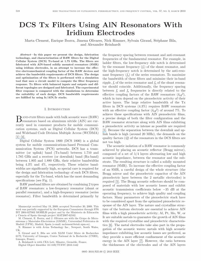
digital cellular system 1800 (dcs 1800) is a global system for mobile communications-based Personal com-munication system (Pcs) networks. dcs has a trans-mitter (or uplink) band (Tx-band) between 1.710 and 1.785 Ghz and a receiver (or downlink) band (rx-band) between 1.805 and 1.880 Ghz, their relative bandwidths being 4.3% and 4%, respectively. These relative band-widths are significantly high, so special care is required for the design and fabrication technology of such dcs filters, especially for the Tx-band, which has the most demanding specifications (see Fig. 1).
BaW passband filters are obtained by combining 2 types of BaW resonators: a low-frequency resonator (shunt or parallel resonator), and a high-frequency resonator (series resonator). Filter bandwidth is determined primarily by
the frequency spacing between resonant and anti-resonant frequencies of the fundamental resonator. For example, in ladder filters, the low-frequency side notch is determined by the resonant frequency (fr) of the shunt resonator, and the high-frequency notch is determined by the anti-reso-nant frequency (fa) of the series resonators. To maximize the bandwidth of these filters and minimize their in-band ripple, fr of the series resonator and fa of the shunt resona-tor should coincide. additionally, the frequency spacing between fr and fa frequencies is directly related to the effective coupling factors of the BaW resonators (keff
2), which in turn depend on the piezoelectric activity of their active layers. The large relative bandwidth of the Tx filters in dcs systems (4.3%) requires BaW resonators with an effective coupling factor (keff
2) of around 7%. To achieve these specifications with aln piezoelectric films, a precise design of both the filter configuration and the BaW resonator structure along with aln films exhibiting a piezoelectric activity as intense as possible are required [5]. Because the separation between the downlink and up-link bands is high (around 20 Mhz), the demands on the quality factors (Q) of the resonators in the dcs filters are not too high.
The acoustic isolation of a BaW resonator is commonly achieved by placing an acoustic reflector (Bragg mirror), composed of a set of λ/4 layers alternating low and high acoustic impedance, between the resonator and the sub-strate. The resulting structure is called a solidly mounted resonator (sMr). To increase the effective coupling factor of an sMr, a careful design of the whole structure (the Bragg mirror and the piezoelectric capacitor of the aln piezoelectric layer between the 2 metallic electrodes) is required [5]. The Bragg acoustic reflectors should be com-posed of materials with low acoustic losses and exhibit acoustic transmission coefficients below −35 dB at the operating frequency, to achieve high quality and coupling factors. Many parameters of the piezoelectric stack have to be considered apart from the optimized piezoelectric re-sponse of the aln layer. The nature and crystalline struc-ture of the bottom electrode are essential to achieve aln films with a high piezoelectric activity; al, Pt, Mo, W, or Ir are suitable metals to guarantee the growth of aln films with the required crystalline and piezoelectric characteris-tics [6]. The metal electrodes take also part in the propa-gation of the acoustic waves: metals with high acoustic impedance exhibiting low acoustic losses are preferred, as they provide a more efficient confinement of the acoustic energy in the aln layer [7]. however, the ratio between the thicknesses of the electrodes and of the aln layers
DCS Tx Filters Using AlN Resonators With Iridium Electrodes
Marta clement, Enrique Iborra, Jimena olivares, nick rimmer, sylvain Giraud, stéphane Bila, and alexandre reinhardt
Manuscript received May 19, 2009; accepted november 30, 2009. This work was partially supported by the European commission through FP6 IsT 2004-027003 MoBIlIs project and by the Ministerio de Educación y ciencia of spain through project MaT2007-62162.
M. clement, E. Iborra, and J. olivares are with the Grupo de Micro-sistemas y Materiales Electrónicos (GMME), Universidad Politécnica de Madrid (UPM), Madrid, spain (e-mail: [email protected]).
n. rimmer is with aviza Technology Inc., newport, south Wales, UK.
s. Giraud and s. Bila are with XlIM Unité Mixte de recherches 6172, University of limoges, centre national de la recherche (cnrs), limoges, France.
a. reinhardt is with cEa leti, Minatec, Grenoble, France.digital object Identifier 10.1109/TUFFc.2010.1442
sets the maximum value of keff2 that can be achieved for
a given piezoelectric coefficient (d33) [8], [9]. Finally, the choice of the loading material for the parallel resonators in the filter also notably influences the value of keff
2; larger values are obtained when loading the resonators with the same material as that of the top electrode, instead of using lighter materials such as sio2 [10], [11].
The demanding specifications of dcs filters cannot be achieved in sMr configurations using conventional molyb-denum electrodes, for which the maximum achievable keff
2 are below 6.3% [12]. Iridium is a high-density noble metal that combines high acoustic impedance [13], a low electric resistivity, and a specific crystal structure that promotes the growth of aln films of excellent piezoelectric activity [14]. It can be considered, thus, as a solid candidate for an electrode in the fabrication of the demanding dcs filters. In fact, in previous works we have achieved keff
2 values greater than 7% in sMr devices with Ir electrodes in the WcdMa band [10].
In this paper, we present the design, fabrication tech-nology, and characterization of dcs Tx-filters composed of sMr devices made of aln piezoelectric stacks with iridium electrodes.
II. Technology
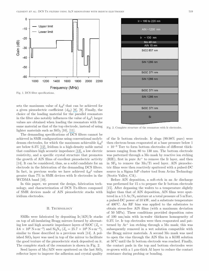
sMrs were fabricated by depositing Ir/aln/Ir stacks on top of all-insulating Bragg mirrors formed by alternat-ing low and high acoustic impedance layers of sioc (Za = 3.6 × 10⁶ n·s·m−3) and si3n4 (Za = 25.7 × 10⁶ n·s·m−3), similar to those described in a previous work [14]. a pol-ished sio2 layer was used in top of the mirror to facilitate the good texture of the piezoelectric stack deposited on it. The complete stack of the resonators is shown in Fig. 2.
seed layers of Mo/aln were sputtered on the last sio2 reflector layer to improve the adhesion and crystal quality
of the Ir bottom electrode. Ir slugs (99.98% pure) were then electron-beam evaporated at a base pressure below 1 × 10⁻⁶ Torr to form bottom electrodes of different thick-nesses ranging from 80 to 130 nm. The bottom electrode was patterned through a Mo mask by reactive ion etching (rIE), first in pure ar+ to remove the Ir layer, and then in sF6 to remove the Mo/Ti seed layer. aln piezoelec-tric films were then reactively sputtered with a pulsed-dc source in a sigma fxP cluster tool from aviza Technology (scotts Valley, ca).
Before aln deposition, a soft-etch in an ar discharge was performed for 15 s to prepare the Ir bottom electrode [15]. after degassing the wafers to a temperature slightly higher than that of aln deposition, aln films were sput-tered in a 1:5 ar/n2 mixture at a total pressure of 5 mTorr, a pulsed-dc power of 10 kW, and a substrate temperature of 400°c. an rF bias was applied to the substrates to obtain stress-free aln films (with a maximum deviation of 50 MPa). These conditions provided deposition rates of 100 nm/min with in-wafer thickness homogeneity of 0.3% 1σ. Ir top electrodes were then evaporated and pat-terned by ar+ ion etching through a Mo mask; this was subsequently removed in a wet solution compatible with the Bragg mirror materials. a second Mo mask was used to open the vias through the aln film in a Koh solution at 50°c until the Ir bottom electrode was reached. Finally, the contact pads in the top and bottom electrodes were re-grown with a 1 µm-thick al layer to reduce the contact resistance during probing or bonding.
519clement et al.: dcs Tx filters using aln resonators with iridium electrodes
Fig. 1. dcs filter specifications.
Fig. 2. complete structure of the resonators with Ir electrodes.
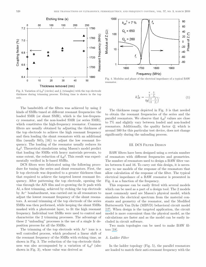
The bandwidth of the filters was achieved by using 2 kinds of sMrs tuned at different resonant frequencies: the loaded sMr (or shunt sMr), which is the low-frequen-cy resonator, and the non-loaded sMr (or series sMr), which constitutes the high-frequency resonator. common filters are usually obtained by adjusting the thickness of the top electrode to achieve the high resonant frequency and then loading the shunt resonators with an additional film (usually sio2 [16]) to adjust the low resonant fre-quency. The loading of the resonator usually reduces its keff
2. Theoretical simulations using Mason’s model predict that loading the sMrs with heavy materials prevents, to some extent, the reduction of keff
2. This result was experi-mentally verified in Ir-based sMrs.
dcs filters were fabricated using the following proce-dure for tuning the series and shunt resonators. First, the Ir top electrode was deposited to a greater thickness than that required to achieve the targeted lowest resonant fre-quency. after patterning the top electrode, opening the vias through the aln film and re-growing the Ir pads with al, a first trimming, achieved by etching the top electrode by ar+ bombardment, was carried out in all resonators to adjust the lowest resonant frequency of the shunt resona-tors. a second trimming of the top electrode of the series sMrs was then performed, while keeping the shunt sMrs masked with a photoresist layer, to fit the high resonant frequency. Individual test sMrs were used to control and characterize the 2 trimming processes. The advantage of these 2 “unloading” processes is the use of a single Ir de-position process for all the sMrs.
The trimming of the top electrode with ar+ ions is a well controlled process, which produced a linear shift of the resonant frequency of the sMrs with etching time, as shown in Fig. 3. The reduction of the top electrode thick-ness was also accompanied by a variation of keff
2 (also shown in Fig. 3), whose value was derived as
ktg
ff
ff
r
a
r
a
eff2 2
2
=×
×( )
p
p. (1)
The thickness range depicted in Fig. 3 is that needed to obtain the resonant frequencies of the series and the parallel resonators. We observe that keff
2 values are close to 7% and slightly vary between loaded and non-loaded resonators. additionally, the quality factor Q, which is around 500 for this particular test device, does not change significantly during the unloading process.
III. dcs Filter design
BaW filters have been designed using a certain number of resonators with different frequencies and geometries. The number of resonators used to design a BaW filter var-ies between 6 and 16. To carry out this design, it is neces-sary to use models of the response of the resonators that allow calculation of the response of the filter. The typical electrical impedance of a BaW resonator is presented in Fig. 4 as a function of the frequency.
This response can be easily fitted with several models which can be used as a part of a design tool. The 2 models most commonly used are Mason’s physical model, which simulates the electrical spectrum from the material con-stants and geometry of the resonator, and the Modified Butterworth Van dyke (MBVd) behavioral circuit model [17]. When design is the targeted application, the circuit model is more convenient than the physical model, as the calculations are faster and as the model can be easily in-cluded in circuit software.
Two main topologies can be used to make BaW fil-ters [18].
A. Ladder Filter
In the ladder topology (Fig. 5), the parallel resonators are loaded to match their anti-resonant frequency with the
520 IEEE TransacTIons on UlTrasonIcs, FErroElEcTrIcs, and FrEqUEncy conTrol, vol. 57, no. 3, March 2010
Fig. 3. Variation of keff2 (circles) and fr (triangles) with the top electrode
thickness during trimming process. Etching time is shown in the top axis.
Fig. 4. Modulus and phase of the electrical impedance of a typical BaW resonator.
resonant frequency of the series resonators. To obtain a passband characteristic (matching the inner electrical im-pedance), the areas of the resonators are optimized. The ladder structure allows a high selectivity to be achieved, but yields a low out-of-band rejection. some of these basic structures could be cascaded to obtain a better out-of-band rejection, but at the cost of generating higher inser-tion losses.
B. Lattice Filter
In the lattice topology (Fig. 6), parallel resonators are loaded to match their impedance level to that of series resonators. This lattice structure allows a larger out-of-band rejection to be obtained, but its selectivity is low.
The filter synthesis sets the BaW filter architecture and the characteristics of each resonator with respect to the electrical specifications. The main output is the area of each resonator. The layout of the filter can be drawn knowing the area of each resonator and the filter archi-tecture; then, verification analysis is performed through a co-simulation including electromagnetic modeling, which allows characterization of both the losses caused by inter-connections and the eventual coupling between the reso-nators. Typical parameters used for the designs are sum-marized in Table I.
We performed the synthesis and the optimization of band-pass filters at 1.75 Ghz (dcs Tx frequencies) for the different topologies shown in Table II, consisting of 2 ladder filters (series-parallel-series and parallel-series-parallel) and 2 lattice filters (2 and 4 stages). For each case, synthesis was performed with differential structures and 100 Ω differential input and output impedances. It is important to note that the number of stages in the 2 ladder configurations is low; these devices have been used as test structures because of their low out-of-band rejec-
tion. however, the lattice designs have a large number of resonators. Therefore, a higher rejection is expected, according to simulations. In this case, it is interesting to note that all the input and output pads are in the top elec-trode, which avoids the step of fabricating the via-holes through the piezoelectric layer.
IV. Filter characterization
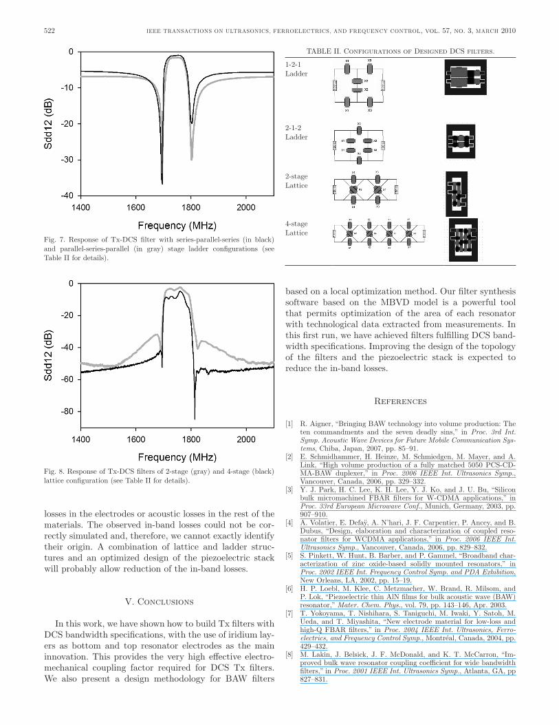
Fig. 7 shows the response of the ladder filters of series-parallel-series and parallel-series-parallel configurations. despite exhibiting very low out-of-band rejection, these simple architectures allow evaluation of whether the char-acteristics of the sMrs are adequate for the dcs filters. The large bandwidth and low insertion losses are the most interesting characteristics of these filters; additionally they exhibit remarkable roll-on and roll-off values. The bandwidth of the filters is around 80 Mhz, which exceeds the 4.3% of the center frequency required for dcs filter implementation. This indicates that the effective coupling factor of the resonators containing Ir electrodes is large enough.
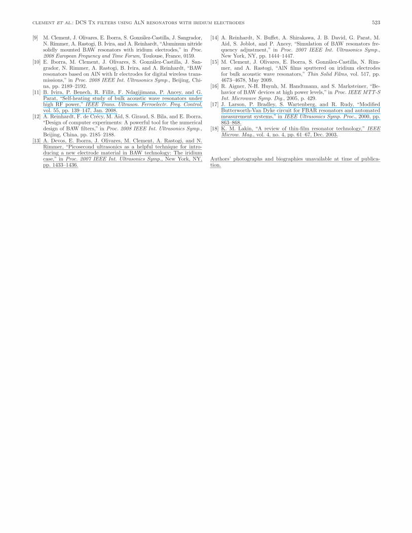
Fig. 8 shows the response of lattice filters with 2 and 4 stage topologies. These structures have a very high out-of-band rejection, limited on measurements by the network analyzer noise floor, which is around 60 dB.
ladder and lattice filter synthesis has been performed with the approximated technological values shown in Table I. We observe that the ladder filters fulfill the dcs specifi-cation regarding the insertion losses (<3 dB) and the filter width, despite a low out-of-band rejection. on the other hand, lattice filters exhibit a suitable out-of-band rejec-tion (<20 dB) for dcs specification, but have insertion losses significantly larger than ladder filters. however, in the design stage, we did not take into account electrical
521clement et al.: dcs Tx filters using aln resonators with iridium electrodes
Fig. 5. schematic, impedance of the resonators, and filter response for the ladder topology. Fig. 6. schematic, impedance of the resonators, and filter response for
the lattice topology.
TaBlE I. Parameters Used as Inputs in the design Procedure.
Effective coupling factor (%)
q at resonant frequency
q at antiresonant frequency
capacitance density (pF/cm2)
aln thickness (nm)
6.5 600 300 64.6 1269
losses in the electrodes or acoustic losses in the rest of the materials. The observed in-band losses could not be cor-rectly simulated and, therefore, we cannot exactly identify their origin. a combination of lattice and ladder struc-tures and an optimized design of the piezoelectric stack will probably allow reduction of the in-band losses.
V. conclusions
In this work, we have shown how to build Tx filters with dcs bandwidth specifications, with the use of iridium lay-ers as bottom and top resonator electrodes as the main innovation. This provides the very high effective electro-mechanical coupling factor required for dcs Tx filters. We also present a design methodology for BaW filters
based on a local optimization method. our filter synthesis software based on the MBVd model is a powerful tool that permits optimization of the area of each resonator with technological data extracted from measurements. In this first run, we have achieved filters fulfilling dcs band-width specifications. Improving the design of the topology of the filters and the piezoelectric stack is expected to reduce the in-band losses.
references
[1] r. aigner, “Bringing BaW technology into volume production: The ten commandments and the seven deadly sins,” in Proc. 3rd Int. Symp. Acoustic Wave Devices for Future Mobile Communication Sys-tems, chiba, Japan, 2007, pp. 85–91.
[2] E. schmidhammer, h. heinze, M. schmiedgen, M. Mayer, and a. link, “high volume production of a fully matched 5050 Pcs-cd-Ma-BaW duplexer,” in Proc. 2006 IEEE Int. Ultrasonics Symp., Vancouver, canada, 2006, pp. 329–332.
[3] y. J. Park, h. c. lee, K. h. lee, y. J. Ko, and J. U. Bu, “silicon bulk micromachined FBar filters for W-cdMa applications,” in Proc. 33rd European Microwave Conf., Munich, Germany, 2003, pp. 907–910.
[4] a. Volatier, E. defaÿ, a. n’hari, J. F. carpentier, P. ancey, and B. dubus, “design, elaboration and characterization of coupled reso-nator filters for WcdMa applications,” in Proc. 2006 IEEE Int. Ultrasonics Symp., Vancouver, canada, 2006, pp. 829–832.
[5] s. Pinkett, W. hunt, B. Barber, and P. Gammel, “Broadband char-acterization of zinc oxide-based solidly mounted resonators,” in Proc. 2002 IEEE Int. Frequency Control Symp. and PDA Exhibition, new orleans, la, 2002, pp. 15–19.
[6] h. P. loebl, M. Klee, c. Metzmacher, W. Brand, r. Milsom, and P. lok, “Piezoelectric thin aln films for bulk acoustic wave (BaW) resonator,” Mater. Chem. Phys., vol. 79, pp. 143–146, apr. 2003.
[7] T. yokoyama, T. nishihara, s. Taniguchi, M. Iwaki, y. satoh, M. Ueda, and T. Miyashita, “new electrode material for low-loss and high-q FBar filters,” in Proc. 2004 IEEE Int. Ultrasonics, Ferro-electrics, and Frequency Control Symp., Montréal, canada, 2004, pp. 429–432.
[8] M. lakin, J. Belsick, J. F. Mcdonald, and K. T. Mccarron, “Im-proved bulk wave resonator coupling coefficient for wide bandwidth filters,” in Proc. 2001 IEEE Int. Ultrasonics Symp., atlanta, Ga, pp 827–831.
522 IEEE TransacTIons on UlTrasonIcs, FErroElEcTrIcs, and FrEqUEncy conTrol, vol. 57, no. 3, March 2010
TaBlE II. configurations of designed dcs filters.
1-2-1 ladder
2-1-2 ladder
2-stage lattice
4-stage lattice
Fig. 7. response of Tx-dcs filter with series-parallel-series (in black) and parallel-series-parallel (in gray) stage ladder configurations (see Table II for details).
Fig. 8. response of Tx-dcs filters of 2-stage (gray) and 4-stage (black) lattice configuration (see Table II for details).
[9] M. clement, J. olivares, E. Iborra, s. González-castilla, J. sangrador, n. rimmer, a. rastogi, B. Ivira, and a. reinhardt, “aluminum nitride solidly mounted BaW resonators with iridium electrodes,” in Proc. 2008 European Frequency and Time Forum, Toulouse, France, 0159.
[10] E. Iborra, M. clement, J. olivares, s. González-castilla, J. san-grador, n. rimmer, a. rastogi, B. Ivira, and a. reinhardt, “BaW resonators based on aln with Ir electrodes for digital wireless trans-missions,” in Proc. 2008 IEEE Int. Ultrasonics Symp., Beijing, chi-na, pp. 2189–2192.
[11] B. Ivira, P. Benech, r. Fillit, F. ndagijimana, P. ancey, and G. Parat, “self-heating study of bulk acoustic wave resonators under high rF power,” IEEE Trans. Ultrason. Ferroelectr. Freq. Control, vol. 55, pp. 139–147, Jan. 2008.
[12] a. reinhardt, F. de crécy, M. aïd, s. Giraud, s. Bila, and E. Iborra, “design of computer experiments: a powerful tool for the numerical design of BaW filters,” in Proc. 2008 IEEE Int. Ultrasonics Symp., Beijing, china, pp. 2185–2188.
[13] a. devos, E. Iborra, J. olivares, M. clement, a. rastogi, and n. rimmer, “Picosecond ultrasonics as a helpful technique for intro-ducing a new electrode material in BaW technology: The iridium case,” in Proc. 2007 IEEE Int. Ultrasonics Symp., new york, ny, pp. 1433–1436.
[14] a. reinhardt, n. Buffet, a. shirakawa, J. B. david, G. Parat, M. aid, s. Joblot, and P. ancey, “simulation of BaW resonators fre-quency adjustment,” in Proc. 2007 IEEE Int. Ultrasonics Symp., new york, ny, pp. 1444–1447.
[15] M. clement, J. olivares, E. Iborra, s. González-castilla, n. rim-mer, and a. rastogi, “aln films sputtered on iridium electrodes for bulk acoustic wave resonators,” Thin Solid Films, vol. 517, pp. 4673–4678, May 2009.
[16] r. aigner, n-h. huynh, M. handtmann, and s. Marksteiner, “Be-havior of BaW devices at high power levels,” in Proc. IEEE MTT-S Int. Microwave Symp. Dig., 2005, p. 429.
[17] J. larson, P. Bradley, s. Wartenberg, and r. rudy, “Modified Butterworth-Van dyke circuit for FBar resonators and automated measurement systems,” in IEEE Ultrasonics Symp. Proc., 2000, pp. 863–868.
[18] K. M. lakin, “a review of thin-film resonator technology,” IEEE Microw. Mag., vol. 4, no. 4, pp. 61–67, dec. 2003.
authors’ photographs and biographies unavailable at time of publica-tion.
523clement et al.: dcs Tx filters using aln resonators with iridium electrodes