csec® industrial technology - roxborough secondary school
TRANSCRIPT

IndustrialTech
TechnologyI
nologyIndustr
echnology
ustrialTech
CSEC®IndustrialTechnologyBuilding TechnologyElectrical and Electronic TechnologyMechanical Engineering Technology
SYLLABUS SPECIMEN PAPER
MARK SCHEME SUBJECT REPORTS

Macmillan Education
4 Crinan Street, London, N1 9XW
A division of Macmillan Publishers Limited
Companies and representatives throughout the world
www.macmillan-caribbean.com
ISBN 978-0-230-48239-5
© Caribbean Examinations Council (CXC®) 2015
www.cxc.org
www.cxc-store.com
The author has asserted their right to be identified as the author of this work in accordance with the
Copyright, Design and Patents Act 1988.
First published 2014
This revised version published 2015
Permission to copy
The material in this book is copyright. However, the publisher grants permission for copies to be
made without fee. Individuals may make copies for their own use or for use by classes of which they
are in charge; institutions may make copies for use within and by the staff and students of that
institution. For copying in any other circumstances, prior permission in writing must be obtained
from Macmillan Publishers Limited. Under no circumstances may the material in this book be used,
in part or in its entirety, for commercial gain. It must not be sold in any format.
Designed by Macmillan Publishers Limited
Cover design by Macmillan Publishers Limited and Red Giraffe

CSEC Industrial Technology Free Resources
LIST OF CONTENTS
CSEC® Industrial Technology Syllabus Extract 5 CSEC® Industrial Technology Syllabuses 6 CSEC® Industrial Technology Specimen Papers:
Paper 01 Specimen Paper 218 Paper 02 Option A (Electrical and Electronic Technology) Specimen Paper 230 Paper 02 Option B (Mechanical Engineering Technology) Specimen Paper 244 Paper 02 Option C (Building and Furniture Technology) Specimen Paper 259 CSEC® Industrial Technology Specimen Paper Mark Schemes:
Paper 01 SP Mark Scheme 228 Paper 02 Option A (Electrical and Electronic Technology) SP Mark Scheme 236 Paper 02 Option B (Mechanical Engineering Technology) SP Mark Scheme 251 Paper 02 Option C (Building and Furniture Technology) SP Mark Scheme 266 CSEC® Industrial Technology: Building Technology Subject Reports:
May/June 2010 Subject Report 280 May/June 2011 Subject Report 325 May/June 2013 Subject Report 344 May/June 2014 Subject Report 380 May/June 2015 Subject Report 403

CSEC® Industrial Technology: Option II - Construction
Construction May/June 2010 Subject Report 302 Construction May/June 2013 Subject Report 361 Construction May/June 2014 Subject Report 423 Construction May/June 2015 Subject Report 443 CSEC® Industrial Technology: Mechanical Engineering Subject Reports:
2005 Subject Report 468 2006 Subject Report 477 2007 Subject Report 486 2008 Subject Report 496 2009 Subject Report 504 2010 Subject Report 514 2011 Subject Report 524 2014 Subject Report 533 2015 Subject Report 540 CSEC® Industrial Technology: Electrical and Electronic Subject Reports
2015 Subject Report 548

Industrial Technology The Industrial Technology syllabuses is a qualitative response by the Caribbean Examinations Council to the Technical and Vocational Education and Training (TVET) needs which are relevant to manufacturing and industrialisation in the Caribbean Region. The cognitive, psychomotor and affective outcomes aimed for in the syllabuses are geared at equipping students with a solid
technical foundation for life-long learning and to enable the students to matriculate seamlessly into entry level occupations in a wide variety of careers and post-secondary institutions. In this new approach, the CSEC technical subjects will comprise successful completion of relevant Level 1 CVQ Units and a portfolio. Candidates who successfully complete the CSEC examinations in the Industrial Technology programmes will be awarded; the CSEC Technical Proficiency Certificate and recognition of competencies for the aligned CVQ Units.
The Industrial Technology syllabuses comprise one Compulsory Core and three Options, organised in sections. THE CORE The core provides a flexible foundation for more detailed study aimed for in the three options. It is
a combination of knowledge, skills and attitudes, pivotal to the programmes of study in Industrial Technology. The Core is, therefore, mandatory for all students. Teachers are required to integrate the competencies and processes in the core discipline with those of the respective options. The Core is made up of the following Sections. Section 1: Fundamentals of Industry.
Section 2: Design Principles and Processes. Section 3: Information Communications and Graphic Technologies.
OPTIONS Each option provides the foundation competencies relevant to industrial transformation and development in the Caribbean. The options are listed below.
Section 1: Electrical and Electronic Technology. Section 2: Mechanical Engineering Technology. Section 3: Building and Furniture Technology. Candidates will complete the core and at least one option for certification. Institutions may also enter candidates for more than one option. In this case, candidates will only be assessed once in
the Core.

CXC 13/T/SYLL 15
CARIBBEAN EXAMINATIONS COUNCIL
Caribbean Secondary Education Certificate
CSEC®
INDUSTRIAL TECHNOLOGY SYLLABUSES
Effective for examinations from May–June 2017

CXC 13/T/SYLL 15
Published by the Caribbean Examinations Council © 2015, Caribbean Examinations Council All rights reserved. No part of this publication may be reproduced, stored in a retrieval system, or transmitted in any form, or by any means electronic, photocopying, recording or otherwise without prior permission of the author or publisher. Correspondence related to the syllabus should be addressed to: The Pro-Registrar Caribbean Examinations Council Caenwood Centre 37 Arnold Road, Kingston 5, Jamaica, W.I. Telephone: (876) 630-5200 Facsimile Number: (876) 967-4972 E-mail address: [email protected] Website: www.cxc.org Copyright © 2015, by Caribbean Examinations Council Prince Road, Pine Plantation Road, St Michael BB11091

CXC 13/T/SYLL 15
RATIONALE ......................................................................................................................................... 1 AIMS ................................................................................................................................................... 2 ORGANISATION OF THE SYLLABUS .................................................................................................... 2 SUGGESTED TEACHING AND LEARNING APPROACHES ..................................................................... 3 SUGGESTED TIMETABLE ALLOCATION ............................................................................................... 3 CERTIFICATION ................................................................................................................................... 3 FORMAT OF THE EXAMINATIONS ...................................................................................................... 5 REGULATIONS FOR PRIVATE CANDIDATES ........................................................................................ 7 REGULATIONS FOR RESIT CANDIDATES ............................................................................................. 7 CORE
Section 1 – Fundamentals of Industry ................................................................................... 8 Section 2 – Design Principles and Processes ......................................................................... 17 Section 3 – Information Communications Technology ......................................................... 20
OPTIONS
Option A – Electrical and Electronic Technology Section 1 – Electrical Principles and Measurements ............................................................ 23 Section 2 – Electrical and Electronic Drafting ....................................................................... 35 Section 3 – Electrical Power and Machines .......................................................................... 38 Section 4 – Electrical Installation .......................................................................................... 43 Section 5 – Fundamentals of Electronics ............................................................................... 52 Workshop Laboratory Facilities ............................................................................................ 61 Resources .............................................................................................................................. 70 Appendix I – Guidelines for Integrating the Competency Based Education Training and Assessment Approach ...................................................................................... 72 Appendix II – Integration of CVQ Units for the SBA…………………………………………………………..81 Appendix III – Portfolio Development……………………………………………………………………………....87
Option B –Mechanical Engineering Technology Section 1 – Materials, Hand tools and Processes ................................................................. 89
Contents

CXC 13/T/SYLL 15
Section 2 – Graphic Communication and Design ................................................................. 97 Section 3 – Production Engineering ...................................................................................... 101 Section 4 – Metal Art Work………………………………………………………………………………………. ....... 115 Workshop Laboratory Facilities ............................................................................................ 117 Resources……………………………………………………………………………………………………………….…………122 Resources……………………………………………………………………………………………………………….…………124 Appendix I – Guidelines for Integrating the Competency Based Education Training and Assessment Approach ...................................................................................... 127 Appendix II – Integration of CVQ Units for the SBA…………………………………………………... ....... 135 Appendix III – Portfolio Development……………………………………………………………………….. ....... 141 Option C - Building and Furniture Technology Section 1 – The Natural and Built Environment .................................................................... 143 Section 2 – Site Work Operations .......................................................................................... 147 Section 3 – Basic Architectural Drawings .............................................................................. 151 Section 4 – Timber Technology ............................................................................................. 154 Section 5 – Building Technology............................................................................................ 158
Section 6 – Furniture Technology………………………………………………………………………………. ....... 173 Workshop Laboratory Facilities ……………………………………………………………………………….. ....... 180 Resources…………………………………………………………………………………………………………………. ....... 184 Appendix I – Guidelines for Integrating the Competency Based Education Training and Assessment Approach ...................................................................................... 188 Appendix II – Integration of CVQ Units for the SBA…………………………………………………... ....... 196 Appendix III – Portfolio Development……………………………………………………………………….. ....... 202

CXC 13/T/SYLL 15
This document CXC 13/T/SYLL 15 replaces the syllabus CXC 13/T/SYLL 00 issued in 2000.
Please note that the syllabus has been revised and amendments are indicated by italics. First Published in 1977 Revised in 1981 Revised in 1985 Revised in 1992 Revised in 2000
Revised in 2015

CXC 13/T/SYLL 15 1
RATIONALE The economic development and competitive edge of the region are inextricably linked to the application of technology in the manufacture and utilisation of goods and services. These considerations make it an imperative for the region to understand, develop and effectively apply competencies that directly impact the quality of our lives. The Industrial Technology syllabuses is a qualitative response by the Caribbean Examinations Council to the Technical and Vocational Education and Training (TVET) needs which are relevant to manufacturing and industrialisation in the Caribbean Region. The cognitive, psychomotor and affective outcomes aimed for in the syllabuses are geared at equipping students with a solid technical foundation for life-long learning and to enable the students to matriculate seamlessly into entry level occupations in a wide variety of careers and post-secondary institutions. Candidates may pursue career paths to include some of the professions in Engineering (Robotics, Fabrication and Civil), Designing (Spatial and Structural), and Education. The changing nature of work and higher level skills requirements globally create a need for agreed regional standards in Competency Based Education Training and Assessment (CBETA). CBETA arose out of the need to improve occupational standards to meet the needs of industrial and economic changes. The School-Based Assessment (SBA) component of the Industrial Technology Syllabus will employ the principles of CBETA, through the integration of the Caribbean Vocational Qualification (CVQ) into the SBA. This integration is aimed at making knowledge, skills and attitudes more practical. A solid educational background (academic and technical) will be achieved through practical and project-based learning, designing and entrepreneurial processes. In this new approach, the CSEC technical subjects will facilitate the successful completion of relevant Level 1 CVQ Units of Competence. Candidates who successfully complete the CSEC examinations in the Industrial Technology will be awarded; the CSEC Technical Proficiency Certificate and where applicable recognition of competencies for the aligned CVQ Units. The broad-range of interdisciplinary competencies aimed for in the Industrial Technology syllabuses will contribute to the development of the attributes of the Ideal Caribbean Person, as documented in the 2000 Caribbean Education Strategy. This person is one who is emotionally secure with a high level of self-confidence and self-esteem; is aware of the importance of living in harmony with the environment; demonstrates multiple literacies, independence and critical thinking; values and displays the creative imagination in its various manifestations and nurtures its development in the economic and entrepreneurial spheres in all areas of life. In addition to the attributes listed above, the syllabuses will contribute to the development of all the UNESCO Pillars of Learning. These are learning to know, learning to do, learning to be, learning to live together and learning to transform oneself and society.
Syllabuses for Examinations in Industrial Technology Programmes

2 CXC 13/T/SYLL 15
AIMS The syllabuses aim to: 1. acquire knowledge of both traditional and new materials, systems, and processes related to
industry;
2. provide the students with an opportunity to understand the interrelationships among technologies, equipment, processes, materials and systems related to industry;
3. develop competencies in the application of manufacturing standards, processes, equipment, materials and tools for entry level employment (government, private sector and self) and life-long learning;
4. develop competencies through the processes of design management and communication,
production and evaluation associated with construction and the manufacturing industries; and,
5. develop innovative and creative minds equipped for our knowledge and technology driven society.
ORGANISATION OF THE SYLLABUSES The Industrial Technology Syllabuses comprise one Compulsory Core and three Options, organised in sections. THE CORE The Core provides a flexible foundation for more detailed study aimed for in the three options. It is a combination of knowledge, skills and attitudes, pivotal to the programmes of study in Industrial Technology. The Core is, therefore, mandatory for all students. Teachers are required to integrate the competencies and processes in the Core with those of the respective Options. The Core is made up of the following Sections. Section 1: Fundamentals of Industry. Section 2: Design Principles and Processes. Section 3: Information Communication and Graphic Technologies. OPTIONS Each Option provides the foundation competencies relevant to industrial transformation and development in the Caribbean. The Options are listed below. Option A: Electrical and Electronic Technology. Option B: Mechanical Engineering Technology. Option C: Building and Furniture Technology. Candidates will complete the Core and at least one Option for certification. Institutions may also enter candidates for more than one Option. In this case, candidates will only be assessed once in the Core.

3 CXC 13/T/SYLL 15
SUGGESTED TEACHING AND LEARNING APPROACHES To facilitate students’ attainment of the objectives, teachers/facilitators are encouraged to engage students in the teaching and learning activities listed below. 1. Utilise resource persons from industry, subject specialists and practitioners to make presentations
and perform demonstrations for students. 2. Establish partnerships with industries, other institutions and National Training Agencies to
benefit from their expertise and resources (institutional and industry). 3. Demonstrate essential concepts using experiments, prototypes and instruments. Make use of
video presentations where applicable and Internet-based simulations.
4. Utilise internal staff to assist students through team teaching. 5. Encourage team-based research, presentation and assessment. 6. Encourage students’ participation in the development of the Quality Control Standards; this
activity is a partnership between the teachers and the students. Teachers and students are, therefore, encouraged to determine the key components of quality and ensure that set standards are maintained.
7. Arrange for the exposure of students to the world of work through job placement, work
experience, job shadowing and apprenticeship. This will ensure that students keep abreast with current industrial processes and resources.
SUGGESTED TIMETABLE ALLOCATION It is recommended that a minimum of six 40-minute periods per week, over two academic years or the equivalent be allocated to the syllabus. Single periods are not recommended. ALLIED SUBJECTS Students should be encouraged to include the following subjects in their programme of study: English A, Information Technology, Environmental Science, Mathematics, Technical Drawing, Physics or Chemistry.
CERTIFICATION This syllabus will be assessed for the awards of both the Technical Proficiency and where applicable for recognition of CVQ competencies. Candidates will complete the Core and at least one Option for certification. Institutions may also enter candidates for more than one Option. In this case, candidates will only be assessed once in the Core. Candidate’s performance will be indicated on the certificate by an overall numerical grade on a six-point scale as well as a letter grade for each of three profile dimensions, namely, Knowledge and Comprehension, Use of Knowledge and Practical Ability.

4 CXC 13/T/SYLL 15
The School-Based Assessment component for this syllabus is aligned to selected units within the regional qualification of the Caribbean Vocational Qualification (CVQ). Through this integration, once all requirements for issuing the CVQ are met, every student with acceptable grades will receive a Statement of Competence to recognise their competencies in selected units (as detailed in Appendix 1) from the Level 1 Caribbean Vocational Qualification (CVQ) in:
- General Construction (CCBCG10102); - Furniture Making (CCLMF10103); - Electrical Installation (CCMEM11002); or, - Metal Work Engineering (CCMEM10302).
The decisions to award competencies will be based on the quality and relevance of the pieces of evidence presented for the occupational area.
DEFINITION OF PROFILE DIMENSIONS
In the examinations, items and questions will be classified according to the kinds of cognitive, affective and psychomotor competencies outlined in the following profile dimensions: (a) Knowledge and Comprehension;
(b) Use of Knowledge; and,
(c) Practical Ability.
Knowledge and Comprehension (KC) Knowledge The ability to identify, remember, and grasp the meaning of basic
facts, concepts, principles, theories, technology and processes already learnt.
Comprehension The ability to:
(a) understand basic facts, concepts, principles, theories, processes and construct meanings from them in contextualised and authentic situations; and,
(b) explain, think, interpret, create, estimate meanings, and, use
knowledge in contextualised and authentic situations. Use of Knowledge (UK) Application The ability to:
(a) apply technical and non-technical knowledge, processes, methods, skills and technology to carry out a procedure and to perform a task or produce to the expected performance standards;
(b) execute, construct, implement, compute and solve problems in contextualised and authentic situations;

5 CXC 13/T/SYLL 15
(c) receive, respond to, organise and value instruction in given or unfamiliar situations; and,
(d) co-operate and value team work activities.
Analysis The ability to:
(a) identify and recognise the component parts of a whole and interpret the relationships between those parts;
(b) make qualitative assessments and judgments based on criteria and standards; and,
(c) compare, extrapolate, infer and distinguish between
component parts and draw conclusions. Synthesis The ability to:
(a) design, innovate, and integrate resources, to create a service or product; and,
(b) make proposals for solving problems. Evaluation The ability to review, assess, investigate, contrast and make reasoned
judgements and recommendations based on criteria and standards. Practical Ability (PA) The ability to:
(a) use facts, concepts, principles, technology, formulae, theories, and processes to produce designs, drawings and make products to given performance standards;
(b) demonstrate manipulative skills using equipment, tools, materials, processes, technology and other resources;
(c) design and create new ideas, products and services based on
performance standards;
(d) demonstrate craftsmanship, creativity and communication skills based on performance standards; and,
(e) respond to one’s environment applying all the senses.
FORMAT OF THE EXAMINATIONS Certification for the Industrial Technology syllabuses will be based on two written Papers; Paper 01 and Paper 02 for the External Assessment and Paper 03 which is the School-based Assessment comprising the SBA Portfolio.

6 CXC 13/T/SYLL 15
External Assessment Paper 01 (1 ¼ hours)
This paper will consist of 60 multiple-choice items covering all Sections of the Core. Fundamentals of Industry, Design Principles and Processes and Information Communications Technology. Knowledge and Comprehension (KC) and Use of Knowledge (UK) will be tested in the ratio of 1:2.
The Paper will be worth 60 marks (1 mark for each item and will represent 20 per cent of the total score.
Paper 02 (2 hours)
This paper will consist of five compulsory structured response questions. Each Option (Electrical and Electronic Technology Mechanical Engineering Technology and Building and Furniture Technology) will have its own paper.
Each question on this paper for all three Options will be worth 18 marks. The marks are distributed across questions and profiles as indicated below:
Knowledge and Comprehension (KC)
- 6 marks;
Use of Knowledge (UK) - 6 marks; and,
Practical Ability (PA) - 6 marks. This paper will represent 30 per cent of the total score.
School-Based Assessment (SBA)
The School-Based Assessment (Appendix 1), Paper 03, will consist of assignments displayed in the School Based Assessment Portfolio. The School-Based Assessment Portfolio will account for 50 marks distributed across the three profile dimensions (Knowledge and Comprehension, Use of Knowledge and Practical Ability). Appendix 2 provides a list of possible units for integration along with an exemplar.
WEIGHTING OF INDUSTRIAL TECHNOLOGY PAPERS
The percentage weightings of the examination components for the Electrical and Electronic Technology, Mechanical Engineering Technology and Building and Furniture Technology Options are:
EXTERNAL EXAMINATION
External Examination
PROFILES Paper 01
20% Paper 02
30%
Paper 03 (SBA PORTFOLIO)
50% TOTAL %
Knowledge and Comprehension
20 30 10 60 20
Use of Knowledge 40 30 20 90 30
Practical Ability - 30 120 150 50
TOTAL 60 90 150 300 100

7 CXC 13/T/SYLL 15
REGULATIONS FOR PRIVATE CANDIDATES
Candidates who do not attend school full-time may undertake the course as a private candidate. A private candidate is one not entered through a school or other approved educational institution. Such a candidate must observe the following guidelines: (i) complete all the components of the examination; (ii) identify a teacher/tutor from a registered institution (school/technical institute/community
college) who will assess and approve the candidate’s submission for the School-Based Assessment component of the syllabus; and,
(iii) submit to the Council on registration for the subject the name, school, and territory of the identified teacher/tutor.
REGULATIONS FOR RESIT CANDIDATES
Resit candidates must rewrite Papers 01 and 02 of the examination for the year in which they re-register. However, resit candidates who have earned a moderated score of 50 per cent or more of the maximum score for the School-Based Assessment component may elect not to repeat this component, provided they rewrite the examination no later than two years immediately following their first attempt. Resit candidates who have obtained a moderated score of less than 50 per cent of the maximum score for the School-Based Assessment component must repeat the component at any subsequent sitting. Resit candidates may enter through schools, recognised educational institutions or the Local Registrar’s Office.

8 CXC 13/T/SYLL 15
CORE SECTION 1: FUNDAMENTALS OF INDUSTRY
GENERAL OBJECTIVES On completion of this Section, students should: 1. understand the organisation of an industry with special focus on the manufacturing and
construction industries; 2. apply a working knowledge of codes and regulations governing the manufacturing and construction industries; 3. demonstrate an awareness of careers in the construction and manufacturing industries and
the contributions made by people who work in them; and,
4. demonstrate skills in the application of workshop and worksite safety, health and maintenance practices through occupational safety and health management systems.
SPECIFIC OBJECTIVES
The students should be able to: 1. discuss the sectors and their roles within the construction and manufacturing industries;
2. create a basic organisational structure of the construction and manufacturing industries;
3. discuss the types of occupation levels and their functions in the construction and
manufacturing industries;
4. analyse career paths and the requisite qualifications in the construction and manufacturing industries;
5. discuss codes and standards governing industrial processes, designs, materials and environmental practices;
6. practise occupational health, safety and welfare standards in the construction and manufacturing industries; and,
7. discuss the impact of industries on the social and economic well-being of Caribbean countries.

9 CXC 13/T/SYLL 15
SECTION 1: FUNDAMENTALS OF INDUSTRY (cont’d)
CONTENT 1. Sectors and their roles (a) Definitions of:
(i) an industry:
- a construction;
- a manufacturing; and,
- an electrical and electronic.
(b) The construction sectors:
(i) residential; (ii) industrial; (iii) commercial; and, (v) civic. (c) The roles of the following in the manufacturing sectors: (i) engineering design; (ii) industrial production; and, (iii) industrial maintenance. 2. Organisational structure (a) Organisational chart of personnel (managers, workers, tasks and relationships): (i) top-down structure; (ii) flat structure; and, (iii) matrix.

10 CXC 13/T/SYLL 15
SECTION 1: FUNDAMENTALS OF INDUSTRY (cont’d) 3. Occupational levels and their functions (a) Semi-skilled. (b) Skilled. (c) Technician supervisory. (d) Technologist/Master Craftsman. (e) Professional. 4. Career paths and qualifications (a) Construction industries: (i) craftsmen /tradesmen - carpenters, electricians, electronics technicians, masons, plumbers, furniture makers, woodcrafters, upholsterers, painters; welders, machine operators and fitters;
(i) technical workers - technicians, technologists, finishing technicians; drafting and design technicians; and,
(ii) professional workers - electrical, mechanical, construction structural, civil
and building service engineers, architects, quantity surveyors, construction project managers, planners.
(b) Fundamentals of entrepreneurship: (i) explaining the term “entrepreneurship”:
- meaning and importance; and,
- risk and success characteristics.
(ii) principles of entrepreneurship:
- goal setting (short, medium, long term and decision making skills); - business plans; - success factors (marketing and promotion, customer satisfaction,
competitiveness, leadership, management of production and efficiency, quality control);

11 CXC 13/T/SYLL 15
SECTION 1: FUNDAMENTALS OF INDUSTRY (cont’d)
- government legislation;
- lending institutions;
- benefits; and,
- risks.
(c) Identifying entrepreneurship opportunities in the construction and manufacturing industries.
(d) Self-employment opportunities in electrical and electronics, metalwork engineering, building construction and furniture productions.
5. Codes and standards 5.1 Occupational Health and Safety Standards
(a) Industry health and safety regulations: (i) legal responsibilities of employers; and, (ii) general duties of employees.
(b) Environmental safety practices.
(c) Safety and maintenance standards.
(e) Health and wellness standards. (e) Standards for fire prevention and response. (f) Basic First Aid standards. (g) Basic emergency response standards.
5.2 Electrical installation and electronics standards
(a) Local and regional standards. (b) International standards:
(i) IEEE (Institute of Electrical and Electronics Engineers) standards; and,
(ii) NEC (National Electrical Code) standards.

12 CXC 13/T/SYLL 15
SECTION 1: FUNDAMENTALS OF INDUSTRY (cont’d)
(c) Safety standards against hazards:
(i) electrical equipment;
(ii) electrical material (wires);
(iii) communication lines;
(iv) installation in buildings; and,
(v) semi-conductor materials and devices.
5.3 Engineering production
(a) ASME (American Society of Mechanical Engineers) Codes. (b) WTO (World Training Organisation) codes. (c) ISO (International Standards Organisation). Relating to:
(i) components;
(ii) processes, systems, equipment, material; and,
(iii) ethics in engineering practices.
5.4 Building Construction
Standards (international and regional – ASNI-American National Standards Institute, BSI, ISO and CUBiC) relating to:
(a) building designs, plans, contracts and construction;
(b) building materials, finishing materials, systems and processes; (c) building construction and natural disasters; and, (d) furniture design, materials and construction.

13 CXC 13/T/SYLL 15
SECTION 1: FUNDAMENTALS OF INDUSTRY (cont’d)
6. Occupational health, safety and welfare standards (a) Practising safety standards for workshop and worksite:
(i) inventory of materials, tools and equipment;
(ii) workshop/worksite layout diagrams;
(iii) listing of danger/hazard points;
(iv) preparing and posting safety signs and symbols in relevant areas of a
workshop/worksite;
(v) marking out safety lanes;
(vi) using safety manuals for workshop and worksite tools and equipment;
(vii) using equipment guards and stop switches safely;
(viii) using the principles of ergonomics (machines, work stations, materials); and,
(ix) selecting and using Personal Protective Equipment - clothing, glasses, goggles, helmets, footwear, ear muffs and plugs, respirators, back brace.
(b) Environmental safety practices:
(i) types of industry, workshop and worksite wastes;
(ii) waste disposal methods; and ,
(iii) recycling methods.
(c) Safety and maintenance standards:
Using equipment, tools and materials associated with electrical installation, electronics, building construction and metal work engineering:
(i) rules and operating procedures for safe use of power, hand, and portable
machine tools;
(ii) safety rules for using and storing materials, tools and equipment;

14 CXC 13/T/SYLL 15
SECTION 1: FUNDAMENTALS OF INDUSTRY (cont’d)
(iii) labelled drawings and sketches showing safety features and safe use of
equipment and tools;
(iv) maintaining workshop, worksite, equipment, materials and tools;
- Types of maintenance in workshop/worksite activities (preventative,
predictive, break down); - inspecting and analysing defects (vibration, wear and tear) in tools
and machines; - using testing, measuring and safety devices; - developing and using maintenance schedules, checklists and duty
roster; and, - using manufacturers’ manuals (tools and machines).
(v) carrying out risk assessments - use of a trained person (safety warden) with
staff and students using safety inspection checklists, safety reports (strengths, weaknesses) and schedule of activities to address weaknesses.
(d) Standards for fire prevention and response:
(i) rules for fire prevention in the workshop and on a worksite;
(ii) types of fires - class A, class B, class C, class D;
(iii) rules for handling the different types of fires;
(iv) types of fire fighting equipment and their storage - fire extinguishers, fire
hydrants, fire alarms, hoses, fire blankets (asbestos-free); and
(v) fire extinguishers.
(e) Health and wellness standards:
(i) observing personal hygiene and appearance standards; (ii) practising wellness/fitness programme; (iii) practising human relationship skills; and,
(iv) managing interpersonal conflicts.

15 CXC 13/T/SYLL 15
SECTION 1: FUNDAMENTALS OF INDUSTRY (cont’d)
(f) Basic First Aid standards:
(i) definitions - first aid, first aider; (ii) first Aid kit station;
(iii) treating of minor burns, electric shocks, wounds and bleeding, abrasions,
injuries to bone ( strains, sprains);
(iv) practising recovery position and mouth-to-mouth resuscitation; (v) procedures for reporting an accident and getting assistance; and, (vi) preparing an accident report (use of standard accident report forms).
(g) Basic emergency response standards.
(h) Getting professional help when an accident occurs:
(i) listing of emergency numbers (police, fire services, hospital, ambulance, Red Cross, the defence force);
(ii) assessing and controlling hazardous substances – spillages and
leakages of chemicals and other hazardous substances;
(iii) responding to evacuation alarm sounds;
(iv) using evacuation route maps, gathering points and bulletin boards;
(v) performing emergency procedures for fires and natural disasters (hurricanes, earthquakes, floods, tsunami, volcanoes); and,
(vi) maintaining accountability systems in emergency operations.
(i) Types of workshop hazards:
Types of workshop, worksite accidents and preventative procedures – falls and slippages, strains, injuries caused by falling objects, improper use of machines, tools and equipment, inhalation of toxic fumes.

16 CXC 13/T/SYLL 15
SECTION 1: FUNDAMENTALS OF INDUSTRY (cont’d)
7. Impact of industries on the Caribbean
(a) Trade Blocks:
(i) CARICOM; (ii) CSME; and, (iii) CARIFORUM.
(b) Entrepreneurial opportunities that lead to self-employment:
(i) productivity and wealth creation;
(ii) career and employment opportunities;
(iii) personal advancement; and,
(iv) entrepreneurial opportunities that lead to self-employment.

17 CXC 13/T/SYLL 15
SECTION 2: DESIGN PRINCIPLES AND PROCESSES
GENERAL OBJECTIVES On completion of this Section, students should: 1. understand the design principles and processes used in the development and modification of
industry goods and services; and,
2. apply the design principles and processes used in industries.
SPECIFIC OBJECTIVES
The students should be able to: 1. explain the design principles;
2. explain the design elements;
3. discuss the design processes;
4. explain the factors that determine the appropriateness of a design; and,
5. use the principles, processes and elements of design.
CONTENT
1. The Design Principles
(a) Line, direction and style.
(b) Shape and size. (c) Colour. (d) Texture. (e) Space. (f) Form.
2. The Design Elements
(a) Line:
(i) weights; and,
(ii) line types.

18 CXC 13/T/SYLL 15
SECTION 2: DESIGN PRINCIPLES AND PROCESSES (cont’d)
(b) Colour.
(c) Shades.
(d) Hatching.
3. The Design Process
(a) Identifying the problem.
(b) Critical analysis of a problem.
(c) Generating alternative solutions.
(d) Selecting the best solution.
(e) Communication of the design ideas.
(f) Development of working drawings.
(g) Manaufacture of the prototype/model (functions, ergonomics, material, construction, economy, aesthetics, virtual).
(h) Testing and evaluation of the product.
(i) Codes and conventions (ISO and BS – British Standards).
4. Factors that determine the appropriateness of a design
(a) Aesthetics.
(b) Functionality.
(c) Economics. (d) Environnent – resource conservation, environmental pollution.
(e) Ergonomics.
(f) Suitability of material.
(g) Innovation.
(h) Decoration.
(i) Anthropometrics.
(j) Selection of material.

19 CXC 13/T/SYLL 15
SECTION 2: DESIGN PRINCIPLES AND PROCESSES (cont’d)
5. Use the principles, elements and processes of design
(a) Using sketches (manual or computer-aided) to design a simple product in the areas of:
(i) Electrical and Electronic Technology;
(ii) Building and Furniture Technologies; and,
(iii) Mechanical Engineering Technology.
(b) Analysing a simple manufactured product in the areas of:
(i) Electrical and Electronic Technology; (ii) Building Technology;
(iii) Mechanical Engineering Technology; and,
(iv) Preparing the analysis report:
- findings (appropriateness of the design); and,
- recommendations.

20 CXC 13/T/SYLL 15
SECTION 3: INFORMATION COMMUNICATION AND GRAPHIC TECHNOLOGIES
GENERAL OBJECTIVES On completion of this Section, students should: 1. understand the uses of multimedia computer systems in industry; 2. understand the operating principles of a multimedia computer system; and, 3. apply basic communication graphics and design software.
SPECIFIC OBJECTIVES The students should be able to: 1. discuss the uses of computers in industry;
2. describe the operating principles of a computer;
3. use communication devices to access and exchange information;
4. describe the basic principles of graphic communication;
5. perform simple tasks using design softwares; and,
6. describe modern trends in engineering technologies.
CONTENT 1. Uses of computers in industry
(i) Word processing.
(ii) Accounting/financial applications.
(iii) Human resource applications.
(iv) Material/inventory management.
(v) Process control.
(vi) Robotics.
(vii) Research and development.
(viii) Metrology.

21 CXC 13/T/SYLL 15
SECTION 3: INFORMATION COMMUNICATION AND GRAPHIC TECHNOLOGIES (cont’d) 2. Using the operating principles of a computer (a) Projects to include:
(i) storing, organising, retrieving and communicating information;
(ii) using software for creating, editing and publishing multimedia projects;
(iii) applying spread sheet development procedures – Writing formulae, using functions, enhancing spread sheet, creating charts, printing basic spread sheets and charts;
(iv) using productivity, application and presentation tools – scanners, digital
cameras, camcorders, projectors, microphones, printers; and,
(v) using storage devices – hard drives, USB drives, compact disc, digital video disc.
3. Using communication devices to access and exchange information (a) Networks:
(i) Intranet (LAN);
(ii) Extranet (WAN); and,
(iii) Internet.
(b) Communication:
(i) Fibre;
(ii) WIFI;
(iii) GPRS; and,
(iv) Dial-up Connection.
(c) Devices:
(i) personal computers (PCs);
(ii) mini computers;
(iii) smart phones/tablets; and,
(iv) cell phones.

22 CXC 13/T/SYLL 15
SECTION 3: INFORMATION COMMUNICATION AND GRAPHIC TECHNOLOGIES (cont’d)
4. Applying graphics communication techniques Using computer based graphical techniques:
(a) preparing pictorial drawings using CAD; (b) isometric, Oblique, Perspective; (c) preparing orthographic drawings using CAD; and, (d) explaining the importance of the basic principles of CAM.
5. Performing simple tasks using design soft wares
(a) Media:
(i) sound;
(ii) pictures;
(iii) video;
(iv) animations; and,
(v) text.
(b) Software:
Multimedia.
(c) Developing presentations for example:
(i) PowerPoint;
(ii) Prezi; and,
(iii) Harvard graphics. 6. Modern trends in Engineering technologies
(a) Computer numerical control machines.
(b) Computer aided manufacturing.
(c) Computer integrated manufacturing.
(d) Virtual manufacturing.

CXC 13/T/SYLL 15
INDUSTRIAL TECHNOLOGY SYLLABUS
OPTION A: ELECTRICAL AND ELECTRONIC TECHNOLOGY

23 CXC 13/T/SYLL 15
OPTION A: ELECTRICAL AND ELECTRONIC TECHNOLOGY
SECTION 1: ELECTRICAL PRINCIPLES AND MEASUREMENTS
GENERAL OBJECTIVES On completion of this Section, students should: 1. apply knowledge of the units and theories associated with electrical principles and
measurements;
2. demonstrate safety practices in the application of electrical theories; and,
3. apply the theories and concepts of related calculations and experimentations.
SPECIFIC OBJECTIVES The students should be able to: 1. discuss the structure of an atom;
2. explain the electronic theory of current flow; 3. analyse the principles of static electricity;
4. outline the basic laws of electromagnetism;
5. explain terminologies relating to electrical measurement and quantities;
6. use electrical measuring instruments safely;
7. verify the principle of Ohm’s law from project data; 8. apply the principles of resistance in determining electrical values;
9. discuss the functions of various types of circuit devices; 10. use the operating principles of AC and DC circuits; 11. outline the operating principles of basic circuit configurations;
12. calculate basic energy bills; and, 13. describe the operating principles of electricity generating devices.

24 CXC 13/T/SYLL 15
SECTION 1: ELECTRICAL PRINCIPLES AND MEASUREMENTS (cont’d)
CONTENT
1. The structure of an atom
(a) Diagrammatic representation of an atom. (b) Parts of the atom and their functions. (c) Nucleus and valence shells. (d) Differentiating between positively and negatively charged atoms:
(i) electron loss; and,
(ii) electron gain.
2. The electronic theory of current flow
(a) Definition of electricity.
(b) Current flow.
(c) Electron flow.
(d) Effects of electricity: (i) heating; (ii) lighting;
(iii) chemical;
(iv) magnetic; and,
(v) use simple projects to demonstrate the operating principles of each effect safely.
(e) Sources of Electromotive Force (emf) and the resistance of the circuit. (f) Difference between emf and potential difference (p.d).
3. Principles of static electricity (a) Effects of friction on an object:
(i) built up of excess electrons; and,
(ii) storage of electric charge.

25 CXC 13/T/SYLL 15
SECTION 1: ELECTRICAL PRINCIPLES AND MEASUREMENTS (cont’d) (b) Basic rules for an electric charge: (i) like charges repel; and, (ii) unlike charges attract. 4. Basic laws of electromagnetism (a) The Molecular theory of magnetism.
(b) Laws of magnetism.
(c) Types of magnetic materials and their uses: (i) ferromagnetic materials (soft and hard magnetic materials); and, (ii) diamagnetic materials.
(d) Using diagrams/sketches to show:
(i) the Magnetic effects of electric current;
(ii) the Corkscrew rule;
(iii) the direction of magnetic field around a current carrying conductor;
(iv) restricting the effects of magnetic field produced by electric currents; and,
(v) plotting the direction of the magnetic field around a current carrying conduct and solenoid.
(e) Winding a coil for simple electro magnets:
(i) guidelines and procedures for a single conductor and an iron core; (ii) noting the magnetic effects of the conductor and the iron core; and, (iii) analysing the process of inducing a voltage across a coil.
(f) Determining the direction of the magnetic field around a single conductor and
solenoid:
(i) Guidelines; and,
(ii) Conventional current and electron flow.

26 CXC 13/T/SYLL 15
SECTION 1: ELECTRICAL PRINCIPLES AND MEASUREMENTS (cont’d)
(g) Analysing the relationship between a current carrying conductor and the magnetic
field surrounding the conductor:
(i) left hand rule for electromagnetism;
(ii) analysing the application of Faraday’s and Lenz’ laws and motor and generator action;
(iii) properties of electromagnetic induction;
(iv) relationship of an electric current and the magnetic field surrounding the
current;
(v) the motor action between two magnetic fields; and,
(vi) factors that affect induced current in a conductor within a magnetic field.
(h) Determining the direction of force between two current-carrying conductors in
parallel:
(i) magnetic field established by current;
(ii) magnetic circuit diagrams showing the current direction and flux direction in a magnetic field; and,
(iii) related calculations.
(i) Performing calculations to determine flux density and energy stored in a magnetic
field:
(i) magnetic motive force (MMF);
(ii) magnetic flux density; and,
(iii) magnetic circuit diagrams showing the current direction and flux direction in a magnetic field.
5. Electrical measurement and quantities
(a) The SI Units:
(i) coulomb;
(ii) ampere;
(iii) period;

27 CXC 13/T/SYLL 15
SECTION 1: ELECTRICAL PRINCIPLES AND MEASUREMENTS (cont’d)
(iv) electromotive force (emf);
(v) power;
(vi) current;
(vii) energy;
(viii) resistance;
(ix) potential difference;
(x) capacitance;
(xi) inductance; and,
(xii) frequency. 6. Measuring instruments
(a) Features, functions and safe guidelines for using:
(i) multimeters;
(ii) moving coils; and,
(iii) digital meters.
(b) Instruments to measure the properties of a circuit:
(i) volt-ohm meter;
(ii) digital volt-ohm meter;
(iii) oscilloscopes (identifying wave form patterns, measuring voltage and frequencies);
(iv) signal generators (supplying various waveforms to circuits); and,
(v) identifying factors that affect the sensitivity of instruments (damping and
meter movement).
(c) Linear and non-linear scales when using instruments:
(i) uses of linear and non-linear scales;
(ii) constructing and using linear and non-linear scales;

28 CXC 13/T/SYLL 15
SECTION 1: ELECTRICAL PRINCIPLES AND MEASUREMENTS (cont’d)
(iii) range extensions;
(iv) calculating series and shunt resistance for scale extensions; and,
(v) series and shunts multimeter and switching arrangements. 7. The principle of Ohm’s law
(a) Ohm’s law as a relationship among voltage (p.d), resistance and power.
(b) Plotting a graph between voltage (V) and current (I) and resistance (R) in a direct current circuit.
(c) Constructing a simple electric circuit comprising ammeter, voltmeter, load and power
supply. (d) Using Ohm’s laws to:
(i) analyse the circuits in (b) and (c); and,
(ii) manipulate the formulae to solve algebraic equations for V, I and R using circuit diagrams and the triangle of Ohm’s Law.
8. The principles of resistance
(a) Definition of resistance.
(b) Types of resistors:
(i) carbon film;
(ii) metal film;
(iii) wire wound;
(iv) SMD;
(v) VDR; and,
(vi) LDR.
(c) Identifying resistor values form colour code for carbon resistors.
(d) Drawing and connecting total resistance in series, parallel and series/parallel. (e) Calculating total resistance in series, parallel and series-parallel circuits.

29 CXC 13/T/SYLL 15
SECTION 1: ELECTRICAL PRINCIPLES AND MEASUREMENTS (cont’d)
(f) Calculating total conductance of resistance in parallel.
(g) Using circuit diagrams to show current flows. (h) Calculating resistivity values:
(i) defining resistivity;
(ii) calculating conductor resistance for changes in length and cross-sectional
area;
(iii) known factors (value, area, length); and,
(iv) equivalent resistance of series resistance.
(i) Temperature coefficient of resistance:
(i) change in material resistance produced by change in temperature:
- positive temperature coefficient; - negative temperature coefficient; and,
- zero temperature coefficients.
(ii) identifying materials with positive, negative and zero temperature
coefficients; and,
(iii) solving problems involving resistivity and temperature co-efficient of resistance.
9. Circuit devices
(a) Functions and features of:
(i) protective devices (fuses, circuit breakers);
(ii) control devices (switches, relays, starters, motors control and starters); and,
(iii) variable resistors.

30 CXC 13/T/SYLL 15
SECTION 1: ELECTRICAL PRINCIPLES AND MEASUREMENTS (cont’d) 10. AC and DC Circuits
(a) Flow of electricity in different materials:
(i) conductors; and,
(ii) insulators.
(b) Differences between AC and DC current with reference to:
(i) sine wave;
(ii) cycle;
(iii) frequency;
(iv) period;
(v) amplitude;
(vi) average value;
(vii) r.m.s value;
(viii) phase; and,
(ix) applications.
(c) Sources of AC and DC current:
(i) electromagnetic generators;
(ii) electromagnetic alternators; and,
(iii) sketches showing e.m.f. sine wave, wave form, maximum, minimum and
r.m.s. and average values.
(d) Analysing the basic components of a simple circuit:
(i) source of e.m.f.;
(ii) load and conductor;
(iii) control and protection (switches and safety devices);
(iv) diagrams and sketches;

31 CXC 13/T/SYLL 15
SECTION 1: ELECTRICAL PRINCIPLES AND MEASUREMENTS (cont’d)
(v) connecting controls in electric circuits; and,
(vi) rheostats and potentio-meters.
(e) Analysing the effects of reactive components:
Capacitor in AC and DC circuits:
(i) uses;
(ii) values and colour codes;
(iii) reactive power;
(iv) quantity of charge;
(v) dielectic strength;
(vi) using Farad formulae;
(vii) constructing a simple capacitor (sketches and diagrams); and,
(viii) connecting capacitors in electrical circuit.
Inductance in AC and DC circuits:
(i) self-inductance;
(ii) mutual inductance;
(iii) true power;
(iv) calculating inductance; and,
(v) connecting inductors in electrical circuits:
- phasor and vector diagrams; and,
- sketches and diagrams.
(vi) time constant and Lenz’s laws.

32 CXC 13/T/SYLL 15
SECTION 1: ELECTRICAL PRINCIPLES AND MEASUREMENTS (cont’d) 11. Basic circuit configurations (series and parallel circuits):
(a) Definitions:
(i) series circuit; and,
(ii) parallel circuit.
(b) Characteristics of the operations of series and parallel circuits:
(i) power distribution rules; and, (ii) relationship of current, voltage and resistance.
(c) Verifying the operations of series and parallel circuits:
(i) connecting filament lamps in series and parallel circuits; (ii) characteristics of the operations of series and parallel circuits; (iii) using instruments to measure the properties of the circuits; and, (iv) identifying the relationship of current, voltage and resistance.
(d) Analysing the current and voltage relationships in series and parallel circuits:
(i) circuits (RL, RC and RCL);
(ii) phases;
(iii) current flow;
(iv) reactance (inductive, capacitance);
(v) impedance;
(vi) power factor;
(vii) apparent power; and,
(viii) active power.
(e) Calculating total capacitance in series and parallel connected capacitance.
(f) Calculating total inductance in series and parallel connected inductance.

33 CXC 13/T/SYLL 15
SECTION 1: ELECTRICAL PRINCIPLES AND MEASUREMENTS (cont’d) 12. Energy bills
(a) Reading a kwh meter:
(i) procedures for reading analogue and digital meters; and,
(ii) units of measurement for power and energy.
(b) Calculating energy bills (flat and block rates). 13. Electricity generating devices
(a) Types of electricity generating devices:
(i) primary cells; and,
(ii) secondary cells.
(b) Differences between primary and secondary cells:
(i) parts of the cells and their functions;
(ii) operating principles;
(iii) labelled sketches and diagrams of Leclanché, Mercury, Nickel Cadmium cells;
(iv) polarisation and local action; and,
(v) charging and discharging devices and their operating principles.
(c) Conduct simple experiments demonstrating the conversion of chemical energy to electrical energy:
(i) direct conversion from chemical to electrical energy in primary cells;
(ii) conversion of electrical to chemical energy in secondary cells; and,
(iii) uses of the energy converted from cells.

34 CXC 13/T/SYLL 15
SECTION 1: ELECTRICAL PRINCIPLES AND MEASUREMENTS (cont’d)
(d) Installing cells in series and parallel as a source of power:
(i) schematic diagrams of cells connected in series and parallel; and,
(ii) calculating voltage of cells connected in series and parallel - cell e.m., internal resistance, internal voltage, terminal p.d.
(e) Charging and maintaining secondary cells:
(i) guidelines and safety practices for lead-acid and alkaline cells;
(ii) charging methods and levels;
(iii) charging calculations;
(iv) discharging and charging characteristics;
(v) using the hydrometer and high rate discharge testers; and,
(vi) preparing electrolyte.

35 CXC 13/T/SYLL 15
SECTION 2: ELECTRICAL AND ELECTRONIC DRAFTING
GENERAL OBJECTIVES On completion of this Section, students should: 1. produce electrical and electronic drawings using the principles of computer-aided design and
manual methods;
2. understand basic electronic signs and symbols; and,
3. display proficiency in the reading and interpretation of electrical and electronic plans, diagrams and representations.
SPECIFIC OBJECTIVES The students should be able to: 1. discuss the types of electrical and electronic drawings;
2. analyse various types of electrical plans and connection diagrams;
3. read and interpret plans for domestic and commercial circuits;
4. prepare simple electrical wiring diagrams and plans to engineering standards;
5. prepare schematic diagrams to engineering standards;
6. prepare flow and block diagrams to engineering standards; and,
7. explain electrical drawings to a construction team.
CONTENT 1. and 7. Electrical and electronic drawings (a) Types: (i) electrical wiring diagrams; and,
(ii) schematic diagrams. (b) Uses, characteristics and sketches of each type. (c) Sketching block, flow and circuit diagrams. (d) Graphical standards and symbols for electrical and schematic diagrams.

36 CXC 13/T/SYLL 15
SECTION 2: ELECTRICAL AND ELECTRONIC DRAFTING (cont’d) 2. Electrical plans and connection diagrams
(a) Components, connections and symbols of electrical plans:
(i) plot plans; (ii) residential and commercial; (iii) internal distribution systems; (iv) electrical distributions systems; and, (v) signalling circuits.
(b) Components and connecting points in connection diagrams: (i) point to point diagrams; (ii) base line diagrams; (iii) high way diagrams; and, (iv) lineless diagrams.
3. Plans for domestic and commercial circuits
(a) Lines and symbols. (b) Circuit routes and isolation points. (c) Wiring layout. (d) Specification of plans, circuit and sub-circuits. (e) Calculating loads. (f) Computing dimensions and outlet positions from plans:
(i) length of circuits; (ii) position of switches; and, (iii) determining quantity and cost of materials from plans (cable, flexible cords,
and accessories).

37 CXC 13/T/SYLL 15
SECTION 2: ELECTRICAL AND ELECTRONIC DRAFTING (cont’d) 4. Electrical wiring diagrams and plans
(a) Guidelines and techniques for line work and notations:
(i) one-line diagram; and,
(ii) principles of operation of one-line diagram (symbols, type of distribution system, signalling circuits).
(b) Converting one-line to three-line diagram and vice versa.
(c) Designing and drawing basic electrical plans.
5. Schematic diagrams
(a) Principles of operation of schematic diagrams.
(b) Drafting principles (references symbols position, sequence, symmetry and balance, line work specification).
(c) Guidelines for simple wiring diagrams converted to schematic diagrams and vice
versa. (d) Circuit connections.
6. Block and flow diagrams
(a) Operating principles for block and flow diagrams.
(b) Drafting principles, codes and regulations for:
(i) block diagrams for common large and small electronic systems - stages of a radio and television receiver/transmitter, stages of a computer;
(ii) flow diagrams showing the process of flow for electrical energy (heat, light, sound) in small appliances or battery operated gadgets; and,
(iii) symbols and sequencing of arrangements.

38 CXC 13/T/SYLL 15
SECTION 3: ELECTRICAL POWER AND MACHINES
GENERAL OBJECTIVES On completion of this Section, students should: 1. understand the principles of electrical power generation and production;
2. demonstrate proficiency in the use of electrical machines;
3. apply the theories and methods of calculation and experimentations to analyse and solve
power and machine problems; and, 4. appreciate the importance of workshop and worksite safety and maintenance standards.
SPECIFIC OBJECTIVES The students should be able to: 1. differentiate among apparent power, true power and power factor; 2. discuss the basic sources of electrical generation and production; 3. explain the principal sources and conversion of primary energy used for the generation of electricity in the region; 4. compare the different types of a.c and d.c. electrical machines; 5. connect d.c. and single and three phase a.c. motors to supply mains; 6. maintain generators; 7. compare different types of transformers; and, 8. install and maintain a low voltage transformer.
CONTENT 1. Apparent power, true power and power factor (a) Differences:
(i) functions; (ii) mathematical relationships and units; and, (iii) engineering relationships.

39 CXC 13/T/SYLL 15
SECTION 3: ELECTRICAL POWER AND MACHINES (cont’d)
2. Basic sources of electrical generation and production
(a) Sources: (i) friction; (ii) pressure; (iii) heat; (iv) light; (v) chemical action; and,
(vi) electromagnetic induction. (b) Functions and characteristics of each source. (c) Advantages and disadvantages of each source. 3. Principal sources of primary energy Non-renewable energy sources:
Fossil fuel – oil, coal, natural gas, mineral fuel (uranium).
(a) Renewable energy sources:
(i) solar;
(ii) wind;
(iii) tidal; and,
(iv) geothermal. (b) Production processes in:
(i) an oil refinery;
(ii) fossil fuel power plant;
(iii) wind farm;
(iv) photovaltic system; and,
(v) nuclear power plant.

40 CXC 13/T/SYLL 15
SECTION 3: ELECTRICAL POWER AND MACHINES (cont’d)
(c) Primary energy and the Law of Thermodynamics.
(d) Methods of converting primary energy to electrical energy: Processes in:
(i) steam-driven generators;
(ii) internal combustion engine-driven generators; and,
(iii) hydro-driven generators. 4. AC and DC electrical machines
(a) Types:
(i) generators;
(ii) motors; and,
(iii) transformers.
(b) Parts and their functions.
(c) Construction features and operating principles. (d) Codes and regulations. (e) Service and maintenance procedures. (f) Generator and motor related calculations: Power, synchronous speed, percentage slip
(Lenz’s law), induced e.m.f., turns, voltage and current ratios of transformers, power transformer efficiency.
5. DC and single and three phase AC motors
(a) Shunt, series and compound machines.
(b) Relays and contactors. (c) Features:
(i) control circuits - push button station, relays, limit switch, fuses, manual
contactor and motor starters, stop and start devices, output power, input power, efficiency and losses, commutator, speed control; and,

41 CXC 13/T/SYLL 15
SECTION 3: ELECTRICAL POWER AND MACHINES (cont’d)
(ii) circuit diagrams.
(d) Installation, testing and dismantling procedures.
(e) Reversing the direction of rotation for AC and DC motors:
(i) guidelines and circuit diagrams and safety procedures; and,
(ii) starters for single and three phase motors. 6. AC generator
(a) Installation tools, equipment, materials, guidelines and safety procedures.
(b) Alternators: voltage fall and rise. (c) Terminal voltage. (d) Back e.m.f. (e) Using checklists for measuring the standard of the completed work including:
(i) alternators;
(ii) voltage fall and rise; and,
(iii) terminal voltage. 7. Types of transformers
(a) Types:
(i) low voltage;
(ii) single-phase;
(iii) three-phase; and,
(iv) current and voltage.
(b) Uses.
(c) Characteristics.

42 CXC 13/T/SYLL 15
SECTION 3: ELECTRICAL POWER AND MACHINES (cont’d)
(d) Construction features and components.
(e) Operating principles. (f) Calculations associated with transformers:
(i) calculating the turns, voltage and current rations; and,
(ii) calculating power transformer efficiency (transformer losses, iron and copper
losses, hysteresis, eddy current and copper.
(g) Cooling methods:
(i) air;
(ii) water; and,
(iii) gas. 8. Low voltage transformer
(a) Installation tools, equipment, materials, guidelines and safety procedures.
(b) Checklists for measuring the standard of the completed work.

43 CXC 13/T/SYLL 15
SECTION 4: ELECTRICAL INSTALLATION
GENERAL OBJECTIVES On completion of this Section, students should: 1. understand the codes and regulations governing electrical wiring systems;
2. demonstrate skills in the installation of wiring systems for domestic and industry purposes;
3. understand the operating principles of lighting, cooling and heating systems;
4. demonstrate with accuracy the use of calculations and experimentations to solve related
problems; and,
5. comply with safety and maintenance standards.
SPECIFIC OBJECTIVES The students should be able to: 1. explain codes and regulations governing wiring systems; 2. explain terminologies associated with wiring systems; 3 distinguish between domestic and industrial installation; 4. explain the different categorises of electrical materials and their uses; 5. discuss the functions of basic wiring systems; 6. discuss the functions of basic electrical terminators; 7. conduct basic tests on wiring systems; 8. troubleshoot faults in wiring systems; and, 9. demonstrate skills in electrical installation.
CONTENT
1. Codes and regulations associated with wiring systems
(a) Regional codes: J S 21 standards.

44 CXC 13/T/SYLL 15
SECTION 4: ELECTRICAL INSTALLATION (cont’d)
(b) International codes:
(i) IEE wiring regulations; and,
(ii) NEC wiring regulations.
2. Terminologies associated with wiring systems
(a) Circuits.
(b) Circuit symbols. (c) Electricity flows. (d) Generating apparatus. (e) Controlling apparatus. (f) Cables. (g) Wiring support.
3. Domestic and industrial installation Differences in:
(a) domestic installation;
(b) commercial; and, (c) industrial installation.
4. Electrical installation materials
(a) Categories:
(i) construction;
(ii) conducting;
(iii) resisting;
(iv) insulating;
(v) magnetic; and,
(vi) semi-conducting.

45 CXC 13/T/SYLL 15
SECTION 4: ELECTRICAL INSTALLATION (cont’d) (b) Examples and uses of each category. 5. Basic wiring systems
(a) Types:
(i) radial system;
(ii) ring circuit systems;
(iii) distribution systems;
(iv) security/fire alarm systems;
(v) domestic telephone systems; and,
(vi) motor starter systems.
(b) Functions of each wiring system.
(c) Sketches/schematic diagrams of each system. 6. Electrical terminators
(a) Types:
(i) passive (a resistor); and,
(ii) active (voltage regulator).
(b) Functions of each type. 7. Wiring systems’ tests:
(a) Verification of polarity.
(b) Insulation resistance between conductors and between conductors and earth. (c) Earth continuity conductor. (d) Earth leakage.

46 CXC 13/T/SYLL 15
SECTION 4: ELECTRICAL INSTALLATION (cont’d)
(e) Circuit breakers.
(f) Loop impedance. 8. Faults in wiring systems
(a) Faults:
(i) overload circuits;
(ii) short circuits;
(iii) blowing of fuse;
(iv) tripping out of circuit breakers;
(v) cable faults; and,
(vi) coil and contact failures in motors.
(b) Selecting fuses and circuit breakers for different types of household equipment.
(c) Determining the rating of uses and circuit breakers for different types of equipment:
(i) fusing current;
(ii) fusing factor;
(iii) current rating; and,
(iv) loading.
(d) Testing and replacing fuses and circuit breakers (types used in building and household equipment).
9. Performing electrical installation work 9.1 Lighting fixtures
(a) Types of lamps.
(b) Types of lamp bases/sockets. (c) Making simple lighting calculations:

47 CXC 13/T/SYLL 15
SECTION 4: ELECTRICAL INSTALLATION (cont’d)
(i) Illumination;
(ii) inverse square law;
(iii) cosine law; and,
(iv) luminous intensity. 9.2 Types of wiring methods and terminations
(a) Wiring methods and their uses:
(i) sheathed;
(ii) amoured cable; and,
(iii) light guage (EMT and PVC conduits).
(b) Methods of terminations:
(i) crimp;
(ii) wire wrap; and,
(iii) solder. 9.3 Fixtures for the operation of lighting and power circuits
(a) Guidelines, standards and safety procedures for a single multi-phase operation using PVC sheathed cables: (i) lighting and power circuits - One light and two lights in parallel using
single pole control switches; (ii) two lights with two-way and intermediate controls; (iii) lighting circuits with four control points; (iv) parts of the electric circuit; (v) circuit/schematic diagrams; and, (vi) testing procedures for:

48 CXC 13/T/SYLL 15
SECTION 4: ELECTRICAL INSTALLATION (cont’d)
- polarity;
- earthing;
- continuity; and,
- earth leakage.
9.4 Installing electrical PVC conduit and fixtures
(a) Guidelines, standards and safety procedures for:
(i) conduit cutting, bending and joining procedures;
(ii) a single multi-phase operation using PVC sheathed cable;
(iii) installing one light using single pole switch and one light with three way controls;
(iv) circuit/schematic diagrams; and,
(v) testing procedures.
9.5 Installing cable and conduit to connect various types of domestic lighting devices;
Guidelines, standards and safety procedures for a single multi-phase operation using PVC sheathed cables:
(a) filament, incandescent and discharge lamps (LPMV, HPMV);
(b) special ceiling and wall fixtures; (c) security and emergency lighting devices; (d) circuit/schematic diagrams; and, (e) testing procedures.
9.6 Steel conduits Guidelines, standards and safety procedures for installation in:
(a) surface, masonry walls and concrete slabs;
(b) masonry wall and concrete slabs;

49 CXC 13/T/SYLL 15
SECTION 4: ELECTRICAL INSTALLATION (cont’d)
(c) conduit cutting, bending and joining standards;
(d) installing one light using a three way control; (e) circuit/schematic diagrams; and, (f) testing procedures.
9.7 Electrical accessories in walls and ceilings Guidelines, standards and safety procedures for:
(a) mounting boxes;
(b) switches; (c) ceiling rose; (d) joint box; (e) circuit/schematic diagrams; and, (f) testing procedures.
9.8 Domestic single phase distribution board for a single phase domestic installation; Guidelines, standards and safety procedures of installation for:
(a) double pole isolating switch;
(b) fuse; (c) miniature circuit breaker; (d) bus bars; (e) neutral block; (f) earthing block and equipment; (g) earthing of exposed metal; (h) circuit/schematic diagrams; and, (i) testing procedures.

50 CXC 13/T/SYLL 15
SECTION 4: ELECTRICAL INSTALLATION (cont’d) 9.9 Accessories for basic domestic single phase fixed equipment circuits to walls Guidelines, standards and safety procedures for installing:
(a) double pole switch with neon indicator;
(b) fixed equipment: electric cooker, fan; (c) circuit/schematic diagrams; and, (d) testing procedures.
9.10 Trembler bell served by a double wound transformer
(a) Guidelines, standards and safety procedures for:
(i) constructing a double wound bell transformer;
(ii) installing;
(iii) the trembler bell circuit;
(iv) bell push;
(v) reset push; and,
(vi) variable contacts and continuous action relay.
(b) Testing procedures. 9.11 Connecting and testing burglar alarm circuits
Guidelines, standards and safety procedures for:
(a) normally open circuits;
(b) normally closed circuits; (c) relays; and, (d) magnetic reed-switches.

51 CXC 13/T/SYLL 15
SECTION 4: ELECTRICAL INSTALLATION (cont’d) 9.12 Linking and terminating optical cables for Television and Internet applications
Guidelines, standards and safety procedures for:
(a) optical Fibre applications; and,
(b) installation and termination.

52 CXC 13/T/SYLL 15
SECTION 5: FUNDAMENTALS OF ELECTRONICS
GENERAL OBJECTIVES On completion of this Section, students should: 1. understand codes and regulations relating to electronics and electronic systems;
2. understand the basic operating principles of electronics;
3. demonstrate a working knowledge of circuit assembly tools and equipment in accordance with
codes, regulations and instructional guidelines; 4. perform accurate calculations and experimentations to analyse and solve problems associated
with circuits, input and output devices; and, 5. observe safety and maintenance standards.
SPECIFIC OBJECTIVES The students should be able to: 1. discuss the features and functions of basic electronic components; 2. compare analogue and digital systems; 3. explain the operating principles of thermoelectricity; 4. prepare solder joints; 5. explain the operating principles of basic semi-conductor devices and materials; 6. differentiate between filtering circuits and rectifying circuits; 7. construct a full and a half wave rectifier circuit; 8. use basic semi-conductor devices; 9. explain the functions of basic logi gates and their truth tables; 10. design circuits using truth tables and Boolean notation for a binary to decimal decoder; 11. construct combinational logic circuits using integrated circuits;
12. evaluate various types of multi-vibrators; 13. construct and test serial shift register and four bit counter circuits; and, 14. explain the production and use of electromagnetic radio and TV frequency waves.

53 CXC 13/T/SYLL 15
SECTION 5: FUNDAMENTALS OF ELECTRONICS (cont’d)
CONTENT 1. Features and functions of basic electronic components
(a) Diodes.
(b) Transistors. (c) Thermistors. (d) Integrated circuits. (e) Composite circuits (RIC, R/L, C/L). (f) TRIACs, SCRs, LEDs.
2. Comparing analogue and digital systems Differences:
(a) uses;
(b) operating principles; (c) circuitry; (d) waveforms; (e) current variations; (f) signals; and, (g) frequency.
3. The operating principles of thermoelectricity
(a) Thermoelectric materials and devices.
(b) Conduction and transportation of electrons. (c) Thermionic emissions. (d) Thermistor and Thermocouple principles and applications. (e) Researchers associated with thermoelectricity (Joule, Seebeck, Peltier, Thompson).

54 CXC 13/T/SYLL 15
SECTION 5: FUNDAMENTALS OF ELECTRONICS (cont’d) 4. Solder joints
(a) Procedures for using soft and hard soldering and soldering irons.
(b) Heat conduction. (c) Oxidation. (d) Oxidation removal. (e) Molecular action. (f) Conductor materials. (g) Flux. (h) Desoldering procedures.
5. Semi-conductor devices and materials (a) Diodes:
(i) p-n junction;
(ii) n-type devices;
(iii) p-type device;
(iv) LED;
(v) the electron theory;
(vi) doping;
(vii) exposure to light;
(viii) signal;
(ix) movement of positive holes; and,
(x) schematic diagrams and symbols.

55 CXC 13/T/SYLL 15
SECTION 5: FUNDAMENTALS OF ELECTRONICS (cont’d)
(b) Transistors:
(i) bipolar;
(ii) field-effect;
(iii) regions;
(iv) electric field;
(v) amplification;
(vi) switching of signals; and,
(vii) schematic symbols and diagrams.
(c) Thrysistor:
(i) layers (n-p type materials);
(ii) switching and circuit-breaker functions;
(iii) terminals;
(iv) gate;
(v) triggering characteristics;
(vi) actions of the anode and cathode;
(vii) holding power; and,
(viii) schematic symbols and diagrams.
(d) Semi-conductor materials:
(i) Electrical conductivity in:
- silicon; and,
- germanium. 6. Rectifier and filtering circuits
(a) Bridge and bi-phase circuits.
(b) Full-wave rectification (centre tap), smoothing circuits, LC/RC filter (pi-network).

56 CXC 13/T/SYLL 15
SECTION 5: FUNDAMENTALS OF ELECTRONICS (cont’d)
(c) Differences:
(i) characteristics;
(ii) operating principles;
(iii) use of the power transformer in rectifier circuits;
(iv) action of the capacitors and inductors in filtering circuits; and,
(v) schematic diagrams. 7. Full and half wave rectifier circuit;
(a) Guidelines, standards and safety procedures for:
(i) use of the transformer;
(ii) use of the oscilloscope;
(iii) diodes;
(iv) resistors; and,
(v) capacitors.
(b) Measuring and recording:
(i) the input voltage; and,
(ii) disconnecting power. 8. Basic semi-conductor devices 8.1 DIODES
(a) Guidelines, standards and safety procedures for:
(i) p-type;
(ii) n-type;
(iii) Zener; and,
(iv) LED (Point-contact, photodiode).

57 CXC 13/T/SYLL 15
SECTION 5: FUNDAMENTALS OF ELECTRONICS (cont’d)
(b) Guidelines, standards and safety procedures for use in:
(i) analogue circuits; and,
(ii) digital circuits.
(c) Testing procedures:
(i) current-voltage relationship (flow and restriction);
(ii) behaviour of the circuits; and,
(iii) charts and diagrams.
8.2 TRANSISTORS
(a) Guidelines, standards and safety procedures for constructing amplifier circuits in different configurations:
(i) CE;
(ii) CC;
(iii) CB;
(iv) advantages and selections of CE, CC, CB configurations; and,
(v) calculating transistor parameters using loadline.
(b) Testing the circuits:
(i) input/output phase relationship;
(ii) voltage gain;
(iii) current gain;
(iv) power gain;
(v) input resistance; and,
(vi) output resistance.

58 CXC 13/T/SYLL 15
SECTION 5: FUNDAMENTALS OF ELECTRONICS (cont’d) 8.3 THRYSISTORS
(a) Guidelines, standards and safety procedures for using SCRs, TRIACs, GTOs in:
(i) battery charging, dimmers and speed control;
(ii) comparing input and output comparisons;
(iii) power output;
(iv) direction;
(v) control; and,
(vi) regulation. (b) Schematic diagrams and sketches.
9. Basic logic gates and their truth tables
(a) Definition of a logic gate.
(b) Logic gates Boolean functions:
(i) AND;
(ii) OR;
(iii) NOT; and,
(iv) NAND.
(c) Symbol for each logic function (IEEE standard):
(i) distinctive shape;
(ii) rectangular shape; and,
(iii) Boolean algebra between (A and B).
(d) Truth tables – Binary system: Visual representation of the switching function of:
(i) 2-input logic gate for each logic function; and,
(ii) output for each logic function.

59 CXC 13/T/SYLL 15
SECTION 5: FUNDAMENTALS OF ELECTRONICS (cont’d)
10. Circuits using truth tables and Boolean notation for a binary to decimal decoder
Guidelines and standards for:
(a) block diagram and truth table;
(b) boolean notation; and, (c) circuit diagram of the system using AND and NOT gates.
11. Combinational logic circuits using integrated circuits
(a) Principles of the operation of integrated circuits.
(b) Guidelines and standards for Programmable ICs:
(i) construction; and,
(ii) testing procedures. 12. Types of multi-vibrators
(a) Types:
(i) flip-flops or bi-stables;
(ii) a-stables; and,
(iii) mono-stables.
(b) Uses.
(c) Circuits diagrams. (d) Operating principles.
13. Serial shift register and four bit counter circuits Guidelines and standards for:
(a) sequential logic gates; and,
(b) memory and counter circuits.

60 CXC 13/T/SYLL 15
SECTION 5: FUNDAMENTALS OF ELECTRONICS (cont’d) 14. Production and uses of electromagnetic radio and TV frequency waves
(a) Characteristics of magnetic waves.
(b) Low and high frequency waves. (c) Uses. (d) Operating principles. (e) Describing the actions of a tuned circuit modulation in radio and TV circuits
- receiving antennae for home radio and TV reception.
(f) Explaining the sequence of stages in AM/FM radio and TV receiver/transmitter.

61 CXC 13/T/SYLL 15
WORKSHOP/LABORATORY FACILITIES Recommended equipment for a class of 16 (Students may, on occasion, work in groups of two or four).
Equipment
Quantity
Work tables, complete with AC and DC variable voltages, socket outlets with main voltage. Store room (storage of materials, tools and projects).
5 1
Test and repair bench, complete with facilities for sawing, boring, threading and testing devices for electrical repairs
1
Half-inch drill press, 6” bench grinder and 4” mechanical vice 1
Director-on-line starter 2
Motor DC shunt 1
Motor – single-phase; capacitance-start and inductance type, universal, permanent split-phase, shaded pole, capacitor motor
1 each
Motor – three-phase S.C. induction 1
Battery charger 1
Transformer: 120/240V 1KVA DRY TYPE T/F 12:24V Secondary 1
Instruments
Quantity
Double beam 5” oscilloscope 2
*Multimeter 10
Signal generator 2
Galvanometer 2
Ammeter, D.C. ()-5A) scale 10
Ammeter, A.C. (0-5A) scale 10
Voltmeter, D.C. (0-100V) 10
Voltmeter, A.C. (0-100V) 10
Wattmeter (0-500W) 1
Lightmeter 1
Insulation resistance tester 1
kWh meter 1
Transistor tester 1
Tachometer 1
Continuity tester 10
Wire wound variable resistors 10
*Students should be encouraged to acquire their own instruments.

62 CXC 13/T/SYLL 15
Tools Quantity
Electrician pliers – insulated 10
Slip joint pliers 10
Diagonal cutting pliers (nippers) – insulated 10
Long nose pliers – insulated 10
Large and small screwdrivers, with assorted tips 30
Large adjustable wrench 5
Small adjustable wrench 5
Bending spring (PVC conduit) 4
Sets of open end spanners – metric 10
Small tweezer set 10
E.M.T. benders (Half inch; three-quarter inch) 4
Medium sized scissors 2
Plastic mallet 10
227g. Ball pein hammer 10
Portable drilling machine *40w Soldering iron
1 5
Small metal files 10
Portable pipe vice 5
Allen wrench set 5
Hacksaw and blade 10
Centre punch 10
Small cold chisel 10
Sets of taps and dies 2
Tin snips (assorted) 2
Consumables Ceiling roses, assorted plugs, switches, adapters, lamp holders, fuse, clips, circuit breakers, fluorescent fittings, wiring nails, conduit pipes, various types of solder, resin core solder flux, batteries, distilled water, cables (various sizes and cores), earth rod, insulation varnish, sealing wax, lighting rod. Miscellaneous Various sizes of cables, assorted lamps and sockets, small compasses, bar and horseshoe magnets, assorted screws and nuts, primary and secondary cells, various types of solder, various values and types of capacitors, resistors, chokes. * Students should be encouraged to acquire their own 40w soldering tools.

63 CXC 13/T/SYLL 15
SELECTION OF SOME SYMBOLS USED IN ELECTRICAL DIAGRAMS SYMBOLS A list of electrical symbols to be used in the examination is provided. Electronic symbols are not included, as it is felt that such symbols are standard and most textbooks on the subject will list them. ELECTRICAL AND PHYSICAL QUANTITIES IN INTERNATIONAL SYSTEM UNITS (SI) In keeping with the trend toward metrication, the syllabus is to be taught in SI units.

64 CXC 13/T/SYLL 15

65 CXC 13/T/SYLL 15
SELECTION OF SOME SYMBOLS USED IN ELECTRICAL DIAGRAMS (cont’d)

66 CXC 13/T/SYLL 15
SELECTION OF SOME SYMBOLS USED IN ELECTRICAL DIAGRAMS (cont’d)

67 CXC 13/T/SYLL 15
SELECTION OF SOME SYMBOLS USED IN ELECTRICAL DIAGRAMS (cont’d)

68 CXC 13/T/SYLL 15
SELECTION OF SOME SYMBOLS USED IN ELECTRICAL DIAGRAMS (cont’d)

69 CXC 13/T/SYLL 15
SELECTION OF SOME SYMBOLS USED IN ELECTRICAL DIAGRAMS (cont’d)
Semiconductor

70 CXC 13/T/SYLL 15
RESOURCES The following is a list of books and other printed material which may be used as resource material for the CXC Electrical and Electronic Technology Option. The list is not exhaustive or prescriptive, but indicates sources which may be appropriate for use by teachers and students.
Boylestad, R. Essentials of Circuit Analysis. New Jersey: Pearson Prentice Hall, 2004.
Brimicombe M. Electronics. Cheltenham: Nelson Thornes Limited, 2002.
Christopher, S. Electrical Installation for NVQ. Cheltenham: Nelson Thornes Limited, 2004.
Green, D. Higher Electrical Principles (3rd Edition). London: Addison Wesley Longman, 1997.
Halls, M. Basic Electricity and Electrons: A complete course for CSEC, Volumes 1 and 2. Kingston: Caribbean Education Publishers Ltd, 2011.
Hughes, E. Electrical Technology (7th Edition). London: Addison Wesley Longman, 1995.
Morley A., Hughes, E. and Bolton, W.
Principles of Electricity (5th Edition). London: Addison Wesley Longman, 1994.
Morris, M. Electrical and Electronic Engineering Principles. London:
Addison Wesley Longman, 1994. Mullin, R. and Simmons, P. Electrical Wiring, Residential, 17th Edition. Boston:
Cengage Learning, 2012. Schuler, C. Electrical Principles and Applications, 6th Edition. New
York: Glencoe McGraw-Hill, 2003.
Simmons, P. Electrical Grounding and Bonding. Boston: Cengage Learning, 2015.
Smith, R. and Stephen, H. Electrical Wiring Industrial, 15th Edition. Boston: Cengage Learning, 2015.
Steinberg, W. and Ford, W. Electricity and Electronics – Basic. Chicago: American Technical Society, 1972.
Tocci, R, Widmer, N. and Moss, F. Digital Systems: Principles and Application, 10th Edition. New Jersey: Pearson Education, Limited, 2013.

71 CXC 13/T/SYLL 15
RESOURCES (cont’d) Thompson, F.G.
Electrical Installation and Workshop Technology, London: Longman and ELBS, 1992.
Revised CXC Teacher Resource Modules (Electrical). Local Electrical Code/Regulations.

72 CXC 13/T/SYLL 15
APPENDIX I
GUIDELINES FOR INTEGRATING THE COMPETENCY BASED EDUCATION TRAINING AND ASSESSMENT APPROACH RATIONALE School-Based Assessment (SBA) is an integral part of candidates’ assessment of the Industrial Technology offerings. It provides an opportunity to individualise a part of the curriculum to meet the needs of the students and facilitate feedback to the student at various stages of the experience. This helps to build the self-confidence of students as they proceed with their studies. The SBA assists in the development of the critical skills and abilities emphasised by the subject and enhances the validity of the examination on which candidate performance is reported. It makes a significant and unique contribution to both the development of relevant skills and the testing and rewarding of students for the development of those skills. In addition, the SBA caters to the multiple intelligences as various teaching and learning strategies are utilised to provide students with the skills needed in everyday life. Through the SBA, students are provided with multiple opportunities and ways to develop and demonstrate knowledge, skills and attitudes. The SBA score is derived from the composite marks of the entries in the School-Based Assessment portfolio which include the related CVQ Units of Competency aligned to the content in the syllabus. The CVQ is an award which represents the achievement of a set of competencies that define the essential (core) work practices of an occupational area consistent with the levels articulated within the Regional Qualifications Framework. It aims at the development of the Ideal Caribbean Worker, seeks to facilitate the movement of skilled certified workers within the CSME, enhances the quality profile and investment attractiveness of the work/labour force of CARICOM states and harmonises TVET systems across the region. The recognition of Unit competencies for the Level 1 CVQ will adhere to the standardised procedures currently operational in schools offering the CVQ programmes. SCHOOL-BASED ASSESSMENT PORTFOLIO
As part of the School-Based Assessment, candidates will be required to produce a portfolio providing evidence of candidates’ progress and learning over the duration of the programmes. The evidence represents the formative and summative assessments of the programmes and are a compilation of all the learning experiences from commencement to the end of the programme. The Portfolio must mirror the key competencies (knowledge, skills, attitudes) required for the labour market and continuing studies. Since the portfolio is an accumulation of the candidates’ on-going learning across the course of the two-year programme, it must be started at the commencement of the Industrial Technology Syllabuses. The guidelines provided in this document for selecting appropriate tasks are intended to assist teachers/facilitators and candidates in formulating assignments that are valid for the purpose of the SBA (Appendix II). The guidelines provided for the assessment of the assignments are intended to assist teachers/facilitators in awarding marks that are reliable indicators of the achievement of candidates in the SBA component of the Industrial Technology programmes.

73 CXC 13/T/SYLL 15
For the effective delivery and assessment of this syllabus institutions must ensure the:
1. availability of the resources, through partnerships with industries, firms and other institutions.
2. comprehension of the assessment and certification requirements by all students.
3. readiness of candidate to demonstrate his or her knowledge and skills.
4. high teaching and assessment standards through the Quality Control Procedures.
5. planning and organisation of authentic work experience opportunities which are critical for the development of competencies which are not achievable in the institution.
6. commencement of the portfolios at the beginning of delivery of the programme. 7. the availability of Internal Verifiers*.
8. the Use of Delivery and Assessment plans. These are indispensible quality control measures
and are encouraged to be joint activities between the teachers/facilitators and students. They are developed at the beginning of the delivery of the programmes.
9. monitoring of the completion and maintenance of the portfolio and ensuring the demonstration of competencies in all areas.
10. the maintenance of the internal records for the portfolio. *An Internal Verifier is an employee of the institution and is responsible for ensuring the quality of the delivery and assessment of all the sections of the syllabus. The Internal Verifier assists the teachers/facilitators in the preparation of the delivery and assessment schedules and monitors the progress of the portfolio development as well as teachers’ and students’ record keeping. They support and work at ensuring accuracy and consistency in the application of the learning experience to achieve the acceptable levels of competence. ASSESSMENT Assessments must produce evidence of the range and depth of skills, knowledge and application taught. Types of assessments may include teacher, peer, authentic and self-assessments. The tasks are to be structured to achieve a balance in both the formative (developmental) and summative (judgemental) roles of assessment. 1. Peer/Group Assessment
Peer Assessment aims to develop the students’ ability to make independent judgements by involving them in evaluating and making decisions on other student’s work. It is used as a group work activity involving a variety of assessment methods to develop students’ team work and cooperative learning skills.
2. Self-Assessment
Self-Assessment aims to supplement teachers’ assessment. It is an effective resource in allowing students to make judgements about their own learning and in allowing them to work at their own pace.

74 CXC 13/T/SYLL 15
3. Authentic Assessment Authentic assessment aims at providing a clear relationship with the knowledge, skills and attitudes being developed and the delivery and assessment activities. Authentic tasks are real and mirror realistic training which is transparent and evokes a strong commitment to study.
METHODS OF ASSESSMENT These may include:
1. oral and written examinations;
2. direct observation; 3. interviews; 4. demonstration of practical; 5. dual training (institution and industry. Effective for practicum); 6. learning contracts agreement between the staff and students; 7. computer-based assessment (provides flexibility in the time, location or even the questions
being answered by students. Effective with multiple – choice questions); and, 8. portfolio assessment. PORTFOLIO ASSESSMENT The portfolio is a student-centred communication approach that adequately reflects the teaching and learning experiences through authentic activities. This assessment provides teachers/facilitators an opportunity to participate in the progress of the students in a very broad context. This may include the observation of the students in exploring, experimenting, taking risks, developing creative solutions and learning to assess or make judgements about their own performances. The portfolio places a high premium on quality. It provides a strong feedback loop of continuous evaluation and improvement in teaching and learning. The portfolio is one of the major quality assurance vehicles for the provision of tangible and intangible evidence, attesting to the quality (relevance, validity, reliability) of educational delivery, assessment and outputs. For the Industrial Technology Syllabus, students will compile a portfolio to provide evidence: 1. That clearly shows the students’ progress. It is a compilation of all the learning experiences
throughout the course and it is assessed by the internal verifier.
2. Of the certification requirements (evidence and certificate) for the Caribbean Vocational
Qualification (CVQ).
75 CXC 13/T/SYLL 15
CHARACTERISTICS OF THE PORTFOLIO ASSESSMENT Portfolio Assessment is multi-dimensional in nature and has the following characteristics of quality: 1. It is continuous and ongoing. It provides both formative and summative evaluation
opportunities for monitoring the students’ progress while they work toward the achievement of the learning outcomes.
2. It uses a wide variety of tangible and intangible evidence (practical and written), reflecting various aspects of the delivery and learning processes.
3. It is reflective; providing students an opportunity to analyse their performance and track the development of their competencies.
4. Assessment results are used to improve the delivery and learning processes. CHARACTERISTICS OF THE PORTFOLIOS The portfolio is a compilation of students’ work based on the teaching and learning experiences and should: 1. reflect the performance outcomes and objectives of the programmes being undertaken (from
the beginning of the delivery process to the stage of being competent);
2. focus on the essential competencies which are performance-based;
3. contain samples of work from the commencement of the programme to the end;
4. contain evidence that represent a variety of assessment methods; and,
5. contain the evidence of the students’ formative and summative development. PLANNING THE PORTFOLIO This is a collaborative activity between the teachers/facilitators and students. Steps: 1. Discuss with the students of the importance of the portfolio as a means of monitoring and
evaluating their progress.
2. Select the entries for the portfolio. These must reflect the learning outcomes and experiences.
3. Organise the evidence (cover page, table of contents, performance outcomes, artefacts, literary work, evaluation, reflection). Please see Appendix III for the Portfolio Development process.
4. Create an evaluation schedule.

76 CXC 13/T/SYLL 15
5. Maintain and store.
6. Reflection on experiences by students. This can take the form of a journal and a learning log. EVALUATION OF THE PORTFOLIO The teachers/facilitators are encouraged to use a variety of scoring strategies to evaluate the portfolio. The evaluation of the portfolio is a joint activity between the teachers and students. Both are involved in the selection of the criteria that will be used to assess and evaluate the evidence throughout the instructional period (formative) and at the end (summative). The use of a portfolio assessment rubric (cover design, authenticity of evidence, organisation of evidence, completeness, accuracy of information, self-reflective statement) is recommended for the portfolio evaluation. FEEDBACK Feedback is an integral process in CBETA. High quality feedback consists of the following elements: 1. Clear criteria against which to judge the comments.
2. Detailed comments which are related to the performance of the students.
3. Comments that are geared at improvement.
EVIDENCE FOR THE PORTFOLIO The pieces of evidence MUST depict the candidates’ developmental progress in each of the Section from which the evidence is derived. Where possible, it is advised that the Sections of the syllabus be integrated to give evidence of their full coverage. The portfolio pieces must show the integration of CVQ Units where applicable. Teachers are encouraged to use the listing below as a guide to selecting pieces from each Section in the Industrial Technology syllabus: CORE SECTION 1: FUNDAMENALS OF INDUSTRY At least 10 pieces of evidence from Section 1: 1. The organisation of a selected construction industry.
2. The organisation of a selected manufacturing industry.
3. Selection of industry codes and standard.
4. A set of safety rules to be followed in a workshop or on the worksite.

77 CXC 13/T/SYLL 15
5. Treatment procedure for each of three injuries which can occur in the workshop/worksite (burns, eye injuries, electric shock, bleeding, falls).
6. Student duty roster and a maintenance programme for the workshop/worksite (machines, tools, general upkeep).
7. A set of photographs of students demonstrating the use of protective gear and equipment while working in the workshop or on a worksite.
8. A report on an accident prepared by the student.
9. A small business plan. SECTION 2: DESIGN PRINCIPLES AND PROCESSES At least three (3) pieces of evidence from Section 2: 1. The design principles, elements and processes.
2. Sketching of simple designs in related areas.
3. Report on the design analysis of a simple manufactured product. SECTION 3: INFROMATION COMMUNICATION AND GRAPHIC TECHNOLOGIES At least three (3) pieces of evidence from Section 3: 1. Samples of projects prepared in the operating principles of a computer.
2. A PowerPoint presentation on modern trends in engineering technologies.
3. Two projects or assignments from the use of communication devices. OPTION A: ELECTIRCAL AND ELECTRONIC TECHNOLOGY SECTION 1: ELECTRICAL PRINCIPLES AND MEASUREMENT At least six (6) pieces of evidence from Section 1 that include: 1. labelled diagrams/sketches of the atom and its charges;
2. application of Ohm’s laws in experimentations and computations;
3. practical projects, drawings, task sheets and performance reports, photographs, videos on:
(a) resistors/lamps connect in series and parallel (codes and industry specifications); (b) resistivity and temperature coefficient measurement on electric motor windings;

78 CXC 13/T/SYLL 15
(c) testing and servicing primary and secondary cells (codes and industry standards); and,
(d) installing, reading and recording ammeter and voltmeter measurements in electric and electronic circuits (applying codes and industry standards).
SECTION 2: ELECTRICAL AND ELECTRONIC DRAFTING (MANUAL AND COMPUTER-ASSISTED DESIGN) At least six (6) pieces of evidence from Section 2 that include: 1. drawings detailing symbols and notations used in electrical and electronic drafting;
2. drawings showing line and block circuit representations in electrical and electronic circuits;
3. electronic schematic diagrams and electrical installation drawings; and,
4. working drawings from architectural plans.
SECTION 3: ELECTRICAL POWER AND MACHINES At least five (5) pieces of evidence from Section 3 that include: 1. sources of energy (primary, secondary, renewable) for generating electricity (detailed
information); 2. practical projects, drawings, a set of photographs of work in progress, videos of work,
performance reports relating to:
(a) connecting and operating capacitor start and inductor start single phase a.c. motors;
(b) connecting direct on line and reduced voltage a.c. motor starters; and,
(c) connecting and operating:
(i) autotransformers and double wound transformers; and,
(ii) a direct current motor (automobile starter). SECTION 4: ELECTRICAL INSTALLATION At least six (6) pieces of evidence from Section 4 that include: 1. electrical Installation materials, uses, codes and regulations;
2. practical projects, drawings, a set of photographs of work in progress, videos of work, performance reports relating to:

79 CXC 13/T/SYLL 15
(a) installing connecting and testing electrical fixtures in lighting and power sub-circuits;
(b) installing electrical equipment to construct main and sub-main circuits in electrical
installations;
(c) completed electrical installations;
(d) connecting and operating bell and indicator circuits; and,
(e) four filament lamps and performing voltage measurements for:
(i) four lamps in series:
(ii) three lamps in parallel and in series with a fourth lamp;
(iii) two lamps in parallel and in series with two individual lamp; and,
(iv) two parallel combinations of two lamps each connected in series.
SECTION 5: FUNDAMENTALS OF ELECTRONICS At least six (6) pieces of evidence from Section 5 that include: 1. Practical projects, drawings, a set of photographs of work in progress, videos of work,
performance reports relating to:
(a) identifying, selecting, conducting testing and static measuring of electronic
components;
(b) constructing and operating half-wave, full-wave, centre top, full wave, budge and
voltage doubler rectifier circuits;
(c) operating a two-stage and push-pull power amplifier; and,
(d) constructing and operating bistable and monstable multivibrators. PERFORMANCE INDICATORS 1. Portfolios.
2. Checklist.
3. Task Sheet.
4. Job Analysis Sheet.

80 CXC 13/T/SYLL 15
5. Performance Criteria Sheet.
6. Quality Control Procedures.
7. Training and Assessment Plans.
8. Internal Verifier Records.
9. Internal Competency Records.
10. External Verifiers Records.
11. Moderation Reports.

81 CXC 13/T/SYLL 15
APPENDIX II
INTEGRATION OF CVQ UNITS FOR THE SBA
The list presented below have been mapped to the content in the syllabus, teachers are encouraged to use this information as they develop activities and projects for the School-Based Assessment Component of the course: CCMEM11002 Level I in Electrical Installation
(a) MEMCOR0141A Follow principles of Occupational Health and Safety (OH&S) in work
environment. (b) MEMCOR0161A Plan to undertake a routine task. (c) MEMCOR0171A Use graduated measuring devices. (d) MEMCOR0191A Use hand tools. (e) MEMCOR0051A Perform related computations (basic). (f) MEMCOR0071A Electrical/Electronic measuring devices. (g) MEMCOR0091A Draw and interpret sketches and simple drawings. (h) MEMMAH0071A Perform manual handling and lifting. (i) MEMINS0071A Prepare for electrical conduits/wiring installation. (j) MEMINS0051A Cut, bend and install electrical conduit. (k) MEMINS0011A Install, terminate and connect electrical wiring.

82 CXC 13/T/SYLL 15
SCHOOL-BASED ASSESSMENT EXEMPLAR 1 – ELECTRICAL AND ELECTRONIC TECHNOLOGY
ASSESSMENT PLAN
This School-Based Assessment is aligned to Cut, bend and install electrical conduit (MEMINS0051A) and Install, terminate and connect electrical wiring (MEMINS0011A) in the Electrical Installation, Level I (CCMEM11002) Regional Occupational Standard. Carry out OH&S requirements (BCGCOR0011A), Use hand tools (MEMCOR0191A) and Use electrical/electronic measuring devices (MEMCOR0071A) may also be assessed with this assignment. CANDIDATE: __________________________ ASSESSOR:__________________________
Elements (MEMINS0051A) 1. Plan and prepare for installation. 2. Install conduits. 3. Inspect and notify of completion of work.
Elements (MEMINS0011A)
1. Prepare for electrical wiring installation, termination and connection.
2. Install electrical wiring.
3. Connect electrical wiring.

83 CXC 13/T/SYLL 15
Work Activities Assessment Methods
A client has presented you with the floor plan of a small apartment as shown above and require lights, plugs and a main breaker installed. You are required to design the electrical circuit, install electrical conduit and install, terminate and connect all electrical wiring. Two-way switching is required for the kitchen and living room.
1. Practical demonstration. 2. Oral questions. 3. Process evaluation. 4. Finished product evaluation.
Underpinning Knowledge and Skills Range
safety and work procedures
regulations and other relevant codes
standards of quality
installation tools and equipment
materials used in installation
materials used for conduits
fabrication techniques
installation techniques
assembly/disassembly techniques
identify potential workplace hazards
preventative measures
work with electrically operated tools and equipment
read and interpret simple freehand sketches
measure accurately
communicate effectively
bend 900, and offsets in conduits
cut, thread and ream conduits
install PVC and metal conduits
marking out
cutting
bending
clamping
drilling/punching
screwing/bolting
cutting mitres
surface mount
flush mount
in PVC conduits up to 32mm
in metal not exceeding 25mm
using mechanical connectors
clamping
pin connection
Candidate’s Signature:_________________________ Date:___________________________ Assessor’s Signature:_________________________ Date____________________________ Internal Verifier’s Signature:____________________ Date____________________________

84 CXC 13/T/SYLL 15
SCHOOL-BASED ASSESSMENT EXEMPLAR 1 – ELECTRICAL AND ELECTRONIC TECHNOLOGY
DIMENSIONS OF COMPETENCY
This School-Based Assessment is aligned to Cut, bend and install electrical conduit (MEMINS0051A) and Install, terminate and connect electrical wiring (MEMINS0011A) in the Electrical Installation, Level I (CCMEM11002) Regional Occupational Standard. Carry out OH&S requirements (BCGCOR0011A), use hand Tools (MEMCOR0191A) and Use electrical/electronic measuring devices (MEMCOR0071A) may also be assessed with this assignment.
WORK ACTIVITY:
A client has presented you with the floor plan of a small apartment shown above and require lights, plugs and a main breaker installed. You are required to design the electrical circuit, install electrical conduit and install, terminate and connect all electrical wiring. Two-way switching is required for the kitchen and living room.
TASK SKILLS TASK MANAGEMENT SKILLS
Candidate has to… Interpret activity Follow health and safety requirements
applicable to work environment Select and accurately use the necessary tools,
equipment Comply with organisational policies and
procedures including Quality Assurance requirements
Carry out correct procedures prior to and during installation processes
Identify and rectify typical faults and problems Demonstrate safe and effective operational
use of tools, plant and equipment Interactively communicate with others to
ensure safe and effective operations
Prepare/ organise/co-ordinate by… Interpret and plan activity Select tools, equipment and materials Apply health and safety procedures Organise work station Work in a logical and sequential manner within
the required time frame
CONTINGENCY MANAGEMENT SKILLS EMPLOYABILITY/ JOB ROLE/ ENVIRONMENT SKILLS
What if …? Tools and equipment are insufficient or
unavailable Material estimates are inaccurate There are delays in sourcing materials
The candidate can …
Collect, analyse and organise information
Communicate ideas and information Plan and organise activities
Work with others and in team
Use mathematical ideas and techniques
Solve problems
Use technology
Assessor’s Signature : Date:

85 CXC 13/T/SYLL 15
SCHOOL-BASED ASSESSMENT EXEMPLAR 1 – ELECTRICAL AND ELECTRONIC TECHNOLOGY
ASSESSOR EVALUATION
This School-Based Assessment is aligned to Cut, bend and install electrical conduit (MEMINS0051A) and Install, terminate and connect electrical wiring (MEMINS0011A) in the Electrical Installation, Level I (CCMEM11002) Regional Occupational Standard. Carry out OH&S requirements (BCGCOR0011A), use hand Tools (MEMCOR0191A) and Use electrical/electronic measuring devices (MEMCOR0071A) may also be assessed with this assignment.
Institution/ Centre:
Candidate’s Name:
ASSESSMENT CRITERIA ASSESSOR
1 2 3 4 5
1. OCCUPATIONAL HEALTH AND SAFETY Candidate is appropriately attired in Personal Protective gear at all times Occupational Health and Safety (OH&S) requirements for tasks and workplace environment adhered to
All materials cleaned, stacked and stored for re-use or bundled for removal Worksite cleared of debris and unused materials. Tools and equipment cleaned, maintained and stored.
2. PROCESS Tools and equipment selected consistent with job requirements Tools and equipment checked for serviceability and any faults reported or rectified Drawings accurately interpreted Conduits are installed in accordance with requirements, without damage or distortion to the surrounding environment or services.
Conduits are terminated and connected in accordance with requirements On-going checks of the quality of the work are undertaken in accordance with established procedures
Electrical wires are installed according to specifications Electrical wiring is connected Installations are made to specifications, manufacturers requirements and to safety and industry regulations
All cables, wires, conductors and installations are marked/tagged and labelled to specification
All completed installations are tested for compliance Work completion is notified in accordance with established procedures
3. PRODUCT
Quality Assurance requirements recognized and adhered to in accordance with company’s construction operations
Final inspections are undertaken to ensure the installed conduits conforms to requirements
All conduit, and wiring are fixed to specifications
All completed installations are tested for compliance
Terminations/connections are made to specifications manufacturers' requirements and to safety and industry requirements
All cables, wires, conductors and connections etc. are marked/tagged and labelled to specification
KEY Competent - Range 3 and above Not Yet Competent - below Range 3

86 CXC 13/T/SYLL 15
Comment/ Feedback: _______________________________ _______________________________ Rating Scale: 1. Cannot perform this task. 2. Can perform this task with constant supervision and considerable assistance. 3. Can perform this task with constant supervision and some assistance. 4. Can perform this task satisfactorily with periodic supervision. 5. Can perform this task satisfactorily with little or no supervision. Assessor’s Signature : Date: Candidate’s Signature: Date:

87 CXC 13/T/SYLL 15
APPENDIX III
Portfolio Development Guidelines A portfolio is an organised convenient means of collection and presentation of materials which records and verifies a candidate’s learning achievements and relates them to the depth and breadth of work required by each unit of the occupational standards. The depth and breadth of work should include a diversity of exhibits which reflects the following criteria: - Writing, Reading and Comprehension Skills - Critical Thinking and Problem Solving Skills - Technology Skills - Practical Skills - Teamwork Skills The outline of the portfolio should include information under the following headings: - Cover Page - Title Page - Table of Contents - Introduction - Supporting Evidence (Depth and Breadth of Work) - Self Assessment/Reflection Details of EACH Heading Cover Page - Name of School - Occupational Area CVQ Level 1 - Assessors Name - Candidate’s Name - Year Title Page - Caribbean Vocational Qualification - CVQ Level 1 - Occupational Area - Year Table of Contents - By units - Number pages Introduction - Portfolio of candidate to include personal data, background information on education/training
experiences and expectations.

88 CXC 13/T/SYLL 15
Supporting Evidence Provides information on the key formative and summative assignments/projects undertaken by the candidates to achieve the performance criteria in each unit on the Occupational Standards. All evidence supplied by the candidate should be reviewed by the assessor using the criteria given. Evidence must be signed and dated on the date of the review by the assessor. Suggestions for supporting evidence: - Written Assignment - Oral Questions (checklist format) - Projects - Work Samples - Research Assignments - Fieldtrip reports - Summative evaluation of practical work - Digital photographs of candidates performing critical tasks
Self-Assessment/Reflections Allows candidates to rate their performance against the requirements of the relevant unit/s of competency and allows candidates to reflect in writing whether their expectations have been achieved in the particular occupational area. Summary Each candidate in every occupational area must prepare a portfolio which will showcase: - Growth and development of the candidate during the two year period. Portfolios must be kept for evaluation by the Internal Verifier, External Verifier and the Quality Assurance auditor of the Caribbean Examinations Council.

CXC 13/T/SYLL 15
INDUSTRIAL TECHNOLOGY SYLLABUS
OPTION B: MECHANICAL ENGINEERING TECHNOLOGY

89 CXC 13/T/SYLL 15
OPTION B: MECHANICAL ENGINEERING TECHNOLOGY SECTION 1: MATERIALS, HAND TOOLS AND PROCESSES
GENERAL OBJECTIVES On completion of this Section, students should: 1. develop an understanding of the fundamental scientific principles associated with engineering
materials, tools and processes;
2. understand the basic scientific principles governing metallurgy and materials engineering;
3. develop a working knowledge of the selection, use and maintenance of materials and hand tools;
4. demonstrate the use of materials, hand tools and processes in the efficient production of goods and services; and,
5. appreciate the importance of engineering codes and regulations.
SPECIFIC OBJECTIVES
The students should be able to:
1. distinguish among the methods used in the production of basic engineering materials and their uses; 2. explain the factors to consider in selecting engineering materials; 3. describe the functions of engineering hand tools; 4. describe the response of solid materials to different type of forces applied to them; 5. discuss the basic heat treatment methods for metals; 6. perform basic heat treatment to ferrous and non-ferrous materials for specific purposes; 7. perform bench work operations; and, 8. discuss the operations of cutting tools.

90 CXC 13/T/SYLL 15
SECTION 1: MATERIALS, HAND TOOLS AND PROCESSES (cont’d)
CONTENT 1. Methods used in the production of basic engineering materials and their uses
(a) Ferrous materials and their alloys:
(i) iron and steel;
(ii) sources;
(iii) production processes ;
(iv) diagrams and sketches of the production processes;
(v) properties; and,
(vi) uses.
(b) Non-ferrous materials and their alloys:
(i) aluminium;
(ii) copper;
(iii) lead;
(iv) zinc; and,
(v) brass:
- sources;
- production processes;
- sketches and diagrams of the production processes;
- properties; and,
- uses.
(c) Plastics:
(i) thermoplastics;
(ii) polymers; and,

91 CXC 13/T/SYLL 15
SECTION 1: MATERIALS, HAND TOOLS AND PROCESSES (cont’d)
(iii) co-polymers;
- sources;
- production processes;
- sketch and diagrams of the production processes;
- properties of various plastics; and,
- uses. 2. Engineering materials
(a) The function of the finished product.
(b) The design of the product. (c) Structural and mechanical properties of the material. (d) Cost of the material. (e) Wear resistance. (f) Corrosion resistance.
3. Engineering hand tools for bench work
(a) Marking out.
(b) Measurement. (c) Inspection and holding. (d) Labelled diagrams and sketches of hand tools.
4. Forces applied to solid materials
(a) Response of engineering materials to:
(i) tension compression;
(ii) types of stresses;
- shear stress; and,
- normal stress;

92 CXC 13/T/SYLL 15
SECTION 1: MATERIALS, HAND TOOLS AND PROCESSES (cont’d)
(iii) strain;
(iv) Young’s Modulus; and,
(v) modulus of rigidity. 5. Heat treatment methods
(a) Concepts of heat production and transfer:
(i) Law of Thermodynamics (Zeroth and 1st Laws);
(ii) conduction;
(iii) convection; and,
(iv) radiation.
(b) Heat treatment processes:
(i) annealing;
(ii) normalising;
(iii) case hardening; and,
(iv) tempering.
(c) Functions of each process.
(d) Sources of heat:
(i) ovens;
(ii) forges; and,
(iii) naked flames. (e) Cooling materials:
(i) water;
(ii) oil; and,
(iii) sand.

93 CXC 13/T/SYLL 15
SECTION 1: MATERIALS, HAND TOOLS AND PROCESSES (cont’d) (f) The iron-carbon diagram.
(g) The iron-carbon equilibrium.
6. Heat treatment for ferrous and non-ferrous materials
(a) Safety guidelines, procedures and standards for annealing:
(i) ferrous material - iron, steel: - equipment;
- temperature; and,
- cooling materials.
(ii) non-ferrous materials - copper, aluminium, brass:
- equipment;
- temperature; and,
- cooling materials.
(b) Management of the stages of the heat treatment:
(i) recovery;
(ii) crystallisation; and,
(iii) grain growth.
7. Bench work operations
(a) Safety guidelines, procedures and standards for simple projects using: hand tools and
holding devices:
(i) vice;
(ii) files;
(iii) chisels; and,
(iv) hacksaws.

94 CXC 13/T/SYLL 15
SECTION 1: MATERIALS, HAND TOOLS AND PROCESSES (cont’d)
(b) Safety guidelines, procedures and standards for using hand and power saws to cut thin
wall tubing and cut corners on light and heavy gauge metals:
(i) Chiselling:
- chip metal;
- Shear metal in vice; and,
- cut a groove.
(ii) Filling:
- file flat, concave and convex surfaces;
- cross file metal, draw file metal;
- test surface for flatness and squareness; and,
- polish metal using abrasives and finishing materials.
(iii) Drilling:
- preparing metal for drilling;
- drilling holes in metal;
- drilling pilot hole; and,
- countersinking holes.
(iv) Screw cutting:
- cutting external threads with dies;
- cutting pipe thread;
- cutting internal threads with taps; and,
- checking threads. 8. Cutting tools and tools maintenance
(a) Classification of cutting tools:
(i) Single point:

95 CXC 13/T/SYLL 15
SECTION 1: MATERIALS, HAND TOOLS AND PROCESSES (cont’d)
- turning; - shaping; and, - boring tools.
(ii) Double point:
- drills.
(iii) Multi-point:
- milling cutters; and,
- gear shaping cutters.
(b) Features of cutting tools:
(i) single point;
(ii) double point; and,
(iii) multi-point cutting tools.
(c) Factors that affect the life of a cutting tool:
(i) rake and clearance angles;
(ii) cutting speed;
(iii) depth of cut;
(iv) chip thickness;
(v) tool geometry; and,
(vi) material used for the cutting fluid (coolants and lubricants).
(d) Diagram showing the theory of metal cutting:
(i) forces acting at a tool point; and,
(ii) treatment of forces at the tool point.

96 CXC 13/T/SYLL 15
SECTION 1: MATERIALS, HAND TOOLS AND PROCESSES (cont’d)
(e) Rake and clearance angles for cutting different materials with different cutting tools:
(i) ease of chip flow;
(ii) avoidance of rubbing of the tool with the machined surface;
(iii) chip formation;
(iv) techniques used in sharpening tools to control chips; and,
(v) Chip removal methods.
(f) Types of cutting fluid and their uses:
(i) straight oil;
(ii) soluble oil; and,
(iii) synthetic oil:
- Fluid pressure measurement and calculation.
(g) Safety guidelines, procedures and standards for sharpening machine tools:
(i) sharpening cutting tools by using abrasive stones;
(ii) grinding lathe tools to required angles;
(iii) sharpening drills; and,
(iv) using coolants and lubricants.

97 CXC 13/T/SYLL 15
SECTION 2: GRAPHIC COMMUNICATION AND DESIGN
GENERAL OBJECTIVES On completion of this Section, students should: 1. develop skills in preparing, reading and interpreting blueprint and design to engineering
standards;
2. understand the principles of design in the identification and solutions of engineering problems; and,
3. develop proficiency in the application of computer-aided design/computer-aided manufacturing.
SPECIFIC OBJECTIVES The students should be able to: 1. compare the basic methods of graphic communication used in engineering;
2. prepare orthographic drawings;
3. discuss the different types of pictorial drawings;
4. prepare engineering drawings;
5. read and interpret engineering drawings;
6. assess the design of basic engineering components; and,
7. design simple engineering products.
CONTENT 1. Basic methods of graphic communication used in engineering
(a) Methods of graphic communication:
(i) pictures;
(ii) diagrams;
(iii) drawings - pictorial, orthographic, working drawing, assembly drawing;
(iv) geometrical drawing - surface developments, interpenetration of solids, projection of points, lines and planes; and,
(v) uses of models, notes and notation.

98 CXC 13/T/SYLL 15
SECTION 2: GRAPHIC COMMUNICATION AND DESIGN (cont’d)
(b) Methods of preparing graphic communication:
(i) manual and Computer-Assisted Drawing (CAD);
(ii) functions of each method;
(iii) advantages and disadvantages of each method; and,
(iv) preparing samples using each method (photographs, sketches, drawings). 2. Orthographic drawings
AD and manual drawing principles for:
(a) first angle projection; and,
(b) third angle projection.
3. Pictorial drawings
(a) Types:
(i) isometric;
(ii) oblique: cavalier; and,
(iii) perspective.
(b) Functions of each type of pictorial drawing.
(c) Drawing principles for each type of pictorial drawing. (d) Drawings and sketches using CAD and manual method:
(i) 2-D CAD drawing; and,
(ii) 3-D CAD drawing.
(e) Applying the basic principles of CAM:
(i) principles of cutting tool axes;
(ii) identifying Z and X axis;
(iii) movement in the Z and X axes; and,
(iv) using absolute coordinates.

99 CXC 13/T/SYLL 15
SECTION 2: GRAPHIC COMMUNICATION AND DESIGN (cont’d) 4. Engineering drawings
(a) Types:
(i) multi-view;
(ii) sectional;
(iii) assembly; and,
(iv) auxiliary drawings.
(b) Preparing multi view drawings of nuts, bolts, pins cam, gear and spring.
(c) Preparing simple engineering geometric drawings:
(i) geometrical solids - prisms, pyramid;
(ii) surface development - prism, cones, cylinders, square pyramid inter-penetration;
(iii) lettering and dimensioning;
(iv) title block;
(v) notes and notation; and,
(vi) tolerance.
5. Reading and interpreting engineering drawings
Using samples of engineering drawing to:
(a) explain ISO drawing standards;
(b) read and convert measurements (imperial and metric); (c) read and interpret dimensions (size, location, hole); (d) read and interpret scales; (e) read and interpret drawing symbols - diameter, centreline, key, centre to centre,
radius, inside diameter, outside diameter, countersink, counter bore, tapped hole, screw thread, datum points, tolerances (location and positioning);
(f) views;

100 CXC 13/T/SYLL 15
SECTION 2: GRAPHIC COMMUNICATION AND DESIGN (cont’d)
(g) line types;
(h) read and interpret notes and notation; and, (i) read and interpret parts list.
6. Engineering components
(a) Using the principles of design to assess the following features of selected machines, tools and components in the metalworking workshop/laboratory:
(i) construction;
(ii) assembly;
(iii) functional features and mechanism of hand tools and machines (relation of
design to material utility, study of the principles of simple mechanisms); and,
(iv) functions of principal machine tool parts.
(b) Preparing the report of the assessment:
(i) introduction;
(ii) methodology;
(iii) findings;
(iv) conclusions; and,
(v) recommendations.
7. Engineering products
(a) Designing simple industry or household products or machine devices to be manufactured in the workshop.
(b) Evaluating the design:
(i) function;
(ii) strength;
(iii) material;
(iv) economy; and,
(v) aesthetics.

101 CXC 13/T/SYLL 15
SECTION 3: PRODUCTION ENGINEERING
GENERAL OBJECTIVES On completion of this Section, students should: 1. demonstrate a working knowledge of the operating principles of production tools, equipment
and manufacturing processes;
2. develop skills in selecting the appropriate materials, tools and equipment for the production of goods and services;
3. develop proficiency in the use of calculations and the design process to analyse and solve
problems relating to production engineering processes; 4. value the principles of quality and standards in the production of goods and services; and,
5. appreciate occupational health and safety standards.
SPECIFIC OBJECTIVES The students should be able to: 1. apply safe working practices, workshop and equipment maintenance techniques; 2. explain the processes used to shape metals; 3. differentiate between sand casting and die-casting techniques; 4. explain the features and operating principles of simple machines; 5. explain the functions of special parts, accessories and processes essential to the effective
operation of productive engineering machines; and, 6. demonstrate competencies in a range of production engineering projects.
CONTENT 1. Safe work practices, workshop and equipment maintenance techniques
(a) OHS standards.
(b) Safety rules for using hand tools and equipment. (c) Predictive and preventative maintenance of hand tools and equipment.

102 CXC 13/T/SYLL 15
SECTION 3: PRODUCTION ENGINEERING (cont’d)
2. Processes used to shape metals
(a) Processes:
(i) casting;
(ii) forging;
(iii) rolling;
(iv) extrusion;
(v) sintering;
(vi) metal machining; and,
(vii) metal fabrication.
(b) Functions of each process.
(c) Equipment, tools and materials used in each process. (d) Sketches/diagrams depicting each process. (e) Safety guidelines and procedures applicable to each process.
3. Sand casting and die-casting techniques
(a) Definitions:
(i) sand casting; and,
(ii) die-casting.
(b) Differences:
(i) operating principles;
(ii) equipment, materials and tools used;
(iii) temperature control and testing instruments;
(iv) advantages and disadvantages of each method;
(v) nature of the casting defects and their solutions;
(vi) labelled diagrams of sand casting and die-casting processes; and,
(vii) safety procedures in each technique.

103 CXC 13/T/SYLL 15
SECTION 3: PRODUCTION ENGINEERING (cont’d) 4. Features and operating principles of simple machines:
(a) Types:
(i) levers;
(ii) pulleys; and,
(iii) wheel and axel.
(b) Operating principles:
(i) levers;
(ii) pulleys; and,
(iii) wheel and axel. 5. Functions of special parts, accessories and processes
(a) Functions of different types of keys used in couplings:
(i) square;
(ii) gib-headed;
(iii) tapered; and,
(iv) woodruff.
(b) Types of couplings commonly used to transmit power from one machine to another:
(i) rigid;
(ii) flexible; and,
(iii) gears.
(c) Types of commonly used seals:
(i) mechanical; and,
(ii) gasket/synthetic;
(d) Features and functions of each type of seals.

104 CXC 13/T/SYLL 15
SECTION 3: PRODUCTION ENGINEERING (cont’d)
6. Production of engineering projects 6.1 Performing Sheet Metal operations:
(a) Layout and develop pattern for sheet metal work:
(i) safety guidelines, procedures and standards;
(ii) principles of pattern development for making simple templates:
- radial line, parallel lines, simple triangulation;
(iii) layout from a datum and centre line;
(iv) layout and develop patterns for cylindrical and conical work;
(v) layout rectangular ducts;
(vi) layout pattern for transitional pieces; and,
(vii) cutting templates;
- template designs; - safety procedures; and,
- waste control strategies.
(b) Safety guidelines, procedures and standards for cutting sheet metal:
(i) cutting sheet metal using hand shares or snips and foot-operated shears;
(ii) cutting a notch or corner;
(iii) punching holes in sheet metal;
(iv) cutting metal with a saw; and,
(v) cutting irregular shapes.
(c) Bending and forming sheet metal.
Safety guidelines, procedures and standards for bending and forming sheet metal by hand and on a brake:
(i) making angular bends;
(ii) bending metal on the bar folder;

105 CXC 13/T/SYLL 15
SECTION 3: PRODUCTION ENGINEERING (cont’d)
(iii) forming bends with bending machine;
(iv) forming cylinders and cones on the slip-roll forming machine; and,
(v) forming metal using stakes.
(d) Sheet Metal Fabrication.
Safety guidelines, procedures and standards for fabricating sheet metals:
(i) designing and producing simple industry and household products in rectangular, cylindrical and conical shapes;
(ii) calculating allowance for making seams and wired edges, length of material for edge;
(iii) making seams and wired edge seams – lap, riveted, soldered, grooved, cap
strip, standing, elbow, corner double;
(iv) making bottom seams – lap, insert, single, double bottom; and,
(v) fastening sheet metal using:
- soldering (seams or joints);
- riveting (use of mechanical fasteners: bolts, nuts, pins, rivets;
- joining (spot welding); and,
- polishing, colouring and protection of the product. 6.2 Soldering and de-soldering operations
Safety guidelines, procedures and standards for soldering and de-soldering:
(a) Soft soldering:
(i) definitions and uses of soft soldering;
(ii) materials used;
(iii) lead/tin equilibrium diagrams;
(iv) melting range; and,
(v) fluxes (types and operations).

106 CXC 13/T/SYLL 15
SECTION 3: PRODUCTION ENGINEERING (cont’d)
(b) Performing hard soldering operations:
Safety guidelines, procedures and standards for silver soldering.
6.3 Hard soldering operations
Safety guidelines, procedures and standards for hard soldering:
(a) Brazing:
(i) definition and uses;
(ii) filler metal;
(iii) flux; and,
(iv) application of the oxyacetylene flames.
(b) Silver soldering:
(i) definition and uses;
(ii) filler metal;
(iii) flux; and,
(iv) application of the oxyacetylene flames.
6.4 Welding operations
Safety guidelines, equipment, procedures and standards for welding operations
(a) Types of welding operations
(i) fusion welding:
- oxy-fuel gas welding;
- gas metal arc welding;
- gas tungsten arc welding;
- resistance welding;
- electric arc welding; and,
- laser welding.

107 CXC 13/T/SYLL 15
SECTION 3: PRODUCTION ENGINEERING (cont’d)
(ii) solid state welding;
(iii) forge welding; and,
(iv) resistance welding.
(b) Uses of each type of welding.
(c) Materials, equipment, tools and accessories used in each type of welding. (d) Labelled diagrams. (e) Preparing for welding operations:
(i) project designs, specifications and safety guidelines;
(ii) preparing materials;
(iii) measuring and related calculations;
(iv) cutting equipment and accessories;
(v) selecting welding process;
(vi) setting up equipment; and,
(vii) testing and adjusting parameters.
(f) Different kinds of welding joints
Safety guidelines, specification and standards for:
(i) lap;
(ii) tee; and,
(iii) butt.
(g) Different kinds of welding joints:
(i) flat/horizontal;
(ii) vertical; and,
(iii) overhead.

108 CXC 13/T/SYLL 15
SECTION 3: PRODUCTION ENGINEERING (cont’d)
(h) Different types of welding techniques: (i) rightward; and,
(ii) leftward.
(i) Performing gas cutting and welding operations:
(i) project designs, specifications and safety guidelines;
(ii) materials - mild steel plate, plain carbon steel, aluminium and stainless steel;
(iii) oxy-fuel gas cutting;
(iv) plasma cutting; and,
(v) welding operations:
- gas;
- metal arc;
- tungsten arc;
- shielded metal arc; and,
- resistance welding.
(j) Preparing for electric arc welding:
(i) safety guidelines, procedures and standards;
(ii) materials:
- mild steel plates of various thicknesses; and,
- electrodes.
(iii) procedures for preparing plates;
(iv) practice in laying of weld bead and striking of the arc;
(v) performing electric arc welding using mild steel plate of various thicknesses;
- project designs for welding joints (square groove butt, VEE groove
butt, lap joints, TEE and corner joints in flat, vertical and horizontal positions); and,
- scratching and tapping techniques.

109 CXC 13/T/SYLL 15
SECTION 3: PRODUCTION ENGINEERING (cont’d)
(k) Welding defects:
(i) identifying welding defects;
(ii) hot cracks;
(iii) cold cracks;
(iv) under cut;
(v) distortion;
(vi) lack of fusion;
(vii) porosity;
(viii) undercut;
(ix) lack of penetration;
(x) out of alignment;
(xi) excessive spatter;
(xii) weld decay;
(xiii) craters;
(xiv) causes of welding defects; and,
(xv) treating welding defects.
6.5 Metrology
(a) Measuring and computing:
(i) reading and measuring with rules, callipers, micrometres, vernier tools and surface plate;
(ii) calculating machine speed and feed; and,
(iii) calculating gear ratio.

110 CXC 13/T/SYLL 15
SECTION 3: PRODUCTION ENGINEERING (cont’d)
(b) Using testing, layout and measurement tools:
(i) checking for flatness and squareness in work pieces;
(ii) measuring round and hollow stock;
(iii) measuring and laying out from datum;
(iv) measuring angles;
(v) preparing and applying layout fluids;
(vi) laying out flat work;
(vii) finding centre of round stock;
(viii) laying out round stock; and,
(ix) inspecting work for accuracy of dimension and form. 6.6 Machining operations
(a) Power Saws
(i) Safety guidelines, procedures and standards for:
- cross-cut saws;
- chop saws; and,
- band saws.
(ii) Operations:
- select and set speeds and feeds;
- select materials (mild steel, cast iron) for sawing operations;
- remove and replace saw blades;
- measure and cut materials (angular and square cutting);
- saw to scribed lines by using a metal band saw; and,
- cut and weld band-saw blades for contour sawing.

111 CXC 13/T/SYLL 15
SECTION 3: PRODUCTION ENGINEERING (cont’d)
(b) Drill Presses
(i) Safety guidelines, procedures and standards for:
- bench drill presses;
- radial arm drill presses; and,
- pedestal drill presses.
(ii) Setting machine controls: - set up drill press vice;
- set up work in vice;
- set up work with different clamps and fittings;
- calculate and select machine speeds and feeds;
- determine reamer allowances for reaming after drilling; and,
- select drill bits.
(iii) Operations:
- ream;
- counter bore;
- counter sink;
- drill;
- centre drill;
- spot face; and,
- fit and remove tapered shank drills.
(c) Operating Grinding Machines:
(i) safety guidelines, procedures and standards for grinding machines:
- inspect grinding wheels;
- balance grinding wheels;

112 CXC 13/T/SYLL 15
SECTION 3: PRODUCTION ENGINEERING (cont’d)
- true grinding wheels; and,
- dress grinding wheels.
(ii) attach and align work pieces for grinding;
(iii) select and set feeds and speeds for grinding machines;
(iv) grind parallel flat surfaces;
(v) grind to a shoulder; and,
(vi) grind a taper.
(d) Centre lathe
(i) Safety guidelines, procedures and standards for turning with chucks and between centres:
- locate and drill centre hole on stock;
- select tool bits – roughing, finishing, parting, screw cutting, recessing;
- select materials – high carbon steel, high speed steel, satellite,
carbide, ceramic;
- set tool bit for turning – rakes and clearance of bits, angles of tool bits in the lathe, lathe dog-types and uses, driving plates;
- check centres for alignment – live, dead, half and rotating centres;
- mount work between centres;
- calculate and set machine for correct speed and feed – cutting speed
for different materials and spindle speeds;
- turn between centres – rough and finished cuts; and,
- use appropriate coolants/cutting fluids for different materials.
(ii) Mount and dismount various chucks – 3-jaw, universal, 4-jaw independent, collet, multi-size:
- mount work in various chucks;
- face work in chuck;
- calculate tapers;

113 CXC 13/T/SYLL 15
SECTION 3: PRODUCTION ENGINEERING (cont’d)
- cut taper using compound slide – using compound slide, taper attachment, offset centre and form tool;
- cut a shoulder and or recess on work in the chuck;
- turn work held in the chuck supported by tailstock; and,
- part off work.
(iii) Drilling:
- drill holes with tapered shank drill in tailstock – parts of a drill, size of
pilot holes;
- drill with straight shank bit held in a Jacob’s chuck, drill in tailstock – drilling, reaming, counter-sinking, counter boring; and,
- ream with reamer held in tailstock.
(iv) Cut threads:
- select gear train - use of handbook or tables, comparison of angles and forms, calculate simple and compound gear train;
- screw thread terms and definition (major and minor diameters, pitch, lead, crest;
- cut external threads using stock and die (metric); and,
- cut internal threads using tap.
(v) Special operations:
- identify the face plate to be used for work piece – face plate, angle
plate, clamps and fixtures;
- fit and cut work on a mandrel – compound rest- adjustment. Kinds of mandrels – solid and expansion;
- turn work piece on mandrel – Counter boring tools, tools post
grinder;
- set and turn work with fixed and travelling steadies – steady and follower rest, parts and uses;
- knurl work; and,
- counter bore work in lathe using a drill (blind holes).

114 CXC 13/T/SYLL 15
SECTION 3: PRODUCTION ENGINEERING (cont’d)
(e) Milling machine:
(i) safety guidelines, procedures and standards for operating vertical and horizontal milling machines operations;
(ii) select cutter for simple operations – plain and end mill cutters, arbours;
(iii) calculate and select cutting speed for size of cutter and material of work piece;
(iv) calculate and select rates of feed;
(v) mount and dismount cutters on spindle;
(vi) mount work in vice and check for parallelism – use of dial indicator to test
parallelism;
(vii) adjust table for travel and depth of cut – use of calibrated dial;
(viii) choose correct coolants and cutting fluids for different materials;
(ix) surface-mill work on horizontal /vertical milling machines – up-cut (conventional) and down-cut (climb) milling); and,
(x) calculate simple indexing – dividing head principle.
(f) Surface grinder
(i) safety guidelines, procedures and standards for performing grinding operations:
- working devices (chucks, grinding wheels);
- calculate speeds and feeds; and,
- select appropriate coolant.

115 CXC 13/T/SYLL 15
SECTION 4: ART METAL WORK
GENERAL OBJECTIVES On completion of this Section, students should: 1. demonstrate a working knowledge of decorative metal craft through the production of basic
household and commercial products; and,
2. appreciate the principles of quality and standards in the production of engineering goods and services.
SPECIFIC OBJECTIVES The students should be able to: 1. explain the basic processes used in art metal work; 2. use different kinds of ornamental metal to prepare basic household and commercial products; and,
3. apply different finishing and decoration techniques using prescribed guidelines and standards.
CONTENT 1. Processes used in art metal work
(a) Shaping metals
Safety guidelines, procedures and standards for shaping metals:
- bending;
- drawing down;
- upsetting;
- punching and drifting;
- fullering;
- flattening;
- swaging;
- twisting;
- cutting; and,
- scrolling.

116 CXC 13/T/SYLL 15
SECTION 4: ART METAL WORK (cont’d)
(b) Finishing
Safety guidelines, procedures and standards for:
- enamelling;
- etching; and,
- hammering.
(c) Uses and operational procedures of each process.
(d) Materials, tools and equipment uses in each process. 2. Ornamental metal for basic household and commercial products
(a) Safety guidelines, procedures and standards in using:
(i) aluminium;
(ii) brass;
(iii) copper;
(iv) gold; and,
(v) silver.
(b) Processes:
(i) rolling;
(ii) hollowing; and,
(iii) raising. 3. Finishing and decoration techniques Decoration techniques:
(a) enamelling;
(b) etching; and, (c) hammering.

117 CXC 13/T/SYLL 15
WORKSHOP/LABORATORY FACILITIES Recommended equipment for a class of 16. This list provided is for a general Mechanical Engineering laboratory for the syllabus sections identified. Machine Shop Lathe 9"/255mm swing, quick change gear box 36"/900mm bed pedestal base 1 (desirable) Lathe 12"/300mm swing, quick change gear box, 48"/1200mm pedestal base 1 (desirable) Recommended Accessories Draw in Collet Chuck assembly (for 9"/225mm swing lathe) 2 sets Independent four jaw and universal chucks 2 sets (for 9"/225mm swing lathe) Sizes 6"/150mm 1 set (for 12"/300mm swing lathe) Size 8"/220mm Universal 3-jaw chuck Sizes 6"/150mm 2 sets (for 9"/225mm swing lathe) Sizes 8"/200mm 1 set (for 12"/300mm swing lathe) Lathe Dogs with cranked on straight tails to suit driving plates provided with Lathes - 1/2"/13mm, 3/4"/16mm, 1"/25mm, 1 1/2"/30mm Jacob’s Chuck 0" – 1/2"/13mm complete with taper shank and sleeve to fit tailstock 1 of both lathes Tool holders – left, right and straight 2 sets Fixed steady 2 Travelling steady 2 Knurling Tool, with coarse, medium and fine knurls (straight and diagonal) 2 Driving plates 2 Boring Bar with holder 2 Rotating centre with taper shank and sleeve 2 Parting Tool with holder 2 Threading tool 2 Metric Screw pitch gauge 1 set Prepared tool bits 2 sets Tool Blanks to fit tool holders 10 pieces Live centres 2 Dead Centres 4 Face plate 8"/200mm 2

118 CXC 13/T/SYLL 15
Additional Tools Callipers - Outside 6"/150mm 3 Inside 6"/150mm 3 Hermaphrodite 6"/150mm 3 Rule Depth Gauge 1 Micrometers – 0 – 25mm 3 Vernier Calliper – 15cm 1 Surface Gauge with fine adjustment 3 Vee blocks with clamps 2 sets Dial Test Indicator with magnetic base 2 Engineer’s Square 16cm 3 Dividers 15cm 2 Combination/Centre drill Nos. 1-5 2 sets Lead Hammer/mallet 3 Precision Spirit Level 1 Rules, steel, 15cm 8 30 cm 8
Milling Machine Universal model with longitudinal transverse and vertical feed, 1"/25mm arbor with collars and spherical nut, guard for cutters, micrometre collars graduated in metric measure
1
Recommended Accessories
Assortment of cutters for horizontal and vertical milling 1 set Machine vice (6" jaw) 1 Drill Press
Drill press 15"/375mm floor type, 0-1/2"/13mm Jacob’s chuck with tapered shank, drill drift
1 set
Drill press vice – 4"/100mm jaw 1 G Clamps – 4"/100mm 4 G Clamps – 6"/150mm 2 Parallel Clamps 2 Countersink drills 2 sets Centre Punches 10 Scribers 16 Drills (metric sizes) 3 – 13mm in steps of 0.2mm 2 sets 13 – 20m in steps of 0.5mm 1 set
(desirable)

119 CXC 13/T/SYLL 15
Grinders Grinders, bench type mounted on pedestal with eye shields 8"/200mm wheels, 1/2-1 h.p.
1
Wheel Dressers 1 Safety glasses 16 Additional
Oil cans (pump type)
2 Safety rags bin 1 Grease gun 1
Recommended Accessories
Tool holder –swivel
1
Vice – 4"/100mm jaws with swivel base 1 Vee Block with clamps 2 U Clamps and bolts 6
Horizontal Spindle Surface Grinding Machines
Table Travel – 8"/450mm
(desirable)
Cross Feed – 8"/200mm (desirable) 1300mm Permanent Magnetic Chuck – 2" or 300 mm (desirable)
Bench Metal
Bench Vice
16
Tap and die set – 1/8"/3mm to 1/2"/12mm 1 3/8"/10mm – 3/4"/16mm (optional) Chisels Cold – flat, cape, round nose, diamond 2 sets
Wrenches
Adjustable - 6"/150mm and 8"/200mm
1 each
Stilton – 8"/200mm and 14"/350mm 1 each Hand Drill 0-1/4"/6mm 1 Toolmakers clamps 2 Hand vice 2 Vice Grip pliers (small) 1 Vice Grip pliers (large) 1 Files – assorted sizes and cuts Needle files 1 set File card 2 Hand lever shears to cut up to 1/8" material 1 Pliers – side cutting, diagonal, long nose 1 set Feeler Gauge 1 Extractor Set 1 Drift Punch 1 Pin Punches 1 set

120 CXC 13/T/SYLL 15
Sheet Metal Bar Folder 24"/600mm slip roll forming machine with rollers for wire edged 24"/600mm rollers
1 each (desirable)
Pan and box brake (24") 1
Stakes Solid Mandrel
1
Hatchet 1 Creasing 1 Bick Iron 1
Square Head 1 Round Head 1 Bench Bar for stakes in use 1 Soldering
Soldering Furnace (gas operated)
1 (optional)
Square Pointed copper 16 oz 1 pair Electric Soldering Iron 2 Snips
Straight 6"/150mm – 10"/250mm
6
Curved 6"/150mm – 10"/250mm 2 Combination 6"/150mm – 10"/250mm 2 Saws
Hacksaw – 12"/300 mm 3 Sheet metal hacksaw 2 Jeweller’s saw 2 Junior hacksaw 2
Hammers
Ball Pein – 16oz 3 Ball Pein – 8 oz 2 Cross Pein – 12 oz 2 Cross Pein – 8oz 2 Straight Pein 2
Mallets
Rawhide 2 Rubber 2 Boxwood, bossing 4 Raising
2

121 CXC 13/T/SYLL 15
Screwdrivers Phillips head (small, medium, large) 1 each Standard (small, medium, large) 2 Additional
Hand groovers – assorted sizes 3 Hand seamers 3"/75mm jaws 2 Scroll former 1 (optional) Radius Gauge 1 Wire Gauge 1 Air Acetylene Torch 1 (optional) Rules, Stainless Steel 24” /600mm 2 Callipers, Outside 12”/300mm 1 (optional) Callipers, Inside 12”/300mm 2 (optional) Smith’s Square, 18”/450 1 Welding – Oxy-Acetylene (Complete)
Welders Goggles with lenses
6
Sparklighter with flint 2 Steel Brushes 4 Carver Clamps, assorted sizes 1 Acetylene Manifold 2 Oxygen manifold 1 (optional) Electric Arc Welding
A.C./D.C. Electric arc welder with cables, ground clamp 1 and electric holder 180-300 amps Welding helmets with slide-in lens holder 3 Double station oxyacetylene work table, each working surface 3’ x 18", covered with 1 (optional) fire bricks Metal table for arc welding with enclosure and canvas curtain Chipping hammer
1 1
Metal Inert Gas Welding Set 1 Tungsten Inert Gas Welding set 1

122 CXC 13/T/SYLL 15
RESOURCES The following is a list of books and other printed material which may be used for the CXC Mechanical Engineering Technology Unit. The list is not exhaustive or prescriptive, but indicates sources which may be appropriate for use by teachers and students.
Austin, V. Workshop Theory. London: MacMillan Educational, 1990. Bedford J. Metal Craft Theory and Practice, 2nd Edition. New International
Metric Standard, London: J Murray, 2008.
Cary, H. and Helzer, S. Modern Welding Technology. New Jersey: Pearson Education, Limited, 2011.
Chapman, W. Workshop Technology – Parts 1 and 11. London: Edward
Arnold, 1974. Driscoll,T. and Hibberson, E. Metalwork Projects for Secondary Schools. London: Macmillan
Caribbean, 1997.
Everette, L. and Barhorst, A. Dynamics for Engineering Practices. Texas: M3P Engineering Publications, 2011.
Feirer, J. General Metals. New York: McGraw-Hill Book Company, 1990. Feirer, J. Machine Tool Metalworking – Principles and Practices (3rd
Edition). New York: McGraw-Hill Book Company, 1990. Gerrish, H.
Technical Dictionary – Technical Terms Simplified. Illinois: The Goodhart Wilcox Company Inc. South Holland, 1982.
Gibson S. Practical Welding. London: Macmillan Education, 1994. Kirkcaldy, C. Metalwork. London: Addison Wesley Longman, 1997. Ludwig, O. Metalworking Technology and Practice. New York: McKnight,
1990. Nise, N. Control Systems Engineering. New Jersey: Wiley, 2014. Petit, T. Craft Education: Metal Work Design. London: Edward Arnold,
1990. Sackey J. Metal Work Technology, The Motivate Series. London:
Macmillan Education, 2007.

123 CXC 13/T/SYLL 15
RESOURCES (cont’d)
Smith, R. Forging and Welding – Revised Edition. New York: McKnight, 1990.
Thomas, G. Metalwork Technology – (Metric Edition). London: John
Murray, 1986.

124 CXC 13/T/SYLL 15
GLOSSARY OF TERMS
WORD/TERM DEFINITION/MEANING account for
present reason for action or event
annotate add a brief note to a label apply use knowledge of principles to solve problems assess
present reasons for the importance of particular structures, relationships or process
calculate arrive at the solution to a numerical problem classify divide into groups according to observable characteristics comment state opinion or view with supporting reasons compare state similarities and differences
construct
use a specific format to make and draw a graph, histogram, pie chart or other representation using data or material provided or drawn from practical investigations, build (for example, a model), draw scale diagram
deduce
make a logical connection between two or more pieces of information; use data to arrive at a conclusion
define state concisely the meaning of a word or term demonstrate show; direct attention to... describe
provide detailed factual information of the appearance or arrangement of a specific structure or a sequence of a specific process
determine find the value of a physical quantity
design plan and present with appropriate practical detail develop expand or elaborate an idea or argument with supporting reasons diagram simplified representation showing the relationship between components. differentiate state or explain briefly those differences between or among items which can
be used to define the items or place them into separate categories. discuss
present reasoned argument; consider points both for and against; explain the relative merits of a case
draw make a line representation from specimens or apparatus which shows an
accurate relation between the parts

125 CXC 13/T/SYLL 15
WORD/TERM DEFINITION/MEANING estimate
make an approximate quantitative judgement
evaluate weigh evidence and make judgements based on given criteria explain give reasons based on recall; account for
find locate a feature or obtain as from a graph formulate devise a hypothesis identify name or point out specific components or features illustrate show clearly by using appropriate examples or diagrams, sketches investigate
use simple systematic procedures to observe, record data and draw logical conclusions
label add names to identify structures or parts indicated by pointers list itemise without detail
measure take accurate quantitative readings using appropriate instruments name give only the name of note write down observations observe
pay attention to details which characterise a specimen, reaction or change taking place; to examine and note scientifically
outline give basic steps only plan prepare to conduct an investigation predict use information provided to arrive at a likely conclusion or suggest a possible
outcome record
write an accurate description of the full range of observations made during a given procedure
relate
show connections between; explain how one set of facts or data depend on others or are determined by them
sketch make a simple freehand diagram showing relevant proportions and any
important details state provide factual information in concise terms outlining explanations

126 CXC 13/T/SYLL 15
WORD/TERM
DEFINITION/MEANING
suggest
offer an explanation deduced from information provided or previous knowledge. (... a hypothesis; provide a generalisation which offers a likely explanation for a set of data or observations.)
test to find out, following set procedures

CXC 13/T/SYLL 15 127
APPENDIX I
GUIDELINES FOR INTEGRATING THE COMPETENCY BASED EDUCATION TRAINING AND ASSESSMENT APPROACH RATIONALE School-Based Assessment (SBA) is an integral part of candidates’ assessment of the Industrial Technology offerings. It provides an opportunity to individualise a part of the curriculum to meet the needs of the students and facilitate feedback to the student at various stages of the experience. This helps to build the self-confidence of students as they proceed with their studies. The SBA assists in the development of the critical skills and abilities emphasised by the subject and enhances the validity of the examination on which candidate performance is reported. It makes a significant and unique contribution to both the development of relevant skills and the testing and rewarding of students for the development of those skills. In addition, the SBA caters to the multiple intelligences as various teaching and learning strategies are utilised to provide students with the skills needed in everyday life. Through the SBA, students are provided with multiple opportunities and ways to develop and demonstrate knowledge, skills and attitudes. The SBA score is derived from the composite marks of the entries in the School-Based Assessment portfolio which include the related CVQ Units of Competency aligned to the content in the syllabus. The CVQ is an award which represents the achievement of a set of competencies that define the essential (core) work practices of an occupational area consistent with the levels articulated within the Regional Qualifications Framework. It aims at the development of the Ideal Caribbean Worker, seeks to facilitate the movement of skilled certified workers within the CSME, enhances the quality profile and investment attractiveness of the work/labour force of CARICOM states and harmonises TVET systems across the region. The recognition of Unit competencies for the Level 1 CVQ will adhere to the standardised procedures currently operational in schools offering the CVQ programmes. SCHOOL-BASED ASSESSMENT PORTFOLIO As part of the School-Based Assessment, candidates will be required to produce a portfolio providing evidence of candidates’ progress and learning over the duration of the programmes. The evidence represents the formative and summative assessments of the programmes and are a compilation of all the learning experiences from commencement to the end of the programme. The Portfolio must mirror the key competencies (knowledge, skills, attitudes) required for the labour market and continuing studies. Since the portfolio is an accumulation of the candidates’ ongoing learning across the course of the two-year programme, it must be started at the commencement of the Industrial Technology Syllabuses. The guidelines provided in this document for selecting appropriate tasks are intended to assist teachers/facilitators and candidates in formulating assignments that are valid for the purpose of the SBA (Appendix II). The guidelines provided for the assessment of the assignments are intended to assist teachers/facilitators in awarding marks that are reliable indicators of the achievement of candidates in the SBA component of the Industrial Technology programmes.

CXC 13/T/SYLL 15 128
For the effective delivery and assessment of this syllabus institutions must ensure the: 1. Availability of the resources, through partnerships with industries, firms and other institutions.
2. Comprehension of the assessment and certification requirements by all students.
3. Readiness of candidate to demonstrate his or her knowledge and skills.
4. High teaching and assessment standards through the Quality Control Procedure.
5. Planning and organisation of authentic work experience opportunities which are critical for
the development of competencies which are not achievable in the institution.
6. Commencement of the portfolios at the beginning of delivery of the programme.
7. The availability of Internal Verifiers*.
8. The Use of Delivery and Assessment plans. These are indispensible quality control measures and are encouraged to be joint activities between the teachers/facilitators and students. They are developed at the beginning of the delivery of the programmes.
9. Monitoring of the completion and maintenance of the portfolio and ensuring the demonstration of competencies in all areas.
10. The maintenance of the internal records for the portfolio. *An Internal Verifier is an employee of the institution and is responsible for ensuring the quality of the delivery and assessment of all the sections of the syllabus. The Internal Verifier assists the teachers/facilitators in the preparation of the delivery and assessment schedules and monitors the progress of the portfolio development as well as teachers’ and students’ record keeping. They support and work at ensuring accuracy and consistency in the application of the learning experience to achieve the acceptable levels of competence. ASSESSMENT Assessments must produce evidence of the range and depth of skills, knowledge and application taught. Types of assessments may include teacher, peer, authentic and self-assessments. The tasks are to be structured to achieve a balance in both the formative (developmental) and summative (judgemental) roles of assessment. 1. Peer/Group Assessment
Peer Assessment aims to develop the students ability to make independent judgements by involving them in evaluating and making decisions on other student’s work. It is used as a group work activity involving a variety of assessment methods to develop students’ team work and cooperative learning skills.

CXC 13/T/SYLL 15 129
2. Self-Assessment Self-Assessment aims to supplement teachers’ assessment. It is an effective resource in allowing students to make judgements about their own learning and in allowing them to work at their own pace.
3. Authentic Assessment
Authentic assessment aims at providing a clear relationship with the knowledge, skills and attitudes being developed and the delivery and assessment activities. Authentic tasks are real and mirror realistic training which is transparent and evokes a strong commitment to study.
METHODS OF ASSESSMENT These may include:
1. oral and written examinations;
2. direct observation; 3. interviews; 4. demonstration of practical; 5. dual training (institution and industry. Effective for practicum); 6. learning contracts agreement between the staff and students; 7. computer-based assessment (provides flexibility in the time, location or even the questions
being answered by students. Effective with multiple – choice questions); and, 8. portfolio assessment. PORTFOLIO ASSESSMENT The portfolio is a student-centred communication approach that adequately reflects the teaching and learning experiences through authentic activities. This assessment provides teachers/facilitators an opportunity to participate in the progress of the students in a very broad context. This may include the observation of the students in exploring, experimenting, taking risks, developing creative solutions and learning to assess or make judgements about their own performances. The portfolio places a high premium on quality. It provides a strong feedback loop of continuous evaluation and improvement in teaching and learning. The portfolio is one of the major quality assurance vehicles for the provision of tangible and intangible evidence, attesting to the quality (relevance, validity, reliability) of educational delivery, assessment and outputs. For the Industrial Technology Syllabus, students will compile a portfolio to provide evidence: 1. That clearly shows the students progress. It is a compilation of all the learning experiences
throughout the course and it is assessed by the internal verifier.

CXC 13/T/SYLL 15 130
2. Of the certification requirements (evidence and certificate) for the Caribbean Vocational Qualification (CVQ).
CHARACTERISTICS OF THE PORTFOLIO ASSESSMENT Portfolio Assessment is multi-dimensional in nature and has the following characteristics of quality: 1. It is continuous and ongoing. It provides both formative and summative evaluation
opportunities for monitoring the students’ progress while they work toward the achievement of the learning outcomes.
2. It uses a wide variety of tangible and intangible evidence (practical and written), reflecting various aspects of the delivery and learning processes.
3. It is reflective; providing students an opportunity to analyse their performance and track the development of their competencies.
4. Assessment results are used to improve the delivery and learning processes. CHARACTERISTICS OF THE PORTFOLIOS The portfolio is a compilation of students’ work based on the teaching and learning experiences and should: 1. reflect the performance outcomes and objectives of the programmes being undertaken (from
the beginning of the delivery process to the stage of being competent);
2. focus on the essential competencies which are performance-based;
3. contain samples of work from the commencement of the programme to the end;
4. contain evidence that represent a variety of assessment methods; and,
5. contain the evidence of the students’ formative and summative development. PLANNING THE PORTFOLIO This is a collaborative activity between the teachers/facilitators and students. Steps: 1. Discuss with the students of the importance of the portfolio as a means of monitoring and
evaluating their progress.
2. Select the entries for the portfolio. These must reflect the learning outcomes and experiences.

CXC 13/T/SYLL 15 131
3. Organise the evidence (cover page, table of contents, performance outcomes, artefacts, literary work, evaluation, reflection). Please see Appendix III for the Portfolio Development process.
4. Create an evaluation schedule. 5. Maintain and store. 6. Reflection on experiences by students. This can take the form of a journal and a learning log. EVALUATION OF THE PORTFOLIO The teachers/facilitators are encouraged to use a variety of scoring strategies to evaluate the portfolio. The evaluation of the portfolio is a joint activity between the teachers and students. Both are involved in the selection of the criteria that will be used to assess and evaluate the evidence throughout the instructional period (formative) and at the end (summative). The use of a portfolio assessment rubric (cover design, authenticity of evidence, organisation of evidence, completeness, accuracy of information, self-reflective statement) is recommended for the portfolio evaluation. FEEDBACK Feedback is an integral process in CBETA. High quality feedback consists of the following elements: 1. Clear criteria against which to judge the comments.
2. Detailed comments which are related to the performance of the students. 3. Comments that are geared at improvement. EVIDENCE FOR THE PORTFOLIO The pieces of evidence MUST depict the candidates’ developmental progress in each of the Section from which the evidence is derived. Where possible, it is advised that the Sections of the syllabus be integrated to give evidence of their full coverage. The portfolio pieces must show the integration of CVQ Units where applicable. Teachers are encouraged to use the listing below as a guide to selecting pieces from each Section in the Industrial Technology syllabus: CORE SECTION 1: FUNDAMENALS OF INDUSTRY At least 10 pieces of evidence from Section 1 1. The organisation of a selected construction industry.

CXC 13/T/SYLL 15 132
2. The organisation of a selected manufacturing industry.
3. Selection of industry codes and standard.
4. A set of safety rules to be followed in a workshop or on the worksite.
5. Treatment procedure for each of three injuries which can occur in the workshop/worksite (burns, eye injuries, electric shock, bleeding, falls).
6. Student duty roster and a maintenance programme for the workshop/worksite (machines, tools, general upkeep).
7. A set of photographs of students demonstrating the use of protective gear and equipment while working in the workshop or on a worksite.
8. A report on an accident prepared by the student.
9. A small business plan. SECTION 2: DESIGN PRINCIPLES AND PROCESSES At least three (3) pieces of evidence from Section 2 1. The design principles, elements and processes.
2. Sketching of simple designs in related areas.
3. Report on the design analysis of a simple manufactured product. SECTION 3: INFROMATION COMMUNICATION AND GRAPHIC TECHNOLOGIES At least three (3) pieces of evidence from Section 3 1. Samples of projects prepared in the operating principles of a computer.
2. A PowerPoint presentation on modern trends in engineering technologies.
3. Two projects or assignments from the use of communication devices. OPTION 2: MECHANICAL ENGINEERING TECHNOLOGY SECTION 1: Materials, Hand Tools and Processes At least six (6) pieces of evidence from Section 1 1. a list of Mechanical Engineering materials and their properties;
2. methods of separation of metals from their ores (include drawings/photographs);

CXC 13/T/SYLL 15 133
3. pictures of projects showing students properly attired and performing operations in filing,
chiselling, thread cutting and other operations;
4. heat treatment of a small hand tool:
(a) punch; and,
(b) cold Chisel.
5. Provide a report detailing the tool, the properties to be enhanced and the heat treatment process used.
SECTION 2: GRAPHIC COMMUNICATION AND DESIGN (MANUAL AND COMPUTER-ASSISTED DESIGN) At least five (5) pieces of evidence from Section 2 that include: 1. steps in the Design process;
2. samples of pictorial, multi-view, sectional and auxiliary drawings; and
3. design of a mechanism to satisfy an engineering need:
(a) transmission Drive;
(b) lifting mechanism; and, (c) provision of a report detailing the design process including conceptualisation and
preliminary design indicating detailed drawings and other information.
SECTION 3: PRODUCTION ENGINEERING At least six (6) pieces of evidence from Section 3 that include: 1. processes used to shape metals;
2. reports on the operating processes of sand and die-casting techniques; and,
3. designs/Photographs of Machining, Sheet metal and Welding projects completed step by
step by students:
Sheet metal project: (a) letter box;
(b) tool box;
(c) gardening water can;

CXC 13/T/SYLL 15 134
(d) feed trough; and,
(e) others.
Machining and welding project:
(a) clamp;
(b) vice; and,
(c) chipping hammer. SECTION 4: ART METAL WORK At least three (3) pieces of evidence from Section 4 that include: 1. pictures/drawing of the processes used in shaping metals; and,
2. pictures/drawings of basis household and commercial products made using ornamental
metal. PERFORMANCE INDICATORS 1. Portfolios.
2. Checklist.
3. Task Sheet.
4. Job Analysis Sheet.
5. Performance Criteria Sheet.
6. Quality Control Procedures.
7. Training and Assessment Plans.
8. Internal Verifier Records.
9. Internal Competency Records.
10. External Verifiers Records.
11. Moderation Reports.

CXC 13/T/SYLL 15 135
APPENDIX II
INTEGRATION OF CVQ UNITS FOR THE SBA
The list presented below have been mapped to the content in the syllabus, teachers are encouraged to use this information as they develop activities and projects for the School-Based Assessment Component of the course: CCMEM10302 Level I in Metal Work Engineering
(a) MEMCOR0141A Follow principles of Occupational Health and Safety. (b) MEMCOR0161A Plan to undertake a routine task. (c) MEMCOR0171A Use graduated measuring devices. (d) MEMCOR0191A Use hand tools. (e) MEMCOR0051A Perform related computations (basic). (f) MEMCOR0081A Mark off/out (general engineering). (g) MEMCOR0121A Classify engineering materials (basic). (h) MEMCOR0091A Draw and interpret sketches and simple drawings. (i) MEMCOR0111A Use power tools. (j) MEMFAB0041A Carry out mechanical cutting operations (basic). (k) MEMFAB0151A Prepare for oxyacetylene/metal arc welding processes. (l) MEMMPO0021A Perform general machining operations. (m) MEMMAH0071A Perform manual handling and lifting.

CXC 13/T/SYLL 15 136
SCHOOL BASED ASSESSMENT EXEMPLAR 1 - OPTION B – MECHANICAL ENGINEERING TECHNOLOGY
ASSESSMENT PLAN
This School-Based Assessment is aligned to Use hand tools (BCGCOR01911A) and Perform general machining operations (MEMMPO0021A) in the Metalwork Engineering, Level I (CCMEM1030) Regional Occupational Standard. Carry out OH&S requirements (BCGCOR0011A), Use graduated measuring devices (MEMCOR0171A) and Mark off/out (general engineering) (MEMCOR0081A) may also be assessed with this assignment. CANDIDATE: __________________________ ASSESSOR:__________________________
Elements (BCGCOR0051A):
Identify hand and power tools
Select hand tools
Use hand tools
Select power tools
Establish power supply to work location
Use power tools
Clean up
Elements (MEMMPO0021A):
Determine job requirements
Follow sequence of operations
Select and mount tools
Perform machining operations
Measure components
Adjust and maintain machine
Clean up
Work Activities Assessment Methods
A client has provided the drawing of a mounting bracket to you for manufacture. The bracket is to be manufactured in three parts from medium carbon steel using a combination of hand and machining operations. The parts are then assembled using an arc welding process.
Practical demonstration
Oral questions
Process evaluation
Finished product evaluation
Mounting
Bracket
Scale: Full size

CXC 13/T/SYLL 15 137
Underpinning Knowledge and Skills Range
Workplace and equipment safety requirements including relevant OH&S guidelines and regulations
Materials (ferrous and non-ferrous)
Bench, pedestal and surface grinders
Conventional milling machine
Conventional metal turning lathes
General machining processes operations or activities
Hand tools, measuring instruments and equipment
Materials relative to cutting processes
materials preparation
Manual handling
Engineering measurement
Related calculations
Drawings, sketches and instructions
Hand tools and equipment
Materials handling whilst operating tools
Workshop procedures
Work safely to instructions
Select appropriate tools for material usage
Use tools correctly
Machining is undertaken on one or more of a range of standard machine tools.
Work is undertaken under supervision to predetermined specifications and standards of quality and safety.
Machines may include lathes, mills, planers, shapers, drills, slotters, surface grinders.
Materials may include standard ferrous and non-ferrous materials.
Operations and set up carried out on those machines are straightforward and may include parallel cutting, slotting, planing, drilling, knurling, cutting flats, non-precision surface grinding operations.
Surface grinding operations covered by this unit are those requiring magnetic chucks and grinding of flat surfaces.
Machining parameters include speeds, feeds, stops, coolant and cutting lubricants.
Hacksaws, hammers, punches.
Hand tools for cleaning, lubricating, tightening and hand sharpening and adjustments.
Candidate’s Signature:_________________________ Date:___________________________ Assessor’s Signature:_________________________ Date____________________________ Internal Verifier’s Signature:____________________ Date____________________________

CXC 13/T/SYLL 15 138
SCHOOL BASED ASSESSMENT EXEMPLAR 1 - OPTION B – MECHANICAL ENGINEERING TECHNOLOGY
DIMENSIONS OF COMPETENCY
This School-Based Assessment is aligned to Use hand tools (BCGCOR01911A) and Perform general machining operations (MEMMPO0021A) in the Metalwork Engineering, Level I (CCMEM1030) Regional Occupational Standard. Carry out OH&S requirements (BCGCOR0011A), Use graduated measuring devices (MEMCOR0171A) and Mark off/out (general engineering) (MEMCOR0081A) may also be assessed with this assignment.
WORK ACTIVITY:
A client has provided the drawing of a mounting bracket to you for manufacture. The bracket is to be manufactured from medium carbon steel using a combination of hand tools and machining operations.
TASK SKILLS TASK MANAGEMENT SKILLS
Candidate has to Interpret activity Follow health and safety requirements
applicable to work environment Select and accurately use the necessary tools
and equipment Comply with organisational policies and
procedures including Quality Assurance requirements
Carry out correct procedures prior to and during machining processes
Use hand tools correctly Identify and rectify typical faults and problems
Demonstrate safe and effective operational use of tools and equipment
Interactively communicate with others to ensure safe and effective operations
Prepare/ organise/ co-ordinate by Interpret and plan activity Select tools, equipment and materials Apply health and safety procedures Organize work station Work in a logical and sequential manner within
the required time frame
CONTINGENCY MANAGEMENT SKILLS EMPLOYABILITY/ JOB ROLE/ ENVIRONMENT SKILLS
What if …? Tools are insufficient or unavailable There is a power outage while machining Material estimates are inaccurate
The candidate can …
Collect, analyse and organise information
Communicate ideas and information
Plan and organise activities
Work with others and in team
Use mathematical ideas and techniques
Solve problems
Use technology
Assessor’s Signature : Date:

CXC 13/T/SYLL 15 139
SCHOOL BASED ASSESSMENT EXEMPLAR 1 - OPTION B –MECHANICAL ENGINEERING TECHNOLOGY
ASSESSOR EVALUATION
This School-Based Assessment is aligned to Use hand tools (BCGCOR01911A) and Perform general machining operations (MEMMPO0021A) in the Metalwork Engineering, Level I (CCMEM1030) Regional Occupational Standard. Carry out OH&S requirements (BCGCOR0011A), Use graduated measuring devices (MEMCOR0171A) and Mark off/out (general engineering) (MEMCOR0081A) may also be assessed with this assignment. Institution/ Centre: Candidate’s Name:
ASSESSMENT CRITERIA ASSESSOR
1 2 3 4 5
1. OCCUPATIONAL HEALTH AND SAFETY
Candidate is appropriately attired in Personal Protective gear at all times
Occupational Health and Safety (OH&S) requirements for tasks and workplace environment adhered to
All equipment and safety devices are used according to legislative requirements
Tools and equipment cleaned, maintained and stored.
Materials are stored for re-use or disposal
2. PROCESS
Tools and equipment selected consistent with job requirements
Tools and equipment checked for serviceability and any faults reported or rectified
Drawings accurately interpreted
Appropriate methods and sequencing are selected for fabrication process
Marking out is carried off/out is carried out to specifications
Datum points are correctly established
Dimensions transferred are correct and appropriate
Sequence of operations are followed to ensure maximum efficiency
Tools are mounted and positioned correctly
Machining parameters are set for job requirements and maximum tool life
Routine maintenance and adjustments are carried out as required
3. PRODUCT
Quality Assurance requirements recognized and adhered to in accordance with manufacturing operations
Components are checked with appropriate instruments or gauges to ensure compliance with specifications
Finished surfaces are in accordance with requirements
Joints are smooth and conform to the requirements of good engineering practices
KEY Competent - Range 3 and above Not Yet Competent - below Range 3

CXC 13/T/SYLL 15 140
Comment/ Feedback: __________________________________________________________________________________ __________________________________________________________________________________ Rating Scale: 1. Cannot perform this task. 2. Can perform this task with constant supervision and considerable assistance. 3. Can perform this task with constant supervision and some assistance. 4. Can perform this task satisfactorily with periodic supervision. 5. Can perform this task satisfactorily with little or no supervision. Assessor’s Signature : Date: _______________________________ Candidate’s Signature: Date: ___________________________________

CXC 13/T/SYLL 15 141
APPENDIX III
Portfolio Development Guidelines A portfolio is an organised convenient means of collection and presentation of materials which records and verifies a candidate’s learning achievements and relates them to the depth and breadth of work required by each unit of the occupational standards. The depth and breadth of work should include a diversity of exhibits which reflects the following criteria: - Writing, Reading and Comprehension Skills - Critical Thinking and Problem Solving Skills - Technology Skills - Practical Skills - Teamwork Skills The outline of the portfolio should include information under the following headings: - Cover Page - Title Page - Table of Contents - Introduction - Supporting Evidence (Depth & Breadth of Work) - Self-Assessment/Reflection Details of EACH Heading Cover Page - Name of School - Occupational Area CVQ Level 1 - Assessors Name - Candidate’s Name - Year Title Page - Caribbean Vocational Qualification - CVQ Level 1 - Occupational Area - Year Table of Contents - By units - Number pages Introduction - Portfolio of candidate to include personal data, background information on education /
training experiences and expectations.

CXC 13/T/SYLL 15 142
Supporting Evidence Provides information on the key formative and summative assignments / projects undertaken by the candidates to achieve the performance criteria in each unit on the Occupational Standards. All evidence supplied by the candidate should be reviewed by the assessor using the criteria given. Evidence must be signed and dated on the date of the review by the assessor. Suggestions for supporting evidence: - Written Assignment - Oral Questions (checklist format) - Projects - Work Samples - Research Assignments - Fieldtrip reports - Summative evaluation of practical work - Digital photographs of candidates performing critical tasks
Self-Assessment/Reflections Allows candidates to rate their performance against the requirements of the relevant unit/s of competency and allows candidates to reflect in writing whether their expectations have been achieved in the particular occupational area. Summary Each candidate in every occupational area must prepare a portfolio which will showcase: - Growth and development of the candidate during the two year period. Portfolios must be kept for evaluation by the Internal Verifier, External Verifier and the Quality Assurance auditor of the Caribbean Examination Council.

CXC 13/T/SYLL 15
INDUSTRIAL TECHNOLOGY SYLLABUS
OPTION C: BUILDING AND FURNITURE TECHNOLOGY

CXC 13/G/SYLL 15 143
OPTION C: BUILDING AND FURNITURE TECHNOLOGY SECTION 1: THE NATURAL AND BUILT ENVIRONMENT
GENERAL OBJECTIVES On completion of this Section, students should: 1. understand the components of the natural and built environment;
2. understand environmental issues and their impact on the built and natural environment;
3. appreciate the influence of other cultures on local and regional building styles; and,
4. understand the principles that govern building industry.
SPECIFIC OBJECTIVES The students should be able to: 1. discuss the components of the natural environment;
2. discuss the components of the built environment;
3. assess the impact of environmental pollution on the natural and built environment;
4. discuss the influence of other cultures on local building styles; and,
5. discuss the principles that govern the building construction industry.
CONTENT 1. Natural environment
(a) Definitions:
(i) the natural environment; and,
(ii) the built environment.
(b) Components of the natural environment:
(i) the eco-system;
(ii) the atmosphere;
(iii) the geosphere; and,
(iv) labelled diagrams.

CXC 13/G/SYLL 15 144
SECTION 1: THE NATURAL AND BUILT ENVIRONMENT (cont’d)
2. Built environment
(a) Definition for the built environment.
(b) Environmental polices relating to land management practices, use and restrictions. (c) Buildings and infrastructure to satisfy humans’ needs (including homes, communities,
cities, industries, bridges, roads). (d) Technology (materials, energy, finances, methods and systems used to construct the
built environment). (e) Labelled diagrams.
3. Impact of environmental pollution on the natural and built environment
(a) Effects of climate change:
(i) definition of climate change;
(ii) reasons for increase in natural disasters (flooding, hurricane, acid rain, earthquakes;
(iii) reasons for decrease in water resources (flow and quality); and,
(iv) reasons for decrease in soil quality (loss of organic matter and soil fertility,
erosion of soil.
(b) Risk management strategies:
(i) the KYOTO Protocol; and,
(ii) local, regional and international convention, treaties and sustainable development practices.
4. The influence of other cultures on Caribbean building styles.
Features of the following architecture in Caribbean building styles:
(a) British;
(b) French; (c) Indian; and, (d) American.

CXC 13/G/SYLL 15 145
SECTION 1: THE NATURAL AND BUILT ENVIRONMENT (cont’d)
5. Principles of the building construction industry
(a) Classification of buildings:
(i) residential;
(ii) commercial; and,
(iii) social/civic industrial.
(b) Basic building structures:
(i) solid;
(ii) framed;
(iii) sub-structure; and,
(iv) super structure.
(c) Basic building elements:
(i) foundations;
(ii) walls;
(iii) floors;
(iv) roofs; and,
(v) openings (doors, windows).
(d) Site works:
(i) site work layout, planning and co-ordination plans with surveyors;
(ii) excavation;
(iii) grading;
(iv) back filling;
(v) drainage;
(vi) drive way;
(vii) septic and sewer systems; and,
(viii) landscaping.

CXC 13/G/SYLL 15 146
SECTION 1: THE NATURAL AND BUILT ENVIRONMENT (cont’d)
(e) Building construction documents:
(i) site specification document;
(ii) architectural plans;
(iii) surveyor’s plan;
(iv) working drawings;
(v) bill of quantities;
(vi) the hydrosphere; and,
(vii) labelled diagrams of each component.

CXC 13/G/SYLL 15 147
SECTION 2: SITE WORK OPERATIONS
GENERAL OBJECTIVES On completion of this Section, students should: 1. develop a working knowledge of the fundamentals of basic site work; and,
2. appreciate the importance and levels of preparation for site work operations.
SPECIFIC OBJECTIVES The students should be able to: 1. discuss the factors to be considered when choosing a building site;
2. prepare for site works operations;
3. explain the methods of clearing a building site;
4. explain the purposes of hoarding;
5. lay out simple buildings/structures; and,
6. prepare for an excavation.
CONTENT 1. Choosing a building site
(a) Factors:
(i) soil-load bearing capacity;
(ii) cohesive and non-cohesive soils;
(iii) correct foundation:
(iv) accessibility;
(v) cost;
(vi) topography;
(vii) history;
(viii) availability of utilities;

CXC 13/G/SYLL 15 148
SECTION 2: SITE WORK OPERATIONS (cont’d)
(ix) zoning;
(x) prospect;
(xi) aspect;
(xii) location;
(xiii) size; and,
(xiv) climate.
2. Site work operations
(a) Types of documentations:
(i) Building design; and,
(ii) Construction documents.
(b) Knowledge of the contractor’s responsibilities.
(c) Construction of temporary shelters and services:
(i) site offices;
(ii) sanitary facilities;
(iii) equipment and material storage;
(iv) water;
(v) electricity;
(vi) gas; and,
(vii) telephone.
(d) Access road.
(e) Types of equipment for:
(i) digging;
(ii) lifting; and,
(iii) fixing and measuring.

CXC 13/G/SYLL 15 149
SECTION 2: SITE WORK OPERATIONS (cont’d)
(f) Safety and maintenance standards (workers, use and storage of equipment). 3. Methods of clearing a building site
(a) Safety guidelines, procedures and standards for manual and mechanical methods.
(b) Operations:
(i) strip site;
(ii) cutting trees;
(iii) demolish old buildings;
(iv) earthing;
(v) salvaging;
(vi) disposing; and,
(vii) removal of debris, old stumps old cars. 4. Hoarding
(a) Definition of hoarding.
(b) Purposes:
(i) protection of the public;
(ii) protection of materials;
(iii) general security; and,
(iv) reduction of interference and interruptions. 5. Laying out simple buildings/structures
(a) Safety guidelines, procedures and standards for manual and mechanical methods:
(i) square and rectangular buildings; and,
(ii) site datum use.

CXC 13/G/SYLL 15 150
SECTION 2: SITE WORK OPERATIONS (cont’d)
(b) Measuring/Calculating:
(i) the distance from the site boundary to the building line on the working drawing; and,
(ii) using Pythagoras theorem (3:4:5) and builder’s square to check squareness.
(c) Establishing levels:
(i) using spirit level aqua level and datum pegs; and,
(ii) introduce laser level.
(d) Using profiles boards to establish:
(i) foundation trench lines and levels; and,
(ii) foundation wall lines and levels. 6. Preparing an excavation
(a) Safety guidelines, procedures and standards for manual and mechanical methods.
(b) Operations:
(i) digging to recommended levels in the subsoil;
(ii) measuring the depth of the excavation (level, boning rod);
(iii) supporting sides of trenches; and,
(iv) removal of excavated soil.

CXC 13/G/SYLL 15 151
SECTION 3: BASIC ARCHITECTURAL DRAWINGS
GENERAL OBJECTIVES On completion of this Section, students should:
1. develop proficiency in the production of basic architectural drawings using manual and CAD
standards; and,
2. develop proficiency in the reading, preparation and interpretation of architectural plans.
SPECIFIC OBJECTIVES Students should be able to: 1. prepare detailed drawings;
2. prepare sectional views;
3. apply the principles of geometric construction; and,
4. read and interpret site plans.
CONTENT 1. Drawings
(a) Using guidelines and standards to prepare:
(i) details of windows in masonry block wall (frame, glass fixing, sill, awning,
sliding, sash, casement, pivot);
(ii) details of doors;
(iii) timber staircase;
(iv) roof member;
(v) floors (timber and concrete upgrade);
(vi) columns (timber and concrete);
(vii) beams; and,
(viii) carcase (framed, box and panel).

CXC 13/G/SYLL 15 152
SECTION 3: BASIC ARCHITECTURAL DRAWINGS (cont’d)
2. Sectional views Using guidelines and standards for the following sectional views of buildings and building components:
(a) a timber floor;
(b) roof members ( rafter, ridge, plate, battens, covering); (c) timber stair-case; (d) broken out sections of a building (masonry block walls; and, (e) doors and windows.
3. Geometrical Construction
(a) Types.
(b) Principles of geometrical construction.
4. Architectural drawings or site plans Sources:
(a) Plot plans to include:
(i) property lines;
(ii) shape, location and size of the building;
(iii) elevation of each corner of the site;
(iv) utilities;
(v) septic tanks;
(vi) scale of the drawing; and,
(vii) property description.
(b) Foundation plans to include:
(i) footings;
(ii) columns;
(iii) foundation walls;

CXC 13/G/SYLL 15 153
SECTION 3: BASIC ARCHITECTURAL DRAWINGS (cont’d)
(iv) floor joists;
(v) drains;
(vi) footing/foundation sections and details;
(vii) dimensions;
(viii) scale of the drawing; and,
(ix) notation.
(c) Floor plans to include:
(i) dimensions;
(ii) interior and exterior walls;
(iii) doors;
(iv) windows;
(v) plumbing fixtures;
(vi) electrical fixtures;
(vii) stairs;
(viii) door and window schedules;
(ix) scale of the drawing; and,
(x) notation.

CXC 13/G/SYLL 15 154
SECTION 4: TIMBER TECHNOLOGY
GENERAL OBJECTIVES On completion of this Section, students should: 1. understand the characteristics, uses, parts and properties of timber and timber products;
2. develop skills in selecting, treating, and storing timber and timber products; and,
3. develop a working knowledge of the preparation of timber for production purposes.
SPECIFIC OBJECTIVES Students should be able to: 1. discuss the main classification of trees;
2. identify the parts of the cross-section of a tree;
3. explain the methods of processing timber;
4. explain the methods of seasoning timber;
5. identify different types of defects associated with timber; and,
6. explain the methods of timber preservation.
CONTENT
1. Classification of trees:
(a) Classification of trees:
(i) hard woods (including mahogany, teak, oak, birch); and,
(ii) soft woods (including cedar, pine and red wood).
2. Parts of a tree and their functions:
(a) cambium layer;
(b) growth ring; (c) pith; (d) xylem and phloem;

CXC 13/G/SYLL 15 155
SECTION 4: TIMBER TECHNOLOGY (cont’d)
(e) bark;
(f) sapwood; (g) heartwood; and, (h) labelled diagrams of the cross section of a tree trunk. Properties of hardwood and soft wood:
(a) grain direction;
(b) texture; (c) colour; (d) strength; (e) weight; and, (f) durability.
3. Methods of processing timber
(a) Conversion of lumber:
(i) plain/flat sawing (through and through sawing, slab sawing);
(ii) quarter sawing;
(iii) tangential sawing; and,
(iv) radial sawing.
(b) Types of timber boards according to:
(i) sizes (boards, lath, posts); and,
(ii) grading (select timber for commercial purposes).
(c) Dress and rough timber: Guidelines, materials, equipment and standards for the following finishes;
(i) Flat;
(ii) Straight.

CXC 13/G/SYLL 15 156
SECTION 4: TIMBER TECHNOLOGY (cont’d)
(d) Storage of timber products.
(e) Methods of wood preservation:
(i) applying paints and varnishes;
(ii) brushing and spraying with preservative;
(iii) pressure treatments; and,
(iv) dipping.
4. Methods of seasoning timber
(a) Definition of seasoning.
(b) Natural: Air-drying. (c) Artificial method: Kiln-drying. (d) Procedures and standards for each natural and artificial method. (e) New and developing methods:
(i) chemical;
(ii) micro wave energy;
(iii) conditioning; and,
(iv) press drying.
(f) Calculating moisture content.
(g) Advantages and disadvantages of artificial and natural methods of seasoning.
5. Timber defects
(a) Natural defects:
(i) shakes; (star, heart, cup and ring);
(ii) knots; (dead, arris, splay, face, live);
(iii) warps;

CXC 13/G/SYLL 15 157
SECTION 4: TIMBER TECHNOLOGY (cont’d)
(iv) bowing;
(v) twists; and,
(vi) splits.
(b) Artificial defects caused by (termites, fungi, beetles).
(c) Characteristics of each defect. (d) Methods of treating natural and artificial defects.
6. Timber Preservation
(a) Types:
(i) Oil;
(ii) Water soluble; and,
(iii) Organic.
(b) Characteristics of a good preservative.
(c) Preservation methods.

CXC 13/G/SYLL 15 158
SECTION 5: BUILDING TECHNOLOGY
GENERAL OBJECTIVES
On completion of this Section, students should: 1. understand the operating principles of tools, equipment and materials used in building
construction processes;
2. understand the principles of the building construction industry; 3. develop competency in basic building construction operations; and, 4. appreciate safety, maintenance and quality standards.
SPECIFIC OBJECTIVES
The students should be able to:
1. explain the production of common building construction materials
2. discuss the uses of different types of building construction material;
3. discuss the uses of different types of building construction tools and equipment;
4. demonstrate skills in the safe use of materials, tools, equipment and processes in a range of building construction operations;
5. demonstrate carpentry skills in the construction of building components;
6. explain the principles of the building construction industry; and,
7. demonstrate basic plumbing skills.
CONTENT 1. Building construction materials:
(a) Aggregates:
(i) gravel;
(ii) sand;
(iii) crushed stone;
(iv) limestone;
(v) granite; and,
(vi) tests for aggregates (silt content).

CXC 13/G/SYLL 15 159
SECTION 5: BUILDING TECHNOLOGY (cont’d)
(b) Cement:
(i) Portland Cement (ordinary, quick setting, modified, water proof);
(ii) slaked or white lime; and,
(iii) building blocks.
2. Uses of construction materials
(a) Boards:
(i) plywood;
(ii) laminated boards;
(iii) hardboards;
(iv) plastic foam board;
(v) cement board;
(vi) gypsum wall board; and,
(vii) MDF (Medium Density Fibreboard).
(b) Plastics:
(i) PVC;
(ii) polymer resin;
(iii) thermoplastics;
(iv) thermosetting plastics; and,
(v) environmental issues surrounding the use of plastics (burning, disposal).
(c) Wall Materials:
(i) bricks;
(ii) building blocks (cement-based, glass);
(iii) stones;
(iv) concrete; and,
(v) timber.

CXC 13/G/SYLL 15 160
SECTION 5: BUILDING TECHNOLOGY (cont’d)
(d) Concrete:
Types:
(i) stressed concrete; and,
(ii) pre-stressed concrete.
(e) Aggregates.
(f) Mortar. (g) Roof materials (aluminium sheeting, tiles, plastic, shingles, concrete). (h) Floor materials (tiles, boards, stone-based and plastic-based, concrete).
3. Building tools and equipment
(a) Tools:
(i) brick and block laying;
(ii) cutting;
(iii) marking;
(iv) finishing;
(v) measuring;
(vi) levelling;
(vii) percussion/impelling;
(viii) boring;
(ix) gripping/holding; and,
(x) excavating.

CXC 13/G/SYLL 15 161
SECTION 5: BUILDING TECHNOLOGY (cont’d)
(b) Equipment:
(i) ladders;
(ii) scaffolds;
- using and dismantling simple scaffolds;
- guidelines, procedures and standards for:
- timber and metal scaffolds of less than 2m height; and,
- guidelines procedures and standards for dismantling the scaffolds.
(iii) mixing machines;
(iv) mobile elevating machines;
(v) vibrators;
(vi) wheel barrow;
(vii) bucket; and,
(viii) skip.
(c) Labelled diagrams.
(d) Operating principles. (e) Safety, maintenance and storage.
4. Building construction operations 4.1 Preparing mortar
(a) Defining mortar.
(b) Materials and their use:
(i) sand;
(ii) water;
(iii) cement;

CXC 13/G/SYLL 15 162
SECTION 5: BUILDING TECHNOLOGY (cont’d)
(iv) properties of sand, cement and water;
(v) tools and equipment;
(vi) guidelines for preparing mortar (calculations of materials based on proportion and using manual and mechanical means);
(vii) standards for the finished products; and,
(viii) guidelines, standards and procedures for applying mortar (as a binding and as
the finishing agent).
4.2 Preparing concrete
(a) Definition.
(b) Guidelines and standards for preparing concrete:
(i) materials, tools and equipment for preparing standard mixes; and,
(ii) differentiating between stressed and pre-stressed concrete.
(c) Concreting operations:
(i) preparing standard mixes;
(ii) batching/proportioning concrete;
- ratio of cement to sand;
- ratio of water to cement;
- batching by weight, volume, strength, homogeneity;
- reduction of waste; and,
- water tightness.
(iii) compacting concrete;
(iv) moisture loss control;
(v) adjusting water content;
(vi) curing concrete (methods – spray, sandbags, ponding);
(vii) testing concrete (slump, cube and compression tests); and,

CXC 13/G/SYLL 15 163
SECTION 5: BUILDING TECHNOLOGY (cont’d)
(viii) placing concrete (precautions – time between mixing and placing, transporting, height of pour).
4.3 Constructing a concrete foundation
(a) Types of foundation:
(i) strip – (simple, narrow, deep, wide, stepped);
(ii) raft;
(iii) pad; and,
(iv) short-bored piles.
(b) Characteristics and uses of each type.
(c) Guidelines, materials, tools and equipment for preparing a:
(i) strip foundation; and,
(ii) standards for the finished project. 4.4 Constructing formwork
(a) Uses.
(b) Materials, tools, equipment and guidelines for constructing a timber formwork. (c) Standards for the completed projects. (d) Safety procedures and methods of dismantling the formwork.
4.5 Constructing lintels and beams
(a) Definition and uses of:
(i) lintels; and,
(ii) beams.
(b) Guidelines, procedures and standards for constructing lintels and beams.

CXC 13/G/SYLL 15 164
SECTION 5: BUILDING TECHNOLOGY (cont’d)
4.6 Constructing walls
(a) Types of walls:
(i) load-bearing;
(ii) non-load bearing;
(iii) exterior; and,
(iv) partition.
(b) Guidelines, procedures and standards for:
(i) each type of wall; and,
(ii) type of bonding.
(c) Guidelines, procedures and standards for finishing using:
(i) rendering;
(ii) plastering;
(iii) screeding;
(iv) painting; and,
(v) tiling.
4.7 Performing steel-fixing operations
(a) Fabricating reinforcement matting: Materials, tools, equipment, guidelines and standards for:
(i) strip foundation matting;
(ii) pad foundation matting;
(iii) size and number of steel bars in matting;
(iv) shape and size of links;
(v) spacing of links;
(vi) length of matten and hookends; and,
(vii) preparation of jig link.

CXC 13/G/SYLL 15 165
SECTION 5: BUILDING TECHNOLOGY (cont’d)
(b) Fabricate reinforcement cages: Materials, tools, equipment, guidelines and standards for:
(i) column and beam reinforcement cage;
(ii) square, rectangular and L-shaped stirrups;
(iii) single and right angle hook and end bars;
(iv) lintel; and,
(v) belt beam.
(c) Reinforcement drawings for mattings and cages.
5. Basic Carpentry skills
5.1 Constructing roofs
(a) Functions of a roofs.
(b) Types of roofs:
(i) lean-to;
(ii) flat (concrete and timber);
(iii) gable;
(iv) hip roof; and,
(v) hipped and valley.
(c) Roof members and their functions:
(i) rafters (common, hip, jack);
(ii) plates;
(iii) ridge;
(iv) ties;
(v) purlins; and,
(vi) laths.

CXC 13/G/SYLL 15 166
SECTION 5: BUILDING TECHNOLOGY (cont’d)
(d) Purpose of the eaves:
(i) protection of roof members;
(ii) protection of walls;
(iii) aesthetics (appearance); and,
(iv) ventilation.
(e) Types of ceilings and their functions:
(i) suspended;
(ii) closed boarded;
(iii) functions:
- tying together opposite walls and roofs;
- supporting upper floors;
- aesthetics; and,
- insulation.
(f) Advantages of using trusses:
(i) economy of time, strength, material, money;
(ii) weight reduction;
(iii) ease of prefabrication; and,
(iv) quality control.
(g) Guidelines, procedures and standards for constructing a single roof using trussed rafters.
(h) Rafter calculations:
(i) number of rafters;
(ii) length of rafters (Pythagoras method, framing and square method; and,
(iii) angle of rafters (pitch).
(i) Selecting and applying coverings (corrugated sheets, shingles, tiles, asphalt, felt building integrated photovoltaic materials).

CXC 13/G/SYLL 15 167
SECTION 5: BUILDING TECHNOLOGY (cont’d) 5.2 Constructing doors
(a) Functions of doors:
(i) protection/security;
(ii) privacy;
(iii) ventilation;
(iv) lighting;
(v) sound insulation; and,
(vi) aesthetics.
(b) Types of doors:
(i) panelled;
(ii) French;
(iii) match boarded;
(iv) flush (interior); and,
(v) louvered doors.
(c) Guidelines, procedures and standards for constructing a panel door.
(d) Guidelines, procedures and standards for installing the door. (e) Selecting ironmongery for doors (locks, knobs, holders, restricters, hasp and staples,
hinges, latchets, tower bolts). 5.3 Constructing windows
(a) Functions of windows:
(i) lighting and ventilation;
(ii) sound reduction; and,
(iii) aesthetics.

CXC 13/G/SYLL 15 168
SECTION 5: BUILDING TECHNOLOGY (cont’d)
(b) Types of windows:
(i) louvre (timber, metal and glass strips);
(ii) casement windows;
(iii) hopper;
(iv) awning;
(v) sliding (vertical and horizontal); and,
(vi) pivot.
(c) Guidelines, procedures and standards for constructing:
(i) mortise and tenon joints for a window frame (incorporate this activity with the Furniture Manufacturing section);
(ii) a window sill (joints, grooves, weather bars, capillary and anti-capillary grooves;
(iii) applying the process of glazing (weather strips, glazing, putty, plain glass,
sheet glass, wire glass); and,
(iv) selecting ironmongery (hinges, stays, fasteners, tower bolts, tracks).
5.4 Constructing floors
(a) Functions of floors.
(b) Types of floors:
(i) concrete on grade; and,
(ii) timber (single and double).
(c) Trimming of floor for stairwell.
(d) Floor members and their functions:
(i) joists;
(ii) bridging;
(iii) sub-floor;

CXC 13/G/SYLL 15 169
SECTION 5: BUILDING TECHNOLOGY (cont’d)
(iv) skirting;
(v) header;
(vi) wall plates; and,
(vii) floor boards.
(e) Calculating:
(i) floorboards;
(ii) joists; and,
(iii) depth of joist.
(f) Guidelines, procedures and standards for constructing a basic timber floor:
(i) choice of timber and characteristics;
(ii) design of boards (plain, tongue and groove);
(iii) cutting joists;
(iv) nailing header joists;
(v) installing bridging;
(vi) fixing boarding; and,
(vii) applying finishing.
5.5 Constructing a simple stair case
(a) Functions of a staircase:
(i) allows access from floor to floor; and
(ii) an emergency escape.
(b) explaining terminologies relating to stairs:
(i) riser;
(ii) thread;
(iii) run;

CXC 13/G/SYLL 15 170
SECTION 5: BUILDING TECHNOLOGY (cont’d)
(iv) rise;
(v) stringer;
(vi) head room;
(vii) handrail;
(viii) Newel posts; and,
(ix) balusters.
(c) Calculating:
(i) numbers of risers;
(ii) numbers of threads;
(iii) total going; and,
(iv) stair safety and comfort using formula.
(d) Guidelines, procedures and standards for:
(i) a timber staircase;
- laying out (straight flight);
- cut members;
- construct joints; and,
- assemble parts.
(ii) installation of the staircase. 5.6 Basic plumbing and related services
(a) Principles of plumbing:
(i) types of pipes;
(ii) pipe materials;
(iii) pipe fittings;
(iv) methods of joining pipes;

CXC 13/G/SYLL 15 171
SECTION 5: BUILDING TECHNOLOGY (cont’d)
(v) trap seals;
(vi) valves (application); and,
(vii) non-return valves.
(b) Principles of roof drainage and disposal:
(i) pitch/slope;
(ii) gutters;
(iii) bends;
(iv) down pipes;
(v) soak-aways;
(vi) inspection chambers;
(vii) drain runs; and,
(viii) vents.
(c) Types of drainage systems:
(i) one pipe;
(ii) two pipes; and,
(iii) operating principles of the types of drainage systems.
(d) Types of plumbing tools and equipment:
(i) tools (Measuring, cutting, bending, pointing, fixing and installation;
(ii) equipment (cutting, bending treading, boring); and,
(iii) fittings (taps, valves).
(e) Traps, elbow, bends, tee, branch.
(f) Functions of tools and equipment. (g) Nails, screws.

CXC 13/G/SYLL 15 172
SECTION 5: BUILDING TECHNOLOGY (cont’d) (h) Performing basic plumbing calculations:
(i) volume and capacity of storage tanks; and,
(ii) area, circumference and perimeter measurements for rectangles, squares,
cylinders.
(i) Guidelines, procedures and standards for installing pipes for domestic water supply:
(i) installing plastic and steel pipes for cold water systems; and,
(ii) testing and inspecting the systems.
(j) Explaining the methods of sewage disposal:
(i) cesspools;
(ii) septic tanks;
(iii) absorption pits;
(iv) soakaways;
(v) disposal fields (filter beds);
(vi) chemical chambers; and,
(vii) characteristics, advantages and disadvantages of each method.

CXC 13/G/SYLL 15 173
SECTION 6: FURNITURE TECHNOLOGY
GENERAL OBJECTIVES On completion of this Section, students should: 1. understand the features of furniture design as influenced by different periods and styles;
2. develop skills in the use and maintenance of furniture materials, tools and equipment;
3. demonstrate the operating principles of production tools, materials, equipment and processes
in the manufacture of furniture products; and,
4. appreciate safety, maintenance and quality standards.
SPECIFIC OBJECTIVES The students should be able to: 1. discuss the features of furniture designs associated with different periods and styles; and,
2. demonstrate the safe use of furniture materials, tools and equipment in the production of
basic furniture products.
CONTENT 1. Features of furniture designs
(a) 16th century:
(i) Queen Anne; and
(ii) Georgian.
(b) 17th century: Victorian.
(c) 19 – 21st century (contemporary):
(i) art deco;
(ii) bauhaus; and,
(iii) tapered and carved legs and components.
(d) Preparing a portfolio of furniture designs for each style and period.

CXC 13/G/SYLL 15 174
SECTION 6: FURNITURE TECHNOLOGY (cont’d) 2. Basic furniture manufacturing
2.1 Furniture manufacturing projects
Guidelines, procedures and standards for the selection, safe use and maintenances of:
(a) nuts and bolts;
(b) hinges; (c) handles; (d) knobs; (e) staples; (f) glass; (g) metal; (h) upholstery materials; and, (i) dressed timber products.
2.2 Furniture making tools
(a) Guidelines, procedures and standards for the selection, safe use and maintenances of:
(i) measuring and marking out tools;
(ii) cutting and boring tools;
(iii) holding and supporting devices; and,
(iv) finishing and abrasives tools and materials;
(b) Power hand tools:
(i) portables electric drills;
(ii) circular saw;
(iii) planers;
(iv) sanders (belt and orbital;

CXC 13/G/SYLL 15 175
SECTION 6: FURNITURE TECHNOLOGY (cont’d)
(v) routers;
(vi) jig saws;
(vii) automatic pins and staple drivers; and,
(viii) nail gun.
(c) Cutting and shaping with hand tools
Guidelines, procedures and standards for simple project identification and designs to include the following operations:
(i) layout, cut chamfers and irregular shapes;
(ii) shape with spoke shaves;
(iii) chisel along and across grains;
(iv) cut and pare with a chisel;
(v) bore and drill holes; and,
(vi) countersink holes.
2.3 Furniture equipment
(a) Guidelines, procedures and standards for the selection, safe use and maintenance of:
(i) mounting and removing saw blades;
(ii) ripping;
(iii) cross cutting;
(iv) cut mitering;
(v) rebating;
(vi) bevelling;
(vii) chamfering;
(viii) grooving; and,
(ix) cleaning, greasing, oiling.

CXC 13/G/SYLL 15 176
SECTION 6: FURNITURE TECHNOLOGY (cont’d)
(b) Guidelines, procedures and standards for operating and maintaining the band saw: Cutting:
(i) a mitre;
(ii) tenons;
(iii) curves;
(iv) circles;
(v) irregular patterns;
(vi) mounting and removal of blades; and,
(vii) greasing and oiling.
(c) Guidelines, procedures and standards for operating and maintaining the planer:
Operations:
(i) surfacing; and,
(ii) thicknessing.
(d) Guidelines, procedures and standards for operating and maintaining the jointer:
Operations:
(i) surfacing;
(ii) edging;
(iii) chamfering;
(iv) bevelling;
(v) tapering; and,
(vi) rebating.

CXC 13/G/SYLL 15 177
SECTION 6: FURNITURE TECHNOLOGY (cont’d)
(e) Guidelines, procedures and standards for operating and maintaining the drill press: Operations:
(i) boring;
(ii) drilling; and,
(iii) mortising.
(f) Guidelines, procedures and standards for operating and maintaining the wood
turning lathe: Cutting:
(i) tapers;
(ii) cylinders;
(iii) turning between centres;
(iv) face plate turning; and,
(v) concave and convex shapes.
(g) Guidelines, procedures and standards for operating and maintaining the
grinder: Operations: Using the grinder to grind various types of tools. 2.4 Production processes:
(a) Preparing woodworking Joints:
(i) types of joints and their uses:
- widening joints (butt, dowel butt, tongue and groove, rebate);
- framing joints (mitre, halving joint, dowelled, mortise and tenon); and,
- carcase joints (rebate dovetail, housing, tee).

CXC 13/G/SYLL 15 178
SECTION 6: FURNITURE TECHNOLOGY (cont’d)
(ii) designing simple projects using different types of joints; and,
(iii) guidelines, procedures and standards for the finished projects.
(b) Assembling frames:
(i) guidelines, procedures and standards for constructing simple household furniture; and,
(ii) operations:
- gluing;
- cramping up;
- squaring up; and,
- winding.
(c) Apply lipping to board material: Guidelines, procedures and standards for the following materials:
(i) pre-glued;
(ii) iron on-tape; and,
(iii) corner edging.
2.5 Furniture Manufacturing
(a) Using construction, assembling and finishing techniques to:
(i) make and install wall and floor level cabinets:
- cupboard;
- counter tops (include sink cut out); and,
- shelves.
(ii) standards for the completed projects.

CXC 13/G/SYLL 15 179
SECTION 6: FURNITURE TECHNOLOGY (cont’d)
(b) Constructing basic household furniture using carved and turned shapes. Including:
(i) preparing for finishing (nail and screw holes treatment, wood sanding, apply filler, stain and sealer);
(ii) applying finishing (lacquer, water and oil based, wax, enamel);
(iii) installing hardware(drawers, doors); and
(iv) standards for the finished projects.
(c) Perform basic upholstering operations Guidelines, procedures and standards for:
(i) prepare and assemble frames;
(ii) cutting coverings;
(iii) locating position of webbing;
(iv) tacking and stretch webbing;
(v) attaching burlap;
(vi) rolling edges on wood;
(vii) applying stuffing;
(viii) cutting covers to fit specific shapes;
(ix) padding surface; and,
(x) making pleats.

CXC 13/G/SYLL 15 180
WORKSHOP/LABORATORY FACILITIES Recommended equipment for a class of 16 in Building Technology and Furniture Manufacturing
ITEM QUANTITY
Machines Tools Chop saw/Electric Mitre saw Circular saw
1
Band (Minimum 350mm Dia) 1 Sabre (Jig) saw 1 Radial-Arm (Min. Dia) saw 1 Jointer (150mm Min) 1 Thickness Planer (300mm) 1 Drill Press (with morticing attachment) 1 Finishing Sander 1 Belt Sander (75 x 600mm) 1 Electric Hand-Drill 2 Wood Lathe – 300mm Gap 1 Air compressor (1 h.p.) 1 Portable Electric Tools Portable Router (1 ½ h.p.) Circular Saw Drill Planer Sander Pneumatic Tools Nail gun Staple Gun Sander Spray Gun (set) Safety Equipment Biological Equipment Safety Glasses Respirators Desk Masks (disposable) Leather Gloves Technology Equipment Computer Printer Scanner Multimedia Projector Television Interactive board Software – CAD/CADD/CAM, Windows Productivity tools, Graphic Packages
1 1 1 1 1
2 1 1 1
1 16 16
6 1 1 1 1 1

CXC 13/G/SYLL 15 181
ITEM Hand Tools
QUANTITY
Squares
Sliding Bevel 5 Try 5 Framing 5 Builders’ Square (3:4:5) (to be fabricated in workshop) 2 Hand Saws
Hand: Rip, Cross Cut, Back 5 Coping 3 Clamps
G (100, 150 and 200mm) 12 Bar (1200mm with extension) 6 Bits
Braces and 3 sets of bits sizes 6mm – 32mm – 3mm intervals 3 Expansion 3 High Speed 3 Drill (3m – 13mm) Spade Bits ( set) Router Bits (set) Forstern Bits (set Hole Saw (set) Dado Head
3 1 1 1 1 1
Wood Chisel
Bevel Edge (3mm – 25mm) 3 Firmer (3mm – 25mm) 3 Mortising (6mm – 13 mm) 3 (Lathe) Turning tools – Heavy Duty 1 Planes
Jack 6 Smoothing 4 Fore 1 Block Plane Hammers
4
Claw hammers 10

CXC 13/G/SYLL 15 182
ITEM Sledge Hammers (2kg)
QUANTITY
2 Warrington Hammers
2
Mallets
(Wooden) Mallets 20 Rubber Mallets 2 Knives
Utility knives 6 Marking knives 10 Putty knives 6 Measuring and Layout Tools
Marking Gauges 10 Mortise Gauges 10 Dividers 6 Calipers (internal and external) 6 Nail Punches 6 30m Measuring Tapes 2 5m Measuring Tapes 5 Spirit Level (600mm long) 3 Spirit Level (1200mm long) 3 Chalk Line 4 Line Level 6
Screwdrivers
Flat end (Assorted Sizes) 10 Phillips (Assorted sizes) 10 Spoke Shaves
Flat 4 Round 4 Hatchet 1 Additional Tools
Crowbars 2 Steel Fixers Nippers 2 Pliers 2 Shares 2 Pick-Axes 2 Oil stones 3

CXC 13/G/SYLL 15 183
ITEM
Shovels (long and short handles)
QUANTITY
4 Trowels 6 Steel Floats 6 Wood Floats (to be fabricated in workshop) 6 Trammel 1 Hack Saw (with replacement blades) 2 Cabinet Scrapers 2 Tile Cutter Roller Stands Extractor/Paint Bay
1 2 1

CXC 13/G/SYLL 15 184
RESOURCES
The following is a list of books that may be used as resource material for the CXC Building Technology syllabus. The list is not exhaustive or prescriptive, but indicates sources which may be appropriate for use by teachers and students.
Chudley, R. Construction Technology. London: Addison Wesley Longman,
1999.
Greeno, R. Principles of Construction, (2nd Edition). London: Addison Wesley Longman, 1995.
Hilton, F. Carpentry and Joinery in the Tropics. London: Addison Wesley Longman, 1997.
Seeley, I. Building Technology. London: MacMillan, 1974.
Kummer, N. Bielefeld, B.
Basic Masonry Construction. Switzerland: Birkhauser-Publishers for Architecture, 2007.
Kern, H. Essential Guide to the Steel Square: Facts, Shortcuts and Problem
Solving Secrets for Carpenters, Woodworkers and Builders. Pennsylvania: Fox Chapel Publishing Company, 2007.
Brotuck, T and Bielefeld, B.
Basic Roof Construction. Switzerland: Birkhäuser-Publishers, 2007.
PHCC Staff and Ater Plumbing 201, 4th Edition. Virginia: PHCC Educational Foundation, 2014.
Newman, J. Advanced Concrete Technology. Oxford: Butterworth-Heinemann, 2003.
Roger, S. Opportunities in Carpentry Careers. Illinois: VGM Career Horizons, 2007.
Wagner, W. and Smith, H.
Modern Carpentry Workbook: Essential Skills for the Building Trades, 11th Edition. Illinois: Goodheart-Willcox Publisher, 2007.
Megson, T Structural and Stress Analysis. Oxford: Butterworth-Heinemann,
2005.
Halliday, S. Sustainable Construction. Oxford: Butterworth-Heinemann, 2008.
Incorporated Master Builders Association of Jamaica
Basic Construction Manual for a Single Storey Domestic Dwelling. Kingston: Incorporated Master Builders Association of Jamaica, 2008.
ABC Building Dictionary
Revised CXC Teacher Resource Manuals (Building) Numbers 1-12
Local Building Code

CXC 13/G/SYLL 15 185
GLOSSARY OF TERMS
WORD/TERM DEFINITION/MEANING account for
present reason for action or event
annotate add a brief note to a label apply use knowledge of principles to solve problems assess
present reasons for the importance of particular structures, relationships or process
calculate arrive at the solution to a numerical problem classify divide into groups according to observable characteristics comment state opinion or view with supporting reasons compare state similarities and differences
construct
use a specific format to make and draw a graph, histogram, pie chart or other representation using data or material provided or drawn from practical investigations, build (for example, a model), draw scale diagram
deduce
make a logical connection between two or more pieces of information; use data to arrive at a conclusion
define state concisely the meaning of a word or term demonstrate show; direct attention to... describe
provide detailed factual information of the appearance or arrangement of a specific structure or a sequence of a specific process
determine find the value of a physical quantity
design plan and present with appropriate practical detail develop expand or elaborate an idea or argument with supporting reasons diagram simplified representation showing the relationship between components. differentiate state or explain briefly those differences between or among items which can
be used to define the items or place them into separate categories. discuss
present reasoned argument; consider points both for and against; explain the relative merits of a case
draw make a line representation from specimens or apparatus which shows an
accurate relation between the parts

CXC 13/G/SYLL 15 186
WORD/TERM DEFINITION/MEANING estimate make an approximate quantitative judgement evaluate weigh evidence and make judgements based on given criteria explain give reasons based on recall; account for
find locate a feature or obtain as from a graph formulate devise a hypothesis identify name or point out specific components or features illustrate show clearly by using appropriate examples or diagrams, sketches investigate
use simple systematic procedures to observe, record data and draw logical conclusions
label add names to identify structures or parts indicated by pointers list itemise without detail
measure take accurate quantitative readings using appropriate instruments name give only the name of note write down observations observe
pay attention to details which characterise a specimen, reaction or change taking place; to examine and note scientifically
outline give basic steps only plan prepare to conduct an investigation predict use information provided to arrive at a likely conclusion or suggest a possible
outcome record
write an accurate description of the full range of observations made during a given procedure
relate
show connections between; explain how one set of facts or data depend on others or are determined by them
sketch make a simple freehand diagram showing relevant proportions and any
important details state provide factual information in concise terms outlining explanations

CXC 13/G/SYLL 15 187
WORD/TERM DEFINITION/MEANING
suggest
offer an explanation deduced from information provided or previous knowledge. (... a hypothesis; provide a generalisation which offers a likely explanation for a set of data or observations.)
test to find out, following set procedures

188 CXC 13/T/SYLL 15
APPENDIX I
GUIDELINES FOR INTEGRATING THE COMPETENCY BASED EDUCATION TRAINING AND ASSESSMENT APPROACH RATIONALE School-Based Assessment (SBA) is an integral part of candidates’ assessment of the Industrial Technology offerings. It provides an opportunity to individualise a part of the curriculum to meet the needs of the students and facilitate feedback to the student at various stages of the experience. This helps to build the self-confidence of students as they proceed with their studies. The SBA assists in the development of the critical skills and abilities emphasised by the subject and enhances the validity of the examination on which candidate performance is reported. It makes a significant and unique contribution to both the development of relevant skills and the testing and rewarding of students for the development of those skills. In addition, the SBA caters to the multiple intelligences as various teaching and learning strategies are utilised; to provide students with the skills needed in everyday life. Through the SBA, students are provided with multiple opportunities and ways to develop and demonstrate knowledge, skills and attitudes. The SBA score is derived from the composite marks of the entries in the School-Based Assessment portfolio which include the related CVQ Units of Competency aligned to the content in the syllabus. The CVQ is an award which represents the achievement of a set of competencies that define the essential (core) work practices of an occupational area consistent with the levels articulated within the Regional Qualifications Framework. It aims at the development of the Ideal Caribbean Worker, seeks to facilitate the movement of skilled certified workers within the CSME, enhances the quality profile and investment attractiveness of the work/labour force of CARICOM states and harmonises TVET systems across the region. The recognition of Unit competencies for the Level 1 CVQ will adhere to the standardised procedures currently operational in schools offering the CVQ programmes. SCHOOL-BASED ASSESSMENT PORTFOLIO As part of the School-Based Assessment, candidates will be required to produce a portfolio providing evidence of candidates’ progress and learning over the duration of the programmes. The evidence represents the formative and summative assessments of the programmes and are a compilation of all the learning experiences from commencement to the end of the programme. The Portfolio must mirror the key competencies (knowledge, skills, attitudes) required for the labour market and continuing studies. Since the portfolio is an accumulation of the candidates’ ongoing learning across the course of the two-year programme, it must be started at the commencement of the Industrial Technology Syllabuses. The guidelines provided in this document for selecting appropriate tasks are intended to assist teachers/facilitators and candidates in formulating assignments that are valid for the purpose of the SBA (Appendix II). The guidelines provided for the assessment of the assignments are intended to assist teachers/facilitators in awarding marks that are reliable indicators of the achievement of candidates in the SBA component of the Industrial Technology programmes.

CXC 13/G/SYLL 15 189
For the effective delivery and assessment of this syllabus institutions must ensure the: 1. Availability of the resources, through partnerships with industries, firms and other institutions.
2. Comprehension of the assessment and certification requirements by all students.
3. Readiness of candidate to demonstrate his or her knowledge and skills.
4. High teaching and assessment standards through the Quality Control Procedures.
5. Planning and organisation of authentic work experience opportunities which are critical for
the development of competencies which are not achievable in the institution.
6. Commencement of the portfolios at the beginning of delivery of the programme.
7. The availability of Internal Verifiers*.
8. The Use of Delivery and Assessment plans. These are indispensable quality control measures and are encouraged to be joint activities between the teachers/facilitators and students. They are developed at the beginning of the delivery of the programmes.
9. Monitoring of the completion and maintenance of the portfolio and ensuring the demonstration of competencies in all areas.
10. The maintenance of the internal records for the portfolio. *An Internal Verifier is an employee of the institution and is responsible for ensuring the quality of the delivery and assessment of all the sections of the syllabus. The Internal Verifier assists the teachers/facilitators in the preparation of the delivery and assessment schedules and monitors the progress of the portfolio development as well as teachers’ and students’ record keeping. They support and work at ensuring accuracy and consistency in the application of the learning experience to achieve the acceptable levels of competence. ASSESSMENT Assessments must produce evidence of the range and depth of skills, knowledge and application taught. Types of assessments may include teacher, peer, authentic and self-assessments. The tasks are to be structured to achieve a balance in both the formative (developmental) and summative (judgemental) roles of assessment. 1. Peer/Group Assessment
Peer Assessment aims to develop the students ability to make independent judgements by involving them in evaluating and making decisions on other student’s work. It is used as a group work activity involving a variety of assessment methods to develop students’ team work and cooperative learning skills.

CXC 13/G/SYLL 15 190
2. Self-Assessment Self-Assessment aims to supplement teachers’ assessment. It is an effective resource in allowing students to make judgements about their own learning and in allowing them to work at their own pace.
3. Authentic Assessment Authentic assessment aims at providing a clear relationship with the knowledge, skills and attitudes being developed and the delivery and assessment activities. Authentic tasks are real and mirror realistic training which is transparent and evokes a strong commitment to study.
METHODS OF ASSESSMENT These may include:
1. oral and written examinations;
2. direct observation; 3. interviews; 4. demonstration of practical; 5. dual training (institution and industry. Effective for practicum); 6. learning contracts agreement between the staff and students; 7. computer-based assessment (provides flexibility in the time, location or even the questions
being answered by students. Effective with multiple – choice questions); and, 8. portfolio assessment. PORTFOLIO ASSESSMENT The portfolio is a student-centred communication approach that adequately reflects the teaching and learning experiences through authentic activities. This assessment provides teachers/facilitators an opportunity to participate in the progress of the students in a very broad context. This may include the observation of the students in exploring, experimenting, taking risks, developing creative solutions and learning to assess or make judgements about their own performances. The portfolio places a high premium on quality. It provides a strong feedback loop of continuous evaluation and improvement in teaching and learning. The portfolio is one of the major quality assurance vehicles for the provision of tangible and intangible evidence, attesting to the quality (relevance, validity, reliability) of educational delivery, assessment and outputs.

CXC 13/G/SYLL 15 191
For the Industrial Technology Syllabus, students will compile a portfolio to provide evidence: 1. That clearly shows the students progress. It is a compilation of all the learning experiences
throughout the course and it is assessed by the internal verifier.
2. Of the certification requirements (evidence and certificate) for the Caribbean Vocational Qualification (CVQ).
CHARACTERISTICS OF THE PORTFOLIO ASSESSMENT Portfolio Assessment is multi-dimensional in nature and has the following characteristics of quality: 1. It is continuous and ongoing. It provides both formative and summative evaluation
opportunities for monitoring the students’ progress while they work toward the achievement of the learning outcomes.
2. It uses a wide variety of tangible and intangible evidence (practical and written), reflecting various aspects of the delivery and learning processes.
3. It is reflective; providing students an opportunity to analyse their performance and track the development of their competencies.
4. Assessment results are used to improve the delivery and learning processes. CHARACTERISTICS OF THE PORTFOLIOS The portfolio is a compilation of students’ work based on the teaching and learning experiences and should: 1. reflect the performance outcomes and objectives of the programmes being undertaken (from
the beginning of the delivery process to the stage of being competent);
2. focus on the essential competencies which are performance-based;
3. contain samples of work from the commencement of the programme to the end;
4. contain evidence that represent a variety of assessment methods; and,
5. contain the evidence of the students’ formative and summative development. PLANNING THE PORTFOLIO This is a collaborative activity between the teachers/facilitators and students. Steps. 1. Discuss with the students of the importance of the portfolio as a means of monitoring and
evaluating their progress.

CXC 13/G/SYLL 15 192
2. Select the entries for the portfolio. These must reflect the learning outcomes and experiences.
3. Organise the evidence (cover page, table of contents, performance outcomes, artefacts, literary work, evaluation, reflection). Please see Appendix III for the Portfolio Development process.
4. Create an evaluation schedule. 5. Maintain and store. 6. Reflection on experiences by students. This can take the form of a journal and a learning log. EVALUATION OF THE PORTFOLIO The teachers/facilitators are encouraged to use a variety of scoring strategies to evaluate the portfolio. The evaluation of the portfolio is a joint activity between the teachers and students. Both are involved in the selection of the criteria that will be used to assess and evaluate the evidence throughout the instructional period (formative) and at the end (summative). The use of a portfolio assessment rubric (cover design, authenticity of evidence, organisation of evidence, completeness, accuracy of information, self-reflective statement) is recommended for the portfolio evaluation. FEEDBACK Feedback is an integral process in CBETA. High quality feedback consists of the following elements: 1. Clear criteria against which to judge the comments.
2. Detailed comments which are related to the performance of the students.
3. Comments that are geared at improvement.
EVIDENCE FOR THE PORTFOLIO The pieces of evidence MUST depict the candidates’ developmental progress in each of the Section from which the evidence is derived. Where possible, it is advised that the Sections of the syllabus be integrated to give evidence of their full coverage. The portfolio pieces must show the integration of CVQ Units where applicable. Teachers are encouraged to use the listing below as a guide to selecting pieces from each Section in the Industrial Technology syllabus: CORE SECTION 1: FUNDAMENALS OF INDUSTRY At least 10 pieces of evidence from Section 1 1. The organisation of a selected construction industry.

CXC 13/G/SYLL 15 193
2. The organisation of a selected manufacturing industry. 3. Selection of industry codes and standard.
4. A set of safety rules to be followed in a workshop or on the worksite.
5. Treatment procedure for each of three injuries which can occur in the workshop/worksite
(burns, eye injuries, electric shock, bleeding, falls).
6. Student duty roster and a maintenance programme for the workshop/worksite (machines, tools, general upkeep).
7. A set of photographs of students demonstrating the use of protective gear and equipment while working in the workshop or on a worksite.
8. A report on an accident prepared by the student.
9. A small business plan. SECTION 2: DESIGN PRINCIPLES AND PROCESSES At least three (3) pieces of evidence from Section 2 1. The design principles, elements and processes.
2. Sketching of simple designs in related areas.
3. Report on the design analysis of a simple manufactured product. SECTION 3: INFROMATION COMMUNICATION AND GRAPHIC TECHNOLOGIES At least three (3) pieces of evidence from Section 3 1. Samples of projects prepared in the operating principles of a computer.
2. A PowerPoint presentation on modern trends in engineering technologies.
3. Two projects or assignments from the use of communication devices. OPTION C: BUILDING AND FURNITURE TECHNOLOGY SECTION 1: THE NATURAL AND BUILT ENVIRONMENT At least three (3) pieces of evidence from Section 1 that include: Selection of a building and an explanation on how history, materials, culture and climate factors influence its design (Include photographs and site visits).

CXC 13/G/SYLL 15 194
SECTION 2: SITE WORK OPERATIONS At least five (5) pieces of evidence from Section 2 that include: 1. a completed checklist used in selecting a building site (temporary shelter, access road, services,
and others);
2. pictures/photographs of excavation methods; and,
3. pictures/photographs of students laying setting out a building (step by step).
SECTION 3: BASIC ARCHITECTURAL DRAWING At least five (5) pieces of evidence from Section 3 that include: 1. drawing projects (pictorial, detailed, exploded assembly, sectional);
2. information on and sketches of the various types of carcase construction (framed, framed
and panelled, solid end, solid); and,
3. a design/redesign of a building component to solve simple functional problems in one of the categories, namely:
Categories
(a) Foundations.
(a) Walls.
(b) Floors.
(c) Roofs.
(d) Stairs.
4. evidence of a plan sheet which include isometric drawing; orthographic drawing; list of
materials with parts, size, materials and cost; list of steps or procedures. SECTION 4: TIMBER TECHNOLOGY At least five (5) pieces of evidence from Section 4 that include a:
1. research on the conversion of timber;
2. research on the seasoning methods of wood; and, 3. presentation on timber defects and their treatment.

CXC 13/G/SYLL 15 195
SECTION 5: BUILDING TECHNOLOGY At least six (6) pieces of evidence from Section 5 that include: 1. labelled sketches of at least six building tools and equipment;
2. a collage or samples of various types of materials used in Carpentry; and,
3. pictures/drawings of students using selected building tools, equipment and operations.
SECTION 6: FURNITURE TECHNOLOGY At least six (6) pieces of evidence from Section 6 that include: 1. pictures/models of completed projects; and, 2. samples of materials used in furniture construction, upholstery and finishing.
PERFORMANCE INDICATORS 1. Portfolios.
2. Checklist.
3. Task Sheet.
4. Job Analysis Sheet.
5. Performance Criteria Sheet.
6. Quality Control Procedures.
7. Training and Assessment Plans.
8. Internal Verifier Records.
9. Internal Competency Records.
10. External Verifiers Records.
11. Moderation Reports.

CXC 13/G/SYLL 15 196
APPENDIX II
INTEGRATION OF CVQ UNITS FOR THE SBA
The list presented below have been mapped to the content in the syllabus, teachers are encouraged to use this information as they develop activities and projects for the School-Based Assessment Component of the course: CCBCG10102 Level I in General Construction (a) BCGCOR0011A Carry out OH&S requirements. (b) BCGCOR0021A Plan and organize work. (c) BCGCOR0031A Draw and interpret simple drawings. (d) BCGCOR0041A Carry out measurements and calculations. (e) BCGCOR0051A Use hand and power tools. (f) BCGCOR0061A Use small plant and equipment. (g) BCGMAS0101A Carry out concreting to simple forms. (h) BCGCOR0111A Handle construction materials and safely dispose of waste. (i) BCGMAS0181A Mix cementitous materials (mortar and concrete). CCLMF10103 Level I in Furniture Making - supports the Furniture Technology section of the syllabus.
(a) LMFFMK0021A Operate basic woodworking machine. (b) LMFFMK0031A Use furniture making hand and power tools. (c) LMFFMK0122A Set up, operate and maintain basic static machines. (d) LMFFMK0161A Construct furniture using leg and rail method. (e) LMFFMK0222A Select timbers for furniture production.

CXC 13/G/SYLL 15 197
SCHOOL BASED ASSESSMENT ASSESSMENT PLAN
EXEMPLAR 1 - OPTION C - BUILDING AND FURNITURE TECHNOLOGY
This School Based Assessment is aligned to Carry out concreting to simple forms (BCGMAS0101A)and Mix
cementitous materials (mortar and concrete) (BCGMAS0181A) in the General Construction, Level I (CCBCG10102) Regional Occupational Standard. Carry out OH&S requirements (BCGCOR0011A), use hand
and Power Tools (BCGCOR0051A) and use small plant and equipment (BCGCOR0061A) may also be assessed with this assignment. CANDIDATE: __________________________ ASSESSOR:__________________________
Elements (BCGMAS0101A)
Select tools and equipment Erect and strip simple formwork
Place and tie reinforcement Place concrete Clean up
Elements (BCGMAS0181A)
Plan and prepare work
Select and batch materials for mixing
Mix concrete
Mix mortar
Clean up
Work Activities Assessment Methods
Your school requires additional outdoor seating for use by students during break and lunch sessions. Your building team has been presented with the drawings above and asked to complete five such benches. These benches are to be made of reinforced concrete in-situ and are to be anchored to the ground using reinforced concrete footings. You are required to layout and excavate the footings and install the benches using the required formwork.
Practical demonstration
Oral questions
Finished product evaluation

CXC 13/G/SYLL 15 198
Underpinning Knowledge and Skills Range Appropriate workplace and equipment safety
practices
select and use hand tools and equipment to include levelling equipment accurately and safely
Concrete and formwork materials
Measure, proportion, transport and place concrete in keeping with industry standards
Measure and calculate ratio and proportion
simple formwork and reinforcement components
Select and handle materials appropriate to concreting processes
Use power tools and hand tools
Mix concrete by hand and with machine
Read, interpret and follow instructions
Communicate effectively
Determine range of mortar additives including plasticisers and their application
Work effectively with colleagues to execute task
Materials. Sand, coarse aggregate, Portland cement, Additives, Colouring (where appropriate)
Simple forms and excavations. Post holes, trench foundations, pad foundations, slabs, pathways, simple concrete aprons, channels, garden edges
Formwork (edging forms). Edge boards, pegs, struts, bracing
Concrete finishes. Wood floated, steel floated and broom brushed
Personal protective equipment. Overalls, boots, hard hat/cap, safety glasses/goggles, gum boots, face masks, waterproof pants and jacket.
Concrete placement. Shovel, wheelbarrow, Chute and pump line
Mixtures. Concrete and mortar mixed to correct specifications
Work is to be undertaken in a team situation or individually under supervision.
Reporting of faults may be verbal or written.
OH&S requirements are in accordance with Statutory requirements
Candidate’s Signature:_________________________ Date:___________________________ Assessor’s Signature:_________________________ Date____________________________ Internal Verifier’s Signature:____________________ Date____________________________

CXC 13/G/SYLL 15 199
SCHOOL BASED ASSESSMENT EXEMPLAR 1 - OPTION C - BUILDING AND FURNITURE TECHNOLOGY
DIMENSIONS OF COMPETENCY
This School Based Assessment is aligned to Carry out concreting to simple forms (BCGMAS0101A)and Mix
cementitous materials (mortar and concrete) (BCGMAS0181A) in the General Construction, Level I (CCBCG10102) Regional Occupational Standard. Carry out OH&S requirements (BCGCOR0011A), use hand
and Power Tools (BCGCOR0051A) and use small plant and equipment (BCGCOR0061A) may also be assessed with this assignment.
WORK ACTIVITY:
Your school requires additional outdoor seating for use by students during break and lunch sessions. Your building team has been presented with the drawings above and asked to complete five such benches. These benches are to be made of reinforced concrete in-situ and are to be anchored to the ground using reinforced concrete footings. You are required to layout and excavate the footings and install the benches using the required formwork.
TASK SKILLS TASK MANAGEMENT SKILLS
Candidate has to Interpret activity Follow health and safety requirements
applicable to work environment Select and accurately use the necessary tools,
equipment Comply with organisational policies and
procedures including Quality Assurance requirements
Carry out correct procedures prior to and during construction processes
Mix concrete and mortar to work specifications Identify and rectify typical faults and problems
Demonstrate safe and effective operational use of tools, plant and equipment
Interactively communicate with others to ensure safe and effective operations
Prepare/ organise/ co-ordinate by Interpret and plan activity Select tools, equipment and materials Apply health and safety procedures Organise work station Work in a logical and sequential manner within
the required time frame
CONTINGENCY MANAGEMENT SKILLS EMPLOYABILITY/ JOB ROLE/ ENVIRONMENT SKILLS
What if …? Tools and equipment are insufficient or
unavailable Material estimates are inaccurate There are delays in sourcing materials
The candidate can …
Collect, analyse and organise information
Communicate ideas and information Plan and organise activities
Work with others and in team
Use mathematical ideas and techniques
Solve problems
Use technology
Assessor’s Signature : Date:

CXC 13/G/SYLL 15 200
SCHOOL BASED ASSESSMENT EXEMPLAR 1 - OPTION C - BUILDING AND FURNITURE TECHNOLOGY
ASSESSOR EVALUATION
This School Based Assessment is aligned to Carry out concreting to simple forms (BCGMAS0101A)and Mix
cementitous materials (mortar and concrete) (BCGMAS0181A) in the General Construction, Level I (CCBCG10102) Regional Occupational Standard. Carry out OH&S requirements (BCGCOR0011A), use hand
and Power Tools (BCGCOR0051A) and use small plant and equipment (BCGCOR0061A) may also be assessed with this assignment
Institution/ Centre: Candidate’s Name:
ASSESSMENT CRITERIA ASSESSOR
1 2 3 4 5
1. OCCUPATIONAL HEALTH AND SAFETY Candidate is appropriately attired in Personal Protective gear at all times Occupational Health and Safety (OH&S) requirements for tasks and workplace environment adhered to
All materials cleaned, stacked and stored for re-use or bundled for removal Pour site and surrounds cleared of concrete spills and other debris and surface left in safe condition
Worksite cleared of debris and unused materials. Tools and equipment cleaned, maintained and stored. Surface for hand mixing concrete or mortar is safe and prepared according to work instruction
2. PROCESS Tools and equipment selected consistent with job requirements Tools and equipment checked for serviceability and any faults reported or rectified Drawings accurately interpreted Formwork accurately erected Reinforcing materials accurately selected Reinforcing components safely handled and carried to required position Formwork/excavation cleaned of excess material and debris prior to concrete placement. Concrete correctly proportioned and mixed and/or safely transported by wheelbarrow and placed under direction
Pump line/chute controlled and concrete placed as directed Formwork accurately stripped on instruction
3. PRODUCT
Quality Assurance requirements recognised and adhered to in accordance with company’s construction operations
Surface of concrete finished as directed to specified finish
Concrete consolidated under direction and screeded to finished levels as directed
Concrete spread as directed to specified levels
KEY Competent - Range 3 and above Not Yet Competent - below Range 3

CXC 13/G/SYLL 15 201
Comment/ Feedback: Rating Scale:
1. Cannot perform this task. 2. Can perform this task with constant supervision and considerable assistance. 3. Can perform this task with constant supervision and some assistance. 4. Can perform this task satisfactorily with periodic supervision. 5. Can perform this task satisfactorily with little or no supervision.
Assessor’s Signature : Date: Candidate’s Signature: Date:

CXC 13/G/SYLL 15 202
APPENDIX III
Portfolio Development Guidelines A portfolio is an organised convenient means of collection and presentation of materials which records and verifies a candidate’s learning achievements and relates them to the depth and breadth of work required by each unit of the occupational standards. The depth and breadth of work should include a diversity of exhibits which reflects the following criteria: - Writing, Reading and Comprehension Skills - Critical Thinking and Problem Solving Skills - Technology Skills - Practical Skills - Teamwork Skills The outline of the portfolio should include information under the following headings: - Cover Page - Title Page - Table of Contents - Introduction - Supporting Evidence (Depth & Breadth of Work) - Self Assessment/Reflection Details of EACH Heading Cover Page - Name of School - Occupational Area CVQ Level 1 - Assessors Name - Candidate’s Name - Year Title Page - Caribbean Vocational Qualification - CVQ Level 1 - Occupational Area - Year Table of Contents - By units - Number pages Introduction - Portfolio of candidate to include personal data, background information on education / training
experiences and expectations.

CXC 13/G/SYLL 15 203
Supporting Evidence Provides information on the key formative and summative assignments / projects undertaken by the candidates to achieve the performance criteria in each unit on the Occupational Standards. All evidence supplied by the candidate should be reviewed by the assessor using the criteria given. Evidence must be signed and dated on the date of the review by the assessor. Suggestions for supporting evidence: - Written Assignment - Oral Questions (checklist format) - Projects - Work Samples - Research Assignments - Fieldtrip reports - Summative evaluation of practical work - Digital photographs of candidates performing critical tasks
Self-Assessment/Reflections Allows candidates to rate their performance against the requirements of the relevant unit/s of competency and allows candidates to reflect in writing whether their expectations have been achieved in the particular occupational area. Summary Each candidate in every occupational area must prepare a portfolio which will showcase: - Growth and development of the candidate during the two year period. Portfolios must be kept for evaluation by the Internal Verifier, External Verifier and the Quality Assurance auditor of the Caribbean Examination Council.
Western Zone Office 13 April 2015

CARIBBEAN EXAMINATIONS COUNCIL
Car ibbean Secondary Educat ion Cer t if icat e ®
INDUSTRIAL TECHNOLOGY
Specimen Papers and Mark Schemes/ Keys
Specimen Papers: - Paper 01 Paper 02 Option A (Electrical and Electronic Technology) Paper 02 Option B (Mechanical Engineering Technology) Paper 02 Option C (Building and Furniture Technology) Mark Schemes and Keys: - Paper 01 Paper 02 Option A (Electrical and Electronic Technology) Paper 02 Option B (Mechanical Engineering Technology) Paper 02 Option C (Building and Furniture Technology)

01327010/SPEC 2015
TEST CODE 01327010
SPEC 2015/01327010
C A R I B B E A N E X A M I N A T I O N S C O U N C I L
CARIBBEAN SECONDARY EDUCATION CERTIFICATE
EXAMINATION
INDUSTRIAL TECHNOLOGY
SPECIMEN PAPER
Paper 01 – General Proficiency
75 minutes
READ THE FOLLOWING INSTRUCTIONS CAREFULLY.
1. This test consists of 60 items. You will have 75 minutes to answer them.
2. In addition to this test booklet, you should have an answer sheet.
3. Each item in this test has four suggested answers lettered (A), (B), (C), (D). Read each item
you are about to answer and decide which choice is best.
4. On your answer sheet, find the number which corresponds to your item and shade the
space having the same letter as the answer you have chosen. Look at the sample item
below.
Sample Item
In drawings, thin short dashes represent Sample Answer
(A) adjacent parts A B C D
(B) hidden details
(C) movable parts
(D) irregular details
The best answer to this item is “hidden details,” so answer space (B) has been shaded.
5. If you want to change your answer, erase it completely before you fill in your new
choice.
6. When you are told to begin, turn the page and work as quickly and as carefully as you
can. If you cannot answer an item, go on to the next one. You may return to this item
later. Your score will be the total number of correct answers.
7. You may do any rough work in this booklet.
8. Figures are not necessarily drawn to scale.
DO NOT TURN THIS PAGE UNTIL YOU ARE TOLD TO DO SO.
Copyright © 2011 Caribbean Examinations Council
All rights reserved.

-2-
01327010/SPEC 2015
GO ON TO THE NEXT PAGE
1. When a safety hazard cannot be
eliminated, students should
(A) avoid the hazard
(B) ignore the hazard
(C) guard or mark off the hazard
(D) share the information with
other students
2. The MOST common injury causing
absence from work is
(A) burns
(B) back injury
(C) broken bones
(D) cuts and bruises
3. Workers practice good housekeeping
in the workplace to
(A) prevent accidents
(B) improve productivity
(C) prevent equipment failure
(D) organise tools and equipment
4. Personal protective equipment (PPE)
must be maintained by the
(A) worker
(B) employer
(C) safety officer
(D) work supervisor
5. Which of the following types of fire
extinguishing materials is BEST used
on oil fires?
(A) Foam
(B) Water
(C) Dry powder
(D) Carbon dioxide (CO2)
6. Which of the following represents the
size relationship of the parts of a
whole?
(A) Line
(B) Scale
(C) Shape
(D) Proportion
7. Colours are said to be contrasting if
they are
(A) dark in value
(B) light in value
(C) bright and intense
(D) different in lightness and
darkness
8. Which of the following factors
determine the appropriateness of a
design?
(A) Aesthetics, functionality,
economic, environment
(B) Functionality, convention,
communication, environment
(C) Environment, manufacture,
evaluation, economic
(D) Communication, evaluation,
functionality, solution
9. In which stage of the design process,
is detailed costing of a product BEST
made?
(A) Generating ideas
(B) Developing a chosen solution
(C) Researching and
specifications
(D) Planning and realising the
chosen solution

-3-
01327010/SPEC 2015
GO ON TO THE NEXT PAGE
10. Detailed orthographic drawings are
BEST used to show
(A) early stages of product
development
(B) 3D views of a finished
product
(C) the dimensions of a finished
product for manufacturing
(D) how mechanical components
fit together to make a product
11. Which stage of the design process is
likely to involve mathematical
models?
(A) Identifying the problem and
the brief.
(B) Researching and
specifications.
(C) Developing the chosen
solution.
(D) Planning and realising the
chosen solution.
12. It is important to annotate freehand
sketching to
(A) explain the thinking behind
the visual images
(B) show the proposed solution in
3D
(C) enable them to be used in
production drawing
(D) enable numerical
manipulation
13. At which stage in the design process,
would orthographic drawings be
MOST relevant?
(A) Generating ideas
(B) Developing the chosen
solution
(C) Planning and realising the
chosen solution
(D) Testing and evaluating the
chosen solution
14. The role of a quantity surveyor is to
(A) prepare working drawings
(B) set out a building on a site
(C) prepare a bill of quantities
(D) manage the finances of a
construction project
15. Which of the following members of
the building team carries the greatest
level of responsibility on a
construction site?
(A) Trade foreman
(B) Project manager
(C) Contractor
(D) Civil engineer
16. A technical worker in construction and
manufacturing industries is paid more
than a skilled or semi-skilled worker
because they have
(A) a better position
(B) highly academic qualifications
(C) higher levels of knowledge
and skills
(D) greater production output

-4-
01327010/SPEC 2015
GO ON TO THE NEXT PAGE
17. A top down structure in an
organisational chart shows a
(A) hierarchical relationship
between workers
(B) horizontal relationship
between workers
(C) hierarchical and horizontal
relationship between
categories of workers
(D) hierarchical and horizontal
relationship between each
worker
18. The role of civil and structural
engineering is to produce buildings for
(A) domestic use only
(B) the banking sector
(C) industrial use
(D) public use
19. Which of the following are standards
used in building construction?
(A) ANSI, BSI, ISO standards
(B) CUBIC, CARIFORUM, ISO
standards
(C) Building regulation, ABNSI,
BSI
(D) ANSI, CUBIC, ISO standards
20. Which of the following names is given
to a group of computers in an
organization that are connected to
each other?
(A) The internet
(B) An intranet
(C) An extranet
(D) A subnet
21. In the area of computer
communications, smart phones and
tablets are connected to computer
networks via
(A) fibre optic cables
(B) dial-up network connections
(C) GPRS technologies
(D) WiFi technologies
22. Which of the following is NOT a form
of pictorial drawing?
(A) Orthographic
(B) Isometric
(C) Oblique
(D) Cavalier
23. Which of the following are used for
developing and presenting project
work?
I. PowerPoint
II. Autocad
III. Prezi
IV. Excel
(A) I only
(B) I and II only
(C) II and III only
(D) I, II, III and IV

-5-
01327010/SPEC 2015
GO ON TO THE NEXT PAGE
24. In the area of Information and
Communication Technologies, the
term multimedia is BEST defined as,
“The combined use of
(A) animations in computer
applications only.
(B) sound and video in computer
applications only.
(C) sound, pictures, video and
animations in computer
applications.
(D) sound, pictures, video,
animations and text in
computer applications.
25. Which of the following is the
CORRECT sequence in the design of
products or services?
(A) Preliminary design, screening,
concept generation, evaluation
and improvement, prototyping
and final design
(B) Concept generation,
screening, preliminary design,
prototyping and final design,
evaluation and improvement
(C) Preliminary design, screening,
concept generation,
prototyping and final design,
evaluation and improvement
(D) Concept generation,
screening, preliminary design,
evaluation and improvement,
prototyping and final design
26. A path made by a moving point is a
(A) line
(B) shape
(C) space
(D) texture
27. Which of the following are three-
dimensional forms?
(A) Cylinders, cubes, spheres,
cones
(B) Circles, squares, rectangles,
triangles
(C) Cylinders, triangles, cubes,
cones
(D) Circles, cylinders, cubes,
cones
28. Artists create visual weight with
(A) balance
(B) emphasis
(C) pattern
(D) rhythm
29. Which of the following factors MOST
influence the success of an
innovation?
(A) Timing, aesthetic, ergonomics
(B) Marketing, product demand,
timing
(C) Available technologies,
economy, durability
(D) Product demand, available
technologies, aesthetics
30. When is a design solution MOST
appropriate?
(A) When it is recyclable.
(B) When it meets the budget.
(C) When it is multifunctional
(D) When it meets the needs of the
client.
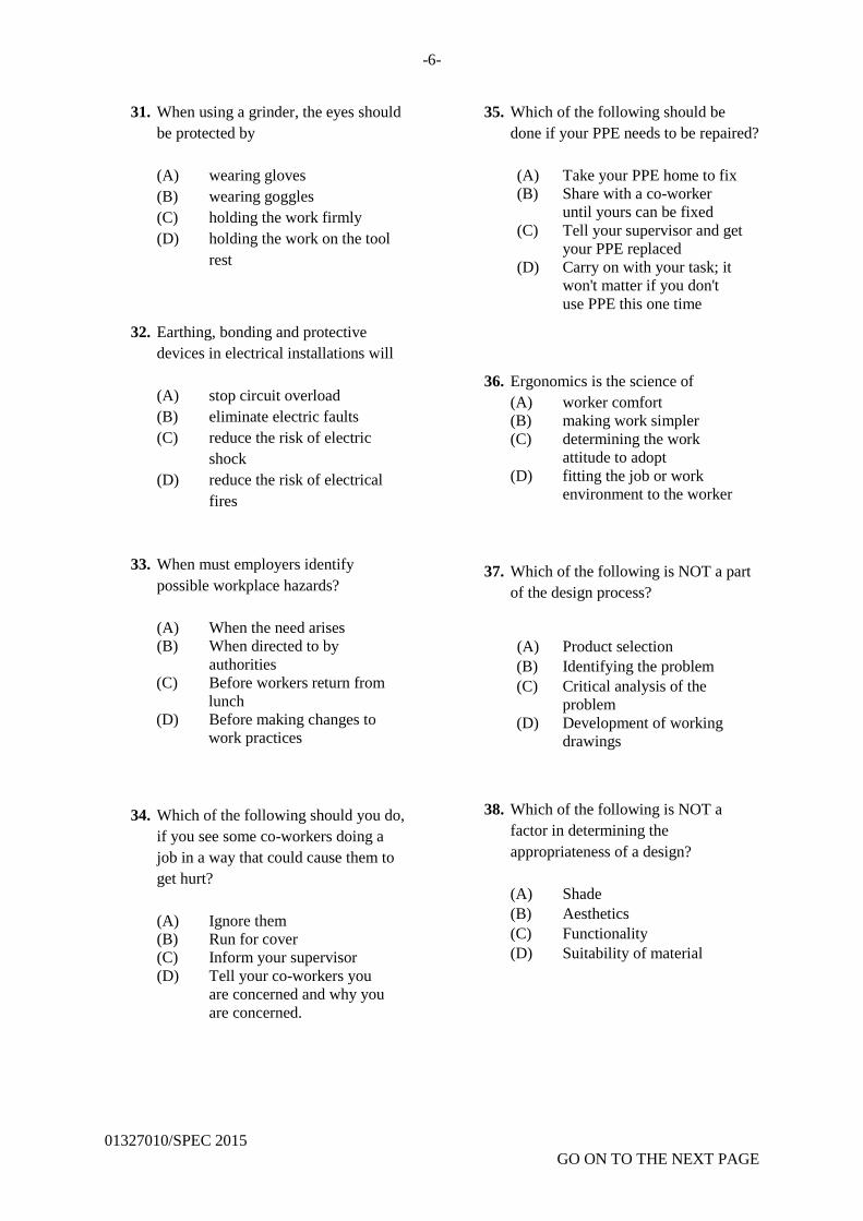
-6-
01327010/SPEC 2015
GO ON TO THE NEXT PAGE
31. When using a grinder, the eyes should
be protected by
(A) wearing gloves
(B) wearing goggles
(C) holding the work firmly
(D) holding the work on the tool
rest
32. Earthing, bonding and protective
devices in electrical installations will
(A) stop circuit overload
(B) eliminate electric faults
(C) reduce the risk of electric
shock
(D) reduce the risk of electrical
fires
33. When must employers identify
possible workplace hazards?
(A) When the need arises
(B) When directed to by
authorities
(C) Before workers return from
lunch
(D) Before making changes to
work practices
34. Which of the following should you do,
if you see some co-workers doing a
job in a way that could cause them to
get hurt?
(A) Ignore them
(B) Run for cover
(C) Inform your supervisor
(D) Tell your co-workers you
are concerned and why you
are concerned.
35. Which of the following should be
done if your PPE needs to be repaired?
(A) Take your PPE home to fix
(B) Share with a co-worker
until yours can be fixed
(C) Tell your supervisor and get
your PPE replaced
(D) Carry on with your task; it
won't matter if you don't
use PPE this one time
36. Ergonomics is the science of
(A) worker comfort
(B) making work simpler
(C) determining the work
attitude to adopt
(D) fitting the job or work
environment to the worker
37. Which of the following is NOT a part
of the design process?
(A) Product selection
(B) Identifying the problem
(C) Critical analysis of the
problem
(D) Development of working
drawings
38. Which of the following is NOT a
factor in determining the
appropriateness of a design?
(A) Shade
(B) Aesthetics
(C) Functionality
(D) Suitability of material

-7-
01327010/SPEC 2015
GO ON TO THE NEXT PAGE
Item 39 refers to the following
statements.
I. Development of working
drawings.
II. Communication of design
ideas.
III. Selection of the best solution.
39. Which of the statements above are
stages in the design process?
(A) I and II only
(B) I and III only
(C) II and III only
(D) I, II and III
40. A product developer has completed
the prototype of a product he was
developing. Which of the following is
the next sequential step to completing
the design process?
(A) Analyzing the problem
(B) Testing and evaluating
(C) Generating alternative
solutions
(D) Communication of the design
ideas
41. A product developer is designing a
number of products for a client who
specifies that the products are to be
used by persons of various weights
and heights. Which of the following
factors should he consider during the
design process?
(A) Economics
(B) Functionality
(C) Anthropometrics
(D) Suitability of material
42. The area around machines should be
(A) free from scraps
(B) waxed and smooth
(C) clearly painted in red
(D) stacked with useful material
43. The most effective agent to use when
putting out an electrical fire is
(A) sand
(B) water
(C) oxygen
(D) carbon dioxide
44. In mouth-to-mouth artificial
respiration, tilting the head backwards
ensures
(A) a clear airway into the
victim’s lungs
(B) a good supply of blood to
the
victim’s brain
(C) effective breathing in
position
for the rescuer
(D) automatic rise and fall of
the victim’s chest
45. Which of the following should be
carried out LAST when treating an
unconscious person who has had an
electric shock?
(A) Treating burns
(B) Loosening tight clothing
(C) Keeping airways to the lungs
clear
(D) Administering artificial
respiration

-8-
01327010/SPEC 2015
GO ON TO THE NEXT PAGE
46. The immediate action which should be
taken to assist a person suffering from
the effect of toxic fumes is to
(A) seek medical assistance
(B) apply artificial respiration
(C) open all doors and windows
(D) remove the person from the
danger
47. Which of the following devices is
MOSTLY used to input data to a
computer system?
(A) UPS
(B) Keyboard
(C) Mouse pad
(D) Floppy disk
48. Computer-aided manufacturing is the
use of computer software to
(A) reduce the amount of labour
intensive activities
(B) control the manufacture of
high quality parts
(C) move work pieces around the
manufacturing plant
(D) control machine tools and
related machinery in the
manufacturing of work pieces
Item 49 refers to the following
statements.
I. Create a faster production
process.
II. Use only the required amount
of material.
III. Produce components and
tooling with more precise
dimensions.
49. Which of the statements above are
purposes of computer-aided
manufacturing?
(A) I and II only
(B) I and III only
(C) II and III only
(D) I, II and III
50. Which of the following operations is
NOT done using computer
numerically controlled machines?
(A) Milling
(B) Turning
(C) Filing
(D) Plasma cutting
51. Entrepreneurship is the capacity and
willingness to
(A) create a business opportunity
(B) manage a business belonging
to someone else
(C) take a business beyond the
development stage
(D) develop, organize and
manage a business venture

-9-
01327010/SPEC 2015
GO ON TO THE NEXT PAGE
52. Which of the following is NOT a
characteristic of an entrepreneur?
(A) Low work ethic
(B) Good technical skills
(C) Key personal attributes
(D) Strong managerial
competencies
53. Which of the following individuals is
responsible for the design of private
and commercial buildings?
(A) Architect
(B) Civil engineer
(C) Quantity surveyor
(D) Structural engineer
Item 54 refers to the following
tradesmen in the construction industry.
I. Mason
II. Electrician
III. Upholsterer
54. Which of the tradesmen listed above
are involved in building a domestic
dwelling house?
(A) I and II only
(B) I and III only
(C) II and III only
(D) I, II and III
55. Which of the following groups of
tradesmen are responsible for applying
finishes to buildings?
(A) Painters, machine operators,
fitters, plumbers
(B) Painters, plumbers,
carpenters, electricians
(C) Fitters, plumbers, machine
operators, carpenters
(D) Welders, electricians,
carpenters, fitters
Item 56 refers to the following
statements.
I. Reduces greenhouse gas
emissions
II. Reduces the amount of waste sent
to landfills and incinerators
III. Prevents pollution by reducing the
need to collect new raw materials
56. Which of the statements are benefits
of recycling?
(A) I and II only
(B) I and III only
(C) II and III only
(D) I, II and III
57. Which of the following is NOT a
method of recycling?
(A) Reusing
(B) Screening
(C) Composting
(D) Energy recovery

-10-
01327010/SPEC 2015
Item 58 refers to the following
statements.
I. Requires minimum land.
II. Can be operated in any
weather.
III. Refuse volume is reduced
considerably.
58. Which of the above statements are
advantages of incineration?
(A) I and II only
(B) I and III only
(C) II and III only
(D) I, II and III
59. Group project work completed by
some students was displayed on the
school’s intranet. What benefit does
this have over publishing the work on
the internet?
(A) Work cannot be copied.
(B) The intranet is safe from
viruses.
(C) Hyperlinks to other websites
cannot be used.
(D) The projects remain private
within the school.
60. In information technology, WAN
stands for
(A) Wide Array Net
(B) WAP Area Network
(C) Wide Area Network
(D) Wireless Area Network
END OF TEST

CSEC Industrial Technology – Specimen 2015
Item Key Syllabus Reference
1 C 1:5.1
2 B 1:5.1
3 A 1:5.1
4 A 1:6:a (viii)
5 C 1:6: d (iii)
6 D 2:1:6
7 D 2:2:b & c
8 A 2:4:c(ii)
9 B 2:3:c
10 C 2:3:e
11 C 2:3:e
12 A 2:3:c
13 B 2:3:d
14 C 1:4:a(iii)
15 B 1:4:a
16 C 1:3
17 C 1:2:a (i)
18 D 1:1:b (iii)
19 A 1:5.5:a
20 B 3:2:a (i)
21 D 3:3:a
22 A 3:4: a(i)
23 B 3:2:a (iv)
24 D 3:1
25 D 2:3
26 A 2:2:a
27 A 2:1:f
28 C 2:2:a
29 B 2:2 (v)
30 D 2:5:c
31 B 1:6:a(viii)
32 C 1:5.2:c
33 D 1:5.1:a (i)
34 D 1:5.1:d 35 C 1:6:a (ix)
36 D 2:4:e
37 A 2:3
38 A 2:4
39 D 2:3
40 B 2:3
41 C 2:4
42 A 1:6:c (i)
43 D 1:6:d (iii)
44 A 1:6:f (iv)

CSEC Industrial Technology – Specimen 2015
Item Key Syllabus Reference
45 A 1:6:f (iii)
46 D 1:6:i
47 B 3:2:a (iv)
48 D 3:6:b
49 D 3:6:b
50 C 3:6:c
51 D 1:4:b (i)
52 A 1:4:b
53 A 1:4:a 9 (ii)
54 A 1:4:a (i)
55 B 1:4:a (i)
56 D 1:6:b (iii)
57 B 1:6:b (iii)
58 D 1:6:b (ii)
59 D 3:3:a (i)
60 C 3:3:a (iI)

01337020/SPEC/2015
TEST CODE 01337020
SPEC 2015/01337020
C A R I B B E A N E X A M I N A T I O N S C O U N C I L
CARIBBEAN SECONDARY EDUCATION CERTIFICATE
EXAMINATION
OPTION A – ELECTRICAL AND ELECTRONIC TECHNOLOGY
SPECIMEN PAPER
Paper 02 – Technical Proficiency
2 hours 10 minutes
READ THE FOLLOWING INSTRUCTIONS CAREFULLY.
1. This paper consists of FIVE compulsory questions.
2. Each question is worth 18 marks.
3. All working must be CLEARLY shown.
4. Use sketches where necessary to support your answers.
5. Silent non-programmable calculators may be used.
6. You are advised to take some time to read through the paper and plan your answers.
DO NOT TURN THIS PAGE UNTIL YOU ARE TOLD TO DO SO.
Copyright © 2012 Caribbean Examinations Council
All rights reserved.

-2-
01337020/SPEC/2015 GO ON TO THE NEXT PAGE
Answer ALL Questions.
1. (a) (i) State Ohm’s law in words and symbols. (2 marks)
(ii) Explain briefly the term ‘resistivity of a material’. (2 marks)
(iii) Explain briefly the term ‘temperature coefficient of a material’.
(2 marks)
(b) Two resistors of 10 ohms and 40 ohms are connected in parallel. A third resistor of 5
ohms is connected in series with the combination and a direct current supply of 240
volts is supplied to the ends of the complete circuit.
(i) Produce a circuit diagram of the complete circuit. (6 marks)
(ii) Calculate the current in each resistor. (3 marks)
(iii) Calculate the total resistance in the circuit. (3 marks)
Total 18 marks
2. (a) (i) State the difference between primary and secondary cells. (2 marks)
(ii) State TWO safety precautions which should be observed when charging
secondary cells. (2 marks)
(iii) State the TWO main indicators of a FULLY charged lead-acid cell and
describe ONE instrument that can be used to measure ONE of the indicators.
(2 marks)
(b) A 6 ohm resistor is connected across a lead-acid battery. The potential difference
across the battery terminals is 20 V for the open-circuit condition and 18 V when the
circuit is closed.
(i) Using the symbol for a lead-acid cell, produce a drawing showing the number
of cells and polarity of each cell and the battery.
(3 marks)
(ii) Produce a circuit diagram of the complete circuit when it is in the closed
condition.
(3 marks)
(iii) Calculate the internal resistance of the lead-acid battery.
(3 marks)

-3-
01337020/SPEC/2015 GO ON TO THE NEXT PAGE
(iv) Calculate the charging current required to charge a 100 AH battery at the
8-hour charging rate.
(3 marks)
Total 18 marks
3. (a) (i) State Lenz’s law and Faraday’s law of electromagnetic induction.
(2 marks)
(ii) Define mutual inductance and self-induction in electrical circuits.
(2 marks)
(iii) Define the term ‘electrostatic screening in transformers’. (2 marks)
(b) Figure 1 shows the incomplete sketch of a compound wound direct current motor
circuit. The missing windings are shown separately.
Figure 1
(i) In your answer booklet, draw the complete circuit, insert the windings A and B in their
positions in the motor circuit, and show the polarity of the direct current supply to the
motor. (3 marks)
(ii) Produce circuit drawings for series, shunt and compound connected direct current
machines. (3 marks)
(iii) State TWO different ways in which the speed of a motor can be increased.
(3 marks)
(iv) Explain the effect on the performance of the motor if terminals 1 and 2 are
interchanged.
(3 marks)
Total 18 marks

-4-
01337020/SPEC/2015 GO ON TO THE NEXT PAGE
4. Figure 2 shows an electric lamp which is controlled by the switches S1, S2, S3 and S4.
Figure 2
(a) (i) Name THREE semi-conductor devices which are used as fast switching
elements in the construction of logic circuits.
(3 marks)
(ii) Name the TWO logic gates that can replace the four switches and the combinational
gate that can replace the switching arrangement in the circuit.
(3 marks)
(iii) Using the three switches, S2, S3 and S4, as inputs and the electric lamp as an output,
draw the truth table of the circuit. (Assume that the open state of the switches is
represented by logic O, and the closed state is represented by logic 1 and that the state
of switch S1, is logic 1 or is closed.)
(6 marks)
(b) A logic circuit is shown in Figure 3.
Figure 3
A, B, C and D represent inputs to the circuit. Derive expressions for output (i) E
(ii) F
(iii) G (6 marks)
Total 18 marks

-5-
01337020/SPEC/2015 GO ON TO THE NEXT PAGE
5. Figure 4 shows the electrical floor plan of a building with items labelled 1 to 10.
Figure 4
(a) (i) In your answer booklet, write the numbers 1, 2, 3, 4, 5 and 6. Next to
EACH number, write the name of the electrical item it represents.
(3 marks)
(ii) Explain briefly the MAIN function of any THREE electrical items named in
(a) (i) above.
(3 marks)
(b) (i) Using standard drawing symbols, produce a single line drawing of a
three-phase, four-wire industrial electrical installation that shows the supply
authority's service entrance, energy meter, main control, main distribution
board, power control and lighting control.
(6 marks)

-6-
01337020/SPEC/2015
(ii) State ONE electrical safety test that must be conducted on all new
installations before the power supply is connected to the circuit.
(1 mark)
(iii) Outline the procedure for conducting insulation resistance tests between the
conductors, and between the conductors and earth in a completed electrical
installation.
(5 marks)
Total 18 marks
END OF TEST

SPEC 2015/01337020 CSEC MS
C A R I B B E A N E X A M I N A T I O N S C O U N C I L
HEADQUARTERS
CARIBBEAN SECONDARY EDUCATION CERTIFICATE
EXAMINATION
OPTION A – ELECTRICAL AND ELECTRONIC TECHNOLOGY
PAPER 02 – TECHNICAL PROFICIENCY
SPECIMEN PAPER
SOLUTIONS AND MARK SCHEME

SPEC 2015/01337020 CSEC MS
-2- Solutions – Question 1
(a) (i) Ohm’s law
The current (I) flowing in a circuit varies directly to the voltage (V) and indirectly to
the resistance (R) at a constant temperature.
Relationship:
1 =𝑉
𝑅 OR V = IR OR 𝑅 =
𝑉
𝐼
(2 marks)
(ii) The resistivity of a material is the resistance of a unit cube of the material measured
across opposite faces of the cube.
(2 marks)
(iii) The temperature coefficient of a material is the increase in the resistance of a one
ohm resistor of the material when it is subjected to a rise in temperature of one degree
centigrade.
(2 marks)
(b) (i)
(6 marks)
Parallel connection 2 marks
Series connection 1 mark
Supply voltage 1 mark
Series–parallel connection 2 marks
(b) (ii) Current through each resistor
It = Vs/Rt
= 240/13 = 18.46 amps = current through the 5 ohm resistor
(1 mark)
Voltage across the parallel group
8 ohms x 18.46 = 147.69 V
Current through 40 ohm resistor
147.69/40 = 3.69 amps
(1 mark)
10 ohms
40 ohms
240 V
∧∧∧ ∧∧∧ 5 ohms

SPEC 2015/01337020 CSEC MS
-3- Current through 10 ohm resistor
147.69/10
= 14.769 amps
(1 mark)
(b) (iii) 1
𝑅𝑝 =
1
40 +
1
10 =
1
40 +
4
40
= 5
40 =
1
8
Rp = 8 Ω
RT = 8 Ω + 5 Ω
= 13 Ω
(3 marks)
Total 18 marks
Solutions – Question 2
(a) (i) The primary cell cannot be recharged while the secondary cell can be recharged.
(2 marks)
(ii) The room must be well ventilated
The charging rate by the manufacturer should be observed.
Correct polarity must be observed when connecting cells to charger device.
1 mark each for any TWO (2 marks)
(iii) Lead — acid cell consists of two sets of plates immersed in an electrolyte
of dilute sulphuric acid.
The plates are constructed in the form of lead grids which serve as a
frame to support the active paste; a mixture of lead oxides and
sulphuric acid.
During charging the active material is converted to lead dioxide on
the positive electrode and to spongy lead on the negative electrode.
(2 marks)
(b) (i)
(3 marks)
Open circuit – 20 V
Closed circuit – 18 V

SPEC 2015/01337020 CSEC MS
-4-
(b) (ii)
(3 marks)
(b) (iii)
I = 𝑉
𝑅
= 18
6
= 3 amps
(3 marks)
(b) (iv)
r = 𝑣
𝐼=
(𝑜𝑝𝑒𝑛 𝑐𝑘𝑡−𝑐𝑙𝑜𝑠𝑒𝑑 𝑐𝑘𝑡)𝑣
𝐼
= 20−18
3
= 2
3
= 0.67 Ω
Battery capacity = A x HRS
Capacity = AH
Charging current = 100 𝐴𝐻
8 𝐻𝑂𝑈𝑅𝑆
Charging Current = 12.5 A
(3 marks)
Total 18 marks
x y

SPEC 2015/01337020 CSEC MS
-5-
Solutions – Question 3
(a) (i) Lenz’s law: The induced electromotive force produces a current that
opposes the motion producing it.
(1 mark)
Faraday’s law: Relative motion between a conductor and lines of magnetic
force so that the conductor cuts lines of force and e.m.f is
induced in the conductor.
(1 mark)
(ii) When charging current in a circuit induces an e.m.f in the circuit, the induced emf is
a self-induced e.m.f.
(2 marks)
(iii) Earthed metal screen between the windings of the transformer to reduce the
capacitive effect of the windings.
(2 marks)
(b) (i)
(3 marks)
(ii)
(3 marks)

SPEC 2015/01337020 CSEC MS
-6-
(iii) To increase the speed, increase the supply voltage or increase the fluid strength.
(3 marks)
(iv) The direction of rotation will change.
(3 marks)
Total 18 marks
Solutions – Question 4
(a) (i) Three semiconductor devices are: transistors, thyristors and Silicon Control Rectifiers
(3 marks)
(ii) Two logic gates: AND Gate, OR Gate
NAND/NOR
(3 marks)
(iii) Equivalent logic circuit
S2 S3 S4 Output
(Lamp)
0 0 1 0
0 1 0 0
0 1 1 0
1 0 0 0
1 0 1 1
1 1 0 1
1 1 1 1
(6 marks)

SPEC 2015/01337020 CSEC MS
-7- (b) (i) At E:
E = A + B
(2 marks) (ii) At F:
F = C.D
(2 marks)
(iii) At G:
𝐺= (𝐴+𝐵)+ (𝐶.𝐷)
(2 marks)
Total 18 marks
Solutions – Question 5
(a) (i) (1) Wall lamp
(2) Socket outlet
(3) Fluorescent lamp
(4) Two-way switch
(5) Electric meter
(6) Earth
1 mark for every TWO (3 marks)
(ii) (1) Wall lamp is a filament lamp installed on a wall.
(2) Socket outlet is used to connect portable appliances to the electric supply.
(3) Fluorescent lamp is used to produce electric lighting.
(4) Two-way switch is used to switch a lamp on and off from two positions.
(5) Electric meter is used to measure the amount of electrical energy used by the
consumer.
(6) Earth — connects the installation to the general mass of earth.
1 mark each for any THREE (3 marks)

SPEC 2015/01337020 CSEC MS
-8-
(b) (i)
1 mark each
(6 marks)
(ii) Earth-fault loop impedance test
(Recheck) polarity test using a voltmeter or approved test lamp
Functional testing:
Operation of protective devices (for example, residual current device – RCD)
(1 mark)
(iii) 1. Remove all lamps.
2. Close all switches and circuit breakers.
3. Disconnect appliances.
4. Test between the phase conductor and earth for every distribution circuit.
5. Test between the neutral conductor and earth for every distribution circuit.
(1 mark each)
(5 marks)
Total 18 marks

01347020/SPEC/2015
TEST CODE 01347020
SPEC 2015/01347020
CARIBBEAN EXAMINATIONS COUNCIL
CARIBBEAN SECONDARY EDUCATION CERTIFICATE
EXAMINATION
INDUSTRIAL TECHNOLOGY
OPTION B – MECHANICAL ENGINEERING TECHNOLOGY
SPECIMEN PAPER
Paper 02 – Technical Proficiency
2 hours 10 minutes
READ THE FOLLOWING INSTRUCTIONS CAREFULLY.
1. This paper consists of FIVE compulsory questions.
2. Each question is worth 18 marks.
3. Use sketches where necessary to support your answers.
4. Silent non-programmable calculators may be used.
5. You are advised to take some time to read through the paper and plan your answers.
DO NOT TURN THIS PAGE UNTIL YOU ARE TOLD TO DO SO
Copyright © 2013 Caribbean Examinations Council ®
All rights reserved.

-2-
01347020/SPEC/2015
Answer ALL Questions.
1. Figure 1 shows a template to be produced from a sheet of mild steel, 3 mm thick, 130
mm long and 100 mm wide.
Figure 1
(a) (i) List the tools and equipment necessary for marking out the template.
(2 marks)
(ii) List the steps of procedure to be followed to mark out the template as shown.
(6 marks)
(b) (i) Explain ONE procedure for cutting out the area labelled ‘A’ on the drawing.
(4 marks)
(ii) Explain how the procedure in (b) (i) above could be carried out without going
outside of the layout lines for the slot. (2 marks)
(c) (i) State TWO safety precautions to be observed when using marking-out tools.
(2 marks)
(ii) State TWO safety precautions to be observed when cutting out the slot in
(b) (i) above. (2 marks)
Total 18 marks

-3-
01347020/SPEC/2015
2. Figure 2 shows a threaded hole in a component. The hole was threaded using
M10 X 1.50 mm taps. While carrying out the threading operation a tap broke
in the hole and had to be removed before the job could be completed.
Figure 2
(a) (i) List the steps of procedure to be followed to reduce the risk of tap breakage
while threading the hole in a component.
(6 marks)
(ii) Explain ONE method of removing a broken tap from a partially threaded hole.
(3 marks)
(b) (i) List any THREE types of cold chisels used in the workshop.
(3 marks)
(ii) Explain the use of each of the THREE types of cold chisels named in (b) (i)
above.
(3 marks)
(iii) List THREE precautions that should be observed while using a chisel in the
workshop.
(3 marks)
Total 18 marks

-4-
01347020/SPEC/2015
3. Figure 3 shows a component that is to be produced on the centre lathe from a piece of
mild steel stock 32 mm in diameter by 105 mm long.
Figure 3
(a) With the aid of sketches, list the steps of procedure for making the component.
(6 marks)
(b) List the tools to be used in the procedure in (a) above.
(2 marks)
(c) Explain the procedure for producing the knurled section of the component in (a)
above.
(4 marks)
(d) State TWO precautions to be observed while producing the knurl in (c) above.
(2 marks)
(e) Calculate the spindle speed that is to be used to produce the section marked ‘A’ on
Figure 3, if the cutting speed of the material is 30 m/min.
(2 marks)
(f) State TWO safety precautions that should be observed while working on the centre
lathe.
(2 marks)
Total 18 marks
DIA.20
DIA.30
A

-5-
01347020/SPEC/2015
4. (a) An oxy-acetylene torch was lit and a sooty flame was produced.
(i) Sketch the sooty flame. (2 marks)
(ii) Name the sooty flame. (1 mark)
(iii) Explain the reason for the sooty particles. (2 marks)
(b) Explain the procedure for lighting the torch and adjusting it to produce an
oxidizing flame, assuming the cylinder valves are open.
(4 marks)
(c) Copy the following table into your answer booklet and complete the welding
and brazing columns to match the factor column.
Factor Welding Brazing
1. Filler rod material
2. Type of flame Carburizing
3. Fusion of work pieces
(3 marks)
(d) A steel bar is to be formed by welding two shorter lengths each of diameter 15
mm using the metal arc welding process. With the aid of sketches, list the
steps of procedure to be followed to ensure strength and dimensional accuracy
of the finished product.
(4 marks)
(e) State TWO safety precautions to be observed when using oxy-acetylene
welding equipment.
(2 marks)
Total 18 marks

-6-
01347020/SPEC/2015
5. Figure 4 shows the general outline of an incomplete arrangement of a hoist and
hook unit. The shaft, B, which is placed horizontally, supports the hook, C, and is
held in position by a housing.
Figure 4

-7-
01347020/SPEC/2015
You are required to design:
(a) A housing for the shaft which can be made by fabrication or casting
(b) A method of attaching the hook, C, to the shaft, B
Your design should clearly show the following:
(i) The shaft, A, in position in the housing and supported by two bronze
bushings inserted into the housing
(6 marks)
(ii) The shaft, B, free to rotate about its axis so as to facilitate the swinging
movement of the hook, C, as indicated by arrow E and free to rotate
through 360o as indicated by arrow F
(6 marks)
(iii) A means of retaining the shaft, B, in the housing in order to prevent axial
movement
(6 marks)
Total 18 marks
END OF TEST

01347020/MS/SPEC
C A R I B B E A N E X A M I N A T I O N S C O U N C I L
HEADQUARTERS
INDUSTRIAL TECHNOLOGY
OPTION B – MECHANICAL ENGINEERING TECHNOLOGY
PAPER 02 – TECHNICAL PROFICIENCY
SPECIMEN MARK SCHEME

01347020/MS/SPEC
-2-
Industrial Technology
Option B – Mechanical Engineering Technology
Paper 02 – Technical Proficiency
Specimen Mark Scheme
QUES. Knowledge and
Comprehension
Marks
Use of Knowledge
Marks
Practical Skills
Marks
B/D Total B/D Total B/D Total
1.
(a) (i)
List of tools and equipment
- Surface plate
- Surface gauge
- Scriber
- Divider
- Hammer
- Rule
- Protractor
(c) (i)
Safety precautions when
marking out
- Do not mark the surface
of the surface plate
- Place tools in centre of
table
(c) (ii)
Safety precautions when cutting
out slots
- Wear gloves
- Wear goggles
- Do not remove chips
with bare hands
2
2
2
(b) (i)
Procedure for cutting out
- Centre punch
- Chain drill
- Chisel/Hacksaw
- File
1 mark each
(b) (ii)
Procedure to remain within lines
- Punch centres within the
layout lines
- Drill inside layout lines
- File to touch layout lines
Two marks for 3 in sequence;
One mark for 2 in sequence
4
2
(a) (ii)
Procedure for Marking out
1. Coat with layout die.
2. Mark all horizontal lines.
3. Scribe all vertical lines.
4. Locate and mark radii.
5. Locate and draw circles.
6. Mark angles.
7. Outline template.
6
6 6 6

01347020/MS/SPEC
-3-
Industrial Technology
Option B – Mechanical Engineering Technology
Paper 02 – Technical Proficiency
Specimen Mark Scheme
QUES.
Knowledge and
Comprehension
Marks
Use of Knowledge
Marks
Practical Skills
Marks
B/D Total B/D Total B/D Total
2.
(b) (i)
Types of cold chisels
- Flat
- Cape or cross-cut
- Round nose
- Diamond point
Any three – 1 mark each
(b) (iii)
Precautions
- Remove mushroom from
head of chisel
- Hold chisel firmly and
correctly
- Maintain correct angle
1 mark each
3
3
(a) (ii)
Removal of broken tap
- Tap extractor
- Use of EDM machine to burn
tap
- Use a pliers if enough tap is
exposed
(b) (ii) Use Of Chisels
- Flat to cut flat sheets, small
rivets, bolts and nuts
- Cape/cross-cut to clean out
grooves
- Round nose to cut round
grooves and correct the start of
wrongly drilled holes
- Diamond point to chip in
corners
Any three – 1 mark each
3
3
(a) (i)
Steps of Procedure
1. Select correct tap and drill
bit.
2. Drill required hole.
3 Start tap squarely.
4. Use taps in sequence.
5. Back-up to break chips.
6. Use lubricant.
1–6 in sequence 6 marks
1–5 in sequence 5 marks
1–4 in sequence 4 marks
1–3 in sequence 3 marks
1–2in sequence 2 marks
1 mark for every 3 not in
sequence
6
6
6
6

01347020/MS/SPEC
-4-
Industrial Technology
Option B – Mechanical Engineering Technology
Paper 02 – Technical Proficiency
Specimen Mark Scheme
QUES.
Knowledge and
Comprehension
Marks
Use of Knowledge
Marks
Practical Skills
Marks
B/D Total B/D Total B/D Total
3.
(b)
Tools for making component
- Facing tool
- Right hand turning tool
- Centre drill
- Parting tool
- Knurling tool
- Tailstock centre
Any three – 1 mark each
(d)
Precautions while producing
knurl
- Ensure tool is on centre.
- Ensure correct speed.
- Ensure both rollers are in
contact with work.
Any two – 1 mark each
2
2
(c)
Procedure for producing knurl - Select required knurling tool.
- Centre knurling tool.
- Set spindle speed to ¼
turning speed.
- Bring tool in contact with
work.
- Engage automatic feed.
- Feed tool and reverse direction
of travel until depth is
achieved.
6 in sequence – 4 marks
5 in sequence – 3 marks
4 in sequence – 2 marks
3 in sequence – 1 mark (e)
Calculation of spindle speed CS X 1000 1 mark
πD 30 X 1000 1 mark
3.142 X 20 = 478 rpm
4
2
(a)
Steps of procedure for making
component 1. Face
2. Turn A
3. Chamfer
4. Turn material
5. Face
6. Centre drill
7. Cut to dia. 30
8. Cut 6 mm gap, 4 deep
9. Chamfer area to be
knurled
10. Set compound slide for
taper
11. Cut taper
12. Knurl
12 in order – 6 marks
10 in order – 5 marks
8 in order – 4 marks
6 in order – 3 marks
4 in order – 2 marks
2 in order – 1 mark
6

01347020/MS/SPEC
-5-
QUES.
Knowledge and
Comprehension
Marks
Use of Knowledge
Marks
Practical Skills
Marks
B/D Total B/D Total B/D Total
3.
(f)
Safety precautions
- Ensure the chuck key is not
left in the chuck
- Do not wear loose clothing
- Wear goggles
Any two – 1 mark each
2
6
6
6

01347020/MS/SPEC
-6-
Industrial Technology
Option B – Mechanical Engineering Technology
Paper 02 – Technical Proficiency
Specimen Mark Scheme
QUES.
Knowledge and
Comprehension
Marks
Use of Knowledge
Marks
Practical Skills
Marks
B/D Total B/D Total B/D Total
4.
(c)
FACTORS WELDING BRAZING
Filler rod
material
Same Different
Type of flame
Neutral Carburizing
Fusion of
pieces
Fusion No fusion
Five correct – 3 marks
Every 2 correct (less than 5) –
1 mark each
(e)
Safety Precautions
- Wear goggles.
- Wear gloves.
- Remove all combustibles.
- Point flame away from
body.
Any two – 1 mark each
(a) (ii)
Name the sooty flame
Luminous
3
2
1
(b)
Lighting and adjusting torch to get
an oxidizing flame
- Open acetylene valve about
half turn.
- Ignite acetylene with torch
lighter.
- Open oxygen needle valve.
- Adjust both valves to get
desired flame (more oxygen).
4 in order – 4 marks
3 in order – 3 marks
2 in order – 2 marks
(a) (iii)
Reason for sooty flame
Only acetylene is burning.
Little or no oxygen is in the
mixture of gases.
High carbon content.
4
2
(d)
SKETCH
Steps of procedure
1. Chamfer ends.
2. Support in angle iron.
3. Clamp pieces.
4. Make root pass.
5. Remove slag/clean.
6. Make series of passes.
7. Repeat steps 5 – 6 until
cavity is filled.
5/6 in order – 4 marks
4 in order – 3 marks
3 in order – 2 marks
2 in order – 1 mark
(a) (i)
Sketch the sooty flame
4
2
6
6
6

01347020/MS/SPEC
-7-
Industrial Technology
Option B – Mechanical Engineering Technology
Paper 02 – Technical Proficiency
Specimen Mark Scheme
QUES.
Knowledge and
Comprehension
Marks
Use of Knowledge
Marks
Practical Skills
Marks
B/D Total B/D Total B/D Total
5.
Drawing
Neatness
Clarity of details
Proportionality
2
2
2
Mechanisms/Methods
Shaft A in housing supported by
bushings.
Shaft A free to rotate to facilitate
swinging of hook and rotation
through 360°.
Shaft is retained in housing.
2
2
2
Function
Shaft “A” in housing
supported by bushings.
Shaft “B” free to rotate to
facilitate swinging of hook and
rotation through 360°.
Shaft is retained in housing.
2
2
2
6 6 6

01347020/MS/SPEC
-8-
Industrial Technology
Option B – Mechanical Engineering Technology
Paper 02 – Technical Proficiency
Specimen Mark Scheme
POSSIBLE SOLUTION TO QUESTION 5

01357020/SPEC/2015
TEST CODE 01357020
SPEC2015/01357020
C A R I B B E A N E X A M I N A T I O N S C O U N C I L
CARIBBEAN SECONDARY EDUCATION CERTIFICATE®
EXAMINATION
INDUSTRIAL TECHNOLOGY
OPTION C – BUILDING AND FURNITURE TECHNOLOGY
SPECIMEN PAPER
Paper 02 – Technical Proficiency
2 hours 10 minutes
READ THE FOLLOWING INSTRUCTIONS CAREFULLY.
1. This paper consists of FIVE compulsory questions.
2. Use sketches when necessary to support your answers. All sketches should be done to
proportion.
3. Silent non-programmable calculators may be used.
4. You are advised to take some time to read through the paper and plan your answers.
DO NOT TURN THIS PAGE UNTIL YOU ARE TOLD TO DO SO
Copyright © 2013 Caribbean Examinations Council
All rights reserved.

-2-
01357020/SPEC/2015 GO ON TO THE NEXT PAGE
BUILDING AND FURNITURE TECHNOLOGY
LIST OF FORMULAE
Candidates should refer to the following list of formulae for assistance in answering questions.
ROOF CALCULATIONS
TRUE LENGTH OF COMMON RAFTER WITH OVERHANG
Overhang = Rise/Run = X/overhang
Value of X = (Rise x Overhang)/Run
Value of X + Original Rise = Total Rise
Run + Given Overhang = Total Run
Rise
Span= Pitch
Pitch x Span = Rise
(Pythagoras’ Theorem)
The Length of Rafter = √Total Rise2 + Total Run2
STAIR DESIGN CALCULATIONS
Formula for calculating tread and rise dimensions
2R + T OR 2R + G = 550 mm to 700 mm
Where R = rise, G = going and T = tread
CONCRETE BLOCK WALL CALCULATIONS
Area of Wall
Area of Block= No. of blocks
MOISTURE CONTENT OF TIMBER
% Moisture Content = Wet Weight−Dry Weight
Dry Weight x 100
DEPTH OF FLOOR JOIST
Span in mm
24 + 50 mm = Depth in (mm)

-3-
01357020/SPEC/2015 GO ON TO THE NEXT PAGE
Answer ALL Question.
This paper contains metric dimensions only. You should work your answers in the metric
system.
1. Figure 1 shows the floor plan of a small building that is constructed with 150 mm hollow
concrete block walls. The dimensions are as indicated on the plan. The floor is 100 mm thick
reinforced concrete slab on grade. The building is covered with a hip roof which has a rise of
1.4 m and the rafters are placed at 400 mm centres. The overhang is 300 mm all around. The
sizes of the members are as follows.
- Rafters 50 mm x 150 mm
- Fascia 25 mm x 250 mm
- Wall plate 50 mm x 100 mm. Bolted to the ring/belt beam
which is 150 mm wide x 250 mm deep
(NOTE: The eave is not boxed and the roof is covered with corrugated (zinc) galvanized sheets.)
Figure 1. Floor Plan

01357020/SPEC/2015
(a) Produce a neat, labelled single-line sketch of the plan of the roof portion
outlined in Figure 1. (6 marks)
(b) (i) List, in sequence, THREE processes involved in safely excavating a strip
foundation with a depth of 1.4 metres. (3 marks)
(ii) Name THREE tools or pieces of equipment required for digging a strip
foundation manually.
(3 marks)
(c) A foundation is to be built on a gentle sloping site.
(i) Name, with reason, a suitable foundation to be used at this site. (2 marks)
(ii) Produce a drawing which illustrates your answer to (c) (i). (4 marks)
Total 18 marks
2. (a) State TWO reasons for stripping a building site. (2 marks)
(b) State TWO temporary services a well-managed building site should provide.
(2 marks)
(c) State TWO functions of the external walls of a building. (2 marks)
(d) (i) Explain how corner profile boards are positioned when setting out a small building
(4 marks)
(ii) Explain, with the aid of drawings, ONE method of ensuring that the corners of a
small building are at 90°.
(2 marks)
(e) Figure 2 shows a panel door
Make a neat sketch of the horizontal section X-X (6 marks)
Total 18 marks
-4-
7-
Figure 2. Panel Door

-5-
01357020/SPEC/2015 GO ON TO THE NEXT PAGE
3. (a) State FOUR functions of a window. (4 marks)
(b) Make a single line sketch of
(i) a louvre window
(ii) a casement window
(iii) an awning window (6 marks)
(c) Figure 3 shows two doors labelled A and B.
Figure 3. Two doors
Using labels A and B, name EACH of the doors shown in Figure 3. (2 marks)
(d) A stair has a total rise of 2.6 m. It has risers 200 mm in height and treads 250 mm
in width. Calculate the
(i) total number of risers in the staircase
(ii) total number of treads in the staircase
(iii) total going of the staircase. (6 marks)
Total 18 marks

-6-
01357020/SPEC/2015 GO ON TO THE NEXT PAGE
4. Figure 4 shows the side view of a surface planer or jointer with three parts labelled X, Y and
Z.
Figure 4. Side view of surface planer
(a) Name EACH labelled part of the surface planer. (3 marks)
(b) (i) List THREE factors which create the smoothness of a planed
surface on the jointer. (3 marks)
(ii) Explain, in sequence, with the aid of sketches, the cutting of a 6 mm deep by
15 mm wide rebate on the jointer. (3 marks)
(c) Explain briefly, and with the aid of a sketch, the position of a worker’s
hands in relation to the surface planer or jointer when
(i) starting a cut
(ii) halfway through the cut
(iii) completing the cut. (3 marks)
(d) (i) List THREE operations other than rebating that can be carried
out on the jointer.
(3 marks)
(ii) Give a possible cause for EACH of the following problems
when using the jointer:
a) The stock chips at the end of the operation
b) The stock chips at the start of the operation
c) The cutter not making contact with the stock
(3 marks)
Total 18 marks

-7-
01357020/SPEC/2015
5. Figure 5 shows a small panel door for a cupboard. The frame is 19 mm thick and is grooved
to receive a plywood panel.
Figure 5. Panel door
(a) (i) State the most appropriate joint that should be used to connect
the rails and stiles of the door. (1 mark)
(ii) Name THREE types of ironmongery necessary for the functioning of
this door. (3 marks)
(iii) State the purpose of any TWO of the types of ironmongery mentioned
in (a) (ii). (2 marks)
(b) Make a labelled isometric sketch of EACH of the following before cutting the joint:
(i) The setting out of a rail (6 marks)
(ii) The setting out of a stile
(c) Describe, in sequence, the steps taken to form the part to be cut at the end of
ONE rail. (6 marks)
Total 18 marks
END OF TEST

01357020/SPEC/MS
C A R I B B E A N E X A M I N A T I O N S C O U N C I L
HEADQUARTERS
INDUSTRIAL TECHNOLOGY
OPTION C – BUILDING AND FURNITURE TECHNOLOGY
PAPER 02 – TECHNICAL PROFICIENCY
SOLUTION & MARK SCHEME 2015
SPECIMEN PAPER

01357020/SPEC/MS
Industrial Technology
Option C – Building and Furniture Technology
Paper 02 – Technical Proficiency
Specimen Mark Scheme
-1-
QUESTION SOLUTION MARKS
KC UK PA TOTAL
1 (a) (i)
PLAN VIEW OF HIP ROOF
Sketch: Hip rafters – 1
Jack rafter – 1
Crown rafter – 1
Ridge – 1
Common rafter – 1
Labelling – 1
-
-
-
6
-
SUB TOTAL - - 6 6

01357020/SPEC/MS
Industrial Technology
Option C – Building and Furniture Technology
Paper 02 – Technical Proficiency
Specimen Mark Scheme
-2-
QUESTION SOLUTION MARKS
KC UK PA TOTAL
1 (b) (i)
(b) (ii)
Select correct method, tools, equipment.
Excavate trench
Timbering must be installed to prevent this side from caving in when digging the required
depth (First three in sequence - 3 marks)
(First two in sequence - 2 marks)
(First one in sequence - 1 mark)
TOOLS AND EQUIPMENT
Excavation work manually
– Pick axe
– Spade or shovel
– Wheel barrow (1 mark each)
3
3
SUB TOTAL 6 - 6 12

01357020/SPEC/MS
Industrial Technology
Option C – Building and Furniture Technology
Paper 02 – Technical Proficiency
Specimen Mark Scheme
-3-
QUESTION SOLUTION MARKS
KC UK PA TOTAL
1 (c) (i)
(ii)
Step foundation (1 mark)
Reason – To reduce the amount of excavation and materials required to produce an adequate foundation
(1 mark)
Step Foundation on a Sloping Site
Step foundation – 2
Reinforcement – 2
(4 marks)
1
1
4
TOTAL 6 6 6 18

01357020/SPEC/MS
Industrial Technology
Option C – Building and Furniture Technology
Paper 02 – Technical Proficiency
Specimen Mark Scheme
-4-
QUESTION SOLUTION MARKS
KC UK PA TOTAL
2 (a)
(b)
(c)
Reasons for Stripping a Building Site
To remove vegetation such as bushes and shrubs
To remove rocks and boulders in the area where the building is to be set out
To clear trees and bushes
To remove termite nests
(1 mark each for any TWO)
Temporary Services
A supply of fresh water
A toilet
An electrical supply
A telephone
(1 mark each for any TWO)
Functions of External Walls of a Building
Enclose the building
Protect the inside of the building from the elements
Support the roof and upper floors
(1 mark each for any TWO)
2
2
2
SUB TOTAL 6 - - 6

01357020/SPEC/MS
Industrial Technology
Option C – Building and Furniture Technology
Paper 02 – Technical Proficiency
Specimen Mark Scheme
-5-
QUESTION SOLUTION MARKS
KC UK PA TOTAL
2 (d) (i)
Position of Corner Profile Boards When Setting Out
Locate the position. (1 mark)
Measure the position on the ground and place peg to mark. (1 mark)
Check that lines are at right angles to the proposed wall position. (1 mark)
Run lines from the centre to the pegs. (1 mark)
4
SUB-TOTAL 6 4 10

01357020/SPEC/MS
Industrial Technology
Option C – Building and Furniture Technology
Paper 02 – Technical Proficiency
Specimen Mark Scheme
-6-
QUESTION SOLUTION MARKS
KC UK PA TOTAL
2 (d) (ii)
Method of Squaring a Small Building During Setting Out
(1) Method – 3 : 4 : 5
(2) Method – Builders’ Square
Builder’s square
(2 marks for sketch and label
of any method)
2
2
TOTAL 6 6 2 14

01357020/SPEC/MS
Industrial Technology
Option C – Building and Furniture Technology
Paper 02 – Technical Proficiency
Specimen Mark Scheme
-7-
QUESTION SOLUTION MARKS
KC UK PA TOTAL
2 (e)
Section X-X of Panelled Door
Sketch:
Stile – 1
Muntin – 1
Panels – 1
Grooves – 1
Horizontal Section – 1
1 mark each for any FOUR (4 marks)
4
TOTAL 6 6 6 18

01357020/SPEC/MS
Industrial Technology
Option C – Building and Furniture Technology
Paper 02 – Technical Proficiency
Specimen Mark Scheme
-8-
QUESTION SOLUTION MARKS
KC UK PA TOTAL
3 (a)
(b)
Function of Windows
- Through vision/privacy
- Ventilation
- Outside view
- Lighting (natural)
- Decoration (1 mark EACH – maximum 4 marks)
Single Sketches of Windows
(2 marks each)
(6 marks)
4
6
SUB TOTAL 4 - 6 10

01357020/SPEC/MS
Industrial Technology
Option C – Building and Furniture Technology
Paper 02 – Technical Proficiency
Specimen Mark Scheme
-9-
QUESTION SOLUTION MARKS
KC UK PA TOTAL
3 (c)
(d) (i)
(ii)
(iii
Names of Doors
(A) - Ledged, braced and battened (match boarded)
(B) - Flush door
(1 mark each – 2 marks)
Total number of risers equal 2.600/200 = 13 risers (2 marks)
Since there is going to be one tread less than the number of risers,
total number of treads equal 13 – 1 = 12 treads. (2 marks)
Total going = 12 × 250 = 3.000 m. (2 marks)
6
TOTAL 6 6 6 18

01357020/SPEC/MS
Industrial Technology
Option C – Building and Furniture Technology
Paper 02 – Technical Proficiency
Specimen Mark Scheme
-10-
QUESTION SOLUTION MARKS
KC UK PA TOTAL
4. (a)
(b) (i)
(b) (ii)
Parts of Planer/Jointer
X – REAR (outfeed) Table
Y – FENCE
Z – FRONT (infeed) Table
(1 mark each)
Factors that determine smoothness of a planed surface
- Diameter of cutter lead
- Number of knives
- Number of revolutions per minute
- Feed speed
(1 mark each for any THREE)
Procedure for cutting a rebate
- Adjust the power 15 mm from the edge of the knife
- Adjust the front infeed table 6 mm down
3
3
3
SUBTOTAL 6 - 3

01357020/SPEC/MS
Industrial Technology
Option C – Building and Furniture Technology
Paper 02 – Technical Proficiency
Specimen Mark Scheme
-11-
QUESTION SOLUTION MARKS
KC UK PA TOTAL
(c)
(d) (i)
(d) (ii)
Sketch
Position of hands on plane
(i) Both hands pressing stock on from table
(ii) Left hand moved over on rear table pressing stock down
(iii) Right hand with push stick/block to finish
Bevel
Clamper
Tongues
Taper (1 mark each for any THREE)
a) Outfeed table too high
b) Outfeed table too low
c) Both tables too high (1 mark each)
TOTAL
3
3
3
6 6 6 18

01357020/SPEC/MS
Industrial Technology
Option C – Building and Furniture Technology
Paper 02 – Technical Proficiency
Specimen Mark Scheme
-12-
QUESTION SOLUTION MARKS
KC UK PA TOTAL
5 (a) (i)
(ii)
(iii)
5 b (i)
Joint
Haunched Mortice & Tenon Joint
Ironmongery
Hinge
Straight Lock (cupboard lock)
Catches
Knob (Handle)
(1 mark each for any THREE)
Purpose
Hanging the door
Locking the door
Keeping the door closed
Operating and closing the door
(1 mark each for any TWO)
Setting out of a rail
(2 marks for sketch)
(1 mark for any TWO labels)
SUB TOTAL
1
3
2
3
6
3

01357020/SPEC/MS
Industrial Technology
Option C – Building and Furniture Technology
Paper 02 – Technical Proficiency
Specimen Mark Scheme
-13-
QUESTION SOLUTION MARKS
KC UK PA TOTAL
5 b (ii)
5 (c)
Setting out the stile
(2 marks for sketch)
(1 mark for any TWO labels)
Pictorial 2
Haunch 1
Tenon 1
Groove 1
Proportion 1
TOTAL
6
3
6 6 6 18

C A R I B B E A N E X A M I N A T I O N S C O U N C I L
REPORT ON CANDIDATES’ WORK IN THE
SECONDARY EDUCATION CERTIFICATE EXAMINATION
MAY/JUNE 2010
BUILDING TECHNOLOGY
OPTION 1 – WOODS
TECHNICAL PROFICIENCY
Copyright © 2010 Caribbean Examinations Council
St Michael, Barbados
All rights reserved.

-2-
GENERAL COMMENTS
The number of candidates sitting the examination was approximately 1,776 and 83 per cent of them received
Grades I–III. Candidates did quite well on the practical project of the School-Based Assessment (SBA) but some
were weak in the written project. Competencies requiring focused attention are Knowledge and Application
which are tested on Paper 01 (Multiple Choice) and Paper 02 (Essay/Structured Response/Problem- Solving
Questions).
DETAILED COMMENTS
Paper 01 – Multiple Choice
Candidates’ performance on this paper improved marginally above that of 2009. Based on the common selection
of certain items, the need for greater coverage of the theoretical aspects of the unit cannot be overemphasized.
Paper 02 – Structured Response /Essay Questions
Paper 02 was a structured response paper with three sections namely, A, B, and C.
Section A This section had a compulsory question based on Module C7.1– Introduction to Drawing. The
question was worth 40 marks.
Section B This section comprised five questions based on Modules C2, C3, C5, C6.1—Materials— and
C6.2—Ironmongery. Candidates were required to attempt three questions from this section.
Section C This section had three questions based on Modules C4, Upholstery, Module 6.3, Basic Cabinet
Making, and Module C6.7, Household Furniture. Candidates were required to answer only one
question from this section.
The mean score on this paper was 51.21 out of a total of 120 marks.
Section A
Question 1
This question, based on Module C7—Drawing and Design—was compulsory. For Parts (a) and (b), primary
focus was given to Objectives C7.1:5–7 from the Introduction to Drawing section of the module while Parts (c)
and (d) focused on Objective C7.2:5 from the Introduction to Design section. The question required candidates
to demonstrate drawing and design skills using either free hand or ruler-assisted sketches. Candidates were
presented with a pictorial view of a small work table with the structural framing to be designed using timber. The
dimensions for the table were: length – 1250 mm, width – 600 mm and height – 750 mm. The table top should be
built using 19 mm plywood and finished with plastic laminate.

-3-
Figure I. A Small Work Table
Part (a) required candidates to show the following orthographic views of the table:
i. A typical front elevation
ii. A typical plan view showing all main hidden details
iii. A typical end view
In Part (b), candidates were required to indicate the title and add two main dimensions for each orthographic view
produced.
For Part (c), candidates were asked to name and sketch the most suitable joint to show the
i. connection of the table leg and bottom rail
ii. connection of the middle slat and bottom rail
iii. connection between the top rail and table leg.
In Part (d), candidates were required to produce a sketch to explain one procedure that could be used to fasten the
table top to the frame. Most candidates scored 60 per cent or more of the marks allocated to this part of the
question.
In response to Parts (a) (i), (ii) and (iii), 60 per cent of the candidates were able to correctly interpret the drawing
and produce the required orthographic views. However, some candidates showed weaknesses in distinguishing
between orthographic and pictorial views or front elevation and end elevation.
In Part (b) (i), most candidates were able to correctly identify and label the views required. A few of the
candidates did not include the titles for the orthographic sketches that they produced.
For Part (b) (ii), some of the candidates were not able to appropriately dimension the sketches to show two main
dimensions. Some candidates did not score well in this areas as they either did not give dimensions or gave
unrealistic dimensions.

-4-
In Part (c), most of the candidates provided satisfactory responses. They were able to sketch suitable joints for the
connection at (i) or (iii) respectively. However, some candidates found it difficult to indicate the most
appropriate joint at (ii) to show the connection of the middle slat and bottom rail. Some candidates sketched
other joints for the connection which were not designed to resist the lateral pressure which may be encountered
between these two members. In general, many candidates identified a range of joints of varying suitability but
were not able to illustrate them with either pictorial or orthographic sketches.
The use of appropriate models and artifacts to illustrate the use of joints in specific applications need to be
reinforced in the classroom. Models in either assembled or exploded forms should be kept on display in the
workshops and used as teaching aids and for reference purposes. Candidates should also be taught good
sketching skills and be allowed to practise these skills and produce pictorial and orthographic views of various
woodwork components.
In Part (d), candidates performed fairly well. They were familiar with fastening principles required to anchor the
table top to the frame but failed to produce suitable sketches to illustrate them.
Candidates should be given sufficient time to communicate their understanding of the components of Cabinetry
and Furniture Construction in graphical form.
The expected responses to question 1 were:
(a) (i)
(ii)

-5-
(iii)
(b) (ii) Typical dimensions are as follows:
- Top length – 1250 mm
- Width – 600 mm
- Height – 750 mm
- Frame – 1150 x 500 mm
- Overhang – 25 to 50 mm
- Table top thickness – 19 mm
- Leg – 50 to 75 mm
(c)
(i) (ii)
Mortise & Tenon Joint
(iii)
Haunch Mortise & Tenon joint

-6-
(d)
Section B
Question 2
This question assessed candidates’ knowledge and application of Module C2—Hand Tools and Bench Klork.
Specific focus was given to the objectives under Module C2.1—Planning and Layout—in relation to layout tools.
Part (a) (i–v) required candidates to state two uses each of the Try square, Sliding bevel, Marking gauge, Mortise
gauge and Marking knife.
The general responses to this part of the question indicated that most of the candidates were familiar with layout
tools and had a fair understanding of their uses in furniture work. However, some candidates could not
distinguish between the use of the mortise and marking gauge while others had difficulty indicating the use of the
sliding bevel.
Based on the responses to this question, it is necessary for students to spend quality time on the layout component
of projects they undertake in the workshop. This will help them to better appreciate the use of various layout hand
tools. In addition, greater emphasis needs to be placed on helping students to correctly use layout tools to
produce joints, shapes and intricate designs on wood surfaces.
For Part (b), candidates were asked to produce neatly labelled sketches of three of the tools indicated in Part (a).
More than 50 per cent of the candidates were not able to use suitably labelled sketches to decipher between the
marking gauge and mortise gauge respectively. This resulted in some candidates producing poor responses to
this part of the question.
The expected responses to Question 2 were:
2 (a)
(i) Try Square—used for marking lines at right angles (90 degrees) to surfaces and for checking the
squareness of framework being assembled.
(ii) Sliding Level—used for marking dovetails and for testing bevels and chamfers.
(iii) Marking gauge—used for marking lines along the grain, these lines being parallel to a given surface. Use
for marking parallel lines when bringing wood to uniform width and thickness.
(iv) Mortise guage—used for marking double parallel lines for tenons, mortises, bridle joints and grooves.
(v) Marking knife—used for razor edge marking of lines for dovetail and housing joints.

-7-
2 (b)
Try Square Marking Gauge Sliding Bevel
Mortise Gauge Marking Knife
Question 3
This question targeted Module C3—Machine Operations—of the syllabus. Candidates’ knowledge and
application of the wood-turning lather was assessed based on objectives related to safety practices, uses and
turning principles.
Part (a) required that candidates list five safety rules that should be observed when operating the wood turning
lathe.
For Part (b) candidates were required to state five items that may be produced on the wood turning lathe.
In Part (c), candidates were required to explain five operational procedures required for preparing and fixing
wood stock between the live and dead centres of the lathe for turning.

-8-
More than 60 per cent of the candidates who responded to Part (a) were able to state appropriate safety rules to be
adhered to when operating the lathe. Nevertheless, some candidates were unable to respond appropriately
regarding safe practices to be followed when preparing to use the lathe.
If candidates are to perform operations such as spindle turning and faceplate turning on the lathe they must be
fully cognizant of the safety rules governing its use. Thorough explanations need to be given regarding safe
practice in the use of the wood-turning lathe among other machines in the workshop. Greater emphasis should
also be placed on the varied uses and correct procedures to be followed in operating the lathe. In addition, the
instructional process will have to entail frequent demonstrations and regular supervised practice. Observation of
safety in using this and all woodwork machines must be emphasized at all times.
The responses to Part (b) clearly indicated that this part of the question was well favoured by the candidates.
Only a few candidates found it difficult to identify the five different items correctly.
Part (c) of the question was fairly well done as approximately 50 per cent of the candidates were able to explain
the procedures required in preparing and fixing a piece of stock for turning on a wood tuning lathe.
Responses to this question include the following:
(a) Safety rules that should be observed when preparing to operate the wood turning lathe.
(i) Do not wear loose fitting clothing or jewelry which could get caught in the revolving stock.
(ii) The tail stock should be checked to ensure that the stock is tight.
(iii) Position the tool rest so that it suits the cutting action of the wood turning tool.
(iv) Ensure that the motor speed is the correct one for the size of stock being turned.
(v) Goggles or face shields must be used to protect the operator from flying chips.
(vi) Avoid resting unused tools on the lathe as they might cause injury or become damaged when they fall.
(b) Items which may be produced on the lathe
(i) Rolling pins
(ii) Table legs
(iii) Lamp stems
(iv) Fruit bowls
(v) Cups
(vi) Tool handles
(c) Steps involved in preparing and fixing stock between the live and dead centres
(i) Square and mark diagonals at both ends of the stock to be turned.
(ii) Use a bradawl to make starter holes at the centre of the diagonal lines at each end.
(iii) For hardwoods, make saw kerfs in one end to receive the pronged or live centre. For softwoods use a
mallet to knock the pronged centre in one end of the stock.
(iv) Insert the shank of the pronged centre in the headstock spindle and slide down the tail stock.
(v) Carefully position the dead centre in the hole made by the bradawl.
(vi) Lock the tailstock then adjust the dead centre into the wood by tightening with the tailstock hand wheel.
(vii) Test grip by spinning with the hand and make necessary adjustment to prevent binding at the dead centre.

-9-
Question 4
This question assessed candidates’ knowledge and application of Furniture Construction—Ironmongery
Module C6.2. The specific sub-modules tested were C6.2:1,C6.2:3 and C6.4:6 respectively.
In Part (a), candidates were asked to list the correct names for the ironmongery labelled as A–D in
Figure 2.
Figure 2. Types of Ironmongery
For Part (b), candidates were required to satisfy two requirements, namely:
- produce neat, labelled sketches of the Tee Hinge, Butt Hinge and
Decorative Hinge
- indicate the most suitable use for each hinge
For Part (c) (i), candidates were asked to reproduce the sketch given in Figure 3 to show the position of the butt
hinge indicated in (b) (ii).
Figure 3. Door and Frame
Part (c) (ii) required candidates to indicate the correct height for the hinge from the top of the door to the upper
part of the hinge.
For Part (a), candidates had some difficulty supplying the correct name for the ironmongery labelled B which
represents the cupboard lock. Many candidates confused this lock with a typical mortise lock.

-10-
Candidates need to be able to distinguish among various types and uses of locks, and correctly select locks for
household uses. Most of the candidates were able to satisfactorily state the names of the ironmongery labelled A,
C and D. The responses indicated that they were more familiar with these types of ironmongery.
Part (b) was generally well known to candidates. Most candidates were able to score satisfactory marks on this
part of the question. Some of them showed weaknesses in sketching the types of hinges.
If candidates are to obtain maximum scores on items involving the production of neat, well-proportioned sketches
of ironmongery among other components, much practice in sketching is required.
Part (c) (i) was satisfactorily done by candidates who were familiar with the use and installation of the butt hinge.
Candidates were able to position the hinge correctly between the style and frame.
For Part (c) (ii), most candidates were able to indicate the correct height of the hinge in reference to the door top.
The expected responses to this question were:
(a)
A) Back flap hinge
B) Cupboard lock/Drawer lock
C) Ball catch
D) Cupboard Door Knob/Handle
(b)
i. Tee hinge: This hinge is mainly used for out-building doors such as barns, storage rooms and gates.
ii. Butt hinge: This is used on panel and flush doors to secure them to their frames without the screws
being exposed.

-11-
iii. Decorative hinges: As their name suggest, these are special hinges that may be used on house doors,
cabinet doors, the lids of chest wardrobe fitments etc.
Question 5
The objectives of this question, based on Module C6.1 of the syllabus, materials, were to test candidates’
knowledge of the types of defects commonly occurring in timber as well as the anatomy of a tree.
Part (a) asked candidates to state the names of the five types of defects labelled A–E in Figure 4.
Figure 4. Types of Wood Defects
For Part (b) (i–iii), candidates were required to produce a typical sketch of the cross-section of a tree trunk and
identify the annual rings, the heartwood and cambium layer.
(c)
(i)
(ii)
Height range
50 – 225 mm

-12-
Part (c) required candidates to explain the function of the leaves, cambium, bark, heartwood and sapwood in
relation to the growth of the tree.
For Part (a), most candidates found it difficult to identify the diagram showing the defect labelled as ‘B’.
Most candidates scored well on Part (b) in that they were able to produce the sketch desired and indicated the
correct locations of the annual rings and the cambium. Some candidates seemed to confuse the position of the
heartwood with the sapwood. The position for the heartwood was therefore incorrectly indicated in some
instances. This resulted in a few of the candidates failing to receive maximum marks for this part of the question.
Part (c) was generally well done. Candidates’ responses to this part of the question indicated that they were very
familiar with the anatomy of a tree and how the function of each part contributed to the growth of the tree.
The expected responses to this question were:
(a)
A Bowing
B Spring
C Cup-shake/Ring Shake
D End splits, Split/check
E Winding/Twisting
(b)
(c) The leaves take in carbon dioxide from the atmosphere. Photosynthesis takes place because of the
sunlight and this assists in the production of food for the tree.
The cambium layer lies between the bast and the wood and forms the new wood and new bast as a result
of the enlargement and division of the cells, both radically and tangentially.
The bark protects the living bast from sudden temperature changes, prevents the evaporation of water,
the entry of injurious insects and protects the tree from injury by animals.
The heartwood’s purpose is to support the tree and is the part of the tree most resistant to decay and
attack by insects and fungi.
The sapwood allows the transportation of mineral salts to all parts of the tree.

-13-
Question 6
This question assessed candidates’ familiarity with Module C5—Finishes candidates were required to
demonstrate their knowledge of the types, components and application of various types of finishes.
Part (a) of the question required candidates to list three types of furniture finishes. For Part (b), candidates were
required to state three reasons for applying finishes to furniture.
Part (c) (i–ii) asked candidates to list four ingredients required for the manufacture of paint and to state ONE
function of each ingredient given.
In Part (d) (i), candidates were required to provide brief explanations of the steps to be followed in preparing
wood surfaces for paint. Part (d) (ii) required candidates to outline three steps to be adhered to achieve quality
painted surfaces.
Approximately 70 per cent of the candidates who attempted this question were able to provide satisfactory
responses. There were clear instances where candidates found it difficult to decipher between preparatory
finishing materials and final finishes.
Candidates must be able to clearly distinguish between materials required to prepare surfaces for a desired finish
as opposed to those to be applied following preparatory work.
The general response to Part (b) was poor. Candidates did not rationalize well in stating three important reasons
for the application of finishes.
Part (c) (i) was satisfactorily done. Candidates were able to identify the appropriate components used in the
manufacture of paints. Part (c) (ii) presented difficulty for some candidates as they were not able to explain the
function of each component in the manufacturing process of paint.
Candidates need to be fully aware of the components and manufacturing process used to acquire various finishes
if they are to be able to use them safely. Finishes such as oil–based paint and varnish for example, with
flammable and toxic properties, must be known to candidates who must interact with these materials.
While Part (d) (i) was satisfactorily done by most candidates, they encountered difficulty with Part (d) (ii) in
which they were required to explain the steps needed to achieve quality painted surfaces. Much practice in the
use of applied finishes should be encouraged in the workshop. The knowledge to be gained will enable
candidates to proficiently apply various finishes to both interior and exterior furniture to marketable standards.
The expected responses to this question were:
(a) Types of furniture finishes
1. Paint
2. Varnish/polyurethane
3. Wax polish
4. Clear lacquer
5. Wood stains
6. Sealer
7. Shellac
8. Linseed oil
9. Teak oil
10. Plastic laminate

-14-
(b) Reasons for applying finishes to furniture:
1. It preserves the life of the material by protecting it from moisture and other elements.
2. It enhances the appearance of the material being coated especially if the material does not possess an
attractive grain structure.
3. Protective coverings such as varnish and oil-based paints provide a surface that can be easily cleaned.
(c) (i) Four paint ingredients/components
1. Drier
2. Pigment
3. Solvent
4. Binder/Vehicle
(c) (ii) The function of the ingredients/components
Drier—these are substances added to oils to speed up oxidation and the curing process.
Pigment—this is a fine powder added to a liquid base to provide colour.
Solvent—this is a liquid mixture which dissolves certain materials.
Binders on Vehicles—this provides the suspension flush for the pigment and also act to bind the
pigment to the surface being provided.
(d) (i) Three steps to be followed in preparing wood for painting (any three of the following)
1. Remove loose knots and plug the holes with wood pellets/filler.
2. Punch any nail holes below the surface.
3. Fill all indentations with wood filler/putty.
4. Sand properly using appropriate grade sandpapers.
5. Treat knots with a coat of shellac polish to prevent resin exuding.
(d) (ii) Steps to achieve quality painted surfaces
1. Primer coating: This first coating should be well worked into the material to provide a base for the
subsequent coatings. Filling and light sanding are required.
2. Undercoating: Apply two coats of coloured matte/undercoating paint. Lightly sand with very fine
grade sandpaper to maintain a smooth surface between coats.
3. Top/Final coating: The final coating should be applied once the undercoating has sufficiently dried.
It can be applied either by a brush or a spray gun.
Section C
Question 7
This question required that candidates demonstrate their knowledge of Module C4—Upholstery—with primary
focus on Module C4.1—Tools and Materials.
Part (a) assessed candidates’ general knowledge of the types and uses of upholstery tools. In Part (a) (i),
candidates were given three upholstery tools in Figure 5 and asked to state the name for each, while Part (a)
(ii) required that they state the function of these tools for upholstery work.

-15-
Figure 5. Upholstery Tools
Part (b) assessed candidates’ knowledge of upholstery material. In Part (b) (i), candidates were given two
diagrams in Figure 6 showing springs used for upholstery work and asked to state the name for each, while Part
(b) (ii) required that they state how each was specifically used for this craft.
Figure 6. Upholstery Springs
Part (c) assessed candidates’ ability to outline, in correct sequence, five steps for making and fitting a padded
seat for the stool given in Figure 7.
Figure 7. Frame of Stool with Webbing in Place
Part (a) (i) was widely known. Candidates who responded to this part of the question readily identified the tools
labelled X and Z but found great difficulty recognizing the tool labelled Y. Part (a) (ii) of the question was.
generally well done Candidates knew the functional requirements for the tools they identified.

-16-
Most candidates misinterpreted the tool labelled Y for a paint brush. Their responses disclosed that they were not
familiar with its use for general upholstery work.
For Parts (b), (i) and (ii), candidates were able to identify the spring labelled A but many had difficulty
labelling spring B.
Candidates’ responses to Part (b) (ii) were poor. This may been a result of their inability to readily identify the
springs shown in Figure 6. The difficulty experienced by candidates affected their ability to correctly indicate
the function/application of Spring B in particular, for upholstery work. Greater effort needs to be placed on the
Upholstery Module of the syllabus if candidates are to perform well on the questions related to it.
Part (c) (ii) was satisfactorily done by most candidates.
Systematic instruction should be given to candidates to enable them to appropriately apply the principles and
techniques required for the production of upholstery work. Visits to factories and workshops would also help
candidates to observe how upholstery skills are applied.
The expected responses to this question were:
(a) (i)
X – Shears/Scissors
Y – Strainer/ Web Stretcher/Tensioning Tool
Z – Tack Hammer
(a) (ii)
Shears are used for cutting fabrics
Strainers are used for tensioning webbing
Tack Hammer is used for driving and removing tacks and nail
(b) (i)
A – Tension Spring
B – Coil Spring
(ii)
Coil spring – used in high quality work and installed vertically
Tension spring – used in cheaper furniture and installed horizontally
(c) Five sequential steps to make and fit padded seat to frame are:
1. Cut hessian 25 mm larger than top.
2. Strain hessian over the edges and secure with tacks.
3. Select padding (foam/sponge) and cut 4–6 mm larger than stool.
4. Measure and cut suitable covering material to cover the padding and
extend beyond the thickness.
5. Secure padding with tacks.

-17-
Question 8
This question assessed candidates’ knowledge and application of Module C6.4 — Household Furniture.
Objectives tested from this module were C6.4:4 and C6.4:5, respectively.
Part (a) (i) required candidates to name and produce sketches of suitable widening joints that could be used to
join boards to achieve a table top width of 900 mm. For Part (a) (ii), candidates were asked to name the tool used
to hold boards when making widening joints.
In Part (b), the elevation of a wall shelf made from solid timber boards was given in Figure 8.
Candidates were asked to
(i) give the name for a joint that is suitable to join the shelves to
the vertical sides of the shelf and
(ii) explain, with the aid of sketches, three steps required to make this joint.
Figure 8. Wall Shelf
Many of the candidates who responded to Part (a) (i) were able to name and produce three suitable sketches of
appropriate widening joints applicable to achieve the width of 600 mm required for the table top. Candidates also
responded well to Part (a) (i).
For Part (b) (i), candidates’ responses were satisfactory. Their responses confirmed that they were quite
knowledgeable of the use of various joints that were appropriate to join the shelves to the sides of the shelving
unit.
Part (b) (ii) was not well done. Candidates found it difficult to adequately explain, with the aid of illustrations,
three steps to be taken to produce the housing joint.
It is imperative for candidates to obtain adequate shop practice in the fabrication of various woodworking joints.
This knowledge should assist them to select and produce appropriate joints for various components required in
both cabinet making and household furniture.

-18-
The expected response to this question were:
(a)
(i) Names and sketches of three typical widening joints
Dowelled joint Alternate sketch
Slot-screwed joint Alternate sketch
Long tongue and groove joint Rebated Joint
(a)
(ii) Sash Cramps can be used to hold the boards together.
(b) (i) Stopped housing/through housing joint

-19-
(b) (ii) Steps required to make the joint named in b (i)
1. Layout the trench leaving space for the stop.
2. Layout the shelf removing the space for the stop.
3. Cut the clearance hole with a chisel.
4. Saw the sides.
5. Remove waste with a paring chisel.
6. Level the bottom with hand router.
(b) (ii)
Diagram showing steps to produce a Housing Joint
Question 9
This question assessed the objectives and content detailed in Modules C6.3 – Cabinet Making. Specific sections
addressed were C6.3:2 and C6.3:4. Candidates were presented with a drawing of a cabinet frame in Figure 9
representing a bathroom cupboard.
Figure 9. Frame for a Bathroom Cupboard
In Part (a) (i), candidates were required to state three suitable materials for making the top for the cabinet.
Part (a) (ii) assessed their ability to choose three waterproof finishes suitable to overlay a wooden top.
Part (b) (i) assessed candidates’ ability to describe four processes to be followed to fabricate the top to fit the
cabinet frame. Part (b) (ii) assessed candidates’ understanding of six steps to be followed to apply a
waterproofing material to the wooden top indicated in (a) (ii).
For Part (b) (iii), candidates were required to state four reasons special care should be taken when selecting a
wooden product for use in the bathroom.

-20-
For Parts (a) (i) and (ii) approximately 50 per cent of the candidates were able to identify suitable materials to
fabricate the cabinet top but were unable to provide appropriate responses of suitable materials to be used for
waterproofing it.
The responses of candidates who attempted Part (b) of the question were not convincing. Many of them could
not adequately explain the procedures required for (b) (i) and (ii) correctly, and, in some cases, confused the
processes.
For Part (b) (iii), approximately 50 per cent of the candidates provided suitable reasons for the need to be
precautious in selecting wood product for use in the bathroom.
In addition to the preparation of materials list and bill of quantities, projects undertaken by students will require
them to conduct even deeper planning and analysis so work can be organized logically. This will include careful
study of environmental factors such as moisture content which may impact material resources available to them.
These phases should supersede students’ engagement in the fabrication and finishing processes. Much time
therefore needs to be spent on product or project analysis to cement these vital skills.
In addition, time also needs to be spent on the execution phases of projects. All projects to be undertaken by
students could be designed in such a way that they mirror the requirements of the School-Based Assessment.
This approach should give students the opportunity to develop an even greater understanding and appreciation for
the processes involved in design and production as used by furniture manufacturers. This will also enable them
to make a smoother transition to the workplace.
The expected responses to this question were:
(a) (i) Materials suitable for making the top of the cabinet
1. Plywood
2. Marine plywood
3. Granite
4. Concrete board
5. Solid timber
(a) (ii) Water proofing materials that can be used to cover a wooden top
1. Plastic laminate
2. Plastic coating
3. Tiles
4. Paint
5. Varnish
(b) (i) Processes for preparing the top to fit the cabinet
1. Measure to correct length and width of top
2. Layout overlaps
3. Square and cut material to correct size
4. Cut out opening for the basin
5. Fit the top to the cabinet

-21-
(b) (ii) Processes for affixing the waterproofing material to the wooden top
If plastic laminate is used as surface finish:
1. Cut strips for edges
2. Glue on strips
3. Trim strips flush with the top
4. Spread contact glue on the top and laminate and allow to dry to touch
5. Affix laminate to top
6. Trim the edges
OR
If clear/transparent finish is used as surface finish:
1. Fill holes/cracks
2. Sand
3. Seal/prime surface
4. Sand/wipe
5. Apply finish coat
OR
If using ceramic tile or similar material as surface finish:
1. Cut strips for edges
2. Fasten strips to edges
3. Mix tile adhesive
4. Spread adhesive to area to be tiled
5. Lay/Place tiles
6. Apply grout
7. Clean surface of tiles
(b) (iii) Reasons one must be careful about selecting a wood product for use in the bathroom
1. The wood can absorb moisture
2. The wood can rot easily
3. The wood can disintegrate
4. The wood may be difficult to keep clean on its own
School-Based Assessment (SBA)
Rationale
The SBA component of the Building Technology, Woods option measured the practical skills not tested on the
multiple choice and free-response papers (papers 1 and 2).
The assignments set for the SBA were intended to deepen students’ knowledge and help them achieve
competency in skills required in the Building/Woodwork industry and which are within the competence of
secondary school students.
By focusing on processes as well as product, the SBA component was designed to allow students to demonstrate
improvement in skills over a period of time and for their teachers’ involvement in the process.

-22-
Requirements
Each candidate was required to complete a practical and a written assignment during terms four and five of the
two-year course (terms one and two of the examination year). The practical assignment was worth 90 marks and
the written assignment was worth 30 marks.
Practical Assignment
For the practical assignment, candidates were required to construct a project designed to utilize the skills and
knowledge covered in the syllabus. Candidates were given the option to choose one project from a list of three
preset requirements provided by CXC. All dimensions for the project were given in millimetres (mm) unless
otherwise stated. The project was not to exceed the dimensions of 700 mm long x 400 mm deep. Dimensions
omitted were left to students’ discretion.
Each student was expected to:
i) Provide a plan sheet for the project which should have included the following:
a) drawings and/or sketches
b) steps of procedure
c) a bill of materials
d) a list of tools and equipment to be used.
ii) construct a project
The particulars of the project had to be approved by the teacher prior to commencement.
Written Assignment
The written assignment took the form of a report of about 1000–1200 words based on the Common Module:
Career Opportunities. Students were required to write on the topic set by CXC for each examination. The topic
was based on the following themes in the module:
i) Job Search
ii) Career Choice
iii) Industrial Visits
iv) Profile of Engineer or Inventor
Students were assessed on accuracy of information, clarity of presentation, the use of technical language and
knowledge of career opportunities in the Building Technology industry as outlined in the Common Module of the
unit.

C A R I B B E A N E X A M I N A T I O N S C O U N C I L
REPORT ON CANDIDATES’ WORK IN THE
SECONDARY EDUCATION CERTIFICATE EXAMINATION
MAY/JUNE 2010
BUILDING TECHNOLOGY
OPTION II – CONSTRUCTION
Copyright 2010 Caribbean Examinations Council
St Michael, Barbados
All rights reserved.

- 2 -
GENERAL COMMENTS
This year, 2010, 1 912 candidates wrote the Building Technology Construction examination. This was
25.29 per cent more than the 1526 who wrote the examination in 2009. Of these, 81 per cent obtained
Grades I – III compared with 2009.
The Building Technology examination consists of three papers:
Paper 01 – Multiple Choice (consisting of 60 items)
Paper 02 – Structured Restricted Response (essay questions)
Paper 03 – School–Based Assessment (SBA)
Candidates performed creditably on the practical projects of the SBA; however, the written assignment
continues to present a challenge. There appears to be a degree of uncertainty on the part of both teachers
and students in terms of the correct format in which the SBA should be presented. Perhaps the mark
scheme needs to be modified in order to simplify the marking of the written assignment.
Candidates seemed knowledgeable in a wide range of topics in the syllabus but were unable to apply that
knowledge when required to do so in the application questions in Paper 02. The conclusion therefore is
that not enough practical time is allocated for candidates to develop competencies that would allow them
to improve their overall performance in the examination. This issue must be addressed urgently in order
to sustain comparable performances in successive examinations.
It is hoped that teachers will use the practical assignment to teach more of the related building principles,
technologies and science inherent in the various modules in the syllabus.
(1) Question 1 of the exmination is compulsory and is based on Modules D5 – D9 which covers
walls, floors, roofs, doors, windows and stairs. This question is worth 40 marks. Over the years,
approximately 30 per cent of the candidates would complete this question. This inevitably
impacts negatively on the overall performance of Paper 02. There is need for a critical analysis of
the factors contributing to the poor performance of candidates on Question 1.
Discussions on the above mentioned issue between the examination committee and the diverse
group of examiners and assistant examiners from a large cross section of the Caribbean revealed
that the major factors are:
Candidates lack the prerequisite knowledge of the constructional procedures and
techniques used to put building components together for example, doors, windows,
floors, roofs and stairs. This hinders their ability to respond to questions requiring them
to produce sectional sketches of those building components. Unfortunately the need to
produce sectional sketches is inevitable because Section 1 of the syllabus deals
specifically with details/sectional drawings of building components and Question 1 is
designed to test candidates’ skills in that area.
- 3 -
Candidates’ poor drawing/sketching skills continue to hinder their ability to
perform creditably, especially on Question I. The skill of producing and
interpreting detailed sectional drawings/sketches is one that must be fully
developed by all candidates with an interest in the field of Building Construction.
Drawing/sketching is the language of the construction industry. Therefore, every
effort must be made to equip candidates with good drawing/sketching skills.
(2) Candidates must be reminded to use the drawing paper attached to the answer booklet to
answer only the compulsory question 1, in Section A. This point may be reiterated as it
continues to cause problems during the marking exercise.
DETAILED COMMENTS
Paper 01 - Multiple Choice
This paper comprised a total of 60 multiple choice items based on all the theoretical aspects of the
syllabus. Candidates responded reasonably well to most of the questions. However, their
responses to some of the questions clearly suggested that they were not adequately prepared for
the examination. Teachers should note the units, specific objectives and related content indicated
in the syllabus and use this to ensure that students are adequately prepared for the examination.
Paper 02 - Structured Restricted Response Essay Questions
This was a free response paper with three sections A, B and C. Each question received equal
weighting for the profile dimensions Knowledge and Application.
Section A This consisted of one compulsory design question based on Modules D5 – D9 of
the syllabus.
The question is worth 40 marks
Section B This contained five questions based on Modules D2 – D10 of the syllabus of
which candidates were expected to answer three questions. The questions were
worth 20 marks each.
Section C This comprised three questions based on Modules D11 – D13 of the syllabus of
which candidates were expected to answer one question. The question is worth
20 marks.

- 4 -
Section A
Question 1
This was a compulsory design question which comprised five parts designed to test candidates’
knowledge and understanding of best practices adopted in the construction industry when
working on
i) doors and door frames
ii) walls
iii) timber staircases
Candidates were presented with a floor plan and the front elevation of a panelled door and frame
(see Figures 1 and 2).
Part (a) tested candidates’ ability to demonstrate their understanding of the constructional details
of a panelled door and frame. This part of the question required candidates to produce a sketch of
a vertical section of the door and frame at A-A on the floor plan. Details of the foundation and
walls were not required.
Candidates who were better prepared for the examination performed creditably. However,
weaker candidates found this question very challenging. Though they encountered difficulties
producing the sketch of the vertical section, they were able to produce correct details of the
foundation, wall and roof which were not required.

- 5 -
Parts (b) (i) and (ii) tested candidates’ knowledge of the type of door and its respective parts.
This part of the question was generally well done. However, weaker candidates referred to
‘Muntin’ as ‘Mullion’ and ‘Middle Rail’ as ‘Intermediate Rail’. Also, candidates named the parts
of the door frame as part of the door. The question particularly asked candidates to label six parts
of the door in Figure 2 (not the door and frame).
Part (c) tested candidates’ ability to demonstrate an understanding of the constructional details of
a window opening in a wall. This part of the question required candidates to produce a labelled
sketch of a vertical section through the wall at section C-C on the floor plan to show details of the
Concrete Sill and Lintel. Details of the window and frame were not required. This was generally
well done.
Parts (d) (i), (ii) and (iii) tested candidates’ knowledge of anti-capillary grooves, their purpose
and where they can be found in buildings. Many candidates showed little or no knowledge of this
constructional feature. This may be because it is not being taught. Teachers are therefore
encouraged to teach all the topics in the syllabus (Note the section of the syllabus that deals with
anti-capillary grooves is D8.2: 6).
Part (e) tested candidates’ understanding of wooden stair constructional techniques.
Part (e) required candidates to
(i) produce a labelled vertical section of the stair at B-B on the plan view in Figure 1 to show
how one riser and one tread are connected together, and
(ii) give the function of a riser, tread, headroom, handrail, balustrade and newel post in
relation to stairs.
See appendix 1 for sample responses to Question 1.
Section B
Question 2
This was one of the popular questions in Section B. It tested candidates’ knowledge and
understanding in the areas of
(i) site preparation and
(ii) basic site management
Part (a) required candidates to list five factors affecting the choice of a building site. This part of
the question was very well done.
Part (b) (i) required candidates to list five reasons for hoarding a building site and (b) (ii) required
them to write brief explanatory notes for each reason given in (b) (i). This part of the question
was a bit challenging for candidates, perhaps because of their inability to express themselves
properly in writing.

- 6 -
In Part (c), candidates were asked to state three reasons for stripping a building site, candidates
performed very well on this part. Part (d) required candidates to give one example of a temporary
service and one example of a temporary shelter. This part posed a problem for the weaker
candidates who were in the habit of simply listing temporary services and shelters.
This was one of the popular questions in section B.
See appendix 2 for sample responses to Question 2.
Question 3
This was a very popular question. It tested candidates’ knowledge and understanding of different
building materials and their uses in the construction industry, for example timber, concrete,
mortar and plastics.
Part (a) required that candidates sketch a cross-section of a tree trunk and label six parts. This was
generally very well done. However, in labelling, some candidates did not correctly identify the
parts.
Parts (b) (i) and (ii) required candidates to define the terms concrete and mortar. Generally, the
question was well done. However, in their responses weaker candidates omitted stating that the
ingredients are ‘mixed in correct proportion’.
Part (c) asked candidates to explain the term moist curing as it relates to concrete. This was not
very well done as candidates demonstrated very little knowledge of this concept in building
construction.
Part (d) required candidates to list four properties of plastics used in the building construction
industry. This part of the question was very well done.
See appendix 3 for sample response to Question 3.
Question 4
This question tested candidates’ knowledge and understanding of foundations and their functions.
It also tested their knowledge of different types of brick bonds, functions of external walls and the
meaning of the term proportioning as it relates to concrete.
Part (a) required candidates to use labelled sketches to illustrate Simple Strip foundation, Raft
foundation and Pad foundation. The lack of drawing skill displayed by candidates hindered their
chances of performing well on this part of the question.
Part (b) required candidates to state two functions of a foundation. This part of the question was
very well done. In Part (c), candidates were asked to list three different types of brick bonds.
Candidates did not perform as expected on this question. They listed a series of incorrect names.
Part (d) required candidates to state three functions of the external walls of a building. The
response to this part of the question was good. For Part (e) candidates were asked to define the
term proportioning as it relates to concrete. Most candidates displayed a good knowledge of the
term proportioning

- 7 -
See appendix 4 for sample responses to Question 4.
Question 5
This was the least popular choice in Section B. It tested candidates’ knowledge and understanding
of floors (both reinforced concrete and timber), their functions and construction.
In Part (a), candidates were asked to produce a neatly labelled sketch to show a vertical section
through a reinforced concrete ground floor with a 19 mm cement sand screed. Candidates
perform well on this part of the question.
Part (b) required candidates to state five functional requirements of floors. The better candidates
performed well on this part. The weaker candidates found it difficult to list five functional
requirements of floors, perhaps because of their inability to express themselves properly.
Part (c) required candidates to state two methods of strutting as they relate to upper timber floors.
Performance on this part of the question was not very good as candidates seemed to have little
knowledge of strutting.
Part (d) required candidates to list three members of a timber floor. This was well done.
The overall response to this question was very poor.
See appendix 5 for sample responses to Question 5.
Question 6
This question tested candidates’ knowledge and understanding of different types of roofs and
their construction.
Part (a) required candidates to produce single line diagrams to illustrate Lean-to roof, Gable roof,
Close couple roof, Hip roof and Hip and valley roof and identify them by inserting the correct
names next to each sketch. This part of the question was generally well done.
Part (b) required candidates to state three advantages of trussed roof construction over other types
of construction systems. Candidates responded well to this part of the question.
In Part (c), candidates were required to name four different types of roof coverings. This was well
done.
Part (d) required candidates to name three members of a close couple roof. Candidates did not
seem to have a good understanding of the structural members of a close couple roof.
See appendix 6 for sample responses to Question 6.

- 8 -
Section C
Question 7
This question tested candidates’ knowledge and understanding of drainage systems.
In Part (a), candidates were asked to write brief explanatory notes on the purpose of a soakaway.
For Part (b), they were asked to briefly explain two advantages and two disadvantages of (i) a
combined system of drainage and (ii) a separate drainage system.
Part (c) required candidates to explain the following terms: cesspool, surface-water drain, sewer,
sewage and drain pipe.
Candidates seemed to have very little knowledge of drainage systems and terms associated with
drainage. This, perhaps, may be owing to a lack of exposure to the topic. Teachers should use
field trips to allow their students to gain knowledge in that important area of building
construction.
See appendix 7 for sample responses to Question 7.
Question 8
This question tested candidates’ knowledge and understanding of the duties of the members of the
building team and the building trades on a construction project/site.
Part (a) required candidates to explain the functions of the following members of the building
team: client, architect, contractor, engineer and quantity surveyor.
Part (b) asked candidates to state two functions of each of the following persons in the building
trades: carpenter, electrician, plumber, painter and mason.
This was a very popular question in Section C and candidates seemed to have performed
reasonably well on both parts.
See appendix 8 for sample responses to Question 8.
Question 9
This question tested candidates’ knowledge and understanding of architectural features from
Britain and the USA that have influenced the design of buildings in the Caribbean. It also tested
candidates’ knowledge of factors that influence building design.
Part (a) required candidates to explain five factors that influence the design of a building. In Part
(b), building features from Britain and the USA that have influenced building design in the
Caribbean were explored.
Very few candidates attempted this question. This has been the trend over the years and this may
be the result of the topic not being taught.
See appendix 9 for sample responses to Question 9.

- 9 -
School-Based Assessment (SBA)
The SBA is intended to be a diagnostic, formative and summative assessment tool. Students can
present their best efforts once the suggested time frame is followed by teachers. The new format
requiring both a practical and written project should be taken seriously if students are to develop
the intended competencies.
Students are required to complete two assignments during terms four and five (terms one and two
of the examination year) and each candidate is required to complete
(i) One practical project to be selected from a list of three published by CXC. This
will be worth 90 marks for profile dimension 3 (Practical Ability).
(ii) A written assignment set by the classroom teacher in keeping with the guidelines
outlined by CXC and based on the Common Modules D1, D14 and D15. This
will be worth 30 marks for profile dimension 3 (Practical Ability).
1. This year’s moderation analysis revealed that, across territories, many candidates’ written
reports were reproductions of a single report. Also, some candidates seem to be reusing
previous years’ reports. This unacceptable practice may have negatively affected
candidates’ overall scores. Teachers’ assessment of the written reports appeared to be
quite generous and in some instances, contrary to the suggested mark scheme.
2. A major aspect of the SBA practical project is design which entails drawing, material,
various machines, manual processes and the evaluation of various methods and systems
in Building Technology. This aspect of the programme must be managed by the teacher,
if students are to derive maximum benefit such as drawing skills and the ability to relate
theory to practice.
The format developed to ensure that the skills are organized systematically includes the
following:
1. Preliminary considerations (usually a statement of what the student wants to do)
2. Preliminary design
3. A pictorial sketch of the project idea
4. Production of a set of working drawings (orthographic, including sectional views)
5. Estimating the quantities and types of material and cost
6. Selecting appropriate materials (or suitable alternatives)
7. Selecting tools and machinery
8. Developing a plan of operations
9. Implementing a plan of operations, in order to complete the project
10. Supervision of team members and coordination of various operations

- 10 -
Item 10 is very important. A series of practical exercises should be developed by the teacher and
administered to students. While this is being done, the teacher should observe the students and
identify those who exhibit a greater sense of responsibility and mastery of the related skills. These
individuals should be used to assist or lead small groups (3–5) in completing larger and more
difficult projects.
RECOMMENDATIONS TO TEACHERS
General recommendations to teachers for previous years are repeated here for those who are new
and for those who may not have seen them before. However, all teachers are encouraged to pay
attention to the suggestions which follow in an effort to improve students’ overall performance in
the examination.
1. Students must be encouraged to read the examination questions carefully and follow
instructions precisely as valuable time can be wasted producing work that will not
produce extra marks.
2. Students should be given opportunities to produce more detailed sectional sketches so as
to assist in improving their knowledge and understanding of vertical and horizontal
sections of buildings and building components.
3. Staircase details, design (stair calculations) and construction require serious attention. In
this regard, it is suggested that teaching aids be used, for example, models and charts
should be displayed in the laboratories/workshops depicting different types of stairs,
building regulations pertaining to stairs, labelled sectional sketches of stairs (both
wooden and concrete).
4. Where possible, students should practice setting out buildings of different shapes both on
flat and sloping sites on the school’s campus if no other site can be found.
5. Where possible, field trips should be organized to a cement plant and other
manufacturing plants related to the construction industry. Plastic, for example, is a
widely used material in the construction industry. Most plumbing pipes and a wide range
of fittings (for example, electrical conduits and concrete forms) are made of plastic.
Teachers should therefore expose students to these materials very early.
6. Types of floor finishes should be taught theoretically and practically.
7. Students should be constantly reminded that all sketches must be labelled as marks are
always awarded for labelling.
8. Charts showing different types of brick bonds should be displayed in the lab/workshop.
9. Sanitary appliances, plumbing fixtures, drainage and sewage disposal are very important
to the overall functioning of buildings. Therefore, the relevant sections of the syllabus
which deal with these must be taught thoroughly.

- 11 -
10. Most communities in the Caribbean have historic buildings in existence. They are either
of timber or brick construction. Students should be encouraged to visit them and observe
their architectural design and main features. Recommendations 8 and 9 will enable
candidates to improve their responses to questions in Section C of the syllabus.
11. Particular attention should be paid to Question 1 in Paper 02. This question is worth 40
marks and usually requires candidates to produce a number of detailed sketches.
Candidates who are not skilled at sketching are likely to find this question very
challenging. Therefore, teachers are encouraged to provide students with
opportunities/activities to help them develop their sketching skills. NOTE: Always
remind students that only Question 1 should be done on the drawing paper provided
for the examination. All other questions must be done in the answer booklet.
12. Since scale drawing is no longer required, candidates must note that well-proportioned
sketches should be produced. Additionally, candidates must acquire a good knowledge of
constructional details of both wooden and concrete structures in order to perform well on
the question.
13. Where a section of the syllabus proves to be beyond the delivery capabilities of the
teacher, it is suggested that he/she solicits the help of resource persons to assist. NOTE:
This is especially important when the section contain hands-on practical work.
Appendix 1
Section A
Sample responses to Question 1
1. (a) Vertical Section of door and frame at A-A on plan of Figure 1

- 12 -
(b) (i) Correct name of door in Figure 2
Four Panel Door
(ii) Six parts of the door in Figure 2
1. Top rail 2. Middle rail
3. Bottom rail 4. Panel
5. Stile 6. Muntin
(c) Labelled vertical section showing details of concrete sill and lintel at Section C-C
on the floor plan in Figure 1.
(d) (i) Explanation for the term ‘anti-capillary groove’:
Anti-capillary groove refers to the grooves that are strategically placed in concrete
or wood which will extend beyond the exterior part of a building or structure.
(ii) Purpose of anti-capillary grooves:
To prevent water or moisture from getting into a building or structure by
ensuring there is a break which would allow water to drip off.
(iii) Two places where anti-capillary grooves can be found:
Anti-capillary grooves can be found on the under sides of concrete sills and
beams, drips, door and window frames.

- 13 -
(e) (i) Labelled vertical section of the stair at B-B showing how one riser and one tread
are joined to each other.
Functions:
1. Riser – encloses the space between two consecutive treads in a flight. It also gives support
to the tread.
2. Tread – provides a platform for climbing the stair.
3. Headroom – the clear vertical height measured from the ceiling to the nosing of the step
which provides unobstructed access from floor to floor.
4. Handrail – provides support to the user when climbing or descending the stair.
5. Balustrade – provides protection to the sides of the stair so persons do not fall off at a
height.
6. Newel post – provides support for the handrail and the staircase.
Apendix 2
Section B
Sample responses to Question 2
2. (a) Factors affecting the choice of a building site.

- 14 -
- Accessibility - History
- Climate - Soil type
- Availability of services - Zoning
- Regulations - Cost
- Topograph - Aspect
(b) (i) Reasons for hoarding:
- Public protection
- Material/equipment protection
- Security
- Reduces vandalism
- Prevents interruption
(ii) Explanatory notes for reasons given:
Public protection – to reduce the risk of accidents by keeping activities
on the site away from outside persons.
Material/equipment protection – to reduce theft of materials.
Security – to ensure workers and equipment are safe on the site.
Reduces vandalism – prevents persons from interfering or destroying
items on the site.
Prevents interruption – persons or animals from the outside would not be
able to distract workers on the site.
(c) Reasons for stripping a building site:
1. Removal of top soil
2. Reducing instability of top soil
3. Removal of vegetation

- 15 -
(d) Examples of temporary services:
1. Light
2. Water
3. Telephone
Examples of temporary shelters:
1. Site office
2. Toilet
3. Changing room
Appendix 3
Sample responses to Question 3
(a) Sketch of cross-section of tree trunk with six parts labelled
(b) (i) Definition for concrete and its use:
A mixture of cement, sand, gravel and water in the correct proportion to form a paste that
can be moulded into any shape. Concrete is used to make columns, beams, etc.
(ii) Definition of mortar and its use:
Cement, sand and water mixed in correct proportion. Mortar is used for making beds, for
laying bricks and for rendering masonry walls.
(c) Explanation of the term ‘moist curing’:

- 16 -
This is a process of wetting concrete that has set to ensure that the process of hydration continues
to develop the required strength of the concrete and prevents shrinkage due to rapid drying of the
concrete.
(d) Properties of plastics used in the building construction industry
They are:
(i) Lightweight (vi) Rustproof
(ii) Strong (vii) Can revert to their natural state
(iii) Pliable
(iv) Waterproof
(v) Non-conductor
Appendix 4
Sample responses to Question 4
Labelled sketches
(a) (i) Simple strip foundation
(ii) Raft foundation

- 17 -
(iii) Pad foundation
(b) Functions of foundation:
(i) Distributes loads
(ii) Anchors the building
(iii) Provides stability

- 18 -
(c) Different types of brick bonds:
(i) Flemish bond
(ii) English bond
(iii) Stretcher bond
(d) Functions of external walls of a building:
(i) Encloses a building
(ii) Protection from the elements
(iii) Load bearing
(e) Definition of the term ‘proportioning’ as it relates to concrete:
This is a method of measuring the ingredients of a concrete mix to maintain consistency
in strength and durability.
Appendix 5
Sample responses to Question 5
(a) Labelled sketch of a vertical section through a reinforced solid concrete ground floor
with a 19 mm cement sand screed

- 19 -
(b) Functional requirements of floors
The floor should be:
1. Stable 4. Resistant to wear
2. Even 5. Durable
3. Level 6. Aesthetically pleasing
(c) Two methods of strutting as they relate to upper timber floors:
1. Solid strutting
2. Herring bone strutting
(d) Three members of a timber floor:
1. Wall plate
2. Common joist
3. Joist hangers
4. Floor boards
5. Binder
Appendix 6
Sample responses to Question 6
(a) Single line diagrams of different types of roofs.

- 20 -
(b) Advantages of truss roof construction over other types of construction systems:
(i) Easy to fabricate
(ii) Less time needed to erect
(iii) Costs less
(iv) Quality can be controlled
(v) Stronger
(c) Types of roof covering:

- 21 -
(i) Corrugated galvanized sheets
(ii) Asphalt shingles
(iii) Roof tiles
(iv) Slate
(v) Wood shingles
(d) Parts of a close couple roof:
(i) Common rafter
(ii) Ridge
(iii) Tie
(iv) Wall plate
(v) Fascia board
Appendix 7
Section C
Sample responses to Question 7
(a) Explanatory notes on the purpose of a ‘soakaway’:
This is a pit dug in permeable ground which receives the water discharge from the roof
and paved areas of building and allows the water to percolate into the surrounding subsoil
(b) Advantages and disadvantages of a combined system of drainage and a separate
drainage system
(i) Advantages of a combined system of drainage:
- Very easy to maintain
- All drains are flushed when it rains
- It is impossible to connect to the wrong sewer
Disadvantages of a combined system of drainage
- All discharge must pass through the sewage treatment installation
- When it rains heavily there is the possibility of overflow of the septic tank
(ii) Advantages of a separate drainage system:

- 22 -
- One sewer receives the surface water discharge and conveys this directly
to suitable out fall without treatment
- There is no chance of over flow during heavy rains
Disadvantages of a separate drainage system:
- There is the risk of connecting to the wrong sewer line
- Soil drains are not flushed during heavy rains
(c) Explanation of drainage terms:
(i) Cesspool – an underground chamber constructed for the reception and storage of
foul water from the building until it is emptied.
(ii) Surface – water drain – drain designed to carry only surface water, rather than
soil or waste.
(iii) Sewer – pipe or closed channel that carries sewage.
(iv) Sewage – domestic waste matter that is carried away by water in a system of sewer
drains.
(v) Drain pipe – pipe designed to carry waste water or sewage from the building.
Appendix 8
Sample responses to Question 8
(a) Functions of the members of the Building Team
Client – the person who commissions the work and directly or indirectly employs
everybody on the project.
Architect – engaged by the client as his/her agent to design, advise and ensure that the
project is keeping within cost and complies with the design.
Contractor – employed by the client on the architect’s advice to carry out the
constructional works. He takes his instructions from the architect.
Engineer – a specialist such as a structural engineer employed to work with the architect
on particular aspects of the design.
Quantity surveyor – engaged to prepare bills of quantities, check tenders, prepare interim
valuations and advise the architect on the cost of variations.
(b) Function of members of the building trades:
Carpenter – erects structural framework and constructs roofs

- 23 -
Electrician – carries out wiring works and installation of fixtures
Plumber – lay pipes, install taps, toilet bowls, etc.
Painter – responsible for finishing the building by applying paint, wall paper, etc.
Mason/tiler – works with concrete and mortar, lay concrete blocks, plaster walls etc.
Appendix 9
Sample responses to Question 9
(a) Factors influencing the design of a building:
(i) History – history of the site, is it prone to flooding or land slide? Is it built-up?
What was its previous use?
(ii) Material – choice and availability of materials
(iii) Culture – influences the shape and style of the structure. Family custom.
(iv) Climate – wet, hot, cold, windy, would determine where windows or balconies
are placed in a building
(v) Cost – determines affordability
(b) Labelled sketches illustrating different French or English architectural features that have
influenced building design in the Caribbean
Brickwork – is still in use in the Caribbean, so is the wooden casement window. The steep
roofs have been adopted since we build roofs which are covered with shingles. Arches are
very common throughout the Caribbean so are staircases with balusters, all of which are
from British and French cultures.

C A R I B B E A N E X A M I N A T I O N S C O U N C I L
REPORT ON CANDIDATES’ WORK IN THE
SECONDARY EDUCATION CERTIFICATE EXAMINATION
MAY/JUNE 2011
BUILDING TECHNOLOGY
TECHNICAL PROFICIENCY EXAMINATION
OPTION I – WOODS
Copyright © 2011 Caribbean Examinations Council
St Michael, Barbados
All rights reserved.

- 2 -
GENERAL COMMENTS
The number of candidates who entered for the Building Technology Option I – Woods examination was
2581. This was in excess candidates of the 2010 entry, by 220 or 9.3 per cent.
The number of candidates sitting the Technical Proficiency examination was 2184 with approximately 90.02
per cent of the candidates receiving Grades I–III. This is in contrast to 2010 when 1942 candidates wrote the
examination and 1794 or 92.37 per cent obtained Grades I–III.
Candidates did quite well on the practical project of the School-Based Assessment (SBA) component but
some were weak in the written project. Competencies requiring focused attention are Knowledge and
Application, which are tested on Paper 01 (Multiple Choice) and Paper 02 (Essay/Structured
Response/Problem-Solving Questions).
DETAILED COMMENTS
Paper 01 – Multiple Choice
Candidates’ performance on this paper improved marginally above that of 2010. Based on the common
selection of certain items, the need for greater coverage of the theoretical aspects of the unit cannot be
overemphasized.
Paper 02 – Structured Response Essay Questions
This was a structured response paper with three sections: A, B and C.
Section A This section had one compulsory question based on Module C, Drawing and Design —
Introduction to Drawing. This question was worth 40 marks.
Section B This section comprised five questions based on Modules C2, C3, C5, C6.1 — Materials and
C2 — Ironmongery. Candidates were required to attempt three questions from this section.
Section C This section had three questions based on Modules C4 — Upholstery, Modules 6.3 — Basic
Cabinet Making and C6.7 — Household Furniture. Candidates were required to answer
only one question from this section.
The mean score on this paper was... out of a total of 120 marks.
Section A
Question 1
This was a compulsory question based on Module C7 — Drawing and Design. The question required
candidates to demonstrate drawing and design skills using either free hand or ruler-assisted sketches to
produce pictorial geometry. It also required the analysis, design and/or selection of suitable materials and
joints for furniture to be used in school or at home. This question was attempted by approximately 90 per
cent of the candidates of which 80 per cent provided satisfactory responses.

- 3 -
Part (a) focused primarily on sub-modules C7.1:6–7 from Module C7 — Introduction to Drawing. Parts (c),
(d) and (e) focused on sub-modules C7.2:1–3 and 5 from Module C7 — Introduction to Design. Candidates
were presented with an incomplete front elevation of a storage cabinet of length 1850 mm, depth of 550 mm
and height of 900 mm (Figure 1). The carcase of the cabinet should be made from 19 mm plywood. More
specifically, the question required candidates to produce a neat pictorial sketch (either in oblique, isometric
or perspective form) of the completed storage cabinet to show:
(i) the design of a timber framed door fitted with 3 mm glass for the section labelled B
(ii) three drawers for the sections labelled C, D and E
(iii) the given shelves
Figure 1. Elevation of an incomplete storage cabinet
Part (a) was generally well done by candidates. Conversely, weaker candidates encountered difficulty
correctly interpreting the given drawing. Candidates should spend quality time to produce suitable sketches
of pictorial and orthographic views of various woodwork components.
For Part (b), candidates were required to produce a neat rule-assisted sketch to show an exploded view of the
joint shown as A in Figure 1. This part of the question was generally well done by candidates. Weaker
candidates had difficulty scoring well in this area.
Part (c) required candidates to state four types of ironmongery that may be used for the door and three
drawers of the cabinet. The responses provided by most candidates were satisfactory. Only about 20 per
cent of candidates failed to acquire maximum marks for this part of the question.
In Part (d), candidates were asked to suggest two types of finishes that would be appropriate for the
cupboard. This part of the question was attempted by 90 per cent of the candidates of which 70 per cent
provided satisfactory responses. Some candidates provided partial responses to this question and this
prevented them from acquiring maximum marks.
For Part (e), candidates were asked to name a suitable joint for each of the following situations in relation to
the storage cabinet:
(i) The connection of the drawer front to the drawer sides
(ii) The connection of the drawer back to the drawer sides
(iii) The connection of the drawer bottom to the drawer front or sides
(iv) Connecting the top rail to the side panel
(v) Securing the top of the cabinet to the side panel
(vi) Where the drawer rail meets the side panel
B
C
E
D
A

- 4 -
For this part of the question, 50 per cent of the candidates provided satisfactory responses. There remains
some level of difficulty for candidates to both assess and correctly supply joints of desirable quality,
functionality and durability. The use of appropriate models in either assembled or exploded forms should be
kept on display in the shops to be used as teaching aids and also for reference purposes. In addition to the
general project given for their SBA, students should be given a number of related small projects to sharpen
their design and interpretation skills and improve their practical ability. Adequate time should also be
provided to engage students in discussion on best practice in areas such as techniques of design, materials
and construction, and elements of a good design (Module C7).
The expected responses to Question 1 (a – e) were as follows:
(a) Candidates had the option to use oblique, isometric or other suitable pictorial methods to produce
the sketch of the completed cabinet showing three drawers, a framed glass door, front overhang and
shelving.
Oblique Drawing of the Completed Cabinet
Isometric Drawing of the Completed Cabinet

- 5 -
(b) Joint at B
Stopped Housing Joint
Other joints to be used are: through housing or dovetail housing.
(c) Suitable ironmongery for the three drawers and the door
Drawer: knob/handle, pull, drawer tracks/slides (mechanical drawer rails)
Door: catch (ball, spring, magnetic), cupboard lock, butt/concealed/decorative hinge, pull
(d) Suitable finishes include:
(i) Plastic laminate
(ii) Paint
(iii) Varnish/stain
(iv) Polish
(v) Lacquer
(e) Joints applicable for the storage cabinet are as follows:
(i) lapped dovetail joint, rebate joint
(ii) housed joint, dovetail joint, butt joint
(iii) grooved joint
(iv) barefaced mortice and tenon, rebate joint, lapped dovetail
(v) dowelled joint, housed joint
(vi) stopped housing joint, pinning joint
Section B
Candidates were required to answer three questions from this section of the paper.
Question 2
This question assessed candidates’ knowledge and application of skills relating to Module C5 — Finishes.
Specific focus was given to sub-modules C5.1 — Types of Finishes and C5.2 — Preparation of Finishes.
This question was attempted by 80 per cent of the candidates of which 60 per cent provided satisfactory
responses.
Part (a) required candidates to list six types of finishes that could be applied to indoor furniture. This part of
the question was generally well done by candidates. Weaker candidates had difficulty differentiating
between finishes and preparatory materials such as shellac and wood sanding sealer. A component such as
pigment (used in the manufacture of paint) was also cited as a finish by some candidates. Based on the
responses to this question, candidates need to spend quality time learning about various types of finishes
applicable to furniture work.
Side of frame
Shelf

- 6 -
Part (b) required candidates to briefly explain five steps that would be required to prepare a wooden surface
to receive a natural finish. A number of candidates were not able to explain the steps satisfactorily. Some
candidates failed to mention the final sanding or dusting which are generally required prior to the application
of the natural finish. Candidates should be able to clearly distinguish between materials required to prepare
surfaces for a desired finish as opposed to those to be applied following preparatory work.
For Part (c), candidates were required to provide four reasons why surface preparation was necessary prior
to applying furniture finishes. Approximately 60 per cent of the candidates who attempted this part of the
question were able to provide satisfactory responses. The responses from the remaining 40 per cent were
inappropriate and seemed to suggest that they were limited in their knowledge and so could not provide an
acceptable rationale in answering this part of the question. In general, students should be given more shop
practice of the steps in the procedures required for the preparation and application of furniture finishes. This
should include the reasons for preparing furniture surfaces for various applied finishes in keeping with the
objectives and contents of Module C5.
The expected responses to this question were:
(a) Types of finishes:
(i) Paint
(ii) Varnish – polyurethane/spar
(iii) Wax
(iv) Clear lacquer
(v) Stain
(vi) French polish
(vii) Linseed oil
(b) Five steps in preparing wood surface for a natural finish:
(i) Remove loose knots and plug holes with wood pellets
(ii) Punch any nails below the surface of the furniture
(iii) Use wood filler to cover all indentations and blemishes
(iv) Treat all knots with knotting compound (Shellac) to prevent resin from bleeding
(v) Apply wood sanding sealer in preparation for finishing material
(vi) Sand properly using appropriate grade abrasive paper to produce a smooth finish
(vii) Dust furniture prior to applying finishing material
(c) Rationale for preparing furniture for applied finishes:
(i) To remove marks made by tools such as scratches
(ii) To remove indentations
(iii) To create a surface that would ensure adhesion of the finishing materials
(iv) To achieve uniformity when using different coloured timber
Question 3
This question was generated from sub-module C6.1 of Module C6 — Furniture Construction — and sub-
module C2.4 of Module C2 — Hand Tools and Laying Out. The question was attempted by approximately
70 per cent of the candidates of which 40 per cent provided satisfactory responses. Candidates’ knowledge
and application of the principles to be applied to furniture manufacturing from timber selection to fabrication
were tested. More specifically, the question required candidates to select appropriate adhesives and metal
fasteners for use in the construction of timber components. For Parts (a) and (b), candidates were given a
scenario relating to the construction of patio furniture (1 table and 4 chairs) for outdoor use.

- 7 -
Part (a) required candidates to state two suitable timbers to be used to construct the patio set. This part of
the question also required that they provide one justification for each timber selected to construct the patio
set. Most candidates who attempted this question provided satisfactory responses. However, the
justifications for some of the timber types selected by candidates were generally weak.
Part (b) was divided into two parts: (i) and (ii). Part (b) (i) required candidates to name two suitable wood
glues that may be used in the production of the patio set.
Some candidates had difficulty selecting glues that were waterproof. Candidates’ responses suggested that
they did not take into consideration the exposure that the furniture would have to the elements. A number of
candidates could not decipher between waterproof adhesives as opposed to those that were not. Candidates
need to be more familiar the conditions requiring the use of various types of glues.
Part (b) (ii) required candidates to name two types of materials that can be used to produce screws for
exterior use. This part of the question also required candidates to provide one justification for each material
named. This question was attempted by 70 per cent of the candidates who also provided satisfactory
responses. Weaker candidates were not able to rationalize why these materials were suitable for outdoor
furniture. The properties of the materials to be used as fasteners for the outdoor furniture would have to be
considered here.
Part (c) was divided into three sections. This part of the question required candidates to produce graphical
illustrations to show the application of selected fasteners to join timber components. This part of the
question was difficult for most candidates. Part (c) (i) required candidates to use sketches to show four steps
to be followed to insert a countersunk head screw into a lap joint created from hardwood timber. Most
candidates had difficulty graphically illustrating the principles required to prepare the screw hole to
accommodate the screw.
For Part (c) (ii) of the question, candidates were required to illustrate graphically, how dovetail nailing is
used to connect the top of a wooden box to the sides. The responses from candidates for this part of the
question were weak. Part (c) (iii) of the question required them to illustrate graphically, how parallel nailing
is used to secure a bench top to a frame. Approximately 50 per cent of the candidates who attempted this
part of the question responded satisfactorily. Given this apparent weakness, it is essential that students are
given sufficient time to become familiar with, and apply various types of fasteners related to Module C2 of
the syllabus. Content delivery should be so designed to enable students to develop proficiency in the
knowledge and application of skills essential for this learning level.
Expected solutions for this question include but were not limited to the following:
(a) Two suitable timbers for the patio set:
(i) Purple heart, Cedar, mahogany,
(ii) Green heart, Treated pine, Oak
Reason for selection
The timbers are
(i) weather resistant
(ii) wear resistant
(iii) insect resistant

- 8 -
(b) (i) Suitable glues:
(i) Casein glue
(ii) Formaldehyde
(iii) Epoxy resin
(iv) Melamine resin
(v) Polyvinyl acetate (with waterproof additive)
(b) (ii) Materials for screws exposed to the elements:
(i) Brass
(ii) Stainless steel
(iii) Aluminum
(iv) Copper
Reasons for material choice:
(i) Brass is corrosion resistant
(ii) Stainless steel is strong and corrosion resistant
(iii) Aluminum is corrosion and erosion resistant
(iv) Copper is also corrosion and erosion resistant
(c)
(i) Process to insert a Countersunk screw (ii) Dovetail Nailing
(iii) Parallel Nailing

- 9 -
Question 4
This question assessed candidates’ knowledge of sub-module C6.2 — Ironmongery — from Module C6 of
the syllabus. It tested candidates’ knowledge of various types of hinges and their applications. This question
was only attempted by 40 per cent of the candidates. The question was divided into three sections: (a), (b)
and (c). Part (a) required candidates to state the most appropriate use for ironmongery such as butt hinge,
tee hinge, back flap hinge and the tower bolt. Most candidates provided appropriate uses for the butt and tee
hinges respectively. However, the responses from some of the candidates regarding the use of the tower bolt
were generally weak. Perhaps the most considerable challenge for most candidates was in stating the
specific use of the back flap hinge. The weak responses to this part of the question underscore the need for
candidates to acquire greater exposure to ironmongery in both theory and practice.
For Part (b), candidates were required to give two terms generally used to describe the cut made in wood to
accommodate hinges. A number of candidates who responded to this part of the question gave varying
terminologies in answer to this part of the question. Only 40 per cent of candidates who attempted this part
of the question provided satisfactory responses. The weaker candidates may have had difficulty correctly
interpreting this part of the question.
Part (c) required candidates to describe five major steps that should be followed to correctly fit a pair of butt
hinge to a framed cabinet door. As much as 50 per cent of the candidates who responded to this part of the
question demonstrated that they were familiar with the process.
A number of candidates encountered difficulty responding to this part of the question. Students should be
given adequate instruction and shop practice in the principles and processes used to install various types of
ironmongery to fully satisfy the requirements given in Module C6 of the syllabus. Content delivery should
be so designed to enable students to develop proficiency in the knowledge and application of skills essential
for this learning level.
The responses expected from candidates were:
(a) Appropriate uses of ironmongery:
(i) Butt hinges: these are used on Panel and Flush doors to secure them to their frames without
the screws being exposed.
(ii) Tee hinges: these are mainly used for out-building doors such as barns, storage rooms and
gates.
(iii) Backflap hinge: these are usually fixed or used on the front of a writing desk and on the
leaves of drop-leaf tables.
(iv) Barrel Bolt: this device is used to hook one side of a pair of doors in position so that the
other pair can be locked in place.
(b) Terms used to describe the indentation to seat a butt hinge:
(i) recess
(ii) gain
(iii) rebate
(iv) housing

- 10 -
(c) Five steps to be followed to fit a pair of butt hinges to a framed cabinet door:
(i) Position the hinges in line with the top and bottom rails.
(ii) Mark the hinge length on the hanging stile edge and on the front face of the carcase.
(iii) Gauge the hinge width and half its thickness between these lines. This defines the length,
width and depth of the recess/gain desired.
(iv) Use a chisel and mallet to cut out the recess/gain in both the stile and the carcase.
(v) Fit the hinges to the stile and fix it in place with one screw each.
(vi) Position and fit the hinges to the face of the carcase with one screw each.
(vii) Test the fitting, make necessary adjustments then fix the remaining screws.
Question 5
This question was developed with reference to the objectives and contents of sub-module C3.1 — The
Circular Saw — from Module C3 — Machine Operations. This question tested candidates’ knowledge and
skills concerning the safe operation of the Circular Saw. It was attempted by 90 per cent of the candidates of
which 60 per cent provided satisfactory responses. This question was divided into two sections: (a) and (b).
Part (a) (i) of the question required candidates to list five safety rules to be observed prior to using the table
saw while Part (a) (ii) focused on the safety procedures to follow during the use of this machine. More than
60 per cent of the candidates who responded to these parts of the question were able to state appropriate
safety rules to be adhered to prior to operating and during the use of the circular saw. However, weaker
candidates gave general safety rules as opposed to specific ones to be adhered to during the use of the table
saw.
Candidates need to become fully cognizant of the safety rules governing the use of the table saw. Instructors
need to place greater emphasis on explaining the versatility of the table saw and the correct procedures to be
followed to safely operate it. In addition, the instructional process must necessitate frequent demonstrations
and regular supervised practice of the correct use of this and all other wood working machines.
Part (b) required candidates to explain five simple steps that should be followed to cut a piece of stock to
length, using the circular saw. This part of the question was misinterpreted by a considerable number of
candidates. This question stated specifically that the stock should be cut on the circular saw. The responses
seemed to suggest that some candidates were either experiencing difficulty understanding the question or
were not familiar with the use of this saw. A number of candidates were not able to distinguish among the
compound mitre saw (chop saw), radial arm saw and the circular saw, while others had difficulty
distinguishing between the table saw and the portable circular saw. Either way, candidates need to acquire
competence in the knowledge and application of woodwork machines, their operations, and the safety
principles related to their use. The use of instructional aids in the form of instructional videos of machine
operations is an excellent teaching strategy to cover woodworking machines. These videos may also be used
as supplementary material in cases where the wood workshop is poorly equipped with stationary tools.
Expected responses to this question included but were not limited to the following:
(a) (i) Before using the table/circular saw
(i) Before using the circular saw, you should be fully instructed on how it is operated.
(ii) Check that the machine is disconnected prior to performing setting up activities.
(iii) Check to ensure that the saw blade is in good working condition before use.
(iv) Ensure that the guard and fence are correctly set up and held securely in place.
(v) Make sure that push sticks, push blocks and other required safety devices are
available for use.

- 11 -
(ii) During the use of table saw
(i) Never feed timber into the circular saw until the blade has reached maximum speed.
(ii) Avoid passing your hand over the blade during cutting activities.
(iii) Never make adjustments to the saw while it is in motion.
(iv) Assume an appropriate stance when engaged in cutting operations.
(v) Always use a push stick when ripping narrow pieces of boards.
(vi) Always use the mitre gauge when performing cross cutting operations.
(b) Five simple steps to be followed to cut a piece of stock to length on the circular saw
(i) Measure and mark off the length of the stock with a square.
(ii) Place the mitre gauge in the groove/slot on the table and adjust it to the correct angle.
(iii) Adjust the height of the saw blade 1.5 to 3 mm above the thickness of the stock.
(iv) Push the fence out of the way and position the stock on the table holding it firmly against
the mitre gauge.
(v) Hold the stock firmly against the mitre gauge and slide it to the blade and align it to cut on
the waste side.
(vi) Turn on the saw and slide the stock towards the blade to make the cut.
Question 6
This question assessed candidates’ knowledge and application of sub-module C2.3 — Joint Construction —
from Module C2, Hand Tools and Laying Out. It was attempted by approximately 60 per cent of the
candidates of which 50 per cent provided satisfactory responses.
Part (a) required candidates to produce a neat sketch of the following wood joints:
(i) Tongue and Groove
(ii) Mitre
(iii) End lap
(iv) Rebate
(v) Bridle
Of the number of candidates who attempted this part of the question, 60 per cent performed at a satisfactory
level. However, most of these candidates were not able to produce appropriate sketches to represent the
given joints. In some instances, graphical representations of the joints were partially done. As a result,
some of the candidates were not able to achieve the maximum score. Time should be reserved during the
teaching/learning process to enable students to become competent in both identifying and graphically
producing common types of wood joints.
For Part (b), candidates were required to state two applications for each of the joints listed in Part (a). The
general response to this part of the question was weak. Some candidates experienced difficulty expressing
themselves fully in stating applications for the joints. The knowledge and application of woodworking joints
is fundamental in the design and fabrication of furniture for production. There should be full coverage of all
the objectives and contents of Module C2 of the syllabus. Classroom instruction should be so designed to
enable students to become proficient in the knowledge and uses of woodworking joints commonly used for
fabrication purposes. This will enable students to develop proficiency in the knowledge and application of
skills essential for this learning level.

- 12 -
Typical examples of required joints in response to the question were:
(a) (i) Tongue and Groove joint (ii) Mitre Joint
(iii) End Lap Joint (iv) Rebate Joint
(v) Bridle Joint
(b) Any two of the following applications for joints were appropriate:
Tongue and Groove Joint
(i) Table top
(ii) Floor boards
(iii) Gates
Mitre Joint
(i) Picture frames
(ii) Plinth
(iii) Corner of boxes

- 13 -
End Lap Joint
(i) Joining corners
(ii) For light frame construction
Rebate Joint
(i) Used to provide recess on door jambs to accommodate doors
(ii) Used on the corners of boxes
(iii) Allow double doors to close flush
(iv) Used on floor boards for widening purposes
(v) Joining drawer sides to drawer face/front
Bridle Joint
(i) Used for corners
(ii) Applicable for frames
(iii) As framing — where table leg meets a rail away from the end
Section C
Candidates were required to answer one question from this section of the paper.
Question 7
This question assessed candidates’ knowledge and application of Module C6 — Furniture Construction —
with specific focus on sub-module C6.4, Household Furniture. This question was attempted by
approximately 30 per cent of the candidates of which 40 per cent provided satisfactory responses.
This question was divided into four parts: (a), (b), (c) and (d). Part (a) asked candidates to state three
advantages for using built-up timber/plywood over solid timber. Part (b) required candidates to produce a
sketch showing a three-plywood with emphasis placed on the grain direction of each veneer. For Part (c),
candidates were asked to state two reasons why edge treatment/lipping should be used when plywood edges
are exposed.
Part (d) required the production of sketches to illustrate appropriate edge treatments to given situations.
Part (d) had two sub-sections. In Part (d) (i), candidates were asked to use sketches to show two methods
required to apply lipping to a flush door while Part (d) (ii) required that they show two methods to be used to
treat the edges of a counter or table top.
This question was not attempted by most candidates. Manufactured boards are used in the fabrication of
furniture and other components by leading manufacturers and a number of woodwork shops. Candidates
should become adequately exposed to the usage of, and care to be applied when using this material. Greater
adherence should therefore be placed on the full coverage of the objectives and contents of Module C3 of
the syllabus. Content delivery should be so designed to enable students to develop proficiency in the
knowledge and application of skills essential for this learning level.
The responses expected for this question were:
(a) Three advantages of using manufactured boards over timber
(i) Built-up material is much stronger than the solid stock.
(ii) Built-up material is much wider than the solid stock.
(iii) There is little or no shrinkage problem in the built-up material.
(iv) Built-up material is resistant to splitting.

- 14 -
Rationale for advantages
(i) The change of grain direction of each veneer/layer contributes to the added strength.
(ii) Because of the built-up techniques, by gluing-up a number of pieces together materials can
be made wider or thicker.
(iii) The veneers or layers are placed at right angles and glued together, this technique eliminates
movement and shrinkage.
(v) The gluing of layers to each other at right angles makes spitting impossible.
(b) Diagram of 3-plywood showing Veneer directions
(c) Any two of the rationale below were appropriate
(i) Edge treatment such as lipping conceals unattractive and porous grains.
(ii) It protects plywood edges from peeling.
(iii) It improves the beauty of corners.
(iv) It is used to provide strength to plywood edges.
(d) (i) Edges of hollow core flush doors
(ii) Edge of counter or table top
corner guard half round flat strip
Question 8
This question was based on the objectives in sub-module C6.3 — Basic Cabinet Making — from Module
C6, Furniture Construction. It was divided into three parts: (a), (b) and (c). Part (a) had two sub-sections
while Part (c) had three sub-sections. Of the number of candidates who attempted this question,
approximately 60 per cent of them provided satisfactory responses while 40 per cent provided weak
responses.
For Part (a) (i), candidates were required to explain the difference between framed construction and carcase
construction, while Part (a) (ii) required that they use suitable sketches to show each construction approach.
For Part (a) (i), the responses from candidates who had some level of exposure to furniture construction
were satisfactory. Weaker candidates encountered difficulty explaining the difference between the two
construction approaches. Only 50 per cent of the candidates produced satisfactory responses for Part (a) (ii)
of the question.

- 15 -
In Part (b), candidates were given an example of household furniture and asked to list four other types. This
part of the question was generally well done. As was expected, candidates were quite familiar with various
types of household furniture. For Part (c) (i), candidates were presented with the elevation of a wardrobe.
They were required to state suitable joints to be used at the points labelled A and B on the given drawing.
Candidates’ responses to this part of the question were satisfactory. Part (c) (ii) required candidates to name
two materials suitable to construct the wardrobe. This part of the question was generally well done by
candidates. Part (c) (iii) asked candidates to state two suitable types of doors that could be used to enclose
the wardrobe. This part of the question was attempted by 70 per cent of the candidates of which 65 per cent
provided satisfactory responses.
Expected responses to this question included but were not limited to the following
(a) (i) Frame construction (Panel-assembled Frame)
(i) The frame has four corner joints faced with hard wood/plywood to form a flush face
(ii) Inner edges may be rebated to form a picture frame
(iii) Ploughed grooves are used to enable solid wood panels to fit in the frame to form
paneled doors
Carcase construction (Box-like Construction)
(i) It consists of sides a top, a base and a back lid.
(ii) The top is sometimes screwed to the top rails.
(iii) Housed joints may be used if shelves are needed.
(ii)
Sketch showing Framed Construction (Panel Assembled to a Frame)
Sketch showing Carcase Construction (Box-like Construction)

- 16 -
(b) The four types of household furniture included but were not limited to the following:
(i) Chest of drawers
(ii) Dresser
(ii) Dining set (chairs, table)
(iii) Coffee table
(iv) Bookshelf
(v) Entertainment centre
(c) (i) Suitable joints for A and B:
A – Lapped joint, butt joint
B – Butt joint, dowelled joint, dovetail joint, housing joint
(ii) Two materials for constructing the wardrobe included but were not limited to:
(i) Plywood
(ii) Medium density fibre board
(iii) Timber
(iv) Other materials such as metal and plastic.
(iii) Two types of doors to enclose the clothing compartment of the wardrobe included but were
not limited to:
(i) Bi-fold door (jalousie type, panelled type)
(ii) Flush door
(iii) Sliding door
Question 9
This question required candidates to demonstrate their knowledge of Module C4 — Upholstery — with
primary focus on sub-module C4.1, Tools and Materials. It was attempted by 65 per cent of the candidates
50 per cent of which gave satisfactory responses. This question contained three parts: (a), (b) and (c). It
tested candidates’ knowledge and application skills of upholstery materials, tools and fabrication processes.
Candidates were given a pictorial drawing of an upholstered stool with sections removed to reveal the
upholstery materials used in its construction. Selected members of the upholstery section of the stool were
labelled A – E.
Part (a) required candidates to name the members labelled A – E in the drawing.
For Part (b), candidates were asked to list the names of five tools generally used for upholstery. This part of
the question was generally well done.
In Part (c), candidates were asked to briefly explain five processes to be followed in applying the final
covering material labelled B on the given drawing of the upholstered stool. Responses from 50 per cent of
the candidates who attempted this part of the question were satisfactory. Weaker candidates had difficulty
articulating the procedures required to apply the covering material and, in some cases, confused the
processes. Field trips to upholstery furniture factories and workshops should be arranged by teachers to help
students to concretize the theory and shop practice covered during classroom instruction. Teachers are
referred to the objectives and contents of Module C4 of the syllabus.

- 17 -
The expected responses to this question were:
(a) Names of labelled members
(A) Loop button
(B) Fabric cover
(C) Foam — plastic or latex
(D) Welts, piping
(E) Burlap
(b) Five types of Upholstery tools
(i) Webbing stretcher
(ii) Ripping chisel
(iii) Pins and tacks
(iv) Electrical foam cutter
(v) Upholsterer’s hammer
(vi) Stapling gun
(vii) Sewing machine
(viii) Cushion-filling machine
(ix) Hot melt adhesives
(x) Spring end-forming tool
(xi) Hot ring and hog ring pliers
(xii) Needle (regulator)
(xiii) Scissors
(xiv) Shears
(c) Five of the following processes may be followed in applying the covering material:
(i) List each piece of fabric needed. Record the width and length of each piece of fabric and
the number of pieces that size.
(ii) Give each piece of fabric a name so that it is clearly identified.
(iii) Measure each piece of fabric in the order in which they appear on your list. This will help
prevent missing a piece.
(iv) Using a tape measure, add four inches extra for parts to be pulled around a frame and
tacked. Allow 2 inches for parts that will be pulled tight with fabric stretcher. Allow ½ inch
for each seam required or for tacking to a wood frame.
(v) Pull the material tightly over the surface to be covered.
(vi) Measure the width first. The pattern in the fabric must run across the width.
(vii) Lay out the measurements of each part on paper. (This forms a pattern for each part.)
(viii) Cut these patterns to size bearing in mind those needing allowance.
(ix) Pin the patterns on the fabric. (Be certain to observe the direction the design in the fabric
will run. Place the patterns so that the design runs in the direction desired. The nap of the
fabric should be raised).
Paper 03 – School-Based Assessment (SBA)
Rationale
The SBA component of the Building Technology — Woods option measured the practical skills not tested on
the multiple choice and free response papers (Papers 01 and 02).
The assignments set for the SBA were intended to deepen students’ knowledge and help them achieve
competency in skills required in the Building/Woodwork industry and which are within the competence of
secondary school candidates.

- 18 -
By focusing on processes as well as product, the SBA component was designed to allow students to
demonstrate improvement in skills over a period of time and for their teachers’ involvement in the process.
Requirements
Each candidate was required to complete a practical and a written assignment, during terms four and five of
the two-years’ course (terms one and two of the examination year). The practical assignment is worth 90
marks and the written assignment is worth 30 marks.
Practical Assignment
For the practical assignment, students were required to construct a project designed to utilize the skills and
knowledge covered in the syllabus. Students were given the option to choose one project from a list of three
provided by CXC to meet preset requirements. All dimensions for the project were given in millimetres
(mm) unless otherwise stated. The project was not to exceed the dimensions of 700 mm long x 400 mm
wide x 400 mm deep. Dimensions omitted were left to the students’ discretion.
Each student was expected to
(i) provide a plan sheet for the project which must include the following:
a) drawings and/or sketches
b) steps of procedure
c) a bill of materials
d) a list of tools and equipment to be used
(ii) construct a project
The particulars of the project had to be approved by the teacher prior to commencement.
Written Assignment
The written assignment took the form of a report of about 1000–1200 words based on the Common Module:
Career Opportunities. Students were required to write on the topic set by CXC for each examination. The
topic was based on the following themes in the module:
(i) Job Search
(ii) Career Choice
(iii) Industrial Visits
(iv) Profile of Engineer or Inventor
Students were assessed on accuracy of information, clarity of presentation, the use of technical language and
knowledge of career opportunities in the building technology industry as outlined in the Common Module of
the unit.
RECOMMENDATIONS TO TEACHERS
General recommendations to teachers for previous years are repeated here for those who are new and for
those who may not have seen them before. However, all teachers are encouraged to pay attention to the
suggestions which follow in an effort to improve students’ overall performances in the examination.
1. Students must be encouraged to read the examination questions carefully and follow instructions
precisely, as valuable time can be wasted in producing work that will not produce extra marks.

- 19 -
2. Students must be encouraged to take both aspects of the SBA (the written assignment and the
practical project) very seriously as the SBA accounts for a very large portion of the overall marks in
the Building Technology examination. For more information on the importance of this aspect of the
examination see pages 8‒9 of the amendment to the syllabus in Industrial Technology which is
placed at the back of the Industrial Technology syllabuses of May/June 2002.
3. Students should be given opportunities to produce more detailed sectional sketches which will assist
in improving their knowledge and understanding of vertical and horizontal sections of furniture
components.
4. Details and construction processes require serious attention. In this regard, it is suggested that
teaching aids (models, videos and charts) should be used in the laboratories/workshops where
applicable to depict different approaches related to specific modules of the syllabus that have
complex processes.
5. Where possible, field trips should be organized to furniture manufacturing plants and factories,
which produce materials for furniture, to concretize the processes taught during classroom
instruction.
6. Students must be constantly reminded that all sketches must be labelled where marks are awarded
for labelling.
7. Particular attention should be paid to Question 1 in Paper 02. This question is worth 40 marks and
usually requires students to produce a number of detailed sketches. Students who are not skilled at
sketching are likely to find this question very challenging. Therefore, teachers are encouraged to
provide students with opportunities/activities to help them develop their sketching skills. Note:
Always remind students that only Question 1 should be done on the drawing paper provided for the
examination. All other questions must be done in the answer booklet.
8. Since scale drawing is no longer required, students must note that well proportioned sketches should
be produced. Additionally, students must acquire a good knowledge of furniture fabrication
processes in order to perform well on the question.
9. Where sections of the syllabus prove to be beyond the delivery capabilities of the teacher, it is
suggested that he/she solicit the help of subject experts. Note: This is especially important when the
section contain hands-on practical work which may not be applicable in the workshop.

C A R I B B E A N E X A M I N A T I O N S C O U N C I L
REPORT ON CANDIDATES’ WORK IN THE
CARIBBEAN SECONDARY EDUCATION CERTIFICATE®
EXAMINATION
MAY/JUNE 2013
BUILDING TECHNOLOGY
TECHNICAL PROFICIENCY
OPTION I – WOODS
Copyright © 2013 Caribbean Examinations Council
St Michael, Barbados
All rights reserved.

- 2 -
GENERAL COMMENTS
The number of candidates who wrote the examination was 2 311, approximately 81 per cent of them
earned Grades I–III. Candidates did quite well on the practical project of the School-Based Assessment
(SBA) but some were weak in the written project. Competencies requiring focused attention are
Knowledge and Application, which are tested on Paper 01 (Multiple Choice) and Paper 02
(Essay/Structured Response/Problem Solving).
DETAILED COMMENTS
Paper 01 — Multiple Choice
This paper consisted of 60 multiple choice items. Candidates' performance on this paper improved
marginally above that of 2012. The mean score was 33.7 compared with 29.0 for 2012. The highest score
attained by any one candidate was 56 compared with 50 for 2012. The lowest score attained was four.
Paper 02 — Structured Response Essay Questions
This is a structured response paper with three sections: A, B, and C.
Section A This section has one compulsory question based on Module C, Drawing and Design:
Introduction to Drawing. This question is worth 40 marks.
Section B This section comprises five questions based on Modules C2, C3, C5, C6.1 – Materials,
and C2 – Ironmongery. Candidates were required to attempt three questions from this
section.
Section C This section had three questions based on Modules C4 – Upholstery, Modules 6.3 – Basic
Cabinet Making, and C6.4 – Household Furniture. Candidates were required to answer
only one question from this section.
The mean score on this paper was 46.6 compared with 35.6 in 2012. The highest score attained on this
paper was 111 compared with 99 for 2012, while the lowest score attained was zero.

- 3 -
Section A
Question 1
This was a compulsory question based on Module C7 – Drawing and Design. It was designed to test
candidates’ knowledge and application of drawing and design skills for the production of either free-hand
or ruler-assisted sketches of pictorial and orthographic views. It also required the analysis, design and/or
selection of suitable materials and joints for furniture to be used for household purposes. Candidates were
presented with an incomplete elevation of a storage cabinet. The length of the stand was given as 2000
mm, width 550 mm and height 850 mm, as shown in Figure 1. This question was worth 40 marks.
Part (a) required candidates to use a suitable labelled, free-hand or rule-assisted sketch to produce a
pictorial view (either in oblique, isometric or perspective form) of the completed cabinet. The specific
requirements for this drawing required that candidates include three drawers with handles and chamfered
edges, a cupboard door with fixed glazing, handles positioned appropriately on the door and drawers, and
four major dimensions.
A total of 91 per cent of the candidates attempted this compulsory question. Candidates’ performance on
this part of the question was much improved in comparison to previous years. Those who were well
prepared illustrated good drawing and interpretation skills. However, candidates who were not fully
exposed to design and drawing techniques encountered some level of difficulty to correctly produce the
required pictorial view. Although candidates were required to use free-hand or ruler-assisted sketches to
produce the required pictorial view, a few of them deviated by using computer-aided drafting software to
do so. This was an anomaly to the normal practice. Furthermore, some of the candidates were not able to
show the glazing symbol on their drawing solutions. Most candidates were able to show two or more
dimensions on their drawings.
Although there are marked improvements in drawing skills, some students are still not being adequately
exposed to all aspects of drawing and design principles and especially the fundamentals of lines,
dimensioning, sketching techniques, types of material symbols and pictorial drawing. Students need to be
adequately exposed to good comprehension and interpretive skills if they are to do well on questions
prepared from the Drawing and Design module of the syllabus.
For Parts (b) (i) and (ii) of the question, candidates were required to make neat illustrative sketches of
joints to be used for points A and B as indicated in Figure 1 as well as name each of them. This question
was designed to test candidates’ knowledge of joints used for cabinet work. Candidates provided
satisfactory responses for these parts of the question.
B
A
Figure 1. Elevation of incomplete storage cabinet
Part (a) of the question required candidates to use a suitable labelled,
free-hand or rule-assisted sketch to produce a pictorial view (either in
oblique, isometric or perspective form) of the completed cabinet. The
specific requirements for this drawing required that candidates
include three drawers with handles and chamfered edges, a cupboard
door with fixed glazing, handles positioned appropriately on the door
and drawers and 4 major dimensions.
B
A

- 4 -
Part (b) (iii) required candidates to name two types of joints that could be used to obtain the width of the
cabinet. The responses provided by most candidates were generally unsatisfactory. The selection of
suitable types of widening joints presented challenges for candidates. The need for candidates to be
closely coached in the knowledge and understanding of the subject content is critical to their becoming
proficient. In addition, the need for quality time to be spent honing their drawing skills to produce
suitable sketches of various wood work components in both pictorial and orthographic forms cannot be
over-emphasized.
In Part (c) candidates were asked to name two types of manufactured boards. This part of the question
was generally well done. Only a small number of candidates could not distinguish between solid timber
and manufactured board.
Part (d) had two sub-sections (d) (i) and (ii). Part (d) (i) asked candidates to state two materials that could
be used to cover the back of the cupboard. Most candidates were able to provide at least one suitable
material for the covering while others supplied materials that were eccentric to standard practices in the
field. For Part (d) (ii), most candidates provided appropriate fasteners. However, there were cases where
candidates provided unrelated sketches to aid their responses. Therefore, they could not obtain maximum
marks.
Parts (e) (i) to (iii) required candidates to name two suitable portable power tools, two hand tools, and two
types of finishes respectively. This part of the question was popular. For Parts (i) and (ii), candidates were
able to provide suitable responses for power tools and hand tools respectively. However, for Part (e) (iii)
some candidates struggled to provide suitable finishing materials to be used for the top of the cabinet to
achieve beautification and hygiene. Therefore, instructors are being encouraged to continue to improve
the process of preparing projects that will encourage students to plan, organize and apply design and
interpretation skills to improve their practical ability and competence in furniture and all related
fabrications.
The mean score on this question was 21.3, with one candidate earning full marks. Seventy-six per cent of
candidates earned marks ranging from 16 to 40 on the question. Five candidates scored zero.
The expected responses to Question 1 (a) to (e) are as follows.
Candidates had the option to use oblique, isometric or other suitable pictorial methods to produce a
suitable sketch of the completed storage cabinet. A typical example is shown below.
(a) (i–vi)
Figure 2. Pictorial drawing of the completed storage cabinet
Isometric View Oblique View

- 5 -
(a) (vii) The dimensions should include any four of the following:
Length — 2000 mm
Overall height — 850 mm
Width = 550 mm
Thickness of top = 20–25 mm
Width of cupboard 400–500 mm
Height of cupboard = 620–700 mm
Width of shelf = 700–1000 mm
Height of shelves = 300–350 mm
Width of drawers = 450–550 mm
Height of drawers = 200–250 mm
Baseboard = 75–100 mm
(b) (i–ii) Sketches and names of suitable joints for ‘A’ and ‘B’ respectively.
Part A
Part B
Figure 3. Suitable joints for parts A and B
Stopped housing joint Through housing joint
Long and short shoulder mortise and tenon joint Haunched mortise and tenon joint

- 6 -
(b) (iii) Two suitable widening joints.
Loose tongue and groove
Dowel
Rebate
Spline
Tongue and groove
Slot and screw
Feathered plough
(c) Two types of suitable manufactured boards.
Plywood
Medium density fibre board
Blockboard
Laminboard
Particle board
Fibreboard
Other suitable manufactured boards
(d) (i) Two materials to cover the back of the cabinet:
3 mm plywood
Hardboard
Other suitable types are accepted
(ii) Two ways/means to secure the covering:
Nails
Screws
Staples
Glue
(e) (i) Two portable power tools:
Router
Belt sander
Electric drill
Planner
Stapler
Nail gun
Jig saw
Circular saw
(ii) Two hand tools:
Try square
Mallet
Hand plane
Mortise chisel
Screw driver

- 7 -
(iii) Type of finishes:
Varnish/Polyurethane
Plastic laminate (Formica)
Oil-based paint
Section B
Candidates were required to answer three questions from this section of the paper. Each question was
worth 20 marks.
Question 2
This question assessed candidates’ knowledge and application of skills related to Modules C2 and C5,
Fasteners and Finishes, of the syllabus. This was the most popular of the optional questions in this
section and was attempted by 72 per cent of the candidates. Candidates’ responses to this question were
generally satisfactory.
In Part (a) candidates were required to list four different types of fasteners that are used in furniture
manufacturing. Most candidates who responded to this part of the question provided appropriate
responses.
For (b), candidates were asked to describe, in sequence, five surface preparation processes for wooden
furniture receiving a clear coat finish, while (c) asked them to state four reasons why these processes were
significant. In general, the responses to this part of the question were satisfactory.
In Part (d) candidates were asked to list two ingredients that are used in the manufacture of paint. This
part of the question was not satisfactorily done by candidates. Sound knowledge and understanding of the
ingredients used in the manufacture of various types of finishes and their characteristics are fundamental
to their use in furniture application.
The mean score for this question was 8.3, with no candidate gaining full marks. Fifty-nine per cent of
candidates who attempted this question earned marks ranging from 8 to 19.
The expected responses to Question 2 (a) are given below.
(a) The four types of fasteners should include:
Screws
Nails/tacks
Bolts
Glue
Staples
Corrugated fasteners
Dowels
(b) Five sequential processes for surface preparation:
Remove loose knots and plug holes with wood pellets
Punch nails below the surface of the furniture
Use wood filler to cover all indentations and blemishes
Sand properly using appropriate grade abrasive paper to produce a smooth finish
Treat all knots with a coat of knotting compound (Shellac) to prevent resin from bleeding

- 8 -
(c) Four reasons for surface preparation:
To remove marks made by tools
To remove all scratches
To remove indentations
To create a surface that would ensure adhesion of the finishing materials
To achieve uniformity when using timbers of different colours.
(d) Ingredients used in the manufacture of paint include but are not limited to:
Pigment
Dryer
Solvent
Vehicle
Question 3
This question was designed to test candidates’ knowledge of suitable materials for furniture construction.
It also sought to test their understanding of suitable materials for making fastening devices and the
application of fasteners to join two pieces of materials. This question was attempted by 60 per cent of
candidates, of whom 30 per cent provided satisfactory responses. The mean score on this question was
6.6, with three candidates earning full marks. Thirty-eight per cent of candidates who attempted this
question scored between 8 and 20 marks.
Candidates’ performance on Part (a) (i) was generally good. However, for Part (a) (ii), they experienced
difficulty when trying to justify their choice of materials. Weak responses suggested that candidates were
not familiar with the factors used for choosing appropriate materials for furniture construction.
Part (b) was divided into two parts. Part (b) (i) required candidates to name a suitable type of wood glue
for use on outdoor furniture and give a reason for their choice. A number of candidates struggled to
furnish a specific glue type to resist the elements and therefore could not provide a reason for its
selection. Instead of identifying specific types of glues for the given situation, many candidates supplied
generic names such as ‘ponal’ and ‘gorilla’ as types of glues. The glues should be identified by their
properties and characteristics.
Part (b) (ii) required candidates to state two types of materials that are used to make screws for outdoor
furniture and to give a reason for the selection of each material. While they were able to provide types of
materials that could be considered to make the screws, they were not able to give pragmatic reasons for
their choice.
Part (c) required candidates to use illustrative sketches to show the correct method for applying: (i) a
countersunk head screw to secure a table top to a rail, (ii) dovetail nailing as opposed to screws, and (iii) a
suitable joint to connect stool legs and rails. Candidates encountered some difficulty distinguishing
between a dovetail joint and dovetail nailing. Teachers are encouraged to not only teach the theoretical
aspect of the topics, but also the associated practical activities.

- 9 -
Expected responses for this question are given below.
(a) (i) Two suitable timber materials include but are not limited to:
Purple heart
Cedar
Green heart
Treated pine (WPP)
Mahoe
(a) (ii) Reason for selecting the wood for outdoor use include but are not limited to:
Weather resistance
Insect resistance
Density of the material (hardwood)
Durability of the material
(b) (i) One suitable glue for outdoor furniture:
Poly vinyl acetate (PVA)
Epoxy resin
(b) (ii) Two suitable materials for screws include but are not limited to:
Brass
Stainless steel
Copper, lead etc.
(b) (ii) Reasons for selecting material for each screw:
Brass is corrosion resistant
Stainless steel is strong and corrosion resistant

- 10 -
3 (c) (i–iii) Illustrative sketches:
(i) Countersunk head screw application (ii) Dovetail nailing
(iii) Mortise and tenon joints
Question 4
This question assessed candidates’ knowledge of sub-module C6.2, Ironmongery. This question tested
candidates’ knowledge and application of hinges that are used in furniture manufacturing. A total of 36
per cent of the candidates attempted this question. The mean score for this question was 8.0, with no
candidate achieving full marks. Fifty-nine per cent of candidates scored marks ranging from 8 to 18. The
question was divided into three parts.
Part (a) was further divided into four parts, (i–iv). This part of the question required candidates to state
two uses each for four types of hinges, namely: (i) back flap, (ii) tee, (iii) cranked cabinet, and (iv)
decorative hinge. The responses given by some of the candidates to Part (a) (i) were generally weak.
This type of ironmongery appears to have been overlooked by some teachers. For Part (a) (iii), the
responses from candidates indicated that they were very familiar with the uses for that type of hinge.
In Part (b), candidates were asked to name two tools that could be used to cut out the recess in frames to
fit a pair of butt hinges. Candidates who responded to this part of the question provided satisfactory
responses.
The final part of this question, Part (c), required candidates to explain the processes involved in fitting a
pair of butt hinges to a cabinet door. Several candidates struggled to explain the processes in a sequential
manner. In general, the responses seemed to indicate that greater emphasis needs to be placed on the
application of various types of ironmongery through classroom instruction and lab practice.
Softwoods
Top of table
Part of table top rail
Long and short shoulder mortise & tenon joint haunched mortise & tenon joint
Haunched mortise & tenon joint Stopped mortise & tenon joint
Countersink hole

- 11 -
The responses expected from candidates are given below:
(a) Two uses of each type of hinge:
i. Backflap hinge – used on the front of a writing desk
– used on the leaves of prop-leaf tables.
ii. Tee hinge – used on out buildings with garage doors and shed doors
– used on light gates
iii. Cranked cabinet hinge – used to enable door to be open free of the cabinet carcase
– to enable easy removal or repair of door
iv. Decorative hinge – used where high quality décor is required
– used on trinket boxes, chests, jewellery boxes
(b) Any two types of cutting hand tools:
Tenon saw
Bevelled-edge chisel
Portable router
Mallet
(c) Any five of the following sequential steps for fitting a pair of built hinges to a framed cabinet
door accepted:
Position the hinges in line with the top and bottom rails.
Mark the hinge length on the hanging stile edge and on the front face of the carcase.
Gauge the hinge width and half its thickness between these lines. This defines the length,
width and depth of the gain desired.
Use a chisel and mallet to cut out the recess in both the stile and the carcase.
Fit the hinges to the stile and fix it in place with one screw each.
Position and fit the hinges to the face of the carcase with one screw each.
Test the fitting, make necessary adjustments then fix the remaining screws.
Question 5
This question tested candidates’ knowledge and ability to apply the skills related to the use of stationary
woodworking equipment as described in Module C3 — Machine Operation. This question was attempted
by 64 per cent of the candidates, 39 per cent of whom provided satisfactory responses. The mean score
was 6.7, with one candidate achieving full marks. The question was divided into two parts, (a) and (b).
Part (a) focused on safety principles related to the jointer and was divided into two sub-parts (a) (i) and
(a) (ii). For Part (a) (i), candidates were asked to list five safety rules to be observed prior to using the
jointer while Part (a) (ii) asked for a listing of safety practices to follow when using the jointer. These
parts of the question were well known to candidates. However, the responses supplied by some
candidates indicated a lack of thorough understanding of the safety rules governing the operation of the
jointer.
For Part (b) candidates were asked to explain sequentially, five steps to be followed to cut a piece of stock
to length using a stationary table/circular saw. The poor responses given by most candidates for this part
of the question clearly indicates that they may not have been adequately exposed to the operation of this
machine. The table saw is used to perform rip and cross cutting operations and is a stationary machine
that is widely used in a woodwork shop.

- 12 -
Students should be adequately exposed to the theory and practice related to all stationary machines.
Greater concentration on the planning and implementation of small and large scale projects, requiring the
use of the table saw and other machines, is needed to ensure that students obtain full coverage of the
application required.
Expected responses to this question include but are not limited to the following
(a) (i) Any five of the following safety rules accepted:
Make sure that personal protective equipment is available.
Make sure that push sticks and push blocks are available for use.
Make sure that the machine is free from all clutter that could impede its performance.
Ensure that the machine is turned off at the outlet prior to performing setting up
activities.
Check to ensure that cutters are in good working condition before use.
Ensure that the blade, guard and fence are correctly positioned.
5 (a) (ii) Any five of the following safety rules accepted:
Wear appropriate personal protective equipment.
Assume an appropriate stance.
Use push blocks/sticks as required.
Wait until the blade achieves maximum speed before planning/jointing.
Feed the stock slowly to the blade.
Avoid passing your hands over the cutters during jointing activities.
Never leave the jointer until the blade (cutters) comes to a full stop.
5 (b) Any five of the following sequential steps accepted:
Measure and mark off the length of the stock with a square.
Place the mitre gauge in the groove/slot on the table and adjust it to the correct angle.
Adjust the height of the saw blade 1.5 to 3 mm above the thickness of the stock.
Push the fence out of the way and position the stock on the table holding it firmly against the
mitre gauge.
Turn on the saw and allow it to reach maximum speed.
Hold the stock firmly against the face of the mitre gauge and slide it to the blade to make the
cut. This cut should be done on the waste side.
Turn off the machine once the cut is completed and remove the stock only after the blade
comes to a full stop.
Question 6
This question was generated from sub-module C2.3:1, Joint Construction. Candidates’ knowledge and
application of the principles to be applied to joint selection and construction were tested. The question
was attempted by approximately 25 per cent of the candidates, of whom 60 per cent provided satisfactory
responses. The mean score for this question was 9.41, with six candidates gaining full marks.
In Part (a) (i–iv) candidates were presented with the names of four types of joints and asked to make
sketches of each type. For Part (b), they were asked to indicate the most appropriate use for each type.
These parts of the question were attempted by most of the candidates, all of whom provided responses
that were satisfactory.

- 13 -
Part (c) required candidates to illustrate the grain structure of wood converted using the through and
through sawing method. This part of the question was not well done. It appears that candidates were
exposed to the type of grain structure created by different conversion methods. In addition, diagrams
showing conversion are usually illustrated to show the entire cross section of the log being cut.
Candidates should become acquainted with the types of end grains produced by each conversion method.
For Part (d), candidates were asked to state two methods that are used to secure a mortise and tenon joint.
This part of the question was satisfactorily done by students who attempted it.
Teachers should engage students in the production of sketches of various techniques and components
related to woodwork. The use of varying, yet interesting, techniques should be integrated during
classroom instruction to develop greater interest in the subject.
Section C
Candidates were required to answer one question from this section of the paper. Each question was worth
20 marks.
Question 7
This question tested candidates’ knowledge and application skills related to Module C6 — Furniture
Construction. The question was divided into three parts. Only 24 per cent of the candidates attempted this
optional question. The mean score for this question was 7.4, with five candidates achieving full marks.
Forty-seven per cent of candidates who attempted this question gave satisfactory responses. In general,
the question focused on the properties, production and application of manufactured boards.
In Part (a) candidates were asked to state five advantages of using plywood over solid timber. The
candidates who attempted this part of the question provided satisfactory responses.
Part (b) required candidates to use a suitable sketch to show how the veneers of three layer plywood are
arranged during manufacture. Most candidates were able to provide a suitable sketch in response to this
part of the question.
For Part (c) candidates were asked to use sketches to show how the edge of plywood can be protected
from peeling when it is used in the manufacture of doors and table tops. The responses to this part of the
question were varied in that some of the candidates were able to show a level of understanding regarding
how to treat the edges of the furniture while others struggled to correctly illustrate how this could be done
to prevent peeling of the veneers.
Teachers should therefore explore a variety of techniques applicable for treating the edges of
manufactured boards when used in furniture manufacturing. Students should also be assessed regularly, to
determine their strengths and weaknesses in regard to the contents of the syllabus, and where required,
remedial learning should be integrated. They should also be exposed to technical jargon so that when
tested they can supply the required responses.
Question 8
This question was based on the objectives provided in sub-module C6.3 — Basic Cabinet Making. This
question was attempted by 24 per cent of the candidates. The mean score for this question was 7.0, with
no candidate achieving full marks. Forty-two per cent of candidates who attempted this question gave
satisfactory responses. The question was divided into three parts. Part (c) contained two sub-parts.

- 14 -
Part (a) asked candidates to use notes and sketches to differentiate between carcase and cabinet
construction. Candidates did not attempt this part of the question. Those who did were able to use
sketches to differentiate between each type but experienced some level of difficulty giving the description
in note form. Consequently, there were weaknesses in the written responses provided by candidates to this
part of the question. Students should be taught how to decipher questions properly. For example, a
question that uses a phrase such as “explain with aid of sketches” clearly requires that notes and sketches
should be used when providing a response.
For Part (b) candidates were asked to name the parts labelled A, B, C and D on a given elevation showing
a solid raised panel cupboard door. The responses from candidates who attempted this question were
generally satisfactory. Candidates who were exposed to the construction of cupboards adequately named
the parts while those who lacked this exposure supplied names that were ambiguous.
In Part (c) (i) candidates were asked to list three types of ironmongery to be used on the door. For Part (c)
(ii), candidates were asked to list three tools that could be used to install the ironmongery they identified
as being suitable. These parts of the question were satisfactorily answered by most candidates. However,
a few candidates indicated fasteners such as screws and nails as types of ironmongery. It is imperative that
students are instructed to distinguish between ironmongery and fasteners used in furniture construction.
Question 9
This question tested candidates’ knowledge of upholstery materials, tools and fabrication processes. It
required candidates to demonstrate their knowledge of Module C4, Upholstery, with primary focus on
sub-modules C4.1 — Tools and Materials, and C4.4 — Padding and Covering. This question was
attempted by 26 per cent of the candidates. The mean score for this question was 6.9, with no candidate
gaining full marks. Forty-three per cent of the candidates who attempted this question provided
satisfactory responses. The question was divided into three parts.
Part (a) required candidates to name five of the labelled parts of a given pictorial drawing of an
upholstered stool. Candidates’ responses to this part of the question were generally satisfactory.
For Part (b) candidates were required to explain briefly five processes to be followed to apply the
covering material to the given stool. Candidates who were exposed to upholstering were able to respond
satisfactorily to this part of the question. Others encountered difficulty in responding to this part of the
question due to a lack of exposure to upholstery manufacturing processes.
Part (c) was focused on assessing candidates’ knowledge of types of upholstery tools. This part of the
question was generally well done. The responses indicated that candidates were exposed to the types of
tools required for upholstery work.
Teachers should prepare projects that will enable students to gain hands-on practice of upholstering
principles and techniques. In addition, field trips to upholstery furniture factories and workshops should
be arranged. This approach will assist students to better appreciate the theory covered during classroom
instruction. In general, teachers should utilize all possible learning opportunities that will advance the
learning capabilities of their students.

- 15 -
Paper 03–School-Based Assessment (SBA)
Rationale
The SBA component of the Building Technology (Woods) Option measured the practical skills not tested
on the multiple choice and free response papers (Papers 01 and 02).
The assignments set for SBA were intended to deepen students’ knowledge and help them achieve
competency in skills required in the building/woodwork industry which are within the competence of
secondary school students.
By focusing on processes as well as product, the SBA component was designed to allow students to
demonstrate improvement in skills over a period of time and for their teachers’ involvement in the
process.
Requirements
Each student was required to complete a practical and a written assignment, during terms four and five of
the two-year course (terms one and two of the examination year). The practical assignment is worth 90
marks and the written assignment is worth 30 marks.
Practical Assignment
For the practical assignment, students were required to construct a project designed to utilize the skills
and knowledge covered in the syllabus. Students were given the option to choose one project from a list
of three provided by CXC to meet preset requirements. All dimensions for the project were given in
millimetres (mm) unless otherwise stated. The project was not to exceed the dimensions of 700 mm long
x 400 mm wide x 400 mm deep. Dimensions omitted were left to the students’ discretion.
Each student was expected to:
Provide a plan sheet for the project which MUST include the following:
drawings and/or sketches
steps of procedure
a bill of materials
a list of tools and equipment to be used
Construct a project
The particulars for the project had to be approved by the teacher prior to commencement.
Written Assignment
The written assignment took the form of a report of about 1000–1200 words based on the Common
Module: Career Opportunities. Students were required to write on the topic set by CXC for each
examination. The topic was based on the following themes in the module:
Job search
Career choice
Industrial visits
Profile of engineer or inventor

- 16 -
Students were assessed on accuracy of information, clarity of presentation, the use of technical language
and knowledge of career opportunities in the building technology industry as outlined in the common
module of the unit.
GENERAL RECOMMENDATIONS TO TEACHERS
General recommendations to teachers for previous years are repeated here for those who are teaching the
syllabus for the first time and for those who may not have seen them before. However, all teachers are
encouraged to pay attention to the suggestions which follow in an effort to improve students’ overall
performance on the written examination and the SBA.
Students must be encouraged to read the examination questions carefully and follow instructions
precisely, as valuable time can be wasted on producing work that will not produce extra marks.
All the modules of the syllabus for Option I, Woods should be adequately covered during teaching.
Teachers are cautioned against preparing students using mainly past papers. Examination questions
are prepared to reflect the content of selected modules of the syllabus while the remaining modules
should be covered to enable students to meet the requirements of their SBA projects. Therefore, the
modules should be thoroughly taught to ensure that students are adequately prepared for their
cognitive and performance examinations as well as for lifelong learning.
Students must be encouraged to take both aspects of the SBA (the written assignment and the
practical projects very seriously as the SBA accounts for a very large portion of the overall marks in
the Building Technology examination. For more information on the importance of this aspect of the
examination, see pages 8–9 of the amendments to the syllabus in Industrial Technology which is
placed at the back of the Industrial Technology syllabuses of May/June 2002.
Students should be given opportunities to produce more detailed sectional sketches so as to assist in
improving their knowledge and understanding of vertical and horizontal sections of furniture
components.
Details and construction processes require serious attention. In this regard, it is suggested that
teaching aids (models, videos and charts) be used in the laboratories/workshops where applicable to
depict different approaches related to specific modules of the syllabus that have complex processes.
The use of instructional tools such as videos and other electronic media are excellent teaching aids
that should be explored and used to complement or supplement the unavailability of resources in
workshops.
Where possible, field trips to furniture manufacturing plants, factories, well-equipped schools and
higher level institutions should be organized by teachers to ensure that students are adequately
exposed to all woodwork machines indicated in the syllabus. In essence, this approach will help
students to concretize the processes taught on the topic during classroom instruction.
Quite a number of students are experiencing varying levels of difficulty articulating their responses to
the questions presented on the examination paper using Standard English. Common weaknesses
include penmanship, spelling and use of the language among others. This problem needs to be more
aggressively tackled by the school’s administration and all other stakeholders.
Students should be constantly reminded that all sketches must be labelled where marks are awarded
for labelling.

- 17 -
Particular attention should be paid to Question 1 in Paper 02. This question is worth 40 marks and
usually requires candidates to produce a number of detailed sketches. Candidates who are not skilled
at sketching are likely to find this question very challenging. Teachers are therefore encouraged to
provide students with adequate opportunities/activities to help them to develop their sketching skills.
Since scale drawing is no longer required, candidates must note that well-proportioned sketches
should be produced. Additionally, candidates must acquire a good knowledge of furniture fabrication
processes in order to perform well on the question.
NOTE: Always remind students that only Question 1 should be done on the drawing paper provided
for the examination. All other questions must be done in the answer booklet.
Where sections of the syllabus prove to be beyond the delivery capabilities of the teacher, it is
suggested that he/she solicit the help of subject experts. NOTE: This is especially important when the
section contains hands-on practical work which may not be applicable in the workshop.
The five steps of the design process are being suggested for consideration and application to assist in
guiding the teaching/learning experience for product development. This is a technique that is driven
by research and development and is widely used in most design and manufacturing industries
globally. The five processes are arranged in a systematic way in order to assist students to plan,
organize, fabricate and evaluate products such as household furniture and other items. This
knowledge will provide students with a good understanding of, and an appreciation for the major
processes that manufactured items have to undergo in order to achieve quality assurance.
Candidates need to acquire competence in the knowledge and application of all woodworking
machines, their operations, and the safety principles related to their use.
Much emphasis should be placed on research work. Classroom instruction should be tailored to allow
for more student-centred learning rather than the traditional teaching approach being used by some
instructors.

C A R I B B E A N E X A M I N A T I O N S C O U N C I L
REPORT ON CANDIDATES’ WORK IN THE
CARIBBEAN SECONDARY EDUCATION CERTIFICATE®
EXAMINATION
MAY/JUNE 2013
BUILDING TECHNOLOGY (CONSTRUCTION)
TECHNICAL PROFICIENCY EXAMINATION
Copyright© 2013 Caribbean Examinations Council
St Michael, Barbados
All rights reserved.

- 2 -
GENERAL COMMENTS
The number of candidates writing the examination was 1883 with approximately 82 per cent earning
Grades I–III compared with 71 per cent in 2012. The improved overall performance in 2013 is reflected in
improved or comparable performance on all profiles. On Profile 1, Knowledge, 69 per cent of candidates
earned Grades I–III compared with 73 per cent in 2012. For Profile 2, Application, 59 per cent of candidates
earned Grades I–III compared with 50 per cent in 2012. On Profile 3, Practical Ability, 97 per cent of
candidates earned Grades I–III compared with 95 per cent in 2012. Candidates did quite well on the practical
project of the School-Based Assessment (SBA) but some weaknesses were evident in the written component.
DETAILED COMMENTS
Paper 01 — Multiple Choice
This paper comprised a total of 60 multiple choice items based on all the theoretical aspects of the syllabus.
Candidates responded reasonably well to most of the questions. However, there were instances where
candidates’ responses were inadequate thus suggesting insufficient preparation for the examination. Overall,
performance on this paper was below that of 2012. The mean score was 31.3 compared with 34.3 for 2012.
The maximum score in 2013 was 49, while the minimum score was 11 compared with the highest score of
57 and lowest score of zero in 2012. Teachers are reminded that the intent of the multiple choice paper is to
test a wide spectrum of the syllabus, and as such it is important that students are prepared with respect to the
entire syllabus.
Paper 02 — Restricted Response Essay Questions
This is a free response paper divided into three sections. Each question receives equal weighting for the
profile dimensions Knowledge and Application.
Section A One compulsory design question based on Modules D5 to D9 of the syllabus. The question
is worth 40 marks.
Section B Five questions based on Modules D2 to D10 of the syllabus. Candidates are required to
answer three questions. Each question is worth 20 marks.
Section C Three questions based on Modules D11 to D13 of the syllabus. Candidates are required to
answer one question. Each question is worth 20 marks.

- 3 -
Section A
Question 1
Figure 1
This compulsory design question comprised six parts and was designed to test candidates’ knowledge and
application of skills in the best practices adopted in the construction industry when working on doors and
door frames, walls, floors, stairs and roofs.
Candidates were presented with a floor plan of a two-storey dwelling house; 6.7 m long by 4.8 m wide. The
foundation walls were constructed using 200 mm hollow concrete blocks, and the exterior walls were
constructed of 150 mm hollow concrete block walls. The floor, partitions and staircase were all constructed
using timber.
Part (a) was widely known as it was attempted by most candidates and they performed well on it. It tested
candidates’ ability to apply their knowledge of roof construction. This part of the question required
candidates to produce a neat sketch of the roof plan in Figure 1, showing the correct arrangement of all the
roof members. Candidates were advised that only the outline of the external walls was required for that part
of the question. Some candidates were unable to put the roof members in the correct places; they sketched a
roof with valley rafters rather than the simple roof with a hip and gable end. Additionally, there was
evidence to suggest that candidates did not read the instructions carefully, because in spite of having notes
placed at the end of the question, candidates produced work that was not required by the question.
Part (b) tested candidates’ knowledge of the framing members of a roof. Candidates were asked to name
five members of the roof they produced in Part (a). Some candidates were not able to name the five roof
members. The crown rafter was one of the members with which candidates were unfamiliar. Several
candidates did not show the wall plate over the wall on the plan; however, they used broken lines to show
the wall outline.

- 4 -
Part (c) tested candidates’ ability to apply their knowledge of the correct method of fixing rafters to wall
plates in a roof. They were asked to produce a neat, labelled sketch to show rafters correctly fixed to a wall
plate. This is especially important for proper load distribution and fixing of the rafters when framing a roof.
Local construction methods which do not utilize wall plates were produced. Teachers need to encourage
candidates to use best practices when responding to questions.
Part (d) tested candidates’ knowledge of types of roof coverings, they were asked to name four types of roof
coverings. Most candidates satisfactorily identified roof coverings.
Part (e) tested candidates’ knowledge of floors and floor construction and required them to produce a
labelled sectional sketch at B-B on the floor plan in Figure 1. A note was inserted directing candidates not to
produce foundation and roof details. However, candidates completed an entire sketch but omitted vital
information for which marks were being awarded, namely the parts of the floor.
Part (f) had three parts (i, ii and iii) and tested knowledge of stair construction and building regulations
associated with stairs. Part (f) (i) asked candidates to name four parts of the staircase shown in Figure 1 that
can be identified when a detailed vertical section is produced at A-A. Part (f) (ii) required candidates to
describe each of the four parts named in Part (f) (i) while Part (f) (iii) asked candidates to state the minimum
dimensions for tread width, headroom and space between balusters according to the building regulations.
Part (f) (iii) presented the greatest difficulty for candidates. Many of them did not attempt this part and those
who did gave incorrect responses. They used imperial rather than metric measurements to state their answer.
The topic needs to be given more attention in the classroom.
The mean score for this question was 17.8, with no candidate achieving full marks. Fifty-three per cent of
candidates scored in the range of 18-38. Forty-four candidates scored zero on the question.
Appendix 1 contains sample responses to the parts of Question 1 that posed a challenge to candidates.
Section B
Question 2
This question tested candidates’ knowledge and their ability to apply that knowledge in the areas of site
preparation, basic site management and setting out. This was a very popular question.
Part (a) required candidates to list factors that must be considered when selecting a building site. This part of
the question was widely known and candidates performed very well.
Part (b) required candidates to state three reasons for stripping a building site. Candidates performed very
well on this part of the question.
Part (c) (i) required candidates to state four reasons for hoarding a building site. This was well
done. In Part (c) (ii), candidates were asked to explain the importance of any three of the reasons for
hoarding given in their response to Part (c) (i). This too was well done.
In Part (d), candidates were asked to sketch two methods used for checking the accuracy of 90º corners
when setting out a small building. This question presented some difficulty for weaker candidates. However,
the better prepared candidates performed very well on this part of the question and produced excellent
sketches.
The mean score for this question was 14.4, with 16 candidates achieving full marks. Seventy-three per cent
of candidates who attempted this question scored in the range of 9-20. Thirty-one candidates scored zero on
the question.
See Appendix 2 for sample responses to the parts of question 2 that posed a challenge to candidates.

- 5 -
Question 3
This question tested candidates’ knowledge of different building materials such as timber, concrete, mortar
and plastics. It also tested candidates’ application of this knowledge regarding the construction industry.
This was a popular question.
Parts (a) (i) and (ii) required candidates to define the terms concrete and mortar respectively. Most
candidates responded very well to this part of the question.
Part (b) asked candidates to list three characteristics of aggregates used for making concrete. Some
candidates did not seem to know the characteristics and did not respond to this part. However, the better
candidates were able to perform very well on this part of the question.
Part (c) asked candidates to explain the benefits to be derived from proportioning or batching a concrete
mix.
Part (d) required candidates to list three uses of plastics in the building construction industry. This part of the
question was very well done by most candidates; however, some candidates gave properties rather than uses
of plastics.
Part (e) required candidates to use sketches to show two types of natural defects in timber. This was
generally very well done. However, some candidates presented sketches of seasoning defects, rather than
natural defects like shakes and knots.
The mean score for this question was 8.0, with no candidate achieving full marks. Forty-six per cent of
candidates who attempted this question scored in the range of 9-20. Fifty-three candidates scored zero on
this question.
See Appendix 3 for sample responses to the parts of Question 3 that posed a challenge to candidates.
Question 4
This question tested candidates’ knowledge and their ability to apply knowledge of different types of
foundations, timbering and its function, moist curing of concrete and the steps involved in carrying out the
slump test. This was not a very popular question, less than 50 per cent of candidates attempted it.
Part (a) asked candidates to state three functions of foundations. This part of the question was widely known
and candidates were able to correctly state the functions.
In Part (b), they were asked to use labelled sectional sketches to illustrate strip and raft foundations.
Candidates were able to draw the foundations correctly in most cases.
Part (c) required candidates to use labelled sketches to illustrate the method of applying timbering in a trench
which was dug in firm soil.
Part (d) asked candidates to state one function of timbering.
Part (e) required candidates to state three methods of moist curing as it relates to concrete.
Part (f) required candidates to list the first three steps when conducting a slump test as it relates to wet
concrete.
Part (e) was not well done, as candidates seemed unfamiliar with the term moist curing and the different
methods used.
The mean score for this question was 7.4, with no candidate achieving full marks. Thirty-seven per cent of
candidates who attempted this question, had scored in the range of 9-19. Thirteen candidates scored zero on
the question.

- 6 -
See Appendix 4 for sample responses to the parts of Question 4 that received poor responses from
candidates.
Question 5
This question tested candidates’ ability to apply their knowledge of walls and bonding, types of brick bonds
and stud partition construction and their importance in the construction industry. This question was not very
popular among candidates and was attempted by less than 50 per cent of candidates.
In Part (a), candidates were asked to state three functions of external walls of a building. Part (b) (i) required
candidates to define the term bonding as it relates to masonry walls. Part (b) (ii) asked candidates to explain
the importance of bonding in masonry wall construction. Part (c) required candidates to name three types of
brick bonds.
Part (d) required candidates to sketch a stud partition with a door opening incorporated into it. Candidates
were also reminded that the best construction practices should be shown. Generally, all parts of the question
were well done.
The mean score for this question was 11.5, with 14 candidates achieving full marks. Sixty-eight per cent of
candidates who attempted this question scored in the range of 9-20. Only three candidates scored zero on
the question.
See Appendix 5 for sample responses to the parts of Question 5 that received poor responses from
candidates.
Question 6
This question tested candidates’ knowledge of doors, floors, windows and the application of varnish to a
new door. It also tested their ability to apply that knowledge in various areas of the construction industry.
This question was popular among candidates.
Part (a) required candidates to state two functions of doors. This part of the question was widely known and
most candidates performed well. Part (b) required candidates to state three functions of floors.
Parts (c) and (d) required candidates to name three members of a timber floor and state one function each for
any two of the members named. In Part (e), candidates were asked to sketch two different types of windows.
Part (f) required candidates to briefly explain the correct sequence to be followed when applying varnish to a
new door surface. Some candidates included information about preparing a new door for a finish, and then
proceeded to give the steps to be followed when applying varnish to a new door. The question simply asked
for steps to be followed when applying varnish to a new door. There is need, therefore, for emphasis to be
placed on the difference between preparation for a finish and the application of a finish.
The mean score for this question was 10.7, with two candidates achieving full marks. Seventy-nine per cent
of candidates who attempted this question scored in the range of 9-20. Only two candidates scored zero on
the question.
See Appendix 6 for sample responses to the parts of Question 6 that received poor responses from
candidates.

- 7 -
Section C
Question 7
This question tested candidates’ knowledge of and their ability to apply knowledge of the building trades.
Additionally, candidates were required to name members of the building team and state their responsibilities
on a construction project/site. This question was popular among candidates, with approximately 82 per cent
of them attempting it.
Parts (a) (i) and (ii) asked candidates to list five building trades and state the main function of each. These
parts of the question were widely known and candidates performed very well. However, there is need for
candidates to provide better responses when asked for the function of trade persons in the building trades;
for example, a painter does more than simply paint. He/she mixes paints, prepares surfaces and applies
different types of finishes (varnish, paint, wax and polishes).
Parts (b) (i) and (ii) required candidates to use a simple flow chart to show the line of authority of members
of the building team from a given list. The members given were client, engineer, building contractor and
architect. Candidates were also asked to explain the function of any three of the members given in the list.
This part presented some difficulty for candidates, especially the flow chart. They were not able to place the
members of the building team in the correct order of authority. Candidates should anticipate questions in
varying forms and should not expect questions exactly as they see them in past papers. This part of the
syllabus should be taught well enough to allow candidates to respond to questions on the topic irrespective
of their structure.
The mean score for this question was 12.1, with 36 candidates achieving full marks. Seventy-seven per cent
of candidates who attempted this question, scored in the range of 9-20. Twelve candidates scored zero on the
question.
See Appendix 7 for sample responses to the parts of Question 7 that received poor responses from
candidates.
Question 8
This question tested candidates’ ability to apply knowledge of sewage disposal systems and the knowledge
of the various terms associated with waste disposal systems. This was not a very popular question among
candidates; eleven per cent of them attempted it.
In Part (a), candidates were asked to use vertical sectional sketches to illustrate how septic tanks and
soakaways work. Part (b) asked candidates to define the terms cesspool, surface-water drain, sewer pipe,
sewage and drain pipe.
The mean score for this question was 8.8, with no candidate achieving full marks. Forty-nine per cent of
candidates who attempted this question, scored in the range of 9-18. Three candidates scored zero on the
question.
See Appendix 8 for sample responses to the parts of Question 8 that received poor responses from
candidates.
Question 9
This question tested candidates’ ability to apply their knowledge of factors that influence building design
and European architectural features that have influenced the design of buildings in the Caribbean. This
question was not very popular, less than five per cent of them attempted it.
Part (a) (i) required candidates to identify four factors that influence the design of a building.
Part (a) (ii) required candidates to explain any three of the factors identified in Part (a) (i).

- 8 -
Part (b) (i) required candidates to describe three European architectural features that have influenced
building design in the Caribbean. Part (b) (ii) required candidates to use sketches to illustrate any two of the
features identified in Part (b) (i).
Part (a) (i) was widely known by candidates, who had very little difficulty listing the factors influencing
building design. In Part (a) (ii), candidates had difficulty explaining the factors they listed.
The mean score for this question was 10.1, with one candidate achieving full marks. Fifty-seven per cent of
candidates who attempted this question scored in the range of 9-20. Six candidates scored zero on the
question.
See Appendix 9 for sample responses to the parts of Question 9 that received poor responses from
candidates.
Paper 03 – School-Based Assessment (SBA)
The SBA is intended to be a diagnostic, formative and summative assessment tool. Students can present
their best efforts once the suggested time frame is followed by teachers. The new format requiring both a
practical and written project should be taken seriously if students are to develop the intended competencies.
Students are required to complete two assignments during terms four and five (terms one and two of the
examination year) and each students is required to complete:
One practical project, worth 90 marks, from a list published by CXC. The practical covers Profile 3,
Practical Ability.
A written assignment, worth 30 marks, testing Profile 3 (Practical Ability) set by the classroom teacher
in keeping with the guidelines outlined by CXC and based on the Common Modules D1, D14 and D15.
Students continue to perform creditably on the SBA practical projects. However, the written assignment
continues to be challenging for weaker candidates.
This year’s moderation analysis revealed that there is a trend across territories whereby students’ written
reports were reproductions of a single report. Additionally, some teachers seem to be reusing reports and
projects from previous years. This unacceptable practice impacts negatively on students’ overall scores. It
was also found that teachers’ assessment of the written reports appeared to be quite generous and, in some
instances, contrary to the suggested mark scheme.
A major aspect of the SBA practical project is design, which entails drawing, and the selection of materials,
machine processes, manual processes and the evaluation of various methods and systems in building
technology.
This aspect of the programme must be managed by the teacher, if students are to derive maximum benefit
from the use of drawing skills and knowing how to relate theory to practice.
The format developed to ensure that the skills are organized systematically include the following:
• Preliminary considerations (usually a statement of what the students want to do)
• Preliminary design
• A pictorial sketch of the project idea
• Production of a set of working drawings (orthographic, including sectional views)
• Estimating the quantities and types of material and cost
• Selecting appropriate materials (or suitable alternatives)
• Selecting tools and machinery
• Developing a plan of operations
• Implementing a plan of operations, in order to complete the project
• Supervision of team members and coordination of various operations

- 9 -
A series of practical exercises should be developed by the teacher and administered to students. While this is
being done, the teacher should observe the students and identify those who exhibit a greater sense of
responsibility and mastery of the related skills. These individuals should be used to assist or lead a small
group (3‒5) in completing larger and more difficult projects.
RECOMMENDATIONS TO TEACHERS
General recommendations to teachers for previous years are repeated here for those who are new and for
those who may not have seen them before. Please note that the recommendations are made by the examining
committee, examiners and assistant examiners, based on direct observations made during the marking
period. Therefore, all teachers are encouraged to pay attention to the following suggestions in an effort to
gain information which will help improve students’ overall performance in subsequent examinations.
Candidates are encouraged to read the examination questions carefully and follow instructions precisely,
as valuable time can be wasted producing work that will not earn extra marks.
Students must be encouraged to take both aspects of the SBA (the written assignment and the practical
project) very seriously as the SBA accounts for a large portion of the overall marks in the Building
Technology examination. For more information on the importance of this aspect of the examination see
pages 7–9 of the amendment to the Industrial Technology syllabus which is placed after page 134 of the
Industrial Technology Syllabuses of May/June 2002.
Students should be given opportunities to produce more detailed sectional sketches so as to assist in
improving their knowledge and understanding of vertical and horizontal sections of buildings and
building components.
Staircase details, design (stair calculations) and construction require serious attention. In this regard, it is
suggested that teaching aids be used (for example, models and charts should be displayed in the
laboratories/workshops depicting different types of stairs, building regulations pertaining to stairs and
labelled sectional sketches of stairs (both wooden and concrete))
Where possible, students should practise setting out buildings of different shapes both on flat and
sloping sites on the school’s campus if no other site can be found.
Where possible, field trips should be organized to a cement plant and other manufacturing plants related
to the construction industry. Plastic, for example, is a widely used material in the construction industry.
Most plumbing pipes and a wide range of fittings (for example, electrical conduits and concrete forms)
are made of plastic. Teachers should therefore expose students to these materials.
The theory and practice related to types of floor finishes should be taught.
Students must be constantly reminded that all sketches must be labelled as marks are always awarded for
labelling.
Charts showing different types of brick bonds should be displayed in the lab/workshop.
Sanitary appliances, plumbing fixtures, drainage and sewage disposal are very important to the overall
functioning of buildings. Therefore, the relevant sections of the syllabus which deal with these must be
covered thoroughly.
Most communities in the Caribbean have historic buildings in existence. They are either of timber or
brick construction. Students should be encouraged to visit them and observe their architectural design,
main features and so on. Recommendations 10 and 11 will enable candidates to improve their responses
to questions in Section C of the examination paper.

- 10 -
Particular attention should be paid to Question 1 on Paper 02 .This question is worth 40 marks and
usually requires candidates to produce a number of detailed sketches. Candidates who are not skilled at
sketching are likely to find this question very challenging. Therefore, teachers are encouraged to provide
students with opportunities/activities to help them develop their sketching skills. Teachers are reminded
to encourage students that only Question 1 should be done on the drawing paper provided for the
examination. All other questions must be done in the answer booklet.
Since scale drawing is no longer required, teachers should remind candidates that well-proportioned
sketches should be produced. Additionally, candidates must acquire a good knowledge of construction
details of both wooden and concrete structures in order to perform well on Question 1.
Where a section of the syllabus proves to be beyond the delivery capabilities of the teacher, it is
suggested that he/she solicit the help of resource persons to assist. This is especially important when the
section contains hands-on practical work.

- 11 -
Appendix 1
Section A
Sample Response to Question 1
(a) Arrangement of roof members
(b) Names of five roof members
(c) Rafter correctly fixed to wall plate
(d) Different types of roof coverings
(i) Shingle
(ii) Corrugated metal sheets
(iii) Asphalt sheeting
(iv) Roofing tiles

- 12 -
(e) Vertical section at B-B with labels
(f) (i) & (ii) Parts of the stair in Figure 1 and description of parts
Riser — vertical member of a step
Tread — the horizontal surface of a step
String — the side support for a flight of wooden stairs
Baluster — in-fill member between the handrail and string
Handrail — an incline balustrade member at the top of balusters
Newel post — the main support for the handrail at each end of a flight
(f) (iii) Building regulations for stairs
220 mm — minimum width of tread
2000 mm — minimum height of headroom
100 mm — space allowed between balusters
Appendix 2
Section B
Sample Response to Question 2
(a) Factors that must be considered when selecting a building site
Location
Accessibility
Cost
Topography
(b) Reasons for stripping a building site
Prevent the growth of vegetation
Reduce instability of top soil
Remove tree stumps
(c) (i) & (ii) Reasons for hoarding a building site and explanations
Public protection — keep outside persons away from site activities
Material/equipment protection — to reduce theft
Security — to ensure workers are safe
Reducing vandalism — prevent persons destroying work done on the site

- 13 -
(d) Methods of checking accuracy of 90º corners
Builder’s square
Appendix 3
Sample Response to Question 3
(a) Definitions
Concrete — a mixture of sand, gravel/crushed stones, cement and water
Mortar — a mixture of sand, cement and water
(b) Characteristics of aggregates used for making concrete
They must be strong
Sound
Well graded
Angular shaped
(c) Benefits derived from proportioning or batching
Good water/cement ratio resulting in very strong concrete
Reduction of waste — financial savings
Reduces shrinkage
Water tightness is achieved — this reduces bleeding when trowelling
(d) Uses of plastics in the building construction industry
Conduits
DPM
Tiles — floor and roof
Guttering/downpipes
(e) Types of natural defects in timber

- 14 -
Appendix 4
Sample Response to Question 4
(a) Function of foundations
Distribution of loads
Anchoring the building
Help stabilize the building
(b) (i) & (ii) Sectional sketches of strip and raft foundations
(c) Timbering in firm soil
(d) Function of timbering
To provide temporary support to the sides of excavation/trenches to prevent collapse of the sides
(e) Methods of moist curing
Ponding
Spraying
Sand bagging
Covering with plastic sheets

- 15 -
(f) The first three steps of the slump test
1. Place the slump cone on a flat base and put the mixed concrete in the cone.
2. Pack it down layer by layer with a tamping rod until the cone is full.
3. Level the top with a trowel.
Appendix 5
Sample Response to Question 5
(a) Function of external walls
Enclosing of space
Protection from the elements/weather
Supporting roofs and upper floors
Act as a sound barrier
Security
(b) (i) Definition of the term bonding
Bonding is a method used for joining brick/blocks in walls to avoid continuous vertical joints.
(ii) Importance of bonding
Bonding is important because it ensures that imposed loads are evenly distributed throughout a
wall.
(c) Name of brick bonds
English bond
Flemish bond
Stretcher/common or running bond
Rat-trap bond
(d) Stud partition with door opening incorporated

- 16 -
Appendix 6
Sample Response to Question 6
(a) Function of doors
Privacy
Security
Light admission
Access/exit
Protection from the elements
(b) Function of floors
Structural stability
Hardwearing surface
Fire resistance
Aesthetic appearance
Stable base
(c) Members of timber floors
Wall plate
Joist
Floor boards
Skirting board
(d) Function of floor members
Wall plate — supports the ends of the joist
Joist (common) — main supporting members of a floor
Floor boards — form the base of the surface of the floor
Skirting board — conceals the gap between the wall and the floor
(e) Sketches of different types of windows
(f) Correct sequence to follow when applying varnish to a new door surface
Clean the surface of the door
Apply sanding sealer
Sand the surface with a fine sand paper
Clean the surfaces
Apply coat of varnish

- 17 -
Appendix 7
Sample Response to Question 7
(a) (i) and (ii) Five building trades and the main function of each
Carpenter — erecting structural framework, constructing roofs, builds formwork, do setting
out.
Mason — works with concrete and mortar to cast floors, pavements, lay concrete blocks,
plaster walls and build stone walls.
Electrician — carries out wiring works, installation of conduits and fixtures
Plumber — lays pipes, install taps, toilet bowls, etc.
Painter — responsible for finishing the building by applying paint, wall paper, etc.
(b) (i) Flow chart showing members of the building team and their line of authority on a building
site
(ii) Function of the members of the building team
Client — the person who commissions the work and directly or indirectly employs
everybody on the project.
Architect — engaged by the client as his/her agent to design, advise and ensure that the
project is kept within cost and complies with the design.
Building Contractor — employed by the client on the architect’s advice to carry out the
building works. He takes his instructions from the architect.
Engineer — a specialist such as a structural engineer employed to work with the architect on
particular aspects of the design.

- 18 -
Appendix 8
Sample Response to Question 8
(a) (i) Vertical section of septic tank
(ii) Vertical section of soakaway
(b) Definition of drainage terms
Cesspool — an underground chamber constructed for the reception and storage of foul water from a
building.
Surface water drains — drain designed to carry only surface water (rain water) rather than soil or
waste. It removes water safely from the site.
Sewer pipe — pipe or closed channel that carries sewage.
Sewage — domestic waste matter that is carried away by water in a system of sewer drains/pipes.
Drain Pipe — pipe designed to carry waste water or sewage from a building.

- 19 -
Appendix 9
Sample Responses to Question 9
(a) (i) & (ii) Factors influencing the design of a building
History — history of the site: Is it prone to flooding or land slide? Is it built-up? What was its
previous use?
Material — choice and availability of materials
Culture — would have an influence on the shape and style of the structure. Family custom
Climate — wet, hot, cold, windy, would determine where windows or balconies are placed in a
building
Cost — determines affordability
(b) (i) European architectural features influencing building design in the Caribbean
Brickwork — walls made from bricks that are arranged in various patterns
Wooden casement — windows that have their sashes hanged to swing like doors
Steep roofs — these are pitched at 45º or more
Arches — curved member spanning openings to create a decorative feature
Staircases — built with decorative features such as balustrades to improve the interior of a
building
(ii) Sketches illustrating European architectural features influencing building design in the
Caribbean

C A R I B B E A N E X A M I N A T I O N S C O U N C I L
REPORT ON CANDIDATES’ WORK IN THE
CARIBBEAN SECONDARY EDUCATION CERTIFICATE® EXAMINATION
MAY/JUNE 2014
BUILDING TECHNOLOGY
OPTION I – WOODS
TECHNICAL PROFICIENCY
Copyright © 2014 Caribbean Examinations Council
St Michael, Barbados
All rights reserved.

- 2 -
GENERAL COMMENTS
The number of candidates who wrote the examination was 2695 and approximately 77 per cent of
them earned Grades I–III. Candidates did quite well on the practical project of the School-Based
Assessment (SBA) but some demonstrated weakness in the written project. Competencies requiring
focused attention are Knowledge and Application, which are tested on Paper 01 (Multiple Choice) and
Paper 02 (Essay/Structured Response/Problem Solving).
DETAILED COMMENTS
Paper 01 — Multiple Choice
This paper consisted of 60 multiple choice items. Candidates' performance on this paper declined
compared with that of 2013. The mean score was 30.7 compared with 33.7 for 2013. The highest
score attained by a candidate was 55 compared with 56 for 2013.
Paper 02 — Structured Response Essay Questions
This is a structured response paper with three sections: A, B, and C.
Section A This section has one compulsory question based on Module C 7, Drawing and
Design: Introduction to Drawing. This question is worth 40 marks.
Section B This section comprises five questions based on Modules C2.2, C3, C5, C6.1, C6.2 –
Cutting and Shaving Hand tools, C3 – Machine Operations, C5 – Finishing, C6.1
Materials and C6.2 – Ironmongery. Candidates were required to attempt three
questions from this section.
Section C This section consisted of three questions based on Modules C4 – Upholstery, 6.3 –
Basic Cabinet Making, and C6.4 – Household Furniture. Candidates were required to
answer only one question from this section.
The mean score on this paper was 46.5 compared with 46.6 in 2013. The highest score attained on this
paper was 107 compared with 111 for 2013.
Section A
Question 1
This was a compulsory question based on Module C7 – Drawing and Design. It was designed to test
candidates’ knowledge and application of drawing and design skills for the production of ruler-
assisted sketches of orthographic views. It also required the analysis, design and/or selection of
suitable materials and joints for furniture construction. Candidates were presented with a pictorial
drawing of a combined desk and bookcase. The labelled parts of the combined desk and bookcase
were the top rail, desktop and bookshelf, with different joints labelled as ‘C’, ‘D’, ‘E’ and ‘F’. The
views were labelled as ‘A’ and ‘B’ and the shelf compartments were labelled as ‘X’ and ‘Y’, as shown
in Figure 1. This question was worth 40 marks.

- 3 -
Figure 1. Sketch of combined desk and bookcase
Part (a) required candidates to use a neat, proportional, ruler-assisted sketch to produce the front
elevation and an end elevation of the combined desk and bookcase. The specific requirements for this
drawing was for candidates to redesign the lower compartment by dividing it to store compact discs
and newspapers and the top rail to receive two small drawers for storing pens, pencils and other small
items. The candidates were also required to identify the views by name and to name three types of
lines used for detailed working drawings. This question was designed to test the application of skills
in drawing and design.
A total of 96 per cent of the candidates attempted this compulsory question. Candidates’ performance
on this part of the question was much improved in comparison to similar questions of previous years.
Those who were well prepared demonstrated good drawing and interpretation skills. However,
candidates who were not fully exposed to design and drawing techniques encountered some level of
difficulty to correctly produce the required pictorial view. Although candidates were required to use
free-hand or ruler-assisted sketches to produce the required pictorial view a few of them deviated by
using computer-aided drafting software to do so. This was an anomaly to the normal practice. Most
candidates were able to show two or more dimensions on their drawings.
Although there was marked improvement in drawing skills, some candidates did not appear to have
been adequately exposed to all aspects of drawing and design principles and especially the
fundamentals of lines, dimensioning, sketching techniques, types of material symbols and pictorial
drawing. Candidates need to be adequately exposed to good comprehension and interpretive skills if
they are to do well on questions prepared from the Drawing and Design module of the syllabus.
For Part (b) of the question, candidates were required to state the most suitable wood joints to be used
for each of the sections labelled C, D, E and F in Figure 1. This question was designed to test
candidates’ knowledge of joints used for cabinet work.
The responses provided by most candidates were generally unsatisfactory. The selection of suitable
types of joints presented challenges for candidates. The need for candidates to be closely coached in
the knowledge and understanding of the subject content is critical to their becoming proficient. In
addition, the need for quality time to be spent honing their drawing skills to produce suitable sketches
of various wood work components in both pictorial and orthographic forms cannot be over-
emphasized.

- 4 -
Part (c) had two subsections, (c) (i) and (ii). In Part (c) (i), candidates were asked to state two types of
suitable solid timber materials that might be used to make the frame of the desk and bookcase. This
question was designed to test candidates’ knowledge of the types of solid timber that could be used in
cabinet making. This part of the question was generally well done. Only a small number of
candidates could not distinguish between solid timber and manufactured board. In Part (c) (ii), the
candidates were asked to state two types of suitable manufactured boards that could be used to make
both the desktop and the bookcase. This question was designed to test candidates’ knowledge of
manufactured boards used in cabinet making. Most candidates were able to provide at least one
suitable material for the covering, while others supplied materials that were eccentric to standard
practices in the field.
Part (d) required candidates to name two methods that could be used to fix the table to the frame. For
Part (d) (ii), most candidates provided appropriate fasteners. However, there were cases where
candidates provided unrelated sketches to aid their responses. Therefore, they could not obtain
maximum marks.
Part (e) required candidates to state how the back of the bookcase could be designed to prevent the
books from falling off. This question was designed to test the candidates’ knowledge of the type of
materials used for the backing in cabinet making. This part of the question was popular.
Part (f) required the candidates to use a table to create a bill of quantities. Candidates were required to
write, in correct order, the most important headings for each of the columns labelled A, B and C. The
candidates demonstrated difficulty in completing the bill of quantities.
Recommendations
All Building Technology (Woods) students must be encouraged to pursue Technical Drawing
to enhance their drawing skills.
Question 1, both the written part and the drawing, should be done solely on the drawing paper
supplied.
The expected responses to Question 1 are as follows:
(a) (i) and (ii). Candidates had to use the orthographic projection method to produce neat,
proportional and ruler-assisted sketches of the front and the side views labelled ‘A’ and ‘B’
respectively of the re-designed combined desk and bookcase. Examples are shown below.

- 5 -
(b)
(iii) The names of the views are front elevation and side elevation.
(iv) Types of lines generally used for detailed working drawings include, but are not
limited to:
Break lines
Extension lines
Object lines
Hidden lines
Construction lines
Centre lines
Dimension lines
(b) The most suitable wood joints for:
C – mitre, butt, rebate
D – stopped housing joint, dowel joint
E – lapped dovetail
F – bare faced mortice and tenon, mortice and tenon, dowel
(c) (i) Two types of suitable solid timber materials that may be used to make the frame for the
desk and bookcase include, but are not limited to:
Pine
Mahoe
Cedar
Poplar
Greenheart
Mahogany

- 6 -
(ii) Two types of suitable manufactured boards that can be used to make both the desktop
and the bookcase include, but are not limited to:
Chipboard
Medium density fibreboard (MDF)
Plywood
Blockboard
(d) Two methods that can be used to fix the table top to the frame include, but are not limited to:
Pocket screwing
Screw and angle plate
Screw and glue block
Screw block in a groove
Screw plate in a groove
(e) The back of the shelf should be supported with a thin, 3–6 mm plywood, hardboard or other
suitable materials.
(f) The most important headings for a bill of quantities for materials are found in the table below.
A- Quantity/amount required B- Description of items C- Sizes
Section B
Candidates were required to answer three questions from this section of the paper. Each question was
worth 20 marks.
Question 2
This question assessed candidates’ knowledge and application of skills related to sub-module C 6.1
‘Materials’, of the syllabus. This was one of the most popular of the optional questions in this section
and was attempted by 64 per cent of candidates. Candidates’ responses to this question were
generally satisfactory.
In Part (a) candidates were required to list four advantages that manufactured boards have over solid
wood. This question was designed to test the candidates’ knowledge of advantages of manufactured
boards over solid wood. Most candidates who responded to this part of the question provided
appropriate responses.
Part (b), had two sub-parts, (i) and (ii). In (b) (i) candidates were asked to state two advantages and
one disadvantage of kiln seasoning, and in Part (b) (ii), candidates were asked to state two advantages
and one disadvantage of air seasoning.

- 7 -
Part (c) had two sub-parts; (i) and (ii). For (c) (i) candidates were asked to sketch one type of
seasoning defect and for (c) (ii) one type of growth defect. This question was designed to test
candidates’ application skills by requiring them to produce illustrative sketches of different types of
wood defects.
In Part (d), candidates were asked to use suitably labelled sketches to show two timber conversion
methods from the following list: (i) quarter sawing, (ii) plain sawing/through and through sawing and
(iii) tangential or back sawing. This question was designed to test the candidates’ application skills by
producing illustrative sketches of different methods of conversion.
The responses were for the most part satisfactory. The part of the question that was widely known was
Part (d), while Part (a) of the question presented the greatest challenge to candidates. Many candidates
were unable to list four advantages that manufactured boards have over solid boards.
Recommendations. There should be more focus on the advantages and disadvantages of manufactured
boards and the methods of seasoning timber and the identification of timber defects should be
reinforced.
The mean score for this question was approximately 8 marks, with five candidates gaining full marks.
Fifty-one per cent of candidates who attempted this question scored in the range of 8–20 marks.
The expected responses to Question 2 are given below.
(a) Four advantages that manufactured boards have over solid timber include but are not limited
to:
They can be obtained in larger sizes.
They possess high uniform strength.
They are free from shrinkage, swelling and warping.
They can be safely nailed or screwed near the end without splitting.
They are more economical.
They can be worked and cut to size easily
(b) (i) Two advantages of kiln seasoning include but are not limited to:
The drying time is shorter.
Staining is unlikely to take place.
Timber is not left exposed to fungi and insect attack.
Moisture content of timber can be controlled.
One disadvantage of kiln seasoning is:
Case hardening can occur.
It is a more expensive process.
(ii) Two advantages of air seasoning include but are not limited to:
Surface checks are minimized.
Collapse and case hardening are minimized.
The process is cheaper.
One disadvantage of air seasoning includes:
Timber is left exposed to the fungi and insect attack.
The drying time is much longer.

- 8 -
(c) Sketches to show one type of seasoning/growth defect:
(d) Two labelled sketches showing timber conversion.
Quarter Sawing
Plain or through
and through
sawing
Tangential or
back sawing

- 9 -
Question 3
This question was designed to test candidates’ knowledge and application of principles relating to the
use and care of chisels. It also sought to test understanding of how a chisel is reconditioned. This
question was attempted by 42 per cent of candidates, of whom 22 per cent provided satisfactory
responses. The mean score on this question was 4.5, with no candidate earning full marks. Twenty-
two per cent of candidates who attempted this question scored in the range of 8–20 marks.
Part (a) consisted of two sub-parts, (i) and (ii). The candidates were asked to state two specific uses
for (i) a bevelled edge chisel and (ii) a mortice chisel. For Part (b) the candidates had to list, in
sequential order, three steps to be followed to recondition a chipped edge on the wood chisel shown in
Figure 2.
Figure 2. Chisel with chipped edge
Part (c) required candidates to use neat sketches to show the difference between (i) a grinding angle
and (ii) a sharpening angle. Part (d) required sketches to show two appropriate ways to use the entire
surface of the oilstone when reconditioning the chisel shown in Figure 2 to achieve the sharpness
required.
Question 3 was an optional question. The responses were for the most part satisfactory. Part 3 (a) (ii)
was the most widely known. Candidates showed that they were experienced in the use of the mortice
chisel. However, Part (b) posed the most difficulty to the candidates. The responses given revealed
that they had very little experience in re-conditioning chisels. It is believed that this area is not widely
taught. Attention is drawn to section C2.2:7 of the syllabus which points out that candidates have to
be able to maintain and sharpen edge tools.
Recommendations
Teachers need to emphasize comprehension and interpretation skills in dealing with questions. They
should also use best practices.
Expected responses for this question are given below.
(a) (i) Two specific uses of the bevelled edge chisel:
Paring
Light chiselling, such as preparing recesses for hinges
Cleaning out corners of joints (dovetail)
(ii) Two specific uses of the mortice chisel:
Heavy chiselling
Deep work
Cutting and digging mortices

- 10 -
(b) Three steps that should be followed to remove the chipped edge on a wood chisel as
shown in Figure 2:
Grind the chipped edge on a bench grinding machine.
Grind the square edge of the chisel to the required angle.
Sharpen/hone the bevel to the correct angle to establish the cutting edge.
(c) Sketches to show the difference between (i) grinding angle and (ii) sharpening angle:
(I) Sharpening Angle (II) Grinding Angle
(d) Illustrative sketches of correct ways to use the oil stone:
Question 4
This question assessed candidates’ knowledge and application of skills related to Module C5,
Finishes. Seventy-eight per cent of the candidates attempted this question. The mean score for this
question was 7.0, with one candidate achieving full marks. Forty-seven per cent of candidates scored
in the range of 8–20 marks. The question was divided into five parts.
Part (a) required candidates to suggest two suitable types of finishing materials that could be used to
protect a picnic table made of timber from exposure to weather conditions. In part (b), candidates
were asked to list three techniques that could be used to apply finishes to wooden furniture. Part (c)
required the candidates to name two types of wood stains, while Part (d) required candidates to state
three reasons for staining a piece of furniture. Part (e) asked candidates to explain, in sequential order,
how finishing materials, namely sealer, wood filler, shellac and sand paper, would be used on a
bookstand.
This was an optional question. The part that was widely known to the candidates was Part (a). The
candidates showed that they knew characteristics of finishes. However, the part that posed the most
difficulty to candidates was Part (c) as most candidates were unable to name two types of wood stains.

- 11 -
The responses expected from candidates are given below.
(a) Two suitable types of finishing materials that could be used to protect the timber from
exposure to weather conditions include, but are not limited to:
Oil-based paint
Spar varnish
Teak oil
Tung
Linseed oil
(b) Three techniques that can be used to apply finishes to furniture include, but are not limited to:
Brushing manually
Spraying using spray gun
Roller application
Rubbed on
(c) Any two of the following types of wood stains:
Water stain
Oil stain
Chemical stain
Spirit stain
(d) Any three reasons for staining a piece of furniture:
To bring all parts of the furniture to a uniform colour
To imitate more expensive woods
To colour a job to match other articles of furniture
To change the colour of timber to show off its grain pattern
The sequential order in which each finishing material is used:
(i) The wood filler would be used first to cover all indentations and blemishes caused by
loose knots and nail holes.
(ii) A coat of shellac (knotting compound) will be used to treat all knots to prevent resin
from bleeding through the wood pores.
(iii) Sanding properly, using appropriate grade abrasive paper to produce a smooth finish.
(iv) A coat of sealer will then be applied to seal the pores of the wood surface.
(v) Sanding will be applied, using finish grade sandpaper prior to the application of the
final finishing material.

- 12 -
Question 5
This question tested candidates’ knowledge of the principles, safety and skills involved in using
stationary woodworking equipment as described in Module C3 – Machine Operation. The question
was divided into five parts, (a), (b), (c), (d) and (e). This question was attempted by 51 per cent of
candidates, 39 per cent of whom provided satisfactory responses. The mean score was 6.6, with no
candidate achieving full marks. Thirty-nine per cent of candidates scored in the range of 8–20 marks.
Figure 3. Stationary jointer
In Part (a) the candidates were required to label parts identified on the jointer. For Part (b) the
candidates were asked to list three cutting operations that could be performed on the jointer. For
Part (c) the candidates were asked to list three factors which determined the quality of finish to be
achieved when planning on the jointer. Part (d) focused on the correct way to position one’s hands
when operating the jointer during the start of the cut, half-way through the cut and when completing
the cut. Part (e) required the candidates to use a suitable sectional sketch to show the depth of cut
made on the edge of a piece of timber as it makes one pass over the cutter head of the jointer.
This question was optional. The responses were for the most part satisfactory. The parts of the
question which were widely known were Parts (a) and (b). The part of the question that presented
most difficulty to candidates was (e).
Recommendations
Candidates need to be engaged in the hands-on or practical use of the jointer and machines in general
in the workshop. Therefore, school workshops must be equipped with these.
Expected responses to this question include but are not limited to the following:
(a) Parts of the jointer labelled A, B, C, D and E as shown in Figure 3
A – Out-feed table
B – Telescopic guard
C - Fence
D – In-feed table
E – Off/On switch
(b) Any three of these cutting operations that can be performed on the jointer:
Surfacing
Edging
Chamfering
Bevelling
Tapering
Rebating

- 13 -
(c) Any three factors which determine the quality of the finish to be achieved when planning on
the jointer:
The diameter of the cutter
Sharpness of the cutting knives
The speed at which the stock is fed
The revolutions per minute of cutter head
Quality of materials
(d) The correct way to position one’s hands when operating the jointer:
(i) At the start of the cut. Both hands should be used to press the board or stock firmly
on the table when feeding to ensure consistency during planning or surfacing.
(ii) Half-way through the cut. When the board has moved 150 mm past the cutter, the
left hand should be placed carefully on the stock to press it down on the out-feed
table. The right hand should be used to keep the stock firmly pressed down on the in-
feed table to continue the cut.
(iii) Completing the cut. The right hand should then be used with a push block to
complete the process.
(e) Sectional sketch to show the depth of cut made on the edge of a piece of timber as it makes
one pass over the cutter head of the jointer.
Question 6
This question was based on sub-module C6.2 relating to Ironmongery. This question tested
candidates’ knowledge and application of the principles and processes involved in laying out where
drawer ironmongery should be located and the steps involved in correctly installing hinges on a
bedside cabinet door. The question was attempted by approximately 31 per cent of the candidates, of
whom 47 per cent provided satisfactory responses. The mean score for this question was 7.2, with no
candidate gaining full marks. Thirty-one per cent of candidates scored in the range of 8–20 marks.
In Part (a), candidates were asked to name the ironmongery labelled A, B, C and D shown in Figure 4.
Figure 4. Types of ironmongery

- 14 -
For Part (b), they were asked to state the type of ironmongery most suitable for use in attaching a
wooden gate to a picket fence to enclose an outdoor garden and ironmongery used for securing/fixing
one of the doors in position.
Part (c) required candidates to give one reason for selecting the type of ironmongery in each situation
in (b).
For Part (d), candidates were asked to name two materials suitable for making ironmongery that could
be exposed to climatic conditions.
In Part (e) (i) candidates were required to use sketches to assist with explaining two layout processes
that should be used to locate the hole indicated by the centre line shown in Figure 5 and in (e) (ii) to
explain, in sequential order, three steps to be taken to correctly install a pair of hinges to the bedside
cabinet door.
Figure 5. Bedside cabinet
This was an optional question. The responses were for the most part satisfactory. The best responses
were provided in (a). In this part, candidates readily named the different types of ironmongery shown.
The part of the question that posed the most difficulty was (b) (ii). Candidates were unable to
satisfactorily name ironmongery used to secure doors. Teachers need to pay more attention to the
specific use of ironmongery and where they are used.
The responses expected from candidates are given below.
(a) Ironmongery labelled A, B, C and D, as shown in Figure 4.
A – mortice cupboard lock
B – spring catch
C – ball catch
D – castor wheel
(b) The type of ironmongery most suitable for use in (i) attaching a wooden gate to a picket fence
to enclose an outdoor garden and (ii) securing/fixing for each type:
(i) Tee hinge
(ii) Bolts – tower or barrel type
(c) One reason for selecting each type of ironmongery in Part (b):
Tee hinge provides good leverage for long gates.
Bolts provide security and restraint.

- 15 -
(d) Two materials suitable for making ironmongery that could be exposed to climatic
conditions:
(i) Brass
(ii) Stainless steel
(iii) Plastic
(iv) Aluminium
(e) (i) Two layout processes that should be used to locate the hole indicated by the centre
line shown on the drawer in Figure 5.
Using diagonal lines Measuring half width and length
(ii) Three steps in sequential order to be taken to correctly install a pair of hinges on the
bedside cabinet door shown in Figure 5.
1. Position the hinges in line with the top and bottom rails.
2. Mark the hinge length on the hanging stile edge and on the front face of the
carcase.
3. Gauge the hinge width and half its thickness between these lines. This defines
the length, width and depth of the gain/recess in both the stile and the carcase.
4. Use the chisel and mallet to cut out the gain or recess in both the stile and
carcase.
5. Place the hinges on the stile and fix in place with one screw each.
6. Position and fit the hinges to the face of the carcase with one screw each.
7. Test the fitting, make necessary adjustments then fix the remaining screw to complete
the installation.
Section C
Candidates were required to answer one question from this section of the paper. Each question was
worth 20 marks.
Question 7
This question tested candidates’ knowledge and application skills related to sub-module C6.3 –
Cabinet Making. The question was divided into four parts. Only 19 per cent of the candidates
attempted this optional question. The mean score for this question was 6.5, with no candidate
achieving full marks. Thirty-eight per cent of candidates who attempted this question gave
satisfactory responses. In general, the question focused on cabinet construction methods and suitable
materials and ironmongery for cabinet making.

- 16 -
In Part (a) candidates were asked to state three features of a framed carcase and a solid end carcase.
Part (b) asked candidates to name two materials used for cabinet counter tops, while Part (c) asked
candidates to name two types of ironmongery generally used for cabinet drawers.
In Part (d) candidates were required to produce a labelled exploded pictorial view to show the joint
which is to be used at the corner of the parts labelled A and B in the given figure. They were also
required to make a suitable sketch of the section labelled X–X on the given figure to show the method
to be used to keep the glass secured in the framing of the cabinet door.
Figure 6. Partial elevation of a rebated cabinet door
The responses to this question were generally poor. The part of the question that was widely known
was (b), where candidates easily named two materials that can be used for cabinet countertops.
However, the part of the question that posed the most difficulty was (a). Candidates were unable to
satisfactorily state three features of the two cabinet construction methods. In Part (d), candidates were
unable to produce correct exploded pictorial views of the required joint. Their responses indicated
lack of knowledge and skills in Technical Drawing. They should be exposed to Technical Drawing,
since this is the communication means for subjects such as Building Technology.
The responses expected from candidates are given below.
Three features of (i) a framed carcase and (ii) a solid end carcase:
(a) (i) Framed carcase construction
The frame has four corner joints faced with plywood to form a flush face.
Inner edges of the frame may be rebated/grooved to receive plywood.
The doors have grooves to enable panels to fit into the frame.
(ii) Solid end carcase construction
It consists of sides; a top, a base and a back.
The top is sometimes screwed to the top rails.
Housed joints may be used if shelves are needed.
(b) Two materials that are used for cabinet counter tops:
Plywood
Medium density fibreboard
Glass
Solid timber
Granite
Marble

- 17 -
(c) Two types of ironmongery that are generally used for cabinet drawers:
Knobs
Pulls/handles
Mortice lock
Drawer slides
(d) Figure 6 shows the partial elevation of one corner of a rebated cabinet door.
(i) Sketch of exploded view
(ii) Sketch of section X – X
Sketch of section X - X
Question 8
This question was based sub-module C6.4, Household Furniture. This optional question was divided
into two parts. This question was attempted by 37 per cent of candidates. The mean score for this
question was 6.4, with no candidate achieving full marks. Three candidates scored 19 marks. Forty
per cent of candidates who attempted this question gave satisfactory responses and scored in the range
of 8–20 marks.
In Part (a), candidates were given a diagram of a pedestal stem for a small kitchen table with three
identical legs. They were required to name three types of woodwork tools that might be used to cut
the legs for the pedestal stand and list five steps to be followed to layout and cut the legs for the stand.

- 18 -
Figure 7. Stem of pedestal stand
For Part (b) (i), candidates were required to use neat, labelled sketches to show two different methods
that could be used to join the legs to the stem of the pedestal stand. For Part (ii) the candidates were
asked to name each of the joints produced in Part (b) (i), while for Part (b) (iii), the candidates had to
briefly explain one method which might be used to layout the position of the joints for the three legs.
The responses were generally satisfactory. The part of the question that was most widely known was
(b) (i). Candidates satisfactorily produced labelled sketches to show two different methods that could
be used to join the legs to the stem of the pedestal. However, the part of the question that posed the
most difficulty to candidates was (b) (iii). Generally, candidates found it challenging to explain one
method which might be used to layout the position of the joints for the three legs. This might largely
be due to limited exposure to the application of joints in various woodworking contexts. Candidates
should have greater exposure to the practical application of joints.
The responses expected from candidates are given below.
(a) (i) Three types of woodwork tools that may be used to cut the legs for the
pedestal stand:
1. Jigsaw
2. Band saw
3. Scroll saw
(ii) Five steps to be followed to layout and cut the three legs for the stand:
1. Design the legs using free hand or drawing tools.
2. Make a template.
3. Layout design on stock.
4. Cut out the shape.
5. Use spokeshave or sander to reduce to finished size.
(b) (i) Labelled sketches to show two different methods that can be used to join the legs to the
stem of the pedestal stand:

- 19 -
(ii) Joints produced to join the legs to the stem of the pedestal:
Dovetail housing joint
Dowel joint
Mortice and tenon joint
(iii) One method which may be used to layout the position of the joints for three legs:
Secure the pedestal stem in a vertical position and use a protractor to divide the
circumference of the stem into three equal parts of 120° (degrees). Then project line
to the side with the aid of a square.
Question 9
This question tested candidates’ knowledge of upholstery materials, tools and fabrication processes. It
required candidates to demonstrate their knowledge of Module C4, Upholstery, with primary focus on
sub-modules C4.1, Tools and Materials; C4.3, Webbing and C4.4, Padding and Covering. This
optional question was divided into four parts. This question was attempted by 27 per cent of
candidates. The mean score for this question was 8.5, with no candidate gaining full marks. Seven
candidates scored 19 marks. Fifty-four per cent of candidates who attempted this question provided
satisfactory responses and scored in the range of 8–20 marks.
Figure 8. Pictorial drawing of upholstered stool
Candidates were given a pictorial drawing of an upholstered stool. In Part (a) candidates were asked
to list four tools required to upholster the seat of the stool and to list four types of upholstering
materials that may be used for creating the stool. Part (b) required the candidates to state two
different methods that could be used to provide support to the drop-on/removable seat. Part (c)
required the candidates to explain clearly, using three given major stages, how to restore the defective
chair seat as shown in the figure.
Figure 9. Defective chair seat

- 20 -
In Part (d), candidates were required to explain why webbing should be arranged in a laced formation
and to explain how webbing should be stretched and tacked to the frame.
The responses to this question were generally satisfactory. The part of the question which was most
widely known was (d) (ii). Candidates were able to explain why the webbing should be stretched and
tacked to the frame. However, the part of the question which posed the most difficulty was (b).
Candidates were unable to give two methods that can be used to support the drop-on/removable seat.
Responses indicated that candidates had little or no exposure to methods used to support drop-in or
removable seats, even though they may be exposed to them in everyday living activities.
Teachers should prepare projects that will enable students to gain hands-on practice of upholstering
principles and techniques. In addition, field trips to upholstery furniture factories and workshops
should be arranged. This approach will assist students to better appreciate the theory covered during
classroom instruction. In general, teachers should utilize all possible learning opportunities that will
advance the learning capabilities of their students.
The responses expected from candidates are given below.
(a) (i) Any four of these upholstering tools required to upholster the seat of the stool:
Foam cutter
Upholsterer’s hammer
Stapling gun
Sewing machine
Cushion-filling machine
Hot ring and hot ring plier
Needle
Scissors
(ii) Any four of these upholstering materials that may be used for creating the seat:
Fabric covering – leather or plastic
Foam – plastic or latex
Welts, piping
Burlap
Plywood base
(b) Any two methods that can be used to provide support to the drop-on/removable seat:
Using rebates on the rails
Using angle corner blocks
Using strips/battens
Using cleats
(c) Three steps to restoring the defective chair seat as shown in Figure 9:
(i) Stripping or removal of old material
Remove the tacks or staples from the covering material and remove the
stuffing (foam).
(ii) Placing the new material
Remove the damaged webbing material and replace it with new material.
Re-stuff the seat with foam.

- 21 -
(iii) The re-covering of the seat
Stretch and tack the covering material in correct places on the wood frame
base.
(d) (i) Explanation of why webbing should be arranged in a laced formation:
The webbing is place in a laced formation to allow for even distribution of
weight.
The arrangement of webbing also prevents unnecessary sagging.
(ii) Explanation of how webbing should be stretched and tacked to the frame:
The webbing should be placed between 50–75 mm apart and stretched using a
webbing stretcher to obtain the required tautness.
Paper 03–School-Based Assessment (SBA)
Rationale
The SBA component of the Building Technology (Woods) Option measured the practical skills not
tested on the multiple choice and free response papers (Papers 01 and 02).
The assignments set for SBA were intended to deepen students’ knowledge and help them achieve
competency in skills required in the building/woodwork industry which are within the competence of
secondary school students.
By focusing on processes as well as product, the SBA component was designed to allow students to
demonstrate improvement in skills over a period of time and for their teachers’ involvement in the
process.
Requirements
Each student was required to complete a practical and a written assignment, during Terms 4 and 5 of
the two-year course (Terms 1 and 2 of the examination year). The practical assignment is worth 90
marks and the written assignment is worth 30 marks.
Practical Assignment
For the practical assignment, students were required to construct a project designed to utilize the skills
and knowledge covered in the syllabus. Students were given the option to choose one project from a
list of three provided by CXC to meet pre-set requirements. All dimensions for the project were given
in millimetres (mm) unless otherwise stated. The project was not to exceed the dimensions of 700 mm
long x 400 mm wide x 400 mm deep. Dimensions omitted were left to the students’ discretion.
Each student was expected to:
Provide a plan sheet for the project which MUST include the following:
drawings and/or sketches
steps of procedure
a bill of materials
a list of tools and equipment to be used

- 22 -
Construct a project
The particulars for the project had to be approved by the teacher prior to commencement.
Written Assignment
The written assignment took the form of a report of about 1000–1200 words based on the Common
Module: Career Opportunities. Students were required to write on the topic set by CXC for each
examination. The topic was based on the following themes in the module:
Job search
Career choice
Industrial visits
Profile of engineer or inventor
Students were assessed on accuracy of information, clarity of presentation, the use of technical
language and knowledge of career opportunities in the building technology industry as outlined in the
common module of the unit.
GENERAL RECOMMENDATIONS TO TEACHERS
General recommendations to teachers for previous years are repeated here mainly for those who are
teaching the syllabus for the first time and for those who may not have seen them before. However,
all teachers are encouraged to pay attention to the suggestions which follow in an effort to improve
overall performance on the written examination and the SBA.
Students must be encouraged to read the examination questions carefully and follow instructions
precisely, as valuable time can be wasted on producing work that will not produce extra marks.
All the modules of the syllabus for Option I, Woods, should be adequately covered during
teaching. Teachers are cautioned against preparing students using mainly past papers.
Examination questions are prepared to reflect the content of selected modules of the syllabus
while the remaining modules should be covered to enable students to meet the requirements of
their SBA projects. Therefore, the modules should be thoroughly taught to ensure that students are
adequately prepared for the theoretical and practical aspects of the assessment as well as for
lifelong learning.
Students must be encouraged to take both aspects of the SBA (the written assignment and the
practical projects) very seriously as the SBA accounts for a very large portion of the overall marks
in the Building Technology examination. For more information on the importance of this aspect
of the examination, see pages 8–9 of the amendments to the syllabus in Industrial Technology
which are placed at the back of the Industrial Technology syllabus of May/June 2002.
Students should be given opportunities to produce more detailed sectional sketches so as to assist
in improving their knowledge and understanding of vertical and horizontal sections of furniture
components.
Details and construction processes require serious attention. In this regard, it is suggested that
teaching aids (models, videos and charts) be used in the laboratories/workshops where applicable
to depict different approaches related to specific modules of the syllabus that have complex
processes.
The use of instructional tools such as videos and other electronic media are excellent teaching
aids that should be explored and used to complement or supplement the unavailability of
resources in workshops.

- 23 -
Where possible, field trips to furniture manufacturing plants, factories, well-equipped schools and
higher level institutions should be organized by teachers to ensure that students are adequately
exposed to all woodwork machines indicated in the syllabus. In essence, this approach will help
students to concretize the processes taught on the topic during classroom instruction.
A number of students are experiencing varying levels of difficulty articulating their responses to
the questions presented on the examination paper using Standard English. Common weaknesses
include penmanship, spelling and use of the language among others. This problem needs to be
more aggressively tackled by the schools’ administration and all other stakeholders.
Students should be constantly reminded that all sketches must be labelled where marks are
awarded for labelling.
Particular attention should be paid to Question 1 in Paper 02. This question is worth 40 marks and
usually requires candidates to produce a number of detailed sketches. Candidates who are not
skilled at sketching are likely to find this question very challenging. Teachers are therefore
encouraged to provide students with adequate opportunities/activities to help them to develop
their sketching skills. Since scale drawing is no longer required, candidates must note that well-
proportioned sketches should be produced. In addition, candidates must acquire a good
knowledge of furniture fabrication processes in order to perform well on the question.
NOTE: Always remind students that only Question 1 should be done on the drawing paper
provided for the examination. All other questions must be done in the answer booklet.
Where sections of the syllabus prove to be beyond the delivery capabilities of the teacher, it is
suggested that he/she solicit the help of other subject experts. NOTE: This is especially important
when the section contains hands-on practical work which may not be applicable in the workshop.
The five steps of the design process are being suggested for consideration and application to assist
in guiding the teaching/learning experience for product development. This is a technique that is
driven by research and development and is widely used in most design and manufacturing
industries globally. The five steps are arranged in a systematic way in order to assist students to
plan, organize, fabricate and evaluate products such as household furniture and other items. This
knowledge will provide students with a good understanding of, and an appreciation for the major
processes that manufactured items have to undergo in order to achieve quality assurance.
Candidates need to acquire competence in the knowledge and application of all woodworking
machines, their operations, and the safety principles related to their use.
Much emphasis should be placed on research work. Classroom instruction should be tailored to
allow for more student-centred learning rather than the traditional teaching approach being used
by some instructors.

C A R I B B E A N E X A M I N A T I O N S C O U N C I L
REPORT ON CANDIDATES’ WORK IN THE
CARIBBEAN SECONDARY EDUCATION CERTIFICATE® EXAMINATION
MAY/JUNE 2015
BUILDING TECHNOLOGY
OPTION I – WOODS
TECHNICAL PROFICIENCY
Copyright 2015 Caribbean Examinations Council
St Michael, Barbados
All rights reserved.

-2-
GENERAL COMMENTS
The Technical Proficiency examination was written by 2191 candidates and approximately 80 per cent of
them earned Grades I to III. Candidates did quite well on the practical project of the School-Based
Assessment (SBA) component but some were weak in the written project. Competencies requiring
focused attention are Knowledge and Application, which are tested on Paper 01 — Multiple Choice, and
Paper 02 — Structured Response.
DETAILED COMMENTS
Paper 01 – Multiple Choice
This paper consisted of 60 multiple-choice items. Candidates' performance on this paper improved
compared with 2014. The mean score was 34.6 compared with 30.7 for 2014. The highest score attained
by a candidate was 57 compared with 55 for 2014.
Paper 02 – Structured Response
This is a structured response paper with three sections: A, B, and C.
Section A This section has one compulsory question based on Module C7 — Drawing and Design:
Introduction to Drawing. This question is worth 40 marks.
Section B This section comprises five questions based on Modules C2, C3, C5, C6.1 — Materials
and C6.2 — Ironmongery. Candidates were required to attempt three questions from this
section.
Section C This section has three questions based on Modules C4 — Upholstery, C6.3 — Basic
Cabinet Making and C6.4 — Household Furniture. Candidates were required to answer
only one question from this section.
The mean score on this paper was 42.8 compared with 46.5 in 2014. The highest mark attained on this
paper was 108 compared with 107 for 2014. Performance on Paper 02 continues to be weak. Candidates
have consistently shown an inability to fully analyse situations and express their responses in full
sentences.
Section A
Question 1
This was a compulsory question based on Module C7 — Drawing and Design. This question was
designed to test candidates’ knowledge and application of drawing and design skills for the production of
either free hand or rule-assisted sketches of orthographic views. It also required the selection of suitable
materials and joints for household furniture. For Parts (a) and (b), primary focus was given to syllabus
objectives C7.1:5–7 and 10 from the Introduction to Drawing section of the module, while Parts (c) and
(d) focused on objective C7.2:1 and 4 from the Introduction to Design section.

-3-
Candidates were presented with an incomplete front elevation of a storage unit to be designed with two
drawers with chamfered edges at the top and two raised panel cupboard doors at the bottom section. The
unit was to be made from 20 mm thick solid timber.
Part (a) required candidates to produce a neat, rule-assisted sketch to show the completed front elevation
of the storage unit with: (i) two drawers having chamfered edges and fitted with knobs at D, (ii) two
raised panel doors fitted with door knobs at E and (iii) five main dimensions.
This question was worth 40 marks. Candidates’ performance on this part of the question was below that
of previous years. Those who were well prepared illustrated fairly good drawing and interpretation skills.
Most candidates were able to produce the elevation; however, there were deficiencies in terms of the level
of detail provided in their responses. This underscores the need for candidates to be fully exposed to all
aspects of design and drawing techniques. The majority of candidates had no difficulty showing the five
dimensions required on the elevation.
Part (b) required candidates to produce a neat, rule-assisted sectional drawing looking in the direction of
the cutting plane A-A of Figure 1. Additionally, they were required to show the raised panel door, the
base of the storage compartment, the plinth board, labels for four parts and three main dimensions. In
order to assess their interpretation skills, candidates were told to omit the details for the top of the unit and
the drawer.
This part of the question presented some degree of difficulty for most candidates. Candidates who
responded provided solutions that indicate that they possess fair knowledge and understanding of how to
produce sectional elevations. However, these same candidates totally ignored the instruction to exclude
details for the top of the unit and the drawer. Candidates need to read the full instruction before

-4-
attempting questions. This should eliminate the mistake of either omitting parts of questions and in some
instances, providing incomplete responses.
Part (c) required candidates to list three suitable timber species that could be used to build the storage
unit. Most candidates were able to provide the required materials in response to this part of the question.
To a lesser extent, responses from some candidates indicated that they were still not sure of the difference
between timber species and manufactured boards.
Part (d) required candidates to: (i) name two types of ironmongery that could be used to secure the raised
panel doors to the storage unit and (ii) name one type of ironmongery used for securing the drawers. This
part of the question presented little difficulty for the candidates. Some candidates, however, had a
challenge providing one type of ironmongery to secure the drawer. Greater attention needs to be placed
on the application of various types of ironmongery for furniture during shop practice.
For Part (e), candidates were asked to name a suitable jointing method for connecting the top rail to the
side of the unit and the plinth to the sides of the section labelled C. Responses to this part of the question
were satisfactory.
Suggestions for Improvement
Since Question 1 is compulsory, candidates need to be given a variety of design and drawing questions
that require them to analyse, interpret and provide solutions. This approach will no doubt equip them to
perform well on questions prepared from the Drawing and Design module of the syllabus. In addition,
instructors are being encouraged to continue to engage students in planning, organizing and implementing
shop projects that will increase their practical ability and competence in the fabrication of household
furniture.

-5-
The expected responses to Question 1 (a–e) are as follows
(a) (i–iii)
Front elevation of the storage unit
(b) (i–v) Sectional elevation A-A required:

-6-
As was indicated in the instruction, the drawing does not include the details for the top of the unit and the
drawer.
(c) Suitable types of timber materials include but are not limited to the following:
Pine (white, yellow)
Poplar
Purpleheart
Cedar
Mahoe
Greenheart
(d) (i) Ironmongery suitable to secure the panel doors include but are not limited to:
Hinges (butt, decorative)
Catches (ball, spring, magnetic, roller)
Bolts (barrel, offset, flush)
(ii) Ironmongery to secure the drawer:
Locks (straight, cut, mortise)
(e) Suitable jointing methods for (i) and (ii) respectively are:
Pinning joint, barefaced tenon, butt joint, stopped housing
Barefaced tenon, stopped mortise and tenon, butt
Section B
Candidates were required to answer three questions from this section of the paper.
Question 2
This question assessed candidates’ knowledge and application of skills related to materials taken from
Module C6.1 of the syllabus. This was a popular question and was attempted by 64 per cent of the
candidates. Candidates’ responses to this question were generally satisfactory. A cross-sectional diagram
showing the structure of a tree trunk was presented. Part (a) required candidates to provide the names for
the parts of the diagram labelled A–F. Most candidates who responded provided appropriate responses.
For Part (b), candidates were asked to state two methods that are used for the conversion of logs to timber.
In Part (c), candidates were asked to name two methods used for seasoning timber; candidates performed
generally well on this part of the question. In Part (d), candidates were given a list of timber defects and
asked to provide suitable sketches to represent each of them. Most candidates performed well, producing
sketches that represented the timber defects required. Notwithstanding, weaker respondents were unable
to decipher between bowing and springing defects.

-7-
Suggestions for Improvement
Instructors need to provide opportunities during class instruction that enable students to develop good
sketching and drawing skills. Samples of various types of defects should be prepared as visual aids for
use during the delivery of the subject content. In such a setting, emphasis should also be placed on
identifying the causes of timber defects and measures to be used for control or elimination where
applicable.
Question 3
This question was developed with reference to Module C3.3 — Machine Operation. It was designed to
test candidates’ knowledge and understanding of the stationary table saw in terms of its parts, purpose and
operations. This question was popular and was attempted by 75 per cent of the candidates. The mean
score was 7.6 and the highest mark achieved was 20.
Candidates’ performance on Part (a) (i) was generally good. Their responses confirmed that they were
quite familiar with the main parts of the saw. However, Part (b) (i) tested their understanding of the
preparation required to set up the saw to perform a rip cut to specific requirements; candidates
experienced difficulty providing the essential procedures required to prepare the stationary circular saw
for cutting. Weak responses seem to suggest that they were not very familiar with the general
preparations to be carried out to ensure that the saw functions effectively. For Part (b) (ii), candidates
were asked to list three personal safety equipment needed to operate the saw. Candidates performed well
on this part of the question.
Part (c) tested candidates’ knowledge of cutting operations that can be performed on the saw. Most
candidates provided appropriate responses while weaker candidates experienced difficulty doing so. For
Part (d), candidates were required to explain the process to be followed to cut a piece of stock on the
circular saw to a given length. Candidates did not perform well on this part of the question. They either
were unfamiliar with cutting operations of the saw or lacked practice in doing so.
Suggestions for Improvement
This particular saw is versatile and is considered a key asset to woodwork shops. It is also one of the first
stationary machines that is examined during instructional learning. Therefore, much time needs to be
committed during shop practice to expose students to the operational procedures for stationary and
portable equipment and tools, and especially those that are considered to be common in all workshops.
Teachers need to make the distinction with respect to the stationary circular saw and other types of saws
where rip cutting is concerned. Both the compound mitre saw (chop saw) and the traditional radial arm
saw are used primarily for cross cutting, unlike the circular saw which can perform several other cuts
apart from cross and rip cutting operations.
Expected responses for this question include the following.
(a) (i) The required responses for labelling the circular saw are:
A – Table, B – Blade guard, C – Fence, D – Blade adjusting wheel, and E – On/Off switch
(b) (i) Any two of the following safety procedures are correct:
Release the rip fence locking handle and set the fence at the required distance from the blade.
Secure the fence by tightening the fence locking handle.

-8-
Use the blade adjusting handle to set the blade to project about 3–6 mm above the
stock/board to be ripped.
Ensure that the guard is correctly positioned to cover the blade.
Make sure that the machine is free from all clutter that could impede its performance.
(b) (ii) Safety equipment needed include any three of the following:
Ear muffs
Safety glasses/goggles
Face shield
Coverall
Safety hard boot
Safety gloves
(c) Two other cutting operations include:
Mitring
Bevellling
Chamfering
Grooving
Trenching
Rebating
(d) Five sequential steps are as follows:
Place the mitre gauge in the groove/slot on the table and adjust it to the correct angle 900 to
the blade.
Adjust the height of the saw blade between 3 and 6 mm above the thickness of the stock.
Push the fence out of the way and position the stock on the table, holding it firmly against the
mitre gauge.
With the aid of the mitre gauge, slide the stock of the blade to align the blade to cut the stock
on the waste side.
Turn on the saw and slide the stock secured to the mitre gauge onto the blade to make the cut.
Question 4
The question was developed with reference to Module C2.3.1 — Joint Construction. It was designed to
test candidates’ knowledge and understanding of furniture joints, their functions, and their methods of
construction. This was the most popular optional question and was attempted by 75 per cent of the
respondents. The mean score was 7.4 and the highest score was 20.
In Part (a) (i), candidates were presented with the pictorial view of a common wood joint as shown below
and asked to label the parts.

-9-
Most candidates who attempted this part of the question were able to correctly label the two parts of the
joint. Part (a) (ii) required candidates to state two uses of the same joint in furniture manufacturing.
In Part (b) (i), candidates were asked to provide the names of three appropriate tools to lay out the joint,
while Part (b) (ii) required them to name two suitable hand tools for cutting the sides of B (the tenon).
The final subpart, (b) (iii), required candidates to provide the name of one hand tool that is used to dig out
the hole/mortise in A. This part of the question was widely known and, therefore, was satisfactorily done
by candidates.
For Part (c), candidates were asked to provide suitably labelled joints to: (i) connect a drawer front to the
drawer side and (ii) two types of joints to increase the width of a wooden tabletop. This part of the
question presented difficulty for some candidates and underscores the need for greater exposure to the
design and fabrication of various furniture components. There needs to be a deeper correlation between
the theory and practice required for the effective teaching of the contents of this module. In essence, much
practice is needed to cement the practical aspects of this module.
Suggestions for Improvement
Teachers and instructors should ensure that students acquire adequate practice in furniture manufacturing.
Students should be guided to produce freehand and rule-assisted sketches of various types of jointing
methods used in the design of various furniture components. This should be done prior to the fabrication
process so students can appreciate how theory informs practice. It must be noted that the theoretical
underpinnings covered in the Joint Construction module are best achieved through the direct application
of construction principles during shop instruction.
Expected solutions for this question include the following:
(a) and (b) – Expected responses for these parts of the question have to do with the mortise and tenon
joint which is a common joint which should be covered in detail during instructional learning.
(c) Sketches of suitable types of joints:
(i) One type for connecting the drawer front to the rail

-10-
(ii) Two types of joints to increase the width of a wooden tabletop include any of the following:
Question 5
This question tested candidates’ knowledge and understanding of the types and application of various
finishes as described in Module C5.1, 2, 3 — Finishes. This question was attempted by 43 per cent of the
candidates. The mean score was 7.7 and the highest score was 19. The question was divided into four
parts.
Part (a) required candidates to list four types of natural furniture finishes while Part (b) asked them to
name two methods used to apply finishes to wooden furniture. Most of the candidates who attempted this
part of the question provided satisfactory responses.
For Part (c), candidates were asked to state one advantage and one disadvantage each for using water-
based and oil-based stains respectively. Responses were not impressive. Candidates struggled to provide
the required answers to this part of the question.
Part (d) (i) required candidates to explain, in sequential order, two standard procedures for preparing the
surface of a bookshelf to receive an oil-based finish. Part (d) (ii) tested candidates’ understanding of the
procedure to be followed to apply the primer, undercoat and final coat to a surface. Some candidates
were unable to respond to Part (d) (ii); this may be due to the lack of practice regarding the preparation
and application of different types of finishes.
Suggestions for Improvement
In-class practice is crucial for students to cement the fundamentals related to types and uses of furniture
finishes. Students should therefore be given adequate exposure to the uses and application of various
types of finishes to ensure that they obtain full coverage of the content. Field trips could be organized by
the instructor/teacher to either a paint manufacturing plant or established furniture manufacturing
company to allow students to experience greater exposure to the versatility of and the application required
for various finishes to wooden furniture.
Expected responses to this question include the following:
(a) Four types of finishes include:
Varnish (polyurethane, spar)
Wax
Lacquer (clear)
French polish

-11-
Linseed oil
(b) Two methods that can be used to apply finishes to wooden furniture:
Brushing
Spraying
Using a rag
Sponging
(c) (i–ii) One advantage and disadvantage are:
Water-based stains
- Advantage It penetrates deeply into the pores of the wood.
- Disadvantage It is difficult to apply evenly as it is quick drying.
It raises the grain of the wood.
Oil-based stains
- Advantage It does not dry quickly and can therefore be applied evenly.
It is naturally water resistant.
- Disadvantage It does not penetrate as deeply as water-based stains
It is volatile/flammable.
(d) (i) Two sequential processes for surface preparation are:
Remove loose knots and plug holes with wood pellets.
Punch any nails below the surface of the furniture.
Use wood filler to cover all indentations and blemishes.
Sand properly using appropriate grade abrasive paper to produce a smooth finish.
Treat all knots with a coat of knotting compound (Shellac) to prevent bleeding.
(d) (ii)
Primer coat — This is the first coat and should be applied either with a brush or spray gun to
provide an even base for subsequent coats.
Undercoat — This is the second coat and is applied twice and allowed to dry between coats.
Light sanding is done to acquire a smooth finish.
Final coat — This is the last coat and should be applied similar to previous coats.
Question 6
This question was generated from sub-module C6.2:3 — Ironmongery of Module C6 — Furniture Con-
struction. It tested candidates’ knowledge and application of knowledge in relation to types and uses of
ironmongery used in furniture manufacturing. The question was not popular. Only 32 per cent of the can-
didates attempted it. The mean score was 5.2 and the highest score was 17.
The question was divided into three parts: (a), (b) and (c).
Part (a) was subdivided into two parts. It required candidates to state the names of four types of
ironmongery given as well as to state one use for each type. The responses given by some of the
candidates to Part (a) (i) were generally satisfactory.

-12-
In Part (b), candidates were asked to name two types of wood screws. These are common fasteners used
with hinges and for securing members. Candidates who responded to this part of the question provided
satisfactory responses.
The final part of this question, Part (c), required candidates to explain with the aid of sketches, the
sequential procedures for fitting a pair of butt hinges to the lid of a box to enable a flushed finish. This
part of the question was poorly done. Quite a number of candidates struggled to explain the procedure
sequentially. Despite the availability of textbooks and several subject reports, it still appears that
inadequate preparation is being given to this topic. In addition, the general responses seem to be
indicating that inadequate shop practice is a major contributor to the poor quality responses made by
students.
Suggestions for Improvement
Greater emphasis needs to be placed on the application of various types of ironmongery used in furniture
manufacturing during classroom instruction and lab practice. Models showing the application of
ironmongery would add value to the learning experience. Teachers should also engage students in the
production of sketches that illustrate processes to clarify steps of procedures in addition to conducting the
fabrication of various components. More emphasis needs to be placed on the fabrication of items
requiring the use of hinges, locks, catches and knobs which are all common in cabinetry. Students should
also be taught how to decipher questions properly. For example, a question that uses a phrase such as
explain with aid of sketches clearly requires that notes and sketches should be used in order to provide a
complete response. The use of sketching as an art form, when used to illustrate manufacturing processes,
is likely to generate greater interest towards the subject and could be integrated during classroom
instruction.
Expected responses are as follows.
(a) (i–ii) Types and use of each type of ironmongery:
A – Back flap hinge It is used on the front of a writing desk.
It is used on the leaves of prop-leaf tables.
B – Cupboard/drawer lock It is used to secure cupboard doors and drawers.
C – Ball catch It is used to secure cupboard doors closed.
D – Door/drawer knob It is a device used for pulling a door or drawer open or pushing to
close them.

-13-
(b) Common types of wood screws:
Flathead
Round head
Oval head
Countersunk head
Cheese head
Fillister head
Coach or square head
(c) Sequential steps to fit the butt hinge are as follows:
Mark out the position of the hinge on the edge of the box with the aid of a pencil and a try square.
Transfer the position of the hinge to the lid and square lines on the side and edge.
Set the depth to half the thickness of the hinge knuckle using a marking gauge.
Transfer the gauge depth to the box and lid.
With the aid of a back saw, make saw kerfs on the recess of the box lid for the hinge. The
bevelled edge chisel could also be used to frame out the recess area.
Use the bevelled edge chisel to pare away the waste to create the recess in the box and lid to
accommodate the hinge.
Section C
Candidates were required to answer one question from this section of the paper.
Question 7
This question tested candidates’ knowledge of various types of upholstery materials and tools. It also
tested their understanding of fabrication processes. It required candidates to demonstrate their knowledge
of Module C4 — Upholstery — with primary focus on sub-modules C4.1 — Tools and Materials, and
C4.4 — Padding and Covering. The question was attempted by 48 per cent of the candidates and was
divided into three parts: (a) (b) and (c). The mean score was 8.9 and the highest score was 18.
In Part (a), candidates were required to name four types of materials used for doing upholstery work. This
was well done, with many candidates being able to name four of the required materials.
For Part (b) (i), candidates were asked to state the use for four of five given upholstery tools. This part of
the question was widely known and was generally well done by candidates. In Part (b) (ii), they were
asked to state two reasons why a stapling gun was largely replacing the use of the tacking hammer. The
overall responses to this part of the question were satisfactory.
For Part (c), candidates were shown a pictorial of the platform of a chair frame to be fitted with a loose
seat. They were required to explain five sequential processes required to upholster the loose seat with
foam padding and fabric. Candidates who were exposed to upholstering work were able to respond satis-
factorily. Those lacking formal instruction on the topic encountered difficulty in responding.

-14-
Suggestions for Improvement
Teachers are being encouraged to organize field trips for students to visit furniture manufacturing plants
that specialize in upholstery work. They may also use supplementary media such as videos on upholster-
ing to complement the teaching of the subject where possible, and should prepare lab assignments that
will enable students to garner the competency skills required in upholstering. In general, teachers should
integrate all possible learning opportunities during instructional learning that will advance the learning
capabilities of their students. They should also engage students with critical questions on the topic to en-
able them to fully develop the knowledge and skills in the contents of this module of the syllabus.
Since Parts (a) and (b) were covered fairly well by most candidates, only the expected response to Part (c)
is indicated below.
(c) Five sequential procedures to upholster the loose seat with foam padding and fabric:
Prepare the plywood base and bevel the edges to fit the rebate in the chair frame.
Cut the foam to 6 mm wider than the plywood base on all sides.
Fix the foam to the plywood base.
Fix the fabric cover onto the prepared base by tacking the front edge first, then the middle and
then outward to the other end.
Tack the back edge from the middle outward and then the sides down.
Tension the fabric evenly over the foam to reduce the thickness of the seat to about 25 mm to the
centre.
Remove excess material at joinery by pulling and cutting with a pair of scissors. The material
should be cut depending on the fold.
Question 8
This question was based on the objectives provided in sub-module C6.3 — Basic Cabinet Making taken
from Module C6 — Furniture Construction. The question was attempted by 8 per cent of the candidates
and was divided into four parts: (a), (b), (c) and (d). The mean score was 7.9 and the highest score was
18.
In Part (a), candidates were asked to name three types of fasteners used to secure a medicine cabinet to a
concrete block wall. This part of the question was not well done, as several candidates were unable to
name the three required types of fasteners. Part (b) required candidates to use suitably labelled sketches to
differentiate between carcase and framed/panelled construction. Candidates who attempted this part of the
question provided sketches that were satisfactory. However, they were unable to provide the level of
detail that made clear distinctions between each type.
For Part (c) (i), candidates were asked to name two types of manufacturing boards suitable for carcase
construction. Responses from candidates who attempted this question were generally satisfactory. In Part
(c) (ii), candidates were asked to list two types of solid timber materials that are suitable for framed and
panelled carcase construction. The responses for this part of the question were also satisfactory.
Part (d) required candidates to list three types of joints that are suitable for securing shelves to a cabinet
side. This part of the question was satisfactorily done by most candidates.

-15-
Suggestions for Improvement
Teachers should engage learners in the design and fabrication of cupboards and cabinets to solve known
problems both in their schools and the wider environment. Best practices used for joinery and cabinetry
should be taught, and where practicable, related demonstrations should be done as this will enable sound
integration of the contents.
Expected responses from candidates are as follows.
(a) Three type of fasteners suitable for anchoring the cabinet to the wall include:
Bolt (anchor, rawl plug)
Concrete nail
Screw (wood, concrete)
Anchor (wedge, sleeve, drop-in)
(b) Sketches of the cabinet construction:
(c) (i) Types of manufactured boards include:
Medium density fibreboard (MDF)
Plywood
Laminated board
(ii) Two types of solid timber materials include:
Pine
Cedar
Mahogany
Greenheart
Oak
Mahoe
(d) Three types of joints to secure shelves include:
Pinning/finger joint
Through housing joint
Stopped housing joint
Framed/panelled (carcase) construction Carcase (framed) construction

-16-
Dovetail joint
Barefaced dovetail
Dowelled joint
Question 9
This question tested candidates’ knowledge and application as it relates to Module C6 — Furniture Con-
struction. The question was divided into four parts namely (a), (b), (c) and (d). Only 34 per cent of the
candidates attempted this optional question. The mean score was 9.4 and the highest score was 20.
In Part (a), candidates were asked to list four types of materials suitable for making household furniture.
Candidates who attempted this part of the question provided satisfactory responses. For Part (b), candi-
dates were asked to produce neat sketches to show the front elevation of (i) a bedside table with a drawer
and a framed door with raised panel, and (ii) a cupboard with a flush panel door. Some candidates had
difficulty sketching a suitable bedside table and flush panel door.
Part (c) required candidates to name three woodworking tools that are used to cut a curved shape on a
chair arm. Responses from candidates reveal that they have fundamental knowledge of various wood-
working tools used for furniture work.
In Part (d), candidates were presented with a pictorial view of a cupboard drawer and asked to (i) list three
types of joints suitable to be used for drawer construction and (ii) use a suitable sketch to show how the
drawer bottom of the given figure should be fitted to the drawer side. This part of the question was satis-
factorily done by candidates.
Suggestions for Improvement
Students should be assessed regularly, to determine their strengths and weaknesses regarding the contents
of the syllabus. Where there are gaps, remedial learning should be integrated. They should also be ex-
posed to technical jargon used in Woods so that when tested they can supply the required responses. Too
many candidates are supplying answers using substandard language.
Expected responses from candidates are as follows:
(a) Four types of materials suitable for making household furniture include:
Plywood
Medium density fibreboard
Solid timber
Metal
Plastic

-17-
(b) (i) Sketches of bedside table and cupboard with flushed panel door:
(c) Three woodworking tools suitable to cut curved shape on chair arm:
Jigsaw
Bandsaw
Coping saw
Bow saw
(d) (i) Three types of joints for drawer construction:
Rebate
Dovetail
Dado joints
Box joints
(ii) A suitable sketch to show joint for fitting drawer bottom to drawer side:
Drawer
Raised panelled
door
Elevation of a bedside table Elevation of cupboard
table

-18-
Paper 03 – School-Based Assessment (SBA)
Rationale
The School-Based Assessment (SBA) component of the Building Technology – Woods option measured
the practical skills not tested on the multiple choice and structured response papers (Papers 01 and 02).
The assignments set for the SBA were intended to deepen students’ knowledge and help them achieve
competency in skills required in the building/woodwork industry and which are within the competence of
secondary school candidates. By focusing on processes as well as product, the SBA component was
designed to allow students to demonstrate improvement in skills over a period of time and for their
teachers’ involvement in the process.
Requirements
Each candidate was required to complete a practical and a written assignment, during Terms 4 and 5 of
the two-year course (Terms 1 and 2 of the examination year). The practical assignment is worth 90 marks
and the written assignment is worth 30 marks.
Practical Assignment
For the practical assignment, students were required to construct a project designed to utilize the skills
and knowledge covered in the syllabus. Students were given the option to choose one project from a list
of three provided by CXC to meet preset requirements. All dimensions for the project were given in
millimetres (mm) unless otherwise stated. The project was not to exceed the dimensions of 700 mm long
x 400 mm wide x 400 mm deep. Dimensions omitted were left to the students’ discretion.
It is suggested that students be guided by the principles of the design process to aid in developing their
SBA project. This approach should enable them to (a) develop a deeper appreciation for their work and
(b) achieve the objective of solving a problem or responding to a situation with a suitable solution. There
is also the need for teachers to ensure that science, technology, engineering and mathematical concepts
related to the Woods syllabus are fully incorporated during content delivery.
Each student was expected to:
i) Provide a plan sheet for the project which MUST include the following:
a) Drawings and/or sketches
b) Steps of procedure
c) A bill of materials
d) A list of tools and equipment to be used.
ii) Construct a project.
The particulars for the project had to be approved by the teacher prior to commencement.
Written Assignment
The written assignment took the form of a report of about 1000–1200 words based on the Common
Module: Career Opportunities. Students were required to write on the topic set by CXC for each
examination.

-19-
The topic was based on the following themes in the module:
i) Job search
ii) Career choice
iii) Industrial visits
iv) Profile of engineer or inventor
Candidates were assessed on accuracy of information, clarity of presentation, the use of technical
language and knowledge of career opportunities in the Building Technology industry as outlined in the
common module of the unit.
RECOMMENDATIONS TO TEACHERS
General recommendations to teachers from previous years are repeated here for those who are new and
those who may not have seen them before. All teachers are encouraged to pay keen attention to the
suggestions which follow in an effort to improve the overall performance of students on the SBA as well
as the examination. The recommendations are as follows:
Students must be encouraged to read the examination questions carefully and follow
instructions precisely, as valuable time can be wasted in producing work that will not produce
extra marks.
All the modules of the syllabus for Option I — Woods — should be adequately covered
during teaching instruction. The practice of preparing students using only past test paper
questions should be discontinued. Examination questions are prepared to reflect the content
of selected modules of the syllabus while the remaining modules should be covered to enable
students to meet the requirements of their SBA projects. Therefore, the modules should be
thoroughly taught to ensure that students are adequately prepared for the theoretical and
practical aspects of the assessment as well as for lifelong learning.
Students must be encouraged to take both aspects of the SBA (the written assignment and the
practical projects) very seriously as the SBA accounts for a very large portion of the overall
marks in the Building Technology examination. For more information on the importance of
this aspect of the examination see pages 8–9 of the amendments to the syllabus in Industrial
Technology which is placed at the back of the Industrial Technology syllabuses of May/June
2002.
Students should be given opportunities to produce more detailed sectional sketches so as to
assist in improving their knowledge and understanding of all aspects of Module C7: Design
and Drawing if they are to do well on Section A of the examination. Specific attention should
be given to such areas as orthographic views, pictorial drawings, sectional elevations and
sketching techniques for drawing furniture components.
Particular attention should be paid to Question 1 in Paper 02. This question is worth 40
marks and usually requires candidates to produce a number of detailed sketches. Candidates
who are not skilled at sketching are likely to find this question very challenging. Therefore
teachers are encouraged to provide students with adequate opportunities/activities to help
them to develop their sketching skills. Since scale drawing is no longer required, candidates
must note that well-proportioned sketches should be produced. Additionally, candidates must

-20-
acquire a good knowledge of furniture fabrication processes in order to perform well on the
question.
NOTE: Always remind students that only Question 1 should be done on the drawing paper
provided for the examination. All other questions must be done in the answer booklet.
Careful attention should be paid to questions requiring sketching. Students should be
constantly reminded that all sketches they are required to produce should be labelled,
especially where marks are awarded for labelling.
Details and construction processes require serious attention. In this regard, teaching aids such
as models, videos and charts should be incorporated during classroom and
laboratory/workshop instruction periods, where applicable, to enhance delivery
methodologies, particularly for modules of the syllabus that have complex processes. The
use of instructional tools such as videos and other electronic media are excellent teaching aids
that should be explored and used to complement or supplement the unavailability of resources
in workshops.
Where possible, field trips to furniture manufacturing plants, factories, well-equipped schools
and higher-level training institutions should be organized by teachers to ensure that students
are adequately exposed to all woodwork machines indicated in the syllabus. In essence, this
approach will help students to concretize the processes taught.
Quite a number of the students are experiencing varying levels of difficulty articulating
responses to questions presented on examination papers in Standard English. Common
weaknesses include penmanship, spelling and the use of the language, among others. These
problems need to be addressed more aggressively by school administrations, content
specialists and all other stakeholders.
Where a section or sections of the syllabus prove to be beyond the delivery capabilities of the
teacher, it is suggested that he/she solicit the help of subject experts.
NOTE: This is especially important when the section contains hands-on practical work which
may not be applicable in the workshop.
The five steps of the design process are being suggested for consideration and application to
assist in guiding the teaching/learning experience for product development. This is a
technique that is driven by research and development and is widely used in most design and
manufacturing industries globally. The five processes are arranged in a systematic way in
order to assist students to plan, organize, fabricate and evaluate products such as household
furniture and other items. This knowledge will provide students with a good understanding
of, and an appreciation for the major processes that manufactured items have to undergo in
order to achieve quality assurance.
Much emphasis should be placed on research work. Classroom instruction should be tailored
to allow for more student-centred learning rather than the traditional teaching approach still
being used by some instructors.

C A R I B B E A N E X A M I N A T I O N S C O U N C I L
REPORT ON CANDIDATES’ WORK IN THE
CARIBBEAN SECONDARY EDUCATION CERTIFICATE® EXAMINATION
MAY/JUNE 2014
BUILDING TECHNOLOGY (CONSTRUCTION)
TECHNICAL PROFICIENCY EXAMINATION
Copyright© 2014 Caribbean Examinations Council
St Michael, Barbados
All rights reserved.

- 2 -
GENERAL COMMENTS
The number of candidates writing the examination was 2049 with approximately 81 per cent earning
Grades I–III compared with 82 per cent in 2013. The consistent overall performance in 2014 is reflected in
comparable performance on all profiles. On Profile 1, Knowledge, 65 per cent of candidates earned Grades
I–III compared with 69 per cent in 2013. For Profile 2, Application, 61 per cent of candidates earned Grades
I–III compared with 60 per cent in 2013. On Profile 3, Practical Ability, 98 per cent of candidates earned
Grades I–III compared with 97 per cent in 2013. Candidates did quite well on the practical project of the
School-Based Assessment (SBA) but some weaknesses were evident in the written component.
DETAILED COMMENTS
Paper 01 — Multiple Choice
This paper comprised a total of 60 multiple choice items based on all the theoretical aspects of the syllabus.
Candidates responded reasonably well to most of the questions. However, there were instances where
candidates’ responses were inadequate thus suggesting insufficient preparation for the examination. Overall,
performance on this paper improved compared with 2013. The mean score was 33.6 compared with 31.3 for
2013. The maximum score in 2014 was 55 compared with 49 in 2013. Teachers are reminded that the intent
of the multiple choice paper is to test a wide spectrum of the syllabus, and as such it is important that
students are prepared with respect to the entire syllabus.
Paper 02 — Restricted Response Essay Questions
This is a free response paper divided into three sections. Each question receives equal weighting for the
profile dimensions Knowledge and Application.
Section A One compulsory design question based on Modules D5 to D9 of the syllabus. The question
is worth 40 marks.
Section B Five questions based on Modules D2 to D10 of the syllabus. Candidates are required to
answer three questions. Each question is worth 20 marks.
Section C Three questions based on Modules D11 to D13 of the syllabus. Candidates are required to
answer one question. Each question is worth 20 marks.
Section A
Question 1
Figure 2. Window

- 3 -
This compulsory design question comprised four parts and five sub-parts and was designed to test
candidates’ knowledge and application of skills in the best practices adopted in the construction industry
when working on windows, window frames, doors, concrete walls, timber floors and gable roofs, .
Candidates were presented with a floor plan of a dwelling house; 12.9 m long by 8.7 m wide. The external
walls were constructed of 150 mm hollow concrete blocks. The floor, partitions and staircase were all
constructed using timber.
Part (a) (i) tested candidates’ knowledge of floors and floor construction and required them to produce a neat
sketch of a vertical section of the wall and three joist at A-A on the floor plan in Figure 1 to show the
arrangement of the members of the timber floor. Candidates were asked to note that they should not include
the foundation and roof details in the sketch. However, candidates in some cases included them.
In Part (a) (ii), candidates were asked to correctly label three parts of the timber floor. This part was very
well done.
Part (b) (i) tested the candidates’ knowledge and practical ability in window installation. They were asked to
sketch a neat vertical section at B-B on the plan in Figure 1 to show details of the window and frame in a
concrete wall opening. The candidates were asked to note that they should not include the foundation and
roof details in the sketch. The performance on this part was good. However, it presented difficulty to the
under prepared candidates.
Part (b) (ii) tested the candidates’ knowledge of the parts that would be seen in the sectional sketch and they
were asked to name four parts of the detailed sketch produced in (b) (i).
(c) (i) tested the candidates’ ability to apply their knowledge of roof construction. This part of the question
required candidates to reproduce a single line sketch of the shape of the external walls of the building and
produce a complete roof framing plan view of the gable roof as outlined in Figure 1. Some candidates were
unable to put the roof members in the correct places; others sketched a roof with valley rafters rather than
the gable roof. Roofs with hip and gable ends were also produced. This suggests that candidates did not read
the instructions carefully nor took time to understand what was required of them. In spite of the points
highlighted, the performance on this question was reasonably good.
Part (c) (ii) tested candidates’ knowledge of the framing members of the gable roof. Candidates were asked
to name five members of the roof they produced. This was done very well.
Part (d) (i) tested the candidates’ knowledge of the function of external doors. Parts (d) (ii) and (iii) tested
the candidates’ knowledge of ironmongery for doors and windows. Most of the candidates performed well
on these parts.
The mean score for this question was 14.03, with no candidate achieving full marks. One candidate scored
39 marks. Thirty-four per cent of candidates scored in the range of 18–40 marks. Thirty-eight candidates
scored zero on the question.
Appendix 1 contains sample responses to the parts of Question 1 that posed a challenge to candidates.

- 4 -
Section B
Question 2
This question tested candidates’ knowledge and their ability to apply that knowledge in the areas of site
preparation, basic site management and setting out. This was a very popular question.
Part (a) required candidates to list three reasons for stripping a building site. Candidates performed very well
on this part of the question.
Part (b) (i) required candidates to list four temporary services that a well-managed building site should
provide. The performance on this part of the question was very good.
Part (b) (ii) required candidates to state three reasons for hoarding a building site. This too was well
done.
Part (c) (i) required candidates to use sketches and brief notes to explain how corner profiles are positioned
when setting out a small L- Shape building as shown Figure 3. This was attempted by many candidates.
Figure 3. L-shaped building
In Part (c) (ii), candidates were asked to sketch two methods used for checking the accuracy of 90º corners
when setting out a small L-shaped building shown in Figure 3. This question presented some difficulty for
some candidates. However, a large number of candidates performed very well on this part of the question
and produced excellent sketches.
The mean score for this question was 9.1, with one candidate achieving full marks. Fifty-seven per cent of
candidates who attempted this question scored in the range of 9-20 marks. Twenty-nine candidates scored
zero on the question.
See Appendix 2 for sample responses to the parts of question 2 that posed a challenge to candidates.
Question 3
This question tested candidates’ knowledge of different building materials, for example timber, concrete,
mortar and plastics. It also tested candidates’ application of this knowledge regarding the use of these
materials in the construction industry. This was a popular question.

- 5 -
Part (a) required candidates to list three characteristics of aggregates used in concrete. Most candidates
responded very well to this part of the question.
Part (b) asked candidates to define the term proportioning in relation to a concrete mix. Candidates were
able to perform very well on this part of the question.
Part (c) required candidates to briefly explain a number of timber related terms including moisture content,
conversion, seasoning, dry rot and natural defects in timber. This was generally very well done. However,
some candidates presented sketches of seasoning defects, rather than natural defects like shakes and knots.
Part (d) required candidates to list three uses of plastics in the building construction industry. This part of the
question was very well done by most candidates; however, some candidates gave properties of plastics
rather than uses of plastics.
The mean score for this question was 9.9, with five candidates achieving full marks. Sixty per cent of
candidates who attempted this question scored in the range of 9–20 marks. Thirty-one candidates scored
zero on this question.
See Appendix 3 for sample responses to the parts of Question 3 that posed a challenge to candidates.
Question 4
This question tested candidates’ knowledge and their ability to apply knowledge of different types of
foundations and brick bonds. Their knowledge of the slump test was also tested. This was a fairly popular
question, with approximately 61 per cent of candidates attempting it.
Part (a) asked candidates to state the main function of the slump test. This part of the question was widely
known and the well prepared candidates were able to correctly state the main function of the test.
In Parts (b) (i) & (ii) Candidates were asked to list three different types of brick bonds and sketch the brick
bonds listed in (b) (i) respectively. They were able to answer this question reasonably well.
Part (c) required candidates to state two functional requirements of foundations. This was very well done.
Parts (d) and (e) required candidates to list three different types of foundations and sketch the three
differently types of foundations listed in (d) respectively. This part was very well done.
The mean score for this question was 11, with eleven candidates achieving full marks. Seventy-two per cent
of candidates who attempted this question, scored in the range of 9–20 marks. Eighteen candidates scored
zero on the question.
See Appendix 4 for sample responses to the parts of Question 4 that received poor responses from
candidates.
Question 5
This question tested candidates’ ability to apply their knowledge of stairs and stair design/calculations and
preparation of wooden surfaces. This question was not very popular among candidates and was attempted by
approximately 28 per cent of candidates.
In Part (a), candidates were asked to state the main function of stairs, while Part (b) required candidates to
define stair terms such as riser, tread, handrail, baluster and newel post. Generally, all parts of the question
were well done.
In Part (c), the candidates were given the specification for a stair that was at the design stage. The total rise
being 2.16 m and the height of a riser is 180 mm. Firstly, they were required to calculate the total number of

- 6 -
risers required for the stair and secondly, calculate the total going of the stair if the width of a tread is 240
mm wide.
Part (d) asked candidates to produce a labelled vertical sectional sketch, through a timber staircase with a
housed string, to show details of how a riser and tread are connected to the string and each other. Part (e)
required candidates to list in sequence three steps required to prepare the surface of the staircase before
applying a lacquer finish. This was done reasonably well.
The mean score for this question was 8.4, with no candidate achieving full marks. Fifty-two per cent of
candidates who attempted this question scored in the range of 9-20 marks. No candidate scored full marks.
Four candidates scored 18 marks. Seven candidates scored zero on the question.
See Appendix 5 for sample responses to the parts of Question 5 that received poor responses from
candidates.
Question 6
This question tested candidates’ knowledge and their ability to apply knowledge of types of roofs.
Candidates were also tested on the advantages of some types of roofs over others, types of roof coverings
and different types of ceilings.
Part (a) required candidates to make neat line drawings to illustrate and identify by name, each of the
following roof types: lean–to roof, gable roof, hip roof and hip and valley roof. This was well done.
Part (b) required candidates to list three advantages of using truss roof construction over traditional roof
construction. This part presented a challenge to the weaker candidates. The weaker candidates responded by
giving the construction material for the ceilings rather than the type of ceiling as required; for example,
vaulted, suspended, tray
Part (c) required candidates to state two different types of ceilings, while Part (d), required candidates to list
five types of roof covering materials.
The mean score for this question was 10.9, with two candidates achieving full marks. Thirteen candidates
scored 19 marks. Seventy-one per cent of candidates who attempted this question scored in the range of 9-20
marks. Eleven candidates scored zero on the question.
See Appendix 6 for sample responses to the parts of Question 6 that received poor responses from
candidates.
Section C
Question 7
This question tested candidates’ ability to apply knowledge of sewage disposal systems and the knowledge
of the various terms associated with waste disposal systems. This was not a very popular question among
candidates; less than six per cent of them attempted it.
In Part (a), candidates were asked to use neat sketches to illustrate the following systems of sewerage
disposal: (i) septic tanks and (ii) soakaways work.
Part (b) asked candidates to briefly describe the operation of each of the following drainage systems in terms
of their function, cost, advantages and disadvantages and effectiveness: (i) combined system of drainage and
(ii) separate drainage system.

- 7 -
The mean score for this question was 8.7, with one candidate achieving full marks. Forty-nine per cent of
candidates who attempted this question, scored in the range of 9-18 marks. Two candidates scored zero on
the question.
See Appendix 7 for sample responses to the parts of Question 7 that received poor responses from
candidates.
Question 8
This question tested candidates’ knowledge of and their ability to apply knowledge of the building team and
the building trades and their responsibilities on a construction project/site. This question was popular among
candidates, with approximately 89 per cent of them attempting it.
Parts (a) (i) and (ii) asked candidates to list five members of the building team and outline one responsibility
of each respectively.
Part (b) required candidates to state two jobs carried out on the building site by the following building
trades: carpenter, electrician, mason, painter and plumber. This part of the question was widely known and
candidates performed very well. However, there is need for candidates to provide better responses when
asked for the job of trade persons in the building trades; for example, a painter does more than simply paint.
He/she mixes paints, prepares surfaces and applies different types of finishes (varnish, paint, wax and
polishes).
The mean score for this question was 12.4, with 45 candidates achieving full marks. Seventy-nine per cent
of candidates who attempted this question, scored in the range of 9-20 marks. Fourteen candidates scored
zero on the question.
Question 9
This question tested candidates’ ability to apply their knowledge of factors that influence building design
and European architectural features that have influenced the design of buildings in the Caribbean. This
question was not very popular, with less than two per cent of candidates attempting it.
Part (a) (i) required candidates to list four factors that influence the design of a building, while Part (a) (ii)
required candidates to explain how any three of the factors identified in (a) (i) each influence building
practices.
Part (a) (iii) asked candidates to explain how steep roof pitches usually found in American houses have
influenced roof pitches in Caribbean houses.
In Part (b) (i), a table was used to show building components used in building construction, the first, second
and third columns showed headings for English and Caribbean building practices. Candidates were required
to select any two of the building components listed in the table and for each compare the design and
materials for English and Caribbean building practices. An example was given as a guide to candidates.
The mean score for this question was 9.1, with one candidate achieving full marks. Fifty-three per cent of
candidates who attempted this question scored in the range of 9–20 marks. No candidate scored zero on the
question.
See Appendix 9 for sample responses to the parts of Question 9 that received poor responses from
candidates.

- 8 -
Paper 03 – School-Based Assessment (SBA)
The SBA is intended to be a diagnostic, formative and summative assessment tool. Students can present
their best efforts once the suggested time frame is followed by teachers. The new format requiring both a
practical and written project should be taken seriously if students are to develop the intended competencies.
Students are required to complete two assignments during terms four and five (terms one and two of the
examination year) and each students is required to complete:
One practical project, worth 90 marks, from a list published by CXC. The project must be in two parts
and must be functional/fit-for-purpose. Examples of project that are in two parts are: window or door
hung in a frame, window or door and frame fixed in a partition. Foundation for a small hut wooden or
concrete, a small hut with a hip or gable roof, park benches, stairs etc. Note: The practical covers Profile
3, Practical Ability.
A written assignment, worth 30 marks, testing Profile 3 (Practical Ability) set by the classroom teacher
in keeping with the guidelines outlined by CXC and based on the Common Modules D1, D14 and D15.
Students continue to perform creditably on the SBA practical projects. However, the written assignment
continues to be challenging for weaker candidates.
This year’s moderation analysis again revealed that there is a trend across territories whereby students’
written reports were reproductions of a single report. Additionally, some teachers seem to be reusing reports
and projects from previous years. This unacceptable practice impacts negatively on students’ overall scores.
It was also found that teachers’ assessment of the written reports appeared to be quite generous and, in some
instances, contrary to the suggested mark scheme.
A major aspect of the SBA practical project is design, which entails drawing, and the selection of materials,
machine processes, manual processes and the evaluation of various methods and systems in building
technology.
This aspect of the programme must be managed by the teacher, if students are to derive maximum benefit
from the use of drawing skills and knowing how to relate theory to practice.
The format developed to ensure that the skills are organized systematically include the following:
• Preliminary considerations (usually a statement of what the students want to do)
• Preliminary design
• A pictorial sketch of the project idea
• Production of a set of working drawings (orthographic, including sectional views)
• Estimating the quantities and types of material and cost
• Selecting appropriate materials (or suitable alternatives)
• Selecting tools and machinery
• Developing a plan of operations
• Implementing a plan of operations, in order to complete the project
• Supervision of team members and coordination of various operations
A series of practical exercises should be developed by the teacher and administered to students. While this is
being done, the teacher should observe the students and identify those who exhibit a greater sense of
responsibility and mastery of the related skills. These individuals should be used to assist or lead a small
group (3‒5) in completing larger and more difficult projects.

- 9 -
RECOMMENDATIONS TO TEACHERS
General recommendations to teachers for previous years are repeated here for those who are new and for
those who may not have seen them before. Please note that the recommendations are made by the examining
committee, examiners and assistant examiners, based on direct observations made during the marking
period. Therefore, all teachers are encouraged to pay attention to the following suggestions in an effort to
gain information which will help improve students’ overall performance in subsequent examinations.
Candidates are encouraged to read the examination questions carefully and follow instructions precisely,
as valuable time can be wasted producing work that will not earn extra marks.
Students must be encouraged to take both aspects of the SBA (the written assignment and the practical
project) very seriously as the SBA accounts for a large portion of the overall marks in the Building
Technology examination. For more information on the importance of this aspect of the examination see
pages 7–9 of the amendment to the Industrial Technology syllabus which is placed after page 134 of the
Industrial Technology Syllabuses of May/June 2002.
Students should be given opportunities to produce more detailed sectional sketches so as to assist in
improving their knowledge and understanding of vertical and horizontal sections of buildings and
building components.
Staircase details, design (stair calculations) and construction require serious attention. In this regard, it is
suggested that teaching aids be used (for example, models and charts should be displayed in the
laboratories/workshops depicting different types of stairs, building regulations pertaining to stairs and
labelled sectional sketches of stairs (both wooden and concrete).
Where possible, students should practice setting out buildings of different shapes both on flat and
sloping sites on the school’s campus if no other site can be found.
Where possible, field trips should be organized to a cement plant and other manufacturing plants related
to the construction industry. Plastic, for example, is a widely used material in the construction industry.
Most plumbing pipes and a wide range of fittings (for example, electrical conduits and concrete forms)
are made of plastic. Teachers should therefore expose students to these materials.
The theory and practice related to types of floor finishes should be taught.
Students must be constantly reminded that all sketches must be labelled as marks are always awarded for
labelling.
Charts showing different types of brick bonds should be displayed in the lab/workshop.
Sanitary appliances, plumbing fixtures, drainage and sewage disposal are very important to the overall
functioning of buildings. Therefore, the relevant sections of the syllabus which deal with these must be
covered thoroughly.
Most communities in the Caribbean have historic buildings in existence. They are either of timber or
brick construction. Students should be encouraged to visit them and observe their architectural design,
main features and so on. Recommendations 10 and 11 will enable candidates to improve their responses
to questions in Section C of the examination paper.

- 10 -
Particular attention should be paid to Question 1 on Paper 02 .This question is worth 40 marks and
usually requires candidates to produce a number of detailed sketches. Candidates who are not skilled at
sketching are likely to find this question very challenging. Therefore, teachers are encouraged to provide
students with opportunities/activities to help them develop their sketching skills. Teachers are reminded
to encourage students that only Question 1 should be done on the drawing paper provided for the
examination. All other questions must be done in the answer booklet.
Since scale drawing is no longer required, teachers should remind candidates that well-proportioned
sketches should be produced. Additionally, candidates must acquire a good knowledge of construction
details of both wooden and concrete structures in order to perform well on Question 1.
Where a section of the syllabus proves to be beyond the delivery capabilities of the teacher, it is
suggested that he/she solicit the help of resource persons to assist. This is especially important when the
section contains hands-on practical work.

- 11 -
Appendix 1
Section A
Sample Response to Question 1
(1) (a) (i) and (ii) Vertical section of wall and three joist showing arrangement of the members of the timber
floor.

- 12 -
(b) (i) and (ii) Vertical section showing details of the window and frame in the concrete wall opening

- 13 -
(c) (i) and (ii) Complete roof framing plan view of the gable roof.

- 14 -
Appendix 2
Section B
Sample Response to Question 2
(c) (i) How corner profiles are positioned when setting out a small-shaped building.

- 15 -
Appendix 3
Sample Response to Question 4
(a) (i) and (ii)
(e)

- 16 -

- 17 -
Appendix 4
Sample Response to Question 5
(5) (b) Definition of stair Terms
Riser — vertical member of a step
Tread — the horizontal surface of a step
Handrail — an incline balustrade member at the top of balusters
Baluster — in-fill member between the handrail and string
Newel post — the main support for the handrail at each end of a flight
(c) (i) Stair calculations
Total rise =2160 mm
Height of one riser= 180 mm
2160/180 =12 risers
(ii) Total going of staircase
240x11 = 2640 mm total going
(d) Vertical section through a staircase

- 18 -
Appendix 5
Sample Response to Question 6
(a) Line drawing of different roof types

- 19 -
Appendix 6
Sample Response to Question 7 Sketches of Septic tank and soakaway

- 20 -
Appendix 7
Sample Response to Question 9

C A R I B B E A N E X A M I N A T I O N S C O U N C I L
REPORT ON CANDIDATES’ WORK IN THE
CARIBBEAN SECONDARY EDUCATION CERTIFICATE® EXAMINATION
MAY/JUNE 2015
BUILDING TECHNOLOGY
OPTION II: CONSTRUCTION
TECHNICAL PROFICIENCY
Copyright© 2015 Caribbean Examinations Council
St Michael, Barbados
All rights reserved.

- 2 -
GENERAL COMMENTS
The examination was written by 2195 candidates with approximately 82 per cent earning Grades I–III
compared with 80 per cent in 2014. The consistent overall performance in 2015 is reflected in comparable
performance on all profiles. On Profile 1, Knowledge, 66 per cent of the candidates earned Grades I–III
compared with 65 per cent in 2014. For Profile 2, Application, 65 per cent of the candidates earned Grades
I–III compared with 60 per cent in 2014. On Profile 3, Practical Ability, 98 per cent of the candidates earned
Grades I–III compared with 98 per cent in 2014. Candidates did quite well on the practical project of the
School-Based Assessment (SBA) but some weaknesses were evident in the written component.
DETAILED COMMENTS
Paper 01 — Multiple Choice
This paper comprised a total of 60 multiple-choice items based on all the theoretical aspects of the syllabus.
Candidates responded reasonably well to most of the questions. However, there were instances where
candidates’ responses were inadequate thus suggesting insufficient preparation for the examination. Overall,
performance on this paper improved compared with 2014. The mean score was 35.0 compared with 33.6 for
2014. The maximum score in 2015 was 60 compared with 55.8 in 2014. Teachers are reminded that the
intent of the multiple-choice paper is to test a wide spectrum of the syllabus, and as such it is important that
students are prepared with respect to the entire syllabus.
Paper 02 — Structured Response
This is a free response paper divided into three sections: A, B and C. Each question receives equal
weighting for the profile dimensions Knowledge and Application.
Section A This section has one compulsory design question based on Modules D5 to D9 of the
syllabus. The question is worth 40 marks.
Section B This section comprises five questions based on Modules D2 to D10 of the syllabus.
Candidates are required to answer three questions. Each question is worth 20 marks.
Section C This section has three questions based on Modules D11 to D13 of the syllabus. Candidates
are required to answer one question. Each question is worth 20 marks.

- 3 -
Section A
Question 1
This compulsory design question comprised six parts and four subparts. It was designed to test candidates’
knowledge and application of skills in the best practices adopted in the construction industry when working
on hip roofs, reinforced concrete floor slab on grade, windows, doors and ironmongery.
Candidates were presented with a floor plan of a small dwelling house (shown below); 5.2 m long by 4.2 m
wide. The external walls were constructed of 150 mm hollow concrete blocks, placed on a floor made of
100 mm thick reinforced concrete slab on grade, with a 19 mm thick cement/sand screed. The partition
(labelled ‘B’) was built of timber and cladded with plywood on both sides. The building was covered with a
hip roof with a rise of 1.4 m and an overhang of 300 mm all around; the rafters were placed at 400 mm on
centre.
Part (a) (i) tested candidates’ ability to apply their knowledge of roof construction. Candidates were required
to produce a neat, two-dimensional sketch of the plan view of a hip roof portion outlined in Figure 1 to show
the correct arrangement of the main roof framing members. Candidates were not expected to show the entire
roof. However, in many cases, the sketch of an entire roof was produced. This was a very popular part of
the question.

- 4 -
In Part (a) (ii), candidates were asked to demonstrate their knowledge of the framing members of a hip roof
by labelling three members of the hip roof. This part was very well done. However, some candidates listed,
rather than labelled the members, thus demonstrating that they cannot identify the members in the sketch.
Candidates must follow instructions very closely in order to maximize the opportunity to improve their
performance in the examination.
Part (b) tested candidates’ knowledge of types of roof covering materials. They were required to name three
materials. This part was very well done.
Part (c) tested candidates’ knowledge of alternative roofing systems. They were required to state three
advantages of using roof trusses. This part of the question posed a challenge to candidates.
In Part (d) (i), candidates were asked to sketch a neat vertical section at A-A on the floor plan in Figure 1 to
show details of the reinforced concrete floor slab on grade. Candidates were asked to note that details of the
foundation and roof were not to be included in the sketch. However, some candidates produced these in their
sketches. Performance on this part of the question was good. However, weaker candidates had difficulty
drawing/sketching the detailed section.
Part (d) (ii) required candidates to label three parts of the reinforced concrete slab in Part (d) (i). This was
very well done.
Part (e) tested candidates’ knowledge of the functional requirement of doors. They were asked to list three
functional requirements of doors; performance on this part of the question was very good.
Part (f) (i) tested candidates’ knowledge of where different types of doors are placed in a building. They
were asked to identify by name one specific type of door for the entrance of the building in Figure 1 and one
for the opening in the partition labelled ‘B’ in Figure 1. This part was very well done.
Parts (d) (ii) and (iii) tested the candidates’ knowledge of windows and the types of ironmongery fitted on
windows. Part (d) (ii) required candidates to state the name of a type of window that swings open for use in
the building in Figure 1 and Part (d) (iii) required candidates to name two types of ironmongery that could
be used on the window named in Part (d) (ii). Most candidates performed well on these parts.
The mean score for this question was 17.0 with no candidate achieving full marks. The highest score
achieved was 37. Forty-eight per cent of candidates scored in the range of 18–40 marks. Thirty-six
candidates scored zero on the question.

- 5 -
Sample responses to the parts of Question 1 that posed a challenge to candidates are provided below.
(a) (i) and (ii) Labelled plan view of hip roof showing the correct arrangement of the main framing
members:
(b) Types of roof covering materials:
Wood shingles
Asphalt shingles
Clay tiles
Corrugated metals
Bituminous felt
(c) Advantages of roof trusses:
Save time (speed of fabrication)
Strong
Covers larger spans
Less waste
Lighter construction
Easy to maintain
Quality control through prefabrication

- 6 -
(d) (i) and (ii) Labelled vertical section at A-A on the floor plan in Figure 1.
Vertical Section of reinforced concrete floor on grade
(e) Functional requirement of floors:
Structural stability
Hardwearing
Even surface
Easy to maintain
Fire resistant
Aesthetic appearance
(f) (i) Door best suited for the entrance of the building in Figure 1 and door best suited for the
partition labelled ‘B’:
Entrance – panelled door
Partition – flush door
(f) (ii) Name of type of window that swings open for use in the building in Figure 1:
Casement window
(f) (iii) Name of types of ironmongery for the casement window:
Butt hinge
Casement stay
Barrel bolt
Tower bolt

- 7 -
Section B
Question 2
This question tested candidates’ knowledge and their ability to apply that knowledge in the areas of site
preparation, basic site management and setting out.
Part (a) required candidates to state three reasons for stripping a building site. Candidates performed well on
this part of the question.
Part (b) required candidates to state two purposes for each of the following as they relate to a building site:
(i) Temporary shelter
(ii) Temporary services
Performance on this part of the question was good.
Part (c) required candidates to state three reasons for hoarding a building site. This too was very well done.
Part (d) (i) required candidates to use sketches to show how corner profiles are positioned when setting out a
small rectangular-shaped building. This was attempted by many candidates.
In Part (d) (ii), candidates were asked to sketch two methods of checking to ensure that the corners of a
small building are at 90 °. This question presented some difficulty for some candidates. However, a large
number of them performed very well on this part of the question and produced excellent sketches.
The mean score for this question was 9.4, with five candidates achieving full marks. Fifty-five per cent of
candidates who attempted this question scored in the range of 9–20 marks. Thirty-eight candidates scored
zero on the question.
Sample responses to the parts of Question 2 that posed a challenge to candidates are provided below
(a) Reasons for stripping a building site:
For removal of vegetation such as bushes and scrubs
To remove rocks and boulders from the site
For removal of tree stumps
To remove termite nests

- 8 -
(b) (i) Purpose of temporary shelter:
To provide bathroom and toilet facilities
To be used as sick bay
Lunchroom or canteen
For material storage
(b) (ii) Purpose of temporary services:
To facilitate work (for example, mixing of concrete/mortar and cleaning)
For lighting, use of power tools
For communication
(c) Reasons for hoarding:
Public protection
Security
To reduce interference
Keep out stray animals
(d) (i) How corner profiles are positioned when setting out a small rectangular building:
(d) (ii) Methods of checking that corners are at 90 degrees:
Builder’s squar

- 9 -
Question 3
This question tested candidates’ knowledge of some of the building materials used in the building
construction industry, for example timber, concrete, mortar and plastics. It also tested candidates’
application of this knowledge regarding the use of these materials in the construction industry. This was a
popular question.
Part (a) required candidates to list five uses of plastics in the building construction industry. This part of the
question was very well done by most candidates; however, some candidates gave properties of plastics
rather than uses of plastics.
Part (b) (i) required candidates to sketch a cross section of a tree trunk to show bark, cambium layer, growth
or annual rings, heartwood, sapwood and pith. Most candidates sketched the cross section of a tree trunk to
show the parts required.
Part (b) (ii) required candidates to use a neat sketch to illustrate ‘through and through’ (or slab) sawing as it
relates to timber conversion. Candidates performed very well on this part.
Part (c) asked candidates to state three characteristics of course aggregates used in concrete. This was very
well done.
Part (d) required candidates to state the ingredients used to produce mortar. This was also very well done.
The mean score for this question was 11.3, with four candidates achieving full marks. Seventy-five per cent
of candidates who attempted this question scored in the range of 9–20 marks. Five candidates scored zero
on this question.
Sample responses to the parts of Question 3 that posed a challenge to candidates are provided below.
(a) Uses of plastics in building construction:
Electrical insulation/fixtures
Conduits
Guttering
Tiles/flooring or roofing finishes
Skirting
DPM/DPC
PVC windows and door frames

- 10 -
(b) (i) Cross section of a tree trunk with six labels
(b) (ii) Through and through, flat or slab sawing
(c) Characteristics of course aggregates used in concrete:
They must be:
Clean
Sound
Well graded
Strong
Angular in shape
(d) Ingredients of mortar:
Cement
Sand or fine aggregate
Water

- 11 -
Question 4
This question tested candidates’ knowledge and their ability to apply knowledge of different types of
foundations and brick bonds. Their knowledge of types of walls was also tested. This was a fairly popular
question, with approximately 75 per cent of candidates attempting it.
In Parts (a) (i) and (ii), candidates were asked to use brief sentences to explain the use of load bearing and
non-load bearing walls. This part of the question was reasonably well answered.
Part (b) required candidates to (i) list three types of brick bonds and (ii) sketch elevations of two of the brick
bonds listed in Part (b) (i). These parts of the question were very well done.
Part (c) required candidates to make sectional sketches of (i) a pad foundation and (ii) a raft foundation.
Candidates produced very good and correct sketches.
Part (d) required candidates to state three functions of foundations. This part of the question was also very
well done.
The mean score for this question was 9.9, with four candidates achieving full marks. Sixty-one per cent of
the candidates who attempted this question scored in the range of 9–20 marks. Seven candidates scored zero
on the question.
Sample responses to the parts of Question 4 that received poor responses from candidates are shown below.
(a) (i) Load-bearing walls – These walls are normally used for buildings or other structures that
require intermediate support. The weight of the roof, upper floor, etc. are supported by load-
bearing walls made of masonry (bricks, concrete blocks, stone) or timber frame
construction.
(a) (ii) Non-load bearing walls – These walls do not support the weight of the roof or upper floor,
they are generally used to create or separate rooms in a building.
(b) (i) Types of brick bonds:
Stretcher bond
English bond
Flemish bond
English garden wall bond

- 12 -
(ii)
(c) (i) and (ii) Sectional sketch of two different types of foundation
(d) Function of foundation:
Distribute loads/transfer
Anchor the building
Provide stability

- 13 -
Question 5
This question tested candidates’ ability to apply their knowledge of types of windows and the parts of a
window frame. It also tested their knowledge of glazing and doors. This question was not very popular and
was attempted by approximately 36 per cent of candidates.
In Part (a), candidates were asked to state three functions of a window. This was very well done.
Part (b) required candidates to make single line diagrams of the following windows (i) louvre, (ii) awning
and (iii) vertical sliding. Generally, this part of the question was well done.
Part (c) required candidates to define the term glazing as it relates to doors and windows. This part of the
question posed a challenge to candidates. They mentioned the word glass in their responses; however, they
rarely indicated the placing of the glass in the grooved or rebated space created in the door or window.
In Part (d), candidates were given the drawing of a wooden window frame (Figure 2) with it parts identified
by arrows labelled A, B, C, D and E, and required to write the correct name of the parts indicated by the
lettered arrows. This part of the question was very well done by most candidates.
Part (e) required candidates to sketch and name a timber door suitable for use on a garden shed. They were
also required to use the letter ‘H’ to indicate the position of the hinges on the door. Well-prepared candidates
were able to sketch a suitable door and correctly identify the hanging edge. However, weaker candidates
encountered difficulty with this part of the question.
The mean score for this question was 7.4, with no candidate achieving full marks. Thirty-eight per cent of
candidates who attempted the question scored in the range of 9–20 marks. Fourteen candidates scored zero
on the question.
Figure 2. Window Frame

- 14 -
Sample responses to the parts of Question 5 that received poor responses from candidates are shown below.
(a) Function of windows:
To allow through vision/privacy
Ventilation
Outside view
Lighting (natural)
Decoration
(b) Single line diagrams of different types of window:
(c) Definition of glazing — process of securing or installing glass panes in grooves or rebates
formed in windows and doors using sprigs, panel pins, putty or glazing beads to keep panes
in place.

- 15 -
(d) Name of parts of timber window frame.
Figure 2. Window frame
(e) Name and sketch of a door suitable for use on a garden shed.
Ledged, braced and batten door or any other match boarded door.
Question 6
This question tested candidates’ ability to apply their knowledge of stairs and stair design/calculations and
the preparation of wooden surfaces for a finish. It also tested candidates’ knowledge of the main ingredients
used in the manufacture of oil paints. This question was not very popular and was attempted by
approximately 16 per cent of candidates.
In Part (a), candidates were asked to state two functions of stairs. This part of the question was well done.

- 16 -
In Part (b), candidates were given the following specifications for a staircase: total rise = 2.6 m (260 mm),
height of a riser = 200 mm, and width of a tread = 250 mm. Candidates were asked to calculate: (i) the total
number of risers in the staircase, (ii) the total number of treads in the staircase and (iii) the total going of the
staircase. This part posed a challenge mainly to weaker candidates as they were unable to complete the
calculations for the number of risers, the number of treads and the going.
Part (c) required candidates to (i) apply the building regulations for stairs formula (2R + G = 550–700 mm)
to the stair in Part (b), and (ii) indicate in one sentence, whether or not the stair was within the safety
regulations. This part of the question posed a challenge as candidates were unable to correctly apply the
formula, then state whether or not the stair was within safety regulations.
In Part (d), candidates were asked to list, in correct sequence, five steps to be followed in preparing the
surface of a staircase to receive clear varnish. This part was very well done by the candidates.
In Part (e), candidates were required to list three ingredients used in the manufacture of oil paint. This was
very well done.
The mean score for this question was 4.3, with no candidate achieving full marks. Thirteen per cent of
candidates who attempted this question scored in the range of 9–20 marks. No candidate scored full marks.
Fifteen candidates scored zero on the question.
Sample responses to the parts of Question 6 that received poor responses from candidates are shown below.
(a) Two main functions of stairs:
To provide safe access from one floor level to another
For emergency exit
(b) (i) Stair calculations
Total rise = 2.6 M (2600 mm)
Height of one riser = 200 mm
2600/200 = 13 risers
(ii) Total number of treads. There is always one more riser than tread.
Total number of treads = 12
(iii) Total going of staircase
250 x 12 = 3000 mm Total going 3 m (or 3000 mm)

- 17 -
(c) (i) Application of building regulation formula (2R + G = 550–700 mm)
200 + 200 + 250 = 650
(ii) Yes the stair is within (550–700) building regulations
(d) Five sequential steps to prepare a timber surface to receive clear varnish:
Fill all gaps.
Sand surfaces with medium sand paper.
Clean surfaces.
Sand with fine grade sand paper and clean surfaces.
Apply sanding sealer to the surfaces and allow to dry.
(f) Three ingredients used in the manufacturing of oil paint:
Pigment
Binder
Vehicle
Dryer
Section C
Question 7
This question tested candidates’ ability to apply their knowledge of sewage treatment and sewage disposal
systems. It also tested their knowledge and application of knowledge in the areas of drainage systems
associated with waste disposal and roof drainage systems. This was not a very popular question among
candidates; 11 per cent of them attempted it.
In Part (a), candidates were asked to produce neat, labelled sectional sketches to illustrate the following
systems of sewerage disposal: (i) septic tank and (ii) soakaway. Candidates who attempted this part did very
well in producing the detailed sketches.
Part (b) asked candidates to briefly describe the operation of each of the following drainage systems: (i)
combined system of drainage and (ii) separate drainage system. This part of the question posed a challenge
to candidates. They were unable to adequately describe the combined and separate drainage systems.

- 18 -
Part (c) required candidates to state four factors to be considered when deciding on the size of gutters and
downpipes required to efficiently dispose of roof water. Candidates did not perform very well on this part.
They failed to identify factors such as area of the roof and intensity of the rainfall.
The mean score for this question was 6.8, with none of the candidates achieving full marks. Thirty per cent
of candidates who attempted this question scored in the range of 9–19 marks. Seven candidates scored zero
on the question.
Sample responses to the parts of Question 7 that received poor responses from candidates are provided
below.
Soakaway

- 19 -
(b) (i) and (ii) Description of combined and separate drainage systems
Drainage system in use
(i) Combined drainage system – A system whereby all sanitary appliances discharge waste into one
main stack or discharge pipe, relying upon appliance trap seals to act as the foul air barrier.
Since all forms of discharge are conveyed in the same sewer the whole effluent must be treated.
(ii) Separate drainage system – One sewer receives the surface water discharge and conveys this to a
suitable outfall where it is discharged without treatment. The second sewer receives all the soil
discharge from baths, basins, sinks, showers and toilets. This is then conveyed to the sewage
treatment installation.
(c) Factors to be considered to determine the size of guttering and downpipes required to efficiently
dispose of roof water:
Area of roof to be drained
Anticipated intensity of rainfall
Material from which gutters and down pipes are made
Slope of roof
Question 8
This question tested candidates’ knowledge and their ability to apply knowledge of building teams and
trades, and their responsibilities on a construction project/site. This question was popular among candidates,
with approximately 81 per cent of them attempting it.
Part (a) provided a scenario to the candidates as follows: A client requires a two-storey building designed
and constructed for use as four apartments. Candidates were required to briefly outline two responsibilities
of each of the following members of the building team in designing and constructing the building (i) client,
(ii) architect, (iii) building contractor, (iv) engineer and (v) quantity surveyor. This part of the question was
very well done.
In Part (b), candidates were required to (i) list five building trades and (ii) state one function of each building
trade listed in (b) (i). This part of the question was widely known and candidates performed very well.

- 20 -
The mean score for this question was 11.8, with 21 candidates achieving full marks. Seventy-five per cent of
candidates who attempted this question scored in the range of 9–20 marks. Seven candidates scored zero on
the question.
Sample responses to Question 8 are provided below.
(a) Responsibilities of the members of the building team:
Client – The person who commissions the work, and directly or indirectly employs
everybody on the project.
Architect – This is the building owner’s agent who advises and ensures that projects are
kept within cost and comply with the design.
Building contractor – This person is employed by the client on the advice of the
architect to carry out construction works according to plan.
Engineer – This person ensures the steel work for floors, beams etc. are correctly
designed and that buildings are structurally sound.
Quantity surveyor – This person prepares bills of quantities, checks tenders, advises the
architect on cost variations and prepares interim valuation.
(b) (i) List of building trades:
Carpenter
Electrician
Plumber
Painter
Mason/Tiler
(b) (ii) Function of building trades:
Carpenter – erects timber framework, roofs and formwork
Electrician – carries out wiring works and installation of fixtures
Plumber – lays pipes, installs taps, installs toilet bowls
Painter – finishes the building by applying colour (paint, varnish, stain etc.).
Mason/Tiler – works with concrete and mortar, lay tiles etc.

- 21 -
Question 9
This question tested candidates’ ability to apply their knowledge of factors that influence building design
and also tested their knowledge of French and British architectural features that have influenced the design
of buildings in the Caribbean. This question was not very popular, with less than four per cent of candidates
attempting it.
Part (a) required candidates to (i) list five factors which influence building designs and (ii) briefly describe
each of the factors listed in Part (a) (i).
Part (b) required candidates to use labelled sketches to illustrate five French or British architectural features
that have influenced building design in the Caribbean. Candidates who attempted this part performed
reasonably well.
The mean score for this question was 9.3, with five candidates achieving full marks. Fifty per cent of
candidates who attempted this question scored in the range of 9–20 marks. Four candidates scored zero on
the question.
Sample responses to the parts of Question 9 that received poor responses from candidates are provided
below.
(a) (i) and (ii) Factors that influence building designs with brief explanations
Location – flood prone, landslide, built-up and previous use
Material – choice and availability of building materials
Culture – influences shape of building, architectural style
Climate – wet, hot, cold or windy determines location of windows, doors, balconies in a design
Cost – determines affordability
(b) French or British architectural features that have influenced building design in the Caribbean:
Brickwork and bricks are still in use in the Caribbean, so are wooden casement windows.
Steep roofs have been adopted as they tend to resist uplift in high winds, the steepness allows for
wood shingle covering to be used without fear of leaks.
Arches are very common throughout the Caribbean so are wooden staircases with turned balusters,
all of which are features associated with British and French culture.

- 22 -
Paper 03 – School-Based Assessment (SBA)
The SBA is intended to be a diagnostic, formative and summative assessment tool. Students can present
their best efforts once the suggested time frame is followed by teachers. The new format requires that both
the practical and written project be taken seriously if students are to develop the intended competencies.
Students are required to complete two assignments during terms 4 and 5 (terms 1 and 2 of the examination
year) and each student is required to complete the activities outlined below.
One practical project, worth 90 marks, from a list published by CXC. The project must be in two parts
and must be functional/fit-for-purpose. Examples of projects that are in two parts are: window or door
hung in a frame, window or door frame fixed in an opening in a partition. Foundation and floor for a
small hut (wooden or concrete), a small hut with a hip or gable roof, park bench and table, picnic table,
straight stairs with balustrade one or both sides, etc.
Note: The practical covers Profile 3, Practical Ability.
A written assignment, worth 30 marks, testing Profile 3 (Practical Ability) set by the classroom teacher
in keeping with the guidelines outlined by CXC and based on the Common Modules D1, D14 and D15.

- 23 -
Students continue to perform creditably on the SBA practical projects. However, the written assignment
continues to be challenging for weaker candidates. This is perhaps so because they need guidance in terms
of the correct structure for their written presentations.
This year’s moderation analysis again revealed that there is a trend across territories whereby students’
written reports were reproductions of a single report. Additionally, some teachers seem to be reusing reports
and projects from previous years. This unacceptable practice impacts negatively on students’ overall scores.
It was found that teachers’ assessment of the written reports appeared to be quite generous and, in some
instances, contrary to the suggested mark scheme. It was also found that in spite of teachers having
submitted their assessment marks to the Caribbean Examinations Council (CXC) and having generated their
five samples in preparation for moderation, there are still many cases where the teachers seem unprepared
for centre moderation.
A major aspect of the SBA practical project is design, which entails drawing, and the selection of materials,
machine processes, manual processes, the evaluation of various methods and systems in building technology
and best practices used in the construction industry.
This aspect of the programme must be managed by the teacher, if students are to derive maximum benefit
from the use of drawing/sketching skills and knowing how to relate theory to practice.
The format developed to ensure that the skills are organized systematically include the following:
• Preliminary considerations (usually a statement of what the students want to do)
• Preliminary design
• A pictorial sketch of the project idea
• Production of a set of working drawings (orthographic, including sectional views)
• Estimating the quantities and types of material and cost
• Selecting appropriate materials (or suitable alternatives)
• Selecting tools and machinery
• Developing a plan of operations
• Implementing a plan of operations, in order to complete the project
• Supervision of team members and coordination of various operations
A series of practical exercises should be developed by the teacher and administered to students. While this is
being done, the teacher should observe students and identify those who exhibit a greater sense of
responsibility and mastery of the related skills. These individuals should be used to assist or lead a small
group (3‒5) in completing larger and more difficult projects.

- 24 -
RECOMMENDATIONS TO TEACHERS
General recommendations to teachers from previous years are repeated here for those who are new and for
those who may not have seen them before. Please note that the recommendations are made by the examining
committee, examiners and assistant examiners, based on direct observations made during moderation and
discussions held among teachers during the marking period. Therefore, teachers are encouraged to pay
attention to the following suggestions in an effort to gain information which will help improve students’
overall performance in subsequent examinations.
Students should be encouraged to read examination questions carefully and follow instructions
precisely, as valuable time can be wasted producing work that will not earn them extra marks.
Students must be encouraged to take both aspects of the SBA (the written assignment and the practical
project) very seriously, as the SBA accounts for a large portion of the overall marks in the Building
Technology examination. Teachers are therefore encouraged to provide students with exemplars to assist
in that regard. For more information on the importance of this aspect of the examination see pages 7–9
of the amendment to the Industrial Technology syllabus which is placed after page 134 of the Industrial
Technology syllabuses of May/June 2002.
Students should be given opportunities to produce more detailed sectional sketches so as to assist in
improving their knowledge and understanding of vertical and horizontal sections of buildings and
building components. The use of teaching aids, charts, YouTube videos, etc. should be employed in that
regard.
Staircase details, for example, design (stair calculations) and construction require serious attention. In
this regard, it is suggested that teaching aids be used (for example, models and charts should be
displayed in the laboratories/workshops depicting different types of stairs, building regulations
pertaining to stairs and labelled sectional sketches of both wooden and concrete stairs). The use of
videos can also be useful.
Where possible, students should practise setting out buildings of different shapes both on flat and
sloping sites on the school’s campus if no other site can be found.
Where possible, field trips should be organized to a cement plant and other manufacturing plants related
to the construction industry. Plastic, for example, is a widely used material in the construction industry.
Most plumbing pipes and a wide range of fittings (for example, electrical conduits and concrete forms)
are made of plastic. Teachers should therefore expose students to these materials.

- 25 -
The theory and practice related to types of floor finishes should be taught.
Students must be constantly reminded that all sketches must be labelled as marks are always awarded for
labelling.
Charts showing different types of brick bonds should be displayed in the lab/workshop.
Sanitary appliances, plumbing fixtures, drainage and sewage disposal are very important to the overall
functioning of buildings. Therefore, the relevant sections of the syllabus which deal with these must be
covered thoroughly. Charts, visits to hardware stores, and videos can also help with the delivery of the
module.
Most communities in the Caribbean have historic buildings in existence. They are either of timber, brick
or stone construction. Students should be encouraged to visit them and observe their architectural
design/main features.
Particular attention should be paid to Question 1 on Paper 02. This question is worth 40 marks and
usually requires candidates to produce a number of detailed sketches. Candidates who are not skilled at
sketching are likely to find this question very challenging. Therefore, teachers are encouraged to provide
students with opportunities/activities to help them develop their sketching skills. Teachers are reminded
to inform students that only responses to Question 1 should be done on the drawing paper attached to the
answer booklet provided for the examination. All other questions must be done in the answer booklet.
Since scale drawing is no longer required, teachers should remind students that well-proportioned
sketches should be produced. Additionally, students must acquire a good knowledge of construction
details of both wooden and concrete structures in order to perform well on Question 1.
Where a section of the syllabus proves to be beyond the delivery capabilities of the teacher, it is
suggested that he/she solicit the assistance of resource persons in that regard. This is especially
important when the section contains hands-on practical work.

C A R I B B E A N E X A M I N A T I O N S C O U N C I L
REPORT ON CANDIDATES’ WORK IN THESECONDARY EDUCATION CERTIFICATE EXAMINATIONS
JUNE 2005
MECHANICAL ENGINEERING TECHNOLOGY
Copyright © 2005 Caribbean Examinations Council ®St. Michael, Barbados
All rights reserved

- 2 -
MECHANICAL ENGINEERING TECHNOLOGYTECHNICAL PROFICIENCY EXAMINATIONS
JUNE 2005
GENERAL COMMENTS
There was a slight increase in the number of candidates who were entered for the 2005 examinationcompared to the 2004 examination. Sixteen hundred and ninety six (1696) candidates were entered in2004, while the total entry for 2005 was seventeen hundred and eighty seven (1787), an increase ofapproximately 5.37%.
Of the 1781 candidates entered for the examination, 51% of the candidates earned Grade III and above.This represented a decrease in performance over that of 2004.
The performance on the SBA showed a decline over previous years. This could be as a result ofteachers not giving the guidance and support that students need to assist them in completing the ex-ercise. There is need for improvement on the written component of the SBA as some candidates con-tinue to see this project as group work and therefore submit identical reports to be assessed. Thereis also the need for urgent attention to be paid to Question 1 on Paper 02, which requires candidatesto demonstrate knowledge and application of the work done in Module B8 of the Unit.
DETAILED COMMENTS
Paper 01 – Multiple Choice
This paper consists of 60 items testing the theoretical aspects of the Syllabus. There were 30 itemstesting the Knowledge profile and 30 items on the Application profile. The topic that most candidatesfound difficult was:
1. The composition of high speed steel.
Paper 02 – Structured Restricted-Response Essay Questions
Paper 02 (2 1/2 hours) - A free response paper divided into three sections. Each question will receiveequal weighting for the profile dimensions, Knowledge and Application.
Section A—One compulsory design question based on Module B8 of the Unit. The question will beworth 40 marks. Candidates should spend approximately 50 minutes on this question.
Section B—Five questions based on Modules B2 to B5 of the Unit. Candidates are required to an-swer three questions. Each question will be worth 20 marks.
Section C—Three questions based on Modules B6, B7 and B9 of the Unit. Candidates are required toanswer one question. The question will be worth 20 marks.
The mean score on this paper fell far below 50 per cent of the total mark of 120.

- 3 -Section A
Question 1
Candidates were required to complete the design for the mounting of a drill press table to the column.The table was to be mounted to the column in such a way that it satisfied the following conditions:
(a) The table should be able to rotate 360 degrees about the column.
(b) The table should be able to slide up and down the column and locked in any position alongit.
(c) The table should be able to swivel 30 degrees to the horizontal as indicated by the arc XX andlocked in any position.
The major design considerations were:
(i) The means of allowing the table to rotate through 360 degrees. This could have been done byattaching the table to a split housing which had a close fit on the column.
Most of the candidates that attempted the question drew some sort of a housing unit that wouldindeed rotate through 360 degrees. Some candidates incorporated bearings into the housing unitwhich was not necessary in the assembly. These candidates associated anything that had torotate with a bearing thus the inclusion of the same in the housing.
(ii) The mechanism for locking the table in any rotated position.
This could have been done by attaching a bolt and nut through the back of the split housingand using a spanner to tighten the unit on to the column. In attempting to lock the table, somecandidates placed a bolt through the column which would prevent the unit from rotating.Others used grub screws or bolts to lock the table against the column. This would in effectdamage the column and would not be very effective in holding the table against the downwardpressure of drilling on the table.
(iii) A mechanism that allowed the table to slide up and down the column.
This could have been done by simply releasing the clamp on the housing unit and move thetable up or down as desired and then tighten the clamp to hold the table in place.
(iv) A means of locking the table in any position along the column.
(v) The mechanism that allowed the table to swivel 30 degrees to the horizontal as indicated byarc XX.
(vi) A means of locking the table in the swivelled position.
On the whole a large number of candidates did not handle this question very well, even though thequestion was based on the drill press which is present in most workshops. Candidates for the mostpart were unable to present reasonable interpretations of the question. The following are some of theproblems that stood out in the solutions.
– Bearings were used for the rotation which was not necessary.– The system of locking was not effective in most cases.– The 30 degrees rotation in the horizontal plane as indicated by XX was interpreted to mean 30
degrees in the vertical plane.

- 4 -
In addition to these problems, the ability to sketch seemed to be a major problem for most of thecandidates as the clarity of details and proportionality of the sketches left much to be desired. Somecandidates did not attempt the question even though it was compulsory and worth forty marks.
This compulsory question continues to be a problem for quite a number of candidates. The ability tointerpret the drawing and provide suitable sketches of the solution seems to be beyond a number ofthese candidates. It appears that candidates are not given enough exposure to the concept of designand are therefore unable to apply the principles involved to the various scenarios presented to them.The need to give candidates the desired exposure to designing has to be addressed if there is going tobe any improvement to the performance of candidates on the question.
Section B
Question 2
The objective of this question was to assess the candidates' knowledge and understanding of:
(a) (i) The type of file that should be used to file a shoulder.
(ii) The reason for using this type of file.
(b) (i) The sequence of operations to produce a thread in a blind hole.
(ii) The tools to be used in the process.
(iii) Precautions to be observed when threading a blind hole.
(c) A method of manually producing a highly polished surface on steel.
(d) What caused each of the following problems?
(i) A drill refusing to cut.
(ii) A drill wondering from the correct centre.
(iii) A drill breaking.
(iv) A screeching noise occurring while drilling.
This question was very popular, with approximately 80% of the candidates responding. (a) (i) and (ii)were poorly handled. The name ‘hand file’ was not the popular response, but many candidates wereaware that you had to use a file with no teeth on one side of the file.
Section (b) (i), (ii) and (iii) of the question were well done. Many candidates were able to give thedesired responses to this section. However (b) (ii) and (iii) were better answered than (b) (i) withmany candidates getting 75% of the marks.
(c) The responses to this part of the question were about average, candidates were aware that to pro-duce a highly polished surface, file and abrasive paper / cloth should be used. Many candidates didnot understand the process in using the different grades of abrasive cloth / paper and polish to obtainthe best surface finish. Candidates obtained a maximum mark of 60% in this part of the question.
(d) This part of the question was well done. Eighty (80%) per cent of the candidates who respondedto this section of the question received at least seventy five (75%) per cent of the marks.

- 5 -
Question 3
The objective of this question was to assess the candidates' knowledge, understanding and applicationof:
(a) The steps of procedure for marking out a sheet metal template.
(b) The procedure for cutting out a rectangular slot in 3 mm thick sheet metal.
(c) Tools to be used to cut out the rectangular slot.
(d) (i) Precautions to be taken during the marking out process to maintain accuracy.
(ii) Safety precautions to be observed while cutting out the rectangular slot.
This was a very popular question attempted by 70% of the candidates. The performance on thequestion was about average. The knowledge aspects of the question were fairly well handled andthis included the following:
– Tools used for the operation– Precautions to be taken while marking out– Precautions to be observed while cutting out the slot
Candidates in some cases were marking out and cutting out at the same time, they did not separate themarking out process from cutting out the slot. In some instances there were no clear distinctionsbetween precautions and safety precautions.
Question 4
The objective of this question was to assess the candidates' knowledge, understanding and applicationof:
(a) The correct shape of various lathe cutting tools for specific operations in the workshop.
(b) The difference between rake and clearance angles with respect to lathe cutting tools.
(c) The calculation of the correct spindle speed for a turning operation given the diameter of thejob and the cutting speed of the material.
(d) (i) The steps of procedure for producing an internal taper in a component on the centrelathe.
(ii) Safety precautions to be observed while cutting an internal taper on the centre lathe.
This was not a very popular question as it was only attempted by 35% of the candidates. Part (a) and(b) of the question were not handled well as most of the candidates that attempted the question wereunable to sketch the desired tools. The candidates also had problems explaining the difference betweenclearance and rake angles.
Part (c) of the question was handled fairly well. Most of the candidates were able to calculate thespindle speed required. There were however errors relating to the units involved as well as difficul-ties handling numerical quantities.
Some candidates interpreted taper to mean tapping and therefore explained how to tap the hole ratherthan how to cut the internal taper.

- 6 -
Question 5
The objective of this question was to assess the candidates' knowledge, understanding and applicationof:
(a) How to make a dimensioned sketch of a sheet metal pattern to include allowances for seams.
(b) How to calculate the length of wire to produce a wired edge.
(c) The steps of procedure required to sweat solder a component.
(d) (i) The various stages in the formation of a folded and grooved seam on a component.
(ii) The tools required to produce a folded and grooved seam.
(e) Safety precautions that should be observed when handling sheet metal.
This was not a popular question as it was only attempted by 17% of the candidates.
(a) This part of the question was not handled well; the candidates were weak in sketching the cor-rect development showing clearly the dotted lines for bending allowances for the seams.
(b) The approach to the formula for calculating the length of the wire was correct, but the mean di-ameter dimension which should have been used for calculating the length of the wire was notused.
(c) Many candidates were able to identify the main points such as heat, tinning and cleaning. Thissection was fairly well done.
(d) (i) This part of the question was fairly well done. The candidates’ strength in this part of thequestion was bending at ninety (90°) degrees and using the hand groover to form the seam.
(ii) This part of the question was well answered. Most candidates were able to list the toolsrequired to produce the seam.
(e) This part of the question was well done. Candidates were able to list safety precautions to beobserved while working with sheet metal.
Question 6
The objective of this question was to assess the candidates' knowledge, understanding and applicationof:
(a) Various types of milling cutters that could be used to produce a rectangular slot on the mill-ing machine.
(b) The steps of procedure for producing slots on the milling machine.
(c) How to calculate the spindle speed for a milling operation given the cutting speed of thematerial and the diameter of the cutter being used.
(d) The result of using a spindle speed that is too high or too low.
(e) The two categories of milling machines.
(f) Safety precautions that should be observed while operating the milling machine.

- 7 -
This was not a very popular question. It was only attempted by 31% of candidates. The question wasfairly well done by those that attempted it. Some candidates had problems with their sketching of thecutters as well as the steps of procedure for producing the slot. The TWO categories for millingmachines also posed a problem for some candidates as they named different machines within a categoryinstead of naming the TWO categories.
Areas of the question that were well done included part (c) the calculation of the spindle speed as wellas part (f) safety precautions that should be observed while milling.
Question 7 A
The objective of this question was to assess the candidates' knowledge, understanding and applicationof:
(a) The preparation that should be made prior to welding a piece of pipe to a base with a holesimilar to that in the pipe and maintain the alignment of both holes after the weld using oxy-acetylene welding.
(b) The rightward method of welding.
(c) The causes and possible correction of the following problems:
– Poor fusion– Torch backfiring– Torch not staying lit– Flame giving off sooth
(d) Safety precautions that should be observed while doing oxyacetylene welding.
This was not a very popular question attempted by 35% of the candidates.
(a) Many candidates were aware, that the surface for welding must be cleaned, clamped and aligned.However, the weakness was in bevelling the cylindrical piece to get proper penetration.
(b) Many candidates failed to answer this part of the question properly. They had a problem withthe direction of travel of the torch and the positioning of the welding rod.
(c) This part of the question was fairly well done. Approximately fifty (50%) per cent of the can-didates received about seventy (70%) per cent of the marks allocated.
(d) This part of the question was very popular and well answered.
Question 7 B
The objective of this question was to assess the candidates' knowledge, understanding and applicationof:
(a) The preparation that should be made prior to welding a piece of pipe to a base with a holesimilar to that in the pipe and maintain the alignment of both holes after the weld using electricarc welding.
(b) The purpose of electrode coatings used in the arc welding process.

- 8 -(c) The cause and method of correction for the following defects in electric arc welding:
– Incomplete penetration– Poor fusion– Slag inclusion– Excessive spatter
(d) The procedure for striking and maintaining the arc during the arc welding process.
(a) This part of the question was fairly well answered. Most of the candidates indicated some meansof clamping the components together, however many of them did not bevel the cylindrical piece forpenetration.
(b) This part of the question was well answered. Eighty (80%) per cent of the candidates who at-tempted this section of the question responded favourably.
(c) This part of the question was fairly well done. Approximately fifty (50%) per cent of the candi-dates received about seventy (70%) of the marks allotted.
(d) This section was very popular and well answered.
Question 8
The objective of this question was to assess the candidates' knowledge, understanding and applicationof:
(a) The steps of procedure required to produce a mould for sand casting.
(b) Precautions that should be taken while preparing the mould to prevent the two halves fromsticking together.
(c) Precautions that should be taken while pouring the molten metal in the mould.
(d) Various forging processes carried out in the workshop.
This was not a popular question as it was only attempted by 5% of the candidates.
Aspects of the question that were well done included the following:
– Steps of procedure for producing the mould.– Sketches of tools and equipment used in the process.– Precaution to be taken to prevent the halves from sticking together.– Precautions to be taken while pouring the mould.
Aspects of the question that were not well done:
– Description of the various forging processesMany candidates did not understand the forging terms especially fullering. Answers were vaguefor the most part and in some instances there were no responses to this section of the ques-tion.

- 9 -
Question 9
The objective of this question was to assess the candidates' knowledge and understanding of:
(a) Various keys used to support engineering components.
(b) (i) The differences between flat belts and v-belts.
(ii) The applications of flat belts and v-belts.
(c) The reasons for using lubricants in the workshop.
(d) Mechanisms found in the workshop on which oil or grease may be applied.
(e) Various types of seals used in mechanical devices.
This was not a very popular question. Approximately thirty (30%) per cent of the candidates attemptedthis question.
(a) This part of the question was not well answered. Many candidates were not familiar with the nameof the keys and their applications.
(b) (i) and (ii) Many candidates were weak in answering this part of the question, according to themark scheme. Most of the responses were centred on the shape of the two belts and the type ofpulleys they were used on.
(c) This part of the question was well done; most of the candidates were knowledgeable about the useof various lubricants.
(d) Most candidates attempted this part of the question, but made reference to machines, for exampledrill press, shaper, lathe, etc. rather than various mechanisms as the question indicated.
(e) This part of the question was answered poorly; many candidates lacked knowledge with respect totypes of seals and the various uses.
Notes to Teachers
1. Candidates need to improve their skills at sketching which is very important in answering ques-tions on paper two of this examination. They should therefore be encouraged to sketch andgiven exercises that will allow them to develop the skills.
2. Candidates should be encouraged to sketch the solution to the design question (1) as a lot oftime is spent by some trying to produce accurate drawings of the given views without therequired solutions.
3. More time should be spent addressing the issue of designing if candidates are expected to ac-quire the skills required to attain the level of competence necessary for success in the exami-nation. This question on designing is worth 40 marks on paper 2 and some candidates do notattempt the question even though it is compulsory.
4. As suggested in previous reports, mechanisms used to convey movement in machines such aschain drives, gear drives and belt drives should be introduced regularly to candidates. Thisprocess might involve taking down machine guards.N.B. Machines must be shut down before these operations are carried out.
5. Candidates should be taught how to differentiate between page number and question number asa large percentage of candidates continue to write page number or the number of the figureassigned to a question as the number for the question.

C A R I B B E A N E X A M I N A T I O N S C O U N C I L
REPORT ON CANDIDATES’ WORK IN THESECONDARY EDUCATION CERTIFICATE EXAMINATIONS
JUNE 2006
MECHANICAL ENGINEERING TECHNOLOGY
Copyright © 2006 Caribbean Examinations Council ®St Michael, Barbados
All rights reserved.

- 2 -
MECHANICAL ENGINEERING TECHNOLOGY
TECHNICAL PROFICIENCY EXAMINATIONS
JUNE 2006
GENERAL COMMENTS
Seventeen hundred and eighty seven (1787) candidates were entered in 2005, while the total entry for2006 was 1777. Approximately 80% of the candidates entered for the examination earned Grade IIIand above; this performance was similar to that of 2005.
Candidates continue to do well on the practical component of the SBA but need to improve theirperformance on the written component. The performance on both Papers 01 and 02 needs to beimproved significantly. Question 01 on Paper 02 continues to be of concern. Candidates do notdemonstrate the knowledge and application needed to satisfy Module B8 of the unit.
DETAILED COMMENTS
Paper 01 – Multiple Choice
The paper consists of 60 items testing the theoretical aspects of the Unit. There were 30 items testingthe Knowledge profile and 30 items on the Application profile. The topics that most candidates founddifficult were:
1. The meaning of the term parting off2. Indexing3. Causes for grinding wheel to wear away rapidly4. Point angle of chisel for cutting aluminium5. How to layout a large circle for drilling6. Hard soldering7. Reading the micrometer8. Calculating the tolerance of a given dimension9. Pattern development10. Machine used for shaping cylinders from sheet metal11. Forging12. Tempering colours for various hand tools13. Welding safety14. Heat treatment process15. Production of aluminium16. Types of thermosetting plastics
PAPER 02 – Essay/Structured Response Questions
Paper 02 (2 _ hours) A free response paper divided into three sections. Each question received equalweighting for the profile dimensions, Knowledge and Application.
Section A – One compulsory design question based on Module B8 of the Unit worth 40 marks.Candidates were required to spend approximately 50 minutes on this question.

- 3 -
Section B – Five questions based on Modules B2 to B5 of the Unit. Candidates were required toanswer three questions. Each question worth 20 marks.
Section C – Three questions based on Modules B6, B7, and B8 of the Unit. Candidates were requiredto answer one question. Each question was worth 20 marks.
Section A
Question 1
Candidates were required to complete the design for a hoist and hook unit. Two views of theincomplete unit were provided and candidates were required to design a housing to house a set ofrollers “D” and a shaft “B”. They were also required to indicate a method of attaching a hook “C” tothe shaft “B”.
The major design considerations were :
(i) The rollers “D” attached and retained to the housing and free to rotate about their axes.
Those that attempted the question indicated the rollers in place as shown on the diagram but most didnot indicate how the rollers were attached. As in previous years, the ability to sketch seemed to be amajor problem as what was represented as solutions for the various requirements was difficulty tointerpret. Some candidates did not represent nuts and bolts very well, and in some instances only oneview was shown which made it difficult to decide what was happening on the opposite side of theunit.
(ii) The shaft B, in position in the housing and supported by two bronze bushings insertedinto the housing.
Most candidates attached the shaft to the housing without the bushings. Some indicated bushings bypointing arrows where the bushings were supposed to be but they were not represented in the sketch.Some candidates did not seem to know the difference between a bushing and an antifriction bearing.
(iii) The shaft “B” free to rotate about its axis to facilitate the swinging movement of thehook “C” as indicated by arrow E.
The drawings produced were not very clear in most cases it was therefore difficult to determine if theshaft could in fact rotate.
(iv) A means of retaining the shaft “B” in the housing in order to prevent axial movement
This aspect of the question was fairly well done by those that attempted it. Pins and washers wereused in some instances to secure the shaft in place.
(v) The hook “C” attached to the shaft so that it could swivel within the shaft as indicatedby the arrows at “F”
Most of the candidates that attempted the question gave reasonable solutions to this aspect of thequestion. They allowed the hook to pass through a hole in the shaft in most instances. Somecandidates however attempted to use bearings etc. to hold the hook as swivelling in their opinion hadto employ the use of bearings.
(vi) The hook being retained in the shaft.

- 4 -
This aspect of the question was fairly well done. Here again pins and washers were used to secure thehook.
(vii) The unit being able to move along the length of the beam “A” in both directions asindicated by the arrows “G” but restricted from any side movement greater than 2mm.
The sketches used to indicate this aspect of the solution were not very clear in most instances and itwas therefore difficult to determine if the unit could in fact move along the beam.
In general there seemed to have been some improvement in the responses for this particular questioneven though a number of candidates did not attempt the question. Some candidates attempted to makeaccurate assembly drawings of the unit and in some instances only reproduced the given sketcheswithout attempting the solutions to the problem. It is preferred if candidates produce neatrepresentational sketches rather than attempt to draw using Tee squares etc. as this could be quite timeconsuming. The solution to the problem is of primary concern as most marks are awarded for thataspect of the question. It is therefore possible for sketches with the solution to be awarded moremarks than neat drawings reproducing the diagrams given for the exercise, without the desiredsolutions to the problem.
Section B
Question 2
The objective of this question was to test the candidates” knowledge and understanding of thefollowing:
(a) (i) The steps of procedure for machining a component on the centre lathe.
(ii) Sketching and naming tools to be used in the process.
(b) How the carriage of the lathe is driven when it is engaged for screw cutting.
(c) Ways in which work may be secured and driven on the centre lathe.
(d) Safety precautions that should be observed when using the centre lathe.
This was a fairly popular question attempted by 83% of the candidates. This question was nothandled very well by the candidates even though it is felt that most if not all institutions have at leastone lathe in their workshop.
Most of the candidates that attempted the question did not outline the steps of procedure in anumerical format. They continue to write “essays” on the various steps and do not includemeasurements to indicate the areas of the component being referred to at each stage of the process.
On the whole it appeared as if candidates did not have enough experience using the lathe or with thevarious lathe tools used on the machine. Most of the candidates were not familiar with how thecarriage moved during a threading operation.
The age old problem involving the difference between personal safety and safety precautions withrespect to machines still persist, and it is felt that candidates need to know the difference.

- 5 -
Question 3
The objective of this question was to test candidates’ knowledge and understanding of the following:
(a) (i) The steps of procedure for marking out a template.
(ii) The list of tools and equipment necessary for the marking out process.
(b) (i) The steps of procedure for cutting out of a slot in sheet metal.
(ii) The tool to be used in the process.
(c) (i) Safety precautions that should be observed while using marking out tools.
(ii) Safety precautions to be observed while cutting out the slot in the sheet metal.
This was a very popular question as 95.5% of the candidates attempted it. The question was fairlywell done. Some candidates however were still not able to differentiate between general and personalsafety. Candidates are still not writing the various steps of procedure in point form and this makes itdifficult at times to search a long essay to find a few steps.The steps for marking out the template would have included the following:-
- Mark all horizontal lines- Scribe all vertical lines- Locate and mark radii- Mark angles- Outline template
The sequence of the operations for cutting out the slot “A” in part (b) of the question would haveincluded the following:-
- Prick punch- Centre punch- Chain drill- Chisel/hacksaw- File
Question 4
The objective of this question was to test the candidates knowledge and understanding of thefollowing:
(a) (i) Steps of procedure for machining a component on a horizontal milling machine.
(ii) Sketching and naming a cutter that could be used to produce a rectangular slot.
(b) (i) Stating the formula for calculating the rpm of a cutter
(ii) Calculating the revolution per minute required for a particular cutter.
(c) Listing advantages and disadvantages of conventional (up-cut) method of milling.
(d) Stating safety precautions to be observed when using the milling machine.

- 6 -
This was not a very popular question as only 33.9% of the candidates attempted it. Many of thecandidates chose other operations rather than the milling machine to produce the slots, these includedchisels, hacksaw and files. Some candidates did not know the names of cutters that could be used toproduce the slots, or the advantages and disadvantages of conventional milling. On the whole mostcandidates did not seem to know a lot about milling in general even though they attempted thequestion. Part (b) of the question dealing with the calculation of rpm as well as part (d) dealing withsafety precautions were fairly well done.
Question 5
The objective of this question was to test the candidates’ knowledge and understanding of thefollowing:
(a) Procedure for filing an area flat and smooth with 90 degrees corners
(b) (i) Stating the various classes of files
(ii) Stating the main differences between the various classes of files.
(c) (i) Problems that may arise when hack-sawing copper tubing.
(ii) How to overcome the problems that might arise while hack-sawing the copper tubing.
(d) Stating safety precautions that should be observed when using the hacksaw.
This was a very popular question as 78.34% of the candidates attempted it.
Most of the candidates that attempted the question did not state clearly the procedures for completingthe job effectively. The sketches indicating the procedure were not well done either and only a fewcandidates mentioned the use of a safe edge file to protect the corners.
Question 6
The objective of this question was to test the candidates’ knowledge and understanding of thefollowing:
(a) The steps of procedure required to produce a wired edge.
(b) Making a dimensional sketch of the material to produce a component.
(c) The steps of procedure for riveting two components together.
(d) Listing safety precautions that should be observed when working with sheet metal.
This was not a very popular question as it attempted by only 20.21% of the candidates.
The question was poorly done by most of those who attempted it. It appeared as if most of thecandidates did not understand the development involved. There appeared to be weaknesses inunderstanding the drawings given on the examination paper. This could be indicating that candidateslack the required exposure in technical drawing. In part (c) of the question most candidates used arivet gun and pop rivets instead of the required snap head rivets to join the components.

- 7 -
Question 7
The objective of this question was to test the candidates’ knowledge and understanding of thefollowing:
EITHER
(a) The steps of procedure for using electric arc welding to join two pieces of mild steel.
(b) The completion of a table indicating cause and remedy for the following problems:
(i) Oxidation of surface
(ii) Sticking of electrode
(iii) Excess metal (wide bead)
(iv) Lack of fusion
(v) Lack of penetration
(c) Stating one factor that influences choice of the size of the electrode in electric are welding.
(d) Stating safety precautions to be observed during the arc welding process.
OR
(e) The completion of a table by indicating the cause and corresponding remedy to the followingoxy-acetylene welding defects.
(i) Distortion
(ii) Oxidation
(iii) Blow holes
(iv) Lack of fusion
(v) Lack of penetration
(f) The use of sketches to show the relative position of the nozzle, rod and weld during theleftward (forehand) oxy-acetylene welding process.
(g) Explaining with the aid of labelled sketches the three types of flames in relation to the gasesused in the oxy-acetylene welding process.
This was a fairly popular question attempted by 47.26% of the candidates. Most of the candidates didnot differentiate between electric arc, and oxyacetylene welding. The responses were all mixed up asthey attempted to use electric arc methods to solve problems relating to oxyacetylene welding. Mostof those that made sketches of the oxy-acetylene flames were not sure of the composition or thecharacteristics of the flames.

- 8 -
Question 8
The objective of this question was to test the candidates’ knowledge and understanding of thefollowing:
(a) The development of a split pattern to produce a component.
(b) Using labelled sketches to list the steps of procedure for preparing a mould ready for pouring.
(c) Stating reasons for the following defects:
(i) Blow holes
(ii) Sand inclusion
(d) Naming foundry tools used in the process of preparing a mould.
This was not a popular question as it was attempted by only 6.7% of the candidates. Most of thecandidates that attempted the question chose to use a solid pattern instead of a split pattern as isrequired for the job.
Other aspects of the question that were not well done included the following:
- Steps of procedure for preparing the mould
- Reasons for the occurrence of the defects mentioned
Many of the candidates that attempted the question were able to name foundry tools used in thepreparation of a mould.
Question 9
The objective of this question was to test the candidates’ knowledge and understanding of thefollowing:
(a) Using sketches to illustrate the following systems of gearing:
(i) Rack and pinion
(ii) Worm and wheel
(iii) Spur
(b) Giving applications of the various gearing systems used in part (a) of the question.
(c) Listing functions of a typical preventative maintenance system.
(d) Indicating the parts and characteristics of a drill press motor and spindle pulleys fitted with abelt.
(e) Highlighting instances where a belt drive is more advantageous than a gear drive system.
This was not a very popular question as it was attempted by only 35.56% of the candidates.

- 9 -
Those that attempted the question made a fair effort at part (a) of the question. However most of themcould not provide the desired application for the various gearing systems.
Most of the candidates that attempted the question were able to list functions of a typical preventativemaintenance system and give reasons for them being important to the proper functioning of machines.
School-Based Assessment (SBA)
School-Based Assessment (SBA) is intended to be useful to teachers and students, and maybe used aseither or a diagnostic, formative and summative assessment tool. Candidates can present their BESTefforts once the suggested time-frame is followed by teachers. This format of the (SBA) requires bothpractical and written projects and should be taken seriously if candidates are to develop the intendedcompetencies.
The overall performance on the SBA continues to be much better than that of the other two papers forthe examination. However, there is room for improvement in the written component of theassignment. It should be noted that the written assignment is an individual project therefore;reproduction in part or whole of one candidates work by another is considered plagiarism.Candidates and teachers need to approach the written component of the SBA with greater planningand analysis of what is required if the aims of the common modules are to be realized.
Notes to Teachers
1. Candidates need to improve their skills at sketching which is very important in answeringquestions on paper 02 of this examination. They should therefore be encouraged to sketch andshould be given exercises that will allow them to develop the required skills.
2. All candidates taking the examination should have technical drawing as a core subject. Theschool’s programme should make it compulsory for them.
3 Candidates should be encouraged to sketch the solution to the design question (1) as a lot of timeis spent by some trying to produce accurate drawings of the given views without the solutions.
4. More time should be spent addressing the issue of designing as the question on design is worth33% of the marks on Paper 02 and some candidates do not attempt the question even though it iscompulsory.
5. Mechanisms used to convey movement in machines such as chain drives, gear drives and beltdrives should be introduced regularly to students. This process might involve taking downmachine guards.
NB. Machines must be shut down before these operations are carried out.
6. Students should be taught how to differentiate between page number and question number as alarge percentage of students continue to write page number or the number of the figure assignedto a question as the number for the question.
C A R I B B E A N E X A M I N A T I O N S C O U N C I L
REPORT ON CANDIDATES’ WORK IN THE SECONDARY EDUCATION CERTIFICATE EXAMINATION
MAY/JUNE 2007
MECHANICAL ENGINEERING TECHNOLOGY
Copyright © 2007 Caribbean Examinations Council ®
St. Michael, Barbados All rights reserved.

- 2 -
MECHANICAL ENGINEERING TECHNOLOGY TECHNICAL PROFICIENCY EXAMINATION
MAY/JUNE 2007
GENERAL COMMENTS 1 475 candidates entered for the 2007 examination compared with 1316 for the 2006 examination. This represented an increase of 12.08%. Of the 1 475 candidates entered for the examination 58.1% of the candidates earned Grade III and above. Candidates did well on the practical project for the Internal Assessment component (SBA) but there is need for improvement on the written project. Question 1 on Paper 02 continued to be a major challenge to many of the candidates.
DETAILED COMMENTS
Paper 01 – Multiple Choice This paper consists of 60 items testing the theoretical aspects of the Unit. There were 30 items testing the Knowledge profile and 30 items on the Application profile. The topics that most candidates found difficult were: 1. Items that are essential for carrying out a brazing operation
2. Reasons for annealing metal
3. Current setting of arc-welding machines
4. Factors affecting life of grinding wheels
5. What causes high speed steel to retain its hardness at high temperatures
PAPER 02 – Essay/Structured Response Questions Section A Question 1 Candidates were required to complete the design for a drilling jig. The frame of the jig was to be made of two pieces of mild steel bars (vertical and horizontal supports) joined together at right angles. For each operation the piece of pipe should be firmly clamped to the horizontal support by the movable jaw in order to drill the hole. A bushing was to be fixed to the movable jaw to guide the drill and prevent it from drifting off to the side of the pipe. The movable jaw was to be operated by a quick-locking and upward-releasing mechanism to allow the easy loading and removal of pipe from the jig. A removable stop guide was put in place to locate the position of the hole to be drilled. The jig, when installed, was to be firmly attached to the base of the drilling machine table.

- 3 -
The major design considerations were: (a) A method of joining the vertical and horizontal supports.
This could have been done by using machine or cap screws for the attachment or they could have been welded together. Most of the candidates that attempted the question indicated that they would weld the pieces together. Some suggested bolting together, riveting, etc. Some of these solutions could work effectively depending on how they were done.
(b) The locking mechanism used to secure the pipe for drilling.
This could have been done by using a cam lock system which would allow quick locking and release. However, most candidates used threads in one form or another to secure the pipe, but these solutions did not really offer a means of quickly locking and releasing the pipe. Some candidates used G-clamps to hold the pipe while others used bolts that went through the pipe. On the whole this aspect of the question was not well done and it would appear that more time needs to be spent looking at locking mechanisms during the course.
(c) A bushing for guiding the drill during the drilling process
This aspect of the question was not handled well as some of the candidates did not seem to know what a bushing was. Instead of securing the bushing in the movable jaw as was suggested some candidates had their bushing suspended in the air without any support. Some candidates used arrows to indicate where the bushing should be located but could not make sketches to represent the bushing. Here a sectional view could have been used to show clearly the bushing in place in the movable jaw.
(d) The mechanism in place for lifting the movable jaw each time the lock is released.
The most common means of lifting the jaw that was used by the candidates was a rack and pinion. This was not a very appropriate solution as most of them attempted to attach the rack and pinion to the column of the drill press. Some candidates hinged the movable jaw to the upright, which would create a problem each time it is raised as it would be forced to hit against the drill. Here simple springs could be used to raise the jaw each time the lock is released. The springs could be placed between the movable jaw and the horizontal support on guide rods fitted to the horizontal support and passing through the movable jaw.
(e) A method of securing the stop guide to the frame.
This could have been done by using counter sunk or cap screws to secure the guide without causing any interference to the pipe. Some candidates welded the guide in place, which would make it permanent. This was not a very good solution as one should be able to replace a guide if changes are to be made to the location of the hole being drilled. Some candidates used hexagonal head bolts which would interfere with the pipe being drilled.
(f) The frame of the jig attached to the machine table.
This section of the problem was dealt with fairly well even though a large number of the candidates threaded bolts directly into the machine table. This solution would work but it was thought that it was not very appropriate to drill and tap the machine table; bolts and nuts

- 4 -
would have been more appropriate since there are usually slots on the drill press table for accommodating such fasteners. This compulsory question was again a problem for quite a number of candidates. The ability to interpret the drawing and provide suitable sketches of the solution seemed to be beyond a number of these candidates. It appeared as if they were not given enough exposure to the area and this needs to be addressed if there is going to be any improvement to the performance of candidates on the question. Some candidates reproduced the given drawings without doing anything with respect to a solution. Candidates should be encouraged to include footnotes along with their sketches, and use localized sections of areas that need to be made clear for proper interpretation. They should also be advised to use more than one view of the completed component to add to the clarity of the solution.
Section B Question 2 The objective of this question was to test the candidates’ knowledge of: (a) How to determine the tap drill for a particular thread size. (b) The steps of procedure to be followed to reduce the risk of tap breakage while threading a
blind hole in a component. (c) Methods that could be used to remove a broken tap from a hole. (d) The use of sketches to show the THREE types of cold chisels used in the workshop. (e) The use of sketches to assist in explaining the procedures for using various chisels in the
workshop. (f) Precautions that should be observed while using a chisel in the workshop. This question was attempted by 82% of the candidates. Aspects of the question that were well done include the following: – Steps of procedure for threading the component
– Safety precautions to be observed while using a chisel
Aspects of the question that were not well done include the following: – How to determine the tap drill size for a hole
– How to extract a broken tap from a hole
Most candidates felt that a drill would be most effective in drilling out the broken tap. Some attempted to break up the tap with a chisel and remove it. This could be done if there was enough space in the hole for the operation.

- 5 -
– The sketches used to display the types and uses of chisels were very poor in most cases, and this is an area that should be improved as a lot of sketching is required in the examination.
Question 3 The objective of this question was to test candidates’ knowledge of: (a) (i) The steps of procedure for marking out a template on sheet metal. (ii) Naming the tools to be used in the marking out process. (b) The procedure for cutting out a slot with a large radius in sheet metal (c) The tools to be used in the cutting out process
(d) Precautions that should be observed while marking out sheet metal to ensure that accuracy is
maintained. (e) Safety precautions that should be observed while cutting out slots in sheet metal. This question was attempted by 86% of the candidates. Aspects of the question that were well done included the following: – Naming the tools to be used in the layout process
– Precautions to be observed while marking out to ensure accuracy is maintained
– Precautions to be observed while cutting out the slot
Aspects of the question that were not well done include the following: – Steps of procedure for marking out the template. Here most candidates did not indicate the various areas of the template that they were
marking out. For example: Some candidates simply said “mark horizontal lines, mark vertical lines”, but they did not indicate where the lines should be marked. The measurements indicated on the given drawing should be used as the guide for listing the steps for marking out. A statement should therefore indicate for example, “Using the given base as datum, mark horizontal lines at 15 mm, 45 mm and 85 mm on the template”. They could then go on to mark vertical lines in a similar manner.
– Procedure for cutting out the required slot. Some candidates attempted to use a 50 mm diameter drill to drill out the slot, which
was not a good idea, considering the thickness and size of the material. Question 4 The objective of this question was to test the candidates’ knowledge of the process of producing a component on the centre lathe from a piece of mild steel stock. The challenges included: (a) Using sketches to assist in outlining the steps of procedure for making component.

- 6 -
(b) Knowledge of the tools to be used in the procedure. (c) Understanding the procedure required to produce a knurled section on a component.
(d) Knowledge of precautions to be observed while producing a knurl on a component.
(e) Calculating the spindle speed that is required to produce a specific size given the cutting speed of the material.
(e) Knowledge of safety precautions that should be observed while working on the centre lathe. This question was attempted by 45% of the candidates. Aspects of the question that were well done included the following: – Safety precautions to be observed while working on the lathe
– Tools to be used to produce the component
Aspects of the question that were not well done include the following: – Using sketches to assist in listing the sequence of operations for producing the
component – Calculating the spindle speed for the operation – Steps of procedure for producing the knurled section of the component Question 5 This question tested the candidates’ knowledge of the process of sheet metal work. The challenges included: (a) Making a well proportioned labelled sketch of the development of a funnel indicating
allowances for the following: (i) Hem (ii) Groove seam (iii) Lap joint (b) The steps of procedure for sweat soldering the spout to the top of a funnel. (c) The steps of procedure for producing a folded and grooved seam. (d) (i) How to determine size of a tin man’s snip. (ii) Methods of producing small holes in tinplate.
(e) Safety precautions that should be observed when working with sheet metal.
This was not a popular question. It was attempted by only 18% of the candidates.

- 7 -
The question was very poorly done. It would appear that more time needs to be spent on this section of the syllabus. The only section of the question that was well done was the section requiring candidates to state safety precautions. Most of the candidates were not familiar with “sweat soldering” so they could not list the steps required for carrying out the process. Question 6
This question tested the candidates’ knowledge of milling operations. The challenges included:
(a) The cutting tools that should be used to produce a dovetail slot on the vertical milling machine.
(b) The steps of procedure for producing the slot on the vertical milling machine.
(c) Factors that could negatively affect the life of a cutting tool.
(d) The primary purpose of the dividing head used in gear cutting operations on the milling machine.
(e) How to calculate simple indexing for various numbers of divisions given the desired hole circles.
(f) Safety precautions to be observed while using the milling machine. This was not a popular question. It was attempted by only 32% of the candidates. This question was also very poorly done. Some of the candidates who attempted the question did not seem to be familiar with the milling machine. They attempted to use a hacksaw and chisel to produce the groove in the component. Only a few of the candidates were able to calculate the indexing required for producing the number of divisions indicated. The candidates were not familiar with factors that could negatively affect the life of the cutting tool. It would appear as if a vast number of the candidates were not exposed to the various machines and their operation in the workshop. Question 7
This question tested the candidates’ knowledge of either the oxyacetylene or the arc welding process. The challenges include:
(a) (i) How to sketch and name the sooty flame produced when the oxyacetylene torch is lit.
(ii) The reason for the particles of soot produced by the flame.
(b) Copying and completing the welding and brazing columns of the given table to match the factors column.
Factors Welding Brazing
1. Filler rod material 2. Type of flame Carburizing 4. Fusion of work pieces

- 8 -
(c) The steps of procedure to be followed in using oxyacetylene welding to join two pieces of 15 mm diameter steel bars end to end, ensuring strength and dimensional accuracy of the finished product.
(d) The procedure for lighting an oxyacetylene torch and adjusting it to create an oxidizing flame
after both valves on the cylinders have been opened. (e) Safety precautions to be observed when using oxyacetylene welding equipment. OR Candidates were required to demonstrate knowledge of: (a) Possible reasons why an arc did not occur when the tip of an electrode was scratched on a
work-piece at the beginning of an arc welding operation. (b) The steps of procedure to be followed in using electric arc welding to join two pieces of
20 mm diameter steel bars end to end, ensuring strength and dimensional accuracy of the finished product.
(c) Pieces of safety equipment commonly used in the arc welding process. (d) Using sketch/sketches to illustrate the set-up to perform an arc welding process using reverse
polarity, and identifying the position of the following:
(i) Work
(ii) Ground connection (iii) Direction of current (iv) Electrode (e) Using sketches to explain the TWO methods of starting an arc. (f) The functions of the coating on the arc welding electrode. This question on welding was attempted by 51% of the candidates. However, it was not well done as most of the candidates were unable to outline procedures clearly, and where sketches were required these were very poor. Aspects of the question that were well done included the following: – Setup for reverse polarity – Procedure for lighting the oxyacetylene torch

- 9 -
Question 8 This question tested candidates’ knowledge of materials and how they are processed. The challenges included: (a) (i) The approximate carbon content of high carbon steel (ii) The minimum temperature to which high carbon steel should be heated for hardening. (iii) The steps of procedure required to harden a cutting tool. (iv) The changes that occur to a material when it is tempered. (b) (i) The difference between thermoplastics and thermosetting plastics. (ii) Different types thermoplastic and thermosetting plastic materials. (iii) The uses of various thermoplastic and thermosetting plastic materials. (c) (i) The use of sketches to list the steps of procedure for producing an eye on a piece of
8 mm diameter mild steel. (ii) The use of sketches to list the steps of procedure for drawing down a piece of 8 mm
diameter mild steel bar to a point.
This was not a popular question as it was attempted by only 15% of the candidates.
It would appear as if this section of the syllabus was not covered adequately by teachers in the various schools. This question was very poorly done by the candidates who attempted it.
Aspects of the question that were not well done included the following:
– Giving the approximate carbon content of high carbon steel
– Steps of procedure required to harden a tool
– Changes that occur in a material that has been tempered
– Explaining the difference between thermoplastic and thermosetting plastic materials
– Stating the uses of thermoplastic and thermosetting plastic materials
– Producing an eye in forging and drawing down a piece of round stock to a point.
Question 9 The objective of this question was to test the candidates’ knowledge of bearings, gears and motions. The challenges included: (a) (i) Friction and antifriction bearings. (ii) The use of sketches to show applications friction and antifriction bearings. (iii) Naming the various parts of an antifriction bearing.

- 10 -
(b) (i) The use of sketches to indicate the driven gears in a mechanism and explanation of how the gears could be used to reduce speed in the mechanism while maintaining the same direction.
(ii) The use of sketches to show how rotary motion can be changed to lateral motion. (c) The properties of lubricants. This was not a very popular question as it was attempted by only 6.29% of the candidates. The question was also very poorly done. Aspects of the question that were not well done included the following: – Naming friction and antifriction bearings – Sketching to show applications of the various bearings – Naming parts of and antifriction bearing – Explaining how gears can be used to reduce speed while maintaining direction in a
mechanism – Showing how rotary motion can be changed to lateral motion – Stating the properties of lubricants Notes to Teachers 1. The written report is an individual assignment and should be treated as such by students. 2. More attention needs to be paid to Unit B8 of the syllabus which addresses Question 1 on
Paper 02. This could be achieved by addressing the following suggestions:
• Students should be given exercises in designing which involve sketching and making models.
• Students can be taken on field trips to various industries where aspects of mechanical
devices/mechanisms not seen in the school workshop can be seen. • Teachers should assist students in examining and reporting on mechanisms relating to
machines in the school’s workshop. • This process might involve the taking down of machine guards etc. It is important to
remember however that machines should be shut down before these operations can be carried out.
3. When schools do not have the machines required for the programme, students can be taken to
centres where these are available and have suitable persons giving demonstrations of the uses of these machines.
4. Students should be encouraged to provide sketches to assist with their explanations in
answering various questions.

CARIBBEAN EXAMINATIONS COUNCIL
REPORT ON CANDIDATES’ WORK IN THE
SECONDARY EDUCATION CERTIFICATE EXAMINATION
MAY/JUNE 2008
MECHANICAL ENGINEERING TECHNOLOGY
Copyright © 2008 Caribbean Examinations Council ®
St Michael, Barbados
All Rights reserved.

-2-
MECHANICAL ENGINEERING TECHNOLOGY
TECHNICAL PROFICIENCY EXAMINATION
MAY/JUNE 2008
GENERAL COMMENTS
1 496 candidates were entered for the 2008 examination compared with 1 475 for the 2007 examination. Of
the 1 496 candidates entered for the examination 82.34% of the candidates earned Grade III and above. This
represented a 1.8% increase in performance over that of 2007.
Candidates continue to do well on the practical project for the Internal Assessment component (SBA) but
there is still the need for improvement on the written component of the (SBA). The candidates performed
poorly on compulsory Question 1 on Paper 02, thus emphasizing the need for urgent attention to be paid to
the question which requires candidates to demonstrate knowledge and application of the work done in
module B8 of the Unit.
DETAILED COMMENTS
Paper 01 – Multiple Choice
This paper consisted of 60 items testing the theoretical aspects of the Unit. There were 30 items testing the
Knowledge profile and 30 items on the Application profile. The topics that most candidates found difficult
were:
1. How to prepare work for turning between centres
2. The engineering use of grey cast iron
3. Identification of engineering fasteners
4. Mechanisms used to connect mechanical devices
5. The use of the various angles on lathe cutting tools
6. Properties of ferrous metals
7. Identification of thermosetting plastic material
PAPER 02 – Essay/Structured Response Questions
Section A
Question 1
Candidates were required to complete the design of a Link Mechanism. A wheel “A” which is free to rotate
through 360 degrees was to be connected by a link to a block “B”. As the wheel “A” rotates it forces the
block “B” to slide to and fro in a guide “G”. A motor which is secured to a plate is used to transmit motion
to the wheel.
The major design considerations were:
(a) Showing the Link in position. This could have been done by showing a bar stretching from the edge
of the wheel “A” to the center of the block “B”. Most of the candidates were able to show a link,
however some used the bracket that was to support the mechanism as the link. This solution would
render the mechanism inoperable as the block would be fixed to the bracket and could not slide to
and fro as required. Others used a belt which could not be used for the process.

-3-
(b) The link connected to the wheel “A”. This could have been done by using a nut and bolt along with
a lock washer to prevent the nut from backing off while the wheel turns. Some of the candidates
used a nut and bolt for the connection, however no washers etc were used to assist in securing the
nut.
(c) The link connected to block “B”. This could have been done by using a bolt in the block with nut
and washer to lock in place and allow it to rotate.
(d) A method of transmitting motion from the motor to the shaft. This could have been done by using
pulleys and a vee belt which would allow the motor and mechanism to remain in place. However
some candidates moved the motor from the given location and used a coupling to connect the motor
spindle to the shaft. This was accepted as a possible solution as it was not specified in the drawing
that the components should remain in the given position.
(e) The motor secured to the plate. This could have been done by using nuts and bolts. Most candidates
used nuts and bolts for the solution, however some just simply said use screws. These would work
themselves loose from the vibration of the motor, so some lock washers would have to be used to
secure the base.
(f) A provision for lubricating the shaft in the bracket. This could have been done with a grease nipple,
or oil cup attached to the unit. Some candidates simply drilled a hole for the lubrication which by
itself would not keep contaminants out of the area.
This question which is compulsory continues to be a problem for a large number of the candidates.
The ability to interpret the given drawing and provide plausible solutions using clear sketches seems
to be beyond a number of these candidates. While some candidates are able to score close to full
marks on the question others did not attempt it, or just reproduced the given drawing without
attempting a solution to the question. One of the problems that the candidates encountered was the
concept of a link, crank mechanism and how the movement was achieved. They connected the link
to the centre of the wheel “A”, this connection would not allow wheel “A” to move the link to effect
the sliding of the block “B”.
Section B
Question 2
The objective of this question was to test the candidates‟ knowledge of:
(a) (i) The procedure for shearing a piece of thick sheet metal using a flat chisel
(ii) Tools besides the flat chisel used in the process
(iii) Safety precautions that should be employed when shearing
(b) (i) An explanation of the term “pinning”
(ii) How pins are removed
(c) (i) The steps of procedure for cutting an M6 X 1.0 external thread
(ii) The type of cutting fluid that should be used when threading steel
(iii) The meaning of M6 X 1.0

-4-
This was a fairly popular question as it was attempted by 74% of the candidates.
Aspects of the question that were well done included the following:
- Safety precautions that should be employed when shearing
Aspects of the question that were not well done included the following:
- Steps of procedure for shearing the sheet metal using a flat chisel
- Explanation of the term “pinning”
- How to remove “pins”
- Steps of procedure for cutting an external thread
- The type of cutting fluid that should be used when threading steel
- The meaning of M6 X 1.0
Most of the candidates were not able to provide a reasonable sketch and list the steps of procedure for
shearing the sheet metal.
Question 3
The objective of this question was to test the candidates‟ knowledge of:
(a) (i) The steps of procedure for marking out a template on sheet metal.
(ii) Naming the tools to be used in the marking out process.
(b) (i) The operations involved in cutting out a slot in sheet metal.
(ii) The tools to be used in the cutting out process.
(c) (i) Precautions that should be taken while marking out to ensure accuracy is
Maintained.
(ii) Safety precautions that should be observed while cutting sheet metal with bench work tools.
(d) The size of the grinding angle of a centre punch.
This was a very popular question as it was attempted by 89% of the candidates.
Aspects of the question that were well done included the following:
- Steps of procedure for marking out the template
- The tools used in the process
- The cutting out of the slot
- Safety precautions to be observed during the processes

-5-
Aspects of the question that were not well done included the following:
- The “mixing up” of marking out procedures with cutting out procedures by some candidates
- Naming the grinding angle of the centre punch
Question 4
The objective of this question was to test the candidates‟ knowledge of:
(a) The name of the parts in a setup for turning between centres on the lathe
(b) The name of the various angles on a lathe tool bit
(c) (i) The steps of procedure for cutting an external thread on the lathe
(ii) The steps of procedure for producing a knurled surface on the lathe
(d) Precautions that should be observed while working on the lathe
This was a fairly popular question as it was attempted by 63% of the candidates.
Aspects of the question that were well done included the following:
- Steps of procedure required to produce the knurled section of the component
- Safety precautions to be observed while working on the lathe
Aspects of the question that were not well done included the following:
- Most candidates were not able to name the parts of components for turning between centres
- Naming lathe tool angles.
Question 5
The objective of this question was to test the candidates‟ knowledge of:
(a) The allowances to be made in sheet metal for producing
(i) wired edge
(ii) lap bottom
(iii) groove seam
(b) Calculating the length or wire required to produce a wired edge on a component
(c) The steps of procedure for producing a wired edge
(d) The steps of procedure for soldering the bottom of a cylindrical component to its side
(e) Safety precautions that should be observed when working with sheet metal
This was not a popular question as it was attempted by only 19% of the candidates. The only aspect of the
question that was well done had to do with stating safety precautions to be observed while working with
sheet metal.

-6-
The remainder of the question was poorly done.
- The sketching was poor and some who produced a sketch did not indicate the allowances
requested.
- Most of the candidates were not able to calculate the length of the wire required to produce the
wired edge. They also found it difficult to list the steps of procedure required to produce it.
- A few of the candidates were able to list the steps of procedure to sweat solder the prepared
bottom to the side, but most of those who attempted the question simply said „solder bottom
with solder iron‟.
Question 6
The objective of this question was to test the candidates‟ knowledge of the:
(a) (i) Steps of procedure for assembling metal plates using counter sunk screws.
(ii) Tools to be used in the assembling process.
(b) (i) Steps of procedure for assembling components with countersunk head rivets.
(ii) Tools to be used in the process.
(c) Precautions that should be observed while producing the assemblies
This was a fairly popular question as it was attempted by 47% of the candidates.
Aspects of the question that were well done included the following:
- Safety precautions that should be observed while producing the assemblies
- Tools to be used for countersunk assembly
Aspects of the question that were not well done included the following:
- Using sketches to assist in listing the sequence of operations for producing the
assembly using the countersunk screws. Some candidates used a 6mm drill to drill the hole
for the M6 tap.
- Most candidates attempted to use a pop rivet gun to complete the riveted assembly, rather
than solid countersunk head rivets.
Question 7
The objective of this question was to test the candidates‟ knowledge of:
(a) (i) The preparation made to 15mm thick plates to weld them together using the electric arc
welding process
(ii) How the joint cavity is built up during the welding process
(b) The name of the component parts of a shielded electrode and the base metal being welded
(c) Ways in which sticking of the electrode can be avoided in the arc welding process
(d) Factors that contribute to proper penetration in the arc welding process

-7-
(e) Safety precautions that should be observed while arc welding
This was a fairly popular question as it was attempted by 44% of the candidates.
Aspects of the question that were well done include the following:
- Ways in which sticking of the electrode could be avoided while striking the arc
- Factors that contributed to proper penetration in a weld
- Safety precautions that should be observed while welding
Aspects of the question that were not well done included the following:
- Sketches indicating the preparation made to accommodate the weld
- Sketches indicating how the joint cavity was to be built up with the weld metal
- Sketch indicating the cross-section of the shielded electrode and the welded component and
naming the parts
Question 8
The objective of this question was to test the candidates‟ knowledge of:
(a) The process of carrying out case hardening, using pack carburizing
(b) Stating the difference between hardening and case hardening
(c) Stating the use of various forging tools
(d) Explaining why a component that is forged is stronger than one that is machined
This was the most unpopular question as it was attempted by only 6% of the candidates. It would appear as
if this section of the syllabus was not covered adequately by teachers in the various schools. This question
was very poorly done by the candidates that attempted it. Aspects of the question that were not well done
included the following:
- The process of carrying out case hardening, using pack carburizing. Here a few of the
candidates attempted some form of case hardening by heating the component with a torch
and dipping it in a case hardening compound. This would case harden the component but
the question specifically asked for pack carburizing.
- Stating the difference between hardening and case hardening.
- Stating the use of various forging tools.
- Giving a plausible explanation of why a component that is forged is stronger than one that is
machined.
Question 9
The objective of this question was to test the candidates‟ knowledge of:
(a) The different forms of maintenance
(b) When it is desirable to use different forms of maintenance

-8-
(c) Using sketches to indicate the type of gearing to use in different situations
(d) Naming the categories into which lubricants fall
(e) The procedures used to lubricate different components
This was not a popular question as it was attempted by only 38% of the candidates.
Aspects of the question that were well done included the following:
- Explaining the different forms of maintenance
- Giving examples of when it was desirable to use the different forms of maintenance
Aspects of the question that were not well done included the following:
- Sketching to show the applications of types of gearing
- Naming the different categories for lubricants
- Explaining the procedures for lubricating mechanical components
Notes to Teachers
1. The written report is an individual assignment and should be treated as such by students.
2. More attention needs to be paid to Unit B8 of the syllabus which addresses Question 1 on Paper 02,
this could be achieved by addressing the following suggestions:
Students should be given exercises in designing which involve sketching, making
models.
Students can be taken on field trips to various industries where aspects of mechanical
devices/mechanisms not seen in the school workshop can be seen.
Teachers should assist students in examining and reporting on mechanisms relating to
machines in the school‟s workshop.
This process might involve the taking down of machine guards to have a first-hand look at
mechanism. It is important to remember however that machines should be shut down before these
operations can be carried out.
3. Where schools do not have the machines required for the programme, students can be taken to
centers where these are available and have suitable persons giving demonstrations of the uses of
these machines.
4. Students should be encouraged to provide sketches to assist with their explanations in answering the
various questions.

C A R I B B E A N E X A M I N A T I O N S C O U N C I L
REPORT ON CANDIDATES’ WORK IN THE
SECONDARY EDUCATION CERTIFICATE EXAMINATION
MAY/JUNE 2009
MECHANICAL ENGINEERING TECHNOLOGY
Copyright © 2009 Caribbean Examinations Council ®
St Michael, Barbados
All rights reserved.

- 2 -
MECHANICAL ENGINEERING TECHNOLOGY
TECHNICAL PROFICIENCY EXAMINATION
MAY/JUNE 2009
GENERAL COMMENTS
Candidates again performedwell on the practical component of Paper 03, the School-Based
Assessment.There is still the need for improvement on the written component of this paper. The
candidates performed poorly on Question 1,the compulsory and only question in Section A of Paper
02. This emphasizes the need for urgent attention to be paid to elements of design,a requirement of
module B8 of the Unit.
DETAILED COMMENTS
Paper 01 – Multiple-Choice Questions
This paper consisted of 60 items testing the theoretical aspects of the Unit. There were 30 items
testing the Knowledge profile and 30 items on the Application profile. The topics that most
candidates found difficult were:
1. Heat treatment terms
2. The difference between cutting speed and feed on the lathe
3. The unit for feed on the lathe
4. Identification of engineering fasteners
5. Mechanisms used to connect mechanical devices
6. Processes involved in forging
7. Properties of non-ferrous metals
Paper 02 – Essay/Structured Response Questions
Section A
Question 1
Candidates were required to complete the design of a pulley adjuster that was to be used to adjust the
tension of the belt in a mechanism. The arrangement consisted of a mild steel shaft (Diameter.15mm)
which was to run freely through the pulley with a bronze bushing.
The pulley and shaft were to be supported by a cylindrical boss with its centre 80mm above the centre
of the shaft.
The cylindrical boss was to be assembled to the wall plate using machine screws with washers.
Pulley tension adjustment was to be achieved by moving the boss vertically on the wall plate as
indicated by the arrows X – X.

- 3 -
They were then asked to complete the design of the pulley adjuster, showing clearly the following:
(a) A bracket to secure the pulley and shaft
This could have been done by fabrication. The candidates who attempted the question
produced various types of brackets and some displayed plausible solutions to securing the
brackets. However, some candidates allowed the pulley to hang freely and attached things
such as belts to the mechanism.
(b) A method of attaching the bracket to the boss
This aspect of the question was poorly done by a number of the candidates, while others had
close to perfect solutions. Some candidates welded the components together, which was not
the most suitable way of attaching the two components in such an assembly.
(c) The provision for vertical movement of the boss to tension the belt on the pulley
This aspect of the question was also poorly done as no provision was made for the movement
of the boss by most of the candidates. Some candidates made the provision in the bracket that
they designed, which was a plausible solution to the problem, and thus they were credited for
their solution.
(d) The bronze bushing in place on the pulley
Some candidates used arrows to indicate where the bushing was but did not represent it on the
sketches that they produced, while others made sketches but did not use the correct
representation for bearings in the views drawn.
(e) The machine screws and washers in place to secure the boss to the wall plate
This aspect of the question was done by most of the candidates even though the sketches of
the machine screws bore no resemblance to actual machine screws. Some candidates used
four screws and placed them at the corners of the slots. This solution would restrict the
movement of the boss as it would be held in one place without any provision for sliding.
(f) A means of securing the bracket so that the distance of 40mm between the pulley and the face
of the boss was maintained.
This aspect of the solution was not done by most of those who attempted the question. This
could have been done by inserting a stop 40 mm long between the two components.
Question1, which is compulsory, continues to be a problem for a large number of the candidates
entered for the examination each year. The ability to interpret the given drawing and provide
plausible solutions using clear sketches seems to be beyond a number of these candidates. While
some candidates were able to score close to full marks on the question, others did not attempt it, or
just reproduced the given drawing without attempting a solution to the question. Some candidates
attempted to produce detailed drawings using tee squares and set squares which would have been time
consuming in a situation where only free-hand or ruler assisted sketches were necessary. Candidates
should be encouraged to produce free-hand sketches of the assembly as their solutions to the
problem.Figure 1 below indicates a possible solution to the problem.

- 4 -
FIGURE 1: POSSIBLE SOLUTION TO PULLEY ADJUSTER
Section B
Question 2
The objectives of this question were to test the candidates’ knowledge of:
(a) Sketching and indicating the components necessary for turning between centres
(b) The steps of procedure required to machine a given test bar between centres
(c) The calculation of the spindle speed required to machine the test bar
(d) (i) The procedure for using the test bar on the lathe to check the alignment of the lathe
centres
(ii) Adjusting the lathe centres to produce parallel work
(e) Precautions that should be taken while turning between centres to prevent overheating and
burning of the centres.
This was not a very popular question as it was attempted by only 43 per cent of the candidates.
Aspects of the question that were well done included the following:
- The calculation of the spindle speed required for machining the test bar
- Precautions that should be taken while turning between centres to prevent overheating and
burning of the centres
DIA. 40
WALL
BOSS
PULLEY
FRONT ELEVATIONEND ELEVATION
SLOTS TO ENABLE UPAND DOWN MOVEMENTOF BOSS WITH PULLEY.
STOP TO ESTABLISHDISTANCE BETWEENBOSS AND PULLEY
GRUB SCREWSTO LOCK BOSSTO SHAFT.
BRACKET
BRONZEBUSHING
HALF SECTIONTHROUGH PULLEY
MACHINE SCREWS
PULLEY

- 5 -
Aspects of the question that were not well done included the following:
- The steps of procedure required to produce the test bar
- The alignment of the centres
- Indicating the various components used to turn between centres on the lathe
- Differentiating between live and dead centres
- Identifying drive plate and lathe dog
The responses to the question gave an indication that a number of candidates are not familiar with
turning between centres. A number of them believe that holding one end of the work in the chuck and
supporting the other end with a centre is actually turning between centres.
Question 3
This question tested the candidates’ knowledge of:
(a) The description of a method of finding the centre of a piece of cylindrical stock.
(a) (i) The steps of procedure for producing an M10 X 1.50 mm thread in a blind hole
(ii) How to calculate the tap drill size for an M10 X 1.50 mm thread
(b) (i) Sketching the profile of the teeth of four classes of files
(ii) Naming each class of file sketched in (b) (i)
(c) (i) The name given to the clogging of file teeth
(ii) A step that could be taken to minimize the clogging of file teeth
This question was attempted by 78 per cent of the candidates.
Aspects of the question that were well done included the following:
- Naming the classes of files
- Identifying the name given to clogging of file teeth and steps taken to minimize the problem.
Aspects of the question that were not well done included the following:
- Method of finding the centre of the round stock
- Calculation of tap drill size
- The steps of procedure for tapping the blind hole
-
Question 4
This question was designed to test the candidates’ knowledge of:
(a) (i) The steps of procedure for marking out a template on sheet metal
(ii) Naming the tools to be used in the marking out process
(b) (i) The operations involved in cutting out a slot in sheet metal using chain drilling

- 6 -
(ii) The tools to be used in the process
(c) Precautions to be observed to ensure accuracy while marking out a component in sheet metal
(d) Safety precautions that should be observed while cutting out a slot in sheet metal
This question was attempted by 62 per cent of the candidates.
Aspects of the question that were well done included the following:
- The tools used in the process
- The cutting out of the slot
- Safety precautions to be observed during the processes
Aspects of the question that were not well done included the following:
- The “mixing up” of marking out procedures with cutting out procedures by some
candidates
- Steps of procedure for marking out the template
- Precautions to be observed to ensure accuracy while marking out
Question 5
This question was designed to test the candidates’ knowledge of:
(a) Methods other than soft soldering that could be used to join strips of brass
(b) Advantages and disadvantages of using soft solder to join strips of brass
(c) (i) Sketching the stages in the formation of a folded and grooved seam
(ii) Illustrating the development of a sheet metal component
(d) Safety precautions that should be observed while handling sheet metal
This was not a popular question as it was attempted by only 33 per cent of the candidates.
Aspects of the question that were well done included identification of the following:
- Safety precautions that should be observed while handling sheet metal.
- Methods that could be used to join the strips of brass
Aspects of the question that were not well done included the following:
- Illustration of the steps of procedure for laying out side “D”.
- Sketching of the stages in the formation of the folded and grooved seam
- Statement of the advantages and disadvantages of using the soft soldering process to join
sheet metal

- 7 -
Question 6
This question set out to test the candidates’ ability to:
(a) (i) Calculate the recommended length of snap head rivets for assembling sheetmetal
(ii) Calculate the recommended length of counter sunk head rivets for assembling sheet
metal
(b) List the steps of procedure for assembling components using countersunk and snap head
rivets
(c) State methods of fastening other than riveting that could be used to join sheet metal
components
(d) (i) Sketch the various types of cold chisels used in the workshop
(ii) Name each type of chisel sketched in (d) (i)
(iii) State the type of work performed by the chisels named in (d) (ii)
This question was attempted by 61 per cent of the candidates.
The majority of candidates demonstrated sound knowledge of the following:
- Safety precautions that should be observed while producing the assemblies
- Tools to be used for the countersunk assembly
Aspects of the question that were not well done included the following:
- Using sketches to assist in listing the sequence of operations for completing the riveting exercise
- Listing methods of fastening other than riveting that could be used to join sheet metal components
Question 7
This question was designed to test the candidates’ knowledge of:
(a) The functions of the electrode coating in relation to making a successful weld
(b) Completing the following table to show cause and correction to the defects listed
DEFECT CAUSE CORRECTION
(i) Excessive splatter (i) (i)
(ii) Poor fusion (ii) (ii)
(iii) Hard to start arc (iii) (iii)

- 8 -
(c) Using sketches to illustrate the differences among the three types of flames used in
oxyacetylene welding
(d) Safety precautions that should be observed while using oxyacetylene welding equipment
(e) (i) Using labelled sketches to illustrate
a) the preparation that had to be done to the edges of sheet metal plates that have to
be butt welded together
b) a method of securing the pieces during the welding process
(ii) Explaining the procedure for butt welding the pieces together
This question was attempted by 42 per cent of the candidates.
Aspects of the question that were well done included the following:
- Sketches indicating the preparation that had to be done to the edges prior to welding
- Procedure for welding the pieces together
- Using sketches to illustrate the differences among the three oxyacetylene welding flames
- Safety precautions that should be observed while welding
Aspects of the question that were not well done included the following:
- Identification of the functions of the electrode coating in relation to making successful welds
- Listing the causes and methods of correction for some welding defects
- Illustration of the methods of securing pieces during the welding process
Question 8
This question set out to test the candidates’ knowledge of:
(a) Reasons why it is important to have a preventative maintenance schedule
(b) (i) Categories into which lubricants can be classified
(ii) Factors that will determine the choice of lubricants for a job
(c) Applications of the various categories of lubricants
(d) Using sketches to illustrate the differences among three common types of belt drives
(e) Giving an application of each belt drive indicated in (d).

- 9 -
This was not a popular question. It was attempted by 33 per cent of the candidates.
Aspects of the question that were well done included the following:
- Reasons why it is important to have a preventative maintenance programme
- Categories into which lubricants can be classified
Aspects of the question that were not well done included the following:
- Factors that determine the choice of lubricant for a job
- Applications of the various categories of lubricants
- Differences among common types of belt drives
- Applications of different belt drives
Question 9
This question was designedto test the candidates’ knowledge of:
(a) (i) Calculating the length of stock required to make a lifting hook
(ii) Using sketches to describe the steps of procedure for forging an eye
(iii) Tools to be used in the process
(b) What happened in each of the following cases involving foundry work:
(i) The pattern used was the same size as the casting to be produced.
(ii) The moulding sand in the mould was too dry.
(iii) There was loose sand in the mould cavity.
(iv) The pattern was produced without a draft angle.
This question was the least popular. Only 11per cent of the candidates attempted it.
Apparently,this section of the syllabus is not covered adequately by teachers in most schoolsand,as a
result, it was poorly done by most of the candidates who attempted it.
Aspects of the question that were well done included the following:
- Tools to be used in the process of forming the eye on the 6mm diameter stock
- Sketch of cross-section of mould ready for pouring
Aspects of the question that were not well done included the following:
- Calculating the length of stock required to make the lifting hook
- Describing the steps of procedure for forging the eye from the 6 mm diameter stock
- Explaining what happened in each of the following cases:

- 10 -
o The pattern used was the same size as the casting to be produced.
o The moulding sand in the mould was too dry.
o There was loose sand in the mould cavity.
o The pattern was produced without a draft angle.
Notes to Teachers
1. Question 1 which was based upon module B8 of the syllabus continues to be a problem for
most of the candidates. Since this is a compulsory question and it is worth 40 marks
candidates who do not attempt this question are at a disadvantage. Teachers therefore need to
spend more time on this unit of the syllabus addressing those issues that frequently pose
problems for candidates. This might be achieved by incorporating the following suggestions
in their classroom activities:
Teachers should try to provide the engineering drawing experiences needed by students
to interpret and understand the various scenarios involving drawing and sketching as
required by the examination.
Students should be given exercises in designing which involve sketching and making
models.
Students may be taken on field trips to various industries where aspects of mechanical
devices/mechanisms not seen in the school workshop can be seen.
There are video clips available with some of these mechanisms; these could be shown to
students in the computer labs in the various schools.
Students could be pointed to web sites for them to interact and familiarize themselves
with the various mechanical components/mechanisms used in industry.
Teachers should assist students in examining and reporting on mechanisms relating to
machines in the school’s workshop.This process might involve the taking down things
such as machine guards. It is important to remember, however, that machines must be
shut down before these operations are carried out.
3. Where schools do not have all of the machines required for the programme, candidates can
be taken to centres where they are available and can, at minimum, benefit from
demonstrations of the uses of these machines.
4. Candidates should be encouraged to provide sketches to assist with their explanations in
answering the various questions.

C A R I B B E A N E X A M I N A T I O N S C O U N C I L
REPORT ON CANDIDATES’ WORK IN THE
SECONDARY EDUCATION CERTIFICATE EXAMINATION
MAY/JUNE 2010
MECHANICAL ENGINEERING TECHNOLOGY
Copyright © 2010 Caribbean Examinations Council
St Michael, Barbados
All Rights reserved.

-2-
GENERAL COMMENTS
Sixteen hundred and ninety eight candidates were entered for the 2010 examination compared with 1808 for the
2009 examination. This represented a 6.08 per cent decrease in the number of candidates entered.
Of the 1698 candidates who wrote the examination, 66 per cent of them earned Grade III and above. This —
represented a 5 per cent increase in Grades I – III over that of 2009.
Candidates continue to do well on the practical project for the School-Based Assessment (SBA) component, but
there is still need for improvement on the written component.
DETAILED COMMENTS
Paper 01 – Multiple Choice Items
This paper consisted of 60 items testing the theoretical aspects of the unit. There were 30 items testing the
Knowledge profile and 30 items testing the Application profile. The topics that most candidates found difficult
were:
1. Heat treatment procedures
2. Types of iron ore
3. Lubrication of bearings
4. Properties of Tungsten and other alloying elements used in steel
5. Mechanisms used to connect mechanical devices
6. Machineability of various steels
7. Sheet metal work involving the development of cones
Paper 02 – Essay/Structured Response Questions
Section A
Question 1
This was a compulsory question and candidates showed improved performance when compared with 2009. This
improved performance could be as a result of increased attention being paid to Module B8 of the unit as
suggested in the various yearly subject reports to schools.
Candidates were required to complete the design of a pressure juicer to be used for squeezing juice from fruits.
The cylinder and plunger of the juicer were made from stainless steel while the column and base were made
from aluminium alloy.
The arm of the mechanism was to be attached to the column and plunger and was expected to move up and
down as indicated in Figure 1 by arrow A–B. The arm should have been able to be pulled down towards ‘B’ to
squeeze the juice and was to return to the top of the arc while at rest. The cylinder was to be supported by a
bracket that should be attached to the column for easy removal of the cylinder and to allow for the disposal of
the pulp after each squeeze.

-3-
Candidates were then asked to use sketches to clearly show the following:
(a) A means of attaching the plunger to the arm at a point designated ‘C’ so that they both move up and down
together.
This could have been done by using a nut and bolt to provide a ‘pin joint’ to facilitate the movement.
Some candidates provided neat sketches of this solution. However, others simply drew the plunger in
place but did not indicate how it would be attached. Some candidates welded the components together
which was not a plausible solution as the plunger could not be contained in the cylinder if the joint was
fixed.
(b) A means of attaching the arm to the column at a point designated ‘D’ thus allowing the arm to move up
and down.
This could have been done by using bolts to fit a small bracket to the column, and a nut and bolt to
provide a ‘pin joint’ to facilitate the movement. Some candidates provided neat sketches of this solution.
However, others simply drew the arm in place but did not indicate how it would be attached. Some
candidates welded the arm to the column even though one material was aluminium and one was stainless
steel. This was not a plausible solution as the arm and the column were made of different metals which
could not be welded together. Some candidates indicated that they welded an aluminium bracket to the
column and then fitted the arm with the nut and bolt; this was a good solution to the problem.
(c) A bracket supporting the cylinder.
(d) A means of attaching the bracket securely to the column at a point designated ‘E’ while allowing the
cylinder to be removed for the easy disposal of pulp.
This could have been done by using bolts to attach the bracket to the column. Some candidates used bolts
to attach the bracket to the column while others welded them together.
(e) A mechanism for lifting the arm back in the raised position after each squeeze.
This could have been done by incorporating a spring in the mechanism. Most of the candidates that
attempted the question included the use of springs in their solutions.
Section B
Candidates were required to answer any three questions from this section. Each question was worth 20 marks.
Question 2
The objective of this question was to test candidates’ ability to
(a) (i) list the steps of procedure for producing a component on the centre lathe to the desired
specification.
(ii) use sketches to assist in explaining the procedure to follow when producing the threaded end of the
component to ensure the thread was started squarely.
(b) differentiate between a ‘rake’ and a ‘clearance angle’ as used on a lathe cutting tool.

-4-
(c) calculate the spindle speed to be used to produce the 20 mm diameter section of the component if given
the cutting speed for mild steel as 30 metres per minute.
(d) determine ways in which the work on a centre lathe may be secured and driven.
(e) identify safety precautions that should be observed when using the centre lathe.
This was a fairly popular question as it was attempted by over 60 per cent of the candidates.
Aspects of the question that were well done included the following:
- Calculation of the spindle speed
- Identifying safety precautions that should be observed while using the centre lathe
Aspects of the question that were not well done related to the following:
- Procedure for starting the threading squarely. Some candidates outlined the procedure for threading on the
lathe even though it was supposed to be a bench operation.
- Explaining the difference between a rake and a clearance angle on the lathe cutting tool.
Question 3
The objective of this question was to test candidates’ knowledge of
(a) (i) the steps in the procedure for marking out a sheet metal template.
(ii) the tools to be used for marking out the template.
(b) (i) the correct sequence of operations to be performed at the bench when cutting out a slot in the
template
(ii) the tools to be used for cutting out the slot.
(c) precautions that should be observed when cutting out a slot in sheet metal to ensure it is done accurately.
(d) safety precautions that should be observed when using laying-out tools.
This was a very popular question as it was attempted by over 80 per cent of the candidates.
Aspects of the question that were well done included the following:
- Identifying tools to be used for marking out the sheet metal template
- Precautions to be observed while cutting out the slot
Aspects of the question that were not well done included the following:
- Listing of steps in the procedure for marking out the sheet metal template
- Listing the correct sequence of operations for cutting out the slot

-5-
Question 4
The objective of this question was to test candidates’ ability to
(a) sketch and name a milling cutter that could be used to produce a slot in a component on a horizontal
milling machine.
(b) use sketches to indicate the direction of the feed, and the rotation of the cutter while outlining the steps in
the procedure for producing the slot using conventional or ‘up cut’ milling.
(c) calculate the desired spindle speed for cutting the slot using a 100 mm diameter cutter, given the cutting
speed for the material as 30 m/min.
(d) explain briefly what was likely to happen in cases where the
(i) spindle speed was too fast
(ii) feed was too fast
(iii) work was not securely fastened for a machining operation
(iv) arbour nut was tightened without the arbour support in place
(e) identifying precautions that should be taken while working on the milling machine.
This was not a very popular question as it was attempted by less than 35 per cent of the candidates.
Aspects of the question that were well done included the following:
- Calculation of the spindle speed for the operation
- Precautions that should be observed while working on the milling machine
Aspects of the question that were not well done here as a result of candidates’ inability to:
- differentiate between conventional ‘up milling and climb’ or ‘down milling’. They failed to indicate the
direction of feed and rotation of the cutter correctly.
- differentiate between a horizontal and a vertical machine. They attempted to carry out the operation on a
vertical machine even though it was clearly stated in the question that the operation should be performed on
a horizontal machine.
Question 5
The objective of this question was to test candidates’ ability to
(a) identify different types of sheet metal that could be used to make a baking pan.
(b) (i) determine properties that the materials named in (a) would be expected to have.
(ii) explain why the properties listed in b (i) are important.

-6-
(c) make a sketch of the development of a pan indicating the allowances for the seams and wired edge to be
used in the process.
(d) use sketches to aid with the description of the procedure necessary for producing the pan.
(e) identify safety precautions that should be observed when working with sheet metal.
This was a fairly popular question as it was attempted by over 55 per cent of the candidates.
Aspects of the question that were well done included the following:
- Types of sheet metal that could be used to make the baking pan
- Safety precautions that should be observed while working with sheet metal.
Aspects of the question that were not well done were as result of candidates’ included the ability to
- determine the properties outlined in Part (b) of the question which were not related to the materials
selected. In addition, candidates could not explain why the properties were important.
- sketch the development of the pan as well as the procedure for producing it. Candidates who made
sketches of the development did not indicate the allowances for the seams and wired edges.
Question 6
The objective of this question was to test candidates’ ability to
(a) illustrate with a neat diagram:
(i) a permanent joint
(ii) a temporary joint
(b) determine circumstances under which hard soldering or brazing would be preferred to soft soldering.
(c) determine the approximate tin-lead composition of the following soft solders that would be used for
(i) general sheet metal work
(ii) soldering electrical components
(d) Differentiate between an ‘active soldering flux’ and a ‘passive soldering flux’.
(e) Give examples of each type of flux named in (d) above.
(f) Use sketches to aid with listing the steps of procedure for completing the following types of joints using
snap head rivets:
(i) double-strap butt joint
(ii) double riveted lap joint
This was not a very popular question as it was attempted by less than 15 per cent of the candidates.

-7-
Overall, this question was poorly done. The results appeared to indicate that not much time was spent on this
section of the syllabus.
Candidates who attempted the question did not score many marks. The best performance was on Part (a);
performance in Part (b) was average. Those who attempted Part (c) of the question appeared to have
misinterpreted the question by stating the use rather than the tin–lead composition in terms of percentages. The
responses for Parts d, e and f were very weak as only a few candidates were able to answer anything correctly.
Section C
Candidates were required to answer one question from this section. Each question was worth 20 marks. They
were required to attempt either Question 7A or 7B.
Question 7A
The objective of this question was to test candidates’ ability to
(a) (i) use sketches to assist in explaining how to align and secure two cylinders having unequal internal
and external diameters and ensuring that the holes remain in alignment after the pieces are welded
together using oxyacetylene welding.
(ii) outline the procedure for welding the pieces together.
(b) use a sketch to assist with explaining the leftward method of welding using the oxy-acetylene torch.
(c) complete a table indicating causes and methods of correcting the following common faults that could
occur when performing oxyacetylene welding:
- Poor fusion
- Torch backfiring
- Torch not staying lit
- Flame giving off soot
(d) Identify safety precautions that should be observed while doing oxyacetylene welding.
This was a fairly popular question as it was attempted by about 40 per cent of the candidates.
Aspects of the question that were well done included the following:
- Part (b) which required a sketch of the leftward method of welding. It was not attempted by many
candidates but those who did answered well.
Aspects of the question that were not well done included the following:
- Parts (a) (i) and (ii) in which the candidates had difficulty aligning the two different diameters. Some used
the idea of clamping in a vice and welding the pieces together. This attempt however could not guarantee
the alignment during the welding process. Many of the candidates confused gas welding with arc welding
in their responses.

-8-
Question 7B
The objective of this question was to test candidates’ ability to
(a) (i) use sketches to assist in explaining how to align and secure two cylinders having unequal internal
and external diameters and ensuring that the holes remain in alignment after the pieces are welded
together using electric arc welding.
(ii) outline the procedure for welding the pieces together.
(b) state purposes of the electrode coatings used in the arc welding process.
(c) complete a table indicating causes and methods of correct the following common faults that correcting
could occur when performing electric arc welding:
- Incomplete penetration
- Poor fusion
- Slag inclusion
- Excessive splatter
(d) use a sketch to assist with describing the procedure for striking and maintaining the arc during the welding
process.
This was a fairly popular question as it was attempted by about 40 per cent of the candidates.
Aspects of the question that were well done included the following:
- Part (b) where candidates were asked to state two purposes of electrode coatings used in electric arc
welding.
- Part (c) which addressed issues dealing with defects that could occur during the arc welding process. Some
candidates however confused the defects with those occurring in oxyacetylene processes.
- Part (d) which had to do with striking and maintaining the arc during the welding process.
Aspects of the question that were not well done included the following:
- The alignment of the pieces posed difficulty for the candidates, similar to what happened in the
oxyacetylene welding
Question 8
The objective of this question was to test candidates’ ability to
(a) illustrate with a neat diagram each of the following forging processes:
(i) upsetting the end of a bar
(ii) bending a right angle
(iii) drawing down a piece of round stock to a point
(b) state major advantages of forging a component to shape rather than machining it from a solid bar.

-9-
(c) use diagrams to assist with describing how to harden and temper the point of a centre punch made from
0.6 per cent carbon.
(d) explain the difference between the following:
(i) hardening and tempering
(ii) normalizing and annealing
(e) (i) differentiate between sand casting and die casting
(iii) use examples to explain when die casting is preferred to sand casting
This was the most unpopular question as it was attempted by only four per cent of the candidates.
Overall, performance was poor in all areas of the question. The results indicated that this area of the syllabus
was not popular in schools. Candidates therefore did not know enough about terms associated with heat
treatment to answer questions satisfactorily. Thus most candidates did not attempt the question. Teachers are
encouraged to give more attention to this section of the syllabus.
Question 9
The objective of this question was to test candidates’ ability to
(a) determine the responsibilities of a laboratory technician as they relate to the maintenance of machines in
the school’s laboratory.
(b) indentify reasons why it was important to have a preventive maintenance schedule.
(c) differentiate between ‘preventive maintenance’ and ‘corrective maintenance’.
(d) indentify different types of lubricants commonly used in the school workshop.
(e) indentify ways in which lubricants could be applied to machines in the workshop.
(f) indentify procedures for applying lubricants to machines in the workshop.
This was a fairly popular question as it was attempted by about 40 per cent of the candidates.
Aspects of the question that were well done included the following:
- Part (a) which addressed issues relating to the completion of a maintenance schedule. Some candidates
however placed ticks and numbers in the columns to indicate the activities rather than explaining what
would happen in each case.
- Part (d) which dealt with different types of lubricants commonly used in the school workshop. Some
candidates gave the names of different oils rather than types of lubricants.

-10-
Aspects of the question that were not well done included the following:
- Part (c) which tested the difference between preventive and corrective maintenance.
- Ways in which lubricants could be applied to machines in the workshop.
- Procedures for applying lubricants to machines in the workshop.
Notes to Teachers
Unit B8 of the syllabus which focuses on the compulsory design question continues to be a problem for
most of the candidates who attempt the question. However, there was an improvement in the performance
of candidates for the 2010 examinations. Many more candidates attempted the question and the marks
awarded showed a vast improvement over previous years. This improved performance could indicate that
more attention is being given to this section of the syllabus by teachers in the various institutions as
requested in the various yearly subject reports. Since this is a compulsory question and it is worth so many
marks, candidates that do not attempt the question are at a disadvantage. Teachers, therefore, need to
spend more time on this unit of the syllabus and should try to address the major issues that prove
problematic for students. This could be achieved by addressing the following suggestions.
Teachers should try to provide the engineering drawing experiences needed by students to interpret and
understand the various scenarios involving drawing and sketching on the examination.
Students should be given exercises in designing which involve sketching such aspects and making models.
Students can be taken on field trips to various industries where aspects of mechanical devices/mechanisms
not seen in the school’s workshop can be seen. There are video clips available with some of these
mechanisms that could be shown to students in the computer labs in the various schools.
Students could be pointed to websites that have information on the various mechanical
components/mechanisms used in industry for them to interact and familiarize themselves.
Teachers should assist students in examining and reporting on mechanisms and other things relating to
machines in the school’s workshop. This process might involve the taking down of machine parts. It is
important to remember however that machines should be shut down before these operations can be carried
out.
Where schools do not have the machines required for the programme, students can be taken to centres
where these are available and have suitable persons demonstrating the uses of these machines.
Students should be encouraged to provide sketches to assist with their explanations in answering the
various questions.
Candidates seem to have difficulty explaining their responses to the various questions, even if they may
have the correct ideas about aspects of the questions. Teachers, therefore, need to spend some time
explaining to students how they should approach questions and suggest ways in which answers may be
presented.

CARIBBEAN EXAMINATIONS COUNCIL
REPORT ON CANDIDATES’ WORK IN THE
SECONDARY EDUCATION CERTIFICATE EXAMINATION
MAY/JUNE 2011
MECHANICAL ENGINEERING TECHNOLOGY
GENERAL PROFICIENCY EXAMINATION
Copyright © 2011 Caribbean Examinations Council
St Michael, Barbados
All rights reserved.
- 2 -
GENERAL COMMENTS
In 2011, 2047 candidates were entered for the examination compared with 2205 in 2010. This represented a
7.17 per cent increase in the number of candidates entered.
The number of candidates who wrote the examination was 1742 and 966 or 55.46 per cent earned Grade III and
above. This per cent represented an 9.80 per cent decrease in performance over that of 2010.
Candidates continue to do well on the practical project for the School-based Assessment (SBA) component but
there is still the need for improvement on the written component of the SBA. Candidates did not perform as well
on the compulsory, Question 1, on Paper 02 as they did in 2010. This decrease in performance was discouraging
as it was felt that the gains made over the last couple of years would continue. It was felt generally that
candidates did not cover enough of the syllabus to demonstrate mastery on the examination.
DETAILED COMMENTS
Paper 01 – Multiple Choice Items
This paper consists of 60 items testing the theoretical aspects of the unit. There were 30 items testing the
Knowledge profile and 30 items on the Application profile. The topics that most candidates found difficult were:
Heat treatment procedures
Components made from grey cast iron
Lubricant used in the gearbox of the centre lathe
The difference between measuring and checking for accuracy
Mechanisms used to connect mechanical devices
Processes used for hardening the surface of high-carbon and alloy steels without affecting the internal
structure
Sheet metal work involving pattern development
Paper 02 – Essay/Structured Response Questions
Section A
Question 1
Candidates were given a figure with the general arrangement of a table top grinder and asked to complete the
design. The grinder was to be driven by a motor running at 600 rpm. The drive to the system was to be
transmitted from the motor to the headstock spindle by a V-belt pulley system. Tension on the drive belt was to
be achieved by adjusting the headstock housing vertically on the headstock support bracket.
The finished assembly should have the motor firmly bolted to the machine base using four hexagonal head
machine screws and washers. The headstock support bracket should be fastened to the machine base using stud
bolts with nuts and washers.

- 3 -
The large pulley was to be assembled to the motor by using a woodruff key and set screw, while the smaller
pulley was to be assembled to the headstock spindle by using a set screw. The headstock spindle should be
prevented from side to side movement by using stops on either side of the housing secured to the shaft, while the
abrasive wheel should be secured to the spindle using a hexagonal nut and washer.
Candidates were then asked to produce a design for the table top grinder assembly to meet the specifications by
using sketches.
In Part (a), candidates were required to produce a presentation that was neat, proportional and indicated clear
details on sketches. Some candidates produced fairly neat sketches while others presented some that were difficult
to understand. Candidates should try to present at least two views of the details they are trying to present.
Candidates could also use footnotes to further explain how their design could work.
For Part (b), candidates were required to show the motor bolted to the machine base using hexagonal head screws
and washers. This aspect of the question was fairly well done. Some candidates however did not seem to know
the difference between bolts and screws.
In Part (c), candidates were required to sketch the large pulley assembled to the motor shaft with a woodruff key
and set screw. This aspect of the question was not well done as most candidates did not seem to know how to
represent a woodruff key in the assembly.
A sketch of the small pulley assembled to the headstock spindle, aligned to the large pulley and secured with a set
screw, was required for Part (d). Some candidates did not attempt to align the pulley and most did not include the
set screw in their solutions.
In Part (e), candidates were required to show the headstock spindle assembled in the headstock housing with stops
to prevent horizontal (side to side) movement. Most candidates who attempted the question omitted this
requirement. Some of them, however, had good solutions that included spacers with set screws, while others
attempted to drill into the shaft and insert pins. The inclusion of pins could work but would not be a good
solution as it would weaken the shaft.
In Part (f), candidates were required to sketch the headstock housing assembled to the headstock support bracket
with provision for tensioning the drive belt. This was not addressed in most of the solutions, even though simple
slots fitted with bolts and nuts could do the job satisfactorily. Some candidates attempted elaborate solutions
involving bevel gears and the like. Candidates should be encouraged to keep their design solutions as simple as
possible.
A sketch of the headstock support bracket assembled to the machine base with stud bolts, nuts and washers was
required for Part (g). Some candidates who attempted this section of the question did not seem to know the
difference between a regular bolt and a stud bolt fitted with nuts.
In Part (h), a sketch of the abrasive wheel secured to the spindle with a hexagonal nut and washer was required.
Most candidates who attempted this section were able to use the nut and washer to secure the wheel on the shaft.
Section B
Candidates were required to answer any three questions of four from this section. Each question was worth 20
marks.
Question 2
The objective of this question was to test candidates’ knowledge of
steps in the procedure for producing a component on the centre lathe to the desired specification
tools to be used in the process

- 4 -
the procedure for knurling a component
problems that could occur during a turning operation and a description of a remedy that could be used
to address the problem named
This was a fairly popular question as it was attempted by over 70 per cent of the candidates.
Aspects of the question that were well done included listing the tools to be used to produce the punch.
Aspects of the question that were not well done included the following:
Steps in the procedure required to produce the solid punch
Procedure for knurling the component
Causes and remedies for problems listed during the operation
Tool rubbing and not cutting
Work climbing over tool
Tool chattering
Tool becoming dull frequently
Question 3
The objective of this question was to test candidates’ knowledge of
the process of cutting an M10 x 1.50 thread
cutting a slot on the milling machine
the meaning of M10 x 1.50
the different types of cutters used on the milling machine
the advantages and disadvantages of using conventional (up milling) on the milling machine
safety precautions that should be observed while using the milling machine
This question was fairly popular, with about 40 per cent of the candidates responding. Candidates’ general
performance was below average.
Aspects of the question that were well done included the following:
Naming two types of milling cutters
Safety precautions to be observed when using the milling machine
Aspects of the question that were not well done included the following:
The calculation of the tap drill size
Definition of the term pitch with reference to Part (b) M10 x 1.5
Disadvantages of conventional milling

- 5 -
Question 4
The objective of this question was to test the candidates’ knowledge of
steps in the procedure for marking out a sheet metal template
the tools to be used for marking out the template
the correct sequence of operations to be performed at the bench in cutting out a slot in the
template by chain drilling
the tools to be used for cutting out the slot
precautions that should be observed while scribing arcs on sheet metal to ensure precision
safety precautions that should be observed while working with sheet metal
This was a very popular question as it was attempted by over 76 per cent of the candidates.
Aspects of the question that were well done included the following:
Identifying tools to be used for marking out
Safety precautions to be observed while working with sheet metal
Aspects of the question that were not well done included the following:
Listing steps in the procedure for marking out
Listing the correct sequence of operations for cutting out the slot
Question 5
The objective of this question was to test candidates’ knowledge of
how to sketch and label a sheet metal pattern indicating bend lines and dimensions
steps in the procedure for making the folds
different types of sheet metal that could be used to make a sheet metal duct
properties that named materials would be expected to have
how several lengths of sheet metal ducts could be joined together to minimize heat loss
safety precautions that should be observed when working with sheet metal
This was a fairly popular question as it was attempted by over 46 per cent of the candidates.
Aspects of the question that were well done included the following:
Types of sheet metal that could be used to make the duct
Safety precautions that should be observed while working with sheet metal

- 6 -
Aspects of the question that were not well done included the following:
Sketch of layout indicating bend lines and dimensions
Steps in the procedure for making the folds
Method of joining several lengths of duct to minimize heat loss
Question 6
The objective of this question was to test candidates’ knowledge of
methods other than riveting that could be used to fasten the stock to the blade of a try square
using sketches to assist with listing the sequence of operations for using countersunk rivets to
assemble components
how to calculate the material needed to form the head of a countersunk rivet given the diameter of
the rivet and the thickness of the material to be riveted
using sketches to assist in explaining the procedure for draw-filing a component smooth and flat
the cuts of files commonly used in the workshop
safety precautions that should be observed while using files
This was a fairly popular question as it was attempted by over 45 per cent of the candidates.
Aspects of the question that were well done included the following safety precautions to be observed while using
files.
Aspects of the question that were not well done included the following:
Methods other than riveting that could be used to fasten the stock to the blade
Calculating the length of rivet required to assemble the component
Procedure for draw-filing a surface smooth and flat
Differentiating between cuts of files and types of files
Section C
Candidates were required to answer one question from this section. Each question was worth 20 marks.
Question 7
The objective of this question was to test candidates’ knowledge of
the steps in the procedure for welding end to end two pieces of steel pipe, ensuring strength and
dimensional accuracy of the finished product
the reasons for using coated electrodes in electric arc welding

- 7 -
how to avoid the sticking of the electrode when striking an arc in electric arc welding
the process of lighting and adjusting the oxy-acetylene torch to produce an oxidizing flame
factors that contribute to proper penetration in the arc welding process
safety precautions to be observed when doing electric arc welding
This was a fairly popular question in this section as it was attempted by about 55 per cent of the candidates.
Aspects of the question that were well done included the following:
Safety precautions to be observed when doing electric arc welding
Lighting and adjusting the flame
How to avoid sticking of the electrodes
Aspects of the question that were not well done included the following:
Listing steps in the procedure to be followed to weld pipes together, ensuring strength and dimensional
accuracy
Differentiating between gas welding and arc welding
Factors that contribute to proper penetration
Reasons for using coated electrodes
Question 8
The objective of this question was to test candidates’ knowledge of
the physical property that is imparted to steel when subjected to various heat treatment processes
physical properties necessary for a punch to function properly
heat treatment processes that could be used to harden a mild steel punch having 0.3 per cent
carbon
how the procedure for hardening the punch could be carried out in the workshop
the working property of various materials listed in a table
the engineering application of the materials listed in the table
This was the most unpopular question as it was attempted by only nine per cent of the candidates.
Performance was poor in all areas of the question. The results indicated that this area of the syllabus was not
popular in schools. Candidates therefore did not know enough about heat treatment terms to answer questions
satisfactorily, so most of them did not attempt the question. Teachers are encouraged to give more attention to
this section of the syllabus.

- 8 -
Question 9
The objective of this question was to test candidates’ knowledge of
steps in the procedure for flattening the end of a rod by forging
tools used in the forging process
the process to be used to treat a work hardened component to make it suitable for further working
methods that could be used to secure a steel bar in a tube
safety precautions to be observed while flattening a rod by forging
how to make neat sketches to show different types of anti-friction bearings
the use of different types of bearings
This was not a popular question as it was attempted by only 14 per cent of the candidates.
Aspects of the question that were well done included the following:
Methods that could be used to secure the bar in the tube
Safety precautions that should be observed while flattening the rod
Aspects of the question that were not well done included the following:
Steps in the procedure for flattening the rod
Tools to be used in the process of flattening the rod
Sketches showing different types of bearings
Use of bearings
Procedures for extending the life of a bearing
RECOMMENDATIONS TO TEACHERS
Unit B8 of the syllabus which focuses on the compulsory design question continues to be a problem for
most students who attempt the question. However, there was an improvement in the performance of
students in the 2011 examinations. Many more students attempted the question and the marks awarded
showed a vast improvement over previous years. This improved performance could indicate that more
attention is being given to this section of the syllabus by teachers in the various institutions as requested
in the various yearly subject reports. Since this is a compulsory question and it is worth so many marks
students who do not attempt the question are at a disadvantage. Teachers therefore need to spend more
time on this unit of the syllabus and try to address the major issues that prove problematic for students.
This could be achieved by addressing the following suggestions:
Teachers must deliver the syllabus fully and not only pay attention to areas of the syllabus with
which they feel comfortable.

- 9 -
Teachers should try to provide the engineering drawing experiences needed by students to
interpret and understand the various scenarios involving drawing and sketching on the
examination.
Teachers who may have weaknesses in this area of the syllabus should attend workshops to
correct same.
Students should be given exercises in designing which involve sketching and making models.
Students can be taken on field trips to various industries where aspects of mechanical
devices/mechanisms not seen in the school workshop can be observed.
There are video clips available with some of these mechanisms. These could be shown to
students in computer labs in the various schools.
Students could be pointed to websites that have information on the various mechanical
components/mechanisms used in industry in order to interact and familiarize themselves with
them.
Teachers should assist students in examining and reporting on mechanisms relating to machines
in the school’s workshop. This process might involve the taking down of machine guards and so
on. It is important to remember however that machines should be shut down before these
operations are carried out.
Where schools do not have the machines required for the programme, students can be taken to
centres where these are available and have suitable persons give demonstrations on the uses of
these machines.
Students should be encouraged to provide sketches to assist with their explanations in answering
the various questions.
Students seem to have difficulty explaining their responses to the various questions, even if they
may have the correct ideas about aspects of the questions. Teachers therefore need to spend some
time explaining to students how they should approach questions and should suggest ways in
which answers may be presented.

C A R I B B E A N E X A M I N A T I O N S C O U N C I L
REPORT ON CANDIDATES’ WORK IN THE
CARIBBEAN SECONDARY EDUCATION CERTIFICATE®
EXAMINATION
MAY/JUNE 2014
MECHANICAL ENGINEERING TECHNOLOGY
TECHNICAL PROFICIENCY EXAMINATION
Copyright © 2014 Caribbean Examinations Council
St Michael, Barbados
All rights reserved.

- 2 -
GENERAL COMMENTS
The number of candidate entries has been consistent over the last 2 year with 2054 entered. The performance
of candidates in this year’s examination was consistent with that of last year with a very slight improvement
in the number of candidates achieving acceptable grades from 70.79% in 2013 to 71.72% in 2014.
Candidates continue to show difficulty in responding to questions requiring experience and knowledge
gained from working with specialized equipment.
DETAILED COMMENTS
Paper 01 – Multiple Choice
This paper consisted of 60 multiple-choice questions, testing the profile dimensions of Knowledge (Profile
1), and Application (Profile 2). The mean score of 33.05 showed some improvement in candidates’
performance on the paper over the previous 2 years.
DETAILED COMMENTS
Paper 02 – Essay/Structured Response Questions
Section A – Compulsory Question
Question 1
Candidates were given a figure showed a conceptual design for a low-cost treadmill. This design would use
the angle of elevation of the platform to increase the load experienced by the user.
The given figure consisted of the following parts: a base, platform, and a handle.
The Specifications given were that:
Part 1: The base, fabricated from steel, upon which the entire treadmill rests, is 3 m long and 2 m wide.
Part 2: The platform, consists of two (2) drums, C and D, and a leather belt which rotates as the user
walks/jogs on the treadmill at variable speeds. The platform is 2 m long and 1 m wide.
Part 3: The handle is made from a 5 cm diameter pipe which is padded with sponge
As part of the low-cost feature it is required that all adjustments are to be made manually, that is by hand.
In Part (a), candidates were required to produce a presentation that was neat, proportional and indicated clear
details on sketches. Some candidates produced fairly neat sketches while others presented some that were
difficult to understand. Candidates should try to present at least two views of the details they are trying to
present. Candidates could also use notes to further explain how their design could work.
In Part (a), candidates were required to complete a design of the design for a low-cost treadmill, to meet the
specifications given, using sketches to show the following:
(i) A method of attaching the base to support the platform at Point A and Point B.
(ii) A method which will allow the drum, C, to rotate about A so that the platform can be inclined
up to a maximum of 300 along the axis X–X.
(iii) The handle attached to the support at Point B.
(iv) A method which will allow the platform to be inclined in 100 increments.
(v) A method which will allow the handle to be adjusted about Point B and always remains
vertical at any angle of inclination of the platform.
There were 2026 responses or 97 per cent of the candidates answered this question.

- 3 -
In general, candidates produced fairly accurate designs with neat sketches containing details which match
the given specifications. Candidates presented very good responses to (b) (i) attaching the base to support
the platform and (ii) method which will allow the drum, C, to rotate about A.
However, some candidates presented drawings which were untidy, lack detail information and which did not
reflect the given specifications. Some designs were often difficult to understand.
Teachers are reminded to guide students to present at least two views of the details they are presenting.
Students should also be encouraged to make use of notes to explain their designs.
Section B
Candidates were required to answer any three questions of five from this section. Each question was worth
20 marks.
Question 2
The question shows a figure of a test plug to be knurled and tapered on the centre lathe.
The objective of this question was to test candidates' knowledge of:
types of tools to be used in the production of the test plug
steps of procedure, for producing the knurled surface
precautions that should be taken to ensure the best knurl was produced
using a sketch to show the work and cutting tool set-up to produce the taper
methods of producing the taper
safety precautions that should be observed while working on the centre lathe
This was a fairly popular question as it was attempted by a large number of the candidates. There were 1504
responses or 72 per cent of the candidates answered this question.
In many cases, candidates were unable to name the types of tools to be used in the production of the test
plug or to list the steps of procedure to produce the knurled surface.
Candidates had difficulty in using a sketch to show the work and cutting tool set-up to produce the taper.
There were no accompanying notes to indicate the different parts of the sketch.
Question 3
The question shows a figure of a component with a T-slot, similar to that on the milling machine table,
which is to be produced on the milling machine.
The objective of this question was to test candidates’ knowledge of:
The cutting tools that could be used to produce the T-slot
Steps of procedure, for producing the T-slot
The factors that could negatively affect the life of a cutting tool
The primary purpose of the dividing head that is used in gear-cutting operations on the milling machine
Calculating simple indexing using the Browne and Sharpe plates
Safety precautions that should be observed when operating the milling machine.
This question was fairly popular. There were 736 responses or 35 per cent of the candidates answered this
question.
In many cases, candidates were unable to name the types of tools to be used in the production of the T-slot,
or to list steps of procedure to produce the T-slot, in many instances, the tools given were ordinary bench

- 4 -
tools. Similarly, the use of bench tools, files, hacksaws, was indicated in the steps of procedure to produce
the T-slot.
Although the safety precautions required were to be related to the operating the milling machine many of the
responses given were general safety precautions such as, the use of gloves or wearing of safety goggles.
Question 4
The question showing a figure of the hub of a wheel puller which is to be produced from a 20 mm thick disc,
cut off from a 100 mm cylindrical bar.
The objective of this question was to test the candidates' knowledge of:
The steps of procedure required for marking out the hub.
Tools to be used to complete marking out of the mechanism.
The precautions that should be observed while marking out the wheel puller.
The steps of procedure, in sequence, to be used for cutting out and finishing the slots by chain drilling.
Tools to be used for the cutting out and finishing the slots.
Safety precautions that should be observed when cutting out the slots.
This was a popular question. There were 1121 responses or 54 per cent of the candidates answered this
question.
The candidate’s responses to the steps of procedure required for marking out the hub were very general and
unclear.
In many cases, candidates were unable to outline the steps of procedure for cutting and finishing the slots by
chain drilling of the wheel puller. Although the steps outlined were correct, in some cases, they were not in
the correct order.
Question 5
The question presented a figure showing a pictorial view of an oil pan, 50 mm deep × 200 mm wide × 300
mm long. The oil pan is to be made from 24-gauge galvanized sheet in the work shop. An additional 10 mm
must be included for making the edges safe.
The objective of this question was to test candidates' knowledge of:
Calculating the minimum length and width of material required for making the oil pan.
Methods of making the corners of the oil pan.
The steps of procedure for making the oil pan.
The steps of procedure for making safe edges.
Methods of making the safe edge for the oil pan.
Tools that will be necessary for completing the oil pan.
Safety precautions that should be observed when working with sheet metal.
This was a popular question as it was attempted by a large number of the candidates. There were 1232
responses or 59 per cent of the candidates answered this question.
Candidates had difficulty in calculating the minimum length and width of material required for making the
oil pan, in many cases, the finished dimensions on the figure were given.
In many cases, candidates were unable to outline the steps of procedure for making the oil pan and for
making safe edges.
Many candidates also confused ‘methods’ of making the safe edge with ‘procedures’ for making the safe
edges.

- 5 -
Question 6
The question presented a figure showing two 50 mm diameter lengths of pipe that are to be joined together
using bolts, nuts and washers, to extend the length of the pipes to form a flag pole.
The objective of this question was to test candidates' knowledge of:
The steps of procedure for marking out and drilling the pipes.
Types of bolts that could be used for fastening the pipes.
Showing, with the aid of a sketch, how the pipe can be held in position for drilling.
Showing, with the aid of a sketches, show the differences in shape of the cutting edges of different
types of cold chisels.
The steps of procedure for grinding the point of a flat cold chisel.
Safety precautions that should be observed when drilling the pipes.
This was another popular question as it was attempted by a large number of the candidates. There were 1256
responses or 60 per cent of the candidates answered this question.
Candidates had difficulties in using a sketch to show how the pipe can be held in position for drilling. They
also had difficulties in showing differences in shape of the cutting edges of different types of cold chisels.
There were no accompanying notes to indicate the different parts of the sketch.
Section C
Candidates were required to answer one question from this section. Each question was worth 20 marks.
Question 7
The question presented a figure showing two pieces of mild steel plates that are to be welded together to
form a ‘T’ component; using either the oxy-acetylene or arc welding process.
The objective of this question was to test candidates' knowledge of:
Pieces of equipment necessary to carry out the process chosen.
The steps of procedure that is necessary to carry out the operation.
Protective clothing that must be used to carry out the operation.
With the aid of a sketch, show the sequence of the weld bead on both sides of the ‘T’ using three
passes of the weld bead to ensure a strong weld.
Safety precautions that should be taken while carrying out the welding process.
Defects that may occur as a result of improper welding.
This was a fairly popular question as it was attempted by a large number of the candidates. There were 1298
responses or 62 per cent of the candidates answered this question.
In general, the candidates were able to list the equipment necessary to carry out the process for either the
oxy-acetylene or arc welding process.
Candidates had difficulties in using sketches to show the sequence of the weld bead on both sides of the ‘T’
using three passes of the weld bead to ensure a strong weld.

- 6 -
Question 8
The question presented a figure showing a length of mild steel bar which is to be flattened and drilled at one
end in order to attach it to a bolt.
The objective of this question was to test candidates' knowledge of:
The process to be used for flattening the rod.
The steps of procedure, in sequence, with the aid of sketches, required for flattening the rod so that
the required size of hole can be drilled.
Tools to be used in the process.
Safety precautions that should be observed during the process.
Situations observed during foundry work, to indicate the result of each situation and a remedy for
each of the situation.
This was not a popular question. There were 91 responses or 4.4 per cent of the candidates answered this
question.
Candidate’s responses indicated ‘procedure’ rather than ‘process.’
Again, candidates encountered difficulties in listing the steps of procedures and using clearly labelled and
well-presented sketches in their responses.
Question 9
The question presented a table showing the design of a maintenance chart for machines in the workshop,
mechanisms for transferring motion; types of lubrication for any of the mechanisms shown; form in which
types of plastic listed are produced and indicate an example of an article which is made from the plastic.
The objective of this question was to test candidates' knowledge of:
Making an entry to demonstrate understanding how the table is used.
Different mechanisms for transferring motion, with the aid of sketches.
Types of lubrication which are necessary for any of the mechanisms shown
Safety precautions that should be observed when servicing a machine in the workshop.
Identifying the form in which types of plastic are produced and indicate an example of an article
which is made from the plastic.
This was not a popular question. There were 199 responses or 9.5 per cent of the candidates answered this
question.
Many of the candidates were able to demonstrate understanding how the table is used. Candidates were also
able to identify the form in which types of plastic are produced and provided an example of an article which
is made from the plastic.
However, candidates had difficulties in using clear and well-presented sketches in their responses to indicate
the different mechanisms for transferring motion.
Recommendations to Teachers
The following suggestions are offered to teachers in the effort to assist the students to improve their
performance in the examination.
Teachers should guide students to make use of additional notes to support the explanation in regard
to how their designs can work.

- 7 -
Teachers should guide students to list steps of procedures in sequential order. This could be done by
requiring students to write the steps of procedures in sequential order before they begin to carry out
the actual procedure.
Teachers should guide students in regard to correct safety precautions. Many of the responses in
regard to safety precautions are generally given as using gloves, wearing goggles, although the
question require application to specific situations, operations or machines.
Teachers are encouraged to develop a time plan for the teaching of the content of the syllabus which
they can then use as a guide to assist them in ensuring that students’ successfully complete the
syllabus in preparation for the examination. Teacher’s time plan may reflect, in their unit and lesson
plans, the breakdown in terms of the area(s) of the syllabus that is to be covered within a week,
month, term or year.
Teacher should emphasize to students the value of neatness in the presentation of their work as this
is that is likely to improved accuracy in the students’ work.
Teachers can work in combination with the Information Communication facility and teachers at
their school or community level to assist students to make use of the Internet to find and use
simulations and animations.
Students’ should be presented with continuous and regular activities that will provide them with
opportunities to interpret engineering drawings and sketches to assist their capability and enhance
learning.
Students’ should be provided with different of opportunities to create design drawings that are likely
to help them recognize their strengths, and identify and work through their weakness. These
exercises may be done as individual tasks or as small group engagements where students can benefit
from the critique and suggestions of their peers.
Students should be presented with opportunities to visit workshops/workplaces where mechanical
engineering skills are practised. In this way students could get first hand experiences of how what
they are learning in the classroom can be put to work in reality. Also, this kind of activity would
give students an opportunity to interface with expertise in the field, which can serve as additional
motivation for them.
In cases where, the institution does not have the necessary equipment and facilities to effectively
deliver the programme as outlined in the syllabus, teachers might find it useful to explore the
possibility of having students visit other schools/centers as a way of helping them to become
familiar with the operations of these equipment.
Also, many manufacturers’ websites have simulations, animations and other resource material that
can enhance students learning experiences. These resource material and learning experiences will
require careful selection, monitoring and supervision, since not all items placed on the Internet are
factual. Encourage use of mobile devices and tablets to access these sites.

C A R I B B E A N E X A M I N A T I O N S C O U N C I L
REPORT ON CANDIDATES’ WORK IN THE
CARIBBEAN SECONDARY EDUCATION CERTIFICATE® EXAMINATION
MAY/JUNE 2015
MECHANICAL ENGINEERING TECHNOLOGY
TECHNICAL PROFICIENCY EXAMINATION
Copyright © 2015 Caribbean Examinations Council
St Michael, Barbados
All rights reserved.

- 2 -
GENERAL COMMENTS
The number of candidate entries has risen slightly compared with 2014, with 2226 candidates sitting the
examination. The performance of candidates in this year’s examination declined compared with that of
2014. The number of candidates who achieved acceptable grades fell from 71.72 per cent in 2014 to 65.84
per cent in 2015. Candidates continue to exhibit difficulty responding to questions requiring experience and
knowledge gained from working with specialized equipment.
DETAILED COMMENTS
Paper 01 – Multiple Choice
This paper consisted of 60 multiple-choice questions, testing the profile dimensions of Knowledge
(Profile 1), and Application (Profile 2). The mean score of 35.87 showed some improvement in candidates’
performance on the paper over the previous two years.
Paper 02 – Essay/Structured Response Questions
Section A – Compulsory Question
Question 1
Candidates were given a figure that showed the major parts of a device to be used by mature persons in
collecting litter from public spaces. They were required to develop a device, the Manual Litter Grabber, for
mature persons to either reduce or eliminate repeated bending of the back.
The following specifications were given:
The column is constructed from 50 mm diameter aluminium tubing.
All the main parts shown in the figure are to be made from aluminium.
Other parts may be made from other materials.
The jaws of the device must remain in an open position until it is being used.
In Part (a), candidates were required to complete a design of the assembled Manual Litter Grabber to meet
the specifications given, using sketches to show the following:
A collar which is attached to the column at Point A.
A means of attaching the lever to the collar.
A link mechanism for connecting the lever to the jaws between Point A and Point B. (Please note that
the link mechanism should be inside the column.)
A method for attaching the jaws to the link mechanism at Point B.
A method of attaching the pivot block to the column.
A method for restricting the movement of the jaws at Point C.
A mechanism between Point B and Point C to keep the jaws in the open position.
In Part (b), candidates were required to produce a presentation that was neat, proportional and indicated clear
details on sketches. Some candidates produced fairly neat sketches while others presented some that were
difficult to understand.
Candidates presented very good responses to Part (a) (i), attaching the collar in the correct position, and
Part (a) (ii), attaching the lever to the column.
In Part (a) (iii), many candidates had problems with the link mechanism; there were connections between
Point A and Point B, but not by a link mechanism. Similarly, in Part (a) (vii), candidates had difficulty
restricting the movement of the jaws at Point C.

- 3 -
In general, candidates produced fairly accurate designs with neat sketches containing details which matched
the given specifications. However, some candidates presented drawings which were untidy, lacked detailed
information and which did not reflect the given specifications. Some designs were often difficult to
understand.
Teachers are reminded to guide students to show at least two views of the details they are presenting.
Students should also be encouraged to make use of notes to explain their designs.
Section B — Options
Candidates were required to answer any three out of five questions from this section. Each question was
worth 20 marks.
Question 2
This question showed a figure of one of several components to be produced on the centre lathe. The
objective was to test candidates' knowledge of:
Steps of procedure for producing the components; this involved parallel turning, turning a taper,
drilling a through hole and counterboring one end for a bolt, and chamfering an end.
Using a sketch to illustrate turning between centres. The sketch should indicate the workpiece,
headstock and tailstock centres, drive plate, and lathe dog.
Different types of lathe steadies.
The advantages and limitations of mandrels.
Calculating spindle speed for turning work on the lathe.
Safety precautions that should be observed while working on the centre lathe.
This was a fairly popular question as it was attempted by 1046 or 51 per cent of the candidates.
Candidates responded correctly to Part (a), steps of procedure for producing the components; Part (e),
calculating spindle speed for turning work on the lathe; and Part (f), safety precautions. However, many of
the responses were not specific to working on the centre lathe.
Candidates had difficulty in Part (b) using a sketch to illustrate turning between centres and, in many cases,
there were no accompanying labels to indicate the different parts of the sketch. Candidates also had
difficulty in Part (c), the types of lathe steadies, and in Part (d), providing advantages and limitations of
mandrels.
Question 3
The question showed a figure of a machine table and the saddle of the milling machine. The table had slots
to clamp the machine vice and a groove to slide along the saddle.
The objective of this question was to test candidates’ knowledge of:
The name of the slot that allows the machine’s vice to be clamped onto the table, and the groove that
will allow the table to slide along the saddle.
The steps of procedure to cut both slots on the machine’s vice and groove on the table.
The name of the cutting tool that will be used to cut the slot and groove.
Possible causes of the vibration and ‘chatter’ during cutting on the horizontal milling machine.
The difference between cutting speed and revolutions per minute (RPM) with reference to the milling
machine.
Calculating the spindle speed given the diameter of the milling cutter and cutting speed.
Safety precautions that should be observed when operating the milling machine.
This question was fairly popular. There were 853 responses which represented 42 per cent of the candidates.

- 4 -
Candidates responded well to Part (c), the name of the cutting tool to be used to cut the slot on the machine’s
vice and the groove; Part (d), possible causes of the vibration and ‘chatter’; and Part (c), safety precautions.
It was also noteworthy that candidates performed very well on Part (d), calculating the spindle speed.
In many cases, candidates had problems indicating the steps of procedure to cut both slots on the machine’s
vice and the groove on the table. Many responses indicated the use of ordinary bench tools such as files,
chisels and hacksaws.
Although the safety precautions required were to be related to operating the milling machine, many of the
responses given were general safety precautions such as the use of gloves or the wearing of safety goggles.
Question 4
This question dealt with rivets and riveting, the hacksaw, checking flat surfaces for parallelism, and
concentricity of a cylindrical workpiece.
The objective of this question was to test candidates' knowledge of:
Different types of rivets commonly used in the workshop, using a sketch to identify the head of the
rivets and identifying the kind of work for which the rivets are used.
The steps of procedure for replacing a hacksaw blade.
Using labelled sketches to illustrate how to check that a flat surface is parallel to another flat surface,
and how to determine that a drilled hole is concentric with the outer surface of a cylindrical
workpiece.
This was a popular question with 878 responses or 43 per cent of the candidates answering.
Candidate’s performance on Part (a), different types of rivets and using a sketch to identify the head of
rivets, was good. However, many candidates had difficulty identifying the kind of work for which the rivets
were used.
Candidate’s responses to Part (b), the steps of procedure required for replacing a hacksaw blade, were
comprehensive and showed knowledge of this area.
Although there were good responses to Part (c), illustrating how to check that a flat surface is parallel to
another flat surface, determining that a drilled hole is concentric with the outer surface of a cylindrical work
piece was not properly addressed. In many cases, candidates’ responses were inadequate.
Although the safety precautions required were to be related to doing bench work, many of the responses
given were general safety precautions such as the use of gloves or wearing of safety goggles.
Question 5
This question presented a figure showing a pictorial view of a four-sided grater, made from 30 gauge sheet
metal. The top edge of the grater was wired while the bottom was folded inward.
The objective of this question was to test candidates' knowledge of:
The layout of the development of the grater, showing all bends and folds including allowances for the
safe edges.
The steps of procedures to complete the grater.
Alternate methods to riveting that can be used for joining the sides of the grater.
The steps of procedure, for one method other than riveting, which can be used for joining the sides of
the grater.
Other materials that are suitable for making the grater.
Safety precautions that must be observed when working with sheet metal.

- 5 -
This was a popular question as it was attempted by a large number of candidates. There were 1293 responses
which represented 63 per cent of the candidates.
In Part (a), although many candidates were able to show the correct development, many had difficulty with
the layout of the development of the grater, showing all bends and folds including allowances for the safe
edges. In these instances, candidates redrew the pictorial shape given in the question.
In Part (b), candidates were able to outline the steps of procedure to complete the grater, and in Part (d), they
were able to provide alternate methods and steps of procedure for joining the sides of the grater.
In Part (c), candidates had difficulty outlining joint processes for sheet metal; many candidates indicated
welding for joining sheet metal. Similarly, candidates had difficulty identifying suitable materials for
making the grater. Although candidates were able to identify the safety precautions that were to be observed
when working with sheet metal, many of the responses were general safety precautions such as the use of
gloves or wearing of safety goggles.
Question 6
This question presented a figure showing a bracket to be produced from a piece of mild steel plate 6 mm ×
50 mm × 120 mm.
The objective of this question was to test candidates' knowledge of:
The steps of procedure for marking out the bracket.
Tools used for the marking out exercise.
The steps of procedure required to produce the slot "A".
Tools used to produce the slot "A".
Ways that layout lines can be easily seen.
Safety precautions to be observed while cutting out the slot "A".
This was another very popular question as it was attempted by 1482 or 72.6 per cent of the candidates.
In general, candidates responded well to all parts of this question. In Part (e), although candidates were able
to identify the safety precautions that were to be observed while cutting out the slot, many of their responses
were general safety precautions such as the use of gloves or wearing of safety goggles.
Section C
Candidates were required to answer one question from this section. Each question was worth 20 marks.
Question 7
Part (a) presented a figure showing two pieces of mild steel pipes to be welded together to form an angle of
90° using either the oxyacetylene or arc welding process.
The objective of Part (a) was to test candidates' knowledge of:
Using sketches to show how the pieces can be securely held in position for welding.
The steps of procedure, in sequence, required to produce the welding flame.
Using labelled sketches of the cross section of a blowpipe to show oxygen and acetylene gases being
mixed.
Using sketches to show the difference between the oxidizing and the neutral welding flames.
The steps of procedure, in sequence, required to complete the welded joint.
Personal protective equipment that must be used when carrying out oxyacetylene welding.
The objective of Part (b) was to test candidates' knowledge of:
Using sketches to show how the pieces can be securely held in position for welding.

- 6 -
The steps of procedure in sequence, required to strike the arc.
Using sketches and labelling the cross section of the shielded electrode and the welded component in the
arc welding process, to show electrode and coating, workpiece, molten pool and slag.
The steps of procedure, in sequence, required to complete the welded joint.
Factors that are likely to affect a welded joint.
Personal protective equipment that must be used when carrying out arc welding.
This was a very popular question as it was attempted by 1255 or 76.2 per cent of the candidates.
In Part (a), although many candidates were able to use sketches to show how the pieces can be held in
position for welding, others had difficulty doing so, some of them indicating unsafe workshop procedures.
In Part (b), in both the oxyacetylene gas welding and arc welding process, and the steps of procedure in
sequence required to produce the welding flame and to strike the arc, candidates were able to outline the
steps of procedure. Although the steps outlined were correct, in some cases, they were not in the correct
sequence.
Most candidates handled Part (c) quite well, both in using sketches and labels to show the cross section of
the shielded electrode, and in showing the difference between the oxidizing and the neutral welding flames.
Candidates produced good sketches that were well labelled.
Both Part (d), oxyacetylene gas welding, the difference between the oxidizing and the neutral welding
flames, and Part (e), the arc welding process and the factors that are likely to affect a welded joint, were well
handled by candidates.
For the steps of procedure (in sequence) required to complete the welded joint, although the steps outlined
were correct, in some cases, they were not in the correct sequence.
In general, candidates correctly identified personal protective equipment that must be used when carrying
out either the oxyacetylene or arc welding process.
Question 8
The question presented a figure showing a pulley block, two of which are to be made in the foundry. One
pulley block is to be made by sand casting and the other by forging.
The objective of this question regarding the pulley block to be sand casted was to test candidates' knowledge
of:
The three stages involved in the process of sand casting.
The important qualities of a good moulding sand.
The steps of procedure for casting the pulley block.
With regard to the pulley block made by forging from two pieces of mild steel the objective of the question
was to test candidates’ ability to:
Identify the shapes of the individual parts before assembly.
List the steps of procedure for fastening the parts.
State safety precautions that should be observed when working with hot metal.
This was not a popular question; it was attempted by 106 or 5.2 per cent of the candidates.
Many candidates had difficulty with the sand casting processes, and the steps of procedure were not well
handled.
Similarly, many candidates had difficulty with the forging processes and the steps of procedure were not
well handled. Many candidates were able to identify the individual parts. In many instances, welding
techniques rather than forging processes were used in fastening the parts.

- 7 -
Again, candidates encountered difficulty listing the steps of procedures and using clearly labelled and well-
presented sketches in their responses.
Most candidates were able to identify the safety precautions that were to be observed when working with hot
metal, however, many responses were general safety precautions.
Question 9
The question dealt with functions of a preventive maintenance (PM) programme, a simple workshop
maintenance activity, motion transfer mechanisms on a centre lathe, types of moulding processes that are
used to shape plastics, and the procedure for carrying out one of these moulding processes.
The question also presented a table showing different plastic materials and required candidates to complete
the table by identifying the properties and uses of the materials.
The objective of this question was to test candidates' knowledge of:
The functions of a preventive maintenance (PM) programme.
The steps of procedure required for maintenance of the gear train on a metal lathe.
Sketching and labelling a motion transfer mechanism on a centre lathe.
Types of moulding processes that are used to shape plastics.
The steps of procedure for carrying out the moulding processes to shape plastics.
Properties of plastic and their uses.
This was not a popular question; it was attempted by 130 or 6.4 per cent of the candidates.
In Part (a), many candidates were able to provide the correct answer, however, others misinterpreted the
term function to mean ‘purpose’.
In Part (b), many candidates were generally able to identify some correct steps of procedure required for
maintenance of the gear train on a metal lathe.
In Part (c), although some candidates had clear sketches, others had difficulty using clear and well-presented
sketches in their responses to indicate the mechanisms for transferring motion on a centre lathe.
In Part (d), many candidates had difficulty with both types of moulding processes to shape plastics and in
Part (e), the steps of procedure were not well handled.
In Part (f), many candidates were also able to identify the properties of plastics and their uses. However,
others were unable to identify either properties or uses of everyday plastics.
Recommendations to Teachers
The following suggestions are offered to teachers in an effort to assist students in improving their
performance in the examination.
Teachers should guide students to make use of additional notes to support explanations with regard to
how their designs can work.
Teachers should guide students on how to list the steps of procedures in sequential order. This could be
done by requiring students to write the steps of procedures in sequential order before they begin to carry
out the actual procedures.
Teachers should emphasize to students the value of neatness in the presentation of their work as this is
likely to improve accuracy in the students’ work.

- 8 -
Teachers should guide students regarding correct safety precautions. Many of the responses in regard to
safety precautions were generally given as using gloves or wearing goggles, although the questions
required application to specific situations, operations or machines.
Teachers are encouraged to develop a time plan for the teaching of the content of the syllabus which
they can then use as a guide to assist them in ensuring that students successfully complete the syllabus in
preparation for the examination. Teachers’ time plan may reflect, in their unit and lesson plans, the
breakdown in terms of the area(s) of the syllabus to be covered within a week, month, term or year.
Teachers can work in collaboration with their information technology department, and teachers at their
school or community level, to assist students in making use of the internet to find and use simulations
and animations.
Students should be presented with continuous and regular activities that will provide them with
opportunities to interpret engineering drawings and sketches to assist their capability and enhance
learning.
Students should be provided with different opportunities to create design drawings that are likely to help
them recognize their strengths, and identify and work through their weaknesses. These exercises may be
done as individual tasks or as small group engagements where students can benefit from the critique and
suggestions of their peers.
Students should be presented with opportunities to visit workshops/workplaces where mechanical
engineering skills are practised. In this way, students could get first-hand experience of how what they
are learning in the classroom can be put to work in reality. Also, this kind of activity would give
students an opportunity to interface with experts in the field, which can serve as additional motivation
for them.
In cases where the institution does not have the necessary equipment and facilities to effectively deliver
the programme as outlined in the syllabus, teachers might find it useful to explore the possibility of
having students visit other schools/centres as a way of helping them to become familiar with the
operations of these equipment.
Also, many manufacturers’ websites have simulations, animations and other resource material that can
enhance students’ learning experiences. These resource materials and learning experiences will require
careful selection, monitoring and supervision, since not all items placed on the internet are factual. The
use of mobile devices and tablets to access these sites should be encouraged.

C A R I B B E A N E X A M I N A T I O N S C O U N C I L
REPORT ON CANDIDATES’ WORK IN THE
CARIBBEAN SECONDARY EDUCATION CERTIFICATE EXAMINATION
MAY/JUNE 2015
ELECTRICAL AND ELECTRONIC TECHNOLOGY
TECHNICAL PROFICIENCY EXAMINATION
Copyright © 2015 Caribbean Examinations Council
St Michael, Barbados
All rights reserved.

-2-
GENERAL COMMENTS
The number of candidates who wrote the examination was 3506. This was an increase from
2014 by about three per cent. The overall performance of candidates resulted in 62 per cent
earning Grades I–III. Candidates did well on the practical project of the internal assessment
but displayed the need for improvement on the written project. Competencies tested in Paper
01 (Multiple Choice) and Paper 02 (Essay and Problem Questions) were Knowledge and
Application. Paper 02 also consisted of compulsory short-answer questions.
DETAILED COMMENTS
Paper 01 – Multiple Choice
This paper consisted of 60 multiple-choice questions, testing the profile dimensions of
Knowledge and Application. Candidate performance on this paper improved compared with
performance in 2014. The mean score achieved was 33.7 compared with 30.3 for 2014. The
highest score achieved was 58 compared with 57 for 2014. However, the analysis shows that
there is still the need for more comprehensive and complete coverage of Modules 1–4 and
6–7 of the syllabus. The results also show that candidates need practice in the multiple-choice
test used in this paper.
Paper 02 – Essay/Problem Questions
The paper comprised three sections: A, B and C. Section A contained five short-answer
questions. Candidates were required to attempt all five questions. Each question was worth
eight marks.
Section B contained four questions. Candidates were required to answer any three of the four
questions. Each question was worth 20 marks.
Section C contained two questions each worth 20 marks. Candidates were required to answer
any one question.
Candidate performance on this paper was comparable to performance in 2014. The mean
score achieved was 24 per cent compared with 23.9 in 2014. The highest score attained was
91 compared with 96 for 2014. Paper 02 continues to pose a challenge to many candidates.
Section A
Question 1
This question tested candidates' knowledge of resistivity, temperature coefficient of resistance
and series–parallel resistance. It also tested the application of types of materials used in the
construction of d.c. motors.
Most candidates were able to perform the calculations correctly for the total resistance.
However, many candidates had difficulty defining resistivity and temperature coefficient of
resistance. Part (d) was poorly done. Most candidates were only able to identify one out of
the two materials used in d.c. motor construction.
Recommendations for Teachers
Greater emphasis should be placed on definition of terms and units of measurement
associated with the topic being taught.

-3-
The correct responses for this question are shown below.
(a)
Total resistance, RT = R1 R2
R1 + R2
=
4 4
4 + 4
=
16 2
8
= 2
(b)
Resistance of series–parallel
circuit =
R2 R3
R2 + R3
=
4 k 4 k
4 k + 4 k
=
16 k22
8 k
= 2 k
(c)
(i) Resistivity:
The resistivity of a material is the resistance of a unit cube of that material measured across
opposite faces of the cube.

-4-
(ii) Temperature Coefficient:
The temperature coefficient of a material is the increase in resistance of a 1 ohm resistor of
that material when it is subjected to a rise in temperature of 1 °C.
(d)
Two materials with different temperature coefficients used to construct d.c. motors are:
Copper – with a positive temperature coefficient
Carbon – with a negative temperature coefficient
Question 2
This question tested candidates’ knowledge of and application of knowledge concerning the
main parts of a dry type Leclanche primary cell, and their ability to differentiate between the
terms polarization and local action.
Many candidates got 50 per cent of the marks for Part (a), which required them to identify the
parts of the dry cell. Part (b) required them to describe polarization and local action. Most
candidates were unable to answer this part of the question.
Recommendation for Teachers
The results for this question seem to suggest that teachers need to make an effort to ensure
that a more practical application of this topic is achieved. Since cells are readily available and
are relatively cheap, instead of the theoretical or superficial treatment that appears to have
been done to this topic, actual cells can be examined by students to reinforce the theory
taught.
The correct responses for this question are shown below.
(a)
The names of the parts of the dry type Leclanche cell are:
A – Carbon rod
B – Depolarizer
C – Ammonium chloride paste (electrolyte and excitants would also have been
acceptable)
D – Zinc case

-5-
(b) (i) Polarization
Bubbles of hydrogen gas (an insulator) form around the carbon electrode when the
cell is in use and resists the flow of current.
(ii) Local action
The electrolyte attacks the impurities in the zinc case forming small cells on the
surface of the case and eroding the case.
Question 3
This question tested candidates' knowledge of Faraday's and Lenz's laws of electromagnetic
induction, and series and shunt motors. While most candidates were able to identify the two
motor circuits correctly, the majority had difficulty explaining the necessary changes in motor
connections that will reverse their rotation. Many candidates were also unable to state both
Faraday's and Lenz's laws of electromagnetic induction.
Recommendations for Teachers
More emphasis should be placed on motors, their construction and the principles on which
they operate.
The correct responses for this question are shown below.
(a)
1 – series-connected d.c. motor
2 – shunt-connected d.c. motor
(b) (i) Reversal of rotation for motor 1 is achieved by reversing connections Y-YY (field)
or A-AA (armature)
(ii) Reversal of rotation for motor 2 is achieved by reversing connections Z-ZZ (field)
or A-AA (armature)
(c) (i) Faraday’s Law of Electromagnetic Induction:
Whenever there is relative motion between a conductor and lines of a magnetic
field in a way that the conductor cuts the lines of force, an electromotive force
(e.m.f.) is induced in the conductor.

-6-
(ii) Lenz’s law of Electromagnetic Induction:
Lenz’s law states that the direction of the induced electromotive force (e.m.f.) is
always such that it tends to set up a current opposing the motion or the change of
flux responsible for inducing that e.m.f.
Question 4
The question tested candidates’ knowledge of transformers and their losses. In Part (a), most
candidates were able to apply the ratio of the voltage and the number of turns correctly.
However, some candidates had difficulty applying the ratio of the current and voltage. In
addition, many candidates were unable to correctly apply the formulae to calculate the
number of turns in the secondary winding and the current flowing in the primary winding. In
Part (b), some candidates were unable to distinguish between copper losses of the winding
and the losses in the core of the transformer. Several candidates appeared to have
misunderstood Part (c) and instead of stating the relationship between the energy losses in the
transformer and the current, they confused the term energy loss of the transformer with
energy conversion.
Recommendations for Teachers
Teachers need to clarify the relationship between the various losses in the transformer as it
relates to its load current. More worked examples relating to voltage and current in the
primary and secondary winding and its turns ratio would help students to internalize the
concepts taught.
The correct responses for this question are shown below.
(a)
(i) Secondary turns, Ns = Np X Vs
Vp
= 2,400 T
12 V
120 V
= 240 T
With no losses in the transformer, secondary power (Ps) is equal to the primary power (Pp).

-7-
(ii) Primary Power, Pp = Vp Ip
Primary Current, IP =
Pp
Vp
Ip =
12 W = 0.10 A = 100 mA
120 V
(b) Two sources of energy losses in a transformer are:
Iron losses (core losses)
Copper losses (winding losses)
(c) In the power transformer, the iron losses are constant irrespective of the load currents.
The copper losses vary as the squares of the load currents vary
Question 5
This question tested candidates’ knowledge of a basic power supply unit with respect to
identifying the various electronic components. Candidates were also required to apply
knowledge concerning the use of a power supply, specifically with respect to calculations
involving the voltage across the electrolytic capacitor and the diode peak inverse voltage
when on no load. Most candidates were able to identify the component parts of the power
supply; however, many made no attempt at the calculations or worked the calculations
incorrectly.
Recommendations for Teachers
The teacher should give a clearer analysis of power supplies with respect to
voltages that exist across the components
terms associated with a.c. waveforms
different/correct terminologies used to identify electronic components.
Guided practice in performing calculations along with constant visual and oral identification
of various components, schematic symbols and names would assist students.
The correct responses for this question are shown below.
(a)

-8-
A – Power transformer
B – Semiconductor diode
C – Electrolytic capacitor
D – Inductor
(b) (i) The maximum voltage developed across the electrolytic capacitor is the maximum
(peak) voltage value.
Vrms = 0.707 Vp
Vp = Vrms
= 1.4 Vrms 0.707
Capacitor Vp = 1.4 12 V = Vmax
Vmax = 16.8 V
(ii) Peak-inverse voltage across diode
= 2 Vp
= 2 16.8 V
= 33.6 V
Section B
Question 6
This question tested candidates’ ability to define the terms used to describe characteristics of
an induced electromotive force. It also tested their ability to solve a series RL circuit. The
question also required candidates to know the phase relationship between current and voltage
in both purely resistive and purely inductive circuits. The application of knowledge of phase
relationships in inductive and capacitive circuits applied to the capacitor start and inductive
start winding of a single-phase machine was required to answer this question.
Many candidates were unable to clearly define the characteristics of an alternating waveform:
frequency, peak voltage, alternating value, RMS value and average value. Very few
candidates recognized that the question required the phase relationship when it asked for the
relationship between current and applied voltage in purely resistive and purely inductive
circuits.
Not many candidates were able to give the relationship between the currents in the main
winding and the start windings for the inductive start and capacitive start single-phase a.c.
motors.
Recommendations for Teachers
Students must be encouraged to learn definitions and this can be done by giving incentives
such as bonus marks at the beginning of each lecture where they are quizzed either orally or
using short written quizzes or both. Teachers should continue to give guided practice in
solving simple a.c. circuits.

-9-
The correct responses for this question are shown below.
(a)
(i) One alternating cycle is the rise to a maximum value and a fall to zero value in each
direction of the alternation.
(ii) Frequency – the number of alternating cycles completed in each second.
(iii) Average value – is the average or mean value of the alternating e.m.f. measured over
one-half of the cycles.
(iv) Root-mean-square (r.m.s) value – is the effective, or d.c. equivalent value of an
alternating e.m.f.
(v) Peak value – is the maximum value or amplitude of the alternating waveform.
(b)
(i) Inductive reactance, XL = 2..f.L
XL = 2 3.14 50 0.01
XL = 3.14

-10-
(ii) Impedance, Z, of the coil,
Z = (R)2 + (XL)2
(Z) = (3)2 + (3.14)2
Z = 4.34
(iii) Current I =
V
Z
=
12 V
4.34
= 2.764 A
(c) (i) In a purely resistive circuit, the circuit current is in phase with the a.c. voltage
applied across the circuit.
(ii) In a purely inductive circuit, current lags the a.c. voltage applied across the
circuit by 90°.
(d) (i) In a single-phase a.c. motor, the current in a highly-inductive starting
winding lags the current in the main winding.
(ii) In a single-phase a.c. motor, the current in a highly capacitive starting
winding leads the current in the main winding.
Question 7
This question tested candidates’ knowledge of and application of knowledge of logic gates.
Specifically, it focused on switching circuits for AND and OR gates; sketching symbols for
the AND, NAND, OR and NOR gates; and analysing combination logic gates. Candidates’
application of knowledge to constructing truth tables for AND and OR gates was also tested.
Most candidates recognized the two logic gates represented by the switching circuits,
although some called the AND switching circuit the OR gate and the OR switching circuit the
AND gate. Most candidates recognized one of the gates to be NAND in the combinational
logic circuit, but many were unable to deduce its resultant action as that of an AND gate.
Very few candidates were able to deduce the logic at the intermediate stage of the
combination logic circuit given its output. Candidates also demonstrated a very good
understanding of the truth table for the AND and OR gates.
Recommendations for Teachers
Teachers should give students more exercises on combination logic circuits. Students should
take the time to read and interpret the questions; hence, more examination-type quizzes
should be done as part of the preparation. Additionally, teachers should give students more
laboratory exercises on combination logic gate circuits.
The correct responses for this question are shown below.

-11-
(a)
1 – AND gate
2 – OR gate
(b)
A B LAMP A B LAMP
OFF OFF OFF OFF OFF OFF
OFF ON OFF OFF ON ON
ON OFF OFF ON OFF ON
ON ON ON ON ON ON
AND GATE OR GATE
(c) (i) AND
(ii) NAND
(iii) OR
(iv) NOR

-12-
(d)
(i) The combinational logic gates are two NAND gates. The resulting logic gate
is an AND gate.
(ii) The output of the first gate is low-logic to give a high AND-logic output for
the AND gate
Question 8
This question tested candidates’ knowledge of the bipolar junction transistor (BJT) schematic
representation for the NPN and PNP transistors. It also tested candidates’ ability to recognize
the BJT configurations CE, CB and CC. Analysis of an H-type biased CE amplifier also
formed part of this question.
Most candidates were able to identify the schematic for the NPN and PNP BJT and its three
connections. A few mixed up the configurations but it was evident that there was knowledge
of the three configurations.
The application of electrical circuit theory laws in solving the H-type analysis proved a
challenge for many candidates. The VBE of the transistor was not given, but most candidates
assumed a silicon transistor and used 0.6 or 0.7. Many used IC as approximately equal to IE
and did not use the β of 200 that was given in the problem.
Of the few candidates attempting the analysis of the H-type biased transistor, many used the
collector voltage (Vc) as the voltage across Rc and not the voltage between collector and
ground (0V). This confusion could have been avoided by calling the resistor in the collector
leg RL
Recommendations for Teachers
The transistor and its analysis showing students how to apply electrical circuit theory laws to
analyse rather than trying to remember voltage equations should be helpful. The student will
then, with the given information, be able to formulate voltage and current equations that will
help in the solution. Many times, in trying to solve this problem, students wrote valid voltage
relationships for the transistor, however, they could not be used for solving based on the
information given. Students should construct an H-type biased NPN single stage transistor
amplifier (BJT). This would allow them to identify components and conduct measurements of
voltage and current at the terminals of the amplifier.

-13-
The correct responses for this question are shown below.
(a)
1 – NPN transistor
2 – PNP transistor
(b)
1 – Common Emitter Connection
2 – Common Collection Connection
3 – Common Base Connection

-14-
(c)
(i)
VB =
R2 VCC
R1 + R2
=
7 K 18 V
33 K + 7 K
= 3.15 V
(ii) VE = VB – 0.7 V
= 3.15 V – 0.7 V
= 2.45 V
(iii)
IE =
V
E
RE
=
2.45 V
400
= 6.125 mA

-15-
(iv) VC = VCC – IC RC
= 18 V - (6.125 10-3 A 1.5 103 )
= 8.812 V
(v) VCE = VC – VE
= 8.812 V – 2.45 V
= 6.362 V
Question 9
This question tested candidates’ knowledge of operating systems (OS) for the personal
computer. Candidates were also required to know and define the various components of the
personal computer. Knowledge of low voltage power supplies for the motherboard of
personal computers was also tested. Candidates were also required to describe the Windows
operating system and various Windows productivity tools: word processing, spreadsheet,
database and presentation software. This was a very popular question with candidates, and
overall performance on this question was good.
Most candidates gave three OS for this part of the question and obtained full marks.
Definitions presented some difficulty to the candidates; the terms firmware and byte presented
the greatest challenge. Knowledge of low voltage power supplies for the motherboard of
personal computers presented the most difficulty to candidates.
Candidates did not properly describe the Windows OS. However, most candidates were not
only able to describe the various productivity tools but gave the name of the tool such as
Microsoft Word, Excel and Access.
Recommendations for Teachers
Frequent oral and short answer quizzes will help students to remember the various parts of the
computer system and to define them. Projects resulting in the use of the various productivity
tools will also impact the students greatly.
The correct responses for this question are shown below.
(a) The names of three master-operating systems are:
Microsoft DOS (MS-DOS)
Microsft Windows
Apple Operating System
Linux
(b) (i) Hardware: The physical devices such as disc drives, printers, monitors and
central processing units (CPU)
(ii) Software: Physically intangible items, such as the programs used to operate
the computer
(iii) Firmware: The composite combination of software stored in hardware items
like a CD-ROM or a Read-Only Memory Chip

-16-
(iv) Motherboard: The main printed circuit board on a personal computer
(v) Byte: a data unit stored in the memory of a computer
(c) (i) Power supply unit
(ii) Lithium battery
(d) The Windows Operating System is a graphical interface operating system. Graphics
are used instead of key strokes to execute computer commands.
(e) Word processing: Processing software are application software that process words to
create and manipulate, transfer, store and print documents.
Spreadsheets: Spreadsheet software are application software that process numbers to
create, manipulate, store, transfer and print numerical statements.
Data management software: DMS are applications that store, manipulate, transfer,
organize and print alphanumerical data.
Presentation software: Presentation software are applications that generate
alphabetical, numerical and graphical displays of data to support the presentation of
information.
Section C
Question 10
This question tested candidates’ knowledge and application of the NPN BJT back-to-back
diode representation. This question also tested candidates’ knowledge and understanding of
the testing of the transistor. The question was optional and only 20 per cent of the candidates
attempted it. Most candidates could not connect the ohmmeter and explain the test to
determine the forward and reverse bias configuration of the base — emitter junction. The
larger percentage of candidates just redrew the schematic diagrams given in the question but
did not include the polarities.
Many candidates who drew the ohmmeter did not state the polarity or colour code of the leads
of the meter to the NPN transistor. Generally, candidates were not able to explain the various
testing procedures. Most candidates were unable to list the various types of semiconductor
diodes used in the design and construction of electronic circuits. They often stated the
material used in the construction.
Recommendation for Teachers
Since transistors are compulsory, teachers may adopt an approach to include:
1. The testing of transistor circuits.
Theory lessons to stress (explanations of operations) and solidify students’ understanding
2. Practical projects which involve the construction of simple NPN transistor circuits. This
will allow students to identify the parts, and have a better understanding of the
configuration for the forward and reverse bias of the NPN transistor.
The correct responses for this question are shown below.

-17-
(a) (i) To check the base-emitter junction of an NPN transistor:
Connect the positive lead of the ohmmeter to the transistor’s base terminal and
the negative lead of the ohmmeter to the emitter terminal.
The ohmmeter should indicate a low-resistance reading, because the base-emitter
junction is forward-biased by the ohmmeter.
The ohmmeter leads are reversed, and the positive lead is connected to the
emitter terminal of the transistor, and the negative lead is connected to the base.
The ohmmeter should indicate a high-resistance reading because the base-
emitter junction is reverse-biased by the ohmmeter.
(ii) To check the base-collector junction of an NPN transistor:
Connect the positive lead of the ohmmeter to the transistor’s base terminal, and
the negative lead of the ohmmeter to the collector terminal.
The ohmmeter should indicate a low-resistance reading, because the base-
collector junction is now forward-biased by the ohmmeter.

-18-
The ohmmeter leads are reversed, and the positive lead is connected to the
collector terminal of the transistor, and the negative lead is connected to the
base.
The ohmmeter should indicate a high-resistance reading because the base-
collector junction is reverse-biased by the ohmmeter.
(iii) To check the transistor action of an NPN transistor:
Connect a 10 k resistor between the base and the collector terminal of the
transistor.
Connect the positive terminal of the ohmmeter to the collector, and the negative
terminal to the emitter.
The ohmmeter will read approximately half-scale, because the base is forward-
biased with respect to the emitter, by the 10 k resistor.
This implies that the base-emitter junction of the transistor is turned on and
collector current is flowing.

-19-
(b) Four types of semiconductor diodes used in the design of electronic circuits are:
Signal
Power
Zener
Light emitting
Question 11
This question tested candidates’ knowledge, understanding and application of common
electrical symbols applied to a two-bedroom floor plan of a dwelling house. The question also
tested candidates’ knowledge and understanding of the various tests to be carried out on an
electrical installation and the instrument to be used in performing same. In Part (a), most
candidates correctly identified the electrical symbols commonly used to represent the
electrical fittings and fixtures. The majority of candidates did not show the practical
understanding of the verification of polarity and earth insulation resistance tests. Most of
them did not show the practical understanding of the word preparation in relation to a new
installation prior to conducting a verification of polarity test or an earth insulation resistance
test.
Most candidates showed a lack of knowledge of the conductors required to establish a low
resistance current path from the exposed metal on the drilling machine to the general mass of
earth. They responded by stating the materials from which the conductors are made rather
than stating types of conductors.
Recommendations for Teachers
To improve students’ skills it is recommended that:
Students be exposed to the practical interpretation of electrical symbols in use on
floor plans. This can be supported by frequent oral and short answer quizzes to help
students remember the symbols used in the floor plan.
Teachers allow students to conduct verification of polarity and earth insulation
resistance tests.
Students have the opportunity to interpret the results from verification of polarity
tests.
The workshop should be equipped with the basic testing instruments.
The correct responses for this question are shown below.
(a) A – Energy meter
B – Fluorescent lamp
C – Socket outlet
D – Distribution board
(b) (i) The purpose of the verification of polarity test is to verify that the fuse and
the switches are placed in the live or phase conductor.
(ii) The purpose of the earth insulation resistance test is to verify that there are no
insulation resistance failures that will provide leakage in current paths to
earth.

-20-
(c) (i) In preparation for a verification of polarity test:
Remove lamps and appliances.
Remove all fuses.
Turn off all switches.
(ii) An ohmmeter or megger is used to conduct a verification of polarity test.
(d) (i) In preparation for an earth insulation resistance test:
All fuses and neutral links in
All lamps in and switches on
All poles of the supply connected together
(ii) An insulation resistance tester or megger is used to conduct an earth
insulation resistance test on an electrical installation.
(e) The four conductors that establish a low resistance current path from the exposed metal
on the drilling machine to the general mass of earth are:
The earth conductor in the flexible cable
The earth continuity conductor in the socket
The earthing lead that connects the electrical installation to the earth electrode
The earth electrode that connects the electrical installation to the general mass of earth