cross-layer design of adaptive multirate wireless networks using truncated harq
TRANSCRIPT
944 IEEE TRANSACTIONS ON VEHICULAR TECHNOLOGY, VOL. 60, NO. 3, MARCH 2011
Cross-Layer Design of Adaptive Multirate WirelessNetworks Using Truncated HARQ
Jaume Ramis, Student Member, IEEE, and Guillem Femenias, Member, IEEE
Abstract—To provide heterogeneous quality-of-service (QoS)guarantees to applications, most wireless communications stan-dards combine the error-correcting capability of hybrid auto-matic repeat request (HARQ) protocols at the data link controllayer with the adaptation ability of adaptive modulation andcoding (AMC) strategies at the physical layer. In this paper, anovel cross-layer multidimensional discrete-time Markov chain(DTMC)-based queuing model is developed to jointly exploit thecapabilities of HARQ and AMC. The analytical DTMC-basedmodel, which generalizes and extends previous results on thistopic, stems from a comprehensive consideration of packet multi-media traffic sources modeled as discrete-batch Markovian arrivalprocesses, finite queue-length systems, truncated HARQ protocols,AMC strategies, and a wireless channel first-order 2-D Markovmodel that relies on the amplitude and rate of change of the fadingenvelope. Based on the stationary state probability distributionof this multidimensional DTMC, closed-form analytical expres-sions for performance metrics such as throughput, average packetdelay, and packet loss rate, which were caused either by bufferoverflow or by exceeding the maximum number of allowed re-transmissions, are derived. Furthermore, the proposed analyticalframework is used to formulate multidimensional and simplified2-D constrained optimization problems aiming at maximizing thesystem throughput under prescribed QoS constraints. Computersimulation results are carried out to verify the validity of theproposed analytical model and to quantify the performance gaindue to cross-layer optimization and the use of truncated HARQprotocols.
Index Terms—Adaptive modulation and coding (AMC),cross-layer design, hybrid automatic repeat request (HARQ),Markov models.
I. INTRODUCTION
IN THE LAST decade, the explosive development of wire-less services and applications has produced an unprece-
dented revolution in wireless communications networks. Insuch networks, the time- and frequency-selective nature ofwireless fading channels poses a great challenge when en-gineering solutions to support the quality of service (QoS)requirements for such heterogeneous mobile applications. Tocombat the impact of wireless fading, a lot of transmissionand reception strategies that improve the spectral and/or powerefficiency of the physical layer have been developed. Among
Manuscript received August 24, 2010; revised November 15, 2010; acceptedJanuary 14, 2011. Date of publication January 28, 2011; date of currentversion March 21, 2011. This work was supported in part by Ministerio deEducación y Ciencia, and in part by Fondo Europeo de Desarrollo Regionalunder Project COSMOS under Grant TEC2008-02422. The review of this paperwas coordinated by Prof. H. H. Nguyen.
The authors are with the Mobile Communications Group, Departmentof Mathematics and Informatics, University of the Balearic Islands, 07122Mallorca, Spain (e-mail: [email protected]; [email protected]).
Digital Object Identifier 10.1109/TVT.2011.2108324
them, the adaptive modulation and coding (AMC) schemeshave received a huge amount of research efforts, resulting intheir adoption in most of the current wireless communicationsstandards.
The unique nature of AMC in improving the performanceof upper layer protocols has spurred the development of cross-layer designs with the goal of integrating QoS provisioningprotocols at higher network layers with AMC implemented atthe physical layer. Specifically, many of the most recent cross-layer design proposals between the physical layer (PHY) andthe data link control (DLC) layer coincide in combining AMCwith an automatic repeat request (ARQ) protocol, which aims toimprove the spectral efficiency by jointly exploiting the adapt-ability of AMC to the wireless channel conditions and the error-correcting capability of ARQ (see, for instance, [1]–[9]). In [1],Liu et al. proposed a scheme combining AMC at the PHY layerwith a truncated ARQ protocol at the DLC layer to improve theoverall system spectral efficiency. However, for analytical con-venience, the fading channel coefficients corresponding to theoriginal and retransmitted packets were assumed independentand identically distributed random variables, and furthermore,queueing effects on the average packet delay were not takeninto account. In [2], the same authors also proposed a cross-layer design combining finite buffer queueing at the DLC layerwith AMC at the PHY layer and applied finite-state Markovchain (FSMC) analysis to derive analytical expressions for thepacket loss rate and throughput. This paper, however, did nottake into account the possible performance improvement fromthe ARQ protocol (i.e., unsuccessfully transmitted packets weredropped) and ignored correlation in the traffic arrival process.In [8], Wang et al. tried to solve some of the previous flaws bygeneralizing the cross-layer combining of queuing with AMCin [1] and the cross-layer combining of queuing with truncatedARQ and AMC in [2]. However, similar to [1] and [2], theyassumed a memoryless packet arrival process. Moreover, tofacilitate the mathematical tractability of the queueing process,they relied on a rather unrealistic assumption, that is, the use ofa time slotted system, where only one frame was transmittedper slot and with each frame at the PHY layer containingat most one packet from the DLC layer. Traffic burstinesswas considered by Le et al. in [5], where they provided ananalytical framework for point-to-point wireless systems withinfinite/finite buffer queueing and ARQ-based error control atthe DLC layer and AMC at the PHY layer. Nevertheless, infi-nitely persistent “pure” ARQ-based error control schemes wereconsidered, whereas the generalization to more sophisticatedtruncated hybrid ARQ (HARQ) protocols was not addressedat all.
0018-9545/$26.00 © 2011 IEEE
RAMIS AND FEMENIAS: CROSS-LAYER DESIGN OF MULTIRATE WIRELESS NETWORKS USING TRUNCATED HARQ 945
In addition to all that has been previously mentioned, oneof the main shortcomings of all these works is that they relyon first-order amplitude-based FSMC (AFSMC) to model thewireless fading channel. However, as was shown by Tan andBeaulieu in [10], first-order AFSMCs having an exponentiallydecaying autocorrelation function (ACF) cannot fit the hyper-geometric ACF of the statistical Rayleigh fading process usedto model wireless flat-fading channels [11], thus compromisingthe design of higher layer protocols. In [12]–[14], based on theuse of a first-order 2-D FSMC (2D-FSMC) model, which is ableto improve the ACF fitting of the first-order AFSMC, a novelcross-layer analytical framework for AMC-based wireless sys-tems using either infinitely persistent or truncated Type-Ihybrid forward error correction (FEC)/ARQ was proposed.Using this approach, analytical expressions for fundamentalperformance metrics (throughput, average packet delay, andpacket loss rate) were derived and then used to pose a cross-layer design optimization problem.
In Type-I hybrid FEC/ARQ schemes, both error detectionand FEC bits are added to each packet prior to transmission(using, for instance, a concatenation of a bit-interleaved codedmodulation scheme and a cyclic redundancy check (CRC)code). When a received codeword is detected in error, twosituations may arise. If the number of errors is within thedesigned error-correcting capabilities of the code, then theerrors are corrected. Otherwise, an uncorrectable error patternis detected, the received coded data block is discarded, and aretransmission is requested by the receiver, similar to standardARQ. Retransmissions take place at either the same or anothercode rate until the packet is correctly received (infinitely per-sistent ARQ) or until a preset number of retransmissions havetaken place (truncated ARQ). Although this method does notrequire a large buffer at the receiver, it is a very inefficientmethod of implementing ARQ.
A more sophisticated form of hybrid FEC/ARQ schemes isknown as HARQ [15]. In Type-I HARQ, if the receiver fails todecode a packet, then any previously received signal is stored ina buffer, and a retransmission request in the form of a negativeacknowledgment (NACK) is fed back to the transmitter. Uponreception of this NACK, the transmitter sends the same codedpacket again. At the receiver side, the optimal solution is tocombine these multiple signals according to the maximal ratiocombining (MRC) principle [16], [17]. The type-I HARQ withMRC is often referred to as the Chase combining (CC) scheme.Alternatively, in the so-called Type-II or Type-III (when eachpacket is self-decodable) HARQ, which is also known as theincremental redundancy (IR) scheme, when the receiver failsto decode a packet, the decoded bits (or log-likelihood ratios)are stored in a buffer, and a retransmission is requested. Thetransmitter, upon reception of a NACK, instead of resending thesame coded packet, transmits additional redundant informationin each retransmission. Obviously, IR requires a larger buffersize than CC; nevertheless, although the CC scheme can im-prove the link performance by coherently combining multiplecopies of the received signal, the IR strategy can benefit fromthese as well as certain coding gains, since the different codedversions jointly form a lower-rate code with stronger errorprotection capabilities [15].
In this paper, based on the physical-layer first-order 2D-FSMC model introduced in [13], a new analytical link-levelqueueing model of a point-to-point adaptive multirate wirelesssystem using truncated HARQ is proposed. This contributiongeneralizes and extends the analytical tools proposed in [8], [9],[13], and [14], where either infinitely persistent or truncatedType-I hybrid FEC/ARQ were assumed. Using this approach,analytical expressions for performance metrics such as through-put, average packet delay, and packet loss rate, both due tobuffer overflow and due to exceeding the maximum number ofallowed retransmissions, are derived. The analytical link levelqueueing model, which is based on the use of discrete-timeMarkov chains (DTMCs), is then used to formulate a cross-layer design (conceived as a multidimensional constrained op-timization problem) that can be used to exploit the joint impacton QoS performance measures of both AMC at the PHY layerand truncated HARQ-based error control at the DLC layer.
The rest of this paper is organized as follows: In Section II,the system model and assumptions are introduced. InSection III, our proposed Markov-chain-based model is pre-sented, and analytical expressions for the average packet lossrate, the average throughput, the average queue length, andthe average packet delay are derived. A cross-layer multi-dimensional optimization strategy to support QoS-guaranteedtraffic is proposed in Section IV, as well as a simplificationof this multidimensional optimization approach. In Section V,analytical and Monte Carlo simulation results are used to verifythe validity of the proposed cross-layer framework, as wellas to compare the performance of classical hybrid FEC/ARQschemes with the HARQ-CC and HARQ-IR strategies. Finally,Section VI summarizes the main results and contributions.
II. SYSTEM MODEL AND ASSUMPTIONS
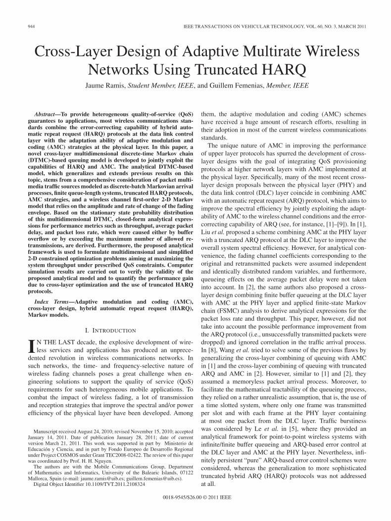
The point-to-point wireless packet communication systemunder consideration is illustrated in Fig. 1, showing the mostimportant blocks involved in the transmission and receptionprocesses. The link is assumed to support QoS-guaranteedtraffic characterized by a maximum average packet delay Dlmax
and a target link layer packet loss rate Plmax . The processingunit at the data link layer is a packet of fixed size equal to Nb
bits, and the processing unit at the physical layer is a framemade of a variable number of packets that depends on the trans-mission mode (TM) selected by the AMC scheme. The AMCscheme is assumed to have a set M = {0, . . . , M − 1} of MTMs, each of which corresponds to a particular combination ofmodulation and coding strategies, including the case in whichthe transmitter does not transmit.
A. Transmitter
At the transmitter side, the HARQ controller manages abuffer (queue) that operates in a first-in–first-out (FIFO) modeand can store up to Q packets. We set the maximum numberof ARQ retransmissions to Nr. Packets will be removed fromthe buffer either after being successfully received by the mobilehost or after Nr + 1 failed attempts.
946 IEEE TRANSACTIONS ON VEHICULAR TECHNOLOGY, VOL. 60, NO. 3, MARCH 2011
Fig. 1. System model.
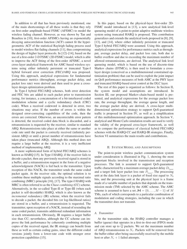
TABLE ITM WITH CONVOLUTIONALLY CODED MODULATION
Without loss of generality, convolutionally codedM-quadrature-amplitude-modulation (M-QAM) schemesadopted from the IEEE 802.16e standard [18] will be usedin the AMC pool. All the considered TMs (except thenon-TM) are listed in Table I. In this case, when using TMn ∈ M, a rate-1/2 convolutional encoder generates a sequenceb = {bl}2Nb
l=1 of encoded bits, and after puncturing, the system
transmits N(n)c = Nb/R
(n)c coded bits per packet, where R
(n)c
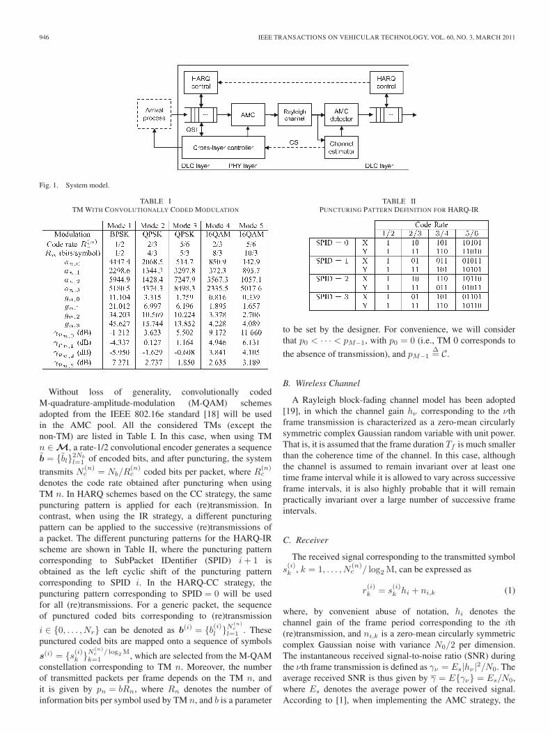
denotes the code rate obtained after puncturing when usingTM n. In HARQ schemes based on the CC strategy, the samepuncturing pattern is applied for each (re)transmission. Incontrast, when using the IR strategy, a different puncturingpattern can be applied to the successive (re)transmissions ofa packet. The different puncturing patterns for the HARQ-IRscheme are shown in Table II, where the puncturing patterncorresponding to SubPacket IDentifier (SPID) i + 1 isobtained as the left cyclic shift of the puncturing patterncorresponding to SPID i. In the HARQ-CC strategy, thepuncturing pattern corresponding to SPID = 0 will be usedfor all (re)transmissions. For a generic packet, the sequenceof punctured coded bits corresponding to (re)transmission
i ∈ {0, . . . , Nr} can be denoted as b(i) = {b(i)l }N
(n)c
l=1 . Thesepunctured coded bits are mapped onto a sequence of symbols
s(i) = {s(i)k }N
(n)c / log2 M
k=1 , which are selected from the M-QAMconstellation corresponding to TM n. Moreover, the numberof transmitted packets per frame depends on the TM n, andit is given by pn = bRn, where Rn denotes the number ofinformation bits per symbol used by TM n, and b is a parameter
TABLE IIPUNCTURING PATTERN DEFINITION FOR HARQ-IR
to be set by the designer. For convenience, we will considerthat p0 < · · · < pM−1, with p0 = 0 (i.e., TM 0 corresponds to
the absence of transmission), and pM−1Δ= C.
B. Wireless Channel
A Rayleigh block-fading channel model has been adopted[19], in which the channel gain hν corresponding to the νthframe transmission is characterized as a zero-mean circularlysymmetric complex Gaussian random variable with unit power.That is, it is assumed that the frame duration Tf is much smallerthan the coherence time of the channel. In this case, althoughthe channel is assumed to remain invariant over at least onetime frame interval while it is allowed to vary across successiveframe intervals, it is also highly probable that it will remainpractically invariant over a large number of successive frameintervals.
C. Receiver
The received signal corresponding to the transmitted symbols(i)k , k = 1, . . . , N
(n)c / log2 M, can be expressed as
r(i)k = s
(i)k hi + ni,k (1)
where, by convenient abuse of notation, hi denotes thechannel gain of the frame period corresponding to the ith(re)transmission, and ni,k is a zero-mean circularly symmetriccomplex Gaussian noise with variance N0/2 per dimension.The instantaneous received signal-to-noise ratio (SNR) duringthe νth frame transmission is defined as γν = Es|hν |2/N0. Theaverage received SNR is thus given by γ = E{γν} = Es/N0,where Es denotes the average power of the received signal.According to [1], when implementing the AMC strategy, the
RAMIS AND FEMENIAS: CROSS-LAYER DESIGN OF MULTIRATE WIRELESS NETWORKS USING TRUNCATED HARQ 947
entire SNR range is partitioned into a set of nonoverlappingintervals defined by the partition
Γm ={[γm
0 , γm1 ) , [γm
1 , γm2 ) , . . . ,
[γm
M−1, γmM
)}(2)
and mode n is selected when γν ∈ [γmn , γm
n+1).1) CC: Assuming perfect channel state information (CSI)
to be available at the receiver side, the HARQ-CC schemecombines multiple received signals according to the MRCprinciple. Thus, assuming without loss of generality that thezeroth puncturing pattern has been used in all (re)transmissions,the combined signal after i (re)transmissions can be ex-pressed as
r(i)k =
i∑j=0
r(j)k h∗
j = s(0)k ρi + υ
(i)k (3)
where ρi =∑i
j=0 |hj |2, and υ(i)k is a zero-mean circularly
symmetric complex Gaussian noise with variance σ2υ,i = ρiN0.
The logarithmic likelihood ratio (LLR) corresponding to bit b(0)l
mapped onto symbol s(0)k on the ith (re)transmission can be
expressed as
λ(i)l = log
Pr{
b(0)l = 1|r(i)
k , ρi
}Pr
{b(0)l = 0|r(i)
k , ρi
}
= log
∑sk∈S
(1)l,i
exp(−∣∣∣r(i)
k − skρi
∣∣∣2 /σ2υ,i
)∑
sk∈S(0)l,i
exp(−∣∣∣r(i)
k − skρi
∣∣∣2 /σ2υ,i
) (4)
where S(0)l,i and S
(1)l,i are, respectively, the sets of sym-
bols sk with the bit indexed by l, corresponding to the ith(re)transmission, equal to 0 or 1. These LLRs are subsequently
depunctured to obtain the sequence λ(i)
= {λ(i)l }2Nb
l=1 that isthen passed to the soft Viterbi decoder.
2) IR: For the IR-HARQ scheme, the LLR corresponding tobit b
(i)l mapped onto symbol s
(i)k on the ith (re)transmission is
given by
λ(i)l = log
Pr{
b(i)l = 1|r(i)
k , hi
}Pr
{b(i)l = 0|r(i)
k , hi
}
= log
∑sk∈S
(1)l,i
exp(−∣∣∣r(i)
k − skhi
∣∣∣2 /N0
)∑
sk∈S(0)l,i
exp(−∣∣∣r(i)
k − skhi
∣∣∣2 /N0
) . (5)
After suitable depuncturing, and assuming an add-LLR soft-output packet combining scheme [20], the sequence of com-bined LLRs is obtained as
λ(i)
=
⎧⎨⎩
i∑j=1
λ(j)l
⎫⎬⎭
2Nb
l=1
(6)
and it is then sent to the soft Viterbi decoder.
Unlike previous work on this topic (see, for instance, [1]–[9]and [12]–[14]), where all the (re)transmissions of a packet in a“pure” ARQ strategy were characterized with the same PacketError Rate (PER), when using more sophisticated HARQprotocols, the PER corresponding to each TM and to eachpossible (re)transmission must be characterized. When usingTM n on the ith (re)transmission and with the assumption of aslow block-fading channel model, the instantaneous PER at theoutput of the soft Viterbi decoder can be approximated as
PERn,i(γ) ≈{
1, 0 ≤ γ <γpn,0i+1
an,0e−gn,0(i+1)γ , γ ≥ γpn,0
i+1
(7)
for the HARQ-CC strategy and
PERn,i(γ) ≈{ 1, 0 ≤ γ < γpn,i
an,ie−gn,iγ , γ ≥ γpn,i
(8)
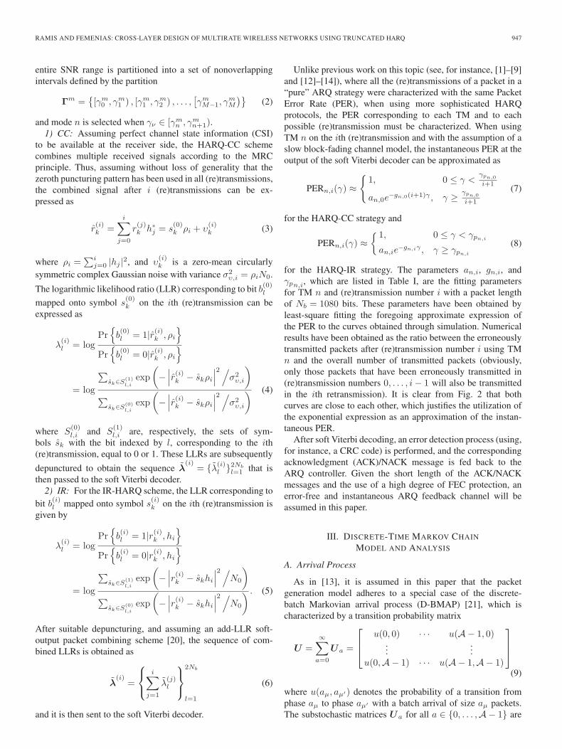
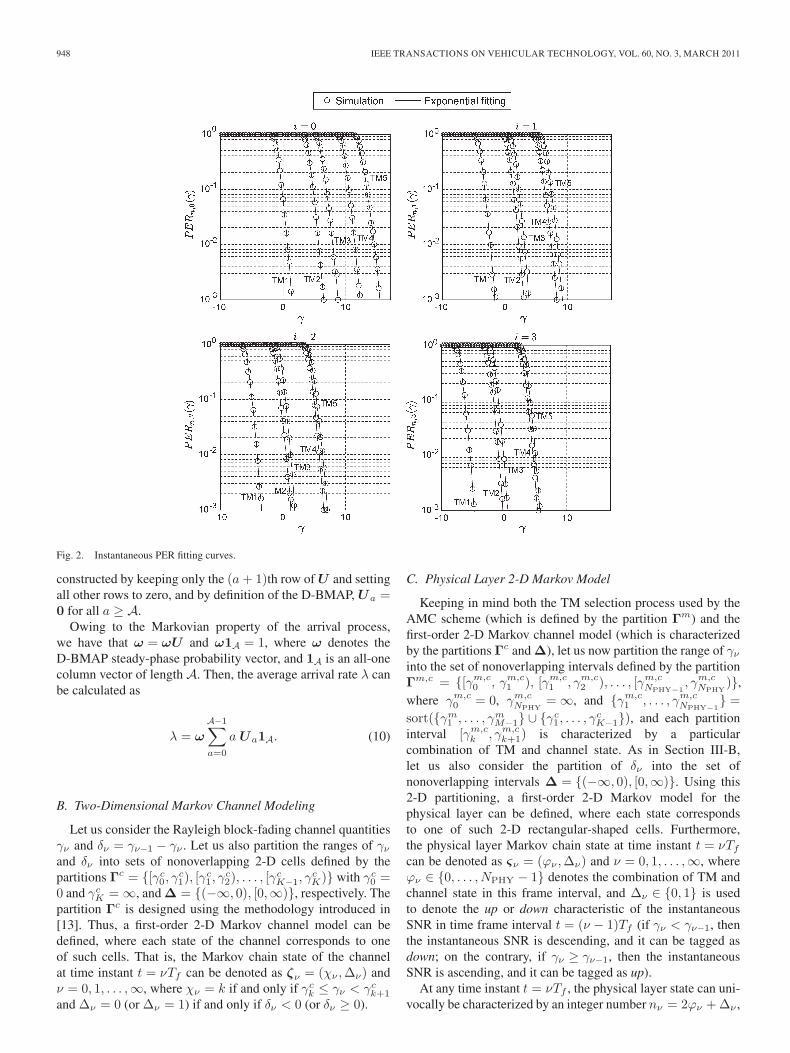
for the HARQ-IR strategy. The parameters an,i, gn,i, andγpn,i, which are listed in Table I, are the fitting parametersfor TM n and (re)transmission number i with a packet lengthof Nb = 1080 bits. These parameters have been obtained byleast-square fitting the foregoing approximate expression ofthe PER to the curves obtained through simulation. Numericalresults have been obtained as the ratio between the erroneouslytransmitted packets after (re)transmission number i using TMn and the overall number of transmitted packets (obviously,only those packets that have been erroneously transmitted in(re)transmission numbers 0, . . . , i − 1 will also be transmittedin the ith retransmission). It is clear from Fig. 2 that bothcurves are close to each other, which justifies the utilization ofthe exponential expression as an approximation of the instan-taneous PER.
After soft Viterbi decoding, an error detection process (using,for instance, a CRC code) is performed, and the correspondingacknowledgment (ACK)/NACK message is fed back to theARQ controller. Given the short length of the ACK/NACKmessages and the use of a high degree of FEC protection, anerror-free and instantaneous ARQ feedback channel will beassumed in this paper.
III. DISCRETE-TIME MARKOV CHAIN
MODEL AND ANALYSIS
A. Arrival Process
As in [13], it is assumed in this paper that the packetgeneration model adheres to a special case of the discrete-batch Markovian arrival process (D-BMAP) [21], which ischaracterized by a transition probability matrix
U =∞∑
a=0
Ua =
⎡⎢⎣
u(0, 0) · · · u(A− 1, 0)...
...u(0,A− 1) · · · u(A− 1,A− 1)
⎤⎥⎦
(9)
where u(aμ, aμ′) denotes the probability of a transition fromphase aμ to phase aμ′ with a batch arrival of size aμ packets.The substochastic matrices Ua for all a ∈ {0, . . . ,A− 1} are
948 IEEE TRANSACTIONS ON VEHICULAR TECHNOLOGY, VOL. 60, NO. 3, MARCH 2011
Fig. 2. Instantaneous PER fitting curves.
constructed by keeping only the (a + 1)th row of U and settingall other rows to zero, and by definition of the D-BMAP, Ua =0 for all a ≥ A.
Owing to the Markovian property of the arrival process,we have that ω = ωU and ω1A = 1, where ω denotes theD-BMAP steady-phase probability vector, and 1A is an all-onecolumn vector of length A. Then, the average arrival rate λ canbe calculated as
λ = ω
A−1∑a=0
a Ua1A. (10)
B. Two-Dimensional Markov Channel Modeling
Let us consider the Rayleigh block-fading channel quantitiesγν and δν = γν−1 − γν . Let us also partition the ranges of γν
and δν into sets of nonoverlapping 2-D cells defined by thepartitions Γc = {[γc
0, γc1), [γ
c1, γ
c2), . . . , [γ
cK−1, γ
cK)} with γc
0 =0 and γc
K = ∞, and Δ = {(−∞, 0), [0,∞)}, respectively. Thepartition Γc is designed using the methodology introduced in[13]. Thus, a first-order 2-D Markov channel model can bedefined, where each state of the channel corresponds to oneof such cells. That is, the Markov chain state of the channelat time instant t = νTf can be denoted as ζν = (χν ,Δν) andν = 0, 1, . . . ,∞, where χν = k if and only if γc
k ≤ γν < γck+1
and Δν = 0 (or Δν = 1) if and only if δν < 0 (or δν ≥ 0).
C. Physical Layer 2-D Markov Model
Keeping in mind both the TM selection process used by theAMC scheme (which is defined by the partition Γm) and thefirst-order 2-D Markov channel model (which is characterizedby the partitions Γc and Δ), let us now partition the range of γν
into the set of nonoverlapping intervals defined by the partitionΓm,c = {[γm,c
0 , γm,c1 ), [γm,c
1 , γm,c2 ), . . . , [γm,c
NPHY−1, γm,c
NPHY)},
where γm,c0 = 0, γm,c
NPHY= ∞, and {γm,c
1 , . . . , γm,cNPHY−1
} =sort({γm
1 , . . . , γmM−1} ∪ {γc
1, . . . , γcK−1}), and each partition
interval [γm,ck , γm,c
k+1) is characterized by a particularcombination of TM and channel state. As in Section III-B,let us also consider the partition of δν into the set ofnonoverlapping intervals Δ = {(−∞, 0), [0,∞)}. Using this2-D partitioning, a first-order 2-D Markov model for thephysical layer can be defined, where each state correspondsto one of such 2-D rectangular-shaped cells. Furthermore,the physical layer Markov chain state at time instant t = νTf
can be denoted as ςν = (ϕν ,Δν) and ν = 0, 1, . . . ,∞, whereϕν ∈ {0, . . . , NPHY − 1} denotes the combination of TM andchannel state in this frame interval, and Δν ∈ {0, 1} is usedto denote the up or down characteristic of the instantaneousSNR in time frame interval t = (ν − 1)Tf (if γν < γν−1, thenthe instantaneous SNR is descending, and it can be tagged asdown; on the contrary, if γν ≥ γν−1, then the instantaneousSNR is ascending, and it can be tagged as up).
At any time instant t = νTf , the physical layer state can uni-vocally be characterized by an integer number nν = 2ϕν + Δν ,
RAMIS AND FEMENIAS: CROSS-LAYER DESIGN OF MULTIRATE WIRELESS NETWORKS USING TRUNCATED HARQ 949
and obviously, nν ∈ {0, . . . , 2NPHY − 1}. The physical layerwill be in a state n ∈ {0, . . . , 2NPHY − 1} with a steady-state probability PPHY(n) that can be calculated using[13, eqs. (8)–9)], and each of these states will be character-ized by a conditional average packet error rate for the ith(re)transmission given by
PERPHYn,i
=
⎧⎪⎪⎪⎪⎨⎪⎪⎪⎪⎩
∫ γm,c
n/2+1
γm,c
n/2
∫ x
0PERβn,i|i−1(x)pγν ,γν−1(x,y)dydx
PPHY(n), n even∫ γ
m,c
(n+1)/2
γm,c
(n−1)/2
∫ +∞
xPERβn,i|i−1(x)pγν ,γν−1(x,y)dydx
PPHY(n), n odd
(11)
where βn denotes the TM corresponding to the nth physicallayer state, pγν ,γν−1(x, y) is the joint probability density func-tion of the random variables γν and γν−1, and PERn,i|i−1(·)represents the probability that the ith (re)transmission attemptfails conditioned on that the previous transmissions have beenerroneous, that is
PERn,i|i−1(γ) =PERn,i(γ)
PERn,i−1(γ). (12)
Furthermore, the physical layer FSMC will be characterized bya transition probability matrix
P s = [Ps(nμ, nμ′)]2NPHY−1nμ,nμ′=0 (13)
whose elements can be calculated using [13, eqs. (11)–(15)]. Inthis paper, the steady-state probabilities, the conditional averagepacket error rates, and the state-transition probabilities have allbeen computed either numerically or by simulation. Clarke’sstatistical Rayleigh fading process, which is characterized by amaximum normalized Doppler frequency fdTf , has been usedto model the wireless flat-fading channel [11].
D. Embedded Markov Chain
The queueing process induced by both the truncated HARQprotocol and the AMC scheme can be formulated in discretetime with one time unit equal to one frame interval. Thesystem states are observed at the beginning of each time unit.Let σν = (qν , aν , nν) denote the system state at time instantt = νTf , where qν = (qν,0, . . . , qν,Nr
) is the queue state atthis time instant, with qν,i denoting the number of packetsin the queue that have already been transmitted i times, and
QνΔ=∑Nr
i=0 qν,i ∈ {0, . . . , Q} denoting the total number ofpackets in the queue, aν ∈ {0, . . . ,A− 1} represents the phaseof the D-BMAP, and nν ∈ {0, . . . , 2NPHY − 1} represents thephysical layer state. If we just look at the set of time instantst = νTf , ν = 0, 1, . . . ,∞, then the transitions between statesare Markovian. Therefore, an embedded Markov chain can beused to describe the underlying queueing process. The statespace of this embedded FSMC is S = {Sn}Ns
n=1 with size Ns =2NPHYA
∑Qk=0
(k+Nr
k
).
The transition probability from state Sμ = (qμ, aμ, nμ) ∈ Sto state Sμ′ = (qμ′ , aμ′ , nμ′) ∈ S can be written as
PSμ,Sμ′ = u(aμ, aμ′)Ps(nμ, nμ′)Pqμ,qμ′ |aμ,nμ(14)
where u(aμ, aμ′) denotes the transition probability betweenD-BMAP phases aμ and aμ′ , which can be obtained from ma-trix U , Ps(nμ, nμ′) is the physical layer transition probabilitybetween states nμ and nμ′ , which can be derived from matrixP s, and Pqμ,qμ′ |aμ,nμ
=∏Nr
i=0 Pqμ,i,qμ′,i|aμ,nμcorresponds to
the queue transition probability from state qμ to state qμ′ whenD-BMAP is in phase aμ and the physical layer state is nμ.
Let us consider that the system state is Sμ and that Qμ,i =∑Nr
l=i qμ,l represents the number of packets in the queue thathave already been transmitted i or more times (obviously,Qμ,0 = Qμ). Additionally, let τμ = min{Qμ, cnμ
} denote thenumber of transmitted packets, τμ,i = min{qμ,i, τμ − Qμ,i+1}the number of transmitted packets among those in the queuethat have been already transmitted i times, and εμ,i the numberof packets erroneously transmitted among those in the queuethat have been already transmitted i times. Using this notation,the feasible queue transitions can be expressed as
qμ′,Nr={
qμ,Nr− τμ, τμ ≤ qμ,Nr
εμ,Nr−1, τμ > qμ,Nr
(15)
qμ′,i =
⎧⎨⎩
qμ,i, τμ ≤ Qμ,i+1
Qμ,i − τμ, Qμ,i+1 < τμ ≤ Qμ,i
εμ,i−1, τμ > Qμ,i
(16)
for i ∈ {1, . . . , Nr − 1}, and
qμ′,0
={
min{Q−Qμ′,1, qμ,0 + aμ}, τμ≤Qμ,1
min{Q−Qμ′,1, Qμ+aμ − τμ}, Qμ,1 <τμ≤Qμ.(17)
Consequently, by defining Pxy (z) Δ=
(xy
)zy(1 − z)x−y and as-
suming a slow block-fading channel, the state transition proba-bilities can safely be approximated as
Pqμ,Nr ,qμ′,Nr|aμ,nμ
=
⎧⎪⎪⎪⎪⎨⎪⎪⎪⎪⎩
1,qμ′,Nr
= qμ,Nr− τμ
τμ ≤ qμ,Nr
Pτμ,Nr−1qμ′,Nr
(PER
PHYnμ,Nr−1
),
τμ > qμ,Nr
τμ,Nr−1 ≥ qμ′,Nr
0, otherwise(18)
Pqμ,i,qμ′,i|aμ,nμ
=
⎧⎪⎪⎪⎪⎪⎪⎪⎪⎨⎪⎪⎪⎪⎪⎪⎪⎪⎩
1,qμ,i = qμ′,i
τμ ≤ Qμ,i+1
1,Qμ,i+1 < τμ ≤ Qμ,i
qμ′,i = Qμ,i − τμ
Pτμ,i−1qμ′,i
(PER
PHYnμ,i−1
),
τμ > Qμ,i
τμ,i−1 ≥ qμ′,i
0, otherwise(19)
950 IEEE TRANSACTIONS ON VEHICULAR TECHNOLOGY, VOL. 60, NO. 3, MARCH 2011
for i ∈ {1, . . . , Nr − 1}, and
Pqμ,0,qμ′,0|aμ,nμ
=
⎧⎪⎪⎪⎨⎪⎪⎪⎩
1,τμ ≤ Qμ,1
qμ′,0 = min{Q − Qμ′,1, qμ,0 + aμ
}1,
Qμ,1 < τμ ≤ Qμ
qμ′,0 = min{Q − Qμ′,1, Qμ + aμ − τμ}0, otherwise.
(20)
To derive the system performance measures, we need toobtain the steady-state probability vector, which can be calcu-lated using the fact that the transition probability matrix P andthe steady-state probability vector π = [πS1 · · ·πSNs
] satisfyπP = π along with the normalization condition π1Ns
= 1.The complexity involved in calculating the steady-state prob-abilities exponentially increases with the number of phases inthe arrival process, the number of states in the physical layerMarkov model, and the number of queue states in the system.Consequently, for large buffer sizes, efficient strategies shouldbe devised to tackle this problem. This is an issue that has beenleft for further research.
E. Packet Loss Rate and Throughput
The number of lost packets due to buffer overflow when thesystem changes from state Sμ to state Sμ′ is given by
NlBO |Sμ,Sμ′
={
max{0, Qμ′,1+qμ,0+aμ−Q}, τμ≤Qμ,1
max{0, Qμ′,1+Qμ−τμ+aμ−Q}, τμ >Qμ,1.(21)
Therefore, the average number of lost packets due to bufferoverflow can be calculated as
NlBO=
Ns∑μ=1
Ns∑μ′=1
πSμPSμ,Sμ′ NlBO |Sμ,Sμ′ (22)
and the packet loss rate PlBO(measured in packets per frame)
can then be obtained as
PlBO= NlBO
/λ. (23)
The number of lost packets due to exceeding the maximumnumber of allowed retransmissions when the system state is Sμ
can be calculated as
NlARQ|Sμ=
τμ,Nr∑l=0
l Pτμ,Nr
l
(PER
PHYnμ,Nr
)(24)
with τμ,Nr= min{qμ,Nr
, cn}, and the corresponding averagenumber of lost packets can be obtained as
NlARQ =Ns∑
μ=1
πSμNlARQ|Sμ
. (25)
Accordingly, the probability of packet loss due to exceeding Nr
retransmissions can be expressed as
PlARQ = NlARQ/λ. (26)
In our finite buffering truncated ARQ-based error controlsystem, the packet loss rate Pl (measured in packets per frame)can be expressed as Pl = PlBO + PlARQ , and given the packetloss rate Pl, the average throughput can be calculated as
η = λ(1 − Pl). (27)
F. Average Queue Length and Average Packet Delay
Using the well-known Little’s formula [22], and taking intoconsideration that the effective packet arrival rate is equalto λ(1 − PlBO), the average delay for our embedded Markovchain can be calculated as
Dp = Lq/λ(1 − PlBO) (28)
where Lq denotes the average number of packets in the queuethat is given by
Lq =Ns∑
μ=1
πSμQμ. (29)
IV. CROSS-LAYER OPTIMIZATION
A. Multidimensional Approach
As shown in the previous sections, given a maximum af-forded queue length Q, an average SNR γ, and a normalizedmaximum Doppler frequency fdTf , the performance measuresof the system, like, for instance, throughput, average packetdelay, or packet loss rate, are a function of the AMC TMswitching levels Γm ∈ R
M+1+ , where R+ denotes the set of
nonnegative real numbers, and the measured or estimated ar-rival packet rate λ ∈ Θ, where Θ is the range of feasible arrivalrate values. Therefore, if the objective of the link adaptationscheme is to maximize the average throughput when supportingQoS-guaranteed traffic characterized by a maximum packetloss rate Plmax and a maximum average packet delay Dlmax ,then the system needs to jointly optimize the selected protocolparameters at the physical and DLC layers by solving the cross-layer optimization problem as(
Γmopt, λopt
)= arg max
Γm∈RM+1+ ,λ∈Θ
η(Γm, λ) (30)
subject to the constraints
Pl
(Γm
opt, λopt
)≤ Plmax , Dl
(Γm
opt, λopt
)≤ Dlmax . (31)
The analytical expressions for η, Pl, and Dl do not leavemuch room for developing efficient algorithms in solving ourconstrained optimization problem. However, considering thatΓm and λ lie in a bounded space R
M+1+ × Θ, we could resort
to a multidimensional exhaustive search to numerically solvethe proposed cross-layer optimization problem.
B. Bidimensional Simplification Approach
To simplify this multidimensional optimization approach, letus define the AMC switching thresholds as the instantaneous
RAMIS AND FEMENIAS: CROSS-LAYER DESIGN OF MULTIRATE WIRELESS NETWORKS USING TRUNCATED HARQ 951
SNR values for which the value of PERn,Nr= P0, that is
γmn =
⎧⎨⎩
1(Nr+1)gn,0
ln(
an,0P0
), (CC)
1gn,Nr
ln(
an,Nr
P0
), (IR)
(32)
for n = 1, . . . ,M − 1, with γm0 = 0, and γm
M = ∞. In thiscase, the simplified constrained optimization problem can beformulated as
(P0opt , λopt) = arg maxP0∈R+,λ∈Θ
η(P0, λ) (33)
subject to the constraints
Pl(P0opt , λopt) ≤ Plmax , Dl(P0opt , λopt) ≤ Dlmax . (34)
Obviously, because P0 and λ lie in a bounded space R+ × Θ,we can resort to a 2-D exhaustive search to numerically solvethe proposed cross-layer optimization problem. The bidimen-sional optimization approach has fewer degrees of freedom thanthe multidimensional strategy, resulting in a simpler scheme atthe cost of a reduction in performance, as will be illustratedin the following section.
V. NUMERICAL RESULTS
To verify the validity of the proposed cross-layer framework,analytical results obtained with the 2D-FSMC model will beconfronted with computer simulation results obtained usingClarke’s statistical Rayleigh model. Unless otherwise specified,numerical results will be obtained using the following defaultparameters: a normalized maximum Doppler frequency fdTf =0.02, an average received SNR γ = 8 dB, a buffer size Q = 8,a number of channel states K = 5, a parameter b = 6, anda D-BMAP either characterized by the transition probabilitymatrix
U =
⎡⎢⎣
0.8 0.1 0.05 0.050.05 0.8 0.1 0.050.05 0.05 0.8 0.10.05 0.05 0.1 0.8
⎤⎥⎦
or parameterized to obtain a truncated Poisson process with anaverage arrival rate λ.
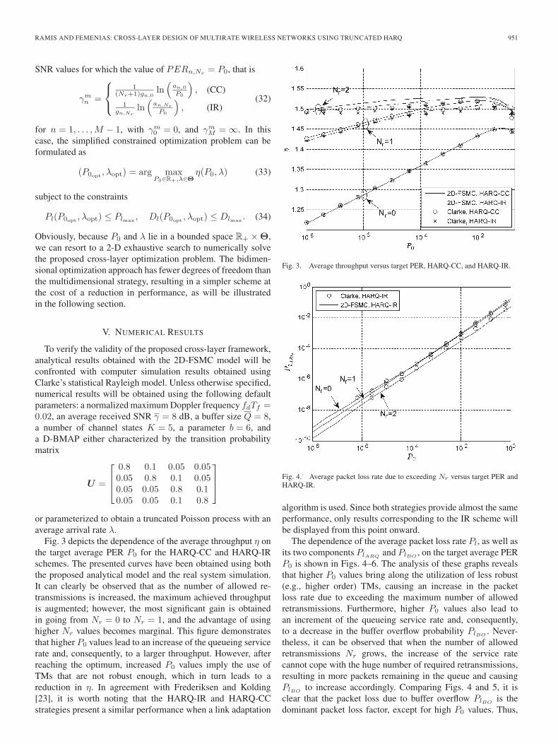
Fig. 3 depicts the dependence of the average throughput η onthe target average PER P0 for the HARQ-CC and HARQ-IRschemes. The presented curves have been obtained using boththe proposed analytical model and the real system simulation.It can clearly be observed that as the number of allowed re-transmissions is increased, the maximum achieved throughputis augmented; however, the most significant gain is obtainedin going from Nr = 0 to Nr = 1, and the advantage of usinghigher Nr values becomes marginal. This figure demonstratesthat higher P0 values lead to an increase of the queueing servicerate and, consequently, to a larger throughput. However, afterreaching the optimum, increased P0 values imply the use ofTMs that are not robust enough, which in turn leads to areduction in η. In agreement with Frederiksen and Kolding[23], it is worth noting that the HARQ-IR and HARQ-CCstrategies present a similar performance when a link adaptation
Fig. 3. Average throughput versus target PER, HARQ-CC, and HARQ-IR.
Fig. 4. Average packet loss rate due to exceeding Nr versus target PER andHARQ-IR.
algorithm is used. Since both strategies provide almost the sameperformance, only results corresponding to the IR scheme willbe displayed from this point onward.
The dependence of the average packet loss rate Pl, as well asits two components PlARQ
and PlBO, on the target average PER
P0 is shown in Figs. 4–6. The analysis of these graphs revealsthat higher P0 values bring along the utilization of less robust(e.g., higher order) TMs, causing an increase in the packetloss rate due to exceeding the maximum number of allowedretransmissions. Furthermore, higher P0 values also lead toan increment of the queueing service rate and, consequently,to a decrease in the buffer overflow probability PlBO
. Never-theless, it can be observed that when the number of allowedretransmissions Nr grows, the increase of the service ratecannot cope with the huge number of required retransmissions,resulting in more packets remaining in the queue and causingPlBO
to increase accordingly. Comparing Figs. 4 and 5, it isclear that the packet loss due to buffer overflow PlBO
is thedominant packet loss factor, except for high P0 values. Thus,
952 IEEE TRANSACTIONS ON VEHICULAR TECHNOLOGY, VOL. 60, NO. 3, MARCH 2011
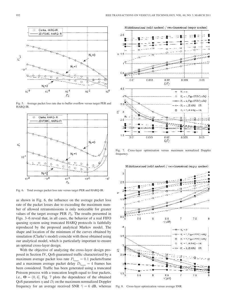
Fig. 5. Average packet loss rate due to buffer overflow versus target PER andHARQ-IR.
Fig. 6. Total average packet loss rate versus target PER and HARQ-IR.
as shown in Fig. 6, the influence on the average packet lossrate of the packet losses due to exceeding the maximum num-ber of allowed retransmissions is only noticeable for greatervalues of the target average PER P0. The results presented inFigs. 3–6 reveal that, in all cases, the behavior of a real FIFOqueuing system using truncated HARQ protocols is faithfullyreproduced by the proposed analytical Markov model. Theshape and location of the minimum of the curves obtained bysimulation (Clarke’s model) coincide with those obtained usingour analytical model, which is particularly important to ensurean optimal cross-layer design.
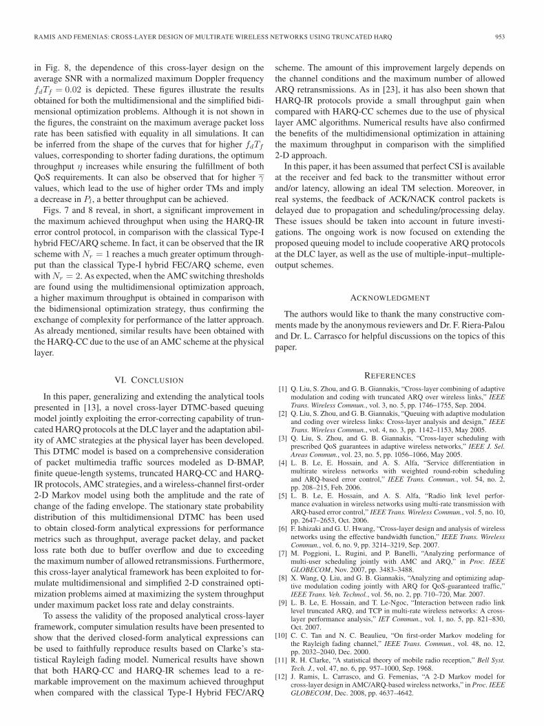
With the objective of analyzing the cross-layer design pro-posed in Section IV, QoS-guaranteed traffic characterized by amaximum average packet loss rate Plmax = 0.1 packets/frameand a maximum average packet delay Dlmax = 4 frames hasbeen considered. Traffic has been generated using a truncatedPoisson process with a truncation length equal to four packets,i.e., Θ = (0, 4]. Fig. 7 plots the dependence of the obtainedQoS parameters η and Dl on the maximum normalized Dopplerfrequency for an average received SNR γ = 6 dB, whereas
Fig. 7. Cross-layer optimization versus maximum normalized Dopplerfrequency.
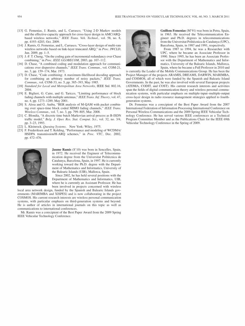
Fig. 8. Cross-layer optimization versus average SNR.
RAMIS AND FEMENIAS: CROSS-LAYER DESIGN OF MULTIRATE WIRELESS NETWORKS USING TRUNCATED HARQ 953
in Fig. 8, the dependence of this cross-layer design on theaverage SNR with a normalized maximum Doppler frequencyfdTf = 0.02 is depicted. These figures illustrate the resultsobtained for both the multidimensional and the simplified bidi-mensional optimization problems. Although it is not shown inthe figures, the constraint on the maximum average packet lossrate has been satisfied with equality in all simulations. It canbe inferred from the shape of the curves that for higher fdTf
values, corresponding to shorter fading durations, the optimumthroughput η increases while ensuring the fulfillment of bothQoS requirements. It can also be observed that for higher γvalues, which lead to the use of higher order TMs and implya decrease in Pl, a better throughput can be achieved.
Figs. 7 and 8 reveal, in short, a significant improvement inthe maximum achieved throughput when using the HARQ-IRerror control protocol, in comparison with the classical Type-Ihybrid FEC/ARQ scheme. In fact, it can be observed that the IRscheme with Nr = 1 reaches a much greater optimum through-put than the classical Type-I hybrid FEC/ARQ scheme, evenwith Nr = 2. As expected, when the AMC switching thresholdsare found using the multidimensional optimization approach,a higher maximum throughput is obtained in comparison withthe bidimensional optimization strategy, thus confirming theexchange of complexity for performance of the latter approach.As already mentioned, similar results have been obtained withthe HARQ-CC due to the use of an AMC scheme at the physicallayer.
VI. CONCLUSION
In this paper, generalizing and extending the analytical toolspresented in [13], a novel cross-layer DTMC-based queuingmodel jointly exploiting the error-correcting capability of trun-cated HARQ protocols at the DLC layer and the adaptation abil-ity of AMC strategies at the physical layer has been developed.This DTMC model is based on a comprehensive considerationof packet multimedia traffic sources modeled as D-BMAP,finite queue-length systems, truncated HARQ-CC and HARQ-IR protocols, AMC strategies, and a wireless-channel first-order2-D Markov model using both the amplitude and the rate ofchange of the fading envelope. The stationary state probabilitydistribution of this multidimensional DTMC has been usedto obtain closed-form analytical expressions for performancemetrics such as throughput, average packet delay, and packetloss rate both due to buffer overflow and due to exceedingthe maximum number of allowed retransmissions. Furthermore,this cross-layer analytical framework has been exploited to for-mulate multidimensional and simplified 2-D constrained opti-mization problems aimed at maximizing the system throughputunder maximum packet loss rate and delay constraints.
To assess the validity of the proposed analytical cross-layerframework, computer simulation results have been presented toshow that the derived closed-form analytical expressions canbe used to faithfully reproduce results based on Clarke’s sta-tistical Rayleigh fading model. Numerical results have shownthat both HARQ-CC and HARQ-IR schemes lead to a re-markable improvement on the maximum achieved throughputwhen compared with the classical Type-I Hybrid FEC/ARQ
scheme. The amount of this improvement largely depends onthe channel conditions and the maximum number of allowedARQ retransmissions. As in [23], it has also been shown thatHARQ-IR protocols provide a small throughput gain whencompared with HARQ-CC schemes due to the use of physicallayer AMC algorithms. Numerical results have also confirmedthe benefits of the multidimensional optimization in attainingthe maximum throughput in comparison with the simplified2-D approach.
In this paper, it has been assumed that perfect CSI is availableat the receiver and fed back to the transmitter without errorand/or latency, allowing an ideal TM selection. Moreover, inreal systems, the feedback of ACK/NACK control packets isdelayed due to propagation and scheduling/processing delay.These issues should be taken into account in future investi-gations. The ongoing work is now focused on extending theproposed queuing model to include cooperative ARQ protocolsat the DLC layer, as well as the use of multiple-input–multiple-output schemes.
ACKNOWLEDGMENT
The authors would like to thank the many constructive com-ments made by the anonymous reviewers and Dr. F. Riera-Palouand Dr. L. Carrasco for helpful discussions on the topics of thispaper.
REFERENCES
[1] Q. Liu, S. Zhou, and G. B. Giannakis, “Cross-layer combining of adaptivemodulation and coding with truncated ARQ over wireless links,” IEEETrans. Wireless Commun., vol. 3, no. 5, pp. 1746–1755, Sep. 2004.
[2] Q. Liu, S. Zhou, and G. B. Giannakis, “Queuing with adaptive modulationand coding over wireless links: Cross-layer analysis and design,” IEEETrans. Wireless Commun., vol. 4, no. 3, pp. 1142–1153, May 2005.
[3] Q. Liu, S. Zhou, and G. B. Giannakis, “Cross-layer scheduling withprescribed QoS guarantees in adaptive wireless networks,” IEEE J. Sel.Areas Commun., vol. 23, no. 5, pp. 1056–1066, May 2005.
[4] L. B. Le, E. Hossain, and A. S. Alfa, “Service differentiation inmultirate wireless networks with weighted round-robin schedulingand ARQ-based error control,” IEEE Trans. Commun., vol. 54, no. 2,pp. 208–215, Feb. 2006.
[5] L. B. Le, E. Hossain, and A. S. Alfa, “Radio link level perfor-mance evaluation in wireless networks using multi-rate transmission withARQ-based error control,” IEEE Trans. Wireless Commun., vol. 5, no. 10,pp. 2647–2653, Oct. 2006.
[6] F. Ishizaki and G. U. Hwang, “Cross-layer design and analysis of wirelessnetworks using the effective bandwidth function,” IEEE Trans. WirelessCommun., vol. 6, no. 9, pp. 3214–3219, Sep. 2007.
[7] M. Poggioni, L. Rugini, and P. Banelli, “Analyzing performance ofmulti-user scheduling jointly with AMC and ARQ,” in Proc. IEEEGLOBECOM, Nov. 2007, pp. 3483–3488.
[8] X. Wang, Q. Liu, and G. B. Giannakis, “Analyzing and optimizing adap-tive modulation coding jointly with ARQ for QoS-guaranteed traffic,”IEEE Trans. Veh. Technol., vol. 56, no. 2, pp. 710–720, Mar. 2007.
[9] L. B. Le, E. Hossain, and T. Le-Ngoc, “Interaction between radio linklevel truncated ARQ, and TCP in multi-rate wireless networks: A cross-layer performance analysis,” IET Commun., vol. 1, no. 5, pp. 821–830,Oct. 2007.
[10] C. C. Tan and N. C. Beaulieu, “On first-order Markov modeling forthe Rayleigh fading channel,” IEEE Trans. Commun., vol. 48, no. 12,pp. 2032–2040, Dec. 2000.
[11] R. H. Clarke, “A statistical theory of mobile radio reception,” Bell Syst.Tech. J., vol. 47, no. 6, pp. 957–1000, Sep. 1968.
[12] J. Ramis, L. Carrasco, and G. Femenias, “A 2-D Markov model forcross-layer design in AMC/ARQ-based wireless networks,” in Proc. IEEEGLOBECOM, Dec. 2008, pp. 4637–4642.
954 IEEE TRANSACTIONS ON VEHICULAR TECHNOLOGY, VOL. 60, NO. 3, MARCH 2011
[13] G. Femenias, J. Ramis, and L. Carrasco, “Using 2-D Markov modelsand the effective-capacity approach for cross-layer design in AMC/ARQ-based wireless networks,” IEEE Trans. Veh. Technol., vol. 58, no. 8,pp. 4193–4203, Oct. 2009.
[14] J. Ramis, G. Femenias, and L. Carrasco, “Cross-layer design of multi-ratewireless networks based on link-layer truncated ARQ,” in Proc. IWCLD,Jun. 2009, pp. 1–5.
[15] J.-F. T. Cheng, “On the coding gain of incremental redundancy over Chasecombining,” in Proc. IEEE GLOBECOM, 2003, pp. 107–112.
[16] D. Chase, “A combined coding and modulation approach for communi-cations over dispersive channels,” IEEE Trans. Commun., vol. COM-21,no. 3, pp. 159–174, Mar. 1973.
[17] D. Chase, “Code combining: A maximum-likelihood decoding approachfor combining an arbitrary number of noisy packets,” IEEE Trans.Commun., vol. COM-33, no. 5, pp. 385–393, May 1985.
[18] Standard for Local and Metropolitan Area Networks, IEEE Std. 802.16,2004.
[19] E. Biglieri, G. Caire, and G. Taricco, “Limiting performance of blockfading channels with multiple antennas,” IEEE Trans. Inf. Theory, vol. 47,no. 4, pp. 1273–1289, May 2001.
[20] S. Aïssa and G. Aniba, “BER analysis of M-QAM with packet combin-ing over space-time block coded MIMO fading channels,” IEEE Trans.Wireless Commun., vol. 7, no. 3, pp. 799–805, Mar. 2008.
[21] C. Blondia, “A discrete time batch Markovian arrival process as B-ISDNtraffic model,” Belg. J. Oper. Res. Stat. Comput. Sci., vol. 32, no. 3/4,pp. 3–23, 1993.
[22] L. Kleinrock, Queuing Systems. New York: Wiley, 1975.[23] F. Frederiksen and T. Kolding, “Performance and modeling of WCDMA/
HSDPA transmission/H-ARQ schemes,” in Proc. VTC, Dec. 2002,pp. 472–476.
Jaume Ramis (S’10) was born in Sencelles, Spain,in 1972. He received the Engineer of Telecommu-nication degree from the Universitat Politècnica deCatalunya, Barcelona, Spain, in 1997. He is currentlyworking toward the Ph.D. degree with the Depart-ment of Mathematics and Informatics, University ofthe Balearic Islands (UIB), Mallorca, Spain.
Since 2002, he has held several positions with theDepartment of Mathematics and Informatics, UIB,where he is currently an Assistant Professor. He hasbeen involved in projects concerned with wireless
local area network design, funded by the Spanish and Balearic Islands gov-ernments (MARIMBA and XISPES) and is now collaborating in the projectCOSMOS. His current research interests are wireless personal communicationsystems, with particular emphasis on third-generation systems and beyond.He is author of articles in international journals on this topic as well ascommunications to international conferences.
Mr. Ramis was a corecipient of the Best Paper Award from the 2009 SpringIEEE Vehicular Technology Conference.
Guillem Femenias (M’91) was born in Petra, Spain,in 1963. He received the Telecommunication En-gineer and Ph.D. degrees in telecommunicationsfrom the Universitat Politècnica de Catalunya (UPC),Barcelona, Spain, in 1987 and 1991, respectively.
From 1987 to 1994, he was a Researcher withUPC, where he became an Associate Professor in1990. Since 1995, he has been an Associate Profes-sor with the Department of Mathematics and Infor-matics, University of the Balearic Islands, Mallorca,Spain, where he became a Full Professor in 2010 and
is currently the Leader of the Mobile Communications Group. He has been theProject Manager of the projects ARAMIS, DREAMS, DARWIN, MARIMBA,and COSMOS, all of which were funded by the Spanish and Balearic IslandGovernments. In the past, he was also involved with several European projects(ATDMA, CODIT, and COST). His current research interests and activitiesspan the fields of digital communication theory and wireless personal commu-nication systems, with particular emphasis on multiple-input–multiple-outputcross-layer design in radio resource management strategies applied to fourth-generation systems.
Dr. Femenias was a corecipient of the Best Paper Award from the 2007International Federation of Information Processing International Conference onPersonal Wireless Communications and the 2009 Spring IEEE Vehicular Tech-nology Conference. He has served various IEEE conferences as a TechnicalProgram Committee Member and as the Publications Chair for the IEEE 69thVehicular Technology Conference in the Spring of 2009.