creating principal 3d curves with digital tape drawing
TRANSCRIPT

Creating Principal 3D Curves with Digital Tape Drawing
Tovi Grossman1,2, Ravin Balakrishnan2,1, Gordon Kurtenbach1,2, George Fitzmaurice1,2, Azam Khan1, Bill Buxton1,2
1Alias|wavefront 210 King Street East
Toronto, Ontario Canada M5A 1J7
2Department of Computer Science University of Toronto
Toronto, Ontario Canada M5S 3G4
ABSTRACT Previous systems have explored the challenges of designing an interface for automotive styling which combine the metaphor of 2D drawing using physical tape with the simultaneous creation and management of a corresponding virtual 3D model. These systems have been limited to only 2D planar curves while typically the principal characteristic curves of an automotive design are three dimensional and non-planar. We present a system which addresses this limitation. Our system allows a designer to construct these non-planar 3D curves by drawing a series of 2D curves using the 2D tape drawing technique and interaction style. These results are generally applicable to the interface design of 3D modeling applications and also to the design of arm’s length interaction on large scale display systems.
Keywords: Tape drawing, large scale displays, 3D modeling, two-handed interaction, interaction techniques
INTRODUCTION In the automobile industry, designers create initial drawings of car body stylings on large scale upright surfaces that maintain scale correspondence to the intended real full-size car. These full scale drawings are created to allow designers and managers to evaluate the principal curves – the few essential curves that define the characteristic shape and styling – of a car design. Thus, it is absolutely essential to evaluate these principal curves without introducing scale artifacts that may occur should the work be done in reduced scale or on a conventional desktop sized display. Traditionally, these drawings have been created not by using pencil and paint, but with a technique called “tape drawing” where black photographic tape is laid onto the drawing surface. Given the large scale size of the drawings, tape drawing has several fundamental advantages over freeform sketching, including the ability to create smooth continuous curves without other physical aids like french curves.
In earlier work [1], we analyzed the tape drawing process and found that while these taped sketches were of high resolution and fidelity, this was difficult to retain when the
drawings were transferred from the physical media to electronic formats for use with the rest of the design process which is largely computerized. We developed a digital 2D tape drawing system [1], which retained much of the fluidity and affordances of the physical technique, while providing the advantages inherent in using electronic media such as storage, retrieval, lossless transfer, and integration with other digital tools.
While tape artists at various auto design studios who tried the system responded positively, they requested additional functionality that would eliminate the need to interpret and merge several 2D tape drawings of different views of a car to form the principal curves of a 3D car model [1]. In response to these requests, we extended the original system to allow for directly creating a 3D model via a series of 2D tape drawings on planar cross-sections of a 3D working volume [6]. While this work allowed us to explore the challenges of combining 2D tape drawing with the simultaneous creation and management of a 3D model, the system was fundamentally limited in that the 3D model was made up of 2D planar curves. Real car models require non-planar 3D curves in order to fully define their primary shape.
In this paper, we extend the previous work into a system whose high-level goal is the creation of the largely non-planar 3D primary curves of a real car design using digital tape drawing. In effect, we now have the capability to completely eliminate the traditionally separate steps of interpreting and combining various 2D tape drawings to form a 3D car model. We also present results of a study observing users performing a representative task of creating the primary curves of a car using the system (Figure 1).
Figure 1. 3D digital tape drawing system.
Permission to make digital or hard copies of all or part of this work for personal or classroom use is granted without fee provided that copies are not made or distributed for profit or commercial advantage and that copies bear this notice and the full citation on the first page. To copy otherwise, or republish, to post on servers or to redistribute to lists, requires prior specific permission and/or a fee. CHI 2002, April 20-25, 2002, Minneapolis, Minnesota, USA. Copyright 2002 ACM 1-58113-453-3/02/0004…$5.00.
minneapolis, minnesota, usa • 20-25 april 2002 Paper: Two-Handed Interaction
Volume No. 4, Issue No. 1 121

SYSTEM HARDWARE Display As in the two previous systems [1, 6], our implementation uses a Hughes/JVC G1000 digital projector with a true 1280x1024 image back projected onto a collapsible and portable 8x6ft screen. While the portability of this 8x6 ft screen allows us to easily take the system to various studios for demonstration purposes, it only allows for midsize cars to be displayed at about half scale. As such, in addition to this default display configuration, we have also explored using a 16x6 ft screen with imagery created by tiling two projectors. This size allows for a 1-1 scale display of a midsize car, which is representative of the scale at which traditional tape drawings are created.
Input Devices Since our system utilizes two-handed interaction techniques, we need to be able to sense the position of both hands on the display surface. There are potentially several solutions to this sensing problem. These include optical tracking techniques [5], the use of a transparent digitizing tablet on the display surface, and electromagnetic or ultrasonic trackers. The previous system used limited range magnetic trackers that were sufficient for the 8x6 ft screen, however, to accommodate our larger screen we now use extended range Ascension Bird trackers held in each hand.
INTERACTION TECHNIQUES Before delving into the details of our current system which supports true 3D curve creation, we review the core characteristics of the previous system [6] upon which the present system is built. These characteristics are: • We retain the interaction style of the traditional tape
drawing technique for creating curves. This allows for smoothly varying, continuous 2D curves to be created easily at this scale, and within a single tool [1].
• The 2D tape drawings can only be performed from the three canonical orthogonal viewpoints – side, top, and front. However, rather than creating these in separate 2D views as is traditionally done, the 2D drawing planes are spatially integrated into a 3D working volume (see Figure 2). This provides the user with information on the correspondence between different viewpoints within a single integrated display.
• The drawing depth within this integrated view can be dynamically changed. Effectively, we draw on the sides of a cube, but since we can vary the depth of these drawing planes, the 2D curves are thus created within the 3D volume. This results in a 3D model, albeit one made up only of planar 2D curves.
Figure 2. (a) Separate orthographic views (b) Views integrated into cubic volume.
• We only have one view of the model at a time. This maximizes the amount of screen real estate available for viewing the model, and doesn’t divide attention between separate views.
• Smooth animated transitions when moving between perspective and orthographic viewpoints of the 3D model allow for the user to visually retain and understand the relationship between these views.
• Conventional user interface widgets such as menu bars at the edges of the screen are largely untenable when working close-up on large displays. As a result all our interface widgets either appear on parts of the model itself, or can be popped up where the user’s hands are. We support fast popup menu and command access using Marking Menus [10].
These basic concepts as demonstrated in the previous system were sufficient to allow the authors to explore how the 2D tape drawing technique could be extended to create simple 3D models. However, it was fundamentally limited in that it could only create 2D planar curves. Now, we discuss how we have extended and added to these concepts to enable both the creation of a wider array of models with non-planar 3D primary curves and additional support for the workflow required to support this process.
3D Curve Creation Our first major extension to the system is a mechanism for creating non-planar 3D curves. Other systems have allowed users to articulate 3D curves directly by inputting a 3D hand gesture [13, 14]. In practice, expressing, visualizing and positioning 3D curves using these freehand methods with precision is difficult. We take an alternative approach that is based on our user group being skilled at drawing precise 2D curves using tape drawing and use repeated applications of this technique to generate precise 3D curves.
We draw on previous work by Cohen et. al. [4] who describe a system for creating 3D curves by first drawing a new curve in a plane, and then drawing the curve’s “shadow” [8]. This shadow or depth curve essentially defines the shape of the curve in the third dimension. This technique is nice in that it leverages off artists’ drawing skills rather than requiring them to learn and operate a more abstract technique for curve creation. In our system, we flip the order of these operations such that the depth curve is created first. This has two advantages over the technique in [4]. First, while we can simply create a new depth curve (Figure 3a,b), we can also select a preexisting curve in the scene to serve as a depth curve. This is important since when building up a car model, curves are typically drawn relative to those already in place. Second, after the depth curve is created or selected, we can then pick the drawing plane on which we will create the final curve, and then display the 3D surface onto which this final curve will be projected (Figure 3c). This provides extra visual feedback to the user as to where their final curve will lie in depth. The final curve may now be drawn in the appropriate orthographic view drawing plane (Figure 3d).
Paper: Two-Handed Interaction CHI changing the world, changing ourselves
122 Volume No. 4, Issue No. 1

This curve is then automatically projected onto the depth surface resulting in a 3D curve (Figure 3e). All curve creation is done using the tape drawing tool [1] which will be described in detail later.
Figure 3. Creating a 3D curve: (a) create depth curve; (b, c) show the depth plane defined by depth curve; (d) from orthographic view, drawing and projecting a curve onto the depth plane; (e) resulting 3D curve.
Orthographic To Perspective Tumbling One of the challenges in integrating the tape drawing technique with 3D model creation is that tape drawing is inherently a 2D technique, and all curves are initially drawn on 2D drawing planes. However, the model being created is in 3D. Hence there is the need to switch back and forth between orthographic views of the 2D drawing plane(s) and the perspective view that is necessary for inspecting the 3D model. Commercial 3D modeling packages typically display three orthographic views and one perspective view in four separate windows on the display. Given that one of our system’s goals is to maintain the large scale that is critical in car design, dividing up the display in this manner would undesirably reduce the viewing area of the model. Further, users’ attention would be divided between the multiple views. In our previous system [6], we attempted to solve this problem by switching between fullscreen orthographic and perspective views via a marking menu issued command, while animating the transition between views in order to maintain visual correspondence between the data in the different views. While this animation eliminated a visually jarring context switch, there still remained a visually discrete step when the orthographic view was replaced by a perspective view.
Our current system improves on [6] in two ways. First, we smoothly interpolate the viewing matrix from the orthographic view to the perspective view over a 50 frame duration. Thus, the transition truly is gradual, rather than animated but distinctly switched as in [6].
Second, we provide the user with a more direct method, which we call OrthoTumble, to invoke this transition and to subsequently control the camera in the perspective view. Most 3D modeling applications have a “tumble” camera control that gives the user the sense of controlling a two degree-of-freedom turntable on which the 3D model sits. Previous research [2] has shown that performing the tumble operation in the non-dominant hand while the dominant hand manipulates the model can result in more facile interaction with significant performance advantages. Building on this prior work, our system’s OrthoTumble tool is invoked by using the non-dominant hand to click and drag outside the 3D model space (Figure 4a). While the user drags, or OrthoTumbles, the view transitions from orthographic to perspective (Figure 4b). If the drag is continued, the tool acts like the typical tumble tool, allowing for the inspection of the 3D model in the perspective view (Figure 4c). When in the perspective view, the user can change the active drawing plane using their dominant hand. Finally, when the drag operation is terminated, the view transitions back to the closest orthographic view – either the front or back – of the active drawing plane (Figure 4d, e). Transitioning back to the closest view, rather than a default front view, allows the user to flip back and forth between the front and back of a model using a simple “spin” gesture with the non-dominant hand.
minneapolis, minnesota, usa • 20-25 april 2002 Paper: Two-Handed Interaction
Volume No. 4, Issue No. 1 123
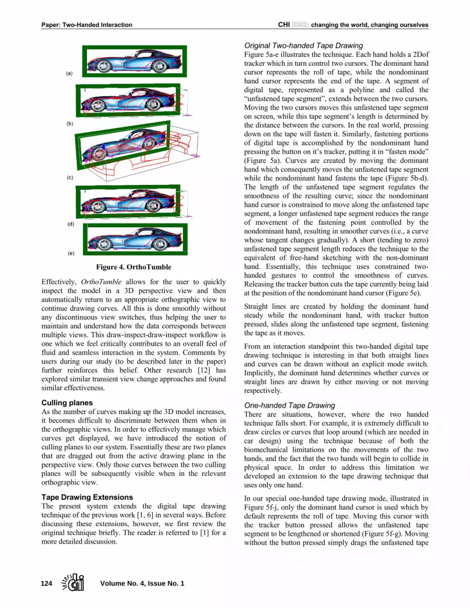
Figure 4. OrthoTumble
Effectively, OrthoTumble allows for the user to quickly inspect the model in a 3D perspective view and then automatically return to an appropriate orthographic view to continue drawing curves. All this is done smoothly without any discontinuous view switches, thus helping the user to maintain and understand how the data corresponds between multiple views. This draw-inspect-draw-inspect workflow is one which we feel critically contributes to an overall feel of fluid and seamless interaction in the system. Comments by users during our study (to be described later in the paper) further reinforces this belief. Other research [12] has explored similar transient view change approaches and found similar effectiveness.
Culling planes As the number of curves making up the 3D model increases, it becomes difficult to discriminate between them when in the orthographic views. In order to effectively manage which curves get displayed, we have introduced the notion of culling planes to our system. Essentially these are two planes that are dragged out from the active drawing plane in the perspective view. Only those curves between the two culling planes will be subsequently visible when in the relevant orthographic view.
Tape Drawing Extensions The present system extends the digital tape drawing technique of the previous work [1, 6] in several ways. Before discussing these extensions, however, we first review the original technique briefly. The reader is referred to [1] for a more detailed discussion.
Original Two-handed Tape Drawing Figure 5a-e illustrates the technique. Each hand holds a 2Dof tracker which in turn control two cursors. The dominant hand cursor represents the roll of tape, while the nondominant hand cursor represents the end of the tape. A segment of digital tape, represented as a polyline and called the “unfastened tape segment”, extends between the two cursors. Moving the two cursors moves this unfastened tape segment on screen, while this tape segment’s length is determined by the distance between the cursors. In the real world, pressing down on the tape will fasten it. Similarly, fastening portions of digital tape is accomplished by the nondominant hand pressing the button on it’s tracker, putting it in “fasten mode” (Figure 5a). Curves are created by moving the dominant hand which consequently moves the unfastened tape segment while the nondominant hand fastens the tape (Figure 5b-d). The length of the unfastened tape segment regulates the smoothness of the resulting curve; since the nondominant hand cursor is constrained to move along the unfastened tape segment, a longer unfastened tape segment reduces the range of movement of the fastening point controlled by the nondominant hand, resulting in smoother curves (i.e., a curve whose tangent changes gradually). A short (tending to zero) unfastened tape segment length reduces the technique to the equivalent of free-hand sketching with the non-dominant hand. Essentially, this technique uses constrained two-handed gestures to control the smoothness of curves. Releasing the tracker button cuts the tape currently being laid at the position of the nondominant hand cursor (Figure 5e).
Straight lines are created by holding the dominant hand steady while the nondominant hand, with tracker button pressed, slides along the unfastened tape segment, fastening the tape as it moves.
From an interaction standpoint this two-handed digital tape drawing technique is interesting in that both straight lines and curves can be drawn without an explicit mode switch. Implicitly, the dominant hand determines whether curves or straight lines are drawn by either moving or not moving respectively.
One-handed Tape Drawing There are situations, however, where the two handed technique falls short. For example, it is extremely difficult to draw circles or curves that loop around (which are needed in car design) using the technique because of both the biomechanical limitations on the movements of the two hands, and the fact that the two hands will begin to collide in physical space. In order to address this limitation we developed an extension to the tape drawing technique that uses only one hand.
In our special one-handed tape drawing mode, illustrated in Figure 5f-j, only the dominant hand cursor is used which by default represents the roll of tape. Moving this cursor with the tracker button pressed allows the unfastened tape segment to be lengthened or shortened (Figure 5f-g). Moving without the button pressed simply drags the unfastened tape
Paper: Two-Handed Interaction CHI changing the world, changing ourselves
124 Volume No. 4, Issue No. 1

segment around. As the unfastened tape segment is moved, however, it leaves behind a trail of fastened tape (Figure 5h). Terminating the tape involves pressing the button (Figure 5i) and reducing the unfastened tape segment length to zero (Figure 5j). This returns the user again to the state of adjusting the unfastened tape segment (Figure 5f).
Essentially, this one-handed version behaves like the two-handed technique would if the non-dominant hand button was always pressed, and the distance between the two cursors was fixed once taping began. Given the fixed distance between the end of the tape and the roll of tape during dragging, perfectly straight lines are difficult to achieve in this one-handed technique. The benefit, however, is that looped curves can now be created easily. Given these tradeoffs, and in the interest of maintaining compatibility with the traditional technique, our system continues to use the two-handed technique as the default line and curve creation tool with the one-handed technique available as an alternate when the need to create looped curves and circles arises.
Curve Guides When designing 3D models consisting of many curves it is often necessary for one curve to intersect other curves in order to form appropriate skeletons for surfaces. While the tape drawing technique allows for high quality curves to be generated, it is not easy to plan ahead and be able to draw the curve such that it will definitely intersect some predetermined points. To assist the tape artist in this regard, we developed a mechanism for guiding the curve towards these intersection points.
As Figure 6 illustrates, we first select the intersection points of interest, and then specify the desired tangents at these points (Figure 6a). Then, using the tape drawing technique we can begin to draw a new curve that is intended to intersect these points. When the new curve is at a certain distance from the first intersection point, a guide curve begins to fade in (Figure 6b-c). Using Bezier interpolation with two slopes (the current slope of the new tape curve, and
the slope of the tangent that was specified at the intersection point) and two points (the tape fastening point, and the intersection point) as inputs, the guide curve gives the user a best guess preview of what the new tape curve should look like in order to smoothly pass through that intersection point. The user can choose to continue taping along this guide curve, or simply choose to accept the guide curve as the desired curve. There are of course situations where the user may choose to deviate significantly from the guide curve. In this case, the system attempts to dynamically keep updating the guide curve with successive best guesses, adjusting the tangent at the intersection point in the process. Once the new curve passes the intersection point, the guide curve and tangent indicator for that point disappears (Figure 6d). In addition, if a new curve is within 20 pixels from an intersection point (Figure 6e), the system assumes that the curve should intersect that point and makes the required small interpolation adjustments to the curve such that it passes smoothly through that point (Figure 6f).
Figure 6. Curve Guides
Figure 5. (top row) Two-handed tape drawing technique. (bottom row) One-handed tape drawing.
minneapolis, minnesota, usa • 20-25 april 2002 Paper: Two-Handed Interaction
Volume No. 4, Issue No. 1 125
Tangent, Perpendicular Snapping, and Rail Guides In order to make our system capable of performing our goal task of designing the principal curves of a real car, we added in several functions which are not new to 3d modeling but have never been used in conjunction with digital tape drawing. To facilitate accurate joining of curves, we implemented a set of curve snapping techniques. These techniques are similar to the snapping approaches originally proposed by Bier et. al. [3] and found in many CAD packages. We have the ability to snap the start of tape curves to other curves to then begin drawing tangentially or perpendicular to the existing curve. Additionally, the snapped-to curve can act as a rail guide (i.e., before tape is fastened for a new curve, the snapped starting point can be moved along the snapped-to curve).
Editing We also allow the cutting out segments of curves by specifying two points and applying a simple up-down gesture over the segment to be removed.
Loading Engineering Criteria In auto design studios, tape drawings are commonly created on top of underlying engineering criteria which specify the car’s underlying mechanical elements such as engine block position, transmission, and wheel wells, etc. The stylistic body designs have to be built around this engineering criteria. As such, our system provides for engineering criteria to be loaded as the background in our drawing planes. These engineering criteria are only visible when in orthographic view, since that is where the tape drawing is done. Another alternative to engineering criteria is to use a reference image to guide the creation of design curves. For example, tape drawing could be done against images of a previous year’s model loaded into the background plane (see Figure 4).
Two-handed Pan and Zoom As in a variety of previous systems [6, 9, 11], we support camera control interactions of pan, tumble and zoom using a bimanual interaction technique. However, in our previous tape drawing system [6], these operations were only available while in perspective viewing mode. In our current system, we have made the techniques available in both perspective and orthographic views. We found this to strongly reflect users’ expectations. For example, just as one expects a tumble operation in an orthographic view to automatically and smoothly transition into a perspective view (and therefore the emergence of our ortho-tumble feature), users also expected zooming and panning within an orthographic view so they could place their work zone in a more comfortable position.
To support this, we adapted and refined the basic bimanual technique proposed in [11]. With this previous technique, when both tracker buttons are pressed, the cursors become attached to the drawing surface and this acts like manipulating the surface like a rubber sheet. Moving both hands together or apart zooms in or out. Keeping both hands
at a constant distance apart and moving them in the same direction pans the surface.
One problem with the previous technique is that panning and zooming cannot be easily performed independently. To allow a user to only pan or only zoom, our technique allows a pan or zoom operation to only occur after a certain threshold of movement is met. To accomplish this we track the vectors of motion for each cursor. The threshold for panning is an angle between the two cursor movement vectors of below 45 degrees (indicating they are moving in the same direction), and a vector length for both cursors of 5 pixels (to filter tracker noise). For zooming, the cursor movement vector angle must be more than 135 degrees (indicating they are moving in opposite directions), with the same length requirement. Once the pan threshold is met, the cube will be panned in the vector of the average of the two cursor movement vectors. When the zoom threshold is met, the zoom is increased proportionally to the increase in distance between the two cursors.
USER STUDY User testing has been performed on our previous tape drawing systems. In both [1] and [6], we report the reactions of automotive designers using their tape drawing systems for short periods of time. With our current system we have similar short-term user testing experiences. Specifically, we demonstrated our system at the SIGGRAPH 2001 tradeshow floor and allowed individuals to try our system hands-on. Users only spent enough time with the system to get a little experience in creating 2D curves and navigating around the model. As in previous systems, we observed that users had little difficulty learning the basic user model (e.g., tape-style drawing on the sides of a 3D cube). In addition, our new navigation techniques appeared easy to understand and operate.
As with the testing of previous systems [1, 6], this type of user testing was meaningful to gauge users’ initial reaction to the basic design approach and functions. However, for our current system, the goal was to provide enough functionality that a user could reasonably attempt to specify the primary curves of real car. Since this is a time consuming task we decided to study an artist attempting to use our system for an extended period of time (several hours) as opposed to testing many users over shorter periods of time.
As a test task we chose the creation of the primary curves of a real car, specifically, the Dodge Viper model. The Viper’s body shape is typical of automotive body design which has sophisticated curved surfaces resulting from long flowing primary curves. We also had a scale metal die-cast model of the Viper at 1/16 scale, which could serve as a reference when trying to create the primary curves. To assist in the test task, we provided reference images of the Dodge Viper against which the user could tape draw (Figure 4).
As a test subject we employed a professional 3D modeler and artist for approximately 3 one hour sessions to initially familiarize himself with the system, then attempt to construct
Paper: Two-Handed Interaction CHI changing the world, changing ourselves
126 Volume No. 4, Issue No. 1

the primary curves of the Viper. Our system is by no means “walk and use” and therefore the researcher who constructed the system spent time training the user on the basic capabilities of the system, explaining minor interface bugs, and helping them out of error states. Our testing was not particularly concerned with the small details and pitfalls of interaction but more concerned with identifying successes and failures in the fundamentals of the user model and system capabilities.
Despite efforts to assist the user in quickly learning how to use the system, the user could only construct a very crude model of the Viper after three hours of experience. We feel this is due to a series of issues which never allowed the user to graduate from the learning phase and be proficient with the system. While we originally thought that the user would refine a model over the three hours of work, we found the user simply discarded the model at the end of each session and restarted from scratch each time. Thus the user rather than trying to reach the goal of creating the model was actually creating initial crude models to explore and learn the system.
Ultimately, we still believed that our system was capable of creating reasonable primary curve model of the Viper. Thus we challenged the implementer of the system, who was the most experienced with the system and had become quite skilled at the tape drawing technique, to attempt to model the Viper. Figure 7 shows the results of 2 hours of work by the system implementer and shows a fairly sophisticated set of 3D curves that are representative of the Viper Model.
From all of these experiences of our user testing we have the following observations:
• Accurate, stable tracking is critical. Although our system used 3D input sensors with a larger range, the accuracy and stability of these trackers was still a major stumbling block in learning and operating the system. While our implementer had learned to understand and deal with these problems, our artist-user experienced numerous problems. The source of these problems, however, is not a fundamental limitation but a technological one posed by the tracking hardware we used. This is easily solved by simply purchasing better tracking technology.
The artist-user reported that the tracker cables somewhat restricted their movement. Not only did this hinder working directly on the display but it also restricted his freedom in stepping back from the screen to examine the model.
• Despite the problems with input, our artist user had some very positive reactions with regard to navigation. Both the Ortho-tumble and two-handed zooming and panning features were learned quickly then used frequently and effectively.
• In terms of 3D curve creation we observed that planning which curves need to be created to specify the primary characteristics of a shape is a difficult problem, independent of the tool. In general, it requires skill to decompose a shape
into its 3D principal curves. For example, our implementer-user claims that majority of time spent in producing the Viper model was not spent actually drawing the curves but spent considering what sort of curve or curves should be drawn to capture the primary characteristics of the model.
• The most encouraging reports from our artist user concerned the basic user model. Our artist user reported that he found the metaphor of tape drawing and the notion of building up a 3D model using tape very easy to understand, specifically the concept of creating complicated curve sets through the combination of simpler 2D curves. Finally, our artist user reported that while tape drawing is used in automotive design, it is also a general technique used in many other types of art work and therefore has utility to a broader audience than automotive designers.
DISCUSSION and CONCLUSIONS While our prototype is clearly not production ready, from a research perspective we have identified and implemented the majority of functionality needed to create the principal curves of an automotive design using tape drawing as the basic curve creation technique on a large scale display surface.
An important issue with 3D line drawing is the limitation of using lines to visualize what will eventually be surfaces. For example, one can draw a circular profile of a sphere from the side, front and top and project each of these curves into a 3D volume by giving them depth. However, from a perspective view the combination of these orthographic circles does not produce the perfect circular profile of the sphere because there is no surface running between the orthographic circles. In general, this lack of surface information “between the curves” can be combated somewhat by adding in more curves that will run along the surface to help a viewer perceive a surface from a series of curves. Future research could be done on how to devise a way to integrate profile curves drawn from a perspective view into the 3D model or alternatively allow a user to create and manipulate surfaces between the profile curves.
Figure 7. Principal curves of test task car model.
minneapolis, minnesota, usa • 20-25 april 2002 Paper: Two-Handed Interaction
Volume No. 4, Issue No. 1 127

The present work gives rise to the major design issue of how far to continue to develop the system. Traditionally, the automotive design workflow involves the production of concept sketches that are turned into 2D tape drawings. These drawings are subsequently digitized and turned into 3D surface models. Based on feedback from automotive designers, we have built a system that allows the 2D tape drawing phase to replace some of the early phases of the construction of the 3D surface modeling. The question is where to stop. Future work would be to study how far 2D tape drawing can be extended into 3D surface modeling. There are several issues to consider. On the one hand, our system could benefit from adding functionality to help edit and refine existing curves similar to those found in 3D modeling programs. On the other hand, there is a question of how much functionality can we introduce into our digital tape drawing system before tape artists reject it because it is perceived to be as complicated as typical 3D CAD surface modeling applications. Another issue is the possible importance of having the tape drawing phase clearly separate from the surface design phase. For example, it may be considered “too much design detail” to mix principal curve creation with surface specification.
Many of the ideas we have explored have general application in both CAD and large display systems. In terms of CAD systems, digital tape could be used as an additional curve generation technique for traditional desktop-based CAD packages especially if two-handed input is available. If not, our one-handed tape drawing technique could be substituted. Additionally, we have already seen our techniques for animating between orthographic and perspective views be adopted in several commercial software packages.
In terms of large display systems, various techniques employed in our tape drawing system could be used in any application where one is working at arm’s length on large display systems, as is done for example by Guimbretière et. al. [7]. Examples of these techniques include pop-up marking menus, one-button per input tracker, and other techniques for avoiding the traditional widgets around the periphery of the display such as menubars and tool pallets. The extension of our two-handed panning and zooming navigation techniques to be operable from both perspective and orthographic views is particularly useful. We believe that, collectively, these techniques could serve as an effective basic interaction model for any application that involves working at arm’s length on large displays.
ACKNOWLEDGMENTS We thank Shane Clodd for participating in our user study.
REFERENCES 1. Balakrishnan, R., Fitzmaurice, G., Kurtenbach, G., &
Buxton, W. (1999). Digital tape drawing. ACM UIST 1999. p. 161-169.
2. Balakrishnan, R., & Kurtenbach, G. (1999). Exploring bimanual camera control and object manipulation in 3D graphics interfaces. ACM CHI 1999. p. 56-63.
3. Bier, E., & Stone, M. (1986). Snap dragging. ACM SIGGRAPH 1986. p. 233-240.
4. Cohen, J., Markosian, L., Zeleznik, R., Hughes, J., & Barzel, R. (1999). An interface for sketching 3D curves. ACM Symposium on Interactive 3D Graphics. p. 17-21.
5. Elrod, S., et al. (1991). Liveboard: a large interactive display supporting group meetings, presentations, and remote collaboration. ACM CHI 1992. p. 599-607.
6. Grossman, T., Balakrishnan, R., Kurtenbach, G., Fitzmaurice, G., Khan, A., & Buxton, B. (2001). Interaction techniques for 3D modeling on large displays. ACM Symposium on Interactive 3D Graphics. p. 17-23.
7. Guimbretière, F., Stone, M., & Winograd, T. (2001). Fluid interaction with high-resolution wall-size displays. ACM UIST 2001. p. (to appear).
8. Herndon, K., Zeleznik, R., Robbins, D., Conner, B., Snibbe, S., & Dam, A.v. (1992). Interactive shadows. ACM UIST 1992. p. 1-6.
9. Hinckley, K., Czerwinski, M., & Sinclair, M. (1998). Interaction and modeling techniques for desktop two-handed input. ACM UIST 1998. p. 49-58.
10. Kurtenbach, G., & Buxton, W. (1993). The limits of expert performance using hierarchical marking menus. ACM CHI 1993. p. 35-42.
11. Kurtenbach, G., Fitzmaurice, G., Baudel, T., & Buxton, W. (1997). The design of a GUI paradigm based on tablets, two-hands, and transparency. ACM CHI 1997. p. 35-42.
12. Pierce, J., Conway, M., Dantzich, M.v., & Robertson, G. (1999). Toolspaces and glances: storing, accessing, and retrieving objects in 3D desktop applications. ACM CHI 1999. p. 163-168.
13. Sachs, E., Roberts, A., & Stoops, D. (1991). 3-draw: A tool for designing 3D shapes. IEEE Computer Graphics and Applications, 11(6). p. 18-26.
14. Schkolne, S., Pruett, M., & Schroeder, P. (2001). Surface drawing: Creating organic 3D shapes with the hand and tangible tools. ACM CHI 2001. p. 261-268.
Paper: Two-Handed Interaction CHI changing the world, changing ourselves
128 Volume No. 4, Issue No. 1