create 3d environment
TRANSCRIPT
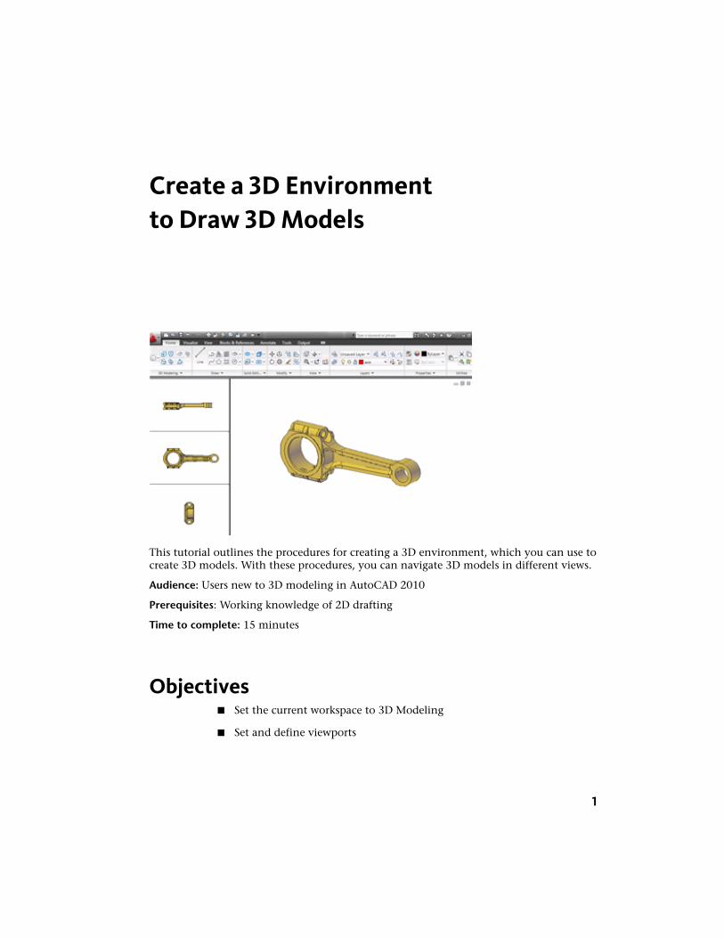
Create a 3D Environmentto Draw 3D Models
This tutorial outlines the procedures for creating a 3D environment, which you can use tocreate 3D models. With these procedures, you can navigate 3D models in different views.
Audience: Users new to 3D modeling in AutoCAD 2010
Prerequisites: Working knowledge of 2D drafting
Time to complete: 15 minutes
Objectives■ Set the current workspace to 3D Modeling
■ Set and define viewports
1
■ Navigate a 3D model
Tutorial FilesAll necessary files for this tutorial are located athttp://www.autodesk.com/autocad-tutorials.
Recommended: Before starting the tutorials
1 Download the 3D_Modeling_Environment.zip fromhttp://www.autodesk.com/autocad-tutorials/.
2 Unzip 3D_Modeling_Environment.zip to C:\My Documents\Tutorials.
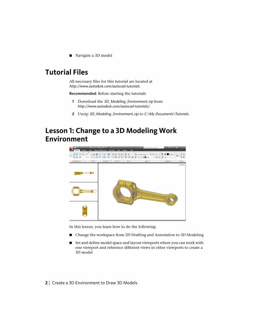
Lesson 1: Change to a 3D Modeling WorkEnvironment
In this lesson, you learn how to do the following:
■ Change the workspace from 2D Drafting and Annotation to 3D Modeling
■ Set and define model space and layout viewports where you can work withone viewport and reference different views in other viewports to create a3D model
2 | Create a 3D Environment to Draw 3D Models
■ Set the annotation scale for layout viewports
File Name: section_plane.dwg
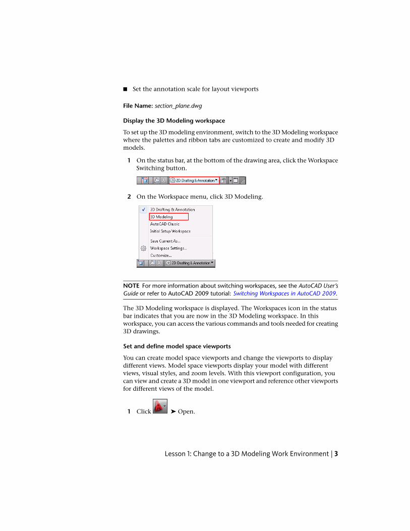
Display the 3D Modeling workspace
To set up the 3D modeling environment, switch to the 3D Modeling workspacewhere the palettes and ribbon tabs are customized to create and modify 3Dmodels.
1 On the status bar, at the bottom of the drawing area, click the WorkspaceSwitching button.
2 On the Workspace menu, click 3D Modeling.
NOTE For more information about switching workspaces, see the AutoCAD User’sGuide or refer to AutoCAD 2009 tutorial: Switching Workspaces in AutoCAD 2009.
The 3D Modeling workspace is displayed. The Workspaces icon in the statusbar indicates that you are now in the 3D Modeling workspace. In thisworkspace, you can access the various commands and tools needed for creating3D drawings.
Set and define model space viewports
You can create model space viewports and change the viewports to displaydifferent views. Model space viewports display your model with differentviews, visual styles, and zoom levels. With this viewport configuration, youcan view and create a 3D model in one viewport and reference other viewportsfor different views of the model.
1 Click ➤ Open.
Lesson 1: Change to a 3D Modeling Work Environment | 3
2 In the Select File dialog box, browse to C:\My Documents\Tutorials andselect section_plane.dwg.
3 Click Open.
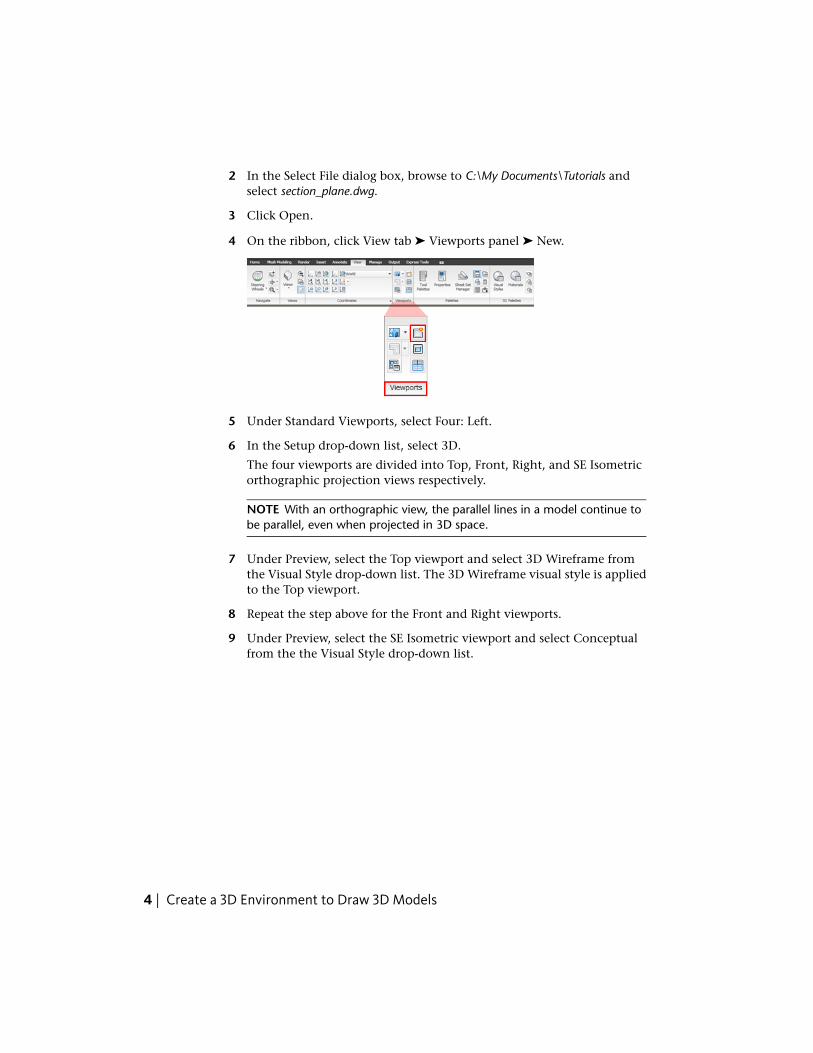
4 On the ribbon, click View tab ➤ Viewports panel ➤ New.
5 Under Standard Viewports, select Four: Left.
6 In the Setup drop-down list, select 3D.
The four viewports are divided into Top, Front, Right, and SE Isometricorthographic projection views respectively.
NOTE With an orthographic view, the parallel lines in a model continue tobe parallel, even when projected in 3D space.
7 Under Preview, select the Top viewport and select 3D Wireframe fromthe Visual Style drop-down list. The 3D Wireframe visual style is appliedto the Top viewport.
8 Repeat the step above for the Front and Right viewports.
9 Under Preview, select the SE Isometric viewport and select Conceptualfrom the the Visual Style drop-down list.
4 | Create a 3D Environment to Draw 3D Models
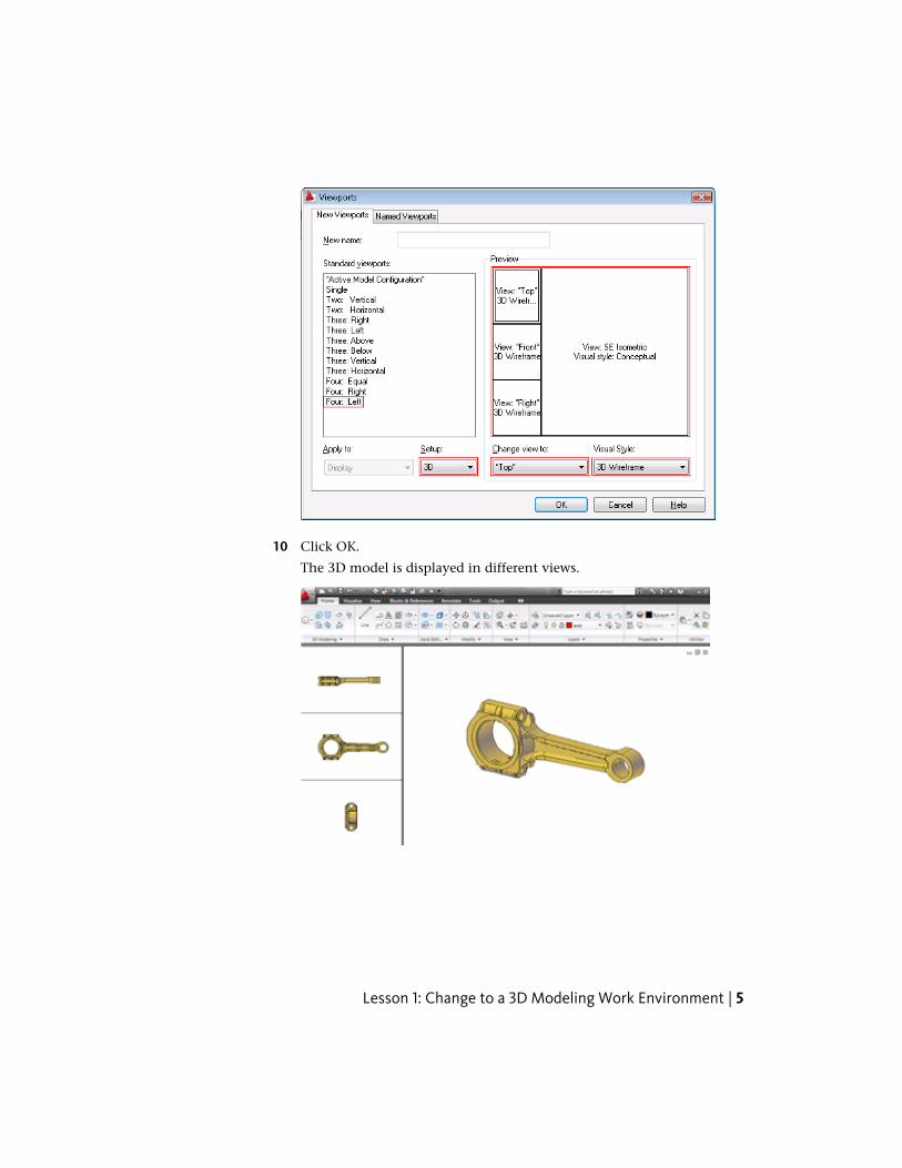
10 Click OK.
The 3D model is displayed in different views.
Lesson 1: Change to a 3D Modeling Work Environment | 5
Set and define layout viewports
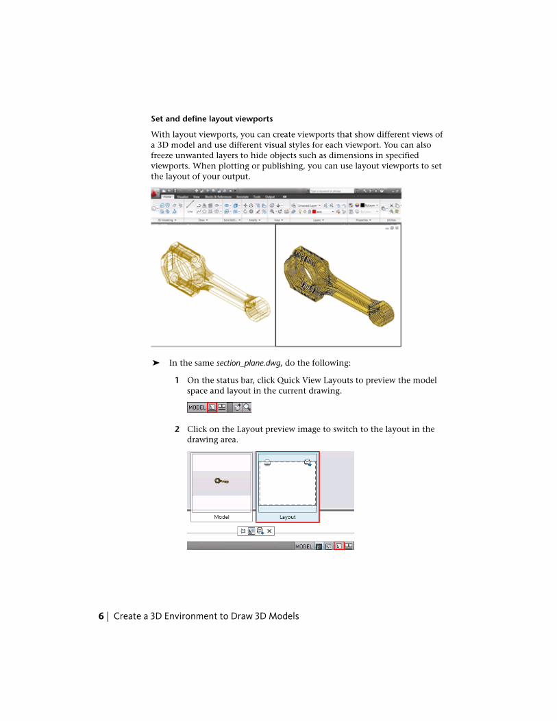
With layout viewports, you can create viewports that show different views ofa 3D model and use different visual styles for each viewport. You can alsofreeze unwanted layers to hide objects such as dimensions in specifiedviewports. When plotting or publishing, you can use layout viewports to setthe layout of your output.
➤ In the same section_plane.dwg, do the following:
1 On the status bar, click Quick View Layouts to preview the modelspace and layout in the current drawing.
2 Click on the Layout preview image to switch to the layout in thedrawing area.
6 | Create a 3D Environment to Draw 3D Models
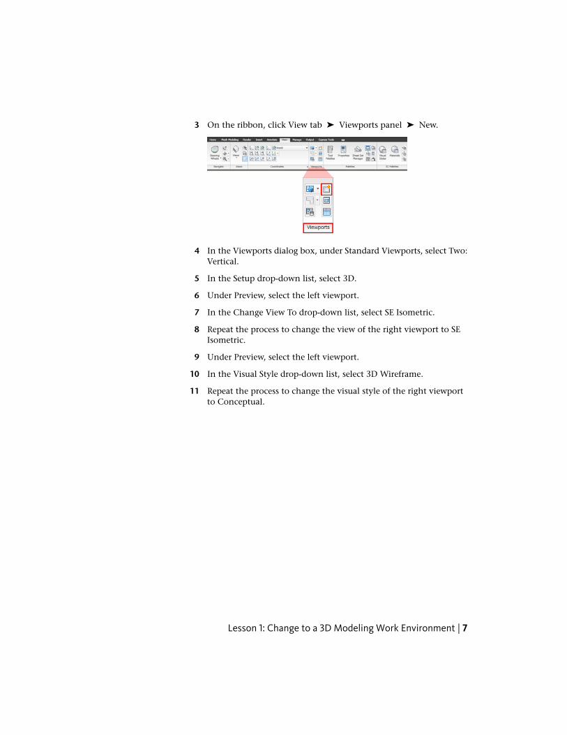
3 On the ribbon, click View tab ➤ Viewports panel ➤ New.
4 In the Viewports dialog box, under Standard Viewports, select Two:Vertical.
5 In the Setup drop-down list, select 3D.
6 Under Preview, select the left viewport.
7 In the Change View To drop-down list, select SE Isometric.
8 Repeat the process to change the view of the right viewport to SEIsometric.
9 Under Preview, select the left viewport.
10 In the Visual Style drop-down list, select 3D Wireframe.
11 Repeat the process to change the visual style of the right viewportto Conceptual.
Lesson 1: Change to a 3D Modeling Work Environment | 7
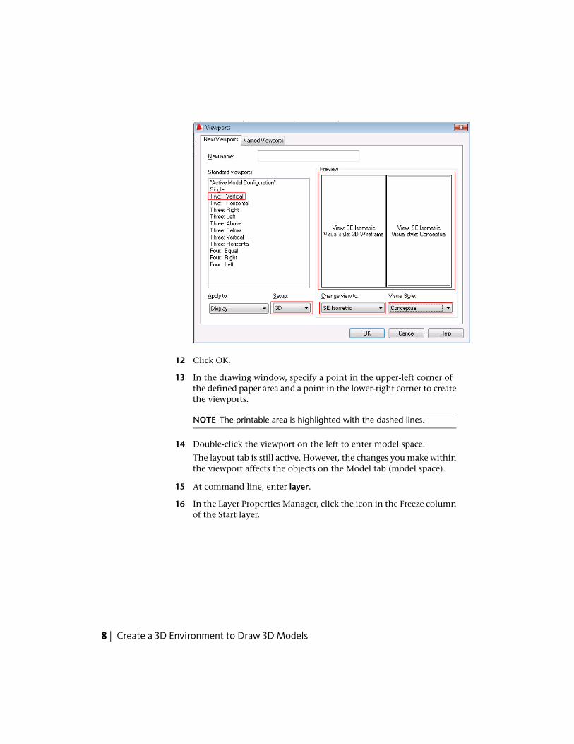
12 Click OK.
13 In the drawing window, specify a point in the upper-left corner ofthe defined paper area and a point in the lower-right corner to createthe viewports.
NOTE The printable area is highlighted with the dashed lines.
14 Double-click the viewport on the left to enter model space.
The layout tab is still active. However, the changes you make withinthe viewport affects the objects on the Model tab (model space).
15 At command line, enter layer.
16 In the Layer Properties Manager, click the icon in the Freeze columnof the Start layer.
8 | Create a 3D Environment to Draw 3D Models
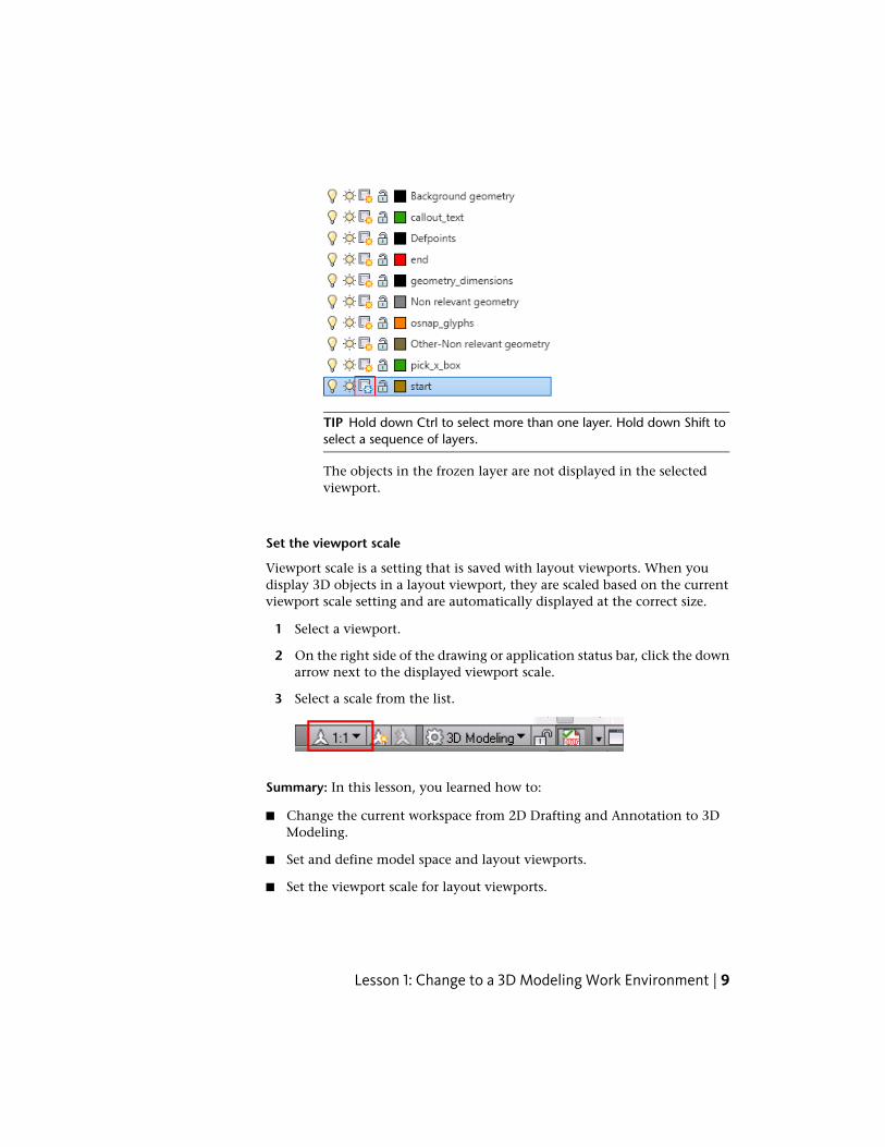
TIP Hold down Ctrl to select more than one layer. Hold down Shift toselect a sequence of layers.
The objects in the frozen layer are not displayed in the selectedviewport.
Set the viewport scale
Viewport scale is a setting that is saved with layout viewports. When youdisplay 3D objects in a layout viewport, they are scaled based on the currentviewport scale setting and are automatically displayed at the correct size.
1 Select a viewport.
2 On the right side of the drawing or application status bar, click the downarrow next to the displayed viewport scale.
3 Select a scale from the list.
Summary: In this lesson, you learned how to:
■ Change the current workspace from 2D Drafting and Annotation to 3DModeling.
■ Set and define model space and layout viewports.
■ Set the viewport scale for layout viewports.
Lesson 1: Change to a 3D Modeling Work Environment | 9
Lesson 2: Navigate Different Views of 3D ModelsIn this lesson, you navigate different views of a 3D solid model.
File Name: section_plane.dwg
Navigate different views of a 3D model with Free Orbit
To create 3D models, you need to navigate different views to ensure that themodels are displayed from different viewports.
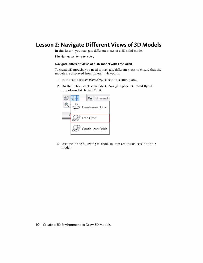
1 In the same section_plane.dwg, select the section plane.
2 On the ribbon, click View tab ➤ Navigate panel ➤ Orbit flyoutdrop-down list ➤ Free Orbit.
3 Use one of the following methods to orbit around objects in the 3Dmodel:
10 | Create a 3D Environment to Draw 3D Models
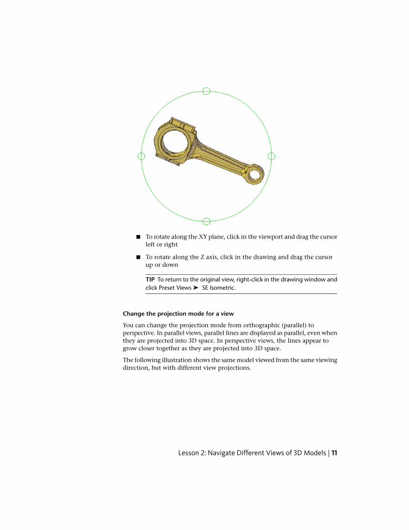
■ To rotate along the XY plane, click in the viewport and drag the cursorleft or right
■ To rotate along the Z axis, click in the drawing and drag the cursorup or down
TIP To return to the original view, right-click in the drawing window andclick Preset Views ➤ SE Isometric.
Change the projection mode for a view
You can change the projection mode from orthographic (parallel) toperspective. In parallel views, parallel lines are displayed as parallel, even whenthey are projected into 3D space. In perspective views, the lines appear togrow closer together as they are projected into 3D space.
The following illustration shows the same model viewed from the same viewingdirection, but with different view projections.
Lesson 2: Navigate Different Views of 3D Models | 11
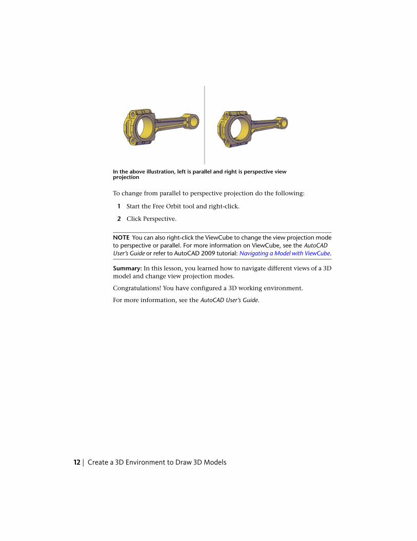
In the above illustration, left is parallel and right is perspective viewprojection
To change from parallel to perspective projection do the following:
1 Start the Free Orbit tool and right-click.
2 Click Perspective.
NOTE You can also right-click the ViewCube to change the view projection modeto perspective or parallel. For more information on ViewCube, see the AutoCADUser’s Guide or refer to AutoCAD 2009 tutorial: Navigating a Model with ViewCube.
Summary: In this lesson, you learned how to navigate different views of a 3Dmodel and change view projection modes.
Congratulations! You have configured a 3D working environment.
For more information, see the AutoCAD User’s Guide.
12 | Create a 3D Environment to Draw 3D Models