crd 2011-09.pdf - easa - europa.eu
TRANSCRIPT
European Aviation Safety Agency 16 Nov 2012
R.F010-02 © European Aviation Safety Agency. All rights reserved. Proprietary document. Page 1 of 79
COMMENT-RESPONSE DOCUMENT (CRD)
TO NOTICE OF PROPOSED AMENDMENT (NPA) 2011-09
for amending the Executive Director Decision 2003/02/RM of 17 October 2003
on certification specifications and acceptable means of compliance, for large
aeroplanes (‘CS-25’)
‘Incorporation of generic SC and AMC CRIs in CS-25’
Reactions to this CRD should be submitted via the CRT by clicking the
‘add a general reaction’ button.
Please indicate clearly the applicable paragraph.
CRD to NPA 2011-09 16 Nov 2012
Page 2 of 79
Executive Summary
NPA 2011-09 proposed an upgrade of CS-25 by introducing generic CRIs (Certification Review
Items) containing Special Conditions and/or Guidance Material, and Acceptable Means of
Compliance.
The intent is to reflect the current certification practices and facilitate future certification
projects.
Following the review of comments received, the Agency made some improvements and
corrections to the CS-25 amendment proposal as explained in detail in the responses to
comments provided hereafter. Furthermore, the proposal amending CS 25.1353 to address the
subject of lithium-ion battery installation is withdrawn because of its lack of maturity and on-
going developments.
Further to these changes, the final resulting text for CS-25 amendment addresses the
following items: stalling speeds for structural design; design manoeuvre requirements; design
dive speed; side stick controls; towbarless towing; steep approach and landing; protection of
essential systems and equipment in Class E cargo compartments; removal of need for berths
intended only for the carriage of medical patients to comply with CS 25.562; inclusion of
engines at ground idle when assessing escape slide performance in wind; oxygen outlets in the
galley work areas; fireproofness of engine cowlings; flight envelope protection; reduced and
derated take-off thrust; go-around performance.
CRD to NPA 2011-09 16 Nov 2012
Page 3 of 79
Explanatory Note
I. General
1. The purpose of the Notice of Proposed Amendment (NPA) 2011-09, dated 28 May 2011,
was to propose an amendment to Decision 2003/02/RM of the Executive Director of the
European Aviation Safety Agency of 17 October 2003 on certification specifications and
acceptable means of compliance, for large aeroplanes (‘CS-25’)1.
II. Consultation
2. The draft Executive Director Decision amending Decision 2003/02/RM was published on
the website (http://easa.europa.eu/agency-measures/agency-decisions.php) on 31 May
2011.
By the closing date of 31 August 2011, the European Aviation Safety Agency (hereafter
referred to as the ‘Agency’) had received 82 comments from 15 national aviation
authorities, professional organisations and private companies.
III. Publication of the CRD
3. All comments received have been acknowledged and incorporated into this Comment-
Response Document (CRD) with the responses of the Agency.
4. In responding to comments, a standard terminology has been applied to attest the
Agency’s acceptance of the comment. This terminology is as follows:
Accepted — The comment is agreed by the Agency and any proposed amendment
is wholly transferred to the revised text.
Partially accepted — Either the comment is only agreed in part by the Agency, or
the comment is agreed by the Agency but any proposed amendment is partially
transferred to the revised text.
Noted — The comment is acknowledged by the Agency but no change to the
existing text is considered necessary.
Not accepted — The comment or proposed amendment is not shared by the
Agency.
The resulting text highlights the changes as compared to the current rule.
The Executive Director Decision on amendment to Decision 2003/02/RM will be issued at
least two months after the publication of this CRD to allow for any possible reactions of
stakeholders regarding possible misunderstandings of the comments received and
answers provided.
5. Such reactions should be received by the Agency not later than 21 January 2013 and
should be submitted using the Comment-Response Tool at
http://hub.easa.europa.eu/crt.
1 As last amended by Decision 2012/008/R of the Executive Director of the Agency of 6 July 2012, ‘CS-
25 Amendment 12’.
CRD to NPA 2011-09 16 Nov 2012
Page 4 of 79
IV. CRD table of comments, responses and resulting text
(General Comments) -
comment 36 comment by: FAA
General comment:
The FAA would like to suggest a future rulemaking or guidance project. We
have noted subjective requirements for crew ability throughout 14 CFR part 25
and CS-25, such as section 25.101(h), “must be able to be consistently
executed in service by crews of average skill.” We would like to work together
with EASA to identify and better define expected flightcrew skill and
performance where referenced within our regulations.
response Noted.
This NPA does not propose any changes to CS 25.101(h). Nevertheless, the
request for future development of this requirement is noted.
comment 58 comment by: UK CAA
Please be advised that the UK CAA have no comments to make on NPA 2011-09
'Incorporation of generic SC and AMC CRIs in CS-25'.
response Noted.
comment 60
comment by: Swedish Transport Agency, Civil Aviation Department
(Transportstyrelsen, Luftfartsavdelningen)
The Swedish Transport Agency, Civil Aviation Department is supporting Option 2
(Amend CS25 by introducing generic CRIs.)
response Noted.
comment 64 comment by: Embraer - Indústria Brasileira de Aeronáutica - S.A.
Embraer appreciates the opportunity to send the attached comments for your
consideration in NPA 2011-09 about Incorporation of generic SC and AMC CRIs
in CS-25.
response Noted.
comment 84 comment by: Swiss International Airlines / Bruno Pfister
SWISS Intl Air Lines takes note of the NPA 2011-09 without further commens.
response Noted.
IV. Content of the draft decision - Design dive speed p. 6
comment 42 comment by: Transport Canada Civil Aviation Standards Branch
Paragraph 13 Design dive speed, Proposed AMC 25.335(b)(1)(ii). For failure of
the high speed protection function, it is likely that the value of VD/MD will be
CRD to NPA 2011-09 16 Nov 2012
Page 5 of 79
greater than the value established with the function operating. In this case a
reduction in VC/MC (and associated VMO/MMO) to maintain a safe operating
margin to VD/MD may be more appropriate than a redefinition of loads at a
higher VD/MD.
response Partially accepted.
See response to comment No 24.
IV. Content of the draft decision - Side stick controls p. 6-7
comment 43 comment by: Transport Canada Civil Aviation Standards Branch
Paragraph 14 Side stick controls, CS 25.777 Cockpit controls. The content of
proposed CS 25.777(i) appears to be missing from the NPA.
response Not accepted.
The proposed CS 25.777(i) is presented on page 18 of NPA 2011-09.
IV. Content of the draft decision - Towbarless towing p. 7-8
comment 44 comment by: Transport Canada Civil Aviation Standards Branch
Paragraph 15 Towbarless towing, Proposed CS 25.745(d)(2). The proposed
limitations, although valid, are not appropriate as AFM limitations (particularly
the last paragraph if the documentation is the AFM)
response Not accepted.
The Agency assumes that your comment actually refers to the proposed AMC
25.745(d), last paragraph, i.e. sub-paragraph (d)(3).
Sub-paragraph (d)(3) details the conditions under which the aeroplane
manufacturer may accept a towbarless towing vehicle.
Sub-paragraph (d)(2) introduces a limitation in the AFM for towbarless towing.
Towbarless towing operations are restricted to the vehicle(s) accepted by the
aeroplane manufacturer. The list of accepted vehicle(s) would be provided in
the appropriate aeroplane manufacturer documentation, i.e. Instructions for
Continued Airworthiness as described in Appendix H, paragraph H25.3(a)(4).
comment 67 comment by: Boeing
Page: 7 of 45
Paragraph 15. Towbarless towing
General comment: It appears that this material puts the airframe
manufacturer in the position of approving tow vehicles. Boeing does not
consider it appropriate to be in the position of approving this type of
equipment; our approach for the past 15 years has been to provide the tow
vehicle manufacturers and airlines with the criteria and guidance necessary for
them to self-certify. Boeing created a tow vehicle assessment document
specifically for this purpose and it has worked well as a means of allowing the
tow vehicle manufacturers to qualify their equipment. Our recommendation is
CRD to NPA 2011-09 16 Nov 2012
Page 6 of 79
to continue with this approach.
AMC 25.509, as currently proposed, would require that the airframe
manufacturer perform an analysis of each vehicle and airplane combination,
and then publish a list of acceptable combinations in the AMM and/or AFM. The
analysis requirement would be an undue burden on Boeing, and maintaining
the results in the AMM would be a similar problem. It invites questions, such as
the requirement to re-do the analysis every time a small change is made to a
tow vehicle. This responsibility clearly belongs to the tow vehicle equipment
manufacturers, not to the airframe manufacturer.
The NPA therefore needs to be revised to allow airframe manufacturers such as
Boeing to continue with our current approach to towbarless towing.
In addition, to maintain the appropriate maximum amount of harmonization
with FAA requirements, any proposed new towbarless towing requirements
should be harmonized with the FAA prior to implementation.
response Partially accepted.
This rulemaking proposal is consistent with the previous JAA interim policy
(INT/POL 25/13 dated 01 June 2001) which was successfully applied over the
past years. The origin of this policy dates back to February 1996 when the JAA
D&F SG Ad-hoc Group on “Towbarless Towing” was in charge of investigating
possible alternative means of compliance with the JAR-25 rule.
This Group, in cooperation with the SAE Towbarless Towing Working Group,
came to the conclusion that protection of the nose-wheel steering system can
also be provided by means of precautions taken on the towbarless towing
vehicle design and operation. For that reason the SAE has developed and
published five ARP’s (Aerospace Recommended Practices): two ARP’s dedicated
to the towbarless towing vehicle designer and three ARP’s dedicated to the
operation, maintenance/calibration and testing of the vehicle.
The principle is that, if the nose wheel steering analysis results in Failure
Condition(s) that can be classified as Major or less severe, each aeroplane
manufacturer provides a Towing Assessment Criteria Document, specifically for
his type of aircraft, to be used by the towbarless towing vehicle manufacturer
for defining interface requirements of the Towing Oversteer
Protection/Indication Systems (TOPIS).
It is recognised that some manufacturers have chosen to stay closely involved
in the qualification of the towbarless vehicles, their operation and the interface
with the airframe; others have chosen to publish criteria and guidance enabling
towbarless vehicle manufacturers to qualify their products. AMC 25.509 is
revised to take into account that over the years different airframe
manufacturers have adopted different (acceptable) approaches to towbarless
towing.
Nevertheless, the Agency does not agree that all responsibility for maintaining,
publishing and updating acceptable towbarless vehicle and aircraft
combinations lies with the towbarless vehicle manufacturers. Appendix H of CS-
25, paragraph H25.3(a)(4), requires the airframe manufacturer to provide
towing (including towbarless towing) instructions and limitations as part of the
Instructions for Continued Airworthiness. The subject proposed text is amended
to clarify this point. In addition, a statement should be present in the AFM
Limitations Section, as specified in AMC 25.745(d).
When the towing vehicle manufacturer has shown compliance to the SAE ARP’s
CRD to NPA 2011-09 16 Nov 2012
Page 7 of 79
and the Towing Assessment Criteria Document, it releases a “Declaration Of
Compliance” for the type and model of towbarless towing vehicle. The
aeroplane manufacturer should then review and accept this declaration of
compliance, and publish its acceptance of that towing vehicle in the
appropriate aeroplane manufacturer maintenance documentation.
When the towing vehicle type is published in the applicable aeroplane
manufacturer documentation, this is considered by the Agency as the approval
for the aeroplane operator to use that type of towbarless towing vehicle for its
aeroplane.
As for harmonisation with the FAA, the subject of towbarless towing has already
been the subject of ARAC harmonisation discussions in the ‘90’s, although it
ended somewhat inconclusive. The Agency, however, believes the proposed
text is acceptable to the FAA as well.
In several places, “must” has been replaced by “should” in the proposed AMC
25.509.
comment 68 comment by: Boeing
Page: 7 of 45
Paragraph 15. Towbarless towing
The proposed text states
Consequently, if ‘towbarless towing’ devices are known to be used and/or have
the approval of the manufacturer for ground manoeuvring of the aeroplane,
some means must be provided within the design of the aeroplane that will give,
at the very least, an equivalent level of protection to the steering system as
that which is available from the more conventional tow bar towing
arrangements.
We suggest the following changes be made:
Consequently, if ‘towbarless towing’ devices are known to be used and/or have
the approval of the manufacturer for ground manoeuvring of the aeroplane,
some means must be provided within the design of the aeroplane that will give,
at the very least, an equivalent level of protection to the steering system as
that which is available from the more conventional tow bar towing
arrangements.
JUSTIFICATION: Towbarless towing devices are not approved by the aircraft
manufacturer.
response Not accepted.
See response to comment No 67.
IV. Content of the draft decision - Steep approach and landing p. 8
comment 45 comment by: Transport Canada Civil Aviation Standards Branch
Paragraph 16 Steep Approach and Landing, Proposed Appendix Q:
1. Section 25.1 Applicability. TCCA does not concur with permitting a
screen height above 50 ft. CS 25.125(b)(2) requires that "A steady
gliding approach, with a calibrated airspeed of not less than 1.3VS, must
be maintained down to the 50 foot height". TCCA considers that an
aircraft must be able to safely conduct an approach to landing using this
CRD to NPA 2011-09 16 Nov 2012
Page 8 of 79
criteria for any glidepath.
2. Section 25.3 Steep Approach and Landing Distance. TCCA proposes an additional paragraph “(g) The measured landing
distance data may be extrapolated to a maximum of 3000 feet above
and 2000 feet below the test altitude without conducting additional
verification tests.
3. Section 25.4 Climb: One-engine-inoperative. TCCA proposes an
additional minimum control speed requirement in sub paragraph “(c) A
climb speed of VREF(SAL) but not less than 1.1VMCL
4. Section 25.5 Safe operational and flight characteristics. TCCA proposes
an additional demonstration condition (a)(4) “An approach path angle 1°
steeper than the selected approach path angle, at VREF(SAL) or VREF(SAL)-1 as
appropriate” and associated condition that the flare must not be initiated
above the screen height.
response Not accepted.
The Agency acknowledges the past attempts to harmonise the steep approach
requirements, nevertheless, offers the standards applied to recent EASA
certifications.
comment 59 comment by: Transport Canada Civil Aviation Standards Branch
1. Section 25.1 Applicability and 25.2 Definitions. TCCA does not concur with
permitting a screen height above 50 ft. CS 25.125(b)(2) requires that "A steady
gliding approach, with a calibrated airspeed of not less than 1.3VS, must be
maintained down to the 50 foot height". TCCA considers that an aircraft must
be able to safely conduct an approach to landing using this criteria for any
glidepath. Allowance of a screen height (and therefore, flare height) greater
than 50 ft will result in an Increased probability of misjudging height:
· too high and loss of airspeed, possible stall warning, excessive pitch
attitude,
· too low and heavy touchdown
2. Section 25.3 Steep Approach and Landing Distance. TCCA proposes an
additional paragraph “(g) The measured landing distance data may be
extrapolated to a maximum of 3000 feet above and 2000 feet below the test
altitude without conducting additional verification tests. “ At present there are
insufficient data to show that the requirements can be met at substantially
higher altitudes than those tested.
3. Section 25.4 Climb: One-engine-inoperative. TCCA proposes an additional
minimum control speed requirement in sub paragraph (c) “ A climb speed of
VREF(SAL) but not less than 1.1VMCL”. In a similar manner to the
requirements for V2, there should be a safe margin between the climb speed
with one engine inoperative and the minimum control speed. 4. Section 25.5 Safe operational and flight characteristics. TCCA proposes an additional demonstration condition (a)(4) “An approach path angle 1° steeper than the selected approach path angle, at VREF(SAL) or VREF(SAL)-1 as appropriate” with the associated condition that “the flare must not be initiated above the screen height. “ TCCA considers that it is essential to demonstrate the capability of arresting the rate of descent that might be obtained under typical operating conditions. Allowing the flare to be initiated above the screen height reduces the
CRD to NPA 2011-09 16 Nov 2012
Page 9 of 79
controllability demonstration requirement. An additional demonstration of a landing from an approach path angle 1° steeper than the selected approach path is considered to represent the effect of operational variables on the rate of descent at screen height.
response Not accepted.
The Agency acknowledges the past attempts to harmonise the steep approach
requirements, nevertheless, offers the standards applied to recent EASA
certifications.
IV. Content of the draft decision - Control surface awareness
electronic/flight control systems p. 9
comment 46 comment by: Transport Canada Civil Aviation Standards Branch
Paragraph 20 Control surface awareness electronic/flight control
systems. Although this item is deferred, it appears to somewhat overlap the
provisions of the last sub paragraph of proposed CS 25.143(k)
response Accepted.
The Agency recognises that there is an overlap between the proposed CS
25.143(k) and the ARAC Flight Controls Harmonization Working Group
(FCHWG) proposal for a new paragraph CS 25.671(e).
Moreover, the Agency’s rulemaking task RMT.0049 (25.029) “Specific risk and
standardised criteria for conducting aeroplane-level safety assessments of
critical systems” is active and has in its Terms of Reference (dated 07 January
2011) the objective to amend CS/AMC 25.671 based on the FCHWG
recommendations; this will include the FCHWG proposal for a new CS
25.671(e). The NPA is being drafted at the time of writing this CRD. Therefore,
it is decided to withdraw the last paragraph of the proposed CS 25.143(k).
IV. Content of the draft decision - Stalling and scheduled operating speeds p. 11
comment 47 comment by: Transport Canada Civil Aviation Standards Branch
Paragraph 23 Stalling and scheduled operating speeds. In addition to Airbus
products, a number of other manufacturers have produced or are intending to
produce aeroplanes with electronic flight control systems which provide high
AOA protection. At present there are significant disagreements between
authorities on the requirements for stalling and scheduled operating speeds,
particularly with respect to the effects of icing. It is of the utmost importance
to initiate and conclude harmonization activities on this subject.
response Noted.
The Agency concurs that there is a need for harmonisation.
IV. Content of the draft decision - Flight envelope protection p. 11
comment 48 comment by: Transport Canada Civil Aviation Standards Branch
Paragraph 24 Flight envelope protection, Proposed CS 25 143(l). Although
TCCA concurs with the intent, this requirement appears to be inconsistent or
CRD to NPA 2011-09 16 Nov 2012
Page 10 of 79
possible confusing with the provisions of CS 25.337(d).
response Not accepted.
The Agency believes that the proposed CS 25.143(l) requirement is compatible
with CS 25.337(d) in that the latter recognises design features which may limit
the manoeuvring load factor capability to below those specified in CS 25.337(b)
& (c) and this proposal is intended to define the minimum standard of
manoeuvre load factor capability which remains acceptable.
IV. Content of the draft decision - Reduced and derated take-off thrust p. 11-12
comment 50 comment by: Transport Canada Civil Aviation Standards Branch
Paragraph 25 Reduced and derated take-off thrust, Proposed changes to AMC
25-13 Paragraph 5 a (4):
(1)TCCA has concerns with respect to unlimited takeoff thrust reduction
from the rated thrust due to ATTCS, derates and/or reduced
thrust. Consequently TCCA proposes that the takeoff thrust setting should not
be less than 60% of the rated takeoff thrust under any condition of ATTCS,
derate and/or reduced thrust. .
(2) Certification practice has been (or should have been) to require
substantiation even at the 75% thrust level. As worded, it implies no
additional substantiation is required for reduced thrust up to 75%. Hence the
paragraph could be clarified by not mentioning the 75% level or ATTCS. In
addition reference should be made to takeoff handling requirements as well as
performance requirements as these may also be affected by changes in thrust
pitching moment. Suggested text for consideration “Is lower than the takeoff
thrust for the existing ambient conditions provided that compliance with the
applicable performance and handling requirements is demonstrated as
thoroughly as for an approved take-off rating”.
(3) Traditional practice has been to determine performance at a thrust
setting (appropriate to altitude, bleed etc.) at a higher temperature than
ambient temperature. As stated in the NPA, this results in conservatism when
the associated takeoff reference speeds are used and because the actual thrust
(at the ambient temperature) is higher than the thrust that would be obtained
at the higher temperature. However it is conceivable with today’s
computational capabilities that performance could also be calculated using
thrust (and operating speeds) for the assumed temperature thrust setting but
at the actual ambient temperature. If this methodology was in fact used (and it
does not appear to be prohibited), a significant amount of conservatism would
be lost.
response Accepted.
Item 1: The Agency agrees with the proposal to limit the reduced thrust setting
such that it should not be less than 60% of the full rated take-off thrust as this
will harmonise with TCCA/FAA standards. However, this proposal remains
applicable to reduced thrust operations not in combination with the use of
derate. As for derated thrust, the current guidance is deemed sufficient.
We revise AMC 25-13 sub-paragraph 5.a(4) to read:
“(4) Is at least 60% of the maximum take-off thrust (no derate) for the existing
ambient conditions, with no further reduction below 60% resulting from
Automatic Take-off Thrust Control System (ATTCS) credit. Consequently, the
amount of reduced thrust permitted is reduced when combined with the use of
derated thrust so that the overall thrust reduction remains at least 60% of the
maximum take-off thrust. For reduced thrust operations, compliance with the
CRD to NPA 2011-09 16 Nov 2012
Page 11 of 79
applicable performance and handling requirements should be demonstrated as
thoroughly as for an approved take-off rating.”
Item 2: This comment has been accepted and addressed in the above revised
proposal.
Item 3: The Agency accepts this comment, nevertheless, these proposals relate
to the traditional assumed temperature method and do not encompass the
suggested operations for which additional guidance may be required.
comment 51 comment by: Transport Canada Civil Aviation Standards Branch
Paragraph 25 Reduced and derated take-off thrust. TCCA has number of
concerns about use of ATTCS, Derated Takeoff Thrust and Reduced Take-off
Thrust that are not addressed in the proposed changes. These concerns are
further explained in TCCA Flight Test Discussion Paper No. 34 (attached) and
are repeated below:
1. The use of multiple derated thrust levels will inevitably lead to more
and more take-off operations becoming take-off field length limited
and remove the conservatism inherent in full take-off thrust
operations. While the minimum requirements are still being met,
this is a less safe operation than when there were only one or two
derated thrust levels available. TCCA proposes that no more than 7
levels of derate should be permitted (resulting in 8 levels of take-off
performance)
2. The potential use of multiple derated thrust levels, with or without
the use of ATTCS, with or without reduced thrust, creates numerous
performance options. Although this may lead to optimizing
operational performance, the potential for crew errors in selecting
the correct thrust configuration (in addition to the correct take-off
configuration) will increase. Design precautions should be
incorporated to reduce the possibility of crew error.
3. TCCA has significant concerns about the use of derated thrust on
contaminated runways. With the availability of multiple derates, a
takeoff thrust can be selected with little performance margin over
the regulatory minimum. While this might be acceptable for dry and
wet runway operations where there is no drag due to runway
contamination displacement and impingement drag, the
methodology for determining contamination drag is at best semi
empiric. A small change in drag can result in a significant decrease
in deceleration and increase in distance, especially with one engine
inoperative. Presumably this is this same concern that leads to the
prohibition of the use of Reduced thrust on contaminated runways in
the FAA and EASA guidance material.
Because Derated thrust is considered a valid take-off thrust (with associated
limitations and performance), VMCG can be determined appropriate to this lower
thrust. Under certain conditions, this allows a decrease in the minimum runway
length required or an increase in take-off weight for a specific runway length,
due to an associated reduction in minimum V1. While this may be valid for a
dry or wet runway, VMCG is not determined on a contaminated runway. In
particular, there is substantially reduced cornering friction produced on a low
friction runway. Therefore VMCG values used to determine minimum V1 are
probably not valid on a contaminated runway, particularly on a contaminated
runway with an adverse crosswind.
To address the safety concern, TCCA has previously required that the AFM
contain a Limitation prohibiting use of Derates on runways contaminated with
standing water, slush or snow.
However, it is recognized that provided no performance increase is derived
CRD to NPA 2011-09 16 Nov 2012
Page 12 of 79
from the use of Derated thrust, the safety concerns are at least partially
satisfied. As an alternative to an outright prohibition, the following AFM
Limitation has been accepted “Derated thrust is not permitted on runways with
standing water, slush or snow unless takeoff performance is adjusted using a
method approved by the appropriate operating authority that addresses
possible loss in conservatism and possible loss of controllability when operating
on these runway surfaces”.
4. For approval of derated thrust take-off, VMCG and VMCA should be
verified for the derated thrust level.
5. For approval of reduced and derated thrust takeoff, the time delay
between VEF and V1 should be verified
response Noted.
The Agency supports the intent of the above comments, however, they
currently fall outside of the scope of this NPA and should await further
harmonisation effort.
comment 56 comment by: GE Aviation
GE Aviation proposes that the AMC wording be changed from:
e. A periodic take-off demonstration is conducted using the aeroplane’s takeoff
thrust setting without ARP ATTCS, if fitted, and the event is logged in the
aeroplane’s permanent records. An approved engine maintenance procedure or
an approved engine condition monitoring programme may be used to extend
the time interval between takeoff demonstrations.
To
e. A periodic take-off demonstration is conducted using the aeroplane’s takeoff
thrust setting without ARP ATTCS, if fitted, and the event is logged in the
aeroplane’s permanent records. An approved engine maintenance
procedure or an approved engine condition monitoring programme may
be used to replace the programme of periodic takeoff demonstrations.
The rationale is that an appropriate condition monitoring program provides
quantified margin between the engine’s current condition and the published
airworthiness limits. The engine health and thrust margin can be trended and
accurate forecasts made to enable the engine to be removed before its
performance becomes unacceptable (exceeds limits published in the
instructions for continued airworthiness). This monitoring process is better
controlled and gives more information than an individual demonstration to see
whether the engine can / cannot make full takeoff thrust on that one occasion.
response Not accepted.
The Agency does not wish to provide a means which could be used to avoid the
use of maximum take-off thrust as the norm and wishes to retain the current
proposals.
IV. Content of the draft decision - Go-around performance p. 13
comment 52 comment by: Transport Canada Civil Aviation Standards Branch
Paragraph 26 Go-around performance, Proposed AMC 25.101(g) is very similar
to TCCA guidance material.. EASA may also want to consider additional TCCA
guidance “For each landing flap, associated steady VEF speed, 3 degree flight
path and WAT, the horizontal and vertical distance from the point of sudden
engine failure on a 3 deg approach to the point at which the approach climb
configuration and speed is reached, should be determined. It is acceptable to
CRD to NPA 2011-09 16 Nov 2012
Page 13 of 79
provide the transition distances for the limiting WAT only.”
response Noted.
The Agency supports the intent of the above comments, however,, they
currently fall outside of the scope of this NPA and should await further
harmonisation effort.
V. Regulatory Impact Assessment p. 14-16
comment 21 comment by: FAA
Page 15, section 6.6 of Regulatory Impact Assessment
Protection of Essential Systems and Equipment in Class E Cargo Compartments:
In recent airplane programs, the FAA has included requirements for cockpit
voice and flight data recorders. Therefore, we believe that the proposed
change to CS-25 will result in a fully harmonized position with FAA practice.
response Noted.
I. Draft Decision - SUBPART B — FLIGHT - CS 25.143 General p. 18
comment 22 comment by: FAA
Page 18; CS 25.143(k).
The FAA recommends the following changes to the proposed standards:
As currently written, the focus seems to be on demonstrating that turbulence
does not produce any adverse pilot-in-the-loop control problems. The
paragraph should be more focused on demonstrating precision control tasks
(such as offset landings) can be performed without any pilot induced oscillation
(PIO) tendencies both in and out of turbulent conditions. The FAA recommends
incorporating the following wording currently used in FAA special conditions:
"It must be shown by flight tests that the use of side stick controllers does
not produce unsuitable pilot-in-the-loop control characteristics when
considering precision path control/tasks and turbulence."
More specific requirements for flight control position annunciation
(consistent with CS 25.1302 and § 25.1322) should be included.
The proposed standard does not address the capability of the other pilot to
contribute or override the controls. Dual pilot inputs should be addressed
within these standards. The FAA recommends incorporating the following
wording currently used in FAA special conditions: “The electronic side stick
controller coupling design must provide for corrective and/or overriding
control inputs by either pilot with no unacceptable characteristics.
Annunciation of controller status must not be confusing to the flightcrew." Although these proposed standards for side stick controllers are based on
standards that have been applied via certification review items and FAA
special conditions on past programs, the FAA has found that these
standards are not specific enough to ensure standardization in compliance
across airplanes or for applicants or certification personnel to know when
the standard has been met. The dependence on a finding of “suitability” for
each provision does not provide a clear and unambiguous regulatory
standard. The FAA would be interested in working together with EASA in a
future rulemaking project to develop specific temporary and prolonged
maximum force levels, as is done for non-side stick controllers in CS
CRD to NPA 2011-09 16 Nov 2012
Page 14 of 79
25.143(j) and for the proposed loads requirements for side stick controllers
in the proposed CS 25.397(d). We would also like to establish more specific
minimum requirements for demonstration of pilot-in-the-loop control
characteristics.
response Noted.
PIO evaluation: The FAA comment is noted. Whilst the Agency does not raise
additional Special Conditions relating to PIO, it is a standard Agency’s practice
to require an applicant to assess PIO tendencies during the flight test
campaign, not limited to side stick controllers. The Agency proposed text is
intended to specifically require such an additional assessment in turbulence
conditions for side stick controllers. Therefore, the intent of the FAA proposal is
met with no additional burden to the applicant and the proposed text is
unchanged.
Dual pilots input: Not accepted. This subject was not in the scope of the original
CRI and may be discussed in a future dedicated rulemaking activity.
Rulemaking project to develop specific temporary and prolonged maximum
force levels: Noted. The Agency agrees this is a subject to be investigated and
treated through a rulemaking task.
comment 38 comment by: Airbus
Airbus recommends that the new CS 25.143(k) be complemented with the
following AMC:
AMC 25.143(k)
Side stick controllers
CS 25.143(k) requires suitable annunciation to be provided to the flight crew
when a flight condition exists in which near-full control authority (not pilot-
commanded) is being used. Suitability of such a display must take into account
that some pilot-demanded manoeuvres (e.g., rapid roll) are necessarily
associated with intended full performance, which may saturate the surface.
Therefore, simple alerting systems, which would function in both intended and
unexpected control-limiting situations, must be properly balanced between
needed crew-awareness and nuisance alerting. Nuisance alerting should be
minimised. The term suitable indicates an appropriate balance between
nuisance and necessary operation. Depending on the application, suitable
annunciations may include cockpit control position, annunciator light, or surface
position indicators. Furthermore, this requirement applies at limits of control
authority, not necessarily at limits of any individual surface travel.
Justification:
The above AMC provides guidance material to set a “suitable” annunciation in
case the control surfaces come close to their limits. This reflects what has been
applied to Airbus programmes through CRIs.
response Not accepted.
The Agency has been aware that there is an overlap between the proposed CS
25.143(k) and the ARAC Flight Controls Harmonisation Working Group
(FCHWG) proposal for a new paragraph CS 25.671(e).
Moreover, the Agency’s rulemaking task RMT.0049 (25.029) “Specific risk and
standardised criteria for conducting aeroplane-level safety assessments of
critical systems” is active and has in its Terms Of Reference (dated 07 January
CRD to NPA 2011-09 16 Nov 2012
Page 15 of 79
2011) the objective to amend CS/AMC 25.671 based on the FCHWG
recommendations; this will include the FCHWG proposal for a new CS
25.671(e). The NPA is being drafted at the time of writing this CRD. Therefore,
it is decided to withdraw the last paragraph of the proposed CS 25.143(k), and
thus there is no more need for the AMC material proposed by Airbus.
comment 62 comment by: Luftfahrt-Bundesamt
No. 14.(1)c) and proposed new CS 25.143(k)
The last sentence of CS 25.143(k) „When a flight case exists where, without
being commanded by the crew, control surfaces are coming so close to their
limits that return to normal flight condition and/or continuing of safe flight
needs a specific crew action, a suitable flight control position annunciation shall
be provided to the crew, unless other existing indications are found adequate or
sufficient to prompt that action.” is not supported as it is not sufficiently clear.
In particular:
- The term “flight case” is not defined and is not common to other CS
paragraphs. It is not clear which cases are to be considered: normal operation
in service, some or all certification flight test manoeuvres prescribed in CS-25
or any situation that may happen in flight in extraordinary conditions.
- The term “without being commanded by the crew” is not clear. Modern EFCS
may involve one or several control surfaces to respond to any crew input on
any single control. Thus, the crew is not necessarily commanding a single
surface with a single input. Technically, even side stick controllers at neutral or
released constitute a command by the crew. Therefore, the proposed
requirement is not clear.
- It is not clear which control surfaces are to be addressed. Primary control
surfaces or secondary control surfaces or both. There are aeroplane designs
where an alert is triggered when any trim is commanded beyond a certain
threshold, but for primary control surfaces such a feature is not common.
- The term “specific crew action” is not defined. It is not clear what “specific”
relates to. A crew action can be anything from an instinctive action on primary
or secondary flight controls to recover, a thrust or configuration change or a
manipulation of the EFCS system control (if available) etc.
- The term “suitable flight control position annunciation” is not clear. Does it
refer to the position of the control (e.g., stick, wheel, rudder pedal) or to the
position of the flight control surfaces ?
- The means to provide the “flight control position annunciation” should be
specified more clearly. Is an automatic display of that information required ?
Should the information be presented in the primary field of view of the pilots?
Is an alert consistent with the given alert and warning philosophy of the
aeroplane sufficient ?
In summary of the above items, the safety objective and its intended
applicability of this requirement are not clear. No associated AMC or IM was
proposed. It seems impossible to imagine compliant design features. This
requirement should be deleted from this NPA and referred back to a working
group.
response Noted.
The Agency has been aware that there is an overlap between the proposed CS
25.143(k) and the ARAC Flight Controls Harmonisation Working Group
(FCHWG) proposal for a new paragraph CS 25.671(e).
Moreover, the Agency’s rulemaking task RMT.0049 (25.029) “Specific risk and
standardised criteria for conducting aeroplane-level safety assessments of
critical systems” is active and has in its Terms of Reference (dated 7 January
2011) the objective to amend CS/AMC 25.671 based on the FCHWG
CRD to NPA 2011-09 16 Nov 2012
Page 16 of 79
recommendations; this will include the FCHWG proposal for a new CS
25.671(e). The NPA is being drafted at the time of writing this CRD. Therefore,
it is decided to withdraw the last paragraph of the proposed CS 25.143(k).
comment 69 comment by: Boeing
Page: 18 of 45
Draft Decision
Subpart B - Flight
CS 25.143(k) - General
The proposed text states:
“25.143 ……
(k) …
When a flight case exists where, without being commanded by the crew, control
surfaces are coming so close to their limits that return to normal flight condition
and/or continuing of safe flight needs a specific crew action, a suitable flight
control position annunciation shall be provided to the crew, unless other
existing indications are found adequate or sufficient to prompt that action. “
The content of this paragraph was addressed by the (FAA/JAA) Flight
Controls Harmonization Working Group (FCHWG) and is included in its
recommendation for section 25.671. We maintain that it should not be
included in section 25.143; instead, the FAA and EASA should
incorporate the harmonized section 25.671 into the certification
material.
JUSTIFICATION: We note the harmonized text agreed upon and
recommended by the FCHWG was as follows: Harmonized 25.671 Proposal Rule:
“(e) The system design must ensure that the flight crew is made suitably
aware whenever the primary control means nears the limit of control
authority.”
Harmonized 25.671 Advisory Material:
“ENCLOSURE 2
11. EVALUATION OF CONTROL AUTHORITY AWARENESS – 25,671(e)
a. FAR/JAR 25.671(e) requires suitable annunciation to be provided to the
flight crew when a flight condition exists in which near-full control authority
(not pilot-commanded) is being used. Suitability of such a display must take
into account that some pilot-demanded maneuvers (e.g., rapid roll) are
necessarily associated with intended full performance, which may saturate the
surface. Therefore, simple alerting systems, which would function in both
intended and unexpected control-limiting situations, must be properly balanced
between needed crew-awareness and nuisance alerting. Nuisance alerting
should be minimized. The term suitable indicates an appropriate balance
between nuisance and necessary operation.
b. Depending on the application, suitable annunciations may include cockpit
control position, annunciator light, or surface position indicators. Furthermore,
this requirement applies at limits of control authority, not necessarily at limits
of any individual surface travel.”
response Accepted.
The Agency recognises that there is an overlap between the proposed CS
25.143(k) and the ARAC Flight Controls Harmonisation Working Group
(FCHWG) proposal for a new paragraph CS 25.671(e).
Moreover, the Agency’s rulemaking task RMT.0049 (25.029) “Specific risk and
standardised criteria for conducting aeroplane-level safety assessments of
critical systems” is active and has in its Terms of Reference (dated 7 January
CRD to NPA 2011-09 16 Nov 2012
Page 17 of 79
2011) the objective to amend CS/AMC 25.671 based on the FCHWG
recommendations; this will include the FCHWG proposal for a new CS
25.671(e). The NPA is being drafted at the time of writing this CRD. Therefore,
it is decided to withdraw the last paragraph of the proposed CS 25.143(k).
I. Draft Decision - SUBPART B — FLIGHT - CS 25.143 General p. 18
comment 23 comment by: FAA
Page 18; CS 25.143(l).
· The requirement should explicitly state the flight envelope to which it
applies. We believe that the requirement should apply to the “normal
flight envelope,” (VMO/MMO).
· The text “in the absence of other limiting factors” should be clarified.
We believe this is referring only to an aerodynamic limitation, so this
phrase should be revised to say “except as limited by reduced lift
capability at high angle of attack.”
· The text “EFCS normal state” should be clarified. We suggest replacing “for the EFCS normal state” with “with the EFCS functioning in
its normal mode.”
· In a recent certification program, the FAA and EASA applied a special
condition that included the requirements in the proposed paragraph CS
25.143(l). The special condition also included the text below. We
believe this text should be added to the proposed paragraph CS
25.143(l).
“Maximum reachable positive load factor wings level may be limited
by flight control system characteristics or flight envelope protections
(other than load factor protection) provided that 1) the required
values are readily achievable in turns, and 2) wings level pitch up
responsiveness is satisfactory.”
“Maximum achievable negative load factor may be limited by flight
control system characteristics or flight envelope protections (other
than load factor protection) provided that 1) pitch down
responsiveness is satisfactory, and 2) from level flight, 0g is readily
achievable or, alternatively, a satisfactory trajectory change is
readily achievable at operational speeds.”
response Partially accepted.
Comment proposing that the requirement should apply to the normal flight
envelope, (VMO/MMO): Not accepted. Applicants for recent projects have
extended the analysis to cover recovery initiated beyond VMO/MMO.
Comment on the text “in the absence of other limiting factors”: Accepted
Comment on the text “EFCS normal state”: Accepted
Comment on adoption of recent CRI additional text (flight system control
characteristics): Accepted
comment 39 comment by: Airbus
Airbus recommends that the proposed CS 25.143(l) be modified and
complemented as follows:
CRD to NPA 2011-09 16 Nov 2012
Page 18 of 79
(l) Electronic flight control systems
For electronic flight control systems (EFCS) which embody a normal load factor
limiting system and in the absence of aerodynamic limitation (lift capability at
maximum angle of attack):
(1) The positive limiting load factor must not be less than:
(i) 2.5 g for the EFCS normal state with high lift devices retracted up to
VMO/MMO. The positive limiting load factor may be gradually reduced down to
2.25 g above VMO/MMO.
(ii) 2.0 g for the EFCS normal state with the high lift devices extended.
(2) The negative limiting load factor must be equal to or more negative than:
(i) Minus 1.0 g for the EFCS normal state with high lift devices retracted;
(ii) 0 g for the EFCS normal state with high lift devices extended.
Maximum reachable positive load factor wings level may be limited by flight
control system characteristics or flight envelope protections (other than load
factor limitation), provided that:
The required values are readily achievable in turn, and
Wings level pitch up responsiveness is satisfactory.
Maximum reachable negative load factor may be limited by flight control
system characteristics or flight envelope protections (other than load factor
limitation), provided that:
Pitch down responsiveness is satisfactory, and
From level flight, 0 g is readily achievable, or at least a trajectory
change of 5 degrees per second is readily achievable at operational
speeds (from VLS to Max speed - 10 kt. VLS is the lowest speed that the
crew may fly with auto thrust or auto pilot engaged. Max speed - 10 kt is
intended to cover typical margin from VMO/MMO to cruise speeds and
typical margin from VFE to standard speed in high lift configurations.
Compliance demonstrations with the above requirements may be performed
without ice accretion on the airframe.
Justification:
The above wording reflects the Special Conditions applied to latest Airbus
programmes. It gives the possibility to limit, in a consistent way, the maximum
reachable positive and negative load factors when limited by flight control
system characteristics or flight envelope protections.
response Accepted.
comment 61 comment by: Jean-Pierre Sarrato
Attachment #1
Proposed CS 25.143 (l) is not fully in line with the latest standards (e.g. A350).
Experience has shown that it can be very difficult to comply literally with
proposed 25.143 (l) 1) and 2), and that there is a need to specify
- which limiting factors are acceptable, and
- a minimum level of maneuvrability when such limiting factors are present
It is strongly suggested that proposed 25.143 (l) be amended to take into
account the more advanced standard discussed in the frame of the latest
projects (see A350 CRI B-06 at issue 2 attached).
response Accepted.
CRD to NPA 2011-09 16 Nov 2012
Page 19 of 79
I. Draft Decision - SUBPART C — STRUCTURE - CS 25.335 Design airspeeds p. 19-20
comment 24 comment by: FAA
Page 19; CS 25.335(b)(1).
· The proposed amendment adds a dive speed requirement for airplanes
equipped with a high speed protection system. To ensure that CS
25.335(b)(1)(ii) comprehensively addresses such airplanes, the FAA
recommends incorporating the following wording currently used in FAA
special conditions:
(C) The applicant must demonstrate that the speed margin, established
under (A) and (B), will not be exceeded in inadvertent or gust induced
upsets resulting in initiation of the dive from non-symmetric attitudes.
(D) Any failure of the high speed protection system that would affect
the design dive speed determination must be improbable.
(E) Failures of the system must be annunciated to the pilots. Flight
manual instructions must be provided that reduce the maximum
operating speeds, VMO/MMO. The operating speed must be reduced to a
value that maintains a speed margin between VMO/MMO and VD/MD that is
consistent with showing compliance with CS 25.335(b)(1)(i) without the
benefit of the high speed protection system.
· Clearly identify what high speed protection features must be present to
qualify for the alternative design dive speed requirements.
· A comma should be added in paragraph CS 25.335(b)(1)(ii)(A), as
follows: “Twenty seconds after initiating the upset, manual recovery is
made ….”
response Partially accepted.
It is now recognised that the FAA position on this issue is different from the
approach traditionally adopted by the Agency. The purpose of this NPA is to
codify existing Generic CRI’s, and, as such, the text proposed by the
commentator is not adopted, but summarised (except for the need to consider
unsymmetrical conditions) in the proposed AMC 25.335(b)(1)(ii) as an(other)
acceptable means of compliance. Future harmonization activities may address
this issue in more detail.
A comma is added in CS 25.335(b)(1)(ii)(A).
See also comment No 70
comment 70 comment by: Boeing
Page: 19 of 45
Draft Decision
Subpart C -- Structure
CS 25.335 Design Airspeeds
While the intent of the NPA is to codify generic CRIs containing Special
Conditions and/or guidance material for means of compliance, we suggest that
the proposed design dive speed rule changes need further examination.
Dive speed protection systems are not amenable to generic requirements as
there are varying design approaches that need design specific requirements.
The proposed rule changes seem focused on a particular approach, “hard”
limiting, but do not adequately address other approaches. For example, the
speed limit may be absolutely hard, with the system allowing no dive speed
exceedance, regardless of control application, or the system may make over-
CRD to NPA 2011-09 16 Nov 2012
Page 20 of 79
speed very difficult through high deterrent control forces. As either approach is
certifiable and quite different in design philosophy, a simple generic rule seems
logically quite difficult.
In addition, design of these systems requires a comprehensive multi-axis
approach to upsets and the interaction of the flight control system. For
example, demonstration requirements for section 25.253 may be affected by
these systems. These considerations can be quite product-specific and not
amenable to a generic approach. The proposed rule changes do not appear to
consider these aspects.
The NPA does not reflect the Boeing approach to these systems for both FAA
and EASA certificated type designs and does not reflect the current certification
practices for these systems. We therefore suggest that treatment of these
systems continue to be covered by CRI, similar to the FAA Issue Paper
approach, to allow for appropriate treatment of specific systems and varying
design approaches. We are also concerned that the proposed rules introduce a
regulatory bias in favor of a hard limiting system, and this approach diverges
from the FAA treatment of these systems..
With regard to the specific proposed text, we find that the wording of paragraph
25.335(b)(1)(ii)(A) is not sufficiently general to cover the different design
approaches to over-speed protection. The proposed wording directs that
control application, up to full authority, is made to try and maintain a 7.5
degree flight path for 20 seconds. It is not clear how a control force deterrent
system would comply with the proposed language, since the pilot action is
limited by high deterrent forces, not by full control application.
JUSTIFICATION: As indicated above, the NPA does not reflect the Boeing
approach to these systems for both FAA and EASA certificated type designs and
does not reflect the current certification practices for these systems. We
therefore suggest that treatment of these systems continue to be covered by
CRI to allow for appropriate treatment of specific systems and varying design
approaches. We are also concerned that the proposed rule would introduce a
regulatory bias in favor of a hard limiting system and this approach would not
be harmonised with the FAA treatment of these systems.
response Not accepted.
The Agency does not believe the proposed text introduces a bias in favour of
hard limiting systems. Also, the comprehensive multi-axis approach as
mentioned by the commentator is not adopted by the Agency.
It is also acknowledged that if the proposed wording is found to be inadequate
for a particular protection system, there is a need for further discussion, and
possibly a CRI will have to be raised.
comment 74 comment by: Embraer - Indústria Brasileira de Aeronáutica - S.A.
Proposed CS 25.335(b)(1)(i) for aeroplanes not equipped with a high speed
protection function requires that “the aeroplane is upset, flown for 20 seconds
along a flight path 7·5º below the initial path”.
Proposed CS 25.335(b)(1)(ii)(A) for aeroplanes equipped with a high speed
protection function requires that “Twenty seconds after initiating the upset
manual recovery is made”.
In the first case it is required that the 20 seconds period starts after reaching a
flight path 7·5º below the initial path, while on the other case it may be
understood that the time starts counting from beginning of the maneuver and
that the requirement that full authority is required only to maintain the
maneuver (pitch angle) and not to initially achieve it. If this is not the intent,
the text should be revised to prevent that slow maneuvers provide lower Vd for
CRD to NPA 2011-09 16 Nov 2012
Page 21 of 79
CS 25.335(b)(1)(ii)(A), by saying that “Twenty seconds after achieving the new
flight path, manual recovery is made at a . . .”
response Accepted.
I. Draft Decision - SUBPART C — STRUCTURE - CS 25.349 Rolling conditions p. 20-21
comment 6 comment by: Airbus
Reference to (a)(2) in subparagraphs (a)(5)(ii) and (a)(5)(iii) is not correct.
Reference should be made to (a)(5)(i).
response Accepted.
This typographical error will be corrected.
comment 25 comment by: FAA
Page 20; CS 25.349(a).
The proposed amendment introduces additional requirements for airplanes
equipped with electronic flight control systems (EFCS). For these airplanes, the
roll maneuver is specified in terms of the cockpit control device, rather than
aileron deflection, since the two might not be proportional. However, the FAA
does not believe that separate requirements are necessary. We believe that
the requirement should be revised as follows, which will cover both
conventional airplanes and those equipped with EFCS without the need to add
sub-paragraph (a)(5):
CS 25.349(a):
The following conditions, speeds, and aileron deflections cockpit roll control
motions (except as the deflections motions may be limited by pilot effort) must
be considered in combination with an airplane load factor of zero and of two-
thirds of the positive maneuvering factor used in design. In determining the
required aileron deflections resulting control surface deflections, the torsional
flexibility of the wing must be considered in accordance with § 25.301(b):
1) (1) Conditions corresponding to steady rolling velocities must be
investigated. In addition, conditions corresponding to maximum angular
acceleration must be investigated for airplanes with engines or other weight
concentrations outboard of the fuselage. For the angular acceleration
conditions, zero rolling velocity may be assumed in the absence of a rational
time history investigation of the maneuver.
2) (2) At VA, a sudden deflection of the aileron to the stop movement of the
cockpit roll control up to the limit is assumed. The position of the cockpit roll
control must be maintained until a steady roll rate is achieved and then must
be returned suddenly to the neutral position.
3) (3) At VC, the aileron deflection must be that required to produce cockpit
roll control must be moved suddenly and maintained to achieve a rate of roll
not less than that obtained in sub-paragraph (a)(2) of this paragraph.
4) (4) At VD, the aileron deflection must be that required to produce cockpit
roll control must be moved suddenly and maintained to achieve a rate of roll
not less than one third of that obtained in sub-paragraph (a)(2) of this
paragraph.
response Not accepted.
Although the proposal from the commentator has a lot of merit, it is felt that it
is beyond the scope of this NPA to change the design manoeuvre requirements
for aircraft with conventional flight controls. For aeroplanes with electronic flight
CRD to NPA 2011-09 16 Nov 2012
Page 22 of 79
controls, supplementary (compared to aircraft with conventional flight controls)
requirements have been imposed, such as the consideration of a range of load
factors and returning the cockpit roll control to neutral for VA and VC conditions.
A merger of the text for both types of aircraft would impose more stringent
requirements on aircraft with conventional flight controls.
(Note: the text of the NPA is incorrectly only addressing the return to neutral
condition for the VA condition, not for the VC condition. This will be corrected by
adding the VC condition in the final text.)
I. Draft Decision - SUBPART C — STRUCTURE - CS 25.351 Yaw manoeuvre
conditions p. 21
comment 5 comment by: Airbus
The proposed paragraph 25.351(e) is new to Airbus and has not been in
any of the Airbus Model Special Condition texts. It is unclear whether this text is replacing the usual SC text: "(e) It must be
established that manoeuvre loads induced by the system itself (i.e. abrupt
changes in orders made possible by electrical rather than mechanical
combination of different inputs) are acceptably accounted for." The rationale behind this proposal, in particular the term “(with critical rate) to
the maximum deflection”, should be explained. Anyway Airbus considers that introduction of this requirement into CS-25 is
premature, since a new task has recently been assigned to the ARAC Flight
Controls Harmonization Working Group (U.S. Federal Register Vol. 76, No. 59,
March 28, 2011, pages 17183-17185), in order to define use/misuse of rudder
control and consider what standards (loads, manoeuvrability, etc.) can be
developed to prevent unintended or inappropriate rudder usage. The result of
this harmonization task should be considered before possibly amending CS
25.2351.
response Partially accepted.
The proposed new paragraph CS 25.351(e) was not directed by the activity
conducted under the “rudder reversal” ARAC group.
However, after considering the comments received on this proposal, it is
accepted to withdraw it as the existing CS 25.351 provisions indeed fulfil the
intent of the proposed CS 25.351(e).
The content of proposed AMC 25.351(e) is, nevertheless, maintained under a
new AMC 25.351 paragraph.
comment 26 comment by: FAA
Page 21; CS 25.351(e).
EASA is proposing this new paragraph to clarify that, for airplanes equipped
with electronic flight controls, “it must be assumed in subparagraph (a) of this
paragraph that the cockpit rudder control is suddenly displaced (with critical
rate) to the maximum deflection ….”
We see no reason to add this new paragraph. We believe that the objective
(sudden displacement of the rudder control with critical rate to the maximum
deflection) is already required by the existing CS 25 requirements. In addition,
paragraphs (b), (c), and (d) are linked to paragraph (a). Paragraphs (b) and
(c) specify maximum rudder deflection, but paragraph (d) specifies neutral
rudder. Therefore, the proposed paragraph (e), which specifies maximum
deflection of the rudder control, is in conflict with paragraph (d).
CRD to NPA 2011-09 16 Nov 2012
Page 23 of 79
The FAA recommends removing the proposed CS 25.351(e).
response Accepted.
The proposed paragraph CS 25.351(e) is withdrawn. The content of proposed
AMC 25.351(e) is, nevertheless, maintained under a new AMC 25.351
paragraph.
comment 80 comment by: Embraer - Indústria Brasileira de Aeronáutica - S.A.
Part of the reason for FAA’s Amendment 91 to 14 CFR 25.351, which is the
basis for the existing requirements of CS 25.351, was to revise the
requirement to base the loads case on rudder control input rather than surface
deflection (regardless of the type of flight control system). To include a new CS
25.351(e) provides no benefit because electronic flight controls are already
adequately addressed by paragraph (a), and this would introduce a lack of
harmonization.
In addition, the proposed paragraph (e) limits cockpit rudder control to control
surface stops, while correctly stating before that “control surfaces does not bear
a direct relationship to the motion of the cockpit control”. There is no reason to
prevent that the current CS 25.351 (a) (and 14 CFR 25.351(a)) limits apply to
electronic control systems.
Because the proposed change to CS 25.351 would introduce a regulatory
difference with FAA without benefit, Embraer suggests that the proposed CS
25.351(e) be withdrawn.
response Accepted.
The proposed paragraph CS 25.351(e) is withdrawn. The content of proposed
AMC 25.351(e) is, nevertheless, maintained under a new AMC 25.351
paragraph.
I. Draft Decision - SUBPART C — STRUCTURE - CS 25.397 Control system
loads p. 21
comment 27 comment by: FAA
Page 21; CS 25.397(d).
EASA is proposing this new subparagraph to define pilot forces for airplanes
equipped with side stick controls. We agree with the criteria, but believe that
clarification is needed in terms of how the rule should be applied. That is,
either additional text in the rule or new advisory material should specify how
the lower jam forces are applied and to which components.
response Not accepted.
The Agency believes the proposed text is sufficiently clear in terms of
application of these forces.
I. Draft Decision - SUBPART D — DESIGN AND CONSTRUCTION - CS 25.745
Nose-wheel steering p. 22
comment 37 comment by: Airbus
CS 25.745(d)(2) would require:
CRD to NPA 2011-09 16 Nov 2012
Page 24 of 79
"(2) A flight crew alert is provided, before the start of taxiing, if damage may
have occurred."
Airbus wishes to highlight that this proposed requirement does not address the
case where a "dead" aircraft (i.e. not powered) is towed, for instance from a
gate to a maintenance area. In such a case, the on-board Oversteer Warning
and indication System (OWS) is inactive, and a tractor OWS should be required
to ensure safe operation. Airport regulations should include such a requirement.
response Not accepted
The proposed AMC 25.745(d) already provides a clear answer to this question.
Paragraph (c) is copied below:
“When protection is afforded by the flight crew alerting system, the damage
detection means should be independent of the availability of aeroplane power
supplies and should be active during ground manoeuvring operations effected
by means independent of the aeroplane. If damage may have occurred, a
latched signal should be provided to the flight crew alerting system.”
I. Draft Decision - SUBPART D — DESIGN AND CONSTRUCTION - CS 25.785
Seats, berths, safety belts and harnesses p. 22
comment 1 comment by: Thomas Brinkmann, Bucher Leichtbau AG
Comment:
Bucher Leichtbau AG supports the approach to implement an exemption for
stetchers from specific paragraphs in the CS 25 regulations.
However, we would like to propose a slightly different wording, since the term
"Stretcher" should be mentioned in the headline of the paragraph. Furthermore
under (b) the intro does not mention anything about the applicability of
stretchers, but in the end (However, stretchers ....) stretchers are exempted
from the previously applied requirements. That could lead to further confusions
whether requirement CS 25.561 is still applicable or not, which is certainly the
case without any doubt.
Find in the following our proposal with the changes highlighted in yellow.
Proposal:
CS 25.785 Seats, stretchers, berths, safety belts and harnesses
…
(b) For each seat, stretcher, berth, safety belt, harness, and adjacent part the
following apply:
(1) Each seat, berth, safety belt, harness, and adjacent part of the aeroplane at
each station designated as occupiable during takeoff and landing must be
designed so that a person making proper use of these facilities will not suffer
serious injury in an emergency landing as a result of the inertia forces specified
in CS 25.561 and CS 25.562.
(2) Stretchers intended only for the carriage of medical patients shall comply
with CS 25.561, but need not to comply with the requirements of CS 25.562.
response Partially accepted
The Agency agrees to clarify that berths used for carriage of medical patients
(including stretchers) do not need to comply with CS 25.562. However, we
keep the sub-paragraph as simple as possible. The proposed paragraph is
changed to:
CRD to NPA 2011-09 16 Nov 2012
Page 25 of 79
“(b) Each seat, berth, safety belt, harness, and adjacent part of the
aeroplane at each station designated as occupiable during take-off and landing
must be designed so that a person making proper use of these facilities will not
suffer serious injury in an emergency landing as a result of the inertia forces
specified in CS 25.561 and CS 25.562. However, berths intended only for the
carriage of medical patients (e.g. stretchers) do not need to comply with the
requirements of CS 25.562.”
comment 72 comment by: Boeing
Page: 22 of 45
Draft Decision
Subpart D – Design and Construction
CS 25.810(a)(1)(iv) Emergency egress assist means and escape routes
The proposed text states:
“(iv) It must have the capability, in 46 km/hr (25-knot) winds directed from
the most critical angle, simultaneously with any engine(s) running at ground
idle, to deploy and, with the assistance of only one person, to remain usable
after full deployment to evacuate occupants safely to the ground.”
Section IV, Content of the draft decision, provides useful background
associated with this proposed change. Providing some additional
clarification based on this background information to the proposed
wording will clarify its intent. We suggest the following changes:
“(iv) It must have the capability, in 46 km/hr (25-knot) winds directed from
the most critical angle, simultaneously with any engine(s) running at ground
idle, to deploy and, with the assistance of only one person, to remain usable
after full deployment to evacuate occupants safely to the ground. If the
erected assisting means is in the proximity to the intake of an
engine(s), it must have the above capability simultaneously with the
engine(s) running at ground idle."
JUSTIFICATION: As noted in the NPA, the effect of the engine running at
ground idle has only been considered for escape slides installed in proximity to
an engine intake. Our suggested change is intended to clarify that this is how
the new rule will be applied in the future.
response Not accepted.
The Agency does not see a benefit in the proposed rule change.
I. Draft Decision - SUBPART D — DESIGN AND CONSTRUCTION - CS 25.855
Cargo or baggage compartments p. 22-23
comment 14 comment by: Airbus
The effect of adding the proposed subparagraph (d) is to increment all
subsequent subparagraphs by one letter.
This change in numbering is likely to introduce confusion in day-to-day
activities of people working on several aircraft programmes with different
certification bases, or working on a significant change under the Changed
Product Rule.
It would be far easier to keep the current numbering of the existing
CRD to NPA 2011-09 16 Nov 2012
Page 26 of 79
subparagraphs and to add the new subparagraph at the end of CS 25.855:
CS 25.855 Cargo or baggage compartments
...
(k) Cockpit voice and flight data recorders, windows and systems or equipment
within Class E cargo compartments shown to be essential for continued safe
flight and landing according to CS 25.1309 must be adequately protected
against fire. If protective covers are used they must meet the requirements of
Appendix F, Part III.
response Partially accepted.
The Agency agrees that the proposed numbering changes could create burden
for people dealing with certification bases or CPR. However, the Agency prefers
to keep this specification before the existing sub-paragraph (d). Therefore,
sub-paragraphs (c)(1) and (c)(2) are created.
comment 28 comment by: FAA
Page 22, CS 25.855
In the past 15 years that FAA has been addressing this issue, we have become
concerned that adequate protection of systems and equipment outside but in
the vicinity of the cargo compartment may not be adequately protected against
the effects of fire within the cargo compartment. Main deck cargo
compartment fires on freighter airplanes are contained through control of
ventilation and by depressurizing the airplane to an altitude at which the
reduced availability of oxygen limits the ability of the fire to be sustained at a
level that threatens the airplane. Critical systems and equipment located in the
vicinity of the main deck cargo compartment, as well as inside the cargo
compartment, could be damaged by the fire (flame damage and/or heat
damage) before the airplane can be depressurized adequately, and could also
be damaged by residual heat after the fire has been suppressed via
depressurization. On recent airplane programs FAA has added the phrase “or in
the vicinity of, Class E cargo compartments” to our special conditions. FAA
proposes the following change to amend CS 25.855(d):
(d) Cockpit voice and flight data recorders, windows and systems or
equipment within, or in the vicinity of, Class E cargo compartments
shown to be essential for continued safe flight and landing according to
CS 25.1309 must be adequately protected against fire. If protective
covers are used they must meet the requirements of Appendix F, Part
III.
response Accepted.
The proposed change clarifies the intent of the proposed rule.
comment 73 comment by: Boeing
Page: 22 of 45
Draft Decision
Subpart D – Design and Construction
CS 25.855 Cargo or baggage compartments
EASA proposes to add a new paragraph (d), as below, and redesignate
the remaining existing paragraphs:
CRD to NPA 2011-09 16 Nov 2012
Page 27 of 79
“(d) Cockpit voice and flight data recorders, windows and systems or
equipment within Class E cargo compartments shown to be essential for
continued safe flight and landing according to CS 25.1309 must be adequately
protected against fire. If protective covers are used they must meet the
requirements of Appendix F, Part III.”
Boeing suggests that the proposed text not be added as paragraph (d),
but instead be added as new paragraph (k).
JUSTIFICATION: EASA’s proposed text would fit best and more appropriately
as a new paragraph (k). This change will avoid “renumbering” the remaining
portion of the regulation [paragraphs (e) to (j)], thus keeping the paragraph
designations consistent with the parallel FAA regulation. This will help to avoid
confusion and additional “differences” between the EASA and FAA regulation.
response Partially accepted.
The Agency agrees that the proposed numbering changes could create burden
for people dealing with certification bases or CPR. However, the Agency prefers
to keep this specification before the existing sub-paragraph (d). Therefore, sub-
paragraphs (c)(1) and (c)(2) are created.
I. Draft Decision - SUBPART E — POWERPLANT - CS 25.1193 Cowling and
nacelle skin p. 24
comment 15 comment by: Airbus
We suggest the following wording:
CS 25.1193 Cowling and nacelle skin...
(e) Each aeroplane must –...
(3) For cowlings and nacelle skins in areas subject to flame if a fire
starts in an engine fire zone,
(i) Have fire proof skin/cowlings in the complete concerned
areas for in-flight operations;
(ii) Have fireproof skin/cowlings for ground operations in the
portions of the concerned areas where fire burning through the
skin/cowlings can create additional hazards to the aircraft; and
(iii) Have fire resistant skin/cowlings or skin/cowlings that
comply with sub-paragraph (e)(1) of this paragraph for ground
operations in the remaining portions of the concerned areas.
(See AMC 25.1193(e))
Justification:
The proposal is made to improve the clarity/legibility of the requirement which
is in fact composed of several sub-requirements. It is considered that using
additional bullets for enunciating the requirements to be met in details will
improve the legibility/clarity of the paragraph.
response Partially accepted.
The Agency retains the proposal to arrange the rule in a bullet style. However,
the wording is kept as close as possible to the original wording.
The proposed rule is modified as follows :
“(e) Each aeroplane must –
…
(3) Have cowlings and nacelle skins, in areas subject to flame if a fire
starts in an engine fire zone, complying with the following:
(i) For in-flight operations, cowlings and nacelle skins must be
fireproof in the complete concerned areas and,
CRD to NPA 2011-09 16 Nov 2012
Page 28 of 79
(ii) For ground operations, cowlings and nacelle skins must be:
(a) Fireproof in the portions of the concerned areas
where a skin burn through would affect critical areas of
the aeroplane, and
(b) Fire-resistant or compliant with sub-paragraph
(e)(1) of this paragraph in the remaining portions of the
concerned areas.
(see AMC 25.1193(e))”
comment 29 comment by: FAA
Page 24, CS 25.1193, and page 26 CS25J1193
The proposed rule text does not specify what is considered “in-flight.” This is
only provided as guidance in the advisory material. The FAA recommends
EASA adopt the ARAC recommendation to include “minimum V1 to minimum
touchdown speed” in the rule. The FAA recommends revising CS 25.1193(e)(3)
on page 24 on the NPA and CS25J1193(e)(3) on page 27 per the ARAC
recommendation:
“For in-flight operations from minimum V1 to minimum touchdown
speed, have fireproof skin in areas subject to flame if a fire starts in an
engine fire zone; and, for ground operation, have fireproof skin
protecting areas of the aeroplane critical during ground operation, and
have skin that is either fire-resistant or complies with subparagraph
(e)(1) of this paragraph in other areas.”
response Not accepted.
The proposed rule already identifies the requirement severity dependence with
flight and ground operation conditions. Clarification of the definition for flight
and ground conditions is provided accordingly in the AMC.
I. Draft Decision - SUBPART F — EQUIPMENT - CS 25.1353 Electrical
equipment and installations p. 25-26
comment 4 comment by: Airbus
Paragraph 25.1353(c)(7)(ix) sets a precedent as it is the first rule to specify
the actual instructions that must be contained within the 25.1529 compliance
material. To date, the only requirements that refer to 25.1529 are those that
may generate Airworthiness Limitations (i.e. 25.571, 25.981 and 25.1309). For
consistency, only rules that drive Limitations should include reference to
25.1529. Furthermore, if the maintenance instructions shall be considered as
Limitations then reference to 25.1353 should be included in appendix H
(however, this is not believed to be the case here).
It has previously been accepted that the determination of all maintenance
instructions that do not constitute Airworthiness Limitations shall be developed
in accordance with Appendix H25.3. This typically is achieved by application of
the MRB Process using MSG-3 logic. This would be the first Part 25 rule to
require the TCH to override that process for an issue not related to
Airworthiness Limitations.
It is proposed that the text is reworded to highlight the need for the applicant
to give due consideration to the need for scheduled maintenance.
Secondly, the ICAs for the aircraft do not include instructions on how
components shall be stored off-aircraft. The documentation that includes this
information is typically not declared as an ICA. Thus, while the intention of the
CRD to NPA 2011-09 16 Nov 2012
Page 29 of 79
sentence is appropriate, the reference to ICA is not. A more generic statement
is proposed.
Proposed text revision:
(ix) During development of the Instructions for Continued Airworthiness
required by CS 25.1529, consideration must be given to the inclusion of
maintenance instructions for measurements of battery capacity at appropriate
intervals to ensure that batteries whose function is required for the safe
operation of the aeroplane will perform their intended function as long as the
batteries are installed in the aeroplane. Component storage instructions must
also contain maintenance procedures for Li-Ion batteries to prevent the
replacement of batteries whose function is required for safe operation of the
aeroplane, with batteries that have experienced degraded charge retention
ability or other damage due to prolonged storage at low state of charge. Justification:
The currently proposed wording introduces two issues that set a precedent with
consequent potential for broader impact than is intended:
1. Overriding the MRB Process
2. Dictating that component storage instructions constitute ICAs
response Noted.
The Agency reviewed the comments received on this NPA and also considered
the discussions presently occurring in the frame of standardisation bodies and
recent industrial projects, including lithium batteries other than Li-Ion or Li-
Polymer batteries. It has been concluded that the proposed amendment needs
to be reviewed in the light of these developments; therefore, the CS 25.1353
amendment proposal is withdrawn. The Agency will make a new proposal once
this item matures.
comment 30 comment by: FAA
Page 25, CS 25.1353(c)(7)
The proposed requirements are limited to Lithium-Ion and Li-Ion Polymer
battery installations. However, all Lithium batteries and battery systems that
contain sensors, charger, protective circuits, etc., need to meet the same
requirements. The means of compliance may differ for different Lithium
chemistry. The FAA recommends that you revise the proposed requirements to
cover all Lithium Batteries and/or Battery system installations for all Lithium
Chemistries instead of just Li-Ion battery for only Li-Ion and Li-Ion Polymer
battery installations.
Page 25, CS 25.1353(c)(7)(ix)
The FAA recommends that this proposed requirement not be limited to the
batteries whose function is required for the safe operation of the airplane only.
Many permanently installed Lithium battery and battery systems whose
function is not required for the safe operation of the airplane pose the same
safety concerns as those whose function is required for the safe operation of
the airplane. The FAA recommends incorporating the following wording
currently used in FAA special conditions:
The Instructions for Continued Airworthiness required by CS 25.1529
must contain maintenance requirements to assure that the lithium
battery is sufficiently charged at appropriate intervals specified by the
battery manufacturer to ensure that batteries whose function is required
for safe operation of the airplane will not degrade below specified
ampere-hour levels sufficient to power the equipment that are required
for continued safe flight and landing. The Instructions for Continued
Airworthiness must also contain procedures for the maintenance of
lithium batteries in spares storage to prevent the replacement of
CRD to NPA 2011-09 16 Nov 2012
Page 30 of 79
batteries whose function is required for safe operation of the airplane
with batteries that have experienced degraded charge retention ability
or other damage due to prolonged storage at a low state of charge.
Replacement batteries must be of the same manufacturer and part
number as approved by the FAA. Precautions should be included in the
Instructions for Continued Airworthiness maintenance instructions to
prevent mishandling of the lithium battery which could result in short-
circuit or other unintentional damage that could result in personal injury
or property damage.
Note 1: The term, "sufficiently charged'' means that the battery will
retain enough of a charge, expressed in ampere-hours, to ensure that
the battery cells will not be damaged. A battery cell may be damaged by
lowering the charge below a point where there is a reduction in the
ability to charge and retain a full charge. This reduction would be
greater than the reduction that may result from normal operational
degradation.
Note 2: These special conditions are not intended to replace CS
25.1353(b) in the certification basis of the aircraft model being certified.
These special conditions apply only to permanently installed
rechargeable lithium batteries and lithium battery systems. The
requirements of CS 25.1353(b) remain in effect for batteries and battery
installations of the airplane model that do not use lithium batteries.
response Noted.
The Agency reviewed the comments received on this NPA and also considered
the discussions presently occurring in the frame of standardisation bodies and
recent industrial projects, including lithium batteries other than Li-Ion or Li-
Polymer batteries. It has been concluded that the proposed amendment needs
to be reviewed in the light of these developments; therefore, the CS 25.1353
amendment proposal is withdrawn. The Agency will make a new proposal once
this item matures.
comment 55 comment by: Garmin International
In regard to the proposed amendment to CS 25.1353(c) for the addition of a
new subparagraph (7) addressing lithium-ion battery installations, Garmin
views the requirement as excessive and should consider battery design,
function, and aircraft installation details with specific regard to a
warning/indication.
Proposed CS 25.1353(c)(7)(vii) requires battery installations to have a system
to automatically control the charging rate of the battery to prevent battery
overheating or overcharging and also requires an additional warning
system. This warning system can be one that senses an over-temperature
condition or one that detects a battery failure. In both cases, the warning
system must automatically disconnect the battery and would be interpreted by
installers to require an indication to the crew.
It is the ‘AND’ requirement of subparagraph (c)(7)(vii) for an additional warning
system that Garmin considers potentially excessive specifically concerning the
need for indication.
The proposed requirement in (c)(7)(vii) gives no consideration for intended use
or what functions are supported by the battery. Nor does the proposed
requirement provide any alleviation in the event that installation/design aspects
determine there is no need for a direct warning or indication to the crew.
For main ship battery installations, it would be a reasonable expectation that
the aircraft should have a warning or indication to alert the crew to an over-
temperature or battery failure condition. However, it also would be reasonable
CRD to NPA 2011-09 16 Nov 2012
Page 31 of 79
to assume the system safety process performed to satisfy the system safety
objectives and requirements of CS 25.1309 would have driven a requirement to
assess the need for an indication and ensure the indication is effective in
limiting the effects of a failure even without the requirement levied in the
proposed CS 25.1353(c)(7)(vii).
Other parts of the proposed rule use the phrase "whose function is required for
safe operation"; Garmin considers this to be an important phrase and
emphasizes the separate criteria recognized by EASA in addressing the
criticality of the battery's intended function.
Some batteries are utilized for non-required or non-essential functions whose
failure would not result in a hazard to the aircraft or occupants without a
battery failure indication. This must be shown using the system safety process
in complying with CS 25.1309 that includes common cause analysis and
associated physical/functional isolation from required systems.
As part of RTCA/DO-311 test requirements associated with Lithium batteries,
short circuit, overcharging (thermal runaway), explosion containment, and
various other tests help determine the robustness of the battery design in
containing flames, smoke, fumes, electrolytic fluid, and debris so as to not
present a hazard to surrounding structure or systems. Additionally, the
installer further considers location of the battery with respect to flammable fluid
zones, and critical or essential wiring and systems when satisfying CS 25.1309.
As CS 25.1309(c) requires warning information be provided to alert the crew to
unsafe operating conditions, it is anticipated that this requirement drives the
need for an appropriate indication. But the way CS 25.1353(c)(7)(vii) reads
currently, one would assume EASA has made the determination that all Lithium
batteries will present an unsafe condition if they do not incorporate a charging
rate system as well as a temperature or failure sensing system and a
warning/indication to the crew.
It is in this regard, that Garmin considers EASA may be dictating design aspects
not absolutely necessary for all batteries and battery installations and additional
consideration is necessary to allow battery manufacturers and installers to
determine need for warnings or indications.
Consequently, Garmin believes that EASA should consider modification of the
proposed requirement and/or a clarifying statement allowing battery
manufacturers and installers the ability to utilize the system safety process to
determine the need for warnings and indications to the crew.
As such, Garmin proposes the following modification to CS
25.1353(c)(7)(vii) with additional clarification added to AMC 25.1353
as reflected below:
(vii) Battery installations must have a system to control the charging rate of
the battery automatically so as to prevent battery overheating or overcharging
with at least one of the following additional characteristics:
(A) A battery temperature sensing system with a means for
automatically disconnecting the battery from its charging source in the event of
an over-temperature condition, or
(B) A battery failure sensing system with a means for automatically
disconnecting the battery from its charging source in the event of battery
failure.
(See AMC 25.1353 (c)(7)(vii))
Proposed clarification for addition to AMC 25.1353:
CS 25.1353(c)(7)(vii) requires battery installations to have a separate system
to:
Detect an over-temperature condition and to automatically disconnect the
battery from its charging source, or
Detect a battery failure and to automatically disconnect the battery from
its charging source.
CRD to NPA 2011-09 16 Nov 2012
Page 32 of 79
In complying with CS 25.1309 for each installation, the installer must also
evaluate the need for a separate indication to ensure the over-temperature or
failure condition does not result in an unsafe operating condition. The
evaluation for the need for indication must also evaluate the ability of the crew
to take appropriate corrective action in a timely manner to prevent an unsafe
condition.
response Noted.
The Agency reviewed the comments received on this NPA and also considered
the discussions presently occurring in the frame of standardisation bodies and
recent industrial projects, including lithium batteries other than Li-Ion or Li-
Polymer batteries. It has been concluded that the proposed amendment needs
to be reviewed in the light of these developments; therefore, the CS 25.1353
amendment proposal is withdrawn. The Agency will make a new proposal once
this item becomes mature.
comment 85 comment by: AWComplianceGroup
CS 25.1353(c)
Cessna requests clarification on why the specific chemistry is included in this
rule. With a few edits and additions, this rule could provide reasonable
minimum requirements for all battery types with the clear understanding that
guidance or means of compliance CRIs may be required for new, unique
requirements specific to a type. Rule making direction in the past has been to
focus on performance based rules that are not specific to a design or
technology; this rule making does not seem consistent with that direction.
response Noted.
The Agency reviewed the comments received on this NPA and also considered
the discussions presently occurring in the frame of standardisation bodies and
recent industrial projects, including lithium batteries other than Li-Ion or Li-
Polymer batteries. It has been concluded that the proposed amendment needs
to be reviewed in the light of these developments; therefore, the CS 25.1353
amendment proposal is withdrawn. The Agency will make a new proposal once
this item becomes mature.
comment 86 comment by: AWComplianceGroup
CS 25.1353(c)(7)(ix)
Use of the term “battery capacity” while generally understood would, in some
domains, refer strictly to the potential energy storage quantity of the battery in
question. Cessna suggests the use of the term “battery health” which would
provide a more generally understood intent.
response Noted.
The Agency reviewed the comments received on this NPA and also considered
the discussions presently occurring in the frame of standardisation bodies and
recent industrial projects, including lithium batteries other than Li-Ion or Li-
Polymer batteries. It has been concluded that the proposed amendment needs
to be reviewed in the light of these developments; therefore, the CS 25.1353
amendment proposal is withdrawn. The Agency will make a new proposal once
this item becomes mature.
I. Draft Decision - SUBPART J — APU INSTALLATIONS - CS 25J1193 APU
compartment p. 27
CRD to NPA 2011-09 16 Nov 2012
Page 33 of 79
comment 16 comment by: Airbus
We suggest the following wording:
CS 25J1193 APU compartment
...
(e) Each aeroplane must –
...
(3) For APU compartment skins in areas subject to flame if a fire starts
in an engine fire zone,
(i) Have fire proof skin in the complete concerned areas for
in-flight operations;
(ii) Have fireproof skin for ground operations in the portions
of the concerned areas where fire burning through the skin can
create additional hazards to the aircraft; and
(iii) Have fire resistant skin or a skin that complies with sub-
paragraph (e)(1) of this paragraph for ground operations in the
remaining portions of the concerned areas.
(See AMC 25.1193(e))
Justification: The proposal is made to improve the clarity/legibility of the requirement
consistently with the proposal made for CS 25.1193(e).
response Partially accepted.
The Agency retains the proposal to arrange the rule in a bullet style. However,
the wording is kept as close as possible to the original wording.
The proposed rule is modified as follows :
“(e) Each aeroplane must –
…
(3) Have APU compartment external skins, in areas subject to flame if a
fire starts in an APU fire zone, complying with the following:
(i) For in-flight operations, APU compartment external skins must
be fireproof in the complete concerned areas, and
(ii) For ground operations, APU compartment external skins must
be :
(a) Fireproof in the portions of the concerned areas where a skin
burn through would affect critical areas of the aeroplane, and
(b) Fire-resistant or compliant with sub-paragraph (e)(1)
of this paragraph in the remaining portions of the
concerned areas.
(see AMC 25.1193(e))”.
I. Draft Decision - APPENDICES - Appendix Q p. 28-32
comment 31 comment by: FAA
Page 29, (SAL) 25.3
An inconsistency exists between the proposed steep approach airworthiness
requirements and the operating requirements. EU OPS 1.515(a) specifies a
landing distance beginning at a height of 50 feet above the threshold. EU OPS
1.515(a)(3) conditionally allows the use of landing distance data based on a
screen height of less than 50 feet, but there is no provision in the operating
rules for a landing distance based on a screen height higher than 50 feet.
Either remove the allowance for establishing a steep approach landing distance
CRD to NPA 2011-09 16 Nov 2012
Page 34 of 79
based on a screen height higher than 50 feet or amend the operating rules to
allow it to be used.
Page 30, SAL 25.5(a)
Add criterion that the engines must remain above flight idle power or thrust
when stabilized on the approach path for all three conditions specified in this
paragraph. This criterion is used by the FAA to ensure adequate capability for a
go-around or for down flight path adjustments.
Page 30, SAL 25.5(a)(2)
For condition (2), flare can be initiated at up to 150% of the screen height.
Allowing the flare to be initiated higher than the screen height is done for flight
test safety reasons. Add a criterion stating that if the flare is initiated above
the screen height, it should be shown by analysis that there is sufficient pitch
control to arrest the descent rate at this 2 degrees steeper approach path angle
with flare initiated at the screen height, consistent with the criteria of
paragraphs (ii) and (v). Page 30, SAL 25.5(a)
The numbering of paragraphs shown is confusing. We recommend that
you:
Designate the paragraph beginning with “For conditions (1), (2) and (3)”
as paragraph (b).
Designate the paragraph beginning with “For conditions (1) and (3)” as
paragraph (c).
Designate the paragraph beginning with “For conditions (2)” as
paragraph (d).
Redesignate the remaining paragraphs accordingly.
response Partially accepted.
Comment on (SAL) 25.3: Noted. The Agency’s Opinion on draft Commission
Regulation on ‘Air Operations - OPS’ (see “Opinion No 04/2011 of the European
Aviation Safety Agency of 1 June 2011 for a Commission Regulation
establishing Implementing Rules for Air Operations” available on the Agency
Website) provides the following provision for Landing distance calculation (see
Annex IV – Part CAT, Subpart C — Aircraft performance and operating
limitations, Section 1 Aeroplanes):
“CAT.POL.A.230 Landing — dry runways
(a) The landing mass of the aeroplane determined in accordance with
CAT.POL.A.105 (a) for the estimated time of landing at the destination
aerodrome and at any alternate aerodrome shall allow a full stop landing from
50 ft above the threshold:
(1) for turbo-jet powered aeroplanes, within 60 % of the landing
distance available (LDA); and
(2) for turbo-propeller powered aeroplanes, within 70 % of the LDA.
(b) For steep approach operations, the operator shall use the landing distance
data factored in accordance with (a), based on a screen height of less than 60
ft, but not less than 35 ft, and shall comply with CAT.POL.A.245.”
Therefore, the proposed operational rule addresses the FAA comment through
the provision of screen heights up to 60 ft.
Comment on SAL 25.5(a): Not accepted. The Agency acknowledges the FAA
proposal which is part of the proposed draft AC 25-7C. However, a past
harmonisation effort failed and the Agency maintains the proposed CRI
standard. The principle of this rulemaking task is to propose CRIs that are
agreed with the industry; adding substantial new requirements would be out of
the Terms of Reference of this rulemaking task.
Comment on SAL 25.5(a)(2): Not accepted. The Agency acknowledges the FAA
proposal which is part of the proposed draft AC 25-7C. However, a past
CRD to NPA 2011-09 16 Nov 2012
Page 35 of 79
harmonization effort failed and the Agency maintains the proposed CRI
standard. The principle of this rulemaking task is to propose CRIs that are
agreed with the industry; adding substantial new requirements would be out of
the Terms of Reference of this rulemaking task.
Comment on SAL 25.5(a): Paragraphs numbering: Accepted.
comment 40 comment by: Airbus
In paragraph (SAL) 25.2 Definitions, the reference to CS 25.143(g) for
manoeuvring capability is wrong. The correct reference is CS 25.143(h).
response Accepted.
I. Draft Decision - BOOK 2 AMC — SUBPART B - AMC 25.101(g) Go-around p. 33
comment 32 comment by: FAA
Page 33, AMC25.101(g)
Safe go-around capability should be shown from any point in an approach prior
to touchdown. Consideration should be given to including rejected landings, up
to a defined point where a rejected landing is no longer possible (e.g., initiation
of reverse thrust). A go-around may be initiated for many reasons after
passing the decision height, including loss of visual reference, other vehicles on
the runway, unexpected environmental conditions, aircraft related failures, etc.
Rejected landings, i.e., a go-around after touchdown should also be safe using
the manufacturer-recommended go-around procedures. The FAA recommends
that EASA replace “from the decision height” with either “from any point in the
approach prior to touchdown” or “from any point in the approach and landing
until a defined point is reached where a rejected landing is no longer
recommended (e.g., at initiation of reverse thrust).”
response Not accepted.
The Agency acknowledges the FAA proposal. The principle of this rulemaking
task is to propose CRIs that are agreed with the industry; adding substantial
new requirements would be out of the Terms of Reference of this rulemaking
task.
comment 63 comment by: Luftfahrt-Bundesamt
Proposed new AMC 25.101(g):
The detailed procedure includes the item “the landing gear selection to the ‘up’
position being made after a steady positive rate of climb is achieved.” Usually,
the landing gear is selected up upon a positive rate of climb, not necessarily a
steady positive rate of climb. The addition of the word “steady” would imply
that the gear up selection shall be made only once the climb rate has been
reached and settled at a constant value after the transition into the climb
phase. To delay the gear retraction compared to other situations (e.g. after
take-off) would introduce some inconsistency in crew workflow and does not
seem to make sense. It is proposed to delete the word “steady”.
response Not accepted.
The proposed wording for gear retraction has been confirmed and deemed clear
CRD to NPA 2011-09 16 Nov 2012
Page 36 of 79
enough in most recent CRIs. It does not mean that the rate of climb must stay
constant (i.e. maintain a fixed value). It just means that the rate of climb has
to be and remain positive.
I. Draft Decision - BOOK 2 AMC — SUBPART C - AMC 25.331(c)(2) Checked
manoeuvre between VA and VD p. 34
comment 33 comment by: FAA
Page 34; AMC 25.331(c)(2).
The proposed new AMC includes the following: “The circular frequency of the
movement of the cockpit control ‘ω’ shall be varied to establish the effect of the
input period and amplitude on the resulting aeroplane loads.”
The proposed AMC text conflicts with the rule, CS 25.331(c)(2). That is, the
rule defines ‘ω’, but the AMC would require variation of the value of ‘ω’ to
establish the effect on loads. If the AMC text is intended as a requirement, it
should be put in CS 25.331(c)(2). Also, the AMC requires that applicants vary
the ‘ω’ parameter to determine the effect on loads, but does not explicitly
require that the most critical loads be applied. The AMC (or rule) should specify
what the applicant is supposed to do once they determine the effect on loads.
response Partially accepted.
The proposed AMC attempts to provide further guidance on the words “with
active control system effects included, where appropriate” in CS
25.331(c)(2)(i), so it does not conflict with the rule. It is acknowledged that the
wording of the proposed AMC needs further clarification, and this is included in
the final proposal.
comment 71 comment by: Embraer - Indústria Brasileira de Aeronáutica - S.A.
The proposed AMC for CS 25.331(c)(2) would require the applicant to
determine the effect of the variation of the frequency of the pitch control input
on aircraft loads. The existing CS 25.331(c)(2) specifies that the undamped
natural frequency of the short period rigid mode (with some additional
limitations on the input to be used) be used as the pitch control input to
calculate loads, so the proposed AMC is requiring significantly more than the
regulation. In addition to that fact that it is an undesirable regulatory practice
for AMCs to require more than the regulation, the added work to generate
these additional loads cases is considerable. Embraer does not see the
technical justification to require this additional effort, and if EASA believes that
is it necessary, then CS 25.331(c)(2) should be revised to specify the
requirement for the control input survey (variation).
response Not accepted.
See response to comment No 33.
I. Draft Decision - BOOK 2 AMC — SUBPART C - AMC 25.335(b)(1)(ii) Design
Dive Speed — High speed protection function p. 34
comment 7 comment by: Airbus
Reference to CS 25.335(b)(2) is not correct. It should be CS 25.335(b)(1)(ii).
CRD to NPA 2011-09 16 Nov 2012
Page 37 of 79
response Accepted.
The proposed AMC 25.335(b)(1)(ii) is amended accordingly.
comment 54 comment by: FAA
Page 34, AMC 25.335(b)(1)(ii)
In AMC 25.335(b)(1)(ii), it appears that the reference to CS
25.335(b)(2) is in error. It should be CS 25.335(b)(1)(ii).
AMC 25.335(b)(1)(ii) states that CS 25.335(b)(2) remains applicable for
any failure condition. However, the rule does not specify such a failure
requirement. Without such a requirement in the rule, the AMC appears
to have no regulatory basis. On the other hand, CS 25.302 does specify
that failure conditions must be evaluated and how they are to be
evaluated.
The FAA does not believe there is any need for the establishment
of a function-off structural design dive speed associated with loss
of the high speed protection function for the determination of
aeroelastic stability margins (§ 25.629). This is due to the fact
that § 25.629 (b)(2) covers the failure case envelope, and is
meant to address both cases: where there is a system that
enables a reduced margin between Vc/Mc and Vd/Md, and where
there is not. The FAA believes § 25.629 adequately covers the
failure case since § 25.629(b)(2) ensures an adequate margin
between Vc/Mc and the fail-safe aeroelastic stability clearance
boundary by setting the clearance speed to the greater of, Vd /
Md, or 1.15Vc / Mc+0.05. The provision for "... or
1.15Vc / Mc+0.05." was done specifically in FAA Amendment 25-
77 to § 25.629 to cover the case where a high speed
limiting/protection system is used to reduce the margin between
Vc / Mc and Vd / Md, thus reducing the aeroelastic stability
clearance margin for failure cases. (Please see the Preamble to
Amendment 25-77 and NPRM 89-24 for the discussion of the
allowance for high speed protection systems in setting the fail-
safe clearance speeds. FAA AC 25.629-1A also acknowledges
this in the “Background” section of the document.) This is also
the reason why CS 25.302 does not apply either for the failure of
high speed protection systems and compliance with § 25.629.
The FAA also does not believe that a function-off structural design dive
speed should be used for the determination of loads related to VD/MD.
Our comments on the proposed changes to CS 25.335(b)(1) are
intended to ensure that only one design dive speed is necessary
response Partially accepted.
The Agency does not agree that CS 25.629(b)(2) adequately addresses the
failure conditions of high speed protection functions. As stated in CS
25.629(b)(3), failure conditions of certain systems must be treated in
accordance with CS 25.302 and Appendix K, and this is the approach the
Agency has traditionally taken for high speed protection functions. See also
comment No 24.
The proposed AMC 25.335(b)(1)(ii) will be amended to correct the reference
(see comment No 7).
comment 65 comment by: Embraer - Indústria Brasileira de Aeronáutica - S.A.
Redefinition of design values (like Vd, Vs, Va) after failures may add much work
CRD to NPA 2011-09 16 Nov 2012
Page 38 of 79
without significant safety improvement. The following comments apply to high
speed protection function inoperative:
In order to be aligned with CS 25, K.25.2(c)(2)(i), there should be no need to
compute loads above the Vc for continuation of flight. The remaining concern to
aeroelastic stability could be addressed by the current CS 25.629(b)(2)(ii),
which requires clearance up to 1.15*Vc after failures. The high speed protection
function failure may increase the overspeed above Vc as others failures would
do along recovery (e.g.: airbrake or elevator inoperative). Thus, there would be
no need to change the approach.
However, to be harmonised with FAA related recent Special Conditions, it could
be required that: “Any failure of the high speed protection system that would result in an
airspeed exceeding those determined [...] must be less than 10-5 per flight
hour.”
And:
“Failures of the system must be annunciated to the pilots. Flight manual
instructions must be provided that reduce the maximum operating speeds,
VMO/MMO. The operating speed must be reduced to a value that maintains a
speed margin between VMO/MMO and VD/MD that is consistent with showing
compliance with § 25.335(b) without the benefit of the high speed protection
system.”
In order to be aligned with CS25, K.25.2(c)(2)(i), there should be no need to
compute loads above the limited operating speed mentioned above.
In summary, Embraer believes the proposed CS 25 regulations, together with
the failure probability and annunciation requirements previously imposed as
special conditions on high speed protection systems/functions are adequate,
and the proposed revision to the AMC will induce a lack of harmonization with
no attendant benefit in safety. Embraer suggests that the new AMC be to the
failure probability and annunciation requirements.
response Partially accepted.
See comment No 24.
comment 75 comment by: Boeing
Page: 34 of 45
AMC – Subpart C
AMC 25.335(b)(1)(ii) Design Dive Speed — High speed protection
function
The proposed text states:
“… It implies that a specific value, which may be different from the VD/MD
value in normal configuration, has to be associated with this failure condition
for the definition of loads related to VD/MD as well as for the justification to CS
25.629. However, the strength and speed margin required will depend on the
probability of this failure condition, according to the criteria of CS 25.302.”
We suggest the text be revised as follows:
“ … It implies that a specific value, which may be different from the VD/MD
value in normal configuration, has to be associated with this failure condition
for the definition of loads related to VD/MD as well as for the justification to CS
25.629. However, the strength and speed margin required will depend on the
probability of this failure condition, according to the criteria of CS 25.302.”
JUSTIFICATION: The reference to CS 25.629 should be removed, as dive
speed system failures are covered in current regulation through CS
25.629(b)(2)(ii).
CRD to NPA 2011-09 16 Nov 2012
Page 39 of 79
response Not accepted.
See comment No 54.
I. Draft Decision - BOOK 2 AMC — SUBPART C - AMC 25.349(a) Rolling
conditions p. 34-35
comment 66 comment by: Embraer - Indústria Brasileira de Aeronáutica - S.A.
The proposed AMC would require two separate conditions to be considered; one
with the rudder held fixed and another with rudder input to minimize sideslip.
Rudder input by the pilot is independent of whether the airplane has electronic
flight control system, so it is not obvious why this AMC should be applicable
only to those airplanes. In addition, this AMC imposes additional requirements
outside that required by the regulation. If EASA believes that two rudder input
cases should be considered, that requirement should be implemented in the
regulation, not as AMC material.
response Partially accepted.
For aeroplanes with electronic flight controls it is felt that design manoeuvres
require more attention and investigation, to make sure the resulting loads are
of a reasonable magnitude so that the necessary level of safety is ensured. This
is why for these aeroplanes two separate conditions are specified. It is
acknowledged that these two conditions should be part of CS 25.349(a)(5), and
they have been added to this subparagraph in the final text.
Upon further review of the proposed AMC 25.349(a), it seems that most of the
proposed text is now redundant with the proposed CS 25.349(a)(5). Therefore,
most of the proposed text of AMC 25.349(a) has been withdrawn, and only the
last paragraph has been maintained.
I. Draft Decision - BOOK 2 AMC — SUBPART C - AMC 25.509 Towbarless
towing p. 35-36
comment 8 comment by: Airbus
Clarification is needed on the interpretation of this AMC:
With this AMC now in place, if the design of the NLG is such that there is no
physical “Tow point” on the nose landing gear (so 100% towbarless
operations), it could be concluded that it is no longer mandatory to design the
Auxiliary gear to a static load level of 0.15 Wt. Instead, the limit static loads
due to towbarless towing are determined by the AMC investigation. Can EASA
confirm this interpretation?
response Noted.
CS 25.509 provides a comprehensive set of load cases, for both main and
auxiliary gear. In general, these load cases (with Ftow based on design ramp
weight) provide a robust design and an acceptable level of safety related to
towing operations. Today, the auxiliary gear is designed for these loads, and an
investigation is conducted to ensure the towbarless towing loads remain within
the structural capability of the gear. To base the set of load conditions of CS
25.509 entirely on Ftow as defined by towbarless towing operations, whilst at
the same time maintaining the current level of safety, would require a more
thorough investigation of the loads occurring during such operation than is
normally conducted. In addition, more safeguards may be needed to prevent
overload conditions (similar to shear pins used on regular towbars.)
CRD to NPA 2011-09 16 Nov 2012
Page 40 of 79
comment 9 comment by: Airbus
Paragraph (b):
In order to clarify the scope of the static loads, a note should be added that the
limit static loads should not include loads resulting from an aircraft braking
action
response Not accepted.
The Agency believes that this point is sufficiently clarified in paragraph (d) of
the proposed AMC 25.509.
comment 10 comment by: Airbus
Paragraph (b)(3):
Dispatch towing should be performed up to MTOW.
Justification:
Dispatch towing replaces typical taxiing operations prior to take off. Therefore,
as the required investigation in line with AMC25.491 is limited to weights up to
MTOW, these same weight criteria should be used for dispatch towing.
response Not accepted.
The definition of dispatch towing in the proposed AMC 25.509 is taken from
several SAE papers on the subject of towbarless towing, and should, therefore,
not be changed. Also, the Agency does not believe that the proposed AMC
25.509 replaces AMC 25.491 in the case of dispatch towing. Both AMC’s have to
be considered.
comment 11 comment by: Airbus
Paragraph (b)(3):
ARP 5983 does not exist. We assume that ARP 5283 is the intended reference.
response Accepted.
This typographical error is corrected.
comment 12 comment by: Airbus
Paragraph (c):
CS 25.509 is a static limit load requirement. Why to introduce here a fatigue
requirement for towbarless towing while no equivalent specific CS-25
requirement exists for towbar towing? Reference to fatigue should be deleted.
Justification:
CS 25.571(a)(1)i and AMC 25.571(a),(b),(e) paragraph 1.2 perfectly address
this topic, and there is no need to duplicate this information in AMC 25.509.
response Not accepted.
The Agency recognises the fact that CS 25.509 is a static load requirement, and
CRD to NPA 2011-09 16 Nov 2012
Page 41 of 79
that AMC 25.571 also (briefly) mentions towing. It is felt, however, that it
would be best to address the structural considerations related to towbarless
towing in a comprehensive way in one AMC.
comment 13 comment by: Airbus
Paragraph (d):
It is stated that “appropriate steps to preclude aircraft braking during normal
towbarless towing should be taken”.
"Appropriate steps" implies much more than today's explicit warning that is
incorporated in documentation.
We recommend that this sentence be changed as follows:
“For these reasons, appropriate information to preclude aircraft braking during
normal towbarless towing should be provided in the applicable documentation.”
Justification:
Bring the AMC in line with current practice.
response Partially accepted.
The subject text is modified accordingly, albeit slightly different than proposed
by the commentator.
comment 76 comment by: Boeing
Page: 35 of 45
AMC – Subpart C
AMC 25.509(a) Towbarless towing - General
The proposed text states:
“(a) General. Towbarless towing vehicles are generally considered as ground
equipment and are as such not subject to direct approval by the (aircraft)
certifying agencies. However, these vehicles should be qualified in accordance
with the applicable SAE ARP documents and the static and dynamic (including
fatigue) loads resulting from these qualification tests should be shared with the
aircraft manufacturer to ensure that the nose landing gear and supporting
structure is not being overloaded during towbarless towing operations with
these vehicles.”
We suggest revising the text as follows:
“(a) General. Towbarless towing vehicles are generally considered as ground
equipment and are as such not subject to direct approval by the (aircraft)
certifying agencies. However, these vehicles should be qualified in accordance
with the applicable SAE ARP documents or aircraft manufacturer
documents and the static and dynamic (including fatigue) loads resulting from
these qualification tests should be shared with the aircraft manufacturer to
ensure that the nose landing gear and supporting structure is not being
overloaded during towbarless towing operations with these vehicles.”
JUSTIFICATION:
Re the deleted text: The aircraft manufacturer has no authority to ensure
towbarless vehicles are qualified in accordance to the SAE documents.
Likewise, the aircraft manufacturer has no authority to ensure loads from tow
vehicle qualification tests are provided to the aircraft manufacturer to verify
overloading does not occur. As written, the proposed AMC would require the
aircraft manufacturer to be involved in the qualification testing and review of
data for each towbarless towing vehicle. The Boeing approach has been to
CRD to NPA 2011-09 16 Nov 2012
Page 42 of 79
publish aircraft load limitations in the towbarless towing vehicle assessment
document to allow the towbarless tow vehicle manufacturers to demonstrate
their vehicles will not overload the aircraft.
Re the added text: This added wording would clarify that it is acceptable for
the aircraft manufacturer to publish aircraft load limitations in a towbarless
towing vehicle assessment document to allow the towbarless tow vehicle
manufacturers to demonstrate their vehicles will not overload the aircraft.
response Partially accepted
See comment No 67.
comment 77 comment by: Boeing
Page: 35 of 45
AMC – Subpart C
AMC 25.509(b) Towbarless towing – Limit static load cases
We suggest deleting the entire text in this proposed paragraph, and replacing it
with the following:
“(b) Limit static load cases. The aircraft manufacturer may publish
aircraft load limitations in a towbarless towing vehicle assessment
document, to allow towbarless tow vehicle manufacturers to
demonstrate their vehicles will not overload the aircraft.”
JUSTIFICATION: Rational analysis would require dynamic loads modeling
including the interaction of the aircraft with the towbarless vehicle's braking
system. The details of the towbarless vehicle's braking system and its behavior
under various operational conditions would be unknown to the aircraft
manufacturer. Each towbarless vehicle may require a loads evaluation and a
separate aircraft certification activity as new or revised tow vehicles are
used. Again, the Boeing approach has been to publish aircraft load limitations
in the towbarless towing vehicle assessment document to allow the towbarless
tow vehicle manufacturers to demonstrate that their vehicles will not overload
the aircraft.
response Partially accepted
See comment No 67.
comment 78 comment by: Boeing
Page: 36 of 45
AMC – Subpart C
AMC 25.509(c) Towbarless towing – Fatigue evaluation
We suggest deleting the entire text of proposed paragraph (c) “Fatigue
evaluation,” and replacing with:
“To be added later.”
JUSTIFICATION: There is no definitive industry data for the frequency of
occurrences for dispatch towing using towbarless vehicles.
response Not accepted.
A fatigue evaluation must be conducted as part of the investigations necessary
to allow towbarless towing operations on a particular aircraft model, and if
insufficient data are available, these will have to be collected during operational
trials.
CRD to NPA 2011-09 16 Nov 2012
Page 43 of 79
comment 79 comment by: Boeing
Page: 36 of 45
AMC – Subpart C
AMC 25.509(d) Towbarless towing -- Other considerations
We suggest deleting the entire text of paragraph (d), “Other considerations,”
and replacing it with:
“To be added later.”
JUSTIFICATION: Aircraft braking during towbarless towing operations is a
controversial issue. Boeing’s position is that aircraft braking while being
operated by a towbarless vehicle, even in emergency situations, may not only
be harmful to the aircraft, but also to the towbarless vehicle and its operators.
However, it is also recognized that aircraft braking may help avoid, or cause
less damage, during some emergency situations. Therefore it is Boeing’s
opinion that the tow vehicle manufacturer, the aircraft operator, the tow vehicle
operator, and the airport authorities are in a better position to determine
appropriate procedures for using or not using aircraft braking during towbarless
towing.
response Partially accepted.
The proposed text of AMC 25.509 has been clarified to recognise that aircraft
braking may occur in emergency situations, although this is expected to be an
obvious situation, and the necessary steps should be taken to subsequently
inspect the aircraft including landing gear(s).
I. Draft Decision - BOOK 2 - AMC — SUBPART D - AMC 25.745(d) Nose-wheel
steering p. 37-38
comment 53 comment by: Transport Canada Civil Aviation Standards Branch
Page 37, Towbarless towing, AMC 25.745(d)(b)(4): The steering system is
protected by shear sections installed on the nose landing gear.
This proposal is not acceptable if it results in weakening the primary landing
gear elements which must cater for all the load conditions of CS25.471 through
25.511.
response Noted.
The compliance with CS 25.745(d) does not lift the requirement of complying
with structural loads specifications provided in CS 25.471 through CS 25.511.
comment 81 comment by: Boeing
Page: 37 of 45
AMC – Subpart D
AMC 25.745(d) Nose-wheel steering
Proposed paragraph (d)(2) states:
“(2) The Aeroplane Flight Manual, in the Section Limitations, should include a
statement that:
‘Towbarless towing is prohibited, unless the towbarless towing operations are
performed in compliance with the appropriate operational regulation using
CRD to NPA 2011-09 16 Nov 2012
Page 44 of 79
towbarless towing vehicles that are designed and operated to preclude damage
to the aeroplane nose wheel steering system, or which provide a reliable and
unmistakable warning when damage to the steering system has occurred.”
Please clarify the meaning of the words “the appropriate operational
regulation” as used in the proposed text (highlighted above).
JUSTIFICATION: It is not clear what is meant by "appropriate operational
regulation" in paragraph (d)(2). Clarification will ensure better comprehension
and compliance.
response Accepted.
The applicable operational regulation depends on where and how the aeroplane
is operated. In the EU, the current applicable regulation for commercial air
transportation is Commission Regulation (EC) No 859/2008 of 20 August 2008
amending Council Regulation (EEC) No 3922/91 as regards common technical
requirements and administrative procedures applicable to commercial
transportation by aeroplane.
comment 82 comment by: Boeing
Page: 37 of 45
AMC – Subpart D
AMC 25.745(d)(3) Nose-wheel steering
The proposed text in paragraph (d)(3) states:
“(3) The acceptance by the aeroplane manufacturer of the applicable
towbarless towing vehicles and its reliability of the oversteer protection and/or
indication system as referred to in subparagraph (b) above should be based on
the following: …”
We suggest revising the text as follows:
“(3) The acceptance by the aeroplane manufacturer of the applicable
towbarless towing vehicles Declaration of Compliance issued by the
towbarless towing vehicle manufacturer and its reliability of the oversteer
protection and/or indication system as referred to in subparagraph (b) above
should be based on the following: …”
JUSTIFICATION: It should be clarified that airplane manufacturers do not "accept" towbarless tow vehicles; rather, we receive a Declaration of Compliance from the vehicle manufacturers and publish a list of vehicles for which the vehicle manufacturers claim to meet this proposed regulation.
response Not accepted.
See response to comment No 67.
I. Draft Decision - BOOK 2 - AMC — SUBPART E - AMC 25.1193(e) Engine
cowling, nacelle and APU compartment skin p. 39-42
comment 2 comment by: BAE Systems Regional Aircraft
This AMC is intended to be published to coincide with the revised version of the
25.1193(e)(3) regulation now under discussion in this NPA. However, section
(d) of the proposed AMC is actually referring to the wording of the rule which
existed before the revision. Whilst the statements it makes are currently true
(as of June 2011), they will not be true when this AMC is formally published
and will therefore make no sense to future readers. This section of the AMC
CRD to NPA 2011-09 16 Nov 2012
Page 45 of 79
should be reworded to make it clear that it is discussing the previous wording of
the rule (i.e. the version that existed before the NPA 2011-09 changes were
applied).
The text in section (e)(3)(ii)(A) of the AMC discusses angular "areas of concern"
for fire burn-through (e.g. +/- 45 degrees). The datum plane for these relative
angles is not defined. A simple diagram illustrating these angles relative to the
engine installation would help to explain the meaning of the text. Otherwise
confusion and mis-interpretation will ensue.
response Accepted.
Sub-paragraph (d) “Background” is reworked as follows: “CS 25.1193(e) and
CS 25J1193(e) previously required the engine cowlings/nacelle skins and APU
compartment external skins to be fireproof if a fire starts in the engine power
or accessory sections or in the APU compartment. During past Type certification
projects it has been found that having non-fireproof engine cowlings/nacelle
skins in some locations under some operating conditions do not adversely affect
safety. Consequently, in practice, not all cowlings/skins ‘subject to flame if a
fire starts in the engine power or accessory sections’ have been required to be
fireproof under all operating conditions and for instance some portions were
approved as fire-resistant only for ground operating conditions.[…]”
The definition of relative angles is improved with the introduction of a
schematic.
comment 17 comment by: Airbus
We suggest the following text for paragraph (d) BACKGROUND:
(d) BACKGROUND
CS 25.1193(e) and CS 25J1193(e) previously required the engine nacelle
cowlings/skin and APU compartment skin to be fire proof if a fire starts in the
engine power or accessory sections or in the APU compartment. During past
type-certification projects it has been found that having non-fireproof skins in
some locations under some operating conditions does not adversely affect
safety. Consequently, in practice, not all cowlings/skins ‘subject to flame if a
fire starts in the engine power or accessory sections’ have been required to be
fireproof under all operating conditions and for instance some portions were
approved as fire resistant only for ground operating conditions. As it
represented... (last 3 sentences unchanged)
Justification:
The proposal is made to improve the clarity and consistency of the background
section which in fact refers to the previous CS25.1193(e)/CS25J1193(e)
requirement, not the one proposed with this NPA which introduces the
relaxation to the fireproof standard.
response Accepted.
comment 18 comment by: Airbus
Attachment #2
We suggest the following text for paragraph (e) FIRE WITHSTANDING
REQUIREMENTS, OPERATING CONDITIONS, AND POTENTIAL HAZARDS:
(e) FIRE WITHSTANDING REQUIREMENTS, OPERATING CONDITIONS,
CRD to NPA 2011-09 16 Nov 2012
Page 46 of 79
AND POTENTIAL HAZARDS
(1) General
The required level of ability to withstand the effects of fire varies with the
potential hazard level associated with different flight and ground operating
conditions, as follows:
(2) Flight Conditions
For the purpose of CS 25.1193(e) and CS 25J1193(e), Flight Conditions are
defined as aircraft operations from minimum V1 speed until minimum
touchdown speed. The complete cowlings, nacelle skin and APU compartment
skin areas subject to flame if a fire starts in an engine or APU fire zone shall be
demonstrated to be fireproof in these conditions.
For this demonstration:
Credit from the external airflow on the skin/cowling can be considered;
The engine/APU should be considered to be operative for the first five
minutes, with the remaining ten minutes under windmilling conditions
for the engine and stopped conditions for the APU;
Historically a low external flow velocity representative of an aircraft final
approach configuration has been used. Consistently the engine power
was considered to be idle power. If a combination of higher engine
power and higher airflow velocity is found to be more critical in terms of
fire withstanding capability, it should be used for the demonstration. For
the APU, airflow velocity and APU power conditions should be assessed
in the same way as for the main engine. (3) Ground Conditions
For the purpose of CS 25.1193(e) and CS 25J1193(e), Ground Conditions are
defined as aircraft operations with a static or taxiing aircraft. For these
conditions, the fire withstanding capability demonstration to be carried out for
the cowlings, nacelle and APU compartment skin areas subject to flame if a fire
starts in an engine or APU fire zone depends on the risk of creating further
hazards to the aircraft if the fire burns through the cowling/skin as detailed
hereafter.
(i) Cowlings/skins areas where fireproof fire withstanding capability is required
-- The portions of engine/nacelle and APU compartment cowlings/skins located
such that not containing the effects of the fire could result in further hazards to
the aircraft should be demonstrated to be fireproof in ground conditions.
Hazards to be considered include, but are not limited to events such as fuel
tank explosions, damages to critical elements outside the fire zone or fuselage
penetrations.
(A) Pod-mounted engines: For these engines a design is considered acceptable
when the fireproof portion of the cowling/skin protects the pylon and other
aircraft areas where further hazards can be created if they are exposed to
flame. A 90° fireproof portion centred on the pylon centre line would typically
be considered acceptable (see illustration below for under-wing mounted
engine). More unique installation configurations may require a greater fireproof
portion or an asymmetrical fireproof portion relative to the pylon centre line.
[INSERT ATTACHED FIGURE HERE]
(B) Turboprops and APUs and other non-pod mounted engines: Due to the wide
variations in installation configurations each installation should be evaluated to
determine if not containing the effects of a fire would cause a serious hazard
such as the examples above. If so, the affected area of the fire zone skin
should be fireproof.
CRD to NPA 2011-09 16 Nov 2012
Page 47 of 79
For the fireproof demonstration in these ground conditions:
No credit from external airflow on the skin/cowling should be considered
in conjunction with the assumption that the aircraft may be static;
The engine/APU should be considered to be operative for the first five
minutes and stopped for the remaining ten minutes. For the APU, credit
may be taken from automated shutdown function that would rapidly cut-
off the APU in case of fire on the ground. If such function is
implemented, the APU may be considered to be operative for a shorter
time;
The engine should be considered to be operated at ground idle power for
the first five minutes of the demonstration. For the APU, the most critical
APU power operating condition (in terms of effects in the cowling/skin
fire withstanding capability) shoud be considered for the first five
minutes of the demonstration (or for the time necessary for the
automatic APU shutdown to activate). (ii) Cowlings/skins where fireproof fire withstanding capability is not required --
For the remaining portions of the engine nacelle /APU compartment skin, it
should be demonstrated that not containing the effects of the fire would not
result in further hazards to the aircraft. This can be achieved by:
(A) Either demonstating that the concerned portions are fire resistant. This
capability is considered to allow sufficient time to stop the aircraft if necessary
and to evacuate it;
(B) Or demonstrating that the concerned portions are such that:
The ability of the cowling/skin to withstand fire is at least equivalent to
the capability of a 1mm (0.040 inch) thick aluminium sheet with no
loads/vibrations nor back side cooling;
It is substantiated that the lower fire withstanding capability will not lead
to hazardous effects such as:
o Upon burn through of the lower than 'fire-resistant' area, both
the fire-resistant and/or fire-proof areas shall not have their fire
withstanding capability affected.
o Liberation of parts that would affect the evacuation procedure or
reduce the efficiency of fire protection means.
o Reduction in flammable fluid drainage capability such that fire
severity would be increased (magnitude, residual presence,
propagation to surrounding area).
o Reduction in evacuation capability due to proximity to escape
routes or due to the visibility of the fire hindering the ability of
the passengers to evacuate the aeroplane in a rapid and orderly
manner.
Note: There is some hazard involving passenger evacuation even in the
absence of burn through due to such concerns as smoke and flaming liquids
exiting from openings. Burn through of nacelle skin should not significantly
increase these hazards.
o Reduction in fire detection capability such that the flight crew
would not be aware of the fire, especially in a situation involving
taxiing prior to take-off.
o Reduction in fire extinguishing capability which could cause or
aggravate one of the potential hazards listed above.
Justification for the above proposed changes:
The proposed modified text has been written with the following objectives:
Clarify/highlight the conditions to be considered for the fire withstanding
demonstration, in particular in terms of credit from the external airflow
on the concerned skins. This was one of the key elements of the CRI
CRD to NPA 2011-09 16 Nov 2012
Page 48 of 79
applied on the previous type certification projects and in the JAA NPA
25E-266.
Clearly defined flight and ground conditions since they are now used in
the rule.
Simplify the considerations to be taken into account for the definition of
the ‘critical’ skin areas, again in line with the historical CRI and the NPA
25E-266. In particular these materials did not, to Airbus knowledge,
include any considerations about coupling distance from the nacelle to
the wing, airflow characteristics, fluid migration scheme, fire plume
patterns. As mentioned in the proposed EASA text the CRI were
nevertheless successfully used in the past. Therefore Airbus considers
that the incorporation of these criteria is not necessary in the AMC text
especially since they are incorporated without any indications about
acceptable values/thresholds (or at least range of acceptable values).
Airbus considers that the assessment of these characteristics is a very
complex task which may, in the absence of agreed acceptable
values/thresholds, lead to subjective conclusions.
Ensure that both Engine nacelle and APU skin are consistently
mentioned throughout the text.
Delete the consideration about fire extinguishing in the very last sub-
paragraph. Capability to extinguish the fire is not pertinent to this
discussion. It shall be assumed that there is a fire that can burn though
a portion if the cowlings/skins and it shall be demonstrated that there is
no further hazards to the aircraft due to this burnthrough. It should be
demonstrated independently of any extinguishing capability.
response Partially accepted.
Comment1 – part (e)(2) Partial agreement – The wording of proposed AMC has
been amended with specific wording taking credit of external airflow. The
Agency’s AMC wording for the critical conditions is kept general since these
conditions are intended to cover all possible situations and it is expected that
the applicant substantiates them. A similar wording layout, as proposed, is
used.
Comment 2 – part (e)(3) Partial agreement – Ground definition is further
detailed into the AMC in consideration of the comment. The proposed definition
does not exhaustively cover the expected ground situations and, therefore, is
not retained. Similar wording layout, as proposed, is used.
Comment 3 – part(e)(3) – Engine/APU operation conditions are moved to the
compliance sub-paragraph.
Comment 4 – part (e)(3) – Pod mounted Engine – Partial agreement – the
proposed AMC wording is detailed so that it allows to capture as many as
possible of the various geometry configurations that could be encountered (i.e
+/- 90°). The proposed wording is deemed too restrictive and, therefore, not
retained. In addition, the proposed wording skips the analysis needed from the
applicant to justify the compliance with the rule intent of the proposed fireproof
portion. The Agency has clearly identified the similarity approach (comparison
to previously certified configurations) and associated in-service experience.
Agreement for the introduction of schematics and wording is also introduced to
define the angular reference.
Comment 4 – part (e)(3)- Other non-pod mounted engines - Partially accepted
– Comments for the acceptable demonstration conditions are introduced into
the AMC in a separate paragraph. No credit for external airflow is highlighted.
Credit for the APU automatic shut-down was neither considered in the ARAC
report nor in the CRI, therefore, it is not introduced as the general wording
already states that engine/APU conditions have to be justified by the applicant.
Comment 5 – part (e)(3) – Other nacelle areas – A generic wording for the
CRD to NPA 2011-09 16 Nov 2012
Page 49 of 79
worst aircraft and engine/APU ground conditions is introduced to condition the
reference to the minimum aluminium thickness.
Comment 6 – Not agreed - The proposed alternative is put at the same level as
that of the “fire resistance” criteria. The latter warrantee a fire extinguishing
agent efficiency over the first 5 min by maintaining the integrity of the
volume/flow lines, therefore, the agent concentration/distribution in case the
system is triggered. The alternative, that considers cowlings/nacelle skins burn
through, shall offer the same level of capability.
comment 20 comment by: Airbus
Proposal:
In AMC 25.1193(f) SPECIFIC CONFIGURATION CONSIDERATIONS, add a sub-
paragraph (5):
(5) Seals: Where seals are used as part of the external engine nacelle or APU
compartment boundary, they should at least have the same ability to withstand
the effect of fire as the surrounding skin.
Justification:
As for the latches, hinges, fittings, it seems valuable to explicitly state that the
considerations of the updated CS 25.1193(e) also apply to seals when they are
part of the external boundary of the engine/APU fire zone.
response Accepted.
comment 34 comment by: FAA
Page 39; AMC 25.1193(e)
In general, the FAA wants to emphasize that the APU compartment needs to be
maintained as fireproof and this policy only applies to the external skin. Any
burnthough of the APU external skin should consider hazards associated with
combustion products and possible outgassing and re-ingestion of toxic air into
cabin air system.
Page 40; AMC 25.1193(e)(3)(ii)
The FAA suggests that EASA add “damage to flight control surfaces” to the
last sentence:
“Serious hazards include, but are not limited to, events such as fuel tank
explosion, hazardous spread of fire to flammable fluid sources outside
the fire zone, damage to flight control surfaces or fuselage penetration.”
Page 40; AMC 25.1193(e)(3)(ii)(B)
The FAA suggests that EASA include propfans since EASA has tasked a
rulemaking project on this subject and addressing the fireproof-ness for this
unique installation now may eliminate the need for a future revision:
“Turboprops, Propfans and APUs and other non-pod-mounted engines”
Page 40; AMC 25.1193(e)(3)(iii)(B)
The FAA agrees that under specific conditions, it may be acceptable to have
areas that are not at least “fire resistant” however, these conditions rarely
occur and should be scrutinized for each design to assure these areas cannot
pose any hazard to the airplane, its occupants, or ground personnel. The FAA
recommends revising the paragraph to add emphasis that the conditions listed
will be considered with careful and thorough attention.
Page 42; AMC 25.1193(f)(4)
CRD to NPA 2011-09 16 Nov 2012
Page 50 of 79
The FAA does not agree that hinges, fittings and latches only need to be as fire
resistant as the surrounding skin. Burning through the skin may not pose a
hazard to the airplane, whereas a fire that burns away the hinges, latches, etc.
and releases the cowl panels could create a hazard such as damage to the wing
or tail. In addition, if this is a pusher propfan design, the loss of the cowl could
allow the cowl to be released into the blades, causing an uncontained failure of
the blades. We suggest EASA revise the wording to require that the fire
resistance of the fitting means should be a conditional finding that is
determined based upon test and/or analysis.
response Partially accepted.
Comment 1: Accepted – The 25J1193 rule text is clarified to designate “APU
compartment external skin”. The toxicity aspect is considered for the burn
through (item identified in AMC sub-paragraph (e)(3)(ii)).
Comment2: Accepted
Comment3: Not Accepted – When Propfan/Open Rotor definition, rules and
associated interpretative materials are mature, the Agency may consider
revision on existing proposed rule and interpretative material if identified during
Propfan/Open Rotor rulemaking activities as affecting CS 25.1193/CS 25J1193.
Comment4: Accepted – The Agency view is identical. Lower than “fire resistant”
may be considered under specific conditions and after a thorough and detailed
investigation.
Comment5 – Accepted – The wording for latches/hinges has been modified
accordingly to emphasise that the listed conditions will be carefully evaluated.
comment 57 comment by: GE Aviation
GE Aviation requests clarification of the issue regarding visibility of the fire
hindering the ability of the passengers to evacuate in an orderly manner. Would
smoke or visible flame issuing from a designed undercowl ventilation exit be
considered to hinder the passengers ability to evacuate? Is there an
expectation that the passengers should not be able to see flames?
response Noted.
In general, openings in a volume serving as fire containment are of relatively
small dimensions and are subject to requirements intending to minimize
hazards due to flammable vapours, flames, flammable fluids, fluid ingestion
(e.g. CS 25.1191, CS 25.1187,…). It is recognised that flame and/or smoke
could become visible since not explicitly banned by the existing rules.
Nevertheless, the existing requirements on openings/drains in fire containment
areas are also recognised to offer a certain level of mitigation with regard to the
visual aspect. In some instances, designs such as flame arrestor, mitigating the
flame propagation, are also minimising the flame external visibility. Not
intended openings resulting from burn through may significantly affect the
basic mitigation level and, therefore, shall be considered. Intense flames and
heavy smoke in the direct path of evacuation may become unacceptable.
I. Draft Decision - BOOK 2 - AMC — SUBPART F - AMC 25.1447(c)(3)
Equipment standards for oxygen dispensing units p. 43
comment 83 comment by: Boeing
Page: 43 of 45
AMC -- Subpart F
AMC 25.1447(c)(3)
CRD to NPA 2011-09 16 Nov 2012
Page 51 of 79
We suggest revising the proposed text as follows:
“AMC 25.1447(c)(3)
Equipment standards for oxygen dispensing units
If oxygen outlets are not provided in a dedicated area, called here remote area,
the applicant shall demonstrate that oxygen dispensing outlets are within ‘five
feet/five seconds’ reach of the remote area(s) and shall show that no visual
obstruction exists between the potential oxygen users and the outlets, such as
curtains or partitions unless another method of indication (e.g., a light) is
provided in the remote area.”
JUSTIFICATION: Our suggested revision allows for oxygen within the 5-
feet/5-seconds that may be in a curtained-off area, by allowing an indication
light. This is consistent with past approvals.
response Accepted.
The AMC has been updated.
I. Draft Decision - BOOK 2 - AMC — AMC — GENERAL ACCEPTABLE MEANS OF
COMPLIANCE — AMC p. 45
comment 35 comment by: FAA
Page 45; AMC 25-13
The FAA recommends revising AMC 25-13 to include an assessment during
failure effects. One example is an engine control commanding full fuel flow on
one engine during the reduced-thrust take-off that could create an asymmetric
thrust condition more severe than an engine failure at V1. This is important for
evaluating engines that use the same controller for a wide range of similar
“family plan” engines.
response Not accepted.
The Agency prefers to maintain the analysis of loss of thrust control failure
conditions under CS 25.1309 safety analysis. The purpose of AMC 25-13 is not
specifically to encompass consideration of failure conditions which are
addressed through the application of CS 25.1309.
CRD to NPA 2011-09 16 Nov 2012
Page 52 of 79
Appendix A - RESULTING TEXT
BOOK 1
SUBPART B — FLIGHT
Create a new CS 25.143(k) as follows:
CS 25.143 General
…
(k) Side stick controllers
In lieu of the maximum control forces provided in CS 25.143(d) for pitch and roll, and in lieu of
specific pitch force requirements of CS 25.145(b) and CS 25.175(d), it must be shown that the
temporary and maximum prolonged force levels for side stick controllers are suitable for all
expected operating conditions and configurations, whether normal or non-normal.
It must be shown by flight tests that turbulence does not produce unsuitable pilot-in-the-loop
control problems when considering precision path control/tasks.
Create a new CS 25.143(l) as follows:
CS 25.143 General
…
(l) Electronic flight control systems
For electronic flight control systems (EFCS) which embody a normal load factor limiting system
and in the absence of aerodynamic limitation (lift capability at maximum angle of attack):
1) The positive limiting load factor must not be less than:
i) 2.5 g with the EFCS functioning in its normal mode and with high lift devices
retracted up to VMO/MMO. The positive limiting load factor may be gradually
reduced down to 2.25 g above VMO/MMO.;
ii) 2.0 g with the EFCS functioning in its normal mode and with the high lift
devices extended.
2) The negative limiting load factor must be equal to or more negative than:
i) Minus 1.0 g with the EFCS functioning in its normal mode and with high lift
devices retracted;
ii) 0 g with the EFCS functioning in its normal mode and with high lift devices
extended.
Maximum reachable positive load factor wings level may be limited by flight control system
characteristics or flight envelope protections (other than load factor limitation), provided that:
• The required values are readily achievable in turn, and
• Wings level pitch up responsiveness is satisfactory.
CRD to NPA 2011-09 16 Nov 2012
Page 53 of 79
Maximum reachable negative load factor may be limited by flight control system characteristics
or flight envelope protections (other than load factor limitation), provided that:
• Pitch down responsiveness is satisfactory, and
• From level flight, 0 g is readily achievable, or at least a trajectory change of 5 degrees
per second is readily achievable at operational speeds (from VLS to Max speed - 10 kt. VLS is
the lowest speed that the crew may fly with auto thrust or auto pilot engaged. Max speed - 10
kt is intended to cover typical margin from VMO/MMO to cruise speeds and typical margin from
VFE to standard speed in high lift configurations.
Compliance demonstrations with the above requirements may be performed without ice
accretion on the airframe.
…
SUBPART C — STRUCTURE
Amend CS 25.331(c) as follows:
CS 25.331 Symmetric manoeuvring conditions
…
(c)(1) …
(See AMC 25.331(c)(1))
(c)(2) …
(See AMC 25.331(c)(2))
Amend CS 25.333(b) as follows:
CS 25.333 Flight manoeuvring envelope
…
(b) Manoeuvring envelope
(See AMC 25.333(b))
Amend CS 25.335(b)(1) as follows:
CS 25.335 Design airspeeds
…
(b) Design dive speed, VD. VD must be selected so that VC/MC is not greater than 0.8 VD/MD, or
so that the minimum speed margin between VC/MC and VD/MD is the greater of the following
values:
CRD to NPA 2011-09 16 Nov 2012
Page 54 of 79
(1) (i) For aeroplanes not equipped with a high speed protection function: From an
initial condition of stabilised flight at VC/MC, the aeroplane is upset, flown for 20
seconds along a flight path 7.5º below the initial path, and then pulled up at a
load factor of 1.5 g (0.5 g acceleration increment). The speed increase occurring
in this manoeuvre may be calculated if reliable or conservative aerodynamic data
issued. Power as specified in CS 25.175(b)(1)(iv) is assumed until the pull up is
initiated, at which time power reduction and the use of pilot controlled drag
devices may be assumed;
(ii) For aeroplanes equipped with a high speed protection function: In lieu of
subparagraph (b)(1)(i), the speed increase above VC/MC resulting from the
greater of the following manoeuvres must be established:
(A) From an initial condition of stabilised flight at VC/MC, the aeroplane is
upset so as to take up a new flight path 7.5° below the initial path.
Control application, up to full authority, is made to try and maintain this
new flight path. Twenty seconds after achieving the new flight path,,
manual recovery is made at a load factor of 1.5 g (0.5 g acceleration
increment), or such greater load factor that is automatically applied by
the system with the pilot’s pitch control neutral. The speed increase
occurring in this manoeuvre may be calculated if reliable or conservative
aerodynamic data is used. Power as specified in CS 25.175(b)(1)(iv) is
assumed until recovery is made, at which time power reduction and the
use of pilot controlled drag devices may be assumed.
(B) From a speed below VC/MC, with power to maintain stabilised level flight at
this speed, the aeroplane is upset so as to accelerate through VC/MC at a
flight path 15° below the initial path (or at the steepest nose down
attitude that the system will permit with full control authority if less than
15°). Pilot controls may be in neutral position after reaching VC/MC and
before recovery is initiated. Recovery may be initiated 3 seconds after
operation of high speed, attitude or other alerting system by application
of a load factor of 1.5 g (0.5 g acceleration increment), or such greater
load factor that is automatically applied by the system with the pilot’s
pitch control neutral. Power may be reduced simultaneously. All other
means of decelerating the aeroplane, the use of which is authorised up to
the highest speed reached in the manoeuvre, may be used. The interval
between successive pilot actions must not be less than 1 second
(See AMC 25.335(b)(1)(ii)).
…
Amend CS 25.349(a) as follows:
CS 25.349 Rolling conditions
…
(a) Manoeuvring. The following conditions, speeds, and aileron deflections and cockpit roll
control motions (except as the deflections and the motions may be limited by pilot effort) must
be considered in combination with an aeroplane load factor of zero and of two-thirds of the
CRD to NPA 2011-09 16 Nov 2012
Page 55 of 79
positive manoeuvring factor used in design. For aeroplanes equipped with electronic flight
controls, where the motion of the control surfaces does not bear a direct relationship to the
motion of the cockpit control devices, these conditions must be considered in combination with
an aeroplane load factor ranging from zero to two thirds of the positive manoeuvring factor
used in design. In determining the required or resulting aileron deflections, the torsional
flexibility of the wing must be considered in accordance with CS 25.301 (b):
(1) Conditions corresponding to steady rolling velocities must be investigated. In
addition, conditions corresponding to maximum angular acceleration must be
investigated for aeroplanes with engines or other weight concentrations outboard of
the fuselage, and for aeroplanes equipped with electronic flight controls, where the
motion of the control surfaces does not bear a direct relationship to the motion of the
cockpit control devices. For the angular acceleration conditions, zero rolling velocity
may be assumed in the absence of a rational time history investigation of the
manoeuvre.
…
(5) For aeroplanes equipped with electronic flight controls, where the motion of the
control surfaces does not bear a direct relationship to the motion of the cockpit
control devices, in lieu of subparagraphs (a)(2), (a)(3) and (a)(4) the following
applies:
(i) At VA, movement of the cockpit roll control up to the limit is assumed. The
position of the cockpit roll control must be maintained until a steady roll rate is
achieved and then must be returned suddenly to the neutral position.
(ii) At VC, the cockpit roll control must be moved suddenly and maintained so as
to achieve a roll rate not less than that obtained in subparagraph (a)(5)(i) of this
paragraph. The return of cockpit control to neutral is initiated suddenly when
steady roll rate is reached.
(iii) At VD, the cockpit roll control must be moved suddenly and maintained so as
to achieve a roll rate not less than one third of that obtained in subparagraph
(a)(5)(i) of this paragraph.
The conditions specified in this sub-paragraph must be investigated with yaw control
held steady, and, as a separate condition, with corrective yaw control action to
reduce sideslip as far as possible.
(See AMC 25.349(a))
…
Amend CS 25.351 as follows:
CS 25.351 Yaw manoeuvre conditions
(see AMC 25.351)
Create a new CS 25.397 (d) as follows:
CS 25.397 Control system loads
…
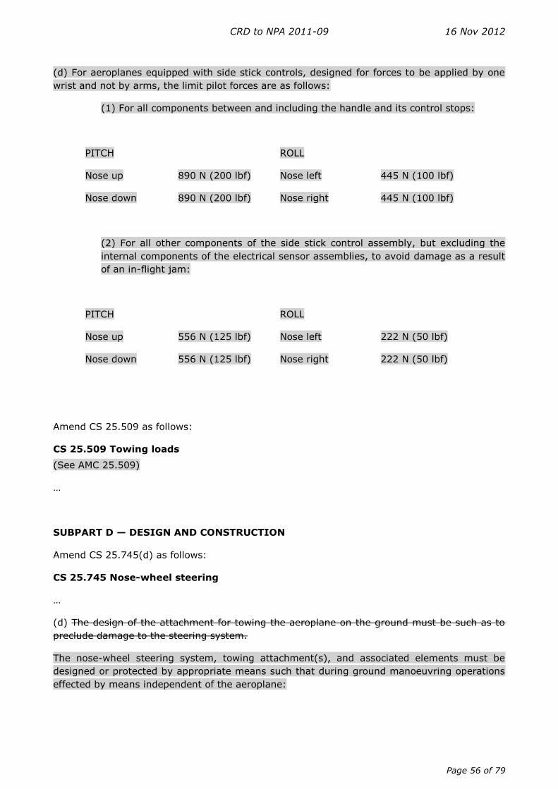
CRD to NPA 2011-09 16 Nov 2012
Page 56 of 79
(d) For aeroplanes equipped with side stick controls, designed for forces to be applied by one
wrist and not by arms, the limit pilot forces are as follows:
(1) For all components between and including the handle and its control stops:
PITCH ROLL
Nose up 890 N (200 lbf) Nose left 445 N (100 lbf)
Nose down 890 N (200 lbf) Nose right 445 N (100 lbf)
(2) For all other components of the side stick control assembly, but excluding the
internal components of the electrical sensor assemblies, to avoid damage as a result
of an in-flight jam:
PITCH ROLL
Nose up 556 N (125 lbf) Nose left 222 N (50 lbf)
Nose down 556 N (125 lbf) Nose right 222 N (50 lbf)
Amend CS 25.509 as follows:
CS 25.509 Towing loads
(See AMC 25.509)
…
SUBPART D — DESIGN AND CONSTRUCTION
Amend CS 25.745(d) as follows:
CS 25.745 Nose-wheel steering
…
(d) The design of the attachment for towing the aeroplane on the ground must be such as to
preclude damage to the steering system.
The nose-wheel steering system, towing attachment(s), and associated elements must be
designed or protected by appropriate means such that during ground manoeuvring operations
effected by means independent of the aeroplane:
CRD to NPA 2011-09 16 Nov 2012
Page 57 of 79
(1) Damage affecting the safe operation of the nose-wheel steering system is precluded,
or
(2) A flight crew alert is provided, before the start of taxiing, if damage may have
occurred (see AMC 25.1322).
(See AMC 25.745(d))
Create a new CS 25.777(i) as follows:
CS 25.777 Cockpit controls
…
(i) Pitch and roll control forces and displacement sensitivity shall be compatible, so that normal
inputs on one control axis will not cause significant unintentional inputs on the other.
Amend CS 25.785(b) as follows:
CS 25.785 Seats, berths, safety belts and harnesses
…
(b) Each seat, berth, safety belt, harness, and adjacent part of the aeroplane at each
station designated as occupiable during take-off and landing must be designed so that a
person making proper use of these facilities will not suffer serious injury in an emergency
landing as a result of the inertia forces specified in CS 25.561 and CS 25.562. However, berths
intended only for the carriage of medical patients (e.g. stretchers) need not comply with the
requirements of CS 25.562.
Amend CS 25.810(a)(1)(iv) as follows:
CS 25.810 Emergency egress assist means and escape routes
…
(a) …
(1) …
(iv) It must have the capability, in 46 km/hr (25-knot) winds directed from the most
critical angle, simultaneously with any engine(s) running at ground idle, to deploy
and, with the assistance of only one person, to remain usable after full deployment
to evacuate occupants safely to the ground.
…

CRD to NPA 2011-09 16 Nov 2012
Page 58 of 79
Amend CS 25.855 as follows:
CS 25.855 Cargo or baggage compartments
…
(c) (1) Ceiling and sidewall liner panels of Class C cargo or baggage compartments, and ceiling
and sidewall liner panels in Class F cargo or baggage compartments, if installed to meet the
requirements of subparagraph (b)(2) of this paragraph, must meet the test requirements of
Part III of Appendix F or other approved equivalent methods.
(2) Cockpit voice and flight data recorder systems, windows and systems or equipment within,
or in the vicinity of, Class E cargo compartments shown to be essential for continued safe flight
and landing according to CS 25.1309 must be adequately protected against fire. If protective
covers are used they must meet the requirements of Appendix F, Part III.
SUBPART E — POWERPLANT
Amend CS 25.1193(e)(3) as follows:
CS 25.1193 Cowling and nacelle skin
…
(e) Each aeroplane must -
…
(3) Have fireproof skin in areas subject to flame if a fire starts in the engine power
or accessory sections. Have cowlings and nacelles skins, in areas subject to flame if
a fire starts in an engine fire zone, complying with the following:
(i) For in-flight operations, cowlings and nacelles skins must be fireproof in the
complete concerned areas and,
(ii) For ground operations, cowlings and nacelles skins must be:
(a) Fireproof in the portions of the concerned areas where a skin burn
through would affect critical areas of the aeroplane, and
(b) Fire-resistant or compliant with sub-paragraph (e)(1) of this
paragraph in the remaining portions of the concerned areas.
(See AMC 25.1193(e))
SUBPART F — EQUIPMENT
Amend CS 25.1447 (c)(3) as follows:
CS 25.1447 Equipment standards for oxygen dispensing units
…
CRD to NPA 2011-09 16 Nov 2012
Page 59 of 79
(c) …
(See AMC 25.1447 (c)(3))
…
SUBPART J — AUXILIARY POWER UNIT INSTALLATIONS
Amend CS 25J1193 as follows:
CS 25J1193 APU compartment
…
(e) Each aeroplane must:
…
(3) Have fireproof skin in areas subject to flame if a fire starts in the APU compartment.
Have APU compartment external skins, in areas subject to flame if a fire starts in an
APU fire zone, complying with the following:
(i) For in-flight operations, APU compartment external skins must be fireproof in
the complete concerned areas, and
(ii) For ground operations, APU compartment external skins must be :
(a) Fireproof in the portions of the concerned areas where a skin burn
through would affect critical areas of the aeroplane, and
(b) Fire-resistant or compliant with sub-paragraph (e)(1) of this
paragraph in the remaining portions of the concerned areas.
(See AMC 25.1193(e))
CRD to NPA 2011-09 16 Nov 2012
Page 60 of 79
APPENDICES
Create a new Appendix Q as follows:
Appendix Q
Additional airworthiness requirements for approval of a Steep Approach Landing
(SAL) capability
(SAL) 25.1 Applicability
This Appendix contains airworthiness requirements that enable an aeroplane to obtain approval
for a steep approach landing capability using an approach path angle greater than or equal to
4.5° (a gradient of 7.9 %).
The requirements of this appendix cover only CS-25 Subparts B and G and they apply in lieu of
CS 25.121(d). They also apply in lieu of CS 25.125 if a reduced landing distance is sought, or if
the landing procedure (speed, configuration, etc.) differs significantly from normal operation,
or if the screen height is greater than 50 ft. Additional requirements may apply with respect to
aeroplane systems or equipment or other relevant items such as autopilot, flight guidance or
GPWS. It is likely that the GPWS mode 1 (sink rate) envelope will need modification to prevent
nuisance alerts. Also, the structural implications of the increased probability of high rates of
descent at touchdown must be considered.
If a steep approach approval is required for flight in icing conditions, substantiation must be
provided accordingly for the steep approach condition.
An applicant may choose to schedule information for an all-engines approach or for an
approach with one engine inoperative. If an all-engines approach is scheduled, it is assumed
that a diversion is required if an engine failure occurs prior to the decision to land.
(SAL) 25.2 Definitions
For the purposes of this Appendix:
— Steep Approach Landing: An approach to land made using a glide path angle greater
than or equal to 4.5°, as selected by the applicant.
— Screen Height: The reference height above the runway surface from which the landing
distance is measured. The screen height is a height selected by the applicant, at 50 ft or
another value from 35 to 60 ft.
— VREF(SAL) is the calibrated airspeed selected by the applicant used during the stabilised
approach at the selected approach path angle and maintained down to the screen height
defined above. VREF(SAL) may not be less than 1.23 VSR, VMCL, or a speed that provides the
manoeuvring capability specified in CS 25.143(h), whichever is greater and may be different to
the VREF used for standard approaches.
— VREF(SAL)-1 is the calibrated airspeed selected by the applicant used during the stabilised
one-engine-inoperative approach at the selected approach path angle and maintained down to
the screen height defined above. VREF(SAL)-1 may not be less than VREF(SAL).
CRD to NPA 2011-09 16 Nov 2012
Page 61 of 79
(SAL) 25.3 Steep Approach Landing Distance (Applicable only if a reduced landing distance
is sought, or if the landing procedure (speed, configuration, etc.) differs significantly from
normal operation, or if the screen height is greater than 50 ft.)
(a) The steep approach landing distance is the horizontal distance necessary to land and to
come to a complete stop from the landing screen height and must be determined (for standard
temperatures, at each weight, altitude and wind within the operational limits established by
the applicant for the aeroplane) as follows:
(1) The aeroplane must be in the all-engines-operating or one-engine-inoperative
steep approach landing configuration, as applicable.
(2) A stabilised approach, with a calibrated airspeed of VREF(SAL) or VREF(SAL)-1 as
appropriate, and at the selected approach angle must be maintained down to
the screen height.
(3) Changes in configuration, power or thrust, and speed must be made in
accordance with the established procedures for service operation (see AMC
25.125(b)(3)).
(4) The landing must be made without excessive vertical acceleration, tendency
to bounce, nose over or ground loop and with a vertical touchdown velocity
not greater than 6 ft/sec.
(5) The landings may not require exceptional piloting skill or alertness.
(b) The landing distance must be determined on a level, smooth, dry, hard-surfaced
runway (see AMC 25.125(c)). In addition -
(1) The pressures on the wheel braking systems may not exceed those specified
by the brake manufacturer.
(2) The brakes may not be used so as to cause excessive wear of brakes or tyres
(see AMC 25.125(c)(2)).
(3) Means other than wheel brakes may be used if that means
(i) Is safe and reliable;
(ii) Is used so that consistent results can be expected in service; and
(iii) Is such that exceptional skill is not required to control the aeroplane.
(c) Reserved.
(d) Reserved.
(e) The landing distance data must include correction factors for not more than 50 % of the
nominal wind components along the landing path opposite to the direction of landing, and not
less than 150 % of the nominal wind components along the landing path in the direction of
landing.
CRD to NPA 2011-09 16 Nov 2012
Page 62 of 79
(f) If any device is used that depends on the operation of any engine, and if the landing
distance would be noticeably increased when a landing is made with that engine assumed to
fail during the final stages of an all-engines-operating steep approach, the steep approach
landing distance must be determined with that engine inoperative unless the use of
compensating means will result in a landing distance not more than that with each engine
operating.
(SAL) 25.4 Climb: One-engine-inoperative
In a configuration corresponding to the normal all-engines-operating procedure in which VSR
for this configuration does not exceed 110 % of the VSR for the related all-engines-operating
steep approach landing configuration, the steady gradient of climb may not be less than 2.1 %
for two-engined aeroplanes, 2.4 % for three-engined aeroplanes, and 2.7 % for four-engined
aeroplanes, with:
(a) The critical engine inoperative, the remaining engines at the go-around power or thrust
setting;
(b) The maximum landing weight;
(c) A climb speed of VREF(SAL); and
(d) The landing gear retracted.
(SAL) 25.5 Safe operational and flight characteristics
(a) It must be demonstrated that it is possible to complete a stabilised approach in calm air
down to the commencement of the landing flare, followed by a touchdown and landing without
displaying any hazardous characteristics for the following conditions (see AMC to Appendix Q,
(SAL) 25.5):
(1) The selected approach path angle at VREF(SAL) or VREF(SAL)-1 as appropriate;
(2) An approach path angle 2° steeper than the selected approach path angle, at
VREF(SAL) or VREF(SAL)-1 as appropriate; and
(3) The selected approach path angle at VREF(SAL) minus 5 knots or VREF(SAL)-1 minus
5 knots as appropriate.
(b) For conditions (1), (2) and (3):
(i) The demonstration must be conducted at the most critical weight and centre of
gravity, either with all-engines-operating or with the critical engine inoperative, as
appropriate;
(ii) The rate of descent must be reduced to 3 feet per second or less before
touchdown;
(iii) Below a height of 200 ft no action shall be taken to increase power or thrust
apart from those small changes which are necessary to maintain an accurate
approach;
CRD to NPA 2011-09 16 Nov 2012
Page 63 of 79
(iv) No nose depression by use of longitudinal control shall be made after initiating
the flare other than those small changes necessary to maintain a continuous and
consistent flare flight path; and
(v) The flare, touchdown and landing may not require exceptional piloting skill or
alertness.
(c) For conditions (1) and (3), the flare must not be initiated above the screen height.
(d) For condition (2), it must be possible to achieve an approach path angle 2° steeper than
the selected approach path angle in all configurations which exist down to the initiation of the
flare, which must not occur above 150 % of the screen height. The flare technique used must
be substantially unchanged from that recommended for use at the selected approach path
angle.
(e) All-engines-operating steep approach. It must be demonstrated that the aeroplane can
safely transition from the all-engines-operating steep landing approach to the one-engine-
inoperative approach climb configuration with one engine having been made inoperative for
the following conditions:
(1) The selected steep approach angle;
(2) An approach speed of VREF(SAL);
(3) The most critical weight and centre of gravity; and
(4 For propeller-powered aeroplanes, the propeller of the inoperative engine shall
be at the position it automatically assumes following an engine failure at high
power.
(f) In addition, for propeller-powered aeroplanes, it must be demonstrated that
controllability is maintained following an engine failure at approach power and with the
propeller at the position it automatically assumes.
(g) The height loss during the manoeuvre required by subparagraph (SAL) 25.5(e) must be
determined.
(h) It must be demonstrated that the aeroplane is safely controllable during a landing with
one engine having been made inoperative during the final stages of an all-engines-operating
steep approach for the following conditions:
(1) The selected steep approach angle;
(2) An approach speed of VREF(SAL);
(3) The most critical weight and centre of gravity; and
(4) For propeller-powered aeroplanes, the propeller of the inoperative engine shall
be at the position it automatically assumes following an engine failure at approach
power.
(i) One-engine-inoperative steep approach. It must be demonstrated that the aeroplane
can safely transition from the one-engine-inoperative steep landing approach to the approach
climb configuration for the following conditions:
CRD to NPA 2011-09 16 Nov 2012
Page 64 of 79
(1) The selected steep approach angle;
(2) An approach speed of VREF(SAL)-1;
(3) The most critical weight and centre of gravity; and
(4) For propeller-powered aeroplanes the propeller of the inoperative engine may
be feathered.
(SAL) 25.6 Aeroplane Flight Manual
The AFM supplement for steep approach landing shall include the following:
(a) The steep approach landing distance determined in accordance with paragraph (SAL)
25.3 of this Appendix for the selected screen height and aeroplane configuration. The landing
distance data may additionally include correction factors for runway slope and temperature
other than standard, within the operational limits of the aeroplane, and may provide the
required landing field length including the appropriate factors for operational variations
prescribed in the relevant operating regulation.
(b) The more limiting of the landing weight, altitude and temperature (WAT) limits derived
in accordance with:
(1) CS 25.119, and
(2) The one-engine-inoperative approach climb requirement of paragraph (SAL)
25.4 of this Appendix.
(c) Appropriate limitations and detailed normal, non-normal and emergency procedures.
Where an aeroplane is not approved for deliberate one-engine-inoperative steep approach
landings, this limitation shall be stated.
(d) A statement that the presentation of the steep approach limitations, procedures and
performance reflects the capability of the aeroplane to perform steep approach landings but
that it does not constitute operational approval.
(e) A statement of headwind and crosswind limitations if they are different from those for
non-steep approaches. The tailwind limitation is 5 knots, unless test evidence shows that more
than 5 knots is acceptable.
(f) The reference steep approach glide slope angle and the screen height used for
determination of the landing distance must be specified.
(g) The height loss during a go-around from the all-engines-operating steep landing
approach to the approach climb configuration with one engine made inoperative, determined in
accordance with (SAL) 25.5(g).
CRD to NPA 2011-09 16 Nov 2012
Page 65 of 79
BOOK 2
AMC — SUBPART B
Amend AMC 25.21(g) as follows:
AMC 25.21(g) Performance and handling characteristics in icing conditions contained
in Appendix C to CS-25
…
4.7 …
h. Installed thrust. This includes operation of ice protection systems when
establishing acceptable power or thrust setting procedures, control, stability, lapse
rates, rotor speed margins, temperature margins, Automatic Reserve Power (ARP)
Automatic Take-Off Thrust Control System (ATTCS) operation, and power or thrust
lever angle functions.
…
Create a new AMC 25.101(g) as follows:
AMC 25.101(g)
Go-around
In showing compliance with CS 25.101(g), it should be shown at the landing weight, altitude
and temperature (WAT) limit, by test or calculation, that a safe go-around can be made from
the minimum decision height with:
— the critical engine inoperative and, where applicable, the propeller feathered,
— a configuration and a speed initially set for landing and then in accordance with the
go-around procedures, using actual time delays and, except for movements of the
primary flying controls, not less than 1 second between successive crew actions,
— the power available,
— the landing gear selection to the ‘up’ position being made after a steady positive
rate of climb is achieved.
It should be noted that for Category 3 operation the system will ensure the aircraft is over the
runway, so any go-around will be safe with the aircraft rolling on the runway during the
manoeuvre. Hence AMC 25.101(g) is only relevant or necessary for decision heights down to
Category 2 operations.
CRD to NPA 2011-09 16 Nov 2012
Page 66 of 79
AMC — SUBPART C
Create a new AMC 25.331(c)(1) as follows:
AMC 25.331(c)(1)
Maximum pitch control displacement at VA
The physical limitations of the aircraft from the cockpit pitch control device to the control
surface deflection, such as control stops position, maximum power and displacement rate of
the servo controls, and control law limiters, may be taken into account.
Create a new AMC 25.331(c)(2) as follows:
AMC 25.331(c)(2)
Checked manoeuvre between VA and VD
The physical limitations of the aircraft from the cockpit pitch control device to the control
surface deflection, such as control stops position, maximum power and displacement rate of
the servo controls, and control law limiters, may be taken into account.
For aeroplanes equipped with electronic flight controls, where the motion of the control
surfaces does not bear a direct relationship to the motion of the cockpit control devices, the
circular frequency of the movement of the cockpit control ‘ω’ shall be varied by a reasonable
amount to establish the effect of the input period and amplitude on the resulting aeroplane
loads. This variation is intended to verify that there is no large and rapid increase in aeroplane
loads.
Create a new AMC 25.333(b) as follows:
AMC 25.333(b)
Manoeuvring envelope
For calculation of structural design speeds, the stalling speeds Vs0 and Vs1 should be taken to
be the 1-g stalling speeds in the appropriate flap configuration. This structural interpretation of
stalling speed should be used in connection with the paragraphs CS 25.333(b), CS 25.335,
CS 25.335(c)(d)(e), CS 25.479(a), and CS 25.481(a)(1).
Create a new AMC 25.335(b)(1) as follows:
AMC 25.335(b)(1)(ii)
Design Dive Speed — High speed protection function
In any failure condition affecting the high speed protection function, the conditions as defined
in CS 25.335(b)(1)(ii) still remain applicable.
It implies that a specific value, which may be different from the VD/MD value in normal
configuration, has to be associated with this failure condition for the definition of loads related
to VD/MD as well as for the justification to CS 25.629. However, the strength and speed margin
required will depend on the probability of this failure condition, according to the criteria of CS
25.302.
CRD to NPA 2011-09 16 Nov 2012
Page 67 of 79
Alternatively, the operating speed VMO/MMO may be reduced to a value that maintains a speed
margin between VMO/MMO and VD/MD that is consistent with showing compliance with CS
25.335(b)(1)(ii) without the benefit of the high speed protection system, provided that:
(a) Any failure of the high speed protection system that would affect the design dive
speed determination is shown to be Remote;
(b) Failures of the system must be announced to the pilots, and:
(c) Aeroplane flight manual instructions should be provided that reduce the maximum
operating speeds, VMO/MMO.
Create a new AMC 25.349(a) as follows:
AMC 25.349(a)
Rolling conditions
The physical limitations of the aircraft from the cockpit roll control device to the control surface
deflection, such as control stops position, maximum power and displacement rate of the servo
controls, and control law limiters, may be taken into account.
Create a new AMC 25.351 as follows:
AMC 25.351
Yaw manoeuvre conditions
The physical limitations of the aircraft from the cockpit yaw control device to the control
surface deflection, such as control stops position, maximum power and displacement rate of
the servo controls, and control law limiters, may be taken into account.
Create a new AMC 25.509 as follows:
AMC 25.509
Towbarless towing
(a) General
Towbarless towing vehicles are generally considered as ground equipment and are as such not
subject to direct approval by the (aircraft) certifying agencies. However, these vehicles should
be qualified in accordance with the applicable SAE ARP documents. It should be ensured that
the nose landing gear and supporting structure is not being overloaded (by static and dynamic
(including fatigue) loads) during towbarless towing operations with these vehicles. This should
be ensured by the aircraft manufacturer, either by specific investigations as described in
subparagraphs (b) and (c) below, or alternatively, by publishing aircraft load limitations in a
towbarless towing vehicle assessment document, to allow towbarless towing vehicle
manufacturers to demonstrate their vehicles will not overload the aircraft.
(b) Limit static load cases
For the limit static load cases, the investigation may be conducted by rational analysis
supported by test evidence. The investigation should take into account the influence on the
CRD to NPA 2011-09 16 Nov 2012
Page 68 of 79
towing loads of the tractive force of the towing vehicle including consideration of its weight and
pavement roughness.
Furthermore, the investigation should include, but may not be limited to, the following
towbarless towing operation scenarios:
(1) P ushback towing: Moving a fully loaded aircraft (up to Maximum Ramp Weight
(MRW)) from the parking position to the taxiway. Movement includes: pushback with
turn, a stop, and short tow forward to align aircraft and nose wheels. Engines may or
may not be operating. Aeroplane movement is similar to a conventional pushback
operation with a towbar.
(2) Maintenance towing: The movement of an aeroplane for maintenance/remote
parking purposes (e.g. from the gate to a maintenance hangar). Aircraft is typically
unloaded with minimal fuel load.
(3) Dispatch (operational) towing: Towing a revenue aircraft (loaded with
passengers, fuel, and cargo up to Maximum Ramp Weight (MRW)) from the terminal
gate/remote parking area to a location near the active runway. The movement may
cover several kilometres with speeds according to SAE ARP 5283 technical
standards, with several starts, stops and turns. Replaces typical taxiing operations
prior to take-off.
Operations that are explicitly prohibited need not to be addressed.
(c) Fatigue evaluation
Fatigue evaluation of the impact of towbarless towing on the airframe should be conducted
under the provision of CS 25.571 and CS 25.1529.
Specifically, the contribution of the towbarless towing operational loads to the fatigue load
spectra for the nose landing gear and its support structure needs to be evaluated. The impact
of the towbarless towing on the certified life limits of the landing gear and supporting structure
needs to be determined.
The fatigue spectra used in the evaluation should consist of typical service loads encountered
during towbarless towing operations, which cover the loading scenarios noted above for static
considerations. Furthermore, the spectra should be based on measured statistical data derived
from simulated service operation or from applicable industry studies.
(d) Other considerations
Specific combinations of towbarless towing vehicle(s) and aircraft that have been assessed as
described above and have been found to be acceptable, along with any applicable towing
instructions and/or limitations should be specified in the Instructions for Continued
Airworthiness as described in Appendix H, paragraph H25.3(a)(4) and in the Aeroplane Flight
Manual as specified in AMC 25.745(d)..
Aircraft braking, while the aircraft is under tow, may result in loads exceeding the aircraft’s
design load and may result in structural damage and/or nose gear collapse. For these reasons,
the aircraft manufacturer should ensure that the appropriate information is provided in the
Aeroplane Maintenance Manual and in the Aeroplane Flight Manual to preclude aircraft braking
during normal towbarless towing. Appropriate information should also be provided in the
CRD to NPA 2011-09 16 Nov 2012
Page 69 of 79
Instructions for Continued Airworthiness to inspect the affected structure should aircraft
braking occur, for example in an emergency situation.
AMC — SUBPART D
Create a new AMC 25.745(d) as follows:
AMC 25.745(d)
Nose-wheel steering
CS 25.745(d) provides for the two following options:
1. A ‘no damage’ situation exists, because damage is precluded.
2. Damage can occur, but indication to the flight crew is provided.
(a) General consideration to CS 25.745(d)(1) and (2)
Some damage may occur during ground manoeuvring activities that can be considered
acceptable and judged to be normal wear and tear. It is not intended that such damage needs
necessarily to be precluded or that it should initiate a flight crew alert.
(b) To comply with CS 25.745(d)(1) the following applies:
The aeroplane may be designed in such a way that under all ground manoeuvring operations
by any towing means no damage affecting the steering system can occur.
Examples are:
(1) The steering system is designed sufficiently strong to resist any applied towing
input.
(2) The steering system is designed to allow 360 degrees rotation.
(3) The steering system is disconnected either automatically or by operational
procedure.
(4) The steering system is protected by shear sections installed on the nose
landing gear.
(c) To comply with CS 25.745(d)(2) the following applies:
When protection is afforded by the flight crew alerting system, the damage detection means
should be independent of the availability of aeroplane power supplies and should be active
during ground manoeuvring operations effected by means independent of the aeroplane. If
damage may have occurred, a latched signal should be provided to the flight crew alerting
system.
(d) Alternative Acceptable Means of Compliance to CS 25.745(d)(1) and (2):
CRD to NPA 2011-09 16 Nov 2012
Page 70 of 79
In the case where the aeroplane design does not comply with CS 25.745(d)(1) and (d)(2) the
following applies:
(1) The Aeroplane Flight Manual, in the Section Limitations, should include a
statement that ‘Towbarless towing is prohibited’, or
(2) The Aeroplane Flight Manual, in the Section Limitations, should include a
statement that:
‘Towbarless towing is prohibited, unless the towbarless towing operations are
performed in compliance with the appropriate operational regulation using
towbarless towing vehicles that are designed and operated to preclude damage to
the aeroplane nose wheel steering system, or which provide a reliable and
unmistakable warning when damage to the steering system has occurred.
Towbarless towing vehicles that are specifically accepted for this type of aeroplane
are listed in the [appropriate maintenance documentation]provided by the
aeroplane manufacturer.’
‘Appropriate maintenance documentation’ means Instructions for Continued
Airworthiness as described in Appendix H, paragraph H25.3(a)(4) of CS-25.
(3) The acceptance by the aeroplane manufacturer of the applicable towbarless
towing vehicles and its reliability of the oversteer protection and/or indication
system as referred to in sub-paragraph ((d)(2)) above should be based on the
following:
(i). The aeroplane Nose Wheel Steering Failure Analysis should include the
effects of possible damage caused by towbarless towing operations.
(ii). If the Nose Wheel Steering Failure Analysis shows that damage to the
steering system by the use of towbarless towing may result in a Failure
Condition that can be classified as Hazardous or Catastrophic (refer to CS
25.1309), the acceptance of a towing vehicle oversteer protection and/or
indication system should be based on an aeroplane safety analysis,
encompassing the reliability of that vehicle system, in order to meet the
aeroplane safety objectives.
(iii). If the Nose Wheel Steering Failure Analysis shows that damage to the
steering system by the use of towbarless towing may result in a Failure
Condition that can be classified as Major or less severe, the aeroplane
manufacturer can accept the design of the towing vehicle oversteer indication
— and/or protection system based on a ‘Declaration of Compliance’, issued by
the towbarless towing vehicle manufacturer. This declaration will state that the
vehicle design complies with the applicable standards (SAE ARPs, Aeroplane
Towing Assessment Criteria Document) and that it is designed and built under
ISO 9001 quality standards or equivalent.
Such a declaration must be made regarding all Towbarless Towing Vehicles to
be used for ground manoeuvring of CS-25 certificated aeroplanes.
CRD to NPA 2011-09 16 Nov 2012
Page 71 of 79
AMC — SUBPART E
Create a new AMC 25.1193 (e) as follows:
AMC 25.1193(e)
Engine cowling and nacelle skin, APU compartment external skin
(a) PURPOSE
This AMC provides guidance for showing compliance with the certification specifications relating
to fire withstanding capability of engine cowlings and nacelles skins, and APU compartment
external skins, in areas subject to flame if a fire starts in an engine or APU fire zone, in
consideration of potential hazard levels associated to operating conditions (flight/ground).
(b) RELATED CERTIFICATION SPECIFICATIONS
CS 25.1193(e), CS 25J1193(e)
(c) APPLICABILITY
This AMC is applicable to engine cowlings and nacelles, and APU compartment external skins
(fixed and/or removable).
(d) BACKGROUND
CS 25.1193(e) and CS 25J1193(e) previously required the engine cowlings/nacelle skins and
APU compartment external skins to be fireproof if a fire starts in the engine power or accessory
sections or in the APU compartment. During past Type certification projects it has been found
that having non-fireproof engine cowlings/nacelle skins in some locations under some
operating conditions do not adversely affect safety. Consequently, in practice, not all
cowlings/skins ‘subject to flame if a fire starts in the engine power or accessory sections’ have
been required to be fireproof under all operating conditions and for instance some portions
were approved as fire-resistant only for ground operating conditions. As it represented a rule
relaxation, such non-fireproof cowlings/skins were formally found to be ‘equivalently safe’ to
comply with the rule. Over time, however, these equivalent safety findings became inherent
within traditionally accepted design practices. Certification Review Item (CRI) released to cover
the relaxation included also interpretations for zone definitions and operating conditions to be
considered for fireproofness or fire-resistance compliance demonstration.
(e) FIRE WITHSTANDING REQUIREMENTS, OPERATING CONDITIONS AND
POTENTIAL HAZARDS
(1) General
The required level of ability to withstand the effects of fire varies with the potential
hazard level associated with different flight and ground operating conditions, as
follows:
(2) Flight Conditions
For the purpose of CS 25.1193(e) and CS 25J1193(e), flight conditions are defined
as aeroplane operation from airspeed above minimum V1 until minimum touchdown
speed in approved normal or abnormal operations. Cowling and skin in areas
subject to flame if a fire starts in an engine or APU fire zone must be demonstrated
to be fireproof.
CRD to NPA 2011-09 16 Nov 2012
Page 72 of 79
For demonstrating the fireproof capabilities of the cowling/skin, the following
applies:
Credit from the external airflow on the cowling/skin can be considered
The airflow levels and the engine/APU powers should be consistent with the
operating conditions. These parameters should be examined and the most
critical ones should be determined.
The engine/APU should be considered to be operative for the first 5 minutes,
and during the remaining 10 minutes under windmilling conditions for engine
and stopped conditions for the APU.
(3) Ground conditions
For the purpose of CS 25.1193(e) and CS 25J1193(e), ground conditions are
defined as aircraft operation not covered by the flight conditions provided in
sub-paragraph (e)(2) of this AMC. It includes static, taxiing, take-off roll and
landing roll.
(i) Areas where fireproof skins are required — The portion of cowling and
skin in areas subject to flame if a fire starts in an engine or APU fire zone, and
located so that not containing the effects of the fire could result in serious
hazards to the aircraft, injuries to crew, passengers or ground personnel, must
be fireproof under all conditions. Serious hazards include, but are not limited
to, events such as fuel tank explosion, hazardous spread of fire to flammable
fluid sources outside the fire zone, fuselage penetration and flight control
surface damages.
(A) Pod-mounted engines: The portion of the nacelle/cowling skin,
which is required to be fireproof on ground, varies by installation. A
design is considered acceptable when it is demonstrated that the fireproof
area protects the pylon strut and other portions of the aircraft considered
to be put at a serious hazard risk if burn through occurs. Factors to
consider within the analysis and to use when substantiating the design
are: the engine location — wing or aft fuselage mounted, the coupling
distance of the nacelle to the wing, the airflow characteristics, the fluid
migration scheme and the fire plume patterns. After the initial analysis,
similarity demonstration and in-service experience may be used as
appropriate. Analyses have demonstrated that the typical area of concern
ranges from 90° ( 45°) to 180° ( 90°) and is centred on the pylon
centre line. This area may increase or decrease depending on the
analysis results. For example, most wing mounted engines not closely
coupled to the wing have been found acceptable with a 45° protection
while more closely coupled installations and those with other unique
design features have required 90° protection. The symmetry of the
protection may also vary. Wing mounted engines usually have
symmetrical protection while aft mounted engines may have non-
symmetrical protection in order to cover more of the inboard area.
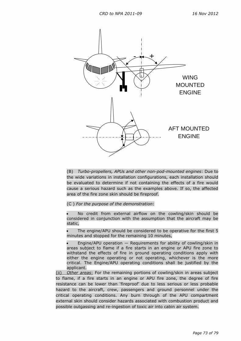
CRD to NPA 2011-09 16 Nov 2012
Page 73 of 79
(B) Turbo-propellers, APUs and other non-pod-mounted engines: Due to
the wide variations in installation configurations, each installation should
be evaluated to determine if not containing the effects of a fire would
cause a serious hazard such as the examples above. If so, the affected
area of the fire zone skin should be fireproof.
(C ) For the purpose of the demonstration:
No credit from external airflow on the cowling/skin should be
considered in conjunction with the assumption that the aircraft may be
static,
The engine/APU should be considered to be operative for the first 5
minutes and stopped for the remaining 10 minutes,
Engine/APU operation — Requirements for ability of cowling/skin in
areas subject to flame if a fire starts in an engine or APU fire zone to
withstand the effects of fire in ground operating conditions apply with
either the engine operating or not operating, whichever is the more
critical. The Engine/APU operating conditions shall be justified by the
applicant.
(ii) Other areas: For the remaining portions of cowling/skin in areas subject
to flame, if a fire starts in an engine or APU fire zone, the degree of fire
resistance can be lower than ‘fireproof’ due to less serious or less probable
hazard to the aircraft, crew, passengers and ground personnel under the
critical operating conditions. Any burn through of the APU compartment
external skin should consider hazards associated with combustion product and
possible outgassing and re-ingestion of toxic air into cabin air system.
- +
WING
MOUNTED
ENGINE
AFT MOUNTED
ENGINE
CRD to NPA 2011-09 16 Nov 2012
Page 74 of 79
(A) Fire-resistant cowlings/skins provide adequate fire protection for
those areas as they provide sufficient time to stop the aeroplane and
evacuate it.
(B) A lower than ‘fire-resistant’ degree of fire protection may be
considered; the following conditions should then be analysed and
submitted to the Agency for approval:
— Cowling/skin should have the ability to withstand fire at least
equivalent to the ability of a 1 mm (0.040 inch) aluminium
sheet in the worst aircraft and engine/APU ground conditions
anticipated;
— Applicants must substantiate that this lower fire protection
level will not lead to hazardous effects including but not limited
to:
o Upon burn through of the lower than ‘fire-resistant’ area,
both the fire-resistant and/or fire-proof areas shall not
have their fire withstanding capability affected,
o Liberation of parts that would affect the aeroplane
evacuation procedure or reduce the efficiency of fire
protection means,
o Reduction in flammable fluid drainage capability such that
fire severity would be increased (magnitude, residual
presence, propagation to surrounding area),
o Reduction in aeroplane evacuation capability due to
proximity to evacuation paths or due to the visibility of the
fire hindering the ability of the passengers to evacuate the
aeroplane in a rapid and orderly manner,
Note: There is some hazard involving aeroplane evacuation even
in the absence of burn through due to such concerns as
smoke and flaming liquids exiting from openings. Burn
through of nacelle skin should not significantly increase
these hazards.
o Reduction in fire detection capability such that the flight
crew would not be aware of the fire, especially in a
situation involving taxiing prior to take-off,
o Reduction in fire extinguishing capability which could cause
or aggravate one of the potential hazards listed above.
o Flammable fluid and/or fire spreading on the aeroplane
evacuation path
(f) SPECIFIC CONFIGURATION CONSIDERATIONS
(1) Multiple skin layers: For some specific fire zones, a fire originating in that zone
will have to pass through several layers of cowling or skin before burning through
the external skin. This may be the case, for example, for the core zone of some
turbofan installations. In such cases, credit may be taken for multiple layers, having
regard to the location of the fire source and the likely direction of propagation from
CRD to NPA 2011-09 16 Nov 2012
Page 75 of 79
that location, providing burn through of the inner layer does not produce other
hazardous effects and it does not invalidate other certification specifications such as
fire extinguishing capability. The corresponding compliance substantiation should
take into account particular geometrical configuration with respect to the risk of
flame propagation, as well as critical systems or structures.
(2) Inlet skins: For external inlet skins, which enclose fire zones, the guidance
provided above for multiple skin layers applies. Inlet ducts should meet CS
25.1103/CS 25J1103 specifications.
(3) Openings: The following considerations are applicable to openings in a fire
zone skin whether the openings are of fixed size, variable or controllable size, or
normally closed, such as access or inspection doors, or pressure relief doors.
(i) Openings should be located such that flame exiting the opening would
not enter any other region where it could cause a hazard in flight or a serious
hazard on the ground as per sub-paragraph (e)(3). Exception is made for
covered openings which meet the same criteria for ability to withstand the
effects of fire as the surrounding cowl skin, and which are not expected to
become open under fire conditions. Since pressure relief doors may open
during some fire conditions, they should be located such that flames exiting
the door will not cause a hazard. However, doors that will remain closed during
most fire conditions, or will tend to re-close following initial opening, have
traditionally been assumed to be closed for the purposes of evaluating fire
detection and extinguishing.
(ii) Openings should have the same ability to withstand the effects of fire as
the adjacent skin with respect to becoming enlarged under fire conditions.
Some enlargement, such as burning away of louvers or doublers surrounding
the opening or gapping of covered openings, is acceptable provided that the
hazard is not significantly increased by a reduction in fire extinguishing or
detection capability, increased airflow causing increase in fire size or intensity,
or increase in probability of a hazardous spread of fire to other regions.
(4) Hinges, Fittings and Latches: These attaching means maintaining the
nacelle/cowlings between them or to the aircraft/engine/APU structure may need to
have a greater ability to withstand the effect of fire than the surrounding skin. Loss
of attaching means may create more severe hazards such as cowling liberation in
comparison to a skin burn through. The applicant must justify the required level of
fire withstanding capability by test and/or analysis.
(5) Seals : Where seals are used part of the external engine nacelle/cowling or APU
compartment boundaries, they should at least have the same ability to withstand
fire as the surrounding cowling/skin.
(g) COMPLIANCE DEMONSTRATION
Compliance should be substantiated per CS 25.1207. Substantiation involving airflow patterns
may include analytical methods such as Computational Fluid Dynamics, test methods or other
flow visualisation methods or a combination of these methods. Fire testing should be
accomplished according to the guidance of ISO 2685 with considerations of applications of
CRD to NPA 2011-09 16 Nov 2012
Page 76 of 79
representative conditions (airflow, loads, vibrations) and establishment of appropriate pass/fail
criteria (burn through, elongation, dislocation).
AMC — SUBPART F
Create a new AMC 25.1447(c)(3) as follows:
AMC 25.1447(c)(3)
Equipment standards for oxygen dispensing units
If oxygen outlets are not provided in a dedicated area, called here remote area, the applicant
shall demonstrate that oxygen dispensing outlets are within ‘five feet/five seconds’ reach of
the remote area(s) and shall show that no visual obstruction exists between the potential
oxygen users and the outlets, such as curtains or partitions, unless another method of
indication (e.g. a light) is provided in the remote area.
AMC — APPENDICES
Create a new AMC to Appendix Q as follows:
AMC to Appendix Q
(SAL) 25.5 Safe operational and flight characteristics
(a) For the approach demonstrations required by (SAL) 25.5(a), due account should be
taken of:
(1) The systems’ aspects of the power/thrust levers being at idle (e.g. arming of
ground lift dump);
(2) The most adverse flight idle power/thrust (e.g. effects of engine bleeds or
FADEC idle power/thrust control); and
(3) The effects on controllability from the use of auxiliary drag devices such as flight
spoilers (e.g. increased stall warning and stall speeds, loss of manoeuvrability).
(b) For the flare, touchdown and landing demonstrations required by (SAL) 25.5(a),
there should not be any occurrence of:
(1) Stall warning;
(2) Tail strike; or
(3) Any other characteristic that would interfere with the completion of the landing
(e.g. automatic thrust increase).
CRD to NPA 2011-09 16 Nov 2012
Page 77 of 79
(c) For the go-around demonstrations required by (SAL) 25.5(e) and (i), due account
should be taken of time delays associated with automatic or manual retraction of auxiliary drag
devices.
GENERAL
ACCEPTABLE MEANS OF COMPLIANCE — AMC
Amend AMC 25-13 as follows:
5 Reduced Thrust: (Acceptable Means of Compliance)
…
a. The reduced take-off thrust setting –
…
(4) Is at least 6075% of the maximum take-off thrust (no derate) or derated take-off
thrust if such is the performance basis, for the existing ambient conditions, for the
existing ambient conditions,with no further reduction below 6075% resulting from ARP
Automatic Take-off Thrust Control System (ATTCS) credit. Consequently the amount of
reduced thrust permitted is reduced when combined with the use of derated thrust so
that the overall thrust reduction remains at least 60% of the maximum take-off thrust.
For reduced thrust operations, compliance with the applicable performance and handling
requirements should be demonstrated as thoroughly as for an approved take-off rating.
…
(6) Enables compliance with CS-25 Appendix I in the event of an engine failure during
take-off, for aeroplanes equipped with an Automatic Reserve Performance system
ATTCS.
…
b. Relevant speeds (VEF, VMC, VR, and V2) used for reduced thrust take-offs are not
less than those which will comply with the required airworthiness controllability criteria
when using the take-off thrust (or derated take-off thrust, if such is the performance
basis) for the ambient conditions, including the effects of an Automatic Reserve
Performance (ARP) system ATTCS. It should be noted, as stated in paragraph c. below,
that in determining the take-off weight limits, credit can be given for an operable ARP
system ATTCS.
c. The aeroplane complies with all applicable performance requirements, including the
criteria in paragraphs a. and b. above, within the range of approved take-off weights,
with the operating engines at the thrust available for the reduced thrust setting selected
for take-off. However, the thrust settings used to show compliance with the take-off
flight path requirements of CS 25.115 and the final take-off climb performance
requirements of CS 25.121(c) should not be greater than that established by the initial
thrust setting. In determining the take-off weight limits, credit can be given for an
operable ARP system ATTCS.
CRD to NPA 2011-09 16 Nov 2012
Page 78 of 79
…
e. A periodic take-off demonstration is conducted using the aeroplane’s take-off thrust
setting without ARP ATTCS, if fitted, and the event is logged in the aeroplane’s
permanent records. An approved engine maintenance procedure or an approved engine
condition monitoring programme may be used to extend the time interval between
take-off demonstrations.
f. The AFM states, as a limitation, that take-offs utilising reduced take-off thrust settings
–
…
(4) Are authorised for aeroplanes equipped with an ARP System ATTCS, whether
operating or not.
…
CRD to NPA 2011-09 16 Nov 2012
Page 79 of 79
Appendix B - Attachments
CRI_B-06_Issue-02(closed).pdf
Attachment #1 to comment #61
NPA2011-09_comment18_figure.pdf
Attachment #2 to comment #18