cpd170 v1.00 bl-en
TRANSCRIPT
Berger Lahr GmbH & Co. KGBreslauer Str. 7D-77933 Lahr
Technical Documentation
Product manual for the AC servo drive system
CPD 170
Order no. ACC1MDADM00EN
Edition: V1.00, 01.2005

AC
C1M
DA
DM
00E
N, V
1.00
, 01.
2005
CPD 170
Servo-Drive CPD170 -2
Important information
The drive systems described here are products for general use that con-form to the state of the art in technology and are designed to prevent any dangers. However, drives and drive controllers that are not specifically designed for safety functions are not approved for applications where the functioning of the drive could endanger persons. The possibility of unexpected or unbraked movements can never be totally excluded wit-hout additional safety equipment. For this reason personnel must never be in the danger zone of the drives unless additional suitable safety equipment prevents any personal danger. This applies to operation of the machine during production and also to all service and maintenance work on drives and the machine. The machine design must ensure per-sonal safety. Suitable measures for prevention of property damage are also required.
For more information see the chapter on safety.
Not all product types are available in all countries. Please see the cur-rent catalogue for the availability of products.
We reserve the right to make technical changes.
All information refers to specifications and not to assured properties.
Most product designations are registered trademarks of their proprie-tors, even when not specifically noted.

AC
C1M
DA
DM
00E
N, V
1.00
, 01.
2005
CPD 170
Servo-Drive CPD170 -3
Table of Contents
Important information. . . . . . . . . . . . . . . . . . . . . . . . . . . . . . . . . -2
Table of Contents . . . . . . . . . . . . . . . . . . . . . . . . . . . . . . . . . . . . -3
Writing conventions and symbols. . . . . . . . . . . . . . . . . . . . . . . -9
1 Introduction
1.1 Unit overview. . . . . . . . . . . . . . . . . . . . . . . . . . . . . . . . 1-1
1.2 Components and interfaces . . . . . . . . . . . . . . . . . . . . 1-2
1.3 Model Selection Chart. . . . . . . . . . . . . . . . . . . . . . . . . 1-3
1.4 Documentation and literature references . . . . . . . . . . 1-3
1.5 Directives and standards. . . . . . . . . . . . . . . . . . . . . . . 1-4
1.6 Declaration of conformity. . . . . . . . . . . . . . . . . . . . . . . 1-5
1.7 TÜV certificate for functional safety. . . . . . . . . . . . . . . 1-6
2 Safety
2.1 Qualification of personnel . . . . . . . . . . . . . . . . . . . . . . 2-1
2.2 Intended use . . . . . . . . . . . . . . . . . . . . . . . . . . . . . . . . 2-1
2.3 Hazard categories . . . . . . . . . . . . . . . . . . . . . . . . . . . . 2-2
2.4 General safety instructions . . . . . . . . . . . . . . . . . . . . . 2-3
2.5 Safety functions. . . . . . . . . . . . . . . . . . . . . . . . . . . . . . 2-4
2.6 Monitoring functions . . . . . . . . . . . . . . . . . . . . . . . . . . 2-4
3 Technical Data
3.1 Environmental conditions . . . . . . . . . . . . . . . . . . . . . . 3-13.1.1 Temperature, humidity, installation height. . . . . . . . 3-13.1.2 Oscillation and shock loading . . . . . . . . . . . . . . . . . 3-13.1.3 Degree of protection as per EN60529 . . . . . . . . . . 3-2
3.2 Mechanical data . . . . . . . . . . . . . . . . . . . . . . . . . . . . . 3-23.2.1 Dimensional drawings. . . . . . . . . . . . . . . . . . . . . . . 3-2
3.3 Electrical Data . . . . . . . . . . . . . . . . . . . . . . . . . . . . . . . 3-43.3.1 Performance data for power amplifier . . . . . . . . . . . 3-43.3.2 24VDC controller power supply . . . . . . . . . . . . . . . 3-63.3.3 Signals . . . . . . . . . . . . . . . . . . . . . . . . . . . . . . . . . . 3-63.3.4 Safety functions . . . . . . . . . . . . . . . . . . . . . . . . . . . 3-73.3.5 Internal ballast resistor . . . . . . . . . . . . . . . . . . . . . . 3-83.3.6 Internal line filter . . . . . . . . . . . . . . . . . . . . . . . . . . . 3-9
3.4 Technical Data accessories. . . . . . . . . . . . . . . . . . . . 3-103.4.1 External ballast resistors . . . . . . . . . . . . . . . . . . . 3-103.4.2 External line filter . . . . . . . . . . . . . . . . . . . . . . . . . 3-103.4.3 Line reactor. . . . . . . . . . . . . . . . . . . . . . . . . . . . . . 3-11
-4 Servo-Drive CPD170
CPD 170
AC
C1M
DA
DM
00E
N, V
1.00
, 01.
2005
3.4.4 Holding brake controller . . . . . . . . . . . . . . . . . . . . . 3-113.4.5 Cable . . . . . . . . . . . . . . . . . . . . . . . . . . . . . . . . . . . 3-11
4 Basics
4.1 Safety functions . . . . . . . . . . . . . . . . . . . . . . . . . . . . . . 4-1
5 Engineering
5.1 Adjustable signal logic . . . . . . . . . . . . . . . . . . . . . . . . . 5-1
5.2 Specification of the con troller type. . . . . . . . . . . . . . . . 5-1
5.3 "Safe Standstill safety function" . . . . . . . . . . . . . . . . . . 5-25.3.1 Definitions . . . . . . . . . . . . . . . . . . . . . . . . . . . . . . . . 5-25.3.2 Function . . . . . . . . . . . . . . . . . . . . . . . . . . . . . . . . . . 5-25.3.3 Requirements for safe application . . . . . . . . . . . . . . 5-35.3.4 Application examples . . . . . . . . . . . . . . . . . . . . . . . . 5-4
6 Installation
6.1 Electromagnetic compatibility, EMC . . . . . . . . . . . . . . . 6-16.1.1 Operation in an IT network. . . . . . . . . . . . . . . . . . . . 6-4
6.2 Mechanical installation . . . . . . . . . . . . . . . . . . . . . . . . . 6-66.2.1 Installing the unit . . . . . . . . . . . . . . . . . . . . . . . . . . . 6-66.2.2 Installing mains filter, mains reactor and ballast resistor 6-9
6.3 Electrical installation . . . . . . . . . . . . . . . . . . . . . . . . . . 6-116.3.1 Overview of procedure. . . . . . . . . . . . . . . . . . . . . . 6-136.3.2 Overview of all connections . . . . . . . . . . . . . . . . . . 6-146.3.3 Reference value signals and limits. . . . . . . . . . . . . 6-166.3.4 Motor phase connections. . . . . . . . . . . . . . . . . . . . 6-166.3.5 Connection of ballast resistor. . . . . . . . . . . . . . . . . 6-206.3.6 Connection of mains power to power amplifier . . . 6-266.3.7 Connection for parallel operation . . . . . . . . . . . . . . 6-286.3.8 Connection of motor sensor (CN2) . . . . . . . . . . . . 6-286.3.9 Connection of holding brake controller (HBC) . . . . 6-316.3.10 Connection of controller supply voltage (24V at CN3). . 6-336.3.11 Connecting encoder signals A, B, I (CN5) . . . . . . . 6-356.3.12 PULSE (CN5) connection . . . . . . . . . . . . . . . . . . . 6-366.3.13 ESIM (CN5) connection . . . . . . . . . . . . . . . . . . . . . 6-396.3.14 CANopen connection (CN1 or CN4) . . . . . . . . . . . 6-416.3.15 Modbus connection (CN4) . . . . . . . . . . . . . . . . . . . 6-436.3.16 Connection of analogue inputs (CN1) . . . . . . . . . . 6-436.3.17 Connection of digital inputs/outputs (CN1) . . . . . . 6-456.3.18 Connection to PC or peripheral control terminal (CN4) . 6-476.3.19 Reference signal adapter . . . . . . . . . . . . . . . . . . . . 6-48
6.4 Checking installation. . . . . . . . . . . . . . . . . . . . . . . . . . 6-51

AC
C1M
DA
DM
00E
N, V
1.00
, 01.
2005
CPD 170
Servo-Drive CPD170 -5
7 Commissioning
7.1 General safety instructions . . . . . . . . . . . . . . . . . . . . . 7-1
7.2 Overview . . . . . . . . . . . . . . . . . . . . . . . . . . . . . . . . . . . 7-3
7.3 Tools for commissioning . . . . . . . . . . . . . . . . . . . . . . . 7-57.3.1 Overview. . . . . . . . . . . . . . . . . . . . . . . . . . . . . . . . . 7-57.3.2 HMI: Human-Machine Interface . . . . . . . . . . . . . . . 7-67.3.3 PS2 commissioning software (Power Suite 2) . . . . 7-9
7.4 Commissioning procedure. . . . . . . . . . . . . . . . . . . . . 7-107.4.1 "Initial Setup" . . . . . . . . . . . . . . . . . . . . . . . . . . . . 7-107.4.2 Operating state (state diagram) . . . . . . . . . . . . . . 7-157.4.3 Setting basic parameters and limit values . . . . . . 7-167.4.4 Analogue inputs . . . . . . . . . . . . . . . . . . . . . . . . . . 7-217.4.5 Digital inputs/outputs . . . . . . . . . . . . . . . . . . . . . . 7-227.4.6 Testing limit switches signals in field bus units . . . 7-237.4.7 Testing safety functions . . . . . . . . . . . . . . . . . . . . 7-247.4.8 Checking holding brake . . . . . . . . . . . . . . . . . . . . 7-257.4.9 Check direction of rotation . . . . . . . . . . . . . . . . . . 7-267.4.10 Setting device parameters for rotary encoder. . . . 7-277.4.11 Run autotuning . . . . . . . . . . . . . . . . . . . . . . . . . . . 7-297.4.12 Extended settings for autotuning . . . . . . . . . . . . . 7-30
7.5 Controller optimisation with step response . . . . . . . . 7-327.5.1 Controller structure . . . . . . . . . . . . . . . . . . . . . . . . 7-327.5.2 Optimisation . . . . . . . . . . . . . . . . . . . . . . . . . . . . . 7-337.5.3 Optimising the speed controller . . . . . . . . . . . . . . 7-347.5.4 Checking and optimising default settings . . . . . . . 7-377.5.5 Optimising the position controller . . . . . . . . . . . . . 7-38
8 Operation
8.1 control mode and operating mode handling . . . . . . . . 8-1
8.2 Access monitor . . . . . . . . . . . . . . . . . . . . . . . . . . . . . . 8-28.2.1 via HMI . . . . . . . . . . . . . . . . . . . . . . . . . . . . . . . . . . 8-28.2.2 via field bus. . . . . . . . . . . . . . . . . . . . . . . . . . . . . . . 8-28.2.3 via commissioning software . . . . . . . . . . . . . . . . . . 8-38.2.4 via hardware input signals . . . . . . . . . . . . . . . . . . . 8-3
8.3 Operating states . . . . . . . . . . . . . . . . . . . . . . . . . . . . . 8-48.3.1 State diagram . . . . . . . . . . . . . . . . . . . . . . . . . . . . . 8-48.3.2 Changing operating state . . . . . . . . . . . . . . . . . . . . 8-78.3.3 Displaying the operating states. . . . . . . . . . . . . . . . 8-9
8.4 Starting and changing operating modes . . . . . . . . . . 8-118.4.1 Start operating mode . . . . . . . . . . . . . . . . . . . . . . 8-118.4.2 Change operating mode . . . . . . . . . . . . . . . . . . . . 8-13
8.5 Operating modes. . . . . . . . . . . . . . . . . . . . . . . . . . . . 8-148.5.1 Jog operation mode . . . . . . . . . . . . . . . . . . . . . . . 8-148.5.2 Current control mode. . . . . . . . . . . . . . . . . . . . . . . 8-168.5.3 Speed control operating mode . . . . . . . . . . . . . . . 8-198.5.4 Electronic gear operation mode . . . . . . . . . . . . . . 8-228.5.5 Profile position operating mode . . . . . . . . . . . . . . 8-26

-6 Servo-Drive CPD170
CPD 170
AC
C1M
DA
DM
00E
N, V
1.00
, 01.
2005
8.5.6 Operation mode Profile velocity . . . . . . . . . . . . . . . 8-298.5.7 Operation mode Homing . . . . . . . . . . . . . . . . . . . . 8-31
8.6 Functions . . . . . . . . . . . . . . . . . . . . . . . . . . . . . . . . . . 8-438.6.1 Monitoring functions. . . . . . . . . . . . . . . . . . . . . . . . 8-438.6.2 Scaling . . . . . . . . . . . . . . . . . . . . . . . . . . . . . . . . . . 8-548.6.3 Movement profile . . . . . . . . . . . . . . . . . . . . . . . . . . 8-578.6.4 Quick Stop . . . . . . . . . . . . . . . . . . . . . . . . . . . . . . . 8-598.6.5 Halt. . . . . . . . . . . . . . . . . . . . . . . . . . . . . . . . . . . . . 8-608.6.6 Standstill window . . . . . . . . . . . . . . . . . . . . . . . . . . 8-618.6.7 Braking function with HBC . . . . . . . . . . . . . . . . . . . 8-628.6.8 Reversal of direction of rotation . . . . . . . . . . . . . . . 8-648.6.9 Analogue signals . . . . . . . . . . . . . . . . . . . . . . . . . . 8-668.6.10 Restoring default values. . . . . . . . . . . . . . . . . . . . . 8-67
9 Examples
9.1 Wiring for field bus control . . . . . . . . . . . . . . . . . . . . . . 9-1
9.2 Example of I/O parameter setting. . . . . . . . . . . . . . . . . 9-2
9.3 Wiring for “Safe Standstill” . . . . . . . . . . . . . . . . . . . . . . 9-3
10 Diagnostics and troubleshooting
10.1 Service . . . . . . . . . . . . . . . . . . . . . . . . . . . . . . . . . . . . 10-1
10.2 Error responses and error classes . . . . . . . . . . . . . . . 10-1
10.3 Error display . . . . . . . . . . . . . . . . . . . . . . . . . . . . . . . . 10-310.3.1 State diagram. . . . . . . . . . . . . . . . . . . . . . . . . . . . . 10-310.3.2 Error display on HMI . . . . . . . . . . . . . . . . . . . . . . . 10-510.3.3 Error display with commissioning software . . . . . . 10-610.3.4 Error display via field bus . . . . . . . . . . . . . . . . . . . . 10-7
10.4 Troubleshooting . . . . . . . . . . . . . . . . . . . . . . . . . . . . 10-1010.4.1 Resolution of malfunctions. . . . . . . . . . . . . . . . . . 10-1010.4.2 Error resolution sorted by error bit . . . . . . . . . . . . 10-11
10.5 Table of error numbers . . . . . . . . . . . . . . . . . . . . . . . 10-13
11 Parameters
11.1 Representation of the parameters . . . . . . . . . . . . . . . 11-1
11.2 List of all parameters . . . . . . . . . . . . . . . . . . . . . . . . . 11-3
12 Accessories and spare parts
12.1 Optional accessories . . . . . . . . . . . . . . . . . . . . . . . . . 12-1
12.2 Ballast resistors . . . . . . . . . . . . . . . . . . . . . . . . . . . . . 12-1
12.3 Mains reactor s . . . . . . . . . . . . . . . . . . . . . . . . . . . . . . 12-1
12.4 Mains filters . . . . . . . . . . . . . . . . . . . . . . . . . . . . . . . . 12-2
12.5 Motor cables . . . . . . . . . . . . . . . . . . . . . . . . . . . . . . . . 12-2
12.6 Encoder cables. . . . . . . . . . . . . . . . . . . . . . . . . . . . . . 12-2

AC
C1M
DA
DM
00E
N, V
1.00
, 01.
2005
CPD 170
Servo-Drive CPD170 -7
12.7 RS 422 . . . . . . . . . . . . . . . . . . . . . . . . . . . . . . . . . . . 12-3
12.8 CANopen. . . . . . . . . . . . . . . . . . . . . . . . . . . . . . . . . . 12-3
12.9 MODBUS. . . . . . . . . . . . . . . . . . . . . . . . . . . . . . . . . . 12-4
12.10 Installation material . . . . . . . . . . . . . . . . . . . . . . . . . . 12-4
13 Glossaries
13.1 Terms and Abbreviations. . . . . . . . . . . . . . . . . . . . . . 13-1
13.2 Product name . . . . . . . . . . . . . . . . . . . . . . . . . . . . . . 13-2
14 Service, maintenance and disposal
14.1 Service address . . . . . . . . . . . . . . . . . . . . . . . . . . . . 14-2
14.2 Maintenance . . . . . . . . . . . . . . . . . . . . . . . . . . . . . . . 14-214.2.1 Operational duration of safety function . . . . . . . . . 14-2
14.3 Replacing units . . . . . . . . . . . . . . . . . . . . . . . . . . . . . 14-3
14.4 Changing the motor. . . . . . . . . . . . . . . . . . . . . . . . . . 14-4
14.5 Shipping, storage, disposal . . . . . . . . . . . . . . . . . . . . 14-4
15 Index

-8 Servo-Drive CPD170
CPD 170
AC
C1M
DA
DM
00E
N, V
1.00
, 01.
2005
AC
C1M
DA
DM
00E
N, V
1.00
, 01.
2005
CPD 170
Servo-Drive CPD170 -9
Writing conventions and symbols
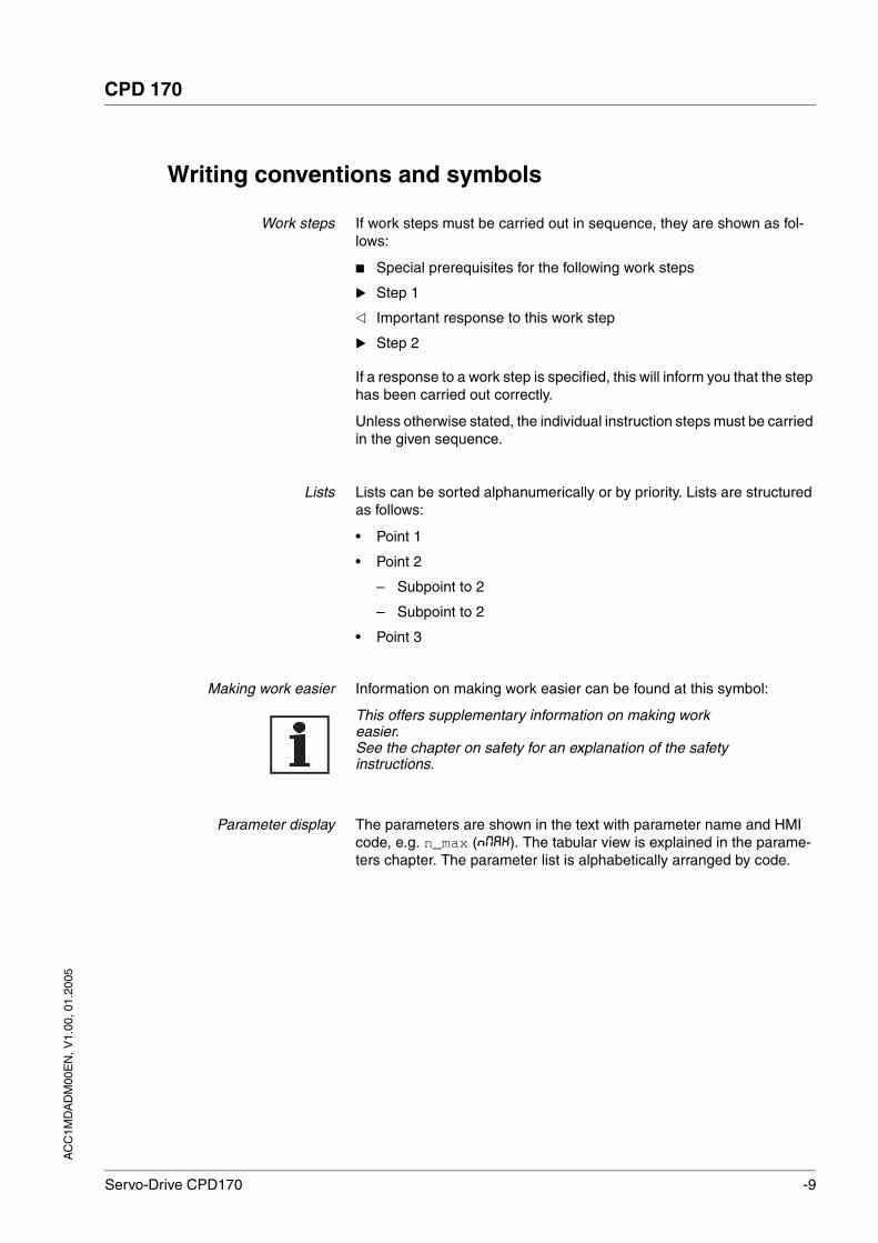
Work steps If work steps must be carried out in sequence, they are shown as fol-lows:
Special prerequisites for the following work steps
Step 1
Important response to this work step
Step 2
If a response to a work step is specified, this will inform you that the step has been carried out correctly.
Unless otherwise stated, the individual instruction steps must be carried in the given sequence.
Lists Lists can be sorted alphanumerically or by priority. Lists are structured as follows:
• Point 1
• Point 2
– Subpoint to 2
– Subpoint to 2
• Point 3
Making work easier Information on making work easier can be found at this symbol:
This offers supplementary information on making work easier.See the chapter on safety for an explanation of the safety instructions.
Parameter display The parameters are shown in the text with parameter name and HMI code, e.g. n_max (NMAX). The tabular view is explained in the parame-ters chapter. The parameter list is alphabetically arranged by code.

-10 Servo-Drive CPD170
CPD 170
AC
C1M
DA
DM
00E
N, V
1.00
, 01.
2005
AC
C1M
DA
DM
00E
N, V
1.00
, 01.
2005
CPD 170 Introduction
Servo-Drive CPD170 1-1
1 Introduction
1.1 Unit overview
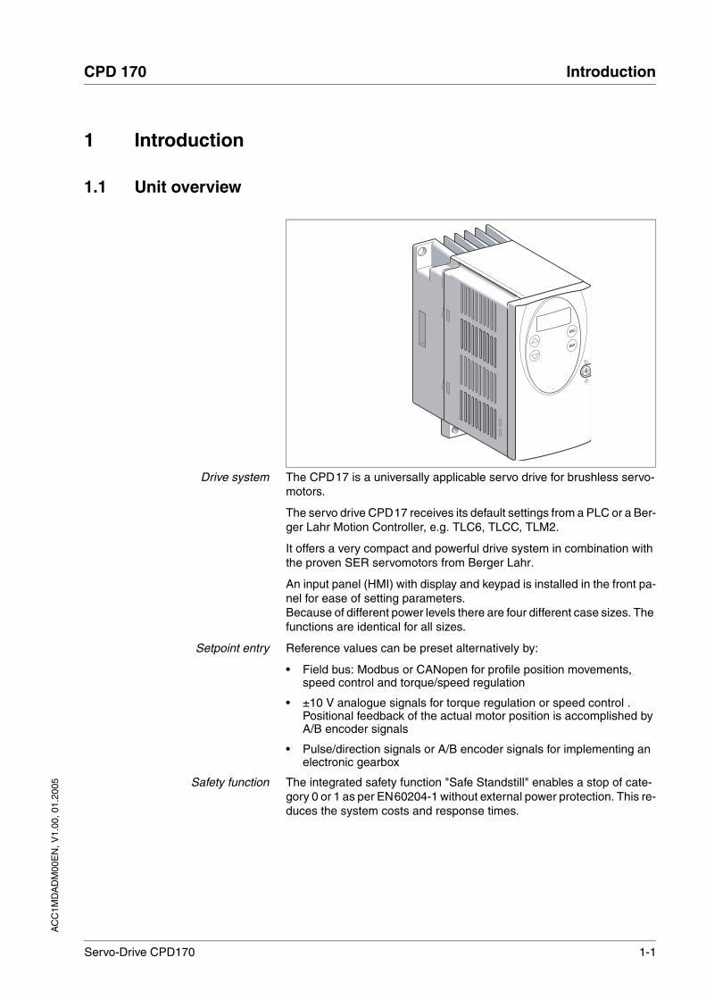
Drive system The CPD17 is a universally applicable servo drive for brushless servo-motors.
The servo drive CPD17 receives its default settings from a PLC or a Ber-ger Lahr Motion Controller, e.g. TLC6, TLCC, TLM2.
It offers a very compact and powerful drive system in combination with the proven SER servomotors from Berger Lahr.
An input panel (HMI) with display and keypad is installed in the front pa-nel for ease of setting parameters. Because of different power levels there are four different case sizes. The functions are identical for all sizes.
Setpoint entry Reference values can be preset alternatively by:
• Field bus: Modbus or CANopen for profile position movements, speed control and torque/speed regulation
• ±10 V analogue signals for torque regulation or speed control . Positional feedback of the actual motor position is accomplished by A/B encoder signals
• Pulse/direction signals or A/B encoder signals for implementing an electronic gearbox
Safety function The integrated safety function "Safe Standstill" enables a stop of cate-gory 0 or 1 as per EN60204-1 without external power protection. This re-duces the system costs and response times.
1-2 Servo-Drive CPD170
Introduction CPD 170
AC
C1M
DA
DM
00E
N, V
1.00
, 01.
2005
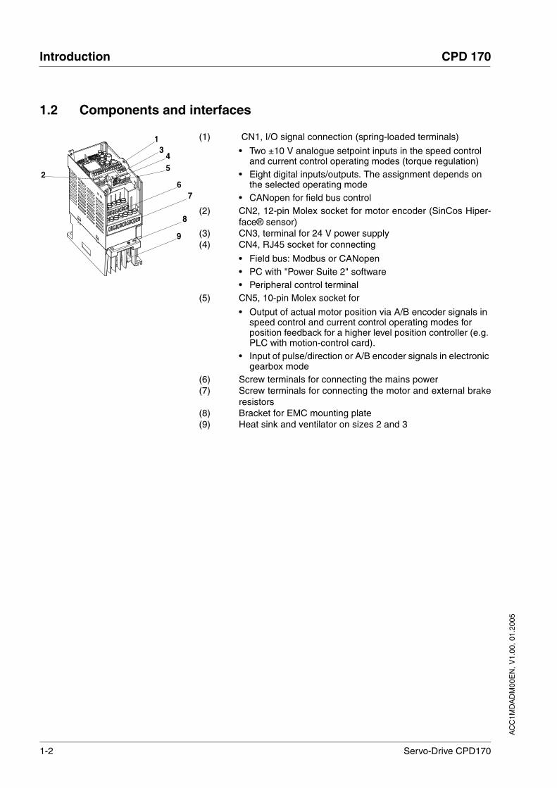
1.2 Components and interfaces
(1) CN1, I/O signal connection (spring-loaded terminals)
• Two ±10 V analogue setpoint inputs in the speed control and current control operating modes (torque regulation)
• Eight digital inputs/outputs. The assignment depends on the selected operating mode
• CANopen for field bus control(2) CN2, 12-pin Molex socket for motor encoder (SinCos Hiper-
face® sensor)(3) CN3, terminal for 24 V power supply(4) CN4, RJ45 socket for connecting
• Field bus: Modbus or CANopen• PC with "Power Suite 2" software• Peripheral control terminal
(5) CN5, 10-pin Molex socket for
• Output of actual motor position via A/B encoder signals in speed control and current control operating modes for position feedback for a higher level position controller (e.g. PLC with motion-control card).
• Input of pulse/direction or A/B encoder signals in electronic gearbox mode
(6) Screw terminals for connecting the mains power(7) Screw terminals for connecting the motor and external brake
resistors(8) Bracket for EMC mounting plate(9) Heat sink and ventilator on sizes 2 and 3
13
54
67
2
8
9
AC
C1M
DA
DM
00E
N, V
1.00
, 01.
2005
CPD 170 Introduction
Servo-Drive CPD170 1-3
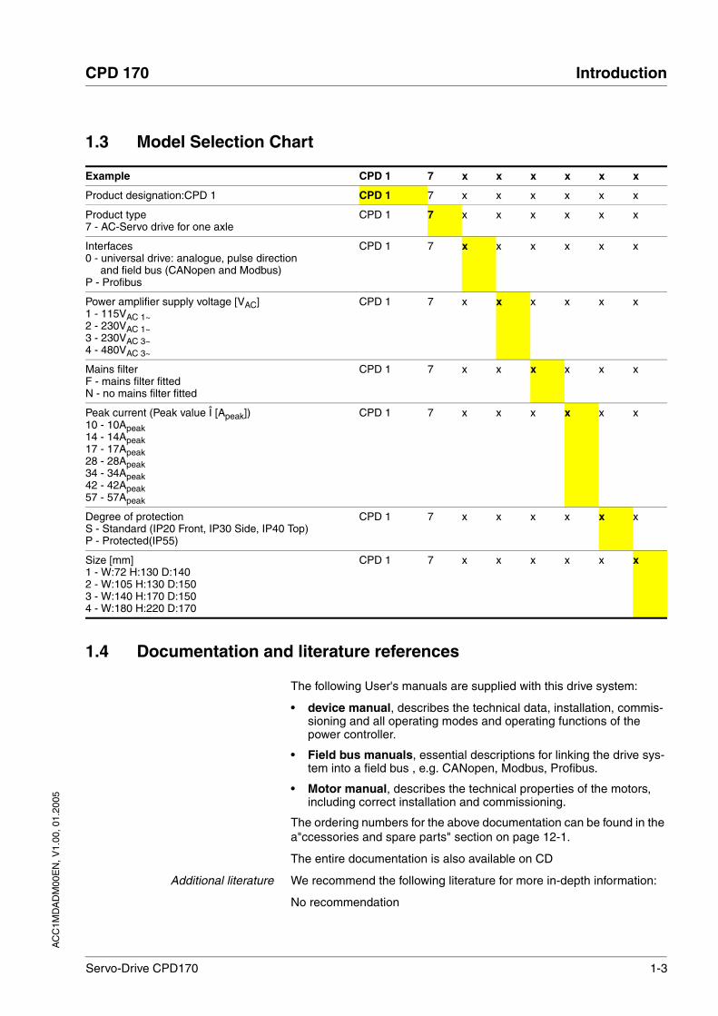
1.3 Model Selection Chart
1.4 Documentation and literature references
The following User's manuals are supplied with this drive system:
• device manual, describes the technical data, installation, commis-sioning and all operating modes and operating functions of the power controller.
• Field bus manuals, essential descriptions for linking the drive sys-tem into a field bus , e.g. CANopen, Modbus, Profibus.
• Motor manual, describes the technical properties of the motors, including correct installation and commissioning.
The ordering numbers for the above documentation can be found in the a"ccessories and spare parts" section on page 12-1.
The entire documentation is also available on CD
Additional literature We recommend the following literature for more in-depth information:
No recommendation
Example CPD 1 7 x x x x x x
Product designation:CPD 1 CPD 1 7 x x x x x x
Product type7 - AC-Servo drive for one axle
CPD 1 7 x x x x x x
Interfaces0 - universal drive: analogue, pulse direction
and field bus (CANopen and Modbus)P - Profibus
CPD 1 7 x x x x x x
Power amplifier supply voltage [VAC]1 - 115VAC 1~2 - 230VAC 1~3 - 230VAC 3~4 - 480VAC 3~
CPD 1 7 x x x x x x
Mains filterF - mains filter fitted N - no mains filter fitted
CPD 1 7 x x x x x x
Peak current (Peak value Î [Apeak])10 - 10Apeak14 - 14Apeak17 - 17Apeak28 - 28Apeak34 - 34Apeak42 - 42Apeak57 - 57Apeak
CPD 1 7 x x x x x x
Degree of protectionS - Standard (IP20 Front, IP30 Side, IP40 Top)P - Protected(IP55)
CPD 1 7 x x x x x x
Size [mm]1 - W:72 H:130 D:1402 - W:105 H:130 D:1503 - W:140 H:170 D:150 4 - W:180 H:220 D:170
CPD 1 7 x x x x x x

1-4 Servo-Drive CPD170
Introduction CPD 170
AC
C1M
DA
DM
00E
N, V
1.00
, 01.
2005
1.5 Directives and standards
CE mark With the declaration of conformity and the CE mark on the product the manufacturer certifies that the product complies with the requirements of all relevant EC directives. The drive systems described here can be used anywhere in the world.
EC Machine Directive The drive systems described here are not machines as defined by the EC Machine Directive (89/392/EEC) but components for installation in machines. They do not have moving parts designed for specific purpo-ses. However, they can be components of a machine or system.
The manufacturer must certify that the complete system conforms to the machine directive with the CE mark.
EC EMC Directive The EC Electromagnetic Compatibility Directives (89/336/EEC) applies to products that cause electromagnetic interference or whose operation may be be adversely affected by electromagnetic interference.
Conformity with the EMC Directive can only be expected of our drive systems after correct installation in the machine. The information on ensuring electromagnetic compatibility given in the chapter on "Installa-tion" must be followed to ensure that the drive system in the machine or system is EMC-compatible and that the product can legally be operated.
EC Low-Voltage Directive The EC Low-Voltage Directive (73/23/EEC) lays down safety require-ments for 'electrical apparatus' as protection against the risks that can originate in such devices and can be created in response to external in-fluences.
The drive systems described here comply with the EN 50178 Standard as per the Low-Voltage Directive.
Declaration of conformity The declaration of conformity certifies that the drive system complies with the specific EC directive.
Standards for safe operation DIN EN 60204-1: 1998-11 Electrical equipment of machines, General requirements
DIN VDE 0100, Regulations regarding the installation of high-voltage systems with voltages up to 1000 V
DIN VDE 0106-100: 1983-03 Protection against electric shock; layout of actuation elements in the vicinity of equipment in danger of contact
DIN EN 60529: 2000-09 IP degrees of protection
DIN EN 954-1: 1997-03 Safety of machines, Safety of components of control devices, Part 1: General design requirements
IEC61508 ”Functional safety of safety-related electric, electronic and programmable electronic systems”
Standards applicable to retainingthe EMC limit values
DIN EN 61000-4-1: 2001-06 Measuring and test procedures, overview
DIN EN 61800-3: 2001-02: Variable-speed electrical drives

AC
C1M
DA
DM
00E
N, V
1.00
, 01.
2005
CPD 170 Introduction
Servo-Drive CPD170 1-5
1.6 Declaration of conformity
EC Declaration of Conformity
Year 2005 BERGER LAHR GmbH & Co.KG Breslauer Str. 7 D-77933 Lahr
according to EC Directive Low Voltage 73/23/EEC; changed by CE Marking Directive 93/68/EEC according to EC Directive on Machinery 98/37/EEC according to EC Directive EMC 2004/108/EEC
We declare that the products listed below meet the requirements of the mentioned EC Directives with respect to design, construction and version distributed by us. This declaration becomes invalid with any modification on the products not authorized by us. Designation: Motor Control Electronics
Type: CPD170xxxxxx
Product number: 00637x170xxxx
Applied harmonized standards, especially:
EN ISO 13849-1:2004, Performance Level "d" EN 61508:2002, SIL 2 EN 50178:1998 EN 61800-3:2001, second environment according to Berger Lahr EMC test conditions
Applied national standards and technical specifications, especially:
UL 508C Berger Lahr EMC test conditions 200.47-01 EN Product documentation
Company stamp: Date/ Signature: 19 January 2005 Name/ Department: Wolfgang Brandstätter/R & D GMC Motors & Drives

1-6 Servo-Drive CPD170
Introduction CPD 170
AC
C1M
DA
DM
00E
N, V
1.00
, 01.
2005
1.7 TÜV certificate for functional safety
05 RWTÜV Systems GmbHPostfach 10 32 61 - 45032 Essen
Berger Lahr GmbH & Co. KG Breslauer Str. 7
77933 Lahr
Germany
for the realisation of the function "Safe Standstill" and Emergency Stop" in theservo drive
Type: CPD17xxx
• IEC 61508: 2000; Part 1 to Part 7; Functional safety of electrical/electronic/programmable electronic safety-related systems; Type B; SIL 2
• pr IEC 62061:2003; SIL 2; Safety of machinery; Safety-related parts of control systems. Part 1: General principles for design
• pr DIN EN ISO 13849-1:2004; Performance-Level „d“ (Category 3); Safety of machinery; Safety-related parts of control systems; Part 1: General principles for design
Certificate-Register-No.: SAS-0078/05 Essen, 2005-01-13 _____________ _____________
File reference: 2.4-4014/04 Valid to: 2010-01-13
Based on the report No.: 701-045/2003CPD in the valid versionthis certificate entitles the owner to use the mark
Validation of TÜViT GmbH in cooperation with RWTÜV Systems GmbH
Michael Eck Dr. Ulrich Adolph
Safety
SA
S-0
07
8/0
4IEC 61508/ SIL 2
pr IEC 62061/SIL 2
pr EN 13849
p-level “d” (Cat.3)
PFH = 2.85*10-9
Lifetime:
20 years
CertificateCertificateThe Certification Body RWTÜV Systems GmbH of Product Safety and Medical Devices hereby certify
the compliance of the below mentioned requirements:
AC
C1M
DA
DM
00E
N, V
1.00
, 01.
2005
CPD 170 Safety
Servo-Drive CPD170 2-1
2 Safety
2.1 Qualification of personnel
Only technicians who are familiar with and understand the contents of this manual and the other relevant manuals are authorised to work on and with this drive system. The technicians must be able to detect po-tential dangers that may be caused by setting parameters, changing pa-rameter values and generally by the mechanical, electrical and electronic equipment.
The technicians must have sufficient technical training, knowledge and experience to recognise and avoid dangers.
The technicians must be familiar with the relevant standards, regulations and safety regulations that must be observed when working on the drive system.
2.2 Intended use
The drive systems described here are products for general use that con-form to the state of the art in technology and are designed to prevent any dangers. However, drives and drive controllers that are not specifically designed for safety functions are not approved for applications where the functioning of the drive could endanger persons. The possibility of unexpected or unbraked movements can never be totally excluded wit-hout additional safety equipment. For this reason personnel must never be in the danger zone of the drives unless additional suitable safety equipment prevents any personal danger. This applies to operation of the machine during production and also to all service and maintenance work on drives and the machine. The machine design must ensure per-sonal safety. Suitable measures for prevention of property damage are also required.
In the system configuration described the drive systems must be used in industrial applications only and must have a fixed connection only.
In all cases the applicable safety regulations and the specified operating conditions, such as environmental conditions and specified technical data, must be observed.
The drive systems may be commissioned and operated only after instal-lation in accordance with EMC requirements and the product-specific specifications.
To prevent personal injury and damage to property damaged drive sys-tems must not be installed or operated.
Changes and modifications of the drive systems are not permitted and if made all no warranty and liability will be accepted.
The drive system must be operated only with the specified wiring and approved accessories. In general, use only original accessories and spare parts.
The drive systems must not be operated in an environment subject to explosion hazard (ex area).

2-2 Servo-Drive CPD170
Safety CPD 170
AC
C1M
DA
DM
00E
N, V
1.00
, 01.
2005
2.3 Hazard categories
Safety notes and general information are indicated by hazard messages in the manual. In addition there are symbols and instructions affixed to the product that warn of possible hazards and help to operate the pro-duct safely.
Depending on the seriousness of the hazard, the messages are divided into three hazard categories.
DANGER!DANGER indicates an imminently hazardous situation, which, if not avoided, will result in death, serious injury, or equipment damage.
WARNING!WARNING indicates a potentially hazardous situation, which, if not avoided, can result in death, serious injury, or equipment damage.
CAUTION!CAUTION indicates a potentially hazardous situation, which, if not avoided, can result in injury or equipment damage.

AC
C1M
DA
DM
00E
N, V
1.00
, 01.
2005
CPD 170 Safety
Servo-Drive CPD170 2-3
2.4 General safety instructions
DANGER!Electric shock, fire or explosion
• Only qualified personnel who are familiar with and understand the contents of this manual and the other relevant manuals are authorised to work on and with this drive system.
• Before working on the drive system:
– Switch off power to all terminals.
– Place a sign "DO NOT SWITCH ON" on the switch and lock to prevent switching on.
– Wait 6 minutes (for discharge of DC bus capacitors).
– Measure voltage between DC+ and DC- and check for <48V. (The DC bus LED is not a safe indication for absence of the DC bus voltage).
• Do not short-circuit DC bus or touch unshielded components or screws of the terminals with voltage present.
• Install all covers and close the housing doors before applying power.
• The motor generates voltage when the shaft is rotated. Lock the shaft of the motor to prevent rotation before starting work on the drive system.
• The system manufacturer is responsible for compliance with all applicable regulations relevant to earthing the drive system.
• Do not reach into the drive system (e.g. no pointed objects).Failure to follow these instructions will result in death or serious injury.
DANGER!Danger of injury by complex system!
When starting field bus operation the attached controllers are gene-rally out of view of the operator and cannot be directly monitored.
• Start the system only if there are no persons within the actua-tion zone of the moving system components and the system can be operated safely.
Failure to follow these instructions will result in death or serious injury.

2-4 Servo-Drive CPD170
Safety CPD 170
AC
C1M
DA
DM
00E
N, V
1.00
, 01.
2005
2.5 Safety functions
Using the safety functions integrated in this product requires careful planning. For more information see 5.3 “"Safe Standstill safety function"“ on page 5-2.
2.6 Monitoring functions
The monitoring functions in the drive protect the system and reduce the risk in the event of system malfunction. The monitoring functions are not designed for personal safety. The following faults and limit values can be monitored:
Table 2.1 Monitoring functions
For the description of the monitoring function see 8.6.1 “Monitoring func-tions“ from page 8-43.
WARNING!Danger of injury and damage to system components by loss of control!
• Observe the accident prevention regulations.
• The system manufacturer must consider the possible errors that could occur with the signals and in particular the critical func-tions to ensure a safe status during and after errors. Examples for these are: emergency stop, final position limit, power failure and restart.
• Consideration of possible errors must also include unexpected delay and failure of signals or functions.
• Separate redundant controller paths must be provided for dan-gerous functions.
• Verify the effictiveness of the measures.Failure to follow these instructions can result in death or serious injury.
Monitoring Task Protective function
Data connection Error response to connection break Functional safety and system protection
Limit switch signals Monitoring the allowable traverse range System protection
Following error Monitoring deviation from motor position to setpoint position Functional safety
Motor overload Monitoring for excessively high current in the motor phases Functional safety and device protection
Overvoltage and undervoltage
Monitoring for overvoltage and undervoltage of the power supply Functional safety and device protection
Overtemperature Monitoring device for overtemperature Device protection
I2t limitation Power limitation at overload Device protection

AC
C1M
DA
DM
00E
N, V
1.00
, 01.
2005
CPD 170 Technical Data
Servo-Drive CPD170 3-1
3 Technical Data
This chapter contains information on the required environmental condi-tions and on the mechanical and electrical properties of the unit family and the accessories.
3.1 Environmental conditions
3.1.1 Temperature, humidity, installation height
When considering the ambient temperature a distinction is made bet-ween the permissible temperatures during operation and the permis-sible storage and transport temperature.
ambient operating temperature The permissible ambient temperature during operation depends on the clearance between the units and the required output. The relevant re-quirements in the chapter on installation are also very important.
Ambient climate for transport andstorage
The environment during transport and storage must be dry and dust-free. The maximum oscillation and shock stress must be within the spe-cified limits. The bearing and transport temperature must remain within the specified range.
Relative humidity The relative humidity is allowed as follows:
Installation height
3.1.2 Oscillation and shock loading
The strength during oscillation stress on the units corresponds to EN 50178 Section 9.4.3.2 and EN 61131 Section 6.3.5.1.
Temperature 1)
1) no icing
[°C] 0 to +50
Temperature [°C] -25 to +70
rel. air humidity conforming to IEC60721-3-3, Class 3K3, 5% to 85%, no condensation per-mitted
Installation height above mean sea level for 100% power
[m] <1000
Max. ambient temperature 40°C, no protective foil and side distance >50 mm
[m] <2000 m
Oscillation and vibration 10Hz to 57Hz: 0.075mm amplitude 57Hz to 150Hz: 1g
Shock loading according to EN 61131 Sect. 6.3.5.2

3-2 Servo-Drive CPD170
Technical Data CPD 170
AC
C1M
DA
DM
00E
N, V
1.00
, 01.
2005
3.1.3 Degree of protection as per EN60529
Degree of protection when using"Safe Stop"
The "Safe Stop" function must only be operated under environmental conditions corresponding to degree of protection IP54. This can be done by using units with degree of protection IP54, or the unit must be in-stalled in a switch cabinet with the corresponding degree of protection. This is essential to prevent short circuits caused by foreign bodies con-tacting the safety-relevant circuit components.
Units with degree of protectionstandard "S"
The units with the "S" degree of protection in the type code have the overall degree of protection IP20, in which degree of protection IP40 is maintained for the top of the case so long as the safety cover on top of the unit has not been removed. If the safety cover must be removed be-cause of the ambient temperature or the unit clearances, see page 6-6
3.2 Mechanical data
Sizes of the standard units The standard units are available in sizes 1 to 4. The last number of the order description denotes the size. A unit with the identification xxx17xxxxxS2 is a standard unit of size 2.
3.2.1 Dimensional drawings
Figure 3.1 Dimensional drawing Size 1
Figure 3.2 Dimensional drawing Size 2
Standard unit Size 1 Size 2 Size 3 Size 4
Dimensions (W*H*D) [mm] 72 * 145* 140 105 * 143* 150 140 * 184* 150 180 * 232* 170
Weight with filter / without filter [kg] 1.1 / 1.1 1.4 / 1.3 2.0 / 2.0 x / x
Type of cooling Convection >1 m/s Fan Fan Fan
Degree of protection IP20 (IP40) 1) IP20 (IP40) 1) IP20 (IP40) 1) IP20 (IP40) 1)
1) IP40 restricted, only from above without removal of safety cover.

AC
C1M
DA
DM
00E
N, V
1.00
, 01.
2005
CPD 170 Technical Data
Servo-Drive CPD170 3-3
Figure 3.3 Dimensional drawing Size 3
3-4 Servo-Drive CPD170
Technical Data CPD 170
AC
C1M
DA
DM
00E
N, V
1.00
, 01.
2005
3.3 Electrical Data
3.3.1 Performance data for power amplifier
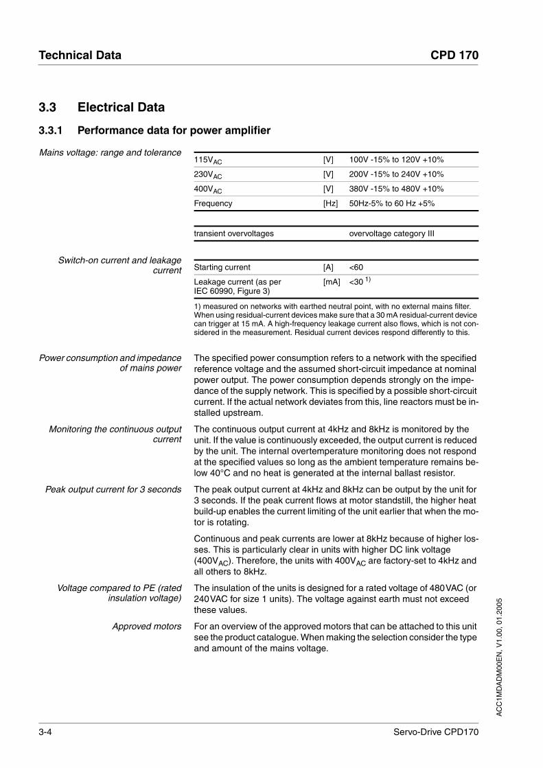
Mains voltage: range and tolerance
Switch-on current and leakagecurrent
Power consumption and impedanceof mains power
The specified power consumption refers to a network with the specified reference voltage and the assumed short-circuit impedance at nominal power output. The power consumption depends strongly on the impe-dance of the supply network. This is specified by a possible short-circuit current. If the actual network deviates from this, line reactors must be in-stalled upstream.
Monitoring the continuous outputcurrent
The continuous output current at 4kHz and 8kHz is monitored by the unit. If the value is continuously exceeded, the output current is reduced by the unit. The internal overtemperature monitoring does not respond at the specified values so long as the ambient temperature remains be-low 40°C and no heat is generated at the internal ballast resistor.
Peak output current for 3 seconds The peak output current at 4kHz and 8kHz can be output by the unit for 3 seconds. If the peak current flows at motor standstill, the higher heat build-up enables the current limiting of the unit earlier that when the mo-tor is rotating.
Continuous and peak currents are lower at 8kHz because of higher los-ses. This is particularly clear in units with higher DC link voltage (400VAC). Therefore, the units with 400VAC are factory-set to 4kHz and all others to 8kHz.
Voltage compared to PE (ratedinsulation voltage)
The insulation of the units is designed for a rated voltage of 480VAC (or 240VAC for size 1 units). The voltage against earth must not exceed these values.
Approved motors For an overview of the approved motors that can be attached to this unit see the product catalogue. When making the selection consider the type and amount of the mains voltage.
115VAC [V] 100V -15% to 120V +10%
230VAC [V] 200V -15% to 240V +10%
400VAC [V] 380V -15% to 480V +10%
Frequency [Hz] 50Hz-5% to 60 Hz +5%
transient overvoltages overvoltage category III
Starting current [A] <60
Leakage current (as per IEC 60990, Figure 3)
[mA] <30 1)
1) measured on networks with earthed neutral point, with no external mains filter. When using residual-current devices make sure that a 30 mA residual-current device can trigger at 15 mA. A high-frequency leakage current also flows, which is not con-sidered in the measurement. Residual current devices respond differently to this.

AC
C1M
DA
DM
00E
N, V
1.00
, 01.
2005
CPD 170 Technical Data
Servo-Drive CPD170 3-5
Overview of single-phase units
Overview of three-phase units
Three-phase units with an operating voltage of 3*230V and designation xxx3Nxx do not have integrated mains filters. Use an external filter to comply with the EMC regulations. For information on mains filters see the chapter on accessories, page 12-2
1F10S1 1F17S2 1F28S3 2F10S1 2F17S2 2F28S3
115V, size 1
115V, size 2
115V, size 3
230V, size 1
230V, size 2
230V, size 3
Power consumption at rated vol-tage
[Arms] 7.3 11 21.6 7 11 20
Nominal voltage [V] 115 115 115 230 230 230
max. permissible short circuit cur-rent of network
[kA] 1 1 1 1 1 1
rated power (motor power output) [kW] 0.4 0.65 0.85 0.75 1.2 2.5
continuous output current at 4kHz [Arms] 4 8 15 4 8 15
peak output current at 4kHz [Arms] 7 12 20 7 12 20
continuous output current at 8kHz [Arms] 3.2 7 13 3.2 7 13
peak output current at 8kHz [Arms] 6 11 20 6 11 20
Primary fuse 1) [A] 10 15/16 25 10 15/16 25
1) Fuses: UL-approved class CC or J fusible links, alternatively circuit breakers with B-characteristic. Specification 15/16 A: circuit breakers are available with 16A nominal current, UL fuses with 15A.
3N10S1 1) 3N17S2 1) 3N42S3 1) 4F14S2 4F34S3 4F57S4
230V, size 1
230V, size 2
230V, size 3
400V, size 2
400V, size 3
400V, size 4
Power consumption at rated vol-tage
[Aeff] 4.5 7.75 16.5 4 9.2 x
Nominal voltage [V] 200 200 200 400 400 400
max. permissible short circuit cur-rent of network
kA 5 5 5 5 5 x
rated power (motor power output) [kW] 0.75 1.4 3.2 1.4 3.0 x
continuous output current at 4kHz [A]eff] 4 8 17 6 15 x
peak output current at 4kHz [A] 7 12 30 10 24 x
continuous output current at 8kHz [Aeff] 3.2 7 15 5 11 x
peak output current at 8kHz [Arms] 6 11 30 7.5 18 x
Primary fuse 2) [A] 10 10 25 10 15/16 x
1) Unit without integrated mains filter2) Fuses: UL-approved class CC or J fusible links, alternatively circuit breakers with B-characteristic. Specification 15/16 A: circuit breakers are available with 16A nominal current, UL fuses with 15A.

3-6 Servo-Drive CPD170
Technical Data CPD 170
AC
C1M
DA
DM
00E
N, V
1.00
, 01.
2005
3.3.2 24VDC controller power supply
CN1 and CN3 spring-loadedterminals
The CN1 and CN3 connections are spring-loaded terminals with a ma-ximum current carrying capacity of 2A.
24 V power supply The 24V supply voltage must meet the requirements of IEC 61131-2 (PELV standard power supply):
3.3.3 Signals
Signal inputs are reverse polarity protected, outputs are resistant to short-circuit. There is an electrical connection to 0VDC.
24V input signals When configured for positive logic, the input levels correspond to EN 61132-2, type 1
24V output signals The 24V output signals correspond to IEC 61131-2.
Analogue input signals
Pulse/direction, A/B input signals The pulse/direction and A/B signals conform to the RS422 interface spe-cifications
ESIM output signals The ESIM signal complies with the RS422 interface specifications
Input voltage [V] 24V -15% / +20%
Input current (without load) [A] ≤1
Ripple voltage <5%
Logic 1 (Vhigh) [V] +15 to +30
Logic 0 (Vlow) [V] -3 bis +5
Debounced, debounce time [ms] 4
Debounce time - Safe Stop [ms] >1
Output voltage [V] ≤30
max. switching current [mA] ≤50
voltage drop at 50 mA load [V] ≤1
Differential input voltage range [V] -10 to +10
Input resistance [kΩ] ≥10
ResolutionANA1 [Bit] 14
ResolutionANA2 [Bit] 12
Sampling time ANA1 [ms] 0.25
Sampling time ANA2 [ms] 1
Symmetrical conforming to RS422
Asymmetrical [V] -7 to +12
Input resistance [kΩ] 5
Input frequency, pulse/direction [kHz] ≤200
Input frequency, A/B [kHz] ≤400
AC
C1M
DA
DM
00E
N, V
1.00
, 01.
2005
CPD 170 Technical Data
Servo-Drive CPD170 3-7
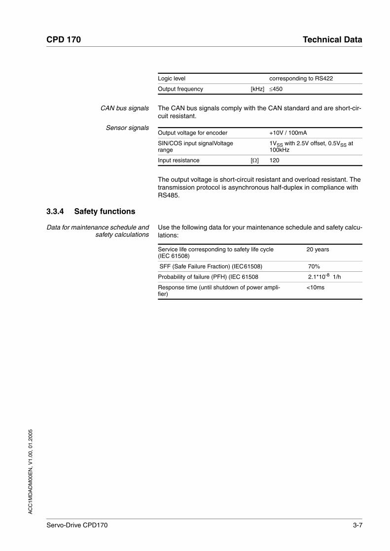
CAN bus signals The CAN bus signals comply with the CAN standard and are short-cir-cuit resistant.
Sensor signals
The output voltage is short-circuit resistant and overload resistant. The transmission protocol is asynchronous half-duplex in compliance with RS485.
3.3.4 Safety functions
Data for maintenance schedule andsafety calculations
Use the following data for your maintenance schedule and safety calcu-lations:
Logic level corresponding to RS422
Output frequency [kHz] ≤450
Output voltage for encoder +10V / 100mA
SIN/COS input signalVoltage range
1VSS with 2.5V offset, 0.5VSS at 100kHz
Input resistance [Ω] 120
Service life corresponding to safety life cycle (IEC 61508)
20 years
SFF (Safe Failure Fraction) (IEC61508) 70%
Probability of failure (PFH) (IEC 61508 2.1*10-8 1/h
Response time (until shutdown of power ampli-fier)
<10ms

3-8 Servo-Drive CPD170
Technical Data CPD 170
AC
C1M
DA
DM
00E
N, V
1.00
, 01.
2005
3.3.5 Internal ballast resistor
The unit has an internal ballast resistor. If this is insufficient, it will be ne-cessary to use one or more external ballast resistors - see also Chapter 6.3.5, "Connecting ballast resistors", page 6-206.3.5 “Connection of bal-last resistor“ 6-20. For an overview of the available external ballast re-sistors see the chapter on accessories on page 12-1
Table 3.1 Values for internal ballast resistors
Unit 1) Energy consumption of internal capacitors Evar
resistance internal
Continuous rating PPR
Peak energy ECR
Switch-on voltage
[Ws] [Ω] [W] [Ws] [V]
Size 1, 115V, 1~ 10.8 40 20 200 250
Size 1, 230V, 1~ 17.7 40 20 900 430
Size 1, 230V, 3~ 17.7 40 20 900 430
Size 2, 115V, 1~ 16.2 40 40 200 250
Size 2, 230V, 1~ 26.6 40 40 900 430
Size 2, 230V, 3~ 26.6 40 40 900 430
Size 2, 400V, 3~ 26.0 2) 40 40 1000 770
Size 3, 115V, 1~ 26.0 20 60 1000 250
Size 3, 230 V, 1~ 43.0 20 60 1600 430
Size 3, 230 V, 3~ 43.0 30 60 1600 430
Size 3, 400 V, 3~ 52.0 3) 30 60 1600 770
1) For allocation of size, voltage and phase number see also type code on page 1-32) at 480 V: 6.0 Ws3) at 480 V: 12.0 Ws
AC
C1M
DA
DM
00E
N, V
1.00
, 01.
2005
CPD 170 Technical Data
Servo-Drive CPD170 3-9
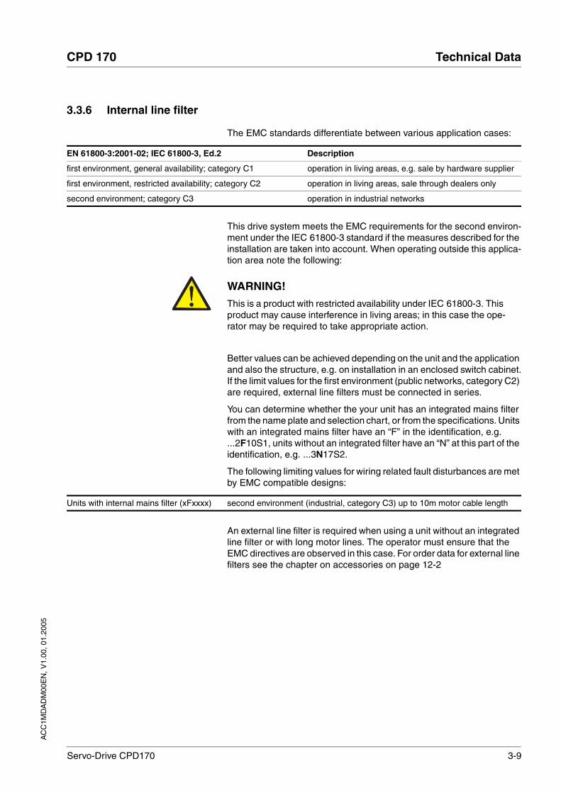
3.3.6 Internal line filter
The EMC standards differentiate between various application cases:
This drive system meets the EMC requirements for the second environ-ment under the IEC 61800-3 standard if the measures described for the installation are taken into account. When operating outside this applica-tion area note the following:
Better values can be achieved depending on the unit and the application and also the structure, e.g. on installation in an enclosed switch cabinet.If the limit values for the first environment (public networks, category C2) are required, external line filters must be connected in series.
You can determine whether the your unit has an integrated mains filter from the name plate and selection chart, or from the specifications. Units with an integrated mains filter have an “F” in the identification, e.g. ...2F10S1, units without an integrated filter have an “N” at this part of the identification, e.g. ...3N17S2.
The following limiting values for wiring related fault disturbances are met by EMC compatible designs:
An external line filter is required when using a unit without an integrated line filter or with long motor lines. The operator must ensure that the EMC directives are observed in this case. For order data for external line filters see the chapter on accessories on page 12-2
EN 61800-3:2001-02; IEC 61800-3, Ed.2 Description
first environment, general availability; category C1 operation in living areas, e.g. sale by hardware supplier
first environment, restricted availability; category C2 operation in living areas, sale through dealers only
second environment; category C3 operation in industrial networks
WARNING!This is a product with restricted availability under IEC 61800-3. This product may cause interference in living areas; in this case the ope-rator may be required to take appropriate action.Failure to follow these instructions can result in death or serious injury.
Units with internal mains filter (xFxxxx) second environment (industrial, category C3) up to 10m motor cable length

3-10 Servo-Drive CPD170
Technical Data CPD 170
AC
C1M
DA
DM
00E
N, V
1.00
, 01.
2005
3.4 Technical Data accessories
3.4.1 External ballast resistors
The unit has an internal ballast resistor. If this is not sufficient, one or more external ballast resistors must be used. The following minimum re-sistance values must be met and the internal resistance must be deac-tivated, see also the chapter on commissioning, page 6-21. For an overview of the available external ballast resistors see the chapter on accessories on page 12-1
Table 3.2 Values for external ballast resistors
3.4.2 External line filter
The EMC standards differentiate between various application cases; see Chapter 3.3.6 “Internal line filter“, page 3-9.
Better values can be achieved depending on the unit and the application and also the structure, e.g. on installation in an enclosed switch cabinet.If the limit values for the first environment (public networks, category C2) are required, external line filters must be connected in series.
The following limiting values for wiring related fault disturbances are met by EMC compatible designs:
An external line filter is required when using a unit without an integrated line filter or with long motor lines. The operator must ensure that the
Unit 1)
1) For allocation of size, voltage and phase number see also type code on page 1-3
External ballast resistor Switch-on voltage
min [Ω] max [Ω] [V]
Size 1, 115V, 1~ 27 45 250
Size 1, 230V, 1~ 50 75 430
Size 1, 230V, 3~ 50 75 430
Size 2, 115V, 1~ 20 27 250
Size 2, 230V, 1~ 27 45 430
Size 2, 230V, 3~ 27 45 430
Size 2, 400 V / 480 V, 3~ 60 80 770
Size 3, 115 V, 1~ 10 20 250
Size 2, 230V, 1~ 16 27 430
Size 2, 230V, 3~ 10 20 430
Size 2, 400 V / 480 V, 3~ 25 36 770
All units with an external mains filter first environment, restricted availability (public network, category C2) up 20m motor cable length, unit installed in an enclosed control cabinet with 15 dB attenuation.
second environment (industrial, category C3) up to 40m motor cable length (100m with 8kHz switching frequency)

AC
C1M
DA
DM
00E
N, V
1.00
, 01.
2005
CPD 170 Technical Data
Servo-Drive CPD170 3-11
EMC directives are observed in this case. For order data for external line filters see the chapter on accessories on page 12-2
3.4.3 Line reactor
Line reactor If the mains power does not correspond to the requirements described for impedance, line reactors may need to be installed, see also the chap-ter on installation. For order data see the chapter on accessories on page 12-1
3.4.4 Holding brake controller
For motors with holding brake we recommend appropriate control logic (HBC) that releases the brake when the motor is powered and locks the motor axis at the correct moment before the power amplifier supply vol-tage is switched off and optionally reduces the braking voltage.
Dimensions of holding brakecontroller HBC
Electrical data of holding brakecontroller HBC
The HBC holding brake controller has a safe electrical isolation between the 24 V input, control input and brake output. For more information see page 6-31, 7-25, 8-62 and 12-1.
3.4.5 Cable
Motor and encoder cable The motor cable and encoder cables are suitable for trailing and are available in various lengths. Various motor cable cross sections are also available. For the corresponding types see the accessories section on page 12-1.
Dimensions (H * B * D) [mm] 99 * 22.5 * 114.5
Installation on top-hat rail
Input
Supply voltage [V] 19.2 to 30
Input current [A] 0.5 + braking current
Output, brake
DC voltage before voltage reduc-tion
[V] 23 to 25
Maximum output current [A] 2.1
Nominal time to voltage reduction [ms] 1000
DC voltage with voltage reduction [V] 17 to 19
Permissible voltage [VAC] 600 (UL and CSA)
Shield Shield braiding
Sheath Oil-resistant PUR
Temperature range [°C] -40 to +90 (fixed)-20 to +80 (movable)
Minimum bending radius 4 x diameter (fixed)7.5 x diameter (moving)

3-12 Servo-Drive CPD170
Technical Data CPD 170
AC
C1M
DA
DM
00E
N, V
1.00
, 01.
2005

AC
C1M
DA
DM
00E
N, V
1.00
, 01.
2005
CPD 170 Basics
Servo-Drive CPD170 4-1
4 Basics
4.1 Safety functions
Automation and safety engineering are two areas that were completely separate in the past but more recently have become more and more in-tegrated. Planning and installation of complex automation solutions are greatly simplified by integrating safety functions. Safety-oriented func-tions are taken into consideration when planning automation and risks can be minimised more easily.
In general the safety engineering requirements depend on the applica-tion. The degree of the requirements is oriented to the risk and the ha-zard potential arising from the specific application.
Working with IEC61508
IEC61508 standard The IEC61508 standard "Functional safety of safety-related electric, electronic and programmable electronic systems" covers the relevant safety-relevant function. This means that it is not only one single com-ponent but always a complete function chain (e.g. from the sensor th-rough the logical processing unit to the actuator) that is considered as one single unit. The function chain must meet the requirements of the specific safety level as a whole. The standard establishes a basic stan-dard that is virtually application-independent. Systems and components that can be used in various applications for safety tasks with comparable risk can be developed in this base.
SIL, Safety Integrity Level The comparable risk is defined by the maximum achievable safety level SIL, which can be at level 1 to level 4 (maximum safety). This is based on an assessment of the hazard potential derived from the hazard and risk analysis. This is used to decide whether the relevant function chain requires a safety function and which hazard potential it must cover.
PFH, Probability of a dangerousfailure per hour
To maintain the safety function the IEC61508 standard, depending on the required SIL, requires staged fault-control and fault-prevention measures. All components of a safety function must be subjected to a probability analysis to assess the effectiveness of the fault-control measures that were taken. This assessment determines the dangerous probability of failure PFH (probability of a dangerous failure per hour) for protective systems. This is the probability per hour that a protective sys-tem fails in a hazardous manner and the protective function cannot be correctly executed. The PFH must not exceed the values calculated for the complete protective system depending on the SIL. The individual PFH of a chain must be calculated together, the total of the PFH must not exceed the maximum value specified in the standard.
SIL PFH at high requirement rate or continuous requirement
4 >10-9 to <10-8
3 >10-8 to <10-7
2 >10-7 to <10-6
1 >10-6 to <10-5

4-2 Servo-Drive CPD170
Basics CPD 170
AC
C1M
DA
DM
00E
N, V
1.00
, 01.
2005
HFT and SFF The standard also requires a specific hardware fault tolerance HFT for the safety system depending on the SIL in connection with a specific proportion of safe failures SFF (safe failure fraction). The hardware fault tolerance is the property of a system that enables it to execute the desi-red safety function in spite of the presence of one or more hardware faults. The SFF of a system is defined as the ratio of the rate of safe fai-lures to the total failure rate of the system. Under IEC61508 the maxi-mum achievable SIL of a system is determined by the hardware fault tolerance HFT and the safe failure fraction SFF of the system.
Fault-prevention measures Systematic faults in the specifications, in the hardware and the software, usage faults and maintenance faults of the safety system must be avo-ided as much as possible. IEC61508 specifies a series of fault-preven-tion measures that must be implemented depending on the required SIL. The fault-prevention measures must accompany the complete life cycle of the safety system, i.e. from design to decommissioning of the system.
SFF HFT type A subsystem
0 1 2
<60% SIL1 SIL2 SIL3
60%- <90% SIL2 SIL3 SIL4
90%- < 99% SIL3 SIL4 SIL4
> 99% SIL3 SIL4 SIL4

AC
C1M
DA
DM
00E
N, V
1.00
, 01.
2005
CPD 170 Engineering
Servo-Drive CPD170 5-1
5 Engineering
This chapter contains basic information on options for use of the unit, which are essential for planning. Assistance is given indicating which settings are required for the specific operational case and how this in-fluences the wiring.
5.1 Adjustable signal logic
This product can switch the 24V inputs and outputs as follows depen-ding on the setting:
Figure 5.1 Positive logic (left) and Negative logic (right)
It is specified by "First Setup" with the parameter IOLogicLevel. This setting affects the wiring and the control of sensors and must be tho-roughly clarified during planning with regard to the application.
The use of negative logic requires special care, because earth fault and wire breakage will be detected as ON status (z.B. start signal). With po-sitive logic a short circuit to earth and wire break will be interpreted as OFF status. See also EN61131-2 for specific information on the proper-ties of negative logic
Special case: Safety functionSAFE_DISABLE
The inputs for the safety function "Safe Stop" (inputs SAFE_DISABLE_A and SAFE_DISABLE_B) are always executed in positive logic regard-less of the setting!
5.2 Specification of the con troller type
Control mode: local or field bus The basic specification of whether the system should be controlled lo-cally or over the field bus must be made when the product is started for
logic active status
positive logic current flows to the input output sends current
negative logic current flows from the input output absorbs current
1 2
+24V
0V
ENABLE
ACTIVE1_OUT
+24V
0V
ACTIVE1_OUT
ENABLE

5-2 Servo-Drive CPD170
Engineering CPD 170
AC
C1M
DA
DM
00E
N, V
1.00
, 01.
2005
the first time. This specification can only be modified by restoring the fac-tory setting, see page 8-67.
The availability of operating modes of the product also depends on this setting.
Local control mode With a local control mode the movement is preset with analogue signals (±10V) or with RS422 signals (e.g. pulse/direction).
Limit switches and reference switches cannot be connected with the control mode.
Field bus control mode In the field bus control mode all communications are made via field bus commands.
5.3 "Safe Standstill safety function"
For some general information on the application of IEC 61508 see page 4-1.
5.3.1 Definitions
Safe Standstill The Safe Standstill safely shuts down the motor torque. There is no mo-nitoring at standstill.
Category 0 stop (EN60204-1) Stopping by immediate removal of power to the machine actuators (i.e. an uncontrolled stop).
Category 1 stop (EN60204-1) A controlled stop with power available to the machine actuators to achieve the stop and then removal of power when the stop is achieved;
5.3.2 Function
The "Safe Stop" safety function integrated into the product can be used to implement the control function "Standstill in Emergency" (EN 60204-1) for Stop Category 0 and Stop Category 1. In addition, this safety func-tion prevents the drive from restarting unexpectedly.
The following safety stages are implemented in accordance with the standards for functional safety:
• IEC 61508 SIL 2
• EN 954-1 category 3
• EN 13849-1 PL d (Performance Level d)
Function The Safe Stop safety function can be triggered with the two redundant inputs SAFE_DISABLE_A and SAFE_DISABLE_B. The circuits of the two inputs must be separate from each other to retain the two channels. The switching process must be simultaneous for both inputs.The power amplifier is without power and an error message is sent as soon as one of the two inputs is shut down. Then the motor cannot ge-nerate torque and runs down without braking. A restart is only possible after resetting the error message.

AC
C1M
DA
DM
00E
N, V
1.00
, 01.
2005
CPD 170 Engineering
Servo-Drive CPD170 5-3
5.3.3 Requirements for safe application
Stop of category 0 In a stop of category 0 the drive runs down uncontrolled. If access to the machine while it is running down is a hazard (result of hazard and risk analysis), suitable measures must be taken.
Stop of category 1 For a stop of category 1 a controlled standstill can be requested with the signal HALT or over the field bus. The standstill is not monitored by the drive system and is not guaranteed if power fails or in the event of an er-ror. The final shutdown is ensured by shutting down the inputs SAFE_DISABLE_A and SAFE_DISABLE_B. This is generally controlled by a standard EMERGENCY STOP module with safe time delay.
Vertical axes, external forces If external forces act on the drive (vertical axis) and an unwanted move-ment, for example caused by gravity, could cause a hazard, the drive must not be operated without additional measures for drop protection corresponding to the required safety.
Prevention of unexpected restart To prevent unexpected restart after restoration of power (e.g. after po-wer failure), the parameter IO_AutoEnable must be set to "off". Note that a higher level controller must not trigger a dangerous restart.
Degree of protection when using"Safe Stop"
The "Safe Stop" function must only be operated under environmental conditions corresponding to degree of protection IP54. This can be done by using units with degree of protection IP54, or the unit must be in-stalled in a switch cabinet with the corresponding degree of protection. This is essential to prevent short circuits caused by foreign bodies con-tacting the safety-relevant circuit components.
Protected line layout If short circuits and cross connections are possible with the lines for the signals SAFE_DISABLE_A and SAFE_DISABLE_B and this cannot be detected by upstream devices, a protected layout is required. A protec-ted layout prevents short circuits and cross connections.
Data for maintenance schedule andsafety calculations
Use the following data for your maintenance schedule and safety calcu-lations:
DANGER!Electric shock caused by incorrect use!
The "Safe Standstill " function does not effect any electrical discon-nection. The inter circuit voltage is still present.
• Turn off the mains voltage using an appropriate switch to achieve a voltage-free condition.
Failure to follow these instructions will result in death or serious injury.
WARNING!Danger of injury by incorrect usage!
Incorrect usage may cause a safety hazard by loss of the safety function.
• Observe the requirements for the safety function.Failure to follow these instructions can result in death or serious injury.
Service life corresponding to safety life cycle (IEC 61508)
20 years

5-4 Servo-Drive CPD170
Engineering CPD 170
AC
C1M
DA
DM
00E
N, V
1.00
, 01.
2005
Hazard and risk analysis As a system manufacturer you must conduct a hazard and risk analysis (e.g. as per EN 1050) of the system. The results should be taken into ac-count when using the "Safe Standstill" safety function.
The circuit resulting from the analysis may deviate from the following ap-plication examples. Additional safety components may be required. The results of the hazard and risk analysis always have priority.
5.3.4 Application examples
Stop category 0 Circuit without EMERGENCY STOP module, Stop category 0.
Figure 5.2 Example Stop category 0
Please note:
• When the EMERGENCY STOP switch is tripped it initiates a stop of category 0
Example: Stop category 1 Circuit with EMERGENCY STOP module, Stop category 1,
SFF (Safe Failure Fraction) (IEC61508) 70%
Probability of failure (PFH) (IEC 61508 2.1*10-8 1/h
Response time (until shutdown of power ampli-fier)
<10ms
ENABLE
24V
FAULTRESET
24V
ENABLEFAULT RESET
24V
EMERGENCYSTOP
SAFE_DISABLE_ASAFE_DISABLE_B
M3~
AC
C1M
DA
DM
00E
N, V
1.00
, 01.
2005
CPD 170 Engineering
Servo-Drive CPD170 5-5
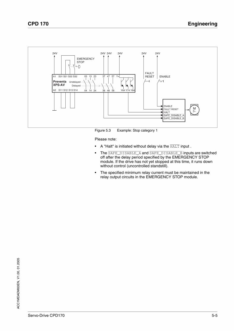
Figure 5.3 Example: Stop category 1
Please note:
• A "Halt" is initiated without delay via the HALT input .
• The SAFE_DISABLE_A and SAFE_DISABLE_B inputs are switched off after the delay period specified by the EMERGENCY STOP module. If the drive has not yet stopped at this time, it runs down without control (uncontrolled standstill).
• The specified minimum relay current must be maintained in the relay output circuits in the EMERGENCY STOP module.
ENABLE
24V
FAULTRESET
24V
ENABLEFAULT RESET
24V
EMERGENCYSTOP
SAFE_DISABLE_ASAFE_DISABLE_B
HALT
S11 S12
PreventaXPS-AV
Y64 Y74 Y8438 48 58
37 47 57S31 S21 S22 S32
Delayed
A2
A1
Undelayed
24V 24V
S13 S14
03 13 23
04 14 24
Y+
24V
M3~

5-6 Servo-Drive CPD170
Engineering CPD 170
AC
C1M
DA
DM
00E
N, V
1.00
, 01.
2005
AC
C1M
DA
DM
00E
N, V
1.00
, 01.
2005
CPD 170 Installation
Servo-Drive CPD170 6-1
6 Installation
6.1 Electromagnetic compatibility, EMC
This drive system meets the EMC requirements for the second environ-ment under the IEC 61800-3 standard if the measures described for the installation are taken into account. When operating outside this applica-tion area note the following:
An EMC-compliant design is required to maintain the specified limit va-lues. Depending in the case better results can be achieved with the fol-lowing measures:
• Upstream mains reactors. Information on current distortions can be obtained on request.
• Upstream external mains filters, particularly to maintain limit values for the first environment (living area, category C2)
WARNING!Danger of injury and damage to system components by loss of control!
• Observe the accident prevention regulations.
• The system manufacturer must consider the possible errors that could occur with the signals and in particular the critical func-tions to ensure a safe status during and after errors. Examples for these are: emergency stop, final position limit, power failure and restart.
• Consideration of possible errors must also include unexpected delay and failure of signals or functions.
• Separate redundant controller paths must be provided for dan-gerous functions.
• Verify the effictiveness of the measures.Failure to follow these instructions can result in death or serious injury.
WARNING!Interference with signals and devices may cause injury
Distorted signals can cause unexpected device responses.
• Install the wiring in accordance with the EMC requirements.
• Check compliance with the EMC requirements, particularly in an environment subject to strong interference.
Failure to follow these instructions can result in death or serious injury.
WARNING!This is a product with restricted availability under IEC 61800-3. This product may cause interference in living areas; in this case the ope-rator may be required to take appropriate action.Failure to follow these instructions can result in death or serious injury.
6-2 Servo-Drive CPD170
Installation CPD 170
AC
C1M
DA
DM
00E
N, V
1.00
, 01.
2005
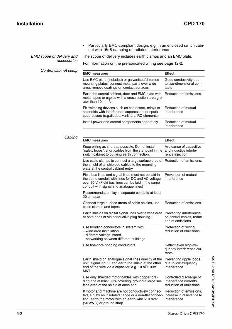
• Particularly EMC-compliant design, e.g. in an enclosed switch cabi-net with 15dB damping of radiated interference
EMC scope of delivery andaccessories
The scope of delivery includes earth clamps and an EMC plate.
For information on the prefabricated wiring see page 12-2.
Control cabinet setup
Cabling
EMC measures Effect
Use EMC plate (included) or galvanised/chromed mounting plates, connect metal parts over wide area, remove coatings on contact surfaces.
Good conductivity due to two-dimensional con-tacts
Earth the control cabinet, door and EMC plate with metal tapes or cables with a cross section area gre-ater than 10 mm2.
Reduction of emissions.
Fit switching devices such as contactors, relays or solenoids with interference suppressors or spark suppressors (e.g.diodes, varistors, RC elements)
Reduction of mutual interference
Install power and control components separately. Reduction of mutual interference
EMC measures Effect
Keep wiring as short as possible. Do not install "safety loops", short cables from the star point in the switch cabinet to outlying earth connection.
Avoidance of capacitive and inductive interfe-rence injection
Use cable clamps to connect a large surface area of the shield of all shielded cables to the mounting plate at the control cabinet entry.
Reduction of emissions.
Field bus lines and signal lines must not be laid in the same conduit with lines for DC and AC voltage over 60 V. (Field bus lines can be laid in the same conduit with signal and analogue lines)
Recommendation: lay in separate conduits at least 20 cm apart.
Prevention of mutual interference
Connect large surface areas of cable shields, use cable clamps and tapes
Reduction of emissions.
Earth shields on digital signal lines over a wide area at both ends or via conductive plug housing.
Preventing interference on control cables, reduc-tion of emissions
Use bonding conductors in system with– wide-area installation– different voltage infeed– networking between different buildings
Protection of wiring, reduction of emissions.
Use fine-core bonding conductors Deflect even high-fre-quency interference cur-rents
Earth shield on analogue signal lines directly at the unit (signal input), and earth the shield at the other end of the wire via a capacitor, e.g. 10 nF/100V MKT.
Preventing ripple loops due to low-frequency interference
Use only shielded motor cables with copper brai-ding and at least 85% covering, ground a large sur-face area of the shield at each end.
Controlled discharge of interference currents, reduction of emissions
If motor and machine are not conductively connec-ted, e.g. by an insulated flange or a non-flat connec-tion, earth the motor with an earth wire >10 mm2 (>6 AWG) or ground strap.
Reduction of emissions, increase in resistance to interference

AC
C1M
DA
DM
00E
N, V
1.00
, 01.
2005
CPD 170 Installation
Servo-Drive CPD170 6-3
Power supply
EMC requirement:motor and motorsensor wiring
Motor leads and motor sensor cables are especially critical signal lines. Use the cables recommended by your local representative. They must be tested for EMC safety and must be suitable for trailing cables.
The motor wiring and the motor sensor wiring on the drive solution must be laid out over a wide area with low resistance on the unit, the switch cabinet output and on the motor.
Lay out motor and motor sensor wiring without interruption (do not install switch components) from the motor and sensor to the unit.If a line has to be interrupted, shielded connections and metal casing must be used to prevent interference.
Lay the motor wiring at least 20 cm from the signal wiring.If the distance is less than this, the motor cable and signal cables must be separated by grounded screening plates.
For long lines bonding conductors with a suitable cross section must be used
Equipotential bonding conductors The shields are connected at both ends for fault protection. Potential dif-ferences can result in excessive currents on the shield and must be pre-vented by equipotential bonding conductor cables.
If lines over 100 m are approved, the following applies: up to 200 m length a cross section of 16 mm2 is sufficient, for greater lengths a cable cross section of 20 mm2 is required.
Lay connections of the 24VDC supply voltage as “twisted pair”.
Preventing interference on control cables, reduc-tion of emissions
Use shielded cables for the signal lines with IP54 products.
Reduction of EMC emis-sions
EMC measures Effect
EMC measures Effect
Operate drive system only on a system with an earthed star point. Do not operate on systems with earthed phase or on a non-earthed system (IT sys-tem).
Line filter is only effec-tive on system with an earthed star point.
Connect the negative output of the 24V power sup-ply to PE.
Reduction of EMC emis-sions, safety
Circuit breaker if there is danger of overvoltage or lightning strike
Protection against damage by overvoltage
6-4 Servo-Drive CPD170
Installation CPD 170
AC
C1M
DA
DM
00E
N, V
1.00
, 01.
2005
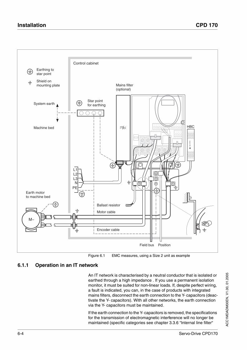
Figure 6.1 EMC measures, using a Size 2 unit as example
6.1.1 Operation in an IT network
An IT network is characterised by a neutral conductor that is isolated or earthed through a high impedance . If you use a permanent isolation monitor, it must be suited for non-linear loads. If, despite perfect wiring, a fault is indicated, you can, in the case of products with integrated mains filters, disconnect the earth connection to the Y- capacitors (deac-tivate the Y- capacitors). With all other networks, the earth connection via the Y- capacitors must be maintained.
If the earth connection to the Y- capacitors is removed, the specifications for the transmission of electromagnetic interference will no longer be maintained (specific categories see chapter 3.3.6 “Internal line filter“
Mains filter(optional)
Control cabinet
Motor cable
Encoder cable
Star pointfor earthing
Earthing tostar point
Shield onmounting plate
System earth
Machine bed
Earth motorto machine bed
HBC
M~
Field bus Position
Ballast resistor

AC
C1M
DA
DM
00E
N, V
1.00
, 01.
2005
CPD 170 Installation
Servo-Drive CPD170 6-5
page 3-9)! Separate measures are required to comply with national re-gulations and standards.
IT network, Sizes 1-3 Isolation monitoring faults in units sizes 1 to 3: Units with an integrated line filter have a switch on the left side of the earth terminal.Only open the switch for operation in IT networks and when isolation mo-nitoring faults still arise despite perfect wiring. The position of the switch is different in the different models (see also Figure 6.7)
Figure 6.2 Y-Capacitors for the internal filter operative (standard), or deacti-vated for IT networks.
IT network, Size 4 Isolation monitoring faults in Size 4 units: In units with integrated line fil-ters, if the isolation monitor fault still arises even with perfect wiring, you will need to connect the wires with cable connectors located above the power terminals in accordance with the illustration shown below, for ope-ration in an IT network,.
Figure 6.3 left: Y-Capacitors for the internal filter operative (standard): Y-Capacitors for the internal filter deactivated for IT networks
Normal(Y-capacitorsare active)
IT-network(Y-capacitorsare inactive)
PE

6-6 Servo-Drive CPD170
Installation CPD 170
AC
C1M
DA
DM
00E
N, V
1.00
, 01.
2005
6.2 Mechanical installation
6.2.1 Installing the unit
control cabinet The switch cabinet must be dimensioned so all units and accessories can be fixed in place and wired to meet EMC standards. The compon-ents include a holding brake controller or ballast resistors.
The switch cabinet ventilation must be capable of extracting the heat ge-nerated by all devices and components installed in the switch cabinet.
Installation spacing;ventilation Size 1 units do not have ventilators and are ventilated by air circulation from bottom to top. Units of size 2, 3 and 4 are fitted with an integrated ventilator.
When selecting the position of the unit in the control cabinet, note the fol-lowing instructions regarding temperature and degree of protection.
• Adequate cooling of the unit must be ensured by complying with the minimum installation distances.
DANGER!Electric shock from foreign bodies or damage.
Conductive foreign bodies in the product or serious damage can cause accidental energisation.
• Do not use damaged products.
• Prevent foreign bodies such as chips, screws or wire clippings from entering the product.
• Do not use products that contain foreign bodies.Failure to follow these instructions will result in death or serious injury.
WARNING!Danger of injury by loss of safety function!
The safety function may fail because of conductive foreign bodies, li-quids or dust. The "Safe Stop" safety function must only be used when the degree of protection IP54 is assured.
• Ensure degree of protection IP54.Failure to follow these instructions can result in death or serious injury.
CAUTION!Hot surfaces can cause burns and damage to system compo-nents!
The heat sink on the product may heat up to over 100°C depending on the operating mode.
• Prevent contact with the hot heat sink.
• Do not install flammable or heat-sensitive components in the immediate vicinity.
• Follow the actions described for heat dissipation.Failure to follow these instructions can result in injury or equipment damage.

AC
C1M
DA
DM
00E
N, V
1.00
, 01.
2005
CPD 170 Installation
Servo-Drive CPD170 6-7
• 'Hot spots' must be prevented.
• The unit must not be installed close to heat sources.
• The unit must not be installed on flammable materials.
• The warm airflow from other units and components, such as an external ballast resistor, must not heat the air used for cooling the unit.
• The drive will switch off as a result of overtemperature when opera-ted above the thermal limits.
• If degree of protection IP20 is sufficient, we recommend removing the protective foil (see page 6-8) on completion of installation.
Figure 6.4 Installation spacing and air circulation
Table 6.1 Installation spacing, actions
At least 10mm of free space is required in front of the unit.At least 50 mm of free space is required above the unit. The connecting cables come out of the bottom of the case. At least 200mm free space under the unit is required to ensure that wiring can be installed without excessive bending.
Installing the unit For the dimensions of the fastening holes see 3.2.1 “Dimensional dra-wings“ from page 3-2.
dd
Temperature Distance Actions required if IP20 is possible Actions required if IP40 is required
-10°C to +40°C d > 50mm None None
d < <50mm Removing the protec-tive foil (page 6-8).
d > 10 mm
+40°C to +50°C d > 50mm Removing the protective foil (page 6-8). Reduce nominal current and continuous current by2.2% per °C above 40°C
d < <50mm Removing protective foil (page 6-8),reduce nomi-nal current and conti-nuous current by2.2% per °C above 40°C
not possible

6-8 Servo-Drive CPD170
Installation CPD 170
AC
C1M
DA
DM
00E
N, V
1.00
, 01.
2005
Install the unit in a vertical position (±10°). This is particularly impor-tant for cooling the unit.
Attach the supplied EMC plate at the bottom of the unit, see also Figure 6.1, or use alternative attaching elements (comb bars, shield clamps, busbars).
Attach plate with safety instructions Attach the plate with safety instructions included with the unit in a visible position on the front panel as specified by the national regu-lations.
As an alternative to fastening the unit directly to the control cabinet mounting plate, mounting plates for snap-mounting to top-hat rails are available as accessories for units sizes 1 and 2, see page 12-1. In this case mains filters cannot be attached directly beside or behind the unit.
Painted surfaces have an insulating effect. Remove the paint from the attachment points over a wide area (bright metal) before attaching the unit to a painted mounting plate.
Removing protective foil
Figure 6.5 Removing protective foil
If degree of protection IP20 is sufficient, we recommend removal of the protective foil.
The protective foil must be removed if required by the thermal conditi-ons. When doing so note the reduction of the degree of protection from IP40 to IP20.
Do not remove the protective foil until all installation work is completed to prevent external influences that may occur during the installation.
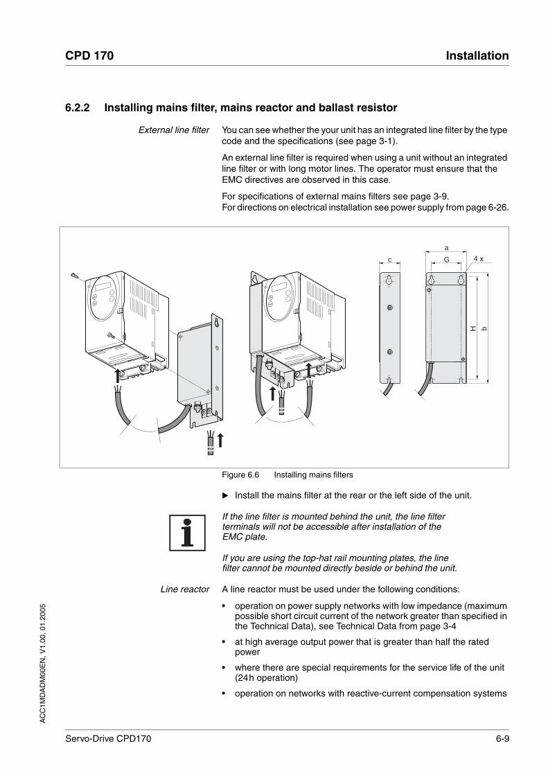
AC
C1M
DA
DM
00E
N, V
1.00
, 01.
2005
CPD 170 Installation
Servo-Drive CPD170 6-9
6.2.2 Installing mains filter, mains reactor and ballast resistor
External line filter You can see whether the your unit has an integrated line filter by the type code and the specifications (see page 3-1).
An external line filter is required when using a unit without an integrated line filter or with long motor lines. The operator must ensure that the EMC directives are observed in this case.
For specifications of external mains filters see page 3-9. For directions on electrical installation see power supply from page 6-26.
Figure 6.6 Installing mains filters
Install the mains filter at the rear or the left side of the unit.
If the line filter is mounted behind the unit, the line filter terminals will not be accessible after installation of the EMC plate.
If you are using the top-hat rail mounting plates, the line filter cannot be mounted directly beside or behind the unit.
Line reactor A line reactor must be used under the following conditions:
• operation on power supply networks with low impedance (maximum possible short circuit current of the network greater than specified in the Technical Data), see Technical Data from page 3-4
• at high average output power that is greater than half the rated power
• where there are special requirements for the service life of the unit (24h operation)
• operation on networks with reactive-current compensation systems
a
Gc
bH
4 x
6-10 Servo-Drive CPD170
Installation CPD 170
AC
C1M
DA
DM
00E
N, V
1.00
, 01.
2005
• for improvement of the power factor at the network input and to reduce the network feedback
• if overvoltages greater than overvoltage category III could occur
Multiple units can be operated with one line reactor. The rated current of the reactor must be considered.
In the case of a network impedance that allows a short-circuit current greater than 1kA the inductivity of the reactor must be greater than 0.8mH.
Supplementary current harmonics place a heavy load on the DC bus ca-pacitors. This has a substantial influence on the service life of the unit. For appropriate line reactors see accessories from page 12-1.
The information sheet included with the line reactor contains additional information on the installation. For directions on the electrical installation see power supply from page 6-26.
External ballast resistor
The ballast resistors recommended in accessories from page 12-1 com-ply with degree of protection IP65. They can be installed outside a con-trol cabinet in an environment with this degree of protection.
The information sheet included with the external ballast resistor contains additional information for the installation.
For information on the function and the electrical installation see page 6-20.
WARNING!Hot surfaces can cause burns, fire and damage to system com-ponents.
The ballast resistor may heat up to over 250°C depending on the operating mode.
• Prevent contact with the hot ballast resistor.
• Do not place flammable or heat-sensitive components in the immediate vicinity of the ballast resistor.
• Ensure good heat dissipation.
• Check the temperature of the ballast resistor by conducting a test run under the most critical conditions.
Failure to follow these instructions can result in death or serious injury.

AC
C1M
DA
DM
00E
N, V
1.00
, 01.
2005
CPD 170 Installation
Servo-Drive CPD170 6-11
6.3 Electrical installation
DANGER!Electric shock, fire or explosion
• Only qualified personnel who are familiar with and understand the contents of this manual and the other relevant manuals are authorised to work on and with this drive system.
• Before working on the drive system:
– Switch off power to all terminals.
– Place a sign "DO NOT SWITCH ON" on the switch and lock to prevent switching on.
– Wait 6 minutes (for discharge of DC bus capacitors).
– Measure voltage between DC+ and DC- and check for <48V. (The DC bus LED is not a safe indication for absence of the DC bus voltage).
• Do not short-circuit DC bus or touch unshielded components or screws of the terminals with voltage present.
• Install all covers and close the housing doors before applying power.
• The motor generates voltage when the shaft is rotated. Lock the shaft of the motor to prevent rotation before starting work on the drive system.
• The system manufacturer is responsible for compliance with all applicable regulations relevant to earthing the drive system.
• Do not reach into the drive system (e.g. no pointed objects).Failure to follow these instructions will result in death or serious injury.
DANGER!Electric shock from foreign bodies or damage.
Conductive foreign bodies in the product or serious damage can cause accidental energisation.
• Do not use damaged products.
• Prevent foreign bodies such as chips, screws or wire clippings from entering the product.
• Do not use products that contain foreign bodies.Failure to follow these instructions will result in death or serious injury.

6-12 Servo-Drive CPD170
Installation CPD 170
AC
C1M
DA
DM
00E
N, V
1.00
, 01.
2005
Suitability of wiring Cables must not be twisted, stretched, crushed or kinked. Use only ca-bles that comply with the cable specification. For example, make sure that it is suitable for:
• Use as a trailing cable
• Temperature range
• Chemical resistance
• Layout outdoors
• Layout underground
DANGER!Electric shock because of insufficient earthing.
With insufficent earthing these is hazard of electric shock.
• Earth the drive system before applying power.
• Use cross-sections of the protective earth conductor that com-ply with the applicable codes.
• Earth the cable shields on both ends, but do not regard the shields as protective earth.
Failure to follow these instructions will result in death or serious injury.
WARNING!Interference with signals and devices may cause injury
Distorted signals can cause unexpected device responses.
• Install the wiring in accordance with the EMC requirements.
• Check compliance with the EMC requirements, particularly in an environment subject to strong interference.
Failure to follow these instructions can result in death or serious injury.
WARNING!This product can cause a d.c. current in the protective conduc-tor!
• Where a residual-current-operated protective device (RCD) is used for protection in case of direct or indirect contact, only an RCD of Type B is allowed on the supply side of this product.
• Otherwise, another protective measure shall be applied, such as separation from the environment by double or reinforced insulation, or isolation from the supply system by a transformer.
Failure to follow these instructions can result in death or serious injury.

AC
C1M
DA
DM
00E
N, V
1.00
, 01.
2005
CPD 170 Installation
Servo-Drive CPD170 6-13
6.3.1 Overview of procedure
Observe the basic settings described in 5 “Engineering“ from page 5-1. The selected settings influence the complete installation:
• 5.1 “Adjustable signal logic“ Chapter from page 5-1
• 5.2 “Specification of the con troller type“ Chapter from page 5-1
• 5.3 “"Safe Standstill safety function"“ Chapter from page 5-2
Unlock the front panel of the unit and open it.
Connect the earth terminal of the unit or the EMC plate to the eart-hing star point of the system.
Connect the required terminal, following the sequence in Table 6.2. If a different connection sequence is followed, terminals may be covered by other lines.
Follow the EMC requirements, see page 6-1.
Then lock the front panel.
Table 6.2 Installation overview
Connection from Connection to from page
Motor phases 6-16
External ballast resistor 6-20
Mains power supply 6-26
Motor rotary encoder CN2 6-28
Holding brake controller (HBC) CN1 and CN3 6-31
24V controller supply voltage CN3 6-33
Encoder A, B, I CN5 6-35
Pulse direction, PULSE CN5 6-36
Encoder simulation, ESIM CN5 6-39
Field bus CANopen CN1 or CN4 6-41
Field bus Modbus CN4 6-43
Analogue inputs CN1 6-45
Digital inputs/outputs CN1 6-43
PC or peripheral operating terminal CN4 6-47

6-14 Servo-Drive CPD170
Installation CPD 170
AC
C1M
DA
DM
00E
N, V
1.00
, 01.
2005
6.3.2 Overview of all connections
Power connections
Figure 6.7 Overview of power connections for all unit types
Table 6.3 Designations of the power connections
Switch setting for units withintegrated line filters.
Figure 6.8 Y-Capacitors for the internal filter for units sizes 1 to 3 operative(standard), or deactivated for IT networks.
L1PE L2/N
DC+ RBI RBE DC- U V W
PE
L2PE L1
DC+ RBI RBE DC- U V W
PE L3 L2L1
DC+ RBI RBE DC- U V W
PE L3
PE
L2PE L1
DC+ RBI RBE DC- U V W
L3
PE
L2/N L1
DC+ RBI RBE DC- U V W
PE
PE
Size 1Three-phase without filter
Size 2 and 3 Three-phase with filter
Size 2 and 3Three-phase without filter
Size 1 Single-phase with filter
Size 2 and3Single-phase with filter
Power connections Description
PE Earth connection (protective earth)
L1, L2/N Mains connection, single phase units
L1, L2, L3 Mains connection, 3-phase units
DC+ DC bus
RBI Internal ballast
RBE External ballast
DC- DC bus
U,V,W Motor connections
Normal(Y-capacitorsare active)
IT-network(Y-capacitorsare inactive)
PE

AC
C1M
DA
DM
00E
N, V
1.00
, 01.
2005
CPD 170 Installation
Servo-Drive CPD170 6-15
In the case of units sizes 1-3 with integrated line filters, there is a switch to allow disconnection of the earth connections of the Y-capacitors in the IT network.
Check the correct switch position for units with internal filter, see page6-4.
Signal connections
Figure 6.9 Overview of the signal connections
Table 6.4 Assignment of the signal connections
CN 2
CN 4
CN 5
CN 3
CN1
OFF
11 2221141312 323123 353433 383736 39
41 444342S1
Connection/switch
Assignments
CN1 Analogue inputs ±10V, pin 11 to 14
CANopen, pin 21-23
Digital inputs/outputs, pin 31-39
CN2 Motor encoder (Hiperface Sensor)
CN3 24V controller supply voltage
CN4 PC, peripheral operating terminal, Modbus, CANopen;(RJ45)
CN5 ESIM (A/B/I out), PULS/DIR in, sensor signals A/B/I in 1)
1) depending on the “First Setup”
S1 Switch for CANopen terminating resistor

6-16 Servo-Drive CPD170
Installation CPD 170
AC
C1M
DA
DM
00E
N, V
1.00
, 01.
2005
6.3.3 Reference value signals and limits
External limits can be specified for the external reference value signals for operation. Table 6.5 shows the assignment options depending on the operating modes.
Table 6.5 Reference value signals and limits
6.3.4 Motor phase connections
Operating mode External reference value
Terminal External limit Terminal
Current control ANA_IN1 (current) CN1, Pin 11, 12 1) None
ANA_IN1 (current) CN1, Pin 11, 12 1) ANA_IN2 (current) CN1, Pin 13, 14
ANA_IN1 (current) CN1, Pin 11, 12 1) ANA_IN2 (rpm) CN1, Pin 13, 14
Speed control ANA_IN1 (rpm) CN1, Pin 11, 12 1) None
ANA_IN1 (rpm) CN1, Pin 11, 12 1) ANA_IN2 (current) CN1, Pin 13, 14
ANA_IN1 (rpm) CN1, Pin 11, 12 1) ANA_IN2 (rpm) CN1, Pin 13, 14
electronic gearbox PULSE/DIR Signal CN5 None
A/B Signal CN5 None
Profile position None, generated by profile generator
CN4 2) LIMP, LIMN CN1, Pin 34, 35
Profile velocity None, generated by profile generator
CN4 2) LIMP, LIMN CN1, Pin 34, 35
Homing None, generated by profile generator
CN4 2) LIMP, LIMN CN1, Pin 34, 35
Jog None, generated by profile generator
Local: NoneField bus: LIMP, LIMN
- CN1, Pin 34, 35
1) CN1, pin 11,12 = analogue input 14-bit; with field bus control mode alternatively via parameter value2) CN4 = CANopen, Modbus connection
DANGER!Electric shock
High voltages can occur unexpectedly at the motor connection.
• The motor generates voltage when the shaft is rotated. Lock the shaft of the motor to prevent rotation before starting work on the drive system.
• AC voltages may jump over unused wires in the motor cable. Isolate unused wires at both ends of the motor cable.
• The system manufacturer is responsible for compliance with all applicable regulations relevant to earthing the drive system. Extend the earth through the motor cable with an additional earth at the motor housing.
Failure to follow these instructions will result in death or serious injury.

AC
C1M
DA
DM
00E
N, V
1.00
, 01.
2005
CPD 170 Installation
Servo-Drive CPD170 6-17
Cable specifications • Shielded cable
• Minimum cross section of wires: see table
• Earthing of the screen at both ends
• Maximum cable length: depends on required limit values for cable-related malfunctions, see Chapter 3.3.6 “Internal line filter“ page 3-9 and Chapter 3.4.2 “External line filter“ page 3-10.
• For more information see 3.4.5 “Cable“ on page 3-11.
The wiring must have a sufficiently large cross section to ensure that the fuse at the mains connection can be triggered in the event of a fault.
Use prefabricated cables to minimise the risk of a wiring fault (from page 12-2).
Preparing cables Note the dimensions specified when fabricating cables.
WARNING!Unexpected motion may cause injury and damage to the sys-tem
Drives can make unexpected movements if incorrectly connected or because of other faults.
• Operate the unit with approved motors only. Even if motors are similar, different adjustment of the sensor system may be a source of danger.
• Check the wiring. Compatibility is not ensured even with mat-ching connectors on power connection and sensor system.
Failure to follow these instructions can result in death or serious injury.
Specifications Module 1 Module 2 Module 3 Module 4
Connection cross-section [mm2]
0.75 - 1.5 1.5-4 1.5-4
AWG connection cross section 14-20 10-16 10-16
Tightening torque for terminal screws [Nm]
0.5 - 0.6 1.2-1.5 1.2-1.5
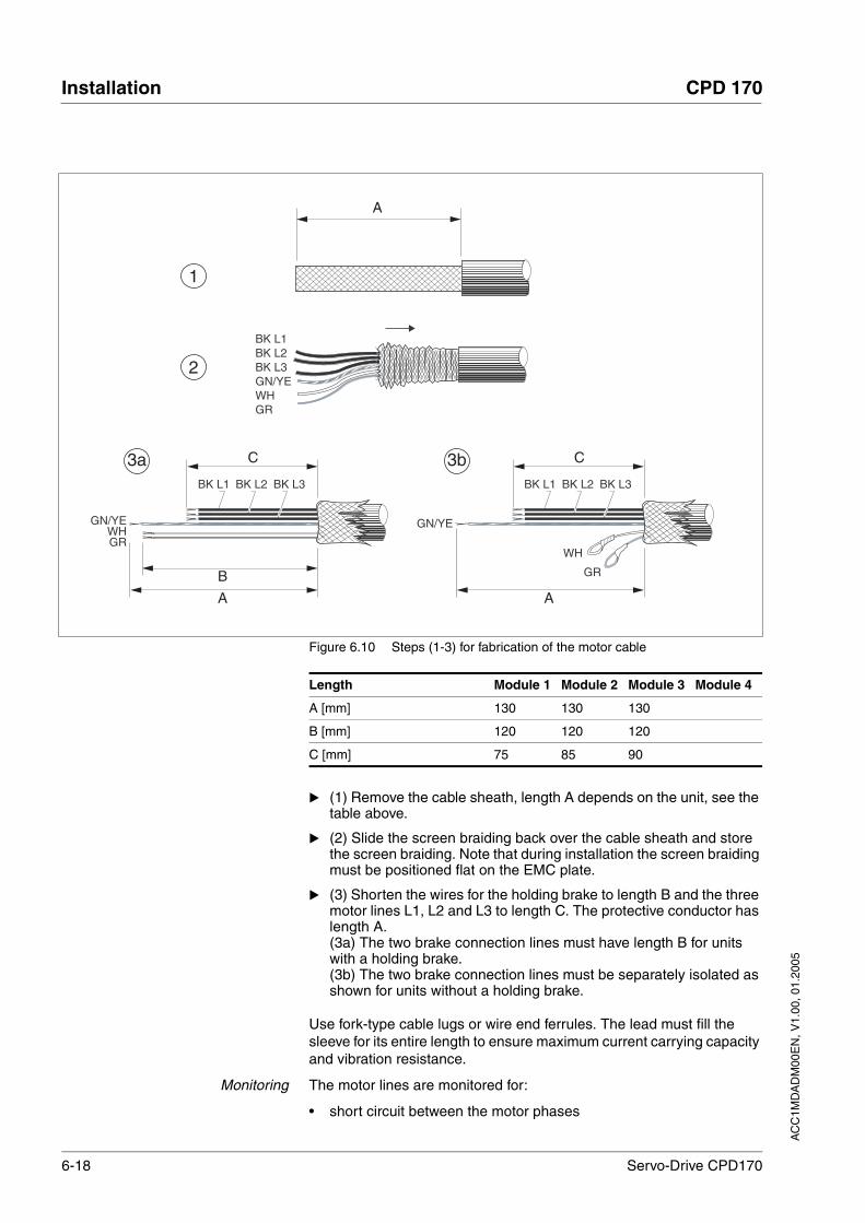
6-18 Servo-Drive CPD170
Installation CPD 170
AC
C1M
DA
DM
00E
N, V
1.00
, 01.
2005
Figure 6.10 Steps (1-3) for fabrication of the motor cable
(1) Remove the cable sheath, length A depends on the unit, see the table above.
(2) Slide the screen braiding back over the cable sheath and store the screen braiding. Note that during installation the screen braiding must be positioned flat on the EMC plate.
(3) Shorten the wires for the holding brake to length B and the three motor lines L1, L2 and L3 to length C. The protective conductor has length A. (3a) The two brake connection lines must have length B for units with a holding brake.(3b) The two brake connection lines must be separately isolated as shown for units without a holding brake.
Use fork-type cable lugs or wire end ferrules. The lead must fill the sleeve for its entire length to ensure maximum current carrying capacity and vibration resistance.
Monitoring The motor lines are monitored for:
• short circuit between the motor phases
BK L1BK L2BK L3GN/YEWHGR
A
BK L1 BK L2 BK L3
GN/YEWHGR
C
A
BK L1 BK L2 BK L3
GN/YE
C
A
WH
GR
3a 3b
1
2
B
Length Module 1 Module 2 Module 3 Module 4
A [mm] 130 130 130
B [mm] 120 120 120
C [mm] 75 85 90
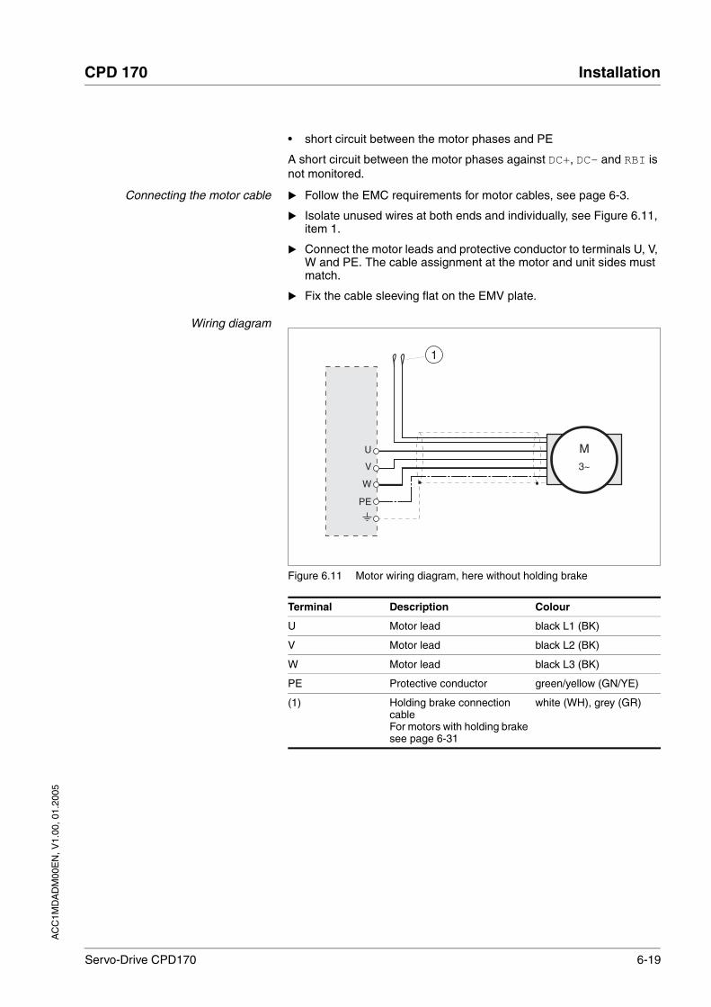
AC
C1M
DA
DM
00E
N, V
1.00
, 01.
2005
CPD 170 Installation
Servo-Drive CPD170 6-19
• short circuit between the motor phases and PE
A short circuit between the motor phases against DC+, DC- and RBI is not monitored.
Connecting the motor cable Follow the EMC requirements for motor cables, see page 6-3.
Isolate unused wires at both ends and individually, see Figure 6.11, item 1.
Connect the motor leads and protective conductor to terminals U, V, W and PE. The cable assignment at the motor and unit sides must match.
Fix the cable sleeving flat on the EMV plate.
Wiring diagram
Figure 6.11 Motor wiring diagram, here without holding brake
Terminal Description Colour
U Motor lead black L1 (BK)
V Motor lead black L2 (BK)
W Motor lead black L3 (BK)
PE Protective conductor green/yellow (GN/YE)
(1) Holding brake connection cableFor motors with holding brake see page 6-31
white (WH), grey (GR)
W
U
V
PE
1
M3~
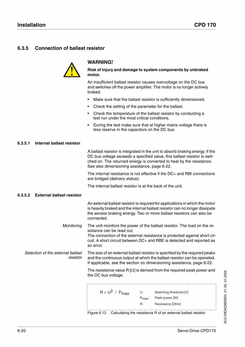
6-20 Servo-Drive CPD170
Installation CPD 170
AC
C1M
DA
DM
00E
N, V
1.00
, 01.
2005
6.3.5 Connection of ballast resistor
6.3.5.1 Internal ballast resistor
A ballast resistor is integrated in the unit to absorb braking energy. If the DC bus voltage exceeds a specified value, this ballast resistor is swit-ched on. The returned energy is converted to heat by the resistance. See also dimensioning assistance, page 6-22.
The internal resistance is not effective if the DC+ and RBI connections are bridged (delivery status).
The internal ballast resistor is at the back of the unit.
6.3.5.2 External ballast resistor
An external ballast resistor is required for applications in which the motor is heavily braked and the internal ballast resistor can no longer dissipate the excess braking energy. Two or more ballast resistors can also be connected.
Monitoring The unit monitors the power of the ballast resistor. The load on the re-sistance can be read out.The connection of the external resistance is protected against short cir-cuit. A short circuit between DC+ and RBE is detected and reported as an error.
Selection of the external ballastresistor
The size of an external ballast resistor is specified by the required peaks and the continuous output at which the ballast resistor can be operated. If applicable, see the section on dimensioning assistance, page 6-22.
The resistance value R [Ω] is derived from the required peak power and the DC bus voltage.
Figure 6.12 Calculating the resistance R of an external ballast resistor
WARNING!Risk of injury and damage to system components by unbraked motor.
An insufficient ballast resistor causes overvoltage on the DC bus and switches off the power amplifier. The motor is no longer actively braked.
• Make sure that the ballast resistor is sufficiently dimensioned.
• Check the setting of the parameter for the ballast.
• Check the temperature of the ballast resistor by conducting a test run under the most critical conditions.
• During the test make sure that at higher mains voltage there is less reserve in the capacitors on the DC bus.
Failure to follow these instructions can result in death or serious injury.
R = U2 / Pmax U : Switching threshold [V]
Pmax : Peek power [W]
R: Resistance [Ohm]

AC
C1M
DA
DM
00E
N, V
1.00
, 01.
2005
CPD 170 Installation
Servo-Drive CPD170 6-21
It two or more resistances are connected, not the following criteria:
• The resistors must be wired in parallel or in series so the required resistance is reached.
• The resistance value of the external resistance must not fall below a bottom limit, see Table 3.1.
• The total continuous output of the individual resistors must yield the required continuous output.
For suitable ballast resistors, see accessories on page 12-1.
Cable specifications • Shielded wires
• Minimum cross section: as in mains supply, see page 6-26. The wiring must have a sufficiently large cross section to ensure that the fuse at the mains connection can be triggered in the event of a fault.
• Earthing of the screen at both ends
• Maximum cable length: 3 m
The ballast resistors recommended in accessories have a 3-wire, tem-perature-resistant cable with a length of 0.75 m to 3 m.
Use fork-type cable lugs or wire end ferrules. The lead must fill the sleeve for its entire length to ensure maximum current carrying capacity and vibration resistance.
Connecting external ballast resistor Observe the safety instructions for the electrical installation.
Before opening the unit disconnect it from the supply voltage.
Remove the bridge between DC+ and RBI.
If the bridge is not removed, the internal ballast resistor may be destroyed during operation.
Earth the PE connection of the ballast resistor.
Connect the ballast resistor to the DC+ and RBE terminals of the unit.
Spread the shielding of the cables out flat on the EMC plate.
Test the function of the ballast resistor under realistic conditions during commissioning (page 7-16).
Wiring diagram
Figure 6.13 Wiring diagram, ballast resistor
Internal ballast resistor(Delivery status)
External ballast resistor
U V WDC+ RBI RBE DC-

6-22 Servo-Drive CPD170
Installation CPD 170
AC
C1M
DA
DM
00E
N, V
1.00
, 01.
2005
6.3.5.3 Rating guide
The elements contributing towards the absorption of braking energy are calculated to assist in specification. This is used to calculate the size of the ballast resistor.
An external ballast resistor is required when the kinetic energy Wkin to be absorbed exceeds the sum of the internal shares, including the inter-nal ballast resistor.
Kinetic energy Wkin The kinetic energy is calculated from the kinetic or rotational energy of the drive.
Internal energy absorption Braking energy is absorbed internally by the following mechanisms:
• DC bus capacitor WZW
• Internal ballast resistor WIN
• Electrical losses in the drive WE
• Mechanical losses in the drive WM
The energy WZW depends in a square-law function on the difference between the voltage before the braking operation and the response threshold.
The voltage before the braking operation depends on the line voltage. The energy absorption by the DC bus capacitors is lowest when the line voltage is highest. Use the values for the highest line voltage.
Energy absorption of the internalballast resistor
Two key values relating to the internal ballast resistor determine its en-ergy absorption.
• The continuous output PAV shows how much energy can be conti-nuously dissipated without overloading the ballast resistor.
• The maximum energy Wpeak limits the higher heat loss which can be dissipated in the short term.
If the continuous output is exceeded for a specified time, the ballast re-sistors remain unloaded for a correspondingly period. This ensures that the ballast resistor is not destroyed.
The characteristic values PAV and Wpeak of the internal ballast resistor can be found from page 3-8.
Electrical losses WE The electrical losses WE in the drive can be estimated from the peak po-wer of the drive. The maximum power loss is around 10% of peak power for a typical efficiency factor of 90%. If the current on braking is lower, the power loss will be reduced accordingly.
Mechanical losses WM The mechanical losses result from absorption by friction, which occurs when the system is running. Mechanical losses can be ignored if the system requires a much longer time to coast to a stop than the time re-quired to stop the system under braking. The mechanical losses can be calculated from the load torque and the speed from which the motor is to stop.
Example Braking of a motor with the following data (AC IN equal to 400VAC):
• Initial speed: n = 4000 min-1
• Rotor inertia: JR = 4 kgcm2
• Load inertia: JL = 6 kgcm2.

AC
C1M
DA
DM
00E
N, V
1.00
, 01.
2005
CPD 170 Installation
Servo-Drive CPD170 6-23
The energy to be absorbed is given by:
WB = 1/2 * J * (2*π*n)2
to 88 Ws
Electrical and mechanical losses are ignored.
23 Ws are absorbed in the DC bus capacitors at a power supply of 400 V.
The internal ballast resistor must absorb the residual 65 Ws. It can ab-sorb a pulse of 80 Ws. The internal ballast resistor is sufficient if the load is stopped once under braking.
If the braking process is repeated cyclically, the continuous output must be considered. If the cycle time is longer than the ratio of the energy to be absorbed WB and the continuous power PAV, the internal ballast re-sistor is sufficient. If braking takes place more frequently, the internal ballast resistor will not be sufficient.
In the example the ratio WB/PAV is 1.3 s. An external ballast resistor is required with a shorter cycle time.
Dimensioning the external ballastresistor
Figure 6.14 Characteristics for rating the ballast resistor
These two characteristics are also used for the rating the motor. The segments of the characteristic under consideration, in which the motor brakes, are designated (Di).
Calculation of the energy at constant runout:
For this we need to know the total inertia (Jt).
Jt is given by:
Jt = Jm + Jc
Jm: Motor inertia with and without brake
Jc: Load inertia
The energy for each runout segment is calculated as follows:
This yields the following for segments (D1) … (D3):
v3
v2
v1
0
v4 t1 t2 t3 t4 t5 t6 t7 t8 t9 t10 t11 t12
M3
M2
M1
0
t
t
M4
M5
Torque required
Motor speed
Cycle time
D1
D2 D3
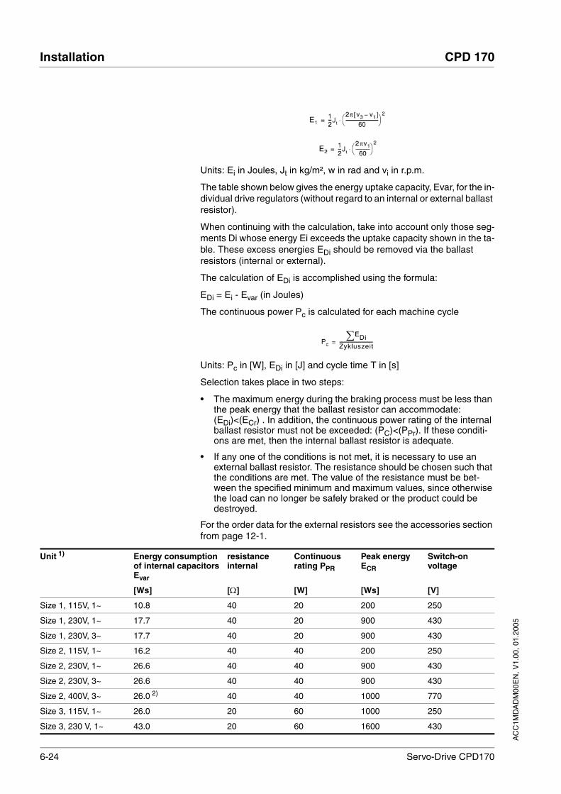
6-24 Servo-Drive CPD170
Installation CPD 170
AC
C1M
DA
DM
00E
N, V
1.00
, 01.
2005
Units: Ei in Joules, Jt in kg/m², w in rad and vi in r.p.m.
The table shown below gives the energy uptake capacity, Evar, for the in-dividual drive regulators (without regard to an internal or external ballast resistor).
When continuing with the calculation, take into account only those seg-ments Di whose energy Ei exceeds the uptake capacity shown in the ta-ble. These excess energies EDi should be removed via the ballast resistors (internal or external).
The calculation of EDi is accomplished using the formula:
EDi = Ei - Evar (in Joules)
The continuous power Pc is calculated for each machine cycle
Units: Pc in [W], EDi in [J] and cycle time T in [s]
Selection takes place in two steps:
• The maximum energy during the braking process must be less than the peak energy that the ballast resistor can accommodate: (EDi)<(ECr) . In addition, the continuous power rating of the internal ballast resistor must not be exceeded: (PC)<(PPr). If these conditi-ons are met, then the internal ballast resistor is adequate.
• If any one of the conditions is not met, it is necessary to use an external ballast resistor. The resistance should be chosen such that the conditions are met. The value of the resistance must be bet-ween the specified minimum and maximum values, since otherwise the load can no longer be safely braked or the product could be destroyed.
For the order data for the external resistors see the accessories section from page 12-1.
Unit 1) Energy consumption of internal capacitors Evar
resistance internal
Continuous rating PPR
Peak energy ECR
Switch-on voltage
[Ws] [Ω] [W] [Ws] [V]
Size 1, 115V, 1~ 10.8 40 20 200 250
Size 1, 230V, 1~ 17.7 40 20 900 430
Size 1, 230V, 3~ 17.7 40 20 900 430
Size 2, 115V, 1~ 16.2 40 40 200 250
Size 2, 230V, 1~ 26.6 40 40 900 430
Size 2, 230V, 3~ 26.6 40 40 900 430
Size 2, 400V, 3~ 26.0 2) 40 40 1000 770
Size 3, 115V, 1~ 26.0 20 60 1000 250
Size 3, 230 V, 1~ 43.0 20 60 1600 430

AC
C1M
DA
DM
00E
N, V
1.00
, 01.
2005
CPD 170 Installation
Servo-Drive CPD170 6-25
Table 6.6 Values for internal ballast resistors
Table 6.7 Values for external ballast resistors
Size 3, 230 V, 3~ 43.0 30 60 1600 430
Size 3, 400 V, 3~ 52.0 3) 30 60 1600 770
1) For allocation of size, voltage and phase number see also type code on page 1-32) at 480 V: 6.0 Ws3) at 480 V: 12.0 Ws
Unit 1) Energy consumption of internal capacitors Evar
resistance internal
Continuous rating PPR
Peak energy ECR
Switch-on voltage
[Ws] [Ω] [W] [Ws] [V]
Unit 1)
1) For allocation of size, voltage and phase number see also type code on page 1-3
External ballast resistor Switch-on voltage
min [Ω] max [Ω] [V]
Size 1, 115V, 1~ 27 45 250
Size 1, 230V, 1~ 50 75 430
Size 1, 230V, 3~ 50 75 430
Size 2, 115V, 1~ 20 27 250
Size 2, 230V, 1~ 27 45 430
Size 2, 230V, 3~ 27 45 430
Size 2, 400 V / 480 V, 3~ 60 80 770
Size 3, 115 V, 1~ 10 20 250
Size 2, 230V, 1~ 16 27 430
Size 2, 230V, 3~ 10 20 430
Size 2, 400 V / 480 V, 3~ 25 36 770

6-26 Servo-Drive CPD170
Installation CPD 170
AC
C1M
DA
DM
00E
N, V
1.00
, 01.
2005
6.3.6 Connection of mains power to power amplifier
Cable specifications The wiring must have a sufficiently large cross section to ensure that the fuse at the mains connection can be triggered in the event of a fault.
In addition, note the suitability of the wiring, see page 6-12 and the EMC-compliant connection, see page 6-2.
Preparing cables Use fork-type cable lugs or wire end ferrules. The lead must fill the sleeve for its entire length to ensure maximum current carrying capacity and vibration resistance.
Connecting mains power Observe the following instructions at all times:
• 3-phase units must only be connected and operated on 3-phase.
• With units without an integrated line filter the power cable must be shielded and earthed at both ends between the external line filter and the unit when the cable is over 200 mm in length.
• Observe the EMC requirements. If necessary, use overvoltage arrestors, line filters and line reactors, see page 6-9.
• Follow the requirements for design of corresponding UL, see page 3-1.
• The PE connection on the case must be connected to the mounting plate because of the high leakage currents.
Wiring diagram of 1-phase unit Figure 6.15 shows the connection of the mains power supply for a single phase unit. The diagram also shows the wiring of the optional external mains filter and mains reactor .
DANGER!Electric shock because of insufficient earthing.
These drive systems have increased leakage current > 3.5 mA. A second protective conductor must always be connected.
• Connect a second protective conductor with a minimum cross section in accordance with IEC 60364-5-54 at the separate earth terminal.
Failure to follow these instructions will result in death or serious injury.
Specifications Module 1 Module 2 Module 3 Module 4
Connection cross-section [mm2]
0.75 to 1.5
1.5 to 4 1.5 to 4
AWG 14 to 20 10 to 16 10 to 16
Tightening torque for terminal screws [Nm]
0.5 to 0.6 1.2 to 1.5 1.2 to 1.5

AC
C1M
DA
DM
00E
N, V
1.00
, 01.
2005
CPD 170 Installation
Servo-Drive CPD170 6-27
Figure 6.15 Wiring diagram:mains power for a single phase unit
(1) Mains reactor (optional)(2) Mains filter (optional)(3) Product
The second fuse is only required when phase L2 is connected. It is not necessary when wiring with neutral conductor N
Connect the power cables to the screw terminals PE, L2/N and L1. Note the exact terminal assignment of your unit as per Figure 6.7 on page 6-14.
Wiring diagram of 3-phase unit Figure 6.16 shows the connection of the mains power supply for a 3-phase unit. The diagram also shows the wiring of the optional external mains filter and mains reactor .
Figure 6.16 Wiring diagram:mains power for 3-phase unit
(1) Mains reactor (optional)(2) Mains filter (optional)(3) Product
Connect the power cables to PE, L1, L2 and L3. Note the exact ter-minal assignment of your unit as per Figure 6.7 on page 6-14.
S1E1
1
L2/N
L1
2
L2/N
L1
3
L2/N
L1
PE
S2
S3
S1
E3
E2
E1
1
L3
L2
L1
2
L3
L2
L1
3
L3
L2
L1
PE

6-28 Servo-Drive CPD170
Installation CPD 170
AC
C1M
DA
DM
00E
N, V
1.00
, 01.
2005
6.3.7 Connection for parallel operation
6.3.8 Connection of motor sensor (CN2)
Function and sensor type The motor sensor is a Hiperface sensor (SinCos sensor) integrated into the motor. It captures the rotor position of the motor and sends the motor position to the unit both analogue and digitally.
Cable specifications • Shielded cable
• Twisted-pair conductors
• Minimum cross section of signal wires: 0.25 mm2
• Earthing of the screen at both ends
• maximum cable length 100m
• For more information see 3.4.5 “Cable“ on page 3-11.
Preparing cables Use prefabricated cables to minimise the risk of a wiring fault (from page 12-2). Step 5 in Figure 6.17 must be carried out even with pre-fabricated cable. The dimensions for positioning the shield on the case are applicable when the included EMC plate is used.
If you are not using prefabricated wiring, follow the procedure and the dimensions in Figure 6.17.
CAUTION!Destruction of the drive system by incorrect parallel operation.
Operation with a non-approved parallel circuit on the DC bus may destroy the drive systems immediately or after a delay.
• Find out the general conditions and requirements for parallel circuits on the DC bus from your local representative.
Failure to follow these instructions can result in injury or equipment damage.

AC
C1M
DA
DM
00E
N, V
1.00
, 01.
2005
CPD 170 Installation
Servo-Drive CPD170 6-29
Figure 6.17 Steps (1-5) for fabrication of the sensor cable
(1) Remove the cable sheath, length A depends on the unit, see the table above.
(2) Slide the braiding back over the cable sheath. The shield brai-ded filler wire is required as the connection.
(3) The red and the violet lead is not required and can be cut off. Isolate the shield lead with shrink wrap.
(4) Crimp the plug contacts on the remaining leads and on the isola-ted shield lead. Isolate the shield braiding with shrink wrap. Plug the
A
B
3
4
1
2
RD+VT
10 x 0.25mm² (AWG24)2 x 0.5mm² (AWG20)
5
C
4
Length Module 1 Module 2 Module 3 Module 4
A [mm] 25 25 25 25
B [mm] 90 100 130
C [mm] 15 15 15 15
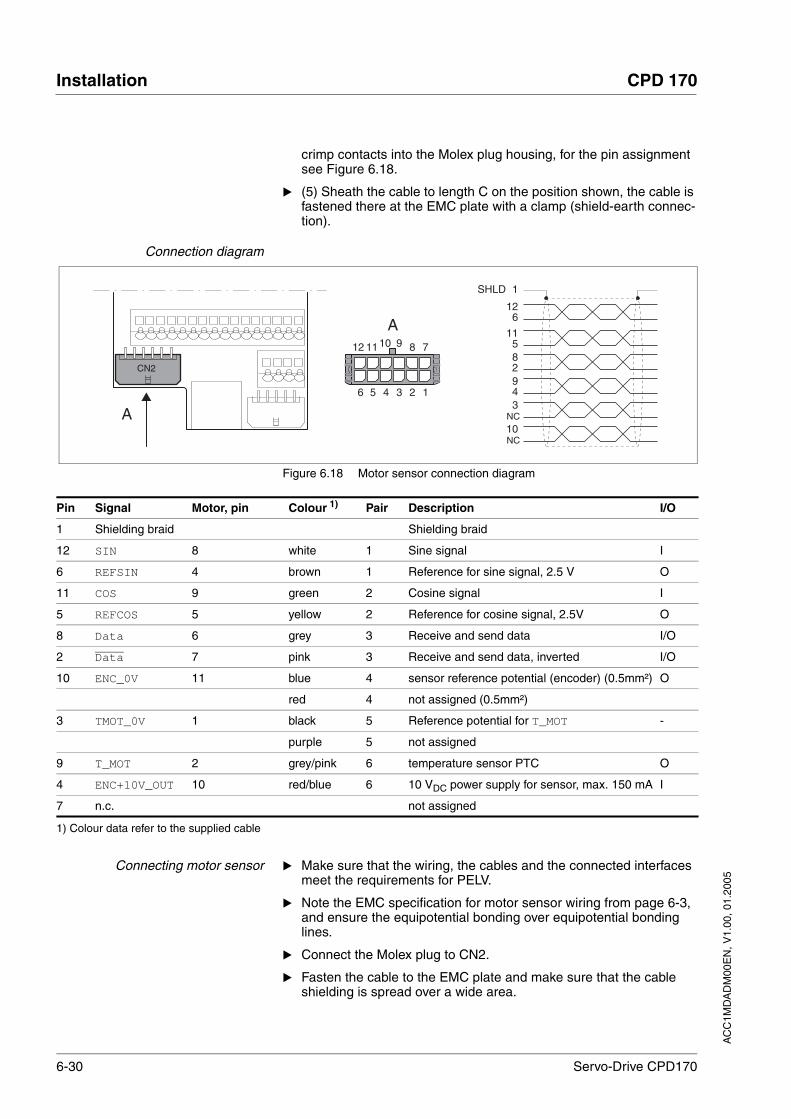
6-30 Servo-Drive CPD170
Installation CPD 170
AC
C1M
DA
DM
00E
N, V
1.00
, 01.
2005
crimp contacts into the Molex plug housing, for the pin assignment see Figure 6.18.
(5) Sheath the cable to length C on the position shown, the cable is fastened there at the EMC plate with a clamp (shield-earth connec-tion).
Connection diagram
Figure 6.18 Motor sensor connection diagram
Connecting motor sensor Make sure that the wiring, the cables and the connected interfaces meet the requirements for PELV.
Note the EMC specification for motor sensor wiring from page 6-3, and ensure the equipotential bonding over equipotential bonding lines.
Connect the Molex plug to CN2.
Fasten the cable to the EMC plate and make sure that the cable shielding is spread over a wide area.
CN2
A
A
5 1234
11 7891012
6
1
3
126
94
82
115
NC
SHLD
10NC
Pin Signal Motor, pin Colour 1) Pair Description I/O
1 Shielding braid Shielding braid
12 SIN 8 white 1 Sine signal I
6 REFSIN 4 brown 1 Reference for sine signal, 2.5 V O
11 COS 9 green 2 Cosine signal I
5 REFCOS 5 yellow 2 Reference for cosine signal, 2.5V O
8 Data 6 grey 3 Receive and send data I/O
2 Data 7 pink 3 Receive and send data, inverted I/O
10 ENC_0V 11 blue 4 sensor reference potential (encoder) (0.5mm²) O
red 4 not assigned (0.5mm²)
3 TMOT_0V 1 black 5 Reference potential for T_MOT -
purple 5 not assigned
9 T_MOT 2 grey/pink 6 temperature sensor PTC O
4 ENC+10V_OUT 10 red/blue 6 10 VDC power supply for sensor, max. 150 mA I
7 n.c. not assigned
1) Colour data refer to the supplied cable

AC
C1M
DA
DM
00E
N, V
1.00
, 01.
2005
CPD 170 Installation
Servo-Drive CPD170 6-31
6.3.9 Connection of holding brake controller (HBC)
Selection and dimensioning For a motor with holding brake, we recommend an appropriate start-up logic (HBC) which releases the brake when current is supplied to the motor and which fixes the motor axle quickly when the motor is stopped.
Delay times for ventilation and the application of the brake can be set by parameters on the unit, see page 8-62. For order data for the HBC see accessories from page 12-1.
Note the power requirement of the HBC. It depends on the switching cur-rent for the holding brake and is calculated by the following:input current HBC [A] = 0.5 A + switching current [A]
Under certain conditions you can omit the control logic system. If the holding brake start-up system is omitted, however, it is imperative that the following points are taken into account:
• You will need a separate voltage supply with the specified toleran-ces.
• The controller supply voltage and the supply for the brake must be electrically isolated.
• The drive power of many motors is reduced if the current reduction to the brake is omitted.
• The unshielded section of the brake wire must not exceed 12 cm because of possible EMC interference.
Cable specifications and fabrication see motor cable, from page 6-2.
The unshielded section of the brake wire must not exceed 12 cm be-cause of possible EMC interference.
CAUTION!Destruction of the drive system.
The terminals for the brake from the motor cable must not be directly connected to the drive amplifier
• Connect the brake to a holding brake control system.Failure to follow these instructions can result in injury or equipment damage.
DANGER!Electric shock
High voltages can occur unexpectedly at the motor connection.
• The motor generates voltage when the shaft is rotated. Lock the shaft of the motor to prevent rotation before starting work on the drive system.
• AC voltages may jump over unused wires in the motor cable. Isolate unused wires at both ends of the motor cable.
• The system manufacturer is responsible for compliance with all applicable regulations relevant to earthing the drive system. Extend the earth through the motor cable with an additional earth at the motor housing.
Failure to follow these instructions will result in death or serious injury.

6-32 Servo-Drive CPD170
Installation CPD 170
AC
C1M
DA
DM
00E
N, V
1.00
, 01.
2005
Wiring diagram HBC
Figure 6.19 Wiring diagram, motor with holding brake and HBC
Connecting HBC Attach the holding brake controller to the right of the unit as shown in the wiring diagram. In units of size 3 and 4 the holding brake con-troller must be mounted flush with the bottom of the unit.
Isolate unused leads individually.
The power supply to the holding brake must be isolated from that of the PELV circuit of the unit. The isolation is internal in the HBC described in the accessories chapter.
For further information on HBC see page 3-11, 7-25, 12-1
HBC terminal HBC connection Description Colour
32 +BRAKE_OUT Brake wire white (WH)
34 -BRAKE_OUT Brake wire grey (GR)
13/23 +RELEASE_BRAKE Control line ACTIVE1_OUT
14/24 -RELEASE_BRAKE Reference potential to ACTIVE1_OUT
11/21 +24VDC Supply voltage
12/22 0VDC Reference potential for supply voltage
+BRAKE_OUT
-BRAKE_OUT
+RELEASE_BRAKE
-RELEASE_BRAKE
0VDC
+24VDC
W
U
V
PE
CN3.44
CN3.42
CN1.32
M3~
HBC
13/23
14/24
12/22
11/21
32
34

AC
C1M
DA
DM
00E
N, V
1.00
, 01.
2005
CPD 170 Installation
Servo-Drive CPD170 6-33
6.3.10 Connection of controller supply voltage (24V at CN3)
DANGER!Electric shock from incorrect power supply.
The +24VDC supply voltage is connected with many exposed sig-nals in the drive system.
• Use a power supply that meets the requirements for PELV (Pro-tective Extra Low Voltage)
• Connect the negative output of the power supply to PE.
• Do not interrupt the negative connection between power supply and load with a fuse or switch
Failure to follow these instructions will result in death or serious injury.
CAUTION!Destruction of contacts.
The connection for the controller power supply at the drive system does not have a make current limit. If the voltage is switched on by switching contacts, the contacts may be destroyed or welded shut.
• Use a power supply that limits the peak value of the output cur-rent to a value permissible for the contact.
• Switch the line input of the power supply instead of the output voltage.
Failure to follow these instructions can result in injury or equipment damage.
CAUTION!Destruction of system components and loss of control moni-toring!
Interrupting the negative connection of the control supply can cause excessive voltages at the signal connections.
• Never switch the negative connection of the control supply.
• Check for correct connection before switching on.
• Never connect the control supply or change its wiring while there is supply voltage present.
Failure to follow these instructions can result in injury or equipment damage.

6-34 Servo-Drive CPD170
Installation CPD 170
AC
C1M
DA
DM
00E
N, V
1.00
, 01.
2005
Wiring diagram
Figure 6.20 Controller supply voltage wiring diagram
Connecting the controller supplyvoltage
Make sure that the wiring, the cables and the connected interfaces meet the requirements for PELV.
Feed the controller supply voltage from a power supply (PELV) to the unit.
Earth the negative output at the power supply
Dimensioning • Terminal CN3, pin 42 and 44 (see Figure 6.20) can be used as a 0V/24V terminal for additional consumers. Note the maximum ter-minal current, see Technical Data, from page 3-1.
• As long as the controller supply voltage is switched on, the position of the motor will remain the same, even if the power amplifier supply voltage is switched off.
L1L2L3N
PE
+24V
0V
41 444342
230V~
24V =
CN3
HBC
Pin Signal Description
41 0VDC Reference potential for 24V voltage
42 0VDC Reference potential for 24V voltage
43 +24VDC 24V controller supply voltage
44 +24VDC 24V controller supply voltage
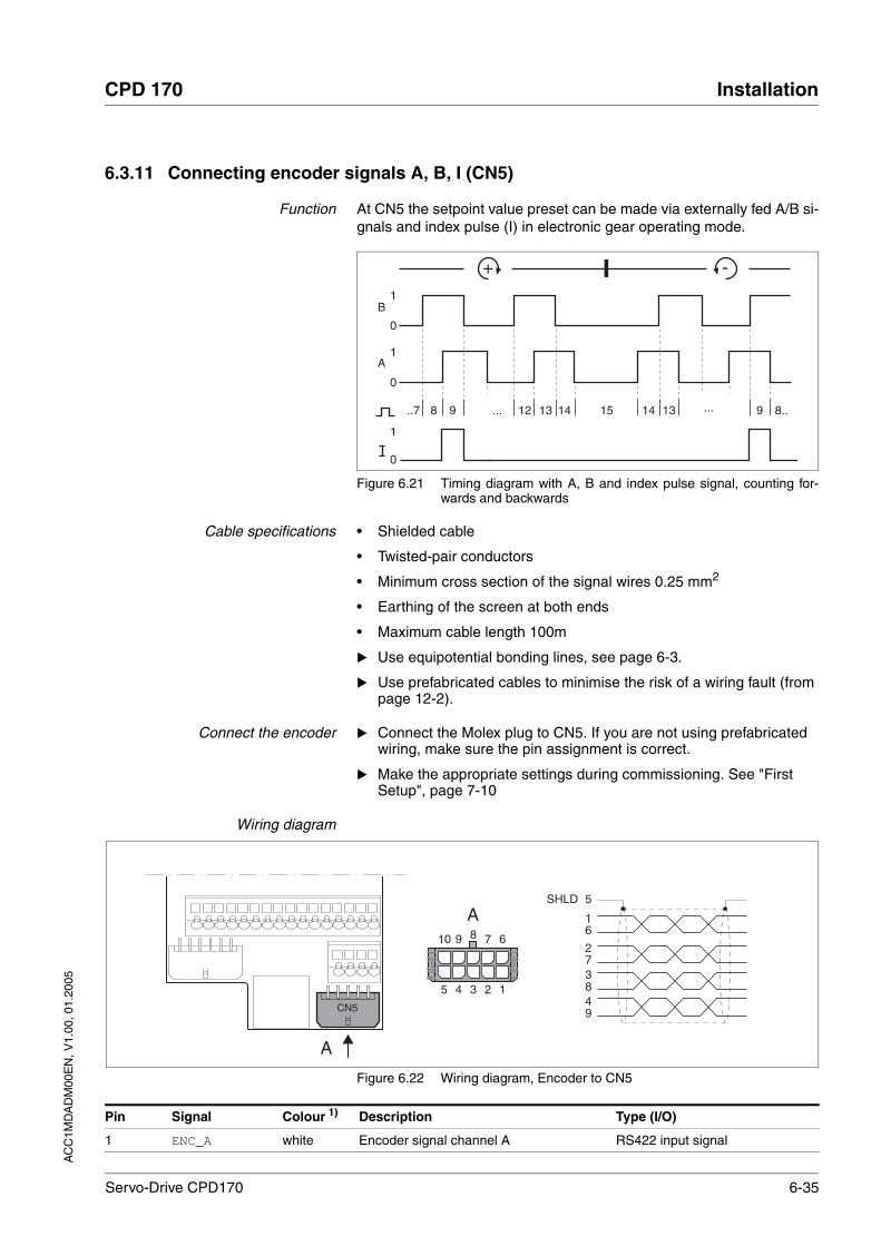
AC
C1M
DA
DM
00E
N, V
1.00
, 01.
2005
CPD 170 Installation
Servo-Drive CPD170 6-35
6.3.11 Connecting encoder signals A, B, I (CN5)
Function At CN5 the setpoint value preset can be made via externally fed A/B si-gnals and index pulse (I) in electronic gear operating mode.
Figure 6.21 Timing diagram with A, B and index pulse signal, counting for-wards and backwards
Cable specifications • Shielded cable
• Twisted-pair conductors
• Minimum cross section of the signal wires 0.25 mm2
• Earthing of the screen at both ends
• Maximum cable length 100m
Use equipotential bonding lines, see page 6-3.
Use prefabricated cables to minimise the risk of a wiring fault (from page 12-2).
Connect the encoder Connect the Molex plug to CN5. If you are not using prefabricated wiring, make sure the pin assignment is correct.
Make the appropriate settings during commissioning. See "First Setup", page 7-10
Wiring diagram
Figure 6.22 Wiring diagram, Encoder to CN5
B
0
1
0
1
0
1
A
+ -
..7 ... ...8 9 1312 13 9 8..14 1415
CN5
A
A
5 1234
10 6789
5
16
49
38
27
SHLD
Pin Signal Colour 1) Description Type (I/O)
1 ENC_A white Encoder signal channel A RS422 input signal

6-36 Servo-Drive CPD170
Installation CPD 170
AC
C1M
DA
DM
00E
N, V
1.00
, 01.
2005
6.3.12 PULSE (CN5) connection
Function The unit is suitable for setpoint value default via externally fed pulse/di-rection signals. For example, they are required for electronic gear ope-rating mode.
Pulse-direction signals are used as reference signals for positioning the motor and as a control signal for power amplifier enable. Drive ready for operation and a possible operating fault are reported.
PULSE/DIR The motor executes an angular step on the leading edge of the PULSE signal PULSE. The direction of rotation is controlled by the DIR signal.
6 ENC_A brown Channel A, inverted RS422 input signal
2 ENC_B green Encoder signal channel B RS422 input signal
7 ENC_B yellow Channel B, inverted RS422 input signal
3 ENC_I grey Channel index pulse RS422 input signal
8 ENC_I pink Channel index pulse, inverted RS422 input signal
4 ACTIVE2_OUT red Drive ready Open collector
9 POS_0V blue Reference potential
5 Shield
10 nc not assigned
1) Information on colour refers to the wires available as accessories.
Pin Signal Colour 1) Description Type (I/O)
WARNING!Unexpected motion may cause injury and damage to the sys-tem.
Incorrect or faulty signals as reference position can trigger unexpec-ted movements.
• Use shielded cables with twisted-pair.
• Operate the interface with push-pull signals.
• Do not use signals without push-pull in critical applications or in an environment subject to interference.
• Do not use signals without push-pull with cable lengths over 3 m and limit the frequency to 50 kHz
Failure to follow these instructions can result in death or serious injury.
CAUTION!Destruction of the product and loss of control monitoring!
The PULSE, DIR and ENABLE inputs on this connection are only ra-ted for 5V. Excessive voltage can cause destruction of the product either immediately or at a later time.
• Check the correct connection before switching on.Failure to follow these instructions can result in injury or equipment damage.
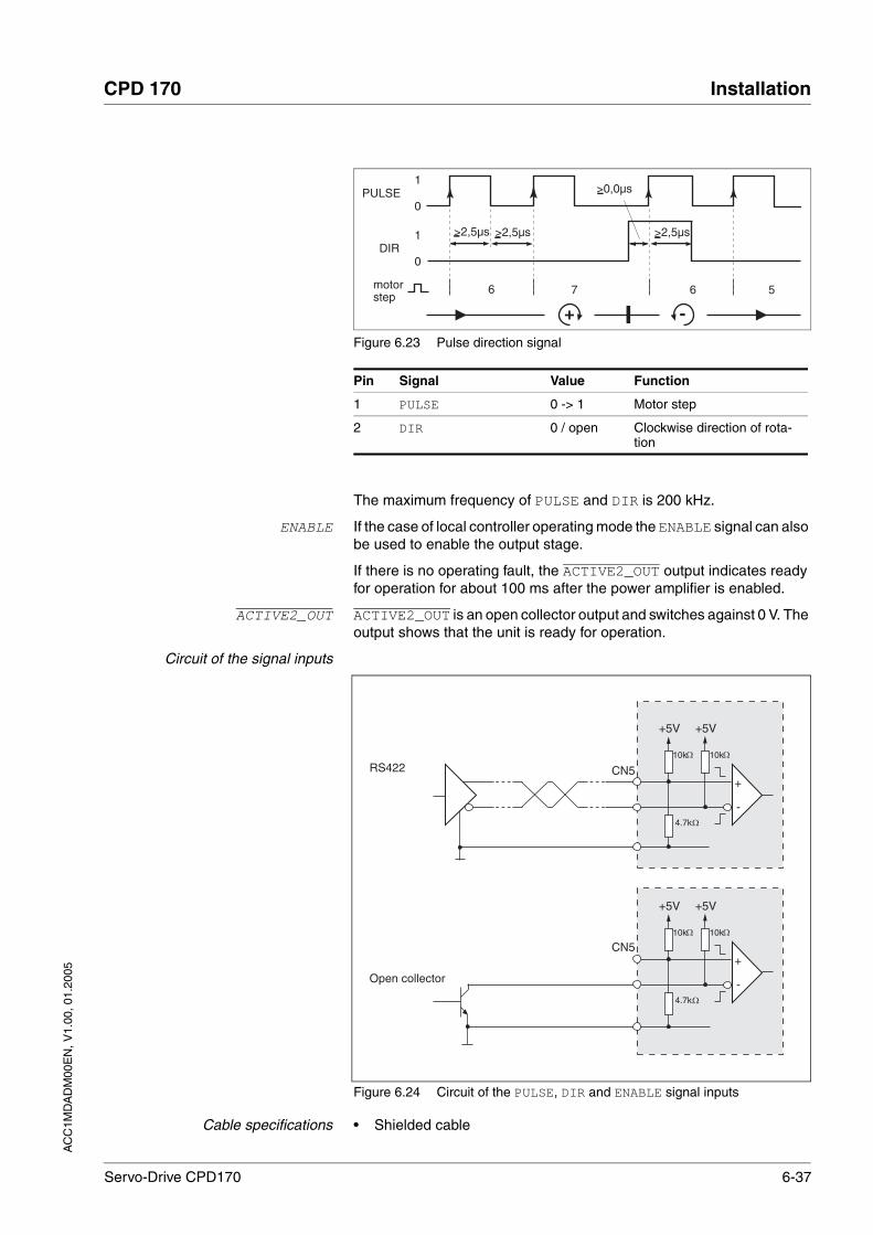
AC
C1M
DA
DM
00E
N, V
1.00
, 01.
2005
CPD 170 Installation
Servo-Drive CPD170 6-37
Figure 6.23 Pulse direction signal
The maximum frequency of PULSE and DIR is 200 kHz.
ENABLE If the case of local controller operating mode the ENABLE signal can also be used to enable the output stage.
If there is no operating fault, the ACTIVE2_OUT output indicates ready for operation for about 100 ms after the power amplifier is enabled.
ACTIVE2_OUT ACTIVE2_OUT is an open collector output and switches against 0 V. The output shows that the unit is ready for operation.
Circuit of the signal inputs
Figure 6.24 Circuit of the PULSE, DIR and ENABLE signal inputs
Cable specifications • Shielded cable
Pin Signal Value Function
1 PULSE 0 -> 1 Motor step
2 DIR 0 / open Clockwise direction of rota-tion
0
1
0
1
+ -
6 6 57
PULSE
DIR>2,5µs >2,5µs >2,5µs
>0,0µs
motorstep
CN5RS422
Open collector
+
-
+5V
10k 10k
4.7k
ΩΩ
Ω
+5V
+
-
+5V
10k 10k
4.7k
ΩΩ
Ω
+5V
CN5

6-38 Servo-Drive CPD170
Installation CPD 170
AC
C1M
DA
DM
00E
N, V
1.00
, 01.
2005
• Twisted-pair conductors
• Minimum cross section of the signal wires 0.14 mm2
• Earthing of the screen at both ends
• Maximum length 100 m
Use equipotential bonding lines, see page 6-3.
Use prefabricated cables to minimise the risk of a wiring fault (from page 12-1).
Connecting PULSE Connect the Molex plug to CN5. If you are not using prefabricated wiring, make sure the pin assignment is correct.
Make the appropriate settings during commissioning. See "First Setup", page 7-10
Connection diagram
Figure 6.25 Connection diagram PULSE
CN5
A
A
5 1234
10 6789
5
16
49
38
27
SHLD
Pin Signal Colour 1) Meaning I/O
1 PULSE white Motor step "Pulse" RS422 input signal
6 PULSE brown Motor step "Pulse", inverted RS422 input signal
2 DIR green direction of rotation "DIR" RS422 input signal
7 DIR yellow direction of rotation "Dir", inverted RS422 input signal
3 ENABLE grey Enable signal RS422 input signal
8 ENABLE pink Enable signal, inverted RS422 input signal
4 ACTIVE2_OUT red Drive ready Open collector
9 POS_0V blue Reference potential -
5 Shield line
10 nc not assigned
1) Information on the colour refers to the cables available as accessories.

AC
C1M
DA
DM
00E
N, V
1.00
, 01.
2005
CPD 170 Installation
Servo-Drive CPD170 6-39
6.3.13 ESIM (CN5) connection
Function The unit is suitable for encoder simulation (ESIM). Signals for output of the actual position cab be led out at CN5. They are two out-of-phase si-gnals A and B. The A/B signals are sent by the motor-encoder module.
Resolution The basic resolution of the encoder simulation at 4x resolution is 4096 increments per revolution.
Figure 6.26 Timing diagram with A, B and index pulse signal, counting for-wards and backwards
Cable specification • Shielded cable
• Twisted-pair conductors
• Minimum cross section of the signal wires 0.14 mm2
• Earthing of the screen at both ends
• Maximum length 100 m
Use equipotential bonding lines, see page 6-3.
Use prefabricated cables to minimise the risk of a wiring fault (from page 12-2).
Connecting ESIM Connect the Molex plug to CN5. If you are not using prefabricated wiring, make sure the pin assignment is correct.
Make the appropriate settings during commissioning. See "First Setup", page 7-10
Connection diagram
Figure 6.27 ESIM connection diagram
B
0
1
0
1
0
1
A
+ -
..7 ... ...8 9 1312 13 9 8..14 1415
CN5
A
A
5 1234
10 6789
5
16
49
38
27
SHLD
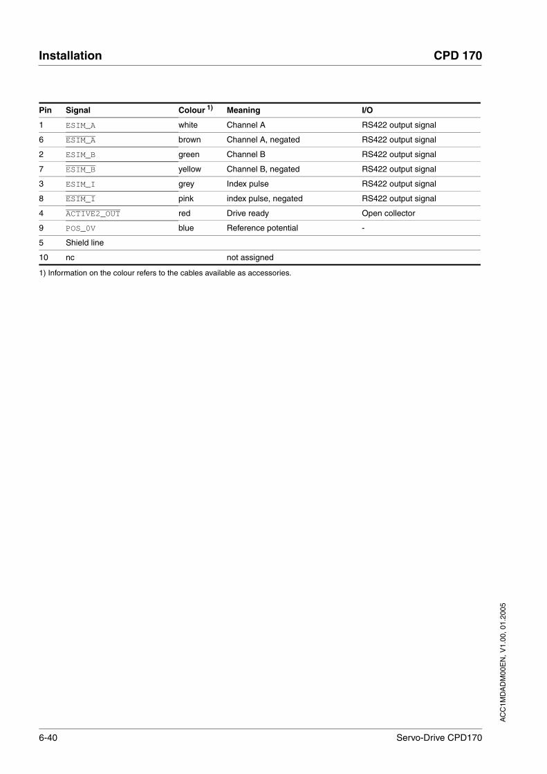
6-40 Servo-Drive CPD170
Installation CPD 170
AC
C1M
DA
DM
00E
N, V
1.00
, 01.
2005
Pin Signal Colour 1) Meaning I/O
1 ESIM_A white Channel A RS422 output signal
6 ESIM_A brown Channel A, negated RS422 output signal
2 ESIM_B green Channel B RS422 output signal
7 ESIM_B yellow Channel B, negated RS422 output signal
3 ESIM_I grey Index pulse RS422 output signal
8 ESIM_I pink index pulse, negated RS422 output signal
4 ACTIVE2_OUT red Drive ready Open collector
9 POS_0V blue Reference potential -
5 Shield line
10 nc not assigned
1) Information on the colour refers to the cables available as accessories.

AC
C1M
DA
DM
00E
N, V
1.00
, 01.
2005
CPD 170 Installation
Servo-Drive CPD170 6-41
6.3.14 CANopen connection (CN1 or CN4)
Function The unit is suitable for connection to CANopen.
In CAN bus multiple network devices can be connected over one bus ca-ble. Up to 32 devices can be addressed in one CAN bus network branch and up to 127 devices in the extended network.
Every network device must be configured before operation on the net-work. It is given a unique, 7-bit node address (node-ID) between 1 (01h) and 127 (7Fh).
The baud rate must be the same for all units in the field bus.
Address and baud rate are set during commissioning. See "First Setup", page 7-10
For additional information see the CANopen manual, order number, see page 12-3.
Cable specifications • Shielded cable
• Twisted-pair conductors
• Minimum cross section of the signal wires 0.14 mm2
• Earthing of the screen at both ends
• Maximum length depends on the number of devices, the baud rate and signal run times. The higher the baud rates the shorter the bus cable must be.
Use equipotential bonding lines, see page 6-3.
Use prefabricated cables to minimise the risk of a wiring fault (from page 12-3).
Make sure that the wiring, the cables and the connected interfaces meet the requirements for PELV.
Maximum bus length The maximum bus length depends on the selected baud rate. The follo-wing table shows the maximum recommended bus lengths for the over-all length.
At a baud rate of 1 Mbit the spur lines are limited to 0.3m.
Terminating resistors The units at the two ends of a bus cable string must be terminated. This can be achieved with CAN by the using terminating resistances of 120Ω between CAN_L and CAN_H
A terminating resistor that is enabled with the S1 switch is integrated into the unit.
baud rate [kbit/s] maximum bus length with CANopen [m]
20 2500
125 500
250 250
500 100
800 25
1000 4

6-42 Servo-Drive CPD170
Installation CPD 170
AC
C1M
DA
DM
00E
N, V
1.00
, 01.
2005
If the unit is at the end of the network, slide the S1 switch for the ter-minating resistor to the left.
Wiring diagram
Figure 6.28 Wiring diagram, CANopen at CN1
Figure 6.29 CANopen wiring diagram at CN4
Connecting CANopen Connect the CANopen cable to CN1, pin 21, 22 and 23 or to CN4 (pin 1, 2 and 8) with an RJ45 plug.
CN1
11 141312 3231 353433 383736 392221 23S1 OFF
Pin Signal Description Type (I/O)
21 CAN_0V CAN reference potential
22 CAN_L data wire, inverted CAN level
23 CAN_H data wire CAN level
CN4
A
A
S1 OFF
18
Pin Signal Description Type (I/O)
1 CAN_H data wire CAN level
2 CAN_L data wire, inverted CAN level
7 MOD+10V_OUT 10V power supply (different assignment from CANopen) Output
8 MOD_0V Reference potential forMOD+10V_OUT Output

AC
C1M
DA
DM
00E
N, V
1.00
, 01.
2005
CPD 170 Installation
Servo-Drive CPD170 6-43
6.3.15 Modbus connection (CN4)
Function The unit is designed for connection to the Modbus
With Modbus, multiple network devices are interconnected by bus cable. Every network device must be configured before operation on the net-work. Each is given a unique node address.
The baud rate must be the same for all units in the field bus.
Address and baud rate are set during commissioning. See "First Setup", page 7-10
For additional in formation see the Modbus manual, order number, see page 12-4.
Cable specifications The cables used must conform to the following properties:
• Shielded cable
• Twisted-pair conductors
• Minimum cross section of the signal wires 0.14 mm2
• Earthing of the screen at both ends
• maximum length 400 m.
Use equipotential bonding lines, see page 6-3.
Use prefabricated cables to minimise the risk of a wiring fault (from page 12-4).
Connection diagram
Figure 6.30 Connection diagram:MODBUS
Connecting Modbus Connect the Modbus cable to CN4 with an RJ45 plug.
6.3.16 Connection of analogue inputs (CN1)
Cable specifications • Shielded cable
CN4
A
A
S1 OFF
18
Pin Signal Description
4 MOD_D1 Bidirectional send/receive signal RS485 level
5 MOD_D0 Bidirectional send/receive signal, inverted RS485 level
7 MOD+10V_OUT 10 V power supply, max. 150 mA) Output
8 MOD_0V Reference potential forMOD+10V_OUT Output

6-44 Servo-Drive CPD170
Installation CPD 170
AC
C1M
DA
DM
00E
N, V
1.00
, 01.
2005
• Twisted-pair conductors
• Minimum cross section of signal wires 0.14 mm2, max. cross sec-tion 1.5 mm2
• maximum length 10 m
Connecting analogue inputs Attach the cable to the EMC plate, the shield must be attached to the earth potential over a wide area. A capacitor, e.g. 10 nF/100 V MKT, must be installed at the other end of the cable between the shield and the earth to prevent HF interference.
Wiring diagram
Figure 6.31 Wiring diagram, analogue inputs
Reference values and limits The ±10V scaling of the analogue reference values and analogue limits can be specified for operation, see page 7-21.
CN1
2221 323123 353433 383736 3911 141312
Pin Signal Type (I/O)
11 ANA1+ Analogue input signal, ±10V, e.g. for current or rotation speed setpoint; Processing: 14 bits
12 ANA1- Reference potential forANA1+, pin 11
13 ANA2+ Analogue input signal, ±10V, e.g. for current or rotation speed limit; Processing: 12 bits
14 ANA2- Reference potential forANA2+, pin 13
AC
C1M
DA
DM
00E
N, V
1.00
, 01.
2005
CPD 170 Installation
Servo-Drive CPD170 6-45
6.3.17 Connection of digital inputs/outputs (CN1)
Cable specifications • minimum cross-section 0.14 mm2, max. cross-section 1.5 mm2
• Maximum length at minimum cross section 15 m..
Minimum connection assignment The following signals must always be connected.
Table 6.8 Minimum connection assignment
If the signals listed in the table are not used, they must be wired with +24VDC. HALT, LIMP, LIMN and REF can also be disabled with the cor-responding parameters.
Terminal assignment for SafeStandstill function
CAUTION!Loss of control monitoring.
The use of LIMP and LIMN can offer some protection against ha-zards (e.g. impact on mechanical stop caused by incorrect motion defaults).
• Use LIMP and LIMN where possible.
• Check that the external sensors or switches are correctly con-nected.
• Check the correct functional installation of the limit switches The limit switches must be mounted in a position far enough away from the mechanical stop to allow an adequate braking distance.
• The functions must be enabled to use LIMP and LIMN.
• This function cannot provide protection against faulty functio-ning of the product or the sensors.
Failure to follow these instructions can result in injury or equipment damage.
Pin Signal Remarks
33 REF with field bus control mode only
34 LIMN with field bus control mode only
35 LIMP with field bus control mode only
36 HALT
37,38 SAFE_DISABLE_BSAFE_DISABLE_A
Two-channel connection, signals are not managed with parameters.
WARNING!Danger of injury by incorrect usage!
Incorrect usage may cause a safety hazard by loss of the safety function.
• Observe the requirements for the safety function.Failure to follow these instructions can result in death or serious injury.
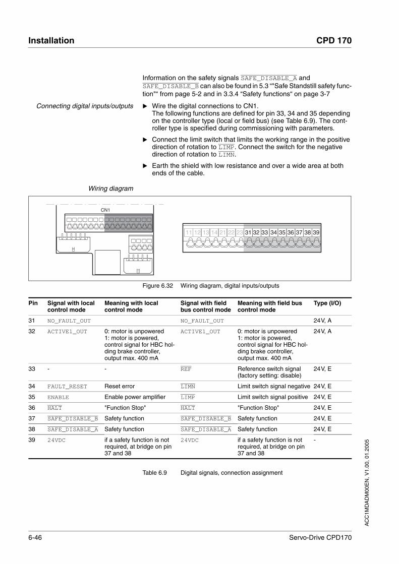
6-46 Servo-Drive CPD170
Installation CPD 170
AC
C1M
DA
DM
00E
N, V
1.00
, 01.
2005
Information on the safety signals SAFE_DISABLE_A and SAFE_DISABLE_B can also be found in 5.3 “"Safe Standstill safety func-tion"“ from page 5-2 and in 3.3.4 “Safety functions“ on page 3-7
Connecting digital inputs/outputs Wire the digital connections to CN1.The following functions are defined for pin 33, 34 and 35 depending on the controller type (local or field bus) (see Table 6.9). The cont-roller type is specified during commissioning with parameters.
Connect the limit switch that limits the working range in the positive direction of rotation to LIMP. Connect the switch for the negative direction of rotation to LIMN.
Earth the shield with low resistance and over a wide area at both ends of the cable.
Wiring diagram
Figure 6.32 Wiring diagram, digital inputs/outputs
Table 6.9 Digital signals, connection assignment
CN1
11 2221141312 323123 353433 383736 39
Pin Signal with local control mode
Meaning with local control mode
Signal with field bus control mode
Meaning with field bus control mode
Type (I/O)
31 NO_FAULT_OUT NO_FAULT_OUT 24V, A
32 ACTIVE1_OUT 0: motor is unpowered1: motor is powered, control signal for HBC hol-ding brake controller, output max. 400 mA
ACTIVE1_OUT 0: motor is unpowered1: motor is powered, control signal for HBC hol-ding brake controller, output max. 400 mA
24V, A
33 - - REF Reference switch signal (factory setting: disable)
24V, E
34 FAULT_RESET Reset error LIMN Limit switch signal negative 24V, E
35 ENABLE Enable power amplifier LIMP Limit switch signal positive 24V, E
36 HALT "Function Stop" HALT "Function Stop" 24V, E
37 SAFE_DISABLE_B Safety function SAFE_DISABLE_B Safety function 24V, E
38 SAFE_DISABLE_A Safety function SAFE_DISABLE_A Safety function 24V, E
39 24VDC if a safety function is not required, at bridge on pin 37 and 38
24VDC if a safety function is not required, at bridge on pin 37 and 38
-

AC
C1M
DA
DM
00E
N, V
1.00
, 01.
2005
CPD 170 Installation
Servo-Drive CPD170 6-47
6.3.18 Connection to PC or peripheral control terminal (CN4)
Function of the control terminal The peripheral control terminal with LCD display and keypad can be connected directly to CN4 with the supplied RJ-45 cable, see accesso-ries from page 12-1. This allows the unit to be operated at a distance from the system. The functions and display of the control terminal are identical to those of the HMI.
Cable specifications • Shielded cable
• Twisted-pair conductors
• Minimum cross section of the signal wires 0.14 mm2
• Earthing of the screen at both ends
• maximum length 400 m
PC connection An RS485 to RS232 converter is required for the PC, see accessories from page 12-1. The converter is powered by the unit.
Connection diagram
Figure 6.33 Connection of PC or decentralised operating terminal
CAUTION!Damage to PC!
If the interface connector on the product is directly connected to a Gigabit Ethernet plug on the PC, the interface on the PC may be de-stroyed.
• Never connect an Ethernet interface directly to this product.Failure to follow these instructions can result in injury or equipment damage.
RS 485
RS 232
CN4
A
A
ESC
ENT
RUNFWO
REV
stopreset
18
Pin Signal Meaning
4 MOD_D1 Bidirectional send/receive signal, inverted RS485 level
5 MOD_D0 Bidirectional send/receive signal RS485 level
7 MOD+10V_OUT 10 V power supply, max. 150 mA) Output
8 MOD_0V Reference potential to MOD+10V_OUT Output

6-48 Servo-Drive CPD170
Installation CPD 170
AC
C1M
DA
DM
00E
N, V
1.00
, 01.
2005
6.3.19 Reference signal adapter
Reference signal adapter RVA Reference signals of a master device can be sent simultaneously to up to five units using the RVA (Reference Value Adapter) reference signal adapter. This adapter also supplies the supply voltage (5V, monitored with sense wires) for the motor sensor. The correct power supply is shown by a "5VSE" LED.
An external rotary encoder (A/B signals) or an encoder simulation (ESIM) can be used as a master device. Pulse/direction signals can also be sent from a higher level controller.
Connecting RVA reference signaladapter
Make sure that the wiring, the cables and the connected interfaces meet the requirements for PELV.
The RVA reference signal adapter is powered by 24 V at the CN9 termi-nals. A higher level controller (pulse/direction) can be connected to CN6. An external rotary encoder or an ESIM signal can be applied to CN7.
Up to five units for evaluating the specified reference signals can be con-nected to CN1 to CN5.
Set switch S1 according to the assignment of CN1-CN5 For example, if units are only connected to CN1, CN3 and CN4, S1-1, S1-3 and S1-4 must be set to "off" and S1-2 and S1-5 to "on".
The "active" LED shows that ACTIVE2_OUT has been set on all connected units and the number of connected units complies with the setting.
OFF
CN6 CN5CN4CN3CN2CN1CN7
S1CN9
CN80VDC
Active
5VSE
41 32 5
1
8
9
15
1
8
9
15
1
8
9
15
1
8
9
15
1
8
9
15
1
8
9
15
8
1
15
9
24VDC
Pin Signal Description
1 PULSE / A / ESIM_A Pulse+, channel A, ESIM_A
9 PULSE / A / ESIM_A Pulse-, channel A inverted, ESIM_A inverted
2 DIR / B / ESIM_B Direction+, channel B, ESIM_B
10 DIR / B / ESIM_B Direction-, channel B inverted, ESIM_A inverted

AC
C1M
DA
DM
00E
N, V
1.00
, 01.
2005
CPD 170 Installation
Servo-Drive CPD170 6-49
Table 6.10 CN1-CN6 connection assignment
Table 6.11 CN7 connection assignment
3 ENABLE / I / ESIM_I ENABLE+, index pulse, ESIM_I
11 ENABLE / I / ESIM_I ENABLE-, index pulse inverted, ESIM_I inverted
8 ACTIVE2_OUT / READY Drive ready
15 GND Reference potential
4, 5, 6, 7, 12, 13, 14 nc not assigned
Pin Signal Description
Pin Signal Description
1 A Channel A
9 A Channel A inverted
12 B Channel B
5 B Channel B inverted
13 I Index pulse
6 I index pulse inverted
10 SENSE+ Monitoring motor sensor power supply
11 SENSE- Reference potential to motor sensor monitor
2 5VDC 5V motor sensor power supply
3 GND Reference potential to 5V motor sensor power supply
4, 7, 8, 14, 15 nc not assigned
CN6 CN5CN4CN3CN2CN1CN7 CN6 CN5CN4CN3CN2CN1CN7
S1CN9CN8
Active5VSE
24VDC
S1CN9CN8
Active5VSE
24VDC
E

6-50 Servo-Drive CPD170
Installation CPD 170
AC
C1M
DA
DM
00E
N, V
1.00
, 01.
2005
Figure 6.34 Wiring example: encoder signals A/B/I (at CN7) are sent to sixunits via two cascaded reference value adapter
Figure 6.35 Wiring example: pulse direction signals (at CN6) are sent to threeunits.
CN6 CN5CN4CN3CN2CN1CN7
S1CN9CN8
Active5VSE
24VDC
41 32 5
Act
ive
Act
ive
Act
ive
Not
Act
ive
Not
Act
ive
Pulse direction

AC
C1M
DA
DM
00E
N, V
1.00
, 01.
2005
CPD 170 Installation
Servo-Drive CPD170 6-51
6.4 Checking installation
After completion of all steps we recommend checking the installation to prevent any errors before operation of the system.
Make sure the drive system is correctly installed and wired up. Check in particular basic connections such as mains power and 24V power supply.
Check in detail:
• Are all protective conductors connected?
• Are all fuses correct?
• Are any live cable ends exposed?
• Are all cables and connectors safely installed and connected?
• Are the control lines connected correctly?
• Have all EMC measures been taken?
Check that all seals are fitted and that degree of protection IP54 is complied with (only when using the "Safe Standstill" function)
Remove the protective foil as required in accordance with the speci-fications in Table 6.1.

6-52 Servo-Drive CPD170
Installation CPD 170
AC
C1M
DA
DM
00E
N, V
1.00
, 01.
2005

AC
C1M
DA
DM
00E
N, V
1.00
, 01.
2005
CPD 170 Commissioning
Servo-Drive CPD170 7-1
7 Commissioning
7.1 General safety instructions
DANGER!Electric shock, fire or explosion
• Only qualified personnel who are familiar with and understand the contents of this manual and the other relevant manuals are authorised to work on and with this drive system.
• Before working on the drive system:
– Switch off power to all terminals.
– Place a sign "DO NOT SWITCH ON" on the switch and lock to prevent switching on.
– Wait 6 minutes (for discharge of DC bus capacitors).
– Measure voltage between DC+ and DC- and check for <48V. (The DC bus LED is not a safe indication for absence of the DC bus voltage).
• Do not short-circuit DC bus or touch unshielded components or screws of the terminals with voltage present.
• Install all covers and close the housing doors before applying power.
• The motor generates voltage when the shaft is rotated. Lock the shaft of the motor to prevent rotation before starting work on the drive system.
• The system manufacturer is responsible for compliance with all applicable regulations relevant to earthing the drive system.
• Do not reach into the drive system (e.g. no pointed objects).Failure to follow these instructions will result in death or serious injury.
DANGER!Electric shock caused by incorrect use!
The "Safe Standstill " function does not effect any electrical discon-nection. The inter circuit voltage is still present.
• Turn off the mains voltage using an appropriate switch to achieve a voltage-free condition.
Failure to follow these instructions will result in death or serious injury.

7-2 Servo-Drive CPD170
Commissioning CPD 170
AC
C1M
DA
DM
00E
N, V
1.00
, 01.
2005
WARNING!Unexpected responses may cause injury and damage to the system.
The behaviour of the drive system is governed by numerous saved data. Unsuitable data may cause unexpected motions or responses to signals.
• Do not operate a unit with unknown data.
• Check the saved data.
• When commissioning carefully run tests for all operating states and fault cases.
• Check the functions after replacing a unit and also after chan-ges to the saved data.
• Start the system only if there are no persons or materials in the danger zone and the system can be operated safely.
Failure to follow these instructions can result in death or serious injury.
WARNING!Danger of injury and damage to system components by loss of control!
• Observe the accident prevention regulations.
• The system manufacturer must consider the possible errors that could occur with the signals and in particular the critical func-tions to ensure a safe status during and after errors. Examples for these are: emergency stop, final position limit, power failure and restart.
• Consideration of possible errors must also include unexpected delay and failure of signals or functions.
• Separate redundant controller paths must be provided for dan-gerous functions.
• Verify the effictiveness of the measures.Failure to follow these instructions can result in death or serious injury.
WARNING!Danger of injury and damage to system components by unbra-ked motor!
Loss of power or faults that result in switching off the power amplifier mean that the motor is no longer actively braked and may run against a mechanical stop at high speed.
• Check the mechanical conditions.
• If necessary, use an absorbent mechanical stop or a suitable brake.
Neglect can result in an accident or damage to the system

AC
C1M
DA
DM
00E
N, V
1.00
, 01.
2005
CPD 170 Commissioning
Servo-Drive CPD170 7-3
7.2 Overview
The following commissioning steps are also required if you are using a configured unit under changed operating conditions.
What must be done
WARNING!Unexpected motion may cause injury and damage to the sys-tem
When the drive is operated for the first time there is a high risk of un-expected motion because of possible wiring faults or unsuitable pa-rameters.
• If possible, run the first test movement without coupled loads.
• Make sure that a functioning button for EMERGENCY STOP is within reach.
• Also anticipate a movement in the incorrect direction or oscilla-tion of the drive.
• Make sure that the system is free and ready for the motion before starting the function.
Failure to follow these instructions can result in death or serious injury.
CAUTION!Hot surfaces can cause burns and damage to system compo-nents!
The heat sink on the product may heat up to over 100°C depending on the operating mode.
• Prevent contact with the hot heat sink.
• Do not install flammable or heat-sensitive components in the immediate vicinity.
• Follow the actions described for heat dissipation.Failure to follow these instructions can result in injury or equipment damage.
What you need to do... Info
Checking installation Page 6-51
Making "Initial Setup" Page 7-10
Check and set critical device parameters Page 7-16
Define ESIM resolution, if used Page 7-20
Setting, scaling, testing analogue signals Page 7-21
Set, test digital signals Page 7-22
Limit switch function, tests the signals LIMP, LIMN Page 7-23
Check signals SAFE_DISABLE, even if the “Safe Standstill” function is not used
Page 7-24

7-4 Servo-Drive CPD170
Commissioning CPD 170
AC
C1M
DA
DM
00E
N, V
1.00
, 01.
2005
Check the functioning of the holding brake controller if it is wired for that
Page 7-25
Checking motor direction of rotation Page 7-26
Run autotuning Page 7-29
Optimise controller settings manually- speed controller- position controller
Page 7-33 Page 7-34Page 7-38
Back up all parameter settings as a file (using the commissio-ning software)
Page 8-67
What you need to do... Info

AC
C1M
DA
DM
00E
N, V
1.00
, 01.
2005
CPD 170 Commissioning
Servo-Drive CPD170 7-5
7.3 Tools for commissioning
7.3.1 Overview
Commissioning and setting parameters and also diagnostic tasks can be carried out with the following tools:
• Integrated HMI
• Peripherical control terminal
• Commissioning software
• Field bus
Access to the complete list of parameters is only possible with the commissioning software or via field bus.
Figure 7.1 Commissioning tools
8.8.8.8
ESC
ENT
Integrated HMI PC with commissioning software
Peripherical Control terminal
8.8.8.8
RUN
ESC
ENT
Field bus

7-6 Servo-Drive CPD170
Commissioning CPD 170
AC
C1M
DA
DM
00E
N, V
1.00
, 01.
2005
7.3.2 HMI: Human-Machine Interface
Function The unit has the option of editing parameters with the integrated control panel (HMI). Displays for diagnosis are also possible. The sections on commissioning and operation include information on whether a function can be carried out with the HMI or whether the commissioning software must be used.
A brief introduction to the HMI structure and the operation is given be-low.
Control panel Figure 7.2 shows the HMI (left) and the decentralised control terminal (right).
Figure 7.2 HMI and decentralised control terminal
(1) LEDs for CANopen(2) ESC:
- exit a menu or parameter- return from the displayed to the last saved value
(3) ENT:- call a menu or parameter- save the displayed value to EEPROM
(4) Down arrow:- switch to next menu or parameter- reduce the displayed value
(5) Up arrow:- switch to previous menu or parameter- increase the displayed value
(6) Red LED on: DC bus under voltage(7) Status display(8) Quick Stop (Software Stop)(9) Fault Reset (Continue)(10) No function
LEDs for CANopen 2 LEDs show the status of the CANopen state machine as per the CANopen standard DR 303-3.
8.8.8.8
RUN Halt
Cont
8.8.8.8
ESC
ENT
RUN
ERR
CAN
1
2
3
7
6
5
4xxxx
xxxx
ESC
ENT
10
7
2
3
9 8
4
5

AC
C1M
DA
DM
00E
N, V
1.00
, 01.
2005
CPD 170 Commissioning
Servo-Drive CPD170 7-7
Figure 7.3 Meaning of the LED signals
"CAN RUN" LED
(1) Unit is in the NMT state OPERATIONAL(3) Unit is in the NMT state PRE-OPERATIONAL(4) Unit is in the NMT state STOPPED
"CAN ERR LED"
(1) CAN is BUS-OFF, e.g. after 32 failed transmission attempts.(2) Unit is operating(4) Warning limit reached e.g. after 16 failed transmission
attempts(5) Monitoring result (node guarding) has occurred(6) SYNC message was not received within the configured period
Font on HMI display Table 7.1 shows the assignment of the letters and numbers on the HMI display for the parameter view. Upper and lower case are only distingu-ished for C.
Table 7.1 HMI, available letters and numbers
Menu structure The HMI is menu-driven. Figure 7.4 andTable 7.2 show the top level of the menu structure
O B C D I F G H I J K L M N O P Q R
A B cC D E F G H i J K L M N o P Q R
S T U V W X Y Z 1 2 3 4 5 6 7 8 9 0
S T U:.. V W X Y Z 1 2 3 4 5 6 7 8 9 0

7-8 Servo-Drive CPD170
Commissioning CPD 170
AC
C1M
DA
DM
00E
N, V
1.00
, 01.
2005
Figure 7.4 HMI menu structure
Table 7.2 HMI, meaning of the menus
Status displays such as RDY- (Ready) can be found from page 7-15.
Calling parameters via HMI The parameters belonging to a specific menu item are in the first level below the top menu level for that item. In order to give a better orienta-tion, the table of parameters also shows the overall menu path, e.g. SET- / A1NS.
Figure 7.5 shows an example of calling a parameter (second level) and input or selection of a parameter value (third level).
Power On:- First Setup not done
- First Setup done
Menus
rdy
ESC
Drive ConfigurationdrC-
ESC
ESCENT
JOG ModeJoG-
ESC
ESCENT
Communication(Om-
ESC
ESCENT
Information / IdentificationInF-
ESC
SettingsSEt-
ESC
ESCENT
ESC
ENT
ESC
ENT
AutotuningtUn-
ESC
ESCENT
FaultFLt-
ESC
ESCENT
Status InformationSTA-
ESC
ENT
First SetupFSU-
ENT
ENT
Save
Menu HMI code Meaning
FSU- FSU- First Setup (First SetUp)
SET- Set- Unit settings (SETtings)
DRC- drC- Unit configuration (DRive Configuration)
TUN- tun- Autotuning (AutoTUNing)
JOG- Jog- Manual movement(JOG Mode)
COM- COm- Communication(COMmunication)
FLT- FLt- Error display(FauLT)
INF- Inf- Information/identification (INFormation / Identification)
STA- StA- Observation/monitoring of unit, motor and movement data (STAtus Information)
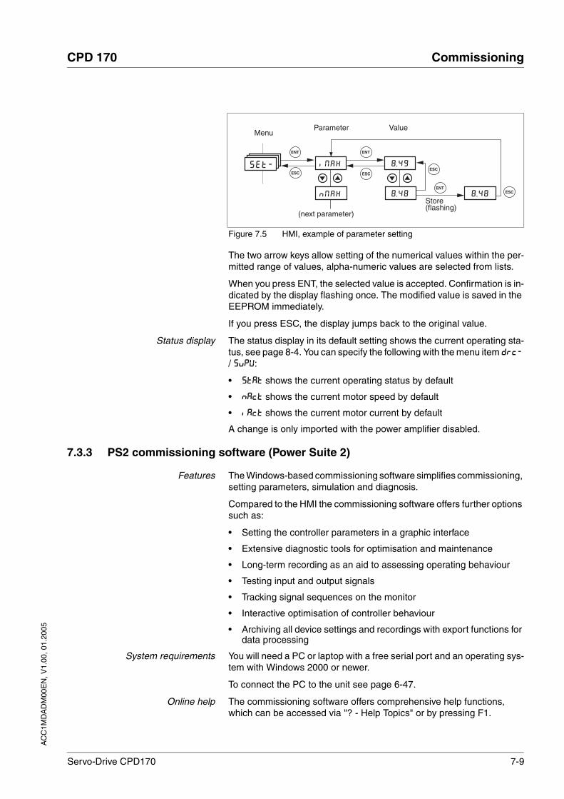
AC
C1M
DA
DM
00E
N, V
1.00
, 01.
2005
CPD 170 Commissioning
Servo-Drive CPD170 7-9
Figure 7.5 HMI, example of parameter setting
The two arrow keys allow setting of the numerical values within the per-mitted range of values, alpha-numeric values are selected from lists.
When you press ENT, the selected value is accepted. Confirmation is in-dicated by the display flashing once. The modified value is saved in the EEPROM immediately.
If you press ESC, the display jumps back to the original value.
Status display The status display in its default setting shows the current operating sta-tus, see page 8-4. You can specify the following with the menu item drc- / supv:
• stat shows the current operating status by default
• nact shows the current motor speed by default
• iact shows the current motor current by default
A change is only imported with the power amplifier disabled.
7.3.3 PS2 commissioning software (Power Suite 2)
Features The Windows-based commissioning software simplifies commissioning, setting parameters, simulation and diagnosis.
Compared to the HMI the commissioning software offers further options such as:
• Setting the controller parameters in a graphic interface
• Extensive diagnostic tools for optimisation and maintenance
• Long-term recording as an aid to assessing operating behaviour
• Testing input and output signals
• Tracking signal sequences on the monitor
• Interactive optimisation of controller behaviour
• Archiving all device settings and recordings with export functions for data processing
System requirements You will need a PC or laptop with a free serial port and an operating sys-tem with Windows 2000 or newer.
To connect the PC to the unit see page 6-47.
Online help The commissioning software offers comprehensive help functions, which can be accessed via "? - Help Topics" or by pressing F1.
ESC
ENT
ESC
ENT
ESC
8 . 48NMAX
IMAX 8 . 49Set-
MenuParameter Value
Store(flashing)
(next parameter)
8 . 48ENT
ESC
7-10 Servo-Drive CPD170
Commissioning CPD 170
AC
C1M
DA
DM
00E
N, V
1.00
, 01.
2005
7.4 Commissioning procedure
7.4.1 "Initial Setup"
"Initial Setup" must be made when the controller supply voltage is swit-ched on for the first time or when the factory settings have been loaded.
Preparation A PC with the commissioning software must be connected to the unit unless the commissioning is conducted exclusively through the HMI.
During commissioning disconnect the connection to the field bus to avoid conflicts caused by simultaneous access.
Switch on the controller power supply.
Automatic read-in of the motor dataset
When the unit is switched on for the first time with the motor connected, the unit reads the motor data set automatically from the Hiperface sen-sor (motor sensor). The data set is checked for completeness and saved in the EEPROM.
The motor data set contains technical information about the motor such as the nominal and peak torque, the nominal current and speed and the pole-pair number. It cannot be modified by the user. The unit cannot be switched ready for operation without this information
"First Setup" via HMI The following diagram shows the sequence using HMI.
WARNING!Unsuitable parameters may cause injury and damage to the system.
If unsuitable parameters are used, safety functions may fail, unex-pected motions or responses to signals may occur.
• Prepare a list with the parameters required for the functions in use.
• Check the parameters before operation.
• Start the system only if there are no persons or materials in the danger zone and the system can be operated safely.
Failure to follow these instructions can result in death or serious injury.

AC
C1M
DA
DM
00E
N, V
1.00
, 01.
2005
CPD 170 Commissioning
Servo-Drive CPD170 7-11
Figure 7.6 "First Setup" via HMI
Unit controller Specify how the unit will be controlled with the parameter DEV-cmdinterf (DEVC).
IO-M
Curr
Sped
Gear
IOPI Ab
Pd
ESIM
COAD 127
COBD 125
mbad 1
mbbd 9600
none
SaVe
ENT
IOLL
ENT
ESC
PoS
NEG
ENT ENT
FSU-
ENT
ENT
ESC
DevC None
CANO
MoDB
IO
ENT
DEVC = CANO / MoDB
DEVC = CANO DEVC = MoDB
DEVC = IO
ENT
ENTENT
ENT
ENT
ENT
ESC
ENT
ESC
ENT
ESC
ENT
ESC
ENT
ESC
ENT
ESC

7-12 Servo-Drive CPD170
Commissioning CPD 170
AC
C1M
DA
DM
00E
N, V
1.00
, 01.
2005
Default operating mode DEVcmdinerf = IODevice(DEVC = IO)
Specify the operating mode in which the unit will start by default every time it is switched on with the parameter IOdefaultMode (IO-M).
The operating modes are described from page 8-11.
Function of the RS422 interface DEVcmdinerf = CANopenDevice / ModbusDevice(DEVC = CANO / MoDB)
Determine the assignment for the IOposInterfac RS422 inter-faces using the (IOPI) parameters.
Parameter NameCodeHMI menu, Code
Meaning UnitMinimum valueDefault valueMaximum value
Data typeR/WperExpert
Parameter address via field bus
DEVcmdinterf
DEVC
NONEDEVC
Specification of the control mode()
0 / none: undefined (default)1 / IODevice / IO: local control mode2 / CANopenDevice / CanO: CANopen3 / ModbusDevice / Modb: Modbus4: reserved
CAUTION: a change in the setting is not enabled until the next start (exception: change of the value 0", at "Initial Setup"").
004
UINT16R/Wper.-
CANopen 3005:1hModbus 1282
Parameter NameCodeHMI menu, Code
Meaning UnitMinimum valueDefault valueMaximum value
Data typeR/WperExpert
Parameter address via field bus
IOdefaultMode
IO-M
DRC-io-M
Start-up of operating mode for 'local control mode'()
0 / none / none : none (default)1 / CurrentControl / Curr: current controller (reference value of ANA1)2 / SpeedControl / Sped: speed controller (reference value of ANA1)3 / GearMode / Gear: electronic gear
The operating mode is automatically enabled when the drive switches to the 'OperationE-nable' status and "I/O Device / I/O" is set in DEVcmdinterf.""
003
UINT16R/Wper.-
CANopen 3005:3hModbus 1286

AC
C1M
DA
DM
00E
N, V
1.00
, 01.
2005
CPD 170 Commissioning
Servo-Drive CPD170 7-13
Field bus CANopen DEVcmdinerf = CANopenDevice(DEVC = CANO)
Specify the node address with the parameter CANadr (COAD) and the baud rate with the parameter CANbaud (COBD).
Every unit must have its own unique node address, which must be assigned only once in the network.
Field bus MODBUS DEVcmdinerf = ModbusDevice(DEVC = MoDB)
Specify the node address with the parameter MBadr (MBAD) and the baud rate with the parameter MBbaud (MBBD).
Parameter NameCodeHMI menu, Code
Meaning UnitMinimum valueDefault valueMaximum value
Data typeR/WperExpert
Parameter address via field bus
IOposInterfac
IOPI
DRC-ioPi
Logic level of the digital inputs/outputs()
RS422 I/O interface (Pos) as:0 / ABinput / AB: input ENC_A, ENC_B, ENC_I (index pulse) 4x evaluation1 / PDinput /PD: input PULSE, DIR, ENABLE22 / ESIMoutput / ESIM: output: ESIM_A, ESIM_B, ESIM_I
002
UINT16R/Wper.-
CANopen 3005:2hModbus 1284
Parameter NameCodeHMI menu, Code
Meaning UnitMinimum valueDefault valueMaximum value
Data typeR/WperExpert
Parameter address via field bus
CANadr
COAD
COM-CoAD
CANopen address (node number)()
valid addresses (node numbers): 1 to 1271127127
UINT16R/Wper.-
CANbaud
COBD
COM-CoBD
CANopen baud rate()
valid baud rates in kbps:50 1252505001000
kbps501251000
UINT16R/Wper.-
Parameter NameCodeHMI menu, Code
Meaning UnitMinimum valueDefault valueMaximum value
Data typeR/WperExpert
Parameter address via field bus
MBadr
MBAD
COM-MBAD
Modbus address()
valid addresses 1 to 24711247
UINT16R/Wper.-

7-14 Servo-Drive CPD170
Commissioning CPD 170
AC
C1M
DA
DM
00E
N, V
1.00
, 01.
2005
Select logic level Specify whether the unit will operate in positive or negative logic with the parameter IOLogicLevel (IOLL), see also the chapter on planning from page 5-1.
Data back-up Back up all inputs on completion.HMI: save your settings for the commissioning software with save: save them with "Configuration - In EEPROM" Save your settings
The unit saves all set values in the EEPROM and displays the sta-tus nRDY, RDY or DIs on the HMI.
A restart of the unit is required to allow the changes to be accepted.
Further steps Stick a label on the unit with all important information required in case of service,e.g. field bus type, address and baud rate.
Make the settings described below for commissioning.
Note that you can only return to the "Initial Setup" by restoring the factory settings, see 8.6.10.2 “Restore factory settings“ page 8-67.
MBbaud
MBBD
COM-MBBD
Modbus baud rate()
Allowable baud rates:96001920038400
Baud01920038400
UINT16R/Wper.-
Parameter NameCodeHMI menu, Code
Meaning UnitMinimum valueDefault valueMaximum value
Data typeR/WperExpert
Parameter address via field bus
Parameter NameCodeHMI menu, Code
Meaning UnitMinimum valueDefault valueMaximum value
Data typeR/WperExpert
Parameter address via field bus
IOLogicLevel
IOLL
DRC-ioLL
Logic level of the digital inputs/outputs()
0 / positive / pos: positive logic (default)1 / negative / neg: negative logic
CAUTION: a change of the setting is not enabled until the next start.
001
UINT16R/Wper.-
CANopen 3005:4hModbus 1288

AC
C1M
DA
DM
00E
N, V
1.00
, 01.
2005
CPD 170 Commissioning
Servo-Drive CPD170 7-15
7.4.2 Operating state (state diagram)
After switching on and at the start of an operating mode, a sequence of operating states is progressed through.
The relationship between the operating states and the state transitions is shown in the state diagram (state machine).
The operating states are internally monitored and influenced by monito-ring and system functions, such as temperature and current monitoring
Graphic representation The state diagram is shown graphically as a flow chart.
Figure 7.7 State diagram
Operating states and modetransitions
For detailed information on operating states and mode transitions see page 8-4.
Switching on
T10
T12
T15
Operating state State transition
3
4
6
disabled
5
Operationenable
Ready toswitch onrdy
Switched onSon
Switch ondis
T11
T16
T4 T5
T6T3T8
T9 T2 T7
T1
Not ready tonrdy
StartINIT1
2
switch on
T0
T13
Fault
Fault Reactionactive
Display flashes
fLt
fLt
8
9
T14
7Quick-Stop active
Display flashes
Stop 8888
8888
FaultClass2, 3, (4)
FaultClass1
Operating fault
HaLt
rUn
stand still
Motor under current
Motor without current

7-16 Servo-Drive CPD170
Commissioning CPD 170
AC
C1M
DA
DM
00E
N, V
1.00
, 01.
2005
7.4.3 Setting basic parameters and limit values
Setting thresholds Suitable thresholds must be calculated from the system configuration and motor characteristics. So long as you are running the motor without external loads you will not need to change the default settings.
The maximum motor current must for example be reduced as a deter-mining factor of the torque if the permissible torque of a system compo-nent will otherwise be exceeded.
Current limiting To protect the drive system, the maximum current flowing can be modi-fied with the CTRL_I_max parameter. The maximum current for the "Quick Stop" function can be limited with the LIM_I_maxQSTP parame-ter and for the "Halt" function with the LIM_I_maxHalt parameter.
Acceleration and deceleration are limited with ramp functions in the point-to-point , speed profile and referencing modes.
Specify the maximum motor current with the CTRL_I_max parame-ter.
Specify the maximum current for "Quick Stop" with the LIM_I_maxQSTP parameter.
Specify the maximum current for "Halt" with the LIM_I_maxHalt parameter.
WARNING!Unsuitable parameters may cause injury and damage to the system.
If unsuitable parameters are used, safety functions may fail, unex-pected motions or responses to signals may occur.
• Prepare a list with the parameters required for the functions in use.
• Check the parameters before operation.
• Start the system only if there are no persons or materials in the danger zone and the system can be operated safely.
Failure to follow these instructions can result in death or serious injury.
Parameter NameCodeHMI menu, Code
Meaning UnitMinimum valueDefault valueMaximum value
Data typeR/WperExpert
Parameter address via field bus
CTRL_I_max
IMAX
SET-iMAX
Current limiting()
Must not exceed max. permissible current of motor or power amplifier.
Default is the smallest value of M_I_nom and PA_I_nom
Apk0.000.00299.99
Field bus0
29999
UINT16R/Wper.-
CANopen 3012:1hModbus 4610
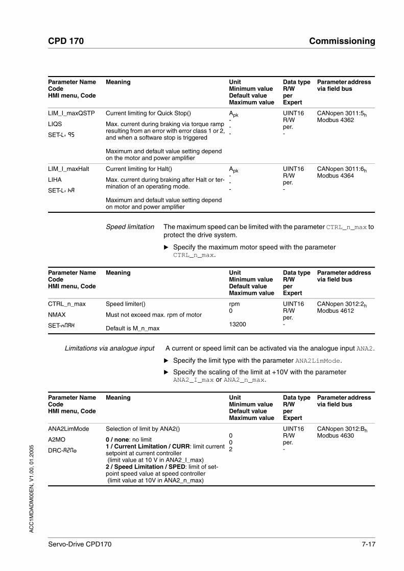
AC
C1M
DA
DM
00E
N, V
1.00
, 01.
2005
CPD 170 Commissioning
Servo-Drive CPD170 7-17
Speed limitation The maximum speed can be limited with the parameter CTRL_n_max to protect the drive system.
Specify the maximum motor speed with the parameter CTRL_n_max.
Limitations via analogue input A current or speed limit can be activated via the analogue input ANA2.
Specify the limit type with the parameter ANA2LimMode.
Specify the scaling of the limit at +10V with the parameter ANA2_I_max or ANA2_n_max.
LIM_I_maxQSTP
LIQS
SET-LiQS
Current limiting for Quick Stop()
Max. current during braking via torque ramp resulting from an error with error class 1 or 2, and when a software stop is triggered
Maximum and default value setting depend on the motor and power amplifier
Apk---
UINT16R/Wper.-
CANopen 3011:5hModbus 4362
LIM_I_maxHalt
LIHA
SET-LihA
Current limiting for Halt()
Max. current during braking after Halt or ter-mination of an operating mode.
Maximum and default value setting depend on motor and power amplifier
Apk---
UINT16R/Wper.-
CANopen 3011:6hModbus 4364
Parameter NameCodeHMI menu, Code
Meaning UnitMinimum valueDefault valueMaximum value
Data typeR/WperExpert
Parameter address via field bus
Parameter NameCodeHMI menu, Code
Meaning UnitMinimum valueDefault valueMaximum value
Data typeR/WperExpert
Parameter address via field bus
CTRL_n_max
NMAX
SET-NMAX
Speed limiter()
Must not exceed max. rpm of motor
Default is M_n_max
rpm0
13200
UINT16R/Wper.-
CANopen 3012:2hModbus 4612
Parameter NameCodeHMI menu, Code
Meaning UnitMinimum valueDefault valueMaximum value
Data typeR/WperExpert
Parameter address via field bus
ANA2LimMode
A2MO
DRC-A2Mo
Selection of limit by ANA2()
0 / none: no limit1 / Current Limitation / CURR: limit current setpoint at current controller (limit value at 10 V in ANA2_I_max)2 / Speed Limitation / SPED: limit of set-point speed value at speed controller (limit value at 10V in ANA2_n_max)
002
UINT16R/Wper.-
CANopen 3012:BhModbus 4630

7-18 Servo-Drive CPD170
Commissioning CPD 170
AC
C1M
DA
DM
00E
N, V
1.00
, 01.
2005
Chopper frequency The factory setting for the chopper frequency in 400V units is 4kHz, in 115V and 230V units 8kHz.
The 24 V power supply must be switched off and on again for the chop-per frequency settings to be effective.
Specify the chopper frequency with the parameter PWM_fChop.
When changing the factory setting, note that with the higher chopper frequency the nominal current and the maximum current are reduced.
ANA2_I_max
A2IM
DRC-A2iM
Scaling for current limiting by ANA2 at +10V()
Default value is lower value from ImaxM or ImaxPA
Apk0.000.00300.00
Field bus0
30000
UINT16R/Wper.-
CANopen 3012:ChModbus 4632
ANA2_n_max
A2NM
DRC-A2NM
Scaling for speed limiting by ANA2 at +10V()
Default value is maximum motor speed M_n_max.
rpm500
30000
UINT16R/Wper.-
CANopen 3012:DhModbus 4634
Parameter NameCodeHMI menu, Code
Meaning UnitMinimum valueDefault valueMaximum value
Data typeR/WperExpert
Parameter address via field bus
Parameter NameCodeHMI menu, Code
Meaning UnitMinimum valueDefault valueMaximum value
Data typeR/WperExpert
Parameter address via field bus
PWM_fChop
-
Switching frequency of power amplifier()
Switching frequency of power amplifier0 / 4kHz: 4 kHz1 / 8kHz: 8 kHz
Factory setting:400 V units: 4 kHzall others: 8 kHz
0
1
UINT16R/Wper.expert
CANopen 3005:EhModbus 1308

AC
C1M
DA
DM
00E
N, V
1.00
, 01.
2005
CPD 170 Commissioning
Servo-Drive CPD170 7-19
Ballast resistor
If an external ballast resistor is connected, the parameter BALint_ext must be set to "external".
The maximum permissible ballast output must be set with the BALext_P parameter. The resistance value must be set with the para-meter BALext_R.
If the actual ballast output exceeds the maximum allowable ballast out-put, the unit will output an error message and the power amplifier will be switched off.
Test the function of the ballast resistor under realistic conditions.
WARNING!Risk of injury and damage to system components by unbraked motor.
An insufficient ballast resistor causes overvoltage on the DC bus and switches off the power amplifier. The motor is no longer actively braked.
• Make sure that the ballast resistor is sufficiently dimensioned.
• Check the setting of the parameter for the ballast.
• Check the temperature of the ballast resistor by conducting a test run under the most critical conditions.
• During the test make sure that at higher mains voltage there is less reserve in the capacitors on the DC bus.
Failure to follow these instructions can result in death or serious injury.
WARNING!Hot surfaces can cause burns, fire and damage to system com-ponents.
The ballast resistor may heat up to over 250°C depending on the operating mode.
• Prevent contact with the hot ballast resistor.
• Do not place flammable or heat-sensitive components in the immediate vicinity of the ballast resistor.
• Ensure good heat dissipation.
• Check the temperature of the ballast resistor by conducting a test run under the most critical conditions.
Failure to follow these instructions can result in death or serious injury.
Parameter NameCodeHMI menu, Code
Meaning UnitMinimum valueDefault valueMaximum value
Data typeR/WperExpert
Parameter address via field bus
BALint_ext
-
Ballast control()
0 / internal: internal ballast resistor1 / external: external ballast resistor
001
UINT16R/Wper.-
CANopen 3005:9hModbus 1298
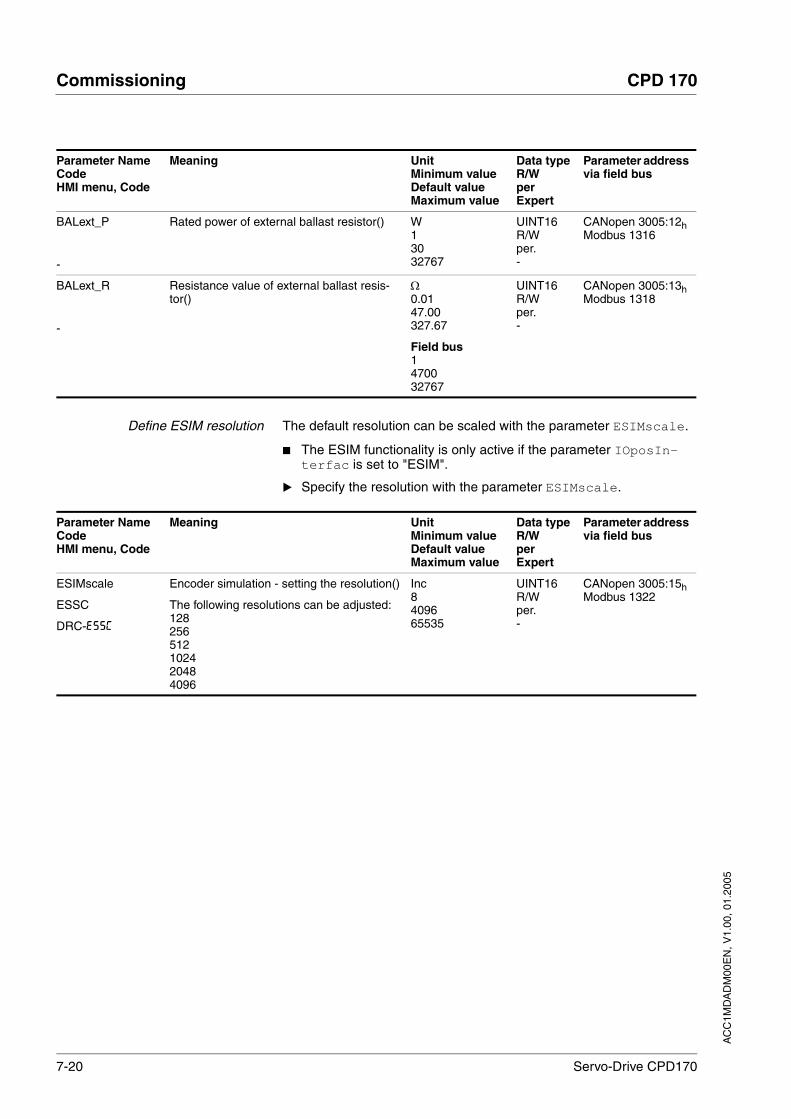
7-20 Servo-Drive CPD170
Commissioning CPD 170
AC
C1M
DA
DM
00E
N, V
1.00
, 01.
2005
Define ESIM resolution The default resolution can be scaled with the parameter ESIMscale.
The ESIM functionality is only active if the parameter IOposIn-terfac is set to "ESIM".
Specify the resolution with the parameter ESIMscale.
BALext_P
-
Rated power of external ballast resistor() W13032767
UINT16R/Wper.-
CANopen 3005:12hModbus 1316
BALext_R
-
Resistance value of external ballast resis-tor()
Ω0.0147.00327.67
Field bus1470032767
UINT16R/Wper.-
CANopen 3005:13hModbus 1318
Parameter NameCodeHMI menu, Code
Meaning UnitMinimum valueDefault valueMaximum value
Data typeR/WperExpert
Parameter address via field bus
Parameter NameCodeHMI menu, Code
Meaning UnitMinimum valueDefault valueMaximum value
Data typeR/WperExpert
Parameter address via field bus
ESIMscale
ESSC
DRC-ESSC
Encoder simulation - setting the resolution()
The following resolutions can be adjusted:128256512102420484096
Inc8409665535
UINT16R/Wper.-
CANopen 3005:15hModbus 1322

AC
C1M
DA
DM
00E
N, V
1.00
, 01.
2005
CPD 170 Commissioning
Servo-Drive CPD170 7-21
7.4.4 Analogue inputs
Power amplifier power is switched off.Controller power supply is switched on.
At the analogue input ANA1or ANA2 apply a voltage in the range of ±10VDC.
Check the applied voltage with the parameter ANA1_act or ANA2_act.
Zero voltage window For the ±10V input, parameters for a zero voltage window can be set using ANA1_win . An input voltage within this window is interpreted as 0V.
Parameter NameCodeHMI menu, Code
Meaning UnitMinimum valueDefault valueMaximum value
Data typeR/WperExpert
Parameter address via field bus
ANA1_act
A1AC
STA-A1AC
Voltage value analogue input ANA1() mV-10000
10000
INT16R/---
CANopen 3009:1hModbus 2306
ANA2_act
A2AC
STA-A2AC
Voltage value analogue input ANA2() mV-10000
10000
INT16R/---
CANopen 3009:5hModbus 2314
Parameter NameCodeHMI menu, Code
Meaning UnitMinimum valueDefault valueMaximum value
Data typeR/WperExpert
Parameter address via field bus
ANA1_win
A1WN
SET-A1WN
Zero voltage window on analogue input ANA1()
Absolute value up to which an input voltage value is interpreted as 0 VExample: setting 20 mV->range of -20 .. +20mV is interpreted as 0mV
mV001000
UINT16R/Wper.-
CANopen 3009:9hModbus 2322

7-22 Servo-Drive CPD170
Commissioning CPD 170
AC
C1M
DA
DM
00E
N, V
1.00
, 01.
2005
7.4.5 Digital inputs/outputs
The switching states of the digital inputs and outputs can be displayed on the HMI and displayed and modified using the commissioning soft-ware or the field bus.
HMI The signal states can be displayed with the HMI, but they cannot be mo-dified.
Call up the menu point sta / ioac.
You will see the digital inputs (Bit 0-7) bit-coded.
Press the "up arrow".
You will see the digital inputs (Bit 8,9) bit-coded.
Figure 7.8 HMI, status display of the digital inputs/outputs
Field bus The current switching states are displayed bit-coded in the parameter _IO_act. The values 1 and 0 indicate whether an input or output is ac-tive.
Bit = 1
Bit = 0
7 6 5 4 3 2 1/9 0/8
Bit Local controller operating mode
Field bus controller opera-ting mode
Type
0 - REF I
1 FAULT_RES LIMN I
2 ENABLE LIMP I
3 HALT HALT I
4 SAFE_DISABLE B SAFE_DISABLE B I
5 SAFE_DISABLE A SAFE_DISABLE A I
6 ENABLE2 1)
1) only with IOposInterfac = PDinput
- I
7 - - I
8 NO_FAULT NO_FAULT O
9 ACTIVE1_OUT ACTIVE1_OUT O

AC
C1M
DA
DM
00E
N, V
1.00
, 01.
2005
CPD 170 Commissioning
Servo-Drive CPD170 7-23
7.4.6 Testing limit switches signals in field bus units
Set up the limit switches so the drive cannot traverse through the limit switch.
Trigger the limit switches manually.
The HMI shows an error message, see Diagnostics from page 10-3
The input signals LIMP, LIMN and REF and the evaluation to active Low or High can be changed with the parameters of the same name, see page 8-43.
Parameter NameCodeHMI menu, Code
Meaning UnitMinimum valueDefault valueMaximum value
Data typeR/WperExpert
Parameter address via field bus
_IO_act
IOAC
STA-ioAC
Status of digital inputs and outputs()
Assignment 24 V inputs:bit x: 'local control mode'/ 'field bus control mode')bit 0: - / REFBit 1: FAULT_RESET / LIMNBit 2: ENABLE / LIMPBit 3: HALTBit 4: STANDSTILL_BBit 5: STANDSTILL_ABit 6: ENABLE2 / -Bit 7: reserved
Bit 6 represents the ENABLE under the follo-wing conditions only:DEVcmdinterf = IODeviceandIOposInterfac = PDinput
Assignment 24 V outputs:Bit 8: NO_FAULTBit 9: ACTIVE
0
65535
UINT16R/---
CANopen 3008:1hModbus 2050
CAUTION!Loss of control monitoring.
The use of LIMP and LIMN can offer some protection against ha-zards (e.g. impact on mechanical stop caused by incorrect motion defaults).
• Use LIMP and LIMN where possible.
• Check that the external sensors or switches are correctly con-nected.
• Check the correct functional installation of the limit switches The limit switches must be mounted in a position far enough away from the mechanical stop to allow an adequate braking distance.
• The functions must be enabled to use LIMP and LIMN.
• This function cannot provide protection against faulty functio-ning of the product or the sensors.
Failure to follow these instructions can result in injury or equipment damage.

7-24 Servo-Drive CPD170
Commissioning CPD 170
AC
C1M
DA
DM
00E
N, V
1.00
, 01.
2005
7.4.7 Testing safety functions
Operation with "Safe Stop" Carry out the following steps to use the "Safe Stop" function:
Power amplifier power is switched off.Controller power is switched off.
Check that the inputs SAFE_DISABLE_A and SAFE_DISABLE_B are isolated from each other. The two signals must not be connec-ted.
Power amplifier power is switched on.Controller power is switched on.
Start the manual movement operating mode (without motor move-ment).(see page 8-14)
Trigger the safety disconnection. SAFE_DISABLE_A and SAFE_DISABLE_B must be disconnected simultaneously.
The power amplifier is switched off and error message 1300 is dis-played. (CAUTION: error message 1301 displays a wiring fault.)
Check that the parameter IO_AutoEnable is set to "off" to prevent unwanted restart.
Check the behaviour of the drive in error states.
Record all tests of the safety function in the acceptance record.
Operation without "Safe Stop" If you do not want to use the safety function:
Check that the inputs SAFE_DISABLE_A and SAFE_DISABLE_B are connected to +24VDC.

AC
C1M
DA
DM
00E
N, V
1.00
, 01.
2005
CPD 170 Commissioning
Servo-Drive CPD170 7-25
7.4.8 Checking holding brake
Testing from HBC to brake
Supply voltage is present at HBC, LED '"24V on'" is lit up.
Switch off the power amplifier supply voltage.
The unit switches to the operating status "Switch on disabled"
Press the "Release brake" button on the HBC several times to release and close the brake alternately.
The LED '"Brake released'" on the HBC flashes if there is brake voltage present and the brake is released by the button.
Test that the axle can be moved manually with the brake lifted (take gearbox into account, if applicable).
Testing from brake to HBC
The unit is in operating status "Ready to switch on"
Start manual movement operating mode(HMI: Jog_ / Strt)
The HMI displays JG. The brake is lifted. The LED "Brake released" on the HBC is lit up if there is brake voltage present and the brake is released.
For further information on HBC see page 3-11, 6-31, 12-1
WARNING!Unexpected motion may cause injury and damage to the sys-tem
For example, if the brake is released with vertical axes an unexpec-ted motion may be triggered in the system.
• Make sure that no damage will be caused by the load dropping.
• Run the test only if there are no persons or materials in the dan-ger zone of the moving system components.
Failure to follow these instructions can result in death or serious injury.

7-26 Servo-Drive CPD170
Commissioning CPD 170
AC
C1M
DA
DM
00E
N, V
1.00
, 01.
2005
7.4.9 Check direction of rotation
Direction of rotation Rotation of the motor shaft in a positive or negative direction of rotation. A positive direction of rotation is defined as the motor shaft rotating clo-ckwise as the observer faces the end of the protruding shaft.
Start jog operating mode(HMI: Jog_ / Strt
The HMI displays JG.
Start a movement with clockwise direction of rotation(HMI: "up arrow")
The motor rotates in the positive direction of rotation. The HMI showsJG-
Start a movement with anticlockwise direction of rotation(HMI: "down arrow")
The motor rotates in anticlockwise direction of rotation. The HMI shows-JG
If the arrow and direction of rotation do not match, correct this with the parameter POSdirOfRotat, see 8.6.8 “Reversal of direction of rotation“ page 8-64.
WARNING!Unexpected movement if motor phases are reversed!
Reversal of the motor phases can cause unexpected movements at high acceleration.
• Use the parameter POSdirOfRotat to reverse the direction of rotation, if required.
• Do not reverse the motor phases.Failure to follow these instructions can result in death or serious injury.
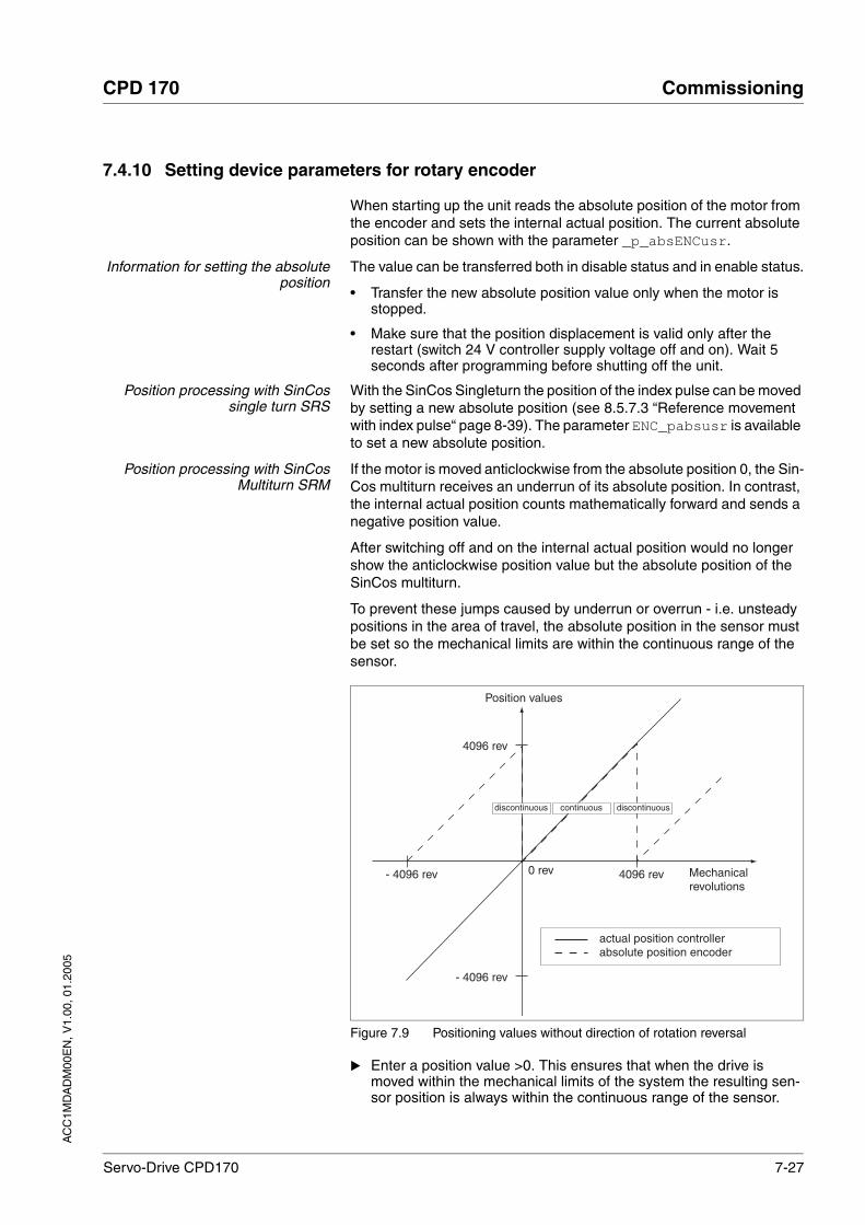
AC
C1M
DA
DM
00E
N, V
1.00
, 01.
2005
CPD 170 Commissioning
Servo-Drive CPD170 7-27
7.4.10 Setting device parameters for rotary encoder
When starting up the unit reads the absolute position of the motor from the encoder and sets the internal actual position. The current absolute position can be shown with the parameter _p_absENCusr.
Information for setting the absoluteposition
The value can be transferred both in disable status and in enable status.
• Transfer the new absolute position value only when the motor is stopped.
• Make sure that the position displacement is valid only after the restart (switch 24 V controller supply voltage off and on). Wait 5 seconds after programming before shutting off the unit.
Position processing with SinCossingle turn SRS
With the SinCos Singleturn the position of the index pulse can be moved by setting a new absolute position (see 8.5.7.3 “Reference movement with index pulse“ page 8-39). The parameter ENC_pabsusr is available to set a new absolute position.
Position processing with SinCosMultiturn SRM
If the motor is moved anticlockwise from the absolute position 0, the Sin-Cos multiturn receives an underrun of its absolute position. In contrast, the internal actual position counts mathematically forward and sends a negative position value.
After switching off and on the internal actual position would no longer show the anticlockwise position value but the absolute position of the SinCos multiturn.
To prevent these jumps caused by underrun or overrun - i.e. unsteady positions in the area of travel, the absolute position in the sensor must be set so the mechanical limits are within the continuous range of the sensor.
Figure 7.9 Positioning values without direction of rotation reversal
Enter a position value >0. This ensures that when the drive is moved within the mechanical limits of the system the resulting sen-sor position is always within the continuous range of the sensor.
4096 rev
- 4096 rev
0 U0 U0 rev Mechanicalrevolutions
4096 rev- 4096 rev
actual position controllerabsolute position encoder
Position values
continuousdiscontinuous discontinuous

7-28 Servo-Drive CPD170
Commissioning CPD 170
AC
C1M
DA
DM
00E
N, V
1.00
, 01.
2005
Note that the absolute position is stored in the SinCos multiturn, so the settings remain when the unit is replaced.
Parameter NameCodeHMI menu, Code
Description UnitMinimum valueDefault valueMaximum value
Data typeR/WperExpert
Parameter address via field bus
_p_absENCusr
-
Absolute position based on motor sensor working range in user-defined units()
Value range is set by sensor typeWith Singleturn motor sensors the value is set with reference to one motor revolution,with multiturn motor sensors with reference to the total working range of the sensor (e.g. 4096 revs.)
usr UINT32R/---
ENC_pabsusr
-
Setting position of the motor sensor directly()
Value range depends on the sensor type.
SRS: Sincos Singleturn: 0..max_pos_usr/rev. - 1SRM: Sincos Multiturn: 0 .. (4096 * max_pos_usr/rev.) -1
max_pos_usr/rev.: maximum user position for a motor revolution, at default position sca-ling this value is 16384.
Important: values are enabled only next time the controller is started.Changing the value also changes the posi-tion of the virtual index pulse.
usr02147483647
UINT32R/W--
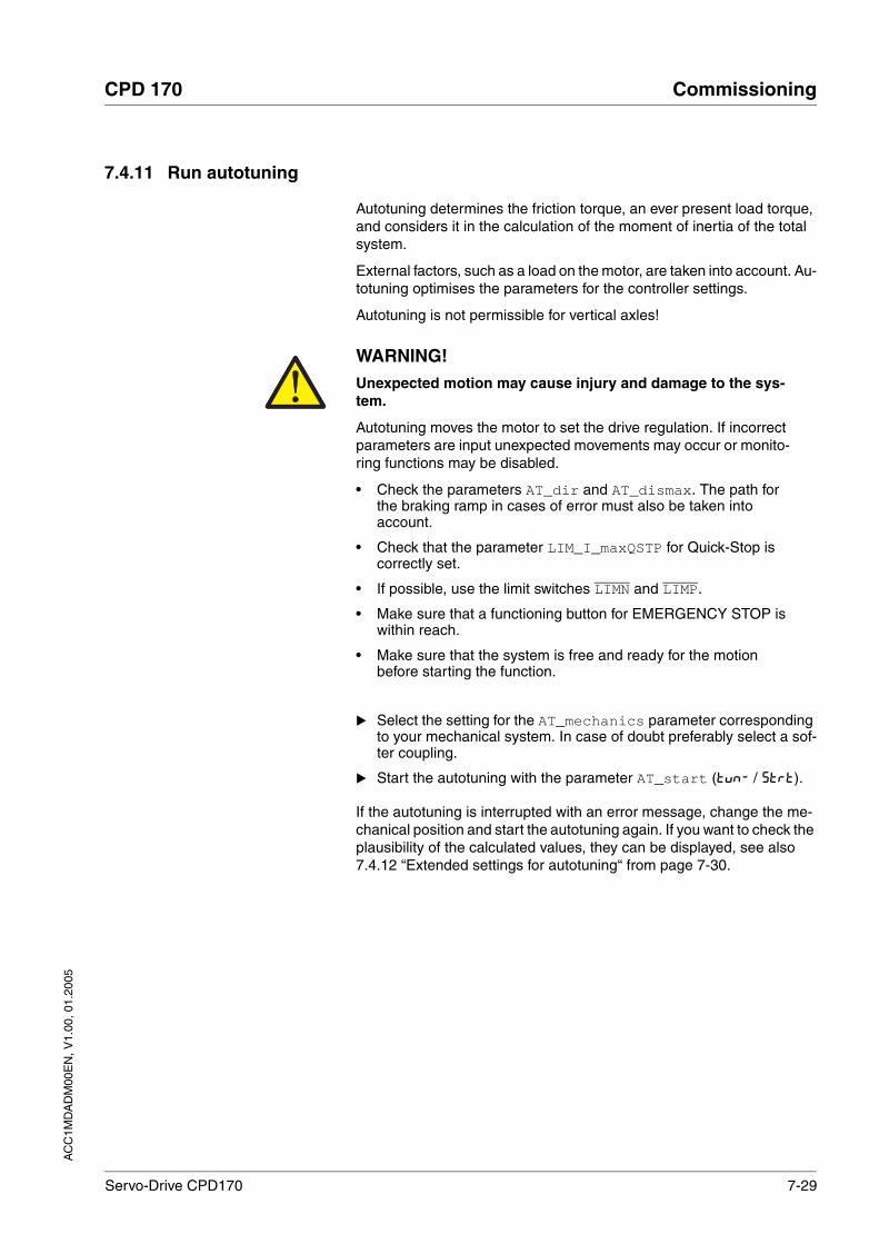
AC
C1M
DA
DM
00E
N, V
1.00
, 01.
2005
CPD 170 Commissioning
Servo-Drive CPD170 7-29
7.4.11 Run autotuning
Autotuning determines the friction torque, an ever present load torque, and considers it in the calculation of the moment of inertia of the total system.
External factors, such as a load on the motor, are taken into account. Au-totuning optimises the parameters for the controller settings.
Autotuning is not permissible for vertical axles!
Select the setting for the AT_mechanics parameter corresponding to your mechanical system. In case of doubt preferably select a sof-ter coupling.
Start the autotuning with the parameter AT_start (TUN- / STRT).
If the autotuning is interrupted with an error message, change the me-chanical position and start the autotuning again. If you want to check the plausibility of the calculated values, they can be displayed, see also 7.4.12 “Extended settings for autotuning“ from page 7-30.
WARNING!Unexpected motion may cause injury and damage to the sys-tem.
Autotuning moves the motor to set the drive regulation. If incorrect parameters are input unexpected movements may occur or monito-ring functions may be disabled.
• Check the parameters AT_dir and AT_dismax. The path for the braking ramp in cases of error must also be taken into account.
• Check that the parameter LIM_I_maxQSTP for Quick-Stop is correctly set.
• If possible, use the limit switches LIMN and LIMP.
• Make sure that a functioning button for EMERGENCY STOP is within reach.
• Make sure that the system is free and ready for the motion before starting the function.
Failure to follow these instructions can result in death or serious injury.

7-30 Servo-Drive CPD170
Commissioning CPD 170
AC
C1M
DA
DM
00E
N, V
1.00
, 01.
2005
7.4.12 Extended settings for autotuning
For most applications the procedure described is sufficient for autotu-ning. The following parameters can be used to monitor or even influence the autotuning.
The parameters AT_state and AT_progress can be used to monitor the status of the autotuning and the percentage progress during the au-totuning process.
Parameter NameCodeHMI menu, Code
Meaning UnitMinimum valueDefault valueMaximum value
Data typeR/WperExpert
Parameter address via field bus
AT_dir
DIR
TUN-DiR
Direction of rotation autotuning()
1 / pos-neg-home / pnh: clockwise direction only then negative direction with return to ini-tial position2 / neg-pos-home / nph: first anticlockwise direction then clockwise direction with return to initial position 3 / pos-home / p-h: clockwise direction only with return to initial position4 / pos / p--: clockwise direction only without return to initial position5 / neg-home / n-h: anticlockwise direction only with return6 / neg / n--: anticlockwise direction without return to initial position
116
UINT16R/W--
CANopen 302F:4hModbus 12040
AT_dismax
DIST
TUN-DiST
Movement range autotuning()
Range in which the automatic optimisation processes of the controller parameters are run. The range is input relative to the current position.Default value = 1 motor revolution.Values from 0.1 to 0.9 are not permissible.CAUTION: value 0 switches monitoring off.
U0.01.0999.9
Field bus0109999
UINT32R/W--
CANopen 302F:3hModbus 12038
AT_mechanics
MECH
TUN-MECh
System coupling type()
1: direct coupling (J ext. to J motor <<3:1)2: flexible coupling ()3: flexible coupling (short toothed belt)4: flexible coupling ()5: high-flexibility coupling (J ext. to J motor >10:1,linear axis)
115
UINT16R/W--
CANopen 302F:EhModbus 12060
AT_start
-
Start Autotuning()
0: Stop1: Enable
001
UINT16R/W--
CANopen 302F:1hModbus 12034

AC
C1M
DA
DM
00E
N, V
1.00
, 01.
2005
CPD 170 Commissioning
Servo-Drive CPD170 7-31
If you are conducting a test operation and want to check how a harder or softer setting affects the control parameters on your system, you can change the settings found during autotuning by writing the parameter AT_gain. A value of 100% is generally not possible, because this value is at the stability limit. The available value is typically 70%-80%. The parameter AT_J can be used to read out the moment of inertia of the entire system calculated during the autotuning.
The parameter AT_wait can be changed to set a wait time between the single steps during the autotuning process. It only makes sense to spe-cify a wait time with a very flexible coupling if the change of hardness has already been made (=next step with autotuning), while the system is still oscillating.
Parameter NameCodeHMI menu, Code
Meaning UnitMinimum valueDefault valueMaximum value
Data typeR/WperExpert
Parameter address via field bus
AT_state
-
Autotuning status()
Bit 15: auto_tune_errBit 14: auto_tune_endBit 13: auto_tune_process
Bit 10..0: last processing step
0
65535
UINT16R/---
CANopen 302F:2hModbus 12036
AT_progress
-
Autotuning progress() %00100
UINT16R/---
CANopen 302F:BhModbus 12054
Parameter NameCodeHMI menu, Code
Meaning UnitMinimum valueDefault valueMaximum value
Data typeR/WperExpert
Parameter address via field bus
AT_gain
GAIN
TUN-GAiN
Adapting controller parameters (tighter/loo-ser)()
Measure of the degree of tightness of the regulation. The value 100 represents the theoretical optimum. Values larger than 100 mean that the regulation is tighter and smal-ler values mean that the regulation is looser.
% UINT16R/W--
CANopen 302F:AhModbus 12052
AT_J
-
Inertia of the entire system()
is calculated automatically during the auto-tuning process
kg cm2
0.00.00.0
UINT16R/Wper.-
CANopen 302F:ChModbus 12056
Parameter NameCodeHMI menu, Code
Meaning UnitMinimum valueDefault valueMaximum value
Data typeR/WperExpert
Parameter address via field bus
AT_wait
WAIT
TUN-WAit
Waiting time between autotuning steps() ms300120010000
UINT16R/W--
CANopen 302F:9hModbus 12050

7-32 Servo-Drive CPD170
Commissioning CPD 170
AC
C1M
DA
DM
00E
N, V
1.00
, 01.
2005
7.5 Controller optimisation with step response
7.5.1 Controller structure
The controller structure in the controller corresponds to the classical cascade control of a position control loop with current controller, speed controller and position controller. The reference value of the speed con-troller can also be smoothed by an upstream filter.
The controllers are set one after the other from the 'inside' to the 'outside' in the sequence current, speed, and position controller. The higher-level control loop in each case stays switched out.
Figure 7.10 Controller structure for encoder evaluation via CN2
Current controller The motor's drive torque is determined by the current controller. The cur-rent controller has been optimised automatically using the stored motor data.
Speed controller The speed controller maintains the required motor speed by varying the output motor torque depending on the load situation. It exerts a decisive influence on the speed with which the drive reacts. The dynamics of the speed controller depend on
• the moments of inertia of the drive and the control distance
• the torque of the motor
• the stiffness and elasticity of the components in the power flow
• the play of the mechanical drive components
A/BP/R
M3~
E
nref
Speedcontroller
Reference-value filter Speedcontroller
Currentcontroller
Profilegenerator
nmax
Speed feed-forward
Pref
Pref
Iref
Power amplifier
nactPact
nact
Pact
Encoder evaluation
Imax
KPref KFPP
Reference-value filter Current controller
nreference Ireference
Actual value- Speed- Position

AC
C1M
DA
DM
00E
N, V
1.00
, 01.
2005
CPD 170 Commissioning
Servo-Drive CPD170 7-33
• the friction
Position controller The position controller reduces the difference between setpoint position and actual motor position (following error) to a minimum. At motor stand-still the following error is virtually zero with a well-adjusted position con-troller. In movement mode a speed-dependent following error occurs. The setpoint position for the position control loop with field bus controller type is generated by the travel profile generator and with a local control-ler type by the A/B or P/R input signals or manual mode.
A requirement for good gain of the position controller is an optimised speed control loop.
7.5.2 Optimisation
The drive optimisation function matches the unit to the operating condi-tions. The following options are available:
• Selecting control loops. Higher level control loops are automatically disconnected.
• Defining reference signal: signal form, height, frequency and star-ting point
• Testing control response with the signal generator.
• Recording and assessing the control behaviour on the monitor with the commissioning software.
Setting reference signals Start the operating mode "Manual Optimisation" in the commissio-ning software.
The window shows a graphic display of the signal paths of the reference signal and the responses of the controller. Multiple response signals can be transmitted and displayed simultaneously.
Set the following values for the reference signal:
• Signal form: "positive jump"
• Amplitude: 100 rpm
• Period duration: 100 ms
• Number of repetitions: 1
The total dynamic behaviour of a control loop can be only understood with the signal forms 'Jump' and 'Square wave'. Refer to the manual for all signal paths for the signal form 'Jump'.
Setting recording signals Select the signals that should be displayed as the step response of the control loop:
• - actual speed of motor _n_act
- setpoint speed of the speed controller _n_ref
- setpoint current of the current controller _Iq_ref
• Input 1 ms in the "Time base" field
• Select the speed controller as type. The speed controller is opti-mised first.

7-34 Servo-Drive CPD170
Commissioning CPD 170
AC
C1M
DA
DM
00E
N, V
1.00
, 01.
2005
Inputting controller values Control parameters must also be input for the individual optimisation steps described over the following pages. These parameters must be tested by initiating a jump function.
A jump function is triggered as soon as a recording is started in the com-missioning software tool bar with the “Start” button (arrow icon).
You can enter controller values for optimisation in the parameters win-dow in the "Control" group.
7.5.3 Optimising the speed controller
The optimum setting for complex mechanical control systems requires practical experience with setting and adjustment procedures for control equipment. This includes the ability to calculate control parameters and to apply identification procedures.
Less complex mechanical systems can generally be successfully opti-mised with the experimental adjustment procedure using the aperiodic limiting case method. Here the following two parameters are set:
Check and optimise the calculated values in a second step, as descri-bed from page 7-37.
Determining the mechanics of thesystem
Decide which one of the following two systems fits the mechanics of your set-up to assess and optimise its response behaviour.
• System with rigid mechanism
• System with less rigid mechanism
Parameter NameCodeHMI menu, Code
Meaning UnitMinimum valueDefault valueMaximum value
Data typeR/WperExpert
Parameter address via field bus
CTRL_KPn
-
Speed controller P-factor()
Default value is calculated from motor para-meters
Amin/rev0.00100.00001.2700
Field bus10
12700
UINT16R/Wper.-
CANopen 3012:3hModbus 4614
CTRL_TNn
-
Speed controller correction time() ms0.009.00327.67
Field bus090032767
UINT16R/Wper.-
CANopen 3012:4hModbus 4616

AC
C1M
DA
DM
00E
N, V
1.00
, 01.
2005
CPD 170 Commissioning
Servo-Drive CPD170 7-35
Figure 7.11 Mechanical systems with rigid and less rigid mechanisms
Connect the motor to your system's mechanism.
Only in the field bus control mode
Carry out a function check of the limit switches once the motor has been installed.
Switch off reference value filter ofspeed controller
With the reference variable filter you can improve the response beha-viour under optimised speed control. The reference value filter must be switched off when setting the speed controller for the first time.
Disable the reference value filter of the speed controller. Set the parameter CTRL_TAUnref to the bottom limit value "0".
The procedure for optimisation of the settings described is only a suggested setting. It is responsibility of the user to decide whether the method is suitable for the actual application.
Determining controller values withrigid mechanics
Requirements for setting the control response as per the table are:
• a known and constant inertia of load and motor
• a rigid mechanism
Rigid mechanism Less rigid mechanism
Belt driveTorsion shaftsGearsElastic coupling
Low elasticity
Direct driveFlange motorRigid coupling
Higher elasticity
No or few moving parts Larger number of moving parts
Parameter NameCodeHMI menu, Code
Meaning UnitMinimum valueDefault valueMaximum value
Data typeR/WperExpert
Parameter address via field bus
CTRL_TAUnref
-
Filter time constant reference value filter of the reference speed value()
ms0.009.00327.67
Field bus090032767
UINT16R/Wper.-
CANopen 3012:9hModbus 4626

7-36 Servo-Drive CPD170
Commissioning CPD 170
AC
C1M
DA
DM
00E
N, V
1.00
, 01.
2005
The P-factor CTRL_KPn and the correction time CTRL_TNn depend on:
• JL: Mass moment of inertia of the load
• JM Mass moment of inertia of the motor
Determine the controller values based on Table 7.3:
Table 7.3 Determining controller values
Determining controller values withless rigid mechanics
For optimisation purposes the P-factor of the speed controller at which the controller adjusts the speed _n_act as quickly as possible without overshooting is determined.
Set the correction time CTRL_TNn to infinite.CTRL_TNn= 0 ms.
If a load torque is acting on the stationary motor, the correction time must be set just high enough to prevent an uncontrolled change of the motor position.
In drive systems in which the motor is loaded while stationary, e.g. with vertical axis operation, the correction time "infinite" may result in unwanted position deviations, thereby requiring the value to be reduced. However, this can adversely affect optimisation results.
Initiate a jump function.
After the first test check the maximum amplitude for the current set-point _Iq_ref.
JL=JM JL=5 * JM JL=10 * JM
JL[kgcm2] KPn TNn KPn TNn KPn TNn
1 0.0125 8 0.008 12 0.007 16
2 0.0250 8 0.015 12 0.014 16
5 0.0625 8 0.038 12 0.034 16
10 0.125 8 0.075 12 0.069 16
20 0.250 8 0.150 12 0.138 16
WARNING!Unexpected motion may cause injury and damage to the sys-tem
The jump function moves the motor in speed mode at constant speed until the specified time has expired.
• Check that the selected values for speed and time do not exceed the available distance.
• If possible, use limit switches or stop as well.
• Make sure that a functioning button for EMERGENCY STOP is within reach.
• Make sure that the system is free and ready for motion before starting the function.
Failure to follow these instructions can result in death or serious injury.

AC
C1M
DA
DM
00E
N, V
1.00
, 01.
2005
CPD 170 Commissioning
Servo-Drive CPD170 7-37
Set the amplitude of the reference value – default was 100 rpm – just high enough so the current setpoint _Iq_ref remains below the maxi-mum value CTRL_I_max. On the other hand, the value selected should not be too low, otherwise friction effects of the mechanism will determine control loop response.
Trigger a jump function again if you need to modify _n_ref and check the amplitude of _Iq_ref.
Increase or decrease the P-factor in small steps until _n_act adjusts as fast as possible. The following diagram shows the adjus-tment response required on the left. Overshooting - as shown on the right - is reduced by reducing CTRL_KPn.
Deviations from _n_ref and _n_act result from setting CTRL_TNn to "infinite".
Figure 7.12 Determining 'TNn' in the aperiodic limiting case
For drive systems in which oscillations occur before the aperiodic limiting case is reached, the P-factor "KPn" must be reduced to the exact point where oscillations can no longer be detected. This occurs frequently with linear axes with a toothed belt drive.
Graphical calculation of the 63%value
Determine graphically the point at which the actual speed _n_act rea-ches 63% of the final value. The correction time CTRL_TNn is then shown as a value on the time axis. The commissioning software will help you with the evaluation:
7.5.4 Checking and optimising default settings
Figure 7.13 Step responses with good controller characteristics
0%t
Amplitude
t
n_act
n_ref
n_act
n_ref
100%
63%
0%
100%
Improve with
KPn
TNn
0%t
Am
plitu
de
Am
plitu
de
t
n_act
n_ref
n_act
n_ref
Rigid mechanism
Less rigid mechanism
100%
0%
100%

7-38 Servo-Drive CPD170
Commissioning CPD 170
AC
C1M
DA
DM
00E
N, V
1.00
, 01.
2005
The controller is properly set when the jump response is approximately identical to the signal path shown. Good control response can be recog-nised by
• Fast adjustment
• Overshooting up to a maximum of 40% - 20% is recommended.
If the control response does not correspond to the curve shown, change CTRL_KPn´ in steps of about 10% and then initiate a jump function once again:
• If the controller is too slow: select CTRL_KPn greater.
• If the controller tends to oscillate: select CTRL_KPn smaller.
You can recognise an oscillation by the motor continuously accelerating and decelerating.
Figure 7.14 Optimise inadequate settings of the speed regulator
If you cannot achieve sufficiently satisfactory controller properties in spite of optimisation, contact your local dealer.
7.5.5 Optimising the position controller
Optimisation requires a good control response in the lower-ranking speed control circuit.
When setting the position control the P-factor of the position controller CTRL_KPp must be optimised in two limits:
• CTRL_KPp too great: overshooting of the mechanism, instability of the controller
• CTRL_KPp too small: Large following error
0%t
Am
plitu
de
Am
plitu
de
t
Improve with
KPn Improve with
KPn
Control oscillatingControl too slow
n_act
n_ref
n_act
n_ref
100%
0%
100%

AC
C1M
DA
DM
00E
N, V
1.00
, 01.
2005
CPD 170 Commissioning
Servo-Drive CPD170 7-39
Setting reference signal Select the position controller reference value in the commissioning software.
Set the reference signal:
• Signal form: 'Jump'
• Set amplitude for about 1/10 motor revolution.
Selecting recording signals Select the values in General Recording Parameters:
• setpoint position of position controller _p_ref
• actual position of position controller _p_act
• actual speed _n_act
• current motor current _Iq_ref
Controller values for the position controller can be changed in the same parameter group used for the speed controller.
Optimising the position controlvalue
Start a jump function with the default controller values.
After the first test check the achieved values _n_act and _Iq_ref for current and speed regulation. The values must not cross into the range of current and speed limiting.
Parameter NameCodeHMI menu, Code
Meaning UnitMinimum valueDefault valueMaximum value
Data typeR/WperExpert
Parameter address via field bus
CTRL_KPp
-
Position controller P-factor() 1/s2.00.0495.0
Field bus20
4950
UINT16R/Wper.-
CANopen 3012:6hModbus 4620
WARNING!Unexpected motion may cause injury and damage to the sys-tem
The jump function moves the motor in speed mode at constant speed until the specified time has expired.
• Check that the selected values for speed and time do not exceed the available distance.
• If possible, use limit switches or stop as well.
• Make sure that a functioning button for EMERGENCY STOP is within reach.
• Make sure that the system is free and ready for motion before starting the function.
Failure to follow these instructions can result in death or serious injury.

7-40 Servo-Drive CPD170
Commissioning CPD 170
AC
C1M
DA
DM
00E
N, V
1.00
, 01.
2005
Figure 7.15 Jump responses of a position controller with a good controlresponse
The proportional factor CTRL_KPp is at its optimum setting when the motor reaches its target position rapidly and with little or no overshoo-ting.
If the control response does not correspond to the curve shown, change the P-factor CTRL_KPp in steps of about 10% and then initiate a jump function once again.
• If the controller tends to oscillate: select CTRL_KPp smaller.
• If the actual value is too slow following the setpoint value: select CTRL_KPp greater.
Figure 7.16 Optimising improper settings of the position controller
t
Am
plitu
de
Am
plitu
de
t
Rigid mechanism
Less rigid mechanism
p_act
p_ref
p_act
p_ref
0%
100%
0%
100%
0%t
Am
plitu
de
Am
plitu
de
t
Improve
with KPpImprove
with KPp
Control oscillatingControl too slow
p_act p_act
p_refp_ref
100%
0%
100%

AC
C1M
DA
DM
00E
N, V
1.00
, 01.
2005
CPD 170 Operation
Servo-Drive CPD170 8-1
8 Operation
The "Operation" section describes the basic operating states, operating modes and functions of the unit.
8.1 control mode and operating mode handling
During initial commissioning, you will have determined during "First Se-tup", amongst other things, whether the unit is to be operated under local control mode or via field bus control mode. This determination cannot be altered in running operation.
The operating modes can be changed at any time during operation. The choice of operating modes is dependent upon the "First Setup".
Setpoint entry The following table shows the type of set value preselection based upon the set control mode.
In the case of local control mode, the motion can be initiated using ana-logue signals (±10V) or with RS422 signals (pulse/direction or A/B)
In the case of field bus control mode, the motion can be initiated using analogue signals (±10V) or with field bus commands.
Figure 8.1 Local control mode and field bus control mode
Operating mode in local control mode in field bus control mode. Description
Jog HMI Field bus commands or HMI Page8-14
Current control ANA_IN1 Field bus command or ANA_IN1 Page8-16
Speed control ANA_IN1 Field bus command or ANA_IN1 Page8-19
Electronic gear P/D or A/B P/D or A/B Page8-22
Profile position - Field bus commands Page8-26
Profile velocity - Field bus commands Page8-29
Homing - Field bus commands Page8-31
L
N

8-2 Servo-Drive CPD170
Operation CPD 170
AC
C1M
DA
DM
00E
N, V
1.00
, 01.
2005
8.2 Access monitor
8.2.1 via HMI
The HMI receives the access monitoring when starting the jog operating mode or when starting auto-tuning. Control via the commissioning soft-ware or by the field bus is then not possible.
In addition, the HMI can be locked using the parameter HMIprotectet This means that control via the HMI is no longer possible.
8.2.2 via field bus
Local control mode Access monitoring via field bus is not possible when in local control mode. It is, however, possible to enter parameters via the field bus.
Field bus control mode In the case of field bus control mode, the parameter AccessLock can be used to limit the access monitoring to the field bus.
Parameter NameCodeHMI menu, Code
Meaning UnitMinimum valueDefault valueMaximum value
Data typeR/WperExpert
Parameter address via field bus
HMIprotected
-
HMI Interlock()
0: HMI interlock not enabled1: HMI interlock enabled
The following actions are not possible when interlocked:- modify parameter- manual mode (jog)- autotuning- FaultReset
001
UINT16R/Wper.-
CANopen 303:1hModbus 14850
Parameter NameCodeHMI menu, Code
Meaning UnitMinimum valueDefault valueMaximum value
Data typeR/WperExpert
Parameter address via field bus
AccessLock
-
Blocking of other access channels()
0: enable other access channels1: block other access channels
The field bus can use this parameter to block active access to the unit for the following access channels:- commissioning tool - HMI- a second field bus
Processing of the input signals (e.g. Halt input) cannot be blocked.
001
UINT16R/W--
CANopen 3001:1EhModbus 316

AC
C1M
DA
DM
00E
N, V
1.00
, 01.
2005
CPD 170 Operation
Servo-Drive CPD170 8-3
8.2.3 via commissioning software
The commissioning software receives the access monitor via the Acti-vate button."" Access via HMI or field bus is then not possible.
Access control via the commissioning software is not possible if the HMI or the field bus has the access monitor.
8.2.4 via hardware input signals
The digital input signals HALT, LIMN / FAULT_RESET, LIMP / ENABLE, REF, SAFE_DISABLE_A and SAFE_DISABLE_B are always operatio-nal, even if the HMI, the commissioning software or the field bus has the access monitor.

8-4 Servo-Drive CPD170
Operation CPD 170
AC
C1M
DA
DM
00E
N, V
1.00
, 01.
2005
8.3 Operating states
8.3.1 State diagram
After switching on and at the start of an operating mode, a sequence of operating states is progressed through.
The relationship between the operating states and the state transitions is shown in the state diagram (state machine).
The operating states are internally monitored and influenced by monito-ring and system functions, such as temperature and current monitoring
Graphic representation The state diagram is shown graphically as a flow chart.
Figure 8.2 State diagram
Operating states The operating states are displayed as standard by the HMI and the com-missioning software.
Switching on
T10
T12
T15
Operating state State transition
3
4
6
disabled
5
Operationenable
Ready toswitch onrdy
Switched onSon
Switch ondis
T11
T16
T4 T5
T6T3T8
T9 T2 T7
T1
Not ready tonrdy
StartINIT1
2
switch on
T0
T13
Fault
Fault Reactionactive
Display flashes
fLt
fLt
8
9
T14
7Quick-Stop active
Display flashes
Stop 8888
8888
FaultClass2, 3, (4)
FaultClass1
Operating fault
HaLt
rUn
stand still
Motor under current
Motor without current
Display Status State description
Init 1 Start Controller supply voltage, electronics is initialised
nrdy 2Not ready to switch on The power amplifier is not ready to switch on
dis 3Switch on disabled Switching on the power amplifier is disabled
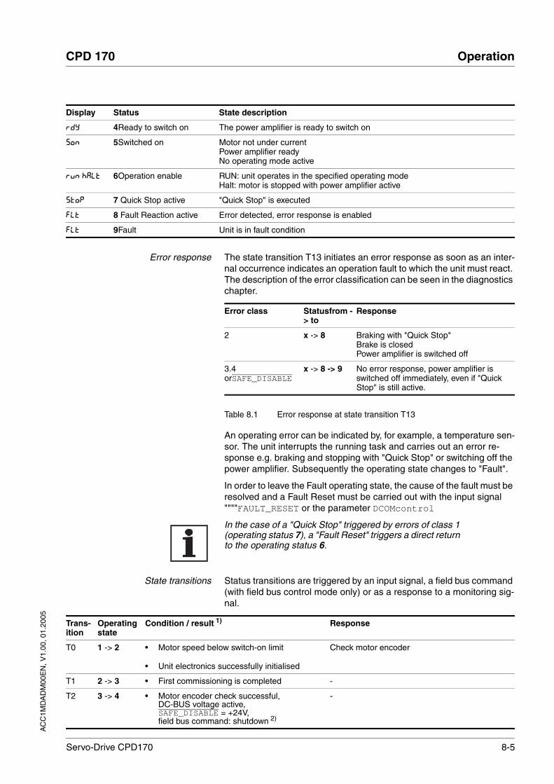
AC
C1M
DA
DM
00E
N, V
1.00
, 01.
2005
CPD 170 Operation
Servo-Drive CPD170 8-5
Error response The state transition T13 initiates an error response as soon as an inter-nal occurrence indicates an operation fault to which the unit must react. The description of the error classification can be seen in the diagnostics chapter.
Table 8.1 Error response at state transition T13
An operating error can be indicated by, for example, a temperature sen-sor. The unit interrupts the running task and carries out an error re-sponse e.g. braking and stopping with "Quick Stop" or switching off the power amplifier. Subsequently the operating state changes to "Fault".
In order to leave the Fault operating state, the cause of the fault must be resolved and a Fault Reset must be carried out with the input signal """"FAULT_RESET or the parameter DCOMcontrol
In the case of a "Quick Stop" triggered by errors of class 1 (operating status 7), a "Fault Reset" triggers a direct return to the operating status 6.
State transitions Status transitions are triggered by an input signal, a field bus command (with field bus control mode only) or as a response to a monitoring sig-nal.
rdy 4Ready to switch on The power amplifier is ready to switch on
Son 5Switched on Motor not under currentPower amplifier readyNo operating mode active
run HALT 6Operation enable RUN: unit operates in the specified operating modeHalt: motor is stopped with power amplifier active
Stop 7 Quick Stop active "Quick Stop" is executed
FLt 8 Fault Reaction active Error detected, error response is enabled
FLt 9Fault Unit is in fault condition
Display Status State description
Error class Statusfrom -> to
Response
2 x -> 8 Braking with "Quick Stop"Brake is closedPower amplifier is switched off
3.4 orSAFE_DISABLE
x -> 8 -> 9 No error response, power amplifier is switched off immediately, even if "Quick Stop" is still active.
Trans-ition
Operating state
Condition / result 1) Response
T0 1 -> 2 • Motor speed below switch-on limit
• Unit electronics successfully initialised
Check motor encoder
T1 2 -> 3 • First commissioning is completed -
T2 3 -> 4 • Motor encoder check successful,DC-BUS voltage active,SAFE_DISABLE = +24V,field bus command: shutdown 2)
-

8-6 Servo-Drive CPD170
Operation CPD 170
AC
C1M
DA
DM
00E
N, V
1.00
, 01.
2005
T3 4 -> 5 • Field bus command: Switch On
• Input signal: ENABLE 0 -> 1
T4 5 -> 6 • Field bus command: Enable Operation Switch on power amplifier. Motor phases, eart-hing,User parameters are checked Brake released
T5 6 -> 5 • Field bus command: Disable Operation
• Input signal: ENABLE 1 -> 0
Interrupt task with "Hlt"Brake actuatedSwitch off power amplifier
T6 5 -> 4 • Field bus command: Shutdown
T7 4 -> 3 • DC-BUS low voltage
• SAFE_DISABLE = 0V
• Field bus command: Disable voltage
-
T8 6 -> 4 • Field bus command: Shutdown Switch off power amplifier immediately
T9 6 -> 3 • Field bus command: Disable voltage Switch off power amplifier immediately
T10 5 -> 3 • Field bus command: Disable voltage
T11 6 -> 7 • Class 1 error
• Field bus command: Quick Stop
Interrupt task with "Quick Stop"
T12 7 -> 3 • Field bus command: Disable voltage Switch off power amplifier immediately, even if "Quick Stop" still active
T13 x -> 8 • Errors Class 2, 3 or 4 Error response is carried out, see "error response"
T14 8 -> 9 • Error response completed
• Errors Class , 3 or 4
T15 9 -> 3 • Field bus command: Fault Reset 3)
• Input signal: FAULT_RESET 0 -> 1 3)
Fault is reset
T16 7 -> 6 • Field bus command: Fault Reset 3)
• Field bus command: Enable Operation 4)
• Input signal: FAULT_RESET 0 -> 1 3)
Local control mode: specified operating mode is automatically continued
1) It is sufficient to fulfil one point to trigger the status transition2) Only required with field bus control mode, field bus CANopen and parameter DCOMcompatib = 13) Cause of error must be corrected4) Only possible if operating status was triggered via field bus
Trans-ition
Operating state
Condition / result 1) Response

AC
C1M
DA
DM
00E
N, V
1.00
, 01.
2005
CPD 170 Operation
Servo-Drive CPD170 8-7
8.3.2 Changing operating state
Local controller operating mode In local controller operating mode, the change of operating state takes place either via the commissioning software, the signal inputs or auto-matically.
field bus controller operating mode In the case of field bus controller operating mode, the operating states are set either by the commissioning software or by the parameter DCOM-control Bits 0 to 3 and Bit 7 are relevant for a state change
Figure 8.3 Changing and monitoring the operating states via parameters
Bit 0 to 3 and 7
Figure 8.4 Changing the operating state
Input signalState transi-tions State change to
ENABLE 0 -> 1 T3, T4 6: Operation enable
ENABLE 1 -> 0 T5, T6 4: Ready to switch on
FAULT_RESET 0 -> 1 T15T16
4: Ready to switch on6: Operation enable
State machine
Monitoring andSystem functions
DCOMcontrol DCOMstatus
Parameter NameCodeHMI menu, Code
Meaning UnitMinimum valueDefault valueMaximum value
Data typeR/WperExpert
Parameter address via field bus
DCOMcontrol
-
Drivecom control word()
Bit coding see Operation section, operating states0: Switch on1: Enable Voltage 2: Quick Stop3: Enable Operation4..6: op. Mode specific7: Fault Reset8: Halt9..15: reserved
UINT16R/W--
CANopen 6040:0hModbus 6914
State machine
15...8 7 03
X X XXXXXXXXX
...
Field bus command state tran-sitions Status change open
Bit 7, Reset Fault
Bit 3, Enable operation
Bit 2, Quick-Stop
Bit 1, Disable Voltage
Bit 0, Switch On
Shutdown T2, T6, T8 4: Ready to switch on X X 1 1 0

8-8 Servo-Drive CPD170
Operation CPD 170
AC
C1M
DA
DM
00E
N, V
1.00
, 01.
2005
The bit states in the fields marked with "X" have no meaning that parti-cular status change.
Bit 4 to 6 Bits 4 to 6 are used for the operating mode specific settings. Details can be found in the description of the individual operating modes in this chapter.
Bit 8, Halt Bit 8=1 can initiate a "Halt".
Bit 9 to 15 reserved
Switch On T3 5: Switched on X X 1 1 1
Disable Voltage T7, T9, T10, T12
3: Switch on disabled X X X 0 X
Quick Stop T7, T10T11 3: Switch on disabled7: Quick Stop active
X X 0 1 X
Disable Operation T5 5: Switched on X 0 1 1 1
Enable operation T4, T16 6: Operation enable X 1 1 1 1
Fault Reset T15 3: Switch on disabled 0->1 X X X X
Field bus command state tran-sitions Status change open
Bit 7, Reset Fault
Bit 3, Enable operation
Bit 2, Quick-Stop
Bit 1, Disable Voltage
Bit 0, Switch On
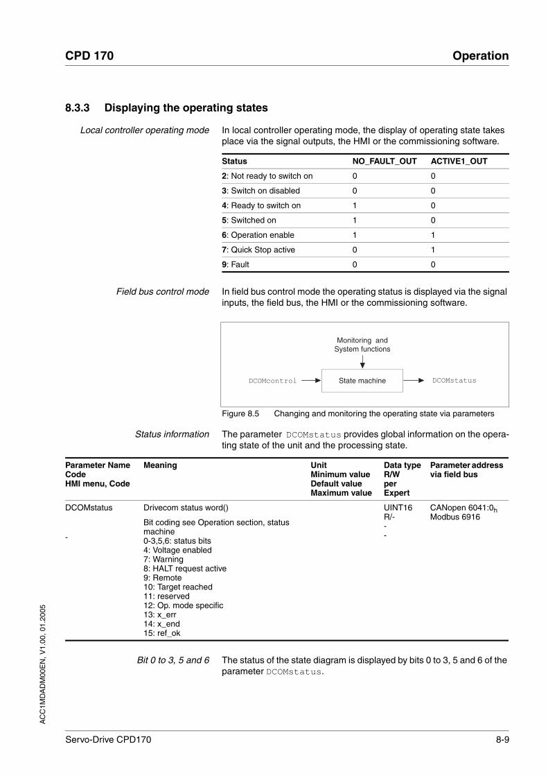
AC
C1M
DA
DM
00E
N, V
1.00
, 01.
2005
CPD 170 Operation
Servo-Drive CPD170 8-9
8.3.3 Displaying the operating states
Local controller operating mode In local controller operating mode, the display of operating state takes place via the signal outputs, the HMI or the commissioning software.
Field bus control mode In field bus control mode the operating status is displayed via the signal inputs, the field bus, the HMI or the commissioning software.
Figure 8.5 Changing and monitoring the operating state via parameters
Status information The parameter DCOMstatus provides global information on the opera-ting state of the unit and the processing state.
Bit 0 to 3, 5 and 6 The status of the state diagram is displayed by bits 0 to 3, 5 and 6 of the parameter DCOMstatus.
Status NO_FAULT_OUT ACTIVE1_OUT
2: Not ready to switch on 0 0
3: Switch on disabled 0 0
4: Ready to switch on 1 0
5: Switched on 1 0
6: Operation enable 1 1
7: Quick Stop active 0 1
9: Fault 0 0
State machine
Monitoring andSystem functions
DCOMcontrol DCOMstatus
Parameter NameCodeHMI menu, Code
Meaning UnitMinimum valueDefault valueMaximum value
Data typeR/WperExpert
Parameter address via field bus
DCOMstatus
-
Drivecom status word()
Bit coding see Operation section, status machine0-3,5,6: status bits4: Voltage enabled7: Warning8: HALT request active9: Remote10: Target reached11: reserved12: Op. mode specific13: x_err14: x_end15: ref_ok
UINT16R/---
CANopen 6041:0hModbus 6916

8-10 Servo-Drive CPD170
Operation CPD 170
AC
C1M
DA
DM
00E
N, V
1.00
, 01.
2005
Figure 8.6 Display of operating state
Bit 4, Voltage enabled Bit 4=1 indicates whether the DC-Bus voltage is correct. If the voltage is missing or is too low, then the unit does not change from state 3 to state 4.
Bit 7, Warning Bit 7=1 signals a fault message without interrupting the traverse opera-tion.
Bit 8, Halt request active Bit 8=1 indicates that a "Halt"is active.
Bit 9, Remote If Bit 9 is set, then the unit carries out the commands via the field bus. If Bit 9 is set, then the unit is controlled from a different interface. The field bus then allows other parameters to be read and written.
Bit 10, Target reached Bit 10 only becomes "1“, if the operating mode is completed successfully and the motor stops. Bit 10 has the value “0”, as long as the motor is run-ning, if the operating mode is interrupted by a "Halt"or discontinued be-cause of a fault.
Bit 11 reserved
Bit 12 Bit 12 is used for the monitoring the current operating mode. Details can be found in the chapter for the individual operating mode.
Bit 13, x_err Bit 13 only becomes "1“, if there is a fault present, which needs to be rec-tified by the further processing. The unit responds corresponding to an error class, see page 10-1.
Bit 14, x_end Bit 14 changes to "0“, if an operating mode is started. When the process is complete or if the process is discontinued e.g. by a "Halt", Bit 14 chan-ges back to "1" when the motor is at a standstill.Bit 14's signal change to '1' is suppressed if one process is followed im-mediately by a new process in a different operating mode.
Bit 15, ref_ok Bit 15 is "1“, if a homing has been completed successfully.
State machine
15...8 6 5 03
XX X XXXXXXX
...MSB LSB
Status
Bit 6,Switch Ondisable
Bit 5, Quick-Stop
Bit 3,Fault Bit 2, OperationE-NABLE
Bit 1, Switch On
Bit 0, Ready toSwitch On
2: Not ready to switch on 0 X 0 0 0 0
3: Switch on disabled 1 X 0 0 0 0
4: Ready to switch on 0 1 0 0 0 1
5: Switched on 0 1 0 0 1 1
6: Operation enable 0 1 0 1 1 1
7: Quick Stop active 0 0 0 1 1 1
9: Fault 0 X 1 1 1 1

AC
C1M
DA
DM
00E
N, V
1.00
, 01.
2005
CPD 170 Operation
Servo-Drive CPD170 8-11
8.4 Starting and changing operating modes
Requirements To start an operating mode the unit must be ready to start and correctly initialised.
An operating mode cannot be carried out in parallel with another opera-ting mode. If an operating mode is active, then you can only change to a different operating mode if the current operating mode is completed or is discontinued.
An operating mode is completed if the drive is at a standstill, e.g. if the target position of a positioning process is reached or if the drive is stop-ped by a "Quick Stop" or "Halt". If a fault occurs during the process which leads to the discontinuation of a current operating mode, then, after the cause of the fault has been removed, the traverse operation can be re-sumed, or you can change to a different operating mode.
8.4.1 Start operating mode
Local control mode In the case of local control mode, after starting, the unit changes to the operating mode set using the parameter IOdefaultMode
The motor is placed under current by setting the input signal ENABLE and the set operating mode is started.
In addition, a "Jog"or "Auto-tuning" can be started using the HMI.
Field bus control mode In the case of field bus control mode, the operating mode is started using the parameter DCOMopmode .
The following table shows the sequence of parameters for starting an operating mode with the example of the current control operating mode.
WARNING!Danger of personal injury and damage to system parts by un-controlled system operation!
• Note that inputs to these parameters are executed by the drive controller immediately on receipt of the data set.
• Make sure that the system is free and ready for movement before changing these parameters
Failure to follow these instructions can result in death or serious injury.
Parameter Description
1 CUR_I_target Transmission of the reference value
2 CURreference Setting the reference quantity
3 DCOMopmode Calling up the operating mode (-3)

8-12 Servo-Drive CPD170
Operation CPD 170
AC
C1M
DA
DM
00E
N, V
1.00
, 01.
2005
In the case of the operating modes point-to-point ("Profile Position Mode") and referencing ("Homing Mode"), the unit receives the instruc-tion to start the set operating mode by Bit 4 in the parameter DCOMcon-trol .
For all other operating modes, the Bits 4 to 6 are not occupied.
Parameter NameCodeHMI menu, Code
Meaning UnitMinimum valueDefault valueMaximum value
Data typeR/WperExpert
Parameter address via field bus
CUR_I_target
-
Setpoint current in current control operating mode(8-16)
For this purpose, the operating mode current control must be activated by pre-setting on the parameter.
Apk-300.000.00300.00
Field bus-30000030000
INT16R/W--
CANopen 3020:4hModbus 8200
CURreference
-
Selection of setpoint source for current cont-rol operating mode(8-16)
0: none1: reference value over +/-10 V interface ANA12: reference value over parameter CUR_I_target
002
UINT16R/W--
CANopen 301B:10hModbus 6944
DCOMopmode
-
Operating mode()
DSP402 operating modes:1 : profile position3 : profile velocity6 : homing--------------------------------------manufacturer operating modes:-1 : jog-2 : electronic gear-3 : current control-4 : speed control
-6
6
INT16R/W--
CANopen 6060:0hModbus 6918
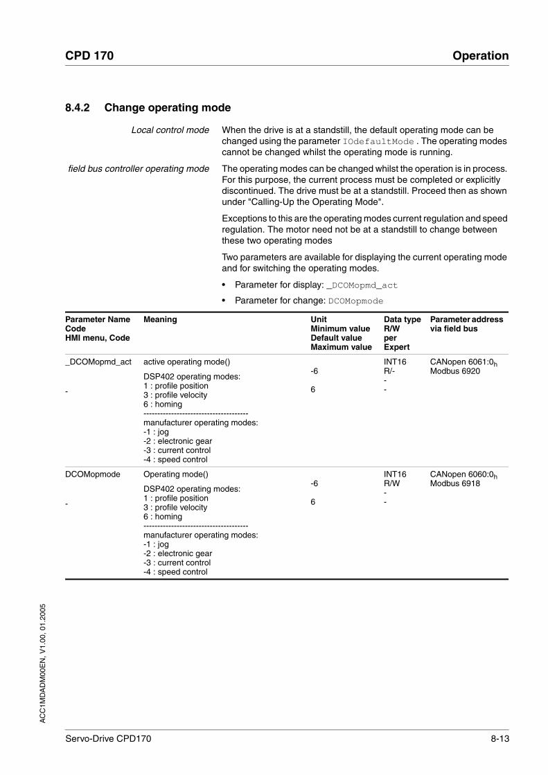
AC
C1M
DA
DM
00E
N, V
1.00
, 01.
2005
CPD 170 Operation
Servo-Drive CPD170 8-13
8.4.2 Change operating mode
Local control mode When the drive is at a standstill, the default operating mode can be changed using the parameter IOdefaultMode . The operating modes cannot be changed whilst the operating mode is running.
field bus controller operating mode The operating modes can be changed whilst the operation is in process. For this purpose, the current process must be completed or explicitly discontinued. The drive must be at a standstill. Proceed then as shown under "Calling-Up the Operating Mode".
Exceptions to this are the operating modes current regulation and speed regulation. The motor need not be at a standstill to change between these two operating modes
Two parameters are available for displaying the current operating mode and for switching the operating modes.
• Parameter for display: _DCOMopmd_act
• Parameter for change: DCOMopmode
Parameter NameCodeHMI menu, Code
Meaning UnitMinimum valueDefault valueMaximum value
Data typeR/WperExpert
Parameter address via field bus
_DCOMopmd_act
-
active operating mode()
DSP402 operating modes:1 : profile position3 : profile velocity6 : homing--------------------------------------manufacturer operating modes:-1 : jog-2 : electronic gear-3 : current control-4 : speed control
-6
6
INT16R/---
CANopen 6061:0hModbus 6920
DCOMopmode
-
Operating mode()
DSP402 operating modes:1 : profile position3 : profile velocity6 : homing--------------------------------------manufacturer operating modes:-1 : jog-2 : electronic gear-3 : current control-4 : speed control
-6
6
INT16R/W--
CANopen 6060:0hModbus 6918

8-14 Servo-Drive CPD170
Operation CPD 170
AC
C1M
DA
DM
00E
N, V
1.00
, 01.
2005
8.5 Operating modes
8.5.1 Jog operation mode
Description The motor traverses by one traverse unit or at constant speed in conti-nuous running. The length of the traverse unit, the speed steps and the change-over time in continuous running can be adjusted.
The current axis position is the start position for the jog operating mode. Position and speed values are input in user-defined units.
Start operating mode In local control mode the operating mode can be started with the HMI. The power amplifier becomes active and the motor is under current by calling up the jog- / strt. The motor runs by pushing the "up arrow"or "down arrow"buttons. You can change between slow and fast movement by simultaneously pushing the ENT-button.
In the case of field bus control mode, the operating mode must be set using the parameter DCOMopmode . The writing of the parameter value simultaneously causes the start of the operating mode. At the start sig-nal for jog the motor first moves over a defined path JOGstepusr. If the start signal is still present after a specific time delay JOGtime the unit changes to continuous running until the start signal has been taken back.
Figure 8.7 Jog, slow and fast
(1) JOGstepusr(2) t < JOGtime(3) t > JOGtime(4) Continuous operation
WARNING!Danger of personal injury and damage to system parts by un-controlled system operation!
• Note that inputs to these parameters are executed by the drive controller immediately on receipt of the data set.
• Make sure that the system is free and ready for movement before changing these parameters
Failure to follow these instructions can result in death or serious injury.
1
0
1
0
1
0
M
JOGactivate Bit0
JOGactivate Bit2
DCOMstatus Bit14
JOGn_slow
JOGn_fast

AC
C1M
DA
DM
00E
N, V
1.00
, 01.
2005
CPD 170 Operation
Servo-Drive CPD170 8-15
The inching distance, delay and jog speeds can be set. If the inching dis-tance is zero, jog starts directly with continuous movement irrespective of the delay.
End operating mode Jog is finished when the motor has stopped and
• the directional signal is inactive.
• the operating mode has been interrupted by "Halt" or an error
Further possibilities For further setting possibilities and functions for the operating mode see from page 8-43.
Parameter NameCodeHMI menu, Code
Meaning UnitMinimum valueDefault valueMaximum value
Data typeR/WperExpert
Parameter address via field bus
JOGactivate
-
Activation of jog()
Bit0 : clockwise direction of rotationBit1 : anticlockwise direction of rotationBit2 : 0=slow 1=fast
007
UINT16R/W--
CANopen 301B:9hModbus 6930
JOGn_slow
NSLW
JOG-NSLW
Speed for slow jog()
The set value is internally limited to the cur-rent parameter setting in RAMPn_max.
r.p.m.16013200
UINT16R/Wper.-
CANopen 3029:4hModbus 10504
JOGn_fast
NFST
JOG-NFST
Speed for fast jog()
The set value is internally limited to the cur-rent parameter setting in RAMPn_max.
r.p.m.118013200
UINT16R/Wper.-
CANopen 3029:5hModbus 10506
JOGstepusr
-
Inching movement before continuous run-ning()
0: direct enable of continuous operation>0: positioning distance per jog cycle
usr020
INT32R/Wper.-
CANopen 3029:7hModbus 10510
JOGtime
-
Waiting time before continuous running()
Time is only effective if an inching section not equal to 0 has been set, otherwise direct transition to continuous running.
ms150032767
UINT16R/Wper.-
CANopen 3029:8hModbus 10512
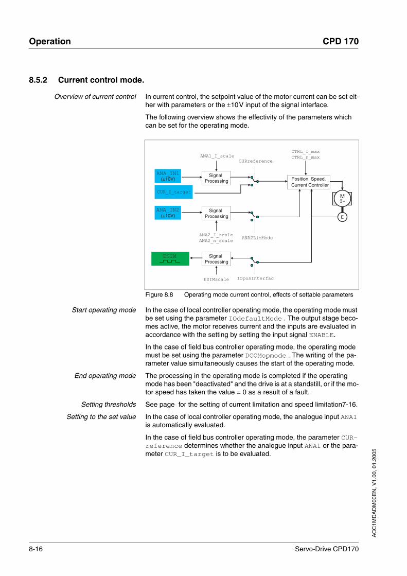
8-16 Servo-Drive CPD170
Operation CPD 170
AC
C1M
DA
DM
00E
N, V
1.00
, 01.
2005
8.5.2 Current control mode.
Overview of current control In current control, the setpoint value of the motor current can be set eit-her with parameters or the ±10V input of the signal interface.
The following overview shows the effectivity of the parameters which can be set for the operating mode.
Figure 8.8 Operating mode current control, effects of settable parameters
Start operating mode In the case of local controller operating mode, the operating mode must be set using the parameter IOdefaultMode . The output stage beco-mes active, the motor receives current and the inputs are evaluated in accordance with the setting by setting the input signal ENABLE.
In the case of field bus controller operating mode, the operating mode must be set using the parameter DCOMopmode . The writing of the pa-rameter value simultaneously causes the start of the operating mode.
End operating mode The processing in the operating mode is completed if the operating mode has been "deactivated" and the drive is at a standstill, or if the mo-tor speed has taken the value = 0 as a result of a fault.
Setting thresholds See page for the setting of current limitation and speed limitation7-16.
Setting to the set value In the case of local controller operating mode, the analogue input ANA1 is automatically evaluated.
In the case of field bus controller operating mode, the parameter CUR-reference determines whether the analogue input ANA1 or the para-meter CUR_I_target is to be evaluated.
ANA_IN1(±10V)
SignalProcessing
ANA1_I_scale
Position, Speed,Current Controller
CTRL_I_max
CTRL_n_max
(±10V)Signal
Processing
ANA2_I_scale
ANA2_n_scale
CURreference
ANA2LimMode
SignalProcessing
ESIMscale
ESIM
M3~
E
IOposInterfac
CUR_I_target
ANA_IN2

AC
C1M
DA
DM
00E
N, V
1.00
, 01.
2005
CPD 170 Operation
Servo-Drive CPD170 8-17
Reference value at +10V inputsignal
The progress of the reference value in relation to the ±10V input value can be altered:
• Setting the reference value at +10V
• Setting parameters for a zero voltage window
The unit calculates a current value, with which the motor accelerates to a speed which is limited by the load moment, from the ±10V analogue value preset. Without a load the motor therefore accelerates to the va-riable speed limit.
The reference value of a voltage value of +10V can be set by the scaling value ANA1_I_scale.
Parameter NameCodeHMI menu, Code
Meaning UnitMinimum valueDefault valueMaximum value
Data typeR/WperExpert
Parameter address via field bus
CURreference
-
Selection of setpoint source for current cont-rol operating mode()
0: none1: reference value over +/-10 V interface ANA12: reference value over parameter CUR_I_target
002
UINT16R/W--
CANopen 301B:10hModbus 6944
CUR_I_target
-
Setpoint current in current control operating mode()
For this purpose, the operating mode current control must be activated by pre-setting on the parameter.
Apk-300.000.00300.00
Field bus-30000030000
INT16R/W--
CANopen 3020:4hModbus 8200
WARNING!Unexpected acceleration may cause injury and damage to the system.
The drive in current regulation mode can reach extreme speeds when operated without limits or load.
• Check the configured speed limiter.Failure to follow these instructions can result in death or serious injury.
Parameter NameCodeHMI menu, Code
Meaning UnitMinimum valueDefault valueMaximum value
Data typeR/WperExpert
Parameter address via field bus
ANA1_I_scale
A1IS
SET-A1iS
Scaling ANA1 for set current at +10V(8-16)
Default value is the lesser value from ImaxM or ImaxPA
With a neg. sign an inversion of the evalua-tion of the analogue signal can be conducted
Apk-300.003.00300.00
Field bus-3000030030000
INT16R/Wper.-
CANopen 3020:3hModbus 8198
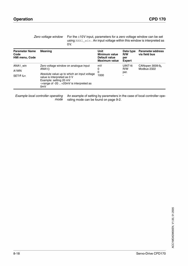
8-18 Servo-Drive CPD170
Operation CPD 170
AC
C1M
DA
DM
00E
N, V
1.00
, 01.
2005
Zero voltage window For the ±10V input, parameters for a zero voltage window can be set using ANA1_win . An input voltage within this window is interpreted as 0V.
Example local controller operatingmode
An example of setting by parameters in the case of local controller ope-rating mode can be found on page 9-2.
Parameter NameCodeHMI menu, Code
Meaning UnitMinimum valueDefault valueMaximum value
Data typeR/WperExpert
Parameter address via field bus
ANA1_win
A1WN
SET-A1WN
Zero voltage window on analogue input ANA1()
Absolute value up to which an input voltage value is interpreted as 0 VExample: setting 20 mV->range of -20 .. +20mV is interpreted as 0mV
mV001000
UINT16R/Wper.-
CANopen 3009:9hModbus 2322

AC
C1M
DA
DM
00E
N, V
1.00
, 01.
2005
CPD 170 Operation
Servo-Drive CPD170 8-19
8.5.3 Speed control operating mode
Description In the operating mode speed regulation, the set value of the motor speed is provided either by parameter or via the ±10V analogue input.
Transitions between two speeds can only take place in relation to the set regulation parameters. Compare this to the operating mode speed pro-file, where the transitions are defined by a profile generator.
The following overview shows the effectivity of the parameters which can be set for the operating mode.
Figure 8.9 Operating mode speed control , effect of settable parameters
Start operating mode In the case of local controller operating mode, the operating mode must be set using the parameter IOdefaultMode . The output stage beco-mes active, the motor receives current and the inputs are evaluated in accordance with the setting by setting the input signal ENABLE.
In the case of field bus controller operating mode, the operating mode must be set using the parameter DCOMopmode . The writing of the pa-rameter value simultaneously causes the start of the operating mode.
End operating mode The processing in the operating mode is completed if the operating mode has been "deactivated" and the drive is at a standstill, or if the mo-tor speed has taken the value = 0 as a result of a fault.
Setting thresholds See page for the setting of current limitation and speed limitation7-16.
Setting to the set value In the case of local controller operating mode, the analogue input ANA1 is automatically evaluated.
In the case of field bus controller operating mode, the parameter SPEE-Dreference determines whether the analogue input ANA1 or the pa-rameter SPEEDn_target is to be evaluated.
SignalProcessing
ANA1_n_scale
Position, Speed,Current Controller
CTRL_I_max
CTRL_n_max
SignalProcessing
ANA2_I_scale
ANA2_n_scale
SPEEDreference
ANA2LimMode
SignalProcessing
ESIMscale
M3~
E
IOposInterfac
SPEEDn_target
ANA_IN1(±10V)
(±10V)
ESIM
ANA_IN2
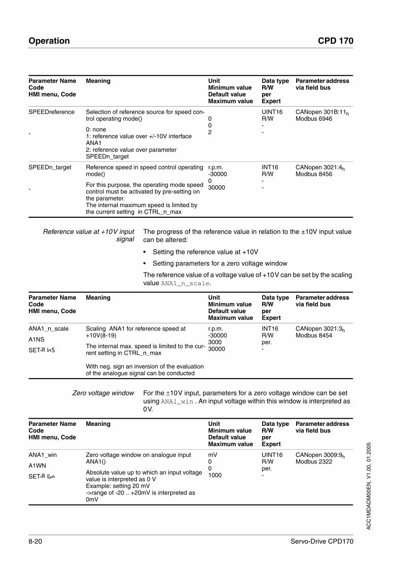
8-20 Servo-Drive CPD170
Operation CPD 170
AC
C1M
DA
DM
00E
N, V
1.00
, 01.
2005
Reference value at +10V inputsignal
The progress of the reference value in relation to the ±10V input value can be altered:
• Setting the reference value at +10V
• Setting parameters for a zero voltage window
The reference value of a voltage value of +10V can be set by the scaling value ANA1_n_scale.
Zero voltage window For the ±10V input, parameters for a zero voltage window can be set using ANA1_win . An input voltage within this window is interpreted as 0V.
Parameter NameCodeHMI menu, Code
Meaning UnitMinimum valueDefault valueMaximum value
Data typeR/WperExpert
Parameter address via field bus
SPEEDreference
-
Selection of reference source for speed con-trol operating mode()
0: none1: reference value over +/-10V interface ANA12: reference value over parameter SPEEDn_target
002
UINT16R/W--
CANopen 301B:11hModbus 6946
SPEEDn_target
-
Reference speed in speed control operating mode()
For this purpose, the operating mode speed control must be activated by pre-setting on the parameter.The internal maximum speed is limited by the current setting in CTRL_n_max
r.p.m.-30000030000
INT16R/W--
CANopen 3021:4hModbus 8456
Parameter NameCodeHMI menu, Code
Meaning UnitMinimum valueDefault valueMaximum value
Data typeR/WperExpert
Parameter address via field bus
ANA1_n_scale
A1NS
SET-A1NS
Scaling ANA1 for reference speed at +10V(8-19)
The internal max. speed is limited to the cur-rent setting in CTRL_n_max
With neg. sign an inversion of the evaluation of the analogue signal can be conducted
r.p.m.-30000300030000
INT16R/Wper.-
CANopen 3021:3hModbus 8454
Parameter NameCodeHMI menu, Code
Meaning UnitMinimum valueDefault valueMaximum value
Data typeR/WperExpert
Parameter address via field bus
ANA1_win
A1WN
SET-A1WN
Zero voltage window on analogue input ANA1()
Absolute value up to which an input voltage value is interpreted as 0 VExample: setting 20 mV->range of -20 .. +20mV is interpreted as 0mV
mV001000
UINT16R/Wper.-
CANopen 3009:9hModbus 2322

AC
C1M
DA
DM
00E
N, V
1.00
, 01.
2005
CPD 170 Operation
Servo-Drive CPD170 8-21
Example local controller operatingmode
An example of setting by parameters in the case of local controller ope-rating mode can be found on page 9-2.

8-22 Servo-Drive CPD170
Operation CPD 170
AC
C1M
DA
DM
00E
N, V
1.00
, 01.
2005
8.5.4 Electronic gear operation mode
Description In the electronic gear operating mode reference signals are fed in as A/B signals or as pulse/direction signals, see Chapter 7.4.1 “"Initial Se-tup"“ page 7-10. They are offset to a new position preset with an adjus-table gear ratio.
Example An NC control provides reference signals to two units. The motors exe-cute different, proportional positioning movements in accordance with the gear ratios.
Figure 8.10 Preset default via NC controller
Start operating mode In the case of local controller operating mode, the operating mode must be set using the parameter IOdefaultMode . The output stage beco-mes active, the motor receives current and the inputs are evaluated in accordance with the setting by setting the input signal ENABLE.
In the case of field bus controller operating mode, the operating mode must be set using the parameter DCOMopmode . The writing of the pa-rameter value simultaneously causes the start of the operating mode.
The type of synchronisation is set and the gear processing is started by a write command on the parameter GEARreference . If positioning
WARNING!Danger of personal injury and damage to system parts by un-controlled system operation!
• Note that inputs to these parameters are executed by the drive controller immediately on receipt of the data set.
• Make sure that the system is free and ready for movement before changing these parameters
Failure to follow these instructions can result in death or serious injury.
Setpoint
NC
600 r.p.m.Actual motor position
Field busMaster
CN5 (PULSE)
32
=ZN
CN2
CN1/CN4 (CANopen, MODBUS)
M3~
E
Actual motor position
CN5 (PULSE)
CN2
CN1/CN4 (CANopen, MODBUS)
900 r.p.m.
450 r.p.m.
34
=ZN
M3~
E

AC
C1M
DA
DM
00E
N, V
1.00
, 01.
2005
CPD 170 Operation
Servo-Drive CPD170 8-23
changes at the reference signals are stored, then the unit computes these with the gear factor and positions the motor to the new set posi-tion.
Positioning values are given in internal units. The unit performs the changes immediately.
End operating mode The processing is complete when the operating mode is deactivated and the motor is at a standstill, or if the motor is at a standstill because of a "Halt"or a fault.
8.5.4.1 Setting parameters
Example local controller operatingmode
An example of setting by parameters in the case of local controller ope-rating mode can be found on page 9-2.
Overview The following overview shows the effectiveness of the parameters which can be set for the operating mode electronic gear.
Figure 8.11 Operating mode electronic gear, effect of settable parameters
The resulting positioning movement is dependent upon the current mo-tor resolution. It amounts to 131072 motor increments per revolution.
The setting values for the electronic gear, independent of the type of synchronisation, are:
• Gear factor (predefined value or intrinsic gear factor)
• size of following error
• Release of the direction of rotation
Setting thresholds See page for the setting of current limitation and speed limitation7-16.
Synchronisation In the case of the operating mode electronic gear, the unit operates syn-chronously in a gear train e.g. with other drives. If the unit leaves the gear processing for a short period of time, then the synchronous run with other drives is lost.
• In the case of local control mode, the positioning changes at the reference signals which arise during the interruption are not evalua-ted. When the gear processing is resumed, the unit follows the posi-tioning changes from that point in time when the gear processing is reactivated.
• In the case of field bus control mode, the positioning changes at the reference signals which arise during the interruption continue to be counted internally. The parameter GEARreference allows setting whether these positioning changes are to be processed or ignored when the gear processing is resumed.
ND
Reference Pulses
GEARratio
GearNumGearDenom
AB PD
IOposInterfac GEARdir_enabl
Position, Speed,Current Controller
IMAXNMAX
M3~
E
MPREF

8-24 Servo-Drive CPD170
Operation CPD 170
AC
C1M
DA
DM
00E
N, V
1.00
, 01.
2005
Gear factor The gear factor is the relationship between the motor increments and the externally inputted guide increments for the movement of the motor.
The parameter GEARratio serves to set the predefined gear factor. Al-ternatively, an intrinsic gear factor can be selected.
The intrinsic gear factor is determined with the parameters count and name. A negative numerator value reverses the motor's direction of ro-tation. The gear ratio is preset to 1:1.
Example At a setting of 1000 reference increments the motor should rotate 2000 motor increments. This yields a gear factor of 2.
Parameter NameCodeHMI menu, Code
Meaning UnitMinimum valueDefault valueMaximum value
Data typeR/WperExpert
Parameter address via field bus
GEARreference
-
Electronic gear processing operating mode()
0: disabled1: real-time synchronisation2: synchronisation with compensation move-ment
002
UINT16R/W--
CANopen 301B:12hModbus 6948
Gear factor = =Reference increments
Motor increments Gear factor numerator
Gear factor denominator
Parameter NameCodeHMI menu, Code
Meaning UnitMinimum valueDefault valueMaximum value
Data typeR/WperExpert
Parameter address via field bus
GEARratio
GFAC
SET-GFAC
Selection of special gear ratios()
0 : use of the specified gear ratiofrom GEARnum/GEARdenom1 : 2002 : 4003 : 5004 : 10005 : 20006 : 40007 : 50008 : 100009 : 409610 : 819211 : 16384
Change of reference values by the specified value effects a motor revolution.
0011
UINT16R/Wper.-
CANopen 3026:6hModbus 9740
GEARnum
-
Numerator of the gear ratio()
Gear ratio numeratorgear ratio= ------------------------------------ gear ratio denominator
The new gear ratio is enabled on transfer of the numerator value.
-214748364812147483647
INT32R/Wper.-
CANopen 3026:4hModbus 9736
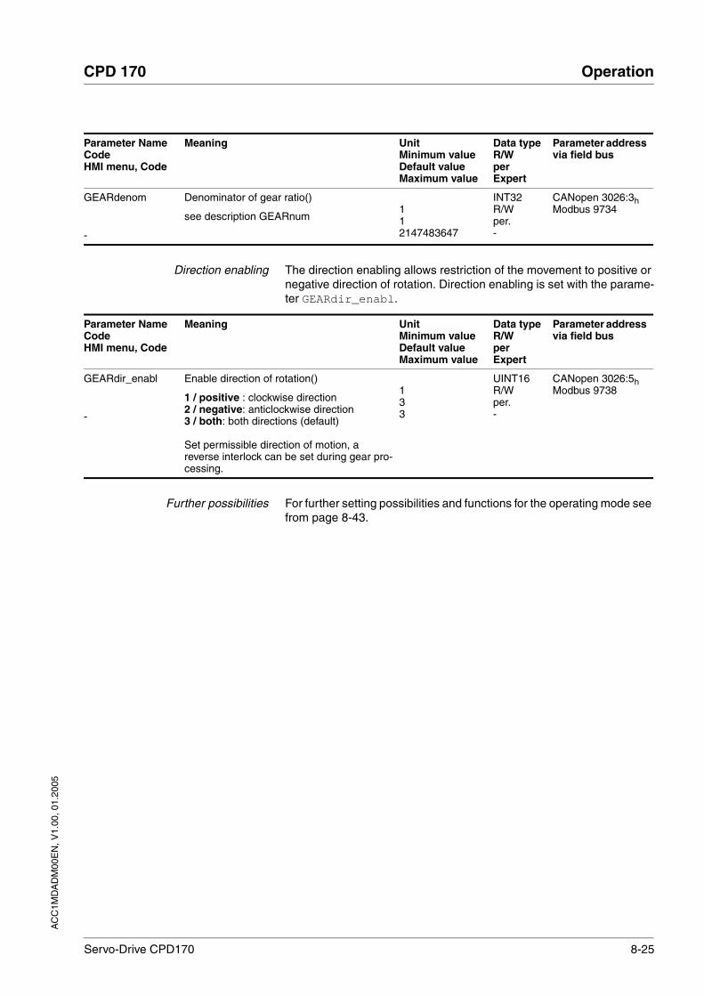
AC
C1M
DA
DM
00E
N, V
1.00
, 01.
2005
CPD 170 Operation
Servo-Drive CPD170 8-25
Direction enabling The direction enabling allows restriction of the movement to positive or negative direction of rotation. Direction enabling is set with the parame-ter GEARdir_enabl.
Further possibilities For further setting possibilities and functions for the operating mode see from page 8-43.
GEARdenom
-
Denominator of gear ratio()
see description GEARnum112147483647
INT32R/Wper.-
CANopen 3026:3hModbus 9734
Parameter NameCodeHMI menu, Code
Meaning UnitMinimum valueDefault valueMaximum value
Data typeR/WperExpert
Parameter address via field bus
Parameter NameCodeHMI menu, Code
Meaning UnitMinimum valueDefault valueMaximum value
Data typeR/WperExpert
Parameter address via field bus
GEARdir_enabl
-
Enable direction of rotation()
1 / positive : clockwise direction2 / negative: anticlockwise direction3 / both: both directions (default)
Set permissible direction of motion, a reverse interlock can be set during gear pro-cessing.
133
UINT16R/Wper.-
CANopen 3026:5hModbus 9738
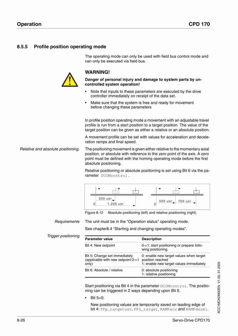
8-26 Servo-Drive CPD170
Operation CPD 170
AC
C1M
DA
DM
00E
N, V
1.00
, 01.
2005
8.5.5 Profile position operating mode
The operating mode can only be used with field bus control mode and can only be executed via field bus.
In profile position operating mode a movement with an adjustable travel profile is run from a start position to a target position. The value of the target position can be given as either a relative or an absolute position.
A movement profile can be set with values for acceleration and decele-ration ramps and final speed.
Relative and absolute positioning, The positioning movement is given either relative to the momentary axial position, or absolute with reference to the zero point of the axis. A zero point must be defined with the homing operating mode before the first absolute positioning.
Relative positioning or absolute positioning is set using Bit 6 via the pa-rameter DCOMcontrol .
Figure 8.12 Absolute positioning (left) and relative positioning (right)
Requirements The unit must be in the "Operation status" operating mode.
See chapter8.4 “Starting and changing operating modes“.
Trigger positioning
Start positioning via Bit 4 in the parameter DCOMcontrol. The positio-ning can be triggered in 2 ways depending upon Bit 5.
• Bit 5=0:
New positioning values are temporarily saved on leading edge of bit 4: PPp_targetusr, PPn_target, RAMPacc and RAMPdecel.
WARNING!Danger of personal injury and damage to system parts by un-controlled system operation!
• Note that inputs to these parameters are executed by the drive controller immediately on receipt of the data set.
• Make sure that the system is free and ready for movement before changing these parameters
Failure to follow these instructions can result in death or serious injury.
1 .200 usr
500 usr500 usr
0700 usr
0
Parameter value Description
Bit 4: New setpoint 0->1: start positioning or prepare follo-wing positioning
Bit 5: Change set immediately(applicable with new setpoint 0->1 only)
0: enable new target values when target position reached1: enable new target values immediately
Bit 6: Absolute / relative 0: absolute positioning1: relative positioning
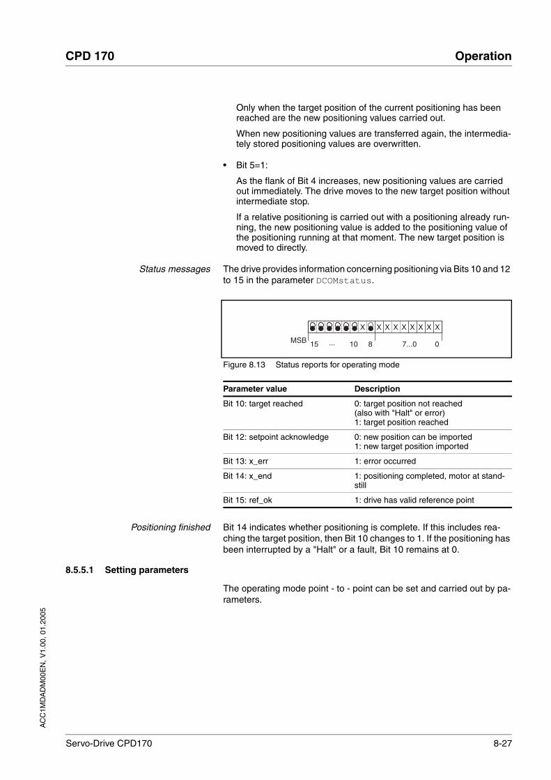
AC
C1M
DA
DM
00E
N, V
1.00
, 01.
2005
CPD 170 Operation
Servo-Drive CPD170 8-27
Only when the target position of the current positioning has been reached are the new positioning values carried out.
When new positioning values are transferred again, the intermedia-tely stored positioning values are overwritten.
• Bit 5=1:
As the flank of Bit 4 increases, new positioning values are carried out immediately. The drive moves to the new target position without intermediate stop.
If a relative positioning is carried out with a positioning already run-ning, the new positioning value is added to the positioning value of the positioning running at that moment. The new target position is moved to directly.
Status messages The drive provides information concerning positioning via Bits 10 and 12 to 15 in the parameter DCOMstatus.
Figure 8.13 Status reports for operating mode
Positioning finished Bit 14 indicates whether positioning is complete. If this includes rea-ching the target position, then Bit 10 changes to 1. If the positioning has been interrupted by a "Halt" or a fault, Bit 10 remains at 0.
8.5.5.1 Setting parameters
The operating mode point - to - point can be set and carried out by pa-rameters.
7...0 0
X X X X X X X X X
...MSB 15 10 8
Parameter value Description
Bit 10: target reached 0: target position not reached(also with "Halt" or error)1: target position reached
Bit 12: setpoint acknowledge 0: new position can be imported1: new target position imported
Bit 13: x_err 1: error occurred
Bit 14: x_end 1: positioning completed, motor at stand-still
Bit 15: ref_ok 1: drive has valid reference point
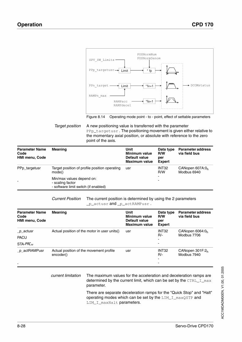
8-28 Servo-Drive CPD170
Operation CPD 170
AC
C1M
DA
DM
00E
N, V
1.00
, 01.
2005
Figure 8.14 Operating mode point - to - point, effect of settable parameters
Target position A new positioning value is transferred with the parameter PPp_targetusr . The positioning movement is given either relative to the momentary axial position, or absolute with reference to the zero point of the axis.
Current Position The current position is determined by using the 2 parameters _p_actusr and _p_actRAMPusr .
current limitation The maximum values for the acceleration and deceleration ramps are determined by the current limit, which can be set by the CTRL_I_max parameter.
There are separate deceleration ramps for the "Quick Stop" and "Halt" operating modes which can be set by the LIM_I_maxQSTP and LIM_I_maxHalt parameters.
Limit * fp
SPV_SW_Limits
PPp_targetusr
POSNormNum
POSNormDenom
Limit *fv=1
*fa=1
DCOMstatusPPn_target
RAMPacc
RAMPdecel
RAMPn_max
Parameter NameCodeHMI menu, Code
Meaning UnitMinimum valueDefault valueMaximum value
Data typeR/WperExpert
Parameter address via field bus
PPp_targetusr
-
Target position of profile position operating mode()
Min/max values depend on:- scaling factor- software limit switch (if enabled)
usr INT32R/W--
CANopen 607A:0hModbus 6940
Parameter NameCodeHMI menu, Code
Meaning UnitMinimum valueDefault valueMaximum value
Data typeR/WperExpert
Parameter address via field bus
_p_actusr
PACU
STA-PACU
Actual position of the motor in user units() usr INT32R/---
CANopen 6064:0hModbus 7706
_p_actRAMPusr
-
Actual position of the movement profile encoder()
usr INT32R/---
CANopen 301F:2hModbus 7940
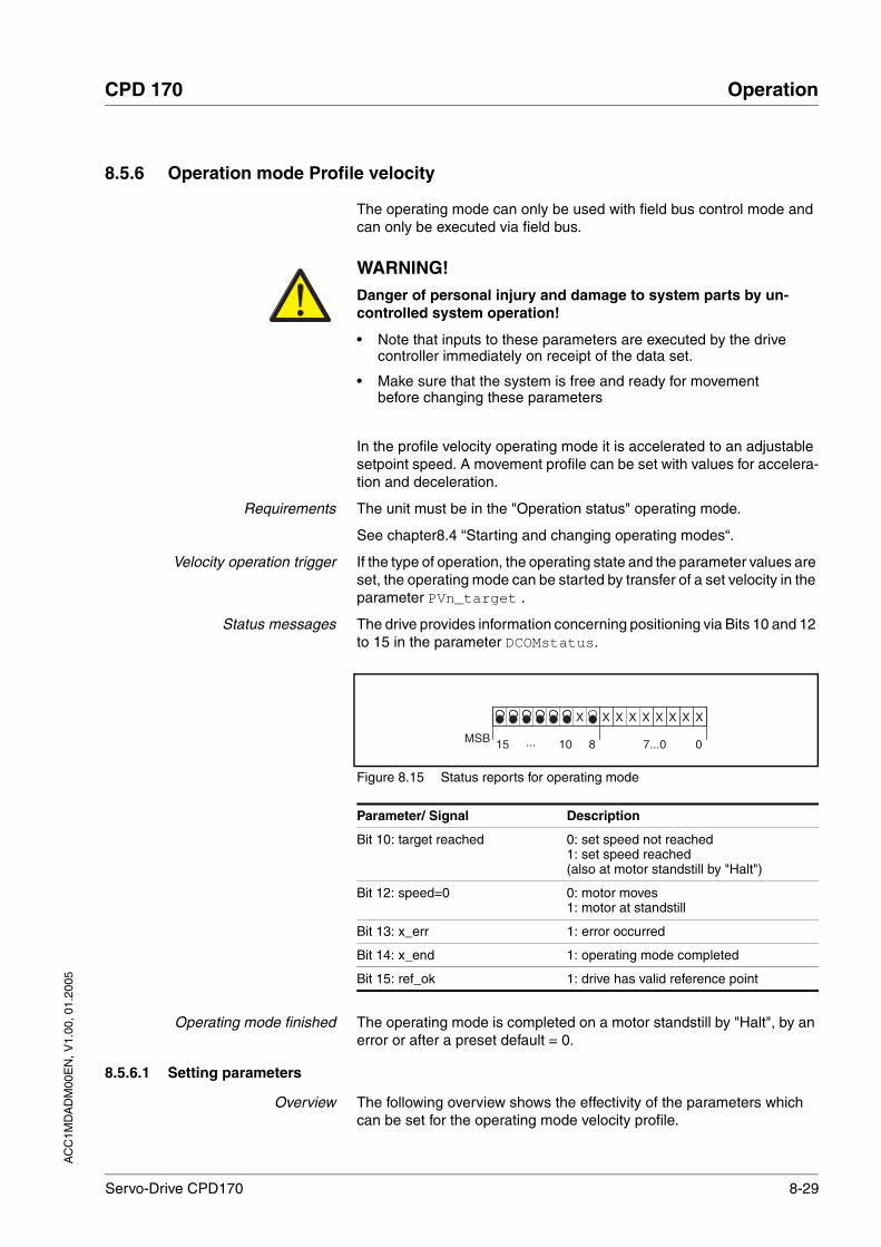
AC
C1M
DA
DM
00E
N, V
1.00
, 01.
2005
CPD 170 Operation
Servo-Drive CPD170 8-29
8.5.6 Operation mode Profile velocity
The operating mode can only be used with field bus control mode and can only be executed via field bus.
In the profile velocity operating mode it is accelerated to an adjustable setpoint speed. A movement profile can be set with values for accelera-tion and deceleration.
Requirements The unit must be in the "Operation status" operating mode.
See chapter8.4 “Starting and changing operating modes“.
Velocity operation trigger If the type of operation, the operating state and the parameter values are set, the operating mode can be started by transfer of a set velocity in the parameter PVn_target .
Status messages The drive provides information concerning positioning via Bits 10 and 12 to 15 in the parameter DCOMstatus.
Figure 8.15 Status reports for operating mode
Operating mode finished The operating mode is completed on a motor standstill by "Halt", by an error or after a preset default = 0.
8.5.6.1 Setting parameters
Overview The following overview shows the effectivity of the parameters which can be set for the operating mode velocity profile.
WARNING!Danger of personal injury and damage to system parts by un-controlled system operation!
• Note that inputs to these parameters are executed by the drive controller immediately on receipt of the data set.
• Make sure that the system is free and ready for movement before changing these parameters
Failure to follow these instructions can result in death or serious injury.
7...0 0
X X X X X X X X X
...MSB 15 10 8
Parameter/ Signal Description
Bit 10: target reached 0: set speed not reached1: set speed reached(also at motor standstill by "Halt")
Bit 12: speed=0 0: motor moves1: motor at standstill
Bit 13: x_err 1: error occurred
Bit 14: x_end 1: operating mode completed
Bit 15: ref_ok 1: drive has valid reference point

8-30 Servo-Drive CPD170
Operation CPD 170
AC
C1M
DA
DM
00E
N, V
1.00
, 01.
2005
Figure 8.16 Operating mode velocity profile, effect of settable parameters
Setpoint speed The set velocity is transferred via the parameter PVn_target in r.p.m. and can be changed during the movement. The operating mode is not li-mited by range limits of the positioning. New velocity values are accep-ted immediately during a running movement order.
Current speed The current speed is determined by using the 2 parameters _n_act and _n_actRAMP .
current limitation The maximum values for the acceleration and deceleration ramps are determined by the current limit, which can be set by the CTRL_I_max parameter.
There are separate deceleration ramps for the "Quick Stop" and "Halt" operating modes which can be set by the LIM_I_maxQSTP and LIM_I_maxHalt parameters.
Limit *fv=1PVn_target
*fa=1RAMPacc
RAMPdecel
DCOMstatusRAMPn_max
Parameter NameCodeHMI menu, Code
Meaning UnitMinimum valueDefault valueMaximum value
Data typeR/WperExpert
Parameter address via field bus
PVn_target
-
Setpoint speed profile velocity operating mode(8-29)
Maximum value is limited to the current set-ting in CTRL_n_max.
0rpm
INT32R/W--
CANopen 60FF:0hModbus 6938
Parameter NameCodeHMI menu, Code
Meaning UnitMinimum valueDefault valueMaximum value
Data typeR/WperExpert
Parameter address via field bus
_n_act
NACT
STA-NACT
Actual speed of the motor() rpm INT16R/---
CANopen 606C:0hModbus 7696
_n_actRAMP
-
Actual speed of the movement profile enco-der()
rpm INT32R/---
CANopen 606B:0hModbus 7948

AC
C1M
DA
DM
00E
N, V
1.00
, 01.
2005
CPD 170 Operation
Servo-Drive CPD170 8-31
8.5.7 Operation mode Homing
The operating mode can only be used with field bus control mode and can only be executed via field bus.
Overview of homing In homing mode, an absolute scale reference of the motor position at a defined axis position is established. Referencing can be carried out by a homing movement or by dimension setting.
• A reference movement performs movement to a defined point, the reference point, on the axis, in order to create the absolute measu-rement reference of the motor position. The reference point simulta-neously defines the zero point that is used for all subsequent absolute positionings as a reference point. Displacement of the zero point can be set by parameters.
The reference movement must be carried out completely to ensure that the new zero point is valid. If it is interrupted, then the reference movement has to be started again. Unlike the other operating modes a reference movement must be completed before you can switch to a new operating mode.
The signals LIMN, LIMP and REF required for the reference move-ment must be wired. Monitoring signals that are not used should be deactivated.
A homing is not required for motors with SinCos Multiturn encoders, because it sends a valid absolute position.
• Set dimensions provides the option of setting the current motor position to a desired position value to which the subsequent posi-tion specifications will refer.
Types of reference movements 4 standard reference movements are available
• Movement to negative limit switch LIMN
• Movement to positive limit switch LIMP
• Movement to reference switch REF with movement in negative direction of rotation
• Movement to reference switch REF with movement in positive direc-tion of rotation
A reference movement can be conducted with or without index pulse.
• Reference movement without index pulseMovement from the edge of the switch to a distance set by parame-ters from the edge of the switch.
• Reference movement with index pulse (SinCos Singleturn encoder)movement from switch edge to the next motor index pulse. The cur-
WARNING!Danger of personal injury and damage to system parts by un-controlled system operation!
• Note that inputs to these parameters are executed by the drive controller immediately on receipt of the data set.
• Make sure that the system is free and ready for movement before changing these parameters
Failure to follow these instructions can result in death or serious injury.
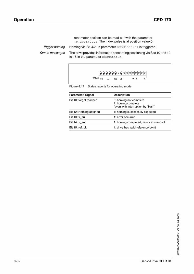
8-32 Servo-Drive CPD170
Operation CPD 170
AC
C1M
DA
DM
00E
N, V
1.00
, 01.
2005
rent motor position can be read out with the parameter _p_absENCusr. The index pulse is at position value 0.
Trigger homing Homing via Bit 4=1 in parameter DCOMcontrol is triggered.
Status messages The drive provides information concerning positioning via Bits 10 and 12 to 15 in the parameter DCOMstatus.
Figure 8.17 Status reports for operating mode
7...0 0
X X X X X X X X X
...MSB 15 10 8
Parameter/ Signal Description
Bit 10: target reached 0: homing not complete1: homing complete(even with interruption by "Halt")
Bit 12: Homing attained 1: homing successfully executed
Bit 13: x_err 1: error occurred
Bit 14: x_end 1: homing completed, motor at standstill
Bit 15: ref_ok 1: drive has valid reference point
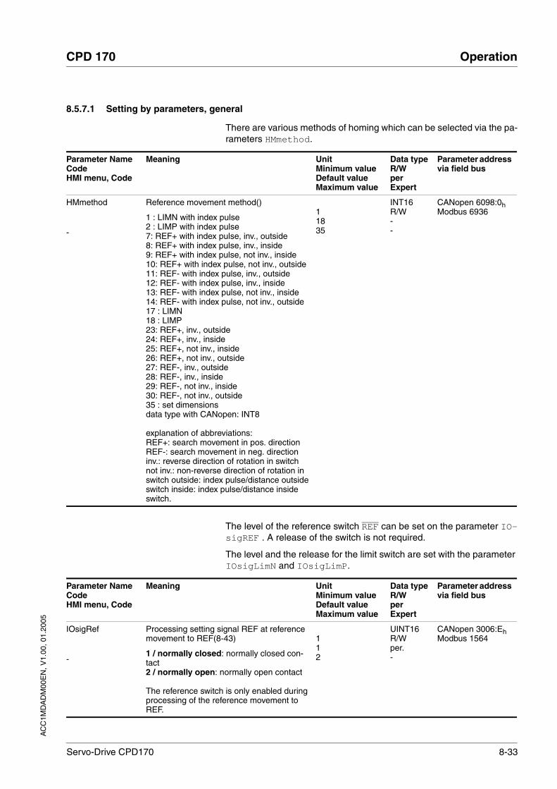
AC
C1M
DA
DM
00E
N, V
1.00
, 01.
2005
CPD 170 Operation
Servo-Drive CPD170 8-33
8.5.7.1 Setting by parameters, general
There are various methods of homing which can be selected via the pa-rameters HMmethod.
The level of the reference switch REF can be set on the parameter IO-sigREF . A release of the switch is not required.
The level and the release for the limit switch are set with the parameter IOsigLimN and IOsigLimP.
Parameter NameCodeHMI menu, Code
Meaning UnitMinimum valueDefault valueMaximum value
Data typeR/WperExpert
Parameter address via field bus
HMmethod
-
Reference movement method()
1 : LIMN with index pulse2 : LIMP with index pulse7: REF+ with index pulse, inv., outside8: REF+ with index pulse, inv., inside9: REF+ with index pulse, not inv., inside10: REF+ with index pulse, not inv., outside11: REF- with index pulse, inv., outside12: REF- with index pulse, inv., inside13: REF- with index pulse, not inv., inside14: REF- with index pulse, not inv., outside17 : LIMN18 : LIMP23: REF+, inv., outside24: REF+, inv., inside25: REF+, not inv., inside26: REF+, not inv., outside27: REF-, inv., outside28: REF-, inv., inside29: REF-, not inv., inside30: REF-, not inv., outside35 : set dimensionsdata type with CANopen: INT8
explanation of abbreviations:REF+: search movement in pos. directionREF-: search movement in neg. directioninv.: reverse direction of rotation in switchnot inv.: non-reverse direction of rotation in switch outside: index pulse/distance outside switch inside: index pulse/distance inside switch.
11835
INT16R/W--
CANopen 6098:0hModbus 6936
Parameter NameCodeHMI menu, Code
Meaning UnitMinimum valueDefault valueMaximum value
Data typeR/WperExpert
Parameter address via field bus
IOsigRef
-
Processing setting signal REF at reference movement to REF(8-43)
1 / normally closed: normally closed con-tact2 / normally open: normally open contact
The reference switch is only enabled during processing of the reference movement to REF.
112
UINT16R/Wper.-
CANopen 3006:EhModbus 1564

8-34 Servo-Drive CPD170
Operation CPD 170
AC
C1M
DA
DM
00E
N, V
1.00
, 01.
2005
The parameters HMn and HMn_out are used for setting the speeds for the reference movement.
The parameter HMp_homeusr can be used to specify a desired position value, which is set at the reference point after a successful reference movement. This position value defines the current motor position at the reference point. This also defines the zero point.
The parameters HMoutdisusr and HMsrchdisusr can be used for activation of the monitoring of the switch function.
IOsigLimN
-
Processing setting signal LIMN(8-43)
0 / none: inactive1 / normally closed: normally closed con-tact2 / normally open: normally open contact
012
UINT16R/Wper.-
CANopen 3006:FhModbus 1566
IOsigLimP
-
Processing setting signal LIMP(8-43)
0 / none: inactive1 / normally closed: normally closed con-tact2 / normally open: normally open contact
012
UINT16R/Wper.-
CANopen 3006:10hModbus 1568
Parameter NameCodeHMI menu, Code
Meaning UnitMinimum valueDefault valueMaximum value
Data typeR/WperExpert
Parameter address via field bus
Parameter NameCodeHMI menu, Code
Meaning UnitMinimum valueDefault valueMaximum value
Data typeR/WperExpert
Parameter address via field bus
HMn
-
Reference speed for search for the switch()
The set value is internally limited to the cur-rent parameter setting in RAMPn_max.
r.p.m.16013200
UINT16R/Wper.-
CANopen 6099:1hModbus 10248
HMn_out
-
Reference speed for retraction from switch()
The set value is internally limited to the cur-rent parameter setting in RAMPn_max.
r.p.m.163000
UINT16R/Wper.-
CANopen 6099:2hModbus 10250
Parameter NameCodeHMI menu, Code
Meaning UnitMinimum valueDefault valueMaximum value
Data typeR/WperExpert
Parameter address via field bus
HMp_homeusr
-
Position on reference point()
After successful reference movement this position value is automatically set at the refe-rence point.
usr-214748364802147483647
INT32R/Wper.-
CANopen 3028:BhModbus 10262

AC
C1M
DA
DM
00E
N, V
1.00
, 01.
2005
CPD 170 Operation
Servo-Drive CPD170 8-35
Parameter NameCodeHMI menu, Code
Meaning UnitMinimum valueDefault valueMaximum value
Data typeR/WperExpert
Parameter address via field bus
HMoutdisusr
-
Maximum run-off distance()
0: withdrawal control inactive>0: run-off in user-defined units
position range within which it must be disab-led again with the switch enabled.
usr002147483647
INT32R/Wper.-
CANopen 3028:6hModbus 10252
HMsrchdisusr
-
Maximum search distance after traversing over the switch()
Positioning range within which, after traver-sing over the switch, this must be reactivated again.0: search path processing inactive>0: search path in user-defined units
usr002147483647
INT32R/Wper.-
CANopen 3028:DhModbus 10266

8-36 Servo-Drive CPD170
Operation CPD 170
AC
C1M
DA
DM
00E
N, V
1.00
, 01.
2005
8.5.7.2 Reference movement without index pulse
Description A reference movement without index pulse can be set with the parame-ter HMmethod = 17 to 30, see page 8-33. The distance to the switching edge can be specified with the parameter HMdisusr.
Reference movement towards limitswitch
A reference movement to the negative limit switch is shown below with the distance to the switch edge (HMmethod = 17).
Figure 8.18 Reference movement to the negative limit switch
(1) Movement to limit switch at search speed(2) Movement to switching point with release speed(3) Movement at the distance to switching point with release
speed
Reference movement to referenceswitch
Reference movements to the reference switch with the distance to the switch edge are shown below (HMmethod = 27 to 30).
Parameter NameCodeHMI menu, Code
Meaning UnitMinimum valueDefault valueMaximum value
Data typeR/WperExpert
Parameter address via field bus
HMdisusr
-
Distance between the switching point and the reference point()
After leaving the switch, the drive is still posi-tioned in the working range for a defined path and this position is defined as a refe-rence point.
The parameters are only effective with refe-rence movements without index pulse sear-ching.
usr12002147483647
INT32R/Wper.-
CANopen 3028:7hModbus 10254
LIMN LIMP
M
R-
HMoutdisusr
HMdisusr
HMn
HMn_out

AC
C1M
DA
DM
00E
N, V
1.00
, 01.
2005
CPD 170 Operation
Servo-Drive CPD170 8-37
Figure 8.19 Reference movements to the reference switch
(1) Movement to reference switch at search speed(2) Movement to switching point with release speed(3) Movement at the distance to switching point with release
speed
Examples Reference movements to the reference switch with the distance to the switch edge are shown below (HMmethod = 27). Various responses at different search speeds and start positions are shown.
• Movement to the reference switch with first movement in the nega-tive direction, reference switch is once before (A1, A2) and once behind the start point (B1, B2).
• Additional movement when traversing through the switching window (A2, B2).
REF
M
HMmethod = 27
HMmethod = 30
HMmethod = 28
HMmethod = 29
LIMN LIMP
HMn
HMn_out
R-
R-
R-
R-

8-38 Servo-Drive CPD170
Operation CPD 170
AC
C1M
DA
DM
00E
N, V
1.00
, 01.
2005
Figure 8.20 Reference movements to the reference switch
(1) Movement to reference switch at search speed(2) Movement to switching point with release speed(3) Excessively fast movement to reference switch with search
speed(4) Return movement to switch area at release speed(5) Movement at the distance to switching point with release
speed
REF
MM
A1
B2
A2
B1
LIMN LIMP
HMn
HMn_out
HMoutdisusr
R-
R-
R-
R-

AC
C1M
DA
DM
00E
N, V
1.00
, 01.
2005
CPD 170 Operation
Servo-Drive CPD170 8-39
8.5.7.3 Reference movement with index pulse
Description A reference movement with index pulse can be set with the parameter HMmethod = 1 to 14, see page 8-33. First, the defined reference switch is approached and finally a search movement is made to the nearest in-dex pulse.
Parameter possibilities The position distance between switching edge and index pulse can be calculated with the parameter HMdisREFtoIDX.The value should be >0.05revolutions.
If the index pulse is too close to the switching edge, the limit switch or re-ference switch can be moved mechanically. Otherwise the position of the index pulse can be moved with the parameter ENC_pabsusr, see Chapter 7.4.10 “Setting device parameters for rotary encoder“ page 7-27. This ensures that a reference movement with index pulse can be reproduced at any time.
Reference movement towards limitswitch
A reference movement to the positive limit switch with movement to the first index pulse is shown below (HMmethod = 2).
Figure 8.21 Reference movement to the positive limit switch
(1) Movement to limit switch at search speed
Parameter NameCodeHMI menu, Code
Meaning UnitMinimum valueDefault valueMaximum value
Data typeR/WperExpert
Parameter address via field bus
HMdisREFtoIDX
-
Distance of switch - index pulse after refe-rence movement()
Reading value provides the value of the dif-ference between the index pulse position and the position on the switching flank of the limit or reference switch.Serves to monitor how far the index pulse is from the switching flank and serves to pro-vide the criterion whether the reference movement with index pulse processing can be safely reproduced.Value input in 1/10000 U
U0.00000.00000.0000
INT32R/---
CANopen 3028:ChModbus 10264
LIMN LIMP
M
HMn
HMn_out
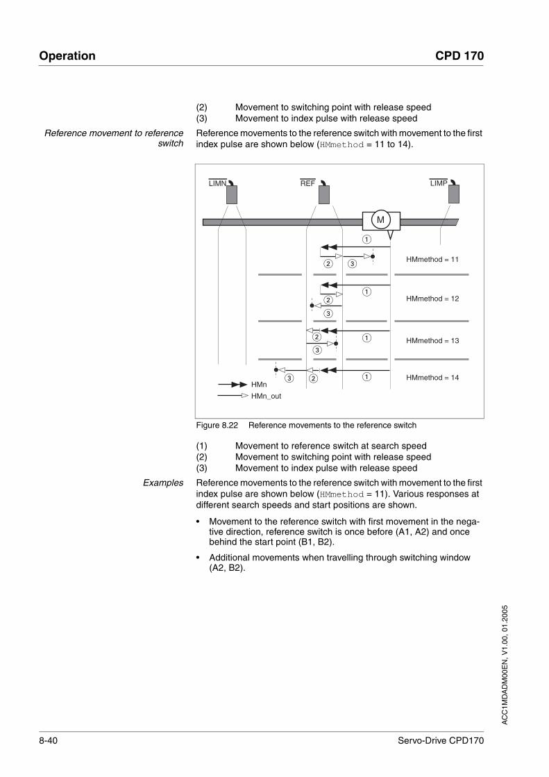
8-40 Servo-Drive CPD170
Operation CPD 170
AC
C1M
DA
DM
00E
N, V
1.00
, 01.
2005
(2) Movement to switching point with release speed(3) Movement to index pulse with release speed
Reference movement to referenceswitch
Reference movements to the reference switch with movement to the first index pulse are shown below (HMmethod = 11 to 14).
Figure 8.22 Reference movements to the reference switch
(1) Movement to reference switch at search speed(2) Movement to switching point with release speed(3) Movement to index pulse with release speed
Examples Reference movements to the reference switch with movement to the first index pulse are shown below (HMmethod = 11). Various responses at different search speeds and start positions are shown.
• Movement to the reference switch with first movement in the nega-tive direction, reference switch is once before (A1, A2) and once behind the start point (B1, B2).
• Additional movements when travelling through switching window (A2, B2).
REF
M
HMmethod = 11
HMmethod = 14
HMmethod = 12
HMmethod = 13
LIMN LIMP
HMn
HMn_out

AC
C1M
DA
DM
00E
N, V
1.00
, 01.
2005
CPD 170 Operation
Servo-Drive CPD170 8-41
Figure 8.23 Reference movements to the reference switch
(1) Movement to reference switch at search speed(2) Movement to switching point with release speed(3) Excessively fast movement to reference switch with search
speed(4) Return movement to switch area at release speed(5) Movement to index pulse with release speed
REF
M
A1
B2
A2
B1
LIMN LIMP
HMn
HMn_out
HMoutdisusr
M

8-42 Servo-Drive CPD170
Operation CPD 170
AC
C1M
DA
DM
00E
N, V
1.00
, 01.
2005
8.5.7.4 Homing by dimension setting
A homing by set dimensions can be set with the parameter HMmethod = 35, see page 8-33. The current motor position is set at the position va-lue in the parameter HMp_setpusr by set dimensions. This also defi-nes the zero point.
Homing by dimension setting can only be carried out when the motor is at a standstill. Any active position deviation is retained and can still be compensated by the position controller after dimension setting has ta-ken place.
Example Dimension setting can be used to carry out a continuous motor move-ment without exceeding positioning limits.
Figure 8.24 Positioning by 4000 usr units with measurement setting
(1) The motor is positioned by 2000 usr.(2) By setting dimensions to 0 the current motor position is set to
position value 0 and the new zero point is simultaneously de-fined.
(3) After triggering a new movement order of 2000 usr, the newtarget position is 2000 usr.
This method avoids crossing absolute position limits during a positioning operation because the zero point is continuously tracked.
The read out of the setpoint is by the parameter _p_refusr.
Parameter NameCodeHMI menu, Code
Meaning UnitMinimum valueDefault valueMaximum value
Data typeR/WperExpert
Parameter address via field bus
HMp_setpusr
-
Position for measurement setting()
Measurement setting position for homing method 35
0usr
INT32R/W--
CANopen 301B:16hModbus 6956
M MM
0
0"0"
2000 usr
"2000"
2000 usr
Parameter NameCodeHMI menu, Code
Meaning UnitMinimum valueDefault valueMaximum value
Data typeR/WperExpert
Parameter address via field bus
_p_refusr
-
Setpoint of the position regulator in user units()
usr INT32R/---
CANopen 301:ChModbus 7704

AC
C1M
DA
DM
00E
N, V
1.00
, 01.
2005
CPD 170 Operation
Servo-Drive CPD170 8-43
8.6 Functions
8.6.1 Monitoring functions
8.6.1.1 Status monitoring in movement mode
8.6.1.2 Positioning range
Positioning range (only field bus) The motor can be moved to any point on the axis within the axis positio-ning range by specifying an absolute positioning process.
The current position of the motor can be read out using the parameter _p_actusr.
Figure 8.25 Positioning range
The positioning limits, with default scaling, are:
(A) -286435456 usr(B) 286435455 usr
An overshoot of the positioning limits is possible in all operating modes, except during an absolute positioning in profile position mode.
Overshoot of motor at a positioning limit loses the reference point.
During a relative position in profile position mode a check of whether the absolute positioning limits will be overshot is made before starting the movement. If yes, an internal dimension setting to 0 is made before star-ting the movement. The reference point is lost (ref_ok = 1->0).
M3~
E
Encoder evaluation
Actual value- speed- position
Z
NM
-
_p_actPosintf
_v_act_Posintf _p_addGEAR
_p_tarRAMPusr
_n_actRAMP_n_targetRAMP
_p_actRAMPusr
_p_diff _n_refPCTRL
POSdirOfrotat
_p_actusr
_p_absworkusr
_p_refusr
_n_refPCTRL
_acc_pref
GEARdir_enabl
+
0
1-Speed controller
_n_act
Power amplifier
Profile generator
Jerk limitPosition controller
CTRL_TAUref
M
M
BA
AA B
A B
BA B
A B

8-44 Servo-Drive CPD170
Operation CPD 170
AC
C1M
DA
DM
00E
N, V
1.00
, 01.
2005
Software limit switches The positioning range can be limited by software limit switch. This is pos-sible as soon as the drive has a valid zero point (ref_ok = 1). The posi-tioning values are quoted relative to the zero point. The software limit switches are set using the parameters SPVswLimPusr and SPVsw-LimNusr are activated using SPV_SW_Limits .
The determining factor for position monitoring of the software limit switch range is the setpoint of the position controller. Depending on the cont-roller setting, therefore, the motor can stop before it reaches the limit switch position. Bit 2 of parameter _SigLatched signals the triggering of a software limit switch
Figure 8.26 Software limit switches
SPVswLimNusr SPVswLimPusr
+...– ...
0
0
Parameter NameCodeHMI menu, Code
Meaning UnitMinimum valueDefault valueMaximum value
Data typeR/WperExpert
Parameter address via field bus
SPVswLimPusr
-
positive position limit for software limit switch()
2147483647usr
INT32R/Wper.-
CANopen 607D:2hModbus 1544
SPVswLimNusr
-
negative position limit for software limit switch()
-2147483648usr
INT32R/Wper.-
CANopen 607D:1hModbus 1546
SPV_SW_Limits
-
Monitoring the software limit switch()
0 / none: none (default)1 / SWLIMP: activation of software limit switch pos. direction2 / SWLIMN: activation of software limit switch neg. direction3 / SWLIMP+SWLIMN: activation of soft-ware limit switch both directions
The software limit switch is only monitored after a successful homing (ref_ok = 1)
003
UINT16R/Wper.-
CANopen 3006:3hModbus 1542

AC
C1M
DA
DM
00E
N, V
1.00
, 01.
2005
CPD 170 Operation
Servo-Drive CPD170 8-45
Limit switch
_SigLatched
SIGS
STA-SiGS
Stored state of the monitoring signals(8-46)
Signal state:0: not enabled1: enabled
Bit assignment:Bit0: general errorBit1: limit switch (LIMP/LIMN/REF)Bit2 software limit switch (SW-LIMP/SW_LIMN)Bit3. Quick Stop via field busBit4. Inputs for safe standstill are 0Bit6. Fault field bus RS485Bit7. Fault field bus CANBit8. Fault field bus ProfibusBit9. Fault pulse input (frequency too high)Bit10. Fault in current operating modeBit14. Low voltage DC busBit15. Excess voltage DC busBit16. Power amplifier supply voltage faulty (phase fault, earth fault)Bit17. Connection to motor faultyBit18. Motor excess current/short circuitBit19. Fault motor encoder or connectionBit20. Under voltage 24 Volt supplyBit21. Temperature too high (power amplifier, ballast, motor)Bit22. Lag errorBit23. Maximum speed exceededBit24. Inputs for safe standstill are differentBit29. Fault in EEPROMBit30. Fault system run-up (hardware or parameter fault)Bit31. Internal system fault (e.g. Watchdog)
UINT32R/---
CANopen 301C:8hModbus 7184
Parameter NameCodeHMI menu, Code
Meaning UnitMinimum valueDefault valueMaximum value
Data typeR/WperExpert
Parameter address via field bus
CAUTION!Loss of control monitoring.
The use of LIMP and LIMN can offer some protection against ha-zards (e.g. impact on mechanical stop caused by incorrect motion defaults).
• Use LIMP and LIMN where possible.
• Check that the external sensors or switches are correctly con-nected.
• Check the correct functional installation of the limit switches The limit switches must be mounted in a position far enough away from the mechanical stop to allow an adequate braking distance.
• The functions must be enabled to use LIMP and LIMN.
• This function cannot provide protection against faulty functio-ning of the product or the sensors.
Failure to follow these instructions can result in injury or equipment damage.

8-46 Servo-Drive CPD170
Operation CPD 170
AC
C1M
DA
DM
00E
N, V
1.00
, 01.
2005
During the movement the two limit switches are monitored with the input signals LIMP and LIMN. If the drive moves to a limit switch, the motor stops. The triggering of the limit switch is signalled.
Release of the input signals LIMP and LIMN and the evaluation to active Low or active High can be changed using the parameters IOsigLimP and IOsigLimN .
Moving drive out The drive can be moved back from the limit switch area to the movement area by using manual movement.
If the drive does not go back to the movement area, check whether the manual drive is activated and that the correct direction of movement has been selected.
8.6.1.3 Monitoring internal signals
Monitoring systems protect the motor, the output stage and the ballast resistor from overheating and contribute to the functional and operatio-nal safety. A list of all the safety equipment can be seen from page 2-4.
Temperature monitoring Sensors monitor the temperature of the motor, the output stage and the ballast resistor. All temperature limits are permanently set. If the tempe-rature of a component approaches its permissible temperature limit, the unit creates a warning signal. If the temperature exceeds the limit value for more than 5 seconds, then the output stage and the regulation swit-ches off. The unit signals a temperature fault.
Parameter NameCodeHMI menu, Code
Meaning UnitMinimum valueDefault valueMaximum value
Data typeR/WperExpert
Parameter address via field bus
IOsigLimP
-
Processing setting signal LIMP()
0 / none: inactive1 / normally closed: normally closed con-tact2 / normally open: normally open contact
012
UINT16R/Wper.-
CANopen 3006:10hModbus 1568
IOsigLimN
-
Processing setting signal LIMN()
0 / none: inactive1 / normally closed: normally closed con-tact2 / normally open: normally open contact
012
UINT16R/Wper.-
CANopen 3006:FhModbus 1566
IOsigRef
-
Processing setting signal REF at reference movement to REF()
1 / normally closed: normally closed con-tact2 / normally open: normally open contact
The reference switch is only enabled during processing of the reference movement to REF.
112
UINT16R/Wper.-
CANopen 3006:EhModbus 1564
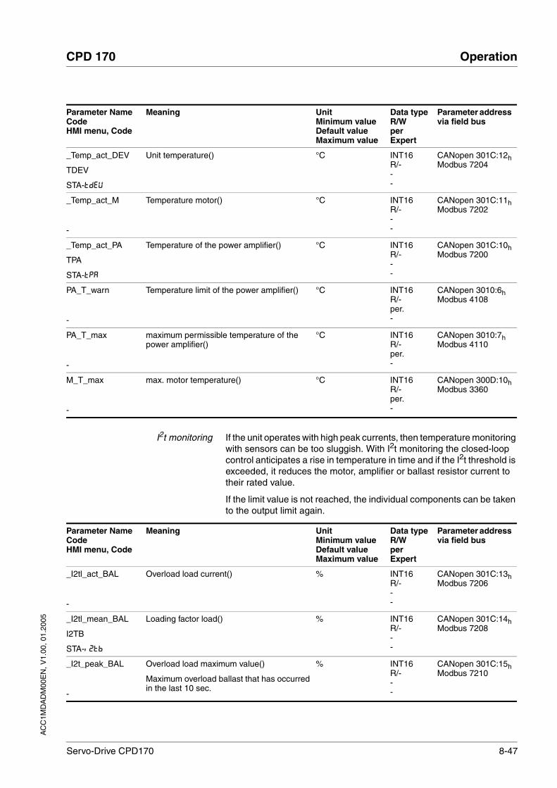
AC
C1M
DA
DM
00E
N, V
1.00
, 01.
2005
CPD 170 Operation
Servo-Drive CPD170 8-47
I2t monitoring If the unit operates with high peak currents, then temperature monitoring with sensors can be too sluggish. With I2t monitoring the closed-loop control anticipates a rise in temperature in time and if the I2t threshold is exceeded, it reduces the motor, amplifier or ballast resistor current to their rated value.
If the limit value is not reached, the individual components can be taken to the output limit again.
Parameter NameCodeHMI menu, Code
Meaning UnitMinimum valueDefault valueMaximum value
Data typeR/WperExpert
Parameter address via field bus
_Temp_act_DEV
TDEV
STA-TDEV
Unit temperature() °C INT16R/---
CANopen 301C:12hModbus 7204
_Temp_act_M
-
Temperature motor() °C INT16R/---
CANopen 301C:11hModbus 7202
_Temp_act_PA
TPA
STA-TPA
Temperature of the power amplifier() °C INT16R/---
CANopen 301C:10hModbus 7200
PA_T_warn
-
Temperature limit of the power amplifier() °C INT16R/-per.-
CANopen 3010:6hModbus 4108
PA_T_max
-
maximum permissible temperature of the power amplifier()
°C INT16R/-per.-
CANopen 3010:7hModbus 4110
M_T_max
-
max. motor temperature() °C INT16R/-per.-
CANopen 300D:10hModbus 3360
Parameter NameCodeHMI menu, Code
Meaning UnitMinimum valueDefault valueMaximum value
Data typeR/WperExpert
Parameter address via field bus
_I2tl_act_BAL
-
Overload load current() % INT16R/---
CANopen 301C:13hModbus 7206
_I2tl_mean_BAL
I2TB
STA-i2TB
Loading factor load() % INT16R/---
CANopen 301C:14hModbus 7208
_I2t_peak_BAL
-
Overload load maximum value()
Maximum overload ballast that has occurred in the last 10 sec.
% INT16R/---
CANopen 301C:15hModbus 7210

8-48 Servo-Drive CPD170
Operation CPD 170
AC
C1M
DA
DM
00E
N, V
1.00
, 01.
2005
Following error monitoring If the reference value changes quickly, the drive cannot follow directly. There is a transient regulation discrepancy. If the setpoint and the actual position are widely different, the movement operation is discontinued by a lag error signal. In order to prevent this regulation discrepancy from switching off the power amplifier, you can set the lag error limiting value. The maximum permissible contouring error can be set with the parame-ter SPV_p_maxDiff.
The maximum control deviation occurring during operation can be de-termined with the parameter _p_DifPeakand compared with the ma-ximum permissible contouring error.
The error class for a lag error can also be changed, see also8.6.1 “Mo-nitoring functions“.
_I2t_act_PA
-
Overload power amplifier current() % INT16R/---
CANopen 301C:16hModbus 7212
_I2t_mean_PA
I2TP
STA-i2TP
Loading factor power amplifier () % INT16R/---
CANopen 301C:17hModbus 7214
_I2t_peak_PA
-
Overload power amplifier maximum value()
Maximum overload power amplifier that has occurred in the last 10 sec.
% INT16R/---
CANopen 301C:18hModbus 7216
_I2t_act_M
-
Overload motor current() % INT16R/---
CANopen 301C:19hModbus 7218
_I2t_mean_M
I2TM
STA-i2TM
Loading factor motor() % INT16R/---
CANopen 301C:1AhModbus 7220
_I2t_peak_M
-
Overload motor maximum value()
Maximum overload motor that has occurred in the last 10 sec.
% INT16R/---
CANopen 301C:1BhModbus 7222
Parameter NameCodeHMI menu, Code
Meaning UnitMinimum valueDefault valueMaximum value
Data typeR/WperExpert
Parameter address via field bus
Parameter NameCodeHMI menu, Code
Meaning UnitMinimum valueDefault valueMaximum value
Data typeR/WperExpert
Parameter address via field bus
_p_DifPeak
-
Value of max. reached lag errors of the posi-tion regulator()
The lag error is the current position regula-tion offset minus the speed-dependent posi-tion regulation offset.Further information see SPV_p_maxDiff.A write operation resets the value again.
U0.00000.0000429496.7295
Field bus004294967295
UINT32R/W--
CANopen 3011:FhModbus 4382

AC
C1M
DA
DM
00E
N, V
1.00
, 01.
2005
CPD 170 Operation
Servo-Drive CPD170 8-49
Monitoring parameters The unit and operating status can be monitored with various objects.
_p_dif
PDIF
STA-PDiF
Current regulation variation of the position regulator()
in 1/10000 revolutions. Actual rule deviation between setpoint and actual position, i.e. without consideration of any dynamic components.
Note: different from SPV_p_maxDiff
U-214748.36480.0000214748.3647
Field bus-2147483648
2147483647
INT32R/---
CANopen 60F4:0hModbus 7716
SPV_p_maxDiff
-
Max. permissible contouring error of position regulator()
The lag error is the current position regula-tion offset minus the speed-dependent posi-tion regulation offset. Actually, only the position offset caused by the moment requirements is still referred to for lag error monitoring.
U0.00011.00004.0000
Field bus11000040000
UINT32R/Wper.-
CANopen 6065:0hModbus 4636
Parameter NameCodeHMI menu, Code
Meaning UnitMinimum valueDefault valueMaximum value
Data typeR/WperExpert
Parameter address via field bus
Parameter NameCodeHMI menu, Code
Meaning UnitMinimum valueDefault valueMaximum value
Data typeR/WperExpert
Parameter address via field bus
_SigActive
-
Current state of the monitoring signals()
Meaning see _SigLatched
UINT32R/---
CANopen 301C:7hModbus 7182

8-50 Servo-Drive CPD170
Operation CPD 170
AC
C1M
DA
DM
00E
N, V
1.00
, 01.
2005
_SigLatched
SIGS
STA-SiGS
Stored state of the monitoring signals()
Signal state:0: not enabled1: enabled
Bit assignment:Bit0: general errorBit1: limit switch (LIMP/LIMN/REF)Bit2 software limit switch (SW-LIMP/SW_LIMN)Bit3. Quick Stop via field busBit4. Inputs for safe standstill are 0Bit6. Fault field bus RS485Bit7. Fault field bus CANBit8. Fault field bus ProfibusBit9. Fault pulse input (frequency too high)Bit10. Fault in current operating modeBit14. Low voltage DC busBit15. Excess voltage DC busBit16. Power amplifier supply voltage faulty (phase fault, earth fault)Bit17. Connection to motor faultyBit18. Motor excess current/short circuitBit19. Fault motor encoder or connectionBit20. Under voltage 24 Volt supplyBit21. Temperature too high (power amplifier, ballast, motor)Bit22. Lag errorBit23. Maximum speed exceededBit24. Inputs for safe standstill are differentBit29. Fault in EEPROMBit30. Fault system run-up (hardware or parameter fault)Bit31. Internal system fault (e.g. Watchdog)
UINT32R/---
CANopen 301C:8hModbus 7184
_WarnActive
-
Active warnings bit-coded()
Meaning of Bits see _WarnLatched
UINT16R/---
CANopen 301C:BhModbus 7190
_WarnLatched
WRNS
STA-WRNS
Stored warnings bit-coded()
Stored warning bits are erased in the event of a FaultReset.Signal state:0: not enabled1: enabled
Bit assignment:Bit 0: general warningBit 1: temperature of power amplifier highBit 2: temperature of motor highBit 3: reservedBit 4: power amplifier overloadedBit 5: motor overloadedBit 6: ballast resistor overloadedBit 7: CAN warningBit 8: motor encoder warningBit 9: RS485 protocol warningBit 10: SAFE_DISABLE_A and/or SAFE_DISABLE_BBit 11: DC Bus undervoltage
UINT16R/---
CANopen 301C:ChModbus 7192
Parameter NameCodeHMI menu, Code
Meaning UnitMinimum valueDefault valueMaximum value
Data typeR/WperExpert
Parameter address via field bus
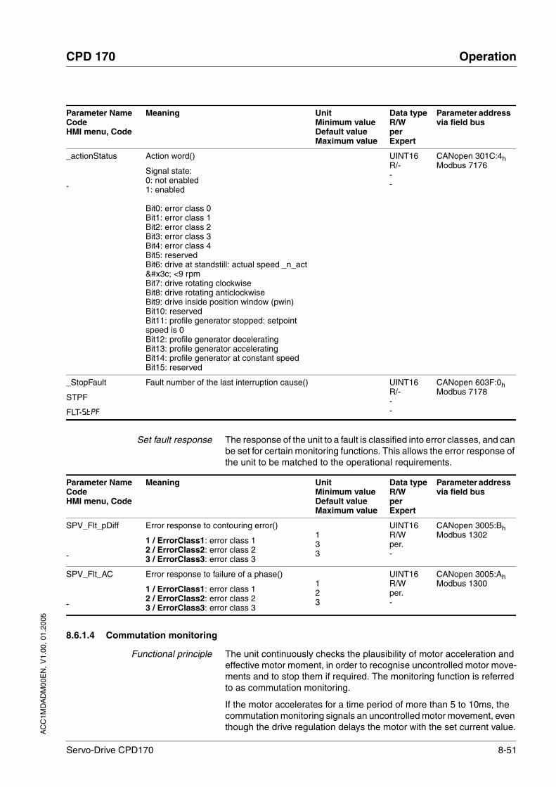
AC
C1M
DA
DM
00E
N, V
1.00
, 01.
2005
CPD 170 Operation
Servo-Drive CPD170 8-51
Set fault response The response of the unit to a fault is classified into error classes, and can be set for certain monitoring functions. This allows the error response of the unit to be matched to the operational requirements.
8.6.1.4 Commutation monitoring
Functional principle The unit continuously checks the plausibility of motor acceleration and effective motor moment, in order to recognise uncontrolled motor move-ments and to stop them if required. The monitoring function is referred to as commutation monitoring.
If the motor accelerates for a time period of more than 5 to 10ms, the commutation monitoring signals an uncontrolled motor movement, even though the drive regulation delays the motor with the set current value.
_actionStatus
-
Action word()
Signal state:0: not enabled1: enabled
Bit0: error class 0Bit1: error class 1Bit2: error class 2Bit3: error class 3Bit4: error class 4Bit5: reservedBit6: drive at standstill: actual speed _n_act < <9 rpmBit7: drive rotating clockwiseBit8: drive rotating anticlockwiseBit9: drive inside position window (pwin)Bit10: reservedBit11: profile generator stopped: setpoint speed is 0Bit12: profile generator deceleratingBit13: profile generator acceleratingBit14: profile generator at constant speedBit15: reserved
UINT16R/---
CANopen 301C:4hModbus 7176
_StopFault
STPF
FLT-STPF
Fault number of the last interruption cause() UINT16R/---
CANopen 603F:0hModbus 7178
Parameter NameCodeHMI menu, Code
Meaning UnitMinimum valueDefault valueMaximum value
Data typeR/WperExpert
Parameter address via field bus
Parameter NameCodeHMI menu, Code
Meaning UnitMinimum valueDefault valueMaximum value
Data typeR/WperExpert
Parameter address via field bus
SPV_Flt_pDiff
-
Error response to contouring error()
1 / ErrorClass1: error class 12 / ErrorClass2: error class 23 / ErrorClass3: error class 3
133
UINT16R/Wper.-
CANopen 3005:BhModbus 1302
SPV_Flt_AC
-
Error response to failure of a phase()
1 / ErrorClass1: error class 12 / ErrorClass2: error class 23 / ErrorClass3: error class 3
123
UINT16R/Wper.-
CANopen 3005:AhModbus 1300
8-52 Servo-Drive CPD170
Operation CPD 170
AC
C1M
DA
DM
00E
N, V
1.00
, 01.
2005
The unit shows flashing on HMI 5603 (error class 4)
Causes of error Uncontrolled motor movements can be traced back to the following cau-ses:
• The motor phases U, V, W are connected to the unit incorrectly, i.e. each offset by 120° , e.g. U with V, V with W, W with U.
• Faulty or interfered evaluation of the rotor position by a faulty posi-tion encoder on the motor, interfered sensor signals or defective position acquisition in the unit.
In addition, the unit can recognise a commutation error in the following cases, since the above-mentioned plausibility conditions could equally apply:
• The motor receives an external torque that is greater than the speci-fied maximum torque. The external force causes it to accelerate.
• The motor is manually moved either in the direction of the motor moment or in the opposite direction, whilst the drive regulation is active.
• The motor is moved to a mechanical stop.
• Speed and position control loop are set to be extremely unstable.
Setting parameters
8.6.1.5 Earth fault monitoring
Functional principle The unit checks the motor phases for earth fault. An earth fault of one or more motor phases is detected. An earth fault of the DC bus or the bal-last resistor is not detected.
Setting parameters
WARNING!Danger of injury and damage to system components by unex-pected movement!
Disabling monitoring functions increases the risk of an unexpected movement.
• Use the monitoring functions.Failure to follow these instructions can result in death or serious injury.
Parameter NameCodeHMI menu, Code
Meaning UnitMinimum valueDefault valueMaximum value
Data typeR/WperExpert
Parameter address via field bus
SPVcommutat
-
Monitoring commutation()
0 / off: off1 / on: on (default)
011
UINT16R/Wper.-
CANopen 3005:5hModbus 1290
WARNING!Danger of injury and damage to system components by unex-pected movement!
Disabling monitoring functions increases the risk of an unexpected movement.
• Use the monitoring functions.Failure to follow these instructions can result in death or serious injury.

AC
C1M
DA
DM
00E
N, V
1.00
, 01.
2005
CPD 170 Operation
Servo-Drive CPD170 8-53
8.6.1.6 Mains phase monitoring
Functional principle The unit checks the mains phases for failure. The failure of a mains phase is detected with 3-phase units.
Setting parameters
Parameter NameCodeHMI menu, Code
Meaning UnitMinimum valueDefault valueMaximum value
Data typeR/WperExpert
Parameter address via field bus
SPV_EarthFlt
-
Earth fault monitoring()
0 / off: Off1 / on: On (default)
In exceptional cases it may require disabling, e.g.:- parallel connection of multiple units- operation on an IT network- long motor linesOnly disable the monitoring if it is triggered when not wanted
011
UINT16R/Wper.expert
CANopen 3005:10hModbus 1312
WARNING!Danger of injury and damage to system components by unex-pected movement!
Disabling monitoring functions increases the risk of an unexpected movement.
• Use the monitoring functions.Failure to follow these instructions can result in death or serious injury.
Parameter NameCodeHMI menu, Code
Meaning UnitMinimum valueDefault valueMaximum value
Data typeR/WperExpert
Parameter address via field bus
SPV_MainsVolt
-
Monitor mains phases()
0 / off: Off1 / on: On (default)
In exceptional cases it may require disabling, e.g.:- when powered via the DC bus
011
UINT16R/Wper.expert
CANopen 3005:FhModbus 1310
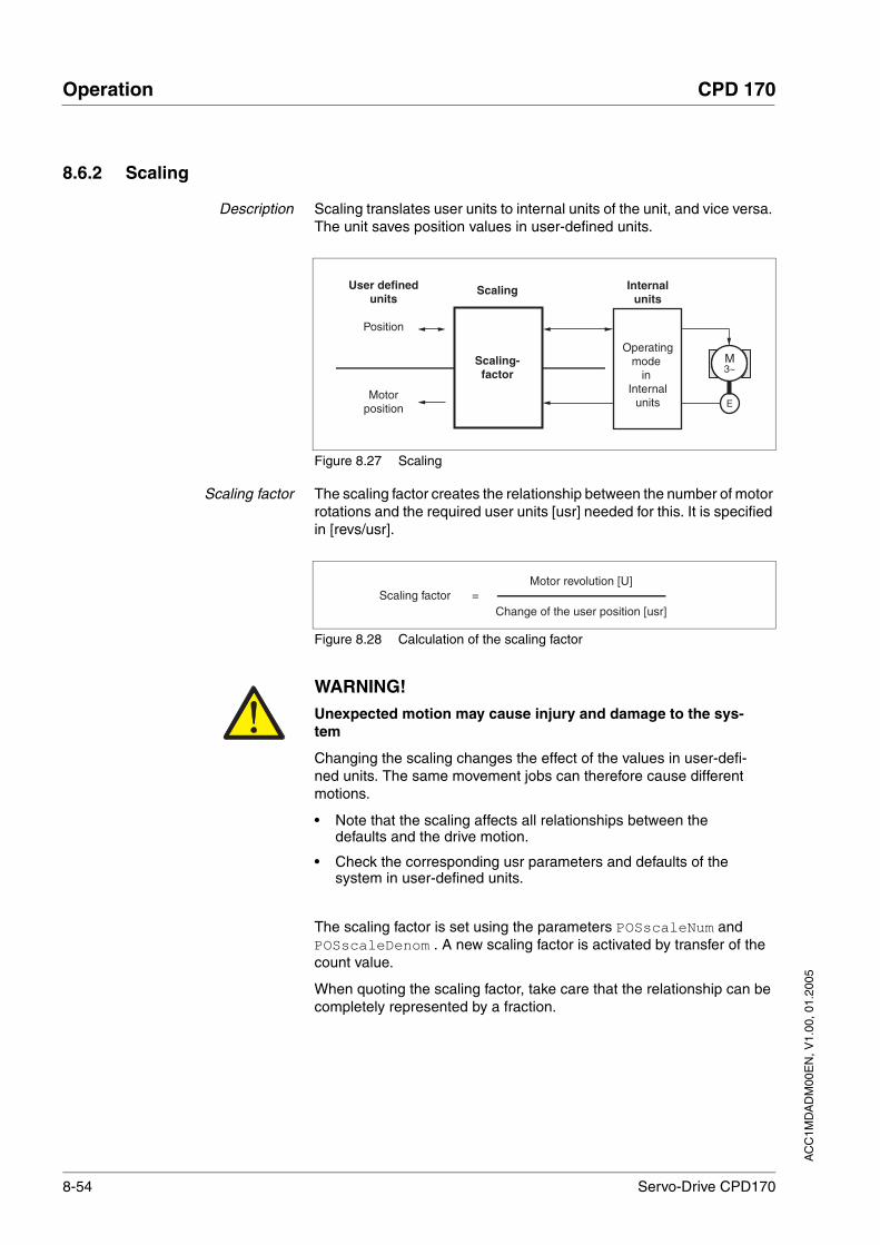
8-54 Servo-Drive CPD170
Operation CPD 170
AC
C1M
DA
DM
00E
N, V
1.00
, 01.
2005
8.6.2 Scaling
Description Scaling translates user units to internal units of the unit, and vice versa. The unit saves position values in user-defined units.
Figure 8.27 Scaling
Scaling factor The scaling factor creates the relationship between the number of motor rotations and the required user units [usr] needed for this. It is specified in [revs/usr].
Figure 8.28 Calculation of the scaling factor
The scaling factor is set using the parameters POSscaleNum and POSscaleDenom . A new scaling factor is activated by transfer of the count value.
When quoting the scaling factor, take care that the relationship can be completely represented by a fraction.
Position
Motorposition
Internalunits
User defined units
E
Scaling-factor
M3~
Scaling
Operatingmode
in Internal
units
Scaling factorChange of the user position [usr]
=Motor revolution [U]
WARNING!Unexpected motion may cause injury and damage to the sys-tem
Changing the scaling changes the effect of the values in user-defi-ned units. The same movement jobs can therefore cause different motions.
• Note that the scaling affects all relationships between the defaults and the drive motion.
• Check the corresponding usr parameters and defaults of the system in user-defined units.
Failure to follow these instructions can result in death or serious injury.

AC
C1M
DA
DM
00E
N, V
1.00
, 01.
2005
CPD 170 Operation
Servo-Drive CPD170 8-55
Value change of the scaling factor is only possible with inactive output stage. Value statements in user units are transformed to internal units when activating the output stage, simultaneously checking the value range.
Examples The minimal scaling is that which causes a change in the motor position of 1/131072 U when changing by 1 usr.
There are 3 cases for the setting of the user units.
• Scaling corresponds to default scaling1 U = 16384 user units
=> every 8th motor position can be approached.
• Scaling corresponds to default scaling1 U = 131072 user units
=> every motor position can be approached.
• Scaling is less than the default scaling1 U = 4096 user units
=> every 32nd motor position can be approached.
To retain the same positioning movement of the motor after changing the scaling factor, the following persistent parameters must be adapted in addition to the user-defined values: HMoutdisusr, HMdisusr, HMp_homeusr, HMsrchdisusr, JOGstepusr, SPVswLimPusr and SPVswLimNusr.
If the parameters are not adjusted, this can cause problems such an er-ror during the reference movement, because the distance to the swit-ching edge of the limit or reference switch is no longer sufficient for safely leaving the switching range.
CodeHMI-CodeParameter Name
Description UnitMinimum valueDefault valueMaximum value
Data typeR/WperExpert
Parameter address via field bus
POSscaleNum
-
Numerator of the position scaling factor()
Specification of scaling factor:
motor revolutions [U]----------------------------------------------------------change of user position [usr]
A new scaling is imported when the numera-tor value is transferred
User-defined limit values may be reduced as a result of the calculation of an internal sys-tem factor
U112147483647
INT32R/Wper.-
CANopen 3006:8hModbus 1552
POSscaleDenom
-
Denominator of the position scaling factor()
Description see count (POSscaleNum)
Acceptance of a new scaling factor is by transfer of the numerator
usr1163842147483647
INT32R/Wper.-
CANopen 3006:7hModbus 1550

8-56 Servo-Drive CPD170
Operation CPD 170
AC
C1M
DA
DM
00E
N, V
1.00
, 01.
2005
If the existing unit is replaced by this unit, and if the same positioning orders are to be used, then the scaling is to be set in accordance with the settings used previously.
Example 1 Positioning of 1111 user-defined units is to correspond to 3 motor revo-lutions. This gives:
If you carry out a relative positioning operation of 900 user-defined units now, the motor will move 900 usr * 3/1111 rev/usr = 2.4302 revolutions.
Example 2 Calculation of the scaling factor in length units: 1 motor revolution cor-responds to a path of 100 mm. Every user-defined unit [usr] should cor-respond to one 0.01 mm step.
This gives: 1 usr = 0.01 mm * 1 rev/100 mm = 1/10000 rev.
Example 3 Setting the positioning in 1/1000 rad1rad = 1 U/(2*π)π = 3,1416 (rounded)
User value = 1 usr
Unit value = 1/(2*π*1000) U
Scaling factor = 3 U
1111 usr
1 U
10000 usr
Scaling factor =
Scaling factor =1 U
2*3,1416*1000 usr
1 U
6283,2 usr=
10 U
62832 usr=

AC
C1M
DA
DM
00E
N, V
1.00
, 01.
2005
CPD 170 Operation
Servo-Drive CPD170 8-57
8.6.3 Movement profile
Profile generator Target position and final speed are input values to be entered by the user. The profile generator uses these values to calculate a motion pro-file dependent on the selected operating mode.
The initial values of the profile generator and the addable jolt limiting are transformed into a motor movement by the drive regulator.
The acceleration and deceleration behaviour of the motor can be descri-bed by the ramp function of the profile generator. The nominal sizes of the ramp functions are the ramp shape and the ramp steepness.
Ramp shape A linear ramp for the acceleration and deceleration phases is available as the ramp shape. The profile settings are valid for both directions of movement of the drive.
Ramp gradient The steepness of the ramp determines the speed changes of the motor per unit time. It can be set, for the acceleration ramp, by using the para-meter RAMPacc and the deceleration ramp by using RAMPdecel.
Figure 8.29 Acceleration and deceleration ramps
t
v RAMPn_maxPPn_target
PVn_target
RAMPacc RAMPdecel
Parameter NameCodeHMI menu, Code
Meaning UnitMinimum valueDefault valueMaximum value
Data typeR/WperExpert
Parameter address via field bus
RAMPacc
-
Profile generator acceleration() r.p.m*s306003000000
UINT32R/Wper.-
CANopen 6083:0hModbus 1556
RAMPdecel
-
Profile generator deceleration() r.p.m*s7507503000000
UINT32R/Wper.-
CANopen 6084:0hModbus 1558

8-58 Servo-Drive CPD170
Operation CPD 170
AC
C1M
DA
DM
00E
N, V
1.00
, 01.
2005
RAMPn_max
-
Profile generator deceleration()
Parameters are effective in the following operating modes:- point-to-point- profile velocity- homing- jog
If a higher setpoint speed is set on one of these operating modes it will be automati-cally limited to this value.This makes it simple to conduct a commis-sioning with limited speed.
r.p.m.601200013200
UINT16R/Wper.-
CANopen 607F:0hModbus 1554
Parameter NameCodeHMI menu, Code
Meaning UnitMinimum valueDefault valueMaximum value
Data typeR/WperExpert
Parameter address via field bus

AC
C1M
DA
DM
00E
N, V
1.00
, 01.
2005
CPD 170 Operation
Servo-Drive CPD170 8-59
8.6.4 Quick Stop
"Quick Stop" is a fast braking function which stops the motor as a result of a fault of error class 1 and 2 or by a software stop.
In the event of a fault category 1 fault response, the power amplifier re-mains on. In the case of error class 2, the output stage switches off after the drive is at a standstill.
Maximum current The unit absorbs the excess braking energy. If the DC bus voltage ex-ceeds the permissible limit the output stage switches off and the unit si-gnals "DC bus overvoltage". The motor runs down without braking.
The current for the moment ramp should be set so that the drive comes to a standstill with the required delay.
If the unit switches off frequently with "Quick Stop" with "DC bus over-voltage", then the maximum braking current should be reduced, the drive load should be reduced or an external ballast resistor should be in-stalled.
Quick Stop reset A "Quick Stop" must be acknowledged with the error confirmation.
If the "Quick Stop" is actuated by the limit switch signals LIMN or LIMP, the drive can be moved back into the movement area by the jog opera-tion, see page 8-14.
WARNING!Risk of injury and damage to system components by unbraked motor.
An insufficient ballast resistor causes overvoltage on the DC bus and switches off the power amplifier. The motor is no longer actively braked.
• Make sure that the ballast resistor is sufficiently dimensioned.
• Check the setting of the parameter for the ballast.
• Check the temperature of the ballast resistor by conducting a test run under the most critical conditions.
• During the test make sure that at higher mains voltage there is less reserve in the capacitors on the DC bus.
Failure to follow these instructions can result in death or serious injury.
Parameter NameCodeHMI menu, Code
Meaning UnitMinimum valueDefault valueMaximum value
Data typeR/WperExpert
Parameter address via field bus
LIM_I_maxQSTP
LIQS
SET-LiQS
Current limiting for Quick Stop()
Max. current during braking via torque ramp resulting from an error with error class 1 or 2, and when a software stop is triggered
Maximum and default value setting depend on the motor and power amplifier
Apk---
UINT16R/Wper.-
CANopen 3011:5hModbus 4362
8-60 Servo-Drive CPD170
Operation CPD 170
AC
C1M
DA
DM
00E
N, V
1.00
, 01.
2005
8.6.5 Halt
The "Halt" function can be set from any source (commissioning soft-ware, field bus, input signal HALT). This is independent of the control mode which has been set during the initial setup.""
The "Halt" function brakes the motor with a moment ramp The parame-ter LIM_I_maxHalt specifies the current for the moment ramp.
After drive standstill an internal position compensation is run, the posi-tion control is enabled and the motor is stopped with the power amplifier active.
The further processing takes place by the retraction of all set HALT-si-gnals and by activation of a new movement order.
Maximum current The unit absorbs the excess braking energy. If the DC bus voltage ex-ceeds the permissible limit the output stage switches off and the unit si-gnals "DC bus overvoltage". The motor runs down without braking.
The current for the moment ramp should be set so that the drive comes to a standstill with the required delay.
Parameter NameCodeHMI menu, Code
Meaning UnitMinimum valueDefault valueMaximum value
Data typeR/WperExpert
Parameter address via field bus
LIM_I_maxHalt
LIHA
SET-LihA
Current limiting for Halt()
Max. current during braking after Halt or ter-mination of an operating mode.
Maximum and default value setting depend on motor and power amplifier
Apk---
UINT16R/Wper.-
CANopen 3011:6hModbus 4364
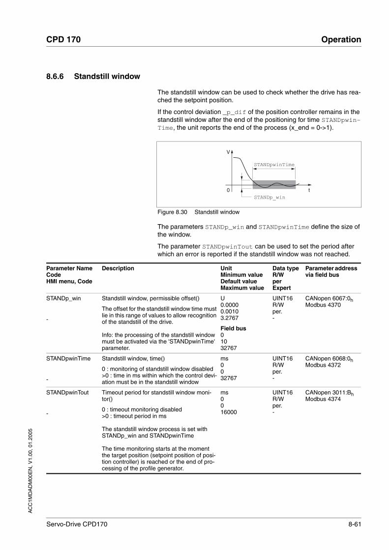
AC
C1M
DA
DM
00E
N, V
1.00
, 01.
2005
CPD 170 Operation
Servo-Drive CPD170 8-61
8.6.6 Standstill window
The standstill window can be used to check whether the drive has rea-ched the setpoint position.
If the control deviation _p_dif of the position controller remains in the standstill window after the end of the positioning for time STANDpwin-Time, the unit reports the end of the process (x_end = 0->1).
Figure 8.30 Standstill window
The parameters STANDp_win and STANDpwinTime define the size of the window.
The parameter STANDpwinTout can be used to set the period after which an error is reported if the standstill window was not reached.
V
0 t
STANDpwinTime
STANDp_win
Parameter NameCodeHMI menu, Code
Description UnitMinimum valueDefault valueMaximum value
Data typeR/WperExpert
Parameter address via field bus
STANDp_win
-
Standstill window, permissible offset()
The offset for the standstill window time must lie in this range of values to allow recognition of the standstill of the drive.
Info: the processing of the standstill window must be activated via the 'STANDpwinTime' parameter.
U0.00000.00103.2767
Field bus01032767
UINT16R/Wper.-
CANopen 6067:0hModbus 4370
STANDpwinTime
-
Standstill window, time()
0 : monitoring of standstill window disabled>0 : time in ms within which the control devi-ation must be in the standstill window
ms0032767
UINT16R/Wper.-
CANopen 6068:0hModbus 4372
STANDpwinTout
-
Timeout period for standstill window moni-tor()
0 : timeout monitoring disabled>0 : timeout period in ms
The standstill window process is set with STANDp_win and STANDpwinTime
The time monitoring starts at the moment the target position (setpoint position of posi-tion controller) is reached or the end of pro-cessing of the profile generator.
ms0016000
UINT16R/Wper.-
CANopen 3011:BhModbus 4374
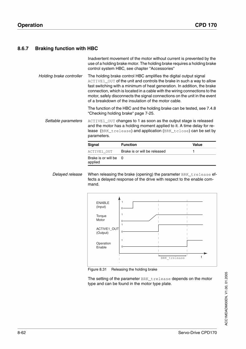
8-62 Servo-Drive CPD170
Operation CPD 170
AC
C1M
DA
DM
00E
N, V
1.00
, 01.
2005
8.6.7 Braking function with HBC
Inadvertent movement of the motor without current is prevented by the use of a holding brake motor. The holding brake requires a holding brake control system HBC, see chapter "Accessories"
Holding brake controller The holding brake control HBC amplifies the digital output signal ACTIVE1_OUT of the unit and controls the brake in such a way to allow fast switching with a minimum of heat generation. In addition, the brake connection, which is located in a cable with the wiring connections to the motor, safely disconnects the signal connections on the unit in the event of a breakdown of the insulation of the motor cable.
The function of the HBC and the holding brake can be tested, see 7.4.8 “Checking holding brake“ page 7-25.
Settable parameters ACTIVE1_OUT changes to 1 as soon as the output stage is released and the motor has a holding moment applied to it. A time delay for re-lease (BRK_trelease) and application (BRK_tclose) can be set by parameters.
Delayed release When releasing the brake (opening) the parameter BRK_trelease ef-fects a delayed response of the drive with respect to the enable com-mand.
Figure 8.31 Releasing the holding brake
The setting of the parameter BRK_trelease depends on the motor type and can be found in the motor type plate.
Signal Function Value
ACTIVE1_OUT Brake is or will be released 1
Brake is or will be applied
0
ENABLE(Input)
TorqueMotor
ACTIVE1_OUT(Output)
OperationEnable
t
0
10
1
0
1
BRK_trelease
0
1
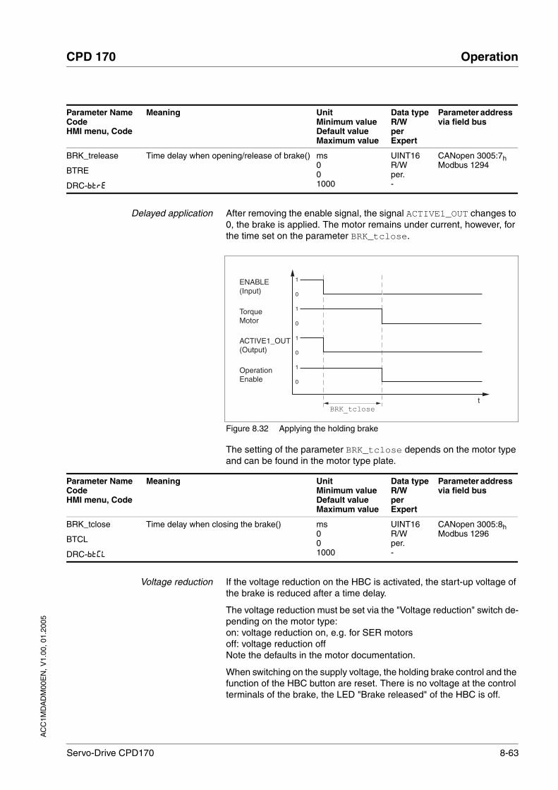
AC
C1M
DA
DM
00E
N, V
1.00
, 01.
2005
CPD 170 Operation
Servo-Drive CPD170 8-63
Delayed application After removing the enable signal, the signal ACTIVE1_OUT changes to 0, the brake is applied. The motor remains under current, however, for the time set on the parameter BRK_tclose.
Figure 8.32 Applying the holding brake
The setting of the parameter BRK_tclose depends on the motor type and can be found in the motor type plate.
Voltage reduction If the voltage reduction on the HBC is activated, the start-up voltage of the brake is reduced after a time delay.
The voltage reduction must be set via the "Voltage reduction" switch de-pending on the motor type:on: voltage reduction on, e.g. for SER motorsoff: voltage reduction offNote the defaults in the motor documentation.
When switching on the supply voltage, the holding brake control and the function of the HBC button are reset. There is no voltage at the control terminals of the brake, the LED "Brake released" of the HBC is off.
Parameter NameCodeHMI menu, Code
Meaning UnitMinimum valueDefault valueMaximum value
Data typeR/WperExpert
Parameter address via field bus
BRK_trelease
BTRE
DRC-BTRE
Time delay when opening/release of brake() ms001000
UINT16R/Wper.-
CANopen 3005:7hModbus 1294
ENABLE(Input)
TorqueMotor
ACTIVE1_OUT(Output)
OperationEnable
tBRK_tclose
1
0
0
1
0
1
0
1
Parameter NameCodeHMI menu, Code
Meaning UnitMinimum valueDefault valueMaximum value
Data typeR/WperExpert
Parameter address via field bus
BRK_tclose
BTCL
DRC-BTCL
Time delay when closing the brake() ms001000
UINT16R/Wper.-
CANopen 3005:8hModbus 1296

8-64 Servo-Drive CPD170
Operation CPD 170
AC
C1M
DA
DM
00E
N, V
1.00
, 01.
2005
8.6.8 Reversal of direction of rotation
The parameter POSdirOfRotat can be used to reverse the direction of rotation of the motor.
The limit switch that limits the working range with positive direction of ro-tation must be connected to LIMP. The limit switch that limits the wor-king range with negative direction of rotation must be connected to LIMN.
If the direction of rotation of the motor must be reversed, all parameter values can be imported unchanged except for the parameters for posi-tion processing with SinCos Multiturn.
By reversing the direction of rotation, the absolute position of the motor _p_absworkusr changes, which is read from the rotary encoder, and also the set position evaluated by the unit _p_actusr.
The direction of rotation should therefore be set at commissioning to the state which will be required later for the operation of this motor.
Parameter NameCodeHMI menu, Code
Meaning UnitMinimum valueDefault valueMaximum value
Data typeR/WperExpert
Parameter address via field bus
POSdirOfRotat
PROT
DRC-PRoT
Definition of the direction of rotation()
0 / clockwise / clw: clockwise1 / counter clockwise / cclw: anticlockwise
Meaning:The drive rotates clockwise at positive speeds when the motor shaft is viewed at the flange.
CAUTION: when using limit switches, after changing the setting the limit switch connec-tions must be changed over. The limit switch which is actuated by moving in jog mode in a positive direction must be connected to the input LIMP, and vice versa.
001
UINT16R/Wper.-
CANopen 3006:ChModbus 1560
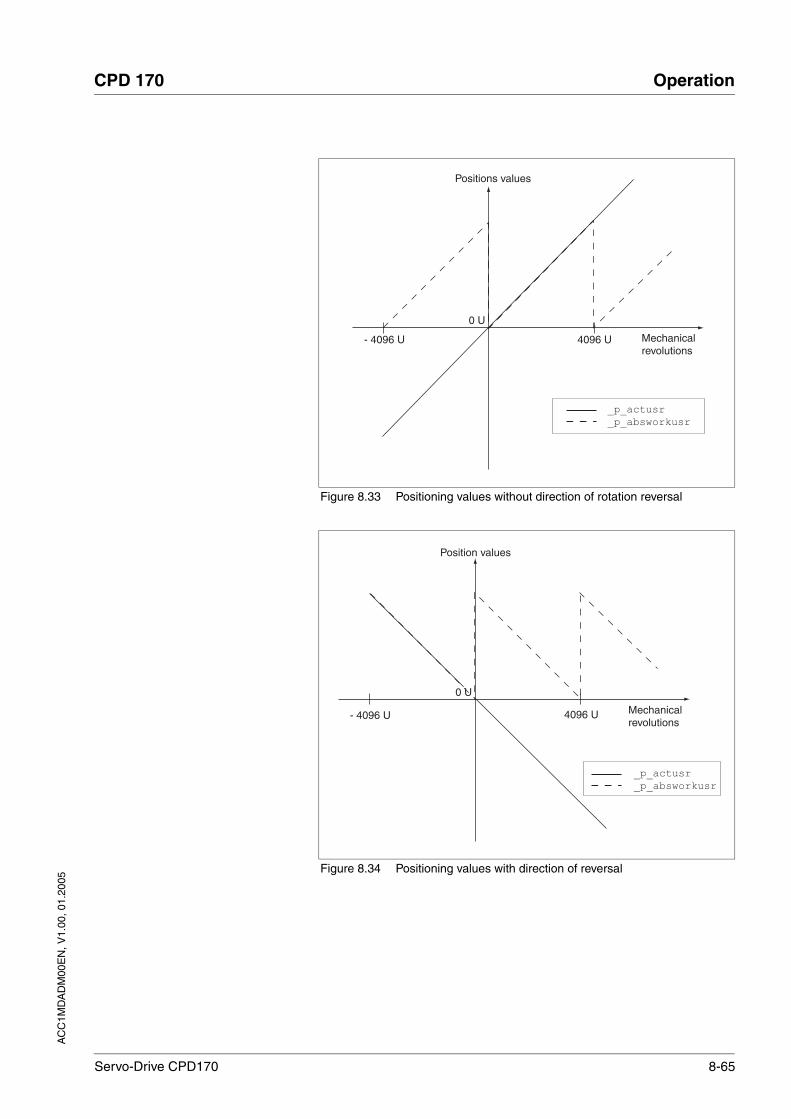
AC
C1M
DA
DM
00E
N, V
1.00
, 01.
2005
CPD 170 Operation
Servo-Drive CPD170 8-65
Figure 8.33 Positioning values without direction of rotation reversal
Figure 8.34 Positioning values with direction of reversal
0 U0 U0 U
Mechanicalrevolutions
4096 U- 4096 U
_p_actusr _p_absworkusr
Positions values
4096 U
0 U0 U0 U
Mechanicalrevolutions
- 4096 U
_p_actusr _p_absworkusr
Position values

8-66 Servo-Drive CPD170
Operation CPD 170
AC
C1M
DA
DM
00E
N, V
1.00
, 01.
2005
8.6.9 Analogue signals
Analog inputs The analogue inputs allow analogue input voltages between -10V and +10V to be read in. The current voltage value on ANA1+ can be read using the parameter ANA1_act
Parameter NameCodeHMI menu, Code
Meaning UnitMinimum valueDefault valueMaximum value
Data typeR/WperExpert
Parameter address via field bus
ANA1_act
A1AC
STA-A1AC
Voltage value analogue input ANA1() mV-10000
10000
INT16R/---
CANopen 3009:1hModbus 2306
ANA1_I_scale
A1IS
SET-A1iS
Scaling ANA1 for set current at +10V()
Default value is the lesser value from ImaxM or ImaxPA
With a neg. sign an inversion of the evalua-tion of the analogue signal can be conducted
Apk-300.003.00300.00
Field bus-3000030030000
INT16R/Wper.-
CANopen 3020:3hModbus 8198
ANA1_n_scale
A1NS
SET-A1NS
Scaling ANA1 for reference speed at +10V()
The internal max. speed is limited to the cur-rent setting in CTRL_n_max
With neg. sign an inversion of the evaluation of the analogue signal can be conducted
r.p.m.-30000300030000
INT16R/Wper.-
CANopen 3021:3hModbus 8454
ANA1_win
A1WN
SET-A1WN
Zero voltage window on analogue input ANA1()
Absolute value up to which an input voltage value is interpreted as 0 VExample: setting 20 mV->range of -20 .. +20mV is interpreted as 0mV
mV001000
UINT16R/Wper.-
CANopen 3009:9hModbus 2322
ANA2_act
A2AC
STA-A2AC
Voltage value analogue input ANA2() mV-10000
10000
INT16R/---
CANopen 3009:5hModbus 2314
ANA2LimMode
A2MO
DRC-A2Mo
Selection of limit by ANA2()
0 / none: no limit1 / Current Limitation / CURR: limit current setpoint at current controller (limit value at 10 V in ANA2_I_max)2 / Speed Limitation / SPED: limit of set-point speed value at speed controller (limit value at 10V in ANA2_n_max)
002
UINT16R/Wper.-
CANopen 3012:BhModbus 4630
ANA2_I_max
A2IM
DRC-A2iM
Scaling for current limiting by ANA2 at +10V()
Default value is lower value from ImaxM or ImaxPA
Apk0.000.00300.00
Field bus0
30000
UINT16R/Wper.-
CANopen 3012:ChModbus 4632

AC
C1M
DA
DM
00E
N, V
1.00
, 01.
2005
CPD 170 Operation
Servo-Drive CPD170 8-67
8.6.10 Restoring default values
8.6.10.1 Restore status after "Initial Setup"
The parameter PARuserReset is used to restore the status after "Initial Setup". All parameter values are reset to default values, with the excep-tion of the communication parameters, the control mode and the logic le-vel.
All the user set parameters will be lost if no back-up has been made onto the data carrier in the commissioning software.
8.6.10.2 Restore factory settings
The parameter PARfactorySet is used to restore the factory settings. All parameter values are reset to the default values.
Remove the connection to the field bus in order to avoid conflicts by simultaneous intervention.
Factory setting via HMI Set DRC and then FCS on the HMI and confirm your selection with yes.
All parameter values are reset to the default values. See "Initial Setup", page 7-10The new settings only become effective after switching off and switching on the unit again.
ANA2_n_max
A2NM
DRC-A2NM
Scaling for speed limiting by ANA2 at +10V()
Default value is maximum motor speed M_n_max.
rpm500
30000
UINT16R/Wper.-
CANopen 3012:DhModbus 4634
Parameter NameCodeHMI menu, Code
Meaning UnitMinimum valueDefault valueMaximum value
Data typeR/WperExpert
Parameter address via field bus
Parameter NameCodeHMI menu, Code
Meaning UnitMinimum valueDefault valueMaximum value
Data typeR/WperExpert
Parameter address via field bus
PARuserReset
-
Resetting the user parameters()
1: set user parameters to default values.All parameters are reset except:- communications parameters- device control- logic level
001
UINT16R/W--
CANopen 3004:8hModbus 1040
Parameter NameCodeHMI menu, Code
Meaning UnitMinimum valueDefault valueMaximum value
Data typeR/WperExpert
Parameter address via field bus

8-68 Servo-Drive CPD170
Operation CPD 170
AC
C1M
DA
DM
00E
N, V
1.00
, 01.
2005
Factory settings via commissioningsoftware
The factory settings are set via the menu points Configuration => Fac-tory Settings. All parameter values are reset to the default values. See "Initial Setup", page 7-10The new settings only become effective after switching off and switching on the unit again.
All the user set parameters will be lost if no back-up has been made onto the data carrier in the commissioning software.
8.6.10.3 Store the settings on the data medium
The unit settings can be saved to a data medium with the commissioning software. Load the configuration of the unit into the commissioning soft-ware with "Action - Transfer". Highlight the configuration and select "File - Export".
This also gives you the option of uploading a stored configuration into a unit of the same type. To do this select "File - Import" and load the desi-red configuration. Highlight the configuration and select "Action - Confi-gure".

AC
C1M
DA
DM
00E
N, V
1.00
, 01.
2005
CPD 170 Examples
Servo-Drive CPD170 9-1
9 Examples
9.1 Wiring for field bus control
Figure 9.1 Wiring for field bus controller operating mode, no Safe Stop
Procedure Unlock the front panel of the unit and open it.
Connect the earth terminal of the unit or the EMC plate to the eart-hing star point of the system.
W
U
V
PE
CN3.44
CN3.42
CN1.33
HBC
13/23
14/24
12/22
11/21
31/32
33/34
CN1.32
CN1.39
CN1.38
CN1.37
CN1.36
CN1.35
CN1.34
CN3.43
CN3.41
CN2
24V=
+BRAKE_OUT
-BRAKE_OUT
+BRAKE_OPEN
-BRAKE_OPEN
0VDC
+24VDC
CN4
CN5
Field bus
Motor Encoder
M3~
Position
Reference switches
Limit switches
Limit switches
Halt
REF
LIMN
LIMP
SAFE_DISABLE_B
SAFE_DISABLE_A
+24VDC
Field bus
CN1.23
CN1.22
CN1.21
1
2
0VDC
+24VDC
ACTIVE1_OUT
CAN_0V
CAN_L
CAN_H
Axis
9-2 Servo-Drive CPD170
Examples CPD 170
AC
C1M
DA
DM
00E
N, V
1.00
, 01.
2005
Connect the required terminal according to the sequence in Table 6.2 “Installation overview“. If a different connection sequence is fol-lowed terminals may be covered by other leads.
Follow the EMC requirements, see page 6-1.
Then lock the front panel.
Table 9.1 Procedure for the “Wiring for field bus control" example
9.2 Example of I/O parameter setting
The following examples show settings for the current control, speed con-trol and electronic gearbox modes. The control is local (I/O Mode), the set value preselection via the analogue inputs.
The parameter setting is performed on the HMI in the following examp-les.
Requirements:
• The motor shaft should not yet be coupled with the system mecha-nism.
• The analogue inputs are already wired up.
• The "Initial Setup" and the settings for the basic parameters and limiting values have been carried out during commissioning.
• The power amplifier is ready to switch on, i.e the status display on the HMI shows rdy.
Example A: current control Set the default operating mode to current control. Under DRC- / io-m select the entry CURR.
The set current should be preset to 200 mA at 10V using ANA1+ . Select under set- / a1is the value 0.20.
The motor speed should be limited using ANA2+ . Under DRC- / A2mo select the entry SPED.
The limit value of the motor speed should be 6000 rpm at 10 V. Under DRC- / A2nm select the value 6000.
Check the speed limiter.
Start the motor for this (input signal ENABLE). Set ANA1+ to maxi-mum and limit it using ANA2+. Read off the speed value under sta- / naCt.
Connection from Connection to from page
Motor phases 6-16
Mains power supply 6-26
Motor position encoder CN2 6-28
Holding brake controller (HBC) 6-31
24 VDC power supply CN3 6-33
Encoder A, B, I CN5 6-35
Field bus CANopen or MODBUS CN4 6-41, 6-43
Digital inputs/outputs CN1 6-45
AC
C1M
DA
DM
00E
N, V
1.00
, 01.
2005
CPD 170 Examples
Servo-Drive CPD170 9-3
Check the actual current value. Read off the value under sta- / iaCt.
Example B: speed control Set the default operating mode to speed control . Under DRC- / io-m select the entry Sped.
The motor speed should be preset to 1500 r.p.m. at 10V using ANA1+ . Select under set- / a1ns the value 1500.
The motor current should be limited using ANA2+ . Under DRC- / A2mo select the entry Curr.
The limit value of the motor current should be 0.5 A at 10 V. Under DRC- / A2im select the value 5.00.
Check the current limiter
Start the motor for this (input signal ENABLE). Set ANA1+ to maxi-mum and limit it using ANA2+. Read off the current value under sta- / iaCt.
Check the current speed. Read off the value under sta- / naCt.
Example C: electronic gear Set the default operating mode to electronic gear. Under DRC- / io-m select the entry gear
The gear ratio should be selected from a list of presets and should be 2000. Under SET- / GFAC select the value 2000.
Check the current speed. Start the motor for this (input signal ENABLE). Read off the value under sta- / naCt.
9.3 Wiring for “Safe Standstill”
Using the safety functions integrated in this product requires careful planning. For more information see 5.3 “"Safe Standstill safety function"“ on page 5-2.

9-4 Servo-Drive CPD170
Examples CPD 170
AC
C1M
DA
DM
00E
N, V
1.00
, 01.
2005

AC
C1M
DA
DM
00E
N, V
1.00
, 01.
2005
CPD 170 Diagnostics and troubleshooting
Servo-Drive CPD170 10-1
10 Diagnostics and troubleshooting
10.1 Service
If you cannot resolve the fault yourself please contact your appointed sa-les partner. Have the following details available:
• Type, identification number and serial number of the product (type plate)
• Type of fault (possibly with fault number)
• Previous and concurrent conditions
• Your own ideas regarding the cause of the fault
Include this information if you return the product for inspection or repair.
10.2 Error responses and error classes
Error response The product triggers an error response in the event of a fault. Depending upon the gravity of the fault, the unit responds in accordance with one of the following error classes:
DANGER!Electric shock, fire or explosion
• Only qualified personnel who are familiar with and understand the contents of this manual and the other relevant manuals are authorised to work on and with this drive system.
• Before working on the drive system:
– Switch off power to all terminals.
– Place a sign "DO NOT SWITCH ON" on the switch and lock to prevent switching on.
– Wait 6 minutes (for discharge of DC bus capacitors).
– Measure voltage between DC+ and DC- and check for <48V. (The DC bus LED is not a safe indication for absence of the DC bus voltage).
• Do not short-circuit DC bus or touch unshielded components or screws of the terminals with voltage present.
• Install all covers and close the housing doors before applying power.
• The motor generates voltage when the shaft is rotated. Lock the shaft of the motor to prevent rotation before starting work on the drive system.
• The system manufacturer is responsible for compliance with all applicable regulations relevant to earthing the drive system.
• Do not reach into the drive system (e.g. no pointed objects).Failure to follow these instructions will result in death or serious injury.

10-2 Servo-Drive CPD170
Diagnostics and troubleshooting CPD 170
AC
C1M
DA
DM
00E
N, V
1.00
, 01.
2005
The occurrence of an event is signalled by the unit as follows:
HMI, commissioning software and field bus indicate whether the safety function has been triggered by SAFE_DISABLE_A or SAFE_DISABLE_B. Neither signal can be configured via parameters.
Error class
Response Description
0 Warning Message only, no interruption of movement mode.
1 Quick Stop Motor stops with "Quick Stop", power amplifier and controller remain switched on and active.
2 Quick Stop with switch-off
Motor stops with "Quick Stop", power amplifier and controller switch off when at standstill.
3 Fatal error Power amplifier and controller switch off immedi-ately, without stopping the motor first.
4 Uncontrolled ope-ration
Power amplifier and controller switch off immedi-ately, without stopping the motor first. Error response can only be reset by switching the unit off.
Event Status HMI-display Entry for last inter-ruption cause (_StopFault)
Entry in fault memory
Halt Operation Enabled HALT - -
Software-Stop Quick Stop active STOP A306 E A306 -
Hardware limit switch (e.g.LIMP) Quick Stop active STOP A302 E A302 E A302
Error with error class 1, e.g. lag error with error class 1
Quick Stop active STOP A320 E A320 E A320
Error with error class>1, e.g. con-touring error with error class 3
Fault FLT A320 E A320 E A320

AC
C1M
DA
DM
00E
N, V
1.00
, 01.
2005
CPD 170 Diagnostics and troubleshooting
Servo-Drive CPD170 10-3
10.3 Error display
The last cause of interruption and the last 10 error messages are stored. The HMI allows the last cause of interruption to be displayed; the com-missioning software and the field bus allow, in addition to the last cause of interruption, the last 10 error messages also to be displayed. A de-scription of all the error numbers can be seen from page 10-13.
10.3.1 State diagram
After switching on and at the start of an operating mode, a sequence of operating states is progressed through.
The relationship between the operating states and the state transitions is shown in the state diagram (state machine).
The operating states are internally monitored and influenced by monito-ring and system functions, such as temperature and current monitoring
Graphic representation The state diagram is shown graphically as a flow chart.
Figure 10.1 State diagram
Operating states The operating states are displayed as standard by the HMI and the com-missioning software.
Switching on
T10
T12
T15
Operating state State transition
3
4
6
disabled
5
Operationenable
Ready toswitch onrdy
Switched onSon
Switch ondis
T11
T16
T4 T5
T6T3T8
T9 T2 T7
T1
Not ready tonrdy
StartINIT1
2
switch on
T0
T13
Fault
Fault Reactionactive
Display flashes
fLt
fLt
8
9
T14
7Quick-Stop active
Display flashes
Stop 8888
8888
FaultClass2, 3, (4)
FaultClass1
Operating fault
HaLt
rUn
stand still
Motor under current
Motor without current
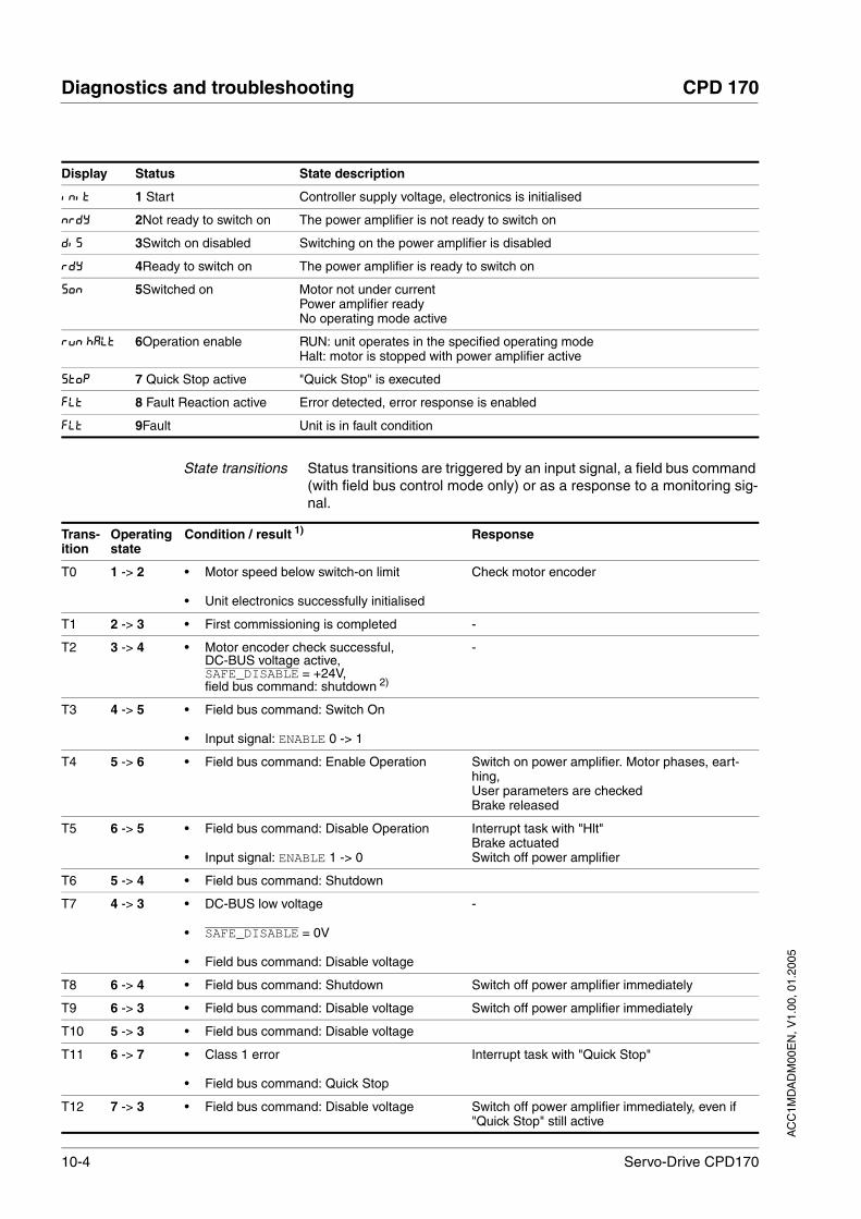
10-4 Servo-Drive CPD170
Diagnostics and troubleshooting CPD 170
AC
C1M
DA
DM
00E
N, V
1.00
, 01.
2005
State transitions Status transitions are triggered by an input signal, a field bus command (with field bus control mode only) or as a response to a monitoring sig-nal.
Display Status State description
Init 1 Start Controller supply voltage, electronics is initialised
nrdy 2Not ready to switch on The power amplifier is not ready to switch on
dis 3Switch on disabled Switching on the power amplifier is disabled
rdy 4Ready to switch on The power amplifier is ready to switch on
Son 5Switched on Motor not under currentPower amplifier readyNo operating mode active
run HALT 6Operation enable RUN: unit operates in the specified operating modeHalt: motor is stopped with power amplifier active
Stop 7 Quick Stop active "Quick Stop" is executed
FLt 8 Fault Reaction active Error detected, error response is enabled
FLt 9Fault Unit is in fault condition
Trans-ition
Operating state
Condition / result 1) Response
T0 1 -> 2 • Motor speed below switch-on limit
• Unit electronics successfully initialised
Check motor encoder
T1 2 -> 3 • First commissioning is completed -
T2 3 -> 4 • Motor encoder check successful,DC-BUS voltage active,SAFE_DISABLE = +24V,field bus command: shutdown 2)
-
T3 4 -> 5 • Field bus command: Switch On
• Input signal: ENABLE 0 -> 1
T4 5 -> 6 • Field bus command: Enable Operation Switch on power amplifier. Motor phases, eart-hing,User parameters are checked Brake released
T5 6 -> 5 • Field bus command: Disable Operation
• Input signal: ENABLE 1 -> 0
Interrupt task with "Hlt"Brake actuatedSwitch off power amplifier
T6 5 -> 4 • Field bus command: Shutdown
T7 4 -> 3 • DC-BUS low voltage
• SAFE_DISABLE = 0V
• Field bus command: Disable voltage
-
T8 6 -> 4 • Field bus command: Shutdown Switch off power amplifier immediately
T9 6 -> 3 • Field bus command: Disable voltage Switch off power amplifier immediately
T10 5 -> 3 • Field bus command: Disable voltage
T11 6 -> 7 • Class 1 error
• Field bus command: Quick Stop
Interrupt task with "Quick Stop"
T12 7 -> 3 • Field bus command: Disable voltage Switch off power amplifier immediately, even if "Quick Stop" still active

AC
C1M
DA
DM
00E
N, V
1.00
, 01.
2005
CPD 170 Diagnostics and troubleshooting
Servo-Drive CPD170 10-5
10.3.2 Error display on HMI
State display Ulow The display shows ULOW (ULOW) when initialised. The voltage of the control supply is too low .
Check the control supply.
State display nrdy The product persists in switch-on state nrdy (NRDY).
After "First Setup", you need to switch the unit off and switch it on again.
Check the installation. If the installation is correct, then there is an internal fault. To diag-nose, read the error memory using the commissioning software. If you cannot resolve the fault yourself please contact your local sales partner.
State display dis If the product stops in state dis (DIS), the DC bus voltage is absent or the safety inputs SAFE_DISABLE_A and SAFE_DISABLE_B are not drawing current
Check the following:
• Are the safety inputs SAFE_DISABLE_A and SAFE_DISABLE_B activated? If not required, these two inputs should be set to +24V.
• Check the installation of the analogue and digital signal connec-tions. Pay particular attention to the minimum occupancy, see page 6.3.17 “Connection of digital inputs/outputs (CN1)“.
• Is the power supply to the power amplifier switched on and does the voltage correspond to the details in the technical data?
Special condition for units with CANopen field bus: Note the setting of the parameter DCOMcompatib in the case of units with field bus and CANopen controller mode. Depending upon the setting of this parame-ter, the unit remains in state dis after switching on.
State display FLt The display flashes alternately with FLt (FLT) and a 4 digit error number. The error number can also be found in the error memory list.
T13 x -> 8 • Errors Class 2, 3 or 4 Error response is carried out, see "error response"
T14 8 -> 9 • Error response completed
• Errors Class , 3 or 4
T15 9 -> 3 • Field bus command: Fault Reset 3)
• Input signal: FAULT_RESET 0 -> 1 3)
Fault is reset
T16 7 -> 6 • Field bus command: Fault Reset 3)
• Field bus command: Enable Operation 4)
• Input signal: FAULT_RESET 0 -> 1 3)
Local control mode: specified operating mode is automatically continued
1) It is sufficient to fulfil one point to trigger the status transition2) Only required with field bus control mode, field bus CANopen and parameter DCOMcompatib = 13) Cause of error must be corrected4) Only possible if operating status was triggered via field bus
Trans-ition
Operating state
Condition / result 1) Response

10-6 Servo-Drive CPD170
Diagnostics and troubleshooting CPD 170
AC
C1M
DA
DM
00E
N, V
1.00
, 01.
2005
Check especially:
• Is a suitable motor connected?
• Is the motor encoder cable correctly wired and connected? The unit cannot correctly start up the motor without a motor encoder signal.
Status displaySTOP The HMI displays STOP (STOP) when a "Quick Stop" has been triggered. This can be caused by a software stop, a hardware limit switch or by an error of error class 1.
Remove the cause of the error and reset the error message.
State display WDOG The display shows WDOG (WDOG) when initialised. The internal monitor has sensed a fault by means of the Watchdog.
Contact the Technical Support of your local sales partner. Advise the peripheral conditions (operating mode, application event) when the fault occurs:
The error can be reset by switching the unit off and on again.
Last cause of interruption Additional error information can be obtained from the menu points cor-responding to the HMI codes in 11.2 “List of all parameters“ .
Press the ENT button on the HMI to acknowledge the current error message.
Change to the FLT menu. The last cause of interruption (Parameter _StopFault) is shown as an error number.
10.3.3 Error display with commissioning software
You will need a PC with the commissioning software and a functio-nal connection to the product, see 6.3.18 “Connection to PC or peri-pheral control terminal (CN4)“ from page 6-47.
Select “Diagnosis error memory“. A dialog box which displays the error messages appears.
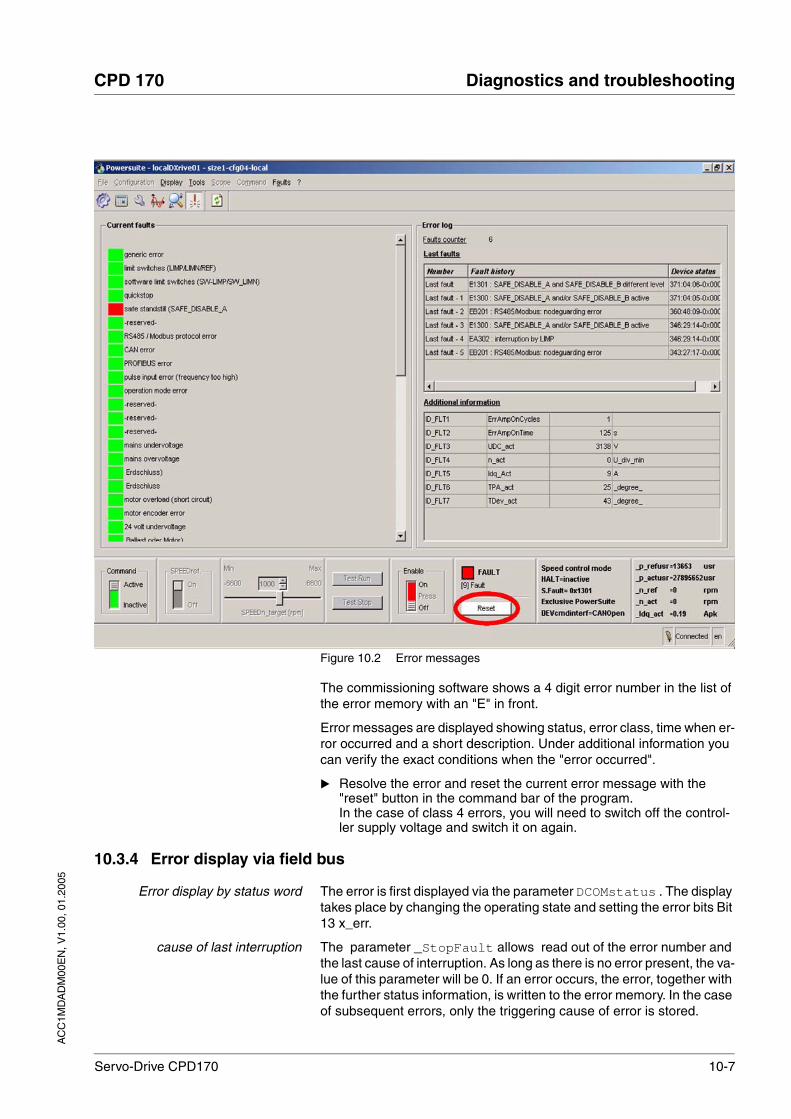
AC
C1M
DA
DM
00E
N, V
1.00
, 01.
2005
CPD 170 Diagnostics and troubleshooting
Servo-Drive CPD170 10-7
Figure 10.2 Error messages
The commissioning software shows a 4 digit error number in the list of the error memory with an "E" in front.
Error messages are displayed showing status, error class, time when er-ror occurred and a short description. Under additional information you can verify the exact conditions when the "error occurred".
Resolve the error and reset the current error message with the "reset" button in the command bar of the program.In the case of class 4 errors, you will need to switch off the control-ler supply voltage and switch it on again.
10.3.4 Error display via field bus
Error display by status word The error is first displayed via the parameter DCOMstatus . The display takes place by changing the operating state and setting the error bits Bit 13 x_err.
cause of last interruption The parameter _StopFault allows read out of the error number and the last cause of interruption. As long as there is no error present, the va-lue of this parameter will be 0. If an error occurs, the error, together with the further status information, is written to the error memory. In the case of subsequent errors, only the triggering cause of error is stored.

10-8 Servo-Drive CPD170
Diagnostics and troubleshooting CPD 170
AC
C1M
DA
DM
00E
N, V
1.00
, 01.
2005
Error memory The error memory is an error history of the last 10 errors and is maintai-ned even if the unit is switched off. The following parameters allow the error memory to be controlled:
The error memory can only be read sequentially. The parameter FLT_MemReset must be used to reset the read pointer. Then the first error entry can be read. The read pointer is automatically moved on to the next entry, re-reading selects the next error entry. If the error number 0 is returned there is no error entry present.
An individual error entry consists of several pieces of information which are read out using various parameters. When reading out an error entry, the error number must always be read out first with the parameter FLT_err_num.
Parameter NameCodeHMI menu, Code
Meaning UnitMinimum valueDefault valueMaximum value
Data typeR/WperExpert
Parameter address via field bus
FLT_del_err
-
Erase error memory()
1: delete all entries in the error memory
The deletion process is completed when 0 is returned during reading.
001
UINT16R/W--
CANopen 303B:4hModbus 15112
FLT_MemReset
-
Reset the error memory read pointer()
1 : set error memory read indicator to oldest error entry.
001
UINT16R/W--
CANopen 303B:5hModbus 15114
Position of the entry Description
1 1. error entry, oldest report
2 2. error entry, later report, if present
... ...
10 10. error entry. In the case of 10 error entries the most current error value is shown here
Parameter NameCodeHMI menu, Code
Meaning UnitMinimum valueDefault valueMaximum value
Data typeR/WperExpert
Parameter address via field bus
FLT_err_num
-
Error number()
Reading this parameter brings the complete error entry (sub-index 1..11) into an interme-diate memory from which all other sub-indi-ces are subsequently read.
In addition, the read indicator of the error memory is automatically switched forward to the next error entry.
0
65535
UINT16R/---
CANopen 303C:1hModbus 15362
FLT_class
-
Error class()
0: warning (no response)1: error (Quick Stop -> status 7)2: error (Quick Stop -> status 8,9)3: fatal error (status 9)4: fatal error (status 9, cannot be acknow-ledged)
0
4
UINT16R/---
CANopen 303C:2hModbus 15364

AC
C1M
DA
DM
00E
N, V
1.00
, 01.
2005
CPD 170 Diagnostics and troubleshooting
Servo-Drive CPD170 10-9
FLT_Time
-
Error time()
referenced to the operating hours counter
s0
536870911
UINT32R/---
CANopen 303C:3hModbus 15366
FLT_Qual
-
Eror additional information()
This entry contains additional information on the error depending on the error number Example: parameter address
0
65535
UINT16R/---
CANopen 303C:4hModbus 15368
Parameter NameCodeHMI menu, Code
Meaning UnitMinimum valueDefault valueMaximum value
Data typeR/WperExpert
Parameter address via field bus

10-10 Servo-Drive CPD170
Diagnostics and troubleshooting CPD 170
AC
C1M
DA
DM
00E
N, V
1.00
, 01.
2005
10.4 Troubleshooting
10.4.1 Resolution of malfunctions
Malfunction Cause Correction
Motor not turning Motor blocked by brake Release brake, check wiring
Break in the motor cable
Check motor cable and connection. One or more motor phases are not connected.
No torque Set the parameters for max. current, max. speed to greater than zero
Incorrect opera-ting mode selec-ted
Set the input signal and parameters for the operating mode you want
Drive system swit-ched off
Switch on drive system, generate release sig-nal
Analogue set value is missing
PLC program and wiring to be checked
Motor phases reversed
Correct the sequence of the motor phases
Motor mechani-cally blocked
Check ancillary units
Current limit acti-vated (analogue I/O or parameter)
Correct the current limit
The motor jerks briefly
Motor phases reversed Check motor cable and connection: connect motor phases U, V and W in the same way on the motor and unit sides
Motor vibrating Amplification factor KP too high reduce KP (speed controller)
Fault in the motor encoder system
Check motor encoder
Reference poten-tial for analogue signal missing
Connect reference potential of analogue signal to the set value source.
Motor running too soft
Integration time TNn too high Reduce Tn (speed controller)
Amplification fac-tor KPn too low
Increase KPn (speed controller)
Motor running too rough
Integration time TNn too low Increase TNn (speed controller)
Amplification fac-tor KPn too high
Reduce KPn (speed controller)
Error message communication error
Drive system switched off Switch on the drive system
Wiring fault Check wiring
Wrong PC inter-face selected
Select correct interface
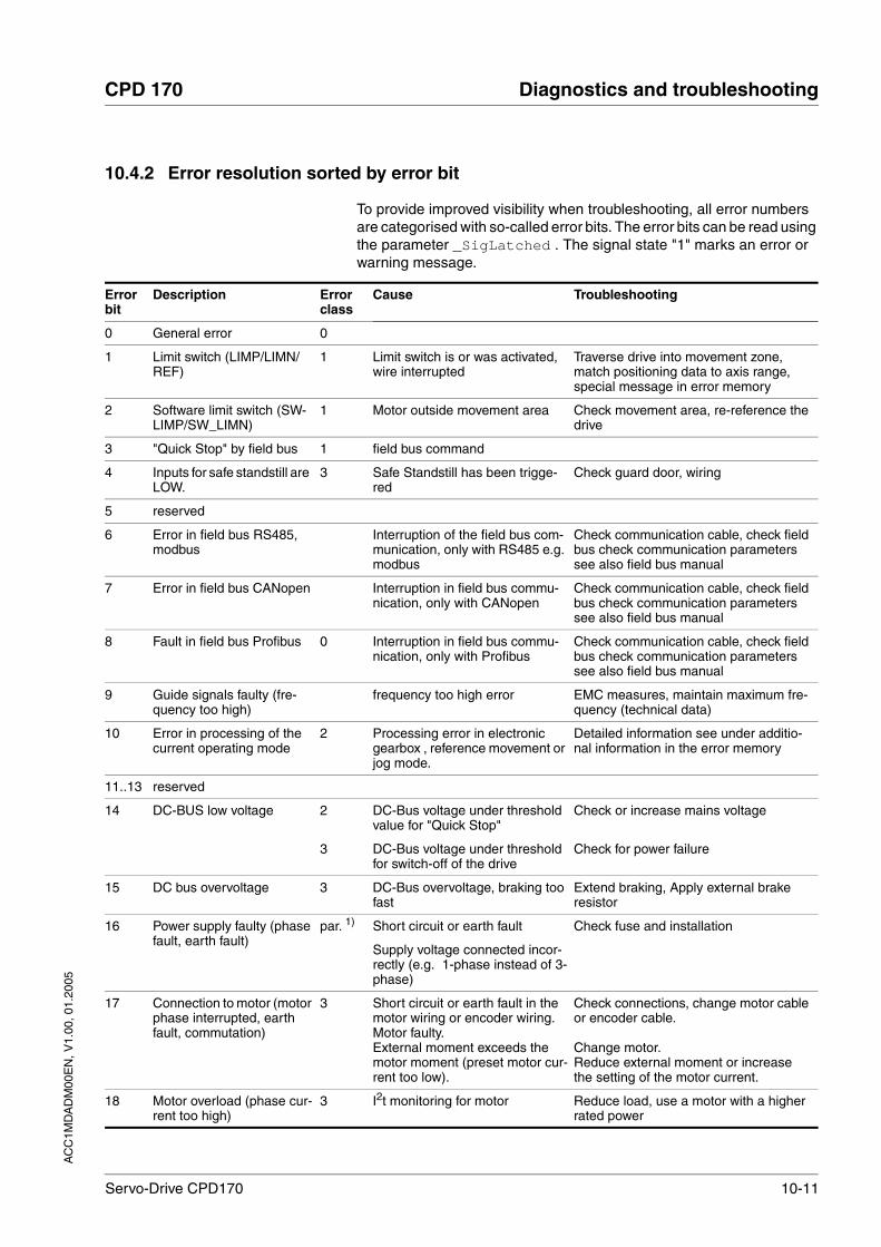
AC
C1M
DA
DM
00E
N, V
1.00
, 01.
2005
CPD 170 Diagnostics and troubleshooting
Servo-Drive CPD170 10-11
10.4.2 Error resolution sorted by error bit
To provide improved visibility when troubleshooting, all error numbers are categorised with so-called error bits. The error bits can be read using the parameter _SigLatched . The signal state "1" marks an error or warning message.
Error bit
Description Error class
Cause Troubleshooting
0 General error 0
1 Limit switch (LIMP/LIMN/REF)
1 Limit switch is or was activated, wire interrupted
Traverse drive into movement zone, match positioning data to axis range, special message in error memory
2 Software limit switch (SW-LIMP/SW_LIMN)
1 Motor outside movement area Check movement area, re-reference the drive
3 "Quick Stop" by field bus 1 field bus command
4 Inputs for safe standstill are LOW.
3 Safe Standstill has been trigge-red
Check guard door, wiring
5 reserved
6 Error in field bus RS485, modbus
Interruption of the field bus com-munication, only with RS485 e.g. modbus
Check communication cable, check field bus check communication parameters see also field bus manual
7 Error in field bus CANopen Interruption in field bus commu-nication, only with CANopen
Check communication cable, check field bus check communication parameters see also field bus manual
8 Fault in field bus Profibus 0 Interruption in field bus commu-nication, only with Profibus
Check communication cable, check field bus check communication parameters see also field bus manual
9 Guide signals faulty (fre-quency too high)
frequency too high error EMC measures, maintain maximum fre-quency (technical data)
10 Error in processing of the current operating mode
2 Processing error in electronic gearbox , reference movement or jog mode.
Detailed information see under additio-nal information in the error memory
11..13 reserved
14 DC-BUS low voltage 2
3
DC-Bus voltage under threshold value for "Quick Stop"
DC-Bus voltage under threshold for switch-off of the drive
Check or increase mains voltage
Check for power failure
15 DC bus overvoltage 3 DC-Bus overvoltage, braking too fast
Extend braking, Apply external brake resistor
16 Power supply faulty (phase fault, earth fault)
par. 1) Short circuit or earth fault
Supply voltage connected incor-rectly (e.g. 1-phase instead of 3-phase)
Check fuse and installation
17 Connection to motor (motor phase interrupted, earth fault, commutation)
3 Short circuit or earth fault in the motor wiring or encoder wiring.Motor faulty.External moment exceeds the motor moment (preset motor cur-rent too low).
Check connections, change motor cable or encoder cable.
Change motor.Reduce external moment or increase the setting of the motor current.
18 Motor overload (phase cur-rent too high)
3 I2t monitoring for motor Reduce load, use a motor with a higher rated power

10-12 Servo-Drive CPD170
Diagnostics and troubleshooting CPD 170
AC
C1M
DA
DM
00E
N, V
1.00
, 01.
2005
19 Encoder in motor signals error or connection to encoder faulty
3-4 No signal from the motor enco-der, encoder faulty
Check encoder cable and encoder, replace cable
20 low voltage from controller supply
Controller supply voltage has fal-len below the minimum value
Secure controller supply voltage. Check short-term voltage failures during load changes
21 Temperature too high (power amplifier, ballast, motor)
3 The power amplifier is overhea-ting
Motor is overheating Temperature sensor not connec-ted
Ventilator faulty or blocked, switch on time for peak current, reduce load or peak moment
Allow motor to cool down, reduce load, use motor with greater nominal rating, temperature sensor faulty, check/change motor and encoder cables
22 Lag error par. 1)
1-3Lag error Reduce external load or acceleration,
error response is adjustable via "Flt_pDiff“
23 Maximum speed exceeded Exceeding the maximum motor speed during feed operations
Reduce vertical loading
24 Inputs for SAFE_DISABLE different
4 Interruption of the signal wiring Signal cable/connection to be checked, check signal encoder or change
25..28 reserved
29 error in EEPROM 3-4 Checksum in EEPROM incorrect "Initial Setup" to be carried out, user parameters to be stored in the EEPROM, consult your local sales part-ner
30 system run-up faulty (hard-ware or parameter fault)
3-4 Cause of error in accordance with error display
Resolution dependent upon error display
31 Internal system fault (e.g. Watchdog)
4 Internal system error
system error, e.g. division by 0 or time-out checks, inadequate EMC
Switch unit off and on, replace unit
Comply with EMC protective measures, switch unit off and on, contact your local service representative
1) par. = configurable
Error bit
Description Error class
Cause Troubleshooting
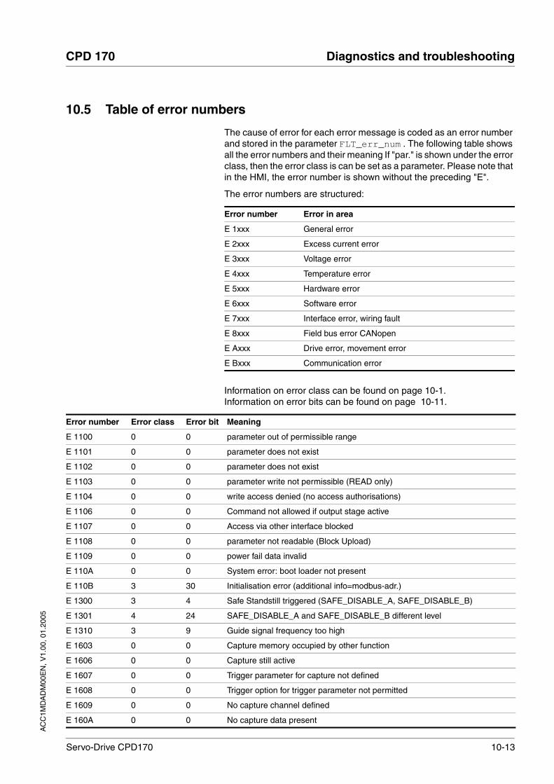
AC
C1M
DA
DM
00E
N, V
1.00
, 01.
2005
CPD 170 Diagnostics and troubleshooting
Servo-Drive CPD170 10-13
10.5 Table of error numbers
The cause of error for each error message is coded as an error number and stored in the parameter FLT_err_num . The following table shows all the error numbers and their meaning If "par." is shown under the error class, then the error class is can be set as a parameter. Please note that in the HMI, the error number is shown without the preceding "E".
The error numbers are structured:
Information on error class can be found on page 10-1.Information on error bits can be found on page 10-11.
Error number Error in area
E 1xxx General error
E 2xxx Excess current error
E 3xxx Voltage error
E 4xxx Temperature error
E 5xxx Hardware error
E 6xxx Software error
E 7xxx Interface error, wiring fault
E 8xxx Field bus error CANopen
E Axxx Drive error, movement error
E Bxxx Communication error
Error number Error class Error bit Meaning
E 1100 0 0 parameter out of permissible range
E 1101 0 0 parameter does not exist
E 1102 0 0 parameter does not exist
E 1103 0 0 parameter write not permissible (READ only)
E 1104 0 0 write access denied (no access authorisations)
E 1106 0 0 Command not allowed if output stage active
E 1107 0 0 Access via other interface blocked
E 1108 0 0 parameter not readable (Block Upload)
E 1109 0 0 power fail data invalid
E 110A 0 0 System error: boot loader not present
E 110B 3 30 Initialisation error (additional info=modbus-adr.)
E 1300 3 4 Safe Standstill triggered (SAFE_DISABLE_A, SAFE_DISABLE_B)
E 1301 4 24 SAFE_DISABLE_A and SAFE_DISABLE_B different level
E 1310 3 9 Guide signal frequency too high
E 1603 0 0 Capture memory occupied by other function
E 1606 0 0 Capture still active
E 1607 0 0 Trigger parameter for capture not defined
E 1608 0 0 Trigger option for trigger parameter not permitted
E 1609 0 0 No capture channel defined
E 160A 0 0 No capture data present

10-14 Servo-Drive CPD170
Diagnostics and troubleshooting CPD 170
AC
C1M
DA
DM
00E
N, V
1.00
, 01.
2005
E 160B 0 0 parameter not recordable
E 160C 1 0 Autotuning: moment of inertia outside permissible range
E 160E 1 0 Autotuning: Test movement could not be started
E 160F 1 0 Autotuning: Output stage cannot be activated
E 1610 1 0 Autotuning: Processing discontinued
E 1611 1 0 System error: Auto-Tuning internal write access
E 1612 1 0 System error: Auto-Tuning internal write access
E 1613 1 0 Autotuning: max. permissible positioning range exceeded
E 1614 0 0 Autotuning: already active
E 1617 1 0 Autotuning: Frictional or load moment too great
E 1618 1 0 Autotuning: optimisation aborted
E 1A00 0 0 System error: FIFO memory overflow
E 1A01 3 19 motor has been changed
E 1A02 3 19 motor has been changed
E 1B00 4 31 System error: Faulty parameter in motor or output stage
E 2300 3 18 power amplifier overcurrent
E 2301 3 18 ballast resistor overcurrent
E 3100 par. 16 mains power supply phase fault
E 3200 3 15 DC bus overvoltage
E 3201 3 14 DC bus low voltage (switch-off threshold)
E 3202 2 14 DC bus low voltage (Quick Stop threshold)
E 3203 4 19 Motor encoder supply voltage
E 3206 0 11 DC BUS low voltage (warning)
E 4100 3 21 Output stage excess temperature
E 4101 0 1 Power amplifier overtemperature warning
E 4102 0 4 Output stage overload (I²t) warning
E 4200 3 21 Unit overtemperature
E 4300 3 21 Motor overtemperature
E 4301 0 2 Motor overtemperature warning
E 4302 0 5 Motor overload (I²t) warning
E 4402 0 6 Ballast resistor overload (I²t) warning
E 5200 4 19 No connection to the motor encoder
E 5201 4 19 errors in motor sensor communication
E 5202 4 19 Motor encoder is not supported
E 5203 4 19 No connection to the motor encoder
E 5204 3 19 Connection to motor encoder lost
E 5430 4 29 System error: EEPROM read error
E 5431 3 29 System error: EEPROM write error
E 5435 4 29 System error: EEPROM not formatted
E 5437 4 29 System error: EEPROM checksum error in manufacturer data
Error number Error class Error bit Meaning

AC
C1M
DA
DM
00E
N, V
1.00
, 01.
2005
CPD 170 Diagnostics and troubleshooting
Servo-Drive CPD170 10-15
E 5438 3 29 System error: EEPROM checksum error in user-defined parameter
E 5439 3 29 System error: EEPROM checksum error CAN parameter
E 543A 4 29 System error: EEPROM HardwareInfo invalid
E 543B 4 29 System error: EEPROM Manufacturer data invalid
E 543C 3 29 System error: EEPROM CAN-data invalid
E 543D 3 29 System error: EEPROM user parameter invalid
E 5600 3 17 motor connection phase error
E 5601 4 19 Interruption or faulty motor encoder signals
E 5602 4 19 Interruption or faulty motor encoder signals
E 5603 4 17 Commutation error
E 6107 0 0 Parameters outside value range (calculation error)
E 6108 0 0 Function not available
E 610D 0 0 Error in selection parameter
E 610F 4 30 System error: Internal time base failed (Timer0)
E 7120 4 19 Invalid motor data
E 7121 2 19 System error: errors in motor sensor communication
E 7122 4 30 Motor data not acceptable
E 7123 4 30 motor current offset outside permissible range
E 7124 4 19 System error: Motor encoder faulty
E 7200 4 30 System error: calibration of analogue/digital converter
E 7201 4 30 System error: motor sensor initialising (quadrant evaluation)
E 7327 4 19 System error: position sensor not ready
E 7328 4 19 Motor encoder sends: position capture errors
E 7329 0 8 Motor encoder sends: Warning
E 7330 4 19 System error: motor encoder (Hiperface)
E 7331 4 30 System error: Motor encoder initialisation
E 7333 4 30 System error: Discrepancy during calibration of analogue/digital converter
E 7334 3 30 System error: Analogue/digital converter offset too big
E 7335 0 8 Communication to motor encoder occupied
E 7400 0 31 System error: illegal interrupt (XINT2)
E 7500 0 9 RS485/Modbus: Overrun-error
E 7501 0 9 RS485/Modbus: Framing-error
E 7502 0 9 RS485/Modbus: Parity-error
E 7503 0 9 RS485/Modbus: Receive error
E 8110 0 7 CANopen: CAN overflow (message lost)
E 8120 0 7 CANopen: CAN Controller in Error Passive
E 8130 2 7 CANopen: Heartbeat or Life Guard error
E 8140 0 0 CANopen: CAN Controller was in Busoff, communication possible again
E 8141 2 7 CANopen: CAN Controller in Busoff
E 8201 0 7 CANopen: RxPdo1 could not be processed
Error number Error class Error bit Meaning

10-16 Servo-Drive CPD170
Diagnostics and troubleshooting CPD 170
AC
C1M
DA
DM
00E
N, V
1.00
, 01.
2005
E 8202 0 7 CANopen: RxPdo2 could not be processed
E 8203 0 7 CANopen: RxPdo3 could not be processed
E 8204 0 7 CANopen: RxPdo4 could not be processed
E 8205 0 7 CANopen: TxPdo could not be processed
E 8206 0 7 CANopen: Internal queue overflow message lost
E A060 2 10 Calculation error with electronic gearbox
E A061 2 10 Change in reference value with electronic gearbox too great
E A300 0 0 Torque ramp with STOP current active
E A301 0 0 Drive in state 'QuickStopActive'
E A302 1 1 Interruption by LIMP
E A303 1 1 Interruption by LIMN
E A304 1 1 Interruption by REF
E A306 1 3 Interruption by user initiated software stop
E A307 0 0 Interruption by internal software stop
E A308 0 0 Drive in state 'Fault'
E A309 0 0 Drive not in state 'OperationEnable'
E A310 0 0 Power amplifier not active
E A312 0 0 Profile generation interrupted
E A313 0 0 Position over-run present (pos_over=1), thus reference point no longer defi-ned (ref_ok=0)
E A314 0 0 No reference position
E A315 0 0 Referencing active
E A316 0 0 Overrun on acceleration calculation
E A317 0 0 Drive not at standstill
E A318 0 0 Operating mode active (x_end = 0)
E A319 1 2 Manual/Autotuning: distance range overflow
E A31A 0 0 Manual/Autotuning: amplitude/offset set too high
E A31B 0 0 STOP requested
E A31C 0 0 Illegal position setting with software limit switch
E A31D 0 0 Speed range exceeded (CTRL_n_max)
E A31E 1 2 Interruption by pos. software limit switch
E A31F 1 2 Interruption by neg. software limit switch
E A320 par. 22 position lag error
E A321 0 0 RS422 position interface not defined as input
E A324 1 10 Error when referencing (additional info = detailed error number)
E A325 1 10 Approach limit switch not activated
E A326 1 10 REF switch not found between LIMP and LIMN
E A327 1 10 Reference movement to REF without reversal of direction of rotation improper activation of limit switch LIM "
E A328 1 10 Reference movement to REF without reversal of direction of rotation, overrun of LIM or REF not permissible
E A329 1 10 More than one signal LIMP, LIMN, REF active
Error number Error class Error bit Meaning
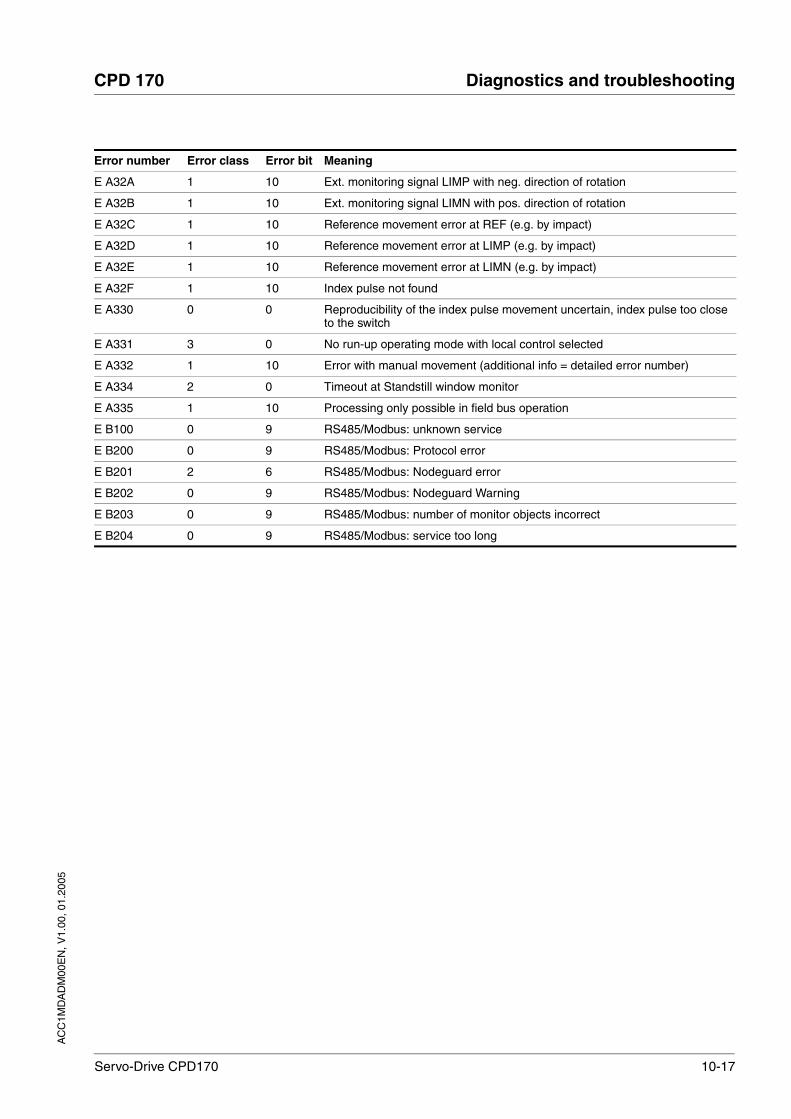
AC
C1M
DA
DM
00E
N, V
1.00
, 01.
2005
CPD 170 Diagnostics and troubleshooting
Servo-Drive CPD170 10-17
E A32A 1 10 Ext. monitoring signal LIMP with neg. direction of rotation
E A32B 1 10 Ext. monitoring signal LIMN with pos. direction of rotation
E A32C 1 10 Reference movement error at REF (e.g. by impact)
E A32D 1 10 Reference movement error at LIMP (e.g. by impact)
E A32E 1 10 Reference movement error at LIMN (e.g. by impact)
E A32F 1 10 Index pulse not found
E A330 0 0 Reproducibility of the index pulse movement uncertain, index pulse too close to the switch
E A331 3 0 No run-up operating mode with local control selected
E A332 1 10 Error with manual movement (additional info = detailed error number)
E A334 2 0 Timeout at Standstill window monitor
E A335 1 10 Processing only possible in field bus operation
E B100 0 9 RS485/Modbus: unknown service
E B200 0 9 RS485/Modbus: Protocol error
E B201 2 6 RS485/Modbus: Nodeguard error
E B202 0 9 RS485/Modbus: Nodeguard Warning
E B203 0 9 RS485/Modbus: number of monitor objects incorrect
E B204 0 9 RS485/Modbus: service too long
Error number Error class Error bit Meaning

10-18 Servo-Drive CPD170
Diagnostics and troubleshooting CPD 170
AC
C1M
DA
DM
00E
N, V
1.00
, 01.
2005

AC
C1M
DA
DM
00E
N, V
1.00
, 01.
2005
CPD 170 Parameters
Servo-Drive CPD170 11-1
11 Parameters
11.1 Representation of the parameters
The parameter display contains, on the one hand, information which is needed for positive identification of a parameter. On the other hand, the parameter display can also provide information on setting options, pre-sets and parameter properties.
A parameter display has the following features:
The most important terms in the heading line of a parameter table are explained in the following.
Parameter Name The parameter name is displayed with the commissioning software in the "Designation" column.
Code and HMI Code The Code is represented on a 7 segment display on the HMI (HMI-Code).
Default values Factory settings.
Data type The data type determines the valid range of values, especially when a parameter does not have explicit minimum and maximum values.
R/W Note on reading and writing the values"R/-" values are read-only"R/W" values are read and write.
per. Designation of whether the value of the parameter is persistent, i.e. after switching off the unit it is retained in the memory. When entering via HMI the unit stores the value of the parameter automatically at each change. When changing a value via commissioning software or field bus, the user must explicitly store the value change in the persistent memory.
Cross reference If there is more information available for these parameters you can find this under this cross-reference.
Parameter NameCodeHMI menu, Code
Meaning UnitMinimum valueDefault valueMaximum value
Data typeR/WperExpert
Parameter address via field bus
Beispiel_Name
BSPI
NONE-BSPI
Example parameter (cross-reference)
Details and selection values1 / selection value1 / WRT1: declaration 12 / selection value2 / WRT2: declaration 2
Apk0.003.00300.00
Field bus030030000
UINT16R/Wper.-
CANopen 1234:5hModbus 1234
Data type Byte Min value Max value
INT16 2 Byte / 16 Bit -32768 32767
UINT16 2 Byte / 16 Bit 0 65535
INT32 4 Byte / 32 Bit -2147483648 2147483647
UINT32 4 Byte / 32 Bit 0 4294967295

11-2 Servo-Drive CPD170
Parameters CPD 170
AC
C1M
DA
DM
00E
N, V
1.00
, 01.
2005
Selection values In the case of parameters which offer a selection of settings, the selec-tion number and the designation of the value when inputting with com-missioning software and HMI are quoted. Example:1 / pos-neg-home / pnh: Explanation
Instructions on inputting values The maximum value corresponds to the relatively smaller maximum va-lue of output stage or motor. The unit automatically limits to the smaller value.
Use the details which are applicable to the type of control being used (lo-cal or field bus).
Please note that the parameter values in the case of field bus controller operating mode are shown without decimal point, e.g.
• For local controller operating mode:Max. value = 327.67
• For field bus controller operating mode(=Fieldbus):Max. value = 32767
Setting parameters with Specifications
Field bus Parameter name
HMI HMI code
Commissioning software Code

AC
C1M
DA
DM
00E
N, V
1.00
, 01.
2005
CPD 170 Parameters
Servo-Drive CPD170 11-3
11.2 List of all parameters
Parameter NameCodeHMI menu, Code
Meaning UnitMinimum valueDefault valueMaximum value
Data typeR/WperExpert
Parameter address via field bus
_acc_pref
-
Acceleration of setpoint generation(8-43)
Sign corresponding to the change in the speed quantity:
increase in speed: pos. signreduction in speed: neg. sign
rpm*s INT32R/---
_AccessInfo
-
Current access channels for action objects(8-2)
Low byte : 0 : assigned by channel in high byte1 : exclusively assigned by channel in high byte
High byte: current assignment of access channel0: reserved1: IO2: HMI3: Modbus4: CANopen5: CANopen via second SDO channel
UINT16R/---
CANopen 3001:ChModbus 280
_actionStatus
-
Action word(8-46)
Signal state:0: not enabled1: enabled
Bit0: error class 0Bit1: error class 1Bit2: error class 2Bit3: error class 3Bit4: error class 4Bit5: reservedBit6: drive at standstill: actual speed _n_act < <9 rpmBit7: drive rotating clockwiseBit8: drive rotating anticlockwiseBit9: drive inside position window (pwin)Bit10: reservedBit11: profile generator stopped: setpoint speed is 0Bit12: profile generator deceleratingBit13: profile generator acceleratingBit14: profile generator at constant speedBit15: reserved
UINT16R/---
CANopen 301C:4hModbus 7176
_DCOMopmd_act
-
active operating mode()
DSP402 operating modes:1 : profile position3 : profile velocity6 : homing--------------------------------------manufacturer operating modes:-1 : jog-2 : electronic gear-3 : current control-4 : speed control
-6
6
INT16R/---
CANopen 6061:0hModbus 6920

11-4 Servo-Drive CPD170
Parameters CPD 170
AC
C1M
DA
DM
00E
N, V
1.00
, 01.
2005
_I2t_act_M
-
Overload motor current(8-46) % INT16R/---
CANopen 301C:19hModbus 7218
_I2t_act_PA
-
Overload power amplifier current(8-46) % INT16R/---
CANopen 301C:16hModbus 7212
_I2t_mean_M
I2TM
STA-i2TM
Loading factor motor(8-46) % INT16R/---
CANopen 301C:1AhModbus 7220
_I2t_mean_PA
I2TP
STA-i2TP
Loading factor power amplifier (8-46) % INT16R/---
CANopen 301C:17hModbus 7214
_I2t_peak_BAL
-
Overload load maximum value(8-46)
Maximum overload ballast that has occurred in the last 10 sec.
% INT16R/---
CANopen 301C:15hModbus 7210
_I2t_peak_M
-
Overload motor maximum value(8-46)
Maximum overload motor that has occurred in the last 10 sec.
% INT16R/---
CANopen 301C:1BhModbus 7222
_I2t_peak_PA
-
Overload power amplifier maximum value(8-46)
Maximum overload power amplifier that has occurred in the last 10 sec.
% INT16R/---
CANopen 301C:18hModbus 7216
_I2tl_act_BAL
-
Overload load current(8-46) % INT16R/---
CANopen 301C:13hModbus 7206
_I2tl_mean_BAL
I2TB
STA-i2TB
Loading factor load(8-46) % INT16R/---
CANopen 301C:14hModbus 7208
_Id_act
-
current motor current d-components() Apk0.000.000.00
INT16R/---
CANopen 301E:2hModbus 7684
_Id_ref
-
Set motor current d component (field weake-ning)()
Apk0.000.000.00
INT16R/---
CANopen 301E:11hModbus 7714
_Idq_act
IACT
STA-iACT
Total motor current (vector sum of d and q components()
Total motor current (vector sum of d and q components
Apk0.000.000.00
INT16R/---
CANopen 301E:3hModbus 7686
Parameter NameCodeHMI menu, Code
Meaning UnitMinimum valueDefault valueMaximum value
Data typeR/WperExpert
Parameter address via field bus
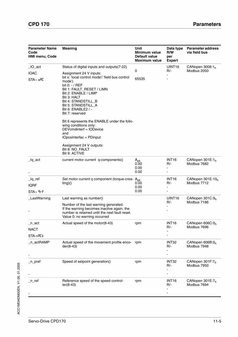
AC
C1M
DA
DM
00E
N, V
1.00
, 01.
2005
CPD 170 Parameters
Servo-Drive CPD170 11-5
_IO_act
IOAC
STA-ioAC
Status of digital inputs and outputs(7-22)
Assignment 24 V inputs:bit x: 'local control mode'/ 'field bus control mode')bit 0: - / REFBit 1: FAULT_RESET / LIMNBit 2: ENABLE / LIMPBit 3: HALTBit 4: STANDSTILL_BBit 5: STANDSTILL_ABit 6: ENABLE2 / -Bit 7: reserved
Bit 6 represents the ENABLE under the follo-wing conditions only:DEVcmdinterf = IODeviceandIOposInterfac = PDinput
Assignment 24 V outputs:Bit 8: NO_FAULTBit 9: ACTIVE
0
65535
UINT16R/---
CANopen 3008:1hModbus 2050
_Iq_act
-
current motor current q-components() Apk0.000.000.00
INT16R/---
CANopen 301E:1hModbus 7682
_Iq_ref
IQRF
STA-iQRF
Set motor current q component (torque-crea-ting)()
Apk0.000.000.00
INT16R/---
CANopen 301E:10hModbus 7712
_LastWarning
-
Last warning as number()
Number of the last warning generated.If the warning becomes inactive again, the number is retained until the next fault reset.Value 0: no warning occurred
UINT16R/---
CANopen 301C:9hModbus 7186
_n_act
NACT
STA-NACT
Actual speed of the motor(8-43) rpm INT16R/---
CANopen 606C:0hModbus 7696
_n_actRAMP
-
Actual speed of the movement profile enco-der(8-43)
rpm INT32R/---
CANopen 606B:0hModbus 7948
_n_pref
-
Speed of setpoint generation() rpm INT32R/---
CANopen 301F:7hModbus 7950
_n_ref
-
Reference speed of the speed control-ler(8-43)
rpm INT16R/---
CANopen 301E:7hModbus 7694
Parameter NameCodeHMI menu, Code
Meaning UnitMinimum valueDefault valueMaximum value
Data typeR/WperExpert
Parameter address via field bus

11-6 Servo-Drive CPD170
Parameters CPD 170
AC
C1M
DA
DM
00E
N, V
1.00
, 01.
2005
_n_targetRAMP
-
Target speed of the movement profile enco-der(8-43)
rpm INT32R/---
CANopen 301F:5hModbus 7946
_OpHours
OPH
STA-oPh
Operating hours counter() s UINT32R/---
CANopen 301C:AhModbus 7188
_p_absmodulo
-
Absolute position referenced to one motor revolution()
Inc UINT32R/---
CANopen 301E:EhModbus 7708
_p_act
-
Actual motor position() Inc INT32R/---
CANopen 6063:0hModbus 7700
_p_actPosintf
-
Actual position at position interface()
Counted increments at pulse input.Requirement: IOposInterfac = Pdinput or Abinput
Inc-2147483648
2147483647
INT32R/---
CANopen 3008:5hModbus 2058
_p_actusr
PACU
STA-PACU
Actual position of the motor in user units(8-43)
usr INT32R/---
CANopen 6064:0hModbus 7706
_p_actRAMPusr
-
Actual position of the movement profile encoder(8-43)
usr INT32R/---
CANopen 301F:2hModbus 7940
_p_addGEAR
-
Start position of electronic gearbox(8-22)
With an inactive gearbox the setpoint posi-tion can be calculated here at the position controller that was set when the gearbox was enabled with the selection 'Synchronisa-tion with compensation motion'.
Inc INT32R/---
CANopen 301F:3hModbus 7942
_p_dif
PDIF
STA-PDiF
Current regulation variation of the position regulator(8-43)
in 1/10000 revolutions. Actual rule deviation between setpoint and actual position, i.e. without consideration of any dynamic components.
Note: different from SPV_p_maxDiff
U-214748.36480.0000214748.3647
Field bus-2147483648
2147483647
INT32R/---
CANopen 60F4:0hModbus 7716
_p_DifPeak
-
Value of max. reached lag errors of the posi-tion regulator()
The lag error is the current position regula-tion offset minus the speed-dependent posi-tion regulation offset.Further information see SPV_p_maxDiff.A write operation resets the value again.
U0.00000.0000429496.7295
Field bus004294967295
UINT32R/W--
CANopen 3011:FhModbus 4382
Parameter NameCodeHMI menu, Code
Meaning UnitMinimum valueDefault valueMaximum value
Data typeR/WperExpert
Parameter address via field bus

AC
C1M
DA
DM
00E
N, V
1.00
, 01.
2005
CPD 170 Parameters
Servo-Drive CPD170 11-7
_p_ref
-
Setpoint of the position regulator() Inc INT32R/---
CANopen 301E:9hModbus 7698
_p_refusr
-
Setpoint of the position regulator in user units(8-43)
usr INT32R/---
CANopen 301:ChModbus 7704
_p_tarRAMPusr
-
Target position of the movement profile generator(8-43)
Absolute position value of the profile genera-tor calculated from transferred relative and absolute position values.
usr INT32R/---
CANopen 301F:1hModbus 7938
_Power_act
-
current output power() W INT16R/---
CANopen 301C:DhModbus 7194
_Power_mean
-
average output power() W INT16R/---
CANopen 301C:EhModbus 7196
_prgNoDEV
_PNR
INF-_PNR
Firmware program number()
Example: PR840.1
Value entered in decimal as: 8401
0.00.00.0
UINT16R/W--
CANopen 3001:1hModbus 258
_prgVerDEV
_PVR
INF-_PVR
Firmware version()
Example.: V4.201
Value is entered in decimal: 4201
0.0000.0000.000
UINT16R/W--
CANopen 3001:2hModbus 260
_serialNoDEV
-
Unit serial number()
Serial number: unique number for identifica-tion of the product
0
4294967295
UINT32R/Wper.-
CANopen 3001:17hModbus 302
_SigActive
-
Current state of the monitoring signals(8-46)
Meaning see _SigLatched
UINT32R/---
CANopen 301C:7hModbus 7182
Parameter NameCodeHMI menu, Code
Meaning UnitMinimum valueDefault valueMaximum value
Data typeR/WperExpert
Parameter address via field bus

11-8 Servo-Drive CPD170
Parameters CPD 170
AC
C1M
DA
DM
00E
N, V
1.00
, 01.
2005
_SigLatched
SIGS
STA-SiGS
Stored state of the monitoring signals(8-46)
Signal state:0: not enabled1: enabled
Bit assignment:Bit0: general errorBit1: limit switch (LIMP/LIMN/REF)Bit2 software limit switch (SW-LIMP/SW_LIMN)Bit3. Quick Stop via field busBit4. Inputs for safe standstill are 0Bit6. Fault field bus RS485Bit7. Fault field bus CANBit8. Fault field bus ProfibusBit9. Fault pulse input (frequency too high)Bit10. Fault in current operating modeBit14. Low voltage DC busBit15. Excess voltage DC busBit16. Power amplifier supply voltage faulty (phase fault, earth fault)Bit17. Connection to motor faultyBit18. Motor excess current/short circuitBit19. Fault motor encoder or connectionBit20. Under voltage 24 Volt supplyBit21. Temperature too high (power amplifier, ballast, motor)Bit22. Lag errorBit23. Maximum speed exceededBit24. Inputs for safe standstill are differentBit29. Fault in EEPROMBit30. Fault system run-up (hardware or parameter fault)Bit31. Internal system fault (e.g. Watchdog)
UINT32R/---
CANopen 301C:8hModbus 7184
_StopFault
STPF
FLT-STPF
Fault number of the last interruption cause(10-3)
UINT16R/---
CANopen 603F:0hModbus 7178
_Temp_act_DEV
TDEV
STA-TDEV
Unit temperature(8-46) °C INT16R/---
CANopen 301C:12hModbus 7204
_Temp_act_M
-
Temperature motor(8-46) °C INT16R/---
CANopen 301C:11hModbus 7202
_Temp_act_PA
TPA
STA-TPA
Temperature of the power amplifier(8-46) °C INT16R/---
CANopen 301C:10hModbus 7200
_Ud_ref
-
Set motor voltage d-components() V0.00.00.0
INT16R/---
CANopen 301E:5hModbus 7690
Parameter NameCodeHMI menu, Code
Meaning UnitMinimum valueDefault valueMaximum value
Data typeR/WperExpert
Parameter address via field bus

AC
C1M
DA
DM
00E
N, V
1.00
, 01.
2005
CPD 170 Parameters
Servo-Drive CPD170 11-9
_UDC_act
UDCA
STA-uDCA
DC bus voltage of the power amplifier supply voltage()
V0.00.00.0
UINT16R/---
CANopen 301C:FhModbus 7198
_Udq_ref
-
Total motor current (vector sum of d and q components()
Total motor current (vector sum of d and q components
V0.00.00.0
INT16R/---
_Uq_ref
-
Set motor voltage q-components() V0.00.00.0
INT16R/---
CANopen 301E:4hModbus 7688
_v_act_Posintf
-
Actual speed at position interface()
Corresponds to frequency of the signal at the pulse input.Requirement: IOposInterfac = Pdinput or Abinput
Inc/s-2147483648
2147483647
INT32R/---
CANopen 3008:6hModbus 2060
_WarnActive
-
Active warnings bit-coded(8-46)
Meaning of Bits see _WarnLatched
UINT16R/---
CANopen 301C:BhModbus 7190
_WarnLatched
WRNS
STA-WRNS
Stored warnings bit-coded(8-46)
Stored warning bits are erased in the event of a FaultReset.Signal state:0: not enabled1: enabled
Bit assignment:Bit 0: general warningBit 1: temperature of power amplifier highBit 2: temperature of motor highBit 3: reservedBit 4: power amplifier overloadedBit 5: motor overloadedBit 6: ballast resistor overloadedBit 7: CAN warningBit 8: motor encoder warningBit 9: RS485 protocol warningBit 10: SAFE_DISABLE_A and/or SAFE_DISABLE_BBit 11: DC Bus undervoltage
UINT16R/---
CANopen 301C:ChModbus 7192
AccessLock
-
Blocking of other access channels(8-2)
0: enable other access channels1: block other access channels
The field bus can use this parameter to block active access to the unit for the following access channels:- commissioning tool - HMI- a second field bus
Processing of the input signals (e.g. Halt input) cannot be blocked.
001
UINT16R/W--
CANopen 3001:1EhModbus 316
Parameter NameCodeHMI menu, Code
Meaning UnitMinimum valueDefault valueMaximum value
Data typeR/WperExpert
Parameter address via field bus

11-10 Servo-Drive CPD170
Parameters CPD 170
AC
C1M
DA
DM
00E
N, V
1.00
, 01.
2005
ANA1_act
A1AC
STA-A1AC
Voltage value analogue input ANA1(7-21) mV-10000
10000
INT16R/---
CANopen 3009:1hModbus 2306
ANA1_I_scale
A1IS
SET-A1iS
Scaling ANA1 for set current at +10V(8-16)
Default value is the lesser value from ImaxM or ImaxPA
With a neg. sign an inversion of the evalua-tion of the analogue signal can be conducted
Apk-300.003.00300.00
Field bus-3000030030000
INT16R/Wper.-
CANopen 3020:3hModbus 8198
ANA1_n_scale
A1NS
SET-A1NS
Scaling ANA1 for reference speed at +10V(8-19)
The internal max. speed is limited to the cur-rent setting in CTRL_n_max
With neg. sign an inversion of the evaluation of the analogue signal can be conducted
r.p.m.-30000300030000
INT16R/Wper.-
CANopen 3021:3hModbus 8454
ANA1_win
A1WN
SET-A1WN
Zero voltage window on analogue input ANA1(7-21)
Absolute value up to which an input voltage value is interpreted as 0 VExample: setting 20 mV->range of -20 .. +20mV is interpreted as 0mV
mV001000
UINT16R/Wper.-
CANopen 3009:9hModbus 2322
ANA2_act
A2AC
STA-A2AC
Voltage value analogue input ANA2(7-21) mV-10000
10000
INT16R/---
CANopen 3009:5hModbus 2314
ANA2_I_max
A2IM
DRC-A2iM
Scaling for current limiting by ANA2 at +10V(7-16)
Default value is lower value from ImaxM or ImaxPA
Apk0.000.00300.00
Field bus0
30000
UINT16R/Wper.-
CANopen 3012:ChModbus 4632
ANA2_n_max
A2NM
DRC-A2NM
Scaling for speed limiting by ANA2 at +10V(7-16)
Default value is maximum motor speed M_n_max.
rpm500
30000
UINT16R/Wper.-
CANopen 3012:DhModbus 4634
ANA2LimMode
A2MO
DRC-A2Mo
Selection of limit by ANA2(7-16)
0 / none: no limit1 / Current Limitation / CURR: limit current setpoint at current controller (limit value at 10 V in ANA2_I_max)2 / Speed Limitation / SPED: limit of set-point speed value at speed controller (limit value at 10V in ANA2_n_max)
002
UINT16R/Wper.-
CANopen 3012:BhModbus 4630
Parameter NameCodeHMI menu, Code
Meaning UnitMinimum valueDefault valueMaximum value
Data typeR/WperExpert
Parameter address via field bus

AC
C1M
DA
DM
00E
N, V
1.00
, 01.
2005
CPD 170 Parameters
Servo-Drive CPD170 11-11
AT_dir
DIR
TUN-DiR
Direction of rotation autotuning(7-29)
1 / pos-neg-home / pnh: clockwise direction only then negative direction with return to ini-tial position2 / neg-pos-home / nph: first anticlockwise direction then clockwise direction with return to initial position 3 / pos-home / p-h: clockwise direction only with return to initial position4 / pos / p--: clockwise direction only without return to initial position5 / neg-home / n-h: anticlockwise direction only with return6 / neg / n--: anticlockwise direction without return to initial position
116
UINT16R/W--
CANopen 302F:4hModbus 12040
AT_dismax
DIST
TUN-DiST
Movement range autotuning(7-29)
Range in which the automatic optimisation processes of the controller parameters are run. The range is input relative to the current position.Default value = 1 motor revolution.Values from 0.1 to 0.9 are not permissible.CAUTION: value 0 switches monitoring off.
U0.01.0999.9
Field bus0109999
UINT32R/W--
CANopen 302F:3hModbus 12038
AT_gain
GAIN
TUN-GAiN
Adapting controller parameters (tighter/loo-ser)(7-30)
Measure of the degree of tightness of the regulation. The value 100 represents the theoretical optimum. Values larger than 100 mean that the regulation is tighter and smal-ler values mean that the regulation is looser.
% UINT16R/W--
CANopen 302F:AhModbus 12052
AT_J
-
Inertia of the entire system(7-30)
is calculated automatically during the auto-tuning process
kg cm2
0.00.00.0
UINT16R/Wper.-
CANopen 302F:ChModbus 12056
AT_mechanics
MECH
TUN-MECh
System coupling type(7-29)
1: direct coupling (J ext. to J motor <<3:1)2: flexible coupling ()3: flexible coupling (short toothed belt)4: flexible coupling ()5: high-flexibility coupling (J ext. to J motor >10:1,linear axis)
115
UINT16R/W--
CANopen 302F:EhModbus 12060
AT_n_ref
NREF
TUN-NREF
Speed when auto-tuning() r.p.m.101001000
UINT16R/W--
CANopen 302F:6hModbus 12044
AT_progress
-
Autotuning progress(7-30) %00100
UINT16R/---
CANopen 302F:BhModbus 12054
Parameter NameCodeHMI menu, Code
Meaning UnitMinimum valueDefault valueMaximum value
Data typeR/WperExpert
Parameter address via field bus

11-12 Servo-Drive CPD170
Parameters CPD 170
AC
C1M
DA
DM
00E
N, V
1.00
, 01.
2005
AT_start
-
Start Autotuning(7-29)
0: Stop1: Enable
001
UINT16R/W--
CANopen 302F:1hModbus 12034
AT_state
-
Autotuning status(7-30)
Bit 15: auto_tune_errBit 14: auto_tune_endBit 13: auto_tune_process
Bit 10..0: last processing step
0
65535
UINT16R/---
CANopen 302F:2hModbus 12036
AT_wait
WAIT
TUN-WAit
Waiting time between autotuning steps(7-30) ms300120010000
UINT16R/W--
CANopen 302F:9hModbus 12050
BALext_P
-
Rated power of external ballast resis-tor(7-16)
W13032767
UINT16R/Wper.-
CANopen 3005:12hModbus 1316
BALext_R
-
Resistance value of external ballast resis-tor(7-16)
Ω0.0147.00327.67
Field bus1470032767
UINT16R/Wper.-
CANopen 3005:13hModbus 1318
BALext_ton
-
max. permissible switch-in time for external ballast resistor()
ms1115000
UINT16R/Wper.-
CANopen 3005:11hModbus 1314
BALint_ext
-
Ballast control(7-16)
0 / internal: internal ballast resistor1 / external: external ballast resistor
001
UINT16R/Wper.-
CANopen 3005:9hModbus 1298
BALint_P
-
Rated power of internal ballast resistor() W UINT16R/-per.-
CANopen 3010:9hModbus 4114
BALint_R
-
Internal ballast resistor()
in 10 mOhm steps
Ω UINT16R/-per.-
CANopen 3010:8hModbus 4112
BRK_trelease
BTRE
DRC-BTRE
Time delay when opening/release of brake(8-62)
ms001000
UINT16R/Wper.-
CANopen 3005:7hModbus 1294
BRK_tclose
BTCL
DRC-BTCL
Time delay when closing the brake(8-62) ms001000
UINT16R/Wper.-
CANopen 3005:8hModbus 1296
Parameter NameCodeHMI menu, Code
Meaning UnitMinimum valueDefault valueMaximum value
Data typeR/WperExpert
Parameter address via field bus
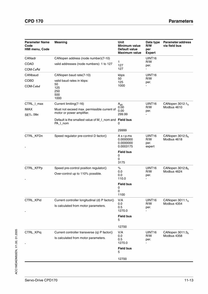
AC
C1M
DA
DM
00E
N, V
1.00
, 01.
2005
CPD 170 Parameters
Servo-Drive CPD170 11-13
CANadr
COAD
COM-CoAD
CANopen address (node number)(7-10)
valid addresses (node numbers): 1 to 1271127127
UINT16R/Wper.-
CANbaud
COBD
COM-CoBD
CANopen baud rate(7-10)
valid baud rates in kbps:50 1252505001000
kbps501251000
UINT16R/Wper.-
CTRL_I_max
IMAX
SET-iMAX
Current limiting(7-16)
Must not exceed max. permissible current of motor or power amplifier.
Default is the smallest value of M_I_nom and PA_I_nom
Apk0.000.00299.99
Field bus0
29999
UINT16R/Wper.-
CANopen 3012:1hModbus 4610
CTRL_KFDn
-
Speed regulator pre-control D factor() A s r.p.ms0.00000000.00000000.0003175
Field bus003175
UINT16R/Wper.expert
CANopen 3012:5hModbus 4618
CTRL_KFPp
-
Speed pre-control position regulator()
Over-control up to 110% possible.
%0.00.0110.0
Field bus001100
UINT16R/Wper.-
CANopen 3012:8hModbus 4624
CTRL_KPid
-
Current controller longitudinal (d) P factor()
Is calculated from motor parameters.
V/A0.00.51270.0
Field bus5
12700
UINT16R/Wper.-
CANopen 3011:1hModbus 4354
CTRL_KPiq
-
Current controller transverse (q) P factor()
Is calculated from motor parameters.
V/A0.00.51270.0
Field bus5
12700
UINT16R/Wper.-
CANopen 3011:3hModbus 4358
Parameter NameCodeHMI menu, Code
Meaning UnitMinimum valueDefault valueMaximum value
Data typeR/WperExpert
Parameter address via field bus

11-14 Servo-Drive CPD170
Parameters CPD 170
AC
C1M
DA
DM
00E
N, V
1.00
, 01.
2005
CTRL_KPn
-
Speed controller P-factor(7-34)
Default value is calculated from motor para-meters
Amin/rev0.00100.00001.2700
Field bus10
12700
UINT16R/Wper.-
CANopen 3012:3hModbus 4614
CTRL_KPp
-
Position controller P-factor(7-38) 1/s2.00.0495.0
Field bus20
4950
UINT16R/Wper.-
CANopen 3012:6hModbus 4620
CTRL_n_max
NMAX
SET-NMAX
Speed limiter(7-16)
Must not exceed max. rpm of motor
Default is M_n_max
rpm0
13200
UINT16R/Wper.-
CANopen 3012:2hModbus 4612
CTRL_TAUnref
-
Filter time constant reference value filter of the reference speed value(7-34)
ms0.009.00327.67
Field bus090032767
UINT16R/Wper.-
CANopen 3012:9hModbus 4626
CTRL_TNid
-
Current controller longitudinal (d) setting time()
Is calculated from motor parameters.
ms0.130.00327.67
Field bus13
32767
UINT16R/Wper.-
CANopen 3011:2hModbus 4356
CTRL_TNiq
-
Current controller lateral (q) setting time()
Is calculated from motor parameters.
ms0.130.00327.67
Field bus13
32767
UINT16R/Wper.-
CANopen 3011:4hModbus 4360
CTRL_TNn
-
Speed controller correction time(7-34) ms0.009.00327.67
Field bus090032767
UINT16R/Wper.-
CANopen 3012:4hModbus 4616
Parameter NameCodeHMI menu, Code
Meaning UnitMinimum valueDefault valueMaximum value
Data typeR/WperExpert
Parameter address via field bus
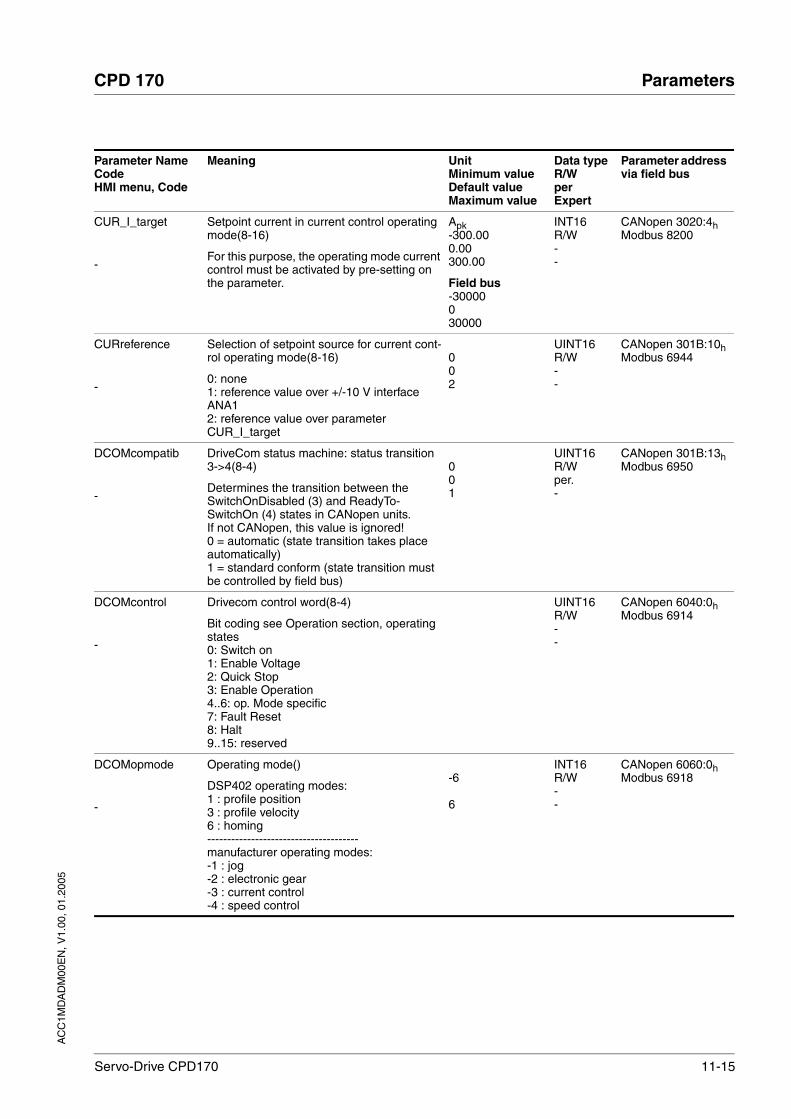
AC
C1M
DA
DM
00E
N, V
1.00
, 01.
2005
CPD 170 Parameters
Servo-Drive CPD170 11-15
CUR_I_target
-
Setpoint current in current control operating mode(8-16)
For this purpose, the operating mode current control must be activated by pre-setting on the parameter.
Apk-300.000.00300.00
Field bus-30000030000
INT16R/W--
CANopen 3020:4hModbus 8200
CURreference
-
Selection of setpoint source for current cont-rol operating mode(8-16)
0: none1: reference value over +/-10 V interface ANA12: reference value over parameter CUR_I_target
002
UINT16R/W--
CANopen 301B:10hModbus 6944
DCOMcompatib
-
DriveCom status machine: status transition 3->4(8-4)
Determines the transition between the SwitchOnDisabled (3) and ReadyTo-SwitchOn (4) states in CANopen units.If not CANopen, this value is ignored!0 = automatic (state transition takes place automatically)1 = standard conform (state transition must be controlled by field bus)
001
UINT16R/Wper.-
CANopen 301B:13hModbus 6950
DCOMcontrol
-
Drivecom control word(8-4)
Bit coding see Operation section, operating states0: Switch on1: Enable Voltage 2: Quick Stop3: Enable Operation4..6: op. Mode specific7: Fault Reset8: Halt9..15: reserved
UINT16R/W--
CANopen 6040:0hModbus 6914
DCOMopmode
-
Operating mode()
DSP402 operating modes:1 : profile position3 : profile velocity6 : homing--------------------------------------manufacturer operating modes:-1 : jog-2 : electronic gear-3 : current control-4 : speed control
-6
6
INT16R/W--
CANopen 6060:0hModbus 6918
Parameter NameCodeHMI menu, Code
Meaning UnitMinimum valueDefault valueMaximum value
Data typeR/WperExpert
Parameter address via field bus

11-16 Servo-Drive CPD170
Parameters CPD 170
AC
C1M
DA
DM
00E
N, V
1.00
, 01.
2005
DCOMstatus
-
Drivecom status word(8-4)
Bit coding see Operation section, status machine0-3,5,6: status bits4: Voltage enabled7: Warning8: HALT request active9: Remote10: Target reached11: reserved12: Op. mode specific13: x_err14: x_end15: ref_ok
UINT16R/---
CANopen 6041:0hModbus 6916
DEVcmdinterf
DEVC
NONEDEVC
Specification of the control mode(7-10)
0 / none: undefined (default)1 / IODevice / IO: local control mode2 / CANopenDevice / CanO: CANopen3 / ModbusDevice / Modb: Modbus4: reserved
CAUTION: a change in the setting is not enabled until the next start (exception: change of the value 0", at "Initial Setup"").
004
UINT16R/Wper.-
CANopen 3005:1hModbus 1282
ESIMscale
ESSC
DRC-ESSC
Encoder simulation - setting the resolu-tion(7-16)
The following resolutions can be adjusted:128256512102420484096
Inc8409665535
UINT16R/Wper.-
CANopen 3005:15hModbus 1322
FLT_AddInfo1
-
ENABLE cycles up to time of error()
Number of power amplifier switch-on proces-ses after switching on the power supply (control voltage) up to the appearance of the error
UINT16R/---
CANopen 303C:5hModbus 15370
FLT_AddInfo2
-
Time error occurs after ENABLE() s UINT16R/---
CANopen 303C:6hModbus 15372
FLT_AddInfo3
-
DC bus voltage at error time() V0.00.00.0
UINT16R/---
CANopen 303C:7hModbus 15374
FLT_AddInfo4
-
Speed at error time() rpm INT16R/---
CANopen 303C:8hModbus 15376
Parameter NameCodeHMI menu, Code
Meaning UnitMinimum valueDefault valueMaximum value
Data typeR/WperExpert
Parameter address via field bus

AC
C1M
DA
DM
00E
N, V
1.00
, 01.
2005
CPD 170 Parameters
Servo-Drive CPD170 11-17
FLT_AddInfo5
-
Motor current at error time() A0.000.000.00
UINT16R/---
CANopen 303C:9hModbus 15378
FLT_AddInfo6
-
Power amplifier temperature at error time() °C INT16R/---
CANopen 303C:AhModbus 15380
FLT_AddInfo7
-
Unit temperature at error time() °C INT16R/---
CANopen 303C:BhModbus 15382
FLT_class
-
Error class()
0: warning (no response)1: error (Quick Stop -> status 7)2: error (Quick Stop -> status 8,9)3: fatal error (status 9)4: fatal error (status 9, cannot be acknow-ledged)
0
4
UINT16R/---
CANopen 303C:2hModbus 15364
FLT_del_err
-
Erase error memory()
1: delete all entries in the error memory
The deletion process is completed when 0 is returned during reading.
001
UINT16R/W--
CANopen 303B:4hModbus 15112
FLT_err_num
-
Error number()
Reading this parameter brings the complete error entry (sub-index 1..11) into an interme-diate memory from which all other sub-indi-ces are subsequently read.
In addition, the read indicator of the error memory is automatically switched forward to the next error entry.
0
65535
UINT16R/---
CANopen 303C:1hModbus 15362
FLT_MemReset
-
Reset the error memory read pointer()
1 : set error memory read indicator to oldest error entry.
001
UINT16R/W--
CANopen 303B:5hModbus 15114
FLT_powerOn
POWO
INF-PoWo
Number of switch-on processes()0
4294967295
UINT32R/---
CANopen 303B:2hModbus 15108
FLT_Qual
-
Eror additional information()
This entry contains additional information on the error depending on the error number Example: parameter address
0
65535
UINT16R/---
CANopen 303C:4hModbus 15368
FLT_Time
-
Error time()
referenced to the operating hours counter
s0
536870911
UINT32R/---
CANopen 303C:3hModbus 15366
Parameter NameCodeHMI menu, Code
Meaning UnitMinimum valueDefault valueMaximum value
Data typeR/WperExpert
Parameter address via field bus

11-18 Servo-Drive CPD170
Parameters CPD 170
AC
C1M
DA
DM
00E
N, V
1.00
, 01.
2005
GEARdenom
-
Denominator of gear ratio(8-22)
see description GEARnum112147483647
INT32R/Wper.-
CANopen 3026:3hModbus 9734
GEARdir_enabl
-
Enable direction of rotation(8-22)
1 / positive : clockwise direction2 / negative: anticlockwise direction3 / both: both directions (default)
Set permissible direction of motion, a reverse interlock can be set during gear pro-cessing.
133
UINT16R/Wper.-
CANopen 3026:5hModbus 9738
GEARnum
-
Numerator of the gear ratio(8-22)
Gear ratio numeratorgear ratio= ------------------------------------ gear ratio denominator
The new gear ratio is enabled on transfer of the numerator value.
-214748364812147483647
INT32R/Wper.-
CANopen 3026:4hModbus 9736
GEARratio
GFAC
SET-GFAC
Selection of special gear ratios(8-22)
0 : use of the specified gear ratiofrom GEARnum/GEARdenom1 : 2002 : 4003 : 5004 : 10005 : 20006 : 40007 : 50008 : 100009 : 409610 : 819211 : 16384
Change of reference values by the specified value effects a motor revolution.
0011
UINT16R/Wper.-
CANopen 3026:6hModbus 9740
GEARreference
-
Electronic gear processing operating mode(8-22)
0: disabled1: real-time synchronisation2: synchronisation with compensation move-ment
002
UINT16R/W--
CANopen 301B:12hModbus 6948
HMdisusr
-
Distance between the switching point and the reference point(8-31)
After leaving the switch, the drive is still posi-tioned in the working range for a defined path and this position is defined as a refe-rence point.
The parameters are only effective with refe-rence movements without index pulse sear-ching.
usr12002147483647
INT32R/Wper.-
CANopen 3028:7hModbus 10254
Parameter NameCodeHMI menu, Code
Meaning UnitMinimum valueDefault valueMaximum value
Data typeR/WperExpert
Parameter address via field bus

AC
C1M
DA
DM
00E
N, V
1.00
, 01.
2005
CPD 170 Parameters
Servo-Drive CPD170 11-19
HMoutdisusr
-
Maximum run-off distance(8-31)
0: withdrawal control inactive>0: run-off in user-defined units
position range within which it must be disab-led again with the switch enabled.
usr002147483647
INT32R/Wper.-
CANopen 3028:6hModbus 10252
HMdisREFtoIDX
-
Distance of switch - index pulse after refe-rence movement(8-31)
Reading value provides the value of the dif-ference between the index pulse position and the position on the switching flank of the limit or reference switch.Serves to monitor how far the index pulse is from the switching flank and serves to pro-vide the criterion whether the reference movement with index pulse processing can be safely reproduced.Value input in 1/10000 U
U0.00000.00000.0000
INT32R/---
CANopen 3028:ChModbus 10264
HMIprotected
-
HMI Interlock(8-31)
0: HMI interlock not enabled1: HMI interlock enabled
The following actions are not possible when interlocked:- modify parameter- manual mode (jog)- autotuning- FaultReset
001
UINT16R/Wper.-
CANopen 303:1hModbus 14850
Parameter NameCodeHMI menu, Code
Meaning UnitMinimum valueDefault valueMaximum value
Data typeR/WperExpert
Parameter address via field bus
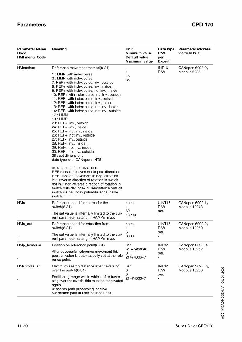
11-20 Servo-Drive CPD170
Parameters CPD 170
AC
C1M
DA
DM
00E
N, V
1.00
, 01.
2005
HMmethod
-
Reference movement method(8-31)
1 : LIMN with index pulse2 : LIMP with index pulse7: REF+ with index pulse, inv., outside8: REF+ with index pulse, inv., inside9: REF+ with index pulse, not inv., inside10: REF+ with index pulse, not inv., outside11: REF- with index pulse, inv., outside12: REF- with index pulse, inv., inside13: REF- with index pulse, not inv., inside14: REF- with index pulse, not inv., outside17 : LIMN18 : LIMP23: REF+, inv., outside24: REF+, inv., inside25: REF+, not inv., inside26: REF+, not inv., outside27: REF-, inv., outside28: REF-, inv., inside29: REF-, not inv., inside30: REF-, not inv., outside35 : set dimensionsdata type with CANopen: INT8
explanation of abbreviations:REF+: search movement in pos. directionREF-: search movement in neg. directioninv.: reverse direction of rotation in switchnot inv.: non-reverse direction of rotation in switch outside: index pulse/distance outside switch inside: index pulse/distance inside switch.
11835
INT16R/W--
CANopen 6098:0hModbus 6936
HMn
-
Reference speed for search for the switch(8-31)
The set value is internally limited to the cur-rent parameter setting in RAMPn_max.
r.p.m.16013200
UINT16R/Wper.-
CANopen 6099:1hModbus 10248
HMn_out
-
Reference speed for retraction from switch(8-31)
The set value is internally limited to the cur-rent parameter setting in RAMPn_max.
r.p.m.163000
UINT16R/Wper.-
CANopen 6099:2hModbus 10250
HMp_homeusr
-
Position on reference point(8-31)
After successful reference movement this position value is automatically set at the refe-rence point.
usr-214748364802147483647
INT32R/Wper.-
CANopen 3028:BhModbus 10262
HMsrchdisusr
-
Maximum search distance after traversing over the switch(8-31)
Positioning range within which, after traver-sing over the switch, this must be reactivated again.0: search path processing inactive>0: search path in user-defined units
usr002147483647
INT32R/Wper.-
CANopen 3028:DhModbus 10266
Parameter NameCodeHMI menu, Code
Meaning UnitMinimum valueDefault valueMaximum value
Data typeR/WperExpert
Parameter address via field bus

AC
C1M
DA
DM
00E
N, V
1.00
, 01.
2005
CPD 170 Parameters
Servo-Drive CPD170 11-21
IO_AutoEnable
IOAE
DRC-ioAE
Automatic Enable at PowerOn, if ENABLE input is active(7-24)
0 / off: active enable during PowerOn does not result in activation of power amplifier (default)1 / on: active enable during PowerOn results in activation of power amplifier
001
UINT16R/Wper.-
CANopen 3005:6hModbus 1292
IOdefaultMode
IO-M
DRC-io-M
Start-up of operating mode for 'local control mode'(7-10)
0 / none / none : none (default)1 / CurrentControl / Curr: current controller (reference value of ANA1)2 / SpeedControl / Sped: speed controller (reference value of ANA1)3 / GearMode / Gear: electronic gear
The operating mode is automatically enabled when the drive switches to the 'OperationE-nable' status and "I/O Device / I/O" is set in DEVcmdinterf.""
003
UINT16R/Wper.-
CANopen 3005:3hModbus 1286
IODirPosintf
-
Count direction at the position interface()
0 / clockwise: clockwise1 / counter clockwise: anticlockwise
001
UINT16R/Wper.-
CANopen 3008:7hModbus 2062
IOLogicLevel
IOLL
DRC-ioLL
Logic level of the digital inputs/outputs(7-10)
0 / positive / pos: positive logic (default)1 / negative / neg: negative logic
CAUTION: a change of the setting is not enabled until the next start.
001
UINT16R/Wper.-
CANopen 3005:4hModbus 1288
IOposInterfac
IOPI
DRC-ioPi
Logic level of the digital inputs/outputs(7-10)
RS422 I/O interface (Pos) as:0 / ABinput / AB: input ENC_A, ENC_B, ENC_I (index pulse) 4x evaluation1 / PDinput /PD: input PULSE, DIR, ENABLE22 / ESIMoutput / ESIM: output: ESIM_A, ESIM_B, ESIM_I
002
UINT16R/Wper.-
CANopen 3005:2hModbus 1284
IOsigLimN
-
Processing setting signal LIMN(8-43)
0 / none: inactive1 / normally closed: normally closed con-tact2 / normally open: normally open contact
012
UINT16R/Wper.-
CANopen 3006:FhModbus 1566
IOsigLimP
-
Processing setting signal LIMP(8-43)
0 / none: inactive1 / normally closed: normally closed con-tact2 / normally open: normally open contact
012
UINT16R/Wper.-
CANopen 3006:10hModbus 1568
Parameter NameCodeHMI menu, Code
Meaning UnitMinimum valueDefault valueMaximum value
Data typeR/WperExpert
Parameter address via field bus
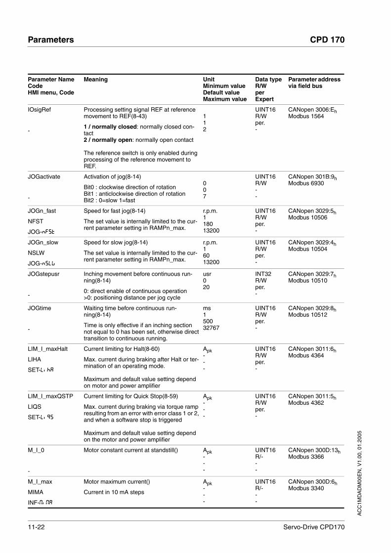
11-22 Servo-Drive CPD170
Parameters CPD 170
AC
C1M
DA
DM
00E
N, V
1.00
, 01.
2005
IOsigRef
-
Processing setting signal REF at reference movement to REF(8-43)
1 / normally closed: normally closed con-tact2 / normally open: normally open contact
The reference switch is only enabled during processing of the reference movement to REF.
112
UINT16R/Wper.-
CANopen 3006:EhModbus 1564
JOGactivate
-
Activation of jog(8-14)
Bit0 : clockwise direction of rotationBit1 : anticlockwise direction of rotationBit2 : 0=slow 1=fast
007
UINT16R/W--
CANopen 301B:9hModbus 6930
JOGn_fast
NFST
JOG-NFST
Speed for fast jog(8-14)
The set value is internally limited to the cur-rent parameter setting in RAMPn_max.
r.p.m.118013200
UINT16R/Wper.-
CANopen 3029:5hModbus 10506
JOGn_slow
NSLW
JOG-NSLW
Speed for slow jog(8-14)
The set value is internally limited to the cur-rent parameter setting in RAMPn_max.
r.p.m.16013200
UINT16R/Wper.-
CANopen 3029:4hModbus 10504
JOGstepusr
-
Inching movement before continuous run-ning(8-14)
0: direct enable of continuous operation>0: positioning distance per jog cycle
usr020
INT32R/Wper.-
CANopen 3029:7hModbus 10510
JOGtime
-
Waiting time before continuous run-ning(8-14)
Time is only effective if an inching section not equal to 0 has been set, otherwise direct transition to continuous running.
ms150032767
UINT16R/Wper.-
CANopen 3029:8hModbus 10512
LIM_I_maxHalt
LIHA
SET-LihA
Current limiting for Halt(8-60)
Max. current during braking after Halt or ter-mination of an operating mode.
Maximum and default value setting depend on motor and power amplifier
Apk---
UINT16R/Wper.-
CANopen 3011:6hModbus 4364
LIM_I_maxQSTP
LIQS
SET-LiQS
Current limiting for Quick Stop(8-59)
Max. current during braking via torque ramp resulting from an error with error class 1 or 2, and when a software stop is triggered
Maximum and default value setting depend on the motor and power amplifier
Apk---
UINT16R/Wper.-
CANopen 3011:5hModbus 4362
M_I_0
-
Motor constant current at standstill() Apk---
UINT16R/---
CANopen 300D:13hModbus 3366
M_I_max
MIMA
INF-MiMA
Motor maximum current()
Current in 10 mA steps
Apk---
UINT16R/---
CANopen 300D:6hModbus 3340
Parameter NameCodeHMI menu, Code
Meaning UnitMinimum valueDefault valueMaximum value
Data typeR/WperExpert
Parameter address via field bus

AC
C1M
DA
DM
00E
N, V
1.00
, 01.
2005
CPD 170 Parameters
Servo-Drive CPD170 11-23
M_I_nom
MINO
INF-MiNo
Motor nominal current()
Current in 10 mA steps
Apk---
UINT16R/---
CANopen 300D:7hModbus 3342
M_I2t
-
maximum permissible time for ImaxM() ms---
UINT16R/---
CANopen 300D:11hModbus 3362
M_Jrot
-
Motor moment of inertia()
in 0.1 kgcm^2 steps
kg cm2
---
UINT16R/---
CANopen 300D:ChModbus 3352
M_Ke
-
Motor EMF constants Ke() Vs---
UINT16R/-per.-
CANopen 300D:BhModbus 3350
M_L_d
-
Mtor inductance d-direction()
in 0.01 mH steps
mH---
UINT16R/---
CANopen 300D:FhModbus 3358
M_L_q
-
Motor inductance q-direction()
in 0.01 mH steps
mH---
UINT16R/---
CANopen 300D:EhModbus 3356
M_M_max
-
Motor peak torque() N cm---
UINT16R/---
CANopen 300D:9hModbus 3346
M_M_nom
-
Motor nominal torque() N cm---
UINT16R/---
CANopen 300D:8hModbus 3344
M_n_max
-
maximum permissible motor speed() rpm UINT16R/---
CANopen 300D:4hModbus 3336
M_n_nom
-
Nominal motor speed() rpm UINT16R/---
CANopen 300D:5hModbus 3338
M_Polepair
-
Number of motor pole pairs() Pole pairs---
UINT16R/---
CANopen 300D:14hModbus 3368
M_R_UV
-
Motor termination resistance()
in 10mOhm steps
Ω UINT16R/---
CANopen 300D:DhModbus 3354
Parameter NameCodeHMI menu, Code
Meaning UnitMinimum valueDefault valueMaximum value
Data typeR/WperExpert
Parameter address via field bus

11-24 Servo-Drive CPD170
Parameters CPD 170
AC
C1M
DA
DM
00E
N, V
1.00
, 01.
2005
M_Sensor
-
Motor encoder type()
0 / unknown: unknown1: reserved2: reserved3 / SRS: SinCos 1024 lines Singleturn4 / SRM: SinCos 1024 lines Multiturn5 / SCS: SinCos 512 lines Singleturn6 / SCM: SinCos 512 lines Multiturn
---
UINT16R/-per.-
CANopen 300D:3hModbus 3334
M_serialNo
-
Motor serial number()---
UINT32R/---
M_T_max
-
max. motor temperature() °C INT16R/-per.-
CANopen 300D:10hModbus 3360
M_T_warn
-
Motor temperature warning threshold() °C INT16R/-per.-
CANopen 300D:15hModbus 3370
M_TempType
-
Type of temperature sensor()
0: PTC1: NTC
---
UINT16R/-per.-
CANopen 300D:12hModbus 3364
M_Type
-
Motor type()
0: no motor selected>0: connected motor type
---
UINT32R/-per.-
CANopen 300D:2hModbus 3332
M_U_nom
-
Motor nominal voltage() V---
UINT16R/---
CANopen 300D:AhModbus 3348
MBadr
MBAD
COM-MBAD
Modbus address(7-10)
valid addresses 1 to 24711247
UINT16R/Wper.-
MBbaud
MBBD
COM-MBBD
Modbus baud rate(7-10)
Allowable baud rates:96001920038400
Baud01920038400
UINT16R/Wper.-
MBdword_order
MBWO
COM-MBWo
Modbus word sequence for double words (32 bit values)()
(register swap)
0 / HighLow / HiLo: HighWord-LowWord, big endian -> Modicon Quantum (default)1 / LowHigh / LoHi : LowWord-HighWordlittle endian -> Premium, HMI (Telemecani-que)
001
UINT16R/Wper.-
Parameter NameCodeHMI menu, Code
Meaning UnitMinimum valueDefault valueMaximum value
Data typeR/WperExpert
Parameter address via field bus

AC
C1M
DA
DM
00E
N, V
1.00
, 01.
2005
CPD 170 Parameters
Servo-Drive CPD170 11-25
MBformat
MBFO
COM-MBFo
Modbus data format()
1 / 8Bit NoParity 1Stop / 8n1: 8 bit, no parity bit, 1 stop bit2 / 8Bit EvenParity 1Stop / 8e1: 8 bit, even parity bit, 1 stop bit (default)3 / 8Bit OddParity 1Stop / 8o1: 8 Bit, odd parity bit, 1 stop bit4 / 8Bit NoParity 2Stop / 8n2: 8 bit, no parity bit, 2 stop bits
124
UINT16R/Wper.-
MBnode_guard
-
Modbus Node Guard()
Connection monitoring0 : inactive (default)>0 : monitoring time
ms0010000
UINT16R/W--
PA_f_DefChop
-
Switching frequency of power amplifier()
0 / 4kHz: 4 kHz1 / 8kHz: 8 kHz
---
UINT16R/-per.-
CANopen 3010:5hModbus 4106
PA_I_max
PIMA
INF-PiMA
Maximum current of power amplifier()
in 10 mA steps
Apk---
UINT16R/-per.-
CANopen 3010:2hModbus 4100
PA_I_nom
PINO
INF-PiNo
Nominal current of power amplifier()
in 10 mA steps
Apk---
UINT16R/-per.-
CANopen 3010:1hModbus 4098
PA_T_max
-
maximum permissible temperature of the power amplifier()
°C INT16R/-per.-
CANopen 3010:7hModbus 4110
PA_T_warn
-
Temperature limit of the power amplifier() °C INT16R/-per.-
CANopen 3010:6hModbus 4108
PA_U_maxDC
-
max. permissible DC bus voltage (DC bus)()
in 0.1V steps
V---
UINT16R/-per.-
CANopen 3010:3hModbus 4102
PA_U_minDC
-
DC bus low voltage threshold for drive switch-off()
in 0.1V steps
V---
UINT16R/-per.-
CANopen 3010:4hModbus 4104
PA_U_minStopDC
-
DC bus low voltage threshold for Quick Stop()
At this threshold, the drive performs a Quick Stop
V---
UINT16R/-per.-
CANopen 3010:AhModbus 4116
PAR_CTRLreset
RES
TUN-RES
Reset controller parameter()
1: controller parameters of the speed and position controller are reset The current controller is automatically set for the connected motor.
001
UINT16R/W--
CANopen 3004:7hModbus 1038
Parameter NameCodeHMI menu, Code
Meaning UnitMinimum valueDefault valueMaximum value
Data typeR/WperExpert
Parameter address via field bus

11-26 Servo-Drive CPD170
Parameters CPD 170
AC
C1M
DA
DM
00E
N, V
1.00
, 01.
2005
PAReeprSave
-
Back up the parameters in the EEPROM memory()
Bit 0 = 1: run backup of user parameters.
The current parameters are backed up in the non-volatile memory (EEPROM).The storing process is complete if a 0 is returned when reading the parameters.
003
UINT16R/W--
PARuserReset
-
Resetting the user parameters(8-67)
1: set user parameters to default values.All parameters are reset except:- communications parameters- device control- logic level
001
UINT16R/W--
CANopen 3004:8hModbus 1040
POSdirOfRotat
PROT
DRC-PRoT
Definition of the direction of rotation(8-64)
0 / clockwise / clw: clockwise1 / counter clockwise / cclw: anticlockwise
Meaning:The drive rotates clockwise at positive speeds when the motor shaft is viewed at the flange.
CAUTION: when using limit switches, after changing the setting the limit switch connec-tions must be changed over. The limit switch which is actuated by moving in jog mode in a positive direction must be connected to the input LIMP, and vice versa.
001
UINT16R/Wper.-
CANopen 3006:ChModbus 1560
POSscaleDenom
-
Denominator of the position scaling fac-tor(8-54)
Description see count (POSscaleNum)
Acceptance of a new scaling factor is by transfer of the numerator
usr1163842147483647
INT32R/Wper.-
CANopen 3006:7hModbus 1550
POSscaleNum
-
Numerator of the position scaling fac-tor(8-54)
Specification of scaling factor:
motor revolutions [U]----------------------------------------------------------change of user position [usr]
A new scaling is imported when the numera-tor value is transferred
User-defined limit values may be reduced as a result of the calculation of an internal sys-tem factor
U112147483647
INT32R/Wper.-
CANopen 3006:8hModbus 1552
PPn_target
-
Speed setpoint for profile position(8-26)
Maximum value is limited to the current set-ting in CTRL_n_max.
rpm060
UINT32R/W--
CANopen 6081:0hModbus 6942
Parameter NameCodeHMI menu, Code
Meaning UnitMinimum valueDefault valueMaximum value
Data typeR/WperExpert
Parameter address via field bus

AC
C1M
DA
DM
00E
N, V
1.00
, 01.
2005
CPD 170 Parameters
Servo-Drive CPD170 11-27
PPp_targetusr
-
Target position of profile position operating mode(8-26)
Min/max values depend on:- scaling factor- software limit switch (if enabled)
usr INT32R/W--
CANopen 607A:0hModbus 6940
ProfileType
-
Motion profile()
0 : Linear000
INT16R/---
PVn_target
-
Setpoint speed profile velocity operating mode(8-29)
Maximum value is limited to the current set-ting in CTRL_n_max.
0rpm
INT32R/W--
CANopen 60FF:0hModbus 6938
PWM_fChop
-
Switching frequency of power amplifier(7-16)
Switching frequency of power amplifier0 / 4kHz: 4 kHz1 / 8kHz: 8 kHz
Factory setting:400 V units: 4 kHzall others: 8 kHz
0
1
UINT16R/Wper.expert
CANopen 3005:EhModbus 1308
RAMPacc
-
Profile generator acceleration(8-57) r.p.m*s306003000000
UINT32R/Wper.-
CANopen 6083:0hModbus 1556
RAMPdecel
-
Profile generator deceleration(8-57) r.p.m*s7507503000000
UINT32R/Wper.-
CANopen 6084:0hModbus 1558
RAMPn_max
-
Profile generator deceleration(8-57)
Parameters are effective in the following operating modes:- point-to-point- profile velocity- homing- jog
If a higher setpoint speed is set on one of these operating modes it will be automati-cally limited to this value.This makes it simple to conduct a commis-sioning with limited speed.
r.p.m.601200013200
UINT16R/Wper.-
CANopen 607F:0hModbus 1554
SPEEDn_target
-
Reference speed in speed control operating mode(8-19)
For this purpose, the operating mode speed control must be activated by pre-setting on the parameter.The internal maximum speed is limited by the current setting in CTRL_n_max
r.p.m.-30000030000
INT16R/W--
CANopen 3021:4hModbus 8456
Parameter NameCodeHMI menu, Code
Meaning UnitMinimum valueDefault valueMaximum value
Data typeR/WperExpert
Parameter address via field bus
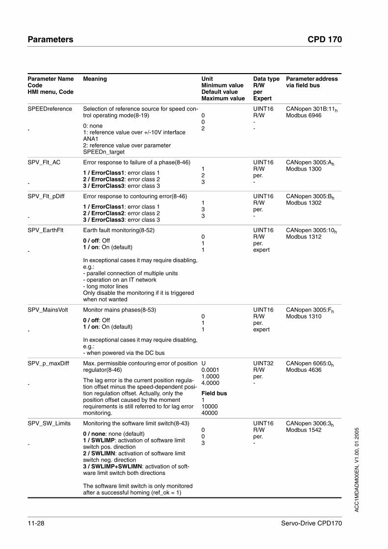
11-28 Servo-Drive CPD170
Parameters CPD 170
AC
C1M
DA
DM
00E
N, V
1.00
, 01.
2005
SPEEDreference
-
Selection of reference source for speed con-trol operating mode(8-19)
0: none1: reference value over +/-10V interface ANA12: reference value over parameter SPEEDn_target
002
UINT16R/W--
CANopen 301B:11hModbus 6946
SPV_Flt_AC
-
Error response to failure of a phase(8-46)
1 / ErrorClass1: error class 12 / ErrorClass2: error class 23 / ErrorClass3: error class 3
123
UINT16R/Wper.-
CANopen 3005:AhModbus 1300
SPV_Flt_pDiff
-
Error response to contouring error(8-46)
1 / ErrorClass1: error class 12 / ErrorClass2: error class 23 / ErrorClass3: error class 3
133
UINT16R/Wper.-
CANopen 3005:BhModbus 1302
SPV_EarthFlt
-
Earth fault monitoring(8-52)
0 / off: Off1 / on: On (default)
In exceptional cases it may require disabling, e.g.:- parallel connection of multiple units- operation on an IT network- long motor linesOnly disable the monitoring if it is triggered when not wanted
011
UINT16R/Wper.expert
CANopen 3005:10hModbus 1312
SPV_MainsVolt
-
Monitor mains phases(8-53)
0 / off: Off1 / on: On (default)
In exceptional cases it may require disabling, e.g.:- when powered via the DC bus
011
UINT16R/Wper.expert
CANopen 3005:FhModbus 1310
SPV_p_maxDiff
-
Max. permissible contouring error of position regulator(8-46)
The lag error is the current position regula-tion offset minus the speed-dependent posi-tion regulation offset. Actually, only the position offset caused by the moment requirements is still referred to for lag error monitoring.
U0.00011.00004.0000
Field bus11000040000
UINT32R/Wper.-
CANopen 6065:0hModbus 4636
SPV_SW_Limits
-
Monitoring the software limit switch(8-43)
0 / none: none (default)1 / SWLIMP: activation of software limit switch pos. direction2 / SWLIMN: activation of software limit switch neg. direction3 / SWLIMP+SWLIMN: activation of soft-ware limit switch both directions
The software limit switch is only monitored after a successful homing (ref_ok = 1)
003
UINT16R/Wper.-
CANopen 3006:3hModbus 1542
Parameter NameCodeHMI menu, Code
Meaning UnitMinimum valueDefault valueMaximum value
Data typeR/WperExpert
Parameter address via field bus

AC
C1M
DA
DM
00E
N, V
1.00
, 01.
2005
CPD 170 Parameters
Servo-Drive CPD170 11-29
SPVswLimNusr
-
negative position limit for software limit switch(8-43)
-2147483648usr
INT32R/Wper.-
CANopen 607D:1hModbus 1546
SPVswLimPusr
-
positive position limit for software limit switch(8-43)
2147483647usr
INT32R/Wper.-
CANopen 607D:2hModbus 1544
SPVcommutat
-
Monitoring commutation(8-51)
0 / off: off1 / on: on (default)
011
UINT16R/Wper.-
CANopen 3005:5hModbus 1290
STANDp_win
-
Standstill window, permissible offset(8-61)
The offset for the standstill window time must lie in this range of values to allow recognition of the standstill of the drive.
Info: the processing of the standstill window must be activated via the 'STANDpwinTime' parameter.
U0.00000.00103.2767
Field bus01032767
UINT16R/Wper.-
CANopen 6067:0hModbus 4370
STANDpwinTime
-
Standstill window, time(8-61)
0 : monitoring of standstill window disabled>0 : time in ms within which the control devi-ation must be in the standstill window
ms0032767
UINT16R/Wper.-
CANopen 6068:0hModbus 4372
STANDpwinTout
-
Timeout period for standstill window moni-tor(8-61)
0 : timeout monitoring disabled>0 : timeout period in ms
The standstill window process is set with STANDp_win and STANDpwinTime
The time monitoring starts at the moment the target position (setpoint position of posi-tion controller) is reached or the end of pro-cessing of the profile generator.
ms0016000
UINT16R/Wper.-
CANopen 3011:BhModbus 4374
StartUpMessage
-
Start-up messages()
Read : start-up messagesWrite: validation
Read :Bit 0 = 1: First SetupBit 1 = 1: motor replacedBit 2 = 1: EEPROM data corruptBit 3 = 1: no motor connectedBit 4-15: reserved
Write:Bit 0 = 1: validation First SetupBit 1 = 1: validation motor replacedBit 2..15: reserved
UINT32R/W--
CANopen 3001:1ChModbus 312
Parameter NameCodeHMI menu, Code
Meaning UnitMinimum valueDefault valueMaximum value
Data typeR/WperExpert
Parameter address via field bus

11-30 Servo-Drive CPD170
Parameters CPD 170
AC
C1M
DA
DM
00E
N, V
1.00
, 01.
2005
SuppDriveModes
-
Supported operating modes as per DSP402()
Bit 0: profile positionBit 1: reservedBit 2: profile velocityBit 3: reservedBit 4: reservedBit 5: homing
Bit 16: jogBit 17: electrical gearboxBit 18: current controlBit 19: speed controlBit 20: reservedBit 21: reserved
UINT32R/---
CANopen 6502:0hModbus 6952
Parameter NameCodeHMI menu, Code
Meaning UnitMinimum valueDefault valueMaximum value
Data typeR/WperExpert
Parameter address via field bus
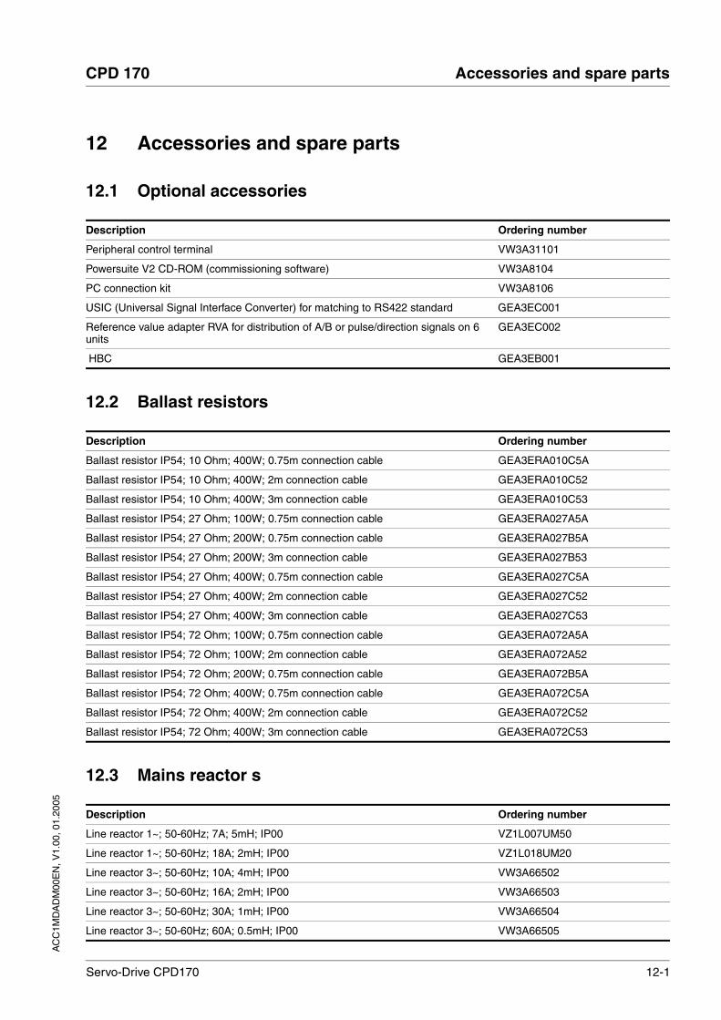
AC
C1M
DA
DM
00E
N, V
1.00
, 01.
2005
CPD 170 Accessories and spare parts
Servo-Drive CPD170 12-1
12 Accessories and spare parts
12.1 Optional accessories
12.2 Ballast resistors
12.3 Mains reactor s
Description Ordering number
Peripheral control terminal VW3A31101
Powersuite V2 CD-ROM (commissioning software) VW3A8104
PC connection kit VW3A8106
USIC (Universal Signal Interface Converter) for matching to RS422 standard GEA3EC001
Reference value adapter RVA for distribution of A/B or pulse/direction signals on 6 units
GEA3EC002
HBC GEA3EB001
Description Ordering number
Ballast resistor IP54; 10 Ohm; 400W; 0.75m connection cable GEA3ERA010C5A
Ballast resistor IP54; 10 Ohm; 400W; 2m connection cable GEA3ERA010C52
Ballast resistor IP54; 10 Ohm; 400W; 3m connection cable GEA3ERA010C53
Ballast resistor IP54; 27 Ohm; 100W; 0.75m connection cable GEA3ERA027A5A
Ballast resistor IP54; 27 Ohm; 200W; 0.75m connection cable GEA3ERA027B5A
Ballast resistor IP54; 27 Ohm; 200W; 3m connection cable GEA3ERA027B53
Ballast resistor IP54; 27 Ohm; 400W; 0.75m connection cable GEA3ERA027C5A
Ballast resistor IP54; 27 Ohm; 400W; 2m connection cable GEA3ERA027C52
Ballast resistor IP54; 27 Ohm; 400W; 3m connection cable GEA3ERA027C53
Ballast resistor IP54; 72 Ohm; 100W; 0.75m connection cable GEA3ERA072A5A
Ballast resistor IP54; 72 Ohm; 100W; 2m connection cable GEA3ERA072A52
Ballast resistor IP54; 72 Ohm; 200W; 0.75m connection cable GEA3ERA072B5A
Ballast resistor IP54; 72 Ohm; 400W; 0.75m connection cable GEA3ERA072C5A
Ballast resistor IP54; 72 Ohm; 400W; 2m connection cable GEA3ERA072C52
Ballast resistor IP54; 72 Ohm; 400W; 3m connection cable GEA3ERA072C53
Description Ordering number
Line reactor 1~; 50-60Hz; 7A; 5mH; IP00 VZ1L007UM50
Line reactor 1~; 50-60Hz; 18A; 2mH; IP00 VZ1L018UM20
Line reactor 3~; 50-60Hz; 10A; 4mH; IP00 VW3A66502
Line reactor 3~; 50-60Hz; 16A; 2mH; IP00 VW3A66503
Line reactor 3~; 50-60Hz; 30A; 1mH; IP00 VW3A66504
Line reactor 3~; 50-60Hz; 60A; 0.5mH; IP00 VW3A66505
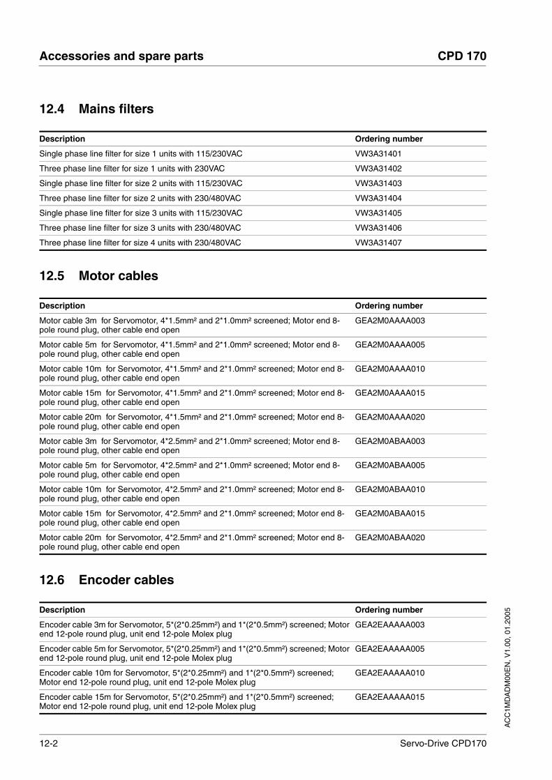
12-2 Servo-Drive CPD170
Accessories and spare parts CPD 170
AC
C1M
DA
DM
00E
N, V
1.00
, 01.
2005
12.4 Mains filters
12.5 Motor cables
12.6 Encoder cables
Description Ordering number
Single phase line filter for size 1 units with 115/230VAC VW3A31401
Three phase line filter for size 1 units with 230VAC VW3A31402
Single phase line filter for size 2 units with 115/230VAC VW3A31403
Three phase line filter for size 2 units with 230/480VAC VW3A31404
Single phase line filter for size 3 units with 115/230VAC VW3A31405
Three phase line filter for size 3 units with 230/480VAC VW3A31406
Three phase line filter for size 4 units with 230/480VAC VW3A31407
Description Ordering number
Motor cable 3m for Servomotor, 4*1.5mm² and 2*1.0mm² screened; Motor end 8-pole round plug, other cable end open
GEA2M0AAAA003
Motor cable 5m for Servomotor, 4*1.5mm² and 2*1.0mm² screened; Motor end 8-pole round plug, other cable end open
GEA2M0AAAA005
Motor cable 10m for Servomotor, 4*1.5mm² and 2*1.0mm² screened; Motor end 8-pole round plug, other cable end open
GEA2M0AAAA010
Motor cable 15m for Servomotor, 4*1.5mm² and 2*1.0mm² screened; Motor end 8-pole round plug, other cable end open
GEA2M0AAAA015
Motor cable 20m for Servomotor, 4*1.5mm² and 2*1.0mm² screened; Motor end 8-pole round plug, other cable end open
GEA2M0AAAA020
Motor cable 3m for Servomotor, 4*2.5mm² and 2*1.0mm² screened; Motor end 8-pole round plug, other cable end open
GEA2M0ABAA003
Motor cable 5m for Servomotor, 4*2.5mm² and 2*1.0mm² screened; Motor end 8-pole round plug, other cable end open
GEA2M0ABAA005
Motor cable 10m for Servomotor, 4*2.5mm² and 2*1.0mm² screened; Motor end 8-pole round plug, other cable end open
GEA2M0ABAA010
Motor cable 15m for Servomotor, 4*2.5mm² and 2*1.0mm² screened; Motor end 8-pole round plug, other cable end open
GEA2M0ABAA015
Motor cable 20m for Servomotor, 4*2.5mm² and 2*1.0mm² screened; Motor end 8-pole round plug, other cable end open
GEA2M0ABAA020
Description Ordering number
Encoder cable 3m for Servomotor, 5*(2*0.25mm²) and 1*(2*0.5mm²) screened; Motor end 12-pole round plug, unit end 12-pole Molex plug
GEA2EAAAAA003
Encoder cable 5m for Servomotor, 5*(2*0.25mm²) and 1*(2*0.5mm²) screened; Motor end 12-pole round plug, unit end 12-pole Molex plug
GEA2EAAAAA005
Encoder cable 10m for Servomotor, 5*(2*0.25mm²) and 1*(2*0.5mm²) screened; Motor end 12-pole round plug, unit end 12-pole Molex plug
GEA2EAAAAA010
Encoder cable 15m for Servomotor, 5*(2*0.25mm²) and 1*(2*0.5mm²) screened; Motor end 12-pole round plug, unit end 12-pole Molex plug
GEA2EAAAAA015

AC
C1M
DA
DM
00E
N, V
1.00
, 01.
2005
CPD 170 Accessories and spare parts
Servo-Drive CPD170 12-3
12.7 RS 422
12.8 CANopen
Encoder cable 20m for Servomotor, 5*(2*0.25mm²) and 1*(2*0.5mm²) screened; Motor end 12-pole round plug, unit end 12-pole Molex plug
GEA2EAAAAA020
Description Ordering number
Description Ordering number
Cable pulse/direction, ESIM, A/B, unit end 10 pole Molex, other end open, 0.5m GEA2RAAABA005
Cable pulse/direction, ESIM, A/B, unit end 10 pole Molex, other end open, 1.5m GEA2RAAABA015
Cable pulse/direction, ESIM, A/B, unit end 10 pole Molex, other end open, 3m GEA2RAAABA030
Cable pulse/direction, ESIM, A/B, unit end 10 pole Molex, other end open, 5m GEA2RAAABA050
Cable ESIM, A/B, for Master/Slave operation of units 2* 10-pole Molex, 0.5m GEA2RBAABB005
Cable ESIM, A/B, for Master/Slave operation of units 2* 10-pole Molex, 1.5m GEA2RBAABB015
Cable ESIM, A/B, for Master/Slave operation of units 2* 10-pole Molex, 3m GEA2RBAABB030
Cable ESIM, A/B, for Master/Slave operation of units 2* 10-pole Molex, 5m GEA2RBAABB050
Cable pulse/direction, ESIM, AB on Premium CAY, 0.5m, 10-pole Molex + 15-pole SubD
GEA2RBAABB005
Cable pulse/direction, ESIM, AB on Premium CAY, 1.5m, 10-pole Molex + 15-pole SubD
GEA2RBAABB015
Cable pulse/direction, ESIM, AB on Premium CAY, 3m, 10-pole Molex + 15-pole SubD
GEA2RBAABB030
Cable pulse/direction, ESIM, AB on Premium CAY, 5m, 10-pole Molex + 15-pole SubD
GEA2RBAABB050
Cable pulse/direction, ESIM, AB on Premium CAY, 0.5m, 10-pole Molex + 15-pole SubD
GEA2REAABC005
Cable pulse/direction, ESIM, AB on Premium CAY, 1.5m, 10-pole Molex + 15-pole SubD
GEA2REAABC015
Cable pulse/direction, ESIM, AB on Premium CAY, 3m, 10-pole Molex + 15-pole SubD
GEA2REAABC030
Cable pulse/direction, ESIM, AB on Premium CAY, 5m, 10-pole Molex + 15-pole SubD
GEA2REAABC050
Cable pulse/direction, ESIM, AB on Siemens S5 IP247, 3m, 10-pole Molex GEA2RFAABE030
Cable pulse/direction, ESIM, AB on Siemens S5 IP247, 3m, 10-pole Molex GEA2RGAABE030
Cable pulse/direction, ESIM, AB Siemens S7-300 FM353, 3m, 10-pole Molex GEA2RHAABD030
Cable pulse/direction, ESIM, AB on RVA, USIC or WP/WPM311, 0.5m GEA2RCAABD005
Cable pulse/direction, ESIM, AB on RVA, USIC or WP/WPM311, 1.5m GEA2RCAABD015
Cable pulse/direction, ESIM, AB on RVA, USIC or WP/WPM311, 3m GEA2RCAABD030
Cable pulse/direction, ESIM, AB on RVA, USIC or WP/WPM311, 5m GEA2RCAABD050
Description Ordering number
CANopen documentation ACC1MDACA01EN
CAN branching socket VW3CANTAP2
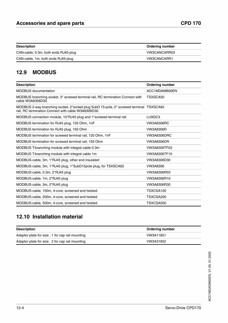
12-4 Servo-Drive CPD170
Accessories and spare parts CPD 170
AC
C1M
DA
DM
00E
N, V
1.00
, 01.
2005
12.9 MODBUS
12.10 Installation material
CAN-cable, 0.3m, both ends RJ45-plug VW3CANCARR03
CAN-cable, 1m, both ends RJ45-plug VW3CANCARR1
Description Ordering number
Description Ordering number
MODBUS documentation ACC1MDAMB00EN
MODBUS branching socket, 3* screwed terminal rail, RC termination Connect with cable W3A8306D30.
TSXSCA50
MODBUS 2-way branching socket, 2*socket plug SubD 15-pole, 2* screwed terminal rail, RC termination Connect with cable W3A8306D30.
TSXSCA62
MODBUS connection module, 10*RJ45 plug and 1*screwed terminal rail LU9GC3
MODBUS termination for RJ45 plug, 120 Ohm, 1nF VW3A8306RC
MODBUS termination for RJ45 plug, 150 Ohm VW3A8306R
MODBUS termination for screwed terminal rail, 120 Ohm, 1nF VW3A8306DRC
MODBUS termination for screwed terminal rail, 150 Ohm VW3A8306DR
MODBUS T-branching module with integral cable 0.3m VW3A8306TF03
MODBUS T-branching module with integral cable 1m VW3A8306TF10
MODBUS-cable, 3m, 1*RJ45 plug, other end insulated VW3A8306D30
MODBUS-cable, 3m, 1*RJ45 plug, 1*SubD15pole plug, for TSXSCA62 VW3A8306
MODBUS-cable, 0.3m, 2*RJ45 plug VW3A8306R03
MODBUS-cable, 1m, 2*RJ45 plug VW3A8306R10
MODBUS-cable, 3m, 2*RJ45 plug VW3A8306R30
MODBUS-cable, 100m, 4-core, screened and twisted TSXCSA100
MODBUS-cable, 200m, 4-core, screened and twisted TSXCSA200
MODBUS-cable, 500m, 4-core, screened and twisted TSXCSA500
Description Ordering number
Adaptor plate for size . 1 for cap rail mounting VW3A11851
Adaptor plate for size . 2 for cap rail mounting VW3A31852
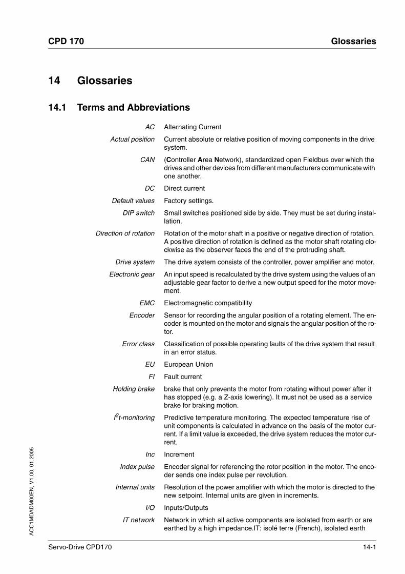
AC
C1M
DA
DM
00E
N, V
1.00
, 01.
2005
CPD 170 Glossaries
Servo-Drive CPD170 14-1
14 Glossaries
14.1 Terms and Abbreviations
AC Alternating Current
Actual position Current absolute or relative position of moving components in the drive system.
CAN (Controller Area Network), standardized open Fieldbus over which the drives and other devices from different manufacturers communicate with one another.
DC Direct current
Default values Factory settings.
DIP switch Small switches positioned side by side. They must be set during instal-lation.
Direction of rotation Rotation of the motor shaft in a positive or negative direction of rotation. A positive direction of rotation is defined as the motor shaft rotating clo-ckwise as the observer faces the end of the protruding shaft.
Drive system The drive system consists of the controller, power amplifier and motor.
Electronic gear An input speed is recalculated by the drive system using the values of an adjustable gear factor to derive a new output speed for the motor move-ment.
EMC Electromagnetic compatibility
Encoder Sensor for recording the angular position of a rotating element. The en-coder is mounted on the motor and signals the angular position of the ro-tor.
Error class Classification of possible operating faults of the drive system that result in an error status.
EU European Union
FI Fault current
Holding brake brake that only prevents the motor from rotating without power after it has stopped (e.g. a Z-axis lowering). It must not be used as a service brake for braking motion.
I2t-monitoring Predictive temperature monitoring. The expected temperature rise of unit components is calculated in advance on the basis of the motor cur-rent. If a limit value is exceeded, the drive system reduces the motor cur-rent.
Inc Increment
Index pulse Encoder signal for referencing the rotor position in the motor. The enco-der sends one index pulse per revolution.
Internal units Resolution of the power amplifier with which the motor is directed to the new setpoint. Internal units are given in increments.
I/O Inputs/Outputs
IT network Network in which all active components are isolated from earth or are earthed by a high impedance.IT: isolé terre (French), isolated earth

14-2 Servo-Drive CPD170
Glossaries CPD 170
AC
C1M
DA
DM
00E
N, V
1.00
, 01.
2005
Limit switch Switch that signals an overrun of the permissible travel range.
Motor phase current In a stepper motor the available torque is specified by the motor phase current. The higher the motor phase current, the higher the torque.
NMT network management (NMT), component of the CANopen communica-tions profile, tasks: initialising network and devices, starting, stopping, monitoring devices
Node-Guarding Monitoring function with slave at an interface for cyclic communication.
NTC resistance with negative temperature coefficient. Resistance value is re-duced as the temperature rises.
Parameter Device functions and values that can be set and called by the user.
PC Personal Computer
PELV Protective Extra Low Voltage, functional low voltage with safe isolation
per. Designation of whether the value of the parameter is persistent, i.e. after switching off the unit it is retained in the memory. When entering via HMI the unit stores the value of the parameter automatically at each change. When changing a value via commissioning software or field bus, the user must explicitly store the value change in the persistent memory.
PLC Programmable Logic Controller
Power amplifier A device that generates current for controlling the motor in accordance with the positioning signals from the controller.
Protection class The protection class is a standardised specification for electrical equip-ment that describes the protection against the ingress of foreign bodies and water (for example, IP20).
PS2 Abbreviation for Power Suite 2 commissioning software
PTC resistance with positive temperature coefficient. Resistance value is in-creased as the temperature rises.
Pulse direction signals Digital signals with variable pulse frequencies which signal changes in position and rotation direction via separate signal wires.
Quick Stop Quick stop, function used to provide quick braking of the motor via a command or in the event of a fault.
rms Effective value of a voltage (Vrms) or a current (Arms); abbreviation of “Root Mean Square”.
Scaling factor This factor gives the relationship between an internal unit and the user unit.
TT network, TN network Earthed networks, distinguished by the PE conductor connection.
User-defined unit Unit whose reference to motor rotation can be determined by the user via parameters.
Watchdog Equipment that monitors cyclic basic functions in the drive system. Po-wer amplifier and outputs are switched off in the event of error.
14.2 Product name
CPD17 Servo drive for brushless servomotors
Power Suite 2, PS2 Software for commissioning

AC
C1M
DA
DM
00E
N, V
1.00
, 01.
2005
CPD 170 Glossaries
Servo-Drive CPD170 14-3
HBC Holding brake controller
Peripheral control terminal hand-held operating unit
USIC (Universal Signal Interface Converter) adapter for RS422 standard
RVA Reference value adapter for distribution of A/B or pulse/direction signals to 5 units

14-4 Servo-Drive CPD170
Glossaries CPD 170
AC
C1M
DA
DM
00E
N, V
1.00
, 01.
2005

AC
C1M
DA
DM
00E
N, V
1.00
, 01.
2005
CPD 170 Service, maintenance and disposal
Servo-Drive CPD170 13-1
13 Service, maintenance and disposal
You cannot carry out repairs yourself. The repair should only be carried out by a certified customer service organisation No warranty or liability is accepted for repairs made by the customer.
DANGER!Electric shock, fire or explosion
• Only qualified personnel who are familiar with and understand the contents of this manual and the other relevant manuals are authorised to work on and with this drive system.
• Before working on the drive system:
– Switch off power to all terminals.
– Place a sign "DO NOT SWITCH ON" on the switch and lock to prevent switching on.
– Wait 6 minutes (for discharge of DC bus capacitors).
– Measure voltage between DC+ and DC- and check for <48V. (The DC bus LED is not a safe indication for absence of the DC bus voltage).
• Do not short-circuit DC bus or touch unshielded components or screws of the terminals with voltage present.
• Install all covers and close the housing doors before applying power.
• The motor generates voltage when the shaft is rotated. Lock the shaft of the motor to prevent rotation before starting work on the drive system.
• The system manufacturer is responsible for compliance with all applicable regulations relevant to earthing the drive system.
• Do not reach into the drive system (e.g. no pointed objects).Failure to follow these instructions will result in death or serious injury.
CAUTION!Destruction of system components and loss of control moni-toring!
Interrupting the negative connection of the control supply can cause excessive voltages at the signal connections.
• Never switch the negative connection of the control supply.
• Check for correct connection before switching on.
• Never connect the control supply or change its wiring while there is supply voltage present.
Failure to follow these instructions can result in injury or equipment damage.
13-2 Servo-Drive CPD170
Service, maintenance and disposal CPD 170
AC
C1M
DA
DM
00E
N, V
1.00
, 01.
2005
13.1 Service address
If you cannot resolve the fault yourself please contact your appointed sa-les partner. Have the following details available:
• Type, identification number and serial number of the product (type plate)
• Type of fault (possibly with fault number)
• Previous and concurrent conditions
• Your own ideas regarding the cause of the fault
Include this information if you return the product for inspection or repair.
If you have any questions please contact your local dealer. Your dealer will be happy to give you the name of a customer service outlet in your area.
13.2 Maintenance
The unit is maintenance free
13.2.1 Operational duration of safety function
The operating life for the Safe Standstill function is designed to be 20 ye-ars. After this period correct function is no longer ensured. The expiry date of the unit is determined by adding 20 years to the DOM shown on the type plate.
This date must be included in the system maintenance schedule.
Example The name plate on the unit includes the DOM in the DD.MM.YY format, z.B. 31.12.06. (31 December 2006). This means that the safety function is guaranteed until 31 December 2026 (06 + 20 = 26).
AC
C1M
DA
DM
00E
N, V
1.00
, 01.
2005
CPD 170 Service, maintenance and disposal
Servo-Drive CPD170 13-3
13.3 Replacing units
Observe the following procedure when changing the units.
Store all parameter settings in your PC with the commissioning soft-ware, see 8.6.10.3 “Store the settings on the data medium“ page 8-68.
Switch off all power supplies. Make sure that power is no longer connected (safety instructions).
Label all connections and remove the product.
Note the identification number and the serial number from the pro-duct type plate for later identification.
Install the new product as specified in 6 “Installation“
If the product that you are installing was previously used in a diffe-rent part of the system, the factory settings must be reset before commissioning. See 8.6.10.2 “Restore factory settings“ from page 8-67.
Carry out commissioning in accordance with chapter 7 “Commissio-ning“.
WARNING!Unexpected responses may cause injury and damage to the system.
The behaviour of the drive system is governed by numerous saved data. Unsuitable data may cause unexpected motions or responses to signals.
• Do not operate a unit with unknown data.
• Check the saved data.
• When commissioning carefully run tests for all operating states and fault cases.
• Check the functions after replacing a unit and also after chan-ges to the saved data.
• Start the system only if there are no persons or materials in the danger zone and the system can be operated safely.
Failure to follow these instructions can result in death or serious injury.
13-4 Servo-Drive CPD170
Service, maintenance and disposal CPD 170
AC
C1M
DA
DM
00E
N, V
1.00
, 01.
2005
13.4 Changing the motor
Switch off all power supplies. Make sure that power is no longer connected (safety instructions).
Label all connections and remove the product.
Note the identification number and the serial number from the pro-duct type plate for later identification.
Install the new product as specified in 6 “Installation“
If the original motor has been replaced with a different motor, the motor data set is read out again. If the unit recognises a different motor type, the regulation parameters are re-calculated and MOT is shown on the HMI.
Change motor type temporarily only Press ESC if you want to operate the new motor type temporarily on this unit.
The newly calculated regulation parameters are not stored in the EEPROM. This means that the original motor can be put back into operation using the previously stored regulation parameters.
Change motor type permanently Press ENT if you wish to operate the new motor type permanently in this unit.
The newly calculated regulation parameters are stored in the EEPROM.
13.5 Shipping, storage, disposal
Shipping The product must be protected against shocks during transport. Use the original packaging for this purpose.
Storage Store the product only under the specified, approved environmental conditions for room temperature and humidity.Protect the product against dust and dirt.
Disposal The product consists of various materials which can be used again and must be disposed of separately. Dispose of the product in accordance with local regulations
WARNING!Unexpected motion may cause injury and damage to the sys-tem
Drives can make unexpected movements if incorrectly connected or because of other faults.
• Operate the unit with approved motors only. Even if motors are similar, different adjustment of the sensor system may be a source of danger.
• Check the wiring. Compatibility is not ensured even with mat-ching connectors on power connection and sensor system.
Failure to follow these instructions can result in death or serious injury.

AC
C1M
DA
DM
00E
N, V
1.00
, 01.
2005
CPD 170 Index
Servo-Drive CPD170 15-1
15 Index
Numerics24V controller supply voltage 6-3324VDC controller power supply 3-63-phase unit 6-27
AAbbreviations 13-1absolute point - to - point positioning 8-26Accessories 12-1accessories
ballast resistor 12-1CANopen 12-3commissioning software 12-1encoder cables 12-2holding brake control HBC 12-1mains reactor s 12-1MODBUS 12-4motor cables 12-2operator terminal 12-1radio interference filters 12-2RS422 12-3RS422 matching 12-1signal cable pulse/direction 12-3signal distribution adaptor 12-1USICI 12-1
ACTIVE1_OUT 8-62ACTIVE2_OUT 6-37Address setting
using parameters 6-41, 6-43Analogue
zero voltage window 7-21, 8-18, 8-20Analogue inputs
connecting 6-44Analogue module
analogue input 8-66Analogue signals 8-66
BBallast resistor
connecting 6-21external 3-10, 6-10internal 3-8selection 6-20setting parameters 7-19
ballast resistorconnecting 6-20installing 6-9
Ballast resistor, external 12-1Baud rate
in the field bus 6-41, 6-43Baud rate setting

15-2 Servo-Drive CPD170
Index CPD 170
AC
C1M
DA
DM
00E
N, V
1.00
, 01.
2005
using parameters 6-41, 6-43Brake controller, see holding brake controllerbrake ramp, see deceleration rampBraking function with HBC 8-62
CCable 3-11Cable specification
analogue inputs 6-43control terminal 6-47digital signals 6-45encoder A, B, I 6-35ESIM 6-37holding brake controller 6-31MODBUS 6-43motor rotary encoder 6-28PC 6-47
Cable specificationsballast resistor 6-21motor connection 6-17
CANopenconnecting 6-42function 6-41LEDs on HMI 7-6terminating resistors 6-41
CANopen, accessories 12-3Cascading, max. terminal current for 6-34Category 0 stop 5-2Category 1 stop 5-2Cause of interruption, last 10-6, 10-7CE mark 1-4change
operating mode 8-13Changing the motor 14-4Changing the operating state 8-7Checking direction of rotation 7-26Checking holding brake 7-25Checking limit switches 7-23Commissioning 7-1
checking direction of rotation 7-26checking holding brake 7-25checking limit switches 7-23checking safety functions 7-24controller structure 7-32digital inputs and outputs 7-22extended settings for autotuning 7-30optimising controller 7-32optimising speed controller 7-34presets and optimisation 7-37run autotuning 7-29setting basic parameters 7-16setting unit parameters for encoder 7-27steps 7-10testing analogue inputs 7-21tool 7-5

AC
C1M
DA
DM
00E
N, V
1.00
, 01.
2005
CPD 170 Index
Servo-Drive CPD170 15-3
Commissioning software 7-9error display 10-6features 7-9online help 7-9setting reference signal 7-33starting recording 7-33system requirements 7-9
Commissioning tools 7-5Connect controller supply voltage 6-34connecting pulse/direction module 6-36Connection
24V controller supply voltage 6-33analogue inputs/outputs 6-43ballast resistor 6-20CAN 6-41digital inputs/outputs 6-45Encoder signals A, B, I 6-35ESIM 6-39holding brake controller 6-31mains power 6-26MOD bus 6-43motor phases 6-16motor sensor 6-28overview of all 6-14PC and external keypad over RS485 6-47
Connection diagramcontrol terminal 6-47ESIM 6-39MODBUS 6-43motor rotary encoder 6-30PC 6-47PULSE/DIR 6-38
control cabinet 6-6Control cabinet setup 6-2Control terminal
connecting 6-47function 6-47
Controllerentering values 7-34optimising 7-32structure 7-32
controllerstructure 7-32
controller supply voltagedimensioning 6-34
CurrentPosition 8-28Speed 8-30
Current control 8-16example of parameter setting 9-2
Current controllerfunction 7-32
current limitation 8-28, 8-30

15-4 Servo-Drive CPD170
Index CPD 170
AC
C1M
DA
DM
00E
N, V
1.00
, 01.
2005
DDanger classes 2-2Degree of protection 3-2Determining controller values
"aperiodic limiting case" procedure 7-36"rigid mechanics and known moments of inertia“ method 7-35
Diagnostics 10-1Diagram
A/B signals 6-35Digital inputs and outputs
display and modify 7-22Digital inputs/outputs
connecting 6-46Dimension setting 8-42Dimensioning aid
ballast resistor 6-22Direction enabling 8-25Direction reversal 8-64Directives 1-4Disposal 14-1, 14-4
EElectrical installation 6-11Electronic gear 8-22
example of parameter setting 9-3EMC
cabling 6-2motor cables and sensor wiring 6-3power supply 6-3scope of delivery and accessories 6-2
ENABLE 6-37Encoder cable 3-11, 12-2encoder cable 12-2Encoder signals A, B, I
connect 6-35Environment
installation height 3-1operating temperature 3-1
Environmental conditions 3-1Equipotential bonding conductors 6-3Error
current 10-5Error class 10-1error class 10-1Error display 10-3
field bus 10-7HMI 10-5
error displaycommissioning software 10-6
Error display on HMI 10-5Error response 8-5, 10-1
meaning 10-1ESIM
function 6-39resolution 6-39
AC
C1M
DA
DM
00E
N, V
1.00
, 01.
2005
CPD 170 Index
Servo-Drive CPD170 15-5
Examples 9-1Extended settings for autotuning 7-30External ballast resistors 3-10External line filter 3-10, 6-9
FFabricating cables
mains power 6-26motor phases 6-17
Fabrication of cablemotor rotary encoder 6-28
Fault (operating state) 8-5Field bus
error display 10-7field bus
CAN 6-41First setup
preparation 7-10via HMI 7-10
Following errormonitoring function 8-48
Functionencoder A, B, I 6-35
Functions 8-43analogue signals 8-66braking function with HBC 8-62direction reversal 8-64Halt 8-60monitoring functions 8-43Quick Stop 8-59restoring default values 8-67scaling 8-54standstill window 8-61travel profile 8-57
GGear factor 8-24
HHalt 8-60HMI
control panel 7-6error display 10-5first setup 7-10function 7-6menu structure 7-7
Holding brakecontrol 3-11
Holding brake controller 3-11connecting 6-32dimensions 3-11rating 6-31Technical Data 3-11

15-6 Servo-Drive CPD170
Index CPD 170
AC
C1M
DA
DM
00E
N, V
1.00
, 01.
2005
holding brake controllerconnection 6-31
Homing 8-31
II²t monitoring 8-47Installation
electrical 6-11mechanical 6-6
Installation spacing 6-6Installation, mechanical 6-6Intended use 2-1Interface signal
FAULT_RESET 8-59Internal ballast resistor 3-8Internal line filter 3-9IT network, operation in 6-4
JJog 8-14
Llast cause of interruption 10-6, 10-7LEDs on HMI
for CANopen 7-6Limit switch
limit switch 8-45reference movement without index pulse 8-36release movement of drive 8-46
Limit valuessetting 7-16
Limitsanalogue inputs 6-44
limits 6-16, 6-44Line filter 6-9
external 3-10internal 3-9
line filter 6-9Line reactor 3-11, 6-9
MMains filter
installing 6-9Mains power
connecting 6-26Mains reactor 12-1mains reactor
installing 6-9Maintenance 14-1malfunctions 10-10Mechanical installation 6-6Mechanics, Layout for control system 7-34Minimum connection assignment 6-45

AC
C1M
DA
DM
00E
N, V
1.00
, 01.
2005
CPD 170 Index
Servo-Drive CPD170 15-7
MODBUSconnecting 6-43function 6-43
MODBUS, accessories 12-4Module
PULSE-C 6-36Monitoring
ballast resistor 6-20motor phases 6-18parameters 8-49
Monitoring functions 2-4, 8-43Motor cable 3-11, 12-2Motor cables
connecting 6-19Motor data set
automatic read-in 7-10Motor rotary encoder
function 6-28motor rotary encoder
sensor type 6-28motor sensor
connecting 6-28
OOpen Collector circuit 6-37Operating mode
change 8-13current control 8-16electronic gear 8-22homing 8-31jog 8-14profile position 8-26profile velocity 8-29speed control 8-19start 8-11
Operating modes 8-14Operating software
triggering jump function 7-34Operating state 7-15
Fault 8-5Operating states 8-4Operation 8-1Operation mode finished
profile velocity 8-29optimising control loops 7-32Optimising presets 7-37Optional accessories 12-1Oscillation loading 3-1Overview 7-3, 7-5
all connections 6-14procedure for electrical installation 6-13

15-8 Servo-Drive CPD170
Index CPD 170
AC
C1M
DA
DM
00E
N, V
1.00
, 01.
2005
PParameter
calling via HMI 7-8view 11-1
Parameters 11-1PC
connecting 6-47Position
current 8-28Target 8-28
Position controllercontrol loop 7-32function 7-33optimising 7-38
Positioning finished 8-27Positioning limits 8-43Power connections
overview 6-14Prerequisite
for point - to - point start 8-26, 8-29Pre-requisites for setting the operating mode 8-11Product name 13-2Profile generator 8-57Profile position 8-26Profile position mode 8-27Profile velocity 8-29PULSE/DIR
connecting 6-38function 6-36
QQualifications, personnel 2-1Quick Stop 8-59
RRadio interference filter 12-2Ramp
shape 8-57steepness 8-57
Ratingcontroller supply voltage 6-34
REF, see reference switchReference movement
matching 8-55with index pulse 8-39without index pulse 8-36
Reference signalsetting 7-33
Reference switchreference movement with index pulse 8-40reference movement without index pulse 8-36
Reference value signals 6-16, 6-44
AC
C1M
DA
DM
00E
N, V
1.00
, 01.
2005
CPD 170 Index
Servo-Drive CPD170 15-9
Reference valuesanalogue inputs 6-44
Reference variable filter 7-35Relative point - to - point positioning 8-26Relative positioning
with running positioning 8-27Remove protective foil 6-8Restoring default values 8-67Rotary encoder (motor)
connecting 6-30RS422, accessories 12-3Run autotuning 7-29
SSafe Standstill 5-2
application examples 5-4definition 5-2
Safe Stopsafety information 5-3short description 5-2
Safety function 5-2Safety functions 2-4, 3-7, 4-1Scaling 8-54Second environment 6-1Selecting the chopper frequency 7-18Service 14-1Service address 14-2Setpoint speed 8-30setting the deceleration ramp 8-57Setting unit parameters for encoder 7-27Shipping 14-4Shock loading 3-1Signal connections
overview 6-15Signal inputs
switching diagram 6-37SinCos rotary encoder
position processing 7-27setting absolute position 7-27
Software limit switches 8-44Speed control 8-19speed control
example of parameter setting 9-3Speed controller
function 7-32setting 7-34
Standards 1-4Standstill window 8-61start
operating mode 8-11Starting recording 7-33State diagram 8-4
15-10 Servo-Drive CPD170
Index CPD 170
AC
C1M
DA
DM
00E
N, V
1.00
, 01.
2005
State displayDIS 10-5NRDY 10-5WDOG 10-6
state displayFLT 10-5
State display ULOW 10-5state machine 10-5State transitions 8-5, 10-4Status machine 7-15Status monitoring in movement mode 8-43Storage 14-4
TTarget position 8-28Technical data 3-1Temperature monitoring 8-46Terminating resistors
CANopen 6-41Terms 13-1Testing analogue inputs 7-21Testing safety functions 7-24Timing diagram
pulse direction signal 6-37Travel profile 8-57Trigger positioning 8-26Triggering jump function 7-34Troubleshooting 10-1, 10-10
from errors sorted by bit class 10-11troubleshooting
malfunctions 10-10
UUnit
installation 6-6, 6-7Unit overview 1-1
VVelocity operation
trigger 8-29ventilation 6-6Voltage reduction 8-63

AC
C1M
DA
DM
00E
N, V
1.00
, 01.
2005
CPD 170 Index
Servo-Drive CPD170 15-11
WWiring controller supply voltage 6-33Wiring diagram
24V power supply 6-34analogue inputs 6-44ballast resistor 6-21CANopen 6-42digital signals 6-46encoder A, B, I 6-35holding brake controller 6-32mains power 6-27mains power, single phase unit 6-26
Zzero voltage window 7-21, 8-18, 8-20

15-12 Servo-Drive CPD170
Index CPD 170
AC
C1M
DA
DM
00E
N, V
1.00
, 01.
2005