coversheet for thesis in sussex research online - core
TRANSCRIPT

A University of Sussex DPhil thesis
Available online via Sussex Research Online:
http://sro.sussex.ac.uk/
This thesis is protected by copyright which belongs to the author.
This thesis cannot be reproduced or quoted extensively from without first obtaining permission in writing from the Author
The content must not be changed in any way or sold commercially in any format or medium without the formal permission of the Author
When referring to this work, full bibliographic details including the author, title, awarding institution and date of the thesis must be given
Please visit Sussex Research Online for more information and further details

ECONOMICALLY SUSTAINABLE PUBLIC
SECURITY AND EMERGENCY NETWORK
EXPLOITING A BROADBAND
COMMUNICATIONS SATELLITE
by
LAWAL LASISI SALAMI
Submitted for the degree of Doctor of Philosophy
at the University of Sussex
Department of Engineering & Design
School of Engineering and Informatics
University of Sussex
Brighton
August, 2014

ii
Declaration and Statement of Originality
DEPARTMENT OF ENGINEERING AND
DESIGN,
SCHOOL OF ENGINEERING AND
INFORMATICS,
UNIVERSITY OF SUSSEX, BRIGHTON
August, 2014
I hereby declare that this thesis has not been submitted, either in the same or different form to
this or any other University for a degree.
It is original work of Lawal Lasisi Salami with contributions from training and experiences of
Nigerian Communications Satellite Projects (NIGCOMSAT-1R) as well as implementation of
National Public Security Communications System.
L.S LAWAL
Signature

iii
Dedication I dedicate this thesis to my amiable family.

iv
Acknowledgement
Special thanks go to Almighty Allah for granting me the strength, mercy and grace throughout
the course of the doctorate’s degree program and project.
I wish to express my sincere appreciation to Professor Chris R. Chatwin for his support,
teachings and guidance throughout the program and in the course of this project including
preparation of the manuscript. In addition, special thanks to staff and lecturers of school of
engineering and informatics for the exposition and tutelage especially Dr. Rupert Young; my
second supervisor and colleagues.
I also appreciate extra research lectures, training and development course received from other
departments and schools, which immensely contributed to the success of my work and short
stay in the university especially the researcher development unit.
My sincere thanks also go to the management of Nigerian Communications Satellite Ltd
especially to the Managing Director and Chief Executive Officer for the sponsorship and
support.
Thanks also to professional friends, colleagues and associates including NIGCOMSAT Ltd
technology partners (CAST, CGWIC, Messers ZTE) for their valuable inputs.
Finally, my sincere appreciation goes to my wife, children and siblings for their sacrifice and
the peace I enjoyed at home throughout the course of this program.
It is my pledge to continue to apply my knowledge and skills for the benefit of my society and
humanity and at the same time strive towards excellence and professional proficiency at all
times, in all positions and circumstance.

v
Abstract
The research contributes to work in Rapid Deployment of a National Public Security and
Emergency Communications Network using Communication Satellite Broadband. Although
studies in Public Security Communication networks have examined the use of communications
satellite as an integral part of the Communication Infrastructure, there has not been an in-depth
design analysis of an optimized regional broadband-based communication satellite in relation to
the envisaged service coverage area, with little or no terrestrial last-mile telecommunications
infrastructure for delivery of satellite solutions, applications and services.
As such, the research provides a case study of a Nigerian Public Safety Security
Communications Pilot project deployed in regions of the African continent with inadequate
terrestrial last mile infrastructure and thus requiring a robust regional Communications Satellite
complemented with variants of terrestrial wireless technologies to bridge the digital hiatus as a
short and medium term measure apart from other strategic needs.
The research not only addresses the pivotal role of a secured integrated communications Public
safety network for security agencies and emergency service organizations with its potential to
foster efficient information symmetry amongst their operations including during emergency and
crisis management in a timely manner but demonstrates a working model of how analogue
spectrum meant for Push-to-Talk (PTT) services can be re-farmed and digitalized as a
“dedicated” broadband-based public communications system. The network’s sustainability can
be secured by using excess capacity for the strategic commercial telecommunication needs of
the state and its citizens. Utilization of scarce spectrum has been deployed for Nigeria’s
Cashless policy pilot project for financial and digital inclusion. This effectively drives the
universal access goals, without exclusivity, in a continent, which still remains the least wired in
the world.

vi
Contents
Declaration and Statement of Originality ii
Dedication iii
Acknowledgement iv
Abstract v
List of Figures ix
List of Tables xix
List of Acronyms xxiii
List of Symbols with Dimensions xxxvii
List of Publications and Successful Launch of Communications Satellite (NIGCOMSAT-1R)
during DPhil Programme. xxxix
CHAPTER 1: Introduction 1
1.1 General Introduction and Literature Review of National Public Security and
Emergency Network. 2
1.2 Growing Needs for National Public Security and Effective Disaster Management. 4
1.3 Common Problems associated with Public Safety and Emergency Networks. 6
1.4 Research Objectives 8
1.5 Achievements 10
1.6 Thesis Organization 12
CHAPTER 2: Communication Satellite Technologies Supporting Broadband Applications And
Rapid Deployment 15
2.0 Summary: 16
2.1 Communications Satellite: Past, Present and Future. 16
2.2 Communications Satellite Architecture and Communications 19
2.3 Higher Spectral Bands; The Ka-Band: New Possibilities and Capabilities. 47
2.4 Satellite Communications Network Technologies for Communications Satellite. 49
2.5 Conclusion 50
CHAPTER 3: Needs Assessment, Feasibility and Suitable Design Specifications for Nigerian
Communications Satellite. 51
3.0 Summary 52
3.1 Introduction of Communications Satellite and Broadband-Based Services. 52
3.2 Needs Assessment and Feasibility Studies for Nigerian Communications Satellite 57
3.3 Suitable Design Specifications and Technical Requirements for Nigerian
Communications Satellite (NIGCOMSAT-1) within the African Sub region to meet desirable
Availability and Quality of Service (QoS). 64
3.4 Conclusion 86
CHAPTER 4: 88
The Redesign of Nigerian Communications Satellite Insurance Replacement (NIGCOMSAT-1R)
with Navigation Capability for Optimal Performance and Test Results. 88
4.0 Summary: 89
4.1 Antennas and Payload Design of Nigerian Communications Satellite (NIGCOMSAT-
1R) to meet Specified Regional Performance Requirements and Service Coverage Areas. 89

vii
4.2 Regional Communications Satellite in Africa, Insurance Replacement of Nigerian
Communications Satellite (NIGCOMSAT-1R) and the its Predecessor (De-Orbited
NIGCOMSAT-1). 124
4.3 Test Data Results, Uncertainty Analysis, Validity Criteria and Test Result Analysis
134
4.4 Broadband Delivery over Communications Satellite 166
4.5 High-Definition Television (HDTV), Digital 3D Broadcast over Communications
Satellites and the London 2012 Olympic Games. 168
4.6 Conclusion 169
CHAPTER FIVE: Space-Based Augmentation System (SBAS) and the Nigerian
Communications Satellite (NIGCOMSAT-1R) with Navigation Capability as a Piggy-Back
Payload with Performance Results 172
5.0 Summary: 173
5.1 Introduction of Space-Based Augmentation System (SBAS) and Nigerian
Communications Satellite (NIGCOMSAT-1R). 173
5.2 Overview of Augmentation System 174
5.3 Overview of Global Position System Technique 175
5.4 Roles of Space-Borne Oscillators for Improved Performance of Satellite-Based
Augmentation System (SBAS). 177
5.5 Regional Satellite-Based Augmentation System 192
5.6 NIGCOMSAT-1R Navigation Payload 194
5.7 Africa’s Contribution to Satellite-Based Augmentation System (SBAS) and Global
Navigation Satellite System (GNSS) using NIGCOMSAT-1R Navigation Payload. 197
5.8 Conclusion 200
CHAPTER 6: Service-Oriented Architecture (SOA) overview of Nigerian Public Security
Communications System (NPSCS). 202
6.0 Summary: 203
6.1 Introduction and Background of The National Public Security Communications
System (NPSCS) Project 203
6.2 The NPSCS Project System Technology And Architecture 205
6.3 Overall System Design Overview of the NPSCS Project 209
6.4 Descriptions of the Five (5) Sub-Systems and Components of The NPSCS. 211
6.5 The NPSCS Project Implementation Results 214
6.6 Benefits of the NPSCS Project 229
6.7 Conclusion 230
CHAPTER 7: Solutions, Applications and Services Exploiting Communications Satellite and
National Public Security and Emergency Network. 232
7.0 Summary: 233
7.1 Broadband Communications for Internet and 234
Mobile Communications 234
7.2 Digital Broadcasting 247
7.3 Emergency Communications Exploiting Communications Satellite with the National
Public Security Communication System (NPSCS). 267
7.4 Telemedicine and Healthcare Delivery 267
7.5 Tele-Education and E-Learning 270
viii
7.6 Community Telecommunications Center (CTC) 273
7.7 Integrated and Secured Public Communications Network. 274
7.8 Other Spin-Offs from the Integrated Communications Satellite Solutions,
Applications and Services. 274
7.10 Conclusion 277
CHAPTER 8: Central Bank of Nigeria’s Cashless Policy Implementation as a Self-Sustaining
Factor for a Dedicated Broadband-Based Public Security and Emergency Network while
Promoting Financial and Digital Inclusion for all. 280
8.0 Summary: 281
8.1 Introduction, Background and Needs Assessment for Cashless Policy Implementation
in Nigeria. 282
8.2 The Lagos Cashless Policy Implementation as a First Trial Project: The Success and
Challenges. 284
8.3 NIGCOMSAT’S Intervention for The Six States Pilot Project 284
8.4 CBN Nationwide Cashless Policy Implementation using NIGCOMSAT-1R and the
dedicated National Public Security And Emergency Network as a Self-Sustaining Model to
Drive Financial and Digital Inclusion. 296
8.5 Conclusion 303
CHAPTER 9:Conclusions, Recommendations, Challenges &Limitations and Future Research
Work 305
9.1 Conclusion 306
9.2 Recommendations 311
9.3 Challenges and Limitations 312
9.4 Future Research 313
References 316
Appendices 338
Appendix A 338
Appendix B 348
Appendix C 355
Appendix D 362
Appendix E 368
Appendix F 383

ix
List of Figures CHAPTER ONE
Figure 1.1: The Big Picture: Emergency Communication Preparedness in Africa Exploiting
Communication Satellites with complementary terrestrial radio technologies .......................... 11
CHAPTER TWO
Figure 2.1: Analogy of a Typical Communication Satellite Architecture with the Human Body
(Lawal, 2009). ............................................................................................................................. 19 Figure 2.2 : Nigeria’s Communication Satellite; NIGCOMSAT-1R. ......................................... 20 Figure 2.3: In-Orbit Antenna Layout configuration with deployed East and West Antenna of the
NIGCOMSAT-1R in the Compact Antenna Test Range (CATR) Room (NIGCOMSAT-1R, 2009).
.................................................................................................................................................... 23 Figure 2.4: Composition and Geometry of deployable West Antenna of Nigerian
Communications Satellite (NIGCOMSAT-1R). (NIGCOMSAT-1R, 2009). ................................ 27 Figure 2.5: Shows Stowed Main Antenna Reflector of the Nigerian Communications Satellite
Spacecraft (NIGCOMSAT-1R) during the Launch Campaign. (NIGCOMSAT-1R, 2009). ........ 31 Figure 2.6: Antenna System Layout of NICOMSAT-1R on L, C, Ku and Ka Band
(NIGCOMSAT-1, 2005). ............................................................................................................. 31 Figure 2.7: Dual feed arrangement on feed support structure of NIGCOMSAT-1R East Ku
Antenna providing zonal beam coverage to the East African region using East Antenna Feed
and part of Asia using Kashi Beam Feed (NIGCOMSAT-1R, 2009). ......................................... 32 Figure 2.8: Ku band Asian Beam Coverage of the NIGCOMSAT-1R satellite using the Antenna
system geometry illustrated in figure 2.4 and 2.7. (NIGCOMSAT-1R, 2009). ........................... 33 Figure 2.9: Ku band East African Beam Coverage of NIGCOMSAT-1R satellite using the
Antenna system geometry illustrated in figure 2.4 and 2.7 (NIGCOMSAT-1R, 2009). .............. 33 Figure 2.10: Typical Diagram of Solar Array-Battery Unified Electrical Power System. ......... 38 Figure 2.11: NIGCOMSAT-1R Stowed Three-Panel Solar Arrays undergoing Deployment Test
under Zero Gravity (NIGCOMSAT-1R, 2009). ........................................................................... 40 Figure 2.12: Schematic of Solar Array Output Power to Power Control Unit (PCU) Via Slip
ring and Brush arrangement about a shaft of SADA-M. ............................................................ 41 Figure 2.13: A Typical Solar Array Drive Assembly Motor (SADA-M) as used in NIGCOMSAT-
1 showing internal structure. ...................................................................................................... 41 Figure 2.14: A Typically Qualified and Flight Proven PCU (NIGCOMSAT-1, 2005)............... 45 Figure 2.15:Fusion of Digital Television, Broadband Internet and mobile Communications.
(Source: Liang et al, 2007). ........................................................................................................ 49

x
CHAPTER THREE
Figure 3.1: Communication Satellite in Orbit ............................................................................ 56
Figure 3.2: Achievable Coverage (footprint) from orbital location 42E with contours 0, 5
and 10 elevation (Feasibility Report, 2003). ............................................................................. 68 Figure 3.3: Ku Band ECOWAS 1 (West Africa) Specified Polygons .......................................... 71 Figure 3.4: Ku Band ECOWAS 2 (East Africa) Specified Polygons .......................................... 73 Figure 3.5: Ku- Band East Asia (Kashi Beam) Specified Polygons ........................................... 75 Figure 3.6: C Band ECOWAS 1 (West Africa) Specified Polygons ............................................ 76 Figure 3.7: Ka Transmit and Receiving Beam Coverage over Europe, Nigeria and South Africa.
.................................................................................................................................................... 78 Figure 3.8: C-Band (Uplink) Navigation Antenna Beam coverage ............................................ 79 Figure 3.9: L Band (Downlink) Navigation Antenna Beam Coverage ....................................... 79 Figure 3.10: Block diagram of frequency block utilization for 14 active transponders with their
respective center frequencies and 4 MHz band separation with adjacent transponders. ........... 81 Figure 3.11: Block diagram of the frequency block utilization for 4 active transponders with
their respective center frequencies and 4 MHz band separation with adjacent transponders. .. 82 Figure 3.12: Block diagram of the Ka-Band frequency block utilization for 8 active
transponders with their respective center frequencies and 30 MHz band separation with
adjacent transponders. ................................................................................................................ 83 Figure 3.13: Ka-band channel configuration for Trunking and Broadcasting. ......................... 83
CHAPTER FOUR
Figure 4.1: Block Diagram Overview of Ku-Band Payload Repeater. ...................................... 90 Figure 4.2: The Composition and Configuration of Ku-Band Deployable Double Off-set West
Antenna for the desired coverage. .............................................................................................. 93 Figure 4.3:XPI Contours of West Antenna Ku Band (ECOWAS 1) of NIGCOMSAT-1R at
12.625GHz (Downlink). .............................................................................................................. 94 Figure 4.4: XPI Contours of West Antenna Ku Band (ECOWAS 1) of NIGCOMSAT-1R at
14.125GHz (Uplink) .................................................................................................................... 94 Figure 4 5: G/T Contour of Ku Band West Antenna (ECOWAS 1) of NIGCOMSAT-1R. .......... 95 Figure 4.6: EIRP Contour of Ku Band West Antenna (ECOWAS 1) of NIGCOMSAT-1R. ........ 95 Figure 4.7: G/T Contour of Ku Band East Antenna (ECOWAS 2) of NIGCOMSAT-1R. ........... 97 Figure 4.8: EIRP Contour of Ku Band East Antenna (ECOWAS 2) of NIGCOMSAT-1R. ........ 98 Figure 4.9: G/T Contour of East Asian Beam using Ku Band East Antenna (ECOWAS 2) of
NIGCOMSAT-1R. ....................................................................................................................... 98 Figure 4.10: EIRP Contour of East Asian Beam using Ku Band East Antenna (ECOWAS 2) of
NIGCOMSAT-1R. ....................................................................................................................... 99 Figure 4.11: The Composition and Configuration of Ku-Band Deployable Double Off-set East
Antenna for the Desired Coverage. ............................................................................................. 99 Figure 4.12: Block Diagram Overview of C-Band Payload Repeater. .................................... 100 Figure 4.13: The Composition and Configuration of C-Band Single Off-set Antenna for the
desired coverage. ...................................................................................................................... 102 Figure 4.14: Gain Contours of C-Band Antenna (ECOWAS 1) of NIGCOMSAT-1R at 3.45GHz.
.................................................................................................................................................. 102 Figure 4.15: Gain Contours of C-Band Antenna (ECOWAS 1) of NIGCOMSAT-1R at 6.475GHz.
.................................................................................................................................................. 103 Figure 4.16: XPI Contours of C-Band Antenna (ECOWAS 1) of NIGCOMSAT-1R at 3.45GHz
(Downlink). ............................................................................................................................... 103 Figure 4.17: XPI Contours of C-Band Antenna (ECOWAS 1) of NIGCOMSAT-1R at 6.475GHz
(Uplink). .................................................................................................................................... 104 Figure 4.18: G/T Contour of C Band Antenna (ECOWAS 1) of NIGCOMSAT-1R. ................. 104

xi
Figure 4.19: EIRP Contour of C Band Antenna (ECOWAS 1) of NIGCOMSAT-1R. .............. 105 Figure 4.20: Block Diagram Overview of Ka-Band Payload Repeater. .................................. 107 Figure 4.21: Composition and Configuration for Ka Transmit or Receive Antenna. .............. 108 Figure 4.22: Gain Contours of Ka-Band Antenna of NIGCOMSAT-1R at 19.0GHz (Downlink)
.................................................................................................................................................. 110 Figure 4.23: Gain Contours of Ka-Band Antenna of NIGCOMSAT-1R at 28.8GHz (Uplink). 111 Figure 4.24: XPI Contours of Ka-Band Antenna of NIGCOMSAT-1R at 19.0GHz (Downlink).
.................................................................................................................................................. 112 Figure 4.25: XPI Contours of Ka-Band Antenna of NIGCOMSAT-1R at 28.8GHz(Uplink). .. 113 Figure 4.26: G/T Contour of Ka Band Antenna of NIGCOMSAT-1R. ..................................... 114 Figure 4.27: Ka Band Broadcast and Trunking EIRP Spot Beam of NIGCOMSAT-1R ......... 115 Figure 4.28: Block Diagram Overview of L-Band Payload Repeater. ..................................... 116 Figure 4.29: C-Band Navigation Antenna Structure Configuration ........................................ 118 Figure 4.30: Directional Antenna Cut Pattern at 6698.42MHz. .............................................. 118 Figure 4.31: Directional Antenna Cut Pattern at 6639.45MHz. .............................................. 119 Figure 4.32: The Gain Contours of the Receive C-Band Navigation Antenna at 6698.42MHz
(LHCP). ..................................................................................................................................... 119 Figure 4.33: The Gain Contours of the Receive C-Band Navigation Antenna at 6639.45MHz
(LHCP). ..................................................................................................................................... 119 Figure 4.34: The Cross-Polarization Gain Contours of the Receive C-Band Navigation Antenna
at 6698.42MHz (RHCP). ........................................................................................................... 120 Figure 4.35: The Cross-Polarization Gain Contours of the Receive C-Band Navigation Antenna
at 6639.45MHz (RHCP). ........................................................................................................... 120 Figure 4.36: L-Band Navigation Antenna Structure Configuration ......................................... 121 Figure 4.37: Directional Antenna Cut Pattern at 1575.42MHz (L1). ...................................... 121 Figure 4.38: Directional Antenna Cut Pattern at 1176.45MHz (L5). ...................................... 122 Figure 4.39: The Gain Contours of the Transmit L-Band Navigation Antenna at L1,
1575.42MHz (RHCP). ............................................................................................................... 122 Figure 4.40: The Gain Contours of the Transmit L-Band Navigation Antenna at L5,
1176.45MHz (RHCP). ............................................................................................................... 123 Figure 4.41: Illustration of NIGCOMSAT-1R Spacecraft Antenna Layout viewed from the
Earth Deck with Deployed Main Ku-Band Reflectors. ............................................................. 124 Figure 4.42: Long March 3B Launcher ready to launch NIGCOMSAT-1 Spacecraft at Xichang
Satellite Launch Center of China. ............................................................................................. 125 Figure 4.43: High Powered Quad-Band NIGCOMSAT-1R Spacecraft Undergoing Compact
Antenna Range Test (CATR) before the Launch Campaign Activities...................................... 126 Figure 4.44: NIGCOMSAT-1R Spacecraft undergoing West and East Antenna Main Reflector
Deployment Mechanism Test. ................................................................................................... 127 Figure 4.45: Integrated and Interfaced NIGCOMSAT-1R Spacecraft atop Enhanced Chinese
Launch Vehicle (LM-3BE). ....................................................................................................... 127 Figure 4.46: Shows Readiness of the integrated NIGCOMSAT-1R Spacecraft with Launch
Vehicle (LM-3BE) ready for launch. ......................................................................................... 128 Figure 4.47: The Lift-off of NIGCOMSAT-1R Spacecraft Launcher (China’s Long March
Launch Vehicle, LM-3BE) on 19th December, 2011 (Nigerian Time). ..................................... 128
Figure 4.48: The Modified Ku Band East Antenna Composition for NIGCOMSAT-1R
Spacecraft with the resulting two zonal service coverages. ...................................................... 130 Figure 4.49: Previous Block Diagram of NIGCOMSAT-1 Ka Band Repeater ........................ 131 Figure 4.50: Typical illustration of Antenna Radiation Patterns showing the Amplitude of
Antenna Main Lobe and Side lobes in 3D Contour Holography. ............................................. 132 Figure 4.51: Ka Band Spot beams of NIGCOMSAT-1R. .......................................................... 132 Figure 4.52: The Baseline Channel Configuration of Ka Band Payload of NIGCOMSAT-1R. 133 Figure 4.53: The Baseline Channel Configuration of Ka Band Payload of NIGCOMSAT-1
which was improved in NIGCOMSAT-1R as presented in Figure 4.52. .................................. 133 Figure 4.54: C-Band Coverage EIRP Test Result of NIGCOMSAT-1R over West Africa. ...... 134 Figure 4.55: Ku-Band ECOWAS-1 Coverage EIRP Test Result of NIGCOMSAT-1R covering
West Africa ................................................................................................................................ 135

xii
Figure 4.56: Ku-Band ECOWAS-2 EIRP Test Result of NIGCOMSAT-1R covering South And
East Africa. ............................................................................................................................... 135 Figure 4.57: Ku-Band (Kashi Beam) EIRP Test Result of NIGCOMSAT-1R covering Asia ... 136 Figure 4.58: Ka Band European Spot Beam EIRP Test Result of NIGCOMSAT-1R covering
Europe ....................................................................................................................................... 136 Figure 4.59: Ka Band Nigerian Spot Beam EIRP Test Result of NIGCOMSAT-1R covering
Nigeria ...................................................................................................................................... 137 Figure 4.60: Ka Band South African Spot Beam EIRP Test Result of NIGCOMSAT-1R covering
South Africa. ............................................................................................................................. 137 Figure 4.61: Global Navigational Band Coverage EIRP Test Result of NIGCOMSAT-1R in L1-
Band .......................................................................................................................................... 138 Figure 4.62: Global Navigational Band Coverage EIRP Test Result of NIGCOMSAT-1R in L5-
Band .......................................................................................................................................... 138 Figure 4.63: Specific Gain-to-Noise ratio of Ka-Band Transponder over Nigeria. ................. 139 Figure 4.64: G/T Result of NIGCOMSAT-1R West Ku-Band Antenna Coverage (ECOWAS-1)
.................................................................................................................................................. 139 Figure 4.65: G/T Result of NIGCOMSAT-1R East Ku-Band Antenna Coverage (ECOWAS-2)
.................................................................................................................................................. 140 Figure 4.66: G/T Result of NIGCOMSAT-1R East-Asia Ku-Band Antenna Coverage (KASHI
BEAM) ...................................................................................................................................... 140 Figure 4.67: G/T Result of NIGCOMSAT-1R C-Band Antenna Coverage (ECOWAS-1) ....... 141 Figure 4.68: G/T Result of NIGCOMSAT-1R Ka-Band European Spot Beam Coverage ........ 141 Figure 4.69: G/T Result of NIGCOMSAT-1R Ka-Band Nigerian Spot Beam Coverage .......... 142 Figure 4.70: G/T Result of NIGCOMSAT-1R Ka-Band South African Spot Beam Coverage .. 142 Figure 4.71: G/T Result (L1) of NIGCOMSAT-1R L-Band Navigation Coverage ................... 143 Figure 4.72: G/T Result (L5) of NIGCOMSAT-1R L-Band Navigation Coverage ................... 143 Figure 4.73: The C-Band Communication Antenna IOT pattern Cut Line .............................. 144
Figure 4.74: C-Band Ecowas 1 Beam Cut line 2 (Roll=0) of NIGCOMSAT-1R. ................... 145
Figure 4.75: C-Band Ecowas 1 Beam Cut line 3 (Roll=-0.6) of NIGCOMSAT-1R. .............. 145
Figure 4.76: C-Band Ecowas 1 Beam Cut line 1 (Roll=0.6) of NIGCOMSAT-1R. ................ 146 Figure 4.77: Gain Transfer Curve Test Result of Channel 11 of Ku-Band Transponder of
NIGCOMSAT-1R. ..................................................................................................................... 147 Figure 4.78: The ALC stability curve of Channel 8 Ku Band transponder measured during
sunny condition. ........................................................................................................................ 147 Figure 4.79: The ALC Transfer curve of Channel 8 Ku Band transponder measured during
sunny conditions........................................................................................................................ 148 Figure 4.80: The static spectrum curve of channel 8 Ku-Band Transponder of NIGCOMSAT-1R
showing the transponder’s cold noise level and static noise curve. ......................................... 148 Figure 4.81: Frequency Conversion Accuracy Test Result of NIGCOMSAT-1R Ka Band
Receiver. ................................................................................................................................... 149 Figure 4.82: Frequency Conversion Accuracy Test Results of NIGCOMSAT-1R Active
Externalized 10MHz Ultra-Stable Crystal Oscillator of NIGCOMSAT-1R.............................. 150
Figure 4.83: Ku Band West Antenna (ECOWAS 1) Beam Cut Line 2 (Roll=0) ..................... 161
Figure 4.84: Ku Band West Antenna (ECOWAS 1) Beam Cut Line 3 (Roll=-0.6) ................. 161
Figure 4.85: Ku Band West Antenna (ECOWAS 1) Beam Cut Line 1 (Roll=0.6) .................. 162
Figure 4.86: Ku Band East Antenna (ECOWAS 2) Beam Cut Line 3 (Pitch=-1.2) ................ 162
Figure 4.87: Ku Band East Antenna (ECOWAS 2) Beam Cut Line 2 (Pitch=-0.6) ................ 163
Figure 4.88: Ku Band East Antenna (ECOWAS 2) Beam Cut Line 1 (Pitch=0) .................... 163
Figure 4.89: Ka Band Nigerian Spot Beam Antenna Cut Line 1 (Pitch=0) ........................... 164
Figure 4.90: Ka Band Nigerian Spot Beam Antenna Cut Line 2 (Pitch=-0.6) ...................... 164
Figure 4.91: Ka Band Nigerian Spot Beam Antenna Cut Line 3 (Pitch=0.6) ....................... 165 Figure 4.92: Diagram of various African Undersea Cables. ................................................... 167 Figure 4.93: Deployment of 1.2m VSAT Antenna using Ku-Band Transponder of NIGCOMSAT-
1R Communications Satellite. ................................................................................................... 171

xiii
CHAPTER FIVE
Figure 5.1: Illustrating the Navigation Payload of NIGCOMSAT-1R with externalized 10 MHz
Master Oscillator in 3X 4 10MHz Hybrid Array Configuration. .............................................. 174 Figure 5.2: Composition of the signals from GPS satellites showing roles of Oscillators
(Sourced from: Dana, 1999 with permission). .......................................................................... 177 Figure 5.3: A Typical Ovenized Crystal Oscillator (OXCO) showing its Crystal Resonator and
external circuits in a proportionally controlled oven to compensate ambient temperature
changes. .................................................................................................................................... 179 Figure 5.4: shows the 10MHz Master oscillator used in the navigation payload of Nigerian
Communications Satellite (NIGCOMSAT-1R). ......................................................................... 179 Figure 5.5: Illustration of accuracy, Precision and stability of oscillators for a marksman’s
bullets hole’s distance to the center of the target in relation to the Oscillator’s Quality. Source:
(Vig, 2007; John, 1992). ........................................................................................................... 180 Figure 5.6: Measured Frequency Stability of NIGCOMSAT-1R 10MHz Ovenized Crystal
Oscillator versus Temperature under vacuum conditions. ....................................................... 183 Figure 5.7: A diagram showing the typical theoretical ageing process of a crystal. Aging effects
can be positive or negative Source: (John, 1997; Vig, 2007). .................................................. 184 Figure 5.8: Typical Ageing Behaviour with an Ovenized Controlled Crystal Oscillator (OCXO)
Interruption (Meeker & Vig, 1991). .......................................................................................... 184 Figure 5.9: Frequency Ageing of NIGCOMSAT-1R 10MHz Ovenized Oscillator ................... 185 Figure 5.10: Ageing Behaviour of NIGCOMSAT-1R 10MHz Ovenized Oscillator After Turn On.
.................................................................................................................................................. 185 Figure 5.11: Illustration of Regional Satellite Based Augmentation System. ........................... 193 Figure 5.12: NIGCOMSAT-1R Spacecraft Project hoisted on Mechanical Ground Support
Equipment (MGSE) in Assembly, Integration and Test (AIT) Room. ....................................... 194 Figure 5.13: The uplink coverage beam of NIGCOMSAT-1R Geo-Navigation Satellite using C-
Band Navigation Antenna. ........................................................................................................ 196 Figure 5.14: The Downlink coverage beam (L1-Band) of NIGCOMSAT-1R Geo-Navigation
Satellite using Dual L-Band Helix Antenna. ............................................................................. 196 Figure 5.15: The Downlink coverage beam (L5-Band) of NIGCOMSAT-1R Geo-Navigation
Satellite using Dual L-Band Helix Antenna. ............................................................................. 197
CHAPTER SIX
Figure 6.1: 3G CDMA-Based Trunking Solution Utilizing Global Open Trunking Architecture
(GOTA). .................................................................................................................................... 205 Figure 6.2: Unique Services Supported by GOTA Technology including Emergency Response
Services. .................................................................................................................................... 206 Figure 6.3: The IP/MPLS bearer network topology of the NPSCS network............................. 207 Figure 6.4: Map of Nigeria with overview of National Public Security Communication System
Network across capital cities of the Nation (NPSCS, 2011). .................................................... 207 Figure 6. 5: The microwave transmission network across northern and southern part of the
country. ..................................................................................................................................... 208 Figure 6.6: Ondo State (Nigeria) IP Backup Topology to the Microwave Link using the C-band
of Nigerian Communication Satellite (NIGCOMSAT-1R). ....................................................... 208 Figure 6.7: A diagram illustrating the general architecture of the National Public Security
Communications System (NPSCS) Project. (NPSCS, 2011). .................................................... 209 Figure 6.8: Illustrates the Top-Level Service Oriented Architecture (SOA) integrated on an
IP/MPLS Bearer Network over Microwave and Complemented with NIGCOMSAT-1R as
Transmission Backbone Infrastructure. .................................................................................... 210

xiv
Figure 6.9: The NPSCS backbone with microwave technology backbone as dotted lines
expected to be complemented with optic fiber backbone in the second and third phase of the
NPSCS project to meet medium and long term needs. .............................................................. 211 Figure 6.10: Top-Level System Architecture of the Video Surveillance System of the NPSCS
with Reconnaissance. ................................................................................................................ 212 Figure 6.11: Map of Nigerian with Coalition Emergency Response System (CERS) Architecture.
.................................................................................................................................................. 213 Figure 6.12: Simplified overview of Integrated Coalition Emergency Response System (CERS)
Network with Application Servers at National and State Centres. ........................................... 214 Figure 6.13: Installed MSCE in Switch room within Nigeria Police Force Headquarter, Abuja.
.................................................................................................................................................. 217 Figure 6.14: Abuja Switch Tower located within the premise of Nigeria Police Force
Headquarter, Abuja. ................................................................................................................. 218 Figure 6.15: A picture showing BSS cabinet installed at Abuja. .............................................. 218 Figure 6.16: Measured Coverage Power level and performance of Abuja; the Federal Capital
Territory (FCT). ........................................................................................................................ 219 Figure 6.17: Measured Coverage Power level and performance of Lagos State. .................... 219 Figure 6.18: Measured Coverage Power level and performance of Abia State. ...................... 220 Figure 6.19: Measured Coverage Power level and performance of Anambra State. ............... 220 Figure 6.20: Measured Coverage Power level and performance of Kano State. ..................... 221 Figure 6.21: Measured Coverage Power level and performance of Ogun State. ..................... 221 Figure 6.22: Measured Coverage Power level and performance of Rivers State. ................... 222 Figure 6.23: A picture of high-speed surveillance camera and footage as viewed from the
central switch centre in Abuja. ................................................................................................. 223 Figure 6.24: A picture of footages at the entrance and exit of Hilton Hotel located at the central
business district of Abuja. ......................................................................................................... 223 Figure 6.25: Arrays of solar panels with a series of Batteries stacked inside the cabinet to
ensure and guarantee the power supply to every installed surveillance camera tower............ 224 Figure 6.26: A picture showing deployed E-police centre at Sokoto State............................... 226 Figure 6.27: A picture showing one of the Emergency Communication Vehicle (ECV) with
deployable C-Band antenna system and mini-mast serving as Base Transceiver Station (BTS)
for communications (Voice, Data & Video & Graphic-based Applications i.e Map). ............. 227 Figure 6.28: 6M-Antenna Earth Station Serving as Gateway for Integration of the ECV
Communication Satellite Links to the core network of the NPSCS using the C-Band of
NIGCOMSAT-1R covering Sub-Saharan Africa. ...................................................................... 227
CHAPTER SEVEN
Figure 7.1: Shows Communications Satellite-Based Solutions, Applications and Services using
iDirect Vendor Equipment on DVB-S2 Technologies with Advanced Features. ...................... 239 Figure 7.2: 7.6M Co-Located Antenna System. Source: (NIGCOMSAT Ltd, 2012). ............... 240 Figure 7.3: iDIRECT 15100 Series Universal Satellite Hub. .................................................. 241 Figure 7.4: A Typical Composition of Communication Satellite Remote Terminal (VSAT) with
User-End Terminals. ................................................................................................................. 242 Figure 7.5: SAT3PLAY IP Broadband Hub. ............................................................................. 244 Figure 7.6: NEWTEC MDM2200 COMSAT IP Broadband Modem with associated Accessories.
.................................................................................................................................................. 245 Figure 7.7: NEWTEC Enterprise MDM3100 COMSAT IP Broadband Modem ...................... 246 Figure 7.8: shows growing penetration of the Communication Satellite Alternative for Digital
TV as satellite TV dishes designed for Walls are even fabricated and deployed on telecoms
mast and towers in proximity to homes and offices. ................................................................. 252 Figure 7.9: National Assembly Complex of Nigeria showing an array of VSAT dishes providing
broadcasting services through satellite to various offices and departments. ........................... 252

xv
Figure 7.10: High Powered Quad-Band NIGCOMSAT-1R Spacecraft undergoing Compact
Antenna Test Range (CATR) before the Launch Campaign Activities...................................... 253 Figure 7.11: HD Channels in Europe. ..................................................................................... 254 Figure 7.12: NIGCOMSAT Direct-To-Home Unified Platform. .............................................. 256 Figure 7.13 shows growing percentage contribution of telecoms to Nigeria’s GDP. .............. 257 Figure 7.14: Pictorial tabular allocation of spectrum in post –Digital Switch Over (DSO) as
Digital Dividends particularly in Africa, which has the least developed terrestrial
telecommunications infrastructure. .......................................................................................... 258 Figure 7.15: Pictorial Diagram of a typical one-way output Low Noise Block Downconverter.
.................................................................................................................................................. 259 Figure 7.16: Functional Diagram of Typical Satellite Integrated Receiver Decoder (IRD). ... 260 Figure 7.17: Shows an Eight (8) Users DTH Deployment using 4X8 Output Multi-Switch
Combined with Quattro Universal Low Noise Block-Downconverter Feedhorn (LNBF) through
a 1.8m Antenna Dish. ................................................................................................................ 261 Figure 7.18: Illustration of increased Antenna gain with increased aperture of the receive
antenna dish at a frequency of 11.747GHz with an efficiency of 65%. .................................... 262 Figure 7.19 shows increasing Antenna Gain in dBi with increasing antenna efficiency (%) and
aperture in meters (m). ............................................................................................................. 262 Figure 7.20: Typical Rain Attenuation (dB) as a function of frequency (GHz) for location
(9.20N, 7.18E) within Sub-Saharan region of Africa................................................................ 265 Figure 7.21: A map of Nigeria showing teaching hospitals and federal medical centers involved
in the Telemedicine pilot project using NIGCOMSAT-1R. ....................................................... 268 Figure 7.22: Interactive Telemedicine Facility with medical experts serving primary health care
providers using Communications Satellite. .............................................................................. 269 Figure 7.23: Overview of the E-Learning Project providing E-Education in Remote, Rural and
Semi-urban Areas via Communications Satellites in Areas with Little or no Terrestrial Facilities.
.................................................................................................................................................. 272 Figure 7.24: Easy Learning Card-based Authentication system with Pin code to create account
to access registered courses. ..................................................................................................... 273 Figure 7.25: Schematic Diagram of NIGCOMSAT’s Community Telecommunications Center
using NIGCOMSAT-1R Communications Satellite. .................................................................. 273 Figure 7.26: NIGCOMSAT-1R Community Telecommunications Center equipped with 100ft
mast for hotspot around the neighborhood. .............................................................................. 274 Figure 7.27: Governor’s Lodge, Akure; Capital City of Ondo State in Nigeria ...................... 275 Figure 7.28: 1.8m VSAT Based Internet access in an abandoned community library in Bida,
Niger State (Northern Nigeria). ................................................................................................ 276 Figure 7.29: Snap shot of an urban area by NIGERIASAT-2 observation satellite (NigeriaSat-2,
2013). ........................................................................................................................................ 277 Figure 7.30: The Big Picture of Broadband Internet Access and Connectivity in Nigeria and
Africa as a whole to meet Short and Medium term goals of bridging the Digital Hiatus. ........ 278
CHAPTER EIGHT
Figure 8.1: Relative Access to Formal and Informal Financial Transaction and Mobile Payment
Services in Selected Countries (Financial Inclusion Strategy, 2012) ....................................... 283 Figure 8.2 shows Signal Strength of the deployed nationwide CDMA network across Six-Geo
Political Regions of Nigeria, where the Cashless Policy Pilot Project were implemented on the
450MHz Terrestrial Spectrum. ................................................................................................. 286 Figure 8.3: A Typical Point-Of-Sales (POS) Terminal. ............................................................ 286 Figure 8.4: Specially Built CDMA450MHz POS Terminal for Direct use with the NPSCS
Network on 450MHz. ................................................................................................................ 287 Figure 8.5: Specially Built CDMA450MHz Multimedia Telephone with Value Added Services
for Financial and Digital Inclusion without exclusivity utilizing the NPSCS Network on 450MHz.
.................................................................................................................................................. 287

xvi
Figure 8.6: System utilizing the Nationwide 450MHz-Based CDMA Network to support existing
Wifi-Based and Ethernet-Bases POS terminals. and thus driving the National Cashless Policy.
.................................................................................................................................................. 288 Figure 8.7: Point-of-Sales (POS) Terminal Distribution across the country utilizing various
Wireless Network Technologies. ............................................................................................... 289 Figure 8.8: Network Overview with NIBSS as Clearing house for E-Payment using
NIGCOMSAT-1R as Backbone Infrastructure. ......................................................................... 290 Figure 8.9 Shows Top-Level Design and Implementation of the VSATs across Six Geo-Political
Regions of Nigeria each equipped with a secured hotspots network (500m radial reach)....... 291 Figure 8.10: Deployment of VSAT System outside NPSCS network coverage. ........................ 292 Figure 8.11:Advanced Broadband Outdoor wireless Radio as Last Mile Infrastructure for Wifi-
Based POS Terminals and Internet Connectivity...................................................................... 292 Figure 8.12: Illustration of Two-Way Spatial Adaptive Beamforming for Optimal Performance.
.................................................................................................................................................. 293 Figure 8.13: Multi-user Performance of Radio with 110 active devices in office environment.
.................................................................................................................................................. 295 Figure 8.14: Successful live test results of a configured POS terminal belonging to Union Bank
and Citiserve Merchants in Nigeria using the NPSCS Network and VSAT Network. .............. 296 Figure 8.15: Map of Nigeria showing population distribution and NPSCS network coverage.297 Figure 8.16: Showing coverage of NPSCS Network, Population distribution and VSAT
requirements for financial inclusion of all in Abuja, Federal Capital Territory (FCT). .......... 298 Figure 8.17: Showing coverage of NPSCS Network, Population distribution and VSAT
requirements for financial inclusion of all in Abia State. ......................................................... 299 Figure 8.18: Showing coverage of NPSCS Network, Population distribution and VSAT
requirements for financial inclusion of all in Anambra State. .................................................. 300 Figure 8.19: Showing coverage of NPSCS Network, Population distribution and VSAT
requirements for financial inclusion of all in Kano State. ........................................................ 301 Figure 8.20: Showing coverage of NPSCS Network, Population distribution and VSAT
requirements for financial inclusion of all in Lagos State. ....................................................... 301 Figure 8.21: Showing coverage of NPSCS Network, Population distribution and VSAT
requirements for financial inclusion of all in Ogun State. ........................................................ 302 Figure 8.22: Showing coverage of NPSCS Network, Population distribution and VSAT
requirements for financial inclusion of all in Rivers State. ...................................................... 302
CHAPTER NINE
Figure 9.1:“SATCOM CRISIS MANAGER” for Emergency Communication Preparedness of
African Countries exploiting Communication Satellites with terrestrial wireless technologies.
.................................................................................................................................................. 315

xvii
APPENDICES
APPENDIX A
Figure A1.1: Diagram of Repeater loss path from Input to Output .......................................... 339 Figure A1.2: Illustration of Power Dissipation Analysis in Power Amplifiers ........................ 343
APPENDIX E
Figure E.1:Coverage of NPSCS Network, Population Distribution and VSAT Requirements for
Financial Inclusion of all in Adamawa State. ........................................................................... 368 Figure E.2: Coverage of NPSCS Network, Population Distribution and VSAT Requirements for
Financial Inclusion of all in Akwa Ibom State. ......................................................................... 368 Figure E.3: Coverage of NPSCS Network, Population Distribution and VSAT Requirements for
Financial Inclusion of all in Bauchi State. ............................................................................... 369 Figure E.4: Coverage of NPSCS Network, Population Distribution and VSAT Requirements for
Financial Inclusion of all in Bayelsa State. .............................................................................. 369 Figure E.5: Coverage of NPSCS Network, Population Distribution and VSAT Requirements for
Financial Inclusion of all in Benue State. ................................................................................. 370 Figure E.6: Coverage of NPSCS Network, Population Distribution and VSAT Requirements for
Financial Inclusion of all in Bornu State. ................................................................................. 370 Figure E.7: Coverage of NPSCS Network, Population Distribution and VSAT Requirements for
Financial Inclusion of all in Cross River State. ........................................................................ 371 Figure E.8: Coverage of NPSCS Network, Population Distribution and VSAT Requirements for
Financial Inclusion of all in Delta State. .................................................................................. 371 Figure E.9: Coverage of NPSCS Network, Population Distribution and VSAT Requirements for
Financial Inclusion of all in Ebonyi State. ............................................................................... 372 Figure E.10: Coverage of NPSCS Network, Population Distribution and VSAT Requirements
for Financial Inclusion of all in Edo State. ............................................................................... 372 Figure E.11: Coverage of NPSCS Network, Population Distribution and VSAT Requirements
for Financial Inclusion of all in Ekiti State. .............................................................................. 373 Figure E.12: Coverage of NPSCS Network, Population Distribution and VSAT Requirements
for Financial Inclusion of all in Enugu State. ........................................................................... 373 Figure E.13: Coverage of NPSCS Network, Population Distribution and VSAT Requirements
for Financial Inclusion of all in Gombe State. .......................................................................... 374 Figure E.14: Coverage of NPSCS Network, Population Distribution and VSAT Requirements
for Financial Inclusion of all in Imo State. ............................................................................... 374 Figure E.15: Coverage of NPSCS Network, Population Distribution and VSAT Requirements
for Financial Inclusion of all in Jigawa State. .......................................................................... 375 Figure E.16: Coverage of NPSCS Network, Population Distribution and VSAT Requirements
for Financial Inclusion of all in Kaduna State. ........................................................................ 375 Figure E.17: Coverage of NPSCS Network, Population Distribution and VSAT Requirements
for Financial Inclusion of all in Katsina State. ......................................................................... 376 Figure E.18: Coverage of NPSCS Network, Population Distribution and VSAT Requirements
for Financial Inclusion of all in Kebbi State. ............................................................................ 376 Figure E.19: Coverage of NPSCS Network, Population Distribution and VSAT Requirements
for Financial Inclusion of all in Kogi State. ............................................................................. 377 Figure E.20: Coverage of NPSCS Network, Population Distribution and VSAT Requirements
for Financial Inclusion of all in Kwara State. ......................................................................... 377 Figure E.21: Coverage of NPSCS Network, Population Distribution and VSAT Requirements
for Financial Inclusion of all in Nasarawa State. ..................................................................... 378 Figure E.22: Coverage of NPSCS Network, Population Distribution and VSAT Requirements
for Financial Inclusion of all in Niger State. ............................................................................ 378

xviii
Figure E.23: Coverage of NPSCS Network, Population Distribution and VSAT Requirements
for Financial Inclusion of all in Ondo State. ............................................................................ 379 Figure E.24: Coverage of NPSCS Network, Population Distribution and VSAT Requirements
for Financial Inclusion of all in Osun State. ............................................................................. 379 Figure E.25: Coverage of NPSCS Network, Population Distribution and VSAT Requirements
for Financial Inclusion of all in Oyo State. .............................................................................. 380 Figure E.26: Coverage of NPSCS Network, Population Distribution and VSAT Requirements
for Financial Inclusion of all in Plateau State. ......................................................................... 380 Figure E.27: Coverage of NPSCS Network, Population Distribution and VSAT Requirements
for Financial Inclusion of all in Sokoto State. .......................................................................... 381 Figure E.28: Coverage of NPSCS Network, Population Distribution and VSAT Requirements
for Financial Inclusion of all in Taraba State. ......................................................................... 381 Figure E.29: Coverage of NPSCS Network, Population Distribution and VSAT Requirements
for Financial Inclusion of all in Yobe State. ............................................................................. 382 Figure E.30: Coverage of NPSCS Network, Population Distribution and VSAT Requirements
for Financial Inclusion of all in Zamfara State. ....................................................................... 382

xix
List of Tables
CHAPTER TWO
Table 2.1: Uplink Polarization Verification of Antennas ........................................................... 23 Table 2.2: Downlink Polarization Verification of Antennas ....................................................... 23 Table 2.3: EIRP Transmit Antenna Pointing to Abuja Location (positioner) for all the Antenna
Beams .......................................................................................................................................... 24 Table 2.4: Corresponding G/T Receive Antenna Pointing to Abuja Location (positioner) for all
the Antenna Beams. ..................................................................................................................... 25 Table 2.5: The XPI Performance Analysis Requirements of Nigerian Communications Satellite
(NIGCOMSAT-1R) Service Antennas. ........................................................................................ 27 Table 2.6:Specified City XPI Analysis of Ku-Band ECOWAS 1 Beam ....................................... 28 Table 2.7: Specified City XPI Analysis of Ku-Band ECOWAS 2 Beam ...................................... 29 Table 2 8: Specified City XPI Analysis of C-Band ECOWAS 1 Beam ........................................ 29
CHAPTER THREE
Table 3.1 : Fixed Telephone Services in Nigeria as at the end of September, 2004 ................... 57 Table 3.2: Estimated Bandwidth Utilization and Requirement for the Nigerian Economy. ....... 58 Table 3.3: Estimated Mobile Subscription as at the end of September, 2004. ............................ 59 Table 3.4: Estimated Total Number of Internet access in Nigeria as at December, 2003.......... 60 Table 3.5:The Table provides comparative parameters of selected number of countries on
access to ICT sourced from ITU in 2003. ................................................................................... 61 Table 3.6: Satellite Capacity Utilization and Projections in Nigeria ......................................... 64 Table 3.7: Satellite Capacity Utilization and Projections within Sub-Saharan Region ............. 65 Table 3. 8: Ku-Band ECOWAS 1(West Africa) Coverage Polygon Points. ................................ 69 Table 3.9: Ku-Band ECOWAS1(West Africa) Region with Specified Cities............................... 71 Table 3.10: Ku-Band ECOWAS 2 (East Africa) Coverage Polygon Points. .............................. 72 Table 3.11: Ku-Band Ecowas2 Region with Specified Cities .................................................... 73 Table 3.12: Ku-Band (Kashi) East Asian Beam Coverage Polygon Points................................ 74 Table 3.13 : C-Band ECOWAS 1(West Africa) Coverage Polygon Points. ................................ 75 Table 3.14: C-Band ECOWAS-1 Region with Specified Cities ................................................... 77 Table 3.15: Uplink Frequency and Polarization Plan of Ku-Band ............................................ 80 Table 3.16: Downlink Frequency and Polarization Plan of Ku-Band ........................................ 80 Table 3.17: Uplink Frequency and Polarization Plan of C-Band .............................................. 81 Table 3.18: Downlink Frequency and Polarization Plan of C-Band .......................................... 81 Table 3.19: Uplink Frequency and Polarization Plan of Ka-Band ............................................ 82 Table 3.20: Downlink Frequency and Polarization Plan of Ka-Band ........................................ 83 Table 3.21: Frequency and Polarization Plan of L-Band (Navigation). ................................... 84 Table 3.22: Minimum Figure of Merit (G/T) for the Bands ....................................................... 85 Table 3.23: Minimum Equivalent Isotropic Radiated Power(EIRP) for the Bands ................... 85
CHAPTER FOUR
Table 4.1: Analytical Parameters of Ku-Band Beam 1 Antenna of NIGCOMSAT-1R ............... 91 Table 4.2: Analytical Parameters of Ku-Band Beam 2 Antenna of NIGCOMSAT-1R ............... 92 Table 4.3: Ku-Band West Antenna (ECOWAS 1) and East Antenna (ECOWAS 2) Specified
African City Performance Parameters Verification Table. ........................................................ 96

xx
Table 4.4: Analytical Parameters of C-Band Beam 1 Antenna of NIGCOMSAT-1R .............. 101 Table 4.5: C-Band Antenna Specified African City Performance Parameters Verification Table.
.................................................................................................................................................. 105 Table 4.6: Analytical Parameters of Ka-Band Transmit Antenna of NIGCOMSAT-1R .......... 108 Table 4.7: Analytical Parameters of Ka-Band Receive Antenna of NIGCOMSAT-1R ........... 109 Table 4.8: Analytical Parameters of C-Band Uplink Navigation Antenna of NIGCOMSAT-1R
.................................................................................................................................................. 117 Table 4.9: Analytical Parameters of L-Band Downlink Navigation Antenna of NIGCOMSAT-
1R .............................................................................................................................................. 120 Table 4.10:The 42 points of the C-Band Communication Antenna IOT pattern Cut Line and the
Relative Positions. ..................................................................................................................... 144 Table 4.11: Table of EIRPs Test Uncertainties ........................................................................ 150 Table 4.12: Table of G/T Test Uncertainties ............................................................................ 150 Table 4.13: Table of IPFD Test Uncertainties ......................................................................... 151 Table 4.14: Table of Amplitude Vs Frequency Response Test Uncertainties ........................... 151 Table 4.15: Table of Gain Step Uncertainties .......................................................................... 151 Table 4.16: Table of ALC Stability Test Uncertainties ............................................................. 151 Table 4.17: Table of Translation Frequency Test Uncertainties .............................................. 152 Table 4.18: Ku Band West Antenna (ECOWAS 1) Antenna Effects Analysis ........................... 152 Table 4.19: Ku Band East Antenna (ECOWAS 2) Antenna Effects Analysis ............................ 152 Table 4.20: C Band Antenna (ECOWAS 1) Antenna Effects Analysis ...................................... 153 Table 4.21: Ka Band Nigerian Beam Antenna Effects Analysis ............................................... 153 Table 4.22: Navigation Band Beam Antenna Effects Analysis ................................................ 153 Table 4.23: Ku Band West Antenna (ECOWAS 1) Beam Cuts Antenna Effects Analysis ......... 154 Table 4.24: Ku Band East Antenna (ECOWAS 2) Beam Cuts Antenna Effects Analysis ......... 154 Table 4.25: C Band Antenna (ECOWAS 1) Beam Cuts Antenna Effects Analysis ................... 155 Table 4.26: Ka Band Nigerian Beam Cuts Antenna Effects Analysis ....................................... 156 Table 4.27: Ku Band West Antenna (ECOWAS 1) Beam EIRP Test Results. ........................... 157 Table 4.28: Ku Band East Antenna (ECOWAS 2) Beam EIRP Test Results. ........................... 157 Table 4.29: C Band Antenna (ECOWAS 1) Beam EIRP Test Results....................................... 157 Table 4.30: L Band (Navigation) Antenna Beam EIRP Test Results. ....................................... 157 Table 4.31: Ka Band Nigerian Antenna Spot Beam EIRP Test Results. ................................... 158 Table 4.32: Ku Band West Antenna (ECOWAS 1) Beam G/T Test Result. ............................... 158 Table 4.33: Ku Band East Antenna (ECOWAS 2) Beam G/T Test Result. ............................... 158 Table 4.34: C Band Antenna (ECOWAS 1) Beam G/T Test Result. ......................................... 158 Table 4.35: Ka Band Nigerian Antenna Spot Beam G/T Test Result. ....................................... 159 Table 4.36: Ku Band West Antenna (ECOWAS 1) Beam SFD Test Result ............................... 159 Table 4.37: Ku Band East Antenna (ECOWAS 2) Beam SFD Test Result ............................... 159 Table 4.38: C Band Antenna (ECOWAS 1) Beam SFD Test Result ......................................... 160 Table 4.39: Ka Band Nigerian Spot Beam Antenna Beam SFD Test Result ............................ 160 Table 4.40: L Band (Navigation) Antenna Beam SFD Test Result ........................................... 160
CHAPTER FIVE
Table 5.1: Commonly used Oscillators. .................................................................................... 177 Table 5.2: Shows 10MHz Reference Oscillator 1 Test Data Summary of Nigerian
Communications Satellite (NIGCOMSAT-1R). ......................................................................... 186 Table 5.3: 10MHz Reference Oscillator 2 Test Data Summary of Nigerian Communications
Satellite (NIGCOMSAT-1R). ..................................................................................................... 188 Table 5.4: 10MHz Reference Oscillator 3 Test Data Summary of Nigerian Communications
Satellite (NIGCOMSAT-1R). ..................................................................................................... 190 Table 5.5: Summary of Technical Characteristics of the Four Regional GNSS Systems. ........ 192 Table 5.6: Downlink Frequency and Polarization of NIGCOMSAT-1R L-Band Payload. ...... 195

xxi
CHAPTER SIX
Table 6.1:The CDMA-EVDO Forward Link Budget and Coverage Forecast on 450MHz of an
Urban Environment. ................................................................................................................. 214 Table 6.2 : Cell Radius Versus Various Frequency Performance ............................................ 229
CHAPTER SEVEN
Table 7.1: The table shows the efficiency and cost-effectiveness of using high performance
multi-switch technology combined with a universal low noise block-downconverter feedhorn
(LNBF) by comparing 65cm antenna dish deployed in 32 homes with 1.8m dish exploiting
systems engineering framework using multi-switch technology and quattro LNBF. ................ 262
CHAPTER EIGHT
Table 8.1: Acceptance Test Plan for the Wireless Last Mile Infrastructure. ............................ 294
APPENDICES
APPENDIX A
Table A1.1: NIGCOMSAT-1R Ku Band T Budget .................................................................... 340 Table A1.2: Summary of NIGCOMSAT-1R Ku Band G/T Budget ........................................... 341 Table A1.3: Summary of Ku band Output Losses and Power Dissipation Budget. .................. 343 Table A1.4: Summary of EIRP Budget of Ku Band Repeater. ................................................. 345 Table A1.5: Summary of Ku Band Gain Budget for NIGCOMSAT-1R ................................... 347
APPENDIX B
Table B2.1: NIGCOMSAT-1R Ku Band T Budget .................................................................... 348 Table B2.2: Summary of NIGCOMSAT-1R C Band G/T Budget .............................................. 349 Table B2.3: Summary of C Band Output Losses and Power Dissipation Budget. .................... 351 Table B2.4: Summary of EIRP Budget of C Band Repeater. .................................................... 352 Table B2.5: Summary of C Band Gain Budget for NIGCOMSAT-1R ..................................... 353
APPENDIX C
Table C3.1: NIGCOMSAT-1R Ka Band T Budget .................................................................... 355 Table C3.2: Summary of NIGCOMSAT-1 Ka Band G/T Budget .............................................. 356 Table C3.3: Summary of Ka Band Output Losses and Power Dissipation Budget. ................ 358 Table C3.4: Summary of EIRP Budget of Ka Band Repeater. ................................................. 360

xxii
Table C3.5: Summary of Ka Band Gain Budget for NIGCOMSAT-1R ................................... 361
APPENDIX D
Table D4.1: NIGCOMSAT-1R Navigation Band T Budget ...................................................... 362 Table D4.2: Summary of NIGCOMSAT-1R L Band G/T Budget .............................................. 363 Table D4.3: Summary of Output Losses and Power Dissipation Budget of L5 Channel ........ 365 Table D4.4: Summary of Output Losses and Power Dissipation Budget of L1 Channel ........ 365 Table D4.5: Summary of EIRP Budget of L Band Repeater. ................................................... 366 Table D4.6: Summary of L Band Gain Budget for NIGCOMSAT-1R ..................................... 367

xxiii
List of Acronyms
ACRONYMS DEFINITION
2G Second Generation
3DTV 3D Television
3G Third Generation
3GPP Third Generation Partnership Project
4G Fourth Generation
AAA Authentication, Authorization and Accounting
ACM Adaptive Code Modulation
ACU Antenna Control Unit
ADM Antenna Deployment Mechanism
AIT Assembly, Integration and Testing
ALC Automatic Level Control
AM Amplitude Modulation
AOCS Attitude Orbit and Control Subsystem
APC Automatic Power Control
APM Antenna Pointing Mechanism
APME Antenna Pointing Mechanism Electronics
ARIB Association of Radio, Industries and Business
ASL Antenna System Layout
ASO Analogue Switch-Off
ASST Antenna Support Structure
ATC Automatic Train Control
ATM Asynchronous Transfer Mode
ATP Acceptance Test Plan
ATS Application Technology Satellite
ATSC Advanced Television Systems Committee
AVTS Automatic Vehicle Tracking System
BBC British Broadcasting Corporation
BCR Battery Charge Regulator
BDR Battery Discharge Regular
BER Bit Error Rate
BNC Bayonet Neil Concelmen
BOL Beginning of Life
Bps Bits Per Second
BSC Base Station Controller

xxiv
BSS Broadcasting Satellite Services
BTS Base Transceiver Station
BUC Block-Up Converter
BWT Broadband Wireless Trunking Project
C4ISR Command , Control, Communications, Computer, Intelligence,
Surveillance and Reconnaissance
C/A Coarse Acquisition Code
CAD Computer Aided Design
CAE Computer Aide Engineering
CAF Communications Auxiliary Facility
CAMP Channel Amplifier
CAST China Academy of Space Technology
CATR Compact Antenna Test Range
CBN Central Bank of Nigeria
CC Convolutional Coding
CCIR International Consultative Committee for Radio
CD Compact Disc
CDMA Code Division Multiple Access
CDMA-EVDO Code Division Multiple Access-Evolution Data Only
CDMA-REV A Code Division Multiple Access-Revision A
CDMA-REV B Code Division Multiple Access-Revision B
CDR Critical Design Review
CERS Coalition Emergency Response Sub-system
CFR Coordinated First Response
CFRP Carbon Fiber Reinforced Plastics
CGWIC China Great Wall Industry Corporation
CID Carrier Identification
CM Communication Module
COMSAT Communication Satellite
COMSEC Communication Security
COTM Communications-on-the Move
COTP Communication-on-the Pause
CPE Customer Premise Equipment
CPI Cross Polarization Isolation
CPM Continuous Phase Modulation
CR Cognitive Radio
CT Counselling and Testing
xxv
CTC Community Telecommunication Center
CTS Communications Technology Satellites
DAB Digital Audio Broadcasting
DAE Digital Agenda for Europe
DARS Digital Audio Radio Service
dB Decibels
dBc/Hz Decibels Relative to the Carrier Per Hertz
dBd Decibels Relative to Dipole Reference Antenna
dBi Decibels in relative to Isotropic Reference Antenna
dB/K Decibels per degree Kelvin
dBm Decibels referenced to One milliWatt (mW)
DBS Direct Broadcasting by Satellite
dBW Decibels above to 1 watt
DC Direct Current
DevCIS Development Control Information System
DMB Digital Multimedia Broadcasting
DMC Disaster Monitoring Constellation
DML Digital Mobile License
DFH-4 DongFangHong-4 (Chinese High Power Satellite Bus)
DoD Department of Defense
DOD Depth of Discharge
DOP Dilution of Precision
DPCM Differential Pulse Code Modulation
DRA Direct Radiating Array
DSL Digital Subscriber Line
DSO Digital Switch Over
DSS Dispatching Service System
D-TDMA Deterministic-Time division Multiple Access
DTH Direct-To-Home
DTT Digital Terrestrial Television
DVB Digital Video Broadcast
DVB-ASI Digital Video Broadcast-Asynchronous Serial Interface
DVB-C Digital Video Broadcast-Cable
DVB-CID Digital Video Broadcast-Carrier Identification
DVB-CPCM Digital Video Broadcast-Content Protection and Copy
Management
DVB-EWS Digital Video Broadcast-Emergency Warning System

xxvi
DVB-GEM Digital Video Broadcast-Globally Executable Middleware
DVB-GSE Digital Video Broadcast-Generic Stream Encapsulation
DVB-H Digital Video Broadcast-Handheld
DVB-MHP Digital Video Broadcast-Multimedia Home Platform
DVB-RCS Digital Video Broadcast-Return Channel over Satellite
DVB-RCT Digital Video Broadcast-Return Channel over Terrestrial
DVB-S Digital Video Broadcast –Satellite
DVB-S2 Digital Video Broadcast –Second Generation Satellite
DVB-SH Digital Video Broadcast-Satellite Services to Handhelds
DVB-SI Digital Video Broadcast-Specification for Service Information
DVB-SUB Digital Video Broadcast-Subtitling
DVB-T Digital Video Broadcast-Terrestrial
DVB-T2 Digital Video Broadcast-Second Generation Terrestrial
DVD Digital Video Disc
E East
EADS European Aeronautic Defense and Space Company
EC European Commission
ECOWAS Economic Community of West African States
ECV Emergency Communications Vehicle
EDGE Enhanced Data Rates for GSM Evolution
EED Electro Explosive Device
EGNOS European Geostationary Navigation Overlay Service
EIRP Equivalent Isotropic Radiated Power
EMC Electromagnetic Compatibility
EMI Electromagnetic Interference
EMS Element Management System
EMTEL Emergency Telecommunications
EOL End of Life
EPC Electronic Power Conditioner
EPS Electrical Power Subsystem
EPON Ethernet Passive Optical Network
EPS Electrical Power Subsystem
ESA European Space Agency
ESD Electrostatic Discharge
ESS Econet Satellite Services
ETSI European telecommunications Standards Institute
EU European Union

xxvii
EWI Econet Wireless International
EWS Emergency Warning System
FAC Frequency Agile Converter
FAT Factory Acceptance Test
FCC Federal Communications Commission
FCT Federal Capital Territory
FEC Forward Error Correction
FEC Federal Executive Council
FFM Flicker Frequency Modulation
FGM Fixed Gain Mode
FGN Federal Government of Nigeria
FIT Failure in Time
FM Frequency Modulation
FMECA Failure Mode Effects and Critical Analysis
FMEA Failure Mode Effects Analysis
FMS Fleet Management System
FOM Field Office Meetings
FNO First National Operator
FOC Full Operational Capability
FPGA Field Programmable Gate Array
FPM Flicker Phase Modulation
FSS Fixed Satellite Services
FTA Free-to-Air
FW Flexible Waveguide
GAGAN GPS-Aided Geo-Augmented Navigation
GBAS Ground-Based Augmentation System
Gbps Gigabits Per second
GCL Global Collaborative Learning
GCS Geostationary Communication Satellites
GOE Government Owned Enterprise
GOTA Global Open Trunking Architecture
G/T Gain/ Total System Noise Temperature (Figure of Merit)
GPS Global Positioning System
GHz Gigahertz
GIS Geographic Information System
GLONASS Globalnaya Navigatsionnaya Sputnikovaya Sistema (Russian
Global Navigation Satellite System)

xxviii
GMT Greenwich Mean Time
GNSS Global Navigation Satellite System
GPON Gigabit Passive Optical Network
GPRS General Packet Radio Service
GPS Global Positioning System
GSM Global System for Mobile Communications
GSMA Global System for Mobile Communications Association
GUI Global Unique Identifier
GVF Global Vsat Forum
GUI Graphic User Interface
H Horizontal
HAP High Altitude Platform
HD High Definition
HDTV High-Definition Television
HFSS High Frequency Structural Simulator
HGDP High Gain Diversely Polarized Antenna Array
HIV/AIDS Human Immunodeficiency Virus Infection / Acquired
Immunodeficiency Syndrome
HLR Home Location Register
HLS Higher Layers Satellite Specification
HP Horizontal Polarization
HPA High Power Amplifier
HRM Hold-Down and Release Mechanism
HSPA High Speed Packet Access
HTS High Temperature Superconductor
HTS High Throughput Satellite
Hz Hertz
ICAN International Commission for Air Navigation
iDEN Integrated Digital Enhanced Network
IDI ICT Development Index
IDU Indoor Unit
IEC International Electrotechnical Committee
I/F Intermediate Frequency
I/P Input
IP Internet Protocol
IP/MPLS Internet Protocol/Multiprotocol Label Switching
IpoS Internet Protocol over Satellite

xxix
ICD Interface Control Document
ICT Information and Communication Technology
IDI ICT Development Index
IF Intermediate Frequency
IMUX Input Multiplexer
InGaAs Indium Gallium Arsenide
IOC Initial Operational Capability
IOD In Orbit Delivery
IOT In Orbit Test
IPTV Internet Protocol Television
IRD Integrated Receiver Decoder
IRIS Internet Routing in Space
ISDN Integrated Services Digital Network
ISDR International Strategy for Disaster Reduction
ISO International Standards Organization
ISP Internet Service Provider
ITC Input Test Coupler
ITU International Telecommunication Union
ITU-D International Telecommunication Union-Development Sector
ITU-T International Telecommunication Union-Standardization
IXP Internet eXchange Point
JPEG Joint Photographic Expert Group
K Kelvin
Kbps Kilobits Per Second
KHz Kilohertz
KHTT Know How Technology Transfer
LAE Liquid Apogee Engine Same as LAM
LAM Liquid Apogee Motor same as LAE
LAN Local Area Network
LBS Location Based Services
LEO Low Earth Orbit
LGA Local Government Area
LHCP Left Hand Circular Polarization
LLS Lower Layers for Satellite Standard
LM-3B Long March 3B (Chinese GEO-Orbit Launch Vehicle)
LM-3BE Long March 3B Enhanced Launch Vehicle
LNA Low Noise Amplifier

xxx
LNB Low noise Block
LNBF Low Noise Block-Down Converter Feed horn
LO Local Oscillator
LOS Line-of-Sight
LTD Limited
LTE Long –Term Evolution
LTWT Linearized Travelling Wave Tube
LTWTA Linearized Travelling Wave Tube Amplifier
LCTWTA Linearized Channel Travelling Wave Tube Amplifier
MAC Media Access Control
MBA Multi-Beam Antennas
Mbps Megabits Per Second
MCS Master Control Station
MCU Multipoint Control Unit
MCXO Microcomputer Compensated Crystal Oscillator
MDA Ministries, Departments and Agencies
MD/CEO Managing Director and Chief Executive Officer
MEA Main Error Amplifier
MEMs Micro-Electro-Mechanical System
MEO Medium Earth Orbit
MFN Multiple Frequency Networks
MF-TDMA Multi-Frequency – Time Division Multiple Access
MGW Multimedia Gateway
MHP Multimedia Home Platform
MHz Megahertz
MIL-STD Military Standard
MIMO Multiple-Input Multiple-Output
MLI Multilayer Insulation
MMH MonoMethyl Hydrazine
MMIC Monolithic Microwave Integrated Circuits
MODCOD Modulation and Coding
MON-1 Nitrogen Tetroxide
MPEG Motion Picture Expert Groups
MRL Master Register List
MSAS MTSAT Satellite Augmentation System
MSC Mobile Switching Center
MSCE Mobile Switch Center Emulator

xxxi
MSS Mobile Switching System
MTSAT Multi-functional Transport SATellite
N North
NASA National Aeronautics and Space Administration
NASRDA National Space Research And Development Agency
NAVSTAR Navigation System with Timing and ranging
NBC National Broadcasting Commission
NCC Nigerian Communications Commission
NCC Network Control Center
NCERC National Coalition Emergency Response Center
NEMA National Emergency Management Agency
NGO Non-Government Organizations
NIBSS National Inter-Bank Settlement System Plc
NIGCOMSAT-1 First Nigerian Communication Satellite
NIGCOMSAT-1R Nigerian Communications Satellite-Replacement
NIGCOMSAT Ltd Nigerian Communications Satellite Limited
NIGERIASAT-1 Nigeria’s First Observation Satellite
NIGERIASAT-2 Nigeria’s Second Observation Satellite
NIGERIASAT-X Nigerian Engineers’-Built Observation Satellite
NITDA National Information Technology Development Agency
NITEL Nigerian Telecommunications Ltd
NLOS Non-Line-of -Sight
NMC Network Management Center
NMS Network Management System
NOS Navigation Overlay Service
NPF Nigeria Police Force
NPSCS National Public Safety Communications System
NPSTC National Public Safety Telecommunications Council
NSAS Nigerian Satellite Augmentation System
NSF National Science Foundation
NSR Northern Sky Research
NTA Nigerian Television Authority
NTIA National Telecommunications and Information Administration
NTSC National Television System Committee
O3B Other 3(Three) Billion
OBDH On-Board Data Handling Subsystem
OCHA Office for the Coordination of Humanitarian affairs

xxxii
OCXO Ovenized Control Crystal Oscillator
ODU Outdoor Unit
OECD Organization for Economic Co-operation and Development
OfCom Office of Communications
OFDM Orthogonal Frequency Division Multiplexing
OGTV Ogun State Television
OMC Operation & Maintenance Center
O/P Output
OMM Operation Management Module
OMT Orthogonal Mode Transducer
OMUX Output Multiplexer
OPEX Operational Expenditure
OTC Output Test Coupler
OTS Orbital Test Satellite
PAL Phase Alternating Line
PCU Power Control Unit
PDA Personal Digital Assistant
PDR Preliminary Design Review
PDSN Packet Data Support Node
PDSS Packet Data Service System
PFD Power Flux Density
PFDU Platform Distribution Unit
PFRTU Platform Remote Terminal Unit
PLDU Payload Distribution Unit
PLRTU Payload Remote Terminal Unit
PIM Passive Intermodulation
Pin Input Power
PIU Pyrotechnic Integration Unit
PLL Phase Locked Loop
PLMN Public Land Mobile Network
PMR Private Mobile Radio
PMTCT Prevention of Mother-to-Child Transmission
POC Proof-of-Concept
POP Point of Presence
Pout Output Power
POS Point of Sales
PP Protocol Processor

xxxiii
PPM Parts Per Million
PSDN Packet Data Support Node
PSTN Public Switch Telephone Network
PSK Phase Shift Keying
PSS Public Security Services
PSWAC Public safety Wireless Advisory Committee
PTO Private Telephone Operators
PTT Push-to-Talk
QAM Quadrature Amplitude Modulation
QoE Quality of Experience
QoS Quality of Service
QPSK Quadrature Phase Shift Keying
RASCOM Regional African Satellite Communication Organization
R R Switch
RbXO Rubidium Crystal Oscillator
RF Radio Frequency
RFI Radio Frequency Interference
RFI-EUI RF Interference-End Users Initiative
RFP Request for Proposal
RHCP Right Hand Circular Polarization
RNP Required Navigation Performance
ROI Return on Investment
RCST Return Channel Satellite Terminal
RRC Regional Radiocommunications Conference
Rx Receive
RWFM Random Walk Frequency Modulation
S South
S3R Sequential Switching Shunt Regulator
SA Solar Array
SA Selective Availability
SADA Solar Array Drive Assembly
SADAE Solar Array Drive Assembly Electronics
SADA-M Solar Array Drive Assembly Motor
SAT Site Acceptance Test
SAT-3 South Atlantic-3 Cable
SATCOM Satellite Communication
SBAS Satellite-Based Augmentation Systems

xxxiv
SCADA Supervisory Control and Data Acquisition
SCERC State Coalition Emergency Response Center
SCPC Single channel Per Carrier
SDCM System Differential Correction and Monitoring
SDTV Standard-Definition Television
SDR Software Defined Radios
SECAM Sequential Couleur A Memoire
SFD Saturated Flux Density
SFN Single Frequency Network
SFP Single Failure Point
SIA Satellite Industry Association
SIM Subscriber Identity Module
sIRG Satellite Interference Reduction Group
SKM Station Keeping Mode
SLA Service Level Agreement
SME Small and Medium Enterprises
SMSC Short Message Service Center
SNAS Satellite Navigation Augmentation System
SNG Satellite News Gathering
SNO Second National Operator
SOA Service-oriented Architecture
SOL Safety of Life
SOHO Small Office, Home Office
SSA Sub-Saharan Africa
SSPA Solid State Power Amplifiers
SUSSEXSAT-1 Virtual Communication Satellite from University of Sussex.
SSTL Surrey Satellite Technology Limited
STB Set-Top Box
STK Satellite Tool Kit
SWOT Strengths, Weaknesses, Opportunities and Threats
T T Switch
T System Noise Temperature
TBC To Be Confirmed
TBD To Be Determine
TBR To Be Reviewed
TBS To be Specified
TC Telecommand

xxxv
TCS Thermal Control Subsystem
TC&R Telemetry Command and Ranging
TCXO Temperature Compensated Crystal Oscillator
TD CDMA Time Division-Code Division Multiple Access
TDM Time Division Multiplexed
TD SCDMA Time Division-Synchronous Code Division Multiple Access
(Chinese National Standard)
TEDS Tetra Enhanced Data Service
TETRA Terrestrial Trunked Radios
TIA Telecommunications Industry Association
TM Telemetry
TM/TC Telemetry/ Telecommand
TNC Threaded Neil Concelman
TPC Turbo Product Coding
TRANSEC Transmission Security
TS Transport Streams
TT&C Telemetry, Telecommand and Ranging
TV Television
TWT Travelling Wave Tube
TWTA Travelling Wave Tube Amplifiers
Tx Transmit
Tx/Rx Transmit/Receive
UHF Ultra High Frequency
UK OfCom United Kingdom Office of Communications
UMTS Universal Mobile Telecommunications System
UNESCO United Nations Educational, Scientific and Cultural
Organization
UPC Uplink Power Control
UPS Unified Propulsion Subsystem
USA United States of America
USB Universal Serial Bus
USD United States Dollar
US FCC United States Federal Communications Commission
USO Ultra-Stable Oscillator
V Vertical
VCE Video Conferencing Equipment
VCO Voltage Controlled Oscillator

xxxvi
VCS Video Conference Sub-system
VCXO Voltage Control Crystal Oscillator
VHF Very High Frequency
VNO Virtual Network Operator
VOD Video-on-Demand
VoIP Voice Over Internet Protocol
VP Vertical Polarization
VPN Virtual Private Network
VSAT Very Small Aperture Terminal
VSS Video Surveillance Sub-system
VSWR Voltage Standing Wave Ratio
W Watt
W West
WAAS Wide Area Augmentation System
WAN Wide Area Network
WBU-ISOG World Broadcasting Union-international Satellite Operations
Group
W-CDMA Wideband Code Division Multiple Access
WFM White Frequency Modulation
WG Waveguide
WGET Working group on Emergency Telecommunications
WGS Wideband Global Satcom
WIFI Wireless Fidelity
WIMAX Worldwide Interoperability for Microwave Access
WPM White Phase Modulation
WRC World Radiocommunications Conference
XO Crystal Oscillator
XPI Cross Polarization Isolation
XPD Cross Polarization Discrimination
XSLC Xichang Satellite Launch Center
ZTE Zhong Xing Telecommunication Equipment Corporation

xxxvii
List of Symbols with Dimensions
S/n Symbol Meaning Dimension
1 c Velocity of light
2 EIRP Equivalent Isotropic Radiated Power dBW
3 f Frequency Hz
4 Fdown Downlink Frequency GHz
5 Fup Uplink frequency GHz
6 Gr Receive Antenna Gain dBi
7 Gt Transmit Antenna Gain dBi
8
9 G/T Figure of Merit (Gain/Total System
Temperature)
dB/K
10 i Angle of inclination Degrees (°)
11 IL Insertion Loss dB
12
Specific impulse of the thrusters or liquid
Apogee Engine (LAE)
Seconds (s)
13 k Boltzmann’s constant expressed in dB -228.6 dBW/K-Hz
14 Initial mass Kg
15 N Number of cells in a battery
16 Pbol Power at Beginning of Life Watts (W)
17 Pdis Dissipated Power (Heat) Watts (W)
18 Pe Error of Probability
19 Peol Power at end of Life Watts (W)
20 Pin Input Power W
21 Pout Output Power W
22 Pr Received Power dBW+30=dBm
23 Pt Transmitted Power dBW
24 SFD (ψ) Saturated Flux Density
25 R Satellite range km
26 Rb Data transmission rate Bits per second (bps)
27 Radius of earth 6378.137km
28 T Absolute Temperature Kelvin (K)
29 λ Wavelength of radio frequency signal Meters (m)
30 π Pie 3.142

xxxviii
31 η Efficiency %

xxxix
List of Publications and Successful Launch of Communications
Satellite (NIGCOMSAT-1R) during DPhil Programme.
Provided in Appendix F.

1
CHAPTER 1: Introduction

2
1.1 General Introduction and Literature Review of National Public
Security and Emergency Network.
Under peaceful and normal operations, public safety and security networks are meant for
protection of life and property in order to facilitate maintenance of law and order. The same
network should be able to meet the needs of disaster response (man-made or natural) when
required. Thus, just like the International Space Station, which remains a triumph of cooperation,
communication and Complex logistics; convergence in communication networks through
integrated connectivities, be it satellite, fiber optics, radio and auxiliary networks are required to
optimize national public security and emergency networks especially in underdeveloped and
developing nations with inadequate or little communication infrastructure with extreme security
needs for the networks (McGee, Coutiere, & Pala,ara, 2012). Communications satellites
transcend national boundaries and engendered cooperation and integration with inter and intra
connectivity among nations just as the whole system of bilateral partnerships is crumbling
(Scott, 1994; Stuart, 1997b;1997c). Communications satellite as noted by Cosper (1997) and
Conte (2005) are known to offer easy and elegant solutions for those in need of ready-made
global communications infrastructure, which could be remote villages, seafaring vessels, airline
passengers and cabin crew etc.
It is believed that Government of almost all Nations recognizes the pivotal role of ICT in socio-
economic development, sustainability of law and order, crime prevention and combat
particularly in the context of achieving a secure integrated communications network through
convergence of all forms of communications infrastructure with the potential to foster
information symmetry among and within nations and its security operatives. Communication
Satellites have that unique role of fostering information symmetry among several different
networks via satellite communications independent of the distance across the ground or
geography. Infrastructure costs of communications via communication satellites are no longer a
function of distance (Stuart, 1997b; James & Andrew, 1999).
The rapid growth in both population and socio-economic activities especially in developing and
underdeveloped countries requires a guarantee of public safety, protection of lives and the
property of law abiding citizens, reduced crime rate, effective and timely disaster response.
Furthermore, considering the need for collaborative efforts amongst not just government
agencies but regional, national and international non-government agencies (NGO) for effective,
timely and efficient disaster response, an emergency management system of public crisis with
networked governance for unified operations is required. A model as suggested by Wei (2011)
was a case study of management of the congelation public crises in Xiuwen county of Guizhou
Province in China, which helped bridge the gap of government agencies’ defects. Building such
a system requires a communication satellite network, which operates reliably regardless of the

3
level of destruction of terrestrial communications. Portable satellite backhauling solutions are
becoming fundamental element in emergency communication networks to help coordinate
disaster operations and relief (Estrem & Werner, 2010). The “emergency.lu”; a communications
platform initiated by three companies based in Luxembourg, with additional world agency
partners is essentially a satellite infrastructure, which proved itself as a critical Emergency
Telecommunications Cluster during the South Sudan crisis and that the emergency preparedness
was a fundamental phase of the response (Donven & Hall, 2012). The inherent advantage is its
pervasiveness in terms of broadcast capability, seamless integration for articulated coordination,
ease of setup while the network is centrally controlled with remote stations setup wherever it is
required helping government and disaster responders to gather information as well as inform
and broadcast information including communications-on-the-move (COTM) capability (Choi &
Lee, 2008).
The Public Safety wireless data network in New York City has exemplified a working example
of a dedicated broadband public safety wireless network using IP Wireless 3GPP TD-CDMA
MIMO technology with high-speed data and video delivery reaching 7Mbps. Wireless
communication technologies and network will continue to play an irreplaceable role to meet the
needs of public protection and disaster relief in emergency situations and they must be
broadband based to support data and real-time communications (Sallent, 2013). The National
Public Safety Telecommunications Council (NPSTC) and other organizations in the US
endorsed LTE technology as early as 2009 as the technological standard for mobile broadband
based public safety and emergency networks (Ferrus et al, 2013).
Research and standardization activity at national and international level to define modern,
interoperable communications and networking standards for emergency response and public
safety are being studied and implemented including several initiatives aimed at effective
emergency response services by international bodies, institutes and stakeholders. For instance,
the GSMA, which represents the interests of mobile operators worldwide, initiated the
deployment of a single, in-vehicle emergency call services known as eCall, across Europe
aimed at establishing voice connection with the emergency services alongside critical data such
as time, location, direction of travel, vehicle identification etc. The International
Telecommunication Union (ITU), Inmarsat and Vizada SAS initiated improved emergency
communications for disaster preparedness via satellite-based solutions among others (GSMA
International Report, 2009). ITU has identified emergency communications as a key priority
with several work groups including ITU- Development sector (ITU-D) to develop technical
recommendations and implementations guidelines on disaster response planning.
Boukerche (2008) provided an overview of the next generation wireless networks for
emergency preparedness and arrays of applications necessary for public safety and security
while China’s broadband Wireless trunking project (BWT) seeks to incorporate mission-critical
features on long-Term Evolution (LTE) as future Public safety Communications Network (Li,

4
Chen, Yu, Meng, & Tan, 2013). Advanced and reliable research is being conducted with
applications using Software Defined Radios (SDR) and Cognitive Radio (CR) technologies
towards better spectrum utilization and management (Gorcin & Arslan, 2008).
The United Nations International Strategy for Disaster Reduction (ISDR) promotes national
capacities. Since 1994 after recognition and adoption of the Tampere Convention (treaty) on
Emergency Telecommunications, the Working Group on Emergency Telecommunications
(WGET) is regularly convened by the United Nations Office for the coordination of
Humanitarian Affairs (OCHA) as a focal point for emergency telecommunication related issues.
WGET encompasses all partners in humanitarian assistance and emergency telecommunications,
experts from private and academic sectors, UN entities including national, international,
governmental and non-governmental organizations (Oh, 2003).
1.2 Growing Needs for National Public Security and Effective
Disaster Management.
Timely disaster response in 21st century has become a priority issue in disaster and crisis
management. Despite all the advances in science and technology, humankind remains
vulnerable to the effect of natural and man-made disasters. Disasters such as floods, volcanic
eruptions, earthquakes, tsunamis, avalanches, landslides, hurricanes, tropical storms, typhoons,
wild-fires etc leave behind devastating destruction encompassing: human injury and loss of life,
environmental damage, health hazards, economic disruption and many other challenges.
Lenka (2010) stressed the importance of unifying communication plans, solutions to problems
associated with crisis communication and the need to evaluate operational communication
processes and behavior during crisis situations. (Musavi Memon, & Chawdhri, 2011) and
(Villaveces, 2011) concluded that the imperative of secured and efficient integrated Information
and Communication Technology (ICT) infrastructure becomes a prerequisite for a successful
response to the incessant and frequent occurrence of natural and man-made disasters including
public safety and utilization of newer technologies. Post-disaster management system are
facilitated by integrated wireless-based communication infrastructure Next-Generation public
safety and security networks must be broadband networks to support the growing transmission
and reception requirements of video, voice, data and heavy graphical applications such as map
and pictures as well as being Internet Protocol (IP) based for an integrated common platform
(McGee et al, 2012). Countries with high risks of natural disasters require advanced planning in
pre and post disaster relief operations on instant delivery of emergency communications
infrastructure (Beebe, 2014).
Poorly wired countries with inadequate terrestrial infrastructure require space-based ICT
infrastructure (Communication Satellite) for advanced planning and disaster preparedness.
Developed countries with adequate terrestrial ICT infrastructure still require a space-based

5
system for strategic needs, as established ICT infrastructure can be rendered inoperable. In
Europe, the ETSI recommendation TS 102 181 recognizes the importance of Location services
in the Emergency Telecommunications framework (EMTEL), which emphasizes the integration
of navigation and communications systems as well as integration of satellite networks with High
Altitude Platforms (HAPs), terrestrial networks such as Terrestrial Trunked Radios (TETRA) or
Universal Mobile Telecommunications System (UMTS). Satellite Communications have a
unique and important role to play in emergency telecommunications (Del Re, Morosi, Jayousi,
Ronga & Suffritti, 2009). Considering the criticality of telecommunications at all phases of
disaster management, the International Telecommunications Union (ITU) currently has a focus-
group working on: disaster relief, network resilience and recovery. The focus-group is co-
ordinating the ITU Telecommunication (ITU-T) Standardization sector work in the disaster
relief field.
Guarantee of public safety, reduced crime rate as well as timely disaster response and
management can be achieved by exploiting broadband telecommunications, video services, high
speed internet, video conference technology, high speed IP-based cameras, emergency response
alert systems all integrated into a multimedia public security communications system with the
ability to deliver information symmetry between the country’s security operatives and other
similar organizations nationwide to address the security and emergency challenges of a
sovereign Nations sustainably. (Bowman,2007; Lawal & Chatwin, 2014).
However, existing terrestrial infrastructure especially in the African hinterlands are usually
grossly inadequate, thus the need to develop national, sub-regional and regional carrier of
carriers and digital links with cross-border inter-connectivity. Though, presently the continent
has adequate capacity on submarine fibre optic cable along the shores of the African coast, it
lacks adequate infrastructure within African countries including cross-border connectivity. The
demand projections suggest the need for a robust passive infrastructure build-out, in and around
Africa to address this large un-met demand for information and communication services. To
address the shortfall in terrestrial ICT infrastructure especially in Africa and as a means of
closing up on the infrastructural gap, communications via satellite complemented by terrestrial
wireless systems using variants of Wifi, Wimax, CDMA, GSM to build the required networks
for broadband telecommunications and the required efficiency, user experience and speed of
transactions and operations to meet short and medium term plans as well as meeting strategic
requirements for emergency communications during disasters (Anonymous, 1994; Cosper, 1997;
Lawal & Chatwin, 2010a, 2010b, 2011, 2012, 2013 Lawal, Ahmed-Rufai, Chatwin & Young,
2013, Lee, Ku, & Ahn, 2010; Dempsey, 2010).
The pivotal role of a secured integrated communications public safety network for security
agencies, emergency service organizations (i.e Police, Fire, Road safety outfits, medical services
etc) has the potential to foster information symmetry between their operations efficiently and
effectively (Dervin, Buret, & Loisel, 2009) & (Del Re, 2012). Such networks with huge data

6
requirements drive investment in new broadband technologies built on an advanced IP network
supporting IP/MPLS and 4G technologies such as Long-Term Evolution (LTE) for real time
video streaming, VoIP, e-mails, web browsing and applications support for operation.
Introduction of digital video broadcasting (DVB) systems to communications satellites was a
milestone paradigm shift for the important role of communication satellites in broadcasting,
telecommunications, mobile communications, convergence with voice, video and data as well as
terrestrial telecommunications technologies (Ong et al, 2007; Liang et al, 2007, Lawal, Ahmed-
Rufai, Chatwin & Liu, 2013). LTE and LTE-Advanced uses orthogonal frequency division
multiplexing (OFDM) as the multiple-access technology using multiple antenna (MIMO)
technique and carrier aggregation with improved higher data rates, low latency, better coverage
and enhanced system capacity.
Least wired Countries with inadequate terrestrial infrastructure require space-based ICT
infrastructure (Communication Satellite) for disaster preparedness including developed
countries with adequate terrestrial ICT infrastructure because tolerance of such terrestrial ICT
infrastructure is almost zero in a disaster event. The disaster may either destroy the little ICT
infrastructure offered by private companies or the disaster event happened in areas with no ICT
infrastructure. The research offered a proposed disaster communications interoperability plan
with features such as redundant transmission plan, more sophisticated vital equipment, backup
subscriber management center, emergency hot lines, paging systems for spreading disaster
warnings, rapid deployment techniques for Base stations during response among others.
Wireless communications technologies and network will continue to play an irreplaceable role
to meeting the needs of public protection and disaster relief in emergency situations and they
must be broadband based to support data and real-time communications.
1.3 Common Problems associated with Public Safety and
Emergency Networks.
In 1994, the National Telecommunications and Information Administration (NTIA) and Federal
Communications Commission (FCC) of the United States established the Public Safety Wireless
Advisory Committee (PSWAC) to evaluate the wireless communications needs of public safety
agencies at local, state and federal level to, identify problems and recommend possible solutions.
The PSWAC concluded its study in 1996, emphasizing three important issues as problems for
public safety communication systems, which are still prevalent today, these are: Lack of
spectrum resources, Interoperability issue due to incompatible radio equipment and use of
multiple frequency bands and reluctance to adopt new emerging wireless technologies with high
data rate applications (Gorcin & Arslan, 2008). Getha-Taylor(2007) noted that twentieth century
bureaucracies are unable to handle twenty-first century problems, and one such problem

7
amongst other disasters was Hurricane Katrina, where the time to react was so short that no
single organization had all the answers with enormous failure as a result. The White House
report on the Federal Response to Hurricane Katrina stressed the importance of unity and shared
responsibility as part of lessons learned. Vanderford et al (2007) also seek to show emergency
communication challenges in response to Hurricane Katrina from the perspective of: Centers for
Disease Control and Prevention. The aftermath of the London terrorist attack on 7th July 2005
tested the resilience of overloaded mobile phone networks similar to Hurricane Katrina until the
National Guard shipped in two satellite communications vehicles. The Australian black
Saturday bushfire in 2009 in which 173 people died and 414 people were injured shows how
vulnerable terrestrial telecoms infrastructure are as the heat of the fires melted radio and
telecoms infrastructures (Evans-Pughe & Bodhani, 2013). Of interest also, was the great East
Japan Earthquake with the resulting large-scale tsunami on March, 11, 2011 and the best effort-
based disaster recovery that followed with lessons learned (Mase, 2012). The efficiency of early
warning systems in terms of unawareness in realizing vulnerabilities to disasters and weak
coordination between stakeholders, and lack of political-will was reported by Musavi et al (2011)
while Meng-Hsun Tsai et al (2011) also noted the deficiency of existing emergency
communications system during the 2009 Typhoon Morakot in Taiwan with serious damage as a
result of flooding and mudslides. Terrestrial Trunked Radio (TETRA) could offer a resilient and
secured digital radio service for voice and short messaging especially in Europe developed by
European Telecommunications Standards Institute (ETSI) with extensive mission–critical
performances and services but has limitations in data transfer with a maximum multi-slot packet
data-rate of 12-15kbps (Salkintzis, 2006). The Tetra Enhanced Data Service (TEDS) delivers
user bit-rates of 100 to 500kbps using the same air-interface technique as wireless standard such
as WiMax and LTE (3GPP Long-Term Evolution) but still falls short of the 21st century
broadband and throughput requirements (Evans-Pughe, 2011). A pilot project was tried
successfully in the UK by the National Police Improvement Agency (NPIA) on 872 to 876MHz
and 918 to 921MHz spectrum. Most European TETRA systems occupy two 5MHz slots within
the 380 to 400MHz band reserved for European Public safety and security forces. 410MHz to
430MHz is a harmonized band, used across Europe including the UK as Private Mobile Radio
(PMR). The allocation of appropriate radio spectrum to enable a broadband-based network for
public safety and an emergency network has been a challenge with most spectrum regulatory
authorities requiring a regulatory framework and business model to address the upsurge of
spectrum demands by commercial mobile operators to meet consumer needs (Sallent, 2013).
Radio spectrum dedication for occasional transmission during emergency is not efficient in the
21st century. Ferrus et al (2013) argued that spectrum for public networks and disaster relief
should exploit dedicated and shared spectrum with synergies from commercial mobile operators
for effective sustainability and management of scare frequency resource. In furtherance to
having National ICT infrastructure and capacity, UNESCO established a consortium for

8
mitigation of disasters through the United Nation’s International Strategy for Disaster Reduction
(ISDR), which includes a funding commitment for developing national capacities. Disaster
management could be viewed from two perspectives: the Pre-Disaster phase, which involves
mitigation, preparation and planning with technological solutions such as monitoring, prediction
and early warning systems etc whereas the post-disaster phase involves response, recovery and
rehabilitation requiring ICT infrastructure for telecommunications, mapping, GIS, health
facilities, telemedicine etc. Musavi et al. (2011) highlighted the importance of an integrated
interoperable wireless communication network for effective disaster response citing weaknesses
and lapses in terms of lack of coordination between agencies and absence of a single command
and control system in the response phase of recent large scale disasters such as the 2005
Kashmir earthquakes, the Margala heights plane crash in Islamabad in August 2010 and floods
in Pakistan in 2010. The disaster may either destroy the little ICT infrastructure offered by
private mobile companies or the disaster event happens in areas with no ICT infrastructure.
Other related issues are organizational and operational hierarchy of assembling emergency
response teams, evacuation and transporting emergency patients, paying for services as it relates
to medical care and health insurance (Joshi et al, 2013; Lawal & Chatwin, 2014).
1.4 Research Objectives
The aim of the research is to provide a satellite–based National Public Security and Emergency
Network and to make it financially sustainable by utilizing the excess bandwidth capacity from
the deployed broadband–based network to drive the national cashless policy. The objectives to
achieve this are as follows:
To identify and analyse needs assessment, feasibility and suitable design specifications
for a Regional Communications Satellite in Sub-Saharan Africa.
To redesign, modify and optimize the payload of Nigeria’s regional Communications
Satellite (NIGCOMSAT-1R) to reflect the growing and prevailing market trends and
potentials beyond the African Continent.
To establish factors governing Antenna Layout Design for optimal performance of
Geostationary Communications Satellite.
To investigate and describe how to present satellite technologies used in the current
commercial satellite bus with the required innovations to meet the increasing
telecommunications, broadcasting and navigation service needs with enhanced In-orbit

9
service life time and capacity through systemic implementation of new technologies at
unit, subsystem and the system level of a geostationary communication satellite
Validation of techniques, improvements and methodologies required for a high powered
spacecraft bus of Geostationary Communications Satellite.
To examine the critical role that Space-Borne Oscillators play in improving
performance of Satellite-Based Augmentation Systems and the strategic role of
NIGCOMSAT-1R as a nascent African contribution to the Global Navigation Satellite
System (GNSS) as well as its importance in emergency preparedness and effective
crisis management.
To examine the critical role of Communication Satellites in driving the national ICT
revolution in providing cost effective solutions and affordable access to meet the
telecommunications and electronic services of the nation as well as providing revenue
diversification for the nation.
To illustrate how a regionally designed Communications Satellite complemented with
variants of terrestrial wireless technologies can be used to bridge the digital hiatus as a
short and medium term measure to rapidly meet growing ICT needs of people and
nation.
To compare and analyse prediction performance results of the NIGCOMSAT-1R
Communications Satellite with In-Orbit Test (IOT) results to validate key performance
parameters of the Communication Satellite.
To exploit Communication Satellites as an alternative broadcast platform to Digital
Terrestrial Television (DTT).
To develop and describe solutions, applications and services exploiting communications
satellite and national public security and emergency network.
To utilize such “dedicated and broadband-based” public security service (PSS) and
emergency network to drive national strategic and commercial needs in locations
lacking sufficient last mile infrastructure.

10
To clarify needs assessment of the National Public Security Communications System
(NPSCS) and description of its Service Oriented Architecture (SOA) exploiting
NIGCOMSAT-1R and Wireless Radio technologies.
To define the requirements for nationwide financial and digital inclusion without
exclusivity by exploiting the combined resources of the NPSCS and NIGCOMSAT-1R.
To develop a long term sustainability model for Public Security Services (PSS) and
Emergency Network by utilizing the excess capacity of NPSCS for Nigeria’s national
cashless policy implementation.
1.5 Achievements
The research not only addresses the pivotal role of a secured integrated communications Public
safety network for security agencies and emergency service organizations for their integrated
operations but demonstrates a working model of how analogue spectrum meant for Push-to-Talk
(PTT) services can be re-farmed and digitalized as a “dedicated” broadband-based public
communications system. The network’s sustainability can be secured by using excess capacity
for the strategic commercial telecommunication needs of the state and its citizens.
Nigeria’s National Public Security and Communications System (NPSCS) Network was
deployed using new emerging broadband-based wireless technologies with high data and video
applications support with the excess capacity being used to support and drive the Nation’s
Cashless Policy project for financial and digital inclusion and at the same time promoting
sustainability of the network’s operations and maintenance. This effectively drives the universal
access goals, without exclusivity, in a continent, which still remains the least wired in the world.
The combined hybrid solution of the NPSCS and NIGCOMSAT-1R network is promoting
effective crisis communication as a coordinated first-response (CFR) during a crisis situation
and remains a key factor for success in crisis and emergency management as shown in figure
1.1, which illustrates the big picture.

11
Figure 1.1: The Big Picture: Emergency Communication Preparedness in Africa
Exploiting Communication Satellites with complementary terrestrial radio technologies

12
The big picture as illustrated in figure 1.1 is required to deliver immediate effects in facilitating
relief coordination in disaster zones as well as the first phase of Nigeria’s C4SIR system (Fixed
and Mobile Command and Control, Communication Computers, Surveillance, Intelligence and
Reconnaissance system), a system with the capability to support operations for general security
alarm, emergency alarm and alarm handling, and cooperative security systems such as
surveillance, interception, information gathering, analysis, preplanning, etc. The Security
Communications system shall allow for collection, management, analysis, fusion and
interpretation of relevant information to commanders, operators to guide planning, resources
deployment, tactical response and strategic planning as well as information sharing and
symmetry with similar organizations and other relevant organizations. A holistic nationally
integrated emergency communication response system will be effective given the political will,
state support, legislation, interconnected ICT network grids and infrastructure. A dedicated
National public security communications network pilot project in Nigeria demonstrates a model
that not only addresses emergency preparedness but the broadband communication needs of
emergency and disaster recovery while leveraging on strategic commercial and non-commercial
telecommunication needs of the state and citizens thus addressing the sustainability factor,
optimization of spectrum utilization, digital and financial inclusion.
The pilot project offered a proposed disaster communications interoperability plan with features
such as redundant transmission, more sophisticated vital equipment, backup subscriber
management center, emergency hot lines, paging systems for spreading disaster warnings, rapid
deployment techniques for base stations during response inter alia.
1.6 Thesis Organization
This thesis focuses on the importance and exploitation of communications preparedness for
public safety, effective security and disaster response to emergencies, which may be man-made
or natural. It explores uses of hybrid communications infrastructure, which comprises of a
communications satellite complemented with terrestrial wireless technologies in locations with
little or no terrestrial last-mile ICT infrastructure considering the criticality of communications
in all phases of disasters, public safety and emergencies. Although studies in Public Security
Communication networks have examined the use of communications satellite as an integral part
of the Communication Infrastructure, there has not been an in-depth design analysis of an
optimized regional broadband-based communication satellite in relation to the envisaged service
coverage area.
In this chapter, a general introduction and literature review of national public security
and emergency network is provided as well as growing needs for network for national public
security and effective disaster management. Also, common problems associated with public
safety and emergency networks were examined. The research objectives and achievements as

13
contributions are summarised with exploitation of Nigerian Communications Satellite
(NIGCOMSAT-1R) and National Public Security Communications System (NPSCS) as a case
study.
The second chapter investigates the present satellite technologies used in the current
commercial satellite bus with the required advancement and innovations to meet increasing
telecommunication, broadcasting and navigation service needs as well as enhanced service life
time and capacity through systemic implementation of new technologies at: unit, subsystem and
the system level of a geostationary communication satellite with reference to the
NIGCOMSAT-1R project and program.
In chapter three, the situational analysis of Information Communications Technology
(ICT) infrastructure in Africa is examined with identification of a strong need for passive Global
Space-based ICT Infrastructure (Communications Satellite System and associated technologies)
as a short and medium term measure to bridge the huge digital hiatus based on needs assessment
and viability despite the arrival of sufficient and adequate undersea cables at the shores of the
African continent in recent years. A well-planned and implemented Very Small Aperture
Terminal (VSAT) with a suitable regional domestic communications satellite will significantly
improve access to telecoms services in rural areas as a niche market as well as address other
strategic needs of the region.
Chapter four presents the design and implementation of Nigerian Communications
Satellite (NIGCOMSAT-1R), which takes cognizance of the situational analysis made in
chapter three as regards needs assessment and feasibility with service coverage area (footprints)
of NIGCOMSAT-1R designed to provide qualitative telecommunications and broadcast needs
within Sub-Saharan Africa and beyond including a Navigational piggyback payload repeater.
The insurance replacement Nigerian Communications Satellite (NIGCOMSAT-1R) after de-
orbiting of the first Nigerian Communications Satellite (NIGCOMSAT-1) as a result of an
irreparable identified single point of failure (SPF) of an on-board subsystem provided the
opportunity to modify and optimize the payload of the COMSAT to reflect the growing and
prevailing market trends and potential beyond the African continent. The design performance is
presented and the actual performance measured during In-Orbit Test (IOT) is also presented.
Chapter five examines the critical role that Space-Borne Oscillators play in improving
Performance of Satellite-Based Augmentation Systems and the strategic role of NIGCOMSAT-
1R as a nascent African contribution to the Global Navigation Satellite System. Furthermore it
shows externalized 10 MHZ Master Oscillators in 3 X 4 hybrid array configuration and the

14
effectiveness of Location Based Services utilizing Navigation for Emergency and Crisis
management amongst other applications.
In chapter six, the background and needs assessment of the National Public Security
Communications System (NPSCS) is outlined. The system design of the NPSCS has a service-
oriented architecture (SOA) that is integrated with the Nigerian Communications Satellite
(NIGCOMSAT-1R). The technology review to reflect medium and long terms needs of the
nation in terms of supporting broadband and higher throughput needs is presented. For long-
term sustainability, the excess bandwidth capacity is utilised for Nigeria’s national cashless
policy implementation and thus a self-sustaining network is being created.
Chapter seven describes solutions, applications and services exploiting the Nigerian
Communications Satellite (NIGCOMSAT-1R) and National Public Security Communications
System (NPSCS). Also discussed is the growing penetration of communication satellite
applications as well as an alternative to Digital Terrestrial Television in migration to digital
broadcasting especially in Africa, Eastern & Central Europe and the Asia-Pacific as we move
closer to the ITU deadline for Analogue Switch-Off (ASO) by June, 2015.
Chapter eight examines the role of Communication Satellite Systems and in particular
the Nigerian Communications Satellite complemented by the National Public Security and
Emergency Network as last mile wireless infrastructure to drive the National ICT revolution in
pursuit of national e-readiness especially the national cashless policy implementation for a
Knowledge-based economy to enable the socio-economic development of Nigeria, which in turn
provides a self-sustaining demonstrator for the dedicated broadband-based National Public
Security and Emergency Network. Utilization of scarce spectrum re-farmed from single channel
Walkie-Talkie single channel analogue system of Public security Services (PSS) demonstrates
without compromise of how such broadband-based network model effectively drive the
universal access goals, without exclusivity, in a continent which still remains the least wired in
the world. Nigeria’s Cashless policy pilot project is a proof-of-concept driving financial and
digital inclusion for all.
Finally, chapter nine gives conclusions, challenges/limitations, recommendations and
future research works.
Some of the research work and experiential results have been presented and published in several
conferences, international workshops and journals as listed in appendix F.

15
CHAPTER 2: Communication Satellite Technologies
Supporting Broadband Applications And Rapid Deployment

16
2.0 Summary:
The continuously increasing demand for services provided by geostationary satellites
requires a capable and enhanced satellite bus to support multi-mission communication satellites.
The importance of optimizing the mass/volume ratio in efficient and advanced spacecraft in
terms of mass, power, thermal and other requirements should not be underestimated. A global
passive communication infrastructure remains an attractive method to meet communication
market demand especially in areas with inadequate terrestrial telecommunication networks.
There is an immediate requirement for advanced leading-edge spacecraft missions supporting
telecommunications, broadcasting and navigational services, the systems deployed will
complement terrestrial communication networks. Continuous increase in demand for services
provided by geostationary satellites has challenged satellite system designers’ ingenuity
resulting in highly complex design requirements for communication satellite spacecraft, which
require multi-transponders, multi-frequency, multi-polarization capability antennas for high
capacity data communications. The dramatic increase in satellite communications capacity,
capability and flexibility in recent times has been made possible through High Throughput
Satellites (HTS).
This chapter investigates the present satellite technologies used in the current commercial
satellite bus with the required advancement and innovations to meet increasing
telecommunication, broadcasting and navigation service needs as well as enhanced service life
time and capacity through systemic implementation of new technologies at unit, subsystem and
the system level of a geostationary communication satellite.
2.1 Communications Satellite: Past, Present and Future.
The space age began with Russian launch of the first man-made satellite, SPUTNIK, on 4th
October, 1957(Drury, 1994). Tremendous changes in communication satellite technologies have
evolved and blossomed over the years and remarkably two decades following the era of
Comstar D1 and D2; RCA Americom’s Satcom I and II, and Western Union’s Westar I and II.
(Morgan, 1997). The remarkable changes as noted by Morgan (1997) were transition from
analogue to digital satellite transmissions, better coding and error corrections, optimized low
noise devices and increase in transmitted satellite power levels with resultant reduction in
customer premises dish (CPE) to as low as 45 centimeter, increased number of channels and
throughput of transponders, use of higher frequency spectrum such as Ku and Ka band other
than C-band, competitive cost of launch and launch vehicle innovations amongst others. The
changes also include transition from purchase of whole satellite transponder for television

17
broadcasting and and providing backup capacity for long-distance telephone traffic to
fractionalized or bite-sized piece of transponders to give end users the required bandwidth for
their services with a resultant explosive growth of communication satellite usage and Internet at
a competitive prices (Primmer, 1998). Communication over satellites has been reliably
complementing terrestrial networks to meet communication, broadcast and navigational needs
of people across the world from the second half of the 20th century. Jakel (2000) referred to
communication satellites as ageless bird in a particularly reference to Marisat F-2, which after
24 years of continued services got another one year contract with the U.S Navy Space and
Naval Warfare Systems Center on behalf of USA-based National Science Foundation (NSF) for
scientific use in the south pole. It is important to note that the design life of Marisat F-2; a
geosynchronous and non-geostationary communications satellite launched in 1976 was five (5)
years, yet it became ageless after being used for nearly five times its design lifetime. Where
would some parts of the world be without earth station equipment as explicitly questioned by
“show stoppers” (1997). Show stoppers went further to note that there is a relationship between
satellite and terrestrial technologies as the integration of communications satellite and terrestrial
technologies continues to grow spontaneously and simultaneously. The industry has over the
years sustainably addressed the cost of acquisition of very small aperture terminal (VSAT) as
the essential customer premises equipment for communications satellite connectivity with
continued improvement of quality. The VSAT system, the mobile satellite telephony systems
and the introduction of Ka-band high data and Internet system was a formidable combination for
the satellite industry as well as its convergence and integration with telecommunications and
terrestrial telecommunications networks. (Gifford, 1997). The age of computational plenty in
science and technology is driving the revolution in the communications satellite industry with
the advancement in super-fast microprocessors for computers, space technologies, high–tech
electronics with fall outs in the form of numerous constellations of small, commercial, low-cost
satellites amongst others.( Francis & Will, 1994). As a global utility, the Global Positioning
System (GPS) offers users endless opportunities ranging from government; military to civil
users with continuous improvement in accuracy of location-based applications especially air
traffic control. (Francis & Will, 1994; Lawal & Chatwin, 2011).
It has helped catalyze and complement the modernization of a significant portion of networks in
some parts of the world, especially Africa, raising tele-densities and broadband access across
countries and borders through seamless integration with terrestrial networks. Satellite
communication has its own vantage point in addressing effective universal access, accelerating
cross border connectivity, broadcasting and provision of Internet access that overcomes the
terrestrial limitation in a timely and effective manner.
Communications over satellite ensures that landlocked communities and nations are not isolated
from the global economy and worldwide communications network growth(Stuart, 1997).
Satellite system design engineers have continue to evolve an enhanced satellite bus with

18
advanced broad-band based communication payloads to support not just broad-band capabilities
but also advanced payload capabilities incorporating on-board switching techniques, multi-
frequency, multi-polarization and multi-spot beams and large geographical coverage areas,
reduced on-orbit cost per transponder, increased service capacity from a single orbital slot,
implemented frequency reuse techniques and especially the utilization of the upper region of the
satellite spectrum i.e Ka Band and extended orbital life.
The improvements in satellite technologies, efficiency techniques and methodologies for
satellite appendage design, particularly solar arrays and antenna aperture and improved
performance in energy/mass ratio of batteries including overall mass/volume optimization of
communication satellites has resulted in high powered communication satellites with the
capability to support several hundred transponders to meet the increasing market demands made
on communication satellite resources for high-definition and digital 3D broadcasting, broadband
communications and other satellite-based services. High satellite capacity – of the order of 100
Gbps coupled with multiple beams and multiple gateways, is already resulting in comparatively
low cost satellite bandwidth. The adoption of High Throughput Satellite (HTS) systems has
introduced a paradigm shift in satellite broadband access services and the satellite industry.
The multi-billion dollar communications satellite industry will continue to evolve with faster,
high throughput and innovative systems far superior to the technologies of the 70’s, 80’s and
90’s; to meet the requirements of the modern digital economy. Recent examples are the High
Throughput Satellites (HTS) and the next-generation satellite networks that are being deployed
by O3B Networks enabled by the Ka-Band spectrum. The Ka-band spectrum is a new
technology with new possibilities that allows transmission over a higher frequency spectrum
range with frequency re-use up to six times using space diversity, whilst optimizing scarce
space resources such as orbital slots and frequencies.
Such multi-mission spacecraft will build and promote connections across cities and
underdeveloped countries to promote digital inclusion without exclusivity as it raises the ICT
Development Index (IDI) of nations with inadequate terrestrial ICT infrastructure. The trend in
the communications satellite industry shows no satellite nirvana any time soon as the industry
continues to push the risk envelope. Marc Pierrat (Show Stoppers, 1997) sums it up best by
saying it is an industry of risk takers. The possibilities seem endless with GPS and
Communications satellite as the bond in global system of systems, vast network of networks as
well as ensuring affordable universal coverage. Satellites especially the low earth orbit (LEO)
and Medium Earth Orbit (MEO) satellites use the position location signal and the time signal
from GPS for in-space navigation and satellite control (Francis & Will, 1994). The future of
communications systems as expressed by Stuart (1997) lies in providing capacity at specific
levels of quality of service (QoS) or quality of experience (QoE), not in the commodity
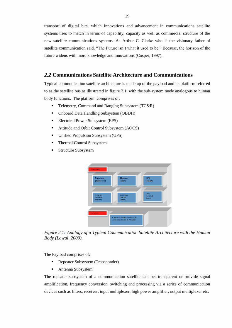
19
transport of digital bits, which innovations and advancement in communications satellite
systems tries to match in terms of capability, capacity as well as commercial structure of the
new satellite communications systems. As Arthur C. Clarke who is the visionary father of
satellite communication said, “The Future isn’t what it used to be.” Because, the horizon of the
future widens with more knowledge and innovations (Cosper, 1997).
2.2 Communications Satellite Architecture and Communications
Typical communication satellite architecture is made up of the payload and its platform referred
to as the satellite bus as illustrated in figure 2.1, with the sub-system made analogous to human
body functions. The platform comprises of:
Telemetry, Command and Ranging Subsystem (TC&R)
Onboard Data Handling Subsystem (OBDH)
Electrical Power Subsystem (EPS)
Attitude and Orbit Control Subsystem (AOCS)
Unified Propulsion Subsystem (UPS)
Thermal Control Subsystem
Structure Subsystem
Figure 2.1: Analogy of a Typical Communication Satellite Architecture with the Human
Body (Lawal, 2009).
The Payload comprises of:
Repeater Subsystem (Transponder)
Antenna Subsystem
The repeater subsystem of a communication satellite can be: transparent or provide signal
amplification, frequency conversion, switching and processing via a series of communication
devices such as filters, receiver, input multiplexer, high power amplifier, output multiplexer etc.

20
The antenna system is referred to as ears & mouth in analogy with the human body, as
illustrated in figure 2.1. It is an energy transducer, which transforms guided electromagnetic
signals into electromagnetic waves propagating in free space when it transmits, or transforms
received electromagnetic waves into guided electromagnetic signals when it is used for
reception.
The satellite bus provides the required platform for: power, mechanical strength, propulsion and
thermally controlled environment so that the spacecraft can carry out its mission.
Figure 2.2 shows Nigeria’s Communication Satellite (NIGCOMSAT-1R); a five (5) tonne high
powered, quad-band satellite frequencies (C, Ku, Ka and L-band) COMSAT meant for
telecommunications, broadcasting and navigation overlay services.
Figure 2.2 : Nigeria’s Communication Satellite; NIGCOMSAT-1R.
The multi-disciplinary interest areas that have been investigated for the COMSAT subsystems
are: repeater subsystem, antenna subsystem, propulsion subsystem, power subsystem, onboard
data handling subsystem and attitude and orbit control subsystem. These sub-systems must be
optimized to deliver the necessary functional performance requirements, processing capabilities
with a standardized, cost-effective and advanced satellite bus. These technologies are described
below:
2.2.1 Antenna Subsystem

21
Continuous increase in demand for services provided by geostationary communication
satellites has challenged satellite system designers’ ingenuity resulting in highly complex
design requirements for communication satellite spacecraft, which require multi-transponders,
multi-frequency, multi-polarization capability antennas for high capacity data
communications and throughput. Such a high capacity requirement can only be delivered via
innovative antenna design. The antenna is one of the most critical components in any radio
frequency (RF) communication system, which is responsible for receiving and transmitting
electromagnetic signals for broadcast, relay, communication and satellite control as illustrated
in figure 2.1. The antenna performance plays an essential role in controlling the quality,
quantity and continuity of data and information flow in all directions. The dramatic increase
in satellite communications capacity, capability and flexibility in recent times has been made
possible by improvements in technology and in the design, geometry and composition of
antenna components both in the space and ground segments particularly in antenna system
layouts of geostationary communication satellite platforms. The satellite antenna provides the
vital link between the ground and the satellite in orbit, performing many more complex
operations in today’s high powered and high capacity satellites; such as: simultaneous
reception and transmission of multi-band communication signals through multiple-antennas,
rejection of interference from neighboring satellites and systems in both the space and
terrestrial domains, maintaining accurate pointing and alignment between earth stations and
the satellite, antenna pointing mechanisms (APM) to steer the satellite footprints to areas not
initially designated (Lawal & Chatwin, 2012).
The main goal in antenna selection, amongst other requirements, is determining the optimal type
and size of antenna needed in space systems, especially for Geo-Communication Satellites. The
main constraints on antenna size are the weight and power requirements. Thus, load balancing
and performance parameter trade-offs require a common level of understanding between system
designers, system integrators, sub-system specialists, users and antenna suppliers. Antenna
performance is of paramount importance in today’s world of advanced communications satellite
systems especially the High Throughput Satellites (HTS). The joint goal of system designers,
integrators and other stakeholders are to maximize the performance standard of the total system
whilst minimizing cost.
The main key factor in achieving high performance communication satellite system is
attributable to advances in antenna technologies.
A variety of forms of antenna can be used for transmitting and receiving from/to a
communication satellite. The actual type of antenna depends largely on the overall application
and the mission requirements.
There is fundamentally no difference between the antennas on satellites and those on the ground,
however; there are a number of different requirements that need to be taken into account for
antenna space-based systems. Some of these are:

22
Harsh space environmental conditions with varying temperature causing expansion and
contraction.
Limited power availability.
Weight, Mass/Volume ratio limitation (Lawal & Chatwin, 2011b).
Antenna earth coverage specification in relation to the required satellite service zones.
Receive and transmit coverage area variations etc.
2.2.1.1 Satellite Antenna Design Stages and Factors
The satellite antenna design steps, inter alia, are:
Consideration of the requirements of the electric and mechanical performance.
Creation of a preliminary design based on comprehensive antenna knowledge and
engineering experience of the space environment.
Analyzing design performance in compliance with the required specifications using
Computer Aided Designs (CAD) and Computer Aided Engineering (CAE). These
utilize but are not restricted to: HFSS, POS4, GRASP, Nastran, TMD, etc.
Optimization of the design via iteration using engineering analysis and prototyping.
2.2.1.2 The Factors that Determine the Type, Size, and Shape of the Satellite Antenna
In order to achieve a practical communication antenna design, system designers must consider
the following factors:
The operating frequency
The radiated power (EIRP: Equivalent Isotropic Radiated Power)
The radiation pattern
Direction of Antenna
The required polarisation
The required Gain
Cross Polarization Isolation (CPI) or Cross Polarization Discrimination (XPD)
The maximum allowable VSWR
Antenna composition
Types of connector interface involved
Power requirement of the antenna
The mechanical structure
Mounting and deployment
Pointing mechanism and coverage
Protection requirements.
2.2.1.3 Antenna System Layout in Geostationary Spacecraft.

23
Antenna System Layout (ASL) in geostationary spacecraft platform refers to the arrangement of
the antenna subsystem on the West, East side and Earth deck of the spacecraft body in
accordance with the principles of Antenna layout design. Figure 2.3 shows the in-orbit antenna
layout configuration of the Nigerian Communication Satellite (NIGCOMSAT-1R) ready for the
Compact Antenna Test Range (CATR). Table 2.1, 2.2 2.3 and 2.4 shows Uplink Polarization
Verification, Downlink Polarization Verification, EIRP and G/T test results of Nigerian
Communication Satellite (NIGCOMSAT-1R) Compact Antenna Test Range (CATR) . The test
results meets performance requirements and serves as a good reference for validation and
performance verification of the spacecraft during In-Orbit Test (IOT) after launch.
Figure 2.3: In-Orbit Antenna Layout configuration with deployed East and West
Antenna of the NIGCOMSAT-1R in the Compact Antenna Test Range (CATR) Room
(NIGCOMSAT-1R, 2009).
Table 2.1: TEST RESULTS AND CONCLUSION OF NIGERIAN COMMUNICATION
SATELLITE (NIGCOMSAT-1R) COMPACT ANTENNA TEST RANGE (CATR).
Table 2.1: Uplink Polarization Verification of Antennas
Table 2.2: Downlink Polarization Verification of Antennas

24
Table 2.3: EIRP Transmit Antenna Pointing to Abuja Location (positioner) for all the
Antenna Beams
Ku Band West Antenna (ECOWAS 1) Beam
Ku Band East Antenna (ECOWAS 2) Beam
Ku Band Kashi Antenna (ECOWAS 2) Beam
C Band Antenna (ECOWAS 1) Beam
Ka Band Antenna Nigerian Spot Beam
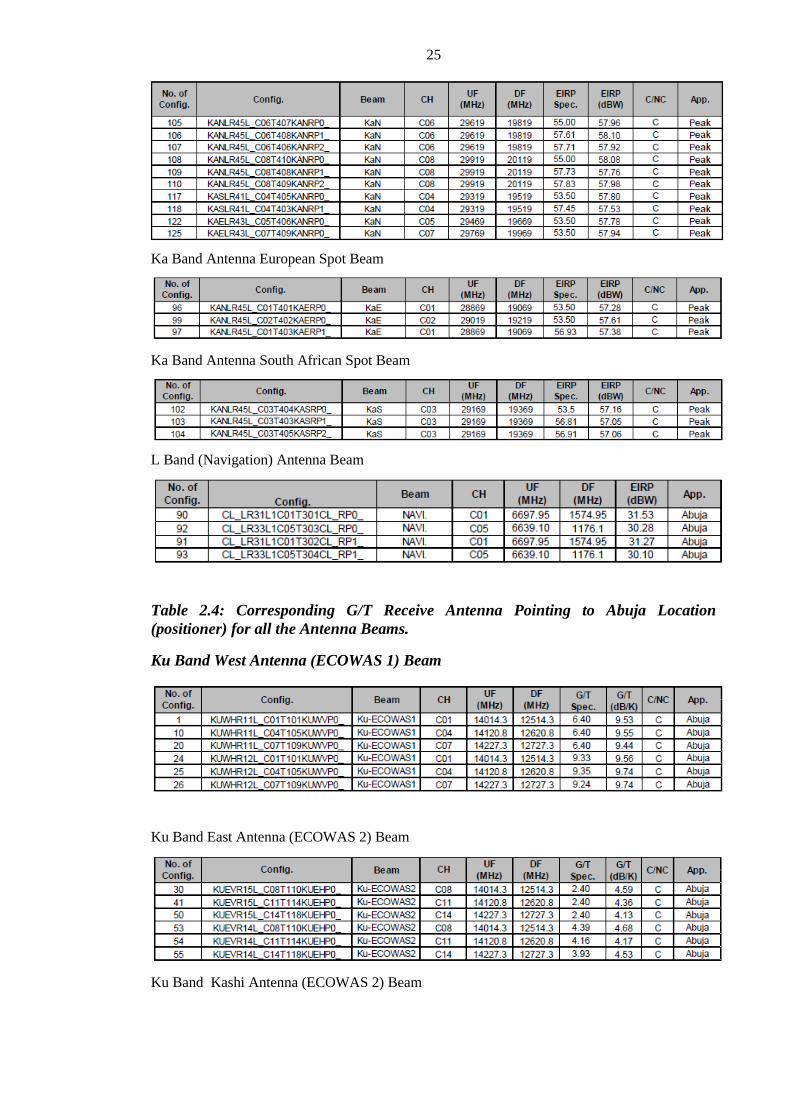
25
Ka Band Antenna European Spot Beam
Ka Band Antenna South African Spot Beam
L Band (Navigation) Antenna Beam
Table 2.4: Corresponding G/T Receive Antenna Pointing to Abuja Location
(positioner) for all the Antenna Beams.
Ku Band West Antenna (ECOWAS 1) Beam
Ku Band East Antenna (ECOWAS 2) Beam
Ku Band Kashi Antenna (ECOWAS 2) Beam

26
C Band Antenna (ECOWAS 1) Beam
Ka Band Antenna Nigerian Spot Beam
Ka Band Antenna European Spot Beam
Ka Band Antenna South African Spot Beam
L Band (Navigation) Antenna Beam
The antenna layout design in geostationary spacecraft considers the following factors:
Antenna Size.
Field of view of each antenna
Better isolation between receiving and transmitting signals which optimizes
performance with greater value of Cross Polarization Isolation( XPI) or Cross
Polarization Discrimination (XPD). The XPI performance analysis requirements of
Nigerian Communications Satellite (NIGCOMSAT-1R) service antennas are expected

27
to be 27dB or more for optimal performance of NIGCOMSAT-1R with effective
service delivery and services. Table 2.5, 2.6, 2.7 and 2.8 shows specified City XPI
Analysis of Ku-Band ECOWAS 1 Beam, Ku- Band ECOWAS 2 Beam and C-Band
ECOWAS 1 Beam respectively.
Connections with repeater devices
Mass of Antenna
Desired ground coverage area.
Degrees of freedom of antenna pointing mechanisms (APM) and Antenna Hold and
Release Mechanisms (HRM).
Composition and geometry of the antenna system i.e arrangement of antenna main
reflectors, sub reflector, feed assembly, Antenna Deployment Mechanism (ADM), Hold
Down Release Mechanism (HRM) etc as illustrated in figure 2.4.
Figure 2.4: Composition and Geometry of deployable West Antenna of Nigerian
Communications Satellite (NIGCOMSAT-1R). (NIGCOMSAT-1R, 2009).
Complexity of Antenna main reflectors i.e curled stowed or mounted on the Earth deck
such that electromagnetic compatibility is optimized. Figure 2.5 shows the Nigerian
Communications Satellite with the stowed main antenna reflector in preparation for
launch.
Table 2.5: The XPI Performance Analysis Requirements of Nigerian
Communications Satellite (NIGCOMSAT-1R) Service Antennas.

28
Table 2.6:Specified City XPI Analysis of Ku-Band ECOWAS 1 Beam

29
Table 2.7: Specified City XPI Analysis of Ku-Band ECOWAS 2 Beam
Table 2 8: Specified City XPI Analysis of C-Band ECOWAS 1 Beam

30

31
Figure 2.5: Shows Stowed Main Antenna Reflector of the Nigerian Communications
Satellite Spacecraft (NIGCOMSAT-1R) during the Launch Campaign. (NIGCOMSAT-
1R, 2009).
Antenna System Layout and geometry has helped immensely in the realization of wideband,
high throughput communication satellites and satellite communications - through frequency-
reuse using space diversity and antenna diversity in high frequency bands such as the Ka-band
with spot beam coverage making more usable communication bandwidth available and over a
wide area.
Figure 2.6: Antenna System Layout of NICOMSAT-1R on L, C, Ku and Ka Band
(NIGCOMSAT-1, 2005).
Examples of modern satellites with optimized antenna system design layout to support high
throughput links and wideband communications are the Wideband Global Satcom (WGS) series
initiated by United States Department of Defense, High Throughput Satellites (HTS) series i.e

32
Viasat-1, Ka-Sat, Jupiter-1 and NIGCOMSAT-1R satellite. Figure 2.6 illustrates the layout of 7
antenna systems on the NICOMSAT-1R satellite on Ku, C, Ka and L band.
Antenna System layout has helped immensely in independent digital channelization and routing
of communications geographically using Space-based routers with the required Internet Routing
in Space (IRIS - CISCO) Payload Architecture (Intelsatgeneral, 2009).
Figure 2.7: Dual feed arrangement on feed support structure of NIGCOMSAT-1R East
Ku Antenna providing zonal beam coverage to the East African region using East
Antenna Feed and part of Asia using Kashi Beam Feed (NIGCOMSAT-1R, 2009).
The typical antenna system layout in figure 2.4 was geometrically arranged, illuminated and
optimized, such that the dual feed as illustrated in figure 2.7 provides two zonal coverages as
shown in figures 2.8 and 2.9; covering the East African region and Part of Asia. This was
achieved with a minimal antenna size delivering the required field of view using the feed
geometry arrangement illustrated in the feed support structure of figure 2.7. The connectors
were located in close proximity to the repeater device, which reduced signal attenuation due to
cable and waveguide lengths. The design optimized electromagnetic compatibility to ensure
isolation of the receive and transmit signals to minimize electromagnetic interference. The mass
of the antenna and its support structure were minimized.

33
Figure 2.8: Ku band Asian Beam Coverage of the NIGCOMSAT-1R satellite using the
Antenna system geometry illustrated in figure 2.4 and 2.7. (NIGCOMSAT-1R, 2009).
Figure 2.9: Ku band East African Beam Coverage of NIGCOMSAT-1R satellite using
the Antenna system geometry illustrated in figure 2.4 and 2.7 (NIGCOMSAT-1R, 2009).
NIGCOMSAT-1R as shown in figure 2.5 is a high power quad-band geostationary
communication satellite designed with more than a 15-year service life; it is based on the
Chinese DFH-4 satellite bus platform with a launch mass of 5080kg. The 9kW (BOL) satellite
with Ku, Ka, C and L-band is a critical ICT backbone element of the global infrastructure meant
to drive Nigeria’s National ICT revolution by providing revenue diversification for the Nation
and offering a cost effective solution with affordable ICT access to meet Nigeria’s

34
telecommunications, broadcast, aviation, maritime, defense and security needs and Africa in
general.
Antenna system layout methodologies supports antenna designs and configurations on advanced
high capacity spacecraft with the goal of providing multi-frequency, multi-polarization and
multi spot beams such that the bandwidth flexibility, high throughput communication links, area
coverage and EMC compatibility of the antenna systems are optimized whilst also minimizing
cost. (Lawal & Chatwin, 2012).
Use of improved multibeam antennas and applications of digital signal processing on
the communication satellite payload to help provide better broadband capabilities and enhanced
bit-error-rate (BER) performance including frequency re-use using polarization and space
diversity. In recent years, optimization of satellite bandwidth and high data rate transmission
were enhanced on COMSAT with the Ka band through frequency reuse over multiple antenna
spot beams spatially separated but with overlapping coverage areas which are ideal and
effective for connecting lowly populated areas that are geographically separated.
Enhanced use of gimbaled antenna pointing mechanism (APM), precise shape-beam antennas
coupled with onboard switching and processing capabilities to provide flexible, reconfigurable
and processed transponders thus helping the satellite to provide telecommunication services
outside their primary coverage areas to hot spots such as places devastated by an: earthquake,
war, undersea cable disruption or big sporting events with an optimum return on investment
(ROI). (Lawal & Chatwin, 2010).
2.2.2 Repeater Subsystem
Use and application of Micro-Electro-Mechanical systems (MEMs) in radio frequency switches
and filters for channelization, multiplexing and demultiplexing of radio frequency signals results
in drastic reduction in mass, volume and power requirement of the repeater subsystem with
enhanced RF performance and reduced RF power and insertion loss (Nguyen, Katehi, & Rebiez,
1998). High packaging density of RF devices, switches and amplifiers, use of high temperature
super conducting materials (HTS) for filters, input multiplexers (IMUX) etc, radiation hardened
and advanced Monolithic Microwave Integrated Circuits (MMICs) with multi-layers,
development of high power, temperature compensated cavity filters for output multiplexers
(OMUX) should be tested as a piggy-back payload onboard a COMSAT, this will play an
important role in the miniaturization of active and passive RF components of the repeater
subsystem as we evolve towards a promising new generation of small communication
transponders with a smaller form factor, low insertion loss, low power consumption, lower mass
and most importantly adaptation for space-based applications through improved stability and
radiation-hardened technology. Such advanced technologies will deliver delay-tolerant and
secure virtual networks in real time (Ivancic, Et al, 2005). through implementation of onboard

35
routers to support routing of voice, video and data communications to multiple areas in one-hop
will expand networking capabilities and broadband services worldwide. On 18th January, 2010,
Cisco announced successful in-orbit test of Its Internet Routing in Space (IRIS) technology
which was deployed on the IS-14 satellite launched on Nov.23, 2009. This underscores the
importance of the deployment of Internet Protocl (IP) routers aboard geostationary satellites.
2.2.3 Enhanced Payload Components and Subsystem Layout Designs
Multi-band support through effective layout configuration of RF devices and equipment on the
communication module of a geo-stationary satellite using computer aided software analyzers to
enhance Electromagnetic Compatibility (EMC), RF power loss minimization, eliminating
Electromagnetic Interference (EMI) to the barest minimum. Optimized redundancy switches
and network designs of either transparent or processed transponders also improves RF
performance.
Optimization and enhancing the capability of the COMSAT bus platform could also be achieved
through implementation of the following advanced technologies at subsystem levels:
2.2.4 On Board Data Handling Subsystem (OBDH)
MIL-STD was developed on shared bus topology and has been in use for application in military
aircraft and control of spacecraft’s onboard communications and data handling. Its reliability,
fault tolerance and simple bus configuration endeared it to system designers for adoption.
However, it has limitations especially support for high data rates in real-time. Use of radiation
hardened Field Programmable Gate Array (FPGA) devices and SpaceWire bus standardized by
the European Space Agency (ESA) (Klar, Mangels, Dykes, & Brysch, 2008) to replace legacy
communication technologies such as the MIL-STD-11553B and RS-422 will enhance high
speed communications, facilitate the use of intelligent software control, autonomous
management and low power consumption. Xilinx recently launched Xilinx Virtex® 5QV FPGA;
a high density radiation hardened reconfigurable FPGA for space applications (Bruce, 2010).
2.2.5 Unified Propulsion Subsystem (UPS)
Use of plasma (Electric) Thrusters against traditional use of bi-propellant chemical based
thruster lowers propellant mass requirements for the spacecraft mission and gives higher
efficiency. NIGCOMSAT-1R uses a liquid bipropellant Mono Methyl Hydrazine (MMH) and
Nitrogen Tetroxide (MON-1) in a pressure-fed system. The use of a plasma (electric) thruster as
part of propulsion system will generate high exhaust velocities (specific impulses) with higher
efficiency (through gas ionization and plasma charged particle acceleration method) than those
reached by chemical propulsion system. It is of interest to note that the propellant mass of most
geostationary satellites constitute between 55%-65% of the total mass of a COMSAT spacecraft.

36
Implementation of an advanced xenon ion propulsion system (XIPS), pioneered by Boeing in its
702 satellite bus, increases the efficiency of its platform in terms of prolonged service life,
weight savings, satellite mass, power and marginal cost savings.
The use of electrical power for propulsion, Orbit raising and De-orbiting after end of life (EOL)
reduces the mass of propellant budget required for mission life; facilitating additional mass for
payload components, additional power subsystem mass requirements and other subsystems for
advanced spacecraft (Lawal, 2009; Lawal & Chatwin, 2010;2011).
2.2.6 Structure/Mechanical Subsystem
Use of enhanced materials through advanced manufacturing processes, digital simulation using
computer aided design and engineering to optimally modularize subsystem layouts with
consideration for thermal engineering, concurrent assembly, integration and test operations (AIT)
while reducing development cycle time and fortifying the spacecraft against harsh space
environment. For instance, Astrium in recent times used Siemens’ femap software with other
Computer Aided Engineering software (CAE) to extensively iterate the process of creating,
checking and viewing bus models while exploring alternatives of complex subsystem
interactions within a concurrent engineering environment used on Astrium’s newer and
enhanced Eurostar family, the E3000 satellite (Nicholas, 2010).
2.2.7 Electrical Power Subsystem (EPS)
Increasing demands for broadband services from Geostationary Communication Satellites (GCS)
and the high power requirements of high definition and 3D-TV digital broadcasting and
increasing communication spectrum demands have resulted in a major increase in GCS power
requirements. This stems from power hungry repeater components, heat rejection requirements
of the high power amplifiers, large mass and the advanced designs required for satellite
appendages such as antennas and solar arrays for admissibility of the spacecraft within the
launch vehicle envelope and capability. This section examines the methodologies and
technologies that support advanced modular power technologies for large spacecraft power
subsystems and the importance of improvements in solar cell technology, energy/mass ratio,
improved battery technologies and other power sub-system units and equipment optimised via
integrated systems engineering processes.
2.2.7.1 Background of Spacecraft Power Systems
All satellites whether scientific, military, communication or observation must be equipped with
suitable and reliable electrical power for its equipment and various sub-systems if it is to
succeed in its mission. The Electrical Power Supply (EPS) is an essential and necessary
subsystem in any spacecraft system and consists of all the required on-board hardware and
software necessary to generate, store, convert, condition and distribute electrical power reliably

37
and safely as required by all on-board equipment during all phases of the spacecraft mission.
Development of the power systems and technologies for a spacecraft mission including manned
space missions to the moon has evolved over five decades and developed rapidly using
increasingly advanced technologies for sophisticated space missions. The mission type
determines the suitable energy source, performance, lifetime, volume, mass and efficiency. One
of the basic functions of the EPS is to convert: light energy, nuclear energy or chemical energy
into electrical energy by means of physical or chemical changes and then store, regulate and
convert the electrical energy in accordance with the spacecraft specifications and requirements.
Of all power sources, the most suitable for geostationary satellites within the solar system is the
photovoltaic system, which converts solar energy to electrical energy using solar panel arrays to
charge regulated battery systems. Power is provided to the satellite through solar arrays during
sunlight and batteries during eclipse.
Generally, over 90% of spacecrafts adopt the solar array-battery systems. Solar array-battery
unified electrical power system provides clean, safe and reliable electrical energy for
geostationary satellites.
The satellite electrical power system hardware configuration is typically composed of: electrical
power source, power control unit, power conversion unit, power distribution unit and electrical
harness.
A Solar Array-battery unified electrical power system as illustrated in Figure 2.10; can provide
reliable, clean and safe electrical energy to geostationary satellites with a deployable solar array
oriented about one or more axes to maximize energy collection from the sun with various
designs in terms of regulation mode and bus voltage dependent on bus platform, manufacturers
technology and spacecraft design architecture.
PCU: Power Control Unit
BCR: Battery Charge Regulator

38
BDR: Battery Discharge Regulator
S3R: Sequential Switching Shunt Regulator
MEA: Main Error Amplifier
Figure 2.10: Typical Diagram of Solar Array-Battery Unified Electrical Power System.
Typically sketched in Figure 2.10 and as may be found on some geo-communication
satellites, power is provided during sunlight operation by the use of photovoltaic solar cells
mounted on two deployable, independently steerable solar array wings. The power from each
array is supplied to the spacecraft body via a Solar Array Drive Assembly (SADA), which
contains the necessary power and signal slip rings. The two SADA mechanisms are respectively
controlled by dedicated SADA Electronics (SADAE). Through the SADA mechanism, power is
transmitted to the Power Control Unit (PCU) and the Sequential Switching Shunt Regulator
(S3R) which resides inside the PCU. The S3R is fully controlled by a reliable main error
amplifier (MEA) and performs solar array power regulation and controls the voltage regulated
power bus. The PCU also contains the Battery Discharge Regulators (BDR) for discharge of
power during eclipse or low solar power conditions and the Battery Charge Regulators (BCR) to
charge the battery during sunlight conditions
2.2.7.2 Technology Design Development to meet High Power Requirements Of A
Modern Communication Satellites
Current trends in the design requirements of communications satellites, especially commercial
satellites, to meet the growing demands of broadband internet services, high definition TV and
3D-TV digital broadcasting has continually challenged satellite system design engineers in
stretching the power capability and capacity of the satellite bus to meet the payload power
requirements of its high power amplifiers and related components. Satellite EPS design is an
important facilitating element of all communication satellites. EPS design and manufacture
necessitate high quality, reduced weight, performance compliances, interfaces with other system
and devices, advanced thermal design, EMC design, reliability design, test requirements etc.
Over the decades, System designers have always used modern science and the technological
achievements of research and development and systems engineering practice to evolve a
balanced, modularized and scalable spacecraft platform that can support the high power
requirements of advanced payloads with due consideration being given to reliability and cost.
Some general basic design principles of Electrical Power System are:
a. Reliable, advanced and economical.
b. Adopting modular design which is standardized and serialized.
c. Adopting a mature software engineering design process.
d. System design requirements analysis, optimization, test with iterative modifications.
e. Mission requirements:

39
i. Orbit: sunlight versus eclipse time
ii. Solar incidence angle for the designated orbit
iii. Influence of satellite lifetime on solar cell design and size.
iv. Influence of temperature on solar design
v. Influence of discharge depth on the battery lifetime.
vi. Effect of temperature on battery design
vii. Effect of shunt regulator, discharge and charge regulators on system
topological structure.
f. Electrical power bus voltage for long term power requirements
g. Electrical power quality in terms of bus ripple voltage, change in bus voltage
characteristics, in-rush current capability and bus voltage leap rate in and out of
eclipse.
h. Lifetime and reliability requirement with consideration to design with End-of-Life
(EOL) requirements
i. Mass, Volume and Cost.
j. Structure and System arrangement considerations:
i. Influences of harness power consumption in energy transmitting path and
spacecraft load.
ii. Solar array size and mass as an appendage in launch vehicle and orbit.
iii. Battery thermal design and dispersion analysis
iv. Battery Thermal control in different operating environments and different
charge and discharge modes.
v. Thermal design and analysis of solar array in stowed and curled mode and
when deployed.
k. Requirements of Electromagnetic Compatibility (EMC), Electromagnetic Interference
(EMI), and Electrostatic Discharge (ESD) of Power system and Spacecraft.
l. Electrical power distribution design with consideration for EMI, EMC, load protection
etc.
m. Structural layouts and electrical harness to reduce circuit loss, minimize EMI and
optimize EMC with consideration for modularity and accessibility during integration,
assembly and test (AIT).
n. Environmental test requirements such as qualification test, check and acceptance test
results and analysis under simulated and conditioned thermal vacuum and thermal
cycle environments.
2.2.7.3 Techniques, Improvements and Methodologies required for High Powered
Spacecraft Bus for Geostationary Orbit.

40
Key bus platform spacecraft design options and units that allow innovative techniques and
methodologies through systems engineering in enhancing the capability and capacity of
spacecraft to support and accommodate high power payloads for broadband communications
and high definition TV broadcasting involves amongst other requirements improvements in
solar cell and battery technologies, use of electric propulsion systems to minimize the propellant
budget of the mission etc. Some of these techniques, methodologies and improvements are as
follows:
2.2.7.3.1 Solar Array Size and Structure
To accommodate the required solar energy generation for higher power spacecraft, solar array
panels can now be structured in such a manner that allows eight or more panels by using
advanced deployment techniques. Figure 2.11 shows a typical High Powered Communication
Satellite undergoing a deployment test of its three panel solar arrays from its stowed position on
the North Panel side of the spacecraft.
Figure 2.11: NIGCOMSAT-1R Stowed Three-Panel Solar Arrays undergoing
Deployment Test under Zero Gravity (NIGCOMSAT-1R, 2009).
2.2.7.3.2 Advanced Solar Array Drive Assembly (SADA)
The mechanism caters for the high current demand using advanced slip ring technology with the
required reliability and mechanical support for the solar arrays. The slip ring design
requirements must cater for both power and control signals. The Solar Array Drive Assembly
Motor (SADA-M) rotates the solar panel wing to keep the array facing the sun always via a

41
shaft assembly. The power slip ring assembly consists of slip ring and brushes to help deliver
solar array output power to power control unit (PCU) with the structure and brushes remaining
fixed to the satellite as it rotates. Figure 2.12 shows a schematic of solar array, slip ring, brushes
and PCU arrangement while figure 2.13 shows typical SADA-M as used in NIGCOMSAT-1R.
Figure 2.12: Schematic of Solar Array Output Power to Power Control Unit (PCU) Via
Slip ring and Brush arrangement about a shaft of SADA-M.
Figure 2.13: A Typical Solar Array Drive Assembly Motor (SADA-M) as used in
NIGCOMSAT-1 showing internal structure.

42
2.2.7.3.3 Advanced Solar Cells
Improvement in solar cells using triple junction cells provides efficient energy conversion and
greater output with the same cell area and mass. Sharp Corporation recently achieved the
world's highest solar cell conversion efficiency of 36.9% using a triple-junction solar cell
utilizing photo-absorption layers in which the solar cell has a stacked three-layer structure
consisting of two or more elements such as indium and gallium. The bottom layer of the stacked
triple structure was InGaAS (Indium Gallium Arsenide) while output maximum power was
ensured through reduced resistance of the junction areas of the solar cell layers. Innovative solar
cells with a lightweight structure are maturating currently (Sharp Corporation, 2011).
Solar cells employed for spacecraft use must undergo intense environmental testing including
mechanical and thermal requirement tests. Other key tests include humidity, high and low
temperature impact test, ultra-radiation and particle radiation tests to ensure reliable long term
performance of the power subsystem.
A good semi-conductor compound solar cell must have the following characteristics:
i. High photoelectric conversion efficiency
ii. Good anti-radiation performance
iii. Good high temperature performance
iv. Support film or the super-thin solar cell.
v. Support for heterogeneous-substrate and multiple-junction level-connection
solar cell.
For effectiveness and efficiency of the power supply system even towards the end of life (EOL)
of the system, degradation coefficients of solar cells including assembly, sunlight and mission
degradation factors amongst others must be considered when computing solar array power
designs. Some of the degradation factors that must be considered are:
i. Insulation
ii. Sun Orientation
iii. Glassing gain
iv. Micromet, cover glass particle loss
v. UV radiation
vi. Thermal properties and thermal cycling
vii. Calibration errors
viii. Mismatch, fabrication and process loss etc
2.2.7.3.4 Improved Battery Performance and Cell Technologies
Batteries are used for energy storage, they convert chemical to electrical energy for use during
eclipse, emergency mode of the satellite including early launch phase of the satellite before
acquisition of the sun after deployment of the solar arrays. They have increased capability and

43
capacity through higher efficiency and increased energy/mass performance using improved
elements and compounds (Lawal & Chatwin, 2011). Battery requirements for High power
geostationary EPS design among other factors should have the following characteristics:
i. High conversion efficiency
ii. High Output Power
iii. Reliable pressurization without leakage
iv. Ease of management
v. Effective electrical performance measure through singular or combined effects of
pressure, voltage or temperature.
There are a variety of batteries suitable for spacecraft based on performance parameters such as
energy density, cycle life, reliability, depth of discharge (DOD), discharge and charge rate and
low-temperature performance and control. Some of these batteries are Nickel-Hydrogen,
Nickel-Cadium, Lithium Ion etc. Other compounds such as sodium-sulphur battery etc are in the
development stage. The most mature, reliable and commonly used battery for Geo-Satellites is
the Nickel-Hydrogen battery with continuously improving performance for higher reliability
and longer lifetime. However, there are higher energy density technology batteries such as
Lithium ion and Sodium–Sulphur batteries but they still require considerable improvement to be
suitable for Geo-orbit for the necessary long lifetime, charge/discharge cycle performance and
reliability.
Battery main functions are:
i. Delivery of Electrical Power
ii. Storage of Electrical Power through optimized Charging
iii. Capability to retain the stored Electrical Power
Additional battery functions are:
i. Reconditioning in orbit
ii. Pressure Monitoring
iii. Voltage and Temperature Remote Telemetry
Battery Stress Functions to consider are:
i. Mechanical, Thermal and Electrical Environment of Satellite and Space
ii. Sustain Environmental conditions from manufacturing to Launch
iii. EMC and EMI
iv. Ease to transport and Assembly, Integration and Test (AIT)
v. Maintainability

44
Some design conditions to consider are:
i. The longest eclipse time
ii. Maximum Depth of Discharge of battery (DOD), which is a measure of the
degree of battery utilization.
iii. Battery supporting energy requirements of the spacecraft during initiation
phase (Between launch and sun acquisition after deployment of solar arrays).
iv. Battery must be designed to meet the requirements and functions enumerated
above and to meet service life requirements in orbit with provision for at least
3 years storage before launch.
2.2.7.3.5 Power Control Unit (PCU)
This refers to all equipment and units for control, protection, adjustment and interfacing with
other sub-units and subsystems of the electrical power system for effective, efficient, safe,
continuous and reliable power. Configuration of power control units varies depending on the
manufacturer and architecture of the power system design.
Via a telemetry interface, the PCU must support the requirements for instructions via tele-
command and monitoring through telemetry for the required operational mode, which may not
necessarily be autonomous and monitoring of the various EPS operation states and its
performance including temperature control and monitoring of the batteries through thermistors.
Figure 2.14 shows a fully qualified Power Control Unit (PCU) for a Solar Array–Battery
Unified Power system. A PCU is typically composed of the following modules:
i. Battery Charge Regulators (BCR) including output switches
ii. Battery Discharge Regulators (BDR).
iii. Sequential Switching Shunt Regulator (S3R) for regulation of the solar array
voltage .
iv. Reliable Main Error Amplifier (MEA) for main bus voltage regulation amongst
other functions.
v. Telemetry (TM) / Telecommand (TC) Interface including over voltage protection.
Power Control Unit functions, amongst others, are:
i. Provides the electrical power bus and the necessary bus voltage filter measures
ii. Regulates the output voltage of the solar array in sunlight and eclipse conditions
and restricts high voltage of the bus to spacecraft load.
iii. Carries out charge control for the optimal performance of the battery.
iv. Carries out battery discharge regulation for optimal performance of the battery and
spacecraft load.
v. Controls and regulates spacecraft load switching from battery to solar array and
vice versa under sunlight and eclipse conditions respectively.

45
vi. Reconditions batteries whilst in-orbit through ground tele-command for optimal
performance of the battery over its long service life-time.
vii. Provides interfaces between EPS and other subsystems
Figure 2.14: A Typically Qualified and Flight Proven PCU (NIGCOMSAT-1, 2005).
2.2.7.3.6 Interface Requirements and Harness
Electrical Power System design must support the following interfaces and requirements:
1. Electrical interface for:
a. Power supply requirements of each satellite subsystem
b. Equipment and converters with failure isolation circuit and load protective
device including insulation, material types and their conductivity.
c. Telecommand support
d. Telemetry parameter support
2. Mechanical Interface with consideration to the followings:
a. Size of the interface
b. Mass of the interface
c. Centroid position
d. Inertia moment
e. Installation mode
f. Material and physical properties
3. Thermal interface: The thermal interface between units, equipment, subsystems and
systems must be designed to requirements especially as it concerns the inside walls and
the inner part of equipment since the thermal control system of the satellite is only
responsible for ambient and surface temperature of equipment.
4. Harness Design: Aside from the primary function of connecting separate units and
integration of distributed equipment and loads. Harness electromagnetic compatibility
must be ensured for low-frequency cable, high frequency cable and electrical power
cables for high and small current loads including pyrotechnic and Electro-Explosive
Devices (EED). The harness materials and physical properties must be safe, reliable and

46
meet all test requirements. The weight and its accessibility must also be considered for
assembly, integration and test (AIT) requirements. Others are shielding layer, insulation,
D.C resistance and harness mechanical movement requirements.
2.2.7.3.7 Pyrotechnic Integration System (PIS).
The subsystem is responsible for safe and reliable operations of all Electro-Explosive Devices
meant for deployment of satellite appendages such as antennas and multiple solar array panels
in high-powered satellites including actuation of propulsion system valves. The EED power is
usually independently provided from the spacecraft batteries through the activation of relay
circuits. The pyrotechnic control and actuation technologies must be reliable and advanced if the
mission of any high-powered communication satellite is going to be successful.
2.2.7.4 Advancement in Electrical Power Subsystems
Enhanced use of semiconductor technology to produce more reliable solar cells with higher
conversion efficiency. Use of enhanced compounds to produce deep cycle cell of battery with
prolonged life span of battery and reduced weight are goals for design requirements and EPS
manufacture for performance targets, High power capability, reliability including thermal and
EMC design requirements. Conceptual design of power subsystem redundancy at the system
level to eliminate single point of failure increases reliability and reduction of space junk.
Some of these innovative requirements have been demonstrated in the Chinese DFH-4 and
Boeing 702 satellite bus using triple-junction Gallium Arsenide solar cells with greater
conversion efficiency yielding power generation as high as 18kW with smaller solar arrays. The
same can be said of the Lockheed Martin A2100 series capable of producing as much as 15kW
using innovative solar “pleated shades” with higher efficiency solar cells.
2.2.8 Attitude and Orbit Control Subsystem (AOCS)
Use of radiation hardened FPGAs over traditional microcontrollers and implementation of
advanced attitude determination using innovative star trackers, advancement in star sensors, sun
sensors and deep space application of GPS technology (Lau, Lichen, Young, & Haines, 1996)
improves pointing accuracies to give fully autonomous attitude determination and corrections in
three stabilized axes of the spacecraft. Orbit corrections and station keeping are also being
improved upon through efficient use of thruster plumes and their layouts, particularly ion
thrusters through modeling and analysis of the plasma environment in space. Alcatel Alenia
recently demonstrated the use of an in-built star tracker in Spacebus 4000.
2.2.9 Thermal Subsystem
Reduction of use of heaters through effective utilization of dissipated heat from high power
amplifiers via conduction (I.e TWTAs, SSPAs etc) over traditional use of space as a heat sink
with radiating fins around high powered TWTAs and SSPAs. Efficient thermal controls have

47
been demonstrated and flown using deployable radiators and improved thermal dissipation
using thermal design software such as SINDA, TRASYS, FEMAP etc, which also helps
conserve onboard power. This helps to support the requirements for greater thermal heat
rejection for the high power payload components and sub-systems.
2.3 Higher Spectral Bands; The Ka-Band: New Possibilities and
Capabilities.
Ka-band is a high radio frequency typically between 20-40 GHz that allows high volume and
faster data throughput to be transmitted and received with relatively very small ground antennas
at competitive prices. Ka-band is distinguished from C-band and Ku-band by its higher
frequency spectrum. The Ka- band uplink frequencies are usually between 24.75 GHz and 31
GHz and downlink uses frequencies are between 17.3 GHz to 21.2 GHz depending on ITU
region, satellite usage, national regulators etc.
Ka-band also offers another technology advantage of frequency re-use through space diversity
by reusing the same frequency up to as much as six times allowing regionalized content space-
based bandwidth resources to be shared between simultaneous users giving rise to today’s High
Throughput Satellites (HTS) with prospect of achieving a terabit/s geostationary satellite system
(Lutz, 2013).
Ka band has moved from experimental laboratory demonstrators to application in high speed
networks with digital channelization using onboard routers for broadcasting,
telecommunications, IP trunking services, Communications –on-the-Move (COTM) etc.
Italian Space Agency was the sponsor of the world’s first Ka-band satellite, Italsat F-1 as the
important step forward to underscore the importance of the technology in orbit (Gargione, &
Brandon, 1999) while the first commercial Ka-band success was with the launch of Telesat’s
Anik F2 on July 17, 2004, which gave Canadians the best hope of bridging their digital gap
especially in the rural areas. The satellite, Anik F2; also had an early breakthrough by using
smaller spot beams to cover specific geographic areas; a transformation from the usual and
traditional one large zonal or large spot beam with other frequency bands. Telesat’s Anik f2
used 45 smaller “spot beams” to cover specific geographic areas with 15 spot beams covering
Canada and 30 spot beams covering the lower 48 US States.
With continuing advances in Ka-band technologies and systems, users have a superior online
broadband experience and high–speed satellite Internet and data services equivalent to fiber-
based services as seen in recent Ka-band High Throughput Satellites (HTS) and Wideband
Global Satcom (WGS) satellites.
These achievements are not feasible without the cooperation of system engineers, integrators for
the needed high-precision and high performance ground Ka-band infrastructure and product

48
developments such as Ka-band antennas, feeds, HPAs, Receivers, High performance cables,
waveguides, Power control, Converters etc including rain attenuation mitigation techniques such
as adaptive coding and modulation(ACM), rate reduction, automatic power control (APC) etc to
suppress the rain-fade column which is the main propagation impairment in the high frequency
band. (Garcia-Rubi, Riera, Garcia-del-Pino, & Benarroch, 2011; Lawal & Chatwin, 2013).
Throughput Satellite (HTS) systems have introduced a paradigm shift in satellite broadband
access services and the satellite industry. The satellite industry has begun a process of
“remaking” the satellite broadband access market into an unprecedented offering that compares
favorably to a DSL and fiber-based services in many unserved or underserved markets.
Ka-band systems and technologies hold great promise for Africa in complementing the
inadequate terrestrial networks and ensuring that its nations are not isolated from the global
economy and world-wide communications network growth (Lawal & Chatwin, 2012). The Ka
band spectrum has helped the satellite industry in optimal utilization and availability of the
Satellite frequency spectrum and management through digital channelization and frequency re-
use. African Leaders and key stakeholders through institutional frameworks have recognized the
role of ICT infrastructure and the multiplier effect it has on other development sectors. As a
means of closing the infrastructure deficiency and after due process and a request for proposals
from various communications satellite companies, the Federal Government of Nigeria took the
bull by the horns by signing a Communication Satellite contract with the China Great Wall
Industry Corporation in December 2004. The high powered, Quad band (Ku, Ka, C and L
Band) geostationary satellite, with a service life span of 15 years, had 8 active transponders on
the Ka-band, which were based on a feasibility field trial assessment of bandwidth demand
projection for Sub-Saharan Africa required to carry Africa’s international voice and data traffics
and the success of the ANIK F2 satellite with Ka-band.
The National priority project and first Nigerian Communication Satellite (NIGCOMSAT-1) was
eventually launched on the 13th of May 2007 becoming the first communication satellite to
provide users with Ka-band resources over African soil. The satellite suffered an onboard
subsystem failure and was de-orbited on 10th of November 2008 bringing all broadcast,
telecommunication services and strategic navigational plans to an abrupt end. An insurance
replacement was launched on 20th December, 2011 as NIGCOMSAT-1R with an improved Ka-
band satellite system over its predecessor; NIGCOMSAT-1. (Haris Caprock, 2012; Lawal &
Chatwin, 2013; NIGCOMSAT-1, 2005; NIGCOMSAT-1R, 2009).
Non-geostationary Ka-band satellites such as the O3B Ka-band satellite designed for medium
earth orbit offers lower latency and throughput equivalent to an optic fiber cable system.
NIGCOMSAT Ltd, as the first satellite operator to provide Ka-band resources over African soil,
will continue to drive the national ICT revolution by the provision of cost effective and
affordable solutions involving: broadcasting, Internet, seamless integration of
telecommunication connectivity and backbone and IP trunking, inter alia, by exploiting its Ka-

49
band resource combined with the use of gateways and hubs complemented by the other bands
onboard NIGCOMSAT-1R and the future fleet of HTS satellites over the African continent and
the globe at large. Well implemented Ka-band multimedia services and applications with
international distribution networks and local service providers remains a key success factor in
driving the new and enhanced satellite service business including new market opportunities such
as Internet-in-the-sky, 3D Digital TV, HDTV, Videos-on-Demand , Interactive multimedia etc.
It remains part of the corner stone for guaranteeing universal access and digital inclusion in a
continent with the least wired terrestrial communications network.
( Lawal, Ahmed-Rufai, Chatwin, & Young, 2013).
2.4 Satellite Communications Network Technologies for
Communications Satellite.
As explained earlier in the literature review of chapter one, introduction of digital video
broadcasting (DVB) systems to communications satellites was a milestone paradigm shift for
the important role communications satellites are playing today in broadcasting,
telecommunications, mobile communications, convergence with voice, video and data as well as
terrestrial telecommunications technologies. (Ong et al, 2007; Liang et al, 2007). The
emergence of variants of mobile technologies, increased demand for communication satellite-
based multimedia and ubiquitous service requirements by end users encouraged by the modern
day knowledge economy (Lawal, Ahmed-Rufai, Chatwin & Liu, 2013; Liang et al, 2007) has
led to worldwide convergence of networks and fusion of technologies as it concerns not just
voice, video and data but some innovative techniques involving digital television, broadband
Internet, mobile communications as illustrated in figure 2.15. Chapter seven provides further
details with applications.
Figure 2.15:Fusion of Digital Television, Broadband Internet and mobile
Communications. (Source: Liang et al, 2007).

50
2.5 Conclusion
The overall effect of implementing these technologies at unit, sub-system and system level on
present commercial geostationary spacecraft will be an optimized communication satellite bus
system with a broader spectrum of: capacity, capability, reliability, intelligence with reduced
cost and small form factor to bridge and complement digital gaps across communities, nations
and continents.
Research intensification in enabling advanced technologies for reliable future
commercial satellite communications could be stimulated among stakeholders (COMSAT
manufacturers, telecommunication users, satellite and Internet service providers, COMSAT
system designers, sub-system satellite designers, AIT experts [assembly, integration & test],
research & academic communities, satellite insurance firms etc ) through forums and
professorial chairs in academic institutions to move today’s billion-dollar large spacecraft
technologies to a more advanced level.
The high-risk activities of the satellite industry make use of mature technologies with flight
heritage at the expense of newer technologies especially in the commercial satellite industry;
satellite insurance companies acting on history, experience and launch failure data largely drive
this. Most commercial in-orbit satellites do not have the latest and most advanced technologies
due to the use of matured but mostly obsolete technologies required by insurance companies. A
paradigm shift could therefore be delivered by the use of advanced technologies as piggyback
payloads, hoisted payloads or experiments on commercial geostationary spacecraft as test
grounds for use of advanced technologies with capacity and capability to enable connectivity
and digital inclusion across the globe, not only as a passive (transparent) global communication
infrastructure but also as an active (processed) global infrastructure.
Such active global communication infrastructures will help promote the use of ICT, which is
central to the well-being of emerging knowledge-based nations that are currently on the wrong
side of the digital divide. These new technologies will play an important role in accelerating
growth, promoting sustainable development and eradicating poverty; in general the digital
divide will be reduced greatly through speedy implementation of COMSAT development
projects and programmes that are designed to have a positive effect on the lives of ordinary
citizens living in remote hamlets, rural and semi-urban areas.
As it complements and connects with terrestrial networks, advanced communication satellites
(COMSAT) remains the corner stone for universal access to the Internet with its huge
knowledge resources.

51
CHAPTER 3: Needs Assessment, Feasibility and Suitable
Design Specifications for Nigerian Communications Satellite.

52
3.0 Summary
In this chapter, the situational analysis of Information Communications Technology (ICT)
infrastructure in Africa was examined and identified a strong need for passive Global Space-
based ICT Infrastructure (Communications Satellite System and associated technologies) as a
short and medium term measure to bridge the huge digital hiatus based on needs assessment and
viability despite arrival of sufficient and adequate undersea cables at the shores of the African
continent in recent years. A well-planned and implemented Very Small Aperture Terminal
(VSAT) with a suitable regional domestic communications satellite will significantly improve
access to telecoms services in rural areas as a niche market as well as address other strategic
needs of the region.
3.1 Introduction of Communications Satellite and Broadband-Based
Services.
Africa is the least wired continent in the world in terms of robust telecommunications
infrastructure and systems to cater for its more than one billion people. The International
Telecommunications Union (ITU) identified in the report released on measuring the information
society (ITU) (2010) that African nations are mostly still in the early stages of Information
Communications Technology (ICT) development as verified by the relatively low ICT
Development Index (IDI) values of all countries in the African region. In developing nations,
mobile broadband subscriptions and penetration between 2000-2009 was increasingly more
popular than fixed broadband subscriptions. To achieve the goal of universal access, with rapid
implementation of ICT infrastructure to complement the sparsely distributed terrestrial networks
in the hinterlands and leveraging the adequate submarine cables along the African coastline,
African nations and their stakeholders are promoting and implementing Communication
Satellite systems, particularly in Nigeria, to help bridge the digital hiatus. This chapter amongst
others things, examines the effectiveness of communication satellites in delivering broadband-
based services.
3.1.1 What is Broadband?
Broadband has different meanings for different people depending on whether their focus is in
terms of capability, capacity, speed, etc. The acceptable baseline for broadband all over the
world is the definition of broadband given by The Organization for Economic Co-operation and

53
Development (OECD), which defines broadband as a service (not a technology) that can
provide an Internet speed or data transmission rate at least 256 kilobits per seconds (kbps) in at
least one direction (Agustin, 2009).
According to Singer (2003), broadband should have sufficient two-way transmission capacity
and speed to allow interactive high-quality full-motion video, data and voice applications
simultaneously via one “pipe.”
The United States Federal Communications Commission (FCC) has up to now used a slightly
different terminology in the United States. “High-speed lines” are connections to end-user
locations that deliver services at speeds exceeding 200 kbps in at least one direction (either
enabling the end-user to send information – upstream – or receive information from the Internet
– downstream), while “advanced services lines”, a subset of high-speed lines, are connections
that deliver services at speeds exceeding 200 kbps in both directions. For the purpose of
information collection, the FCC has used “broadband connections” as a synonym of “high-speed
lines”. In June 2008, the FCC modified its requirements for reporting broadband lines largely
based on consumer trends and usage of applications such as high-quality graphics and video
telecommunications such as video conferencing, high definition video streaming etc.
Specifically, it established eight download speed tiers and nine upload speed tiers, which
providers must employ in reporting broadband index. The Sixth Broadband Progress Report
increased the Commission’s speed benchmark for broadband to 4 Mbps download and 1 Mbps
upload because network capabilities, consumer applications and expectations have evolved in
ways that demand increasing amounts of bandwidth in the United States. However, there was
consideration on the extent of broadband deployment and measures of the current threshold
definition to the varying technologies such as fixed–terrestrial broadband, mobile broadband
and satellite broadband (US FCC, 2012). The broadband definition threshold keeps changing on
a regional and national basis driven by usage and applications. In Asia, in particular India with
over 1.3 billion people, the definition of broadband was revised from 256 kbps to 512 kbps on
1st January, 2011. Considering consumer trends and projections, particularly on mobile network
data speeds, the Government of India approved stipulated download speed of 2 mbps for any
broadband connection based on any technology with effect from January 1, 2015 based on its
national broadband plan (India TRA, 2010). Under the voluntary code of practice of the Office
of communications (OfCom), United Kingdom, Broadband speed definitions as used in the code
are categorized based on headline or advertised speed by an Internet Service Provider (ISP),
access line speed based on the maximum speed of the data connection, actual throughput speed
based on consumer user experience at a particular time and average throughput speed, which is
the average actual throughput speed for each broadband product offered by an ISP (UK OfCom,
2012).
The International Telecommunication Union definition of broadband combines connection
capacity (bandwidth) and speed. Recommendation I.113 of the ITU Standardization Sector

54
defines broadband as a “transmission capacity that is faster than primary rate Integrated Services
Digital Network (ISDN) at 1.5 or 2.0 Megabits per second (Mbits)” (ITU, 2003). The trend in
threshold definition of broadband will continue to change within the foreseeable future due to
the level of change of our technologies to support such forecasts driven by demands. For
instance, the European Commission provided an update on implementation of national
broadband plans in the EU-27 countries, along with Croatia, Norway and Switzerland in which
the Digital Agenda for Europe (DAE) required all member states to devise and make operational
by 2012, and national broadband plans, which would enable the EU to meet the broadband
targets for Europe by 2020. Those targets are as follows:
▪ Basic broadband (512 kbps to 4 Mbps) to all by 2013
▪ Fast broadband by 2020: broadband coverage at 30 Mbps or more for 100% of EU
citizens.
▪ Ultra-fast broadband by 2020: 50% of European households should have subscriptions
above 100 Mbps.
To date, about 22 member states have national broadband plans while the rest are either under
review or in the drafting process (European Commission, 2012). Threshold definition of
broadband in African nations beyond 256 kbps should be within the context of the level of
access to telecommunications infrastructure, usage of applications such as: high-quality graphics,
video streaming, video conferencing and the level of new generation networks deployed and
envisaged to be deployed within mid-term future projections.
Evolution of Broadband Networks
Before the arrival of the Internet and Packet-Switching Technology, which allows voice to ride
over Internet Protocol systems (VoIP) designed for data networks; speech, telegraph, paging and
fax systems were run on legacy systems and networks, which were basically narrow-band
systems.
The arrival of Packet-switching techniques and the Internet resulted in a sharp and continuous
increase in demand for converging data networks supporting data, voice, fax and video services,
which led to the development of broadband technologies in both satellites and terrestrially based
networks (i.e DSL over legacy telephone networks and fiber-based networks, which led to the
introduction of multi-core fibers).
Broadband is widely used to describe high-speed access to support today’s converged networks
of not only voice or data as well as multimedia traffic of high-quality voice, data, graphics,
streamed videos and video conferencing. High-speed mobile technologies are becoming
increasingly important particularly as services and applications in broadband delivery. However,
second generation mobile technologies and their improved versions such as GSM and GPRS
(2.5G), cannot be considered broadband, when their download rates reach only 60 to 80 kbps,
well short of the OECD threshold. EDGE/Evolved EDGE, W-CDMA (UMTS), CDMA-2000
3G, TD-SCDMA (Chinese National Standard), HSPA and LTE mobile technologies can deliver

55
well above the 256 kbps OECD threshold with higher speed throughputs. Hence, governments
of developing countries and their communication regulators should encourage mobile operators
to roll out 3G networks rather than investing huge capital sums to upgrade 2G systems.
3.1.2. Why Broadband?
Broadband-based technologies accelerate economic and social development. The introduction of
broadband technologies through fiber, satellite and variants of fixed and mobile wireless
systems has enabled traditional and new forms of communication to become a reality
throughout the world. Most traditional and legacy technologies do not meet the high bandwidth
requirements for emerging applications for triple play services (voice, video and data).
The importance of broadband has been highlighted by the Managing Director and Chief
Executive Officer (MD/CEO) of NIGCOMSAT LTD; Engr. Timasaniyu Ahmed-Rufai (2012)
in the quest for NIGCOMSAT Ltd to target 40% of the Nigerian Broadband Market by 2015
through NIGCOMSAT-1R stated“...In today’s challenging economic climate, the dividing line
between progress and chaos, the rich and poor nations is the Broadband connectivity. Looking
at the near future, Broadband connectivity will be similar to the difference between life and
death. For us to be alive as a nation, we must lay a solid foundation for a knowledge-based
economy—with ubiquitous broadband and a declining cost of connectivity”.
Broadband has the potential to facilitate and boost entire new industries, improve the education
system, deliver and enhance health care, enhance farming, monitor and ensure public safety and
engage with government. Increasingly, broadband is used to access, organize and disseminate
knowledge, increase market productivity, facilitate the generation of new jobs and improve the
quality of life through e-Government, distance learning, e-Commerce, e-Banking, e-Village, e-
Agriculture and national Security amongst others.
3.1.3 Communications Satellite
Communications Satellite abbreviated as COMSAT is an artificial satellite placed in an orbit;
mostly geostationary orbit to aid broadcasting, telecommunications and/or navigation by
reflecting, relaying or processing a radio signal. Figure 3.1 shows a pictorial diagram of a
communications satellite in orbit oriented towards the earth.

56
Figure 3.1: Communication Satellite in Orbit
The impact of communications satellites on business, culture, human relations, education and
humanity in general can be historically likened to that of the railroad in the last century or the
development of modern transportation. (Francis & Will, 1994). It has aided international
communications with access to broadband, broadcast and value-added services. (Logue, 1996).
Communication Satellites and the Internet collided at the Internet’s very beginning according to
Puetz (1999). Puetz (1999) reiterated that the original five super computer centres were
interconnected under the National Science Foundation (NSF) in 1985 with 56 kilobits per
second (kbps) SCPC links using a Ku-band Communications satellite. Today, Internet-2 is the
high bandwidth backbone dedicated for university research. Communications satellites have
played and will continue to play a very significant role in the expansion of the Internet across
the world. It has today helped bridged the information access gap in the early beginning of
Internet, which was thought of as not a universally available, global phenomenon. (Stuart, 1997).
Communications Satellite impact is not only limited to Internet, TV Broadcast and multimedia
but also satellite-based Digital Audio Radio Service (DARS). Boyer (1998) noted that the
essential lure of satellite radio aside Compact-Disk (CD) quality, is a service that people can
enjoy in their vehicles without ever driving beyond the range of the transmitter. In the beginning,
vehicles used Amplitude Modulation (AM). Then came Frequency Modulation (FM) and now
comes DARS on S-band in the history of radio as noted by Lon Levin, the president and founder
of American Mobile Radio, which was a subsidiary of American Mobile Satellite Corporation
(Boyer, 1998).

57
3.2 Needs Assessment and Feasibility Studies for Nigerian
Communications Satellite
3.2.1 General Overview
Nigeria successfully placed its first national satellite; NigeriaSat-1 in orbit in September 2003.
Based on the success of the earth observation satellite, the federal government decided to
explore the possibility of a national communication satellite system to improve the country’s
comatose ICT infrastructure considering growing needs of telecommunications needs of its
citizens amongst other requirements since deregulation in 1993, which allowed private sector
participation and investment for the country’s telecommunications service delivery. The mobile
phone services, Internet, VSAT services significantly changed the face of communications in
Nigeria. It is often remembered with nostalgia how the VSAT services transformed the banking
sector in the early 90’s from paper-based and manual based systems to an Information
Technology driven sector particularly the new generation banks with a wildfire effect on old
generation banks who struggled to remain competitive. The demand and utilization of
communication satellite services surged with enormous traffic considering the inadequacy of
terrestrial networks despite the rising cost of subscription to satellite services from international
satellite operators with little or no local presence neither was there adequate postal service
support.
An extensive data collection exercise on needs assessment was embarked upon covering 36
states of the federation including the Federal Capital Territory (FCT). The data collection was
centered on prospects of a national communication satellite system with coverage over Africa
and Europe, the immediate two key trading partners of Nigeria. Other complementary data
collection methodologies were field survey, telephone interviews, consultations with ICT
stakeholders, review of government policy papers, company brochures, conference reports and
proceedings, journals, specialized magazines on ICT, websites, press releases, desk studies,
internal and external research by project team members and officials of the National Space
Research and Development Agency (NASRDA) as well as data compilation on communication
requirements of African countries. Table 3.1 shows fixed telephony services status in Nigeria as
at the end of September, 2004 in a country with over 130 Million at that time.
Table 3.1 : Fixed Telephone Services in Nigeria as at the end of September, 2004
S/
N
OPERATOR SYSTEM
CAPACIT
Y
NO. OF
CONNECT
ED LINES
%
CONNECT
ED
1 NIGERIAN
TELECOMMUNIC
ATIONS LTD
733,611 518,976 71%

58
(NITEL)
2 PRIVATE
TELECOMMUNIC
ATION
OPERATORS
(PTO)
341,740 200,000 59%
TOTAL 1,075,351 718,976 67%
63% (452,955) of the connected lines were for homes while the remaining 37% (266,021)
accounts for office connections.
Table 3.2 shows a summary of estimated current capacity requirement of data bandwidth as at
2004 utilized by key sectors of the Nigerian economy.
Table 3.2: Estimated Bandwidth Utilization and Requirement for the Nigerian
Economy.
S/N SECTOR BANDWIDTH
REQUIREMENT/UTILIZATION (MB)
1 BANKS 12
2 OIL SECTOR 137
3 GOVERNMENT
AGENCIES
12
4 NITEL 221.5
CURRENT
TOTAL
544.5MB
ESTIMATED
TOTAL
REQUIREMENTS
IN
FIVE YEARS
1536.2MB
While a conservative estimate of 1536.2 Mbps was expected in 2009 based on current macro-
economic indicators, optimistic data service growth projection and demand was expected to be
3,301Mbps by year 2009.
Nigeria’s outbound international traffic was estimated to be between 350-600 million minutes
yearly mainly generated from NITEL network and carried mostly via NITEL satellite Earth
Stations in Lagos, Lanlate-Oyo, Enugu and Kaduna across six geo-political regions of the
country. It was also projected to rise to about 1 billion minutes in the next three years
considering the increasing growth of mobile phone subscription dominated by GSM operators.
The mobile subscription figures as shown in table 3.3 was about 6.9 million as at the end of
September, 2004.

59
Table 3.3: Estimated Mobile Subscription as at the end of September, 2004.
S/N MOBILE PHONE
OPERATOR
CONNECTED SUBSCRIPTION
(MILLIONS)
1 MTN 3
2 GLOBACOM 1.7
3 V MOBILE (NOW AIRTEL) 1.6
4 MTEL (MOBILE SUBSIDIARY
OF NITEL)
0.6
TOTAL 6.9 MILLIONS
Increasingly, mobile operators carry more voice traffic than the fixed-line and by December,
2004, Africa was expected to have over 50 million mobile subscribers and 20 million fixed-line
subscribers. Mobile operators possess international gateway licenses and thus use
communication satellites to carry international traffic. Thus, African cellular operators were in
the driving seat to meet demand for capacity in the last three to four years prior to 2004. For
example, MTN Nigeria, a mobile operator uses communication satellite links to provide its
international connectivity using the then PanAmSat and New Skies, as well as to carry GSM
traffic between mobile switching centers (MSCs) in Lagos, Port Harcourt and Abuja. Most
mobile operators also use the satellite links for their transmission networks such as backhauling
traffic from remote base stations to central MSCs or between various MSCs. In the Democratic
Republic of Congo, new entrant mobile operator, Vodacom utilize a satellite backbone due to
inadequate terrestrial transmission networks and infrastructure. This brings to fore the
importance of satellite transmission in African mobile network and thus their engagement into
satellite business. Telecel International, for instance uses M-Link based in Belgium to provide a
gateway service for each Telecel’s African subsidiaries that are routing telephone traffic out of
their respective countries and deliver traffic from international carriers into Africa using Telecel
networks. Econet Satellite Services (ESS), based in the UK, was set up by Zimbabwean-based
operator Econet to operate and market international carrier services using satellite-based
infrastructure. ESS also aimed to provide a routing service for traffic emanating from operations
in which Econet Wireless International (EWI) acts as the operator. In February, 2002; MSI
cellular, a mobile operator with subsidiaries in thirteen African countries announced the
acquisition of satellite operator, LinkAfrica from Intercel to improve data and voice connectivity
within and between these countries and areas that can’t be reached with terrestrial solutions.
Celtel DRC, MSI Cellular’s subsidiary in the Democratic Republic of Congo became market
leader with 70,000 customers since launching their service in December, 2000 and LinkAfrica’s
largest single customer. With the installation of earth station in Kinshasa in 1992, LinkAfrica
built out a VSAT network covering DRC cities and also in Guinea and Madagascar where

60
Telecel has networks with a whole transponder on the Intelsat 707 satellite to connect
international traffic via teleports in the USA and Belgium.
Internet usage grew with over 40 licensed Internet Service Providers (ISP) by the National
Communications Commission (NCC), Nigeria’s Telecommunication regulator as at December,
2003. However, the services were unreliable and made worse by the gross inadequacy of last
mile connection from the ISP access points of presence (POP) to the user premises.
Estimated total number of Internet Access Points (Host computers connected to Internet) in
Nigeria is 685,459 with composition as shown in table 3.4
Table 3.4: Estimated Total Number of Internet access in Nigeria as at December,
2003.
S/N USERS NUMBER OF
HOST
COMPUTERS
PERCENTAGE
(%)
1 OFFICES 530,968 77.4
2 HOMES 122,431 18.9
3 CYBERCAFES 32,060 4.7
TOTAL 685,459 Internet
Access Points
3.2.2 Summary of Internet Usage in Nigeria as at 2004.
The summary of Internet usage in Nigeria reveals the followings:
i. There are about 700,000 Internet Access points in Nigeria.
ii. A growing number of Internet Cafes are using VSAT to connect to the backbone.
iii. The quality of service are rated higher and better where VSAT is used as against dial up.
iv. The churning rate amongst users is high- most subscribers have used at least three ISPs.
v. Revenue from Internet alone in Nigeria is over N11.63 billion annually.
vi. Internet penetration in Nigeria is less than 0.5
vii. 33% of Internet users encounter problems when establishing a link to the ISP as a result
inadequate last mile infrastructure for dial-up and wireless services.
viii. 51% encounter problems when establishing an Internet session as a result of inadequate
bandwidth capacity for international access largely due to high cost of acquisition.
ix. Less than 2% of the population of Nigeria (130 million) have used the Internet.
x. It takes about 15 to 30 Minutes to access a Cybercafe in Urban areas in Nigeria.
xi. At least 60 to 120 minutes to access a Cybercafe outside urban areas.
3.2.3 The Impact of Confidentiality and Security on Internet Growth.
Below shows the level of concern expressed by Nigerians over the issue of confidentiality and
security of their Internet access as follows:

61
i. 47% of Internet users expressed some concern
ii. 36% expressed serious concern (very concerned)
iii. 11% were not concerned
iv. 6% were indifferent.
The survey result shows an overwhelming 83% of Internet users consider confidentiality and
security of their information over the Internet as an important issue and thus this affects
utilization and rate of Internet growth and by extension sensitive sectors and services such as E-
commerce, E-banking etc.
3.2.4.Viability Assessment of Nigerian Communications Satellite based on ICT
Access Parameters of the Country.
Table 3.5:The Table provides comparative parameters of selected number of countries
on access to ICT sourced from ITU in 2003.
Countr
y
Teleph
one
Subscri
ber
Lines
per
100
inhabit
ants
Mobile
Subscri
bers
per 100
Inhabita
nts
Intern
et
Tariff
as %
of
Gross
Natio
nal
Inco
me
Per
capita
Intl.
Internet
Bandwi
dth
Per 100
Inhabit
ants
Broadba
nd
Subscri
bers
Per 100
inhabita
nts
Internet
Users
per
100
Inhabit
ants
Swede
n
65.2 88.9 1.1 10611.
2
8 57.3
Korea 48.6 67.9 1.2 361.5 21.9 55.2
USA 65 47.3 0.5 1323.6 6.9 55.1
South
Africa
9.5 30.4 15.4 12.4 0 6.8
Gabon 2.5 21.6 46.9 12.6 0 1.9
Camer
oon
0.7 4.3 110.7 0.6 0 0.4
Ghana 1.3 2.4 177.8 0.6 0 0.8
Nigeri
a
0.6 1.3
(2.5)*
353.7 0.6 0 0.3
(2.6)*
Senega
l
2.3 5.6 103.7 8.1 0 1.1
Cote d’
Ivoire
2.0 6.2 132.1 0.4 0 0.5
Benin 1.0 3.3 146.5 0.3 0 0.8
Angola 0.6 0.9 143.3 0.5 0 0.3

62
The 2003 Internet study by the ITU verified Nigeria as having one of the highest Internet tariffs
in the world with Internet tariff standing at 353.7% of the Gross National Income Per Capita
compared to neighbouring Ghana with 177.8% and South Africa with 15.4% on the same
continent.
20 hours of local dial-up Internet access per month in Nigeria is about:
i. 500% higher than in India
ii. 140% higher than in South Africa and Namibia
iii. About the same as Uganda
iv. Over 300% higher than OECD countries
v. ISP costs are less than 50% of the average end-user costs in all countries, the rest being
Telco charges.
vi. International Internet Connectivity accounts for about 30% of ISP costs.
vii. International Internet Connectivity has two parts:
▪ International leased circuits; over-priced most often
▪ Global Internet connectivity : rarely identified separately
viii. Reluctance by operators to disclose information suggests that it is key to competiveness.
Prevailing average price for 64kbps VSAT bandwidth before NIGCOMSAT-1 in Nigeria was
$8,340 per year.
128/1024 kbps bandwidth costs about $2,000 monthly, this implies that 2MB (E1) would cost
$3,500 per month or $42,000 yearly
Comparatively, equivalent capacity of 2Mbps (E1) full circuit on SAT-3 fibre optic cable from
Lagos to Europe (Portugal). The only operating cable, was: $144,500 per year by NITEL.
NITEL (Nigerian Telecommunications Ltd) is Nigerian Government owned telecommunication
company managing the only landing cable in Nigerian Shores (Lagos).
3.2.5 Analytic Summary of Viability of Nigerian Communications Satellite as a
Passive Regional ICT Infrastructure
Internet eXchange Points (IXPs) are presently few in a handful of countries facilitating peering
between ISPs, however the bulk of Internet traffic in most countries is international and a
growing number of companies are diversifying into becoming ICT infrastructure providers
using satellite and fiber, as applicable, to deliver growing end-to-end services as well as IP
based services. Pan African Communications Network (PACONET), a regional IP operator
acquired full international VSAT operating licenses in a number of countries with a vision of
providing low-cost international telecommunications services to Africa and creating a fully
meshed African voice and data network with Points of Presence (PoPs) in all major African
cities. These PoPs were to carry international telecommunication traffic throughout the

63
continent as well as to and from the rest of the world. A fully operational Pan African Network
will allow African nations to communicate directly with each other, rather than having to switch
through one of the major US or European hubs. In the Democratic Republic of Congo, Paconet
took a step further and in addition to licenses to operate international VSAT Gateways, rolled
out Wireless local loop networks. They also got licenses to offer Voice over Internet Protocol
(VoIP) services including providing Internet access and rural telephony services. Interestingly,
70% of Nigerians live in rural areas, which translates to over 90 million people. Although most
rural folks in Nigeria, as in most African countries are less economically endowed, the
implications of such a large population cannot be ignored or dismissed. There are 774 local
Government areas and headquarters in Nigeria, survey data shows only about 220 are connected
to the national grid of NITEL and mostly at the Local Government Headquarters level and some
of the telecom facilities in these Local Government headquarters are not even functional
considering maintenance challenges, unreliable power supply services etc. In theory, the
estimated number of people served by available telecoms services in the 220 Local
Governments mostly located in urban areas is about 53 Million served by about 509, 443
connected telephone lines based on field survey and as supported by data in table 3.1. The rest
of the 77 Million people of the estimated 130 Million people as at 2003 do not have even
theoretical access to telecoms services. The practical reality is that much less than 53 million
people in the 220 Local Governments have access to telecoms service considering difficulty of
access as a result of long distance travel of over 20km especially on not all-seasons roads, thus a
large number of people are without access.
To achieve e-Governance in Nigeria, at least 200GB of bandwidth was the projected
requirement to be effective; undoubtedly, a significant proportion of this bandwidth will be
satellite-based considering the office locations with non-existent or adequate terrestrial ICT
infrastructure.
NITEL, the government-owned First National Operator (FNO) and manager of SAT3 optic-
fibre in Nigeria has 3 digital and one analogue Satellite Earth Stations with an estimated
combined total of 7,500 voice channels. With an assumed 64Kbps per channel implies a
combined total capacity of 480Mbps. This makes a very significant demand on the satellite
space segment and resources.
Thus, NITEL, the four GSM operators, over 20 Private Telephone operators (PTOs), over 30
active ISPs, numerous VSAT groups and the Second National Operator (SNO) amongst others
are potential strategic partners and consumers for the Nigerian Communication Satellite project.
Nearly all Africa’s international bandwidth is provided through Communications Satellite
except countries, which are connected to and utilising submarine fiber-optic cables such as
Algeria, Djibouti, Egypt, Morocco, Senegal, South Africa, Tunisia, Canary Islands and Cape
Verde and more recently countries with landing points of Sat-3 viz: Senegal, Cote d’Ivorie,
Ghana, Benin, Nigeria, Cameroun, Gabon, Angola and South Africa.

64
A well-planned and implemented VSAT network will significantly improve access to telecoms
services in rural areas and a conservative estimate of 20 satellite channels per local Government
areas for at least 500 local government areas is a good candidate for satellite communication.
3.3 Suitable Design Specifications and Technical Requirements for
Nigerian Communications Satellite (NIGCOMSAT-1) within the
African Sub region to meet desirable Availability and Quality of
Service (QoS).
3.3.1 General System Design Approach
A Bottom-to-Top design approach was used for the Nigerian Communications Satellite
(NIGCOMSAT) project dictated by market requirements, needs assessment within the spectrum
allocated by the ITU with weather and climatic consideration of Sub-Saharan Africa to ensure
availability at all times and seasons as well as good user quality of experience (QoE).
The needs assessment was based on current and projected demand for satellite communications
while taking into account future development in competitive systems such as planned optical
fiber backbone networks, future plans of existing satellite operators and new potential satellite
operators such as the Regional African Satellite Communication Organization (RASCOM)
project. However, accurate evaluation is quite impracticable considering the number of
unlicensed operators and service providers as well as an unwillingness by stakeholders to
disclose or provide sensitive confidential information.
Current utilization of satellite capacity for domestic communications in Nigeria alone was
conservatively estimated at 25 x 36 MHz transponders and envisaged to grow to at least 38
transponders within the next three years. The conservative projections for domestic satellite
communications for Nigeria and Sub-Saharan Africa are as provided in Table 3.6 and 3.7
respectively:
Table 3.6: Satellite Capacity Utilization and Projections in Nigeria
SATELLITE CAPACITY UTILIZATION & PROJECTIONS FOR DIFFERENT USER
GROUPS IN NIGERIA
S/N USER GROUP USAGE AS
AT 2004
(No. of of
Transponders)
PROJECTED
USAGE FOR
2007
(No. of of
Transponders)
PROJECTED
USAGE FOR
2010
(No. of
Transponders)
1 MAIN TELECOM
OPERATORS
7 10 12
2 VSAT/ISP 10 15 20

65
OPERATORS
3 BROADCASTERS 7 10 14
4 OTHERS 1 3 2
TOTAL 25 38 48
Table 3.7: Satellite Capacity Utilization and Projections within Sub-Saharan Region
PROJECTED NUMBER OF 36MHz TRANSPONDERERS
UTILIZATION FOR NIGERIA AND SUB-SAHARAN AFRICA
USER
GROUP
2004 2007 2010 2015 2020
NIGERIA 20 30 48 58 70
AFRICA
(SUB-
SAHARAN)
65 80 95 110 140
The revenues due from NewSkies direct sales to customers in Nigeria is about US$14m yearly
representing 60% of New Skies revenues from Africa and ranks 4th in the world in terms of
country revenues for the company. The estimate is considered conservative because it does not
include capacity leased from NewSkies by entities outside Nigeria and which are for the
purpose of providing communication links to Nigeria. The satellite capacity utilization as at
2004 was provided by international satellite service providers namely Eutelsat, New Skies,
Intelsat and the then PanAmSat. 16% of Intelsat revenues come from Africa. The baseline
assumptions for projections of utilization was validated and endorsed by stakeholder forums
comprising of Government agencies, major commercial and private end-users among which are
National Information Technology Development Agency (NITDA), First Bank of Nigeria, MTN
(major mobile operator in Nigeria), Nigerian Telecommunications Ltd (NITEL), Zenith Bank,
Guaranty Trust Bank PLC, National Emergency Management Agency (NEMA), National
Broadcasting Commission (NBC), Nigerian Television Authority (NTA), a host of private
television houses i.e Ogun State Television (OGTV) TITV.
3.3.2 Services to be Carried
Expected traffic for the Nigerian Communication Satellite based on utilization pattern,
projections and deliberations of the stakeholders’ forum are as follows:
I. Internet Access
II. Broadcasting services for Direct-to-Home (DTH), TV distribution, radio broadcasting,
newsgathering etc.
III. Trunking services for domestic, inter-African and international traffic.
IV. Rural communications
V. Corporate and private networks

66
VI. Defence and security needs
VII. Transponder lease for ISP use and others.
3.3.3 Satellite Technology
Based on the review of the trends of satellite communications technology, a high powered
dedicated communication satellite system optimally designed to provide coverage for Nigeria,
Africa and Europe will result in cheaper space segment charges for service providers and
translate to lower end user costs. The modern communication satellite with high power, long
lifetime, high reliability and zonal beams will require use of small dishes as customer premise
equipment (CPE), thus lowering the cost of CPEs with the required availability, Quality of
Service (QoS) and Quality of Experience (QoE).
3.3.4 Frequency Band Considerations
3.3.4.1 C-Band (4-6GHz)
C-Band has a long heritage for fixed satellite services (FSS) and was considered for existing
services and end-users to retain compatibility especially in the VSAT and broadcast sector as
well as feeder link. Rain attenuation is not as severe as at higher frequencies such as Ku and Ka
band. Though it requires large user terminals with antenna diameters in excess of 1.5 meters.
3.3.4.2 Ku-Band (12-14GHz)
Ku band is the most suitable band for broadband and broadcast services to medium size
terminals with antenna sizes from about 0.6m to 1.8m diameter. It is also suitable for feeder link
once the feeder link design has sufficient margin to cope with heavy rain fades reaching up to
12dB in certain areas. This can effectively be taken care off with Uplink Power Compensation
systems.
3.3.4.3 Ka-Band (18-30GHz)
The Ka-band has a bright future but however bears the risk of bringing the user terminal
technology to the market. It is affected by rain and other environmental conditions such as water
vapour. Ground terminals as well as innovative payload technology requires continuous
research and development for broadband, broadcast and trunking needs with smaller user
terminals.
3.3.4.4 Navigation Band (1.5-1.6GHz)
A dedicated part of L-band has been exclusively allocated to Navigation. Such services are in
exclusive use considering its importance to security and defence. These parts of the L-band are
protected due to its importance for navigation.

67
3.3.5 General Recommendations on Frequency Bands for a Nigerian Communication
Satellite
Provision of broadband and broadcast services in competitive market with the aim of
introducing smaller user terminals, higher performances and lower costs implies an all Ku-band
satellite as the ideal satellite model in the absence of all other constraints.
Addition of C-band is justified to retain customers currently operating in the C-band range
considering its sizeable market.
Inclusion of the Ka band payload is justifiable if Ku-band return channels could not be
accommodated as a result of frequency co-ordination constraints particularly over Europe for
small user terminals based on a cursory look at the various satellites in the ITU Master Register
List (MRL)
Transparent navigation transponder could technically be added to the payload for its potential
for the military, aviation and maritime industry to provide augmentation of the GPS system.
However, introduction of the navigation transponder comes with the following penalties:
I. Reduces the remaining capacity of the main payload of the satellite system
II. Increase in schedule complexity and risks of delay of Satellite system delivery
III. Increase in performance risks
IV. Increase in ground segment and operational cost .
Summarily, the frequency bands for the Nigerian Communications Satellite will naturally be a
function of compromise between user requirements, budget limitations, frequency co-ordination
pressures, strategic considerations and commercial promise/viability.
3.3.6 Coverage Possibility and Capability as well as Frequency Band Options from 42
Degrees East.
From a coverage point of view from the orbital slot 42E, as illustrated in figure 3.2, addresses
key market targets within wealthy pockets of Africa.
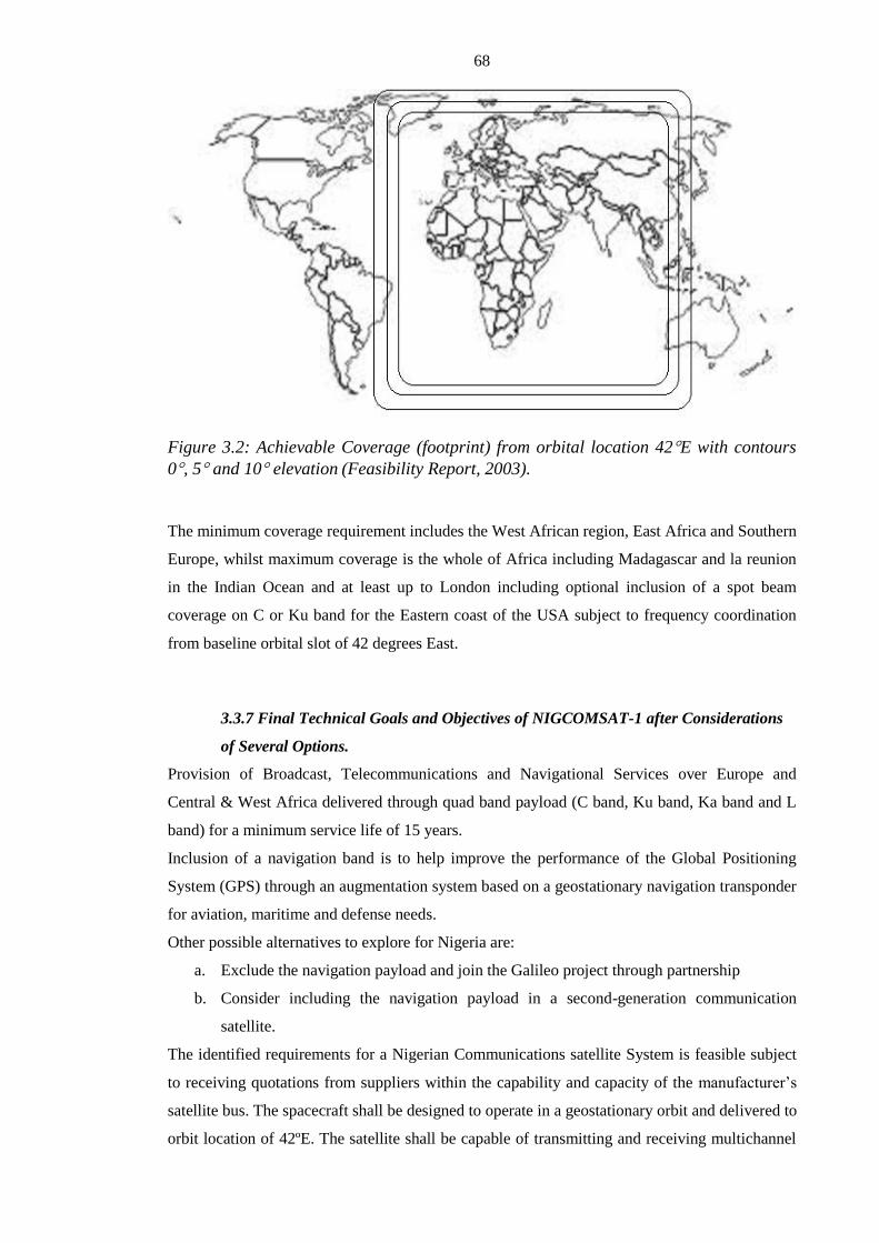
68
Figure 3.2: Achievable Coverage (footprint) from orbital location 42E with contours
0, 5 and 10 elevation (Feasibility Report, 2003).
The minimum coverage requirement includes the West African region, East Africa and Southern
Europe, whilst maximum coverage is the whole of Africa including Madagascar and la reunion
in the Indian Ocean and at least up to London including optional inclusion of a spot beam
coverage on C or Ku band for the Eastern coast of the USA subject to frequency coordination
from baseline orbital slot of 42 degrees East.
3.3.7 Final Technical Goals and Objectives of NIGCOMSAT-1 after Considerations
of Several Options.
Provision of Broadcast, Telecommunications and Navigational Services over Europe and
Central & West Africa delivered through quad band payload (C band, Ku band, Ka band and L
band) for a minimum service life of 15 years.
Inclusion of a navigation band is to help improve the performance of the Global Positioning
System (GPS) through an augmentation system based on a geostationary navigation transponder
for aviation, maritime and defense needs.
Other possible alternatives to explore for Nigeria are:
a. Exclude the navigation payload and join the Galileo project through partnership
b. Consider including the navigation payload in a second-generation communication
satellite.
The identified requirements for a Nigerian Communications satellite System is feasible subject
to receiving quotations from suppliers within the capability and capacity of the manufacturer’s
satellite bus. The spacecraft shall be designed to operate in a geostationary orbit and delivered to
orbit location of 42ºE. The satellite shall be capable of transmitting and receiving multichannel

69
and multiband signals operated in continuous as well as intermittent modes (i.e voice activation,
data burst) to all desirable service areas.
3.3.8 Communication Design Requirement of NIGCOMSAT-1R based on Needs
Assessment and DFH-4 Satellite Bus.
The C-band payload with 4 operational channels to cover West Africa.
The Ku-band payload with 14 operational channels, 2 fixed beams over Africa region.
The Ka-band payload shall have 8 operational channels with spot beams to cover Europe,
Nigeria and South Africa providing trunking and broadcast capabilities.
The L-band payload for navigation services over Europe and Africa providing a Navigation
Overlay Service (NOS) with functionality similar to the European Geostationary Navigation
Overlay Service (EGNOS).
The TC & R system shall be provided on C-band and located at Abuja, Nigeria with a backup
station in China.
3.3.9 Desired Communications Service Coverage Areas through Polygon Definition
to ensure Effective Satellite Service Delivery.
The polygon definition for the service area within the African sub-region based on needs
assessment of section 3.2 and earlier sections of section 3.3 of this chapter is presented in table
3.8 using coordinates of African cities for the Ku band West Antenna coverage.
Figure 3.3 shows the result of the service area for Ku band West Antenna Tx/Rx beam using
the coordinates of the African cities in Table 3.8 as the edge of the service coverage area. Table
3.9 shows specified cities within the polygon for verification of expected and required
communication satellite performance parameters to ensure good quality of service experience.
Table 3. 8: Ku-Band ECOWAS 1(West Africa) Coverage Polygon Points.
POLYGON 1 POLYGON 2
Polygon
Point
Latitude
(ºN)
Longitude
(ºE)
Polygon
Point
Latitude
(ºN)
Longitude
(ºE)
A1 3.5 5.5 A2 4.5 6.0
B1 4.5 3.5 B2 6.5 4.0
C1 5.0 1.0 C2 6.5 1.0
D1 4.5 -2.0 D2 5.0 -2.8

70
E1 5.0 -4.5 E2 5.5 -4.5
F1 4.0 -8.0 F2 4.5 -7.5
G1 7.5 -12.5 G2 7.0 -10.5
H1 12.0 -16.4 H2 10.0 -13.7
I1 15.0 -17.6 I2 13.8 -16.5
JI 16.7 -16.5 J2 16.0 -15.5
KI 15.0 0.0 K2 15.5 -12.0
L1 13.0 9.0 L2 15.5 -8.0
M1 13.7 13.0 M2 13.0 -1.0
N1 12.5 15.5 N2 8.5 4.0
O1 10.0 15.6 O2 8.5 6.0
P1 9.5 14.6 P2 6.5 8.5
Q1 7.5 16.0 Q2 5.5 8.7
R1 5.0 15.2 R2 4.7 8.2
S1 2.8 16.6 A2 4.5 6.0
T1 1.5 16.7
U1 0.0 14.6
V1 -2.5 14.4
W1 -4.0 11.2
X1 -1.5 8.8
Y1 2.8 8.0
A1 3.5 5.5

71
Figure 3.3: Ku Band ECOWAS 1 (West Africa) Specified Polygons
Table 3.9: Ku-Band ECOWAS1(West Africa) Region with Specified Cities
VALID CITIES FOR IN-ORBIT TEST RESULTS
CITIES IN AFRICA Latitude
(ºN)
Longitude (ºE)
LAGOS 6.45 3.40
KANO 12.00 8.50
ZARIA 11.12 7.73
KADUNA 10.55 7.45
MAIDUGURI 11.85 13.17
BAUCHI 10.32 9.83
SOKOTO 13.07 5.27
OGBOMOSHO 8.13 4.25
IBADAN 7.28 3.50
PORT HARCOURT 4.72 7.08
BAMAKO 12.65 -8.00
NIAMEY 13.52 2.12
DAKAR 14.67 -17.43
BISSAU 11.85 -15.58
CONAKRY 9.50 -14.72
FREETOWN 8.50 -13.25

72
MONROVIA 6.30 -10.78
ABIDJAN 5.32 -4.03
LIBREVILLE 0.38 9.45
ACCRA 5.55 -0.22
LOME 6.13 1.22
NOVO 6.48 2.62
YAOUNDE 3.87 11.52
OUAGADOUGOU 12.37 -1.52
FORT-LAMY 12.12 15.05
KINSHASA 4.30 15.30
Similarly, table 3.10 represents the coordinates of African cities for the Ku band East Antenna
coverage, while figure 3.4 shows the expected coverage service area of Ku band East Antenna
Tx/Rx beam defined using the coordinates of such African cities as the edge of coverage. Table
3.11 shows specified cities within the polygon for verification of expected and required
communication satellite performance parameters to ensure a good quality of service experience
as well.
Table 3.10: Ku-Band ECOWAS 2 (East Africa) Coverage Polygon Points.
POLYGON POINTS FOR EAST AFRICAN
ANTENNA (ECOWAS 2)
Polygon
Point
Latitude
(ºN)
Longitude
(ºE)
A1 4.3 6.0
B1 6.0 4.5
C1 6.0 2.0
D2 10.0 2.5
E2 12.5 7.0
F2 13.0 13.0
G2 12.5 16
H2 8.0 17.5
I2 4.5 20
J2 0.0 18.5
K2 -5.0 16
L2 -7.5 18
M2 -6.5 21.5
N2 -12.5 28.5
O2 -16.0 30.5

73
P2 -22.0 -30
Q2 -25.5 26.0
R2 -29.3 19.5
S2 -29.3 16.0
T2 -23.0 13.8
U2 -17.5 11.0
V2 -11.0 13.2
W1 -4.0 11.0
X1 -1.5 8.8
Y1 4.0 9.2
A1 4.3 6.0
Figure 3.4: Ku Band ECOWAS 2 (East Africa) Specified Polygons
Table 3.11: Ku-Band Ecowas2 Region with Specified Cities
VALID CITIES FOR IN-ORBIT TEST RESULTS
CITIES IN AFRICA Latitude
(ºN)
Longitude (ºE)
LAGOS 6.45 3.40
KANO 12.00 8.50
ZARIA 11.12 7.73
KADUNA 10.55 7.45
MAIDUGURI 11.85 13.17

74
BAUCHI 10.32 9.83
OGBOMOSHO 8.13 4.25
IBADAN 7.28 3.50
PORT HARCOURT 4.72 7.08
NOVO 6.48 2.62
YAOUNDE 3.87 11.52
LIBREVILLE 0.38 9.45
FORT-LAMY 12.12 15.05
BANGUI 4.37 18.58
KINSHASA 4.30 15.30
PORT NOIRE -4.80 11.85
LUANDA -8.50 13.33
LUSAKA -15.42 28.28
BULAWAYO -20.15 28.60
KANYE -24.98 25.32
WINDHOEK -22.50 17.00
For the new beam covering Eastern Asia, table 3.12 represents the coordinates of Asian cities
for the Ku band East Asia Antenna coverage while figure 3.5 shows expected coverage service
area of Ku band East Asia Antenna Tx/Rx beam defined using the coordinates of the Asian
cities as the edge of coverage.
Table 3.12: Ku-Band (Kashi) East Asian Beam Coverage Polygon Points.
POLYGON 1 POLYGON 2
Polygon
Point
Latitude
(ºN)
Longitude
(ºE)
Polygon
Point
Latitude
(ºN)
Longitude
(ºE)
A1 70.95 40.52 A2 62.01 30.72
B1 73.81 41.66 B2 64.44 36.86
C1 76.48 40.88 C2 67.44 42.07
D1 76.28 37.51 D2 72.79 48.18
E1 74.72 32.75 E2 76.50 49.53
F1 72.89 29.74 F2 82.38 50.61
G1 71.62 28.97 G2 84.12 47.29
H1 69.38 29.58 H2 83.63 43.22
I1 68.21 30.96 I2 81.08 39.50
J1 67.41 33.88 J2 78.67 36.06
K1 68.06 37.03 K2 76.25 31.35
L2 74.80 27.03

75
M2 75.04 24.33
N2 73.87 21.66
O2 71.55 19.79
P2 68.73 20.21
Q2 67.22 19.73
R2 64.43 20.28
S2 62.20 22.59
T2 61.57 26.53
Figure 3.5: Ku- Band East Asia (Kashi Beam) Specified Polygons
For the C-band payload, table 3.13 represents the coordinates of African cities for the C band
Antenna coverage on the earth deck of the spacecraft while figure 3.6 shows expected coverage
service area of C Band ECOWAS 1 Antenna Tx/Rx beam defined using the coordinates of such
African cities as the edge of coverage. Table 3.14 shows specified cities within the polygon for
verification of expected and required communication satellite performance parameters to ensure
good quality of service.
Table 3.13 : C-Band ECOWAS 1(West Africa) Coverage Polygon Points.
POLYGON 1 POLYGON 2
Polygon
Point
Latitude
(ºN)
Longitude
(ºE)
Polygon
Point
Latitude
(ºN)
Longitude
(ºE)

76
A1 4.3 6.0 A1 4.3 6.0
B1 6.0 4.5 B2 3.0 10.0
C1 6.0 2.0 C2 2.5 15.0
D1 4.5 -2.0 D2 4.5 24.5
E1 5.0 -4.5 E2 0.0 28.0
F1 4.0 -8.0 F2 -5.0 29.5
G1 7.5 -13.0 G2 -4.0 38.0
H1 12.0 -17.0 H2 1.0 41.0
I1 15.0 -18.0 I2 9.0 40.0
JI 16.7 -16.5 J2 15.0 36.0
KI 15.7 -5.0 K2 17.0 31.0
L1 14.5 5.0 L2 11.0 26.5
M1C 12.0 14.0 M2 13.7 13.0
N1C 10.0 13.0 N2 16.5 5.0
O1C 6.3 11.2 O2 17.5 -5.0
P1C 6.7 9.8 P2 17.5 -17.0
Q1C 4.5 9.0 J1 16.7 -16.5
A1 4.3 6.0 K1 15.7 -5.0
L1 14.5 5.0
M1C 12.0 14.0
N1C 10.0 13.0
O1C 6.3 11.2
P1C 6.7 9.8
Q1C 4.5 9.0
A1 4.3 6.0
Figure 3.6: C Band ECOWAS 1 (West Africa) Specified Polygons

77
Table 3.14: C-Band ECOWAS-1 Region with Specified Cities
POLYGON 1 POLYGON 2
CITIES Latitu
de
(ºN)
Longit
ude
(ºE)
CITIES Latitu
de
(ºN)
Longit
ude
(ºE)
LAGOS 6.45 3.40 NOUAKCH
OTT
18.10 -15.95
KANO 12.00 8.50 TINBUKTU 16.77 -3.02
ZARIA 11.12 7.73 ZINDER 13.80 8.98
KADUNA 10.55 7.45 YAOUNDE 3.87 11.52
MAIDUGUR
I
11.85 13.17 BANGUI 4.37 18.58
BAUCHI 10.32 9.83 FORT-
LAMY
12.12 15.05
SOKOTO 13.07 5.27 KHARTOU
M
15.60 32.53
OGBOMOS
HO
8.13 4.25 ADDIS
ABABA
9.00 38.83
IBADAN 7.28 3.50 NAIROBI -1.28 36.82
PORT
HARCOURT
4.72 7.08 KAMPALA 0.32 32.42
BAMAKO 12.65 -8.00 KIGALI -1.95 30.67
OUGADOU
GOU
12.37 -1.52 BUJUMBU
RA
-3.38 29.37
NIAMEY 13.52 2.12 MWANZA -2.52 32.90
DAKAR 14.67 -17.43 KISANGAN
I
2.48 26.58
BISSAU 11.85 -15.58
CONAKRY 9.50 -14.72
FREETOWN 8.50 -13.25
MONROVIA 6.30 -10.78
ABIDJAN 5.32 -4.03
ACCRA 5.55 -0.22
LOME 6.13 1.22
NOVO 6.48 2.62

78
Coverage over Europe with Ka Band was considered appropriate for Internet contents and
trunking to help meet the Nigerian telecommunications and broadcast needs of the people with
complementary alternative to South Africa as well. Figure 3.7 shows the service area for Ka
TX/Rx antenna beams centered around Europe, Nigeria and South Africa respectively with
consideration for cities that can serve as Gateways for trunking.
Figure 3.7: Ka Transmit and Receiving Beam Coverage over Europe, Nigeria and
South Africa.
The inclusion of the navigation band to help improve the performance of the Global Positioning
System (GPS) through the augmentation system based on a geostationary navigation
transponder was considered important for aviation, maritime and defence needs not only for
Nigeria but the African continent and thus Figure 3.8 shows the receive coverage service area
for the Navigation band with a boresight angle of 7.5 degrees, while figure 3.9 shows the
uplink service area for C-band navigation with Northern Africa including Nigeria and Europe as
a minimum.

79
Figure 3.8: C-Band (Uplink) Navigation Antenna Beam coverage
Figure 3.9: L Band (Downlink) Navigation Antenna Beam Coverage
3.3.10 Allotted Frequencies
The following frequency ranges for Ku-band, C-band, Ka-band and L-band were allotted by the
International Telecommunication Union (ITU) for NIGCOMSAT-1(R) operations and services.
Ku-band:
Down link 12.50~12.75 GHz Uplink 14.00~12.50GHz
C-band:

80
Down link 3.40~3.70 GHz Uplink 6.425~6.725GHz
Ka-Band:
Down link 19.0~20.20 GHz Uplink 28.8~30.0GHz
L-Band:
Down link 1166.45~1577.42MHz Uplink 6629.45~6700.42MHz
3.3.11 Channel Assignment and Polarization
Ku band Channels receive in one polarization and transmit in the orthogonal polarization. The
channel plan is based on 35.5 MHz frequency separation between centers of adjacent channels
and the bandwidth of each channel is 31.5MHz.
Table 3.15 and 3.16 shows the uplink and downlink Ku-band frequency and polarization plan
respectively with frequency reuse through polarization to double the 250MHz frequency block
from International telecommunications Union (ITU) to 500MHz. The conversion frequency
from Uplink to downlink is 1500MHz. Figure 3.10 shows the block diagram of the frequency
block utilization for 14 active transponders with their respective center frequencies and 4 MHz
band separation with adjacent transponders.
Table 3.15: Uplink Frequency and Polarization Plan of Ku-Band
Bands Frequency Polarization Bands Frequency Polarization
Channel 1 14018 H Channel 8 14018 V
Channel 2 14053.5 H Channel 9 14053.5 V
Channel 3 14089 H Channel 10 14089 V
Channel 4 14124.5 H Channel 11 14124.5 V
Channel 5 14160 H Channel 12 14160 V
Channel 6 14195.5 H Channel 13 14195.5 V
Channel 7 14231 H Channel 14 14231 V
Table 3.16: Downlink Frequency and Polarization Plan of Ku-Band
Bands Frequency Polarization Bands Frequency Polarization
Channel 1 12518 V Channel 8 12518 H
Channel 2 12553.5 V Channel 9 12553.5 H
Channel 3 12589 V Channel 10 12589 H
Channel 4 12624.5 V Channel 11 12624.5 H
Channel 5 12660 V Channel 12 12660 H
Channel 6 12695.5 V Channel 13 12695.5 H
Channel 7 12731 V Channel 14 12731 H

81
Figure 3.10: Block diagram of frequency block utilization for 14 active transponders
with their respective center frequencies and 4 MHz band separation with adjacent
transponders.
C band Channels shall be FSS payload for reception and transmission of circularly polarized RF
signals. The channel plan is based on a 40MHz frequency separation between centers of
adjacent channels and the bandwidth of each channel is 36MHz.
Table 3.17 and 3.18 shows the uplink and downlink C-band frequency and polarization plan
respectively. The conversion frequency from Uplink to downlink is 3025MHz. Figure 3.11
shows the block diagram of the frequency block utilization for 4 active transponders with their
respective center frequencies and 4 MHz band separation with adjacent transponders.
Table 3.17: Uplink Frequency and Polarization Plan of C-Band
Bands Frequency Polarization
Telecommand 1 6429 RHCP
Telecommand 2 6439 RHCP
Channel 1 6465 RHCP
Channel 2 6505 RHCP
Channel 3 6545 RHCP
Channel 4 6585 RHCP
Table 3.18: Downlink Frequency and Polarization Plan of C-Band
Bands Frequency Polarization
Channel 1 3440 LHCP

82
Channel 2 3480 LHCP
Channel 3 3520 LHCP
Channel 4 3560 LHCP
Telemetry 1 3696.84 LHCP
Telemetry 2 3694.14 LHCP
Figure 3.11: Block diagram of the frequency block utilization for 4 active transponders
with their respective center frequencies and 4 MHz band separation with adjacent
transponders.
The Ka-band Channels with bi-directional capability has a channel planned with a 150MHz
frequency separation between the centers of adjacent channels and a bandwidth of 120MHz per
transponder with circularly polarized RF signals. Table 3.19 and 3.20 shows the uplink and
downlink Ka-band frequency and polarization plan respectively. The conversion frequency from
Uplink to downlink is 9800MHz. Figure 3.12 shows the block diagram of the frequency block
utilization for 8 active transponders with their respective center frequencies and 30 MHz band
separation with adjacent transponders, while figure 3.13 shows the channel plan for trunking
and broadcasting over the spot beams.
Table 3.19: Uplink Frequency and Polarization Plan of Ka-Band
Bands Frequency Polarization
Channel 1 28875 LHCP
Channel 2 29025 LHCP
Channel 3 29175 LHCP
Channel 4 29325 LHCP
Channel 5 29475 LHCP
Channel 6 29625 LHCP
Channel 7 29775 LHCP

83
Channel 8 29925 LHCP
Table 3.20: Downlink Frequency and Polarization Plan of Ka-Band
Bands Frequency Polarization
Channel 1 19075 RHCP
Channel 2 19225 RHCP
Channel 3 19375 RHCP
Channel 4 19525 RHCP
Channel 5 19675 RHCP
Channel 6 19875 RHCP
Channel 7 19975 RHCP
Channel 8 20125 RHCP
Figure 3.12: Block diagram of the Ka-Band frequency block utilization for 8 active
transponders with their respective center frequencies and 30 MHz band separation with
adjacent transponders.
Figure 3.13: Ka-band channel configuration for Trunking and Broadcasting.

84
L-Band Navigation payload is meant to augment the Global Positioning System (GPS) signals
on L1 and L5 frequencies. It is a Navigation Overlay Service (NOS) with functionality similar
to the European Geostationary Navigation Overlay Service (EGNOS). The frequency
assignment and polarization plan for both uplink and downlink frequencies is as presented in
table 3.21
Table 3.21: Frequency and Polarization Plan of L-Band (Navigation).
3.3.12 Service Capability and Minimum Performance Parameters of the Nigerian
Communications Satellite (NIGCOMSAT-1R)
All RF performances to be fulfilled inside the angular aperture defined by the contour as
required.
The C-band payload with 4 operational channels and coverage over West Africa.
The Ku-band payload with 14 operational channels, 2 fixed beams over West , East Africa and
East Asia.
The Ka-band payload with 8 operational channels and spot-beams over Europe, Nigeria and
South Africa and with trunking and broadcast capability.
The L-band payload shall serve as Navigation Overlay Service (NOS) with functionality similar
to the European Geostationary Navigation Overlay Service (EGNOS) over Europe and Africa.
3.3.12.1 Service Capabilities
TV Broadcast (C, Ku and Ka Band)
Audio Broadcast (C, Ku and Ka Band)
Telecommunication (C, Ku and Ka Band)
Navigation Services (L-Band)
Channel Frequency MHz Polarization Bandwidth
C1 - Uplink 6698.42 LHCP 4 MHz
C5 - Uplink 6639.45 LHCP 20 MHz
L1 - Downlink 1575.42 RHCP 4 MHz
L5 - Downlink 1176.45 RHCP 20 MHz

85
3.3.12.2 Minimum Figure of Merit (G/T) for all the Bands
The G/T for the specified coverage shall be equal or more than the value defined in table 3.22.
Table 3.22: Minimum Figure of Merit (G/T) for the Bands
Ku Band
G/T (dB/K)
Beam 1 Zone 1 (West Antenna) +5.0
Beam 1 Zone 2 (West Antenna) +4.5
Beam 2 (East Antenna) +1.0
Beam 3 Zone 1 (Kashi East Asia Beam) +6.5
Beam 3 Zone 2 (Kashi East Asia Beam) +2.0
C Band
G/T (dB/K)
Beam 1 Zone 1 1.0
Beam 1 Zone 2 -5.0
Ka Band
G/T (dB/K)
Ka Band Spot Beam Europe +12 (Peak)
Ka Band Spot Beam Nigeria +12 (Peak)
Ka Band Spot Beam South Africa +12 (Peak)
L Band
G/T (dB/K)
Navigation -12
3.3.12.3 Minimum Equivalent Isotropic Radiated Power (EIRP) for all the Bands
The EIRP inside the specified coverage shall be equal or more than the value defined in table
3.23 below.
Table 3.23: Minimum Equivalent Isotropic Radiated Power(EIRP) for the Bands
Ku Band
EIRP dBW
Beam 1 Zone 1 53
Beam 1 Zone 2 52.5

86
Beam 2 48.0
Beam 3 Zone 1 52
Beam 3 Zone 2 48
C Band
EIRP dBW
Beam 1 Zone 1 41
Beam 1 Zone 2 35
Ka Band
EIRP dBW
Ka Beam Europe 52
Ka Beam Nigeria 55
Ka Beam South Africa 52
L Band
EIRP dBW
L5 EIRP 26.2
L1 EIRP 28.1
3.3.12.4 Saturated Flux Density (SFD) Requirements(Minimum and Maximum
Range) for the Bands
SFD Requirement for Ku-Band -(77+G/T)dBw/m2~ -(97+G/T) dBw/m
2
SFD Requirement for C-Band -(78.5+G/T)dBw/m2 ~ -(98.5+G/T) dBw/m
2
SFD Requirement for Ka-Band -(63+G/T)dBw/m2 ~ -(83+G/T) dBw/m
2
SFD Requirement for L-Band -80dBw/m2 ~ -96 dBw/m
2
3.4 Conclusion
The use of communication satellite for Internet, Digital Television transmission and reception
and the consequence of Voice over IP (VoIP) increased the demands for communication
satellite resources and on a long-term contract beyond even the life span of a typical satellite.
Satellite communications technology remains a tremendous force for change and innovation.
The global coverage of the Olympics had more than 3 billion viewers. Communication Satellite
and satellite communications technology has helped to create a world community and global
village. From over $300 trillion annual electronic fund transfers to hundreds of millions of
airline reservations with communication satellites playing critical roles in finance, business and
international trades especially in countries and regions with inadequate terrestrial
communications. Despite growth in fibre optic cables, over 50% of all overseas
communications is satellite based. More than 200 countries and territories rely on about 200

87
satellites for domestic, regional and/or global linkages, defence communications, direct
broadcast services, navigation, data collection, mobile communications etc. Generally, the
satellite communications industry is a $15 billion per year business as at 2003 and was expected
to grow to $30 billion per year within the next decade.
The Nigerian market for satellite equipment and services is significant and conservatively
estimated at over US$250 million yearly and growing.
Communication Satellites and satellite communications technologies remains one of the fastest
growing areas for data communications as it is a valuable supplement and alternative to existing
and available terrestrial ICT networks. A regional and domestic Communications Satellite with
suitable design specifications and zonal coverages to Nigeria, African continent and coverage
over Europe for Internet content and trunking will help meet the telecommunications and
broadcast needs of the people especially the financial sectors, manufacturing, oil and gas,
commercial companies, government agencies, transport and tourism including schools and
Universities. Conclusively, the Nigerian Communications Satellite project is an economically
viable project as a regional communication satellite service provider in Sub-Saharan Africa. The
Insurance replacement Nigerian Communications Satellite (NIGCOMSAT-1R) after de-orbiting
of the first Nigerian Communications Satellite (NIGCOMSAT-1) as a result of identified single
point of failure (SPF); provided the opportunity to modify and optimize the payload and its
repeaters to reflect the growing and prevailing market trends and potential beyond the African
continent.

88
CHAPTER 4:
The Redesign of Nigerian Communications Satellite Insurance
Replacement (NIGCOMSAT-1R) with Navigation Capability for
Optimal Performance and Test Results.

89
4.0 Summary:
The design and implementation of Nigerian Communications Satellite takes cognizance of the
situational analysis made in chapter three as regards needs assessment and feasibility with
service coverage area (footprints of NIGCOMSAT-1(R) designed to provide qualitative
telecommunications and broadcast needs within Sub-Saharan Africa and beyond including a
Navigational piggyback payload repeater. The Insurance replacement Nigerian Communications
Satellite (NIGCOMSAT-1R) after de-orbiting of the first Nigerian Communications Satellite
(NIGCOMSAT-1) as a result of an irreparable identified single point of failure (SPF) of an on-
board subsystem provided the opportunity to modify and optimize the payload of the COMSAT
to reflect the growing and prevailing market trends and potential beyond the African continent.
The design performance is presented and the actual performance measured during In-Orbit Test
(IOT) is also presented.
4.1 Antennas and Payload Design of Nigerian Communications
Satellite (NIGCOMSAT-1R) to meet Specified Regional
Performance Requirements and Service Coverage Areas.
4.1.1 Summary of Results for Ku Band Antenna and Payload Design of
NIGCOMSAT-1R
Figure 4.1 gives overview block diagram of the Ku band to meet the designed configuration.
Details of Ku-Band Antenna and Payload Design with Gain and Loss Computations is provided
in Appendix A.

90
Figure 4.1: Block Diagram Overview of Ku-Band Payload Repeater.
The Ku band antenna analytic design for the service area coverage for beam 1(ECOWAS1-
WEST AFRICA) and beam 2 and beam 3 (ECOWAS 2-EAST AFRICA & KASHI EAST ASIA

91
BEAM) are presented in table 4.1 and 4.2 respectively. Detailed computations are provided in
table A1.2 and A1.4 of Appendix A. The antennas for the Ku-band are Gregorian type,
deployable double off-set reflector with shaped main paraboloid reflector as illustrated in figure
4.2.
The main reflector surface optimization was computed with TICRA POS4 and the antenna
patterns are computed with GRASP8 software.
Table 4.1: Analytical Parameters of Ku-Band Beam 1 Antenna of NIGCOMSAT-1R
Items Ku-Band Beam 1(West Antenna)
Coverage Zone 7 Operational Channels of 31.5MHz over fixed beam1 covering
West African Subregion.
Frequency bandwidth (MHz) Transmit: downlink, 12500.0MHz-12750MHz
Receive: uplink, 1400MHz-14500MHz
Gain(dBi) 32.8 (Downlink); 32.6 (Uplink) Reference to Table A1.4 and
A1.2 respectively of Appendix A.
Polarization Dual Linear Polarization
Antenna type (unit:m) Gregorian type, deployed double off-set reflector
Shaped main paraboloid reflector:
D=3.0 X 2.2
Shaped elliptic-sphere sub-reflector:
Deployed double off-set reflector
Receive and transmit feed shared
Design software:
GRASP 8-Co-polarization coverage area
POS-4- Shaped reflector design
Feed Assembly Feed assembly:
Radial corrugated horn
Square-circular transition
Orthogonal Mode Transducer (OMT)
Low pass filters
High Pass Filters
Dual Polarization Ports
Design and simulated Software ANSOFT-HFSS

92
Table 4.2: Analytical Parameters of Ku-Band Beam 2 Antenna of NIGCOMSAT-1R
Items Ku-Band Beam 2 (East Antenna)
Coverage Zone 7 Operational Channels of 31.5MHz over fixed beam 2 covering
East Africa.
Frequency bandwidth (MHz) Transmit: downlink, 12500.0MHz-12,750MHz
Receive: uplink, 14000MHz-14250MHz
Gain(dBi) 28.4 (Downlink); 29.1 (Uplink) Reference to Table A1.4 and
A1.2 respectively of Appendix A
Polarization Dual Linear Polarization
Antenna type (unit:m) Gregorian type, deployed double off-set reflector [1]
Shaped main paraboloid reflector:
D=2.6 X2.16
Shaped elliptic-sphere sub-reflector:
Deployed double off-set reflector
Receive and transmit feed shared
Design software:
GRASP 8-Co-polarization coverage area
POS-4- Shaped reflector design
Feed Assembly Feed assembly:
Radial corrugated horn
Square-circular transition
Orthogonal Mode Transducer (OMT)
Low pass filters
High Pass Filters
Dual Polarization Ports
Design and simulated Software ANSOFT-HFSS

93
Figure 4.2: The Composition and Configuration of Ku-Band Deployable Double Off-set
West Antenna for the desired coverage.
The resulting XPI Contours at 12.625GHz, Corresponding XPI Contours at 14.125GHz, G/T
and EIRP of Ku Band West Antenna (ECOWAS 1) of NIGCOMSAT-1R based on African
cities coverage are provided in Figure 4.3, 4.4, 4.4 and 4.6 respectively. Table 4.3 is
verification of the satellite performance on a region-by-region basis.
Similarly, the G/T and EIRP of Ku Band East Antenna (ECOWAS 2) are provided in Figure 4.7
and 4.8 respectively as well as G/T and EIRP of East Asian Beam as figure 4.9 and 4.10
respectively using Ku-Band East Antenna with deployable double off-set reflector as shown in
figure 4.11.

94
Figure 4.3:XPI Contours of West Antenna Ku Band (ECOWAS 1) of NIGCOMSAT-1R
at 12.625GHz (Downlink).
Figure 4.4: XPI Contours of West Antenna Ku Band (ECOWAS 1) of NIGCOMSAT-1R
at 14.125GHz (Uplink)

95
Figure 4 5: G/T Contour of Ku Band West Antenna (ECOWAS 1) of NIGCOMSAT-1R.
Figure 4.6: EIRP Contour of Ku Band West Antenna (ECOWAS 1) of NIGCOMSAT-1R.

96
Table 4.3: Ku-Band West Antenna (ECOWAS 1) and East Antenna (ECOWAS 2)
Specified African City Performance Parameters Verification Table.
Ku-Band West Antenna (ECOWAS 1) Specified African City Performance Parameters
Verification Table (Table A1.2 and A1.4 of Appendix A).
Ku-Band East Antenna (ECOWAS 2) Specified African City Performance Parameters
Verification Table (Table A1.2 and A1.4 of Appendix A).

97
Figure 4.7: G/T Contour of Ku Band East Antenna (ECOWAS 2) of NIGCOMSAT-1R.

98
Figure 4.8: EIRP Contour of Ku Band East Antenna (ECOWAS 2) of NIGCOMSAT-1R.
Figure 4.9: G/T Contour of East Asian Beam using Ku Band East Antenna (ECOWAS
2) of NIGCOMSAT-1R.

99
Figure 4.10: EIRP Contour of East Asian Beam using Ku Band East Antenna
(ECOWAS 2) of NIGCOMSAT-1R.
Figure 4.11: The Composition and Configuration of Ku-Band Deployable Double Off-
set East Antenna for the Desired Coverage.

100
4.1.2 Summary of Results for C Band Antenna and Payload Design of
NIGCOMSAT-1R
Figure 4.12 gives overview block diagram of the C band to meet the designed configuration.
Details of C-Band Antenna and Payload Design with Gain and Loss Computations is provided
in Appendix B.
Figure 4.12: Block Diagram Overview of C-Band Payload Repeater.

101
The C band antenna analytic design for the service area coverage for beam 1(ECOWAS1-
WEST AFRICA) is presented in table 4.4. The antenna for the C-band is Shaped single off-set
reflector with circular aperture as illustrated in figure 4.13.
The analytical design was perfected and optimized with the use of TICRA POS 4 software while
Grasp 8 software was used to compute the antenna patterns including co-polarization coverage
gain.
Table 4.4: Analytical Parameters of C-Band Beam 1 Antenna of NIGCOMSAT-1R
Items C-Band Beam 1(West Antenna)
Coverage Zone 4 Operational Channels of 36MHz over fixed beam1 covering
West African Subregion.
Frequency bandwidth (MHz) Transmit: downlink, 3400.0MHz-3600MHz
Receive: uplink, 6425MHz-6625MHz
Gain(dBi) 26.0 (Downlink); 23.0 (Uplink) Reference to Table B2.4 and
B2.2 respectively of Appendix B
Polarization Circular Polarization
Antenna type (unit:m) Off-set single shaped reflector
Shaped main paraboloid reflector:
D=1.6
Receive and transmit feed shared
Design software:
GRASP 8-Co-polarization coverage area
Pos-4- Shaped reflector design
Feed Assembly Feed assembly:
Ring-loaded corrugated horn
Orthogonal Mode Transducer (OMT)
Low Pass Rectangular Waveguide Filters
High Pass Rectangular Waveguide Filters
Tx/ Rx Polarizers
Design and simulated Software ANSOFT-HFSS

102
Figure 4.13: The Composition and Configuration of C-Band Single Off-set Antenna for
the desired coverage.
The resulting Gain Contours at 3.45GHz, Corresponding Gain Contours at 6.475GHz, XPI
Contours at 3.45GHz, Corresponding XPI Contours at 6.475GHZ, G/T and EIRP of C Band
West Antenna (ECOWAS 1) of NIGCOMSAT-1R based on African cities coverage are
provided in Figure 4.14, 4.15, 4.16, 4.17, 4.18 and 4.19 respectively. Table 4.5 is verification of
the satellite performance on a region-by-region basis.
Figure 4.14: Gain Contours of C-Band Antenna (ECOWAS 1) of NIGCOMSAT-1R at
3.45GHz.

103
Figure 4.15: Gain Contours of C-Band Antenna (ECOWAS 1) of NIGCOMSAT-1R at
6.475GHz.
Figure 4.16: XPI Contours of C-Band Antenna (ECOWAS 1) of NIGCOMSAT-1R at
3.45GHz (Downlink).

104
Figure 4.17: XPI Contours of C-Band Antenna (ECOWAS 1) of NIGCOMSAT-1R at
6.475GHz (Uplink).
Figure 4.18: G/T Contour of C Band Antenna (ECOWAS 1) of NIGCOMSAT-1R.

105
Figure 4.19: EIRP Contour of C Band Antenna (ECOWAS 1) of NIGCOMSAT-1R.
Table 4.5: C-Band Antenna Specified African City Performance Parameters
Verification Table.

106

107
4.1.3 Summary of Results for Ka Band Antennas and Payload Design of
NIGCOMSAT-1R
Figure 4.20 gives overview block diagram of the Ka band to meet the designed configuration.
Details of Ka-Band Antenna and Payload Design with Gain and Loss Computations is provided
in Appendix C.
Figure 4.20: Block Diagram Overview of Ka-Band Payload Repeater.

108
The Ka band transmit antenna is a standard 0.7m off-set reflector antenna mounted on the earth
deck of NIGCOMSAT-1R Spacecraft. The Antenna composition is illuminated by three feeds
located at the focal plane and provides service coverages for Europe, Nigeria and South Africa
as shown in figure 4.21. The analytic design for the service area spot beam coverages by the Ka
band Transmit Antenna is presented in table 4.6.
The performance of the polarizer assembly was analyzed and optimized using Ansoft HFSS,
while antenna pattern are computed by TICRA GRASP 8 Software including co-polarization
coverage gain.
Similarly, the Ka Receive antenna is a standard, 0.65m off-set reflector antenna mounted on the
earth deck of NIGCOMSAT-1R spacecraft. The Antenna composition is also illuminated by
three feeds located at the focal plane and provides service coverages for Europe, Nigeria and
South Africa. The analytic design for the service area spot beam coverages by the Ka band
Transmit Antenna is presented in table 4.7.
Figure 4.21: Composition and Configuration for Ka Transmit or Receive Antenna.
Table 4.6: Analytical Parameters of Ka-Band Transmit Antenna of NIGCOMSAT-
1R
Items Ka Band Transmit Antenna
Coverage Zone The coverage is defined by boresight angle of ±8.7 degrees.
Frequency bandwidth (GHz) Transmitting: downlink, 19.0 ~ 20.2
Gain(dBi) Downlink 36.1 Reference to Table C3.4 of Appendix C
Polarization Downlink: RHCP

109
Mount Plane Southeast of the Earth Deck of Spacecraft.
Antenna type and feed Φ 700mm(Circle) off-set reflector
Antenna is illuminated by three feeds located in the focal plane
and provides coverage for Europe, Nigeria and South Africa
through spot beams. Each feed is made of a radially corrugated
horn, rectangle-to-circular transition and polarizer. The
performance of the polarizer assembly is analyzed by Ansoft
HFSS.
Table 4.7: Analytical Parameters of Ka-Band Receive Antenna of NIGCOMSAT-1R
Items Ka Band Receive Antenna
Coverage Zone The coverage over Europe and Africa is defined by boresight
angle of ±7.5 degrees.
Frequency bandwidth (GHz) Receiving: uplink, 28.8 ~ 30.0
Gain(dBi) Uplink 38.3 Reference to Table C3.2 of Appendix C
Polarization Uplink: LHCP
Mount Plane Northwest of the Earth Deck of Spacecraft.
Antenna type and feed Φ 650mm(Circle) off-set single reflector
Antenna is illuminated by three feeds located in the focal plane
and provides coverage for Europe, Nigeria and South Africa
through spot beams.
The resulting Gain Contours at 19.0GHz, Corresponding Gain Contours at 28.8GHz, XPI
Contours at 19.0GHz, Corresponding XPI Contours at 28.8GHZ, G/T and the EIRP of Ka Band
Spot beams of NIGCOMSAT-1R are provided in Figure 4.22, 4.23, 4.24, 4.25, 4.26 and 4.27
Respectively.
The output channel frequency response and input performance of the Band-Pass filter of Ka
Band are provided in figure 4.36 and 4.37 verifying performance of the Ka Band repeater units
and passive components.

110
Figure 4.22: Gain Contours of Ka-Band Antenna of NIGCOMSAT-1R at 19.0GHz
(Downlink)

111
Figure 4.23: Gain Contours of Ka-Band Antenna of NIGCOMSAT-1R at 28.8GHz
(Uplink).

112
Figure 4.24: XPI Contours of Ka-Band Antenna of NIGCOMSAT-1R at 19.0GHz
(Downlink).

113
Figure 4.25: XPI Contours of Ka-Band Antenna of NIGCOMSAT-1R at
28.8GHz(Uplink).

114
Figure 4.26: G/T Contour of Ka Band Antenna of NIGCOMSAT-1R.

115
Figure 4.27: Ka Band Broadcast and Trunking EIRP Spot Beam of NIGCOMSAT-1R
4.1.4 Summary of Results for L Band Antenna and Payload Design of NIGCOMSAT-
1R
Figure 4.28 gives overview block diagram of the L band piggy payload to meet the designed
configuration. Details of L-Band Antenna and Payload Design with Gain and Loss
Computations is provided in Appendix D.

116
Figure 4.28: Block Diagram Overview of L-Band Payload Repeater.
The C band Navigation antenna defined by boresight of ±7.5 degrees for the minimum uplink
service area coverage over Africa and Europe is presented in table 4.8. The antenna for the C-
band accommodates LHCP and is dual-frequency conical horn antenna mounted on the earthy
deck of NIGCOMSAT-1R spacecraft as illustrated in figure 4.29.

117
The antenna cut patterns were analyzed using Ansoft HFSS as shown in figure 4.30 and 4.31 at
6698.42MHz (C1)and 6639.45MHz (C5) respectively while the contour patterns are computed
by TICRA GRASP 8 software as shown in Figure 4.32 and 4.33 at 6698.42MHz and
6639.45MHz respectively. The corresponding Cross-Polarization gain contours at 6698.42MHz
and 6639.45MHz are shown in figure 4.34 and 4.35 respectively.
The L Band Navigation Antenna defined by boresight angle of ±8.7degrees has a global
coverage as presented in table 4.9 The L Band navigation antenna accommodates RHCP and is
a dual-frequency helical antenna with a backfire cavity mounted on the earth deck of
NIGCOMSAT-1 spacecraft. It is comprised of helical unit, coaxial line, backfire cavity and
antenna support structure (ASST) as shown in figure 4.36. The backfire cavity is used to reflect
the EM waves and improve the gain of the center insert of the reflector. The antenna cut patterns
was analyzed using Ansoft HFSS as shown in figure 4.37 and 4.38 at 1575.42MHz (L1) and
1176.45MHz (L5) respectively while the contour patterns are computed by TICRA GRASP 8
software as shown in Figure 4.39 and 4.40 at 1575.42MHz and 1176.45MHz respectively.
Table 4.8: Analytical Parameters of C-Band Uplink Navigation Antenna of
NIGCOMSAT-1R
Items C Band Navigation Antenna
Coverage Zone Coverage over Europe and Africa defined by boresight angle of
±7.5 degrees.
Frequency Bandwidth (MHz) Receiving: Uplink 6629.45~6700.42MHz
Gain(dBi) Uplink: 16.5 Reference to TableD4.2 of Appendix D
Polarization Uplink: LHCP
Mount Plane Northwest of the Earth Deck of Spacecraft.
Antenna type and Assembly Conical Horn Antenna
Horn, Square to Circular Transition, Polarizations, Waveguide
Assembly, Support Structure.

118
Figure 4.29: C-Band Navigation Antenna Structure Configuration
Figure 4.30: Directional Antenna Cut Pattern at 6698.42MHz.
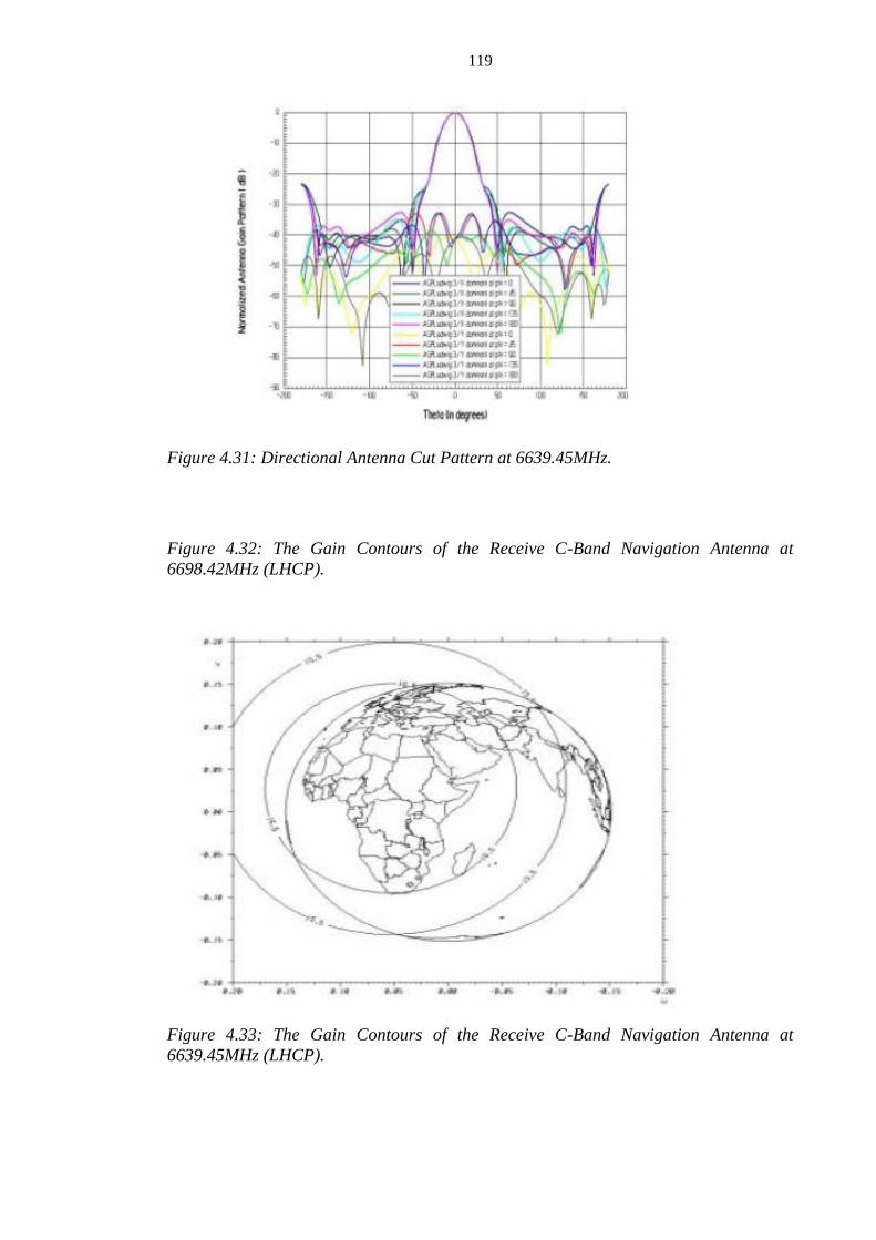
119
Figure 4.31: Directional Antenna Cut Pattern at 6639.45MHz.
Figure 4.32: The Gain Contours of the Receive C-Band Navigation Antenna at
6698.42MHz (LHCP).
Figure 4.33: The Gain Contours of the Receive C-Band Navigation Antenna at
6639.45MHz (LHCP).

120
Figure 4.34: The Cross-Polarization Gain Contours of the Receive C-Band Navigation
Antenna at 6698.42MHz (RHCP).
/
Figure 4.35: The Cross-Polarization Gain Contours of the Receive C-Band Navigation
Antenna at 6639.45MHz (RHCP).
Table 4.9: Analytical Parameters of L-Band Downlink Navigation Antenna of
NIGCOMSAT-1R
Items L Band Navigation Antenna
Coverage Zone Global coverage defined by boresight angle of ±8.7 degrees.
Frequency bandwidth (MHz) Transmitting: Down link 1166.45~1577.42MHz
Gain(dBi) Downlink; 13 Reference to Table D4.5 of Appendix D
Polarization Downlink: RHCP
Mount Plane Northeast of the Earth Deck of Spacecraft.
Antenna type and Assembly Helical Antenna
Reflector (Reflector Aperture Φ 514mm) and Support Structure.

121
Figure 4.36: L-Band Navigation Antenna Structure Configuration
Figure 4.37: Directional Antenna Cut Pattern at 1575.42MHz (L1).

122
Figure 4.38: Directional Antenna Cut Pattern at 1176.45MHz (L5).
Figure 4.39: The Gain Contours of the Transmit L-Band Navigation Antenna at L1,
1575.42MHz (RHCP).

123
Figure 4.40: The Gain Contours of the Transmit L-Band Navigation Antenna at L5,
1176.45MHz (RHCP).
4.1.5 The Antenna System Design Layout of NIGCOMSAT-1R.
In accordance with principles of Antenna layout design, the followings were considered in the
layout design of NIGCOMSAT-1R (Lawal and Chatwin, 2012c).
Antenna Size;
Field of view of each antenna;
Isolation between receiving and transmitting
Connection with repeater;
Mass of Antenna
Desired coverage area.
The communications subsystem provides simultaneously Fixed Satellite Service (FSS)
operational at C-band, Ku-band and Ka band with Navigational services through L band piggy
back payload. These require receiving and transmitting microwave signals within the defined
coverage service areas.
The antenna subsystem of NIGCOMSAT-1R Spacecraft accordingly consists of seven antennas
as illustrated in figure 4.41.
Ku-Band Beam 1 Antenna (West Antenna; 3m X 2.2m)
Ku-Band Beam 2 Antenna ( East Antenna; 2.6m X 2.16m)
C-Band Antenna Beam 3 ( Center of Earth Deck ɸ1.6m)
Ka-Band Transmit Antenna (Southeast of Earth Deck ɸ 0.7m)
Ka-Band Receive Antenna (Northwest of Earth Deck ɸ 0.65m)
C Band Navigation Antenna ( Northwest of Earth Deck, Horn Antenna)
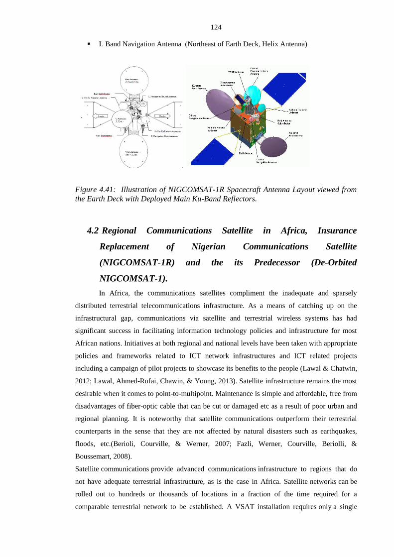
124
L Band Navigation Antenna (Northeast of Earth Deck, Helix Antenna)
Figure 4.41: Illustration of NIGCOMSAT-1R Spacecraft Antenna Layout viewed from
the Earth Deck with Deployed Main Ku-Band Reflectors.
4.2 Regional Communications Satellite in Africa, Insurance
Replacement of Nigerian Communications Satellite
(NIGCOMSAT-1R) and the its Predecessor (De-Orbited
NIGCOMSAT-1).
In Africa, the communications satellites compliment the inadequate and sparsely
distributed terrestrial telecommunications infrastructure. As a means of catching up on the
infrastructural gap, communications via satellite and terrestrial wireless systems has had
significant success in facilitating information technology policies and infrastructure for most
African nations. Initiatives at both regional and national levels have been taken with appropriate
policies and frameworks related to ICT network infrastructures and ICT related projects
including a campaign of pilot projects to showcase its benefits to the people (Lawal & Chatwin,
2012; Lawal, Ahmed-Rufai, Chawin, & Young, 2013). Satellite infrastructure remains the most
desirable when it comes to point-to-multipoint. Maintenance is simple and affordable, free from
disadvantages of fiber-optic cable that can be cut or damaged etc as a result of poor urban and
regional planning. It is noteworthy that satellite communications outperform their terrestrial
counterparts in the sense that they are not affected by natural disasters such as earthquakes,
floods, etc.(Berioli, Courville, & Werner, 2007; Fazli, Werner, Courville, Beriolli, &
Boussemart, 2008).
Satellite communications provide advanced communications infrastructure to regions that do
not have adequate terrestrial infrastructure, as is the case in Africa. Satellite networks can be
rolled out to hundreds or thousands of locations in a fraction of the time required for a
comparable terrestrial network to be established. A VSAT installation requires only a single

125
vendor; and multi-vendor coordination is not required. An installation can usually be completed
in a matter of hours, no matter where the site is located, meaning complete wide area network
deployment can be accomplished in a matter of weeks, rather than months. Satellite network
installation and deployment are indeed quick and simple.
High satellite capacity of the order of 100 Gbps coupled with multiple beams and multiple
gateways, has already resulted in comparatively low cost satellite bandwidth. Satellite systems
are optimized for services like Internet access, Virtual Private Networks (VPN), personal access,
etc. The adoption of High Throughput Satellite (HTS) systems has introduced a paradigm shift
in satellite broadband access services and the satellite industry. The satellite industry has begun
a process of “remaking” the satellite broadband access market into an unprecedented offering
that compares favourably to a DSL and fiber-based services in many unserved or underserved
markets.
Nigeria is in the history books as the first African country to deploy a Ka-band based
Communication Satellite covering the African continent and Europe with the launch of
NIGCOMSAT-1 spacecraft on 13th May, 2007 (GMT+1, Nigerian Time). Figure 4.42 Shows
the NIGCOMSAT-1 spacecraft atop Chinese launch vehicle LM 3B at Xichang Satellite Launch
Center (XSLC) in China shortly before launch at exactly 00.04am (Beijing Local Time) of 14th
May, 2007 (GMT+8).
Figure 4.42: Long March 3B Launcher ready to launch NIGCOMSAT-1 Spacecraft at
Xichang Satellite Launch Center of China.

126
After successful launch with In-Orbit Test (IOT), the In-Orbit Delivery (IOD) followed which
marked the commencement of commercial operations with significant entry into the satellite
market sector providing affordable and qualitative services in local currency as a regional
operator and player before it suffered an on-board subsystem abnormality in regions termed as
single point of failure (SPF) in the spacecraft reliability table, which are capable of reducing or
ending the mission service years of the spacecraft. The on-board abnormality was Solar Array
Drive Assembly Motor (SADA-M) failure. The SADA-M failure implies Solar Array Output
current will not be able to meet the lowest load requirement of the spacecraft as well as battery
recharge requirement and thus spacecraft power exhaustion. Before the exhaustion of the
spacecraft battery power and as part of risk management to avoid in-orbit collateral damage
especially with neighbouring Communication satellite within 42.5 degrees east, the spacecraft
was de-orbited safely above the geostationary arc on 10th November, 2008 (Nigerian Time) after
18 months In-orbit operation.
Figure 4.43 shows NIGCOMSAT-1R Spacecraft undergoing Compact Antenna Range Test
(CATR) before the Launch Campaign Activities while figure 4.44 shows NIGCOMSAT-1R
undergoing West and East Antenna Main Reflector Deployment Mechanism Test. Figure 4.45
shows the writer monitoring and inspecting the integrated and interfaced NIGCOMSAT-1R
spacecraft atop enhanced Chinese Launch Vehicle (LM-3BE) in accordance with design
analysis and specification of the spacecraft while Figure 4.46 shows readiness of the integrated
NIGCOMSAT-1R with Launch Vehicle ready for launch.
Figure 4.43: High Powered Quad-Band NIGCOMSAT-1R Spacecraft Undergoing
Compact Antenna Range Test (CATR) before the Launch Campaign Activities.

127
Figure 4.44: NIGCOMSAT-1R Spacecraft undergoing West and East Antenna Main
Reflector Deployment Mechanism Test.
Figure 4.45: Integrated and Interfaced NIGCOMSAT-1R Spacecraft atop Enhanced
Chinese Launch Vehicle (LM-3BE).

128
Figure 4.46: Shows Readiness of the integrated NIGCOMSAT-1R Spacecraft with
Launch Vehicle (LM-3BE) ready for launch.
Nigeria’s High-Powered, quad-band Communications Satellite carrying Ku, Ka, C and L-Band
was re-launched as NIGCOMSAT-1R with enhancements on 19th December, 2011 (Nigerian
Time) as shown in figure 4.49.
Figure 4.47: The Lift-off of NIGCOMSAT-1R Spacecraft Launcher (China’s Long
March Launch Vehicle, LM-3BE) on 19th
December, 2011 (Nigerian Time).
The replacement satellite had better performance parameters based on further design inputs
related to the weather and climatic conditions of the African Environment, lessons learnt from

129
operations and market experience of the de-orbited first Nigerian Communication Satellite and
inclusive participation of Nigerian Engineers and Managers in the Communication Satellite
project and program as presented in section 4.1. Communication Satellites over Africa,
particularly over the Sub-Saharan region, should be designed with higher Equivalent Isotropic
Radiated Power (EIRP) particularly if the satellite utilizes the upper region of the satellite
spectrum i.e Ku and Ka Band to appreciably compensate for the rain fade column with other
complementary measures such as adaptive code modulation (ACM), Uplink Power Control
(UPC) system implementation etc.
The second Nigerian Communication Satellite (NIGCOMSAT-1R) with quad-band high power
communications; whose geostationary orbit is positioned at 42.5oE and with a launch mass of
5,080 kg has a service life of more than 15 years while the design life is 22.5 years. The satellite
has a reliability value of 99.7% with more than a 75% reliability value at the end of its service
life. Analytical Design optimization in antenna and payload units and subsystem layout
significantly improved performance parameters of the Insurance replacement beyond
specifications as evident in the test results of NIGCOMSAT-1R shown in Test Data Results,
Uncertainty Analysis, Validity Criteria and Test Result Analysis of Section 4.3.
The satellite provides Ku-band, C-band, Ka-band and Navigation payloads capability. The Ku-
band payload has 14 operational channels, 2 fixed beams over Western and Eastern Africa. The
C-band payload has 4 active channels with coverage of Western Africa. The Ka-band payload
has 8 channels providing a communications and trunking capability using 3 fixed spot beams
over Europe, South Africa and Nigeria. The Navigation payload has 2 receive uplink signals on
C-band covering Nigeria and Europe, and 2 transmit downlink signals on L-band: L1 and L5,
giving global coverage.
The additional enhancements aside improvements of the satellite performance parameters of
NIGCOMSAT-1R over the de-orbited NIGCOMSAT-1 are as follows:
i. Introduction of Kashi Ku band Beam by modifying the Ku-Band East Antenna
composition as shown in figure 4.50. With an additional feed using Snell’s basic
principle. The modified East Antenna composition provided two Service coverage
beams as East (ECOWAS 2) Ku Band Beam and Kashi Beam is shown in figure
4.48. The beam was introduced based on new market potentials of Asian countries
with West African Countries and Africa in general. It is important to note that the
de-orbited NIGCOMSAT-1 only provided Ecowas 2 beam coverage over East
Africa.

130
Figure 4.48: The Modified Ku Band East Antenna Composition for NIGCOMSAT-1R
Spacecraft with the resulting two zonal service coverages.
ii. Change of Trunking TWTA power amplifiers of the Ka Band repeater from
50Watts to 70Watts RF output power. The 70Watt TWTA significantly suppressed
rain attenuation with other compensation measures and it also allowed single
redundancy ring of 10: 8 as shown in the Ka Band block diagram of Figure 4.22
Instead of the double redundancy ring of 6:4 for 50watts and 70watts meant for
trunking and broadcasting respectively as shown in figure 4.49.

131
Figure 4.49: Previous Block Diagram of NIGCOMSAT-1 Ka Band Repeater
with Double Redundancy Ring of 6:4.
iii. The European transmit and receive feed were aligned in its antenna support
structure as shown earlier in figure 3.23 such that the maximum gain of the main
antenna lobe as exemplified in figure 4.50 falls within Raisting, Germany; a major
teleport and gateway region for trunking services from Europe to Africa. Figure
4.51 shows the European spotbeam of NIGCOMSAT-1R Ka-band. Generally, the

132
level of the side lobe radiation relative to maximum of the antenna main lobe is
used to characterise the antenna-roll off contour patterns in undefined service areas.
Figure 4.50: Typical illustration of Antenna Radiation Patterns showing the Amplitude
of Antenna Main Lobe and Side lobes in 3D Contour Holography.
Figure 4.51: Ka Band Spot beams of NIGCOMSAT-1R.
iv. In addition to modification of the Ka-band repeater, change in the switching
configuration matrix of the trunking channels to support two transponders to and fro
Europe. This implies baseline configuration of a total of 6 transponders for trunking
needs and 2 transponders for broadcasting needs based on prevailing market
realities, trends, demands and potentials. Figure 4.52 illustrates the baseline Ka

133
band channel configuration of NIGCOMSAT-1R and improvement over channel
configuration of NIGCOMSAT-1 as shown in figure 4.53
Figure 4.52: The Baseline Channel Configuration of Ka Band Payload of
NIGCOMSAT-1R.
Figure 4.53: The Baseline Channel Configuration of Ka Band Payload of
NIGCOMSAT-1 which was improved in NIGCOMSAT-1R as presented in Figure 4.52.
v. The EIRP of performance of the navigation payload was improved to meet 30dBW
requirements of European coverage area through improved optimization and
antenna system layout and harnessing of the spacecraft (Lawal & Chatwin, 2011;
2012C). The L1 and L5 EIRP of 28.1dBW and 26.2dBW respectively improved to
over 30dBW at even edge of coverage service areas as shown in Figure 4.61 and
Figure 4.62 respectively. Chapter five provides further details on Navigation,
Augmentation and Nigerian Communications Satellite Navigation Payload.

134
4.3 Test Data Results, Uncertainty Analysis, Validity Criteria and Test
Result Analysis
4.3.1 Test Data Results
Below are results to confirm Payload In-orbit test (IOT) requirements especially key tests that
are related to performance in communication satellite resource service delivery.
4.3.1.1 EIRP Results
Figures 4.54 to 4.62 below shows the predicted EIRP coverage test results of the
NIGCOMSAT-1R satellite across Africa, Part of Europe and Asia including global navigation
coverage in the C-Band, Ku Band Ecowas-1, Ku Band Ecowas 2, Ku-Band Asia, Ka-Band
European spot beam, Ka-Band Nigerian spot beam, Ka-Band South African spot beam and the
Global Navigational band coverages, respectively based on Compact Antenna Test Range
(CATR).
Figure 4.54: C-Band Coverage EIRP Test Result of NIGCOMSAT-1R over West Africa.

135
Figure 4.55: Ku-Band ECOWAS-1 Coverage EIRP Test Result of NIGCOMSAT-1R
covering West Africa
Figure 4.56: Ku-Band ECOWAS-2 EIRP Test Result of NIGCOMSAT-1R covering
South And East Africa.

136
Figure 4.57: Ku-Band (Kashi Beam) EIRP Test Result of NIGCOMSAT-1R covering
Asia
Figure 4.58: Ka Band European Spot Beam EIRP Test Result of NIGCOMSAT-1R
covering Europe

137
Figure 4.59: Ka Band Nigerian Spot Beam EIRP Test Result of NIGCOMSAT-1R
covering Nigeria
Figure 4.60: Ka Band South African Spot Beam EIRP Test Result of NIGCOMSAT-1R
covering South Africa.
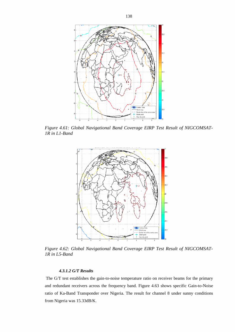
138
Figure 4.61: Global Navigational Band Coverage EIRP Test Result of NIGCOMSAT-
1R in L1-Band
Figure 4.62: Global Navigational Band Coverage EIRP Test Result of NIGCOMSAT-
1R in L5-Band
4.3.1.2 G/T Results
The G/T test establishes the gain-to-noise temperature ratio on receiver beams for the primary
and redundant receivers across the frequency band. Figure 4.63 shows specific Gain-to-Noise
ratio of Ka-Band Transponder over Nigeria. The result for channel 8 under sunny conditions
from Nigeria was 15.33dB/K.

139
General results over the entire bands and coverages as obtained from CATR are as provided in
figure 4.64 to 4.72.
Figure 4.63: Specific Gain-to-Noise ratio of Ka-Band Transponder over Nigeria.
Figure 4.64: G/T Result of NIGCOMSAT-1R West Ku-Band Antenna Coverage
(ECOWAS-1)

140
Figure 4.65: G/T Result of NIGCOMSAT-1R East Ku-Band Antenna Coverage
(ECOWAS-2)
Figure 4.66: G/T Result of NIGCOMSAT-1R East-Asia Ku-Band Antenna Coverage
(KASHI BEAM)

141
Figure 4.67: G/T Result of NIGCOMSAT-1R C-Band Antenna Coverage (ECOWAS-1)
Figure 4.68: G/T Result of NIGCOMSAT-1R Ka-Band European Spot Beam Coverage

142
Figure 4.69: G/T Result of NIGCOMSAT-1R Ka-Band Nigerian Spot Beam Coverage
Figure 4.70: G/T Result of NIGCOMSAT-1R Ka-Band South African Spot Beam
Coverage

143
Figure 4.71: G/T Result (L1) of NIGCOMSAT-1R L-Band Navigation Coverage
Figure 4.72: G/T Result (L5) of NIGCOMSAT-1R L-Band Navigation Coverage
4.3.1.3:THE ANTENNA CUT MEASUREMENT RESULTS
The Antenna Cut measurement was performed to verify correct antenna pointing and shape as
well as good correlation with the measured antenna results over the entire pattern. Figure 4.73
shows the C-Band Communication Antenna IOT pattern Cut Line while table 4.10 shows the 42
points C-Beam IOT pattern Cut lines. Figure 4.73, 4.74 and 4.75 shows the C-Band Ecowas 1
Beam plot with minimum and maximum errors at line 2 (Roll=0), line 3 (Roll=-0.6) and line 1
(Roll=0.6) respectively. The results show good correlation with the measured relative position

144
after alignment of the antenna verification with the satellite coordinate. The positive direction
for pitch is east while the positive direction for roll is north.
Figure 4.73: The C-Band Communication Antenna IOT pattern Cut Line
Table 4.10:The 42 points of the C-Band Communication Antenna IOT pattern Cut
Line and the Relative Positions.
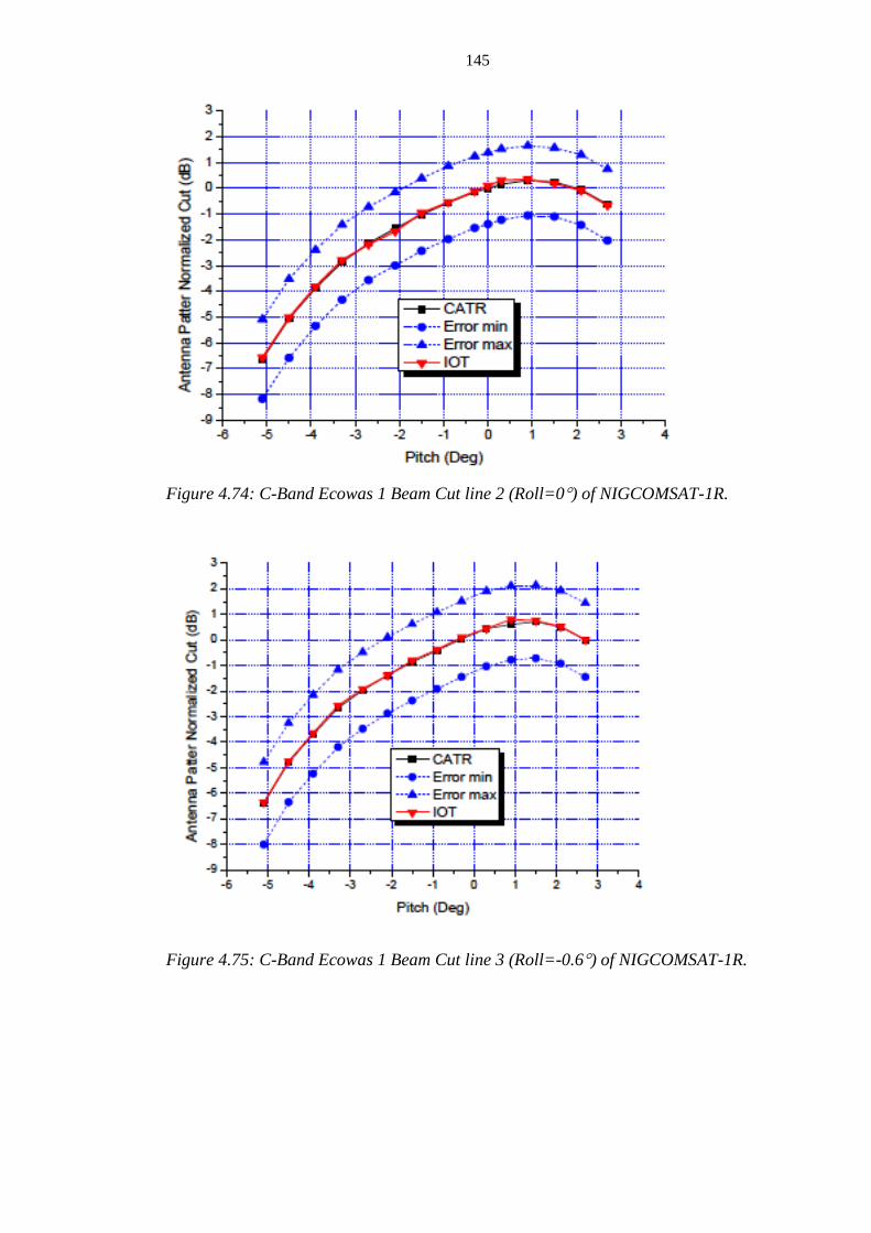
145
Figure 4.74: C-Band Ecowas 1 Beam Cut line 2 (Roll=0) of NIGCOMSAT-1R.
Figure 4.75: C-Band Ecowas 1 Beam Cut line 3 (Roll=-0.6) of NIGCOMSAT-1R.

146
Figure 4.76: C-Band Ecowas 1 Beam Cut line 1 (Roll=0.6) of NIGCOMSAT-1R.
4.3.1.4 The AM/AM Test.
The AM/AM test was performed on all High Power Amplifiers including redundant amplifiers.
TWTA Helix current, TWT Anode voltage and CAMP input power levels were record during
AM/AM transfer test from -20dB to +6dB relative to input saturation. The test was performed at
nominal gain setting to establish saturation flux density and saturated EIRP. The Gain transfer
responses were measured for input drive levels from 20dB below the operating point to +2dB
above the operating point of the HPA. Figure 4.77 shows gain transfer curve test result of
channel 11 of Ku-Band Transponder of NIGCOMSAT-1R measured during sunny conditions
with an uplink frequency of 14,124.5MHz and Downlink Frequency of 12,624.5MHz. The
Saturated Flux Density and EIRP was -90.4dBW/m2
and 51.58dBW respectively (point of
intersection of the curves in figure 4.77) with saturated HPA gain of 186.44dB. All test results
were validated and acceptable.

147
Figure 4.77: Gain Transfer Curve Test Result of Channel 11 of Ku-Band Transponder
of NIGCOMSAT-1R.
4.3.1.5: The Gain Step and Automatic Level Control (ALC) Mode Functionality of
the High Power Amplifiers (HPA) of all Transponders.
The Fixed Gain Mode (FGM) was verified for all HPAs on level setting in three steps (normal
step ±1 step). The ALC mode functionality for Ku-Band, Ka-Band and C-Band HPAs
transponders were verified by observing its stability, change in downlink power and consistency.
Figure 4.78 and 4.79 shows the ALC stability and transfer curve respectively of Channel 8 Ku
band transponder measured during sunny conditions.
Figure 4.78: The ALC stability curve of Channel 8 Ku Band transponder measured
during sunny condition.

148
Figure 4.79: The ALC Transfer curve of Channel 8 Ku Band transponder measured
during sunny conditions.
4.3.1.6: The In-Band Frequency Response and Group Delay of Transponder.
The in-band frequency response helps verify channel passband performance at nominal gain
setting in fixed gain mode (FGM) of the transponder’s HPA. Figure 4.80 shows the static
spectrum curve of channel 8 Ku-Band Transponder of NIGCOMSAT-1R showing the
transponder’s cold noise level and static noise curve.
Figure 4.80: The static spectrum curve of channel 8 Ku-Band Transponder of
NIGCOMSAT-1R showing the transponder’s cold noise level and static noise curve.

149
4.3.1.7: Frequency Conversion Accuracy and Stability of Receivers
The frequency conversion and stability of all receiver units were tested and verified at mid-
frequency including that of Navigation Band, which were externalized outside the receiver and
ovenized considering the criticality of frequency stability and conversion accuracy to time-based
signals for precision in applications. Figure 4.81 and 4.82 shows frequency conversion accuracy
test results of NIGCOMSAT-1R Ka band receiver and the active externalized 10MHz Ultra-
Stable Crystal Oscillator of NIGCOMSAT-1R. Uplink Frequency conversion to Downlink
frequency is 9800MHz while Uplink C1-Band frequency conversion (6698.42MHz) to
Downlink L1-Band frequency (1575.42MHz) is 5123MHz. The 8.98 x 10⁻⁹
of figure 4.82 of the
L1 transponder of NIGCOMSAT-1R Navigation was a very good result considering
requirement of at least 2.0 x 10⁻⁷
over service life time of the spacecraft (15 years).
Figure 4.81: Frequency Conversion Accuracy Test Result of NIGCOMSAT-1R Ka Band
Receiver.

150
Figure 4.82: Frequency Conversion Accuracy Test Results of NIGCOMSAT-1R Active
Externalized 10MHz Ultra-Stable Crystal Oscillator of NIGCOMSAT-1R.
4.3.2 Uncertainty Tests Analysis
4.3.2.1 Test Setup Uncertainty Analysis
The equipment test setup introduces uncertainty and errors based on configuration and
parameters used during In-orbit test (IOT) result confirmation. The IOT result is validated by
eliminating total uncertainty elements from the results as computed below in table 4.11 to 4.17
for the EIRP, IPFD, G/T, Amplitude Vs Frequency Response, Gain Step, ALC stability and
Translation Frequency Tests respectively.
Table 4.11: Table of EIRPs Test Uncertainties
Table 4.12: Table of G/T Test Uncertainties

151
Table 4.13: Table of IPFD Test Uncertainties
Table 4.14: Table of Amplitude Vs Frequency Response Test Uncertainties
Table 4.15: Table of Gain Step Uncertainties
Table 4.16: Table of ALC Stability Test Uncertainties

152
Table 4.17: Table of Translation Frequency Test Uncertainties
4.3.2.2 Antenna Effects Analysis
During IOT, the influence of antenna pointing error errors was considered with respect to
normal mode or station keeping mode of the satellite in its orbit. Based on the satellite
specification and requirement, the antenna pointing error should be less than 0.1 degree in
normal mode. Based on test point as the center, the maximum and minimum performance were
obtained from the CATR results of figure 4.54 to 4.62 for the EIRPs and 4.64 to 4.72 for the
G/Ts within 0.1 degree circle. Table 4.18 to 4.26 shows the antenna effects analysis used in
validity criteria for the test data obtained.
Table 4.18: Ku Band West Antenna (ECOWAS 1) Antenna Effects Analysis
Table 4.19: Ku Band East Antenna (ECOWAS 2) Antenna Effects Analysis

153
Table 4.20: C Band Antenna (ECOWAS 1) Antenna Effects Analysis
Table 4.21: Ka Band Nigerian Beam Antenna Effects Analysis
Table 4.22: Navigation Band Beam Antenna Effects Analysis

154
Table 4.23: Ku Band West Antenna (ECOWAS 1) Beam Cuts Antenna Effects
Analysis
Table 4.24: Ku Band East Antenna (ECOWAS 2) Beam Cuts Antenna Effects
Analysis

155
Table 4.25: C Band Antenna (ECOWAS 1) Beam Cuts Antenna Effects Analysis

156
Table 4.26: Ka Band Nigerian Beam Cuts Antenna Effects Analysis
4.3.3 Validity Criteria for the Test Data.
The IOT results particularly EIRP, SFD and G/T; key performance parameters of
communication satellite service delivery were analysed and validated over reference spacecraft
tests based on prediction result carried out (CATR results in particular as final benchmark test
before launch campaign) and test uncertainty analysis during In-Orbit Tests (IOT).
Considering antenna effect analysis as ∂0, let the test result be Y with uncertainty as ∂1 and the
prediction result as X with uncertainty as ∂2, then the test results are valid and accepted when
|Y-X| √
|Y-X| √
……………………………………………..Equation 4.1
4.3.4 Test Result Analysis
Test results validations
4.3.4.1 EIRP Test Result Analysis
The EIRP results during IOT are consistent with the predicted CATR results and the delta is
within the uncertainties. The EIRP results analysis of selected channel configurations of all
bands as presented in table 4.27 to 4.31 are consistent and compliant and within the
uncertainties of equation 4.1.

157
Table 4.27: Ku Band West Antenna (ECOWAS 1) Beam EIRP Test Results.
Table 4.28: Ku Band East Antenna (ECOWAS 2) Beam EIRP Test Results.
Table 4.29: C Band Antenna (ECOWAS 1) Beam EIRP Test Results.
Table 4.30: L Band (Navigation) Antenna Beam EIRP Test Results.

158
Table 4.31: Ka Band Nigerian Antenna Spot Beam EIRP Test Results.
4.3.4.2 G/T Result Analysis
The G/T results during IOT are consistent with the predicted G/T results and the delta is within
the uncertainties of equation 4.1. The G/T results analysis of selected channel configurations of
bands as presented in table 4.32 to 4.35 are consistent and compliant and within the
uncertainties. The Antenna noise temperature difference (Delta) is used to compensate the noise
temperature between ground test and IOT. It is estimated that the antenna noise temperature
during IOT was 200K while antenna noise temperature of earth is 290K.
Table 4.32: Ku Band West Antenna (ECOWAS 1) Beam G/T Test Result.
Table 4.33: Ku Band East Antenna (ECOWAS 2) Beam G/T Test Result.
Table 4.34: C Band Antenna (ECOWAS 1) Beam G/T Test Result.

159
Table 4.35: Ka Band Nigerian Antenna Spot Beam G/T Test Result.
4.3.4.3 SFD Result Analysis
The SFD results during IOT are consistent with the predicted G/T results and the delta is within
the uncertainties. The SFD results analysis of selected channel configurations of bands as
presented in table 4.36 to 4.40 are consistent and compliant and within uncertainties of equation
4.1.
Table 4.36: Ku Band West Antenna (ECOWAS 1) Beam SFD Test Result
Table 4.37: Ku Band East Antenna (ECOWAS 2) Beam SFD Test Result

160
Table 4.38: C Band Antenna (ECOWAS 1) Beam SFD Test Result
Table 4.39: Ka Band Nigerian Spot Beam Antenna Beam SFD Test Result
Table 4.40: L Band (Navigation) Antenna Beam SFD Test Result
4.3.4.4 Antenna Pattern Verification Analysis
Compared with CATR results, the results of the antenna pattern verification shows that the
pointing of antennas was correct and beam shape is same with CATR results. After lift-off and
Low Earth Orbit Phase and Manoeuvre, the antenna pointing does not require adjustment based
on results in figure 4.74 to 4.76 for C-Band Antenna. For Ku Band Antennas and Ka Band
Antenna. Figure 4.83 to 4.91 also shows acceptable antenna pattern verifications.

161
Figure 4.83: Ku Band West Antenna (ECOWAS 1) Beam Cut Line 2 (Roll=0)
Figure 4.84: Ku Band West Antenna (ECOWAS 1) Beam Cut Line 3 (Roll=-0.6)

162
Figure 4.85: Ku Band West Antenna (ECOWAS 1) Beam Cut Line 1 (Roll=0.6)
Figure 4.86: Ku Band East Antenna (ECOWAS 2) Beam Cut Line 3 (Pitch=-1.2)

163
Figure 4.87: Ku Band East Antenna (ECOWAS 2) Beam Cut Line 2 (Pitch=-0.6)
Figure 4.88: Ku Band East Antenna (ECOWAS 2) Beam Cut Line 1 (Pitch=0)

164
Figure 4.89: Ka Band Nigerian Spot Beam Antenna Cut Line 1 (Pitch=0)
Figure 4.90: Ka Band Nigerian Spot Beam Antenna Cut Line 2 (Pitch=-0.6)

165
Figure 4.91: Ka Band Nigerian Spot Beam Antenna Cut Line 3 (Pitch=0.6)
4.3.4.5 AM/AM Analysis
AM/AM test was performed on all HPAs of the transponders including redundant HPAs. And
the test results are acceptable as shown in figure 4.77.
4.3.4.6 The Frequency Response Analysis
The frequency response test was performed on each channel including primary and redundant
channels and the test results are acceptable and within IOT uncertainties.
4.3.4.7 The Gain Step Test Analysis
The frequency response test was performed on each LCTWTA and the test results are
acceptable within IOT uncertainties with considerations of interference from adjacent satellites.
4.3.4.8 The ALC Stability Analysis.
The ALC stability test was performed on each LCTWTA and the test results are acceptable
within IOT uncertainties of equation 4.1 as exemplified in figure 4.78.
4.3.4.9 The ALC Transfer Test Analysis
The ALC transfer test was performed on each LCTWTA and the IOT test results are consistent
with the on ground tests and acceptable within IOT uncertainties as exemplified in figure 4.79.

166
4.3.4.10 The Frequency Accuracy Analysis
The frequency accuracy test was performed on each receiver at mid-frequency and the test
results are consistent with the on ground tests (CATR) and acceptable within IOT uncertainties
of equation 4.1 and as exemplified in figure 4.81 and 4.82.
The spacecraft is designed so that each Radio Frequency (RF) channel meets the specified
requirements, works reliably throughout its Service Life including eclipse conditions; and it has
a conservative allowance for degradation, wear-out and radiation damage. The In-Orbit Test
(IOT) data review including the platform (satellite bus) IOT data performance review was
satisfactorily in compliance with design specifications and requirements and meets mission
statement and requirement as defined in chapter three. The acceptance of the NIGCOMSAT-1R
payload and platform IOT based on performance analysis marks successful In-Orbit Delivery
(IOD) of the COMSAT and milestone commencement of commercial communications satellite
service delivery on 19th March, 2012.
4.4 Broadband Delivery over Communications Satellite
The percentage of the world’s population using the Internet is just 39.0% as at December, 31,
2013 while Africa’s penetration stood at 21.3% (Internet Usage Statistics, 2013). Africa is the
least wired continent in the world, with over one billion people; approximately 90% lack
Internet access. Though, Africa has adequate capacity on submarine fiber optic cables deployed
along the continental shores, as shown in figure 4.92 below; however, Africa lacks adequate
regionally planned connectivity into the hinterlands and adequate metro fibre rings within cities
and rural areas.

167
SOURCE: Steve Song
Figure 4.92: Diagram of various African Undersea Cables.
Based on the ICT Development Index (IDI) of all countries in Africa, as reported in the ITU
2010 report- Measuring the information Society (ITU, 2010), which reiterated slow ICT
development as verified by the relatively low IDI values of all countries in the region. Thus, to
achieve an all-inclusive goal of universal access, Communication Satellites and variants of other
wireless systems such as Code Division Multiple Access (CDMA), Global System for Mobile
Communications (GSM), Wireless Fidelity (WiFi), Long-Term Evolution (LTE) etc remain the
cornerstones for rapid implementation of ICT infrastructure to complement the sparsely
distributed terrestrial networks in the hinterlands.
Communication Satellites represent an attractive option for businesses, government surveillance
in rural areas, semi-urban and underserved urban centers enable new applications that provide
services to mobile sites such as ships, trains, planes and vehicles. Aside from fast deployment of
satellite services, broadcasting can serve large geographical areas using a single beam. This is
one of the major advantages of satellite communications.
The satellite telecommunications technology of today has the potential to accelerate the
availability of high-speed Internet services in developing countries, including the least-
developed countries, the land-locked and island nations to meet the requirements of new
knowledge-based economies (Back Haul, 1999; O’Rourke, 1999; Gifford, 1996; Gargione &
Brandon, 1999). There is a close link between the availability of a large-scale broadband
168
infrastructure and the provision of public education, health, trade services and on-line access to
e-government and e-trade information.
Satellites can deliver a robust infrastructure, independent of terrains and distances, and as well
provide service solutions in various ways servicing–backhaul with last mile via wireless,
Internet cafes, or directly to homes via dishes. The effectiveness of satellite broadband is
unmatched in emergency situations during natural disasters, acts of terrorism and even theft.
Nortel recounts the vulnerability of terrestrial –only technology in Mexico where 97 miles fiber-
optic cables serving rural communities with much needed voice services by a
telecommunications provider were exhumed within days and used as new and creative jewelry
in the form of colorful flowers in local markets (Show Stoppers, 1997).
Satellite system design engineers have developed the enhanced satellite bus with advanced
broad-band based communication payloads to support not just broad-band capabilities but also
advanced payload capabilities incorporating on-board switching techniques, multi-frequency,
multi-polarization and multi-spot beams and large geographical coverage areas, reduced on-
orbit cost per transponder, increased service capacity from a single orbital slot, implemented
frequency reuse techniques and extended orbital life.
The improvements in satellite technologies, efficiency techniques and methodologies for
satellite appendage design, particularly solar arrays and antenna aperture and improved
performance in energy/mass ratio of batteries including overall mass/volume optimization of
communication satellites has resulted in high powered communication satellites with the
capability to support several hundred transponders to meet the increasing market demands made
on communication satellite resources for high-definition and digital 3D broadcasting, broadband
communications and other satellite-based services (Lawal & Chatwin, 2010, 2010a, 2011, 2012
& 2012a; Fidler, Hernandez, Lalovic,Pell, & Rose, 2002).
4.5 High-Definition Television (HDTV), Digital 3D Broadcast over
Communications Satellites and the London 2012 Olympic Games.
High–definition Television (HDTV) provides a resolution that is substantially higher than that
of standard-definition television (SDTV) improving the quality and performance of direct-to-
home and high definition television broadcasting. Standard Definition resolution could be
National Television System Committee (NTSC) mostly used in North America and South
America with 640 x 480 pixels or Phase Alternating Line (PAL) mostly used in Western Europe
and African countries with 720 x 576 pixels using either 4:3 or 16:9 aspect ratio and in France,
the Sequential Couleur A Memoire ( SECAM) system is used. High Definition uses far more
data for a better and enhanced image using higher resolutions. The International Consultative
Committee for Radio (CCIR) defined HDTV systems as those with more than 1000 lines and
some of the proposals for HDTV standards are 1250 lines (Europe), 1125 lines (Japan), 1050

169
lines (USA) amongst others. High Definition signal resolution could be 1280 x 720 pixels or
1920 x 1080 pixels with 16:9 aspect ratio. (Drury, 1994; Sugawara, Mitani, Kanazawa, Okano,
& Nishida, 2006). 3DTV is achieved by sending two video streams required to provide the
perceived depth characteristics of the displayed images, thus doubling the bandwidth
requirements of HDTV. The digital bandwidth requirements to transmit video signals for High
Definition Television broadcast and 3DTV calls, with the required colour depth, video
resolution and frame rate for a single uncompressed HD-quality 3D video stream can be as
much as 13 Gbps. To reduce this huge bandwidth requirement, the industry developed standards
and formats such as MPEG-2, MPEG-4 etc that set the requirements for audio and video
compression for HD video transport over both terrestrial systems and satellites. The goal of
these compression tools is to reduce the bandwidth requirements of a video file or stream as
much as possible whilst the quality of the video is optimized. This also includes a requirement
for migration to enhanced Digital Video Broadcasting (DVB-S2), which increases spectral
efficiency of broadcast services.
The London Olympics 2012 games was attestation to not just the broadband capability of
Communication Satellites but also the HDTV and 3DTV transmission quality assurance. The
2012 Olympic games was the first Genuine Major Carrier Cooperation for DVB satellite
television transmissions, achieving historic levels of broadcast quality that was enabled by
collaboration of the international broadcast and satellite industries, which jointly launched the
first in a series of carrier-ID implementations. The break-through initiative, which benefited
billions of viewers, was supported by major broadcasters, satellite operators, encoder and
modulator manufacturers and uplink service providers, and proved that it is possible to increase
satellite TV quality assurance during major international events. The effort was also supported
by four industry associations: the RF Interference – End Users Initiative (RFI-EUI), the World
Broadcasting Union-International Satellite Operations Group (WBU-ISOG), the GVF (Global
VSAT Forum) and the sIRG (satellite Interference Reduction Group). (Satnews Publishers,
2012).
4.6 Conclusion
Africa is rapidly becoming one of the most important Telecom (Voice & Data) markets in the
world facilitated by wireless telecommunication infrastructure comprising of Communication
Satellites and variants of terrestrial wireless systems such as GSM, CDMA, LTE, WIFI,
WIMAX etc to complement the adequate tens of terabytes of capacity at the shores of the
African continent in providing last mile services. Wireless Systems such as Satellite
communications and terrestrial radio technologies hold great promise for Africa in the short and
medium term plans to ensure that its nations are not isolated from the global economy and
world-wide communications network growth considering inadequacy or lack of intra-city and

170
inter-city metropolitan optic fiber system and sparsely distributed terrestrial link extensions
across hamlets and villages. The Nigerian Communications Satellite was designed to cater for
the regional telecommunications, broadcast, Internet and navigational needs of the Sub-Saharan
region based on needs assessment and feasibilities carried out. The first communications
satellite (NIGCOMSAT-1) was launched on 13th May, 2007 and 18 months later suffered an on-
board subsystem failure in one of the identified single point of failures (SPF) capable of
reducing or ending the mission of the spacecraft. The spacecraft was immediately de-orbited to
avoid in-orbit collateral damage to neighboring satellites within 42.5 degrees east window based
on risk assessment and management on 10th November, 2008. The insurance replacement of the
Communication Satellite was launched on 20th December, 2011 with improvement of the
payloads to further cater for prevailing market trends and potentials beyond Africa.
Definition of broadband by African nations should be led by the telecommunications regulatory
agencies and commissions based on each African country’s needs assessment, demand and the
industry statistics at their disposal. Broadband Based Satellites with efficient technologies
allows more throughputs from the same bandwidth, which saves operational expenditure
(OPEX). In technical terms, efficient technologies push more bits (bps) through the same
bandwidth. Without broadband-based Communication Satellites, High Definition Television
transmission of the Olympic Games to over 6 billion people around the globe would have been
impossible.
Broadband penetration is further being aided with a newer generation of communication
satellites such as High Throughput Satellites (HTS) with high efficient technology thus
changing the business model of the satellite industry while competing strongly with terrestrial
broadband technologies. There is a paradigm shift from legacy satellite technologies to satellites
with higher bandwidth capacity at lower prices per Megabit sustaining satellite service
provider’s growth, relevance and profitability. While, the mass-volume requirements of the
Piggyback payload limited the capacity of the spacecraft to about 5Gbps with a focus on
qualitative satellite service delivery with high performance units and sub-systems, the
subsequent fleet shall be High Thoughput Satellite-based to meet the growing space-based
resource requirements of the region. A questionnaire response from users and subscribers of
Nigerian Communication Satellite services across six geo-political regions of Nigeria with
different social status confirmed satisfactory quality of experience (QoE) in service delivery
with excellent pre-sales and post-sales service support.
Generally, with participation in design analysis, optimized harnessing and layout of antennas
and equipment especially in the L-band repeater to minimize cable and waveguide loss
including change of 50W TWTA power amplifier to 70W in the Ka-band repeater payload to
improve rain attenuation compensation with other complementary technologies; as Project team
member at Beijing Space City during offsite research from school also as a DPhil student of the
University of Sussex, the insurance replacement of Nigerian Communications Satellite

171
(NIGCOMSAT-1R) launched on 20th December, 2011 was a success, with acceptable and
improved results compared to its predecessor (the de-orbited NIGCOMSAT-1 COMSAT) based
on specified service capability and minimum performance parameters of NIGCOMSAT-1R as
projected and defined in chapter three and evident in the payload In-Orbit Test (IOT) results
and report conducted between 1st to 14
th January, 2012. The results are as summarized in Test
Data Results, Uncertainty Analysis, Validity Criteria and Test Result Analysis of chapter four
(section 4.3) before In-Orbit Delivery (IOD on 19th March, 2012), which signified successful
validation of the Communications Satellite performance parameters at both payload and satellite
bus of the spacecraft and thus milestone commencement of operational and commercial services
by NIGCOMSAT Ltd. Figure 4.93 shows the writer deploying 1.2m VSAT Antenna on Ku-
band transponder of NIGCOMSAT-1R for multimedia and Internet access at home. It is a
critical ICT backbone infrastructure driving the National ICT revolution in providing revenue
diversification for the nation and offers a cost effective solution and affordable access to meet
not only Nigeria’s telecommunication, broadcast and broadband needs including financial
inclusion through cashless policy implementation as detailed in chapter 7 and 8.
The Nigerian-Based regional indigenous Communications Satellite beacons in Sub-Saharan
Africa and beyond, as a paradigm shift for Nigeria, which previously was just a satellite
bandwidth consumer.
Figure 4.93: Deployment of 1.2m VSAT Antenna using Ku-Band Transponder of
NIGCOMSAT-1R Communications Satellite.
172
CHAPTER FIVE: Space-Based Augmentation System (SBAS)
and the Nigerian Communications Satellite (NIGCOMSAT-
1R) with Navigation Capability as a Piggy-Back Payload with
Performance Results

173
5.0 Summary:
The chapter seek to examine the critical role that Space-Borne Oscillators play in improving
Performance of Satellite-Based Augmentation Systems and the strategic role of NIGCOMSAT-
1R, the nascent African contribution to the Global Navigation Satellite System. Furthermore it
shows externalized 10 MHZ Master Oscillators in 3 X 4 hybrid array configuration and the
effectiveness of Location Based Services utilizing Navigation for Emergency and Crisis
management amongst other applications.
5.1 Introduction of Space-Based Augmentation System (SBAS) and
Nigerian Communications Satellite (NIGCOMSAT-1R).
Satellite-Based Augmentation System (SBAS) arose from the need to provide
continuity, availability, integrity and accuracy of global positioning signals to eliminate errors
and compensate for discrepancies associated with GPS signals and other navigation systems.
The NigComSat-1R Navigation (L-band) payload as illustrated and designed in section 4.1.4 of
chapter four with payload repeater diagram in figure 5.1 is a Space Based Augmentation System
meant to provide a Navigation Overlay Service (NOS) similar to the European Geostationary
Navigation Overlay Service (EGNOS).

174
Figure 5.1: Illustrating the Navigation Payload of NIGCOMSAT-1R with externalized
10 MHz Master Oscillator in 3X 4 10MHz Hybrid Array Configuration.
5.2 Overview of Augmentation System
An augmentation system can be Ground-Based (GBAS) or Satellite-Based (SBAS) and arises
from the need to provide continuity, availability, integrity and accuracy of Global positioning
signals to eliminate errors and compensate for discrepancies associated with GPS signals.

175
Augmentation is important in applications that involve safety of life, i.e all phases of flight,
which requires improved accuracy of the global positioning signals to eliminate errors and
compensate for discrepancies through differential corrections associated with GPS signals and
other navigation systems in terms of positioning, velocity and timing requirements of aviation,
maritime and land-based transport systems.
The most effective augmentation system, especially for coverage capability, is the Satellite-
Based Augmentation System (SBAS), which involves the use of Geostationary Communication
Satellites to transmit signals over a wide geographic area creating and contributing to the Global
Navigation Satellite System (GNSS).
Oscillators are found on all spacecraft vehicles as a primary element of their onboard clocking
system, which is required for systems control, signal generators and transponders, whether in a
communications satellite or a navigation payload. When using satellites for Navigation, time
precision is the key determinant of accuracy in locating position, displacement and velocity.
5.3 Overview of Global Position System Technique
After the First World War, radio time signals offered alternative technology for determination of
the Greenwich time and thus longitude at sea. The first manifestation of new technology capable
of usurping the super accurate mechanical chronometers occurred in 1904, when the United
States Navy began to experiment with the transmission of radio-time signals as an aid to the
determination of longitude (Davies, 1978; Lawal & Chatwin, 2011a). The challenge in precision
continued with precision in Navigation systems, which depends on electromagnetic waves
travelling at 300,000,000 m/s, which means that one microsecond error in a vessel’s time will
result in 300metres of navigational error.
The Global Positioning System (GPS) originated from the Navigation System with Timing and
Ranging known as NAVSTAR, which was initiated by the Joint Program Office (JPO) of the
U.S. Department of Defence (DoD) in 1973.The first GPS satellite was sent into orbit in 1978.
Initial Operational Capability (IOC) was reached in July 1993 with 24 satellites, while Full
Operational Capability (FOC) was declared on July, 17th, 1995. The primary goals were military
but the U.S Congress directed the Department of Defense (DOD) to promote civil use free of
charge. As a result, the C/A signal on the L1 carrier was made public but intentionally degraded
by Selective Availability (SA). Final deactivation of the selective availability was stopped on
the 2nd
May 2000 and improvement for civilian users went from 100m to about 20m accuracy
(Parkinson & Spilker, 1996; Gregory, 1996; Kowoma, 2009; Dana, 1999).
Improvement in accuracy for general transportation, especially in aviation, ushered in the
Regional Augmentation System. The quest for performance focused on the ability to accurately
transmit and keep time signals stable up to the picosecond level and more in receivers and clock
reference of space systems especially in navigation satellites using high performance oscillators

176
ranging from ultra-stable quartz crystals with ovenized control to high performance atomic
circuits (Lawal & Chatwin, 2011a).
The Global Positioning System (GPS) is primarily a ranging system as it tries to find how far an
object is from itself (satellite). Thus, GPS operates on the principle of trilateration, which refers
to determination of an unknown point by measuring the lengths of the sides of the triangle
between the unknown points and two or more known points of the satellites (their orbits).
Triangulation gives more meaning as it takes angular bearings from two or more known
distances and computes the unknown points from the resultant triangle. The satellite carries out
position determination by transmitting a radio signal code that is unique to each satellite. The
GPS receivers receive these satellite signals and measure the time taken for the signal to be
received. Thus, ranged distance is mathematically computed by multiplying the signal’s speed
(c) with the time it takes the signal to travel. But the ranged distance is not enough to give the
exact location of the object on the surface of the earth as it does not contain other vector
information such as bearing and azimuth, thus the need for two more satellites to evaluate the
precise location. Additional information from more satellites increases the accuracy of the
position of the object. At least four satellites are required for precise determination of position
as the fourth satellite acts as a time reference for the receiver’s accuracy. Each satellite carries
four atomic clocks on board (two rubidium and two cesium clocks) which are precise to within
billionths of a second per month. (Gregory, 1996; Sung, Gyu, Hun, &Sung, 2004; Kowoma,
2009; Lawal & Chatwin, 2011a).
Generally, for a GPS receiver to work properly, it is expected to carry out four tasks, namely:
(i) Find GPS signals i.e frequency, code phase
(ii) Track and demodulate the message from each GPS satellite at the same time.
(iii) Calculate the position based on distances to the satellites
(iv) Calculate the correction to your local clock.
The C/A code navigational information illustrated in figure 5.2, consists of a 50Hz signal and
data such as satellite orbits, clock corrections and other system parameters of the satellite status.
The correction for the satellite clocks is important as runtime measurement of the signals
through the process of cross-correlation and Doppler effect helps in determination of position
and speed. Each satellite continuously transmits this data.

177
Figure 5.2: Composition of the signals from GPS satellites showing roles of Oscillators
(Sourced from: Dana, 1999 with permission).
5.4 Roles of Space-Borne Oscillators for Improved Performance of
Satellite-Based Augmentation System (SBAS).
An oscillator is basically an electronic circuit that produces a repetitive clock signal that drives
and regulates radio receivers, radar, guidance systems, aviation, TV, computers, video games,
toys, celestial navigation and satellite transponders. The satellite transponders may be for
communication or navigation.
Oscillators come in various forms, shapes and sizes depending on applications and working
environment.
Commonly used oscillators are listed in Table 5.1:
Table 5.1: Commonly used Oscillators.
S/n Acronyms Terms Degree of
Accuracy
(Seconds)
Application
1 XO Crystal
Oscillators
10-5
to 10-4
Toys, Video
Games etc
2 VCXO Voltage
Controlled
Crystal
Oscillator
10-6
Frequency
control in
tactical
radios etc
3 TCXO Temperature
Compensated
10-6
Frequency
control

178
Crystal
Oscillator
applications
etc
4 OCXO Ovenized
Controlled
Crystal
Oscillators
10-8
to 10-10
Navigation
System ,
Radar,
frequency
standard etc
5 MCXO Microcomputer
Compensated
Crystal
Oscillator
10-8
to 10-7
Spread
Spectrum
System Clock,
Radio etc
6 Atomic
Circuit
i.eRbXO
Rubidium
Crystal
Oscillator
10-8
Radar, GPS
Satellite etc
General guidelines for the selection of oscillators are as follows (Vig, 2007; John, 1992;
TemexSpace, n.d.):
(i) Choice of Nominal Frequency i.e variable: VCXO or Fixed: XO, TCXO or OCXO
(ii) Choice of stability i.e low stability: XO, Medium stability: TCXO, High Stability:
OCXO, USO etc.
(iii) Frequency accuracy or reproducibility for the system to operate properly?
(iv) Recalibration Interval requirement i.e. How long must this accuracy be maintained.
Will the oscillator be calibrated or replaced periodically or should the oscillator
maintain the required accuracy for the service life of the satellite?
(v) Power availability and conditions
(vi) Required or allowable warm-up time
(vii) Operating environmental conditions of the oscillator.
(viii) Short-term stability (phase-noise) requirement
(ix) What is the size/mass constraint?
Generally and for the stringent requirements of stability, space-borne oscillators use customized
ovenized controlled oscillators designed to suit the orbit and space environment in which they

179
will be deployed; particularly in terms of radiation and temperature variations. Figure 5.3 shows
a typical OCXO Block diagram while Figure 5.4 shows the 10MHz Master oscillator used in the
navigation payload of Nigerian Communications Satellite (NIGCOMSAT-1R).
Figure 5.3: A Typical Ovenized Crystal Oscillator (OXCO) showing its Crystal
Resonator and external circuits in a proportionally controlled oven to compensate
ambient temperature changes.
Figure 5.4: shows the 10MHz Master oscillator used in the navigation payload of
Nigerian Communications Satellite (NIGCOMSAT-1R).
At steady state, the closed –loop gain of a stable oscillator is 1, if a phase perturbation occurs,
the frequency of oscillation shifts by f in order to maintain the 2n phase condition.
i.e for a series –resonance oscillator,
Where QL is the loaded Q of the crystal in the network circuit as illustrated in Figure 5.3.

180
Generally, frequency of oscillation is determined by the requirements of the closed loop shift
equivalent to 2n, where n is an integer and could be 0 or 1. An oscillator when initialized or
energized generates undesirable noise until the component of frequency satisfies the phase
condition as it propagates around the circuit with increasing amplitude. For short-term stability,
a high Q factor of the circuit guarantees better tuning of the circuit as well as filtration of
undesired harmonics and noise.
The following also helps reduce phase noise in oscillators:
(i) The Q-factor of the resonating circuit should be maximized.
(ii) Use of low LC ratio to maximize reactive energy across the resonating circuit
(iii) Active device should have a low noise figure
(iv) Saturating devices should be avoided.
In the course of oscillation, they exhibit varieties of instabilities ranging from noise, frequency
changes with noise, aging, ionized radiation, variation in voltage and power supply, acceleration,
frequency changes with temperature amongst others. The terms stability, accuracy and precision
are often used to describe an oscillator’s quality in relation to functions of instabilities as
illustrated in analogy to a Marksman’s bullets hole’s distance to the center of the target of figure
5.5 as the measured quantity, figure 5.5 (Vig, 2007; John, 1992).
Figure 5.5: Illustration of accuracy, Precision and stability of oscillators for a
marksman’s bullets hole’s distance to the center of the target in relation to the
Oscillator’s Quality. Source: (Vig, 2007; John, 1992).
For long term precision, accuracy and stability especially in positioning, navigation systems and
defense systems the requirements are for stability over a wide range of parameters such as:
timing, power, phase, voltage, low noise, frequency changes measured over minutes, hours,
days and years. High and maximized Q of the resonator as illustrated in figure 5.3 helps to
guarantee stability and performance of the Oscillator. Factors that could affect the Q of the

181
resonator are Overtone, Surface finish of the crystal, Material impurities and defects, Mounting
stresses, Bonding stresses, Temperature, Electrode geometry and type, Blank geometry (contour,
dimensional ratios), Drive level, Gases inside the enclosure(pressure, type of gas), Interfering
modes, Ionizing radiation etc (Vig, 2007; Ambrosini, 2000; Hong, Xiaohung, & John, 2008;
Yung, Trong, Che, Chia, & Rong, 2006; Zedong, Kangling, & Xu, 2006; Parkinson, Dempster,
Mumford, & Rizos, 2006; Jun & Xuchu, 2008; Gregory, Mathew, & Mihran,2004; Asmar, 1997;
Bloch, Mancini, & McClelland, 2009).
Of particular interest here, as it concerns space-borne oscillators performance requirements are
the following, especially during the Preliminary Design Review (PDR) and Critical Design
Review (CDR) of the unit assembly:
5.4.1 Systems Requirement and Interface
To guarantee a seamless interface between the navigation subsystem and the satellite
systems, the followings needs validation, qualification, technical adequacy and acceptance in
conformity with system requirements.
(i) Detailed functional description
(ii) Circuit diagrams, drawings and pictures
(iii) Packaging Techniques and Circuitry (i.e PCB technology, substrate, interconnect,
Package Design, ASIC, Hybrids etc).
(iv) Interface Specifications and Interface Control Documents (ICDs)
(v) Test requirements including thermal vacuum test results and records.
(vi) Software and its validation
(vii) Summary of available test data and reports of measured performance.
5.4.2 Mechanical Analysis and Environmental Conditions of the Unit
The checklist below ensures reliability through advanced enclosures within ambient
environments that guarantee performance, mass budget and mechanical stress limits:
(i) Weight and Mass properties analysis
(ii) Humidity limits
(iii) Thermal analysis of unit
(iv) Mechanical, Structural and protection performance of unit packaging
demonstrating Stress Analysis, dynamic responses during flight vibration, harmonic
random vibration limits, shock levels requirements within operational limits. Apart
from structural damage, shock and flight vibrations outside set limits can produce
large phase deviations on performance of circuits particularly those with phase
locked loops (PLL) or Phase Shift Keying (PSK).
(v) Ambient (Operating) temperature range and limits that guarantees stability of
frequency oscillation.

182
(vi) Radiation analysis, testing and worst case of shielding material and effects as
required and specified for digital and mixed signal devices.
5.4.3 Reliability
The followings ensure reliability of space-borne oscillators throughout the service life
time of the spacecraft in a harsh space environment (Lawal & Chatwin, 2010):
(i) Single Point of Failure analysis (SPF)
(ii) Failure Mode, Effects and Criticality Analysis (FMECA) and failure detection methods
(iii) Thermal Reliability of unit assembly.
(iv) Flight heritage of the unit assembly
5.4.4 Electrical Analysis and Performance Requirements
(i) Output Frequency: Nominal output frequency should meet design requirement with
expected initial frequency accuracy limits and short-term frequency stability for various
set time requirements.
In Navigation systems, the tunability of the oscillator over a wide frequency range must be
avoided as it degrades stability of the circuit in both the short term and long term. A highly
stable ovenized 10MHz voltage controlled oscillator may have a tuning range of 50ppm and an
ageing rate of 2 ppm per year. Long-term frequency stability is desirable and characterized with
the ageing effect. (Asmar, 1997; Gregory, Mathew, & Mihran, 2004).
(ii) Effects of Radiation on performance must be simulated, modeled, specified and
controlled especially response to pulses of ionizing radiation. Maximum radiation level
at component level must be specified and met.
(iii) Phase Noise outside acceptable limits causes inaccurate detection of phase transition
resulting in high bit error rates in applications ( Vig, 2007). Phase Noise levels for
various set frequencies must be complied with.
(iv) Variations in temperature both during operation or storage must be predicted and
controlled. Intensive research is being used to reduce the long-term drift of space-based
frequency reference. Frequency stability over different operating temperature ranges at
specified voltages must be within the acceptance limits of the system design
requirements. Figure 5.6 shows measured frequency stability of NIGCOMSAT-1R
10MHz Ovenized Crystal Oscillator versus Temperature under vacuum conditions.

183
Figure 5.6: Measured Frequency Stability of NIGCOMSAT-1R 10MHz Ovenized
Crystal Oscillator versus Temperature under vacuum conditions.
(v) Variations in solar flares must be predicted and controlled including radiation
sensitivity of the resonators within the orbit operating parameters (Gregory, Mathew, &
Mihran, 2004).
(vi) Other environmental stresses and perturbations including shocks from the flight
sequence must be predicted and controlled
(vii) Effects of Aging: Aging rate and its total effect on frequency at the beginning of life
(BOL) and the end of life (EOL) of the Navigation Satellite (5 to 20 years) should be
predicted and taken into account with tests result analysis during PDR and CDR of a
spacecraft project particularly for navigation. Ageing improvements relative to crystals
helps in long-term performance. Crystals could age positively or negatively as analyzed
and documented by Dr. John Vig (2007). requirements over one day, one month, one
year and service lifetime must be specified and complied with. Figure 5.7 shows
modelled aging behavior of a typical crystal with occasional reversal in aging direction.
The aging rate of an oscillator is at its peak when first turned on and generally referred
to as the stabilization period. Thereafter, at a constant temperature, the aging usually
has an logarithmic dependence on time as exemplified by the computer simulated aging
model of figure 5.7 The reversal is the sum of the other two curves. In the aging model,
A(t) initially dominates, then decays faster than B(t) and thereafter, the aging
mechanism described by B(t) dominates the aging. A new aging cycle is initiated when
the temperature of a crystal unit is changed as characterized by figure 5.8, where an

184
ovenized controlled crystal oscillator (OXCO) was switched off and switched on later.
The ageing rates per year should be minimal for applications that require optimal
precision. For instance, the aging rates of a cheap watch oscillator range from 5 to 10
Parts Per Million (ppm) per year, TCXO ranges from 0.5 to 2 ppm per year, and an
OCXO ranges from 0.05 to 0.1 ppm per year. More expensive and higher precisioned
OCXOs can age less than 0.01ppm per year
(Frequency Change in Parts Versus Time)
Figure 5.7: A diagram showing the typical theoretical ageing process of a crystal.
Aging effects can be positive or negative Source: (John, 1997; Vig, 2007).
(Frequency change parts in 109 (Parts Per Billion, ppb) Vs Time in Days)
Figure 5.8: Typical Ageing Behaviour with an Ovenized Controlled Crystal Oscillator
(OCXO) Interruption (Meeker & Vig, 1991).
Thus, ageing specifications should be specified for systems that require a high level of precision.
It may be expressed as a normalized frequency change per unit after a specified time period,
which could be a day or as a total normalized frequency change over a specified time duration
or lifetime. For instance, Figure 5.9 shows frequency ageing of NIGCOMSAT-1R 10MHz
Ovenized Oscillator over days while figure 5.10 shows the ageing behavior after turn on. It was

185
warmed up at 25 degrees Celcius, after two (2) hours in switch-off mode, it was switched on for
three (3) hours.
Figure 5.9: Frequency Ageing of NIGCOMSAT-1R 10MHz Ovenized Oscillator
Figure 5.10: Ageing Behaviour of NIGCOMSAT-1R 10MHz Ovenized Oscillator After
Turn On.
(viii) Effects of Drift: It must be noted that while aging is the variation of frequency with time
due to internal changes in the oscillator as standardized by the International Radio
Consultative Committee (CCIR), Drift is variation due to aging including changes in the
environment and other factors that are external to the oscillator. Drift effects can be
minimized and isolated using succeeding stages of amplification of well-designed
buffers.

186
(ix) Harmonics Level: Harmonic spurs should be low and within acceptable limits and
spurious frequency generation under vibration should be minimized through mechanical
designs of the crystal, crystal cut etc.
(x) Phase Noise in Static and dynamic conditions should be low and within acceptable
limits as may be specified. Improvement should apply primarily close to the carrier
since the noise floor is determined by circuit design not necessarily by the crystal.
(xi) Static and dynamic frequency stability versus temperature effects must be critically
reviewed and analyzed in relation to operating orbit environment including during
warm-up, thermal hysteresis, retrace and accelerations.
(xii) Allan Variance limits which measures frequency stability within noise processes using
M-Sample variance (example of Noise types are White Phase Modulation (WPM);
Flicker Phase Modulation (FPM); White Frequency Modulation (WFM); Flicker
Frequency Modulation (FFM); Random Walk Frequency Modulation (RWFM).
(Ambrosini, 2000).
(xiii) Power consumption should be low, clean and well regulated. Good grounding
techniques should be deployed with a good overall efficiency. Most Space-borne
oscillators have dedicated Dc/Dc converter integrated into the oscillator unit assembly
to guarantee a reliable power source while taking care of variations. Power consumption
requirements for warm-up and steady state should be taken into account during
preliminary and critical design reviews.
(xiv) Other output performance: Input Voltage, Linearity, VSWR ratio specifications,
Settling Time, Post-Tuning drift requirements, magnetic-field effects, ambient pressure
change during altitude change, Frequency tolerance against voltage, EMC & EMI
considerations, Electric field change effects, fast warm up requirements and system
interactions on stability must be taken into account and controlled.
Table 5.2, 5.3 & 5.4 shows test results of the (3) three 10MHz Reference Oscillators before
acceptance for integration on the piggy back navigation payload of Nigerian Communications
Satellite (NIGCOMSAT-1R) considering its criticality in the optimal performance of time-based
signals. It shows electrical performance compliance level before and after mechanical
environment tests at unit level.
Table 5.2: Shows 10MHz Reference Oscillator 1 Test Data Summary of Nigerian
Communications Satellite (NIGCOMSAT-1R).
No Test Item Requirement Initial Test Final Test (Post
Vibration Test) Compliance
Power
Voltage
1. Output Frequency
(MHz) 10
9.9999999512 10.0000004602 √ 95V
9.9999999512 10.0000004612 √ 100V
9.9999999512 10.0000004618 √ 105V
2. Initial Frequency
Accuracy ≤6×10⁻⁸
-4.88×10⁻⁸ 4.60×10⁻⁸ √ 95V
-4.88×10⁻⁸ 4.61×10⁻⁸ √ 100V
-4.88×10⁻⁸ 4.62×10⁻⁸ √ 105V

187
No Test Item Requirement Initial Test Final Test (Post
Vibration Test) Compliance
Power
Voltage
3. Short-Term Stability
10ms;≤1X10-11 1.48×10⁻¹¹ 1.03×10-11 ×
95V 100ms:≤2X10-12 1.95×10⁻¹² 1.70×10⁻¹² √
1s:≤2X10-12 2.00×10⁻¹² 1.85×10⁻¹² √
10ms;≤1X10-11 1.38×10⁻¹¹ 1.17×10-11 ×
100V 100ms:≤2X10-12 1.93×10⁻¹² 1.71×10⁻¹² √
1s:≤2X10-12 1.86×10⁻¹² 1.90×10⁻¹² √
10ms;≤1X10-11 1.30×10⁻¹¹ 1.22×10-11 ×
105V 100ms:≤2X10-12 1.90×10⁻¹² 1.78×10⁻¹² √
1s:≤2X10-12 1.88×10⁻¹² 1.93×10⁻¹² √
4. Output Power(dBm) ≥10
10.91 11.05 √ 95V
10.90 11.05 √ 100V
10.91 11.05 √ 105V
5. Phase Noise(dBc/Hz)
@1Hz:≤-100 -100.3 -102.5 √
95V
@10Hz:≤-130 -131.7 -132.3 √
@100Hz:≤-140 -148.4 -148.4 √
@1kHz:≤-150 -154.5 -154.6 √
@10kHz:≤-155 -156.7 -156.3 √
@100kHz:≤-157 -157.1 -157.1 √
@1MHz:≤-160 -161.9 -164.1 √
@1Hz:≤-100 -101.9 -101.5 √
100V
@10Hz:≤-130 -130.5 -132.3 √
@100Hz:≤-140 -148.8 -148.6 √
@1kHz:≤-150 -154.0 -155.4 √
@10kHz:≤-155 -157.2 -156.6 √
@100kHz:≤-157 -157.1 -157.2 √
@1MHz:≤-160 -163.7 -164.2 √
@1Hz:≤-100 -103.7 -102.7 √
105V
@10Hz:≤-130 -130.0 -131.1 √
@100Hz:≤-140 -147.1 -148.5 √
@1kHz:≤-150 -154.6 -154.9 √
@10kHz:≤-155 -156.8 -157.4 √
@100kHz:≤-157 -157.6 -157.2 √
@1MHz:≤-160 -165.4 -163.7 √
6. Harmonics(dBc) ≤-30 dBc
-64.22 -62.28 √ 95V
-64.33 -62.37 √ 100V
-64.18 -62.34 √ 105V
7. 500Hz-100kHz
Spurious(dBc) ≤-120 dBc
<-120 <-120 √ 95V
<-120 <-120 √ 100V
<-120 <-120 √ 105V
8. 100kHz-500kHz
Spurious(dBc) ≤-100 dBc
<-120 <-120 √ 95V
<-120 <-120 √ 100V
<-120 <-120 √ 105V
9. VSWR ≤2.0 1.54 1.61 √
10. Power Consumption ≤10 / / √ 95V

188
No Test Item Requirement Initial Test Final Test (Post
Vibration Test) Compliance
Power
Voltage
Warm-Up(W) 7.73 7.73 √ 100V
/ / √ 105V
11. Power Consumption
Steady State(W) ≤8
5.85 5.85 √ 95V
5.97 5.97 √ 100V
6.12 6.12 √ 105V
12. TM(V) 0~5
3.13 3.13 √ 100V
3.13 3.13 √ 95V
3.13 3.13 √ 105V
13. Inrush Current(A) ≤0.5 0.090 0.090 √ 100V
Table 5.3: 10MHz Reference Oscillator 2 Test Data Summary of Nigerian
Communications Satellite (NIGCOMSAT-1R).
No Test Item Requirement Initial Test Final Test(Post Vibration
Test) Compliance Power Voltage
1. Output
Frequency(MHz) 10
10.000000051 10.000000068 √ 95V
10.000000050 10.000000068 √ 100V
10.000000050 10.000000068 √ 105V
2. Initial Frequency
Accuracy ≤6×10⁻⁸
5.1×10⁻⁹ 6.8×10⁻⁹ √ 95V
5.0×10⁻⁹ 6.8×10⁻⁹ √ 100V
5.0×10⁻⁹ 6.8×10⁻⁹ √ 105V
3.
Short-term
Frequency
Stability
10ms ;
≤1X10-11 9.45X10⁻¹² 8.10X10⁻¹² √
95V 100ms :
≤2X10-12 1.3X10⁻¹² 9.48X10⁻¹³ √
1s :
≤2X10-12 2.7X10⁻¹³ 5.10X10⁻¹³ √
10ms ;
≤1X10-11 9.67X10⁻¹² 8.13X10⁻¹² √
100V
100ms :
≤2X10-12 1.45X10⁻¹² 9.25X10⁻¹³ √
1s :
≤2X10-12 3.67X10⁻¹³ 5.00X10⁻¹³ √
10ms ;
≤1X10-11 9.95X10⁻¹² 8.10X10⁻¹² √
105V 100ms :
≤2X10-12 1.45X10⁻¹² 7.42X10⁻¹³ √
1s :
≤2X10-12 3.78X10⁻¹³ 4.40X10⁻¹³ √
4. Output
Power(dBm) ≥10
10.95 10.93 √ 95V
10.90 10.93 √ 100V
10.93 10.93 √ 105V
5. Phase
Noise(dBc/Hz)
@1Hz : ≤-
100 -100.9 -111.0 √ 95V

189
No Test Item Requirement Initial Test Final Test(Post Vibration
Test) Compliance Power Voltage
@10Hz:≤-
130 -131.5 -132.7 √
@100Hz :
≤-140 -145.7 -152.7 √
@1kHz:≤-
150 -153.9 -157.2 √
@10kHz :
≤-155 -156.9 -158.1 √
@100kHz:
≤-157 -157.8 -158.3 √
@1MHz :
≤-160 -163.0 -164.3 √
@1Hz : ≤-
100 -103.0 -112.6 √
100V
@10Hz:≤-
130 -131.5 -132.7 √
@100Hz :
≤-140 -145.7 -152.2 √
@1kHz:≤-
150 -153.9 -156.6 √
@10kHz :
≤-155 -156.9 -158.8 √
@100kHz:
≤-157 -159.3 -158.6 √
@1MHz :
≤-160 -163.0 -164.3 √
@1Hz : ≤-
100 -101.9 -110.5 √
105V
@10Hz:≤-
130 -135.0 -132.7 √
@100Hz :
≤-140 -146.0 -152.2 √
@1kHz:≤-
150 -152.7 -157.0 √
@10kHz :
≤-155 -157.2 -158.3 √
@100kHz:
≤-157 -157.8 -158.4 √
@1MHz :
≤-160 -163.0 -164.3 √
6. Harmonics(dBc) ≤-30
-54.63 -54.74 √ 95V
-54.89 -54.88 √ 100V
-54.61 -54.80 √ 105V
7. 500Hz-100kHz
Spurious(dBc) ≤-120
<-120 <-120 √ 95V
<-120 <-120 √ 100V
<-120 <-120 √ 105V

190
No Test Item Requirement Initial Test Final Test(Post Vibration
Test) Compliance Power Voltage
8. 100KHz-500kHz
Spurious(dBc) ≤-100
-108.81 -109.05 √ 95V
-108.06 -108.16 √ 100V
-110.12 -108.20 √ 105V
9. VSWR ≤2.0 1.68 1.67 √
10.
Power
Consumption
warm-up(W)
≤10
7.6 7.6 √ 95V
7.7 7.8 √ 100V
7.77 7.88 √ 105V
11.
Power
Consumption
steady state(W)
≤8
5.13 5.32 √ 95V
5.30 5.40 √ 100V
5.36 5.56 √ 105V
12. TM(V) 0~5
3.10 3.10 √ 100V
3.10 3.10 √ 95V
3.10 3.10 √ 105V
13. Inrush
Current(A) ≤0.5 0.11 0.11 √ 100V
Table 5.4: 10MHz Reference Oscillator 3 Test Data Summary of Nigerian
Communications Satellite (NIGCOMSAT-1R).
No Test Item Requirement Initial Test Final Test(Post
Vibration Test) Compliance
Power
Voltage
1. Output Frequency (MHz) 10
9.999999878 9.999999897 √ 95V
9.999999879 9.999999898 √ 100V
9.999999879 9.999999897 √ 105V
2. Initial Frequency Accuracy ≤6×10⁻⁸
-1.22×10⁻⁸ -1.03×10⁻⁸ √ 95V
-1.21×10⁻⁸ -1.02×10⁻⁸ √ 100V
-1.21×10⁻⁸ -1.03×10⁻⁸ √ 105V
3. Short-Term Stability
10ms ;
≤1X10-11 1.00X10⁻¹² 6.95X10⁻¹² √
95V 100ms :
≤2X10-12 1.28X10⁻¹² 7.16X10⁻¹³ √
1s: ≤2X10-
12 4.07X10⁻¹³ 5.40X10⁻¹³ √
10ms ;
≤1X10-11 9.91X10⁻¹² 6.97X10⁻¹² √
100V 100ms :
≤2X10-12 1.22X10⁻¹² 7.10X10⁻¹³ √
1s: ≤2X10-12 3.21X10⁻¹³ 5.40X10⁻¹³ √
10ms ;
≤1X10-11 9.97X10⁻¹² 6.96X10⁻¹² √
105V 100ms :
≤2X10-12 1.41X10⁻¹² 7.17X10⁻¹³ √
1s: ≤2X10-12 3.97X10⁻¹³ 4.80X10⁻¹³ √
4. Output Power(dBm) ≥10
10.94 10.93 √ 95V
10.91 10.93 √ 100V
10.93 10.94 √ 105V
5. Phase Noise(dBc/Hz) @1Hz:≤-100 -107.3 -110.4 √ 95V

191
No Test Item Requirement Initial Test Final Test(Post
Vibration Test) Compliance
Power
Voltage
@10Hz:≤-130 -133.4 -132.8 √
@100Hz:≤-140 -145.7 -152.1 √
@1kHz:≤-150 -154.1 -157.1 √
@10kHz:≤-155 -156.5 -158.2 √
@100kHz : ≤-
157 -157.6 -158.8 √
@1MHz:≤-160 -164.0 -163.9 √
@1Hz:≤-100 -107.3 -108.9 √
100V
@10Hz:≤-130 -133.4 -132.8 √
@100Hz:≤-140 -145.7 -151.4 √
@1kHz:≤-150 -154.1 -156.3 √
@10kHz:≤-155 -156.5 -157.5 √
@100kHz : ≤-
157 -157.6 -158.3 √
@1MHz:≤-160 -164.0 -164.3 √
@1Hz:≤-100 -104.5 -108.9 √
105V
@10Hz:≤-130 -133.4 -132.8 √
@100Hz:≤-140 -146.3 -152.0 √
@1kHz:≤-150 -153.9 -156.3 √
@10kHz:≤-155 -156.5 -158.4 √
@100kHz : ≤-
157 -158.4 -158.7 √
@1MHz:≤-160 -162.7 -164.5 √
6. Harmonics(dBc) ≤-30 dBc
-52.87 -53.02 √ 95V
-53.09 -53.09 √ 100V
-52.95 -53.03 √ 105V
7. 500Hz-100kHz
Spurious(dBc) ≤-120 dBc
<-120 <-120 √ 95V
<-120 <-120 √ 100V
<-120 <-120 √ 105V
8. 100kHz-500kHz
Spurious(dBc) ≤-100 dBc
-107.48 -109.50 √ 95V
-110.50 -107.98 √ 100V
-109.33 -107.14 √ 105V
9. VSWR ≤2.0 1.66 1.66 √
10. Power Consumption Warm-
Up(W) ≤10
7.6 7.6 √ 95V
7.80 7.8 √ 100V
7.88 7.98 √ 105V
11. Power Consumption Steady
State(W) ≤8
5.22 5.42 √ 95V
5.50 5.60 √ 100V
5.56 5.78 √ 105V
12. TM(V) 0~5
3.10 3.10 √ 100V
3.10 3.10 √ 95V
3.10 3.10 √ 105V
13. Inrush Current(A) ≤0.5 0.11 0.1 √ 100V

192
5.5 Regional Satellite-Based Augmentation System
Global Navigation Satellite System (GNSS) as it is, whether GPS, GLONASS, GALILEO or
BEIDOU are not type approved for critical and demanding sectors that involves safety of life
(SOL) such as aviation, maritime and professional applications. They also lack real-time
monitoring and application with dynamic positioning system except newer generation with
modernization concepts. Thus, Augmented systems are meant to provide integrity, availability,
accuracy, continuity and fleet management capability.
Augmentation can be ground-based (Ground-Based Augmentation System, (GBAS) or Satellite-
Based Augmentation System (SBAS). SBAS systems using Geostationary Communication
Satellite are ubiquitous and over wide area compared to localized GBAS system. Global and
Regional satellite-based augmentation systems are part of efforts geared towards GPS integrity
enhancement techniques, with enhanced accuracy service guarantee and improved performance
providing additional ranging capability, integrity of information, differential corrections using
geo-satellites and ground-related infrastructures. Table 5.5 shows summarized technical
characteristics of GPS and three other navigation systems of the Global Navigation Satellite
System (GNSS) while Figure 5.11 shows sketches of regional Augmentation systems in the
world in both planned and operational status while some are already expanding and extending
their operational reach. Regional SBAS across the world (operational and planned) are as
follows:
a. USA: Wide Area Augmentation System (WAAS), expanded to Canada as CWAAS
and planned expansion to South America.
b. Europe: European Geostationary Navigation Overlay System (EGNOS) with
expansion over Africa.
c. China: Chinese Satellite Navigation Augmentation System (SNAS).
d. Japan: MTSAT Satellite Augmentation System (MSAS).
MTSAT means Multi-functional Transport SATellite.
e. India: GPS-Aided Geo-Augmented Navigation (GAGAN).
f. Russian Federation: System Differential Correction and Monitoring (SDCM).
g. AFRICA: Nigerian Satellite Augmentation System (NSAS): First with Nigeria and
expansion to African countries including oceans to the extent of NIGCOMSAT-1R
coverage.
Table 5.5: Summary of Technical Characteristics of the Four Regional GNSS
Systems.
System No. of Satellites Nominal
Altitude
(Km)
Orbit
Inclination i
(º)
Service Launch

193
GPS 31+1 (January, 2014) 20,200 55 1995
GLONASS 24 + 4 (January,
2014)
19,100 64.8 1996, 2010
2010
GALILEO Presently 4 as at 12th
Oct. 2012 (30)
24,000 56 2014 (IOC)
2020 (FOC)
tentatively
COMPASS Presently 4 as at 12th
Oct. 2011. (30)
19-24000 2020
Key:
IOC: Initial Operational Capability
FOC: Full Operational Capability
Figure 5.11: Illustration of Regional Satellite Based Augmentation System.
WAAS: US Wide Area Augmentation System and planned expansion to South America.
EGNOS: European Geostationary Navigation Overlay Service could be expanded to cover
Africa,Russia that are within the broadcast coverages of the geostationary satellites when fully
operational( Dana, 1999)..
CWAAS: Canadian Wide Area Augmentation System, expanded US WAAS
MSAS: Japanese MTSAT Satellite Augmentation System. MTSAT means Multi-functional
Transport SATellite.
SNAS: Chinese Satellite Navigation Augmentation System
While some of the augmentation systems above are fully operational such as the WAAS in the
US and Canada, others are at initial operational capability (IOC) i.e EGNOS of Europe,
GAGAN of India, SNAS of China and MSAS of Japan.

194
5.6 NIGCOMSAT-1R Navigation Payload
Nigeria’s first communication satellite (NIGCOMSAT-1), a quad-band high powered satellite
with navigational capability and capacity launched on 13th May, 2007 was Africa’s first
contribution to the Global Navigation Satellite System. It was however de-orbited on the 10th of
November, 2008 due to an irreparable single point of failure on-board the satellite.
All broadcast, telecommunication services being offered by the satellite including strategic
navigational plans and objectives were disrupted.
The NIGCOMSAT-1R spacecraft project, as shown in figure 5.12, is the insurance replacement
for the NIGCOMSAT-1 satellite, NIGCOMSAT-1R was launched on 20th December, 2011.
Figure 5.12: NIGCOMSAT-1R Spacecraft Project hoisted on Mechanical Ground
Support Equipment (MGSE) in Assembly, Integration and Test (AIT) Room.
The NigComSat-1R Navigation (L-band) payload is meant to provide a Navigation Overlay
Service (NOS) similar to the European Geostationary Navigation Overlay Service (EGNOS)
system. The system will augment the Global Navigation Satellite System (GNSS) over Europe
and Africa. Recognizing the important advance of dual user frequencies over the single L1
frequency capabilities of previous GNSS, the planned modernization of the GPS constellation
will produce an additional civil signal on the L5 frequency. The incoming GALILEO system
will broadcast Safety-of-Life signals on both the L1 and L5 frequencies, the navigation payload
of NigComSat-1R has been designed to support and operate in both the L1 and L5 frequencies.
Unlike the transponders of communication satellites, the receiver of navigation
transponders (as is the case in the NIGCOMSAT-1R system design) uses a 10MHz ultra stable
crystal oscillator to meet the performance requirements of frequency conversion stability and
accuracy. The system functionality is identical and similar to European geostationary
Navigation Overlay Service (EGNOS), where a number of ground reference stations monitor the
GPS satellites’ signals and provide their observations to one or more Master Control stations

195
(MCS). An augmentation message is then generated by the MCS and two (2) signals, C1 and C5,
are transmitted via uplink stations within the uplink coverage areas on the C-band. The
navigation payload down converts the C-band signals to L-band, L1 and L5, and retransmits
these signals globally to users as earlier shown in figure 5.11 and 5.12 respectively. Figure 5.13
illustrates the coverage of the C-band uplink signals. The NOS augments the GPS standard
positioning service by providing three types of information to users: Ranging information,
Differential GPS corrections and Integrity monitoring information (NIGCOMSAT-1R, 2009).
The onboard navigation payload has various component redundancies. It is a dual-channel bent-
pipe transponder that down-converts two C-band (C1 and C5) uplink signals from a ground
earth station to two downlink signals in the two separate bands, L1 and L5. A 4.0 MHz-wide C1
band uplink channel relays in the L1 downlink channel and allows the transmission of the L1
signal while a 20.0 MHz-wide C5 band uplink channel relays in the L5 downlink channel and
allows transmission of the L5 signal.
Table 5.6: Downlink Frequency and Polarization of NIGCOMSAT-1R L-Band
Payload.
Channel Frequency (MHz) Polarization Bandwidth (MHz)
L1-Downlink 1575.42 RHCP 4
L5-Downlink 1176.45 RHCP 20
The beam from the downlink L-band navigation antenna is global, ensuring that NigComSat-1R
is capable of broadcasting to its coverage area, GEO ranging signals and Satellite Based
Augmentation System (SBAS) signals through the L1 and L5 frequencies as depicted in Table
5.6. The In-Orbit Test (IOT) was used to validate the functional capability of the navigation
payload and its readiness for function and purpose. Figure 5.14 and 5.15 shows the EIRP results
of the re-launched Nigerian Communications Satellite (NIGCOMSAT-1R) in L1 and L5 signal
bands respectively.

196
Figure 5.13: The uplink coverage beam of NIGCOMSAT-1R Geo-Navigation Satellite
using C-Band Navigation Antenna.
Figure 5.14: The Downlink coverage beam (L1-Band) of NIGCOMSAT-1R Geo-
Navigation Satellite using Dual L-Band Helix Antenna.

197
Figure 5.15: The Downlink coverage beam (L5-Band) of NIGCOMSAT-1R Geo-
Navigation Satellite using Dual L-Band Helix Antenna.
5.7 Africa’s Contribution to Satellite-Based Augmentation System (SBAS)
and Global Navigation Satellite System (GNSS) using NIGCOMSAT-
1R Navigation Payload.
The NigComSat-1R Navigation (L-band) payload as earlier explained is meant to provide a
Navigation Overlay Service (NOS) similar to the European Geostationary Navigation Overlay
Service (EGNOS) system. The system can augment the Global Navigation Satellite System
(GNSS) over Europe and Africa. Recognizing the important advance of dual user frequencies
over the single L1 frequency capabilities of previous GNSS, the modernization of the GPS
constellation produces additional civil signal on the L5 frequency as safety-of-life signals. The
navigation payload of NigComSat-1R has been designed to support and operate in both the L1
and L5 frequencies.
The system functionality is identical and similar to European geostationary Navigation
Overlay Service (EGNOS), where a number of ground reference stations monitor the GPS
satellites’ signals and provide their observations to one or more Master Control station (MCS).
An augmentation message is then generated by the MCS and two (2) signals, C1 and C5, are
transmitted via uplink stations within the uplink coverage areas on the C-band. The navigation
payload down converts the C-band signals to L-band, L1 and L5, and retransmits these signals
globally to users. The NOS augments the GPS standard positioning service by providing three

198
types of information to users: Ranging information, Differential GPS corrections and Integrity
monitoring information with precision and accuracy with the above benefits over GPS:
A single digit of the received signal of about 3 – 5 m or better.
Reduce delay as a result of good ground station design.
Real time application with dynamic positioning system
Fleet management
Extended regional coverage.
Reduce error with increase in precision for three dimensional positioning
National and augmented worldwide coverage.
Unlimited number of users
24 hours availability and operation in all weather (NIGCOMSAT-1R, 2009).
5.7.1 Benefits, Applications and Derivable Services of NIGCOMSAT-1R Navigation
Payload
The NIGCOMSAT-1R L-B and SBAS together with complementary ground infrastructure i.e
master station and reference stations will meet the Required Navigation Performance (RNP)
aviation, maritime and other critical sectors thus filling a great gap in the augmentation system
in Africa.
5.7.1.1 Defence and Surveillance Applications by Military for Territorial Protection
With the required precisioning and timing nature of navigation payload, the system is fit for
application on land, air and sea during military operations or normal routine surveillance.
The navigation payload improves greatly the highly accurate position, velocity and time
information provided by the GPS. This concept provides the means to locate an enemy follow-
on force as early as possible, determine its route of advance, and direct an attack against it in
order to cause delay, disruption, and attrition.
A follow-on-force attack concept, which requires navigation application systems capable of all-
weather surveillance for moving and fixed target acquisition, weapon delivery, processing and
fusing of information in near real-time.
Naval and civilian ships are better monitored considering the precision and real-time vessel
management facilities.
5.7.1.2 Emergency & Recovery Services
Natural disaster has become part of our existence; hence adequate preparation must be made for
immediate recovery and future planning. With a well-integrated satellite imagery and navigation
technology, evacuation of disaster victims would be easily addressed.
Man-made disasters like fire outbreak, building collapse, vehicular accidents etc, are better
managed if the city satellite map is available both for precise site location and road navigation

199
for evacuation. A typical example is the fire service city navigation and nearest hospital location
for instant treatment of disaster victims and thus effectiveness emergency preparedness and
management (Lawal & Chatwin, 2014).
5.7.1.3 Transportation
From land to sea and air, safe navigation continues to generate concern and need for an
appropriate solution.
5.7.1.3.1 Land: Road traffic technology would be enhanced with navigation systems
integrated into the national road network. Also the navigation electronic tolling system would
help to monitor movement and ticketing.
Major services are:
Automatic Vehicle Tracking System (AVTS)
Fleet Management System (FMS)
These would serve in both facility and human management, reducing car theft and
mismanagement. The rail system is best managed under support of Automatic Train Control
(ATC), which among others things can be used to monitor goods from different geopolitical
ends on the nation.
5.7.1.3.2 Maritime: Ocean, coastal, port approach and port maneuvers, under all weather
conditions are better achieved under a space-based navigation system, which NIGCOMSAT-1R
is set to provide with its L1 & L5 transponders. The satellite system provides precise navigation
along inland waterways, inland ports, surveys and other maritime activities.
5.7.1.3.3 Aviation: The air traffic management today depends on the navigation precision for
airplanes landing and taking-off. Electronic landing systems are used to keep airplanes landing
in all kinds of weather. GPS permits a much cheaper and easier means of providing these
capabilities but with less precision and other value-added services such as tracking and fleet
management.
Other services to be provided by the L-band transponder include;
Airport Surveillance
Search and Rescue
5.7.1.4: Land Surveying (Mapping)
Precision mapping and land surveying today can better be done through a satellite positioning
system to one millimeter (1mm) accuracy. Precision equipment like hand-held GNSS device
and stations has replaced the old theodolite technology used for land survey and mapping.

200
5.7.1.5: Agriculture
Precision farming and agricultural productivity has improved tremendously today by exploiting
satellite navigation system applications such as enhanced fish farming with navigation and
positioning support provided by navigation satellite, even distribution of chemicals and
fertilizers for even fertility of agricultural soil & field, the movement of the aquatic food supply
can be monitored for a precision harvest etc.
5.7.1.6: Utility Management: Remote Asset Management Solution – (Telematics)
Heavy-duty equipment and facilities could be monitored using the navigation system. The
human location of the facility using real-time alarm system would help prevent intruders and
mismanagement.
5.8 Conclusion
Improvements on space-borne oscillators not only enhances the precision of Satellite
Based Augmentation systems but the general performance of the system in terms of fast
acquisition of navigation signals, lower power consumption, optimized spectrum utilization,
improved error rates, longer service life, improved recalibration requirements, improved
navigation capability, and improved defense application requirements in terms of target
detection and tracking and jamming resistance. Table 5.2, 5.3 and 5.4 shows performance
analysis of the 3(three) 10MHz TEMEX reference oscillators used on NIGCOMSAT-1R. The
result of the last two newly supplied Oscillators (2 & 3 are presented in table 5.3 and 5.4
respectively) complied completely with the required specifications while the first oscillator (1)
with test results in table table 5.2 which was a backup oscillator for NIGCOMSAT-1 launched
in 2007 suffered slight non-compliance in 10mS Short-Term stability as a result of frequency
aging after storage. Armed with research knowledge of performance requirements and
parameters of oscillators for time-based signals, the writer campaigned strongly for use of
family of 10MHz oscillators over other products during field office meetings (FOM) at
Assembly, Integration and Test facility of Beijing Space City after test and comparative
performance analysis as a field project officer of NIGCOMSAT-1R project considering its
criticality to ensure frequency accuracy and stability of the global signals and in turn efficiency
and effectiveness of positioning accuracy and location based services (LBS). Timing and
ranging accuracy of SBAS are further improved and corrected using reference signals from
related ground infrastructures, which again rely on high quality oscillators for exact time
measurement, ranging and calibration. The African Regional Satellite Based Augmentation
System through NIGCOMSAT-1R SBAS will improve emergency & Recovery services, Fleet
management systems, Transportation (Land, Maritime, and Aeronautical applications),
Agriculture, Land Surveying and Utility Management. The drive for improved performance has

201
also encouraged improved system architecture that allows convergence of all regional and
continental navigational systems into compatible and interoperable Global Navigational Satellite
Services (GNSS). Combined use of GPS, GLONASS and any other regional or GNSS system,
considering increased number of satellites in different orbital planes reduces Dilution of
Precision (DOP) (position in 3 dimensions and Geometric) thus saving time in acquisition of
signals and improved performance by using multi-chip receivers for Location Based Services
(LBS). For instance, Smartphones like iPhone 4S supports both the GLONASS and GPS system
using a multi-chipset receiver to improve the phone’s geo-positioning applications and Location
Based Services (LBS) compared to iPhone 4, which supports the GPS system only.
Generally, with active participation in design analysis, optimized harnessing and layout of
antennas and equipment especially in the L-band repeater to minimize cable and waveguide loss
as Project team member at Beijing Space City during offsite research from school as a DPhil
student of the University of Sussex, the insurance replacement of Nigerian Communications
Satellite (NIGCOMSAT-1R) launched on 20th December, 2011 is successful, with acceptable
and improved results compared to its predecessor (the de-orbited NIGCOMSAT-1 COMSAT).
This is evident in the EIRP results shown of Navigation Bands of L1 and L5 shown in figure
5.14 and 5.15 respectively. Location Based Services utilizing Navigation systems and
technologies are desirable for emergency preparedness and effective crisis management.
With a well-integrated satellite imagery and navigation technology in National Public Security
and Emergency Network of Chapter Six, it handles the evacuation of disaster victims easily.
Disasters like fire outbreak, building collapse, vehicular accidents etc, are better managed if the
city satellite map is available both for precise site location and road navigation for evacuation. A
typical example is the fire service city navigation and nearest hospital location system for
instant treatment of disaster victims. NIGCOMSAT-1R Navigation transponder amongst others
has addressed such solutions including locations of e-health services and applications,
makeshift medicare and medication centers facilitated and coordinated with the hybrid public
security and emergency network.

202
CHAPTER 6: Service-Oriented Architecture (SOA) overview
of Nigerian Public Security Communications System (NPSCS).

203
6.0 Summary:
In this chapter, the background and needs assessment of the National Public Security
Communications System (NPSCS) is outlined and the system design of the NPSCS integrated
into the regional communications satellite (NIGCOMSAT-1R) is discussed as well as the
review of technology to reflect medium and long terms needs of the nation as well as supporting
broadband and higher throughput needs. For long term sustainability, the excess bandwidth
capacity is utilised for Nigeria’s national cashless policy implementation and thus a self-
sustaining network is being created.
6.1 Introduction and Background of The National Public Security
Communications System (NPSCS) Project
The importance of a very effective and efficient information and communication technology
(ICT) infrastructure has come to the fore to fast track disaster relief as a first line of emergency
response (Musavi, Memon & Chawdhri, 2011). Phillip and Hodge (1995) also acknowledged
the role of effective communication in the Northridge expanse and complex disaster response
and recovery effort. A Public safety and emergency communications network must be simple to
operate, robust, reliable, interoperable, secure, cost-effective and ubiquitous as reiterated by
Backof (2013). As mentioned earlier in Chapter One, the Governments of almost all Nations
recognize the pivotal role of ICT in socio-economic development, sustainability of law and
order, crime prevention; particularly in the context of achieving a secure integrated
communications network through convergence of all forms of communications infrastructure
with the potential to foster information symmetry between and within nations and it’s security
operatives. Communication Satellites can facilitate information symmetry among several
different networks via satellite communications independent of the distance across the ground or
geography. Infrastructure costs of communications via communication satellites are no longer a
function of distance (Stuart, 1997; James & Andrew, 1999).
Evans et al (2005) also noted the niche areas of Communications Satellite and its role in
convergence of terrestrial communications infrastructure.
Security has been identified as the major issue facing the Nigerian nation. Problems ranging
from kidnapping, piracy, political and electioneering conflicts, socio-economic agitations,
ethno-religious crises, ethnic militias, criminality and organized crimes are on the rise. These
problems constitute threats to the peace, security and economic development of Nigeria.
Currently communications by top level government officials and security operatives are carried
on the network of private telecommunications operators with the result that security and privacy
of communications is not guaranteed. In addition, communications in emergency situations in

204
order to obtain critical help and assistance required in life or death circumstances is also
presently non-existent. The needs assessment of the project is therefore founded on provision of
independent, secure, reliable and broadband communications system using the Ultra High
Frequency band of 450MHz spectrum re-farmed from 2-way radio Push-to-Talk (PTT) system
for national security agencies and departments for provision of an information system platform
for public security management. The deployed network uses Code Division Multiple Access
(CDMA) Evolution –Data Optimized(EV-DO) Revolution B (Rev. B) technology on 450MHz.
Revolution B (Rev. B) is a natural evolution from Revolution A (Rev. A) with multicarrier
broadband experience supporting higher data rates and lower latency for bursty applications. It
supports software upgrade with a peak downlink speed of 14.7Mbps and uplink speed of
5.4Mbps. However, considering constraints on the initial contract agreement for CDMA 1X
technology, our recommendation and technology of choice for CDMA-Rev. B was reduced to
CDMA EVDO REV A technology with peak downlink speed of 3.1Mbps and peak uplink speed
of 1.8Mbps. Considering the highlights made on seamless migration of CDMA-Rev. B
technology to Long Term Evolution (LTE) supporting a rich multimedia experience, high-level
agreement was reached with equipment manufacturers for a trade-off of the CDMA-Rev. A to
LTE equipment during the second phase development term as the network nears 70-80%
capacity utilization.
The Federal Government of Nigeria (FGN) recognizes the pivotal role of ICT in crime
prevention and combat particularly in the context of achieving a secured integrated
communications network with the potential to foster information symmetry among the country’s
security operatives nationwide.
The Nigerian National Public Security Communications System (NPSCS) Project, provides a
visionary and strategic infrastructure-driven pilot project was designed to address the current
security challenges in the country.
After full deployment of the three phases of the project as recommended in our review, design
modification and appraisal of the project, the system will be integrated to form the core of the
Nigerian C4SIR system (Fixed and Mobile Command and Control, Communication Computers,
Surveillance, Intelligence and Reconnaissance system), an intelligence system with the
capability to support operations for general security alarm, emergency alarm and alarm handling,
and cooperative security systems such as surveillance, interception, information gathering,
analysis, preplanning, etc. The Security Communications system shall allow for collection,
management, analysis, fusion and interpretation of relevant information to commanders,
operators to guide planning, resources deployment, tactical response and strategic planning as
well as information sharing and symmetry with similar organizations and other relevant
organizations. The excess network capacity is being used for strategic national ICT such as
Central Bank of Nigeria cashless society pilot projects and programmes currently supported
using a hybrid solution comprising of Communication Satellites with Wifi and Ethernet based
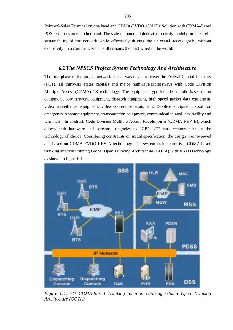
205
Point-of–Sales Terminal on one hand and CDMA-EVDO 450MHz Solution with CDMA-Based
POS terminals on the other hand. The state-commercial dedicated security model promotes self-
sustainability of the network while effectively driving the universal access goals, without
exclusivity, in a continent, which still remains the least wired in the world.
6.2 The NPSCS Project System Technology And Architecture
The first phase of the project network design was meant to cover the Federal Capital Territory
(FCT), all thirty-six states capitals and major highways/expressways with Code Division
Multiple Access (CDMA) 1X technology. The equipment type includes mobile base station
equipment, core network equipment, dispatch equipment, high speed packet data equipment,
video surveillance equipment, video conference equipment, E-police equipment, Coalition
emergency response equipment, transportation equipment, communication auxiliary facility and
terminals. In contrast, Code Division Multiple Access-Revolution B (CDMA-REV B), which
allows both hardware and software, upgrades to 3GPP LTE was recommended as the
technology of choice. Considering constraints on initial specification, the design was reviewed
and based on CDMA EVDO REV A technology. The system architecture is a CDMA-based
trunking solution utilizing Global Open Trunking Architecture (GOTA) with all-TO technology
as shown in figure 6.1.
Figure 6.1: 3G CDMA-Based Trunking Solution Utilizing Global Open Trunking
Architecture (GOTA).

206
The GOTA technology aside common services such as voice calls, interconnection, short
message services and high speed data services supports group calls, emergency calls, broadcast
calls, private calls, location based services (LBS), dynamic regrouping, unified dispatching
platform, inter-fleet calls , group management, trunked video services etc as shown in figure 6.2.
Figure 6.2: Unique Services Supported by GOTA Technology including Emergency
Response Services.
The first phase of the network is deployed across 36 states of the federation and the Federal
Capital Territory (FCT) using Internet Protocol/Multiprotocal Label Switching (IP/MPLS)
bearer over Microwave backbone with 697 base stations; the physical location of important data
including user information are in Abuja and Lagos with wireless video surveillance services.
Figure 6.3 shows the IP/MPLS bearer network topology of the NPSCS network while figure 6.4
is a map of Nigeria showing architecture of the terrestrial telecommunications infrastructure
deployed in various locations and capital cities of the nation.

207
Figure 6.3: The IP/MPLS bearer network topology of the NPSCS network.
Figure 6.4: Map of Nigeria with overview of National Public Security Communication
System Network across capital cities of the Nation (NPSCS, 2011).
Figure 6.5 shows the microwave transmission network across northern and southern part of the
country. To ensure a reliable and robust network with network resilience especially in areas

208
prone to disasters such as floods, the regional Nigerian Communications Satellite
(NIGCOMSAT-1R) was used as backup to its microwave link infrastructure as shown in the
network topology of figure 6.6. Figure 6.6 illustrates one of the state’s backup communication
satellite network topology to the base stations from one of the master switching centers (MSC).
Figure 6. 5: The microwave transmission network across northern and southern part of
the country.
Figure 6.6: Ondo State (Nigeria) IP Backup Topology to the Microwave Link using the
C-band of Nigerian Communication Satellite (NIGCOMSAT-1R).
The Federal Government of Nigeria with ambitious ICT policies and regulations as well as
favorable laws and de-regulation, which has commensurately enhanced private sector
participation to transform business practices and expedite the required diffusion of ICTs rolled
out the National Public Security Communications Network based on CDMA EVDO technology

209
across the nation for public safety use, security organizations using re-farmed national spectrum
on 450-470MHz from initial single frequency, single channel walkie-Talkie system.
6.3 Overall System Design Overview of the NPSCS Project
The project is composed of five sub-systems to provide communications and tracking capability
for security agencies. The Architecture is Service Oriented Architecture (SOA) with five sub-
systems as follows:
1. Global Open Trunking Architecture (GoTa) Sub-system (a digital trunking
communication system independently developed by ZTE, based on the Third
Generation (3G) wireless communication technology — CDMA2000 REV.A)
2. Video Surveillance Sub-system
3. E-Police Sub-system
4. Video Conference Sub-system
5. Coalition Emergency Response Sub-system (CERS)
The Figure 6.7 illustrate the general overall architecture of the National Public Security
Communications System (NPSCS) with its five sub-systems while figure 6.8 shows top-level
service oriented architecture (SOA) integrated on an IP/MPLS bearer network over Microwave
and complemented with NIGCOMSAT-1R as transmission backbone infrastructure.
Figure 6.7: A diagram illustrating the general architecture of the National Public
Security Communications System (NPSCS) Project. (NPSCS, 2011).

210
Figure 6.8: Illustrates the Top-Level Service Oriented Architecture (SOA) integrated on
an IP/MPLS Bearer Network over Microwave and Complemented with NIGCOMSAT-
1R as Transmission Backbone Infrastructure.
The network is being built with an integrated network infrastructure comprising of:
Communication satellite, Microwave links, Wireless network etc as shown in the figure 6.7.
The microwave topology aided rapid deployment in the first phase being a wireless terrestrial
infrastructure complemented with NIGCOMSAT-1R.
The Fiber optic backbone deployment will be used to complement the microwave topology
network in the second phase to meet medium and long term plans as video and data traffic
grows exponentially. Figure 6.9 shows the NPSCS backbone with microwave technology
expected to be complemented with optic fiber backbone in the second and third phase of the
NPSCS project to meet medium and long-term needs.

211
Figure 6.9: The NPSCS backbone with microwave technology backbone as dotted lines
expected to be complemented with optic fiber backbone in the second and third phase of
the NPSCS project to meet medium and long term needs.
.
6.4 Descriptions of the Five (5) Sub-Systems and Components of
The NPSCS. 6.4.1 Global Open Trunking Architecture (GOTA) Sub-System
A digital trunking communication system independently developed by ZTE, based on the Third
Generation (3G) wireless communication technology — CDMA2000
The GoTa system for the first phase of the project deployment consists of 100,000 GoTa
terminals, 675 Outdoor BTS (Base Transceiver Station), 21 Repeater Stations, 12 BSC (Base
Station Controller), 12 DSS (Dispatching Service System), 2 MSS (Mobile Switching System)
and related OMC (Operation & Maintenance Centre), 2 PDSS (Packet Data Service System), 1
SC (Short message Centre) and the transmission network (mainly microwaves). The Network
deployed covers the entire state capitals of the federation as shown in figure 6.3 to 6.9.
6.4.2 Video Surveillance Sub-System
Wide coverage of the surveillance network and surveillance contents was implemented. The
surveillance network covered all-important areas. For the first phase pilot project, Two thousand

212
(2000) cameras were deployed in Lagos and Abuja cities. Figure 6.10 shows top-level system
architecture with reconnaissance capability.
Figure 6.10: Top-Level System Architecture of the Video Surveillance System of the
NPSCS with Reconnaissance.
6.4.3 E-Police Sub-System
The E-Police sub-system aims to create an all-round electronic and hi-tech network platform by
integrating the criminal records management, pursuit of fugitives, biometrics, and police mails
with case management activities at its core. This sub-system helps set up a criminal pursuit and
identification system network for the nation. In the first phase, the E-Police System consists of a
Police Portal, Mail/Push Mail system, Training system and Police Information System in all the
36 states of the federation and the FCT.
6.4.4 Video Conference Sub-System
Video Conference Sub-system enables the Nigeria Police Force (NPF) with geographically
dispersed workforces to communicate and collaborate more effectively with enhanced
productivity time over distance. The Video Conference system consists of 19 MCU Equipment,
38 video conferencing system terminals and Network Management System for the Video
Conferencing system.
6.4.5 Coalition Emergency Response Sub-System (CERS)
The Coalition Emergency Response Sub-system (CERS) is an integrated, seamless and
complete system for processing of public emergency events for police, fire, hospital, traffic etc.
The Coalition Emergency Sub-system (CERS) consists of 1 Display Wall Hardware, 12 CERS
systems, 25 CERS Main Equipment, 20 CERS Terminals-Q10, 219 CERS Terminals-Lenovo

213
M7150 PC, 340 CERS Terminals-17 inch Television Screen. The pilot project offered a
proposed disaster communications interoperability plan with features such as redundant
transmission, more sophisticated vital equipment, backup subscriber management centre,
emergency hot lines, paging systems for spreading disaster warnings, rapid deployment
techniques for base stations during response inter alia. The Coalition Emergency Response Sub-
system (CERS) of the National Public Security Communications System (NPSCS) meets such
requirements, with two different levels of emergency centre. They are the National Coalition
Emergency Response Center (NCERC) and State Coalition Emergency Response Center
(SCERC) as shown in figure 6.11. The NCERC is the top level control centre for the national
emergency response network as well as critical and the major emergency case that transcends
state level while the SCERCs, with presence in 36 states of the federation, are meant to receive
and process common and non-emergency cases within its area of jurisdiction. The NCERC and
SCERC are connected beyond the NPSCS network to the Public Switched Telephone Network
(PSTN), Public Land Mobile Network (PLMN) via digital trunks and IP-based networks as
shown in figure 6.12. The Geographical information and Command system (Xu, Chen & Ma,
2010) are integrated into the CERS to support dynamic handling and planning, as well as
providing effective tools for visual and global command to security agencies, emergency service
organizations (i.e Police, Fire, Road safety outfits, medical services etc) and thus facilitating
information symmetry amongst their operations efficiently and effectively.
Figure 6.11: Map of Nigerian with Coalition Emergency Response System (CERS)
Architecture.

214
Figure 6.12: Simplified overview of Integrated Coalition Emergency Response System
(CERS) Network with Application Servers at National and State Centres.
6.5 The NPSCS Project Implementation Results
The Followings are highlights and summary of the project Implementation in the first phase:
The first call was made on 17th May, 2011 after completion of the central equipment
room building for Abuja with CDMA core network equipment installed.
The 2000 cameras pilot was deployed and integrated with VSS in city centre locations
of Abuja; the Federal Capital City and Lagos State including the two (2) international
airports.
Building of Central Equipment Room in Lagos completed.
The building of 35 States’ Central Equipment Rooms to house CERS, VSS, VCE were
completed.
BTS Tower deployment and Integration completed.
Table 6.1 shows the CDMA-EVDO Forward Link Budget and Coverage forecast on 450MHz in
an Urban Environment.
Table 6.1:The CDMA-EVDO Forward Link Budget and Coverage Forecast on
450MHz of an Urban Environment.
Terminal Type Single Antenna
Data Rate(kbps) 38.4 76.8 153.6
307.
2
614.
4 921.6
122
8.8
1843.
2
2457.
6
BTS Tx
Power(Watt) 20 20 20 20 20 20 20 20 20
BTS Tx
Power(dBm)
43.0
1 43.01 43.01
43.0
1
43.0
1 43.01
43.0
1 43.01 43.01

215
BTS Antenna
Gain(dBi) 14 14 14 14 14 14 14 14 14
BTS Jumper
Loss(dB) 0.3 0.3 0.3 0.3 0.3 0.3 0.3 0.3 0.3
BTS Cable
Loss(dB/100m) 2.9 2.9 2.9 2.9 2.9 2.9 2.9 2.9 2.9
BTS Cable
Length(m) 40 40 40 40 40 40 40 40 40
Other Loss(dB) 1 1 1 1 1 1 1 1 1
BTS Cable
Loss(dB) 2.46 2.46 2.46 2.46 2.46 2.46 2.46 2.46 2.46
BTS
EIRP(dBm)
54.5
5 54.55 54.55
54.5
5
54.5
5 54.55
54.5
5 54.55 54.55
Terminal
Antenna
Gain(dBi) 0 0 0 0 0 0 0 0 0
Body Loss(dB) 0 0 0 0 0 0 0 0 0
Thermal
Noise(dBm/Hz) -174 -174 -174
-
174
-
174 -174
-
174 -174 -174
Target PER(%) 2 2 2 2 2 2 2 2 2
Multi-user
Diversity
Gain(dB) 2 2 2 2 2 2 2 2 2
Rx Diversity
Gain(dB) 0 0 0 0 0 0 0 0 0
Receiver
Sensitivity(dBm
)
-
109.
81
-
105.8
1
-
102.0
1
-
99.7
1
-
95.4
1
-
91.91
-
87.9
1
-
81.91
-
76.41
Log-normal Std.
Deviation(dB) 8 8 8 8 8 8 8 8 8
Edge Coverage
Probability(*10
0%) 0.75 0.75 0.75 0.75 0.75 0.75 0.75 0.75 0.75
Log-normal
Fade
Margin(dB) 5.40 5.40 5.40 5.40 5.40 5.40 5.40 5.40 5.40
Soft Handoff
Gain(dB) 0 0 0 0 0 0 0 0 0
Maximum Path
Loss(dB)
160.
96
156.9
6
153.1
6
150.
86
146.
56
143.0
6
139.
06
133.0
6
127.5
6
Coverage

216
Forecast
Building
Penetration Loss
(dB) 20 20 20 20 20 20 20 20 20
Down Link
Path Loss(dB)
140.
96
136.9
6
133.1
6
130.
86
126.
56
123.0
6
119.
06
113.0
6
107.5
6
BTS Antenna
Height(m)
40.0
0 40.00 40.00
40.0
0
40.0
0 40.00
40.0
0 40.00 40.00
Terminal
Antenna
Height(m)
1.50 1.50 1.50 1.50 1.50 1.50 1.50 1.50 1.50
Frequency(MHz
)
460.
00
460.0
0
460.0
0
460.
00
460.
00
460.0
0
460.
00
460.0
0
460.0
0
Hata Terrain
Correction(dB) 0 0 0 0 0 0 0 0 0
1km Path
Loss(dB)
117.
07
117.0
7
117.0
7
117.
07
117.
07
117.0
7
117.
07
117.0
7
117.0
7
Slope
34.4
1 34.41 34.41
34.4
1
34.4
1 34.41
34.4
1 34.41 34.41
Radius of
Coverage(km) 4.95 3.79 2.94 2.52 1.89 1.49 1.14 0.76 0.53
6.5.1 CDMA Core Network Elements and Results
The CDMA core network consists of:
MSCE (Mobile Switch Centre Emulator), MGW (CDMA Multimedia Gateway), PDSN:
(Packet Data Support Node), HLR (Home Location Register), AAA: (Authentication,
Authorisation and Accounting Server) and EMS (Element Management System). Figure 6.13
shows picture of MSCE installed in the Abuja switching room within the headquarters of
Nigeria Police Headquarters.
• MSCE Installed for both Abuja and Lagos
• HLR Installed for both Abuja and Lagos
• MGW installed with locations at Abuja, Lagos, Kano, Zamfara, Bauchi, Gombe,
Plateau, Kogi, Edo, Rivers, Enugu, Oyo
• PDSN installed
• AAA installed
• EMS installed.

217
Figure 6.13: Installed MSCE in Switch room within Nigeria Police Force Headquarter,
Abuja.
6.5.2 BSS (Base Station Subsystem) Implementation and Results
The BSS comprises of three main systems, the Base Transceiver Station (BTS),
Operation Management Module (OMM) and the Base Station Controller (BSC). Figure
6.14 shows the deployed Abuja switch tower located close to the Abuja switching
centre and within the premises of the Nigeria Police Force Headquarters, Abuja while
figure 6.15 shows picture of installed BSS cabinet at Abuja and Figure 6.16 to 6.22
shows the selected coverage power levels and performance of Abuja and six geo-
political regions of the country namely Lagos, Abia, Anambra, Kano, Ogun and Rivers
State respectively.

218
Figure 6.14: Abuja Switch Tower located within the premise of Nigeria Police Force
Headquarter, Abuja.
Figure 6.15: A picture showing BSS cabinet installed at Abuja.
• OMM installation - deployed in Abuja and Lagos and ten (10) other locations.
• BSC installation - deployed in Abuja and Lagos and ten (10) other locations.
Abujaswitchtower

219
• BTS installation - 37 BTSs installed and completed in all locations.
• BSC and OMM Locations are Abuja, Lagos, Kano, Zamfara, Bauchi, Gombe,
Plateau, Kogi, Edo, Rivers, Enugu, Oyo.
Figure 6.16: Measured Coverage Power level and performance of Abuja; the Federal
Capital Territory (FCT).
Figure 6.17: Measured Coverage Power level and performance of Lagos State.

220
Figure 6.18: Measured Coverage Power level and performance of Abia State.
Figure 6.19: Measured Coverage Power level and performance of Anambra State.

221
Figure 6.20: Measured Coverage Power level and performance of Kano State.
Figure 6.21: Measured Coverage Power level and performance of Ogun State.

222
Figure 6.22: Measured Coverage Power level and performance of Rivers State.
6.5.3 DSS (Dispatching Service System) Results
The DSS is the GoTa component, which handles Push-to-talk (PTT) and dispatcher services.
There are twelve (12) DSS each with capacity of 100,000 subscribers deployed in the Network.
DSS has been installed in Abuja, Lagos and 10 other locations.
One DSS has been installed in each of the 12 BSC regions namely Abuja, Lagos, Kano,
Zamfara, Bauchi, Gombe, Plateau, Kogi, Edo, Rivers, Enugu and Oyo state.
6.5.4 Surveillance Network
Wide coverage of the surveillance network and surveillance contents was implemented. The
surveillance network covered all-important areas based on inputs provided by Nigerian Police
Force. In the first phase, two thousand (2000) cameras and 37 sets of surveillance systems were
deployed. The 2000 cameras consist of 860 High Speed Dome Cameras and 1140 Infrared Fixed
Cameras.
Video Surveillance System in Abuja and Lagos has been completed.
Figure 6.23 shows one of the high speed dome camera system deployed at Millenium Park with
footage from the surveillance screen as viewed from the Abuja Switching Centre, while figure
6.24 shows footages of surveillance from Cameras deployed at the entrance and exit of five star
Hilton Hotel at the central business district of Abuja.

223
Figure 6.23: A picture of high-speed surveillance camera and footage as viewed from
the central switch centre in Abuja.
Figure 6.24: A picture of footages at the entrance and exit of Hilton Hotel located at the
central business district of Abuja.
Figure 6.25 shows arrays of solar panels with a Series of Batteries stacked inside the cabinet to
ensure and guarantee power supply to every installed surveillance camera tower.

224
Figure 6.25: Arrays of solar panels with a series of Batteries stacked inside the cabinet
to ensure and guarantee the power supply to every installed surveillance camera tower.
6.5.5 IP/MPLS (Multiprotocol Label Switching) Bearer Network Status and
Results
The IP/MPLS Bearer Network is used for connecting all the services and generates the route for
all Internet Protocol (IP-based) services to communicate seamlessly with one another in the
network.
IP/MPLS installation - The IP/MPLS implementation was started in Abuja and integrated with
the other 36 Central Offices.
13 Routers, 28 Ethernet Switch-Type1, 4 Ethernet Switch-Type 2 and 37 Intelligent Integrated
Multi-Service Routers were deployed in the Network to provide interconnectivities and
communication of services in the 37 central equipment rooms.
6.5.6 Microwaves
Microwaves are used for point-to-point communication in the Network.
Microwaves and Microwave cabinet implementation has been completed for the 697 microwave
transmission hops as shown in figure 6.5 and 6.9 earlier
A total of 697 Microwave Transmission hops, 1 NMS (Network Management System) and 58
Microwave Cabinets were deployed in the Network.

225
6.5.7 Communications Auxiliary Facility (CAF)
The CAF is the Communication Auxiliary Facility, which consists of Tower, Diesel Generator
Set (Double Generators), Shelter, Air Conditioner, Battery and Distribution Product.
Implementation of CAF components and systems has been deployed and integrated.
6.5.8 GOTA Terminals
One hundred thousand (100,000) GoTa Terminals were deployed in the first phase of the
network.
Two hundred (200) GoTa terminals were deployed and used during the presidential
inauguration on 29th May, 2011.
6.5.9 SMSC, CERS, VCS and E-Police Implementation Status
Police SMSC (Short Message Service Centre) is used for delivering SMS messages in the
network. An SMSC was deployed in the Network at the Abuja Central Room. Installation has
since been completed.
The CERS (Collation Emergency Response System) is an integrated, seamless and complete
system for processing public emergency events for the Police, fire service, hospitals, traffic
issues etc. The CERS has been deployed in 37 Central Equipment Room.
The VCS (Video Conference System) enables the Nigerian Ministry of Police with its
geographically dispersed workforce to communicate and collaborate effectively and
productively over distance. 38 VCS have been deployed. Figure 6.26 shows one of the E-police
systems deployed at Sokoto state of Nigeria.
The E-Police System consists of a Police Portal, Mail/Push Mail system, Training system and
Police Information System. The system has been deployed and integrated.

226
Figure 6.26: A picture showing deployed E-police centre at Sokoto State.
6.5.10 The Emergency Communication Vehicle System (ECV)
The Emergency Communication Vehicle shown in figure 6.27 are also veritable assets and
equipment for emergency events such as disaster relief, anti-terrorism, fire outbreak control etc
to help improve timely response and capability of security agencies. Six (6) Telecommunication
Trucks deployed in six geo-political region of the country were deployed in the Network using
the C-band of Nigerian Communications Satellite (NIGCOMSAT-1R) to provide satellite link
via a very small aperture terminal (VSAT) to the core network of the NPSCS through a 6m
antenna earth station in figure 6.28. This greatly enhances the flexibility of the GoTa system in
the areas without fixed GoTa BTS. The mobile communication Vehicle forms substantial
coverage to provide services such as voice data and video surveillance in stadiums, hot spots
areas, big events, emergency areas and disaster locations. The Emergency Communication
Vehicle System has improved the response ability of Federal Government of Nigeria
considerably but more ECVs are required to increase effectiveness.

227
Figure 6.27: A picture showing one of the Emergency Communication Vehicle (ECV)
with deployable C-Band antenna system and mini-mast serving as Base Transceiver
Station (BTS) for communications (Voice, Data & Video & Graphic-based Applications
i.e Map).
Figure 6.28: 6M-Antenna Earth Station Serving as Gateway for Integration of the ECV
Communication Satellite Links to the core network of the NPSCS using the C-Band of
NIGCOMSAT-1R covering Sub-Saharan Africa.
A pilot project has been proposed using DVB Emergency Warning System (EWS) to extend the
early warning system to reach wider audience and public through their TV and radio receivers.
The Digital Video Broadcasting (DVB) EWS provides the necessary mechanisms and standards
to distribute relevant information to a wider audience as a warning system for pre-eminent
dangers etc (DVB-EWS, 2013).

228
Disasters like fire outbreak, building collapse, vehicular accidents etc, are better managed if the
city satellite map is available both for precise site location and road navigation for evacuation. A
typical example is the fire service city navigation and nearest hospital location system for
instant treatment of disaster victims. NIGCOMSAT-1R Navigation transponder amongst others
is addressing such solutions viz-a-viz the need for pre-call and post-call preparedness, including
convergence of existing emergency numbers setup at state and national agencies. e-health
services and applications , makeshift medicare and medication centers are facilitated and
coordinated with the hybrid public security and emergency network (Chronaki et al, 2008).
Research and standardization activity at national and international level to define modern,
interoperable communications and networking standards for emergency response and public
safety are being studied and implemented including several initiatives aimed at effective
emergency response services by international bodies, institutes and stakeholders. For instance,
the GSMA, which represents the interests of mobile operators worldwide, initiated the
deployment of a single, in-vehicle emergency call services known as eCall, across Europe aimed
at establishing voice connection with the emergency services alongside critical data such as time,
location, direction of travel, vehicle identification etc. The International Telecommunication
Union (ITU), Inmarsat and Vizada SAS initiated improved emergency communications for
disaster preparedness via satellite-based solutions among others (GSMA International Report50
,
2009). ITU has identified emergency communications as a key priority with several work
groups including ITU- Development sector (ITU-D) to develop technical recommendations and
implementations guidelines on disaster response planning.
Boukerche (2008) provided an overview of the next generation wireless networks for
emergency preparedness and arrays of applications necessary for public safety and security
while China’s broadband Wireless trunking project (BWT) seeks to incorporate mission-critical
features on long-Term Evolution (LTE) as future Public safety Communications Network (Li,
Chen, Yu, Meng, & Tan, 2013). Advanced and reliable research is being conducted with
applications using Software Defined Radios (SDR) and Cognitive Radio (CR) technologies
towards better spectrum utilization and management (Gorcin & Arslan, 2008).
The United Nations International Strategy for Disaster Reduction (ISDR) promotes national
capacities. Since 1994 after recognition and adoption of the Tampere Convention (treaty) on
Emergency Telecommunications, the Working Group on Emergency telecommunications
(WGET) is regularly convened by the United nations Office for the coordination of
Humanitarian Affairs (OCHA) as a focal point for emergency telecommunication related issues.
WGET encompasses all partners in humanitarian assistance and emergency telecommunications,
experts from private and academic sectors, UN entities including national, international,
governmental and non-governmental organizations (Oh, 2003).

229
6.6 Benefits of the NPSCS Project
6.6.1 Security and Confidentiality
a. Improved public safety and security.
b. Keeping information secured within security agencies
c. Private and group calls with group management
6.6.2 Improved Working Efficiency of Security Agencies
d. Efficient and centralized dispatch and intelligence gathering platform.
e. Unified and accessible communication anytime and anywhere
f. Collaborative and efficient emergency response system.
6.6.3 Reduced Government Spend and Job Creation
g. Reduced the usual routine communication expenditure with net savings of over
USD480 Million annually.
h. Has encouraged tourism and direct foreign investments in the country including
job creation, increased national productivity and development but requires
commencement of phase two and three for entire coverage of the nation.
6.6.4 The CDMA-EVDO 450MHZ as an Improved Technology over other Public
Security Services (PSS) Technologies.
i. The 3G/4G CDMA-based technology with an all-IP technology is an
enhanced improvement over other Public Security Services (PSS) technology
such as TETRA; a digital based trunking system but circuit switched with low
data rate.
j. The 450MHz has a superior propagation characteristics and better
penetration compared to commonly used frequencies such as
800/900/1800/1900MHz and thus is most suitable in sparsely populated and
rural areas. A single cell tower can cover 7,521 Km2 compared to 553Km
2 on
1900MHz. Table 6.2 shows Cell radius versus various Frequency Performance.
Table 6.2 : Cell Radius Versus Various Frequency Performance
6.6.5 Strategic Commercial Telecommunications Need of the State for
Sustainability of the Network.

230
k. The excess capacity as a result of re-farmed spectrum for a digitalized CDMA-
EVDO network technology provided excess capacity and utilization of scare
spectrum to drive Nigeria’s cashless pilot project for financial and digital inclusion
and thus effectively promotes universal access goals, without exclusivity. Chapter
eight (8) provides further details.
6.7 Conclusion
The National Public Security Communications System (NPSCS) has been deployed and
provided on CDMA- EVDO-Rev. A Technology. A total IP technology with services such as
Professional GoTa command and dispatch services in response to emergency situations,
Prioritized communications between high level users, high quality voice service and short
messaging service, high speed data service for data and surveillance and live audio/video
streaming, strong encryption technology to ensure system security, emergency alarm service for
the general public for pre-emptive and reactive emergencies reporting to police, video
surveillance service, video conference service, coalition emergency response service, Police
office e-service system, training and after sales support
Highlights of the solution provided by the project include security of the GoTa system, special
trunked service to enable individual, group, emergency and broadcast calls as well as calls
prioritization, wireless broadband data service, 3G service, low cost network with mature
products. In addition all network equipment complied with national environmental protection
standards and poses no danger to the citizens and the environment.
The system supports an integrated intelligence system with capability to support operations for
general security alarm, emergency alarm and alarm handling, and cooperative security systems
such as surveillance, interception, information gathering, analysis, preplanning, etc. The
Security Communications system allows for collection, management, analysis, fusion and
interpretation of relevant information to commanders, operators to guide planning, resources
deployment, tactical response and strategic planning as well as information sharing and
symmetry with similar organizations and other relevant organizations.
The NPSCS Network is designed with support to backhaul and integrate with the Nigerian
Communications Satellite Limited (NIGCOMSAT) satellite, NigComSat-1R, launched in
December, 2011 including subsequent fleets of communication satellites to provide an IP cloud
all over the country and facilitate the availability of transmission infrastructure and connection
to the national public security communication backbone everywhere in the country and along
border areas until there is adequate terrestrial metro-transmission such as fiber optical
transmission; Gigabit Passive Optical Network (GPON) and Ethernet Passive Optical Network
(EPON) for the huge video transmission as more cameras are deployed in the second and third
phase of the project to cover Abuja, Lagos and other big cities and hot spots for the whole

231
nation. The long-term security communications system to complement the deployed 2,000 video
surveillance system pilot project requires the deployment of optic fiber link in the third phase to
support the huge video traffic transmission for entire coverage of the nation.
The Nigerian National Public Security Communication Network has impacted positively on the
security of the nation with social benefits. The project is economically sustainable through
utilization of the network for financial and digital inclusion, viable and critical for national
security and as well as enhancing the overall total productivity factor of the nation.

232
CHAPTER 7: Solutions, Applications and Services Exploiting
Communications Satellite and National Public Security and
Emergency Network.

233
7.0 Summary:
Africa still remains the least wired continent in the world in terms of robust telecommunications
infrastructure and systems to cater for its more than one billion people. Existing communication
infrastructure in the African hinterlands is grossly inadequate, thus there is a need to develop
intra-city, inter-city, national, sub-regional and regional carrier of carriers and digital links with
cross-border inter-connectivity. Although, the continent has adequate capacity on submarine
fibre optic cables along the shores of the African coastline, it lacks adequate ICT infrastructure
in cities, suburban and especially rural areas. The demand projection suggests that there is a
need for a robust passive infrastructure built in and around Africa to address the large un-met
demand for information and communication services in the short and medium term. The success
of Africa’s information technology policy and infrastructure depends greatly on satellite
communications in conjunction with variants of wireless technologies to rapidly actualize
universal access goals and leverage the tens of terabyte capacity of the marine optical fibres that
have been installed along the African coastline. This chapter examines the role of
Communication Satellite Systems and in particular Nigerian Communications Satellite
including the National Public Security and Emergency Network as last mile terrestrial wireless
infrastructure as a vehicle to drive the National ICT revolution in pursuit of: national e-readiness,
ICT self-reliance and the skills acquisition required for a Knowledge-based economy to enable
the socio-economic development of Nigeria. Also discussed is the growing penetration of
communication satellite applications as well as an alternative to Digital Terrestrial Television in
migration to digital broadcasting especially in Africa, Eastern & Central Europe and the
Asia–Pacific as we move closer to the ITU deadline for Analogue Switch-Off (ASO) by June,
2015.

234
7.1 Broadband Communications for Internet and
Mobile Communications
Communications via satellite is as old as space age itself because whatever is launched into orbit
must receive commands from the ground and send telemetry back to ground as was the case
with the first man-made earth orbiting satellite called SPUTNIK, which was launched by the
Russians on 4th October, 1957. Thereafter applications and services evolved over time for
transmissions such as video pictures of the far side of the moon on 26th October, 1959 by the
Russian vehicle Lunik III. (Drury, 1994). Syncom meaning synchronous Communications
satellite was started in 1961 as NASA program for active geosynchronous communication
satellites developed and manufactured by Hughes Space and Communications. Syncom-1 was
launched in February, 1963 and was successfully injected into a nearly synchronous orbit but
suddenly lost in the final second of the 21-seconds Apogee motor burn. After a series of
corrections to preclude occurrence of failure, Syncom-2 was successfully injected into orbit on
July 26th 1963, as the world’s first geosynchronous communications satellite while Syncom-3
launched in 1964 was the world’s first geostationary communications satellite (Bentley &
Owens, 1964).This was followed by development of technology with Applications Technology
Satellite (ATS) series including the Communications Technology Satellite (CTS) program in
cooperation with Canada (Wolff, 1977). As explained earlier in literature review of chapter one,
introduction of digital video broadcasting (DVB) systems to communications satellites was a
milestone paradigm shift for the important role communication satellites are playing today in
broadcasting, telecommunications, mobile communications, convergence with voice, video and
data as well as terrestrial telecommunications technologies. (Ong et al, 2007; Liang et al, 2007).
The Digital Video Broadcasting (DVB) Project, an industry-led and market-led consortium of
private and public organizations including regulatory bodies committed themselves to designing
open interoperable standards for global delivery of digital and broadcast services considering
the prevalence of proprietary architectures and technologies of communication satellite
transmission and broadcast technologies. The specification of DVB has been a European
initiative and standardized by the European Telecommunications Standards Institute (ETSI)
since 1991 when broadcasters, equipment manufacturers and regulatory bodies came together to
discuss issues arising from interoperability, mainly in the satellite industry. A consensus-based
framework and memorandum of understanding (MOU) was signed in 1993 and has since
produced a wide family of standards beyond broadcasting and satellite services fostering more
than 35 countries around the world outside Europe. The DVB project work in the beginning
involved establishing standards to enable the delivery of digital TV through the traditional
broadcast networks over satellite networks, cable networks and terrestrial networks with the

235
following standards as DVB-S, DVB-C and DVB-T respectively including a whole range of
supporting standards such as service information (DVB-SI), Subtitling (DVB-SUB), interfacing
(DVB-ASI) etc. The switch from analogue to digital enabled interactive TV and network
convergence which led to more development of standards such as return channel standards;
DVB-RCS for Satellite, DVB-RCT for terrestrial. These enabled more services such as
Multimedia Home Platform (MHP), DVB’s open middleware specification including innovative
technologies that allow delivery of DVB services over fixed and wireless telecommunications
networks (i.e DVB-H and DVB-SH for mobile TV). After content protection and copy
management (DVB-CPCM), then came development efforts for standardization efforts for IPTV,
Internet TV and Home Networks and most importantly telecommunications services such as
telephony and Internet access. The DVB-MHP is actually a collective name for a compatible set
of middleware specifications developed by DVB-project as an open standard for interactive TV
middleware helping receiver manufacturers to produce interoperable devices for multiple
service providers. The three versions of MHP published so far not only supports broadcast-only
profile but also broadband connectivity. The MHP allows digital TV receivers to also have
interactive TV applications, which could be via satellite, terrestrial, cable or hybrid networks
including non-DVB support. Other versions provide variety of applications such as storage,
Video on Demand (VOD), DVB-IPTV, monitoring functions etc. (ETSI TS 102 727, 2010;
DVB-MHP Factsheet, 2011). For satellite communications, European Telecommunications
Standards Institute (ETSI) published two standards for mobile sitcom in late 1990s. These were
DVB-RCS early in 2000 and the Internet Protocol via Satellite (IPoS) system released as an
ETSI specification in a cross-publishing agreement with TIA in the USA.
The EN 301 790 (ETSI EN 301, 2003) as the first generation of DVB-RCS actually defined and
described how to build on the physical and MAC layers to provide return channel capability
transporting IP-traffic in a satellite broadcast system on DVB to a full VSAT or RCST using
guideline documents of TR 101 790 (ETSI TR 101 790, 2009). This was so because the DVB-S
and even DVB-S2 (with 30% spectral efficiency over DVB-S) were actually standards
specifically meant for broadcasting and thus the ETSI EN 301 192 document combined with
other ETSI report and guidelines went further to specify how data could be transported in
transmission media specifically oriented to containing MPEG-2 video and audio. Data
Broadcasting in interactive multimedia of today is seen as an important extension of the MPEG-
2 based DVB transmission standards for delivery of Internet services over broadcast channels
(IP tunnelling), interactive TV etc. (ETSI EN 301 192, 2008).
The DVB-RCS/RCS2 provides Hub-Spoke connectivity typically where all remote user
terminals connect centrally to a central system called a hub, which controls the network system
and as well as acts as a gateway to terrestrial connectivity and Internet as illustrated in figure 7.1.
The user terminals are composed basically of an outdoor antenna, outdoor units (ODU)
comprising of Low Noise Block (LNB:Receiver) and Buck Up Converter (BUC: Transmitter)

236
all connected to an antenna feed for transmission and reception of RF Signals to and from the
communications satellite to the Indoor Unit (IDU), which is the COMSAT Modem as illustrated
in remote location 1 of figure 7.1 and further elaborated in figure 7.4. The LNB amplifies the
received signal from COMSAT and down converts the received signal to the L-band between
950Mhz to 1550MHz while the BUC amplifies the uplink communications satellite signal
transmission. The user terminal offers IP-over Ethernet from the satellite modem to connected
computers directly or indirectly through a local area network (LAN), which may be configured
wirelessly via radios, and/or through a wired switch depending on needs assessment of the client
or users anywhere within the footprints of the communications satellite for Internet, VoIP,
Video Conference, e-mail and other IP-Based applications. The communication satellite
transmission scheme is Multi-Frequency Time Division Multiple Access (MF-TDMA) for the
return link, which could be fixed or dynamic. All the remote terminals use and share the highly
efficient DVB-S2 standard with adaptive transmission as the forward link. The MF-TDMA
allows a group of Return Channel Satellite Terminals (RCSTs) to communicate with the
gateway using a set of carrier frequencies, each divided into time slots. The network control
center as represented by the hub in figure 7.1 allocates each active RCST with a series of bursts
defined by frequency, bandwidth, start time and duration. (ETSI EN 301 790, 2003).
2009 was a great year, which saw the completion of family of second-generation delivery
standards with DVB-T2 for terrestrial, DVB-C2 for cable and joining the already published and
deployed DVB-S2 for satellite enabling broadband access and high throughput. (Ong et al, 2007;
ETSI EN 301 790, 2009; ETSI TR 101 790 , 2009; ETSI EN 302 307, 2013; DVB Project
Factsheet, 2013). The current DVB standards utilize a series of specifications already published
by the International Standards Organization (ISO) known as MPEG-2 as detailed later in section
7.2.2 under Digital Broadcasting of same Chapter 7. At the core of these standards is a time-
division multiplex that uses fixed-sized frames, transport stream (TS) packets to deliver streams
of data which could be digital video, digital data, digital audio or any form of digitalized
contents thus allowing equipment conforming to the DVB standards to be used in any of the six
continents of the world. However, other countries have their variants of the standards such as
Advanced Television Systems Committee (ATSC) specifications in the USA and the
Association of Radio, Industries and Businesses (ARIB) standard used in Japan. The second
generation DVB standards have helped shape and modernized how communications satellite
networks are built using transmission system such as framing, packet formats etc that now lies
at the core of most modern networks beyond the physical or lower layers of the system which
provided the opportunity to use components and devices meant for the mass market with some
degree of open architecture rather than proprietary network technologies such as the Hughes
Network System, IP over satellite from Hughes, had little support beyond original vendor even
after receiving widespread deployment for Internet services (Fairhust & Yun, 2013). The first
generation of DVB-RCS was only successful as a reference for implementation of systems

237
providing interactive channels for communications satellite broadcast and distribution systems
with different solutions addressing varying market segments on mostly closed architectures but
without any possible interoperability between terminals and hubs. The first generation focused
mainly on physical-layer performance thus allowing interoperability of equipment from
different vendors only at the physical-layer level and at a time when Asynchronous Transfer
Mode (ATM) was in vogue. Innovations and requirements for additional features such as
security, bandwidth efficiency and optimization, return link adaptivity, channel coding, multiple
virtual network support, harmonized IP-level QoS, Management and support amongst others are
required if it is to be a commercial success as was the case with DVB-S/S2 in broadcasting
sector. The articulation of these advanced features and innovations to address the deficiencies in
the first generation gave birth to the second-generation standardization effort as DVB-RCS2 to
address whole set of the Open Systems Interconnection (OSI) layers from physical to up to the
application layer to allow data, management and control planes thus allowing terminals from
multiple vendors on the same hub. (Skinnemoen, 2013). The second generation DVB-RCS2 is
published in three parts as TS 301 545-1 ( Overview and System Level Specification), EN 301
545-2 (LLS, Lower Layers for Satellite Standard) and TS 101 545-3 (Higher Layers Satellite
Specification) capable of delivering several tens of Mbit/s down to terminals and up to 10Mbit/s
or more as a return link from each terminal. The DVB-RCS2 (Second Generation) is a standard
conceived to provide broadband interactivity connection as an extension of the Digital Video
Broadcasting Satellite Systems. It defines MAC and Physical layer protocols of the air interface
used between the communications satellite operator hub and the interactive user terminals
(VSAT or RCST) as shown in figure 7.1. The hub typically combines feeder, gateway together
with network control centre (NCC) and Network Management Centre (NMC). The NMC
provides overall management of the communication system and manages the service level
agreement (SLA) assigned to each user terminal accordingly via IPv4 or IPv6 as management
signalling while the NCC is the central entity that supports control signalling via the lower layer
signalling (L2S). The DVB-RCS2 embraces both DVB-S and DVB-S2 standards implemented
in the commercial broadcasting sector to exploit economics of scale. The modulation schemes
supports Continous Phase Modulation (CPM), 8PSK, 16QAM in addition to QPSK. The
Forward Error Correction (FEC) for QPSK, 8PSK, and 16QAM is a 16-state turbo code
commonly called turbo-phi (turbo) while the FEC for CPM is convolutional coding. The
architecture at lower layers are designed to deliver performance especially for Ka-band and
other higher frequencies using technique such as the adaptive coding and modulation (ACM) in
both forward and return links to address effects of rain fading. DVB-RCS2 was designed with
higher later satellite architecture as the next generation of DVB with return channel via
communications satellite transmission system approved by DVB in 2011 and in 2012, mobility
extensions (DVB-RCS2+M) were added, supporting mobile/normadic terminal and direct
terminal-to-terminal (mesh) connectivity including live handovers between satellite spot-beams,

238
spread-spectrum features to meet regulatory constraints for mobile terminals and continuous–
carrier transmissions for terminals with high traffic aggregations. The DVB-RCS2 is arguably
the largest standardization effort conducted for the satellite communication systems following
excellent collaboration between industry and research organizations across not only Europe but
Asia, USA, several DVB-groups and ETSI enabling interoperability with various
manufacturer’s equipment and devices with specific Internet functionality via IP. It is the first
open standard that specifies Internet Protocol (IP)-level functionality. The IP protocols and
techniques on IPv4 or IPv6 in its architecture ensure high performance and efficient use of
communications satellite bandwidth in a transponder. The flexible QoS architecture for the
higher layers offers integrated link and network function to support IP-based differentiated QoS
and thus ensuring maximized spectrum efficiency as well as meeting specific user service
agreement (SLAs). The QoS offers ISP some form of performance specifications, which forms
part of contract agreement with clients and customer often referred to it as SLA with however
considerations of adaptive coding in the forward and return links, which reduces available
capacity especially during rain fade events. The QoS mechanisms the network system room to
perform QoS traffic engineering, performance optimization and efficiency based on network
traffic characteristics and/or user service level agreements (SLAs). The introduced continuous
phase modulation (CPM) schemes provides excellent trade-offs between performance and non-
linear distortions at low and medium spectral efficiency especially the instability of high power
amplifiers thus reducing communications satellite channel impairments and thus the
convolutional coding CPM (CC-CPM) solution based on thorough analysis has been proposed
and included in the DVB-RCS2 specifications as an alternative mode to the linear modulation
schemes especially in mesh networks and even the hub-spoke network scenarios. Additional
security features, which have been an important consideration in the design of the DVB-RCS2
waveform, has helped satisfy a wide range of security requirements for professional, consumer
and government markets including the military. The security architecture includes
Communications Security (COMSEC) at IP (layer 3) and Transmission Security (TRANSEC)
performed at link (layer 2). The security in DVB-RCS2 ensures sufficient confidentiality,
availability, integrity and indeed non-repudiation of performance in any customer/client
scenarios. The DVB-RCS2 is a modern SATCOM commercial market-opener beyond single
communications satellite operator networks to a unified platform of multiple communications
satellite operators, service providers, equipment vendors and manufacturers and end users
addressing SOHO, corporate, SCADA, institutional and backhauling needs with the right
quality of service (QoS) and quality of experience (QoE). (Rinaldo, Vazquez-Castro & Morello,
2004; Chatziparaskevas, Kolsidas, & Pavlidou, 2011; ETSI TS 101 545-1, 2012; ETSI EN 301
545-2, 2012; ETSI TS 101 545-3, 2012; Fairhust & Yun, 2013; Beidas, et al, 2013; Bomyer,
Erup, & Lexow, 2013; Fairhurst, Secchi, & Yun, 2013; Shinnemoen et al, 2013; Skinnemoen,
2013; DVB RCS2 Factsheet; 2013).

239
With the commencement of commercial operations, after a very successful In-Orbit Test (IOT)
exercise followed by In-Orbit Delivery (IOD) of the replacement communications satellite in
March 19, 2012, NIGCOMSAT-1R presently provides ubiquitous broadband services through
its various transponders in different bands namely the C, Ku, and Ka-Band. The Communication
Satellite partnered with undersea submarine cable operators to expand its coverage into the
hinterlands of Africa by strategic deployment and implementation of a teleport hub through a
gateway using iDirect equipment vendor on DVB-S2 technology to serve as an African
convergence port where the terrestrial fiber can connect and merge with the Communication
Satellite Network.
The hub is a gateway for all satellite-based networks into the Internet Superhighway.
Figure 7.1: Shows Communications Satellite-Based Solutions, Applications and
Services using iDirect Vendor Equipment on DVB-S2 Technologies with Advanced
Features.
For a complete round trip communication, the network architecture aside the communications
satellite as illustrated in figure 7.1 generally comprises of Return Channel Satellite Terminal
(RCST) also referred to as Very Small Aperture Terminal (VSAT), The Hub and its components
depending on network vendor used and the feeder gateway, which is usually an earth station
similar to the 7.6m antenna shown in figure 7.2.

240
Figure 7.2: 7.6M Co-Located Antenna System. Source: (NIGCOMSAT Ltd, 2012).
The iDirect satellite-based IP communications technology solves communication satellite
network challenges and integration with terrestrial networks anywhere and everywhere through
combined hardware and software with advanced features using DVB technologies. The DVB-S2
and Adaptive Coding and Modulation (ACM) including the new DVB-RCS2 has dramatically
improved bandwidth efficiencies. The iDirect network is a satellite based IP network with a star
topology using Time Division Multiplexed (TDM) broadcast downstream channel from a
central hub location and shared by as many remotes sites as required. Typically, the iDirect hub
equipment is actively comprised of one or more protocol processors (PP), Network Management
System (NMS), One or more NMS Server, core or edge router which connects to the Internet
Backbone, universal line cards in one or more iDirect Hub Chassis with the required RF
equipment connected to a feeder gateway as regional teleport. The remote site is comprised of
appropriate iDirect Broadband Router (Satellite modem), and VSAT equipment with end-user
utilities i.e computers and accessories.
NigComSat Ltd was the first to launch one of the most modern teleport services in the Sub-
Saharan region, using the scalable and flexible iDX 3.0 (As at 2011) supporting backward
compatibility of earlier versions and support for future upgrades on DVB-S2 and Adaptive
coding and Modulation (ACM) technology and 2D-16 state modulation and coding (MODCOD)
technique on the iDirect Network hub system which dramatically enhances inbound (return )
link performance as depicted in figure 4.3. iDirect’s DVB-S2 supports 20 various MODCODs
as at late 2011. DVB-S2 actually embraces many techniques such as varying modulations,
Encodings and adaptivity of Coding and modulations to enhance and optimize performance. The
2D-16 states is a new generation of FEC circuit based on quaternary convolutional turbo codes
with excellent error correcting performances (BER of 10-10) and improved efficiency over

241
turbo product coding (TPC). Series of earth station antennas in varying bands such as the 7.6 m
Ku Band Antenna system as shown in figure 7.2 serves as a feeder to and from the
communications satellite and the hub with a fully redundant 100W BUC solution supporting
multi-carriers. Series of iDirect communications satellite routers provides connectivity to the
shared bandwidth platform of the hub. They are integrated COMSAT modem and IP router with
TCP optimization over COMSATs, QoS prioritization and compression. The iDirect families of
routers are evolution DVB-S2 and iFINITI TDM models etc. The Evolution Satellite routers as
IDU integrated to ODU of a VSAT supports DVB-S2 with ACM for service delivery through
the deployed NIGCOMSAT iDirect 15100 hub. These compact satellite modem with IP Routers
come in various forms based on need assessment and applications. The evolution series are X1,
X5 and X7 satellite modem routers with increasing capability and functionalities.
Figure 7.3: iDIRECT 15100 Series Universal Satellite Hub.
The iDirect satellite hub specifically the 15100 family series is a universal satellite hub
operating multiple high performance IP broadband networks. The 5IF with 20 slots for line
cards supports multiple bands and transponders of communications satellites of as much as five
communications satellites. The hub supports star, mesh and SCPC topologies while the hub line
cards consists of Evolution DVB-S2, iSCPC and iNFINITI TDM line cards designed to fit into
slots of the universal hub series. The deployed 15100 family series in figure 7.3 is currently
used to deploy multiple classes of services on IP broadband networks to various remote
locations using variants of Very Small Aperture Terminal (VSAT) systems with maximum data
rate of up to 138Mbps on the outbound with DVB-S2 and up to 10.8 Mbps on the inbound via
D-TDMA. A typical VSAT with user-end terminals is illustrated in figure 7.4. Network
monitoring and management are handled through iMonitor software packages of iDirect, which
is part of the iVantage NMS suite of applications. The iDirect iVantage Network Management

242
(NMS) System is a complete suite of tools for monitoring, configuring and control of the entire
communications satellite network from a centralized location. The other two applications of the
iVantage suite are iBuilder and iSite.
iMonitor provides network operators with detailed information in real-time and past and present
performance of the network including analysis of bandwidth usage, remote site status, and
network events amongst others. The iBuider is the software application that allows one to build
and configure the network configurations of the system while the iSite is an application
primarily used for commissioning new remote (VSAT/RCST) sites quickly and professionally..
It includes functions and calculators for antenna look angles, assistance for antenna pointing,
cross polarization, monitoring and aid process in the field. The SatManage solution is a
powerful and sophisticated extension to iDirect’s iVantage NMS which automates and improves
the overall efficiency of the COMSAT network operations end-to-end guaranteeing customers’
satisfaction and loyalty. (iDirect iVantage NMS, n.d; Minor, 2011).
Figure 7.4: A Typical Composition of Communication Satellite Remote Terminal (VSAT)
with User-End Terminals.
A typical VSAT system as illustrated in figure 7.4 can be used directly or indirectly for rural
and urban telephony and mobile communications especially in areas that lack adequate facilities
from Public Switch Telephone Network (PSTN). Integration of communications satellite is

243
essentially achieved by integrating the PSTN to the Communications Satellite Network through
the hub network. They can also be used as alternative communications for emergency situations,
hotspot events and communication of choice after natural or artificial disasters. There are
communications satellites designed specifically and specially for terminal-to-terminal device for
local and long distance telephone communications integrated on the same hand-held terminals.
These mobile communication satellites are designed to also offer broadband mobile and
multimedia services from LEO, MEO or GEO orbits at a global level. These networks such as
Thuraya, Iridium, Globalstar (Conte, 2005) provide broadband integrated services digital
network (B-ISDN) channel capacity and IP-based or ATM packet switching services to
anywhere within the footprint(s) of the communications satellite(s). Phones meant for terrestrial
communications can now innovatively be made to communicate directly with communications
satellite on a device (adaptor) with an antenna capable of communicating with mobile
communications satellite. For instance, Thuraya SatSleeve brings satellite communications to
android-based smartphones such as Galaxy S3, S4, iPhone etc by simply docking a smartphone
on the SatSleeve adapter to enjoy communications satellite connectivity in emergencies or
where there is no terrestrial network after integration with appropriate software applications.
(Thuraya SatSleeve, 2014). Similarly, Iridium recently revolutionized personal communications
with industry's first global portable Satellite hotspot referred to as “Iridium GO” similar to
Globalstar’s Sat-Fi. The device enables voice and data communications on smartphones and
tablets anywhere in the world. The SOS functionality creates a fast and reliable bi-directional
connectivity with any emergency provider (Kriz, 2014; Globarstar Sat-Fi, 2014).
Key important elements that require consideration for Voice over Internet protocol (VoIP) on a
communications satellite network are:
i. Latency: One-way propagation delay of satellite link considering location of
geostationary communications satellites is approximately over 250millseconds (ms).
ii. Jitter: This effect amounts to network delays on packets arriving at the receiver at
irregular intervals despite transmission of packets from the transmitters at equal
intervals. Jitter buffers are techniques used to counteract these network fluctuations
by holding incoming packets for a considerable amount of time thus creating
smooth packet flow at the receiving end.
iii. Packet Loss: Packet loss causes degradation of voice quality in VoIP. Thus it is
important to have a low bit error rates (BER) to ensure low loss or non-corruption
of packets considering the fact that voice traffic uses connectionless Internet
protocol otherwise known as User Datagram Protocol (UDP).
iv. Compression Technologies: The most dominant encoding standard scheme for
voice is the G.729 codec requiring minimum of 8kbps. However, between 16-
18Kbps is required for implementation considering overheads, equipment vendor

244
and configurations. Other standards are available such as the G.723, which requires
only 5.3Kbps.
v. QoS and Traffic Prioritization: It is important to prioritized voice traffic with the
required QosS especially in congested network to avoid delayed, dropped or out of
sequence VoIP call.
The iDirect VoIP solution is capable of delivering a BER better than 10-9
, which is considered a
very channel suitable for VoIP applications including QoS implementation with Committed
Information Rate (CIR) to guarantee high quality VoIP calls. iDirect platform also supports
H.323 or Session Initiation Protocol (SIP) compliant VoIP solutions thus ensuring compatibility
with multiple equipment vendors.
In furtherance to the delivery of a broadband solution and the advent of high throughput satellite
(HTS) technology to meet the growing market of communications satellite with fast data rates
and at a lower cost per Megabyte (MB), next-generation ground infrastructure are required too,
to guarantee high-performance remotes. For instance, iDirect released iDX 3.2 operating
software upgrades for its network platform as well as the X7 satellite router to help deliver high
performance. The iDX 3.2 comes with adaptive TDMA, which improves return channel
performance even during rain fade and satellite link degradation considering the increased use
of Ka-band satellites and the challenges of weather conditions while the X7 COMSAT Modem
and router is built on new multi-core hardware with best-in-class TDMA embedded AC/DC
power subsystem and 100Mbps of combined outbound and inbound throughput when using the
DVB-S2 demodulator.
To provide seamless migration of services from other satellites to NIGCOMSAT-1R through
multiple hub equipment vendor with opportunity for multiple virtual network operators (VNO)
thus supporting business development for Nigerians as virtual network operators and Internet
Service Providers (ISP). Another advanced hub and gateway with differentiated service classes,
was implemented using the NEWTEC Sat3Play Broadband Gateway System.
SOURCE: NEWTEC and Nigerian Communications Satellite Limited, December 2012
Figure 7.5: SAT3PLAY IP Broadband Hub.

245
The core of the Sat3Play system, as shown in figure 7.5, is a DVB-S2 system that enables the
provisioning of both basic and complex services to consumer and business markets. It transmits
DVB-S2 carrier with ACM with the forward link to all remote terminals while the remote uses
MF-TDMA to communicate back to the hub as return link. The network system is designed for
scalability of both traffic and network management capacity with support for a growing range of
data, multimedia and voice applications (Newtec Sat3Play Hub, n.d.).
The Sat3play management system offers multi service provider platforms for wholesale parts of
the system infrastructure with capacity for several large and medium-sized ISPs and VPN
operators. The remote terminal comes mainly with two variants of COMSAT modems as MDM
2200 and MDM3100.
i. MDM 2200 is NEWTEC IP broadband modem meant for Ku and Ka band networks
and suitable for SOHO, small and medium enterprises (SME), Point of Sales (POS)
and banking as shown in figure 7.6. Supports antenna sizes ranging from 0.75m to
1.2m as well as interactive low noise blocks (iLNB) and BUCs ranging from 0.5W
to 2.0W. Maximum download and upload capability are 22Mbps and 3.5Mbps
respectively (Newtec MDM2200, n.d.).
Figure 7.6: NEWTEC MDM2200 COMSAT IP Broadband Modem with associated
Accessories.
ii. MDM 3100 is NEWTEC IP broadband modem as shown in figure 7.7 is meant for
Ku, Ka and C band networks and suitable for small and medium enterprises (SME),

246
Large Enterprises and organizations. Supports antenna sizes ranging from 1.0m to
2.4m as well as interactive low noise blocks (iLNB) and BUCs ranging from 3W to
5W. Maximum download and upload capability are 45Mbps and 5Mbps
respectively (Newtec MDM3100, n.d.).
Figure 7.7: NEWTEC Enterprise MDM3100 COMSAT IP Broadband Modem
The teleport facilities are of utmost importance to the economy of the nation; making available
high performance IP broadband networks for education, government, military, healthcare
system, enterprise organizations, Upstream Internet Service Providers, Government MDAs,
Schools, E-Learning initiative drives, smart communities, e-villages etc.
The differentiated classes of services offered by the teleport are capable to improve the ICT,
Internet, Broadband penetration and Broadband speed indices of not just Nigeria but the entire
African region and beyond.
It is easier to link up every Government office under a wide area network such that every
office can talk with one another and be able to share information seamlessly and even have the
capacity to implement video conferencing where each party can interact and communicate
effortlessly, thus improving the efficiency of governance as well as promoting transparency and
accountability.
Corporate Intranet/Extranet and Virtual Private Networks for the government are also easily
achieved. These will encourage investors to invest in the enterprise ICT solutions market sector
allowing small-scale companies in Nigeria, without physical ownership of communications
satellite, satellite hubs, gateways etc to participate in the satellite value chain and extract value
by leveraging on NIGCOMSAT’s valuable assets through Virtual Network Operators (VNO)
thus presenting a new investment opportunity, which will stimulate market growth, development
and job opportunities for Nigerians whilst enhancing penetration of services to all.
To ensure continuity of services including the need for communications satellites as backup to
serve as risk mitigation if the working satellite fails, NIGCOMSAT Ltd with the support of the
federal government, as a government owned enterprise (GOE), is working assiduously to launch
two more satellites known as NIGCOMSAT-2 and NIGCOMSAT-3. The entire system network
of NIGCOMSAT-1R, 2 & 3 will offer added advantages in reliability, compatibility, security,
operations and marketing and increased customer confidence as a client of NIGCOMSAT LTD.
The three communication satellites will strengthen the company’s corporate vision as “…the

247
leading communications satellite operator and service provider in Africa.” including strong
coverage over other continents such as Europe, South America and a steerable spot beam in the
Ku-band for wider market capture and patronage.
NIGCOMSAT Ltd; a Nigerian-Based Satellite operator and satellite service provider
beacons as a bandwidth provider in Sub-Saharan Africa and beyond, a paradigm shift for
Nigeria, which previously was just a bandwidth consumer.
7.2 Digital Broadcasting
The Space age began with broadcasting when the Russians launched the first man-made satellite,
Sputnik on 4th October, 1957 because two years later (Precisely on 26
th October, 1959); the feat
of transmission to earth of television pictures of the far side of the moon by the Russian vehicle
Lunik III took place. The feat marked the beginning of the marriage of Communications
Satellite with Broadcasting. But the major public event which brought both technologies
together was when TELSTAR was used to transmit live television pictures between the United
States of America (U.S.A) and Europe on 11th July, 1962 and followed by the greatest live
television event of all time when man first stepped onto the surface of the moon on 21st July,
1969. (Drury, 1994). The pioneering era was made possible through analogue frequency
modulation (FM) via communications satellite. In the late 1960’s, the satellite broadcast
industry became interested in digital transmission techniques and by early 1970s, time division
multiple access (TDMA) had been established. Drury (1994) noted further that, in 1980,
experiments were performed in Europe with the Orbital Test Satellite (OTS) before EUTELSAT
to investigate the feasibility of transmitting television signals at a bit rate of about 60Mb/s using
a whole transponder bandwidth of about 36MHz using coding technique such as differential
pulse code modulation (DPCM). Improvement and advancement over the years on digital signal
processing, coding and video compression has made digital satellite television domestically
possible known mostly as direct-to-home (DTH) and in the context of satellite referred to as
direct broadcasting by satellite (DBS). Digital Television is the technological evolution of
broadcast television into the digital realm instead of analogue waveforms with resulting higher
quality pictures, more channels, multi-lingual delivery of programmes and more capacity than
analog and it has lower operating costs in transmission and broadcasting. The digitization of
broadcasters’ signals implies convergence of technologies in which computing,
telecommunications and broadcasting merges and integrates once in digital format. (Drury,
1994).
Digital Broadcast Migration is simply migration from inefficient analogue broadcasting to
efficient digital broadcasting. A global decision on the transition process for sound and
television broadcastings to Digital Audio Broadcasting (T-DAB) and Digital Video
Broadcasting (DVB-T) standards respectively was reached at the International

248
Telecommunications Union (ITU) Regional Radiocommunications Conference (RRC-06) held
in Geneva, June, 2006. Deadlines were set for a total switchover of all broadcast channels from
analogue to digital. Many countries in the ITU regions, including Nigeria as a country, were
signatories to the agreement with the deadline set for digital broadcasting services in the Very
High Frequency Band (VHF) and Ultra High Frequency Band (UHF). 123-230MHz for the
VHF band while the UHF band is 470-862MHz. The transition period for Analogue Switch-Off
(ASO) to Digital Switch Over (DSO) started from 17th June, 2006 to 17
th June, 2015 with an
additional five year extension for some countries in the VHF band till 17th June, 2020. The
Digital migration from DSO to complete ASO is revolutionary as it affects all aspects and
segments in the broadcasting chain from content production, transmission to reception. The
transition comes with opportunities and challenges including dual broadcast illumination before
ASO amongst others for the broadcasting industry, regulators and other stakeholders in the
value chain. For realization of the inherent benefits, the migration must be fully-fledged across
the value-chain; content production, storage/archiving, transmission, distribution, reception and
public acceptance encouraged by various national governments, regulators, manufacturers and
other stakeholders. As regards reception of digital Television (TV) signals, Analogue TVs
owned by millions of viewers are still useful by integrating them to Set-Top Boxes (STB),
which converts the digitally transmitted TV signals to Analogue though with limited digital
benefits with the Analogue TV, such as storing capability etc. (Berger, 2010; ITU, 2012).
Digital Terrestrial Television (DTT) is the technological evolution of broadcast television into
the digital realm with resulting better quality pictures, efficient use of spectrum, more channels
than analog signals, more accommodation of programmes with multi-lingual support, new
multimedia services using terrestrial resources such as land for numerous transmitters, high
power transmitters, terrestrial spectrum. Huge capital, manpower and training are required for
the turnkey transition within such a short time frame for countries that have not migrated until
now (Ihechu & Uche, 2012). Nigeria, for instance had to reset its target date to migrate to digital
broadcasting from 17th of June, 2012 to 1
st January, 2015. However, the government-owned
media, Nigerian Television Authority is expected to be fully digitalized by June, 2014. Similarly,
Ghana had to postpone its original 2012 switch over date (APC, 2011).
7.2.1 Major Challenges and Limitations in Migration to Digital Terrestrial Television
(DTT)
Growing popularity of Non-Terrestrial TV Platforms i.e Satellite -TV Especially Free-
To-Air (FTA).
Sustainable IPTV and Online Videos as a result of adoption of Broadband plans of
many Nations.
Bundling of Pay-TV with Broadband and Telephony with reliable broadband
connectivity.

249
Funding: Huge capital requirements for deployment of transmitters and equipment,
masts, declining advertising volume and rates as a result of alternative platforms such as
satellite, broadband video internet etc.
Operational logistics for numerous sites, civil works, building, mast structures, coverage
optimization, signal reliability and interference from neighbors.
Issues on adoption of Technical standards, Spectrum planning, Compression and
Transmission technologies.
Legislation, Regulatory and Licensing regime issues.
Human Capital Development and training requirements.
Adapting to changing business models suitable for economic sustainability.
Set-Up Box issues on: cost, technical specifications: Open architecture for
interoperability and proprietary solutions.
Irregular Terrestrial power supply to energize site infrastructure.
Issues with dual broadcast illumination period especially, the costs before Analogue
Switch-Off (ASO) by June 17th, 2015.
Content creation, production and provision to populate new channels.
New coverage planning and co-ordination with Single Frequency Networks (SFN) and
Multiple Frequency Networks (MFN).
Public awareness.
Spectrum Re-farming issues for Digital Dividend, which has affected re-allocation of
upper UHF band (790-862MHz) of the DTT frequency band for mobile broadband
communications as ratified by World Radio communications Conference of 2007
(WRC-07) on co-primary basis; a modification of RRC-06 digital plan as well as WRC-
12 resolution 232 lowering the upper UHF band to 694MHz such that 694-790MHz in
region 1 is allocated further to mobile communications on a co-primary basis except for
aeronautical mobile services and to be identified as International Mobile
Telecommunications (IMT) to be effected at WRC-15 and subsequently re-modification
of the RRC-06 digital plan requiring further frequency planning and co-ordination
(Amana, 2013).
Issues of Government-led incentives and subsidies for countries with liberalized
broadcast sector.
7.2.2 The Growing Need for Communication Satellites for Satellite Communications
Especially Broadcasting
Satellite communication has become a major means of broadcast and mass media as well as
domestic communication based on improvements and innovations in payload capability,

250
capacity and technologies on communication satellite systems amidst inadequate terrestrial
telecommunication infrastructure. The technologies and innovations based on needs assessment
resulted in a dramatic increase in the use of space for commercial activity such as
Communication Satellites for GPS Navigation, telecommunications for global and mobile
telephony, Digital Video Broadcasting (DVB), Data Broadcasting, Multimedia video streaming
and high-speed Internet connectivity etc (Vines, 1994; Gifford, 1996; Smith, 1998; Ingley, 2000;
Lawal & Chatwin, 2010,2011, 2012a, 2012b; Igor,Riccardo, Hung, Fotini-Niovi, & Takaya,
2010; Hao, 2013).
The world’s first digital satellite TV services were launched in Thailand and South Africa at the
end of 1994 using the newly released DVB-S system by DVB project. The DVB-S2 delivers
efficient and excellent performance and it was a success commercially gaining worldwide
acceptance and adoption by the International Telecommunications (ITU) study group on
satellite delivery for Digital satellite Broadcasting system as well as laxity on intellectual
licensing rights by holders of key DVB-S2 intellectual property rights. (DVB-S2 Factsheet,
2012; ETSI EN 302 307, 2013). The recently concluded 2012 London Olympics games is
attestation to not just the broadband capability of Communication Satellites but also the HDTV
and 3DTV transmission quality assurance. DVB-3DTV is the first Plano-stereoscopic 3D
television developed by DVB project for two images considered as the left and right images and
are arranged such that they are directed at the left and right eyes through a combination of
screen arrangements and with or without special viewer glasses. The DVB-3DTV aims for a
frame-compatible system that could provide a 3D full image color using existing receivers over
cable, terrestrial and communications satellite broadcast and broadband channels. (DVB-3DTV,
2011). The 2012 First HD Olympic games was the first Genuine Major Carrier Cooperation for
DVB satellite television transmissions, achieving historic levels of broadcast quality that was
enabled by collaboration of the international broadcast and satellite industries, which jointly
launched the first in a series of Carrier-ID implementations delivering interference-free viewing
of the games (Satnews Publishers, 2012). The Carrier-ID is a very important tool for mitigating
and reducing interference between COMSAT’s signals. The DVB project has developed the
DVB carrier identification (CID) for digital satellite transmission that describes the modulation,
channel coding and signaling protocol intended for the identification of the host carrier with
standards published as ETSI TS 103 129 in May, 2013. The satellite interference reduction
group (sIRG) strongly supports the development of the standard, which comes with
development of a database to be migrated to the space data association (SDA) for global
visibility, security and integration. (DVB-CID Factsheet, 2013; ETSI TS 103 129, 2013). In
terms of capacity, Intelsat alone according to Intelsat’s Vice President for Europe and Middle
East; responded to customer requirements in Asia, Europe and the Americas with 11 satellites in
the C and Ku-band supporting approximately 50 channels with 15,000 to 20,000 estimated
hours of coverage for the three week international event. Non-terrestrial TV platforms such as

251
satellite and IPTV has become very dominant in Africa and other countries of the world.
Northern Sky Research (NSR) predicts TV households in Sub-Saharan Africa (SSA) will grow
to 63 million in 2012 to 108 million by 2022. DTH holds great promise in SSA particularly
Nigeria with over 160 million people as the TV penetration rate increases rapidly, foreign
investments, economic development and political stability will facilitate the development of a
truly low-cost operator similar to the Indian experience, that will be able to generate significant
revenue from the many untapped market segments (Curcio, 2012). There is continued growth in
the number of satellite TV platforms around the world reported to be nearly 140 in 2011
reaching 180 Million subscribers according to the Euroconsult (2012) Satellite TV platforms
world Survey and Prospects to 2021, 5th edition released recently; May, 2012. The report
estimated revenues in 2011 to be US$90 billion and is projected to reach $150 billion by 2021
with emerging markets in Africa, Asia, the Middle East, Central Europe, Latin America and
Russia. The report by Euroconsult (2012) noted that there are over 2,800 High Definition (HD)
channels across the different platforms worldwide in 2011, HD & 3D investments maintain
attractiveness and value-added services. Almost 600 HD channels were launched in 2011 alone
as part of the strategy to drive growth over the coming decade. Curcio (2013) in the NSR’s
Direct-to-Home Markets, 6th Edition estimates 40 million DTH subscribers in India in 2012 thus
the largest DTH market in the world even though other publications and press releases put it at
60 million subscribers with the difference accounting for inactive short-term and pre-paid
subscribers. It further reported that nearly 100 million new households will become digital by
2014 as the digitalization process continues in India giving DTH an advantage over cable with
its ubiquitous and geographic coverage. Modern houses, high-rise buildings and office
complexes are incomplete without a Satellite TV receiver dish on the roof-top, walls, fence or
fabricated on masts and towers as shown in figure 7.8.

252
Figure 7.8: shows growing penetration of the Communication Satellite Alternative for
Digital TV as satellite TV dishes designed for Walls are even fabricated and deployed
on telecoms mast and towers in proximity to homes and offices.
Figure 7.9 shows the National Assembly complex, the highest elective law-making building in
the Federal Capital City of Abuja, housing both the House of representatives and Senate, it has
arrays of VSAT dishes providing broadcasting services via satellite, to various offices and
departments. Arrays of VSAT dishes on residential homes and buildings, office complexes,
high-rise buildings, estates etc are common sights in cities, semi-urban, urban and new estates in
African countries. The satellite pay-TV subscribers base is expected to hit 250 million by 2018
according to a recent study conducted by Digital TV Research with Africa and Asia Pacific
identified as hotspots for DTH. (Homes, 2013).
Figure 7.9: National Assembly Complex of Nigeria showing an array of VSAT dishes
providing broadcasting services through satellite to various offices and departments.
Based on the growing needs of Communication Satellite requirements to support satellite-based
digital broadcast television, amongst other services i.e telecommunication needs. The Federal
Government of Nigeria responded with a communication satellite launch designed to meet the
majority of the African Sub-Saharan regional needs.
NIGCOMSAT-1R Communications Satellite is shown in Figure 7.10 undergoing a Compact
Antenna Range Test before the launch campaign.

253
Figure 7.10: High Powered Quad-Band NIGCOMSAT-1R Spacecraft undergoing
Compact Antenna Test Range (CATR) before the Launch Campaign Activities.
Satellite platforms for both free-to-air and pay services have proven more suitable for
broadcasting a range of HD channels than DTT since the bandwidth spectrum is not scarce
(frequency reuse through polarization and space diversity, utilization of higher frequency bands
such as the Ka-band etc).
Africa is considered an emerging market for satellite-based platforms in terms of FTA and Pay
TV penetration. Year-on-year growth of multi-channels to the second quarter of 2008 was 7%
for new satellite subscriptions with South Africa leading the way (12% growth and 23% pay TV
penetration). Free-to-Air satellite penetration is stronger in North Africa with Algeria (94%)
taking the lead followed by Tunisia (79%). The French free-to-air satellite platform, tntsat has
proven successful, so far signing over 1 million customers by the end of 2008. Similarly, we
have also seen countries outside Africa with dramatic penetrations in satellite TV. For instance,
Cyfrowy Polsat in Poland is one of the fastest growing and most competitive markets for
satellite with six different service providers. It grew from 0.65 million subscribers in 2005 to 2.4
million in September 2008 representing 17% of Polish TV households. The same rapid growths
were recorded in Eastern Europe recently, in such countries as Romania, Slovakia, Czech
Republic etc. (Human Capital, 2009).
Increased use of compression such as MPEG-4, H264 over MPEG-2 and Transmission
technologies such as DVB-S2 (Digital Video Broadcast Second Generation enhanced Satellite),
DVB-T2 (Digital Video Broadcast second Generation enhanced Terrestrial) over DVB-S and
DVB-T standards respectively has resulted in increased High Definition niche market viewers,
especially in satellite Pay-TV as depicted in Figure 7.11, which compares HD Channels
availability in Pay-TV, Free-to-Air and DTT in Europe. Compression techniques have evolved
over the years from the days of the standards developed jointly by the International Standards
Organizations (ISO) and International Electrotechnical Committee (IEC) referred to as ISO/IEC

254
MPEG responsible specifically for Broadcasting, the source coding and multiplexing portions.
Sub Committee 29 of the 1st Joint Technical Committee of the ISO/IEC; ISO/IEC/JTCI/SC29 is
responsible for the Coding of Moving Pictures and associated audio while the 11th working
group of this committee is known as the Motion Picture Expert Group (MPEG). A sister group
known as the Joint Photographic Expert Group (JPEG) developed a standard for coding still
images. The MPEG developed appropriate source coding standards for video and audio
beginning with MPEG I at bit rates of 1.5 Mb/s, compatible improvement at rates of 10Mb/s
(MPEG II). However, current products, which employ MPEG-1 standard, can deliver up to
15mb/s and similarly MPEG-2 can deliver beyond 10Mb/s. (Drury, 1994). BBC High Definition
are currently delivered over freesat in the UK as a Free-to-Air satellite has proven more suitable
for HD broadcasting than Digital Terrestrial Television (DTT) due to comparative bandwidth
and spectrum scarcity. TNTsat, the French FTA satellite has proved successful with over one
million subscribers at the end of 2008, while similar satellite projects are taking off in countries
where terrestrial TV coverage can be poor. i.e New Zealand. African countries should not be an
exception where terrestrial spectrums are needed far more for mobile broadband penetration to
bridge the digital hiatus (Human Capital, 2009; Richards, 2007; Ofcom, 2007).
Source: Human Capital, 2009
Figure 7.11: HD Channels in Europe.
7.2.3 NIGCOMSAT Ltd Unified Direct-To-Home (DTH) to Promote and Facilitate
Digital Migration through the Communications Satellite Alternative.
Considering the challenges that come with digital migration, which are more pronounced in
developing nations especially as it requires huge capital, manpower, appropriate technology
selection, training, cost/benefit analysis etc for the turnkey transition within such a short time
frame amidst growing requirement for a satellite alternative for digital broadcasting. Others
modes of digital television are digital cable, digital multimedia broadcasting (DMB), Internet
Protocol television (IPTV), multichannel multipoint distribution service (MMDS) as digital
microwave, digital video broadcasting handheld (DVB-H). Design breakthroughs in broadband-
based satellites (i.e HTS), Digitization, DVB-S2 with improved spectral efficiencies and

255
associated standards supporting interactive TV such as DVB-Globally Executable Middleware
(GEM), DVB-Generic Stream Encapsulation (GSE), DVB-Multimedia Home Platform (MHP)
etc have permitted NIGCOMSAT Ltd to complete state-of-the art digital satellite TV Direct –
To- Home (DTH), which is meant to provide a unified platform for broadcasters, content
providers, content distributors as well as open up media business services in Africa for DTH TV
broadcasting entrepreneurs thus easing off implementation bottlenecks especially for small and
medium enterprises (SME) in the broadcast industry. The DVB-IPTV is a set of open,
interoperable technical specifications, developed by the DVB project to ensure delivery of
digital TV using the Internet Protocol (IP) over bi-directional fixed broadband networks. While
DVB-H is a technical specification for the transmission of digital TV to handheld receivers such
as mobile telephones and PDAS primarily over the UHF bands, the DVB-SH is the transmission
standard designed to deliver video, audio and data services to handheld and vehicles a hybrid of
satellite and terrestrial system using frequencies below 3GHz particularly the S-band as part of
mobile TV. The DVB-SH does not define transport protocols rather it is an electronic service
guide with a combination of satellite footprint and complementary terrestrial infrastructure to
deliver qualitative nationwide coverage to terminals in conjunction with specification standards
such as DVB-IPDC which describes the essential components required to deploy a commercial
mobile TV service based on Internet Protocol (DVB-IPDC, 2011; DVB-IPTV, 2012; DVB-SH,
2011).
The NIGCOMSAT Direct-to-Home (DTH) system was designed to offer viewers hundreds of
channels of Standard Definition (SD) television programming on both the free-to-air (FTA) and
pay as you go service delivery model. The system is designed to support and transmit High
Definition (HD) channels on demand. The architecture supports MPEG-4 AVC, H.264
algorithms, HD Channels, Ultra HDTV and is 3D compliant.
NIGCOMSAT Ltd’s major function is the carriage of channels (content carrier). The unified
multi-platform system can also deliver backhaul services for Digital Terrestrial Television (DTT)
transmissions after analogue to digital migration. The unified platform enables participating
broadcasters to have on demand uplink satellite capacity for Satellite News Gathering (SNG)
purposes without huge investments in reserved satellite capacity anywhere within the footprint
of NIGCOMSAT-1R coverage and its future fleets. Figure 7.12 shows a pictorial view of
NIGCOMSAT Ltd Unified Direct-To-Home platform. (DVB-GEM, 2013; DVB-GSE, 2011;
DVB-MHP Factsheet, 2011).

256
Figure 7.12: NIGCOMSAT Direct-To-Home Unified Platform.
7.2.4 Digital Dividends, Convergence and Promotion of Universal Access.
Guy Berger (2010) in his widely read booklet titled Challenges and Perspective of digital
migration for African Media argues that there is no major pressure to free up the air wave
spectrum in Africa compared to the European sector and therefore there should be no rush to
complete migration by 2015. While the assertion may have been true in the early clamour for
digital migration, the African telecommunication environment has since changed, being the least
wired continent in the world requiring digital dividends to bridge its digital hiatus. Broadband
Internet connectivity, which is required for economic development to take place, is grossly
inadequate. Last mile deployment of broadband through wire-lines requires huge investment
and is hardly affordable in rural areas, which in Nigeria constitutes 70% of our population and
thus is not economically viable for entrepreneurs, furthermore it is time-consuming to create
such an infrastructure when compared to mobile broadband. Nigeria is in dire need of a mobile
broadband infrastructure to help in the utilization of its adequate capacity at its shores as a short
term measure until implementation of its planned intra and inter-city metro-ring fiber network
has been completed. As such, communication satellites and variants of terrestrial wireless
systems such as GSM, CDMA, WIFI have permeated areas with little or no adequate wired
telecommunication infrastructure to optimize access to information and guarantee universal
access to almost all African inhabitants, including those in very remote and swampy
environments as well as enabling regional and cross-border connectivity with the tens of
terabytes of capacity from marine optical cables on the African coastline. (UNESC, 2000; Lawal
& Chatwin, 2012;UNESC, 2000; Singer, 2012).

257
The released terrestrial radio spectrum as, a result of the Digital Switch Over (DSO), known as
the “Digital Dividend” is a valuable public resources in the 21st century, especially in Africa
with inadequate inter and intra city metro-ring optical fibers for richly enabled smart-based
communities and cities. The spectrum is better utilized in value added services such as
broadband penetration in the form of mobile broadband communications to bridge the digital
hiatus and satisfy the universal Internet access goals that African governments have committed
to. Figure 7.13 shows the growing contribution of telecoms to the Gross Domestic Product
(GDP) of Nigeria largely as a result of the mobile subscriber base, which stands at 120,362,218
active lines (85.97% Teledensity) as of June, 2013 after the Digital Mobile License (DML)
Auction of 2001. Active Internet subscription via the Global System for the Mobile
Communications (GSM) network alone stood at 48,165,033 as of June, 2013. (NCC, 2013).
Source: NCC, 2013.
Figure 7.13 shows growing percentage contribution of telecoms to Nigeria’s GDP.
Figure 7.14 shows the digital dividend conceptual spectrum allocation as a result of DSO based
on needs assessment as it concerns telecommunications infrastructure realities, growing
technological innovations and improvements, market realities etc. With the growing alternative
satellite scenario that can play a complementary role in Digital Terrestrial Television
deployment, additional spectrum allocation to DTT should not only be a function of market
realities but technological improvements in compression and transmission technologies with
resulting capacity and efficiency increase when using the existing spectrum. Fourth Generation
(4G) services are being deployed in countries that have fully migrated from Analogue TV signal
transmission i.e United States of America (698-806MHz), Europe (790-862MHz) and Asia-
Pacific (698-806MHz) with huge financial benefits from: sales of the spectrum, job creation and
new business activities. (RRC, 2006; Amana, 2013;Lawal & Chatwin, 2013; Lawal, Ahmed-
Rufai, Chatwin, Liu, 2013).

258
Figure 7.14: Pictorial tabular allocation of spectrum in post –Digital Switch Over
(DSO) as Digital Dividends particularly in Africa, which has the least developed
terrestrial telecommunications infrastructure.
Overall, the major drive in the legislative and technical policies including technical standards
should be on the digital environment, which enhances convergence of broadcasting with
telecoms and Internet anchored by the 3As of universal broadband plans: Availability,
Accessibility and Affordability. For instance, the architecture of STBs should have return
channel capability which could be through terrestrial, cable, satellite or specifically with
Subscriber Identity Module (SIM) and/or USB port that allows USB-based mobile broadband
dongles with the necessary middleware as a return path to support interactive capability and
access to the Internet via the television screen; deepening Government-to-citizens, Government-
to-Business and Citizens-to-citizens services and national debate with far reaching impacts in
closing up the infrastructural ICT gap as it enables interactive service portals, interactive
weather information, knowledge portals, transactional portals, smart communities with database,
online marketplaces providing sign post for sustainable e-governance, e-government, e-
commerce, e-agriculture, e-health, e-commerce etc. Furthermore, with the rising vulnerability of
humankind to the effects of natural and man-made disasters, the DVB project team has also a
standard known as the DVB Emergency Warning System (WBS) for every broadcast system to
provide the necessary mechanisms to distribute relevant information to the general public in
case of emergencies considering the importance of communications-disaster preparedness as the
first line of action to facilitate timely disaster response. The DVB-EWS is defined in the DVB-
Service Information (SI) standard and in combination with specification for video and audio
coding implementable over all broadcast channels which could be terrestrial, cable, IPTV or
Communications Satellite. (ETSI EN 300 468, ).
7.2.5 Deployment of Efficient System Engineering Framework for Clustered Direct-
To-Home (DTH) Users.
CURRENT ALLOCATION
TO DTT
ADDITIONAL ALLOCATION
TO DTT POST-ASO BASED
ON NEEDS ASSESSMENT
AND MARKET REALITIES
DIG
ITA
L D
IVID
EN
DS
POST-ASO SPECTRUM TO
AID MOBILE BROADBAND
PENETRATION
ESPECIALLY IN AFRICA.

259
The Direct to Home (DTH) industry is generally a multi-billion dollar industry being a digital
platform through which millions of customers and subscribers are guaranteed good quality
Standard Definition (SD) and High Definition (HD) TV besides other value added services
through their Customer Premises Equipment (CPE). The DTH operators are investing heavily in
technology platforms, satellite bandwidth with desired footprint, sales & distribution networks,
content providers, content creators, broadcasters, installations, customer care, license fees
collection, custom duties inter alia illustrating the interesting prospects and opportunities for
DTH with plenty of room for growth in satellite TV (FTA and Pay-TV) as new markets open up
especially in Africa, Eastern Europe and the Asia-Pacific. The universal Low Noise Block-
Down converter feed horn (LNBF) as shown in Figure 7.15 normally converts the transmitted
satellite signals, which could be C-band, Ku-Band or the newly introduced high frequency Ka-
band, from the geostationary orbit to an intermediate frequency (IF) for transmission through
coax cable i.e (RG-6 or RG-11) to the Integrated Receiver Decoder (IRD) also referred to as a
Satellite Set-Top Box (STB) (Hyun-Chul, 1993).
Figure 7.15: Pictorial Diagram of a typical one-way output Low Noise Block
Downconverter.
For wideband dual-polarized transponders populated with bouquets, each receiver must control
its own LNB output. Polarization switching of the LNB is controlled by direct current (DC)
voltage supplied by the Satellite Integrated Receiver Decoder (IRD) as depicted in Figure 7.16
as well as tuning capability from lower band to upper band by a 22 kHz signal at 0.5V peak-
peak to switch its Local Oscillator (9.75GHz) to high band i.e 10.75GHz in a Ku-band Low
Noise Block-Down converter (LNB) and thus, it is technically wrong to split signal with
splitters from one output LNBF and will not work effectively and optimally.

260
Figure 7.16: Functional Diagram of Typical Satellite Integrated Receiver Decoder
(IRD).
The ideal way of splitting signals to one or more receivers is the use of two or more way
universal LNBF so designed with alternative local oscillator frequencies with support to handle
linear (vertical and/or horizontal) and circular (Left hand and right hand) polarizations with the
required frequency stability. Besides the use of dual, quad or octo-output universal LNBF,
Quattro LNBF provides four unique outputs at intermediate frequency (IF), as below :
3 Horizontal Polarization low band
4 Horizontal polarization high band
5 Vertical polarization low band
6 Vertical polarization high band
The four unique outputs are then fed to a multi-switch device (i.e 4X 32 way multi-switch)
allowing multiple subscribers to connect to one large dish using high quality cables and
connectors to ensure optimal signal reception by the various receivers in Clustered DTH users,
High-Rise Buildings, residential estates, hotels, office complexes etc. (Hadden & Bruce, 2002;
Skorobogatove, 2012).

261
Figure 7.17: Shows an Eight (8) Users DTH Deployment using 4X8 Output Multi-
Switch Combined with Quattro Universal Low Noise Block-Downconverter Feedhorn
(LNBF) through a 1.8m Antenna Dish.
Our experience with a 65cm aperture dish during the rainy season was not satisfactory until the
acquisition of a 1.8m aperture dish fabricated on a mounting post to fit within a constrained
space, as shown in Figure 7.17, which helps guarantee continued good quality of service (QOS)
and increased viewing time even during heavy precipitation, which causes signal degradation
and loss in the Ku band as a result of rain attenuation. A quattro universal LNBF was used to
distribute signals to other rooms and neighboring bungalows using the 1.8m dish instead of
proliferating the neighborhood either with eight (8) 65cm or 90cm aperture dish for the eight (8)
receivers (IRDs). Figure 7.18 illustrates increasing antenna gain with increased aperture of the
receiving antenna dish at an efficiency of 65% using 11.747GHz (Ku band) as simulated with
Satmaster Pro software application.

262
Figure 7.18: Illustration of increased Antenna gain with increased aperture of the
receive antenna dish at a frequency of 11.747GHz with an efficiency of 65%.
The use of High quality antennas with rated efficiencies improves the antenna gain of the
receiving dish. Figure 7.19 shows increased antenna gains in dBi of antennas with increased
efficiencies in percentage (%) and antenna aperture in meters (m) in the 12GHz (Ku band) using
Satmaster Pro software.
Figure 7.19 shows increasing Antenna Gain in dBi with increasing antenna efficiency
(%) and aperture in meters (m).
The Systems Engineering framework ensures the use of optimized systems as illustrated in
Figure 7.17, 7.18 & 7.19 for clustered direct-to-home (DTH) users, office building complexes,
high-rise buildings, residential estates, hotels etc, Table 7.1 shows the efficiency and cost-
effectiveness of using high performance multi-switch technology combined with universal low
noise block-downconverter feedhorn(LNBF) by comparing 65cm antenna dish deployed in 32
homes with 1.8m dish system engineering framework using multi-switch technology and
Quattro LNBF.
Table 7.1: The table shows the efficiency and cost-effectiveness of using high
performance multi-switch technology combined with a universal low noise block-
downconverter feedhorn (LNBF) by comparing 65cm antenna dish deployed in 32
homes with 1.8m dish exploiting systems engineering framework using multi-switch
technology and quattro LNBF.
S/n ITEM 32 Stand-alone
65cm receive-only
antenna system
32 distribution network
using “Quattro”
universal LNB, multi-
Remark

263
switch and 1.8m Receive-
only Antenna system
COST EFFECTIVENESS
1. Typical Ku-band Low
Noise Block for signal
reception
Standard one-port
LNB is $20.00
Thus for 32 users;
$20*32=$640.00
“Quattro “universal LNB
is $40.00
5X 32 output multi-switch
is $300; Thus costing
$340.00
Aggregate of
$300 saved for 32
users scenario.
2. Receive-only Antenna 65cm dish(standard)
is $22.00. Thus for 32
users; $22*
32=$704.00
1.8m receive only dish is
$75.00
Aggregate of
$629 saved for 32
users scenario
Total Cost for a 32-user
scenario for CPE without
other features that are
common to both systems
(i.e Inter-frequency cables,
Top-up Box(Satellite
Receiver), connectors,
viewing card, remote
control etc
$1,344.00 $415.00 Total amount
saved is $929.00
This represents
74% cost savings
through an
integrated system
engineering
multi-user
delivery
framework
IMPROVED QUALITY OF SERVICE
(EFFICIENCY)
1 Using Satmaster Pro Link With 0.65m dish, the With 1.8m dish, the excess Aggregate excess

264
Budget assuming a 7.6m
uplink station at
Johannesburg, South Africa
(26.18S, 28.07E) and a
Direct to Home Location in
Abuja, Nigeria (9.20N,
7.18E) through Eutelsat W7
built on spacebus 4000C4
satellite bus located 36E
with EIRP of 48dBW over
Sub-Saharan region
excess link budget
under clear sky
condition was 7.57dB
while downlink rain
condition has a value
of 1.73dB
link budget under clear
sky condition was
10.29dB while downlink
rain condition has a value
of 8.01dB
link margin of
6.28dB was
gained with
change of 0.65m
to 1.8m antenna
dish under ITU
rainfall model
thus increasing
TV viewing time
during rainfall.
2 Average (Not Effective)
Signal Collection Area in a
simplified computation
using area of a circle (πr2)
Radius of 65cm
aperture dish is
32.5cm, thus the
average signal
collection area of the
dish is
3.142*32.5cm*32.5c
m=3319cm2.
Radius of 1.8m aperture
dish is 90cm, thus the
average signal collection
area of the dish is
3.142*90cm*90cm=25,30
4.4cm2.
The average
quantified
improvement in
signal collection
in the bigger dish
is over 760% thus
increasing
availability and
quality of TV
viewing period
during
precipitation in
Ku band.

265
The exploitation of the above system engineering framework using large dish receive-only
antenna, combined with multi-switch technology should be encouraged by DTH operators
especially in the Sub-Saharan region of Africa, which, not only improves the quality of
reception as well as providing greater signal availability at all times and seasons especially
during rainfall as a result of increased link margin with larger aperture but also attracts more
subscribers through its aggregated cost effectiveness and efficiency. Rain attenuation is much
more pronounced for high satellite frequencies (Ku and Ka band) compared to traditional C-
band. Ku and Ka band are common bands in modern day satellites especially High Throughput
Satellites (HTS) to meet the growing demands of Communication satellite services in the
telecommunications and broadcast sector. Figure 7.20 shows increasing rain attenuation in dB
with increased frequency for the Sub-Saharan location (9.20N, 7.18E) using the SatMaster Pro
simulation with the ITU rain model. However, innovative technologies has allowed system
design engineers to manufacture high powered satellites with Higher Equivalent Isotropic
Radiated Power (EIRP) particularly utilizing the upper region of the satellite spectrum i.e Ku
and Ka Band to appreciably compensate for the rain fade column with other complementary
measures such as adaptive code modulation (ACM), Uplink Power Control (UPC) system
implementation etc. The DTH platforms provide most developing nations, especially Africa,
with a good non-terrestrial platform for digitization of television signals in free-to-air (FTA)
regimes and Satellite Pay-TV platforms as typified by the few regional service providers and
NIGCOMSAT’s unified DTH platform.
Figure 7.20: Typical Rain Attenuation (dB) as a function of frequency (GHz) for
location (9.20N, 7.18E) within Sub-Saharan region of Africa.
Digital Broadcasting comes with huge benefits with resulting higher quality pictures, multiple
channel reception, multi-lingual delivery of programmes and more efficient use of the spectrum

266
than analog with lower operating costs in transmission and broadcasting and many other
possibilities as digital television converges to also perform the functions of computers and
telephone handsets as it provides access to the Internet and Voice over Internet Protocol (VoIP).
Implementation of efficient transmission and compression technologies such as DVB-T2 and
MPEG-4 respectively, should be encouraged as a minimum requirement for DTT as they deliver
more data and video with spectral efficiency than their predecessors i.e DVB-T and MPEG-2.
Satellite DTH platform with an open architecture for futuristic technologies offers an
economically viable solution for the delivery of high quality digital signals to subscribers as an
alternative to Digital Terrestrial Television as we move closer to the ITU deadline for Analogue
Switch-Off (ASO) and into the digital era with its numerous benefits including digital dividends
for mobile broadband communications, mobile television (DVB-H) and other value added
services.
DTH opportunities are boundless and promising for the entire broadcasting industry value chain
especially in Africa, Central and Eastern Europe and the Asia-Pacific. The Governments of
nations, particularly Africa should put in place adequate measures and resources to digitize and
preserve past content and archives in order not to erode past cultural history and values. African
regulatory bodies in the broadcast sector should do more in relevant statistics gathering on the
broadcast industry to encourage private investment and sustainable growth. For realization of
the inherent benefits, the migration must be full-fledged across the value-chain and public
acceptance encouraged by various national governments, regulators, manufacturers and other
stakeholders through changes in the existing laws, determination of appropriate standards,
development of policies, laws and regulations including appropriate modification of the GE-06
digital plan for digital dividends to bridge the digital hiatus particularly in Africa.
To improve the quality of service of subscribers, particularly non C- band subscribers (i.e Ku
and Ka band subscribers) in Sub-Saharan Africa, where there is heavy rainfall and reduce the
proliferation of outdoor customer premises equipment as observed in most cities, as well as
attract more subscribers. DTH service providers should encourage a systems engineering
framework for distributed service DTH network design using efficient large aperture antenna
dishes with suitable multi-switch technology for identified clustered subscribers, residential
estates, high-rise buildings, hotels, office building complexes conveyed through high quality
coax cables and connectors to various IRDs and STBs. The systems engineering approach
reduces the overall cost of deployment, reduces proliferation of VSAT antennas allowing
buildings to retain uninterrupted aesthetic features and most importantly it improves the user
experience by providing increased signal to noise performance during rainfall, which is a
function of the increased aperture of the receiving dish diameter as well as interference-free
operations in environments with numerous DTH operators using different COMSATs. This
approach delivers increased TV viewing even during heavy precipitation; performance is a
function of the Satellite Power, Satellite Bus Technology, aperture of the uplink station and

267
other complementary technology measures. Small aperture dish i.e 45cm in regions with high
precipitation should be discouraged as they lack the required excess link margin to provide link
availability under non-clear sky conditions especially in the Sub-Saharan region.
7.3 Emergency Communications Exploiting Communications
Satellite with the National Public Security Communication
System (NPSCS).
Section 6.4.5 and 6.5.10 as Coalition Emergency Response Sub-system(CERS) and The
Emergency Communication Vehicle System (ECV) of Chapter six and Chapter six in general
addressed in details Emergency Communications exploiting hybrid of NPSCS and
NIGCOMSAT-1R Communications Satellite.
7.4 Telemedicine and Healthcare Delivery
Telemedicine is typically medical practice via telecommunications and interactive video
technology with patient and medical experts at both ends while telehealth is differentiated as
integration of telecommunication systems with health practice to enhance health care delivery,
disease prevention and health promotion. The e-health or electronic health is referred to as the
internet-mediated access to health service markets, products and capabilities. Thus, e-healthcare
is broader than telemedicine and telehealth. (Tan, Cheng & Rogers, 2002). Telemedicine and
healthcare facilitates can be extended to physically inaccessible or under-developed areas using
Communication Satellites. Well-equipped and advanced hospitals with specialists could be
linked to distant places for provision of clinical services, medical education, and research
including diagnosis.
Patients will be able to stay in any remote part of the country and receive his or her medicare
from any medical expert located in any part of the country or the world provided there is
telecommunication link. It will equally help teams of medical experts to do cross consultation
and get second opinions on any medical issues or cases requiring medical brainstorming and/or
research without physical travel. Telemedicine practice aids health care delivery but also health
profession education, health administration, public health and dissemination, health business,
school education in health etc.

268
Figure 7.21: A map of Nigeria showing teaching hospitals and federal medical centers
involved in the Telemedicine pilot project using NIGCOMSAT-1R.
Considering the derivable benefits of telemedicine and healthcare delivery in Nigeria,
immediately after the launch of Nigeria’s first communications satellite (NIGCOMSAT-1R) on
13th May, 2007, a pilot project involving Nigerian teaching hospitals and federal medical centers
as indicated in figure 7.21 was initiated and implemented using the Ku-band of NIGCOMSAT-
1 deployed on an HN Hughes hub. The project greatly improved the quality of lives and the
health of Nigerians who accessed the facility including life-saving strategies through timely
medical delivery. However, all operations were brought to a halt when NIGCOMSAT-1 was de-
orbited on 10th of November, 2008 due to a solar array drive assembly motor (SADA-M)
anomaly.

269
Figure 7.22: Interactive Telemedicine Facility with medical experts serving primary
health care providers using Communications Satellite.
With the launch of NIGCOMSAT-1R, NIGCOMSAT Ltd in conjunction with Ministry of
Health and other stakeholders intends to achieve an all-inclusive telemedicine project by
partnering with both private and public hospitals to establish telemedicine facilities in rural and
semi-urban areas in the six geo-political zones of the country including mobile tele-medicine
centres as shown in figure 7.22 The mobile tele-medicine centers will be equipped with video
conferencing facilities and tele-medicine basic equipment and a set of personal computers,
printing and scanning equipment. In collaboration with the Federal Ministry of Health, a Web
portal will be established to be accessed by each tele-medicine centre and content will be
published on the following:
a. HIV/AIDS prevention and control (for National Quality Management program on
adult and paediatric care and treatment, Prevention of Mother-To-Child
Transmission (PMTCT), Counselling and Testing (CT) and Early Warning
indicators).
b. Malaria Prevention and Control information (use of insecticides, Anti-mosquito nets
etc.)
c. Information on Prevention, Control and Management of disease outbreak, Fire
disasters, flood, etc.
d. General Community Health programs (How to create and maintain clean
environments, etc.)

270
The portal will provide content published in English and the major ethnic languages within the
region of the country.
This will help dissemination of health information in the community, save the lives of Nigerians
and the wastage of millions of dollars of foreign reserves spent on antiretroviral, malaria drugs
etc while knowledge-based sharing among health personnel and experts is promoted through the
global ICT infrastructure; communications satellite. The success of telemedicine, telehealth and
e-health services requires the support and co-operation of all stakeholders in the entire value
chain ranging from surgeons, physicians, computer scientists, telecommunications engineers,
health information systems specialists, health managers, policy makers, patients, people and
government for an unprecedented level of acceptance and use (Jarris, R.F, 1994; Tan, Cheng, &
Rogers, 2002; Chronaki et al, 2008).
7.5 Tele-Education and E-Learning
The reality of the 21st century is the pervasiveness of Information and Communication
Technology (ICT) in all spheres of human life. Modern technology today has presented a new
and better way of operationing to support its citizens. Entrepreneurship among the youth has
thrived in countries where young people are introduced to ICT products and services at a tender
age. Replicating such ICT infrastructure in Nigeria is a daunting and herculean task due to a
lack of terrestrial broadband infrastructure required for e-learning and e-Education for socio-
economic development, especially in schools.
Other challenges that may affect E-learning initiatives are:
a. Poor resources, including equipment, material and technology;
b. Lack of relevant content in a language understood by the user;
c. Lack or limited access to open education resources;
d. Lack of teachers’ training to use technology effectively in the classroom.
Government and relevant stakeholders however recognize the enormous transformative effect
ICT has on education regardless of the economic conditions i.e. in very advanced school
systems as well as in poorly resourced ones. The vision and the potential of ICT to transform
education are universal. ICT can improve student achievement, improve access to schooling,
increase efficiency and reduce costs, enhance students’ ability to learn, promote their lifelong
learning, and prepare them to be part of a globally competitive workforce.
The E-Learning project is considered a national priority project to extend educational
opportunities to every one guaranteeing equal access to high quality education including
opportunities to the rural areas of Nigeria.
The project is a communications satellite multimedia network supporting Voice, Data and Video
content delivered via the Internet, intranet/extranet. It can be self-paced or instructor-led with
media aids in the form of text, image, animation, streaming video and audio, video tape, satellite

271
TV, CD-ROM, DVD etc. The E-learning Initiatives delivered through the Very Small Aperture
Terminal system as shown in figure 7.23 is key to National Planning Development and
Enhancement for a modern and vibrant education system with the opportunity to deliver
maximum potential using competent manpower in secondary (middle) schools, Polytechnics,
universities and research institutes. The accruable benefits and advantages are as follows:
a. Motivation to learn and school through provision of multimedia classrooms in our
learning institutions with broadband Internet access.
b. Facilitating the acquisition of “21st Century Skills”
c. Improves students’ achievement through increased access to resources and collaboration;
d. Enhances students’ ability to learn and promote their lifelong learning, and prepare
them for a globally competitive workforce.
e. Facilitating Global Collaborative Learning (GCL)
f. Development of digital content and distribution via e-Library project that will emerge.
g. Prepares, catalyzes and promotes e-readiness of the nation for e-economy and programs
such as eHospital, eSchool, ePost, eGovernance, eBank, ePolice, eMilitary, eCommerce,
eCustoms, eID & ePassport, eAgriculture etc
h. Contribute to early industrialization of other sectors of the economy.
i. Melt-down gap between city vs. rural
j. Unification of citizens as one nation regardless of regions, tribes, religion or state.
k. Promoting peace and endurable political stability.
l. Providing cost effective solutions to the ICT requirements of the nation and affordable
access to information and communication for Nigerians and the African continent.
m. Diversifying the revenue base of the nation from oil to knowledge and services.
n. Poverty Alleviation
o. Bridging the Digital hiatus and Digital Divide.
p. It shall promote human capacity building and entrepreneurship.
q. To enhance, quantify and qualify Africa’s existing globally diffused ICT expertise with
the last frontier of Technology.

272
Figure 7.23: Overview of the E-Learning Project providing E-Education in Remote,
Rural and Semi-urban Areas via Communications Satellites in Areas with Little or no
Terrestrial Facilities.
In furtherance to creating a pool of skilled workers, knowledgeable workforce and entrepreneurs,
NIGCOMSAT Ltd with other relevant stakeholders partnered to provide easy learning platform
for home-based and office-based distant learning for self-improvement and set of skills required
for 21st century workforce as well as creation of new work opportunities. Easy Learning is a
respected e-learning program that delivers more than 1500 affordable, certification-level IT,
desktop and professional development courses through the Web, allowing students to learn
anytime, anywhere for a fraction of the cost of class-based training using a card-based
authentication system with pincode to create an account through a web portal;
http://www.campus.easylearning.org/nigeria/
as shown in figure 7.24 with access to registered courses. It allows students to achieve the
following:
I. Learn new, globally in-demand skills
II. Get affordable, high-quality training with globally recognized certificates.
III. Access flexible, convenient online learning
IV. Choose from 1500+ certification-level courses

273
Figure 7.24: Easy Learning Card-based Authentication system with Pin code to create
account to access registered courses.
7.6 Community Telecommunications Center (CTC)
Community Telecommunications Center were setup and created to open up access to
information and knowledge with more opportunities for people; empowering them to become
more self-sufficient including promoting access to e-learning initiatives and programs as
discussed in section 7.5. Community Telecommunications Center is a high-speed one-stop shop
implemented with structured and wireless infrastructure with triple-play services across six geo-
political regions of the country especially in rural areas with little or no terrestrial
telecommunications network. Figure 7.25 shows schematic diagram of the community
telecommunication center using NIGCOMSAT-1R communications satellite with wireless radio
mounted on a 100-150ft mast to provide hotspot in and around the neighborhood and vicinity of
the center.
Figure 7.25: Schematic Diagram of NIGCOMSAT’s Community Telecommunications
Center using NIGCOMSAT-1R Communications Satellite.
The center makes information acquisition and management easier and more efficient and opens
up possibilities for universal access to knowledge and markets. Community-based access

274
centres or telecentres such as the NIGCOMSAT CTCs as deployed in Gwagwalada Area
council of Federal Capital Territory shown in figure 7.26 provide access to government
information, commerce, online training, onsite training etc. The aim is to provide public access
to the Internet within walking distance. This in turn provides access to information, government
activities and services for the public with immeasurable benefits and increased trust in
government’s developmental program through information dissemination, which are readily
available through Federal, state and local government area (LGA) web portals. The centers are
provided with hybrid power solution through arrays of solar panels mounted on the rooftop to
provide continued power in the absence of a public power supply (Chen & Liou, 2002; Lawal,
Ahmed-Rufai, Chatwin, & Liu, 2013).
Figure 7.26: NIGCOMSAT-1R Community Telecommunications Center equipped with
100ft mast for hotspot around the neighborhood.
7.7 Integrated and Secured Public Communications Network.
Chapter Six provides details of how the problem of poor information gathering and secure data
sharing between the security agencies is being solved exploiting the Service –oriented
Architecture (SOA) of the NPSCS network.
7.8 Other Spin-Offs from the Integrated Communications Satellite
Solutions, Applications and Services.
The global space-based ICT infrastructure; NIGCOMSAT-1R, associated ground stations and
complemented by the terrestrially deployed Wireless Network; NPSCS on 450Mhz supported
by human resources is driving not only the National ICT revolution in pursuit of socio-
economic development but also the country’s transformation into an information society. The
NIGCOMSAT-1R Communication satellite as a passive global ICT infrastructure and its
supporting technologies is fast-tracking development and playing a critical role in delivering

275
ICT readiness in terms of making Internet access available to unserved and underserved areas
with spin-off benefits in technology transfer, wealth and job creation, e-governance, e-education
and facilitating the deployment of ICTs to deliver self-reliant services and the required skills for
engineering and technology domestication as part of the effort geared towards diversification of
the nation’s monolithic oil/gas based national revenue to create a knowledge based economy
through enhanced ICT readiness, Intensity, usage, impact with skills as reflected in the annual
increment of the ICT Development Index (IDI) of Nigerian citizens (UNESC, 2000; Singer,
2003; Fidler, Hernandez Lalovic, Pell & Rose, 2002).
Figure 7.27 shows one of the VSAT broadband Internet service deployed to Ondo State
Government for use in hospitals, schools, government and the legislative house with
immeasurable benefits while promoting e-education, e-government, e-commerce services as
well as interactive service portals for land applications, renewals, licenses, birth and death
registrations.
Figure 7.27: Governor’s Lodge, Akure; Capital City of Ondo State in Nigeria
Municipalities and other communities are getting connected with mainstream ICTs using
Community Telecommunication Centers as exemplified in figure 7.32 for local and community
development.
The picture in figure 7.28 shows implementation of a 1.8m VSAT-based Internet access system
in an abandoned community library in Bida, Niger State (Northern Nigeria). During deployment,
an elected local council leader of the community, youths and good people of the community
watched with great enthusiasm delivery of instant access to the Internet super highway in the
un-cleared grasslands. The community members with support from their paramount ruler and
emir of Bida have since cleared the surroundings of the dilapidated library and now have an
increased reading culture and patronage of the library. Plans are ongoing with Niger State
Government through the Ministry of Science and Technology to renovate the center and extend
similar facilities to villages and communities around the state (Mody, 1979; Lawal & Chatwin,

276
2012a; Lawal, Ahmed-Rufai & Young, 2013; Brody, Coffin, Cohn, Homayoun & Swanson,
1996; Phillip, 2008).
Figure 7.28: 1.8m VSAT Based Internet access in an abandoned community library in
Bida, Niger State (Northern Nigeria).
These centers and others empower individuals, businesses, especially SMEs, local and
community groups, women and marginalized or disenfranchised people or groups to do what
they do, only better. With ICTs and the capacity to use ICTs, these groups can access the same
information that government and large corporations use leveling the playing field through
increased participation in economic and human development activities. It expands the range of
choices and opportunities by facilitating greater access to economic, educational and
development-related information. It helps inform investors of the availability of natural
resources in local government areas and verification of such through local government owned-
portals thus enhancing and simplifying internal revenue collection in local government areas
with rich mineral and agro-allied products.
Environmental Awareness is greatly enhanced through easy access to information about urban
and regional planning, weather and the environment with some degree of preparedness against
environmental catastrophes and disasters. In Sub-Saharan Africa, earth observation is used to
predict crop failure, flood and prepare for emergency and aids relief. The National Space
Research and Development Agency (NASRDA) of Nigeria, a sister agency to NIGCOMSAT
Ltd, operates a fleet of observation satellites: Nigeriasat-1 (De-orbited), Nigeriasat-2 and
Nigeriasat-X for environmental monitoring and urban development including emergencies.
NigeriaSat-2, Nigeria’s highly advanced Earth observation satellite built by SSTL won the 2012
Sir Arthur Clarke award for "Best Space Activity - Industry / project.
NigeriaSat-2 was launched in 2011 for Nigeria’s space agency (NASRDA). It was cited as being
“the most powerful UK-built Earth Observation satellite in orbit” providing a very high 2.5m
resolution imaging service for natural resource management and urban planning amongst other

277
applications. The satellite has significantly advanced Nigeria’s Earth Observation capability.
NigeriaSat-2, the first of SSTL’s 300kg class satellites, is a major asset in the Disaster
Monitoring Constellation (DMC), to which it belongs. Information on urban development,
floods and emergencies is provided and distributed using the internet superhighway to even the
remotest part of the country using the NIGCOMSAT-1R Communication Satellite data
networks and Internet facility. Figure 7.29 shows a picture taken by NIGERIASAT-2 satellite
for regional and urban planning
Figure 7.29: Snap shot of an urban area by NIGERIASAT-2 observation satellite
(NigeriaSat-2, 2013).
7.10 Conclusion
The success of Nigeria’s information technology policy and other developing nations with little
or no terrestrial infrastructure depends greatly on satellite communications and its supporting
technologies to meet short and medium term plans. Satellite Communications have a
competitive advantage as they complement the present sparsely distributed terrestrial links (fiber
optic) and radio link extensions contributing to accelerated economic growth, secure
communications for security agencies, socio-economic development and launchpad for
participation in the global knowledge-based economy thus accelerating sustainable growth and
development. The big picture of broadband Internet access and connectivity in Nigeria and
Africa as a whole is illustrated in Figure 7.30 below:

278
Figure 7.30: The Big Picture of Broadband Internet Access and Connectivity in Nigeria
and Africa as a whole to meet Short and Medium term goals of bridging the Digital
Hiatus.
ICT is a development enabler. The ICT development process, and a country’s transformation to
becoming an information society, can be described using the following three-stage model and
contexts:
Stage 1: ICT readiness (reflecting the level of networked infrastructure and access to ICTs);
Stage 2: ICT intensity (reflecting the level of use of ICTs in the society);
Stage 3: ICT impact (reflecting the result/outcome of efficient and effective ICT use)
Nigeria’s digital opportunity index and access is low due to inadequate networked ICT
infrastructure around the country as well as an absence of Inter and intra-metropolitan optical
fiber communications networks. The NIGCOMSAT-1R Communication satellite as a passive
global ICT infrastructure and its supporting technologies is fast-tracking development and
playing a critical role in delivering ICT readiness in terms of making Internet access available to
unserved and underserved areas with spin-off benefits in technology transfer, wealth and job
creation and empowerment, e-governance, e-education, emergency and recovery services,
transportation systems, fleet management as well as driving new and enhanced communications
satellite service business and new market opportunities such as qualitative and digitalized High-
Definition and 3D direct-to-home broadcast services. To ensure optimized qualitative and

279
quantitative user experience, link budget is exploited for sizing of antennas, high power
amplifier (HPA), Low Noise Block (LNB) type while factoring in rain attenuation, solar outage,
location and communication satellite data before COMSAT’s Customer Premise Equipment
(CPE) tailored-designed deployment. Generally, communication satellite systems facilitate
timely deployment of ICT infrastructure anywhere.
The NigComSat-1R satellite is a strategic continental ICT and Broadcast infrastructure provider
in Sub-Saharan Africa with far reaching impacts in enhancing telecommunications, broadcasting,
other value-added telecommunications services, real-time monitoring services and navigation in
Africa including transforming Nigeria from just being a consumer of bandwidth to a provider as
well as a content carrier/distributor in the broadcast sector as an alternative to Digital Terrestrial
Television (DTT) as we move closer to the ITU deadline for Analogue Switch-Off (ASO).

280
CHAPTER 8: Central Bank of Nigeria’s Cashless Policy
Implementation as a Self-Sustaining Factor for a Dedicated
Broadband-Based Public Security and Emergency Network
while Promoting Financial and Digital Inclusion for all.

281
8.0 Summary:
This chapter examines the role of Communication Satellite Systems and in particular a Nigerian
Communications Satellite supporting the National Public Security and Emergency Network and
last mile terrestrial wireless infrastructure to drive the National ICT revolution in pursuit of
national e-readiness especially the national cashless policy implementation for a Knowledge-
based economy to enable the socio-economic development of Nigeria which in turn provides a
self-sustaining demonstrator for the dedicated broadband-based National Public Security and
Emergency Network. The revenue from the deployment is designed to support the National
Public Security and Emergency network making it a sustainable system.

282
8.1 Introduction, Background and Needs Assessment for Cashless
Policy Implementation in Nigeria.
Nigeria lags behind many African countries with regards to provision of financial services. In
2010, 36% of adults which roughly translates to 31 million out of an adult population of 85
million were served by formal financial services. The figure compares to 68% in South Africa
and 41% in Kenya (Financial Inclusion in Nigeria, 2012). The existing banking infrastructure
has the capacity to accommodate and grow financial inclusion up to 70% when considering the
combined total of 5,797 bank branches, 9,958 Automatic Teller Machines (ATMs) and 11,223
Point-of- Sales (POS) terminals as at December, 2010. The available banking infrastructure was
operating below its potential because it has the capacity to serve more clients. Average number
of clients per branch was 3,882 compared to 3,922 in Kenya and 8,595 in Tanzania. The
financial inclusion strategy of Nigeria outlined a framework to significantly increase both access
to and use of financial services by 2020. The frame work seeks to increase the formal use of
financial services to 70% from current level of 36% of the adult population and as well reach the
best-in-class levels while doubling the number of clients each bank branch serves. Financial
inclusion is globally becoming a mainstream topic especially amongst emerging economies of
how to increase access to and use of financial services. Some countries have made significant
progress such as Brazil and Malaysia including Indonesia while Kenya and South Africa are
best in class emerging economies in Sub-Saharan Africa. While Nigeria has 36% formal
payments penetration, South Africa and Kenya had 59% and 52% payments penetration
respectively. Despite high penetration and teledensity of mobile phones in Nigeria, the use of
mobile payments in Nigeria is worrisome considering users’ experience with incomplete end-to-
end transactions. Figure 8.1 shows relative access to formal and informal financial transaction
and mobile payment services in selected countries comparatively to Nigeria including South
Africa and Kenya.

283
Figure 8.1: Relative Access to Formal and Informal Financial Transaction and Mobile
Payment Services in Selected Countries (Financial Inclusion Strategy, 2012)
In order to promote financial inclusion, check corruption and enhance accountability as well as
ensure transparency in governance and avoid delays in Government transactions, the Federal
Government of Nigeria (FGN) through the Central Bank of Nigeria (CBN) directed all
Ministries, Departments and Agencies (MDAs) to adopt E-payment mechanisms for disbursing
salaries to employees and also for making third party payments in line with its national financial
inclusion strategy 2020 (Financial Inclusion Strategy, 2012).
E-payment is simply an electronic method of transferring funds rather than the usual
inconvenient way of carrying large sums of money that may lead to misappropriation. It is a
system that seeks to eliminate many of the problems associated with physical cash distribution.
Under the current scheme, the FGN has made it mandatory for the employees, suppliers/vendors,
pensioners, utility organisations (water, electricity, telephone bills, etc.), Insurance
Organisations, Subscription organisations (clubs, associations, etc.) to indicate their bank
account number and other relevant e-payment details so that payment can be transferred via
electronic means instead of payment through cheques or Cash.
However, implementation of the E-payment systems by some organisations in the country is
marred by payment delays with cumbersome processes and procedures largely attributed to
improper implementation and inadequate ICT readiness for the E-payment programme. The
system currently implemented has earned a name for its self as “manual e-payment” because the
requisite connectivity requirement is not adequate.

284
8.2 The Lagos Cashless Policy Implementation as a First Trial Project:
The Success and Challenges.
The Lagos trial project was an eye opener to all stakeholders in terms the strengths, weaknesses
of its performance, opportunities and risks of implementing and enforcing a nationwide cashless
policy in Nigeria. Over N80billion ($500 Million ) was recorded in volume of daily
transactions as at Dec 2012 in Lagos metropolitan city, whilst associated savings in terms of
cash handling cost by CBN and banks was estimated at over N14billion ($87.5 Million) per day.
The pilot was a success in terms of savings the tremendous costs associated with huge volume
of cash transactions and management, increased use of electronic payment systems, enhanced
efficacy of the CBN monetary policy etc.
Based on SWOT analysis of the Lagos trial project, a six-states pilot project was conceived
before nationwide cashless policy implementation with expected savings amounting to N160
billion ($1 Billion) per day.
The lessons learnt were mainly attributable to the inadequacy of a reliable and consistent
communication infrastructure. The inadequacy of consistent telecommunication links grossly
affects complete electronic transaction processes and interoperability of Point of Sales (POS)
transactions. Affordability of the telecommunication services by merchants also needs to be
addressed.
8.3 NIGCOMSAT’S Intervention for The Six States Pilot Project
We followed with special interest the CBN’s policies to reduce the high usage of cash,
moderate the cost of cash management and encourage the use of electronic payment channels
with a view to reduce the dominance of cash in the economy and its attendant implications for
the cost of cash management to the banking industry, security and money laundering amongst
others. The pilot cash policy started in Lagos State in January 1st, 2012 (“tagged Cashless
Lagos”) provided the writer (researcher) with an insight of how a combined hybrid solution of
the regional Communications Satellite (NIGCOMSAT-1R) and the National Public Security and
Emergency Network could be used as a model to mitigate against the failures experienced in the
Lagos trial project, drive financial and digital inclusion and thereafter roll out the policy to
other regions across the country on a nationwide scale for a win-win scenario.
The policy will no doubt reduce the cost of banking services; improve the effectiveness of
monetary policy in managing inflation and driving economic growth, increase tax collection,
check corruption, enhance accountability, ensure transparency in governance, avoid delays in
government transactions and drive development and modernization of our payment system in
line with Nigeria’s financial inclusion strategy.
However, the success of this policy depends largely on easy, affordable and the ubiquitous
availability of broadband Internet access in the country. Presently, 75% of broadband

285
connectivity exist only in urban areas and does not come cheap. Last mile deployment of
broadband through wire-line requires huge investment which is hardly affordable, deployment
in rural areas is time consuming and not economical.
Several memos and presentations were exchanged and made with Central Bank of Nigeria and
National Inter-Bank Settlement System Plc (NIBSS), (which serves as clearing house for
automated processing and settlement of payments and funds transfer instructions between banks,
discount houses and card companies in Nigeria) stating the capability and capacity of our hybrid
solution to deliver on the six pilot project and nationwide implementation. To clear any doubt
that a Government-Owned Enterprise (GOE) can deliver, the writer spearheaded what I called
“Proof-of-Concept (POC) and live-demonstrations” of solutions in areas experiencing cashless
transactions difficulty as a result of absence of adequate last mile infrastructure offered by
commercial mobile operators to guarantee at least consistent 4kbps to enable POS terminals to
conduct end-to-end query with the backend E-payment servers of the clearing house (NIBSS).
The bottom-top approach yielded success and combined executives of CBN and NIBSS further
provided me and my team with 20 locations across six geopolitical regions of the country slated
for the six-state pilot project. The 20 locations given are: shop location, shopping complexes,
markets etc experiencing connectivity challenges and transaction difficulties using the
inadequate last mile infrastructure of commercial mobile operators.
Areas covered by the NPSCS terrestrial network were identified in the six state locations and
Lagos State namely Abuja, Abia, Anambra, Kano and Ogun States as shown in figure 8.2 with
detailed coverage performance in figure 6.11 to 6.17 of chapter six. Areas with inactive Base
Transceiver Station (BTS) powered down as a result of funds unavailability were immediately
activated considering the future potential of the cashless policy implementation sustaining the
NPSCS network while areas outside NPSCS coverage were complemented with a
Communication satellite solution.

286
Figure 8.2 shows Signal Strength of the deployed nationwide CDMA network across
Six-Geo Political Regions of Nigeria, where the Cashless Policy Pilot Project were
implemented on the 450MHz Terrestrial Spectrum.
The NPSCS is a highly secured, efficient and effective Communications platform based on
CDMA EVDO technology with exclusive capacity for strategic commercial and socio-economic
activities as earlier explained in chapter six. The cashless policy is considered to be a national
strategic priority and thus POS terminals with communications channel on CDMA 450MHz
were procured on special request from POS manufacturers and suppliers to enable payment
transactions to be tunnelled through Internet Protocol (IP) to NIBSS back-end servers. The
request is considered special and requires a series of tests as typical POS terminal using CDMA
communication links are designed and built to operate on standard 800/1900MHz frequency.
A typical Point-of-Sale (POS) terminal as shown in figure 8.3 are designed and manufactured
with standard communication links using Ethernet (LAN Port), General Packet Radio Service
(GPRS), Dial-up modem, CDMA, and/or Wifi links which may all be integrated costing more or
typically common communications links with others as options.
Figure 8.3: A Typical Point-Of-Sales (POS) Terminal.
The CDMA communication link is standardly built on 800/1900MHz frequency thus requiring a
special request and test process to build a 450MHz-based CDMA POS terminal with antenna
support to communicate with the terrestrial NPSCS network.
Figure 8.4 and 8.5 provides details of the POS terminal and Telephone built on 450MHz. The
POS terminal branded NIGCOMSAT and Model POS E330 as shown in figure 8.4 are
designed to work within humidity of 5-95% and supports the following encryptions; ANSI
X.9.8/ISO9564, ANSI X9.9/ISO8731, 3DES. It has a high speed thermal printer for POS
receipts. The FX200 model shown in figure 8.5 was built to support not just CDMA 450 but
also CDMA800/1900MHz for economy of scale. It has battery backup system, USB modem,
SMS, display, Stopwatch, Alarm, FM radio, Calendar, POS Support through Ethernet Port and

287
Wifi, not just to support Cashless policy programme for digital inclusion for all without
exclusivity.
Figure 8.4: Specially Built CDMA450MHz POS Terminal for Direct use with the
NPSCS Network on 450MHz.
Figure 8.5: Specially Built CDMA450MHz Multimedia Telephone with Value Added
Services for Financial and Digital Inclusion without exclusivity utilizing the NPSCS
Network on 450MHz.
To complement the success of 450MHz CDMA-based POS terminal in the Nigerian Market, a
solution by the writer is depicted in figure 8.6, was rolled out to utilize existing wireless-based
and Ethernet based Point-of-Sale (POS) terminal through a 450MHz IP cloud of the nationwide
NPSCS network.

288
Figure 8.6: System utilizing the Nationwide 450MHz-Based CDMA Network to support
existing Wifi-Based and Ethernet-Bases POS terminals. and thus driving the National
Cashless Policy.
Figure 8.6 illustrates how an off-the shelf 450MHz CDMA-EVDO USB dongle was inserted,
integrated and configured as a 3G/4G wireless router, which also has 5-hours battery backup
power enabling a wireless-based POS terminal to communicate with the NIBSS back-end E-
payment servers through IP for completion of online payment transaction.
A total of 78,482 POS terminals exists in Nigerian E-payment market as at February, 2014. The
POS terminals have varying communication modules supporting WIFI, LAN (Ethernet), GPRS,
Standard CDMA. Figure 8.7 shows POS distribution across the country utilizing various
wireless network technologies. 88% are predominantly utilizing General Packet Radio Service
(GPRS) of the Global System for Mobile Communications (GSM). The issues and challenges
experienced by users of POS are mostly with the GPRS-based POS terminals considering the
fact that most GSM networks were deployed in the early 2000,they are mostly first and second
generation systems designed originally for voice and not data.

289
Figure 8.7: Point-of-Sales (POS) Terminal Distribution across the country utilizing
various Wireless Network Technologies.
The NigComSat-1R Communication Satellite’s complements the National Public Security
Communications System (NPSCS) terrestrial network infrastructure especially in rural areas.
Each deployed VSAT is equipped with secured hotspot facility within 500 meters radial
coverage to enable wifi-based and Ethernet (LAN)-based point-of-sales (POS) terminals in
shops, neighbourhood centres, shopping malls especially in areas without NPSCS coverage
while good percentage of the GPRS-Based POS are being retrofitted with Wifi modules thus
facilitating effective cashless transactions and fast tracking cashless policy implementation and
most importantly in urban areas with inadequate terrestrial wireless infrastructure. The IP-based
Wide Area Network (WAN) and Local Area Network (LAN) are backhauled to the Nigeria
Inter-Bank Settlement Scheme (NIBSS) headquarters for completion of the back-end transaction
as the clearing-house of Nigeria as shown in figure 8.8. The NIBSS provides the infrastructure
for automated processing, settlement of payments and fund transfer instructions between banks,
discount houses, and card companies in Nigeria etc. Figure 8.9 illustrates top-level design of the
VSATs with secured hotspots network while Figure 8.10 shows the writer deploying a VSAT
solution in a shopping complex location outside the NPSCS coverage.

290
Figure 8.8: Network Overview with NIBSS as Clearing house for E-Payment using
NIGCOMSAT-1R as Backbone Infrastructure.

291
Figure 8.9 Shows Top-Level Design and Implementation of the VSATs across Six Geo-
Political Regions of Nigeria each equipped with a secured hotspots network (500m
radial reach).
The Satellite Modem of the VSAT as shown in figure 8.8 and 8.9 is integrated into a high
powered outdoor access point radio as shown in figure 8.11. The radio has a good multi user
performance, high capacity delivery, faster user rates and superior connectivity under both line-
of-sight (LOS) and non-line-of-sight (NLOS) conditions. It has a powerful spatially adaptive
beamforming technology for optimal performance and interference mitigation as illustrated in
figure 8.12. The spatially adaptive beamforming technique helps multiple High Gain Diversely
Polarized (HGDP) antenna arrays to track movements and noise variations to effectively adapt,
exploits multipaths and coherently combine reflections with focused transmit and receive energy
for optimal performance especially in a very noisy environments with radio spectrum users.
Table 8.1 shows test description and procedure for acceptance and commissioning of the
wireless last mile infrastructure with VSAT backbone Infrastructure as shown in figure 8.8 or
NPSCS backbone infrastructure as shown in figure 8.2 and 8.6

292
Figure 8.10: Deployment of VSAT System outside NPSCS network coverage.
Figure 8.11:Advanced Broadband Outdoor wireless Radio as Last Mile Infrastructure
for Wifi-Based POS Terminals and Internet Connectivity.

293
Figure 8.12: Illustration of Two-Way Spatial Adaptive Beamforming for Optimal
Performance.

294
Table 8.1: Acceptance Test Plan for the Wireless Last Mile Infrastructure.
S/N TEST TEST
DESCRIPTION
TEST
PROCEDURE
PASS FAIL COMMENTS/R
EMARKS
1 IPERF
TEST
To validate the
throughput of end-
user while
associating with the
access point in Line
of Sight (LOS) and
Non-Line of Sight
(NLOS)
RUN IPERF Ok
2 PING
TEST
To verify wireless
NIC association
with Access Point
To verify LAN
Connectivity
To verify a
Laptop/Computer
gets IP address
from the network.
To verify data path
through the access
point
PING BETWEEN
TWO
CONFIGURED
END-USERS OR
LAPTOPS/COMPUT
ERS
Ok
3 Internet
Access
and
Authen
tication
To test the
Authentication
Process
Search for the hotspot
SSID.
Open home page in
the Internet Browser
Insert provided
Username and
Password.
Try to access
Ok
4 Point-
of –
Sale
(POS)
Termin
al
TEST
TEST
Authentication
Process of NIBSS
certified Wifi-based
POS Terminal with
N0.01 transaction
Search the hotspot
SSID using the POS
Terminal, configure
username and
password, enter one
kobo (N0.01)
transaction for
payment.
OK GO FOR
COMMERCIAL
MARKET

295
Figure 8.13 shows multi user performance result of radio technology of choice based on an
indoor office environment test conducted with 110 active users comprising of laptops,
handhelds and other CPEs while figure 8.14 shows live test result of a configured POS terminal
belonging to Union Bank and Citiserve merchants. The N0.01 transaction test based test item 4
of table 8.1 was successful which signalled commissioning of the POS terminal for commercial
transaction.
Figure 8.13: Multi-user Performance of Radio with 110 active devices in office
environment.

296
Figure 8.14: Successful live test results of a configured POS terminal belonging to
Union Bank and Citiserve Merchants in Nigeria using the NPSCS Network and VSAT
Network.
8.4 CBN Nationwide Cashless Policy Implementation using
NIGCOMSAT-1R and the dedicated National Public Security And
Emergency Network as a Self-Sustaining Model to Drive
Financial and Digital Inclusion.
With a successful proof-of-concept (POC), twenty sites were deployed across six geo-political
zones of the country in the city of Lagos, Abuja, Kano, Anambra, Abia, Ogun and Rivers State.
The number shall be increased to 1,000 locations to cater for full coverage of the Cash-less roll-
S/N TEST TEST
DESCRIPTION
TEST
PROCEDURE
PASS COMMENTS/R
EMARKS
1 Point-of –Sale
(POS) Terminal
TEST using
CITISERVE’S
POS
TEST
Authentication
Process of NIBSS
certified Wifi-based
POS Terminal with
several N0.01
transaction of Sight
(NLOS)
Search the
hotspot SSID
using the POS
Terminal,
configure
username and
password, enter
one kobo
(N0.01)
transaction for
payment.
Ok GO FOR
COMMERCIAL
MARKET
2 Point-of –Sale
(POS) Terminal
TEST using
UNION
BANK’S POS
TEST
Authentication
Process of NIBSS
certified Wifi-based
POS Terminal with
several N0.01
transaction
Search the
hotspot SSID
using the POS
Terminal,
configure
username and
password, enter
one kobo
(N0.01)
transaction for
payment.
OK GO FOR
COMMERCIAL
MARKET

297
out plan subject to user acceptance of the proof of concept (POC). The deployment for 1,000
locations nationwide is as presented in figure 8.15 using NPSCS network deployment and
population distribution while the Nigerian Communications Satellite covers areas outside the
first phase of NPSCS coverage reach.
Figure 8.15: Map of Nigeria showing population distribution and NPSCS network
coverage.
Leveraging on the NPSCS coverage which presently covers capital cities of 36 states and the
Federal Capital Territory (FCT-Abuja) and Population Distribution of Nigeria as illustrated in
Figure 8.15, a total of 896 VSAT terminals are required to complement the coverage of NPSCS
network especially in rural areas and thus full coverage of the six-states pilot project and the
FCT as shown in figure 8.16 to 8.22 for financial inclusion without exclusivity. The data used in
the study for projection of number of VSATs to complement the NPSCS network was obtained
from Nigeria’s most recent national population census.

298
Figure 8.16: Showing coverage of NPSCS Network, Population distribution and VSAT
requirements for financial inclusion of all in Abuja, Federal Capital Territory (FCT).

299
Figure 8.17: Showing coverage of NPSCS Network, Population distribution and VSAT
requirements for financial inclusion of all in Abia State.

300
Figure 8.18: Showing coverage of NPSCS Network, Population distribution and VSAT
requirements for financial inclusion of all in Anambra State.

301
Figure 8.19: Showing coverage of NPSCS Network, Population distribution and VSAT
requirements for financial inclusion of all in Kano State.
Figure 8.20: Showing coverage of NPSCS Network, Population distribution and VSAT
requirements for financial inclusion of all in Lagos State.

302
Figure 8.21: Showing coverage of NPSCS Network, Population distribution and VSAT
requirements for financial inclusion of all in Ogun State.
Figure 8.22: Showing coverage of NPSCS Network, Population distribution and VSAT
requirements for financial inclusion of all in Rivers State.
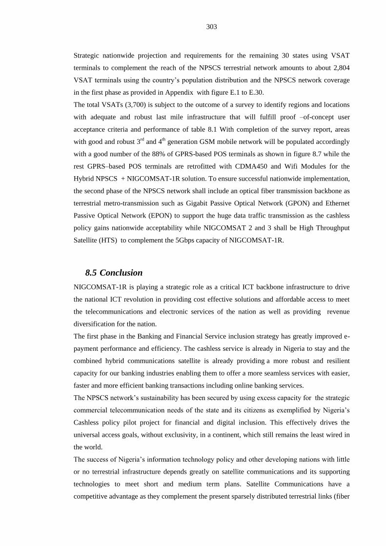
303
Strategic nationwide projection and requirements for the remaining 30 states using VSAT
terminals to complement the reach of the NPSCS terrestrial network amounts to about 2,804
VSAT terminals using the country’s population distribution and the NPSCS network coverage
in the first phase as provided in Appendix with figure E.1 to E.30.
The total VSATs (3,700) is subject to the outcome of a survey to identify regions and locations
with adequate and robust last mile infrastructure that will fulfill proof –of-concept user
acceptance criteria and performance of table 8.1 With completion of the survey report, areas
with good and robust 3rd
and 4th generation GSM mobile network will be populated accordingly
with a good number of the 88% of GPRS-based POS terminals as shown in figure 8.7 while the
rest GPRS–based POS terminals are retrofitted with CDMA450 and Wifi Modules for the
Hybrid NPSCS + NIGCOMSAT-1R solution. To ensure successful nationwide implementation,
the second phase of the NPSCS network shall include an optical fiber transmission backbone as
terrestrial metro-transmission such as Gigabit Passive Optical Network (GPON) and Ethernet
Passive Optical Network (EPON) to support the huge data traffic transmission as the cashless
policy gains nationwide acceptability while NIGCOMSAT 2 and 3 shall be High Throughput
Satellite (HTS) to complement the 5Gbps capacity of NIGCOMSAT-1R.
8.5 Conclusion
NIGCOMSAT-1R is playing a strategic role as a critical ICT backbone infrastructure to drive
the national ICT revolution in providing cost effective solutions and affordable access to meet
the telecommunications and electronic services of the nation as well as providing revenue
diversification for the nation.
The first phase in the Banking and Financial Service inclusion strategy has greatly improved e-
payment performance and efficiency. The cashless service is already in Nigeria to stay and the
combined hybrid communications satellite is already providing a more robust and resilient
capacity for our banking industries enabling them to offer a more seamless services with easier,
faster and more efficient banking transactions including online banking services.
The NPSCS network’s sustainability has been secured by using excess capacity for the strategic
commercial telecommunication needs of the state and its citizens as exemplified by Nigeria’s
Cashless policy pilot project for financial and digital inclusion. This effectively drives the
universal access goals, without exclusivity, in a continent, which still remains the least wired in
the world.
The success of Nigeria’s information technology policy and other developing nations with little
or no terrestrial infrastructure depends greatly on satellite communications and its supporting
technologies to meet short and medium term plans. Satellite Communications have a
competitive advantage as they complement the present sparsely distributed terrestrial links (fiber

304
optic) and radio link extensions contributing to accelerated economic growth, secure
communications for security agencies, socio-economic development and launchpad for all-
inclusive participation in the global knowledge-based economy thus accelerating sustainable
growth and development.

305
CHAPTER 9:Conclusions, Recommendations, Challenges
&Limitations and Future Research Work

306
9.1 Conclusion
The success of information communications technology policy of emerging nations and
economies with little or no terrestrial ICT infrastructure depends greatly on satellite
communications and its supporting terrestrial wireless technologies to meet short and medium
term plans. Satellite Communications have a competitive advantage as they complement the
present sparsely distributed terrestrial links (fiber optic) and last-mile ICT infrastructure
contributing to accelerated economic growth, secure communications for security agencies,
socio-economic development and launchpad for participation in the global knowledge-based
economy thus accelerating sustainable growth and development by leveraging on the adequate
terabyte submarine optic fiber cable at the shores of African continent made possible with
favorable and ambitious ICT de-regulation and business climate to enhance and promote private
participation with strong independent regulatory mechanisms to ensure compliance to
Government ICT frameworks (Lawal & Chatwin, 2011). The continuously increasing demand
for services provided by geostationary satellites challenges satellite system design engineers to
continue to evolve an enhanced satellite bus with advanced broad-band based communication
payloads to support not just broad-band capabilities but also advanced payload capabilities
incorporating on-board switching techniques, multi-frequency, multi-polarization and multi-spot
beams and large geographical coverage area capability with reduced on-orbit cost per
transponder, increased service capacity from a single orbital slot, frequency reuse techniques
especially in the utilization of the upper region of the satellite spectrum i.e Ka Band and
extended orbital life. The importance of optimizing the mass/volume ratio, optimal antenna
layout technique with high power delivery are key factors in providing efficient and advanced
leading-edge spacecraft missions supporting high capacity capability amongst other
requirements as detailed in Chapter two. A global passive communication infrastructure remains
an attractive method to meet market demand for telecommunications, broadcasting, navigational
and other value-added services especially in areas with inadequate terrestrial telecommunication
networks. The dramatic increase in satellite communications services and resources in recent
times has been made possible through High Throughput Satellites (HTS).
ICT is a development enabler. The ICT development process, and a country’s transformation to
becoming an information society, can be described using the following three-stage model and
contexts:
Stage 1: ICT readiness (reflecting the level of networked infrastructure and access to ICTs);
Stage 2: ICT intensity (reflecting the level of use of ICTs in the society);
Stage 3: ICT impact (reflecting the result/outcome of efficient and effective ICT use)

307
The situational analysis of Information Communications Technology (ICT) infrastructure in
Africa was thoroughly examined and identified through a feasibility survey, needs assessment
with a strong need for passive Global Space-based ICT Infrastructure (Communications Satellite
System and associated technologies) as a short and medium term measure to bridge the huge
digital hiatus as detailed in chapter three. A suitably designed regional communications satellite
was assembled and integrated with its systems and tested before being launched to significantly
improve access to telecoms services in the Sub-Saharan region, especially in rural areas as a
niche market as well as address other strategic needs of the region even beyond the African
continent, as detailed in chapter four with verified key performance parameters.
The NIGCOMSAT-1R Communication satellite is a passive regional global ICT infrastructure
and its supporting terrestrial wireless technologies has leveraged on the grossly under-utilized
fibre-optic terabyte capacity at the shores of Africa, playing a critical role in delivering ICT
readiness in terms of making Internet access available to unserved and underserved areas and
acting as a signpost for the e-readiness of a knowledge-based economy to drive transformation
as is evident from the questionnaire response from users and subscribers to Nigerian
Communication Satellite services across six geo-political regions of Nigeria with different
social status. The results confirmed satisfactory quality of experience (QoE) in service delivery
with excellent pre-sales and post-sales service support.
NIGCOMSAT-1R is playing a strategic role as a critical ICT backbone infrastructure to drive
the national ICT revolution in providing cost effective solutions and affordable access to meet
the telecommunications and electronic services of the nation as well as providing revenue
diversification for the nation .
The national public security communications system (NPSCS) has been deployed and provided
on CDMA- EVDO-Rev. A technology using a Service-Oriented Architecture (SOA). A total IP
technology with services such as Professional GoTa command and dispatch services in response
to emergency situations, prioritized communications between high level users, high quality
voice service and short messaging service, high speed data service for data and surveillance and
live audio/video streaming, strong encryption technology to ensure system security, emergency
alarm service for the general public for pre-emptive and reactive emergencies reporting to police,
video surveillance service, video conference service, coalition emergency response service,
police office e-service system, training and after sales support
Highlights of the solution provided by the project include security of the GoTa system, special
trunked service to enable individual, group, emergency and broadcast calls as well as calls
prioritization, wireless broadband data service, 3G service, low cost network with mature
products as detailed in chapter six. In addition, all network equipment complied with national
environmental protection standards and poses no danger to the citizens and the environment.

308
The system supports an integrated intelligence system with the capability to support operations
for general security alarms, emergency alarms and alarm handling, and cooperative security
systems such as surveillance, interception, information gathering, analysis, preplanning, etc. The
Security Communications system allows for collection, management, analysis, fusion and
interpretation of relevant information to commanders, operators to guide planning, resources
deployment, tactical response and strategic planning as well as information sharing and
symmetry between similar organizations and other relevant organizations.
The NPSCS Service Oriented Architecture (SOA) is built on IP/MPLS bearer service oriented
architecture (SOA) to integrate with the Nigerian Communications Satellite (NIGCOMSAT-1R)
as a backhaul complemented with microwave topology to provide an IP cloud all over the
country and facilitate rapid availability of transmission infrastructure and connection
everywhere in the country and along border areas until there is adequate terrestrial metro-
transmission such as fiber optical transmission; Gigabit Passive Optical Network (GPON) and
Ethernet Passive Optical Network (EPON) for the huge video transmission as more cameras are
deployed in the second and third phase of the project to cover Abuja, Lagos and other big cities
and hot spots for the whole nation. The long-term security communications system to
complement the deployed 2,000 video surveillance system pilot project requires the deployment
of fibre optic links in the third phase to support the huge video traffic transmission for entire
coverage of the nation.
The Nigerian National Public Security Communication Network has impacted positively on the
security of the nation with social benefits. The project is economically sustainable through
utilization of the network for financial and digital inclusion, viable and critical for national
security and as well as enhancing the overall total productivity factor of the nation.
The first phase in the Banking and Financial Service inclusion strategy has greatly improved e-
payment performance and efficiency. The cashless service is already in Nigeria to stay and the
combined hybrid solution of NIGCOMSAT-1R and the National Public Security
Communications System (NPSCS) is already providing a more robust and resilient capacity for
our banking industries enabling them to offer more seamless services with easier, faster and
more reliable banking transactions including online banking services.
The NPSCS network’s sustainability has been secured by using excess capacity for the strategic
commercial telecommunication needs of the state and its citizens as exemplified by Nigeria’s
Cashless policy pilot project for financial and digital inclusion. This effectively drives the
universal access goals, without exclusivity, in a continent, which still remains the least wired in
the world. The utilization of scarce spectrum re-farmed from the single channel Walkie-Talkie
analogue system of Public Security Services (PSS) demonstrates without compromise of how
such a broadband-based security network model can effectively drive the universal access goals,
without exclusivity, in a continent which still remains the least wired in the world.

309
The strategic business model as detailed in chapter 8 also helps resolve the challenge of
spectrum regulatory authorities allocating appropriate radio spectrum to enable a broadband-
based network for public safety and an emergency network as it is considered waste of scarce
spectrum resource by commercial mobile operators and other stakeholders to dedicate radio
spectrum for occasional transmission during emergency in the 21st century. Nigeria’s Cashless
policy pilot project is a proof-of-concept (POC) pilot driving financial and digital inclusion for
all. A requirement for nationwide coverage of financial and digital inclusion without exclusivity
has been defined exploiting the combined resources of NIGCOMSAT-1R and the NPSCS
network system using the country’s most recent population distribution profile. To ensure
successful nationwide implementation, the second phase of the NPSCS network shall include an
optical fiber transmission backbone as terrestrial metro-transmission such as Gigabit Passive
Optical Network (GPON) and Ethernet Passive Optical Network (EPON) to support the huge
data transmission traffic as the cashless policy gains nationwide acceptability while
NIGCOMSAT 2 and 3 next fleet shall be High Throughput Satellites (HTS) to complement the
5Gbps capacity of NIGCOMSAT-1R.
Communications-disaster preparedness of nations especially in the continent of Africa,
exploiting communication satellite systems complemented and supported by broad-band based
terrestrial wireless technologies as the first line of action to facilitate reliable and timely disaster
response remains an important necessity as a key factor for success in a crisis situation and
emergency management in the face of incessant natural and man-made disasters in 21st century.
The Coalition Emergency Response Sub-system (CERS) of the National Public Security
Communications System (NPSCS) was designed to meet such emergency requirements as
detailed in this research work with six emergency communication vehicles integrated into the
NIGCOMSAT-1R communications satellite to provide triple-play mobile communications
services in areas not covered terrestrially by the fixed Base Transceiver station as well as areas
affected by disasters. With well-integrated satellite imagery, location-based services and
navigation technologies, evacuation, fire outbreaks, location of the nearest hospitals, disaster
relief guidance and routes to access: aid, evacuation centers, shelters, e-health services and
makeshift medicare and medication centers are easily facilitated and symmetrically co-
ordinated with various emergency response teams, government agencies, aid donors at local,
national and international level. To improve the precision of location based services (LBS) and
navigation system utilization, we examined thoroughly the critical role that Space-Borne
Oscillators play in improving Performance of Satellite-Based Augmentation Systems, guidelines
for selection of appropriate oscillators, system requirements, electrical analysis and performance
requirements, qualification, test and validation of such performance requirements considering its
criticality in ensuring frequency stability and stability of global time-based signals viz-a-viz
positioning accuracy of location based services and navigation. Improvements in space-borne

310
oscillators not only enhances the precision of Satellite Based Augmentation systems but the
general performance of the system in terms of fast acquisition of navigation signals, lower
power consumption, optimized spectrum utilization, improved error rates, longer service life,
improved recalibration requirements, improved navigation capability, and improved defense
application requirements in terms of target detection and tracking and jamming resistance.
NIGCOMSAT-1R is a hybrid communication satellite with a piggy-back payload for
navigation. The externalized 10 MHz Ultra-Stable Crystal Oscillators in 3 X 4 hybrid array
configuration was qualified, tested and validated for the effectiveness of Location Based
Services and navigation services as verified by the In-orbit test results detailed in chapter five
including utility for Emergency and Crisis management amongst other applications.
NIGCOMSAT-1R is similar to European Geostationary Navigation Overlay Service (EGNOS)
providing Navigation Overlay Service (NOS) and African’s nascent contribution to the Global
Navigation Satellite System (GNSS).
Definition of broadband by African nations should be led by the telecommunications regulatory
agencies and commissions based on each African country’s needs assessment, demand and the
industry statistics at their disposal. Broadband-based communications Satellites enabled by
efficient technologies allows more throughput and supporting High Definition Television
transmission of the Olympic Games to people around the globe. The NigComSat-1R satellite is
a strategic continental ICT and Broadcast infrastructure provider in Sub-Saharan Africa with far
reaching impacts in enhancing telecommunications, broadcasting, other value-added
telecommunications services, real-time monitoring services and navigation in Africa as detailed
in chapter seven including transforming Nigeria from just being a consumer of bandwidth to a
provider as well as a content carrier/distributor in the broadcast sector as an alternative to
Digital Terrestrial Television (DTT) as we move closer to the ITU deadline for Analogue
Switch-Off (ASO).
Conclusively, NIGCOMSAT-1R communications Satellite complements and connects to the
National Public Security and Communications System serving not just Public Security Service
(PSS) and emergency needs but remains a corner stone for universal access goals in a continent
that still remains the least wired and a business model demonstrator for allocation of
appropriate radio spectrum to enable a broadband-based network for public safety and an
emergency with optimal utilization for strategic commercial and national needs as exemplified
by Nigeria’s National cashless policy implementation on public security network.

311
9.2 Recommendations
The ICT readiness of any nation is a function of the level of networked
telecommunications infrastructure and a determinant for the 3As for universal access
goals and digital inclusion. The 3As are:
o Availability
o Affordability
o Accessibility
Convergence in communications networks through integrated connectivities (Satellite,
fiber optics, radio s etc) are required to optimize national public security and emergency
networks especially in Africa, which still remains the least wired continent in the world.
Appropriate Quality of Service (QoS) and Quality of Experience implementation and
suppression of latency syndrome with appropriate technologies and differentiated class
of users based on traffic engineering to avoid apathy and the perception that
Communications Satellite cannot deliver broadband-based services.
The need for safety and disaster preparedness of Communication Satellite Systems with
redundant backup satellites, geographically separated backup ground stations with
satellite control and network operations (Lawal & Chatwin, 2010b).
Need to canvass for support for additional satellite position filings with the International
Telecommunications Union (ITU) and spectrum allocation for global satellite
communications within the African continent as a disadvantaged continent requiring
space-based assets and resources to bridge the digital hiatus and at the same time the
need for ITU to evolve new procedures that will discourage paper-based (satellites that
are never launched) communication satellites; this generally hurts the multi-billion
dollar communications satellite industry.
Adoption and replacement of low data rate public security service (PSS) such as the
Walkie-talkie and Push-to-Talk (PTT) systems, the analogue trunking multi-channel
system, the TETRA and iDEN (integrated digital enhanced network) networks with
newer emerging broadband-based terrestrial wireless technologies that supports higher
data rate for video, map and data applications.
20th century bureaucracies are unable to handle 21
st century disasters.
Need for effectiveness of early warning systems to a wider audience and
public awareness in realizing their vulnerability to disasters.
Need for operational and organizational hierarchy and symmetry of

312
assembling emergency response teams through coordinated first response (CFR) of an
integrated communication system.
Need for sufficient terrestrial spectrum resource allocation for public safety and
emergency communications network with a synergetic commercial model for
commercial utilization without compromise to security of the network, while enhancing
self-sustenance and maintenance of the network system.
9.3 Challenges and Limitations
There are a number of challenges in the communications satellite industry. Polluted skies with
space debris comprising of manmade and natural sources pose a major concern to working
spacecraft in different orbits as well as during launch operations enroute to the desired orbit.
However, the U.S Space Surveillance Network tracks pieces of orbital debris that are greater
than 10 centimeters in diameter on a routine basis while spacecraft manufacturers have taken a
number of measures to reduce number of debris produced by spacecrafts for various missions.
(Rudd, 1998; Thrash, 1999).
A powerful and newly built communications satellite can be reduced to shrapnel during launch
as a result of launch failure (Gifford, 1997). If the launch vehicle successfully places the
communications satellite into the desired orbit, in-orbit failure may occur due to either Solar
power arrays or drive mechanism similar to the NIGCOMSAT-1 failure (NIGCOMSAT-1, 2005)
or propulsion or other subsystem failure or anomaly. The Communications Satellite industry is
surely a very risky business as emphasized by Gifford (1997) requiring insurance but with few
brokers and underwriters willing to shoulder such high risks, thus a considerable premium is
paid to the few satellite insurers that are out there.
Incessant failures of launch vehicles such as the late 1990s failures of first two Delta 3 missions,
Three Titan 4S, Athena 2 missions amongst others caused an unprecedented backlog in the
launch of commercial and non-commercial satellites similar to a re-run of the late 1950s, when
rockets regularly veered off course and exploded into a ball of flames before attention to detail
was mastered through high quality design, testing procedures, launch vehicle engineering etc.
(Williamson, 1999).
Limitations of Communication Satellites systems are as follows:
Capacity, throughput (bandwidth) and power are limited by number of transponders and
available power on-board a Communications satellite.
High propagation delay due to altitudes of satellites (36,000km away from earth
surface), which results to latency of about 250msecs (earth-satellite-earth). The latency
doubles to 500msec for a return path transmission affecting real-time communications.
Orbital slots of COMSATs are limited and scarce resources offered on first come, first
serve basis by ITU.

313
Satellite resources and capacities are also limited by frequencies in Fixed Satellite
Service (FSS) and Broadcast Satellite Service (BSS) range.
Satellite Service Performance and quality of service (QoS) are easily affected by
changes in weather e.g rain attenuation especially in Ku and Ka band range, non-clear
sky (cloudy) conditions.
9.4 Future Research
High throughput satellites offer significant opportunities for the future; current 15kW systems
can support data rates upto 140 Gb/s. Terabyte satellites require the development of key
technologies, much of which is already emerging. Such as triple junction solar panels offering
efficiencies upto 42%. 50 kW satellites will be able to deliver huge bandwidths facilitating
global communication systems that will secure low cost high bandwidth to any location on the
planet. The following future research directions are enabling technologies for highly optimized
High Throughput Satellites as Global non-passive (active) ICT spaced-based Infrastructure:
Flexible Reconfigurable Payload Technologies for High Throughput Satellites to Meet
Future Business Needs by exploiting steerable antenna pointing mechanism (APM),
periodic and aperiodic Direct Radiating Array (DRA) antennas, multi-port high power
amplifiers, flexible channelization and routing using onboard routers, on-board
processors, switches, digital signal processing capability and multi-feed per beam
antenna technologies (Lawal and Chatwin, 2010a).
Propagation delay-tolerant and secure virtual networks in real time by implementation
of on-board routers and processors support routing of voice, video and data
communications to multiple areas in one-hop.
The Ka band ushering additional bandwidth to satellite operators and communications
satellite industry through the use of new HTS systems. However, it is affected by
atmospheric propagation effects and Fade mitigation techniques helped tremendously in
signal fades originating from propagation effects. Improved modelling of propagation
effects with meteorological database on a region by region basis will improve our
knowledge of satellite systems behaviour and our ability to combat rain attenuation in
real time to optimize link availability as well as enhanced availability estimations for
definite service level agreements (SLAs).
High Powered Ka band waveguides and Isolator technologies with improved power
handling and matching capability operating without Multipaction, Passive
Intermodulation (PIM), thermal breakdown or non-liner distortions and effects.
Use of Micro-Electro-Mechanical systems (MEMs) with a drastic reduction in mass,
volume and power requirement in radio frequency switches and filters for

314
channelization, multiplexing and demultiplexing of radio frequency signals of the
repeater subsystem with enhanced RF performance and reduced insertion loss.
High packaging density of RF devices, switches and amplifiers with optimal
mass/volume ratio as well as Use of radiation hardened Field Programmable Gate Array
(FPGA) devices.
Use of high temperature super conducting materials (HTS) for filters, input multiplexers
(IMUX) , radiation hardened and advanced Monolithic Microwave Integrated Circuits
(MMICs) using multi-layers, development of high power, temperature compensated
cavity filters for output multiplexers (OMUX) etc.
Research on high powered dual multiplexers offering significant improvements in size,
mass and insertion loss with optimized channel filter for multi-beam communications
satellite system architecture.
Use and implementation of effective plasma (Electric) Thrusters in modern satellite bus
(platform) in place of propellant and chemical-based system as propulsion subsystem
lowering propellant mass requirements for the spacecraft mission constitutes between
55%-65% of the total mass of a most geostationary satellite spacecraft.
Improved high performance battery technologies with improved depth of discharge,
longer charge/discharge life cycle, minimal thermal and heat dissipation.
Advanced on-board resource management with appropriate bandwidth on-demand
(BoD) algorithm for advanced Multi-beam star/meshed Networks based on DVB-RCS2
in HTS Communications Satellite for optimal performance.
Research work on low-cost commercial anti-interference and anti-jamming technical
solutions to guarantee high level of quality of service in crisis areas and denial-of-
service (DOS) territories exploiting multi-beam antenna (MBA), spatial processing,
beam-shaping, diversity and beam forming technology on antenna sub-system, receivers;
RF/Digital technique using frequency agile converter (FAC) on RF processing
equipment including at Digital Signal Processing Level using Time Domain Adaptive
filtering. Implementation of Digital Video Broadcasting Carrier Identification (DVB-
CID) with global Unique identifier (GUI) as better way of identifying and locating non-
malicious radio frequency interference (RFI) of digital satellite signals and thus
lowering RFI events.
Electronically controlled or hybrid solution of mechanics and electronics conformal
phased-array antennas for mobile and airborne satellite communication systems with
strict control of beamwidth, beam pointing accuracy and sidelobe performance.
Future research studies to achieve Terabit/s geostationary satellite system through
improving technologies at payload and platform level several multi-feed reflector
antennas, optical feeder links and ground segment gateway stations.

315
Design and implementation of HTS-based NIGCOMSAT 2 & 3 to complement and
serve as a backup to NIGCOMSAT-1R operations, capacity and capability.
Multi-band and versatile Communication Satellite terminal equipment i.e Ku/Ka Band
equipment and devices.
Design and implementation of optic-fiber backbone topology to complement the
microwave and NIGCOMSAT-1R backbone topology in the second and third phase of
NPSCS network.
Research work on software-defined radio (SDR) GNSS receivers to ensure
interoperability with global and regional GNSS systems and general performance of the
system in terms of fast acquisition and detection of navigation signals, lower power
consumption, optimized spectrum utilization, improved error rates, longer service life,
improved navigation capability, improved defense application requirements in terms of
target detection and tracking.
Integration of variants of mobile communication satellite last-mile equipment models
named “SATCOM CRISIS MANAGER” for Emergency Communication Preparedness
of African Countries exploiting Communication Satellites as illustrated below in figure
9.1:
Figure 9.1:“SATCOM CRISIS MANAGER” for Emergency Communication
Preparedness of African Countries exploiting Communication Satellites with terrestrial
wireless technologies.
Collaborative Research in Software-Defined Radios (SDR) and Cognitive Radios (CR)
for Very Small Aperture Terminal (VSAT) hardware to promote seamless
interoperability at different frequencies and with different communications satellites
especially for the SATCOM CRISIS MANAGER.

316
References
Agustin D. (2009). Working Party on Communication Infrastructures and Services Policy.
Organisation for Economic Co-operation and Development.
DSTI/ICCP/CISP(2009)3/FINAL. Retrieved from
http://www.oecd.org/internet/broadbandandtelecom/44381795.pdf
Ahmed-Rufai T. (2012). NIGCOMSAT-IR targets 40% of Nigerian broadband market by 2015.
Technology Times Online. Retrieved from
http://www.technologytimesng.com/news/2012/04/nigcomsat-ir-targets-40-of-nigerian-
broadband-market-by-2015/
Africa Undersea Cable (2014). Retrieved from
http://www.nashua.co.za/wp-content/uploads/2012/06/Africa_Undersea.jpg
Amana, E.I. (2013). Managing the Spectrum Dividend Opportunities for Mobile and
Broadcasting. Digital TV Africa, Kemilinks International, Lagos-Nigeria.
Ambrosini, R. (2000). Measurements of Allan Variance and Short Term Phase Noise of
Millimeter Local Oscillators. Institute of Radio Astronomy, CNR,Italy.
Anonymous. (1994). Mobile Satellite: The Latest in Global Communications, Satellite
Communications, 18(3),23-24.
APC. (2011). Digital Broadcast Migration in West Africa: Ghana Research Report. Association
for Progressive Communications, APC and Balancing Act.
Asmar, S.W.( 1997). Characteristics Trends of Ultrastable Oscillators for Radio Science
Experiments. TDA Progress Report (42-129).
Back Haul, (1999). Satellite Communications, 23(12),16.
Backof, C. (2013). Public Safety Communications in Emergencies. IEEE Vehicular Technology
Magazine,8(2),4.Doi:10.1109/MVT.2013.2252264.
Beebe, N. (2014, January 21). Improving Disaster Response Outcomes. Via Satellite
Publications, http://www.satellitetoday.com/publications/2014/01/21/improving-disaster-
response-outcomes-2/
Bentley, R.M., & Owens, A.T. (1964). Syncom Satellite Program. Journal of Spacecraft and
Rockets, 1(4), 395-399. doi: 10.2514/3.27667.
Beidas, B.F., Cioni, S., De Bie, U., Ginesi, A., Iyer-Seshadri, R., Kim P., ...Vanelli-Coralli, A.
(2013). Continous Phase Modulation for Broadband Satellite Communications: Design
317
and Trade-offs. International Journal of Satellite Communications and Networking, 31,
249-262.
Berger, G. (2010). Challenges and Perspectives of Digital Migration for African Media. Panos
Institute of West Africa, ISBN 978086104621, First Edition, pp. 12-25.
Berioli, M., Courville, N., & Werner, M. (2007). Emergency Communications over Satellite.
Proceeding of 16th IST Mobile and Wireless Communications Summit, (pp1-5),
doi:10.1109/ISTMWC.2007.4299271.
Bloch, M., Mancini, O., & McClelland, T. (2009). Effects of Radiation on Performance of
Space-Borne Quartz Crystal Oscillators. IEEE International Frequency Control
Symposium Joint with 22nd
European Frequency and Time Forum, (171-174), Besancon.
doi: 10.1109/FREQ.2009.5168163.
Boukerche, A. (2008). The Next Generation Wireless Network Challenges for an Emergency
Preparedness and Response Class of Applications: A Necessary Public Safety and
Security. International Symposium on Computers and Communications, ISCC, ppxvii-
xviii. Doi:10.1109/ISCC.2008.4625580.
Bowman, J. (2007). Robust and affordable Mobile Communications for Emergency
Management. International Journal of Emergency Management, 4(4), 649-669.
Bowyer, M., Erup, L., Lexow, & H.P. (2013). Security in DVB-RCS2. International Journal of
Satellite Communications and Networking, 31, 263-276.
Boyer, W.H. (1998). Don’t Touch that Dial. Satellite Communications, 22(5), 44-47.
Brody, G., Coffin, R., Cohn, S., Homayoun, F., & Swanson, T. (1996). New Frontiers in Global
Communications. TELESIS, 50-64.
Bruce, F. (2010, July 19). Xilink launches first High-density Rad-hard reconfigurable FPGA for
Space Applications. Xilink Inc. Retrieved from
http://satellite.tmcnet.com/news/2010/07/19/4906834.htm
Burton, I.E., & Robert, S.C. (1982). Business Use of Satellite Communications. American
Association for the Advancement of Science, 215(4534), 837-842.
Bystrom, J.W & Maddox, B. (1975). The Application of Satellites to International Interactive
Service Support Communication. Proceedings of the Royal Society of London. Series A,
Mathematical and Physical Sciences, 345(1643), 493-510.

318
Chatziparaskevas, P., Koltidas, G., & Pavlidou, F.N. (2011). On Fairness of Return Channel
Capacity Allocation in DVB-RCS-based Satellite Networks. International Journal of
Satellite Communications and Networking, 29(2), 163-184.
Chen, M., & Liou, Y.I. (2002). Building a Knowledge-Enabled Electronic Commerce
Environment. Journal of Computer Information Systems, 42(5), 95-101.
Cheong, C.P., Fong, S., Lei, P., Chatwin, C., & Young, R. (2012). Designing an Efficient and
Secure Credit card-Based Payment System with Web Services Based on the ANSI X9.59-
2006. Journal of Information Processing Systems, 8(3), 495-520.
Choi, K.S., & Lee, S.P. (2008). A Proposal of the National Disaster Emergency Satellite
Communications Networking. 10th IEEE International Conference on Advanced
Communications Technology, 1, 396-399, doi: 10.1109/ICACT.2008.4493786.
Chronaki, C. E., Kontoyiannis, V., Charalambous, E., Vrouchos, G., Ma,amtopoulos, A., &
Vourvalakis, D. (2008). Satellite–Enabled eHealth Applications in Disaster Management-
Experience from a Readiness Exercise. Computers in Cardiology, 35, 1005-1008.
Conte, R. (2005). Satellite Rural Communications: Telephony and Narrowband Networks.
International Journal of Satellite Communications and Networking, 23, 307-321.
Cosper, A.C. (1997a). Digging for Solutions. Satellite Communications, 21(8), 6.
Cosper, A.C. (1997b). The Year the Industry lit the Fuse. Satellite Communications, 21(12), 40-
41.
Curcio, B. (2013, August 15). Changes in the most Dynamic DTH Market and The Last DTH
Frontier. Northern Sky Reprot’s (NSR) Direct-To-Home Markets. 6th Edition. Retrieved
from http://www.nsr.com/news-resources/the-bottom-line/changes-in-the-most-dynamic-
dth-market/
Dana, P.H. (1999). The Global Positioning System Overview: The Geographer’s Craft.
Retrieved from: http://www.colorado.edu/geography/gcraft/notes/gps/gps_f.html
David, L. (1980). The Creation of Knowledge and technique: Todays Task and Yesterday’s
Experience. Modern Technology: Problem or Opportunity?: Daedalus, American
Academy of Arts and Science, MIT Press, 109 (1), 111-120.

319
Davida, C. (2003). Lone Geniuses in Popular Science: The devaluation of Scientific Consensus
Written Communication, 20(3), 215-241. doi: 10.1177/0741088303257505.
Davies, A.C. (1978). The life and death of a scientific instrument: The marine chronometer,
1770-1920. Annals of Science, 35(5), 509-525. doi: 10.1080/00033797800200391
Retrieved from: http://dx.doi.org/10.1080/00033797800200391
Del Re, E. (2012). Satellite Communications for Emergency. Proceedings of First AESS
European Conference on Satellite Telecommunications, ESTEL, (pp1-5).
doi:10.1109/ESTEL.2012.6400172.
Del Re, E., Morosi, S., Jayousi, S., Ronga, L.S., & Suffritti, R. (2009). Satellite Role in
Emergency Services. European Wireless Technology Conference, EuWIT,195-200.
Dempsey, P. (2010). Analysis: How Comms Teams are helping Haiti. Engineering and
Technology, 5 (2), 14-15.
Dervin, M., Buret, I., & Loisel, C. (2009). Easy-to-Deploy Emergency Communication System
Based on a Transparent Telecommunication Satellite. Proceedings of First International
Conference on Advances in Satellite and Space Communications, SPACOM, (pp168-173).
doi:10.1109/SPACOM.2009.11.
Donnell, J.O. (2002, November 15). John Harrison and the Longitude Problem. Royal
Observatory & History of Astronomy, Retrieved from: http://www.nmm.ac.uk/harrison
Donven, M., & Hall, M. (2012). From a Lab in Luxembourg to Satellites in South Sudan.
Forced Migration Review, 41, 44-45.
Drury, G.M. (1994). Broadcasting by Satellites. International Journal of Satellite
Communications, 12, 394-417. doi:10.1002/sat.4600120407.
DVB-3DTV Factsheet. (2011). Delivering 3DTV to Viewers: The Unique 3DTV standard for
the World. European Telecommunications Standards Institute, ETSI.
DVB-CID Factsheet. (2013). DVB Carrier Identification: DVB’s Caller –ID Solution to Stop
Satellite Interference. European Telecommunications Standards Institute, ETSI.

320
DVB-EWS Factsheet. (2013). DVB Standards for Emergency Warning System (EWS).
European Telecommunications Standards Institute, ETSI.
DVB-GEM Factsheet. (2013). DVB Globally Executable Middleware: Open Middleware for
Interactive TV. European Telecommunications Standards Institute, ETSI.
DVB-GSE Factsheet. (2011). DVB Generic Stream Encapsulation: enabling the carriage of IP
directly over DVB networks. European Telecommunications Standards Institute, ETSI.
DVB-H Factsheet. (2011). DVB-H, Broadcasting to Handhelds: Digital Terrestrial Mobile TV.
European Telecommunications Standards Institute, ETSI.
DVB-IPDC Factsheet. (2011). DVB IPDC, Internet Protocol Datacast: Complete Specifications
for Delivery of mobile TV Services. European Telecommunications Standards Institute,
ETSI.
DVB-IPTV Factsheet. (2012). DVB IPTV, Internet Protocol TV: Broadcast to Broadband –
Open Standards for IPTV. European Telecommunications Standards Institute, ETSI.
DVB-MHP Factsheet. (2011). DVB Multimedia Home Platform: Open Middleware for
Interactive TV. European Telecommunications Standards Institute, ETSI.
DVB-Project Factsheet. (2013). Introduction to the DVB Project: Open, Interoperable and
Market-Driven Standards for Digital Television. European Telecommunications
Standards Institute, ETSI.
DVB-RCS2 Factsheet (2012). Second Generation Digital Video Broadcasting (DVB)-Return
Channel Satellite (RCS2), DVB-RCS2. European Telecommunications Standards
Institute,ETSI.
DVB-SH Factsheet. (2011). DVB-SH: Satellite Services to Handhelds. European
Telecommunications Standards Institute, ETSI.
Estrem, A.V., & Werner, M. (2010). Portable Satellite Backhauling Solution for Emergency
Communications. 5th Advanced satellite Multimedia Systems Conference, ASMA and 11
th
Signal Processing for Space Communications Workshop (SPSC), pp 262-269. Doi:
10.1109/ASMS-SPSC.2010.5586923.

321
ETSI EN 301 192 (2008). Digital Video Broadcasting (DVB); DVB specification for data
broadcasting, V1.4.2. European Telecommunications Standards Institute, ETSI. Retrieved
from: Retrieved from:
http://www.etsi.org/deliver/etsi_en/301100_301199/301192/01.04.02_60/en_301192v010
402p.pdf
ETSI EN 301 545-2 (2012). Digital Video Broadcasting (DVB); Second Generation DVB
Interactive Satellite System (DVB-RCS2); Part 2: Lower Layers for Satellite standard,
V1.1.1. European Telecommunications Standards Institute, ETSI. Retrieved from:
Retrieved from:
http://www.etsi.org/deliver/etsi_en/301500_301599/30154502/01.01.01_60/en_30154502
v010101p.pdf
ETSI EN 301 790 (2003). Digital Video Broadcasting (DVB); Interaction Channel for Satellite
Distributions Systems, V1.3.1. European Telecommunications Standards Institute, ETSI.
Retrieved from: Retrieved from:
http://www.etsi.org/deliver/etsi_en/301700_301799/301790/01.03.01_60/en_301790v010
301p.pdf
ETSI EN 301 790 (2005). Digital Video Broadcasting (DVB); Interaction Channel for Satellite
Distributions Systems, V1.4.1. European Telecommunications Standards Institute, ETSI.
Retrieved from: Retrieved from:
http://www.etsi.org/deliver/etsi_en/301700_301799/301790/01.04.01_60/en_301790v010
401p.pdf
ETSI EN 301 790 (2009). Digital Video Broadcasting (DVB); Interaction Channel for Satellite
Distributions Systems, V1.5.1. European Telecommunications Standards Institute, ETSI.
Retrieved from: Retrieved from:
http://www.etsi.org/deliver/etsi_en/301700_301799/301790/01.05.01_60/en_301790v010
501p.pdf
ETSI EN 302 307. (2013). Digital Video Broadcasting (DVB); Second generation framing
structure, channel coding and modulation systems for Broadcasting, Interactive Services,
News Gathering and other broadband satellite applications (DVB-S2), V1.3.1. European
Telecommunications Standards Institute, ETSI. Retrieved from
http://www.etsi.org/deliver/etsi_en/302300_302399/302307/01.03.01_60/en_302307v010
301p.pdf

322
ETSI TR 101 790. (2009). Digital Video Broadcasting (DVB); Interaction channel for Satellite
Distribution Systems; Guidelines for the use of EN 301 790, V1.4.1. European
Telecommunications Standards Institute, ETSI. Retrieved from:
http://www.etsi.org/deliver/etsi_tr/101700_101799/101790/01.04.01_60/tr_101790v0104
01p.pdf
ETSI TS 101 545-3. (2012). Digital Video Broadcasting (DVB); Second Generation DVB
Interactive Satellite System (DVB-RCS2); Part 3: Higher Layers Satellite Specification.
V1.1.1. European Telecommunications Standards Institute, ETSI. Retrieved from:
Retrieved from:
http://www.etsi.org/deliver/etsi_ts/101500_101599/10154503/01.01.01_60/ts_10154503v
010101p.pdf
ETSI TS 101 545-1. (2012). Digital Video Broadcasting (DVB); Second Generation DVB
Interactive Satellite System (DVB-RCS2); Part 1: Overview and System Level
specification,V1.1.1. European Telecommunications Standards Institute, ETSI. Retrieved
from: Retrieved from:
http://www.etsi.org/deliver/etsi_ts/101500_101599/10154501/01.01.01_60/ts_10154501v
010101p.pdf
ETSI TS 103 129 (2013). Digital Video Broadcasting (DVB); Framing structure, channel
coding and modulation of a carrier identification system (DVB-CID) for satellite
transmission, V1.1.1. European Telecommunications Standards Institute, ETSI. Retrieved
from: Retrieved from:
http://www.etsi.org/deliver/etsi_ts/103100_103199/103129/01.01.01_60/ts_103129v0101
01p.pdf
ETSI TS 102 727 (2010). Digital Video Broadcasting (DVB); Multimedia Home Platform
(MHP) Specification 1.2.2, V1.1.1. European Telecommunications Standards Institute,
ETSI. Retrieved from: Retrieved from:
http://www.etsi.org/deliver/etsi_ts/102700_102799/102727/01.01.01_60/ts_102727v0101
01p.pdf
Euroconsult. (2012, May 24). Satellite TV Platforms World Survey and Prospects to 2021. The
Euroconsult Satellite TV Platforms,5th Edition, May, 2013: Emerging Markets Sustain

323
Robust Growth for Satellite TV Platforms. Retrieved from http://www.euroconsult-
ec.com/news/press-release-33-4/56.html
European Commission. (2012). Commission Staff Working Document on the Implementation of
National Broadband Plans. European Commission, Brussels, 23.3.2012, SWD (2012) 68
Final/2. Retrieved from
http://ec.europa.eu/information_society/newsroom/cf/itemdetail.cfm?item_id=7948
Evans, B., Werner, M., Lutz, E., Bousquet, M., Corrazza, G.E., Maral, G., & Rumeau, R. (2005).
Integration of Satellite and Terrestrial Systems in Future Multimedia Communications.
IEEE Wireless Communications, 12 (5),72-80. Doi: 10.1109/MWC.2005.1522108.
Evans-Pughe, C. (2011). Call for back-up! Engineering and Technology, 6 (1), 74-77.
Evans-Pughe, C., & Bodhani, A. (2013). Comms in a Crisis. Engineering and Technology, 8 (2),
74-77.
Ferrus, R., Sallent, O., Baldini, G., & Goratti, L. (2013). LTE : The Technology Driver for
Future Public Safty Communications. IEEE Communications Magazine, 51(10), 154-161.
doi: 10.1109/MCOM.2013.6619579.
Fairhust, G., Secchi, R., & Yun, A. (2013). Fexible QoS Architecture for DVB-RCS2.
International Journal of Satellite Communications and Networking, 31, 219-232.
Fairhust, G., & Yun, A. (2013). Design of the DVB-RCS2 Higher Layer Satellite Architecture.
International Journal of Satellite Communications and Networking, 31, 233-248.
Fazli, E.H., Werner, M., Courville, N., Beriolli, M., & Boussemart, V. (2008). Integrated
GSM/WiFi Backhauling Over Satellite: Flexible Solution for Emergency
Communications. Proceedings of IEEE Vehicular Technology Conference, (pp2962-
2966), doi:10.1109/VETECS.2008.312.
Feasibility Report. (2003). Feasibility Report of viability of Communications Satellite in Nigeria
( 2003). NIGCOMSAT-1 Project.
Fidler, A.J.H., Hernandez, G., Lalovic, M., Pell, T., & Rose, I.G. (2002). Satellite-A new
Opportunity for Broadband Applications. BT Technology Journal, 20(1).
Financial Inclusion in Nigeria. (2012). National Financial Inclusion Strategy Summary Report.
RolandBerger: Strategy Consultants.

324
Francis, K., & Will, J. (1994). Navster GPS & Satellite Communications: Partners in the Age of
Space. Satellite Communications, 18(9), 44.
Garcia-Rubi, J.M., Riera, J.M., Garcia-del-Pino, P., & Benarroch, A. (2011). Propagation in the
Ka Band: Experimental Characterization for Satellite Applications. IEEE Antennas and
Propagation Magazine, 53(2).
Gargione, F., & Brandon, W.T. (1999). Ka-Band Update. Satellite Communications, 23(3), 48-
52.
Gether-Taylor, & H. (2007). Collaborative Governance: Lessons from Katrina. Public Manager,
36, 7-11.
Gifford, J.M. (1996a). China: The Year of the Dish. Satellite Communications, 20(5), 22.
Gifford, J.M. (1996b). The Best New Technologies. Satellite Communications, 20(9), 48-52.
Gifford, J.M. (1997a). Bringing the World Closer. Satellite Communications, 21(9), 36-38.
Gifford, J.M. (1997b). Risky Business. Satellite Communications, 21(2), 39-41.
Globalstar Sat-Fi (2014, January 29). Globalstar introduces Sat-Fi™, A Groundbreaking MSS
Solution. Globalstar Press Release. Retrieved from:
http://www.globalstar.com/en/index.php?cid=7010&pressId=804
Gorcin, A., & Arslan, H. (2008) Public Safety and Emergency Case Communications :
Opportunities from the Aspect of Cognitive Radio. 3rd
IEEE Symposium on New
frontiers in Dynamic Spectrum Access Networks, pp 1-10. Doi:
10.1109/DYSPAN.2008.68
Gregory, T.F. (1996). Understanding the GPS: An introduction to the Global Positioning
System.
Greogory, W., Matthew, R., & Mihran, M. (2004). Developments in Ultra-Stable Quartz
Oscillators for Deep Space Reliability. 36th Annual Precise Time and Time Interval
(PTTI) Meeting (369-382), USA.

325
GSM Association (GSMA) International Report. (2009). Telecommunication Emergency
Communication Systems. Microwave Journal, 52 (11), 49-50.
Hadden, I., & Bruce, J. (2002). Dual-Polarity Low Noise Block Downconverter Systems and
Methods. Retrieved from
http://www.google.com/patents?hl=en&lr=&vid=USPAT6424817&id=rWEJAAAAEBAJ
&oi=fnd&dq=low+noise+block&printsec=abstract#v=onepage&q=low%20noise%20bl
ock&f=false
Hao, W. (2013). Briefing on China’s Satellite Communications Progress and Future. China
Communications. 10(10), vi-viii. doi: 10.1109/CC.2013.6650313.
Harris CapRock. (2012). Not all Bands are Created Equal: A Closer Look at Ka & Ku High
Throughput Satellites. Harris CapRock White Paper, Harris CapRock Communications
Inc. Retrieved from
http://www.harriscaprock.com/downloads/HarrisCapRock_WhitePaper-Ka-
Ku_Analysis.pdf
Henry, T.I. (1986). New Media, Old Media: The Technologies of International Development,
International Review of Education, Educational Technology and Mass Media, 32(3), 251-
267.
Hyun-Chul, P. (1993). Low-Noise Block Converter for a satellite Broadcasting System.
Retrieved from
http://www.google.com/patents?hl=en&lr=&vid=USPAT5263182&id=iBgdAAAAEBAJ
&oi=fnd&dq=low+noise+block&printsec=abstract#v=onepage&q=low%20noise%20bl
ock&f=false
Homes, M. (2013, August 22). Satellite TV Subscribers Expected to Reach 250 Million by 2018,
Asia and Africa Hotspots for DTH. Via Satellite. Retrieved from
http://www.satellitetoday.com/publications/2013/08/22/satellite-tv-subscribers-expected-
to-reach-250-million-by-2018-asia-and-africa-hotspots-for-dth/
Human Capital. (2009). The limits to terrestrial television’s case for further spectrum. Human
Capital (Strategy, Research & Development). Retrieved from
http://www.gsma.com/spectrum/wp-
content/uploads/DigitalDividend/DDtoolkit/uploads/assets/downloads/04/the-limits-to-
terrestrial-televisions-case-for-further-spectrum.pdf

326
Hong, S., Xiaohong, J., & John, X. (2008). Study of Fundamental Limit and Packaging
Technology Solutions for 40 Gbps Transceiver Package Design. Altera Corporation,
DesignCon, CP-01038-1.0.
Ian, R.B., & Steven, J.D. (1981). The First Time Balls. Science History Publications Ltd, NASA
Astrophysics Data System, 12 (155B), 155-164.
IDirect iVantage NMS. (n.d.). iDirect iVantage Network Management System (NMS). Vt
iDirect NMS. Retrieved from:
http://www.idirect.net/~/media/Files/Solution%20Overviews/PRODUCT%20BROCHUR
E_iVantage_Network_Management_System.ashx
Igor, B., Riccardo, D.G., Hung, N., Fotini-Niovi, P., & Takaya, Y. (2010). Recent Advances in
Satellite and Space Communications. Journal of Communications and Networks. 12(6),
523-528. doi: 10.1109/JCN.2010.6388298.
Ihechu, I.P., & Uche, U. (2012). The Challenges of Digitization of Broadcasting in Nigeria.
International Institute for Science, Technology and Education (IISTE), 5, ISSN 2224-
3267.
India Telecom Regulatory Authority. (2010). Recommendations on National Broadband Plan.
India Telecom Regulatory Authority. Retrieved from
http://www.trai.gov.in/WriteReadData/Recommendation/Documents/Rcommendation812
10.pdf
Ingley, C. (2000). Challenges for Satellite Broadband Multimedia. Satellite Communications,
24(1), 16.
Internet Usage Statistics (2013). World Internet Usage and Population Statistics. Retrieved from
http://www.internetworldstats.com/stats.htm
Intelsatgeneral. (2009). Internet Routing in Space. Joint Capability Technology Demonstration.
Retrieved from http://www.intelsatgeneral.com/sites/default/files/pdfs/iris.pdf
ITU. (2003). Birth of Broadband: ITU Internet Reports Executive Summary. International
Telecommunications Union, ITU. Retrieved from
http://www.itu.int/osg/spu/publications/sales/birthofbroadband/exec_summary.html
ITU. (2007). Recommendation of ITU-R S.1709-1 :Technical characteristics of air interfaces for
global broadband satellite systems. International Telecommunications Union, ITU.
Retrieved from http://www.itu.int/rec/R-REC-S.1709/en

327
ITU. (2010). ITU-D Report on Measuring the Information Society. International
Telecommunications Union, ITU. Retrieved from http://www.itu.int/ITU-
D/ict/publications/idi/2010/index.html
ITU. (2012). Guidelines for the Transition from Analogue to Digital Broadcasting-Including the
Asia-Pacific Region. International Telecommunications Union, ITU.
Ivancic, W., Et al. (2005). Secure, Network-Centric Operations of a Space-Based Asset; Cisco
Router in Low Earth Orbit (CLEO) and Virtual Mission Operations Center (VMOC).
NASA Glenn Research Center. doi:NASA/TM-2005-213556.
Jakel, P. (2000). Ageless Bird. Satellite Communications, 24(8), 18-19.
James, C., & Andrew, G. (1999). The Coming of the Wired City? The Recent Development of
Cable in Britain, Liverpool University Press, The Town Planning Review, 63, (3), 243-
264.
Jarris, R.F. (1994). Satellite Video System Aids Offshore treatment. Health Management
Technology, 15(4), 32-34.
John, R.V. (1992). Introduction to Quartz Frequency Standards. Research and Development
Technical Report, Army Research Laboratory, SLCET-TR-92-1 (Rev. 1) Retrieved from :
http://www.ieee-uffc.org/frequency_control/teaching.asp?name=vigtoc
Joshi, A., Rajhans, P., Galwankar, S., Arquilla, B., Swaroop, M., Stawicki, S.,...Kalra, O. (2013).
Academic College of Emergency Experts in India’s INDO-US Joint Working Group
(JWG) White paper on the integrated Emergency Communication Response Service in
India: Much More than just a Number!. Journal of Emergencies, Trauma & Shock, 6 (3),
216-223.
Jun, X., & Xuchu, M. (2008). Implementation of FPGA-Based Acquisition of Weak GPS
Signals. International Symposium on GPS/GNSS, Tokyo.
Kalil, T. (1995). Public Policy and the National Information Infrastructure. Business Economics,
30, 15-15.
Klar, R., Managels, C., Dykes, S., Brysch, M. (2008). Design Considerations for adapting
Legacy System Architecture to SpaceWire. Proceedings of 2nd
SpaceWire International

328
Conference, Japan. Retrieved from http://2008.spacewire-
conference.org/downloads/Papers/Networks%20%26%20Protocols%203/Klar.pdf
Kowoma. (2009, April 19). The GPS System. Retrieved from:
http://www.kowoma.de/en/gps/history.htm
Kriz, K., (2014, February 4). Iridium Launches New Products, Prepares for Iridium Next
Replacement Program. Via Satellite. Retrieved from
http://www.satellitetoday.com/technology/2014/02/04/iridium-launches-new-products-
prepares-for-iridium-next-replacement-
program/?hq_e=el&hq_m=2825542&hq_l=5&hq_v=2d4f091c1a
Lau, K., Lichen, S., Young, L., & Haines, B. (1996). An Innovative Deep Space Applications of
GPS Technology for Formation Flying Spacecraft. AIAA Guidance, Navigation and
Control Conference. doi: AIAA-96-3819.
Lawal, L, S. (2009). MultiMission Communications Satellite System: SussexSat-1(Master’s
thesis). University of Sussex, Brighton, United Kingdom.
Lawal, L.S., & Chatwin, C.R. (2010a). Optimized and Advanced Multi-Mission
Communication Satellite System: A Panecea for a Systemic Paradigm Shift towards
Small Standardized and Advanced Multi-Purpose Geostationary Spacecraft for an active
Global Communication Infrastructure to Promote Digital Inclusion In The Global Village.
Proceedings of 28th AIAA International Communications Satellite Systems Conference
and Exposition, California,USA. doi: 10.2514/6.2010-8887.
Lawal, L.S., & Chatwin, C.R. (2010b). Safety and Disaster Preparedness for Strategic Global
Infrastructure: Communication Satellite Systems. Proceedings of 5th IET International
System Safety Conference, Manchester,UK. doi:10.1049/cp.2010.0810.
Lawal, L.S., & Chatwin, C.R. (2011a). Essential Parameters of Space-Borne Oscillators That
Ensures Performance of Satellite-Based Augmentation System. Proceedings of 3rd
IEEE
International Conference on Science and Technology, ICAST, (pp42-50). Abuja-Nigeria.
doi: 10.1109/ICASTech.2011.6145156.
Lawal, L.S., & Chatwin, C.R. (2011b). Optimization of Mass Volume ratio of Spacecraft
Structure for Advanced and High Powered Communication Satellites, Proceedings of 10th

329
International Information and Telecommunication Technologies conference,
Florianopolis, Santa Catarina Island, Brazil.
Lawal, L.S., & Chatwin, C.R. (2012a). The Future of Wireless Communications in Africa.
International Conference on Wireless Network and Information System. Future Wireless
Networks and Information Systems, Lecture Notes in Electrical Engineering, Springer
Link, 143, 243-251. doi: 10.1007/978-3-642-27323-0_31.
Lawal, L.S., & Chatwin, C.R. (2012b). Advanced High Power Systems for Geostationary
Satellites. Proceedings of 2012 2nd International Conference on Electric Information and
Control Engineering, ICEICE, IEEE Computer Society,4,138-142, Lushan,China.
Doi:10.1109/ICEICE.2012.1164.
Lawal, L.S., & Chatwin, C.R. (2012c). Antenna System Layout in High Capacity Geostationary
Communication Satellites. Antennas and Propagation in Wireless Communications, IEEE
APWC 2012 Topical Conference, (pp1012-1015), Capetown, South Africa. doi:
10.1109/APWC.2012.6324983.
Lawal, L.S., Ahmed-Rufai, T., Chatwin, C.R., & Young, R.C.D. (2013). Delivery of Broadband
Services to Sub-Saharan Africa via Nigerian Communications Satellite. International
Journal of Information and Computer Science (IJICS). 2(5), 77-88.
Lawal, L.S., Ahmed-Rufai, T., Inuwa, D.A., & Chatwin, C.R., (n.d.). The Unique Role of
Communications Satellites in addressing the Rapid Socio-Economic Development of
Nigeria. Unpublished.
Lawal, L.S., & Chatwin, C.R. (2013). Nigerian Communication Satellite (NIGCOMSAT-1R)
Ka-band System”, 19th Ka and Broadband Communications, Navigation and Earth
Observation Conference and 31st
AIAA International Communications Satellite Systems
Conference (ICSSC), Florence-Italy. Retrieved from http://www.kaconf.org/#
Lawal, L.S., Ahmed-Rufai, T., & Chatwin, C.R., (2013). Communication Satellite Alternative
to Digital Terrestrial Television. Proceedings of 2nd
IEEE International Conference on
Emerging and Sustainable Technologies for Power and ICT in a Developing Society,
Owerri, Nigeria. Retrieved from http://www.nigercon.info/#!
Lawal, L.S., Ahmed-Rufai, T., Chatwin, C.R., & Liu, R. (2013). The Role of Communication
Satellites in Public Management, Education, Governance and Business in Nigeria.

330
International Conference on Electronics Engineering, Advanced Communication, and
Information Technology, EEACIT, Kuala Lumpur, Malaysia. Human Resource
Management Research Journal, 3(5),178-187. doi: 10.5923/j.hrmr.20130305.02.
Retrieved from http://article.sapub.org/10.5923.j.hrmr.20130305.02.html
Lawal, L.S & Chatwin, C.R. (2014). Emergency Communication Preparedness in Africa
Exploiting Communication Satellites. Global Space Applications Conference (GLAC)
by International Astronautical Federation (IAF) and United Nations Educational,
Scientific and Cultural Organization (UNESCO) on 2-4 June, 2014 at UNESCO HQ,
Paris, France. Retrieved from http://www.iafastro.org/wp-
content/uploads/2014/04/GLAC_FP_FINAL_May201428_online_2.pdf
Lee,Y., Ku, B., & Ahn, D. (2012). A Satellite Core Network System For Emergency
Management and Disaster Recovery. Proceedings of International Conference on
Information and Communication Technology Convergence, ICTC, (pp 549-552). doi:
10.1109/ICTC.2010.5674753.
Lenka, K. (2010). Effective Communication During the Crisis Situation. Social Behavioural
Sciences and Humanities, 15(2), 229-233.
Liang, X., Ong, F.L.C., Pillai, P., Chan, P.M.L., Mancuso, V., Koltsidas, G.,...Fairhurst, G.
(2007). Fusion of Digital Television, Broadband Internet and Mobile Communications-
Part II: Future Service Scenerios. International Journal of Satellite Communications and
Networking, 25, 409-440. doi: 10.1002/sat.880
Ling, R. (1994). Africa Embraces Satellite Communications, Satellite Communications 18(6),16.
Li, S. Q., Chen, Z., Yu, Q. Y., Meng, W. X., & Tan, X. Z. (2013). Toward Future Public Safety
Communications. IEEE Vehicular Technology Magazine, 8 (2), 55-63. Doi:
10.1109/MVT.2013.2252277.
Logue, T.J. (1996). Opening doors around the world. Satellite Communications. 20(8), 31.
Lutz, E. (2013). Achieving a Terabit/s Geo Satellite System, 19th Ka and Broadband
Communications, Navigation and Earth Observation Conference and 31st
AIAA
International Communications Satellite Systems Conference (ICSSC), Florence-Italy.
Retrieved from http://www.kaconf.org/#

331
Mark,T. (1999, July 27). African Banks to Use Satellite Communications. Financial Times, 8,
London, UK.
Mase, K. (2012). Communication Service Continuity under a Large-Scale Disaster: Providing a
wireless multihop network and shelter communication service for a disaster area under
the Great East Japan Earthquake. 2012 IEEE International Conference on
Communications (ICC), pp 6314-6318. Doi: 10.1109/ICC.2012.6364749.
McGee, A.R., Coutiere, M., & Palamara, M.E. (2012). Public Safety Network Security
Considerations. Bell Labs Technical Journal, 17(3), 79-86.
Meeker, T.R & Vig, J.R. (1991). The Aging of Bulk Acoustic Wave Resonators, Oscillators and
Filters. Proceedings of the 45th Annual Symposium on Frequency Control, IEEE Cat.
91CH2965-2.
Meng-Hsun Tsai, Chen, R., Jui-Feng Sung., Wu, E., Wie, E., Zheng-Han Wu., & Jiu-Shan
Liang. (2011). Efficient and Flexible Emergency Communications in Next Generation
Mobile Network. 2011 8th IEEE International Conference on e-Business Engineering. Pp
96-101. Doi: 10.1109/ICEBE.2011.46.
Minor, B.M. (2011). Training Guide on iDirect Operation and Maintenance. VT iDirect iDX
Release 3.0.
Mody, B. (1979). Satellites for Rural Development. Journal of Communication (Pre-1986), 29
(4), 289-299.
Morgan, W.L. (1997). 1977-1997: What a difference!. Satellite Communications, 21(10), 36-40.
Musavi, S.H.A, Memon, A.R, & Chawdhri, B.S. (2011). Modeling an Interoperable Information
and Communication Network for Disaster Management First Responders. International
Journal of Academic Research, 3(2), 17-25.
National Maritime Museum (n.d.). Harrison’s First Marine Timekeeper (H1). National Maritime
Museum. Retrieved from: http://www.nmm.ac.uk/collections/images/200/A/27/A2759.jpg
National Public Safety Communications System. (2011). Design Review of the NPSCS Project.
Nigerian Communications Satellite Limited. Abuja, Nigeria: NPSCS.

332
NCC. (2013). Percentage Contribution of Telecoms to GDP of Nigeria. Nigerian
Communications Commission, NCC. Retrieved from
http://www.ncc.gov.ng/index.php?option=com_content&view=article&id=68:art-
statistics-industry&catid=65:cat-web-statistics&Itemid=70
NEWTEC MDM2200, (n.d.). Newtec MDM2200 IP Satellite Modem, NEWTEC. Retrieved
from:
http://www.newtec.eu/backend/files/leaflet/Newtec%20MDM2200%20IP%20Satellite%2
0Modem%20Rev2.pdf
NEWTEC MDM3100, (n.d.). Newtec MDM3100 IP Satellite Modem, NEWTEC. Retrieved
from:
http://www.newtec.eu/backend/files/leaflet/Newtec%20MDM3100%20IP%20Satellite%2
0Modem%20Rev4.pdf
NEWTEC Sat3Play Hub, (n.d.). Newtec Sat3Play IP Broadband Hub, NEWTEC. Retrieved
from: http://www.newtec.eu/backend/files/leaflet/TP110%20leaflet%20Rev3.pdf
Nicholas, T. (2010, May). Taking Satellite Development to New Heights. Siemens PLM
Software, SatMagazine Online. Retrieved From
http://www.satmagazine.com/story.php?number=1452420789
NigComSat-1. (2005). Preliminary Design Review (PDR) and Critical Design Review (CDR) of
NIGCOMSAT-1 Communications Satellite Project. Nigerian Communications Satellite
Limited. Abuja, Nigeria:NIGCOMSAT-1.
NigComSat-1 Project Office. (2003). Feasibility Studies and report of Nigerian
Communications Satellite. National Space Research and Development Agency. Abuja,
Nigeria.
NIGCOMSAT Ltd. (2013). Nigerian Communications Satellite Limited. Federal Ministry of
Communications Technology, Nigeria. Retrieved from http://www.nigcomsat.net/
NigComSat-1R. (2009). Preliminary Design Review (PDR) and Critical Design Review (CDR)
of NIGCOMSAT-1R Communications Satellite Project. Nigerian Communications
Satellite Limited. Abuja, Nigeria: NIGCOMSAT-1R.

333
NIGERIASAT-2 (2013). Snap Shot of an Urban Area by NIGERIASAT-2 Observation Satellite.
National Space Research and Development Agency (NASRDA). Retrieved from:
http://www.sstl.co.uk/Blog/November-2012/NigeriaSat-2-wins-Sir-Arthur-Clarke-Award
Nyugen, C.T.C., Katehi, L.P.B., & Rebiez, G.M. (1998). Micromachined Devices for Wireless
Communications. IEEE Wireless Communications, 86(8), 1756-1768.
OfCom. (2007). Review of DTT HD Capacity Issues. An independent Report From ZetaCast
Ltd Commissioned by Ofcom, UK, Version 3.0.
Oh, E.S. (2003). Information and Communication Technology in the Service of Disaster
Mitigation and humanitarian Relief. Proceedings of the 9th Asia-Pacific Conference on
Communications. 2, 730-733. Doi: 10.1109.APCC.2003.1274454.
Ong, F.L.C., Liang, P., Pillai, P., Chan, P.M.L., Koltsidas, G., Pavlidou,F.N.,...Mancuso, V.
(2007). Fusion of Digital Television, Broadband Internet and Mobile Communications-
Part I: Enabling Technologies. International Journal of Satellite Communications and
Networking, 25, 367-407. doi: 10.1002/sat.879
O’Rourke, S. (1999). Divine Winged Messenger. Satellite Communications, 23(12), 42-44.
Parkinson, B.W., & Spilker, J.J. (1996). Global Positioning System: Theory and Applications.
Volume I.
Parkinson, K.J., Dempster, A.G., Mumford, P., & Rizos, C. (2006). FPGA based GPS receiver
design considerations. Journal of Global Positioning Systems, 5, (1-2), 70-75. Retrieved
from: http://www.gmat.unsw.edu.au/snap/publications/parkinson_etal2006b.pdf
Phillip, G., & Hodge, R. (1995) Disaster Area Architecture : Telecommunications Support to
Disaster Response and Recovery. Proceedings of Military Communications Conference,
Milcom, 2,833-837.
Phillip, O. (2008). Information, Communication and Space Technology Applications for
Sustainable Development. International Journal of Innovation and Sustainable
Development, 3(3-4), 328-345. doi: 10.1504/IJISD.2008.022232.
Primmer, B. (1998). Just a Slice of Transponder, Satellite Communications, 22(2), 57-60.
Pueyz, J. (1999). Bandwidth Frenzy. Satellite Communications, 23(10), 26.

334
Ramachandran, R. (2003). Measuring Knowledge Development and Developing Official
Statistics for the Information Age. International Statistical Review, 71(1), 83-107.
Ramsay, K.A. (1995). Rural Communications: The Versatile Satellite Solution,
Telecommunications, 29 (9), 173-176.
Rice, E.R., & Parker, E. B. (1979). Satellites for Rural Development: Telecommunications
Alternatives for Developing Countries, Journal of Communication (pre-1986), 29, (4),
125-136.
Richards, E. (2007). The Future of Digital Terrestrial Television: Enabling new services for
viewers. Briefing for Stakeholders by Chief Execetive of Ofcom, UK.
Rinaldo, R., Vazquez-Castro, M.A., & Morello, A. (2004). DVB-RCS2 ACM modes for IP and
MPEG Unicast Applications. International Journal of Satellite Communications and
Networking, 22, 367-399.
RRC. (2006). Final Acts of the Regional Radiocommunications Conference. Revision of the
Geneva 1989 Agreement, Regional Radiocommunications Conference, RRC-06-Rev.
GE89, Geneva.
Rudd, N. (1998). Time for Plain Talk about Risks. Satellite Communications, 22(1), 42-43.
Salkintzis, A.K. (2006) Evolving Public Safety Communication Systems by Integrating WLAN
and TETRA Networks. IEEE Communications Magazine, 44(1), 38-46. Doi:
10.1109/MCOM.2006.1580931.
Sallent, O. (2013). Visions on Future Public Safety Communications. IEEE Vehicular
Technology Magazine, 8(2), 26-27. doi: 10.1109/MVT.2013.2259351.
Satellite Industry Association Report. (2013). State of the Satellite Industry Report. Satellite
Industry Association (SIA), The Tauri Group. Retrieved from http://www.sia.org/wp-
content/uploads/2013/06/2013_SSIR_Final.pdf
Satnews Publishers. (2012, September 7). London’s 2012 Olympic Games...A Genuine First Of
Major Carrier Cooperation. Satnews Daily Online. Retrieved from
http://www.satnews.com/story.php?number=513283356

335
Scott, W.B. (1994). Satellites key to 'Infostructure', Aviation Week & Space Technology140(11),
57.
Sharp Corporation. (2011, November 4). Sharp Develops Solar Cell with World’s Highest
Conversion Efficiency of 36.9%. Achieved with Triple-Junction Compound Solar Cell:
Sharp Corporation. Retrieved from http://sharp-world.com/corporate/news/111104.html
“Show Stopper”. (1997). Satellite Communications. 21(11), 20-26
Singer, M. (2003). Economic and Social Benefits of Broadband. ITU SPU Broadband
Workshop. Retrieved from
http://www.itu.int/osg/spu/ni/promotebroadband/presentations/11-singer.pdf
Skinnermoen, H. (2013). Introduction Special Issue on DVB-RCS2. Editorial, International
Journal of Satellite Communications and Networking, 31, 199-200.
Skinnemoen, H., Rigal, C., Yun, A., Erup, L., Alagha, N., & Ginesi, A. (2013). DVB-RCS2
Overview. International Journal of Satellite Communications and Networking, 31, 201-
217.
Skorobogatove, G. (2012). Distribution of Signal from Satellite Dish. Retrieved from
http://www.google.com/patents/WO2012176164A1
Smith, N. (1998). Putting an End to the World Wide Wait. Satellite Communications, 22(3), 41-
44.
Srinivasan, R. (2008). Sources, Characteristics and effects of Emerging Technologies: Research
Opportunities in Innovation, Industrial Marketing Management, Elsevier Inc. 37, 633-640.
Stuart, S. (1997a). A Feeling of Déjà vu . Satellite Communications. 20(11), 62.
Stuart, S. (1997b). Death of Distance. Satellite Communications. 21(10), 30.
Stuart, S. (1997c). The Information Access Gap. Satellite Communications. 21(11), 28.
Sugawara, M., Mitani, K., Kanazawa, M., Okano, F., & Nishida, Y. Future Prospects of HDTV
– Technical Trends Toward 1080p. Society of Motion Picture & Television Engineers
Motion Imaging Journal, 115(1)10-15, Retrieved from
http://journal.smpte.org/content/115/1/10.full.pdf+html doi: 10.5594/J11496.

336
Sung, C.B., Gyu, I.J., Hun, S.C., & Sung, H.I. (2004). A FPGA-Based Software GPS Receiver
Design using Simulink. International Symposium on GNSS/GPS, Sydney.
Tan, J., Cheng, W., & Rogers, W.J. (2002). From Telemedicine to E-health: Uncovering New
Frontiers of Biomedical Research, Clinical Applications & Public Health Services
Delivery. Journal of Computer Information Systems, Special Issue, 42(5), 7-18.
TemexSpace, (n.d.). TemexSpace Crystal Oscillators Guide. Retrieved from:
http://www.temex.com/dynamic_content/File/Products/SPEC%20standard/spatial%20OC
T%202010/Space%20Oscillator%20choice%20V5.pdf.
Thrash, T.A. (1999). Polluted Skies. Satellite Communications. 23(6), 36-43.
Thuraya Satsleeve. (2014, January 15). Thuraya Launches SatSleeve for Android. Thuraya
Press Release. Retrieved from: http://www.thuraya.com/content/thuraya-launches-
satsleeve-android.
UK OfCom. (2008). Voluntary Code of Practice: Broadband Speeds. Office of Communications,
Version 1.0 Retrieved from
http://stakeholders.ofcom.org.uk/binaries/telecoms/cop/bb/copbb.pdf
UNESC. (2000). High-level segment Development and international cooperation in the twenty-
first century: the role of information technology in the context of a knowledge-based
global economy. United Nations: Economic and Social Council. Retrieved from
http://www.un.org/documents/ecosoc/docs/2000/e2000-l9.pdf
US FCC. (2012). 9th Inquiry into Broadband Availability. United States Federal
Communications Commission, USFCC. Retrieved from
http://www.fcc.gov/document/fcc-launches-ninth-inquiry-broadband-availability
US FCC. (2012). United States Federal Communications Commission’s International
Broadband Data Report. United States Federal Communications Commission, USFCC.
Retrieved from http://www.fcc.gov/document/international-broadband-data-report
Vanderford, M.L., Nastoff, T., Telfer, J.L., & Bonzo, S.E. (2007). Emergency Communication
Challenges in Response to Hurricane Katrina: Lessons from the Centers for Disease
Control and Prevention. Journal of Applied Communication research, 35(1), 9-25.

337
Vig, J.R. (2007). Quartz Crystal Resonators and Oscillators for Frequency Control and Timing
Applications, (Rev 8.5.3.6). Retrieved from : http://www.cnssys.com/files/Vig-
tutorial_Jan_2007.ppt
Villaveces, J. (2011). Disaster Response 2.0. Forced Migration Review, 38,7-9.
Vines, J. (1994). The Two Faces of Satellite TV in Africa. Satellite Communications, 18(1),
22.
Wei, M. (2011). The Establishment of Public Emergency Security Mechanism in Perspective of
the Network Governance and Synergetics Theories-A case study of management of the
congelation public crises in Xiuwen County of Guizhou Province. International on
Computer science and Service System, 2717-2724. doi:10.1109/CSSS.2011.5974432.
Williamson, M (1999). It’s only Rocket Science. Satellite Communications. 23(12), 41.
Wolff, E. A. (1977) Public Service Satellite Communications Opportunities. IEEE MTT-S
International Microwave Symposium Digest, pp 421-423.doi:
10.1109/MWSYM.1977.1124478.
Xu, Y., Chen, X., & Ma, L. (2010). LBS Based Disaster and Emergency Management. 18th
International Conference on Geoinfomatics. Pp. 1-5.
Doi:10.1109/GEOINFORMATICS.2010.5567872.
Yung, L.H., Trong, Y.L., Che, C.H., Chia, C.T., & Rong, S.H (2006). A Low-Cost GPS
Satellite Signal Baseband System Using FPGA Prototyping. Retrieved from:
http://www.slidefinder.net/L/Low_Cost_GPS_Satellite_Signal/4.A%20LowCost%20GPS
%20Satellite%20Signal%20Baseband%20System%20Using%20FPGA%20Prototyping/1
1346983
Zedong, N., Kangling, F., & Xu, X. (2006). A Portable Positioning System Based on SOPC
Technology. 8th International Conference on signal Processing, Beijing, 2006. doi:
10.1109/ICOSP.2006.346112.2006.

338
Appendices
Appendix A
1.0 Ku Band Antenna and Payload Design with Gain and Loss Computations of
NIGCOMSAT-1R.
Frequency range
Down link 12.500~12.725GHz
Uplink 14.00~14.25Hz
Saturation Flux Density
-(77 + G/T) dBW/m2 ~ -(97 + G/T) dBW/m
2
TWTA Output Power
150 Watts
Generally, repeater gain can be evaluated from the difference between input power and the
output power. Given that input power and output power are represented by Pin and Pout
respectively, the total gain in dB is given by:
Total gain (dB) = [Pout] – [Pin]
NB: In this thesis, brackets are used to denote decibel quantities using the basic power definition.
In calculating repeater gain, the gain of the receiver, the gain of the power amplifier, input loss,
middle loss and output loss are required. Figure A1.1 illustrates simply the sources of these
gains and losses as analyzed from the block diagram of the Ku Band repeater in figure 4.1 of
chapter 4 in the main text.
Please note that the lengths of the coaxial cables and waveguides in the diagram do not
necessarily represent the actual proportions in the satellite-harness layout.

339
Figure A1.1: Diagram of Repeater loss path from Input to Output
Repeater input loss includes the loss of input test coupler, input filter, receiver input switcher
and the connection waveguide.
The middle loss consists of the loss from the receiver output port to the power amplifier
input port.
The output loss includes the loss of high power isolators, high power switches, OMUX, output
test coupler (OTC) and the connection waveguides.
1.1 Input Loss and T Budget of Ku Band Repeater
The table A1.1 below gives a summary of the insertion losses of various repeater input
equipment from which the total input loss and T budget of Ku band for NIGCOMSAT-1R is
calculated. The insertion losses are inherited based on the DFH-4 Chinese Satellite bus for on
System Noise Temperature (T) budget but with consideration to average ambient
(environmental) temperature of Sub-Saharan Africa. The standard atmospheric temperature at
mean sea level is 15 degrees Celsius according to the International Commission for Air
Navigation (ICAN), and Sub-Saharan African atmospheric temperature at mean sea level was
Receive
Antenna
LCTWTA
(Gain)
Receiver
(Gain) OMT ITC Filter
Hybrid Hybrid IMUX
R
T T
Isolator OTC R
Input loss
Middle loss
Output loss
Coaxial cable
OMUX
Transmit
Antenna
Waveguide
LEGEND

340
evaluated to be 17 degrees Celcius and thus 290K deduced for computations as thermal noise
due to earth in Sub-Saharan region (Mustafa, n.d). The Chinese DFH-4 satellite bus is similar to
other commercial high powered geostationary satellite bus’s such as Spacebus 4000 of Alcatel
Alenia Space, 702 Family of Boeing, 1300 Bus of Space Systems Loral, A2100 family of
Lockheed Martin, E3000 Bus of EADS Astrium and the Express Series Satellite Bus of Russia
(Lawal, 2009).
Table A1.1: NIGCOMSAT-1R Ku Band T Budget
S/N Units Insertion loss (dB)
1 Waveguide 0.4
2 Input Test Coupler 0.1
3 Input Pre-Filter 0.6
4 Waveguide 0.1
5 R switch 0.2
6 Waveguide 0.1
7 Total Input loss 1.5
8 10log290 24.6
9 Noise figure of receiver 1.9
10 T (Noise Temperature) 1.5+24.6+1.9 = 28.0
28.0
Sub-Saharan Atmospheric Temperature at mean sea level as thermal noise due to earth= 290K
1.2 G/T Budget of Ku Band Repeater
To determine a suitable gain for the receiving antenna, GR, the equations relating GR, T, and
G/T are as deduced below :
Generally speaking,
[G/T] = [GR] – [T] Eqn. A1.2.1
[GR] = [G/T] + [T] Eqn. A1.2.2
A tolerance margin is added to the specified G/T, thus:
[G/T] = [G/T]spec + [margin] Eqn.A1.2.3
Substituting equation A1.2.3 into equation A1.2.2 above gives:

341
[GR] = [G/T]spec + [margin] +[T] A1.2.4
Utilizing the spec values of G/T as provided in Table A1.2, The gains of the Ku Antennas are as
follows:
Gain of Ku Receive Antenna
Beam 1(ECOWAS 1) Zone 1:
Let [margin] = 0dB
[GR] = 5.0 + 0.0 + 28 dB
[GR] = 33dB
Beam 1(ECOWAS 1) Zone 2:
Let [margin] = 0.6dB
[GR] = 4.0 + 0.6 + 28 dB
[GR] = 32.6dB
Beam 2 (ECOWAS 2):
Let [margin] = 0.1dB
[GR] = 1+ 0.1 + 28 dB
[GR] = 29.1dB
Beam 3(East Asia Beam) Zone 1:
Let [margin] = 0dB
[GR] = 6.5 + 0.0 + 28 dB
[GR] = 34.5dB
Beam 3 (East Asia Beam) Zone 2:
Let [margin] = 0.0dB
[GR] = 2.0 + 0.0 + 28 dB
[GR] = 30.0dB
With the T budget in Table A1.1, the expected G/T in dB/K is presented in Table A1.2.
Table A1.2: Summary of NIGCOMSAT-1R Ku Band G/T Budget
Beam GR
(dBi)
T
(K)
G/T
(dB/K)
G/Tspec
(dB/K)
Margin
(dB)
1 (Zone 1) 33.0 28.0 5.0 5.0 0.0
1(Zone 2) 32.6 28.0 4.6 4.0 0.6
2 29.1 28.0 1.1 1 0.1

342
3 (Zone 1) 34.5 28.0 6.5 6.5 0.0
3 (Zone 1) 30.0 28.0 2.0 2.0 0.0
Summary of computed Ku Band G/T Budget for NIGCOMSAT-1R is presented in table A1.2.
1.3 Output Loss and Power Dissipation Budget of Ku Band Repeater
As stated earlier in section 1.0 & 1.1 and illustrated in figure A1.1, the output loss includes the
loss of high power isolators, high power switches, OMUX, output test coupler (OTC) and the
connection waveguides.
These losses are in decibel (dB), while the power dissipation equivalents are in Watts, W.
Equation for heat dissipation analysis is:
Pdis = Pin – (Pin * 10(-IL/10)
) Eqn A1.3.1
Or generally speaking,
Pdis = Pin – Pout where Pout= Pin * 10(-IL/10)
Eqn A1.3.2
Keys for the equation
Pdis = Power dissipated (W)
Pin = Input Power
Pout = Output Power
IL = Insertion Loss
For the thesis and typical of spacecraft design, the method below is used as it gives a good and
better analytical approximate.
Pdis = Pin – Pout
Output power and dissipated power are deduced using eqn A1.3.2 with values of unit loss in
table A.1.3.
Given that:
Pin (TWTA) = 150W
[Pin] = 10log150 = 21.76dB
[Loss] (Waveguide) = 0.1dB
Hence,
[Pout] = 21.76 – 0.1 =21.66dB
Pout (W) = 10(21.66/10)
Pout (W) = 146.55W

343
Therefore,
Pdis = Pin – Pout
Pdis = 150 – 146.55W
Pdis = 3.45W
For the next stage of power dissipation, the input power is the output power from the previous
stage.
That is; Pin(stage 2) = Pout(stage 1) as illustrated in diagram of figure A1.2. Table A1.3 gives
summary of Ku Band Output losses and power dissipation budget based on 150W TWTA power
amplifier.
Figure A1.2: Illustration of Power Dissipation Analysis in Power Amplifiers
Pin (Isolator) =146.55W
[Pin] = 21.66dB
[Loss] (Isolator) = 0.15dB
[Pout] = 21.66 – 0.15 = 21.51dB
Hence,
Pout (W) = 10(21.51/10)
Pout (W) = 141.58W
Therefore,
Pdis = Pin – Pout
Pdis (W) = 146.55 – 141.58W
Pdis = 4.97W
Table A1.3: Summary of Ku band Output Losses and Power Dissipation Budget.
S/N Units Loss
(dB)
Power Dissipation
(W)
LCTWTA output power (150W)
1 Waveguide 0.1 3.45
Stage 1 Stage 2 Pin Pout Pin

344
2 Isolator 0.15 4.97
3 Waveguide 0.25 7.92
4 High power R switch 0.1 3.04
5 Waveguide 0.1 2.98
6 Multiplexer 0.95 (one channel) 25 (one channel)
7 Output Test Coupler 0.1 (one channel) 2.34 (one channel)
8 Waveguide 0.25 (channel) 5.61 (one channel)
Total 2.0
1.4 EIRP Budget of Ku Band Repeater of NIGCOMSAT-1R
Generally, the Equivalent Isotropic Radiated Power (EIRP) is determined by the sum in dB of
the transmit power; PT, gain of transmit GT, and loss from passive components of the transmit
chain. The loss is negated as seen in equation A1.4.1:
[EIRP] = [PT] + [GT] – [Losses] Eqn A1.4.1
From equation A1.4.1, the gain of the transmitting antenna can be easily calculated. Making GT
the subject of the formula gives:
[GT] = [EIRP] – [PT] + [Losses] Eqn A1.4.2
The designed EIRP for the budget will be the specified EIRP, [EIRP] spec plus a tolerance
margin.
[EIRP] = [EIRP]spec + [margin] Eqn A1.4.3
Therefore, substituting eqn A1.4.3 into eqn A1.4.2 gives
[GT] = [EIRP]spec +[margin] – [PT] + [Losses] Eqn A1.4.4
Gain of Ku Beams are deduced using eqn. A1.4.4 with specified EIRPs in Table A1.4, losses in
table A1.4 etc.
Gain of Ku Beam Transmit Antenna
Let the [margin] = 0dB
Beam 1 (Zone 1):
[EIRP]spec = 53dBW

345
[EIRP] = 53 + 0 = 53dB
[GT] = 53 – 21.7 + 2 dB
[GT] = 33.3dB
Beam 1 (Zone 2):
[EIRP]spec = 52dBW
[EIRP] = 52 + 0.5= 52.5dB
[GT] = 52.5 – 21.7 + 2 dB
[GT] = 32.8dB
Beam 2:
[EIRP]spec = 48dBW
[EIRP] = 48.0+ 0.1 = 48.1dB
[GT] = 48.1 – 21.7 + 2 dB
[GT] = 28. 4dB
Beam 3 (Zone 1):
[EIRP]spec = 52dBW
[EIRP] = 52 + 0 = 52dB
[GT] = 52 – 21.7 + 2 dB
[GT] = 32.3dB
Beam 3 (Zone 2):
[EIRP]spec = 48dBW
[EIRP] = 48 + 0.0= 48dB
[GT] = 48 – 21.7 + 2 dB
[GT] = 38.3dB
Thus, summary of EIRP Budget of KU Band Repeater for NIGCOMSAT-1R is as presented in
Table A1.4.
Table A1.4: Summary of EIRP Budget of Ku Band Repeater.
S/N Beam LCTWTA
Power (dB)
GT
(dBi)
Loss
(dB)
EIRP
(dBW)
EIRPspec
(dBW)
Margin
(dBW)
1 1 (Zone 1) 21.7 33.3 2.0 53.0 53.0 0.0

346
2 1 (Zone 2) 21.7 32.8 2.0 52.5 52.0 0.5
3 2 21.7 28.4 2.0 48.1 48.0 0.1
4 3 (Zone 1) 21.7 32.3 2.0 52.0 52.0 0.0
5 3 (Zone 2) 21.7 28.3 2.0 48.0 48.0 0.0
1.5 Gain Budget of Ku Band Repeater
The power, PR, delivered to a matched receiver is the power flux density, Ψ or Saturated Flux
Density (SFD), multiplied by the effective aperture, of the receiving antenna, Aeff, which is
given by the equation A.1.5.1:
PR = SFD * Aeff A1.5.1
Aeff = GR * (4π /λ2)
-1 A1.5.2
Hence with substitution of eqn A1.5.2 into eqn A1.5.1
PR = SFD * GR * (4π /λ2)
-1 A1.5.3
Where,
GR = gain of receiving antenna (minimum)
λ = wavelength of uplink signal in meters (m)
λ2/4π = effective area of an isotropic antenna
Re-writing equation A1.5.3 in dB format:
[PR] = [SFD] + [GR] - [4π /λ2] dBW A1.5.4
Converting to dBm gives,
[PR] = [SFD] + [GR] - [4π /λ2] + 30 dBm A1.5.5
Ku band uplink frequency range requirement is 14.0 ~ 14.25 GHz. In evaluating PR therefore,
the least frequency is used so as to provide a reasonable design margin.
c = f * λ
Therefore,
λ = c/f
c = 3 x 10⁸m/s
f = 14.0GHz = 14 x 109Hz
λ = 0.021m
Thus,
(4π /λ2)
-1 = 3.66 x 10
-5m
2

347
[4π /λ2] = 44.3dBW
The requirement specified different G/T values for beam 1 and beam 2. To get the value of the
Ψ or SFD needed for our calculation, the least G/T will be used so as to ensure enough margins.
Hence, if the least G/T gives an acceptable repeater gain, it can be concluded that the higher G/T
values will do the same.
Thus, from the specified SFD range of section A1.0
[SFD] = - (74 + G/T) ~ - (80 + G/T)
[SFD] = - (74 + 1.0) ~ - (80 + 1.0)
[SFD] = -75 ~ -81 dBW/m2
Using eqn A1.5.5
[PR] = [SFD] + [GR] - [4π /λ2 ] + 30 dBm
[PR] = (-75 ~ -81) + 30.75 – 44.4 + 30 dBm
[PR] = -60.45 ~ -66.45dBm
Table A1.5: Summary of Ku Band Gain Budget for NIGCOMSAT-1R
S/N Item Gain (dB) Power (dBm)
1 G/T (dB/K) Beam 1 = 4.0
Beam 2 = 1.0
2 SFD (dBW/m2) -(77 + G/T) ~ -(97 + G/T)
3 [4π/λ2] (dB/m2) 44.3
4 GR (dBi) 29.0
5 Input power (dBm) SFD+GR-(4π/λ2)
-63.3~ -83.30
6 Input loss (dB) -1.5 -64.80 ~ -84.80
7 Receiver gain (dB) 62 -2.8 ~ -22.8
8 Cable loss /middle loss (dB) -19.44 -22.24 ~ -42.24
9 LCTWTA gain (dB) 78.2-84.2 51.76
10 Output loss (dB) -2.0
11 Output power (dBm) 49.76
Total gain (dB) Output power – Input
power
49.76– (-63 ~ -83)
112.76 ~ 132.76
Based on table A1.5, the value of the repeater gain is between 112.76 dBm to 132.76 dBm.

348
Appendix B
2.0 C Band Antenna and Payload Design with Gain and Loss Computations of NIGCOMSAT-
1R
Frequency range
Down link 3.400~3.600GHz
Uplink 6.425~6.625Hz
Saturation Flux Density
-(78.5 + G/T) dBW/m2 ~ -(98.5 + G/T) dBW/m
2
TWTA Output Power
60 Watts
2.1 Input Loss and T Budget of C Band Repeater
The table B2.1 below gives a summary of the insertion losses of various repeater input
equipment from which the total input loss and T budget of C band for NIGCOMSAT-1R is
calculated. The insertion losses are inherited based on DFH-4 Chinese Satellite bus for on
System Noise Temperature (T) budget but with consideration to average ambient
(environmental) temperature of Sub-Saharan Africa. The standard atmospheric temperature at
mean sea level is 15 degrees celcius according to the International Commission for Air
Navigation (ICAN), and Sub-Saharan African atmospheric temperature at mean sea level was
evaluated to be 17 degrees Celcius and thus 290K deduced for computations as thermal noise
due to earth at Sub-Saharan region (Mustafa, n.d).
Table B2.1: NIGCOMSAT-1R Ku Band T Budget
S/N Units Insertion loss (dB)
1 Waveguide 0.3
2 Input Test Coupler 0.1
3 Input Pre-Filter 0.6
4 Waveguide 0.1
5 R switch 0.2
6 Waveguide 0.2
7 Total Input loss 1.5
8 10log290 24.6
9 Noise figure of receiver 1.8
10 T (Noise Temperature) 1.5+24.6+1.8 = 27.9
27.9
Sub-Saharan Atmospheric Temperature at mean sea level as thermal noise due
to earth = 290K

349
2.2 G/T Budget of C Band Repeater
To determine a suitable gain for the receiving antenna, GR, the equation relating GR, T, and G/T
are as deduced below (Lawal, 2009):
Generally speaking,
[G/T] = [GR] – [T] Eqn.B2.2.1
[GR] = [G/T] + [T] Eqn.B2.2.2
A tolerance margin is added to the specified G/T, thus:
[G/T] = [G/T]spec + [margin] Eqn. B2.2.3
Substituting equation B2.2.3 into equationB2.2.2 above gives:
[GR] = [G/T]spec + [margin] +[T] Eqn.B2.2.4
Utilizing Eqn. B2.2.4 with specified values of G/T in dB/K of table B2.2. The gains of the C-
Band Receive Antenna are as below and results in Table B2.2:
Gain of C Receive Antenna
Beam 1(ECOWAS 1) Zone 1:
Let [margin] = 0.1dB
[GR] = 1.0 + 0.1 + 27.9 dB
[GR] = 29dB
Beam 1(ECOWAS 1) Zone 2:
Let [margin] = 0.1dB
[GR] = -5.0 + 0.1 + 27.9 dB
[GR] = 23.0dB
With the T-budget in table B2.1, the expected G/T in dB/K is presented in Table B2.2
Table B2.2: Summary of NIGCOMSAT-1R C Band G/T Budget
Beam GR
(dBi)
T
(K)
G/T
(dB/K)
G/Tspec
(dB/K)
Margin
(dB)
1 (Zone 1) 29.0 27.9 1.1 1.0 0.1
1(Zone 2) 23 27.9 -4.9 -5.0 0.1
Summary of computed C Band G/T Budget for NIGCOMSAT-1 is presented in table B2.2.
2.3 Output Loss and Power Dissipation Budget of C Band Repeater

350
As stated earlier in section 1.0 & 1.1 and illustrated in figure A1.1 of Appendix A, the output
loss includes the loss of high power isolators, high power switches, OMUX, output test coupler
(OTC) and the connection waveguides.
These losses are in decibel (dB), while the power dissipation equivalents are in Watts, W.
Equation for heat dissipation analysis is:
Pdis = Pin – (Pin * 10(-IL/10)) EqnB2.3.1
Or generally speaking,
Pdis = Pin – Pout where Pout = Pin * 10(-IL/10)
EqnB2.3.2
Keys for the equation
Pdis = Power dissipated (W)
Pin = Input Power
Pout = Output Power
IL = Insertion Loss
For the thesis and typical of spacecraft design, the method below is used as it gives a good and
better analytical approximate.
Pdis = Pin – Pout
Output power and dissipated power are deduced using eqn B2.3.2 with values of unit loss
in Table B2.3
Given that:
Pin (TWTA) = 60W
[Pin] = 10log60 = 17.78dB
[Loss] (coaxial cable) = 0.2dB
Hence,
[Pout] = 17.78 – 0.2 =17.58dB
Pout (W) = 10(17.58/10)
Pout (W) = 57.28W
Therefore,
Pdis = Pin – Pout
Pdis = 60 – 57.27W
Pdis = 2.7W
Pin (Isolator) =57.27W
[Pin] = 17.58dB
[Loss] (Isolator) = 0.25dB
[Pout] = 17.58 – 0.25 = 17.33dB
Hence,
Pout (W) = 10(17.33/10)
Pout (W) = 54.08W

351
Therefore,
Pdis = Pin – Pout
Pdis (W) = 57.27 – 54.08W
Pdis = 3.2W
For the next stage of power dissipation, the input power is the output power from the previous
stage.
That is; Pin(stage 2) = Pout(stage 1) as illustrated in diagram of figure A1.2 of Appendix A.
Table 2.3 gives summary of C Band Output losses and power dissipation budget based on 60W
TWTA power amplifier.
Table B2.3: Summary of C Band Output Losses and Power Dissipation Budget.
S/N Units Loss
(dB)
Power Dissipation
(W)
LCTWTA output power (60W)
1 Coaxial Cable 0.2 2.7
2 Isolator 0.25 3.2
3 Coaxial Cable 0.3 3.6
4 High power T switch 0.2 2.3
5 Coaxial Cable 0.25 2.7
6 Multiplexer + Harmonic Filter 0.65 (single channel) 6.3 (single channel)
7 Waveguide Circulator 0.1 (single channel) 0.9 (single channel)
8 Output Test Coupler 0.05 (single channel) 0.4 (single channel)
9 Waveguide 0.2 (single channel) 1.7 (single channel)
Total 2.2
2.4 EIRP Budget of C Band Repeater of NIGCOMSAT-1R
Generally, the Equivalent Isotropic Radiated Power (EIRP) is determined by the sum in dB of
the transmit power; PT, gain of transmit GT, and loss from passive components of the transmit
chain. The loss is negated as seen in equation B2.4.1:
[EIRP] = [PT] + [GT] – [Losses] Eqn B2.4.1
From equation B2.4.1, the gain of the transmitting antenna can be easily calculated. Making GT
the subject of the formula gives:
[GT] = [EIRP] – [PT] + [Losses] Eqn B2.4.2
The designed EIRP for the budget will be the specified EIRP, [EIRP]spec plus a tolerance
margin.
[EIRP] = [EIRP]spec + [margin] Eqn B2.4.3
Therefore, substituting eqn B2.4.3 into eqn B2.4.2 gives

352
[GT] = [EIRP]spec +[margin] – [PT] + [Losses] Eqn B2.4.4
Gain of C Beam is deduced using eqn.B2.4.4 with specified EIRPs in Table B2.4
Gain of C Beam Transmit Antenna
Let the [margin] = 0.5dB
Beam 1 (Zone 1):
[EIRP]spec = 41dBW
[EIRP] = 41 + 0.5 = 41.5dB
[GT] = 41.5 – 17.7 + 2.2 dB
[GT] = 26dB
Beam 1 (Zone 2):
[EIRP]spec = 35dBW
[EIRP] = 35 + 0.5= 35.5dB
[GT] = 35.5 – 17.7 + 2.2 dB
[GT] = 20dB
Thus, summary of EIRP Budget of C Band Repeater for NIGCOMSAT-1R is as presented in
Table B2.4.
Table B2.4: Summary of EIRP Budget of C Band Repeater.
S/N Beam LCTWTA
Power (dB)
GT
(dBi)
Loss
(dB)
EIRP
(dBW)
EIRPspec
(dBW)
Margin
(dBW)
1 1 (zone 1) 17.7 26 2.2 41.5 41 0.5
2 1 (Zone 2) 17.7 20 2.2 35.5 35 0.5
2.5 Gain Budget of C Band Repeater
The power, PR, delivered to a matched receiver is the power flux density, Ψ or Saturated Flux
Density (SFD), multiplied by the effective aperture, of the receiving antenna, Aeff, which is
given by the equation B2.5.1:
PR = SFD * Aeff Eqn B2.5.1
Aeff = GR * (4π /λ2)
-1 Eqn B2.5.2
Hence with substitution of eqnB 2.5.2 into eqn B2.5.1
PR = SFD * GR * (4π /λ2)
-1 Eqn B2.5.3
Where,
GR = gain of receiving antenna (minimum)
λ = wavelength of uplink signal in meters (m)

353
λ2/4π = effective area of an isotropic antenna
Re-writing equation 2.5.3 in dB format:
[PR] = [SFD] + [GR] - [4π /λ2] dBW Eqn B2.5.4
Converting to dBm gives,
[PR] = [SFD] + [GR] - [4π /λ2] + 30 dBm Eqn B2.5.5
C band uplink frequency range requirement is 6.425 ~ 6.625 GHz. In evaluating PR therefore,
the least frequency is used so as to provide a reasonable design margin.
c = f * λ
Therefore,
λ = c/f
c = 3 x 10⁸m/s
f = 6.425GHz = 6.425 x 10⁹Hz
λ = 0.047m
Thus,
(4π /λ2)
-1 = 1.73 x 10
-4m
2
[4π /λ2] = 37.7dBW
The requirement specified different G/T values for beam 1 (zone1) and beam 1 (zone 2). To get
the value of the Ψ or SFD needed for our calculation, the least G/T will be used so as to ensure
enough margins. Hence, if the least G/T gives an acceptable repeater gain, it can be concluded
that the higher G/T values will do the same.
Thus, from the specified SFD range of section B2.0
[SFD] = - (78.5 + G/T) ~ - (98.5+ G/T)
[SFD] = - (78.5 + (-5.0)) ~ - (98.5 + (-5.0))
[SFD] = -73.5 ~ -93.5 dBW/m2
Using Eqn B2.5.5
[PR] = [SFD] + [GR] - [4π /λ2 ] + 30 dBm
[PR] = (-73.5 ~ -93.5) + 23 – 37.7 + 30 dBm
[PR] = -58.2 ~ -78.2dBm
Table B2.5: Summary of C Band Gain Budget for NIGCOMSAT-1R
S/N Item Gain (dB) Power (dBm)
1 G/T (dB/K) Beam 1 = 1.0
Beam 2 = -5.0
2 SFD (dBW/m2) -(78.5 + G/T) ~ -(98.5 +
G/T)
3 [4π/λ2] (dB/m2) 37.7
4 GR (dBi) 23.0
5 Input power (dBm) SFD+GR-(4π/λ2)
-58.2~ -78.2

354
6 Input loss (dB) -1.5 -59.7 ~ -79.7
7 Receiver gain (dB) 60 -0.3 ~ -19.7
8 Cable loss /middle loss (dB) -14.52 -14.22 ~ -34.22
9 LCTWTA gain (dB) 62-82 47.78
10 Output loss (dB) -2.2
11 Output power (dBm) 45.58
Total gain (dB) Output power – Input
power
45.58– (-58.2 ~ -78.2)
103.78 ~ 123.78
Based on table B2.5, the value of the repeater gain is between 103.78dBm to 123.78dBm.

355
Appendix C
3.0 Ka Band Antenna and Payload Design with Gain and Loss Computations of NIGCOMSAT-
1R
Frequency range
Down link 19.000~20.200GHz
Uplink 28.800~30.000Hz
Saturation Flux Density
-(63 + G/T) dBW/m2 ~ -(83 + G/T) dBW/m
2
TWTA Output Power
70 Watts for both Trunking and Broadcasting
3.1 Input Loss and T Budget of Ka Band Repeater
The table C3.1 below gives a summary of the insertion losses of various repeater input
equipment from which the total input loss and T budget of Ka Band for NIGCOMSAT-1R is
calculated. The insertion losses are inherited based on DFH-4 Chinese Satellite bus for on
System Noise Temperature (T) budget but with consideration to average ambient
(environmental) temperature of Sub-Saharan Africa.
Table C3.1: NIGCOMSAT-1R Ka Band T Budget
S/N Units Insertion loss (dB)
1 Waveguide 0.6
2 Input Test Coupler 0.2
3 Input Pre-Filter 0.5
4 Waveguide 0.2
5 R switch (C Switch) 0.3
6 Waveguide (cable) 0.2
7 Total Input loss 2.0
8 10log290 24.6
9 Noise figure of receiver 2.6
10 T (Noise Temperature) 2.0+24.6+2.6 = 27.9
29.2
Sub-Saharan Atmospheric Temperature at mean sea level as thermal noise due
to earth = 290K
3.2 G/T Budget of Ka Band Repeater
To determine a suitable gain for the receiving antenna, GR, the equation relating GR, T, and G/T
are as deduced below:

356
Generally speaking,
[G/T] = [GR] – [T] Eqn C3.2.1
[GR] = [G/T] + [T] Eqn C3.2.2
A tolerance margin is added to the specified G/T, thus:
[G/T] = [G/T]spec + [margin] Eqn C3.2.3
Substituting equation C3.2.3 into equation C3.2.2 above gives:
[GR] = [G/T]spec + [margin] +[T] Eqn C3.2.4
Utilizing the spec values of G/T in dB/K as provided in Table C3.2, the gains of the Ka
Antennas are as follows :
Gain of Ka Antenna
Trunking Beam (Europe):
Let [margin] = 0.1dB
[GR] = 9.0 + 0.1 + 29.2 dB
[GR] = 38.3dB
Trunking Beam (South Africa)):
Let [margin] = 0.1dB
[GR] = 9.0 + 0.1 + 29.2 dB
[GR] = 38.3dB
Trunking Beam (Nigeria):
Let [margin] = 0.8dB
[GR] = 9.0 + 0.8 + 29.2 dB
[GR] = 39dB
Broadcast Beam (Nigeria):
Let [margin] = 0.8dB
[GR] = 9.0 + 0.8 + 29.2 dB
[GR] = 39dB
With the T-budget in Table C3.1, the expected G/T in DB/K is represented in Table C3.2.
Table C3.2: Summary of NIGCOMSAT-1 Ka Band G/T Budget
Beam GR
(dBi)
T
(K)
G/T
(dB/K)
G/Tspec
(dB/K)
Margin
(dB)
Trunking Beam
(Europe)
38.3 29.2 9.1 9.0 0.1
Trunking Beam
(South Africa)
38.3 29.2 9.1 9.0 0.1
Trunking Beam 39 29.2 9.8 9 0.8

357
(Nigeria)
Broadcast
Beam
39 29.2 9.8 9 0.8
Summary of computed Ka Band G/T Budget for NIGCOMSAT-1R is presented in table C3.2.
3.3 Output Loss and Power Dissipation Budget of Ka Band Repeater
As stated earlier in section A1.0 & A1.1 and illustrated in figure A1.1 of Appendix A, the
output loss includes the loss of high power isolators, high power switches, OMUX, output test
coupler (OTC) and the connection waveguides.
These losses are in decibel (dB), while the power dissipation equivalents are in Watts, W.
Equation for heat dissipation analysis is:
Pdis = Pin – (Pin * 10(-IL/10)) Eqn C3.3.1
Or generally speaking,
Pdis = Pin – Pout where Pout= Pin * 10(-IL/10) Eqn C3.3.2
Keys for the equation
Pdis = Power dissipated (W)
Pin = Input Power
Pout = Output Power
IL = Insertion Loss
For the thesis and typical of spacecraft design, the method below is used as it gives a good and
better analytical approximate.
Pdis = Pin – Pout
Output power and dissipated power are deduced using eqn C3.3.2 bwith values of unit loss in
table C3.3.
Given that:
Pin (TWTA) = 70W
[Pin] = 10log70 = 18.45dB
[Loss] (Waveguide) = 0.15dB
Hence,
[Pout] = 18.45 – 0.15 =18.3dB
Pout (W) = 10(18.3/10)
Pout (W) = 67.61W
Therefore,
Pdis = Pin – Pout
Pdis = 70 – 67.61W
Pdis = 2.39W=2.4W

358
Pin (Isolator) =67.61W
[Pin] = 18.3dB
[Loss] (Isolator) = 0.25dB
[Pout] = 18.3 – 0.25 = 18.05dB
Hence,
Pout (W) = 10(18.05/10)
Pout (W) = 63.83W
Therefore,
Pdis = Pin – Pout
Pdis (W) = 67.61 – 63.83W
Pdis = 3.78W
For the next stage of power dissipation, the input power is the output power from the previous
stage.
That is; Pin(stage 2) = Pout(stage 1) as illustrated in diagram of figure A1.2 of Appendix A.
Table C3.3 gives summary of Ka Band Output losses and power dissipation budget based on
70W TWTA power amplifiers.
Table C3.3: Summary of Ka Band Output Losses and Power Dissipation Budget.
S/N Units Loss
(dB)
Power Dissipation
(W)
LCTWTA output power (70W)
1 Waveguide 0.15 2.4
2 Isolator 0.25 3.8
3 Waveguide 0.35 5.1
4 High power R switch 0.2 2.7
5 Waveguide 0.2 2.5
6 Multiplexer 0.9 (single channel) 10.1 (single channel)
7 Output Test Coupler 0.15 (single channel) 1.5 (single channel)
8 Waveguide 0.3 (single channel) 2.8 (single channel)
Total 2.5
3.4 EIRP Budget of Ka Band Repeater of NIGCOMSAT-1R
Generally, the Equivalent Isotropic Radiated Power (EIRP) is determined by the sum in dB of
the transmit power; PT, gain of transmit GT, and loss from passive components of the transmit
chain. The loss is negated as seen in equation C3.4.1:
[EIRP] = [PT] + [GT] – [Losses] Eqn C3.4.1
From equation C3.4.1, the gain of the transmitting antenna can be easily calculated. Making GT
the subject of the formula gives:

359
[GT] = [EIRP] – [PT] + [Losses] Eqn C3.4.2
The designed EIRP for the budget will be the specified EIRP, [EIRP]spec plus a tolerance
margin.
[EIRP] = [EIRP]spec + [margin] Eqn C3.4.3
Therefore, substituting eqn C3.4.3 into eqn C3.4.2 gives
[GT] = [EIRP]spec +[margin] – [PT] + [Losses] Eqn C3.4.4
Gains of Ka beams are deduced using Eqn. C3.4.4 with specified EIRP values in Table
C3.4, losses in table C3.4 etc.
Gain of Ka Beam Antenna
Let the [margin] = 0.5dB
European Spot Beam:
[EIRP]spec = 52dBW
[EIRP] = 52 + 0.5 = 52.5dB
[GT] = 52.5 – 18.4 + 2.5 dB
[GT] = 36.6dB
South African Spot Beam:
[EIRP]spec = 52dBW
[EIRP] = 52 + 0.5 = 52.5dB
[GT] = 52.5 – 18.4 + 2.5 dB
[GT] = 36.6dB
Nigerian Spot Beam:
[EIRP]spec = 52dBW
[EIRP] = 52 + 1.4 = 53.4dB
[GT] = 53.4 – 18.4 + 2.5 dB
[GT] = 37.5dB
Broadcast Spot Beam:
[EIRP]spec = 52dBW
[EIRP] = 52 + 0 = 52dB
[GT] = 52 – 18.4 + 2.5 dB
[GT] = 36.1dB
Thus, summary of EIRP Budget of Ka Band Repeater for NIGCOMSAT-1R is as presented in
Table C3.4.

360
Table C3.4: Summary of EIRP Budget of Ka Band Repeater.
S/N Beam LCTWTA
Power (dB)
GT
(dBi)
Loss
(dB)
EIRP
(dBW)
EIRPspec
(dBW)
Margin
(dBW)
1 European
Beam
18.4 (70W) 36.6 2.5 52.5 52 0.5
2 South
African
Beam
18.4 (70W) 36.6 2.5 52.5 52 0.5
3. Nigerian
Beam
18.4 (70W) 37.5 2.5 53.4 52 1.4
4 Broadcast
Beam
18.4 (70W) 36.1 2.5 52 52 0
3.5 Gain Budget of Ka Band Repeater
The power, PR, delivered to a matched receiver is the power flux density, Ψ or Saturated Flux
Density (SFD), multiplied by the effective aperture, of the receiving antenna, Aeff, which is
given by the equation C3.5.1:
PR = SFD * Aeff C3.5.1
Aeff = GR * (4π /λ2)
-1 C3.5.2
Hence with substitution of eqn C3.5.2 into eqn C3.5.1
PR = SFD * GR * (4π /λ2)
-1 C3.5.3
Where,
GR = gain of receiving antenna (minimum)
λ = wavelength of uplink signal in meters (m)
λ2/4π = effective area of an isotropic antenna
Re-writing equation C3.5.3 in dB format:
[PR] = [SFD] + [GR] - [4π /λ2] dBW C3.5.4
Converting to dBm gives,
[PR] = [SFD] + [GR] - [4π /λ2] + 30 dBm C3.5.5
Ka band uplink frequency range requirement is 28.800 ~ 30.000 GHz. In evaluating PR therefore,
the least frequency is used so as to provide a reasonable design margin.
c = f * λ
Therefore,
λ = c/f
c = 3 x 10⁸m/s
f = 28.8GHz = 28.8 x 10⁹Hz
λ = 0.010m
Thus,
(4π /λ2)
-1 = 8.634 x 10
-6m
2
[4π /λ2] = 50.8dBW
Thus, from the specified SFD range of section C3.0

361
[SFD] = - (63 + G/T) ~ - (83+ G/T)
[SFD] = - (63 + 12) ~ - (83 + 12)
[SFD] = -75 ~ -95 dBW/m2
[PR] = [SFD] + [GR] - [4π /λ2 ] + 30 dBm
[PR] = (-75 ~ -95) + 42 – 50.8 + 30 dBm
[PR] = -53.8 ~ -73.8dBm
Table C3.5: Summary of Ka Band Gain Budget for NIGCOMSAT-1R
S/N Item Gain (dB) Power (dBm)
1 G/T (dB/K) 12.0
2 SFD (dBW/m2) -(63 + G/T) ~ -(83 + G/T)
3 [4π/λ2] (dB/m2) 50.8
4 GR (dBi) 42.0
5 Input power (dBm) SFD+GR-(4π/λ2)
-53.8~ -73.8
6 Input loss (dB) -2.0 -55.8~ -75.8
7 Receiver gain (dB) 56 0.2 ~ -19.8
8 Cable loss /middle loss (dB) -19.7 -19.5 ~ -39.5
9 LCTWTA gain (dB) 66.5-86.5 (Trunking)
67.9-87.9 (Broadcasting)
47 (Trunking)
48.4 (Broadcast)
10 Output loss (dB) -2.5
11 Output power (dBm) 44.5 (Trunking)
45.9 (Broadcast)
Total gain (dB) Output power – Input
power
44.5– (-53.8 ~ -73.8)
45.9– (-53.8 ~ -73.8)
98.3 ~ 118.3
(Trunking)
99.7 ~ 119.7
(Broadcast)
Based on table C3.5, the value of the repeater gain is between 98.3dBm to 118.3dBm for
trunking while the value of the repeater gain is between 99.7dBm to 119.7dBm for Broadcast.

362
Appendix D
4.0 L Band (Navigation) Antenna and Payload Design with Gain and Loss Computations of
NIGCOMSAT-1R
Frequency range
Down link 1166.45~1577.42MHz
Uplink 6629.45~6700.42MHz
Saturation Flux Density
-80 dBW/m2 ~ -96 dBW/m
2
SSPA Output Power
45 Watts for L5 and 62Watts for L1
4.1 Input Loss and T Budget of Navigation Band Repeater
The table D4.1 below gives a summary of the insertion losses of various repeater input
equipment from which the total input loss and T budget of L- Band for NIGCOMSAT-1R is
calculated. The insertion losses are inherited based on DFH-4 Chinese Satellite bus for on
System Noise Temperature (T) budget but with consideration to average ambient
(environmental) temperature of Sub-Saharan Africa.
Table D4.1: NIGCOMSAT-1R Navigation Band T Budget
S/N Units Insertion loss (dB)
1 Waveguide 0.2
2 Input Test Coupler 0.1
3 Input Pre-Filter 0.7
4 Waveguide 0.1
5 R switch 0.2
6 Waveguide (cable) 0.2
7 Total Input loss 1.5
8 10log290 24.6
9 Noise figure of receiver 1.8
10 T (Noise Temperature) 1.5+24.6+1.8 = 27.9
27.9
Sub-Saharan Atmospheric Temperature at mean sea level as thermal noise due to earth
= 290K
4.2 G/T Budget of Navigation Band Repeater
To determine a suitable gain for the receiving antenna, GR, the equation relating GR, T, and G/T
are as deduced below :

363
Generally speaking,
[G/T] = [GR] – [T] Eqn D4.2.1
[GR] = [G/T] + [T] Eqn D4.2.2
A tolerance margin is added to the specified G/T, thus:
[G/T] = [G/T]spec + [margin] Eqn D4.2.3
Substituting equation D4.2.3 into equation D4.2.2 above gives:
[GR] = [G/T]spec + [margin] +[T] Eqn D4.2.4
Utilizing the spec values of G/T in dB/K as provided in Table D.4.2, the gain of the L-Band
Antenna is as follows:
Gain of L Band Receive Antenna
Navigation Beam
Let [margin] = 0.6dB
[GR] = -12.0 + 0.6 + 27.9 dB
[GR] = 16.5dB
With the T-budget table in Table D4.1, the expected G/T in dB/K is presented in Table D4.2.
Table D4.2: Summary of NIGCOMSAT-1R L Band G/T Budget
Beam GR
(dBi)
T
(K)
G/T
(dB/K)
G/Tspec
(dB/K)
Margin
(dB)
Navigation 16.5 27.9 -11.4 -12.0 0.6
Summary of computed L Band G/T Budget for NIGCOMSAT-1R is presented in table D4.2.
4.3 Output Loss and Power Dissipation Budget of L Band Repeater
As stated earlier in section A1.0 & A1.1 and illustrated in figure A1.1 of Appendix A, the
output loss includes the loss of high power isolators, high power switches, OMUX, output test
coupler (OTC) and the connection waveguides.
These losses are in decibel (dB), while the power dissipation equivalents are in Watts, W.
Equation for heat dissipation analysis is:
Pdis = Pin – (Pin * 10(-IL/10)) Eqn D4.3.1 Or generally speaking,
Pdis = Pin – Pout where Pout= Pin * 10(-IL/10) Eqn D4.3.2

364
Keys for the equation
Pdis = Power dissipated (W)
Pin = Input Power
Pout = Output Power
IL = Insertion Loss
For the thesis and typical of spacecraft design, the method below is used as it gives a good and
better analytical approximate.
Pdis = Pin – Pout
Output power and dissipated power are deduced using eqn D4.3.2 with values of unit loss in
Table D4.3
Given that:
Pin (SSPA) = 45W (L5)
[Pin] = 10log45 = 16.53dB
[Loss] (Cable) = 0.25dB
Hence,
[Pout] = 16.53 – 0.25 =16.25dB
Pout (W) = 10(16.25/10)
Pout (W) = 42.17W
Therefore,
Pdis = Pin – Pout
Pdis = 45 – 42.17W
Pdis = 2.7W
Similarly, Pin (SSPA) = 62W (L1)
[Pin] = 10log62 = 17.92dB
[Loss] (Cable) = 0.25dB
Hence,
[Pout] = 17.92 – 0.25 =17.67dB
Pout (W) = 10(17.67/10)
Pout (W) = 58.48W
Therefore,
Pdis = Pin – Pout
Pdis = 62 – 58.28W
Pdis = 3.7W
For the next stage of power dissipation, the input power is the output power from the previous
stage.
That is; Pin(stage 2) = Pout(stage 1) as illustrated in diagram of figure A1.2 of Appendix A.
Table D4.3 and D4.4 gives summary of L Band Output losses and power dissipation budget
based on 45W and 62W Solid State Power Amplifier (SSPA) respectively for corresponding L5
and L1 channels.

365
Table D4.3: Summary of Output Losses and Power Dissipation Budget of L5
Channel
S/N Units Loss
(dB)
Power Dissipation
(W)
SSPA output power (45W)
1 Coaxial Cable 0.25 2.7
4 High power C switch 0.3 2.8
5 Coaxial Cable 0.3 2.6
6 Multiplexer 0.6 (single channel) 4.8 (single channel)
9 Coaxial Cable 0.45 (single channel) 3.2 (single channel)
Total 1.9
Table D4.4: Summary of Output Losses and Power Dissipation Budget of L1
Channel
S/N Units Loss
(dB)
Power Dissipation
(W)
SSPA output power (62W)
1 Coaxial Cable 0.25 3.7
4 High power C switch 0.3 2.8
5 Coaxial Cable 0.3 2.6
6 Multiplexer 0.6 (single channel) 6.6 (single channel)
9 Coaxial Cable 0.45 (single channel) 4.4 (single channel)
Total 1.9
4.4 EIRP Budget of L (Navigation) Band Repeater of NIGCOMSAT-1R
Generally, the Equivalent Isotropic Radiated Power (EIRP) is determined by the sum in dB of
the transmit power; PT, gain of transmit GT, and loss from passive components of the transmit
chain. The loss is negated as seen in equation D4.4.1:
[EIRP] = [PT] + [GT] – [Losses] Eqn D4.4.1
From equation D4.4.1, the gain of the transmitting antenna can be easily calculated. Making GT
the subject of the formula gives:
[GT] = [EIRP] – [PT] + [Losses] Eqn D4.4.2
The designed EIRP for the budget will be the specified EIRP, [EIRP]spec plus a tolerance
margin.
[EIRP] = [EIRP]spec + [margin] Eqn D4.4.3
Therefore, substituting eqn D4.4.3 into eqn D4.4.2 gives
[GT] = [EIRP]spec +[margin] – [PT] + [Losses] Eqn D4.4.4

366
Gains of L band beams are deduced using Eqn D.4.4.4 with specified EIRP values in table D4.4,
losses in Table D4.4 etc.
Gain of L1 & L5 Band Beam Antenna
Let the [margin] = 1.4dB
The Antenna Beams:
[EIRP]spec = 28.1dBW and 26.2dBW for L1 and L5 respectively
[GT] = 28.1 +1.4-17.9 +1.9 for L5 and
[GT] = 26.2 +1.4-16.5 +1.9 for L1
[GT] = 13.5dB for L5 and
[GT] = 13dB for L1.
Thus, summary of EIRP Budget of L Band Repeater for NIGCOMSAT-1R is as presented in
Table C4.5.
Table D4.5: Summary of EIRP Budget of L Band Repeater.
S/N Beam LCTWTA
Power (dB)
GT
(dBi)
Loss
(dB)
EIRP
(dBW)
EIRPspec
(dBW)
Margin
(dBW)
1 L1 17.9 13.5 1.9 29.5 28.1 1.4
2 L5 16.5 13 1.9 27.6 26.2 1.4
4.5 Gain Budget of L (Navigation) Band Repeater
The power, PR, delivered to a matched receiver is the power flux density, Ψ or Saturated Flux
Density (SFD), multiplied by the effective aperture, of the receiving antenna, Aeff, which is
given by the equation D4.5.1:
PR = SFD * Aeff Eqn D4.5.1
Aeff = GR * (4π /λ2)
-1 Eqn D4.5.2
Hence with substitution of eqn D4.5.2 into eqn D4.5.1
PR = SFD * GR * (4π /λ2)
-1 Eqn D4.5.3
Where,
GR = gain of receiving antenna (minimum)
λ = wavelength of uplink signal in meters (m)
λ2/4π = effective area of an isotropic antenna
Re-writing equation D4.5.3 in dB format:
[PR] = [SFD] + [GR] - [4π /λ2] dBW Eqn D4.5.4
Converting to dBm gives,
[PR] = [SFD] + [GR] - [4π /λ2] + 30 dBm Eqn D4.5.5

367
L band uplink frequency range requirement is 6629.45 ~ 6700.42 MHz. In evaluating PR
therefore, the least frequency is used so as to provide a reasonable design margin.
c = f * λ
Therefore,
λ = c/f
c = 3 x 10⁸m/s
f = 6629.45MHz = 6.62945 x 10⁹Hz
λ = 0.045m
Thus,
(4π /λ2)
-1 = 1.6296 x 10
-4m
2
[4π /λ2] = 37.9dBW
[SFD] = -80 ~ -96 dBW/m2 as specified in section D4.0,
[PR] = [SFD] + [GR] - [4π /λ2 ] + 30 dBm
[PR] = (-80 ~ -96) + 16.5 – 38 + 30 dBm
[PR] = -71.5 ~ -87.5dBm
Table D4.6: Summary of L Band Gain Budget for NIGCOMSAT-1R
S/N Item Gain (dB) Power (dBm)
1 G/T (dB/K) -10
2 SFD (dBW/m2) -80 ~ -96
3 [4π/λ2] (dB/m2) 38
4 GR (dBi) 16.5
5 Input power (dBm) SFD+GR-(4π/λ2)
-71.5~ -87.5
6 Input loss (dB) -1.5 -73 ~ -89
7 Receiver gain (dB) 63 ~ 79 -10
8 Cable loss (dB) -13.6 -23.6
9 SSPA gain (dB) 71.5 (L1)
70.1 (L5)
47.9 (L1)
46.5 (L5)
10 Output loss (dB) -1.9
11 Output power (dBm) 46.0 (L1)
44.6 (L5)
Total gain (dB) Output power – Input
power
46.1– (-71.3 ~ -87.3)
44.6– (-71.3 ~ -87.3)
117.3 ~ 133.3 (L1)
115.9 ~ 131.9 (L5)
Based on table D4.6, the value of the repeater gain for L1 and L5 are between 117.3dBm to
133.3dBm and 115.9dBm and 131.9dBm respectively.

368
Appendix E Coverages of NPSCS Network, Population Distribution and VSAT Requirements for Financial
Inclusion in 30 others States of Nigeria ranging from Adamawa, E1 to Zamfara State, E30
Respectively.
Figure E.1:Coverage of NPSCS Network, Population Distribution and VSAT
Requirements for Financial Inclusion of all in Adamawa State.
Figure E.2: Coverage of NPSCS Network, Population Distribution and VSAT
Requirements for Financial Inclusion of all in Akwa Ibom State.

369
Figure E.3: Coverage of NPSCS Network, Population Distribution and VSAT
Requirements for Financial Inclusion of all in Bauchi State.
Figure E.4: Coverage of NPSCS Network, Population Distribution and VSAT
Requirements for Financial Inclusion of all in Bayelsa State.

370
Figure E.5: Coverage of NPSCS Network, Population Distribution and VSAT
Requirements for Financial Inclusion of all in Benue State.
Figure E.6: Coverage of NPSCS Network, Population Distribution and VSAT
Requirements for Financial Inclusion of all in Bornu State.

371
Figure E.7: Coverage of NPSCS Network, Population Distribution and VSAT
Requirements for Financial Inclusion of all in Cross River State.
Figure E.8: Coverage of NPSCS Network, Population Distribution and VSAT
Requirements for Financial Inclusion of all in Delta State.

372
Figure E.9: Coverage of NPSCS Network, Population Distribution and VSAT
Requirements for Financial Inclusion of all in Ebonyi State.
Figure E.10: Coverage of NPSCS Network, Population Distribution and VSAT
Requirements for Financial Inclusion of all in Edo State.
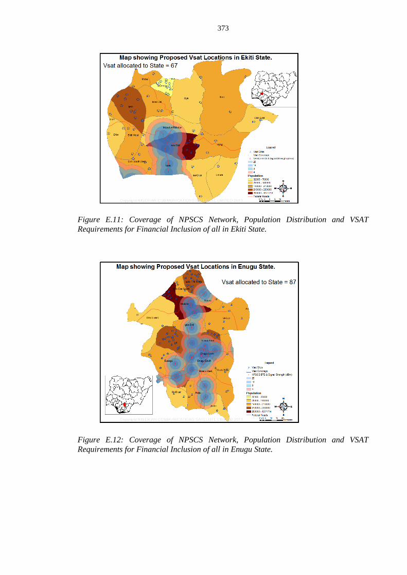
373
Figure E.11: Coverage of NPSCS Network, Population Distribution and VSAT
Requirements for Financial Inclusion of all in Ekiti State.
Figure E.12: Coverage of NPSCS Network, Population Distribution and VSAT
Requirements for Financial Inclusion of all in Enugu State.

374
Figure E.13: Coverage of NPSCS Network, Population Distribution and VSAT
Requirements for Financial Inclusion of all in Gombe State.
Figure E.14: Coverage of NPSCS Network, Population Distribution and VSAT
Requirements for Financial Inclusion of all in Imo State.

375
Figure E.15: Coverage of NPSCS Network, Population Distribution and VSAT
Requirements for Financial Inclusion of all in Jigawa State.
Figure E.16: Coverage of NPSCS Network, Population Distribution and VSAT
Requirements for Financial Inclusion of all in Kaduna State.

376
Figure E.17: Coverage of NPSCS Network, Population Distribution and VSAT
Requirements for Financial Inclusion of all in Katsina State.
Figure E.18: Coverage of NPSCS Network, Population Distribution and VSAT
Requirements for Financial Inclusion of all in Kebbi State.

377
Figure E.19: Coverage of NPSCS Network, Population Distribution and VSAT
Requirements for Financial Inclusion of all in Kogi State.
Figure E.20: Coverage of NPSCS Network, Population Distribution and VSAT
Requirements for Financial Inclusion of all in Kwara State.

378
Figure E.21: Coverage of NPSCS Network, Population Distribution and VSAT
Requirements for Financial Inclusion of all in Nasarawa State.
Figure E.22: Coverage of NPSCS Network, Population Distribution and VSAT
Requirements for Financial Inclusion of all in Niger State.

379
Figure E.23: Coverage of NPSCS Network, Population Distribution and VSAT
Requirements for Financial Inclusion of all in Ondo State.
Figure E.24: Coverage of NPSCS Network, Population Distribution and VSAT
Requirements for Financial Inclusion of all in Osun State.

380
Figure E.25: Coverage of NPSCS Network, Population Distribution and VSAT
Requirements for Financial Inclusion of all in Oyo State.
Figure E.26: Coverage of NPSCS Network, Population Distribution and VSAT
Requirements for Financial Inclusion of all in Plateau State.

381
Figure E.27: Coverage of NPSCS Network, Population Distribution and VSAT
Requirements for Financial Inclusion of all in Sokoto State.
Figure E.28: Coverage of NPSCS Network, Population Distribution and VSAT
Requirements for Financial Inclusion of all in Taraba State.

382
Figure E.29: Coverage of NPSCS Network, Population Distribution and VSAT
Requirements for Financial Inclusion of all in Yobe State.
Figure E.30: Coverage of NPSCS Network, Population Distribution and VSAT
Requirements for Financial Inclusion of all in Zamfara State.

383
Appendix F
List of Publications and Successful Launch of Communications Satellite (NIGCOMSAT-
1R) during DPhil Programme.
Lawal, L.S., & Chatwin, C.R. (2011). Essential Parameters of Space-Borne Oscillators That
Ensures Performance of Satellite-Based Augmentation System. Proceedings of 3rd
IEEE
International Conference on Science and Technology, ICAST, (pp42-50). Abuja-Nigeria.
doi: 10.1109/ICASTech.2011.6145156.
Lawal, L.S., & Chatwin, C.R. (2011). Optimization of Mass Volume ratio of Spacecraft
Structure for Advanced and High Powered Communication Satellites, Proceedings of 10th
International Information and Telecommunication Technologies conference,
Florianopolis, Santa Catarina Island, Brazil.
Lawal, L.S., & Chatwin, C.R. (2012). The Future of Wireless Communications in Africa.
International Conference on Wireless Network and Information System. Future Wireless
Networks and Information Systems, Lecture Notes in Electrical Engineering, Springer
Link, 143, 243-251. doi: 10.1007/978-3-642-27323-0_31.
Lawal, L.S., & Chatwin, C.R. (2012). Advanced High Power Subsystem for Geostationary
Satellites. IEEE Computer Society, The Association of Computing Machinery Digital
Library. 4, 138-142. ISBN: 978-0-7695-4703-9
Lawal, L.S., & Chatwin, C.R. (2012). Advanced High Power Systems for Geostationary
Satellites. Proceedings of 2012 2nd International Conference on Electric Information and
Control Engineering, ICEICE, 04, (pp138-142), Lushan,China.
Doi:10.1109/ICEICE.2012.1164.
Lawal, L.S., & Chatwin, C.R. (2012). Antenna System Layout in High Capacity Geostationary
Communication Satellites. Antennas and Propagation in Wireless Communications, IEEE
APWC 2012 Topical Conference, (pp1012-1015), Capetown, South Africa. doi:
10.1109/APWC.2012.6324983.

384
Lawal, L.S., Ahmed-Rufai, T., Chatwin, C.R., & Young, R.C.D. (2013). Delivery of Broadband
Services to Sub-Saharan Africa via Nigerian Communications Satellite. International
Journal of Information and Computer Science (IJICS). 2(5), 77-88.
Lawal, L.S., Ahmed-Rufai, T., Inuwa, D.A., & Chatwin, C.R., (n.d.). The Unique Role of
Communications Satellites in addressing the Rapid Socio-Economic Development of
Nigeria. (Unpublished)
Lawal, L.S., & Chatwin, C.R. (2013). Nigerian Communication Satellite (NIGCOMSAT-1R)
Ka-band System”, 19th Ka and Broadband Communications, Navigation and Earth
Observation Conference and 31st
AIAA International Communications Satellite Systems
Conference (ICSSC), Florence-Italy. Retrieved from http://www.kaconf.org/#
Lawal, L.S., Ahmed-Rufai, T., & Chatwin, C.R., (2013). Communication Satellite Alternative
to Digital Terrestrial Television. Proceedings of 2nd
IEEE International Conference on
Emerging and Sustainable Technologies for Power and ICT in a Developing Society,
Owerri, Nigeria. Retrieved from http://www.nigercon.info/#!
Lawal, L.S., Ahmed-Rufai, T., Chatwin, C.R., & Liu, R. (2013). The role of Communication
Satellites in Public Management, Education, Governance and Business in Nigeria. Human
Resource Management Research Journal, 3(5),178-187. doi: 10.5923/j.hrmr.20130305.02.
Retrieved from http://article.sapub.org/10.5923.j.hrmr.20130305.02.html
Lawal, L.S., Ahmed-Rufai, T., Chatwin, C.R., & Liu, R. (2013). The role of Communication
Satellites in Public Management, Education, Governance and Business in Nigeria.
Proceedings of International conference on Electronics Engineering, Advanced
Communications and Information Technology, EEACIT, Kuala Lumpur- Malaysia.
Retrieved from http://www.eeacit.com/
Lawal, L.S & Chatwin, C.R. (2014). Emergency Communication Preparedness in Africa
Exploiting Communication Satellites. Global Space Applications Conference (GLAC) by
International Astronautical Federation (IAF) and United Nations Educational, Scientific
and Cultural Organization (UNESCO) on 2-4 June, 2014 at UNESCO HQ, Paris, France.
Retrieved from http://www.iafastro.org/wp-
content/uploads/2014/04/GLAC_FP_FINAL_May201428_online_2.pdf

385
Chatwin, C.R, Lawal, L.S, Young, R.C.D & Birch, P. (2014). Satellite & Fibre Communications:
A Solution for Africa. Conference paper proceeding of the Institution of Engineering and
technology (IET) at Crawley, Hawth, UK on 3rd
June, 2014.
Lawal, L.S & Chatwin, C.R. (2014). Bridging The Digital Hiatus via Communications Satellite
Broadband. The World Engineering Conference 2014 on Sustainable Infrastructure
(WECSI 2014) by World Federation of Engineering Organizations (WFEO) in
association with the Nigerian Society of Engineers (NSE) at the International Conference
Centre, Abuja, Nigeria on November, 2-7, 2014.
(Abstract Accepted and Paper submitted for the Journal).
Lawal, L.S, & Chatwin, C.R. (2014) African Rural Financial and Digital Inclusion exploiting
Nigerian Communications Satellite, The 1st University Meets Microfinance (UMM)
Workshop in Africa with conference theme; ACCELERATING INNOVATIVE RURAL
FINANCE IN AFRICA at Ougadougou Burkina Faso, 1st-5
th December, 2014.
(Abstract and Paper submitted for the International Workshop and Conference).
Successful Launch of over $250 Million Nigerian Communications Satellite Replacement
project (NIGCOMSAT-1R)as project team member with design contributions especially on
service coverage and L-Bank Piggyback payload on the 20th of December, 2011 with enhanced
performance as evident in In-Orbit Test (IOT) results and efficient satellite service delivery.
