contoil® dn 4 - 8 | trans-asiatic
TRANSCRIPT
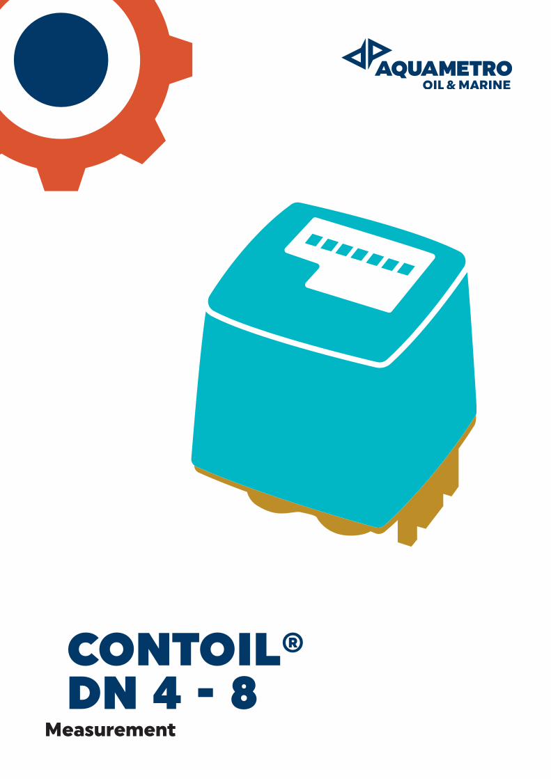
CONTOIL® DN 4 - 8
Measurement
2
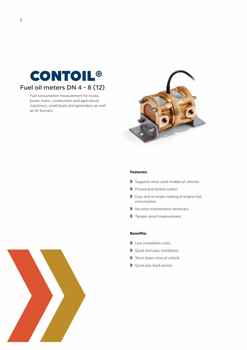
CONTOIL®Fuel oil meters DN 4 - 8 (12)
Fuel consumption measurement for trucks, buses, trains, construction and agricultural machinery, small boats and generators as well as for burners.
Features:
Supports most used models of vehicles
Proved and tested system
Easy and accurate reading of engine fuel consumption
No extra maintenance necessary
Tamper-proof measurement
Benefits:
Low installation costs
Quick and easy installation
Short down-time of vehicle
Quick pay-back period
3
CONTENTIntroduction 4
Operating principle 5
Product range 6
Technical specifications 8
Project planning notes 25
Installation 27
Warranty, safety instructions 30
4
INTRODUCTIONThank you for your decision to work with Aquametro Oil & Marine Fuel Performance Products. This technical specification describes the installation, commissioning and use of CONTOIL® fuel oil meters. For additional information please contact your local sales agent at: www.aquametro-oil-marine.com.
Liability Disclaimer
The manufacturer cannot monitor the compliance to this manual as well as the conditions and methods during the installation, operation, usage and maintenance of the system regulator. Improper installation can cause damage and endanger people. Therefore, we assume no responsibility and liability for losses, damage or costs that result due to incorrect installation, improper operation, usage and maintenance or in any manner associated therewith. Similarly, we assume no responsibility for patent right or other right infringements of third parties caused by usage of this system regulator. The manufacturer reserves the right, without prior notification, to make modifications concerning the product, technical data or installation and operating manual.
Safety precautions
CONTOIL® fuel oil meters must only be used for their intended purpose and comply with local and international safety regulations. All documentation is to be followed exactly. None of the information stated here or elsewhere releases planners, installers and operators from their own careful and comprehensive assessment of the respective plant configuration in terms of functional capability and operational safety.
Local applicable working regulations must be complied with, during all work on the plant and/or ship. All safety, installation and operation instructions as described in this manual must be followed. Sensors are sensitive measuring instruments and should be treated carefully.
5
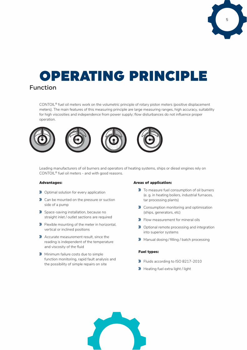
OPERATING PRINCIPLEFunction
CONTOIL® fuel oil meters work on the volumetric principle of rotary piston meters (positive displacement meters). The main features of this measuring principle are large measuring ranges, high accuracy, suitability for high viscosities and independence from power supply; flow disturbances do not influence proper operation.
Leading manufacturers of oil burners and operators of heating systems, ships or diesel engines rely on CONTOIL® fuel oil meters - and with good reasons.
Advantages:
Optimal solution for every application
Can be mounted on the pressure or suction side of a pump
Space-saving installation, because no straight inlet / outlet sections are required
Flexible mounting of the meter in horizontal, vertical or inclined positions
Accurate measurement result, since the reading is independent of the temperature and viscosity of the fluid
Minimum failure costs due to simple function monitoring, rapid fault analysis and the possibility of simple repairs on site
Areas of application:
To measure fuel consumption of oil burners (e. g. in heating boilers, industrial furnaces, tar processing plants)
Consumption monitoring and optimisation (ships, generators, etc)
Flow measurement for mineral oils
Optional remote processing and integration into superior systems
Manual dosing / filling / batch processing
Fuel types:
Fluids according to ISO 8217-2010
Heating fuel extra light / light
6
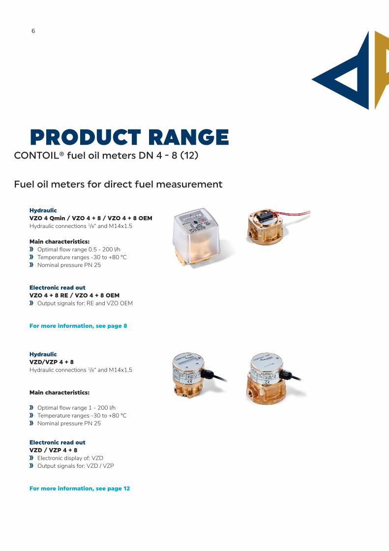
PRODUCT RANGECONTOIL® fuel oil meters DN 4 - 8 (12)
Fuel oil meters for direct fuel measurement
Hydraulic VZO 4 Qmin / VZO 4 + 8 / VZO 4 + 8 OEM Hydraulic connections 1/8“ and M14x1.5 Main characteristics:
Optimal flow range 0.5 - 200 l/h Temperature ranges -30 to +80 °C Nominal pressure PN 25
Electronic read out VZO 4 + 8 RE / VZO 4 + 8 OEM
Output signals for: RE and VZO OEM
For more information, see page 8
Hydraulic VZD/VZP 4 + 8 Hydraulic connections 1/8“ and M14x1.5
Main characteristics:
Optimal flow range 1 - 200 l/h Temperature ranges -30 to +80 °C Nominal pressure PN 25
Electronic read out VZD / VZP 4 + 8
Electronic display of: VZD Output signals for: VZD / VZP
For more information, see page 12
7
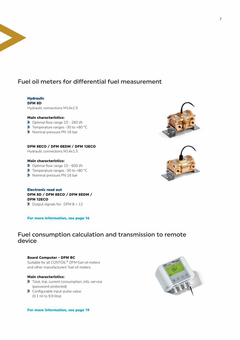
Fuel oil meters for differential fuel measurement
Hydraulic DFM 8D Hydraulic connections M14x1.5 Main characteristics:
Optimal flow range 10 - 260 l/h Temperature ranges -30 to +80 °C Nominal pressure PN 16 bar
DFM 8ECO / DFM 8EDM / DFM 12ECO Hydraulic connections M14x1.5 Main characteristics:
Optimal flow range 10 - 600 l/h Temperature ranges -30 to +80 °C Nominal pressure PN 16 bar
Electronic read out DFM 8D / DFM 8ECO / DFM 8EDM / DFM 12ECO
Output signals for: DFM 8 + 12
For more information, see page 16
Fuel consumption calculation and transmission to remote device
Board Computer - DFM BC Suitable for all CONTOIL® DFM fuel oil meters and other manufacturers’ fuel oil meters. Main characteristics:
Total, trip, current consumption, info, service (password-protected)
Configurable input-pulse value (0.1 ml to 9.9 litre)
For more information, see page 19
8
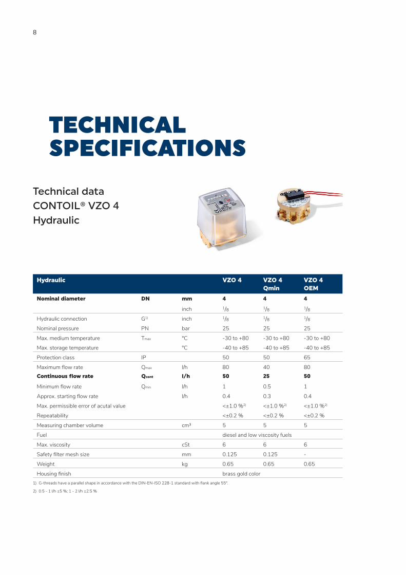
Hydraulic VZO 4 VZO 4 Qmin
VZO 4 OEM
Nominal diameter DN mm 4 4 4
inch 1/8 1/8 1/8Hydraulic connection G1) inch 1/8 1/8 1/8Nominal pressure PN bar 25 25 25
Max. medium temperature Tmax °C -30 to +80 -30 to +80 -30 to +80
Max. storage temperature °C -40 to +85 -40 to +85 -40 to +85
Protection class IP 50 50 65
Maximum flow rate Qmax l/h 80 40 80Continuous flow rate Qcont l/h 50 25 50
Minimum flow rate Qmin l/h 1 0.5 1
Approx. starting flow rate l/h 0.4 0.3 0.4
Max. permissible error of acutal value <±1.0 %2) <±1.0 %2) <±1.0 %2)
Repeatability <±0.2 % <±0.2 % <±0.2 %
Measuring chamber volume cm³ 5 5 5
Fuel diesel and low viscosity fuels
Max. viscosity cSt 6 6 6
Safety filter mesh size mm 0.125 0.125 -
Weight kg 0.65 0.65 0.65
Housing finish brass gold color1) G-threads have a parallel shape in accordance with the DIN-EN-ISO 228-1 standard with flank angle 55°.
2) 0.5 - 1 l/h ±5 %; 1 - 2 l/h ±2.5 %
TECHNICAL SPECIFICATIONS
Technical data CONTOIL® VZO 4Hydraulic
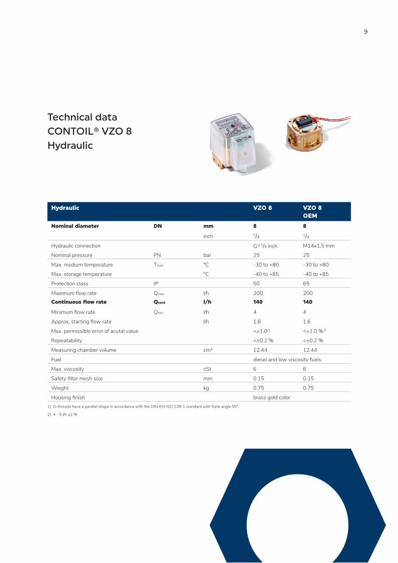
9
Hydraulic VZO 8 VZO 8 OEM
Nominal diameter DN mm 8 8
inch 1/4 1/4Hydraulic connection G1) 1/4 inch M14x1.5 mm
Nominal pressure PN bar 25 25
Max. medium temperature Tmax °C -30 to +80 -30 to +80
Max. storage temperature °C -40 to +85 -40 to +85
Protection class IP 50 65
Maximum flow rate Qmax l/h 200 200Continuous flow rate Qcont l/h 140 140
Minimum flow rate Qmin l/h 4 4
Approx. starting flow rate l/h 1.6 1.6
Max. permissible error of acutal value <±1.02) <±1.0 %2)
Repeatability <±0.2 % <±0.2 %
Measuring chamber volume cm³ 12.44 12.44
Fuel diesel and low viscosity fuels
Max. viscosity cSt 6 6
Safety filter mesh size mm 0.15 0.15
Weight kg 0.75 0.75
Housing finish brass gold color1) G-threads have a parallel shape in accordance with the DIN-EN-ISO 228-1 standard with flank angle 55°.
2) 4 - 5 l/h ±2 %
Technical data CONTOIL® VZO 8Hydraulic
10
Technical data CONTOIL® VZO 4 + 8 Electrical and output specifications
Electronic VZO 4 VZO 8 VZO 4
OEM
VZO 8
OEM
Reed pulser
RE 1 l/pulse - - -
RE 0.1 l/pulse - - -
RE 0.00125 l/pulse - - -
RE 0.00311 l/pulse - - -
Pulse frequency
RE 0.00125 at Qmax Hz 17.777 - - -
at Qmin Hz 0.222 - - -
RE 0.00311 at Qmax Hz - 17.864 - -
at Qmin Hz - 0.357 - -
Reed pulser RE l/pulse 0.005 0.01244
Pulse frequency RE at Qmax Hz 4.444 4.444
at Qmin Hz 0.056 0.089
Electronic
CONTOIL® VZO 4 + 8
RE pulser
Switching element Reed switch with dry contact (inert gas)
Switching voltage Max. 48 VAC/DC, protection class III (SELV)
Switching current Max. 50 mA
Quiescent current Open contact
Switching power Max. 2 W
ON-time VZO 4-RE 0.00125: 30 - 70 % (17 - 39 ms at 80 l/h)
VZO 4-RE 0.1: 40 - 60 %
VZO 8-RE 0.00311: 30 - 70 % (17 - 39 ms at 200 l/h)
VZO 8-RE 1: 40 - 60 %
Ambient temperature -10 to +60 °C
Protection class IP 50 (IEC 60529) against harmful dust deposits Option: IP 54 additional against splashing water
Connections On plug connector with cable 3.5 - 5 mm Ø
11
Electronic
CONTOIL® VZO 4 + 8 OEM
RE pulser
Switching element Reed switch with dry contact (inert gas)
Switching voltage Max. 230 VAC/DC
Switching current Max. 50 mA
Quiescent current Open contact
Switching power Max. 3 VA
ON-time 40 - 55 %
Ambient temperature -10 to +60 °C
Protection class IP 65 (IEC 60529) against dust and water jets
Connections Cable cross section 2 x 0.5 mm2, length 480 mm
Safety note
When connecting the Reed pulser to a low-voltage power source (50 - 250 VAC/DC), the specialist installing the equipment is responsible for ensuring that all local regulations are observed (e. g. regulations for electrical installations, personnel safety).
Avoid disturbance of electromagnetic fields.
12
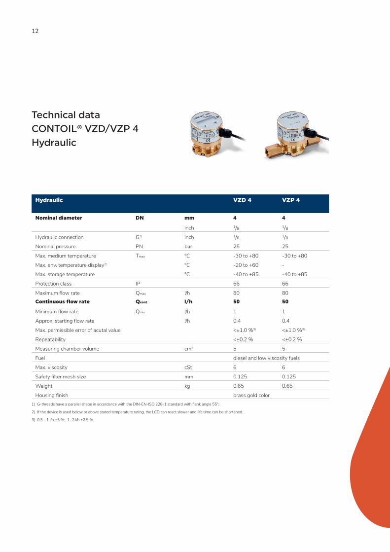
Technical data CONTOIL® VZD/VZP 4Hydraulic
Hydraulic VZD 4 VZP 4
Nominal diameter DN mm 4 4
inch 1/8 1/8Hydraulic connection G1) inch 1/8 1/8Nominal pressure PN bar 25 25
Max. medium temperature Tmax °C -30 to +80 -30 to +80
Max. env. temperature display2) °C -20 to +60 -
Max. storage temperature °C -40 to +85 -40 to +85
Protection class IP 66 66
Maximum flow rate Qmax l/h 80 80Continuous flow rate Qcont l/h 50 50
Minimum flow rate Qmin l/h 1 1
Approx. starting flow rate l/h 0.4 0.4
Max. permissible error of acutal value <±1.0 %3) <±1.0 %3)
Repeatability <±0.2 % <±0.2 %
Measuring chamber volume cm³ 5 5
Fuel diesel and low viscosity fuels
Max. viscosity cSt 6 6
Safety filter mesh size mm 0.125 0.125
Weight kg 0.65 0.65
Housing finish brass gold color1) G-threads have a parallel shape in accordance with the DIN-EN-ISO 228-1 standard with flank angle 55°.
2) If the device is used below or above stated temperature rating, the LCD can react slower and life time can be shortened.
3) 0.5 - 1 l/h ±5 %; 1- 2 l/h ±2.5 %
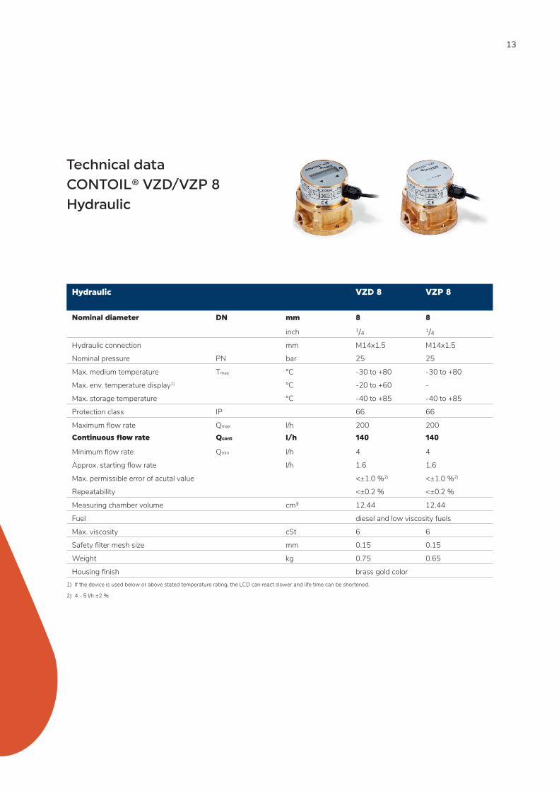
13
Hydraulic VZD 8 VZP 8
Nominal diameter DN mm 8 8
inch 1/4 1/4Hydraulic connection mm M14x1.5 M14x1.5
Nominal pressure PN bar 25 25
Max. medium temperature Tmax °C -30 to +80 -30 to +80
Max. env. temperature display1) °C -20 to +60 -
Max. storage temperature °C -40 to +85 -40 to +85
Protection class IP 66 66
Maximum flow rate Qmax l/h 200 200Continuous flow rate Qcont l/h 140 140
Minimum flow rate Qmin l/h 4 4
Approx. starting flow rate l/h 1.6 1.6
Max. permissible error of acutal value <±1.0 %2) <±1.0 %2)
Repeatability <±0.2 % <±0.2 %
Measuring chamber volume cm³ 12.44 12.44
Fuel diesel and low viscosity fuels
Max. viscosity cSt 6 6
Safety filter mesh size mm 0.15 0.15
Weight kg 0.75 0.65
Housing finish brass gold color1) If the device is used below or above stated temperature rating, the LCD can react slower and life time can be shortened.
2) 4 - 5 l/h ±2 %
Technical data CONTOIL® VZD/VZP 8Hydraulic
14
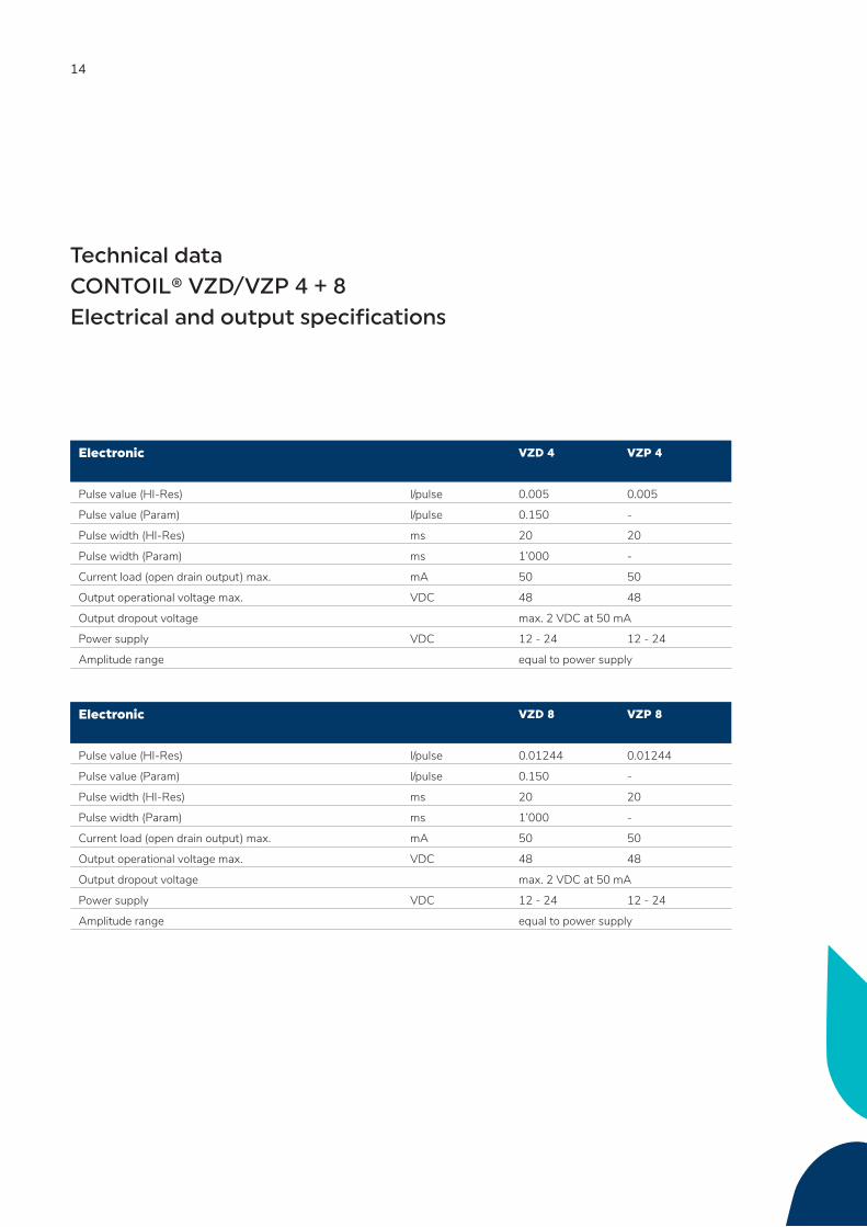
Technical data CONTOIL® VZD/VZP 4 + 8Electrical and output specifications
Electronic VZD 4 VZP 4
Pulse value (HI-Res) l/pulse 0.005 0.005
Pulse value (Param) l/pulse 0.150 -
Pulse width (HI-Res) ms 20 20
Pulse width (Param) ms 1’000 -
Current load (open drain output) max. mA 50 50
Output operational voltage max. VDC 48 48
Output dropout voltage max. 2 VDC at 50 mA
Power supply VDC 12 - 24 12 - 24
Amplitude range equal to power supply
Electronic VZD 8 VZP 8
Pulse value (HI-Res) l/pulse 0.01244 0.01244
Pulse value (Param) l/pulse 0.150 -
Pulse width (HI-Res) ms 20 20
Pulse width (Param) ms 1’000 -
Current load (open drain output) max. mA 50 50
Output operational voltage max. VDC 48 48
Output dropout voltage max. 2 VDC at 50 mA
Power supply VDC 12 - 24 12 - 24
Amplitude range equal to power supply
15
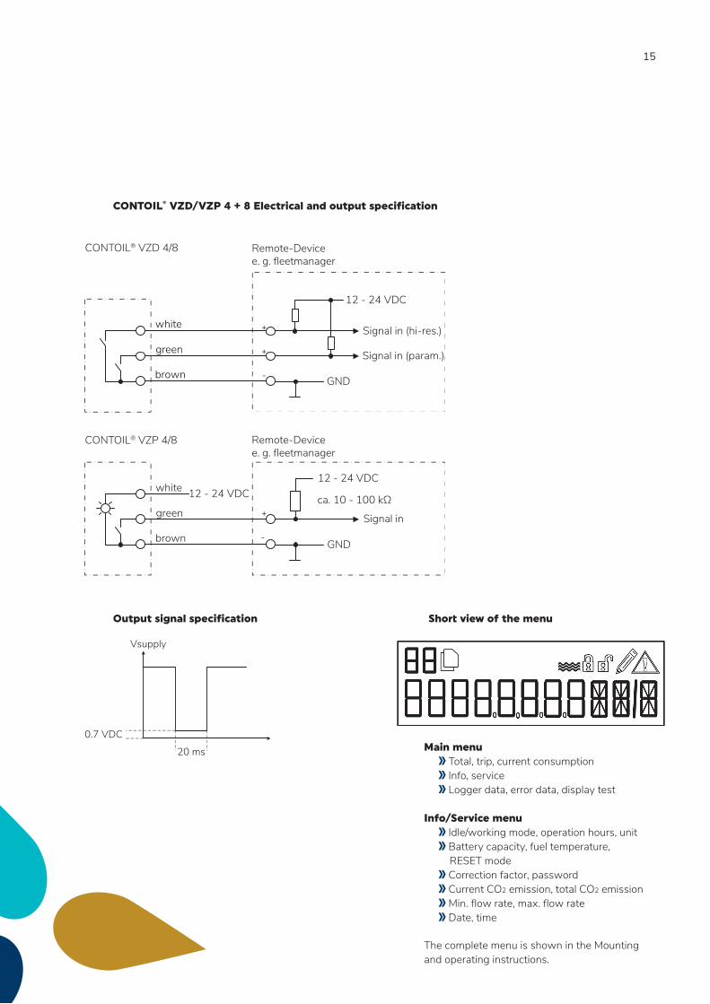
Remote-Devicee. g. fleetmanager
CONTOIL® VZP 4/8
+
-
12 - 24 VDC12 - 24 VDC ca. 10 - 100 kΩ
Signal in
GND
green
white
brown
+
-
+
Remote-Devicee. g. fleetmanager
CONTOIL® VZD 4/8
green
white
brown
12 - 24 VDC
Signal in (hi-res.)
GND
Signal in (param.)
Vsupply
20 ms
0.7 VDC
Output signal specification Short view of the menu
Main menu Total, trip, current consumption Info, service Logger data, error data, display test Info/Service menu Idle/working mode, operation hours, unit Battery capacity, fuel temperature, RESET mode Correction factor, password Current CO2 emission, total CO2 emission Min. flow rate, max. flow rate Date, time
The complete menu is shown in the Mounting and operating instructions.
CONTOIL® VZD/VZP 4 + 8 Electrical and output specification
16
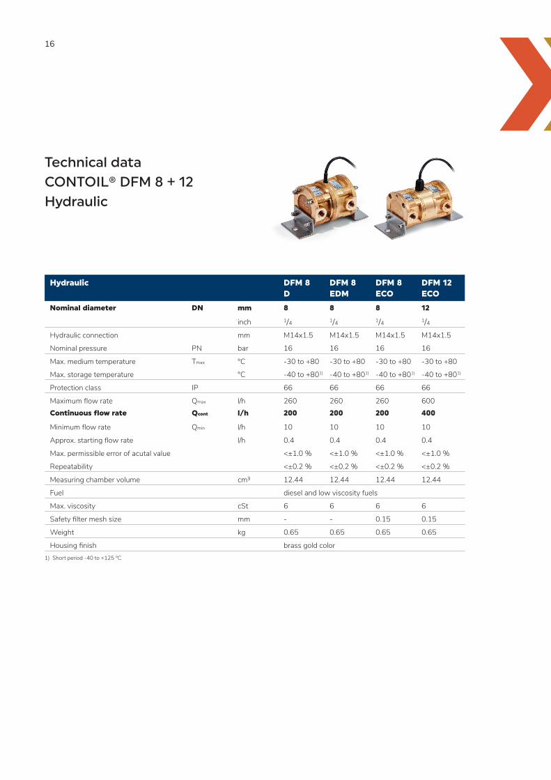
Hydraulic DFM 8 D
DFM 8 EDM
DFM 8 ECO
DFM 12 ECO
Nominal diameter DN mm 8 8 8 12
inch 1/4 1/4 1/4 1/4Hydraulic connection mm M14x1.5 M14x1.5 M14x1.5 M14x1.5
Nominal pressure PN bar 16 16 16 16
Max. medium temperature Tmax °C -30 to +80 -30 to +80 -30 to +80 -30 to +80
Max. storage temperature °C -40 to +801) -40 to +801) -40 to +801) -40 to +801)
Protection class IP 66 66 66 66
Maximum flow rate Qmax l/h 260 260 260 600Continuous flow rate Qcont l/h 200 200 200 400
Minimum flow rate Qmin l/h 10 10 10 10
Approx. starting flow rate l/h 0.4 0.4 0.4 0.4
Max. permissible error of acutal value <±1.0 % <±1.0 % <±1.0 % <±1.0 %
Repeatability <±0.2 % <±0.2 % <±0.2 % <±0.2 %
Measuring chamber volume cm³ 12.44 12.44 12.44 12.44
Fuel diesel and low viscosity fuels
Max. viscosity cSt 6 6 6 6
Safety filter mesh size mm - - 0.15 0.15
Weight kg 0.65 0.65 0.65 0.65
Housing finish brass gold color1) Short period -40 to +125 °C
Technical data CONTOIL® DFM 8 + 12Hydraulic
17
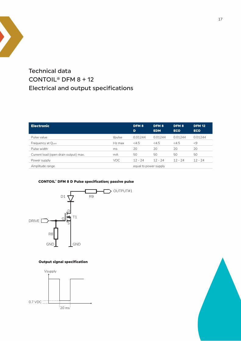
Technical data CONTOIL® DFM 8 + 12Electrical and output specifications
Electronic DFM 8
D
DFM 8
EDM
DFM 8
ECO
DFM 12
ECO
Pulse value l/pulse 0.01244 0.01244 0.01244 0.01244
Frequency at Qcont Hz max <4.5 <4.5 <4.5 <9
Pulse width ms 20 20 20 20
Current load (open drain output) max. mA 50 50 50 50
Power supply VDC 12 - 24 12 - 24 12 - 24 12 - 24
Amplitude range equal to power supply
CONTOIL® DFM 8 D Pulse specification; passive pulse
OUTPUT#1R9D1
D
T1GS
GNDGND
R8
DRIVE
Output signal specification
Vsupply
20 ms
0.7 VDC
18
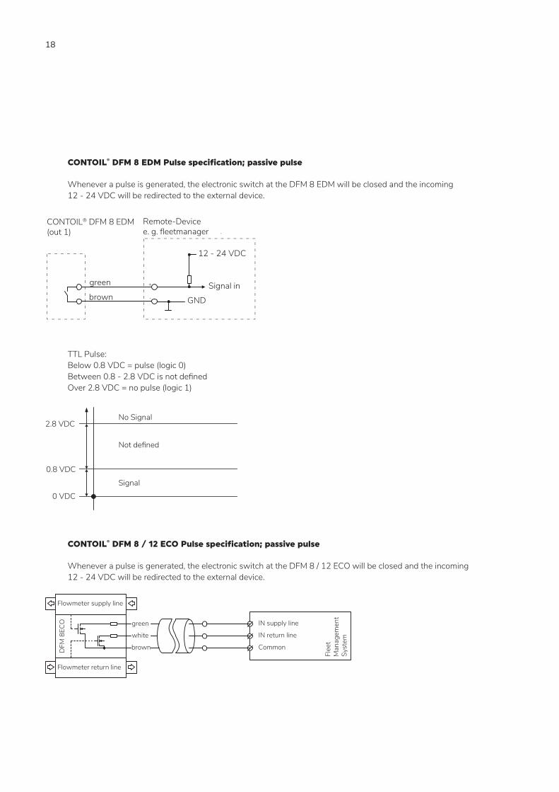
CONTOIL® DFM 8 EDM Pulse specification; passive pulse
Whenever a pulse is generated, the electronic switch at the DFM 8 EDM will be closed and the incoming 12 - 24 VDC will be redirected to the external device.
Remote-Devicee. g. fleetmanager .
12 - 24 VDC
GND
Signal ingreen
brown+
-
CONTOIL® DFM 8 EDM(out 1)
TTL Pulse: Below 0.8 VDC = pulse (logic 0) Between 0.8 - 2.8 VDC is not defined Over 2.8 VDC = no pulse (logic 1)
Signal
No Signal
Not defined
2.8 VDC
0.8 VDC
0 VDC
CONTOIL® DFM 8 / 12 ECO Pulse specification; passive pulse
Whenever a pulse is generated, the electronic switch at the DFM 8 / 12 ECO will be closed and the incoming 12 - 24 VDC will be redirected to the external device.
Flowmeter supply line
Flowmeter return line
green
white
brownDFM
8EC
O IN supply line
IN return line
Common
Flee
t M
anag
emen
t Sy
stem
19
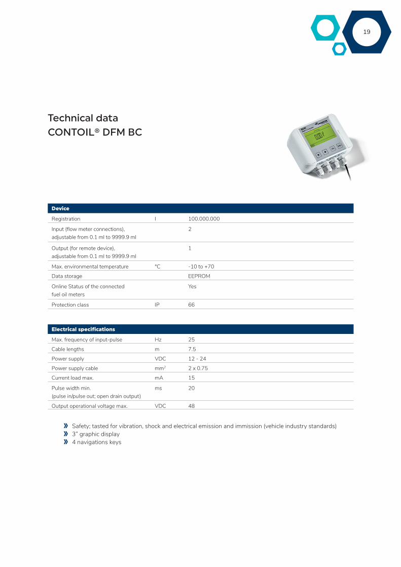
Technical data CONTOIL® DFM BC
Device
Registration l 100.000.000
Input (flow meter connections), adjustable from 0.1 ml to 9999.9 ml
2
Output (for remote device),adjustable from 0.1 ml to 9999.9 ml
1
Max. environmental temperature °C -10 to +70
Data storage EEPROM
Online Status of the connected fuel oil meters
Yes
Protection class IP 66
Electrical specifications
Max. frequency of input-pulse Hz 25
Cable lengths m 7.5
Power supply VDC 12 - 24
Power supply cable mm2 2 x 0.75
Current load max. mA 15
Pulse width min.(pulse in/pulse out; open drain output)
ms 20
Output operational voltage max. VDC 48
Safety; tasted for vibration, shock and electrical emission and immission (vehicle industry standards) 3” graphic display 4 navigations keys
20
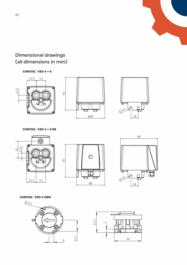
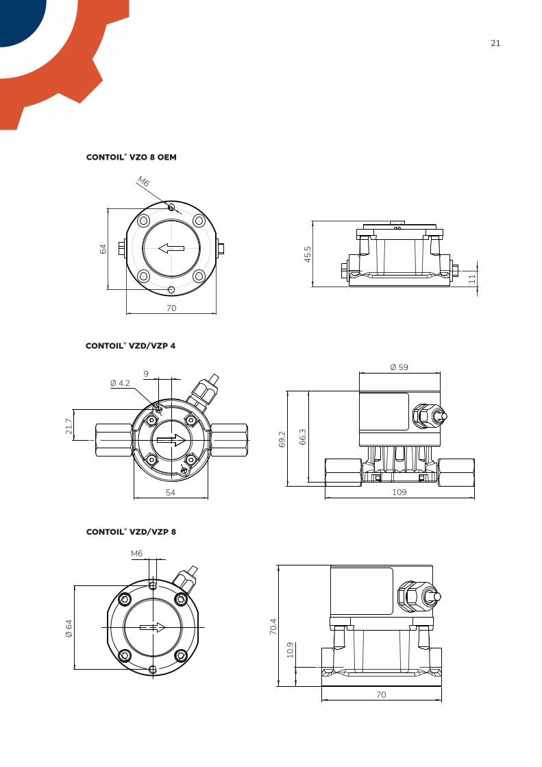
Dimensional drawings(all dimensions in mm)
CONTOIL® VZO 4 + 8
2322.5
11.5
68ߛ
78
18Ø 5.5
2322.5
41 11.5
68
78
89
18Ø 5.5
CONTOIL® VZO 4 + 8 RE
9
Ø 4.2
21.7 54
7
41.2
CONTOIL® VZO 4 OEM
21
64
70
M6
11
45.5
9
54
21.7
Ø 4.2
Ø 59
69.2
109
66.3
Ø 6
4
M6
70
70.4
10.9
CONTOIL® VZO 8 OEM
CONTOIL® VZD/VZP 4
CONTOIL® VZD/VZP 8
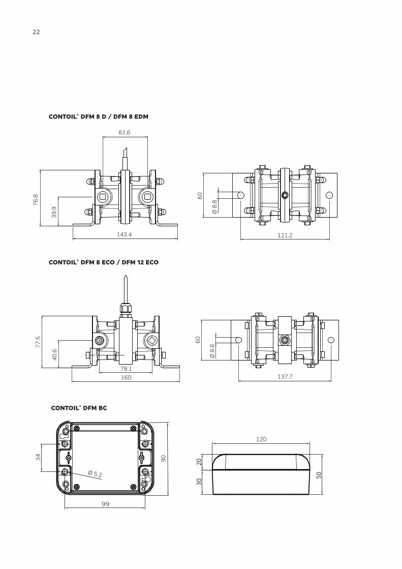
22
143.4
61.6
76.8
39.9
121.2
60
Ø 8
.8
16078.1
77.5
40.6
137.7
60
Ø 8
.8
CONTOIL® DFM 8 D / DFM 8 EDM
CONTOIL® DFM 8 ECO / DFM 12 ECO
120
3020
50
34
99
Ø 5.2
90
CONTOIL® DFM BC
23
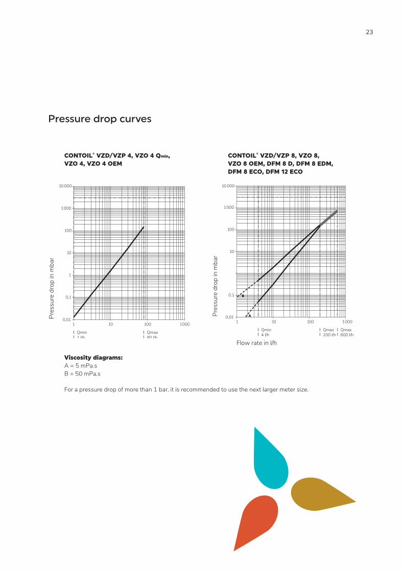
CONTOIL® VZD/VZP 4, VZO 4 Qmin, VZO 4, VZO 4 OEM
CONTOIL® VZD/VZP 8, VZO 8, VZO 8 OEM, DFM 8 D, DFM 8 EDM, DFM 8 ECO, DFM 12 ECO
Viscosity diagrams: A = 5 mPa.s B = 50 mPa.s
For a pressure drop of more than 1 bar, it is recommended to use the next larger meter size.
10 000
1000
100
10
1
0,1
0,01
Flow rate in l/h
1 10 100
1000
Pres
sure
dro
p in
mba
r
Qmax 80 l/h
Qmin1 l/h
10 000
1000
100
10
0,1
0,01
Flow rate in l/h
1 10 100
1000
Pres
sure
dro
p in
mba
r
Qmax 200 l/h
Qmin4 l/h
Qmax 600 l/h
B
A
Pressure drop curves
24
VZO 4 + 8 Description Art. No.
Threaded connections kit PS-Kit VZO 41/8″ - 8
81583
Mounting kit PS-Kit VZO 8 81130
Mounting kit1) VSR-SET VZD/VZP 41/8″ - M14x1.5
80630
Threaded connections to suit PS-Kit VZO 8
VSR 3/8″ 81156
1) 2 sets needed for one flow meter.
DFM Description Art. No.
Hose connector1) include 1x hollow union, 1 single ban-jo body, 2x copper seal
DFM 8 D, DFM 8 EDM, DFM 8 ECO, DFM 12 ECO
80447
1) 4 sets needed for one DFM 8 D, DFM 8 EDM, DFM 8 ECO, DFM 12 ECO.
Mounting kit for VZO 8 - dimensions and some possible mounting positions (all dimensions in mm)
Accessories
G 1 /2
″
G 1 /4
″
32
130
130
46
88
130
6565
25
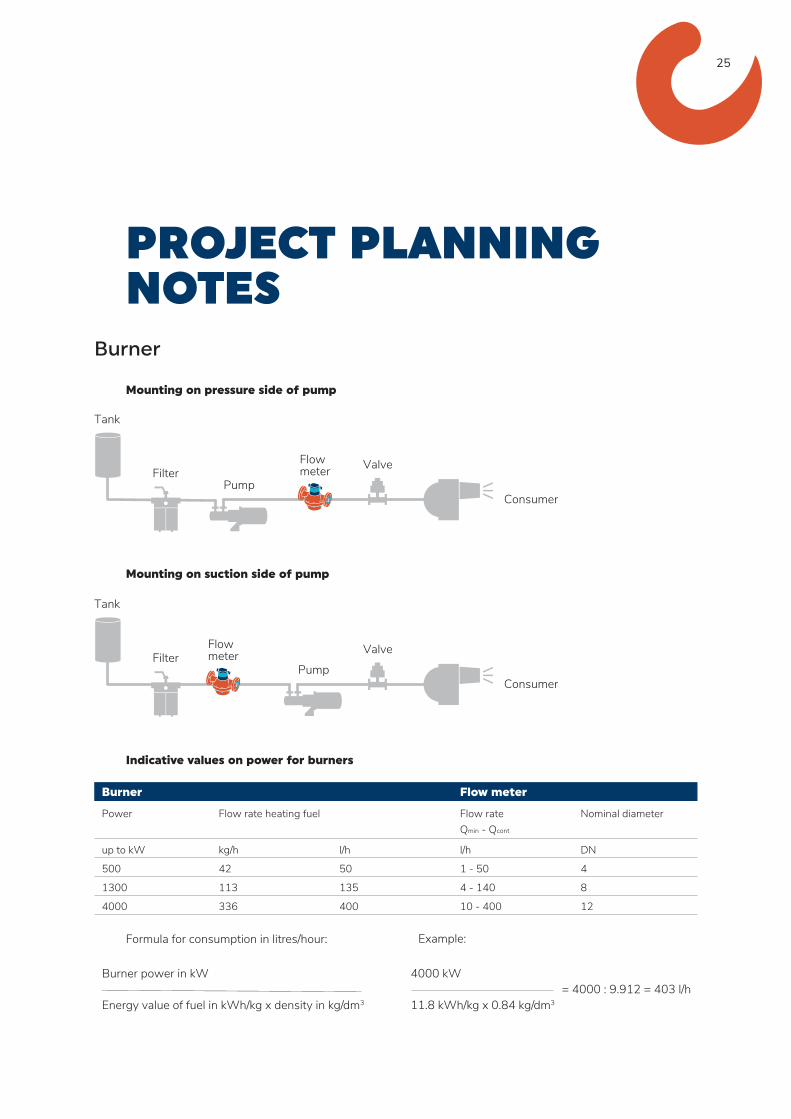
PROJECT PLANNING NOTES
Burner
Mounting on pressure side of pump
Mounting on suction side of pump
Indicative values on power for burners
Burner Flow meter
Power Flow rate heating fuel Flow rateQmin - Qcont
Nominal diameter
up to kW kg/h l/h l/h DN
500 42 50 1 - 50 4
1300 113 135 4 - 140 8
4000 336 400 10 - 400 12 Formula for consumption in litres/hour:
FilterFlowmeter Valve
Tank
PumpConsumer
Filter
Flowmeter Valve
Tank
PumpConsumer
Burner power in kW Energy value of fuel in kWh/kg x density in kg/dm3
Example:
4000 kW = 4000 : 9.912 = 403 l/h 11.8 kWh/kg x 0.84 kg/dm3
26
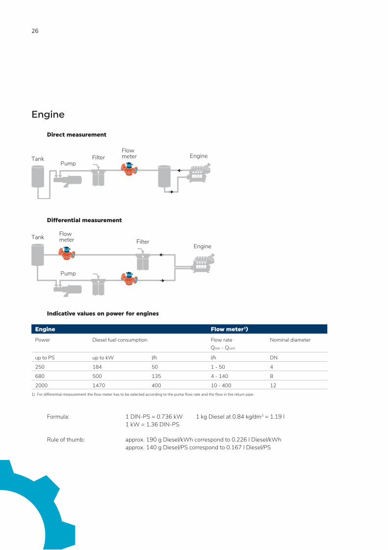
Engine
Direct measurement Differential measurement Indicative values on power for engines
Engine Flow meter¹)
Power Diesel fuel consumption Flow rateQmin - Qcont
Nominal diameter
up to PS up to kW l/h l/h DN
250 184 50 1 - 50 4
680 500 135 4 - 140 8
2000 1470 400 10 - 400 121) For differential measurement the flow meter has to be selected according to the pump flow rate and the flow in the return pipe.
Formula: 1 DIN-PS = 0.736 kW 1 kg Diesel at 0.84 kg/dm3 = 1.19 l 1 kW = 1.36 DIN-PS
Rule of thumb: approx. 190 g Diesel/kWh correspond to 0.226 l Diesel/kWh approx. 140 g Diesel/PS correspond to 0.167 l Diesel/PS
Engine FilterFlowmeterTank
Pump
EngineFilter
Tank
Pump
Flowmeter
27
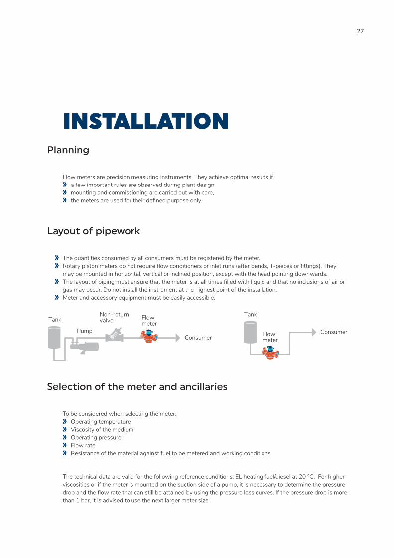
INSTALLATION Planning
Flow meters are precision measuring instruments. They achieve optimal results if a few important rules are observed during plant design, mounting and commissioning are carried out with care, the meters are used for their defined purpose only.
Layout of pipework
The quantities consumed by all consumers must be registered by the meter. Rotary piston meters do not require flow conditioners or inlet runs (after bends, T-pieces or fittings). They
may be mounted in horizontal, vertical or inclined position, except with the head pointing downwards. The layout of piping must ensure that the meter is at all times filled with liquid and that no inclusions of air or
gas may occur. Do not install the instrument at the highest point of the installation. Meter and accessory equipment must be easily accessible.
Consumer
Tank
FlowmeterConsumer
Tank
Pump
Non-returnvalve Flow
meter
Selection of the meter and ancillaries
To be considered when selecting the meter: Operating temperature Viscosity of the medium Operating pressure Flow rate Resistance of the material against fuel to be metered and working conditions
The technical data are valid for the following reference conditions: EL heating fuel/diesel at 20 °C. For higher viscosities or if the meter is mounted on the suction side of a pump, it is necessary to determine the pressure drop and the flow rate that can still be attained by using the pressure loss curves. If the pressure drop is more than 1 bar, it is advised to use the next larger meter size.
28
Dirt filter, safety filter
Filters are any way required in the system to protect engines and pumps to keep their performance and live time. For fuel oil meters this is no different - that’s why we recommend installing the fuel oil meters (in flow direction) always directly after the filter. Some particles in the fuel are also from engine’s wear and tear, that’s why we also recommend a filter in the fuel return line. Usually basket type filters are best choice for the return line and automatic filters in the supply line. Major engine producers recommend a mesh size of 5 - 10 μm (automatic filters), especially to filter out very abrasive cut fines. It is best for the flow meter to install it be-tween this automatic filter and the engine. The maximum filter mesh size for a respective meter can be found in below table.
Examples of filter:
Maximum mesh width for filters
Nominal diameter
DN 4 0.08 mm
DN 8 0.1 mm
The filter mounted in the meter inlet is only a safety filter and is too small to act as a dirt filter. If a dirt filter with the given mesh size is used, the safety filter in the meter inlet may be removed.
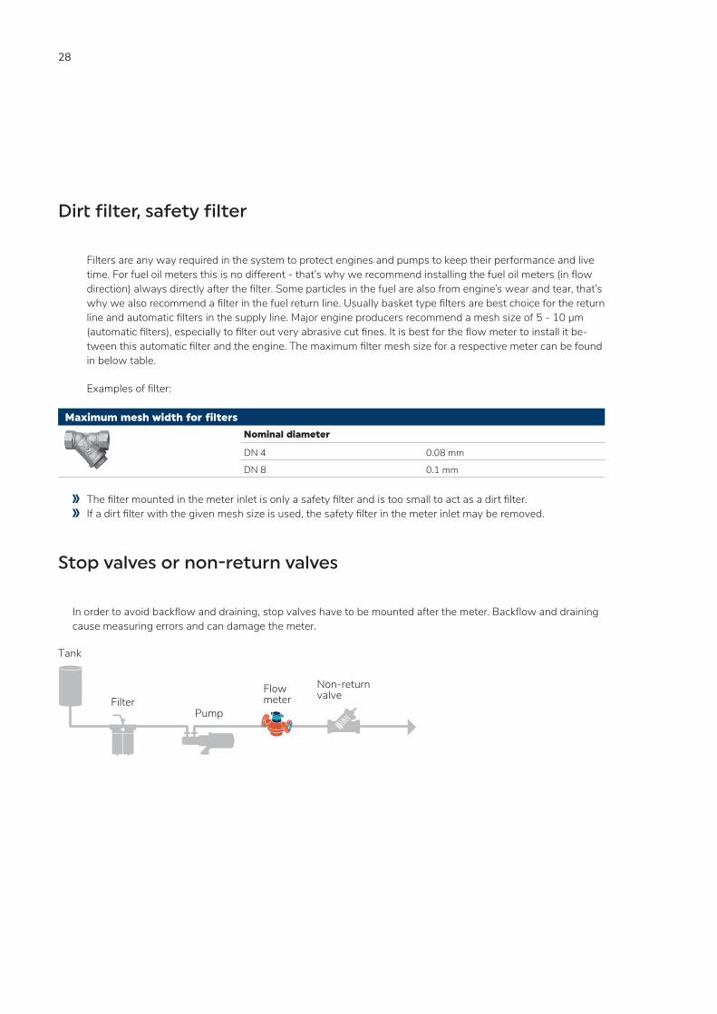
Stop valves or non-return valves
In order to avoid backflow and draining, stop valves have to be mounted after the meter. Backflow and draining cause measuring errors and can damage the meter.
FilterFlowmeter
Non-returnvalve
Tank
Pump
29
Remote Processing / Ancillaries
Any backflow must be avoided on meters equipped with pulsers for remote processing. If this cannot be achieved by appropriate plant design, a non-return valve should be fitted.
Electrical wiring and installations
Electrical wiring and installations are subject to statutory regulations which must be taken into account when planning the system. For installations in zones subject to explosion hazards, consult an appropriate expert. The following factors should be taken into account during plant design:
ancillaries connected to the meter environmental interference maximum permissible cable lengths (with or without amplifier) junction boxes, cable guides
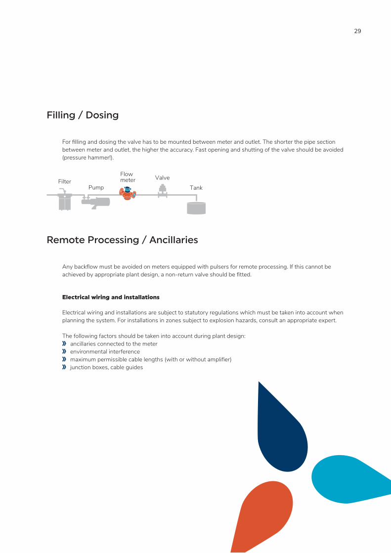
Filling / Dosing
For filling and dosing the valve has to be mounted between meter and outlet. The shorter the pipe section between meter and outlet, the higher the accuracy. Fast opening and shutting of the valve should be avoided (pressure hammer!).
FilterFlowmeter
PumpValve
Tank
30
WARRANTY, SAFETY INSTRUCTIONS Warranty Disclaimer
Aquametro Oil & Marine guarantees the quality of the product in the context of its General Terms of Business. The owner, operator or installer will be liable for the correct installation as well as the appropriate handling of the equipment upon its receipt.
Please observe the application-, mounting- and operation-instructions. Use the unit exclusively for its designed purpose. Maintain the unit and service it according to prescriptions. Use accessories only if their applicability is technically safe.
Safety rules and precautionary measures
The manufacturer accepts no responsibility if the following safety rules and precautions are disregarded. Modifications of the device implemented without preceding written consent from the manufacturer, will
result in the immediate termination of product liability and warranty period. Installation, operation, maintenance and decommissioning of this device must be carried out by trained,
qualified specialists, authorized by the manufacturer, operator or owner of the facility. The specialist must have read and understood these mounting- and operating-instructions and must follow the instructions here in.
Check the voltage and the information on the type plate before installing the device. Check all connections, settings and technical specifications of peripherals which may be present. Open the housing or parts of housings, which electric or electronic components included, only when the
electric power is turned off. Do not touch any electronic components (ESD sensitivity). Expose the system with respect to the mechanical load (pressure, temperature, IP protection, etc.), only to
a maximum of the specified classifications. During operations that involve mechanical components of the system, release the pressure in the pipe
system or reduce the temperature of the medium to a safe level for humans. None of the information stated here or elsewhere releases planners, installers and operators from their
own careful and comprehensive assessment of the respective system configuration in terms of functional capability and operational safety.
The local labor, safety laws and regulations must be adhered to.

31

Aquametro Oil & Marine GmbHDE-18119 Rostock, [email protected] +49 381 382 530 00www.aquametro-oil-marine.com
Aquametro Oil & Marine AG CH-4106 Therwil, [email protected] Phone +41 61 725 44 00 V
D 4
-200
e 0
9.20
19Th
e en
glis
h ve
rsio
n sh
all p
reva
il. Su
bjec
t to
chan
ge w
ithou
t not
ice.
A
ll in
telle
ctua
l pro
pert
y rig
hts
are
excl
usiv
ely
with
Aqu
amet
ro O
il &
Mar
ine
AG
, Sw
itzer
land