construction management and planning
TRANSCRIPT

CONSTRUCTION MANAGEMENT AND PLANNING

CONSTRUCTlOlv MANAGEMENT AND
PLI dlN(
er Sengup Professor of Civil Engineeri
Jadavpur Univers Director, ACFA'= r-7sultant Pvt. Limit
Calcu 'ed ltta
H Guha Ex-Faculty, Jadavpur University
Director, Mas Construction Pvt. Limited Calcu
- -
tta
Tata McGraw-Hill Publishing Company Limited VEW DELHI
IlrbVl Hill OfficnC New Delhi New York St Louis San Franciscc d Bogota
Hamburg Lisbon London Madrid M an Montrc Paris San Juan SBo Paulo S i n c l a ~ ~ l ~ -vdnev Tonyv I U I U I
Aucklan exico Mil; n*....L.- C
Guatem: ?al Panar I,.,. T....
Tata MCC Graw-l A Divisio
Yill n of The McGraw-Hill Companies
S:
Six1 RDI
Thit Tat:
Pub 7 \n Urv c D
9 9 5 , Tata ishing Cot npany L'ir
th reprint )BCRQAR(
s edition (
a McGraw
dished by Jest Patel .ashi Press
D";..+a-L.
2002 CAXL
is publical rior writte
:an be exr ,-Hill Publ
tion can b n permiss
e reprodul ion'of tile
ced in an) publisher
)orted frot lishing Co
n India 01
Impany Li ily by the mited
Tata McGraw-Hill Publishing Nagar. New Delhi 110 008, t :, Vaidwara, Meerut 250 001
, E-120 Sector 7, Noida (U.P.) 201 3.01.
: Compan: ypeset at and printe
r form or S
publisher
y Limited,
d at
by any ml

Dedicated in rnernorj
Dr Santimay Chak
Yowrah,
'Civil E ye (Deen , West E
hgineer; zed ~ n i
ing, uersity),

is aimec engineer ". - professic This book mals working
I the construction industry. stuaents of architecture and civil engineering iploma courses and AMIE will also find the book quite useful.
The book gives the readers a working knowledge of the subject, rather than providing any detailed insight into it. It contains a total of 19 chapters which carry a wide-ranging discussion of construction management issues- from statistics to law and accounts. This interdisciplinary stud) of construc- tion management is important because decisions taken in practice are based on the integral effects of all these factors.
The first four chapters describe the construction industry as a whole and its various units. Elementary topics like definitions, organisational structure and working methods have been covered. Chapter 5 introduces statistics and illustrates with examples its usefulness in construction management. The lethods and machineries for different types of construction like earthwork nd concrete have been taken up in chapters six and seven. Chapter eight eals with scheduling and describes standard methods like PERT and CPM
along with advanced techniques to study time-cost relationships and uncer- tainty. Chapter nine pertains to various operation research techniques like linear programming, queuing and simulation that are useful in construction
tanagement problems. Various management-related issues like quality, dety, inventory, accounts, cost control, and finance are discussed in Chap- :rs 10 to 14. Chapters 15 and 16 present the commercial and industrial laws ?lated to construction. Chapter 17 is a case study showing the analysis of a mder bid. The applications of computers are discussed in Chapter 18 and Ie last chapter draws the attention of the readers to the latest research in Ie field of construction management. In some chapters, like Chapters 8 afid 18, :es have been made to
-xnmercially available computer softwares mar can be used to assist in construction management. A number of computer softwares, that are similar in logic but are sometimes restricted in their scope and conditions for use and are termed as 'Shareware', are available in the market at very low prices. Readers desiring to acquire shareware programs in construction manage- ment may write to Himadri Guha, 78 Kiron Shankar Roy Road, 5th Floor,
, referenc ., ,

viii P n
Calcutta-700 001 self-addr imped er softwares.
, with a
Mr Chi. grateful .,
for his -Hill Pul 1 T . - I 1
amilies fc ject.
3r their c or, ;tart t mcourag
'or a list of such
We wish to express our appreciation to all those who have helped us in writing this book. We also wish to thank our ex-students Mr Arup Chatterjee and Mr Supriya Chandra. for their help in software applications. We thank
tta Ranjan Dutta effort in the man to Tata McGraw 3lishing I y Limitec
me pu~l i shhg of this boo^. Last, out certainly nor the least, we are maemeu to our fi this pro:
luscript. for exF
- . - - . . ..
We are )editing . 3 -3- L - 3
rt the sha ping of
MADRI G ATISH SEI
UHA UGUPTA
Con desi
hap.
boo: expt sing
ew year s back,
- 3s for im] y gratefu
This BOO
a senior Publishi ?quested isiderablt ~ourite a a course I prescrib 1 . 1
- proveme ltoanyr
advancec this sul
1. At that
id not di stead I t
) my stuc ley have
executive of Ta qpany Limited re vrite a book on 1 structu gn. I had a con ?rice in teaching ~ject w h ~ pens to be my fa7 hpted his proposa time I h
undertaken to teach on Construction Management and Planning. So I requested him to le a list of books on the subject. Unfortunately, there was no book wnicn covered all the topics and he asked me to write a
k on that subject also. I d are comment as I had not had much xience in te3clung it. In: hought it over and realized that to le-handedly write a book on a subject which covers such a vast range
of topics would be difficult. So I approached Dr. Himadri Gu colleague, who had taught Construction Management for a Without his efforts, this book would never have been published.
I am very much indebted tc ients for in this subject. The questions tl asked he from new angles altogether.
uggestio~ he readex 111 be ver: 10 points
nt from f e-ader wk
the intert we led m
2st they 1 e to view
.s will be out any j
ex tremel nadvertc
ha, my 6
long tin
lave s h o ~ the subjc
y welcon tnt mistal
ral ich ad
?X-
ne.
vn ect
le. ke.
Preface
The Construction Industry 1 Types of Construction-Public and Private 2 Construction Practice: The Owner, the Consultal
Duties and Responsibilities 2 Finand;lg Requirements 6 Regulating Requirements 6 Construction and National Developme Features of Construction Economy 9 I Instruction Management 11 1 12 Role of Cc Exercises
2. CONTRACT MANAGEM
Contracts 13 Construction by Direct L a b o ~ -. "ntract Documents 18 lalling Tenders 20 Scrutinising and Comparing Tenders 21 Choosing a Tender 22 Opening a Tender 23 Acceptance of a Tender 24 Risk Allocation 24 Security Bond 26 Contractual Changes and Termination of Contract Subcontract 28 Rights of the Subcontractors 28 Duties of the Subcontractor. 29 Marketing 29 Public Relations and Advertising 31 International Market 32 ,
Exercises 33
ENT
ir 77
~ t . the Coi ntractor, t: heir
3. DETAILS OF CONSTRUCTION ?r;
Introduction 35 Estimates 36 Rate Analysis 40 Codes and Standards 44 Exercises 46
4. CONSTRUCTION ORGANISATION AND SUPERINTENDENCE 47
Organisation Planning and Organisation Chart 47
Decentralisation 49 Construction Supervision and Superintendence 50 Detailed Superintendence 51 Hiring and Discharging of Personnel and Related Matters 5 Payrolls and Records 52 Purchase and Delivery of Construction Materials and Equipment 52 Records of Cost and Payment 53 Percentage Completion Report 54 Insurance Record 54 Project Office Requirement 54 Safety 56 Changes in Contract 56 Disputes and Stoppages 56 Organisation Chart of a Small Construction Company 58 Organisation Chart of a Medium Construction Company 59 Organisation Chart of a Large Construction Compa Exercises 61
5. OPERATION ANALYSIS AND STATISTICS 62
Introduction 62 Distribution 63 Sampling 67 Regression and Correlation 71 Forecasting 74 Decision Theorv 76 Replacement Decision Tree 76 Motion and Studies 78 Activity Sampling 79 Multiple Activity Chart 81 Exercises 83
6. CONSTRUCTION PRACTICE I
Earth Work and Excavation 86 I Earth Moving and Excavating Machinery 88
xii Contents
Tunnelling 101 Exercises 107
7. CONSTRUCTION PRACTICE 11: SUPEI
Introduction 109 Cement 110 Aggregates 11 3 Water 115 Admixtures 11 6 Concrete 117 Reinforcing Steel 127 Form Work 128 Scaffolding 135 Brick Masonry 137 Structural Steel 139 Welding 140 Exercises 141
8. TIMES MAINALEMLN 1 ANU XHLL)ULING
1 ime
Unce Prog Cnm
I I Introduction 143
Bar Chart 144 Critical Path Method (CPM) 154 PERT 161 Resource Constraints 165 v. .. Cost Trade Off l E n
brtain Durations 1 ; ress Report 178
-. .-.puter Applications 185
wises 184 Ext
9. QI JANTITATIVE MA
Introduction : Linear Prograr Queuing Conc Simulation 2C Bidding Mode Game Theory Exercises 207
288 nming 1, ept and P
NAGEM
stical Met
10. QUALITY MANAGEMENT AND SAF
Introduction 21 0
. . Quality Control by Stati: Sampling Plan 213 Control Charts 37.1
hods 211
--- 3f Constn ments 22
ETY
CTURE
'ONS
y Aspect I
y Require
Safc Exe ICLDL-D LLr
References 224
RESOURCE MANAGEMENT AND I:
Introduction 225 Basic Concepts 225 Labour Requirements 227 Labour Productivity 229 Site Productivity 229 Non-prodcctive Acitivities 229 Equipment Management 230 Material Management 231 Inventory Control 232 Exercises 245 References 246
Intrj Basi Aco
D ~ P Bala Pvn4
31arl
Tax: Exer
ACCOUNTS MANAGEMENT
oduction 247 .c Concepts 248 ounting System and Bookkeeping 251 Ireciation 253 lnce Sheet 256
.,,.it and Loss Statemr Ratio Analysis 257 Du Pont System for Appraising 263 Internal Auditing 264 "-'utory Audit 265
ition 266 rises 269
13. CO!
Intrc pro; Ordl Unit Con
Cost cost Spec D . . 1 uuui
Acti. Fore
nitude 2: the Bill ol ates 276
ST MANAGEMENT
>duction 273 iuction Function 273 er of Mag : Cost for 2s 275 trol Estim
direct Costs 276 mtingency 279 )st-Volume Relationship 279
Control System 2Q7 .Codes 285 :ial Aspects of Equi get 287 vity Cost Control ; casting of Costs 21
pment CE
xiv ' Contents
Cash Flow Control 289 . Fund Flow 292
Exercises 299 References 305
14. FINANCIAL MANAGEMENT
Introduction 306 Concept of Valuation 306 Net Present Value (NPV) Method 306
' Internal Rate of Return (IRR) Method 307 Difference between IRR and NPV 308 Evaluation of a Risky Investment 308 Required Rates of Return 311 Cost of Debt 312 Cost of Equity Capital 312 Cost of Preference Shares and Bonds 313 Cost of Retained Earning 314 Weighted-Average Cost of Capital 315 Working Capital 315 Management of Cash 318 Synchronisation of Cash Flows 318 Stochastic Model 319 Financing Working Capital 320 Modes of Securing Risk 322 Intermediate Term Financing 323
, Financing Non Profit and Public Sector Project 32( Exercises 337
15. CONTRACT AND RELEVANT COMMERCIAL LAW?
Introduction 341 1 Laws of Contract 341
Definition of Contract 342 Elements of Contract 342 Contract Conditions 348 Sales of Goods 355 Distinction between Sale and Agreement to Sale 356 .Transactions other than Sale 356 Goods 357 Destruction of the Goods 357 Price 358 Implied Conditions of Sale 358 Conditions as to the Merchantability 358 Laws of Insurance 359 Types of Insurance 359 Characteristics of Insurance Contracts 3.1 Arbitration 362
Modes of Arbitration 362 Implied Condition of an Arbitration 363 Duties of the Arbitrator or Umpire 363 Revocation of Arbitrator's Authority 364 Award 364 Income Tax 364 Transfer of Property Act 367 Sale 367 Mortgage 367 Charge 368 Lease 368 Exchange 369 Gift 369 Sales Tax on Works-Contracts 369 Exercises 371 References 3 73
16. RELEVANT LABOUR AND INDUSTRIAL LAW>
Introduction 374 Payment of Wages Act, 1936 374 Contract Labour (Regulation and Abolition) Act, 1970 375 Minimum Wages Act, 1948 377 Employees' State Insurance Act, 1948 379 Workmen's Compensation Act, 1923 381 ' Payment of Bonus Act, 1965 383 Employees' Provident Fund (and Miscellanea
Act), 1952 384 Payment of Gratuity Act, 1972 386 Factories Act, 1948 387 Trade Union Act, 1926 389 Industrial Disputes Act, 1947 390 Exercises 392
17. CASE STUDY
Introduction 394 Tender Document 394 Coventional Quotation 395 Analysis of Work Programme 395 Analysis of the Work Programme and Site Planning 411 Optimisation of Time and Cost Trade-Off 413 Simulation Mode ;s Risk of Meeting De 418
18. INFORMATIOI IGEMENT AND C TERS
Introduction 421 Information Types and Usc Computers 423
!1 to Asses
V MANL
IUS Provis
ladlines
OMPU
xvi Contents
Database and Softwares 424 General Application Programs $LO
Civil Engineering Programs 429 Project Management Programs 430 Advanced Co
ns
truction Engineering Programs 431 Construction Management Programs Expert Systems for Construction 440 Computer Aided Training (CAT) 441 References 444
19. SELECTED RESEARCH TOPICS n MANAGEMENT
V CONS
Introduction 445 Bidding Models 446 Uncertainty of Scheduling 449 Resource Optimisatia 454 Aggregate Blending 454 Construction Haul Roads 456 Minimum Time 457 3ptimum Number of Crews 458 Financial Management 460 References 463 j
Ann J . Areas under the Normal Curb, ucLvvccll LclL
to P t Right o I: X Ti Students
. I : The Chi-Square DistTlvurlvlL . App. IV: Probability of Zero Units in tl App. V: Control Chart Constants App. VI: Master Format Code!
App. VII: Secondary Divisions ,r Formal
App. VIII: The Present Value of an ~ n n u i t y of Re - App. IX: The Present Value of
lland Tail. my Poin
3bles of $ -. . -
f Mean
.;L..+;-.. t k U 1 v c
le Systen
3
in Maste .. A ..
: for Site .1
Work
Bibliography
Index
I CHAPTER I I
Introduction
THE CONSTRUCTION INDUSTRY
The construction i y is one of the oldest and largest industries. Construction activity puvides employment on a large scale. The ur- -' machines and equipment, which have become part and parcel of construc in modern times, has not only reduced the time of construction and nu1 of people engaged in construction but also improved the quality of consrrm- tion and materials. The construction of high rise buildings, dams and barrages, metro rail, cable stayed bridge, high chimneys, etc. are now undertaken easily because of the availability of equipment and machines. In most of the developed countries, scientific tools such as construction management techniques are used, while in developing countries very little modemisation has taken place in this industry. These countries still continue with the traditional labour-intensive style of c ion which is time-con- suming and does not match quality requireme mded in construction. If construction project schedules are not mamtmecl, the cost increases by leaps and bounds. While it is true that in the third world countries with a high population, it is not appropriate to opt for complete mechanisation of construction, it must be realised that the use of plants and machinery sometimes becomes absolutely necessary for certain types of construction and to ensure good quality. Therefolp, no politics with labour unions or otherwise should be allowed to cause any delay and stoppage of work u the pretext of loss of employment due to the use of machines.
Thus, the use of plants and machinery and the adoption of the 1 construction management methods should be the construction industries in modem times.
:onstruct~ ?nts demi . . . .
essentia 1 feature
>e Ul
:tion nber L-_ -

2 Construction Management and F.-. .. ... .,
TYPES OF CONSTRUCTION-PUBLIC AND PF
on quot 1 not obli . . . , -
to suffe .ure so tl
~ c - , .
percenta le job ger 1 .
elt that uality of . . . 1
!". The r: ed on tir ,.,-...* 4 . ~ ~ 7
~ t e s quot ne. -.?;I1 m* "
'unds or I the 0th .-A --A -.
any une: er hand, -LA-- LL-
ed are w
r than tl )es to the
-1 . .. 11. .
)es not f: . C I ,
I underta
orkable i
l.;** -..h
INER, R,
cpected (
there arc --l--L--
&nstruction projects are carried out by the public sector or the Gov and also by the private sector. The projects undertaken by the gov are much bigger and involve large outlays. These are of national importance and meant to direct the overall econodic development of the country. For example, a river valley project involvind the construction of dams, barrages, irrigation and navigation canals, aquid&cts and generation of hydro-electric power is a huge project which takes a lAng time to complete and requires a large sum o w n e y . The construction of steel plants, power plants, national highways, interstate roads, long span bridges, etc. are of similar nature. The development of neighbourhoods under urban renewal schemes, big housing projects or establishing new towns are also generally carried out by the Government. Many of these projects are specialised in nature and hence need specialist contractors. For the execution bf these projects generally only a few construction companies are available. obal tenders are floated in order to select the appropriate contractors. $ hen jobs are awarded to these specialised companies, the project invdriably runs smoothly. The money is provided from the allocated funds wdich may or may not be fully ready before the work is undertaken. Monev mav also be raised from foreim aid agencies. If there is a dearth of f funds, the project may suffer. 01 which are not of specialised nature ~ I I U W I I ~ I C ULV bele~~1~11 UI CuI lLlaLLuI> 13
based ations " ge lo*ei luled prj thougk gatory tl- lerally gc idder. So the rates quoted are really unworkable. Unaer tne circumsrances the jvvs dre bound r. It is f there hc proced lat the q
1 work dc
times quorarlons are also mvlrea on the' basis or percenrage nigner rnan me scheduled price".
In the private sector, the job is normallj is ready and there are no quotations based on "percentage less than the scheduled pricc normally finish
Whether the culLllllY YVlll tjV VIL c V ULULEj yuVllC , , L ~ V U L L D U L ~ U ~ will be 1 encouraged is a matter of policy of the ruling gc
may change at different times with difkerent peop
I CO,NSTRUCTI( THE b~ THE CONSUL^ rRACTO THEIR DUTIES AND RESPONSIBILITIE
Civil engineering construction needs the
he sched lowest b -: . . ~ ...A 8
a changt 111 below . -
.ken only
md once
,-.W n..;
wernmer le at the
lelay in : many n
- -L ---I..
when th
- started i
.,at;rs,;r\.
it and th helm of
" releasing lore jobs .--L--- :-
ice" and metimes . : - I - -
ook and d. Some- 11 - . 11.
e money . . these are
is policy affairs.
materials. The construction industry is one of the mos mt indus which provides jobs to a very large number of labourers, technic engineers and technologists throughout the country. Before the comrnt ment of any construction project, it is required to know the purpose o project, design all the structural elements including the superstructure the substructure well ahead of the beginning of the construction, and pre the detailed drawings according to which the construction will proceed the completion of construction, it is required to check the working of the elements of construction and installations before the project is commissioned. All these activities may last for quite a good number of years depending
on the size of the project. It may need thousands of hands, the ce of generations of experts and the use of natural and manufacture :ts of different trades and occupations. During the period of design i truc- tion, it is of utmost importance that the flow of money be smooth so that the job may proceed unhindered and the supply of materials of construction and labour also follow the schedule of construction.
7 the succ ltation of the
proj and the
'he kej ect are
The Owner
r person! the own
; respon er, the cc
sible for msultant
cessful i~ contract1
t import;
nplemen or.
experien d produc md cons
:take the . .. .. work af . .
ter a dc d
The owner or the I decides to unde~ ?tailed analysis of the costs and the payment schedule for me project. rhe p a y e n + to be made by the owner has to be regular and in line with the progre the work. To maintain the flow of money the owner may utilise his resources or borrow money from other sources. The money arranged and spent for the job is known as the "capital investment". The owner must have absolute faith on his expert advisers regarding the surety of performance of the project and the estimated cost required for its completion. The owner is generally expected he suppl ver and the construction site.
The owner may ut: a yersult o r a group of yersurls acting as a corporate body such as a local government authority or a gove! lepartrnent, a company, a corporation or joint board or any other :y possessing adeauate c --.----
to arrar lge for t: water tc
V
rnment c authorit
lanS, mce- f the
8 and !pare I. On . -
L %LA. L
ss of own
The consultant/engineer or architect is a person or a group of persons or a company who gives the owner the technical advice for the project. The primary function of the engineer is to design, do the necessary research work for the design, provide the calculation for the cost, appraise the owner about the pros and cons of the project and impress the owner in a manner that the owner can rely on him regarding all technicalities of the project so as to
4 Construction Management and Planning
develop full confidence on him. He must be well-trained in quality and workmanship requirements, and must supervise the construction daily or periodically as the case may be. In respect of all the duties and related technical matters the engineers must exercise a realistic, thoroughly profes- sional and entirely independent judgement.
An owner or a promoter may engage a consultant for the job in one of the following ways:
1. He may engage a single consultant for the entire job.
2. He may engage one competent engineer from his own employment to do the job. Many local authorities and government departments employ their chief engineer as the consultant particularly for specialised jobs like bridges and tunnels where they have got their own expertise and the chief engineer gets the design work done by his junior engineers under his own guidance.
3. He may engage a consultant for a portion of the job in which his own men are not expert but the remaining portion may be awarded to his own men, e.g., in a building project he may get the architectural design from an architect consultant but the structural design may be done by his own engineers. This is quite common when the ow government department or agency.
ner is a
The payment made by the owner to the consultant is known as the "consultancy fees". This may vary depending on the volume of work to be done and whether daily or periodic supervision is to be carried out by the consultant. In case, the owner or promoter decides to employ his chief engineer as the consultant engineer then the chief engineer enjoys all the powers of a consultant for design and also works as an administrator for the construction.
A consultant is generally employed because he has every fre exercise his knowledge and experience for the new design and ~ ~ ~ ~ L L U L L L U L L .
He could give ample thought to the project problem as this is his main job, work out the various alternatives based on his knowledge and experience and could finally select the one which has the most suitable form considering feasibility and economy. He has to keep abreast of the new materials and products available in the market. In addition a number of different problems are tackled by a consultant which is substantially more compared to that of a chief engineer in a government department who has specialised in problems of design and construction of his own department and may not be as good as the consultant for other problems. Thus employment of a consultant may be essential in some cases while it may be optional in others.
Introductii
The Contractor
A civil engineering contractor is a person, or a group of persons or a company who undertakes the construction. He offers to do the job for a given su money and in case the tender is accepted he signs a contract with the o1 or promoter to undertake the construction. He must have the skill competence to execute the work exactly as the owner wants and the eng advises. He is to do the construction work as per the drawings, specifica and instructions issued to him by the engineer and as per the details r in the contract signed by him.
For the construction work, the owner has got several choice contractors:
s for sele
Im of wner
-..A a1 IU
ineer tions -..*-- ;1vn1
cting
1. the whole job may be awarded to a construction company, or
2. if the promoter is a government department having a full-flecltjFu maintenance wing, the new construction could also be entrusted with the maintenance division depending on the size of the new construc- tion and the supervision of construction could be done bv the departmental engineer in addition to the design work.
~ t h the dt Sometimes the promoter may employ the contractor to do bc and the construction on contract. This arrangement is known as the "package deal" or "turn key".
The owner is supposed to reimburse the cost of construction to the contractor as per the advice of the consultant and there shou ! any dispute.
Id not be
The arrangement that is made between the owner, consultant ana contrac- tor should be such that there is no chance of misunderstanding an themselves and every effort is given by these three parties for the g success of the project.
nong rand
There is no direct contract between the engineer and the contractor. The engineer has no power to accept or reject a tender. The engineer calls upon construction firms to tender. After receiving the tenders or quotations he is to refer them to the employer and seek the employer's acceptance. But the engineer has to guide and advise the employer to select the tenderer. In order to make the contract binding between the owner and the contractor, an agreement has to be signed between the two parties. This document is normally sealed in case of government or quasi-government departments. For sanctioning any extra work to the contractor for genuine reasons, the owner is to be consulted first. The contract may have the provision for a "provisional sum" and provision for contingencies which act as buffers for accommodating extra work to be done which are not included in the tender document. For example, local weakness or character of the soil exposed excavation may call upon changes in the size or the type of foundation w
after rhich

6 Construction Management and Planning
FINANCE REQUIREMENTS
Law! divided
2 is the r proper a in the co
; smootl d cash flc le and a1
- - - - - -.
uld be o' ~lvement
should n or India
--:I-.. . I - .
lot be cl- m patent . . . . . - - . .
may involve extra cost. This extra cost is made available from the above sums of money. But changes in specification in the items of work should not be encouraged, e.g. white wash on walls ! langed into lime punning, or plaster of paris finish of wall! stone should not be changed to marble floor. In case sitnilar cnanges are required, prior permission from the owner shol informed about the financial invc item is actually undertaken.
Similarly, there may be inadvertent omission c the tender was prepared, e.g. the consultant mig cranes, hoists, etc. during construction but while preparing the tenders these may not have been mentioned. Under these circumstances, the permission as well as the sanction of the owner are necessary before the equipment is actually used at site.
btained ; for the s
md the I
pecified I
)f impori ht have
owner st zhange b~
~ould be efore the
REGUL
tant thin: thought
gs while of using
Financt nost important r e s u u l ~ ~ and it is generally in short Hence nd efficient utilisation of finance is very importan1 cularly ntext of an ever increasing price. Financial accountat to be built into the performance and appraisal system fol sing the efficiency at minimum cost. All short term and long tern require- ments have to be planned and arranged at a proper time in I run the project: ~ly. Financial institutions are to be approached and the require ~w is to be drawn. Advances and dues should be realised in due tin 1 efforts should be made to keep the interest element to the barest minimum. A good knowledge of acc necessary for the construction compar economically and efficiently.
j and re1 I into sev
gulations .era1 cate
and taxa transactir
: maximi 1 capital I order tc
tion is al: ~g the 1
: supply. t, parti- dity has
Like otllr~ ~ u > ~ l ~ t . s s dcuvities, the construcc~vr~ worn also operates wlaer
government rules and regulations. Most of these legislations and rules are in force to protect public safety and welfare. Such regulations and rules were evolved decades ago and have become quite complicated and even con- tradictory in several instances. A construction manager is required tc knowledge of the rules and regulations applicable to his problem in prepare an action plan. In addition, advice from experts is essential m complex situations. A construction manager unless cauti~ commit legal misconducts inviting intervention from reg causing delay, financial and other losses.
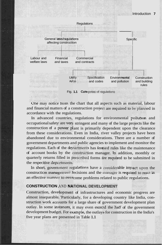
, that affect the construction work can be gories and is presented in Fig. 1.1.
ous C O U ~ '
ulatory i
9 have a order to
.. . . d easily agencies
Introduction 7
I Regulations
General laws/regulations affecting construction
Specific
I Labour and Financial Commercial welfare laws and taxes and contracts
Construction and building
rules
I Util rull
I onmental pollution
specif/cation Envir and codes and
Fig. 1.1 Catec
une may notice trom the chart that all aspects such as material, labour and financial matters of a construction projec ed in accordance with the regulations.
In advanced countries, regulations for environmental polluhon and occupational safety stringent and many of the large projects like the construction of a I ant is primarily dependent upon the clearance from these considerations. Even in India, river valley projects have been abandoned due to environmental considerations. There are a number of government departments and public agencies to implement and monitor the regulations. Each of the dey s has fra s like the maintenance of account books by the ( ion man addition, monthly or quarterly returns filled in p 1 forms 2 red to be submitted in the respeci
In shori gulations have a sable imy constructic jell Jecisions and the ILL^ Lasrl is requi~ ILL U L
an effective LILdIUIe come problems related to public regulations.
3 are req uired to
' are very Jower pl
ned rule ager. Tn ire requii
tive depz t, govern >n manal - -- - - .- .- -
>act up01 red to re:
n the .-I. :-
r to ovev
AND NA CONSTRUCTION ,
Construction, deve almost inseparable struction work accc outlay. In some in: development budgc
hlopment . 'Particu ~un t s for
of infrastructures and economic progress are larly, for a developing country like India, con- a large share of government development plan
, it may even excec alf of the government ?xample, the outlay struction in the India's
;tances, 2t. For (
presen
ed the h, .s for con
five year plans are ted in Table 1.1

8 Construction Management and Planning
Table 1.1 Construction share of five year plans
Percentage of total Plan development budget
First Plan (1951-56) 50.4
Second Plan (1956-61) 42.6
Third Plan (1961-66) 42.3
Fourth Plan (1969-74) ' 43.2
Fifth Plan (1 974-79) 43.4
Sixth Plan (1980-85) 36.2
Seventh Plan (1985-90) 40.0
Even with this emphasis in national planning, construction requires more funds than allocated for adequate development of the infrastructure and housing. The contribution of construction to gross national product (GNP) in India is about 5-6 per cent. In other developing countries, particularly in the middle east, the percentage is much higher. In a developed country like the United States, the value of new construction contributes about 10 per cent to GNP. In absolute monetary terms, the investment in construction in India, say in 1979-80, was about 1,760 crore rupees (i.e. Rs 1.76 x 10'') and in United States for the same period it was about US $ 300 billion (i.e. Rs 3.9 x 10¹² approximately). In other words, the investment in absolute monetary units in construction in a year in US is more than 200 times than that of India.
An important feature in the construction industry is its multiplier role to the national economy. It is estimated that every rupee invested in construc- tion would generate about Rs 0.80 incremental earning to GNP. The corres- ponding figures for agriculture and manufacturing are about Rs 0.20 and Rs 0.14 respectively. From the fiscal point of view, investment in construction is more desirable to boost the economy. In developed economies, like the U.K. and the U.S.A., the fiscal policy makers routinely create favourable or unfavourable situations to guide the real estate market which in turn affect the construction and the short term economic environment.
Construction creates large scale employment which by itself is a sig- nificant contribution to the Indian economy. It is also a good vehicle for the distribution, of wealth which means that a significant proportion of the money spent in construction moves directly from the rich to poor people. In India, it is estimated that about 3,100 mandays of unskilled labour 3,000 mandays of skilled labour and 1,300 mandays of technical personnel are required for every lakh of rupees invested in construction. According to an estimate for 1983, there are 12 lakhs of workers regularly employed by the corporate sector, 24 lakhs of workers employed by the small contractors and
Introduction,
non-reporting sectors, and 67 lakhs of seasonal workei rork only, p of the year in construction and the rest of the time in agricultural work, ~r
available. The total workforce associated with construction was over 4 per cent of the total 245 million workforce in India in 1983. Tn the organised sector, employment generated in construction is over 5 per cent of the total employment. Employment generated in construction also significantly helps the rural population. According to 1971 census, about 51 per cent of the construction workforce comes from the rural area and 49 per cent fron
- urban and semi-urban areas. I
The size of the construction industry and its impact on the nab economy will be evident from the comparative data of the s plan presented in Table 1.2.
Table 1.2 Investment in gross domestic product, GDP (19e
Amount (at 1979-80 prices)
Increml Investment
(in crores of in GDP per cent
Rupees)
ent
Agriculture
Construction
Manufacturing
Transport (except railways)
Trade
I the
ional
It is surprising that despite its massive size, the ce not declared it as an 'industry' which would enable ir ro nave easier ac---- to bank finance and other economic benefits. There is no comprehensive act that guides the labour welfare for the construction workers. Till 1990, the government did not have any national housing policy that is intimately linked to construction activities. These features probably indicate that the macro economical aspects of construction related issues have not been adequately attended due to the lack of awareness caused by the limited knowledge and growth of t h ~ s b u c t i o n management the d re- search under Indian context.
FEATURES OF CONSTRUCTION ECONOMY
ories anc
t has 'Cf'SS
From an economist's point of view, construction is a service which has a demand to improve economy. The position of construction in the overall economic system is presented in Fig. 1.2.
10 Construction Management and Planning
condition
General demand
H Buildings for production h
Buildings for H investment
Buildings for dwellings
General
New creati
Facilities for Total supply
structure
I Market for real estate
E l - and infrastructure
udy of F to the :
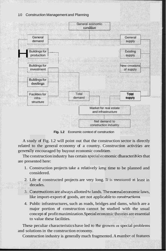
Fig. 1.2 Economic context of construction
A st ig. 1.2 will point out that the construction related general economy of a country. Construct generally encouraged by buyout economic conditi
The construction industry has certain sl are presented here:
Lon. momic cl
sector is ion activ
haracteri!
directly ities are
1. Construction projects take a relatively lent considered.
2. Life of constructed projects are very long. IL . . , ca~uLcu least in
; time to
T t ;C mn-
I be plan
>oq*,.n,4 - 4
stics that
decades.
Construc tions are ) lands. 1 "he normi 31 econor
!cia1 econ
# . I
ned and
nic laws, ..- -
always allotted tc like import-export of goods, are not applicable to constructior~s.
4. Public infrastructures, such as roads, bridges and dams, which are a major portion of construction cannot be studied with the usual concept of profit maximization. Spe to value these facilities.
essential
These peculiar characteristics have led ro me growrn or special problems and solutions in the construction economy.
Construction industry is generally much fragmented. A ni features
Introduction 11
of the industry generally create favourable conditions for the establishment of new firms. The features are presented here.
1. Construction firms have relatively low of fixed costs. A products are assembled at the site no large premises are require'
2. Construction firms have relative low rt The construction is started only after ,
monthly payments are made.
?quireme specific c
,nts of wc xder anc
3. Construction trade normally uses labour contractor workforce is not maintained and fixed cost is lowered.
>rking ca 1 traditio
s the d.
pital. nally
s. Perm;
4. In the Indian context, very few machines are essential and, therefore, requirements of initial investment are low. Even in developed' countries, smaller firms have easy access to leasing comvanies to obtain machinery and plants as required.
These factors have made the construction industry firms are entering into the market continuously. The prorir margin is lvwer than that of other industries. Statistics about the size of truction firms in India are not readily available. In U.K., 90% of th 2mploy fewer than 8 permanent people. The 100 biggest firms in U.K. account for 20% of the industry's output. According to one estimate, in U.K. there were about 1,80,000 construction firms operating in 1990 and the total number of registered firms in the country is about 3,70,0nn
In U.S.A., the number of construction firm 'ever, 60% of the construction is executed by the to1 , it is estimated that about 90,000 firms are registered as contractors in various government departments and agencies.
The above statistics provide an idea about the fragmentation and competi- tion in the construction industry. The average profit n nds to be low and is generally assumed as 10%. However, the actual ok profit may be even lower than 10%.
2"".
s exceed p 400 fin
very corn _ C.. ...
' the cons le firms t T r
one milli ns, while
nargin te gross bo
ion. How in India
ROLE OF CONSTRUCTION MANAGEMEN'
In the construction industry here was a time when all the projects were labour intensive and management in those days meant proper utilisation of labour to make optimum progress in construction in the most economical manner. But nowadays technological advancement and new scientific invenl tions have added new dimensions to the construction industry. A project is now considered as a group of activities having interrelations, which may include the role of specialists and specialised work using the latest knowledge and skill available, to be undertaken in the most systematic manner failing which the project may be stalled or the progress may be
12 Construction Management and ~~annrng
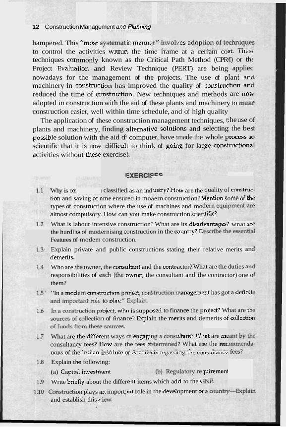
hampered. This "mdst s ic manne to control the activities witnm the time rrame at a cerram co techniques cor known as the Critical Path Method (CPR Project Evaluz d Review Technique (PERT) are being nowadays for the management of the projects. The use of plant a n c machinery in construci improved the quality of construc reduced the time of cc >n. New techniques and methods adopted in construction with the aid of these plants and machinery to m a t
construction easier, well within time schedule, and of high quality The application of these construction management techniques, t
plants and machinery, altematii .possible solution with t ' comput scientific that it is now t to thin activities without these
ires adop sr. lnesc /I) or thc
appliec 3 .
nmonly ition an
- tion has bnstructic
. - -
:tion a n c are nom
:he use o: . .
ons and made the ~g for la:
finding he aid of
difficul
{e solutic er, have I
k of go i~
selecting I whole F rge cons1
; the bes brocess sc tructiona
exercise!
I
Why is COI I as an ind >w are the tion and saving or nme ensured in moaern construction? k~enrion some or mnl types of construction where the use of machines and mo almost compulsory. How can you make construction scier
What is labour intensive construction? What are its disa'dvantagesc wnat arc ountry? C
I classified lustry? Hc 8 quality o . I .. .
f construc . . C L l
dern equi ~tific?
the hurdli Features o - .
?s of mod1 f modem
ernising c8 construct . - -.
onstructic ion.
In in the cs
Explain private and public constructions stating their relative merits an( demsrits.
Who are t responsibilities of e,,,, ,,,,, awner, the consultant and the contractor) one o
.he owner, , the cons1 ,="h /+ha .
lltant and the contri actor? Wh - . at are the duties an(
them?
"In a mod Int has go t a definitc lern const ..'--L "-1-
ruction pr to play.''
*eject, con! l2.,-1-:..
nanagemc
ance the F rits and d
hat are thc ! collectio~
jsed to fin in the me1
broject? W emerits oi
roject, whc n of finan
o is suppc ce? Expla.
&ant? WI ? What a1 1- - LL- --
What are consultan
< .,
the differ1 cy fees? I
~ T 1.
ent ways iow are t r . . . . .
of engagi~ he fees dc
r A .I.:..
at are mf re the recc
1L-- -. nons or me lnalan lnsrirure or Arcnlmecrs reraruinr ule curlsultalicv
Explain tl
(a) Capiti
ne followi
a1 investrr
ng:
lent quiremenl -. .-
Write brif ?fly about the differ .ent items
3nt role in
which ad
the devel'
d to the < :onstructil and estab
opment oi on plays a lish this .v
m import; ,iew.
CHA
ONTRAC'"
between .-- -. .LZ
ties for 4
.> -L :- A.
contract 2 performeu or rerriuneu rrvm wnicn nas veer1 arriveu d~ UI suc11 a rlld
form, an 2nt that i
I two or -1- L-- L-
:ts to nner,
t has enf legal
vn pd
:t forth ir !feet. -
I such a
m a civil enpeering construction contract, an agreemenr is sl ?tween the owner and the contractor which ensures ~b within the scheduled time, following drawings, .td workmanship as given by the consultant and at a price as quotea o
0- -- - )f the ~tions v the
8 the corn designs,
lpletion c specifica
. .,
I YPES OF CONTRACTS . -
ivil en* ontracts 'ally of t~
1. Contract at a Fixed PI
nd the m
'ice
This is the oldest a ost comr ~ o d of lei a work under contract when bids are received at rxea prices. These may be based nn
lit prices for ead 31 sum sl a1 cost of the proj a single
rn may be quoted for the ,,,.
non met1 ,-. v
tting out - --- :and~ total
~ot ing UI Ir the tot,
I of the i ject or sc ink
tems of . me times
work an( , a lump
1 the toti sum, i.e.
ct other ,,.+.. ..I "*<
, Contra .,,a &I., "
than Fi] .+ -g +LA clc utc a c r u a l cuJr ul uLc " 1 u l c L r IS first derived and the contract is I
e contrac percentz
l a m m fixed' fee
2r that th or fixed
L ,
:tor wou! ige etc.
ld receivt 2 a profit over the actual cc
14 Construction Management and Planning
Contract at a fixed price may be divided as follows: bill of quantities contract, sihedule of rate contract, and lump sum contract.
In a similar manner contract other than fixed price may be classified as follows: cost plus percentage contract, and cost plus fixed fee contract. All these above contracts are discussed in a nut shell below.
Bill of Quantities Contract
In this contract the total cost is derived from the sum of the individual items as'priced in the bill plus lump sum, provisional sum and prime cost for some of the items as quoted. The quantities are measured from the contract drawings. It comes under the fixed price contract since the unit rates quoted by the contractor for the individual items in the bill are fixed. The total quantities of work measured in the field may somewhat vary from the quantities measured from the design drawings therefore, it does not give a fixed total sum. But since the construction closely follows the design, the total price paid by the employer will be' more or less equal to the total sum tendered. It has the following advantages:
1. Payment is made to the contractor as per the work (
I'he price quoted for individual it :ost is more or less fixed as derive( from the drawings
ems are d from tl
fixed. Tk 1e measu
lone.
the total ~btained
nough 2
Je accept change.
rlteratior ed durin
1s and dc g constn
from thc .t even th
: original .en the UI
l drawinl ?it price (
5s could does not
4. Comparison of a tender becomes easier since the basis of tendering is same for all the tenderers and the price quoted are very much competitive.
5. The bill submitted gives a clear picture of of construction, type of construction and details of the works to be d---
Schedule of Rz
re some e. For ex; :A,. ..--..
working ies beco~
rte Cont~
e case of d before . - red, so t ie circun
irisualise ndation t
- 4
the quar he desig :-:I-- L-
ner may LA-- LL -
There a jobs where it becomes difficult to 7
advanc~ mple, in case of a R.C.C. piled foul not declur ~ ~ U L L the diameter, the length and the nulrlver ur vllrs. uerore ule load fest is done on the test piles, or in th mgth of the well to be sunk may not be determine, ilable is measured at site, or it may also be necessary ro srarr me ]OD urgenriy before all the drawings are not prepa hat the measurement of quantiti nes difficult. Under thes lstances the schedule is
a tubew the discl- ..I .I. - : - I .
I - ,
ell, the It large ava
- . . I
-9ntract Management 15
clearly hea schedule of rates" so that the contractor would only quote the price or irems. In this contract, there may be some items which would not be done at all or in some other items the volume may increase or decrease when compared to the volume expected for such jobs as visualised by the tenderer from his experience. Here the tenderer is to quote very intelligently so that even if all the above unforeseen things happen, he is not at a loss. The special features of the contract are the following:
1. The quantities are not generally inserted, but sometimes even if inserted those are rounded off.
2. More items than actually needed 'might have to be sche ~ c e it may be difficult to foretell exactly the items required.
3. No guarantee that all or any of the items of work will be ca out, hence tt rer has to fix up rates so that each of the i carrv its owr~ UVCILLCC--]
ump Sur
I this con xed pricc . . I 1
? is given le tendei . , ..,, L,,
n Contri
duled s i ~
rried items
for the jc I all the - - -
)b and is details o .. 2 . - . .
Ir tract a single lump sum is quoted acceptec f i: ?. This will be possible only wher d the wc presenrea in the drawings so that the contractor may worK our the exact price
of the structure. Sometimes a bill of quantity js also attached to help the contractor to have a better picture of the job and sometimes a schedule of rate is also presented which may be used in pricing the variations in quantities. This contract is better suited for over ground jobs and not so much for structures below ground as overground structures are always visible and quantities could be measured at any time. This is found to be very effective when
1. The job is comparatively small 2. The job is precisely and exactly describ 3. There is not much risk attached to its (
be any hazard which could not be v i s ~ 4. Alterations are kept to the minimum
led in all :onstruct lalised bi
details. ion, i.e. t 2forehanc
here ma? A.
The major advantages of this contract are:
1. It avoids a lot of detailing and accounting thereby m a m g me jou easy. 2. It offers the c 'ixed total price and the 01 ~appy with it. 3. The contractc chance to do the work wit ch hindrance.
bwner a f )r gets a I
may be !
ifficult tc tinns
stated as
3 accomr idditions, nodate a ,,., specirica .,,,.,.
2. In case of unforeseen hazards during construc put to unlimited hardship.
Nner is h hout mu
tion, the contract
16 Construction Management and Planning
Even in case of a bill bf quantity or An item rate. contract, there are sometimes items which are asked to be quoted as lump sum. This saves a lot of work as otherwise the break-up of sucR items is to be given andeach of the sub-items is to be priced separately. Lump sum contract works better for mechanical and electrical installations than in civil engineering construc- tion.
Cost plus Percentage Contract
In this contract the contractor is paid the actual expenditure he incurs for purchasing the materials, the installation of plants and machinery and the cost of labour. In addition he is paid a certain percentage to cover his overhead expenses and profit. Under the circumstances there is every possibility that if the contractor is less efficient he will spend more money on the project, and his income or fees being directly proportional to the overall cost of the project he will earn more. Thus inefficiency on the part of the contractor becomes more rewarding. Such a system is neither liked by the owner, nor does the engineer prefer it because to ensure quality the engineer has to pay more attention for each and every item of the work. The contractor alsh has to get a sanction for even a small amount and has to maintain books showing every detail of the expenses made and these are to be sanctioned by the employer's auditor before any payment is obtained. Over and above, the process encourages misunderstanding and mistrust between the owner, the engineer and the contractor.
The above contract has no other advantage except that it is suitable for temporary use in case of an emergency until one switches over to some better contract.
Cost plus Fixed Fee Contract
In this contract also the payment is made to the contractor on the basis of the actual expenses incurred plus a fee which is a fixed sum of money unrelated to the amount of expenses made to cover overheads and profits. Thus the tendency to spend more in order to earn more as in the case of cost plus percentage contract is absent in this contractual arrangement. The fixed fee may be decided on the basis of a competition with other co~ltractors while tenders are accepted, or this fee may be negotiated between the owner and the contractor. In this contract, the engineer and the contractor could work together for attaining the best quality. Since they have got full freedom to adopt any method or the best method of construction, they can change the specifications, or the materials used in the construction to a limited extent with the cowent of the owner, With efficient contractors this contract works very well.
Contract Management 1 7
CONSTRUCTION BY DIRECT LABOUR
Sometimes for relatively small construction work, the job may be awarded to labour contractors when the supply of all materials and the detailed supervision have to be done by the owner himself, i.e. no contractor as such is employed. This system is also found to be practised by many Government and semi- or quasi-government bodies who have to maintain a large number of people both labour and supervisor for their general maintenance work and small departmental works. These departments while working like promoters or owners may employ heir own people for new construction projects. If required, it is always possible to increase the manpower and plant required for such construction by temporarily hiring extra men and the required equipment. The advantages that may be derived from this system are that the construction may be started before the plans and specifications are completed in all details and thereby a delay of many months in the starting and completion may be avoided, the niaterials may be selected by the owner according to his choice, and the changes in plans if required may also be done easily. It is sometimes claimed that in this system the total cost of the project may be found to be smaller than other contracts. Since the overheads and profits to be paid to the contractor are not required here, many of the staff members are fruitfully engaged. But experience shows that direct labour construction tends to be more expensive than construction by con- tract. Since contract construction is highly competitive the contractor's men are used to working under high pressure, and since the chance of losing their job if found inefficient is present, people will always try to produce their best. Unfortunately, it may be found to be difficult to get work from the departmental staff with comparable efficiency. It is also not correct to think that in this method of construction contractor's overheads and profits are saved by the owner. In fact the work which is performed by the men under the contractor's employment whose cost is chargeable to the overheads must in all cases be performed by some one and who will ultimately be paid as a part of the construction cost. There is no personal incentive in this system to keep the construction cost at the lowest and a lack of responsibility is felt with all the people engaged in the work. There are a number of items of construction materials which have got a repetitive use in construction. For a contractor who undertakes projects one after the other the cost of these items evens out when charged on a number of projects, but with the owner's own management these materials are to be purchased by the owner and the owner may not find these items useful after the construction is completed and thus the toral cost of these items is to be charged on the project in question thereby enhancing the cost of the project considerably.
18 Construction Management and Planning
CONTRACT DOCUMENTS
The contract for constmction is a legal agreement between the owner and the constructor or contractor. It is a very important document which binds the contractor to construct and the owner to pay. It describes the details of the works, the specifications to be followed, mode of payments to 1 the duty and authority of the owner or contractor, etc. It comprises a of documents which are:
1. Contract drawings: which show the plan, elevation, sections of structural and architectural elements in scale, the levels, per view, etc. according to which the construction will be done.
2. Specifications: which describes in words the construction to be done, the quality of materials and workmanship to be used, the method of construction to be adopted, plant and machinery and equipment to be used, the method of testing, etc.
)e made, number
relevant -spective
3. Bill of quantities: which furnishes the measure of each of the items of work to.be done as calculated from drawings (this is verified as per actuals and differences if any are noted and cause of difference beyond certain percentage has to be investigated after the construction) and classified accordh particular item of
ng to the work.
t trade, I(
. . ,
rials usec
. .-. .
1 for the
General conditions of contract: which defme the habihties, respon- sibilities and powers of thc .er, contr; the methods of payment, :e, liabilii
. tract, etc.
2 employ insuranc
~ctor and ties of p;
! enginee vties to
r, covers the con-
5. Tender: which is the signed financial offer of the contr, the work according to the drawings, specifications, bill of quantities
~ral conditions of contract. md gene
Letters of ,:-- -L? --
explanation: which are given for th ~ U I I UI ~ I V of the items stated in 1-5.
Legal agr zonfirmb nents.
J
r m e n t : ~g their :
actor to c .--
onstruct
elabora-
which is signed by both the pa respective intention as defined in
rties in &e abot
contract re docu-
e an offer .. . . ; known nder to materialise ct, the contractor i
as suemitting a tender. , , ,.,,,lber of contractors suDmit tenaers ror a particular job and the selection of a contractor is based on certain norms and principles. Once accepted no amendment could be made by the owner. In case an amendment becomes necessary the tender ceases to exist unless the
tor agrees to the amendment and a fresh document is prepared. contract document for large projects which are called for international
contrac The I
bidding known as global tendering are quite bulky which may run to several volumes. They are made specifically for a particular job designed bv a group or several groups of specialist.requiring several years. A typical . may contain the following matters :
1. Instruction to tenderers: This will tell the contractor how he is sup- posed to prepare the tender, when and where to send it, the sources of major materials, g~arantee and bond required, tax and import
ition, various schedules to be fillec
, u
l contract
1 in, etc.
e terms a .--
rendices to instructions which give th~ ' t P ~ s for which import licence will be or will not be granted, e t ~ .
nd abbre viations i used, P
I C L l l
3. Tent tent
pletion: '
.eign cur
- I'he schl Tency fo
edule g Ir labour
ier bond and schedules for corn; ierer's estimate for local and f o ~
materials, etc.
iving and
;ual forn 4. General conditions of contract: General may also include some special conditions wrucn exist m tne COL..,,
ion, special duties, risks and liabili
Uy it tab . . es the us . . . . I but lnfrv
.%. .- of c
5. The
onstructi
specifcat
ties, etc.
)f the Ian ion: It starts with the description (: XP~Y, tmunications, climate, rainfall, topography geology river flow, etc. he project site. The specifications to be adopted for the materials :onstruction and the details of construction are furnished under
"-'- heading and these are drawn group by group according to the 1s of work of similar nature. Separate groups may also be made the items of work to be subcontracted or temporary works to be
undertaken.
con of f of c UUS
iten for
6. Bill ofquanfities: Normally a separate volume is made for this. It gives the quantities for each of the items of work. The number of such itam= should be m !ss as possible.
..-A= .L.
rates
.ade as le
This is i 7. Bill schedule: I part where the c required to supply labour and material for special jobs 01
ordinary jobs.
r sets out r may be
-3 - - - I -
even
8. Contract drawing are the drawings prepared in a reduceu sciue from the drawings for sending them anywh asily. M a of level, geology, hydrology, soil mda- tinn, graaes of concrete, steel or other materias, ana some of the
not shov rawings.
working ere in the : world e4 cs or fou
reql mer
- --- locu- lired cor
lt are pru t details 3 these d
r other p
Construction contract within the country for jobs of comparatively smaller size needs to have all the above documents and details; only the number of pages may be less and the volumes may be thinner. Sometimes the general
20 Construction Management and Planning
conditions of contract is not printed separately but referred to the renowned authority having the possession of these documents to cut short the process of preparation as also to have similar legal implications for all jobs of the country. The bill of quantities for the sake of convenience is sometimes separately printed so that several priced copies may be made.
The original tender signed by the contractor, together with all correspon- dences relating to the negotiations of the tender, a set of contract drawings, general conditions, etc. will form the legal agreement between the owner and the contractor and this is signed by both the parties which then forms the contract between both the parties.
The engineer should provide all the important information required for tendering and present them in the tender document in a manner such that there is no chance on the part of the contractor to miss any such important thing before tendering. The tenderer should always be asked to visit the site before preparing the tender. Sometimes a visit to the site may not give sufficient information for tendering if the job deals with the construction of a highway passing through, different parts and terrains of the country or laying of pipe lines for a water supply scheme in a hilly area or layhg of oil line, several visits may be required. This is because the soil characteristics, geological features and contours for these long stretches may vary from place to place. It may not be possible for the contractor to do the preliminary work to ascertain these features; neither is he expected to undertake steps for knowing them at this stage. So the tender document should be so worded that there should be enough scope to make proper payments to the contractor for the said jobs. In general a visit to the site would always lead to a realistic tendering and hence should be insisted upon by the contractors. Three to four weeks should be regarded as the minimum time required for tendering for even small jobs, six weeks is considered as the minimum time to quote for bigger jobs, and for projects outside the country three months or more may be required. The engineer should allbw the said period in order to receive tenders which have been prepared with adequate effort.
CALL!NG TENDERS
A tender notice, usually drafted by an engineer contains a brief but adequate description of the required work, is publicly advertised in the newspaper calling attention of tenders and giving the name of the employer on the top of the notice. Further, it may be mentioned in that notice that no reimburse- ment will be made for the expenses incurred for submitting tenders and.the employer has the liberty to choose any tender he thinks best without giving any explanation to any body and he is not bound to select the lowest tender. The contractors are required to purchase the tenders and is not free of cost.
Contract Management 21
The price depends on the volume of the documeni and approximate estimated cost of the job as evaluated by the employer's consultant. This is done in order to make sure that only genuinely interested parties quote for the job.
Alternatively, sometimes jobs are awarded on the basis of the quotations received from "selected tenderers", which means tenders are invited from a group of known reputed contractors who are considered suitable for the job. This method is known as "prequalification" and saves a lot of time on the part of the employer, consultant and the contractor. Sometimes, for special types of jobs it may be mentioned in the advertisement that specialist contractors having considerable experience alone apply. In order to judge the credibility and capacity of the contractor the employer may like to know the names of the previous employer, present labour force, plant and equipment possessed or any other details considered necessary by the employer and the contractor is to oblige the employer with this information.
Sometimes the consultants have their own list of empanelled contractors who have already worked with those consultants. The distribution of tender papers may be restricted among these contractors which have the advantage of saving time but on the other hand this debars other good contractors not known to the consultkt from tendering. In a special case, negotiations may be directly made with only one known contractor for a very specialised job or may be the contractor by his actions has gained enough of confidence from the consultant or the employer. Such an action may raise objections from others particularly for government jobs but for the private sector the employer is found to gain in many ways by making such awards. Having found a good contractor once, many companies like to continue with the same contractor for getting prompt and dependable service from the said firm.
SCRUTlNlSlNG AND COMPARING TENDERS
The consultant is expected to brief the employer about the offers received from the various contractors and recommend a suitable contractor for the job. However the final decision for the choice of the contractor lies with the employer.
The consultant studies each of the offers received from each contractor with an eye to judge whether the quotes are approximately similar. Some may have quoted'with reservation, while others may insist on provisions not covered in the document prepared. And some others may suggest his own specification for some of the items of work which may be inferior or may be even better than what are suggested in the specifications. There may be mistakes in arithmetic, or even in interpretation.
22 Construction Management and Planning
The time of completion is another important aspect. Sometimes the consultant may propose the name of a relatively high-priced tenderer whose time of completion is relatively lesser because any structure completed earlier will yield returns earlier. In addition, the price of materials, even those scheduled under government's supply, increases with time and hence earlv completion is preferable.
All the above parameters are studied vis-a-vis making a fair comparison of all the tenders.
From this comparison the lowest 3 or 4 tenders are meticulously ex- amined. When the tenders are based on the bill of quantities, the detailed price submitted by different contractors for the same portion of work could be compared well. It becomes easy to judge whether the price quoted are on the higher side and therefore unworkable. As far as the contractors are concerned, it may be their strategy to underquote some of the items and to overquote others. It is the consultant's job to be to note that the quotes do not go to the extreme.
Supposing a contractor quotes quite a high price for the items of work which are done at the beginning of the construction while low price are quoted for the following items and the contractor after finishing the initial items of work stops construction on any plea and finally leaves the job, then the employer has to suffer a lot as he has really overpaid the contractor, or even the contractor may have a tendency to give less attention for the loosing items which will indirectly result in bad workmanship and items below specifications. With hundreds of items of work it is found that there are few items which cost 70 to 90% of the total value of work. These are the most important items which should be studied carefully. The unit price qu the provisional items should also be given proper attention. In case tl is high and the quantity of the item is larger than planned, the employer nas to pay a higher price which may even exceed the price of contractor.
trd offer,
the nexf
thereby
oted for he price
. l . - ~
: lowest
CH0051NG A TENDER
After completing the comparison table, the consultant may lnvlte one or two of the lowest tenderers to discuss specific points of their offer. This may be a clarification of some points of the tender or may be on the method of construction, the construction schedule and other important points related to the construction not covered in the tender. The engineer is not expected to reveal to any contractor the rate quoted by others. This is considered highly unethical and is not to be done. However, enquiries about the competence of the contractor from the referees can always be made.
After the tenders have been compared on the same uniform bas] is, each
Contract Management 23
tender is shown to be in conformity with the requirements of the documents and all the pertinent points are cleared, the consultant/engineer is to choose the contractor and provide an explanation on why the job should not be awarded to the lowest tenderer.
If the engineer has definite information that the contractor is on the verge of bankruptcy or if it is found that the tenderer has plans of subletting a major portion of the job, then the engineer has good reasons for not selecting the lowest tenderer. Otherwise it becomes difficult to reject the lowest tenderer.
Sometimes the tenderer may quote a low price for keeping the mer. and equipment engaged or sometimes even to start work at a place where more prospective and profitable jobs are expected in near future. If the consultant recommends the tender which is not the lowest one, he has to convince the client and other contractors about his decision. In fact such recommendaL:--- make the consultant more responsible to guarantee trouble free job.
In the report forwarded to the employer recommending the contractc engineer has to be absolutely unbiased and has to keep facts separate rrom opinions. He has to elaborate the relevant facts and figures of each tender, provide his analysis and opinion, and finally give his recommendation.
When the tenderers are selected by means of a pre-qualification test, the offer is normally given to the lowest tenderer because all other points have been considered on the basis of the pre-qualification.
OPENING A TEND
Public opening of icl~uers is good and shoulu ve u u l ~ e l u r all ~ ~ ~ e r l ~ a l i o n a l tenders. The general practice is to open all the tenders at the same time by the employer or his representative in the presence of the consultant and tenderers. The tenders are then handed over to the consultant for reporting. The engineer is supposed to position them on the basis of the total sum quoted but the job may not be awarded before the engineer has detailed and scrutinised each tender meticulously as there may be mistakes or omissions. Sometimes the tenderer might not have followed exactly as the engineer wanted him to do. They are at liberty to suggest any measure or method for improvement. Thus a thorough study of the tenders is necessary to bring them at par for comparison and then it is to be rep( the employer giving suggestions and recommendations. No commii 2ver made on the basis of total sum quoted while the tender is oper.,,.
Mistakes in tenders can arise innocently or may be intentionally done by crooked tenderers. To deal with an innocent mistake the consulting engineer may lay down rules in advance concerning mistakes which may include the following: (i) unit price should guide and not the total sum of each item, (ii) correction of decimals in any quoted price is allowed only if the price quoted
24 Construction Management and Planning
L W L U L L .
list to i
The
followc seal aff such c: report 1
to the (
to do tl
tenders preparc - -.
e objectic
the offel 1 -~
ne of the is found to have such mistakes, (iii) if so1 items are not quoted they should be considered as priced nil and the employer is not supposed to pay for these items, (iv) the summary total will be 1 for arithmetical errors. These rules are to prevent the juggling of ~n the part of the +nnA-er. The engineer is to make a list of these mistakes and circulate the
311 tenderers before taking a final decision. engineer is allowed to take m y step agai
c Y c l L "e blacklisted if it is found to contain intentiultal uuaLafir>. ~ullirullttts
even after taking all care for preparing a tender on the part of the consulting engineer, the tenderer may not really understand certain items of portions given in the document. Clarification of these items from the consulting engineer before tendering may be the real solution. But this may not always be possible for want of time or the availability of the consultant. Alternative- ly, the tenderer may have his own interpretation on these items or portions and express the same in a covering lette~ wwarded with the tender. At the time of opening tenders, these poi be raised by the tenderer and the engineer may give his own interpretation while in case of a difference of opinion the tenderer may raisi
r to be fc ints may . ..
correctec ' prices a . -
nst the t ,,,I -1,
He may - -G---
- of a cor ~y simply 1 . t .,
stating: . .
ledure is tractor. T
. .
kas made employe
- -
to prepa he consu
. - .
r e a deec llting eng . -
d with a ;ineer in
- -
ACCEPTANCE OF A TENDER
A private individual may accept "I accept your offer." But this simple acceptance is nor vaua as tne teriaer
ent states that an acceptance is 'subject to contractf. ise the acceptance is to be obtained from a company, a Joint Board, a uthority, a Government department, etc. there is a procedure to be ?d for accepting the offer. The pro( ixed by the employer and the coni lses acts as the channel of cornrnunicabon. After he has made his on the tenders and the employer k :ontractor informing him that the le job and inform that the formal legal document btULtj U I L \ V Y I L UY 13
to be jaintly signed by both the parties. These documents contain the tender papers, correspondences, any other matter or documents which needs to be included as a part of the formal contract. The englneer then forwards all the
' and reports to the employer and after the legal docum, :d, the employer and the contractor jointly signs the contl
athxes the seal therebv formalisinrr the contract between the varties
a decisic 'r is plea:
on, he is sed to se ..;.-.- A*-.
to write lect him
med as t e and is 5
Lu1 L 3 L L LLCLIUII w t ~ f i 13 ~111e1e1ltly d rlbKY venrure. h e risk in rnls alscussion is assu~ he business risk which i! I as the variability of an outcom iometimes quantitatively n as the standard deviation
; definec neasured
Contract Management 25
of an outcome. A quantitative estimate of a risk and the subsequent pricing for it is a difficult task particularly in developing countries for want of a ' data base for such as statistical analysis.
There is a tendency among owners to force the contractor to assun risks that may arise in the project. As a result, in many construction contract, the project risk is heavily directed towards the contractor. On the other hand, the under-prepared contractor is forced for an arbitrary pricing to deduce the financial implication of a risk. This causes delays 1 battles in the future. Therefore, a judicial allocation of the project ri 5 the contract- ing parties is essential.
In a construction contract, provisions for the allocation of risk may appear in a number of places. These provisions dictate the responsibilities of the respective parties for covering the unforeseen situation. A representative list allocating the risk to different parties is presented he
Force Majure
and lega sk amonl
re.
It relates to external events like strike, new laws, "act of God", etc. thai interfere with the work. Many contracts specify that the contract exempted for the part of the responsibilities affected by Force Majure.
t may :or is
Indemnification
It relates to guarantee by the first party to protect the second party losses or damages claimed by a third party caused by any act of the first party. Many contracts specify that the contractor shall indemnify the owner from any damage suit filed by any party in connection with an accident or a breach of law.
Differing Site Condition
This means that the difficulties and the associated cost that would be encountered in the foundation work which cannot be easily estimated in many situations. In smaller contracts and shallow foundations the contract specifies that all cost for subsurface work like shoring and dewatering shall be paid by the contractor. In larger works with substantial amount of earthwork the contractor may not be willing to assume the high risk for unfcrzseen circumstances. In such cases, the contract specifies that the extra work like dewatering, shoring and management of existing underground facilities shall be paid by the owner.
Delays
Delay occurs frequently in c~nstruction work. Most of the contracts specify that a liquidated damage for' each day/week shall be paid to the owner for delay. The contractor may assume the risk of liquidated damage caused by
26 Construction Management and Planning
SECURITY BOND
ons fron ,on the l-., ,,",,
the delay for which he is responsible. Howeuer, a substantial part of the delay is caused by factors for which he has no control. Inclement weather, civil disorder, unavailability of drawings and decisi .I the owner are examples of such delays. To reduce the risk u~ contractor, many contracts specify that an extension of time is to Uc r;lmlted for the delav beyond the control of the contractor.
The owners naturally demand good quality wor At the same time, owners do not want to share the risk of adul~~ur~cu exyerlses that may arise during the course of work. Particularly in h contract allocates risks heavily towards the contractor. Compet long the contractors force them to disregard the pricing for risk. Lvnrracrs are so drawn that a contractor during the course of work may find that the representative of the owner is in a position to accept or reject unilaterally many risk related claims. The situation provides a strong financial power to the post of the engineer-in-charge and tends to breed corruption which is not uncommon in construction work. Unfortunately, the quality of construc- tion in the presence of corruption is invariably lowered and the owner suffers in the long run. Therefore, the owner allocates the risk judiciously during the development of the contract document so that it helps the owner in the long run.
with ad? se of dis . l l LL- -
a reason; 2 : c - - - 1 .
ndia, the
thout tht 1 10% of
bank's the v a l ~
consent. Ie of the
On the contracts for construction it is usually stipulated that the contractor obtains a security bond. Generally these bonds are issued by the bank against a security of an equal amount to be deposited by the contractor which he may not sell, encash or otherwise dispose of wii Normally the bond is obtained for approximatel! work.
Though the employer holds the contractor in so many other ways like (i) withholding around 10% on all on account bills, (ii) the payment actually made may lag behind the construction by 2/3 months, (iii) the materials
- dumped at site vance drawn from the employer, and (iv) even the employer, in ca pute and termination of contract, may legally take possession of all ulr plants and machineries brought at site until final settlement. But the bond indirectly assesses the financial liquidit contractor and psychologically this gives the employer a sense security.
CONTRACTUAL CHANGES AND TERMINATION OF CONTRACT
Whene the san
ver there ne and el
! needs some change in the contra1 nter into a fresh one. For large pro
ct it is bf jects con
y of the of extra
?&ate .or years
Conrracr Management 27
it may be found that the contract is difficult to work with because of the changes or changed circumstances. Under these circumstances, the owner or the contractor or both may come forward suggesting the termination of the contract. It will be the choice of the owner whether to employ the same contractor or a different one for the unfinished " >metimes the contractor may also like to engage a subcontr rtion of the work.
mination may be
y terminate the Cc
If the contractor becomes bankrupt or insolvent;
If he refuses or fails to finish on time in spite of all commitn or if the delay is caused only because of his inefficiency;
If he fails to pay the subcontractol
If he disregards laws, ordinances violates rision of the contl
If there j each of contract r in an em
(f) If he neglects to protect the work from damages.
Under the umstances, the 01 ant after g i ~ contractor seven aays nc cermman contract taking possession of the premises and all materials, tools and appliances thereon and get the work finished by whatev )d he finds suitable. In such a case the contractor shall not 1 zd to receive any further payment until the work is finished. I the unpaid balance exceeds the cost of the remaining job the difference is to be paid to the contractor. In case such expense exceeds the unpaid balance the contractor should pay the difference to th The expense incurred by the owner and the damage inc r the contractors default shall be certified by the architect/co
the right to termin
ly a court order for s1u1s ur more for any reason;
(b) If the architect/consultant fails to I ment after the stipulated period;
(c) If the owner fails to pay the contractor aftel of certification for the payment from tl arbitrato-
ke contra uch cases after se ~ n e r the ard ~y stop all work mer
I
WOrK. 3(
the remz actor for lining PO
zasons fo
en the 01
lr the ten
mer ma:
the follo
mtract:
wing:
F architec any pro1
is any bn . . .
:act;
esulting ergency;
1sult- the
said circ ring the
- dvised b: ~tice to ' --
rer methc be entitlt -. -
e owner. urred bj nsultant.
en the co
If the wc
Intractor
,rk is sto
attains
pped b
.ate: .
three mc
issue the certifical
r the stip he cons1
ulated pt lltant or
zriod , the
r.
ctor in si ~itect m;
lrving du and rec
Tk and
le notice over fro1
to the 01 m the 01
zu bonsrrucrrori Managemerrr arru Planning
payment for all work executed, pry loss sur material and reasonable vrofits and damaa
stained u -0
plant or lpon any
ctor and to carry
A subcontract is an agreement between the prime or general contra one or more subcontractors under which the subcontractors agree out a portion of work of the project. The portion subcontracted may be of very special nature or may be a portion where a small contractor having less overheads could manage to work whereas the general contractor with higher overheads is bound to lose, e.g. plumbing work or electrical work in a building or excavation in road construction. If the contractor sublets any portion of the work, he is to do it with the prior consent of the owner and the prime contractor shall be fully responsible for any act of omissions or commissions on the part of the subcontractors and for a mployed directly or indirectly by them in sddition to the liability L by law upon the contractor, and in fact there is no direct relationship between the subcontractor and the owner. Generally, all th ctual obligations applicable to the contractor are also applicable to ontractor and the
this unless a separate deal is made between sval of tl
nyone el imposed . . .
e contra the subc~ -
ok after 1
nd apprc prime I
them v :ontractc vrith the c le owner
CTORS
fications,
RIGHTS OF THE SUBCONTRA
1. To receive copies of speci: as given i of quantj
drawings and er rery othe !r details to the pri ities.
me contr
- .--
,actor inc
. .
luding a I copy of u schedule
He is not liable for any omission, commission or negligence or me prime contractor.
r hazard or other ,. In case.of damag the main
1 any firt natural calamity contract
pposed t ... L L - -.-.-
I compen
om the r L, ,,.,
lsate the damages
tractor M ,L-C,.
He is SU] o get pa days aftel LLLC ~ullsultant CCL L L L ~ C ~ U ~ C p y l l . I C L ~ LLLUI L l l lullcy
and generally 2?/0 cash discount to the general contractor. In case the contractor fails to pay he can suspend the work with due notice and go for an arbitration. The owner has pot the vower to vav the subcontr i deduct the samc
yment fr -.-...I.:L:.-." 4
nain con lent, less
0
from th I
le contrac :torrs bil
r from tl
actor anc
most cas . He is in ,es entitled to get contractor, could use the scaffolding erected by me maln contractor, claim for the allotment of space fc of the facilities required at site.
~ n d 'wate . . .. le prime . .
power a
'n men a nd most br huts fc )r his ow
Contract Management 29
6 . In case of dispute he has the right to take steps within the provisions . of the contract.
DUTIES OF THE SUBCONTRACTOR
1. He is supposed to execute and complete the work specified including the variations within the conditions of the general contract.
2. He is not supposed to sublet his work without the prior permission of the owner.
3. He should not act in a manner which will cau! contractor.
4. He should not charge the main contractor to r in his own work.
5. He should insure his own men and property and certificate in case f ie contractor wants to see the same.
y to the 1
e the
6. He is supposed to follow the instructions of the architc,..
7. He should make his own arrangement of power and water from the source provided by the prime contractor.
8. He should not make wrongful use of or interfe property and should take full responsibility o! ment and indemnify a contractor from claims.
re with id : the plar
le contra \t tools, e
ctor 's !quip-
9. He should not suspend +he work without gasonable cause, refuse to remove defective work, commit an act of bankruptcy and in case of any such action the prime contractor has the power to terminate the job.
MARKETING
Marketing has been defined in a number of ways, t 2ntral point in most definitions is that it includes the performance of ; activities that direct the flow of goods and services from the producer to the consumer or user.
For a single firm, the task of marketing includes the dissemination of information about the firm's range of services to the potential clients and impressing upon the potential clients its capabilitic may include a number of steps as shown:
jut the cc business
actice, it
1. Identifying the potential market commensurate with the firm's capabilities (i.e. geographical locations, government or public com- panies and size of contracts).
2. Identifying the potential clients. It includes tender notice scanning, enquiry from professionals like architects and consultants.
30 Construction Management and Planning
3. Evaluating and if necessary altering the product mix. In the competi- tive business world, a firm is always under pressure to improve and diversify its services. For example, a building contractor may find that he is losing tenders because competitors have in house capabilities for piling work. The firm is now under compulsion to diversify into piling work. However, a marketing study in time would have allowed the firm to discover the need for piling equipment ahead of competitors.
In theory, the primary purpose of a firm is to maximise profit. In practice, a number of other factors like continuity of work, execution of prestigious contracts and market share of a particular client may shape the marketing policy of a firm. Marketing is a management function which enables the company to keep in touch with the customer needs and thus helps to ensure the long term prospect of the firm. It is changed with the movements of products and services from the producer 1 :r. The ability to construct a project does not guarantee success. The sell the service at a profit is the critical test.
In the adoption of a marketing strategy, a firm analysis which determines the following issues.
:o the u s ability to
has to c
The present market share of the comvanv tu eacl l c l l n l r UI t;luup UJ
:lients for different classes or work
f i e market share and turnover for major compenrors mar rrequently - compete with the firm in tender bids.
3. The recent growth records and profitability of the m or representative firms of the same size and type competinr uL ulr:
market.
~ajor corn
4. The mark-ups of the competing fi~ 1: study would point out thc i ompetition in the industq
from tht : tender e improv I.
ements r
. . The porenr~al of the market is also requlrea to be stualea. lne study should investigate: 1
1. The volume of work in each class c I h year.
~f work tl hat is pu' t to tendt In in eac
sentative . . 2. 1 ! lists of the contracts where major competitc
frequently taKe part in the tenders with the firm have competed m the last year.
ors who .. -
3. The forecast of th growth i class of w--'-
e likely n the co: nstructio in each n sector ' ULLC.
g survey The marketin should include the potel ~tial for
ntract Management 31
acquire new resources that would be required to cal volume of work. The analysis for increased resourcc fol- lowing:
1. Capi men
'In a spec mPrc ----- -
then indi~
.tal is the b -1 " - - : A
many cas CL, A,.,
econom pose. A J - - - - -- - - - .
nomy in govern .-, A,, ,
nry out t !s would
I all cou lent has
he increased include the
2 success in an ot ?€!fore re1 ule cond
- -
ceting pc
peaking, !rs to ex€
ased req~ I ,... c..,....
portant factor in I ;es. Incre, L UI ~aylial is either satisfied from L I L ~ uwlLers' fun^ uL lLVlll
lending institutions. The present eco 3s a periodic boom and slump cycle. The like changing interest rates to counterbalanc~ LIIC I I ~ ~ L L U C L U L L U ~ L L L L cycles.
planned y, the banks generally advance loans only for ified pur 'irm in search of fresh capital is therefore at the :y of the macroeconomic factors to obtain funds. These factors are ?fore required to be considered in the marl f an ~idual firm.
ful execu remight I
quired tc uctine tl
ntries hi to react .--." -.-
2. ln the construction trade, experienced and effective manpower m the management is short in supply. Theoretically s a firm, after obtaining a contract, may appoint new manage !cute the job. Such overnight expansion in practice is too risky and may not even be feasible. Commitments towards the company, rapports among the managers, confidence between the different levels of management and supervisory staff are all essential for thc - job, and these are very difficult to achieve n of the total management. A firm is the1 2 its management expansion capabilities wl study.
[tion of a expansio > analyst le marke
lire- the
3. For large constructions, equipment availability is also a m a p ~ullcem. The firm has to explore the possibility of acquiri tquipment to increase the work volume.
4. A number of other factors like the increased requirement of materials, labours and potential for obtaining government clearances, if any, are also required to be included in the market survey.
PUBLIC RELATIONS AND ADVERTISING
nagemen ,tries, are operly m
Advertising, and a more encompassing topic, ~ U L J U L I n a L l u l m (J >me of the least understood and appreciated ma ~t tools. Construction companies, in contrast to the consumer indus very conservative in PR and advertising. Advertising and PR if pr ana aged are powerful tools available to corporate management of a construc n to incn its performance. Advertising is essentially a controlled c ication a1 the firm and its service.
It is quite a difficult job for a client to select the contractor for a partic job. In construction contract award, negotiation is very common and
?R) are sc
ular the
Instruction Management and Planning
client may find ractors a g to execute the jc same price. The cllent under tnese circumstances would consider factors other tl h to award the tender. The client's enquiry at 'ompany would rith the information obtained from the PR a1 tisement about the firm. The advertisement and PR are, therefore, kcl ~ ~ ~ ~ ~ r t a n t to
that sev .. . era1 cont . .. ~b at the
han price be met t\ . -.
)out the c nd adver ,,.-7 4--.
a firm A f i
preseni
for its mi rm can ti
- . -
arket pel ake a nu . c~ll.-....:l
.formanc1 mber of ng:
e. steps to improve its PR. , A few m odes are
ted in tht IuUuwli
1. I ~g a good record of notable pertom, c 2mphasis on contract claims, and if CUUlpdIlrlg ule udta with industry average.
2. Taking pa universiti
3. Encouraging employees to contribute arbcles m learned lournals, news magazines, etc.
4. Producing video c have an academic LU L/lU1C331Ul Lal L L C l C 3 L Lu LC CAVCI La a tu 3tudents.
5. k the appr ~y's wel- f scheme a
6. Auvcu~ceu suuuurt facilities, l i ~ e sopnisricarea resrlng, equipment, lanagem ns, will ogically 2 metimes
cl l r r l ts rrmy uewrne Impressed with me rim A fir jtitute the advertising programme i~
of the s presented here: 1. Aavertlsement in the press about the completion of a project and the
new management appoint] 2. Advertisement in the trade
tion, etc. 3. A standari
tation anc etter qua &active [oarding:
leveloph .arly corr . - - - - - - -
~g and m lpletion : - LL- 1-
"
.aintainir md low i
ance like possible
1 training ; courses with the rtinexhi .es, etc.
ibitions, : seminars, , practica
tg difficu * C-..--I. Cr
~ l t work . +I., ,.,,. 1s which
idvertise are and 1 ,2------;
ment in :raining : 1 - - - - - - -
opriate n nd safet~ - - 1:1.-
nedium : YT records __._1:_. .
tbout the
. . a . 3 . - - I I - -
ised acc ent and technic; l compan
a1 syster ~y and sol ! image o
---I-
tdvanced .I r .
m can in: iteps are . -.
TS. Some
ment. journals with em n timely comple-
scheme i d colour i plants.
md logo for all cc sapers, t~
dity stati, sales brc ; installef
onery. xhure. i at work sire ma ar public places liKe play grounds.
booklet nance th; Ion.
or hand1 at can be
out desc~ , distribu
ribing thc .ted to th
compat Le prospe
I perfor- nforma-
ATIONE C---l L-. Internailul~dl uus~llcss car1 ue uerlneu as profit-oriented business relation-
1 bound; )art fron :tors in construc rket has nore to
ships c domest
onduc tec ic markc
i across ?t, interr
I the fa1 many r

consider. The pricing considerations, tax structure, foreign sta :gula- tions, material and manpower movements etc. are only a few examples. However, international construction market is rewarding particular] developing countries like India because of the availability of relatively ( and trained manpower. In addition, it is beneficial to the national ecoi d -eign exchange ea he globa ction cor tl :oss national bow an be est s US 100 per year. About 33% of the rr~arner IS situated in Middle East alu ~ U U U L LJ 10
is generat )uth America cor me bala traded el! ited States and I lominate international consrrucrion Each of USA and vvesrem Europe cum-
-Pined has - of about 40% of the intern ontracts. Japan and Soutl bas a share of 9% of the coi dia has 11 1% of the internationa construction business. The vaue or contracts execur~d hv h in Table
ly for
nomv lue to for raded acl
mings. 'I ~daries c, - - - l - -L 2
1 constru imated a
tracts th billion d .-A -1 --..
at are ollars L ' 1 C O /
. -
jia, Afric Firms f
, ...
- -
nbined. ' Europe c ,A,--# -..~.
nce is s +e
a and Sc 'rom Un market. 1
sewhere. 1 ,
a share (
1 Korea h .. 1
ational c Each of, ess than ntract. In
ndian fin ms are p:
Ta
resented
~hle 3 1 ,,., ,. . International construction cor
Amount
Uverseas Construction Council of India and National Institute of 'nnc-
truction Management and Research the performance of Indian firms a b ~
International construction market is dyna ature. Support sei like environmental impact analysis, financial or international in tions, soft loans, tumkey services includin neries and man^ training are provided in the construction activities. 'Consortium Approach' with other firms or national governments may become essential. Firms
,should therefore be properly organised before entering the international Cl
have p~ ?oad.
iblished informat ion relati
mic in ni reports fi .g machi
rvices istitu- bower
onstructi et.
LAL
2.1 Whe price al iu Lvliuacr UUKL L I I~ I I I~ACU ~ L ~ L C :
dlowing contracts. Under wf d to be useful? Mention thei~
: fixed ~t is mean . ..,A ",,4
t by a cor .....A& ,.&I.,..
2.2 Expl conb
!ain the fc racts foun
re each of its.
' these lat circun- r merits a]
34 Construction Management and Planning
(a) Bill of quantities contract
(b) Schedule of rate contract
Lumpsum contract
Cost plus percentage contract
,=, Cost plus fixed~fee contract.
What do you mean by construction using direct labour? Under what cir- cumstances is this found to be effective? Do you think that this contract will yield economy compared to other contracts?
Name and explain the documents which comprise the total contract for a construction project. What are the matters required to be contained in a typical contract?
Describe the procedure for calling a tender. How are tenders ed and compared before the selection of the tender is made? How 'r to be chosen?
; smtinis is a tende
Describe the procedure for opening a tender. What are the formalities to be performed before accepting a tender in case the job is to be owned by a (i) private party o'r (ii) government or quasi-government organisation?
What do you understand by the term "Risk allocation"? In this connection explain the terms Force Majure, Indemnification, differing site condition and delays.
What is a security bond? What is its purpose? Why is it so important for any construction project?
Why is it required to terminate a contract? Under what circumstances does the owner or the contractor terminate the contract?
2.10 What is sub-contracting? Why is it required sometimes to engage a sub-con- tractor. Write down the duties and responsibilities of a sub-contractor.
2.11 Define the term 'marketing'. Write down the steps adopted to i m ~ potential client about the product of a manufacturer.
2.12 How does a firm conduct a market analysis? How is the potential of the market studied? What are the things to be included for the analysis of increased resources?
2.13 What do you understand by the word 'advertising'? How are the relations maintained through advertisement?
2.14 What are the steps to be adopted by a firm to improve public relations? I the number of ways with which a firm could institute advertising programmes.
public
liscuss
2.15 Explain the term 'International market'. What is meant by a global construction contract? Give an account of the percentage share of Ftemational market by USA, countries of Western Europe, Japan, South Korea, etc. in the field of construction during the last ten years.
Details of Construction
INTRODUCTION
from thc .em A h r \ I
client .nhr\mc.G -
ject. The awings a
done at i
I cost esti .-.- ----
3 later di mate is f ,.-&..-- -
1 costing .al and la 1 - 3 1- --.
Whc ~roject re he green signal les
prepared for the pro] detailed cost an; ate when the working dr, re almost ready. 1 air enough to predict the CVoL "I the project with1 a cclraul y r ~ c c l ~ ~ a t ; ~ , say within f 5% to 10%. In order to reach the fina every item of work has to be analysed to evaluate the cost of materi bour separately and then overhead charges and profits are to be adaeu 1r1 vriler to determine the costing or a chargeable rate for the item. This particular exercise leading to the rates to be charged is very important so that whenever required it is possible to convince the concerned persons about the rates establishing the logic behind the quoted rates. This process is known as the "analysis of the rate" or "rate analysis". Normally, the consultant has to find out a cost of the project based on the quantities of each of the items of work multiplied by the chargeable rates. But this is not the final. Quotations are then invited from different contractors who we supposed to quote as they think best. The consultant could always challenge any rate which seems to be too low or too high if his exercise of costing is ready with him for the sake of comparison. While doing the exercise it is required to get the ideas from different sources. One of these acceptable sources is the Central Public Works Department or C.P.W.D. as it is popularly known. They have got a schedule of rates covering almost all items of work except very special types of items. These schedules are generally kept up-to-date. Considering normal and abnormal price hiking the practice is to quote "percentage above" the schedule.
Similarly, there are State Public Works Department or Statc in ! P.W.D.
different state, good sot IS
and estimates. For remote and inaccessible prlacca it may be L ~ Y U U C U cv ~ u l l c ~ t local data regarding rates and base the estimate on these rates. One has to be very clear in his mind as to how best one could quote the rates so that the quoted rates are justifiable. While taking measurements of items one has to follow the drawings. But one should not follow the ;s blindly. There are codes and standards which often make the estin: quantities simpler and easier though not exact but very near to the exact .values and are accepted f ~ctical p~ ards have got very impo 3s to pla]
s which - are also - .
nformati ding rate I &.-. --IT--
drawing lation of - -L -.
or all pri rtant rolc
Thus the nd stand
ESTIMATES
Before the commencement 01 any projecr, me consulrant should gve me owner clear ideas about the approximate volume of different materials required for the project and the probable cost of the complete project. In order to have this idea the consultant is supposed to work out the estimates of materials and money required r may get prepared for the procurement of the materials i mange the money for the project. Otherwise, the project mignt get staled while running. - y public :tion of the funds n these ates are required s before.ana arter tne project is through so that adlustments and minor changes in specification and quantity c t within the budget. There are di
so that tl in advan . . .
he owne: .ce and 2
. . .. . ror an; based 01
lent time : work p estimate . .-.
rior sanc s. Estim,
. . is essen to be F .. . ..
tial whic ~repared
h is also at differ . .
~d the p ;timates I
roject co namely:
- st is kep made ax
yes of es
ough Cc ,st Estin late
,,,, ,S also sometimes called the preliminary es~u~rarc UL lvurlt ca~u~are. Z This i!
any 0:
s preparc € the foUl
!d on the 3wing m
8 basis of ethods:
matic dri "
f the pro. ject usin!
determb : a hosp - c-..
(a) Unit rate estimate The cost.of an unit is first und from recent experiences. This unit may be a bed foi ling or a classroom for a school or a eallon of water for a water srorage tank or a
t
ned as fo ital builc
- a - ... . .
kilom~ of uni
etre lengi t rate ant
th for a h. 3 the nu1
'3
ighway. : f i e total mits.
cost is de 1 from th~ e produc
a estima practice j
)etitive u .- .. for evalu nits. He11
ating thc e the cos - . .
Cb) PI cost 0: -1 EL-
linth are is very much in I : f apartmc lctures having re^ t
UI ule units is spelr on me asi is of the plinth area or tne uruts. lrus aso includ st of land, free space etc. and one m late the tc ?
built L it the total cost of the project so tha ! may COI 5
les the co ~p agains
lay calcul t the rate
~ ta l spact ne out a
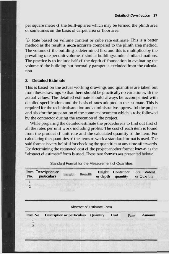
Details of Construction 37
per square metre of the built-up area which may be termed the plinth area or sometimes on the basis of carpet area or floor area.
(c) Rate based on volume content or cube rate estimate This is a better method as the result is mor: accurate compared to the plinth area method. The volume of the building is determined first and this is multiplied by the prevailing rate per unit volume of similar buildings under similar situations. The practice is to include half of the depth of foundation in evaluating the volume of the building but normally parapet is excluded from the calcula- tion.
2. Detailed Estimate
This is based on the actual working drawings and quantities are taken out from these drawings so that there should be practically no variation with the actual values. The detailed estimate should always be accompanied with detailed specifications and the basis of rates adopted in the estimate. This is required for the technical sanction and administrative approval of the project and also for the preparation of the contract document which is to be followed by the contractor during the execution of the project.
While preparing the detailed estimate the procedure is to find out first of all the rates per unit work including profits. The cost of each item is found from the product of unit rate and the calculated quantity of the item. For calculating the quantities of the items of work a standard format is used. The said format is very helpful for checking the quantities at any time afterwards. For determining the estimated cost of the project another format hown as the "abstract of estimate" form is used. These two formats are presented below:
Standard Format for the Measurement of Quantities
Item Descr No. part
1
iption or iculars
Height Content or T Length Breadth or depth quantity c
otal Contt Jr Quantii
--
Abstract of Estimate Form
Rate - - --
Item No. Description or particulars Quantity Unit Amount
1
38 Construction Management and Planniny
In order to arrive at the rate of each item one may foll of rates of the C.P.W.D. or P.W.D. and state "the percenta5= u r c u l ~ l e schedule". Though this may not be very scientific since the increase in cost of each item of work is not uniform, this is popular because of its simplicity. The consultant has to work out the actual cost of the items of work based on the prevalent market rates so that if standard schedules are not followed he could judge whether the rates are under-quoted or over-priced. While estimating the cost of construction it is important to have clear ideas about the factors such as the quantity of each of the basic materials since the cost is directly proportional to the quantity. Whether the availability of the material throughout the construction period is ensured or it has to be stock piled, the transport charges, the number of loadings and unloadings before brought to the site, and the handling of materials at site depending on availability of space are the other items which add cost to the price of materials.
While preparing the detailed estimate, quantities are ~e detziled working drawings. But in order to avoid unnecessary r 1s calculations, a code has made certain simplifications which a IS
followed. Some such examples are given here to indicate their uti
; masonr ?adth x h'
ressed in he found
cubic mt lation an1
3 2tre (m ), d plinth
m and tl each of sured in
n arch of ining the
chedule I
, 4h ,, 41.
t from tl . -
i.e. lengt are place
Brick y Here quantities are exp .h x brc eight. Brick masonry for t md under one ite lat for the super structure is separately itemised. But quantities for the storeys are calculated separately. Thin partition walls are mea square metre (m2). For honeycombed brick wall, the item is separately drawn but deductions for openings are not ma1
Deductions for door window are made from the quantities con is solid first. No deduction is made for openings up to 0.1 m2, nor for enas of beams and posts up to 0.05 m2 in area and also for bed plate and ie bearing of chajjahs up to 0.1 m depth. Bearings of floor and roof sk o not deducted from the brick work. The rectangular portion of the openmg, when the top of the opening is made as a ' small rise, is only d and not the curved segment for determ m quantity to be dt
de. sidered E
. - 3 -
wall plai 3b are als
, deducte 2ducted.
Plastering and pointing This item is calculated in m2. Measurements are taken for the entire face of the wall for both sides and then deductions are made for the openings as,
(a) No deduction is made for ends o lf beams, . .
posts, ra ~fters, etc
(c) For ope
m b s sof
lnings of
(b) For s m d openings up to 0.5 m2 no deduction is made, nelther are of the j i fits and f
size 0.5 r
~gs are ac
g is cons:
ided.
idered or I one fact
the other face being treated solid and no extra for jambs, soffi sills are considered.
(d) For openings exceeding 3 m2, area of the opening is deducted o faces and areas for the jambs, soffits and sills are added.
its and
n both
Reinforced concrete work All reinforced cement concrete work is measured in cubic metre. Bearings of beams and lintels are added extra to get the dimension. Though the quantity of steel measured in quintals/tonnes are paid as a separate item including bending binding, no deduction is made from the volume of concrete occupied by the steel reinforcement. Form work is also measured separately as a separate item but sometimes for smaller iobs with conventional shuttering work the item may be included in the r concreting.
Similar do's and dont's for taking measurement of any item of wc available. One may go through any text book on estimating and calcu required.
ate for
.-I. ---
3. There 'are other estimates namely re estimate, etc. which could be presented as f
vised es ~ollows:
itimate, supplem entary
Revised Estimate
This is made when there is a change amounting to more than 5% original value due to price hiking or change in specification. But thi- ---- not include any major change in structural design. the met1 preparation is similar to that of a detailed estimate, a lstimate 5
be accompanied with a comparative statement showmg variations from rnp
original work and also reasons for the changes.
of the s drips
!ms were .hate. A L :,- -A;-"
ked or found .-,. &L-
Supplementary Estimate
This is required to be prepared when some of the it€ not foreseen during the preparation of the original est that when these supplementary items are included it 5uu15 Lu 3UlYC
sanctioned amount, a supplementary estimate is prepared in the sarr as the detailed estimate. This should be accompanied with a stat showing the extra work involved and the reasons for preparing. this ~ ~ ~ I I L C I L ~ :
should be clearly reported.
133 U L C
te line ement L2- - L-
4. Total Estimate
This is also known as the complete estimate which of the project. This includes cost of land and requir construction of the project, consultants' fees including supervision, visits, etc. cost of water and electricity required during construction, legal expenses like the examination of deeds, the title of land, the agreement for the contract and
furnishe: ~d land
s the toti survey, c
. .
11 cost lost of
4u ~~onsrfucr~on danagemenr ana rrannrng
other legal matters, if any; contingency of 5% over the cost for extra work, if any, Thus the total estimate is the sum of all c~Utcllr3 "1
uction ,,c, ,C
1 connect expendit ure to be I made ir
RATE ANALYSIS
)er unit v - . . - . . . - . -
volume I-. m--
This give ails of th or per number whichever is appucable for an lrem or worK or supply. Ine analysis would give as to how a particular rate has been obtained and its justification or the logic behind its determination. This would include the cost of materials or the cost of different ingredients required to prepare the material, the cost of labour to produce the item of work and cost o petty expenses required for the work. The item should follow I
specifications and the rate should be based on that. It might require tne use of tools and plants. A certain weightage is to be given for the use o tools, plants or machines based on their production capacity and the depreciation or replacement. On the top of the contractor's profits, ov~~,.-.., and establishment charge: ftarges are also tc the rate of work. Broadly charged should b following aspects:
!s the det e analysi .. , per unit area or 1 r . 1 ~
--- - - - - f other certain
f these rate of ~rhparl
3, and in( ; the rat(
) be inclu le based
lded in on the
~tity and Cost of Materia 1. Quan
3tity of n n experi tions. Th
laterials required for an item of work could be ascertained The qua based 01
specifica ence or e costs o
dards a7 11s are ta
vailable ken as dc
followin; elivered i
g the re at site in
lquired clusive
of transp
2. Cost
jort, local taxes, e tc.
of Labour
For the cost of labour one must know hou 3bourers are required to produce a certain item of work. There ma; iriety of hands required for the job, e.g. artisans, masons, coolies, nelpers and bhistis (sprayers or
n). They itr~dures. Therefc alcula- nunbers lquired to be fou In this
connection the Ah Uldla btanaara bcnedule of rates prepared by tne luational
r many li y be a vz . .
have go and cos .- .. A.
t differer t of hanc . .s
lt wage 6 3s are IF . . . .
)re, the c nd out. . .. - 7
waterme tion of r
. .
Building enquired
y be refe: ling rate: ; should also be a1 prevai
3. Cost
Dependi
;, Plants
e type ol - and Ma
f work i~ . ..
chinery
~volved i .. .*
Of TOOIS
ng on th )merits and plant usea are selected. m order to rationause me appornonment of charges ro we
ially for jobs which involv robable total production tl
the equil . .
imposed machine:
under tl. S, one is t
lis headi o determ
ng espec line the p
,e big pla le m a c ~
n t and le may
pils of Construction 41 Deti
e may ru - give or the total number of hours the ma chin^ n during its lifetime, and cost of a similar one at the end of its lifetime. prom these two figures a basis is formed which will indirectly evaluate the proportion of charges in the form of a percentage of the total cost of the project to be added on the rate of this item of work.
There are certain other small tools and plants where the above exercise is difficult to perform. The cost of such equipment may be included under the heading 'overhead'.
4. Overhead Chars ges such I as Supervision and Vis its
This includes all items ror running an office like rent, electric charges, telephone bills, depreciation of office equipment, staff salary, salary of supervisors and engineers, stationeries, perishable materials like ropes, nails, G.I. wires, or tools to be provided to the masons, artisans, or helpers and labourers and sundries are also included. Cost of travelling, visits of senior personnel occasional entertainment to concerned people etc. is also to be included under this heading. All these are again expressed as a percentage, say 3 to 5% of the rates to be charged on the items of work. Though for smaller work these may not be substantial and may be ignored but for big job s these a
Contrac
re to be j
tor's Prc
ncluded.
>fit
A contractor will take all the trouble of undertaking a job only when he ea a reasonable amount out of it. The construction itself is full of hassles , hazards. This has been made more difficult due to certain advanta demanded from the associated people. In addition, t factors political interferences or interferences of local influent ns and tl followers, which have made this profession more difficuri. DU one will t this venture only when one is properly rewarded otherwise o. t be forced to sacrifice quality. An average profit,after meeting all dul due expenses, to the tune of 10% for big jobs and 15% on small jobs ueymdine on the cost of project should be considered reasonable.
The analysis of rates for the three major items of wok plastering work and reinforced cement concrete work are presenrea nen ._
provide some ideas. For more details and other works one may standard textbooks on "Rate analysis and estimation".
The primary ingredients of the above three items of work an class b~ and, cen
xcement First reinfc
First 3
m , c
ricks, mc s .
nent, stc
here are ial perscs - .I= C- -
)ne chip
'l'he basic price of these materials as in January 1992 are: class bricks: Rs 1200/- per 1000, medium sand: R ement: Rs 120/- per bag, 20 mm down stone chips: I
ne mighi e and unc - -1
brick wc . - * - 3 1 --..
-. s and s
lms and lees &e aeir ake
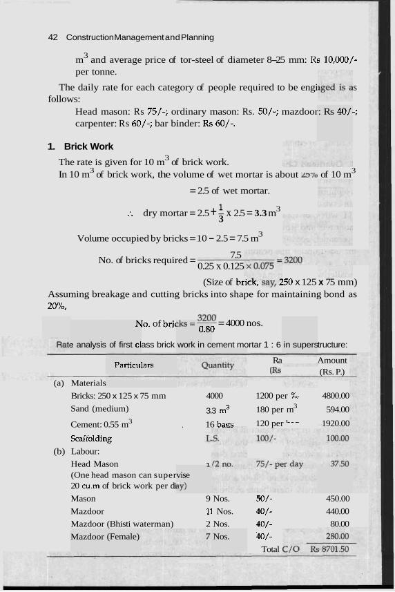
42 Construction Management and Planning
m3 and average price of tor-steel of diameter 8-25 mm: Rs 10,000/- per tonne.
The daily rate for each category of people required to be engi s follows:
Head mason: Rs 75/-; ordinary mason: Rs. 50/-; mazdoor: Rs 40/-; carpenter: Rs 60/-; bar binder: Rs 60/-.
1. Brick Work
The rate is given for 10 m3 of brick work. In 10 m3 of brick work, the volume of wet mortar is about zs% of 10 m3
= 2.5 of wet mortar.
1 :. dry mortar = 2.5 + - x 2.5 = 3.3 m 3 3
3 Volume occupied by bricks = 10 - 2.5 = 7.5 m
No. of bricks required = 7.5
0.25 x 0.125
(Size of b r i ~ ~ , MY, 150 x 125 x 75 mm) Assuming breakage and cutting bricks into shape for maintaining bond as 20%,
s analysis
h
of first cl
Particu
.h = -- - 0.8(
work in c
lo. of bric - 32130 = 4000 nos. 1
Scaifolding
(b) Labour:
ass brick
lars
ement mortar 1 : 6 tructure:
Ra Amount (b (Rs. P.)
(a) Materials
Bricks: 250 x 125 x 75 mm 4000 1200 per %O 4800.00
Sand (medium) 3.3 m3 180 per rn3 594.00
Cement: 0.55 m3 , 16 baes 120 per "-- 1920.00
Head Mason 1
in supers
Mazdoor
A 2
vise
ay)
(One head mason can super 20 cu.m of brick work per di
Mason 9 Nos. ,50/- 450.00
Mazdoor 11 Nos. 40/- 440.00
Mazdoor (Bhisti waterman) 2 Nos. 40/- 80.00
40/- (Female) Nos.
Total
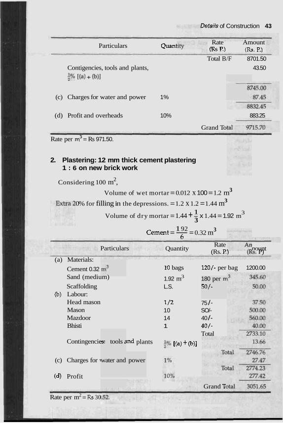
getails of Construction 43
Particulars Quani Rate Amount (Rs P.) (Rs. P.)
Total B/F 8701.50
Contigencies, tools and plants, 43.50
$/. [(a) + @)I
(c) Charges for water and power 1%
(d) Profit and overheads 10% 883.25
Grand To
Rate per m3 = Rs 971.50.
2. Plastering: 12 mm thick cement plastering 1 : 6 on new brick work
Considering 100 m2,
Volume of wet mortar = 0.012 x 100 = 1.2 m 3
0% for filling in the depressions. = 1.2 x 1.2 = 1.44 m 3
1 Volume of dry mortar = 1.44 + - x 1.44 = 1.92 m3
3 1 92
Cement = - = 0.32 m 3 h
Particulars
(a) Materials:
Cement 0.32 Sand (medium)
Scaffolding (b) Labour:
Head mason Mason Mazdoor Bhisti
Contingencie
(c) Charges for i
(d) Profit
!s: tools 2
water and
Rate Quantity nount (Rs. P.) (&s. P)
10 bags 120/- per bag 1200.00
1.92 m3
L.S. 180 per ~r
50/-
1 /2 75 /- 10 SO/- 14 40 /- 1 40/-
Total lnd plants 2% [(a) + (b)]
power
Grand Tc
Rate per m2 = Rs 30
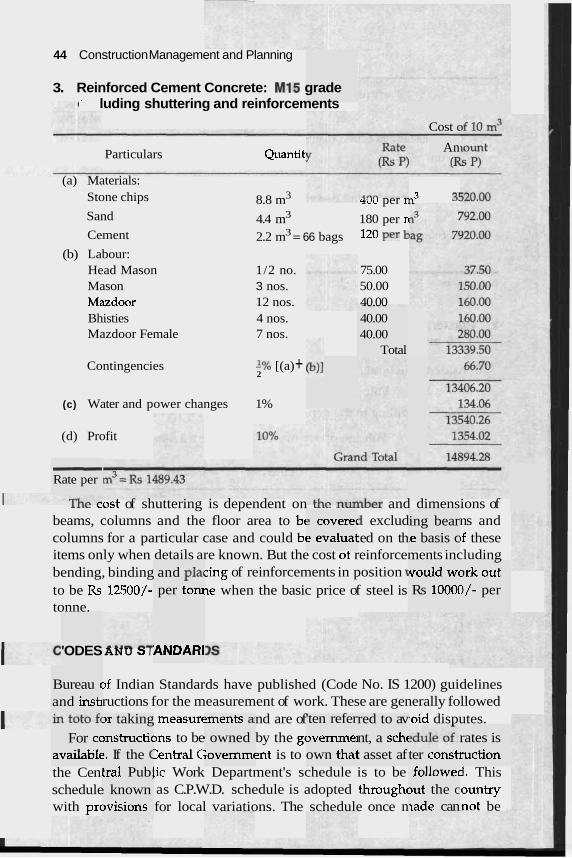
44 Construction Management and Planning
3. Reinforced Cement Concrete: MI5 grade - luding shuttering and reinforcements
Cost (
An Particulars Quantit:
(a) Materials: Stone chips 8.8 m3 ruu per rn3 3! Sand 4.4 m3 180 per n Cement 2.2 m3 = 66 bags 120 Per
(b) Labour: Head Mason 1/2 no. 75.00 Mason 3 nos. 50.00 Mazdoor 12 nos. 40.00 Bhisties 4 nos. Mazdoor Female 7 nos.
40.00 40.00
Total Contingencies '% [(a) +
2
(c) Water and power changes 1%
(d) Profit
- Rate per
,,,, ,ost of shuttering is dependent on .,,,nber and dimensions of beams, columns and the floor area to bt 3 exclud ns and columns for a particular case and could bc :ed on th ~f these items only when details are known. But the cost of reinforcements including bending, binding cing of reinforcements in position 1
to be Rs 12500/- ~e when the basic price of steel is tonne.
? coverec e evaluat
ing bear ~e basis c
and plat per tom
would wc Rs 100a
- 3rk out I/- per
'ODES ANDARI ANU 3 I
>f Indian Standards have published (Code No. IS 1200) guidelines ructions for the measurement of work. These are generally followed
measurc nd are of raid disputes. 3ns to be by the gc 3entral C 2nt is to lic Work Department's schedule is to be as C.P.W.D. schedule is adopted through( for local variations. The schedule once n
Bureau c and instl
>r taking )nstructic ?. If the (
lments a b owned ;ovemma
'ten refer wemmei own thai
red to av nt, a schc : asset af
For cc availablc
rates is ruction ter const
the Cen schedule with prc
tral Pub; ! known )visions
followec >ut the c lade can
5. This 'ountry mot be
Petails of Construction 45
and carr Buildj ,',,, s,
les inclu - .
~tage hig
a such q le basic r
uy insta . .
? percen! t a partic - ---LC-:-.
quote fc rs are COI
.I. - .
uotationr ates for f
tage abo mlar yea
L-- --
water !
changed often. However, the prices of materials, labour and other items involved in construction are always rising almost in everv month/year. Therefore, the practice is to declare a reasonable lve the schedule to be considered for a particular place a ~r. This increase above the schedule of rates may not also be sulllcler~r l u r guod and standard work. The contractors are permitted to )r a percentage higher than the revised schedule of rates and tende mpared accord- ingly. The contractor can also quote a percentage lower man the schedule if he has got valid reasons and argument fo s. The C.P.W.D. schedule at the beginning has presented th he hire charges for plants, labour, mate~ials for building and roaa worK, materials for S C N ~ ~ P S
iage. ng work and its details are presented next-where one may
yrlce3 lor the carriage of materials for various leads, earth work, I Y ~ U ~ L ~ L ~ ,
concrete work, reinforced cement concrete, brick work, stone work, work, wood work, steel work, flooring, roofing, finishing, repairs to ings, dismantline and demolishing and other miscellaneous ~ I A I I U U L ~
works. Servic ad work, sanita uarlv~lb, $upply,
drainage and mscellaneous items related to the services are presented next. The schedule also include horticultural work at the end of the book.
Generally, this book has given almost all the details of items for I
constructions but for special constructions if non-scheduled items decision on quoted raks are taken after studying the market prices.
State P.W.D. schedules are also prepared on similar lines and an followed for works belonging to state government. Each and every state government has prepared their own schedule of rates which also includes building works, carriage, materials and labour. Tenders are accepted on the basis of a percen her than the revised ,schedule or an the revised schedule.
The Central Guverrul~ent as also the State Governments r w v e gut other books containing general conditions, general specifications, additional con- dition of contract for departmental materials, standard charts for material consumption, etc. which are part and parcel of the contract and are binding to both the parties.
For non-governmental work or works for private parties one can follow the CP.W.D. or P.W.D. schedules but this is not compulsory. It is considered to be more rational to price each item of work on the basis of actual price of material and labour prevailing in the market. Thus a uniform percentage above or below the schedule which has no scope to detail out the actual rise in price of individual ingredients consisting an item of work is not required to be agreed upon. These are generally looked after by the consultants.
get the B nrCn
marble build-
.:lA;-"
normal appear
e to be
46 Construction Management and Planning
EXERCISES
-101.v does lpplemen
stimate
it vary fr tary estin-
. estimate,
.om the d' late? Expli
etailed ain the
3.1 In connection with the rough cost estimate for a construction work, explaln the following with their relative merits:
(a) Unit rate estimate (b) Plinth area e
(c) Cube rate estimate.
3.2 Why is a rough cost estimate prepared? I estimate? What is a revised estimate or a si term 'total estimate'.
3.3 Draw a standard format for
(a) Measurement of quantities, (b) Abstract for
(c) Rate analysis.
3.4 What do you understand by "the percentage higt applicable to the C.P.W.D. or state P.W.D. schedule?
3.5 What are the items which add cost to the price of materials?
3.6 Give some examples to establish how the IS. Code has simplif of quantities.
3.7 Prepare rate analyses of the following items:
(a) Joinery work for door and window frames .
(b) Door and window shutters
(c) Plain concrete in foundation
(d) Lime punning work
(e) In-situ mosaic flooring
(f) Plaster of Paris on wall surfaces
(g) Laying of sewer lines in buildings
(h) Painting doors and windows.
3.8 Describe briefly the structure of the C.P.W.D. schedule. Ment sections available there.
and
ile" as
'ied the de
ion the di fferent
I CHAPTER 4 b
Construction Organisation and Superintendt
ORGANISATION PLANNING AND ORGANISATION CHART
In an organised construction company like any other good organisation there is a grouping of activities headed by persons both.specialists and generalists who are supposed to bear the full responsibility of the job allotted to them. As an organisation expands the problems of management also increase. Some of these problems are visualised in advance and the company could take necessary steps. While there are others which cannot be foreseen and demand on-the-spot solutions. To tackle these problems the company undertakes organisation planning in a manner such that the individuals in small groups or in large groups or divisions take the right decision.
Thus, in a well organised company the various functions of management emerge as they apply to individuals. Individuals are next grouped for the group functions and finally several groups are combined to form divisjons on a functional basis to complete the overall organisation structure. A chart called the organisation chart is normally prepared to explain this structure. The other important purpose the chart serves is to indicate the route of promotions for young officers as they gain experience and training to reach the top echelons of the company. This has got a very conducive effect in the minds of young officers who could do the intended career planning. In an organisation chart since the route to be followed is clearly kxpressed this saves much time and energy thereby avoiding duplication of work. The organisation chart may be prepared for each division and group headed by a full chart for the company as a whole. An organisation chart indicates the
48 Construction Management and Planning
channels for the movement of action from the chief administrator to their subordinates. It also shows expansion, contraction, reorganisation required to improve the overall efficiency of the compa chart is generally published and made available to any person wh aested and looking at it one may easily know his own position in tht L U A L ~ ~ U I ~ and how one is fitting in into the overall programme of the company. The process of charting itself indicates the process of efficiency as because an organisation which cannot be charted automatically indicates that there is scope for im~rove- ment in planning since there is confusion in the process of decisior The three organisation charts presented at the end of this chapter s 2
essential features and activitv routes for a small. medium and large company.
OF RES - - - . . - .
DELE VEL REQUIREMENT AND DIVISION OF WORK
In any organisation, whether it is a small company owned by a single man or a joint company or corporation maximum responsibility is delegated to a single man who is called the managing director, chairman or president. The responsibility of varying degrees is delegated to the chief executive first and then divided and subdivided down through several layel organisa- tion. In a company owned by an individual who is to lo ~lanning, execution, finance, etc., responsibilities are concentrated. 1 in a large corporation the responsibilities are delegated and divided to many in- dividuals. The executive is to organise programmes of work within the field of his responsibility and engage appropriate personnel to carry out these programmes as per a schedule. It is the duty and responsibility of the head to create an interest among the juniors and subordinates who will automati- cally carry out their work. A good executive is one who could energise subordinates to work and make them carry out his orders. It is not necessary for him to work continuously himself to finish the job. He is to select and develop his subordinates as'equal or better successors for each individual position of responsibility including his own replacement.
In a large construction company, a good number of per ther than technical persons are also required. They normally give assistance for the smooth running of the company though not technically qualified themselves. For example many smart young personnel are required for the maintenance of office records, finance and legal matters. Staff are' also required to assist executives for their own sections. In a sn nisation be employed on a part-time basis.
The size of a n organisation is the final crlrenon for divid~ng me work and the responsibilities. The following table may b distribution of manpower for a good organisatior
nall orga
e consid 1.
as of the 10k into 1 Vhereas :
sonnel ol
these pec
I. ., ered as
I
I making ihows tht - - .. . .. . - -
~ p l e may
an ideal
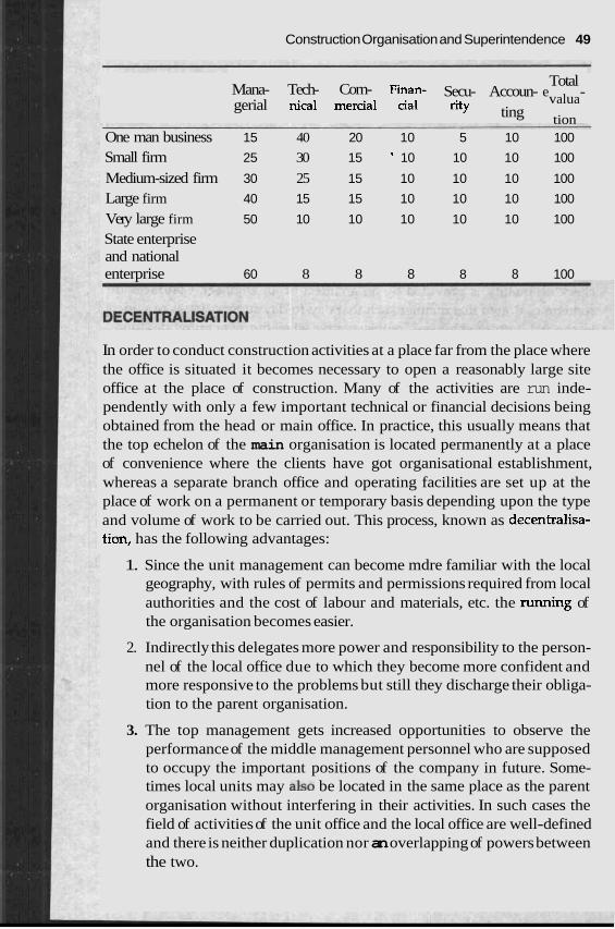
Construction Organisation and Superintendence 49
Total Mana- Tech- Com- Finan- Secu- Accoun- evalua- gerial nical mercial cia1 rity ting tion
One man business 15 40 20 10 5 10 100
Small firm 25 30 15 ' 10 10 10 100
Medium-sized firm 30 25 15 10 10 10 100
Large firm 40 15 15 10 10 10 100
Very large firm 50 10 10 10 10 10 100
State enterprise and national enterprise 60 8 8 8 8 8 100
In order to conduct construction activities at a place far from the place where the office is situated it becomes necessary to open a reasonably large site office at the place of construction. Many of the activities are run inde- pendently with only a few important technical or financial decisions being obtained from the head or main office. In practice, this usually means that the top echelon of the main organisation is located permanently at a place of convenience where the clients have got organisational establishment, whereas a separate branch office and operating facilities are set up at the place of work on a permanent or temporary basis depending upon the type and volume of work to be carried out. This process, known as decentralisa- tion, has the following advantages:
1. Since the unit management can become mdre familiar with the local geography, with rules of permits and permissions required from local authorities and the cost of labour and materials, etc. the running of the organisation becomes easier.
2. Indirectly this delegates more power and responsibility to the person- nel of the local office due to which they become more confident and more responsive to the problems but still they discharge their obliga- tion to the parent organisation.
3. The top management gets increased opportunities to observe the performance of the middle management personnel who are supposed to occupy the important positions of the company in future. Some- times local units may also be located in the same place as the parent organisation without interfering in their activities. In such cases the field of activities of the unit office and the local office are well-defined and there is neither duplication nor an overlapping of powers between the two.
50 Construction Management and Planning
CONSTRUCTION SUPERVISION AND SUPERINTENDENCE
Construction supervision is the regular checking of the construction work which includes checking of the drawings, the quality of materials against specifications, the equipment to be used in the work, the quality of work during construction and the precautionary measures to be adopted to achieve quality during and after construction. Supervision is normally done by an architect or an engineer and it is a part of the contract with the owner. Generally the day-to-day supervision of the work is done by the contractor and this becomes his responsibility while periodic supervision and overall check on quality is provided by an architect or an engineer. Contracts are sometimes drawn in a manner such that day-to-day supervision is provided by the architects or engineers' representative when the owner provides funds separate from the consultancy fees for the employment of the resident engineer or the clerk-of-works. This provides a useful check on the activities of the contractor.
Construction superintendence is different from that of supervision of the work in many ways as elaborated below though the two words are used synonymously. Superintendence of the progress of works becomes the joint responsibility of the general contractor's superintendent (sometimes called the superintendent engineer), i.e. the man-in-charge of the project and the resident engineer or clerk-of-works who is the representative of the architect. The superintendent engineer is to arrange for every thing so that the progress is not hampered whereas the resident engineer (RE.) or the clerk-of-works (C.O.W.) inspects it and certifies it before acceptance. If they disagree they may suggest appropriate changes for the improvement or may consult the owner for the final decision if required. The superintendent is basically concerned with the costs as also workmanship and materials whereas the R.E.'s or C.O.W.'s main concern is the workmanship and material but both must be vigilant about unauthorised substitution, improper short-cuts, careless work and deliberate omissions. The final payment is made by the owner when this is recommended by the superintendent and R.E. or C.O.W.
Many times it is found that the general contractor has to subcontract some portions of the work to others. In such cases the superintendent does not have any direct control over the subcontractor's men as he could enforce over his own men. But, since it is the general contractor, who is answerable to the architect or the owner, he has to take the necessary steps from the very beginning of the project such that the channel of authority or procedure for following them is established with any such subcontractor.
The drawings and specifications to be followed is generally a complete document. The copies of these documents should be given to all the
Construction Organisation and Superintendence 51
subcontractors, but in case of any change found necessary during construc- tion, it should be brought to the notice of the consulting architect and architect's opinion is to be conveyed to all concerned in the project.
DETAILED SUPERINTENDENCE
The broad responsibilities and superintendence may be grouped as follows: 1. Record of contractor's personnel including hiring and discharging
people, trades and craftsmen, pay rolls and records. 2. Purchase and delivery of construction materials and equipment includ-
ing storage, protection and maintenance. 3. Cost records including labour, material, insurance and miscellaneous
expenses. 4. Project office control including provision for facilities for the general
office, office operations, maintenance of construction safety standards. 5. Contract changes, disputes and stoppage of Works.
HIRING AND DISCHARGING OF PERSONNEL AND RELATED MAlTERS
Each contractor or subcontractor maintains a record of the bio-data of the personnel employed in their respective organisation.
Instructions are issued from the site office to the head office regarding the requirement of tradesmen or craftsmen for the job. These people are initially sent to the timekeeper who in turn sends them to the various individual foreman who needs their service. The foreman who decides to hire them fills out a hiring ticket and sends them to the timekeeper who then issues a badge or check number to be retained by them during the period of service in the particular site. This number is entered in the daily time record in the timekeepers office. In addition an employment record in duplicate along with a withholding statement is issued in favour of the new recruit. The original is sent to the head office while the copy is filled at the site. The head office maintains this record of the person on a cumulative-basis to record the activities of the person concerned with the company so as tg calculate the old age benefits, taxes, etc. The following general information are recorded in the form of a bio-data:
Date, name, address and telephone no., date and place of birth, name of father, citizenship, occupation, marital status, no. of dependents, name and address of the nearest relative (next to kin), and the previous employer.
When a workman is discharged the foreman fills put a discharge slip and sends him to the timekeeper with this slip. The timekeeper calculates all the dues payable to him and passes them on to the pay master who prepares a
52 Construction Management and Planning
voucher and arranges for the payment by cheque or in cash. The timekeeper updates his records on the employee record card.
In case of any increase in the rate of pay for any individual or in general a change of rate, the pay-slip is made out by the superintendent. The company may use the standard printed forms for record-keeping available in the market. Sometimes big companies may get their own standard forms printed for use under the banner of the particular project.
PAYROLLS AND RECORDS
In big construction sites in order to keep track of men, materials, equipment used and payments to be made, it becomes necessary to follow a certain systematic way of recording these details.
Payrolls and records involve the foreman's daily time report, the daily time record, the timekeeper's checking card, the timekeeper's payroll report, and the withholding statements.
The foreman fills out the daily time report where he shows the work done by each man, the materials used and the item of work done. This report is checked against the daily time record which is maintained by the timekeeper, as the men enter and leave the site, using a time clock or card system. From the daily time report the pay-master prepares the payroll subdivision sheets and the weekly cost report.
The weekly payroll sheet is prepared in duplicate where wages, deduc- tions, straight time engaged and overtime or premium time of work are also recorded. Other relevant information like transfer to other payrolls, re- employment, or notice of discharge are also entered in these sheets. As a general rule these payroll sheets need the approval of the superintendent who sends them back to the timekeeper who sends the original to the main office retaining a copy in his office.
The subcontractors engaged in the work are also supposed to maintain similar records for men, material and equipment, and submit the same to the timekeeper who prepares a daily log to be approved by the superintendent. Copies of this report are also sent to the RE./C.O.W. and the head office.
The receipts signed by men after receiving their weekly pay packets are maintained in a file in the site office. Tax withholding statements are submitted by the contractor usually in the head office from the consolidated record and a copy of the same is submitted in the office of the District Income Tax Oficer/Director.
PURCHASE AND DELIVERY OF CONSTRUCTION MATERIALS AND EQUIPMENT
For purchasing materials or equipment, some form of purchase order is to
Construction Organisation and Superintendence 53
be issued from the project managerfs/or superintendent's office. Normal progrciss of construction is possible only when there is a steady flow of materials timed as per the requirement and there is no piling of materials in the work area for a good length of time. The order form is usually made in triplicate. The original and first copy goes to the supplier who returns the copy indicating his acceptance. The second copy is filled in the office for follow-up action-and for future reference.
The purchasing department/section is informed about the needs of the project by requisitioning the required materials/equipment which is done by a responsible site officer. These requisitions are kept in the office whereas an order for the same is placed with the supplier by the purchase department who actually makes the purchase.
When materials and equipment are delivered at the project site those are accompanied with shipping order made by the supplier. People at site are supposed to sign the delivery receipt. But this does not indicate acceptance of the material or equipment but only acknowledges receipt. Final acceptance is given after proper and thorough inspection by authorised personnel and sometimes the final acceptance is given after the installation of the equipment and its demonstration.
Timely delivery of material/equipment is very important but excessively early delivery is also not desirable as that may cause repeated handling, shifting and storage problems.
RECORDS OF COST AND PAYMENT
In order to control the cost of project it is of utmost importance that records be maintained meticulously for all expenditures. Periodic checks on the volume of work done and expenses incurred against the estimated cost of items of work should be made to know the financial position of the project. This checking also helps to provide reliable price information for future jobs that may need to be quoted.
A good cost accounting system must present the expenditures made under different headings and by different units of the project separately which should include the expenses incurred by the units maintained by the estimator, thg engineer, the accountant, the superintendent and others so as to work out the proportional overheads required by each of these units. On this basis, the reallocation of expenses could be done for the sake of efficiency. In a cost plus contract, the owner prepares a budget which is controlled
by an architect or an engineer. The record of changes are also maintained to check the estimated cost of the project. In a lump sum contract, it is in the interest of the contractor to maintain the records of cost so as to control the job expenses.
54 Construction Management and Planning
If the work involved in a particular item increases, it is labelled as extra work and in case the volume of an item decreases it is labelled as a credit memorandum. These are all kept in the job file for adjusting the money available in the contract.
All vouchers or weekly pay roll sheets for the contractor's own men, subcontractor's men and vouchers for materials are the records for the expenditure made. These are transferred to a weekly cost report from which a monthly cost report is prepared and is kept in the job file.
PERCENTAGE COMPLETION REPORT
In order to prepare the cost report, the estimating section witl-, the help of contractor's engineer prepares the percentage of completion for each item of work. From such updated cost figures the estimate of 'amount to complete' and the 'final estimated cost' are compared to the working estimates and extras. This comparison clearly reveals the 'over run' and 'under run1 which aids the sound management of the progress of the project.
Again the values shown in the cost report can also be used to check the progress schedule of the project and to establish a correct percentage of completion. This percentage when applied to the total anticipated cost should be near to the cost-to-date figure. In case of a mismatch between these two figures one may be made alert to investigate the cause of difference particularly when the cost becomes relatively high.
INSURANCE RECORD
The contractor has to maintain all records of action taken under the provision of insurance of the contract and other state and central laws in connection with insurance benefits for the labourers. The following records are essen- tially maintained.
1. Workmen's compensation and employer's liability insurance in accordance with applicable laws;
2. Comprehensive general liability insurance to cover both body and property damage;
3. Comprehensive automobile liability insurance to cover both body and property damage;
4. Fire insurance to cover materials, tools, equipment, supplies, tem- porary and permanent structures.
PROJECT OFFICE REQUIREMENT
In a construction site the different people who work are the general contractor, the subcontractors and the architect/engineer. Each of the organi- sation needs adequate space to run their individual office which of course
Construction Organisation and Superintendence 55
depends on the number of people employed and the bulk of records to be handled. Space for office has to be provided for the general contractor, subcontractors and the architects. To maintain the smooth functioning of the project activities these areas should be so earmarked that one is easily accessible from the other. At the same time there should be some sort of isolation so that unnecessary interference of daily work is intelligently avoided.
In the construction site, there are some activities which go together simultaneously while there are others where one follows the other. If different agents or subcontractors are engaged for different items of work the space planning may be done accordingly so that the same space may be used by different agents at different periods of construction.
The separate organisational groups as mentioned may all be housed under one roof or in separate buildings depending upon which arrangement is best suited for a particular project. If all are housed in one building each of the offices should have a separate entrance and the office space distinctly separated out from others.
The resident engineer or clerk-of-works who is the agent of the architects are to maintain the records of drawings and revisions, specifications and revisions, correspondences, actions of committees, notes on meetings and conferences, inspection reports, control surveys and construction progress information. The general contractor has to maintain records of men and material employed, datewise progress planning of items of jobs to be executed, materials, equipment and men to be employed for the job element, records of cost of labour material, the record of subcontractors employed, individual progress of their jobs, etc. While the subcontractor is to maintain almost all records maintained by the general contractor, the scale is smaller when compared to the general contractor as he is responsible for only that portion of job awarded to him.
In order to have an updated knowledge of the progress of work, the schedule of work to be maintained, hurdles and hindrances to be overcome, meetings are often required to be held at site. In order to fix guidelines to be followed and the details to be drawn, these meetings are needed frequently at the beginning. When the progress gears up and people are highly busy in their own activities, frequent meetings are not required but as a routine there should be one meeting every fortnight or a month where people may discuss, exchange their views and adopt measures for the smooth running of the project.
The meetings also serve the purpose of fixing responsibility for the acceptance of materials and workmanship, enforcing quality control, etc. The personnel involved iriclude key individuals from the general contractor's organisation, representatives from the architects or engineers and sometimes
56 Construction Management and PIanning
the client also. The report on the job meeting is prepared in the contractor's site office and is circulated to all people concerned with the work. A file is maintained to keep the reports of the meeting for ready reference in future.
SAFETY
If the contractor works in an orderly and disciplined manner he can easily realise many benefits. He can save a lot of money because of reduced cost of insurance, labour and field operations. Thus he can quote a more competitive price compared to others and chances of getting the job are better. But he is to be very vigilant on construction safety which he is to undertake himself. Dependence on others is not that effective and generally found to be costlier. Depending on the volume of work to be handled and the value of the job undertaken, the direct and indirect costs associated with construction acci- dents total well over a few lakhs of rupees per annum. This includes the direct cost of insurance premiums, direct costs of emergency medical benefit, loss due to payment of full wages to the injured worker,,expensive corrective action, repair and replacement of damaged work and equipment, cost of training for new recruits and replacement of old trained personnel. The more the arrangement of safety measures adopted at site the more sense of security comes to the minds of all concerned and the reputation of the contractor runs high. Prevention of accident in construction is largely a matter of education, vigilance and co-operation by everyone involved in the project.
CHANGES IN CONTRACT
Changes in contract are quite normal and natural in the process of construc- tion. Changes may be initiated by the client by incorporating minor changes of the plan, changes in design may also be found essential for the improve- ment of the design or even changes in specifications may be entertained for the general improvement of the job.
A procedure is to be followed for regularising these matters of changes. The resident engineer or clerk-of-works should logically be the person to maintain records of these changes. The contract period should also be given due importance. No change in the contract period should be entertained though changes as mentioned are required to be incorporated. All parties of the original contract should sign the change order in person or by authorised agents so that the changes become part of the contract.
DISPUTES AND STOPPAGES
The general contractor and subcontractors enter into agreement with the Trade and Crafts Union whom they are going to employ. As such if contracts
Construction Organisation and Superir
ement sk erstandir 3 - - . . -.
nd empl mion rep
u
greemeni mtinue c - a 2 -- -.-I-
ttendence
ally all tl
57
hese are negotiated at local level their terms will vary but basic; agreements deal with the wage rates, working conditions and time limit for such settlements. In case of any dispute the superintendent may help in arbitration. Labour peace means more profitable job for all.
The most common cause of dispute are wages and jurisdiction. Each agreement related to the wages should be clear without any ambiguity. Jurisdictional disputes are clashes between trades, each of which claims the right to do the same work. The contract agre lould be clear in this respect so that chances of misundc ~g may n~
A strike is basically a test of strength which aoes nor mean that conait are so worse that the employer and the employee cannot go together. It now become a sort of a prestige issue induced by the political leaders the labourers go on strike only to show their existence. The employer understand this psychology and prepare themselves beforehand so tha knows when and how they should allow some indulgence without cau loss of money and time on the overall project. There are certain matters w are the joint responsibility of the employer a oyee, e.g working conditions, job discipline, seniority, L lresentati and overtime rates, insurance and other frlnge benefits. Sometunes negotiation has to be started before the lapse of the time period for which the agreement was made due to the mid-term announcement of certain changes in wages, pattern of wages and fringe benefits by the ruling partv or the government running the country. Unfortunately the whole thing - be one-sided, i.e. there may not be any extra benefit given to the contra though these are announced for the labourers. The contractor has to undc lot of tension to complete such projects lest the project runs at a loss.
Whenever a dispute does arise the contractor has to see that it does lead to the stoppage of work. At first a meeting is held between the superintendent and the union leader. Many a: ts provide for arb tion and state specifically that work should cr luring this proces complete record of all grievances and of all acuvrl mated thereto shoulc recorded and referred for future negotiations and agreements.
made cq ot arise a -. --. 3 ! C
;. the ger on, pay :
ptal t all. ions : has that is to lt he sing hich leral ;tale
; re-
u
not
itra- s. A Abe
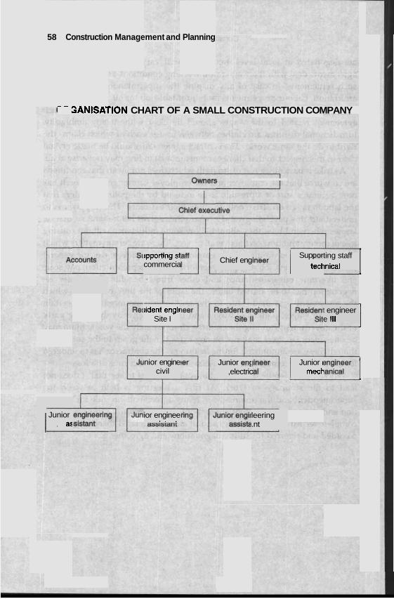
58 Construction Management and Planning
-- 3ANISATION CHART OF A SMALL CONSTRUCTION COMPANY
I I
1
rpporHng s1 commercia Chief eng
Sup par I teck ting staff ~nical
L tident engir
Site I t engineer e Ill
nior engine civil
Junior en$ ,electric
Junior I I mecp
Junior I , as ior enginee . . . leering
.nt
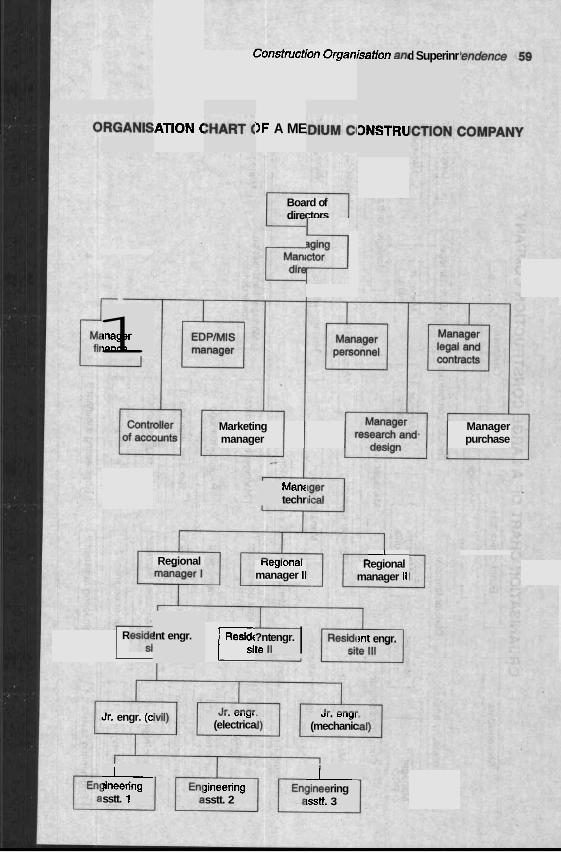
Constmction Organ1
)ATION C IF A ME
isation an1 d Superinr
ONSTRU
Board of directors
aging 3
Marketing Manager manager purchase
tnager lance 1
Manc techr
I Regional Regional neglonal
manager II manager II
!nt engr. Reside r;[ Reside 1 ~: ?nt engr. te 11 I ?nt engr.
Jr. engr. (c .#, . Y. ,y.
(electrica Ul . Ul lyl
(mechanic
I $nee ring lSStt. 3
I jineering sstt. 1
jineering sstt. 2
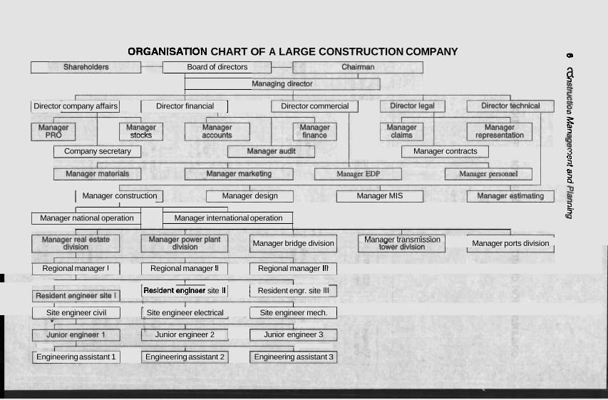
Manager bridge division Manager transmission Manager ports division
ORGANISATION CHART OF A LARGE CONSTRUCTION COMPANY ui o
Board of directors a 5
I [It I Director company affairs I I Director financial ] Director commercial 3
5 - k
stocks 5
Company secretary Manager contracts % 3 (D 5 -L
P,
3 I Manager construction Manager design Manager MIS
I I I
5 5'
I Regional manager l I I Regional manager ll I I Regional manager Ill I
-1 1 ~esident engineer site II I I 1 Resident engr. site Ill
fa Manager national operation
I I I
I Site engineer civil I r Site engineer electrical I I Site engineer mech. 1
Manager international operation
I I
Junior engineer 2 Junior engineer 3
I I I .
Engineering assistant 1 I Engineering assistant 2 Engineering assistant 3
Constnrction .Organisation and Superintendence 61
EXERCISES
4.1 What is an organisation chart? How does it help smooth functioning of a company?
4.2 It is said that delegation of responsibility and divisions of work help the organisation to function better. Explain.
4.3 Discuss how the total manpower requirement of companies of different sizes should be divided among the technical and non-technical heads so that the company could run smoothly.
4.4 What do you understand by 'Decentralisation'? Why is it found to be necessary? Do you think that the performance of a company improves by decentralization?
4.5 What is the basic difference between construction supervision and construction superintendence? Write down the different headings for which detailed super- intendence will be necessary.
4.6 What is the procedure to be followed for hiring and discharging of personnel in a construction site? What is the general information required to be known about the person to be hired?
4.7 What are the items to be recorded in preparing pay rolls and records? 4.8 Discuss the procedure to be adopted for the purchase and delivery of
construction materials and equipment. 4.9 Suggest a rational .method of keeping records of cost and payment in a
construction site.
4.10 What is meant by 'percentage completion report'? Why is it made? How does it help superintendence of construction work?
4.11 Make a list of the insurances to be maintained in a construction site.
4.12 Write down the requirements of a project office. How should the office be planned in order to have optimum functions?
4.13 Write short notes on :
(i) Safety, (ii) Changes in contract, (iii) Disputes and stoppages.
observ problei --- -.- down incidm ability
Operation
On the c ased upo . . ..
nber of I
ing, i.e. I 1 1
s to one.
Many of the civil engineering problems are ~ased either upon classical theories or on empirical observations. For example, a beam design is derived from mechanics and the gravity flow in a pipe is derived from empirical
ations. I )ther hand, a n u construction management ms are bi ~n chance happen xobability. For example, a
consrmction manager rhough much concernea about problems like break- of a machine or the completion date of a project c, edict the ~t exactly. However, the construction manager ma to prob- theories to find a workable solution to the problem. ~t present,
probability plays a considerable role in managerial decis nutshell elementary statistics is discussed here to help the a= encouraged to consult other statistics book for further referenc
Probability is the chance that something will happen. Probabi expressed in fractions or as decimals. A zero probability of an event I
no possibilities of the event whereas unity indicates definite OCculrcIi~c ur the event.
Probability theory is based on the follc 1. The probability (P) of an event (L, V C L U ~ l ~ ~ ~ \IIE)) is a L L W ~ L U C ~
1 0 and 1.C I P(E) I 1.0
2. 111~ ~ L U H of all vruvdvurles of all mutually m~uslve ourcomes ror a
$ven evc I
mt equal
ioms : --... I D /
annot pr y resort . - ion malc readers.
ing. In a Readers le. lities are indicates .--n,.
- , _ rarron ~nalysis and aransrrcs oa
3. The 1 is eai
xobability of either of two mutually exclusive events occurring _lual to the sum of the probabilities of each of the two events.
4. The I . p o ~ a ~ l l l r y or w o indepenaenr events occurring s~mummeul lent is eq
eveni ual to th ts.
le produc
- .
:t of the
- - -
probabil
. - . -
he two i indepmd
L (
ie (EV) is ~hted avc dl possible outco~ m m a even slruation in wlucn pro~abilities can De assigned or assume
cted va l~ .. . . f i e expe /.
; the weil . . 4~
erage of i I .-
aes d.
, Oi = oui where Pi = independent probability for event i, event actually occurs, and i = l,2,3, . . . , rn.
:come for event if the
:tractor fr machine -
lat in the hr ing e 1- 1-La...
last !a& . A
Example 5.1 A building con .om his record discovers th 200 slab castings his mixer ! went wrong 21 times. 1 L--akdown he had to pay OIL d v c l a g about Rs 2,500/- for id r lauvul. fi
ndby mixer machine if hired on the day of slab casting would cost I jut Rs ZOO/- per day what should be the course of action of the contracl
Solution :
Probability lown is about 21 /200
Expected lobJ l j l v ~ as 0.105(2500 - 200) - 1.a L=A.J".
'UlC
sta abc - -
~ tor?
ixer
d b ~
The expected loss is greater than the mitigation expense of hiring the m machine, i.e. Rs 200/-. Therefore, the contractor should hire the s t m mixer machine to make profit in the long run.
'ION
Dis the n t n
Ih the inc p of data , .-.~.t".i"
persion indicates the extent to whic lividual values scatter aro~ average or central value in a grou: .. It is a way of expressing
,Aabability of a variable attaining a LNLLLuI value as a function of tkmt variable. The distribution could be discrete or continuous. A discrete pr ability is allowed to take only a limited number of values. For example, probability of completion of a job in the next month is discrete because th could be only 30 possible values. On the other hanc probability distribution, the variable is permitted to take a given range. In a sense, it is a discrete distribution thaC I m v c IIUIV VVJDI
outcomes all of which are very close to each other. For examp strength of MI5 concrete can be any value close to 15 ~ / m m ~ .
md the
A L a L
,ob- the . f i e 1ClC
OUS
hin :Ll-
I, in the ?onany1 L L-..- -.
continu1 d u e wit ---. --"".
1v1r
ube , 1
lle, the a
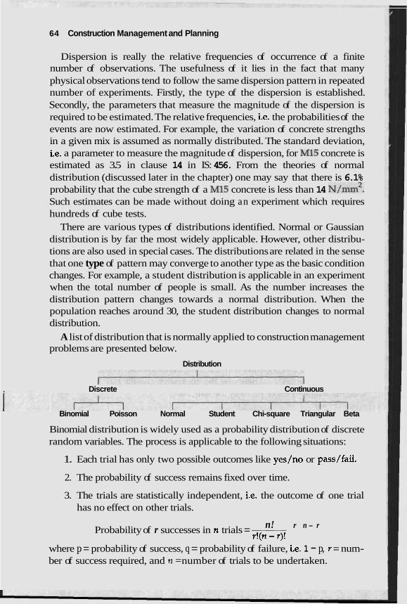
64 Construction Management and Planning
Dispersion is really the relative frequencies of occurrence of a finite number of observations. The usefulness of it lies in the fact that many physical observations tend to follow the same dispersion pattern in repeated number of experiments. Firstly, the type of the dispersion is established. Secondly, the parameters that measure the magnitude of the dispersion is required to be estimated. The relative frequencies, i.e. the probabilities of the events are now estimated. For example, the variation of concrete strengths in a given mix is assumed as normally distributed. The standard deviation, i.e. a parameter to measure the magnitude of dispersion, for MI5 concrete is estimated as 3.5 in clause 14 in IS: 456. From the theories of normal distribution (discussed later in the chapter) one may say that there is 6.1% probability that the cube strength of a MI5 concrete is less than 14 ~ / m m ~ . Such estimates can be made without doing an experiment which requires hundreds of cube tests.
There are various types of distributions identified. Normal or Gaussian distribution is by far the most widely applicable. However, other distribu- tions are also used in special cases. The distributions are related in the sense that one type of pattern may converge to another type as the basic condition changes. For example, a student distribution is applicable in an experiment when the total number of people is small. As the number increases the distribution pattern changes towards a normal distribution. When the population reaches around 30, the student distribution changes to normal distribution.
A list of distribution that is normally applied to construction management problems are presented below.
Distribution ~ Discrete Continuous
Binomial Poisson Normal Student Chi-square Triangular Beta
Binomial distribution is widely used as a probability distribution of discrete random variables. The process is applicable to the following situations:
1. Each trial has only two possible outcomes like yes/no or pass/fail.
2. The probability of success remains fixed over time.
3. The trials are statistically independent, i.e. the outcome of one trial has no effect on other trials.
n! r n - r Probability of r successes in n trials = r!(n -r)! where p = probability of success, q = probability of failure, i.e. 1 - p, r = num- ber of success required, and n =number of trials to be undertaken.
Operation Analysis and Statistics fir;
Example 5.2 A labour inspector is going to visit 6 sites and wants to k the probability of getting exactly 3 favourable reports from the visits. data yield that 8 out of 10 such visits produce favourable resu
Solution:
Probability of 3 favourable reports out of 6 visits
A cumulative binomial distribution table is available'in many handbs to facilitate calculations.
Example 5.3 A sample of 20 items is drawn from an inventory of which is defective. Find the probability that the sample contains 1. 4 or mol less than 2,3. exactly 5 and 4. no defectives.
Solution:
From the table of cbmulative binomial distribution
Probabilities: \
other.
. .
ooks
=1 - 0.9612 = 0.0388 Poisson distribution is used in several management problems. Particularly,
queuing problems are solved with ,the help of Poisson distribution. The process is applicable 10 the following situations:
1. The probability of one event in a second is small and is constant 2. The probability of two events taking place in a second is infin_.-_,
small, i.e. zero. 3. The events are statistically independent of each
The probability of exactly x occurrence in a Po~sson d l ~ t ~ - l t ~ ~ t l o calculated as
where h = mean of the distribution.
66 Construction Management and Planning
Example 5.4 In a construction site, the contractor requests on the average 5 times a day to the owner's engineers to check works for approval. What is the probability that the contractor shall request at least 3 times on each day?
Solution:
Probability of three requests a day = 1 - 0.26511 = 0.7348!
The normal distribution or the Gaussian distribution is the mosr wiaely used distribution in practice. Normal distribution has the following charac- teristics:
1. The curve has a single peak.
2. It is bell-shaped.
3. The distribution is symmetrical around a vertical line erected at mean.
4. The two tails of the normal probability distribution extend indefinitely '
and is asymptotic with the horizontal axis.
The normal distribution can be measured using the mean and standard deviation.
,cxi Mean=- and standard
n The probability density function of n stribution is
where z - -- d
The table illustrating the area under the normal curve between the left hand tail and any point to the right of mean is pesented in the Appendix I. An example is presented to show the use of normal distribution table.
Example 5.5 Historical records in a group of bank accounts indicate that the mean amount per account is Rs 5,000/- with a standard deviation of Rs 1,000/-. What is the probability that an account drawn at random will have a balance more than Rs 7,000/-?
d Statistic
ibution i ring higl: - - c L- --.
action ol mtion is
prom tne appenauc 1, probability is U.Y//L
Therefore, the probability that th~ loo/- is 1 - 0.97725 = 0.02275.
Beta distribution is another contirlUvUJ ulstribution. It is especially useful when the variable represents a fr, mtity. In construction management problems, a beta distril ime estimates required to be made for PEFT analvsis.
Triangular distr s also a continuous distribution. It has an ad- vantage of spec* lest, lowest and mean value. In addition, the distribution need nor ue symmetrical at a vertical axis drawn at the mean. Triangular distribution, in construction management, is used in specdying the probability distribution of variables in Monte Carlo's simulation.
! shall be
f some c used in t
I more th
SAMPLING
Sampling theory is a D L U U ~ of relationships existing vcrvvnll a population and samples drawn from the population. It is useful in the estimation of unknown statistical parameters of a population from a knowledge of corresponding sample statistics. In order that conclusions of sampling theory and statistical inference be valid samples must be chosen so as to be representative of a population. One way in which a representative sample may be obtained is by a process called random sampling in which samples
we chosen such that each member of the population has an equal probability F being selected. Sampling is widely used in the management practice including construc-
tion. Most methods of sampling assume that samples are chosen at random .and the population have a normal distribution. Statistically speaking, one is rarely certain that these assumptions are perfectly satisfied. In practice, most of the large set of physical, chemical or financial observations are at least approximately normally distributed and it is reasonably easy to select samples more or less randomly with the help of random number tables available in mathematical handbooks or with gener~tors in most of the computers.
The two main branches of statistical inference are:
random number
mation ( istic deri
1. Esti stat
2. Test of hypo population parameters.
)f unknown population p ved from the sample.
)thesis th are not
.at the st, sigmfic
atistic ba antly dj
lsed on s ifferent :
rs like m
amples c
from thc
.em fron I the
lrawn from a e population
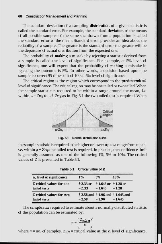
68 Construction Management and Planning
The standard deviation of a sampling distribution1 of a given statistic is called the standard error. For example, the standard dthiation of the means of all possible samples of the same size drawn from a population is called the standard error of the mean. Standard error provides an idea about the reliability of a sample. The greater is the standard error the greater will be the departure of actual distribution from the expected one.
The probability of making a mistake by rejecting a statistic derived from a sample is called the level of significance. For example, at 5% level of sigruficance, one will expect that the probability of making a mistake in rejecting the outcome is 5%. In other words, a decision based upon the sample is correct 95 times out of 100 at 5% level of significance.
The critical region is the region which correspond to the predetermined level of significance. The critical region may be one tailed or two tailed. When the sample statistic is required to be within a range around the mean, i.e. within p - Zo? to p + Zo? as in Fig. 5.1 the two tailed test is required. When
Fig. 5.1 Normal distribution-curve
the sample statistic is required to be higher or lower up to a range from mean, i.e. within p f Zojg one tailed test is required. In practice, the confidence limit is generally assumed as one of the following I%, 5% or 10%. The critical values of Z is presented in Table 5.1.
Table 5.1 Critical value of Z
a, level of significance 1% 5% 10%
Z critical values for one + 2.33 or + 1.645 or + 1.28 or tailed tests -2.33 - 1.645 - 1.28
Z critical values for two + 2.58 and + 1.96 and + 1.645 and tailed tests - 2.58 - 1.96 - 1.645
The sample.size required to estimate about a normally distributed statistic of the population can be estimated by:
= (3yJ where n = no. of samples, Zd = critical value at the a level of significance,
Operation Anarysrs and Statistics 69
o = standard deviation of population, and h = confidence interval, i.c distance between p - Z,: and p + Z,:.
e. the
Example 5.6 A supplier sends steel plates in a huge quantity to a contractor. The first batch was exhaustively examined for thickness and gave a standard deviation of 1.80. The contractor feels that the know1 range of 0.5 to its true value for a probability of 95Oh Determine the size of sample.
Solution:
!edge of I
1 would I mean wii >e satisfa
thina ctory.
In case of small sample, student or t-distribution m lieu of normal distribution and the sample size can be expressed by:
appropri * .
c. less t . ..
ate in
where n = sample size, t&, - =critical value at a level of sigruficanc n - 1 degrees of freedom, o = standard deviation of population. and h = LWL-
fidence interval. The student distribution is suitable for small population, i.c han .30.
Under such a circumstance, the distribution curve varies witn tne number of population. Therefore, tables for the student distributior :e the number of population, i.e. degree of freedom. A table is ed in Appendix 11.
I indicat presentc
e and - ---
Y many L---A a
Example 5.7 Hot readings of a sighting should be taken theodolite if it is rtvyeu so specify the sighting within k0.5" with 77m confidence. It is estimated from previous trial that the standard deviation of the reading is expected to be in the neighbourhood of 0.6".
Solution:
By trial and error f e in Appendix 11, n shoulc In many business applications, one is required to ascertain the freq~
of events falling in specified categories. For example in quality contra can count the number of defectives produced by a machine during a a period. In these situations, where measurements are made bv frequen each category Chi-square test is applied.
The Chi-square, denoted by the letter X2 is freque ntly use( 1 in testi
11 one rtain LCV in
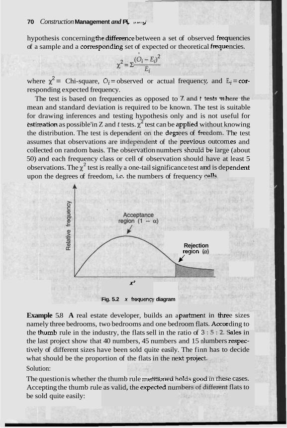
70 Construction Management and Pi,. ,, .., ,, hypothesis concerning thc lce between a set of observed freqi of a sample and a corresponding set of expected or theoretical freque
,
e differen . . uencies ncies.
y, and E
4,"C" ... L ;i = cor- 2 where x = Chi-square, Oi = observed or actual
responding expected frequency. The test is based on frequencies as opposed to mtu r Lcam w l t c l r utr:
mean and standard deviation is required to be known. The test is suitable for drawing inferences and testing hypothesis only and is not useful for bstimation as possible'in Z and t tests. test can be awwlied without knowing the distribution. The test is depen the degx "he test assumes that observations are in( ~t of the ~es and collected on random basis. The observation numbers snvula De large (about 50) and each frequency class or cell of observation should least 5 observations. The test is really a one-tail significance test a endent upon the degrees of freedom, i.e. the numbers of frequency
frequenc
7 ,..A 4
I I
ees of frt previou: .- -1. -..13
j outcom 1__ I---_
have at nd is dep r ~ l l c
Rejection
jesion (a)
x2
frequenc! Fig. 5.2 x / diagram
Example 5.8 A real estate developer, builds an a namely three bedrooms, two bedrooms and one bed the thumb rule in the industry, the flats sell in the ratio of ? the last project show that 40 numbers, 45 numbers and 15 n tively of different sizes have been sold quite easily. The fin what should be the proportion of the flats
Solution:
t in thre ts. Accorl
partrnen room fla
e sizes ding to
r : 5 :2 .$ lumbers : n has to
;ales in respec- decide
!xt projec
-1 3 - -- _
in the ne
.... -.J1. The question is whether the thumb rule mennonea nvlas gvvu m rrlesc Accepting the thumb rule be sold quite easily:
e cases. - - -. -.
flats to as valid, . the expf ?cted nur
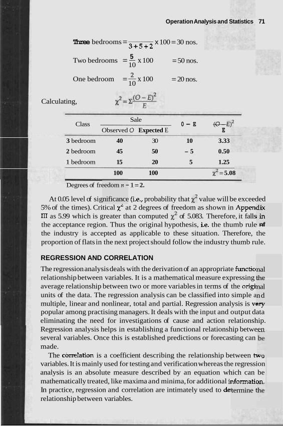
Operation Analysis and Statistics 71
Three bedrooms = x 100 = 30 nos. 3 + 5 + 2
5 Two bedrooms = - x 100 10
= 50 nos.
One bedroom = x 100 10
= 20 nos.
Calculating,
Sale Class 0 - E (0 - E ) ~
Observed 0 Expected E E
3 bedroom 40 30 10 3.33
2 bedroom 45 50 - 5 0.50
1 bedroom 15 20 5 1.25
100 100 X 2 = 5.08
Degrees of freedom n - 1 = 2.
nificance - At 0.05 level of sig I (i.e., probability that X2 value will be exceeded 5% of the times). Critical xL at 2 degrees of freedom as shown in Appen' III as 5.99 which is greater than computed x2 of 5.083. Therefore, it falls the acceptance region. Thus the original hypothesis, i.e. the thumb rule -- the industry is accepted as applicable to these situation. Therefore, the proportion of flats in the next project should follow the industry thumb rule.
REGRESSION AND CORRELATION
termine l
dix ; i n b nf
The regression analysis deals with the derivation of an appropriate functio: relationship between variables. It is a mathematical measure expressing - U L ~
average relationship between two or more variables in terms of the origi units of the data. The regression analysis can be classified into simple a multiple, linear and nonlinear, total and partial. Regression analysis is vc-, popular among practising managers. It deals with the input and output data eliminating the need for investigations of cause and action relationship. Regression analysis helps in establishing a functional relationship between several variables. Once this is established predictions or forecasting can made.
The correlation is a coefficient describing the relationship between t ~ . ,
variables. It is mainly used for testing and verification whereas the regression analysis is an absolute measure described by an equation which can be mathematically treated, like maxima and minima, for additional informatien In practice, regression and correlation are intimately used to dei relationship between variables.
nal &L
nal nd =rV
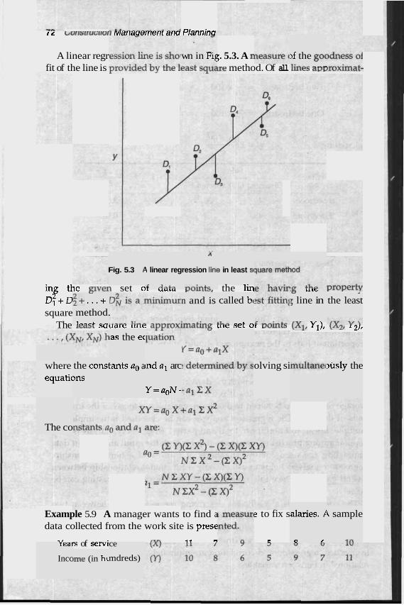
I L ~vrrs~ru~.[lori marraoerrrerrr arro Plannina
A linear regr ;. 5.3. A P fit of the line is ~ ~ U V ~ U C U L J ~ r l l r 1ra3r wuare method. Of all U N Z ~ LIVVLVALIILQL-
wn in Fig )f the go( I;-," ..-..
,3
ression lint
..,.;*+c
Fig. 5.3 I 4 linear reg
,6 A,,+"
z in least st
- -. in^ tl, LLVSII set 01 u a L a YVYtY, the lin property D l + D square
The I C ~ ~ L ~UUCUC ULC ~ V V I U A U L L Q L U ~ ~ ULC ~ C L VL VUIILL~ ( X I , Y1), ( ~ 2 , 1 21,
I5 utr
5 line in L,
I$+ ...+ method. I,,,& ,,
n and is called bc
&I..,. .-..-.I. *
<
the least
Las the ec
the cons4 )ns
where equatic
tants a. a ~nd al arc
Y = a o N i
olving si 3usly the
The co
alaries. 1
0 ,'
4 sample
i n
Example 5.9 A manager wants to find a data collected from the work site is prese
" rs of servi ,T7, 4 , "
e to fix s
C real
Incc
ce
mdreds) )me (in h~
Operation Analysis and StatisticJ ,
What should be the salary of a person with 13 years of experience applied for the job?
Solution:
The computations are:
The regression equation is Y = 2 + 0.75 X The person with 13 years of experience should have a salary of Rs 1,175/-. Correlation is a quantitative measure to determine the relationship be-
tween two or more sets of data. It varies from - 1 to + 1. The zero correlation indicates no relationship. A positive 1 indicates that a change in one set of data is perfectly matched by a change in the same direction of the other set of data. Anegative 1 indicates a change in one set of data is perfectly matched by a change in the other direction of the other set of data. Several quantitative measures are proposed. One such method known as short computational formula is presented:
NZXY-(ZX)(ZY) r =
d [ ~ z x2 - (Z w 2 j [ ~ c y2 - (z v 2 j If the precise values of the variables are unavailable the data may be
ranked in groups and can be expressed as:
where D = difference between ranks of corresponding values of X and Y, and N =number of pair of values (X, Y) in the data.
Example 5.10 In a construction site, the tensile strength between 8 mm dia bars and 16 mm dia bars from different mills were tested and following - results were obtained.
Mill 1 2 3 4 5 6 7 8 9 1 0 1 1 1 2 8mmdia 65 63 67 64 66 64 70 66 68 67 69 71
16 mm dia 68 66 68 65 69 66 68' 65 71 67 68 70 . Correlation coefficient = (12)(54107) - (800)(811)
d[(12)(53418) - (800)~][(12)(54849) - (811 )2
= 0.7027 The correlation coefficient is about 0.7 indicating moderately high correli in tensile strength between 8 mm dia and 16 mm dia bars from the : mill.
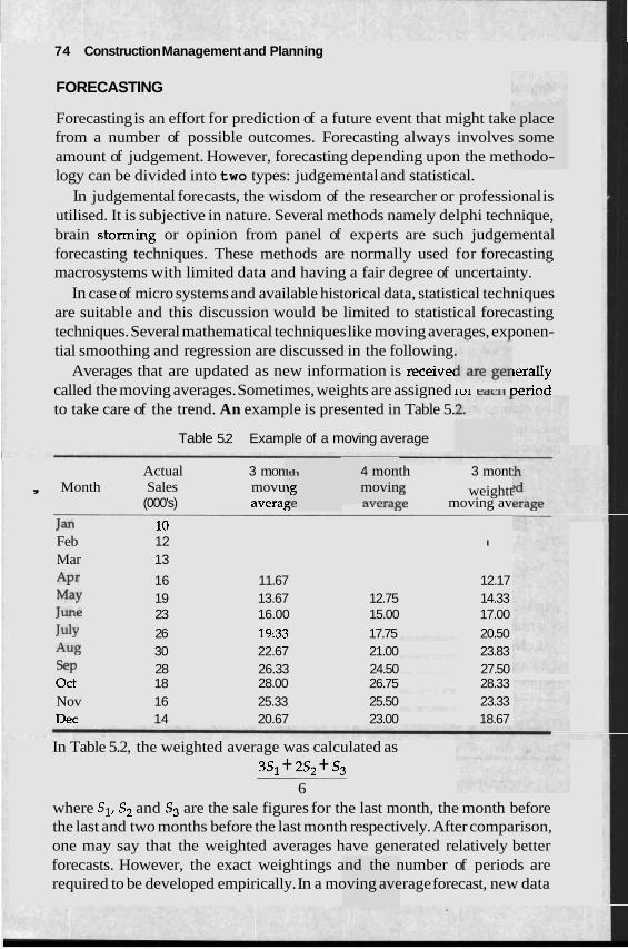
74 Construction Management and Planning
FORECASTING
Forecasting is an effort for prediction of a future event that might take place from a number of possible outcomes. Forecasting always involves some amount of judgement. However, forecasting depending upon the methodo- logy can be divided into two types: judgemental and statistical.
In judgemental forecasts, the wisdom of the researcher or professional is utilised. It is subjective in nature. Several methods namely delphi technique, brain storming or opinion from panel of experts are such judgemental forecasting techniques. These methods are normally used for forecasting macrosystems with limited data and having a fair degree of uncertainty.
In case of micro systems and available historical data, statistical techniques are suitable and this discussion would be limited to statistical forecasting techniques. Several mathematical techniques like moving averages, exponen- tial smoothing and regression are discussed in the following.
Averages that are updated as new information is receive( lerally called the moving averages. Sometimes, weights are assigned lur eaclt ~er iod to take care of the trend. An example is presented in Table 5.
Table 5.2 Example of a moving average
lth
'8 e;e
4 mon movin "*,A..".-
Actual 3 mon th 3 mont , Month Sales movu g weightt
(000's) avera~ a v moving av - Jan 10 Feb 12 I
Mar 13
A P ~ 16 11.67 12.17 May 19 13.67 12.75 14.33 June 23 16.00 15.00 17.00 July 26 19:33 17.75 20.50 A% 30 22.67 21.00 23.83 SP 28 26.33 24.50 27.50 Oct 18 28.00 26.75 28.33 Nov 16 25.33 25.50 23.33 Dec 14 20.67 23.00 18.67
In Table 5.2, the weighted average was calculated as 3S, + 2.5, + 53
6 where S1, S2 and S3 are the sale figures for the last month, the month before the last and two months before the last month respectively. After comparison, one may say that the weighted averages have generated relatively better forecasts. However, the exact weightings and the number of periods are required to be developed empirically. In a moving average forecast, new data
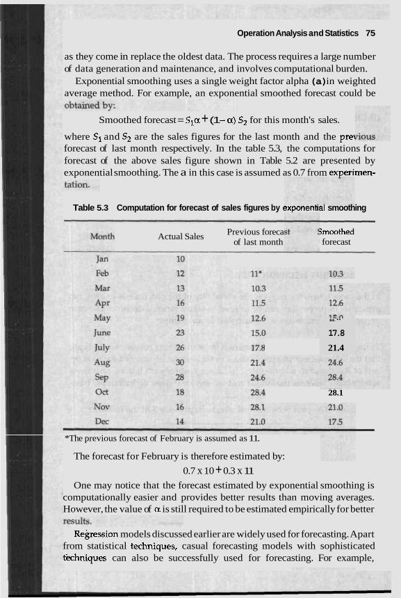
Operation Analysis and Statistics 75
as they come in replace the oldest data. The process requires a large number of data generation and maintenance, and involves computational burden.
Exponential smoothing uses a single weight factor alpha (a) in weighted average method. For example, an exponential smoothed forecast could be
Smoothed forecast = Sla + (1 -a) S2 for this month's sales.
where S1 and S2 are the sales figures for the last month and the prey forecast of last month respectively. In the table 5.3, the computations for forecast of the above sales figure shown in Table 5.2 are presented by exponential smoothing. The a in this case is assumed as 0.7 from experimen-
Table 5.3 Computation for forecast of sales figures by exponentlal smoothing
Actual Sales Previous foreca Gmoothed of last month forecast
28.1
*The previous forecast of February is assumed as 11.
The forecast for February is therefore estimated by:
0.7 x 10 + 0.3 x 11 One may notice that the forecast estimated by exponential smoothing is
computationally easier and provides better results than moving averages. However, the value of a is still required to be estimated empirically for better
Rebssion models discussed earlier are widely used for forecasting. Apart from statistical techniques, casual forecasting models with sophisticated tkhniques can also be successfully used for forecasting. For example,
Id."
17.8
21.4
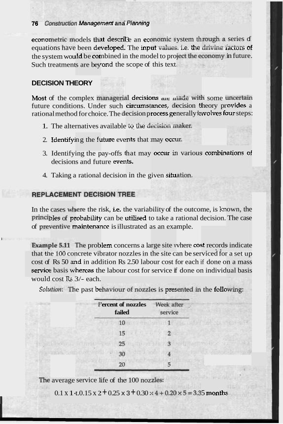
76 ~;onsrnrct~on Managemenr ana rrannrng
econo~ odels th 3e an ecc equations nave been developea. The inpur vd~ueb. 1.e. ult: U L I V U I ~ L I ~ C L O I S 01 the system wou nbined in the model to pro Such treatment rond the scope of this text
~t descril 3
ystem th . : - LL..
series of C-,.-- -1
in future. lld be cor s are bey
DECISION THEORY
Most of the complex f~larlrl~erldl decisiorls me 11~ut. wlrh some U.ncertain future conditions. Under such rational method for choice. The dl
circums t ecision p:
ances, dl rocess ge
ecision tl nerally ir
heory pr tvolves fc
tovides a >ur steps:
1. The alternatives available r w ule ueclslu~l 11
nts that : ng the fi 2. Identifyj lture eve may occ~
hat may 1ts.
; combin ations of 3. Identifying the pay-offs t decisions and future eyen
occur ir I various
=ti-- 4. Taking a rational decision in the given situ
cases wh >les of p~ ---a:-.- -
own, the The case
In the ,ere the risk, i.k. the variability of the outcome, is kn princi~ sobability can be utilised to take a rational decision. of prevell~lvt. lnaintenance is illustrated as an example.
llem concerns a la vhere co: e 100 concrete vibrator nozzles in the site can be serviced for a set up
~d in addition Rs 2.50 labour cost for each if done o hereas the labour cost for service if done on individ
would cost Rs 3/- each.
Solu e past bc
f i e prob ;t records . - -
; indicate rge site v - .
that th cost of servict - -
Rs 50 ar I basis w -
n a mass ual basis
the follo es is pres
'ercent of faile
nozzles d
average
0.1 x 1 - service 1
t.0.15 x 2
ife of the
: + 0.25 x
1 100 noz
3 + 0.30 : 5 month:
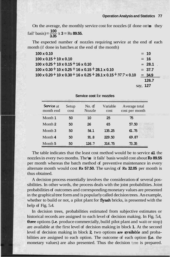
Operation Analysis and Statistics 77
On the average, the monthly service cost for nozzles (if done on 'as they 100
fail' basis) = - x 3 = Rs 89.55. 3.35
The expected number of nozzles requiring service at the end of each month (if done in batches at the end of the month)
100 x 0.10 = 10 100 x 0.15 + 10 x 0.10 = 16 100 x 0.25 + 10 x 0.15 + 16 x 0.10 = 28.1 .
100 x 0.30 + 10 x 0.25 + 16 x 0.15 + 28.1 x 0.10 = 37.7 100 x 0.20 + 10 x 0.30 + 16 x 0.25 + 28.1 x 0.15 + 3 7 . 7 ~ 0.10 = 34.9
126.7 say, 127
Service cost for nozzles
Senrice at Setup No. of Variable Average total month end cost Nozzle cost cost per month
Month 1 50 10 25 75
Month 2 50 26 65 57.50
Month 3 50 54.1 135.25 61.75
Month 4 50 91.8 229.50 69.87
Month 5 50 126.7 316.75 73.35
The table indicates that the least cost method would be to service all the nozzles in every two months. The 'as it fails' basis would cost about Rs 89.55 per month whereas the batch method of preventive maintenance in every alternate month would cost Rs 57.50. The saving of Rs 32.05 per month is thus obtained.
A decision process essentially involves the consideration of several pos- sibilities. In other words, the process deals with the joint probabilities. Joint probabilities of outcomes and corresponding monetary values are presented in the graphical tree form and is popularly called decision trees. An example, whether to build or not, a pilot plant for flyash bricks, is presented with the help of Fig. 5.4.
In decision trees, probabilities estimated from subjective estimates or historical records are assigned to each level of decision making. In Fig. 5.4, three options (i.e. produce commercially, build pilot plant and wait or stop) are available at the first level of decision making in block 1. At the second level of decision making in block 2, two options are qvailable and proba- bilities are assigned to each option. The outcome of each option (i.e. the monetary values) are also presented. Thus the decision tree is prepared.
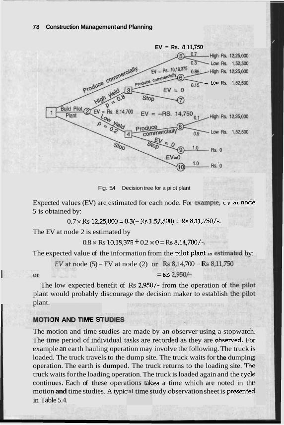
78 Construction Management and Planning
- Low Rs.
EV = Rs. 8,11,750
Fig. 5.4 Decision tree for a pilot plant
Expected values (EV) are estimated for each node. For exa~~ly~e, L v a r rwue 5 is obtained by:
0.7 x RS 12,25,000 =0.3(- Rs 1,52,500) = Rs 8,11,750/-.
The EV at node 2 is estimated by
0.8 x Rs 10,18,375 + 0.2 x 0 = Rs 8,14,700/-
The expected value of the information from the ~ i l o t plan1 13 ~ s ~ l l a t e d bv:
ode (5) - EV at node (2) 14,700 - I = KS ~,350/-
The low expected benefit of Rs 2,950/- from the operation of plant would probably discourage the decision maker to establish plant.
3N AND TIME S
The motion and time studies are made by an observer using a stopwatch. The time period of individual tasks are recorded as they are obse~ed . For example an earth hauling operation may involve the following. The truck is loaded. The truck travels to the dump site. The truck waits for the dumping operation. The earth is dumped. The truck returns to the loading site. Thc truck waits for the loading operation. The truck is loaded again and the cycle continues. Each of these opera :es a time which are noted in tht motion and time studies. A typic tudy observation sheet is presentec in Table 5.4.
tions tak :a1 time s
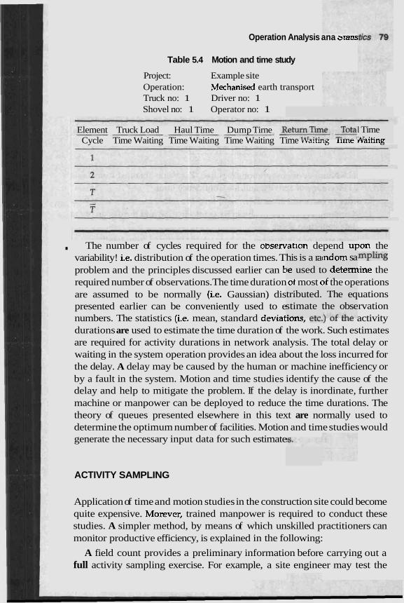
Operation Analysis ana ararrs
Table 5.4 Motion and time study
Project: Example site Operation: Mechanised earth transport Truck no: 1 Driver no: 1 Shovel no: 1 Operator no: 1
Element Truck Load Haul Time Dump Tirne J Cycle Time Waiting Time Waiting Time Waiting Time vvalnng lime -- "
his is a ra je used t
tributed. stimate :r\..r - C n
. The number of cycles required for the observation depend upon the variability! i.e. distribution of the operation times. T m~l ing problem and the principles discussed earlier can t line the required number of observations. The time duration of most of the operations are assumed to be normally (i.e. Gaussian) dis uations presented earlier can be conveniently used to e rvation numbers. The statistics (i.e. mean, standard deviatlulLJ, cLL.l ul ULc activity durations are used to estimate the time duration of the work. Such estimates are required for activity durations in network analysis. The total delay or waiting in the system operation provides an idea about the loss incurred for the delay. A delay may be caused by the human or machine inefficiency or by a fault in the system. Motion and time studies identify the cause of the delay and help to mitigate the problem. If the delay is inordinate, further machine or manpower can be deployed to reduce the time durations. The theory of queues presented elsewhere in this text are normally used to determine the optimum number of facilities. Motion and time studies would generate the necessary input data for such estimate
tndom sa o detem
> - The eq
the obse
I Time Waitinn
ACTIVITY SAMPLING
Application of time and motion studies in the construction site could become quite expensive. Morever, trained manpower is required to conduct these studies. A simpler method, by means of which unskilled practitioners can monitor productive efficiency, is explained in the following:
A field count provides a preliminary information before carrying out a full activity sampling exercise. For example, a site engineer may test the
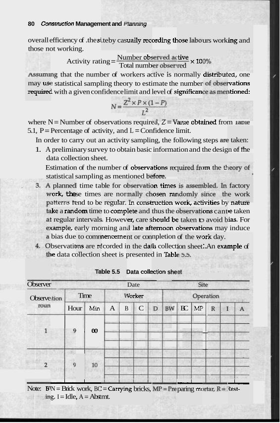
80 Consrmction Management and ~ lsnn inn 'U, ., ,,, '3
ually rec, overall efficiency of .the si .te by cas ording tk lose lab0 urs work ing and those not working.
:tive -x10 red
Number ob: Activity rating =
Total numb ASSumlng that the number of workers active is normally distributed, one
statistical sampling theory to estimate the number vations i with a given confidence limit and level of sigrufican ~tioned:
may usc requirec
where N = Number of observations requirea, L = vatue o~tained from lame 5.1, P = Percentage of activity, and L = Confidence limit.
In order to carry out an activity sampling, the following steps arc
1. A preliminary survey to obtain basic information and the design or me data collection sheet.
! taken: - - C .l. _
Estimation of the number of observz statistical sampling as mentioned b~lulc.
I time ta se times
arrerns rend to be regular. m consmcnon WOTK, acuvities by narure I to comp )e taken 1. Howev tias. For
<ample, early morning ana lare arrernoon oDservarions may induce bias due nenceme. npletion bservatit !corded i La collect: le data collection sheet is presented in Tabb
>m the tl ltions rec .$*..A
factory e work - .--L ..--
planned rork, the -U_-_ l_
>n times losen rar ... . - c: - .- -
ble for o are nor
~ke a ranc t regular .--_il- .
iom time intervals . -- -
llete and thus the ( ihould b~ I . . . - - .
om cant ) avoid b - ~ - . - - -
: taken tc 1 . . . . 'er, care s
J 1 r .
to comn nt or con n the dal
of the wc ork day. :. An exa ion sheet mple of )ns are IY
*- .
ble 5.5 Data colle !ction she -- - -
Observer Date
Vorker Time Observe
Hour Min A B C V BC MP
' 0 0 -- --
-.
- Note: B1 I N = Brick I work, BC , A = Abst
u I = Carryi~ mt.
A ~g bricks, I paring mc I Rest-
g, I = Idle,
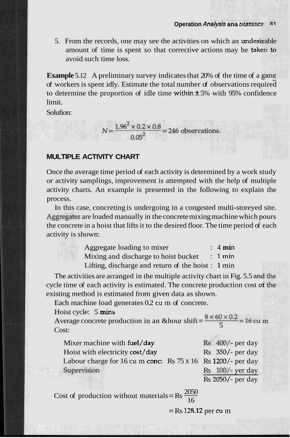
Operation Anarysrs ana srarrsrra
5. From the records, one may see the activities on which an undesii amount of time is spent so that corrective actions may be takc avoid such time loss.
rable bn to
Example 5.12 A preliminary survey indicates that 20% of the time of a L " of workers is spent idly. Estimate the total number of observations required to determine the proportion of idle time within* 5% with 95% confidence limit.
Solufion:
MULTIPLE ACTIVITY CHART
Once the average time period of each activity is determined by a work study or activity samplings, improvement is attempted with the help of multiple activity charts. An example is presented in the following to explain the process.
In this case, concreting is undergoing in a congested multi-storeyed site. ~ ~ g r e ~ a t e s are loaded manually in the concrete mixing machine which pours the concrete in a hoist that lifts it to the desired floor. The time period of each activity is shown:
Aggregate loading to mixer : 4 min Mixing and discharge to hoist bucket : 1 min Lifting, discharge and return of the hoist : 1 min
The activities are arranged in the multiple activity chart in Fig. 5.5 an( cycle time of each activity is estimated. The concrete production cost ol existing method is estimated from given data as shown.
Each machine load generates 0.2 cu m of concrete. Hoist cycle: 5 mins
8 x 6 0 ~ 0 . 2 = ~ ~ ~ Average concrete production in an &hour shift = Cost:
5
Mixer machine with fuel/day W/&0/- per day Hoist with electricity cost/day Rs 350/- per day Labour charge for 16 cu m conc: Rs 75 x 16 Rs 1200/- per day
Rs loo/- ver dav Rs 2050/- per day
2050 Cost of production without materials = Rs - 16
= Rs 128112 per cu m
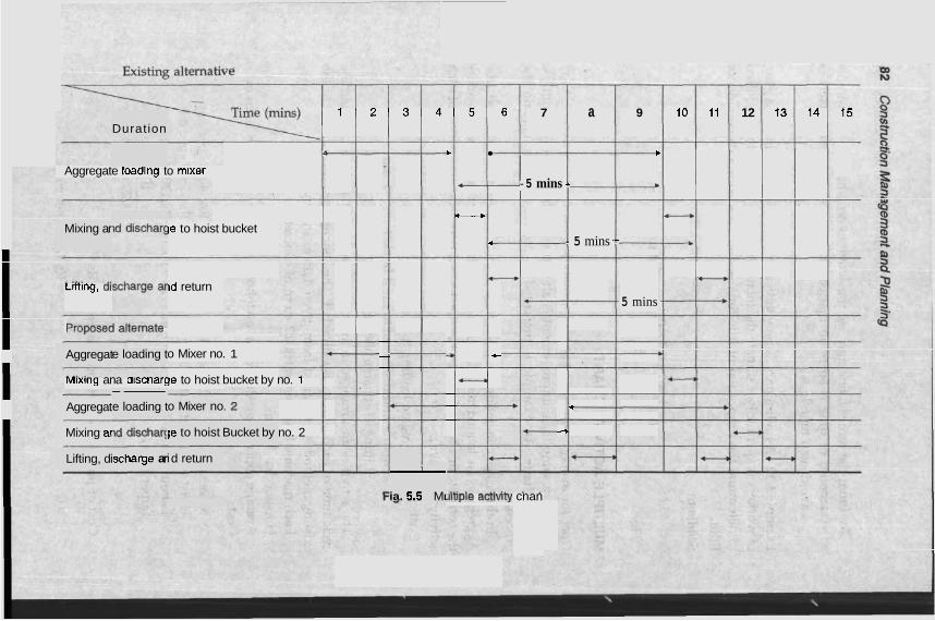
Mixing ar
Aggregat
Duration 1 2 3 4 5 6 7 a 9 10 11 12 13 14 15
4 b b
Aggregate loadlng to mixer 4 - 5 mins -- b
C--* - le to hoist bucket
4 - 5 mins -- b
* ---, Lmlng, a1 ~d return
5 mins
-. - o Mixer no. 1 -, + .-
-.
Mlxlng ana olscnarge to hoist bucket by no. i c--. - -.
-. 4
- -.
no. 2 4
e loading t
Aggregat -- e loading t o Mixer no
Mixing ar le to hoist Bucket by
Lifting, di scharge ar i d return I
ia. 5.5 MI Jlnple acrlvlry cnan
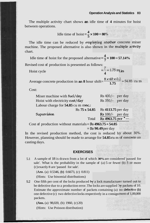
Operation Analysis and Statistics 83
The multiple activity chart shows an idle time of 4 minutes for hoist between operations.
4 Idle time of hoist = - x 100 = 80'
5
nother c n the mt
oncrete I
lltiple ac mixer :tivity
The idle time can be reduced by emp: machine. The proposed alternative is also chart.
loying a shown h
4 Idle time of hoist for the proposed alternative = - x 100 = 57.14% 7
Revised cost of production is presented as follows:
Hoist cycle --- -7-1.75m 4
Lins
m 8 x 6 0 ~ 0 . Average concrete production in an 8 hour shift= 1.75
Cost:
er day er day
Mixer machine with fuel/day Rs 4
Hoist with electricity cost/day Rs 2 Labour charge for 54.85 cu m conc.: -
Rs 75 x 54.85 Rs 4113.75 per day supervision Rs loo/- per day
Total Rs 4963.75 p--- '--- Cost of production without materials = Rs 4963.75 - 54.85
= Rs 90.49 per day In the revised production method, the cost is reduced b y about
of concrt However, planning should be made to arrange for 54.85 cu m casting days.
EXERCISES
5.1 A sample of 18 is drawn from a lot of which 30% are considered 'passed for sale'. What is the probability in the sample of (a) 5 or fewe ' more (c) exactly 8 are 'passed for sale'.
(Ans. (a) 0.5346, (b) 0.6673, (c) 0.811)
(Hints: Use binomial distributions)
5.2 One fifth per cent of the locks produced bj be defective due to a production error. The locks are supplied 1 Estimate the approximate number of packets containing (a) one defective (c) two defective locks respectively in a consign packets.
(Ans. (a) 98,020, (b) 1960, (c) 20)
(Hints: Use Poisson distribution)
r a lock m anufactur er turned >y packets no defecb ment of 1,
; of 10. ive (b) 00,000
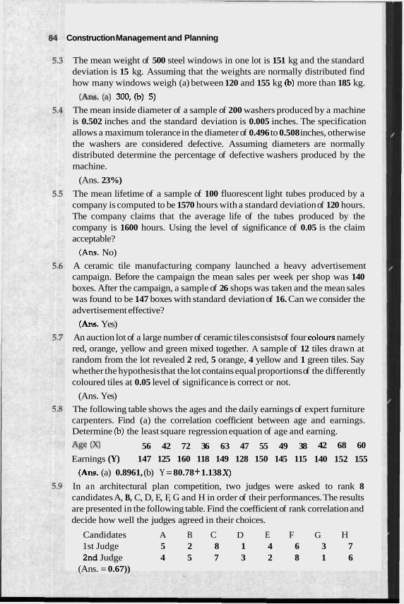
Construction Management and Planning
The mean weight of 500 steel windows in one lot is 151 kg and the standard deviation is 15 kg. Assuming that the weights are normally distributed find how many windows weigh (a) between 120 and 155 kg (b) more than 185 kg.
(Am. (a) 300, (b) 5) The mean inside diameter of a sample of 200 washers produced by a machine is 0.502 inches and the standard deviation is 0.005 inches. The specification allows a maximum tolerance in the diameter of 0.496 to 0.508 inches, otherwise the washers are considered defective. Assuming diameters are normally distributed determine the percentage of defective washers produced by the machine.
(Ans. 23%)
The mean lifetime of a sample of 100 fluorescent light tubes produced by a company is computed to be 1570 hours with a standard deviation of 120 hours. The company claims that the average life of the tubes produced by the company is 1600 hours. Using the level of significance of 0.05 is the claim acceptable?
(Ans. No)
A ceramic tile manufacturing company launched a heavy advertisement campaign. Before the campaign the mean sales per week per shop was 140 boxes. After the campaign, a sample of 26 shops was taken and the mean sales was found to be 147 boxes with standard deviation of 16. Can we consider the advertisement effective?
(Ans. Yes)
An auction lot of a large number of ceramic tiles consists of four colours namely red, orange, yellow and green mixed together. A sample of 12 tiles drawn at random from the lot revealed 2 red, 5 orange, 4 yellow and 1 green tiles. Say whether the hypothesis that the lot contains equal proportions of the differently coloured tiles at 0.05 level of significance is correct or not.
(Ans. Yes)
The following table shows the ages and the daily earnings of expert furniture carpenters. Find (a) the correlation coefficient between age and earnings. Determine (b) the least square regression equation of age and earning.
Age (XI 56 42 72 36 63 47 55 49 38 42 68 60
Earnings (Y) 147 125 160 118 149 128 150 145 115 140 152 155
(Ans. (a) 0.8961, (b) Y = 80.78 + 1.138 X) In an architectural plan competition, two judges were asked to rank 8 candidates A, B, C, D, E, F, G and H in order of their performances. The results are presented in the following table. Find the coefficient of rank correlation and decide how well the judges agreed in their choices.
Candidates A B C D E F G H 1st Judge 5 2 8 1 4 6 3 7 2nd Judge 4 5 7 3 2 8 1 6
(Ans. = 0.67))
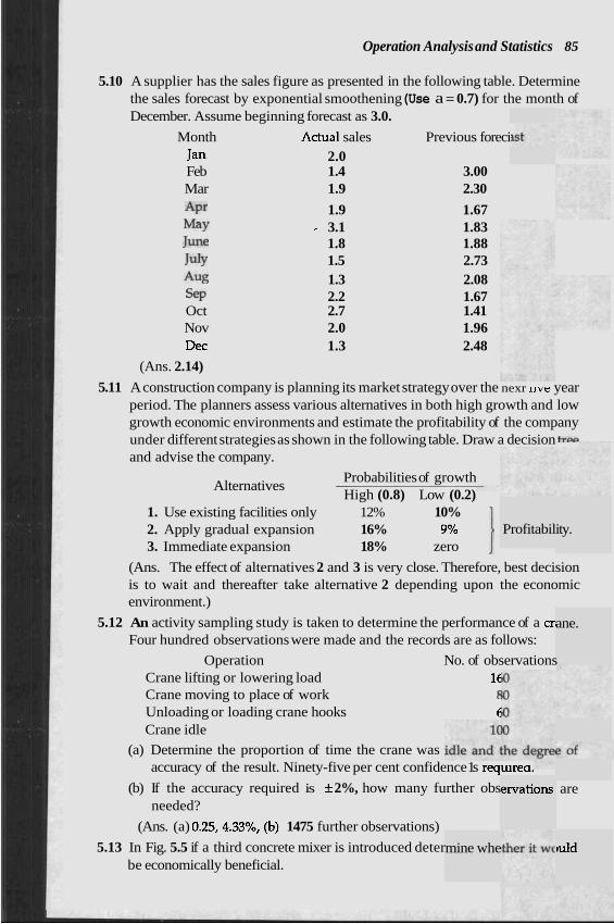
Operation Analysis and Statistics 85
5.10 A supplier has the sales figure as presented in the following table. Determine the sales forecast by exponential smoothening (Use a = 0.7) for the month of December. Assume beginning forecast as 3.0.
Month Actual sales Previous foreci Jan 2.0 Feb 1.4 3.00 Mar 1.9 2.30
Apt- 1.9 1.67 May - 3.1 1.83 June 1.8 1.88 July 1.5 2.73 Aug 1.3 2.08 ST 2.2 1.67 Oct 2.7 1.41 Nov 2.0 1.96 Dec 1.3 2.48
(Ans. 2.14)
5.11 A construction company is planning its market strategy over the nexr nve year period. The planners assess various alternatives in both high growth and low growth economic environments and estimate the profitability of the company under different strategies as shown in the following table. Draw a decision tn.p and advise the company.
Probabilities of growth Alternatives
High (0.8) Low (0.2)
Profitabil ity. 1. Use existing facilities only 12% 10% 2. Apply gradual expansion 16% 9% 1 3. Immediate expansion 18% zero
(Ans. The effect of alternatives 2 and 3 is very close. Therefore, best decision is to wait and thereafter take alternative 2 depending upon the economic environment.)
5.12 An activity sampling study is taken to determine the performance of a cr, Four hundred observations were made and the records are as follows:
Operation No. of observations Crane lifting or lowering load 1f Crane moving to place of work f Unloading or loading crane hooks C Crane idle
(a) Determine the proportion of time the crane was accuracy of the result. Ninety-five per cent confidence 1s requa.&-.
(b) If the accuracy required is f 2%, how many further obs needed?
(Ans. (a) 0.25,4.33%, (b) 1475 further observations)
5.13 In Fig. 5.5 if a third concrete mixer is introduced deter be economically beneficial.
mine whe
ervations
ane.
are
tuld
I CHAPTER 6 1
Construction Practice 1
EARTH WORK AND EXCAVATION
Any new construction work involves some excavation fo 7dation. There are structures like canals, dams, spillways, barrages, ar ~kments where the earth work in excavation or filling or both forms a su~stantial portion of the work. For structures like basement and tunnels, the excavated earth may not be required fully or even partly for the required filling, and hence this has to be disposed of. Thus in general earth work involves the movement of a portion of earth's surface from one location to another and the creation of the shape and condition as required and sometimes disposing of the excavated material as spoils. A number of factors are to be considered while deciding upon the type of excavating machinery to be used for the purpose. In order to attain maximum efficiency one of the important factors is the type of material to be handled which may be the top.soil, earth, rock, muck and unclassified soil or a combination of the types mentioned.
Top soil supports the growth of trees and other vegetation, hence this contains more moisture. The soil beneath the top is normally easier to handle. The top soil when removed should be pi11 ite or at a different place.
Earth is the type of soil encountered btlLcauc u L ~ L U ~ >oil. Earth is used for the construction of embankments, earthen dams, etc.
Rock is to be removed by drilling and blasting in a sys The boulders which come out as a result of blasting are d~su useu I r r
embankments at a deeper place or may be used as stones for different purposes.
Muck is defined as any soil having an excessive amount of water. This has to be dried by spreading over a wide area he sun before it c used for any purpose.
ed for re1 use at thl
I under ti
r its foul id embar 1
e same s
tematic I -- - I - - .
WIIS[IUG~IUI~ Practice r 0 1
As said ie purpo:
aria
culv flow . .
wor
6. Borr to bc
type abo
I7 _-L
k on soil
ow pits :
! of soil r rrow pit
!xcavatio work:
!ans remc sed surfz "n".,-G-.
!r constn :er for ti
nay not 1 may be : - - -.- -. . . . .
be suitab located q - 3 r - - 1 .
I
rove or e
nachiner - -
;ilos, bun to be d . r
als up to a perma
! amount mrdcmeni
2 constru from the
c - 1
a certair nent emt &.A- *he
ction of I
embanlu . . ,-
embankr nent site
The type of earth needs to be classified since the types of machinery to be used varies from one type to the other. Sometimes when these are mixed up it becomes difficult to distinguish and hence it is kept unclassified. Therefore, the soil may consist of anything from top soil to muck including rocks, and the contractor has to quote and arrange for excavation intelligently.
earlier, e ns are also required to be classified accordi tl- ;e of the
1. Stripping me ~ v a l of all materi, I level so that the top expo ice could act like m.nkrnent.
2. Road way en~avauvll where required, starts ll"lll LLLC! level of the stripped of earth and ends at the level or grade as per the drawing.
3. Drainage excavation is the removal of material for the installation of minor drainage structures such as culverts. Back filling for such cases
need a different type of material to be brought at site.
nnel excavation may deal with shaping a natural drainage for the u-tment cf a better flow of water or channelising the flow to the ert unde lction or may be finding out new routes of the
of wat he benefit of the people like navigation and lrrrgation canals.
5. Bridge excavation may involve a large r the construction of pier, abutments, emb La/ cLL. A rolve
of a variety of physical characteristics.
%re pits dug out order to collect soil for embankments ? constructed at an adjacent place or at a different place. Since any
le for tht nent, [uite far j
ox~dvdrion is also requlrea ror nousing the rounaation or any structure like buildings, sheds, water towers, 5 lkers and chimneys. In order to save material and labour this has one strictly as per drawings. Sometimes even formworks are not usea ror such foundations.
In order to maintain the channel of a waterway in rivers or to maintain the capacity of reservoirs of dams dredging excavation is required where the dredged material is removed bv vumping. These materials may be dumped by the pipe network to imp blevate some marshy lands.
For selecting the type of I ,y or equipment to be used for the earth work one has to know the depth of excavation and height to which the excavated earth is to be lifted, how the lifted material should be disposed of,
' the distance of the site of excavation to the spoil bank, the type of hauling unit to be used, the hauling length to be covered, special loading equipment required, the type of soil to be excavated, the load supporting ability of original ground and the load supporting ability of the material to be
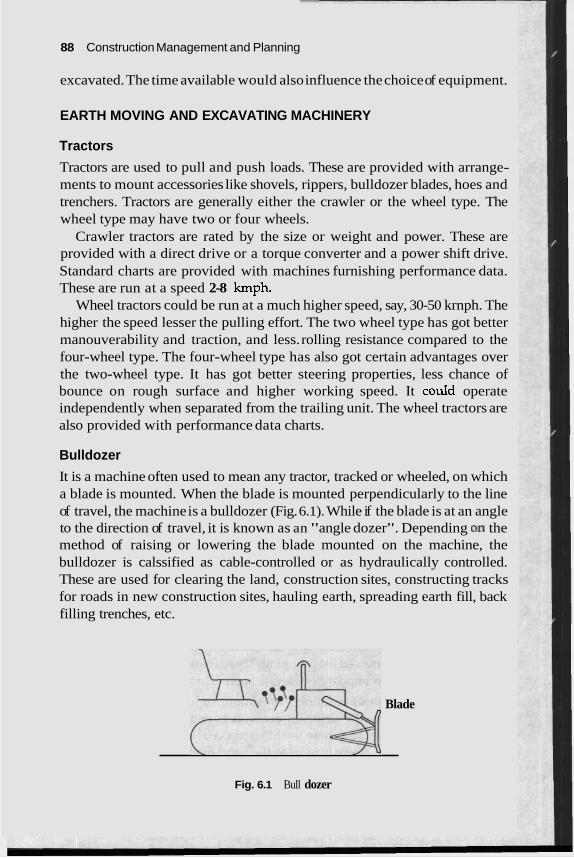
88 Construction Management and Planning
excavated. The time available would also influence the choice of equipment.
EARTH MOVING AND EXCAVATING MACHINERY
Tractors
Tractors are used to pull and push loads. These are provided with arrange- ments to mount accessories like shovels, rippers, bulldozer blades, hoes and trenchers. Tractors are generally either the crawler or the wheel type. The wheel type may have two or four wheels.
Crawler tractors are rated by the size or weight and power. These are provided with a direct drive or a torque converter and a power shift drive. Standard charts are provided with machines furnishing performance data. These are run at a speed 2-8 kmph.
Wheel tractors could be run at a much higher speed, say, 30-50 krnph. The higher the speed lesser the pulling effort. The two wheel type has got better manouverability and traction, and less. rolling resistance compared to the four-wheel type. The four-wheel type has also got certain advantages over the two-wheel type. It has got better steering properties, less chance of bounce on rough surface and higher working speed. It couId operate independently when separated from the trailing unit. The wheel tractors are also provided with performance data charts.
Bulldozer
It is a machine often used to mean any tractor, tracked or wheeled, on which a blade is mounted. When the blade is mounted perpendicularly to the line of travel, the machine is a bulldozer (Fig. 6.1). While if the blade is at an angle to the direction of travel, it is known as an "angle dozer". Depending 011 the method of raising or lowering the blade mounted on the machine, the bulldozer is calssified as cable-controlled or as hydraulically controlled. These are used for clearing the land, construction sites, constructing tracks for roads in new construction sites, hauling earth, spreading earth fill, back filling trenches, etc.
+TTpr$ Blade
Fig. 6.1 Bull dozer
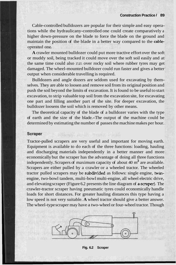
Construction Practice 1 89
Cable-controlled bulldozers are popular for their simple and easy opera- tions while the hydraulicany-controlled one could create comparatively a higher down-pressure on the blade to force the blade on the ground and maintain the position of the blade in a better way compared to the cable-
A crawler mounted bulldozer could put more tractive effort over the soft or muddy soil, being tracked it could move over the soft soil easily and at the same time could also run over rocky soil where rubber tyres may get damaged. The wheel-mounted bulldozer could run faster and gives a better output when considerable travelling is required.
Bulldozers and angle dozers are seldom used for excavating by them- selves. They are able to loosen and remove soil from its original position and push the soil beyond the limits of excavation. It is found to be useful to start excavation, to strip valuable top soil from the excavation site, for excavating one part and filling another part of the site. For deeper excavation, the bulldozer loosens the soil which is removed by other means.
The theoretical capacity of the blade of a bulldozer varies with the type of earth and the size of the blade.-The output of the machine could be determined by estimating the number of passes the machine makes per hour.
Tractor-pulled scrapers are very useful and important for moving earth. Equipment is available to do each of the three functions: loading, hauling and discharging materials independently in a better manner and more economically but the scraper has the advantage of doing all three functions
3 independently. Scrapers of maximum capacity of about 40 m are available. Scrapers are either pulled by a crawler or a wheeled tractor. The wheeled tractor pulled scrapers may be sabdivided as follows: single engine, twin- engine, two-bowl tandem, multi-bowl multi-engine, all wheel electric drive, and elevating scraper (Figure 6.2 presents the line diagram of a.scraper). The crawler-tractor scraper having pneumatic tyres could economically handle loads for short distances. For greater hauling distances this type having a low speed is not very suitable. A wheel tractor should give a better answer. The wheel-type scraper may have a two-wheel or four-wheel tractor. Though
Fig. 6.2 Scraper
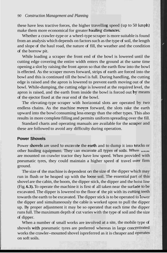
90 Construction Management and Planning
travellin 1 . - - 3
g speed .-.. . .._
these have less tractive forces, the higher (up to 50 kmph) make them more economical for greater hauling aisrances.
Whether a crawler-type or a wheel-type scraper is more suitable is found from an analysis which depends on factors such as the type of soil, the length and slope of the haul road, the nature of fill, the weather and the condition of the borrow pit.
While loading a scraper the front end of the bowl is lowered until the cutting edge covering the entire width enters the ground at the same time opening a slot by raising the front apron so that the earth flow into the bowl is effected. As the scraper moves forward, strips of earth are forced into the bowl and this is continued till the bowl is full. During handling, the cutting edge is raised and the apron is lowered to prevent earth moving out of the bowl. While-dumping, the cutting edge is lowered at the required level, the apron is raised, and the earth from inside the bowl is forced out b~ of the ejector fixed at the rear end of the bowl.
The elevating-type scraper with horizontal slots are operated endless chains. As the machine moves forward, the slots rake the earth upward into the bowl consuming less energy than the other types. This also results in more complete filling and permits uniform spreading over the fill.
Standard charts and operating manuals are available for the scra these are followed to avoid any difficulty during operation.
Power
I means
by two
per and
Shovels
;hovels a -*.I:-- -,
[re used i -..:----d
ite the e; -- -.,"-., to dump ,,c #.F r .
rucks or >-
1 the size ose soil.
ed with rer firm
Power : r th and it into t~ other haulu15 T ~ U ~ I I L C L L L . l l l c y w.~a\iate all tJrye3 "1 a ~ i l ~ . WhtlL L l L F a F
are mounted on crawler tractor they have low speed. When provid pneumatic tyres, they could maintain a higher speed of travel 01 ground.
The size of the machine is dependent or of the dipper wh run in flush or be heaped up with the 101 The essential par shovel are the cabin, the boom, the dipper stick, the dipper and the hoist line (Fig. 6.3). To operate the machine it is first of all taken near the surfa excavated. The dipper is lowered to the floor of the pit with its cuttjl towards the earth to be excavated. The dipper stick is to be operated to lower the dipper and simultaneously the cable is worked upon to pull the dipper up. By proper adjustment it may be so operated that each time the dipper runs full. The maximum depth of cut varies with the type of soil and the size of dipper.
When a number of small works are inv a site, the mobile type of shovels with pneumatic tyres are preferred whereas in large conct works the crawler-mounted shovel ispreferred as it is cheaper and ( on soft soils.
~ce to be ng teeth I t
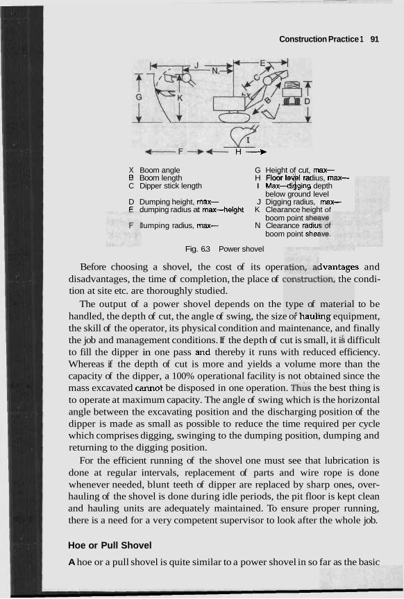
Construction Practice 1 91
t F + b H -+ X Boom angle G Height of cut, max- B Boom length H Floor le , I radius, max- C Dipper stick length I Max-d$ng depth
below ground level D Dumping height, max- J Digging radius, max- E dumping radius at max-height K Clearance height of
boom point she$ lumping radius, max- N Clearance radiu:
boom point she2
Fig. 6.3 Power shovel
Before choosing a shovel, the cost of its oper ivantages and disadvantages, the time of completion, the place of cv~~ar~u~ i ion , the condi- tion at site etc. are thoroughly studied.
The output of a power shovel depends on the to be handled, the depth of cut, the angle of swing, the size or naul1.g equipment, the skill of the operator, its physical condition and maintenance, and finally the job and management conditions. If the depth of cut is small, it is difficult to fill the dipper in one pass ar.d thereby it runs with reduced efficiency. Whereas if the depth of cut is more and yields a volume more than the capacity of the dipper, a 100% operational facility is not obtained since the mass excavated cannot be disposed in one operation. ~ h & s the best thing is to operate at maximum capacity. The angle of swing which is the horizontal angle between the excavating position and the discharging position of the dipper is made as small as possible to reduce the time required per cycle which comprises digging, swinging to the dumping position, dumping and returning to the digging position.
For the efficient running of the shovel one must see that lubrication is done at regular intervals, replacement of parts and wire rope is done whenever needed, blunt teeth of dipper are replaced by sharp ones, over- hauling of the shovel is done during idle periods, the pit floor is kept clean and hauling units are adequately maintained. To ensure proper running, there is a need for a very competent supervisor to look after the whole job.
Hoe or Pull Shovel
A hoe or a pull shovel is quite similar to a power shovel in so far as the basic
type of ,-. *. material
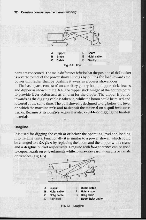
92 Construction Managemenr ana r
A Dipper B Brace C Cable
Fig. 6.4 Hc
U tjoc E Hoi! F Gar
rm st cable
parts are concerned. The main difference he ?bucket is reverse to that of the power shovel. It digs by pulling the load towards the power unit rather than by pushing it away as a power shovel does.
The basic parts consist of an auxiliary gantry boom, dipper stick, braces and dipper as shown in Fig. 6.4. The dipper stick hinged at the bottom point to provide lever action acts as an arm for the dipper. The dipper is pulled inwards as the digging cable is taken in, while the boom could be raised and lowered at the same time. The pull shovel is designed to dig below the level on which the machine re: trucks. Because of its pos materials.
!re is that the posit *. . . ion of tht . .
the mitt nk or in hardest
:rial on a )le -of dig
spoil ba; ging the
3ts and tc itive acti~ lso capat
It is used for digging the earth at or below the operating level and loading it to hauling units. Functionally it is similar to a power shovel, which could be changed to a dragline by replacing the boom and the dipper with a crane and a dragline bucket re5 1. Draglir mger cre to deposit earth on emba while it t ; earth frc
le with 14 ?xcavate:
mes can 1rn pits o
be used r canals
or trenches (Fig. 6.5).
A Bucket B Hoist cable C Drag cable
Dump cal Hoist cha Drag cha
ble in In
Boom ho
line
ist cable n
6.5 Drag
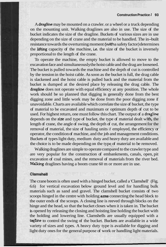
Construction Practice 1 93
A dragline may be mounted on a crawler. or a wheel or a truck depending on the mounting unit. Walking draglines are also in use. The size of the bucket indicates the size of the dragline. Buckets of various sizes are in use depending on the size of crane and the material to be handled. The in-built resistance towards the overturning moment (with a safety factor) determines the lifiing capacity of the machine, i.e. the size of the bucket is inversely proportional to the length of the crane.
To operate the machine, the empty bucket is allowed to move to the excavation face and simultaneously the hoist cable and the drag are loosened. The bucket is pulled towards the machine and the depth of cut is controlled by the tension in the hoist cable. As soon as the bucket is full, the drag cable is slackened and the hoist cable is pulled back and the material from the bucket is dumped at the desired place by releasing the drag cable. The dragline does not operate with equal efficiency at any position. The whole work should be so planned that digging is generally done from the best digging zone and little work may be done from the poor digging zone if unavoidable. Charts are available which correlate the size of bucket, the type of material to be excavated and maximum or optimum depth of cut to be used. For highest return, one must follow this chart. The output of a dragline depends on the size and type of bucket, the type of material dealt w length of crane, the angle of swing, the depth of cut, the arrangement removal of material, the size of hauling units if employed, the efficiency or operator, the condition of machine, and the job and management conditions. Buckets of types light duty, medium duty and heavy duty are available and the choice is to be made depending on the type of material to be removed.
Walking draglines are simple to operate compared to the crawler type and are very popular for the construction of embankments, canals, open, pit excavation of coal mines, and the removal of materials from the river bed. Waking draglines having a boom crane 60 m or more are in use.
The crane boom is often used with a hinged bucket, called a 'Clamshell' (Fig. 6.6) for vertical excavation below ground level and for handling bulk materials such as sand and gravel. The clamshell bucket consists of two scoops hinged in the centre with holding arms connecting the head block to the outer ends of the scoops. A closing line is reeved through blocks on the hinge and the head, so that the bucket closes when it is taken in. The bucket is opened by releasing the closing and hoisting line holding the bucket with the holding and lowering line. Clamshells are usually equipped with a tagline to control the swing of the bucket. Buckets are available in a wide variety of sizes and types. A heavy duty type is available for digging and light duty ones for the general purpose of work or handling light materials.
.ith, the for the
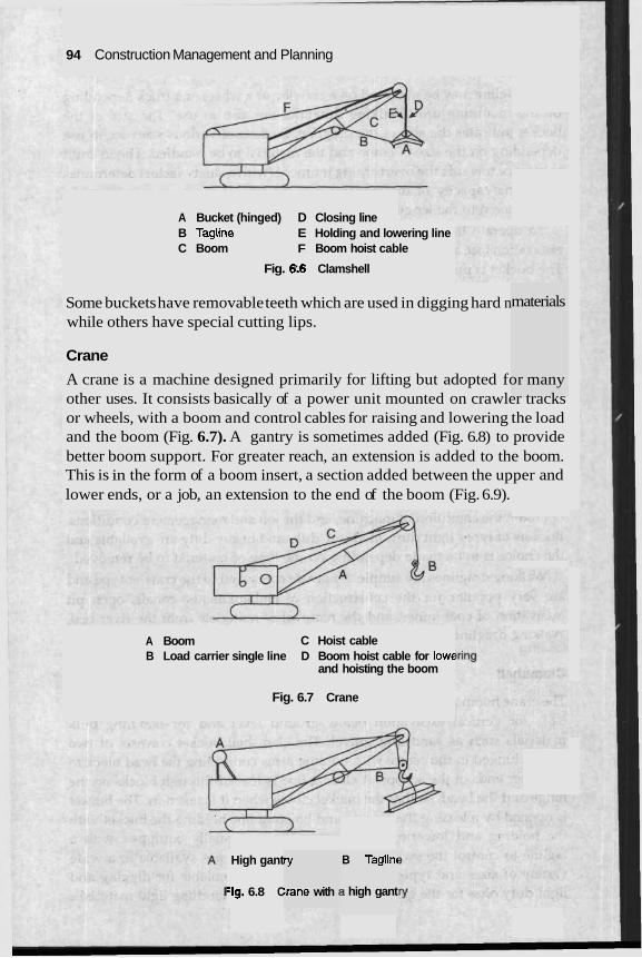
94 Construction Management and Planning
A Bucket (hinged) D Closing line B Tagline E Holding and lowering line C Boom F Boom hoist cable
Fig. 6:6 Clamshell
Some buckets have removable teeth which are used in digging hard n while others have special cutting lips.
materials
Crane
A crane is a machine designed primarily for lifting but adopted for many other uses. It consists basically of a power unit mounted on crawler tracks or wheels, with a boom and control cables for raising and lowering the load and the boom (Fig. 6.7). A gantry is sometimes added (Fig. 6.8) to provide better boom support. For greater reach, an extension is added to the boom. This is in the form of a boom insert, a section added between the upper and lower ends, or a job, an extension to the end of the boom (Fig. 6.9).
A Boom C Hoist cable B Load carrier single line D Boom hoist cable for lowt
and hoisting the boom
Fig. 6.7 Crane
High gant
:ig. 6.8 C
ry
:rane with :
B Taglinc
3 high gant
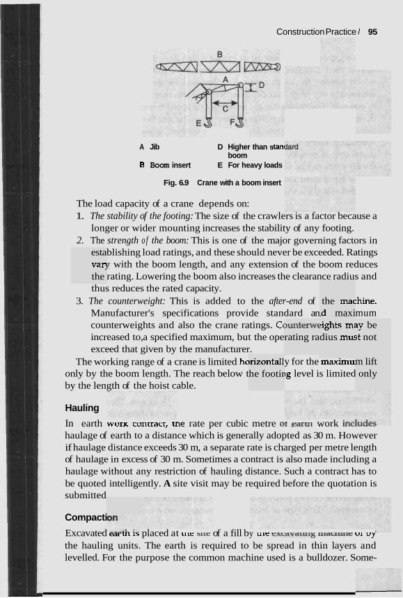
esta vaq the
Construction Practice 1 95
A Jib D Higher than stanl boom
B Boom insert E For heavy loads
Fig. 6.9 Crane with a boom insert
The load capacity of a crane depends on: 1. The stability of the footing: The size of the crawlers is a factor because a
longer or wider mounting increases the stability of any footing. 2. The strength o f the boom: This is one of the major governing factors in
blishing load ratings, and these should never be exceeded. Ratings Y with the boom length, and any extension of the boom reduces rating. Lowering the boom also increases the clearance radius and
thus reduces the rated capacity. 3. The counterweight: This is added to the after-end of :hine.
Manufacturer's specifications provide standard an mum counterweights and also the crane ratings. Cc increased to, a specified maximum, but the ope exceed that given by the manufacturer.
The working range of a crane is limited ha only by the boom length. The reach below t by the length of the hoist cable.
~rizontall he footir
3unterwc rating ra
the mac ~d maxi lights mi dius mu:
y for the maximu ~g level is limited
3y be ;t not
m lift only
Hauling
In earth worK contract, tne rate per cubic metre or -earrn work inc----- haulage of earth to a distance which is generally adopted as 30 m. However if haulage distance exceeds 30 m, a separate rate is charged per metre length of haulage in excess of 30 m. Sometimes a contract is also made including a haulage without any restriction of hauling distance. Such a contract has to be quoted intelligently. A site visit may be required before the quotation is submitted
Compacti
Excavated ear UI 1s placed at LIK s l ~ e of a fill by ult: exLavawl5 lilacllulr UI uy
the hauling units. The earth is required to be spread in thin layers and levelled. For the purpose the common machine used is a bulldozer. Some-
~b (ionsrmcr~on Managemenr ana ~ a n n ~ n g
times another machine named as is also used. Graders are providea wim a set or teem aneaa or me waae which loosens the earth before it is handled by the blade. The blade is adjusted to any angle and depth so that the earth may be moved forward or to one side. The grader has got an adjustable speed from 3-30 kmph and are designated by the horse power of the engine, the length of the blade and the number of driving axles. The moisture content is suitably adjusted by sprinkling water so that it reaches the optimum moisture content of soil under compaction. By compacting the eari rolled conditions, the air voids can be completely eliminatec
The equipment used for the comvactlul~ ul caluL 1111 are the smooth- wheeled roller, the sheep-foot rol
which do 0
es the jol: . .* 1
3 more ej , .- .. Ficiently
- 1 *
natic-tyr ed roiler. .ler and t
Smooth-wheeled Roller
The smooth-wheeled roller normally has three wheels and with weight varying from 2-18 tonnes. In some of these rollers adjustment of loads in wheel could be made by filling the hollo~ ith sand, gravel or water. It is, therefore, necessary to specify the I unit width and the gross weight of the roller. These rollers are ope steam or diesel or petrol and are used mostlv for
w rolls w oad per rated by
road surj Faces.
ler Sheep-foot Rol
It consists of a heavy drum fitted with projecting spikes blunt at the end. Sometimes the drum is made hollow and filled with sand during operation at site. To achieve efficiency either the drum diameter is made quite big or the spikes are inserted o .face of the drum pirals. Changing the head of the spikes it c de to run on diffei taterials required to be compacted. Generally the diameter varies from 75-150 crn and length 90-150 cm, and the total weight varies from 2-13 tonnes. These may be operated with the help of a crawler tractor and a pair of them is made to run side by side while the third one which runs at the back moves at the middle of the front pairs. A number of pa type of soil to be compacted.
To transport such a roller from one place ru anurner, me rvller splltes 01 er may damage the existing track. So, sc s the sp d on detachable curved plates attached to I. So thai
transport the curved plates and the spikes are detachea ana the drum 1s maae to run easily. This type of roller i:
n the s u ~ an be ma .- - -
in twos rent fill IY
-- .-
sses may vary fro g on the
..:1..- - c
lependin,
. -.-'I7 - ..
the roll arrange L . . .- -. . -
me time: the drun
I 1 .
ikes are b during
; sometir nes cdec ertible ro ller.
Pneumatic-tvred Roller
itform m the front
A pneu two ax1
matic-tyr es, the rt
of a bo, nore wht
:ed roller ?ar one f
>etween leels are
- consists las one r
c or a pk ?el than 1
~ounted 1 . The wh
Construction Practice 1 97
so arranged that the front and rear wheels move in different tracks. The rubber-tyred wheels individually sink into any rabbit hole and therefore compaction is completed without any hole.
These are mostly used for fine-grained soil or sand whereas for cohesive soil they perform best when water content is 2 to 4% below the plastic limit. The depth of layer should be around 200 mm so that proper and good compaction is achieved.
Tools for Rock Excavation
There are various types of drills available for the purpose of rock excavation. Some of the more common and important ones will be discussed here. The pattern of drilling, i.e. the plan of drilling is also an interesting feature for rock drilling. According to the working characteristics, rock drills are classified as hammer type drills, percussion drills and rotary drills. Hammer type of drilling is the most important type of drilling. It consists of a hammer, drill steel and bit. In this method a wedge is driven into the rock by means of a hand-driven hammer so that a not& is produced. The wedge is then rotated a part turn and a fresh notch is cut out. The procedure is repeated until a bore hole is produced. In mechanical type drilling, a piston-type hammer is acted on by continuous blows in the drill steel. The to-and-fro motion is effected by compressed air which is allowed on either side of piston alternatively.
In case of percussion-hand drilling, a heavy drill steel is raised and dropped successively. As it goes down it breaks small particles of rock. In case of a mechanical percussion drill, compressed air is used for effecting the to-and-fro motion. In hammer-type machines, the number of blows may be 1100-2500 per min while in the percussion type it is between 350-600 per minute.
In case of rotary drilling, the bit is rotated by a machine driven by compressed air. The drilling speed depends on the shape of the bit. For cutting soft rock and ores of coal and potash, these are found to be very suitable.
Hammer Drills
Hammer type drills may be classified as jack hammer, dril pressed air, and drills with screw arrangement.
Jack Hammers
11s using com-
Jack hammers are operated manually with the help of a handle. They work at all places and are very simple to operate. In drift or tunnel driving this could proceed during mucking also. The hammer weighs 10-40 kg as required. The diameter of the cylinder is another important parameter as the
98 Construction Management and Planning
back pressure proportionately increases with the square of the cylinder diameter.
Jack hammers with automatic rotation are provided with an automatic rotating device of this bit and the turning motion is derived from the movement of the piston. The turning motion is transmitted through a bit holder. The depth of penetration is made limited by a shoulder. For upward boring the jack hammer is provided with an auxiliary device. For very hard soil, heavy duty jack hammers known as sinkers are used.
Drills using Compressed Air
These drills are fitted with pneumatic feed with a compressed air feed cylinder. These do not need any additional device for boring upward or in inclined position. The rotation of the machine is either by hand or by automatic means. Automatic ones run easily in ha1 d rocks.
Drills with Screw Arrangements
These are heavj :rew to effect ro tdvance heading in very e are used in con uxiliary device only In drnr mixmg mese are used with colurm~s ur oars arid on the surface with tripods or quarry bars.
7 drills 1
hard roc ..: CL ... :- .:.
with a sc :ks. Thes~ -- 1 1 _ _ _ _
tation u5 juction M . . -- - - -
;ed for a rith an a. L--.- --;
Rock Drills with Percussive Action
These drills are divided into percussion dr ripping machines.
ills, and column-i 'ype cutt ing and
Percussion Drills
These are self-rotating machines with rigidly built-in slide for hana-screw feed to be used in connection with some auxiliary devices only Here the piston does not strike freely on the stationary drill steel but is firmly connected with the later. At each stroke, the whole set moves to-and-fro with the piston.
The number of blows here are smaller but the stroke is longer tl hammer-action drills. The connection between the piston and drill steel is easily separable. A powerful rotating device and a retroactive force effects easy movement without getting entangled in the fissured rocks. Water supply is to be maintained for removing cuttings and dusts.
Column-type Cutting and Ripping Mach
These are fastened with the help of a plue secrur ru cl c u l ~ l ~ r u ~ cu~u u ~ e
machine is adjusted to any desired angl 8wivellinl complished by turning a crank handle.
.e. The s 5 motior 1 is ac-
Construction Practice l 99
The cutting tool has got 3,5 or 8 edges connected to a detachable carving* kit and is connected to the piston by a shoe.
otary Dri
For drilling in coal, potash or medium or softer utiifonn ground rotary drills are used. The rotary piston is eccentrically supported with slots enclosing thin-walled slides. When the piston rotates the slides whirl outward by the centrifugal action and seal the chamber. The rotating action is accomplished by compressed air and is transmitted through transmission gears.
These drills are light weight, highly efficient, and the formation of dust, vibrations and noise are better controlled.
Auxiliary Tools
Other than the drills, tools like pneumatic chisel, pneumatic spades and pneumatic picks and rock breakers are commonly used for rock drilling, cutting and removing the debris. Each one of these have got special and specific services to offer.
EXPLOSIVES FOR BLASTING
i or remc Blasting is done to loosen the rock so that it may be t wed from its existing location. It is done by charging explosives and causlng fire to it in pre-determined holes made for the purpose. There are a number of explosives used for blasting. Some of them are described in this section.
Dynamite
It is available in many grades and sizes suitable for a particular job. Its strength is specified by the ratio of the weight of nitroglycerir weight of cartridge. The cartridges are 25-200 mm diameter anc long. After putting it in the bore hole it is tamped sharply so that it fills hole. A charge is fired by a blasting cap or a prima cord fuse. The el€ caps are avail&ie with two leg wires and these wires are joined witl wires of other holes to form a closed electric circuit for firing purposes.
is allow with fue
for 24 hc lixture cc
t is also (
lers and .L "r I - - -
le to the i 200-600 - . -.--
%s explosive is very mum m use in construcuo~~ sites for the purpose ur blasting both overground and underground. The cosi zheaper com- pared to the dynamite. It is detonated by special prirr is much safer in use. It is made up of 1 gallon of diesel fuel and abour ft3 ~g of ammonium nitrate fertilizer. The mixtun red to set trate gets thoroughly saturated . 1. The rr )side
>urs so tl ould eas
\at the ni ily go ir
total mm " *ha
rtric 1 the
100 Construction Management and Planning
vertical holes, for horizontal holes it may bc 0.7 kg/cm2.
Ammonium nitrate is not waterproof. In orde~ ect it from the ingress of water either a long closed plastic tube is in 1 inside the hole and then the explosive is introduced or the explosive is poured in a tu- the tube is inserted in the hole. If the hole is wet for some portio~ remaining is dry, the wet portion may be filled with dynamite gel a dry portion with ammonium nitrate. Arm primers consisting of charges of dynamite and also at intermediate positions, if requir
2 run insi ide by co A air at mpressec
* to prot troduced
be and ns and nd the
moniurn placed a med.
nitrate i t the bot
s detona tom of tl
ted by le hole
Slurry
It is a plastic water resistant explosive thar is maae ~y Drenalng several materials such as inert gel, ammonium nitrate and aluminium particles with water to produce the desired consistency. It may be directly poured in the holes or packaged in plastic bag and placed inside the hole. Being denser it sinks to the bottom of the holes containing water. Slurries are detonated by special primers such as dynamite, and Trinitrotoluene (TNT) using blasting caps or a prima cord. The cost of slurry is something in between a dynami+@ and ammokum nitrate.
OTHER ASPECTS OF BLASTINC-
There are few other things which oi rock blasting. These are explained
tn with get conve
Stemming
After a hole is filled with explosive up to me requmd depth, ule oal th some i erial which is known as stemming. Stemrnir placed b~ lharges at predetermined locations. When c
are separated by sremmmg, a separate primer may be used for each --
charges.
ance is - - - - - - -
'g may barges of the
filled wii even be
nert mat1 etween c . . - - . . . -
Firing Cnarge
Several holes are fired at a time in a parallel or a seri combination thereof. Normally circuits are tested with a galvi
- .
making the final electric c breaks and misfu
In order to hav necessary to place a higher concentration of explosive near the E: Stemming might help the process or dynamite of stronger quality is pri at the bottom and as one moves up less stronger ones are provided.
omectio
re blastin
n. Each (
~g with rc
tested to
ragrnenti lottom. ovided
Construction Practice 1 101
Electric Blasting Caps
These are used to detonate charges of dynamite or prima cord fuse. A cap is exploded by passing an electric current through a wire bridge inside the cap. The current required is approximately 1.5 amperes.
Prima Cord
It is a highly explosive fuse used to detonate dynamites or special primer for ammonia nitrate explosive. The core is covered with a sheath for protection, strength and waterproofing. One or two fuses are placed along the full depth to avoid misfire. To fire several holes at a time, several fuse from holes are tied to a common fuse which is fired by the blasting cap. The detonation of prima cord is initiated by an electric blasting cap attached to the free end of the fuse.
TUNNELLING
Tunnels are constructed for providing passage ways for railway lines, roads, access to mines, conduits for water, housing, electric or gasline and similar other purposes. They may run through rocks, igneous, sedimentary or metamorphic and therefore physical defects of rocks like joints fissures and faults etc. are important things to be considered before firtalising the route of a tunnel. Tunnels constructed under soft soil by cut and cover method are known as box culverts.
Soil exploration has to be undertaken to know the geology of the place where the tunnel is to be constructed. This should include the determination of the type of earth, rock, ground water, etc. If a tunnel is driven through solid rocks no roof may be required but for other soft soils and disintegrated rock, the construction of a roof will be necessary. The arrangement of continuous pumping may be required in the case of presence of a significant amount of ground water, or pressure grouting may be done to reduce the flow of water. It may be necessary to change the route if possible to avoid the presence of ground water. Shock waves propagated through the route generated by detonated explosives irr holes along the route may be taken up to study the characteristics of soil. Disturbed, undisturbed and cores of samples of earth, rock or soil may be collected and tested by drilling and other suitable method. The spacing of points for collecting samples should be close to each other in case of irregular character such as the presence of faults and folds and the spacing may be made wider where more or less uniform character sf soil is encountered.
After preliminary investigations, the route suitable for the construction of the tunnel should be selected.
Smaller tunnels may be cut from one direction. For longer tunnels, the construction might be started Irom either ends and the provision of inter-
102 Construction Management and Planning
mediate shafts (to be converted into ventilation shaft afterwards) may be made as required.
Tunnel construction involves a sequence of operations which may vary with the site conditions, the size and shape of tunnel. For tunnelling through rock the sequential steps involved are setting up .and drilling, loading holes and shooting the explosives, ventilating and removing the dusts following explosion, loading and hauling muck, removing ground water, erecting supports for roof and sides, if necessary, and placing the reinforcements to undertake concrete lining. .
The common methods of attack for driving tunnels throl face;heading and bench, drift, and pilot tunnel.
In the full face method, the whole cross-section is drilled, I with explosives and fired. This method is suitable for rc
~ g h rock
suitably ( tlatively . .
are full
lharged smaller . .., tunnels. It may also be applied for larger tunnels using the jumoo or arul
carriage. In the heading and bench method, the driving of the top portion of the
tunnel goes ahead of the bottom portion. If the rock is firm and the roof is self-supporting, the process may be one round ahead. For a badly broken rock, the top heading is driven well ahead ofthe bench and the bench is used to install timbers to support the roof.
In driving a large tunnel it becomes advantageous to driv 1 tunnel known as the drift tunnel for a portion or the full length of t 1. Drifts may be driven at the centre, at the bottom, at the top or at the sides. The advantages of driving a drift are:
1. The local problems if any are made known before driving the entire section and steps could be taken well in advance.
2. It acts like a ventilation shaft when the main tunnel if 3. The quantity of explosives required is found to be les 4. The side drifts may facilitate the ir n of sup
required. The disadvantages of a drift are:
riving of main bore is delayed, anc' le relative cost of the removal of m
.-I be done manually.
Drilling Rock
)mes higl
; driven. s.
3e excav
roof, if
~y have
Drill holes'are to be made in the rock for charglrlg rrle rloles w i u ~ explosives.
Drifter consisting of drill bits and detachable bits either steel or carbide-insert are used for the purpose. Water or compressed air is used to remove the cuttings fro& the holes. The depth and spacing of holes which depends on the shape and size of tunnel and the type of I ,ated is determined experimentally.
Construction Practice 1 1 nn
For smaller tunnels, drills are mounted on bars or columns dependir whether the width or the depth of the tunnel is smaller than the other. S---. . jacks are used to secure the bar or column tight against the walls or slabs. The drift is directly mounted on the bar or the column through an adjustable clamp.
For larger tunnels, the drills are mounted on jumbos which have a por carriage with one or more working platforms with adjustable he equipped with bars and columns to support the drill. The support> aIc designed to permit the drill to follow any set pattern. Nowadays a hydraulic or air-powered boom is attached to support the drill. The boom is equipped with controls which facilitates spotting of the drills easily. Several drills may be operated from each platform. A jumbo ma) n rails or natic tyres as provided with.
A drill pattern is selected by conducting experiments in oraer KO have economy and satisfactory breakage of the rock. Over breaking is never to be encouraged as it will involve more cost.
Of all explosives used for blasting, ammonium nitrate blended with fuel oil is found to be the best for tunnelling, as it yields better f ition, requires lesser time for loading and blasting, it is cheaper, sim safer to 1
table mights " -w,7
7 travel 01
ragrnent: pler and
Tur 3 with Mechanical Moles
A recent development in the field of tunnelling is the introduction of mechanical moles. Various types of moles are in use. The basic principle being more or less same. It goes on cutting the soil or earth as per the cross-section by a rotating disc cutter head. During the operation of the expanding jacks maintain a pressure between the disc and the face c tunnel while the disc mounting revolves @ 4 to 7 r.p.m. The cutting el ey fall on a belt cc ports tk
uL ,">ition control of the mole both vertically and horizontally, a laser bc
mole ~f the s are
evated o: tem. En,. - n o
n the top of mole where th hat trans
;ed nowz
Venrrrarrng I unnel
nove ust. , ntnr-
A tunnel is to be ventilated for furnishing fresh air to the worker, to re1 obnoxious gases and fumes that come from explosives or to remove dl
Mechanical ventilation usually is supplied by one or more electric in driven fans which brings in fresh air and takes out dust and the tunnel.
Each worker is to be supplied with 200-500 cubic feet/mitu~c ~ L I I
fresh air. Firing fill me1 with gas and dust. The cycle of opera may be organised i ler so that the workers retire a safe distance
L"."L
from
-1 -L
foul air
;-.-&.... /-L* 11) Ul
tions from
!s the tur n a manr
104 Construction Management and Plannin~,
the face before firing and have break during the time required to remove gases and dusts which needs about 30 minutes.
The size of the blower depends on the quantity bf fresh air to be supplied. The cost of energy required to operate the blowers increases directly with the length of the tunnel and this is to be included to the vroiect co-'
Dust Control
The various operations such as drilling, blasting, loading and hauling muck cause dust in the tunnel. This creates serious health hazard to the workers unless properly controlled. To control the dust, water instead of air is used to remove cuttings from the drilled holes. To remove the dust that come from the hole during drilling, a vacuum hood is fitted around the drill steel. Complete ventilation of the tunnel face by the exhaust method following each round of blasting, keeping the mucE ring load detergent with water are the other meast jntrol thc
c wet dui Ires to cc
ing and 1
: dust. using the
mecha used. ' muck ( the loa used ir
Muc
The mi latches
I 11
lding eql I tunnels .I* :- L-.
~tives or . two lan ..---*-J
uck car i! at the bc
1 ..
be done - - . g a powc - -
trucks. Fl es depen 7.L- --- ; constru ~ttom to
powered ~ealth grc
with an ~und . . - I :- --
cted wit] permit e;
1 .
cars, stec the size -1. :- - I - -
!I sides h 3sy duml , .
internal combusi
nical mug !h conve: .t.An*ll-, ,
tion engi
Mucking
Mucking could by hand, or usin zr shovel tractor loader. Hand mucking is done in small tunnels where the ,, ,, ,
nical mucker is difficult. For larger tunnels, mecha ckers are mese muckers discharge the muck into a belt whic ys it to a :ar for final removal. The machines are normallv elecLllLruLv aperated.
xipment ne is not on the 1
.n 13 11aaled front a Lul l le l IIL I L ~ ~ U W - g d u g e IIIUCK cdrb pulled by locomc or muck !1 rails are require1 ~y be one lane 01 ding on of tunnel and the of muck to be ~ ~ L ~ L U V C U . I ~ L C sdlrle rail trarn 15 cllsu used for timbering arlu concreting.
inged at the top and fastened with 3ing. The locomotives used may be
a rrolley, a warrery or a comwlnatlon or a trolley and a battery. The trolley type is easy to operate but the bare trolley wire inte~ th other operations. The battery type is operated by storage batterie rd on the locomotive. The batteries can work for eight hours and tnen need to be charged for another eight hours. The combined type is used when haulage is required inside and outside the tunnel. For running inside, the battery is operated while at outside the trolley may serve the purpoFa
d and mz 8 volume
-- _1 --
Groun r..,
d Suppa
wnen a tunnel is anven, it may pe necessary to support tne grouna aajacent to the tunnel until a permanent concrete lining is provided. Temporary supports which is known as timbering should be strong enough to prevent
Construction Practice 1 105
collapse particulary near the faults, fold and fissures. Timbering depends on the size and shape of tunnel and also on the type of,soil. In recent times H-beams fabricated at site are being used as an alternadve to timbers. These could be installed quickly and may be found to be cheaper at times. To prevent falling of broken stones into the bore of the tunnel, lagging (a sort of cover between ribs) is to be done.
Sometimes bolts are used for supporting the entire roof or individual rock slabs that tend to fall into the bore. The weight of roof is transmitted to the supporting walls by the arch action. The soil below the arch tends to fall off and bolting prevents that. The bolts should be long enough to secure the rock from falling. Tapered expansionable plugs are used at the tail end of the bolt so that good anchorage is effected.
Controlling Water
In the process of tunnelling operations it is important to see that water is prevented from entering the tunnel and water that has entered is pumped out of the tunnel. Water comes from the water used for washing the cuttings from the drill hole and the other source is the ingress of ground water. It is possible to know in advance the presence of fissures and faults in front of the tunnel and these should be plugged by grouting before the tunnel reaches such a spot.
Air-driven and electric motor-driven centrifugal pumps are used for pumping water. Air-driven sump pump is suitable near the face of the tunnel and electric motor-driven pump is used for the main pumping operation.
Cross-section of a Tunnel
The cross-section of the concrete lining should be strong enough to resist the effect of earth pressure. In solid rock, the desired shape of tunnel may be provided. For the aqueduct, the section may be circular whereas for a vehicular tunnel it may have a flat invert, vertical wall and an arched roof. For tunnelling through a broken rock, a horse shoe shape gives a more stable section. For tunnelling through an unstable section, a medium circular cross-section is preferable regardless of the purpose for which used. Elliptical shape is preferred for water lines, sewer lines etc.
Concrete Lining
The thickness of concrete lining depends on the size and shape of the tunnel and the pressure to which it is subjected which in turn depends on the geological features of the surroundings. If steel ribs and reinforcements are used, the thickness may be reduced. But this may not strike the desired economy. The rule is to adopt 25-30 mm thickness per 250-300 mm diameter. Tunnelling through solid rock does not impose any load on the tunnel and therefore the
106 ConstructionManagement ana rlannmng
lining may be of a minimum thickness. Under such a circumstance 1 bore may be completed before lining is started so that mucking ana ~mmg do not interfere with each other. Under unstable ground conditions, lining is done after each round of excavation and mucking. The sequence of installing a lining around the perimeter of the tunnel will depend on a number of factors. For a circular section the entire section may be placed in one operation. For a tunnel with rigid base the form work for the roof and wall may be supported on the base, for large tunnels the pours may be divided into phases as lining the base first, next the walls and then the roof. For a tunnel having a base vertical wall and an arch roof, the junctions of the base and the wall may be cast first, next thewall and roof in one operation and finally the base.
Reinforcing steel when required in a tunnel lining may consist of a steel rib, bar or both. In thick linings two layer of steel may be required one near the inner and the other-near the outer surface of the lining whereas, for thinner lining one layer of steel near the centre of lining will be adequate.
The forms used are of a movable type. Sieel forms though initially costlier compared to timber but because of repetitive use are found ultimately cheaper. The movable type of form is composed of steel skeleton and on the outer side of the skeleton it is covered with a steel plate or timber which conforms to the shape of the tunnel. The whole form work may be mounted on wheels to move over rails and is equipped with adjustable jacks which create the expansion of the form to the shape required and concreting is done. After concreting it is reduced in size by operating the same jack and moved to the new position without any difficulty.
The most common method of constructing a concrete lining is with a pump crete machine. The machine includes an agitator or a remixer hopper, a single or double cylinder piston pump and a discharge pipe through which concrete is pumped in the form. At first the concrete is fed into the remixer hopper where it is agitated for ensuring uniform quality and it flows to the pump. The pump is placed just beneath the hopper and during the pull stroke concrete flows into the pump and during the push stroke the ejects out into the discharge pipe.
e, the ful 1 1 . .
concrete
The machine may be set up outside the tunnel near the portal ur Durlre
vertical shaft. As concrete could be pumped only up to 300 ft, the machine is to be shifted for longer length of construction. In case of a very large bore the machine may be set up inside the bore over rails so that the machine could be shifted as concreting PI
The concrete walls may be pl, the discharge pipe through temporary openmgs m the tom. Atter Me wall concrete has progressed as required, the discharge is directed tom arch pipe or slick pipe already placed on the roof arch. Concretin
:ogresses
aced by I directing the flow . - rete from . .
rards the g should
Construction Practice l 107
; having xe, a pne
bc y done in order to have the balancing of load on either side of the cenrre me. Compress'ed air is injected at intervals so as to push the concrete to a remote place of the arch and this process is known as air slugging. In order to vibrate the concrete and remove honeycombs, nozzle or form vibrators are used.
For long tunnels smaller sections where it is difficul P the pump crete machb wmatic placer is used. This collect ~crete from the cars which carry the concrete from the hopper. Compressed air is injected in the placer to force the concrete from a discharge pipe into the form. The velocity of concrete through the discharge pipe is maintained low in order to avoid seggregation.
t to set u s the cor
EXERCISES
6.1 Discuss how excavation is classifed according to the purpose of work.
6.2 Define and explain the following:
(a) Stripping (b) Roadway excavation
(c) Drainage excavation (d) Channel excavation
(e) Bridge excavation (f) Borrow pits.
:aim shell
le the equ --.. -c &I..
6.3 Name the principal earth moving machinery and discuss their specific 1
6.4 Write down the functions of the following machinery with brief discus'si their operating principles:
(a) Tractor (b) Bulldozer (c) Scraper
(d) Power shovel . (e) Hoe or pull shovel (f) Dragline
(g) c (h) Crane. 6.5 Nam ipment used for compacting the earth. Write the specific 1
each ullr UL ten-
6.6 Classify the rock ~ccording to their working characteristics. Discuss
(a) Jack hamme] (b) Drills using compressed air and
(c) Drills with screw arrangement.
6.7 What is a percussion drill? Explain its working principle. How does a rotary drill function?
1.
: drills e
r,
Explain tl
ises.
on on
ise of
6.8 What are the materials used for blasting. ; le process of blasting by dynamite and ammonium nitrate.
6.9 Write short notes on
(b) Stemming (c) Firing charge
(d) Electric blasting cap (e) Prima cord
6.10 What is tunnelling? How is it done? Describe the sequenc ration followed for tunnelling.
6.11 Explain (a) Full force, (b) Heading and bench, (c) Drift and 11s.

Explain i . 3 .
How shc meant by
control bc ; and why
e made ef is it done
; adopted ~vided in 1
i..-7 Un..,
in tunnel1 tunnels.
;L. ;t Am..*
6.12 the proce5 stana by ventilating tunnels
~uld dust mucking
1s supported?
What are the steps ~ntrol wai concrete lining pro
What is pumpcreti,,, ..,,, ,a uu,cc ,,, a ,,,,,, lining?
.,
mechanic
'fedive in ? How the
ling opera
. ;.. I-..;...-
tunnelliq ? ground z
tions to CI
:- t..-rr.1
What do
g operatic idjacent tc
you unde
jn? What is ) the tunnel
ter? How
Construction Practic - Superstructure
INTRODUCTION
Concrete is one of the most common building materials which could carry high compressive stress but is weak in tension. The biggest advantage with concrete is that it could be given any shape or ,form as required. It '
composed of a matrix of aggregates coarse and fine, cement, and water mb in a certain proportion as per the required strength in a semi-solid form is cast within or over a form work, and allowed to set and hardened. The standard test performed to determine its ultimate compressive strength is known as the cube crushing strength or cylinder strength as specified and determined from the crushing strength of standard cubes 150mmx 150 mm x 150 mrn or 150 mm diameter cylinder of length equal to 300 mm made out of concrete cast in moulds tested after 28 days of casting in a compressidn testing machine. The coarse aggregates used are broken stone, e.g. granite or sand stone, crushed in the form of small irregular cubes of different sizes. Sometimes gravels obtained from river beds or pits are also used for the purpose. The coarse aggregate is properly in order to have minimum voids in concrete. The fine aggregat s normally coarse-graded sand obtained from river beds or pi1 !nt used is generally ordinary Portland cement and water is potable, free from acid or alkali. Water and cement mixed together form a paste. This is mixed with sand to make a soft mortar which occupies the voids present in the coarse aggregate. Thus the mixture becomes almost a homogenous matrix of these ingredients and is known as concrete. Since concrete is weak in tension, steel in the form of bars are used with concrete primarily for carrying the tension
graded e used i ts. Ceme
1 10 Construction Management and Planning
in a structure. The whole composite gives rise to the well-known reinforced concrete, which is a versatile material used in the construction of most of the structures nowadays. The tension is transferred to the concrete through a bond between steel and concrete. Hence the bond is very important and should be proper so that there is-no slip between the steel bar and concrete. Concrete being generally impermeable protects the steel from corrosion. Since the thermal coefficient of concrete and steel is almost same, any change in the atmospheric temperature does not affect concrete. Cracks are found to develop in the reinforced concrete near tk I zone. But as these do not affect the material much, they do not re1 r special protection under normal conditions. For aggressive environmenr protective measures may be required to save steel from corrosion and concrete from spalling of
CEMENT
Ie tensior quire an! --- - - L ---
types of
Portland
' cement
l Cemenf
used in (
: (O.P.C.)
ion are c
Blast Fur Resisting -I-:- PA-
ning C ~ I ic Cemen Al--J
The main raw materials used in cement are lime, silica, : and iron oxide. Since a wide variety of raw materials is used, the oxiae conrent varies. The calcium oxide reacts with silica, alumina and iron oxide resulting in tricalcium silicate, dicalcium silicate, tricalcium aluminate, tetracalcium aluminoferrite, etc. When water is added to cement, tricalcium silicate jellifies evolving heat. This is responsible for the strength of concrete within first 14 days, whereas dicalcium silicate hydrates slowly and provides a progressive increase of strength for 14 to 28 days and onwards. Tricalcium aluminate is responsible for setting and hardening of cement. Other ingredients do not have much effect on the strength or the setting time. Calcium sulphate is sometimes added to the clinker for controlling the setting time. Fineness of grinding improves the early development of strength. Shrinkage and crack- ing of cement increases due to the increase in the rate of development of strength.
The different
1. Ordinary 2. F rdening Portland 3. I t Portland Cemen 4. hign ~ l u m i n a Cement (H. 5. Portland nace Cement (l?B
' 6. Sulphate ; Portland Cemen 7. Hvdro~hovlc ~el l ient (H.P.C.) 8. k 9. E OrdL1ary ~ U L U ~ ~ L U cement is trle Irrust commonly useu standard cerrlerlr.
It has got all the desirable properties of n a balanced form, while others are used under special circumstl are manufactured using
nent (A.1 lt (P.C.)
Cement ~t (L.HaP.( A.C.)
E.C.)
cement i mces or
lassified
C o n s f r u ~ . rractlce 11: Superstructure 11 1
different ingredients. All other cements are compared with O.P.C. for high- lighting their special characteristics. Rapid hardening portland cement h~ high early strength since it hardens rapidly due to high content of tricalci silicate. Low heat cement having a high percentage of dicalcium silicate slow hardening and generates less heat while hydrating. High alum*-- cement having,a high Alumina content develops rapid strength evolvin lot of heat and is more resistant to sulphate attack. Portland blast fum cement is more resistant to chemical attack and it hardens slowly genera& low heat. In sulphate resisting portland cement, tricalcium aluminate is low and it is more resistant to sulphate attack. Hydrophobic cement is manufac- tured with an additive which provides a film around the cement particles and makes it water repellant. The film breal and makes normal hydration effective.
Air entraint cement is so manufactured thar ir creares air bubbles in concrete when used and thereby makes it lighter and resistant to freezing. Pozzolonic cement, where pozzolona is used during manufacture, protects the concrete better from sulphate attack and develops strength comparativ ' s10\
IS: 269 a 1t cemen
lone h a in constr
Standard tests as per re to be c rrder to ascertain the physi properties of differer ~ ts used ,uction. These tests are to done for any cement used in construction and the results should be compa: with the spec:fied values in IS: 269. For convenience, the results of ordini portland cement which is the most commonly used cement are given belc
1. Chemical Comp (a) Loss on ignitic (b) Insoluble~esic (c) Lime and alun :ent (d) Magnesia (e) Sulphur content
osition )n lues ~ i n a con1
:xcess of -a, alumi
e causes ron oxidc
with lirr nd form:
noisture -
~ ~
! content in O.P.C. .. .
; crystals
- .-L.
um has .u n u
g a ace
Loss on ignition occurs due to the evapora ,on dioxide in cement and these are absorbed from the atmosphere. For ordin?-. portland cement, this should be maximum 5 per cent.
Insoluble residues come mainly from impurities i presence of other inactive materials. This should not exceeu L 10 in O.P.C.
E free lim unsoundness. Hence the of lime sillic na and i 2 is restricted to 0.66-1.02 I
Excess or magnesia also causes unsoundness so it should not exceed C/O
in O.P.C. Sulphur combines ~e and alumina a 8 of calcium
and cark -.
m and i
ical be
red
ary )W:
l X Y
the
1 12 Consrrucrron managemenr ana r~annmg I
;ion and sulphoaluminate. This causes ai Hence it is limited to 2.T0'
ent unso 1 3 10.
(rs to the -- l--L--
2. Fil quantity .t weight. The fi11t.l u l r CCILICIIL UIC ~a3~t.1 is the d t . v ~ l u ~ ~ l ~ t . ~ ~ c UL ~ L I ~ L ~ U L . rlowever, excessive 'fine cement causes more shrinkage. Fina zasured by a sieve analysis which recommends that the percentage of should not exceed 10% for O.P.C. It is also measured by specific surface dred test which should not be less than 2250 crn2/gm for 0.P.t permeability method as per IS: 4031.
This refe .----I. 4.1
~t particle --L -l "L
less is mc : residue ! --- ---- 3
- - - - ~ - .~
iine's air accordh
determir Iness, a c ..-I----..
time, ter ~rmal COI .--L--
3. Normal consistency For ling the setting ~sile and compressive strength and sound ement paste of nc nsistency is used. Therefore it is necessary LU luluvv the auantitv of W ~ C T T ~tf~uired for normal consistency.
4. Initial and final setting tirll= 1 L I r ~ 1 u ~ t . 3 3 VY ~ 1 ~ d - t C3A tricalcium aluminate in cement reacts with water and gets soliaified is known as setting. This is followed by reaction of C3S tricalcium silicate and C2S dicalcium -*l:--L
? with water when the paste starts harden in^. This Drocess needs to be rtation and placi rm work tting starts. But it 8 possible
t no craw aevelops. The setting ana naraenmg r l m e ror "O '; I
b l l l C d L t
dela ye could 1 - - # I . -
d so thal De done 1 . .- -
ng concr should 1 -.J I . - .
V L
-ete with in the fo t transpc ; early as
c - - SO ma specifil minutt
u.1-.L. 1s
than 600 3 codes ; tively.
is not le! ;s than 3 2s and n ot more
if harden1 ,ete. The _I---- I-.
desirable measure 2 2- L L -
~undness Change in the 7 ed concrete is not I [uses an undesirable stress test performed to
rnis nl cement paste is known as ule soununess rest. This is performeu I ~ L ule
Le Chatelier apparatus and the extension of the standard specimen should not exceed 10 mm. But if this is done after aeration and spreading, the extension should not be more than 5 mm. Sometimes this test is also done by the Autoclave method when the percc : expansi 0.8%.
~olume o v in concr LL - - - - - .-
on is resl
rength o:
ide of on
6. Compressive strength The average compressive s t 2 three mortar cube of cement (area of face = 5000 mm ) mz
:e parts c ; Leighto t is to be of water
€ at least
~e part of cerneni sand) 1
t and thn ~y weigh
. .
rd sand (I red. The
known a: quantity
1 .
d annore xed with
tne cement IS given by per cent or comwlned weignr 01 cement ana
is the percentag .er requi .educe a itency. The cubes ~e prepar d and tes
sand v standa
.e of wat should b
~d to ed, store1
vhere P rd consis
Construction Practice 11: Superstructure 1 13
IS: 4031. The results of crushing strength after 72+ 1 hot
16 ~ / m m ~ .
7. Heat of hydration For low heat cement, the heat of hydration sh not exceed 65 cal/gm and 75 cal/gm after 7 days and 28 days respecti __, Otherwise the temperature differential created between the interior in a mass concrete work may cause excessive the resulting in cracks.
AGGREGATES
surface ma1 strt
ould velv. and
2sses
Aggregates which are inert materials constitute the major part of the conc These are divided into coarse and fine aggregates. Any particle size less 4.75 mm and more than 75 micron is called a fine aggregate and those 1; than 4.75 rnrn but smaller than 80 mm is called coarse aggregate. The more densely the aggregate is packed in concrete the better is its strength and weather resistance. For this reason graded aggregate which give better packing is preferred. It is also important that the aggregate has good strength, durability and weather resistance. Its surface should be free from impurities like loam, silt 5nd organic matter which may weaken the bond with the cement paste and hence the strength. Aggregates shall not contain har~ material such as pyrites, coal, lignite, shale or any other material that attack the steel reinforcements or chemically react with alkalies.
:rete. than kreer
As per IS: 2386, the aggregate crushing value or impact value shall not exceed 45% for concrete other than wearing surfaces and 30% for concrete on wearing surfaces such as runways, roads and pavements. The abra-4-- value using the Los Angeles (LA) machine should not exceed 30%
.J&VIL
I for wearing surfaces and 50% for other concrete.
Aggregates used nowadays may be classified as: 1. Normal density aggregates having a specific gravit between 2.5 Y 3.6 and bulk density between 14.5 and 17.5 KN/m includes mo
aggregates like gravel, crushed rock, and blast furnace slag.
and st of
2. High density aggregates are mostly used in nuclear power plants for shielding radioactive elements and are obtained from barium sulphate rock, ferrous ores like magnetite, haematite and limonite.
3. Light weight aggregates are porous solids, natural or artificial. The density, strength, and thermal conductivity in concrete gets lowered with the use of these aggregates. These may be Jhama bl broken,
;tone. Nc and b u ~
or other light weight stones such as Hght sand 5
in the shape of marbles are made in machine temperature to produce similar aggregates.
Fibre aggregates like fibres of asbestos and galvanised iron ( G.I.) w
:icks clay high
1 14 Construction Management and Planning
cut in small pieces, other cut pieces of artificial and jute fibres are also used for the manufacture of concrete for specific purposes.
In air entraint concrete the bubbles, generated by foaming the cement paste occupies spaces in concretelike aggregate and this is called the gaseous aggregate in some references.
Physical Properties of Aggregates
The important physical properties of aggregates are size, shape, surface texture, strength (of. coarse aggregate) specific gravity, bulk density, water absorption and surface moisture, deleterious substances, soundness and durability.
Based on the size of particles aggregates are classified as coarse or fine aggregate. Any aggregate having size 80-4.75 mm is called a coarse aggregate while an aggregate having size below 4.75 mm and above 75 p are termed fine aggregate or sand. Particles having 0.06 to 0.002 mm are called silt and smaller than 0.002 mm are known as clay. Silt and clay impair the strength of concrete and should be removed from aggregates used for concrete.
Single size aggregate is not generally used in concrete rather graded aggregate is preferred because of its high density and high strength charac- teristics when compared to single size aggregate.
Aggregate, may be rounded, cubical, angular or flaky. The shape of particles affects the voids and hence the strength of concrete. Rounded particles give rise to 30-33s voids while angular particles have maximum voids ranging from 40-50%. Flaky and elongated particles impair strength and hence not desirable.
Aggregates having rough surfaces increase the strength however it reduces the workability while rounded aggregates increase the workability but reduce the strength. The surface texture may be glassy as in black flint. It may be smooth, e.g. gravel chirt, slate or marble. It may be granular as in sandstone or volite. The texture is rough in the case of basalt or limestone. If the aggregates are granite, gabro or gneiss, the surface texture is crystalline. The texture is found to be honeycombed or porous when brick, pumice, foamed slag or expanded clay are used as aggregates.
Generally the strength of aggregate is greater than the strength of concrete. Under compression, it is the sand cement mortar which crushes and not the aggregate proper. In case of very high strength concrete the strength of aggregate may govern the strength of concrete.
The specific gravity and bulk density of aggregates suitable for concrete are 2.5-3.0 and 14.5-17.5 kN/m3 generally. The values of high density aggregates are higher and may be 3.5-4.5 and 18-20 kN/m3 respectively.
Aggregates contain permeable holes through which moisture permeates. When an aggregate sample is dried at 100°C for 24 hours it becomes bone
Construction Practice 11: Superstructure 1 5
dry. When aggregate is dried in air it is known as air dry aggregate. When all pores are saturated but the surface is dry it is called saturated and surface dry when it is fully saturated and has got free moisture on the surface it is called moist aggregate. Saturated and surface dry condition of aggregate is the ideal condition for measuring the water cement ratio without any adjustments necessary.
Deleterious substances if present make the concrete weak. Organic im- purities interfere with the hydration of cement, silt or clay affecting the bond between mortar and aggregates which act as coating on the surface of the aggregate. They also provide additional specific surface area of the aggregate and affects workability. Light weight soft particles may also affect the compressive strength of concrete.
If there is a change in the volume of the aggregate under heating and cooling, wetting and drying, or freezing and thawing due to climatic changes, the concrete is subjected to undesirable stresses. Thus a good quality aggregate does not undergo changes in volume under normal conditions and this is defined as soundness of aggregate.
The active silica content of aggregate reacts with the alkali present in cement and forms a silica gel which swells in volume and disintegrates the concrete and thus affecting the durability of concrete.
Sand, the fine aggregate used in cancrete, has a peculiar characteristic of changing volume according to the moisture content. This is known as the bulking of sand and has to be determined before fresh concrete is prepared. With the increase in moisture content, the bulking of sand, i.e. an increase in volume from 15-40% is possible when the moisture content increases 5-8'/0. Beyond this the film of water surrounding the sand particle merges and water moves in the voids of the particles resulting in the decrease in the volume of sand. Obviously, fine sand bulks more than coarse sand. Thus to get the necessary volume of sand required for concrete it is necessary to know at what moisture content its volume is the minimum. Bulking of sand is tested in a measuring cylinder applying measured quantity of water gra- dually inside the sand and observing the change in volume.
WATER
Water used for making and curing concrete should be free from injurious substances like oils, acids, alkalies, salts, sugar, organic material and other elements deleterious to concrete or steel. Water fit for drinking is also suitable for concreting. Sea water is not recommended for concl'eting as it contains harmful salts. As per IS: 456, water to be used for concreting should conform to the following:
1. Acids and alkalies

1 Manager vent and
(a) 200 ml sample of wate 2 ml of 0.1 normal Na(
(I content in water should I
!r should 3H or 10
be neut I ml of 0.
y not mc I HC1.
b) Solid ages: 0ro;li
!d the fol
,,,-uc 200 mg/l, Inorganic 3uuu mg/l, Sulphates as SO3 500 mg/l, Chlorides as C12000 gm/ for reinforced concrete.
2. There should not be even traces of tannic acid and su 3. Humic acid or carbonic acid as fou
concrete. ' 4. The pH value of water should not exceed 6. 5. In case of doubts, the setting time of cement and cube c ltre~gth
of concrete should be determined prior to the actual construction using the available water and comparing the results with similar tests done with distilled water. The water should be approved if the results of cube crushing strength using the water is found to be 90% or more compared to the samples where distilled water has been used. The initial setting time of the test sample should not be less than 30 minutes and should not differ by f 30 min compared to the sample prepared
ith distilled water. This is because the setting time is likely to be kcted by the presence of sugar, carbonates, bicarbonates of sodium ~d potassium, and salts of sodium, zinc, copper and lead. Water jntaining NaOH may induce quid
e and lo(
[gar. er is har arsh wat
rushing s . ..
; used in :ding to
Admixtr specific
materials !s. Acco~
tfy its pn these a
operty fc re classi
Jres are I
purpose concrete these p
)r some fied as
follows: 1. Accelerating admixtures or accelerators
early strength and generally used in cola wearner or ror q u i c ~ repalr. Calcium chloride, fluorosilicates and trithanolamine , for the purpose.
2. Retarding admixhtres or retarders These are used to retard me semng ne and reduce the evolution of heat. T bncreting in hot weather and in ready mix (
E! products of starches, cellulose sugar, hydroxyl carboxyllc aclds and th Retardel re he water
3. Water reducing admixtures TlLc YUIYVJc U J A ~ these admixtures is to duce the quantity of water without affecting the workability. llphonic acids and their salts or hydroxylated carboxylic ad
These z tre used -.I. ...
for attab r - - -. .: -1.
ling an . . . - .. - . ..
are most: ly used
hese are :oncrete. . .
! also us Comma . .
jed for n types . .
~eir salts. ducing tl
7s reduce -cement
-
the wai ratio. hn -..-r
thereby ?d for COI
Ligno- ~ d s and
Constmction Practice 11: Superstructure 1 17
their salts are used for the purpose. These admixtures when used increase the setting time. To achieve normal setting time or to ac- celerate the process, accelerators may be used in combination with these agents.
4. Air entraining admixtures These are used to entrain air in the form of small disconnected air bubbles which increase the workability and resistance to freezing and thawing. Air entrainment should be limited to 4-5% as it decreases the strength of concrete. The agents used for the purpose are, animal and vegetable oils and fats, natural wood resins, vinsol resin and alkali salts of sulphated and sulphonated organic compounds.
CONCRETE
Concrete has got two states: green or plastic concrete and hardened concrete. During the plastic state, concrete is cast within the form work and com- pacted. Concrete is made workable so that it is easily mixed, placed, compacted and finished at the surface. It does not bleed or get seggregated. Within the form work, the concrete sets, hardens and gains in strength. A hardened concrete has adequate strength and is durable, impermeable sound. The properties of concrete are stated below:
Plastic Concrete
Plastic concrete has good workability and is free from segregation and bleeding.
'Workability It is the easeness with which fresh plastic concrete could be handled, cast within the form work, made to pass round reinforcements a h compacted. The proportion of water mixed in concrete is the main factor which affects the workability. It is sometimes defined as the amount of internal work required to produce full compaction. Workability can be improved by reducing surface area of the aggregate. The increase in the maximum size of aggregate increases the workability. The increase in the quantity of coarse aggregate at the expense of fine aggregates using round aggregates instead of crushed angular aggregates are some ways to improve workability. Fresh concrete loses workability with time as some water is lost due to evaporation and consumed in the hydration of cement and some due to absorption by the aggregates. Workability of concrete is tested using a slump test or a compacting factor test, a Veebee test or a vibro workability test. In India the first two are generally done and details are available in IS: 1199. Guidelines for the required workability using different aggregates, concrete having different percentage of steel, different working condition and type of structure are available and need to be followed for better concreting.
11 8 ~o'nstruction Management and Planning
Segregation It is defined as the separation of coarse aggregate from the mortar thus loosing uniformity and homogenity of concrete. The difference in size of particles and specific gravity are the prime causes of segregation. Concrete made out of well-graded particles holds the mortar better and hence reduces segregation. This may result from the incorrect handling during transportation and the placing of concrete and overcompaction. Segregation results in what is known as the honeycombing of concrete when aggregate particles stick to each other with very little or no mortar thus the strength reduces a d the absorption of water and other pollutants from the atmosphere affect concrete and it disintegrates. To prevent segregation of concrete, aggregate needs to be well graded and the water content, handling and transportation need to be well controlled.
Bleeding This occurs when concrete contains more water than necessary. Under the circumstances, the aggregate particles settle down and the excess water comes up over the surface of the compacted concrete. Bleeding makes the concrete porous and hence weak and non-durable. Sometimes the excess water is trapped within the concrete especially near reinforcement and a zone of poor bond is created.
Bleeding is prevented by controlling the water content, using finely ground cement and controlling compaction. Sometimes pozzolona or aiuminium powder is used to reduce bleeding.
Hardened Concrete
The hardened concrete should have the following properties: Strength, durability and impermeability.
Strength The quality of concrete is usually specified in terms of its crushing strength at the age of 28 days. The 3-days or 7-days strength is also specified to indicate the early strength of concrete. Standard cubes or cylinders are tested to determine the compressive strength in a compression testing machine. The value of ultimate compressive stress may vary from 10-60
2 N/mm depending on the quality of concrete generally used for concrete work.
When data is not available, 28-days strength may be considered as approximately 1.5 times that of 7-days strength. It is observed that the compressive strength increases slowly after 28 days and this may continue even after one year. The increase in strength after one year over the 28 days strength may be even 25%. IS: 456 has recognised this gain in strength by specifying 10%,15% and 20% increase of strength at 3 months, 6 months and one year after casting respectively if the full design load does not come within the 28 days after casting. The strength of concrete is influenced by the
Construction Practice 11: Superstructure 1 19
fineness of cement. The finer the cement the higher is its rate of gain in strength though this does not affect the ultimate strength.
The strength is governed by the strength of aggregate, strength of mortar and bond between the aggregate and the mortar. Generally the strength of aggregate is higher than the strength of mortar or a bond between mortar and aggregate. The strength of mortar depends on the water-cement ratio while the said bond depends on size, shape and texture of aggregate.
The strength of a fully compacted concrete versus the water-cement ratio is found to be inversely proportional and could be related by an empirical
rule as S = - 98'4 where S is the strength of concrete in kg/cm2 and W/C is (W/C>'
the water-cement ratio.
The compressive strength of concrete which depends on a number of factors is found to depend on temperature, humidity, moisture content and on the rate of loading on the standard test specimen. IS: 516 specifies the rate of loading as 140 kg/cm2/min. In order to standardise the moisture content, the code specifies that the cubes be taken out of water just before testing and made dry by rubbing their surfaces with a cloth.
Concrete contains a large number of micro cracks particularly at the interfaces between the coarser aggregate and the mortar. These are due to segregation, shrinkage and thermal changes. It also develops during loading because of difference of stiffness of mortar and aggregates. The behaviour of concrete under uniaxial compression (where the strain is plotted as the abscisa and stress as the ordinate) shows that the stress-strain relation is more or less linear up to 0.3 fc', where fc' is the ultimate crushing strength. Since the existing micro cracks before loading do not change up to this load for stresses between 0.3-0.5 fc', the bond cracks start to extend and remain stable as the crack length rapidly attains its final value. Between 0.5-0.7 fc', the crack lengths grow and the formation of further cracks takes place in the mortar. For stress more than 0.75 fc', the larger cracks reach their critical length. The system becomes unstable as the complete failure takes place even if the load is kept constant, the strees-strain curve bends sharply and approaches the peak point at fc'. After this the curve drops down rapidly until failure occurs due to crushing. The strain at the maximum stress is approximately 0.002 and this is more or less same with either rich or poor concrete. Only in the case of low grade concrete, the tip of the curve is comparatively flatte;. The ultimate strain is adopted as 0.0035 in many countries including India though at failure it may even reach a value of 0.01 or 0.012. The initial value of the modulus of elasticity of concrete which depends on the compressive strength is given as E, = 5 7 0 0 6 ~ / r n r n ~ , where fck is the characteristic strength bf
2 concrete in N/mm . The ~oisson's ratio of concrete under uniaxial compres- sion is found to have a value between 0.15 to 0.22.
120 Construction Management and Planning
Concrete is not supposed to bear tensile stress but since this is related to crack and subsequent failure, it is important to study the effect of tensile stress of concrete. Generally the permissible tensile stress has a value between 10-15% of the compressive stress. The higher the crushing strength the higher is its value but the rate of increase of tensile stress is slow for higher values. The tensile strength of concrete is measured indirectly by a test known as a split cylinder test, when a cylinder is placed horizontally in a loading machine and loaded along a diameter to split. The tensile strength is found
from - 2P where P is the applied load at splitting, while h and d are the .x: hd'
length and diameter of the cylinder. The split cylinder strength usually gives a value of 50-75% of the value of the modulus of rupture. In case the tensile stress is required to be used for some calculation of the strength of concrete it is a practice to consider the variation of stress and strain as a straight line variation up to the failure in tension and adopt the Young's modulus of concrete, E,, for compression as that of tension which comes within this range
of stress in compression. The flexural strength is expressed in terms of the modulus of rupture of
concrete which is the maximum tensile or compressive stress of concrete at M rupture computed as a = - x Y, where a is the stress, M is the bending I
moment, I is the moment of inertia of the standard specimen and y is the distance of the furtherest fibre from the neutral axis. The modulus of rupture
is expressed as KC in some references, where K is an empirical constant
and fck is the characteristic strength of concrete.
Tests to determine the shear strength of concrete directly are not con- clusive because of the effects of bending, friction, lateral restraint, etc. The arrangement of applying pure shear on the concrete specimen is difficult to attain. Direct investigation with moment and shear has shown that shear strength is 20-30% more than the tensile strength and thus the safe value of shear strength may be adopted as 15% of compressive strength. Depending on the test to be conducted and the arrangement of lozding, the shear strength may show quite a high value. Under triaxial compressive loading, the limiting shear stress can even be made to exceed the compressive strength under axial loading.
Under flexure, there is a tendency of the reinforcing bars to slip out of the concrete. This is prevented by the resistance provided by the adhesive force generated between the hardened concrete and the surface of the reinforcing bars. This is known as the bond between concrete and steel. The bond is also affected by the shrinkage of concrete relative to steel, mechartical properties of steel and its position within the concrete member. The bond is found to
Construction Practice 11: Superstructure 1 21
increase with the quality of concrete and hence the bond strength is related to the grade of concrete. The increase in bond is almost linear up to M25 concrete (crushing strength of 2 5 ~ / m m ~ ) and thereafter the rate of increase reduces.
Durability
Durability of concrete is the- resistance to deterioration and environmental effects to which it is exposed. It includes the resistance to weather, chem attack, corrosion of steel and fire. The main requirements of durability an upper limit of W/C ratio, a lower limit of cement content, a lower limi the concrete cover to reinforcement, good compaction, and adequate curing. In addition the concrete is to be kept free from alkali-aggregate reactions, volume change due to non-compatibility of thermal and mechanical proper- ties of aggregate, cement paste and the presence of-sulphates and chlorides. In case of reinforced concrete, the ingress of moisture or air facilitates the corrosion of steel, followed by its increase of volume, cracking and spalling of concrete cover.
Too high a cement content may not always be good from the consideration of durability since it increases the risk of cracking due to drying shrinkage if the section is thin or due to thermal stress in case of a thick section. For prestressed concrete, I.S. has limited the value to 530 kg/m3. Too low a cement content makes it difficult to obtain a durable concrete and so it is desirable to mention a minimum cement content. The cement content agah influences the following characteristics of concrete.
1. Workability which in turn depends on placing condition, cover, thick- ness and crowding of reinforcements.
2. Alkalinity of concrete which ensures to provide an e ent against corrosion of steel. Thus, in a marine environment or under sea water, the maximum cement specified i han that required in normal conditions.
3. Water-cement ratio to provide sufficient ccuLcltr paste to fill the vo:-'- in the compacted concrete.
The recommendations of I.S. serve as a good guide for various cases.
Impermeability
s more t:
ical are .t to
The permeability of cement paste and hence concrete increases exponenti; with the increase in the water-cement ratio beyond 0.45. High water-cement ratio will have evaporable water and bubbles of trapped air occupy spaces called voids. The permeability increases with the amount of voids. Ex- perience shows that when the absorption of water exceeds 7% the= i chance of the corrosion of steel. Increased cover thickness, say 15-50 m may be provided when the concrete is exposed to the harmful action
122 Construction Management and Planning
chemicals, acids, vapour and saline atmosphere. For reinforced concrete members under sea water, the cover should be 40 mm more than specified for normal conditions. A low permeability also offers better resistance to weathering like rain, freezing and thawing. It increases rapidly with the increase in voids and with the increase in the water-cement ratio. The ordinary portland cement having C3A less than 5% has got the maximum resistance against sulphate environment. Portland slag cement and poz- zolona cement are preferable in marine and sulphuric conditions. An optimum value of chloride content is required to initiate the corrosion of reinforcements. So I.S. limits this chloride content to 0.15% by mass of cement. The code also restricts the sulphate content to 4% by mass of cement so that reinforcements are not easily affected.
The quality of concrete is also infiuenced by 'creep of concrete' and 'shrinkage of concrete'. These are explained here.
Creep of Concrete
Under stress concrete undergoes a gradual increase in strain with time. Such deformations under sustained load is known as creep. The final value of creep strain may be several times higher than the elastic strain. It depends on the stress in concrete, the age of loading, the duration of loading, the type and content of aggregate, water-cement ratio, the humidity, etc. On the removal of load, the elastic strain is recovered immediately (which is less than the initial value since E, increases with time). There is also some recovery of creep strain with the removal of load but this is very small.
Shrinkage of Concrete
Shrinkage occurs due to the evaporation of moisture from concrete. It increases with time at a decreasing rate. It depends on the mix proportion and the water-cement ratio, and increases with cement content. Shrinkage causes cracking as the structures are restrained. Cracks also occur due to difference of shrinkage.
Concrete Mix Design
Concrete mix design is a subject by itself. There are various methods of mix design in practice depending on the type of ingredients, their properties, sources of supply, strength required, environmental conditions, percentage of steel, manufacturing and transportation, laying processes of green con- crete, etc. These details are not included here.
Equipment and Machines used for Concreting
Each of the-equipment generally used for concrete construction is discussed in this section.
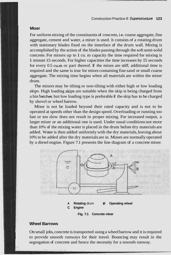
Construction Practice 11: superstructure 123
I Mixer
1 For uniform mixing of the constituents of concrete, i.e. coarse aggregate, fine ' aggregate, cement and water, a mixer is used. It consists of a rotating drum with stationary blades fixed on the innerface of the drum wall. Mixing is accomplished by the action of the blades passing through the soft semi-solid concrete. For mixers up to 1 cu. m capacity the time required for mixing is 1 minute 15 seconds. For higher capacities the time increases by 15 seconds for every 0.5 cu.m or part thereof. If the mixes are stiff, additional time is required and the same is true for mixes containing fine sand or small coarse aggregate. The mixing time begins when all materials are within the mixer drum.
The mixers may be tilting or non-tilting with either high or low loading skips. High loading skips are suitable when the skip is being charged from a bin batcher, but low loading type is preferable if the skip has to be charged by shovel or wheel barrow.
Mixer is not be loaded beyond their rated capacity and is not to be operated at speeds other than the design speed. Overloading or running too fast or too slow does not result in proper mixing. For increased output, a larger mixer or an additional one is used. Under usual conditions not more than 10% of the mixing water is placed in the drum before dry materials are added. Water is then added uniformly with the dry materials, leaving about 10% to be added after the dry materials are in. Mixers are normally operated by a diesel engine. Figure 7.1 presents the line diagram of a concrete mixer.
A Rotating drum B Operating wheel C Engine
Fig. 7.1 Concrete mixer
Wheel Barrows
1 On small jobs, concrete is transported using a wheel barrow and it is required I to provide smooth runways for their travel. Bouncing may result in the
segregation of concrete and hence the necessity for a smooth runway.
124 Construction Management and Planning
Buggies
Push carts and power buggies are made in a variety of sizes and are equipped with pneumatic tyres for smoother operation. They must also be provided with smooth and rigid runways to minimise segregation. In high rise building construction, pushcarts or power buggies are used to transfer concrete in a hoist at the ground level and the hoist moves to different floors of construction. During such transfer it is important to ensure that concrete does not get segregated.
Chute
Chutes are used to carry concrete directly from the mixers to forms or from a hopper conveniently situated to allow chuting. Chutes are metal or metal-lined with rounded bottoms and of sufficient size to guard against. overflow. 'hey are designed so that concrete travels fast enough to keep the chute clean but does not create segregation. The slope of chute is generally recommended as 3 : 1 or 2 : 1 though a steeper chute is used to carry stiff mixes.
Buckets
Buckets lifted and-moved about by-a crane or a tower are commonly used where concrete has to be placed at a considerable height above the ground level, or where the forms are in otherwise inaccessible locations. Buckets vary in size and are circular or rectangular in cross-section. The load is released by opening a gate which forms the bottom of the bucket. The gate can regulate the flow so that it discharges the amount required at a certain place and normally full load is not emptied at the same location. Care is taken to prevent jarring or shaking of buckets while they are in t rasi t in order to prevent segregation.
Belt Conveyor
Belt conveyors used to transfer concrete may be classified as portable series, and side discharge conveyors. Series conveyor operates at fairly high speed while portable and side discharge types operate at considerably slower speed. Concrete is fed into a conveyor belt from a hopper. In order to get an even distribution of materials along the belt they are well supported so that they do not vibrate and cause the segregation of the concrete. The slope varies according to concrete mix and type of belt used. Figure 7.2 shows a line diagram of the belt conveyor.
Vibrator
. The concrete placed in the hms is to be properly consolidated. It is ensured that no pocket or space'remains unfilled and that the face of the formed
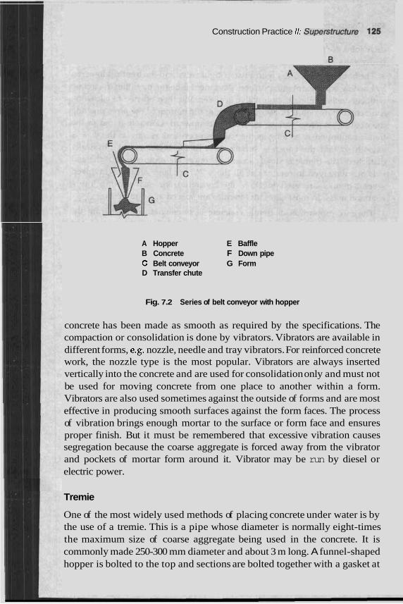
Construction Practice 11: S U ~ ~ I P I I U G ~ U I ~ ; .
A Hopper E Baffle B Concrete F Down pipe C Belt conveyor G Form D Transfer chute
Fig. 7.2 Series of belt conveyor with hopper
concrete has been made as smooth as required by the specifications. The compaction or consolidation is done by vibrators. Vibrators are available in different forms, e.g. nozzle, needle and tray vibrators. For reinforced concrete work, the nozzle type is the most popular. Vibrators are always inserted vertically into the concrete and are used for consolidation only and must not be used for moving concrete from one place to another within a form. Vibrators are also used sometimes against the outside of forms and are most effective in producing smooth surfaces against the form faces. The process of vibration brings enough mortar to the surface or form face and ensures proper finish. But it must be remembered that excessive vibration causes segregation because the coarse aggregate is forced away from the vibrator and pockets of mortar form around it. Vibrator may be run by diesel or electric power.
Tremie
One of the most widely used methods of placing concrete under water is by the use of a tremie. This is a pipe whose diameter is normally eight-times the maximum size of coarse aggregate being used in the concrete. It is commonly made 250-300 mm diameter and about 3 m long. A funnel-shaped hopper is bolted to the top and sections are bolted together with a gasket at
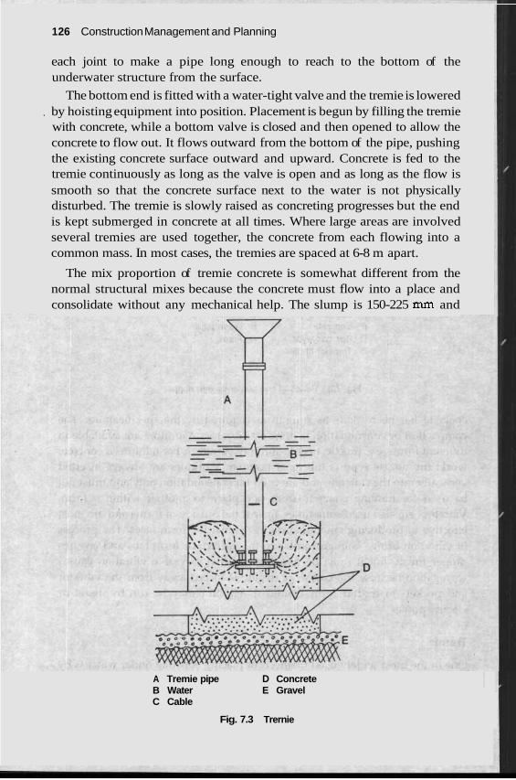
1 26 Construction Management and Planning
each joint to make a pipe long enough to reach to the bottom of the underwater structure from the surface.
The bottom end is fitted with a water-tight valve and the tremie is lowered , by hoisting equipment into position. Placement is begun by filling the tremie
with concrete, while a bottom valve is closed and then opened to allow the concrete to flow out. It flows outward from the bottom of the pipe, pushing the existing concrete surface outward and upward. Concrete is fed to the tremie continuously as long as the valve is open and as long as the flow is smooth so that the concrete surface next to the water is not physically disturbed. The tremie is slowly raised as concreting progresses but the end is kept submerged in concrete at all times. Where large areas are involved several tremies are used together, the concrete from each flowing into a common mass. In most cases, the tremies are spaced at 6-8 m apart.
The mix proportion of tremie concrete is somewhat different from the normal structural mixes because the concrete must flow into a place and consolidate without any mechanical help. The slump is 150-225 mm and
A Tremie pipe D Concrete B Water E Gravel C Cable
Fig. 7.3 Trernie
Construction Practice 11: Superstructure 127
generally rounded coarse aggregate is preferable to crushed stone since the flow is better with this aggregate. Figure 7.3 shows the working principle of a tremie.
REINFORCING STEEL
In concrete structures, steel is used either as reinforcement or for prestressing structures. Reinforcing steel primarily used for carrying tension is placed in the form work and then concreting is done and this is subjected to stresses under load. Whereas in the case of prestressed concrete the steel is stressed before the member is loaded and the tension in steel keeps the concrete under compression so as to neutralise the tension that may come due to application of loads.
The most commonly used steel reinforcement is available in the form of round bars of various diameters starting from 6-50 mm diameter. These bars have plain or deformed surfaces. Welded wire fabric is often used for reinforcing slabs, walls, shells, etc. These consist of cold-drawn steel wires running in two directions at certain spacing and welded at the junctions by passing a high electric current.
The commonly used steel reinforcements are mild steel (Fe 250, Fe 230 and Fe 210), medium tensile steel (Fe 353, Fe 348, Fe 323), high yield strength deformed bars (Fe 415, Fe 500) having lugs, ribs or indentations. Recently the Steel Authority of India (SAIL) has introduced a high strength micro alloy structural steel available in the name SAILMA having a range of qualities Fe 300, Fe 350, Fe 410 and Fe 450. Tor-steel Research and Foundation have also introduced a new product known as TOR-KARI steel of quality Fe 550 where wires 3-9 mm diameter in steps of 1 mm diameter are produced. This has brought about an economical use of steel.
The mild steel has a definite yield point and the plastic strain may extend up to a strain of 0.15. Cold work high strength deformed bars, SAILMA or TOR-KARI steel do not have a sharp yield point and the characteristic strength is expressed as 0.2% proof stress. High tensile steel available in the form of wires, strands and cables also do not have a sharp yield stress and its characteristic strength is expressed as 0.2% proof stress.
The reinfarcing bars need to be free from cracks, surface flaws, laminations and other defects. They should. comply with the requirements of dimension and weight.
Tensile bars should be tested for tensile test, and cold bend test. Tensile test is performed to obtain the stress-strain curve, yield stress or 0.2% proof stress, ultimate stress, percentage elongation, etc. The length of a test specimen between the grips of the machine has to be more than 9 times the diameter up to 25 mm diameter and 4.5 times the diameter for higher
I
128 Construction Management and Planning
diameter bars. During testing, the load applied should be .axial. The gauge length is adopted as 8 times diameter for bars up to 25 mm diameter and 4 times for higher diameter bars. The stress-strain curve is automatically recorded in the recording and the plotting device attached to the machine. Sometimes extensions are recorded by an extensometer and the load recorded in the dial. The rate of loading is maintained 30 kg/sq. cm/s.
The cold bend test is conducted to note whether the bars are bent without causing fracture. The specimen is bent by pressure or with-a steady blow from a hammer until the two sides of the specimen are parallel. The internal radius of the bent'is less than equal to diameter of the bar for bars up to 25 mm diameter and 1.5 times diameter of the bar for bar greater than 25 mm diameter. The bars must not fracture under the test.
FORM WORK
Introduction
Concrete in plastic stage has no form and therefore it needs to be moulded in the required shape. Form work includes the mould in contact with concrete, the supports and bracings and the necessary hardwares. The form work techniques have also developed along with the growth of concrete construction. Previously only timber was used for form work but dowadays, plywood, metals, fibre glass, plastics with special type of accessories and hardwares are in use. Prefabricated form work with repetitive use is becom- ing popular to save time and maintain quality.
Previously the erection of form work was normally done by carpenters using timber and nails in a most conventional way with a high degree of safety. Nowadays with the advent of plywood, steel and plastics, the design of form work has become quite an involved task on the part of the construction engineer. The failure of form work and the consequent loss of money labour and sometimes even life is not very uncommon. Failure may be due to a fault in the design, material, construction, a combination of these or may even by loss of strength due to too many repetitive uses. In USA and U.K., committees were established to study the causes of failure of form work. In addition to many technical causes of failure, they have also highlighted the failure due to the occurrence of horizontal loads on the false work or form work which the designers normally ignore. Out of all recommendations made by these committees, the following are important and are to be noted. The form work is designed thoroughly on similar lines as structural design and sketches and calculations are available to the contractors. Horizontal load equal to the sum of all horizontal load plus 1% of vertical loading or 3% vertical loading are considered as the horizontal loading on the form work. There are short courses on form work or false
I Construction Practice 11: Superstructure 129
work provided to architects, consultants and supervisory staff members. Handbooks are to be prepared for estimation and providing guidance for the form work.
A form work designer is supposed to achieve the basic objects of quality, which means to build a form accurately so that shape, size and finish of the concrete is attained; safety, to ensure that the form is capable of supporting dead load, live load and other lateral load on the casting, and economy in time, money and labour. To achieve the above correct assessment of loads, the pressure of green concrete, selection of forming material considering its strength durability and cost and selection of supporting system must be given due attention. Provision for proper and safe working and access for labour and equipment must be made as also proper schedules with regard to the stripping, removing shuttering and form work after completion.
Loads on Forms
Loads to be considered on form work are based on the density and slump of concrete, rate of pour, method and height of discharge, concrete tempera- ture, vibration, reinforcement details, stiffness of forms, etc. A load of 300 kg/m2 on sheeting, 200 kg/m2 on joists, 1800-2500 kg/m2 in walls and columns may be assumed for the form surface, an additional load of 1000 kg/m2 may be adopted to account for the falling of concrete over a height of 2 m or more. All factors given due consideration, the maximum pressure for design of forms need to exceed 15000 kg/m2.
The transfer of load from floor to floor during consi s an important consideration to be given. Propped-up floors receive soaas from the fresh concrete laid on floors above in a multi-storeyed structure where the flexibility of the props and the rigidity of floors are important aspects to be considered. Under such conditions, 2.4-3.0 times the load due to the self weight is considered to be adequate for the safety of the floors.
Codes and Specifications
For ensuring safety, quality and economy in building forms, standard and specifications are available in different countries.
In the USA, the recommendations of the ACI Committee, 'Form wo concrete updated now as Recommended Practice for Concrete Form (ACI 347/78) is followed.
In the UK, the Standard Codes BS: 4074, BS: 5973, BS: 5974, BS: 5975 and BS: 6100 are followed for &e form work. The codes specify that form work should be of appropriate quality to produce satisfactory dimensions and surface appearance, it should be safe and the risk of damage to people and property shall be a minimum and its cost should be as low as possible. For
codes
rk for work'
130 Construction Management and Planning
------ effect
re@ rnnr?
m ties 01 failure tc
and adr ure. :-LA
- nixtures,
-..-I. LL?.
5. Premature removal of supports, vibrations ar movement and the lack of field inspection 1 work conforms to the design.
i Materials Used for Form Work
mmperatu and seql
~d shock :o ascert:
I Locally available forming materials are generally chose] I Timber, plywood, hard board plastic, fibre board, corruga
aluminium and plaster of Paris are commonly used fo I improve the surface texture, thin metal sheets, PVC sht
I sheets, neoprene kraft paper and hard board fibre board a attached to the inside face of forms.
I
!ly, the hc ... 1A am....
I the design of form work, two principal loading cases name
I load and the vertical load are accounted for. The design shclulu LV1131Uc2 ULc
plan and dimensions, the type of cement the rate of rise and the concrete temperat
The basic planning of form work takes ULLU ~LLUUILL ULC IUIIVWU~F L J U L I L L 5 .
I I strength and stiffness, repetition, durability, stripability and cost.
In India, the Indian Roads Congress has prepared 'Guidelines or and Erection of Form work for Road Bridges'. Indian Standard Institunon 1s presently engaged in the'formulation of 'Code of Practice for Form Work'.
In Australia, 'SAA Formwork Code' Australian Standard 1509 has specified rules for design, fabrication, erection and stripping of form work and false work for any concrete structure. This code has identified and clearly stated the common deficiencies of form work leading to its failure. These are:
1. Inadequate lateral and diagonal bracing of shores, lack of bracing at joints in shores, poor splicing of timber shores, out of plumb shoring.
2. Locking devices on metal shoring not locked, in-operative or missing, %adequately tightened for a wedges, insuffic he Use of prop on prop, 3 recheck tightne! loors below. 'he following points also need to be addressed to prevent fai
[a) to inspect form work during and after concreting tc abnormal deflection if any and adopt corrective measure
b) to provide adequately agains pressur~ control the vertical rate of pla 3f concre lat~ral pressure on forms with regara to slump, type ot vlbratlon,
of admixtures, low concrete te ate properly the horizontal rate
-,-.--.ete to avoid unbalanced loading on t o m v
Timber almost c
Timbe: every wF
r is the m Lere. It is
lost corn compara
non matt ~tively ch
rrial for s leaper an
hutterin~ d could 1
the fom
L-ll--.- :-.
t height,
ient naili 3s of resl
es on fc !te and f
,. . - - res and lence of ,rnrC
; arising 1 lin that t
n for th~ lted boxc r shutte~ =ts, pol] re used :
, I
1 Design . .. .
lure:
1 detect 'S;
~rmS, to herefore ,. . .
also to placing
e work. ?s, steel, :ing. To ysterene LS liners
; and is available 3e easily shaped.
Construction Practrce rrr aupersrrucrufe 1 31
Good quality timber and skilled carpenters are difficult to get. Timber deteriorates under the stress of heat and contact with water. It is difficult to evaluate the proper strength of timber. Thus, a scientific approach of design with timber becomes difficult and a conventional approach is adopted. Because of the inherent defects, timber shuttering may not be repeatedly used for many times. In India, for supporting the form work of floor slabs, timber props or ballies of diameter 60-150 mm are used at close intervals. These are cut to have proper length and are adjusted with wedges underneath. Timber runners are used in both directions being supported on the props. Timber plank or plywood shuttering or steel forms are placed to support the slab. Wedges are to be placed very carefully so that these do not come out due to vibrations. The ballies are not always straight and should be inter-connected with adequate bracing so that an eccentric loading does not cause buckling and subsequent failure.
Plywood Plywood has got a better surface and g noother These are useful and economical for larger panels wlth repetitive uses. lhe top coating of plywood resist abrasion and reduces absorption of moisture. Sometimes these need timber frame backing. Plywood bonded with phenol formaldehyde has better resistance against layered separation due to the effect of heat and moisture. It is also available with resin impregnated fibre face permanently fused under heat and pressure. Such plywoods are known as plastic coated plywood which may even be used sc ~ e s if used with care. Plywood is also available with texturised surfat signs which are used for exposed concrete surfaces. Timber shutters ns are found to deteriorate at the cut edges due to heat or is not in use, these need careful storage so i
of uses.
effect of as to ens1
2veral tin :es or de: and forn moisture ure maq
I. Thus u I more nl
finish. -
rhen it umber
'om woc ire. Thes
Hard ba [ard boards are manufactured fr ~d fibre under controllel lation of pressure, heat and moish e are tempered with the impregnation of drying oils which are stabilised by heating. Tempered hard boards have improved strength, low water absorption, better abrasion resistance and are used as formwork lining. Thinner hard board could give curved surfaces easily.
~rms for c ~al ls , roc Fibre forms Fibre forms are used as lost fa ,fs and slabs. These are left in place on the exposed face of the concrete where it gives architectural look and also improves acoustical and insulating proper- ties. These are made from glass or wood fibres. The manufacturers publish re bndations [re to be strictly followed. i which a
Gypsum board Gypsum moulds are generally t ised to I artistic
I JL bonsrrucrlon Managernenr and Plannin!
design or ornamental pattern for the ex1 I with an oreanic fibre or coir to make ir tvug1tt.r. LvIlcrere qualiry may impro jorption of extra water present in board: e and needs careful handling.
ncrete fa1 P--.
einforcea I:,-- -----
U
ve due tc ;. These 2
D the ab: Ire fragil
concrete by thesc
Asbestos tiles sheets are used
' If acor I. Someti
rugated i mes thes
face is rec e tiles ge
ies like cc :rete due
mugated to bond.
rester strc a ~ r ~ U J y are ma I shapes, do not rust and are easy to clean. They do not deform and assembly and dismantling are rather easy. Polypropylene moulds are nowadays very popular for waffle slabs. These moulds have got another advantage because
re welda
c forms me of thc
PVC, nf I plastic
and pol4 use. The:
~ngthene nufactura
!d with g .d as per
lass fibre required
?oprene, Forms in
ble. they a
Lost f 'orms Forms, which are not removed after casting, form a part and ;. These i t
s, card bc t re~ntorced concrete lolsts, clay filler blocks and ferrocement planks are
I
parcel forms. . -
of the st Precast c
that beh; 3lanks, p
we as co ressed fit -... - -
mposite: )re plank
3re know )ard tube
m as losi s, precasl
des. In In 3f these f
1 Enginec re in use
ntre has I dia, the E o m s anc
jtructura d these a
nesh FE Ires are c Ire applit
:onstructc ?d over t
?d with a he wire
s h as the o form a
Wire r lost fo stnlrture 01 Knvwn sna]
rms. Son ...- -CI..-
r --
hese me Inflate $nrm 7 ,
mwranes [sed to serve as a lVLlll "vork. After inflatmg the membrane to the required shape, it is coated with a layer of plaster which is reinforced with a steel I rigidity. Plaster may be spread by short creating. These forms re time of construction and the stripping &-- -s could easily be ulallcantled bv
ties in ini
ld memt * . -
wane T . - .
etimes u . . are som
mesh for !duce thc - A:.-....- . , L U ~ L C ai
~lso used on. Such membra L L -
nes are 2 for cavil
.- 1
places.
I . 7 . form work Steel rorms consisnng or angles, tubes, joists, nat plates ry much in use as shores, bracings, runners, slab shutters, etc. Steel re also in use in combination with timber. These are very strong, could d repetitively without much damage done to these forms. Because of own cha cs of steel, desig tions are easily done in a latic man line, level, dirnen! surface finish are all nicely bd with steel forms. The entire system is so designed that it can be >led very and in proper sequence. For smalle these are ~lly operi 11e for larger panels mechanical h could be
31ee1 1
are ve: form a we use the kn system
.. .
racteristi ner. The . . .
n calcula ;ion and
attame asseml manue
. quickly ated whj
!r panels andling
done. Accessories suitable for different dimensions of the s are available and the forms are adjustable in order to have differenL ~ ~ ~ ~ ~ ~ s i o n s .
The form work supports are either single-leg type or multi-leg type single-leg type is known as the prop or shore and is made as a telescopic- These are generally made for height up to 5 m. Beyond this height the.,- --- used in tiers tied and braced to form a rigid structure. For a multi-legged system, frames and trestles are used which could be assembled one above the other to get the required heights. For finer adjustment the small L C ~ D ~ A T
jacks either at the top or bottom are generally used.
?sties. Nc 1 wide fr
I keep th r bracket
) interme ee space!
member .b A:-,.-*
beams o _.. -- C _
Horizontal supports are constructed as light weigh or triangular section which are also telescopic and can cover a range o r s
They rest on either beam forms or shores/trf bdiate sul may be necessary for these arrangements anc j are avai below the form work.
Other features like plumbing frames whicl e form work in PI shape using tilt-up struts or rakers. Walk-wa! s may also be atta to the main form work. Dropheads which when used on the top of the sl would support a wide area and the form work at other places coul removed within a short time after concreting and reused. This has mad steel form work so versatile.
Nowadays, more sophisticated steel form work known as I used for wall concreting and table form are used for casting slam lnes handled by cranes since these are used in large sections. Tc accurate alignment of the gang forms, plumbing frames and sy concrete hardwares are used. The table forms rest on adjustable legs, the may be steel or plywood and serves as soffit shutters for the slab. The v table along with the shores are built in one unit and can be lowered or r, by means of specially designed jacks. After concreting, the table is lo^ and taken out of the building by rolling the table out on cas slinging with a crane.
;ang fon 3
tors and
. The
type. ;e a w
f box pans. 2port . ilable
roper ~ched hores Id be .e the
n are ;e are te an )es of deck fhole aised rered then
Slip forms In slip form or sliding form construction, which is an extn process, the rate of movement of forms is regulated so that when the f leave the concrete it is strong enough to retain its shape while supporth., own weight. This is applied where continuous concreting and monolithic structure is designed. Silos, bins, shafts, cores, caissons, bridge-piers are some of the vertical structures where slip forms are used while canal lining, k-nal
inverts, high way pavements and water conduits are the horizontal struc where slip form are used.
Vertical slip form system comprises assembly panels made of timbrr UL
steel and is supported by a Yoke assembly placed at 1.5-2.0 m interval form work is moved by mechanical or hydraulic jacks which climb eith
~s ion o m s .rn i t c
I I U L L I
tures
. The er on
134 Construction Management and Planning
a pipe or a solid rod embedded in the concrete. The entire load of shuttering including the platform deck is transferred to the jack rod or pipe through the jack. The gripping devices in the jack are either tooth or ball type. The speed of sliding depends on the setting time of concrete, the ambient temperature of concrete and the type of cement. With normal portland cement under tropical climate a sliding speed up to 6 m per day is possib
Changes in the cross-section, the provision for dowels for out for doors and windows inserts and pockets to run otrcu~ls ar t : I ~ U W
possible on the vertical slip forms. Tapered structures like chimneys and , cooling towers are now constructed with additional mechanical or hydraulic
jacks which adjust the forms circumferentially to the required dimensions simultaneously with the moving of forms vertically.
Horizontal slip forms generally move on a rail system or a shaped beam. I The slip forms both vertical and horizontal carry with them the working
.. deck, the concrete supply hoppers and 2
required for concreting. During sliding the drifting from plumb and twisting alF y l F V F l l C F U U y
adequate bracing of the frame work and checking the verticality by plumb bob and the platform should be always kept at the same height as the water level system.
In order to have a fre~ lent of the Jack r eve of 1. long is inserted around 1 vithin the concrei attachec yoke. S l i ~ forming is a jov L U I I L U ~ U ~ ~ round the clocn arlu is a special rype of cons and the lination betweer erent agc onomy, quality atu wurkmanship ru prvauce a monolirnic srmcrure. lvov '
major cc s of the country are well equipped with slip form a ments.
truction I the diff --J -.---
e moven :he rod \ .L -,.-A:-
refore nc encies. It
L_
s main a 3 . - _ _ -
;e super
od, a sle~ te and is
--J
vision ar e is the 5 1 - _, . . .,
le. extensioi L-,,- -
n, Block --
~d coord
0-1.5 m i to the ! - I I--..
vaaays, rrange-
Suspended, moving and other forms These are also in use for spec of work and serve as an alternative to slip forms. Suspended forms a for chimneys and silos, whereas moving forms are used for the construcnvr~ of tunnel lining, sewer lines, galleries, cull walls, folded pla shells where repetitions of similar structur ie for long stretch
Moulds for Prec :ast Con
rnber of ! - 7 - -
- - -
rerts, sea e contint
and neei nplete b~
; are reqt ? . .
iired, pre .. c
ial type re used -. -L: --
tes and Les.
When a large nu similar structural element$ is done. It may be aone on or near the job site or in factor~es qulte rar-orr ana are transported to the site of construction. Precasting ensures accuracy, controlled quality and uniformity in floor elements, columns, lintels, door window frames, railway sleepers, louvers of cooling tower and others. Any small element that could be easily handled i s mass scale production could be done with precast concrete. A COI ridge is constructed with
Construction Practice 11: Superstructure 135
precast elements handled by mechanical means. The moulds are robust to withstand large repetitive use. These are easy to assemble and detach thereby reducing productior rrangements for good vibration and accelerated curing are provided he mould. The choice of mould depends on the total number and rare or production, the shape of element and facilities available in the con! yard for casting, curing, storing and handling.
Precasting is don by horizontal or vertical moulding. Horizontal casting is undertaken tor rimed or curved elements, multi-layered elements, etc. whereas vertical castings are done for single layer slab panels. Shutter vibrators are often mounted on the underside of the mould for horizontal casting and on the sides for vertical casting.
Of all types of moulds available, masonry moulds, wooden moulds, steel moulds and plastic moulds are most c6mmonly used. Sometimes small structural components are cast on a vibratorv table which ensures e---l compaction of conc~
Prestressed prete~ elements sometimes in long line or production Day m oraer to nave mass proauctlon.
I time. A within f
- r ...
;truction e either
,- .. .
uuu
s or unit stec nsioned I 21 mould 1 .
are prot 7 ,
Scaffolds are used for providing temporary platforms at various levels. These elements are also used for centering or supporting heavy loads at great heights. Timber scaffolds are mostly used and are available throughout the COT erea as rn :fold are now be ~ing intrc COI ns.
Timber Scaffolding
In timber scaffold, a have bally or ban almost in all places srarung from small bu~lalng unlrs rv mu~nsroreyed building complexes as also in the construction of dam, barrage! iilar structures. For high structures, the bally and bamboo scaffolding lade that it looks dreadful and the user does not feel much comfortau~e when using these scaffolds. By and large, the bally or bamboo scaffolds constructed by tying them with coconut coir ropes. Due to contin exposure, these ropes as also the bamboos get deteriorated and the joint! -, not remain firm. It is also very difficult to keep these scaffolds on plumb. Therefore, the factors of economy, availability and ease of usage make timber scaffolds the preferred ones. It is required to make laws to ensure that these scaffolds are not used for tall structures.
Timber scaffolds are of two types: 1. Single pole Here one row of poles are fixed closed to the uuuulrlg ur
wall and connected horizontally by ledgers along with cross member or put logs connecting the building or wall.
I
Ine may I . . .-. Lese are c
. ~ - l ~ : - c -..-
5 and sin- ; are so m . 1 1 - ---.
are ued 2 A n
i 30 c;onsrmcaon Management ana rrannlng
2. Double pole Here h or wall line and the otner row aDout one metre rurtner apart.
These two rot tical poles are coi tally by ledgers s also known a: diagonal bracing* art: also provided. Somenmes wrlen mese memDers are sawn they are nailed together instead of t )ns and joints. IS: 3696, which provides the safety folding and ladders, must he followed.
of poles are fixed rtotheb uilding NO rows .1
one nea~ . ,. ..
YS of ver #. This i! -- --- -1-
nnected 1 ; indepe. -..:--- -.
7y put lo ndent sc -L -- LL -
'gs and h :affold. S -- 1.
ying wit and det;
h ropes i
d s of tin ?it junctic nber scaf
Metal scaffolds
Metal scaffolds are generally made of steel. Other n rarely u the purpose. In order to provide a more durable [able, stc s t r ~ i ~ g scaffolding, metal scaffoldings of various types are being [email protected] used. In metal scaffoldings, the heavy duty ones are used for brick rr or concrete construction, medium duty are for carpentry and plaste while light duty ones are used by the electricians, painters and ~lccutcr>. Depending on the arrangement, one may gle row put log scaffold or independent double pole scaffold as in t ,f timber scaffolds. Metal scaffolds are also used as cantilever scaffolu w l t a t lt is reauired to vrotrude them from the face of the buildings or structures.
Metal platforms may be erected at any desired 1( in order to ease the construction work or place heavy objects at any level. &ch scaffolds are known as platfo Ads. Tower scaffo tructed of metal scaffolds having upright! ted by ledgers an ms, are often made mobile by fixing castors at the base. For special tvpe ( - ' -
ed scaffolds known as cri om build thout touching the grounc
Metal scaffolds may be either tube and fitting type or prefabricated unit frame type. Tube and fitting type is the most common one while the frame type is made for specific jobs. The tube and fitting type consists of plain tubes, which are used for making uprights, ledgers . ~ t logs, various types of clamps, couplers, joint pins, etc. a 'onnec- tions. There are various codes of practice which speclry me aetails of
he scaffc ns are gi
netals arc , depend
~sed for ~ut , and
. - rwurljry
lasonry !r work Am--..-
have sin he case c A ..-I.,.- :
I
letal scaf folding - - ~rn scaffc 5 conned
ld'is, cons d trans01
3f jobs, L struc- suspend
tures wi ~dles are I.
hung frl < L
lings anc
1s and p~ nd are u . .- sed for c ., , .
construc these spc
1. Th
,Id and f ven bela a L.. La-.
'or the si w:
I---:-
these sca
-a .----.2.
ffolds. S
--ll-- :-
Dme of
rder to ha bc
2. To prevent overturning and collapse under htgh wlnd loads annrr21
id and si should E
-r---* folds. ary meaz
and toe
- iure of ar
boards !
whorage
should al
is to be
lways be
taken f o ~
provide
: the scaf
d for the ecaution,
~ ide rails ! safety
Construction Practict r r . oupcratr uuur c
of the workmen as also safety nets and screens should b catch any falling materials.
4. There should not be any uninsulated wires near the metal scaffol 5. Scaffold on thoroughfares should have warning lights. Grease, I
paint, etc. should be removed at once if these items fall on the sca and sand or saw dust should be spread to prevent slipp
6. While dismantling it should exactly follow the reverst used for assembly.
For prefabricated unit-frame type scaffolds, many goo s patente manufacturers are available.
These are made using adjustable components with mrumum loose 1 and are easily erected at site by unskilled labour. Each componei thoroughly examined in order to determine the individual load car1 capacity of each component correctly.
-
BRICK MASONRY
d design
or more. the quali ^L^--
0
ortar ust
roof. V ~ I ight be t .&A" ",,,I
Id. nud, ffnld
parts nt is
ying
Brick, except sand lime or sand cement brick, are burned from fire clay or mixtures thereof. The fire clay bricks attain a colour Durr or shale bricks become red generally when burnt and sometimes it takes brown or black colours also. When bricks are underburned they look pale orange and are too soft. Sometimes well-burnt bricks may also take the pale orange colour which is due to the ingredients present in clay. Underburned bricks make a dull sound when one is struck with another and may also disintegrate when subjected to wetting or freezing. The strength of brick is expressed in kg/cm2 or ~ / r n r n ~ when tested in a compression testing machine. There may be bricks of various strengths available and accordingly these are classified as Class I or Class 11. For load bearing masonry structures, Class I bricks are used having a crushing strength 70-200 kg/cm2
1 The crushing strength of brick masonry construction depends on i ty of bricks and the type of mortar used. The permissible compressive srrwlrth of the various quality of brick masonry against the type of m available in IS: 1905.
The common problem with brick masonry is the efflorescence W ~ L . ,,
caused due to leaching out of salts in brick or mortar. There is practically no cure for this other than waiting till the leaching stops, plastering.the surface after cleaning and washing the surface with turmeric water.
In many cases the brick work needs to be made waterp chemicals and products are available in the market which m Silicone is one such treatment which makes the masonry W ~ L C L - L ~ ~ ~ L ~ U ~ L .
This may be applied using a low pressure tree spray with neoprene washer and hose instead of using a brush. Waterproofing mixture contains around
138 Construction Managel I ICI I L I J Planning
3% of silicone resin solids. Brick is one of the most common building I
Commonly available varieties are common building brick, sand lime vl o a l u
cement building brick (unburned), cinder brick, flyash brick, fac ceramic and glazed face bricks, paving bricks and sewer bricks.
Common bricks are used when the surfaces are generally finishea wltn plaster or similar material. These have got a lot of variety depending on the crushing strength of brick and brick work which depends on the quality of brick and the composition of mortar. The size of common bricks available in India are 225 x 113 x 75, 250 x 125 x 75, 200 x 100 Machine-made module bricks are also available.
element. . ,r -,,A
:e brick,
* ...
Sand lime brick are usually used for back uv and has pot a whitish cu~uur, not preferred for load bearing multistore inder an1 are now used for manufacturing bricks. ~ratively than common bricks.
- I -~
y ronstn These a
d flyash cheaper :e compa
Face brick is specified for use where stive brick work intended. It is generally packed with care t from damages, i is good and textured as specified and coloured as desired. Ceramic or glazed-face bricks are used for distinctive brick work with a glazed finish. They also reach the site well packed in cartons so as to prevent damage. It also has a glossy or matte finish.
Paving bricks are tough, durable and evenly shows uniformly dense structure free from lime, alr power
Sewer bricks might be made to have edges and curves to suit th of sewer lines to be laid. These must also be strong and well burnec
In order to inspect the brick masonry work at site the following are to be done :
a distinc to protec
finish is ts finish
burned. . .. .. - -1 ~ -,
When b: s, etc.
roken it
.e shape 1.
. .
, 1. 1
composing the mortar like in an approved laboratory.
Ill mater ials like 1 )rick, con cks and c 'lay tiles 2 md the n sand anc
L- J---
d cemenl : or lime
LL
should b e tested
- I : - - -f 2. Sieve analysis of sand to vt. uulte at site belure ule vrevarauurL WI
mortar.
3. Bricks should be compared with cllF JvCLuILaUVIl rulU LUIVUIIIcU
pricks are iected. 8 to be re;
luld be 1; oints shc r the spe cificatior 11e may E le made nd new ( )oints alx
ion shou ss of join
Id be con .ts, type (
- - - -
.fore app 18, the m
lportant :d, etc.
If lime is used in mortar it should be checked vvllculcI ULF L U L ~ Z is high c e or hydrated Lin se of high calcium quick 11 to site in powder J er pulverised or granular, alcium q ime whic
pick lim h comes
ne. In ca; [ o m eith
,onstruct/on ~ractrce 11: Superstructure
it has to be slaked by adding days.
rdrated li be ordinary hydrated lime ure hydr . Ordinm :ed variety should be soakc :er at leas
L* l~ours befblC U3c. Jut for pressure hydrated llme ~t could be s; in mixture just like cemen
water an td must 1 ?d to age
h e may :y hydra1 .urn ..,.A T-
ated it for a f e l x r
! or press ed in waf .. .
* * L A J
eeze
put :
6. Bricl
.t.
one in M reather c k laying should not be d tar. mor
d should ked and no void U~LLK work. Walls should be checked for plumbmg ana also ror 1
COUI
8. All 1
be chec . - - - .
should 1 . . ed insidt . , - 7
: the I P V P ~ .- . --
use. be thoro cept facE ng bricks ; should ughly WI 2t before
mj end
oints cor of brick
. . T
npletely filled with invrta~ and brick shored into plac
r. Mortar :e.
to be tro I the
rk is Y. ~t snoula De checked that no more weignc or me raw uncK wo
laid at one time than the lintels, piers can carry without excessive deflection.
-- --
tbers or other support ing mem
10. Where put log holes are left through the wa scaffolding, these .holes are to be filled wit1 thickness of the wall after these have served th
)port oul for the
Ise.
RAL STEEL
Tktc C L C L L L ~ L ~ ~ ~ of structural steel are received at site m a readymade condition suitable for erection. Assuming that steel has been inspected in the shop following additional inspections are done to make sure that the construc is in order. Members are checked against damages due to transporta su ~t plate, connection angles and member themselves. This is t dc e erection so that the rejection of an unacceptable member oc berore erection. Size, location, elevation and plumbing for the anchor 1 are also checked. Base plates and grillages are checked for level and pr grouting columns supported on the base plate, @ages or girders column splices are checked for bearing and milling. Care and attentic given to the sections where the column sections change the size. Plumbing is checked before bolting or riveting permanently. Minor corrections are made with s t e l strains. As erection proceeds, the members are matched as per drawings. Usually the members are properly marked and there wi less chance of committing mistakes. Even then random checking is cal out as a rule;
The rivets and bolts are checked in a mann in and no hole is empty. These are also chec
I, the :tion tion, :o be :curs bolts oper and ,n is
er so thai ked for s
.oles are filled tightness and
140 Construction Management and Planning
the alignment of holes is checked before driving. If the alignment is not proper, reamed and larger-sized rivets are used. It is passed only if it is tight and has got a full concentric head. Burning of holes with torch, enlarging unfair holes with drift pin and tightening of rivet by chalking are not to be encouraged.
Rivets are tested using a small hammer and checked for any possible up and down movement. Defective rivets are marked with chalk and while one is removed since it loosens a number of adjoining ones, all loose rivets are removed. Sufficient temporary bolts are used to hold pieces tight together while riveting is done.
Bolted connections must be tight but not turned up so as to strip thread. Washer, lock nut, etc. are checked thoroughly and carefully. Beams on walls are checked for bearing and anchorages. Structures are safeguarded during erection. Steel carrying derricks must be strong enough to bear the erection loads and stresses. Overloading on crane is never to be tolerated. Guying and bracing of steel in the process of erection are important so that nothing happens for lateral loads due to wind or seismic forces. Painting should be done according to the specifications. If the shop paint is removed during transport, repainting is done before erection. Field paint must have a different colour from shop paint. All steel must be free from rust and scale and also must be dry. Painting is hbt done during freezing weather. The engineer in charge of construction;brings to the notice of the inspector regarding particular portions which needs special attention. The inspector must have good idea of the design if he wants to do proper supervision.
WELDING
Welding is a specialist job, which needs a certificate to qualify The welder placed at site makes test pieces or samples and get them passed by the concerned authority before doing the actual job.
Conformity of the electrodes as per the specification, the condition and capacity of the welding equipment, the quality of welds for overlap, colour, porosity, slag inclusiond, under cutting uniformity, etc. are the different aspects to be properly observed and certified. For fillet welding if gap is more than 1.6 mm, the size of weld has to the increased.
Welding is to be done in a proper sequence in order to reduce residual stresses. Jack welds if required to be fused with the final welds are thoroughly inspected and if necessary are removed and rewelded.
Cleanliness is very important as good welds cannot be made on dirt, rust or slag. In multiple pass weld, slag must be chipped and wire brushed to a shiny surface before the next pass is made.
A welder must be properly protected from wind. This is not be done at temperature less than O'F when surfaces are free from rain, snow or ice. At
ConstrU~tiorr rratiirtie rr. auperslrutiture
temperatures between O'F and 32'~, surfaces are heated. For material m m or more thickness, 7 0 ' ~ should be considered as the minimum ternpld- ture.
Cross-sectional size, length and location are to be done as per the specifications. The length of the weld more than required might ' '
unaccounted restraint and may affect the structure.
EXERCISES
7.1 Name the different types of cement available in the market. Write dow special qualities of each of these cements and mention their field of applic
7.2 How is the chemical composition of cement to be ascertained? What a] tests run to assess the physical properties of cement?
7.3 How the aggregates, c,oarse and fine should be tested to ensure its suita for reinforced cement concrete?
7.4 Write down the characteristics of water which make it suitable for u reinforced concrete construction.
7.5 What do you understand by the word Adlrlixture? Why are these used? P the principal industries who manufacture admixtures in India. Write in the products they produce and their uses.
7.6 With reference to the manufacture of concreate define the following terms:
(a) Workability, (b) Seggregation (c) Bleeding.
7.7 What do you understand by (a) Strength, (b) Durability and (c) Impermea of concrete. How are these affected due to (i) Increase in water, (ii) Increz water-cement ratio (iii) Increase in aggregate cement ratio?
n the ahon.
:e the
bility
ise in
\Tame brief
bility lse in
7.8 What are the steps required to be taken to, prevent distress in concrete in aggressive environment?
7.9 What are the tests generally recommended to measure the tensile strength of concrete? How are they performed?
7.10 What do you mean by creep and shrinkage of concrete? How do they affect the strength of concrete?
7.11 Justify the statement 'Concrete mix should be designed before use'. Write c briefly the methods of designing concrete mixes. with special referen~ IS-code method of design.
and man1 chines us1 7.12 Name and write a few sentences on the equipment concrete construction.
7.13 How is the reinforcing steel used in concrete tested for tensile strength? 1
are the other tests required to ensure the suitability of steel to be us( reinforced concrete construction?
7.14 What are basic principles of Formwork design? How should the loads on fl be assessed?
7.15 Name and write briefly the materials generally used for the formwork de
Nhat ?d in
142 Construction Management and Planning
7.16 What is a slip form? Describe how a slip form is operated
7.17 Write short notes on
(a) Suspended forms and moving forms
(b) Moulds for precast concrete
(c) Scaffolding
(d) 'Structural steel
(e) Welding
Time Managen Scl
IN'
ion prdje .in& schc ~lvement
!ct invoh ?duling, of a nun
A modem construct les a good number of acti~ investigation, plann and control at every stag1 might need the invc ~ b e r of specialised agencie of even one to deliver goods in due time migk 8 the acti~ it cripple
m is net'
planned such tha
- . - ~ - l
on of thi
essary bc altemati7 t other ac
- -. . C l
he projec done to .. .
o control le by re1 ..
t and
rities suc e. Beside 's and fai
or stall the entire project. A close co-ordinatic lese agencies and in case of the failure of one, pre- I are to be chosen or new evolved ctlvitles may continue.
Modem techniques or project management are maae use or oy managers who deal with planning scheduling and control of tl :ts. Planning involves the listing of jobs or activities that have to be :omplete the project. The requirement of men, material, equipment, estimates of cost as also the duration of each of the activities are part of planning. Schedul on the other hand, deals with the time order in which these activities ar take place, as also the manpower, material, etc. required at every stagc ,-
production should be shown in the scheduling. It is a common experience that even after a lot of exercises on project planning and scheduling, no project follows the programme exactly as chalked out due to unforeseen reasons. An efficient technique helps the management tl the progress of work as close as possible to the original schedu; ~iewing and reprogramming under the changed condition in order to adhere to the target time of completion. The analysis and correcti basic aspects of control.
rity of otl ?tween tl ve routes .. ...
Ice form
h as 's, it lure hers
the
144 Construction Management and Planning
Whatever technique is adopted for the presentatisn of plan, prograinme and schedule, graphic representation of the activities through diagrams is found to be helpful to manoeuvre the project. In this connection, the following four techniques of project management are presented:
1. Bar chart method 2. Line of balance 3. Critical path method (CPM) 4. Programme evaluation and review technique (PER"'
BAR CHART
In any construction project, men, material and mach LY arranged by the contractor in a manner that there is stead .k according to the programme. The original programme of le by the consultant or the cIient might not be adhered to in to R constr~ction, since the contractor could not participate in dr ~e programme as he was not seIected at that time. After the job is aw ~e contractor is asked to submit a work programme, and he then submits it taking into consideration his own problems and difficulties. This programme may be submitted in tune with the original one suggested by the consultant or he may modify it in a manner he thinks best for the smooth progress of the project keeping in view his own constraints. The form, in which these commitments are made, consists of certain dates by which certain jobs or activities are to be finished. More detailed work would translate these dates into a bar chart which presents the programme of work in a graphicaI form and this gives the date of starting and date of finishing of each of the items of work, overlapping of these items, chronological order of each item, etc. A variety of forms of such charts are available. The choice of the most suitable one depends on the type of the project work. Judgement is required to be exercised to choose the correct one.
A typical simple form of a bar chart for a large multi-storeyed building is presented in Fig. 8.1. The first column gives the description of each item of work. The subsequent columns give the time in days, weeks or months depending on the duration of each item of work. Under the heading time, it is given month-wise for a particular year since the project is supposed to continue for more than one year. Each of the items of wc \own by a symbol indicating the date/time of start and date/time of s the work progresses the actual work done is also marked below thc yluru~ed timing using a different symbol showing the 2 lrting time, actual finishing time and the present status, if not fin e., the proportion of work completed. Thus the chart gives the folluwu~r utformation at a dance:
1. The date of actual starting of an 2 J f starting of the same;
~ctual sta ~ished, i.l
. . --...-- .- gainst th
ines are y progre construc
)rk are sk finish. A! ,- -,.,.-m<
" e propos
general1 ss of wor tion mad to durin afting tk. arded, th
ed date (
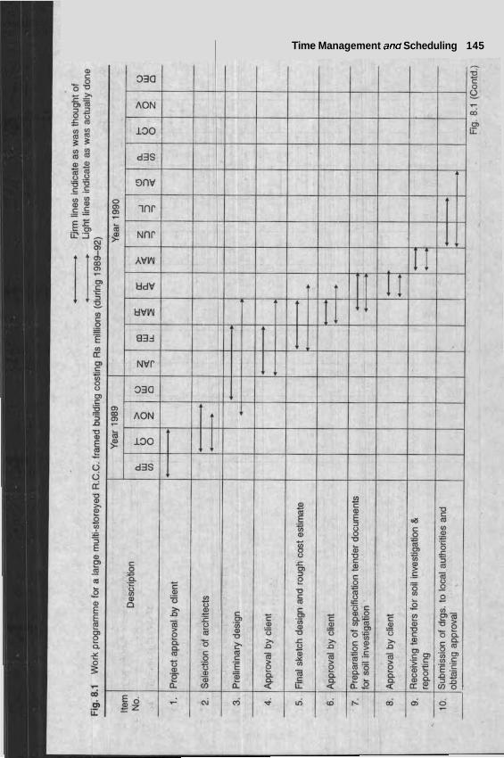
~ Time Management and Scheduling 145
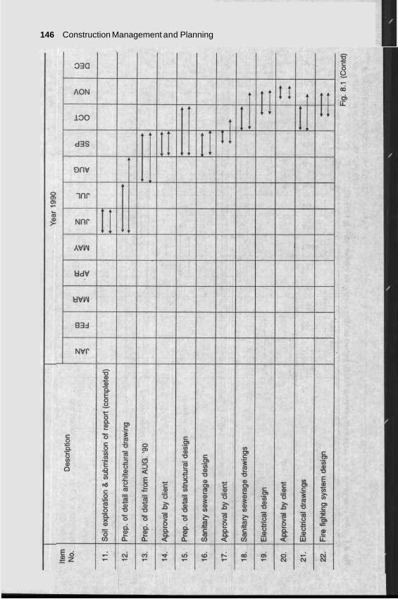
146 Construction Management and Planning
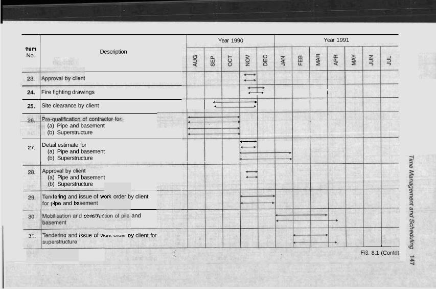
Item No.
Year 1990
Description
Year 1991
requali f icat ion-ef-60~1t~acbrf~ (a) Pipe and basement (b) Superstructure
24.
25.
Fire fighting drawings C+ I
4
Site clearance by client 4 b
(a) Pipe and basement (b) Superstructure
y client
and
27.
3rk order b
Detail estimate for C-, -
(a) Pipe and basement I b
(b) Superstructure I b
issue of wc isement
lering and )ipe and bz
d construc
1 I lelluallllu all" lssua UI wuln UIUGI ~y client for
I
3. 8.1 (Cor
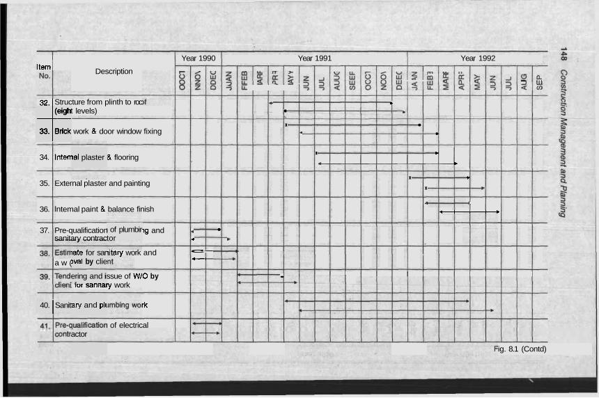
(eigh
33. Brick +
40. Sanit I
ial plaster
Year 1990 Year 1991 Year 1992 Item Description
+ > o ~ o w z f j q ~ r r k Z - , a a + > u ~ W O O W ~ L ~ Q C L r n ~ u ~ z ~ O n 3 W
O Z O ~ L L ? ? < w o z o % D - r ~ r % ' ? < m
32.) Structure from plinth to roc +. D.
t levels) b
I
work & door window fixing 4
34. lnten & flooring I b
* b
I b
35. External plaster and painting I +
4 I.
36. lntemal paint & balance finish I -
- 37. Pre-qualification l g and 4
sanitary contrac 4 +
iitary work and c-
a w ( c-
ssue of WIO by •
I ror sanlrary work
rk
I of electrical
late for sar )val by clie
ering and i z
ary and p l ~
actor
I of plumbir tor
ig. 8.1 (Contd)
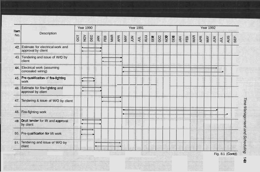
Year 1990 Year 1991 Year 1992 Item No. Description
~ ~ ~ z ~ % ~ $ z ~ ~ n + > o z r n ~ a $ ~ ~ o n 2 w 0 o w n 3 w ~ z o $ ~ ~ a ~ ? ? a m ~ z o % ~ ~ a ~ ? ? ~ m
42. Estimate for electrical work and 4
approval by client 4 b
43. Tendering and issue of WIO by 4
client t w
44. Electrical work (assuming #
concealed wiring) 4 b
45. Pre-qual~fication of fire-fiqhting 4 w work 4 b
------ 4 + 4 +
* b
f client I b
.C b
4- b
4 b
I 4 b --
4 b
* 4
ing & issue
hting work
19. Draft t6 I L -,I-- !rider for lif -A
alification fc
ng and iss
ghting and
t and appn
,r lift work
Fig. 8.1 (Contl A P w
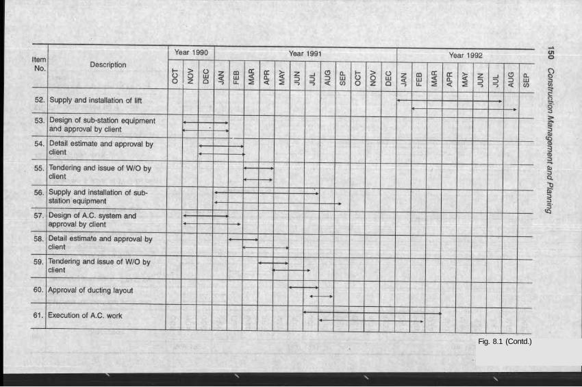
Fig. 8.1 (Contd.)
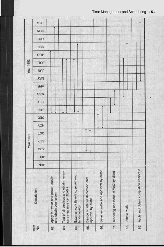
Time Management and Scheduling 1 51
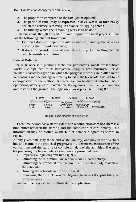
152 Construction Management and ~lannmng
2. The proportion compared to the tot, 3. The period of time (may tie expressea m aays, weelcs, or montns) vy
which the activity is moving in advance or lagging b 4. The time by which the remaining work is to be done The bar chart, though very helpful and popular for small projects, it has
got the following inherent limitations: 1. Bar chart does not depict the inter-
showing their interdependence; 2. It does not consider the cost since
which considers only time.
a1 job coi ? . ,
npleted;
ehind;
ihip amo ctivities
method .eject controlling
Line of Balance Line of balance is a planning technique works like pipelines, multi-storeyed bui balance is basically a graph in which the p vertical axis and the passage of time is plot1 example clarifies the method. A sewer lit operations, namely, earth excavation, lay and restoring the ground. The logic diagri
xly suitc , row hc
2d for re ,usings.
mpetitive Line of
rogress o ted in the xe can bt
f works : ' horizoni 2 dividec
ire plotte tal axis. P i into f01
'd in the 1 s4mp1e ar basic
.ing lines sm is pre
;, constn lsented ir
lcting m I Fig. 8.2
t, days
4 ~tion ~nrl Comnlntion
t, days t, days t3 4
-0 w@- Earth Laying Constructing work linc- manholes
-49- Restora
Fig. s diagram ( line
; date an( ~ t e and tk Each time period has a starting 1 a completion da \ere is a time buffer between the starting completion of ea ty. This information may be plotted in tne nne of balance diagram as snown in Fig. 8.3. At any given date (say at the enc line and estimate the proposed prugress ur worn rrvrrl ule uILersecnur1 ui ule
vertical line and the starting or completion date of the activities. TI for preparing the line of balance diagram are presented here:
1. Preparing a logic diagram like Fig. 8 7 2. Estimating the minimum ti^ 3. Estimating the proposed tin
the schedule. 4. Drawing the schedule as sh 5. Reviewing the line of bala
improvem--+c (ample i!
and the 1 1. -
ch activi . t-
1 of the E - --- - - -1
5th day) ' 1- c-.
draw a LA----c-.
vertical - -1 LL-
one may -- LL- :-
- ~-
le steps
,.-. rement f~ ement fo
Dr each a r each ac
ctivity. 'tivity to
me requi le requir achieve
own in E mce diag assess tl le possif
. X . I L L J .
; present e application.
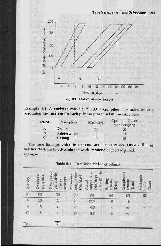
Time Management and Scr w u u r r r IY
100 .
! in days
balance dl
- iagram Fig. 8.3 Line of
1 A cor ?forma tic
Exa assc
ltract col 3n for ea
nsists of ch pile a
100 bo1 re preser
red piles ~ted in th
. The ac ke table h
Acti ivity
4 B'
Descriptic mum No. n per gan
10 oring . * erntorcem 12 asting 15
ovided hl me contract is rour we,,,. ,,,w a line ;. Assum~
C
'he time mce diag
rtion: chedule the work e data as
In for line Calculatic of balanc
- Total 7
1 54 Construction Management and Plannini
In 1 the optimum gang size is given. 7 column (3) is obtained by dividing the man-days given m the problem by column (2). Minimum buffer between the ion of one activit! commencement of the other is assumed 2 ~y as shown in col The total time excluding buffer to complrLc all ULZ activities, i.e. ont LrLlc operations, is 7 days. As the total allowable tin days, 4 cycles of operations can be made. Assuming the earliest po ~ r t operations and considering the time period per activity and minit~tullt uulfer time. one mav fill up the starting and completion of activities as shown ir (6). The corresponding line of balance diagram is shown in modify the schedules in many different ways and the line or Dalance aiagram will be correspon attendec
'ime peri od per at ctivity in - - -
! complet is one da .*A -11 &LC
1 and the lumn (8). . ".."1"
ne is 30 ssible sta -..- L * - K
.I
s (5) and I column Fig. 8.3. (
r l l - ~ -~
3ne may 1.
tdingly
CRITICAL PATH METHOD (CPI
The bar chart method is suitable ror small projects wnere tne manager has a e of execution of each operation or activity. E ~f technical trades the bar chart method
uate ana neeas a more rational and scientific method ot project planning and this is represented in a graphical form. The graphical repre- sentation of the activities is called a network diagram or simply network. This deals with events and activities and considers both time and cost.
A network depicts th~ ship bet 'ferent activities by means ' of arrows in a logical se Events a 2d by nodal points which
indicate the start or finish of an activity b~ a rlwdp of activities. Events are denoted by circl nbered fc entificati no time dimens nce it gi karting c activity.
clear id it conc inadeq
lea about :ems a r
:the mod tumber (
lut when becomes
ween dif re denott ... - *"A..
Les. Thest ;ion of it
2 are nun s own si
- )r easy id ves the s
ion. An e lr finishh
vent has ng of an
ictivity is id resour ?. -C c:,,
to be do is arrow
lroject, sc function .:L-- :- -.-
it must s: it indic - ..> -..I..
indicate zates the . . . - . . . .
; the actual work n e m a ~ res by arrows. has two
- ; wl L u l L c , and it gives the secjue~lce of activlry dn vrueny manner. The following c es and e S, nodal points, arrows, , t inter-re1 ented as "preceded by" 2 ____owes ~ y " and the auration or eacn actlvity is given in terms of days.
Suppose the project is consist of a number of activities,
Visiting s set.
L
:xample activities ind "foll~
introduc, , etc. Thc - - - - 3 , - -~
xplains t lation of
1 ..
he ideas activities
< 1
of event are pres
.. ..
, to instal s e t for 1 ; water. ? %is may -'b"
ferent su nd select ns of dif ppliers a le pump
g quotati ons frorr t differen
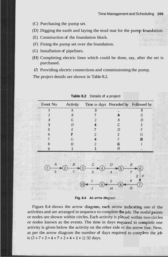
Time Management and Scheduling 155
(C) Purchasing the pump set.
(D) Digging the earth and laying the mud mat for the pumt, found;
(E) Construction of the foundation block.
(F) Fixing the pump set over the foundation.
(G) Installation of pipelines.
(H) Completing electric lines which could be done, say, after the set is purchased.
(0 Providing electric connections and commissioning the pump.
The project details are shown in Table 8.2.
Table 8.2 Details of a project
Event No. Activity Time in days Preceded by Followed by 1 A 3 - B 2 B 7 A C 3 C 2 B D 3 D 4 C E 5 E 7 D F 6 F 2 E G 7 G 4 F H 8 H 2 G I 9 I 1 H -
Fig. 8.4 An anow dial
Figure 8.4 shows the arrow diagram,'each arrow activities and are arranged in sequence to complete the or nodes are shown within circles. Each activity is gla or nodes known as the events. The time in days reql activity is given below the activity on the other side o as per the arrow diagram the number of days require is ( 3 + 7 + 2 + 4 + 7 + 2 + 4 + 2 + 1 ) 32 days.
indicatir :job. The ced with lired to (
f the arrc !d to con
ig one o I nodal pc
f the oints
in two circles zomplete one )w line. Now, ~plete the job
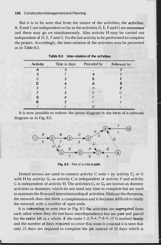
156 Construction Management and Planning
But it is to be seen that from the nature of the activities, the activ A, B and C are independent so far as the activities D, E, F and G are concerrleu and these may go on simultaneously. Also activity H may be carried out independent of D, E, F and G. I is the last activity to be performed to complete the project. Accordingly, the inter-relation of the activities may be presented as in Table 8.3.
Table 8.3 Inter-relation of the acti\ rities
It is now possible to redraw the diagram as in Fig. 8.5.
arrow d iagram i~
Fig. 8.5 Plot of a critical path
Follc
n the for1
Activity Time in days Preceded by A 3 - B 7 A C C 2 B F D 4 A E E 7 n F F 2 G G 4 I H 2 T
teresting 'r when t . . .
wand in not show
Dotted arrows are used to connect activity C witn k by activity C1 or G with H by activity G1 as activity C is independent of activity F and activity G is independent of activity H. The activities C1 or G1 are known as dummy activities or dummies which do not need any time to complete but are used to maintain the flo terrelationship of activities t the dun the network does r a completeness and it bet fficult to the network with a number of open ends.
It is in that in Fig. 8.5 tl- tgregatec each othe lot have interdep ,art and for the entlre job as a whole. If the route 1-2-5-6-7-8-9-10 is marked , and the number oj pired to cover th d it is seen that only 21 days are I to complete the days which is
to note hey do r - - f days re( required
le activit: endence -
is route i job inste
comes di ~mies, study
ies are sc but are I
- - .
1 from parcel firmly
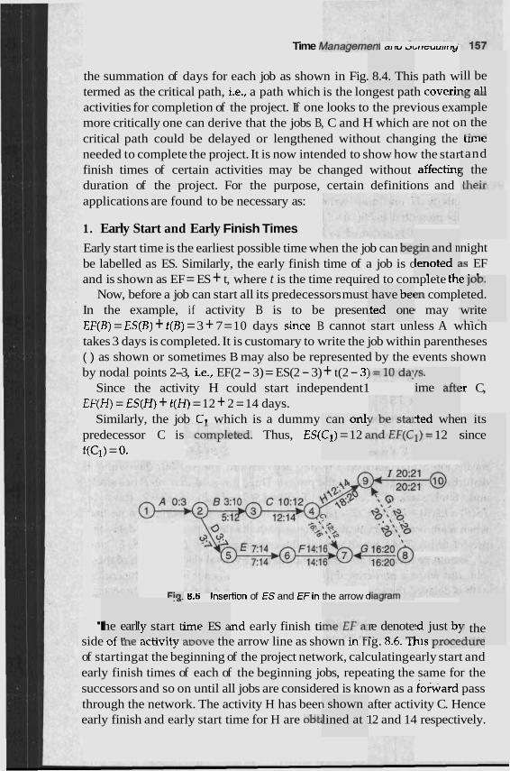
Time / L r a r r a y ~ r r r a r r ~ a r r u ~ ~ r r e u u r r r r y
the summation of days for each job as shown in Fig. 8.4. This path w termed as the critical path, i.e., a path which is the longest path coverir activities for completion of the project. If one looks to the previous exa more critically one can derive that the jobs B, C and H which are not o critical path could be delayed or lengthened without changing the needed to complete the project. It is now intended to show how the star finish times of certain activities may be changed without affectint duration of the project. For the purpose, certain definitions and applications are found to be necessary as:
ill be .- -11 16 all
mple n the L:-- L l l i l t :
tand 5 the
e l . -:..
1. Early Start and Early Finish Times
Early start time is the earliest possible time when the job can be] be labelled as ES. Similarly, the early finish time of a job is c and is shown as EF = ES + t, where t is the time required to complete tnc
Now, before a job can start all its predecessors must en compl In the example, if activity B is to be presen I may EF(B) = ES(B) + t (B) = 3 + 7 = 10 days since B cannot start unless A which takes 3 days is completed. It is customary to write the job within parentheses ( ) as shown or sometimes B may also be represented by the events shown by nodal points 2-3, i.e., EF(2 - 3) = ES(2 - 3) + t(2 - 3:
Since the activity H could start independent1 !r C, E F ( H ) = ES(H) + t(H) = 12 + 2 = 14 days.
Similarly, the job C7 which is a dummy predecessor C is ?ted. Thus, ES(1 t(C,) = 0.
sin and n lenoted 2 . . ..
night 1s EF . .
e 10". eted. write - . -
: have bec :ted one
1s. ime aft€
can onl: C]) = 12 2
?ed whe ])= 12 :
n its since
ria- 6.6 Insertion of ES and EFin the arrow L .a-
ly start t: .. ..
'I nd early finish ti side or me actlvity move tne arrow line as shown m rig. 0.0. lnis proce---- of startingat the beginning of the project network, calculating early start and early finish times of each of the beginning jobs, repeating the same for the successors and so on until all jobs are considered is known as a folivard pass through the network. The activity H has beer after activity C. Hence early finish and early start time for H are out; 12 and 14 respectively.
'he earl ,- ..
ime ES a .'
re denote .' n , - :d just b1
I . - -
y the 'd l lT~
1 shown lined at :
158 Construction Management and t ,, lY
It is now required to know how late the jol the job H may be finished so that the project 1s not delayed and IS h
on time.
2. Late o r a l L an td Late Finish Ti1
b H may !d and hc * . *.
may bc .te start a
1- -.- -
,w late nichorl
Late start LS of an activity is defined as the latest time when it can begin without delaying the date of completion of the project. Similarly late finish LF of an activity is the late start time plus its duration, thus LF = LS + t . For the activity H one may write LF(H) = L S ( H ) + t ( H ) which ? more usefully presented as LS(H) = LF(H) - t(H). To calculafe the la nd late finish times, it is required to begin at the end of the netwvrx arid work backwards and this is known as a backward pass. In the example, s i~ required to be finished in 21 days, for I late start and late finish are 21 days, but for H , LS may be 20 - 2 = 18 days and LF = 20 days. lnus LS and LF for C are 12 and 14 and not 16,18 since LS and LF for F are 14 and 16 for B, 5 and 12, for G, 16 and 20, for F, 14 and 16, for E, 7 and 14, for D, 3 and 7, and for A, 0 and 3 respectively. If LS and LF for A are calculated from B the values are 2 and 5 but this will delay the project by two days, hence LS and LF for A should be 0 and 3 respectively. The late start and late finish time for jobs are entered just below the arrow line in I-' - -
3. Total -. .
Slack T . .
4. Free Slack F!
It is defined as tk the early start tirn
le amou~ e of any
is quite 1 the delz ical ,path
L - L .
nce I is 20 and
rm
~t 1s now seen m pig. 8.b that there are jobs llke U , L;, t and G where la and early start as also late finish and early finish are identical when jobs like B and C these are different, e.g,. for B, ES(B) = 3, and LS(B) =
means job B may start on any day between 3rd and the 5' rithout disturbing the target time of the project. Thus, it is said that ; slack, and total slack T S of B is T S ( B ) = LS(B) - ES(B) = 5 - kys or T S ( B ) = LF(B) - EF(B) = 12 - 10 = 2 days. It interesting to note that when a job is on the critical or longest patE ty to start will delay the project finish. Thus for all jobs on the criti the ES and LS, EF and LF should be identical and there should be zero rural slack for each o jobs. But when a non-critical job, i.e., a job which is not lying on the I
path is delayed the succeeding jobs get delayed by equal length of tim if job C is delayed until day 12 then its EF time is 12 + 2 = 14, the 14 and job H will be delayed equally, but if job B is delayed up to LF tin day 12, job C could have ES as 13, the 13th day. Total slack is also knc total float in man
~t of time a job c other job. Thus, ir
th day M job B has 3 = 2 da
te start eas for : 5 that
f these critical le, e.g., th day le, i.e., )wn as
an be de I the exa
llayed wi mple the
ithout ah activity,
fecting H may
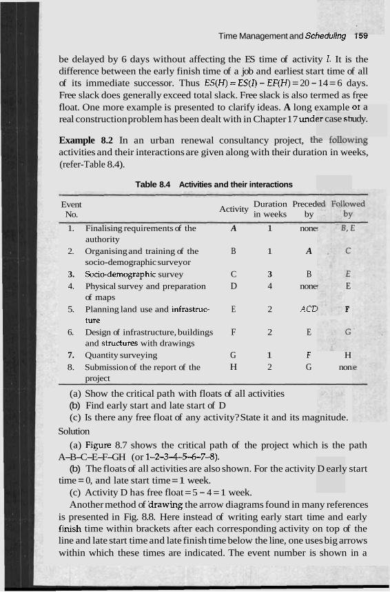
Time Management and Scheaurmg i DY
be delayed by 6 days without affecting the ES time of activity I. It is the difference between the early finish time of a job and earliest start time of all of its immediate successor. Thus ES(H) = ES(I) - EF(H) = 20 - 14 = 6 days. Free slack does generally exceed total slack. Free slack is also termed as free float. One more example is presented to clarify ideas. A long example
'
real construction problem has been dealt with in Chapter 17 undc ?r case sh
.,-. L.ll,.-.
or a udy.
Example 8.2 In an urban renewal consultancy project, tFLc lvuvv~ing activities and their interactions are given along with their duration in weeks, (refer-Table 8.4).
Table 8.4 Activities and their interactions
Event No.
Activity Duration Preced in weeks by
1. Finalising requirements of the A 1 none authority
2. Organising and training of the B 1 A socio-demographic surveyor
3. Socio-demographic survey C 3 B 4. Physical survey and preparation D 4 none E
of maps
5. Planning land use and infrastruc- E 2 ACE F ture
6. Design of infrastructure, buildings F 2 E and structures with drawings
7. Quantity surveying G 1 F H 8. Submission of the report of the H 2 G non
project
(a) Show the critical path with floats of all activities (b) Find early start and late start of D (c) Is there any free float of any activity? State it and its magnitude.
Solution
(a) Fipre 8.7 shows the critical path of the project which is the path A-B-C-E-F-GH (or 1-2-3-4-5-6-7-8).
(b) The floats of all activities are also shown. For the activity D early start time = 0, and late start time = 1 week.
(c) Activity D has free float = 5 - 4 = 1 week. Another method of arawing the arrow diagrams found in many references
is presented in Fig. 8.8. Here instead of writing early start time and early fjnish time within brackets after each corresponding activity on top of the line and late start time and late finish time below the line, one uses big arrows within which these times are indicated. The event number is shown in a
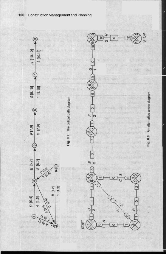
Construction Management and Planning
Time Management and Scheduling 161
bigger circle which is also partitioned and the duration of an activity is written within the partitioned chamber as shown. The free floats available for any activity is shown in a rectangular chamber in between two arrows giving the expanse of the activity. It is to be noted that for all activities except D the number zero '0' is entered within the rectangular chamber since these have got no free floats. The number entered for activity D within the said chamber indicates free fIoat for D is 1 week.
In conclusion, it is to be noted that the chain connecting the critical events or the chain formed by the critical activities is called the critical path. Tl~e critical path starts from the first event and after passing th;ough all the critical path determines the project duration, the most optimum time to start an activity and finish an activity, the interrelation between the activities, and finally how the manager or the man-in-charge of the project should find out alternative paths in case there is undue delay due to unforeseen reasons.
PERT
The programme evaluation and review technique is also presented in the form of a network diagram whose logic is based on similar lines like CPM but these two techniq~~es were developed independently and have got distinct applications to different industries and settings.
PERT is preferred when there is some uncertainties in the choice of methodology, availability of materials, and the final answer is not clearly known, whereas CPM is applied when things are almost certain. As for example, in the case of a construction project, once the project has been finalised there is little doubt about men, materials and equipments required, the time when these are required, and so on.
The duration of any activity in the case of a PERT programme is calculated as a weighted average of three time estimates, namely the optimistic time to, the pessimistic time t p and the most probable time t,,. Further, since it is assumed that the most probable time is four times more likely to occur compared to the other two, the expected time of completion of an activity is presented as
to + 4 f,, + tP t , =
6 It is possible to plot an activity duration versus likelihood of occurrence as shown in Fig. 8.9 and determine the expected time. This Fig. 8.9 is very close to a probability distribution curve as given by statisticians and is presented in Fig 8.10.
Referring to Fig. 8.9 and Fig. 8.10 let us assume that the most optimistic time to of an activity is equal to say 4 days, most probable estimate of time t,, is 8 days and most pessimistic time estimate is 16 days then the expected time,
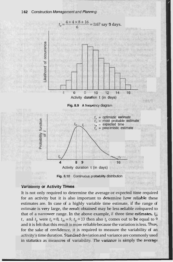
1 62 Construction Mana! 7d Plannir
3.67 say ! 3 days.
~- J u
Activity duratic 8 " . L
3n t (in d
Fig. 8.9 A frequ~ tncy diagra
nlsIlC esrln t probable
,, - ,n,dcted time irnistic est
4 8 9 Activity duration t (in days)
Fig. obability di stribution
. ,. .,olllry or Activity I lmes
It is not only required to determine the average ? required for an activity but it is also important to detf lble these estimates are. In case of a highly variable time estimate, 11 me range of estim# .y large, the resul npared to that c Iwer range. In th mates, to, t , ana t were to = 8, t ' P = l u tnen also re comes out to De equal to 9
and it is felt that this re5 ,re reliable because the variation is less. Thus for the sake of confidc s required to measure the variability of a] ~~+ i~ l i t y ' s time duration. btandard deviation and variance are commonly use(
tistics as
low relia , .r .*
ate is ver ~f a narc 1 .
t obtaine e above I
d m .,
!d may b example,
1 I
e less re1 if three
iable cot time esti . 1
LaLLL"
in sta 2s of var I'he vari: mce is si imply thi e averagi
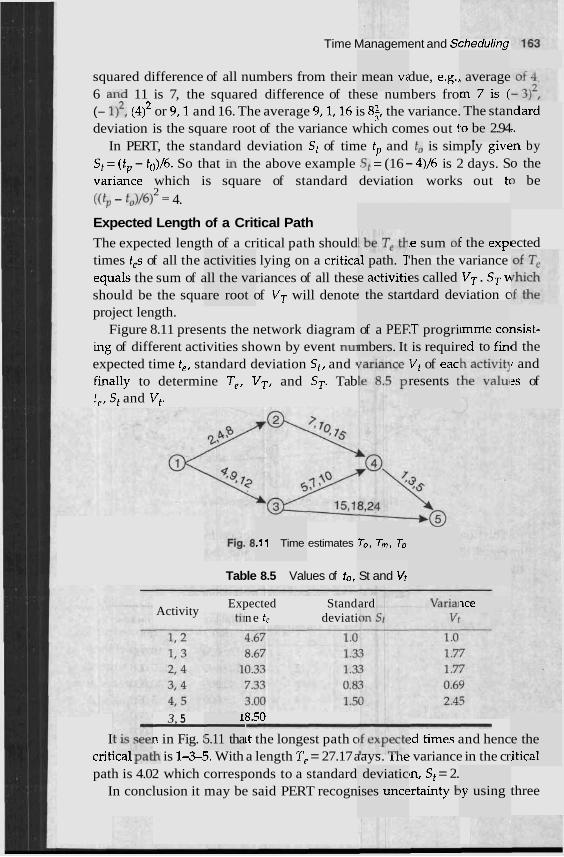
Time Management and Scnedul~ng
squared difference of all numbers from their due, e.g., 6 and 11 is 7, the squared difference of these numbers fro (- I)', (4)' or 9.1 and 16. The average 9,1,16 is 8$ the variance. deviation is the square root of the variance which comes out t
In PERT, the standard deviation St of time tp and to is simply ~ I V E
S t = ( t p - t0)/6. So that in the above example St = (16 - 4)/6 is 2 days. S
mean v: , average m 7 i s ( The star
.o be 2.94 . .
tdard I. ?n by o the 3 be variance which is square of standard deviation works out tc
2 ((t, - f,)/6) = 4.
Expected Length of a Critical Path
The expected length of a critical path should times t,s of all the activities lying on a critic; equaIs the sum of all the variances of all thes should be the square root of VT will denote project length.
Figure 8.11 presents the network diagram ing of different activities shown by event nu1 expected time t,, standard deviation St, and 1
Finally to determine T,, VT, and ST. Tab t,, St and Vt.
F the expl ected le sum 01 11 path. 7 e activitil ! the star
'hen the variance es called VT . ST v tdard deviation c
of a PEF mbers. It
:T progri is requir
nsist- d the
unme coi ,ed to fin'
Vt of eac resents t
r and 2s of
.11 Time estimates
Table 8.5 Values of to,
To, T m , TD
St and Vt
ard nce Expected Stand Activity n e t, deviati
3, 5 - 8.50
I n in Fig. I ~t the longest path c ?d times and henc cribcal pa& is 1-S5. With a length T, = 27.17 aays. lne variance in the cr path is 4.02 which corresponds to a standard ~n, St = 2.
In conclusion it may be said PERT recogn !rtainty k
1 - 5.11 tha e the
itical deviatic
ises unce ty using three
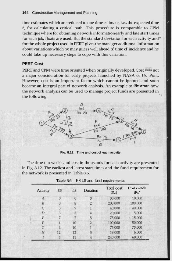
164 Construction Management and Planning
time estimates which are reduced to one time estimate, i.e., the expected time t, for calculating a critical path. This procedure is comparable to CPM technique where for obtaining network information early and late start times for each job, floats are used. But the standard deviation for each activity and* for the whole project used in PERT gives the manager additional information about variations which he may guess well ahead of time of incidence and he could take up necessary steps to cope with this variation.
PERT Cost
PERT and CPM were time oriented when originally developed. Cost was not a major consideration for early projects launched by NASA or Du Pont. However, cost is an important factor which cannot be ignored and soon became an integral part of network analysis. An example to illustrate how the network analysis can be used to manage project funds are presented in . , the following:
Fig. 8.12 Time and cost of each activity
The time t in weeks and cost in thousands for each activity are presented in Fig. 8.12. The earliest and latest start times and the fund requirement for the network is presented in Table 8.6.
Table 8.6 ES LS and fund requirements
Activity Total cost' Cost/week Duration (Rs) (Rs)
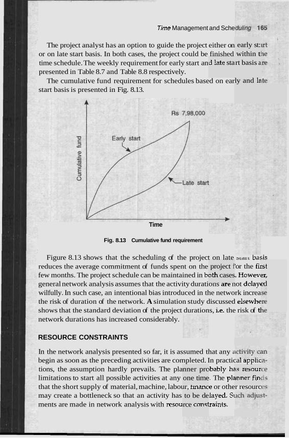
Time Management and Sche
The project analyst has an option to guide the project either on or on late start basis. In both cases, the project could be finished time schedule. The weekly requirement for early start an presented in Table 8.7 and Table 8.8 respectively.
The cumulative fund requirement for schedules based on ear start basis is presented in Fig. 8.13.
i early st: within t rt basis a d !ate sta
ly and le
Time
Fig. 8.13 Cumulative fund requirement
Figure 8.13 shows that the scheduling of the project on late > L ~ L vasis reduces the average commitment of funds spent on the 'or the fii few months. The project schedule can be maintained in b~ . Howevl general network analysis assumes that the activity durations are not delay1 wilfully. In such case, an intentional bias introduced in the network increa the risk of duration of the network. A simulation study discussed elsewhe shows that the standard deviation of the project durations, i.e. the risk of tl network durations has increased considerably.
rst er, ed
project f 0th cases - .- - - .. .-
RESOURCE CONSTRAINTS
In the network analysis presented so far, it is assumed that any E
begin as soon as the preceding activities are completed. In practical applic tions, the assumption hardly prevails. The pla ~bably h; limitations to start all possible activities at any I. The pk that the short supply of material, machine, labour, fmance or other resourc may create a bottleneck so that an activity has slayed. Si ments are made in network analysis with resou :raints.
- -
IS resour inner fin
nner prc one time
to be de rce consf
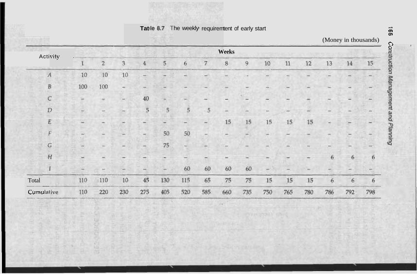
Tat he weekly 1 requirem tent of early start A
0) 0,
(Money in thousands) 2
Weeks 2 vity - Acti
Total -- Cumulai
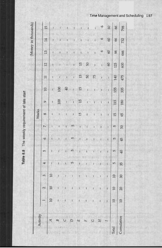
Time Management and Scheduling 1
1 -
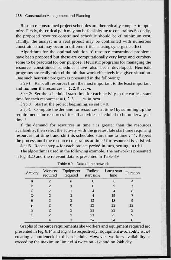
168 Construction Management and Planning
Resource-constrained project schedules are theoretically complex to opti- mize. Firstly, the critical path may not be feasible due to constraints. Secondly, the proposed resource constrained schedule should be of minimum cost. Thirdly, the analyst in a real project may be confronted with numerous constraints, that may occur in different tiiies causing synergistic effect.
Algorithms for the optimal solution of resource constrained problems have been proposed but these are computationally very large and cumber- some to be practical for our purpose. Heuristic programs for managing the resource constrained schedules have also been developed. Heuristic programs are really rules of thumb that work effectively in a given situation. One such heuristic program is presented in the following:
Step 1: Rank all resources from the most important to the least important and number the resources i = l ,2 ,3 . . . rn.
Step 2: Set the scheduled start time for each activity to the earliest start time for each resources i = l ,2 ,3 . . . , m in turn.
Step 3: Start at the project beginning, so set t = 0. Step 4: Compute the demand for resources i at time t by summing up the
requirements for resources i for all activities scheduled to be underway at time f.
If the demand for resources in time f is greater than the resources availability, then select the activity with the greatest late start time requiring resources i at time t and shift its scheduled start time to time t + 1. Repeat the process until the resource constraints at time f for resource i is satisfied.
Step 5: Repeat step 4 for each project period in turn, setting t = t + 1. The algorithm is used in the following example. The network is presented
in Fig. 8.20 and the relevant data is presented in Table 8.9
Table 8.9 Data of the network
Workers Equipment Earliest Latest start Activity Duration required required start time time - - -- - - -
A 2 0 0 0 4 B 2 1 0 9 3 C 2 1 4 4 8 D 2 1 4 15 7 E 2 1 12 13 9 F 2 0 12 12 12 G 2 1 21 22 2 H 2 1 21 25 5 I 4 1 23 24 6
Graphs of resource requirements like workers and equipment required arc presented in Fig. 8.14 and Fig. 8.15 respectively. Equipment availabili? is nct creating a bottleneck in this schedulr. However, workers availability 1s
exceeding the maximum limit of 4 twice on 21st and on 24th day.
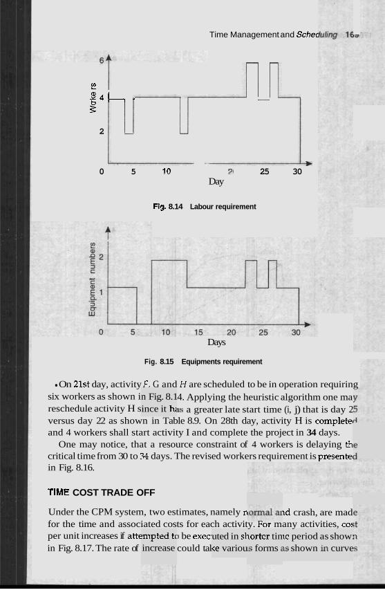
Time Management and Schec
- -
$2 $ 4 - - - P 2 - -
b 0 5 10 ? I 25 30
Day
Fig. 8.14 Labour requirement
Days
Fig. 8.15 Equipments requirement
n Fig. 8.1 ince it h;
On 21st day, activity F. G and H are scheduled to be in operation requiring six workers as shown i 4. Applying the heuristic algorithm one ma reschedule activity H s 3s a greater late start time (i, j) that is day 2 versus day 22 as shown in Table 8.9. On 28th day, activity H is complete^ and 4 workers shall start activity I and complete the project in 34 days.
One may notice, that a resource constraint of 4 workers is delaying th critical time from 30 to .34 days. The revised workers requirement is presentel in Fig. 8.16.
TIME COST TRADE OFF
tmpted tc increase
uted in sl <e variou
Under the CPM system, two estimates, namely n ~d crash, are mad for the time and associated costs for each activity. For many activities, co: per unit increases if attc I be exec1 in Fig. 8.17. The rate of could tal
lorter tin Is forms 2
le period 1s shown
as show: in curve
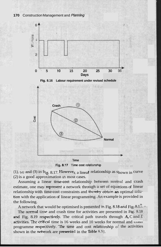
170 Construction Management and Plannlng
The nc tnd Fig.
I .-..... _
0 5 10 15 20 25 30 : Days
Fig. 8.16 Labour requirement under revised
Crash
- CO
3
jrmal tin 8.19 res 11. - _..:L
near tim . represel &;..'-.A r n r 4
ctively. ' rork are
1.8.17 Ti1
Howeve
The tim€ presentec
ime
me cost re1
schedule
Normal
ationship
r relation ship as s (11, \L) an :ig. 8.17. r, a lineal hown in (2) is a good approximation m most cases.
Assuming a li ~e-cost relationsh nal and estimate, one may ~t a network thro ttions of relationship with r u ~ ~ r ~ v o i constraints and tiereby obta~n an optimal ,,,, tion with the application of linear programn example is provided in the following.
A network that would be optimised is pre3c~lrcu ~1 Fig. 8.18.and Fig a . Ie and crash time for activities are presented in Fig
a ,pectively. The critical path travels through A, C acnvmes. lne crirical time is 16 weeks and 10 weeks for normal and L L ~ ~ L ,
programme respe b and co mship oj shown in the n e b in the ' I.
st relatic rable 8.1(
f the act
curve
crash linear ' cnl**-
ivities
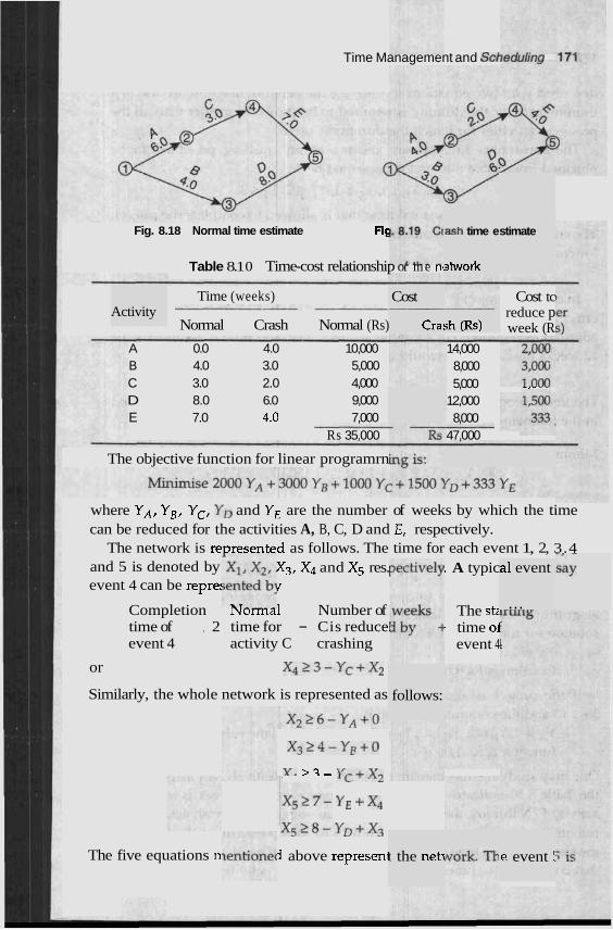
Time Management and Scbnllnnn
,ash time e
etwork
stimate Fig. 8.18 Normal time estimate Fic
Table 8.1 0 Time-cost relationship or me nc
Time (weeks)
Normal Crash Normal (Rs)
A 0.0 4.0 10,000 B 4.0 3.0 5,000 C 3.0 2.0 4,000 D 8.0 6.0 9,000 E 7.0 4.0 7,000
Rs 35.000
Cost -- Cra: sh (Rs)
Cost tc reduce p week (R
14,000 8,000 5,000 -,- - .
12,000 8,000
47.000
Activity
The objective function for linear programrn
where YA, YB, YC, Yo and YE are the number of weeks by which the time can be reduced for the activities A, B, C, D and E, respectively.
The network is re~resented as follows. The time for each event 1, 2, 3.4 and 5 is denoted by X3, X4 and X5 res. : A typic event 4 can be repre: J
a1 event
... Completion lvurrnal Number of time of , 2 time for - Cis reduce' event 4 activity C crashing
or X423-Yc+X2
The st; - time 01
event 4
Similarly, the whole network is represented as follows:
x 3 > 4 - y B + 0
I-. '2- Y c + q
+ x4
K ~ L ~ ( - Y ~ + X ~
1 above represenl The five equations n .e event ! t the net1
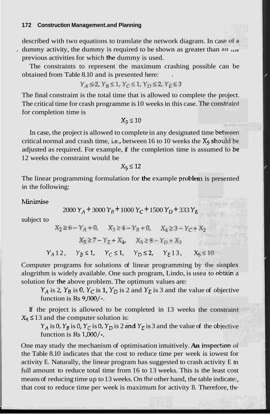
172 Construction Management. and Planning
described with two equations to translate the network diagram. In cas . dummy activity, the dummy is required to be shown as greater than all LILC
previous activities for which the dummy is used. The constraints to represent the maximum crashing possible can be
obtained from Table 8.10 and is presented here: .
YA12,YB<1,Yc<1,YD<2,YE<3
The final constraint is the total time that is allowed to complete the project. The critical time for crash programme is 10 weeks in this case. The cons for completion time is
X, I 10
In case, the project is allowed to complete in any designated time bei critical normal and crash time, i.e., between 16 to 10 weeks the X5 s h o ~ adjusted as required. For example, if the completion time is assumed to oe 12 weeks the constraint would be
x5 I 12
The linear programming formulation for the example probler in the following:
hlinimise 2000 YA + 3000 YB + 1000 Yc + 1500 YD + 333 YE
n is pres ented
subject to x226-YA+o, x324-YB+o, x423 -Yc+
X527-YE+X4, X528-YD+X3
YA 12 , YB I 1, YC 11, Y D 12 , YE 13 , X
Computer programs for solutions of linear programming b nplex alogrithm is widely available. One such program, Lindo, is usea to o~ta in a solution for the above problem. The optimum values are:
YA is 2, YB is 0, YC is 1, YD is 2 and YE is 3 and the value of objective function is Rs 9,000/-.
the cons If the project is allowed to be completed in 13 weeks X5 5 13 and the computer solution is:
YA is 0, YB is 0, Yc is 0, YD is 2 ajnd YE is 3 and the value of the objc function is Rs 1,000/-.
One may study the mechanism of optimisation intuitively. An inspecti,,. ,. the Table 8.10 indicates that the cost to reduce time per week is iowest for activity E. Naturally, the linear program has suggested to crash activity E tn full amount to reduce total time from 16 to 13 weeks. This is the least cost means of reducing time up to 13 weeks. On the other hand, the table indicate:, that cost to reduce time per week is maximum for activity B. Therefore, thv
Time Manaaernent and Schedulin
ivity B ur while cr linear programming solution has left the act touched ashing the network to 10 weeks.
Such intuitive approach is applicable only to example problems. The real life networks are usually large enough so that only a computer solution is the practical method to optimise a network. For example, a small network in practical life has been analysed in chapter XVII. There are 38 events and the number of constraining equations are 86. It is not uncommon to encounter networks having more than 100 events. The constraints may amount up to 1000 equations. Under such circumstances, only the computer techniques as proposed in this discussion is an effective tool to optimise the time-cost trade-off.
UNCERTAIN DURATIONS
The common approach to incorporate uncertainty in the scheau~lng F is to apply the critical path scheduling process with a probabilisti
. period. The process is usually referred as PERT and is already discus Although the PERT method is widely in circulation it has two major
problems. Firstly, the procedure calculates the probabilistic time period of the critical path only while it is entirely possible that other activities might be so delayed that a new critical path- is created through the delayed activities. PERT does not address to sucl~ problems.
Secondly, PERT assumes that durations are independent random variables having a beta probability distribution. The durations are correlated with one another. For example, difficulties in obtaining cement delays a number of activities in a site. The assumption of beta probability distribution for activity durations may not be true in practice. In many projects, the network is already crashed. Therefore, the difference between optimistic and most likely time is very small if any, whereas the pessimistic time is long due to the risk and uncertainty of the constn~ction activities. In other words, the probability distribution of the activity durations is skewed as opposed to an evenly distributed beta distribution assumed in PERT, Sometimes the probability distribution of activity duration is a function of the season. For example, the pessimistic time of an earthwork may be two months if started in winter, whereas the pessimistic time of the same earthwork might be three months if started in the rainy season. Beta distribution for activity durations are not applicable in these cases. PERT typically underestimates the project duration. As an alternative to PERT, a method to estimate the pro'bability distribution
- of the time duration and other information like cost for a network can be obtained from the Monte Carlo simulation. This technique calculates the pro- ject duration number of times from the artificial but realistic data randomly chosen from a given distribution for each activity duration and applylng a critical path scheduling to the resulting network and finally calculates the
jrocess c time sed.
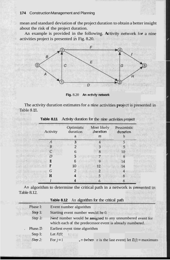
1 74 Construction Management and Planning
mean and standard deviation of the project duration to obtain a better insight about the risk of the project duration.
An example is provided in the following. Ac activities project is presented h Fig. 8.20.
)r a nine
Fig. 8.20 An activ fity network
he activi The activity duration estimates for a ni i.11.
ties projc
Table 8.11 Activity duration for the nine i activities F
Optimi Lost likely Activity durati iuration
a m
3
Pessir dura
b
nistic tion
2 6
U 5 E 6 F 10 G 2 H 4 I 4
An algorithm to determine the critical path in a network is pres Table 8.12.
Table 8.12 An algorithm for the critical path
base I:
Step 1: 0, -
Event n
Starting x 7 .
umber algorithm
; event number woi
>rep L: luext number would be assignea to any unnumbered e7 which each of the predecessor event
. Phase. 11: Earliest event time algorithm
Step 1: Let E(0) -
Sfep 2: For j = 1 , rz (wherc n is the last event ) let E( j ) = maximur
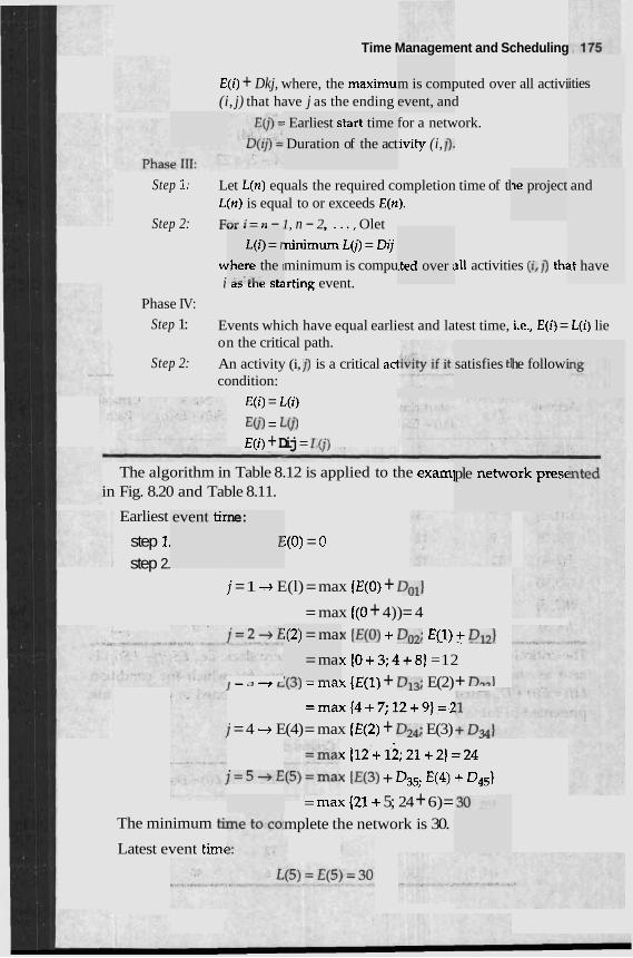
Time Management and Scheduling
E ( i ) + Dkj, where, the maximu (i, j) that have j as the ending
m is computed over all activi event, and
for a network.
:ivity (i, 11.
ities
: Earliest s
Duration
itart time
of the act
le project and Step 1: Let L(n) equals the required completion time of tl L(n) is equal to or exceeds E(n).
Step 2: For ; = n - 1, n - 2 , ..., Olet
ninimum L(j) = Dij w minimum is compu 311 activities (it 1) th; i aa ulr ardrting event.
Phase IV:
Step 1: Events which have equal earliest and latest time, i.e., E(i) = L(i) lie on the critical path.
Step 2: An activity (i, 1) is a critical acl condition:
E(i) = L(i)
E(j) = L(j)
.,. .-,. L(i) = r
rhere the I
--.LL.. ..' lted over i ~t have
satisfies ti he followi
E(i) + Dij = I:(;)
ple netwc ork presc The algorithm in Table 8.12 is applied to the exam] in Fig. 8.20 and Table 8.11.
Earliest event tir ne:
f step 1. :(o) = 0 step 2.
j = 1 -., E(l) = max (E(0) + Doll
= max ((0 + 4)) = 4
K HO) + Do2; ECl) + Dl21
K {O+3;4+8) =12
i = a --t L ~ J ) = I n d X (E(1) + Dl3; E(2) + Dm) =max(4+7;12+9]=2
i = 4 + E(4) = max (E(2) + D24; E(3)
u{12+12;21+2]=24 j=5+E u 1E(3) + 4.5; E(4) + 045)
= IIMX {21+ 5; 24 + 6) = mplete the network is 30.
:(2) = ma:
= ma: ,(-\ - - -.
The minimum ti
Latest event tirnt
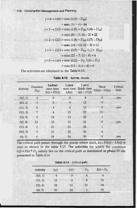
vvr ,,,ion Management and Plannin
= rnin (L( .
= min (3U - 6)= 24
= rnin (L(
= rnin (3C
L(4) - 0 3 4 )
-2 )=22
= min {L( L(3) - 4 3 )
= min (24 - 91 = 12
= rnin {L(3) - u13; L(2) - Dl '
j = 0 + L(U) LL,u, ,u,Z) - LJ,; 1
= rnin (12
The activities are tabulated in the Tat:
Table 1 8.13 Act ivity detai
arliest Latest Late: start timc
LS(ij) e finish t
L(j) = L
4
I\*, - The c
- e slack, i. ritical pa th passer
. ., I the pou r n "-I
nts when .. ... as shown m me tame 6.13. rne act~viries for whicn me condition E(i) + Dij e nted in T
zero satisfy 1
able 8.14 ies on th e critical path as ed in phi
ritical patt
ctivity ' i j E(
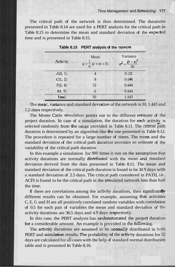
' and Scht
The critical path of the network is thus determined. The duratic presented in Table 8.14 are used for a PERT analysis for the critical path Table 8.15 to determine the mean and standard deviation of the expec1 time and is presented in Table 8.15.
Table 8.15 PERT analysis of the networK
Activ Variance
2 (b -a12
4 0 , C(1, : F(2, 1(4, E
Tota
111 LAA
viation o ndard de he mex , variancc jays respectively.
The Monte Carlo simulatic In point: simulat
-...-A -..,. nate of 1 1 activity ...;+:,--I --
; out to the different estb project duration. In case of a ion, the duration for ead is selected randomly from.the ~ L U L S C p~fv ided in Table 8.11. The CIILILQI ydth duration is determined by an algorithr 1 Table 8.12. The procedure is repeated for a large !an and the standard deviation of the critical path uulauulr L J L L J V N L Z ~ mate of the variability of the critical path duration
In this example a simulation for 501 activity durations are normally distri~ureu with the lrleilll a r l u ~ L ~ I I U C
deviation derived from the data presented in Table 8.11. The standard deviation of the critical path duration is found to be 30.' a standard deviation of 2.5 days. The critical path considered in PATH, i ACFI is found to be the critical path in ss than h the time.
If there are correlations among the activity aurations, tnen significan.-, different results can be obtained. For example, assuming thz C, E, G and H are all positively correlated random variables with of 0.5 for each pair of variables the mean and standard devianon or 1
activity durations are 36.5 days and 4.' !spec tivel In this case, the PERT analysis has timated
.for a considerable amount. An example is provided in the tollou-.,. The activi assumec distributed in bc
PERT and s i ~ f i e prob ~ i t y durations for days are calculated for all cases with the help of standard normal distributi table and is presented in Table 8.16.
n like thc number A.*..-&:-..
? one pre of times . -..,.-.:A*
sented in . The me
5 run on 0 times i: L-.L-J
the assul ---- --
nption tl -1 -L---1-
mean a 9 days w
nd ith .e..
. the simt
.. .. tlv
it activit correlati . . r .
ies on .he
9 days re underes
[YO
the proje . .- .. 'ct durati ,line
~ty durat ions are results. '
--
~ormally f the acti~ - - ability oj
- - - nulation - - -
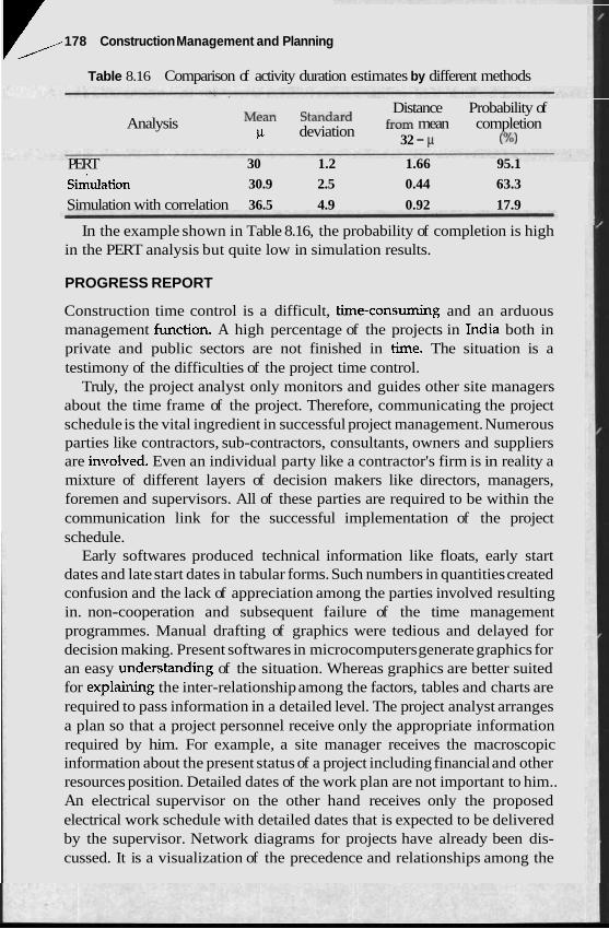
II 178 Construction Management and Planning
Table 8.16 Comparison of activity duration estimates by different methods
Analysis Distance Probability of
Mean Standard from mean completion p deviation 32 - w) PERT 30 1.2 1.66 95.1
~imula tion 30.9 2.5 0.44 63.3
Simulation with correlation 36.5 4.9 0.92 17.9
In the example shown in Table 8.16, the probability of completion is high in the PERT analysis but quite low in simulation results.
PROGRESS REPORT
Construction time control is a difficult, time-consuming and an arduous management function. A high percentage of the projects in India both in private and public sectors are not finished in time. The situation is a testimony of the difficulties of the project time control.
Truly, the project analyst only monitors and guides other site managers about the time frame of the project. Therefore, communicating the project schedule is the vital ingredient in successful project management. Numerous parties like contractors, sub-contractors, consultants, owners and suppliers are inx~olved. Even an individual party like a contractor's firm is in reality a mixture of different layers of decision makers like directors, managers, foremen and supervisors. All of these parties are required to be within the communication link for the successful implementation of the project schedule.
Early softwares produced technical information like floats, early start dates and late start dates in tabular forms. Such numbers in quantities created confusion and the lack of appreciation among the parties involved resulting in. non-cooperation and subsequent failure of the time management programmes. Manual drafting of graphics were tedious and delayed for decision making. Present softwares in microcomputers generate graphics for an easy understanding of the situation. Whereas graphics are better suited for explaining the inter-relationship among the factors, tables and charts are required to pass information in a detailed level. The project analyst arranges a plan so that a project personnel receive only the appropriate information required by him. For example, a site manager receives the macroscopic information about the present status of a project including financial and other resources position. Detailed dates of the work plan are not important to him.. An electrical supervisor on the other hand receives only the proposed electrical work schedule with detailed dates that is expected to be delivered by the supervisor. Network diagrams for projects have already been dis- cussed. It is a visualization of the precedence and relationships among the
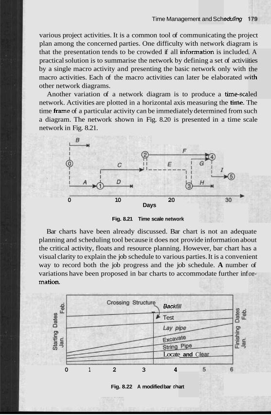
Time Managemen t and Sch eduling '
various project activities. It is a common tool of communicating the project plan among the concerned parties. One difficulty with network diagram is that the presentation tends to be crowded if all information is included practical solution is to summarise the network by defining a set of activii by a single macro activity and presenting the basic network only with macro activities. Each of the macro activities can later be elaborated w other network diagrams.
Another variation of a network diagram is to produce a time-sca network. Activities are plotted in a horizontal axis measuring the W e . The time frame of a particular activity can be immediately determined from such a diagram. The network shown in Fig. 8.20 is presented in a time scale network in Fig. 8.21.
. A ties the
0 10 20 Days
rith
led
Fig. 8.21 Time scale network
Bar charts have been already discussed. Bar chart is not an adequate planning and scheduling tool because it does not provide information about the critical activity, floats and resource planning. However, bar chart has a visual clarity to explain the job schedule to various parties. It is a convenient way to record both the job progress and the job schedule. A number of variations have been proposed in bar charts to accommodate further inf mation.
Bacl
Test
Locate and C
0 1 2 3 4
Fig. 8.22 A modified bar chi art
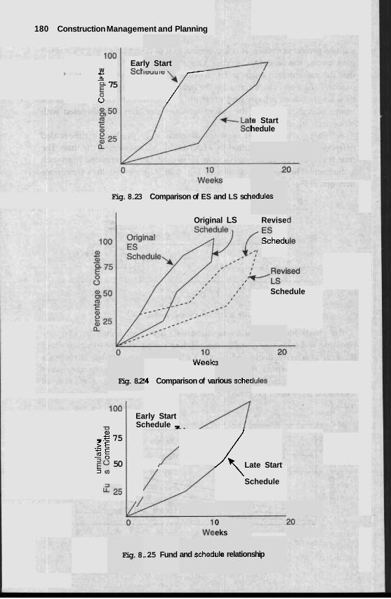
180 Construction Management and Planning
loo Early Start w
I - C a, - a 75 - G 0 /
:e Start hedule
Fig. 8.23 Comparison of ES and LS sch
Original LS
Fig. 8.2
vveeK:
!4 Comparison of va
loo Early Start -0 Schedule , a, , E 75
> E .- 3: z 0 50 I 3 Ul
z 2 5 1
edules
Revise
Schedt
Schedule
3
rious schec
.( Late Start
Schedule
0 eks
Fig. 8. .25 Fund and sched~ ule relation ship
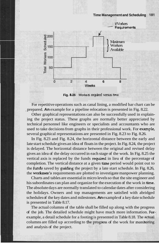
Time Management and Scheduling
Vorkers dequirements
Fig. 8.5
Maximum Workers Available
6 8 'ee ks
rs required versus tim
For repetitive operations such as canal lining, a modified bar chart can be prepared. An example for a pipeline relocation is presented in Fig. 8.22.
' Other graphical representations can also be successfully used in explain- ing the project status. These graphs are normally better appreciated by technical personnel like engineers or specialists and accountants who are used to take decisions from graphs in their professional work. For example, several graphical representations are presented in Fig. 8.23 to Fig. 8.26.
In Fig. 8.23 and Fig. 8.24, the horizontal distance between the early and late start schedule gives an idea of floats in the project. In Fig. 8.24, the project is delayed. The horizontal distance between the original and revised delay gives an idea of the delay occurred in each stage of the work. In Fig. 8.25 the vertical axis is replaced by the funds required in lieu of the percentage of completion. The vertical distance at a given time period would point out to the funds saved by guiding the project by a late start schedule. In Fig. 8.26, the workmen's requirements are plotted to investigate manpower planning.
Charts and tables are essential in micro levels so that the site engineer and his subordinates can plan and organize for the execution of the work in time. The absolute days are normally translated to calendar dates after considering the holidays. Owners and top managements are satisfied with abridged schedules of the key dates and milestones. An example of a key date schedule is presented in Table 8.17.
The actual columns of the table shall be filled up along with the progress of the job. The detailed schedule might have much more information. For. example, a detail schedule for a footing is presented in Table 8.18. The aph1-l columns are filled up according to tl ess of the work for monitc and analysis of the project.
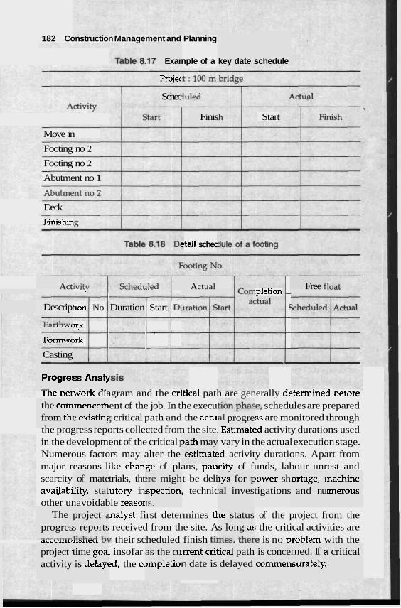
1 82 Construction Management and Planning
.I7 Exar nple of a key date . schedule
Projec
Schec
Finis Start
Move in
Footing no 2
Footing no 2
Abutment no 1
Deck
Finishir
?tail schec
- J ..- ~~ ipletion -
tion No Start Dl $ -
~ r k - --
jrk -
Act Actual Free f
Descrip Duration
LC11 C I 1 . l " \
Formwc
Casting -
Progre: d
ss Analy . .. lhe network diagram and the cntical path are generally determined before
I ent of the job. In the execu ;el schedules are prepared 5 critical path and the actu 'ss are monitored through
the progress reports collected from the site. bstnnated activity durations used in the development of the critical 1 vary in the actual execution stage. Numerous factors may alter the !d activity durations. Apart from major reasons like change of plans, paucitv of funds, labour unrest and scarcity trials, tht t be deli availabi utory in , technic other unavoidable reasor
lnalyst first determines tl of the project from the received from the site. A ; the critical activities are
QLLVILLCIIIDILCU U? their scheduled finish t k ~ r a , u~aie is no problem with the 1 insofar 2d, the cc
the corn from th~
Lmencem e existing a1 progre
- .
3ath may estimate
of mate ility, stat
. - -
- ?re migh .spection IS.
3ys for 1 :a1 inves
)ewer sh tigations
.ortage, I and nu
nachine unerous
The progres
project a s reports 1:nL-A I..
Ie status s long a:
&L-*
project I
activity time goa: is delayc
as the cu ~mpletio:
.rrent crii n date is
rned. If e ~surately.
1 critical ical path delayed
is conce commen
Time Management and Scheduling 1 83
In such a situation, a new critical path is created. There might be a number of ways for corrective actions. The activities can be crashed. Portions critical activities can be assigned to the sub-contractors to enlarl resources committed to the project. Critical activities can be re-stud--- .- create if possible an alternative path. For example, critical activities can be subdivided and run in parallel. A change in specification or relaxation of a standard may allow to shorten the critical path. The reduction of critical duration invariably increases the associated cost that is requir according to the provisions of the contract.
Once the corrective action is proposed after the analysis of the delav schedule is prepared and passed to the site personnel as a re and thus the cycle of progress reports and schedules are col completion of the project.
COMPUTER APPLICATIONS
Network analysis involves many repetitive calculat~~~ts atu 1s paluCulalIy suited for the use of computers. Since its early development and applications, computer techniques were an integral part for operation research methods like linear programming, Monte Carlo's simulation and network an-'---'- Although manual methods are successfully used, nf tice is almost impossible without computer aids.
The present-day revolution of information technology nas reaucea me
I price of personal or micro computers within the reach of mc construction industry. A situation is created to use projec
3 lot of cc 2 amoun
pmputer. t of time
. . *
prograrr nrnercial
1s are ah progran
!vised scl ntinued i
nalysis ir
~~ - 2
st firms :t manag
work. A 1 I in evah . . ;o availal 1s along
, aware
e main F
of the ;e the' id tn
;ha red
a new ~edule till the
in the ;emen t
techniques widely. Therefore, project management involves i project
analyst is required to spend a considerablc lation, maintenance and management of software systems which is beyond the scope of this book. Numerous commercial ble for construction project management. Such cor with a few tailor-made support programs are sufficient for most project analysis. The scenario in computer programs are rapidly changing and information about commercial computer programs is bound to be dated within a short time. However, a few of the commercial programs in the field of project management are presented in Table 8.19 as reference. The detail program listings of these softwares are not available for commercial reasons. The alogrithms for solutions are mentioned so that a user is 01
Most commercial packages have the following parts. Thc )o consists of the algorithm similar to those discussed in the chapter the the basic calculations. The second part deals with the interaction w user. These programs are menu-driven and user-friendly. A user can
F the
rtion lt does ith the follow
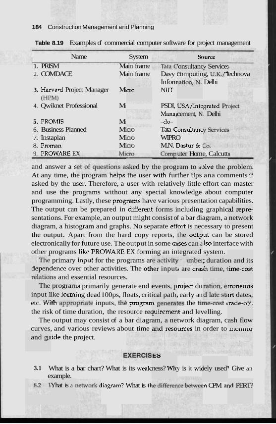
1 84 Construction Management arid Planning
Table 8.19 Examples of commercial computer software for project management
Name System 1. PRISM Main frame 2. COMDACE Main frame Davy computing, u .K. / lechnova
Inforn Delhi 3. Harvard Project Manager Mi NIIT
(HPM) 4. Qwiknet Professional Mi PSDI,
Manag 5. PROMIS Mi 40- 6. Business Planned Micro Tata Consu~tanc 7. Instaplan Micro WIPRO 8. Proman Micro M.N. Dastur & 9. PROWARE Ev
Sc
'onsultanc -
mrce :y Service: - - -- .-
cro
USA/Inte cement, N
grated Pr I. Delhi
uter Hom - e, Calcutt
sked by . ,
3lve the . and answer a s At any time, the program nelps tne user witn rurtner tips ana comments lr
asked by the user. Therefore, a user with relatively little effort can master and use the programs without any special knowledge about computer programming. Lastly, these programs have various presentation capabilities. The output can be prepared in differenl ncluding graphic sentations. For example, an output might f a bar diagram, a diagram, a histogram and graphs. No separate ettort is necessary to present the output. Apart from the hard copy reports, lut can be stored electronically for future use. The output in some ca ~lso interface with other programs like PROWARE EX forming an integrated system.
primary input for the programs ar lence over other activities. The otk
A L Z . . . ~ , ~ ~ and essential resources. 1s primarily generate end I roject du ing dead
4
100ps, floats, crit . early an etc. Wiul ayYlupriate inputs, the progran~ re~lrlates the tiiltc-LU~L LICIUC-UU.
the risk of time duration, the resource re( ~t and levelling. The output may consist of a bar diagr twork diagram, c
curves, and various reviews about time tutu lesuurces in order to Irturulur
lide the project.
the prog: .., r
problem. . .<
ram to sc ., . .
t forms i consist o
. *,
a1 repre- network
the outp lses can a
; duratio ;h time, 1
n and its :ime-cost depenc ker input s are cra:
The input 1
- -
prograrr ike form
events, p ical path, - - ^ ..-,
rroneous irt dates, .-- A - -LC
" piremen am, a ne --A ---a
ash flow
and gu
ES
ness? Wh 3.1 What is a bar chart? What is its weak] example.
liagram? What is tl-
y is it wic iely used' ? Give an
~d PERT? Yhat is a I !n CPM a1
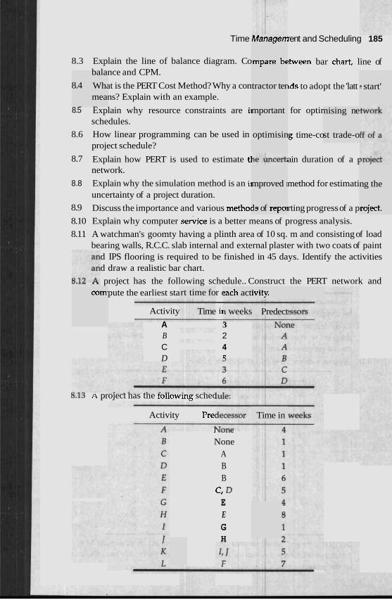
Time Mahagen
lmpare bc
rent and Scheduling 185
8.3 Explain the line of balance diagram. Co balance and CPM.
8.4 What is the PERT Cost Method? Why a con means? Explain with an example.
- -
!tween bar chart, line of
tds to adopt the 'latt tractor ter I start'
mportant
optimisin
8.5 Explain why resource constraints are ii schedules.
for optir nising ne
st trade-o 8.6 How linear programming can be used in project schedule?
8.7 Explain how PERT is used to estimate tl network.
g time-co
ain duration of a 1
8.8 Explain why the simulation method is an i~ uncertainty of a project duration.
method for estimati mproved I
3s of repol
ng the
roject. 8.9 Discuss the importance and various methoc rting progress of a p
8.10 Explain why computer s e ~ i c e is a better means of progress analysis.
8.11 A watchman's goomty having a plinth area of 10 sq. m and consisting of load bearing walls, R.C.C. slab internal and external plaster with two coats of paint
d IPS flooring is required to be finished in 45 days. Identify the activities d draw a realistic bar chart.
L.-, . . project has the following schedule.. Construct the PERT network and pute the earliest sta r ( -
Activity ii - A 3 B 2 C 4 D C
comi rt time fo ?ach act ivity.
Time I weeks Predect
&.la n project nas tne rollowlng scnec
Activity Prec Time in
1 uu, ,c
None A B B
c, D E E G H
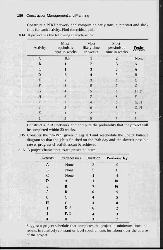
1 86 Construction Management and Planning
Construct a PERT network and compute an early start, a late start and slack time for each activity. Find the critical path.
8.14 A project has the following characteristics:
Most Most Most Activity optimistic likely time pessimistic Prede-
cessors time in weeks in weeks time in weeks
A 0.5 1 2 None
B 1 2 3 A
C 1 3 5 A D 3 4 5 B
Construct a PERT network and compute the probability that the project will be completed within 30 weeks.
8.15 Consider the probIem given in Fig. 8.3 and reschedule the line of balance diagram so that the job is finished on the 29th day and the slowest possible rate of progress of activities can be achieved.
8.16 A project characteristics are presented here:
Activity Predecessors Duration Workers/day
A None 3 9
B None 5 6
C None 1 4
D A 1 10
E B 7 16
f B 6 9
G C 4 5 H C 3 8
I D, E 6 2 '
1 F, G 4 3 K H 3 7
Suggest a project schedule that completes the project in minimum time and results in relatively constant or level requirements for labour over the course of the project.
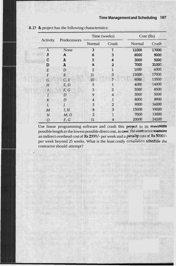
Time Management and Scheduling
8.17 A project has the following characteristics:
Time (weeks) Cost (Rs) Activity Predecessors
Normal Crash Normal Cras
A None 3 I 11000 17000 B A 6 3 6000 9000 C A 5 4 3000 5000 D A 8 2 7000 3100
2, the cont ~enalty co . --. .- 1 -*: -.
Use linear programming software and crash this project to its mini^..^.,.
possible length at the lowest possible direct cost, in casf tains an indirect overhead cost of Rs 2000/- per week and a 1 KK)/-
per week beyond 25 weeks. What is the least costly cornmerlun scrleuue the contractor should attempt?
ractor sus st of Rs 5C - --I--J..l

Quantitative Management Applications
INTRODUCTION
Nowa years. -..*.,.-
days, pr~ The inte.
we coml ,ng the ac , , ,,, r r
jlex and ztivities E \.---*:L^L
1 for a n st impli~ C - - - l --
LINEAR PROGRAMMING
cial. ters with quantita
. - . . . . - , . .
oject operations i may rur umber of rrelationship amc n d the cc cations of
YsVJCLLJ u l a y llot be always a p p l ~ ~ ~ . v ~ a l ~ ~ ~ d ~ i v e and i u n r t d ~ dnalysis of operations may in many cases prove to be benefi
Operation research (OR) provides decision ma1 tive basis for decision making. The advent of low-priced microcompurers having adequate capacity has eased the use of OR even by smaller firms.
The techniques of network analyses like PERT and CPM are widely known to the civil engineers. Other OR techniques like linear programming, trans- portation models, queuing theory and Monte Carlo simulations can also be very useful in the analysis of projects. A few of the techniques are discussed in this chapter. The descriptions are purposefully brief and the readers are encouraged to read other OR texts to obtain a complete idea about the several OR topics. It is assumed that project engineers use the readymade computer softwares to apply the techniques. Therefore, a basic understanding of the techniques is generally sufficient to the practising project engineer
aracterisl tics of tl
Linear programming is a mathematical technique for finding the optional uses of an organization's resources. The word linear refers to the assumption that the variables are linearly related. The ch he linear programming are presented here:
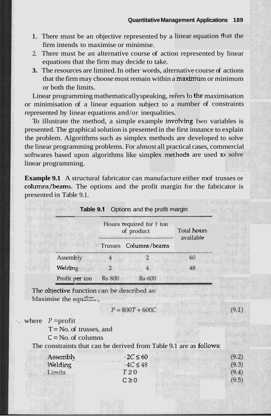
Quantitative Management Applications 189
1. There must be an objective represented by a firm intends to maximise or minimise.
2. There must be an alternative course of action represented by linear equations that the firm may decide to take.
3. The resources are limited. In other words, alternative course of actions that the firm may choose must remain within a m or minimum or both the limits.
Linear programming mathematically speaking, rerers to tne maximisation or minimisation of a linear equation subject to a of constraints represented by linear equations and/or inequalities.
To illustrate the method, a simple example involving two variables is presented. The graphical solution is presented in the first instance to explain the problem. Algorithms such as simplex methods are developed to solve the linear programming problems. For almost all practical cases, commercial softwares based upon algorithms like sim .hods are used to linear programming.
plex met
linear eq
maximu
r . .*
number
. . .
uation tl \at the
Example 9.1 A structural fabricator can manufacture either roof trusses or ' colurnns/beams. The options and the profit margin for the fabricator is presented in Table 9.1.
The 01 hAq";..
Asseml
Weldin
Profit 1 - )jective fi
Table 9
)er ton
unction c .n*. -+;-- lvLaAu;lise the EY u a r l v i L,
1.1 Optio ns and th e profit m,
luula required fcJl 1 L L j 1 1
of product
Trusses Columns/beams
argin
Total hoi availab
urs le
.. . where P =profit T = No. of trusses, and % = No. of columns
The constraints that can be derived from Table 9.1 are as iollows:
issembly 2C560 Velding 4 C 5 4 8 .imits -p 2 0
C 2 0
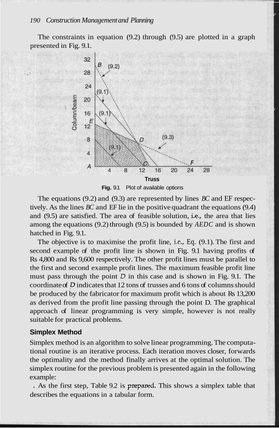
190 Construction Management and Planning
The constraints in equation (9.2) through (9.5) are plotted in a graph presented in Fig. 9.1.
Truss Fig. 9.1 Plot of available options
The equations (9.2) and (9.3) are represented by lines BC and EF respec- tively. As the lines BC and EF lie in the positive quadrant the equations (9.4) and (9.5) are satisfied. The area of feasible solution, i.e., the area that lies among the equations (9.2) through (9.5) is bounded by AEDC and is shown hatched in Fig. 9.1.
The objective is to maximise the profit line, i.e., Eq. (9.1). The first and second example of the profit line is shown in Fig. 9.1 having profits of Rs 4,800 and Rs 9,600 respectively. The other profit lines must be parallel to the first and second example profit lines. The maximum feasible profit line must pass through the point D in this case and is shown in Fig. 9.1. The coordinate of ,D indicates that 12 tons of trusses and 6 tons of columns should be produced by the fabricator for maximum profit which is about Rs 13,200 as derived from the profit line passing through the point D. The graphical approach of linear programming is very simple, however is not really suitable for practical problems.
Simplex Method Simplex method is an algorithm to solve linear programming. The computa- tional routine is an iterative process. Each iteration moves closer, forwards the optimality and the method finally arrives at the optimal solution. The simplex routine for the previous problem is presented again in the following example: . As the first step, Table 9.2 is prepared. This shows a simplex table that
describes the equations in a tabular form.
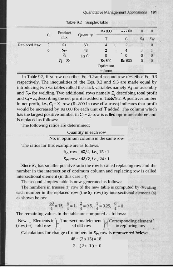
Quantitative Man agement ,
Table 9.2 Simplex table
Rs 800 .,, L
Cj Quantity mix T C
Replaced row 0 s A 60 4 ,I, 2
0 Sw 48 2 , 4 0 z~ Rs 0 0 ' 0 0
Cj - Zj Rs 800 Rs 600 0 Optimum column -
In Table 9.2, first row describes Eq. 9.2 and second row aescri~es Eq. 9.3 respectively. The inequalities of the Eqs. 9.2 and 9.3 are made equal by introducing two variables called the slack variables namely SA for assembly and Sw for welding. Two additional rows namely ZJ describing total profit and Ci - ZI describing the net profit is added in Tab& 9.2. A positive number in net profit, i.e., Ci - Z, row (Rs 800 in case of a truss) indicates that profit would be increased by Rs 800 for each unit of T added. The column which has the largest positive number in Ci - Zi row is callc is replaced as follows:
The following ratios are determined:
~d optim nn and
Quantity in each row No. in optimum column in the same row
The ratios for this example are as follows:
SA row : 60/4, i.e., 15 : 1
Sw row : 48/2, i.e., 24 : 1
Since SA has smaller positive ratio the row is called replacing row and the number in the intersection of optimum column and replacing row is called intersectional element (in this case ; 4).
The second simplex table is now generated as follows: The numbers in trusses (f ) row of the new table is computed by dl
each number in the replaced row (the SA row) by intersectic as shown below:
The remaining values in the table are computed as follows:
In repli
represen
New - Elements in Intersectional element (row)-( old row )-( of old row
Calculations for change of numbers in Sw row is
48 - (2 x 15) = 18
2- (2x 1)= 0
acing rov
lted be101
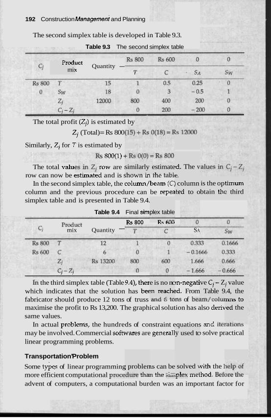
--
192 Construction ~ a n a ~ e m e n t and Planning
The second simplex table is developed in Table 9.3.
Table 9.3 The second simplex table
Prod- mi:
uct Quantity -
Y 1
The total profit (Zi) is estimated by
Zj (Total) = Rs 800
Similarly, Zj for 7' is estimated by
s 800(1) - similarly -1. .- -. '.
!d. The v The total valu~ row are ! row can now be esrlrnared and is snown m me ram
In the second simplex table, the column/beam (C: column and the previous procedure can be repea simplex table and is presented in Table 9.4.
estimate '1.. c - 1 - 1 e.
I column .ted to o
is the op btain thr
timum 2 third
Table 9.4 Final siml - RS 800 n a ovv
ci mix Quantity - SA
plex table D.. ~ n n
-1 -1
In the third simplex table (Table 9.4), ther which indicates that the solution has bee
e is no nc !n reachc ..-A I;. err
)n-negati !d. From
ve Cj- Z Table 9
.m Inrrl...
j value .4, the - n o C n fabricator should produce 12 tons of truss LlllCl L U ~ S of behlll, Culul
maximise the profit to Rs 13,200. The graphical solution has also derh same values.
,11115 L U
red the
In actual problems, the hundreds of constraint equations and itelaLlurLo may be involved. Commercial softwares are general1 ) solve practical linear programming problems.
y used tc
Transportation' Problem
Some types of linear programming vith the 1 more efficient computational proceuulr UlaL Lllc ~lllylm lltcihod. BeftJLc U l c
advent of computers, a computational burden was an important factor for
; problen A*-"- L L - .
IS can be - LL,. -:- solved t
.,I,., ,a4
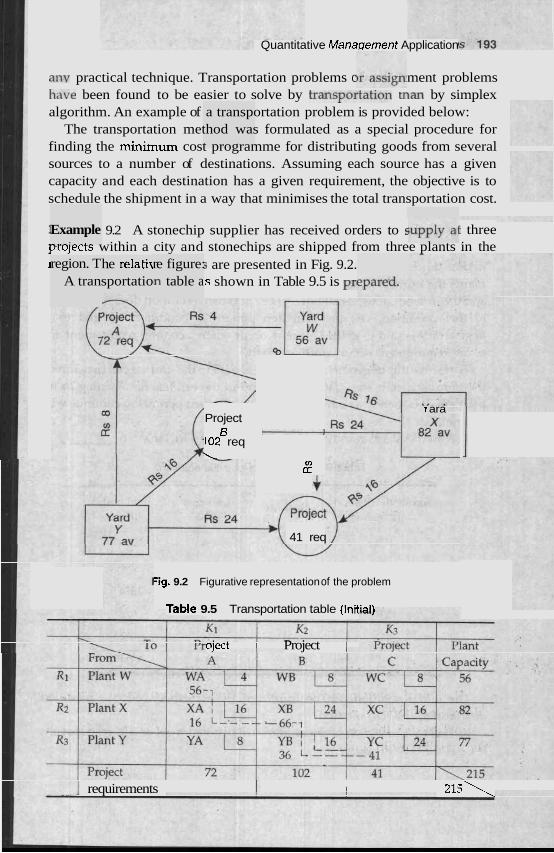
Quantitative Manaqement Application
any practical technique. Transportation problems c ment problems h<~ve been found to be easier to solve by t r a n s p o ~ ~ ~ ~ ~ ~ ~ ~ L L L ~ by simplex algorithm. An example of a transportation problem is provided below:
The transportation method was formulated as a special procedure for finding the minimum cost programme for distributing goods from several sources to a number of destinations. Assuming each source has a given capacity and each destination has a given requirement, the objective is to schedule the shipment in a way that minimises the total transportation cost.
Example -..-:. .. . - 1 9.2 A stonechip supplier has received orders to 5 : three prujeccs within a city and stonechips are shipped from three plants in the I 5 are presented in Fig. 9.2.
s shown in Table 9.5 is pa region. T
A tran he relatir sportatio
re figure: In table a
Project 5
102 req '.
V) u
41 req
r ara
-ig. 9.2 Figurative representation of the problem
TaMe 9.5 Transportation table (Initial\
oject Project i
1 requirements 1 I 1 2 1 5 1
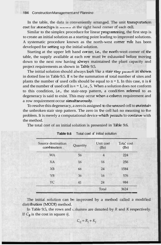
Construction Manaaement arru r r c n r r
In the table, the d ged. The ,n*,,, ,4
unit tra ' -"-h -.-,I
nsportati 1. cost for stonechips is J L I V V Y l l u 1 ULc LL511C llallu CVILICl CaLII Ccl
Similar to the simplex proceduce for linear programn first step is to create an initial solution as a starting point leading to d solutions. A systematic procedure known as the north-west c o ~ ~ t r l L U L ~ has been developed for setting up the initial sol
Starting at the upper left hand cor the table, the supply available at each row 111~s~ LJC exl~au>~t.u v r r u ~ t . I L L U V ~ ~
down to the next row having alway! nd project requirements as shown in Tab11
The initial solution should always loo^ l i ~ e a srair srey partern as srluwn in dotted line in Table 9.5. If n be the summation of total number of sites and plants the number of used cells should be equal to n - 1. In this case, n is 6 and the number of used cell is n - 1, i.e., 5. When a solution does not conform to this condition, i.e., the stair-step as degeneracy is said to exist. This may o nd
ning, the improve .,,, ,.1
ution. ner, i.e., ... -..- L 1
the nortl LA -..L--.
s mainta e 9.5. - -1. 1:1.-
ined the
- -L-1.. ..I
pattern, ccur whc :lv.
a condi !n a colul
ition reft nn requi
:rred to rement a
a row requirement occur sirnultaneou~_, .
To resolve this degeneracy, a zero is assigned 1 3in the unbroken stair step pattern. The zero in th he problem. It is merely a computational device whicn permts to contlnue with the method.
The total (
to the uni e cell ha!
1
used cell j no mea .. . ~ - -
to mainti ning to 1 .. .
I initial s bed in Tal ble 9.6. s preseni
. . . . 'able 9.6 Total co 1st of initia
rce destin combinatic
Unit Iota1 cos (Rs)
- a modifi
- n can bt red by a he initia
.1 . ' r
method lounon (MODI) method. 1 Table 9.5, the rows and c , is the cost in square ij,
are den0 espective
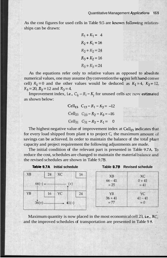
Quantitative Management Applicarions 1
As the cost figures for used cells in Table 9.5 are know1 ships can be drawn:
R1+K1= 4
R2+K1=16
R2+K2=24
R3+K2=16
R3+K3=24
As the equations refer only to relative values as opposed numerical values, one may assume (by convention the ul cell) R1 = 0 and the other values would be deduced K3 = 20, R2 = 12 and R3 = 4.
Improvement index, i.e., Cil -Xi - Ki for unused cells are nov
as shown below:
Celll3 C13 - R1 - K3 = -12
Cell23 C23 - R2 - K3 = -16
Cell31 C31 - R3 - K1 = 0
The highest negative value of improvement index at Cellz3 in, for every load shipped from plant x to project C, the maximum savings can be achieved. In order to maintain the balance of the total p12 capacity and project requirement the following adjustments are made.
The initial condition of the relevant part is presented in Table 9.7A. reduce the cost, schedules are changed to maintain the material t -
the revised schedules are shown in Table 9.78.
Tsbk 9.7A Initial schedule Table 9.7B Revised schedule
1 followi
,per left 1 . as K1 =
to absoli land con :4, K2=
v estimai
dicates tl amount . *
Maximum quantity is now placed in the most economical cell 23, i.e., X and the improved schedules of transportation are presented in Table 9 5.
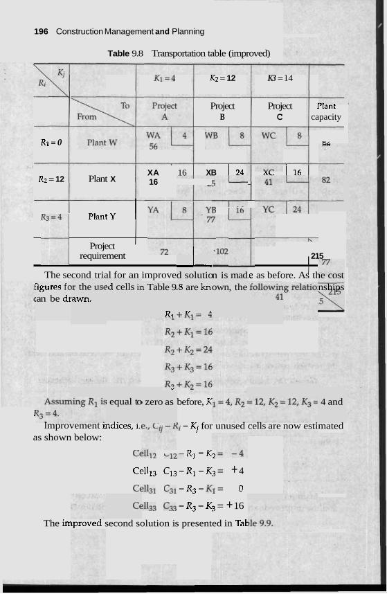
196 Construction Management and Planning
Table 9.8 Transportation table (improved)
K 1 = 4 Kz = 12 K3 = 14
Project Project 1- ant B C capacity
R1= 0 CL
XA 16 XB 1 2 4 AL 1 1 6 Rz = 12 Plant X 16 -
--
R 3 ~ 4 ~ yA72y';: ' l b I PlantY , 4l , ; Project
requirement 215
The second trial for an improve 'igures fc :an be dr
,r the us6 'awn.
!d cells i~ I Table 9
R ,
L d solutio .8 are knl
. T I A
i equal to
-. I
1 I lmprovement mdlces, i.1
as shown below:
d
I zero as
n is mad own, the
le as before. As the cost nships
before, K
!i - Kj for unused cells are now estimated
CC*-*~ -,L- R1 - K-
Celll3 C13 - R1 - K3 = + 4
Cell31 C3i - R3 - KT = 0
Cell33 C33 - R3 - K3 = + 16
The irnprovea second solution is presented in Tat
: 4 and
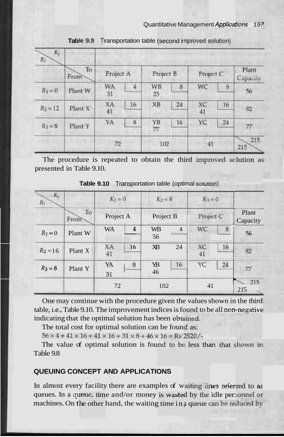
Quantitative Management Applicat~ons 19;
ransportation table Tab T I I
(second i~
Plant P--- -:*--
lution a! The procedure is repeated to obtain the th presented in Table 9.10.
ird imp1
Table 9.10 Transportation table (optimal sotutlnnl
Project A Project B --
R1= 0 Plant W WA 1 4 WB I 4
56 - ""
R2 =16 Plant X 16 XB 24 -
YA 1 R3 = 8 Plant Y 31 8 YB 1 YYL
46 . 72 102 41 --.
21 5
Plant Capacity
56
One may continue with the procedure given the values shown in the third table, i.e., Table 9.10. The improvement indices is found to be all non-negative indicating that the optimal solution has been obti
The total cost for optimal solution can be foun 5 6 ~ 4 + 4 1 ~ 1 6 + 4 1 ~ 1 6 + 3 1 ~ 8 + 4 6 ~ 1 6 = R s 2 5 2 U / - The value of optimal solution is fou
Table 9.8
d as: ---- ,
3 less th; m that s
QUEUING CONCEPT AND APPLICATIONS
In almost every facility there are examples of w queues. In a q~ e and/or money machines. On t' hand, the waiting
les refer] idle per:
red to as leue, tim he other
is waste1 ; time in ,
d by the a queue (
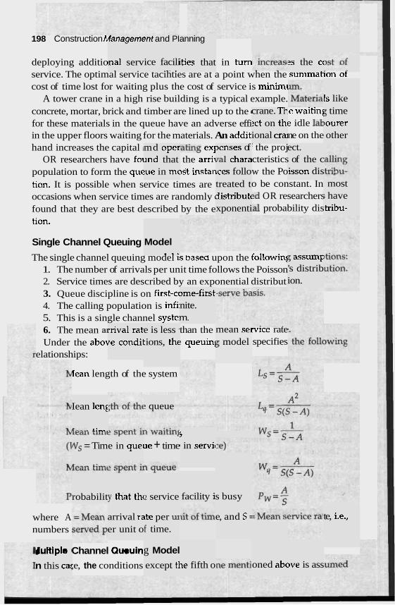
198 Construction h (anagemt
lnal serv
ent and PI
ice facili .a. .
anning
[ties that deploying additio in turn service. The optimal service tacihties are at a point when the summat~on of cost of time lost for waiting plus the cost of service is minimi
A tower crane in a high rise building is a typical example. -.
concrete, mortar, brick and timber are lined up to the (
for these materials in the queue have an adverse effi in the upper floors waiting for the materials. An addit hand increases the capital i *ating ex]
OR researchers have foi the arri~ population to form the que )st instar tion. It is possible when service times are occasions when service times are randomly I
found that they are best described by the e tion.
2s the cc
1s like crane. Th ?ct on th~ ional cra
le waitin! e idle lab ne on the
5 time jourer other
md ope1 md that !ue in mc
3enses of ,a1 chara lces follo
' the proj cteristics w the Po o be constant. In .d OR researchers .a1 probability dis
ect. of the c
isson dis treated t distributt xponenti
most ; have tribu-
Single Channel Queuing
The single channel queuing model IS Dasea upon the followinl 1. The number of arrivals per unit time follows the Poisson 2. Service times are described by an exponential distribut 3. Queue discipline is on first-cc 4. The calling population is infb 5. This is a single channel systei 6. The mean a1 Under the a b o ~
elationships:
Model . .. 5 assumF
's distrib ion.
)me-first, nite. m.
rrival rat1 re condil
e is less i :ions, the
than the ! queuinl
mean sei 5 model
wce rate specifies
Iean length of the system
Iean l e n ~
r--- &:-.
? queue
5
5 in servic Ws = Tim
a,,- a:-.
e in quei xe + time
facility i robabilit y tliat thc 2 service s busy
where A numbers
arrival re er unit o
e, and S = te, i.e., ~ t e per u~ f time.
Sultiple I
n this ca:
g Model
except tl
Channel Queuin~
;e, the conditions oned abc le fifth o )ve is ass
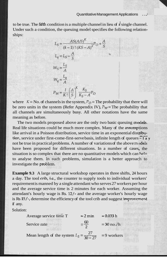
I Quantitative Management Applications . - - I
to be true. The fifth condition is a multiple channel in lieu of d single channel. Under such a condition, the queuing model specifies the following relation- ships: 1
where K = No. of channels in the system, Po = The probability that there will be zero units in the system (Refer Appendix IV), Pw = The probability that all channels are simultaneously busy. All other notations have the same meaning as before.
The two models proposed above are the only two basic queuing meA-'- Real life situations could be much more complex. Many of the assump like arrival in a Poisson distribution, service time in an exponential dist tion, service under first-come-first-serve basis, infinite length of queues not be true in practical problems. A number of variations of the above mc have been proposed for different situations. In a number of cases situation is so complex that there are no quantitative models which can rlerv
to analyse them. problems, simulation is a better approac investigate the pro1
I U C I J .
tions ribu- ---- ~ l a y ~de l s , the L -1-
Example 9.3 A large structural workshop operates in three shifts, 24 hours a day. The tool crib, i.e., the counter to supply tools to individual workers' requirement is manned by a single attendant who serves 27 workers per hour and the average service time is 2 minutes for each worker. Assuming the attendant's hourly wage is Rs. 12/- and the average worker's hourly wage is Rs 15/-, determine the efficiency of the tool crib and suggest i rnp rove~~n t if any. I
Solution: I
Average service t h e T =2min =0.033 h
Service rat( - 60 -- 2
= 3(
27 Mean length of the system Ls = ----- = 9 workers
30 - 27
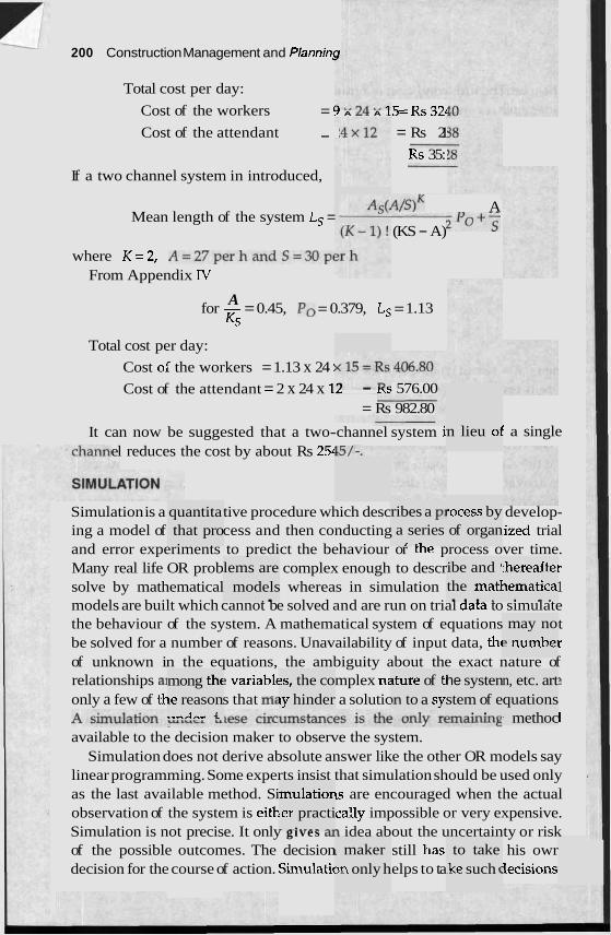
200 Construction Management and Planninp
Total cost per day:
Cost of the workers = 5 A L* A 15= Rs 328
Cost of the attendant - - = Rs 21
Rs 35:
If a two channel system in introduced,
A/slK A P O + ?
(KS - A) Mean length of the system Ls =
where K=2, A=27perhandS=30pi From Appendix IV
A for - = 0.45, Po = 0.379, Ls = 1.13 Ks
Total cost per day:
Cost ol' the workers = 1.13 x 24 :
Cost of the attendant = 2 x 24 x 1, - L; 576.00 = Rs 982.80
n lieu 01 I a single It can now be suggested that a two-channel system i el reduces the cost by about Rs 254
rocess by of organ
Simulation is a tive procedure which desc develop- ing a model of cess and then conducting ized trial and error experiments to predict the behaviour or tne process over time. Many real life OR prob complex enough to descr r solve by mathematical whereas in simulation 1 models are built which cannot be solved and are run on trial aata to simulate the behaviour of the system. A mathematical system of equations t be solved for a number of reasons. Unavailability of input data, thc r
of unknown in the equations, the ambiguity about the exact nature of relationships a1 : variablt mplex n: ?
only a few of tl- s that me a solutic I
available to the decision maker to observe the system. Simulation does not derive absolute answer like the other OR models say
linear programming. Some experts insist that simulation should be used only as the last available method. Si 1s are encouraged when the actual observation of the system is eith cally impossible or very expensive. Simulation is not precise. It only gives m idea about the uncertainty or risk of the possible outcomes. The decision still has his owr decision for the course of action. Sirnulatic elps to ta lecisions
quantita that pro
ribes a PI a series ,- .3
lems are models
. . ibe and i the mat1 . . . .
thereaftel ~ematica . . .
may no 2 numbei
mong thc Le reason .. ..A,... +l.
3s, the co ly hinder
tture of E ,n to a sy,
he systen stem of e
. .
n, etc. art quations ; methoc
mulatior :er practi - - - - - - - -
to take ,ke such (
I maker sn only h
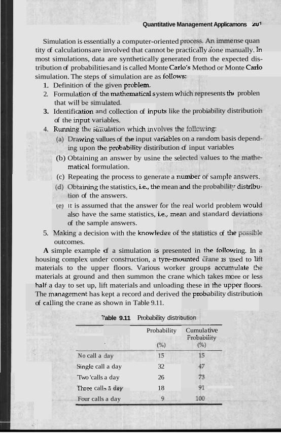
Quantitative Management Applicamons zu
Simulation is essentially a computer-oriented I tity of calculations are involved that cannot be practically aone manually. 11. most simulations, data are synthetically generated from the expected dis- tribution of probabilities and is called Monte Carlo's Method or Monte Carlo simulation. The steps of simulation are as follow=.
1. Definitic 2. Formula
that will vc 3U11L
3. Identific on of in^ of the ir
4. Runnine LAIC ~UILUICILIUIL v~hich int v l v c a nLc lvllv vv
nse quan T
)D of the .tion of tl. I LA -4-..
given pr le mathel ,l"t,-.A
.oblem. matical s. ystem wl esents thc problen
LlaLcu. 1 collecti ables. ..l-L: -,
)uts like
.-I-?,." 4 . h .
the probi
n L.llnT.,;
ation an( put vari - LL -:-
ability di
* l T .
stributioi
lom basi variables
lues of th e probab
le input \ ility disti
rariables ribution I
on a ran( of input
s depend lwing val upon thl
(b) Obtaining an answer by usine the sel matical formulation.
lues to tl
' 1 - (c) Repeating the process to generate a numDer or sample answers.
:aining the statistics, i.e., th 1 of the answers.
(el ~t is assumed that the answer tor tne real world problem woulc ) have the same statistics, andard c
he sample answers.
5. L V L ~ K U I ~ a decision with the knowleure ul U L ~ b~a~latics of thc ~ U ~ L U I
outcomes. A simple example I ulation i ring. In
housing complex under consrruction, a ryre-mounreu craw 1s used to lii materials to the upper floors. Various worker group ulate th materials at ground and then summon the crane which )re or les 1 (lr day to set up, lift materials and unloading these in me upper floors
~anagement has kept a record and derived ability distributioi ling the crane as shown in Table 9.11.
le mean a
,- .. nd the PI r distribu
1
alsc of t
1 2-1.:- -
i.e., mee
l - J - - -< 1
~n and st
LL- -L-L:,.
ted in tl ...- L - 2 --
le follow . - - - - - - -
of a sim .- .-,
s presen L . . . . - --
-
s accurn takes mc . LL - nalr a
The n of cal:
the probi
'able 9.11 Probability distrit - tive .. . Probability Cumula - . ,.
No call a
jingle call a day 32
Two 'calls a day 26
Three call- - -'--. 18 3 a uay
a day Four calls
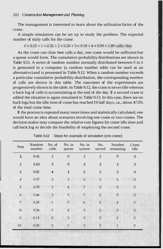
202 Construction Management and Planning
The management is interested to learn about the utilisation factor of the crane.
A simple simulation can be set up to study the problem. The expected number of daily calls for the crane:
As the crane can clear two calls a day, one crane would be sufficient but a queue would form. The cumulative probability distributions are shown in Table 9.11. A series of random number normally distributed between 0 to 1 is generated in a computer (a random number table can be used as an alternative) and is presented in Table 9.12. When a random number exceeds a particular cumulative probability distribution, the corresponding number of calls are shown in this table. The outcomes of the experiments are progressively shown in the table. In Table 9.12, the crane is never idle whereas a back log of calls is accumulating at the end of the day. If a second crane is added the situation is again simulated in Table 9.13. In this case, there are no '
back logs but the idle time of crane has reached 19 half days, i.e., about 47.5% of the total crane time.
If the process is repeated many more times and statistically calculated, one would have an idea about scenarios involving one crane or two cranes. The decision maker may compare the relative cost figures for crane idle time and call back log to decide the feasibility of employing the second crane.
Table 9.12 Steps for example of simulation (one crane)
Step Random No. of No. in No. in No. Number Crane number calls queue system served remaining idle
1 0.41 2 0 2 2 0 0
2 0.63 3 0 3 2 1 0
3 0.92 4 1 5 2 3 0
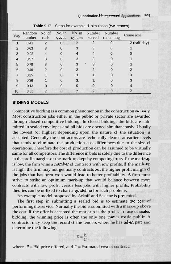
I Quantitative Managerrrarrc nrplicafions ""*
in No. le syste
Table 9.13 Steps for example of simulation (two cranes)
Random No. of No. in Number Number Crane idle Step number calls q u e ~ ,rn served remaining 1 0.41 2 0 2 0 2 (half day)
2 0.63 3 0 3 3 0 1
3 0.92 4 0 4 4 0 0
4 0.57 3 0 3 3 0 1
5 0.78 3 0 3 ' 3 0 1
6 0.46 2 0 2 2 0 2
7 0.25 1 0 1 1 0 3
8 0.36 1 0 1 1 0 3
9 0.13 0 0 0 0 0 4
BIDDWG MODELS
Competitive bidding is a common phenomenon in the construction maustry. Most construction jobs either in the public or private sector are awarded through closed competitive bidding. In closed bidding, the bids are sub- mitted in sealed envelopes and all bids are opened simultaneously. Usually the lowest (or highest depending upon the nature of the situation) is accepted. Generally the contractors are technically cleared at earlier levels that tends to eliminate the production cost differences due to the size of operations. Therefore the cost of production can be assumed to be virtually same for all competitors. The difference in bids is solely due to the difference in the profit margins or the mark-up kept by competing firms. If the mar' is low, the firm wins a n ~ ~ m b e r of contracts with iow profits. If the mar is high, the firm may not get many contracts b ~ t the higher profit marg the jobs that has been won would lead to better profitability. A firm must strive to strike an optimum mark-up that would balance between more contracts with low profit versus less jobs with higher profits. Probability theories can be utilized to chart a guidelhe for such problems -k~ example model proposed by Ackoff and Sasiene is presc The first step in submitting a sealed bid is to estimate tne co:
performing the service. Normally the bid is submitted the cost. If the offer is accepted the mark-up is the p bidding, the winning price is often the only one th contractor may keep the record of the tenders where determine the following:
where P = Bid price offered, and C = Estimated cost (
with a m rofit. In (
at is ma he has t~ tken part
k-Up k-up in of
bove !sled ic. A
204 Construction Management and Planning
The probability that one has the lowest bid is the probability that P/C is less than a random variable that is normally distributed about p with standard deviation o. The probability is
The expected profit is given as
P=(p-c)f[$)
In order to maximise P with respect to p the first derivative is el zero
P Assuming y = Z, L
f(Z)+(Z-l)f'(Z)=O andif Z = p + f o ,
and
Thus t t satisfies
derers m
IY
in Fig. 5
I GAME THEOF
).3. The (
quated tc
, The above relabonshlp can be solved krom me standard normal tables available in the statistical handbooks.
The relationship is plotted in a graph )ptirnum 3
can be estimated from the graph. However, a number of simplified assump- tions are implicit in the approach. For example, it is assumed that competitors would not be influenced by each other. In real life cases, the presence of
-- competing ten~ ~lter the behaviour of a contractor.
lation in I which t
here a gz non-zerc
which m he outco
.ore than me is the
one deci! result of
sion mak the coml
kin of onc )-sum ga
may no1 : be equa
A game is a sit1 er chooses courses of acthn and u sination of choices taken by partic,-..,.
The games where some players gain more than others at the CI I
are called competitive games. A game with two players where f player equals the loss to the other is known as a two-person zero-sum game. In the game w- may or e
other is called me. 1 to the 1'
onclusiol a gain o
OSS of thc
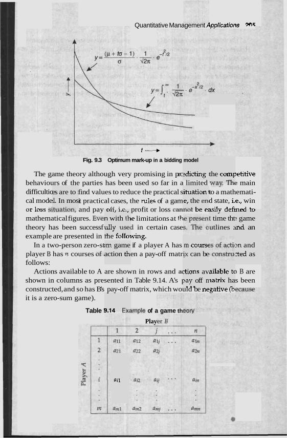
Quantitative Management Applicatiorc m*
t ---+ Fig. 9.3 Optimum mark-up in a bidding model
2dicting ; The game theory although very promising in prc )etitive behaviours of the parties has been used so far in a limited way. IIL~ main difficultic find values to reduce the practical s to a mathemati- cal mode it practical cases, the rules of a gam d state, i.e., win or loss S~LU~LLUII, and pay -" ' - profit or loss canrlui ve easilv defi--" '-
the comF ..7--7 I%.
es are to j 11. In mos ,.---c--
ituation i .el the en1 --L L- -.
UIIl 1.5.'
n with th Ileu LU
? game ind an
-I
t time tht mathematical figures. Eve] le limitations at th theory has been successf d in certain case example are presented in me rollowing.
In a two-person zero-st if a player A has player B has n courses of4 en a pay-off matr follows:
Actions available to A are shown in rows and a( shown in columns as presented in Table 9.14. A's I constructed, and so has B's pay-off matrix, which would be negatlve (D
ully Use( 4 1 r-11
utlines 2
sn and cted as
Im game action th,
m coursc & can be
2tions av 2ay off n . ..
> B are s been
ailable tc natrix ha
.. "
it is a zero-sum game). - -
D id E v c Table '1. ., Lfidmple of a game th
Play
ail
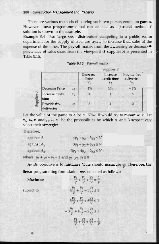
ling rct~on Management and ~ a n r
There are les. However, linear programmmg tnat can De usea as a genera method of solution is shown in ~ple. Example 9.4 Two 1 21 distrik :tor department for the supply of steel are trymg to mcrease their sales at the
ense of t % 2entage c l in le 9.15.
various method: ; of solvi . 3 .
ng such two pers sum gaIY
the exan arge stec ublic sec . .
he other. )f sales s
The -pa! ?-off mat n the vit
- - :rix from the incn
of supplj hare fro1 Per' Tab
Tabl
cease Increase credit tim~
Y2 - -.
Provic e deliv
Y
le free rice I
Y1
eries 3 --.
'rice a
edit a Increase cr 1 time 'rovide frc eliveries
the value of the game to A be V. Now, B would try to minirnise V. Let
ely
Let probabil ities by which A and B 1 respectiv I Yl, Y2. Y:
trategies be the X11 X21. X3 and
select their s
gamst A:
P
line,
is B's objective is to mm11 nise V, 1-
ion can 1:
le should maximj
)e stated as follow
.erefore, the
ar programming fonnulat
daximise
--A LA
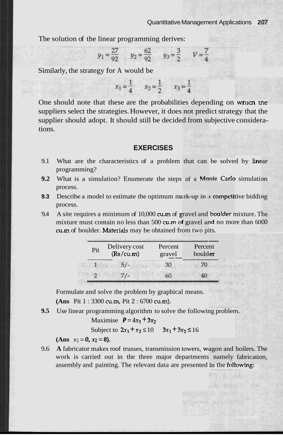
Quantitative Management Applications 2
The solution of the linear programming derives:
Similarly, the strategy for A would be
One should note that these are the probabilities depending on wnlcn t., suppliers select the strategies. However, it does not predict strategy that the supplier should adopt. It should still be decided from subjective considera- tions.
EXERCISES
9.1 What are the characteristics of a problem be solved by linc programming?
9.2 What is a simulation? Enumerate the steps uL ~"~"nte Carlo simulati process.
9.3 Describe a model to estimate the optimum ma tive biddi process.
9.4 A site requires a minimum of 10,000 cu.m of g woulaer mixture. T mixture must contain no less than 500 cu.m 01 ~d no more than 60 cu.m of boulder. MateriaIs may be obtained from two pits.
Pit Delivery cost Percent (Rs/cu.m) gravel p- - - - --
that can
-I= - 1.4-
ravel and ' gravel a1
Perce bould
3 competi
1 3 ,
- nt ler
Formulate and solve the problem by graphical means.
(Ans Pit 1 : 3300 cu.m, Pit 2 : 6700 cu.m).
9.5 Use linear programming algorithm to solve the following probler
Maximise P = 4x1 + 3x2
Subject to 2x1 + x2 I 10 3x1 + 3x2 5 16
(Ans XI = 0, x2 = 8).
9.6 A fabricator makes roof trusses, transmission towers, wt work is carried out in the three major departments assembly and painting. The relevant data are presented In tne rollowlng:
agon and i namely . ., ,- .>
boilers. T fabricatic
, .
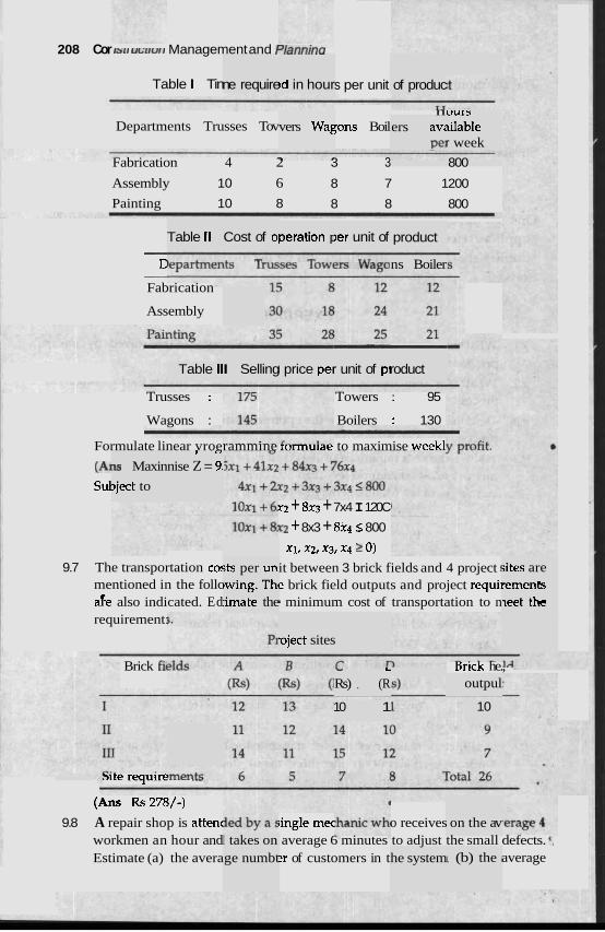
208 Cor 13t1 u~~rurr Management and /-~arrnrnu
Table l Tin s per unit
n ;ens Boil
ne require !d in hour of produc
vers Wag ours ~ilable r week
Departments Trusses Tov ers av; Pel
Fabrication 4 2 3 3 800
Assembly 10 6 8 7 1200
Painting 10 8 8 8 800
Table II Cost of 01 peration F )er unit of product - D -
Fabrication
ns Boiler
Assembly
- - unit of pl
- roduct I Selling I price pel Table II
Trusses : Towers : 95
Wagons : Boilers : 130
Formulate linear vroerammine rormulae to maximise week1
(A1 Sul
1s Maxin
~ject to
1 . 2
nise Z = 9!
K2 + 8x3 + 7x4 I 120C
~2 + 8x3 + 8x4 < 800
Xl, x2, x3, x4 2 0) it between 3 brick fields and 4 project ! e brick field outputs and project requii b minimum cost of transportation to n
sts per un )wing. Tht rimate the
sites are rements ~ e e t thc
9.7 The transportation cor mentioned in the follc afe also indicated. Ed requirement:
-eject sites
Brick fit Brick he., - L
Rs) , (R
10 1
outpul
10
--te requlre
(Ans Rs 278/-)
on the av 9.8 A repair shop is attenc iingle mec o receives average 6 minutes to adjust the small defects. ', ~r of customers in t average
workmen an hour and Estimate (a) the avera
I takes on ge numbt I, (b) the i he system

Quantitative Ma t Applicati
number of customers waiting to be served, (c) average ti1 service.
(Ans (a) 0.67, (b) 0.267, (c) 4 minutes)
9.9 A construction firm is planning to purchase a special instrument. T ment on the average can perform 25 operations per month. The fir1 about 80 such operations per month in the next few montl
I
(a) How many instruments should the firm purchase? (b) What is the average number of operations in such a g
(Ans (a) At least 4 instruments, (b) 5.58 operations)
REFERENCE
1. Ackof and Sasiene. Fundamentals of Operntion Research. Wil 1968.
ey Easterr
ons 209
excluding
he instru- rn expects
I Limited,
I CHAPTER 10 1
Qualify Management and C-#etv
INTRODUCTION
., confom lance an
project r Quality control, which is a crucial part of nanagement, is generally given less importance when compared to other aspects of const Through quality control, the probability of finding a substandard pn estimated, thereby providing an index on the quality of the product
For the effective management of a quality control programme, a realistic and workable quality control design is required. To attain the quality criteria during the construction process, the specification of quality requirements in the design and contract documentation becomes extremely important.
After evaluating the owner's need the designer has to plan a facility that meets the requirements giving due consideration to time and cost constraints. The owner's needs are expressed in the form of specific criteria that guide the engineering and design process.
Once the quality of design is established, it is the construction manager's responsibility to adhere to the standards fixed by the designer. The project manager is required to evaluate the trade-offs between the quality of conformance and the cost of achieving the standards.
The quality of conformance is also influenced 'by number of factors namely, (i) methods of field construction, (ii) equipment capabilities, (iii) skills of the workmen, (iv) supervision standards, (v) quality of raw materials, and (v) quality control plan. Quality control is the responsibility of the designer during the design phase and that of the construction manager during the construction phase. Thus the qualitv of design and the quality of
z complt to eacl and the combined plan I other,
ruction. oduct is
Quality hanagemenr ana sarery ;n i
QUALITY CONTROL BY STATISTICAL METHOLa
; In this I chapter, the effori determines the quality of the constructed facility is to concentrate on the quality control plans.
A number of organisation charts can be made for ensuring quality and safety at construction sites. In the case of small sites, the project engineel undertakes this responsibility. In most cases, independent groups arc primarily responsible for quality and safety aspects.
Personnel from different organisations are involved in ensurin and safety standards. Each party directly concerned with the project have their own quality and safety inspectors. They may incluc from the owners, the architects, the prime contractors, tl. other contracting firms and various government agencies.
In developed countries, the main responsibility to adhere to quality conformance is generally assumed by the contract manager. In India, the architect's and owner's representatives normally supervise matters related to quality control. Occasional visits by tbe inspectors fr agencies such as the municipality, the labour department mental agencies are common.
For large projects, the contractor may maintain an inhouse department to ensure quality control. Such a department normally reports directly to the project manager or other senior management staff so that immediate correc- tive action could be taken if necessary. In addition to the on site inspections, samples of materials are commonly tested by specialised laboratories like the National Test House for compliance. Sometimes specialised firms like the x-ray weld tester, the remotely operated pipeline tester and the nondestruc- tive concrete tester are contracted to ensure proper quality control.
It is also important to monitor quality control parameters. The collection of accurate and useful information is important for maintaining quality standards. Preservation of documents like change orders, 'as built' drawings and accounting records are important for maintenance, modifications of plans and disputes that may arise.
A .
ie repres 1e subcol
.om the ;
and the statutory environ-
e inspec- L- L:--
In an ideal situation both raw materials and finished goods requirc tion and approval. Exhaustive or 100% testing of all materials can ut: L U I I ~ :
consuming and exceedingly expensive. Moreover, many major items like concrete testing require the destruction of a material sample, and hence exhaustive testing may not even be feasible. Thus, a small sample is exhaustively tested and inference on the production can be drawn using statistical methods. These are called statistical sampling techniques and have been developed particularly for the manufacturing industries. In recent years, statistical sampling is increasingly used in the cons truction : industry.
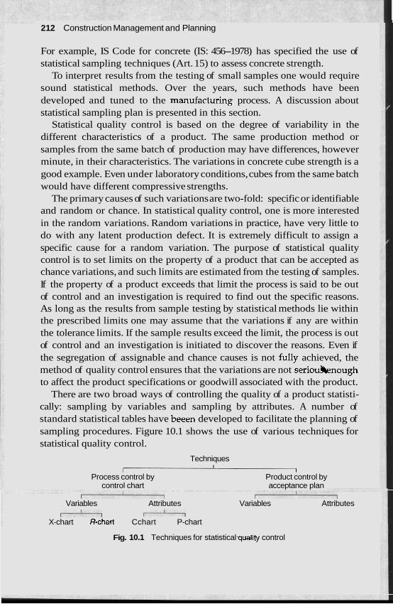
21 2 Construction Management and Planning
For example, IS Code for concrete (IS: 456-1978) has specified the use of statistical sampling techniques (Art. 15) to assess concrete strength.
To interpret results from the testing of small samples one would require sound statistical methods. Over the years, such methods have been developed and tuned to the manufact-uring process. A discussion about statistical sampling plan is presented in this section.
Statistical quality control is based on the degree of variability in the different characteristics of a product. The same production method or samples from the same batch of production may have differences, however minute, in their characteristics. The variations in concrete cube strength is a good example. Even under laboratory conditions, cubes from the same batch would have different compressive strengths.
The primary causes of such variations are two-fold: specific or identifiable and random or chance. In statistical quality control, one is more interested in the random variations. Random variations in practice, have very little to do with any latent production defect. It is extremely difficult to assign a specific cause for a random variation. The purpose of statistical quality control is to set limits on the property of a product that can be accepted as chance variations, and such limits are estimated from the testing of samples. If the property of a product exceeds that limit the process is said to be out of control and an investigation is required to find out the specific reasons. As long as the results from sample testing by statistical methods lie within the prescribed limits one may assume that the variations if any are within the tolerance limits. If the sample results exceed the limit, the process is out of control and an investigation is initiated to discover the reasons. Even if the segregation of assignable and chance causes is not fully achieved, the method of quality control ensures that the variations are not seriouknough to affect the product specifications or goodwill associated with the product.
There are two broad ways of controlling the quality of a product statisti- cally: sampling by variables and sampling by attributes. A number of standard statistical tables have beeen developed to facilitate the planning of sampling procedures. Figure 10.1 shows the use of various techniques for statistical quality control.
Techniques I
I I
Process control by Product control by control chart acceptance plan
Variables Attributes Variables Attributes &
A A X-chart R-chart Cchart P-chart
Fig. 10.1 Techniques for statistical .quality control
Quality Management and Safety 21 3
SAMPLING PLAN
Sometimes the quality characteristics of a product has a quantified or measurable value, e.g., the compressive strength of concrete or the tensile strength of the steel reinforcement. Such variables have continuous values and the frequency distribution would follow a Gaussian distribution. Control charts like the E-chart and R-chart are applicable here. The characteristic representing the quality of certain products cannot be quantitatively measured. These products are either acceptable or not acceptable. For
'example, the quality of a terrazo floor or french polish in a timber door is judged qualitatively by a trained professional. Statistically, the characteristics are discrete in nature and a Poisson distribution is applicable, Charts like the C, P and np are applicable.
-. whichever sampling plan is used, the assumption that the samples tend to represent the entire population remains unchanged. Samples are chosen at random so that each member of the population has an equal chance of being chosen. Convenient sampling plans like weighing every 15th dump truck or picking the top piece of marble from each of the delivery trucks are suitable only if the population is randomly mixed. Otherwise, care is taken to choose the samples at random.
CONTROL CHARTS
The statistical control charts can be used for a number of purposes. A few examples are described here:
1. A control chart describes the performance of a process system. It indicates when the process should be left alone or when corrective actions need to be initiated.
2. A control chart is used to detect the shifts in the average process from the desired level. Control charts are used to make future predictions of the performance of a system.
3. Since a sample is actually tested, the control chart saves cost.
4. ?'he concept of control charts can be extended to budgets and estimates. Estimated figures and actual values can be compared.
A short description of a few control charts are presented here:
%chart
2-chart is suitable to control continuous variables. The chart is constructed from samples called subgroups which are frequently drawn during a production process. Each subgroup may consist of 4 or 5 samples and around 25 subgroups are tested to prepare the %-chart.
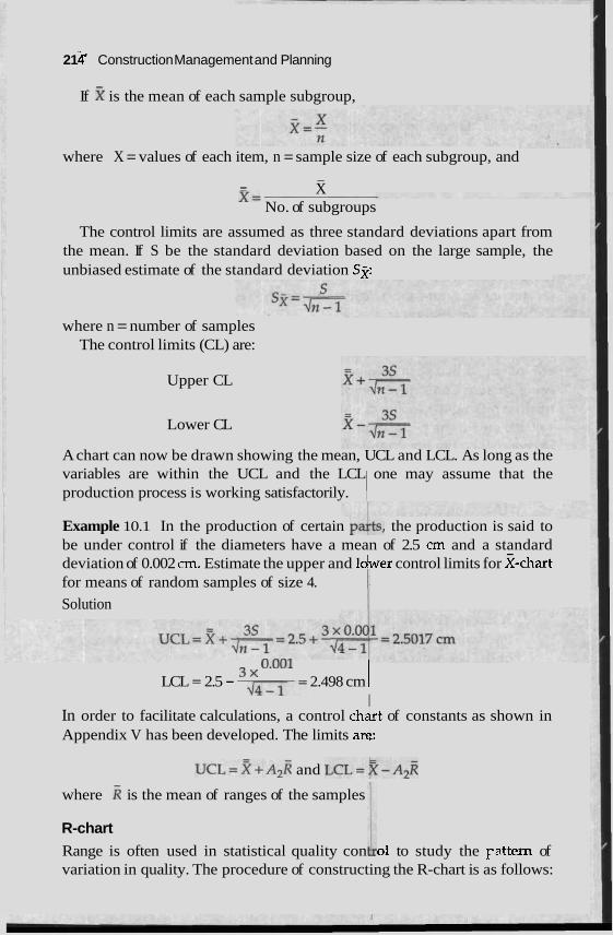
21 k Construction Management and Planning
If % is the mean of each sample subgroup,
where X = values of each item, n = sample size of each subgroup, and - - x= X
No. of subgroups
The control limits are assumed as three standard deviations apart from the mean. If S be the standard deviation based on the large sample, the unbiased estimate of the standard deviation Sji:
where n = number of samples The control limits (CL) are:
Upper CL
Lower CL
A chart can now be drawn showing the mean, UCL and LCL. As long as the variables are within the UCL and the LCL one may assume that the production process is working satisfactorily.
Example 10.1 In the production of certain pakts, the production is said to be under control if the diameters have a mean of 2.5 crn and a standard deviation of 0.002 cm. Estimate the upper and loher control limits for %-chart for means of random samples of size 4.
Solution
LCL = 2.5 - 0'001 2.498 cm / d G i =
I In order to facilitate calculations, a control ch&t of constants as shown in Appendix V has been developed. The limits ard:
U C L = R + A ~ R and L C L = ~ - A ~ R
where R is the mean of ranges of the samples
R-chart
Range is often used in statistical quality con 1 01 to study the pattern of variation in quality. The procedure of constructing the R-chart is as follows:
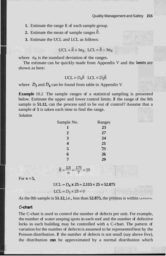
Quality Management and Safety 21 5
1. Estimate the range R of each sample group.
2. Estimate the mean of sample ranges R. 3. Estimate the UCL and LCL as follows:
where OR is the standard deviation of the ranges. The estimate can be quickly made from Appendix V and the li
shown as here: mits are
UCL = D ~ R LCL = D ~ R where D3 and D4 can be found from table in Appendix V.
Example 10.2 The sample ranges of a statistical sampling is presented below. Estimate the upper and lower control limits. If the range of the 8th sample is 51.12, can the process said to be out of control? Assume that a sample of 5 is taken each time to find the range.
Solution
Sample No. Ranges 1 23 2 27 3 24 4 21 5 '25
26 6 7 29
For n = 5, UCL = D4 x 25 = 2.115 x 25 = 52.875
As the 8th sample is 51.12, i.e., less than 52.875, the proc' ess is within cunrrul.
Cchart
The C-chart is used to control the number of defects per unit. For example, the number of water seeping spots in each roof and the number of defective locks in each building may be controlled with a C-chart. The pattern of variation for the number of defects is assumed to be represented best by the Poisson distribution. If the number of defects is not small (say above five), the distribution can be approximated by a normal distribution which
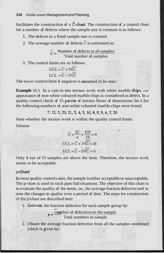
21 6 C~rra~r uhrrvri Management and Planning
facilitates the construction of a C-chart. The construction of a control chart for a number of defects where the sample size is constant is as follows:
1. The defects in a fixed sample size is counted.
2. The average number of defects E is estimated as:
- Number of defects in all samples C =
Total number of samples
3. The control limits are as follows:
U C L = C + ~ ~ ? -
LCL =c-3*
The lower control limit if negative is assur
Example 10.3 In a cast-in-situ terrazo work with white marble chips, u~t.
appearance of non-white coloured marble chips is considered as defect. In a quality control check of 15 pariels of terrazo floors of dimensions 2m x 2m the following numbers of non-white coloured marble chips were found.
7,12,3,20,21,5,4,3,10,8,0,9,6,7,20
State whether the terrazo work is within the quality control limits.
Solution
Only 3 out of 15 samples are above the limit. Therefore, the terrazo work seems to be acceptable.
In most quality control cases, the sample is either acceptable or unacceptable. The p-chart is used in such pass-fail situations. The objective of this chart is to evaluate the quality of the items, i.e., the average fraction defective and to note the changes in quality over a period of time. The steps for construction
chart are described here: . .
;timate the fraction defective for each sample group by:
btain the
I\] UI p = -
r average
"' nber of defectives in the sample Total numbers in sample
, fraction defective from all the samples cor nbined hich is g iven by:
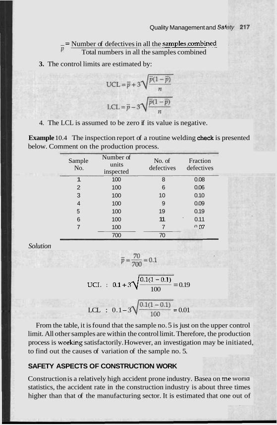
Quality Management and Saft
- Number of defectives in all the s a m p l e s r o m b ~ ' Total numbers in all the samples combined
3. The control limits are estimated by:
4. The LCL is assumed to be zero if its value is negative.
Example 10.4 The inspection report of a routine welding check is presented below. Comment on the production process.
Sample Number of No. of Fraction No. units defectives defectives
inspected 1 100 8 0.08 2 100 6 0.06 3 100 10 0.10 4 100 9 0.09 5 100 19 0.19 6 100 11 ' 0.11 7 100 7 n "7
700 70 - Solution
UCL : 0 . 1 + 3 4 O.l(J - 0.1)
100 = 0.19
LCL : 0.1-3 = 0.01
From the table, it is found that the sample no. 5 is just on the upper control limit. All other samples are within the control limit. Therefore, the production process is worlung satisfactorily. However, an investigation may be initiated, to find out the causes of variation of the sample no. 5.
SAFETY ASPECTS OF CONSTRUCTION WORK
Construction is a relatively high accident prone industry. Basea on tne worm statistics, the accident rate in the construction industry is about three times higher than that of the manufacturing sector. It is estimated that one out of
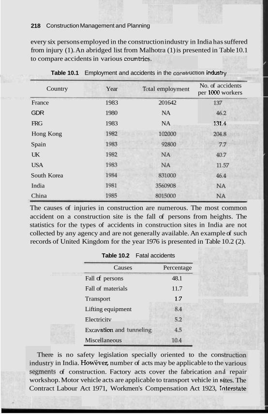
21 8 Construction Management and Planning
every six persons employed in the construction industry in India has suffered from injury (1). An abridged list from Malhotra (1) is presented in Table 10.1 to compare accidents in various countrie!
Table 10.1 Employment and accidents in the IQU U L U O ~ indust1
tal emplo Year Country No. of accidents yment per 1000 workers
France 1983 201642
GDR 1980 NA
FRG 1983 NA 131.4
Hong Kong
Spain
UK
USA
South Korea
India
China --
The causes of injuries in construction are numerous. The most common accident on a construction site is the fall of persons from heights. The statistics for the types of accidents in construction sites in India are not collected by any agency and are not generally available. An example of such records of United Kingdom for the year 1976 is presented in Table 10.2 (2).
Table 10.2 Fatal accidents
Causes Percentage
Fall of persons 48.1
Fall of materials 11.7
Transport .1.7
Lifting equipment
Electricitv
,ation and
llaneous
Excav
Misce - Ther
industr e is no safety legislation specially oriented to the cons y in India. How'ever, number of acts may be applicable to the
~ I Z ~ ~ L ~ I Z L ~ ~ S of construction. Factory acts cover the fabrication ana repair workshop. Motor vehicle acts are applicable to transport vehicle in sl Contract Labour Act 1971, Workmen's Compensation Act 1923, Ir
various 1
ites. The ~terstate

Quality Mal ra3Grr IGI rt and Safety 21 9
In each percenta .--
5. A feu
work sit1
examplt
abour tu
zs are p
mover, sl
resented
.asonal e
in the
mploy-
lvligranr Workers Act 1979, etc. have provisions to ensure partly the health, welfare and safety of construction workers.
The Indian construction industry has several special features which affect the safety and health of the workers as compared to the workers of the manufacturing industrie! r of the following:
Temporary duration of es, high 1 ment, extensive use of subcontractors, and high competition for jobs.
A construction site is by definition a temporary work site till the facility is built. The character of the work and associated risk profiles also change very quickly along with the progress of the work. For example, the shuttering and reinforcement placing work in a building is inherently riskier than the finishing works like carpentry and flooring. Temporary nature of works also causes temporary arrangements for electricity and explosive storage which are hazardous business. Temporary and open to environment access and pathways generally induce slippery steps, gangways without railings or handholds, etc. These factors caused by the temporary nature of the job create
. a high risk environment. In a factory, on the other hand, risk can be minimised with simple devices like machine guards, handholds and auto- matic switch-off mechanisms.
A construction site is associated with a high labour turnover. Workers routinely move from one site to another after the completion of their trade.
site, workers face typical risks that have to be encountered. A high Ige of workers who have a rural background go back to the native
villages for agricultural jobs like sowing and harvesting. For medium and large sites, groups of migrant workers from distant and remote places perform manual works like earthmoving. The seasonal nature of construc- tion work also interrupts the worker's daily routines in certain seasons. These workers tend to forget the safety rules and precautions that they have learnt previously. In a factory, on the other hand, labourers are more or less permanently working and hence the safety rules and precautions are per- manently imprinted in their mind and hence they follow safety precautions almost instinctively.
Construction firms are generally managed by small family-bound entrepreneurs. Even for large sites, the prime contractors generally award components of the contract to other contractors who again subdivide the work to smaller contractors. The work is thus divided into number of smaller subcontractors who directly supervise the workmen. Smaller firms cannot afford the safety precautions because of their low profit margins. It is much difficult for the regulatory agencies to regulate the small firms. Competitive tendering with high emphasis for lowest rate creates stiff competition for cost cutting by any means. Even large firms under pressure from such
220 Construction Management and Planning
competition encourage cost cutting, and this generally affects safety facilities and supervisions.
SAFETY REQUIREMENTS
pplicable There are several sources of legal requirements reg to the construction industry. These include:
1, Safety standards by the Bureau of Indian Standards
2. Statutory provisions framed under different labour
3. Contract conditions as agreed with the employer
4. Decisions and awards given by the judiciary.
The IS1 has published a number of codes related to the safety of construc- tion work sites. A representative list is presented in Table 10.3.
Table 10.3 Construction safety codes published by BIS
Code No..
I IS: 3696(I)-1966 Scaffolds
1 , IS: 3696(II)-1966 Ladders
Title
IS: 3764-1966 Excavation work
IS: 4082-1977 Stacking and'storage of construction mater: recommendation).
ials at site
1 IS: 4130-1976 Demolition of buildings.
IS: 4912-1978 Floor and wall openings, railing and the bc
IS: 5121-1969 Piling and other deep foundations.
IS: 5916-1970 Constructions involving use of hot bituminous matel
IS: 7205-1974 Erection of structural steel work.
IS: 7969-1975 Handling and storage of building materials.
IS: 8989-1978 Erection of concrete framed structures.
m (only a
National Building Code (NBC) (3) has discussed a number of safety I
procedures for construction sites. National Institute of Construction Manage- ment and Research (NICMAR) has also published a number of manuals that provide guidelines for specific types of construction sites (4).
NBC have provided general stipulations while the guidelines from NIC- MAR provide specific details. An example relating to the pile driving pulley would'illustrate the point. NBC-1983 in Article 13.2.9 of part VII specifies,
I Quality Management and Safety .221 I
"For every hoisting machine and for every chain righook, shakle, swivel and pulley block used in hoisting or as means of suspension, the safe working loads shall be ascertained . . ." In the same topic, the NICMAR Guideline No. 3 in page 29 mentions, "The failure of a pulley due to shearing of bolt or pin is quite common. Therefore, frequent check-ups of the pulley is essential". It is to be noted that the NICMAR guidelines make an effort to provide practical advice. A number of statutes have provisions for safety and welfare for workmen. NBC-1983 in Article 2.1.2.1 of part VII have specifically mentioned to share responsibilities to conform to statutes like the Workmen's Compen- sation Act 1923, the Payment of Wages Act 1936 and the Payment of Bonus Act 1965 etc. In any case the regulations indicated in the laws are applicable to concerned parties irrespective of its citation in the NBC. Sometimes, provisions in several acts may touch an incident. For example, the Section .
1 10B of Workmen's Compensation Act and the Section 88 of the Factories Act both deal with the requirement of a notice to a competent authority after a
1 fatal accident. Such overlapping stipulations are common in other countries too. For example in the USA, Hendrickson and Au (5) pointed out that the Occupational Safety and Health Administration (OSHA) has 140 regulations covering the safety aspects of a ladder. Therefore, the construction manager should be careful to conform to the relevant provisions of all the statutes.
The contract conditions that have bben executed between the owner and the contractor define the respective responsibilities and liabilities. This shall not absolve the owner from any of his ultimate responsibilities under the statutes. However, in many instances such responsibilities can be passed on to the contractor by the terms of the contract. As long as the contractor does not fail to conform to the provisions of the statutes, the owner's obligations under the statutes remain fulfilled. Certain safety measures are settled purely in terms of the contract. For example, the code (NBO, 1983, Part VII, Art 2.1.2) specifies that h e fire safety requirements should be enforced by the owner even though the facility may otherwise be entirely under the jurisdiction of the contractor.
Decisions and awards given by the judiciary also define safety respon- sibilities. In some countries, the tort is an important legal right and a stranger to a contract may claim damages showing a case of gross negligence on the part of the builder. A contractor should take legal advice from experts about a particular situation and study relevant judicial decisions to evaluate the consequences of not introducing a safety measure. The provisions of specific safety measures are quite elaborate and are beyond the scope of this chapter. The readers are encouraged to study the safety codes mentioned in Table 10.3, and NBC Part VII and the NICMAR safety guideline series for the required safety measures.
222 . Consrrucrron Management ana r~annm&
SAFETY MANAGEMENT
The safety programme of a construction r i m is an output or tne safety policy of the company. The safety policy should include
1. Safe working condition for workmen.
2. Safe operating procedure
3. Compliance with the various statutes and I
ury to w
the- folio
local rule
wing:
matters r elated to
4. Adequate training to workmen
5. Timely attention to any notice of thc safety
6. In case of an accident, the quick settlement of claims imposition of proper measures to avoid the repeated occul such accidents for the same cause.
The long-term objective of the safety policy is t goodwill of the firm. In particular, the safety pollcy snoula arram me following specific objectives:
1. Reduction of accidents causing inj
:o increa 1 .
se the pi 1 1 1
and the rrence of
rofit and I . . .,
2. Reduction of accidents causing damages to matenals ana equipments
3. Developing solutions to operational or environmental haza: ciated with work
rds asso-
4. Identification and mitigation of ris
5. Imparting training to create safety
A large company would require to establish a safety department to monitor the safety aspects of the sites. The department should be similar to the accounts section, should be an independent staff department and should report directly to the top management about the safety situation at the site. The functions of the safety department would be listed as follows:
1. To establish the guidelines for the provisions of safety in different sites depending upon the nature of the job, the 1c ~tion, the contract conditions and the statutory requirements
2. To prepare manuals, checklists, advice to the site-m-charge, etc. that will be followed to ensure safety standards
3. To supervise the in-house safety conditions of the site and submit reports and recommendations to both the site-in-charge anc management
4. To conform to statutory obligations and to maintain liaison with me
1 the top
uality Mar and Safel
statutory agencies and labour unions in relat of the job
5. To maintain safety records and statistics for tl- the safety aspects of the job.
ion to th~
le better I
ispects
management of
A safety officer, who will report directly to the h ~ r l r l r ~ sources director of the firm, would have to be employed to oversee the activities of the safety department. For a large work site, a safety committee consisting of employers, all the prime contractors, labour representatives and statutnrv agencies would coordinate the safety measures in the site.
\at are the ! factors tl -
Igramme.
\at are the . . . . -1. ..
! benefits 1
at affect 1
. rl;FCoror,
ERCISE! 5
y of confo the qualit:
10.2 Describe in brief the UIIIF.IZllt methods of organizing a quailljr Lu..t,Y.
Pro 10.3 Wk of statistical quality control?
10.4 Draw a cnart and describe the different methods ot 5rdIlsrlCdl quoury LUIIL~UI-
10.5 What is a control chart? Describe its uses.
10.6 "The Indian construction industry requires a comprehensive legislation for the safety and welfare of its workmen". Comment on the statement.
10.7 Describe the special problems associated with the safety of a construction site.
10.8 List the sources and provide a description of the safety standards to be adopted for construction.
10.9 What should be the safety policy of a construction firm?
10.10 Describe the objectives of a safety policy.
10.11 What are the functions of a safety department?
10.12 The values of sample mean ji and the range R for 10 samples consisting of 5 items in each sample are given below.
SampleNo. 1 2 3 4 5 6 7 8 9 10 - X 43 49 37 44 45 37 51 46 43 47 R 5 6 5 7 7 4 8 6 4 6
Draw the mean and range charts and comment on the state of quality control.
(Ans chart: UCL = 47.56, LCL = 40.84
R chart: UCL = 12.26, LCL = 0)
10.13 Based on 15 subgroups each of size 200 taken at intervals of 45 minutes from a manufacturing process, the average fraction defective was found to be 0.068. Calculate the values of central line and the control limits for a p-chart.
(Ans 0.068 f 3 x 0.0178)
10.14 The false ceilings were checked and the result for inspection for seven rooms are presented.
Room No No. of del
1 Planning
Calculate the control limits for a contl production process.
(Ans UCL = 21.23, LCL = 1.16)
IFEREN
rol chart 1
CES -
'or defect!
n, Art. 13.:
!nt on the
1. Malhotra, M.K., "Safety Management in Construction Industy", J. of the Inst. of Engrs. (India), Civ. Engr. Div. V69, Sept. 1988.
2. Department of Employment, "Reported Accidents in Construction", Health and Safety Executive, Her Majestry's Stationery Office, London, April 1978.
3. Indian Standards Institlrfion, "National Building Code of India", New Delhi, 1983.
4. National Institute of Construction Management and Research, "Planning for Safety on Construction Projects", NlCMAR Guidelines, No. 1, Bombay 1990.
5. Hendrickson, C. and T. Au, Projecf Marlage onstrtrctio 2, Prentice Hall, New Jersey, USA, 1989.
CHAPTER 11 I Resource Management
and In ventory
INTRODUCTION
The progress of a construction project at optimal cost requires a judicious allocation of available resources like finance, labour, material and equipment. Finance is the basic resource that is required to procure the other three. The financial management is treated elsewhere in this book. In this chapter, the arrangements for labour, material and equipment are discussed. Particularly for large jobs and remote sites, the supply and availability of these resources are crucial and must be overcome for the success of the project. Even for small jobs or urban sites, the optimal cost for procuring the resources are vitally important for the profitability of the project.
The basic objective of resource management is to supply and support the field operatGons so that a planned time schedule can be met and cost can be optimally controlled. The project manager is responsible to identify and schedule future requirements so that field managers may obtain the resources at an appropriate time and place to employ these in the project.
The scheduling and allocation of manpower, equipment, materials, finance and time frames are all intemlated. Resource management is devised to take the appropriate decision among these interrelating options.
BASIC CONCEPTS
The flow diagram of the resource management is presented in Fig. 11.1. The planning and network diagram dictates the quantum of the work that is required to be achieved within the given time period. The quantum of work in turn necessitates the amount of resources. For example, the network
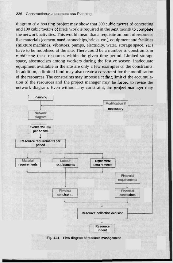
226 Construction rvrar raut;~~rarr~ arru Planning
diagram of a hou ject may show that 300 cu and 100 cubic meLlc3 u r vl,ick work is required in the lirni I L L U ~ L U L LU LU
the network activities. This would mean that a requisite amount of re5 like materials (cement, sand, stonechips, bricks, etc.), equipment and fz (mixture machines, vibrators, pumps, electricity, water, storage space, erc.) have to be mobilised at the site. There could be a number of constraints in mobilising these resources within the given time period. Limited storage space, absenteeism among workers during the festive season, inadequate equipment available in the site are only a nples of the constraints. In addition, a limited fund may also create aint for the mobilisation of the resources. The constraints may impose a celllng limit of the accumula- tion of the resources and the project manager may network diagram. Even without any constraint, th
sing pro +,.- ,C I-."
bic metrc ..A\,& - A
2s of con ...&I.. 2.- "A.
creting m~lete
few exar a constr, .. .
be forcc le projeci
:d to rev t managc
ise the :r may
j P l a n n i n g
I-- necessary
I L Vorks volu~ per perioc I . +
Resource requirements per period I
irements Equiprnen
'e~uiremen I requirements / 1 requ: I
requi -IT con: I7 aints straints iysica' I
Resourc -- -
e collectior I decision
1 Resource
indent
Fig. 11.1 Flow diagr urce rnana gement
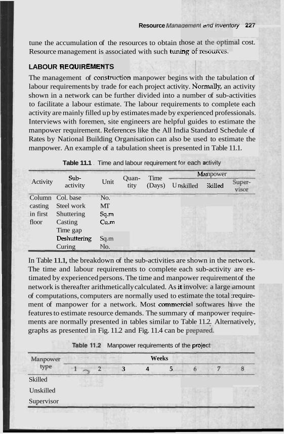
Resource Manauerrrtsr~l arru rrrvarrlury LLI
tune the accumulation of the resources to obtain t la1 cost. Resource management is associated with such tunby, U L 1rsuurct.s.
LABOUR REQUIREMEk ITS L . .
hose at t :-- ,K ,,,
The management of consrmcnon manpower begins with the tabulation of labour requirements by trade for each project activity. fiormally, an activity shown in a network can be further divided into a number of sub-activities to facilitate a labour estimate. The labour requirements to complete each activity are mainly filled up by estimates made by experienced professionals. Interviews with foremen, site engineers are helpful guides to estimate the manpower requirement. References like the All India Standard Schedule of Rates by National Building Organisation can also be used to estimate the manpower. An example of a tabulation sheet is presented in Table 11.1.
Table 11.1 . Time and labour requirement fc 2r each ac
Mai
Column Col. base No. casting Steel work MT in first Shuttering Sq.m floor Casting Cu.m
Time gap Deshuttering S Curing
q.m lo.
skilled
npower Activity Sub-
Unit Quan- Time
activity tity (Days) U n skilled
In Table 11.1, the breakdown of the sub-activities are shown in the network. The time and labour requirements to complete each sub-activity are es- timated by experienced persons. The time and manpower requirement of the network is thereafter arithmetically calculated. As il amount a large i
he total I
Manpower requirements of
Weeks
3 4 5
: involve: stimate t rcial soft
the projec
wares hi of computations, computers are normally used to e require- ment of manpower for a network. Most comme! we the features to estimate resource demands. The summary of manpower require- ments are normally presented in tables similar to Table 11.2. Alternatively, graphs as presented in Fig. 11.2 and Fig. 11.4 can be prepared.
Skilled
Unskilled
Supervisor
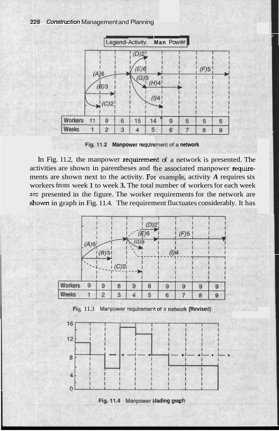
--, ,onstructlon Management and Planning - Man Pow Activitv.
-2 Manpo wer requirt network
In Fig. 11.2, the manpower requireme] etwork is presented. The activities are shown in parentheses and t iated manpower require- ments are shown next to the activity. Foi c,-.allLpie, activity A requires six workers &om week 1 to week 3. The total number of workers for each week are presented in the figure. The worker requirements for the network are s h o w in graph in Fig. 11.4. The requirement fluctuates considerably. It has
~t of a n he assoc
,-.vnm-1
g. 11.3 Ma, ,,WVVCI IC,UIIWIICI 11 UI a l l a t w ~ r k (Revise
lading graF

Resource Management and /hventory zzv
implications upon labour cost and morale. The shortage indicatc requirement for fresh appointment and surplus indicates retrenchrnenr benefits. Heuristic programmes, i.e., thumb rules, that work hav developed to level the resource requirements. In this case, the lr approach is to identify the activities that can be delayed as long; as QOSSltJle without delaying the completion of entire network. The re1 npower schedule is estimated in Fig. 11.3 and the manpower requi ; almost constant at 9 workers per week. Such computations are teOlvuJ uL pactical cases a t commercial software packages have resource levelling feature: I be utilised to level the manpower requirements. A practical exam le of manpower scheduling in Indian scenario has been resented bv Joshi. P
nd mosi ; that can
LABOUR PRODUCTIVITY
llar worl re indepe
- . (ised ma rement i: ;.. 7
defined re of the
e been- ~euristic .. .
Productivity in the construction industry can be broadlj I as the output per labour hour. Labour productivity is a measui overall effectiveness of a construction work system in utilising labour, equipment and capital to convert labour efforts into useful output and is not a measure of capabilities of labour alone. Labour productivity is influenced by many factors. Some of the factors are typical to a partic1 1 can be termed as site productivity. Other factors which a1 'job site can be defined as non-productive activities.
c site a n c ndent of
SITE PRODUCTIVITY
Several factors that affect the site productivity are listed below:
1. Work size and complexity
2. Work site accessibility
3. Labour availability
4. Equipment utilisation
5. Contractual agreements
6. Local climate
7. Local cultural characteristics particularly w' ork cultu
NON-PRODUCTIVE ACTIVITIES
Anumber of non-productive activities are inherent in the labour prod These factors consume labour resources but is not directly assoc production. Some of the non-productive factors are listed below:
1. Indirect labour required for supervision and maintenance oft
.uc tivity. :iated to
he work
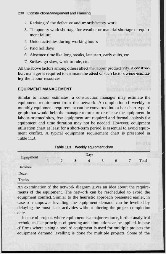
230 Construction Management and Planning
2. Redoing of the defective and unsai work
3. Temporary work shortage for weather or material shortage or equip- ment failure
4. Union activities during working hours
5. Paid holidays
6. Absentee time like long breaks, late start, early quits, etc.
7. Strikes, go slow, work to rule, etc.
All the above factors among others affect t r product tion manager is required to estimate the ettect ot such factors wnile esnmat- ing the labour resources.
tisfactory
onstruc- .. .
EQUIPMENT MANAGEMENT
Similar to labour estimates, a construction manager may estimate the equipment requirement from the network. A compilation of weekly or monthly equipment requirement can be converted into a bar chart type of graph that would help the manager to procure or release the equipment. In labour-oriented sites, few equipment are required and formal analysis for equipment and time duration may not be needed. However, equipment utilisation chart at least for a short-term period is essential to avoid equip- ment conflict. A typical equipment requirement chart is presented in Table 11.3.
Table 11.3 Weekly equipment chart
ment - Days
2 3 4 5 6 7 Total
Backhoe
Dozer
Trucks
An examination of the network diagram gives an idea about the require- ments of the equipment. The network can be rescheduled to avoid the equipment conflict. Similar to the heuristic approach presented earlier, in case of manpower levelling, the equipment demand can be levelled by delaying the most slack activities without altering the project completion date.
In case of projects where equipment is a major resource, further analytical techniques like principles of queuing and simulation can be applied. In case of firms where a single pool of equipment is used for multiple projects the equipment demand levelling is done for multiple projects. Some of the
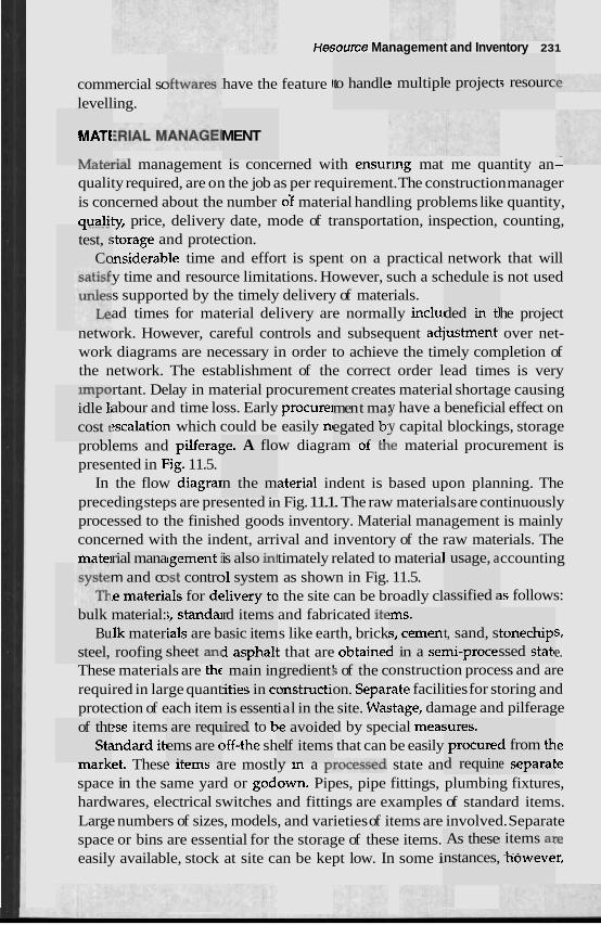
commercial sc levelling.
MATt
n a- I.*.
-1 ------
test, s Cc
*PO idle 1i cost t - -
bulk Bu
steel,
of tht St:
1-
rial mana m and cc .e materii
~gement i )st contrc 11s for dc
material: lk mater. roofing :
;, standai ials are b sheet an(
are requ ems are c . :. -
Hesource Management and Inventory 231
have the feature 1
MENT
;e. A flo
n the m
is also in! )1 system :livery to rd items asic item i asphall main in
ities in cc is essent . 3 . .
gredient! ~nstmcti, ial in the le avoide elf items - . . .- - .-
to handle s multipl e project s resourc
men t ma: egated b:
.- ..
IvlaLcrial management is concerned with ensurrng mat me quantity an- quality required, are on the job as per requirement. The construction manager is concerned about the number df material handling problems like quantity, auality, price, delivery date, mode of transportation, inspection, counting,
;torage and protection. ~nsiderable time and effort is spent on a practical network that will y time and resource limitations. However, such a schedule is not used s supported by the timely delivery of materials. ad times for material delivery are normally inclu~ he project
network. However, careful controls and subsequent adjusnnenr over net- work diagrams are necessary in order to achieve the timely completion of the network. The establishment of the correct order lead times is very
rtant. Delay in material procurement creates material shortage causing abour and time loss. Early procurel y have a beneficial effect on scalation which could be easily n~ y capital blockings, storage
problems and pilferag w diagram of the material procurement is presented in Fig. 11.5.
In the flow diagra~ aterial indent is based upon planning. The preceding steps are presented in Fig. 11.1. The raw materials are continuously processed to the finished goods inventory. Material management is mainly concerned with the indent, arrival and inventory of the raw materials. The mate] timately related to material ccounting
as shown in Fig. 11.5. I the site can be broadly cl is follows: and fabricated it€ s like earth, brick S, : that are obtainec e.
These materials are thc onstruction process and are required in large quant mate facilities for storing and protection of each item stage, damage and pilferage
?se items urea to D d by special mea: mdard itc )ff-the sh that can be easily ~e
mar~et. These irems are mostly m a processed state an te space in the same yard or godown. Pipes, pipe fittings, plumbing fixtures, hardwares, electrical switches and fittings are examples of standard items. Large numbers of sizes, models, and varieties of items are involved. Separate space or bins are essential for the storage of these items. "e easily available, stock at site can be kept low. In some i 'r,
5 of the c on. Sepal , site. Wa!
!ms, S, cemen. i in a sel
ded &-t tl _ _ L
1 usage, a
assified :
t, sand, s ni-proce:
;ures. procure4
d requin
As these nstances,
tonechip ssed statc
i from th e separal
! items a] howeve
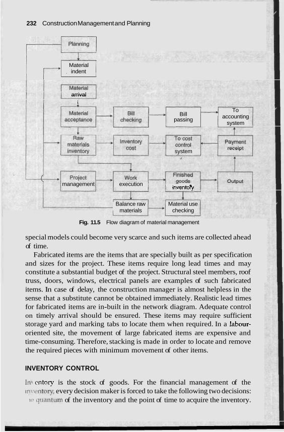
232 Construction Management and Planning
Planning r---r-I Material
, indent 1 arrival
I - Bill To
passing - accounting
system
system
management execution inventoQ
Balance raw Material use materials checking
Fig. 11.5 Flow diagram of material management
special models could become very scarce and such items are collected ahead of time.
Fabricated items are the items that are specially built as per specification and sizes for the project. These items require long lead times and may constitute a substantial budget of the project. Structural steel members, roof truss, doors, windows, electrical panels are examples of such fabricated items. In case of delay, the construction manager is almost helpless in the sense that a substitute cannot be obtained immediately. Realistic lead times for fabricated items are in-built in the network diagram. Adequate control on timely arrival should be ensured. These items may require sufficient storage yard and marking tabs to locate them when required. In a labour- oriented site, the movement of large fabricated items are expensive and time-consuming. Therefore, stacking is made in order to locate and remove the required pieces with minimum movement of other items.
INVENTORY CONTROL
In. entory is the stock of goods. For the financial management of the ~n~,t-ntorv, every decision maker is forced to take the following two decisions:
1,. qr~anturn of the inventory and the point of time to acquire the inventory.
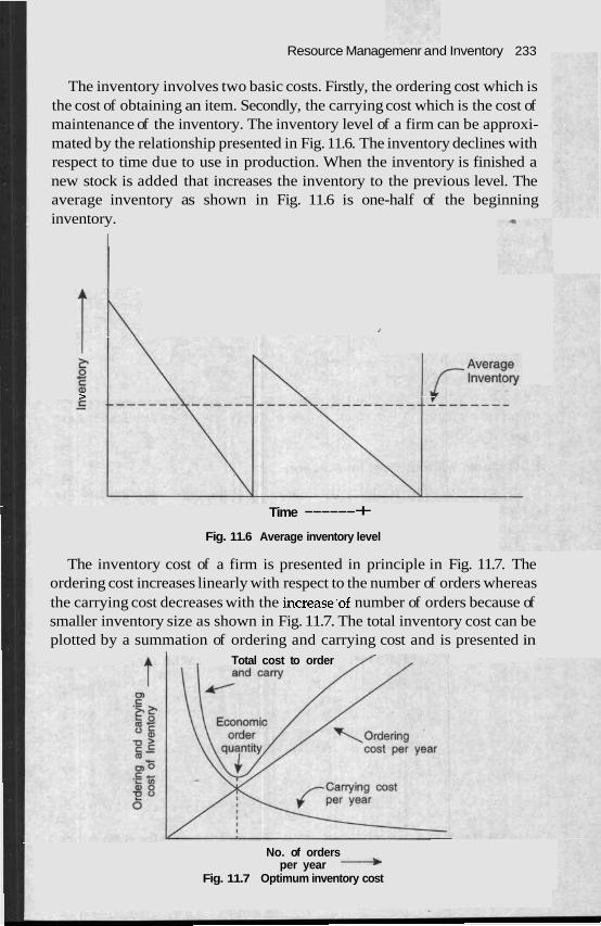
Resource Managemenr and Inventory 233
The inventory involves two basic costs. Firstly, the ordering cost which is the cost of obtaining an item. Secondly, the carrying cost which is the cost of maintenance of the inventory. The inventory level of a firm can be approxi- mated by the relationship presented in Fig. 11.6. The inventory declines with respect to time due to use in production. When the inventory is finished a new stock is added that increases the inventory to the previous level. The average inventory as shown in Fig. 11.6 is one-half of the beginning inventory.
>
Time ------+ Fig. 11.6 Average inventory level
The inventory cost of a firm is presented in principle in Fig. 11.7. The ordering cost increases linearly with respect to the number of orders whereas the carrying cost decreases with the increase-of number of orders because of smaller inventory size as shown in Fig. 11.7. The total inventory cost can be plotted by a summation of ordering and carrying cost and is presented in
Total cost to order
No. of orders per year +
Fig. 11.7 Optimum inventory cost
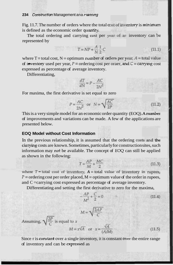
234 c'onsrruction Management ana rtann~ng
Fig. 11.7. The number of orders where the total cc is defined as the economic order quantitv.
The total ordering and carrying cor represented by
- J .
;t per ye
where T = total cost, N = optimum numt Jer of ord
entory is minimum
)e I invento Iry can E
lers per )i of hentory used per year, P = ordering cost per oraer, ana L = carrylng cost expressed as percentage of average inventory.
Differentiating,
For maxima, the first derivative is set equal to zero
This is a very simple model for an economic order quantity (EOQ). Anumber of improvements and variations can be made. A few of the applications are presented below.
EOQ Model without Cost Information
In the previous relationship, it is assumed that the ordering costa cUlu ~ t e carrying costs are known. Sometimes, particularly for construction sites, such information may not be available. The concept of EOQ can still be applied as shown in the following:
Y V I L C I c - LVCaI LVJL U L V C L I L ~ ~ Y , A = total valhc ~~gen to ry it L U ~ C C ~ ,
P = ordering cost per order placed, M = optimum value of the order in rupees, and C =carrying cost expressed as percentage of average inventory.
Differentiating and setting the first derivative to zero for the maxima,
Since x is COI-lstant over a single of inventory and can be expres!
inventor jed as
y, it is co: nstant ok ler the entire range
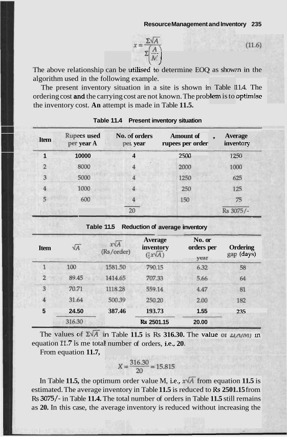
Resource Management and Inventory 235
iJ 1 determ The above relationship ~tilised tc
algorithm used in the following example. The present inventory situation in a site is shown ir 11.4. The
ordering cost and the carrying cost are not known. The prob optirnise the inventory cost. An attempt is made in Table 11.5.
can be L I as show ine EOQ 7n in the
I Table I ,lem is to
Table 11.4 Present inventory situation
!es used Item f orders Amount of year A . year rupees per order
1 10000 4 2Fnn
No. 0
Per , Ave
inve rage ntory
LLJU
- Table ' 11.5 Reduction of inventory average i
Item .I;i Average No. or inventory orders per Ordering (;a) year gap (days)
5 24.50 387.46 193.73 1.55 73.5
- Rs 2501.15 20.00
The n Table 11.5 is Rs 316.30. The value or L(N/NI ) III values c "a - . equation 11.7 is me total
From equation 11.7, ! number a of orders, i.e., 20
In Table 11.5, the optimum order value M, i.e., fi from equation 11.5 is estimated. The average inventory in Table 11.5 is reduced to Rs 2501.15 from Rs 3075/- in Table 11.4. The total number of orders in Table 11.5 still remains as 20. In this case, the average inventory is reduced without increasing the
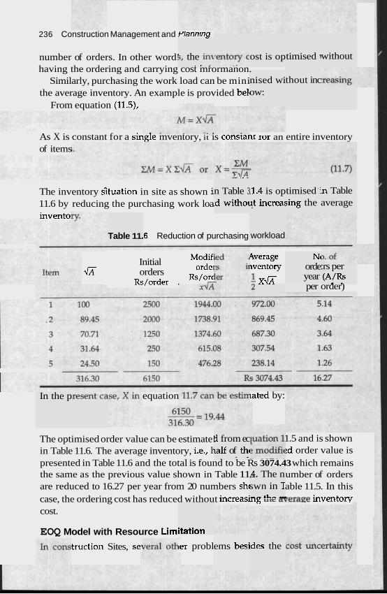
236 Construction Management and Plannrng
number of orders. In other word! having the ordering and carrying cost mrormanon.
Similarly, purchasing the work load can be mini the average inventory. An example is provided bell
From equation (11.5),
5, the in\ . . ,-
ost is op timised 7 without
nised wi ow:
thout inc
As X is constant for a single mventory, it is consranr ror an entire inventory of items
- .- -
n Table 3 .d with01
.1.4 is op ?t increa!
timised ' i sing the
in Table average
The inventory Gtuation in site as shown i 11.6 by reducing the purchasing work loa invent0
,6 Reduction of purchasing workload Table 11.
Initial Modif
fi orde~ orders &/order . Rs/orc
TT
Average wentory
4 xfi
Nc orde year
:rs per (A/Rs . . per order)
In the p equation lated by:
d from ec ialf of thc
- - -
The optimised order value can be estimate! 1.5 and is shown in Table 11.6. The average inventory, i.e., k :d order value is presented in Table 11.6 and the total is found to be Rs 3074.43 which remains the same as the previous value shown in Table 11. umber of orders are reduced to 16.27 per year from 20 numbers shc able 11.5. In this case, the ordering cost has reduced without increasi15 ulc aqerage inventory cost.
-4. The n swn in T ..*+I.,. ...
EOQ Model with Resource Limi itation
ems besi .des the truction Sites, sel ler probl
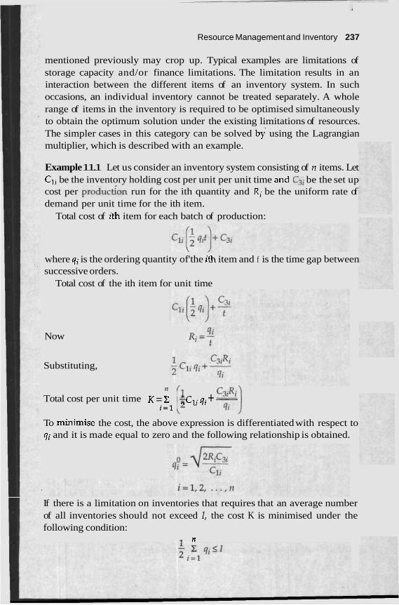
Resource Management and Inventory 237
mentioned previously may crop up. Typical examples are limitations of storage capacity and/or finance limitations. The limitation results in an interaction between the different items of an inventory system. In such occasions, an individual inventory cannot be treated separately. A whole range of items in the inventory is required to be optimised simultaneously to obtain the optimum solution under the existing limitations of resources. The simpler cases in this category can be solved by using the Lagrangian multiplier, which is described with an example.
Example 11.1 Let us consider an inventory system consisting of n items. Let Cli be the inventory holding cost per unit per unit time and C3i be the set up cost per production run for the ith quantity and Ri be the uniform rate of demand per unit time for the ith item.
Total cost of ith item for each batch of production:
where qi is the ordering quantity of'the ith item and f is the time gap between successive orders.
Total cost of the ith item for unit time
Now
Substituting,
[i c;;i] Total cost per unit time K = C -Cli qi + - i = 1
To minirnise the cost, the above expression is differentiated with respect to qi and it is made equal to zero and the following relationship is obtained.
If there is a limitation on inventories that requires that an average number of all inventories should not exceed I, the cost K is minimised under the following condition:
.r n
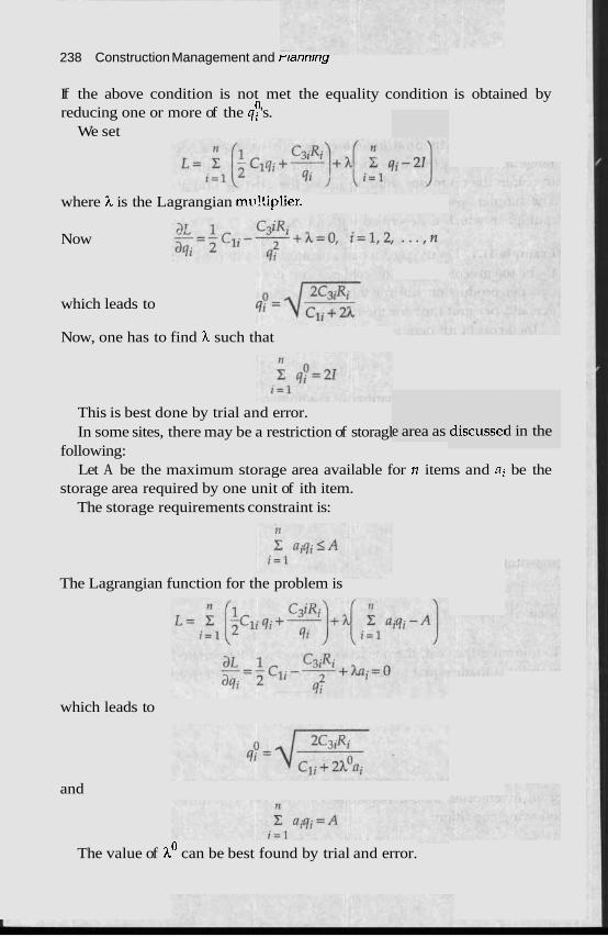
238 Construction Management and r~annrng
If the above condition is not met the equality condition is obtained by 0 reducing one or more of the qi 's.
We set
where h is the Lagrangian mu!tiplier.
Now
which leads to
Now, one has to find h such that
discussel d in the e area as This is best done by trial and error. In some sites, there may be a restriction of storagl
following: Let A be the maximum storage area available for n items and ai be the
storage area required by one unit of ith item. The storage requirements constraint is:
The Lagrangian function for the problem is
which leads to
and
The value of ho can be best found by trial and error.
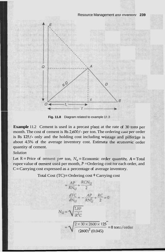
Resource Management an& rrrverrlurl/ 239
Fig. 11.8 Diagram related to example 1
Example 11.2 Cement is used in a precast plant at the rate 1s per month. The cost of cement is Rs 2,600/- per ton. The ordering cost per order is Rs 125/- only and the holding cost including w: ige is about 4.5% of the average inventory cost. Estimat order quantity of cement.
Solution
Let R = Price of ct: ?r ton, N,, = Economic or(
istage ar :e the ec
3er quar . P
of 30 tor - - - c ..
~d pilfer; ronomic
~tity, A = Total rupee value of cement usea per month, P =Ordering cost ror each order, and C = Carrying cost expressed as a percentage of average inventory.
Total Cost (TC) = Ordering cost + Carrying cost
- LAP "u=Vz
I2x30x2600x 125 = 8 ton:
(2600)~ (0.045)
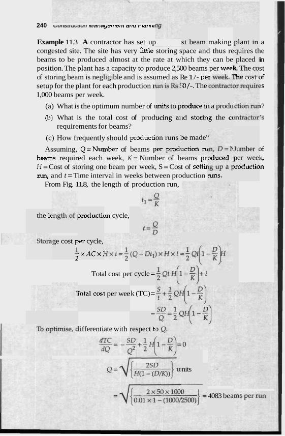
240 clvrrarruc.rrvrr rvrarrayerrrerrt crrru rrarrrrrr
Example 11.3 A contractor has set up making a congested site. The site has very iittle storing space and thus requires the beams to be produced almost at the rate at which they can be in position. The plant has a capacity to produce 2,500 beams per wee1 st of storing beam is negligible and is assumed as Re 1/- ve- -*.--'- IILC LUJL af setup for the plant for each production r 2s 1,000 beams per week.
(a) What is the optimum number of I 1 ?
(b) What is the total cost of prod Is requirements for beams?
(c) How frequently should producti~
Assuming, Q=Number of beams F 3f
beams required each week, K = Number of beams pr k, H = Cost of storing one beam per week, S = Cost of settir ~n run, and t = Time interval in weeks between production
From Fig. 11.8, the length of production run,
st beam plant in
placed i k. The co rh, ",,4..
iO/-. The
mits to p
ucing ar
roduce ir
ld storin
I a produ
.g the cc
on runs 1
ler prodl
3e made'
lction m Jumber (
oduced : %UP a 1 runs.
per wee. )roductia
productic the 1c 3n cycle,
ge cost F 1 - 7
ber cycle,
; x A C x j L L
Total cost pe r cycle =
rota1 cosl t per wee I k (TC) =
- -
respect tc lifferentiate with
nits
4083 bea
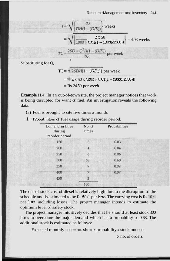
Resource Management and Inventory 241
weeks
2 x 50 = ~ { l O 0 O x O.Ol(1- (1000,2500))
= 4.08 weeks
h
Substituting for Q,
TC = ~ { ~ S D H [ I - (D/K)]} per week
= d (2 x 50 x 1000 x 0.01[1- (1000/2500)]}
= Rs 24.50 per weck
Example 11.4 In an out-of-town site, the project manager notices that work .. . is being disrupted for want of fuel. An investigation reveals the following data:
(a) Fuel is brought to site five times a month.
fb) Probabi-lities of fuel usage during reorder period.
rjemand in litres No. of Probabilities during times
reorder period
The out-of-stock cost of diesel is relatively high due to the disruption of the schedule and is estimated to be Rs 50/- per litre. The carrying cost is Rs lo/- per litre including losses. The project manager intends to estimate the optimum level of safety stock.
The project manager intuitively decides that he should at least stock 300 litres to overcome the major demand which has a probability of 0.68. The additional stock is estimated as follows:
Expected monthly cost = no. short x probability x stock out cost
x no. of orders
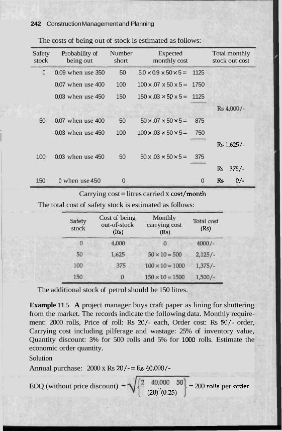
242 Construction Management and Planning
The costs of being out of stock is estimated as follows:
Safety Probability of Number Expected Total monthly stock being out short monthly cost stock out cost
0 0.09 when use 350 50 5.0 x 0.9 x 50 x 5 = 1125
0.07 when use 400 100 100 x .07 x 50 x 5 = 1750
0.03 when use 450 150 150 x .03 x 50 x 5 = 1125
50 0.07 when use 400 50 50 x .07 x 50 x 5 = 875
i 0.03 when use 450 100 100 x .03 x 50 x 5 = 750
RS 1,625/-
100 0.03 when use 450 50 50 x .03 x 50 x 5 = 375
Rs 375/-
150 0 when use 450 0 0 Rs O/-
Carrying cost = litres carried x cost/month
The total cost of safety stock is estimated as follows:
Cost of being Monthly Total cost out-of-stock carrying cost stock
(Rs) (Rs) (Rs)
The additional stock of petrol should be 150 litres.
Example 11.5 A project manager buys craft paper as lining for shuttering from the market. The records indicate the following data. Monthly require- ment: 2000 rolls, Price of roll: Rs 20/- each, Order cost: Rs 50/- order, Carrying cost including pilferage and wastage: 25% of inventory value, Quantity discount: 3% for 500 rolls and 5% for 1000 rolls. Estimate the economic order quantity.
Solution
Annual purchase: 2000 x Rs 20/- = Rs 40,000/-
EOQ (without price discount) = d{2 401000 50 = 200 rolls per oder (20)'(0.25)
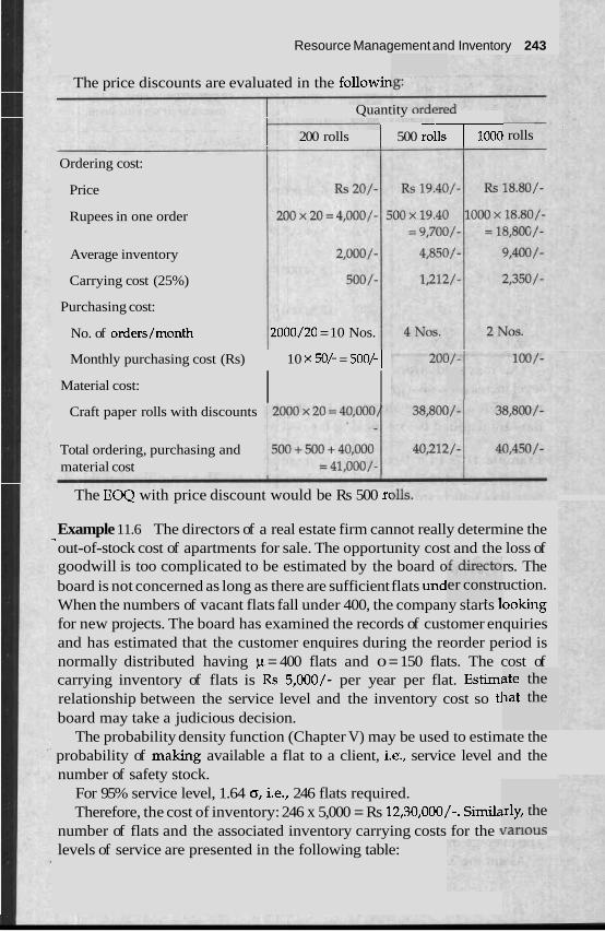
Resource Management and Inventory 243
The price discounts are evaluated in the followin
Quantity ordereu
200 rolls 1 500 rol- rolls --
Ordering cost:
Price
Rupees in one order
Average inventory
Carrying cost (25%)
Purchasing cost:
No. of orders/month 2000/20 = 10 Nos.
Monthly purchasing cost (Rs) 1 10 x 50/- = 500/- 1 Material cost: I I
Craft paper rolls with discounts
Total ordering, purchasing and material cost
The EOQ with price discount would be Rs 500 rc
Example 11.6 The directors of a real estate firm cannot really determine the -, out-of-stock cost of apartments for sale. The opportunity cost and the loss of goodwill is too complicated to be estimated by the board o rs. The board is not concerned as long as there are sufficient flats und uction. When the numbers of vacant flats fall under 400, the company starts looking for new projects. The board has examined the records of customer enquiries and has estimated that the customer enquires during the reorder period is normally distributed having p = 400 flats and 0 = 150 flats. The cost of carrying inventory of flats is Rs 5,000/- per year per flat. Estimi relationship between the service level and the inventory cost so tl board may take a judicious decision.
The probability density function (Chapter V) may be used to estimate the probability of making available a flat to a client, i.e., service level and the number of safety stock.
For 95% service level, 1.64 0, i.e., 246 flats required. Therefore, the cost of inventory: 246 x 5,000 = Rs 12,30,000/-. Simila
number of flats and the associated inventory carrying costs for the tclllvuJ
levels of service are presented in the following table:
er constr . . .
ate the at the
~rly, the r-w.r...c
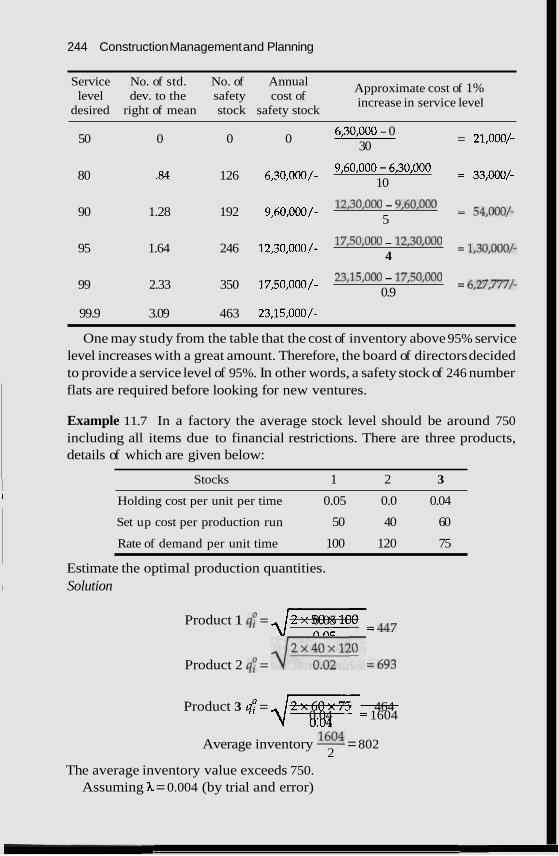
244 Construction Management and Planning
Service No. of std. No. of Annual Approximate cost of 1% level dev. to the safety cost of increase in service level
desired right of mean stock safety stock
50 0 0 0 6,30,000 - 0
30 = 21,000/-
80 .84 126 6,30,000/- 9,60,000 - 6,30,000
10 = 33,000/-
90 1.28 192 9,60,000/- 12,30,000 - 9,60,000 = 54,000/- 5
95 1.64 246 12,30,000/- 17,50,000 - 12,30,000 = 1,30,000/- 4
99 2.33 350 17,50,000/- 23,15,000 - 17,50,000 = 6,27,m,- 0.9
99.9 3.09 463 23,15,000/-
I One may study from the table that the cost of inventory above 95% service level increases with a great amount. Therefore, the board of directors decided to provide a service level of 95%. In other words, a safety stock of 246 number flats are required before looking for new ventures.
Example 11.7 In a factory the average stock level should be around 750 including all items due to financial restrictions. There are three products, details of which are given below:
~ Stocks 1 2 3 I Holding cost per unit per time 0.05 0.0 0.04
Set up cost per production run 50 40 60
Rate of demand per unit time 100 120 75
Estimate the optimal production quantities. I Solution I
Product 1 q: = -\I-= 0.05 447
2 x 4 0 ~ 1 2 0 =693 Product 2 q; = dTF Product 3 q: = -\I-- 464
0.04 1604
Average inventory 1M)4 = 802 2
The average inventory value exceeds 750. Assuming h = 0.004 (by trial and error)
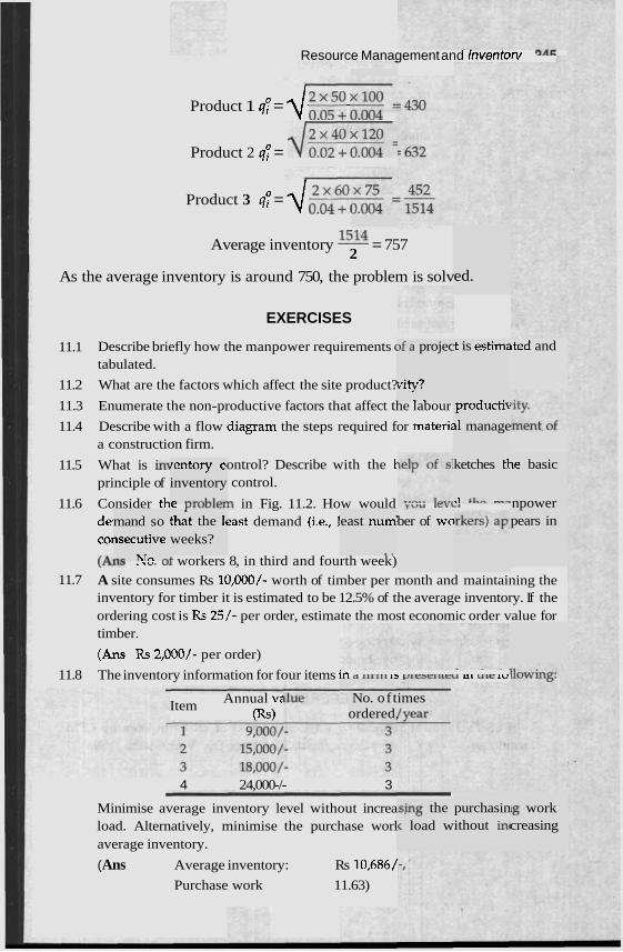
Resource Management and Inventon/ 3AF
Product 1 qp = --- d :.;:: u., Product 2 qp = dE%=
Product 3 qp = -- d :;::, I , Average inventory 1514 = 757
2
As the average inventory is around 750, the problem is solv ed.
EXERCISES
11.1 Describe briefly how the manpower requirements ( tabulated.
11.2 What are the factors which affect the site product?
11.3 Enumerate the non-productive factors that affect the labour
11.4 Describe with a flow diagram the steps required for materiz a construction firm.
)fa projec ,t is estima ~ted and
vity? , . .
productib
rl manage
ketches t'r
>l +LO -n
le basic
npower
11.5 What is in1 principle of
rentory CI
inventory n ....,.Ll.-.+
ontrol? Describe with the 1 control.
11.6 Consider thc r~vvlcln in Fig. 11.2. How would Y V U
dei last demand (i.e., 1 COI
mand so ~secutive n c hTrr r r r
that the 1, east num'
. .
ber of wa pears in weeks?
(A;- ..,. ,I workers 8, in third and fourth week) 11.7 A site consumes Rs 10,000/- worth of timber per month and maintaining the
inventory for timber it is estimated to be 12.5% of the average inventory. If the ordering cost is Rs 25/- per order, estimate the most economic order value for timber.
(Ans Rs 2,000/- per order)
11.8 The inventory information for four items i r t d u r r l l IB vlescluru LIL r lLr ICJ
No. of t ordered,
Item Annual ve (Rs)
imes
4 24,000-/- 3
Minimise average inventory level without increa load. Alternatively, minimise the purchase worl average inventory.
( Ans Average inventory: Rs 10,686/
Purchase work 11.63)
purchasin ithout in1
~g work creasing
~ s b g the < load w
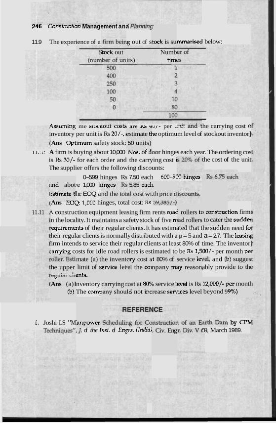
246 ~onstrucrron Management ana r~ann~ns 7
tock is su 11.9 The experience of a ig out of s mrnarised below:
kock out Numb timl its)
I
9ssuming me stuc~uur costs are 11s r u l - per urut mu the carrying cost o nventory per unit is Rs 20/-, I ne optimum level of stockout inventor] estimate tl
50 units) - 7 ,- . Ans Optimum safety stock:
1 1 . 1 ~ A firm is buying about 10,000 NOS. or door hinges each year. The ordering cos is Rs 30/- for each order and the carrying cost i the cost of the unit The supplier offers the following discounts:
0-599 hinges Rs 7.50 each 600-9h mnges re 1,000 h
he EOQ a
~ n d abot
Zstimate tl . -A .
~inges &
nd the tot
j 5.85 eacl
,a1 cost wi -
1.
.th price d - - - - - , . Ans EW: 1,000 hinges, total cost: KS 5Y,385/-)
1 construction equipment leasing firm rents roac tion firm: n the locality. It maintains a safety stock of five rc -le sudder ,equirements of their regular clients. It has estimated that the sudden need fo. heir regular clients is normally distributed with a p = 5 and a = 2.7. The leasin[ irm intends to service their regular clients at least 80% of time. The inventor] :awing costs for idle road rollers is estimated to be Rs 1,500/- per month pel
(el, and (I ably prov
1 rollers tc )ad rollers . . ... . .
3 construc to cater tl . .
mate (a) t limit of s ents.
he invent emice let
ory cost a re1 the col
,t 80% of i
npany mi service lei 3y reason,
,) suggest ide to the he upper
,--. -1: (7
Ans (a) I (b)
carrying c )any shou
lost at 809 Id not inc
b service 1 rease sen
eve1 is Rs rices level
12,000/- I beyond 9
,er month '9%)
nventory The comF
1. Joshi LS "M T- -
'anpower . by CPN 59, March 1989. ,,I. of the Inst. of Engrs. (Indial I, Civ. Eng
Accounts Managem
Accounting is directed towards evaluating the financial position and progress of an enterprise. Accounting considers all the financial transactions of a company and presents the data in a highly structured form that explains information about the financial health of the enterprise. Accounting is to a large measure a classification process in which a variety of distinctions are made in the monetary values to create a set of tables and charts like profit 'and loss statement and balance sheets to describe the financial history of an cmterprise. Accountine concepts or principles which dictate the classification process are ther y important. A list of basic concep
" efore vel
1. Financial
Results o
Enterpris - .. .
conditic )n (i.e., asset, liability, shareholders
ons (i.e., revenue, expense:
brporate entity, financial st
3, loss, in1
:atement,
~ts are as
equity, 6
come, prc
etc.)
4. COnhnulty (i.e., accounting time period, gomg concern, etc.)
Present fi . .
airly (i.e. , consistc . .-
le preser bunts adc
ncy, full disclosure, etc.)
the basic
follows:
!tc.)
ofit, etc.)
In Order to ensure the un~torm quality, standards and concepts, accounts are normally audited by chartered accountants who as certifiers enjoy certain statutory privileges and obligations. Under normal circumstances, audited balance sheets and profit and loss statements are the only objective docu- rnents available to an outsider to evaluate the financial performances of a company. Taxes due to the governments are also estimated according to the audited accounts. The preparation and audit of the account is beyond the scope of this chapter. ll lt discussion is limited to standing of audited accc lressed to a beginner.
: under-
248 Construction Management and Planning
BASIC CONCEPTS
The principles of accounting are built on a foundation of a few basic concepts. Oue must understand the concepts in order to draw conclusions from the accounting statements. A few of the important concepts are listed below.
Money Measurement
111 financial accounting, a record is made only on those facts that can be directly expressed in monetary terms. This concept imposes a limitation on the scope of an accounting report. A number of important information may remain outside the accounting report because of this limitation. For example, a lawsuit or a dispute among the partners of a firm, statutory restrictions 1.ausing hardship to the business, deteriorating labour relations, increasing risk of a strike, advancing age of the founder-director of a small firm may have significant impact upon the performance of the firm but these are not reflected in the accounting statement by any means. It follows, then, that an accounting report does not reflect all the important information about the company.
Business Entity
Accounting are kept for business entities, as distinguished from the persons ;vho are associated with these entities. When the owner takes cash out of his tlusiness, for example, the accounting records show that business has less cash than previously, even though the real effect of this event to the owner himself may have been negligible. When the owner injects fund to the business the accounting records show it as owner's equity and would treat it as a liability of the business to the owner. The entity concept has significant clffect on the taxation of a firm as shown in the following example:
Two parMership firms have floated and incorporated a private limited company. The profit earned by the company is taxed at company tax rate. The after tax profit is earned by the partnership firms as profit and are taxed at the firm's tax rate. The after tax profit from the firm is earned by the partners arid is again taxed at the individual's tax rate. In accounting, each account is treated as an entity irrespective of its ownership.
Going Concern
In accounting, a business is viewed as a mechanism for creating values for perpetuity. Resources owned by the firm is shown as its purchase price less accumulated depreciation. The current resale value is irrelevant since it is assumed that these will not be sold as such but rather these would be used in the creation of future output values.
Accounts Management 9Aa
Cost Reporting
The resources like securities, land, building, plant and equipment, that a business owns are called assets. The real worth of an asset may change with time for a variety of reasons. The assets in accounting are almost always shown at its cost value less accumulated depreciati the market value of an asset may be quite different. for objectivity.
ion. The The cost
book val concept
ue and is used
Double Entry System
The double entry system is true for most of the accounts. Every event mat is recorded in the accounts affects at least two items, one each from tl: and the liability side. Accounting systems are so set up that m e entered on both sides and the following concept always remains trut
; = Liabilities + Owners' ec
Dual ent has both conceptual and, is unive~ epted.
le asset vent is 3. -.
Assets
n, which
pity
arithmeti ry syster ical adva ntages, sally acc
Realisal Time of
A firm generally provides service and earns revenues continuously. The cheque received in one accounting period may very well be for the service rendered in a previous accounting period. When should the revenue be recognised? Revenues are generally recognised in the period in which the firm is reasonably certain that the amount would be received. The time of realisation is not related to the actual receipt of cheque. For construction companies, the time of realisation is ordinarily the date of submission of bills. The concept has an important bearing upon cash flow and taxation. Income tax is payable upon the bills that are raised but not yet realised. Therefore. the fund for taxes for unpaid bills has to be arrange
. - - - - - -
rces. !d from c jther sou
Matching Concept
Matchin! t guides, that to the extent feasible, the costs are reported as exper he period in which the associated revenue is reported. Similarly, uLc ~ ~ ~ e i p t s are taken as only advance received. When the r---'-- is provided, advance recei 'onsidere mues.
- 5 concep tses in t . CL, ,",
Consistency Concept
In accounting practice, ma ing. The consistency conc method, it treats all subs methods are used for the si be confidently compared.
ucting account? decided on one
nptions are made for cond ires that once a firm has (
?vents by the same meth ; of events, accounting info
my assur ept requ
.fferent cannot
iequent t
ame clas: od. If dj ~rmation
250 Construction Management and Planning
Materiality Concept
The accountant does not attempt to record events ro sucn aerau mar me record-keeping itself becomes unjustified by the usefulness of the result. For cnxample, in most of the construction site accounts, a paint drum once open is considered as used. One may go into details like measuring the use of paint on a daily basis and report the partly used drums as the owners' asset at any given time. The materiality concept allows the accountant to decide the level of detail that can be ignored.
ACCOUNTING SYSTEM AND BOOKKEEPING
lamely ti 31, bank
-,...A
>unt are is the pl
book, pa
; and su bgical orc - 1. . 1
n a daily and sale
w or recc le books. ram in Fi lent esth In. The I
res vouc. I-.. - .
rty ledgc
An accounting system involves a number of boo1 daily transactions of the firm are represented in th accounting system is represented in the flow diagi
In Fig. 12.1, the planning and project managen require- ment of resources, i.e., indent for work executic ; can be obtained either through a cash or a bill purchase. Purchase creates an inventory that are used for the work execution. Bill purchase follows bill rc~eipts that are paid after verification from the site. Work execution follows payments receivable from the clients.
The first step of the accounting entries invoh hers. W1 flows out of the firm, the account is debited by deoir vouchers. When cash flows into the firm, the account is credited.
The heart of the system are the account books where records of the vouchers are tabulated in a logical manner. In most cases, at least four account books r he journi are maintained.
tions showing the names of accounts that are to be debitec amounts of debits and credits and any brief information a1 tion. A journal is the list where all vouchers are first record
A ledger is a device for reclasslfylng mmarising, by accounts, information originally listed in a chronolc ler in the journal. A party ledger shows the accounting position with lnaiviaual parties like a client or a supplier. Each page of the ledger is dedicated to an individual party. The bill number, the amount payable or receivable and the advance paid or received are shown in the ledger. The party ledger shows the daily account- ing position with the individual parties.
Bank books maintain the daily records mk. The cheque details and the amounts transacted are recorded. lhe current balance ~xwition in the bank accc shown o
The -cash book recon urchase
ctions w . . - basis. details
3rd-keep A typica
ing. The 11 project
ig. 12.1. nate the resources
?r and ca
" 1 or cred bout the led.
ith the bz
of the fi
ken cash
.sh book
ited, the transac-
rm. The
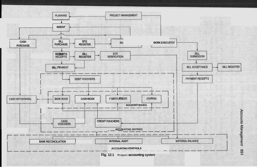
PROJECT MANAGEMENT D 4
I INDENT
WORK EXECU
+ BILL SlTE
PURCHASE REGISTER CASH I PURCHASE PM RECEIPTS BlLL
REGISTER
BlLL PA\(
I I
CASH BOOK
_. . BOOKS
I
1 'ARTY LED( 3
ACCOUNT
T I CREDIT VOUCHERS
ACCOl ---
BANK RECONCILIATION 1 INTERNAL AUDIT
ACCOUNTING eONTROLS --------A-
Fig. 12.1 Project accounting systen
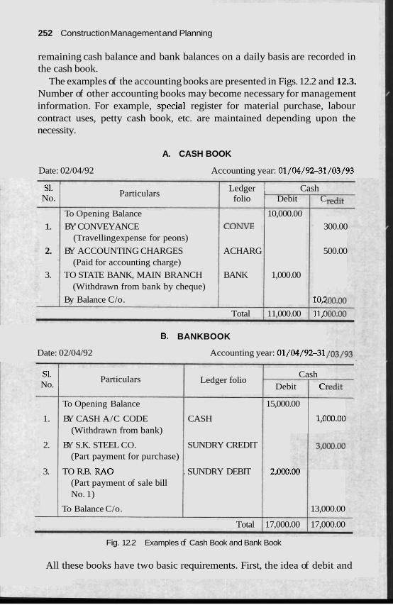
252 Construction Management and Planning
remaining cash balance and bank balances on a daily basis are recorded in the cash book.
The examples of the accounting books are presented in Figs. 12.2 and 12.3. Number of other accounting books may become necessary for management information. For example, special register for material purchase, labour contract uses, petty cash book, etc. are maintained depending upon the necessity.
A. CASH BOOK
Date: 02/04/92 Accounting year: 01/04/92-31/03/93
S1. Ledger Cash No. Particulars
folio Debit C
To Opening Balance 10,000.00
1. BY' CONVEYANCE C O W 300.00 (Travelling expense for peons)
2. BY ACCOUNTING CHARGES ACHARG 500.00 (Paid for accounting charge)
3. TO STATE BANK, MAIN BRANCH BANK 1,000.00 (Withdrawn from bank by cheque)
By Balance C/o. 10,;
Total 11,000.00 11,C
6. BANKBOOK
Date: 02/04/92 Accounting year: 01/04/92-31
S1. Cash Particulars No. Ledger folio
Debit C.
To Opening Balance 15,000.00
1. BY CASH A/C CODE CASH 1,000.00 (Withdrawn from bank)
2. BY S.K. STEEL CO. SUNDRY CREDIT (Part payment for purchase)
3. TO R.B. RAO . SUNDRY DEBIT 2,000.00 (Part payment of sale bill No. 1)
To Balance C/o. 13,000.00
Total 17,000.00 17,000.00
Fig. 12.2 Examples of Cash Book and Bank Book
All these books have two basic requirements. First, the idea of debit and
Accounts Managemenr zo.
credit equality is maintained. Whenever an account is debited or credited the opposite is required to be done in the other appropriate account Secondly, the books are balanced periodically. After the accountin both sides are matched and the balanced figure in either debit or c is used as the starting balance for the next period.
Several control features like bank reconciliations, internal audit an( material balance are used to ensure the correct data compilation in the books
ig period redit sid~
DEPRECIATION
Depreciation is the decrease in value. Professionals from different fields art concerned with depreciation. To an economist, depreciation is the reductior of the market value while to an eng'ineer it is the loss of proficiency, i.e. physical deterioration. To an accountant, depreciation is the progressivt amortisation of the book value of the asset. Depreciation accounting is : system of accounting which aims to distribute the cost of tangible capita assets less salvage value, if any, ovQ the estimated useful life of the unit ir a systematic and rational manner.
As an illustration, a tangible capital asset say a concrete mixer wortl Rs 90,000/- is purchased in the first year. The mixer can be used for five year! and the scrap value is estimated to be Rs 10,000/-. In the first year, the valu: of the mixer machine is shown as Rs 90,000/- in the machinery asset columr. of the balance sheet. In the sixth year, when the machine is sold as scrap for Rs 10,000/- the sum is shown in the monetary asset column of the balance sheet and the value of the machinery asset is correspondingly reduced. The machinery asset column in the balance sheet from the second to the fifth yea] reflects the progressive decrease of the value of Rs 80,000/- during the lifc span of the mixer machine. Such a decrease is made in the balance sheet b~ affecting depreciation expenses.
Depreciation has a major impact on the taxation. Depra as an expense in the balance sheet by the tax authori._--. --2recianor increases operating expenses thereby reduces profit and income tax. How- ever, depreciation is not an actual cash outflow from the company. In thc previous illustration if one assumes fifty per cent as marginal income ta>c and neglects time value of money, the total savings in taxes is
accepted . '.
A sum of Rs 40,000/- is saved in taxes by showing Rs 80,000/- as depreciation expe!lses which is not actually a cash outflow. In other words, the after tax cost cf the mixer machine is Rs 90,000/- less Rs 40,000/-, i.e., RS 50,000/-.
Almost all canital tangible assets like building, plant, machinery and
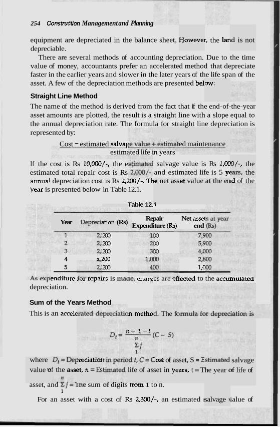
254 Construflion Management and Planning
equipment are depreciated in the balance sheet, r, the lan depreciable.
There aR several methods of accounting depreciation. Due to the time value of money, accountants prefer an accelerated method that depreciate faster in the earlier years and slower in the later years of the life span of the asset. A few of the depreciation methods are presented be1
Howevei id is not
dw:
Straight Line Method The name of the method is derived from the fact that if the end-of-the-year asset amounts are plotted, the result is a straight line with a slope equal to the annual depreciation rate. The formula for straight line depreciation is represented by:
-
ed maint enance Cost - estimated salvaf estimated life in years
lo/-, the ?ars, the
If the cost is Rs 10,000/-, the e estimated total repair cost is Rs annual depreciation cost is Rs 2,200/-. Th jlear is presented below in Table 12.1.
salvage value is Rs 1,OC and estimated life is 5 yt le net ass
.I
;et value at the en td of the
Table 12. I -- --
Repair Net assel Expenditure (Rs) end
DO DO DO
Year tio on (Rs)
200 200 200
4 3 '200 - -
z,t 5 - 200 - 1,c -
mditure rur repdlrs is maw, cnarges are eriected to the accumularea depreciation.
Sum of the Years Method
This is an accek d. The fc In metho
r r 1 - C
where
value .o
,reciati&
et, n = Es Zest of as
set in ye,
set, S = E ars, t = T
salvage
>f life of he year ( f the asst life of as
asset, and 21 =.l'he sum of digits trom 1 to n. 1
For an asset with a cost of Rs 2,300/-, an estimated : ialue of salvage 7

Accounts Management 255
Rs 200/- and an estimated life of 5 years, the yearly depreciation is presented below in Table 12.2.
rable 12.:
Fraction deprec
5 / :
of total Deprec iation amour
15 7C
Total - Declining-Balance Meth
In this method, a fixed rat ed each year to th~ mce, the method results in decreasing the annual charges for depreciation. ~n many instances, income tax rules and pr: t the rat1 1. There are also methods to deduce the rai ample, o llowing formula for the determination of h e rate:
e is appli . . e net balz .. -
ictices se te. For ex
reciation Lse the fo
2 for d e ~ ne may L
Salvage value Depreciation rate = 1 - n Cost
For the above ex yearly depreciati
:ample, t on is pre
he depre msented b
ciation rate would be 38.64 per ce elow in Table 12.3.
nt. The
'able 12.3
Year Balance : rn-1
eciation
- authorit or the of incor he rate approved by the ies are
required ;ed. The ed methods have a clear i ;e from the tax accounting point of view. The larger deductions in the early years mean tax payments are postponed for a considerable period. From the financial point of view, a cash outflow for the purchase of a capital asset is compensated by less cash outflow arising out of a lesser amount of tax caused by the depreciated expenses. In other words, a higher depreciation allowed in the tax rules induces more investment in the capital asset.
ne tax, 1 accelerat . .
purpose to be us
. . advantag
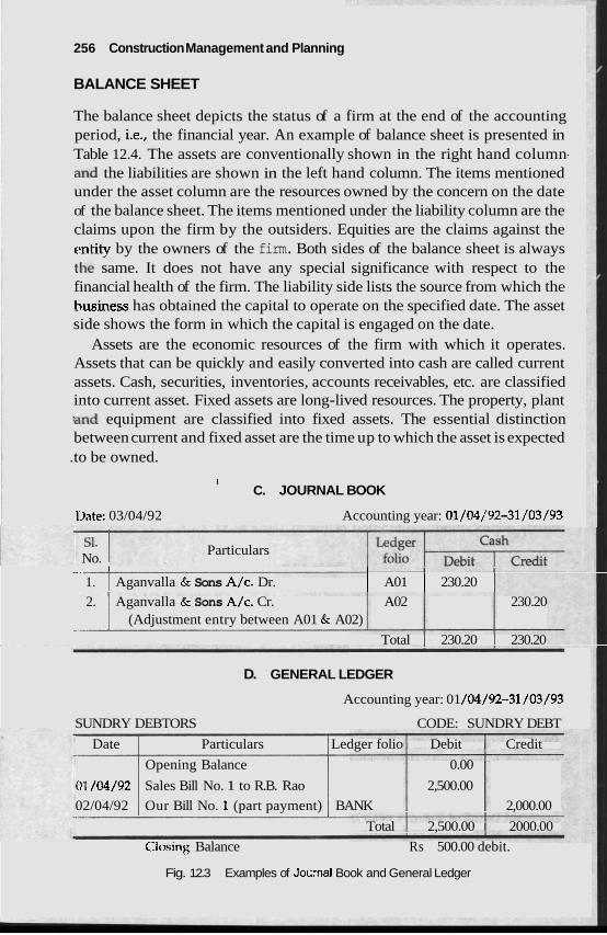
256 Construction Management and Planning
BALANCE SHEET
The balance sheet depicts the status of a firm at the end of the accounting period, i.e., the financial year. An example of balance sheet is presented in Table 12.4. The assets are conventionally shown in the right hand column- 'and the liabilities are shown in the left hand column. The items mentioned under the asset column are the resources owned by the concern on the date of the balance sheet. The items mentioned under the liability column are the claims upon the firm by the outsiders. Equities are the claims against the ctntity by the owners of the firm. Both sides of the balance sheet is always the same. It does not have any special significance with respect to the financial health of the firm. The liability side lists the source from which the husiness has obtained the capital to operate on the specified date. The asset side shows the form in which the capital is engaged on the date.
Assets are the economic resources of the firm with which it operates. Assets that can be quickly and easily converted into cash are called current assets. Cash, securities, inventories, accounts receivables, etc. are classified into current asset. Fixed assets are long-lived resources. The property, plant :and equipment are classified into fixed assets. The essential distinction between current and fixed asset are the time up to which the asset is expected
.to be owned.
I C. JOURNAL BOOK
1)ate: 03/04/92 Accounting year: 01/04/92-31/03/93
No. I Particulars I ~ -. 1 I I
1. I Aganvalla & Sons A/c. Dr. ( A01 1 230.20 1 2. Aganvalla & Sons A/c. Cr. A02 230.20
I
I (Adjustment entry between A01 & A02)
Total 230.20 230.20
D. GENERAL LEDGER
Accounting year: 01 /04/92-31/03/93
SUNDRY DEBTORS CODE: SUNDRY DEBT
Date Particulars Ledger folio Debit Credit
Opening Balance 0.00
0'1 /04/92 Sales Bill No. 1 to R.B. Rao 2,500.00
02/04/92 Our Bill No. 1 (part payment) BANK 2,000.00
Total 2,500.00 2000.00
Clos~ng Balance Rs 500.00 debit.
Fig. 12.3 Examples of Jou:nal Book and General Ledger
anagemei
Liabil obligatio Accounts payable, tax liability, accrued c current liabilities. Owners' equity is the 0
I : 'capital of the firm. Retained earnings is th
the firm but has 1 returned to the owners i Retained earning o be viewed as the amou for its own use.
the firm': 5 require!
s obligation to other parties. Current liabilities are d to be met within a short time, say within a year.
' considered as rds the ned by
m of dividend. led by the firm
ities are 1
~ns that i! !xpenses, wners' CI
e profit i
etc. are ontributi that has
not been s can als
n the f o ~ nts retajl
)SS STATEMENT PROFIT AND LC
Profit and loss statement is a summary of the revenues and expenses within an accounting period. It is also called an income statement. An example is provided in Table 12.4. Income statement is important in the sense that it reports the earnings of the firm in the current financial year. Gross sale is the total sale, i.e., turnover of the firm. The difference between the gross si the cost of goods sold is the gross profit margin. The overhead depre and other costs are deducted to obtain a net le estimated tax is deducted to obtain a net income.
ale and ciation
: profit m
Relationship between B, ;beet and Income Statement
The balance sheet is the status or the firm on a parbcu~ar aate. It shows the form of the capital and how it is owned by the firm on a given da balance sheet is the cumulative effect of the firm's performance for ih life. Income statement concentrates on the firm's performance for the current financial year. It determin t income of the firm for the said year. The retained earnings (i.e., thc ice between the net income and the stock holders dividend) from the mcome statement is transferred to the equity column I
te. The ; entire
es the ne . differen . .
3f the ba lance shc
S
tet.
RATIO ANALYSI
The purpose of tl nalysis is to form ideas or .edictions about a firm in the conrexr or some decision setting. A consrrucrion manager in many instances is faced with the problem of evaluating the financial position of a firm. The evaluation becomes essential before awarding a contract among competing firms. Similarly, a banker may find it necessary to judge the solvency of tl efon! granting loans or a shareholder may wish to know the perforn :he firm. In these instances, the financial statements are the only objectlve rmancial document available to an outside evaluator. A syster )n of the financial stater ratio analysis provides e firm's standing and perj
le ratio a I I r
make pr - . -..... -L
le firm b lance of 1 . . ,-.
- . natic in\ ; an idea
~estigatic about th
nents by formancc
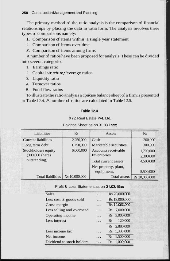
258 Construction Management and Planning
The primary method of the ratio analysis is the comparison of financial relationships by placing the data in ratio form. The analysis involves three types of comparisons namely:
1. Comparison of items within a single year statement 2. Comparison of items over time 3. Comparison of items among firms A number of ratios have been proposed for analysis. These can be divided
into several categories 1. Earnings ratio 2. Capital structure/leverage ratios 3. Liquidity ratio 4. Turnover ratios 5. Fund flow ratios To illustrate the ratio analysis a concise balance sheet of a firm is presented
in Table 12.4. A number of ratios are calculated in Table 12.5.
Table 12.4
XYZ Real Estate Pvt. Ltd.
Balance Sheet as on 31.03.1 9xx
Liabilities Rs Assets Rs
Current liabilities 2,250,000 Cash 200,000 Long term debt 1,750,000 Marketable securities 300,000
Stockholders equity 6,000,000 Accounts receivable 1,700,000 (300,000 shares Inventories 2,300,000 outstanding) Total current assets 4,500,000
Net property, plant, equipment, 5,500,000
Total liabilities Rs 10,000,000 Total assets Rs 10,000,000
Profit & Loss Statement as on 31.03.19~~
Sales . . . Rs 28,000,000
Less cost of goods sold . . . Rs 18,000,000 Gross margin . . . Rs 10,00C,000 Less selling and overhead . . . Rs 7,000,000
Operating income . . . Rs 3,000,000 Less interest . . . Rs 120,000
Rs 2,880,000 Less income tax . . . Rs 1,380,000 Net income . . . Rs 1,500,000 Dividend to stock holders . . . Rs 1.000.000
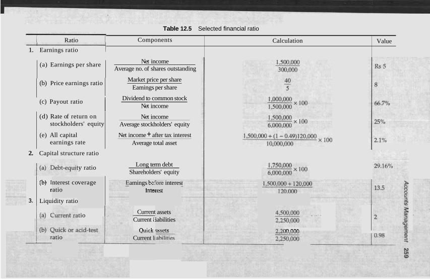
1 Ratio I Table 12.5 Selected financial ratio
1. Earnings ratio 1 Components
Net income Average no. of shares outstanding
(a) Earnings per share
Calculation
Market price per share Eamings per share
Value
(b) Price earnings ratio
Dividend to common stock Net income
(c) Payout ratio I (d) Rate of return on
stockholders' equity Net income
Average stockholders' equity
(e) All capital earnings rate
Net income + after tax interest Average total asset
2. Capital structure ratio
Long term debt Shareholders' equity
:y ratio
tio
3.
nterest co atio
('J) 1 r
Liquidity ratio
verage
(a) (
amings be1 Intel
Fore interes rest
Current Current li
nrrirb
assets iabilities
arrntr ?n nnn YU'L'.
Current li atio
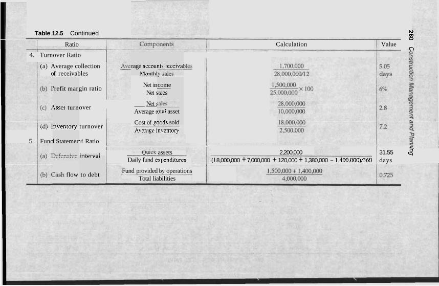
Table 12.5 Continued h) Q) 0
Calculation Value 0
I 1 Ratio I
4. Turnover Ratio I (a) Average collection bles
of receivables uLY..L..AJ YU.Y.I nts receival 11 calpc
rage accoui Mnntlil
come - ;ales
gin ratio Net in Net
'refit mar,
Net 5 over I --
Average t Isset turn
,ale>
otal asset
,,, -nventory turnover
5. Func ~t Ratio
Cost of gc Average irlvcrilu~y
~ o d s sold
l Statemer
>ncn...-;.,n
- 2,200,000 31.55 2'
(1 8,000,000 + 7,000,000 + 120,000 + 1,380,000 - 1,400,000)1360 days 4..4,.+....1 ,,.-.. assets
Daily fund expendih~res I, L L C L v',,
to debt Fund provided by operations
Total liabilities :ash flow
Additional data: The market price of common st s 40/- p Depreciation deducted in determining above net mcome is Rs 1,400,000. A short description of each of the ratio is presented llowing:
Earnings per share is a widely used ratio. It is a I 3f the prc of the firm from the shareholder's point of view. As most firms retam a
I of earnings (i.e., dividend payout ratio is I value of ends to increase over time due to change ir lings per 1s opposed to the profitability of each sha~r U L V C ~ L C L L . ever, the
EI'S remains to be a common measure fo of a firn
Price-earnings ratio is a measure of tl :ctation 2
firm. In the dynamic business world, the future performance of a company is influenced by many I decisions. The , ~g data which is historical does not alu ect the future ac nt. For example,
,obtaining a major contract would positively change the future performance in the next year and this cannot be seen in the prc ~r's balance sheet. In such a case, the price of share in the stock exch, Is to increase due '- '--.?stars' preference. Price-earnings ratio is ~ ~ L ~ J A L ~ V C under these condi-
ock is R . ~- - - -
er share.
in the fo neasure (
portior share t share i
.ess than 1 the reta .... :-..A-b
one), the ined ean ,A U,..,
r the prc
1e invest'
1.
ibout the
external rays ref11
- ~sent yea ange ten( ..&&;r,~ ..
I t > U l V t
tions.
Pay . . . out ratio indicate! cent of n
stoc~-nolders. A high percentage indicates less retamea earnmgs ror rurure expansion. From the investor's point of view, higher dividends indicate more annual income and more taxes. Less percentage indicates less annual income and less taxes but more sale value of the stock attracting more capital gain
?rential tax rate between ne and capital gain of an stor is a guiding factor for e of stock of that particular
j the per let incom le that an . 1
e paid ba ~ck to the r .
taxes. indivic
The diffc iual inve
the incor the choic
Ir.
? of retur firm. It e
I I I V C J L I
Ratc of the
stock-hol the effeci
nonthe. xcludes
Iders' equity is a r t of the fund sup] owner's funds a
f the performanc~
)f the prc the credi md by the firm in
,fitability tors. The
neasure c
died by ratio reveals how profit other words, it is a mt management.
:ably the mure oj
re utilise e of the
' firm. In financial
All 1
capital net inc
zapital earning rate is a ratio reflecting the overal.1 performance of the employed by the firm. The numerator of this ratio is defined as the
:ome plus net interest after income tax. Thus, the numerator is an figure which is i lent of the capital
the ratio, the mo nt is the use of th incoin< higher
Cav
indepenc re efficie: : - - -.-l-L-
structur e capital _--_--_-I-
eofthef 'irm. The
, ital structure rahus relare the various conlvu~~e~us, IX., ~ ~ U I L Y NIU
creditor's share that fc total capital of The relationship between borrowed func wner's capital is ir measure of the
I
a firm. )rms the Is and o.
long term financial solvency or a firm which is founa m me debt-equity ratio. The ratio is a measure of the financial leverage of a he firm's abilitv to increase the total capital by obtaining loa eits own
firm. It ir ns over 2
262 Construction Management and Planning
equity. Increasing the leverage obviously attracts more interest which is measured by the interest coverage ratio. It is sometimes called tirnes-inter- est-eamed ratio. The basic distinction between the two types of ratios is that the leverage ratio is based on the balance sheet, while the interest coverage rittio is based on the profit and loss statement. One purpose of the capital structure ratio is to provide a measure of solvency, the ability to meet commitments. A second purpose of the capital structure ratio is to evaluate tlie risk of the stock. As the leverage increases, the risk upon the stock increases.
While the capital structure ratios are the measure of the firm's ability to meel long term commitments, the liquidity ratios evaluate the firm's ability to meet short term obligations. The short term liquidity is important for the proper day-to-day functioning of the firm.
A current ratio is a measure of the short term liquidity. In some cases, the usc of the current ratio is not appropriate. For example, the inclusion of ~nventory in current assets may impair its usefulness. Inventory in some business are not liquid assets and take a considerable amount of time to convert into cash or receivables. This criticism has led to the use of quick or acid-test ratio. In the quick ratio, cash, securities and receivables are included as quick assets but inventory is excluded.
Turnover ratios are the measure of the business activity of the firm. The average collection of receivables is a measure of the speed at which outstand- :tig receivables are collected. Changes in this ratio may signal changes in credit terms, changes in quality of customers to whom credit is extended or changes in the quality of collection efforts. Profit margin ratio determines the per cent of profit with respect to the turnover. Profit margirl ratio is one of the basic measurement of the business health of the firm. A decrease in profit margin ratio indicates difficult times for the firm in the long run. The asset tur~iover ratio varies for different industries. Among the same type of b~rsinesses, the higher asset turnover ratio indicates a better utilisation of the asset in respect of the production of inventory with the use of the said asset. The inventory turnover ratio is the time required to sell the average inventory a t hand. A change in this ratio over time is induced by factors such as the cost of holding inventories, changes in product mixes, changes in production technology, etc.
Turnover ratios are very important in evaluating a firm's performance for thc next few years. It is of special importance for an outsider to judge the f inn's ability to execute contracts. A comprehensive use of turnover ratios is developed and is called du Pont's system which is described subsequently in this chapter.
Fund statement ratio emphasises upon the flow of fund in the operation of thc company. A bank or a short term creditor is more interested to know
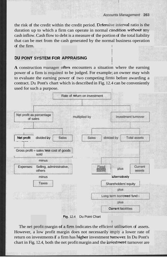
the risk of the credit within the credit period. Defen! .val ratio duration up to which a firm can operate in normal cbndition withoh, u,y
cash inflow. Cash flow to debt is a measure of the portion of the total liability that can be met from the cash generated by the normal business operation of the firm. I
is the rC ?"rr
I !
APPRAISING I I I
~f ten encounters a situation where the earning
I r SYSTEM FOR
A construction m
I U PON'
power of a firm is i to be judged. For example; an owner may wish to evaluate the earning power of two competing fir& before awarding a contract. Du Pont's chart which is described in Fig. 12.4 can be conveniently used for such a purpose. 1
Rate of retl urn on investment
of sales
Net profit divided ,, , w c w Gross profit = sales k
sold ?SS cost of goods I
minus + assets , ,,nu. $q blternatively
I Shareholders' equity I
Expenses: Selling, administrative, others
minus
pz--j
3wed fund:
l 2 ! Y ~drrent lia
Fiq. 12.4 Du Point Chart -
Fafirmh I
en1 utilis The ne nargin oj ndicates the effici ation of assets. However, a low profit margin does not necessarily &ply a lower rate of return on investments if a firm has higher investment tdrnover. In Du Pont's chart in Fig. 12.4, both the net profit margin and the indestrnent turnover are
st profit r
zb4 ~onsrrucrion Managemenr ana nannrr
combined to obtain the rate of return o ~vterred to as the earning power or overall prorlraolllry or me rlrn
Ratio analysis is widely used in assessing the perfc n particularly by outsiders like bankers, creditors and clien
Liquidity position, long term solvency, operating efficiency, overall profitability and performance can be evaluated by the ratio analysis. Indivi- dual ratios may or may not carry much information. However, a set of ratios when compared with similar ratios of other firms, in the same business or with respect to time reveal much information about the firm.
Ratio analysis is easy to perform. Statistical techniques like the discri- ~ninnnt a~alysis or the multip1 r becomt - rsome for casual users.
Ratio analysis though widf reral lim Different accounting practices or the impact of inflation may distort the ratios. An analyst should not be carried away by the apparently precise numerical values of ratios. The overall indications from the ratios nevertheless provide '1 reasonably accurate picture about a fir
strnent r I - I . . * . . - - -
atio whit r . 1 r . .
ch is als
sion ma!
has sel
le regres:
?ly used
INTERNAL AUDITING
he systen lures an(
nism in tl IS, procec
Internal auditing can be described as a monitoring mecha to ensure that the firm's financial and accounting policie controls are being followed.
2 principal purpose of internal aud Thr
1.
liting is z
uate the
1s follows:
To assist the management to eval and supervisors.
performance of employees
To assist supervisors to locate the proble~ and controls are necessary.
2 close fc
nd proce To ascertain if the firm's financial duses are being implemented.
4. To ascertain if the expenses and resource uses are juuicious~y aone by the supervisors.
5. To locate the areas where misappropriation, negligence and wastage have taken place
6. To recommend c ! action where appropriate
The internal auditing tunction may operate on both a post-audit or preaudit basis. Post-audit serves the useful purpose of reporting the fact, -- identifying errors of omission or commission and recommending steps for improvement.
For a construction f t which materials were 1 r
irm, an mrchase
internal d or lab(
audit in1 ~urers w
~olves sc ere emp;
:rutiny o loyed. Tl
f rates a 1e laboui
Accounts Management 265
and material quantum are verified with respect to the work done. The ~naintenance cost incurred to maintain the equipment is compared with other sil~iilar sites to evaluate the maintenance programme of the site managers. Arithmetical errors, if any -in the vouchers are also checked. Normally, internal auditors do not have sufficient time and resources to check all the vouchers. Therefore, the vouchers are selected randomly based upon statis- tical sampling techniques. If a problem area is located, detail scrutinies are made.
At the conclusion of an audit, the internal auditor is responsible for submitting a report identifying the objective and scope of study, the methods used and his findings. The finding does not only show the number, percent- age and type of errors but also suggests corrective actions.
STATUTORY AUDIT
This audit pertains to an examination of a firm's financial statements by an independent auditor. The auditor being a Chartered Accountant, a member of the Council of the Institute of Chartered Accountants of India, enjoys certain statutory privileges and obligations. The audit, in this sense, may be described as the process by which the auditor assures himself of the fairness of the financial statements, their conformity with generally accepted account- ing principles and the consistency with which the accounting principles have been applied from year to year. Under the current provisions of the Income Tax Act (see 44AB, 1991), a firm having a turnover above forty lakhs of rupees per year is required to obtain a detailed opinion of the auditors in the prescribed form. Such a report describes the accounting and financial details of the firm in addition to certifying financial statements. The auditor's reports are brief but reveals substantial details to an expert. Financial statements and reports certified by the auditor are the basis of evaluation of the firm by outsiders like tax authorities, bankers, clients, and stockholders. The auditing procedure involves the following :
1. Observation 2. Inspection 3. Confirmation 4. Comparison 5. Analysis 6. Computation 7. Inquiry 8. Certification The audit is normally conducted on a test basis. The auditor observes the
firm's accounting process, internal control etc. to gain an insight about the possible loop holes. The auditor confirms sample vouchers. For example, an advance received by a client may be confirmed by the auditor independently.
266 Construction Management and Planning
The auditor may inspect to verify the accounting data. For example, the auditor may like to inspect the inventory to check whether the actual inventory matches with the figures in the book. The auditor compares extensively with previous financial statements to discover significant varia- tions. Auditing involves extensive computations. For example, the deprecia- tion claimed by the company may be computed independently by the auditor to verify the firm's claim. Auditing sometimes involves inquiry. For example, an auditor may independently enquire about an ongoing lawsuit against the firm that have a significant bearing on the financial matters. Finally, the auditor certifies that the financial statements and reports prepared by the firm are correct and fairly representative of the firm's financial affairs to the public at large.
TAXATION
Tax management normally comes under the accounting management section of a firm. About sixty per, cent or more of the net income of most medium or large sized firms are levied as income taxes. In addition, a number of other taxes like turnover tax, wealth tax, capital gain tax, works contract tax and sales tax are enforceable upon the firm. Therefore, tax management is vitally important for any firm.
Tax planning refers to take advantage of the various tax shields that are offered under the act. There is nothing wrong in taking actions that lower the tax. However, tax evasion which is a criminal offence refers to the suppression of material information to avoid taxes. Attempts to evade taxes is not justified under any circumstance. Tax planning is also a complicated affair. Income tax laws and its application in practice is cumbersome in nature. One may not know whether a claim made under the provision of the act are accepted by the assessing officer. In many instances, the cases are required to be settled in higher administrative and/or judicial levels. In most cases, the facts are revealed from the accounting entries. The arguments placed by both the sides only try to explain the fact from different law points. Accounting entries or any action plan as described in the account books are therefore important from the point of view of taxation. Continuous advice from tax consultants is essential and very common to most firms. Any major decision like the purchase and sale of an asset, a new venture, etc. is therefore required to be discussed with a tax consultant before any accounting entries are made in the book.
Example 12.1. The following are the ratios relating to the activities of a company.
Stock velocity 8 months
Gross profit ratio 25%
Amounrs rvrarrayarrrer
Gross profit for the year ending 31st December amounts to Rs 4,00 Closing stock of the year is Rs 10,000/- above the ouenine stock. Es (a) the sales, and (b) closkg stock
Solution
Gross profit (a) Gross profit ratio =
Sales
41001000 x 100 = Rs 16,00,C Sales = -- 0.25
(b) Closing stock: Stock turnover takes 8 month
loo/-
IS.
i.e., Inventory turnover ratio = = 1.5 12
Cost of goods sold Inventory turnover ratio=
Average inventory
- Sales - gross profit Average inventory
or, 1.5 = RS 12,00 mn 1-
Average i
or, Average inventory= Rs 8,00,00 1
Prf Closing stock - Opening stock= Rs 10,000,
Closing stock + Opening stock - - Rs 8,00,00 2
or, Closinp; stock + Opening stock= Rs 16,00,C
From thc
"
e above c
,,"" -, nventory
2 x Openlng stock = Rs 16,00,000 - Rs-11 J - I J I J I ~ I -
Or, Opening stock = Rs 7,95,00
- , - - - I
nnn . . Closing stock = Rs 7,95,00v + 1- LU,UUUI -
Example 12.2 A firm has applied to a bank for a s I loan. The loan officer has collected the ratios for the last two ye; ~e firm and the similar industry averages which are presented. L Y I A L C : a small report to recommend/or not to recommend the loan. Show mendatioh.
hort tern ars for tl IATr;+n .r
reasons in your
- .
recom-
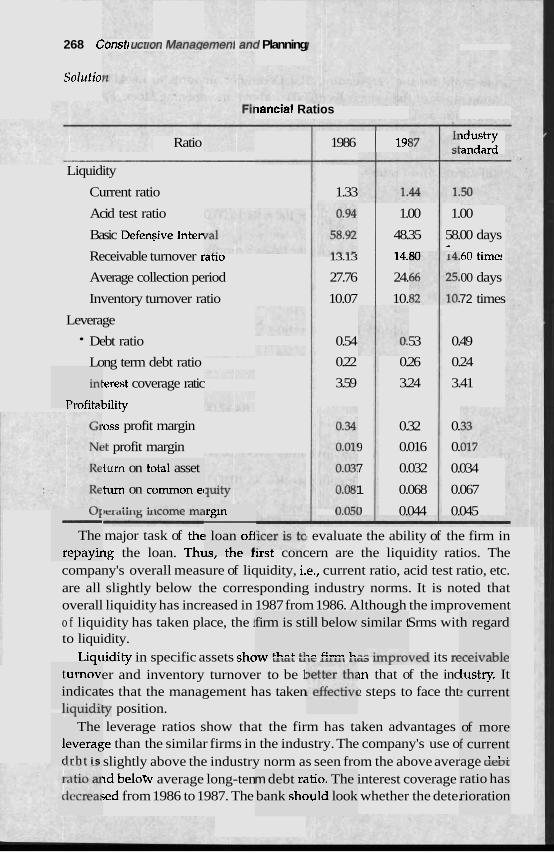
268 Cvrratr UUICNI Manautlllclll ~ I I J Planning
Soliitio
in1
Prnfital
WE - The
rep ayii
t umov, indicat l:-.*:A:,
The leverag drht i s
turn on tc
turn on cc .. .
~tal asset
ommon ec
iancial Ratios
Ratio 1986 19: ~dustry :andard
Liquidity
Current ratio 1.33
Acid test ratio 1.00 1.00
Basic Defen~ive Inten 48.35 58.00 days
Receivable turnover ratlo 13.13 14.-A " 60 time!
Average collection period 27.76 24. 00 days
Inventory turnover ratio 10.07 10. 72 times
Leverage
Debt ratio 0.54 53 0.49
Long term debt ratio 0.22 0.26 0.24
:erest coverage ratic 3.59 3.24 3.41
. . ....., bility
,ass profit margin 0.32 0.
!t profit margin 9 0.016 0.
7 0.032 0.034
1 0.068 0.067
u.u~O 0.044 0.045 lrgin
! loan off 1r t h ~ f
firm is st
.r.r +I..-.+ +I
m debt rl bank shc
- similar 1 h regard
."-:.?-Ll"
major task of the I evaluate the ability of the firm in ~g the loan. Tht,, .,., ,ust concern are the liquidity ratios. The
company's overall measure of liquidity, i.e., current ratio, acid test ratio, etc. are all slightly below the corresponding industry norms. It is noted that overall liquidity has increased in 1987 from 1986. Although the improvement o f liquidity has taken place, the 1 Srms wit to liquidity.
Liquidity in specific assets show u t a L ute lull1 llan ullylu~ed its E ~ e l v a v ~ e
er and inventory turnover to be 1: m that of the inc es that the management has taken 2 steps to face tht
l~uululty position. leverage ratios show that the firm has taken advantages ;e than the similar firms in the industry. The company's use o slightly above the industry norm as seen from the above average aeD1: ~d below average long-ten interest coverage jed from 1986 to 1987. The whether the dete.
ill below
.,. 42- l.
itio. The )uld look
lustry. It ? current
of more f current
. 1 - 1 I
ratio has rioration
Accounts Management 269
in coverage ratios resulted from lower income, higher finance changes or a (.ombination of the two.
The profitability ratios show that the firm has identical gross profit margin with other firms in the industry. The operating income margin is slightly lower than the norm, a fact indicating that operating expenses are slightly higher as a per cent of sales than the norm.
The net profit margin is little less than the industry norm. It has probably twen caused by higher interest changes and higher operating income of the firm.
The firm's return on total asset and operating income margin is little less than the industry norm. This is expected because both gross and net profit margin is less than the industry norm.
In summary, the ratios indicate the following:
1. The company's liquidity has increased in the last two years probably because of adequate management of current assets. Howevet; Lle company still faces liquidity problems in relation to similar firms in the industry.
2. The firm has used in the last two years higher le han the industry norm.
3. The current liabilities constitute a larger portion of total debt than is common in the trade.
4. The overall profitability of the firm is little lower than the industry probably because of higher operating income and finance changes. However, the profitability on owner's equity is higher than the norm due to higher leverage.
Rr~conzliznzdation: As the firm has lower liquidity and lower overall profit margin and higher leverage the loan is relatively risky. Therefore, the loan should not be ordinarily granted at a concessional rate. However, the firm is not in an extreme position. Therefore the loan may be granted with ag- propriate interest rate and collateral security to cover the financial risk.
EXERCISES
12.1 Explain how the change in depreciation rate may affect the profitability of a firm.
.I 2.2 Describe the basic concepts on which the accounting systems are based.
12.3 Explain why a firm may have to pay taxes upon an income that has not been received yet.
12.4 Explain and discuss the statement "Accounts may fail to recognise many important aspects of a firm".
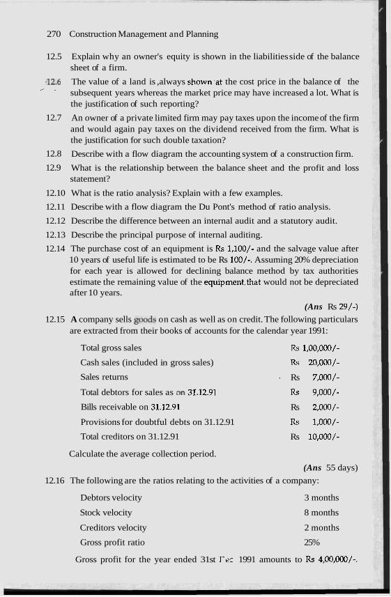
270 Construction Management and Planning
12.5 Explain why an owner's equity is shown in the liabilities side of the balance sheet of a firm.
.12.6 The value of a land is ,always shown.at the cost price in the balance of the .-. .
subsequent years whereas the market price may have increased a lot. What is the justification of such reporting?
12.7 An owner of a private limited firm may pay taxes upon the income of the firm and would again pay taxes on the dividend received from the firm. What is the justification for such double taxation?
12.8 Describe with a flow diagram the accounting system of a construction firm.
12.9 What is the relationship between the balance sheet and the profit and loss statement?
12.10 What is the ratio analysis? Explain with a few examples.
12.11 Describe with a flow diagram the Du Pont's method of ratio analysis.
12.12 Describe the difference between an internal audit and a statutory audit.
12.13 Describe the principal purpose of internal auditing.
12.14 The purchase cost of an equipment is Rs 1,100/- and the salvage value after 10 years of useful life is estimated to be Rs loo/-. Assuming 20% depreciation for each year is allowed for declining balance method by tax authorities estimate the remaining value of the equipment.that would not be depreciated after 10 years.
(Ans Rs 2R/-)
12.15 A company sells p o d s on cash as well as on credit. The following particulars are extracted from their books of accounts for the calendar year 1991:
Total gross sales Rs 1,00,000/-
Cash sales (included in gross sales) Rs 20,000/-
Sales returns ' Rs 7,000/-
Total debtors for sales as an 31.12.91 Rs 9,000/-
Bills receivable on 31.12.91 Rs 2,000/-
Provisions for doubtful debts on 31.12.91 Rs 1,000/-
Total creditors on 31.12.91 Rs 10,000/-
Calculate the average collection period.
(Ans 55 days)
12.16 The following are the ratios relating to the activities of a company:
Debtors velocity 3 months
Stock velocity 8 months
Creditors velocity 2 months
25% Gross profit ratio
Gross profit for the year ended 31st Tec 1991 amounts to Rs 4,00,000/-.
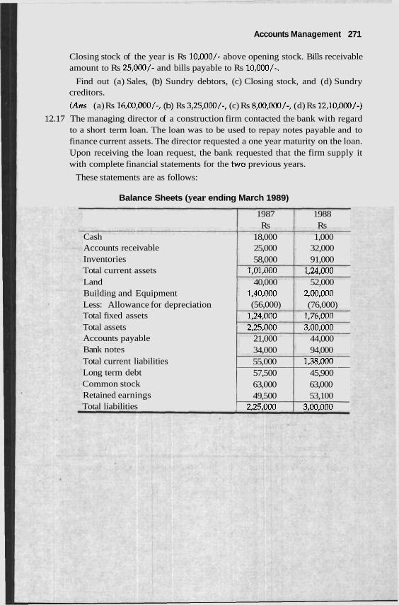
Accounts Management 271
Closing stock of the year is Rs 10,000/- above opening stock. Bills receivable amount to Rs 25,000/- and bills payable to Rs 10,000/-.
Find out (a) Sales, (b) Sundry debtors, (c) Closing stock, and (d) Sundry creditors.
(Ans (a) Rs 16,00,000/-, (b) Rs 3,25,000/-, (c) Rs 8,00,000/-, (d) Rs 12,10,000/-)
12.17 The managing director of a construction firm contacted the bank with regard to a short term loan. The loan was to be used to repay notes payable and to finance current assets. The director requested a one year maturity on the loan. Upon receiving the loan request, the bank requested that the firm supply it with complete financial statements for the two previous years.
These statements are as follows:
Balance Sheets (year ending March 1989)
1987 1988 Rs Rs
Cash 18,000 1,000 Accounts receivable 25,000 32,000 Inventories 58,000 91,000 Total current assets 1,01,000 1,24,000 Land 40,000 52,000 Building and Equipment 1,40,000 2,00,000 Less: Allowance for depreciation (56,000) (76,000) Total fixed assets 1,24,000 1,76,000 Total assets 2,25,000 3,00,000 Accounts payable 21,000 44,000 Bank notes 34,000 94,000 Total current liabilities 55,000 1,38,000 - Long term debt 57,500 45,900 Common stock 63,000 63,000 Retained earnings 49,500 53,100 Total liabilities 2,25,000 3,00,000
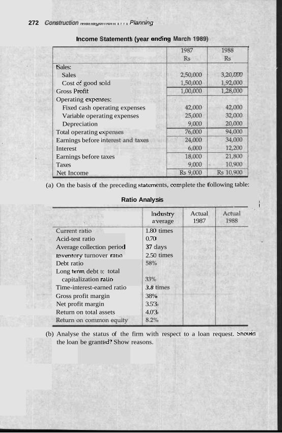
272 C ~ r r ~ l r u ~ l r u r r r v r a r r a y G r r r G r r l a r r u r r a r r r r r r r y
I
-
s (year er ncome 9 tatement! iding Ma1
- !
Cost c
Gross PI
Operating expens Fixed cash operating expenses Variable operating expenses Depreciation
Total operating er Earnings before u Interest Earnings before taxes Taxes Net Income
-
nnn Sales:
Sales )f good sc rofit
)Id
es:
(a) On the basis of the preceding statem
Ratio Analy:
ents, corn
sis
plete the 1 following table:
I - 1
In a.
1.80 0.70
I 37 c
lnvenrory turnover rarlo 2.50 Debt rat Long tel
capita Time-interest-earned ratio 3.8 1
Gross profit margin 38% Net profit margin 3.5'3 Return on total assets 4.0'3
Actual 1987
Idustry verage
1 times Acid-tes Average
t ratio collectior
I
lays 1 times
1 period
io .m debt tc lization r;
total 3tio
(b) Analyse the status of the firm with respect to a loan request. snoula the loan reasons. be grantt 2d? Show
Cost Mz
INTRODUCTION
cost esti: perform6 es.
mates alt !d accorc
lay be t e ~ Ine or a
PRODUCTION
most sin
,ts of con! the objec
Cost estimating is one of the most important aspec struction manage- ment. Several types of estimates depending upon ztives and resour- ces of the decision maker can be prepared. As ekvcc~ru, the accuracv of a cost estimate is proportional to the time and fund! 2d. A few the cost estimates are the production function, orc gnitude, for the bill of quantities, and control estimates.
Most of the hough IY literatures are : ling to a basic approach,
s deploy( ler of ma
med diff combina
erently ir tion of tl
defined lantum (
as the relationshi 3f various inputs
. . . ,xn)
!e in cons is the esi
In economics, the production function is the quantity of an output Q and the q~ XI, 9, . . . , xn to achieve it.
if (XI, X2,
The nple and I exampl a building based upon the covered area. In this case, an inp Its 200/- in 1990) is found to be required on an average to p of a unit square foot of covered area of standard specificatic building. The value of such estimates change with time mainly be inflation, i.e. price increase. It also assumes that the scope of work specification is fully known. In common problems like the estir residential building such information is generally '
In other cases, the individual production fi
known. unctions for the
types of unit cost
I various 2e above
P -0%
namely,
h a t e of ney (say, n output sidential !cause of . and the late of a
various
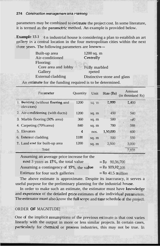
274 Consrrucrron w~anagemenr ana riannmng
parameters may be comb ~stimate the project cost. In some literature, it is termed as the paramerrlc method. An example is provided below.
ined to e - L.2 ... . ,
. Exampl i n industrial house is considering a plan to establish an art gallery m a central location in the four metropolitan cities within the next
ars. The following parameters are known- t I1 ree ye
Built-up area 1200 sq. m Air-conditioned rantrally Flooring:
Core area and lobby Ily marbled Gallery rpeted
External cladding Distinctive stone and glass
bstimate for the funding required is to be determined.
)meter Quantity Unit I Rate (Rs) Amo
(in thousi
7 n r
unt and Rs)
I . Bullding (without floorira 3-A 1200 aq. L A L 7 nnn 'b U1.U
ucts)
tors)
mditionin sq. m 1200
3. Marble flooring (30% area) 360 sq. m 500 4 ,-
4. Carpeting (70% area) 840 sq. m 700
5. Elevators 4 nos. 1,50,000
la1 cladding 1100
cost for built-up area 1200 -
>tal
ig (with d
6. Exter~
7. Land
sq. m
sq. m
Assur ",,"I
ning an i - 2 .,Am..,-
average price increase for the . ., ycCLIJ as 15% the total value = Rs 90,36.7M ning a contingency of 15"/ lue = Rs 103,92
ate for four such galleries = Rs 41.5 n
The above estimate is approximate. Despite its inaccuracy, it serves a useful purpose for the preliminary planning for the industrial I~ouse.
In order to make such an estimate, the estimator must have knowledge ailed pric 2 individ low the 1 e schedu
1 L C * I
Assur
Estim b, the val
and expc The estir
xience o nator mu
f the deti 1st also kl
:e estima !ull scopc
tes of thc : and tiw
ual para le of the I
ORDER OF MAGNITUDE
One of the implicit assum vious est that cost varies f the pre or less similar projects. In certain cases, ess industries, this may not be true. Ic
linearly particula
with the rly for c
output :hemica1
in more or proc~
addition, a number of statistical studies conducted ove ars have developed a better idea about the cost-volume relationships particularly for the chemical and process industries. Usually, tl derived through regression analysis techniques.
The most common among such techniques is called the factored cost metho, >lant, system or compone accura !thod. The most common
r the ye . .
le relatic
d. The cc tely by sl
1st of a I uch a mc
nt can bc formula :
estirnat is:
ed fairly
fact0 New plant size
?d cost = Reference plant size 1 Estimate lant cost x Ref. p
ldex x Price index x Location ir ~,
Although the factoi is sometimes called the sixth tenth factor it depends upon the system and may vary from 0.2 to 1.4 for different systems. The price increase index accounts for the inflation and vrice rise. The location index adjusts the price that mi lue to co tage of the location of ject. The literature like woods.'
The sophisticated sta echnique :ost functions for many process-equipmer L can be d to estimate the cost of a system. Relevarlr l~rerature is he~prul io ouram a cost function for the required sy!
While using ~ctions, one mus limitations. Otherwise, gross errors may crop up m tne estimate.
i~y arise ( the pro
mparatix ! factors
re advani may be
tage or d found f
isadvan- 'rom 'the
itistical tl ~ t , which -L l:L--.-,
IS have c ierived c
stem. cost fLll - ..- . . - .
eful abo; ut its sc~ . .
ope and
UNIT COST FOR THE BILL OF QUANTITIES
This is the most important and widely used means for achieving the cost estimates of civil construction. The work is divided into individual items. In practice, the items have been standardised over the years. In India, items used by PWD have been followed mostly as standard.
The system is simple and effective.-The unit cost is the summation of the cost of materials, labour, equipment, overhead and profit. The practising cost engineer must be conversant wjth the method of (
. In order to facilitate the estimation, standard 1 published by National Buildings 0rganisation2 arc cVllllllVlllY UJcU. lllcac
har!dbooks provide a list of standard items and m nd labour inputs to produce one unit of the standard items. The est xmally provides the going rate of materials, labour and overheads LV a l l l ~ e at the unit rate. The rat ~rther de book.
ing the u ks like t --l-, ..",-..
- lnit cost. he ones -1 I-%,.-
ateials, a imator nc
&A .."..;.,* - .e analys is which gives fu tails is p rovided .e in the
276 Construction Management ana rlannmg
CONTF 'IMATES
Dirring me actual execution or tne construction, a detaled analysis or costs are required to be made. The cos tes prepared duri esign or bidding stage may not be sufficiei licable during the )n stage. During the execution stage, the control estimate system serves two useful purposes. First, it develops the production informz materials, labour iw~E~-&~ui~ment that can be used as input for futu ates. Secondly, it generates information so - ~ d v to ta m inimise the co
;t estimal nt or app
ng the dl ! executic
rtion for : Ire estim,
1 that on6 step.
? may sh ke correc :tive mea sures to st at any
INDIRECT COS
Apart from the I
generally c0mbhtt.s a11 uu1t.r cusrs UILU overliedus. 111 cast. UI curlrlul esurrlares, overheads may be divided into ates for ruonitoring purposes. A checklist d here.
direct m: --- -11 -Ll
tterial, ec L-- ---L-
t and lab .L---1- TI
our, the 1 . ---- -1 -
Llnit cost .----I --
method L:--L--
a numk for such
direct cc costs arc
~ -
)st estim ! provide
rary Utili
~Iudes th 1:-..
ity ~e cost 01 .___ 1 _..-,
This in( manage] and sewage ulspvsal system. m a ciry area, these urilines may we purcnasea directly from the public system. I generated within the site
tion and -:.-. - ~
water, ell 1 - ~
ment of .. I . . . - - -
utility : n many instance s, these may be
. Consumables
Consumables in 1 clothin c. Hard hats, boots, goggles ror welamg, snoveis, spades, baslcets, tumbler locks, rags,
IS, electric bulbs, hammer ed as a percentage of lab0
!ry, medi f the iter
cal supp ns can bi
lies, fuse 2 estimat
s, wrencl ur costs.
hes, etc.
Cleanin
The co: .. .
'g ;t of clei
estimated. It can be calculated as a percentage of labour hours and the e site ar . . . sal of n
number a of hauli
i..,"
ng truck:
Unload
The cos like tra~
jading m s, large (
. -
are requi pipes, a
rred to b~ nd prefa . .
ted. Bulk stntcturi
.y items t1 items
docks. If .elay in rr
may require special on 5
ports are involved the cos may be substantial.
;ite road: ,t of demi
; and un urrage in
[loading case of d
: the rail laterial h
head or andling
Cost Management 277
Transportation within the Job Site
The material handling cost within the site is required to be estimated. Bulky items like the roof truss or precast piles that is required to be transported within the site may be time-consuming and costly. Special access roads may be required. In a labour-oriented construction site, material handling is time-consuming. Any mistake in planning may become time-consuming and costly. Transportation facilities within a job site may be taken as percentage of material cost or a part of the transportation may be directly estin
Warehousing
A large amount of construction materials are required to be stored in site. Special facilities are required to be made for this. The cost of a cement godown, equipment storage godown, etc. are directly estimated. The cost of devices for safety and anti-pilferage are required to be estimated.
Workshop
In a large site, a number of construction machinery are deployed. In most sites the machines are not used and maintained well. The machines operate through extreme clhates and in an environment containing dust and mud. Machines require continuous maintenance and replacement. A workshop having minimum facilities are required in a site, the cost of which should be estimated.
Laboratory
Construction materials are required, to be routinely checked for quality control. l l ~ e cost of establishing and operating a laboratory are required-to be estimated.
Construction Office
For some sites, temporary or mobile structure is sufficient for the construc- tion office. In most situation, a semi-permanent office is required for a construction office. The size depends upon the number of people that must be accommodated. Sufficient storage for files is required for safe keeping. In an extreme climate, the office is required to be temperature-controlled.
Communication
Communications with outside and inside the site are very I I I ~ ~ V I L ~ ~ ~ . The cost may not be much while the public systems are used. In many cases, private wireless systems are required to be established and maintained. In remote sites, considerable expenses may be involved for the construction of microwave towers, dish antenna, etc.
278 Construction Management and Planning
Safety and Medical
Safety and medical costs will depend upon the labour force, and the type of construction. Medical costs and supplies are to be included.
Quality Assurance Quality assurance programme is an important factor for any construction site. Routine tests for aggregates, concrete and welding are required to be made. In addition, incoming supplies are required to be checked routinely. The cost of a quality assurance programme depends upon manpower and consumables deployed.
Catering
As construction work is continued for long hours, the arrangement for catering is made in many sites. For remote sites, catering is very important and expensive. Catering cost depends upon the manpower deployed.
Hospitality Cost Various forms of hospitality costs are incurred. Visits from the corporate office, architects or owners are the common cause of expenses.Visits from the reguiatory agencies are also very common. For large sites, public relation and communication with the press are also very important for the positive pro-jection of corporate images. The cost of hospitality depends upon the duration of the project.
Indirect Labour Cost
This is an important factor that is required to be estimated. Non-productive labour cost arises for several reasons like bad weather, sick pay, employment benefits, holiday pays, delay for test checking and measurements.
Project Management Cost
This is also an important source of expenditure to be controlled. The design and management costs for shop drawings, scheduling, bill preparations, material reconciliations and project management are required to be esti- mated. The cost can be derived from an estimate of the manpower proposed to be deployed.
Insurance
Insurance is a safeguard against risk. For an individual firm, the insurance is the most cost-effective and probably the only method to deal with the risk of an industrial accident. Insurance covers are generally available in a basic policy with add-on facilities. The basic policy could be on natural hazards like fire and earthquake, with add-on facilities like riot, strike and flood.
;t Manage ment 27
There are also tailor-made all risk cover policy of for constructioi~ sites. Separate policies are also i
tion of workmen or third party risk. Insurance c the indirect cost of a project.
the insur, for the c
ance firm :ompens:
CONTINGENCY
(:c>ntingency is a cushion of cost to deal with the l*omplicated because of the different definition ed by the variot parties. To the top management, contingency is t y which would nc t)c expended and would be returned as profit a 1 of the project. 1 tmgineers, contingency is a savings account thal drawn on to cow thc additional costs of add-on features to th t. To constructio managers, contingency is an indirect cost like a )arty and gifts thi cannot be charged directly to the project.
Contingency, in principle, is intended tl < of an over-run fc a project executed under expected conditic t factors that belon to contingency are rnh p changes, underestimate of cost and quar tities, lack of experien ticipated price changes, corrections of minc erroneous assumption: lot identified fully in the estimating stage an some unforeseen regulations and safety problems.
Contingency may or may not include escalation and I
tion is a provision in the estimated cost for inflation or COI
increase over time. Allowance is a fund included in the estimate for iten that are known but cannot be defined to the extent to estimate the cost.
The method for developing contingency depends on the organisation, tl type and duration of the project, the type of estimate ar project.
The subjective estimate by skilled professionals are most orten -- percentage difference between an estimated and an a st projects provides a better idea of probable contingencies.
For large projects with different types of works, a weigntea average of contingencies for each work may be used for the total pr 3r very large projects, tec like the Monte Carlo simulation mi b d l to ascertain the contingency or the risk of the project. The contingency is generally included under a separate hei
as becom IS assum he mone: ~t the enc t can be le projec I social p
:e the risl ew of the
o reduc Ins. A fl
nor desig ce, unan 5, items r
dlowanc ntinuing
es. Escali price lev'
~d the pl-
. c.
type of hniques
,ejects. Fc 3y be use
ad in the .. .
project c
COST-VOLUME RELATIONSHIP
ship exa mines th As the name t-volumc ship among cs profit.
The cost is divided into fixed and variable con the cost and revenues against the volume of bus;
suggests ost, volu
, the cos me and 1
: relation
nponents hess (Fie
;. The an: ;.13.1). Tl
dysis plo Ie revenl
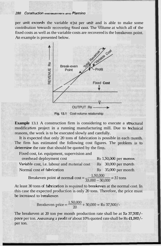
280 C~rrsiruu~rvrr marrauerrrerrl arru Plannina
is able to make some C U ~ ~ L ~ ~ V U L L U L I L U W C ~ I U ~ I ~ L U V C I U I ~ ILXCU LWL. 111t: volume at which all of the fixed costs as well as the variable costs are recovered is the E An example is presented below.
per unii ---L:L..
: exceed: A:-.- A.,..
; the va --.-lo -",
riable cc .-*--:-- L
)st per I :.*--I - - - I
mit and . n- ---
1 point.
Break-even Point
/ 1 I Cost
13.1 A construction firm is considering to execute a str tion project in a running manufacturing mill. Due to tel the work is to be executed slowly and carefully. xpected that only 20 tons of fabrication is possible I has estimated the following cost figures. The le the rate that should be quoted by the fin
cost, i.e. equipment, supervision and head deployment cost RS I,SU,UUU per mon,.
.e. labou 30,000
f fabricat 35,000
uctural chnical
Example modifica reasons,
It is e The firn
in each I
problem determir
Fixed over
r and mz ion
per mon. )le cost, i
a1 cost oj
Variat
Norm per mon
~t normal Breakeven point a 1 cost = - 3.
D tons
At least 30 tons of fabricat breakem this case the expected production is only 20 tons. Therefore, the price must
~sed to b~
ion is re( - .
en at the - normal c
be increa reakeven
I
20 ton I The brea h production rate shall be at Rs 37,500/- pnce per ton. Assuming a profit or about 10% quoted rate shall be Rs 41,000/-
keven at )er mont r . . ,-
per ton.
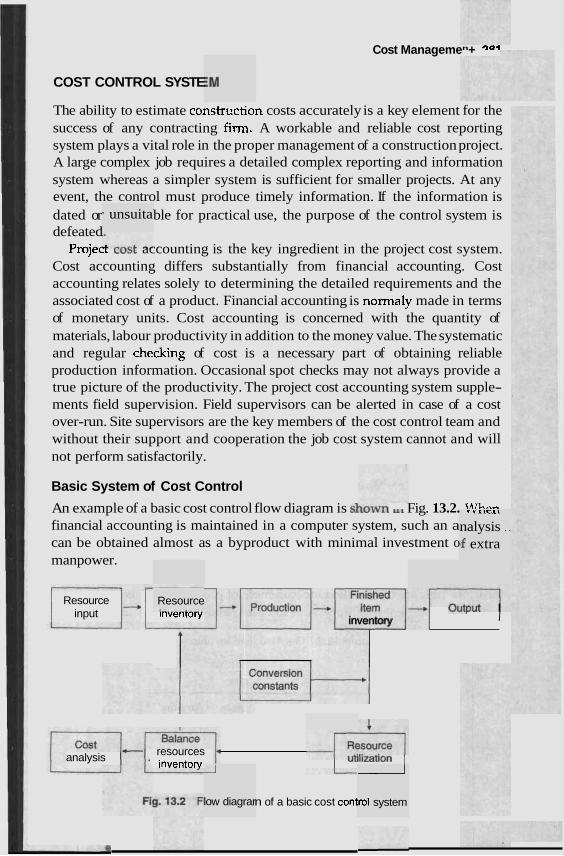
COST CONTROL SYSTE
Cost Managemen+ OQi
- unsuita
The ability to estimate constr~ction costs accurately is a key element for the success of any contracting firm. A workable and reliable cost reporting system plays a vital role in the proper management of a construction project. A large complex job requires a detailed complex reporting and information system whereas a simpler system is sufficient for smaller projects. At any event, the control must produce timely information. If the information is dated or ble for practical use, the purpose of the control system is defeated
ProjecL LVJL accounting is the key ingredient in the project cost system. Cost accounting differs substantially from financial accounting. Cost accounting relates solely to determining the detailed requirements and the associated cost of a product. Financial accounting is normaly made in terms of monetary units. Cost accounting is concerned with the quantity of materials, labour productivity in addition to the money value. The systematic and regular checking of cost is a necessary part of obtaining reliable production information. Occasional spot checks may not always provide a true picture of the productivity. The project cost accounting system supple- ments field supervision. Field supervisors can be alerted in case of a cost over-run. Site supervisors are the key members of the cost control team and without their support and cooperation the job cost system cannot and will not perform satisfactorily.
Basic System of Cost Control
An example of a basic cost control flow diagram is slLuvvLL U L Fig. 13.2. IA"---
financial accounting is maintained in a computer system, such an a can be obtained almost as a byproduct with minimal investment o manpower.
V V I L C I L
nalysis . . if extra
Resource I input 1- I lnvenrory Resource 1 q . - Z q - , " i t ,
inventory
analysis resources inventow I ,.ll~zation 1
_I
low diagrar n of a basic cost cont
I
,rol system
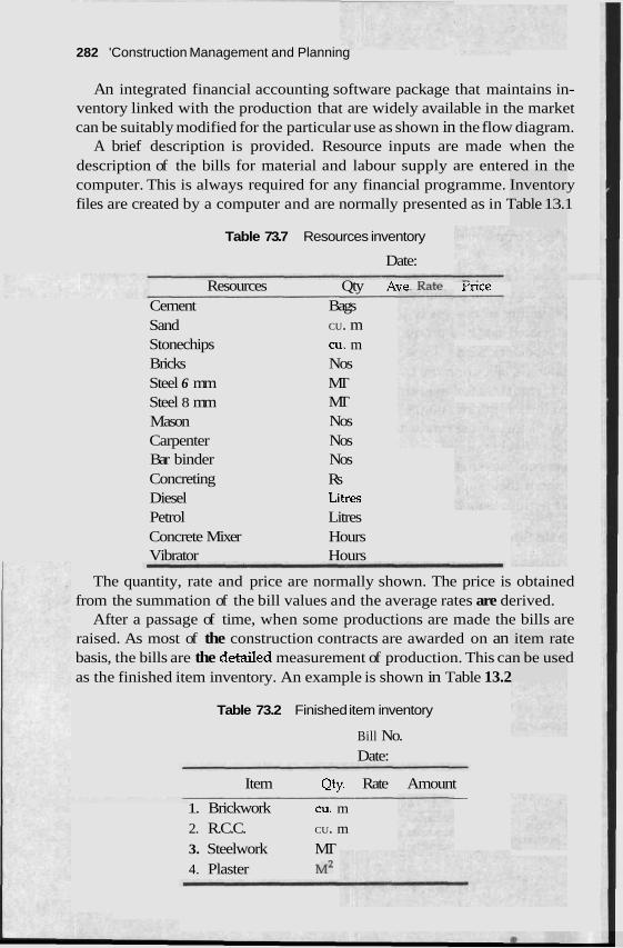
282 'Construction Management and Planning
An integrated financial accounting software package that maintains in- ventory linked with the production that are widely available in the market can be suitably modified for the particular use as shown in the flow diagram.
A brief description is provided. Resource inputs are made when the description of the bills for material and labour supply are entered in the computer. This is always required for any financial programme. Inventory files are created by a computer and are normally presented as in Table 13.1
Table 73.7 Resources inventory
Date:
Resources Qty AVP Rate rrlce Cement Bags Sand Stonechips Bricks Steel 6 mm Steel 8 mm Mason Carpenter Bar binder Concreting Diesel Petrol Concrete Mixer Vibrator
CU. m CU. m Nos MT MT Nos Nos Nos Rs Litres Litres Hours Hours
The quantity, rate and price are normally shown. The price is obtained from the summation of the bill values and the average rates are derived.
After a passage of time, when some productions are made the bills are raised. As most of the construction contracts are awarded on an item rate basis, the bills are the detaiIed measurement of production. This can be used as the finished item inventory. An example is shown in Table 13.2
Table 73.2 Finished item inventory
Bill No. Date:
Item Qty. Rate Amount -
1. Brickwork CU, m
2. R.C.C. CU. m
3. Steelwork MT 4. Plaster M~
Cost Management 283
When such bills are prepared by the computer, the resources required to produce the finished items are estimated by the computer. The conversion o f raw materials to finished goods are made upon the conversion constants already stored in the computer. In this case, the standard materials constant that are available in handbooks or PWD manuals are used. The balance raw materials are automatically calculated and are shown in the inventory output by the computer. An actual site checking is made on the date of the measurement for the bill. A comparison between the actual site inventory and the balance theoretical inventory produced by the computer gives an idea about the variation of the material used with the theoretical quantities. One would also ascertain from the monetary values the actual cost of the production or profit accrued in the time period. The obvious advantage of the system is limited to the manpower requirement. The bills for the incoming supply and outgoing product are required to maintain in the software system for financial accounting. Inventory and cost control can be done with the same database. The major disadvantage is that the raw materials that are used in the different finished product are combined. For clxample, sand or cement may be used for concreting, brickwork and plaster. One may not be able to account for cement for individual items. Cement may be spoiled during plaster but with such a system it cannot be pin-pointed. For smaller sites, overall checking of material costing may be sufficient. As long as the total material consumption remains within control one may assume that individual uses are alright. In case of a problem, one may initiate a detailed system of cost control.
Detailed System of Cost Control
I11 the detailed system of cost control, meticulous cost figures are maintained. Example blank forms are shown in Table 13.3. Daily material, labour and equipment usage, and associated costs are collected. When the measurements for bills are made, a cost report as shown in Table 13.4 is prepared. The budgeted cost, cost during the time period and cumulative cost are collected. In Table 13.4, the budgeted costs shown in columns 5, 8,11 and 14 are the product of actual work done in this period shown in column 3 and the unit rate estimated during the budget or tender preparation. The actual costs shown in columns 6, 9, 12 and 15 are estimated from the summation of respective daily data shown in Table 13.3.
The actual cost and the budgeted cost are compared and are shown in Table 13.5. The profit or loss for each item are compared for the said time period and total duration of the work. The deviation from the budget are ilso indicated. One may decide from Table 13.5 what are the items that require special cost control and attention during the execution of the work. The projection of profit and loss can also be estimated.
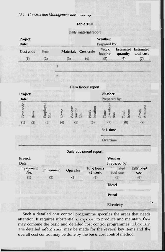
284 Construction Management ancl rrdrrrrrrry
Table 13
y material
Project: Weather: prensred by:
~rk Estimated Estimated tion quantity total cost i'1 16) (7'1
Date:
Material: ; Cost cc Cost cc
report ly labour I
Project: Date:
tather:
1. time
Daily equlpmer ~t report
Project: Weather: Date: Prepared bv:
- . - - . -
Equipmi tir No.
quipment C(
Opera
(3)
tal hours )f work
nated Et
Diesel
Petrol
:,. Electricit
Such a detailed cost control me specifies the areas that needs attention. It requires substantial ~ e r to produce and maintain. Oqe rnay combine the basic and detailed cost control programmes judiciousk. The detailed information may be made everal key items overall cost control may be done by the t control method.
program manpow ~- -
for the s basic cost
and t ie
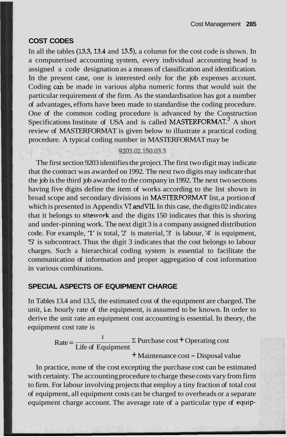
Cost Management 285
COST CODES In all the tables (13.3,13.4 and 13.5), a column for the cost code is shown. In a computerised accounting system, every individual accounting head is assigned a code designation as a means of classification and identification. In the present case, one is interested only for the job expenses account. Coding c& be made in various alpha numeric forms that would suit the particular requirement of the firm. As the standardisation has got a number of advantages, efforts have been made to standardise the coding procedure. One of the common coding procedure is advanced by the Construction Specifications Institute of USA and is called MASTER FORMAT.^ A short review of MASTERFORMAT is given below to illustrate a practical coding procedure. A typical coding number in MASTERFORMAT may be
The first section 9203 identifies the project. The first two digit may indicate that the contract was awarded on 1992. The next two digits may indicate that the job is the third job awarded to the company in 1992. The next two sections having five digits define the item of works according to the list shown in broad scope and secondary divisions in MASTERFORMAT list, a portion of which is presented in Appendix VI andVII. In this case, the digits 02 indicates that it belongs to sitework and the digits 150 indicates that this is shoring and under-pinning work. The next digit 3 is a company assigned distribution code. For example, '1' is total, '2' is material, '3' is labour, '4' is equipment, '5' is subcontract. Thus the digit 3 indicates that the cost belongs to labour charges. Such a hierarchical coding system is essential to facilitate the communication of information and proper aggregation of cost information in various combinations.
SPECIAL ASPECTS OF EQUIPMENT CHARGE
In Tables 13.4 and 13.5, the estimated cost of the equipment are charged. The unit, i.e. hourly rate of the equipment, is assumed to be known. In order to derive the unit rate an equipment cost accounting is essential. In theory, the equipment cost rate is
Rate = 1 - Z Purchase cost + Operating cost
Life of Equipment + Maintenance cost - Disposal value
In practice, none of the cost excepting the purchase cost can be estimated with certainty. The accounting procedure to charge these costs vary from firm to firm. For labour involving projects that employ a tiny fraction of total cost of equipment, all equipment costs can be charged to overheads or a separate equipment charge account. The average rate of a particular type of equip-
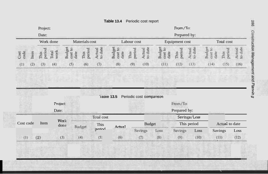
Table 13.4 Periodic cost report
Project:
Date:
From/To:
Prepared by:
Work done Materials cost Labour cost Equipment cost Total cost
Cost cod e Item
Projec.
Date:
Wor don
2 3 3 5'
laole 13.5 Periodic cost comparlson (Q
tal cost
This rorinrl
Actual - Budget
Prepared by:
Savings/Loss
This period a1 to date
Savings Loss Loss
Actu
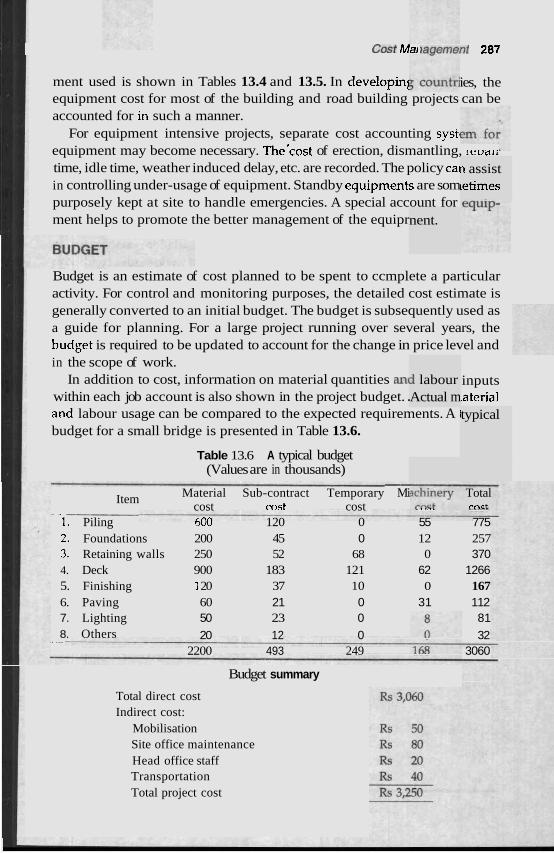
Cost M a , ravcrrrcnt 287
ment used is shown in Tables 13.4 and 13.5. In developinl ies, the equipment cost for most of the building and road building projects can be accounted for in such a manner.
For equipment intensive projects, separate cost accounting systi equipment may become necessary. The'cost of erection, dismantling, rcvalr
time, idle time, weather induced delay, etc. are recorded. The policy ca in controlling under-usage of equipment. Standby equipments are som purposely kept at site to handle emergencies. A special account for ment helps to promote the better management of the equipr nent.
i labour Actual m
n assist letimes
Budget is an estimate of cost planned to be spent to ccmplete a particular activity. For control and monitoring purposes, the detailed cost estimate is generally converted to an initial budget. The budget is subsequently used as a guide for planning. For a large project running over several years, the budget is required to be updated to account for the change in price level and in the scope of work.
In addition to cost, information on material quantities an( inputs within each job account is also shown in the project budget. . laterial and labour usage can be compared to the expected requirements. A i budget for a small bridge is presented in Table 13.6.
Table 13.6 A typical budget (Values are in thousands)
typical
- Item Material Sub-contract Temporary Mi
- - cost ccpst cost LU". L.,<L
1. Piling 600 120 0 55 775 2. Foundations 200 45 0 12 257 3. Retaining walls 250 52 68 0 370 4. Deck 900 183 121 62 1266 5. Finishing '1 20 37 10 0 167 6. Paving 60 21 0 31 112 7. Lighting 50 23 0 81 8. Others
. ..- 20 12 0 32 2200 493 249 3060
Budget summary
Total direct cost Indirect cost:
Mobilisation Site office maintenance Head office staff Transportation Total project cost
Total m c t
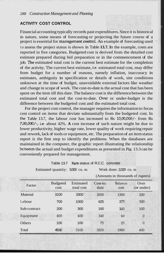
288 Construction Management and Planning
ACTIVITY COST CONTROL
Financial accounting typically records past expenditures. Since it is historical in nature, some means of forecasting or projecting the future course of a project is essential for management.contro1. An example of forecasting used '.
t o assess the project status is shown in Table 13.7. In the example, costs are reported in five categories. Budgeted cost is derived from the detailed cost estimate prepared during bid preparation or in the commencement of the job. The estimated total cost is the current best estimate for the completion of the activity. The current best estimate, i.e. estimated total cost, may differ from budget for a number of reasons, namely inflation, inaccuracy in estimates, ambiguity in specification or details of work, site conditions unknown at the time of budget, unavoidable external factors like weather and change in scope of work. The cost-to-date is the actual cost that has been spent on the item till this date. The balance cost is the difference between the estimated total cost and the cost-to-date. Over or under-budget is the difference between the budgeted cost and the estimated total cost.
For the project cost control, the manager requires the information to focus cost control on items that deviate substantially from the budgeted cost. In tlie Table 13.7, the labour cost has increased to Rs 10,00,000/- from Rs 7,00,000/-, i.e. about 42%. A cost increase of such nature might be due to lower productivity, higher wage rate, lower quality of work requiring repair and rework, lack of tools or equipment, etc. The preparation of an item status report is the first step to identify the problems. When the databases are maintained in the computer, the graphic report illustrating the relationship between the actual and budget expenditures as presented in Fig. 13.3 can be conveniently prepared for management.
~ Table 13.7 Item status of R.C.C.
Estimated quantity: 3,000 cu. m Work done: 2,020 cu. m
(Amounts in thousands o f rupees)
Factor Budgeted Estimated
cost total cost Cost-to.
date Over
)r under)
Material 3100 3300
L,a bour 700 1000 625 3
Sub-contract 200 300 160 1
Others 100 100
Total 4501
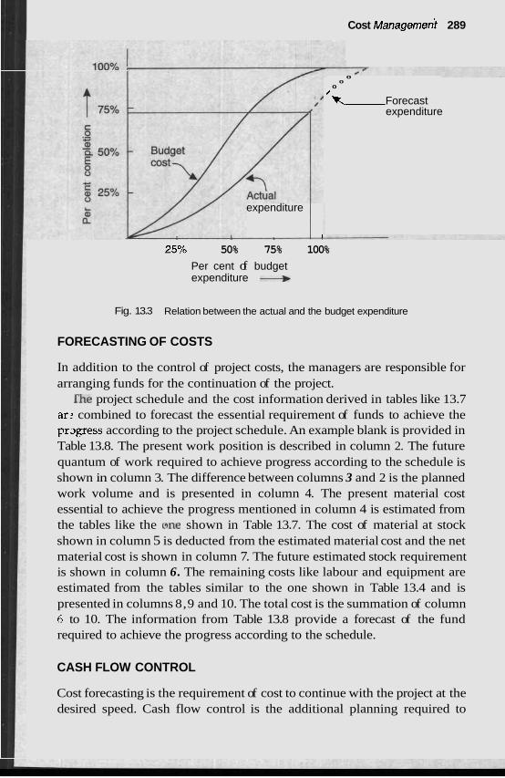
Cost ~anagemed 289
0 0
0
'R Forecast expenditure
expenditure
I
25% 50% 75% 100%
Per cent of budget expenditure
Fig. 13.3 Relation between the actual and the budget expenditure
FORECASTING OF COSTS
In addition to the control of project costs, the managers are responsible for arranging funds for the continuation of the project.
f i e project schedule and the cost information derived in tables like 13.7 ar: combined to forecast the essential requirement of funds to achieve the pr2gress according to the project schedule. An example blank is provided in Table 13.8. The present work position is described in column 2. The future quantum of work required to achieve progress according to the schedule is shown in column 3. The difference between columns 3 and 2 is the planned work volume and is presented in column 4. The present material cost essential to achieve the progress mentioned in column 4 is estimated from the tables like the one shown in Table 13.7. The cost of material at stock shown in column 5 is deducted from the estimated material cost and the net material cost is shown in column 7. The future estimated stock requirement is shown in column 6. The remaining costs like labour and equipment are estimated from the tables similar to the one shown in Table 13.4 and is presented in columns 8,9 and 10. The total cost is the summation of column 6 to 10. The information from Table 13.8 provide a forecast of the fund required to achieve the progress according to the schedule.
CASH FLOW CONTROL
Cost forecasting is the requirement of cost to continue with the project at the desired speed. Cash flow control is the additional planning required to
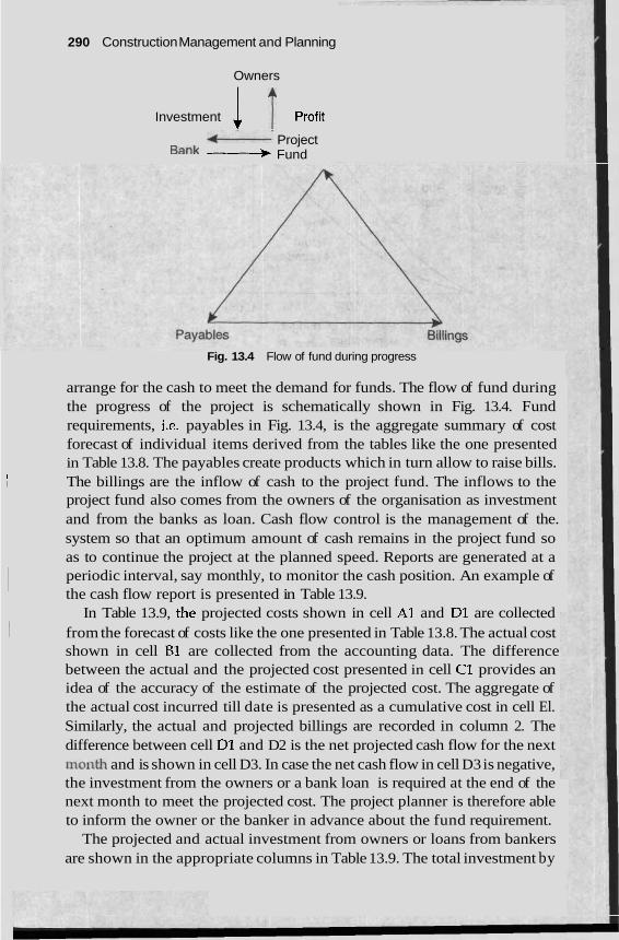
290 Construction Management and Planning
Owners
Investment 1 1 profit
f----- Project Bank ---) Fund
Fig. 13.4 Flow of fund during progress
arrange for the cash to meet the demand for funds. The flow of fund during the progress of the project is schematically shown in Fig. 13.4. Fund requirements, i.e. payables in Fig. 13.4, is the aggregate summary of cost
I forecast of individual items derived from the tables like the one presented in Table 13.8. The payables create products which in turn allow to raise bills.
I I The billings are the inflow of cash to the project fund. The inflows to the
project fund also comes from the owners of the organisation as investment and from the banks as loan. Cash flow control is the management of the. system so that an optimum amount of cash remains in the project fund so
I as to continue the project at the planned speed. Reports are generated at a periodic interval, say monthly, to monitor the cash position. An example of I the cash flow report is presented in Table 13.9.
In Table 13.9, the projected costs shown in cell A1 and Dl are collected 1 from the forecast of costs like the one presented in Table 13.8. The actual cost
shown in cell B1 are collected from the accounting data. The difference between the actual and the projected cost presented in cell C1 provides an idea of the accuracy of the estimate of the projected cost. The aggregate of the actual cost incurred till date is presented as a cumulative cost in cell El. Similarly, the actual and projected billings are recorded in column 2. The difference between cell Dl and D2 is the net projected cash flow for the next non nth and is shown in cell D3. In case the net cash flow in cell D3 is negative, the investment from the owners or a bank loan is required at the end of the next month to meet the projected cost. The project planner is therefore able to inform the owner or the banker in advance about the fund requirement.
The projected and actual investment from owners or loans from bankers are shown in the appropriate columns in Table 13.9. The total investment by

1 this mor
lis month --
:e this mc
1 next mo
nth
nth
able 13.9 Monthe nd cashflc lw status report
Table 13.8 Monthly forecast of cost
2 - Y Lo
3 2 .5 3 ; g FI w
3 aJ
a 2 !j Labour Equipment. Other Total Item .+
2 . .f E .g cost cost cost cost Y 5 % Y 5 C4 . 5 E
(1) (2) (3) (4) (5) (6) (8) (9) (10) (11) 1. Concrete cu. m
2. Shuttering sq. m
3. Brickwork cu. - T, -
h 8 -0 Owners investment Bank c c - 5 Expected
; 0 .2 gross $3 Item 9 8 .- m + 2 * aJ
+ .- . - L o 5 2 6 5 YL $ = 3 Inflo;.: Outflow Net Loan Interest % 3 u b i j n & e g u d Profit LOSS ' ti z 8 1 7 2 A C; A 7 8 9 1C) 11 17 12 lA
Projectec
Actual tl
Differenc C
Projectec D
Actual C U ~ L ~ U ~ ~ L ~ V ~ ! till date E
292 Construction Management and Planning
the owner or the total interest paid for the project can thus be known to the decision maker. The expected profit or loss column can be filled up from the following relationship
E l 2 / 1 3 = E 3 - E l - E 6 - E 7 - E 8 + E 9 + E l O + E l l
The quantum of gross profit provides an idea for tax and a provision for tax from the project fund that is shown in col. 9 can be made. The monthly cash fund shown in cell Ell shall be positive and could be estimated from the following relationship:
Dl1 =D2-Dl+D6+D7>0
The monthly cash flow status helps to identify the problem areas. A few examples are provided in the following.
In civil (particularly for unit rate) contract, billing is a lengthy process. ,It involves a recording of measurement, bill preparation, checking and pay- ment. There is a time lag between the work done and bill passing. If the billing section does not have the proper manpower, the time lag may increase. In other words, the rate of progress in site may exceed the rate of progress of bills. Under the circumstances, more and more company finance gets involved in the project without any return. Table 13.9 normally identifies tlie problem. If cell C1 remains small in a month, it indicates that the desired amount of work is completed. If cell C2 for the next month does not exceed cell C1 of this month more h d from the company is getting involved and the planner generally looks for the problem mentioned above. If cell C3 is persistently negative, the loss shows up in cell El3 and the remedial action is required. In extreme cases like when cell D7 exceeds the loan limit imposed by the bank, the work schedule may be slowed down which reduces cell Dl to catch up the bill thereby increasing the cell E3 and E l l . Such a fine tuning of cost and schedule can be planned with the cash flow status report.
The information from the cash flow status can be combined to obtain the graphics as shown in Fig. 13.5 for the top management.
FUND FLOW
Fund flow is the movement of the fund, i.e. cash in an organisation. Closely related to the projected fund-flow statements are the cash budget. It is indispensable to the financial manager in determining the short-term cash needs of the firm. Construction firms particularly the smaller ones are perpetually strangled with the financial crunch. Cash budget is therefore a very important exercise for most of the firms. When cash budgeting is extended to include a range of possible outcomes, the financial manager can evaluate the business risk and liquidity of the firm, and plan a more realistic margin of safety.
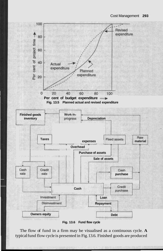
Cost Management 293
Per cent of budget expenditure + Fig. 13.5 Planned actual and revised expenditure
Finished goods Work-in- inventory Depreciation
I
Taxes expenses material
Overhead
Purchase of assets
Sale of assets
purchase
I I
Cash
Loan
Repayment
I Owners equity I I Debt I Fig. 13.6 Fund flow cycle
The flow of fund in a firm may be visualised as a continuous cycle. A typical fund flow cycle is presented in Fig. 13.6. Finished goods are produced
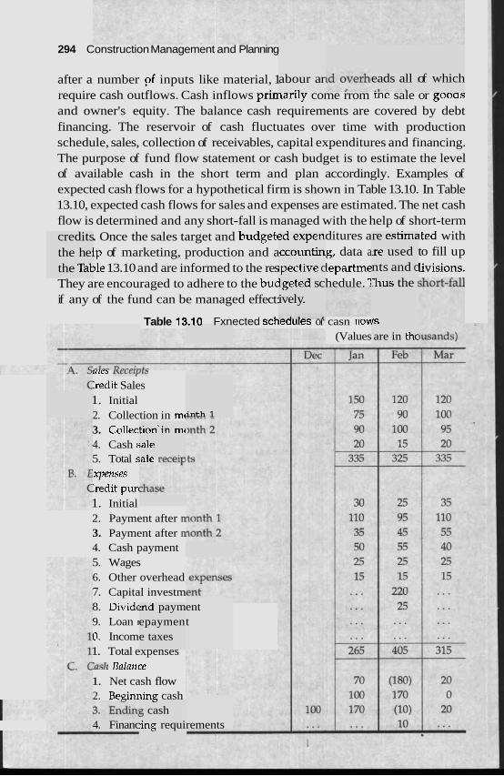
294 Construction Management and Planning
after a number pf inputs like material, 1 require cash outflows. Cash inflows primar~ly come rrom tne sale or gooas and owner's equity. The balance cash requirements are covered by debt financing. The reservoir of cash fluctuates over time with production schedule, sales, collection of receivables, capital expenditures and financing. The purpose of fund flow statement or cash budget is to estimate the level of available cash in the short term and plan accordingly. Examples of expected cash flows for a hypothetical firm is shown in Table 13.10. In Table 13.10, expected cash flows for sales and expenses are estimated. The net cash flow is determined and any short-fall is managed with the help of short-term
. Once the sales target and budgetc ditures a lted with lp of marketing, production and a g, data a to fill up )le 13.10 and are informed to the res lepartme Iivisions.
They are encouraged to adhere to the buc hedule. 1 if any of the fund can be managed effect:
abour ar eads all I of which
credits the he: the Tal
?d expen ccountin ipective c
re estime Ire used nts and c
lgeted sc ivel y.
h u s the I
IS Table 13-10 Fxnected scheou~es or casn rlom (Values are in thc
U'CJ I\CLC'f,LJ
:redit Sales 1. Initial 2. Collection in mc 3. Collec 4. Cash s 5. Total sale: L - C I ~
xpenses :redit purl 1. Initial 2. Payment after n 3. Payment after n 4. Cash payment 5. Wages 6. Other overhead 7. Capital investm 8. Divide 9. Loan I
0. Incom 1. Total expenses :ash Balailce 1. Net cash flow 2. Be~nning cash
inth 1
tion'in mc ;ale -1, ,,,,:,
ent t
?nd paym epaymen e taxes
., 5 cash
4. Financ :ing requi rements