constructal conjugate cooling channels with internal heat generation
TRANSCRIPT
This article appeared in a journal published by Elsevier. The attachedcopy is furnished to the author for internal non-commercial researchand education use, including for instruction at the authors institution
and sharing with colleagues.
Other uses, including reproduction and distribution, or selling orlicensing copies, or posting to personal, institutional or third party
websites are prohibited.
In most cases authors are permitted to post their version of thearticle (e.g. in Word or Tex form) to their personal website orinstitutional repository. Authors requiring further information
regarding Elsevier’s archiving and manuscript policies areencouraged to visit:
http://www.elsevier.com/copyright

Author's personal copy
Constructal conjugate cooling channels with internal heat generation
O.T. Olakoyejo, T. Bello-Ochende ⇑, J.P. MeyerDepartment of Mechanical and Aeronautical Engineering, University of Pretoria, Pretoria Private Bag X20, Hatfield 0028, South Africa
a r t i c l e i n f o
Article history:Received 24 March 2011Accepted 7 March 2012Available online 30 April 2012
Keywords:OptimisationLaminar flowForced convectionOptimal geometryPeak temperatureConstructal theoryThermal resistanceDynamic-Q
a b s t r a c t
This paper presents a geometric optimisation of conjugate cooling channels in forced convection withinternal heat generation. Two configurations were studied; circular channels and square channels. Theconfigurations were optimised in such a way that the peak temperatures were minimised subject tothe constraint of fixed total global volume. The fluid was forced through the cooling channels by the pres-sure difference across the channels. The structure has one degree of freedom as design variable: channelhydraulic diameter and once the optimal channel hydraulic diameter is found, optimal elemental volumeand channel-to-channel spacing result. A gradient-based optimisation algorithm is applied in order tosearch for the best and optimal geometric configurations that improve thermal performance by minimis-ing thermal resistance for a wide range of dimensionless pressure difference. This optimiser adequatelyhandles the numerical objective function obtained from CFD simulations. The results obtained show thebehaviour of the applied pressure difference on the optimised geometry. There are unique optimal designvariables for a given pressure difference. The numerical results obtained are in agreement with the the-oretical formulation using scale analysis and method of intersection of asymptotes.
� 2012 Elsevier Ltd. All rights reserved.
1. Introduction
A procedure that sufficiently allocates and optimises a fixedglobal space constraint using a physical law for heat-generatingdevices has been adopted recently as an optimisation technique[1]. The method seeks to optimise the flow architecture, which pre-dicts the flow and thermal fluid behaviour in a structure that issubject to a global volume constraint. This body of knowledge iscalled constructal theory and design. Bejan [1] stated this law as:For a finite-size system to persist in time (to live), it must evolve insuch a way that it provides easier access to the imposed (global)currents that flow through it. The application of this theory startedwith Bejan and Sciubba [2], who obtained a dimensionless pressuredifference number for optimal spacing of an array of parallel platesand a maximum heat transfer density, which can be fitted into afixed volume in an electronic cooling application using the methodof intersection of asymptotes.
The applications of this theory have been reviewed mostrecently by the work of Bejan and Lorente [3] in which it was con-cluded that, under certain constraints, the best architecture of aflow system can be achieved by the one that gives less flow resis-tances, or allows high flow access. In other words, the shapes of thechannels and elemental structure that are subject to global con-straint are allowed to morph. The optimisation of heat exchanger
and multiscale devices by constructal theory has also recently beenreviewed and summarised by Reis [4] and Fan and Luo [5].
Yilmaz et al. [6] studied the optimum shape and dimensions forconvective heat transfer of laminar flow at constant wall tempera-tures for ducts with parallel plate, circular, square and equilateraltriangle geometries. Approximate equations were derived in theform of maximum dimensionless heat flux and optimum dimen-sionless hydraulic diameter in terms of the duct shape factorsand the Prandlt number (Pr).
Muzychka [7] used this theory and Bejan’s intersection ofasymptotes method to present an analytical optimisation of circu-lar and non-circular cooling channel geometries. Also, he has re-cently studied and analysed the optimisation of microtube heatsinks and heat exchangers for maximum thermal heat transfer byusing a multiscale design approach [8]. In his analysis, he was ableto show that through the use of interstitial microtubes, the maxi-mum heat transfer rate density for an array of circular tubes in-creased. He obtained an approximate solution using Bejan’sintersection of asymptotes method. The multiscale design ap-proach gives a greater thermal performance of heat exchangerand heat sink compared with the conventional design methods.
Da Silva et al. [9] optimised the space allocation on a wall occu-pied by discrete heat sources with a given heat generation rate byforced convection using the constructal design in order to mini-mise the temperature of the hot spot on the wall. Bejan and Faut-relle [10], maximised the heat transfer density in a multiscalestructure filled by multiple length scale plates that generate heat.
0017-9310/$ - see front matter � 2012 Elsevier Ltd. All rights reserved.http://dx.doi.org/10.1016/j.ijheatmasstransfer.2012.04.007
⇑ Corresponding author. Tel.: +27 12 4203105; fax: +27 12 362 5124.E-mail address: [email protected] (T. Bello-Ochende).
International Journal of Heat and Mass Transfer 55 (2012) 4385–4396
Contents lists available at SciVerse ScienceDirect
International Journal of Heat and Mass Transfer
journal homepage: www.elsevier .com/locate / i jhmt

Author's personal copy
They inserted additional parallel plates and optimised the spacingin the flow structure.
Bello-Ochende and Bejan [11] studied and extended the work ofBejan and Fautrelle [10] numerically based on the concept of con-structal theory. Also, Bello-Ochende et al. [12,13] studied a three-dimensional optimsation of heat sink and cooling channels withheat flux using scale analysis and the intersection of asymptotesmethod based on constructal theory to investigate and predictthe design and optimisation of the geometric configurations ofthe cooling channels.
Matos et al. [14] conducted three-dimensional numerical andexperimental analyses of laminar rows of tubes. Ordonez [15] con-ducted a two-dimensional heat transfer analysis in a heat-gener-ated volume with cylindrical cooling channels and air as theworking fluid. Reis et al. [16] optimised the internal configurationsof parallel plate and cylindrical channels using constructal theoryto understand the morphology of particle agglomeration and thedesign of air-cleaning devices.
Also, the constructal theory for optimisation of several compo-nents and systems and components in engineering applicationshas been extensively discussed and documented in the literature[17–19].
This paper focuses on the study of three-dimensional laminarforced convection cooling of solid structures. It examines the opti-misation of a fixed and finite global volume of solid materials fortwo cooling channel configurations (circular and square channels)with a uniform internal heat generation rate. This was achieved byvarying and arranging the elemental volume of structure withcooling channels of fixed porosity to reduce the peak temperatureat any point inside the global volume. The design variables weredealt with simultaneously since the effect of one of the design
variables cannot be neglected, especially at a microscopic scale.Bau [20] suggested that the ‘‘integrity of fin thickness (channelspacing) during fabrication and operation should be asserted andmaintained’’. Therefore, the need exists to consider the three de-sign variables simultaneously. It is expected that there must bean optimal configuration that gives the minimum peak tempera-ture. Any values below or above those of the optima designvariables will cause the working fluid to not be properly used,which will cause the peak temperature to increase and will leadto thermal stress that affects the performance of cooling channels.
2. Models
The physical configuration is shown schematically in Fig. 1. Thesystem consists of parallel cooling channels of length, L of fixedglobal volume, V for the two configurations. The internal heatgeneration in the solid material is q000s . An elemental volume, vel, con-sisting of a cooling channel and the surrounding solid was used foranalysis because of the assumption of the symmetrical heat distri-bution inside the structure. However, the elemental volume vel isnot fixed and is allowed to morph by varying cooling channel shapevc for fixed porosity and fixed channel length. The heat transfer in theelemental volume is a conjugate problem, which combines heat con-duction in the solid and the convection in the working fluid. Thesetwo modes of heat transfer are coupled together through the conti-nuity of heat flux at the solid-fluid interface.
2.1. Design variables
In Fig. 2, an elemental volume, vel, constraint is considered to becomposed of an elemental cooling channel of hydraulic diameter,
Nomenclature
Ac cross sectional area of the channel, m2
As cross sectional area of the structure, m2
Be Bejan numberCP specific heat at constant pressure, J/kg KCyl cylindrical configurationdh hydraulic diameter, mH structure height, mh elemental height , mi mesh iteration indexk thermal conductivity, W/mKL axial length, mN number of channelsn normalP pressure, kPaPc perimeter of the channelPo Poiseuille numberPr Prandtl number_q00 heat flux, W/m2
q000s internal heat generation density, W/m3
_q heat transfer rate, WR thermal resistanceRe Reynolds numbers channel spacing, mSqr square configurationT temperature, 0C~Tmax dimensionless maximum temperature ~Tmax ¼ T�T in
q000v2=3=kf
� �~u velocity vector, m/sV global structure volume, m3
vc channel volume, m3
vel elemental volume, m3
W structure width, mw elemental width, mx, y, z cartesian coordinates, m
Greek symbolsa thermal diffusivity, m2/sl viscosity, kg/m.sm kinematics viscosity, m2/sq density, kg/m3
@ differential1 far extreme end, free streamu porosityD difference» differential operators shear stress, Pac convergence criterion
Subscripts� dimensionlessc channelf fluidin inletl largemax maximum, peakmin minimumopt optimums solidsm smallw wall
4386 O.T. Olakoyejo et al. / International Journal of Heat and Mass Transfer 55 (2012) 4385–4396
Author's personal copy
dh, and the surrounding solid of thickness s (spacing betweenchannels) and these variables are defined as:
w ¼ h ð1Þ
vel ¼ w2L ð2Þ
w ¼ dh þ s ð3Þ
For a fixed length of the channel, we have
As ¼ HW ð4Þ
Therefore, the total number of channels in the structure arrange-ment can be defined as:
N ¼ HW
ðdh þ sÞ2ð5Þ
However, the void fraction or porosity of the unit structure can bedefined [15] as:
/ ¼ vc
vel� dh
w
� �2
ð6Þ
The fundamental problem under consideration is the numericaloptimisation of the hydraulic diameter, dh, and spacing betweenchannels, s, which corresponds to the minimum resistance of a fixedvolume for a given pressure drop. The optimisation is evaluatedfrom the analysis of the extreme limits of (0 6 vel 61),(0 6 dh 61) and the extreme limits of (0 6 s 61). The optimalvalues of the design variables within the prescribed interval of theextreme limits exhibit the minimum thermal resistance.
The temperature distribution in the model was determined bysolving the equation for the conservation of mass, momentumand energy numerically. The discretised three-dimensional
(a)
(b)
Fig. 2. The boundary conditions of the three-dimensional computational domain of the cooling channel: (a) cylinder, (b) square.
(a)
(b)
Fig. 1. Ducts with cooling channels: (a) circular cooling channels. (b) square coolingchannel.
O.T. Olakoyejo et al. / International Journal of Heat and Mass Transfer 55 (2012) 4385–4396 4387
Author's personal copy
computational domains of the circular and square configurationsare shown in Fig. 3. The cooling fluid was water; it is assumed tobe in single-phase, steady, and a Newtonian fluid with constantthermophysical properties, and was forced through the coolingchannels by a specified pressure difference, DP, across the axiallength of the structure. Water is more promising than air, becauseair-cooling techniques are not likely to meet the challenge of highheat dissipation in electronic packages [21,22]. The governing dif-ferential equations used for the fluid flow and heat transfer analy-sis inside the unit volume of the structure are:
r �~u ¼ 0 ð7Þ
qð~u � r~uÞ ¼ �rP þ lr2~u ð8Þ
qf CPf ð~u � rTÞ ¼ kfr2T ð9Þ
while the energy equation for a solid with internal heat generationis given as:
ksr2T þ q000s ¼ 0 ð10Þ
The continuity of the heat flux at the interface between the solidand the liquid is given as:
ksoTon
���� ¼ kfoTon
���� ð11Þ
A no-slip boundary condition is specified at the wall of the channel,
~u ¼ 0 ð12Þ
and at the inlet (x = 0)
ux ¼ uy ¼ 0 ð13Þ
T ¼ T in ð14Þ
P ¼ BealL2 þ Pout ð15Þ
where, Be is the dimensionless pressure difference called the Bejannumber [23,24].
At the channel outlet (x = L), a zero normal stress is prescribed,and
Pout ¼ 1 atm ð16Þ
At the solid boundaries, all the outside walls and plane of symmetryof the solid structure were modelled as adiabatic as shown in Fig. 2.That is:
rT ¼ 0 ð17Þ
and an internal heat generation, q000s , is assumed in the solid material.The measure of performance is the minimum global thermal
resistance, which could be expressed in a dimensionless form as:
Rmin ¼kf ðTmax � T inÞmin
q000s L2 ð18Þ
and it is a function of the optimised design variables and the peaktemperature,
Rmin ¼ f ðdhopt ; sopt; velopt ;Nopt; TmaxminÞ ð19Þ
where Rmin is the minimised dimensionless thermal resistance forthe optimised design variables. The inverse of Rmin is the maximisedoverall global thermal conductance.
3. Numerical procedure and grid analysis
The simulation procedure began by fixing the length of thechannel, applied pressure difference, porosity, internal heat gener-ation and material properties and we kept varying the values ofelemental volume and hydraulic diameter of the channel in orderto identify the best (optimal) internal and external geometries thatminimised the peak temperature.
The numerical solution of the continuity, momentum and energyEqs. (7) - (10) along with the boundary conditions (11) - (17) was ob-tained by using a three-dimensional commercial package FLUENT™[25], which employs a finite volume method. The details of themethod were explained by Patankar [26]. The computational fluiddynamics package was coupled with the geometry and mesh gener-ation package GAMBIT [27] using MATLAB [28] to allow the automa-tion and running of the simulation process. After the simulationconverged, an output file was obtained containing all the necessarysimulation data and results for the post-processing and analysis. Thecomputational domain was discretised using hexahedral/wedgeelements. A second-order upwind scheme was used to discretisethe combined convection and diffusion terms in the momentumand energy equations. The SIMPLE algorithm was then employedto solve the coupled pressure-velocity fields of the transport equa-tions. A flow chart representing the numerical procedure is shownin Fig. 4. The solution is assumed to be converged when the norma-lised residuals of the mass and momentum equations fall below 10�6
and while the residual convergence of energy equation was set toless than 10�10. The number of grid cells used for the simulationsvaried for different elemental volume and porosities. However, gridindependence tests for several mesh refinements were carried out toensure the accuracy of the numerical results. The convergence crite-rion for the overall thermal resistance as the quantity monitored is:
c ¼ jðTmaxÞi � ðTmaxÞi�1jjðTmaxÞij
6 0:01 ð20Þ
where i is the mesh iteration index. The mesh is more refined as iincreases. The i – 1 mesh is selected as a converged mesh whenthe criterion Eq. (20) is satisfied.
Fig. 3. The discretised 3-D computational domain: (a) cylinder, (b) square.
4388 O.T. Olakoyejo et al. / International Journal of Heat and Mass Transfer 55 (2012) 4385–4396

Author's personal copy
4. Numerical results using a traditional method
In this section, the numerical results are presented using atraditional method by post-processing the simulation data and re-sults manually. The elemental volume of the structure was in therange of 0.025 mm3 to 5 mm3 and the porosities ranged between0.1 6 u 6 0.2 and a fixed length of L = 10 mm at a fixed pressuredrop of DP = 50 kPa. The global structure is assume to have a totalglobal cross-sectional area of 2.5 mm by 2.5 mm. The thermalconductivity of the solid structure (silicon) was 148 W/m K; and
the internal heat generation within the solid was taken to be fixedat 100 kW/cm3. The thermophysical properties of water [29] usedin this study were based on water at 300 K and the inlet water tem-perature was fixed at this temperature.
Fig. 5 shows the grid independence test for a cylindrical config-uration for vel = 0.4 mm3 and u = 0.2 for DP = 50 kPa. Also, compu-tational cells of 7500, 68388 and 108750 were used for the gridindependence test. It is observed that an almost identical resultswere predicted when 68388 and 108750 cells were used. There-fore, a further increase in the cell density beyond 68388 has a neg-ligible effect on the numerical result.
The validation of the numerical simulation was also carried outby comparing the present simulation for a circular configurationwith the dimensionless temperature simulation of Ordonez [15]as shown in Fig. 6. The curves were found to be similar in trendand the optimised hydraulic diameters were also found to be ingood agreement.
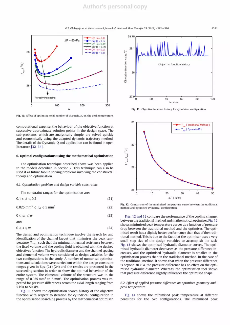
Figs. 7–10 show the existence of an optimum hydraulic diameterand spacing of the cooling channel and elemental volume structure,respectively, where the peak temperature is minimised at any pointin the channel for the two configurations studied. These Figures arefor the case where the pressure difference was fixed at DP = 50 kPafor 0.025 mm3
6 vel 6 5 mm3 and 0.1 6 u 6 0.2.Fig. 7 shows the graph of peak temperature as a function of the
channel hydraulic diameter. It shows that there exists an optimalchannel hydraulic diameter, which lies in the range of50 lm 6 dh 6 220 lm, minimising the peak temperature. The chan-nel spacing also has a strong effect on the peak temperature, asshown in Fig. 8. The minimum peak temperature is achieved whenthe optimal channel spacing exists in the range of 50 lm 6 s6 350 lm. These indicate that the peak temperature decreases asglobal design variables increase and that maxima (optimal) valuesof the design variables are reached beyond which the peak temper-ature begins to increase. Therefore, the global peak temperature de-creases as the design variables increase or the global peaktemperature decreases as the design variables decrease until it getsto the optimal design values. Any increase or decrease in the designvariable beyond the optimal values indicates that the working fluidis not properly engaged in the cooling process, which is detrimentalto the global performance of the system.
Also, in Fig. 9, there exists an optimal elemental volume of thestructure that minimised the peak temperature and this lies in the
Fig. 4. Flow chart of numerical simulation.
27
27.5
28
28.5
10
7500 Cells68388 Cells108750 Cells
Sta
tic te
mpe
ratu
re (
o C)
ZL
Fig. 5. Grid independent test for cylindrical configuration at fixed pressuredifference and porosity.
O.T. Olakoyejo et al. / International Journal of Heat and Mass Transfer 55 (2012) 4385–4396 4389
Author's personal copy
range of 0.2 mm36 vel 6 2 mm3. The results show that the optimal
arrangement of the elemental volume for the entire structure atthis fixed pressure difference should be very small in order toachieve better cooling.
Fig. 10 shows existence of an optimal total number of channelsrequired in the structure that minimised the peak temperature andthis also, lies in the range of 10 6 N 6 120.
It can also be shown from Figs. 7 and 10 that porosity has a sig-nificant effect on the peak temperature and the overall thermalresistance. There is no optimum porosity. The best performance oc-curs at the highest porosity, which means as the porosity increases,the peak temperature decreases.
5. Mathematical optimisation (Dynamic-Q)
The results shown in the preceding session were done using atraditional method by post-processing the simulation data and re-sults manually. In this section, the entire solution and results are
obtained by using a mathematical optimiser since the design vari-ables are mutually interdependent. The approach is to assume thatthere must be optima design variables at which the system willperform best. A numerical algorithm, Dynamic-Q [30], is employedand incorporated into the finite volume solver and grid (geometryand mesh) generation package, as shown in Fig. 4, to search andidentify the optimal design variables at which the system will per-form optimally for more efficient and better accuracy. The algo-rithm is also specifically designed to handle constraint problemswhere the objective and constraint functions are expensive toevaluate.
The mathematical optimisation algorithm is a multidimensionaland robust gradient-based optimisation algorithm which does notrequire an explicit line search. The technique involves the applica-tion of a dynamic trajectory LFOPC (leapfrog optimisation programfor constrained problems) which is adapted to handle constrainedproblems through approximate penalty function formulations [31].This dynamic approach is applied to successive approximatequadratic sub-problems of the original problem. The successivesub-problems are constructed from sampling, at relative high
0 0.05 0.1
Be= 108
Pr = 1φ = 0.1
Ordonez [15]
Present study
0
0.001
0.002
hdL
300s
f
kk
=
Tm
ax
~
Fig. 6. Thermal resistance curves: present study and Ordonez [16].
27
28
29
30
31
0 50 100 150 200 250 300 350
ΔP = 50kPa Cyl (φ = 0.1)
Sqr (φ = 0.1)
Cyl (φ = 0.15)
Sqr (φ = 0.15)
Cyl (φ = 0.2)
Sqr (φ = 0.2)
Tm
ax(
o C )
Porosity increasing
dh
( μm )
Fig. 7. Effect of optimised hydraulic diameter dh, on the peak temperature.
27
28
29
30
31
0 100 200 300 400 500
ΔP = 50kPa
Cyl (φ = 0.1)Sqr (φ = 0.1)Cyl (φ = 0.15)Sqr (φ = 0.15)Cyl (φ = 0.2)Sqr (φ = 0.2)
Tm
ax(
o C )
Porosity increasing
s ( μm )
Fig. 8. Effect of optimised channel spacing, s, on the peak temperature.
27
28
29
30
31
0 1 2 3 4 5
ΔP = 50kPa
Cyl (φ = 0.1)Sqr (φ = 0.1)Cyl (φ = 0.15)Sqr (φ = 0.15)Cyl (φ = 0.2)Sqr (φ = 0.2)
Tm
ax (
o C )
Porosity increasing
vel
( mm3 )
Fig. 9. Effect of optimised elemental volume, vel, on the peak temperature.
4390 O.T. Olakoyejo et al. / International Journal of Heat and Mass Transfer 55 (2012) 4385–4396
Author's personal copy
computational expense, the behaviour of the objective function atsuccessive approximate solution points in the design space. Thesub-problems, which are analytically simple, are solved quicklyand economically using the adapted dynamic trajectory method.The details of the Dynamic-Q and application can be found in openliterature [32–34].
6. Optimal configurations using the mathematical optimisation
The optimisation technique described above was been appliedto the models described in Section 2. This technique can also beused it as future tool in solving problems involving the constructaltheory and optimisation.
6.1. Optimisation problem and design variable constraints
The constraint ranges for the optimisation are:
0:1 6 / 6 0:2 ð21Þ
0:025 mm36 vel 6 5 mm3 ð22Þ
0 6 dh 6 w ð23Þ
and
0 6 s 6 w ð24Þ
The design and optimisation technique involve the search for andidentification of the channel layout that minimises the peak tem-perature, Tmax, such that the minimum thermal resistance betweenthe fixed volume and the cooling fluid is obtained with the desiredobjectives function. The hydraulic diameter and the channel spacingand elemental volume were considered as design variables for thetwo configurations in the study. A number of numerical optimisa-tions and calculations were carried out within the design constraintranges given in Eqs. (21)-(24) and the results are presented in thesucceeding section in order to show the optimal behaviour of theentire system. The elemental volume of the structure was in therange of 0.025 mm3 to 5 mm3. The optimisation process was re-peated for pressure differences across the axial length ranging from5 kPa to 50 kPa.
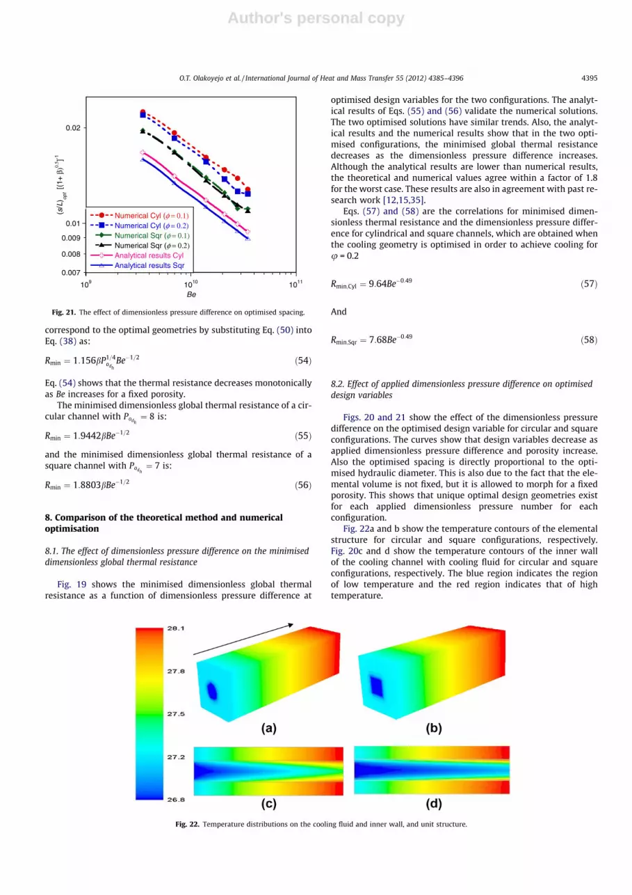
Fig. 11 shows the optimisation search history of the objectivefunction with respect to iteration for cylindrical configuration inthe optimisation searching process by the mathematical optimiser.
Figs. 12 and 13 compare the performance of the cooling channelbetween the traditional method and mathematical optimiser. Fig. 12shows minimised peak temperature curves as a function of pressuredrop between the traditional method and the optimiser. The opti-mised result has a slightly better performance than that of the tradi-tional method. This is due to the fact that the optimiser uses a verysmall step size of the design variables to accomplish the task.Fig. 13 shows the optimised hydraulic diameter curves. The opti-mised hydraulic diameter decreases as the pressure difference in-creases, and the optimised hydraulic diameter is smaller in theoptimisation process than in the traditional method. In the case ofthe traditional method, it shows that when the pressure differenceis beyond 30 kPa, the pressure difference has no effect on the opti-mised hydraulic diameter. Whereas, the optimisation tool showsthat pressure difference slightly influences the optimised shape.
6.2. Effect of applied pressure difference on optimised geometry andpeak temperature
Fig. 14 shows the minimised peak temperature at differentporosities for the two configurations. The minimised peak
28
30
0 100 200 300
ΔP = 50kPaCyl (φ = 0.1)Sqr (φ = 0.1)Cyl (φ = 0.15)Sqr (φ = 0.15)Cyl (φ = 0.2)Sqr (φ = 0.2)
Tm
ax (
o C )
N
Porosity increasing
Fig. 10. Effect of optimised total number of channels, N, on the peak temperature.
0 20 40 60 80 10027.9
28
28.1
28.15
Iteration
Obj
ecti
ve f
unct
ion
valu
e, o C
Objective function history
Fig. 11. Objective function history for cylindrical configuration.
28
29
30
31
0 10 20 30 40 50
Tmin
( Traditional Method )
Tmin
( Dynamic-Q )
(Tm
ax ) m
in(
o C )
Δ P ( kPa )
Fig. 12. Comparison of the minimised temperature curve between the traditionalmethod and optimised cylindrical configuration.
O.T. Olakoyejo et al. / International Journal of Heat and Mass Transfer 55 (2012) 4385–4396 4391

Author's personal copy
temperature decreases as the pressure difference across the axiallength increases for different porosity arrangements. As the pres-sure difference and porosity keep increasing, the peak temperaturebecomes less sensitive. The trend is in agreement with previousworks [35].
The optimal behaviours of the circular and square configurationswith respect to applied pressure difference are reported in Figs. 15and 17. Fig. 15 shows that there is an optimal unit volume for eachof the two configurations. It also shows that the optimised globalelemental volume decreases as the pressure difference increasesand this lies in the region of 0.5 mm3
6 vel 6 2.4 mm3. This again,shows that the optimal arrangement of the elemental volume forthe entire structure should be very small to achieve better cooling.In Fig. 16, the global dhopt and sopt decrease as the pressure differenceincreases. dhopt and sopt lie in the vicinity of 100 lm 6 dh 6 270 lm.It is also observed that the sopt deceases as the dhopt decreases, this isdue to the fact that the elemental volume is not fixed for a fixedporosity and there is no optimum porosity. Fig. 17, shows totalnumber of channels arrangement is a function of pressure differ-
ence and porosity increases. The global Nopt increases as the pres-sure difference and porosity increase. Nopt lies in the region of10 6 Nopt 6 100. It is also, observed that there is a unique optimalnumber of channels for every diving force (DP) required for eachconfiguration to achieve effective cooling.
7. Method of intersection of asymptotes for conjugate channelswith internal heat generation
This section deals with a theoretical analysis which is presentedfor the circular and square configurations using the intersection ofasymptotes method to provide the existence of an optimal geome-try, which minimises the global thermal resistance. The followingassumptions are made throughout the analysis: the inlet tempera-ture and the pressure difference, DP, are fixed with a uniform flowdistribution in all the channels, laminar flow, constant cross-sec-tional area of the channels, negligible inlet and exit plenum losses,and negligible axial conduction. An elemental volume is consid-ered because of the symmetry of the heat distribution.
27
30
33
36
0 10 20 30 40 50
( Tmax
)min
Cyl (φ = 0.1)
( Tmax
)min
Sqr (φ = 0.1)
( Tmax
)min
Cyl (φ = 0.2)
( Tmax
)min
Sqr (φ = 0.2)
( Tm
ax ) m
in(
o C )
ΔP ( kPa )
Porosity increasing
Fig. 14. The effect of pressure difference and porosity on optimised peaktemperature.
0
1
2
3
0 10 20 30 40 50
( vel
)opt
Cyl (φ = 0.2)
( vel
)opt
Sqr (φ = 0.2)
( v el
) opt
( m
m3 )
ΔP ( kPa )
Fig. 15. The effect of pressure difference on optimised elemental volume.
100
150
200
250
0 10 20 30 40 50
dhopt
( Traditional Method )
dhopt
( Dynamic-Q )
dhop
t ( μ
m )
Δ P (kPa)
Fig. 13. Comparison of the optimised design variable curves between thetraditional method and optimised for cylindrical configuration.
100
200
300
0 10 20 30 40 50
dhopt
Cyl (φ = 0.2)
sopt
Cyl (φ = 0.2)
dhopt
Sqr (φ = 0.2)
sopt
Cyl (φ = 0.2)
dhop
t,s
opt (
μm )
Δ P ( kPa )
Fig. 16. The effect of pressure difference on optimised hydraulic diameter andoptimised spacing.
4392 O.T. Olakoyejo et al. / International Journal of Heat and Mass Transfer 55 (2012) 4385–4396

Author's personal copy
The heat generated in the elemental volume [12,15] is:
_q ¼ q000ðAs � AcÞL ð25Þ
The heat is conducted and is deposited as the heat flux, q00, throughthe solid wall to the fluid, therefore,
q000ðAs � AcÞL ¼ q00PcL ð26Þ
The porosity is assumed to be fixed u = Ac/As, therefore Eq. (26)becomes
q00 ¼ 14
q000h b ð27Þ
where b is the numerical value determined from the porosity of thechannel and is defined as:
b ¼ 1� //
� �ð28Þ
And dh is the channel hydraulic diameter defined as:
dh ¼4Ac
Pcð29Þ
The global thermal resistance or global thermal conductance will bedetermined in two extreme limits.
7.1. Extreme limit 1: small channel
When the channel’s characteristic dimension is very small andvery slender, that is dh ? 0 and dh << L, the flow is fully developedalong the length, L. From the first law of thermodynamics, the rateof heat transfer in a unit volume to the working fluid is equal to en-thalpy gained by the working fluid, and then for constant, Cp
_qs ¼ qAc �uCpðTout � T inÞ ð30Þ
In this extreme limit, the fluid in the channel quickly becomes fullydeveloped flow and the working fluid is overworked in such a waythat the outlet temperature Tout approaches the peak temperature,Tmax, at the solid structure.
Therefore, Eq. (30) becomes,
_qsm ¼ qAc �uCpðTmax � T inÞ ð31Þ
This is equal to the heat deposited as heat flux, q00, through the wallto the fluid, therefore
qAc �uCpðTmax � T inÞ ¼ q00PcL ð32Þ
The average velocity, �u, when the flow is fully developed is given byHagen–Poiseuille as:
�u ¼ DP12
4lPo1 Lð33Þ
where f is the characteristic dimension used to define the Poiseuillenumber, Po, and in this case the hydraulic diameter, dh.
Combine Eqs. (32) and (33) and substitute f as dh, then rear-range to get
ðTmax � T inÞ ¼ q0016lPodh
L2
qd3hCpDP
!ð34Þ
Substituting Eq. (27) into Eq. (34) and rearrange to get,
ðTmax � T inÞq000L2 ¼ b
4lPodh
qd2hCpDP
!ð35Þ
But,
Cp ¼kf Prqm
ð36Þ
Substituting Eq. (36) into Eq. (35) and rearranged as:
kf ðTw � T inÞq000L2 ¼ b
4lmPodh
d2hPrDP
!ð37Þ
The dimensionless global thermal resistance is defined in terms ofdimensionless pressure difference as:
R ¼ kf ðTmax � T inÞq000L2
" #ffi 4Podh
bdh
L
� ��2
Be�1 ð38Þ
where
Be ¼ DPL2
lað39Þ
From Eq. (38) for a smaller channel dh� L, the thermal resistance isinversely proportional to d2
h . Keeping b (which is a function ofporosity) constant, it shows that the global thermal resistance in-creases as the hydraulic diameter decreases.
7.2. Extreme limit 2: large channel
In this extreme limit, the channel’s characteristic dimension issufficiently large. That is dh ?1, the boundary layer of surface be-comes distinct and the channel diameter is larger than the bound-ary layer thickness. The working fluid is not properly utilised andworking fluid outside the boundary layers becomes useless andthe body is not properly cooled in the downstream.
The rate of heat transfer across the thermal boundary layer is
_ql ¼ hAsðTmax � T inÞ ð40Þ
and the heat flux is
_q00l ¼ hðTmax � T inÞ ð41Þ
The heat transfer rate can be related to Nusselt number and heattransfer coefficient over the unit system. The heat transfer coeffi-cient is defined [36] for a laminar boundary layer as:
hLkf¼ 0:453kf Pr1=3Re1=2 for 0:5 < Pr < 10 ð42Þ
Substitute Eq. (42) into (41) to get
0
50
100
0 10 20 30 40 50
Nhopt
Cyl (φ = 0.1)
Nhopt
Sqr (φ = 0.1)
Nhopt
Cyl (φ = 0.2)
Nhopt
Sqr (φ = 0.2)
Nop
t
Δ P ( kPa )
Fig. 17. The effect of pressure difference on optimised total number of channels.
O.T. Olakoyejo et al. / International Journal of Heat and Mass Transfer 55 (2012) 4385–4396 4393

Author's personal copy
_q00l ¼0:453kf Pr1=3Re1=2
LðTmax � T inÞ ð43Þ
where
ReL ¼�u1Lm
ð44Þ
u1 is the free-stream velocity that sweeps the boundary layers, butthe longitudinal pressure force balance on the control volume in-scribed inside a unit volume channel is
DPAc ¼ PcL�sw ð45Þ
where �sw is the average wall shear stress over the length and can beobtained from the laminar boundary layer flow solution [36] as:
�sw ¼ 0:664qu21Re�1=2
L ð46Þ
Combine Eqs. (29) and (44) to Eq. (46) to obtain
ReL ¼DPdhL
2:656qm2
� �2=3
ð47Þ
Substitute Eq. (47) into Eq. (43) to obtain
_q00l ¼0:3271kf Pr1=3
LDPdhLqm2
� �1=3
ðTmax � T inÞ ð48Þ
Substitute Eq. (27) into Eq. (48) and rearrange to define the dimen-sionless global thermal resistance as:
R ¼ kf ðTmax � T inÞq000L2
" #ffi 0:7643b
dh
L
� �2=3
Be�1=3 ð49Þ
From Eq. (49), for a larger channel, the global thermal resistance isdirectly proportional to d2=3
h . Keeping b (which is a function ofporosity) constant, confirms that as the hydraulic diameter be-comes lager, the global thermal resistance increases.
The geometric optimisation in terms of channel could beachieved by combining Eqs. (38) and (49) using the intersectionof asymptotes method as shown in Fig. 18. The optimal dimensioncan be generally approximated for the two configurations ashydraulic diameter where the two extreme curves intersect. Theintersection result is:
dh
L
� �opt
� 1:8602P3=8odh
Be�1=4 ð50Þ
where dhopt is the optimal hydraulic diameter and for circular chan-nel Podh
¼ 8, hence Eq. (50) reduces to
dh
L
� �opt
� 4:057Be�1=4 ð51Þ
For a square channel with hydraulic diameter dh, Podh¼ 7, and hence
Eq. (50) reduces to:
dh
L
� �opt� 3:859Be�1=4 ð52Þ
The optimal spacing sopt follows from Eqs. (3), (6), and (50):
sL
� �opt� 1:8602½ð1þ bÞ1=2 � 1�P3=8
odhBe�1=4 ð53Þ
Eqs. (50) and (53) show that in the two extremes, the hydraulicdiameter and channel spacing decreases as the pressure differenceincreases for fixed porosity.
The minimum dimensionless global thermal resistance can beobtained for an elemental volume for the two configurations that
0
0.04
0.07
5002500
2~ hR d −
2/3~ hd
opthd
( )hR d
R
hd
R
Fig. 18. Method of intersection of asymptotes: Global thermal resistance.
10-5
10-4
109 1010 1011
Numerical Cyl (φ = 0.1)Numerical Sqr (φ = 0.1)Numerical Cyl (φ = 0.2)Numerical Sqr (φ = 0.2)Analytical results Cyl
Analytical results Sqr
Rm
inβ−1
Be
Fig. 19. Effect of dimensionless pressure difference on the dimensionless globalthermal resistance.
0.008
0.009
0.01
0.02
0.03
109 1010 1011
Numerical Cyl (φ = 0.1)Numerical Cyl (φ = 0.2)Numerical Sqr (φ = 0.1)Numerical Sqr (φ = 0.2)Analytical results CylAnalytical results Sqr
(dh/L
) opt
Be
Fig. 20. The effect of dimensionless pressure difference on the optimised hydraulicdiameter.
4394 O.T. Olakoyejo et al. / International Journal of Heat and Mass Transfer 55 (2012) 4385–4396
Author's personal copy
correspond to the optimal geometries by substituting Eq. (50) intoEq. (38) as:
Rmin ¼ 1:156bP1=4odh
Be�1=2 ð54Þ
Eq. (54) shows that the thermal resistance decreases monotonicallyas Be increases for a fixed porosity.
The minimised dimensionless global thermal resistance of a cir-cular channel with Podh
¼ 8 is:
Rmin ¼ 1:9442bBe�1=2 ð55Þ
and the minimised dimensionless global thermal resistance of asquare channel with Podh
¼ 7 is:
Rmin ¼ 1:8803bBe�1=2 ð56Þ
8. Comparison of the theoretical method and numericaloptimisation
8.1. The effect of dimensionless pressure difference on the minimiseddimensionless global thermal resistance
Fig. 19 shows the minimised dimensionless global thermalresistance as a function of dimensionless pressure difference at
optimised design variables for the two configurations. The analyt-ical results of Eqs. (55) and (56) validate the numerical solutions.The two optimised solutions have similar trends. Also, the analyt-ical results and the numerical results show that in the two opti-mised configurations, the minimised global thermal resistancedecreases as the dimensionless pressure difference increases.Although the analytical results are lower than numerical results,the theoretical and numerical values agree within a factor of 1.8for the worst case. These results are also in agreement with past re-search work [12,15,35].
Eqs. (57) and (58) are the correlations for minimised dimen-sionless thermal resistance and the dimensionless pressure differ-ence for cylindrical and square channels, which are obtained whenthe cooling geometry is optimised in order to achieve cooling foru = 0.2
Rmin;Cyl ¼ 9:64Be�0:49 ð57Þ
And
Rmin;Sqr ¼ 7:68Be�0:49 ð58Þ
8.2. Effect of applied dimensionless pressure difference on optimiseddesign variables
Figs. 20 and 21 show the effect of the dimensionless pressuredifference on the optimised design variable for circular and squareconfigurations. The curves show that design variables decrease asapplied dimensionless pressure difference and porosity increase.Also the optimised spacing is directly proportional to the opti-mised hydraulic diameter. This is also due to the fact that the ele-mental volume is not fixed, but it is allowed to morph for a fixedporosity. This shows that unique optimal design geometries existfor each applied dimensionless pressure number for eachconfiguration.
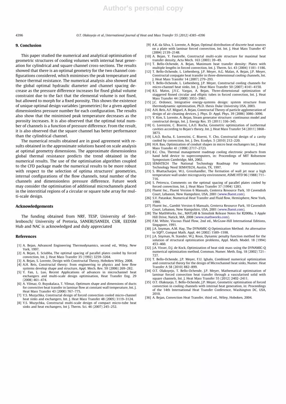
Fig. 22a and b show the temperature contours of the elementalstructure for circular and square configurations, respectively.Fig. 20c and d show the temperature contours of the inner wallof the cooling channel with cooling fluid for circular and squareconfigurations, respectively. The blue region indicates the regionof low temperature and the red region indicates that of hightemperature.
0.007
0.008
0.009
0.01
0.02
109 1010 1011
Numerical Cyl (φ = 0.1)Numerical Cyl (φ = 0.2)Numerical Sqr (φ = 0.1)Numerical Sqr (φ = 0.2)Analytical results CylAnalytical results Sqr
(s/L
) opt [(
1+ β
)0.5 ]-1
Be
Fig. 21. The effect of dimensionless pressure difference on optimised spacing.
Fig. 22. Temperature distributions on the cooling fluid and inner wall, and unit structure.
O.T. Olakoyejo et al. / International Journal of Heat and Mass Transfer 55 (2012) 4385–4396 4395
Author's personal copy
9. Conclusion
This paper studied the numerical and analytical optimisation ofgeometric structures of cooling volumes with internal heat gener-ation for cylindrical and square channel cross-sections. The resultsshowed that there is an optimal geometry for the two channel con-figurations considered, which minimises the peak temperature andhence thermal resistance. The numerical analysis also showed thatthe global optimal hydraulic diameter and channel spacing de-crease as the pressure difference increases for fixed global volumeconstraint due to the fact that the elemental volume is not fixed,but allowed to morph for a fixed porosity. This shows the existenceof unique optimal design variables (geometries) for a given applieddimensionless pressure number for each configuration. The resultsalso show that the minimised peak temperature decreases as theporosity increases. It is also observed that the optimal total num-ber of channels is a function of pressure difference. From the result,it is also observed that the square channel has better performancethan the cylindrical channel.
The numerical results obtained are in good agreement with re-sults obtained in the approximate solutions based on scale analysisat optimal geometry dimensions. The approximate dimensionlessglobal thermal resistance predicts the trend obtained in thenumerical results. The use of the optimisation algorithm coupledto the CFD package made the numerical results to be more robustwith respect to the selection of optima structures’ geometries,internal configurations of the flow channels, total number of thechannels and dimensionless pressure difference. Future workmay consider the optimisation of additional microchannels placedin the interstitial regions of a circular or square tube array for mul-ti-scale design.
Acknowledgements
The funding obtained from NRF, TESP, University of Stel-lenbosch/ University of Pretoria, SANERI/SANEDI, CSIR, EEDSMHub and NAC is acknowledged and duly appreciated
References
[1] A. Bejan, Advanced Engineering Thermodynamics, second ed., Wiley, NewYork, 1997.
[2] A. Bejan, E. Sciubba, The optimal spacing of parallel plates cooled by forcedconvection, Int. J. Heat Mass Transfer 35 (1992) 3259–3264.
[3] A. Bejan, S. Lorente, Design with Constructal Theory, Hoboken Wiley, 2008.[4] A.H. Reis, Constructal theory: from engineering to physics and how flow
systems develop shape and structure, Appl. Mech. Rev. 59 (2006) 269–282.[5] Y. Fan, L. Luo, Recent Applications of advances in microchannel heat
exchangers and multi-scale design optimisation, Heat Transfer Eng. 29(2008) 461–474.
[6] A. Yilmaz, O. Buyukalaca, T. Yilmaz, Optimum shape and dimensions of ductsfor convective heat transfer in laminar flow at constant wall temperature, Int. J.Heat Mass Transfer 43 (2000) 767–775.
[7] Y.S. Muzychka, Constructal design of forced convection cooled micro-channelheat sinks and exchangers, Int. J. Heat Mass Transfer 48 (2005) 3119–3124.
[8] Y.S. Muzychka, Constructal multi-scale design of compact micro-tube heatsinks and heat exchangers, Int J. Therm. Sci. 46 (2007) 245–252.
[9] A.K. da Silva, S. Lorente, A. Bejan, Optimal distribution of discrete heat sourceson a plate with laminar forced convection, Int. Int. J. Heat Mass Transfer 47(2004) 2139–2148.
[10] A. Bejan, Y. Fautrelle, Constructal multi-scale structure for maximal heattransfer density, Acta Mech. 163 (2003) 39–49.
[11] T. Bello-Ochende, A. Bejan, Maximum heat transfer density: Plates withmultiple lengths in forced convection, Int. J. Therm. Sci. 43 (2004) 1181–1186.
[12] T. Bello-Ochende, L. Liebenberg, J.P. Meyer, A.G. Malan, A. Bejan, J.P. Meyer,Constructal conjugate heat transfer in three-dimensional cooling channels, Int.J. Heat Mass Transfer 14 (2007) 279–293.
[13] T. Bello-Ochende, L. Liebenberg, J.P. Meyer, Constructal cooling channels formicro-channel heat sinks, Int. J. Heat Mass Transfer 50 (2007) 4141–4150.
[14] R.S. Matos, J.V.C. Vargas, A. Bejan, Three-dimensional optimization ofstaggered finned circular and elliptic tubes in forced convection, Int. J. HeatMass Transfer 44 (2000) 3953–3961.
[15] J.C. Ordonez, Integrative energy-systems design: system structure fromthermodynamic optimization, Ph.D. thesis Duke University USA, 2003.
[16] A.H. Reis, A.F. Miguel, A. Bejan, Constructal Theory of particle agglomeration ofdesign of air-cleaning devices, J. Phys. D: Appl. Phys. 39 (2006) 3086–3096.
[17] Y. Kim, S. Lorente, A. Bejan, Steam generator structure: continuous model andconstructal design, Int. J. Energy Res. 35 (2011) 336–345.
[18] G. Lorenzini, C. Biserni, L.A.O. Rocha, Geometric optimization of isothermalcavities according to Bejan’s theory, Int. J. Heat Mass Transfer 54 (2011) 3868–3873.
[19] L.A.O. Rocha, E. Lorenzini, C. Biserni, Y. Cho, Constructal design of a cavitycooled by convection, Int. J. Des. Ecodyn. 5 (2010) 212–220.
[20] H.H. Bau, Optimization of conduit shapes in micro heat exchangers Int, J. HeatMass Transfer 41 (1998) 2717–2723.
[21] R.C. Chu, Thermal management roadmap cooling electronic products fromhand held device to supercomputers, in: Proceedings of MIT RohsenowSymposium Cambridge, MA, 2002.
[22] SEMATECH The National Technology Roadmap For Semiconductors:Technology Need SEMATECH, Austin, TX, 1997.
[23] S. Bhattacharjee, W.L. Grosshandler, The formation of wall jet near a hightemperature wall under microgravity environment, ASME HTD 96 (1988) 711–716.
[24] S. Petrescu, Comments on the optimal spacing of parallel plates cooled byforced convection, Int. J. Heat Mass Transfer 37 (1994) 1283.
[25] Fluent Inc., Fluent Version 6 Manuals, Centerra Resource Park, 10 CavendishCourt, Lebanon, New Hampshire, USA, 2001 (www.fluent.com).
[26] S.V. Patankar, Numerical Heat Transfer and Fluid flow, Hemisphere, New York,1980.
[27] Fluent Inc., Gambit Version 6 Manuals, Centerra Resource Park, 10 CavendishCourt, Lebanon, New Hampshire, USA, 2001 (www.fluent.com).
[28] The MathWorks, Inc., MATLAB & Simulink Release Notes for R2008a, 3 AppleHill Drive, Natick, MA, 2008 (www.mathworks.com).
[29] F.M. White, Viscous Fluid Flow, 2nd ed., McGraw-Hill International Editions,Singapore, 1991.
[30] J.A. Snyman, A.M. Hay, The DYNAMIC-Q Optimization Method: An alternativeto SQP?, Comput Math. Appl. 44 (2002) 1589–1598.
[31] J.A. Snyman, N. Stander, W.J. Roux, Dynamic penalty function method for thesolution of structural optimization problems, Appl. Math. Model. 18 (1994)453–460.
[32] J.A. Visser, D.J. de Kock, Optimization of heat sink mass using the DYNAMIC-Qnumerical optimization method, Commun. Numer. Meth. Eng. 18 (2002) 721–727.
[33] T. Bello-Ochende, J.P. Meyer, F.U. Ighalo, Combined numerical optimizationand constructal theory for the design of Microchannel heat sinks, Numer. HeatTransfer A 58 (2010) 882–899.
[34] O.T. Olakoyejo, T. Bello-Ochende, J.P. Meyer, Mathematical optimisation oflaminar forced convection heat transfer through a vascularised solid withsquare channels, Int. J. Heat Mass Transfer 55 (2012) 2402–2411.
[35] O.T. Olakoyejo, T. Bello-Ochende, J.P. Meyer, Geometric optimisation of forcedconvection in cooling channels with internal heat generation, in: Proceedingsof the 14th International Heat Transfer Conference, Washington DC, USA,2010.
[36] A. Bejan, Convection Heat Transfer, third ed., Wiley, Hoboken, 2004.
4396 O.T. Olakoyejo et al. / International Journal of Heat and Mass Transfer 55 (2012) 4385–4396