computer aided design of involute gear shaper cutters
TRANSCRIPT

Cranfield Unversity
Jevgenijs Butans
Computer Aided Design of Involute GearShaper Cutters
School of Applied Sciences
MSc by Research Thesis

Cranfield Unversity
School of Applied Sciences
MSc by Research Thesis
Academic Year 2006-2007
Jevgenijs Butans
Computer Aided Design of Involute Gear Shaper Cutters
Supervisor: A. Tiwari
October 2007
This thesis is submitted in patial fulfilment of the requirements
for the degree of MSc by Research
c©Cranfield University 2007. All rights reserved. No part of this publication may
be reproduced without the written permission of the copyright owner.

Contents
Contents i
List of figures vii
List of tables xi
List of publications xiii
List of acronyms xv
Abstract xvii
1 Introduction 1
1.1 Nomenclature, conventions and definitions . . . . . . . . . . . . . . . 1
1.1.1 General definitions and nomenclature . . . . . . . . . . . . . . 2
1.1.2 Tooth spiral and pitch . . . . . . . . . . . . . . . . . . . . . . 4
1.1.3 Tooth parts . . . . . . . . . . . . . . . . . . . . . . . . . . . . 5
1.1.4 Tooth dimensions . . . . . . . . . . . . . . . . . . . . . . . . . 7
1.1.5 Involute surfaces . . . . . . . . . . . . . . . . . . . . . . . . . 8
1.2 Introduction to generating cutting . . . . . . . . . . . . . . . . . . . . 9
1.2.1 Generation with a rack type cutter . . . . . . . . . . . . . . . 14
1.2.2 Generation with a grinding wheel . . . . . . . . . . . . . . . . 15
i
1.3 Introduction to gear shaper cutters . . . . . . . . . . . . . . . . . . . 17
1.4 Problem statement and motivation . . . . . . . . . . . . . . . . . . . 17
1.5 Thesis layout . . . . . . . . . . . . . . . . . . . . . . . . . . . . . . . 19
2 Literature review 23
2.1 Key features of a gear shaper cutter . . . . . . . . . . . . . . . . . . . 23
2.1.1 Differences between gear shaper cutter and gear . . . . . . . . 26
2.1.2 Design problems . . . . . . . . . . . . . . . . . . . . . . . . . 27
2.1.3 Basic rack . . . . . . . . . . . . . . . . . . . . . . . . . . . . . 28
2.2 Profile modifications . . . . . . . . . . . . . . . . . . . . . . . . . . . 30
2.2.1 Rake angle . . . . . . . . . . . . . . . . . . . . . . . . . . . . . 30
2.2.2 Tip and root rise . . . . . . . . . . . . . . . . . . . . . . . . . 32
2.2.3 Protuberance . . . . . . . . . . . . . . . . . . . . . . . . . . . 32
2.2.4 Chamfer . . . . . . . . . . . . . . . . . . . . . . . . . . . . . . 33
2.2.5 Tool life optimisation . . . . . . . . . . . . . . . . . . . . . . . 34
2.2.6 Sharpening angle . . . . . . . . . . . . . . . . . . . . . . . . . 34
2.2.7 Meshing of internal gears . . . . . . . . . . . . . . . . . . . . . 34
2.3 Relationship between cutter and gear profiles . . . . . . . . . . . . . . 35
2.4 Existing software systems for gear shaper cutter design . . . . . . . . 37
2.5 Summary . . . . . . . . . . . . . . . . . . . . . . . . . . . . . . . . . 40
2.6 Research gap . . . . . . . . . . . . . . . . . . . . . . . . . . . . . . . 42
3 Research aim, objectives and methodology 45
3.1 Research aim . . . . . . . . . . . . . . . . . . . . . . . . . . . . . . . 45
3.2 Research objectives . . . . . . . . . . . . . . . . . . . . . . . . . . . . 45
3.3 Research scope . . . . . . . . . . . . . . . . . . . . . . . . . . . . . . 46
3.4 Research methodology . . . . . . . . . . . . . . . . . . . . . . . . . . 46
3.4.1 Describe the gear shaper cutter design process . . . . . . . . . 47
ii
3.4.2 Establish an analytical model . . . . . . . . . . . . . . . . . . 48
3.4.3 Produce CAD software . . . . . . . . . . . . . . . . . . . . . . 48
3.4.4 Produce a set of case studies to verify the model and the software 49
3.5 Industrial context . . . . . . . . . . . . . . . . . . . . . . . . . . . . . 49
3.6 Industrial focus . . . . . . . . . . . . . . . . . . . . . . . . . . . . . . 50
3.7 Summary . . . . . . . . . . . . . . . . . . . . . . . . . . . . . . . . . 51
4 Gear shaper cutter design process 53
4.1 Design process definition challenges . . . . . . . . . . . . . . . . . . . 55
4.2 Design process modelling methodology . . . . . . . . . . . . . . . . . 55
4.3 Cutter design case . . . . . . . . . . . . . . . . . . . . . . . . . . . . 56
4.4 Gear and cutter design case . . . . . . . . . . . . . . . . . . . . . . . 58
4.5 Redesign case . . . . . . . . . . . . . . . . . . . . . . . . . . . . . . . 59
4.6 Manufacturing requirements . . . . . . . . . . . . . . . . . . . . . . . 61
4.7 Body selection . . . . . . . . . . . . . . . . . . . . . . . . . . . . . . . 62
4.8 Summary . . . . . . . . . . . . . . . . . . . . . . . . . . . . . . . . . 63
5 Analytical model of gearing 65
5.1 Cutter tooth geometry . . . . . . . . . . . . . . . . . . . . . . . . . . 66
5.1.1 Circular thickness . . . . . . . . . . . . . . . . . . . . . . . . . 68
5.1.2 Centre distance . . . . . . . . . . . . . . . . . . . . . . . . . . 69
5.1.3 Tool life . . . . . . . . . . . . . . . . . . . . . . . . . . . . . . 71
5.2 Relationship between cutter and rack profiles . . . . . . . . . . . . . . 72
5.3 Relationship between cutter and gear profiles . . . . . . . . . . . . . . 74
5.3.1 External gear case . . . . . . . . . . . . . . . . . . . . . . . . 74
5.3.2 Internal gear case . . . . . . . . . . . . . . . . . . . . . . . . . 76
5.4 Summary . . . . . . . . . . . . . . . . . . . . . . . . . . . . . . . . . 76
iii
6 CAD software 81
6.1 Methodology for CAD package development . . . . . . . . . . . . . . 82
6.2 Identification of the software requirements . . . . . . . . . . . . . . . 82
6.3 Architecture of the software package . . . . . . . . . . . . . . . . . . 83
6.4 Visualisation of the design data . . . . . . . . . . . . . . . . . . . . . 84
6.4.1 Requirements for design visualisation . . . . . . . . . . . . . . 86
6.4.2 Challenges in parametric design visualisation . . . . . . . . . . 86
6.5 Software interface prototype . . . . . . . . . . . . . . . . . . . . . . . 87
6.6 Implementation details . . . . . . . . . . . . . . . . . . . . . . . . . . 90
6.7 Summary . . . . . . . . . . . . . . . . . . . . . . . . . . . . . . . . . 92
7 Real life case studies 97
7.1 Case study selection rationale . . . . . . . . . . . . . . . . . . . . . . 97
7.2 Cutter only case . . . . . . . . . . . . . . . . . . . . . . . . . . . . . . 98
7.3 Internal gear and cutter case . . . . . . . . . . . . . . . . . . . . . . . 104
7.4 External cutter and gear case with redesign . . . . . . . . . . . . . . 107
7.5 Validation . . . . . . . . . . . . . . . . . . . . . . . . . . . . . . . . . 114
7.6 Summary . . . . . . . . . . . . . . . . . . . . . . . . . . . . . . . . . 115
8 Discussion and conclusions 117
8.1 Discussion . . . . . . . . . . . . . . . . . . . . . . . . . . . . . . . . . 117
8.1.1 Contributions . . . . . . . . . . . . . . . . . . . . . . . . . . . 117
8.1.2 Limitations of the present work . . . . . . . . . . . . . . . . . 118
8.2 Future work . . . . . . . . . . . . . . . . . . . . . . . . . . . . . . . . 119
8.3 Conclusions . . . . . . . . . . . . . . . . . . . . . . . . . . . . . . . . 120
References 121
A Interview questions 129
iv

B Gear shaper cutter design process inputs 131
C Software interface prototype 133
D Software requirements specification 135
E Final drawing 137
v

vi
List of Figures
1.1 Common gear terms, as presented in [1] . . . . . . . . . . . . . . . . . 3
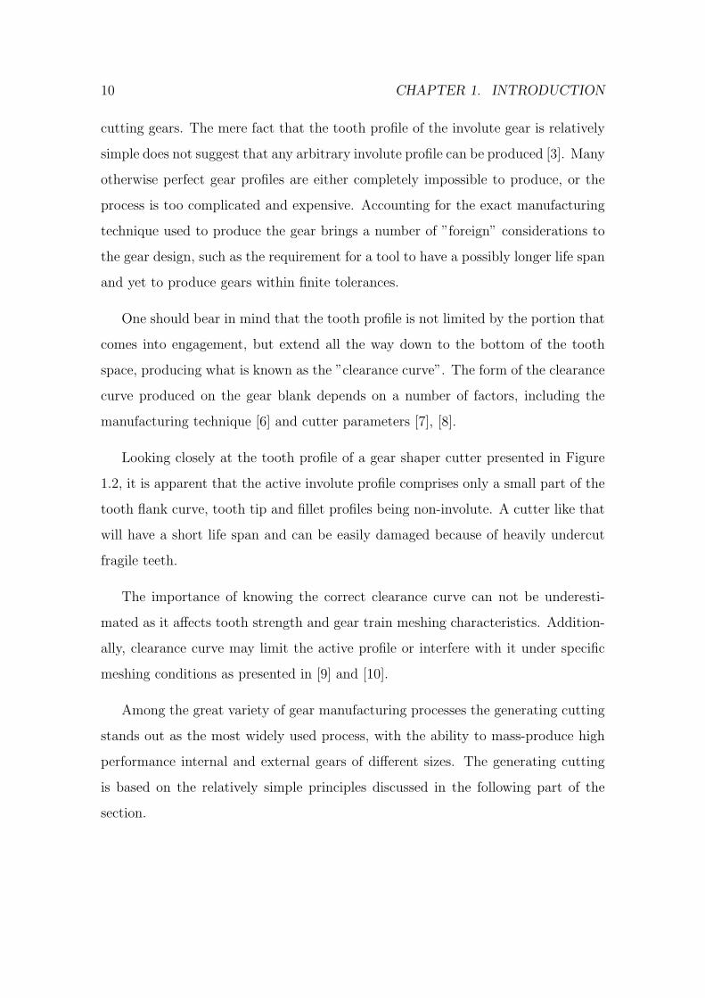
1.2 Gear shaper cutter tooth with severe undercut (8.47 DP, 14.5 PA, 25
teeth) . . . . . . . . . . . . . . . . . . . . . . . . . . . . . . . . . . . 11
1.3 A graphical solution to the conjugate profile problem. Cutter profile
A, gear profile B. . . . . . . . . . . . . . . . . . . . . . . . . . . . . . 13
1.4 A mechanical device used to obtain the conjugate profile . . . . . . . 13
1.5 Gear generation with a rack type cutter . . . . . . . . . . . . . . . . . 15
1.6 Generation of a helical gear shaper cutter with a grinding wheel . . . 16
2.1 Generation of internal gear by shaper cutting process . . . . . . . . . 24
2.2 Helical gear shaper cutter during generation process . . . . . . . . . . 25
2.3 The effect of rake angle on cutting force, as presented by Saglam et
al. in [2] . . . . . . . . . . . . . . . . . . . . . . . . . . . . . . . . . . 26
2.4 Fabrication of helical gear shaper cutters using different types of ma-
chines. (a) - cutter axis is first twisted for helix angle and then lifted
for top rake angle, (b) - cutter axis is lifted for top rake angle and
then twisted for helix angle. . . . . . . . . . . . . . . . . . . . . . . . 28
2.5 Spur gear and equivalent basic rack . . . . . . . . . . . . . . . . . . . 29
2.6 Spur gear shaper cutter rake angles . . . . . . . . . . . . . . . . . . . 31
2.7 Criteria used to assess available CAD systems . . . . . . . . . . . . . 39
vii
4.1 Gear shaper cutter design process model . . . . . . . . . . . . . . . . 54
4.2 Different definition planes of a gear . . . . . . . . . . . . . . . . . . . 60
4.3 Cutter profiles that are obtained from the same gear at different pitch
diameters. (a) - design master gear profile was not redesigned, (b) -
design master gear profile was redesigned . . . . . . . . . . . . . . . . 61
4.4 Manufactured cutter trace is superimposed on the theoretical cutter
profile with grinding allowances . . . . . . . . . . . . . . . . . . . . . 62
4.5 Gear shaper cutter body drawing and its embodiment in metal . . . . 63
5.1 The involute line, base circle, radius vector, polar and pressure angles.
θ - polar angle, ψ - pressure angle, ρ - angle between the radius vector
to the origin of the involute and the tangent to the involute profile,
r0 - base radius of the involute . . . . . . . . . . . . . . . . . . . . . . 66
5.2 Circular thickness of the cutter . . . . . . . . . . . . . . . . . . . . . 70
5.3 Meshing between the cutter blank and the basic rack . . . . . . . . . 78
5.4 Meshing between the gear blank (below) and the cutter (above) . . . 79
6.1 Top level architecture of the software package . . . . . . . . . . . . . 85
6.2 CAD software interface prototype: cutter page . . . . . . . . . . . . . 89
6.3 CAD software interface prototype: gear page . . . . . . . . . . . . . . 91
6.4 CAD software interface prototype: multigraph page . . . . . . . . . . 94
6.5 Cutter generation with a basic rack . . . . . . . . . . . . . . . . . . . 95
7.1 Case study 1: Basic rack profile . . . . . . . . . . . . . . . . . . . . . 101
7.2 Case study 1: Cutter profile . . . . . . . . . . . . . . . . . . . . . . . 102
7.3 Case study 1: Cutter profile at different wear levels . . . . . . . . . . 103
7.4 Case study 2: The profile of the basic rack of the cutter . . . . . . . . 105
7.5 Case study 2: The profile of the cutter . . . . . . . . . . . . . . . . . 106
viii

7.6 Case study 2: Generation of the cutter profile by rolling the basic
rack around its pitch circle . . . . . . . . . . . . . . . . . . . . . . . . 107
7.7 Case study 2: Gear profile cut by the cutter at nominal outside diameter108
7.8 Case study 2: Gear profile cut by the cutter at maximal outside
diameter . . . . . . . . . . . . . . . . . . . . . . . . . . . . . . . . . . 108
7.9 Case study 3: Cutter shape obtained from non-redesigned master gear 110
7.10 Case study 3: Cutter shape obtained from non-redesigned master
gear with radial root rise modification . . . . . . . . . . . . . . . . . . 111
7.11 Case study 3: Cutter shape obtained from gear redesigned at ψ = 25◦ 112
7.12 Case study 3: Gear profiles cut by non-redesigned and redesigned
cutters . . . . . . . . . . . . . . . . . . . . . . . . . . . . . . . . . . . 113
7.13 Case study 3: Root and chamfer diameter graphs of the gear . . . . . 114
ix

x
List of Tables
2.1 Assessment of existing gear design systems . . . . . . . . . . . . . . . 39
7.1 Cutter profile parameters: General . . . . . . . . . . . . . . . . . . . 99
7.2 Cutter profile parameters: Protuberance . . . . . . . . . . . . . . . . 100
7.3 Cutter profile parameters: Tip rise . . . . . . . . . . . . . . . . . . . 100
7.4 Design master gear parameters . . . . . . . . . . . . . . . . . . . . . 104
7.5 Cutter profile parameters . . . . . . . . . . . . . . . . . . . . . . . . . 105
7.6 Design master gear parameters . . . . . . . . . . . . . . . . . . . . . 109
7.7 Cutter profile parameters . . . . . . . . . . . . . . . . . . . . . . . . . 110
7.8 Gear chamfer parameters . . . . . . . . . . . . . . . . . . . . . . . . . 114
xi

xii
List of publications
1. J. Butans, A. Tiwari, Computer Aided Design of Involute Gear Shaper Cutters.
Submitted to: Mechanism and Machine Theory.
2. J. Butans, A. Tiwari, Gear Shaper Cutter Design. Submitted to: Decision
Engineering Report Series.
3. J. Butans, A. Tiwari, Web-based design of gear cutting tools. Submitted to:
Proceedings of the Institution of Mechanical Engineers, Part C: Journal of
Mechanical Engineering Science.
xiii

xiv

List of acronyms
AJAX Asynchronous JavaScript and XML
API Application Programming Interface
CAD Computer-Aided Design
CAM Computer-Aided Manufacturing
CNC Computer Numerical Control
DP Diametral pitch
DXF Drawing Exchange Format
JSON JavaScript Object Notation
MOD Module
NumPy Numerical Python
PA Pressure angle
PDF Portable Document Format
SRS Software Requirements Specification
SVG Scalable Vector Graphics
xv

TCO Total Cost of Ownership
XML eXtensible Markup Language
xvi
Abstract
The global market competition has put a pressure on the industry to reduce lead
time and increase quality of parts. In particular, the area of gear cutting tool design
requires capability to rapidly produce tool designs with increased tool geometry
precision. The aim of this research is to explore the field of gear shaper cutter design
and produce a model and software that would enable creation of more precise cutter
designs, faster.
A literature survey of involute cylindrical gearing geometry highlights deficiencies
in addressing industry requirements of tool manufacturing, as most of the research
in the area is focused on problems of gear design, but not tool design. This research,
therefore, focuses on the process of gear manufacturing using the gear shaper cutters.
It attempts to develop an analytical model and a set of tools that are able to aid
the design process of gear shaper cutter.
With cylindrical gear being essentially ”flat” and therefore easier to express an-
alytically, the focus of recent papers has shifted to non-cylindrical and non-involute
gear trains. Yet the geometry of the tools used to produce cylindrical gears remains
largely untapped area, in particular the geometry of gear shaper cutters. The knowl-
edge about the profile of the cutter teeth and the profile cut by the cutter in the
gear blank are essential for high precision gear manufacturing.
The gear shaper cutter is a metal cutting tool and therefore should be re-
sharpened on a regular basis. These re-sharpening operations change the profile
xvii

of the tool and, consequently, the profile of the gear it cuts. The changes in the
cutter and gear geometry are analysed in this thesis and a way to calculate the life
span of the tool is suggested.
Gear shaper cutter profiles usually have one or more modifications to the theoret-
ical ideal involute profile applied. Some of these modifications are used to produce
a better cutter profile, while other should in turn produce modifications to the gear
profile, and, finally, some are used to overcome generated gear profile constraints.
Computer-Aided Design (CAD) software for gear shaper cutter design should be
able to show the profile of the cutter and the profile cut by the cutter with arbitrary
modifications applied. The analysis and visualisation of gear shaper cutters profiles
cut by these cutters is impossible without a clear understanding of the principles
of operation of gear generation hardware, generating motion and different machine
geometry, all being covered in this thesis.
In order to verify the analytical model and the CAD software case studies of the
real-life gear shaper cutter designs were performed.
xviii
Chapter 1
Introduction
Looking around one can see that many mechanisms starting from alarm clock to
Airbus A380 jet plane use gears of various kinds. Among those the most widely used
are cylindrical gears with involute (refer to Section 1.1.5) tooth profile. Cylindrical
gears with straight teeth are called ’spur’ gears while ones that have teeth inclined
at an angle to the gear rotation axis are referred to as ’helical’ gears.
While gears and especially combinations of gears working together in gear trains
(transmissions) are interesting study objects by themselves, the special interest of
this thesis is how gears are being manufactured. In particular, the author looks at
the process of cylindrical gear manufacturing by means of generating cutting with
gear shaper cutters and applies CAD methods to improve the process.
1.1 Nomenclature, conventions and definitions
This section gives the nomenclature, conventions and definitions created to cover
all aspects of gear geometry, conjugate gear-tooth motion and gear manufacturing.
The classification in the following section is based on the one presented by Merritt
1
2 CHAPTER 1. INTRODUCTION
in [3]. Definitions are taken from the relevant British and international standards.
In particular, extended definitions could be obtained from [4] and [5].
The importance of consistent nomenclature that covers the entire scope of this
thesis has been recognised by the author, and every care was taken to ensure that
this thesis adheres to it. To show the dimensions of a same nature but different in
application or magnitude small and capital letters are used for the cutter and gear
respectively, further aided by suffixes. For example, d is used to represent the pitch
diameter for the cutter, while the pitch diameter for the gear bears D symbol. Base
diameters of cutter and gear are represented by d0 and D0 respectively.
All calculations and figures in this thesis use polar coordinate system, unless
explicitly stated otherwise. Greek letters are used to indicate angular dimensions,
except the letter π that stands for the numerical value of the ratio of the circumfer-
ence of a full circle to its diameter. Distinctions between gear and cutter are made
using suffixes, where necessary.
1.1.1 General definitions and nomenclature
The analysis of cylindrical gear teeth starts with defining pitch surfaces and relative
shaft position of conjugate members. The pitch surfaces of gears that have paral-
lel axes are imaginary rotational surfaces concentric with axes of respective gears.
The pitch surfaces roll without slip when the gears rotate with angular velocities
reciprocal to the number of teeth in each gear. Pitch surfaces of gears connecting
parallel shafts are cylinders, so the name pitch cylinders may be used as well. Two
pitch surfaces make contact along a straight line termed as pitch-surface generator,
as this line when rotated round the axes of conjugate gears produces respective pitch
surfaces.
1.1. NOMENCLATURE, CONVENTIONS AND DEFINITIONS 3
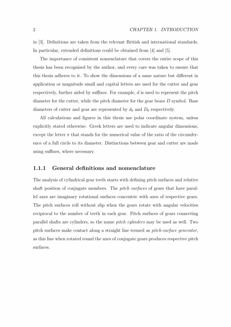
Figure 1.1: Common gear terms, as presented in [1]
The gear will be examined in the following three major planes.
• An axial plane is a plane that contains the axis of a gear and intersects with
the pitch surface along pitch-surface generator.
• A transverse plane is a plane perpendicular to the axis of a gear. Intersection
of the transverse plane with the pitch surface gives the pitch circle of a gear.
• A normal plane is a plane to which the tooth spiral is normal at pitch point.
Proceeding to describe definitions and nomenclature relating to the pitch surfaces
of gears, the two pitch surfaces in a transverse plane make contact at a point termed
4 CHAPTER 1. INTRODUCTION
as pitch point. The circle formed by intersecting pitch surface with a transverse
plane is called pitch circle of the gear. The pitch diameter is the diameter of the
pitch circle.
The dimensions described in this section use the following notation throughout
the thesis.
d - Pitch diameter of cutter.
D - Pitch diameter of gear.
t - Number of teeth in cutter.
T - Number of teeth in gear.
C - Centre distance. The shortest distance between the axes of gears.
Considering the contact of two toothed bodies, one of them being substantially
larger then the other and having more teeth, the former will be called wheel, while
the later will be called pinion. Consequently, internal gear is always a wheel, while
smaller mating gear or cutter is always a pinion.
1.1.2 Tooth spiral and pitch
A tooth spiral is the curve of intersection between the tooth flank and the pitch
surface. The tooth spiral of a gear having helical teeth is called tooth helix.
A normal helix of a gear having helical teeth is a tooth spiral lying in the pitch
cylinder and having its spiral angle complementary to the spiral angle of the tooth
helix. In other words, tangents drawn through the point of intersection between the
tooth helix and normal helix cross at right angle.
σ - Spiral angle. The angle between a tangent to a tooth spiral at any point and
the pitch-surface generator passing through the same point.
σp - Helix angle. The angle between a tangent to a tooth helix at pitch point
and the pitch-surface generator passing through the pitch point.
1.1. NOMENCLATURE, CONVENTIONS AND DEFINITIONS 5
Pitch is the measure of the spacing between successive tooth spirals on tooth
faces of the same orientation.
p - The circular pitch is the distance measured along the pitch circle between
two immediately following tooth faces of the same orientation.
P - Diametral pitch. The diametral pitch is the expression of pitch by quotient
obtained by dividing the number of teeth in gear by the pitch diameter.
m - Module. The module is the expression of pitch obtained by dividing the
circular pitch by π. One can note that the module is reciprocal to the diametral
pitch.
1.1.3 Tooth parts
The profile of gears is a combination of ’tooth’ and ’space’ profiles repeated many
times. In fact, tooth and space profiles overlay each other, thus two adjacent space
profiles make up for one full tooth profile and two half tooth profiles.
The tooth is a part of a gear used to transmit the rotary motion. The teeth
extend beyond the pitch surface of a gear.
t - Index of a tooth dimension used where distinction from similar space dimen-
sion is necessary.
The space is the absence of material between adjacent gear teeth.
s - Index of a space dimension used where distinction from similar tooth dimen-
sion is necessary.
In the context of this thesis it is important to distinguish between gear and
tooth profiles. The tooth profile starts from the centre of immediately preceding
space profile and ends at the centre of immediately following space profile. In turn,
space profile lies between centres of adjacent tooth profiles.
The blank is a plain metal cylinder from which a gear is made by cutting teeth
in it.
6 CHAPTER 1. INTRODUCTION
The crest is part of the original outside cylinder of the blank remaining on the
gear after tooth generation process.
The addendum circle is the circle containing tooth crests.
The dedendum circle is the circle tangent to bottom of tooth spaces.
The tooth face is the portion of active tooth profile above the pitch circle.
The flank is the portion of active tooth profile below the pitch circle.
The tip of the tooth is the edge between the tooth face and tooth crest or the
portion of the tooth profile immediately adjacent to that edge.
The root is the bottom part of the tooth.
The clearance curve is the bottom portion of the space profile, joining two adja-
cent tooth flanks.
The fillet is a part of the clearance between the tooth flank and the bottom of
tooth space.
Some gears have arbitrary modifications to the tooth profile whereby small
amounts of material are removed from profile portions close to tooth tip or (and)
root. Such modifications are called tip relief and root relief, respectively. Cutters
designed to cut these gears will have complementary profile modifications termed
root rise and tip rise. It is important to note that tip modification on gear results
in root modification on cutter and vice versa.
A profile modification termed chamfer is used to enable sliding gears engage
more smoothly. It puts a sloping involute surface at the tip of the gear tooth.
Consequently, on the cutter chamfer occurs near the root of the tooth.
After being cut by a gear shaper cutter most gears are thermally treated and
afterwards have to be finished by grinding. The operation removes small amounts of
material along the involute profile of the gear tooth. This may leave a sharp ’step’
between the fillet and the involute profile, which is undesirable. To avoid finishing
step on the gear the cutter profile should be modified by offsetting a portion of the
1.1. NOMENCLATURE, CONVENTIONS AND DEFINITIONS 7
involute profile at the tip of the cutter tooth. The offset portion undercuts the gear
tooth in such a way that after finishing no sharp step appears. This modification to
the cutter tooth is termed as protuberance.
The top rake angle is the angle between pitch-surface generator and the crest of
the tooth in axial plane of the cutter.
The front rake angle is the angle between front surface of the tooth and transverse
plane of the cutter.
1.1.4 Tooth dimensions
This section lists the dimensions of the tooth with the following definitions and
symbols: ψ - Pressure angle. The acute angle between the common pitch plane and
the common normal to the profiles of meshing gear teeth at the point of contact,
measured in arbitrary plane. By default this angle is understood to be measured in
transverse plane.
Addendum. The distance between the pitch circle and the tooth crest measured
in radial direction.
a - Addendum of cutter.
A - Addendum of gear.
Dedendum. The distance between the pitch circle and the bottom of the tooth
space measured in radial direction.
b - Dedendum of cutter.
B - Dedendum of gear.
c - Clearance. The amount of space between the bottom of the cutter space and
the crest of the gear tooth.
Outside diameter. The diameter of the addendum circle.
Root diameter. The diameter of the dedendum circle.
8 CHAPTER 1. INTRODUCTION
Circular thickness. The distance between two adjacent tooth flanks measured
round the circle of a given diameter. Unless explicitly stated otherwise, this quan-
tity is understood to be the thickness of the tooth measured at the pitch circle in
transverse plane.
gt - Circular thickness of cutter tooth. This quantity is measured between the
flanks of the same tooth.
Gt - Circular thickness of gear tooth. This quantity is measured between the
flanks of the same tooth.
gs - Circular thickness of cutter space. This quantity is measured between the
flanks of two adjacent teeth joined by the clearance curve.
Gs - Circular thickness of gear space. This quantity is measured between the
flanks of two adjacent teeth joined by the clearance curve.
l - Cutter life. The length of the tooth crest measured in the axial plane of the
cutter.
1.1.5 Involute surfaces
The dimensions and definitions related to the involute part of the tooth profile are
listed in the following section:
The involute is the locus of points made by the end of a tightly pulled string
as it being unwound from a circle in the plane of that circle. That circle is being
termed as the base circle of the involute. The point lying on the base circle at which
the involute starts is called origin of that involute. Considering the involute as the
surface being unwound from the cylinder, that cylinder is termed as base cylinder.
Refer to Figure 5.1 for involute-related definitions.
Base diameter. The diameter of a base circle or base cylinder.
d0 - Base diameter of cutter.
D0 - Base diameter of gear.
1.2. INTRODUCTION TO GENERATING CUTTING 9
p0 - Base pitch. The base pitch is the distance between two immediately succes-
sive involutes forming tooth flanks measured along a common normal.
Circular base thickness. The distance between two involutes forming adjacent
tooth flanks measured round the base circle. By default, this quantity is understood
to be measured between the involutes forming the flanks of the same tooth.
g0t - Circular base thickness of cutter tooth. This quantity is measured between
the involutes forming the flanks of the same tooth.
G0t - Circular base thickness of gear tooth. This quantity is measured between
the involutes forming the flanks of the same tooth.
g0s - Circular base thickness of cutter space. This quantity is measured between
the involutes forming the flanks of two adjacent teeth joined by the clearance curve.
G0s - Circular base thickness of gear space. This quantity is measured between
the involutes forming the flanks of two adjacent teeth joined by the clearance curve.
The basic rack is a gear with infinite base diameter. On the basic rack the
involutes constituting tooth flanks are straight lines.
1.2 Introduction to generating cutting
Generating cutting is a standard manufacturing technique widely used for spur and
helical gear manufacturing. Without going into details at this stage it can be noted
that the form produced in a gear blank by the generating cutting process is different
from the inverse form of a cutter.
Knowing the principles underlying the process of gear manufacturing is essential
for the study and design of a gear profile. It has been often staited that if a gear
profile is designed with certain involute dimensions, the particular way of how it will
be produced is irrelevant to the designer. This assumption caused (and causes) a
good deal of trouble to the people responsible for producing and maintaining tools for
10 CHAPTER 1. INTRODUCTION
cutting gears. The mere fact that the tooth profile of the involute gear is relatively
simple does not suggest that any arbitrary involute profile can be produced [3]. Many
otherwise perfect gear profiles are either completely impossible to produce, or the
process is too complicated and expensive. Accounting for the exact manufacturing
technique used to produce the gear brings a number of ”foreign” considerations to
the gear design, such as the requirement for a tool to have a possibly longer life span
and yet to produce gears within finite tolerances.
One should bear in mind that the tooth profile is not limited by the portion that
comes into engagement, but extend all the way down to the bottom of the tooth
space, producing what is known as the ”clearance curve”. The form of the clearance
curve produced on the gear blank depends on a number of factors, including the
manufacturing technique [6] and cutter parameters [7], [8].
Looking closely at the tooth profile of a gear shaper cutter presented in Figure
1.2, it is apparent that the active involute profile comprises only a small part of the
tooth flank curve, tooth tip and fillet profiles being non-involute. A cutter like that
will have a short life span and can be easily damaged because of heavily undercut
fragile teeth.
The importance of knowing the correct clearance curve can not be underesti-
mated as it affects tooth strength and gear train meshing characteristics. Addition-
ally, clearance curve may limit the active profile or interfere with it under specific
meshing conditions as presented in [9] and [10].
Among the great variety of gear manufacturing processes the generating cutting
stands out as the most widely used process, with the ability to mass-produce high
performance internal and external gears of different sizes. The generating cutting
is based on the relatively simple principles discussed in the following part of the
section.
1.2. INTRODUCTION TO GENERATING CUTTING 11
0.00000.0500
0.10000.1500
outside diameter
root diameter
start of involutepro�le
end of involutepro�le
tangential deviation fromthe theoretical involute
scal
e: 1
:100
0
Figure 1.2: Gear shaper cutter tooth with severe undercut (8.47 DP, 14.5 PA, 25
teeth)
The underlying principle of gear design is the fact that two toothed bodies moving
relative to each other in constant mesh have their conjugate profiles in determined
relationship. Many books and papers, such as [11], [12], [13] discuss the rules gov-
erning that relationship, such as the relative position of the point of contact, relative
motion of two toothed bodies participating in the contact and geometry of conjugate
profiles.
12 CHAPTER 1. INTRODUCTION
If the geometry of one of the conjugate profiles is given along with the relative
motion of both profiles, the geometry of the second profile could be obtained by
either analytical, numerical or graphical means. Although this thesis mainly deals
with the former two, a brief description of the graphical solution was deemed helpful
by the author for the reader to aid his (or her) imagination.
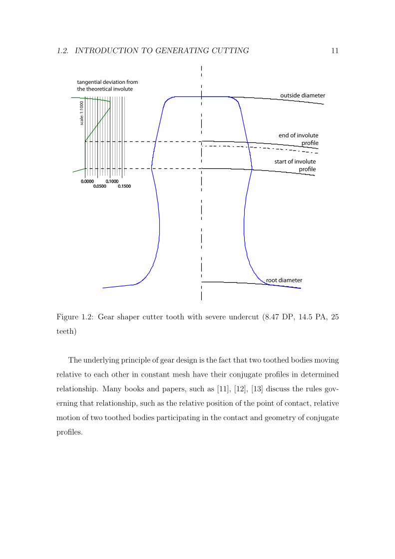
Consider Figure 1.3 that illustrates a gear during the generation process. The
cutter profile ”A” is mounted in a determined position to the gear blank ”B”. The
determined position means that the pitch circle of the cutter is tangent to the pitch
circle of the gear to be produced from the blank. Both parts rotate at angular
velocities that are inversely proportional to their pitch diameters. If the profile
”A” is given cutting properties and moved reciprocally in the axial plane (a plane
perpendicular to the plane of the drawing), it will produce the conjugate gear profile
on the gear blank.
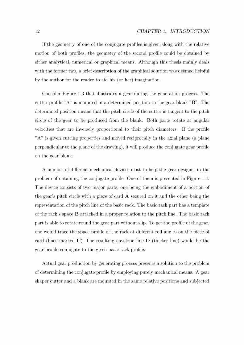
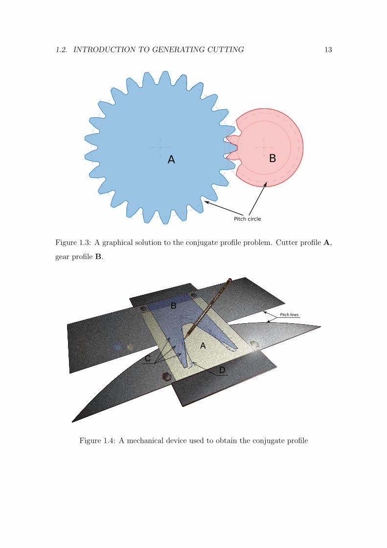
A number of different mechanical devices exist to help the gear designer in the
problem of obtaining the conjugate profile. One of them is presented in Figure 1.4.
The device consists of two major parts, one being the embodiment of a portion of
the gear’s pitch circle with a piece of card A secured on it and the other being the
representation of the pitch line of the basic rack. The basic rack part has a template
of the rack’s space B attached in a proper relation to the pitch line. The basic rack
part is able to rotate round the gear part without slip. To get the profile of the gear,
one would trace the space profile of the rack at different roll angles on the piece of
card (lines marked C). The resulting envelope line D (thicker line) would be the
gear profile conjugate to the given basic rack profile.
Actual gear production by generating process presents a solution to the problem
of determining the conjugate profile by employing purely mechanical means. A gear
shaper cutter and a blank are mounted in the same relative positions and subjected
1.2. INTRODUCTION TO GENERATING CUTTING 13
Figure 1.3: A graphical solution to the conjugate profile problem. Cutter profile A,
gear profile B.
A
B
CD
Pitch lines
Figure 1.4: A mechanical device used to obtain the conjugate profile
14 CHAPTER 1. INTRODUCTION
to the same rolling motion as the two gears in a gear train. A general idea of the
process is based on two principles:
• the cutter is subjected to the motion along the axis perpendicular to the
transverse plane of the gear that makes the cutting edge of the tool to cast off
metal from the gear blank;
• the blank is mounted in a determined relationship with the cutter and both
tool and blank are given a relative rolling motion equal to the motion between
conjugate profiles represented by the cutter and gear that should be produced.
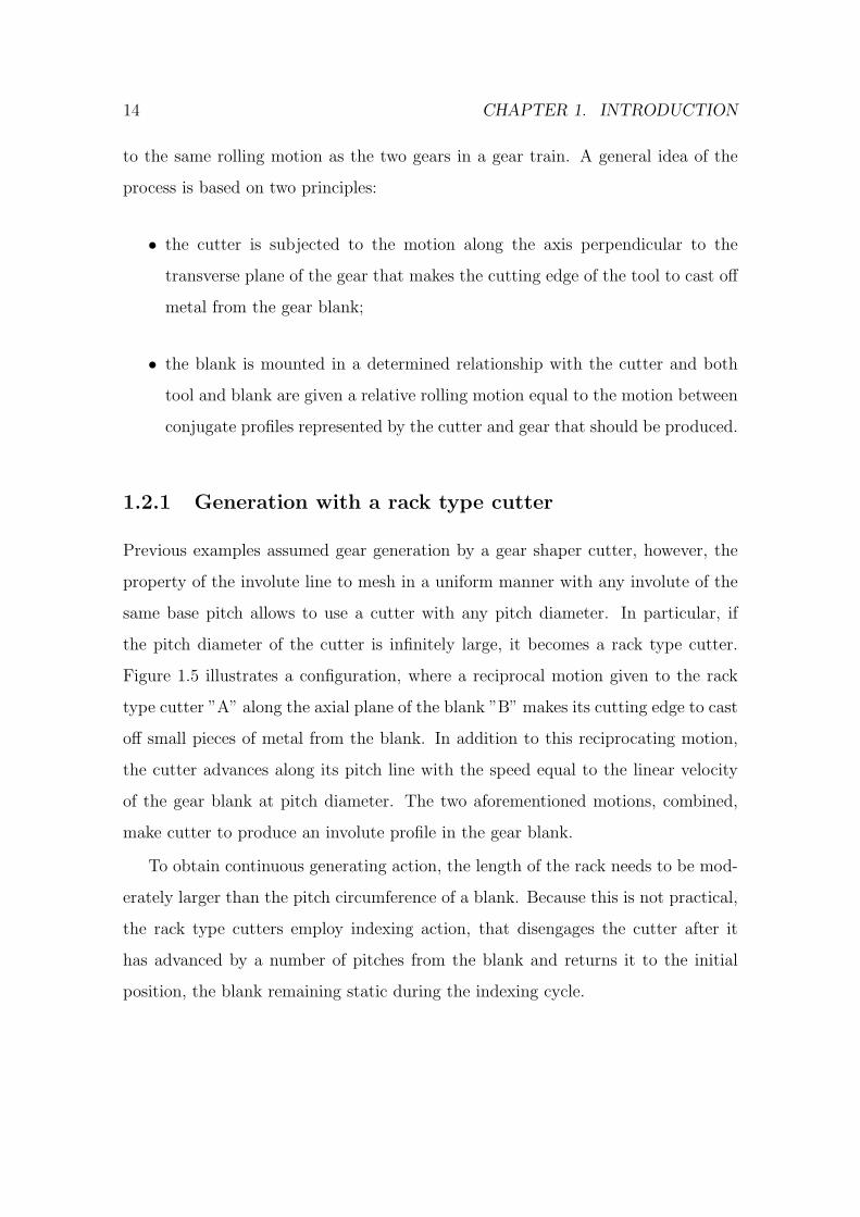
1.2.1 Generation with a rack type cutter
Previous examples assumed gear generation by a gear shaper cutter, however, the
property of the involute line to mesh in a uniform manner with any involute of the
same base pitch allows to use a cutter with any pitch diameter. In particular, if
the pitch diameter of the cutter is infinitely large, it becomes a rack type cutter.
Figure 1.5 illustrates a configuration, where a reciprocal motion given to the rack
type cutter ”A” along the axial plane of the blank ”B” makes its cutting edge to cast
off small pieces of metal from the blank. In addition to this reciprocating motion,
the cutter advances along its pitch line with the speed equal to the linear velocity
of the gear blank at pitch diameter. The two aforementioned motions, combined,
make cutter to produce an involute profile in the gear blank.
To obtain continuous generating action, the length of the rack needs to be mod-
erately larger than the pitch circumference of a blank. Because this is not practical,
the rack type cutters employ indexing action, that disengages the cutter after it
has advanced by a number of pitches from the blank and returns it to the initial
position, the blank remaining static during the indexing cycle.
1.2. INTRODUCTION TO GENERATING CUTTING 15
A
B
Figure 1.5: Gear generation with a rack type cutter
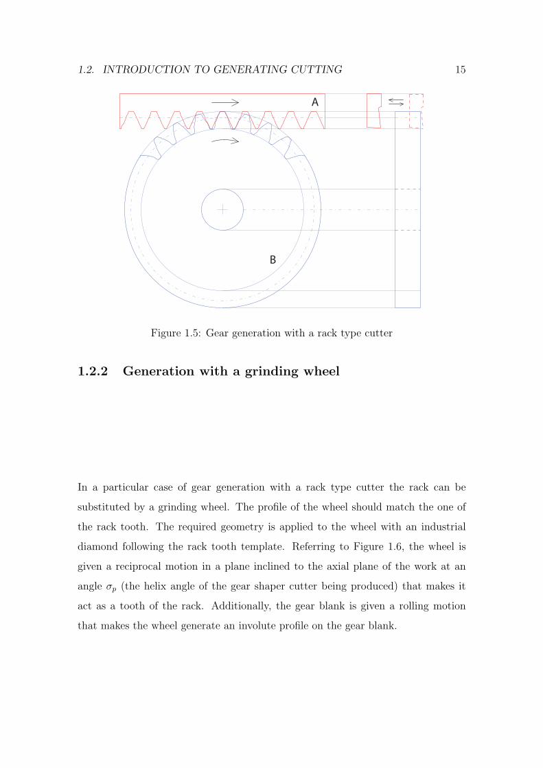
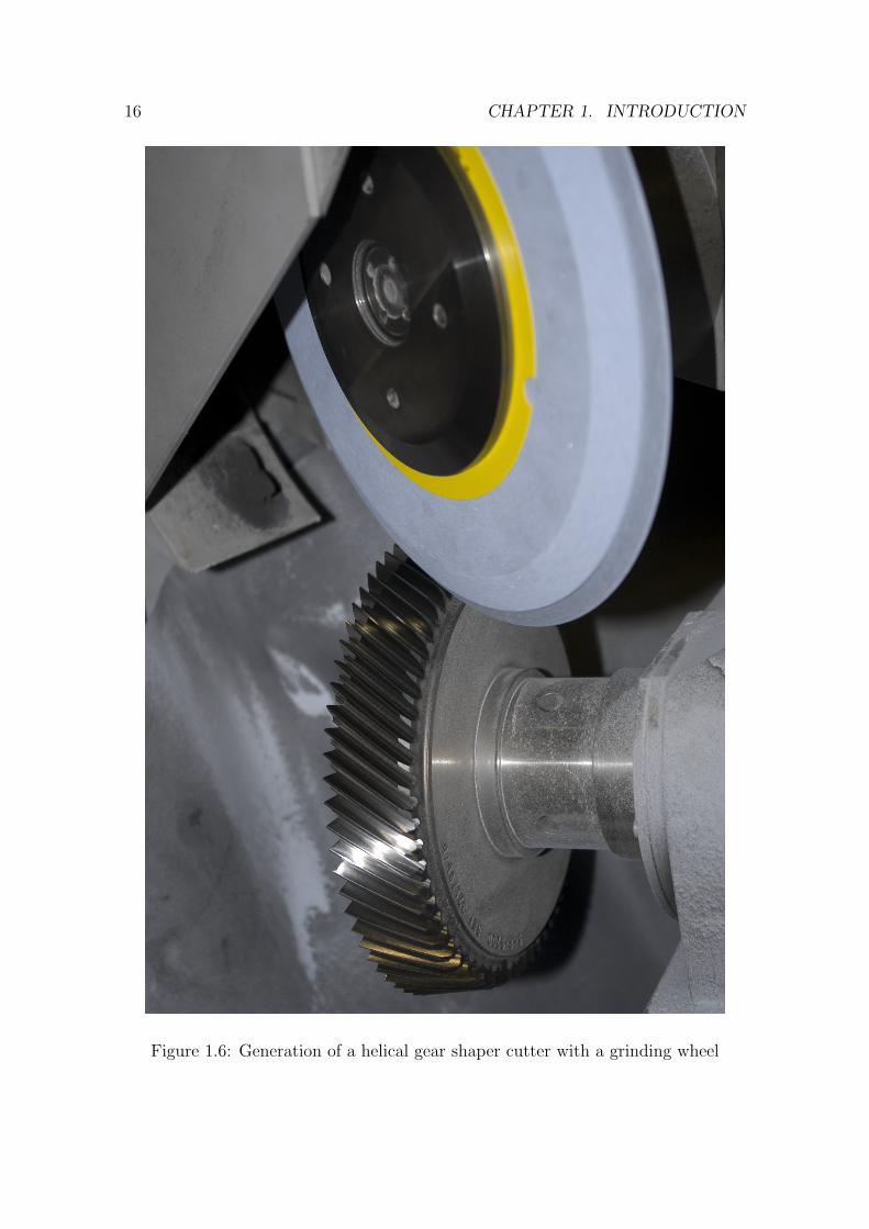
1.2.2 Generation with a grinding wheel
In a particular case of gear generation with a rack type cutter the rack can be
substituted by a grinding wheel. The profile of the wheel should match the one of
the rack tooth. The required geometry is applied to the wheel with an industrial
diamond following the rack tooth template. Referring to Figure 1.6, the wheel is
given a reciprocal motion in a plane inclined to the axial plane of the work at an
angle σp (the helix angle of the gear shaper cutter being produced) that makes it
act as a tooth of the rack. Additionally, the gear blank is given a rolling motion
that makes the wheel generate an involute profile on the gear blank.
16 CHAPTER 1. INTRODUCTION
Figure 1.6: Generation of a helical gear shaper cutter with a grinding wheel
1.3. INTRODUCTION TO GEAR SHAPER CUTTERS 17
1.3 Introduction to gear shaper cutters
A gear shaper cutter is a mechanical tool used to produce gears of various kinds.
Owing to the property of the involute profile to mesh correctly with a gear of any
pitch diameter under certain conditions, a rack type cutter may be substituted with
any gear derived from it. Simply put, a gear shaper cutter is a gear having its teeth
suitably relieved to cut the material of blank without rubbing it. On a closer look,
it turns out that the gear shaper cutter is somewhat different from the typical gear,
because it might have profile modifications required to produce gear with certain
special properties.
A gear might have a chamfer to remove sharp end between tooth face and crest.
To aid gear in engagement, their teeth can have root and tip reliefs of different
configurations. Some gears require optimisation to the fillet profile. Finally, a gear
that is subject to a finishing operation after, for example, a heat treatment, should
have an appropriate modification to remove the sharp step between the finished
profile and the fillet. Generally, it is desirable to put all aforementioned modifications
with the same tool that generates the active involute profile, as this reduces time
required to produce gear and the manufacturing costs associated with a number of
tools and appropriate machinery.
Considering that a gear shaper cutter might have to produce all of the afore-
mentioned modifications simultaneously, plus additional modifications to the cutter
itself to get a better tool life or better manufacturability, the geometry of the cutter
and gear may become very complex.
1.4 Problem statement and motivation
A question that should be answered as a necessary precondition to defining the
problems encountered in the course of gear shaper cutter design is ’what makes
18 CHAPTER 1. INTRODUCTION
gear shaper cutters worth using for gear manufacturing’. The gear shaper cutters
are reliable tools for high-volume production of external gears. What makes them
special, is the ability to cut internal gears, because neither hob type cutters nor rack
type cutters are able to produce internal gears. Additionally, machines employing
gear shaper cutters do not require indexing cycles that are inherent to the machines
that use rack type cutters.
A quick look at the literature available in the area of cylindrical gearing (see
Chapter 2 for details) shows vast number of papers and books about topics such as
design of gears and gear trains, various gear profile modifications and CAD tech-
niques. There is a decent number of software CAD packages aimed to ease the life
of gear designer. At the same time the amount of research on topics of gear shaper
cutter design process, profile modifications, tool life and interaction between the
cutter and gear is comparatively low. Likewise, CAD packages for gear design are
difficult to use for gear shaper cutter design due to some functionality missing.
Based on the observations presented above, the following problems can be defined
to be addressed in the present thesis:
• the exact nature and scope of the gear shaper cutter design process is not
defined in the current literature;
• no analytical model exists that is suited in an unmodified form for the analysis
of the gear profile generated by the gear shaper cutter, includes provisions for
all necessary gear shaper cutter profile modifications and accounts for the
changes in the cutting tool profile geometry throughout its life;
• there is no software suite readily available to aid a gear shaper cutter designer
in his / her job, making what should be a simple and quick operation a craft
that requires lots of manual work.
1.5. THESIS LAYOUT 19
1.5 Thesis layout
This thesis is organised into eight chapters with References and Appendices counting
separately. The chapter are in the order they appear in the thesis: the Introduction,
Literature review, Research aim, objectives and methodology, Gear shaper cutter
design process, Analytical model of involute cylindrical gearing, Computer-Aided
Design software for gear shaper cutter design, Real life case studies and Discussion
and conclusions.
The first chapter, Introduction, contains information of a general kind about
generating process used to manufacture gears as a whole and gear shaper cutters
in particular. A major portion of the first chapter is devoted to describing the
nomenclature, conventions and definitions that are used throughout the rest of the
work. In the final pages a problem definition is given along with the current portion,
the Thesis layout.
The second chapter is dedicated to a review of the current literature. First the
literature about the features of a gear shaper that make it different from the gear
are discussed; those are the few papers existing about the gear shaper cutter design.
Afterwards the sources concerned with profile modifications on the gear are analysed
in the hope to get a foundation for a similar analysis of a cutter. Finally, a brief
analysis of current approaches to dealing with the gears in motion is attempted
resulting in a summary and identification of the research gap.
Chapter 3 defines the aim of this research and establishes research objectives and
scope. Subsequently, the research methodology gets outlined, based on the specifics
of the research field. Following sections provide the reader with details about the
industrial context of the research and industrial focus for the development of better
gear shaper cutter design techniques.
In the fourth chapter the author attempts to analyse and document the gear
shaper cutter design process. Namely, real gear shaper cutter designers were asked
20 CHAPTER 1. INTRODUCTION
about their workflow, challenges in tool design and specific requirements that might
not be obvious to an outside observer. An analysis revealed three major design cases
with separate design processes with computations and input parameters required for
each of them. That resulted in three separate sections entitled Cutter design case,
Gear and cutter design case and Redesign case. Auxiliary design operations are
summarised in the Manufacturing requirements and Body selection sections. At the
end a short summary is provided. It is important to keep in mind, that cutter and
gear geometry do not get discussed within this chapter. Instead, it focusses on the
process of design and definition of the requirements for the analytical model and
software package.
Chapter five establishes an analytical model of involute cylindrical gearing. Tak-
ing the process model from the previous chapter, the author provides an exact
solution to each stage of the design process. Strategies for dealing with variable sets
of inputs are given as a separate section. The model is tailored to meet the require-
ments of the software CAD package that would be discussed in the next chapter
entitled Computer-Aided Design software for gear shaper cutter design. In partic-
ular, the equations required to compute profile deviations from the theoretically
perfect ones are discussed.
Successive chapters contain description of the developed CAD package and case
studies accomplished with the help of the software package. In particular, chapter six
provides a detailed view on the architecture, principles of operation, implementation,
interface and usage of the software for cutter design. It starts with the description
of the methodology used for the development and proceeds to the identification of
the requirements based on the material of Chapter 4. The next section discusses
CAD package architecture, i.e. the details of the principles of operation and the
software platform. As already stated before, visualisation of the design data is
very important for the human designer. The visualisation presents a number of
1.5. THESIS LAYOUT 21
challenges, such as choosing a drawing format or supporting interactive graphics in
the end-user applications, therefore a separate section is dedicated to the problems
of visual representation of data.
Next section contains a description of the software interface prototype that was
created, based on the interviews and co-operative design work with the practition-
ers in the field of gear shaper cutter design. The chapter finishes with a portion
about the actual CAD package along with usage notes. A summary of the chapter’s
contents is provided.
Chapter 7 contains a set of three case studies, that cover three different design
cases, namely, a case where the cutter is being designed form scratch, a case where
the cutter is being designed based on the gear data and also one case with the
redesign. Subsequently, the key findings are analysed and documented along with
the author’s comments and a summary.
The last chapter provides the reader with conclusions and discussion about the
accomplished work. In addition, an indication of the future work in the area of the
computer aided design of gear shaper cutters is given in a separate section.

22 CHAPTER 1. INTRODUCTION
Chapter 2
Literature review
Otto von Bismarck once said: ”Nur ein Idiot glaubt, aus den eigenen Erfahrungen zu
lernen. Ich ziehe es vor, aus den Erfahrungen anderer zu lernen, um von vornherein
eigene Fehler zu vermeiden.” In English translation that would be: ”Only an idiot
would believe he could learn from his own experience. I prefer learning from others’
experience to get rid of own mistakes in the first place.” The author could not
underestimate the importance of that approach, making a study of the literature a
necessary prerequisite for any research.
2.1 Key features of a gear shaper cutter
The initial application of the generating process to the fabrication of gears employed
rack type cutters. A rack type cutter is a section of the gear profile with infinite
number of teeth. When the number of teeth in a gear approaches infinity, so does
the base diameter of the involute that forms the active profile of the gear tooth. An
involute curve having infinitely large base diameter becomes a straight line, conse-
quently the flanks of the rack tooth are composed of straight lines. This property
makes rack type cutters easy to design, manufacture and inspect [14].
23
24 CHAPTER 2. LITERATURE REVIEW
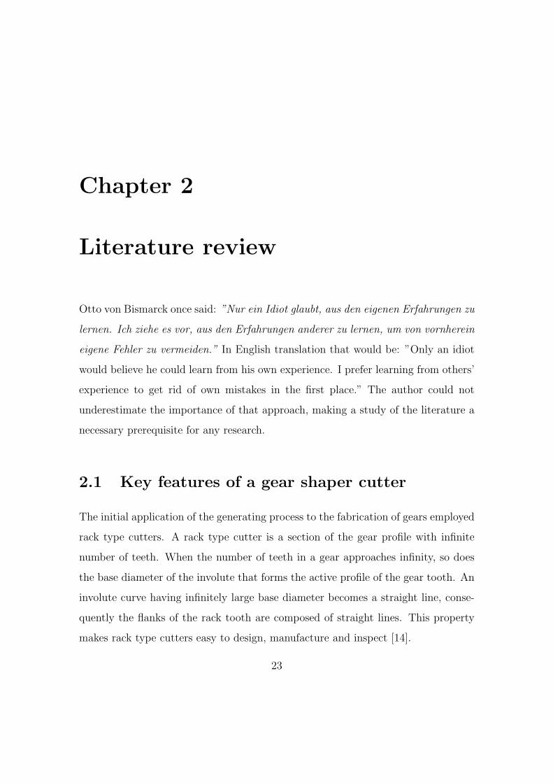
Figure 2.1: Generation of internal gear by shaper cutting process
A rack cutter may be substituted by any gear that may be derived from the
same basic rack. This property of the involute is the basis of gear-shaping process
or Fellows process, named by the Fellows Corporation founder, Edwin R. Fellows
[3]. This cutter is close in appearance to the pinion gear with appropriate profile
modifications (Figure 2.1). The spatial position and motion of the cutter and gear
blank are the same as the position and motion of two meshing involute profiles.
Reciprocating motion of the cutter along its axis causes cutting edge to cast off
severed pieces of metal producing a conjugate profile to the mating gear represented
by the cutter. In addition the cutter and the blank are mechanically connected
and subject to the relative motion based on the number of teeth. The process
is continuous in that it does not require indexing cycle required by the rack-type
cutters.
Numerous re-sharpening operations carried out throughout the life of the tool
reduce the shaper cutter diameter and therefore the distance between centres of
gear and cutter. Because of the special properties of the involute curve two engaging
involute surfaces could mesh correctly as the centre distance changes. Consequently,
2.1. KEY FEATURES OF A GEAR SHAPER CUTTER 25
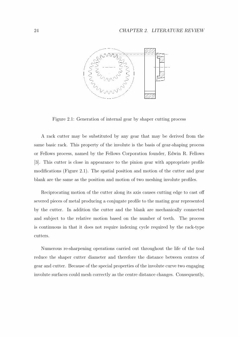
Figure 2.2: Helical gear shaper cutter during generation process
aforementioned changes in the centre distance result only in minor variations of the
involute gear profile [15], [16]. Nevertheless, the effects of cutter re-sharpening
should be expected and included in the analytical model.
A shaper cutter with appropriate helix angle if given relative helical motion to
the blank can cut helical gears. A gear with two opposing helices cut by two similar
helical gear shaper cutters that differ only in helix hand (direction of the helix) is
basis for the so called Sykes process [3] of manufacturing herringbone gears.
Shaper cutter is manufactured by abrasive wheel, which represents one teeth of
the basic rack [3]. The process of producing helical shaper cutter is presented in
Figure 2.2. Spur shaper cutters are not different in production with the exception of
helix angle that is not set in the machine. The wheel itself is formed with industrial
diamonds based on the basic rack template of the cutter corrected for the machine
geometry.
26 CHAPTER 2. LITERATURE REVIEW
0100200300400500600
0 6 12 20Rake angle-γ
Cut
ting
forc
e-F
(N)
0
100
200
300
400
Tem
pera
ture
-Tm (0 C
)Fc Ff Ft Tm
(a) v=75, χ=600
0100
200300
400500
600
0 6 12 20Rake angle-γ
Cut
ting
forc
e-F
(N)
0
100
200
300
400
500
Tem
pera
ture
-Tm (0 C
)
(b) v=113, χ =600
0
100
200
300
400
500
0 6 12 20Rake angle-γ
Cut
ting
forc
e-F
(N)
0
100
200
300
400
500
Tem
pera
ture
-Tm (0 C
)
(c) v=160, χ =600
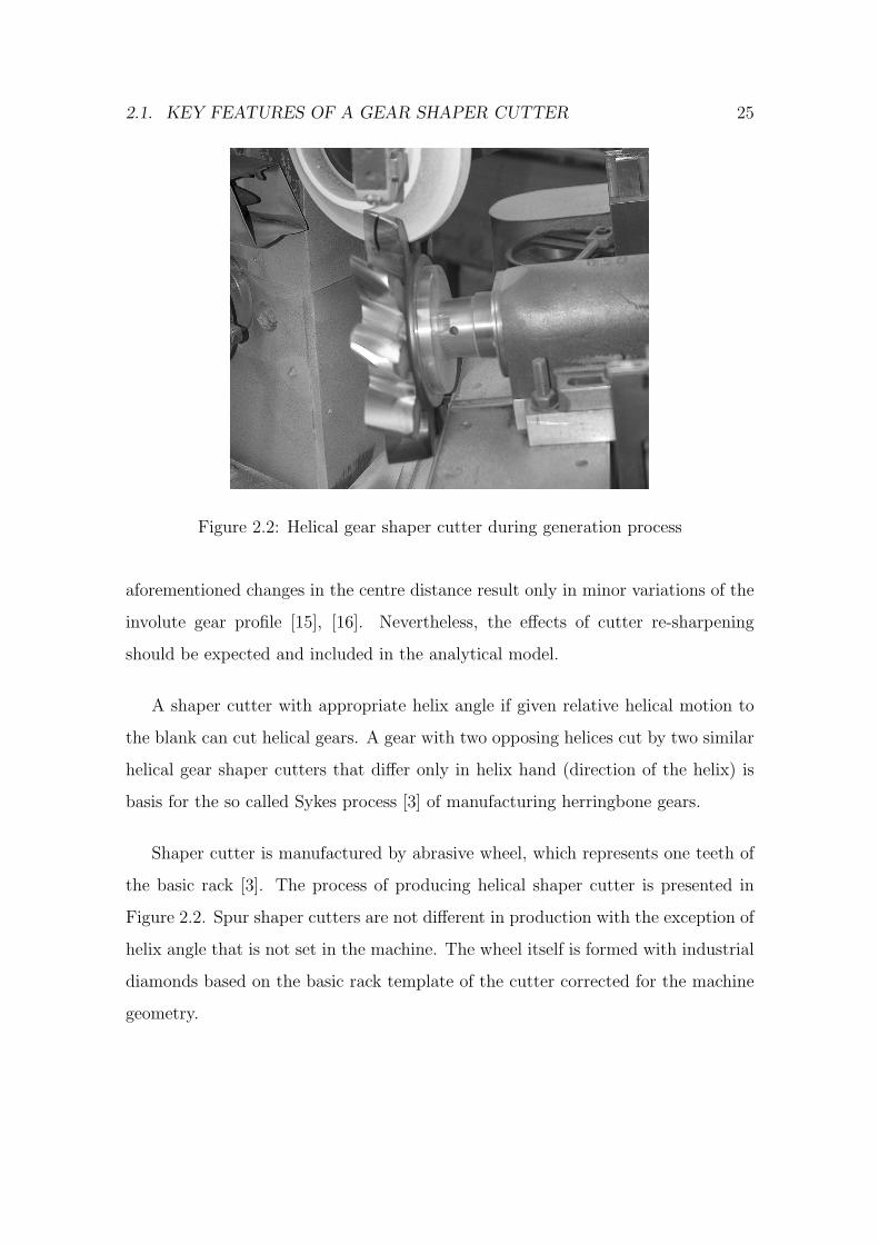
Figure 2.3: The effect of rake angle on cutting force, as presented by Saglam et al.
in [2]
2.1.1 Differences between gear shaper cutter and gear
A gear shaper cutter is a tool that closely resembles mating gear in appearance.
However, there are a number of significant differences between gear shaper cutter
and gear because of the fact that the cutter is a cutting tool.
To produce desired chip and reduce cutting force the tool has to have rake angles.
A tool with a positive rake (sharp) will lead to lower cutting forces but to less cutting
edge strength [2]. A tool with negative or neutral rake will lead to higher cutting
forces, as shown in the Figure 2.3 but increased edge strength.
The flanks of gear shaper cutter tooth must be suitably raised to provide relief
on the gear blank. Relief is a discretionary modification of the tooth edge shape to
eliminate interference between mating gear profiles. Root rise on the cutter provides
tip relief on the gear blank and tip rise on the cutter provides root relief on the gear
blank. In addition, the cutter must possess correct clearance. If the gear is intended
to be finished after cutting, the cutter should have protuberance to avoid finishing
step. Some cutters may have so-called semi-topping to produce gears with a finished
tooth top.
2.1. KEY FEATURES OF A GEAR SHAPER CUTTER 27
2.1.2 Design problems
Despite the relative simplicity of cylindrical involute gear geometry, the high quality
of gear shaper cutters produced today is mainly attributed to many years of experi-
ence and a large amount of empirical design data. This emerges due to the spatial
nature of the shaper cutter and the complex geometry involved in the analysis of
spatial gearing.
Design of a gear shaper cutter is mostly parametric, i.e. it requires a number
of equations to be solved at the design stage. Therefore the choice of a suitable
analytical model that takes into consideration the manifold requirements of the
shaper cutter production process is critical [17].
There are a number of ways to design a shaper cutter and the process does
depend upon the manufacturing techniques employed. The two main methods are
single flank grinding and full form generation. The tooth generation process is
performed on various types of machines that may differ in geometry but produce
the same tool. The core difference between the different types of machines is how
the top rake is positioned in relation to the helix angle. Some machines put the top
rake on first then twist for the helix while others twist for helix and then put the
top rake on.
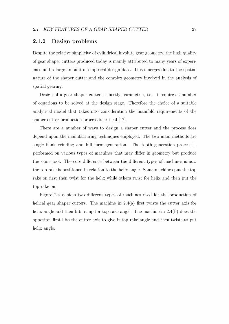
Figure 2.4 depicts two different types of machines used for the production of
helical gear shaper cutters. The machine in 2.4(a) first twists the cutter axis for
helix angle and then lifts it up for top rake angle. The machine in 2.4(b) does the
opposite: first lifts the cutter axis to give it top rake angle and then twists to put
helix angle.
28 CHAPTER 2. LITERATURE REVIEW
(a) (b)
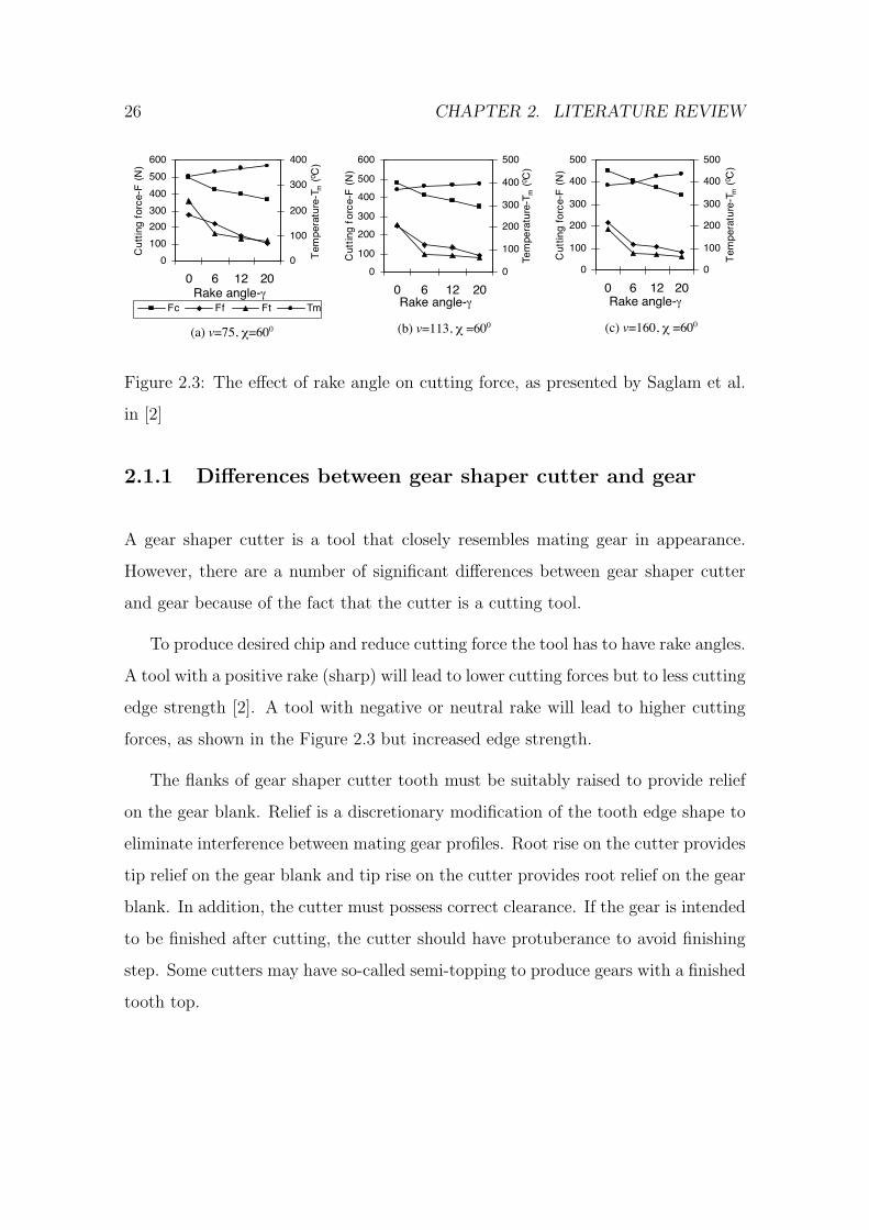
Figure 2.4: Fabrication of helical gear shaper cutters using different types of ma-
chines. (a) - cutter axis is first twisted for helix angle and then lifted for top rake
angle, (b) - cutter axis is lifted for top rake angle and then twisted for helix angle.
Both the machines produce the same tool, but it is presented to the grinding
wheel in a different plane so the grinding template and the wheel have to be slightly
different in both cases. These differences do not change the way the basic rack of
the shaper cutter is designed but they change the way the rack is corrected into the
grinding plane for use as a wheel template.
2.1.3 Basic rack
Basic rack is the shape produced by taking a circular cutter or gear and straightening
it out or giving it an infinite number of teeth. Because of the special properties of
the involute curve, the basic rack could substitute any gear derived from it (a gear
2.1. KEY FEATURES OF A GEAR SHAPER CUTTER 29
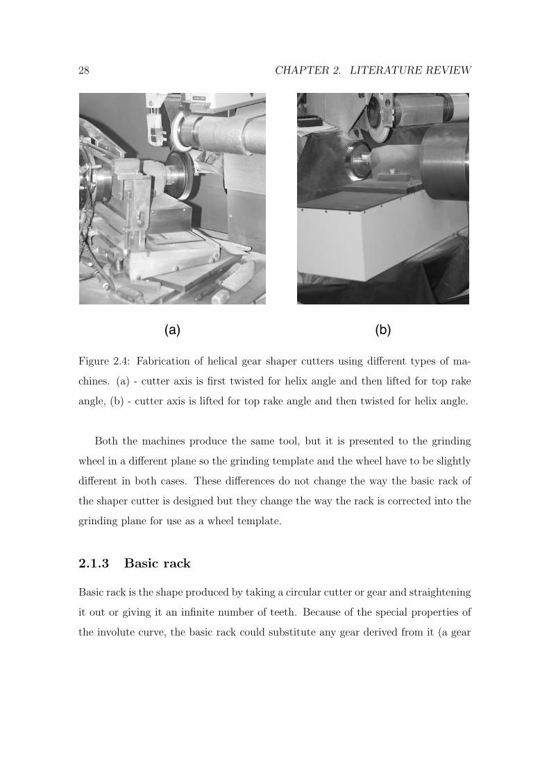
Figure 2.5: Spur gear and equivalent basic rack
that has the same diametral pitch and pressure angle). It is the basis of gear shaper
cutter design as the tool is usually produced by grinding the cutter template with
an abrasive wheel. As the basic rack is the only part of the cutter that does not
change in shape as the cutter diameter varies, it is often better to define the tool by
means of its basic rack.
Because of the properties of the involute curve the active involute profile on
the rack becomes a straight line. This can be seen in Figure 2.5. This property
makes the basic rack easier to correct for different machine geometry, cutter rake
and sharpening angles than the gear shaper cutter itself.
The aim of gear shaper cutter design is to produce a basic rack which is corrected
for top rake, front rake, helix angle and sharpening angle to form the grinding wheel
template to generate the cutter.
30 CHAPTER 2. LITERATURE REVIEW
2.2 Profile modifications
Some gears are impossible to manufacture, while being a perfectly good design. In
other cases the gear would have undercut tooth and therefore unable to handle the
designed load. This follows from the properties of the generating process.
Profile modifications are discretionary tooth shape changes to achieve various
desirable effects in the gear train or to enable production of gears with the specified
parameters. Profile modifications used in common practice for gear shaper cutter
fabrication are: tip and root relief, chamfer, front and top rake angles, semi-topping,
protuberance and sharpening angles. All these modifications change the profile
produced on the gear blank, so the analytical model of a gear shaper cutter must
include these modifications.
2.2.1 Rake angle
Most existing analytical models consider gear generation by shaper cutters as a two
dimensional problem [18]. In the following section the author claims that design of
the shaper cutter should be considered only within three dimensional space because
of the specific properties of the cutter as a metal cutting tool.
For a gear shaper cutter to cut involute profile on a gear, the tooth edge pro-
jection on the transverse plane should also be involute. The projected curve is the
same as the meshing curve between the cutter and the gear. For gear shaper cutters
designed using traditional approaches, tooth flanks are involute surfaces and the
projection of the tooth edge to the transverse plane is also an involute curve.
Gear shaper cutter, being a practical machining tool, usually has tooth face
positioned at an angle to the transverse plane, called front rake angle. The cutter
also should have side and top clearance so that it can cut without rubbing. This
is achieved by orienting tooth profile in the axial direction so that the top land
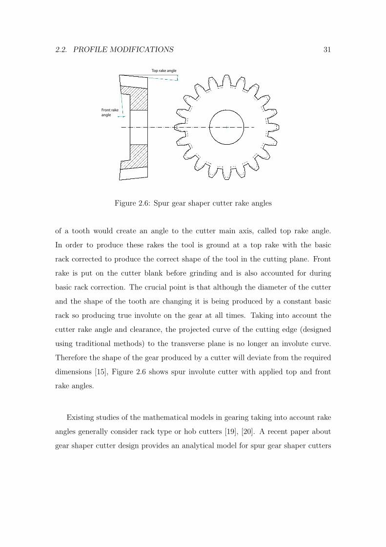
2.2. PROFILE MODIFICATIONS 31
Top rake angle
Front rakeangle
Figure 2.6: Spur gear shaper cutter rake angles
of a tooth would create an angle to the cutter main axis, called top rake angle.
In order to produce these rakes the tool is ground at a top rake with the basic
rack corrected to produce the correct shape of the tool in the cutting plane. Front
rake is put on the cutter blank before grinding and is also accounted for during
basic rack correction. The crucial point is that although the diameter of the cutter
and the shape of the tooth are changing it is being produced by a constant basic
rack so producing true involute on the gear at all times. Taking into account the
cutter rake angle and clearance, the projected curve of the cutting edge (designed
using traditional methods) to the transverse plane is no longer an involute curve.
Therefore the shape of the gear produced by a cutter will deviate from the required
dimensions [15], Figure 2.6 shows spur involute cutter with applied top and front
rake angles.
Existing studies of the mathematical models in gearing taking into account rake
angles generally consider rack type or hob cutters [19], [20]. A recent paper about
gear shaper cutter design provides an analytical model for spur gear shaper cutters
32 CHAPTER 2. LITERATURE REVIEW
only [15]. However, [15] assumes different profile of the gear shaper cutter tooth
then presented in this paper.
2.2.2 Tip and root rise
Tip rise on the cutter produces root relief on the gear blank. Likewise, root rise
on the cutter produces tip relief on the gear. Tip and root relieves are used to
minimise static transmission errors in gear train and avoid interference between
meshing profiles. The effects of tip relief on gears were studied by many researchers,
among these Tavakoli [21] and Mao [22] were studying spur gears while Guilbault [23]
was considering helical gears. However, none of these studies considered necessary
modifications of relief/rise profiles for producing correct cutter grinding template.
Apart from widely known elliptical, radial and linear forms of relief curve some
researchers proposed different forms, such as linear-parabolic as proposed in [24].
However, the effects of non-standard relief curve profiles should be further investi-
gated.
2.2.3 Protuberance
A gear manufactured by gear shaper cutter is usually finished by shaving to achieve
improved precision. The shaving operation removes a small amount of material from
the gear tooth flank. The gear tooth cut by an unmodified cutter leads to a step
between the fillet and the active involute profile. The step may adversely affect
noise, wear and kinematic characteristics of a gear train.
To remove the shaving step, the gear is treated with a protuberance pre-shaving
cutter to produce a controlled amount of undercut. A gear cut without protuberance
always has sharp shaving step near the end of the involute profile. Adequately
chosen protuberance parameters ensure that the shaving tool is able to cut full
tooth depth without damaging itself. The finished gear will have smooth transition
2.2. PROFILE MODIFICATIONS 33
between involute profile and fillet. Protuberance parameters depend upon both the
dimensions of the cutter and gear. A study on parameters of protuberance pre-
shaving cutters and their effect on the generated gear profile using Litvin’s tooth
generation method was performed by Kuang and Chen [25]. An alternative method
that, although being simpler, is only applicable to standard spur gears, was presented
in [7].
It is desirable to combine generating cutting and pre-shaving operations by using
a gear shaper cutter with protuberance. This eliminates the need for a separate pre-
shaving cutter and reduces the time to fabricate a gear, however the shape of the
resulting fillet should be determined precisely.
A comprehensive study of gear tooth fillet generated by rack type cutters was
presented in [26]. The same approach appears to be useful for the determination of
fillet shape of gears generated by gear shaper cutters.
2.2.4 Chamfer
Gear teeth manufacturing process is not limited to rough tooth surface forming.
Other processes may be required for a particular gear, for example, chamfering.
Chamfer is a bevelled edge at the intersection of gear tooth face and top land (crest)
surfaces [27]. This typically requires additional roughing process with different tools
and machinery. A chamfer tool usually has the form of mating gear with additional
tooth profile modifications near the fillet. As chamfer tool and the gear engage, they
start to rotate in unison and the modified profile displaces metal on the edge of the
gear tooth forming the chamfer. As with the protuberance, it is desirable to put
chamfer on the gear with the same tool as used for generation.
34 CHAPTER 2. LITERATURE REVIEW
2.2.5 Tool life optimisation
As the tool is being re-sharpened during day-to-day use and the tool diameter re-
duces the centre distance between gear blank and cutter on the gear-shaping machine
is changing. This change of generating action and centre distance causes variation
in true involute form (T.I.F.), root diameter, chamfer diameter etc. All these vari-
ations need to be considered and the variations kept within the tolerances required
on the component. This gives the cutter a definite life, reflected in the length of
tooth that can be re-sharpened. To enhance this life the cutter can be enlarged from
its initial design diameter defined by the basic rack, reducing the variation in tooth
length being cut during tool life cycle. The author proposes to call this concept
oversize.
2.2.6 Sharpening angle
Helical gear shaper cutters have one more cutting angle usually not present on spur
cutting tools. The angle between transverse plane of the cutter and the plane in
which individual tooth of the cutter is sharpened is called sharpening angle.
Sharpening angle influences the projected tooth surface to both the transverse
and normal plane of the cutter, and therefore cutter grinding template should be
corrected for sharpening angle as well.
2.2.7 Meshing of internal gears
Teeth of the wheel may be cut on the internal surface of the annulus, producing an
internal gear. The internal gears are largely similar to the external gears except that
the shafts rotate in the same direction and the teeth engage external to the line of
centres. Pinions for external and internal wheels have the same tooth profiles.
2.3. RELATIONSHIP BETWEEN CUTTER AND GEAR PROFILES 35
Although internal gears closely resemble external ones, there are a number of
additional constraints that should be considered at the design stage of the internal
gear shaper cutter. In particular, the interference between conjugate profiles in
internal gears could occur not only at the contact point, but in other parts of the
gear tooth profile too [28]. In addition, the teeth of internal gears could be trimmed
during backoff, infeed, and rotary feed cycles of the tool [29]; so analysis of various
forms of interference is of a great importance.
Internal pinions tend to have small number of teeth to avoid backoff interference,
worsening problems of tip interference and undercut [30].
2.3 Relationship between cutter and gear profiles
Existing literature provides many methods for analysing the curvature of engag-
ing gear profiles. These methods can be divided into three main categories: the
classic approach not involving differential geometry as presented by the works of
Buckingham [11], Colbourne [31] and Merrit [3], an approach developed by Litvin
[32] together with numerous later improvements, and finally the one proposed by Di
Puccio, Gabiccini and Guiggiani in [13] and [33] (an earlier preliminary work exists
by the same authors [34]).
The classical approach to curvature analysis of gears considers them as two di-
mensional objects that are represented by two dimensional involute profiles. All
analytical models developed by these approaches heavily rely on transformations
between gear and basic rack, as the involute profile of the gear tooth becomes a
straight line on the basic rack, therefore enabling the use of conventional trigono-
metric equations to describe tooth profile modifications. In particular, these models
perform gear to rack conversion to account for both top and front rake angles of
gear shaper cutters. The classical approach is characterised by using manifold of
36 CHAPTER 2. LITERATURE REVIEW
different reference systems tied to various significant points in the gear train, e.g.,
point of contact and centres of gear wheel and pinion. A number of studies have
been carried out on this theory to develop CAD models and software; among these
particularly interesting results were obtained by [17] who used solid modelling proce-
dure to simulate tooth fabrication process and [35], where tooth undercut conditions
are investigated in detail.
The approach developed by Litvin [32] carries on the tradition of using multi-
ple reference systems but considers the gear as a three dimensional object. This
approach presents an important step in gear curvature analysis as it moves from
profile curve analysis to tooth surface analysis. The ability to represent gear as a
whole is very important for gear shaper cutter design as the shaper cutter is not a
cylindrical body and therefore requires surface modelling. The surface of the gear
to be generated by a shaper cutter is considered to be generated by the envelope
of surfaces of the cutter [36]. This idea allows for strict analytical determination of
undercut conditions. A singularity of the envelope surface presents the condition
for the undercut; this was investigated in a number of papers [37], [38] and [39].
Despite the novelty and importance of Litvin’s theory [32], it contained some
limiting ties to legacy approaches. The main disadvantage was how the approach was
dealing with vectors representing gear teeth surfaces. The common practice at the
time was to work with vectors by means of their components, thus creating a number
of reference system to express these components. All that led to complications
(usually a set of formulae is provided for each reference system) and confusion among
practitioners.
A novel approach was developed by Di Puccio, Gabiccini and Guiggiani in [13]
and further developed in [33] and [40]. The proposed theory aimed to create ana-
lytical model of gearing without any reference systems. This was achieved by using
2.4. EXISTING SOFTWARE SYSTEMS FOR GEAR SHAPER CUTTER DESIGN37
vectors without expressing them through their components. Overall the approach
leads to more compact and understandable equations of the gearing theory.
One important difference between the two latter methods is how they obtain
relationships between two conjugate gear profiles. Litvin’s method derives surface
curvature equations by studying the motion of the contact point between two gears.
In this way Litvin’s approach can be regarded as indirect. Also the approach does not
consider generating motion, focusing, as mentioned above, on meshing conditions.
In contrast, the new approach [13] obtains equations for the normal surface
curvature and geodesic torsion of surfaces by directly applying their definitions to
the enveloping process [41].
A number of other less known approaches exists for gearing analysis, for example,
Argyris developed an original approach to rotation analysis that uses matrix calculus
[42]. One more recent development is the use of special geometric objects known as
dynamic blocking contours in gear design and modelling [43].
2.4 Existing software systems for gear shaper cut-
ter design
Gear shaper cutters profiles contain portions with complex geometry that is not
possible to create without extensive calculations. Therefore, general purpose CAD
packages are of a limited use for gear shaper cutter design. It can be argued that
considering the expenses associated with the licensing costs of proprietary CAD
packages and compatibility problems among different software versions, it is more
efficient either to use a purpose-built software or to develop one. The following
section contains a survey of existing gear design software and its applicability to
gear shaper cutter design.
38 CHAPTER 2. LITERATURE REVIEW
The target systems were selected by doing extensive web search using Google
Internet search engine [44], which has been proven to have the largest index size
among currently available search engines [45]. Four systems for gear design (CON-
FORMS, Gear C.A.M., Gear Factory, HyGears) [46, 47, 48, 49] were selected and
subjected to a set of criteria to determine their usefulness for cutter design.
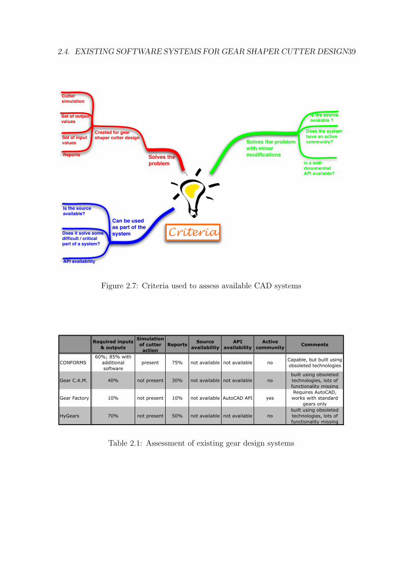
Consider Figure 2.7 that outlines the criteria used in the survey of existing
software systems. Ultimately, a system might fit into one of three main categories,
namely it can solve the problem of gear shaper cutter design completely, require
minor modifications to solve it or be used as a part of the new system. It is clear
that a system that completely solves the problem of gear shaper cutter design should
be designed for that task. Notably, it should be able to perform simulation of cutter
action on the component, match required sets of input and output values (refer to
Appendix B) and generate appropriate drawings and Computer Numerical Control
(CNC) code. If the system is not able to solve the problem fully, it may still be better
to modify it instead of producing a completely new system. However, the system
should meet the following conditions in order to be considered for modification.
First, it should have an active community which in turn implies that the system
should use current software technologies. And second, either the source code should
be open or a well-documented Application Programming Interface (API) should be
available.
Table 2.1 shows exiting gearing CAD systems evaluated using the criteria defined
previously in Figure 2.7. Columns 2 and 4 show implementation quality of a given
criteria as a percentage of the theoretical maximum. The evaluation is based on the
view of the experts from the industrial sponsor (”Dathan Tools”).
Analysing the data from the Table 2.1, the two most capable systems are CON-
FORMS and HyGears. Unfortunately, both could not be extended with new features
because no source or API are available to the general public. In addition, both sys-
2.4. EXISTING SOFTWARE SYSTEMS FOR GEAR SHAPER CUTTER DESIGN39
Reports
Created for gear shaper cutter design
Can be used
as part of the
system
Set of output values
Solves the
problem
Criteria
Solves the problem
with minor
modifications
Set of input values
Cutter simulation
is the source available ?
is a well-documented API available?
Is the source available?
API availability
Does the system have an active community?
Does it solve some difficult / critical part of a system?
Figure 2.7: Criteria used to assess available CAD systems
Required inputs
& outputs
Simulation
of cutter
action
ReportsSource
availability
API
availability
Active
communityComments
CONFORMS
60%; 85% with
additional
software
present 75% not available not available noCapable, but built using
obsoleted technologies
Gear C.A.M. 40% not present 30% not available not available no
built using obsoleted
technologies, lots of
functionality missing
Gear Factory 10% not present 10% not available AutoCAD API yes
Requires AutoCAD,
works with standard
gears only
HyGears 70% not present 50% not available not available no
built using obsoleted
technologies, lots of
functionality missing
Table 2.1: Assessment of existing gear design systems
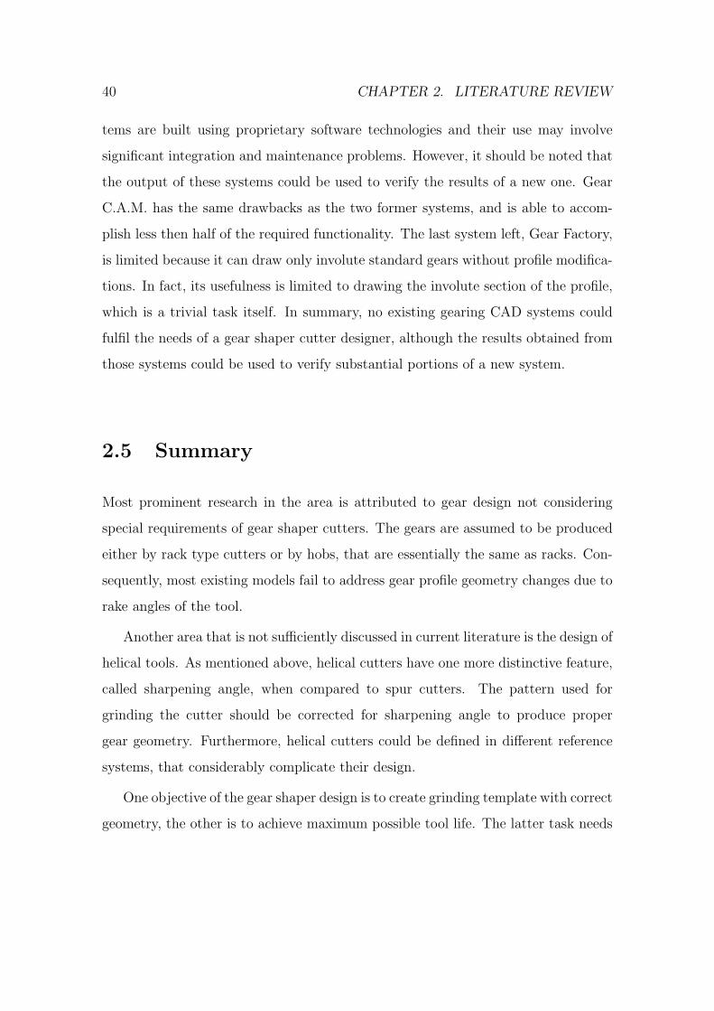
40 CHAPTER 2. LITERATURE REVIEW
tems are built using proprietary software technologies and their use may involve
significant integration and maintenance problems. However, it should be noted that
the output of these systems could be used to verify the results of a new one. Gear
C.A.M. has the same drawbacks as the two former systems, and is able to accom-
plish less then half of the required functionality. The last system left, Gear Factory,
is limited because it can draw only involute standard gears without profile modifica-
tions. In fact, its usefulness is limited to drawing the involute section of the profile,
which is a trivial task itself. In summary, no existing gearing CAD systems could
fulfil the needs of a gear shaper cutter designer, although the results obtained from
those systems could be used to verify substantial portions of a new system.
2.5 Summary
Most prominent research in the area is attributed to gear design not considering
special requirements of gear shaper cutters. The gears are assumed to be produced
either by rack type cutters or by hobs, that are essentially the same as racks. Con-
sequently, most existing models fail to address gear profile geometry changes due to
rake angles of the tool.
Another area that is not sufficiently discussed in current literature is the design of
helical tools. As mentioned above, helical cutters have one more distinctive feature,
called sharpening angle, when compared to spur cutters. The pattern used for
grinding the cutter should be corrected for sharpening angle to produce proper
gear geometry. Furthermore, helical cutters could be defined in different reference
systems, that considerably complicate their design.
One objective of the gear shaper design is to create grinding template with correct
geometry, the other is to achieve maximum possible tool life. The latter task needs
2.5. SUMMARY 41
to be formalised. i.e., there should be a formal way to calculate the period during
which the tool produces gears within given tolerances.
The correct design of gear cutting tools is impossible without proper and rigourous
verification of results obtained by the means of analytical model. The objectives of
verification would be to measure deviations of the produced tool from the theoreti-
cal one, determine machine settings used for tool production and provide a way to
superimpose geometry of the produced tool on the geometry of the theoretical one.
Existing papers in the area of tool measurement, such as the study published by
Litvin [50], provide foundation that should be reconsidered and adopted for analyt-
ical model verification.
Most existing analytical models for gear and gear shaper cutter designs are ap-
plicable either to spur or to helical profiles, but not both. However, both spur and
helical profiles have many common features and characteristics. One can prove that
a helical involute gear shaper cutter with zero helix angle is essentially a spur cutter.
The tooth profile in the normal plane of a helical gear is the same as the transverse
profile of a spur gear.
For practical reasons it is desirable to have one common model both for spur and
helical gears. This provides code reuse during CAD system development. Unified
model also reduces the possibility of error due to a significantly lower amount of
code and allows for common interface for spur and helical tool design.
However, latest research in the area of gear shaper cutter design is limited to
spur shaper cutters. The approach proposed by Lai and Wu [15] could be enhanced
with methods developed by Di Puccio, Gabiccini and Guiggiani [13], [33], leading
to more compact and universal models.
An overview of gear generating was presented together with the description of
one of the cutting tools used in the process, namely the gear shaper cutter. Main
principles of the generating motion, tool and machine specifics were covered.
42 CHAPTER 2. LITERATURE REVIEW
Main problems faced during shaper cutter design stages were listed, leading to
the discussion about necessary profile modifications of the basic rack.
Profile modifications commonly used in gear manufacturing were identified and
described. The studies concerning each modification were also given.
Major existing approaches to gear surface curvature analysis were presented and
categorised. Where appropriate the deficiencies in the scope of current research are
noted.
2.6 Research gap
Due to their widespread usage in gear manufacturing the gear shaper cutters have
received a lot of attention, with substantial number of papers in the area of gear
shaper cutter geometry and design, such as [15], [18], [6] and [51] to name a few. Still,
there is no sufficient description of the gear shaper cutter design process found in the
literature produced to date. The design process is understood to be a comprehensive
description of the following topics and concepts:
• Design workflow. A report on the necessary and sufficient steps one should
take to design a gear shaper cutter suitable for manufacturing. All process
inputs and outputs should be included in the description.
• Requirements for the cutter as a cutting tool. A list of the requirements and
constraints that are specific to gear shaper cutters as metal cutting tools.
Such requirements are usually ignored in the papers devoted to gear design
and manufacturing.
• Input parameters. The complete list of input parameters required by the de-
sign workflow with the variations required by the manufacturing process. All

2.6. RESEARCH GAP 43
parameters should have their meaning described along with their effect on the
gear.
Notwithstanding the amount of research put into the study of the conjugate pro-
files produced by shaper cutters with various modifications performed by [16], [32],
[51] and others, these studies usually consider a small number of modifications ap-
plied simultaneously to the cutter tooth. Furthermore, the application of developed
techniques to building a CAD software might be difficult. A straightforward and
simple model, yet one that is able to obtain the conjugate profile from the cutter
with any number of arbitrary modifications and that can be easily adopted by CAD
software writers is what the current research lacks.

44 CHAPTER 2. LITERATURE REVIEW
Chapter 3
Research aim, objectives and
methodology
3.1 Research aim
The research aim is to develop an analytical model and a set of tools that are able
to aid the design process of a gear shaper cutter.
3.2 Research objectives
In order to fulfil the aim of this research, the following research objectives are set
forth below:
• study and describe the nature and scope of the gear shaper cutter design
process;
• establish an analytical model:
– to obtain the geometry of the cutter based on what gear it has to produce;
45
46 CHAPTER 3. RESEARCH AIM, OBJECTIVES AND METHODOLOGY
– to assess the changes in the profile of the gear as the cutter geometry
changes during its life;
• produce a software suite that would draw on the aforementioned analytical
model to enable rapid gear shaper cutter design according to a documented
design process;
• produce a set of case studies to verify the model and the software.
3.3 Research scope
This research is concerned with the design stage of gear shaper cutters used to cut
cylindrical gears having involute active profile. However, the results of this research
may be applicable with alterations to non-involute profiles as well because of the
way the conjugate profile is obtained.
3.4 Research methodology
In dealing with something that one had a limited or no experience with before, a wise
approach would be to get acquainted with the subject matter by studying the works
of others having more exposure to the problem. The author’s modus operandi is no
different in that regard, so the first step is to find a treatise on the gear design and
geometry. A number of good books were found, including the ones of Buckingham
[11], Merritt [3] and Colbourne [31].
After a sufficient understanding of the subject area is gained, the literature search
expanded to cover recent papers about involute cylindrical gears in general and
gear shaper cutters in particular. For the purposes of obtaining the initial list of
3.4. RESEARCH METHODOLOGY 47
papers a script in the Python language1 was created with the ability to search
the Scopus database using predefined set of keywords, and obtain list of references
for each paper. This allowed to include the papers not directly contained within
Scopus database. For the papers where the Portable Document Format (PDF)
source was present in Scopus, it was retrieved and examined with an extended set
of keywords. The results were put into a relational database for further analysis.
Iterative reduction of the initial input set resulted in a set of 73 papers and books,
with most of them subjected to a detailed study. This resulted in the material
presented in Chapter 2 and identification of the research gap. The aim and the
objectives of this research were set based on the review of the literature and the
research gap. The remainder of this section describes the methodology used to
achieve each of the stated research objectives.
3.4.1 Describe the gear shaper cutter design process
Semi-structured interviews with three practitioners in the domain of gear shaper
cutter design were carried out at the industrial sponsor to extract knowledge required
to understand and document the design process. The semi-structured interview
approach was chosen because it combines high validity of the results and ability
to clarify complex questions because the interviewed people are able to talk about
the subject in greater depth and detail. Additionally, semi-structured interviews
resolve the problem of ”pre-judgement” where the interviewer predetermined set of
topics to cover. All questions are open-ended to facilitate dialogue-like conversation
between the researcher and the interviewee.
The interview questions are attached in Appendix A. Due to the unique nature
of the process (only a few companies in the world produce gear shaper cutters) it
1Python was used due to the power and ease of use of text processing functions and excellent
code readability.
48 CHAPTER 3. RESEARCH AIM, OBJECTIVES AND METHODOLOGY
was not possible to include more than one company in the data collection activities.
During the interviews the existing gear shaper cutter design workflow was docu-
mented in the form of photographs, which later turned out to be an invaluable data
source.
The interview data was analysed and resulted in the description of the design
process accompanied by the process model drawn using a standard diagramming
software, list of cutter profile modifications commonly used in gear shaper cutter
design, and the functional or user requirements for the CAD software. The require-
ments were captured in the form of the interface prototype drawn using a standard
diagramming software and the software requirements specification document writ-
ten in a text processor. The findings were presented to the interviewed people for
comments and refinement.
3.4.2 Establish an analytical model
With the understanding of the subject matter, the list of industrial requirements and
knowledge about the state of the art in the research of cutter and gear geometry, the
analytical model of interaction between the gear and the cutter was developed. The
primary tools being used for this purpose remain unchanged for centuries. There
are no better tools than a pencil, ruler and a sheet of paper. The model creation
process was greatly assisted by the Python Numerical Python (NumPy) software
library that provided means for fast numerical verification of the results. It was
chosen because of its availability for the Mac platform and open-source nature.
3.4.3 Produce CAD software
The software was developed alongside the analytical model using Python program-
ming language. Refer to Section 6.1 for in-depth description of the methodology
used to develop the software package.
3.5. INDUSTRIAL CONTEXT 49
3.4.4 Produce a set of case studies to verify the model and
the software
The case studies used to verify the analytical model and the CAD software were
given by the industrial sponsor and reflect real requirements of gear shaper cut-
ter designers. The case studies were chosen to be representative of the different
cases of gear shaper cutter design. Additionally, a set of requirements for the cases
themselves was established (refer to Section 7.1 for more details).
The verification process used the profiles obtained by other means (i.e., not full
form generated) to compare with the profiles obtained with the help of the CAD
software. The profiles were also verified by rolling the conjugate profile around
the pitch circle. Additionally, the design lead times using the new system and the
existing one are compared.
3.5 Industrial context
The present research is industry-oriented in its nature and therefore impossible with-
out close contact with the industry. For purposes of staying in touch with industry
needs, a company called ”Dathan Tools and Gauge Co. Ltd” based in the United
Kingdom was selected that specialises in gear shaper cutter design and manufactur-
ing. Dathan Tools are manufacturing a variety of precision cutters for automotive,
aerospace and defence industries. The special property that makes this company
a good target for research is that it is doing both manufacturing of the tools and
through-the-life service (re-sharpening and re-coating), so the effects of the varia-
tions in the tool geometry as it goes through numerous re-sharpening cycles could
be observed.
Special attention was paid to ensure that analytical model and the software
developed in the course of this research could be used in real life to design a gear
50 CHAPTER 3. RESEARCH AIM, OBJECTIVES AND METHODOLOGY
shaper cutter. In fact, the output of the CAD package could be directly used by a
Computer-Aided Manufacturing (CAM) system to drive a CNC grinding machine
that produces disk cutters, although currently there is an intermediate stage of
producing paper drawings.
3.6 Industrial focus for development of gear shaper
cutter design techniques
Gears and, consequently, gear cutting tools are manufactured for more than a cen-
tury already. The question that might be nagging to the reader is what is the
incentive for further development of gear shaper cutter design techniques. There
are two main reasons for this. Firstly, the improved cutter design techniques al-
low for increased precision in gear manufacturing. In particular, a better analytical
model would allow for tight control over such gear parameters as root, chamfer, root
and tip relief diameters and root and tip relief profiles produced throughout the life
of the tool. Secondly, and perhaps even more important is that the gear shaper
design process nowadays is time consuming craft that requires a highly skilled work-
force. The specifics of the modern cutter tool industry, namely, the use of the special
wear-resistant coatings that considerably prolong the life of the tool, shifted the tool
orders into low-volume category. This means that instead of ordering hundreds of
the same tool now companies order only a number of the same tool. The time re-
quired for the design should be reduced accordingly, and that is not possible with
the old design techniques. So there is a constant pressure to reduce the time re-
quired to design a tool without sacrificing (and even improving) the precision of
the component and the degree of control over parameters of gears produced by that
tool.

3.7. SUMMARY 51
3.7 Summary
This chapter defines the aim, objectives and methodology of the research. The aim
of the research establishes a general direction to proceed while the objectives provide
a set of milestones to achieve. The analytical model, while being a purely abstract
thing, should be tailored to the requirements of the application software. Both are
impossible to master without a clear understanding of the background process. For
an applied research it is very important to keep the balance between the theoretical
and the applied parts. And this balance is reflected in the objectives defined herein.
The research guidelines ensure quality of the research and reduce project risks.
In addition, methodology plays an important role in obtaining repeatable results.

52 CHAPTER 3. RESEARCH AIM, OBJECTIVES AND METHODOLOGY
Chapter 4
Gear shaper cutter design process
To build an analytical model and a software that would enable rapid design of gear
shaper cutters is a complex task that requires a solid knowledge of the geometry
of gearing and programming skills. Assuming it is successfully accomplished, the
result might be, however, useless without the knowledge of the actual gear shaper
cutter design process. In other words, one would get a perfect tool that would not
do the job, because it was not designed with that particular job in mind. To avoid
such pitfalls, this chapter attempts to study and document the detailed nature and
scope of the gear shaper cutter design process.
Figure 4.1 provides the reader with the design process model, which will be
discussed in subsequent sections. Note that decision points are shown in yellow,
activities related to data collection and processing are shown in green, while the
portions related to geometry processing and visualisation are in pink colour. The
decision points are presented in the form of question to be answered at that point
with the respective answers placed above the arrows coming out from the boxes.
The blue box highlights the special Redesign activity. The parts that are outside the
scope of the design process have white background (e.g., the CNC code is produced
by a CAM system).
53
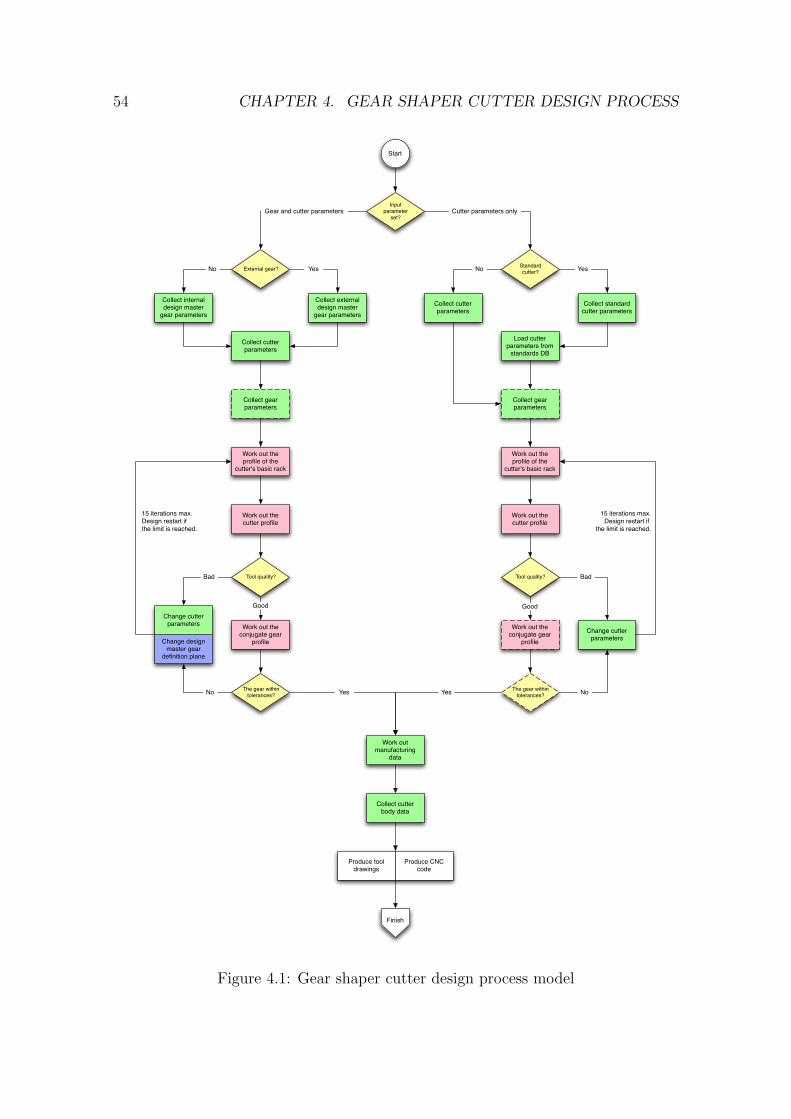
54 CHAPTER 4. GEAR SHAPER CUTTER DESIGN PROCESS
Start
Inputparameter
set?
Work out the profile of the
cutter's basic rack
Cutter parameters onlyGear and cutter parameters
Work out manufacturing
data
The gear within tolerances?
Produce tool drawings
No YesYes
Finish
Standardcutter?
Collect cutter parameters
Collect standard cutter parameters
Load cutter parameters from
standards DB
External gear?
Collect internal design master
gear parameters
Collect external design master
gear parameters
Collect gear parameters
No
Collect cutter parameters
No Yes
Input set 1
Processing decision
Input set 2 ... Input set N
Equation set 1 Equation set 2 ... Equation set N
Result
Collect gear parameters
Work out the cutter profile
Work out the conjugate gear
profile
Tool quality?
Change design master gear
definition plane
Change cutter parameters
Bad
Good
Work out the profile of the
cutter's basic rack
The gear within tolerances?
Work out the cutter profile
Work out the conjugate gear
profile
Tool quality?
Good
No
Change cutter parameters
Bad
Collect cutter body data
Produce CNC code
Yes
15 iterations max.Design restart if
the limit is reached.
15 iterations max.Design restart if the limit is reached.
Figure 4.1: Gear shaper cutter design process model
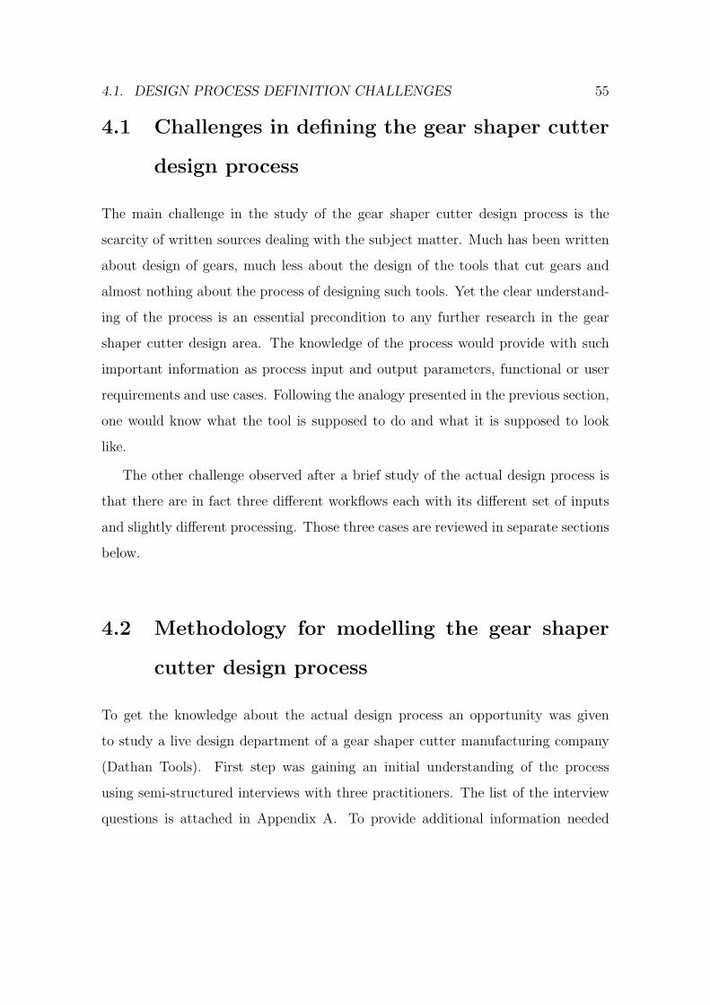
4.1. DESIGN PROCESS DEFINITION CHALLENGES 55
4.1 Challenges in defining the gear shaper cutter
design process
The main challenge in the study of the gear shaper cutter design process is the
scarcity of written sources dealing with the subject matter. Much has been written
about design of gears, much less about the design of the tools that cut gears and
almost nothing about the process of designing such tools. Yet the clear understand-
ing of the process is an essential precondition to any further research in the gear
shaper cutter design area. The knowledge of the process would provide with such
important information as process input and output parameters, functional or user
requirements and use cases. Following the analogy presented in the previous section,
one would know what the tool is supposed to do and what it is supposed to look
like.
The other challenge observed after a brief study of the actual design process is
that there are in fact three different workflows each with its different set of inputs
and slightly different processing. Those three cases are reviewed in separate sections
below.
4.2 Methodology for modelling the gear shaper
cutter design process
To get the knowledge about the actual design process an opportunity was given
to study a live design department of a gear shaper cutter manufacturing company
(Dathan Tools). First step was gaining an initial understanding of the process
using semi-structured interviews with three practitioners. The list of the interview
questions is attached in Appendix A. To provide additional information needed
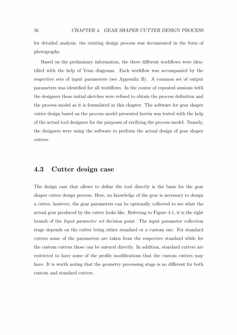
56 CHAPTER 4. GEAR SHAPER CUTTER DESIGN PROCESS
for detailed analysis, the existing design process was documented in the form of
photographs.
Based on the preliminary information, the three different workflows were iden-
tified with the help of Venn diagrams. Each workflow was accompanied by the
respective sets of input parameters (see Appendix B). A common set of output
parameters was identified for all workflows. In the course of repeated sessions with
the designers those initial sketches were refined to obtain the process definition and
the process model as it is formulated in this chapter. The software for gear shaper
cutter design based on the process model presented herein was tested with the help
of the actual tool designers for the purposes of verifying the process model. Namely,
the designers were using the software to perform the actual design of gear shaper
cutters.
4.3 Cutter design case
The design case that allows to define the tool directly is the basis for the gear
shaper cutter design process. Here, no knowledge of the gear is necessary to design
a cutter, however, the gear parameters can be optionally collected to see what the
actual gear produced by the cutter looks like. Referring to Figure 4.1, it is the right
branch of the Input parameter set decision point. The input parameter collection
stage depends on the cutter being either standard or a custom one. For standard
cutters some of the parameters are taken from the respective standard while for
the custom cutters those can be entered directly. In addition, standard cutters are
restricted to have some of the profile modifications that the custom cutters may
have. It is worth noting that the geometry processing stage is no different for both
custom and standard cutters.
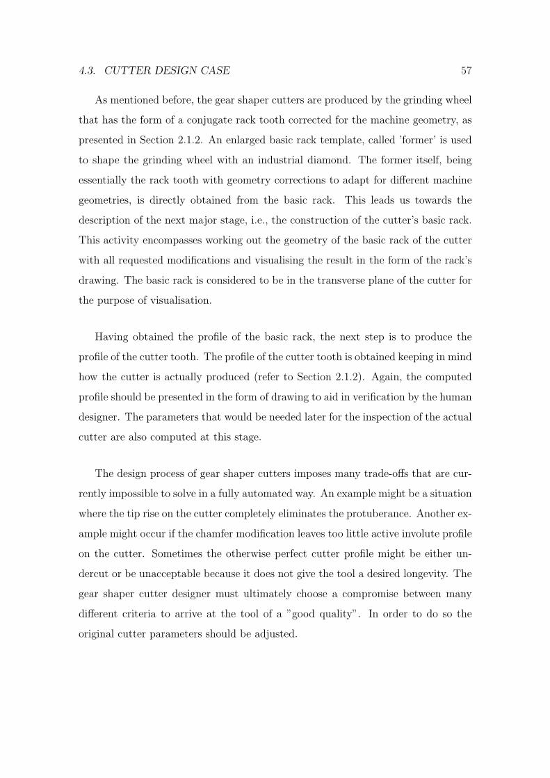
4.3. CUTTER DESIGN CASE 57
As mentioned before, the gear shaper cutters are produced by the grinding wheel
that has the form of a conjugate rack tooth corrected for the machine geometry, as
presented in Section 2.1.2. An enlarged basic rack template, called ’former’ is used
to shape the grinding wheel with an industrial diamond. The former itself, being
essentially the rack tooth with geometry corrections to adapt for different machine
geometries, is directly obtained from the basic rack. This leads us towards the
description of the next major stage, i.e., the construction of the cutter’s basic rack.
This activity encompasses working out the geometry of the basic rack of the cutter
with all requested modifications and visualising the result in the form of the rack’s
drawing. The basic rack is considered to be in the transverse plane of the cutter for
the purpose of visualisation.
Having obtained the profile of the basic rack, the next step is to produce the
profile of the cutter tooth. The profile of the cutter tooth is obtained keeping in mind
how the cutter is actually produced (refer to Section 2.1.2). Again, the computed
profile should be presented in the form of drawing to aid in verification by the human
designer. The parameters that would be needed later for the inspection of the actual
cutter are also computed at this stage.
The design process of gear shaper cutters imposes many trade-offs that are cur-
rently impossible to solve in a fully automated way. An example might be a situation
where the tip rise on the cutter completely eliminates the protuberance. Another ex-
ample might occur if the chamfer modification leaves too little active involute profile
on the cutter. Sometimes the otherwise perfect cutter profile might be either un-
dercut or be unacceptable because it does not give the tool a desired longevity. The
gear shaper cutter designer must ultimately choose a compromise between many
different criteria to arrive at the tool of a ”good quality”. In order to do so the
original cutter parameters should be adjusted.
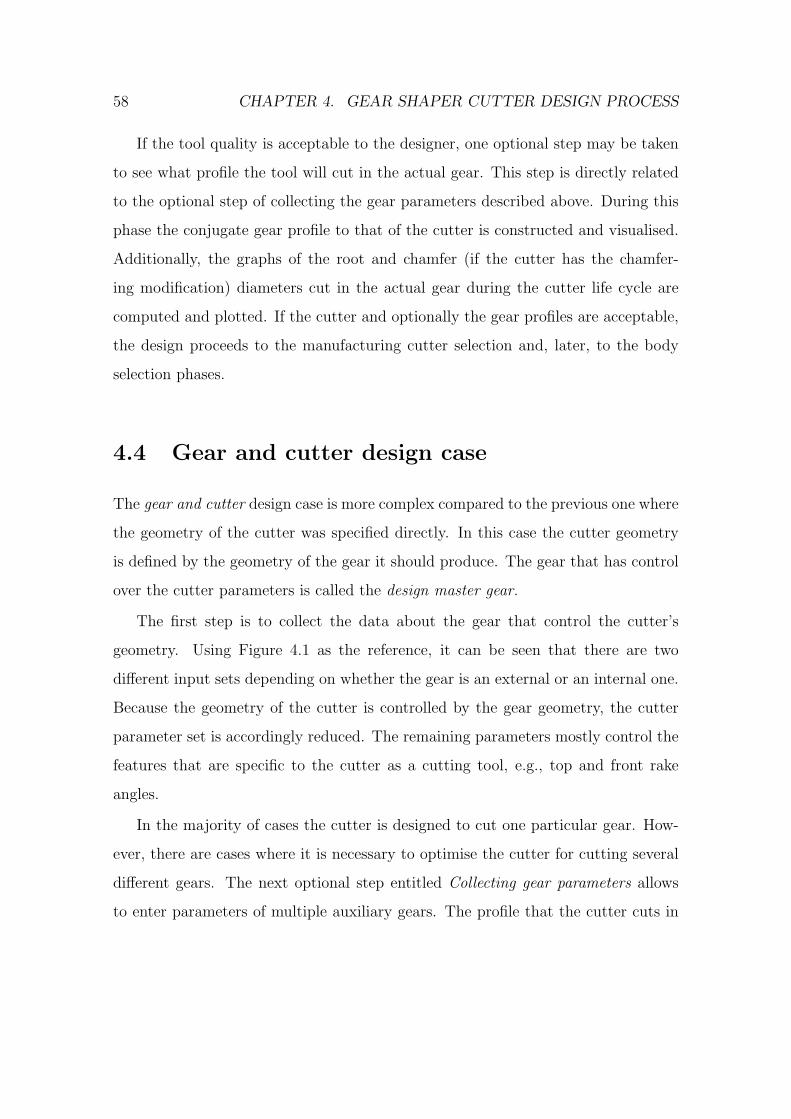
58 CHAPTER 4. GEAR SHAPER CUTTER DESIGN PROCESS
If the tool quality is acceptable to the designer, one optional step may be taken
to see what profile the tool will cut in the actual gear. This step is directly related
to the optional step of collecting the gear parameters described above. During this
phase the conjugate gear profile to that of the cutter is constructed and visualised.
Additionally, the graphs of the root and chamfer (if the cutter has the chamfer-
ing modification) diameters cut in the actual gear during the cutter life cycle are
computed and plotted. If the cutter and optionally the gear profiles are acceptable,
the design proceeds to the manufacturing cutter selection and, later, to the body
selection phases.
4.4 Gear and cutter design case
The gear and cutter design case is more complex compared to the previous one where
the geometry of the cutter was specified directly. In this case the cutter geometry
is defined by the geometry of the gear it should produce. The gear that has control
over the cutter parameters is called the design master gear.
The first step is to collect the data about the gear that control the cutter’s
geometry. Using Figure 4.1 as the reference, it can be seen that there are two
different input sets depending on whether the gear is an external or an internal one.
Because the geometry of the cutter is controlled by the gear geometry, the cutter
parameter set is accordingly reduced. The remaining parameters mostly control the
features that are specific to the cutter as a cutting tool, e.g., top and front rake
angles.
In the majority of cases the cutter is designed to cut one particular gear. How-
ever, there are cases where it is necessary to optimise the cutter for cutting several
different gears. The next optional step entitled Collecting gear parameters allows
to enter parameters of multiple auxiliary gears. The profile that the cutter cuts in
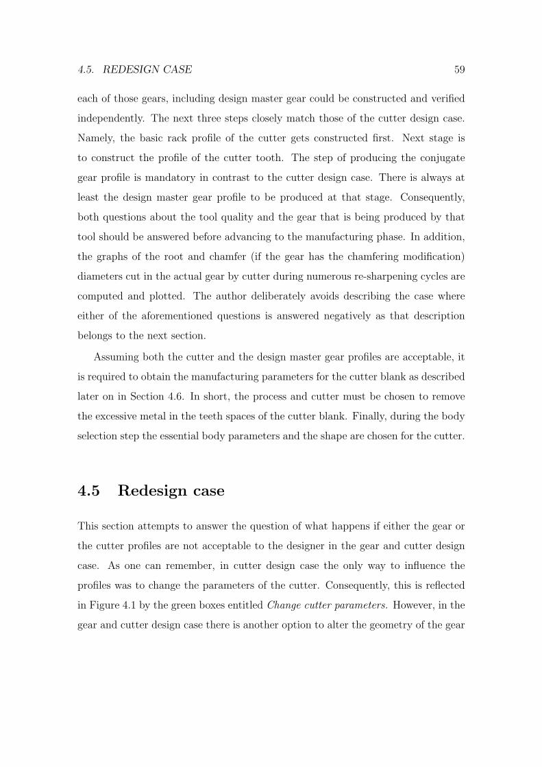
4.5. REDESIGN CASE 59
each of those gears, including design master gear could be constructed and verified
independently. The next three steps closely match those of the cutter design case.
Namely, the basic rack profile of the cutter gets constructed first. Next stage is
to construct the profile of the cutter tooth. The step of producing the conjugate
gear profile is mandatory in contrast to the cutter design case. There is always at
least the design master gear profile to be produced at that stage. Consequently,
both questions about the tool quality and the gear that is being produced by that
tool should be answered before advancing to the manufacturing phase. In addition,
the graphs of the root and chamfer (if the gear has the chamfering modification)
diameters cut in the actual gear by cutter during numerous re-sharpening cycles are
computed and plotted. The author deliberately avoids describing the case where
either of the aforementioned questions is answered negatively as that description
belongs to the next section.
Assuming both the cutter and the design master gear profiles are acceptable, it
is required to obtain the manufacturing parameters for the cutter blank as described
later on in Section 4.6. In short, the process and cutter must be chosen to remove
the excessive metal in the teeth spaces of the cutter blank. Finally, during the body
selection step the essential body parameters and the shape are chosen for the cutter.
4.5 Redesign case
This section attempts to answer the question of what happens if either the gear or
the cutter profiles are not acceptable to the designer in the gear and cutter design
case. As one can remember, in cutter design case the only way to influence the
profiles was to change the parameters of the cutter. Consequently, this is reflected
in Figure 4.1 by the green boxes entitled Change cutter parameters. However, in the
gear and cutter design case there is another option to alter the geometry of the gear
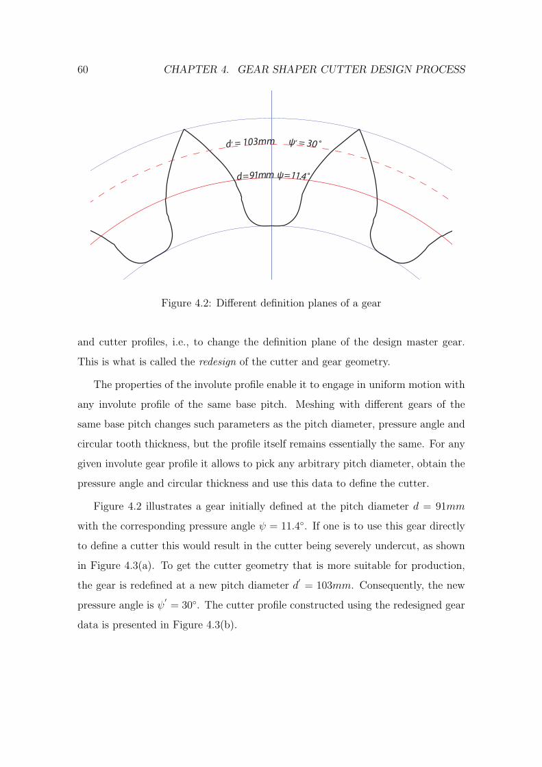
60 CHAPTER 4. GEAR SHAPER CUTTER DESIGN PROCESS
d! = 103mm "! = 30˚
d = 91mm " = 11.4˚
Figure 4.2: Different definition planes of a gear
and cutter profiles, i.e., to change the definition plane of the design master gear.
This is what is called the redesign of the cutter and gear geometry.
The properties of the involute profile enable it to engage in uniform motion with
any involute profile of the same base pitch. Meshing with different gears of the
same base pitch changes such parameters as the pitch diameter, pressure angle and
circular tooth thickness, but the profile itself remains essentially the same. For any
given involute gear profile it allows to pick any arbitrary pitch diameter, obtain the
pressure angle and circular thickness and use this data to define the cutter.
Figure 4.2 illustrates a gear initially defined at the pitch diameter d = 91mm
with the corresponding pressure angle ψ = 11.4◦. If one is to use this gear directly
to define a cutter this would result in the cutter being severely undercut, as shown
in Figure 4.3(a). To get the cutter geometry that is more suitable for production,
the gear is redefined at a new pitch diameter d′
= 103mm. Consequently, the new
pressure angle is ψ′= 30◦. The cutter profile constructed using the redesigned gear
data is presented in Figure 4.3(b).

4.6. MANUFACTURING REQUIREMENTS 61
(a) (b)
Figure 4.3: Cutter profiles that are obtained from the same gear at different pitch
diameters. (a) - design master gear profile was not redesigned, (b) - design master
gear profile was redesigned
4.6 Manufacturing requirements
Before finishing the cutter profile with the grinding wheel, it is desirable to remove
the excessive metal in the teeth spaces of the cutter blank by using hob, rack or
gear shaper cutter or a milling cutter. The reason behind this is that the grinding
is slow and expensive but allows high precision finishing. So the task of a cutter
designer at the manufacturing phase is to choose a cutter that would cut the closest
possible profile to the required one on the cutter blank. Referring to Figure 4.4,
the theoretical cutter profile is drawn to a proper scale and compared to the traces
of various available manufacturing cutters. The profile cut by the manufacturing
cutter is a conjugate profile in the case of a gear shaper cutter or the inverse profile
in the case of the milling cutter. The profile can be moved along the line OO1 to
adjust the amount of metal left in the root and in the tip of the cutter blank. The
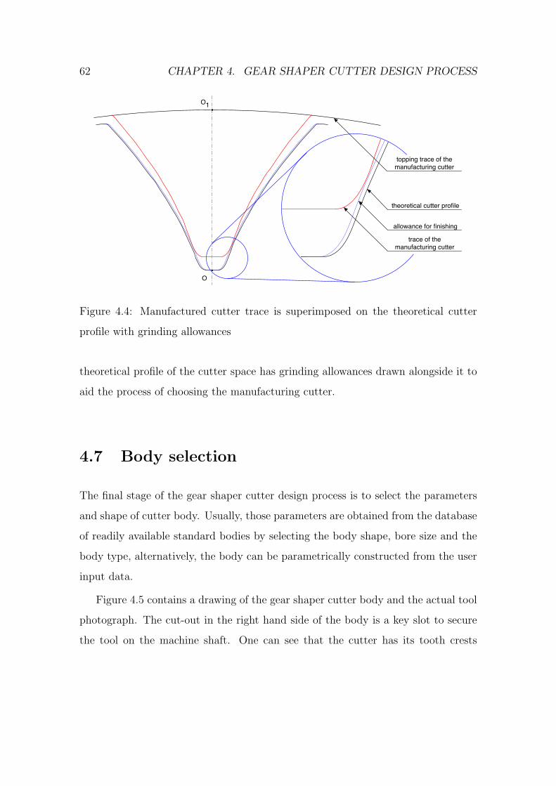
62 CHAPTER 4. GEAR SHAPER CUTTER DESIGN PROCESS
theoretical cutter profile
allowance for finishing
trace of the manufacturing cutter
topping trace of the manufacturing cutter
O1
O
Figure 4.4: Manufactured cutter trace is superimposed on the theoretical cutter
profile with grinding allowances
theoretical profile of the cutter space has grinding allowances drawn alongside it to
aid the process of choosing the manufacturing cutter.
4.7 Body selection
The final stage of the gear shaper cutter design process is to select the parameters
and shape of cutter body. Usually, those parameters are obtained from the database
of readily available standard bodies by selecting the body shape, bore size and the
body type, alternatively, the body can be parametrically constructed from the user
input data.
Figure 4.5 contains a drawing of the gear shaper cutter body and the actual tool
photograph. The cut-out in the right hand side of the body is a key slot to secure
the tool on the machine shaft. One can see that the cutter has its tooth crests
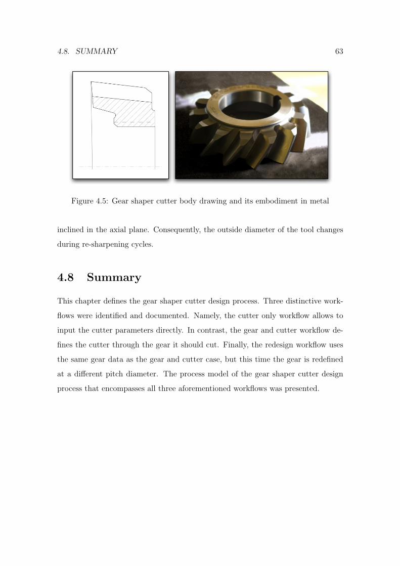
4.8. SUMMARY 63
Figure 4.5: Gear shaper cutter body drawing and its embodiment in metal
inclined in the axial plane. Consequently, the outside diameter of the tool changes
during re-sharpening cycles.
4.8 Summary
This chapter defines the gear shaper cutter design process. Three distinctive work-
flows were identified and documented. Namely, the cutter only workflow allows to
input the cutter parameters directly. In contrast, the gear and cutter workflow de-
fines the cutter through the gear it should cut. Finally, the redesign workflow uses
the same gear data as the gear and cutter case, but this time the gear is redefined
at a different pitch diameter. The process model of the gear shaper cutter design
process that encompasses all three aforementioned workflows was presented.

64 CHAPTER 4. GEAR SHAPER CUTTER DESIGN PROCESS
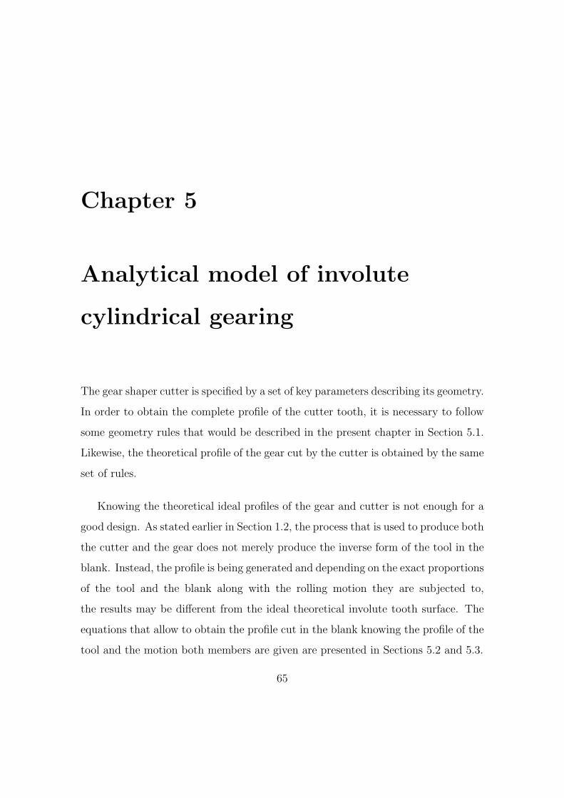
Chapter 5
Analytical model of involute
cylindrical gearing
The gear shaper cutter is specified by a set of key parameters describing its geometry.
In order to obtain the complete profile of the cutter tooth, it is necessary to follow
some geometry rules that would be described in the present chapter in Section 5.1.
Likewise, the theoretical profile of the gear cut by the cutter is obtained by the same
set of rules.
Knowing the theoretical ideal profiles of the gear and cutter is not enough for a
good design. As stated earlier in Section 1.2, the process that is used to produce both
the cutter and the gear does not merely produce the inverse form of the tool in the
blank. Instead, the profile is being generated and depending on the exact proportions
of the tool and the blank along with the rolling motion they are subjected to,
the results may be different from the ideal theoretical involute tooth surface. The
equations that allow to obtain the profile cut in the blank knowing the profile of the
tool and the motion both members are given are presented in Sections 5.2 and 5.3.
65
66 CHAPTER 5. ANALYTICAL MODEL OF GEARING
! "#
O
I
M
Nr$
r
Figure 5.1: The involute line, base circle, radius vector, polar and pressure angles.
θ - polar angle, ψ - pressure angle, ρ - angle between the radius vector to the origin
of the involute and the tangent to the involute profile, r0 - base radius of the involute
5.1 Cutter tooth geometry
The gear shaper cutter is manufactured by the grinding wheel, that represents a
portion of the cutter basic rack. So the first step to obtain the profile of the cutter
tooth is to construct the basic rack of the cutter. But even before that some basic
properties of the involute curve and the cylindrical gears in general [11] should be
discussed.
Figure 5.1 illustrates the basic symbols that define the involute line. Let I be
the pitch point. Then from the first principles of trigonometry the tangent of the

5.1. CUTTER TOOTH GEOMETRY 67
angle ψ is equal to the ratio of the opposite side to the adjacent side in the triangle
OIN :
tanψ =IN
ON. (5.1)
The angle ρ between the origin of the involute line and the tangent to the base
circle drawn from the pitch point is equal to the ratio of the portion of circumference
enclosed between two radii to the length of the radius, that is:
ρ =MN
r0, (5.2)
where MN is the length of the arc between M and N . From the definition of the
involute line as the locus of points formed by the end of unwinding rope, it follows
that MN = IN . Knowing, that ON is r0, the angle ρ can be expressed as follows:
ρ = tanψ. (5.3)
From the geometrical conditions presented in the Figure 5.1, the radius vector r
and the vectorial angle θ are, respectively:
r =r0
cosψ(5.4)
θ = ρ− ψ. (5.5)
Substituting the angle ρ in (5.5) with (5.3) results in the following equation:
θ = tanψ − ψ. (5.6)
The equation (5.6) is called the involute function [3] of the angle ψ or simply
invψ. Together with equation (5.4) it allows to obtain the coordinates of the involute
profile at any value of the pressure angle ψ.

68 CHAPTER 5. ANALYTICAL MODEL OF GEARING
5.1.1 Circular thickness
The circular thickness of the cutter tooth gt is the width of the tooth along the
circumference of a circle with the centre on the axis of the cutter. The input data
for the cutter usually contains the circular thickness at pitch diameter d. Various
calculations presented further in this chapter require the ability to calculate the
circular tooth thickness at an arbitrary diameter.
Consider Figure 5.2, that shows the circular tooth thickness at two different radii
r and r′. From the geometrical conditions presented in the drawing, the angle α is:
α =gt2r
=gtd. (5.7)
The sum of the vectorial angle θ and the angle α stays constant for all possible
values of θ, resulting in the following equation:
α + θ = α′+ θ
′
α′
= α + θ − θ′. (5.8)
Bearing in mind (5.6) and (5.7), the equation (5.8) could be expressed as:
α =gtd
+ invψ − invψ′, (5.9)
that leads to the expression for the new circular tooth thickness as:
g′
t = d′(gtd
+ invψ − invψ′). (5.10)
One can prove that for internal gears the equation (5.8) has the form of:
α′= α− θ + θ
′, (5.11)
5.1. CUTTER TOOTH GEOMETRY 69
that gives the following expression for the new circular thickness for internal
gears:
g′
t = d′(gtd− invψ + invψ
′). (5.12)
5.1.2 Centre distance
The outside diameter of the cutter changes as the cutter gets used more and more
because of the re-sharpening. In order to cut gears of constant thickness the cen-
tre distance between two toothed bodies has to be adjusted for different outside
diameters of the cutter.
The equations (5.13) and (5.14) give the expressions for the circular thickness of
the cutter and the circular thickness of the gear, respectively, at an arbitrary pitch
diameters d′c and d
′g and corresponding pressure angles.
g′
tc = d′
c(gtcdc
+ invψc − invψ′
c). (5.13)
g′
tg = d′
g(gtgdg
+ invψg − invψ′
g). (5.14)
Bearing in mind that ψ′c = ψ
′g and substituting ψ using equation (5.4), the
following expression can be obtained for the new pitch diameter of the cutter:
d′
c =docd
′g
dog
, (5.15)
where doc and dog are outside diameters of cutter and gear, respectively. At the
same time, g′tc = g
′sg
, and
g′
sg=πd
′g
T− g
′
tg , (5.16)
therefore
g′
tc =πd
′g
T− g
′
tg . (5.17)
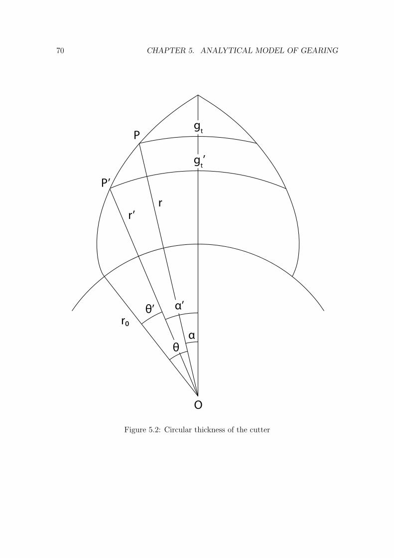
70 CHAPTER 5. ANALYTICAL MODEL OF GEARING
!
!’
"
"’
r
r#
r’
O
P
P’
gt
gt’
Figure 5.2: Circular thickness of the cutter

5.1. CUTTER TOOTH GEOMETRY 71
From (5.17), (5.13) and (5.14) follows, that
d′
c(gtcdc
+ invψ − invψ′) =
πd′g
T− d
′
g(gtgdg
+ invψ − invψ′). (5.18)
Substituting d′c with (5.15), the expression (5.19) for the new pressure angle ψ
′is
obtained
ψ′= ainv
gtc
dogcosψ + doc
doginvψ − π
T+
gtg
dg− invψ
doc
dog− 1
. (5.19)
It should be noted, that the ainv function is calculated using numerical means.
New gear and cutter pitch diameters are calculated using equation (5.4). The
centre distance between the two toothed bodies is equal to the half of the sum of
the pitch diameters
C =d
′g + d
′c
2. (5.20)
5.1.3 Tool life
Authors define tool life L as a measure of the extent to which the tool can be re-
sharpened while maintaining the component profile within given tolerances. The
life is the length of the useful portion of the cutter tooth crest measured in the
axial plane of the cutter. Typically for the gear generation process with gear shaper
cutters, tolerances are specified as border conditions for the gear root diameter drg .
The changing outside diameter of the cutter can be expressed as
d′
oc= doc + 2∆doc , (5.21)
where the quantity ∆doc is the radial oversize of the cutter tooth. The relationship
between the oversize and tool life is represented as:
L =doc
sinα, (5.22)
where α is the top rake angle of the cutter.
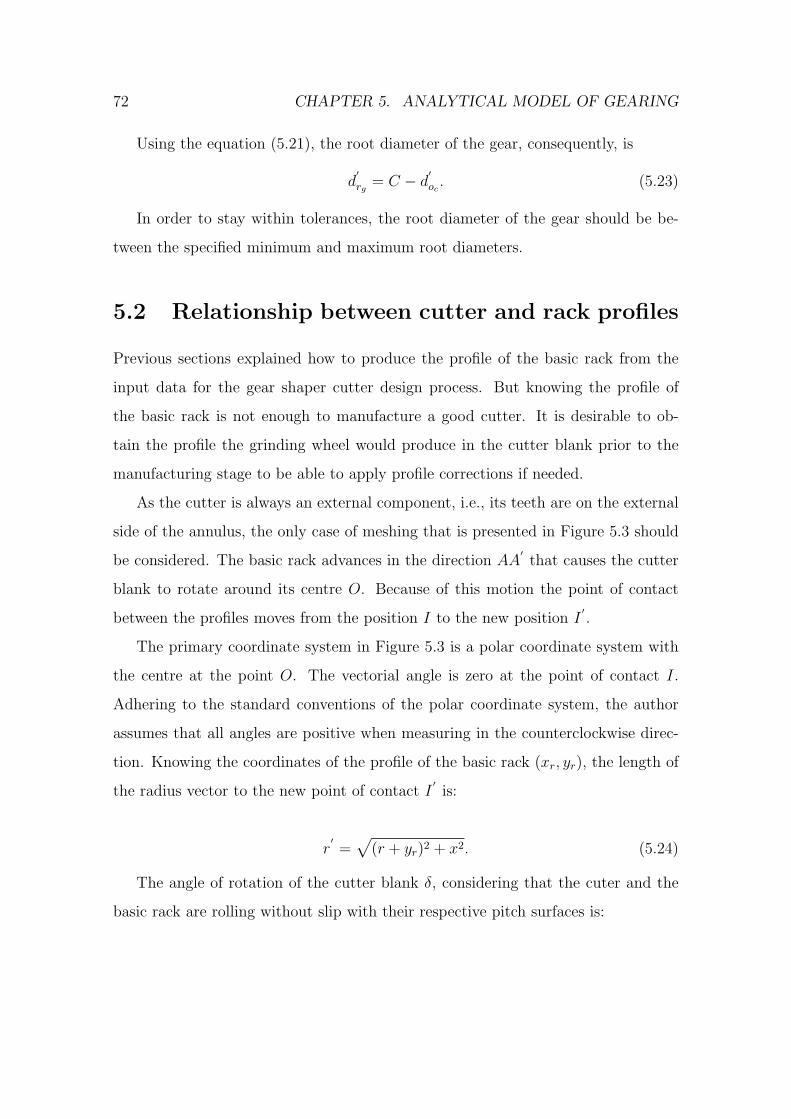
72 CHAPTER 5. ANALYTICAL MODEL OF GEARING
Using the equation (5.21), the root diameter of the gear, consequently, is
d′
rg = C − d′
oc. (5.23)
In order to stay within tolerances, the root diameter of the gear should be be-
tween the specified minimum and maximum root diameters.
5.2 Relationship between cutter and rack profiles
Previous sections explained how to produce the profile of the basic rack from the
input data for the gear shaper cutter design process. But knowing the profile of
the basic rack is not enough to manufacture a good cutter. It is desirable to ob-
tain the profile the grinding wheel would produce in the cutter blank prior to the
manufacturing stage to be able to apply profile corrections if needed.
As the cutter is always an external component, i.e., its teeth are on the external
side of the annulus, the only case of meshing that is presented in Figure 5.3 should
be considered. The basic rack advances in the direction AA′
that causes the cutter
blank to rotate around its centre O. Because of this motion the point of contact
between the profiles moves from the position I to the new position I′.
The primary coordinate system in Figure 5.3 is a polar coordinate system with
the centre at the point O. The vectorial angle is zero at the point of contact I.
Adhering to the standard conventions of the polar coordinate system, the author
assumes that all angles are positive when measuring in the counterclockwise direc-
tion. Knowing the coordinates of the profile of the basic rack (xr, yr), the length of
the radius vector to the new point of contact I′
is:
r′=
√(r + yr)2 + x2. (5.24)
The angle of rotation of the cutter blank δ, considering that the cuter and the
basic rack are rolling without slip with their respective pitch surfaces is:

5.2. RELATIONSHIP BETWEEN CUTTER AND RACK PROFILES 73
−δ =x− xrr
(5.25)
δ =xr − x
r.
Note, that this angle is negative because the blank rotates in the clockwise
direction as the rack moves in the AA′
direction. The vectorial angle θ of the radius
vector r′
to the new point of contact, assuming the blank remains stationary, is:
θ = arctanx
r + yr− δ. (5.26)
Using the value of the −δ from the equation 5.25, the expression of the vectorial
angle takes the following form:
θ =x− xrr
+ arctanx
r + yr. (5.27)
The equations 5.24 and 5.27 allow to determine the conjugate profile of the cutter
if the profile of the basic rack is known.
The only question remaining unanswered is how to find the abscissa x of the new
point of contact I′. The instantaneous pressure angle at the point of contact must
be found first. From the definition of the pressure angle as the acute angle between
the common pitch plane and the common normal to the profiles of meshing toothed
bodies and the geometrical conditions presented in Figure 5.3 follows:
tanψ =dxrdyr
. (5.28)
The abscissa of the new point of contact is, therefore:
x =−yr
tanψ. (5.29)
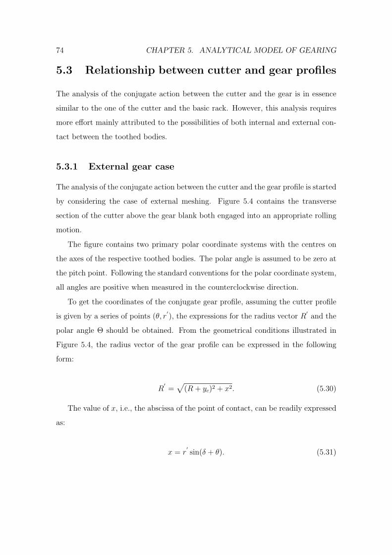
74 CHAPTER 5. ANALYTICAL MODEL OF GEARING
5.3 Relationship between cutter and gear profiles
The analysis of the conjugate action between the cutter and the gear is in essence
similar to the one of the cutter and the basic rack. However, this analysis requires
more effort mainly attributed to the possibilities of both internal and external con-
tact between the toothed bodies.
5.3.1 External gear case
The analysis of the conjugate action between the cutter and the gear profile is started
by considering the case of external meshing. Figure 5.4 contains the transverse
section of the cutter above the gear blank both engaged into an appropriate rolling
motion.
The figure contains two primary polar coordinate systems with the centres on
the axes of the respective toothed bodies. The polar angle is assumed to be zero at
the pitch point. Following the standard conventions for the polar coordinate system,
all angles are positive when measured in the counterclockwise direction.
To get the coordinates of the conjugate gear profile, assuming the cutter profile
is given by a series of points (θ, r′), the expressions for the radius vector R
′and the
polar angle Θ should be obtained. From the geometrical conditions illustrated in
Figure 5.4, the radius vector of the gear profile can be expressed in the following
form:
R′=
√(R + yc)2 + x2. (5.30)
The value of x, i.e., the abscissa of the point of contact, can be readily expressed
as:
x = r′sin(δ + θ). (5.31)

5.3. RELATIONSHIP BETWEEN CUTTER AND GEAR PROFILES 75
The value of the angle δ, which is the angle of cutter rotation from the zero
position, can be in turn expressed as:
δ = ψ − λ− θ. (5.32)
The instantaneous pressure angle at the point of contact can be calculated using
the following equation:
ψ = arccosr
′cosλ
r(5.33)
Finally, the angle λ between the common tangent to the tooth profiles at the
pitch point and the radius vector is:
λ = arctan(r′ dθ
dr′ ) (5.34)
The polar angle Θ is equal to the difference between the sum of the pressure
angle ψ and the angle of gear rotation from the zero position −∆ and the angle
between the common tangent to the tooth profiles and the radius vector Λ:
Θ = ψ −∆− Λ. (5.35)
The angle ∆ can be obtained by multiplying the angle δ by the ratio of cutter
and gear pitch radii:
−∆ = δr
R(5.36)
∆ = −δ rR.
Following the same considerations as in the equation 5.33, the angle Λ can be
calculated as:

76 CHAPTER 5. ANALYTICAL MODEL OF GEARING
Λ = arccosR cosψ
R′ . (5.37)
5.3.2 Internal gear case
In the internal gear case the reasoning logic is the same as with the external gear,
however the arrangement of the cutter and gear is different, namely, the centres
of both toothed bodies lie on the same side of the common normal to the tooth
profiles at the pitch point. Additionally, the cutter and the gear rotate in the same
direction. That causes some differences in the equations.
In particular, the length of the radius vector of the gear profile will be:
R′=
√(R− yc)2 + x2. (5.38)
Because both toothed bodies rotate in the same direction, the angles of rotation
from the zero position would have the same sign:
∆ = δr
R. (5.39)
Carrying out the calculations for the internal gears, one should remember that
the angles δ and θ have their signs swapped compared to the external gear case.
5.4 Summary
This chapter establishes the analytical base for the full form technique that is used
obtain the conjugate profile. By full form the author understands that the initial
profile is considered as a whole regardless of the number and type of the profile
modifications applied. Therefore, it is sufficient to construct the profile of the basic
rack in order to obtain the profile of the cutter tooth.

5.4. SUMMARY 77
The major precondition of the full form generation technique is the ability to
remove crossed over sections from the conjugate profile. For this purpose the algo-
rithm developed by Shamos and Hoey [52] is used. This will be discussed in detail
in the following chapter.
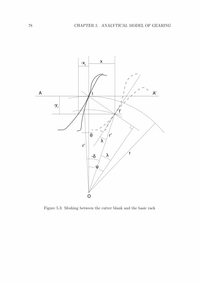
78 CHAPTER 5. ANALYTICAL MODEL OF GEARING
r’
r’
r-δ
λ
λ
θ
-yr
x-xr
ψ
I
I’
A A’
O
Figure 5.3: Meshing between the cutter blank and the basic rack
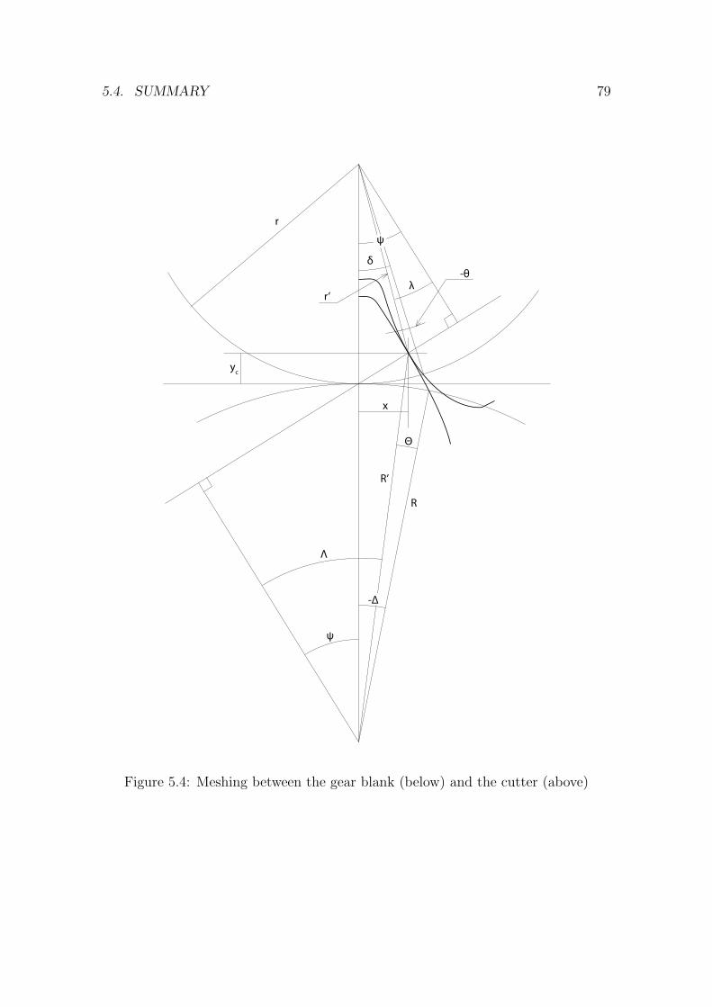
5.4. SUMMARY 79
!
!
"
-#
R’
r’
r
$
%
R
-&
'
yc
x
Figure 5.4: Meshing between the gear blank (below) and the cutter (above)

80 CHAPTER 5. ANALYTICAL MODEL OF GEARING
Chapter 6
Computer-Aided Design software
for gear shaper cutter design
As noted in Sections 2.6 and 3.1 the results of the analysis of gear generation by
gear shaper cutters should be in a useable form to build a package for computer
aided design of the gear shaper cutters. It can be argued that there is no better
way to ensure that the model is suitable as a base for the CAD software than to
actually write the software. That decision is further supported by the fact that
no software for gear shaper cutter design is hitherto available. The current CAD
packages could not be used for gear shaper cutter design because the cutter design
is a highly parametric task that requires extensive computations.
One added advantage of the CAD package readily available is the ability to verify
the real industry requirements for both the gear shaper cutter design process and
the analytical model. Thus the software becomes an important verification tool for
the findings of the present research.
81
82 CHAPTER 6. CAD SOFTWARE
6.1 Methodology for CAD package development
The development of the CAD package for gear shaper cutter design is a project
where both the functional or user requirements and the added requirements are not
clearly known initially and are continuously refined during the development process.
Another important aspect of the project is that the development team is very small,
i.e., the author. The choice among the methodologies suggested by the literature
yielded the Rapid Prototyping [53], [54] as the ultimate choice for the project.
The rapid prototyping methodology suggests to develop a prototype that im-
plements the major or best-known requirements and continuously refine it as the
new requirements are revealed in the development process. That approach allows
to develop the software alongside the analytical model, the importance of which can
not be underestimated. The iteration time was chosen to be two weeks.
In the course of adopting the methodology for the project requirements, it was
enhanced with techniques acquired from the Extreme Programming approach [55],
[56] and [57]. In hope to produce code of a better quality and reduce the number of
errors peer reviews of the source code were adopted. Namely, the changes in each
new revision of the code were reviewed by a fellow researcher. Automated regression
tests were implemented where possible to reduce the time required for testing on
each iteration.
6.2 Identification of the software requirements
The semi-structured interview with gear shaper cutter designers at the industrial
sponsor provided initial material for requirements analysis. The interface prototype
was jointly developed with the practitioners at Dathan based on initial functional
requirements (attached in Appendix C).
6.3. ARCHITECTURE OF THE SOFTWARE PACKAGE 83
The lists of inputs for each of the design cases from Chapter 4 aided in the
process of interface prototype refinement. Alongside the interface prototype, a Soft-
ware Requirements Specification (SRS) document was developed and approved by
Dathan. The SRS document can be found in the Appendix D.
6.3 Architecture of the software package
The design of the gear shaper cutter is parametric and therefore does nor require a
lot of interactive graphical information. It is based on a set of textual inputs and
a set of textual outputs accompanied by the drawings of the basic rack, cutter and
gear profiles. Additional requirement imposed was to make the software platform
independent and based on the freely available components and standards.
Considering the aforementioned requirements, the software was chosen to be
web-based implementing client-server architecture. The main idea underlying that
choice was the ability of the client portion of the software to work in any modern
browser1 on any computing platform, be it an IA-32 PC running MS Windows or
GNU/Linux or Macintosh running OS X or GNU/Linux.
The client portion of the software is based on the templates written in a spe-
cially created language and uses the Scalable Vector Graphics (SVG) format for
the graphical data interchange and representation. The interactive features of the
user interface are supported by the MochiKit JavaScript library that provides an
abstraction layer from the browser-specific implementation of the JavaScript run-
time. A desktop-like experience when using the software is implemented using the
Asynchronous JavaScript and XML (AJAX) technology that uses JavaScript Object
Notation (JSON) as the data interchange format between the client and the server.
1Currently, both the Mozilla Firefox 2.0+ and Safari 3.0+ are fully compatible. Other browsers
that use either WebKit or Gecko are compatible, such as Shiira and Camino. Microsoft Internet
Explorer was never tested in the absence of it.
84 CHAPTER 6. CAD SOFTWARE
The server portion of the software is written using Python programming language
and the TurboGears programming framework. The framework helps to process web
requests and provides the authentication and deployment services. The PostgreSQL
database was chosen as the database back end for its reliability and speed. The top
level architecture of the system is illustrated in the Figure 6.1.
During the development a special attention was paid to maintain the server
portion of the software as portable as possible. This resulted in the ability of the
unmodified server part of the software to run on both the Mac OS X and GNU/Linux
operating systems provided the PostgreSQL database and Python with the appro-
priate modules are installed. MS Windows compatibility is likely though not tested.
The use of a dedicated GNU/Linux server based system resulted in a better
connection to other company resources and better uptime compared to traditional
CAD systems. Both characteristics were found very important and valuable by the
industrial sponsor.
6.4 Visualisation of the design data
Due to the nature of the gear shaper cutter design process where a designer needs to
find a compromise between different cutter parameters, such as tooth strength, life
and ability to cut gears with different numbers of teeth, the design data should be
visualised in some form to aid the decision making. The commonly accepted form
of visualising geometry data is a form of drawing of the actual tooth profile.
The problems that are being dealt by the present research could be visualised
either in two or in three dimensions. Two dimensional representation was chosen
due to its simplicity in both realisation and perception of the actual drawings.
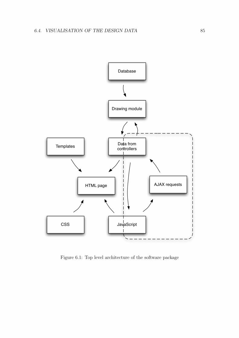
6.4. VISUALISATION OF THE DESIGN DATA 85
Templates Data from controllers
HTML page
CSS JavaScript
AJAX requests
Drawing module
Database
Figure 6.1: Top level architecture of the software package
86 CHAPTER 6. CAD SOFTWARE
6.4.1 Requirements for design visualisation
The following requirements for design visualisation were identified:
• The graphics should be interactive, i.e., support drawing the objects on top of
the drawing or moving existing ones.
• Drawings must be able to scale within the web interface.
• An obvious requirement for the drawings is to be able to be generated by the
program code.
• The drawings should be compatible with external CAD programs.
6.4.2 Challenges in parametric design visualisation
The web based nature of the design software imposed a number of challenges for the
design data visualisation. The most important challenge was to make the drawings
immediately available to the user within the web browser, without being forced to
use supplementary programs. Considering the requirements defined in the previous
section, that meant to choose between one of the two widely used vector graphic
formats: SVG or Flash. The preference was given to SVG that despite being much
less widespread, than Flash, has native support from major browsers and is a World
Wide Web consortium Recommendation [58].
As noted earlier, the drawing should be able to be produced as the result of an
automated process, and SVG excels in that being essentially an eXtensible Markup
Language (XML) [59] subset, i.e., a human-readable text. An SVG file is a set of
statements called tags that specify geometrical objects, their position, size and other
attributes. The size and position are specified by means of attributes - text nodes
with numerical values. Such text based formats are not only human readable, but
also very easy to produce by a program. Another advantage of the SVG format is
6.5. SOFTWARE INTERFACE PROTOTYPE 87
that it can be readily translated to the Drawing Exchange Format (DXF) format,
which is a standard data interchange format for commercial CAD packages. This
enabled the new system to export data to external CAD programs.
A major challenge to the web based CAD is the requirement for an interactive
user interface. A ”zoom” action is defined to illustrate the most basic interactive
operation with a drawing, whereby the user selects a portion of the drawing that
should be displayed instead of the entire drawing, magnified to fill the viewport. If
this action is to be split into elementary blocks, it would result in a set of elemen-
tary requirements that must be supported by the program architecture in order to
perform zoom action.
For the user to select a portion of the drawing, the system must be able to detect
the coordinates of the pointing device and provide a visual feedback by highlighting
the selected area. While a common action on a desktop system, its realisation inside
a browser is a complicated task as no standard way of doing that exists. After the
selection area is defined, the system should be able to determine the zoom ratio and
provide the user with an enlarged portion of the drawing within selection. That
requires the system either to be able to retrieve the enlarged portion of the image
from the server in real time or to scale and position the image itself.
6.5 Software interface prototype
In the early stages of the present research the industry requirements for the gear
shaper cutter analytical model and design software were not fully known. Fur-
thermore, the full set of input parameters for each of the design cases described
in Chapter 4 was not defined and, consequently, the modifications of the cutter
profile required by the industry were difficult to identify. To refine the initial user
requirements and obtain a full set of input parameters for three different gear shaper
88 CHAPTER 6. CAD SOFTWARE
cutter design cases in accordance with the course of action suggested by the proto-
type building development methodology, an interface prototype was created.
The interface prototype was created from the images of the actual web interface
elements. Being very close in appearance to the look of the actual software package it
was used to perform user tests. Referring to Figure 6.2 one can see that the interface
consists of four primary parts. Part A is the main menu and control portion of the
interface, that allows to go through the design steps, load and save data and choose
global options like the measurement system.
Part B contains the actual input parameters that define the geometry of the
cutter. Note, that not all of the parameters are displayed at the same time. Instead,
the input fields are conditionally displayed depending on the chosen design case and
required modifications.
Part C displays calculated parameters that are required for the inspection of the
manufactured gear shaper cutters. The values in the block C are corrected for the
top and front rake angles of the gear shaper cutter.
Finally, the block D displays brief graphical outputs of the software. Those
include a drawing of the cutter profile at three positions, namely when the cutter is
new, at nominal outside diameter and when the cutter is at the end of its life. The
next drawing shows the profile of the cutter’s basic rack. Last portion of part D
is the gear root diameter graph. It shows variations in the gear root diameter that
occur due to changes in the outside diameter of the cutter caused by re-sharpening
cycles. The drawings, when clicked by a pointing device, display more information
and drawing options. Those additional options will be discussed further in this
section.
For the designs that are based on the gear parameters or where it is necessary
to know the precise shape of the gear being cut by the cutter, the gear parameters
can be input in the gear section. Figure 6.3 illustrates the gear page of the software
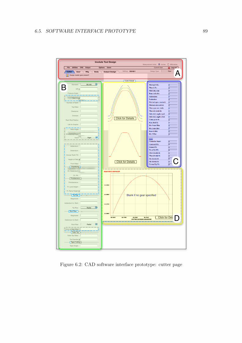
6.5. SOFTWARE INTERFACE PROTOTYPE 89
SpurDesign Type:
Involute Tool DesignMeasurement Units:
File Log outUtilities CNC Output
Inches Millimetres
Users Current User
Editing: 105/48/1
Options
Output Design
appears only for custom tools
active only for radial root rise
appear only for custom tools
BS.436Standard:
Cutter Details
Pressure Angle:
Number of Teeth:
Top Rake:
Clearance:
Oversize:
Rack Root Radius:
Life for Graphs:
BodyMfg.GearCutter
Addendum:
Dedendum:
Circular Tooth TH:
Front Rake:
Design master gear present!
DP:
Height of Fillet:
Pr. Ramp Height:
Appear only for helical tools
Helix Angle:
Sharpening Angle:
Chamfering
Protuberance
Tip Rise
Root Rise:
False Top
Taper Cutting
Ch. Dedendum:
Ch. PA:
Protuberance:
Pr. Land Height:
Magnitude:
Addendum to Start:
Magnitude:
Dedendum to Start:
RadialRoot Rise:
Ovrsz at Rad. Rise:
False Top Rake:
Tip Chamfer:
Taper Angle:
RightHand:
RadialTip Rise:
Bias PA:
Click for Details
Click for Details
Blank if no gear specified
Click for Details
AB
C
D
Figure 6.2: CAD software interface prototype: cutter page
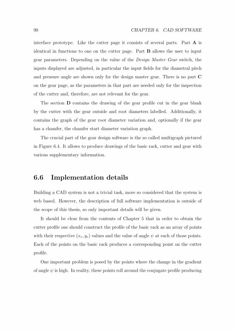
90 CHAPTER 6. CAD SOFTWARE
interface prototype. Like the cutter page it consists of several parts. Part A is
identical in functions to one on the cutter page. Part B allows the user to input
gear parameters. Depending on the value of the Design Master Gear switch, the
inputs displayed are adjusted, in particular the input fields for the diametral pitch
and pressure angle are shown only for the design master gear. There is no part C
on the gear page, as the parameters in that part are needed only for the inspection
of the cutter and, therefore, are not relevant for the gear.
The section D contains the drawing of the gear profile cut in the gear blank
by the cutter with the gear outside and root diameters labelled. Additionally, it
contains the graph of the gear root diameter variation and, optionally if the gear
has a chamfer, the chamfer start diameter variation graph.
The crucial part of the gear design software is the so called multigraph pictured
in Figure 6.4. It allows to produce drawings of the basic rack, cutter and gear with
various supplementary information.
6.6 Implementation details
Building a CAD system is not a trivial task, more so considered that the system is
web based. However, the description of full software implementation is outside of
the scope of this thesis, so only important details will be given.
It should be clear from the contents of Chapter 5 that in order to obtain the
cutter profile one should construct the profile of the basic rack as an array of points
with their respective (xr, yr) values and the value of angle ψ at each of those points.
Each of the points on the basic rack produces a corresponding point on the cutter
profile.
One important problem is posed by the points where the change in the gradient
of angle ψ is high. In reality, these points roll around the conjugate profile producing
6.6. IMPLEMENTATION DETAILS 91
SpurDesign Type:
Involute Tool DesignMeasurement Units:
File Log outUtilities CNC Output
Inches Millimetres
Users Current User
Editing: 105/48/1
Options
Output Design
Option for externalOption for Internal
Appear only for master design gear
SpurDesign Type:
Gear Details
Number of Teeth:
Major Dia Max:
Diameter:
Minor Dia Min:
BodyMfg.Cutter Gear
External Internal
Design Master GearADD DELETEGear1Gear Design: RENAME
DP:
Pressure Angle:
Bias PA:
Chamfering
Ch. Dia. Max:
Ch. Dia. Min:
Ch. Angle
Tip Relief
Root Relief
Magnitude:
Magnitude:
Diameter:
Diameter:
Taper Cutting
Taper Angle:
Pre-finishing
Fin. Circ. Tooth Th.:
Sh. Circ. Tooth Th.:
Major/Minor Dia Min/Max:
Major/Minor Dia Min/Max
Options
Required S.A.P (dia):
Required T.I.F. (dia):
23.0000
16.0000
22.9922
17.5133
AB
D
Figure 6.3: CAD software interface prototype: gear page
92 CHAPTER 6. CAD SOFTWARE
a curve that is locus of the points with the same coordinates on the basic rack but
with different pressure angle. In Figure 6.5 one can see that the point A on the basic
rack (the point where the crest of the rack join with the tooth face) rolling around
the cutter tooth contacts the cutter profile at different pressure angles. In order to
obtain correct conjugate profile as seen in Figure 6.5 each point with high change in
pressure angle gradient should be substituted with a series of points with the same
spatial position and intermediate pressure angle values. The number of intermediate
points could be adjusted using angular discretisation threshold and step values.
As noted before, one point on the basic rack produces a corresponding point
on the cutter profile. On rare occasions some of these points may be irrelevant in
respect to the final profile. Consider that the profile of the cutter in reality is a
surface of a solid object and therefore some points produced by one part of the
basic rack profile can be later removed by an other part of the basic rack. For the
analytical profile it results in the curve that is crossed over itself. The parts that are
crossed over should be removed as no material exists ”in space” beyond the surface of
the cutter. To remove those non-existent portions of the profile an implementation
of the Shamos-Hoey algorithm [52] in Python language was created, that finds the
intersection points of the curve with itself and removes closed regions of the profile.
The algorithm uses a sweep line approach to track intersection between segments
of the polyline. When the intersection is found, the intersection point is computed
and the portion of the polyline that forms an enclosed region is removed from the
profile.
6.7 Summary
A weak point of the purely theoretical research is its unproven ability to help in
real world tasks. With the software that uses the developed analytical model, its

6.7. SUMMARY 93
applicability to the real world requirements could be easily verified. In addition,
the ability to test the model with real world examples gives confidence that the
analytical model is correct.
Web-based CAD software architecture was used because it provides several im-
portant advantages over traditional one. All compatibility problems between differ-
ent versions of client CAD software, operating system and other installed applica-
tions are resolved because of the ability of the client portion of the system to run
inside a regular web browser. In addition, browser-based interface allows remote
access and access from portable devices, which would in turn allow initial data in-
put by customers. Because no external CAD program is needed, the Total Cost of
Ownership (TCO) of the system is reduced as well.
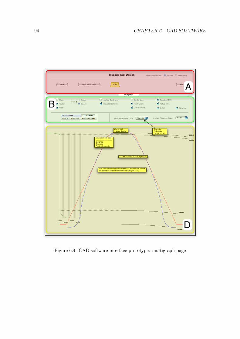
94 CHAPTER 6. CAD SOFTWARE
Involute Tool Design
BACK Open in Ext. Editor PRINTNote
Measurement Units: Inches Millimetres
43.2869
35.7869
36.9408
43.1242
0.0000
0.1000
0.2000
0.3000
Multigraph
Textual Sideframe
Involute Sideframe
Curve Breaks
Tooth
Space Pitch Circle
Center Line
Cutter
Rack
Gear
Gear
1:500Involute Abscissa Scale:DiameterInvolute Ordinate Units
DiameterRoll angleLength of roll
Actual T.I.F.
Required T.I.F.
S.A.P.
Zoom tool+ scale display
Measurement tools===============DistanceDiameterRadius from point
Finishing
Choice of either 1, 2 or 3 graphs
The amount of deviation at the end of the involute profilethe diameter where the deviation starts (ref 1123)
A
B
D
Figure 6.4: CAD software interface prototype: multigraph page
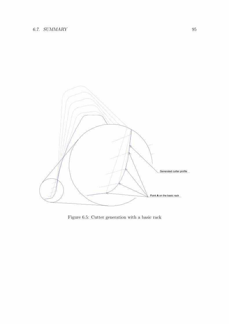
6.7. SUMMARY 95
Generated cutter profile
Point A on the basic rack
Figure 6.5: Cutter generation with a basic rack

96 CHAPTER 6. CAD SOFTWARE
Chapter 7
Real life case studies
7.1 Case study selection rationale
The case study approach applies in-depth thorough examination to a limited set of
events called cases, rather than using rigid examination algorithms on large sampling
sets. Therefore, the problem of choosing the cases that are most beneficial for
the research becomes a primary importance. Using a sampling method that relies
on the amount of information contained within the case rather than any form of
random sampling should produce better result as an average case may be poor on
information.
Considering the selected cases as a set, it should satisfy a couple of conditions to
be relevant. First, the set should provide a sufficient coverage of the problem area.
Referring to the design process description provided in Chapter 4 and the list of the
profile modifications in Chapter 2, the following necessary coverage conditions may
be defined:
• each design process case should be covered with at least one case study;
• the key profile modifications should be covered.
97
98 CHAPTER 7. REAL LIFE CASE STUDIES
To keep the number of cases small and reduce the amount of work required
for case studies, one more condition should be added for the case set: diversity.
The cases should be as different from each other as possible, which in terms of the
present research means that if one case covers chamfering modification on design
master gear then others should include some other modifications and (or) internal
gearing examples.
In light of the mentioned details, three cases were selected. First case is the
simplest one with the cutter being directly specified through its parameters. The
second case shows the use of the internal design master gear that is used to define
a cutter. Finally, the third case encompasses the redesign situation, whereby the
design master gear is redefined at a different pressure angle in order to obtain a
better geometry of the cutter.
7.2 Cutter only case
The cutter only case is the basic design case whereby the cutter is directly specified
by its parameters. The particular gear shaper cutter is designed as ’custom’, i.e.,
not having standard proportions. That allows for a greater control over cutter
geometry parameters (standard cutters are restricted to have many of the profile
modifications).
The general parameters that define the cutter profile are listed in Table 7.1.
This is a small cutter with lots of teeth so the undercut is not likely. It has a round
fillet with a radius of 0.5 mm. When cutting a gear the cutter would have 0.5 mm
clearance from the bottom of cutter tooth space to the crest of the gear tooth.
The cutter has protuberance profile modification. This means that the cutter
produces an artificial undercut on the gear to avoid the sharp step that appears on
the gear tooth after finishing. Referring to Table 7.2 the protuberance is offset from
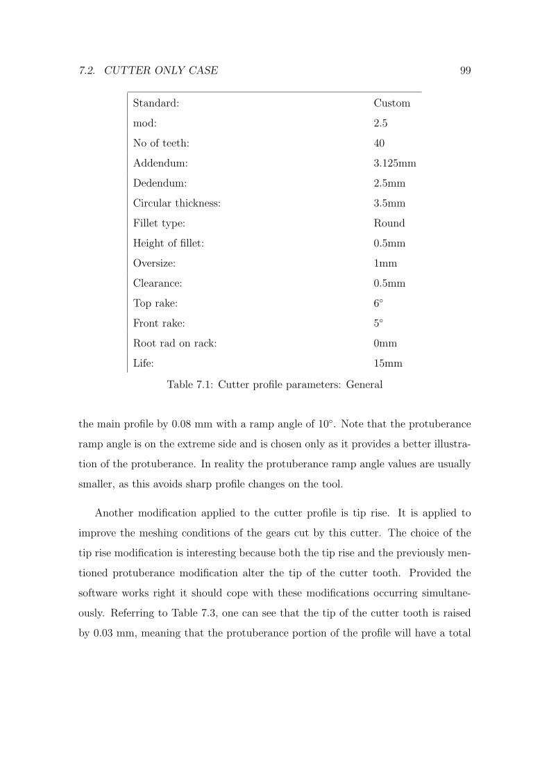
7.2. CUTTER ONLY CASE 99
Standard: Custom
mod: 2.5
No of teeth: 40
Addendum: 3.125mm
Dedendum: 2.5mm
Circular thickness: 3.5mm
Fillet type: Round
Height of fillet: 0.5mm
Oversize: 1mm
Clearance: 0.5mm
Top rake: 6◦
Front rake: 5◦
Root rad on rack: 0mm
Life: 15mm
Table 7.1: Cutter profile parameters: General
the main profile by 0.08 mm with a ramp angle of 10◦. Note that the protuberance
ramp angle is on the extreme side and is chosen only as it provides a better illustra-
tion of the protuberance. In reality the protuberance ramp angle values are usually
smaller, as this avoids sharp profile changes on the tool.
Another modification applied to the cutter profile is tip rise. It is applied to
improve the meshing conditions of the gears cut by this cutter. The choice of the
tip rise modification is interesting because both the tip rise and the previously men-
tioned protuberance modification alter the tip of the cutter tooth. Provided the
software works right it should cope with these modifications occurring simultane-
ously. Referring to Table 7.3, one can see that the tip of the cutter tooth is raised
by 0.03 mm, meaning that the protuberance portion of the profile will have a total
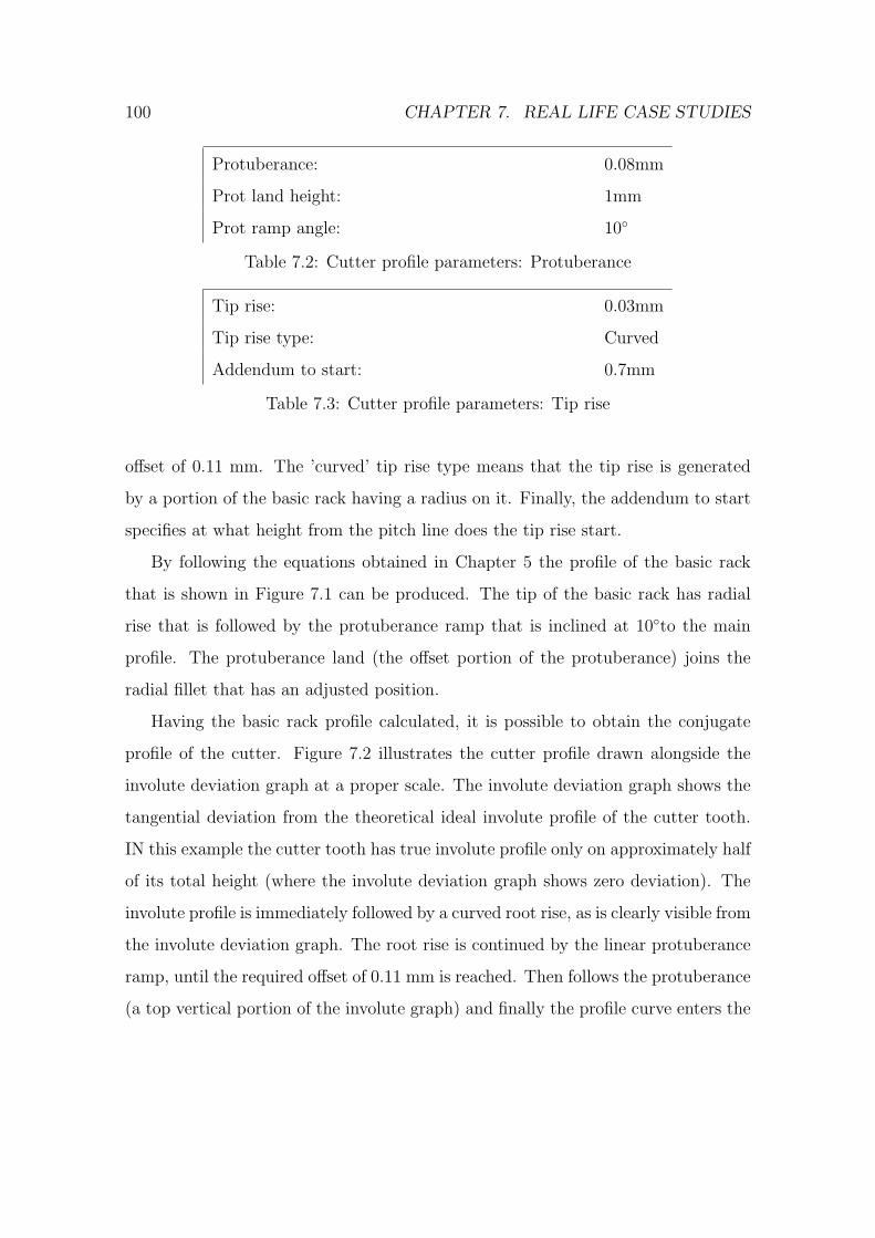
100 CHAPTER 7. REAL LIFE CASE STUDIES
Protuberance: 0.08mm
Prot land height: 1mm
Prot ramp angle: 10◦
Table 7.2: Cutter profile parameters: Protuberance
Tip rise: 0.03mm
Tip rise type: Curved
Addendum to start: 0.7mm
Table 7.3: Cutter profile parameters: Tip rise
offset of 0.11 mm. The ’curved’ tip rise type means that the tip rise is generated
by a portion of the basic rack having a radius on it. Finally, the addendum to start
specifies at what height from the pitch line does the tip rise start.
By following the equations obtained in Chapter 5 the profile of the basic rack
that is shown in Figure 7.1 can be produced. The tip of the basic rack has radial
rise that is followed by the protuberance ramp that is inclined at 10◦to the main
profile. The protuberance land (the offset portion of the protuberance) joins the
radial fillet that has an adjusted position.
Having the basic rack profile calculated, it is possible to obtain the conjugate
profile of the cutter. Figure 7.2 illustrates the cutter profile drawn alongside the
involute deviation graph at a proper scale. The involute deviation graph shows the
tangential deviation from the theoretical ideal involute profile of the cutter tooth.
IN this example the cutter tooth has true involute profile only on approximately half
of its total height (where the involute deviation graph shows zero deviation). The
involute profile is immediately followed by a curved root rise, as is clearly visible from
the involute deviation graph. The root rise is continued by the linear protuberance
ramp, until the required offset of 0.11 mm is reached. Then follows the protuberance
(a top vertical portion of the involute graph) and finally the profile curve enters the
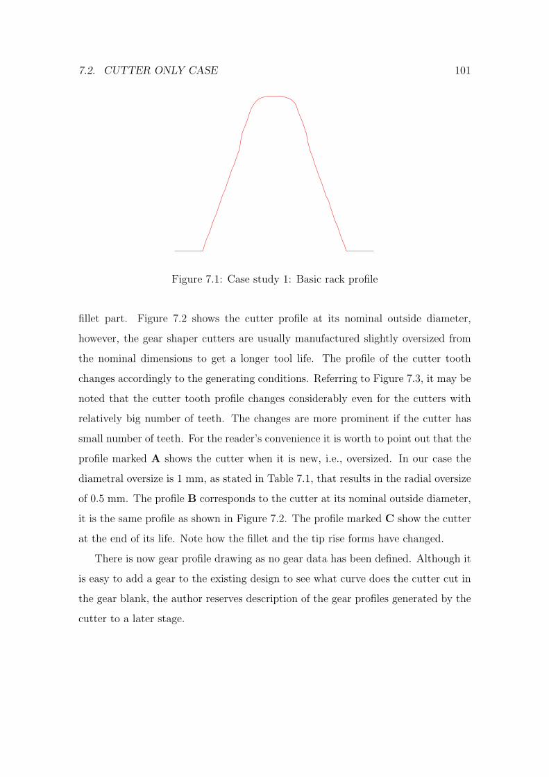
7.2. CUTTER ONLY CASE 101
Figure 7.1: Case study 1: Basic rack profile
fillet part. Figure 7.2 shows the cutter profile at its nominal outside diameter,
however, the gear shaper cutters are usually manufactured slightly oversized from
the nominal dimensions to get a longer tool life. The profile of the cutter tooth
changes accordingly to the generating conditions. Referring to Figure 7.3, it may be
noted that the cutter tooth profile changes considerably even for the cutters with
relatively big number of teeth. The changes are more prominent if the cutter has
small number of teeth. For the reader’s convenience it is worth to point out that the
profile marked A shows the cutter when it is new, i.e., oversized. In our case the
diametral oversize is 1 mm, as stated in Table 7.1, that results in the radial oversize
of 0.5 mm. The profile B corresponds to the cutter at its nominal outside diameter,
it is the same profile as shown in Figure 7.2. The profile marked C show the cutter
at the end of its life. Note how the fillet and the tip rise forms have changed.
There is now gear profile drawing as no gear data has been defined. Although it
is easy to add a gear to the existing design to see what curve does the cutter cut in
the gear blank, the author reserves description of the gear profiles generated by the
cutter to a later stage.
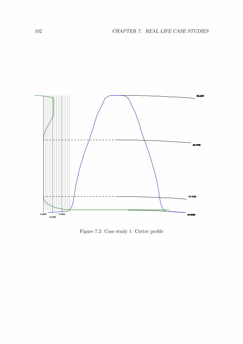
102 CHAPTER 7. REAL LIFE CASE STUDIES
53.1250
47.0000
47.7173
50.7446
0.0000
0.1000
0.2000
Figure 7.2: Case study 1: Cutter profile
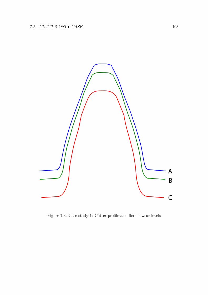
7.2. CUTTER ONLY CASE 103
AB
C
Figure 7.3: Case study 1: Cutter profile at different wear levels
104 CHAPTER 7. REAL LIFE CASE STUDIES
Gear type: Internal
mod: 2
Pressure angle: 20◦
Teeth count: 70
Major dia max: 145.1mm
Major dia min: 145mm
Major dia min: 136mm
Circular thickness: 3.141mm
Table 7.4: Design master gear parameters
7.3 Internal gear and cutter case
Internal gear and cutter case addresses the second gear shaper cutter design process
workflow, whereby the parameters of the dimensions of the cutter are defined by
means of the design master gear geometry. The input parameters of the design
master gear are presented in Table 7.4.
The cutter parameter list is appropriately reduced, because the cutter geometry
is defined by the design master gear. Referring to Table 7.5, the parameters for
the standard, diametral pitch, addendum, dedendum and circular thickness are not
included, and only the parameters that define cutter-specific features like number
of teeth in the cutter and the top rake are left.
Having both the design master gear and the cutter parameters in place, it is
possible to obtain the profile of the cutter’s basic rack as shown in Figure 7.4. The
profile of the basic rack has round fillet with no profile modification defined.
Knowledge about the basic rack geometry allows to produce the conjugate cutter
profile as described in Section 5.2. The obtained profile of the cutter is presented
in Figure 7.5. The same profile could be generated by rolling the basic rack around
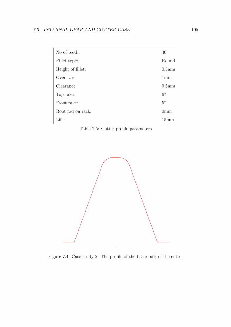
7.3. INTERNAL GEAR AND CUTTER CASE 105
No of teeth: 40
Fillet type: Round
Height of fillet: 0.5mm
Oversize: 1mm
Clearance: 0.5mm
Top rake: 6◦
Front rake: 5◦
Root rad on rack: 0mm
Life: 15mm
Table 7.5: Cutter profile parameters
Figure 7.4: Case study 2: The profile of the basic rack of the cutter
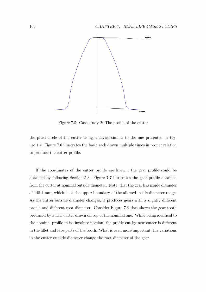
106 CHAPTER 7. REAL LIFE CASE STUDIES
42.5500
37.5000
Figure 7.5: Case study 2: The profile of the cutter
the pitch circle of the cutter using a device similar to the one presented in Fig-
ure 1.4. Figure 7.6 illustrates the basic rack drawn multiple times in proper relation
to produce the cutter profile.
If the coordinates of the cutter profile are known, the gear profile could be
obtained by following Section 5.3. Figure 7.7 illustrates the gear profile obtained
from the cutter at nominal outside diameter. Note, that the gear has inside diameter
of 145.1 mm, which is at the upper boundary of the allowed inside diameter range.
As the cutter outside diameter changes, it produces gears with a slightly different
profile and different root diameter. Consider Figure 7.8 that shows the gear tooth
produced by a new cutter drawn on top of the nominal one. While being identical to
the nominal profile in its involute portion, the profile cut by new cutter is different
in the fillet and face parts of the tooth. What is even more important, the variations
in the cutter outside diameter change the root diameter of the gear.
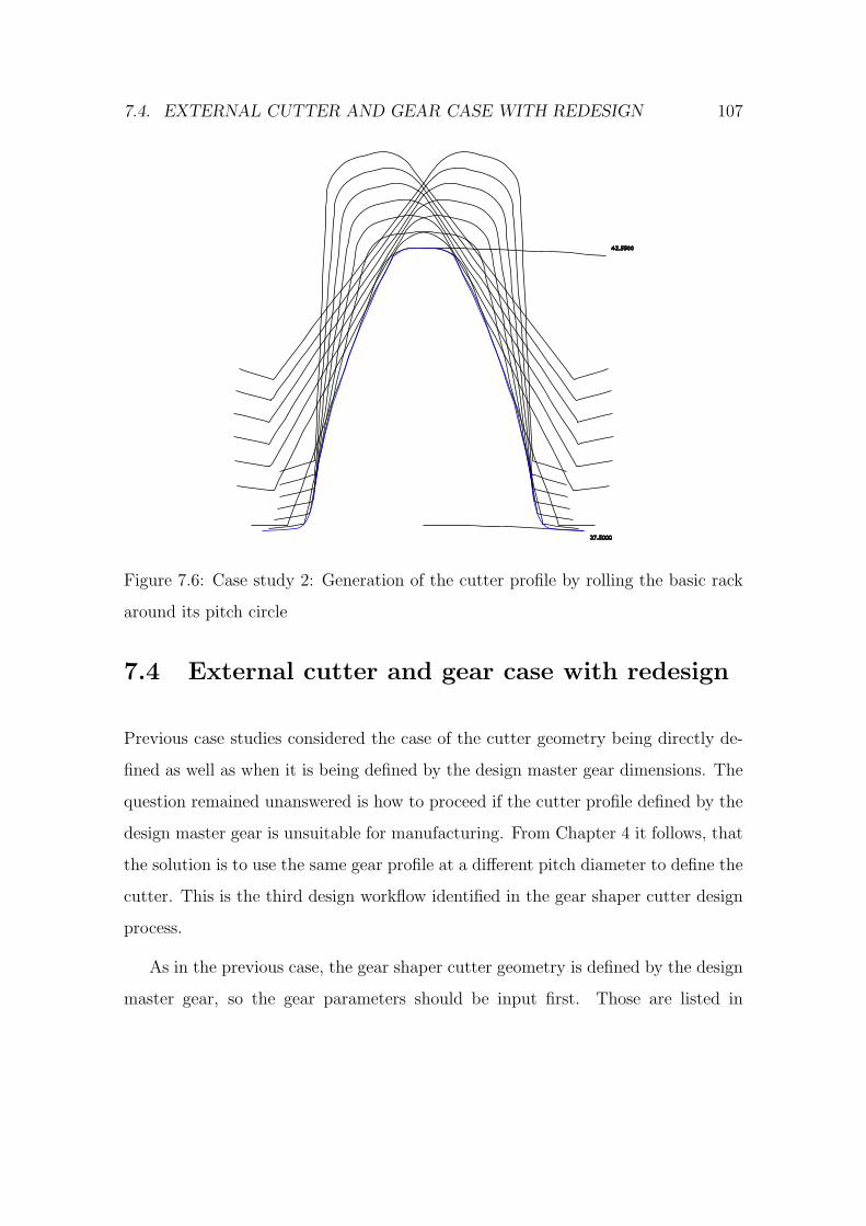
7.4. EXTERNAL CUTTER AND GEAR CASE WITH REDESIGN 107
42.5500
37.5000
Figure 7.6: Case study 2: Generation of the cutter profile by rolling the basic rack
around its pitch circle
7.4 External cutter and gear case with redesign
Previous case studies considered the case of the cutter geometry being directly de-
fined as well as when it is being defined by the design master gear dimensions. The
question remained unanswered is how to proceed if the cutter profile defined by the
design master gear is unsuitable for manufacturing. From Chapter 4 it follows, that
the solution is to use the same gear profile at a different pitch diameter to define the
cutter. This is the third design workflow identified in the gear shaper cutter design
process.
As in the previous case, the gear shaper cutter geometry is defined by the design
master gear, so the gear parameters should be input first. Those are listed in
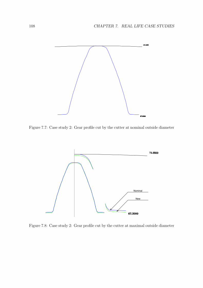
108 CHAPTER 7. REAL LIFE CASE STUDIES
72.5500
67.5000
Figure 7.7: Case study 2: Gear profile cut by the cutter at nominal outside diameter
72.5500
67.5000
Nominal
New
Figure 7.8: Case study 2: Gear profile cut by the cutter at maximal outside diameter
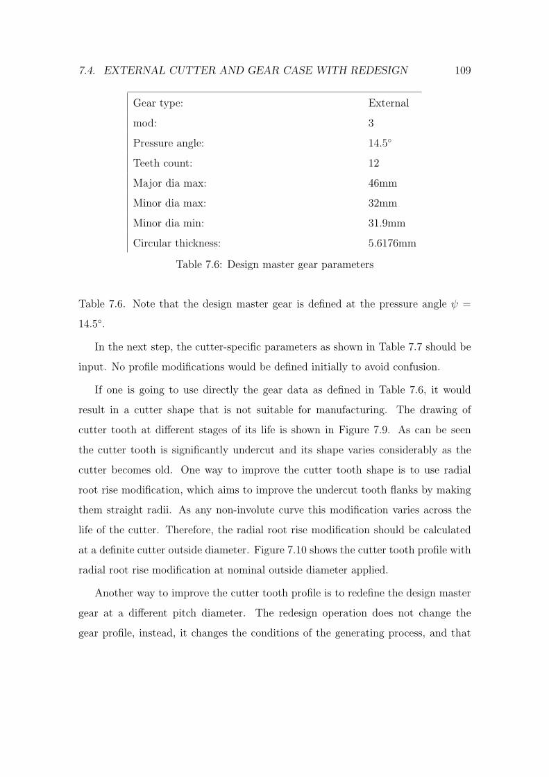
7.4. EXTERNAL CUTTER AND GEAR CASE WITH REDESIGN 109
Gear type: External
mod: 3
Pressure angle: 14.5◦
Teeth count: 12
Major dia max: 46mm
Minor dia max: 32mm
Minor dia min: 31.9mm
Circular thickness: 5.6176mm
Table 7.6: Design master gear parameters
Table 7.6. Note that the design master gear is defined at the pressure angle ψ =
14.5◦.
In the next step, the cutter-specific parameters as shown in Table 7.7 should be
input. No profile modifications would be defined initially to avoid confusion.
If one is going to use directly the gear data as defined in Table 7.6, it would
result in a cutter shape that is not suitable for manufacturing. The drawing of
cutter tooth at different stages of its life is shown in Figure 7.9. As can be seen
the cutter tooth is significantly undercut and its shape varies considerably as the
cutter becomes old. One way to improve the cutter tooth shape is to use radial
root rise modification, which aims to improve the undercut tooth flanks by making
them straight radii. As any non-involute curve this modification varies across the
life of the cutter. Therefore, the radial root rise modification should be calculated
at a definite cutter outside diameter. Figure 7.10 shows the cutter tooth profile with
radial root rise modification at nominal outside diameter applied.
Another way to improve the cutter tooth profile is to redefine the design master
gear at a different pitch diameter. The redesign operation does not change the
gear profile, instead, it changes the conditions of the generating process, and that
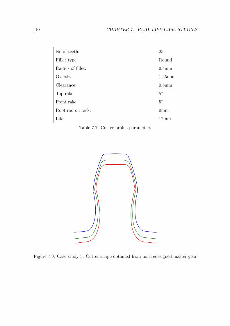
110 CHAPTER 7. REAL LIFE CASE STUDIES
No of teeth: 25
Fillet type: Round
Radius of fillet: 0.4mm
Oversize: 1.25mm
Clearance: 0.5mm
Top rake: 5◦
Front rake: 5◦
Root rad on rack: 0mm
Life: 12mm
Table 7.7: Cutter profile parameters
Figure 7.9: Case study 3: Cutter shape obtained from non-redesigned master gear
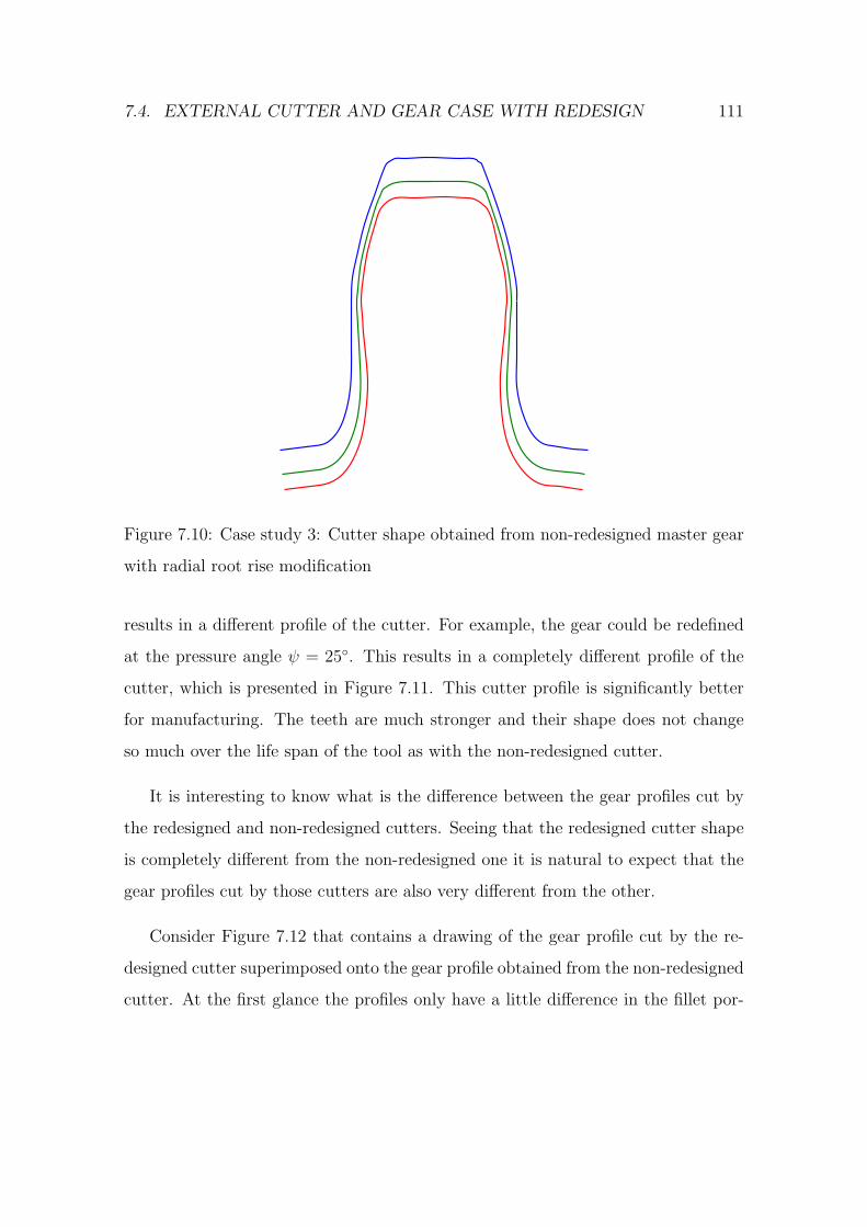
7.4. EXTERNAL CUTTER AND GEAR CASE WITH REDESIGN 111
Figure 7.10: Case study 3: Cutter shape obtained from non-redesigned master gear
with radial root rise modification
results in a different profile of the cutter. For example, the gear could be redefined
at the pressure angle ψ = 25◦. This results in a completely different profile of the
cutter, which is presented in Figure 7.11. This cutter profile is significantly better
for manufacturing. The teeth are much stronger and their shape does not change
so much over the life span of the tool as with the non-redesigned cutter.
It is interesting to know what is the difference between the gear profiles cut by
the redesigned and non-redesigned cutters. Seeing that the redesigned cutter shape
is completely different from the non-redesigned one it is natural to expect that the
gear profiles cut by those cutters are also very different from the other.
Consider Figure 7.12 that contains a drawing of the gear profile cut by the re-
designed cutter superimposed onto the gear profile obtained from the non-redesigned
cutter. At the first glance the profiles only have a little difference in the fillet por-
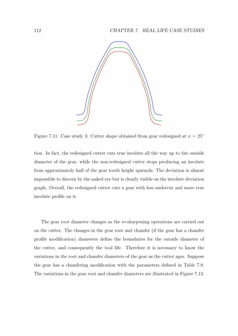
112 CHAPTER 7. REAL LIFE CASE STUDIES
Figure 7.11: Case study 3: Cutter shape obtained from gear redesigned at ψ = 25◦
tion. In fact, the redesigned cutter cuts true involute all the way up to the outside
diameter of the gear, while the non-redesigned cutter stops producing an involute
from approximately half of the gear tooth height upwards. The deviation is almost
impossible to discern by the naked eye but is clearly visible on the involute deviation
graph. Overall, the redesigned cutter cuts a gear with less undercut and more true
involute profile on it.
The gear root diameter changes as the re-sharpening operations are carried out
on the cutter. The changes in the gear root and chamfer (if the gear has a chamfer
profile modification) diameters define the boundaries for the outside diameter of
the cutter, and consequently the tool life. Therefore it is necessary to know the
variations in the root and chamfer diameters of the gear as the cutter ages. Suppose
the gear has a chamfering modification with the parameters defined in Table 7.8.
The variations in the gear root and chamfer diameters are illustrated in Figure 7.13.
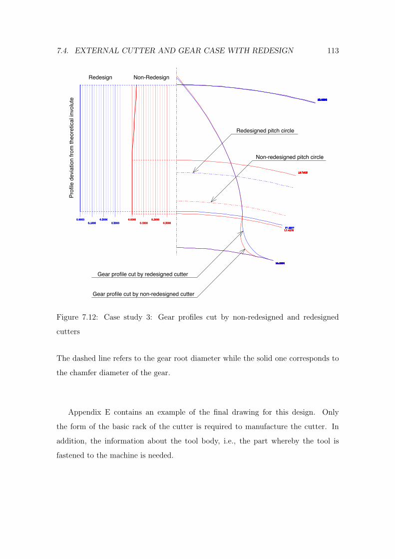
7.4. EXTERNAL CUTTER AND GEAR CASE WITH REDESIGN 113
23.0000
16.0000
19.7605
17.4578
0.0000
0.1000
0.2000
0.3000
23.0000
16.0000
22.9873
17.5617
0.0000
0.1000
0.2000
0.3000
Gear profile cut by redesigned cutter
Gear profile cut by non-redesigned cutter
Non-RedesignRedesign
Pro
file
devia
tion fro
m theore
tical in
volu
te
Redesigned pitch circle
Non-redesigned pitch circle
Figure 7.12: Case study 3: Gear profiles cut by non-redesigned and redesigned
cutters
The dashed line refers to the gear root diameter while the solid one corresponds to
the chamfer diameter of the gear.
Appendix E contains an example of the final drawing for this design. Only
the form of the basic rack of the cutter is required to manufacture the cutter. In
addition, the information about the tool body, i.e., the part whereby the tool is
fastened to the machine is needed.
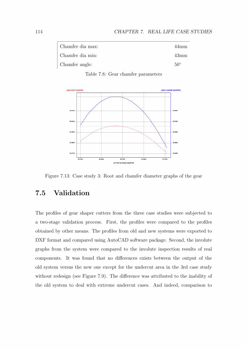
114 CHAPTER 7. REAL LIFE CASE STUDIES
Chamfer dia max: 44mm
Chamfer dia min: 43mm
Chamfer angle: 50◦
Table 7.8: Gear chamfer parameters
31.9740 43.9465
31.9840 43.9565
31.9940 43.9665
32.0040 43.9765
32.0140 43.9865
85.7321 86.2321 86.7321 87.2321 87.7321
CUTTER OUTSIDE DIAMETER
GEAR ROOT DIAMETER GEAR CHAMFER DIAMETER
Figure 7.13: Case study 3: Root and chamfer diameter graphs of the gear
7.5 Validation
The profiles of gear shaper cutters from the three case studies were subjected to
a two-stage validation process. First, the profiles were compared to the profiles
obtained by other means. The profiles from old and new systems were exported to
DXF format and compared using AutoCAD software package. Second, the involute
graphs from the system were compared to the involute inspection results of real
components. It was found that no differences exists between the output of the
old system versus the new one except for the undercut area in the 3rd case study
without redesign (see Figure 7.9). The difference was attributed to the inability of
the old system to deal with extreme undercut cases. And indeed, comparison to

7.6. SUMMARY 115
the involute inspection data from real components manufactured using design data
found the results from the new system correct.
7.6 Summary
This chapter is devoted to case studies made using the developed CAD software.
Three case studies were performed, each of the covers one of the workflows of the
gear shaper cutter design process.
A number of profile modifications were presented with the changes in the cutter
and where appropriate the gear profile pointed out and accompanied with comments.
Special attention was paid to the problem of changes in the profile of the cutter as
it is being re-sharpened.
The time required to complete the case studies using the new system was on
average 1.6 times lower than using the previous system. It was observed that the
system produced results with precision within manufacturing tolerances.

116 CHAPTER 7. REAL LIFE CASE STUDIES
Chapter 8
Discussion and conclusions
This chapter was created to provide the reader with a short summary of all the good
and bad that the author thinks about his own work.
8.1 Discussion
With so many papers available on the topic of gear design it came to surprise that
the area of gear cutting tools and in particular the design of gear shaper cutters
were largely untapped. The quality of the existing gear cutting tools may therefore
be attributed to the extensive experience of those who are responsible for the tool
design and manufacturing. This thesis is an attempt to make the demanding task
of designing a good gear shaper cutter easier.
8.1.1 Contributions
The author sees the gear shaper cutter design process description presented in this
work as an important contribution to knowledge. Knowledge about the process pro-
vides the foundation for future research, in particular the analytical model presented
in Chapter 5 and the CAD software presented in Chapter 6.
117
118 CHAPTER 8. DISCUSSION AND CONCLUSIONS
The analytical model uses full form generation technique for the purpose of
obtaining the conjugate profile. This technique improves the process of the gear
shaper cutter design by allowing to add arbitrary profile modifications to the basic
rack and produce the conjugate cutter and gear profiles without extending the ana-
lytical model for each modification. Consequently, it allows non-involute gear shaper
cutters to be designed and verified using the same set of equations. Unfortunately,
the full form generation technique produces conjugate profiles that may be crossed
over themselves and therefore of a limited use to the gear designer. A successful
application of the Shamos-Hoey algorithm [52] allows to produce profiles without
crossed sections while still using the full form generation.
The gear shaper cutter design software provides a validation test bed for the
analytical and process models of gear shaper cutter design. On a side note, the
software is a rare example of a fully web-based cross-platform CAD software, that
requires no auxiliary programs on the client computer. Being web-based it is not a
proof of concept, but a feature-full system able to solve real life design tasks.
8.1.2 Limitations of the present work
The biggest limitation of this thesis is that the findings presented herein are not
applicable to the other gear types except cylindrical gears. The present work deals
exclusively with cylindrical gears.Also several profile modifications were not consid-
ered, like the elliptical fillet.
The other area that needs attention is the identification of the tasks that are
currently being solved manually by the gear shaper cutter designer and trying to
automate them. The process of finding the compromise between the parameters of
the gear shaper cutter is a multi-objective optimisation problem and it should be
possible to solve using multi-objective optimisation techniques. This thesis does not
try to solve optimisation problems of the design process.
8.2. FUTURE WORK 119
One more limitation is that the developed CAD software does not have link with
the CAM system used to operate the CNC machines.
8.2 Future work
It is the author’s sincere hope to provide a guideline for those wanting to further
explore the field of the gear cutting tools. A guideline that consists not only of
answers, but more so of questions that have yet to be answered. The following is
the list of ’yet to be...’ written by the author in the course of the present research.
One direction for the future work would be to define the gear shaper cutter design
problem as a multi-objective optimisation problem and try to solve it. In theory,
it should provide a completely automated way to obtain the profile of the cutter
suitable for a CAM system from the input data.
The other area of the research is to define new cutter profile modifications based
on the experimental data. Each modification should be accompanied with a guide
on how to apply it on the basic rack.
Important issue left outside of the scope of the current research are the trimming
problems in the internal gear - cutter pairs. In internal gears the cutter and the
gear profile could interfere during backoff and infeed motions of the tool. The gear
shaper cutter design software should be able to detect such situations and advice
the user on the actions that should be taken to prevent interference. Consequently,
there analytical model should be extended with equations of internal gear profile
interference with a cutter.

120 CHAPTER 8. DISCUSSION AND CONCLUSIONS
8.3 Conclusions
This thesis is considered by the author as a successful attempt to study and docu-
ment the gear shaper cutter design process. It provides a base for future research
in describing the scope and the nature of the design process and providing the tools
to aid the gear designer and researcher in constructing the conjugate profiles of the
basic rack, cutter and gear.
The tools allow to visualise any given profile modification and see what the cutter
with this modification cuts in the gear blank.
The thesis contributes to the knowledge with the description and the process
model of the gear shaper cutter design process. Another contributions is the full
form generation technique used in conjunction with the algorithm presented in [52]
to obtain a correct conjugate profile.
The software developed in the course of this project is a rare example of a
CAD system with web-based interface. The system provides scalable drawings and
interacts with the user in real time through the browser.
References
[1] Gear terms, http://en.wikipedia.org/wiki/gear, (accessed: 17.10.2007).
[2] H. Saglam, S. Yaldiz, F. Unsacar, The effect of tool geometry and cutting speed
on main cutting force and tool tip temperature, Materials and Design 28 (1)
(2007) 101–111.
[3] H. Merritt, Gears, Sir Isaac Pitman & Sons, 1954.
[4] BS2519-1:1976 ISO/R1122:1969, Glossary of gears — Geometrical definitions.
[5] BS ISO 21771:2007, Gears — Cylindrical involute gears and gear pairs — Con-
cepts and geometry.
[6] C. Salamoun, M. Suchy, Computation of helical or spur gear fillets, Mechanism
and Machine Theory 8 (1973) 305–323.
[7] V. Math, S. Chand, An approach to the determination spur gear tooth root
fillet, Journal of Mechanical Design 126 (2004) 336–340.
[8] D. Dooner, On the invariance of gear tooth curvature, Journal of Mechanical
Engineering Science 220 (2006) 1083–1096.
[9] F. L. Litvin, Methods for generation of gear tooth surface and basic principals of
computer aided tooth contact analysis, Proceeding of Computers in Engineering
1 (1985) 556–564.
121
122 REFERENCES
[10] C.-B. Tsay, Helical gears with involute shaped teeth: geometry, computer sim-
ulation, tooth contact analysis, and stress analysis, Journal of mechanisms,
transmissions, and automation in design 110 (1988) 482–491.
[11] E. Buckingham, Analytical mechanics of gears, McGraw-Hill Book Co, 1949.
[12] F. L. Litvin, Theory of gearing, Tech. rep., AVSCOM, available in Cranfield
Library (1989).
[13] F. Di Puccio, M. Gabiccini, M. Guiggiani, Alternative formulation of the theory
of gearing, Mechanism and Machine Theory 40 (2005) 613–637.
[14] D. Dudley, Handbook of practical gear design, CRC Press, 1994.
[15] H.-Y. Lai, D.-S. Wu, An enhanced dfm model for shaper cutters, Advanced
Manufacturing Technology 19 (2002) 482–491.
[16] G. Twu, S. Chang, A study on the tooth profiles of involute spur gears manu-
factured by shaper cutters, Journal of the Chinese Society of Mechanical Engi-
neers, Transactions of the Chinese Institute of Engineers, Series C (Chung-Kuo
Chi Hsueh Kung Ch’eng Hsuebo Pao) 25 (2) (2004) 105–113.
[17] R. L. Huston, D. Mavriplis, F. B. Oswald, Y. S. Liu, Basis for solid modeling of
gear teeth with application in design and manufacture, Mechanism and Machine
Theory 29 (5) (1994) 713–723.
[18] C.-B. Tsay, W.-Y. Liu, Y.-C. Chen, Spur gear generation by shaper cutters,
Journal of Materials Processing Technology 104 (2000) 271–279.
[19] J.-Y. Liu, S.-L. Chang, Design of hob cutters for generating helical cutting
tools with multi-cutting angles, International Journal of Machine Tools and
Manufacture 43 (2003) 1185–1195.
REFERENCES 123
[20] S.-L. Chang, H.-C. Tseng, Design of a novel cutter for manufacturing helical
cutting tools, Journal of Mechanical Engineering Science 219 (2005) 395–408.
[21] M. S. Tavakoli, D. R. Houser, Optimum profile modifications for the mini-
mization of static transmission errors of spur gears., Journal of mechanisms,
transmissions, and automation in design 108 (1) (1986) 86–95.
[22] K. Mao, Gear tooth contact analysis and its application in the reduction of
fatigue wear, Wear 262 (5-6) (2007) 505–513.
[23] R. Guilbault, C. Gosselin, L. Cloutier, Helical gears, effects of tooth deviations
and tooth modifications on load sharing and fillet stresses, Journal of Mechan-
ical Design, Transactions of the ASME 128 (2) (2006) 444–456.
[24] M. Beghini, F. Presicce, C. Santus, Proposal for tip relief modification to reduce
noise in spur gears and sensitivity to meshing conditions, VDI Berichte 1904 (II)
(2005) 1719–1734.
[25] J.-H. Kuang, W.-L. Chen, Determination of tip parameters for the protuberance
preshaving cutters, Mechanism and Machine Theory 31 (7) (1996) 839–849.
[26] X. Su, D. Houser, Characteristics of trochoids and their application to de-
termining gear teeth fillet shapes, Mechanism and Machine Theory 35 (2000)
291–304.
[27] E. Oberg, F. Jones, H. Horton, H. Ryffell, Machinery’s Handbook, 26th Edition,
Industrial Press, 2000.
[28] G. Mimmi, P. Pennacchi, Non-undercutting conditions in internal gears, Mech-
anism and Machine Theory 35 (2000) 477–490.
124 REFERENCES
[29] C.-B. Tsay, Computer aided design of internal involute spur gears, American
Society of Mechanical Engineers, Design Engineering Division (Publication) DE
14 (1988) 353–358.
[30] R. Maiti, A. Roy, Minimum tooth difference in internal-external involute gear
pair, Mechanism and Machine Theory 31 (1996) 475–485.
[31] J. Colbourne, The geometry of involute gears, Springer-Verlag, 1987.
[32] F. L. Litvin, Gear geometry & applied theory 2nd edition, Cambridge University
Press, 2004.
[33] F. Di Puccio, M. Gabiccini, M. Guiggiani, Generation and curvature analysis
of conjugate surfaces via a new approach, Mechanism and Machine Theory 41
(2006) 382–404.
[34] M. Gabiccini, M. Guiggiani, F. Di Puccio, New investigation on the geometry of
the contact in gear generation, in: Proceedings of the ASME Design Engineering
Technical Conference, Vol. 4 B, 2003, pp. 683–693.
[35] F. L. Litvin, I. H. Seol, Computerized determination of gear tooth surface as
envelope to two parameter family of surfaces, Computer Methods in Applied
Mechanics and Engineering 138 (1-4) (1996) 213–225.
[36] F. L. Litvin, N. N. Krylov, M. L. Erikhov, Generation of tooth surfaces by two-
parameter enveloping, Mechanism and Machine Theory 10 (5) (1975) 365–373.
[37] J. Argyris, F. L. Litvin, Q. Lian, S. A. Lagutin, Determination of envelope
to family of planar parametric curves and envelope singularities, Computer
Methods in Applied Mechanics and Engineering 175 (1-2) (1999) 175–187.
REFERENCES 125
[38] F. L. Litvin, A. M. Egelja, M. D. Donno, Computerized determination of sin-
gularities and envelopes to families of contact lines on gear tooth surfaces,
Computer Methods in Applied Mechanics and Engineering 158 (1998) 23–34.
[39] F. Litvin, M. De Donno, Q. Lian, S. Lagutin, Alternative approach for determi-
nation of singularity of envelope to a family of parametric surfaces, Computer
Methods in Applied Mechanics and Engineering 167 (1998) 153–165.
[40] F. Di Puccio, M. Gabiccini, M. Guiggiani, An invariant approach for gear gen-
eration with supplemental motions, Mechanism and Machine Theory 42 (3)
(2007) 275–295.
[41] F. Di Puccio, M. Gabiccini, M. Guiggiani, Comparison of different methods in
gear curvature analysis using a new approach, Journal of Mechanical Engineer-
ing Science 219 (2005) 1279–1294.
[42] J. Argyris, An excursion into large rotations, Computer Methods in Applied
Mechanics and Engineering 32 (1982) 85–155.
[43] V. I. Goldfarb, A. A. Tkachev, New approach to computerized design of spur
and helical gears, Proceedings of the ASME Design Engineering Technical Con-
ference 4 B (2003) 575–578.
[44] Google, http://www.google.co.uk/, (accessed: 01.12.2007).
[45] M. Cheney, M. Perry, A comparison of the size of the yahoo! and google indices,
http://vburton.ncsa.uiuc.edu/indexsize.html, (accessed: 12.01.2008).
[46] Conforms, http://sofengsvc.com/, (accessed: 10.01.2008).
[47] Gear c.a.m., http://www.gearcam.co.uk/index2.html, (accessed: 10.01.2008).

126 REFERENCES
[48] Gear factory, http://www.cwattsdesign.com/gearfactory.htm, (accessed:
11.01.2008).
[49] Hygears, http://www.hygears.de/hygears.htm, (accessed: 11.01.2008).
[50] F. L. Litvin, Y. Zhang, J. Kieffer, R. F. Handschuh, Identification and mini-
mization of deviations of real gear tooth surfaces, Journal of Mechanical Design
113 (1) (1991) 55–62.
[51] C. Chen, C. Tsay, Tooth profile design for the manufacture of helical gear
sets with small numbers of teeth, International Journal of Machine Tools and
Manufacture 45 (12-13) (2005) 1531–1541.
[52] M. I. Shamos, D. Hoey, Geometric intersection problems, in: FOCS, IEEE,
1976, pp. 208–215.
[53] R. Acosta, C. Burnsand, W. Rzepka, J. Sidoran, Applying rapid prototyping
techniques in the requirements engineering environment, in: Proceedings of the
April 1994 1st International Conference on Requirements Engineering, 1994,
pp. 66–73.
[54] I. Sommerville, Software Engineering, Addison Wesley, 2000.
[55] K. Beck, Extreme programming eXplained embrace change, Addison-Wesley,
Reading, MA, 2000.
[56] K. Beck, M. Fowler, Planning extreme programming, Addison-Wesley, Boston,
2001.
[57] K. Auer, R. Miller, Extreme programming applied playing to win, Addison-
Wesley, Boston, 2002.

REFERENCES 127
[58] Scalable vector graphics (svg) 1.1 specification (January 2003),
http://www.w3.org/tr/svg11/, (accessed: 17.10.2007).
[59] Extensible markup language (xml) 1.1 (second edition),
http://www.w3.org/tr/2006/rec-xml11-20060816/, (accessed: 17.10.2007).

128 REFERENCES

Appendix A
Interview questions
129

130 APPENDIX A. INTERVIEW QUESTIONS

Interview questions:
Could you describe your typical workflow?
What are the special cases that should be considered?
How is the cutter geometry specified?
How is the gear geometry specified?
What modifications are used for the cutter profile?
How are these modifications specified?
How the results of the design process look like?
How the results should be measured?
Who will be the user of the system?
What functions must the system perform?
What requirements does the function X impose on the system?
What does this requirements mean to you as a cutter designer?
Could this requirement to be reformulated to be more specific?
Will some of the users be dedicated/casual users?
Should access control be implemented?
Are there any standards on inputs/data processing/outputs?
Are there any identified/expected constraints?
Are there any other questions that I should ask you?
Appendix B
Gear shaper cutter design process
inputs
131

132 APPENDIX B. GEAR SHAPER CUTTER DESIGN PROCESS INPUTS

INPUTS – CUTTER DETAILS ONLY
COMMON AND SPUR
HELICAL VARIATIONS / ADDITIONS
DP/MOD/CP NNDP/CDP,N MOD/C MOD,NCP/CCP
PA NPA/CPA
BIAS PA / INVOLUTE DEVIATION AT TIP BIAS NPA/CPA
HELIX ANGLE
ADDENDUM
DEDENDUM
CIRC TOOTH THICKNESS NORM / TRANS CIRC TH
HEIGHT OF FILLET / RADIUS OF FILLET /
ELIPTICAL FILLET HT & WIDTH
HEIGHT OF FILLET / TRANSVERSE RAD OF
FILLET / ELIPTICAL HT & WIDTH TRANS & NORM
OVERSIZE
CLEARANCE
TOP RAKE NORMAL TO RAKE / TRANSVERSE TOP RAKE
FRONT RAKE
SHARPENING ANGLE
HAND
ROOT RAD ON RACK TRANSVERSE ROOT RAD ON RACK
LIFE (for graphics)
Optional if chamfering
CHAMFER DEDENDUM
CHAMFER PA TRANS CHAM PA / NORMAL CHAM PA
Optional if protuberance
PROTUBERANCE NORMAL PROT / TRANS PROT
PROT LAND HEIGHT
PROT RAMP HEIGHT / PROT RAMP ANGLE
Selectable options for root rise – selection box title ROOT RISE / RELIEF
LINEAR / CURVED
If linear or curved tip rise / relief then inputs required of:-
TIP RISE TRANS / NORMAL TIP RISE
ADDENDUM TO TIP RISE START
Selectable options for tip rise – selection box title TIP RISE / RELIEF
LINEAR / CURVED / RADIAL / BS 436
If linear or curved root rise / relief then inputs required of:-
ROOT RISE TRANS/NORMAL ROOT RISE
DEDENDUM TO ROOT RISE START
If radial root rise input of:-
OVERSIZE AT RADIAL PLANE
If false topped
FALSE TOP RAKE
TIP CHAMFER / TIP RADIUS
If for taper cutting
TAPER ANGLE

WHERE THERE ARE TWO OR MORE INPUTS IN ONE BOX THEY ARE OPTIONAL QUESTIONS
TO GET TO THE SAME ANSWER EG PROT RAMP HEIGHT / PROT RAMP ANGLE. ONLY ONE OF
THE OPTIONS IS REQUIRED TO BE ANSWERED
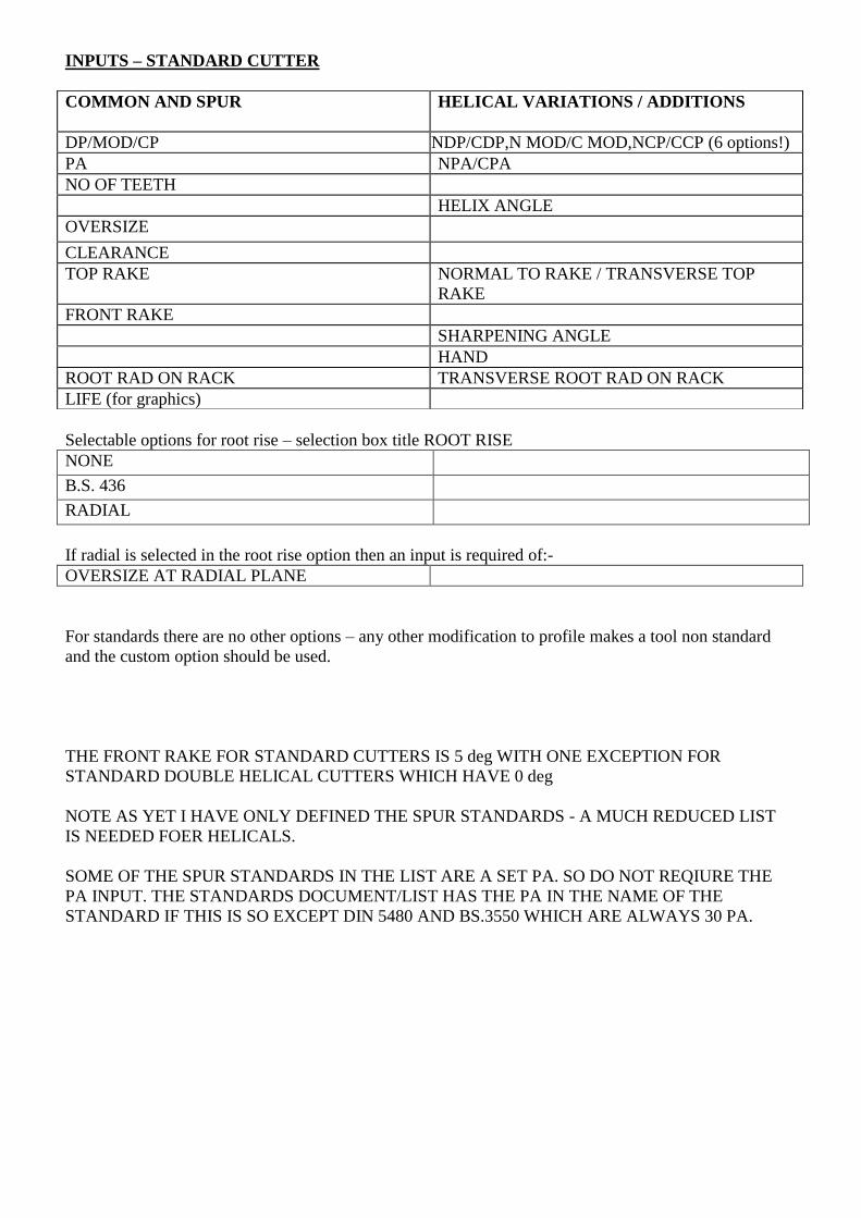
INPUTS – STANDARD CUTTER
Selectable options for root rise – selection box title ROOT RISE
NONE
B.S. 436
RADIAL
If radial is selected in the root rise option then an input is required of:-
OVERSIZE AT RADIAL PLANE
For standards there are no other options – any other modification to profile makes a tool non standard
and the custom option should be used.
THE FRONT RAKE FOR STANDARD CUTTERS IS 5 deg WITH ONE EXCEPTION FOR
STANDARD DOUBLE HELICAL CUTTERS WHICH HAVE 0 deg
NOTE AS YET I HAVE ONLY DEFINED THE SPUR STANDARDS - A MUCH REDUCED LIST
IS NEEDED FOER HELICALS.
SOME OF THE SPUR STANDARDS IN THE LIST ARE A SET PA. SO DO NOT REQIURE THE
PA INPUT. THE STANDARDS DOCUMENT/LIST HAS THE PA IN THE NAME OF THE
STANDARD IF THIS IS SO EXCEPT DIN 5480 AND BS.3550 WHICH ARE ALWAYS 30 PA.
COMMON AND SPUR
HELICAL VARIATIONS / ADDITIONS
DP/MOD/CP NNDP/CDP,N MOD/C MOD,NCP/CCP (6 options!)
PA NPA/CPA
NO OF TEETH
HELIX ANGLE
OVERSIZE
CLEARANCE
TOP RAKE NORMAL TO RAKE / TRANSVERSE TOP
RAKE
FRONT RAKE
SHARPENING ANGLE
HAND
ROOT RAD ON RACK TRANSVERSE ROOT RAD ON RACK
LIFE (for graphics)

1
INPUTS – GEAR & CUTTER DETAILS
COMMON AND SPUR
HELICAL VARIATIONS / ADDITIONS
K GEAR DETAILS
INTERNAL OR EXTERNAL
DP/MOD/CP NNDP/CDP,N MOD/C MOD,NCP/CCP
PA NPA/CPA
BIAS PA / INVOLUTE DEVIATION AT TIP BIAS NPA/CPA
HELIX ANGLE
NO OF TEETH
MAJOR DIA MAX
MAJOR DIA MIN (option for external)
MINOR DIA MAX (option for internal)
MINOR DIA MIN
REQUIRED S.A.P. (option)
REQUIRED T.I.F. (option)
SHAPED CIRC TOOTH THICKNESS/DIMENSION
OVER/UNDER BALLS/SPAN DIMENSION
NORM / TRANS CIRC TH
Optional if pre-finishing
FINISHED CIRC TOOTH THICKNESS/DIMENSION
OVER/UNDER BALLS/SPAN DIMENSION
NORM / TRANS CIRC TH
Optional if chamfering
CHAMFER DIA MAX
CHAMFER DIA MIN
CHAMFER ANGLE TRANS CHAM ANG / NORMAL CHAM ANG
Selectable options for tip relief – selection box title TIP RELIEF / RISE
LINEAR / CURVED
TIP RELIEF TRANS / NORMAL TIP RELIEF
DIA /ROLL ANG /ROLL LENGTH /ADDENDUM AT
RELIEF START
Selectable options for root relief – selection box title ROOT RELIEF / RISE
LINEAR / CURVED
ROOT RISE TRANS/NORMAL ROOT RISE
DIA /ROLL ANG /ROLL LENGTH /DEDENDUM AT
RISE START
If taper gear
TAPER ANGLE/SIDE RAKE ON PART

2
DESIGN DETAILS
TYPE OF DESIGN
If redesign
REDESIGN PA / REDESIGN PCD REDESIGN NPA/CPA
If th/add redesign
CUTTER THICKNESS / ADDENDUM
If not auto root dia optimisation
DESIGN ROOT DIAMETER
If not auto chamfer dia optimisation
DESIGN CHAMFER DIAMETER
COMMON AND SPUR
HELICAL VARIATIONS / ADDITIONS
K CUTTER DETAILS
NO OF TEETH
HEIGHT OF FILLET / RADIUS OF FILLET /
ELIPTICAL FILLET HT & WIDTH
HEIGHT OF FILLET / TRANSVERSE RAD OF
FILLET / ELIPTICAL HT & WIDTH TRANS & NORM
OVERSIZE
CLEARANCE
TOP RAKE NORMAL TO RAKE / TRANSVERSE TOP RAKE
FRONT RAKE
SHARPENING ANGLE
HAND (options of right/left or both)
ROOT RAD ON RACK TRANSVERSE ROOT RAD ON RACK
LIFE (for graphics)
Optional if protuberance
PROTUBERANCE NORMAL PROT / TRANS PROT
PROT LAND HEIGHT
PROT RAMP HEIGHT / PROT RAMP ANGLE
Selectable option of radial root rise on cutter - only if no tip relief is selected in gear section (this is used to
suppress undercut on the tool only. Tool is not required to produce modification on part even if it does have
to.)
OVERSIZE AT RADIAL RISE
If false topped
TIP CHAMFER / TIP RADIUS

Appendix C
Software interface prototype
133

134 APPENDIX C. SOFTWARE INTERFACE PROTOTYPE

SpurDesign Type:
Involute Tool DesignMeasurement Units:
File Log outUtilities CNC Output
Inches Millimetres
Users Current User
Editing: 105/48/1
Options
Blank if no gear specified
Output Design
appears only for custom tools
active only for radial root rise
appear only for custom tools
BS.436Standard:
Cutter Details
Pressure Angle:
Number of Teeth:
Top Rake:
Clearance:
Oversize:
Rack Root Radius:
Life for Graphs:
BodyMfg.GearCutter
Addendum:
Dedendum:
Circular Tooth TH:
Front Rake:
Design master gear present!
DP:
Height of Fillet:
Pr. Ramp Height:
Appear only for helical tools
Helix Angle:
Sharpening Angle:
Chamfering
Protuberance
Tip Rise
Root Rise:
False Top
Taper Cutting
Ch. Dedendum:
Ch. PA:
Protuberance:
Pr. Land Height:
Magnitude:
Addendum to Start:
Magnitude:
Dedendum to Start:
RadialRoot Rise:
Ovrsz at Rad. Rise:
False Top Rake:
Tip Chamfer:
Taper Angle:
RightHand:
RadialTip Rise:
Bias PA:
Click for Details
Click for Details
Click for Details
A
B
C
D

Involute Tool Design
BACK Open in Ext. Editor PRINTNote
Measurement Units: Inches Millimetres
43.2869
35.7869
36.9408
43.1242
0.0000
0.1000
0.2000
0.3000
Multigraph
Textual Sideframe
Involute Sideframe
Curve Breaks
Tooth
Space Pitch Circle
Center Line
Cutter
Rack
Gear
Gear
1:500Involute Abscissa Scale:DiameterInvolute Ordinate Units
DiameterRoll angleLength of roll
Actual T.I.F.
Required T.I.F.
S.A.P.
Zoom tool+ scale display
Measurement tools===============DistanceDiameterRadius from point
Finishing
Choice of either 1, 2 or 3 graphs
The amount of deviation at the end of the involute profilethe diameter where the deviation starts (ref 1123)
A
B
D

SpurDesign Type:
Involute Tool DesignMeasurement Units:
File Log outUtilities CNC Output
Inches Millimetres
Users Current User
Editing: 105/48/1
Options
Output Design
Option for externalOption for Internal
Appear only for master design gear
SpurDesign Type:
Gear Details
Number of Teeth:
Major Dia Max:
Diameter:
Minor Dia Min:
BodyMfg.Cutter Gear
External Internal
Design Master GearADD DELETEGear1Gear Design: RENAME
DP:
Pressure Angle:
Bias PA:
Chamfering
Ch. Dia. Max:
Ch. Dia. Min:
Ch. Angle
Tip Relief
Root Relief
Magnitude:
Magnitude:
Diameter:
Diameter:
Taper Cutting
Taper Angle:
Pre-finishing
Fin. Circ. Tooth Th.:
Sh. Circ. Tooth Th.:
Major/Minor Dia Min/Max:
Major/Minor Dia Min/Max
Options
Required S.A.P (dia):
Required T.I.F. (dia):
23.0000
16.0000
22.9922
17.5133
A
B
D

SpurDesign Type:
Involute Tool DesignMeasurement Units:
File Log outUtilities CNC Output
Inches Millimetres
Users Current User
Editing: 105/48/1
Options
Output Design
Base Pitch Clearance for Th
Cutter Details
BodyGear
ADD DELETECutter1Cutter: RENAME
Mfg.Cutter
Gearshaper / Hob / Rack Milling
Text Field103/10Text Field
Text FieldIdenticalText Field
Reference ...Text Field0.0321Text Field
Text FieldText FieldHob/shaper/rack; form modifications
Text Field Text Field Text Field Text FieldText Field Text Field Text Field Text FieldText Field Text Field Text Field Text FieldText Field Text Field Text Field Text Field
0.2951Base Pitch Cutter: 0.025Ideal Clearance: 0.025Actual Clearance:
0.5Depth:
Draw with finished profile
Disabled

Appendix D
Software requirements
specification
135

136 APPENDIX D. SOFTWARE REQUIREMENTS SPECIFICATION
Software Requirements Specification
for
CAD “Dathan”
Version 1.2
Prepared by Eugene Butan
11-Dec-06

Software Requirements Specification for CAD “Dathan” Page ii
Table of Contents
Table of Contents .......................................................................................................................... ii
Revision History ............................................................................................................................ ii
1. Introduction ..............................................................................................................................1 1.1 Purpose ........................................................................................................................................... 1 1.2 Intended Audience and Reading Suggestions................................................................................. 1 1.3 Project Scope .................................................................................................................................. 1 1.4 References ...................................................................................................................................... 1
2. Overall Description ..................................................................................................................1 2.1 Product Perspective ........................................................................................................................ 1 2.2 Product Features ............................................................................................................................. 2 2.3 User Classes and Characteristics .................................................................................................... 2 2.4 Operating Environment .................................................................................................................. 2 2.5 Design and Implementation Constraints ......................................................................................... 3 2.6 User Documentation ....................................................................................................................... 3 2.7 Assumptions and Dependencies ..................................................................................................... 3
3. System Features ........................................................................................................................3 3.1 Involute Helical Design .................................................................................................................. 3 3.2 Involute Spur Design ...................................................................................................................... 3 3.3 Formula input into fields ................................................................................................................ 4 3.4 DXF export ..................................................................................................................................... 4 3.5 Rack Helical Design ....................................................................................................................... 4 3.6 Rack Spur Design ........................................................................................................................... 5
4. External Interface Requirements ...........................................................................................5 4.1 User Interfaces ................................................................................................................................ 5 4.2 Hardware Interfaces ........................................................................................................................ 5 4.3 Software Interfaces ......................................................................................................................... 5 4.4 Communications Interfaces ............................................................................................................ 6
5. Other Nonfunctional Requirements .......................................................................................6 5.1 Performance Requirements ............................................................................................................. 6 5.2 Safety Requirements ....................................................................................................................... 6 5.3 Security Requirements .................................................................................................................... 6 5.4 Software Quality Attributes ............................................................................................................ 6
Revision History
Name Date Reason For Changes Version
Initial 22-Nov-06 1.0
RC-1 01-Dec-06 Additional user classes, CNC iface, nonfunctional requirements
1.1
Release-1 11-Dec-06 Small fixes 1.2
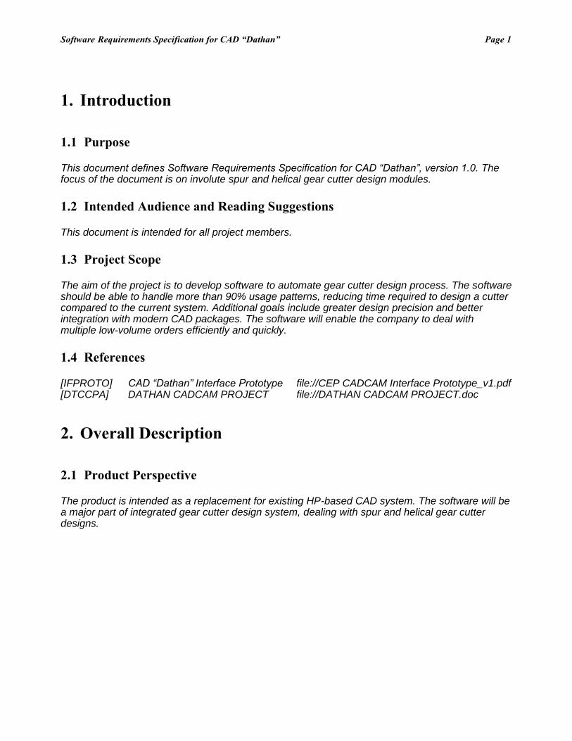
Software Requirements Specification for CAD “Dathan” Page 1
1. Introduction
1.1 Purpose
This document defines Software Requirements Specification for CAD “Dathan”, version 1.0. The focus of the document is on involute spur and helical gear cutter design modules.
1.2 Intended Audience and Reading Suggestions
This document is intended for all project members.
1.3 Project Scope
The aim of the project is to develop software to automate gear cutter design process. The software should be able to handle more than 90% usage patterns, reducing time required to design a cutter compared to the current system. Additional goals include greater design precision and better integration with modern CAD packages. The software will enable the company to deal with multiple low-volume orders efficiently and quickly.
1.4 References
[IFPROTO] CAD “Dathan” Interface Prototype file://CEP CADCAM Interface Prototype_v1.pdf [DTCCPA] DATHAN CADCAM PROJECT file://DATHAN CADCAM PROJECT.doc
2. Overall Description
2.1 Product Perspective
The product is intended as a replacement for existing HP-based CAD system. The software will be a major part of integrated gear cutter design system, dealing with spur and helical gear cutter designs.
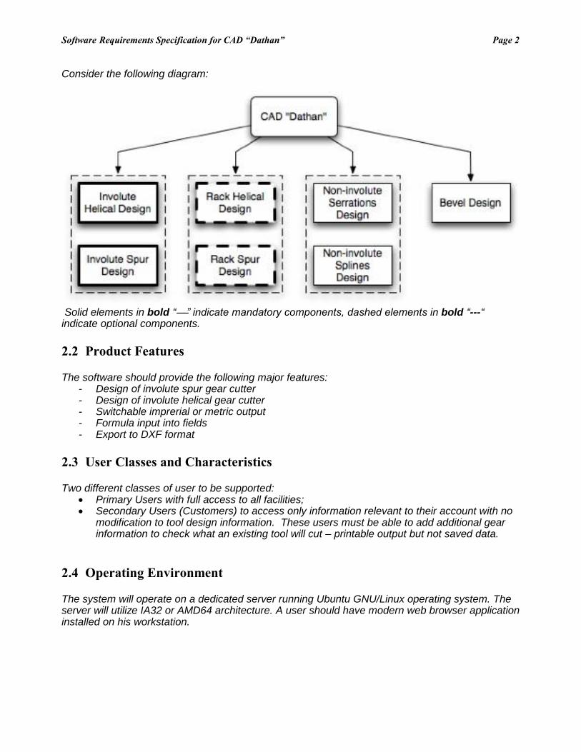
Software Requirements Specification for CAD “Dathan” Page 2
Consider the following diagram:
Solid elements in bold “” indicate mandatory components, dashed elements in bold “---“ indicate optional components.
2.2 Product Features
The software should provide the following major features: - Design of involute spur gear cutter - Design of involute helical gear cutter - Switchable imprerial or metric output - Formula input into fields - Export to DXF format
2.3 User Classes and Characteristics
Two different classes of user to be supported: Primary Users with full access to all facilities; Secondary Users (Customers) to access only information relevant to their account with no
modification to tool design information. These users must be able to add additional gear information to check what an existing tool will cut – printable output but not saved data.
2.4 Operating Environment
The system will operate on a dedicated server running Ubuntu GNU/Linux operating system. The server will utilize IA32 or AMD64 architecture. A user should have modern web browser application installed on his workstation.

Software Requirements Specification for CAD “Dathan” Page 3
2.5 Design and Implementation Constraints
A single P4 3Ghz 512 MB RAM server should be sufficient for serving 5 users. The interface should feature real-time response to user actions. The software should be implemented using the Python language and TurboGears framework. PostgreSQL will be used as a database backend. Secure communications between server and client will rely on SSL encryption. Currently the maintenance of the delivered software is the responsibility of the customer.
2.6 User Documentation
The delivered software should feature interactive context-sensitive help system. Built-in help is supplemented with user manual in PDF format. Full development documentation should be provided as well.
2.7 Assumptions and Dependencies
A PDF reader program such as Adobe Acrobat Reader should be installed on a user’s computer in order to view and print output files. The system uses external DXF editor to support custom modifications of design files.
3. System Features
3.1 Involute Helical Design
3.1.1 Description and Priority
A set of tools integrated under a single interface that allows to specify, calculate and simulate involute helical gear shaper cutter. This feature is of high priority.
3.1.2 Stimulus/Response Sequences
A user is starting a new design or loading an existing one with the type “Helical”
3.1.3 Functional Requirements
Refer to the [DTCCPA] for a list of software capabilities associated with this feature.
IHD-1: IHD-2: IHD-3:
3.2 Involute Spur Design
3.1.1 Description and Priority
A set of tools integrated under a single interface that allows to specify, calculate and simulate involute spur gear shaper cutter. This feature is of high priority.
3.1.2 Stimulus/Response Sequences
Software Requirements Specification for CAD “Dathan” Page 4
A user is starting a new design or loading an existing one with the type “Spur”
3.1.3 Functional Requirements
Refer to the [DTCCPA] for a list of software capabilities associated with this feature.
ISD-1: ISD-2: ISD-3:
3.3 Formula input into fields
3.1.1 Description and Priority
The system should allow input of simple mathematical formulas into all input fields. It should be able to recognize imperial and metric units in formulas. This feature is of high priority.
3.1.2 Stimulus/Response Sequences
User inputs a formula in the input field. The system calculates the formula and takes result as the input value.
3.1.3 Functional Requirements
Refer to the [DTCCPA] for a list of software capabilities associated with this feature.
FOR-1: FOR-2: FOR-3:
3.4 DXF export
3.1.1 Description and Priority
Ability to export design files in DXF format. This feature is of high priority.
3.1.2 Stimulus/Response Sequences
User presses “Edit in External Editor” button. System displays dialog box prompting to save DXF file.
3.1.3 Functional Requirements
Refer to the [DTCCPA] for a list of software capabilities associated with this feature.
DXF-1: Compatibility with SolidWorks; Unigraphics; CATIA; Autocad. DXF-2: DXF-3:
3.5 Rack Helical Design
3.1.1 Description and Priority
A set of tools integrated under a single interface that allows to specify, calculate and simulate helical rack cutter. This feature is of low priority.
Software Requirements Specification for CAD “Dathan” Page 5
3.1.2 Stimulus/Response Sequences
A user is starting a new design or loading an existing one with the type “Helical Rack”
3.1.3 Functional Requirements
Refer to the [DTCCPA] for a list of software capabilities associated with this feature.
RHD-1: RHD-2: RHD-3:
3.6 Rack Spur Design
3.1.1 Description and Priority
A set of tools integrated under a single interface that allows to specify, calculate and simulate spur rack cutter. This feature is of low priority.
3.1.2 Stimulus/Response Sequences
A user is starting a new design or loading an existing one with the type “Spur Rack”
3.1.3 Functional Requirements
Refer to the [DTCCPA] for a list of software capabilities associated with this feature.
RSD-1: RSD-2: RSD-3:
4. External Interface Requirements
4.1 User Interfaces
The system should use CSS based GUI and rely on standard HTML interface components wherever possible. See [IFPROTO] for details on the user interface.
4.2 Hardware Interfaces
The system relies on abilities of users’ computers to print DXF and PDF documents. No additional modifications to the system to accommodate for new output devices should be necessary.
4.3 Software Interfaces
A possibility of connection with existing order management system JobShop should be explored. Hooks for interfacing with CNC routines must be present. (Data format and communication protocol to be defined)
Software Requirements Specification for CAD “Dathan” Page 6
4.4 Communications Interfaces
The server will communicate with clients using HTTP protocol with optional SSL encryption. The system should not exhibit any noticeable communication latency on a standard 100 Base-T Ethernet network.
5. Other Nonfunctional Requirements
5.1 Performance Requirements
A delivered system – to specification - in line with the original Project Charter completion dates. Costs in line with original budget.
5.2 Safety Requirements
System must error trap / foolproof / highlight any out of range inputs. System must error trap / foolproof / highlight any out of range outputs. (Ranges to be agreed)
5.3 Security Requirements
Unauthorized remote access to any systems must be prevented. The system must be able to guarantee no loss of data in the event of hardware failures. System security must conform to best practices
5.4 Software Quality Attributes
24 hour maximum downtime during typical operation Less than 6 critical errors within last 6 weeks The system must have documentation sufficient to allow future modifications and issue resolution to
take place at Dathan.

Appendix E
Final drawing
137