complex evolution of paleolacustrine systems on mars: an example from the holden crater
TRANSCRIPT
Complex evolution of paleolacustrine systems on Mars:
An example from the Holden crater
M. Pondrelli, A. Baliva, S. Di Lorenzo, L. Marinangeli, and A. P. Rossi1
International Research School of Planetary Sciences, Universita d’Annunzio, Pescara, Italy
Received 28 July 2004; revised 3 January 2005; accepted 11 January 2005; published 29 April 2005.
[1] The �150 km wide Holden crater lies in an area characterized by high density ofvalley networks implying conditions conducive to forming of water-related environments.We undertook geological mapping and a stratigraphic survey in order to probe theevolution of water-related landforms and their paleoenvironmental implications. Ourinvestigations lead us to propose that the Holden area was subjected to a ‘‘wet’’ lacustrinephase of Hesperian age and an ‘‘icy’’ phase during the Amazonian. Deltaic, coastal, andlacustrine environments occurred during the ‘‘wet’’ phase, some displaying a cyclicdepositional pattern presumably related to autogenic processes. Water was delivered to thebasin by the Uzboi Vallis and by surface runoff channels from a series of drainage basinsalong the crater walls. Fan delta geometries and coastal onlap enabled estimation of majorwater levels. Two levels of major stand of the water have been recognized, possiblyreflecting allogenic controls. Geologic units related to this ‘‘wet’’ lacustrine phase weresubsequently eroded by glacial abrasion and plucking and were disconformably overlainby glacial deposits of Amazonian age, defining an ‘‘icy’’ phase. These features areconsistent with a warm-based glacier entering the Holden crater through the wide UzboiVallis to form a proglacial lake in the central part of the crater. Changes in sedimentaryunits reflect changes of depositional environments probably connected with climaticvariation.
Citation: Pondrelli, M., A. Baliva, S. Di Lorenzo, L. Marinangeli, and A. P. Rossi (2005), Complex evolution of paleolacustrine
systems on Mars: An example from the Holden crater, J. Geophys. Res., 110, E04016, doi:10.1029/2004JE002335.
1. Introduction
[2] Since the pioneering work of Milton [1973] based onMariner 9 data, the possibility that for some of its geologichistory water flowed on the surface of Mars resultingin major surface modification has been extensively investi-gated and described [Pieri, 1980; Lucchitta, 1981; Carr andClow, 1981; Gulick and Baker, 1989; Ori and Mosangini,1998; Malin and Edgett, 2000; Baker, 2001; Gulick, 2001;Hynek and Phillips, 2001, 2003; Baker et al., 1992]. Thehypothesis that an ancient ocean extended over the NorthernPlains [Baker et al., 1991; Parker et al., 1993] has beensupported by new evidence from MGS data [Head et al.,1999; Parker and Currey, 2001]. The possibility that gla-ciers were involved in surface-modification has been pro-posed [Lucchitta, 1981; Anguita and Moreno, 1992; Headand Marchant, 2003]. Many authors have looked for anddescribed lacustrine depositional environments and relatedsubenvironments [Williams and Zimbelman, 1994; Cabrol etal., 1996, 1999, 2000; Ori et al., 2000a; Cabrol and Grin,1999, 2001, 2002]. Due to their reduced dimensions, lacus-trine settings are extremely sensitive to environmental fluc-
tuations when compared to planetary-scale oceans, and,accordingly, are a prime target for studying the evolutionof water- and ice-related landforms as well as astrobiologicalinvestigations [McKay and Nedall, 1988; Cabrol et al.,1999, 2001; Komatsu and Ori, 2000; Ori et al., 2000b].[3] Being situated in a fluvial network connecting Argyre
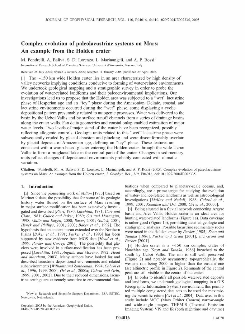
basin and Ares Vallis, Holden crater is an ideal area forhunting water-related landforms (Figure 1a). Data coverageis rather good (Figure 1b), permitting detailed geologic andstratigraphic analyses. Possible lacustrine sedimentary rockswere noted in the Holden crater by Parker [1985], Scott andTanaka [1986], Parker and Grant [2001], and Grant andParker [2001].[4] Holden crater is a �150 km complex crater of
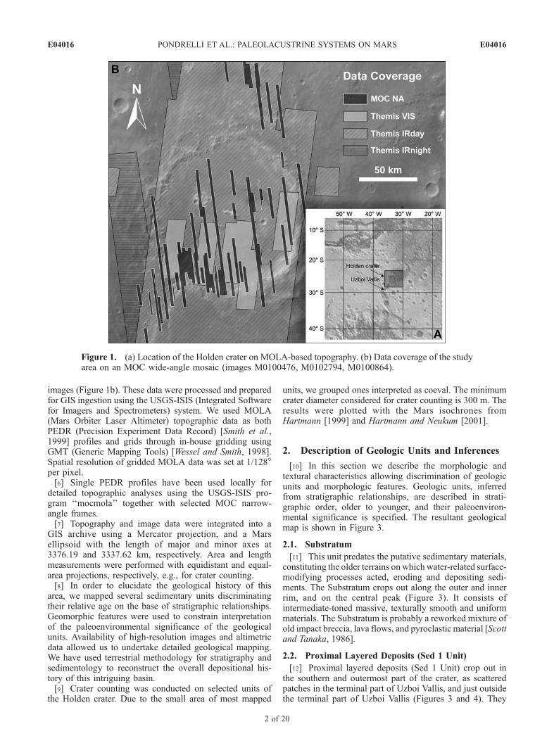
Noachian age [Scott and Tanaka, 1986] breached to thesouth by Uzboi Vallis. The rim is still well preserved(Figure 2) and notably asymmetric topographically, thewestern rim being 2000 m higher than the eastern one(see altimetric profile in Figure 2). Remnants of the centralpeak are still visible in the centre of the crater.[5] In order to identify all possible water-related deposits
and landforms, we undertook geological mapping in a GIS(Geographic Information System) environment; this permit-ted multiple coregistered data sets to be used for maximiz-ing the scientific return [Ori et al., 2004]. Data used in thisstudy include MOC (Mars Orbiter Camera) narrow-angleand wide-angle images, THEMIS (Thermal EmissionImaging System) VIS and IR (both nighttime and daytime)
JOURNAL OF GEOPHYSICAL RESEARCH, VOL. 110, E04016, doi:10.1029/2004JE002335, 2005
1Now at Research and Scientific Support Department, ESA ESTEC,Noordwijk, Netherlands.
Copyright 2005 by the American Geophysical Union.0148-0227/05/2004JE002335
E04016 1 of 20
images (Figure 1b). These data were processed and preparedfor GIS ingestion using the USGS-ISIS (Integrated Softwarefor Imagers and Spectrometers) system. We used MOLA(Mars Orbiter Laser Altimeter) topographic data as bothPEDR (Precision Experiment Data Record) [Smith et al.,1999] profiles and grids through in-house gridding usingGMT (Generic Mapping Tools) [Wessel and Smith, 1998].Spatial resolution of gridded MOLA data was set at 1/128�per pixel.[6] Single PEDR profiles have been used locally for
detailed topographic analyses using the USGS-ISIS pro-gram ‘‘mocmola’’ together with selected MOC narrow-angle frames.[7] Topography and image data were integrated into a
GIS archive using a Mercator projection, and a Marsellipsoid with the length of major and minor axes at3376.19 and 3337.62 km, respectively. Area and lengthmeasurements were performed with equidistant and equal-area projections, respectively, e.g., for crater counting.[8] In order to elucidate the geological history of this
area, we mapped several sedimentary units discriminatingtheir relative age on the base of stratigraphic relationships.Geomorphic features were used to constrain interpretationof the paleoenvironmental significance of the geologicalunits. Availability of high-resolution images and altimetricdata allowed us to undertake detailed geological mapping.We have used terrestrial methodology for stratigraphy andsedimentology to reconstruct the overall depositional his-tory of this intriguing basin.[9] Crater counting was conducted on selected units of
the Holden crater. Due to the small area of most mapped
units, we grouped ones interpreted as coeval. The minimumcrater diameter considered for crater counting is 300 m. Theresults were plotted with the Mars isochrones fromHartmann [1999] and Hartmann and Neukum [2001].
2. Description of Geologic Units and Inferences
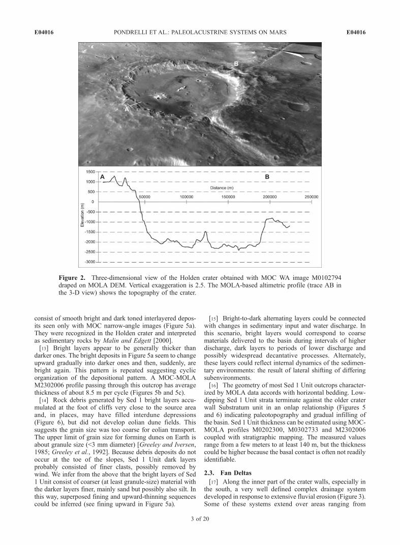
[10] In this section we describe the morphologic andtextural characteristics allowing discrimination of geologicunits and morphologic features. Geologic units, inferredfrom stratigraphic relationships, are described in strati-graphic order, older to younger, and their paleoenviron-mental significance is specified. The resultant geologicalmap is shown in Figure 3.
2.1. Substratum
[11] This unit predates the putative sedimentary materials,constituting the older terrains on which water-related surface-modifying processes acted, eroding and depositing sedi-ments. The Substratum crops out along the outer and innerrim, and on the central peak (Figure 3). It consists ofintermediate-toned massive, texturally smooth and uniformmaterials. The Substratum is probably a reworked mixture ofold impact breccia, lava flows, and pyroclastic material [Scottand Tanaka, 1986].
2.2. Proximal Layered Deposits (Sed 1 Unit)
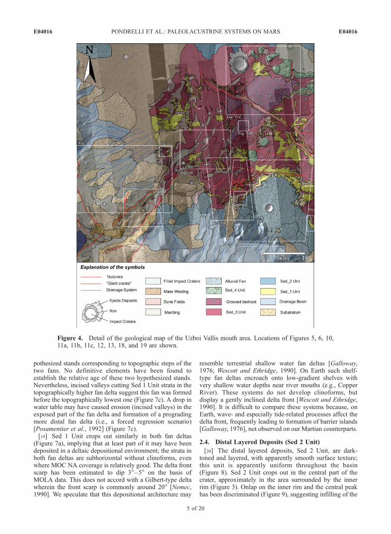
[12] Proximal layered deposits (Sed 1 Unit) crop out inthe southern and outermost part of the crater, as scatteredpatches in the terminal part of Uzboi Vallis, and just outsidethe terminal part of Uzboi Vallis (Figures 3 and 4). They
Figure 1. (a) Location of the Holden crater on MOLA-based topography. (b) Data coverage of the studyarea on an MOC wide-angle mosaic (images M0100476, M0102794, M0100864).
E04016 PONDRELLI ET AL.: PALEOLACUSTRINE SYSTEMS ON MARS
2 of 20
E04016
consist of smooth bright and dark toned interlayered depos-its seen only with MOC narrow-angle images (Figure 5a).They were recognized in the Holden crater and interpretedas sedimentary rocks by Malin and Edgett [2000].[13] Bright layers appear to be generally thicker than
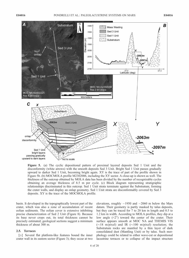
darker ones. The bright deposits in Figure 5a seem to changeupward gradually into darker ones and then, suddenly, arebright again. This pattern is repeated suggesting cyclicorganization of the depositional pattern. A MOC-MOLAM2302006 profile passing through this outcrop has averagethickness of about 8.5 m per cycle (Figures 5b and 5c).[14] Rock debris generated by Sed 1 bright layers accu-
mulated at the foot of cliffs very close to the source areaand, in places, may have filled interdune depressions(Figure 6), but did not develop eolian dune fields. Thissuggests the grain size was too coarse for eolian transport.The upper limit of grain size for forming dunes on Earth isabout granule size (<3 mm diameter) [Greeley and Iversen,1985; Greeley et al., 1992]. Because debris deposits do notoccur at the toe of the slopes, Sed 1 Unit dark layersprobably consisted of finer clasts, possibly removed bywind. We infer from the above that the bright layers of Sed1 Unit consist of coarser (at least granule-size) material withthe darker layers finer, mainly sand but possibly also silt. Inthis way, superposed fining and upward-thinning sequencescould be inferred (see fining upward in Figure 5a).
[15] Bright-to-dark alternating layers could be connectedwith changes in sedimentary input and water discharge. Inthis scenario, bright layers would correspond to coarsematerials delivered to the basin during intervals of higherdischarge, dark layers to periods of lower discharge andpossibly widespread decantative processes. Alternately,these layers could reflect internal dynamics of the sedimen-tary environments: the result of lateral shifting of differingsubenvironments.[16] The geometry of most Sed 1 Unit outcrops character-
ized by MOLA data accords with horizontal bedding. Low-dipping Sed 1 Unit strata terminate against the older craterwall Substratum unit in an onlap relationship (Figures 5and 6) indicating paleotopography and gradual infilling ofthe basin. Sed 1 Unit thickness can be estimated using MOC-MOLA profiles M0202300, M0302733 and M2302006coupled with stratigraphic mapping. The measured valuesrange from a few meters to at least 140 m, but the thicknesscould be higher because the basal contact is often not readilyidentifiable.
2.3. Fan Deltas
[17] Along the inner part of the crater walls, especially inthe south, a very well defined complex drainage systemdeveloped in response to extensive fluvial erosion (Figure 3).Some of these systems extend over areas ranging from
Figure 2. Three-dimensional view of the Holden crater obtained with MOC WA image M0102794draped on MOLA DEM. Vertical exaggeration is 2.5. The MOLA-based altimetric profile (trace AB inthe 3-D view) shows the topography of the crater.
E04016 PONDRELLI ET AL.: PALEOLACUSTRINE SYSTEMS ON MARS
3 of 20
E04016
around 20 to 325 km2. At the toe of these basins, alluvial fansand fan deltas can be discriminated (Figure 7), formed byreduced transport energy, related mainly to decreased topo-graphic gradient. A spectacular fan delta has been imaged inthe northeastern crater, next to the Holden crater (Figure 3)[Malin and Edgett, 2003; Moore et al., 2003]. Fan deltas arethe most compelling indicators of the presence of formerstanding bodies of water on Mars.[18] In order to discriminate possible fan deltas, fan-like
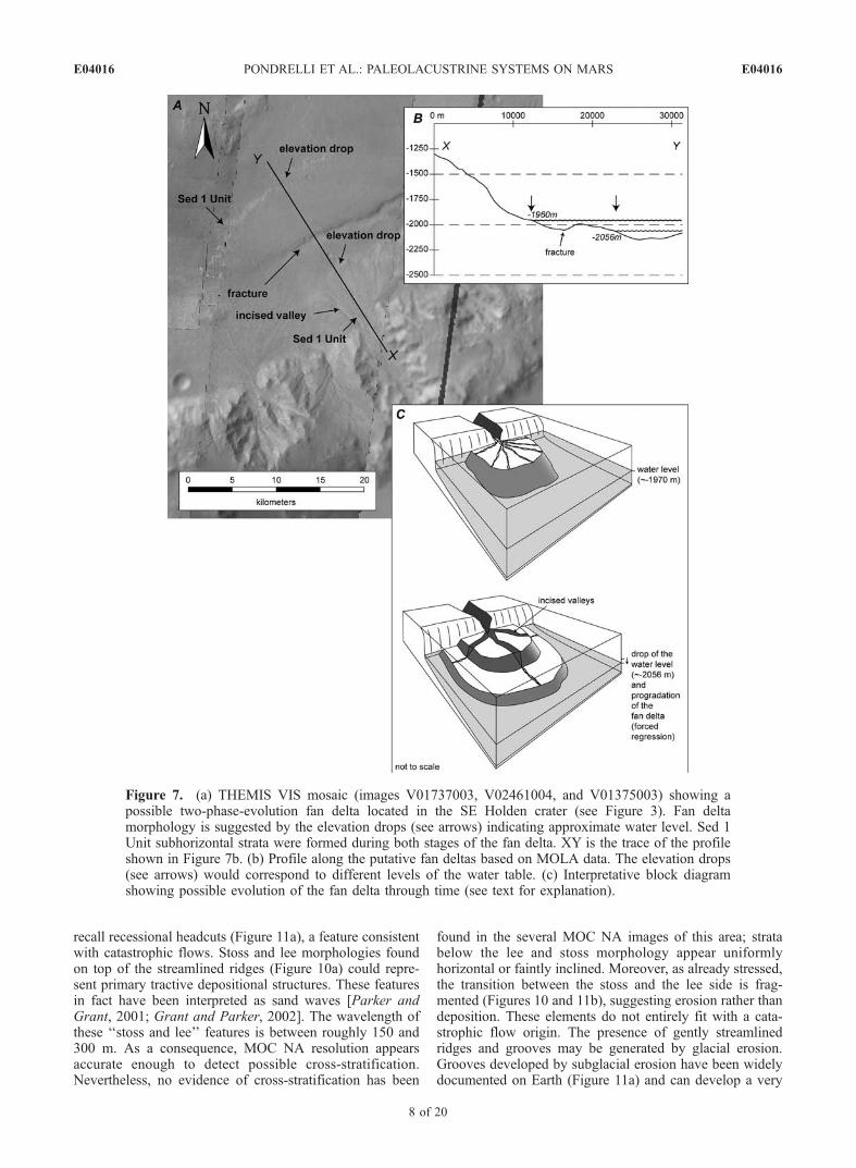
features have been studied using MOLA data. In the areaimaged in Figure 7, where two superposed fan-like struc-tures occur, the topographic profile from crater wall to craterfloor shows a surface dipping slightly toward the craterfloor, becoming more inclined toward the crater center. An
elevation drop occurs between the proximal low dippingand distal high dipping part of the fan (Figures 7a and 7b).Continuing toward the crater center, another elevation dropoccurs (Figures 7a and 7b). These features may haveoriginated when fluvial-dominated processes began tointeract with putative wave-dominated processes related tothe presence of a standing body of water. This implies thatthe fan-like features observed in the study area may haveacted as fan deltas and might also indicate the Holden craterto have been a lake during their emplacement. The gentlydipping parts may have been the subaerial portion of the fandelta, with the more inclined part equating with the sub-merged delta front. This pattern accords with a multiphaseevolution of the putative lacustrine system with two hy-
Figure 3. Geological map of the Holden crater. AA0 is the trace of the geological section in Figure 15.
E04016 PONDRELLI ET AL.: PALEOLACUSTRINE SYSTEMS ON MARS
4 of 20
E04016
pothesized stands corresponding to topographic steps of thetwo fans. No definitive elements have been found toestablish the relative age of these two hypothesized stands.Nevertheless, incised valleys cutting Sed 1 Unit strata in thetopographically higher fan delta suggest this fan was formedbefore the topographically lowest one (Figure 7c). A drop inwater table may have caused erosion (incised valleys) in theexposed part of the fan delta and formation of a progradingmore distal fan delta (i.e., a forced regression scenario)[Posamentier et al., 1992] (Figure 7c).[19] Sed 1 Unit crops out similarly in both fan deltas
(Figure 7a), implying that at least part of it may have beendeposited in a deltaic depositional environment; the strata inboth fan deltas are subhorizontal without clinoforms, evenwhere MOC NA coverage is relatively good. The delta frontscarp has been estimated to dip 3�–5� on the basis ofMOLA data. This does not accord with a Gilbert-type deltawherein the front scarp is commonly around 20� [Nemec,1990]. We speculate that this depositional architecture may
resemble terrestrial shallow water fan deltas [Galloway,1976; Wescott and Ethridge, 1990]. On Earth such shelf-type fan deltas encroach onto low-gradient shelves withvery shallow water depths near river mouths (e.g., CopperRiver). These systems do not develop clinoforms, butdisplay a gently inclined delta front [Wescott and Ethridge,1990]. It is difficult to compare these systems because, onEarth, wave- and especially tide-related processes affect thedelta front, frequently leading to formation of barrier islands[Galloway, 1976], not observed on our Martian counterparts.
2.4. Distal Layered Deposits (Sed 2 Unit)
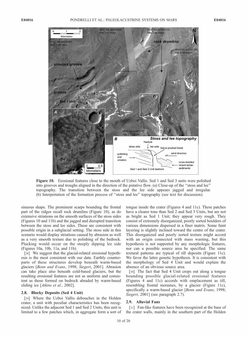
[20] The distal layered deposits, Sed 2 Unit, are dark-toned and layered, with apparently smooth surface texture;this unit is apparently uniform throughout the basin(Figure 8). Sed 2 Unit crops out in the central part of thecrater, approximately in the area surrounded by the innerrim (Figure 3). Onlap on the inner rim and the central peakhas been discriminated (Figure 9), suggesting infilling of the
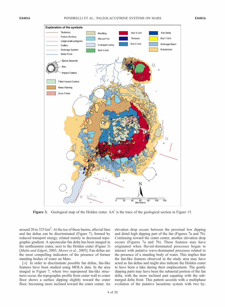
Figure 4. Detail of the geological map of the Uzboi Vallis mouth area. Locations of Figures 5, 6, 10,11a, 11b, 11c, 12, 13, 18, and 19 are shown.
E04016 PONDRELLI ET AL.: PALEOLACUSTRINE SYSTEMS ON MARS
5 of 20
E04016
basin. It developed in the topographically lowest part of thecrater, which was also a zone of accumulation of recenteolian sediments. The eolian cover is extensive inhibitingprecise characterization of Sed 2 Unit (Figure 8). Becauseits base never crops out, its total thickness cannot beprecisely estimated; geological sections suggest a minimumthickness of about 300 m.
2.5. Terraces
[21] Several flat platform-like features bound the innercrater wall in its eastern sector (Figure 3); they occur at two
elevations, roughly �1950 and �2060 m below the Marsdatum. Their geometry is partly masked by talus deposits,but they can be traced for 7 to 20 km in length and 0.5 to1.2 km in width. According to MOLA profiles, they dip at alow angle (<2�) toward the center of the crater. Theirsurface appears smooth at MOC NA and THEMIS VIS(�18 m/pixel) and IR (�100 m/pixel) resolution; theSubstratum rocks are mantled by a thin layer of darkconsolidated dust (Mantling Unit) or by talus. Such mor-phology could be related to either wave-cut or depositionallacustrine terraces or to collapse of the impact structure
Figure 5. (a) The cyclic depositional pattern of proximal layered deposits Sed 1 Unit and thedisconformity (white arrows) with the smooth deposits Sed 3 Unit. Bright Sed 1 Unit passes graduallyupward to darker Sed 1 Unit, becoming bright again. XY is the trace of part of the profile shown inFigure 5b. (b) MOCMOLA profile M2302006, including the XY sector. A close-up is shown as well. Thethickness of the outcrop obtained by MOLA data has been divided by the number of recognizable cyclesobtaining an average thickness of 8.5 m per cycle. (c) Block diagram representing stratigraphicrelationships discriminated in this outcrop. Sed 1 Unit strata terminate against the Substratum, formingthe crater walls, and display an onlap geometry. Sed 1 Unit strata are disconformably covered by Sed 3deposits. XY is the trace of the MOCMOLA profile.
E04016 PONDRELLI ET AL.: PALEOLACUSTRINE SYSTEMS ON MARS
6 of 20
E04016
[Melosh, 1989] (see discussion by Ori et al. [2000a]). In thelatter case, the platforms would be fault-bounded andrimward dipping, whereas on the MOLA profile theyappear clearly to dip toward the crater floor. No evidenceconsistent with the possible presence of faults has beenfound.[22] We conclude that terrace formation was not due to
collapse of the impact structure rim, but is another line ofevidence for presence of a standing body of water inside thebasin. In essence, the two orders of terraces match the twowater levels inferred from topography of the fan deltas(Figure 7).[23] Terraces could be produced by erosional or deposi-
tional processes related to wind/wave action [Bradley, 1958:Bradley and Griggs, 1976]. No layered deposits have beendiscriminated on top of the uppermost terraces, thus imply-ing that depositional processes were negligible at thoseelevations. Higher order terraces (�1950 m) shouldthus reflect mainly erosional processes, as with wave-cutterraces. On the contrary, the lower order of terraces(�2060 m) is characterized by the presence of Sed 1 Unit
layered deposits on their top. In this case, either depositionalprocesses played an important role in terrace formation orSed 1 Unit strata were deposited during a postulated phaseof higher water stand (coeval with the higher order ofterraces) and then eroded, forming what we interpret aswave-cut terraces.
2.6. Smooth Deposits (Sed 3 Unit)
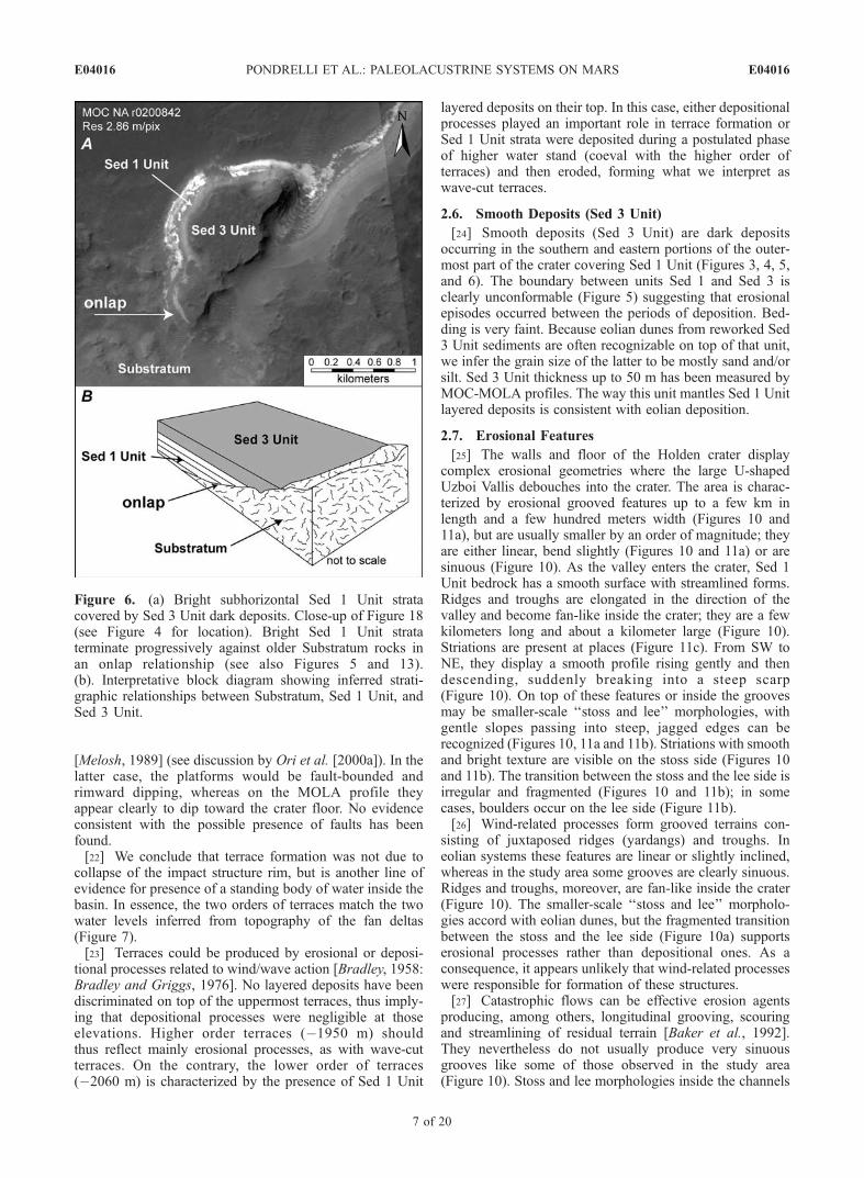
[24] Smooth deposits (Sed 3 Unit) are dark depositsoccurring in the southern and eastern portions of the outer-most part of the crater covering Sed 1 Unit (Figures 3, 4, 5,and 6). The boundary between units Sed 1 and Sed 3 isclearly unconformable (Figure 5) suggesting that erosionalepisodes occurred between the periods of deposition. Bed-ding is very faint. Because eolian dunes from reworked Sed3 Unit sediments are often recognizable on top of that unit,we infer the grain size of the latter to be mostly sand and/orsilt. Sed 3 Unit thickness up to 50 m has been measured byMOC-MOLA profiles. The way this unit mantles Sed 1 Unitlayered deposits is consistent with eolian deposition.
2.7. Erosional Features
[25] The walls and floor of the Holden crater displaycomplex erosional geometries where the large U-shapedUzboi Vallis debouches into the crater. The area is charac-terized by erosional grooved features up to a few km inlength and a few hundred meters width (Figures 10 and11a), but are usually smaller by an order of magnitude; theyare either linear, bend slightly (Figures 10 and 11a) or aresinuous (Figure 10). As the valley enters the crater, Sed 1Unit bedrock has a smooth surface with streamlined forms.Ridges and troughs are elongated in the direction of thevalley and become fan-like inside the crater; they are a fewkilometers long and about a kilometer large (Figure 10).Striations are present at places (Figure 11c). From SW toNE, they display a smooth profile rising gently and thendescending, suddenly breaking into a steep scarp(Figure 10). On top of these features or inside the groovesmay be smaller-scale ‘‘stoss and lee’’ morphologies, withgentle slopes passing into steep, jagged edges can berecognized (Figures 10, 11a and 11b). Striations with smoothand bright texture are visible on the stoss side (Figures 10and 11b). The transition between the stoss and the lee side isirregular and fragmented (Figures 10 and 11b); in somecases, boulders occur on the lee side (Figure 11b).[26] Wind-related processes form grooved terrains con-
sisting of juxtaposed ridges (yardangs) and troughs. Ineolian systems these features are linear or slightly inclined,whereas in the study area some grooves are clearly sinuous.Ridges and troughs, moreover, are fan-like inside the crater(Figure 10). The smaller-scale ‘‘stoss and lee’’ morpholo-gies accord with eolian dunes, but the fragmented transitionbetween the stoss and the lee side (Figure 10a) supportserosional processes rather than depositional ones. As aconsequence, it appears unlikely that wind-related processeswere responsible for formation of these structures.[27] Catastrophic flows can be effective erosion agents
producing, among others, longitudinal grooving, scouringand streamlining of residual terrain [Baker et al., 1992].They nevertheless do not usually produce very sinuousgrooves like some of those observed in the study area(Figure 10). Stoss and lee morphologies inside the channels
Figure 6. (a) Bright subhorizontal Sed 1 Unit stratacovered by Sed 3 Unit dark deposits. Close-up of Figure 18(see Figure 4 for location). Bright Sed 1 Unit strataterminate progressively against older Substratum rocks inan onlap relationship (see also Figures 5 and 13).(b). Interpretative block diagram showing inferred strati-graphic relationships between Substratum, Sed 1 Unit, andSed 3 Unit.
E04016 PONDRELLI ET AL.: PALEOLACUSTRINE SYSTEMS ON MARS
7 of 20
E04016
recall recessional headcuts (Figure 11a), a feature consistentwith catastrophic flows. Stoss and lee morphologies foundon top of the streamlined ridges (Figure 10a) could repre-sent primary tractive depositional structures. These featuresin fact have been interpreted as sand waves [Parker andGrant, 2001; Grant and Parker, 2002]. The wavelength ofthese ‘‘stoss and lee’’ features is between roughly 150 and300 m. As a consequence, MOC NA resolution appearsaccurate enough to detect possible cross-stratification.Nevertheless, no evidence of cross-stratification has been
found in the several MOC NA images of this area; stratabelow the lee and stoss morphology appear uniformlyhorizontal or faintly inclined. Moreover, as already stressed,the transition between the stoss and the lee side is frag-mented (Figures 10 and 11b), suggesting erosion rather thandeposition. These elements do not entirely fit with a cata-strophic flow origin. The presence of gently streamlinedridges and grooves may be generated by glacial erosion.Grooves developed by subglacial erosion have been widelydocumented on Earth (Figure 11a) and can develop a very
Figure 7. (a) THEMIS VIS mosaic (images V01737003, V02461004, and V01375003) showing apossible two-phase-evolution fan delta located in the SE Holden crater (see Figure 3). Fan deltamorphology is suggested by the elevation drops (see arrows) indicating approximate water level. Sed 1Unit subhorizontal strata were formed during both stages of the fan delta. XY is the trace of the profileshown in Figure 7b. (b) Profile along the putative fan deltas based on MOLA data. The elevation drops(see arrows) would correspond to different levels of the water table. (c) Interpretative block diagramshowing possible evolution of the fan delta through time (see text for explanation).
E04016 PONDRELLI ET AL.: PALEOLACUSTRINE SYSTEMS ON MARS
8 of 20
E04016
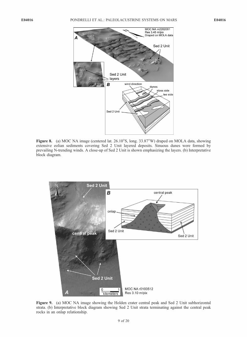
Figure 8. (a) MOC NA image (centered lat. 26.10�S, long. 33.87�W) draped on MOLA data, showingextensive eolian sediments covering Sed 2 Unit layered deposits. Sinuous dunes were formed byprevailing N-trending winds. A close-up of Sed 2 Unit is shown emphasizing the layers. (b) Interpretativeblock diagram.
Figure 9. (a) MOC NA image showing the Holden crater central peak and Sed 2 Unit subhorizontalstrata. (b) Interpretative block diagram showing Sed 2 Unit strata terminating against the central peakrocks in an onlap relationship.
E04016 PONDRELLI ET AL.: PALEOLACUSTRINE SYSTEMS ON MARS
9 of 20
E04016
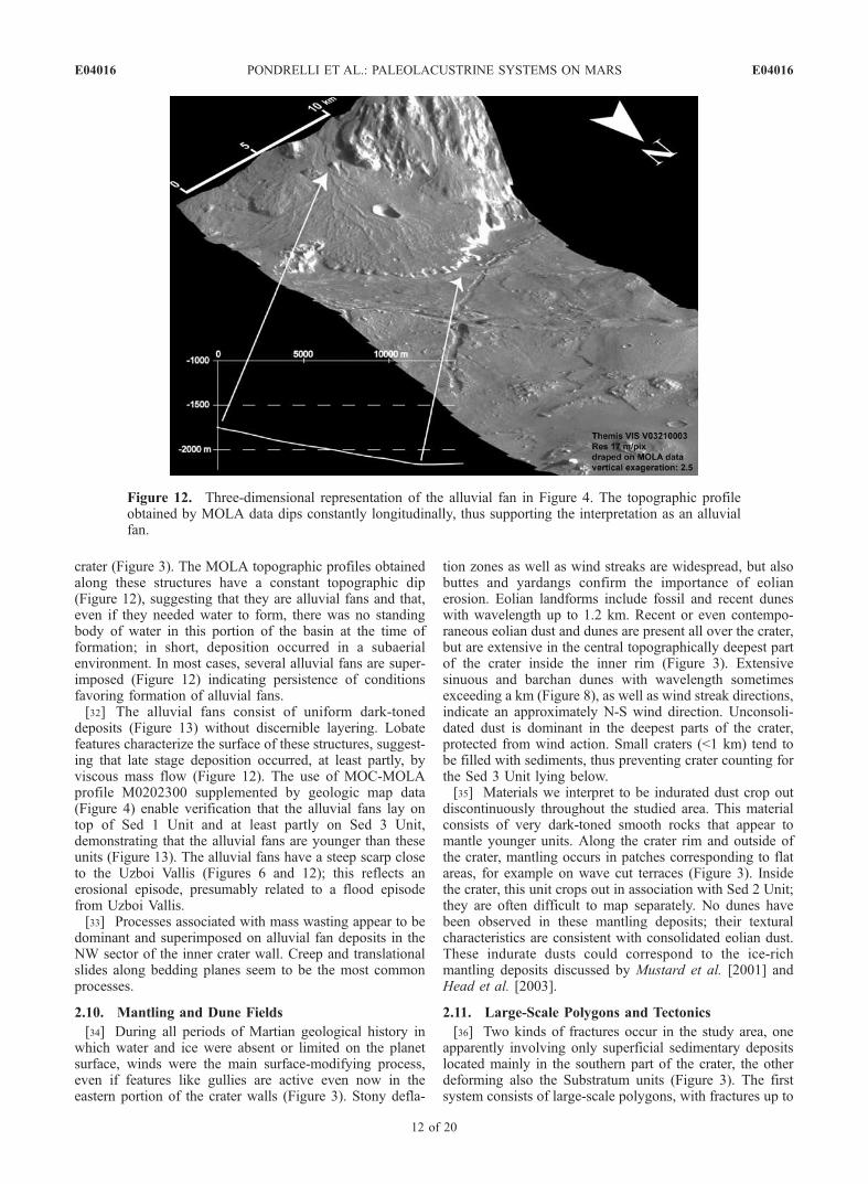
sinuous shape. The prominent scarps bounding the frontalpart of the ridges recall rock drumlins (Figure 10), as doextensive striations on the smooth surfaces of the stoss sides(Figures 10 and 11b) and the jagged and disrupted transitionbetween the stoss and lee sides. These are consistent withpossible origin in a subglacial setting. The stoss side in thisscenario would display striations caused by abrasion as wellas a very smooth texture due to polishing of the bedrock.Plucking would occur on the steeply dipping lee side(Figures 10a, 10b, 11a, and 11b).[28] We suggest that the glacial-related erosional hypoth-
esis is the most consistent with our data. Earthly counter-parts of these structures develop beneath warm-basedglaciers [Benn and Evans, 1998; Siegert, 2001]. Abrasioncan take place also beneath cold-based glaciers, but theresulting erosional features are not as uniform and consis-tent as those formed on bedrock abraded by warm-basedsliding ice [Atkins et al., 2002].
2.8. Blocky Deposits (Sed 4 Unit)
[29] Where the Uzboi Vallis debouches in the Holdencrater, a unit with peculiar characteristics has been recog-nized. Unlike the adjacent Sed 1 and Sed 2 Units, this unit islimited to a few patches which, in aggregate form a sort of
tongue inside the crater (Figures 4 and 11c). These patcheshave a clearer tone than Sed 2 and Sed 3 Units, but are notas bright as Sed 1 Unit; they appear very rough. Theyconsist of extremely disorganized, poorly sorted boulders ofvarious dimensions dispersed in a finer matrix. Some faintlayering is slightly inclined toward the centre of the crater.This disorganized and poorly sorted texture might accordwith an origin connected with mass wasting, but thishypothesis is not supported by any morphologic features,nor can a possible source area be specified. The sametextural patterns are typical of till deposits (Figure 11c).We favor the latter genetic hypothesis. It is consistent withthe morphology of Sed 4 Unit and would explain theabsence of an obvious source area.[30] The fact that Sed 4 Unit crops out along a tongue
bounding possible glacial-related erosional features(Figures 4 and 11c) accords with emplacement as till,resembling frontal moraines, by a glacier (Figure 11c),specifically a warm-based glacier [Benn and Evans, 1998;Siegert, 2001] (see paragraph 2.7).
2.9. Alluvial Fans
[31] Fan-like features have been recognized at the base ofthe crater walls, mainly in the southern part of the Holden
Figure 10. Erosional features close to the mouth of Uzboi Vallis. Sed 1 and Sed 3 units were polishedinto grooves and troughs aligned in the direction of the putative flow. (a) Close-up of the ‘‘stoss and lee’’topography. The transition between the stoss and the lee side appears jagged and irregular.(b) Interpretation of the formation process of ‘‘stoss and lee’’ topography (see text for discussion).
E04016 PONDRELLI ET AL.: PALEOLACUSTRINE SYSTEMS ON MARS
10 of 20
E04016
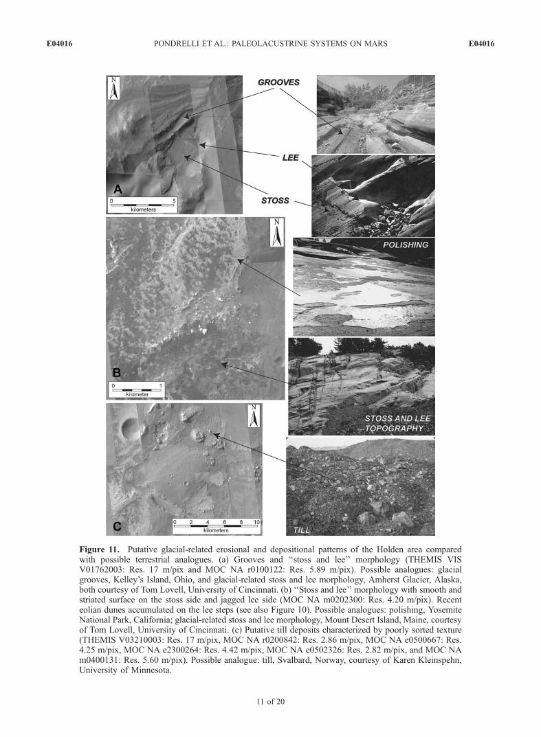
Figure 11. Putative glacial-related erosional and depositional patterns of the Holden area comparedwith possible terrestrial analogues. (a) Grooves and ‘‘stoss and lee’’ morphology (THEMIS VISV01762003: Res. 17 m/pix and MOC NA r0100122: Res. 5.89 m/pix). Possible analogues: glacialgrooves, Kelley’s Island, Ohio, and glacial-related stoss and lee morphology, Amherst Glacier, Alaska,both courtesy of Tom Lovell, University of Cincinnati. (b) ‘‘Stoss and lee’’ morphology with smooth andstriated surface on the stoss side and jagged lee side (MOC NA m0202300: Res. 4.20 m/pix). Recenteolian dunes accumulated on the lee steps (see also Figure 10). Possible analogues: polishing, YosemiteNational Park, California; glacial-related stoss and lee morphology, Mount Desert Island, Maine, courtesyof Tom Lovell, University of Cincinnati. (c) Putative till deposits characterized by poorly sorted texture(THEMIS V03210003: Res. 17 m/pix, MOC NA r0200842: Res. 2.86 m/pix, MOC NA e0500667: Res.4.25 m/pix, MOC NA e2300264: Res. 4.42 m/pix, MOC NA e0502326: Res. 2.82 m/pix, and MOC NAm0400131: Res. 5.60 m/pix). Possible analogue: till, Svalbard, Norway, courtesy of Karen Kleinspehn,University of Minnesota.
E04016 PONDRELLI ET AL.: PALEOLACUSTRINE SYSTEMS ON MARS
11 of 20
E04016
crater (Figure 3). The MOLA topographic profiles obtainedalong these structures have a constant topographic dip(Figure 12), suggesting that they are alluvial fans and that,even if they needed water to form, there was no standingbody of water in this portion of the basin at the time offormation; in short, deposition occurred in a subaerialenvironment. In most cases, several alluvial fans are super-imposed (Figure 12) indicating persistence of conditionsfavoring formation of alluvial fans.[32] The alluvial fans consist of uniform dark-toned
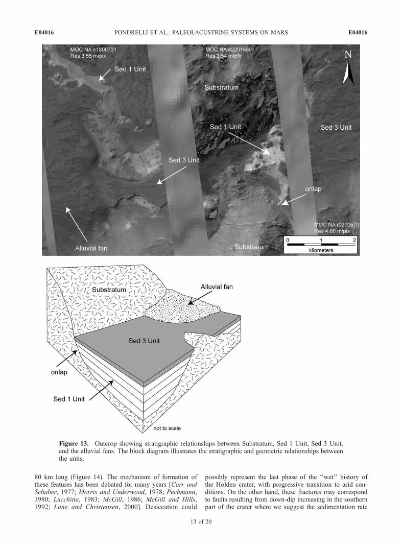
deposits (Figure 13) without discernible layering. Lobatefeatures characterize the surface of these structures, suggest-ing that late stage deposition occurred, at least partly, byviscous mass flow (Figure 12). The use of MOC-MOLAprofile M0202300 supplemented by geologic map data(Figure 4) enable verification that the alluvial fans lay ontop of Sed 1 Unit and at least partly on Sed 3 Unit,demonstrating that the alluvial fans are younger than theseunits (Figure 13). The alluvial fans have a steep scarp closeto the Uzboi Vallis (Figures 6 and 12); this reflects anerosional episode, presumably related to a flood episodefrom Uzboi Vallis.[33] Processes associated with mass wasting appear to be
dominant and superimposed on alluvial fan deposits in theNW sector of the inner crater wall. Creep and translationalslides along bedding planes seem to be the most commonprocesses.
2.10. Mantling and Dune Fields
[34] During all periods of Martian geological history inwhich water and ice were absent or limited on the planetsurface, winds were the main surface-modifying process,even if features like gullies are active even now in theeastern portion of the crater walls (Figure 3). Stony defla-
tion zones as well as wind streaks are widespread, but alsobuttes and yardangs confirm the importance of eolianerosion. Eolian landforms include fossil and recent duneswith wavelength up to 1.2 km. Recent or even contempo-raneous eolian dust and dunes are present all over the crater,but are extensive in the central topographically deepest partof the crater inside the inner rim (Figure 3). Extensivesinuous and barchan dunes with wavelength sometimesexceeding a km (Figure 8), as well as wind streak directions,indicate an approximately N-S wind direction. Unconsoli-dated dust is dominant in the deepest parts of the crater,protected from wind action. Small craters (<1 km) tend tobe filled with sediments, thus preventing crater counting forthe Sed 3 Unit lying below.[35] Materials we interpret to be indurated dust crop out
discontinuously throughout the studied area. This materialconsists of very dark-toned smooth rocks that appear tomantle younger units. Along the crater rim and outside ofthe crater, mantling occurs in patches corresponding to flatareas, for example on wave cut terraces (Figure 3). Insidethe crater, this unit crops out in association with Sed 2 Unit;they are often difficult to map separately. No dunes havebeen observed in these mantling deposits; their texturalcharacteristics are consistent with consolidated eolian dust.These indurate dusts could correspond to the ice-richmantling deposits discussed by Mustard et al. [2001] andHead et al. [2003].
2.11. Large-Scale Polygons and Tectonics
[36] Two kinds of fractures occur in the study area, oneapparently involving only superficial sedimentary depositslocated mainly in the southern part of the crater, the otherdeforming also the Substratum units (Figure 3). The firstsystem consists of large-scale polygons, with fractures up to
Figure 12. Three-dimensional representation of the alluvial fan in Figure 4. The topographic profileobtained by MOLA data dips constantly longitudinally, thus supporting the interpretation as an alluvialfan.
E04016 PONDRELLI ET AL.: PALEOLACUSTRINE SYSTEMS ON MARS
12 of 20
E04016
80 km long (Figure 14). The mechanism of formation ofthese features has been debated for many years [Carr andSchaber, 1977; Morris and Underwood, 1978; Pechmann,1980; Lucchitta, 1983; McGill, 1986; McGill and Hills,1992; Lane and Christensen, 2000]. Desiccation could
possibly represent the last phase of the ‘‘wet’’ history ofthe Holden crater, with progressive transition to arid con-ditions. On the other hand, these fractures may correspondto faults resulting from down-dip increasing in the southernpart of the crater where we suggest the sedimentation rate
Figure 13. Outcrop showing stratigraphic relationships between Substratum, Sed 1 Unit, Sed 3 Unit,and the alluvial fans. The block diagram illustrates the stratigraphic and geometric relationships betweenthe units.
E04016 PONDRELLI ET AL.: PALEOLACUSTRINE SYSTEMS ON MARS
13 of 20
E04016
was greatest for the crater, due to sedimentary input fromthe Uzboi Vallis.[37] Tectonic structures discriminated in the studied area
are partly related to the cratering process; they are distrib-uted radially and concentrically throughout the crater. Twosystems are observed, oriented NNE-SSW and WNW-ESE,respectively (Figure 3). These systems are subparallel andpossibly related to structures controlling the first stage ofValles Marineris formation [Tanaka et al., 1991].
2.12. Drainage Basins
[38] The overall drainage pattern is centripetal with riversand streams flowing down the crater walls toward the craterfloor. Drainage basins show two different kinds of pattern:
(1) dendritic drainage systems, characterizing most of thedrainage basins (Figure 3), and (2) treelike drainage pat-terns, usually characterizing areas of uniform, erodiblerocks, possibly Substratum rocks subjected to impact shock.In a few cases, parallel drainage patterns have reflectedmainly impact-related radial fractures.
2.13. Stratigraphic Relationships
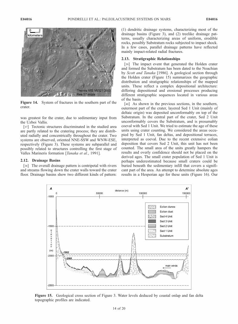
[39] The impact event that generated the Holden craterand formed the Substratum has been dated to the Noachianby Scott and Tanaka [1986]. A geological section throughthe Holden crater (Figure 15) summarizes the geographicdistribution and stratigraphic relationships of the mappedunits. These reflect a complex depositional architecture:differing depositional and erosional processes producingdifferent stratigraphic sequences located in various areasof the basin.[40] As shown in the previous sections, in the southern,
outermost part of the crater, layered Sed 1 Unit (mainly ofdeltaic origin) was deposited unconformably on top of theSubstratum. In the central part of the crater, Sed 2 Unitunconformably covers the Substratum, and is presumablycoeval with Sed 1 Unit. We tried to estimate the age of theseunits using crater counting. We considered the areas occu-pied by Sed 1 Unit, fan deltas, and depositional terraces,interpreted as coeval. Due to the recent extensive eoliandeposition that covers Sed 2 Unit, this unit has not beencounted. The small area of the units greatly hampers theresults and overly confidence should not be placed on thederived ages. The small crater population of Sed 1 Unit isperhaps underestimated because small craters could beburied beneath the sedimentary infill that covers a signifi-cant part of the area. An attempt to determine absolute agesresults in a Hesperian age for these units (Figure 16). Our
Figure 14. System of fractures in the southern part of thecrater.
Figure 15. Geological cross section of Figure 3. Water levels deduced by coastal onlap and fan deltatopographic profiles are indicated.
E04016 PONDRELLI ET AL.: PALEOLACUSTRINE SYSTEMS ON MARS
14 of 20
E04016
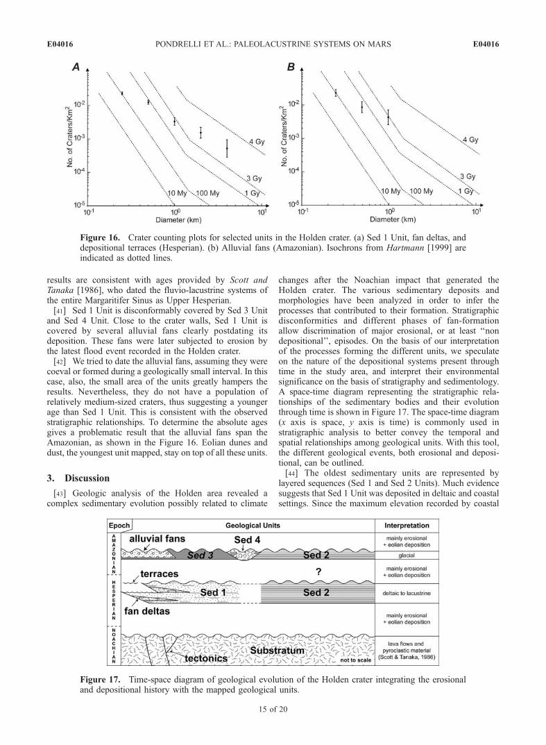
results are consistent with ages provided by Scott andTanaka [1986], who dated the fluvio-lacustrine systems ofthe entire Margaritifer Sinus as Upper Hesperian.[41] Sed 1 Unit is disconformably covered by Sed 3 Unit
and Sed 4 Unit. Close to the crater walls, Sed 1 Unit iscovered by several alluvial fans clearly postdating itsdeposition. These fans were later subjected to erosion bythe latest flood event recorded in the Holden crater.[42] We tried to date the alluvial fans, assuming they were
coeval or formed during a geologically small interval. In thiscase, also, the small area of the units greatly hampers theresults. Nevertheless, they do not have a population ofrelatively medium-sized craters, thus suggesting a youngerage than Sed 1 Unit. This is consistent with the observedstratigraphic relationships. To determine the absolute agesgives a problematic result that the alluvial fans span theAmazonian, as shown in the Figure 16. Eolian dunes anddust, the youngest unit mapped, stay on top of all these units.
3. Discussion
[43] Geologic analysis of the Holden area revealed acomplex sedimentary evolution possibly related to climate
changes after the Noachian impact that generated theHolden crater. The various sedimentary deposits andmorphologies have been analyzed in order to infer theprocesses that contributed to their formation. Stratigraphicdisconformities and different phases of fan-formationallow discrimination of major erosional, or at least ‘‘nondepositional’’, episodes. On the basis of our interpretationof the processes forming the different units, we speculateon the nature of the depositional systems present throughtime in the study area, and interpret their environmentalsignificance on the basis of stratigraphy and sedimentology.A space-time diagram representing the stratigraphic rela-tionships of the sedimentary bodies and their evolutionthrough time is shown in Figure 17. The space-time diagram(x axis is space, y axis is time) is commonly used instratigraphic analysis to better convey the temporal andspatial relationships among geological units. With this tool,the different geological events, both erosional and deposi-tional, can be outlined.[44] The oldest sedimentary units are represented by
layered sequences (Sed 1 and Sed 2 Units). Much evidencesuggests that Sed 1 Unit was deposited in deltaic and coastalsettings. Since the maximum elevation recorded by coastal
Figure 16. Crater counting plots for selected units in the Holden crater. (a) Sed 1 Unit, fan deltas, anddepositional terraces (Hesperian). (b) Alluvial fans (Amazonian). Isochrons from Hartmann [1999] areindicated as dotted lines.
Figure 17. Time-space diagram of geological evolution of the Holden crater integrating the erosionaland depositional history with the mapped geological units.
E04016 PONDRELLI ET AL.: PALEOLACUSTRINE SYSTEMS ON MARS
15 of 20
E04016
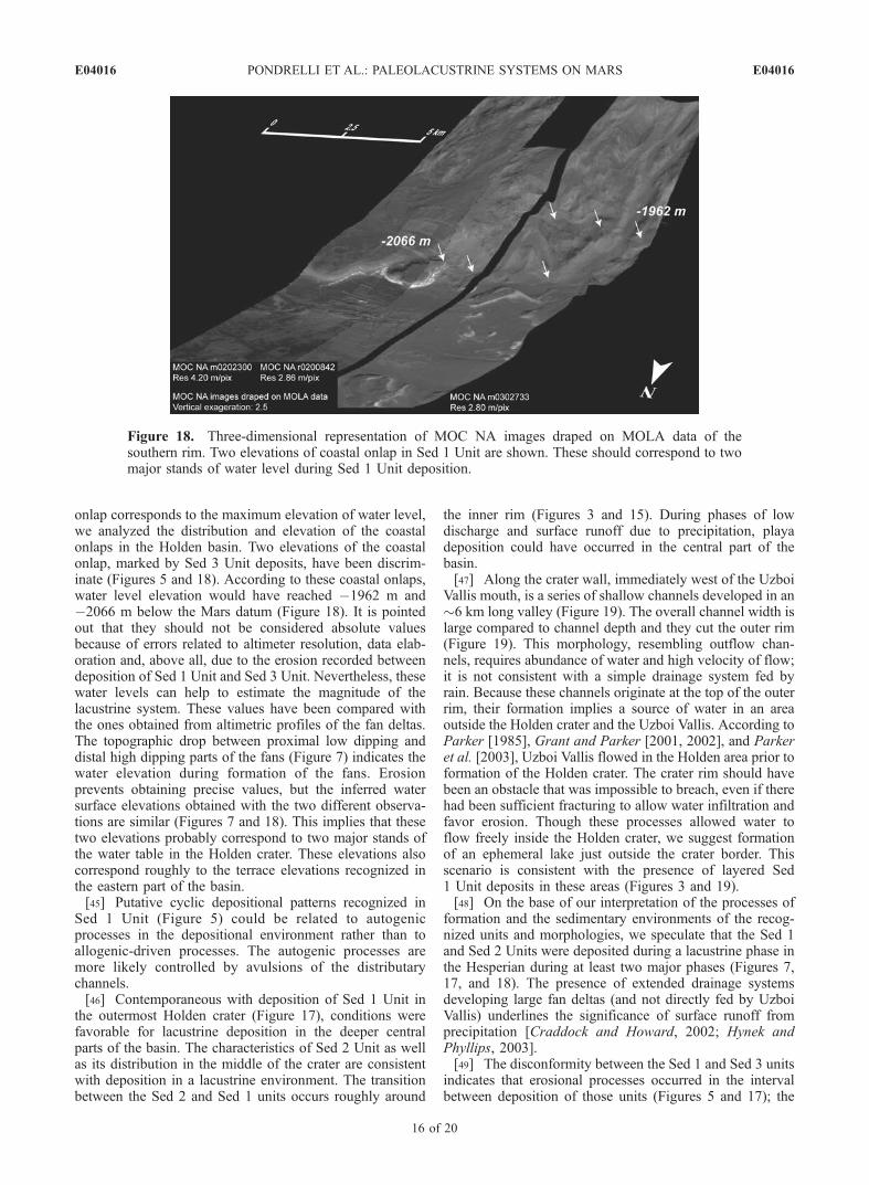
onlap corresponds to the maximum elevation of water level,we analyzed the distribution and elevation of the coastalonlaps in the Holden basin. Two elevations of the coastalonlap, marked by Sed 3 Unit deposits, have been discrim-inate (Figures 5 and 18). According to these coastal onlaps,water level elevation would have reached �1962 m and�2066 m below the Mars datum (Figure 18). It is pointedout that they should not be considered absolute valuesbecause of errors related to altimeter resolution, data elab-oration and, above all, due to the erosion recorded betweendeposition of Sed 1 Unit and Sed 3 Unit. Nevertheless, thesewater levels can help to estimate the magnitude of thelacustrine system. These values have been compared withthe ones obtained from altimetric profiles of the fan deltas.The topographic drop between proximal low dipping anddistal high dipping parts of the fans (Figure 7) indicates thewater elevation during formation of the fans. Erosionprevents obtaining precise values, but the inferred watersurface elevations obtained with the two different observa-tions are similar (Figures 7 and 18). This implies that thesetwo elevations probably correspond to two major stands ofthe water table in the Holden crater. These elevations alsocorrespond roughly to the terrace elevations recognized inthe eastern part of the basin.[45] Putative cyclic depositional patterns recognized in
Sed 1 Unit (Figure 5) could be related to autogenicprocesses in the depositional environment rather than toallogenic-driven processes. The autogenic processes aremore likely controlled by avulsions of the distributarychannels.[46] Contemporaneous with deposition of Sed 1 Unit in
the outermost Holden crater (Figure 17), conditions werefavorable for lacustrine deposition in the deeper centralparts of the basin. The characteristics of Sed 2 Unit as wellas its distribution in the middle of the crater are consistentwith deposition in a lacustrine environment. The transitionbetween the Sed 2 and Sed 1 units occurs roughly around
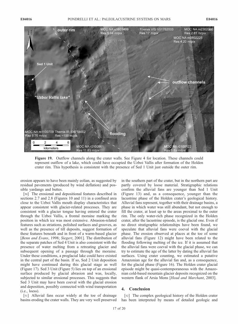
the inner rim (Figures 3 and 15). During phases of lowdischarge and surface runoff due to precipitation, playadeposition could have occurred in the central part of thebasin.[47] Along the crater wall, immediately west of the Uzboi
Vallis mouth, is a series of shallow channels developed in an�6 km long valley (Figure 19). The overall channel width islarge compared to channel depth and they cut the outer rim(Figure 19). This morphology, resembling outflow chan-nels, requires abundance of water and high velocity of flow;it is not consistent with a simple drainage system fed byrain. Because these channels originate at the top of the outerrim, their formation implies a source of water in an areaoutside the Holden crater and the Uzboi Vallis. According toParker [1985], Grant and Parker [2001, 2002], and Parkeret al. [2003], Uzboi Vallis flowed in the Holden area prior toformation of the Holden crater. The crater rim should havebeen an obstacle that was impossible to breach, even if therehad been sufficient fracturing to allow water infiltration andfavor erosion. Though these processes allowed water toflow freely inside the Holden crater, we suggest formationof an ephemeral lake just outside the crater border. Thisscenario is consistent with the presence of layered Sed1 Unit deposits in these areas (Figures 3 and 19).[48] On the base of our interpretation of the processes of
formation and the sedimentary environments of the recog-nized units and morphologies, we speculate that the Sed 1and Sed 2 Units were deposited during a lacustrine phase inthe Hesperian during at least two major phases (Figures 7,17, and 18). The presence of extended drainage systemsdeveloping large fan deltas (and not directly fed by UzboiVallis) underlines the significance of surface runoff fromprecipitation [Craddock and Howard, 2002; Hynek andPhyllips, 2003].[49] The disconformity between the Sed 1 and Sed 3 units
indicates that erosional processes occurred in the intervalbetween deposition of those units (Figures 5 and 17); the
Figure 18. Three-dimensional representation of MOC NA images draped on MOLA data of thesouthern rim. Two elevations of coastal onlap in Sed 1 Unit are shown. These should correspond to twomajor stands of water level during Sed 1 Unit deposition.
E04016 PONDRELLI ET AL.: PALEOLACUSTRINE SYSTEMS ON MARS
16 of 20
E04016
erosion appears to have been mainly eolian, as suggested byresidual pavements (produced by wind deflation) and pos-sible yardangs and buttes.[50] The erosional and depositional features described in
sections 2.7 and 2.8 (Figures 10 and 11) in a confined areaclose to the Uzboi Vallis mouth display characteristics thatappear consistent with glacier-related processes. They areconsistent with a glacier tongue having entered the craterthrough the Uzboi Vallis, a frontal moraine marking theposition in which ice was most extensive. Abrasion-relatedfeatures such as striations, polished surfaces and grooves, aswell as the presence of till deposits, suggest formation ofthese features beneath and in front of a warm-based glacier[Benn and Evans, 1998; Siegert, 2001]. The distribution ofthe separate patches of Sed 4 Unit is also consistent with thepresence of water melting from a retreating glacier andsubsequent opening of a passage through the moraine.Under these conditions, a proglacial lake could have existedin the central part of the basin. If so, Sed 2 Unit depositionmight have continued during this glacial stage as well(Figure 17). Sed 3 Unit (Figure 5) lies on top of an erosionalsurface produced by glacial abrasion and was, locally,subjected to similar erosional processes. This suggests thatSed 3 Unit may have been coeval with the glacial erosionand deposition, possibly connected with wind transportation(i.e., loess).[51] Alluvial fans occur widely at the toe of drainage
basins eroding the crater walls. They are very well preserved
in the southern part of the crater, but in the northern part arepartly covered by loose material. Stratigraphic relationsconfirm the alluvial fans are younger than Sed 1 Unit(Figure 13) and, as a consequence, younger than thelacustrine phase of the Holden crater’s geological history.Alluvial fans represent, together with their drainage basins, aphase in which water was still abundant, but not enough tofill the crater, at least up to the areas proximal to the outerrim. The only water-rich phase recognized in the Holdencrater, after the lacustrine episode, is the glacial one. Even ifno direct stratigraphic relationships have been found, wespeculate that alluvial fans were coeval with the glacialphase. The erosion observed at places at the toe of somealluvial fans (Figure 12) might have been related to theflooding following melting of the ice. If it is assumed thatthe alluvial fans were coeval with the glacial phase, we cantry to estimate the age of the latter by dating the alluvial fansurfaces. Using crater counting, we estimated a putativeAmazonian age for the alluvial fan and, as a consequence,for the glacial phase (Figure 16). The Holden crater glacialepisode might be quasi-contemporaneous with the Amazo-nian cold-based mountain glacier deposits recognized on thewestern flank of Arsia Mons [Head and Marchant, 2003].
4. Conclusion
[52] The complex geological history of the Holden craterhas been interpreted by means of detailed geologic and
Figure 19. Outflow channels along the crater walls. See Figure 4 for location. These channels couldrepresent outflow of a lake, which could have occupied the Uzboi Vallis after formation of the Holdencrater rim. This hypothesis is consistent with the presence of Sed 1 Unit just outside the outer rim.
E04016 PONDRELLI ET AL.: PALEOLACUSTRINE SYSTEMS ON MARS
17 of 20
E04016
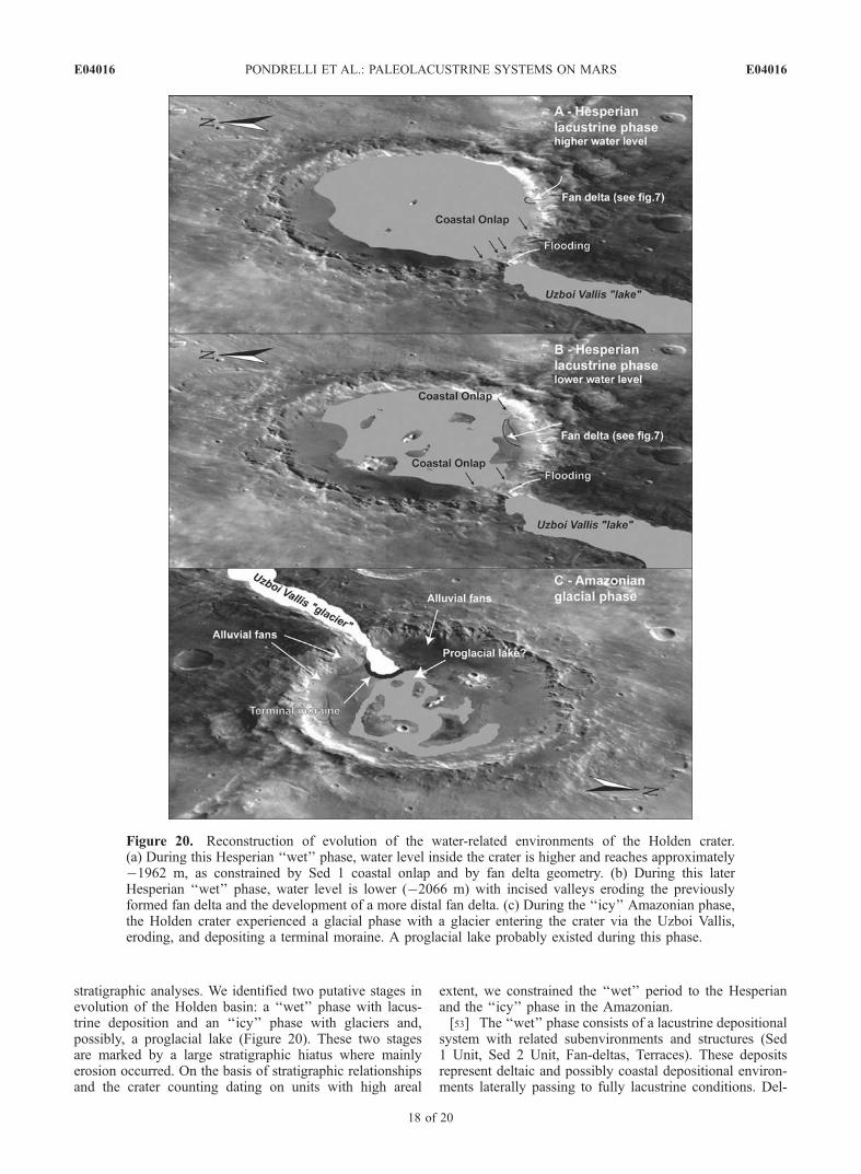
stratigraphic analyses. We identified two putative stages inevolution of the Holden basin: a ‘‘wet’’ phase with lacus-trine deposition and an ‘‘icy’’ phase with glaciers and,possibly, a proglacial lake (Figure 20). These two stagesare marked by a large stratigraphic hiatus where mainlyerosion occurred. On the basis of stratigraphic relationshipsand the crater counting dating on units with high areal
extent, we constrained the ‘‘wet’’ period to the Hesperianand the ‘‘icy’’ phase in the Amazonian.[53] The ‘‘wet’’ phase consists of a lacustrine depositional
system with related subenvironments and structures (Sed1 Unit, Sed 2 Unit, Fan-deltas, Terraces). These depositsrepresent deltaic and possibly coastal depositional environ-ments laterally passing to fully lacustrine conditions. Del-
Figure 20. Reconstruction of evolution of the water-related environments of the Holden crater.(a) During this Hesperian ‘‘wet’’ phase, water level inside the crater is higher and reaches approximately�1962 m, as constrained by Sed 1 coastal onlap and by fan delta geometry. (b) During this laterHesperian ‘‘wet’’ phase, water level is lower (�2066 m) with incised valleys eroding the previouslyformed fan delta and the development of a more distal fan delta. (c) During the ‘‘icy’’ Amazonian phase,the Holden crater experienced a glacial phase with a glacier entering the crater via the Uzboi Vallis,eroding, and depositing a terminal moraine. A proglacial lake probably existed during this phase.
E04016 PONDRELLI ET AL.: PALEOLACUSTRINE SYSTEMS ON MARS
18 of 20
E04016
taic successions show a cyclic depositional pattern reflect-ing internal dynamics and discontinuities in the waterdischarge. Water was delivered to the basin via the largeUzboi Vallis, but also by some surface runoff channelsformed after episodes of rain; from these originated a seriesof drainage basins along the crater walls. At least two majorstands of the water table during this phase have beendocumented by means of fan deltas and coastal onlap, thusproving that water was supplied with relative continuity tothe basin for a long time. Incised valleys cutting thetopographically upper fan delta allow addressing the relativeage of these stands, with the upper one, roughly located at�1962 m, older than the lower one, around �2066 m belowthe Mars datum (Figure 20). Control on this fluctuation wasprobably allogenetic. The ‘‘wet’’ phase (Holden Lake) istentatively dated to have occurred during the Upper Hespe-rian. The end of this ‘‘wet’’ phase for the Holden crater ismarked by erosion. During a not estimable time interval,arid conditions prevailed with widespread eolian erosionaland depositional activity, and without evidence for signifi-cant water supply.[54] Eolian deposits and older deltaic-lacustrine sedimen-
tary rocks were later eroded by abrasion and plucking byglaciers during the ‘‘icy’’ phase (Figure 20). A glacial tongueentered the basin through the U-shaped Uzboi Vallis, erodingby abrasion and plucking processes and depositing a frontalmoraine (Sed 4 Unit); this marks the maximum extension ofice. Erosional as well as sedimentary patterns are consistentwith deposition beneath and in front of a warm-based glacier.A subglacial lake is thought to have formed in the centerand deepest part of the crater during this phase. Drainagesystems along the crater walls, and associated possibledebris-flow-dominated alluvial fans at the toe of the slopewere probably coeval with this event.[55] The complex environmental evolution discriminated
in the Holden crater area helps chronicle the climaticchanges that occurred during Martian history.
[56] Acknowledgments. We are grateful to our colleagues GianGabriele Ori and Goro Komatsu for fruitful discussions, to John Talent,Maquarie University, for polishing our English, and to anonymousreviewers for suggestions that greatly improved the manuscript. Ourresearch was funded by the Italian Space Agency and the Italian Ministryof Universities and Research.
ReferencesAnguita, F., and F. Moreno (1992), Shear-induced folding in Arsia Monsaureole: Evidence for low-latitude Martian glaciations, Earth MoonPlanets, 59, 11–22.
Atkins, C. B., P. J. Barrett, and S. R. Hicock (2002), Cold glacier erode anddeposit: Evidence from Allan Hills, Antarctica, Geology, 30(7), 659–662.
Baker, V. R. (2001), Water and the Martian landscape, Nature, 412, 228–236.
Baker, V. R., R. G. Strom, V. C. Gulick, J. S. Kargel, G. Komatsu, and V. S.Vale (1991), Ancient oceans, ice sheets and the hydrological cycle onMars, Nature, 352, 589–594.
Baker, V. R., M. H. Carr, V. C. Gulick, C. R. Williams, and M. S. Marley(1992), Channels and valley networks, inMars, edited by H. H. Kieffer etal., pp. 349–354, Univ. of Ariz. Press, Tucson.
Benn, D. I., and D. J. A. Evans (1998), Glaciers and Glaciation, 734 pp.,Arnold, London.
Bradley, W. C. (1958), Submarine abrasion and wave-cut platforms, Geol.Soc. Am. Bull., 69, 967–974.
Bradley, W. C., and G. B. Griggs (1976), Form, genesis, and deformation oncentral California wave-cut platforms, Geol. Soc. Am. Bull., 87, 433–449.
Cabrol, N. A., and E. A. Grin (1999), Distribution, classification and agesof Martian impact crater lakes, Icarus, 142, 160–172.
Cabrol, N. A., and E. A. Grin (2001), The evolution of lacustrine environ-ments on Mars: Is Mars only hydrologically dormant?, Icarus, 149, 291–328.
Cabrol, N. A., and E. A. Grin (2002), Overview on the formation ofpaleolakes and ponds on Mars, Global Planet. Changes, 35, 199–219.
Cabrol, N. A., E. A. Grin, and G. Dawidowicz (1996), Ma’adim Vallisrevisited through new topographic data: Evidence for an ancient intra-valley lake, Icarus, 123, 269–283.
Cabrol, N. A., E. A. Grin, H. E. Newsom, R. Landheim, and C. P. McKay(1999), Hydrogeologic evolution of Gale crater and its relevance to theexobiological exploration of Mars, Icarus, 139, 235–245.
Cabrol, N. A., E. A. Grin, and W. H. Pollard (2000), Possible frost moundsin an ancient Martian lake bed, Icarus, 145, 91–107.
Cabrol, N. A., D. D. Wynn-Williams, D. A. Crawford, and E. A. Grin(2001), Recent aqueous environments in Martian impact craters: Anastrobiological perspective, Icarus, 154, 98–112.
Carr, M. H., and G. D. Clow (1981), Martian channels and valleys: Theircharacteristics, distribution, and age, Icarus, 48, 91–117.
Carr, M. H., and G. G. Schaber (1977), Martian permafrost features,J. Geophys. Res., 82, 4039–4054.
Craddock, R. A., and A. D. Howard (2002), The case for rainfall on awarm, wet early Mars, J. Geophys. Res., 107(E11), 5111, doi:10.1029/2001JE001505.
Galloway, W. E. (1976), Sediments and stratigraphic framework of theCopper River fan delta, Alaska, J. Sediment. Petrol., 46, 726–737.
Grant, J. A., and T. J. Parker (2001), The history of water discharge in theMargaritifer Sinus region of Mars, Lunar Planet. Sci. [CD ROM], XXXII,abstract 1224.
Grant, J. A., and T. J. Parker (2002), Drainage evolution in the MargaritiferSinus region, Mars, J. Geophys. Res., 107(E9), 5066, doi:10.1029/2001JE001678.
Greeley, R., and J. D. Iversen (1985), Wind as a Geological Process onEarth, Mars, Venus and Titan, 333 pp., Cambridge Univ. Press, NewYork.
Greeley, R., N. Lancaster, S. Lee, and P. Thomas (1992), Martian Aeolianprocesses, sediments, and features, inMars, edited by H. H. Kieffer et al.,pp. 730–766, Univ. of Ariz. Press, Tucson.
Gulick, V. (2001), Origin of the valley networks on Mars: A hydrologicalperspective, Geomorphology, 37, 241–268.
Gulick, V. C., and V. R. Baker (1989), Fluvial valleys and Martian palaeo-climates, Nature, 341, 514–516.
Hartmann, W. K. (1999), Martian cratering VI: Crater count isochrons andevidence for recent volcanism from Mars Global Surveyor, Meteorit.Planet. Sci., 34, 167–177.
Hartmann, W. K., and G. Neukum (2001), Cratering chronology and theevolution of Mars, Space Sci. Rev., 96, 165–194.
Head, J. W., and D. R. Marchant (2003), Cold-based mountain glaciers onMars: Western Arsia Mons, Geology, 31(7), 641–644.
Head, J. W., H. Hiesengard, M. A. Ivanov, M. A. Kreslavsky, S. Pratt, andB. J. Thomson (1999), Possible ancient oceans on Mars: Evidence fromMars Orbiter Laser Altimeter data, Science, 286, 2134–2137.
Head, J. W., J. F. Mustard, M. A. Kreslavsky, R. E. Milliken, and D. R.Marchant (2003), Recent ice ages on Mars, Nature, 426, 797–802.
Hynek, B. M., and R. J. Phyllips (2001), Evidence for extensive denudationof the Martian highlands, Geology, 29, 470–480.
Hynek, B. M., and R. J. Phyllips (2003), New data reveal mature, integrateddrainage systems on Mars indicative of past precipitation, Geology, 31(9),757–760.
Komatsu, G., and G. G. Ori (2000), Exobiological implications of potentialsedimentary deposits on Mars, Planet. Space Sci., 48, 1043–1052.
Lane, M. D., and P. R. Christensen (2000), Convection in a catastrophicflood deposit as the mechanism for the giant polygons on Mars, J. Geo-phys. Res., 105(E7), 17,617–17,628.
Lucchitta, B. K. (1981), Mars and Earth: Comparison of cold climatefeatures, Icarus, 45, 264–303.
Lucchitta, B. K. (1983), Permafrost on Mars: Polygonally fractured ground,in Permafrost: 4th International Conference Proceedings, pp. 744–749,Natl. Acad. Press, Washington, D. C.
Malin, M. C., and K. S. Edgett (2000), Sedimentary rocks of early Mars,Science, 290, 1927–1937.
Malin, M. C., and K. S. Edgett (2003), Evidence for persistent flow andaqueous sedimentation on Early Mars, Science, 302, 1931–1934.
McGill, G. E. (1986), The giant polygons of Utopia, northern Martianplains, Geophys. Res. Lett., 13, 705–708.
McGill, G. E., and L. S. Hills (1992), Origin of giant Martian polygons,J. Geophys. Res., 97, 2633–2647.
McKay, C. P., and S. S. Nedall (1988), Are there carbonate deposits inValles Marineris, Mars?, Icarus, 73, 142–148.
Melosh, H. J. (1989), Impact Cratering: A Geological Process, 245 pp.,Oxford Univ. Press, New York.
E04016 PONDRELLI ET AL.: PALEOLACUSTRINE SYSTEMS ON MARS
19 of 20
E04016
Milton, D. J. (1973), Water and processes of degradation in the Martianlandscape, J. Geophys. Res., 78, 4037–4047.
Moore, J. M., A. D. Howard, W. E. Dietrich, and P. M. Schenk (2003),Martian layered fluvial deposits: Implications for Noachian climate sce-narios, Geophys. Res. Lett., 30(24), 2292, doi:10.1029/2003GL019002.
Morris, E. C., and J. R. Underwood (1978), Polygonal fractures of theMartian plains, NASA Tech. Memo., TM-79729, 97–99.
Mustard, J. F., C. D. Cooper, and M. K. Rifkin (2001), Evidence for recentclimate change on Mars from the identification of youthful near-surfaceground ice, Nature, 412, 411–414.
Nemec, W. (1990), Aspects of sediment movement on steep delta slopes, inCoarse-Grained Deltas, edited by A. Colella and D. P. Prior, Spec. Publ.Int. Assoc. Sedimentol., 10, 3–12.
Ori, G. G., and C. Mosangini (1998), Complex depositional systems inHydraotes Chaos, Mars: An example of sedimentary process interactionsin the Martian hydrological cycle, J. Geophys. Res., 103(E10), 22,713–22,723.
Ori, G. G., L. Marinangeli, and A. Baliva (2000a), Terraces and Gilbert-type deltas in crater lakes in Ismenius Lacus and Memnonia (Mars),J. Geophys. Res., 105(E7), 17,629–17,641.
Ori, G. G., L. Marinangeli, and G. Komatsu (2000b), Martian paleolacus-trine environments and their geological constraints on drilling operationsfor exobiological research, Planet. Space Sci., 48, 1027–1034.
Ori, G. G., E. Flamini, A. P. Rossi, S. Di Lorenzo, L. V. Lorenzoni,L. Marinangeli, and A. Di Iorio (2004), Mars Express Planetary Geo-sciences Information System (MEGIS) Project, Lunar Planet. Sci.[CD ROM], XXXV, abstract 1472.
Parker, T. J. (1985), Geomorphology and geology of the southwesternMargaritifer Sinus-northern Argyre region of Mars, M.S. thesis,165 pp., Geol. Dept., Calif. State Univ., Los Angeles.
Parker, T. J., and D. R. Currey (2001), Extraterrestrial coastal geomorphol-ogy, Geomorphology, 37, 303–328.
Parker, T. J., and J. A. Grant (2001), Accessing Martian fluvial and lacus-trine sediments by landing in Holden Crater, Margaritifer Sinus, paperpresented at Field Trip and Workshop on the Martian Highlands andMojave Desert Analogs, Lunar and Planet. Inst., Las Vegas, Nev.
Parker, T. J., D. S. Gorsline, R. S. Saunders, D. C. Pieri, and D. M.Schneeberger (1993), Coastal geomorphology of the Martian northernplains, J. Geophys. Res., 98, 11,061–11,078.
Parker, T. J., J. A. Grant, F. S. Anderson, and W. B. Banerdt (2003), Fromthe South Pole to the Northern Plains: The Argyre Planitia story, in SixthInternational Conference on Mars, LPI Contrib. 1164, abstract 3274,Lunar and Planet. Inst., Houston, Tex.
Pechmann, J. C. (1980), The origin of polygonal troughs on the northernplains of Mars, Icarus, 42, 185–210.
Pieri, D. C. (1980), Geomorphology of Martian valleys, NASA Tech.Memo., TM-81979.
Posamentier, H. W., G. P. Allen, D. P. James, and M. Tesson (1992), Forcedregressions in a sequence stratigraphic framework: Concepts, examplesand exploration significance, AAPG Bull., 76, 1687–1709.
Scott, D. H., and K. L. Tanaka (1986), Geologic map of the western equa-torial region of Mars, U. S. Geol. Surv. Misc. Invest. Ser., Map I-1802-A.
Siegert, M. J. (2001), Ice Sheets and Late Quaternary EnvironmentalChange, 231 pp., John Wiley, Hoboken, N. J.
Smith, D., G. Neumann, P. Ford, E. A. Guinness, and S. Slavney (1999),Mars Global Surveyor Laser Altimeter Precision Experiment DataRecord, NASA Planetary Data System, MGS-M-MOLA-3-PEDR-L1A-V1.0, vol. MGSL_0001–MGSL_0054.
Tanaka, K. L., M. P. Golombek, and W. B. Banerdt (1991), Reconciliationof stress and structural histories of the Tharsis region of Mars, J. Geo-phys. Res., 96, 15,617–15,633.
Wescott, W. A., and F. G. Ethridge (1990), Fan deltas—Alluvial fans incoastal settings, in Alluvial Fans: A Field Approach, edited by A. H.Rachocki and M. Church, pp. 195–211, John Wiley, Hoboken, N. J.
Wessel, P., and W. H. F. Smith (1998), New, improved version of GenericMapping Tools released, Eos Trans. AGU, 79, 579.
Williams, S. H., and J. R. Zimbelman (1994), ‘‘White Rock’’: An erodedMartian lacustrine deposit(?), Geology, 22, 107–110.
�����������������������A. Baliva, S. Di Lorenzo, L. Marinangeli, and M. Pondrelli, International
Research School of Planetary Sciences, Universita d’Annunzio, VialePindaro 42, I-65127 Pescara, Italy. ([email protected])A. P. Rossi, Research and Scientific Support Department, ESA ESTEC,
Mail Code SCI-SB, P.O. Box 299 Keplerlaan 1, 2200 AG Noordwijk,Netherlands.
E04016 PONDRELLI ET AL.: PALEOLACUSTRINE SYSTEMS ON MARS
20 of 20
E04016