comparison between new families of double-layer tensegrity grids
TRANSCRIPT

Proceedings of the First Conference
Transformables 2013.In the Honor of Emilio Perez Piñero 18th-20th September 2013, School of Architecture Seville, Spain
EDITORIAL STARBOOKS. Felix Escrig and Jose Sanchez (eds.)
1
Comparison between new families of Double-Layer Tensegrity Grids
V. Gomez-Jauregui 1, C. Manchado
2, C. Otero
3
1 EGICAD Research Group, Assistant Lecturer, University of Cantabria, Santander, Spain,
[email protected] 2 EGICAD Research Group, Assistant Lecturer, University of Cantabria, Santander, Spain, [email protected]
3 EGICAD Research Group, Associate Professor, University of Cantabria, Santander, Spain, [email protected]
Summary: Rot-Umbela manipulations permit conventional double-layer grids (DLG) to be transformed into tensegrity
grids. By means of this method, two new tensegrity modules (Quastrut and Sixstrut) were already discovered. The aim
of this work is to compare the behavior of the new family of Double-Layer Tensegrity Grids (DLTG) obtained by the
juxtaposition of the Quastrut in some of its variations depending on enantiomorphic variants (e.g. monogyre Vs.
racemic), orientations (e.g. 0º Vs. 90º) and configurations (e.g. open Vs. closed). It will be possible to determine which
DLTG performs better taking into account their resistance, structural efficiency, deflection, etc. Furthermore, analysis
of their mechanisms and states of self-stress could help to understand their structural characteristics better.
Deployability will be revealed as one of the most challenging and interesting potentials of these DLTGs.
Keywords: Tensegrity, Structure, Deployable, Double-Layer, Grid, Quastrut
INTRODUCTION
Tensegrity systems are considered as self-stressed and
auto-stable structures composed by isolated components
in compression inside a net of continuous tension, in such
a way that the compressed members (usually bars or
struts) do not touch each other and the pre-stressed
tensioned members (usually wires or even tensile
membranes) delineate the system spatially [1].
It has been recently proved that the use of Rot-Umbela
Manipulations, applied to Double-Layer Tensegrity Grids
(DLTGs) produces a transformation to some other new
and unknown, until now, tensegrity grids [2]. A closed
observation of the new grids permits new kinds of
tensegrity modules to be obtained, baptized as Quastruts
and Sixstruts, integrated in the novel grids [3].
All the modules of the family are characterized for having
some nodes with just two wires meeting at them, which
simplifies the configuration of the nodes (and thus their
costs) and makes any type of deployment of the module
easier. A brief description of these components is
provided, as well as some information about their static
analysis, states of self-stress and internal mechanisms.
Nowadays, the principal use taken into consideration for
Quastruts and Sixstruts is the generation of DLTGs
(which is actually its origin), but these modules could also
be implemented for the design of another kind of
structures, like pedestrian bridges or light canopies.
The principal aim of this work is to compare the behavior
of the new families of DLTGs obtained by the
juxtaposition of the Quastrut in some of its variations
depending on enantiomorphic variants (e.g. monogyre Vs.
racemic), orientations (e.g. 0º Vs. 90º) and configurations
(e.g. open Vs. closed). Besides, it would also be
interesting to compare them with other DLTGs already
existing and well known in the tensegrity field.
In such a way, and after analyzing their advantages and
disadvantages, it will be possible to determine which
DLTGs perform better taking into account their
resistance, structural efficiency, deflection, etc.
ROT-UMBELA MANIPULATIONS
In the case of a grid or tessellation, a Rot-Umbela
Manipulation is defined as a transformation of the vertex
of a grid in such a way that it originates an “atomization”
of a node, converting it to several nodes linked together
and usually rotated around the original vertex. Final shape
and rotation would be defined by the initial conditions
imposed to geometry and state of self-stress applied to the
structure. For any vertex of valence v, a new polygon of u
sides could be generated around it, saying that it has an
‘umbela valence’ u. Vertex of Fig. 01 is processed with a
‘natural’ umbela valence (u=v=6) and a rotation of 120º.
Fig. 01 Rot-Umbela manipulation in a grid.

2
GENERATION OF QUASTRUTS AND SIXSTRUTS
By means of applying a Rot-Umbela Manipulation to the
DLTG 44-Be1-Te1 (nomenclature according to [4]),
originally patented by Raducanu and Motro [5] under the
name “2-way grid” and composed by expanders V22 (Fig.
02), it is possible to generate three new shapes inside the
original grid.
Fig. 02 DLTG 44-Be1-Te1 or “2-way grid”
These subsystems, when isolated, produce three
innovative module configurations depending on the
arrangement of the cables (struts always keep the same
position for all types). Because they are composed of
groups of four struts, they will be baptized as Quastruts
(Fig. 03).
Quastrut-S: The first configuration of cables, in Fig. 03.a,
is a module composed by four struts (1-7, 2-6, 3-8, 4-5)
overlapping each other, an S-shape net of cables on the
top layer (1-3, 3-2, 2-4, forming 90º between them, in
dark blue lines), and another S-shape net of cables on the
bottom layer (6-7, 7-5, 5-8, in clear green lines) rotated by
180º relative to the superior one. Four more wires in the
periphery of the module (1-5, 2-8, 3-6, 4-7), close the
sides of the module in the plan view. This module is super
stable, as it is stated by the fact that its force density
matrix is positive definite [6], having five mechanisms
(m=5) and just one state of self-stress (s=1).
Quastrut-Z: The second variation, in Fig. 03.b, occurs
when horizontal wires form a Z-shape (5-8, 8-6, 6-7 in
bottom layer and 3-1, 1-4, 4-2 in top layer). Coordinates
are the same as those of Quastrut-S, but the topology is
different. However, this original configuration is not
stable by itself, having four internal mechanisms (m=4)
and no state of self-stress (s=0) capable to stiffen the
structure. Thus, it cannot be considered a tensegrity
structure on its own, but only when combined with other
modules or stiffen by additional components.
Quastrut-S-Z: The third variation can be created when
both configurations exposed above are mixed together.
For instance, the bottom wires form a Z-shape while the
top wires form an S-shape (or vice versa).
Another new tensegrity module can be obtained by
applying a Rot-Umbela Manipulation to the DLTG 36-
Be1-Te1 or “3-way grid”. The result is the so-called
Sixstrut (because of the six bars that it composes), another
super stable tensegrity with just one state of self-stress
(s=1) and six mechanisms (m=6). Some other new
analogous structures have been discovered with different
number of struts (Octastrut, Decastrut, Dodecastrut, etc.)
Fig. 03 a) Quastrut-S and b) Quastrut-Z.
COMPOSITION OF NEW DLTGS
It is easily conceivable to create a wide range catalogue of
different DLTGs attending to the combinations of all of
them. However, in this work only compositions made
with the Quastrut-S and Quastrut-Z will be analyzed, as
they are interesting enough to develop a significant case
study.
All the modules exposed in the previous section,
including the Quastruts that are being studied, are
enantiomorphic, so it is possible to use a “monogyre”
composition with either dextrorse or sinistrorse modules
(d and s respectively in Fig. 04 and Fig. 05), or a
“racemic” arrangement, i.e. using both dextrorotatory and
levorotatory forms of the modules.
Enantiomers of Quastruts can also be rotated in the grid,
aligning them at 0º or 90º, and thus conforming different
grids by combining these two variations.
Even though there are multiple possibilities to combine
the Quastruts and their variations, only four different
possibilities for each one of them (Quastrut-S and
Quastrut-Z) will be taken into account in order to keep the
scope of the study manageable.
Type 1: Monogyre, rotation 0º.
Type 2: Monogyre, rotation 0º and 90º.
Type 3: Racemic, rotation 0º
Type 4: Racemic, rotation 0º and 90º
Classification of any tensegrity structure can be done
depending on its class k (maximum number of struts
concurring to the same joint). While types 1 and 4 are
class 2, types 2 and 3 are class 4.
Proceedings of the First Conference
Transformables 2013.In the Honor of Emilio Perez Piñero 18th-20th September 2013, School of Architecture Seville, Spain
EDITORIAL STARBOOKS. Felix Escrig and Jose Sanchez (eds.)
3
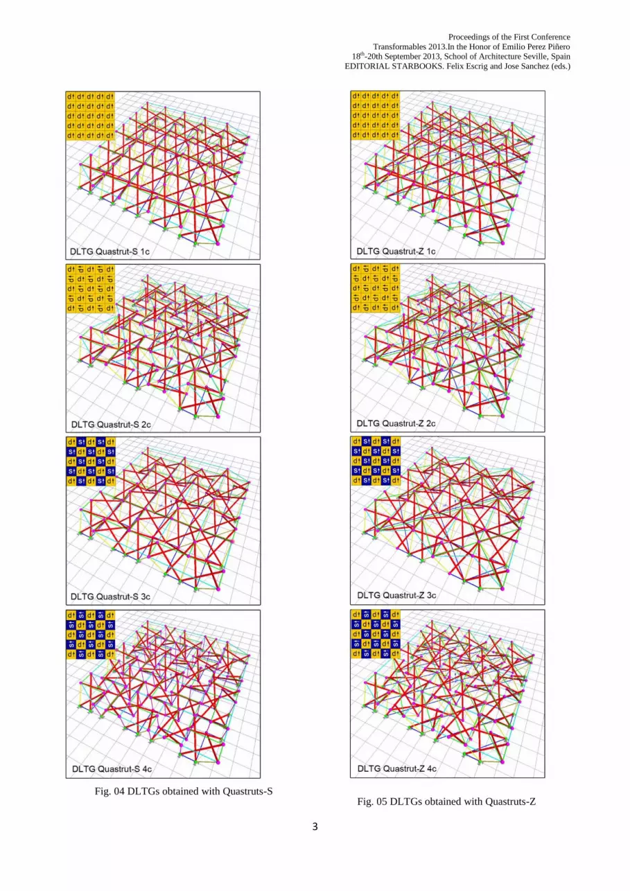
Fig. 04 DLTGs obtained with Quastruts-S
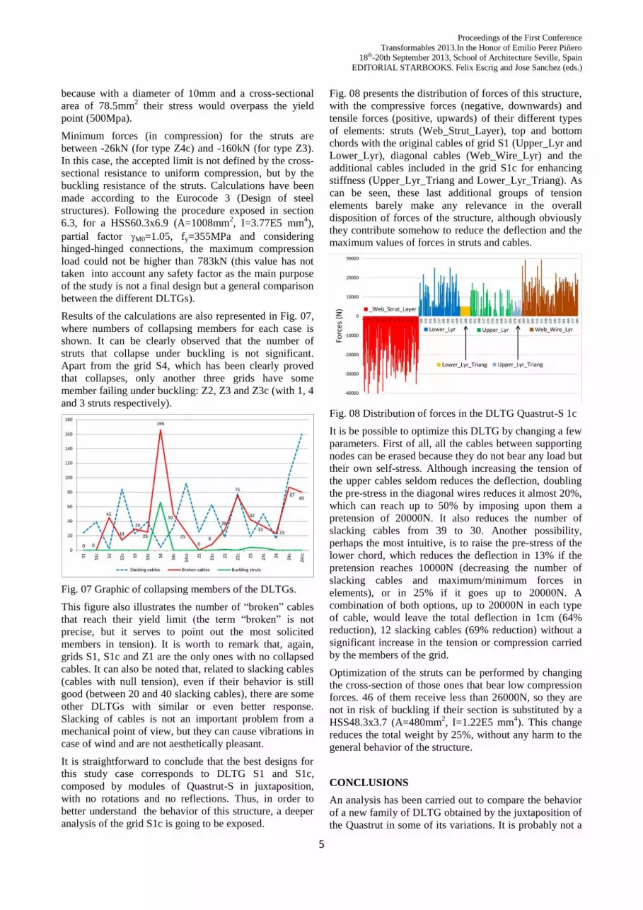
Fig. 05 DLTGs obtained with Quastruts-Z

4
The graphical representations of these grids are shown in
Fig. 04 (for Quastruts-S) and Fig. 05 (for Quastruts-Z).
For each of them, two variants have been considered:
o) Open or Original one, just by juxtaposition of
the modules.
c) Closed or Covered one, by addition of cables
to top and bottom layers to “fill the gaps” and
reinforce the grid.
For the comparison of the grids, all of them have been
designed flat and composed by 5x5 modules, each module
being 2x2m in plan view and a total height of 1,5m. As a
result, all the grids measure 10x10m with a depth of 1,5m.
DESIGN CRITERIA
Oncethe geometry of the DLTGs have been defined, as
explained in the previous section, the boundary conditions
must be fixed. Grids are simply supported at all the nodes
lying on the boundaries of the lower layer.
After several trials, an initial set of conditions was
established for accomplishing a feasible comparison of
the behavior of the structures.
The material of all elements was steel (E=210000MPa,
=7850kg/m3), with different elastic limits for struts
(fy=355MPa) and cables (fy=500MPa). Struts were
defined with a round hollow structural section
HSS60.3x6.9 (A=1008mm2) and cables with a nominal
diameter of 10mm (A=78.5mm2).
Related to the load hypothesis, a simple combination of
Ultimate Limited States (ULS) actions are considered: G
+ Q + S where (G) is the self-weight of the structure, (Q)
the active loads and (S) the self-stress. As this study is a
comparison between the behaviors of the DLTGs and not
a real design process, at this stage no partial safety factors
were considered.
Self-weight (G) is applied automatically by the program
by defining section areas, lengths and densities of the
different elements and considering a gravity acceleration
of -1 in Z direction.
Application of active loads (Q) is distributed as a set of
nodal masses among all the free nodes of the structure
(those who are not supports). For this study, two uniform
loads are applied, each one of 1kN/m2. The first one
related to the typical roof live load and the second one
responding to ground snow load. Because these
conditions are certainly severe for such a structure,
permanent loads of the covering roofing were considered
negligible compared to them.
For the self-stress (S), a general and not optimized state of
self-stress is applied to all the cables of the structure by
introducing a pretension of 5000N (approximately 12.5%
of their yield strength).
CALCULATIONS AND RESULTS
First of all, a study of the mechanisms and states of self-
stress of each type of DLTG could help to understand
their structural characteristics better. A numerical method
to obtain the rank of the equilibrium matrix [7] applied to
4x4 DLTGs proves that the number of states of self-stress
is significantly different in type S4 (s=8) and similar in
the other cases (s=16 for S1 and s=17 for S2 and S3). The
number of mechanisms is discordant enough for each
type: 45, 53, 29 and 93 for DLTGs S1, S2, S3 and S4
respectively.
Static analyses of the structures have been carried out
using the software ToyGL [8], a real time implementation
of a discrete element method (mass-spring systems). This
is an explicit dynamic nonlinear analysis, although for our
purpose it was also used as a versatile method for the
design and static analysis of tensegrity systems. It permits
structures in real time to be created and modified, with a
direct feedback on their behavior. It has been proved to be
especially adequate for the design and calculation of
tensegrity structures [8].
When working with this program, for automatically
processing the input of the data (from an AutoCad file)
and output of the results (to an Excel file), a customized
set of routines have been developed by the authors of this
contribution.
Weights of the grids are sensibly equivalent (maximum
difference of 10%), as all of them have the same number
of struts (100), which are the heaviest elements of the
structure. The lightest DLTG is the S3 (2297kg) and the
heaviest is the Z4cc (2562kg), with an average weight of
23,7kg/m2.
Fig. 06 shows the behavior of all the DLTGs in terms of
deflection (in cm) as well as maximum and minimum
forces (in kN). As can be observed, there are three grids
that collapse. This is not due to the lack of resistance to
the applied loads, but to the lack of stability and self-
equilibrium. The rest of the structures are able to support
the external loads, but among them the minimum
deformations correspond to the grid S1 (2.9cm) and S1c
(2.8cm). For the other types these values are between
approx. 6 and 40 cm.
Fig. 06 Graphic of deflections and forces in the DLTGs.
Not considering collapsed structures, maximum forces (in
tension) for the cables are between 29kN (again in DLTG
S1 and S1c) and 131kN (for type Z2). Values higher than
approx. 40kN would mean the plasticity of the cables,
Proceedings of the First Conference
Transformables 2013.In the Honor of Emilio Perez Piñero 18th-20th September 2013, School of Architecture Seville, Spain
EDITORIAL STARBOOKS. Felix Escrig and Jose Sanchez (eds.)
5
because with a diameter of 10mm and a cross-sectional
area of 78.5mm2 their stress would overpass the yield
point (500Mpa).
Minimum forces (in compression) for the struts are
between -26kN (for type Z4c) and -160kN (for type Z3).
In this case, the accepted limit is not defined by the cross-
sectional resistance to uniform compression, but by the
buckling resistance of the struts. Calculations have been
made according to the Eurocode 3 (Design of steel
structures). Following the procedure exposed in section
6.3, for a HSS60.3x6.9 (A=1008mm2, I=3.77E5 mm
4),
partial factor M0=1.05, fy=355MPa and considering
hinged-hinged connections, the maximum compression
load could not be higher than 783kN (this value has not
taken into account any safety factor as the main purpose
of the study is not a final design but a general comparison
between the different DLTGs).
Results of the calculations are also represented in Fig. 07,
where numbers of collapsing members for each case is
shown. It can be clearly observed that the number of
struts that collapse under buckling is not significant.
Apart from the grid S4, which has been clearly proved
that collapses, only another three grids have some
member failing under buckling: Z2, Z3 and Z3c (with 1, 4
and 3 struts respectively).
Fig. 07 Graphic of collapsing members of the DLTGs.
This figure also illustrates the number of “broken” cables
that reach their yield limit (the term “broken” is not
precise, but it serves to point out the most solicited
members in tension). It is worth to remark that, again,
grids S1, S1c and Z1 are the only ones with no collapsed
cables. It can also be noted that, related to slacking cables
(cables with null tension), even if their behavior is still
good (between 20 and 40 slacking cables), there are some
other DLTGs with similar or even better response.
Slacking of cables is not an important problem from a
mechanical point of view, but they can cause vibrations in
case of wind and are not aesthetically pleasant.
It is straightforward to conclude that the best designs for
this study case corresponds to DLTG S1 and S1c,
composed by modules of Quastrut-S in juxtaposition,
with no rotations and no reflections. Thus, in order to
better understand the behavior of this structure, a deeper
analysis of the grid S1c is going to be exposed.
Fig. 08 presents the distribution of forces of this structure,
with the compressive forces (negative, downwards) and
tensile forces (positive, upwards) of their different types
of elements: struts (Web_Strut_Layer), top and bottom
chords with the original cables of grid S1 (Upper_Lyr and
Lower_Lyr), diagonal cables (Web_Wire_Lyr) and the
additional cables included in the grid S1c for enhancing
stiffness (Upper_Lyr_Triang and Lower_Lyr_Triang). As
can be seen, these last additional groups of tension
elements barely make any relevance in the overall
disposition of forces of the structure, although obviously
they contribute somehow to reduce the deflection and the
maximum values of forces in struts and cables.
Fig. 08 Distribution of forces in the DLTG Quastrut-S 1c
It is be possible to optimize this DLTG by changing a few
parameters. First of all, all the cables between supporting
nodes can be erased because they do not bear any load but
their own self-stress. Although increasing the tension of
the upper cables seldom reduces the deflection, doubling
the pre-stress in the diagonal wires reduces it almost 20%,
which can reach up to 50% by imposing upon them a
pretension of 20000N. It also reduces the number of
slacking cables from 39 to 30. Another possibility,
perhaps the most intuitive, is to raise the pre-stress of the
lower chord, which reduces the deflection in 13% if the
pretension reaches 10000N (decreasing the number of
slacking cables and maximum/minimum forces in
elements), or in 25% if it goes up to 20000N. A
combination of both options, up to 20000N in each type
of cable, would leave the total deflection in 1cm (64%
reduction), 12 slacking cables (69% reduction) without a
significant increase in the tension or compression carried
by the members of the grid.
Optimization of the struts can be performed by changing
the cross-section of those ones that bear low compression
forces. 46 of them receive less than 26000N, so they are
not in risk of buckling if their section is substituted by a
HSS48.3x3.7 (A=480mm2, I=1.22E5 mm
4). This change
reduces the total weight by 25%, without any harm to the
general behavior of the structure.
CONCLUSIONS
An analysis has been carried out to compare the behavior
of a new family of DLTG obtained by the juxtaposition of
the Quastrut in some of its variations. It is probably not a

6
coincidence that the best behaviors correspond to those of
the original DLTGs obtained directly from the Rot-
Umbela Manipulations (DLTG Quastrut-S1 and DLTG
Quastrut-Z1). However, what is interesting is the fact
that these structures are class 2, when apparently a class 4
(grids type 2 and 3) should be stiffer and stronger. As
expected, there is a certain influence of the number of
states of self-stress and mechanisms in the overall
response of these structures; grids with less states of self-
stress and more mechanisms are more inclined to
collapse, as happens with type S4.
In general, DLTG generated with Quastruts-S behave
better than those composed by Quastruts-Z. This is more
than probably due to the fact that the Quastrut-S is super
stable by itself, while Quastrut-Z is not, and can only be
in equilibrium when inserted in a bigger and more
complex structure and supported properly.
It also looks clear that the improvement of any grid can be
easily achieved by just adding a few cables on the top and
bottom layers. However, real optimization of the grids is
obtained by changing the initial pre-stress of the cables
and reducing the cross-section areas of the least loaded
struts. As a result, it is possible to obtain a light structure
of 17.6 kg/m2, composed by juxtaposition of Quastruts-S,
with no rotation or reflection, with an acceptable
resistance to self-weight and external active loads.
FURTHER RESEARCH
A deeper study of the self-stress of each grid, the choice
of its level, the design of the elements (cross-section
areas, types of section, materials, etc.) will be necessary
to optimize the design of the DLTGs. Besides, it would
also be interesting to compare them under exactly the
same conditions as other DLTGs already existing and
well known in the tensegrity field.
It is not the intention of the present work to analyze in
depth, but yes to mention, an interesting performance of
the Quastruts: deployability. Physical models prove that
their singular topology and geometry may lead to the
consideration of several ways of folding and unfolding the
grids composed by these modules.
A first way of folding Quastrut-S is shown in the Fig.
09.b, and even if it cannot be appreciated in pictures,
release of the element that fixes the module in that flat
configuration makes the module come back to its original
unfolded shape (Fig. 09.a) automatically thanks to the
elastic behavior of the tendons. A second way of folding
is shown in Fig. 09.c and d, where the first one is the step
in which the edges of the bottom (i.e. 6 and 8) and top
cables (i.e. 1 and 4) that have an S-shape are detached
from the struts, whose edges (i.e. 1’, 4’, 6’ and 8’) run
through those cables until they approach the adjacent
vertices of the other struts edges (i.e. 2, 3, 5 and 7).
Second step is clearly illustrated in Fig. 09.d.
These characteristics make an in depth analysis of the
possible deployability and foldability of the DLTGs
exposed in this work feasible.
Fig. 09 a) Quastrut-S in unfolded position. b) Folding by
elasticity, pushing down. c) Folding by disconnection of
edges of the S and approaching vertices, first step. d)
Second step.
References
[1] Gomez-Jauregui, V., Tensegrity structures and their
application to architecture. Santander: Universidad
de Cantabria. Servicio de Publicaciones, 2010.
[2] Gomez-Jauregui, V., Arias, R., Otero, C. &
Manchado, C., Novel Technique for Obtaining
Double-Layer Tensegrity Grids, International Journal
of Space Structures, vol. 27, Special Issue 2–3, pp.
155–166, Jun. 2012.
[3] Gomez-Jauregui, V., Otero, C., Arias, R. &
Manchado, C., Innovative Families of Double-Layer
Tensegrity Grids: Quastruts and Sixstruts, Journal of
Structural Engineering ASCE, Sep. 2012.
[4] Gomez-Jauregui, V., Otero, C., Arias, R. &
Manchado, C., Generation and Nomenclature of
Tessellations and Double-Layer Grids, Journal of
Structural Engineering ASCE, vol. 138, no. 7, pp.
843–852, Jul. 2012.
[5] Raducanu, V. & Motro, R., Stable self-balancing
system for building component, Patent
WO02081832, granted 09-Apr-2001.
[6] Connelly, R., Tensegrity Structures: Why are They
Stable?, in Rigidity theory and applications. MF
Thorpe and PM Duxbury (Eds.), Kluwer/Plenum
Publishers, pp. 47–54, 1999.
[7] Pellegrino, S. & Calladine, C.R., Matrix analysis of
statically and kinematically indeterminate
frameworks, International Journal of Solids and
Structures, vol. 22, no. 4, pp. 409–428, 1986.
[8] Averseng, J., Quirant, J. & Dubé, J.-F., Interactive
design and dynamic analysis of tensegrity systems,
International Journal of Space Structures, vol. 27,
Special Issue 2–3, Jun 2012.