communication of digital twin - core
TRANSCRIPT
Riku Ala-Laurinaho
Sensor Data Transmission from a Physical Twin to a Digital Twin
Thesis submitted for examination for the degree of Master of
Science in Technology.
Espoo 08.04.2019
Supervisor: Prof. Kari Tammi
Instructor: M.Sc. (Tech.) Juuso Autiosalo
Aalto University, P.O. BOX 11000, 00076 AALTO
www.aalto.fi
Abstract of master's thesis
2
Author Riku Ala-Laurinaho
Title of thesis Sensor Data Transmission from a Physical Twin to a Digital Twin
Degree programme Master’s Programme in Mechanical Engineering
Thesis supervisor Prof. Kari Tammi
Thesis advisor(s) M.Sc. (Tech.) Juuso Autiosalo
Date 08.04.2019 Number of pages 90+15 Language English
Abstract
A digital twin is a digital counterpart of a physical thing such as a machine. The term digital twin was first introduced in 2010. Thereafter, it has received an extensive amount of interest because of the numerous benefits it is expected to offer through-out the product life cycle. Currently, the concept is developed by the world’s largest companies such as Siemens. The purpose of this thesis is to examine which applica-tion layer protocols and communication technologies are the most suitable for the sensor data transmission from a physical twin to a digital twin. In addition, a plat-form enabling this data transmission is developed. As the concept of a digital twin is relatively new, a comprehensive literature view on the definition of a digital twin in scientific literature is presented. It has been found that the vision of a digital twin has evolved from the concepts of ‘intelligent products’ presented at the beginning of the 2000s. The most widely adopted defi-nition states that a digital twin accurately mirrors the current state of its corre-sponding twin. However, the definition of a digital twin is not yet standardized and varies in different fields. Based on the literature review, the communication needs of a digital twin are de-rived. Thereafter, the suitability of HTTP, MQTT, CoAP, XMPP, AMQP, DDS, and OPC UA for sensor data transmission are examined through a literature review. In addi-tion, a review of 4G, 5G, NB-IoT, LoRa, Sigfox, Bluetooth, Wi-Fi, Z-Wave, ZigBee, and WirelessHART is presented. A platform for the management of the sensors is developed. The platform narrows the gap between the concept and realization of a digital twin by enabling sensor data transmission. The platform allows easy addition of sensors to a physical twin and provides an interface for their configuration remotely over the Internet. It sup-ports multiple sensor types and application protocols and offers both web user in-terface and REST API.
Keywords Digital twin, IoT, communication, application layer protocol, wireless
networks
Aalto-yliopisto, PL 11000, 00076 AALTO
www.aalto.fi
Diplomityön tiivistelmä
3
Tekijä Riku Ala-Laurinaho
Työn nimi Anturidatan lähettäminen fyysiseltä kaksoselta digitaaliselle kaksoselle
Koulutusohjelma Konetekniikan maisteriohjelma
Työn valvoja Prof. Kari Tammi
Työn ohjaaja(t) DI Juuso Autiosalo
Päivämäärä 08.04.2019 Sivumäärä 90+15 Kieli Englanti
Tiivistelmä
Digitaalinen kaksonen on fyysisen tuotteen digitaalinen vastinkappale, joka sisältää tie-don sen nykyisestä tilasta. Digitaalisen kaksosen käsite otettiin ensimmäisen kerran käyttöön vuonna 2010. Sen jälkeen digitaalinen kaksonen on saanut paljon huomiota, ja sitä ovat lähteneet kehittämään maailman suurimmat yritykset, kuten Siemens. Tä-män työn tarkoituksena tutkia, mitkä sovelluskerroksen protokollat ja langattomat ver-kot soveltuvat parhaiten anturien keräämän datan lähettämiseen fyysiseltä kaksoselta digitaaliselle kaksoselle. Sen lisäksi työssä esitellään alusta, joka mahdollistaa tämän tiedonsiirron. Digitaalisen kaksosesta esitetään laaja kirjallisuuskatsaus, joka luo pohjan työn myö-hemmille osioille. Digitaalisen kaksosen konsepti pohjautuu 2000-luvun alussa esitel-tyihin ajatuksiin ”älykkäistä tuotteista”. Yleisimmän käytössä olevan määritelmän mu-kaan digitaalinen kaksonen heijastaa sen fyysisen vastinparin tämän hetkistä tilaa. Mää-ritelmä kuitenkin vaihtelee eri alojen välillä eikä se ole vielä vakiintunut tieteellisessä kirjallisuudessa. Kirjallisuuskatsauksen avulla johdetaan digitaalisen kaksosen kommunikaatiotarpeet. Sen jälkeen arvioidaan seuraavien sovelluskerroksen protokollien soveltuvuutta anturi-datan lähettämiseen kirjallisuuskatsauksen avulla: HTTP, MQTT, CoAP, XMPP, AMQP, DDS ja OPC UA. Myös seuraavien langattomien verkkojen soveltuvuutta tiedonsiirtoon tutkitaan: 4G, 5G, NB-IoT, LoRaWAN, Sigfox, Bluetooth, Wi-Fi, Z-Wave, ZigBee ja Wi-relessHART. Osana työtä kehitettiin myös ohjelmistoalusta, joka mahdollistaa anturien hallinnan etänä Internetin välityksellä. Alusta on pieni askel kohti digitaalisen kaksosen käytän-nön toteutusta, sillä se mahdollistaa tiedon keräämisen fyysisestä vastinkappaleesta. Sen avulla sensorien lisääminen fyysiseen kaksoseen on helppoa, ja se tukee sekä useita sensorityyppejä että sovelluskerroksen protokollia. Alusta tukee REST API –rajapintaa ja sisältää web-käyttöliittymän.
Avainsanat Digitaalinen kaksonen, IoT, kommunikaatio, sovellus kerroksen protokol-
lat, langattomat verkot
4
Preface
I would like to thank my supervisor Professor Kari Tammi and instructor Juuso Autiosalo
for their valuable advices and guidance through the writing of this thesis. Thank should
also go to Professor Petri Kuosmanen, who initially made me interested in the concept of
a digital twin. I would like to acknowledge the assistance of Heikki Timonen for his ad-
vices in coding and writing and Ivar Koene for his help with microcontrollers. I would
also like to thank the members of DigiTwin consortium for their ideas and visions of a
digital twin.
Finally, special thanks to my friends and family, who have supported me through the
writing of this thesis.
Espoo 08.04.2019
Riku Ala-Laurinaho
5
Table of contents Abstract
Tiivistelmä
Preface
Table of contents ............................................................................................................... 5 Abbreviations .................................................................................................................... 7 1 Introduction ............................................................................................................... 8
1.1 Background ........................................................................................................ 8
1.2 Objective ............................................................................................................ 8 1.3 Scope .................................................................................................................. 9 1.4 Structure of the thesis ......................................................................................... 9
2 Digital twin ............................................................................................................. 10 2.1 Background ...................................................................................................... 10 2.2 Concept ............................................................................................................. 12 2.3 Digital twin in this thesis .................................................................................. 24
2.4 Data contained in a digital twin ........................................................................ 26 3 Communication ....................................................................................................... 29
3.1 Communication needs ...................................................................................... 29 3.2 Use cases .......................................................................................................... 30
3.3 The layered architecture of the Internet............................................................ 32 3.4 Application layer protocols .............................................................................. 33
3.4.1 HTTP ......................................................................................................... 35
3.4.2 MQTT ....................................................................................................... 37
3.4.3 CoAP ......................................................................................................... 39 3.4.4 XMPP ........................................................................................................ 40 3.4.5 AMQP ....................................................................................................... 41
3.4.6 DDS ........................................................................................................... 43 3.4.7 OPC UA .................................................................................................... 43
3.4.8 Comparison ............................................................................................... 45 3.5 Communication technologies ........................................................................... 47
3.5.1 Low power wide area networks (LPWANs) ............................................. 48
3.5.2 Short-range networks ................................................................................ 50 3.5.3 Comparison ............................................................................................... 51
3.6 IoT platforms .................................................................................................... 53
4 Sensor configurator platform .................................................................................. 56
4.1 Requirements .................................................................................................... 56 4.2 Hardware .......................................................................................................... 56 4.3 Software ............................................................................................................ 58
5 Results ..................................................................................................................... 60 5.1 Sensor configurator platform ............................................................................ 60
5.2 Sensor Data Transmission Protocol ................................................................. 66 5.3 Data server ........................................................................................................ 67 5.4 User test ............................................................................................................ 67
6 Discussion ............................................................................................................... 70 6.1 Sensor configurator platform ............................................................................ 70
6.2 Communication ................................................................................................ 72
6.3 Digital twin ....................................................................................................... 73 7 Conclusion .............................................................................................................. 75 References ....................................................................................................................... 76 List of appendices ........................................................................................................... 91

6
Appendices
7
Abbreviations
AES Advanced Encryption Standard
AMQP Advanced Message Queuing Protocol
CoAP Constrained Application Protocol
CPS Cyber-Physical System
CPPS Cyber-Physical Productions System
C2PS Cloud-Based Cyber-Physical System
DDS Data Distribution Service
DES Data Encryption Standard
HTTP Hypertext Transfer Protocol
IoT Internet of Things
IIoT Industrial Internet of Things
LoRa Long Range
LoRaWAN Long Range Wide Area Network
LPWAN Low Power Wide Area Network
M2M Machine-to-Machine
MES Manufacturing Execution System
MQTT Message Queuing Telemetry Transport
MQTT-SN MQTT for Sensor Networks
NB-IoT Narrowband IoT
OPC UA Open Platform Communications Unified Architecture
PLC Programmable Logic Controller
PLM Product Lifecycle Management
QoS Quality of Service
SCP Sensor Configurator Platform
SDTP Sensor Data Transmission Protocol
TCP Transmission Control Protocol
TLS Transmission Layer Security
UDP User Datagram Protocol
URL Uniform Resource Locator
WUI Web User Interface
XMPP Extensible Messaging and Presence Protocol
8
1 Introduction
1.1 Background
Digital twin is a digital counterpart of a physical object, which accurately mirrors the
current state of its corresponding physical twin. It offers numerous benefits throughout
the product life cycle. Therefore, the concept of a digital twin has gained a lot of attention
recently. In addition, it is developed by the world’s largest companies such as Siemens
(Boger & Rusk, 2017), and Gartner has chosen it three times in a row to its Top 10 Stra-
tegic Technology Trends list (Panetta, 2016, 2017, 2018b).
Despite a digital twin concept is constantly developed, there is a lack of real-world im-
plementations of it. This is because a digital twin is a complex system of systems having
numerous functionalities. This thesis focuses on the digital twin’s functionality of repre-
senting the current status of the physical twin, which is enabled by data collection from
the physical twin. The thesis narrows the gap between the concept of a digital twin and
its implementation in two ways:
- By presenting communication methods suitable for sensor data transmission from
a physical twin to a digital twin
- By introducing a platform for managing sensors remotely allowing this data trans-
mission
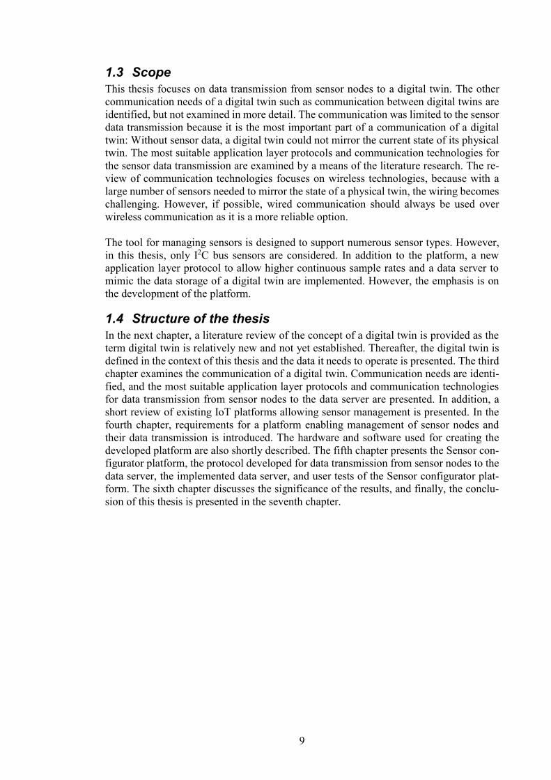
This thesis has been written as part of DigiTwin-project, which aims to the realization of
a digital twin concept by creating a digital twin of the overhead crane called Ilmatar. The
crane is located at Aalto University Industrial Internet Campus (Figure 1) and it is used
as an example of a product having a digital twin in this thesis. This thesis supports the
DigiTwin-project by allowing data collection from the overhead crane with the developed
platform for management and configuration of sensor nodes.
Figure 1. Ilmatar overhead crane located at Aalto University Industrial Internet Campus.
1.2 Objective
In order for a digital twin to mirror accurately the current state of its physical twin, meas-
urement data from the physical twin has to be collected continuously. For that reason,
numerous sensors have to be attached to it. The massive amount of data produced by these
sensors is needed to be transmitted to the digital twin. The first objective of this thesis is
to present the most suitable application layer protocols and communication technologies
for this sensor data transmission.
The second objective is to enable sensor data transmission from a physical twin to a dig-
ital twin in practice. To fulfill this goal, a tool for management and configuration of sensor
nodes is developed. The platform is required to support multiple sensor types and allow
the addition of new sensor nodes to the physical twin effortlessly. Both objectives of this
thesis ultimately aim at narrowing the gap between the concept of a digital twin and its
realization.
9
1.3 Scope
This thesis focuses on data transmission from sensor nodes to a digital twin. The other
communication needs of a digital twin such as communication between digital twins are
identified, but not examined in more detail. The communication was limited to the sensor
data transmission because it is the most important part of a communication of a digital
twin: Without sensor data, a digital twin could not mirror the current state of its physical
twin. The most suitable application layer protocols and communication technologies for
the sensor data transmission are examined by a means of the literature research. The re-
view of communication technologies focuses on wireless technologies, because with a
large number of sensors needed to mirror the state of a physical twin, the wiring becomes
challenging. However, if possible, wired communication should always be used over
wireless communication as it is a more reliable option.
The tool for managing sensors is designed to support numerous sensor types. However,
in this thesis, only I2C bus sensors are considered. In addition to the platform, a new
application layer protocol to allow higher continuous sample rates and a data server to
mimic the data storage of a digital twin are implemented. However, the emphasis is on
the development of the platform.
1.4 Structure of the thesis
In the next chapter, a literature review of the concept of a digital twin is provided as the
term digital twin is relatively new and not yet established. Thereafter, the digital twin is
defined in the context of this thesis and the data it needs to operate is presented. The third
chapter examines the communication of a digital twin. Communication needs are identi-
fied, and the most suitable application layer protocols and communication technologies
for data transmission from sensor nodes to the data server are presented. In addition, a
short review of existing IoT platforms allowing sensor management is presented. In the
fourth chapter, requirements for a platform enabling management of sensor nodes and
their data transmission is introduced. The hardware and software used for creating the
developed platform are also shortly described. The fifth chapter presents the Sensor con-
figurator platform, the protocol developed for data transmission from sensor nodes to the
data server, the implemented data server, and user tests of the Sensor configurator plat-
form. The sixth chapter discusses the significance of the results, and finally, the conclu-
sion of this thesis is presented in the seventh chapter.
10
2 Digital twin In this chapter, the background and concept of a digital twin are presented. In the first
section, the history and initial goals of predecessors of a digital twin concept are
examined. The second section presents the definitions of a digital twin in the scientific
literature and the third section introduces the definition of digital twin used in this thesis.
Finally, the data needed and produced by a digital twin is presented in the fourth section.
2.1 Background
The term digital twin is fairly new and was first brought to the public by Shafto et al.
(2010, 2012; Schroeder et al., 2016, p. 13) However, very similar ideas to the digital twin
have already been developed at the beginning of the 2000s by, for example, Grieves
(Grieves & Vickers, 2017, p. 93) and Främling et al. (2003). In this section, a few prede-
cessors of a digital twin concept are presented. These concepts share some similar features
to the current vision of a digital twin but can’t yet be called digital twins.
Brussel et al. (1999) represent ”holons”, which are autonomous agents for Holonic man-
ufacturing system (HMS). Holons can co-operate to achieve a common goal as well as
react to disturbances and optimize the process. HMS consists of three basic building
blocks: 1) product holon, which contains information about product itself such as up-to-
date information on the product lifecycle and bill of materials, 2) resource holon used for
resource allocation, which consists of physical part (resource) and information-processing
part, 3) order holon, which is “an active entity responsible for performing the work cor-
rectly and on time.”
Wong et al. (2002) introduce the concept of an intelligent product and examine its effects
on the lifecycle of the product. They define an intelligent product as having at least some
of the following characteristics:
1) Unique identity
2) Ability to communicate with its environment
3) Can retain or store data about itself
4) Can express its features, production requirements etc.
5) A capability of participating in or making decisions relevant to its own destiny
Software agents enable intelligent products to address the above-mentioned features 4
and 5. Wong et al. define software agent as “a distinct software process, which can reason
independently, and can react to change induced upon it by other agents and its environ-
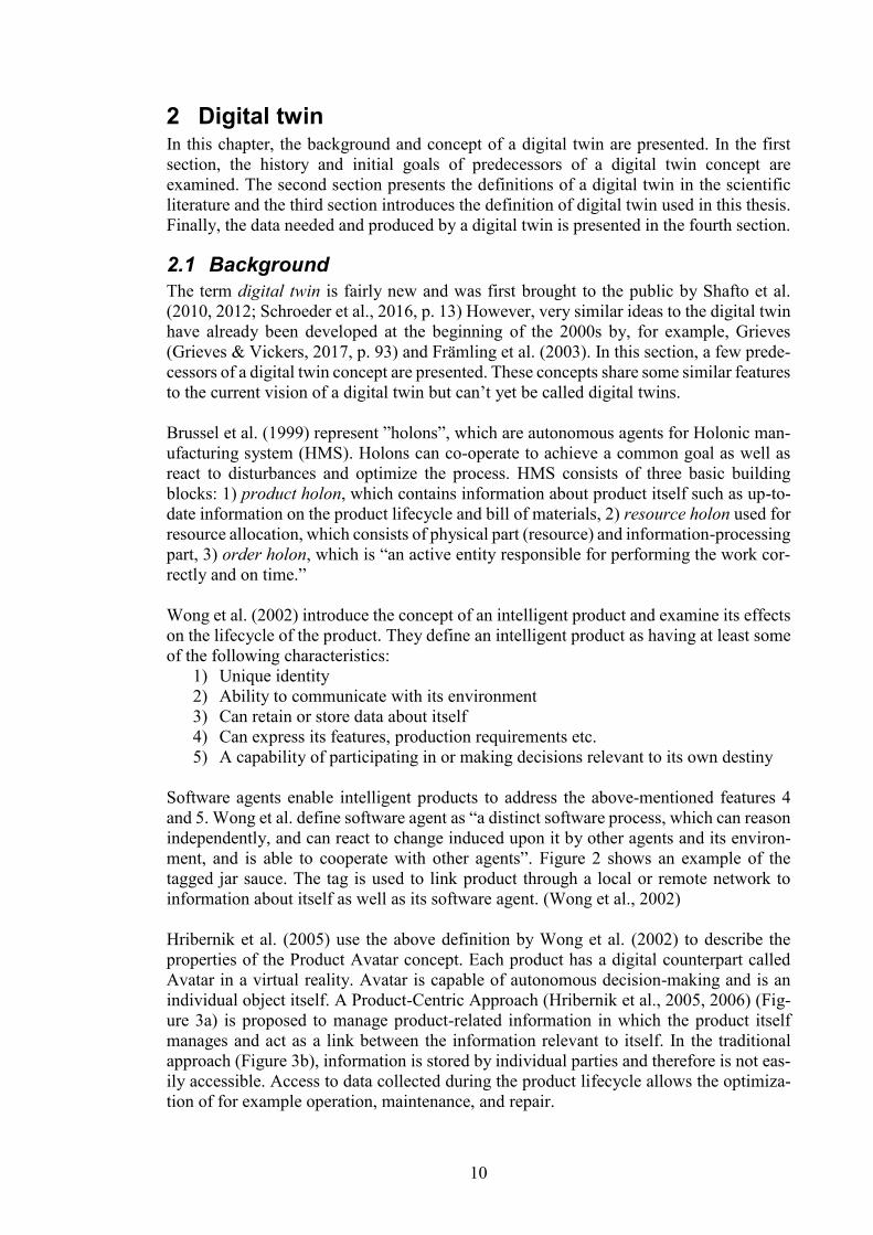
ment, and is able to cooperate with other agents”. Figure 2 shows an example of the
tagged jar sauce. The tag is used to link product through a local or remote network to
information about itself as well as its software agent. (Wong et al., 2002)
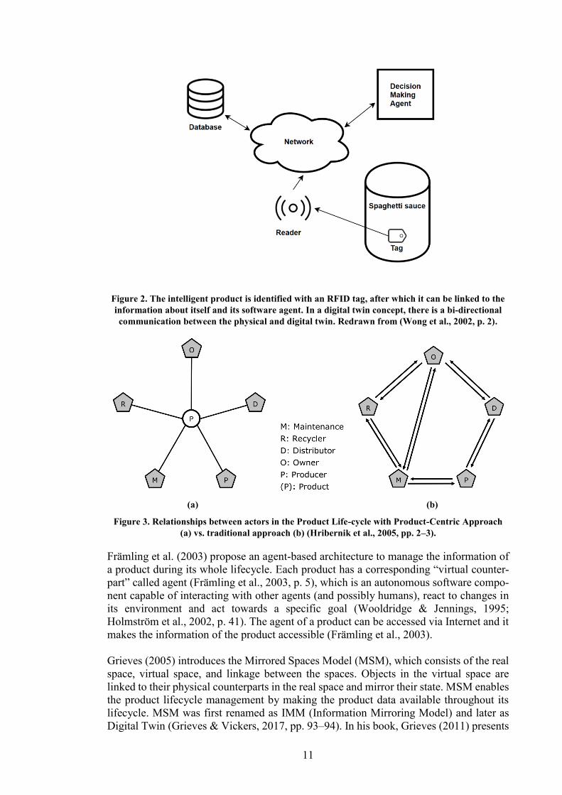
Hribernik et al. (2005) use the above definition by Wong et al. (2002) to describe the
properties of the Product Avatar concept. Each product has a digital counterpart called
Avatar in a virtual reality. Avatar is capable of autonomous decision-making and is an
individual object itself. A Product-Centric Approach (Hribernik et al., 2005, 2006) (Fig-
ure 3a) is proposed to manage product-related information in which the product itself
manages and act as a link between the information relevant to itself. In the traditional
approach (Figure 3b), information is stored by individual parties and therefore is not eas-
ily accessible. Access to data collected during the product lifecycle allows the optimiza-
tion of for example operation, maintenance, and repair.
11
Figure 2. The intelligent product is identified with an RFID tag, after which it can be linked to the
information about itself and its software agent. In a digital twin concept, there is a bi-directional
communication between the physical and digital twin. Redrawn from (Wong et al., 2002, p. 2).
(a) (b)
Figure 3. Relationships between actors in the Product Life-cycle with Product-Centric Approach
(a) vs. traditional approach (b) (Hribernik et al., 2005, pp. 2–3).
Främling et al. (2003) propose an agent-based architecture to manage the information of
a product during its whole lifecycle. Each product has a corresponding “virtual counter-
part” called agent (Främling et al., 2003, p. 5), which is an autonomous software compo-
nent capable of interacting with other agents (and possibly humans), react to changes in
its environment and act towards a specific goal (Wooldridge & Jennings, 1995;
Holmström et al., 2002, p. 41). The agent of a product can be accessed via Internet and it
makes the information of the product accessible (Främling et al., 2003).
Grieves (2005) introduces the Mirrored Spaces Model (MSM), which consists of the real
space, virtual space, and linkage between the spaces. Objects in the virtual space are
linked to their physical counterparts in the real space and mirror their state. MSM enables
the product lifecycle management by making the product data available throughout its
lifecycle. MSM was first renamed as IMM (Information Mirroring Model) and later as
Digital Twin (Grieves & Vickers, 2017, pp. 93–94). In his book, Grieves (2011) presents
12
the value of virtual products to the PLM (Product Lifecycle Management) and further
develops the IMM concept (Grieves & Vickers, 2017, p. 93). Grieves is generally con-
sidered as the creator of the concept of a digital twin, even though Shafto et al. (2010)
first presented the term digital twin.
Kiritsis et al. (2011) define an intelligent product as a “product system which contains
sensing, memory, data processing and communication capabilities at various intelligence
levels.” The intelligence of a product is divided into four levels: a product at intelligence
level 1 does not have any intelligence and product at level 4 is capable of decision-making
and communication with its environment. Smart products enable data collection, which
closes the PLM information loop. This allows manufacturers to get data from the actual
use of the product and improve the maintenance operations, as the up-to-date status of the
product is known. The smart products change the focus from the product type to the in-
dividual product.
The concept of Cyber-Physical System (CPS) is closely related to a digital twin as a dig-
ital twin can be seen as “the cyber part of a Cyber-Physical System” (Autiosalo, 2018, p.
243). Lee (2008, p. 363) describes CPSs as “integrations of computation with physical
processes”. In a CPS, sensor data is collected and analyzed to control the physical process
(Alam & El Saddik, 2017, pp. 2050–2051). It can be seen from the Scopus database that
the concept of CPS has emerged a few years earlier than a digital twin, and the amount
of publications related to CPSs is twentyfold compared to digital twins. The Cyber-Phys-
ical Systems can be seen as another path leading to the development of a digital twin
because CPS can use a digital twin to process the sensor data and control the physical
system (Alam & El Saddik, 2017). Further examination of the concept of CPS and its
similarities to the concept of a digital twin is out of the scope of this thesis.
As a conclusion, predecessors of a digital twin addressed the following issues:
1) Where to store the product data?
2) How to share the data among various stakeholders?
3) How to store and manage data related to product life-cycle management?
4) How to add intelligence to the product?
5) How can products communicate with each other?
The current vision of a digital twin also addresses these problems but expands the capa-
bilities to the next level as the technology has considerably advanced since the beginning
of the 21st century. It is noteworthy that the later concepts of a product agent such as one
presented by Främling et al. (2013) are very similar to the current concept of the digital
twin. Thus, instead of a new concept, a digital twin should be seen as a next step in the
development of ‘intelligent products’.
2.2 Concept
In this section, purposes and definitions of a digital twin in the scientific literature are
examined. The purpose and definition are inseparable as the digital twin is often defined
by its intended use.
The literature review was conducted by using the Scopus Database. The search phrase
was “digital twin” and it was targeted to title, abstract and keywords. The release date of
the publications was limited to years 2010-2018, as the term “digital twin” was used first
time in 2010 by Shafto et al. (Schroeder et al., 2016). The date of the search was 5.7.2018.
Only publications written in English, which had five or more citations, were considered.
13
However, some of the publications were not accessible and therefore could not be in-
cluded in this thesis. In addition, some of the publications used in this literature review
does not fulfill the requirement for the minimum amount of citations but were still con-
sidered as they were otherwise relevant, for example, cited by the other papers or recom-
mended by colleagues.
The first and probably the best-known definition of a digital twin is by Shafto et al. (2010,
2012) in NASA’s (National Aeronautics and Space Administration) roadmap. It says: ”a
digital twin is an integrated multi-physics, multi-scale, probabilistic simulation of a vehi-
cle or system that uses the best available physical models, sensor updates, fleet history,
etc., to mirror the life of its corresponding flying twin.” In addition, Shafto et al. (2010)
state a digital twin integrates sensor data, maintenance history, and fleet data. A digital
twin contains essentially all available data from the whole lifecycle of a physical twin
from manufacturing anomalies to the operational data. In addition to being capable of
accurately mirroring the current state of its physical twin, they propose that a digital twin
is used to run simulations to predict the future states of its corresponding physical twin.
The following applications for a digital twin are represented by Shafto et al. (2010):
1) Flying the mission beforehand. This enables examination of the effects of modi-
fying the mission parameters and strategies to mitigate the consequences of unex-
pected failures during the flight. A digital twin can also predict the probability of
mission success.
2) Mirroring the state of the physical twin during the mission, which enables contin-
uously predicting the future states of a physical twin by running simulations.
3) Analyze the cause of anomaly during the flight.
4) Predicting the effects of modifications to mission parameters during the flight.
This can be used to make the most informed decision if there is a need to change
the parameters, for example, as a result of the failure of a single system.
5) “Certification of vehicles by simulation”
As can be seen, NASA’s vision of a digital twin is mainly focused on improving the safety
of the flights.
Tuegel et al. (2011) also examine a digital twin from aeronautics perspective. A digital
twin is described by being “ultrarealistic in geometric detail, including manufacturing
anomalies, and in material detail, including the statistical microstructure level”. A digital
twin is capable of acting as a virtual sensor interpolating data acquired from real sensors.
Currently, there is a separate model for each type of physics such as computational fluid
dynamics (CFD) model, the structural dynamics model (SDM), and the thermodynamic
model to predict the structural life of aircraft. With a digital twin, these models could be
integrated. By having a digital twin containing all information related to specific aircraft
tail number including reliability estimates of all primary structural components, the
maintenance can be optimized. (Tuegel et al., 2011)
In another publication by Tuegel (2012), a digital twin is presented as a cradle-to-grave
ultra-realistic computational model of the as-built aircraft. A digital twin consists of
multiple integrated submodels. These submodels use the best available physics, share in-
formation with each other and are updated during the lifecycle of an aircraft so that the
accuracy of the models is improved. An Aircraft Digital Twin enables virtual testing of
the design, health monitoring and forecasting the need for maintenance.
14
Glaessgen & Stargel (2012) emphasize that a digital twin represents an as-built version
of the vehicle or system and includes information at the level of material microstructure.
This information about the physical structure on a scale from “less than a micron to me-
ters” is used to create ”ultra high-fidelity physical models to predict the future states of
the vehicle”. A digital twin can perfectly mirror the state of its corresponding physical
twin and use ultra-high fidelity simulations to predict the physical twin’s possible future
states. Glaessgen & Stargel claim that with a digital twin it is possible to abandon empir-
ical and heuristic design rules, which result in heavy structures as well as uncertainties
related to the actual reliability of the structure. In addition, they claim a digital twin will
revolutionize certification as the vehicle can be tested virtually.
Smarslok, Culler & Mahadevan (2012) present USAF’s (United States Air Force) vision
of a digital twin in which a digital twin enables “condition-based fleet management by
tail number through numerical simulation of the structural response to the same flight
spectrum as experienced by the physical system.” They take steps towards the actual im-
plementation of a digital twin vision by creating a framework to assess the confidence in
model predictions for the aerothermoelastic model. Without this assessment of confi-
dence, a digital twin would not be able to make autonomous decisions regarding efficient
simulations and risk mitigation.
Lee et al. (2013) expand the usage of digital twins from aeronautics to manufacturing
systems. They describe a digital twin as a coupled model of the real machine, which “op-
erates in the cloud platform and simulates the health condition with an integrated
knowledge from both data-driven analytical algorithms as well as other available physical
knowledge.” A digital twin has knowledge of product design as well as the current con-
dition of the physical machine. In addition, in their vision a digital twin eases the access
to the information about the physical product.
Cerrone et al. (2014) further motivate the need for a digital twin concept by providing a
use case, in which the path of the crack is predicted with the finite element model. To
predict the path, the as-manufactured geometry of the specimen is required. Therefore,
they emphasize a digital twin’s ability to store information about the as-manufactured
properties of the product.
Grieves (2014) presents a digital twin concept’s benefits to manufacturing. He describes
a digital twin as a “virtual, digital equivalent to a physical product”, which is “virtually
indistinguishable” of its physical counterpart. He divides the concept of a digital twin into
three parts: physical products, virtual products, and the connections and information,
which links these digital and physical products together. For this linkage, he proposes
Unified Repository (UR), which includes the design data and data collected from the
physical product. For example, when a product is manufactured, the factory’s MES (Man-
ufacturing Execution System) pushes the information of the as-manufactured character-
istics of a product to UR. The information of the manufacturing process could also be
sent to factory simulation, which enables almost real-time or real-time visualization of
the factory state. In addition, this information allows a comparison between the desired
products and the actual products being manufactured.
Even though Bazilevs et al. (2015) have “digital twin” in their article’s keywords, they
use the term Dynamic data-driven application system (DDDAS) instead of a digital twin.
However, this DDDAS is similar to the digital twin concept and is defined as a “frame-
work in which sensor and measurement data collected for a given physical system are
15
used to dynamically update a computational model of that system.” The major difference
between a digital twin and DDDAS is that in the DDDAS the structural model, instead of
being an exact representation, is only a “fairly complete” representation of the physical
structural system. In the article, DDDAS is used to improve the predictive power of the
introduced framework for fatigue-damage modeling.
Ríos et al. (2015) compare the digital twin concept and the product avatar concept. The
concepts are created from the different point of views and for different purposes, but ad-
dress the same high-level issue of storing the data and information from the whole lifecy-
cle of the product. They also identify several expected benefits of a digital counterpart
such as the possibility to create intelligent services and accessibility to product infor-
mation among various stakeholders through a product’s lifecycle. A digital twin utilizes
various interoperable models to represent the physical counterpart during its life cycle.
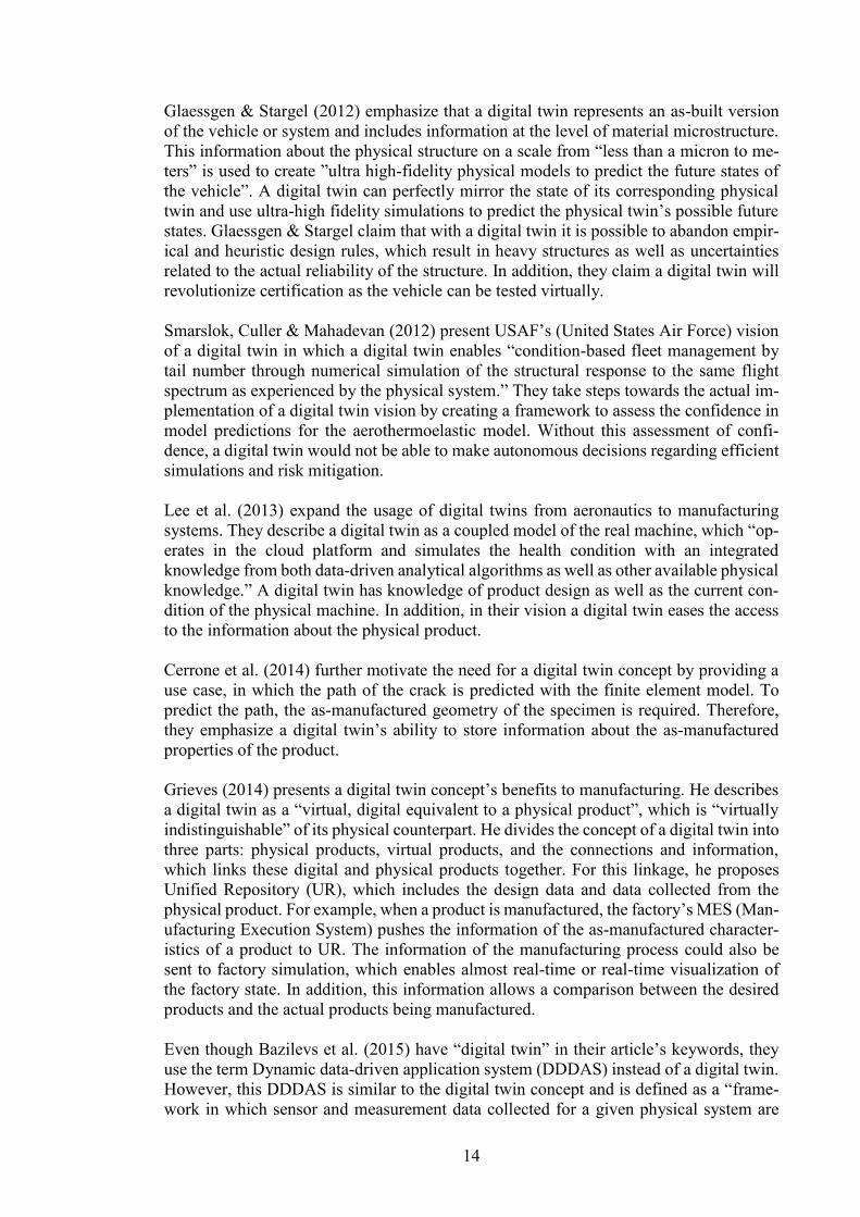
Rosen et al. (2015) state a digital twin is “the next wave in modeling, simulation and
optimization technology” (Figure 4). Simulations should not be used only in the design
phase, but throughout lifecycle supporting also the operation of the product. A digital
twin is a necessary tool to create autonomous manufacturing system. It holds the infor-
mation about the current state of the environment and the process, which is needed to
optimize the system and to run forward simulations. These forward simulations are then
used to support action planning of the autonomous system.
Figure 4. The Digital Twin concept is the next wave in modeling and simulation (Rosen et al., 2015,
p. 568).
Gabor et al. (2016) describe a digital twin as an ultra-high fidelity simulation. A digital
twin integrates previously separate structural models, which allows the system to be sim-
ulated as a whole. A digital twin has knowledge of all systems of its type and uses the
information collected from those systems to improve the accuracy of simulations. If sim-
ulations can be run fast enough, the future behavior of the system can be predicted. Gabor
et al. also claim that a digital twin can be used as a tool for testing as it has the ability to
provide test cases. In addition, its ability to mirror the physical world enables to acquire
virtual sensor readings and a software engineer to use virtual and physical components
interchangeably.
16
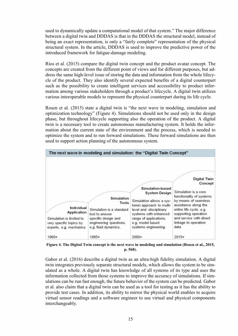
Weyer et al. (2016) examine a digital twin from Cyber-Physical Production Systems
(CPPS) perspective. With CPPS the production is more scalable and flexible, all phases
of production are quickened, and (re-)engineering tasks previously performed sequen-
tially can be performed simultaneously (Figure 5). Simulations are an essential part of
CPPS as they can predict the system behavior and performance under changes supporting
the decision-making. Simulations require an exact state of the system and therefore each
physical component has a digital counterpart, which is used to store this information. A
digital twin uses this information to “monitor, adjust and optimize real processes, antici-
pate failures and increase efficiency.”
Figure 5. Cyber-Physical Production System allows previously sequentially performed tasks to be
performed simultaneously. Colored squares are used to describe a single (re-)engineering step in
the manufacturing system. (Weyer et al., 2016, p. 98)
Schroeder et al. (2016) see a digital twin as a virtual representation of a real product or as
a cyber representation of a Cyber-Physical System (CPS), which contains all the infor-
mation and knowledge of a physical product from its whole lifecycle. They use the term
“Big Data” along with digital twin to describe the problem of managing the huge amount
of data produced in all phases of a product’s lifecycle. In their article, high-level data
models for easy data exchange between systems is implemented with AutomationML.
Boschert & Rosen (2016) examine a digital twin’s possibilities from a simulation point
of view. A digital twin is described as “a comprehensive physical and functional descrip-
tion of a component, product or system, which includes more or less all information which
could be useful in all—the current and subsequent— lifecycle phases.” It acts as a link
between separate systems such as PLM (Product lifecycle management), PDM (Product
data management) and SCADA (Supervisory Control and Data Acquisition) storing prod-
uct information and makes the data and set of various fidelity simulation models availa-
ble. Boschert & Rosen state a digital twin can be seen as a part of the physical product,
which helps the operation of a product via simulations throughout the product lifecycle.
In the system integration testing, physical components can be replaced with virtual ones
to allow testing even if the physical components aren’t yet available.
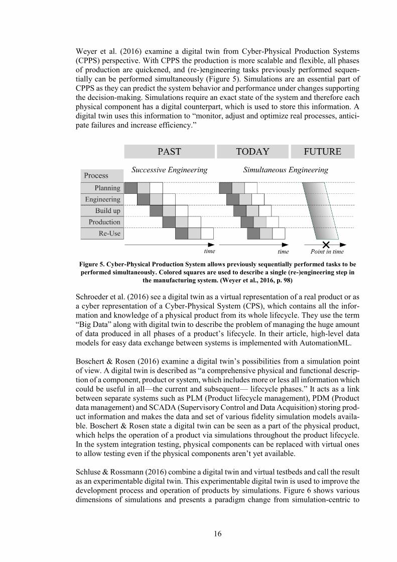
Schluse & Rossmann (2016) combine a digital twin and virtual testbeds and call the result
as an experimentable digital twin. This experimentable digital twin is used to improve the
development process and operation of products by simulations. Figure 6 shows various
dimensions of simulations and presents a paradigm change from simulation-centric to
17
digital twin centric. Digital twins are described as “virtual substitutes of real-world ob-
jects consisting of virtual representations and communication capabilities making up
smart objects acting as intelligent nodes inside the internet of things and services.”
Figure 6. Various aspects of simulations (Schluse & Rossmann, 2016, p. 1).
A digital twin is used to predict the values of process variables to create robust compo-
nents in additive manufacturing. The use of a digital twin reduces the need for time-con-
suming and expensive, “try-and-error”, experiments. (DebRoy et al., 2017; Knapp et al.,
2017) DebRoy et al. (2017) identify the building blocks needed to create a digital twin
for additive manufacturing and Knapp et al. (2017) develop and experimentally verify a
model to predict the values of process variables. A digital twin is “a digital replica of
additive manufacturing hardware”, which, along with integrated models of for example
temperature and microstructure, is used for calculating the needed process variables
(DebRoy et al., 2017).
Schleich et al. (2017) summarize the vision of a digital twin as follows: ”a bi-directional
relation between a physical artefact and the set of its virtual models.” The distinct simu-
lation models of a digital twin evolve during the lifecycle of the product from simple
models to more complex ones. A digital twin helps to assess the consequences of design
18
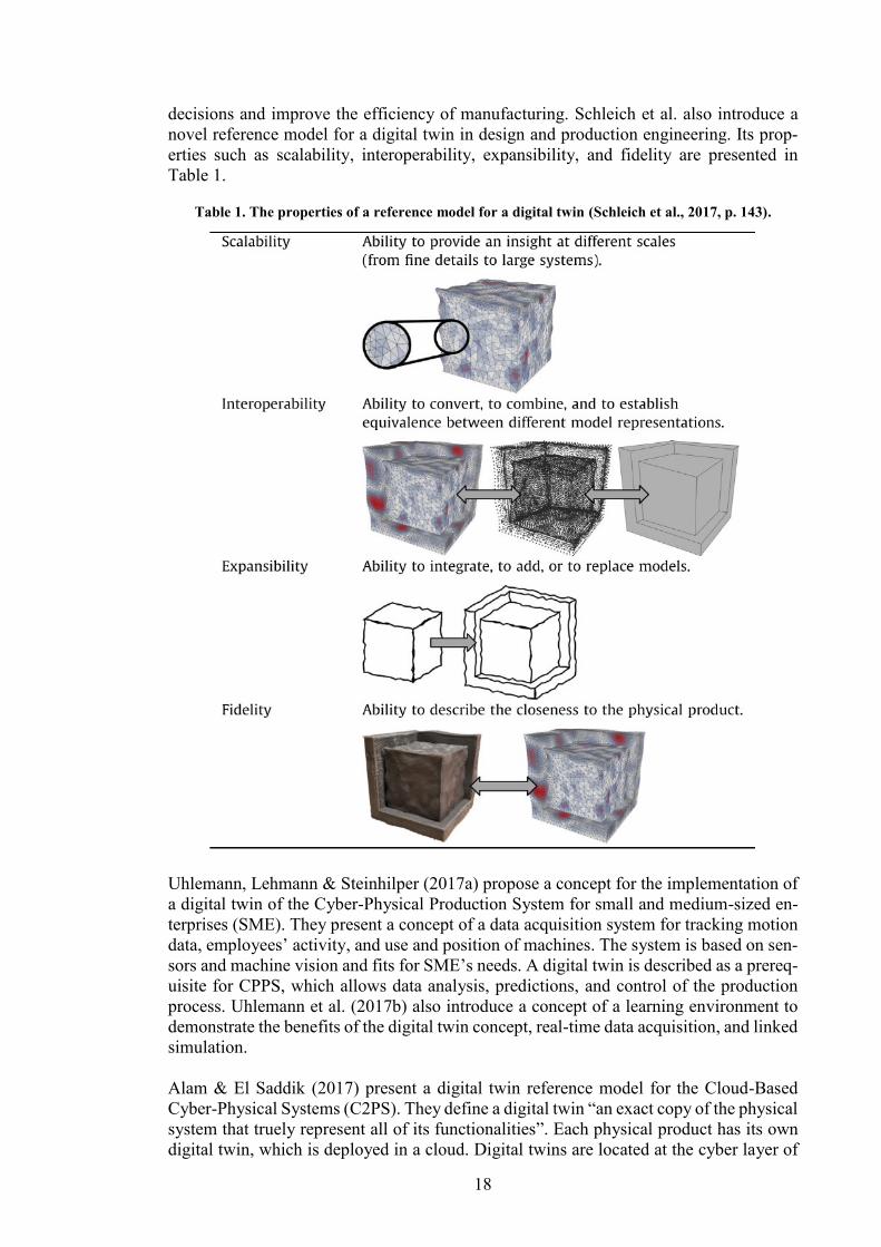
decisions and improve the efficiency of manufacturing. Schleich et al. also introduce a
novel reference model for a digital twin in design and production engineering. Its prop-
erties such as scalability, interoperability, expansibility, and fidelity are presented in
Table 1.
Table 1. The properties of a reference model for a digital twin (Schleich et al., 2017, p. 143).
Uhlemann, Lehmann & Steinhilper (2017a) propose a concept for the implementation of
a digital twin of the Cyber-Physical Production System for small and medium-sized en-
terprises (SME). They present a concept of a data acquisition system for tracking motion
data, employees’ activity, and use and position of machines. The system is based on sen-
sors and machine vision and fits for SME’s needs. A digital twin is described as a prereq-
uisite for CPPS, which allows data analysis, predictions, and control of the production
process. Uhlemann et al. (2017b) also introduce a concept of a learning environment to
demonstrate the benefits of the digital twin concept, real-time data acquisition, and linked
simulation.
Alam & El Saddik (2017) present a digital twin reference model for the Cloud-Based
Cyber-Physical Systems (C2PS). They define a digital twin “an exact copy of the physical
system that truely represent all of its functionalities”. Each physical product has its own
digital twin, which is deployed in a cloud. Digital twins are located at the cyber layer of
19
a cyber physical system and enable monitoring, diagnostics, and predictions of a physical
counterpart as well as offers real-time services to the application layer of the CPS. The
properties and functionalities of products are enhanced with their digital twin. A
telematics-based driving assistance application is developed to demonstrate the C2PS. In
this application, real-time processing is performed in the physical layer of the system and
more resource intensive calculations are executed in the cloud.
Negri, Fumagalli & Macchi (2017) analyze the definition of a digital twin in the scientific
literature and its role in Industry 4.0. Their definition of a digital twin is following: “the
virtual and computerized counterpart of a physical system that can be used to simulate it
for various purposes, exploiting a real-time synchronization of the sensed data coming
from the field.” They found that the definition of a digital twin is not unanimous in the
scientific literature. In addition, they found various uses of a digital twin such as:
- Health analysis
- Monitoring the system
- Maintenance optimization
- Mirroring the physical twin
- Predicting the system behavior
- Optimization of the system operation
Negri et al. (2017) also emphasize that the first publications in Scopus database, from
years 2012-2013, are from the same 53rd/54th AIAA/ASME/ASCE/AHS/ASC Structures,
Structural Dynamics, and Materials Conference, and the number of publications started
to rise in the year 2015. In addition, they note that most of the publications are conference
proceedings indicating that the scientific literature of a digital twin is at its infancy.
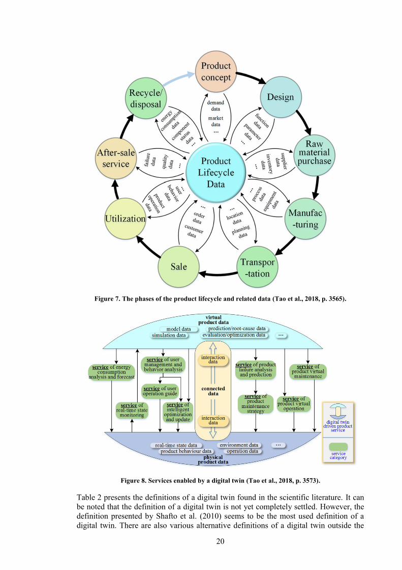
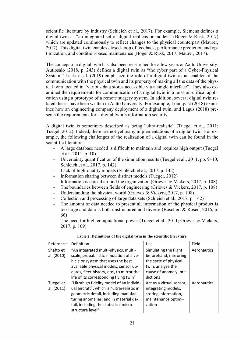
Tao et al. (2018) present a digital twin as an effective way of managing and handling data
through all phases of the product lifecycle (Figure 7). They present the following proper-
ties of a digital twin:
1) Real-time mirroring of the physical system.
2) Connecting data from all phases of the product lifecycle.
3) Continuous updating of virtual models.
A digital twin is used to improve the design of the product by for example offering data
from previous generations and simulations. In the manufacturing phase, a digital twin
concept allows resource management, monitoring, and optimization of the process. In the
operation phase, a digital twin can offer the following services (Figure 8):
1) Real-time monitoring of a product state
2) Energy consumption analysis and prediction
3) User management and behavior analysis
4) Guidance to the operation of the product
5) Optimization of the system operation
6) Analysis and prediction of failures
7) Maintenance optimization
8) Maintenance operations can be trained by first performing them virtually
9) The operator of the product can train the use of the product virtually
20
Figure 7. The phases of the product lifecycle and related data (Tao et al., 2018, p. 3565).
Figure 8. Services enabled by a digital twin (Tao et al., 2018, p. 3573).
Table 2 presents the definitions of a digital twin found in the scientific literature. It can
be noted that the definition of a digital twin is not yet completely settled. However, the
definition presented by Shafto et al. (2010) seems to be the most used definition of a
digital twin. There are also various alternative definitions of a digital twin outside the
21
scientific literature by industry (Schleich et al., 2017). For example, Siemens defines a
digital twin as “an integrated set of digital replicas or models” (Boger & Rusk, 2017)
which are updated continuously to reflect changes to the physical counterpart (Maurer,
2017). This digital twin enables closed-loop of feedback, performance prediction and op-
timization, and condition-based maintenance (Boger & Rusk, 2017; Maurer, 2017).
The concept of a digital twin has also been researched for a few years at Aalto University.
Autiosalo (2018, p. 243) defines a digital twin as “the cyber part of a Cyber-Physical
System.” Laaki et al. (2019) emphasize the role of a digital twin as an enabler of the
communication with the physical twin and its property of making all the data of the phys-
ical twin located in “various data stores accessible via a single interface”. They also ex-
amined the requirements for communication of a digital twin in a mission-critical appli-
cation using a prototype of a remote surgery system. In addition, several digital twin re-
lated theses have been written in Aalto University. For example, Lönnqvist (2018) exam-
ines how an engineering company deployment of a digital twin, and Lagus (2018) pre-
sents the requirements for a digital twin’s information security.
A digital twin is sometimes described as being ”ultra-realistic” (Tuegel et al., 2011;
Tuegel, 2012). Indeed, there are not yet many implementations of a digital twin. For ex-
ample, the following challenges of the realization of a digital twin can be found in the
scientific literature:
- A large database needed is difficult to maintain and requires high output (Tuegel
et al., 2011, p. 10)
- Uncertainty quantification of the simulation results (Tuegel et al., 2011, pp. 9–10;
Schleich et al., 2017, p. 142)
- Lack of high-quality models (Schleich et al., 2017, p. 142)
- Information sharing between distinct models (Tuegel, 2012)
- Information is spread around the organization (Grieves & Vickers, 2017, p. 108)
- The boundaries between fields of engineering (Grieves & Vickers, 2017, p. 108)
- Understanding the physical world (Grieves & Vickers, 2017, p. 108)
- Collection and processing of large data sets (Schleich et al., 2017, p. 142)
- The amount of data needed to present all information of the physical product is
too large and data is both unstructured and diverse (Boschert & Rosen, 2016, p.
66)
- The need for high computational power (Tuegel et al., 2011; Grieves & Vickers,
2017, p. 109)
Table 2. Definitions of the digital twin in the scientific literature.
Reference Definition Use Field
Shafto et al. (2010)
“An integrated multi-physics, multi-scale, probabilistic simulation of a ve-hicle or system that uses the best available physical models, sensor up-dates, fleet history, etc., to mirror the life of its corresponding flying twin”
Simulating the flight beforehand, mirroring the state of physical twin, analyze the cause of anomaly, pre-dictions
Aeronautics
Tuegel et al. (2011)
“Ultrahigh fidelity model of an individ-ual aircraft”, which is “ultrarealistic in geometric detail, including manufac-turing anomalies, and in material de-tail, including the statistical micro-structure level”
Act as a virtual sensor, integrating models, storing information, maintenance optimi-zation
Aeronautics
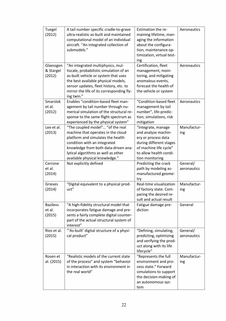
22
Tuegel (2012)
A tail number specific cradle-to-grave ultra-realistic as-built and maintained computational model of an individual aircraft. “An integrated collection of submodels.”
Estimation the re-maining lifetime, man-aging the information about the configura-tion, maintenance op-timization, virtual test-ing
Aeronautics
Glaessgen & Stargel (2012)
“An integrated multiphysics, mul-tiscale, probabilistic simulation of an as-built vehicle or system that uses the best available physical models, sensor updates, fleet history, etc. to mirror the life of its corresponding fly-ing twin.”
Certification, fleet management, moni-toring, and mitigating anomalous events, forecast the health of the vehicle or system
Aeronautics
Smarslok et al. (2012)
Enables “condition-based fleet man-agement by tail number through nu-merical simulation of the structural re-sponse to the same flight spectrum as experienced by the physical system”
“Condition-based fleet management by tail number”, life-predic-tion, simulations, risk mitigation
Aeronautics
Lee et al. (2013)
“The coupled model”… “of the real machine that operates in the cloud platform and simulates the health condition with an integrated knowledge from both data-driven ana-lytical algorithms as well as other available physical knowledge.”
“Integrate, manage and analyze machin-ery or process data during different stages of machine life cycle” to allow health condi-tion monitoring
Manufactur-ing
Cerrone et al. (2014)
Not explicitly defined Predicting the crack path by modeling as-manufactured geome-try
General/ aeronautics
Grieves (2014)
“Digital equivalent to a physical prod-uct”
Real-time visualization of factory state. Com-paring the desired re-sult and actual result
Manufactur-ing
Bazilevs et al. (2015)
“A high-fidelity structural model that incorporates fatigue damage and pre-sents a fairly complete digital counter-part of the actual structural system of interest”
Fatigue damage pre-diction
General
Rios et al. (2015)
“‘As-built’ digital structure of a physi-cal product”
“Defining, simulating, predicting, optimizing and verifying the prod-uct along with its life lifecycle”
General/ aeronautics
Rosen et al. (2015)
“Realistic models of the current state of the process” and system “behavior in interaction with its environment in the real world”
“Represents the full environment and pro-cess state.” Forward simulations to support the decision-making of an autonomous sys-tem
Manufactur-ing
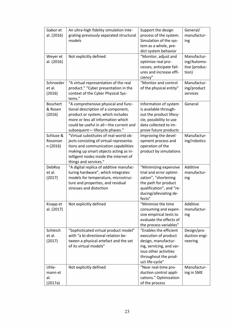
23
Gabor et al. (2016)
An ultra-high fidelity simulation inte-grating previously separated structural models
Support the design process of the system. Simulation of the sys-tem as a whole, pre-dict system behavior
General/ manufactur-ing
Weyer et al. (2016)
Not explicitly defined “Monitor, adjust and optimize real pro-cesses, anticipate fail-ures and increase effi-ciency”
Manufactur-ing/Automo-tive (produc-tion)
Schroeder et al. (2016)
“A virtual representation of the real product.” “Cyber presentation in the context of the Cyber Physical Sys-tems.”
“Monitor and control of the physical entity”
Manufactur-ing/product services
Boschert & Rosen (2016)
“A comprehensive physical and func-tional description of a component, product or system, which includes more or less all information which could be useful in all—the current and subsequent— lifecycle phases.”
Information of system is available through-out the product lifecy-cle, possibility to use data collected to im-prove future products
General
Schluse & Rossmann (2016)
“Virtual substitutes of real-world ob-jects consisting of virtual representa-tions and communication capabilities making up smart objects acting as in-telligent nodes inside the internet of things and services.”
Improving the devel-opment process and operation of the product by simulations
Manufactur-ing/robotics
DebRoy et al. (2017)
“A digital replica of additive manufac-turing hardware”, which integrates models for temperature, microstruc-ture and properties, and residual stresses and distortion
“Minimizing expensive trial and error optimi-zation”, “shortening the path for product qualification”, and “re-ducing/alleviating de-fects”
Additive manufactur-ing
Knapp et al. (2017)
Not explicitly defined “Minimize the time consuming and expen-sive empirical tests to evaluate the effects of the process variables”
Additive manufactur-ing
Schleich et al. (2017)
“Sophisticated virtual product model” with “a bi-directional relation be-tween a physical artefact and the set of its virtual models”
“Enables the efficient execution of product design, manufactur-ing, servicing, and var-ious other activities throughout the prod-uct life-cycle”
Design/pro-duction engi-neering
Uhle-mann et al. (2017a)
Not explicitly defined “Near real-time pro-duction control appli-cations.” Optimization of the process
Manufactur-ing in SME
24
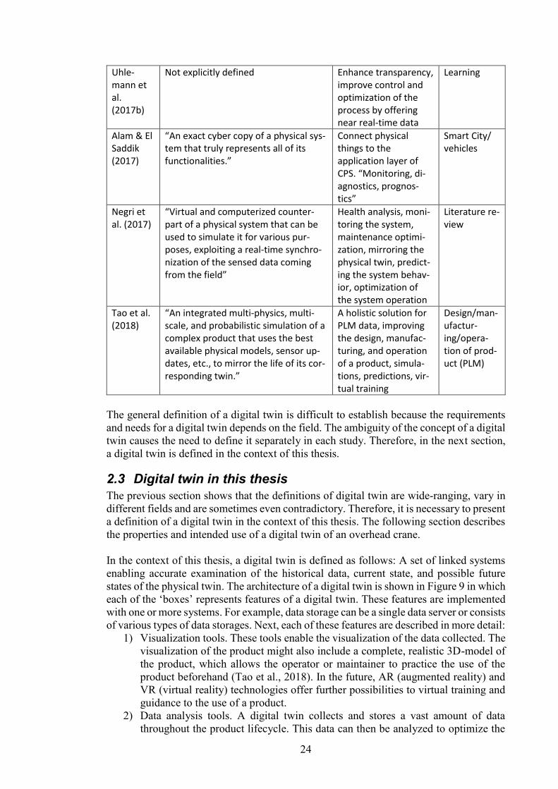
Uhle-mann et al. (2017b)
Not explicitly defined Enhance transparency, improve control and optimization of the process by offering near real-time data
Learning
Alam & El Saddik (2017)
“An exact cyber copy of a physical sys-tem that truly represents all of its functionalities.”
Connect physical things to the application layer of CPS. “Monitoring, di-agnostics, prognos-tics”
Smart City/ vehicles
Negri et al. (2017)
“Virtual and computerized counter-part of a physical system that can be used to simulate it for various pur-poses, exploiting a real-time synchro-nization of the sensed data coming from the field”
Health analysis, moni-toring the system, maintenance optimi-zation, mirroring the physical twin, predict-ing the system behav-ior, optimization of the system operation
Literature re-view
Tao et al. (2018)
“An integrated multi-physics, multi-scale, and probabilistic simulation of a complex product that uses the best available physical models, sensor up-dates, etc., to mirror the life of its cor-responding twin.”
A holistic solution for PLM data, improving the design, manufac-turing, and operation of a product, simula-tions, predictions, vir-tual training
Design/man-ufactur-ing/opera-tion of prod-uct (PLM)
The general definition of a digital twin is difficult to establish because the requirements
and needs for a digital twin depends on the field. The ambiguity of the concept of a digital
twin causes the need to define it separately in each study. Therefore, in the next section,
a digital twin is defined in the context of this thesis.
2.3 Digital twin in this thesis
The previous section shows that the definitions of digital twin are wide-ranging, vary in
different fields and are sometimes even contradictory. Therefore, it is necessary to present
a definition of a digital twin in the context of this thesis. The following section describes
the properties and intended use of a digital twin of an overhead crane.
In the context of this thesis, a digital twin is defined as follows: A set of linked systems
enabling accurate examination of the historical data, current state, and possible future
states of the physical twin. The architecture of a digital twin is shown in Figure 9 in which
each of the ‘boxes’ represents features of a digital twin. These features are implemented
with one or more systems. For example, data storage can be a single data server or consists
of various types of data storages. Next, each of these features are described in more detail:
1) Visualization tools. These tools enable the visualization of the data collected. The
visualization of the product might also include a complete, realistic 3D-model of
the product, which allows the operator or maintainer to practice the use of the
product beforehand (Tao et al., 2018). In the future, AR (augmented reality) and
VR (virtual reality) technologies offer further possibilities to virtual training and
guidance to the use of a product.
2) Data analysis tools. A digital twin collects and stores a vast amount of data
throughout the product lifecycle. This data can then be analyzed to optimize the
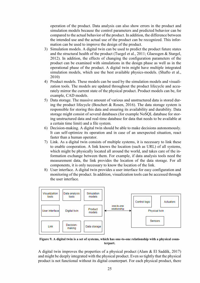
25
operation of the product. Data analysis can also show errors in the product and
simulation models because the control parameters and predicted behavior can be
compared to the actual behavior of the product. In addition, the difference between
the intended use and the actual use of the product can be recognized. This infor-
mation can be used to improve the design of the product.
3) Simulation models. A digital twin can be used to predict the product future states
and the structural health of the product (Tuegel et al., 2011; Glaessgen & Stargel,
2012). In addition, the effects of changing the configuration parameters of the
product can be examined with simulations in the design phase as well as in the
operational phase of the product. A digital twin might have multiple integrated
simulation models, which use the best available physics-models. (Shafto et al.,
2010)
4) Product models. These models can be used by the simulation models and visuali-
zation tools. The models are updated throughout the product lifecycle and accu-
rately mirror the current state of the physical product. Product models can be, for
example, CAD models.
5) Data storage. The massive amount of various and unstructured data is stored dur-
ing the product lifecycle (Boschert & Rosen, 2016). The data storage system is
responsible for storing this data and ensuring its availability and durability. Data
storage might consist of several databases (for example NoSQL database for stor-
ing unstructured data and real-time database for data that needs to be available at
a certain time limit) and a file system.
6) Decision-making. A digital twin should be able to make decisions autonomously.
It can self-optimize its operation and in case of an unexpected situation, react
faster than a human operator.
7) Link. As a digital twin consists of multiple systems, it is necessary to link these
to enable cooperation. A link knows the location (such as URL) of all systems,
which might be physically located all around the world, and takes care of the in-
formation exchange between them. For example, if data analysis tools need the
measurement data, the link provides the location of the data storage. For all
components, it is only necessary to know the location of the link.
8) User interface. A digital twin provides a user interface for easy configuration and
monitoring of the product. In addition, visualization tools can be accessed through
the user interface.
Figure 9. A digital twin is a set of systems, which has one-to-one relationship with a physical coun-
terpart.
A digital twin improves the properties of a physical product (Alam & El Saddik, 2017)
and might be deeply integrated with the physical product. Even so tightly that the physical
product is not functional without its digital counterpart. For each physical product, there
26
exists only one digital twin: there is a one-to-one relationship between the physical and
digital counterparts (Ríos et al., 2015, pp. 661–662; Alam & El Saddik, 2017, p. 2053).
However, a complex product might consist of multiple components each of those having
their own corresponding digital twin. Therefore, a digital twin might consist of multiple
digital twins.
A physical counterpart contains actuators, a myriad of sensors to provide enough infor-
mation for a digital twin to know exactly the current status of the physical product, and
control logic (Figure 9). If a real-time control of the product is needed, control logic needs
to be located close to the physical product. Usually, it should be embedded in the physical
product, but edge computing can also be utilized. A digital twin updates the control logic
of the physical product or can even control it directly if the requirement for latency is not
very strict.
The above definition of a digital twin and its functionalities are also valid for the overhead
crane used as an example in this thesis. Below, the specific use cases for a digital twin of
an overhead crane are presented for both the manufacturer and the user of the crane. For
the manufacturer:
- Verify the design of the overhead cranes in the real environment
- Optimization of the maintenance by knowing historical loads of an individual
crane
- Providing customized inspection lists and the information of the as-maintained
state of the crane to the maintainer
- Fleet data provides information about individual components quality
For the user of the crane:
- Provide information to customers external systems such as MES
- Data about the use of a crane
- Optimizing the routes of the overhead crane
- Visualizations of the crane can ease the use of the crane and allow virtual training
- Advanced features such as anti-sway control of the crane
- The crane can communicate with its environment and adjust its operation. For
example, if there is no rush on the factory, the crane can drive slower to save
wearable parts.
The above use cases are used as guidelines to derive the data needed by a digital twin
presented in the following section and to choose the use cases for the assessment of ap-
plication protocols and communication technologies.
2.4 Data contained in a digital twin
To identify the communication needs of a digital twin, it is necessary to examine what
types of data it contains and what type of data is needed to be transmitted. In this section,
the data a digital twin contains is first presented at a general level, and thereafter from the
overhead crane point of view.
The generic digital twin can be described as containing the following data:
- Simulation models, which might be stored to an external system. If a simulation
is needed to be performed the model can be fetched from the external system or
the whole simulation can be run on that system. However, in some cases, forward
simulations are continuously run, in which case the simulations should be per-
formed close to other parts of a digital twin and physical twin to reduce delays.
- Product models. These might also be stored to an external system. Product models
are updated continuously to mirror the state of the physical product: they include
27
the maintenance data and changed components as well as information about the
wear of the material of the product.
- Design parameters and data. This data can be stored to a manufacturer’s system
and might not be accessible by users of the product. The existence of the design
data allows improving the later versions of the product. The design data can also
be compared to the data collected from the field to compare if the product is used
as intended. Thereafter, the design parameters can be modified to better reflect the
real use of the product.
- Measurement data from various sensors. The physical quantities measured as well
as the requirements for data quality and measurement rates are highly dependent
on the type of product. In addition, if the product uses the measurement data to
control itself, low latency is needed.
- Miscellaneous data. There is a substantial amount of miscellaneous data such as
instructions related to every product. Miscellaneous data is unstructured and di-
verse as it can be almost any kind of data such as documents or videos.
However, as the products having a digital twin are different from each other, also the data
contained in their digital twins is diverse.
Because the digital twin of an overhead crane is used as an example in this thesis, the data
it contains is presented in more detail. This data can be derived from the list above and
from the use cases for the digital twin of an overhead crane presented in the previous
section. The data the digital twin of an overhead crane contains includes:
- Simulation models. These allow calculating loads of an overhead crane using
FEM analysis. The simulation results can be combined with the measurement
data, which enables improving the model accuracy. Simulation models could also
be utilized by, for example, anti-sway control of the crane. In addition, the wear
of the machine could be predicted by running simulations based on the measure-
ment data.
- Product models. These contain the as-maintained structure of the crane including
all modifications to the standard configuration and replaced parts. The product
models also include visualizations of the crane. These visualizations can be used
to assist inspections and train the crane operators.
- Design data. The design data includes, for example, the environment and expected
use of the crane. In addition, it includes the maximum loads and safety factors.
The design parameters can be compared to the actual usage of the crane to see if
they have been selected correctly. The parameters can then be modified to im-
prove the efficiency of future generations of cranes.
- Measurement data. In order for a digital twin to accurately mirror the current state
of the overhead crane, a myriad of sensors, which produce a vast amount of data,
are needed to be attached to the crane. Sensors could measure, for example, the
weight of the payload, the vibrations in wheels, the strain of the bridge, and the
location of the hook. In addition, machine vision could be used to visual inspec-
tion of the crane. The type of data defines how often it is sent to the data storage
of the digital twin. For example, if the location of the hook is used for controlling
the movement of the crane, it should be transferred nearly real-time. Whereas, if
the temperature of the environment is monitored, it is likely to be enough to send
it e.g. every 10 minutes to the data storage. Data can also be processed before
transmitting it to save storage space. For example, if the vibration in the wheels
stays at the same level, it may be sufficient to send only the average level and
characteristics of vibration instead of the whole measured data. However, data
processing can hide the emerging underlying phenomenon. The automation data,
28
which includes information used for controlling the machine, can also be included
in the measurement data. This information can usually be fetched from the PLC
(Programmable logic controller) system of the machine.
- Miscellaneous data. This includes for example instructions for the maintenance
and operation, the log of crane users, and the description of the environment in
which the crane is used.
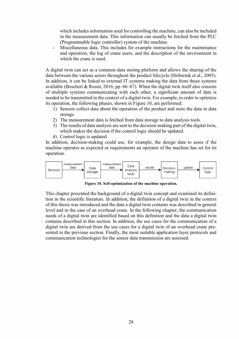
A digital twin can act as a common data storing platform and allows the sharing of the
data between the various actors throughout the product lifecycle (Hribernik et al., 2005).
In addition, it can be linked to external IT systems making the data from those systems
available (Boschert & Rosen, 2016, pp. 66–67). When the digital twin itself also consists
of multiple systems communicating with each other, a significant amount of data is
needed to be transmitted in the context of a digital twin. For example, in order to optimize
its operation, the following phases, shown in Figure 10, are performed:
1) Sensors collect data about the operation of the product and store the data in data
storage.
2) The measurement data is fetched from data storage to data analysis tools.
3) The results of data analysis are sent to the decision-making part of the digital twin,
which makes the decision if the control logic should be updated.
4) Control logic is updated.
In addition, decision-making could use, for example, the design data to asses if the
machine operates as expected or requirements an operator of the machine has set for its
operation.
Figure 10. Self-optimization of the machine operation.
This chapter presented the background of a digital twin concept and examined its defini-
tion in the scientific literature. In addition, the definition of a digital twin in the context
of this thesis was introduced and the data a digital twin contains was described in general
level and in the case of an overhead crane. In the following chapter, the communication
needs of a digital twin are identified based on this definition and the data a digital twin
contains described in this section. In addition, the use cases for the communication of a
digital twin are derived from the use cases for a digital twin of an overhead crane pre-
sented in the previous section. Finally, the most suitable application layer protocols and
communication technologies for the sensor data transmission are assessed.
29
3 Communication In this chapter, the communication of a digital twin is examined. First, the communication
needs of a digital twin are identified. Thereafter, use cases for assessing the application
protocols and communication technologies are presented. Section 3.3 shortly presents the
layered architecture of the internet and the widely used OSI-model. In section 3.4, the
most commonly used application layer protocols are examined, and, in section 3.5, most
relevant wireless communication technologies in the context of a digital twin and IoT
communication are introduced. Finally, a short review of IoT platforms, which enable
data collection and sensor management, is presented.
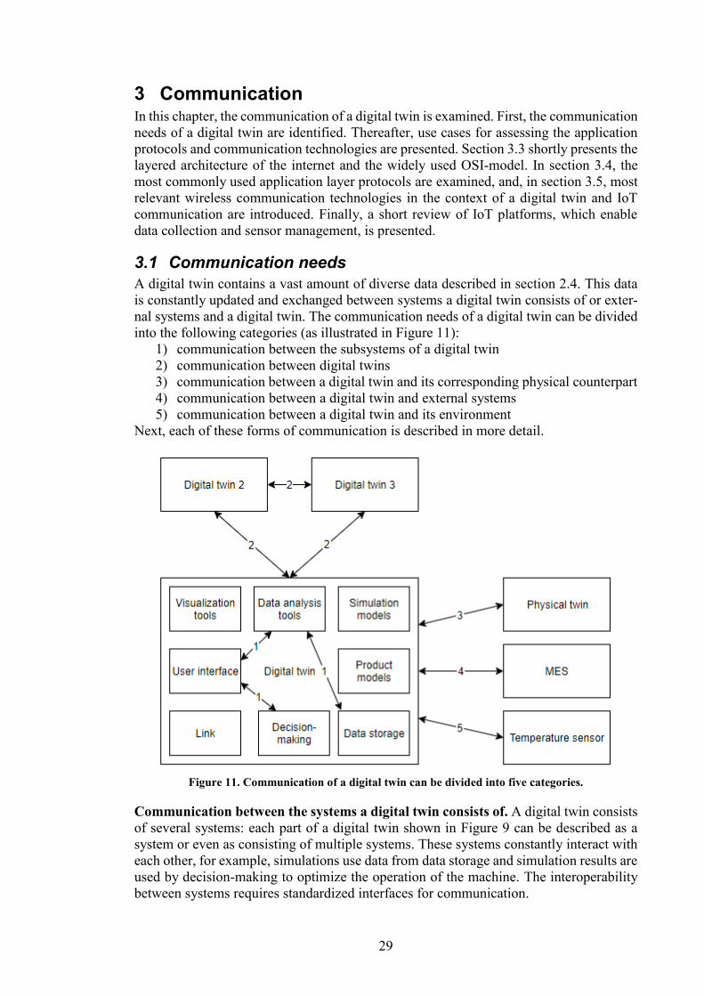
3.1 Communication needs
A digital twin contains a vast amount of diverse data described in section 2.4. This data
is constantly updated and exchanged between systems a digital twin consists of or exter-
nal systems and a digital twin. The communication needs of a digital twin can be divided
into the following categories (as illustrated in Figure 11):
1) communication between the subsystems of a digital twin
2) communication between digital twins
3) communication between a digital twin and its corresponding physical counterpart
4) communication between a digital twin and external systems
5) communication between a digital twin and its environment
Next, each of these forms of communication is described in more detail.
Figure 11. Communication of a digital twin can be divided into five categories.
Communication between the systems a digital twin consists of. A digital twin consists
of several systems: each part of a digital twin shown in Figure 9 can be described as a
system or even as consisting of multiple systems. These systems constantly interact with
each other, for example, simulations use data from data storage and simulation results are
used by decision-making to optimize the operation of the machine. The interoperability
between systems requires standardized interfaces for communication.
30
Communication between digital twins. A digital twin might consist of several other
digital twins. For example, each part (at least the larger ones) of an overhead crane have
their own digital twins. The communication between digital twins can be divided into two
categories: communication between digital twins a larger digital twin consists of, for ex-
ample, between trolley and bridge of an overhead crane, and communication between
digital twin and other machines’ digital twins, for example, between digital twins of over-
head cranes located at the same factory hall. By communicating with each other, digital
twins can, for example, share information about their environment or about their statuses
and future actions. The communication between digital twins of machines allows co-op-
eration of the physical machines.
Communication between a digital twin and its physical twin. The communication be-
tween a digital twin and its physical counterpart can be divided into two categories: Data
transmission from the physical twin to the digital twin, which includes sensor data and
status data, and data transmission from a digital twin to physical twin, which includes
remote control commands and software updates. This thesis focuses on the former cate-
gory, as the data collection from the physical twin is the key enabler for the realization of
a digital twin. In addition, a digital twin needs to know the status of the physical counter-
part by its definition.
Communication between a digital twin and external systems. External systems can
act as data storage, offer computational power or enable simulations. They also include,
for example, MES to which digital twins used in production can push the manufacturing
data. An external system should offer a standardized interface a digital twin can use for
communication. Therefore, communication between external systems and systems a dig-
ital twin of are not differing from each other. Actually, the boundary between external
systems and systems a digital twin consists of is quite fluid as both can be located at the
cloud and offer similar services. The major distinguishing factor is that external systems
are managed by an external party instead of the owner of the digital twin.
Communication between a digital twin and its environment. This includes monitoring
of physical twin’s environment and informing the environment about the status of the
physical twin. Monitoring can be performed using physical twin’s sensors or external
sensor nodes. Informing the environment about the status of the physical twin increases
safety and allows co-operation with the environment. If the external sensor nodes have
digital twins and each (significant) part of the environment has their own digital twin,
communication can be reduced to communication between digital twins.
This thesis focuses on the communication between a digital twin and its physical twin
and, more precisely, on the sensor data transmission from physical twin to the digital
twin. Sensor data transmission was selected for further examination as a digital twin is
not a digital twin by a definition if it does not have knowledge of the current status of the
physical twin. The measurement data from sensors is used to continuously update the
digital twin so that it can have this knowledge of the current status. The following section
presents the use cases considered in the assessment of the most suitable application layer
protocols and communication technologies for the sensor data transmission later in this
chapter.
3.2 Use cases
In this thesis, the focus is on the measurement data collected by sensors attached to the
physical twin, that is, communication between the physical and the digital twin. Sensor
31
nodes attached to a physical twin should be wireless because wiring becomes challenging
if there is an extensive number of sensor nodes. A sensor node is an IoT device, which
contains sensor(s) and a microcontroller capable of sending data wirelessly. The applica-
tions of the IoT devices can be divided into the following categories (Qin et al., 2014, pp.
1–2):
- Real-time point-to-point applications, in which the status of the device needs to
be transmitted reliably with low latency
- Monitoring applications collecting data periodically
- Data exchange between objects such as vehicles
This thesis covers the first two categories as the sensor data transmission from a physical
twin to a digital twin is examined. Two more specific use cases related to the overhead
crane are identified:
1) Sensor data is used to control the location of the hook in real-time
2) Sensor data is used to monitor the stress of the bridge
In the first case, the most important requirement for communication is low latency. In
addition, high reliability and security are crucial factors. For example, if the connection
is broken, the crane can’t operate, or if incorrect measurement data is received, the crane
might operate incorrectly or even dangerously. The location of the hook can be measured,
for example, with laser sensors measuring the location of the bridge and rotary encoders,
which measure how many rotations the wheels of the trolley and hoist motor have rotated.
In the second case, communication should be as efficient as possible, meaning the band-
width usage, as well as the energy consumption of the sensor node, needs to be as low as
possible. If the energy consumption is low enough, sensor nodes can be powered by bat-
teries making them truly wireless. Because the computational power of sensor nodes is
limited, the protocols should be lightweight in both use cases. In addition, easy imple-
mentation and availability of support are important factors. In this case, the stress is meas-
ured with a strain gauge, which is possible if the material properties are well known. The
strain is measured once in a second and saved as an integer (4 bytes). Therefore, the data
produced is 240 bytes per minute and 345.6 kB per day. The measurement data is sent to
the data storage once in a minute. The requirements for both use cases for communication
are summarized in Table 3.
Table 3. Requirements for use cases.
Low
late
ncy
Low
co
mp
uta
tio
nal
po
we
r
Low
ban
dw
idth
usa
ge
Low
en
ergy
co
nsu
mp
tio
n
Secu
rity
Rel
iab
ility
Easy
imp
lem
enta
tio
n
Case 1 x x x x x
Case 2 x x x x x
This section presented the use cases, which are used in the assessment of the application
layer protocols and communication technologies. Before moving to the assessment, the
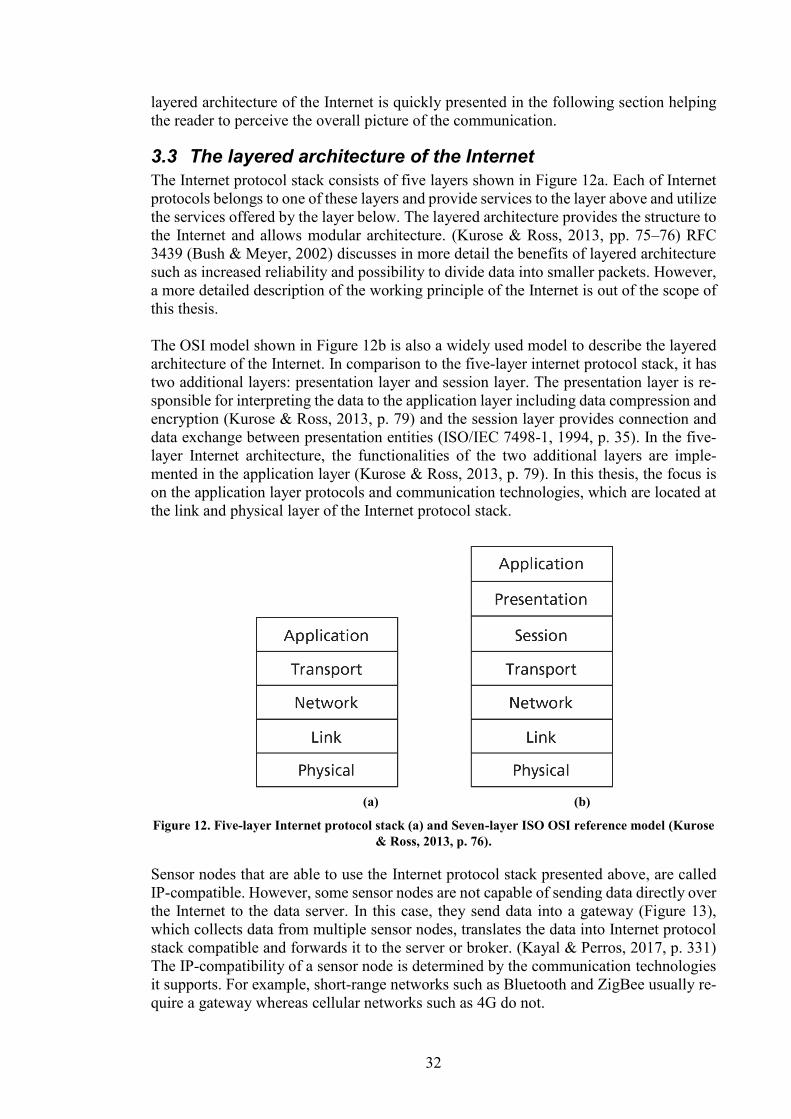
32
layered architecture of the Internet is quickly presented in the following section helping
the reader to perceive the overall picture of the communication.
3.3 The layered architecture of the Internet
The Internet protocol stack consists of five layers shown in Figure 12a. Each of Internet
protocols belongs to one of these layers and provide services to the layer above and utilize
the services offered by the layer below. The layered architecture provides the structure to
the Internet and allows modular architecture. (Kurose & Ross, 2013, pp. 75–76) RFC
3439 (Bush & Meyer, 2002) discusses in more detail the benefits of layered architecture
such as increased reliability and possibility to divide data into smaller packets. However,
a more detailed description of the working principle of the Internet is out of the scope of
this thesis.
The OSI model shown in Figure 12b is also a widely used model to describe the layered
architecture of the Internet. In comparison to the five-layer internet protocol stack, it has
two additional layers: presentation layer and session layer. The presentation layer is re-
sponsible for interpreting the data to the application layer including data compression and
encryption (Kurose & Ross, 2013, p. 79) and the session layer provides connection and
data exchange between presentation entities (ISO/IEC 7498-1, 1994, p. 35). In the five-
layer Internet architecture, the functionalities of the two additional layers are imple-
mented in the application layer (Kurose & Ross, 2013, p. 79). In this thesis, the focus is
on the application layer protocols and communication technologies, which are located at
the link and physical layer of the Internet protocol stack.
(a) (b)
Figure 12. Five-layer Internet protocol stack (a) and Seven-layer ISO OSI reference model (Kurose
& Ross, 2013, p. 76).
Sensor nodes that are able to use the Internet protocol stack presented above, are called
IP-compatible. However, some sensor nodes are not capable of sending data directly over
the Internet to the data server. In this case, they send data into a gateway (Figure 13),
which collects data from multiple sensor nodes, translates the data into Internet protocol
stack compatible and forwards it to the server or broker. (Kayal & Perros, 2017, p. 331)
The IP-compatibility of a sensor node is determined by the communication technologies
it supports. For example, short-range networks such as Bluetooth and ZigBee usually re-
quire a gateway whereas cellular networks such as 4G do not.
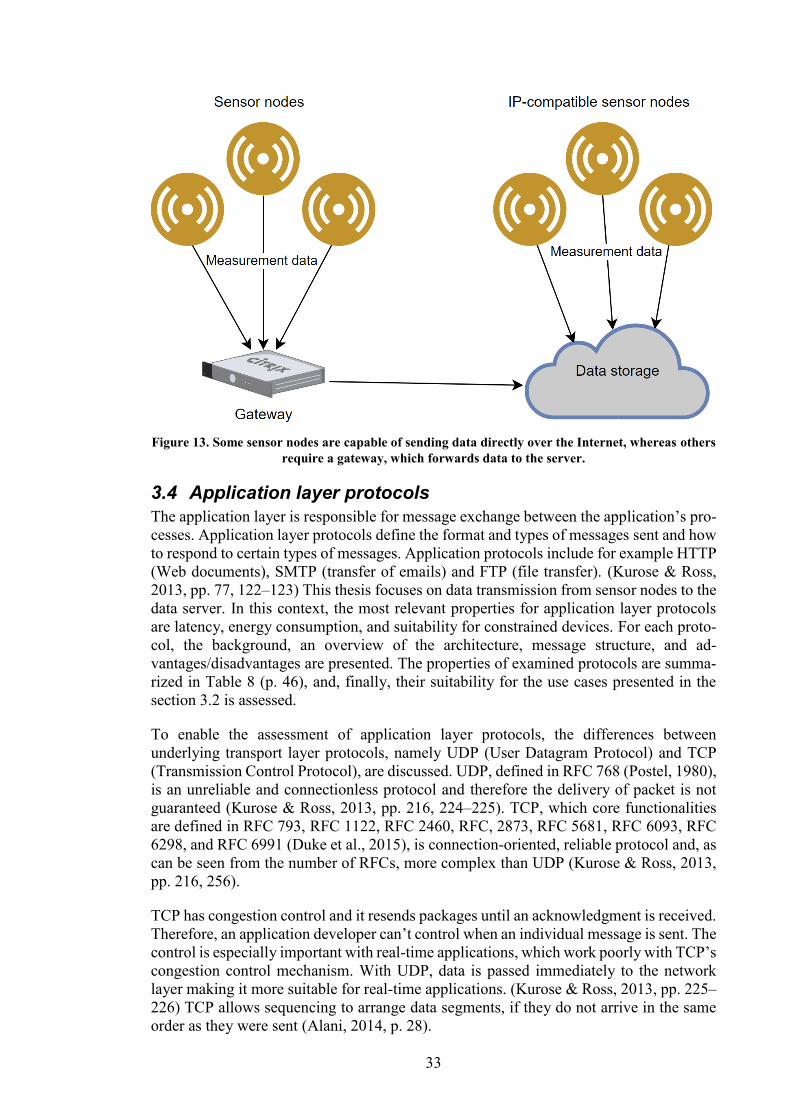
33
Figure 13. Some sensor nodes are capable of sending data directly over the Internet, whereas others
require a gateway, which forwards data to the server.
3.4 Application layer protocols
The application layer is responsible for message exchange between the application’s pro-
cesses. Application layer protocols define the format and types of messages sent and how
to respond to certain types of messages. Application protocols include for example HTTP
(Web documents), SMTP (transfer of emails) and FTP (file transfer). (Kurose & Ross,
2013, pp. 77, 122–123) This thesis focuses on data transmission from sensor nodes to the
data server. In this context, the most relevant properties for application layer protocols
are latency, energy consumption, and suitability for constrained devices. For each proto-
col, the background, an overview of the architecture, message structure, and ad-
vantages/disadvantages are presented. The properties of examined protocols are summa-
rized in Table 8 (p. 46), and, finally, their suitability for the use cases presented in the
section 3.2 is assessed.
To enable the assessment of application layer protocols, the differences between
underlying transport layer protocols, namely UDP (User Datagram Protocol) and TCP
(Transmission Control Protocol), are discussed. UDP, defined in RFC 768 (Postel, 1980),
is an unreliable and connectionless protocol and therefore the delivery of packet is not
guaranteed (Kurose & Ross, 2013, pp. 216, 224–225). TCP, which core functionalities
are defined in RFC 793, RFC 1122, RFC 2460, RFC, 2873, RFC 5681, RFC 6093, RFC
6298, and RFC 6991 (Duke et al., 2015), is connection-oriented, reliable protocol and, as
can be seen from the number of RFCs, more complex than UDP (Kurose & Ross, 2013,
pp. 216, 256).
TCP has congestion control and it resends packages until an acknowledgment is received.
Therefore, an application developer can’t control when an individual message is sent. The
control is especially important with real-time applications, which work poorly with TCP’s
congestion control mechanism. With UDP, data is passed immediately to the network
layer making it more suitable for real-time applications. (Kurose & Ross, 2013, pp. 225–
226) TCP allows sequencing to arrange data segments, if they do not arrive in the same
order as they were sent (Alani, 2014, p. 28).
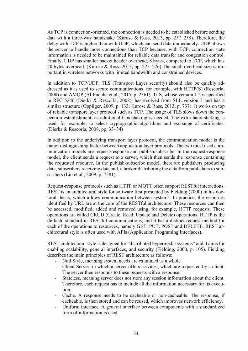
34
As TCP is connection-oriented, the connection is needed to be established before sending
data with a three-way handshake (Kurose & Ross, 2013, pp. 257–258). Therefore, the
delay with TCP is higher than with UDP, which can send data immediately. UDP allows
the server to handle more connections than TCP because, with TCP, connection state
information is needed to be maintained for reliable data transfer and congestion control.
Finally, UDP has smaller packet header overhead, 8 bytes, compared to TCP, which has
20 bytes overhead. (Kurose & Ross, 2013, pp. 225–226) The small overhead size is im-
portant in wireless networks with limited bandwidth and constrained devices.
In addition to TCP/UDP, TLS (Transport Layer security) should also be quickly ad-
dressed as it is used to secure communications, for example, with HTTP(S) (Rescorla,
2000) and AMQP (Al-Fuqaha et al., 2015, p. 2361). TLS, whose version 1.2 is specified
in RFC 5246 (Dierks & Rescorla, 2008), has evolved from SLL version 3 and has a
similar structure (Oppliger, 2009, p. 133; Kurose & Ross, 2013, p. 737). It works on top
of reliable transport layer protocol such as TCP. The usage of TLS slows down the con-
nection establishment, as additional handshaking is needed. The extra hand-shaking is
used, for example, to select cryptographic algorithms and exchange of certificates.
(Dierks & Rescorla, 2008, pp. 33–34)
In addition to the underlying transport layer protocol, the communication model is the
major distinguishing factor between application layer protocols. The two most used com-
munication models are request/response and publish/subscribe. In the request-response
model, the client sends a request to a server, which then sends the response containing
the requested resource. In the publish-subscribe model, there are publishers producing
data, subscribers receiving data and, a broker distributing the data from publishers to sub-
scribers (Liu et al., 2009, p. 7581).
Request-response protocols such as HTTP or MQTT often support RESTful interactions.
REST is an architectural style for software first presented by Fielding (2000) in his doc-
toral thesis, which allows communication between systems. In practice, the resources
identified by URL are at the core of the RESTful architecture. These resources can then
be accessed, modified, added and removed using, for example, HTTP requests. These
operations are called CRUD (Create, Read, Update and Delete) operations. HTTP is the
de facto standard in RESTful communications, and it has a distinct request method for
each of the operations to resources, namely GET, PUT, POST and DELETE. REST ar-
chitectural style is often used with APIs (Application Programing Interfaces).
REST architectural style is designed for “distributed hypermedia systems” and it aims for
enabling scalability, general interfaces, and security (Fielding, 2000, p. 105). Fielding
describes the main principles of REST architecture as follows:
- Null Style, meaning system needs are examined as a whole
- Client-Server, in which a server offers services, which are requested by a client.
The server then responds to these requests with a response.
- Stateless, meaning server does not store any session information about the client.
Therefore, each request has to include all the information necessary for its execu-
tion.
- Cache. A response needs to be cacheable or non-cacheable. The response, if
cacheable, is then stored and can be reused, which improves network efficiency.
- Uniform interface. A general interface between components with a standardized
form of information is used.
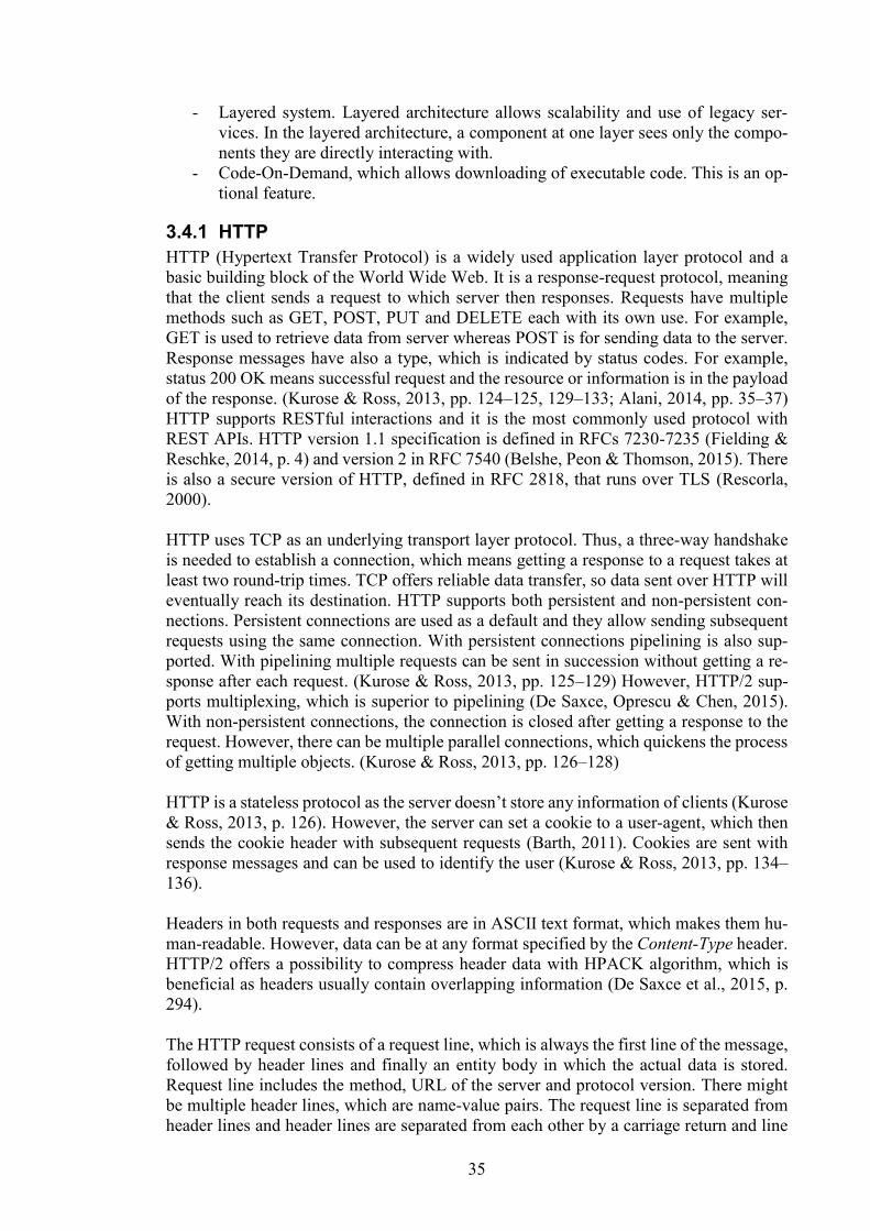
35
- Layered system. Layered architecture allows scalability and use of legacy ser-
vices. In the layered architecture, a component at one layer sees only the compo-
nents they are directly interacting with.
- Code-On-Demand, which allows downloading of executable code. This is an op-
tional feature.
3.4.1 HTTP
HTTP (Hypertext Transfer Protocol) is a widely used application layer protocol and a
basic building block of the World Wide Web. It is a response-request protocol, meaning
that the client sends a request to which server then responses. Requests have multiple
methods such as GET, POST, PUT and DELETE each with its own use. For example,
GET is used to retrieve data from server whereas POST is for sending data to the server.
Response messages have also a type, which is indicated by status codes. For example,
status 200 OK means successful request and the resource or information is in the payload
of the response. (Kurose & Ross, 2013, pp. 124–125, 129–133; Alani, 2014, pp. 35–37)
HTTP supports RESTful interactions and it is the most commonly used protocol with
REST APIs. HTTP version 1.1 specification is defined in RFCs 7230-7235 (Fielding &
Reschke, 2014, p. 4) and version 2 in RFC 7540 (Belshe, Peon & Thomson, 2015). There
is also a secure version of HTTP, defined in RFC 2818, that runs over TLS (Rescorla,
2000).
HTTP uses TCP as an underlying transport layer protocol. Thus, a three-way handshake
is needed to establish a connection, which means getting a response to a request takes at
least two round-trip times. TCP offers reliable data transfer, so data sent over HTTP will
eventually reach its destination. HTTP supports both persistent and non-persistent con-
nections. Persistent connections are used as a default and they allow sending subsequent
requests using the same connection. With persistent connections pipelining is also sup-
ported. With pipelining multiple requests can be sent in succession without getting a re-
sponse after each request. (Kurose & Ross, 2013, pp. 125–129) However, HTTP/2 sup-
ports multiplexing, which is superior to pipelining (De Saxce, Oprescu & Chen, 2015).
With non-persistent connections, the connection is closed after getting a response to the
request. However, there can be multiple parallel connections, which quickens the process
of getting multiple objects. (Kurose & Ross, 2013, pp. 126–128)
HTTP is a stateless protocol as the server doesn’t store any information of clients (Kurose
& Ross, 2013, p. 126). However, the server can set a cookie to a user-agent, which then
sends the cookie header with subsequent requests (Barth, 2011). Cookies are sent with
response messages and can be used to identify the user (Kurose & Ross, 2013, pp. 134–
136).
Headers in both requests and responses are in ASCII text format, which makes them hu-
man-readable. However, data can be at any format specified by the Content-Type header.
HTTP/2 offers a possibility to compress header data with HPACK algorithm, which is
beneficial as headers usually contain overlapping information (De Saxce et al., 2015, p.
294).
The HTTP request consists of a request line, which is always the first line of the message,
followed by header lines and finally an entity body in which the actual data is stored.
Request line includes the method, URL of the server and protocol version. There might
be multiple header lines, which are name-value pairs. The request line is separated from
header lines and header lines are separated from each other by a carriage return and line
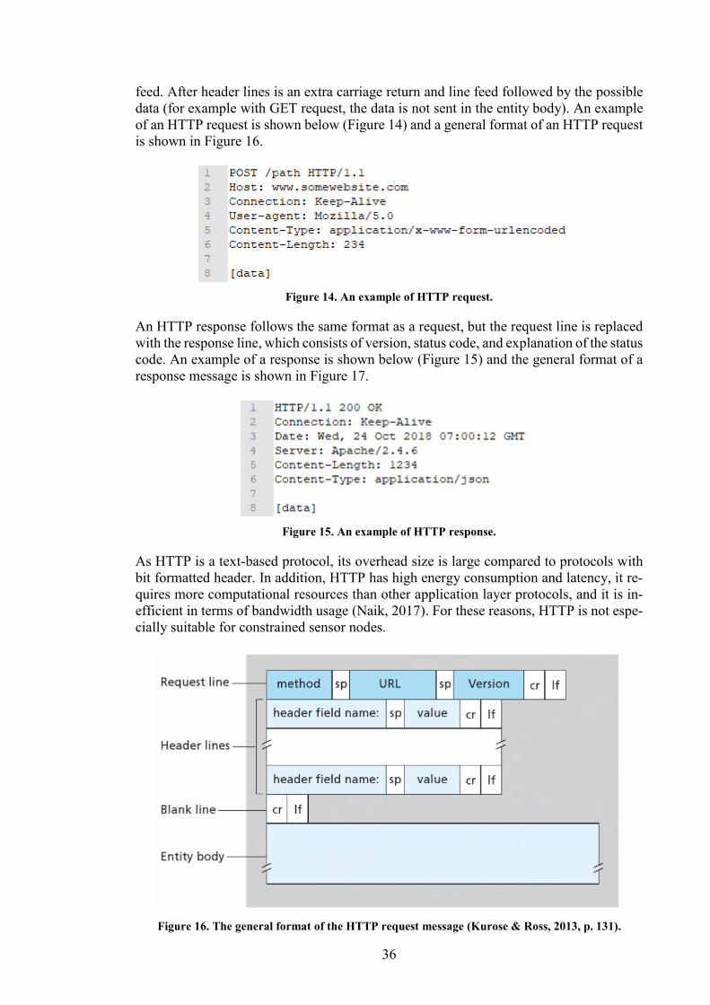
36
feed. After header lines is an extra carriage return and line feed followed by the possible
data (for example with GET request, the data is not sent in the entity body). An example
of an HTTP request is shown below (Figure 14) and a general format of an HTTP request
is shown in Figure 16.
Figure 14. An example of HTTP request.
An HTTP response follows the same format as a request, but the request line is replaced
with the response line, which consists of version, status code, and explanation of the status
code. An example of a response is shown below (Figure 15) and the general format of a
response message is shown in Figure 17.
Figure 15. An example of HTTP response.
As HTTP is a text-based protocol, its overhead size is large compared to protocols with
bit formatted header. In addition, HTTP has high energy consumption and latency, it re-
quires more computational resources than other application layer protocols, and it is in-
efficient in terms of bandwidth usage (Naik, 2017). For these reasons, HTTP is not espe-
cially suitable for constrained sensor nodes.
Figure 16. The general format of the HTTP request message (Kurose & Ross, 2013, p. 131).
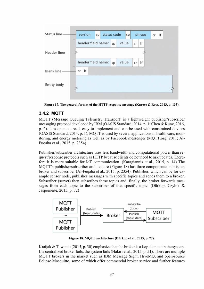
37
Figure 17. The general format of the HTTP response message (Kurose & Ross, 2013, p. 133).
3.4.2 MQTT
MQTT (Message Queuing Telemetry Transport) is a lightweight publisher/subscriber
messaging protocol developed by IBM (OASIS Standard, 2014, p. 1; Chen & Kunz, 2016,
p. 2). It is open-sourced, easy to implement and can be used with constrained devices
(OASIS Standard, 2014, p. 1). MQTT is used by several applications in health care, mon-
itoring, and energy metering as well as by Facebook messenger (MQTT.org, 2011; Al-
Fuqaha et al., 2015, p. 2354).
Publisher/subscriber architecture uses less bandwidth and computational power than re-
quest/response protocols such as HTTP because clients do not need to ask updates. There-
fore it is more suitable for IoT communication. (Karagiannis et al., 2015, p. 14) The
MQTT’s publisher/subscriber architecture (Figure 18) has three components: publisher,
broker and subscriber (Al-Fuqaha et al., 2015, p. 2354). Publisher, which can be for ex-
ample sensor node, publishes messages with specific topics and sends them to a broker.
Subscriber (server) then subscribes these topics and, finally, the broker forwards mes-
sages from each topic to the subscriber of that specific topic. (Dürkop, Czybik &
Jasperneite, 2015, p. 72)
Figure 18. MQTT architecture (Dürkop et al., 2015, p. 72).
Kraijak & Tuwanut (2015, p. 30) emphasize that the broker is a key element in the system.
If a centralized broker fails, the system fails (Hakiri et al., 2015, p. 51). There are multiple
MQTT brokers in the market such as IBM Message Sight, HiveMQ, and open-source
Eclipse Mosquitto, some of which offer commercial broker service and further features
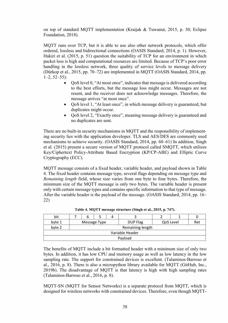
38
on top of standard MQTT implementation (Kraijak & Tuwanut, 2015, p. 30; Eclipse
Foundation, 2018).
MQTT runs over TCP, but it is able to use also other network protocols, which offer
ordered, lossless and bidirectional connections (OASIS Standard, 2014, p. 1). However,
Hakiri et al. (2015, p. 51) question the suitability of TCP for an environment in which
packet loss is high and computational resources are limited. Because of TCP’s poor error
handling in the lossless network, three quality of service levels to message delivery
(Dürkop et al., 2015, pp. 70–72) are implemented in MQTT (OASIS Standard, 2014, pp.
1–2, 52–55):
QoS level 0, “At most once”, indicates that message is delivered according
to the best efforts, but the message loss might occur. Messages are not
resent, and the receiver does not acknowledge messages. Therefore, the
message arrives “at most once”.
QoS level 1, “At least once”, in which message delivery is guaranteed, but
duplicates might occur.
QoS level 2, “Exactly once”, meaning message delivery is guaranteed and
no duplicates are sent.
There are no built-in security mechanisms in MQTT and the responsibility of implement-
ing security lies with the application developer. TLS and AES/DES are commonly used
mechanisms to achieve security. (OASIS Standard, 2014, pp. 60–61) In addition, Singh
et al. (2015) present a secure version of MQTT protocol called SMQTT, which utilizes
Key/Ciphertext Policy-Attribute Based Encryption (KP/CP-ABE) and Elliptic Curve
Cryptography (ECC).
MQTT message consists of a fixed header, variable header, and payload shown in Table
4. The fixed header contains message type, several flags depending on message type and
Remaining length field, whose size varies from one byte to four bytes. Therefore, the
minimum size of the MQTT message is only two bytes. The variable header is present
only with certain message types and contains specific information to that type of message.
After the variable header is the payload of the message. (OASIS Standard, 2014, pp. 16–
22)
Table 4. MQTT message structure (Singh et al., 2015, p. 747).
bit 7 6 5 4 3 2 1 0
byte 1 Message Type DUP Flag QoS Level Ret
byte 2 Remaining length
Variable Header
Payload
The benefits of MQTT include a bit formatted header with a minimum size of only two
bytes. In addition, it has low CPU and memory usage as well as low latency in the low
sampling rate. The support for constrained devices is excellent. (Talaminos-Barroso et
al., 2016, p. 8). There is also a micropython library available for MQTT (GitHub, Inc.,
2019b). The disadvantage of MQTT is that latency is high with high sampling rates
(Talaminos-Barroso et al., 2016, p. 8).
MQTT-SN (MQTT for Sensor Networks) is a separate protocol from MQTT, which is
designed for wireless networks with constrained devices. Therefore, even though MQTT-
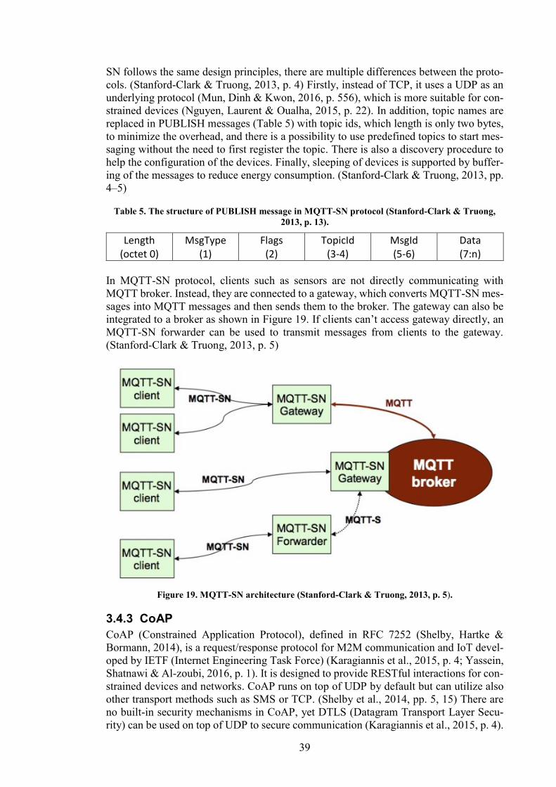
39
SN follows the same design principles, there are multiple differences between the proto-
cols. (Stanford-Clark & Truong, 2013, p. 4) Firstly, instead of TCP, it uses a UDP as an
underlying protocol (Mun, Dinh & Kwon, 2016, p. 556), which is more suitable for con-
strained devices (Nguyen, Laurent & Oualha, 2015, p. 22). In addition, topic names are
replaced in PUBLISH messages (Table 5) with topic ids, which length is only two bytes,
to minimize the overhead, and there is a possibility to use predefined topics to start mes-
saging without the need to first register the topic. There is also a discovery procedure to
help the configuration of the devices. Finally, sleeping of devices is supported by buffer-
ing of the messages to reduce energy consumption. (Stanford-Clark & Truong, 2013, pp.
4–5)
Table 5. The structure of PUBLISH message in MQTT-SN protocol (Stanford-Clark & Truong,
2013, p. 13).
Length (octet 0)
MsgType (1)
Flags (2)
TopicId (3-4)
MsgId (5-6)
Data (7:n)
In MQTT-SN protocol, clients such as sensors are not directly communicating with
MQTT broker. Instead, they are connected to a gateway, which converts MQTT-SN mes-
sages into MQTT messages and then sends them to the broker. The gateway can also be
integrated to a broker as shown in Figure 19. If clients can’t access gateway directly, an
MQTT-SN forwarder can be used to transmit messages from clients to the gateway.
(Stanford-Clark & Truong, 2013, p. 5)
Figure 19. MQTT-SN architecture (Stanford-Clark & Truong, 2013, p. 5).
3.4.3 CoAP
CoAP (Constrained Application Protocol), defined in RFC 7252 (Shelby, Hartke &
Bormann, 2014), is a request/response protocol for M2M communication and IoT devel-
oped by IETF (Internet Engineering Task Force) (Karagiannis et al., 2015, p. 4; Yassein,
Shatnawi & Al-zoubi, 2016, p. 1). It is designed to provide RESTful interactions for con-
strained devices and networks. CoAP runs on top of UDP by default but can utilize also
other transport methods such as SMS or TCP. (Shelby et al., 2014, pp. 5, 15) There are
no built-in security mechanisms in CoAP, yet DTLS (Datagram Transport Layer Secu-
rity) can be used on top of UDP to secure communication (Karagiannis et al., 2015, p. 4).
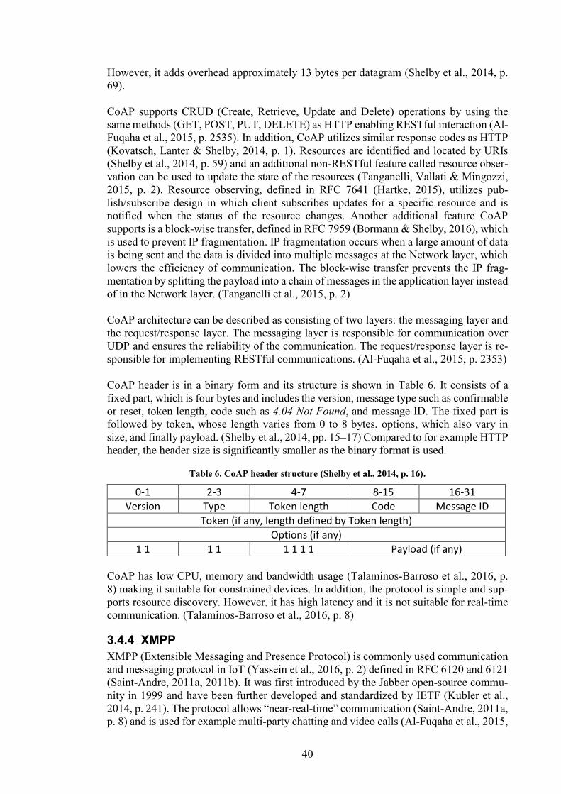
40
However, it adds overhead approximately 13 bytes per datagram (Shelby et al., 2014, p.
69).
CoAP supports CRUD (Create, Retrieve, Update and Delete) operations by using the
same methods (GET, POST, PUT, DELETE) as HTTP enabling RESTful interaction (Al-
Fuqaha et al., 2015, p. 2535). In addition, CoAP utilizes similar response codes as HTTP
(Kovatsch, Lanter & Shelby, 2014, p. 1). Resources are identified and located by URIs
(Shelby et al., 2014, p. 59) and an additional non-RESTful feature called resource obser-
vation can be used to update the state of the resources (Tanganelli, Vallati & Mingozzi,
2015, p. 2). Resource observing, defined in RFC 7641 (Hartke, 2015), utilizes pub-
lish/subscribe design in which client subscribes updates for a specific resource and is
notified when the status of the resource changes. Another additional feature CoAP
supports is a block-wise transfer, defined in RFC 7959 (Bormann & Shelby, 2016), which
is used to prevent IP fragmentation. IP fragmentation occurs when a large amount of data
is being sent and the data is divided into multiple messages at the Network layer, which
lowers the efficiency of communication. The block-wise transfer prevents the IP frag-
mentation by splitting the payload into a chain of messages in the application layer instead
of in the Network layer. (Tanganelli et al., 2015, p. 2)
CoAP architecture can be described as consisting of two layers: the messaging layer and
the request/response layer. The messaging layer is responsible for communication over
UDP and ensures the reliability of the communication. The request/response layer is re-
sponsible for implementing RESTful communications. (Al-Fuqaha et al., 2015, p. 2353)
CoAP header is in a binary form and its structure is shown in Table 6. It consists of a
fixed part, which is four bytes and includes the version, message type such as confirmable
or reset, token length, code such as 4.04 Not Found, and message ID. The fixed part is
followed by token, whose length varies from 0 to 8 bytes, options, which also vary in
size, and finally payload. (Shelby et al., 2014, pp. 15–17) Compared to for example HTTP
header, the header size is significantly smaller as the binary format is used.
Table 6. CoAP header structure (Shelby et al., 2014, p. 16).
0-1 2-3 4-7 8-15 16-31
Version Type Token length Code Message ID
Token (if any, length defined by Token length)
Options (if any)
1 1 1 1 1 1 1 1 Payload (if any)
CoAP has low CPU, memory and bandwidth usage (Talaminos-Barroso et al., 2016, p.
8) making it suitable for constrained devices. In addition, the protocol is simple and sup-
ports resource discovery. However, it has high latency and it is not suitable for real-time
communication. (Talaminos-Barroso et al., 2016, p. 8)
3.4.4 XMPP
XMPP (Extensible Messaging and Presence Protocol) is commonly used communication
and messaging protocol in IoT (Yassein et al., 2016, p. 2) defined in RFC 6120 and 6121
(Saint-Andre, 2011a, 2011b). It was first introduced by the Jabber open-source commu-
nity in 1999 and have been further developed and standardized by IETF (Kubler et al.,
2014, p. 241). The protocol allows “near-real-time” communication (Saint-Andre, 2011a,
p. 8) and is used for example multi-party chatting and video calls (Al-Fuqaha et al., 2015,
41
p. 2355). XMPP uses TCP as an underlying transport layer protocol and offers both pub-
lish/subscribe and request/response models for communication. There is also built-in se-
curity in the protocol, which utilizes SSL/TLS. (Karagiannis et al., 2015, p. 5)
XMPP typically uses a decentralized architecture (Saint-Andre, 2011a, p. 148) in which
streams consisting of XML stanzas are used for communication (Kubler et al., 2014, p.
241). XML stanzas are the basic units of communication in XMPP (Saint-Andre, 2011a,
pp. 20–21). As the stanzas are text-based (Al-Fuqaha et al., 2015, p. 2355) and contain
unnecessary tags, the overhead size is large (Karagiannis et al., 2015, p. 5). However,
EXI (Efficient XML Interchange) (The World Wide Web Consortium, 2014) can be used
to compress stanzas (Al-Fuqaha et al., 2015, p. 2355). The use of XML also requires
additional computational power as it is necessary to parse the messages (Karagiannis et
al., 2015, p. 5).
There are three types of stanzas: 1) message, which is used for sending data from one
entity to another 2) presence, which follows publish/subscribe pattern and is used for
“broadcasting information about network availability” to multiple entities 3) IQ
(info/query), which follows request/response pattern. (Saint-Andre, 2011a, pp. 21, 104)
An example of a structure of a message stanza from a client to a server is presented in
Figure 20.
Figure 20. An example of XML stanza in XMPP (Saint-Andre, 2011a, p. 68).
XMPP is an established and standardized protocol, and there is a large amount of open-
source software available (Kirsche & Klauck, 2012, p. 456). It is suitable in IoT commu-
nication as it offers low latency, supports small messages (Yassein et al., 2016, p. 2), and
can be used without middleware or protocol gateways (Kirsche & Klauck, 2012, p. 456).
However, XMPP has also some disadvantages such as high CPU and bandwidth usage,
no support for QoS options and insufficiency for real-time applications (Talaminos-
Barroso et al., 2016, p. 8). Chen & Kunz (2016, p. 1) even left it out from their article as
the implementations of XMPP were only for chatting/messaging applications instead of
an IoT and the development of the protocol has been stopped. However, the development
of the protocol seems to have continued as extensions to XMPP are currently developed
by the XSF (XMPP Standards Foundation) (xmpp.org, 2019).
3.4.5 AMQP
AMQP (Advanced Message Queuing Protocol) was introduced in 2003 by John O’Hara
at JPMorgan Chase (Luzuriaga et al., 2015, p. 931), and was later standardized by OASIS
(Yassein et al., 2016, p. 3). In 2014, it was accepted as an ISO/IEC standard (ISO/IEC
19464:2014, 2014). AMQP is designed for business messaging (AMQP v1.0, 2011, p. 6)
and is commonly used in commercial platforms (Yassein et al., 2016, p. 3). AMQP uses
a reliable transport layer protocol such as TCP and ensures security by using TLS and
SASL negotiation. The protocol follows a publish/subscribe model but, in addition, point-
to-point communication is supported. (Al-Fuqaha et al., 2015, pp. 2355, 2361)
AMQP consists of two layers: a binary protocol for transport of messages and messaging
layer, which defines the message format (AMQP v1.0, 2011, p. 6). The transport layer
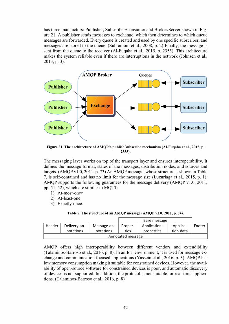
42
has three main actors: Publisher, Subscriber/Consumer and Broker/Server shown in Fig-
ure 21. A publisher sends messages to exchange, which then determines to which queue
messages are forwarded. Every queue is created and used by one specific subscriber, and
messages are stored to the queue. (Subramoni et al., 2008, p. 2) Finally, the message is
sent from the queue to the receiver (Al-Fuqaha et al., 2015, p. 2355). This architecture
makes the system reliable even if there are interruptions in the network (Johnsen et al.,
2013, p. 3).
Figure 21. The architecture of AMQP’s publish/subscribe mechanism (Al-Fuqaha et al., 2015, p.
2355).
The messaging layer works on top of the transport layer and ensures interoperability. It
defines the message format, states of the messages, distribution nodes, and sources and
targets. (AMQP v1.0, 2011, p. 73) An AMQP message, whose structure is shown in Table
7, is self-contained and has no limit for the message size (Luzuriaga et al., 2015, p. 1).
AMQP supports the following guarantees for the message delivery (AMQP v1.0, 2011,
pp. 51–52), which are similar to MQTT:
1) At-most-once
2) At-least-one
3) Exactly-once.
Table 7. The structure of an AMQP message (AMQP v1.0, 2011, p. 74).
Bare message Header Delivery-an-
notations Message-an-
notations Proper-
ties Application-properties
Applica-tion-data
Footer
Annotated message
AMQP offers high interoperability between different vendors and extendibility
(Talaminos-Barroso et al., 2016, p. 8). In an IoT environment, it is used for message ex-
change and communication focused applications (Yassein et al., 2016, p. 3). AMQP has
low memory consumption making it suitable for constrained devices. However, the avail-
ability of open-source software for constrained devices is poor, and automatic discovery
of devices is not supported. In addition, the protocol is not suitable for real-time applica-
tions. (Talaminos-Barroso et al., 2016, p. 8)
43
3.4.6 DDS
DDS (Data Distribution Service) is standardized by Object Management Group (2015a)
and provides reliable real-time communication for IoT applications and M2M communi-
cation (Al-Fuqaha et al., 2015, p. 2356). For predictable behavior (Talaminos-Barroso et
al., 2016, p. 6), 23 QoS policies are defined, which allows controlling of, for example,
security, priority, and reliability. DDS follows a publish-subscribe model and uses broker-
less architecture. (Al-Fuqaha et al., 2015, p. 2356) The protocol does not specify a
transport layer protocol, hence both TCP and UDP are supported. Therefore, different
implementations are not able to interoperate with each other. (Object Management Group,
2013, p. 5). The security model and Service Plugin Interface (SPI) architecture, which
allows “out-of-box security and interoperability between compliant DDS applications”,
are standardized in (Object Management Group, 2018).
The architecture of DDS, shown in Figure 22, consists of two layers: Data-Centric Pub-
lish-Subscribe (DCPS) and an optional Data-Local Reconstruction Layer (DLRL) (Al-
Fuqaha et al., 2015, p. 2356), which works on top of DDS and integrates DDS into appli-
cation layer by offering interface to access data (Object Management Group, 2015b, pp.
1–3). The DCPS layer consist of the following entities (Al-Fuqaha et al., 2015, p. 2356;
Object Management Group, 2015a, pp. 6–7):
1) Publisher, which distributes the data
2) DataWriter, which passes the data from application to the publisher
3) Subscriber, which receives the published data and makes it available to the
application
4) DataReader, which application uses to access the data
5) Topic, identified by a name unique in the domain, which acts as a link between
DataReader and DataWriter.
DDS supports automatic discovery of information and has high scalability. In addition,
latency and jitter are low, which along with high predictability allows the use of the pro-
tocol in real-time applications. However, due to the automatic discovery, memory con-
sumption and the use of computational resources are high, and because of decentralized
architecture, the CPU usage grows exponentially, when publishing rate increases. The
development and configuration are also rather complex compared to other protocols and
the availability of open-source libraries for constrained is inadequate. (Talaminos-
Barroso et al., 2016)
3.4.7 OPC UA
OPC UA (Open Platform Communications Unified Architecture) is a protocol designed
for industrial use suitable for IIoT and M2M communications (OPC Foundation, 2017, p.
8). It is standardized in IEC 62541 parts 1-11, 13 and 100 (IEC TR 62541-1:2016, 2018),
and continuously developed by OPC foundation (Gruner, Pfrommer & Palm, 2016, p.
1833). OPC UA provides secure communication, robustness, and a mechanism for quick
recovery of communication failure. The protocol is platform-independent and supports
multiple types of servers from PLC to enterprise servers. As some servers are resource
constrained, they are allowed to provide only a subset of the broad range of capabilities
OPC UA servers may implement. These subsets of capabilities are called profiles, and
clients can utilize them in communication with server. (Sauter & Lobashov, 2011, p. 707;
OPC Foundation, 2017, pp. 9–10)
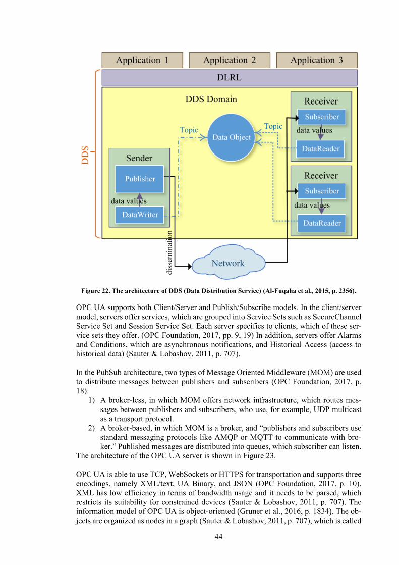
44
Figure 22. The architecture of DDS (Data Distribution Service) (Al-Fuqaha et al., 2015, p. 2356).
OPC UA supports both Client/Server and Publish/Subscribe models. In the client/server
model, servers offer services, which are grouped into Service Sets such as SecureChannel
Service Set and Session Service Set. Each server specifies to clients, which of these ser-
vice sets they offer. (OPC Foundation, 2017, pp. 9, 19) In addition, servers offer Alarms
and Conditions, which are asynchronous notifications, and Historical Access (access to
historical data) (Sauter & Lobashov, 2011, p. 707).
In the PubSub architecture, two types of Message Oriented Middleware (MOM) are used
to distribute messages between publishers and subscribers (OPC Foundation, 2017, p.
18):
1) A broker-less, in which MOM offers network infrastructure, which routes mes-
sages between publishers and subscribers, who use, for example, UDP multicast
as a transport protocol.
2) A broker-based, in which MOM is a broker, and “publishers and subscribers use
standard messaging protocols like AMQP or MQTT to communicate with bro-
ker.” Published messages are distributed into queues, which subscriber can listen.
The architecture of the OPC UA server is shown in Figure 23.
OPC UA is able to use TCP, WebSockets or HTTPS for transportation and supports three
encodings, namely XML/text, UA Binary, and JSON (OPC Foundation, 2017, p. 10).
XML has low efficiency in terms of bandwidth usage and it needs to be parsed, which
restricts its suitability for constrained devices (Sauter & Lobashov, 2011, p. 707). The
information model of OPC UA is object-oriented (Gruner et al., 2016, p. 1834). The ob-
jects are organized as nodes in a graph (Sauter & Lobashov, 2011, p. 707), which is called
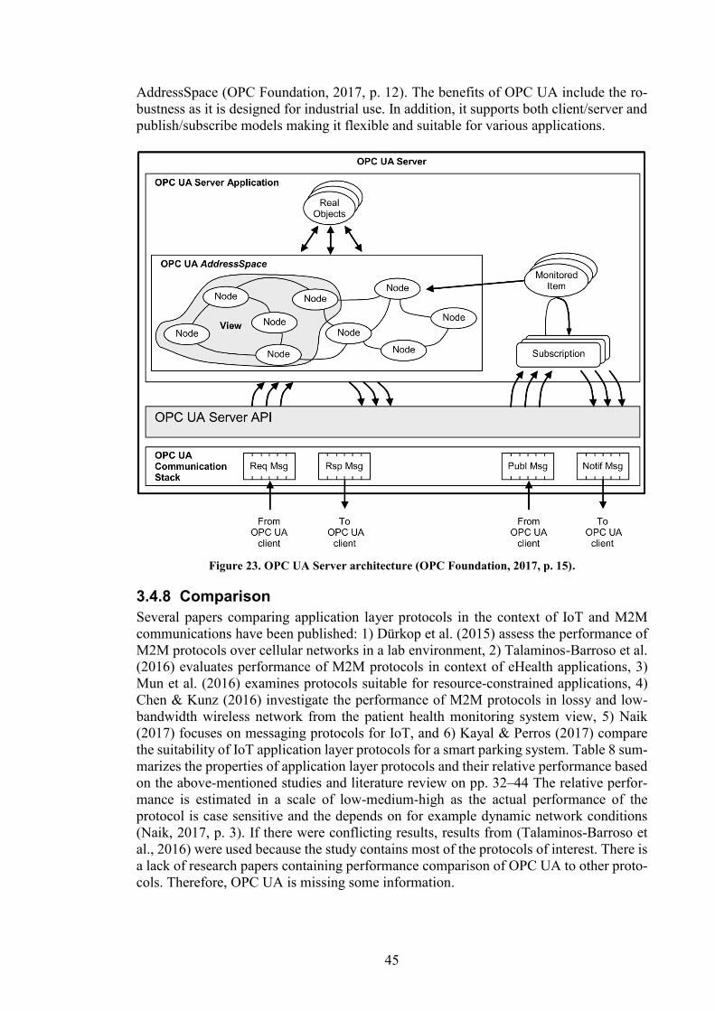
45
AddressSpace (OPC Foundation, 2017, p. 12). The benefits of OPC UA include the ro-
bustness as it is designed for industrial use. In addition, it supports both client/server and
publish/subscribe models making it flexible and suitable for various applications.
Figure 23. OPC UA Server architecture (OPC Foundation, 2017, p. 15).
3.4.8 Comparison
Several papers comparing application layer protocols in the context of IoT and M2M
communications have been published: 1) Dürkop et al. (2015) assess the performance of
M2M protocols over cellular networks in a lab environment, 2) Talaminos-Barroso et al.
(2016) evaluates performance of M2M protocols in context of eHealth applications, 3)
Mun et al. (2016) examines protocols suitable for resource-constrained applications, 4)
Chen & Kunz (2016) investigate the performance of M2M protocols in lossy and low-
bandwidth wireless network from the patient health monitoring system view, 5) Naik
(2017) focuses on messaging protocols for IoT, and 6) Kayal & Perros (2017) compare
the suitability of IoT application layer protocols for a smart parking system. Table 8 sum-
marizes the properties of application layer protocols and their relative performance based
on the above-mentioned studies and literature review on pp. 32–44 The relative perfor-
mance is estimated in a scale of low-medium-high as the actual performance of the
protocol is case sensitive and the depends on for example dynamic network conditions
(Naik, 2017, p. 3). If there were conflicting results, results from (Talaminos-Barroso et
al., 2016) were used because the study contains most of the protocols of interest. There is
a lack of research papers containing performance comparison of OPC UA to other proto-
cols. Therefore, OPC UA is missing some information.
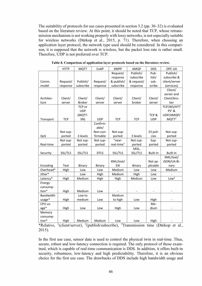
46
The suitability of protocols for use cases presented in section 3.2 (pp. 30–32) is evaluated
based on the literature review. At this point, it should be noted that TCP, whose retrans-
mission mechanism is not working properly with lossy networks, is not especially suitable
for wireless networks (Dürkop et al., 2015, p. 71). Therefore, when choosing an
application layer protocol, the network type used should be considered. In this compari-
son, it is supposed that the network is wireless, but the packet loss rate is rather small.
Therefore, UDP is not preferred over TCP.
Table 8. Comparison of application layer protocols based on the literature review.
HTTP MQTT CoAP XMPP AMQP DDS OPC UA
Comm. model
Request/ response
Publish/ subscribe
Request/ response
Request/ response
& publish/ subscribe
Publish/ subscribe
& request/ response
Pub-lish/ sub-
scribe
Publish/ subscribe & client/server
(services)
Architec-ture
Client/ server
Client/ Broker
Client/ server
Client/ server
Client/ broker
Client/ server
Client/ server and Client/bro-
ker
Transport TCP
TCP or UDP
(MQTT-SN) UDP TCP TCP
TCP & UDP
TCP/WS/HTTPS1 &
UDP/AMQP/MQTT2
QoS Not sup-ported 3 levels
Confirm-able/
Non-con-firmable
Not sup-ported 3 levels
23 poli-cies
Not sup-ported
Real-time Not sup-ported
Not sup-ported
Not sup-ported
"near-real-time"
Not sup-ported
Sup-ported
Not sup-ported
Security SSL/TLS SSL/TLS DTLS SSL/TLS SASL,
SSL/TLS Built-in Built-in
Encoding Text Binary Binary XML/text/
EXI Binary Not ap-plicable
XML/text/ JSON/UA Bi-
nary
Overhead* High Low Low Medium Low Low Medium
Jitter* - Low High Medium High Low -
Latency* High Medium High High Medium Low Low3
Energy consump-tion* High Medium Low - - - -
Bandwidth usage* High
Low to medium Low
Medium to high Low High -
CPU us-age* High Low Low High Low
Me-dium -
Memory consump-tion* High Medium Medium Low Low High -
*Relative, 1(client/server), 2(publish/subscribe), 3Transmission time (Dürkop et al.,
2015).
In the first use case, sensor data is used to control the physical twin in real-time. Thus,
secure, robust and low-latency connection is required. The only protocol of those exam-
ined, which is capable of real-time communication is DDS. In addition, it offers built-in
security, robustness, low-latency and high predictability. Therefore, it is an obvious
choice for the first use case. The drawbacks of DDS include high bandwidth usage and
47
memory consumption as well as medium CPU usage, which restricts its use with very
constrained environments.
The second use case, in which the strain of the bridge is measured periodically, has not
strict requirements for the communication in terms of latency, data rate or robustness.
Therefore, all protocols are suitable for that use case to some extent. However, low energy
consumption, suitability for constrained devices and overall efficiency are desirable prop-
erties to make sensor nodes battery-operated and, thus, truly wireless. The most emphasis
in this comparison is given to the suitability for constrained devices, which includes low
energy consumption and bandwidth usage. The most suitable protocols are therefore
CoAP, MQTT and AMQP.
MQTT is a publish/subscribe protocol, CoAP is a request/response protocol, and AMQP
supports, in addition to the publish/subscribe model, point-to-point communication. In
the second use case, the data is sent to a single entity: the data storage of a digital twin.
Therefore, publish-subscribe is not advantageous over the request/response pattern. Both
MQTT and AMQP use TCP as an underlying transport layer protocol, while CoAP uses
UDP. Thus, CoAP should perform better in lossy networks because TCP’s congestion
control is not suitable for those types of networks.
The bandwidth usage is quite similar for each of these protocols as well as the CPU usage,
but AMQP uses slightly less memory (Talaminos-Barroso et al., 2016, pp. 5–6). CoAP
has lower energy consumption than MQTT with package size less than 1024 bytes. With
larger package sizes, the energy consumption of CoAP increases due to packet fragmen-
tation and, thus, MQTT has lower energy consumption with large packet sizes. (Mun et
al., 2016, p. 558) Chen & Kunz (2016, pp. 4–5) note that with low packet loss rate and
latency, MQTT consumes more bandwidth than CoAP, but increasing both reduces the
bandwidth consumption, while CoAP has steady bandwidth consumption. Therefore,
with high packet loss and latency, MQTT performs better than CoAP in terms of band-
width usage.
Talaminos-Barroso et al. (2016, p. 8) claim that AMQP lacks open-source libraries for
constrained devices and CoAP is missing support for tools and libraries. The availability
of libraries makes the implementation of MQTT easier than CoAP and AMQP. Because
the properties of the protocols are otherwise quite similar, this makes MQTT the recom-
mended choice for the second use case. It is also implemented on the developed sensor
configurator platform. However, in lossy networks CoAP is preferred choice, because it
uses UDP instead of TCP as an underlying transport layer protocol. In general, the easi-
ness of the implementation and integration to existing systems as well as the availability
of support are important factors, when choosing application layer protocol. In addition,
the used communication technology should be considered when choosing an application
layer protocol and vice versa because, for example, the high packet loss in a network have
different effects on different application layer protocols.
3.5 Communication technologies
This section presents a short review of wireless communication technologies used for
M2M, IoT, and IIoT. Communication technologies can be divided into two categories:
Low Power Wide Area Networks (LPWAN) and short-range networks (Al-Sarawi et al.,
2017, p. 685). With short-range networks, a gateway is needed for wide area connectivity
(Aijaz & Aghvami, 2015, p. 103). This literature review examines both types of commu-
nication technologies.
48
3.5.1 Low power wide area networks (LPWANs)
LPWANs have a long range up to a few tens of kilometers depending on the environment
(Petäjäjärvi et al., 2015), operate usually at unlicensed ISM (Industrial, Scientific and
Medical) bands at 169, 433, 868/915 MHz, and 2.4 GHz (Georgiou & Raza, 2017, p.
162), and have a low bitrate and energy consumption (S. Raza et al., 2017, p. 855). In this
review, also cellular networks are included to LPWAN as also Al-Sarawi et al. (2017)
have done in their review.
Cellular networks include 2G/3G/LTE and 5G technologies (Karagiannis et al., 2015, p.
1). 4G also known as LTE-A (Long Term Evolution Advanced) is commonly used with
cell phones, offers high data rate up to 3 Gbps uplink and 1.5 Gbps downlink (Gupta &
Jha, 2015, p. 1211), and low latency up to below 5 ms (Gandotra, Kumar Jha & Jain,
2017, p. 11). To serve the needs of M2M and IoT communication such as low energy
consumption, 3GPP (3rd Generation Partnership Project) is developing new standards
based on the existing ones. These new standards try to utilize the existing cellular network
infrastructure. As a result, for example, LTE eMTC (Long Tem Evolution enhancements
for Machine Type Communications and NB-IoT (Narrow Band IoT) have been released.
(U. Raza, Kulkarni & Sooriyabandara, 2017, p. 864)
NB-IoT specifications were released in 2016 by 3GPP (Mekki et al., 2018, p. 3). NB-IoT
is able to utilize GSM (Global System for Mobile Communications), GPRS (General
Packet Radio Service), and LTE networks. The existing LTE infrastructure needs only a
software update to be compatible with NB-IoT. The data rate is low, up to 250 kbps for
multi-tone downlink and 20 kbps for the uplink. (U. Raza et al., 2017, p. 865) NB-IoT
implements only a limited set of features of LTE and is optimized for low-power IoT
devices. It allows connection of 100 000 devices to each cell. (Mekki et al., 2018, pp. 3–
4)
5G increases the data rates up to 10 Gbps (Li et al., 2017, p. 1510) and lowers the latency
to under 1 ms (Gandotra et al., 2017, p. 11). The 5G is expected to offer a massive number
of connections, high data rate, security, and reliability as well as low latency and energy
consumption. 5G has multiple technologies making it suitable for IoT use such as wireless
network function virtualization (WNFV), which allows dividing network into multiple
virtual networks providing processing capability, and Direct Device to Device (D2D),
which allows communication between devices without base station (Li, Xu & Zhao, 2018,
pp. 4–6).
LoRaWAN (Long Range Wide Area Network) operates at unlicensed sub-GHz ISM
bands and offers data rate from 300 bps to 50 kbps. The chirp spread spectrum (CSS)
modulation used allows spreading of the signal over a wider bandwidth. By varying the
spreading factor, the trade-off between high data rate and high range can be selected.
(Mekki et al., 2018, pp. 2–3) LoRaWAN divides end-devices to three classes (U. Raza et
al., 2017, p. 866):
- Class A, in which a device listens to downlink communication only a short time
after it has sent data.
- Class B, in which the downlink is listened only at certain times.
- Class C, in which the downlink is listened continuously
The messages sent by end-devices are delivered to all base stations within range, which
makes delivery more reliable by adding redundancy (Mekki et al., 2018, p. 3). The dif-
ference between LoRa and LoRaWAN is that LoRa implements only the physical layer
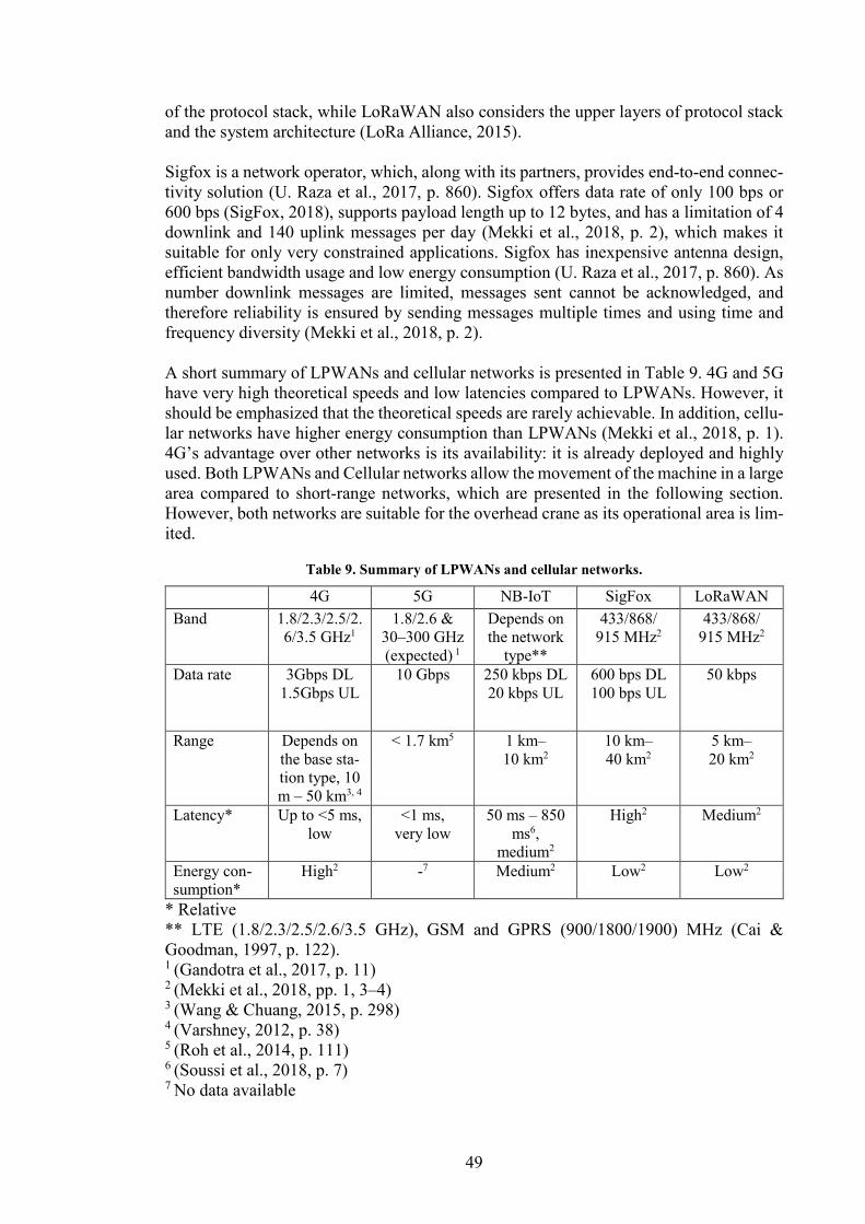
49
of the protocol stack, while LoRaWAN also considers the upper layers of protocol stack
and the system architecture (LoRa Alliance, 2015).
Sigfox is a network operator, which, along with its partners, provides end-to-end connec-
tivity solution (U. Raza et al., 2017, p. 860). Sigfox offers data rate of only 100 bps or
600 bps (SigFox, 2018), supports payload length up to 12 bytes, and has a limitation of 4
downlink and 140 uplink messages per day (Mekki et al., 2018, p. 2), which makes it
suitable for only very constrained applications. Sigfox has inexpensive antenna design,
efficient bandwidth usage and low energy consumption (U. Raza et al., 2017, p. 860). As
number downlink messages are limited, messages sent cannot be acknowledged, and
therefore reliability is ensured by sending messages multiple times and using time and
frequency diversity (Mekki et al., 2018, p. 2).
A short summary of LPWANs and cellular networks is presented in Table 9. 4G and 5G
have very high theoretical speeds and low latencies compared to LPWANs. However, it
should be emphasized that the theoretical speeds are rarely achievable. In addition, cellu-
lar networks have higher energy consumption than LPWANs (Mekki et al., 2018, p. 1).
4G’s advantage over other networks is its availability: it is already deployed and highly
used. Both LPWANs and Cellular networks allow the movement of the machine in a large
area compared to short-range networks, which are presented in the following section.
However, both networks are suitable for the overhead crane as its operational area is lim-
ited.
Table 9. Summary of LPWANs and cellular networks.
4G 5G NB-IoT SigFox LoRaWAN
Band 1.8/2.3/2.5/2.
6/3.5 GHz1
1.8/2.6 &
30–300 GHz
(expected) 1
Depends on
the network
type**
433/868/
915 MHz2
433/868/
915 MHz2
Data rate 3Gbps DL
1.5Gbps UL
10 Gbps 250 kbps DL
20 kbps UL
600 bps DL
100 bps UL
50 kbps
Range Depends on
the base sta-
tion type, 10
m – 50 km3, 4
< 1.7 km5 1 km–
10 km2
10 km–
40 km2
5 km–
20 km2
Latency* Up to <5 ms,
low
<1 ms,
very low
50 ms – 850
ms6,
medium2
High2 Medium2
Energy con-
sumption*
High2 -7 Medium2 Low2 Low2
* Relative
** LTE (1.8/2.3/2.5/2.6/3.5 GHz), GSM and GPRS (900/1800/1900) MHz (Cai &
Goodman, 1997, p. 122). 1 (Gandotra et al., 2017, p. 11)
2 (Mekki et al., 2018, pp. 1, 3–4)
3 (Wang & Chuang, 2015, p. 298) 4 (Varshney, 2012, p. 38)
5 (Roh et al., 2014, p. 111) 6 (Soussi et al., 2018, p. 7) 7 No data available
50
3.5.2 Short-range networks
Bluetooth works on unlicensed ISM 2.4 GHz frequency spectrum (Bluetooth SIG, 2018b)
and by the year 2018, almost 4 billion devices with Bluetooth capability were shipped
(Bluetooth SIG, 2018c). Bluetooth has two radio versions: Bluetooth Low Energy (LE),
which is directed to low power devices and supports multiple data rates and transmission
powers making it flexible, and Bluetooth Basic Rate/Enhanced Data Rate (BR/EDR),
which has higher data rates and more channels. Bluetooth LE also offers broadcast and
mesh network topologies (Bluetooth SIG, 2018b), and supports device discovery
(Collotta & Pau, 2015, p. 139). BLE is optimized for data transfer whereas BE/EDR is
optimized for audio streaming (Bluetooth SIG, 2018d). The range of Bluetooth depends
on transmit power and is about 15-30 meters (Lopez et al., 2013, p. 1353). However,
higher ranges are achievable, and some commercial solutions claim to have a range of up
to 500 meters. In addition, Bluetooth 5.0 should increase range fourfold compared to the
older generations. (Bluetooth SIG, 2018a)
Wireless local area networks (WLANs) usually refer to IEEE 802.11 class of standards.
These standards are also called as Wi-Fi and include, for example, 802.11a/b/g/n. (Kurose
& Ross, 2013, pp. 552–553) The most interesting Wi-Fi standard in the context of this
thesis is 802.11ah, which offers lower energy consumption and longer range (100 m – 1
km (Tian, Famaey & Latre, 2016, p. 1)) than other Wi-Fi standards (Sethi & Sarangi,
2017, p. 13). It works on sub-GHz frequency band (Tian, Deronne, et al., 2016, p. 49)
while other Wi-Fi standards usually work either on 2.4 GHz or 5 GHz (5.1 GHz - 5.8
GHz) frequency bands (Kurose & Ross, 2013, p. 552). 802.11ha offers low data rates
from 150 kbps to 8 Mbps (in addition, higher data rates up to 347 Mbps are achievable,
but are not available in every continent as they require 16 MHz frequency band) (IEEE
Standard 802.11ah-2016, 2017). In comparison, for example, 802.11ax allows very high
data rates up to 9.6 Gbps (Khorov et al., 2018, p. 6). Because 802.11ah is a fairly new
standard, there is a lack of devices supporting it. The benefits of Wi-Fi standards include
IP-network compatibility, and power saving mechanism, which allows sleeping of a de-
vice lowering energy consumption (Tozlu et al., 2012, pp. 134, 136).
Z-Wave is a low power protocol “used for IoT communication, especially in smart homes
and small commercial domains” (Al-Sarawi et al., 2017, p. 687). It was developed by
Zensys (presently a division of Sigma Systems) and, currently, it is developed by Z-Wave
Alliance. Z-Wave uses ISM 900 MHz frequency band and provides a data rate of 40 kbps
but supports also 2.4 GHz frequency band, which allows higher data rates up to 200 kbps.
The range is approximately 30m indoor and 100m outdoor. (Gomez & Paradells, 2010,
p. 97) Z-Wave has two types of devices: slaves and controllers. Controllers are responsi-
ble for managing slaves and maintaining a table of a network topology for routing. Rout-
ing is based on source routing, in which the route is sent along with the packet. Z-Wave
offers a reliable transmission by optional ACK messages. (Al-Fuqaha et al., 2015, p.
2360)
ZigBee is a low-cost, low-power communication standard, which works on top of IEEE
802.15.4 physical (PHY) and medium access control (MAC) layers (Zigbee Standards
Organization, 2012, pp. 1–2). It is used for home automation and monitoring (Lennvall,
Svensson & Hekland, 2008, p. 87). ZigBee works on both 868/915 MHz and 2.4 GHz
frequency bands. The data rate depends on the used frequency band being 20 kb/s at low-
est (868 MHz) and 250 kb/s at highest (2.4GHz). (Gomez & Paradells, 2010, pp. 95–96)
The range is up to 75m - 100m indoor, up to 300m meters with line of sight, and up to
1km on sub-GHz frequency band (ZigBee Alliance, 2018). ZigBee supports three types
51
of network topologies: star, tree, and mesh. The mesh topology increases the reliability
of the network via redundant paths. (Wang & Jiang, 2016, p. 2201) However, the lack of
robustness of the technology is limiting its suitability for industrial applications (Lennvall
et al., 2008, p. 88). There is also an IPv6-compatible version of ZigBee (Wang & Jiang,
2016, p. 2204).
WirelessHART (Highway Addressable Remote Transducer Protocol) is a wireless com-
munication standard designed for process automation applications and industrial use
(Wang & Jiang, 2016, p. 2200). It is developed by the HART Communication Foundation
and was released in 2007 (Kim et al., 2008). The standard uses IEEE 802.15.4 at the
physical (PHY) layer at a 2.4 GHz frequency band (Wang & Jiang, 2016, pp. 2200, 2205).
The maximum data rate up to 250 kbps and range varies from 50 m indoor to 250 m
outdoor (Qureshi & Hanan Abdullah, 2014, p. 1220). The protocol supports both star and
mesh network topologies, but the mesh is preferred to ensure robustness and reliability.
In addition, TDMA (Time Division Multiple Access) with CSMA (Carrier-sense Multiple
Access) is used, which allows deterministic latency. (Wang & Jiang, 2016, pp. 2202,
2205) TDMA and pre-scheduled time slots reduce both collisions and energy consump-
tion. As the protocol is designed for industrial use, the security of the protocol is at a high
level and can’t be disabled. (Lennvall et al., 2008, pp. 87–88)
Table 10 summarizes the properties of short-range networks from the above review. How-
ever, there is a lack of comprehensive comparison of short-range networks in the
scientific literature. In addition, the existing technologies are constantly updated, and new
technologies released. Thus, at the time a scientific article is published, it might be already
outdated. For the above reasons, some of the information about latencies and energy con-
sumption have been collected from non-scientific sources. Therefore, the values should
be considered more as guidelines.
Short-range networks have a large variation in data rates as can be seen from Table 10.
802.11ah has the fastest data rate along with Bluetooth. However, the theoretical maxi-
mum speed of 802.11ah is not achievable in every continent. The ranges of the networks
depend mostly on the used frequency band: with 900 MHz frequency band, the range is
significantly longer than with 2.4 GHz. The only industrial protocol in this literature
review is WirelessHART. Compared to other protocols, it is more robust and has both
deterministic latency and built-in security. Therefore, it is the most suitable communica-
tion technology for use cases in which high predictability and security are required. How-
ever, the high latency of WirelessHART reduces its suitability for controlling machines.
The above review and Table 10 show that short-range networks have a large variation in
their properties. Therefore, each of the networks has its own most suitable applications.
The suitability of both short-range networks and LPWANs for the selected use cases are
assessed in the following section.
3.5.3 Comparison
There are numerous aspects that are concerning the selection of communication technol-
ogy such as data rate, latency, robustness, security, and energy consumption. In addition,
some of the properties such as energy consumption are use case dependent. Furthermore,
the lack of scientific papers with a comprehensive comparison of communication
technologies makes the selection of the most suitable communication technology even
more challenging. However, some comparisons are available. For example, Siekkinen et
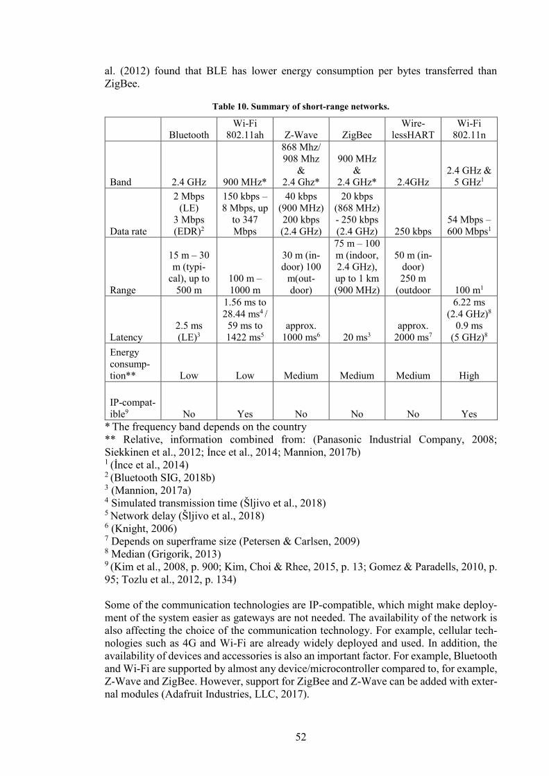
52
al. (2012) found that BLE has lower energy consumption per bytes transferred than
ZigBee.
Table 10. Summary of short-range networks.
Bluetooth
Wi-Fi
802.11ah Z-Wave ZigBee
Wire-
lessHART
Wi-Fi
802.11n
Band 2.4 GHz 900 MHz*
868 Mhz/
908 Mhz
&
2.4 Ghz*
900 MHz
&
2.4 GHz* 2.4GHz
2.4 GHz &
5 GHz1
Data rate
2 Mbps
(LE)
3 Mbps
(EDR)2
150 kbps –
8 Mbps, up
to 347
Mbps
40 kbps
(900 MHz)
200 kbps
(2.4 GHz)
20 kbps
(868 MHz)
- 250 kbps
(2.4 GHz) 250 kbps
54 Mbps –
600 Mbps1
Range
15 m – 30
m (typi-
cal), up to
500 m
100 m –
1000 m
30 m (in-
door) 100
m(out-
door)
75 m – 100
m (indoor,
2.4 GHz),
up to 1 km
(900 MHz)
50 m (in-
door)
250 m
(outdoor 100 m1
Latency
2.5 ms
(LE)3
1.56 ms to
28.44 ms4 /
59 ms to
1422 ms5
approx.
1000 ms6 20 ms3
approx.
2000 ms7
6.22 ms
(2.4 GHz)8
0.9 ms
(5 GHz)8
Energy
consump-
tion** Low Low Medium Medium Medium High
IP-compat-
ible9 No Yes No No No Yes
* The frequency band depends on the country
** Relative, information combined from: (Panasonic Industrial Company, 2008;
Siekkinen et al., 2012; İnce et al., 2014; Mannion, 2017b) 1 (İnce et al., 2014) 2 (Bluetooth SIG, 2018b)
3 (Mannion, 2017a) 4 Simulated transmission time (Šljivo et al., 2018) 5 Network delay (Šljivo et al., 2018) 6 (Knight, 2006) 7 Depends on superframe size (Petersen & Carlsen, 2009) 8 Median (Grigorik, 2013) 9 (Kim et al., 2008, p. 900; Kim, Choi & Rhee, 2015, p. 13; Gomez & Paradells, 2010, p.
95; Tozlu et al., 2012, p. 134)
Some of the communication technologies are IP-compatible, which might make deploy-
ment of the system easier as gateways are not needed. The availability of the network is
also affecting the choice of the communication technology. For example, cellular tech-
nologies such as 4G and Wi-Fi are already widely deployed and used. In addition, the
availability of devices and accessories is also an important factor. For example, Bluetooth
and Wi-Fi are supported by almost any device/microcontroller compared to, for example,
Z-Wave and ZigBee. However, support for ZigBee and Z-Wave can be added with exter-
nal modules (Adafruit Industries, LLC, 2017).
53
None of the communication technologies is technically superior to each other, and the
same use case can be implemented using various communication technologies. This
might be the reason, why there are so many communication technologies available. There
are also numerous other communication technologies available than the ones examined
in this literature review, especially in the industrial field. For example, NFC was left out
as its range is only in order of 10 cm (Want, 2011, p. 4) and RFID, because it is only
suitable for reading static, pre-programmed data, instead of measurement data (Al-Sarawi
et al., 2017, p. 686).
In both use cases, a short-range network is an option because the overhead crane is rather
a static object as the movement range is a few tens of meters. For the first use case, in
which the sensor data is used to control the machine, very low latency is required. There-
fore, suitable options are 4G, the coming 5G, Bluetooth or 802.11ah/802.11n. However,
all of these are technologies are also used by other devices, which might cause congestion.
The congestion increases latency and slows down the data rate, which makes the behavior
unpredictable. WirelessHART has otherwise suitable properties such as robustness and
deterministic latency, but its latency is too high for controlling the crane. The choice for
the first case is 802.11n in the 5Ghz frequency spectrum as it has the lowest latency.
However, with 802.11n, the sensor node can’t be battery operated because of the high
energy consumption.
For the second use case, there is no single “the most suitable technology” as the require-
ments for the data rate and latency are not strict. Only Sigfox does not meet the require-
ments as the number of uplink messages is limited to 140 per day. In general, Sigfox is
suitable for use cases in which the status of the machine is updated rather seldom instead
of sending measurement data due to the small payload and restricted number of uplink
messages. Wi-Fi (802.11n) is the preferred choice for the second use case due to easy
implementation. It offers IP-compatibility and deploying a network is effortless. If low
energy consumption is considered as the most important factor, Bluetooth is the recom-
mended choice from short-range networks and LoRaWAN from LPWANs.
In general, if there are multiple sensors measuring at very high sample rates, only 4G, 5G,
Wi-Fi or Bluetooth are able to transfer data at speeds high enough. 4G and 5G allow a
free movement of the machine, while Wi-Fi and Bluetooth allow movement only at the
very limited area (Wi-Fi 802.11ah maximum range is 1 km). 802.11ah would be a good
choice in general as it has low energy consumption, high range, and high data rate but
there are no devices available supporting it.
In this chapter, the communication needs of a digital twin were identified. In addition,
application layer protocols and communication technologies were examined and their
suitability for sensor data transmission was assessed through the selected use cases. The
next chapter presents the requirements for a platform, which enables the management of
sensors and sensor data transmission from physical twin to a digital twin in practice.
3.6 IoT platforms
To enable data collection from a physical twin in practice, a system for managing sensor
nodes is required. Thus, this section presents a short review on existing IoT platforms,
which allow the management of sensor nodes. The amount of IoT platforms, IoT related
software, standards, and protocols is enormous. Therefore, presenting a comprehensive
review of IoT platforms in out of the scope of this thesis. The literature review focused
on platforms presented at the scientific papers, which might leave out recently published
54
platforms as well as some commercial platforms. The following properties, which are
beneficial for the platform enabling sensor node management, were considered on the
review of existing IoT platforms:
- Possibility to change measurement settings
- Support for multiple application layer protocols
- Support for multiple sensor types
- Easy addition of new sensor types
- Free and open-source
There exist several IoT platforms with various focus points. IoT platforms can be divided
into the following three categories (da Cruz et al., 2018, p. 875):
1) Device management
2) Application management, in which the platform is used for developing applica-
tions
3) Application enablement, in which the platform allows developing external appli-
cations by, for example, providing the sensor data
Da Cruz (2018, p. 875) identified the following device management concentrated plat-
forms (*=open-source): Alljoyn*, Artik Cloud, Carriots (currently Altair SmartCore),
IoTivity*, Linksmart*, Losant, OpenIoT*, Stack4Things*, Telit IoT Platform, WSO2 IoT
server*, Webinos* and Xively. As can be seen, the number of available platforms is over-
whelming. In addition, new platforms are constantly released and the development of
older ones are stopped: For example, the latest commit to OpenIot platform was made
over three years ago (GitHub, Inc., 2019c). The problem with open-source platforms cre-
ated as a part of research project seems to be that after the research project has ended also
the development of the platform ceases.
The platforms usually offer the same functionalities, but the variety of their implementa-
tions makes the comparison of platforms difficult (Guth et al., 2016, p. 1). A few para-
digms for implementation of the device management can be found from the scientific
literature. For example, El-Mougy et al. (2015) present a Software-defined Networking
based method (SDN). Simplified, SDN separates the data plane and control plane of net-
work and therefore allows better control of the network (Benzekki, El Fergougui &
Elbelrhiti Elalaoui, 2016, pp. 5803–5804). An SDN-based architecture would allow con-
figuration and programming of sensors wirelessly. However, the current hardware of sen-
sors does not support this method. (El-Mougy et al., 2015)
Vresk & Cavrak (2016) present a microservices based architecture for IoT platform, in
which the platform consists of small interconnected software components called micro-
services to enhance the scalability of the system. An edge-computing based approach
called transparent computing is presented by Ren, Guo & Zhang (2017). This approach
allows IoT devices to download updates from the cloud, increases the scalability of the
system and offers real-time and context-aware data processing. Next, two implementa-
tions of IoT platforms found in the scientific literature are presented.
Lazarescu (2015) developed a platform for WSN (Wireless Sensor Network). The plat-
form was designed for detecting wildfires in the rural area. It uses the 433 MHz ISM band
and a star topology for communication. The sensor nodes use ATtiny microcontroller and
gateways ATmega324P microcontroller. However, the platform is lacking the possibility
to control measurement settings, which is one of the key features, which make the system
suitable for the data collection from a physical twin.
55
Lin et. al (2017) present an IoT platform called IoTtalk. It uses a device called MorSensor
as its sensor node. The platform allows “plug-n-play” addition of new sensors to the sys-
tem: after a new sensor is attached to the MorSensor device, the sensor type is recognized,
and it is added to the platform’s database. IoTtalk allows control of actuators attached to
MorSensors. The inputs (data produced by sensors) can be linked to the output devices
(actuators such as display or fan) from the GUI of the platform. The platform is open-
sourced, but documentation is poor or missing (GitHub, Inc., 2019a).
In this chapter, the communication needs of a digital twin were identified. In addition,
application layer protocols and communication technologies were examined and their
suitability for sensor data transmission was assessed through the selected use cases. Fi-
nally, a short review on existing IoT platforms were presented. The next chapter presents
the requirements for a platform, which enables the management of sensors and sensor
data transmission from physical twin to a digital twin in practice.
56
4 Sensor configurator platform A platform for the management of sensor nodes was developed as a part of this thesis.
The platform narrows the gap between the concept of a digital twin and its realization by
allowing the sensor data transmission from a physical twin to a digital twin. This chapter
presents requirements for the developed platform, called the Sensor Configurator Plat-
form (SCP). In addition, the hardware and software used by the platform are described.
4.1 Requirements
The purpose of the developed platform is to allow the management of the sensor nodes
remotely over the internet and, thus, allow the data collection in the context of a digital
twin. The management includes changing measurements settings such as sample rate or
sensitivity and adding/removing sensors. In the previous chapter, the most suitable appli-
cation layer protocols and communication technologies for the sensor data transmission
from a physical twin to a digital twin were compared. The results indicate that MQTT
and DDS as well as Wi-Fi (802.11n) should be supported by the platform. In addition,
support for other application layer protocols and communication technologies is a desir-
able property to make the platform suitable for various use cases. For the same reason,
multiple sensor types should be supported.
Currently available IoT platforms usually offer numerous properties from data pro-
cessing, visualization, and storing to acting as a platform for apps. However, in the case
of a digital twin these functionalities can be implemented by the other (sub)systems of a
digital twin. Therefore, the developed platform should focus only on the management of
sensor nodes. This allows making the platform light-weight and simple. An interface,
which subsystems of a digital twin can use to modify the measurement settings, is re-
quired. This interface should be a REST API because a REST API is an easy-to-use and
a widely adopted way of implementing interfaces.
Existing IoT platforms concentrate on enabling the communication of the sensor node,
but the implementation of the measurement loop and fetching data from the sensor has to
be programmed by the user. To facilitate this configuration process of sensors, the plat-
form should automatically generate the code for sensor nodes. This allows the use of the
platform without prior knowledge of microcontrollers and their programming.
The requirements for a platform enabling the management of sensors and sensor data
transmission are presented in Table 11. The requirements are divided into demands and
wishes to indicate the importance of the requirement to the functionality of the platform.
The requirements marked as demands were emphasized in the development of the plat-
form.
4.2 Hardware
The hardware of the system implemented consists of sensors, microcontrollers, and Rasp-
berry PIs. A sensor node consists of a microcontroller and, currently, a single sensor.
Sensors use I2C bus to communicate with microcontrollers. The platform currently sup-
ports the following sensors:
- ADXL345, a three-axis accelerometer (Analog Devices, Inc., 2019) shown in Fig-
ure 24a.
- LIS3DSH, a three-axis accelerometer (STMicroelectronics, 2019).
- Seeed Grove I2C ADC, a 12-bit analog to digital converter based on
ADC121C021 (Seeed Technology Co., Ltd., 2018).
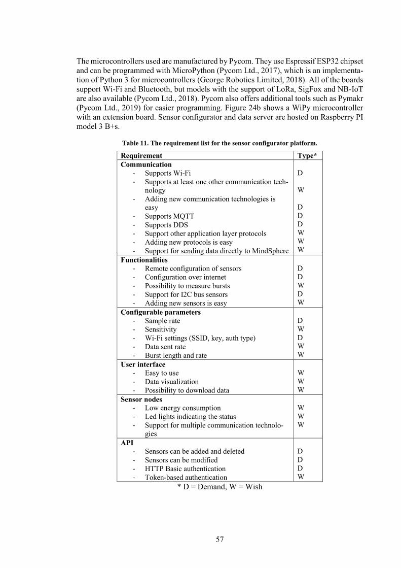
57
The microcontrollers used are manufactured by Pycom. They use Espressif ESP32 chipset
and can be programmed with MicroPython (Pycom Ltd., 2017), which is an implementa-
tion of Python 3 for microcontrollers (George Robotics Limited, 2018). All of the boards
support Wi-Fi and Bluetooth, but models with the support of LoRa, SigFox and NB-IoT
are also available (Pycom Ltd., 2018). Pycom also offers additional tools such as Pymakr
(Pycom Ltd., 2019) for easier programming. Figure 24b shows a WiPy microcontroller
with an extension board. Sensor configurator and data server are hosted on Raspberry PI
model 3 B+s.
Table 11. The requirement list for the sensor configurator platform.
Requirement Type*
Communication
- Supports Wi-Fi
- Supports at least one other communication tech-
nology
- Adding new communication technologies is
easy
- Supports MQTT
- Supports DDS
- Support other application layer protocols
- Adding new protocols is easy
- Support for sending data directly to MindSphere
D
W
D
D
D
W
W
W
Functionalities
- Remote configuration of sensors
- Configuration over internet
- Possibility to measure bursts
- Support for I2C bus sensors
- Adding new sensors is easy
D
D
W
D
W
Configurable parameters
- Sample rate
- Sensitivity
- Wi-Fi settings (SSID, key, auth type)
- Data sent rate
- Burst length and rate
D
W
D
W
W
User interface
- Easy to use
- Data visualization
- Possibility to download data
W
W
W
Sensor nodes
- Low energy consumption
- Led lights indicating the status
- Support for multiple communication technolo-
gies
W
W
W
API
- Sensors can be added and deleted
- Sensors can be modified
- HTTP Basic authentication
- Token-based authentication
D
D
D
W
* D = Demand, W = Wish
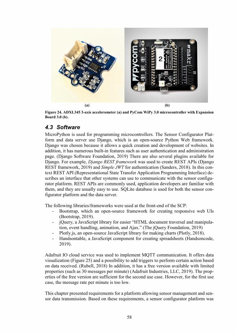
58
(a) (b)
Figure 24. ADXL345 3-axis accelerometer (a) and PyCom WiPy 3.0 microcontroller with Expansion
Board 3.0 (b).
4.3 Software
MicroPython is used for programming microcontrollers. The Sensor Configurator Plat-
form and data server use Django, which is an open-source Python Web framework.
Django was chosen because it allows a quick creation and development of websites. In
addition, it has numerous built-in features such as user authentication and administration
page. (Django Software Foundation, 2019) There are also several plugins available for
Django. For example, Django REST framework was used to create REST APIs (Django
REST framework, 2019) and Simple JWT for authentication (Sanders, 2018). In this con-
text REST API (Representational State Transfer Application Programming Interface) de-
scribes an interface that other systems can use to communicate with the sensor configu-
rator platform. REST APIs are commonly used, application developers are familiar with
them, and they are usually easy to use. SQLite database is used for both the sensor con-
figurator platform and the data server.
The following libraries/frameworks were used at the front-end of the SCP:
- Bootstrap, which an open-source framework for creating responsive web UIs
(Bootstrap, 2019).
- jQuery, a JavaScript library for easier “HTML document traversal and manipula-
tion, event handling, animation, and Ajax.” (The jQuery Foundation, 2019)
- Plotly.js, an open-source JavaScript library for making charts (Plotly, 2018).
- Handsontable, a JavaScript component for creating spreadsheets (Handsoncode,
2019).
Adafruit IO cloud service was used to implement MQTT communication. It offers data
visualization (Figure 25) and a possibility to add triggers to perform certain action based
on data received. (Rubell, 2018) In addition, it has a free version available with limited
properties (such as 30 messages per minute) (Adafruit Industries, LLC, 2019). The prop-
erties of the free version are sufficient for the second use case. However, for the first use
case, the message rate per minute is too low.
This chapter presented requirements for a platform allowing sensor management and sen-
sor data transmission. Based on these requirements, a sensor configurator platform was
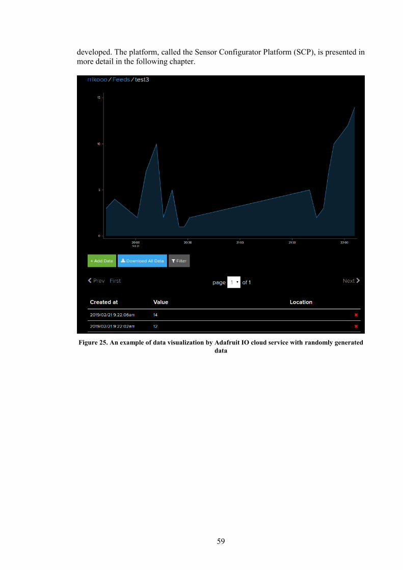
59
developed. The platform, called the Sensor Configurator Platform (SCP), is presented in
more detail in the following chapter.
Figure 25. An example of data visualization by Adafruit IO cloud service with randomly generated
data
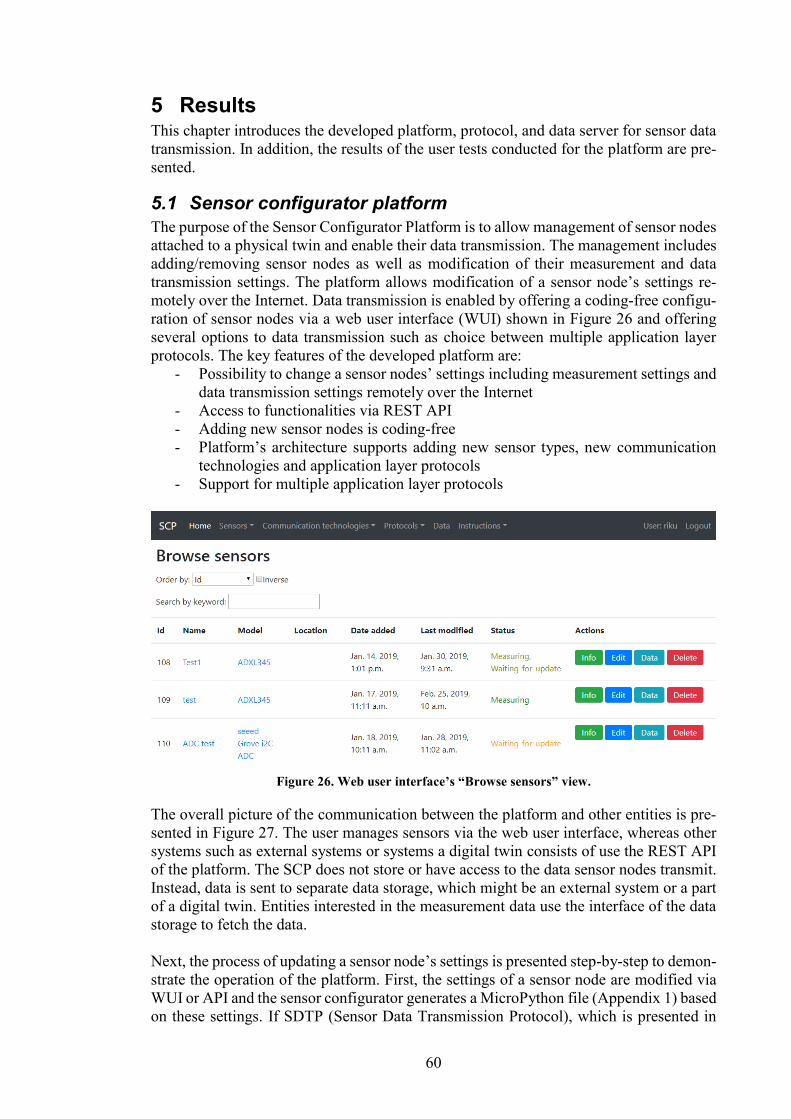
60
5 Results This chapter introduces the developed platform, protocol, and data server for sensor data
transmission. In addition, the results of the user tests conducted for the platform are pre-
sented.
5.1 Sensor configurator platform
The purpose of the Sensor Configurator Platform is to allow management of sensor nodes
attached to a physical twin and enable their data transmission. The management includes
adding/removing sensor nodes as well as modification of their measurement and data
transmission settings. The platform allows modification of a sensor node’s settings re-
motely over the Internet. Data transmission is enabled by offering a coding-free configu-
ration of sensor nodes via a web user interface (WUI) shown in Figure 26 and offering
several options to data transmission such as choice between multiple application layer
protocols. The key features of the developed platform are:
- Possibility to change a sensor nodes’ settings including measurement settings and
data transmission settings remotely over the Internet
- Access to functionalities via REST API
- Adding new sensor nodes is coding-free
- Platform’s architecture supports adding new sensor types, new communication
technologies and application layer protocols
- Support for multiple application layer protocols
Figure 26. Web user interface’s “Browse sensors” view.
The overall picture of the communication between the platform and other entities is pre-
sented in Figure 27. The user manages sensors via the web user interface, whereas other
systems such as external systems or systems a digital twin consists of use the REST API
of the platform. The SCP does not store or have access to the data sensor nodes transmit.
Instead, data is sent to separate data storage, which might be an external system or a part
of a digital twin. Entities interested in the measurement data use the interface of the data
storage to fetch the data.
Next, the process of updating a sensor node’s settings is presented step-by-step to demon-
strate the operation of the platform. First, the settings of a sensor node are modified via
WUI or API and the sensor configurator generates a MicroPython file (Appendix 1) based
on these settings. If SDTP (Sensor Data Transmission Protocol), which is presented in
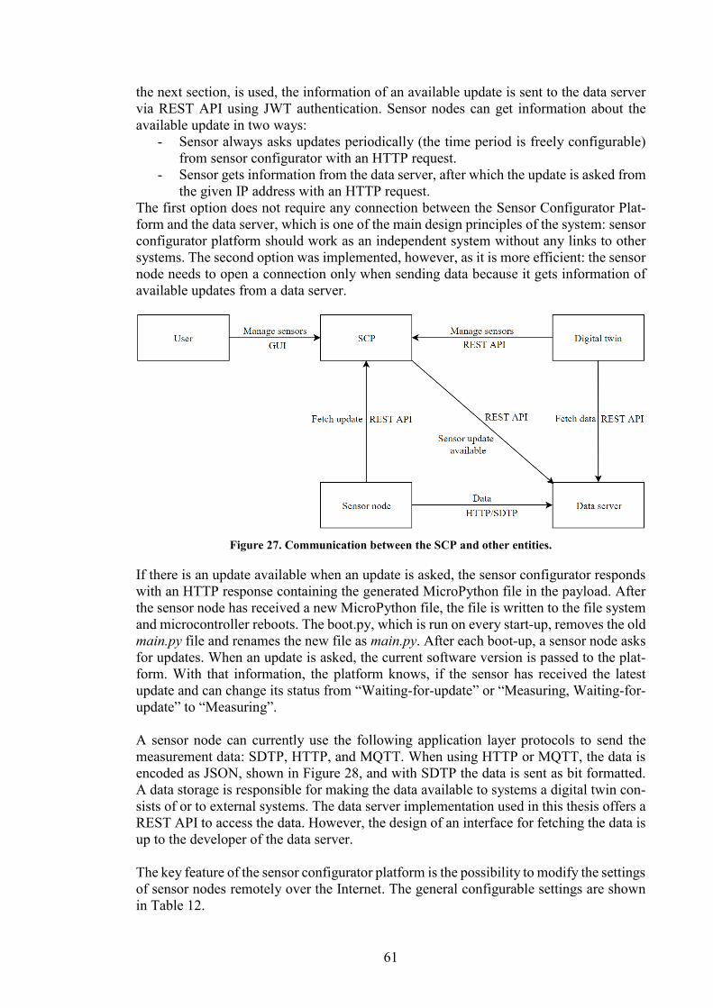
61
the next section, is used, the information of an available update is sent to the data server
via REST API using JWT authentication. Sensor nodes can get information about the
available update in two ways:
- Sensor always asks updates periodically (the time period is freely configurable)
from sensor configurator with an HTTP request.
- Sensor gets information from the data server, after which the update is asked from
the given IP address with an HTTP request.
The first option does not require any connection between the Sensor Configurator Plat-
form and the data server, which is one of the main design principles of the system: sensor
configurator platform should work as an independent system without any links to other
systems. The second option was implemented, however, as it is more efficient: the sensor
node needs to open a connection only when sending data because it gets information of
available updates from a data server.
Figure 27. Communication between the SCP and other entities.
If there is an update available when an update is asked, the sensor configurator responds
with an HTTP response containing the generated MicroPython file in the payload. After
the sensor node has received a new MicroPython file, the file is written to the file system
and microcontroller reboots. The boot.py, which is run on every start-up, removes the old
main.py file and renames the new file as main.py. After each boot-up, a sensor node asks
for updates. When an update is asked, the current software version is passed to the plat-
form. With that information, the platform knows, if the sensor has received the latest
update and can change its status from “Waiting-for-update” or “Measuring, Waiting-for-
update” to “Measuring”.
A sensor node can currently use the following application layer protocols to send the
measurement data: SDTP, HTTP, and MQTT. When using HTTP or MQTT, the data is
encoded as JSON, shown in Figure 28, and with SDTP the data is sent as bit formatted.
A data storage is responsible for making the data available to systems a digital twin con-
sists of or to external systems. The data server implementation used in this thesis offers a
REST API to access the data. However, the design of an interface for fetching the data is
up to the developer of the data server.
The key feature of the sensor configurator platform is the possibility to modify the settings
of sensor nodes remotely over the Internet. The general configurable settings are shown
in Table 12.
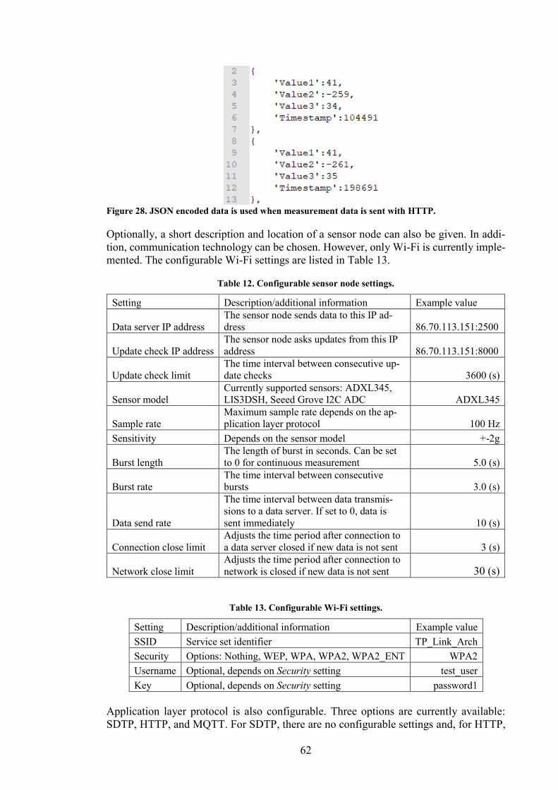
62
Figure 28. JSON encoded data is used when measurement data is sent with HTTP.
Optionally, a short description and location of a sensor node can also be given. In addi-
tion, communication technology can be chosen. However, only Wi-Fi is currently imple-
mented. The configurable Wi-Fi settings are listed in Table 13.
Table 12. Configurable sensor node settings.
Setting Description/additional information Example value
Data server IP address
The sensor node sends data to this IP ad-
dress 86.70.113.151:2500
Update check IP address
The sensor node asks updates from this IP
address 86.70.113.151:8000
Update check limit
The time interval between consecutive up-
date checks 3600 (s)
Sensor model
Currently supported sensors: ADXL345,
LIS3DSH, Seeed Grove I2C ADC ADXL345
Sample rate
Maximum sample rate depends on the ap-
plication layer protocol 100 Hz
Sensitivity Depends on the sensor model +-2g
Burst length
The length of burst in seconds. Can be set
to 0 for continuous measurement 5.0 (s)
Burst rate
The time interval between consecutive
bursts 3.0 (s)
Data send rate
The time interval between data transmis-
sions to a data server. If set to 0, data is
sent immediately 10 (s)
Connection close limit
Adjusts the time period after connection to
a data server closed if new data is not sent 3 (s)
Network close limit
Adjusts the time period after connection to
network is closed if new data is not sent 30 (s)
Table 13. Configurable Wi-Fi settings.
Setting Description/additional information Example value
SSID Service set identifier TP_Link_Arch
Security Options: Nothing, WEP, WPA, WPA2, WPA2_ENT WPA2
Username Optional, depends on Security setting test_user
Key Optional, depends on Security setting password1
Application layer protocol is also configurable. Three options are currently available:
SDTP, HTTP, and MQTT. For SDTP, there are no configurable settings and, for HTTP,
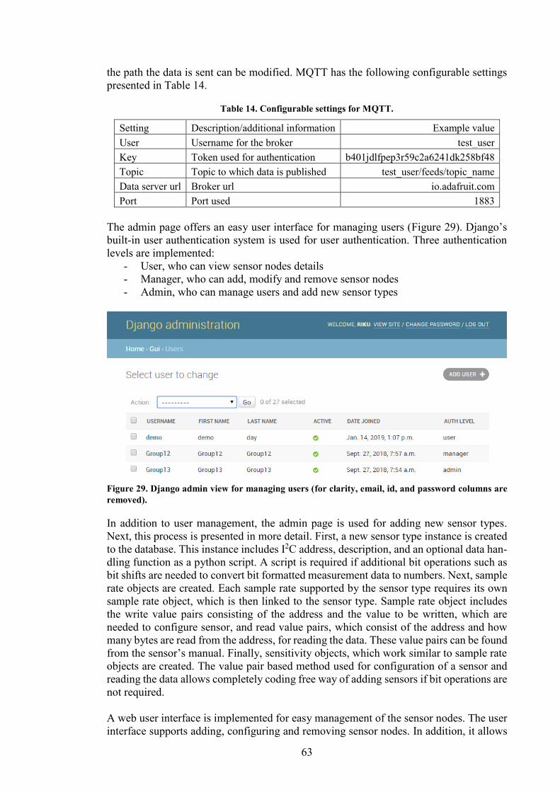
63
the path the data is sent can be modified. MQTT has the following configurable settings
presented in Table 14.
Table 14. Configurable settings for MQTT.
Setting Description/additional information Example value
User Username for the broker test_user
Key Token used for authentication b401jdlfpep3r59c2a6241dk258bf48
Topic Topic to which data is published test_user/feeds/topic_name
Data server url Broker url io.adafruit.com
Port Port used 1883
The admin page offers an easy user interface for managing users (Figure 29). Django’s
built-in user authentication system is used for user authentication. Three authentication
levels are implemented:
- User, who can view sensor nodes details
- Manager, who can add, modify and remove sensor nodes
- Admin, who can manage users and add new sensor types
Figure 29. Django admin view for managing users (for clarity, email, id, and password columns are
removed).
In addition to user management, the admin page is used for adding new sensor types.
Next, this process is presented in more detail. First, a new sensor type instance is created
to the database. This instance includes I2C address, description, and an optional data han-
dling function as a python script. A script is required if additional bit operations such as
bit shifts are needed to convert bit formatted measurement data to numbers. Next, sample
rate objects are created. Each sample rate supported by the sensor type requires its own
sample rate object, which is then linked to the sensor type. Sample rate object includes
the write value pairs consisting of the address and the value to be written, which are
needed to configure sensor, and read value pairs, which consist of the address and how
many bytes are read from the address, for reading the data. These value pairs can be found
from the sensor’s manual. Finally, sensitivity objects, which work similar to sample rate
objects are created. The value pair based method used for configuration of a sensor and
reading the data allows completely coding free way of adding sensors if bit operations are
not required.
A web user interface is implemented for easy management of the sensor nodes. The user
interface supports adding, configuring and removing sensor nodes. In addition, it allows
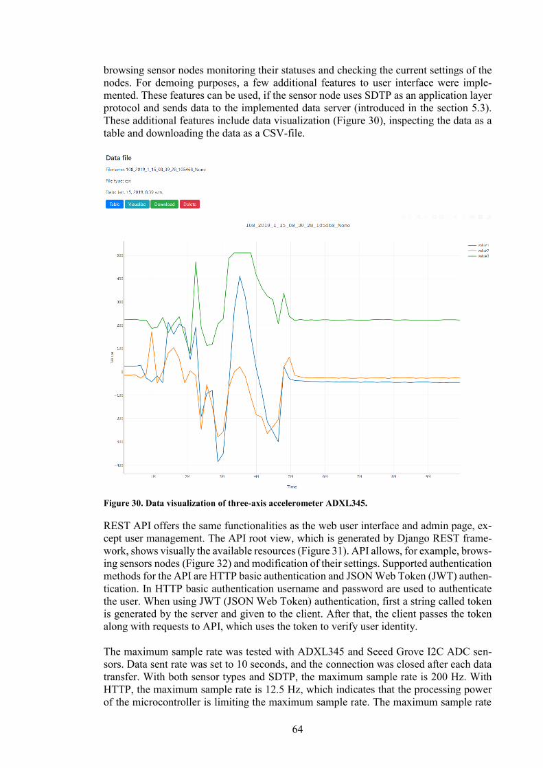
64
browsing sensor nodes monitoring their statuses and checking the current settings of the
nodes. For demoing purposes, a few additional features to user interface were imple-
mented. These features can be used, if the sensor node uses SDTP as an application layer
protocol and sends data to the implemented data server (introduced in the section 5.3).
These additional features include data visualization (Figure 30), inspecting the data as a
table and downloading the data as a CSV-file.
Figure 30. Data visualization of three-axis accelerometer ADXL345.
REST API offers the same functionalities as the web user interface and admin page, ex-
cept user management. The API root view, which is generated by Django REST frame-
work, shows visually the available resources (Figure 31). API allows, for example, brows-
ing sensors nodes (Figure 32) and modification of their settings. Supported authentication
methods for the API are HTTP basic authentication and JSON Web Token (JWT) authen-
tication. In HTTP basic authentication username and password are used to authenticate
the user. When using JWT (JSON Web Token) authentication, first a string called token
is generated by the server and given to the client. After that, the client passes the token
along with requests to API, which uses the token to verify user identity.
The maximum sample rate was tested with ADXL345 and Seeed Grove I2C ADC sen-
sors. Data sent rate was set to 10 seconds, and the connection was closed after each data
transfer. With both sensor types and SDTP, the maximum sample rate is 200 Hz. With
HTTP, the maximum sample rate is 12.5 Hz, which indicates that the processing power
of the microcontroller is limiting the maximum sample rate. The maximum sample rate
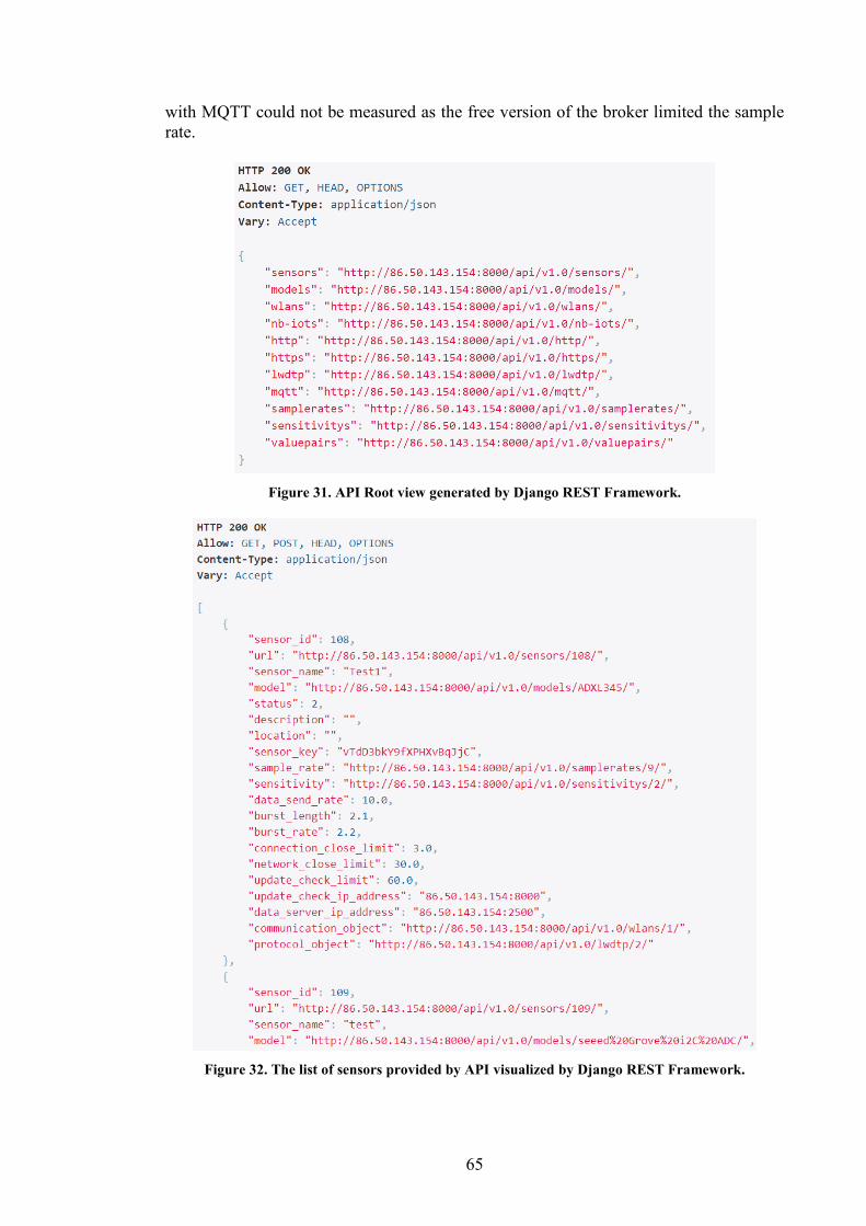
65
with MQTT could not be measured as the free version of the broker limited the sample
rate.
Figure 31. API Root view generated by Django REST Framework.
Figure 32. The list of sensors provided by API visualized by Django REST Framework.
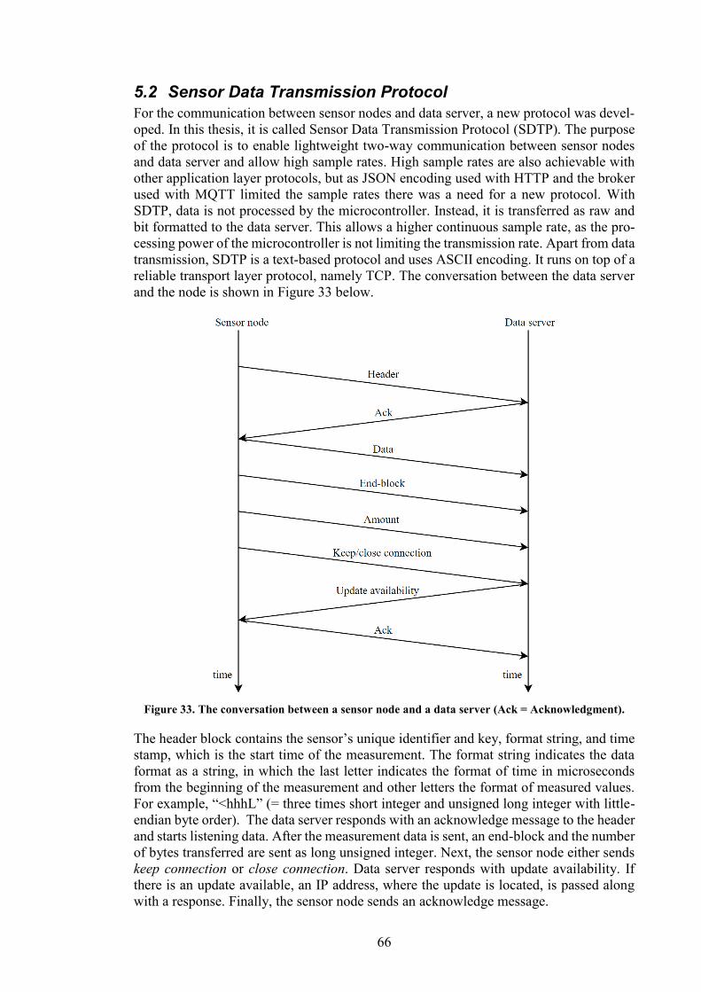
66
5.2 Sensor Data Transmission Protocol
For the communication between sensor nodes and data server, a new protocol was devel-
oped. In this thesis, it is called Sensor Data Transmission Protocol (SDTP). The purpose
of the protocol is to enable lightweight two-way communication between sensor nodes
and data server and allow high sample rates. High sample rates are also achievable with
other application layer protocols, but as JSON encoding used with HTTP and the broker
used with MQTT limited the sample rates there was a need for a new protocol. With
SDTP, data is not processed by the microcontroller. Instead, it is transferred as raw and
bit formatted to the data server. This allows a higher continuous sample rate, as the pro-
cessing power of the microcontroller is not limiting the transmission rate. Apart from data
transmission, SDTP is a text-based protocol and uses ASCII encoding. It runs on top of a
reliable transport layer protocol, namely TCP. The conversation between the data server
and the node is shown in Figure 33 below.
Figure 33. The conversation between a sensor node and a data server (Ack = Acknowledgment).
The header block contains the sensor’s unique identifier and key, format string, and time
stamp, which is the start time of the measurement. The format string indicates the data
format as a string, in which the last letter indicates the format of time in microseconds
from the beginning of the measurement and other letters the format of measured values.
For example, “<hhhL” (= three times short integer and unsigned long integer with little-
endian byte order). The data server responds with an acknowledge message to the header
and starts listening data. After the measurement data is sent, an end-block and the number
of bytes transferred are sent as long unsigned integer. Next, the sensor node either sends
keep connection or close connection. Data server responds with update availability. If
there is an update available, an IP address, where the update is located, is passed along
with a response. Finally, the sensor node sends an acknowledge message.
67
Example messages sent in conversation:
- Header: "BEGIN: 6; 1234; <hhhL; (2017, 2, 28, 10, 30, 0, 0, 0)"
- Ack: “OK”
- Data: 0xE70x790x650x00013815 (as hexadecimal)
- End-block: “END”
- Amount: 12000
- Keep/close connection: “KEEP” or “CLSE”
- Update availability: “UPDATE: 86.50.143.154:8000” or “UPTODATE”
5.3 Data server
A distinct data server supporting SDTP was implemented to allow faster sample rates.
The developed data server offers a REST API interface for accessing the data, which is
also used by the SCP to fetch data for data visualization, and other additional features.
The API uses similar authentication methods as the Sensor configurator platform, namely
HTTP Basic and JWT authentication. It allows browsing the data files produced by sen-
sors and downloading them as a CSV file. The API is also used by the SCP to fetch the
data. The API root view generated by Django REST Framework is shown in Figure 34.
The data produced by sensors is stored as text files.
Figure 34. The data server's API Root view.
5.4 User test
A user test was arranged to assess the ease of use of the developed platform, which was
one of its main design criteria. 26 students from technical universities around Europe
participated in the user test. 22 of the participants answered to the feedback form. Their
fields of study are listed in Table 15. 45 % of the respondents had used microcontrollers
before this user test and 9% of them a system, which resembled the sensor configurator
platform. The task given was to add a new sensor to the system, and it was executed in
groups of two. The instructions given can be found in Appendix 2. The test setup con-
tained a microcontroller attached to an expansion board, ADXL345 sensor, and cables
shown in Figure 35. The time limit for finishing the task was roughly 60 minutes. Finally,
feedback was collected using Google Forms.
73% of the respondents managed to accomplish the task given even though there were
technical problems with the system. 73% of the respondents also needed to ask for help
during the user test. Despite this, the Sensor Configurator Platform was considered easy
to use (Figure 36). In addition, most of the problems (Figure 37) encountered by partici-
pants, were related to connecting the computer to the microcontroller via Wi-Fi and mov-
ing initial files to the microcontroller, which are actually more related to the microcon-
troller’s software than the sensor configurator itself. All of the respondents found the
platform useful and 73% of them would use a system like it in the future. All questions
and answers can be found in Appendix 3.
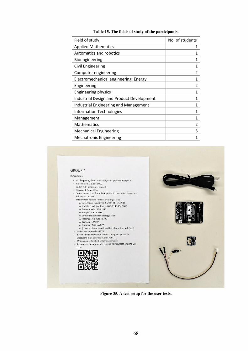
68
Table 15. The fields of study of the participants.
Field of study No. of students
Applied Mathematics 1
Automatics and robotics 1
Bioengineering 1
Civil Engineering 1
Computer engineering 2
Electromechanical engineering, Energy 1
Engineering 2
Engineering physics 1
Industrial Design and Product Development 1
Industrial Engineering and Management 1
Information Technologies 1
Management 1
Mathematics 2
Mechanical Engineering 5
Mechatronic Engineering 1
Figure 35. A test setup for the user tests.
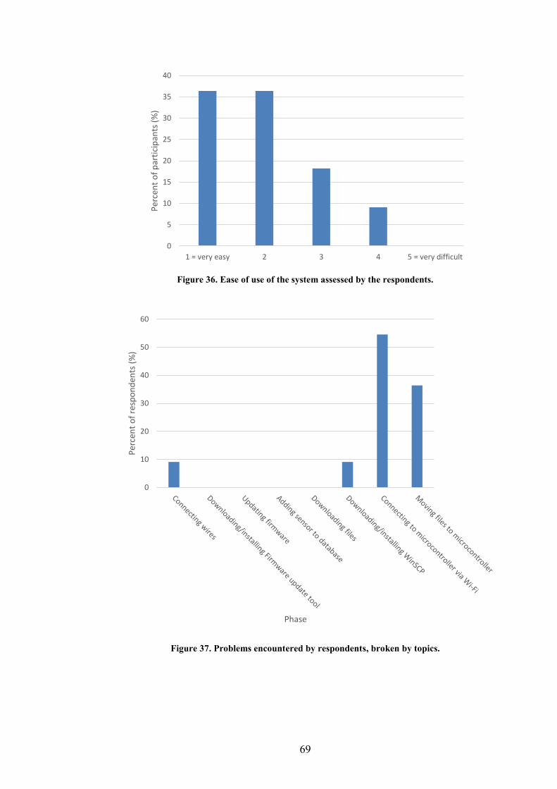
69
Figure 36. Ease of use of the system assessed by the respondents.
Figure 37. Problems encountered by respondents, broken by topics.
0
5
10
15
20
25
30
35
40
1 = very easy 2 3 4 5 = very difficult
Per
cen
t o
f p
arti
cip
ants
(%
)
0
10
20
30
40
50
60
Per
cen
t o
f re
spo
nd
ents
(%
)
Phase
70
6 Discussion The developed platform is a single ready-to-use system for a set of linked systems a dig-
ital twin consists of and allows data transmission from a physical twin to a digital twin.
It allows easy addition of new sensor nodes to a physical twin, their remote management
and data transmission using the most suitable standards. Therefore, the platform narrows
the gap between the concept of a digital twin and its realization. The platform offers a
REST API that the other subsystems of a digital twin can use to manage sensors remotely.
In addition, the platform has a web user interface, which allows its use by a human oper-
ator.
Because the platform allows easy addition, configuration and management of sensor
nodes, it can also be used outside the context of a digital twin. For example, the platform
enables conducting simple measurement tasks in the laboratory and it can be used in
teaching to demonstrate a measurement system. In student projects, the platform allows
students to focus on the processing of the data instead of collecting it.
This chapter considers the future development areas of the platform and whether the de-
veloped platform fulfills the requirements set for it. In addition, recommendations for the
most suitable application layer protocols and communication technologies for transmit-
ting the measurement data from a physical twin to a digital twin based on the literature
review are presented. The concept of a digital twin is also discussed. Finally, the signifi-
cance of the platform and this thesis is evaluated in the context of a digital twin and Digi-
Twin project.
6.1 Sensor configurator platform
The developed sensor configurator platform narrows the gap between the concept of a
digital twin and its realization by enabling the sensor data transmission. The transmission
is allowed by easy addition, configuration and management of sensor nodes. In this sec-
tion, the developed platform is assessed by examining whether it fulfills the requirements
given in Table 11. Thereafter, the limitations and further development needs of the plat-
form are presented.
The Sensor Configurator Platform fulfills all demands, except support for DDS, given in
the requirement list (Table 11). DDS wasn’t implemented because there is not a micropy-
thon library available and implementing a new library is out of the scope of this thesis.
The demand for easiness of use was verified by means of user tests. The user test, which
results are presented in chapter 5.4, indicated that the platform is easy to use even without
prior knowledge of microcontrollers. Users also found the platform useful and, surpris-
ingly, most of the users could contribute to this kind of platform if it was an open-source
project.
Almost every wish was also fulfilled. Only the following wishes weren’t accomplished:
- The connection to Siemens MindSphere. This wish couldn’t be implemented, be-
cause the implementation of authentication and the process of creating new sen-
sor/device instances to MindSphere was challenging.
- The support for multiple communication technologies. The wish of multiple com-
munication technologies was discarded because Wi-Fi is suitable for most of the
use cases. The initial plan was to add also support for NB-IoT. However, when
the microcontroller’s firmware was updated to enable the NB-IoT connection, the
whole microcontroller became unresponsive.
71
- Low energy consumption. The low energy consumption could not be verified be-
cause there were problems with the power supply of the microcontrollers.
These unfulfilled wishes will be implemented in the next phase of the development of the
platform.
Even though the platform is fully functional, there are several areas for improvement.
Currently, the user management of the platform does not allow restricting the visibility
of sensor nodes: every sensor node can be seen by every user. Basically, this means that
to reduce visibility each user group of the system should have their own instance of the
platform running on the server. Another limitation is the support for only Pycom’s mi-
crocontrollers. However, the microcontrollers are based on general ESP32, and the
MicroPython-file generated have only one Pycom specific functionality: flashing of led
lights indicating the status of the board. One of the future development targets is to add
support for several microcontrollers and allow generating code in other languages such
as C and Arduino. At the moment, a microcontroller needs to be able to perform an HTTP
request to fetch updates from the platform. Therefore, a microcontroller needs to be IP-
compatible, which prevents the use of very constrained devices. Those devices would
need a gateway for the Internet connection.
Microcontrollers use their internal memory to store the data read from the sensors. This
restricts the time interval sensor can measure without forwarding data to the data server
as the available memory is only in order of two megabytes. However, support for saving
data to a memory card can be added in the future as the expansion boards used with mi-
crocontrollers have a slot for microSD card.
The CPU performance of the microcontroller limits the sample rate. Currently, the max-
imum sample rate is in order of 200 Hz with SDTP and 10Hz with HTTP. However, the
used sensors are capable of sample rates over 1000 Hz. As can be seen from the HTTP
sample rates, the microcontroller should not perform any processing of data (in this case,
converting bit formatted data into integers and constructing JSON). If higher data rates,
for example, with HTTP are required, edge computing could be used. With edge compu-
ting, the measurement data could be sent as a raw bit format data to a gateway, which
could convert it to a JSON format and forward the data as an HTTP request to the data
server.
Configurable settings presented in Table 12 cover the requirements for the management
of a sensor node. However, the possibility to add threshold values to trigger certain ac-
tions could be added in the future. For example, if the value of temperature rises over a
certain limit, a warning message could be sent to a certain IP address.
Currently, the platform uses an SQLite database, which does not support concurrent writ-
ing operations (Owens, 2006, p. 12). Therefore, if the platform is used by a large number
of users and sensor nodes, the database should be changed. However, the write operations
are quite rare in the sensor configurator platform, and thus, the SQLite is unlikely to cause
performance issues. In addition, Django supports multiple databases and switching the
database is straightforward.
Safety, which is an important factor in the industry, was not in the focus in the develop-
ment of the platform. Currently, the data is sent unencrypted over HTTP, MQTT or SDTP
protocols and sensors fetch their updates without encryption. In addition, the platform has
72
not been comprehensively tested, which exposes it to vulnerabilities. However, the safety
of the platform will be considered in the further development of the platform.
As the platform is aimed to be suitable for various use cases, the next step in the devel-
opment of the platform is to add support for multiple application layer protocols and com-
munication technologies. In addition, benchmarking tools for the assessment of the pro-
tocols could be added. Thereafter, the platform could be used to verify the results of the
literature review of the most suitable application layer protocols and communication tech-
nologies.
The general problem in the selection of IoT platform is that there is an overwhelming
amount of them with seemingly similar features. In addition, the same functionality can
be implemented in several ways, which further complicates the comparison of platforms
(Guth et al., 2016, p. 1). The developed platform stands out from other IoT platforms with
the ease of use, the possibility of adding new sensors coding-free, and light-weightiness
(focus only on the management of the sensor nodes).
6.2 Communication
The literature review of application protocols and communication technologies presents
the most suitable and already established standards for transmission of the measurement
data from a physical twin to a digital twin. The focus on the data collection leaves a
significant part of the communication needs identified out of the scope of this thesis.
However, this limitation is necessary, as it is not feasible to examine all areas of commu-
nication in a satisfactory manner in the context of this thesis. Furthermore, there is a great
need for additional research of each of these communication needs.
The number of standards related to application layer protocols and communication tech-
nologies is overwhelming, and, in addition, new standards are constantly released. There-
fore, it is not possible to review all of them in the context of this thesis. For example,
some industrial standards such as ISA100.11 (Li et al., 2017, p. 1509) were left out. How-
ever, the most common standards are included in the literature review.
There is a lack of comprehensive comparisons of both application layer protocols and
communication technologies in the scientific literature, which makes the assessment of
them challenging. In addition, existing comparisons are often based on literature review
and, thus, there is a need for additional field tests to verify results. The comparison of
communication methods in this thesis is also based on solely literature review. However,
the field tests could be executed in the next phase of the research project after support for
several protocols is added to the sensor configurator platform.
The literature review shows that there exist suitable standards and protocols for sensor
data transmission. While some examined standards are better suited for a digital twin than
others, practical choices often dictate the choice between them. For example, the availa-
bility of libraries is important when choosing application layer protocols, and the existing
network infrastructure when choosing communication technology. Therefore, for exam-
ple, only Wi-Fi was implemented to the SCP, even though the used microcontrollers sup-
ported also LoRa, Sigfox, and NB-IoT.
While none of the standards is superior to each other, the developers often choose the one
they are familiar with. Without a common decision to use a certain protocol, the use of
73
protocols remains diverse. This thesis recommends using the following application layer
protocols:
1) DDS for real-time applications
2) MQTT for periodic data collection in stable networks
3) CoAP for periodic data collection in lossy networks
In addition, the following communication technologies are recommended:
1) Wi-Fi 802.11n for real-time applications
2) Wi-Fi 802.11n for periodic data collection if an easy implementation is the most
important factor
3) Bluetooth for periodic data collection if the movement area of the physical twin
is limited to a few tens of meters and energy consumption has to be low
4) LoRaWAN for periodic data collection if the movement area of the physical twin
is not limited and energy consumption has to be low
6.3 Digital twin
The concept of digital twin, which came to the public only a few years ago, is still at its
infancy. In the scientific literature, there is no unanimity of the features and the definition
of a digital twin. The research field greatly influences to which features of a digital twin
are being emphasized. For example, aeronautics is interested in forward simulations of
systems, whereas manufacturing is interested in optimizing their process. For this reason,
this thesis recommends creating a framework for identifying the core functionalities of a
digital twin, after which a reference architecture of a digital twin could be derived. This
allows the further development of the concept by enabling collaboration between fields
and converging the existing visions of a digital twin.
The expectations towards a digital twin are set high as it is expected to offer numerous
benefits throughout the product life cycle. Thus, the concept has gained huge popularity
lately, and, actually, it is at the phase of inflated expectations in the hype curve (Panetta,
2018a). It is clear that some features of a digital twin such as the ability to completely
mirror the state of physical twin are not feasible in practice. However, a digital twin is
constantly developed, and the number of papers published has increased rapidly. In addi-
tion, a digital twin is not a completely new concept and it is built on top of the concepts
presented already at the beginning of the 2000s indicating that there is a real need for the
concept. Despite the constant development and need for a digital twin, there is a lack of
realizations of a digital twin.
What makes the realization challenging, is the complexity of a digital twin and the nu-
merous functionalities it offers. A digital twin consists of a set of linked systems working
collaboratively together with external systems to offer these functionalities. Therefore,
the interoperability between systems a digital twin consists of and external systems is
fundamental. To enable this interoperability, standardized interfaces and protocols for
communication between systems are required. However, there is a lack of standardization
with digital twins as well as with IoT in general (Al-Qaseemi et al., 2016). The standard-
ization of the communication is prerequisite for the emergence of digital twins. This thesis
responds to the need of standardization by presenting the most suitable and already es-
tablished standards for the transmission of the measurement data from a physical twin to
a digital twin and by developing a platform, which allows the utilization of these most
suitable standards.
The developed platform takes the DigiTwin project towards its goal of building a digital
of an overhead crane by enabling the data collection from the physical twin. The platform
74
allows attaching sensors nodes to the physical crane effortlessly, and their remote man-
agement. In addition to the platform, this thesis also presented the most suitable applica-
tion layer protocols and communication technologies for sensor data transmission from a
physical twin to digital twin. The results can be utilized when designing the communica-
tion of the digital twin of an overhead crane. Other communication needs of a digital twin
were also identified. These needs should be taken into account when designing the overall
architecture of the digital twin. However, each of these communication needs identified
requires more research.
This thesis can be considered successful because it helps the DigiTwin project to reach
its goals and fulfills its purpose of examination of sensor data transmission from a phys-
ical to a digital twin. The thesis presented a comprehensive literature review on applica-
tion layer protocols and also the most commonly used communication technologies. The
literature review is not limited to the context of a digital twin and can be as a general
guide when selecting IoT protocols. Therefore, the thesis has significance also in the field
of IoT in general. Finally, the thesis narrows the gap between a concept of a digital twin
and its realization by presenting a single ready-to-use system for a set of systems a digital
twin consists of.
75
7 Conclusion Digital twin is a digital counterpart of a physical object, which accurately mirrors the
current state of its corresponding physical twin. It further develops concepts of smart
products presented at the beginning of the 2000s. The definition of a digital twin is not
yet established in the scientific literature and varies depending on the field as can be seen
from Table 2.
The thesis focused on the communication between a digital twin and its physical coun-
terpart, and more specifically on transmission of data collected from physical twin to a
digital twin. This focus area was chosen because one of the key properties of a digital
twin is an ability to accurately mirror its corresponding physical twin, which requires
constant monitoring of the physical twin via sensors. Two distinct use cases for data col-
lection from an overhead crane were derived. In the first use case sensor data is used to
control the location of the hook in real-time and in the second use case the sensor data is
used to monitor the stress of the bridge.
The literature review of communication focused on examining the most suitable applica-
tion layer protocols and communication technologies for the selected use cases. The ex-
amined application layer protocols were HTTP, MQTT, CoAP, XMPP, AMQP, DDS,
and OPC UA. The most suitable protocol for the first use case is DDS, as it capable of
real-time communication, offers built-in security, and has low latency. For the second use
case, MQTT, CoAP, and MQTT have the most suitable properties including low band-
width, memory, and CPU usage. MQTT has the best availability of open-source libraries,
which makes its implementation easier than CoAP and AMQP. Therefore, it is the pre-
ferred choice for the second use case. However, because CoAP uses UDP as underlying
transport layer protocol instead of TCP, it is the recommended choice for lossy networks.
The examined communication technologies included 4G, 5G, NB-IoT, LoRaWAN, Sig-
fox, Bluetooth, 802.11ah, 802.11n, ZigBee, Z-Wave, and WirelessHART. For the first
use case, Wi-Fi 802.11n is the recommended choice as it offers the lowest latency. For
the second use case, there is not a single the most suitable option. However, Wi-Fi
802.11n is the recommended choice because of its easy implementation. Other suitable
options are Bluetooth and LoRaWAN, because of their low energy consumption.
A sensor configurator platform was developed as part of this thesis. The platform narrows
the gap between the concept of a digital twin and its realization by enabling data trans-
mission from a physical twin to a digital twin. It allows the management of sensors re-
motely over the internet and offers a REST API interface that the subsystems of a digital
twin and external systems can use. User tests on the platform were promising and indi-
cated that the platform is easy to use. The developed platform benefits the DigiTwin pro-
ject as it allows data collection from the overhead crane, which is prerequisite for creating
the digital twin of the crane.
76
References ISO/IEC 7498-1. (1994) Information Technology - Open Systems Interconnection -
Basicreference Model: The Basic Model. Genova: ISO/IEC, p. 59.
Adafruit Industries, LLC. (2017) ZigBee & Z-Wave ‘Home Area Network’ Radios.
Available at: https://learn.adafruit.com/alltheiot-transports/zigbee-z-wave (Accessed: 21
February 2019).
Adafruit Industries, LLC. (2019) Adafruit IO. Available at: https://io.adafruit.com
(Accessed: 21 February 2019).
Aijaz, A. & Aghvami, A. H. (2015) Cognitive machine-to-machine communications for
internet-of-things: A protocol stack perspective. IEEE Internet of Things Journal, 2(2),
pp. 103–112. doi: 10.1109/JIOT.2015.2390775. ISSN 2327-4662 (Online).
Al-Fuqaha, A., Guizani, M., Mohammadi, M., Aledhari, M. & Ayyash, M. (2015)
Internet of things: A survey on enabling technologies, protocols, and applications. IEEE
Communications Surveys & Tutorials, 17(4), pp. 2347–2376. doi:
10.1109/COMST.2015.2444095. ISSN 1553-877X (Online).
Al-Qaseemi, S. A., Almulhim, H. A., Almulhim, M. F. & Chaudhry, S. R. (2016) IoT
architecture challenges and issues: Lack of standardization. in 2016 Future Technologies
Conference (FTC). 6-7 Dec. San Francisco, CA, USA: IEEE, pp. 731–738. doi:
10.1109/FTC.2016.7821686. ISBN 978-1-5090-4171-8 (Online).
Al-Sarawi, S., Anbar, M., Alieyan, K. & Alzubaidi, M. (2017) Internet of Things (IoT)
communication protocols: Review. in 2017 8th International Conference on Information
Technology (ICIT), pp. 685–690. doi: 10.1109/ICITECH.2017.8079928. ISBN 978-1-
5090-6332-1 (Online).
Alam, K. M. & El Saddik, A. (2017) C2PS: A digital twin architecture reference model
for the cloud-based cyber-physical systems. IEEE Access, 5, pp. 2050–2062. doi:
10.1109/ACCESS.2017.2657006. ISSN 2169-3536 (Online).
Alani, M. M. (2014) Guide to OSI and TCP/IP Models. Cham: Springer International
Publishing (SpringerBriefs in Computer Science). doi: 10.1007/978-3-319-05152-9.
ISBN 978-3-319-05151-2.
AMQP v1.0 (2011) AMQP Specification v1.0. Revision 1350.
Analog Devices, Inc. (2019) ADXL345. Available at: https://www.analog.com/en/
products/adxl345.html#product-overview (Accessed: 25 January 2019).
Autiosalo, J. (2018) Platform for industrial internet and digital twin focused education,
research, and innovation: Ilmatar the overhead crane. IEEE World Forum on Internet of
Things, WF-IoT 2018 - Proceedings, 2018–Janua, pp. 241–244. doi: 10.1109/WF-
IoT.2018.8355217. ISBN 978-1-4673-9944-9 (Online).
Barth, A. (2011) HTTP State Management Mechanism. RFC Editor. RFC6265. Available
at: http://www.rfc-editor.org/rfc/rfc6265.txt. ISSN 2070-1721.
Bazilevs, Y., Deng, X., Korobenko, A., Lanza di Scalea, F., Todd, M. D. & Taylor, S. G.
77
(2015) Isogeometric Fatigue Damage Prediction in Large-Scale Composite Structures
Driven by Dynamic Sensor Data. Journal of Applied Mechanics, 82(9), pp. 091008-
091008-12. doi: 10.1115/1.4030795. ISSN 0021-8936.
Belshe, M., Peon, R. & Thomson, M. (2015) Hypertext Transfer Protocol Version 2
(HTTP/2). RFC Editor. RFC7540. Available at: http://www.rfc-editor.org/rfc/
rfc7540.txt. ISSN 2070-1721.
Benzekki, K., El Fergougui, A. & Elbelrhiti Elalaoui, A. (2016) Software-defined
networking (SDN): a survey. Security and Communication Networks, 9(18), pp. 5803–
5833. doi: 10.1002/sec.1737. ISSN 1939-0122 (Online).
Bluetooth SIG, Inc. (2018a) Bluetooth 5. Available at: https://www.bluetooth.com/
bluetooth-technology/bluetooth5/bluetooth5-paper (Accessed: 27 November 2018).
Bluetooth SIG, Inc. (2018b) Radio Versions. Available at: https://www.bluetooth.com/
bluetooth-technology/radio-versions (Accessed: 27 November 2018).
Bluetooth SIG, Inc. (2018c) Technology. Available at: https://www.bluetooth.com/
bluetooth-technology (Accessed: 27 November 2018).
Bluetooth SIG, Inc. (2018d) Topology Options. Available at: https://www.bluetooth.com/
bluetooth-technology/topology-options (Accessed: 27 November 2018).
Boger, T. & Rusk, J. (2017) What does a Siemens digital twin look like? Siemens Product
Lifecycle Management Software Inc. Available at: https://community.plm.automation.
siemens.com/t5/Digital-Twin-Knowledge-Base/What-does-a-Siemens-digital-twin-
look-like/ta-p/432968 (Accessed: 21 June 2018).
Bootstrap (2019) Bootstrap. Available at: https://getbootstrap.com/ (Accessed: 28
January 2019).
Bormann, C. & Shelby, Z. (2016) Block-Wise Transfers in the Constrained Application
Protocol (CoAP). RFC Editor. RFC7959. Available at: http://www.rfc-editor.org/rfc/
rfc7959.txt. ISSN 2070-1721.
Boschert, S. & Rosen, R. (2016) Digital Twin—The Simulation Aspect. in Hehenberger,
P. and Bradley, D. (eds) Mechatronic Futures. Cham: Springer International Publishing,
pp. 59–74. doi: 10.1007/978-3-319-32156-1_5. ISBN 978-3-319-32156-1 (Online) 978-
3-319-32154-7 (Print).
Brussel, H. Van, Bongaorts, L., Wyns, J., Valckenaers, P. & Van Ginderachter, T. (1999)
A Conceptual Framework for Holonic Manufacturing : Identification of Manufacturing
Holons. Journal of Manufacturing systems, 18(1), pp. 35–52.
Bush, R. & Meyer, D. (2002) Some Internet Architectural Guidelines and Philosophy.
RFC Editor. RFC3439. Available at: http://www.rfc-editor.org/rfc/rfc3439.txt. ISSN
2070-1721.
Cai, J. & Goodman, D. J. (1997) General packet radio service in GSM. IEEE
Communications Magazine, 35(10), pp. 122–131. doi: 10.1109/35.623996. ISSN 1558-
1896 (Online) 0163-6804 (Print).
78
Cerrone, A., Hochhalter, J., Heber, G. & Ingraffea, A. (2014) On the effects of modeling
as-manufactured geometry: Toward digital twin. International Journal of Aerospace
Engineering, 2014. doi: 10.1155/2014/439278. ISSN 1687-5974 (Online) 1687-5966
(Print).
Chen, Y. & Kunz, T. (2016) Performance evaluation of IoT protocols under a constrained
wireless access network. in 2016 International Conference on Selected Topics in Mobile
& Wireless Networking (MoWNeT) 11-13 April 2016. Cairo, Egypt: IEEE, pp. 1–7. doi:
10.1109/MoWNet.2016.7496622. ISBN 978-1-5090-1743-0 (Online).
Collotta, M. & Pau, G. (2015) Bluetooth for Internet of Things: A fuzzy approach to
improve power management in smart homes. Computers & Electrical Engineering.
Pergamon, 44, pp. 137–152. doi: 10.1016/j.compeleceng.2015.01.005. ISSN 0045-7906.
da Cruz, M. A. A., Rodrigues, J. J. P. C., Al-Muhtadi, J., Korotaev, V. V. & de
Albuquerque, V. H. C. (2018) A Reference Model for Internet of Things Middleware.
IEEE Internet of Things Journal, 5(2), pp. 871–883. doi: 10.1109/JIOT.2018.2796561.
ISSN 2327-4662 (Online).
DebRoy, T., Zhang, W., Turner, J. & Babu, S. S. (2017) Building digital twins of 3D
printing machines. Scripta Materialia. Acta Materialia Inc., 135, pp. 119–124. doi:
10.1016/j.scriptamat.2016.12.005. ISSN 1359-6462.
Dierks, T. & Rescorla, E. (2008) The Transport Layer Security (TLS) Protocol Version
1.2. RFC Editor. RFC5246. Available at: http://www.rfc-editor.org/rfc/rfc5246.txt. ISSN
2070-1721.
Django REST framework (2019) Django REST framework. Available at: https://www.
django-rest-framework.org/ (Accessed: 25 January 2019).
Django Software Foundation (2019) Why Django? Available at: https://www.
djangoproject.com/start/overview/ (Accessed: 30 January 2019).
Duke, M., Braden, R., Eddy, W., Blanton, E. & Zimmermann, A. (2015) A Roadmap for
Transmission Control Protocol (TCP) Specification Documents. RFC Editor. RFC7414.
Available at: http://www.rfc-editor.org/rfc/rfc7414.txt. ISSN 2070-1721.
Dürkop, L., Czybik, B. & Jasperneite, J. (2015) Performance evaluation of M2M
protocols over cellular networks in a lab environment. in 2015 18th International
Conference on Intelligence in Next Generation Networks 17-19 Feb. 2015. Paris, France:
IEEE, pp. 70–75. doi: 10.1109/ICIN.2015.7073809. ISBN 978-1-4799-1866-9 (Online).
Eclipse Foundation (2018) Eclipse Mosquitto. Available at: https://mosquitto.org/
(Accessed: 27 October 2018).
El-Mougy, A., Ibnkahla, M. & Hegazy, L. (2015) Software-defined wireless network
architectures for the Internet-of-Things. in IEEE 40th Local Computer Networks
Conference Workshops (LCN Workshops). 26-29 Oct. Clearwater Beach, FL, USA:
IEEE, pp. 804–811. doi: 10.1109/LCNW.2015.7365931. ISBN 978-1-4673-6773-8
(Online).
Fielding, R. & Reschke, J. (2014) Hypertext Transfer Protocol (HTTP/1.1): Message
Syntax and Routing. RFC Editor. RFC7230. Available at: http://www.rfc-editor.org/
79
rfc/rfc7230.txt. ISSN 2070-1721.
Fielding, R. T. (2000) Architectural Styles and the Design of Network-based Software
Architectures. University of California, Irvine. Available at: https://www.ics.uci.edu
/~fielding/pubs/dissertation/fielding_dissertation.pdf (Accessed: 30 January 2019).
Främling, K., Holmström, J., Ala-Risku, T. & Kärkkäinen, M. (2003) Product agents for
handling information about physical objects. Helsinki University of Technology
Laboratory of Information Processing Science, TKO-B 153/03, p. 20. Available at:
http://www.cs.hut.fi/Publications/Reports/B153.pdf. ISBN 951-22-6853-1 (Online).
Främling, K., Holmström, J., Loukkola, J., Nyman, J. & Kaustell, A. (2013) Sustainable
PLM through Intelligent Products. Engineering Applications of Artificial Intelligence.
Pergamon, 26(2), pp. 789–799. doi: 10.1016/J.ENGAPPAI.2012.08.012. ISSN 0952-
1976.
Gabor, T., Belzner, L., Kiermeier, M., Beck, M. T. & Neitz, A. (2016) A Simulation-
Based Architecture for Smart Cyber-Physical Systems. in 2016 IEEE International
Conference on Autonomic Computing (ICAC). Wurzburg, Germany: IEEE, pp. 374–379.
doi: 10.1109/ICAC.2016.29. ISBN 978-1-5090-1654-9 (Online).
Gandotra, P., Kumar Jha, R. & Jain, S. (2017) A survey on device-to-device (D2D)
communication: Architecture and security issues. Journal of Network and Computer
Applications. Elsevier, 78, pp. 9–29. doi: 10.1016/j.jnca.2016.11.002. ISSN 1084-8045.
George Robotics Limited (2018) MicroPython. Available at: http://micropython.org/
(Accessed: 25 January 2019).
Georgiou, O. & Raza, U. (2017) Low Power Wide Area Network Analysis: Can LoRa
Scale? IEEE Wireless Communications Letters, 6(2), pp. 162–165. doi:
10.1109/LWC.2016.2647247. ISSN 2162-2345 (Online) 2162-2337 (Print).
GitHub, Inc. (2019a) IoTtalk. Available at: https://github.com/IoTtalk (Accessed: 6
February 2019).
GitHub, Inc. (2019b) mqtt.py. Available at: https://github.com/pycom/pycom-
libraries/blob/master/examples/mqtt/mqtt.py (Accessed: 18 February 2019).
GitHub, Inc. (2019c) OpenIoT - The Open Source Internet of Things. Available at:
https://github.com/OpenIotOrg/openiot (Accessed: 6 February 2019).
Glaessgen, E. & Stargel, D. (2012) The Digital Twin Paradigm for Future NASA and
U.S. Air Force Vehicles. in 53rd AIAA/ASME/ASCE/AHS/ASC Structures, Structural
Dynamics and Materials Conference. 23-26 April 2012. Reston, Virigina. doi:
10.2514/6.2012-1818. ISBN 978-1-60086-937-2 (Online).
Gomez, C. & Paradells, J. (2010) Wireless home automation networks: A survey of
architectures and technologies. IEEE Communications Magazine. IEEE, 48(6), pp. 92–
101. doi: 10.1109/MCOM.2010.5473869. ISSN 1558-1896 (Online) 0163-6804 (Print).
Grieves, M. (2005) Product lifecycle management: the new paradigm for enterprises.
International Journal of Product Development, 2(1/2), pp. 71–84. doi:
10.1504/IJPD.2005.006669. ISSN 1477-9056.
80
Grieves, M. (2011) Virtually Perfect: Driving Innovative and Lean Products through
Product Lifecycle Management. Cocoa Beach, Florida: Space Coast Press, LLC. ISBN
978-0982138007.
Grieves, M. (2014) Digital Twin: Manufacturing Excellence through Virtual Factory
Replication, pp. 1–7. Available at: http://innovate.fit.edu/plm/documents/doc_mgr/912
/1411.0_Digital_Twin_White_Paper_Dr_Grieves.pdf.
Grieves, M. & Vickers, J. (2017) Digital twin: Mitigating unpredictable, undesirable
emergent behavior in complex systems. in Kahlen, F. J., Flumerfelt, S., and Alves, A.
(eds) Transdisciplinary Perspectives on Complex Systems: New Findings and
Approaches. Springer, Cham, pp. 85–113. doi: 10.1007/978-3-319-38756-7_4. ISBN
9783319387567 (Online) 978-3-319-38754-3 (Print).
Grigorik, I. (2013) WiFi. Available at: https://hpbn.co/wifi/ (Accessed: 21 February
2019).
Gruner, S., Pfrommer, J. & Palm, F. (2016) RESTful Industrial Communication With
OPC UA. IEEE Transactions on Industrial Informatics, 12(5), pp. 1832–1841. doi:
10.1109/TII.2016.2530404. ISSN 1941-0050 (Online) 1551-3203 (Print).
Gupta, A. & Jha, R. K. (2015) A Survey of 5G Network: Architecture and Emerging
Technologies. IEEE Access. IEEE, 3, pp. 1206–1232. doi:
10.1109/ACCESS.2015.2461602. ISSN 2169-3536 (Online).
Guth, J., Breitenbucher, U., Falkenthal, M., Leymann, F. & Reinfurt, L. (2016)
Comparison of IoT platform architectures: A field study based on a reference architecture.
in 2016 Cloudification of the Internet of Things (CIoT). 23-25 Nov. Paris, France: IEEE,
pp. 1–6. doi: 10.1109/CIOT.2016.7872918. ISBN 978-1-5090-4960-8 (Online). ISSN
00181560.
Hakiri, A., Berthou, P., Gokhale, A. & Abdellatif, S. (2015) Publish/subscribe-enabled
software defined networking for efficient and scalable IoT communications. IEEE
Communications Magazine, 53(9), pp. 48–54. doi: 10.1109/MCOM.2015.7263372. ISSN
1558-1896 (Online) 0163-6804 (Print).
Handsoncode (2019) Handsontable. Available at: https://handsontable.com/ (Accessed:
28 January 2019).
Hartke, K. (2015) Observing Resources in the Constrained Application Protocol (CoAP).
RFC Editor. RFC7641. Available at: http://www.rfc-editor.org/rfc/rc7641.txt. ISSN
2070-1721.
Holmström, J., Främling, K., Tuomi, J., Kärkkäinen, M. & Ala‐Risku, T. (2002)
Implementing Collaboration Process Networks. The International Journal of Logistics
Management, 13(2), pp. 39–50. doi: 10.1108/09574090210806414. ISSN 0957-4093.
Hribernik, K. A., Rabe, L., Thoben, K. D. & Schumacher, J. (2006) The product avatar
as a product-instance-centric information management concept. International Journal of
Product Lifecycle Management, 1(4), pp. 367–379. doi: 10.1504/IJPLM.2006.011055.
ISSN 1743-5129 (Online) 1743-5110 (Print).
Hribernik, K., Rabe, L., Schumacher, J. & Thoben, K.-D. (2005) A concept for product-
81
instance-centric information management. in 2005 IEEE International Technology
Management Conference (ICE). 20-22 June 2005. Munich, Germany: IEEE, pp. 1–8. doi:
10.1109/ITMC.2005.7461301. ISBN 978-0-85358-221-2 (Print).
IEC TR 62541-1:2016 (2018) OPC unified architecture - Part 1: Overview and concepts.
Available at: https://webstore.iec.ch/publication/25997 (Accessed: 15 November 2018).
IEEE Standard 802.11ah-2016 (2017) IEEE Standard for Information Technology-
Telecommunications and Information Exchange Between Systems- Local and
Metropolitan Area Networks- Specific Requirements Part 11: Wireless LAN Medium
Access Control (MAC) and Physical Layer (PHY) Specifica. doi:
10.1109/IEEESTD.2017.7920364. ISBN 9781504439114 (online).
İnce, A. T., Elma, O., Selamoğulları, U. S. & ve Vural, B. (2014) Data Reliability and
Latency Test for ZigBee- based Smart Home Energy Management Systems. in 7th
International Ege Energy Symposium & Exhibition. 18-20 June 2014. Usak, Turkey.
ISO/IEC 19464:2014 (2014) Advanced Message Queuing Protocol (AMQP) v1.0
specification.
Johnsen, F. T., Bloebaum, T. H., Avlesen, M., Spjelkavik, S. & Vik, B. (2013) Evaluation
of transport protocols for web services. in Military Communications and Information
Systems Conference (MCC), 2013, 7-9 Oct. 2013. St.-Malo, France, pp. 1–6. ISBN 978-
83-934848-4-3 (Online).
Karagiannis, V., Chatzimisios, P., Vazquez-Gallego, F. & Alonso-Zarate, J. (2015) A
Survey on Application Layer Protocols for the Internet of Things. Transaction on IoT and
Cloud Computing, 3(1), pp. 11–17. doi: 10.5281/zenodo.51613. ISSN 2331-4761
(Online) 2331-4753 (Print).
Kayal, P. & Perros, H. (2017) A comparison of IoT application layer protocols through a
smart parking implementation. in 2017 20th Conference on Innovations in Clouds,
Internet and Networks (ICIN). Paris, France: IEEE, pp. 331–336. doi:
10.1109/ICIN.2017.7899436. ISBN 978-1-5090-3672-1 (Online) ISSN: 2472-8144
(Online).
Khorov, E., Kiryanov, A., Lyakhov, A. & Bianchi, G. (2018) A Tutorial on IEEE
802.11ax High Efficiency WLANs. IEEE Communications Surveys and Tutorials. IEEE,
Early acce, pp. 1–19. doi: 10.1109/COMST.2018.2871099. ISSN 1553-877X (Online).
Kim, A. N., Hekland, F., Petersen, S. & Doyle, P. (2008) When HART goes wireless:
Understanding and implementing the WirelessHART standard. in 2008 IEEE
International Conference on Emerging Technologies and Factory Automation. 15-18
Sept. 2008. Hamburg, Germany: IEEE, pp. 899–907. doi: 10.1109/ETFA.2008.4638503.
ISBN 978-1-4244-1505-22 (Print). ISSN 1946-0740 (Print) 1946-0759 (Online).
Kim, S.-M., Choi, H.-S. & Rhee, W.-S. (2015) IoT home gateway for auto-configuration
and management of MQTT devices. in 2015 IEEE Conference on Wireless Sensors
(ICWiSe) 24-26 Aug. 2015. Melaka, Malaysia: IEEE, pp. 12–17. doi:
10.1109/ICWISE.2015.7380346. ISBN 978-1-4673-9398-0 (Online).
Kiritsis, D. (2011) Closed-loop PLM for intelligent products in the era of the Internet of
things. CAD Computer Aided Design. Elsevier Ltd, 43(5), pp. 479–501. doi:
82
10.1016/j.cad.2010.03.002. ISSN 0010-4485.
Kirsche, M. & Klauck, R. (2012) Unify to bridge gaps: Bringing XMPP into the Internet
of Things. in 2012 IEEE International Conference on Pervasive Computing and
Communications Workshops. 19-23 March 2012. Lugano, Switzerland: IEEE, pp. 455–
458. doi: 10.1109/PerComW.2012.6197534. ISBN 978-1-4673-0907-3 (Online) 978-1-
4673-0905-9 (Print).
Knapp, G. L., Mukherjee, T., Zuback, J. S., Wei, H. L., Palmer, T. A., De, A. & DebRoy,
T. (2017) Building blocks for a digital twin of additive manufacturing. Acta Materialia,
135, pp. 390–399. doi: 10.1016/j.actamat.2017.06.039. ISSN 1359-6454.
Knight, M. (2006) How safe is Z-Wave? Computing and Control Engineering, 17(6), pp.
18–23. doi: 10.1049/cce:20060601. ISSN 0956-3385.
Kovatsch, M., Lanter, M. & Shelby, Z. (2014) Californium: Scalable Cloud Services for
the Internet of Things. Proceedings of the 4th International Conference on the Internet of
Things (IoT 2014), pp. 1–6. ISBN 978-1-4799-5154-3 (Online).
Kraijak, S. & Tuwanut, P. (2015) A survey on internet of things architecture, protocols,
possible applications, security, privacy, real-world implementation and future trends. in
2015 IEEE 16th International Conference on Communication Technology (ICCT) 18-20
Oct. 2015. Hangzhou, China: IEEE, pp. 26–31. doi: 10.1109/ICCT.2015.7399787. ISBN
978-1-4673-7005-9 (Online) 978-1-4673-7004-2 (Print).
Kubler, S., Madhikermi, M., Buda, A. & Främling, K. (2014) QLM Messaging Standards:
Introduction and Comparison with Existing Messaging Protocols. in Borangiu, T.,
Trentesaux, D., and Thomas, A. (eds) Service Orientation in Holonic and Multi-Agent
Manufacturing and Robotics. Cham: Springer International Publishing, pp. 237–256. doi:
10.1007/978-3-319-04735-5_16. ISBN 978-3-319-04735-5.
Kurose, J. F. & Ross, K. W. (2013) Computer Networking: A Top-Down Approach. 6th.
Inter. Essex, England: Pearson Education. ISBN 9780273775638 (Online).
Laaki, H., Miche, Y. & Tammi, K. (2019) Prototyping a Digital Twin for Real Time
Remote Control Over Mobile Networks: Application of Remote Surgery. IEEE Access.
IEEE, 7, pp. 20325–20336. doi: 10.1109/ACCESS.2019.2897018. ISSN 2169-3536
(Online).
Lagus, H. (2018) Digitaalisen kaksosen tietoturvavaatimukset. Aalto University.
Available at: http://urn.fi/URN:NBN:fi:aalto-201806193390.
Lazarescu, M. T. (2015) Design and field test of a WSN platform prototype for long-term
environmental monitoring. Sensors, 15(4), pp. 9481–9518. doi: 10.3390/s150409481.
ISSN 1424-8220.
Lee, E. A. (2008) Cyber physical systems: Design challenges. in 2008 11th IEEE
International Symposium on Object and Component-Oriented Real-Time Distributed
Computing (ISORC). 5-7 May 2008 . Orlando, FL, USA, pp. 363–369. doi:
10.1109/ISORC.2008.25. ISBN 978-0-7695-3132-8 (Print). ISSN 2375-5261 (Online)
1555-0885 (Print).
Lee, J., Lapira, E., Bagheri, B. & Kao, H. an (2013) Recent advances and trends in
83
predictive manufacturing systems in big data environment. Manufacturing Letters.
Society of Manufacturing Engineers (SME), 1(1), pp. 38–41. doi:
10.1016/j.mfglet.2013.09.005. ISSN 2213-8463.
Lennvall, T., Svensson, S. & Hekland, F. (2008) A comparison of WirelessHART and
ZigBee for industrial applications. in IEEE International Workshop on Factory
Communication Systems - Proceedings, WFCS. 21-23 May 2008. Dresden, Germany:
IEEE, pp. 85–88. doi: 10.1109/WFCS.2008.4638746. ISBN 978-1-4244-2349-1 (Print).
Li, J.-Q., Yu, F. R., Deng, G., Luo, C., Ming, Z. & Yan, Q. (2017) Industrial Internet: A
Survey on the Enabling Technologies, Applications, and Challenges. IEEE
Communications Surveys & Tutorials, 19(3), pp. 1504–1526. doi:
10.1109/COMST.2017.2691349. ISSN 1553-877X (Online).
Li, S., Xu, L. Da & Zhao, S. (2018) 5G Internet of Things: A survey. Journal of Industrial
Information Integration, 10, pp. 1–9. doi: 10.1016/j.jii.2018.01.005. ISSN 2452-414X.
Lin, Y. B., Lin, Y. W., Huang, C. M., Chih, C. Y. & Lin, P. (2017) IoTtalk: A
Management Platform for Reconfigurable Sensor Devices. IEEE Internet of Things
Journal, 4(5), pp. 1552–1562. doi: 10.1109/JIOT.2017.2682100. ISSN 2327-4662
(Online).
Liu, N., Liu, M., Zhu, J. & Gong, H. (2009) A Community-Based Event Delivery Protocol
in Publish/Subscribe Systems for Delay Tolerant Sensor Networks. Sensors, 9(10), pp.
7580–7594. doi: 10.3390/s91007580. ISSN 1424-8220 (Online).
Lönnqvist, R. (2018) Modeling requirements for the digital twin. Available at:
http://urn.fi/URN:NBN:fi:aalto-201811135724.
Lopez, P., Fernandez, D., Jara, A. J. & Skarmeta, A. F. (2013) Survey of Internet of
Things Technologies for Clinical Environments. in 2013 27th International Conference
on Advanced Information Networking and Applications Workshops. 25-28 March 2013.
IEEE, pp. 1349–1354. doi: 10.1109/WAINA.2013.255. ISBN 978-0-7695-4952-1
(Online) 978-1-4673-6239-9 (Print).
LoRa Alliance (2015) What is LoRaWANTM. Available at: https://lora-
alliance.org/sites/default/files/2018-04/what-is-lorawan.pdf.
Luzuriaga, J. E., Perez, M., Boronat, P., Cano, J. C., Calafate, C. & Manzoni, P. (2015)
A comparative evaluation of AMQP and MQTT protocols over unstable and mobile
networks. in 2015 12th Annual IEEE Consumer Communications and Networking
Conference (CCNC) 9-12 Jan. 2015. Las Vegas, NV, USA: IEEE, pp. 931–936. doi:
10.1109/CCNC.2015.7158101. ISBN 978-1-4799-6390-4 (Online). ISSN 2331-9860
(Online) 2331-9852 (Print).
Mannion, P. (2017a) Comparing Low-Power Wireless Technologies (Part 1). Available
at: https://www.digikey.com/en/articles/techzone/2017/oct/comparing-low-power-
wireless-technologies (Accessed: 20 February 2019).
Mannion, P. (2017b) Comparing Low Power Wireless Technologies (Part 3). Available
at: https://www.digikey.com/en/articles/techzone/2017/dec/comparing-low-power-
wireless-technologies-part-3 (Accessed: 20 February 2019).
84
Maurer, T. (2017) What is a digital twin? Siemens Product Lifecycle Management
Software Inc. Available at: https://community.plm.automation.siemens.com/t5/Digital-
Twin-Knowledge-Base/What-is-a-digital-twin/ta-p/432960 (Accessed: 21 June 2018).
Mekki, K., Bajic, E., Chaxel, F. & Meyer, F. (2018) A comparative study of LPWAN
technologies for large-scale IoT deployment. ICT Express. Elsevier B.V. doi:
10.1016/j.icte.2017.12.005. ISSN 2405-9595.
MQTT.org (2011) MQTT used by Facebook Messenger. Available at:
http://mqtt.org/2011/08/mqtt-used-by-facebook-messenger (Accessed: 25 October
2018).
Mun, D.-H., Dinh, M. Le & Kwon, Y.-W. (2016) An Assessment of Internet of Things
Protocols for Resource-Constrained Applications. in 2016 IEEE 40th Annual Computer
Software and Applications Conference (COMPSAC) 10-14 June 2016. Atlanta, GA,
USA: IEEE, pp. 555–560. doi: 10.1109/COMPSAC.2016.51. ISBN 978-1-4673-8845-0
(Online). ISSN 0730-3157 (Online).
Naik, N. (2017) Choice of effective messaging protocols for IoT systems: MQTT, CoAP,
AMQP and HTTP. in 2017 IEEE International Symposium on Systems Engineering, ISSE
2017 - Proceedings. 11-13 Oct. 2017. Vienna, Austria. doi:
10.1109/SysEng.2017.8088251. ISBN 978-1-5386-3403-5 (Online).
Negri, E., Fumagalli, L. & Macchi, M. (2017) A Review of the Roles of Digital Twin in
CPS-based Production Systems. Procedia Manufacturing. The Author(s), 11(June), pp.
939–948. doi: 10.1016/j.promfg.2017.07.198. ISSN 2351-9789.
Nguyen, K. T., Laurent, M. & Oualha, N. (2015) Survey on secure communication
protocols for the Internet of Things. Ad Hoc Networks. Elsevier B.V., 32, pp. 17–31. doi:
10.1016/j.adhoc.2015.01.006. ISSN 1570-8705.
OASIS Standard (2014) MQTT Version 3.1.1. OASIS Standard. Edited by Andrew Banks
and Rahul Gupta.
Object Management Group (2013) The Real-time Publish-Subscribe Wire Protocol
(RTPS) DDS Interoperability Wire Protocol Specification Version 2.2. Available at:
https://www.omg.org/spec/DDSI-RTPS/2.2/.
Object Management Group (2015a) Data Distribution Service (DDS) Version 1.4.
Available at: https://www.omg.org/spec/DDS/1.4/.
Object Management Group (2015b) DDS Data Local Reconstruction Layer (DDS-
DLRL) Version 1.4. Available at: https://www.omg.org/spec/DDS-DLRL/1.4/.
Object Management Group (2018) DDS Security Version 1.1. Available at:
https://www.omg.org/spec/DDS-SECURITY/1.1/.
OPC Foundation (2017) OPC Unified Architecture Specification Part 1: Overview and
Concepts Release 1.04.
Oppliger, R. (2009) SSL and TLS : theory and practice. Artech House. ISBN 978-1-
59693-447-4.
85
Owens, M. (2006) Introducing SQLite. in The Definitive Guide to SQLite. Apress, pp. 1–
16. doi: 10.1007/978-1-4302-0172-4_1. ISBN 978-1-59059-673-9.
Panasonic Industrial Company (2008) Wireless Modules. Available at:
ftp://ftp.panasonic.com/pub/Panasonic/Drivers/PBTS/manuals/PIC_WirelessModules_
web08.pdf.
Panetta, K. (2016) Gartner’s Top 10 Strategic Technology Trends for 2017 - Smarter
With Gartner. Gartner, Inc. Available at: https://www.gartner.com/smarterwithgartner
/gartners-top-10-technology-trends-2017/ (Accessed: 26 June 2018).
Panetta, K. (2017) Gartner Top 10 Strategic Technology Trends for 2018 - Smarter With
Gartner. Gartner, Inc. Available at: https://www.gartner.com/smarterwithgartner
/gartner-top-10-strategic-technology-trends-for-2018/ (Accessed: 26 June 2018).
Panetta, K. (2018a) 5 Trends Emerge in the Gartner Hype Cycle for Emerging
Technologies, 2018. Gartner, Inc. Available at: https://www.gartner.com/smarterwith
gartner/5-trends-emerge-in-gartner-hype-cycle-for-emerging-technologies-2018/
(Accessed: 7 February 2019).
Panetta, K. (2018b) Gartner Top 10 Strategic Technology Trends for 2019 - Smarter With
Gartner. Available at: https://www.gartner.com/smarterwithgartner/gartner-top-10-
strategic-technology-trends-for-2019/ (Accessed: 1 February 2019).
Petäjäjärvi, J., Mikhaylov, K., Roivainen, A., Hanninen, T. & Pettissalo, M. (2015) On
the coverage of LPWANs: range evaluation and channel attenuation model for LoRa
technology. in 2015 14th International Conference on ITS Telecommunications (ITST).
2-4 Dec. 2015. Copenhagen, Denmark: IEEE, pp. 55–59. doi:
10.1109/ITST.2015.7377400. ISBN 978-1-4673-9382-9 (Online).
Petersen, S. & Carlsen, S. (2009) Performance evaluation of WirelessHART for factory
automation. in 2009 IEEE Conference on Emerging Technologies & Factory Automation.
22-25 Sept. 2009. Mallorca, Spain: IEEE, pp. 1–9. doi: 10.1109/ETFA.2009.5346996.
ISBN 978-1-4244-2727-7 (Print).
Plotly (2018) plotly.js. Available at: https://plot.ly/javascript/ (Accessed: 28 January
2019).
Postel, J. (1980) User Datagram Protocol. RFC Editor. RFC768. Available at:
http://www.rfc-editor.org/rfc/rfc768.txt. ISSN 2070-1721.
Pycom Ltd. (2017) WiPy 3.0. Available at: https://pycom.io/wp-content/uploads/
2018/08/wipy3Specsheet171205.pdf (Accessed: 25 January 2019).
Pycom Ltd. (2018) Shop. Available at: https://pycom.io/webshop/ (Accessed: 25 January
2019).
Pycom Ltd. (2019) Tools/Features. Available at: https://docs.pycom.io/pymakr/tools
features.html (Accessed: 25 January 2019).
Qin, Z., Denker, G., Giannelli, C., Bellavista, P. & Venkatasubramanian, N. (2014) A
Software Defined Networking architecture for the Internet-of-Things. in 2014 IEEE
Network Operations and Management Symposium (NOMS) 5-9 May 2014. Krakow,
86
Poland: IEEE, pp. 1–9. doi: 10.1109/NOMS.2014.6838365. ISBN 978-1-4799-0913-1
(Online). ISSN 2374-9709 (Online) 1542-1201 (Print).
Qureshi, K. N. & Hanan Abdullah, A. (2014) Adaptation of wireless sensor network in
industries and their architecture, standards and applications. World Applied Sciences
Journal, 30(10), pp. 1218–1223. doi: 10.5829/idosi.wasj.2014.30.10.14152. ISSN
19916426 (Online).
Raza, S., Misra, P., He, Z. & Voigt, T. (2017) Building the Internet of Things with
bluetooth smart. Ad Hoc Networks. Elsevier B.V., 57, pp. 19–31. doi:
10.1016/j.adhoc.2016.08.012. ISSN 1570-8705.
Raza, U., Kulkarni, P. & Sooriyabandara, M. (2017) Low Power Wide Area Networks:
An Overview. IEEE Communications Surveys & Tutorials, 19(2), pp. 855–873. doi:
10.1109/COMST.2017.2652320. ISSN 1553-877X (Online).
Ren, J., Guo, H., Xu, C. & Zhang, Y. (2017) Serving at the Edge: A Scalable IoT
Architecture Based on Transparent Computing. IEEE Network, 31(5), pp. 96–105. doi:
10.1109/MNET.2017.1700030. ISSN 1558-156X (Online) 0890-8044 (Print).
Rescorla, E. (2000) HTTP Over TLS. RFC Editor. RFC2818. Available at:
http://www.rfc-editor.org/rfc/rfc2818.txt. ISSN 2070-1721.
Ríos, J., Hernández, J. C., Oliva, M. & Mas, F. (2015) Product avatar as digital
counterpart of a physical individual product: Literature review and implications in an
aircraft. Advances in Transdisciplinary Engineering. Edited by R. Curran, N. Wognum,
M. Borsato, J. Stjepandić, and W. J. C. Verhagen. IOS Press BV, Amsterdam,
Netherlands. doi: 10.3233/978-1-61499-544-9-657. ISBN 978-1-61499-544-9 (Online)
978-1-61499-543-2 (Print). ISSN 2352-7528.
Roh, W., Seol, J., Park, J., Lee, B., Lee, J., Kim, Y., Cho, J., Cheun, K. & Aryanfar, F.
(2014) Millimeter-wave beamforming as an enabling technology for 5G cellular
communications: theoretical feasibility and prototype results. IEEE Communications
Magazine. IEEE, 52(2), pp. 106–113. doi: 10.1109/MCOM.2014.6736750. ISSN 1558-
1896 (Online) 0163-6804 (Print).
Rosen, R., von Wichert, G., Lo, G. & Bettenhausen, K. D. (2015) About The Importance
of Autonomy and Digital Twins for the Future of Manufacturing. IFAC-PapersOnLine.
Elsevier, 48(3), pp. 567–572. doi: 10.1016/J.IFACOL.2015.06.141. ISSN 2405-8963.
Rubell, B. (2018) What is Adafruit IO? Available at: https://learn.adafruit.com/welcome-
to-adafruit-io/what-is-adafruit-io (Accessed: 21 February 2019).
Saint-Andre, P. (2011a) Extensible Messaging and Presence Protocol (XMPP): Core.
RFC Editor. RFC6120. Available at: http://www.rfc-editor.org/rfc/rfc6120.txt. ISSN
2070-1721.
Saint-Andre, P. (2011b) Extensible Messaging and Presence Protocol (XMPP): Instant
Messaging and Presence. RFC Editor. RFC6121. Available at: http://www.rfc-editor.org/
rfc/rfc6121.txt. ISSN 2070-1721.
Sanders, D. (2018) Simple JWT. Github, Inc. Available at:
https://github.com/davesque/django-rest-framework-simplejwt (Accessed: 25 January
87
2019).
Sauter, T. & Lobashov, M. (2011) How to access factory floor information using internet
technologies and gateways. IEEE Transactions on Industrial Informatics, 7(4), pp. 699–
712. doi: 10.1109/TII.2011.2166788. ISSN 1941-0050 (Online) 1551-3203 (Print).
De Saxce, H., Oprescu, I. & Chen, Y. (2015) Is HTTP/2 really faster than HTTP/1.1? in
2015 IEEE Conference on Computer Communications Workshops (INFOCOM
WKSHPS). Hong Kong, pp. 293–299. doi: 10.1109/INFCOMW.2015.7179400. ISBN
9781467371315. ISSN 0743166X.
Schleich, B., Anwer, N., Mathieu, L. & Wartzack, S. (2017) Shaping the digital twin for
design and production engineering. CIRP Annals - Manufacturing Technology. CIRP,
66(1), pp. 141–144. doi: 10.1016/j.cirp.2017.04.040. ISSN 0007-8506.
Schluse, M. & Rossmann, J. (2016) From simulation to experimentable digital twins:
Simulation-based development and operation of complex technical systems. in 2016
IEEE International Symposium on Systems Engineering (ISSE). 3-5 Oct. 2016.
Edinburgh, UK: IEEE, pp. 1–6. doi: 10.1109/SysEng.2016.7753162. ISBN 978-1-5090-
0793-6 (Online).
Schroeder, G. N., Steinmetz, C., Pereira, C. E. & Espindola, D. B. (2016) Digital Twin
Data Modeling with AutomationML and a Communication Methodology for Data
Exchange. IFAC-PapersOnLine. Elsevier, 49(30), pp. 12–17. doi:
10.1016/J.IFACOL.2016.11.115. ISSN 2405-8963.
Seeed Technology Co., Ltd. (2018) Grove - I2C ADC. Available at: http://wiki.seeed
studio.com/Grove-I2C_ADC/ (Accessed: 25 January 2019).
Sethi, P. & Sarangi, S. R. (2017) Internet of Things: Architectures, Protocols, and
Applications. Journal of Electrical and Computer Engineering. Hindawi Publishing
Corporation, (Article ID 9324035), pp. 1–25. doi: 10.1155/2017/9324035. ISSN 2090-
0155 (Online) 2090-0147 (Print).
Shafto, M., Conroy, M., Doyle, R. & Glaessgen, E. (2010) DRAFT Modeling,
Simulation, information Technology & Processing Roadmap. Technology Area 11.
Available at: http://www.nasa.gov/pdf/501321main_TA11-MSITP-DRAFT-Nov2010-
A1.pdf.
Shafto, M., Conroy, M., Doyle, R. & Glaessgen, E. (2012) Modeling, Simulation,
information Technology & Processing Roadmap. Technology Area 11. Available at:
https://www.nasa.gov/sites/default/files/501321main_TA11-ID_rev4_NRC-
wTASR.pdf.
Shelby, Z., Hartke, K. & Bormann, C. (2014) The Constrained Application Protocol
(CoAP). RFC Editor. RFC7252. Available at: http://www.rfc-editor.org/rfc/rfc7252.txt.
ISSN 2070-1721.
Siekkinen, M., Hiienkari, M., Nurminen, J. K. & Nieminen, J. (2012) How low energy is
bluetooth low energy? Comparative measurements with ZigBee/802.15.4. in 2012 IEEE
Wireless Communications and Networking Conference Workshops, WCNCW 2012 1
April 2012. Paris, France: IEEE, pp. 232–237. doi: 10.1109/WCNCW.2012.6215496.
ISBN 978-1-4673-0682-9 (Online) 978-1-4673-0681-2 (Print).
88
SigFox (2018) Sigfox Technology Overview. Available at: https://www.sigfox.com/
en/sigfox-iot-technology-overview (Accessed: 26 November 2018).
Singh, M., Rajan, M. A., Shivraj, V. L. & Balamuralidhar, P. (2015) Secure MQTT for
Internet of Things (IoT). in 2015 Fifth International Conference on Communication
Systems and Network Technologies 4-6 April 2015. Gwalior, India: IEEE, pp. 746–751.
doi: 10.1109/CSNT.2015.16. ISBN 978-1-4799-1797-6 (Online).
Šljivo, A., Kerkhove, D., Tian, L., Famaey, J., Munteanu, A., Moerman, I., Hoebeke, J.
& De Poorter, E. (2018) Performance Evaluation of IEEE 802.11ah Networks With High-
Throughput Bidirectional Traffic. Sensors, 18(2), p. 325. doi: 10.3390/s18020325. ISBN
3247902457. ISSN 1424-8220.
Smarslok, B., Culler, A. & Mahadevan, S. (2012) Error Quantification and Confidence
Assessment of Aerothermal Model Predictions for Hypersonic Aircraft. in 53rd
AIAA/ASME/ASCE/AHS/ASC Structures, Structural Dynamics and Materials
Conference. 23-26 April 2012. Reston, Virigina: American Institute of Aeronautics and
Astronautics, pp. 1–19. doi: 10.2514/6.2012-1817. ISBN 978-1-60086-937-2 (Online).
Soussi, M. El, Zand, P., Pasveer, F. & Dolmans, G. (2018) Evaluating the Performance
of eMTC and NB-IoT for Smart City Applications. in 2018 IEEE International
Conference on Communications (ICC). 20-24 May 2018. Kansas City, MO, USA: IEEE,
pp. 1–7. doi: 10.1109/ICC.2018.8422799. ISBN 978-1-5386-3180-5 (Online).
Stanford-Clark, A. & Truong, H. L. (2013) MQTT For Sensor Networks (MQTT-SN)
Protocol Specification Version 1.2. Available at: http://mqtt.org/new/wp-content/
uploads/2009/06/MQTT-SN_spec_v1.2.pdf (Accessed: 25 October 2018).
STMicroelectronics (2019) LIS3DSH. Available at: https://www.st.com/en/mems-and-
sensors/lis3dsh.html (Accessed: 25 January 2019).
Subramoni, H., Marsh, G., Narravula, S., Lai, P. & Panda, D. K. (2008) Design and
evaluation of benchmarks for financial applications using advanced message queuing
protocol (AMQP) over infiniband. 2008 Workshop on High Performance Computational
Finance, WHPCF 2008. 16 Nov. 2008. doi: 10.1109/WHPCF.2008.4745404. ISBN 978-
1-4244-2911-0 (Print).
Talaminos-Barroso, A., Estudillo-Valderrama, M. A., Roa, L. M., Reina-Tosina, J. &
Ortega-Ruiz, F. (2016) A Machine-to-Machine protocol benchmark for eHealth
applications – Use case: Respiratory rehabilitation. Computer Methods and Programs in
Biomedicine, 129, pp. 1–11. doi: 10.1016/j.cmpb.2016.03.004. ISSN 0169-2607.
Tanganelli, G., Vallati, C. & Mingozzi, E. (2015) CoAPthon: Easy development of
CoAP-based IoT applications with Python. in 2015 IEEE 2nd World Forum on Internet
of Things (WF-IoT). 14-16 Dec. 2015. Milan, Italy: IEEE, pp. 63–68. doi: 10.1109/WF-
IoT.2015.7389028. ISBN 978-1-5090-0366-2 (Online).
Tao, F., Cheng, J., Qi, Q., Zhang, M., Zhang, H. & Sui, F. (2018) Digital twin-driven
product design, manufacturing and service with big data. The International Journal of
Advanced Manufacturing Technology. Springer London, 94(9–12), pp. 3563–3576. doi:
10.1007/s00170-017-0233-1. ISSN 1433-3015 (Online) 0268-3768 (Print).
The World Wide Web Consortium (W3C) (2014) Efficient XML Interchange (EXI)
89
Format 1.0 (Second Edition). Available at: https://www.w3.org/TR/2014/REC-exi-
20140211/ (Accessed: 8 November 2018).
The jQuery Foundation (2019) jQuery. Available at: https://jquery.com/ (Accessed: 28
January 2019).
Tian, L., Deronne, S., Latré, S. & Famaey, J. (2016) Implementation and Validation of
an IEEE 802.11ah Module for ns-3. in Proceedings of the Workshop on ns-3 - WNS3 ’16
15 - 16 Jun. New York, New York, USA: ACM Press, pp. 49–56. doi:
10.1145/2915371.2915372. ISBN 978-1-4503-4216-2. ISSN 16130073.
Tian, L., Famaey, J. & Latre, S. (2016) Evaluation of the IEEE 802.11ah Restricted
Access Window mechanism for dense IoT networks. in 2016 IEEE 17th International
Symposium on A World of Wireless, Mobile and Multimedia Networks (WoWMoM) 21-
24 June 2016. Coimbra, Portugal: IEEE. doi: 10.1109/WoWMoM.2016.7523502. ISBN
978-1-5090-2185-7 (Online).
Tozlu, S., Senel, M., Wei Mao & Keshavarzian, A. (2012) Wi-Fi enabled sensors for
internet of things: A practical approach. IEEE Communications Magazine, 50(6), pp.
134–143. doi: 10.1109/MCOM.2012.6211498. ISSN 1558-1896 (Online) 0163-6804
(Print).
Tuegel, E. (2012) The Airframe Digital Twin: Some Challenges to Realization. in 53rd
AIAA/ASME/ASCE/AHS/ASC Structures, Structural Dynamics and Materials Conference
. 23-26 April 2012. Reston, Virigina: American Institute of Aeronautics and Astronautics.
doi: 10.2514/6.2012-1812. ISBN 978-1-60086-937-2 (Online).
Tuegel, E. J., Ingraffea, A. R., Eason, T. G. & Spottswood, S. M. (2011) Reengineering
aircraft structural life prediction using a digital twin. International Journal of Aerospace
Engineering. Hindawi, 2011, pp. 1–14. doi: 10.1155/2011/154798. ISSN 1687-5974
(Online) 1687-5966 (Print).
Uhlemann, T. H. J., Lehmann, C. & Steinhilper, R. (2017a) The Digital Twin: Realizing
the Cyber-Physical Production System for Industry 4.0. Procedia CIRP. The Author(s),
61, pp. 335–340. doi: 10.1016/j.procir.2016.11.152. ISSN 2212-8271.
Uhlemann, T. H. J., Schock, C., Lehmann, C., Freiberger, S. & Steinhilper, R. (2017b)
The Digital Twin: Demonstrating the Potential of Real Time Data Acquisition in
Production Systems. Procedia Manufacturing. Elsevier B.V., 9, pp. 113–120. doi:
10.1016/j.promfg.2017.04.043. ISSN 2351-9789.
Varshney, U. (2012) 4G wireless networks. IT Professional. IEEE, 14(5), pp. 34–39. doi:
10.1109/MITP.2012.71. ISSN 1941-045X (Online) 1520-9202 (Print).
Vresk, T. & Cavrak, I. (2016) Architecture of an interoperable IoT platform based on
microservices. in 2016 39th International Convention on Information and
Communication Technology, Electronics and Microelectronics (MIPRO). 30 May-3
June. Opatija, Croatia: IEEE, pp. 1196–1201. doi: 10.1109/MIPRO.2016.7522321. ISBN
978-953-233-086-1 (Online).
Wang, Q. & Jiang, J. (2016) Comparative examination on architecture and protocol of
industrial wireless sensor network standards. IEEE Communications Surveys & Tutorials,
18(3), pp. 2197–2219. doi: 10.1109/COMST.2016.2548360. ISSN 1553-877X (Online).
90
Wang, Y. C. & Chuang, C. A. (2015) Efficient eNB deployment strategy for
heterogeneous cells in 4G LTE systems. Computer Networks, 79, pp. 297–312. doi:
10.1016/j.comnet.2015.01.013. ISSN 1389-1286.
Want, R. (2011) Near field communication. IEEE Pervasive Computing, 10(3), pp. 4–7.
doi: 10.1109/MPRV.2011.55. ISBN 9781119965794. ISSN 1558-2590 (Online) 1536-
1268 (Print).
Weyer, S., Meyer, T., Ohmer, M., Gorecky, D. & Zühlke, D. (2016) Future Modeling and
Simulation of CPS-based Factories: an Example from the Automotive Industry. IFAC-
PapersOnLine. Elsevier B.V., 49(31), pp. 97–102. doi: 10.1016/j.ifacol.2016.12.168.
ISSN 2405-8963.
Wong, C. Y., McFarlane, D., Ahmad Zaharudin, A. & Agarwal, V. (2002) The intelligent
product driven supply chain. in IEEE International Conference on Systems, Man and
Cybernetics. 6-9 Oct. 2002. Yasmine Hammamet, Tunisia, Tunisia: IEEE, p. 6. doi:
10.1109/ICSMC.2002.1173319. ISBN 0-7803-7437-1 8 (Print). ISSN 1062-922X (Print).
Wooldridge, M. & Jennings, N. R. (1995) Intelligent agents: theory and practice. The
Knowledge Engineering Review, 10(2), pp. 115–152. doi: 10.1017/S0269888900008122.
ISSN 1469-8005 (Online) 0269-8889 (Print).
xmpp.org (2019) Standards Process. Available at: https://xmpp.org/about/standards-
process.html (Accessed: 15 February 2019).
Yassein, M. B., Shatnawi, M. Q. & Al-zoubi, D. (2016) Application layer protocols for
the Internet of Things: A survey. in 2016 International Conference on Engineering &
MIS (ICEMIS) 22-24 Sept. 2016. Agadir, Morocco: IEEE, pp. 1–4. doi:
10.1109/ICEMIS.2016.7745303. ISBN 978-1-5090-5579-1 (Online).
ZigBee Alliance (2018) Zigbee 3.0. Available at: https://www.zigbee.org/zigbee-for-
developers/zigbee-3-0/ (Accessed: 30 November 2018).
Zigbee Standards Organization (2012) ZigBee Specification Document 053474r20.
91
List of appendices
Appendix 1. An example of micropython file generated by the Sensor configurator plat-
form. 6 pages.
Appendix 2. Instructions given in user tests. 1 page.
Appendix 3. Results of user tests. 7 pages.
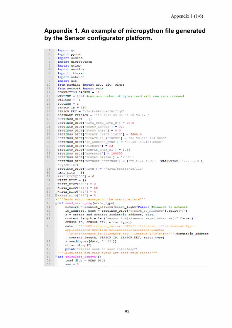
Appendix 1 (1/6)
92
Appendix 1. An example of micropython file generated by the Sensor configurator platform.
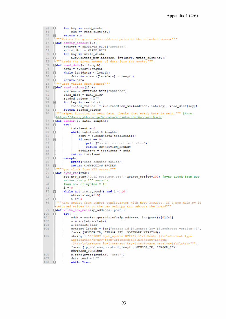
Appendix 1 (2/6)
93
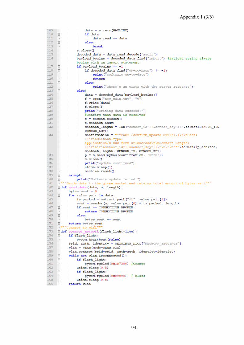
Appendix 1 (3/6)
94
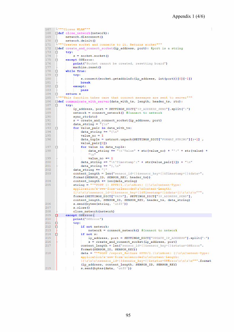
Appendix 1 (4/6)
95
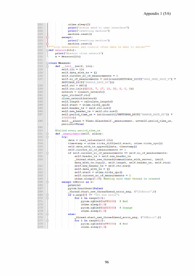
Appendix 1 (5/6)
96
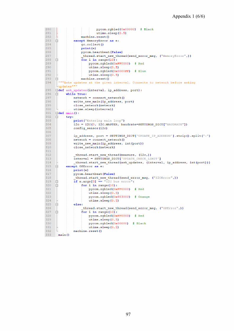
Appendix 1 (6/6)
97
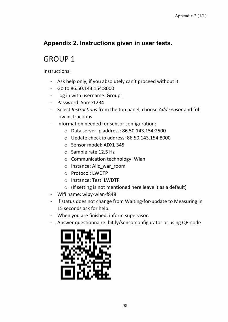
Appendix 2 (1/1)
98
Appendix 2. Instructions given in user tests.
GROUP 1
Instructions:
- Ask help only, if you absolutely can’t proceed without it
- Go to 86.50.143.154:8000
- Log in with username: Group1
- Password: Some1234
- Select Instructions from the top panel, choose Add sensor and fol-
low instructions
- Information needed for sensor configuration:
o Data server ip address: 86.50.143.154:2500
o Update check ip address: 86.50.143.154:8000
o Sensor model: ADXL 345
o Sample rate 12.5 Hz
o Communication technology: Wlan
o Instance: Aiic_war_room
o Protocol: LWDTP
o Instance: Testi LWDTP
o (If setting is not mentioned here leave it as a default)
- Wifi name: wipy-wlan-f848
- If status does not change from Waiting-for-update to Measuring in
15 seconds ask for help.
- When you are finished, inform supervisor.
- Answer questionnaire: bit.ly/sensorconfigurator or using QR-code
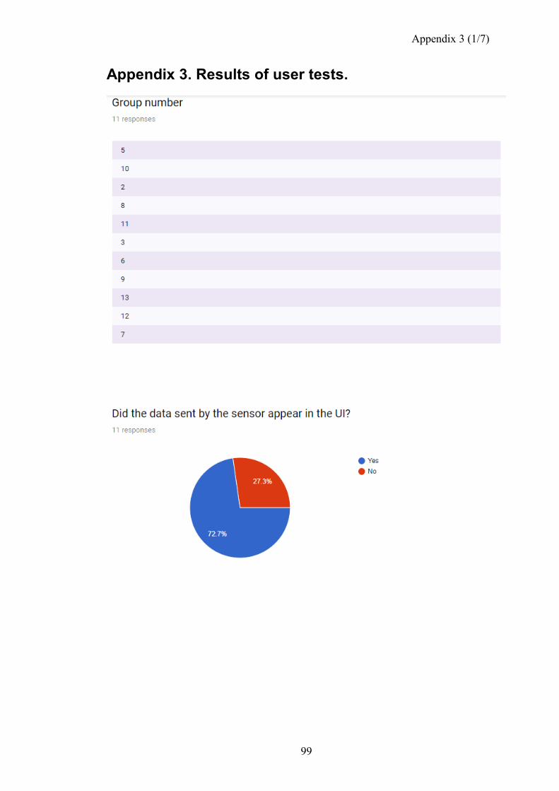
Appendix 3 (1/7)
99
Appendix 3. Results of user tests.
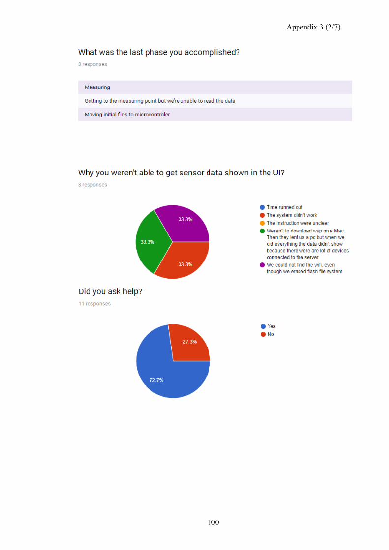
Appendix 3 (2/7)
100
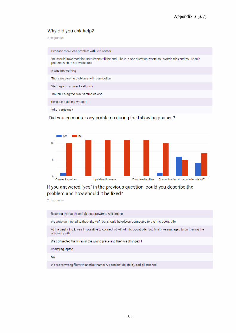
Appendix 3 (3/7)
101
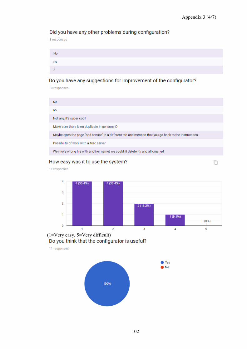
Appendix 3 (4/7)
102
(1=Very easy, 5=Very difficult)
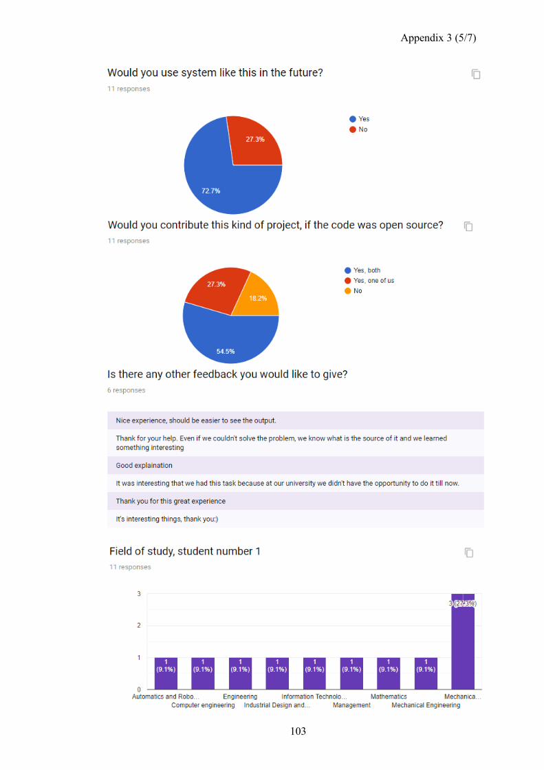
Appendix 3 (5/7)
103
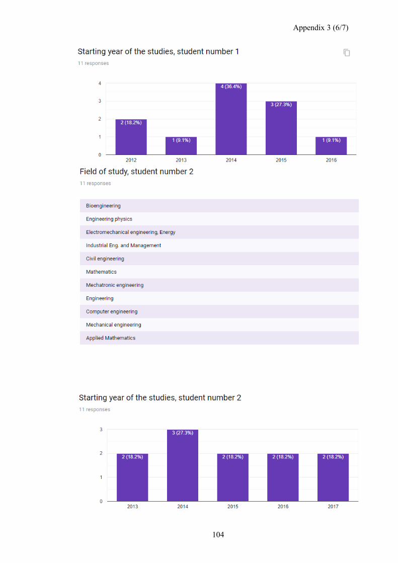
Appendix 3 (6/7)
104
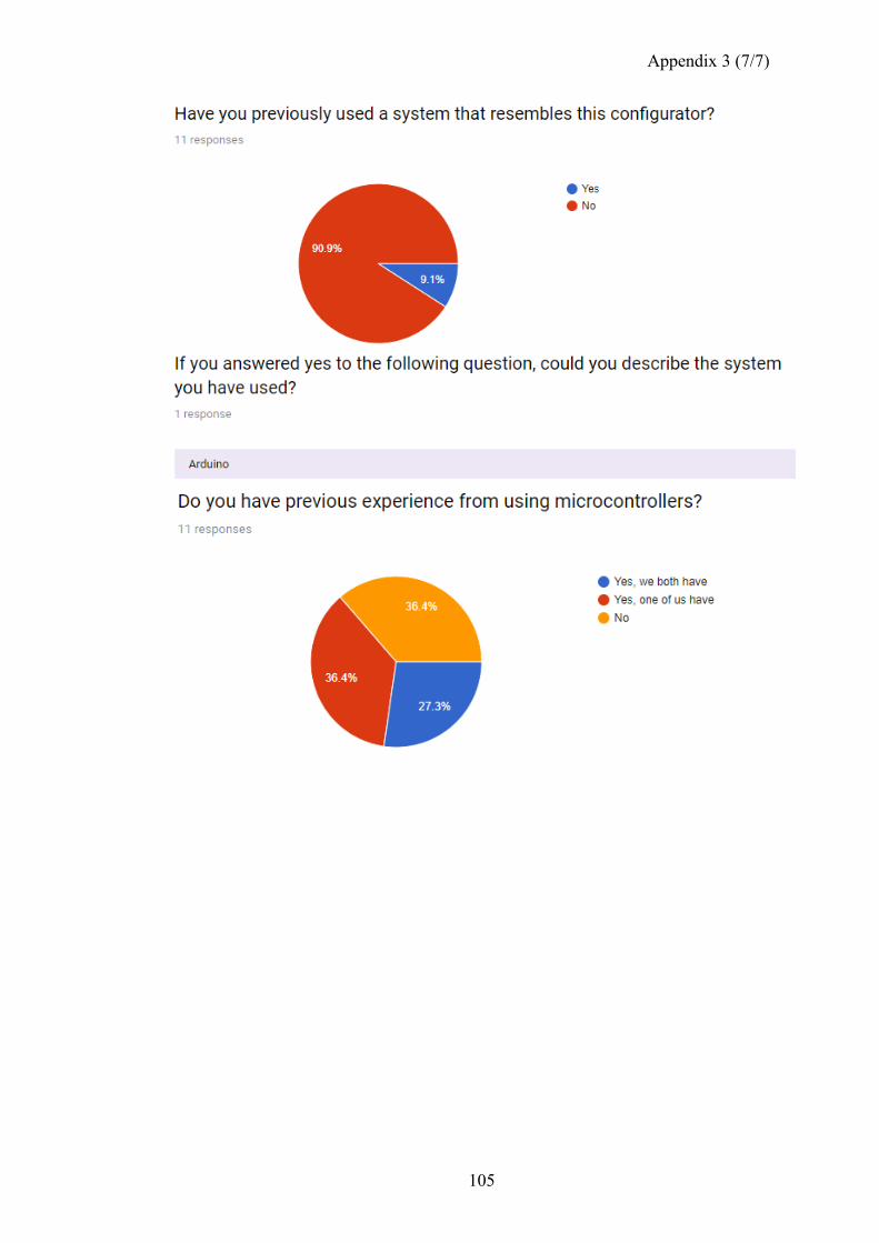
Appendix 3 (7/7)
105