combining segmentations for understanding and annotating 3d objects
TRANSCRIPT
Eurographics Italian Chapter Conference (2010), pp. 1–8E. Puppo, A. Brogni, and L. De Floriani (Editors)
Manual Segmentation and Semantic-based HierarchicalTagging of 3D models
Laura Papaleo1,2 and Leila De Floriani1
1Department of Computer Science, University of Genova, Italy2IT Department, Province of Genova, Italy
AbstractToday 3D objects have become widely available in different application domains, thus it is becoming fundamentalto use, integrate and develop techniques for extracting and maintaining their implicit knowledge. These techniquesshould be encapsulated in intelligent systems able to semantically annotate the 3D models, thus improving theirusability and indexing, especially in innovative web cooperative environments. In our work, we are moving in thisdirection, by defining and developing data structures, methods and interfaces for structuring and semanticallyannotating 3D complex models (and scenes), even changing over time, according to ontology-driven metadata.In this paper, we focus on tools and methods for manually segmenting manifold 3D models and on the underlinestructural representation that we build and manipulate. We present also an interface from which the user caninspect and browse the segmentation, describing also the first prototype of an annotation tool which allows ahierarchical semantic-driven tagging of the segmented model.
Categories and Subject Descriptors (according to ACM CCS): I.3.5 [Computer Graphics]: ComputerGraphics—Computational Geometry and Object Modeling Curve, surface, solid, and object representations;[H.5.1]Multimedia Information Systems;
1. Introduction
Nowadays, multidimensional data (pictures, audio and, also,3D shapes) are available within digital libraries and they areused and shared by wide communities. Among them, the im-portance of 3D object models is increasing: they are playinga preeminent role in application domains such as manufac-turing, science, edu-entertainment and many more. More-over, all these application domains are recently opening theiractivities to the Web thanks also to the development of col-laborative environments. In this context, efficient and effec-tive methods to manage these data are becoming crucial. Ge-ometric meshes, as for example triangle meshes, provide un-structured descriptions of object shapes which, in general,are not sufficient for reasoning on them. The knowledge em-bedded into these digital representations can be better orga-nized by using different levels of abstractions namely, ge-ometry, structure and semantics [aim07]. At the geometriclevel, topological and geometric information are explicit butno further information is encoded in the model. At the struc-tural level, meaningful parts of the shape are described to-
gether with their connections. Finally, the semantic level as-sociates semantics to lower levels: the association can bedone manually or through an automatic semantic annotationprocess. In order to reason and understand a given 3D model,all the information identifiable at the three different levelsmust be extracted and kept.
At the state-of-the art, there is a strong request of an-notation tools capable of extracting semantics from com-plex 3D shapes and of enhancing digital representationswith context-dependent metadata [DHP∗07,ARSF07,HG10,MSS10]. Also, with the advent of the Semantic Web[BLHL01] and moving toward the Web 3.0 [LH07, Hen08],Internet is becoming a universal medium for data, informa-tion, and knowledge. To be really accessible and usable,multimedia data (as 3D shapes) must be represented ac-cordingly. The Semantic Web envisages technologies, whichcan make possible the generation of “intelligent” multimediacontent. We can define an intelligent multimedia content asa content which “knows about” its own meaning in orderthat automated processes can “know what to do” with it. The
submitted to Eurographics Italian Chapter Conference (2010)
2 L. Papaleo & L. De Floriani / Manual Segmentation and Semantic-based Hierarchical Tagging of 3D models
Semantic Web proposes annotating document content usingsemantic information. The result is multimedia content withmachine interpretable mark-up that provide the source ma-terial with which agents and Semantic Web services operate,thus creating annotations with well-defined semantics.
In this context, we designed (and we are developing)a framework for inspecting complex (manifold and non-manifold) 3D shapes (and scenes) - even changing over time- and for structuring and annotating them using ontology-driven metadata. The contribution of this paper is relatedto the manual segmentation module as to the semantic an-notator of our Semantic Web framework. In particular, weimproved our previous manual segmentation tool presentedin [DPC08] with a more powerful segmentation method withthe main goal of decomposing the input 3D model intomeaningful parts. A model can be in this way segmentedmanually according to the user perception. We keep thesemantic-based decomposition into a structural representa-tion, in the form of a segmentation graph. In this graph,the nodes identify the portions of the model and the arcsthe connections among these portions as the information ofthe shared boundaries. Our system has been developed inJava and supports the visualization and editing of 3D sur-face models described in X3D [x3d08]. Our interface allowsthe global visualization and inspection of the segmentationgraph, rendered as an hyperbolic graph. For the semantic an-notation, we developed a hierarchical semantic-based tag-ging procedure by which we are able to maintain the historyof the segmentation. Once semantically annotated, the por-tions of the model can be saved all together or separately,thus preparing the basis of a semantic-based modeling envi-ronment.
The reminder of this paper is organized as follows. In Sec-tion 2 we present the related work on manual segmentation,in Section 3 we introduce the underlying structural represen-tation we use for semantic annotation. Section 4 is devotedto the presentation of our previous mesh editing tool as to thedescription of our previous segmentation graph visualizationtool, while Section 5 presents our advanced tool for manualsegmenting a 3D model by painting strokes on it. Section6 will focus on the first prototype of the annotation tool. InSection 7 some concluding remarks are drawn.
2. Related Work
Different manual or user-guided segmentation techniqueshave been proposed in the literature and they are rootedin the expert perception of the object [GSL∗99, ZSH00,WPH∗04, FKS∗04, SBSCO06, ZLZG06, WPP∗07, Bro08,LHMR08]. In this sense, the regions of interest are intrinsi-cally guided by the semantic the user recognizes in the objectmodel. In opposition to the automatic segmentation tech-niques (see [Sha08] for a complete survey), which have beenusually developed for a specific application context (e.g.
CAD/CAM or biomedicine), manual segmentation methodsare general purpose.
We can divide the existing manual segmentation techniquesinto two main categories: cut-based methods and region-based methods. Algorithms belonging to the first category[GSL∗99, ZSH00, WPH∗04, FKS∗04, SBSCO06] allow theuser to draw the cutting path on the model while those whichbelong to the second category let the user select the interest-ing regions, and they automatically compute the right posi-tion of the cut [ZLZG06, WPP∗07, Bro08, LHMR08].
The most simple cut-based manual segmentation method isthe one who allows the user to iteratively select vertices,edges or faces on the input model, drawing in this way thecut directly on the model. This approach, is effective but verytime-consuming. Additionally, in case of complex shapes,the selection of a vertex can be almost impossible due to oc-clusions. Another idea is to use specific primitives in orderto isolate portions of the input model: in this case, the cuttingpath is defined by the set of model components which inter-sect the boundary of the chosen primitive. The most simpleprimitive is the plane: drawing a line in the scene, a planeis computed which cuts the input model into two pieces. Inthis case, the main problem is that the chosen plane dependson the view point and the cutting can produce undesirableresults. In [WPH∗04] different primitives are used, such ascylinders or cubes. In [BS01] a cut-based manual segmenta-tion method is proposed, in which a cut can be directly drawnon a triangle mesh, thus simulating the use of a scissor. Someother methods allow the user to select a sequence of ver-tices on the surface mesh and cut along the shortest pathsbetween them [GSL∗99, ZSH00]. However, these methodspresent the necessity to rotate the mesh during the selec-tion. To solve this problem, there exist different approacheswhich use a sort of automatic completion of the cutting path.In [SBSCO06], for example, the user paints a stroke nearthe desired position of the cut. The positions of the mouseare projected onto the surface and a set of faces are createdto represent the stroke. The method computes automaticallythe invisible part of the cut, by adjacency using Dijkstra’salgorithm. A similar approach, from which we took inspira-tion, is the one presented in [FKS∗04], where the so-calledintelligent scissoring of 3D meshes is described (see Section5 for more details).
Following a complementary idea, the region-based methodslet the user choose the meaningful portions of the model bydrawing scribbles or points on them and they compute auto-matically the cut using different heuristics. In this case, theuser, instead of concentrating his attention on the cut, is morefocused on the regions he wants to identify. In [ZLZG06],taking inspiration from a image segmentation method pre-sented in [BJ01], a 3D model region-based manual segmen-tation method is presented. Here, the user selects with aforeground scribble the region to be cut, and with the back-ground scribble the remaining part of the model. Once the
submitted to Eurographics Italian Chapter Conference (2010)
L. Papaleo & L. De Floriani / Manual Segmentation and Semantic-based Hierarchical Tagging of 3D models 3
scribbles have been drawn, the method automatically com-putes the two associated regions. The method works only fortriangle meshes and it allows to draw only two scribbles at atime. In [WPP∗07] an extension of the method in [ZLZG06]is presented, in which the user can define multiple scribbles.An improvement in terms of time efficiency of the methodin [ZLZG06] has been presented recently in [Bro08]. Here,the entire segmentation process is performed using a hier-archical acceleration procedure which works on the struc-tural graph representing the model, using an octree to com-press the quantity of information. Another recent method,presented in [LHMR08], is a manual approach which aimsat segmenting triangle meshes by taking inspiration from theimage segmentation method presented in [Gra06] and by us-ing a method, initially developed for mesh noise removal,presented in [SRML07]. In [LHMR08] the user selects nfaces, s1, . . . ,sn (called seeds), where n will be the numberof regions the user wants to identify. The method assigns aprobability value to each edge of each face in the model andproceeds in order to assign a label to each face. In particu-lar, a face f will belong to the region denoted by the seedsi, if the random path starting from f will have higher prob-ability to reach si than any other seed chosen by the user.By using different probability distributions, the method canbe used to segment different kinds of models. Obviously themain problem in this case, is to find, every time, the optimalprobability distribution.
3. The Structural Representation for SemanticAnnotation
As we said before, we are working in the direction to developand implement data structure, methods and interfaces to dealwith complex (manifold and non-manifold) 3D shapes andscenes, even changing over time. Our main objective is todevelop a general framework for structuring and semanti-cally annotating these complex shapes for improving theirusability, indexing and retrieval. Semantic annotation can beperformed if a structural representation underlying the in-put model (or scene) is used. In our case, the structural de-scription has been defined as a two-level graph representa-tion able to capture information in case of both manifold andnon-manifold conditions.
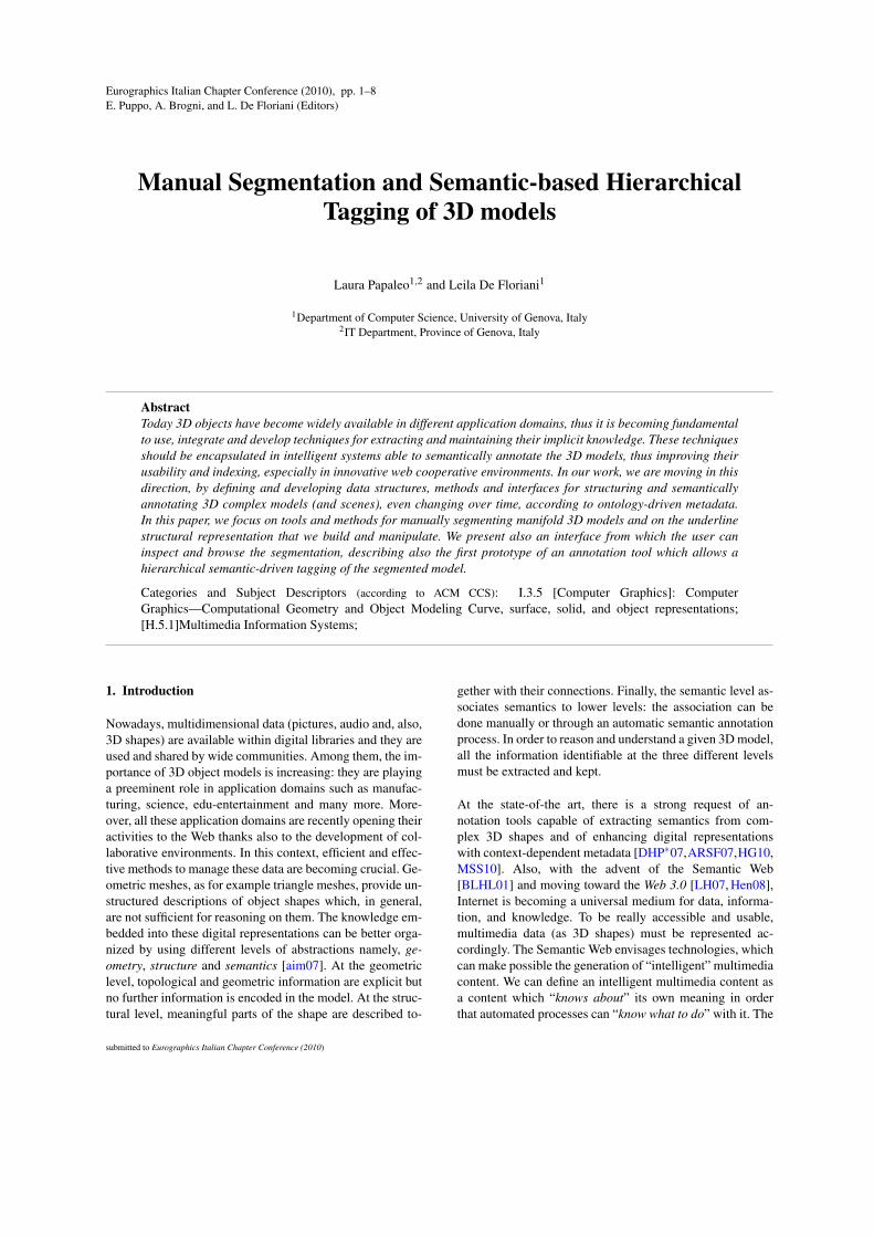
The first level, in case of non-manifold models, is a descrip-tion of the decomposition of the shape into manifold com-ponents (Figure 1). Their structural interconnection is rep-resented as a graph, that we call the decomposition graph,described as a hypergraph H = (N,A) in which the nodescorrespond to the components in the decomposition, whilethe hyperarcs catch the structure of the connectivity amongthe components or are self-loops. In this latter case, theyrepresent the non-manifold structure of a single componentand correspond to the duplicated non-manifold vertices andedges in the component. In the two-level graph represen-tation, each manifold component (if further segmented) is
Figure 1: The two-level decomposition graph. A non-manifold model representing a flower and the relative de-composition graph. Three component are identified - twoshells (the flower and the leaf, respectively) and a wireweb(the stalk).
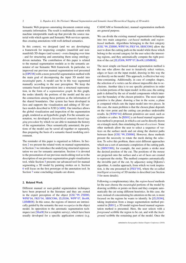
structured in a segmentation graph ((Figure 2). In this graph- used in the tools presented in this paper - the nodes iden-tify the portions of the model and the arcs the connectionsamong these portions. Formally, in the segmentation graphG, a node ni represents a patch C of the input shape andan arc a = (ni,n j) represents the adjacency relationship be-tween the patches Ci and C j and, thus, their shared boundary.
Figure 2: The two-level decomposition graph. The non-manifold model representing the same flower of Figure 1 fur-ther decomposed and the relative segmentation graph.
The two-level segmentation graph is also the core of a com-plex framework, we designed for bridging Semantic Webtechnologies and Shape Structuring and Analysis [DHP∗07].In this work, we present two modules of the frameworknamely the Manual Segmentation module (Section 5) and aninitial prototype of the Semantic Annotator (Section 6) forthe manifold parts. Thus, we will focus on the updates andoperations on the segmentation graph G, described above. Inparticular, in our implementation, G is represented using astandard adjacency list with additional information (also onthe arcs) necessary for performing the manual segmentation.
In a more general view, the entire two-level graph repre-sentation represents the basis for the semantic annotationwhich will be performed attaching specific information tothe nodes of the graph (geometric components of the model).The semantic meaning will be added by following concep-tual schema previously defined in domain-specific ontolo-gies. The chosen domains will guide the annotation, thus al-lowing a multi-level semantic tagging where each geomet-ric element of the input model will possibly have differentmeanings, depending on the annotation procedure.
submitted to Eurographics Italian Chapter Conference (2010)
4 L. Papaleo & L. De Floriani / Manual Segmentation and Semantic-based Hierarchical Tagging of 3D models
4. Previous Approach and its Limitations
In [DPC08], a Java3D framework is presented, able to com-bine automatic segmentation and merging techniques for theanalysis of manifold objects represented by triangle meshesin X3D format. Two well known partitioning techniques[CSAD04, She01] have been used adapting them to the de-veloped framework. In the work it has been proved that, bycombining different automatic techniques good quality seg-mentations can be obtained, in specific application domains.However, while automatic segmentation techniques can befast and precise, in some cases, the intervention of the useris fundamental, since modeling the human perception intoan automatic system is still an open issue. We believe, infact, that a combination of automatic and manual segmen-tations can be a real support to the user, when he points tosemantically annotate a 3D model according to different cri-teria. These criteria can be objective (thus, based on specific,computable measures) and subjective, namely dependent onthe user personal perception. The main goal is that the sys-tem can be able to associate different metadata to each patchof the model, allowing a hierarchical semantic organizationof the identified portions.In this direction, in [DPC08], the framework has been ex-tended with a simple manual editing functionality. Basically,a basilar cut-based manual segmentation method has beenimplemented, which allows the user to split a selected re-gion of the model into two new regions by manually drawinga cutting path on the model. This path is built by iterativelyselecting adjacent vertices on the input model. This function-ality has been proved to be a good support, in combinationwith the automatic techniques implemented. However, it isquite complex to be used. For example, in case of regionswith complex shape, it forces the user to rotate the selectedregion in order to reach all the necessary vertices. This paperpresents our results in the design and implementation of anadvanced cut-based manual segmentation tool which over-comes the above limitations (see Section 5).
Also, in [DPC08] an initial prototype of a tool for inspectingboth the segmented model and the produced segmentationgraph has been described. With this tool, the user can nav-igate the graph discovering geometrical properties of eachregion of the model. Once a region has been selected, it ispossible to visualize a graphical representation of the cor-responding node in the segmentation graph. The main lim-itation is that the user cannot have a global vision of thesegmentation graph, but only a focus on the selected portion(graph node) and all the adjacent regions (graph nodes). Thislimits, in some sense, the possibility to be a real support inthe reasoning. In this work, we present a new segmentationgraph visualization and inspection tool (Section 6).
5. Manual Segmentation by Strokes Painting
We developed a cut-based manual segmentation tool whichenables the user to paint strokes on the mesh surface. By
painting these strokes on the visible part of the model, theuser specifies where cuts should be made and the systemautomatically computes the entire cut, splitting the selectedportion of the model into two pieces and updating the seg-mentation graph accordingly.
We took inspiration from the intelligent scissoring opera-tion presented in [FKS∗04]. The general idea of the originalmethod is the following: the user draws a stroke on the sur-face model. It has a specified width (r) representing a regionof uncertainty within which the method should construct thecut. Cuts are considered along edges of the mesh. The strokestarts in a region (in which the algorithm selects an initialvertex a) and ends in another region (in which a final vertex bis selected). Successively, two edges paths (minimum paths)are computed: one front-side, involving edges touched bythe stroke, and the other back-side. This last is the minimumpath formed by edges not visible from the view point con-necting the initial and the final vertices. Each minimum pathis computed by using the Dijkstra’s algorithm with a costfunction which depends also on geometric properties of eachedge involved (e.g., dihedral angles).
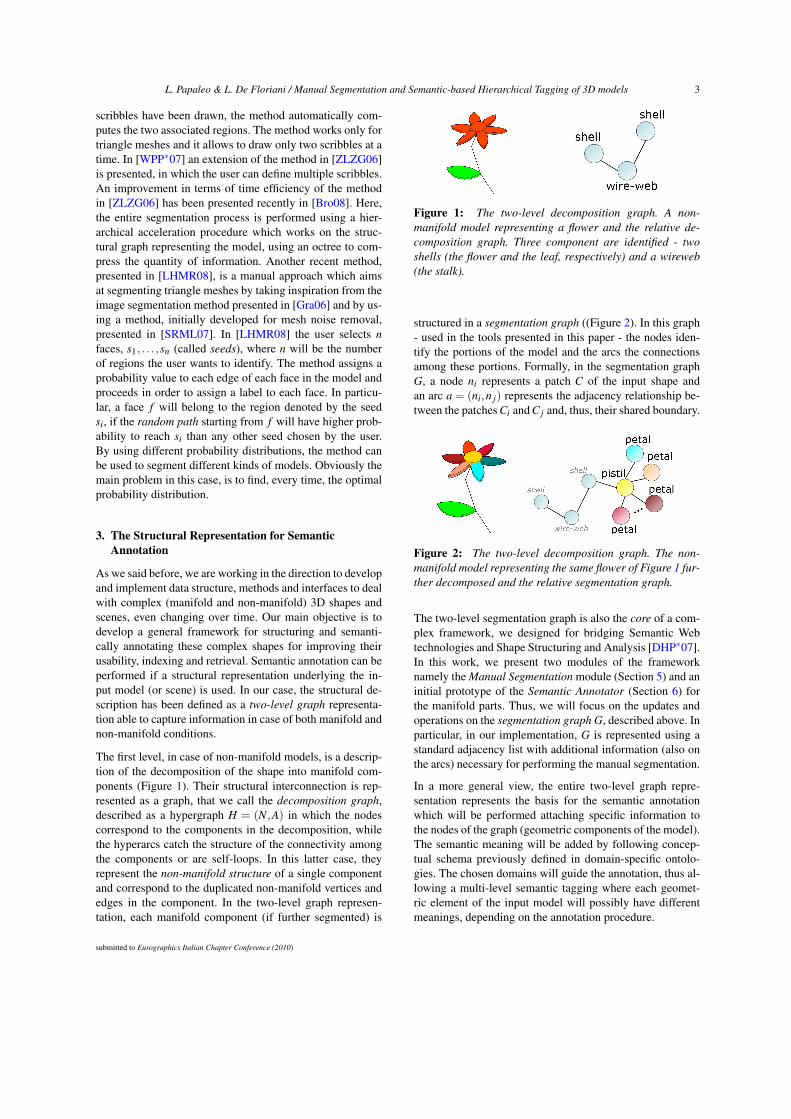
Figure 3: A 3D model representing a fish. As shown in thewireframe visualization, the model is not triangular. More-over it is composed by different connected components. Onthe right the segmentation produced with our tool is de-picted.
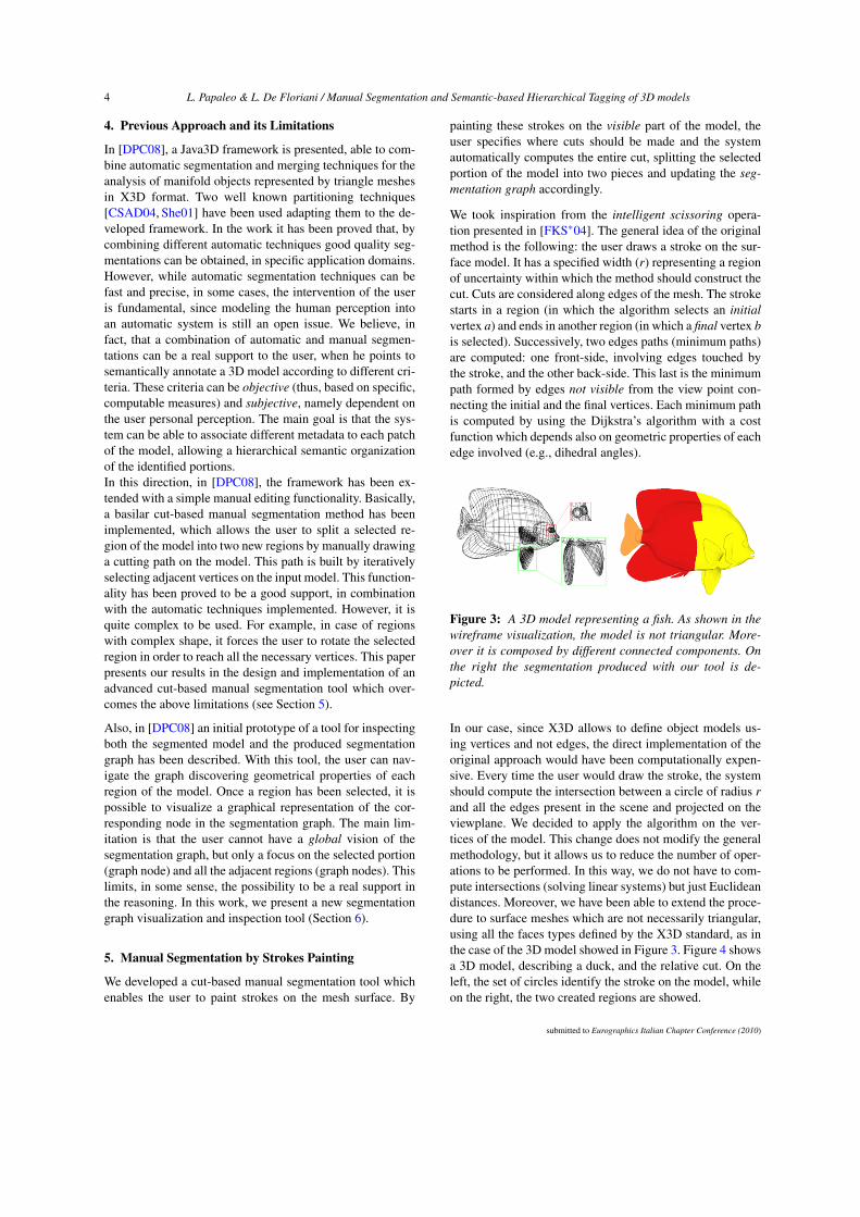
In our case, since X3D allows to define object models us-ing vertices and not edges, the direct implementation of theoriginal approach would have been computationally expen-sive. Every time the user would draw the stroke, the systemshould compute the intersection between a circle of radius rand all the edges present in the scene and projected on theviewplane. We decided to apply the algorithm on the ver-tices of the model. This change does not modify the generalmethodology, but it allows us to reduce the number of oper-ations to be performed. In this way, we do not have to com-pute intersections (solving linear systems) but just Euclideandistances. Moreover, we have been able to extend the proce-dure to surface meshes which are not necessarily triangular,using all the faces types defined by the X3D standard, as inthe case of the 3D model showed in Figure 3. Figure 4 showsa 3D model, describing a duck, and the relative cut. On theleft, the set of circles identify the stroke on the model, whileon the right, the two created regions are showed.
submitted to Eurographics Italian Chapter Conference (2010)
L. Papaleo & L. De Floriani / Manual Segmentation and Semantic-based Hierarchical Tagging of 3D models 5
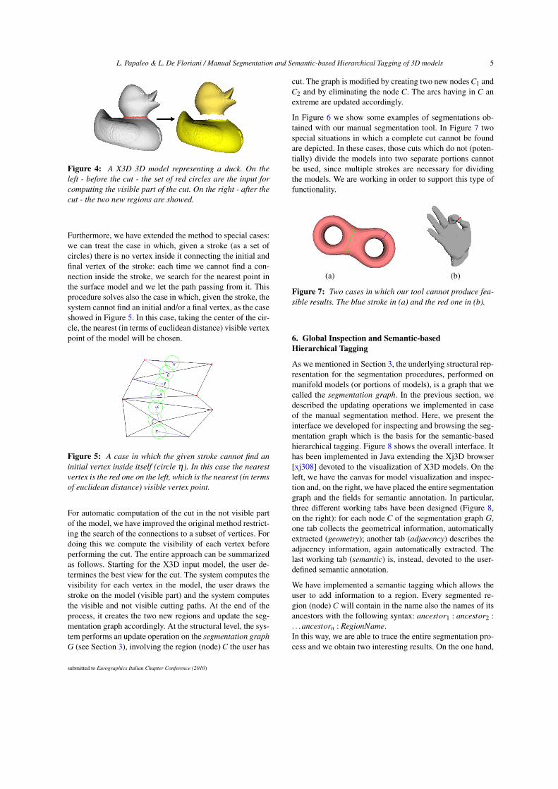
Figure 4: A X3D 3D model representing a duck. On theleft - before the cut - the set of red circles are the input forcomputing the visible part of the cut. On the right - after thecut - the two new regions are showed.
Furthermore, we have extended the method to special cases:we can treat the case in which, given a stroke (as a set ofcircles) there is no vertex inside it connecting the initial andfinal vertex of the stroke: each time we cannot find a con-nection inside the stroke, we search for the nearest point inthe surface model and we let the path passing from it. Thisprocedure solves also the case in which, given the stroke, thesystem cannot find an initial and/or a final vertex, as the caseshowed in Figure 5. In this case, taking the center of the cir-cle, the nearest (in terms of euclidean distance) visible vertexpoint of the model will be chosen.
Figure 5: A case in which the given stroke cannot find aninitial vertex inside itself (circle η). In this case the nearestvertex is the red one on the left, which is the nearest (in termsof euclidean distance) visible vertex point.
For automatic computation of the cut in the not visible partof the model, we have improved the original method restrict-ing the search of the connections to a subset of vertices. Fordoing this we compute the visibility of each vertex beforeperforming the cut. The entire approach can be summarizedas follows. Starting for the X3D input model, the user de-termines the best view for the cut. The system computes thevisibility for each vertex in the model, the user draws thestroke on the model (visible part) and the system computesthe visible and not visible cutting paths. At the end of theprocess, it creates the two new regions and update the seg-mentation graph accordingly. At the structural level, the sys-tem performs an update operation on the segmentation graphG (see Section 3), involving the region (node) C the user has
cut. The graph is modified by creating two new nodes C1 andC2 and by eliminating the node C. The arcs having in C anextreme are updated accordingly.
In Figure 6 we show some examples of segmentations ob-tained with our manual segmentation tool. In Figure 7 twospecial situations in which a complete cut cannot be foundare depicted. In these cases, those cuts which do not (poten-tially) divide the models into two separate portions cannotbe used, since multiple strokes are necessary for dividingthe models. We are working in order to support this type offunctionality.
(a) (b)
Figure 7: Two cases in which our tool cannot produce fea-sible results. The blue stroke in (a) and the red one in (b).
6. Global Inspection and Semantic-basedHierarchical Tagging
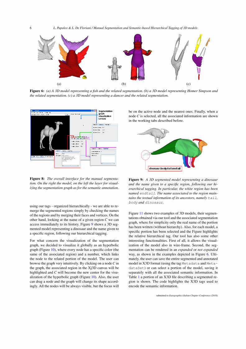
As we mentioned in Section 3, the underlying structural rep-resentation for the segmentation procedures, performed onmanifold models (or portions of models), is a graph that wecalled the segmentation graph. In the previous section, wedescribed the updating operations we implemented in caseof the manual segmentation method. Here, we present theinterface we developed for inspecting and browsing the seg-mentation graph which is the basis for the semantic-basedhierarchical tagging. Figure 8 shows the overall interface. Ithas been implemented in Java extending the Xj3D browser[xj308] devoted to the visualization of X3D models. On theleft, we have the canvas for model visualization and inspec-tion and, on the right, we have placed the entire segmentationgraph and the fields for semantic annotation. In particular,three different working tabs have been designed (Figure 8,on the right): for each node C of the segmentation graph G,one tab collects the geometrical information, automaticallyextracted (geometry); another tab (adjacency) describes theadjacency information, again automatically extracted. Thelast working tab (semantic) is, instead, devoted to the user-defined semantic annotation.
We have implemented a semantic tagging which allows theuser to add information to a region. Every segmented re-gion (node) C will contain in the name also the names of itsancestors with the following syntax: ancestor1 : ancestor2 :. . .ancestorn : RegionName.In this way, we are able to trace the entire segmentation pro-cess and we obtain two interesting results. On the one hand,
submitted to Eurographics Italian Chapter Conference (2010)
6 L. Papaleo & L. De Floriani / Manual Segmentation and Semantic-based Hierarchical Tagging of 3D models
(a) (b) (c)
Figure 6: (a) A 3D model representing a fish and the related segmentation. (b) a 3D model representing Homer Simpson andthe related segmentation. (c) a 3D model representing a dancer and the related segmentation.
Figure 8: The overall interface for the manual segmenta-tion. On the right the model, on the left the layer for visual-izing the segmentation graph as for the semantic annotation.
using our tags - organized hierarchically - we are able to re-merge the segmented regions simply by checking the namesof the regions and by merging their faces and vertices. On theother hand, looking at the name of a given region C we canaccess immediately to its history. Figure 9 shows a 3D seg-mented model representing a dinosaur and the name given toa specific region, following our hierarchical tagging.
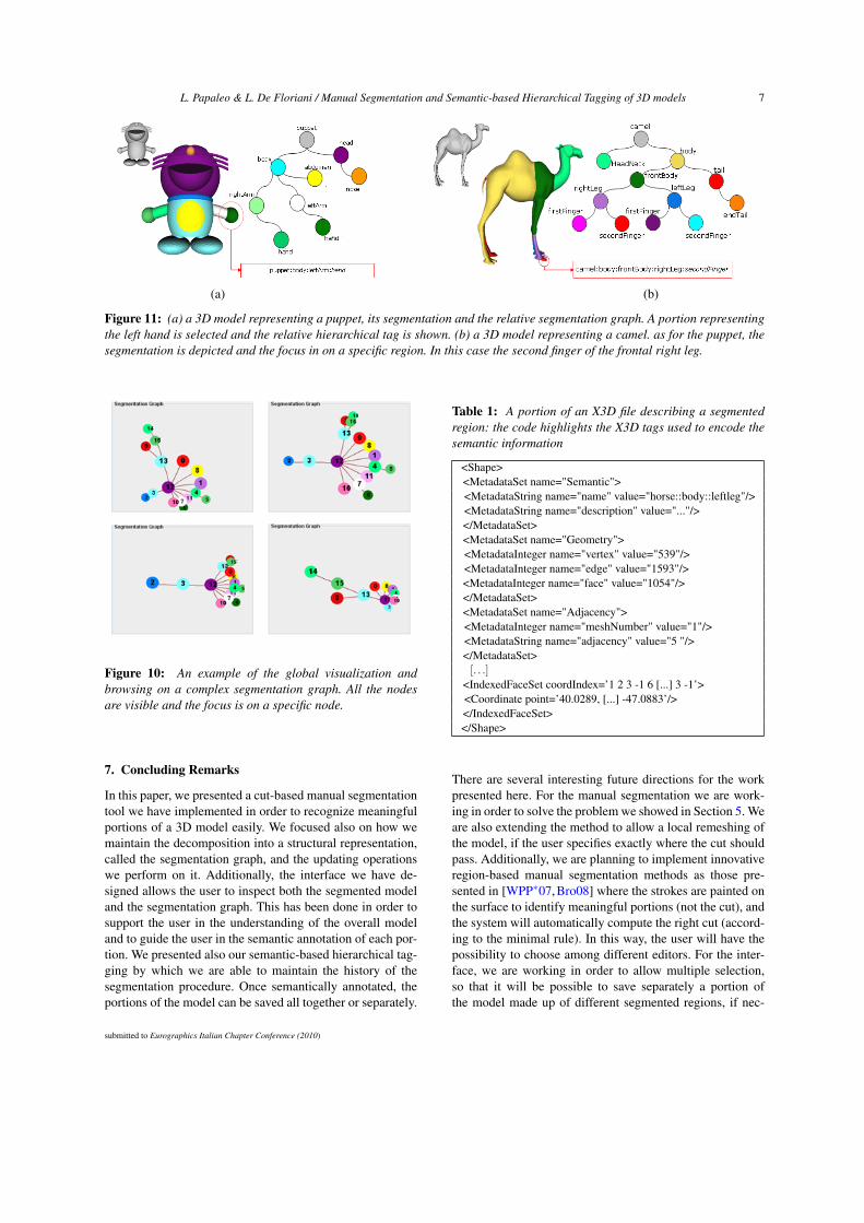
For what concern the visualization of the segmentationgraph, we decided to visualize it globally as an hyperbolicgraph (Figure 10), where every node has a specific color (thesame of the associated region) and a number, which linksthe node to the related portion of the model. The user canbrowse the graph very intuitively. By clicking on a node C inthe graph, the associated region in the Xj3D canvas will behighlighted and C will become the new center for the visu-alization of the hyperbolic graph (Figure 10). Also, the usercan drag a node and the graph will change its shape accord-ingly. All the nodes will be always visible, but the focus will
be on the active node and the nearest ones. Finally, when anode C is selected, all the associated information are shownin the working tabs described before.
Figure 9: A 3D segmented model representing a dinosaurand the name given to a specific region, following our hi-erarchical tagging. In particular, the white region has beennamed endtail. The name associated to the region main-tains the textual information of its ancestors, namely tail,body and dinosaur.
Figure 11 shows two examples of 3D models, their segmen-tations obtained via our tool and the associated segmentationgraph, where for simplicity only the real name of the portionhas been written (without hierarchy). Also, for each model, aspecific portion has been selected and the Figure highlightsthe relative hierarchical tag. Our tool has also some otherinteresting functionalities. First of all, it allows the visual-ization of the model also in wire-frame. Second, the seg-mentation can be rendered in an expanded or not expandedway, as shown in the examples depicted in Figure 6. Ulti-mately, the user can save the entire segmented and annotatedmodel in X3D format (using the tag Metadata and Meta-dataSet) or can select a portion of the model, saving itseparately with all the associated semantic information. InTable 1 a portion of an X3D file describing a segmented re-gion is shown. The code highlights the X3D tags used toencode the semantic information.
submitted to Eurographics Italian Chapter Conference (2010)
L. Papaleo & L. De Floriani / Manual Segmentation and Semantic-based Hierarchical Tagging of 3D models 7
(a) (b)
Figure 11: (a) a 3D model representing a puppet, its segmentation and the relative segmentation graph. A portion representingthe left hand is selected and the relative hierarchical tag is shown. (b) a 3D model representing a camel. as for the puppet, thesegmentation is depicted and the focus in on a specific region. In this case the second finger of the frontal right leg.
Figure 10: An example of the global visualization andbrowsing on a complex segmentation graph. All the nodesare visible and the focus is on a specific node.
7. Concluding Remarks
In this paper, we presented a cut-based manual segmentationtool we have implemented in order to recognize meaningfulportions of a 3D model easily. We focused also on how wemaintain the decomposition into a structural representation,called the segmentation graph, and the updating operationswe perform on it. Additionally, the interface we have de-signed allows the user to inspect both the segmented modeland the segmentation graph. This has been done in order tosupport the user in the understanding of the overall modeland to guide the user in the semantic annotation of each por-tion. We presented also our semantic-based hierarchical tag-ging by which we are able to maintain the history of thesegmentation procedure. Once semantically annotated, theportions of the model can be saved all together or separately.
Table 1: A portion of an X3D file describing a segmentedregion: the code highlights the X3D tags used to encode thesemantic information
<Shape><MetadataSet name="Semantic"><MetadataString name="name" value="horse::body::leftleg"/><MetadataString name="description" value="..."/></MetadataSet><MetadataSet name="Geometry"><MetadataInteger name="vertex" value="539"/><MetadataInteger name="edge" value="1593"/><MetadataInteger name="face" value="1054"/></MetadataSet><MetadataSet name="Adjacency"><MetadataInteger name="meshNumber" value="1"/><MetadataString name="adjacency" value="5 "/></MetadataSet>[. . .]
<IndexedFaceSet coordIndex=’1 2 3 -1 6 [...] 3 -1’><Coordinate point=’40.0289, [...] -47.0883’/></IndexedFaceSet></Shape>
There are several interesting future directions for the workpresented here. For the manual segmentation we are work-ing in order to solve the problem we showed in Section 5. Weare also extending the method to allow a local remeshing ofthe model, if the user specifies exactly where the cut shouldpass. Additionally, we are planning to implement innovativeregion-based manual segmentation methods as those pre-sented in [WPP∗07,Bro08] where the strokes are painted onthe surface to identify meaningful portions (not the cut), andthe system will automatically compute the right cut (accord-ing to the minimal rule). In this way, the user will have thepossibility to choose among different editors. For the inter-face, we are working in order to allow multiple selection,so that it will be possible to save separately a portion ofthe model made up of different segmented regions, if nec-
submitted to Eurographics Italian Chapter Conference (2010)
8 L. Papaleo & L. De Floriani / Manual Segmentation and Semantic-based Hierarchical Tagging of 3D models
essary. Finally, the semantic annotator we have presented inSection 6 is the basis for annotation. In our implementationthe user can define specific tags, in some well-defined ap-plications, instead, pre-defined thesauri or dictionaries couldbe used (e.g. medicine, bio-informatics and so on). We areworking in order to support RDF/RDFS integration in thesystem. Thus we will be able to annotate according to spe-cific ontological schema in OWL [W3C10a] or using SKOS[W3C10b]. In this case, the semantics associated to the por-tions of the model will be saved also in separate RDF files,thus allowing experimenting the complete power of Seman-tic Web technologies.
Acknowledgments.
The authors would like to thank Matteo Bertucelli for the im-plementation of the segmentation method and the interface.Some shapes used are taken from the AIM@SHAPE shaperepository [aim07] and converted in X3D.
References[aim07] The European Network of Excellence AIM@SHAPE -
contract number 506766. www.aimatshape.net, 2004-2007.
[ARSF07] ATTENE M., ROBBIANO F., SPAGNUOLO M., FAL-CIDIENO B.: Semantic annotation of 3d surface meshes basedon feature characterization. In Falcidieno et al. [FSA∗07].
[BJ01] BOYKOV Y. Y., JOLLY M. P.: Interactive graph cuts foroptimal boundary & region segmentation of objects in n-dimages. vol. 1, pp. 105–112.
[BLHL01] BERNERS-LEE T., HENDLER J., LASSILA O.: Thesemantic web. Scientific American 284, 5 (2001), 34–43.
[Bro08] BROWN S. W.: Interactive part selection for meshand point models using hierarchical graph-cut partitioning. InBrigham Young University, PhD Thesis (2008).
[BS01] BRUYNS C., SENGER S.: Interactive cutting of 3d surfacemeshes. Computers & Graphics 25, 4 (2001), 635–642.
[CSAD04] COHEN-STEINER D., ALLIEZ P., DESBRUN M.:Variational shape approximation. ACM Trans. Graph. 23, 3(2004), 905–914.
[DHP∗07] DE FLORIANI L., HUI A., PAPALEO L., HUANG M.,HENDLER J. A.: A semantic web environment for digital shapesunderstanding. In Falcidieno et al. [FSA∗07], pp. 226–239.
[DPC08] DE FLORIANI L., PAPALEO L., CARISSIMI N.: Ajava3d framework for inspecting and segmenting 3d models. InWeb3D (2008), Fellner D. W., Collins S., (Eds.), ACM, pp. 67–74.
[FKS∗04] FUNKHOUSER T., KAZHDAN M., SHILANE P., MINP., KIEFER W., TAL A., RUSINKIEWICZ S., DOBKIN D.: Mod-eling by example. ACM Transactions on Graphics 23, 3 (2004),652–663.
[FSA∗07] FALCIDIENO B., SPAGNUOLO M., AVRITHIS Y. S.,KOMPATSIARIS I., BUITELAAR P. (Eds.):. Semantic Multime-dia, Second International Conference on Semantic and DigitalMedia Technologies, SAMT 2007, Genoa, Italy, December 5-7,2007, Proceedings (2007), vol. 4816 of Lecture Notes in Com-puter Science, Springer.
[Gra06] GRADY L.: Random walks for image segmentation.IEEE Transactions on Pattern Analysis and Machine Intelligence28, 11 (2006), 1768–1783.
[GSL∗99] GREGORY A. D., STATE A., LIN M. C., MANOCHAD., LIVINGSTON M. A.: Interactive surface decomposition forpolyhedral morphing. The Visual Computer 15, 9 (1999), 453–470.
[Hen08] HENDLER J.: Linked data, web 3.0 and the semanticweb. International Conference on Semantics, Knowledge andGrid 1 (2008), 10–20.
[HG10] HUNTER J., GERBER A.: Harvesting community anno-tations on 3d models of museum artefacts to enhance knowledge,discovery and re-use. Journal of Cultural Heritage 11, 1 (2010),81 – 90.
[LH07] LASSILA O., HENDLER J.: Embracing "web 3.0". IEEEInternet Computing 11, 3 (2007), 90–93.
[LHMR08] LAI Y.-K., HU S.-M., MARTIN R. R., ROSIN P. L.:Fast mesh segmentation using random walks. In SPM ’08: Pro-ceedings of the 2008 ACM symposium on Solid and physicalmodeling (New York, NY, USA, 2008), ACM, pp. 183–191.
[MSS10] MORONI D., SALVETTI M., SALVETTI O.: Shape anal-ysis, semantic annotation and context modelling for the retrievalof 3d anatomical structures. Pattern Recognition and ImageAnalysis 20 (2010), 86–93. 10.1134/S1054661810010098.
[SBSCO06] SHARF A., BLUMENKRANTS M., SHAMIR A.,COHEN-OR D.: Snappaste: an interactive technique for easymesh composition. The Visual Computer 22, 9-11 (2006), 835–844.
[Sha08] SHAMIR A.: A survey on mesh segmentation techniques.Computer Graphics Forum (2008).
[She01] SHEFFER A.: Model simplification for meshing usingface clustering. Computer-Aided Design 33, 13 (Nov. 2001),925–934.
[SRML07] SUN X., ROSIN P. L., MARTIN R. R., LANGBEINF. C.: Random walks for mesh denoising. In SPM ’07: Proceed-ings of the 2007 ACM symposium on Solid and physical modeling(New York, NY, USA, 2007), ACM, pp. 11–22.
[W3C10a] W3C: Owl web ontology language overview.www.w3.org/TR/owl-features/, 2010.
[W3C10b] W3C: Skos simple knowledge organization system.www.w3.org/2004/02/skos/, 2010.
[WPH∗04] WEYRICH T., PAULY M., HEINZLE S., KEISER R.,SCANDELLA S., GROSS M.: Post-processing of scanned 3dsurface data. In Symposium on Point-Based Graphics (2004),pp. 85–94.
[WPP∗07] WU H.-Y., PAN C., PAN J., YANG Q., MA S.: Asketch-based interactive framework for real-time mesh segmen-tation. In Proceedings of the Computer Graphics International(CGI) (2007).
[x3d08] The Web3D consortium x3d working group.www.web3d.org/x3d, 2008.
[xj308] The xj3d project. www.xj3d.org, 2008.
[ZLZG06] ZHONGPING J., LIGANG L., ZHONGGUI C., GUOJINW.: Easy mesh cutting. Computer Graphics Forum 25, 3 (2006),283–292.
[ZSH00] ZÖCKLER M., STALLING D., HEGE H.-C.: Fast andintuitive generation of geometric shape transitions. The VisualComputer 16, 5 (2000), 241–253.
submitted to Eurographics Italian Chapter Conference (2010)