combined and consecutive use of external and internal fixation
TRANSCRIPT

1309L.N. Solomin (ed.), The Basic Principles of External Skeletal Fixation Using the Ilizarov and Other Devices, DOI 10.1007/978-88-470-2619-3_26, © Springer-Verlag Italia 2008, 2012
This chapter presents the techniques of lengthening of a long bone over a nail (Sect. 26.1 ), bone transport over a nail (Sect. 26.2 ), and consecutive external fi xation and blocked nailing at lengthening and long-bone deformity correction (Sect. 26.3 ). Section 26.4 is devoted to the technique used in the one-stage correction of deformities and the fi xation of fragments by means of external fi xation with immediate transition to internal fi xation, i.e., external- fi xator-assisted nailing and plating.
Information concerning training courses in the combined and consecutive use of external and internal fi xation can be obtained here: http://rniito.org/solomin , http://www. rniito.org/download/ex fi x-nail-course-9-engl.pdf , http://www.rniito.org/download/ex fi x-nail-course-4-engl.pdf , http://ortho-suv.org .
26.1 Lengthening Over a Nail (LON)
Mehmet Kocaoğlu , Leonid Nikolaevich Solomin, and Erkal F. Bilen
26.1.1 Introduction
Lengthening over an intramedullary nail is a superior to lengthening by conventional external fi xator techniques. Bost and Larsen [ 493 ] reported a technique for LON in which they used Rush pins for nailing. The current LON technique was fi rst described by Raschke [ 494 ] and optimized further by Paley et al. [ 177 ] . The external fi xation time is decreased signi fi cantly, which subsequently increases patient comfort, compliance, and function while reducing risks related to the prolonged use of external fi xators, such as pin-tract infection and reduced range-of-motion at the adjacent joints. In addi-tion, the periosteal blood supply is signi fi cantly increased with the LON technique [ 178, 495, 496 ] .
Another technique for lengthening, internal lengthening, is even better since it does not require external fi xation [ 149, 173 , 312 , 313 ] , but it also has several drawbacks: it enables limited lengthening (only up to 6 cm via Fitbone, 8 cm via ISKD, and 10 cm via Albizzia nails), the cost is three times higher than that of the LON procedure, and there is no chance for re-shortening in case the bone is overlengthened. Thus, LON is still a favorable technique for lengthening.
Other, alternative techniques have also been described: Lengthening and then nailing (LATN) [ 497 ] and plating after lengthening (PAL) [ 498 ] . Detailed information concerning the sequential use of external and internal fi xation is pre-sented in Sects. 26.3 and 26.4 .
The advantages of LON are related to the fact that the external fi xation device fi xes a limb segment during the dis-traction period only. Earlier removal of the apparatus than is possible with the Ilizarov method provides for: (a) increased treatment comfort for the patient; (b) simpli fi cation of medi-cal monitoring; and (c) a lower risk of pin-tract infections and trans fi xation pin-induced joint stiffness.
Combined and Consecutive Use of External and Internal Fixation
Mehmet Kocaoğlu , Leonid Nikolaevich Solomin , Erkal F. Bilen , Alexandr Nikolaevich Chelnokov , John E. Herzenberg , and Florian Maria Kovar
26
M. Kocaoğlu , M.D. (*) Department of Orthopedics and Traumatology, Istanbul Medical Faculty , Istanbul University , 34690 Capa, Istanbul , Turkey e-mail: [email protected], [email protected]
L. N. Solomin , M.D., Ph.D. R.R. Vreden Russian Research Institute of Traumatology and Orthopedics , 8 Baykova Str. , St. Petersburg 195427 , Russia e-mail: [email protected]
E. F. Bilen , M.D., FEBOT Department of Orthopedics, Istanbul Memorial Hospital , Piyalepasa Bulvari, Okmeydani , 34385 Istanbul , Turkey
A. N. Chelnokov , M.D., Ph.D. Department of Orthopedics Traumatology, Ural Scienti fi c Research Institute of Traumatology and Orthopedics , 7 Bankovsky Str. , Ekaterinburg 620014 , Russia
J. E. Herzenberg , M.D., FRCSC Department of Orthopedics, Sinai Hospital of Baltimore , 2401 West Belvedere Avenue , Baltimore , MD , USA
F. M. Kovar , M.D. Department of Traumatology , AKH-Vienna, Medical University Vienna , Währinger Gürtel 18-20 , A-1180 Vienna , Austria

1310 M. Kocaoğlu et al.
There are, however, also several disadvantages of LON. First, as the femur can be lengthened only along its ana-tomic axis, the procedure can lead to lateral deviation of the mechanical axis (Figs. 16.34 and 16.35 ). Second, there is an increase in the amount of damage incurred by the opera-tive intervention that becomes clinically signi fi cant in the simultaneous lengthening of two segments. Third, the risk of a deep pin-tract infection is higher and an expanded medullary infection may occur. Finally, there is the neces-sity of an additional operation: distal blocking of the nail and removal of the nail after reorganization of the distrac-tion regenerate. The latter is optional while the former is carried out simultaneously with frame removal.
26.1.2 Indications and Contraindications
Indications: Limb length discrepancy in adults • Constitutional short stature • Dwar fi sm • Post-traumatic epiphyseal injury sequelae • Concomitant lengthening and deformity correction •
Contraindications: Active infection • Immune-compromised patients [ • 499, 500 ] Open physeal plate • Intramedullary canal diameter <8 mm • At femoral lengthening: initial lateral deviation of the • mechanical axis of the lower limb, if it is impossible to obtain an adequate correction at LON
26.1.3 Special Features of the Equipment
In patients weighing >80 kg and requiring increased postop-erative mobility, and when two segments are lengthened simultaneously, non-cannulated titanium nails and locking screws of 5–6 mm diameter should be used.
Guide wires that allow not only the formation of the blocking nails but also the correct insertion of half-pins for the distraction frame should be used.
For distraction, monolateral (Figs. 26.6 and 26.9d ), circu-lar (Figs. 26.13 and 26.14 ) or hybrid (Figs. 26.8 , 26.9a, b, and 26.11 ) devices are options. Circular and hybrid devices may be needed for lower leg LON and cross-lengthening procedures.
26.1.4 Femoral LON: Surgical Technique
The patient is placed supine on the radiolucent table. A radi-olucent support underneath the buttock is used to elevate the ipsilateral hip. The femur is checked for visualization with a
C-arm image intensi fi er, from the hip to the knee, preferable by the attending surgeon prior to surgery. Sterile preparation should include the hip up to the iliac crest. A K-wire is inserted through the piriformis fossa percutaneously while the surgical assistant places the extremity across the unin-volved limb (scissors position) (Fig. 26.1a ).
A lateral shift of the entry point on the frontal plane will produce varization of the proximal fragment, whereas a medial shift will produce its valgization. Thus, the position of the K-wire must be checked with the C-arm on both planes, AP and lateral. A 5-mm cannulated drill is used over this K-wire to open the entry point. Multiple drill holes are created at the previously planned osteotomy level through a 0.5–1 cm incision by slow turns, in order to prevent heat necrosis of the bone. This also produces venting of the canal as well as internal grafting (Fig. 26.2 ). The medullary canal is reamed by 0.5-mm increments to 1.5–2 mm more than the diameter of the planned intramedullary (IM) nail. At this point the osteotomy is completed by an osteotome, while the
a
b
c
Fig. 26.1 Positions of the patient on the operating table. ( a ) Scissors posi-tion, ( b ) using pelvic and lower leg supports, ( c ) at use of retrograde nail

131126 Combined and Consecutive Use of External and Internal Fixation
guide wire remains in the medullary canal. The completeness of the osteotomy is checked with the C-arm by translation of the fragments (Fig. 26.3 ). The IM nail (for example, Ortopro 4 G IM, Istanbul, Turkey) is inserted over the guide wire, which is then removed. Proximal locking of the nail may be done either in the cephalomedullary (recon) or the intertro-chanteric (standard) direction, with no advantages of one over the other.
26.1.4.1 Half-Pin Insertion Paley et al. [ 177 ] described three alternative con fi gurations for half-pin placement (Fig. 26.4 ). In the fi rst, the half-pins are inserted posterior to the nail both proximally and distally; in the second, they are inserted anterior to the nail both proxi-mally and distally; and in the third they are inserted anterior to the nail proximally, and posterior to the nail distally. We prefer the posterior insertion of the half-pins proximally and distally as this con fi guration places the external fi xator parallel to the nail on the sagittal plane, which subsequently makes sliding over the nail smoother and decreases sticking of the nail.
The proximal half-pins are inserted at the level of the minor trochanter and posterior to the IM nail, without touch-ing the latter (Fig. 26.5 ). This is achieved by initially insert-ing a guide wire with the aid of an image intensi fi er: there must be enough space between the wire and the IM nail on the sagittal plane, and the wire must be perpendicular to the IM nail on the frontal plane. Upon establishment of the desired position of the guide wire, both cortices are drilled via a 3.5-mm canulated drill bit, and a tapered 6-mm hydroxy-apatite coated half-pin is inserted. At this point, the half-pin
a b Fig. 26.2 ( a , b ) Multiple drill-hole technique for osteotomy
Fig. 26.3 Translation of the fragments, evidencing the completeness of the osteotomy

1312 M. Kocaoğlu et al.
is checked with the image intensi fi er to ensure that it is per-pendicular to the IM nail on the frontal plane (Fig. 26.6 ) and not in contact with the IM nail on the sagittal plane (Fig. 26.7 ).
The clamp of the external fi xator (Ortho fi x LRS or EBI Monorail) is used as a guide for insertion of the second half-pin. The distal half-pins are inserted at the supracondylar level. The femoral condyles are imaged such that they are superimposed on the sagittal view with the C-arm to obtain a true lateral view. Two half-pins are inserted distally in the same manner as explained above; perpendicular to the IM nail on the frontal plane, without contact with the IM nail on the sagittal plane. Holding the proximal and distal screws as joysticks, the attending surgeon checks the distal frag-ment manually for free rotation as a predictor of sliding over the nail.
26.1.4.2 Application of the External Fixator The claws and the rail of the external fi xator are connected to the half-pins. To ensure smooth sliding, the rail is checked with the C-arm to con fi rm that it is parallel to the IM nail in the frontal and sagittal planes. The claw at one side of the osteotomy is fi xed, while the other side is left loose for slid-ing. Before the session is concluded, the acute distraction test by 0.5 cm must be performed as this will establish whether or not the mechanism is working. If the distraction test is positive, then the wound dressing is applied, and the session may be concluded.
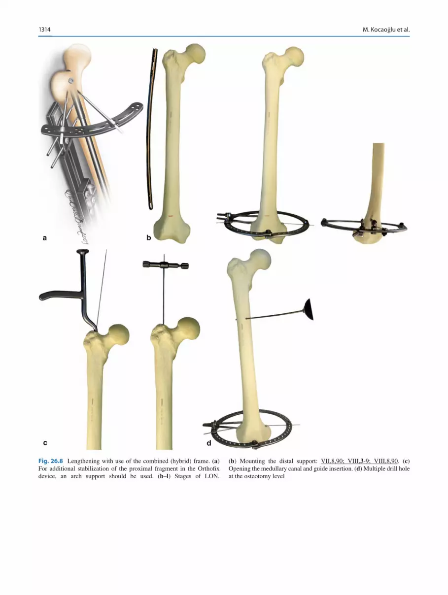
Note : If there is concern regarding the stability of the half-pins, especially in osteoporotic bones, extra half-pins and wires are inserted on different planes and connected to the external fi xator with use of a large Ilizarov arch (Fig. 26.8a ). Figure 26.8b–l shows the stages of LON with the use of a combined (hybrid) frame.
When antegrade insertion of the nail is impossible (due to a deformity in the proximal femur or the presence of a foreign body), a nail is inserted using the retrograde method. In this case, upon completion of lengthening, the nail is locked proximally (Fig. 26.9 ).
26.1.5 Tibial LON: Surgical Technique
The patient is placed supine on the radiolucent table. Prior to surgery, the tibia is checked with the image intensi fi er on AP and lateral views, preferably by the attending surgeon. The lower limb is prepared in sterile fashion to the level of the iliac crest. A 2-cm transverse incision is made at the lower pole of the patella (Fig. 26.10 ). A conventional longitudinal section also can be used.
Following the subcutaneous dissection, the paratenon and patellar ligament are split longitudinally. The entry point is prepared using a 5-mm cannulated drill, as in the standard tibial nailing technique. The guide wire is inserted. Multiple
Fig. 26.4 Three different con fi gurations for half-pin insertion
Fig. 26.5 Placement of the proximal half-pins posterior to the IM nail without contact

131326 Combined and Consecutive Use of External and Internal Fixation
drill holes are created at the previously planned osteotomy level through a 1-cm incision by slow turns, in order to pre-vent heat necrosis of the bone. This also will produce venting of the canal as well as internal grafting. The medullary canal is reamed by 0.5-mm increments 1.5 mm wider than the diameter of the planned IM nail. At this point, the osteotomy is completed by an osteotome, while the guide wire remains in the medullary canal. A 1-cm incision is made at the mid-diaphyseal level of the fi bula and the fi bula is osteotomized via the multiple drill-hole technique. The alternative proce-dure of fi bular osteotomy can be used (Fig. 15.1 ). The com-pleteness of both osteotomies is checked with the C-arm by translation of the fragments. The tibial IM nail (for example, Orthopro 4 G IM) is inserted over the guide wire, which is then removed. Proximal locking of the IM nail is done in the usual manner.
26.1.5.1 Application of the External Fixator We prefer circular type external fi xators for tibial LON due to the otherwise high risk of valgization of the fragments during distraction, caused by the stiffness of the interosseous membrane. Herzenberg et al. [ 501 ] reported similar results
Fig. 26.7 Placement of the distal half-pins posterior to the IM nail without contact
a b c
Fig. 26.6 ( a – c ) In the frontal plane, half-pins must be perpendicular to the IM nail: I,10,90; II,10,90 ←→ ←→ VI,9,90; VII,10,90
1314 M. Kocaoğlu et al.
a
c d
b
Fig. 26.8 Lengthening with use of the combined (hybrid) frame. ( a ) For additional stabilization of the proximal fragment in the Ortho fi x device, an arch support should be used. ( b – l ) Stages of LON.
( b ) Mounting the distal support: VII,8,90; VIII, 3 -9; VIII,8,90. ( c ) Opening the medullary canal and guide insertion. ( d ) Multiple drill hole at the osteotomy level

131526 Combined and Consecutive Use of External and Internal Fixation
Fig. 26.8 (continued)
e
f
g
( e ) Drilling-out the medullary canal and osteotomy. ( f ) Nail insertion and proximal interlocking. ( g ) Mounting the proxi-mal support: I,8,90; I,11,90; II,8,90

1316 M. Kocaoğlu et al.
Fig. 26.8 (continued)
i
h
j
( h ) Connection of the distal and intermediate supports: ____ ― VII,8,90; VIII, 3 -9; VIII,8,90. ( i ) Connection of prox-imal and distal modules: I,8,90; I,11,90; II,8,90 ― _______ ←→
VII,8,90; VIII, 3 -9; VIII,8,90. ( j ) Frame assembly using extracortical clamp devices (ECD) (Chap. 12.5 )

131726 Combined and Consecutive Use of External and Internal Fixation
Fig. 26.8 (continued)
k l
( k ) Distal interlocking (using the standard assembly and the assembly based on ECD). ( l ) Frame removal

1318 M. Kocaoğlu et al.
a
c d e
b
Fig. 26.9 Lengthening over a retrograde nail. ( a – l ) Stages of the pro-cedure; ( k – o ) clinical examples. ( a ) Assembling the proximal support: I,9,90; I,11,90; II,9,90. ( b ) Multiple drill holes at the osteotomy level.
( c ) Opening the medullary canal and guide insertion. ( d ) Drilling-out of the medullary canal. ( e ) Osteotomy

131926 Combined and Consecutive Use of External and Internal Fixation
f g
h
Fig. 26.9 (continued) ( f ) Nail insertion and distal interlocking. ( g ) Mounting of the distal and intermediate supports: _____ ― VII,8,90; VIII, 3 -9; VIII,8,90. ( h ) Connection of the proximal and distal modules: I,9,90; I,11,90; II,9,90 ― ______ ←→ VII,8,90; VIII, 3 -9; VIII,8,90

1320 M. Kocaoğlu et al.
i
j
Fig. 26.9 (continued) ( i ) Proximal interlocking. ( j ) Frame assembly with ECD (Chap. 12.5 )

132126 Combined and Consecutive Use of External and Internal Fixation
k
m n
l
Fig. 26.9 (continued) ( k ) Proximal interlocking (similar to ( i )). ( l ) Frame removal. ( m–q ) Clinical examples

1322 M. Kocaoğlu et al.
oFig. 26.9 (continued)

132326 Combined and Consecutive Use of External and Internal Fixation
when they used unilateral external fi xators for tibial LON. A frame is prepared consisting of three rings: one for the proximal fragment, one for the distal fragment, and one “dummy” ring in between, which is not used for fi xation but for frame stability (Fig. 26.11 ).
A wire parallel to the proximal tibial joint surface is inserted posteriorly and fi xed to the proximal ring of the frame. At the supramalleolar level, another K-wire, parallel to the distal tibial joint line on the frontal plane, is inserted posteriorly without touching the IM nail and fi xed to the distal ring of the frame. Two half-pins (preferably hydroxy-apatite coated) are inserted proximally without touching the IM nail, one of which will also fi x the fi bular head in order to prevent distal migration during lengthening. This half-pin is placed in the anteromedial tibia by the cannu-lated drill bit technique. Both half-pins are fi xed to the proximal ring (Fig. 16.11 ).
Distally, an olive wire is inserted at the lateral malleolar level parallel to the joint line to establish tibio fi bular fi xation: VIII( 8 -2)8-2. At this point, the distraction test is performed and the procedure is concluded.
When frame assembly can be based on the wires only, to pre-vent a valgus position of the fragments during distraction, basic wires should be inserted in “hypercorrection” (Fig. 26.12 ).
Figure 26.13 shows an example of bilateral tibial LON of the anticnemion, and Fig. 26.14 LON of the upper arm and forearm.
26.1.6 Distraction Period
Distraction starts on day 7 at a rate 0.25 mm four times day. On day 5, control roentgenogram should be done to specify the conformity of the distraction size and regenerate lengths. Usually, both should be 1–2 mm less due to a de fl ection of the transosseous elements.
26.1.7 Removal of the External Fixator
The external fi xator should be removed immediately after the desired amount of lengthening is achieved. The extremity is sterilely prepared, including the frame, in the supine position.
p q
Fig. 26.9 (continued)

1324 M. Kocaoğlu et al.
The whole frame is draped except for the area used for distal interlocking. The distal locking holes are prepared using can-nulated drills over the K-wire via the free-hand technique, and the interlocking screws are inserted. If the insertion is at the metaphyseal level, interference screws may be used on each side of the IM nail to increase stability [ 502 ] .
After the frame has been removed the patient is mobilized with two crutches and is allowed to bear 10% of his or her body weight (depending on the nail type). The patient returns for follow-up every month until the regenerate consolidates. During this period, stretching and range-of-motion exercises are encouraged. To decrease the risk of nail breakage, full weight-bearing is allowed only when three of four cortices are consolidated, as seen on AP and lateral views during follow-up.
For locking screws with a diameter >5 mm and nails with a diameter of ³ 12 mm, the fatigue resistance of the locking nail is usually suf fi cient not to limit weight-bearing begin-ning at the fi rst days after nailing [ 502 ] .
26.1.8 Complications
There are signi fi cant complications associated with LON: Mechanical sticking of the distraction system (wrong • technical application). Pin-tract infection. • Delayed union/inadequate regenerate production or pre-• mature consolidation; distraction rates should be individ-ually regulated on the basis of patient monitoring. Development of stiffness of adjacent joints. Therapeutic • exercises should be instituted during distraction and fi xation periods. The threat of development of a severe contracture is an indication to stop the lengthening (Chap. 23 ). Breakage of a half-pin or interlocking screw usually arises • from inadequate loading on the leg. Detailed information on the complications arising from
external fi xation are presented in Chap. 33 . A total lengthening of 6 cm, a lengthening rate of 21.5%,
and a Paley dif fi culty score of 8.5 are the critical cut-off points above which complications are more likely to occur [ 176, 177 ] .
a b
Fig. 26.11 ( a , b ) The middle “dummy” ring is not used for fi xation but to increase the stability of the frame: I, 9 -3; I,1,90; II,3-9 ←→ _____ ― VII,I,90; VIII( 8 –2)8-2; VIII, 4 -10
a
b
Fig. 26.10 Position of the patient on the operating table ( a ) and variant of the incision over the ligamentum patella for nail insertion ( b )

132526 Combined and Consecutive Use of External and Internal Fixation
d
a b
c
e
Fig. 26.12 ( a – n ) Stages of lower leg LON. ( a ) Determination of the level of distal assembly. ( b ) Mounting the distal support VIII( 8 -2)8-2; VIII, 4 -10 . The support should be located with slight “hypercorrection” to
prevent a valgus deformity during distraction. ( c ) Multiple drill-holes at the osteotomy level. ( d ) Opening the medullary canal and guide insertion. ( e ) Drilling-out the medullary canal

1326 M. Kocaoğlu et al.
h
i
g
j
f
Fig. 26.12 (continued) ( f ) Fibular osteotomy. ( g ) Tibial osteotomy. ( h ) Nail insertion and proximal interlocking. ( i ) Mounting the proximal support I,9-3; II,3-9. The support should be located with slight “hypercorrection” to prevent valgus deformation during distraction. ( j ) Frame mounting

132726 Combined and Consecutive Use of External and Internal Fixation
n
k l
m
Fig. 26.12 (continued) ( k ) Insertion of stabilizing half-pins II,1,80 and VII,1,90. ( l ) Final frame assembly: I, 9 -3; II,1,80; II, 3 -9 ←→ _____ ― VII,1,90; VIII( 8 -2)8-2; VIII, 4 -10. ( m ) Distal interlocking. ( n ) Frame removal

1328 M. Kocaoğlu et al.
a
e
f
b c d
Fig. 26.13 ( a – f ) Clinical view of a patient with bilateral tibial LON

132926 Combined and Consecutive Use of External and Internal Fixation
26.2 Bone Transport Over Nail (BTON)
26.2.1 Introduction
Mehmet Kocaoğlu , Erkal F. Bilen , and Leonid Nikolaevich Solomin
Numerous procedures for the treatment of bone defects have been devised (Chap. 19 ), including acute shortening and then lengthening (most suitable for segmental defects up to 5 cm long), bone transport (the best option for defects 5–12 cm in length), and vascularized free fi bular grafting in combination with transport and lengthening or ipsilateral fi bular transport (for segmental bone defects >12 cm). Titanium mesh cages fi lled with autograft, demineralized bone matrix, and allografts have also been used to reconstruct large segmental bone defects [ 503, 504 ] .
In patients with limited life expectancy, the use of a seg-mental prosthesis may be indicated, without having to wait for healing [ 505 ] .
Bone transport with the use of an external fi xator is known to be a reliable solution that leads to successful outcomes. The time spent in an external fi xator (the external fi xation time, EFT) depends on the length of the required distraction, with longer EFTs carrying a higher a risk of complications. The distraction phase is followed by the consolidation phase (which often lasts more than twice as long), which is dif fi cult for the patient to tolerate. Removal of the external fi xator before satisfactory con-solidation has occurred is associated with fracture, deformity,
and shortening through the distracted callus [ 153 ] . Older frames often required repeated adjustment to prevent misalignment of the docking site. The use of an IM nail together with an external fi xator avoids misalignment of the docking site, leading to signi fi cant decreases in the EFT, and better maintenance of the anatomic length and the alignment [ 494 ] .
The BTON technique prevents the common complica-tions of bone transport, such as delayed consolidation, axial deviation, translation, and deformity recurrence or occur-rence. This is attributed to the improved construct stability provided by the IM nail.
Alternatively, minimally invasive plate osteosynthesis (MIPO) may be used to obtain similar advantages [ 506, 507 ] . Bone transport may also be accomplished through the use of fully implantable IM lengthening devices, such as an internal lengthening nail (ISKD). Cole [ 508 ] reported a technique through which healing of the non-union was targeted fi rst, followed by lengthening with an ISKD to resolve a limb length discrepancy.
Oedekoven et al. [ 710 ] reported on the results obtained with the monorail system for bone transport over unreamed interlocking nails, used in 20 patients. Defect distances var-ied between 5 and 18.5 cm, and average transport time was 19.42 days/cm for the tibia, and 15.93 days/cm for the femur. Kocaoglu et al. [ 509 ] reported a mean external fi xation index (EFI) of 13.5 days per cm in 13 patients (7 tibiae, 6 femurs) by means of the BTON technique.
By contrast, bone transport achieved with the Ilizarov device alone was associated with an extended EFT (average
a b
Fig. 26.14 ( a , b ) Upper arm and forearm LON

1330 M. Kocaoğlu et al.
16.7 months) and high EFI (average 2 months/cm) compared to the BTON technique. There was also a signi fi cant differ-ence in the EFI between smokers and non-smokers ( on aver-age, 2.60 vs. 1.45 months/cm, respectively) [ 510 ] .
Although most surgeons are cautious about using IM nails in open fractures, the BTON technique was shown to be suc-cessful in the treatment of Gustilo 3b open tibial fractures [ 511, 512 ] . The transport process not only treats the bony defect, it also helps with soft-tissue coverage.
Management of the docking site requires speci fi c proce-dures. Acute shortening of the defect can reduce the trans-port time to achieve docking. The tibia and the humerus can be safely shortened by up to 3–4 cm, and the femur by up to 5–7 cm. Once docking is established, straightforward length-ening may be performed.
To further reduce the EFT, bifocal or trifocal strategies may be used. Each osteotomy helps to shorten the overall treatment time by 0.5–1 mm/day.
Upon completion of bone transport and lengthening, the IM nail is locked statically and the external fi xator is then removed prior to consolidation of the new bone. However, the bone transport over a nail technique has a steep learning curve and requires meticulous preoperative planning in addi-tion to perfect patient compliance.
The cost of treatment is another issue that surgeons must take into account. BTON signi fi cantly reduces the rate of complications, overall number of operative sessions and duration, and total hospital inpatient length of stay, thus reducing the cost of treatment. Amputation, as it is followed by prosthetic care for the remainder of the patient’s life, incurs greater overall costs [ 513 ] .
We note that BTON undermines two of Ilizarov’s princi-ples for optimizing osteogenesis: preservation of the blood supply and of the medullary osteogenic tissue. Histological analysis of the regenerated segment has revealed asymme-tries in terms of enchondral bone formation, trabecular struc-ture, metabolic activation, and cell viability [ 514 ] . However, it has been shown that LON does not compromise the viabil-ity of the regenerating segment [ 177, 515 ] . One should be cautious about the endosteal circulation, which might be negatively affected.
26.2.2 Indications and Contraindications
Indications: Bone defects of 5–12 cm • Contraindications: Vascular disease • Diabetes mellitus • Active infection • Open physeal plate • Intramedullary canal diameter <8 mm •
Relative contraindications: Bone defect >12 cm • Tobacco abuse •
26.2.3 Special Features of the Equipment
Preoperative planning is of paramount importance for bone transport procedures. AP standing orthoroentgenograms and lateral plain X-rays are obtained and studied together with IM nail templates to determine the placement of additional holes to achieve locking of the transport segment.
For femoral defect reconstructions, unilateral external fi xators are used (Ortho fi x LRS, Italy; EBI Monorail, Biomet, USA), and for tibial defect reconstructions circular external fi xators (Ilizarov and Ortho-SUV Frames, Vreden Russian Research Institute; Taylor Spatial Frame, Smith and Nephew, USA).
26.2.4 General Principles of the BTON Surgical Technique
Surgery can be executed either “closed” or “open.” In the closed method, a nail is inserted without exposing the ends of the bone fragments. If the closed method is dif fi cult or impossible (due to expressed sclerosis, deformities of the bone ends, or foreign bodies) the operation is performed using the open variant. This variant is indicated when the bone ends are thin, incongruent, or have a reduced blood supply, as this may result in atrophic non-union of the dock-ing site.
The open method starts with processing of the bone ends, in which the medullary canals of the fragments are re-cana-lized. It is important to ensure adequate blood supply to the bone ends, con fi rmed with the “Paprika sign” recommended by Mader [ 499 ] . If needed, an additional resection should be performed to ensure viable bone ends. At the end of the bone transport process, the bone ends must be congruous (Fig. 26.15 ).
The next stage requires reaming the bone fragments. The medullary canal should be reamed 1.5–2 mm wider than the diameter of the IM nail to allow sliding of the nail. As a rule, the longer bone fragment is used for lengthening, whether proximal or distal.
The next stage involves inserting the nail up to the osteot-omy level, followed by the osteotomy and further forward insertion of the nail. The osteotomy is performed using the multiple drill-hole technique (Fig. 26.2 ). If the nail is inserted into a bone fragment that will be elongated, a diasta-sis at the osteotomy level is possible. This can be prevented by temporarily fi xing the fragment using a surgical hook, wire, or extracortical clamp device as it is carried through

133126 Combined and Consecutive Use of External and Internal Fixation
an intermediate bone fragment (Chap . 12.5 ). However the presence of a diastasis is not a problem because once the IM nail is inserted and locked, the fragment to be transported is fi xed either by wires or half-pins; thus any distraction or diastasis through the osteotomy level can be corrected via the external fi xation.
The nail should be locked statically (proximally and dis-tally) if additional lengthening is not required following bone transport (Fig. 26.19 ). Then the external fi xator is applied; wires and half-pins should be inserted tangentially, with no nail contact.
Wires (Figs. 26.16a , 26.20 and 26.21 ), half-pins (Figs. 26.18 , 26.19 and 26.22 ), and cables (Fig. 26.16b ) can be used for the transport of intermediate bone fragments.
Brunner et al. [ 515 ] found that the overall transport forces for large defects were slightly greater than those for small defects. In the former, transport forces leveled off during bone transport before rising again, ultimately reaching 350 N.
In patients with large defects, bifocal distraction is recom-mended to shorten net treatment times. Vidyadhara et al. [ 516 ] reported an interesting observation regarding bifocal distractions, namely, that despite the same rate of distraction, shorter fragments move faster than longer fragments. This can be attributed to the attachment of the soft tissue to the longer fragment, thereby hindering distraction. If the
segmental defect is very large (>10 cm), trifocal transport over the nail may be helpful to reduce the EFT and the related problems [ 516, 517 ] .
Once docking is accomplished, the patient returns to sur-gery for debridement (to guarantee viable ends with maxi-mum contact) and grafting (to reduce the risk of non-union or refracture at the docking site and to shorten treatment duration) [ 518 ] . An iliac crest bone graft along with demin-eralized bone matrix (DBM) or bone morphogenetic protein (BMP-2) may be used for grafting. The docking site may be compressed acutely if the external fi xator is to be removed in the same session. Alternatively, compression may be contin-ued at a rate of 0.25 mm every other day until consolidation of the docking site, if lengthening will be continued. We pre-fer autogenous posterior iliac crest bone grafting and addi-tionally use DBM to improve the healing potential in all cases.
For intermediate bone fragment fi xation, an additional locking screw is inserted. The other option is a conventional plate or monocortical locking plate (Fig. 26.17 ).
26.2.5 Femoral BTON Surgical Technique
Diagrams of BTON using orthograde and retrograde nails are provided in Figs. 26.18 , 26.19 , and 26.20 .
The patient is placed supine on a radiolucent table with the limbs in a scissors position (Fig. 26.1 ), and with a cush-ion placed below the pelvis on the ipsilateral side. A standard approach (through the piriformis fossa for antegrade nailing and through a parapatellar 1-cm transverse incision for retro-grade nailing) is used for reaming the medullary canal. After the reconstruction, there should be suf fi cient nail length on both sides of the regenerated bone to guarantee adequate sta-bility. Thus, if lengthening is planned in conjunction with bone transport, the IM nail must be longer than the length of the femur (Fig. 26.20 ).
In such cases, retrograde nailing is preferred because it allows the excess nail length to protrude into the buttock until distraction has been completed, by which time the nail will have glided gradually to its correct position. Since the proxi-mal part of the nail features a larger diameter, the proximal femur should be over-reamed in antegrade, and the distal femur over-reamed in retrograde applications. An appropri-ately placed corticotomy is then performed percutaneously using the multiple drill-hole technique (Fig. 26.2 ) before the IM nail is inserted. The osteotomy level is chosen at least 5–6 cm away from the bone defect. Finally, an IM nail (e.g., Ortopro 4 G) of appropriate size is inserted and locked proxi-mally, distally, or on both sides, according to the planned distraction.
Two to three half-pins are inserted both proximally and distally to the osteotomy level, taking care that they do not
Fig. 26.15 Congruence of the ends of the bone fragments

1332 M. Kocaoğlu et al.
come into contact with the IM nail. There should be at least 1 mm of free space between the half-pins and the IM nail to prevent medullary infection triggered by a pin-site infection [ 176 ] . To insert half-pins without nail contact, the cannulated drill-bit technique described by Paley et al. [ 177 ] is recommended. A wire is inserted on the lateral femoral cortex, perpendicular to the IM nail, at the level of the half-pin. The location of the wire is con fi rmed with the C-arm. A hole is reamed over the wire with the cannulated drill bit. The half-pin can then be inserted, and clearance between the pin and the nail con fi rmed with the C-arm.
In Figs. 26.17d , 26.18l and 26.19j , an alternative femoral BTON technique is presented. In the case of rigid fi xation of a nail in a proximal bone fragment, additional fi xation of the fragment by external fi xation support is not required. Half-pins and wires can be used for bone transport (Fig. 26.16 ).
26.2.6 Tibial BTON Surgical Technique
The standard ligament split approach is followed and the medullary canal is over-reamed 1.5 mm wider than the planned diameter of the nail. The nail is then inserted and a three-ring circular external fi xator is used (Fig. 26.21 ). It is very important that the longitudinal axis of the external fi xator is parallel to the IM nail. Proximal and distal rings are fi xed with one wire and a half-pin. The fi bula should be fi xed to the tibia on each end. None of the external fi xation pins or wires should come into contact with the nail. Before the IM nail is inserted, a corticotomy is performed at the appropriate level using ei ther the multiple drill hole (Fig. 26.2 ) or the Gigli saw technique. If there is shortening in conjunction with the segmental bone defect, then an IM nail of the eventual desired tibial length is inserted and left
Fig. 26.16 ( a , b ) Different methods of intermediate bone fragment transport

133326 Combined and Consecutive Use of External and Internal Fixation
a
d
b c
Fig. 26.17 ( a – d ) Different types of intermediate bone fragment fi xation. ( a , b ) Using a locking screw; ( c , d ) using a plate

1334 M. Kocaoğlu et al.
a
d
b
c
Fig. 26.18 ( a – m ) Bone transport using an orthograde nail. ( a ) Opening the medullary canal and guide insertion. ( b ) Drilling-out the medullary canal. ( c ) Osteotomy. ( d ) Nail insertion, proximal and distal interlocking

133526 Combined and Consecutive Use of External and Internal Fixation
Fig. 26.18 (continued)
e
h
f
g
( e ) Half-pin insertion in the proximal bone fragment. Mounting of proximal support I,8,90; I,11,90; II,8,90. ( f ) Mounting the distal support VI,8,90; VII, 3 -9; VIII,4,90 . ( g ) Insertion of
transosseous elements for bone transport: III,8,90 и IV,9,90. ( h ) Mounting the intermediate support

1336 M. Kocaoğlu et al.
i
k
j
Fig. 26.18 (continued) ( i ) Connection of the proximal and distal modules: I,8,90; I,11,90; II,8,90 →← III,8,90; IV,9,90 ←→ VI,8,90; VII, 3 -9; VIII,4,90 . ( j ) Bone transport. ( k ) Frame assembly using ECD

133726 Combined and Consecutive Use of External and Internal Fixation
l
m
Fig. 26.18 (continued) ( l ) Option of frame assembly (when rigid fi xation of the proximal fragment by nail is possible). ( m ) Docking site care, fl oating bone fragment fi xation, and frame removal

1338 M. Kocaoğlu et al.
a
e
b
c
d

133926 Combined and Consecutive Use of External and Internal Fixation
Fig. 26.19 (continued)
Fig. 26.19 ( a – k ) Bone transport using a retrograde nail. ( a ) Assembling proximal support I,8,90; I,11,90; II,9, 90. ( b ) Opening the medullary canal and guide insertion. ( c ) Drilling-out the medullary canal. ( d ) Osteotomy. ( e ) Nail insertion, distal and proximal interlocking
g
h i
f
( f ) Mounting distal support VII,8,90; VIII, 3 -9; VIII,8,90 . ( g ) Mounting the intermediate support and support con-nection: I,8,90; I,11,90; II,9,90 ←→ V,9,90; VI,9,90 →← VII,8,90;
VIII, 3 -9; VIII,8,90. ( h ) Frame assembly using ECD (Chap. 12.5 ). ( i ) Bilocal osteosynthesis

1340 M. Kocaoğlu et al.
proximally proud so that it can slide distally during distraction.
Figure 26.22 shows the use of the monolateral device in BTON.
26.2.7 Postoperative Care
Distraction is started on postoperative day 7 at a rate of 1 mm/day, divided into four equal increments. Range-of-motion exercises for both hip and knee are initiated immediately, excluding those patients with a long tibial IM nail (in whom knee exercises should be postponed until the proud part of the nail enters the tibia during lengthening). Full weight-bearing with two crutches is started as soon as possible.
Once distraction and lengthening are completed, the nail is statically locked and the external fi xator is removed. In patients with proximal femoral osteotomy, a non-vascularized fi bular graft can be inserted into the posteromedial distrac-tion site to provide additional support and to decrease the force transmitted through the nail until total consolidation occurs.
26.2.8 Complications
There are signi fi cant complications in BTON: Pin-tract infection (most common problem with all types • of external fi xation). Vigilant preventive maintenance is necessary to avoid the development of a deep infection with expansion of the IM canal. Non-union of the docking site (most common problem • except frame-related complications). The reason is over-val-uation of the blood supply of the ends of the bone fragments. Treatment: bone autografting, compression osteosynthesis; less often, a resection of the fragment ends. Poor regenerate formation is related to an improper rate of • bone transport. Premature consolidation occurs when the latency period • before lengthening is too long or the rate of lengthening is too slow. Pin cut-out during transport. This complication is more • likely to occur in osteoporotic patients with large bone defects [ 519 ] . Detailed information about the complications caused by
external fi xation can be found in Chap. 29 .
Fig. 26.19 (continued)
kj
( j ) Option of frame assembly (when rigid fi xation of the proximal fragment by nail is possible). ( k ) Docking site care and fl oating bone fragment fi xation; frame removal

134126 Combined and Consecutive Use of External and Internal Fixation
a
c d e
b
Fig. 26.20 ( a – e ) The femoral retrograde BTON technique with additional lengthening

1342 M. Kocaoğlu et al.
a
e
f g
b c d
Fig. 26.21 ( a – j ) The tibial BTON technique. ( a ) Determining the level of distal support assembly. ( b ) Opening the medullary canal and guide insertion. ( c ) Drilling-out the medullary canal. ( d ) Tibial osteot-omy. ( e ) Nail insertion, and proximal and distal interlocking.
( f ) Mounting the frame: I, 9 -3; II,1,80; II, 3 -9 ― _____ ― VII,1,90; VIII( 8 -2)8-2; VIII, 4 -10. ( g ) Insertion of transosseous elements for bone transport: IV,2,90; V, 3 -9

134326 Combined and Consecutive Use of External and Internal Fixation
a b c d
Fig. 26.22 ( a – d ) Patient X-rays showing the tibial BTON technique and the results. Note the fi xation of the distal tibio fi bular syndesmosis by the screw
Fig. 26.21 (continued)
h i j
( h ) Bone transport : I, 9 -3; II,1,80; II, 3 -9 →← IV,2,90; V, 3 -9 ←→ VII,1,90; VIII( 8 -2)8-2; VIII, 4 -10 . ( i ) Option of frame assembly (when rigid fi xation of the distal fragment by nail is
possible). ( j ) Docking site care, fl oating bone fragment fi xation, and frame removing

1344 M. Kocaoğlu et al.
26.3 Sequential External Fixation and Nailing (SEFaN)
Alexandr Nikolaevich Chelnokov and Leonid Nikolaevich Solomin
26.3.1 Introduction
Acute deformity correction techniques using external fi xation methods followed by immediate internal fi xation are covered in Sect. 26.4 . However, these techniques are not always applicable due to the limited indications for acute deformity correction (Chap. 16 and Sect. 26.3 ). Under these conditions, we use a two-stage sequential external fi xation and nailing (SEFaN) procedure. SEFaN is the alternative to LON (Sect. 26.1 ) and BTON (Sect. 26.2 ) methods.
The advantages of SEFaN are that the extremity segment is fi xed with an external fi xator only for the period of the defor-mity correction. The technique provides several advantages. First, it minimizes both technical problems and traumatic injury related to nailing due to the prior alignment of the axis and the length of the segment. Second, treatment is more comfortable for the patient and facilitates medical monitoring. Third, there is a lower risk of infectious complications and pin-induced joint stiffness. Fourth, plastic transformation is unnecessary and fracture of the regenerate after fi xator removal does not occur. Finally, it obviates decision-making as to whether the regenerate is mature enough to allow fi xator removal.
The disadvantages of the technique are the more exten-sive traumatic injury of the surgical procedure; the necessity of additional surgical interventions, i.e., nailing followed by removal of the construction in some cases; and the risk of infection spread in the medullary canal.
26.3.2 Indications and Contraindications
Indications: Congenital or acquired deformities of the long bones • Non-unions, associated with persistent deformity of the • segment
Defect of the long bones • Contraindications: Acute infection • Open physeal plate • Besides, it is not always technically possible to perform
nailing if there are residual deformities of the segment, non-removed implants, or a short epimetaphyseal fragment that is insuf fi cient for the fi xation of at least two locking screws.
26.3.3 Special Features of the Equipment
Formation of a nail canal requires special reamers and drills especially in case of pathological alterations of the medul-lary cavity, such as closing of the bone ends formed due to non-unions and eburnation of the bone ends in fi brous dys-plasia. Using stiff straight drills is fraught with the formation of false canals, associated with bone plate perforation. With fl exible guides and reamers, it is often impossible to perfo-rate the sclerosed bone in the needed direction. To solve this problem, we suggest special elastic reamers of increasing diameter [ 520 ] . These reamers consist of titanium rectangu-lar cross-section nails with fi xed cutting elements in the form of a two-facet trapezoidal, conical, or diamond-shaped cutter having butt and side cutting edges. The reamer set also con-tains a T-shaped handle (Fig. 26.23 ).
To decrease the risk of in fl ammatory complications, solid titanium nails must be used [ 239 ] . In patients weighing >80 kg who require increased postoperative mobility, non-cannulated titanium nails and locking screws >5 mm in diameter should be used.
Indications to use nails coated with antibiotic-containing cement are: in the treatment of severe open fracture conse-quences; pyoin fl ammatory complications in the fi xator cor-rection period; and chronic osteomyelitis in remission or following surgical sanation of the focus.
To cover a nail with cement it must be placed in a form fi lled with liquid bone cement and removed from the form after polymerization of the cement [ 501, 521– 523 ] . The antibacterial coating is prepared ex tempore using either a reusable mold or a silicon tube, e.g., a chest tube [ 522 ] The
Fig. 26.23 Set of elastic titanium reamers with a handle for their insertion

134526 Combined and Consecutive Use of External and Internal Fixation
silicon tube is more practical since the nail obtained does not require further treatment except reconstruction of the holes, while with the reusable mold it is necessary to remove the ridge formed along the form’s junction [ 522 ] .
A nail 8–10 mm in diameter is placed in a silicone tube 12–14 mm in diameter. A syringe is then used to inject cement containing an antibiotic into the nail. Vancomycin is the most popular antibiotic for this purpose since it suc-cessfully combines high antimicrobial properties, a wide range of action, and thermal stability. To one portion of the cement (20 g) 2 g of vancomycin are added. To prevent the cement from being too dense, about 75% of the dose should be used or an additional amount of liquid monomer should be added.
If cement already containing another antibiotic is used, a dose of vancomycin should be added. After the cement becomes hard, the tube is cut off (Fig. 26.24 ). The cement covering to some extent decreases the rigidity of the osteo-synthesis since a tube of smaller diameter is used with lock-ing screws of a smaller diameter, which is to be taken into consideration during preoperative planning.
To perform SEFaN of the femur, extracortical fi xators are needed (Table 1.2 , item 23, Chap. 12.5 , and Fig. 26.26 ). Moreover, an Ilizarov distraction external fi xator module may also be needed for surgery (Figs. 26.27 and 26.29 ).
26.3.4 General Principles of the SEFaN Surgical Technique
In the fi rst stage, using external fi xation, all bone deformity components are eliminated, such as angulation, peripheral dislocation, and shortening (Chaps. 16 and 17 ). Angular dis-location and shortening are preferably eliminated with slight hypercorrection.
In the assembly of the external fi xator, the forthcoming second stage of the surgery should be taken into account. The intraosseous elements must be inserted so that they will not interfere with the following insertion of the IM nail. Thus, in the metaphyseal part, from the side of a nail inser-tion at least one transosseous element must be placed eccen-trically, i.e., beyond the projection of the nail canal. For example, in the proximal part of the tibia one wire or half-pin can be inserted in the frontal plane in the posterior semicircle of the bone. It enables the removal of only those intraosseous elements that will interfere with nail insertion; while the rest (at least one in the proximal and distal parts) will provide
a
b
c
d
Fig. 26.24 Making a nail with an antibacterial covering: ( a ) pumping cement into a silicone tube; ( b ) inserting the nail into the tube with the liquid cement; ( c ) removing the tube after the cement has hardened; ( d ) removing the cement from the holes in the nail

1346 M. Kocaoğlu et al.
fi xation of the achieved position of the bone fragments before the insertion and locking of the intraosseous nail.
If this requirement has not been followed for whatever reason, the external fi xator is appropriately reassembled before the nailing. For example, prior to IM fi xation of the femur the wire in the proximal part should be inserted just before the rods are removed from the upper third of the femur.
Intramedullary fi xation is best performed immediately after external fi xator correction is completed. It is not neces-sary to wait for the regenerate to be seen on the X-rays. Keep in mind that as the duration of the external fi xation increases, so does the risk of infection of the transosseous element canals. Accordingly, delayed tactics (removal of the external
fi xator, healing the wounds made by the intraosseous elements, and then nailing) increases the risk of infectious complications development [ 239 ] .
The patient is supine on the operating table, as a rule. In case of external fi xation of the femur, lying on the healthy side can be more comfortable. Considering the presence of the fi xator maintaining the achieved length and axis for the period of nail insertion and locking, the use of a traction table is not recommended. A plain non-opaque table is pref-erable. The patient’s position must allow for the use of mobile fl uoroscopy equipment to visualize the whole bone. The assembled external fi xator is not removed; rather, only the intraosseous elements that will interfere with nail inser-tion are removed. In order not to lose the position of the bone
a b
Fig. 26.25 ( a , b ) Formation of the nail canal using titanium reamers

134726 Combined and Consecutive Use of External and Internal Fixation
fragments at the level of the proximal and distal metaphyses, as achieved by the external fi xator, 1–2 intraosseous elements are left, i.e., those located in the bone beyond the trajectory of the nail insertion. Next, the fi xator is carefully treated with antiseptics.
If in the basic (monolateral, arch) supports tangential intraosseous elements cannot be fi xed, then the supports should be lengthened with radial plates to make them cir-cular or semicircular. After fi xation of the proximal and distal wires and the creation of a longitudinally stable con-struction, the intermediate intraosseous elements are removed. To preserve the ability to control the bone frag-ments’ positions, the half-pins are removed from the distal cortical plate and medullary canal but left fi xed in the near cortical plate.
Another option is when one more external fi xators are to be mounted over the present external fi xator, which is a dis-traction fi xation module. In this case, two external supports are used that must be one to three times larger than the sup-ports of the main external fi xator. At the level of the proximal and distal metaphyses of the bone, 1–2 intraosseous elements are inserted. These are to be located tangentially in the bone, i.e., not intersecting the medullary cavity (Fig. 26.27 ). These transosseous elements are fi xed in the supports of the distrac-tion fi xation module. The module supports must be located so that they will not interfere with nail insertion and locking. After assembly of the distraction fi xation module, the main external fi xator is removed.
The crucial stage of the surgery is to form the canal for the nail in the pathologically altered medullary cavity. For this purpose, a set of elastic titanium reamers is used (Fig. 26.23 ). In an axial deformity at the junction of the bone fragments, they can be modeled (bent), which enables the formation of a bent canal. The technical properties of the reamers provide rigidity and fl exibility at the same time and fully transmit both rotational and hammer forces on the cutting edge, even if it is located signi fi cantly far from the point of insertion and is bent in the medullary cavity. The cutting element, in the form of a facet with butt and side cutting edges, enables both drilling-out the canal by the side edges and canal formation by the butt edges. It also enables the use of a hammer to pass an imperforated segment of the canal by hitting and rotating forces (Fig. 26.25 ). After the canal has been made, if the seg-ment axis is normal then further insertion and locking of the IM nail is performed according to the standard method and presents no dif fi culties.
In some cases, due to sclerosis and curving of the bone fragments’ ends as well as in case of residual widthwise, lengthwise and angular dislocations, it may be virtually impossible to insert the reamer or drill in to the next bone segment. In these situations, a canal in the adjacent bone fragment is made from the opposite side (for example, in the
proximal fragment in the femur or upper arm bones in the antegrade direction, and in the distal fragment in the retro-grade direction) or, as a last resort, the fragments edges are exposed, the reamer is introduced into the wound , and the medullary cavity is opened under visual control.
After the nail’s insertion into the canal, it is locked. To maintain the distraction forces, the nail must be locked stati-cally. In case of over-distension, the options are either acute compression of the bone fragments until the necessary length is achieved followed by static or dynamic locking of the nail considering gradual shortening of the bone frag-ments over the nail under the effect of dosed axial loading. The external construction is disassembled, as a rule, following nail locking.
If the fi rst stage consisted of bone defect replacement by bilocal compression distraction external fi xation, then during nailing the intermediate fragment must be stabilized by an additional locking screw. This will require the preoperative planning of an additional hole for a locking screw. To decrease the risk of a fatigue fracture of the nail at this level, the diameters of the hole and the locking screw must be smaller than the diameters of the standard locking holes in the nail.
To fi x the intermediate fragment, it is also possible to use a locking plate with monocortical fi xation of screws (Chap. 26.2 ).
26.3.5 Femoral SEFaN Surgical Technique
Figure 26.26 shows an option for an external fi xator assem-bly in which external supports are connected with the bone by extracortical fi xators. These devices provide stable osteo-synthesis and facilitate the insertion of a locking nail.
If traditional intraosseous elements are used, then tangen-tially inserted wires in the anterior-posterior direction for the whole period of external fi xation are extremely uncomfort-able for the patient. Instead, it is advisable to insert these wires in the transition to IM fi xation, with this option included in the distraction fi xation module (Fig. 26.27 ).
The SEFaN surgical technique as applied to the femur implies both antegrade and retrograde insertion of the locking nail.
26.3.6 Tibial SEFaN Surgical Technique
The wires are inserted at levels 0, I, and III in the frontal plane along the wall of the posterior cortical plate of the tibia so that the wires will not prevent nail insertion. The distal basic wires are inserted 3–5 mm distally from the level of the planned position of the nail end. In case of a low position of

1348 M. Kocaoğlu et al.
a
b
Fig. 26.26 ( a – d ) Using the Ortho-SUV Frame based on extracortical fi xators for deformity correction a Before correction: II,10,90; IV,9,90 ―SUV― V,9,90; VII,8,90 . ( b ) After correction

134926 Combined and Consecutive Use of External and Internal Fixation
Fig. 26.26 (continued)
c
d
( c ) Extracortical fi xators do not interfere with nail insertion and locking. ( d ) After nailing

1350 M. Kocaoğlu et al.
a
b
Fig. 26.27 SEFaN procedure for the femur: ( a – i ) stages of the operation; ( j – o ) clinical example a Frame mounting (for example, the Ortho-SUV Frame): II,10,120; III,9,90; IV,8,100 ―SUV― V,8,120; VI,9,90; VII,8,70. ( b ) Deformity correction. Note the slight hypercorrection and diastasis

135126 Combined and Consecutive Use of External and Internal Fixation
c
d
Fig. 26.27 (continued) ( c ) Traction device. The orientation of the proximal support will not interfere with locking of the nail. ( d ) The traction module is applied on the basis of wires I,6-12 and IX,3-9. In a stiff deformity, additional wires should be used

1352 M. Kocaoğlu et al.
e
g
f
Fig. 26.27 (continued) ( e ) Frame removal. ( f ) Opening the medullary canal and guide insertion. ( g ) Formation of the canal for a nail using a titanium reamer

135326 Combined and Consecutive Use of External and Internal Fixation
h i
j k
Fig. 26.27 (continued) ( h ) Nail insertion, and distal and proximal locking. ( i ) After locking. ( j ) Subtrochanteric non-union of the femur with shorten-ing by 5 cm after intramedullary fi xation. ( k ) After length alignment by distraction at three levels (non-unions and corticotomy at two levels)

1354 M. Kocaoğlu et al.
l
m
n
o
Fig. 26.27 (continued) ( l ) Fixator view after the completion of distraction. ( m ) Mounting a distraction fi xation module over the basic fi xator. ( n ) Removal of the rods and disassembly of the basic fi xator as the intramedullary nail is inserted. ( o ) After nailing

135526 Combined and Consecutive Use of External and Internal Fixation
the bone wound at levels VI and VII, then in addition to the distal basic wires inserted at level IX additional stabilizing wires are inserted through the talus or calcaneus. At the level of the diaphysis, the wires are inserted beyond the canal through the crest of the tibia.
If an Ilizarov external fi xator has been traditionally assem-bled, the wires not interfering with the nail insertion are inserted and fi xed to the supports just before nailing (Fig. 26.28 ). If deformity correction requires the use of a
monolateral or arch fi xator, a distraction fi xation module is mounted over it just before the nailing procedure.
26.3.7 Upper Arm and Forearm SEFaN Surgical Technique
As a rule, the SEFaN surgical technique for the upper arm and forearm implies assembling a distraction fi xation module
a
b
Fig. 26.28 SEFaN of the lower leg: ( a – j ) stages of the procedure; ( k – n ) clinical example. ( a ) Frame mounting (for example, the Ortho-SUV Frame): II,1,90; III, 4 -10; IV,2,120 ―SUV― V,2,120; VI, 8 -2; VII,1,90. ( b ) Deformity correction. Note the slight hypercorrection and diastasis

1356 M. Kocaoğlu et al.
c
d e
Fig. 26.28 (continued) ( c ) Insertion of tangential wires. ( d ) Removal of the transosseous elements that prevent nail insertion. ( e ) Opening the medullary canal

135726 Combined and Consecutive Use of External and Internal Fixation
f
h
g
Fig. 26.28 (continued) ( f ) Formation of the canal for a nail using a titanium reamer. ( g ) Drilling-out the medullary canal. ( h ) Shift of the frame (if needed)

1358 M. Kocaoğlu et al.
i
j
k
Fig. 26.28 (continued) ( i ) Nail insertion, and distal and proximal locking. ( j ) Frame removal. ( k ) Before deformity correction

135926 Combined and Consecutive Use of External and Internal Fixation
l
n
m
Fig. 26.28 (continued) ( l ) After deformity correction. ( m ) Nail insertion. ( n ) Final X-ray after nailing

1360 M. Kocaoğlu et al.
after deformity correction and removal of the basic fi xator (Figs. 26.29 and 26.30 ). On the upper arm, the distal basic wire VIII, 3-9 or VII, 3-9 is used, both in the basic fi xator and in the module. The proximal basic wire of the module is inserted at the level I or II in the sagittal plane maximally close to the medial cortical plate.
On the forearm, the proximal basic wire I, 3-9 is inserted through the ulnar bone eccentrically anterior, closer to the base of the coronoid process. Wire I, 3-9 is also inserted through the radial bone. If the fi xator assembly of a distrac-tion fi xation module is intended for the insertion of a wire into both bones, then this wire is inserted tangentially
a
b
c
d
Fig. 26.29 ( a – d ) Upper arm SEFaN surgical technique. ( a ) Fixation of an open fracture of the upper arm using a monolateral half-pin based frame for 2 months. ( b ) The distraction module I,12-6 ←→ VIII, 3 -9 is
mounted over the basic fi xator. ( c ) The basic fi xator is removed. ( d ) One month after elastic stable intramedullary fi xation

136126 Combined and Consecutive Use of External and Internal Fixation
Fig. 26.30 ( a – e ) Forearm SEFaN surgical procedure. ( a ) Before ana-tomic reduction in the fi xator. ( b ) After anatomic reduction. ( c )
Distraction device I,4-10 ←→ VIII,6-12(6-12) is mounted and the fi xator is removed. ( d ) Insertion of nails in the radius and ulna
a b
dc

1362 M. Kocaoğlu et al.
beyond the canal through the ulna into the radius: I,5-11 (I,5-11). If radial nailing is planned, the distal basic wire of the distraction fi xation module should be inserted through the distal epimetaphysis of the ulna (metacarpal bones) closer to the palm side. For the ulna, this wire is VIII, 5-11.
26.3.8 Postoperative Period
The techniques of deformity correction and bone defect replace-ment in the long bones are covered in Chaps. 16 and 19 .
After the second stage of surgery (conversion from external to internal fi xation), removal of the intraosseous elements provides maximally early patient mobilization and restoration of the adjacent joints’ function. There is no need to restrict loading on the extremity when intraosseous fi xators with a diameter ³ 12 mm and locking screws >5 mm are used. If locking screws with a diameter of 4–5 mm are used and if there is no butt-end contact of the main bone fragments or, especially, in a distraction diasta-
sis, loading on the extremity must be limited until the X-ray shows signs of union (the regenerate’s organotypic remodeling).
As a rule there is no need for dynamization of the nail (removing the static screw or screws, enabling approxi-mation of the bone fragments along the nail) after the regenerate is formed; its maturation and organotypic remodeling occur according to the length set by the nail. Rarely, dynamization may be required in the case of slow organotypic remodeling or asymmetric formation of the regenerate, particularly, when during walking with full loading there is a risk of fatigue fracture by the fi xator or locking screws. These terms vary by 1–2 months when nails with a diameter <12 mm and locking screws with a diameter <4–5 mm are used in the lower extremities, and by 6–8 months and longer when fi xators with a larger diameter have been applied. Early term dynamization appears to result in shortening of the bone fragments over the nail with loss of the achieved segment length. It should be emphasized that if nails of small diameter (8–10 mm) and locking screws with a diameter £ 5 mm were used, then postoperative loading on the operated segment should be limited until clinical and X-ray signs of the distraction regenerate’s organotypic remodeling proves to be suf fi cient.
The locking nail is removed according to the clinical and X-ray fi ndings of a non-union or union and to the degree of orga-notypic remodeling of the distraction regenerate. There are no absolute contraindications for asymptomatic intraosseous fi xator removal.
26.3.9 Complications
Possible complications when using external fi xation are cov-ered in Chap. 33 .
If there is infection of the medullary canal, it is advisable to remove the IM nail and insert a spacer that includes cement and antibiotics for 4–6 weeks. If sanation of the medullary canal is successful, nailing and its locking must be repeated. However, if the suppurative process is not controlled the spacer must be removed, the medullary cavity treated with a reamer, and the canal thoroughly rinsed, followed by repeated insertion of the spacer.
An IM spacer or nail with an active antibacterial covering should be used in medullary or localized osteomyelitis types I and III according to the classi fi cation of Cierny-Mader [ 524 ] . An extracanal spacer made of beads is advisable in case of super fi cial osteomyelitis type II. A combination of intra- and extracanal spacers is advised in diffuse osteomy-elitis type IV.
e
Fig. 26.30 (continued) ( e ) After osteosynthesis

136326 Combined and Consecutive Use of External and Internal Fixation
26.4 External Fixation Assisted Nailing (EFAN) and External Fixation Assisted Plating (EFAP) for Deformity Correction
John E. Herzenberg and Florian Maria Kovar
26.4.1 Introduction
Deformities of the lower limb may be corrected by two main methods: osteotomy and internal fi xation or osteotomy and external fi xation [ 525, 526 ] . External fi xation has the possibility of gradual correction during the postoperative phase, which means that less than accurate initial results can be corrected postoperatively to achieve normal alignment [ 525– 528 ] . With the ORIF (open reduction and internal fi xation) approach, a precise correction of the deformity must be achieved at the time of the initial surgery, with no option for changes in the postoperative phase. This requires considerable technical skill and expertise [ 529 ] . External fi xation is uncomfortable for the patient, as it has to be maintained for months at a time. Internal fi xation is more comfortable and avoids the problems associ-ated with chronic external fi xation, such as tethering of the muscles and recurrent pin-tract infections.
To obtain the accuracy and adjustability of external fi xation and the patient comfort of internal fi xation, we advocate the use of fi xator-assisted locked nailing (FAN) and fi xator-assisted locked plating (FAP). These two related methods combine the advantage of external fi xation (accuracy, adjustability) with the bene fi ts of internal fi xation (patient comfort). Osteotomy and correction are performed with the help and stabilization of a temporarily applied external fi xator, which is used to adjust and fi ne-tune the correction until the desired accuracy is achieved, as measured by radiographic tools. Once the fi nal adjustment is made, the fi xator is tightened to lock it in place, and then the osteotomy is permanently fi xated by a locked IM nail or a lock-ing plate [ 177, 526, 530– 532 ] . Once the permanent internal fi xation is fi nished, with all the screws inserted, the fi xator is removed before the patient wakes up from surgery. The FAN/FAP techniques have three main advantages: the ability to achieve precise correction, the ease of applying internal fi xation while the osteotomy is comfortably and securely held with the external fi xator, and the permanent fi xation with a nail or plate without a loss in correction. The disadvantages primarily relate to the technical steps involved in applying the temporary exter-nal fi xation apparatus and pins in such as way as to not interfere with the IM rod or the locked plate.
26.4.2 Goals of Deformity Correction
The main goal in deformity correction (Chap. 16 ) is to estab-lish joint orientation angles within the anatomic range so as
to enable normal alignment and a painless range of move-ment and protect the cartilage surface of the involved bones [ 532– 537 ] . To achieve this goal, accuracy in preoperative planning and surgical execution is an absolute must [ 538, 539 ] . Many possible solutions have been offered both in the current literature and in the form of commercially available medical devices [ 526, 527, 538, 540– 542 ] .
One has to differentiate between internal and external fi xation. The two methods have in common an osteotomy of the bone near the CORA [ 174, 531, 543, 544 ] . The most fre-quently used techniques are the drill-hole osteotomy (Sect. 26.1 ), focal dome osteotomy [ 545 ] , derotation osteot-omy [ 546 ] , and the open [ 547 ] or closed wedge osteotomy [ 548 ] (Chap. 16 ).
After the osteotomy has been performed, it must be stabilized. Four primary questions should be consid-ered: (1) Which method is the most accurate? (2) Which method is the most adjustable? (3) Which procedure has the lowest complication rate, including surgery and fol-low-up? (4) Which method is the most comfortable for the patient? Possible answers to these questions are pro-vided below.
26.4.2.1 Which Method Is the Most Accurate? In recent years, a preference for the use of a plate instead of an IM nail for internal fi xation has developed in response to the introduction of low-contact locking plates. These have gained broad acceptance for indications previously domi-nated by IM nailing [ 517, 542– 551 ] .
Marangoz et al. [ 525 ] reported about 20 patients, including children and young adults, with frontal and sagittal plane deformities (valgus, varus and procurva-tum) that were corrected using a Taylor Spatial Frame. Successful correction of severe deformities was achieved gradually with this frame, resulting in a postoperative correction of within 2.1° in the mechanical lateral distal femoral angle (mLDFA) (range: 1–7) in the valgus group and 1.5° (0–3) in the varus group. The postoperative pos-terior distal femoral angle (PDFA) was within 0.8° of normal (0–1).
In a series of eight polytrauma patients with open Gustilo III femoral fractures, normal anatomic alignment, as deter-mined based on the mLDFA, PDFA, and mechanical axis deviation (MAD) was achieved in all patients using the Taylor Spatial Frame [ 552 ] .
Sha fi [ 666 ] compared FAP vs. monolateral frames in a series of 36 extremities for deformity correction. The aver-age MAD in the frame group with varus and valgus defor-mity was 52 mm medial (18–100) and 34 mm lateral (8–83). In the FAP group with valgus deformity, MAD was 27 mm lateral (3–55). An average correction of 48 mm in the varus and 37 mm in the valgus group was achieved using a rail

1364 M. Kocaoğlu et al.
frame. In the plating group, for valgus deformity an average correction of 28 mm was reached.
Bilen et al. [ 554 ] presented a series of 18 patients treated with FAN for lower limb deformities caused by metabolic bone diseases. The mean change in MAD was 47.5 mm.
Bar-On et al. [ 526 ] published a series of 18 limb segments in 11 pediatric patients with corrective lower limb osteoto-mies in whom the FAP subcutaneous plating technique was used. The deformities of all patients were corrected to within 2° of the planned correction.
Kocaoglu et al. [ 529 ] published a series of 25 patients treated with the FAN and LON (Sect. 26.1 ) techniques for lengthening and deformity correction. The mean MAD improved from 33.9 mm before treatment to 11.3 mm (0–30 mm) after treatment.
Gugenheim et al. [ 555 ] reported using the FAN technique in distal varus and valgus deformity correction in 14 femora. Final average mLDFA in the valgus group was 89° (88–90) and 89° (86–93) in the varus group. Average MAD deviation was 5 mm medial (14–0) in the valgus group and 3 mm (25 mm medial and 48 mm lateral) in the varus group.
In our opinion, plating has an advantage over nailing under certain situations. Once the osteotomy has been per-formed and then stabilized by the external fi xator, changes in the limb’s position on the table should be minimized until internal fi xation has been secured. However, with the retro-grade FAN technique, it is necessary to bend the knee for retrograde access to the femur. This risks correction loss, especially if the external fi xator has been applied with only one pin proximally and one pin distally.
26.4.2.2 Which Method Is the Most Adjustable? For malformation correction in the lower limb, external fi xation allows postoperative correction, at least theoreti-cally. A publication compared the original Ilizarov to the Taylor Spatial Frame and found that, for increasingly com-plex deformities, the latter was better at achieving the desired correction [ 527 ] . The combination of a rigid hexa-pod fi xation system with the support of a web-based soft-ware program offers the possibility of simultaneous corrections of multidirectional deformities [ 527, 540 ] . Recently, new products have emerged with capabilities similar to those of the Taylor Spatial Frame, including the Ilizarov hexapod system from Germany, and the Ortho-SUV Frame from Russia (Chap. 17 ). By contrast, the ORIF approach is highly operator dependent with respect to the quality of the correction that can be achieved, as no adjust-ments are possible once the patient leaves the operating room. Internal fi xation with a plate or a nail is a procedure in which fi nal deformity correction has to be achieved per-fectly during surgery. Plates tend to be more forgiving, especially the newer generation of locking plates, which do
not depend on plate–bone contact. Plates are available in many different shapes, sizes, and angles. IM nails provide excellent fi xation but have even less room for adjustability than plates. Regardless of the type of internal fi xation used (plates or IM nails), there is a need for the surgeon (or the assistant) to hold the bone ends securely and accurately, and without movement, until de fi nitive fi xation has been applied and locked. Given these limitations, it would seem that the combination of temporary external fi xation to secure the correction while the permanent internal fi xation is implanted would be the most adjustable internal fi xation method for complex deformity correction.
26.4.2.3 Which Procedure Has the Lowest Complication Rate, Including Surgery and Follow up?
Reviewing the current literature, pin-site infection and osteo-myelitis are the two main complications associated with external fi xation devices [ 556– 559 ] . In contrast to this surgi-cal challenge, the infection of plates and nails in elective, previously non-infected cases of deformity correction is a rare occurrence [ 526, 555 ] .
Hardware failure in external vs. internal fi xation methods can be estimated as comparable and tolerably low. External fi xation devices that are chronically installed carry an ongo-ing risk of infection, whereas in internal fi xation the risk for infection is primarily only in the fi rst 2 weeks, until the sur-gical incision is healed.
Fat embolism is a serious but rare complication associ-ated with IM reaming and nailing. This risk can be reduced but not totally eradicated by the use of reaming irrigation devices [ 501, 560, 561 ] or by venting the canal prior to reaming. With the FAN technique, the osteotomy is always done prior to reaming, thereby creating a large vent for any increased IM pressure caused by subsequent IM reaming.
26.4.2.4 Which Method Is the Most Comfortable for the Patient?
External fi xation devices (circular, monolateral or hybrid) have a great disadvantage when it comes to patient comfort. They are cumbersome, making clothing choices dif fi cult, and can lead to social isolation, as the patient may feel embarrassed and inhibited to have an external fi xator attached to his or her limb. Moreover, consider a patient going through airport security screening with an external fi xator, creating consternation and suspicion [ 562, 563 ] . On the other hand, internal fi xation allows a relatively brief treatment period with the possibility of early rehabilitation. A second surgical intervention for hardware removal is mentioned as a risk fac-tor by some authors. This can be necessary if an internal fi xation device causes pain or is under the skin in locations in

136526 Combined and Consecutive Use of External and Internal Fixation
which close contact or pressure is unavoidable, such as the malleoli in the ankle region.
26.4.3 Special Features of the Equipment
Clinical and detailed radiographic preoperative planning are a prerequisite. In addition, a detailed explanation of the planned procedures and the aftercare with a suggested time-frame during face to face meeting with the patient is manda-tory in maintaining realistic expectations. Long-standing radiographs of both sides in two planes (AP, lateral; see Chap. 6.1 ) are considered necessary and allow the surgeon to see where the malalignment and malorientation originate. We use the CORA method to determine the apex, level, and magnitude of the deformity, so that an osteotomy can be planned. After surgery, the same radiographic analysis tech-niques allow the surgeon to determine whether the correction was successful (Chap. 4 ) [ 174, 238, 283 ] .
In femoral deformity reconstruction, unilateral (Figs. 26.31 , 26.33 , and 26.34 ) and circular (Figs. 26.32 , 26.35 , and 26.36 ) external fi xators can be used, depending on the surgeon’s preference. However, for FAN and FAP, monolateral fi xators are preferred over circular ones due to their better accessibility.
In cases of femoral EFAN, the use of extracortical clamp devices instead of conventional half-pins is reasonable (Fig. 26.32 ; for additional information, see Table 1.2 , item 23, and Chap. 12.5 ).
26.4.4 Indications and Contraindications
EFAN and EFAP are applicable for any long-bone deformity but are primarily used for osteotomies of the femur distal to the lesser trochanter and for the tibia at all levels. In adults, either FAN or FAP is appropriate. In children, FAP is pre-ferred, in order to avoid crossing the physes with IM rods.
26.4.5 External Fixator Assisted Retrograde Nailing for Acute Distal Femur Valgus Deformity Correction: Surgical Technique
The patient is placed in supine position on a radiolucent table with a cushion under the ipsilateral hemi-sacrum. A C-arm is positioned from the opposite side, with the ability to take AP and cross-table lateral views from hip to knee. The procedure starts by applying a monolateral four-pin external fi xator to the femur, mimicking the valgus deformity. Two 6-mm half-pins are inserted from the lateral aspect of the femur, in the frontal plane parallel to the knee joint, in the anterior one-fourth of the
distal part of the femur, and two half-pins are inserted in the proximal femur, below the lesser trochanter, proximal to the planned location beyond the projected proximal tip of the IM nail. The distance between the two pins proximally and distally is dependent on the type of monolateral fi xator used. The pins are connected with a monolateral external fi xator. Distally, the external fi xation pins are anterior to the planned nail path; proximally, they are beyond the tip. The proximal pins may therefore be inserted across the medullary canal. The interlocking screws will be applied from the medial side, so that the (medial) distal interlocking jig does not come into contact with the lateral external fi xator (Fig. 26.31 ).
Instead of conventional half-pins screws, extracortical clamp devices are an option (see Table 1.2 , item 23, Chap. 12.5 , and Fig. 26.32 ).
In preoperative planning, the level of osteotomy has to be proximal enough to enable the placement of at least two interlocking screws. A 2–3 cm vertical parapatellar tendon or transpatellar tendon incision is made to gain access to the knee for retrograde nailing. This is facilitated by fl exing the knee to 90° and bringing the C-arm into a cross-table lateral view. Next, the osteotomy is performed in the supracondylar region through a 1-cm lateral incision. The periosteum is elevated, multiple drill holes 4.8 mm in diameter (Fig. 26.2 ) are made. The osteotomy is then completed with an osteot-ome. The ideal osteotomy is straight, not comminuted, so that it can translate in the frontal plane fi rst and then angu-late. The external fi xation pins may be used for leverage in shifting and angulating the bone fragments to mimic the pre-operative planning correction. Typically, the osteotomy is proximal to the CORA, so some fragment translation is needed to achieve ideal alignment (Chap. 4 ).
In the next step, this preliminary deformity correction is stabilized by reapplying the external fi xator. The fi xator con-nections are tightened, and the frontal plane alignment are checked by using a cautery cord stretched from the hip to the ankle, visualized by C-arm AP images centered on the hip, knee, and ankle (Figs. 16.140 and 16.141 ). If the cautery cord is medial or lateral to the desired center of the knee, the external fi xator is adjusted and the alignment rechecked. These steps are repeated as needed until a satisfactory result is obtained. The sagittal plane alignment is then evaluated by fully extending the knee to ensure that there is no fl exion or hyperextension deformity, and the osteotomy is visualized with the C-arm in the cross-table lateral position. Once the alignment is con fi rmed to be perfect, the knee is fl exed to 90° and a retrograde IM nail inserted. The starting point is care-fully checked on the AP and lateral C-arm images. Over a beaded guide wire, a reamer is used to create a canal at least 1–1.5 mm wider than the diameter of the selected nail. The reamings will partially exit the osteotomy site, and function as pre-positioned bone graft. The nail is inserted, with the

1366 M. Kocaoğlu et al.
Fig. 26.31 ( a – k ) External fi xator assisted retrograde nailing for acute distal femur valgus deformity correction. ( a ) AP view: mechanical axis planning demonstrates a 12° valgus deformity with the CORA in the distal metaphysis. ( b ) Four external fi xation pins have been inserted; the distal pins are placed anterior in the bone to avoid interference with the nail during insertion: I,9,90; II,9,90 –o– VIII,10,90; IX,10,90 . Transverse
osteotomy is performed just proximal to the distal pins. ( c ) Angulation and translation to correct the alignment; the fi xator is reapplied. ( d ) Starting point to access the intramedullary canal, posterior to the exter-nal fi xator pins. ( e ) Insertion of an intramedullary beaded guide wire. ( f ) Lateral view: retrograde reaming over a guide wire. ( g ) After nail insertion and locking with screws
d e f g
a
NormalmLDFA= 87°
ActualmLDFA= 75°
7°
12°=Magnitudeof deformity
CORA
b
Osteotomyfor opening
wedgecorrection
c
mLDFA= 87° Angulation
12°
Translation

136726 Combined and Consecutive Use of External and Internal Fixation
h i
NormalmLDFA = 87°
j k
Fig. 26.31 (continued) ( h ) Close-up view of the distal locking screw delta con fi guration. ( i ) Final AP view after the removal of the external fi xator: result of correction with mLDFA of 87°. ( j ) Preoperative erect-legs fi lm showing left genu valgum and lateral MAD. ( k ) Postoperative view showing corrected alignment after retrograde FAN

1368 M. Kocaoğlu et al.
a
b

136926 Combined and Consecutive Use of External and Internal Fixation
Fig. 26.32 (continued)
c
Fig. 26.32 ( a – c ) An example of two-level deformity correction of the femur (L.N. Solomin’s case). ( a ) Before correction. ( b ) A hexapod assembled on the base of the extracortical clamp devices (Chap. 12.5 )
was used for acute deformity correction: I,10,90; II,9,90 – IV,9,90 –o– IX,8-2; IX,4-10 . After correction

1370 M. Kocaoğlu et al.
locking jig (from the medial side) used to insert the three distal locking screws. The ideal IM nail for this application has three distal screws in a delta con fi guration for maximal stability. Additional Pollard screws may be inserted but are rarely necessary. Next the proximal two interlocking screws are inserted and the external fi xator removed [ 555 ] .
26.4.6 External Fixator Assisted Plating (EFAP) for Distal Femur Valgus Deformity Correction: Surgical Technique
Preoperative planning and hardware selection are completed as described above. Positioning is also the same. The leg is exsanguinated with an Esmarch bandage and a sterile tourni-quet is in fl ated. A longitudinal lateral incision is made about 5 cm in length, starting at the distal femoral condyle and extending proximally. The fascia lata is split and the vastus lateralis is elevated from the intermuscular septum and lateral femur. A subperiosteal dissection is made only at the level of the intended osteotomy. The remainder of the periosteum should be preserved. For distal femoral plating, the external fi xator is mounted in the frontal plane, medially. Typically it is stable enough such that a single pin can be used above and below the osteotomy, as the knee will not be fl exed during this procedure (unlike FAN). The distal 6-mm external fi xation pin is placed parallel to the knee joint, just distal to where the locking plate will be applied. The proximal 6 mm pin is placed 1–2 cm above the intended osteotomy level. More proximal placement in the inner thigh would risk injuring the super fi cial femoral artery and should be avoided. Once the external fi xator has been applied, it is removed for the osteotomy. Multiple drill holes are made with a 4.8-mm drill bit, and the osteotomy is completed with an osteotome (Fig. 26.2 ). Since the defor-mity apex is typically distal to the level of the osteotomy, it is necessary to fi rst translate and then angulate through the osteotomy. With the preliminary reduction, the medial exter-nal fi xator is reattached and tightened.
The frontal plane alignment should be checked using a cautery cord stretched from the hip to the ankle, with multiple C-arm images focused on the hip, knee, and ankle (Figs. 16.140 and 16.141 ). Reduction in the sagittal plane is checked with the C-arm in the cross-table lateral position. If needed, the external fi xator is loosened, the bone repositioned, and the set-up controlled again as needed until the alignment is satisfactory. This step is followed by locking plate insertion in the submuscular-extraperiostal plane. Two to three lock-ing screws should be placed on both sides of the osteotomy either through the incision itself or through an additional percutaneous incision. A minimum of three to four screws in each segment is required. Empty holes in the plate may be fi lled with “dummy” screws to increase the strength of the plate. Finally, the external fi xator is removed, the tourniquet is de fl ated, hemostasis obtained, and all incisions are closed, over a drain if needed [ 526, 550 ] .
The procedure is shown in Figs. 26.33 , 26.34 , and 26.35 .
26.4.7 Postoperative Care. Additional Concepts
Partial weight-bearing is encouraged as soon as possible (e.g., on the fi rst post-operative day). Full weight-bearing without crutches may be permitted when osseous healing (two of four intact cortices) is seen on follow-up radiographs, taken every 4 weeks. Modi fi cations of the operative tech-nique may be made as needed and desired. For example, for combined frontal and sagittal plane (oblique plane) deformi-ties, it is necessary to apply a second two-pin external fi xator anteriorly, in the sagittal plane, to control fl exion and exten-sion at the osteotomy site. Fixators may be placed either medially or laterally, depending on the hardware con fi guration planned. As locking screws are being inserted, they may impinge on certain external fi xation pins. In such cases, the other pins should be inserted fi rst; then, once provisional fi xation is secured, the external fi xator pins are removed and the remaining locking screws inserted.

137126 Combined and Consecutive Use of External and Internal Fixation
fe
a
Opening wedgeosteotomy site
Externalfixatorapplied
c
Distalfemurangled10°
d
Clampstightened
b
Distal femurtranslatedlaterally Clamps
loosened
Fig. 26.33 ( a – i ) External fi xator assisted plating (EFAP) for distal femur valgus deformity correction. ( a ) Short medial fi xator applied: VI,3,90 –o– IX,3,90 . Note the planning lines with CORA in the distal metaphysis, and the osteotomy level proximal to the CORA. ( b ) External fi xator loosened to allow the osteotomy to be translated later-
ally. ( c ) Angulation of the osteotomy and tightening of the external fi xator to lock in the reduction. ( d ) Locking plate applied. ( e ) Close-up lateral view showing the locking plate. ( f ) Final AP view with the exter-nal fi xator removed

1372 M. Kocaoğlu et al.
g h i
Fig. 26.33 (continued) ( g ) Preoperative erect-legs fi lm showing bilat-eral genu valgum. ( h ) Intraoperative photograph during an FAP of the distal femur, showing the medial two-pin external fi xator and the inser-
tion jig for locking the distal femur plate, and the separate stab incisions for the most proximal locking screw. ( i ) Postoperative view showing the corrected alignment

137326 Combined and Consecutive Use of External and Internal Fixation
a b c
Fig. 26.34 ( a – c ) Alternative variants of the external fi xation device a Variation with two external fi xators applied, perpendicular to each other, for additional stability, particularly if there is a sagittal plane deformity: VI,12,90 –o– VIII,12,90 and VII,3,90 –o– IX,3,90. b Lateral
view showing the anterior external fi xator in pro fi le. c Variation with four-pin medial fi xator for increased stability: VI,3,90; VII,3,90 –o– VIII,3,90; IX,9,90

1374 M. Kocaoğlu et al.
a
b
b
c
d
Fig. 26.35 ( a – e ) An example of acute femur deformity correction (L.N. Solomin’s case). ( a ) Before treatment. ( b ) The Taylor Spatial Frame is applied. The proximal fragment is fi xed using wire V,12-6 and extracortical
clamp device (Chap. 12.5 ) V,10,90. The distal fragment was fi xed using half-pins IX,4,90 and VIII,3,90. ( c ) Dome osteotomy. ( d ) Acute defor-mity correction and plate “ fi tting”

137526 Combined and Consecutive Use of External and Internal Fixation
a
Fig. 26.36 ( a – c ) An example of an acute proximal tibia deformity correction (L.N. Solomin’s case). ( a ) Before treatment
e
Fig. 26.35 (continued) ( e ) Plating and frame removal

1376 M. Kocaoğlu et al.
Fig. 26.36 (continued)
bb
cc
( b ) Acute deformity correction using the hexapod (Chap. 17 ): 0,3,90; I,3,90 ―0― VI, 9 -3; VII,1,70. ( c ) Plating

137726 Combined and Consecutive Use of External and Internal Fixation
Fig. 26.36 (continued)
Note After the title of this chapter, all Authors, who have contributed to the chapter, are listed. The specifi c authorship of the individual para-graphs is given after each section title
d
( d ) Postoperative view showing the corrected alignment