collaborative immersive workspace through a shared augmented environment
TRANSCRIPT
Collaborative immersive workspace through
a shared augmented environment Kiyoshi Kiyokawa1, Hidehiko Iwasa, Haruo Takemura, and Naokazu Yokoya
Nara Institute of Science and Technology 8916-5, Takayama, Ikoma, Nara 630-0101, JAPAN
ABSTRACT We focus on a shared augmented environment (SAE) as an almost ideal face-to-face collaborative virtual
workspace. In an SAE, multiple users can observe both a virtual world and real partners through optical
see-through head mounted displays (STHMDs). This paper describes two experiments for verifying the
effectiveness of an SAE compared with a conventional shared virtual environment (SVE) and exploring
improvement of them. Through the experiments, the effectiveness of an SAE compared with an SVE was
confirmed. It was also confirmed that enhancement of the shared environment with computer graphics, i.e.
displaying a partner’s body in an SVE, drawing a line as a partner’s viewing direction and emphasizing
virtual objects to which a partner pay attention, improves workers’ feeling and collaboration efficiency.
Keywords: collaboration, virtual reality, augmented reality, face-to-face interaction.
1. INTRODUCTION In the last decade, computers have been used for supporting not only desktop collaboration but also
spatial collaboration using virtual reality techniques. Multiple users can share a virtual workspace and
solve a variety of problems cooperatively in the shared virtual environment (SVE). However, because of
poor computer-generated representation of remote participants and communication delay, collaboration
within an SVE has a serious drawback compared with collaboration within the real world. That is,
awareness information is hard to be transferred so that each participant has significant difficulty in
recognizing what other participants are doing.
On the other hand, several attempts have been made to construct more informative and more natural
collaborative workspace, in which two participants are at the same location. Such workspaces permit
face-to-face interaction, and still support real-time 3-D computer graphics from respective participants’
viewpoints. Some systems consist of a rear projector and two pairs of liquid crystal shuttered glasses,
others employ two optical see-through head mounted displays (STHMDs). In this paper, we focus on the
latter type, because virtual objects can be displayed at arbitrary positions, e.g., between two participants
1 Research fellow of the Japan Society for the Promotion of Science.
with HMDs unlike projectors. In this paper, we call this setup a shared augmented environment (SAE).
Users of an SAE can observe both real and virtual worlds at the same place through optical STHMDs, and
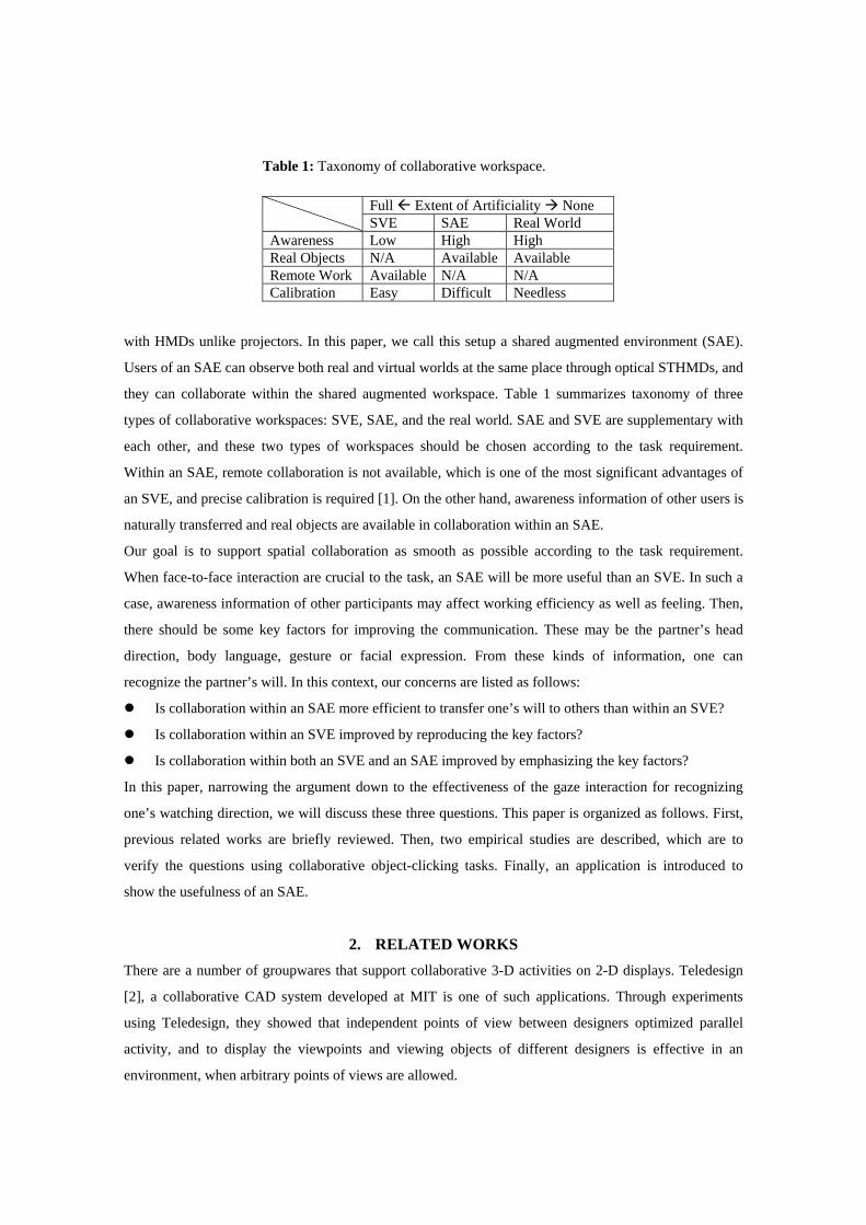
they can collaborate within the shared augmented workspace. Table 1 summarizes taxonomy of three
types of collaborative workspaces: SVE, SAE, and the real world. SAE and SVE are supplementary with
each other, and these two types of workspaces should be chosen according to the task requirement.
Within an SAE, remote collaboration is not available, which is one of the most significant advantages of
an SVE, and precise calibration is required [1]. On the other hand, awareness information of other users is
naturally transferred and real objects are available in collaboration within an SAE.
Our goal is to support spatial collaboration as smooth as possible according to the task requirement.
When face-to-face interaction are crucial to the task, an SAE will be more useful than an SVE. In such a
case, awareness information of other participants may affect working efficiency as well as feeling. Then,
there should be some key factors for improving the communication. These may be the partner’s head
direction, body language, gesture or facial expression. From these kinds of information, one can
recognize the partner’s will. In this context, our concerns are listed as follows:
Is collaboration within an SAE more efficient to transfer one’s will to others than within an SVE?
Is collaboration within an SVE improved by reproducing the key factors?
Is collaboration within both an SVE and an SAE improved by emphasizing the key factors?
In this paper, narrowing the argument down to the effectiveness of the gaze interaction for recognizing
one’s watching direction, we will discuss these three questions. This paper is organized as follows. First,
previous related works are briefly reviewed. Then, two empirical studies are described, which are to
verify the questions using collaborative object-clicking tasks. Finally, an application is introduced to
show the usefulness of an SAE.
2. RELATED WORKS There are a number of groupwares that support collaborative 3-D activities on 2-D displays. Teledesign
[2], a collaborative CAD system developed at MIT is one of such applications. Through experiments
using Teledesign, they showed that independent points of view between designers optimized parallel
activity, and to display the viewpoints and viewing objects of different designers is effective in an
environment, when arbitrary points of views are allowed.
Table 1: Taxonomy of collaborative workspace.
Full Extent of Artificiality None SVE SAE Real World Awareness Low High High Real Objects N/A Available Available Remote Work Available N/A N/A Calibration Easy Difficult Needless
Shared virtual environments have been used for supporting collaborative 3-D activities within 3-D
workspace. CALVIN [3] developed at University of Illinois at Chicago, is a good application that
supports collaborative design. Making good use of the characteristics of a virtual environment, CALVIN
provides collaborators with a variety of multiple perspectives that include multiple camera parameters,
multiple information filters and so on. In terms of natural awareness, however, multi-perspective may
break the sense of unity. For example, not being in the same coordinates, one’s ‘here’ is no more the same
position of the other’s ‘here.’ VISTEL [4], a virtual space teleconferencing system developed at ATR, is
an attempt to reproduce computer-generated remote participants as real as possible, which include
gestural and facial expression. In the system, all participants belong to the same coordinates and they can
have a virtual face-to-face meeting.
Employing a video conference technique is an easy and effective way of making remote users more
realistic, though the image is flat. ClearBoard [5] developed at NTT Human Interface Lab. permits
co-workers in two different locations to operate a collaborative drawing tool while maintaining direct eye
contact using a video conference technique. In this system, the drawback that the image of other
participant is flat is inconspicuous since the drawing activity is limited on the surface. Networked
SPIDAR [6] developed at Tokyo Institute of Technology is a networked multimodal interface that offers
a shared virtual 3-D workspace. Networked SPIDAR permits face-to-face video conference, and also
transmits auditory and haptic information. In this case, the coordinates of the video image have little
relation to the coordinates of the virtual workspace.
All systems mentioned above support remote collaboration. However, in many cases, collaborative
partners are at the same place, e.g. the same office or the same laboratory, rather than distant places. In
such cases, most convenient and effective way for acquiring both a sense of awareness as rich as possible
and common coordinates in which they collaborate as exact as possible is to let the co-workers be at the
same place. The Two-User Responsive Workbench [7] developed at Stanford University supports
face-to-face collaboration. Two users of the system stand by a rear-projector that displays four images as
two stereo pairs in each rendering cycle. However, projection-based virtual reality can display virtual
objects only within a limited viewing frustum. See-through head mounted displays (STHMDs) solve this
problem. AR2 Hockey [8] developed at Mixed Reality Systems Lab. uses a pair of STHMDs, permits two
users to share a physical game field, mallets, and a virtual puck to play an air-hockey game. This setup
supports both face-to-face collaboration and displaying virtual objects at arbitrary positions, e.g., between
the users.
3. EXPERIMENTS Previous researches claim the importance of face-to-face interaction. Then, what aspects of face-to-face
interaction are crucial? Why is it better than blind interaction with which you cannot see your partners?
We assume that one can get more efficient activities as well as a sense of unity or a sense of security with
face-to-face interaction rather than with blind interaction. One of the reasons may be that one can notice
more quickly what his/her partner is going to do next with face-to-face interaction by his/her gesture,
facial expression, gaze direction and so on. A partner’s head motion is probably helpful for recognizing
what he/she is looking at. His/her gaze direction may be much more helpful. Therefore, the following
three hypotheses corresponding to the questions mentioned in section 1 are conceivable:
a) Collaboration efficiency is higher within an SAE than within an SVE, because of rich awareness.
b) Even within an SVE, collaboration efficiency can be improved by displaying the computer graphics
of partner’s body including his/her head.
c) Within both an SAE and an SVE, collaboration efficiency can be improved further by displaying the
partner’s viewing direction or his/her viewing object clearly.
Of course, superiority mentioned in these hypotheses will vary depending on circumstances. For example,
without eye-tracking systems, viewing direction is hard to be acquired. Instead, head direction is used to
estimate the viewing direction. Therefore, accuracy of estimated viewing direction is affected by the
degree of crowdedness of objects, field of view of the HMDs, habits, squints and so on. In the following,
described are two experiments conducted to confirm these hypotheses. The experiment 1 was conducted
under a condition in which the superiority would be prominent, while the experiment 2 was conducted
under a condition in which the superiority would be quiet.
1. Experiment 1 (Sparse, looking-front condition)
Experimental Setup
A simple collaborative object-clicking task is set for the experiment 1. The experimental task requires two
subjects in each trial, an instructor and an operator. They share the same workspace controlled and
rendered by two graphics workstations, Indigo2 Maximum Impact (SGI), sitting on opposite sides of a
black wooden desk of 75cm in depth. Through an optical STHMD Mediamask (Olympus), each subject
sees the workspace with a head tracking facility provided by a magnetic 3-D tracker, Fastrak (Polhemus).
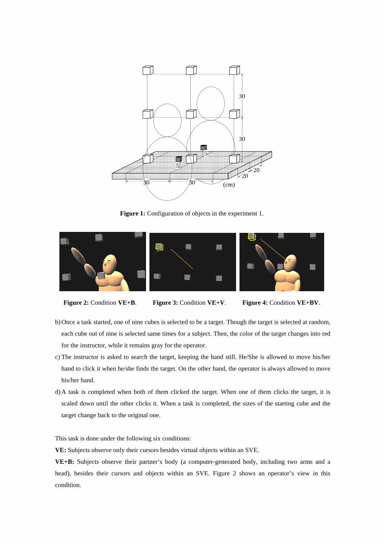
Figure 1 shows the configuration of the workspace in the experiment 1. There exist nine gray virtual
cubes of 5cm each side and two red cubes of 3cm each side floating in the workspace. Each subject holds
a pair of 3-D input devices with two-hands, each composed of a receiver of Fastrak and a push button.
Four arrow-shaped virtual 3-D cursors follow corresponding input devices. Mutual calibration error of
two virtual spaces is about 1 to 4cm within the workspace in eye measurement. The experimental task is
done as the following procedures:
a) The red cubes are for starting each task. When both an instructor and an operator point corresponding
red cubes by the 3-D cursors by their dominant hands, and one of them presses the button attached on
the input device, the red cubes are scaled down and the task starts.
b) Once a task started, one of nine cubes is selected to be a target. Though the target is selected at random,
each cube out of nine is selected same times for a subject. Then, the color of the target changes into red
for the instructor, while it remains gray for the operator.
c) The instructor is asked to search the target, keeping the hand still. He/She is allowed to move his/her
hand to click it when he/she finds the target. On the other hand, the operator is always allowed to move
his/her hand.
d) A task is completed when both of them clicked the target. When one of them clicks the target, it is
scaled down until the other clicks it. When a task is completed, the sizes of the starting cube and the
target change back to the original one.
This task is done under the following six conditions:
VE: Subjects observe only their cursors besides virtual objects within an SVE.
VE+B: Subjects observe their partner’s body (a computer-generated body, including two arms and a
head), besides their cursors and objects within an SVE. Figure 2 shows an operator’s view in this
condition.
5
5
30
30
30 30
2020
(cm)
Figure 1: Configuration of objects in the experiment 1.
Figure 2: Condition VE+B. Figure 3: Condition VE+V. Figure 4: Condition VE+BV.
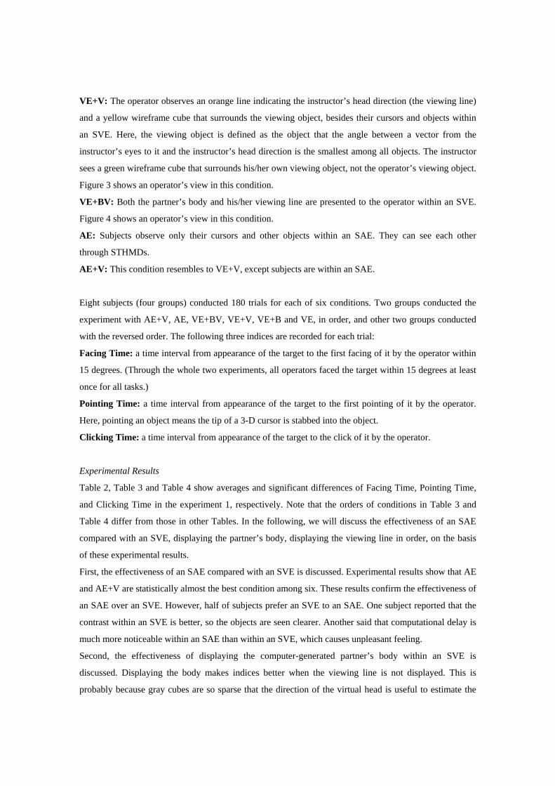
VE+V: The operator observes an orange line indicating the instructor’s head direction (the viewing line)
and a yellow wireframe cube that surrounds the viewing object, besides their cursors and objects within
an SVE. Here, the viewing object is defined as the object that the angle between a vector from the
instructor’s eyes to it and the instructor’s head direction is the smallest among all objects. The instructor
sees a green wireframe cube that surrounds his/her own viewing object, not the operator’s viewing object.
Figure 3 shows an operator’s view in this condition.
VE+BV: Both the partner’s body and his/her viewing line are presented to the operator within an SVE.
Figure 4 shows an operator’s view in this condition.
AE: Subjects observe only their cursors and other objects within an SAE. They can see each other
through STHMDs.
AE+V: This condition resembles to VE+V, except subjects are within an SAE.
Eight subjects (four groups) conducted 180 trials for each of six conditions. Two groups conducted the
experiment with AE+V, AE, VE+BV, VE+V, VE+B and VE, in order, and other two groups conducted
with the reversed order. The following three indices are recorded for each trial:
Facing Time: a time interval from appearance of the target to the first facing of it by the operator within
15 degrees. (Through the whole two experiments, all operators faced the target within 15 degrees at least
once for all tasks.)
Pointing Time: a time interval from appearance of the target to the first pointing of it by the operator.
Here, pointing an object means the tip of a 3-D cursor is stabbed into the object.
Clicking Time: a time interval from appearance of the target to the click of it by the operator.
Experimental Results
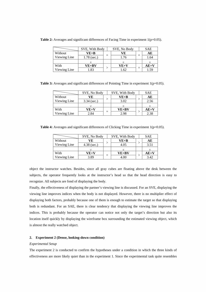
Table 2, Table 3 and Table 4 show averages and significant differences of Facing Time, Pointing Time,
and Clicking Time in the experiment 1, respectively. Note that the orders of conditions in Table 3 and
Table 4 differ from those in other Tables. In the following, we will discuss the effectiveness of an SAE
compared with an SVE, displaying the partner’s body, displaying the viewing line in order, on the basis
of these experimental results.
First, the effectiveness of an SAE compared with an SVE is discussed. Experimental results show that AE
and AE+V are statistically almost the best condition among six. These results confirm the effectiveness of
an SAE over an SVE. However, half of subjects prefer an SVE to an SAE. One subject reported that the
contrast within an SVE is better, so the objects are seen clearer. Another said that computational delay is
much more noticeable within an SAE than within an SVE, which causes unpleasant feeling.
Second, the effectiveness of displaying the computer-generated partner’s body within an SVE is
discussed. Displaying the body makes indices better when the viewing line is not displayed. This is
probably because gray cubes are so sparse that the direction of the virtual head is useful to estimate the
object the instructor watches. Besides, since all gray cubes are floating above the desk between the
subjects, the operator frequently looks at the instructor’s head so that the head direction is easy to
recognize. All subjects are fond of displaying the body.
Finally, the effectiveness of displaying the partner’s viewing line is discussed. For an SVE, displaying the
viewing line improves indices when the body is not displayed. However, there is no multiplier effect of
displaying both factors, probably because one of them is enough to estimate the target so that displaying
both is redundant. For an SAE, there is clear tendency that displaying the viewing line improves the
indices. This is probably because the operator can notice not only the target’s direction but also its
location itself quickly by displaying the wireframe box surrounding the estimated viewing object, which
is almost the really watched object.
2. Experiment 2 (Dense, looking-down condition)
Experimental Setup
The experiment 2 is conducted to confirm the hypotheses under a condition in which the three kinds of
effectiveness are more likely quiet than in the experiment 1. Since the experimental task quite resembles
Table 3: Averages and significant differences of Pointing Time in experiment 1(p=0.05).
SVE, No Body SVE, With Body SAE VE VE+B AE Without
Viewing Line 3.34 (sec.) > 3.02 > 2.56 > = =
VE+V VE+BV AE+V With Viewing Line 2.84 = 2.98 > 2.38
Table 4: Averages and significant differences of Clicking Time in experiment 1(p=0.05).
SVE, No Body SVE, With Body SAE VE VE+B AE Without
Viewing Line 4.38 (sec.) > 4.05 > 3.51 > = =
VE+V VE+BV AE+V With Viewing Line 3.89 = 4.00 > 3.42
Table 2: Averages and significant differences of Facing Time in experiment 1(p=0.05).
SVE, With Body SVE, No Body SAE VE+B VE AE Without
Viewing Line 1.78 (sec.) = 1.76 = 1.64 = = =
VE+BV VE+V AE+V With Viewing Line 1.83 > 1.62 = 1.59

to that of the experiment 1, only the differences are mainly explained. Figure 5 shows the configuration of
the workspace in experiment 2. There exist twenty-five gray virtual cubes of 5cm each side and one red
cube of 3cm each side floating in the workspace. The experimental task is done as following procedures:
a) When both an instructor and an operator point the red cube by 3-D cursors by their dominant hands,
and one of them presses the button attached on the input device, a task starts.
b) Once a task started, one of twenty-five gray cubes is selected to be a target. The target color changed
into red for the instructor, while it remains gray for the operator.
c) Both the instructor and the operator are asked to search and click the target as quickly as possible. Note
that the instructor may move his/her hand sooner than he/she finds the target.
d) A task is completed when both of them clicked the target.
Six conditions and recorded data of the experiment 2 are exactly the same as those of the experiment 1.
Other eight subjects (four groups) conducted 200 trials for each six conditions. Two groups conducted the
experiment with AE+V, AE, VE+BV, VE+V, VE+B and VE, in order, and other two groups conducted
with the reversed order.
Experimental Results
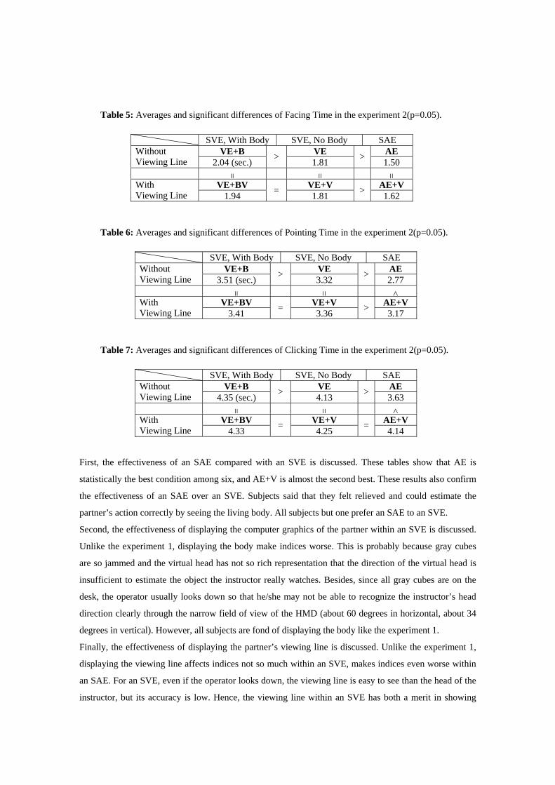
Table 5, Table 6 and Table 7 show averages and significant differences of Facing Time, Pointing Time,
and Clicking Time in the experiment 2, respectively. In the following, we will discuss the effectiveness of
an SAE compared with an SVE, displaying the partner’s body, displaying the viewing line of the
instructor, in order, on the basis of these experimental results.
30
15 1515 15 1515
1515
(cm)
Figure 5: Configuration of objects in the experiment 2.
First, the effectiveness of an SAE compared with an SVE is discussed. These tables show that AE is
statistically the best condition among six, and AE+V is almost the second best. These results also confirm
the effectiveness of an SAE over an SVE. Subjects said that they felt relieved and could estimate the
partner’s action correctly by seeing the living body. All subjects but one prefer an SAE to an SVE.
Second, the effectiveness of displaying the computer graphics of the partner within an SVE is discussed.
Unlike the experiment 1, displaying the body make indices worse. This is probably because gray cubes
are so jammed and the virtual head has not so rich representation that the direction of the virtual head is
insufficient to estimate the object the instructor really watches. Besides, since all gray cubes are on the
desk, the operator usually looks down so that he/she may not be able to recognize the instructor’s head
direction clearly through the narrow field of view of the HMD (about 60 degrees in horizontal, about 34
degrees in vertical). However, all subjects are fond of displaying the body like the experiment 1.
Finally, the effectiveness of displaying the partner’s viewing line is discussed. Unlike the experiment 1,
displaying the viewing line affects indices not so much within an SVE, makes indices even worse within
an SAE. For an SVE, even if the operator looks down, the viewing line is easy to see than the head of the
instructor, but its accuracy is low. Hence, the viewing line within an SVE has both a merit in showing
Table 7: Averages and significant differences of Clicking Time in the experiment 2(p=0.05).
SVE, With Body SVE, No Body SAE VE+B VE AE Without
Viewing Line 4.35 (sec.) > 4.13 > 3.63 = = <
VE+BV VE+V AE+V With Viewing Line 4.33 = 4.25 = 4.14
Table 5: Averages and significant differences of Facing Time in the experiment 2(p=0.05).
SVE, With Body SVE, No Body SAE VE+B VE AE Without
Viewing Line 2.04 (sec.) > 1.81 > 1.50 = = =
VE+BV VE+V AE+V With Viewing Line 1.94 = 1.81 > 1.62
Table 6: Averages and significant differences of Pointing Time in the experiment 2(p=0.05).
SVE, With Body SVE, No Body SAE VE+B VE AE Without
Viewing Line 3.51 (sec.) > 3.32 > 2.77 = = <
VE+BV VE+V AE+V With Viewing Line 3.41 = 3.36 > 3.17
rough viewing area and a demerit in showing incorrect viewing object. This may be the reason why there
is no distinct effectiveness within an SVE. Displaying viewing direction not as a line but a frustum or a
cone may be better. For an SAE, the discrepancy of the real head and the virtual viewing line arisen from
computational delay may cause delusion to the operator. In fact, half of subjects opposed displaying the
viewing line within an SAE, while only one subject is against it within an SVE.
3. Summary of the experiments
In this section, two experiments were conducted to evaluate the effectiveness of an SAE over an SVE,
displaying the computer graphics partner within an SVE, and displaying the viewing line of the partner.
Through the experiments, the following things are found to make it faster for a user to notice where
his/her partner is looking at.
a) Regardless of the configuration, collaborating within an SAE is more effective than within an SVE.
b) Displaying the partner’s body within an SVE is effective only if virtual objects are sparse and the
computer graphics face is rich enough to estimate the partner’s viewing direction. However, displaying
the body surely improves the feeling of manipulation for any conditions.
c) Displaying the viewing line of the partner is effective when virtual objects are so sparse that the
estimated viewing object is almost correct.
Not moving your head, your eyes can look at fairly wide direction. Hence, viewing object estimation fails
easily. However, the estimating policy may be improved by considering some factors, for example:
Body direction: We are reluctant to move our heads than our eyes. So, the viewing object does not
likely lie between the head direction and the body direction.
Hand movement: When your hand is approaching an object and it is visible to you, the object may
probably be watched.
Duration: If you are watching something, not looking around, the head direction may be firmly for a
while.
Property of the object: Larger, brighter, or nearer object may be more likely to be watched.
These factors may be useful to improve the accuracy of the estimation, though further studies are needed.
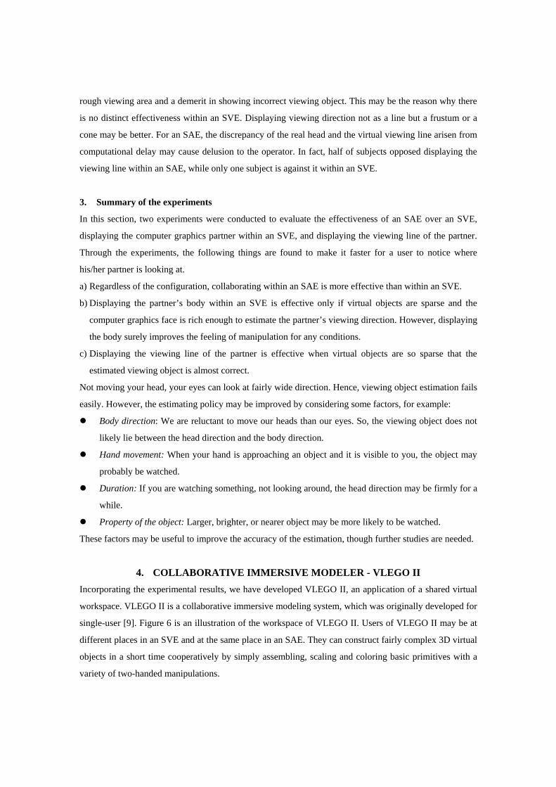
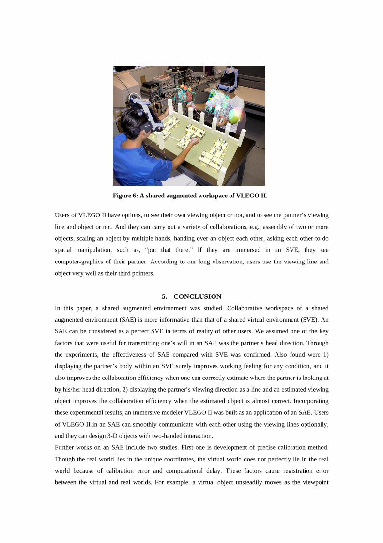
4. COLLABORATIVE IMMERSIVE MODELER - VLEGO II Incorporating the experimental results, we have developed VLEGO II, an application of a shared virtual
workspace. VLEGO II is a collaborative immersive modeling system, which was originally developed for
single-user [9]. Figure 6 is an illustration of the workspace of VLEGO II. Users of VLEGO II may be at
different places in an SVE and at the same place in an SAE. They can construct fairly complex 3D virtual
objects in a short time cooperatively by simply assembling, scaling and coloring basic primitives with a
variety of two-handed manipulations.
Users of VLEGO II have options, to see their own viewing object or not, and to see the partner’s viewing
line and object or not. And they can carry out a variety of collaborations, e.g., assembly of two or more
objects, scaling an object by multiple hands, handing over an object each other, asking each other to do
spatial manipulation, such as, “put that there.” If they are immersed in an SVE, they see
computer-graphics of their partner. According to our long observation, users use the viewing line and
object very well as their third pointers.
5. CONCLUSION In this paper, a shared augmented environment was studied. Collaborative workspace of a shared
augmented environment (SAE) is more informative than that of a shared virtual environment (SVE). An
SAE can be considered as a perfect SVE in terms of reality of other users. We assumed one of the key
factors that were useful for transmitting one’s will in an SAE was the partner’s head direction. Through
the experiments, the effectiveness of SAE compared with SVE was confirmed. Also found were 1)
displaying the partner’s body within an SVE surely improves working feeling for any condition, and it
also improves the collaboration efficiency when one can correctly estimate where the partner is looking at
by his/her head direction, 2) displaying the partner’s viewing direction as a line and an estimated viewing
object improves the collaboration efficiency when the estimated object is almost correct. Incorporating
these experimental results, an immersive modeler VLEGO II was built as an application of an SAE. Users
of VLEGO II in an SAE can smoothly communicate with each other using the viewing lines optionally,
and they can design 3-D objects with two-handed interaction.
Further works on an SAE include two studies. First one is development of precise calibration method.
Though the real world lies in the unique coordinates, the virtual world does not perfectly lie in the real
world because of calibration error and computational delay. These factors cause registration error
between the virtual and real worlds. For example, a virtual object unsteadily moves as the viewpoint
Figure 6: A shared augmented workspace of VLEGO II.
changes. Hence, users see a virtual object at different positions in the real world. There are many efforts
for precise calibration, which we also should consider. Second one is development of enhanced
communication methods. Collaboration can be considered as a sequence of communicating some
information between workers, and there should be some methods for enhancing the information
appropriately. The viewing line discussed in this paper is an example. We would like to analyze
collaboration with a variety of conditions, extract important information, and develop useful methods for
enhancing useful information.
6. ACKNOWLEDGMENTS This work was supported in part by the Sasagawa Scientific Research Grant from The Japan Science
Society.
7. REFERENCES 1. Azuma, R. and Bishop, G., “Improving Static and Dynamic Registration in an Optical See-through
HMD,” Proc. ACM SIGGRAPH ’94, pp.197-204, 1994.
2. Shu, L. and Flowers, W., “Groupware Experiences in Three-Dimensional Computer-Aided Design,”
Proc. ACM CSCW ’92, pp.179-186, 1992.
3. Leigh, J., Johnson, A. E., Vasilakis, C. A. and DeFanti, T. A., “Multi-Perspective Collaborative
Design in Persistent Networked Virtual Environments,” Proc. IEEE VRAIS ’96, pp.253-260, 1996.
4. Takemura, H. and Kishino, F., “Cooperative Work Environment Using Virtual Workspace,” Proc.
ACM CSCW ’92, pp.226-232, 1992.
5. Ishii, H., Kobayashi, M. and Grudin, J., “Integration of Inter-Personal Space and Shared Workspace:
ClearBoard Design and Experiments,” Proc. ACM CSCW ’92, pp.33-42, 1992.
6. Ishii, M., Nakata, M. and Sato, M., “Networked SPIDAR: A Networked Virtual Environment with
Visual, Auditory, and Haptic Interactions,” PRESENCE Teleoperators and Virtual Environments,
Vol.3, No.4, pp.351-359, 1994.
7. Agrawala, M., Beers, A. C., Fröhlich, B. and Hanrahan, P., “The Two-User Responsive Workbench:
Support for Collaboration Through Individual Views of a Shared Space,” Proc. ACM
SIGGRAPH ’97, pp.327-332, 1997.
8. Ohshima, T., Satoh, K., Yamamoto, H. and Tamura, H., “AR2 Hockey: A Case Study of
Collaborative Augmented Reality,” Proc. IEEE VRAIS ’98, pp.268-275, 1998.
9. Kiyokawa, K., Takemura, H., Katayama, Y., Iwasa, H. and Yokoya, N., “VLEGO: A Simple
Two-handed Modeling Environment Based on Toy Blocks,” Proc. ACM VRST ’96, pp.27-34, 1996.