cognitive cooperation for the downlink of frequency reuse small cells
TRANSCRIPT
Hindawi Publishing CorporationEURASIP Journal on Advances in Signal ProcessingVolume 2011, Article ID 525271, 11 pagesdoi:10.1155/2011/525271
Research Article
Cognitive Cooperation for the Downlink ofFrequency Reuse Small Cells
Salam Akoum,1 Marie Zwingelstein-Colin,2 Robert W. Heath Jr.,1 and Merouane Debbah3
1 Wireless Networking and Communications Group, Department of Electrical and Computer Engineering,The University of Texas at Austin, 1 University Station C0803, Austin, TX 78712-0240, USA
2 IEMN/DOAE, UMR 8520, University Lille Nord de France, 59000 Lille, France3 Ecole Superieure d’Electrecite (SUPELEC), Alcatel-Lucent Chair on Flexible Radios, 3 rue Joliot-Curie,91192 Gif sur Yvette Cedex, France
Correspondence should be addressed to Marie Zwingelstein-Colin, [email protected]
Received 1 June 2010; Revised 28 September 2010; Accepted 16 November 2010
Academic Editor: Robert Schober
Copyright © 2011 Salam Akoum et al. This is an open access article distributed under the Creative Commons Attribution License,which permits unrestricted use, distribution, and reproduction in any medium, provided the original work is properly cited.
We develop a cooperative diversity protocol coded over space, time, and frequency to achieve improved quality of service for mobileusers in the downlink of small-cell frequency reuse networks. The proposed protocol, called cooperative frequency reuse (CFR),leverages the cellular frequency reuse concept to create space and frequency diversity among pairs of adjacent base stations. TheCFR protocol is compatible with the half-duplex mode and is distributed in the sense that each base station acts in autonomy,without the need of a centralized entity. It is implemented in two phases. During the first phase, each base station independentlyserves its own users on its dedicated frequency band. It simultaneously listens to the symbols transmitted by neighboring basestations. Cognitive cooperation is introduced in the second phase, where each base station transmits on two frequency bands tothe scheduled users in both base stations, by means of an appropriately chosen distributed space time code based on the Goldencode. We analyze and discuss the performance of the proposed protocol in terms of bit error rate, probability of outage, andergodic sum rate under different scenarios. Simulation results show that the proposed protocol yields considerable improvementover direct transmission frequency reuse strategies.
1. Introduction
Small-cell wireless networks provide increased capacity andhigher area spectral efficiency [1–3]. The benefits reapedfrom these networks come, however, at the expense of in-creased cochannel interference, especially at the cell edge.Conventional cellular networks manage the interferenceproblem by requiring adjacent base stations (BSs) to transmiton different frequency bands. This mechanism is called fre-quency reuse (FR). It increases the reliability of the cellularnetworks while at the same time incurring a poor spatialreuse of the expensive frequency spectrum [1]. Fractionalfrequency reuse (FFR) achieves a higher spatial reuse ofthe spectrum and is suggested for next generation cellularsystems [4, 5]. It divides the frequency bands into subchan-nels, to be shared orthogonally among BSs to serve usersthat are interference limited. It maintains, however, universal
frequency reuse in the cell center. Small cell networksencounter conflicting requirements between providing anincreased area spectral efficiency and maintaining qualityof service for their mobile users. One way to resolve thistradeoff is through combining frequency reuse with coop-eration between adjacent BSs. Implementing a cooperationalgorithm that leverages the FFR concept of cellular systemsachieves the dual benefit of higher reliability and higherspectral efficiency.
Cooperation in cellular networks, depending on the levelof data and channel state information (CSI) shared betweenBSs, can be implemented in several ways [6–9]. Cooperativespace diversity [6, 10] is one such method. It exploitsspatial diversity by implementing a virtual antenna arraybetween adjacent BSs, and distributed space-time codes canbe constructed over the formed virtual array to increase thereliability of the system [11–13]. In this paper, we design a
2 EURASIP Journal on Advances in Signal Processing
cooperation protocol based on space and frequency diversity,for cooperation between a pair of adjacent BSs. The proposedprotocol, called Cooperative Frequency Reuse (CFR), lever-ages the frequency reuse concept of cellular systems, creatinga virtual multiple-input single-output (MISO) system basedon the sharing of OFDM frequency bands among adjacentBSs. It can be applied to cellular systems that use FFR, such asWiMAX and LTE, in a straightforward manner. It is cognitivein the sense that the BSs use, opportunistically in time, thefrequency bands allocated to their adjacent BSs to transmitto the mobile users, hence creating cognitive diversity on thedownlink of the cellular system.
In contrast to the cooperative multicell transmissionstrategies available in the literature [7, 14, 15], where basestations jointly process the downlink signals of the mobileusers, thereby creating a multiple-input multiple-output(MIMO) broadcast channel, the proposed CFR protocol im-plements cooperation through a distributed space time code.It is thus especially suitable for mobile flexible networks[16], where the BSs have limited or no wired backhaulcommunication. The proposed strategy is different from thecooperative transmit diversity in the multihop relay specifi-cation for WiMAX, the IEEE 802.16j standard [17]. In thelatter, distributed space time codes are implemented acrossantennas of the deployed relays and the BS, in the samecell, over the same time and frequency resources. It is alsodifferent from the shared relay concept proposed in IEEE802.16m [9], where a relay is placed at the intersection oftwo or more cells, and used to decode the signals from theintersecting BSs. The CFR protocol also differs from othercooperative protocols proposed in the literature such as in[10–12, 18]. The latter protocols are applied for cooperationamong mobile nodes on the uplink of cellular systems andcan be used for communication among terminals in adhocnetworks.
Assuming a half-duplex mode, whereby nodes cannottransmit and receive at the same time on the same frequencyband, the CFR protocol is implemented, for a pair of adjacentBSs, in two phases. During the first phase, each BS serves itsown users in a protected band, orthogonal to the frequencybands that the adjacent base stations transmit on. The BSlistens, during the same phase, to the signal sent by thecooperating BS on another frequency band. The underlyingassumption here is that the wireless link between the pairof adjacent BSs is reliable, which is generally the case inpractice, when the BSs have a line of sight channel. In thesecond phase, the BSs divide their transmit power betweentwo frequency bands: they use one band to serve their ownusers and the other band for cooperation by relaying thesignal of the other BS. During the second phase, the CFRprotocol implements a distributed space-time code betweenthe cooperating base stations, based on the Golden code [19].The Golden code is a full-rate space-time code that achievesthe optimal diversity-multiplexing tradeoff (DMT). It hasbeen applied in the cooperative communication literature[20], where it was proven to be optimal for the single-inputsingle-output (SISO) amplify-and-forward (AF) cooperativechannel.
In this paper, we establish the benefits of the CFRprotocol in terms of bit error rate and probability ofoutage and achievable ergodic sum rate, through extensivenumerical simulations. We first consider the ideal case of anisolated pair of collaborating BSs, where the BS to BS link isassumed perfect. We then extend the analysis to incorporatethe imperfections in the BS to BS link, for the isolated two-base station case. We finally consider the effect of other cellinterference from neighboring noncooperating base stations.The rest of the paper is organized as follows. We describethe multicell downlink transmission model in Section 2. InSection 3, our CFR protocol is presented and discussed. Theperformances of the CFR protocol in terms of bit error rate,probability of outage, and ergodic sum rate are evaluatedin Section 4.1 for the case of isolated collaborating pairof base stations. Section 4.2 analyses the CFR protocol forthe case of an infinite number of adjacent base stations,where each collaborating pair acts as an interferer for theother cooperating pairs in the network. Numerical results arepresented in Section 5. Concluding remarks and insights intofuture work are given in Section 6.
Throughout the paper, the following notation is used.Bold lowercase letters x are used to denote column vectors,bold uppercase letters X are used to denote matrices,nonbold letters x are used to denote scalar values, and cal-ligraphic letters X are used to denote sets or functions of sets.Using this notation, |x| is the magnitude of a scalar, ‖x‖ is thevector 2-norm, and XH is the conjugate transpose of X. Weuse E to denote expectation. In is the identity matrix of sizen×n, and the probability of event E is P(E). i = √−1, Z is theensemble of relative integers, and ⊗ is the Kronecker productfor matrices.
2. Multicell Downlink Transmission Model
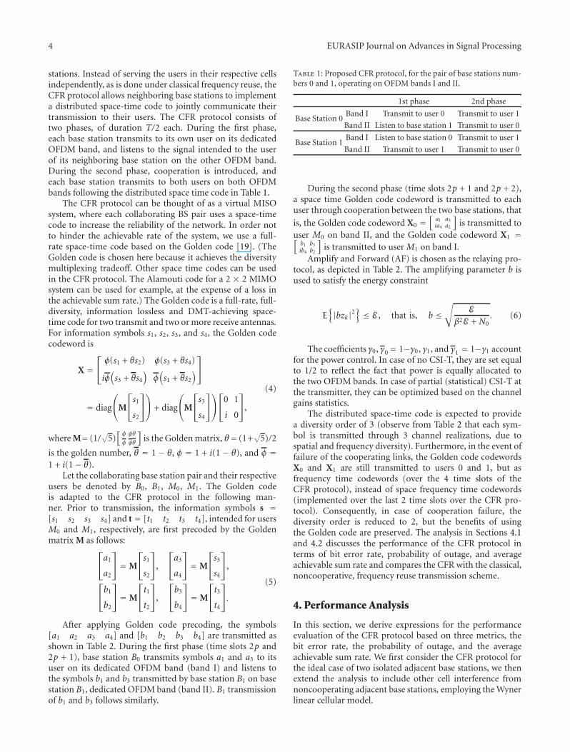
In this section, we present the system model, shown inFigure 1, for the downlink of the multicell network ofinterest. The BSs and the user terminals are assumed to beequipped with a single antenna. The BSs employ OFDMmodulation with N subchannels per OFDM frequencyband. They implement fractional frequency reuse, such thatthe users at the cell edge are protected against intercellinterference. In order for the model to be consistent withpractical considerations, we assume that the base stationsoperate in half-duplex mode; that is, they cannot transmitand receive at the same time on the same frequency band.We also assume Time Division Multiple Access (TDMA) asthe multiple access scheme. We further consider slow fading,such that the coherence time of the channel is larger thanthe maximum delay tolerated by the application. We donot account for scheduling, resource allocation, or fairnessamong users. Only global performance over the OFDMfrequency band is considered.
The cellular layout that we consider corresponds to thelinear Wyner cellular model [21]. Albeit simple and ana-lytically tractable, this model provides considerable insightinto the working of real cellular networks [22–26] in theabsence of a more realistic tractable approach to other cell
EURASIP Journal on Advances in Signal Processing 3
(band I) (band II) (band I) (band II) (band I) (band II)
· · · · · ·
β β β β β
αα ααα3 α3α2
α2 α2
α21 1
Cell −2 Cell −1 Cell 0 Cell 1 Cell 2 Cell 3
Figure 1: Cellular system layout (Wyner model).
interference. It allows for representation of the cellularinterference using only one parameter. The linear model isillustrated in Figure 1, where the cells are indexed in in-creasing order from left to right. The FR factor betweenadjacent cells is set to 2; that is, 2 OFDM bands, band I andband II, are allocated alternatively to the cells in the lineararray. For simplicity, we focus on the cell-edge users, andthus, for fractional frequency reuse, consider only the regionsin the cells with frequency reuse greater than 1.
The downlink channel gains account for the effects ofpath loss as well as Rayleigh fading. The effect of log-normal shadowing is ignored. The path loss is assumed to beinvariant to frequency, whereas a different and independentrealization of Rayleigh fading is assumed on each OFDMsubchannel. In the following, we, respectively, denote by Bk
and Mk the BS and the user terminal in cell k. To make theanalysis analytically tractable, we set the average channel gainbetween each base stationBk and its userMk to 1. The averagechannel gain between Bk and a user in an adjacent cell Mk+1
or Mk−1 is set to α and that between Bk and Mk+2 or Mk−2 isset to α2, and so on. The link between adjacent base stationsis assumed to be an additive white Gaussian noise (AWGN)channel free of fading, with a line of sight component whosegain is denoted by β.
The signal received by user k at time slot m on OFDMsubchannel n can be expressed as
yk(m,n) = hk,k(m,n)xk(m,n)
+∑
l /= k
h�,k(m,n)x�(m,n) + wk(m,n),(1)
where xk(m,n) is the symbol transmitted by BS k at time slotm and subchannel n, h�,k(m,n) is the instantaneous channelgain from BS � to user k at time slot m and subchannel n,and wk(m,n) is the AWGN with variance σ2
w = N0. Thechannel gain h�,k(m,n) accounts for the effects of Rayleighfading (independent for each value of n) and path loss(the same for all n). Assuming a slow fading scenario, theframe length T is less than the coherence period of thechannel (quasistatic assumption); hence, the time index mis, hereafter, omitted in the channel gain notation. We writeh�,k(n) instead of h�,k(m,n). The signal-to-noise ratio is
defined as SNRΔ= E /N0, where E = E{|xk|2} is the average
energy for transmitting a symbol across the link and N0 is thevariance of the thermal noise observed at the receiver.
The signal received by base station k at time slot m onsubcarrier n is
zk(m,n) =∑
� /= k
β�,kx�(m,n) + vk(m,n), (2)
where x�(m,n) is the symbol transmitted by base station �at time slot m and subchannel n, β�,k is the (deterministic)gain of the link between base station � and base station k,and vk(m,n) is the AWGN at base station k with variance σ2
v .The channel gain β�,k is modeled as
β�,k = βa+1, (3)
where a is the number of base stations separating base station� and base station k. In the following, we will consider twocases for the base station to base station link.
(1) Ideal base station to base station link, with β = 1 andσ2v = 0,
(2) nonideal link, with 0 ≤ β < 1 and σ2v = N0.
The channel coefficients are assumed to be perfectly knownat the receiver, whereas two different scenarios are consideredfor the channel state information at the transmitter (CSI-T):
(1) no CSI-T,
(2) partial (statistical) CSI-T, where only the statistics ofthe channel gains are known at the transmitter (thecoefficient α).
3. Cooperative Frequency Reuse
In this section, we present the cooperative diversity protocolproposed for improving the quality of service at the cell edgeof a small-cell network. The protocol is to be implementedbetween pairs of adjacent base stations, based on the realisticassumption that the link between two adjacent base stationsis, in general, a line-of-sight link that does not manifestsevere attenuation.
Assuming fractional frequency reuse and operation inhalf-duplex mode, each base station transmits informationto the scheduled users inside its cell, while at the sametime, but on a different frequency band, listens to the signaltransmitted by its neighboring base station to the users inthe adjacent cell. With some incurred delay, whose effect isneglected in the following analysis, both base stations learneach other’s transmitted information and become, thereafter,able to retransmit this information in a collaborative manner,creating a virtual MISO system. Based on this key idea, theproposed protocol is implemented using a distributed space-time code that optimally exploits the available degrees offreedom.
The cooperative protocol is called Cooperative FrequencyReuse (CFR), as it leverages the frequency reuse cellularconcept and allows for cooperation between adjacent base
4 EURASIP Journal on Advances in Signal Processing
stations. Instead of serving the users in their respective cellsindependently, as is done under classical frequency reuse, theCFR protocol allows neighboring base stations to implementa distributed space-time code to jointly communicate theirtransmission to their users. The CFR protocol consists oftwo phases, of duration T/2 each. During the first phase,each base station transmits to its own user on its dedicatedOFDM band, and listens to the signal intended to the userof its neighboring base station on the other OFDM band.During the second phase, cooperation is introduced, andeach base station transmits to both users on both OFDMbands following the distributed space time code in Table 1.
The CFR protocol can be thought of as a virtual MISOsystem, where each collaborating BS pair uses a space-timecode to increase the reliability of the network. In order notto hinder the achievable rate of the system, we use a full-rate space-time code based on the Golden code [19]. (TheGolden code is chosen here because it achieves the diversitymultiplexing tradeoff. Other space time codes can be usedin the CFR protocol. The Alamouti code for a 2 × 2 MIMOsystem can be used for example, at the expense of a loss inthe achievable sum rate.) The Golden code is a full-rate, full-diversity, information lossless and DMT-achieving space-time code for two transmit and two or more receive antennas.For information symbols s1, s2, s3, and s4, the Golden codecodeword is
X =⎡⎣φ(s1 + θs2) φ(s3 + θs4)
iφ(s3 + θs4
)φ(s1 + θs2
)
⎤⎦
= diag
⎛⎝M
⎡⎣s1
s2
⎤⎦⎞⎠ + diag
⎛⎝M
⎡⎣s3
s4
⎤⎦⎞⎠⎡⎣
0 1
i 0
⎤⎦,
(4)
where M= (1/√
5)[φ φθ
φ φθ
]is the Golden matrix, θ= (1+
√5)/2
is the golden number, θ = 1 − θ, φ = 1 + i(1 − θ), and φ =1 + i(1− θ).
Let the collaborating base station pair and their respectiveusers be denoted by B0, B1, M0, M1. The Golden codeis adapted to the CFR protocol in the following man-ner. Prior to transmission, the information symbols s =[s1 s2 s3 s4] and t = [t1 t2 t3 t4], intended for usersM0 and M1, respectively, are first precoded by the Goldenmatrix M as follows:
⎡⎣a1
a2
⎤⎦ = M
⎡⎣s1
s2
⎤⎦,
⎡⎣a3
a4
⎤⎦ = M
⎡⎣s3
s4
⎤⎦,
⎡⎣b1
b2
⎤⎦ = M
⎡⎣t1
t2
⎤⎦,
⎡⎣b3
b4
⎤⎦ = M
⎡⎣t3
t4
⎤⎦.
(5)
After applying Golden code precoding, the symbols[a1 a2 a3 a4] and [b1 b2 b3 b4] are transmitted asshown in Table 2. During the first phase (time slots 2p and2p + 1), base station B0 transmits symbols a1 and a3 to itsuser on its dedicated OFDM band (band I) and listens tothe symbols b1 and b3 transmitted by base station B1 on basestation B1, dedicated OFDM band (band II). B1 transmissionof b1 and b3 follows similarly.
Table 1: Proposed CFR protocol, for the pair of base stations num-bers 0 and 1, operating on OFDM bands I and II.
1st phase 2nd phase
Base Station 0Band I Transmit to user 0 Transmit to user 1
Band II Listen to base station 1 Transmit to user 0
Base Station 1Band I Listen to base station 0 Transmit to user 1
Band II Transmit to user 1 Transmit to user 0
During the second phase (time slots 2p + 1 and 2p + 2),a space time Golden code codeword is transmitted to eachuser through cooperation between the two base stations, that
is, the Golden code codeword X0 =[
a1 a3ia4 a2
]is transmitted to
user M0 on band II, and the Golden code codeword X1 =[b1 b3ib4 b2
]is transmitted to user M1 on band I.
Amplify and Forward (AF) is chosen as the relaying pro-tocol, as depicted in Table 2. The amplifying parameter b isused to satisfy the energy constraint
E{|bzk|2
}≤ E , that is, b ≤
√E
β2E + N0. (6)
The coefficients γ0, γ0= 1−γ0, γ1, and γ1 = 1−γ1 accountfor the power control. In case of no CSI-T, they are set equalto 1/2 to reflect the fact that power is equally allocated tothe two OFDM bands. In case of partial (statistical) CSI-T atthe transmitter, they can be optimized based on the channelgains statistics.
The distributed space-time code is expected to providea diversity order of 3 (observe from Table 2 that each sym-bol is transmitted through 3 channel realizations, due tospatial and frequency diversity). Furthermore, in the event offailure of the cooperating links, the Golden code codewordsX0 and X1 are still transmitted to users 0 and 1, but asfrequency time codewords (over the 4 time slots of theCFR protocol), instead of space frequency time codewords(implemented over the last 2 time slots over the CFR pro-tocol). Consequently, in case of cooperation failure, thediversity order is reduced to 2, but the benefits of usingthe Golden code are preserved. The analysis in Sections 4.1and 4.2 discusses the performance of the CFR protocol interms of bit error rate, probability of outage, and averageachievable sum rate and compares the CFR with the classical,noncooperative, frequency reuse transmission scheme.
4. Performance Analysis
In this section, we derive expressions for the performanceevaluation of the CFR protocol based on three metrics, thebit error rate, the probability of outage, and the averageachievable sum rate. We first consider the CFR protocol forthe ideal case of two isolated adjacent base stations, we thenextend the analysis to include other cell interference fromnoncooperating adjacent base stations, employing the Wynerlinear cellular model.
EURASIP Journal on Advances in Signal Processing 5
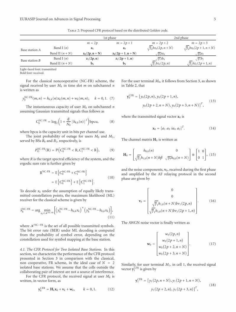
Table 2: Proposed CFR protocol based on the distributed Golden code.
1st phase 2nd phase
m = 2p m = 2p + 1 m = 2p + 2 m = 2p + 3
Base station ABand I (n) a1 a3
√γ0bz0(2p,n + N)
√γ0bz0(2p + 1,n + N)
Band II (n + N) z0(2p, n + N) z0(2p + 1, n + N) √γ0ia4
√γ0a2
Base station BBand I (n) z1(2p, n) z1(2p + 1, n)
√γ1ib4
√γ1b2
Band II (n + N) b1 b3
√γ1bz1(2p,n)
√γ1bz1(2p + 1,n)
Light-faced font: transmittedBold font: received.
For the classical noncooperative (NC-FR) scheme, thesignal received by user Mk in time slot m on subchannel nis written as
yNC-FRk (m,n) = hk,k(n)xk(m,n) + wk(m,n), k = 0, 1. (7)
The instantaneous capacity of user Mk on subchannel nassuming Gaussian transmitted signals thus follows as
CNC-FRk = log2
(1 +
E
N0
∣∣hk,k(n)∣∣2)
bpcu, (8)
where bpcu is the capacity unit in bits per channel use.The joint probability of outage for users M0 and M1,
served by BSs B0 and B1, respectively, is
PNC-FRO (R) = P
(CNC-FR
0 < R,CNC-FR1 < R
), (9)
where R is the target spectral efficiency of the system, and theergodic sum rate is further given by
RNC-FR = E{CNC-FR
0 + CNC-FR1
}
= E{CNC-FR
0
}+ E{CNC-FR
1
}.
(10)
To decode xk under the assumption of equally likely trans-mitted constellation points, the maximum likelihood (ML)receiver for the classical scheme is given by
x̂NC-FRk = arg min
xk∈N NC-FR
[(yNC-FRk −hk,kxk
)∗(yNC-FRk −hk,kxk
)],
(11)
where N NC−FR is the set of all possible transmitted symbols.The bit error rate (BER) under ML decoding is computedfrom the probability of symbol error, depending on theconstellation used for symbol mapping at the base station.
4.1. The CFR Protocol for Two Isolated Base Stations. In thissection, we characterize the performance of the CFR protocolpresented in Section 3 in comparison with the classical,non cooperative, FR scheme, in the ideal case of N = 2isolated base stations. We assume that the cells outside thecollaborating pair of interest are not a source of interference.
For the CFR protocol, the received signal at user Mk iswritten, in vector form, as
yCFRk = Hkxk + vk + wk, k = 0, 1. (12)
For the user terminal M0, it follows from Section 3, as shownin Table 2, that
yCFR0 = [y0
(2p,n
), y0(2p + 1,n
),
y0(2p + 2,n + N
), y0(2p + 3,n + N
)]T ,(13)
where the transmitted signal vector x0 is
x0 = [a1 a3 ia4 a2]T. (14)
The channel matrix H0 is written as
H0 =⎡⎣
h0,0(n) 0√γ1h1,0(n + N)bβ √
γ0h0,0(n + N)
⎤⎦⊗
⎡⎣
1 0
0 1
⎤⎦, (15)
and the noise components, v0, received during the first phaseand amplified by the AF relaying protocol in the secondphase are given by
v0 =
⎡⎢⎢⎢⎢⎢⎢⎢⎣
0
0√γ1h1,0(n + N)bv1
(2p,n
)
√γ1h1,0(n + N)bv1
(2p + 1,n
)
⎤⎥⎥⎥⎥⎥⎥⎥⎦
. (16)
The AWGN noise vector is finally written as
w0 =
⎡⎢⎢⎢⎢⎢⎢⎣
w0(2p,n
)
w0(2p + 1,n
)
w0(2p + 2,n + N
)
w0(2p + 3,n + N
)
⎤⎥⎥⎥⎥⎥⎥⎦. (17)
Similarly, for user terminal M1, in cell 1, the received signalvector yCFR
1 is given by
yCFR1 = [y1
(2p,n + N
), y1(2p + 1,n + N
),
y1(2p + 2,n
), y1(2p + 3,n
)]T ,(18)
6 EURASIP Journal on Advances in Signal Processing
where
x1 = [b1 b3 ib4 b2]T ,
H1 =⎡⎣h1,1(n + N) 0√γ0h0,1(n)bβ √
γ1h1,1(n)
⎤⎦⊗
⎡⎣
1 0
0 1
⎤⎦,
v1 =
⎡⎢⎢⎢⎢⎢⎢⎢⎣
0
0√γ0h0,1(n)bv0
(2p,n + N
)
√γ0h0,1(n)bv0
(2p + 1,n + N
)
⎤⎥⎥⎥⎥⎥⎥⎥⎦
,
w1 =
⎡⎢⎢⎢⎢⎢⎢⎣
w1(2p,n + N
)
w1(2p + 1,n + N
)
w1(2p + 2,n
)
w1(2p + 3,n
)
⎤⎥⎥⎥⎥⎥⎥⎦.
(19)
The instantaneous capacity of user Mk under the CFRprotocol follows as
CCFRk = 1
4log2
(det(
I4 +HkE{
xkxHk
}HH
k E−1
×{
(vk+wk)(vk+wk)H}))
bpcu, k = 0, 1.
(20)
The joint probability of outage for users M0 and M1 is
PCFRO (R) = P
(CCFR
0 < R,CCFR1 < R
), (21)
where R is the target spectral efficiency. The average sum rateis given by
RCFR = E{CCFR
0 + CCFR1
}. (22)
To analyse the bit error rate of the CFR protocol, MLdecoding is implemented
x̂CFRk = arg min
xk∈N
[(yCFRk −Hkxk
)∗(yCFRk −Hkxk
)], (23)
where N is the set of all possible transmitted Golden codecodewords.
To analyze the performance of the CFR protocol interms of probability of outage, ergodic sum rate, and biterror rate, we numerically evaluate the expressions in (21),(22), and (23), respectively, for the QAM constellation ofinterest. We compare them to the results obtained from theclassical NC-FR protocol in (9), (10), and (11). To accountfor the effect of CSI-T at the base stations, we analyze theperformance of the CFR algorithm with and without channelstate information at the transmitter. When channel stateinformation is available at the transmitter, the fractionalpower control factors γk are adjusted to optimize the per-formance metric in question. For instance, the problem ofminimizing the joint probability of outage, for M0 and M1, iswritten as follows.
Problem 1. Find the optimal γ̂0, γ̂1 such that the probabilitythat both users are in outage P(CCFR
0 < R,CCFR1 < R) is
minimized. In other words,(γ̂0, γ̂1
) = arg minγ0,γ1
(CCFR
0 < R,CCFR1 < R
)
= arg minγ0,γ1
(P(CCFR
0 < R)P(CCFR
1 < R))
.(24)
Finding the fractional power allocations that minimize thejoint probability of outage requires finding the probabilitydistribution of the instantaneous capacities CCFR
0 and CCFR1
in terms of γk and γ(k+1). When channel state information isnot available at the transmitter, the fractional power factorsare equally allocated between the two frequency bands γ0 =γ1 = 1/2. Unfortunately, closed-form expressions for theseoptimization problems cannot be evaluated for finite signal-to-noise ratio levels.
For the link between the base stations, we consider,as discussed in Section 3, both the ideal case and thenonideal case with the line-of-sight channel with AWGNnoise. Numerical results in Section 5 show the performanceof the CFR protocol for all the cases of interest, using MonteCarlo simulations.
4.2. The CFR Protocol for N Base Stations. We extend theanalysis in Section 4.1 to the more realistic case of a networkconsisting of N > 2 base stations. For this scenario, the basestations still collaborate on a pair basis, but the interferencefrom the noncooperating pair on the user terminals is takeninto account. The collaborating pairs are assumed static, inthe sense that if base station Bk collaborates with adjacentbase station Bk+1, the collaborating pair remains fixedthroughout the duration of the cooperative protocol anddoes not change based on received signal strength at the userterminals. For simplicity, we consider the performance ofthe base station pairs (Bk,Bk+1) = (B0,B1) with interferencefrom the pairs . . . ,(B−4,B−3), (B−2,B−1), (B2, B3), (B4,B5) . . .(see Figure 1).
The received signal at user Mk, in cell Bk , is written invector form as
yCFR,Nk = Hkxk + uk + vk + wk, k = 0, 1, (25)
where xk, Hk, vk, and wk are given by (14), (15), (16), and(17), respectively, and
uk =
⎡⎢⎢⎢⎢⎢⎢⎢⎢⎢⎢⎢⎢⎢⎢⎢⎢⎣
∑
i∈Zi /= k
h2i−k,k(n + kN)x2i−k(2p,n + kN
)
∑
i∈Zi /= k
h2i−k,k(n + kN)x2i−k(2p + 1,n + kN
)
∑
i∈Zi /= 0i /= 1
hi,k(n + (1−k)N)xi(2p + 2,n + (1−k)N
)
∑
i∈Zi /= 0i /= 1
hi,k(n + (1−k)N)xi(2p + 3,n + (1−k)N
)
⎤⎥⎥⎥⎥⎥⎥⎥⎥⎥⎥⎥⎥⎥⎥⎥⎥⎦
,
k = 0, 1(26)
EURASIP Journal on Advances in Signal Processing 7
corresponds to the vector of interfering signals from the basestations outside the collaborating pair.
The performance of the CFR protocol for the linearWyner model with N base stations is evaluated, similarly toSection 4.1, based on Monte Carlo simulations in Section 5.Expressions for the performance metrics such as bit errorrate, joint probability of outage, and ergodic sum rateare derived using yCFR,N
k , and the effect of the additionalinterference term uk is evaluated for the ideal and thenonideal CSI-T cases of interest.
5. Numerical Results and Discussion
We provide numerical results to evaluate the performance ofthe proposed cooperative frequency reuse algorithm in termsof achievable bit error rate, probability of outage, and ergodicsum rate. For our simulations, we consider a linear Wynermodel cellular setup, where all cells have the same radius andusers are uniformly distributed inside each cell, assumingone sector per cell.
When partial (statistical) CSI-T is available at thetransmitter, the power factors γ0 and γ1 are chosen from thediscrete set (γ0, γ1) ∈ {0, 0.25, 0.5, 0.75, 1} in order to opti-mize the performance metric in question (i.e., the bit errorrate, the probability of outage, or the ergodic sum rate). Forthe case of no CSI-T, the power factors γ0 = γ1 = 1/2 areallocated equally between the two frequency bands.
We start by examining the performance of the CFRprotocol for the case of two isolated base stations. We presentin Figures 2, 3, and 4, respectively, the bit error rate, theprobability of outage, and the average sum rate as a functionof the signal-to-noise ratio, for the CFR protocol with thefollowing scenarios:
(1) no CSI-T, ideal link between the base stations (β = 1and σ2
v = 0),
(2) no CSI-T, non ideal (worst case) link quality betweenthe base stations (β = α and σ2
v = N0),
(3) CSI-T, ideal link between the base stations,
(4) CSI-T, non ideal (worst case) link quality between thebase stations.
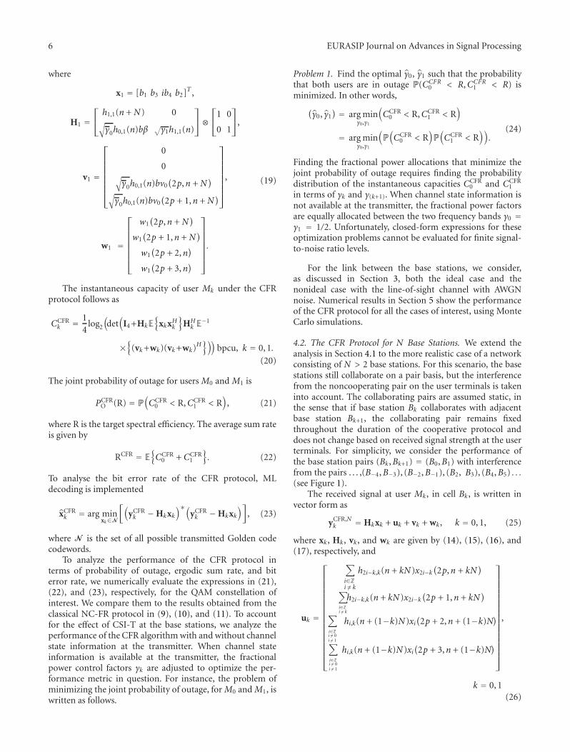
Figure 2 plots the bit error rate versus SNR, for symbolss and t chosen from a 4-QAM and a 16-QAM constellation.The link quality between the adjacent base stations and theuser terminal is set equal to α = 0.1. For comparison,we include in the figure the bit error rate for the classicalfrequency reuse FR 2 scheme, as well as the bit error ratefor the universal frequency reuse, FR 1 scheme, where thelatter’s symbols are taken from a BPSK and a 4-QAMconstellation, respectively, for fairness of comparison. It canbe observed from Figure 2 that even in the absence of CSI-T, for the worst case of nonideal link, the CFR protocoloutperforms the classical FR 2 protocol, for all signal-to-noise ratio values. The FR 1 scheme outperforms the CFRprotocol at low SNR, where the distributed space-time codedoes not perform well. At high SNR values, the diversityobtained from the CFR protocol outperforms that of the
3025200 15105
SNR (dB)
100
10−1
10−2
10−3
10−4
10−5
α = 0.1
6-QAM
4-QAM
FR1, 4-QAMFR2, 16-QAMFR1, BPSKFR2, 4-QAM
No CSIT, idealNo CSIT, non idealCSIT, ideal
BE
R
CSIT, non ideal
FR1 curves
Figure 2: Bit error rate (BER), as a function of the SNR (dB), fortwo isolated base stations. The link quality α = 0.1, and the mod-ulation is 4-QAM and 16-QAM, respectively. The FR1 curves denotethe direct transmission scheme with BPSK and 4-QAM modulation,respectively. The non ideal link denotes the case when the basestation-to-base station link gain is β = α.
FR 1 direct transmission protocol, and the CFR protocolachieves the best performance. The good performance ofthe CFR protocol at high SNR can be well invested forapplication in the small-cell scenario. Due to the proximity ofthe base station from its intended receiver in a small-cellenvironment, the signal-to-noise ratio at the receiver isexpected to be high, and the quality of the link α is expectedto be large. Hence, the CFR protocol is most suitable forcooperation in small-cell environments.
The CFR protocol with CSI-T and ideal link betweenthe cooperating base stations achieves the best performance,among the CFR protocol setups. The presence of channelstate information at the transmitter improves the bit errorrate performance by 1 dB at high SNR. When the linkbetween the base stations is nonideal, in the worst case (β =α), the performance degradation is negligible. It is .5 dBon average at high SNR for the case of no CSI-T and non-discernible for the case of when CSI-T is available at the basestation.
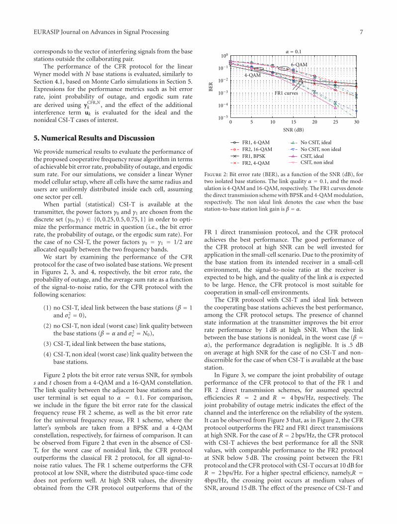
In Figure 3, we compare the joint probability of outageperformance of the CFR protocol to that of the FR 1 andFR 2 direct transmission schemes, for assumed spectralefficiencies R = 2 and R = 4 bps/Hz, respectively. Thejoint probability of outage metric indicates the effect of thechannel and the interference on the reliability of the system.It can be observed from Figure 3 that, as in Figure 2, the CFRprotocol outperforms the FR2 and FR1 direct transmissionsat high SNR. For the case of R = 2 bps/Hz, the CFR protocolwith CSI-T achieves the best performance for all the SNRvalues, with comparable performance to the FR2 protocolat SNR below 5 dB. The crossing point between the FR1protocol and the CFR protocol with CSI-T occurs at 10 dB forR = 2 bps/Hz. For a higher spectral efficiency, namely,R =4bps/Hz, the crossing point occurs at medium values ofSNR, around 15 dB. The effect of the presence of CSI-T and
8 EURASIP Journal on Advances in Signal Processing
3025200 15105
SNR (dB)
100
10−1
10−2
10−3
10−4
10−5
Pro
babi
lity
ofou
tage
FR1FR2No CSIT, idealNo CSIT, non ideal
CSIT, ideal
R = 4 bps/Hz
R = 2 bps/Hz
α = 0.1
CSIT, non ideal
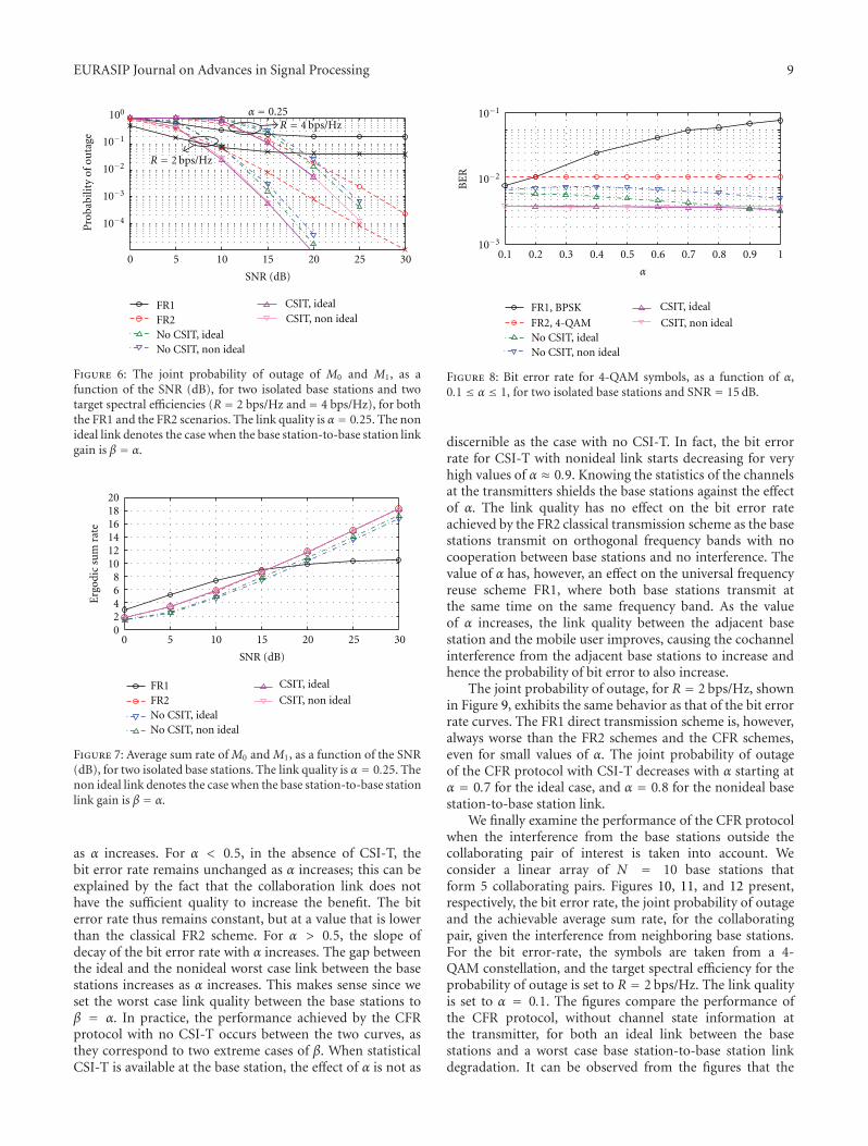
Figure 3: The joint probability of outage of M0 and M1, as afunction of the SNR (dB), for two isolated base stations and twotarget spectral efficiencies (R = 2 bps/Hz and R = 4 bps/Hz), forboth the FR1 and the FR2 scenarios. The link quality is α = 0.1. Thenon ideal link denotes the case when the base station-to-base stationlink gain is β = α.
the errors in the base station-to-base station links followsimilarly the bit error rate performance in Figure 2. In par-ticular, the presence of CSI-T incurs a gain of around 1 dBat high SNR, and the effect of the nonideality in the link isnegligible, especially with CSI-T.
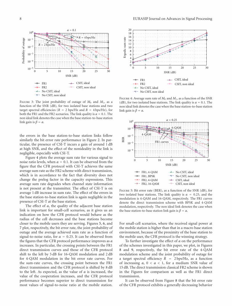
Figure 4 plots the average sum rate for various signal tonoise ratio levels, when α = 0.1. It can be observed from thefigure that the CFR protocol with CSI-T achieves the sameaverage sum rate as the FR2 scheme with direct transmission,which is in accordance to the fact that diversity does notchange the prelog factor in the capacity expressions. Thisaverage sum rate degrades when channel state informationis not present at the transmitter. The effect of CSI-T is onaverage 1 dB increase in sum rate. The effect of the errors inthe base station-to-base station link is again negligible in thepresence of CSI-T at the base station.
The effect of α, the quality of the adjacent base stationlink is important for small-cell scenarios, as it gives us anindication on how the CFR protocol would behave as theradius of the cell decreases and the base stations becomecloser to the mobile users they are serving. Figures 5, 6, and7 plot, respectively, the bit error rate, the joint probability ofoutage and the average achieved sum rate as a function ofsignal-to-noise ratio, for α = 0.25. It can be observed fromthe figures that the CFR protocol performance improves as αincreases. In particular, the crossing points between the FR1direct transmission curves and those of the CFR protocolshift to the left by 5 dB for 16-QAM modulation and 2 dBfor 4-QAM modulation in the bit error rate curves. Forthe sum-rate curves, the crossing point between the FR1direct transmission and the CFR protocol is shifted by 8 dBto the left. As expected, as the value of α is increased, thevalue of the cooperation increases, and the CFR protocolperformance becomes superior to direct transmission formost values of signal-to-noise ratio at the mobile station.
3025200 15105
SNR (dB)
FR1FR2No CSIT, idealNo CSIT, non ideal
CSIT, ideal
1816141210
20
86420
Erg
odic
sum
rate
CSIT, non ideal
Figure 4: Average sum rate of M0 and M1, as a function of the SNR(dB), for two isolated base stations. The link quality is α = 0.1. Thenon ideal link denotes the case when the base station-to-base stationlink gain is β = α.
3025200 15105
SNR (dB)
100
10−1
10−2
10−3
10−4
FR1, 4-QAM
FR2, 16-QAM
FR1, BPSKFR2, 4-QAM
No CSIT, idealNo CSIT, non ideal
CSIT, non idealCSIT, ideal
BE
Rα = 0.25
6-QAM
4-QAM
FR1 curves
Figure 5: Bit error rate (BER), as a function of the SNR (dB), fortwo isolated base stations. The link quality is α = 0.25, and themodulation is 4-QAM and 16-QAM, respectively. The FR1 curvesdenote the direct transmission scheme with BPSK and 4-QAMmodulation, respectively. The non ideal link denotes the case whenthe base station-to-base station link gain is β = α.
For small-cell scenarios, where the received signal power atthe mobile station is higher than that in a macro base stationenvironment, because of the proximity of the base station tothe mobile user, the CFR protocol is the winning strategy.
To further investigate the effect of α on the performanceof the schemes investigated in this paper, we plot, in Figures8 and 9, respectively, the bit error rate of the 4-QAMmodulation scheme and the joint probability of outage fora target spectral efficiency R = 2 bps/Hz, as a functionof increasing α, 0 < α < 1, for a medium SNR value of15 dB. The direct transmission classical FR2 scheme is shownin the Figures for comparison as well as the FR1 directtransmission.
It can be observed from Figure 8 that the bit error rateof the CFR protocol exhibits a generally decreasing behavior
EURASIP Journal on Advances in Signal Processing 9
3025200 15105
SNR (dB)
100
10−1
10−2
10−3
10−4
Pro
babi
lity
ofou
tage
FR1FR2No CSIT, idealNo CSIT, non ideal
CSIT, ideal
α = 0.25R = 4 bps/Hz
R = 2 bps/Hz
CSIT, non ideal
Figure 6: The joint probability of outage of M0 and M1, as afunction of the SNR (dB), for two isolated base stations and twotarget spectral efficiencies (R = 2 bps/Hz and= 4 bps/Hz), for boththe FR1 and the FR2 scenarios. The link quality is α = 0.25. The nonideal link denotes the case when the base station-to-base station linkgain is β = α.
3025200 15105
SNR (dB)
FR1FR2No CSIT, idealNo CSIT, non ideal
CSIT, ideal
1816141210
20
86420
Erg
odic
sum
rate
CSIT, non ideal
Figure 7: Average sum rate of M0 and M1, as a function of the SNR(dB), for two isolated base stations. The link quality is α = 0.25. Thenon ideal link denotes the case when the base station-to-base stationlink gain is β = α.
as α increases. For α < 0.5, in the absence of CSI-T, thebit error rate remains unchanged as α increases; this can beexplained by the fact that the collaboration link does nothave the sufficient quality to increase the benefit. The biterror rate thus remains constant, but at a value that is lowerthan the classical FR2 scheme. For α > 0.5, the slope ofdecay of the bit error rate with α increases. The gap betweenthe ideal and the nonideal worst case link between the basestations increases as α increases. This makes sense since weset the worst case link quality between the base stations toβ = α. In practice, the performance achieved by the CFRprotocol with no CSI-T occurs between the two curves, asthey correspond to two extreme cases of β. When statisticalCSI-T is available at the base station, the effect of α is not as
10−1
10−2
10−3
BE
R
0.1 0.2 0.3 0.4 0.5 0.6 0.7 0.8 0.9 1
α
No CSIT, idealNo CSIT, non ideal
CSIT, ideal
CSIT, non ideal
FR1, BPSK
FR2, 4-QAM
Figure 8: Bit error rate for 4-QAM symbols, as a function of α,0.1 ≤ α ≤ 1, for two isolated base stations and SNR = 15 dB.
discernible as the case with no CSI-T. In fact, the bit errorrate for CSI-T with nonideal link starts decreasing for veryhigh values of α ≈ 0.9. Knowing the statistics of the channelsat the transmitters shields the base stations against the effectof α. The link quality has no effect on the bit error rateachieved by the FR2 classical transmission scheme as the basestations transmit on orthogonal frequency bands with nocooperation between base stations and no interference. Thevalue of α has, however, an effect on the universal frequencyreuse scheme FR1, where both base stations transmit atthe same time on the same frequency band. As the valueof α increases, the link quality between the adjacent basestation and the mobile user improves, causing the cochannelinterference from the adjacent base stations to increase andhence the probability of bit error to also increase.
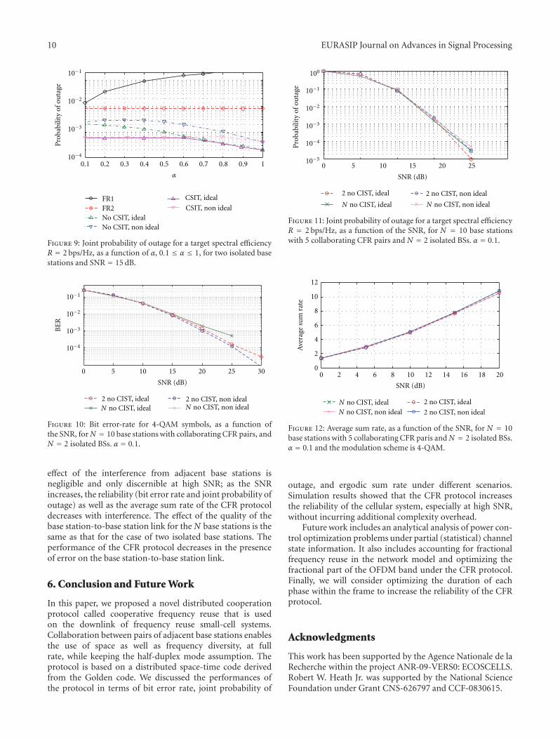
The joint probability of outage, for R = 2 bps/Hz, shownin Figure 9, exhibits the same behavior as that of the bit errorrate curves. The FR1 direct transmission scheme is, however,always worse than the FR2 schemes and the CFR schemes,even for small values of α. The joint probability of outageof the CFR protocol with CSI-T decreases with α starting atα = 0.7 for the ideal case, and α = 0.8 for the nonideal basestation-to-base station link.
We finally examine the performance of the CFR protocolwhen the interference from the base stations outside thecollaborating pair of interest is taken into account. Weconsider a linear array of N = 10 base stations thatform 5 collaborating pairs. Figures 10, 11, and 12 present,respectively, the bit error rate, the joint probability of outageand the achievable average sum rate, for the collaboratingpair, given the interference from neighboring base stations.For the bit error-rate, the symbols are taken from a 4-QAM constellation, and the target spectral efficiency for theprobability of outage is set to R = 2 bps/Hz. The link qualityis set to α = 0.1. The figures compare the performance ofthe CFR protocol, without channel state information atthe transmitter, for both an ideal link between the basestations and a worst case base station-to-base station linkdegradation. It can be observed from the figures that the
10 EURASIP Journal on Advances in Signal Processing
10−1
10−2
10−3
0.1 0.2 0.3 0.4 0.5 0.6 0.7 0.8 0.9 1
α
FR1FR2No CSIT, idealNo CSIT, non ideal
CSIT, ideal
10−4
Pro
babi
lity
ofou
tage
CSIT, non ideal
Figure 9: Joint probability of outage for a target spectral efficiencyR = 2 bps/Hz, as a function of α, 0.1 ≤ α ≤ 1, for two isolated basestations and SNR = 15 dB.
3025200 15105
SNR (dB)
10−1
10−2
10−3
10−4
BE
R
2 no CIST, ideal 2 no CIST, non idealN no CIST, ideal N no CIST, non ideal
Figure 10: Bit error-rate for 4-QAM symbols, as a function ofthe SNR, for N = 10 base stations with collaborating CFR pairs, andN = 2 isolated BSs. α = 0.1.
effect of the interference from adjacent base stations isnegligible and only discernible at high SNR; as the SNRincreases, the reliability (bit error rate and joint probability ofoutage) as well as the average sum rate of the CFR protocoldecreases with interference. The effect of the quality of thebase station-to-base station link for the N base stations is thesame as that for the case of two isolated base stations. Theperformance of the CFR protocol decreases in the presenceof error on the base station-to-base station link.
6. Conclusion and Future Work
In this paper, we proposed a novel distributed cooperationprotocol called cooperative frequency reuse that is usedon the downlink of frequency reuse small-cell systems.Collaboration between pairs of adjacent base stations enablesthe use of space as well as frequency diversity, at fullrate, while keeping the half-duplex mode assumption. Theprotocol is based on a distributed space-time code derivedfrom the Golden code. We discussed the performances ofthe protocol in terms of bit error rate, joint probability of
25200 15105
SNR (dB)
2 no CIST, ideal 2 no CIST, non ideal
100
10−1
10−2
10−3
10−4
10−5
Pro
babi
lity
ofou
tage
N no CIST, ideal N no CIST, non ideal
Figure 11: Joint probability of outage for a target spectral efficiencyR = 2 bps/Hz, as a function of the SNR, for N = 10 base stationswith 5 collaborating CFR pairs and N = 2 isolated BSs. α = 0.1.
0
2
4
6
8
10
12
Ave
rage
sum
rate
0 2 4 6 8 10 12 14 16 18 20
SNR (dB)
2 no CIST, ideal
2 no CIST, non idealN no CIST, idealN no CIST, non ideal
Figure 12: Average sum rate, as a function of the SNR, for N = 10base stations with 5 collaborating CFR paris andN = 2 isolated BSs.α = 0.1 and the modulation scheme is 4-QAM.
outage, and ergodic sum rate under different scenarios.Simulation results showed that the CFR protocol increasesthe reliability of the cellular system, especially at high SNR,without incurring additional complexity overhead.
Future work includes an analytical analysis of power con-trol optimization problems under partial (statistical) channelstate information. It also includes accounting for fractionalfrequency reuse in the network model and optimizing thefractional part of the OFDM band under the CFR protocol.Finally, we will consider optimizing the duration of eachphase within the frame to increase the reliability of the CFRprotocol.
Acknowledgments
This work has been supported by the Agence Nationale de laRecherche within the project ANR-09-VERS0: ECOSCELLS.Robert W. Heath Jr. was supported by the National ScienceFoundation under Grant CNS-626797 and CCF-0830615.
EURASIP Journal on Advances in Signal Processing 11
References
[1] M. S. Alouini and A. J. Goldsmith, “Area spectral efficiency ofcellular mobile radio systems,” IEEE Transactions on VehicularTechnology, vol. 48, no. 4, pp. 1047–1066, 1999.
[2] V. Chandrasekhar, J. G. Andrews, and A. Gatherer, “Femtocellnetworks: a survey,” IEEE Communications Magazine, vol. 46,no. 9, pp. 59–67, 2008.
[3] S. Ramanath, M. Debbah, E. Altman, and V. Kumar, “Asymp-totic analysis of precoded small cell networks,” in Proceedingsof IEEE INFOCOM, pp. 1–8, San Diego, Calif, USA, May 2010.
[4] F. Wang, A. Ghosh, C. Sankaran, P. J. Fleming, F. Hsieh,and S. J. Benes, “Mobile WiMAX systems: performance andevolution,” IEEE Communications Magazine, vol. 46, no. 10,pp. 41–49, 2008.
[5] 3GPP TR 36.814, “Further advancements for E-UTRA physi-cal layer aspects,” 3rd Generation Partnership Project, Techni-cal Specification Group Radio Access Network, February 2009.
[6] J. N. Laneman, D. N. C. Tse, and G. W. Wornell, “Cooperativediversity in wireless networks: efficient protocols and outagebehavior,” IEEE Transactions on Information Theory, vol. 50,no. 12, pp. 3062–3080, 2004.
[7] S. Shamai and B. M. Zaidel, “Enhancing the cellular downlinkcapacity via co-processing at the transmitting end,” in Proceed-ings of the IEEE Vehicular Technology Conference (VTC ’01),vol. 3, pp. 1745–1749, May 2001.
[8] J. Zhang, R. Chen, J. G. Andrews, A. Ghosh, and R. W. Heath,“Networked MIMO with clustered linear precoding,” IEEETransactions on Wireless Communications, vol. 8, no. 4, pp.1910–1921, 2009.
[9] Y. Song et al., “Relay station shared by multiple base sta-tions for inter-cell interference mitigation,” IEEE C802.16m-08/1436r1, November 2008.
[10] A. Sendonaris, E. Erkip, and B. Aazhang, “User cooperationdiversity part I: system description,” IEEE Transactions onCommunications, vol. 51, no. 11, pp. 1927–1938, 2003.
[11] J. N. Laneman and G. W. Wornell, “Distributed space-time-coded protocols for exploiting cooperative diversity in wirelessnetworks,” IEEE Transactions on Information Theory, vol. 49,no. 10, pp. 2415–2425, 2003.
[12] M. Badr and J. C. Belfiore, “Distributed space time codes forthe Amplify-and-Forward multiple-access relay channel,” inProceedings of the IEEE International Symposium on Informa-tion Theory (ISIT ’08), pp. 2543–2547, July 2008.
[13] C. Hucher, G. R. B. Othman, and J. C. Belfiore, “AF and DFprotocols based on Alamouti ST code,” in Proceedings of theIEEE International Symposium on Information Theory (ISIT’07), pp. 1526–1530, June 2007.
[14] S. Jing, D. N. C. Tse, J. B. Soriaga, J. Hou, J. E. Smee,and R. Padovani, “Downlink macro-diversity in cellularnetworks,” in Proceedings of the IEEE International Symposiumon Information Theory (ISIT ’07), pp. 1–5, June 2007.
[15] S. Shamai (Shitz), O. Somekh, and B. M. Zaidel, “Multi-cell communications: an information theoretic perspective,”in Proceedings of the Joint Workshop on Communications andCoding (JWCC ’04), October 2004.
[16] M. Debbah, “Mobile flexible networks: the challenges ahead,”in Proceedings of the International Conference on AdvancedTechnologies for Communications (ATC ’08), pp. 3–7, October2008.
[17] S. W. Peters and R. W. Heath Jr., “The future of WiMAX:multihop relaying with IEEE 802.16 j,” IEEE CommunicationsMagazine, vol. 47, no. 1, pp. 104–111, 2009.
[18] M. Janani, A. Hedayat, T. E. Hunter, and A. Nosratinia,“Coded cooperation in wireless communications: space-timetransmission and iterative decoding,” IEEE Transactions onSignal Processing, vol. 52, no. 2, pp. 362–371, 2004.
[19] J. C. Belfiore, G. Rekaya, and E. Viterbo, “The goldencode: a 2 × 2 full-rate space-time code with nonvanishingdeterminants,” IEEE Transactions on Information Theory, vol.51, no. 4, pp. 1432–1436, 2005.
[20] S. Yang and J. C. Belfiore, “Optimal space-time codes forthe MIMO amplify-and-forward cooperative channel,” IEEETransactions on Information Theory, vol. 53, no. 2, pp. 647–663, 2007.
[21] A. D. Wyner, “Shannon-theoretic approach to a Gaussiancellular multiple-access channel,” IEEE Transactions on Infor-mation Theory, vol. 40, no. 6, pp. 1713–1727, 1994.
[22] S. Jing, D. N. C. Tse, J. B. Soriaga, J. Hou, J. E. Smee, andR. Padovani, “Multicell downlink capacity with coordinatedprocessing,” EURASIP Journal on Wireless Communicationsand Networking, vol. 2008, Article ID 586878, 2008.
[23] O. Somekh, B. M. Zaidel, and S. Shamai, “Sum rate characteri-zation of joint multiple cell-site processing,” IEEE Transactionson Information Theory, vol. 53, no. 12, pp. 4473–4497, 2007.
[24] O. Simeone, O. Somekh, H. V. Poor, and S. Shamai, “Localbase station cooperation via finite-capacity links for the uplinkof linear cellular networks,” IEEE Transactions on InformationTheory, vol. 55, no. 1, pp. 190–204, 2009.
[25] S. Shamai and A. D. Wyner, “Information-theoretic consider-ations for symmetric, cellular, multiple-access fading channels- Part I,” IEEE Transactions on Information Theory, vol. 43, no.6, pp. 1877–1894, 1997.
[26] O. Somekh and S. Shamai, “Shannon-theoretic approach to aGaussian cellular multiple-access channel with fading,” IEEETransactions on Information Theory, vol. 46, no. 4, pp. 1401–1425, 2000.

Photograph © Turisme de Barcelona / J. Trullàs
Preliminary call for papers
The 2011 European Signal Processing Conference (EUSIPCO 2011) is thenineteenth in a series of conferences promoted by the European Association forSignal Processing (EURASIP, www.eurasip.org). This year edition will take placein Barcelona, capital city of Catalonia (Spain), and will be jointly organized by theCentre Tecnològic de Telecomunicacions de Catalunya (CTTC) and theUniversitat Politècnica de Catalunya (UPC).EUSIPCO 2011 will focus on key aspects of signal processing theory and
li ti li t d b l A t f b i i ill b b d lit
Organizing Committee
Honorary ChairMiguel A. Lagunas (CTTC)
General ChairAna I. Pérez Neira (UPC)
General Vice ChairCarles Antón Haro (CTTC)
Technical Program ChairXavier Mestre (CTTC)
Technical Program Co Chairsapplications as listed below. Acceptance of submissions will be based on quality,relevance and originality. Accepted papers will be published in the EUSIPCOproceedings and presented during the conference. Paper submissions, proposalsfor tutorials and proposals for special sessions are invited in, but not limited to,the following areas of interest.
Areas of Interest
• Audio and electro acoustics.• Design, implementation, and applications of signal processing systems.
l d l d d
Technical Program Co ChairsJavier Hernando (UPC)Montserrat Pardàs (UPC)
Plenary TalksFerran Marqués (UPC)Yonina Eldar (Technion)
Special SessionsIgnacio Santamaría (Unversidadde Cantabria)Mats Bengtsson (KTH)
FinancesMontserrat Nájar (UPC)• Multimedia signal processing and coding.
• Image and multidimensional signal processing.• Signal detection and estimation.• Sensor array and multi channel signal processing.• Sensor fusion in networked systems.• Signal processing for communications.• Medical imaging and image analysis.• Non stationary, non linear and non Gaussian signal processing.
Submissions
Montserrat Nájar (UPC)
TutorialsDaniel P. Palomar(Hong Kong UST)Beatrice Pesquet Popescu (ENST)
PublicityStephan Pfletschinger (CTTC)Mònica Navarro (CTTC)
PublicationsAntonio Pascual (UPC)Carles Fernández (CTTC)
I d i l Li i & E hibiSubmissions
Procedures to submit a paper and proposals for special sessions and tutorials willbe detailed at www.eusipco2011.org. Submitted papers must be camera ready, nomore than 5 pages long, and conforming to the standard specified on theEUSIPCO 2011 web site. First authors who are registered students can participatein the best student paper competition.
Important Deadlines:
P l f i l i 15 D 2010
Industrial Liaison & ExhibitsAngeliki Alexiou(University of Piraeus)Albert Sitjà (CTTC)
International LiaisonJu Liu (Shandong University China)Jinhong Yuan (UNSW Australia)Tamas Sziranyi (SZTAKI Hungary)Rich Stern (CMU USA)Ricardo L. de Queiroz (UNB Brazil)
Webpage: www.eusipco2011.org
Proposals for special sessions 15 Dec 2010Proposals for tutorials 18 Feb 2011Electronic submission of full papers 21 Feb 2011Notification of acceptance 23 May 2011Submission of camera ready papers 6 Jun 2011